6 Tm TENDON SURVEL TEST REPT.
329
1jH 20 rie ~~' ~ 20TH YEAR SURVEILLANCE OF THEFord POST-TENSIONING SYSTEM AT THE Florida CRYSTAL RIVER NUCLEAR PLANTuT Power d 66UNIT 3 CORPORATION SI. SURVEILLANCE PROCEDURES Volume 2, Section 9, Appendix F of the 20th Year Physical Surveillance Report contains the detailed procedures for conducting the tendon surveillance. The surveillance consists of the following steps: 1. Visual examination of casing filler grease. 2. Analytical testing of casing filler grease samples. 3. Inspection of the anchor assembly of each of the surveillance tendon ends for deleterious conditions such as corrosion, cracks, broken or missing buttonheads. 4. Inspection of concrete surrounding the bearing plate. 5. Measurement of the liftoff force for each of the surveillance tendons. 6". Removal of one wire from the surveillance tendons which are detensioned for examination and testing. 7. Retensioning of the detensioned tendons and measuring the corresponding tendon elongation. 8. Visual inspection for corrosion, pitting, or any significant physical change of wires removed from the tendons. 9. Testing of wires removed from tendons for yield strength, ultimate strength, and percentage elongation at failure. 10. Resealing tendon cans and replacement of lost sheathing filler into the j tendon duct and grease can. 11. Evaluation of test and inspection results to assess the general condition of the post tensioning system. i1
-
Upload
khangminh22 -
Category
Documents
-
view
0 -
download
0
Transcript of 6 Tm TENDON SURVEL TEST REPT.

1jH20 rie
~~' ~ 20TH YEAR SURVEILLANCE OF THEFordPOST-TENSIONING SYSTEM AT THE FloridaCRYSTAL RIVER NUCLEAR PLANTuT Power
d 66UNIT 3 CORPORATION
SI. SURVEILLANCE PROCEDURES
Volume 2, Section 9, Appendix F of the 20th Year Physical SurveillanceReport contains the detailed procedures for conducting the tendonsurveillance. The surveillance consists of the following steps:
1. Visual examination of casing filler grease.
2. Analytical testing of casing filler grease samples.
3. Inspection of the anchor assembly of each of the surveillance tendon ends fordeleterious conditions such as corrosion, cracks, broken or missingbuttonheads.
4. Inspection of concrete surrounding the bearing plate.
5. Measurement of the liftoff force for each of the surveillance tendons.
6". Removal of one wire from the surveillance tendons which are detensioned forexamination and testing.
7. Retensioning of the detensioned tendons and measuring the correspondingtendon elongation.
8. Visual inspection for corrosion, pitting, or any significant physical change ofwires removed from the tendons.
9. Testing of wires removed from tendons for yield strength, ultimate strength,and percentage elongation at failure.
10. Resealing tendon cans and replacement of lost sheathing filler into thej tendon duct and grease can.
11. Evaluation of test and inspection results to assess the general condition ofthe post tensioning system.
i1

20TIH YEAR SURVEILLANCE OF THEPOST-TENSIONING SYSTEM AT THE Florida
-- CRYSTAL RIVER NUCLEAR PLANT PowerUNIT 3 COPORATON
lI. SHEATHING FILLER ANALYSIS
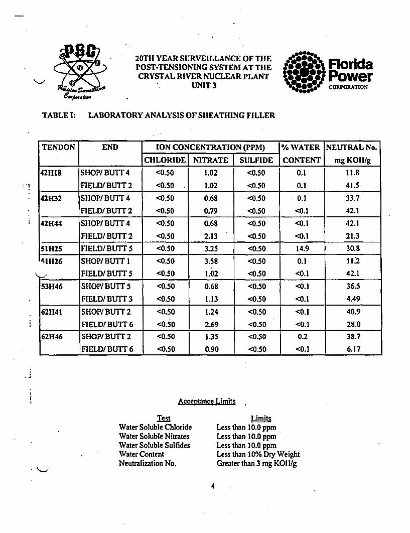
A sample of sheathing filler (grease) was removed from each end of the surveillance tendons.Chemical tests were performed on each sample by Suburban Laboratories, Inc., the results arepresented in Appendix B and are summarized in Table 1.
The maximum acceptable limits are 10 percent by weight for water content and 10 parts per million forwater-soluble chlorides, nitrates and sulfides. All samples met the acceptance criteria as stated abovein all respects except 51H25 field end which had a water content result of 14.9%. As there is a limitedamount of grease available for testing in this grease cans, due to the large shim volume, and a leakinggasket. The small quantity of grease did not allow for additional samples and the water penetration wasin the area of gasket failure. This result is not necessarily indicative of the tendon grease condition
ýthroughout the tendon. Inspection of the tendon end anchorage, shims, and buttonheads showed noabnormal corrosion which would indicate a moisture problem. The gasket was replaced and theanchorage refilled with new grease.
'~j Tendon 53H2 samples were unavailable for testing.
Also included was the report of the neutralization number of each grease sample. This test is generallyperformed by grease manufacturers on new batches of the product. It is a method of determining theoverbase additives in the grease. Degradation of the sheathing filler will yield a change in the acidity of
* the filler material as well as an increase in the ion content. The required neutralization number is>3mg KOH/g and has been achieved by all samples in this test.
The large range in the neutralization numbers found between various tendons is indicative of differenttypes of grease, such as P2 and P4, where P2 was originally installed and P4 added during latter work.This is not a sign of grease or system degradation.
qj
2

20TH YEAR SURVEILLANCE OF TIlEPOST-TENSIONING SYSTEM AT TIIECRYSTAL RIVER NUCLEAR PLANT
UNIT 3
FloridaPowerCORPORATION
lITABLE I: LABORATORY ANALYSIS OF SHEATHING FILLER
TENDON END ION CONCENTRATION (PPM) % WATER NEUTRAL No.
I CHLORIDE NITRATE SULFIDE CONTENT mg KOHI/g
12VI SHOP/TOP <0.50 1.24 <0.50 0.1 42.1
FIELD/ BOTT. <0.50 1.02 <0.50 0.4 42.1
23V2 SHOP/ TOP <0.50 1.46 <0.50 0.2 46.6
FIELD/ BOTT. <0.50 2.02 <0.50 0.1 47.1
61V21 SHOP/TOP <0.50 1.02 <0.50 0.2 50.5
_FIELD/BOlT. <0.50 1.46 <0.50 <0.1 24.1
D113 SHOP/NEAR 2 <0.50 0.79 <0.50 <0.1 36.5
FIELD/NEAR 6 <0.50 1.13 <0.50 0.1 39.3
'.15 SHOP/NEAR 2 <0.50 1.68 <0.50 0.2 40.9
FIELD/NEAR 6 <0.50 1.13 <0.50 0.2 43.2
D212 SHOP/NEAR 1 <0.50 1.13 <0.50 0.1 26.4
FIELD/NEAR 3 <0.50 0.68 <0.50 0.1 40.9
D304 SHOP/NEAR 4 <0.50 0.79 <0.50 0.3 40.9
FIELD/NEAR 2 <0.50 0.68 <0.50 0.1 33.7
D311 SHOP/NEAR 4 <0.50 1.02 <0.50 0.3 47.7
L FIELD/NEAR 2 <0.50 0.68 <0.50 0.1 33.7
i
J Acceptance Limits
TestWater Soluble ChlorideWater Soluble NitratesWater Soluble SulfidesWater ContentNeutralization No.
LimitsLess than 10.0 ppmLess than 10.0 ppmLess than 10.0 ppmLess than 10% Dry WeightGreater than 3 mg KOH/g
3
20TH YEAR SURVEILLANCE OF TIlEPOST-TENSIONING SYSTEM AT THECRYSTAL RIVER NUCLEAR PLANT
UNIT 3
FloridaPowerCORPORATION
TABLE I: LABORATORY ANALYSIS OF SHEATHING FILLER
:!
TENDON END ION CONCENTRATION (PPM) % WATER NEUTRAL No.
I CHLORIDE NITRATE SULFIDE CONTENT mg KOII/g
42H18 SHOP/BUTT 4 <0.50 1.02 <0.50 0.1 11.8
FIELD/BUTT 2 <0.50 1.02 <0.50 0.1 41.5
42H32 SHOP/ BUTT 4 <0.50 0.68 <0.50 0.1 33.7
I_ FIELD/ BUTT 2 <0.50 0.79 <0.50 <0.1 42.1
42H44 SHOP/ BUTT 4 <0.50 0.68 <0.50 <0.1 42.1
FIELD/BUTT 2 <0.50 2.13 <0.50 <0.1 21.3
5IH25 FIELD/BUTT5 <0.50 3.25 <0.50 14.9 30.8511126 SHOP/BUTT 1 <0.50 3.58 <0.50 0.1 1112
FIELD/BUTT 5 <0.50 1.02 <0.50 <0.1 42.1
53H46 SHOP/ BUTT 5 <0.50 0.68 <0.50 <0.1 36.5
FIELD/BUTT 3 <0.50 1.13 <0.50 <0.1 4.49
62H41 SHOP/BUTT 2 <0.50 1.24 <0.50 <0.1 40.9
FIELD/ BUTT 6 <0.50 2.69 <0.50 <0.1 28.0
62H46 SHOP/BUTT 2 <0.50 1.35 <0.50 0.2 38.7
FIELD/ BUTT 6 <0.50 0.90 <0.50 <0.1 6.17
•to
t!! Acceptance Limits
TestWater Soluble ChlorideWater Soluble NitratesWater Soluble SulfidesWater ContentNeutralization No.
Less than i0.0 ppmLess than 10.0 ppmLess than 10.0 ppm
Less than 10% Dry WeightGreater than 3 mg KOH/g
4

* 20TH YEAR SURVEILLANCE OF THE
POST-TENSIONING SYSTEM AT THE FloridaCRYSTAL RIVER NUCLEAR PLANT Power
UNIT 3 coroAn
IIl. ANCHORAGE COMPONENTS
In the following discussion, all procedures referred to are included in Volume2, Section 9, Appendix F of the 20th Year Physical Report while all datasheets are included in Section 4, Appendix A.
Inspection of the anchorage components began with the removal of the greasecan (PSC Procedure SQ 6.0). Complete grease coating (100%) was found onall surveillance tendons except 42H18 field end with 70% of grease cancoated, 42H32 field end with 60% of the grease can coated, 62H41 shop endwith 60% of the grease can coated and 62H41 field end with 70% of the greasecan coated. The percentage of grease coverage was recorded on Data Sheet SQ6.0 with the results tabulated in Table I!.
During removal of the grease can and physical inspections of the anchorageassemblies water was detected during removal of a can, or inside it, on onlyone tendon end. Tendon 51H25 fiild end exhibited drops of water in thegrease can. No water was detected in any other surveillance or grease repairtendon. Water Inspections were recorded on Data Sheet SQ 6.1 and aresummarized in Table III.
The anchorage components (anchorhead, bushing, shims, buttonhead andbearing plate) were inspected for corrosion level and cracks per PSCProcedure SQ 8.0. The results were recorded on Data Sheet SQ 8.0 and aresummarized in Table IV. Corrosion levels on all items was either level I -"bright metal, no visible oxidation", or level 2 - "reddish brown color, nopitting". No evidence of cracking was observed in any of the anchoragecomponents.
5

20Thl YEAR SURVEILLANCE OF THEPOST-TENSIONING SYSTEM AT THECRYSTAL RIVER NUCLEAR PLANT
UNIT 3
6 "Floridao Power
CORPORATION
4
Ill. ANCHORAGE COMPONENTS
The buttonheads were inspected for their physical condition and a count wasmade of protruding or missing buttonheads per PSC Procedure SQ 8.0. Theresults of these inspections are also recorded on Data Sheet SQ 8.0, andsummarized in Table V.
\.- d
Tendon 12VI shop end was found'to have one wire protruding 0.6"and NCR No. FN604-001 was.written to address this.* .1
*1Tendon 51H26 (field end shown) wasfound to have one broken wire 6.05"long after initial liftoff wasperformed. NCR No. FN604-003 wasgenerated to document this findingand the broken section was laterremoved during detensioning.
A continuity test was conducted andall remaining wire were found to becontinuous
201TH YEAR SURVEILLANCE OF THEPOST-TENSIONING SYSTEM AT THECRYSTAL RIVER NUCLEAR PLANT
UNIT 3
FloridaPowerCORPORATTION
IIl. ANCHORAGE COMPONENTS
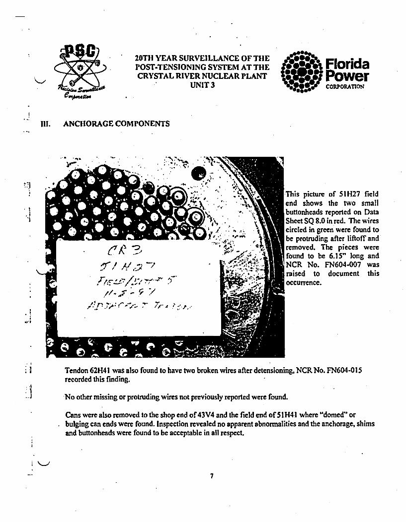
tThis picture of 51H27 fieldend shows the two smallbuttonheads reported on DataSheet SQ 8.0 in red. The wirescircled in green were found tobe protruding after liftoff andremoved. The pieces werefound to be 6.15" long andNCR No. FN604-007 wasraised to document thisoccurrence.
.!a
,o°g.
)-ITendon 62H41 was also found to have two broken wires after detensioning, NCR No. FN604-015recorded this finding.
No other missing or protruding wires not previously reported were found.
Cans were also removed to the shop end of 43V4 and the field end of 51H41 where "domed" orbulging can ends were found. Inspection revealed no apparent abnormalities and the anchorage, shimsand buttonheads were found to be acceptable in all respect.
7

20Til YEAR SURVEILLANCE OF TIlEPOST-TENSIONING SYSTEM AT THECRYSTAL RIVER NUCLEAR PLANT
UNIT 3
FloridaS- oeIII. ANCHORAGE COMPONENTS
* j
~1
'I
* I
d
* I
-j
* I
Scratches found on the face of the anchorhead on 52H46 shop end were reported on Data Sheet SQ 8.0
9

20TH YEAR SURVEILLANCE OF TIIEPOST-TENSIONING SYSTEM AT THECRYSTAL RIVER NUCLEAR PLANT
UNIT 3
FloridaPowerCORPORATION
Ill. ANCHORAGE COMPONENTS--i - -JB ,. •,
''1S
* I
* 4
The above 3/8" shim on tendon 51 H27 field end was foundto be deformed at the shim gap which was 0.8" wide. Thisshim was replaced and the shim gap closed up during liftoff.
9

20TH YEAR SURVEILLANCE OF TIlEPOST-TENSIONING SYSTEM AT TIlECRYSTAL RIVER NUCLEAR PLANT
-UNIT 3
III. ANCHORAGE COMPONENTS
Pieces of rope found protruding fromshim gap on tendon 51H28 field end.
Florida0.Power1014F.. FCORPORATION
wrF, -f
z
10

20TH YEAR SURVEILLANCE OF THlEPOST-TENSIONING SYSTEM AT THECRYSTAL RIVER NUCLEAR PLANT
UNIT 3Florida-owe
IIII.
*1
*1
I
ANCHORAGE COMPONENTS
The concrete was inspected around the bearing plates for cracks per PSCProcedure SQ 8.3 with the results being recorded on Data Sheet SQ 8.3 andsummarized in Table VI. Two tendons exhibited cracks exceeding 0.010", D311and 5 1H26 (shown on the next two pages). No cracks that had a width in excessof 0.010" were found to any other inspection tendon. Data Sheets SQ 8.4 detailthe general containment exterior concrete inspection and at the time of thesurveillance a contractor was on site making concrete repairs to thecontainment buttresses.
Bearing plate ID's were either illegible or not found on several tendon ends.
.1
11

20THl YEAR SURVEILLANCE OF TIlEPOST-TENSIONING SYSTEM AT THECRYSTAL RIVER NUCLEAR PLANT
UNIT 3
ro- FloridaS~PowerCO"PORATION
.1
'1
*1
.1
III. ANCHORAGE COMPONENTS
Crack found around the bearing plateat 5 1-H26 shop end.See NCR No. FN604-004
I I
12
20TII YEAR SURVEILLANCE OF TIHEPOST-TENSIONING SYSTEM AT THECRYSTAL RIVER NUCLEAR PLANT
UNIT 3( ov"' Florida3WjjPower
0#0004CORPORATION'
J1I1. ANCHORAGE COMPONENTS
ri
*1
* J
* L
~-wi-~1
*'~.. '~
'4-.,..-.
,-.. ~
-. ~., .. ~'
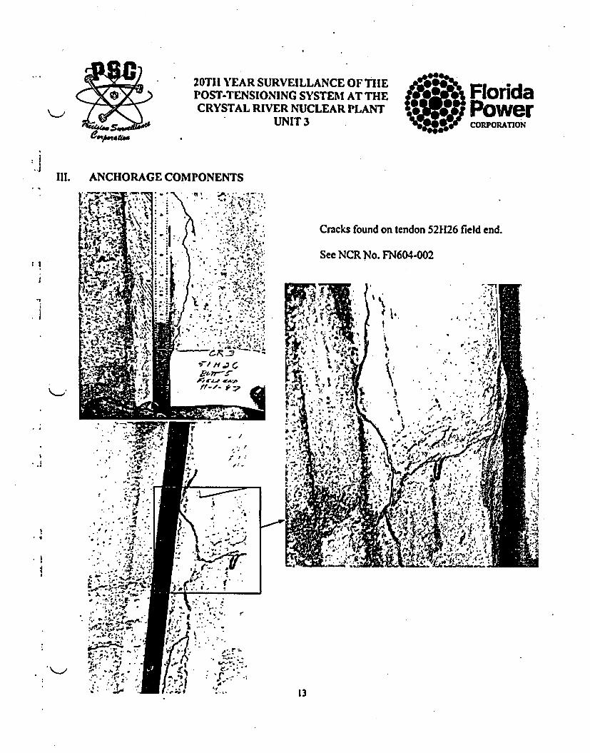
.'j•,t LCracks found on tendon 52H26 field end.
See NCR No. FN604-002
*%.1 ., .1 g
1, • ,
All.8 0. ,Ord
* € y
~1
* J-. 1
4
-.
~* -....
C> -.
.8*
13

" 20TH YEAR SURVEILLANCE OF TIIEPOST-TENSIONING SYSTEM AT TIlECRYSTAL RIVER NUCLEAR PLANT
- ~ UNIT 3
TABLE II: SUMMARY OF DATA SHEETS SQ 6.0GREASE CAN REMOVAL.
FloridaPowerCORPORATION
'1
..1
TENDON END GREASE COATING (%)
GREASE BUTTON- ANCHOR- SHIMS BEARINGCAN -HEADS HEADS PLATE
12VI SHOP/TOP 100 100 100 100 100
FIELD/BOT. 100 100 100 100 100
23V2 SHOP/TOP 100 100 100 100 100
FIELD/BOT. 100 100 100 100 100
61V21 SHOP/TOP 100 100 100 100 100
FIELD/BOT. 100 100 100 00 100
V4 SHOP/TOP 100 '00 100 100 100
D113 SHOP/NEAR 2 100 100 100 100 100
FIELD/NEAR6 100 100 100 100 100
DI1 SHOP/NEAR 2 100 100 100 100 100
FIELD/NEAR 6 100 100 100 100 100
D212 SHOP/NEAR 1 100 100 100 100 100
FIELD/NEAR 3 100 100 100 100 100
D304 SHOP/NEAR4 100 100 100 100 100
FIELD/NEAR2 100 100 100 100 100
D311 SHOP/NEAR 4 100 100 100 100 100
FIELD/NEAR 2 100 100 100 100 100
14

20TI! YEAR SURVEILLANCE OF THEPOST-TENSIONING SYSTEM AT THECRYSTAL RIVER NUCLEAR PLANT
UNIT 3?FloridaPower
CORPORATION
.1 TABLE If: SUMMARY OF DATA SHEETS SQ 6.0GREASE CAN REMOVAL
Ii
* j
TENDON END GREASE COATING (%)
GREASE BUTTON- ANCHOR- SHINMS BEARINGCAN IHEADS lHEADS PLATE
42H!8 SHOP/BUTI 4 100 100 100 100 100
FIELD/BUTT 2 70 100 100 100 100
42H29 SHOP/BUTT 4 100 100 100 100 100
FIELD/BUTT 2 100 100 100 100 100
42H30 SHOP/BUTT 4 100 100 100 100 100
FIELD/BUTT 2 100 100 100 100 100
421131 SHOP/BUTT 4 100 100 100 100 100
FIELD/BUTT 2 100 100 100 100 100
42H32 SHOP/BUTT 4 100 100 100 100 100
FIELD/BUTT 2 60 100 100 100 100
421133 SHOP/BUTT 4 100 100 100 100 100
FIELD/BUTT 2 100 100 100 100 100
421134 SHOP/BUTT 4 100 100 100 100 100
FIELD/ BUTT 2 100 100 100 100 100
42H35 SHOP/BUTT 4 100 100 100 100 100
FIELD/BUTT 2 100 100 100 100 100
42H36 SHOP/BUTT 4 100 100 100 100 100
FIELD/BUTT 2 100 100 100 100 100
42H37 SHOP/BUTT 4 100 100 100 100 100
FIELD/BUTT2 100 100 100 100 100
'U
.1
.1
.1
15

20TI" YEAR SURVEILLANCE OF TIIEPOST-TENSIONING SYSTEM AT TIlECRYSTAL RIVER NUCLEAR PLANT
UNIT 3
FloridaPower0 CORPORATION
! TABLE II: SUMMARY OF DATA SHEETS SQ 6.0GREASE CAN REMOVAL
! 1
'1
* g
TENDON END GREASE COATING (%)
GREASE BUTTON- ANCHOR- SHIMS BEARINGCAN HEADS HEADS PLATE
42H44 SHOP/BUTT 4 100 100 100 100 100
FIELD/BUTT 2 100 100 100 100 100
51H25 SHOP/BUTT 1 100 100 100 100 100
FIELD/BUTT 5 100 100 100 100 100
511126 SHOP/BUTT 1 100 100 100 100 100
FIELD/BUTT 5 100 100 100 100 100
511127 S...OP/.BUTT 100 100 100 100 100
FIELD/ BUTT 5 100 100 100 100 100,
51H28 SHOP/BUTT 1 100 100 100 100 100
FIELD/BUTT 5 100 100 100 100 100
53112 SHOP/BUTTS 100 100 100 100 100
FIELD/BUTT 3 100 100 100 100 100
531146 SHOP/BUTT 5 100 100 100 100 100
FIELD/BUTT 3 100 100 100 100 100
62H41 SHOP/BUTT 2 60 100 100 100 100
FIELD/BUTTI6 70 100 100 100 100
621146 SHOP/BUTT 2 100 100 100 100 100
FIELD/BUTT 6 100 100 100 100 100
51H41 FIELD/BUTT 5 100 100 100 100 100
:1
bo
16
20THl YEAR SURVEILLANCE OF THEPOST-TENSIONING SYSTEM AT THECRYSTAL RIVER NUCLEAR PLANT
UNIT 3 FloridaPowerCORPORATION
J
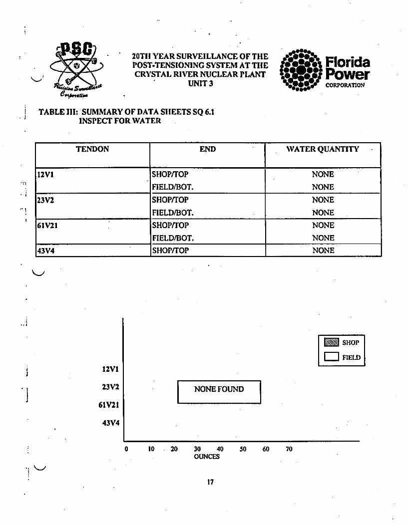
.1 TABLE III: SUMMARY OF DATA SHEETS SQ 6.1INSPECT FOR WATER
-' I-
TENDON END WATER QUANTITY
12VI SHOP/TOP NONE
FIELD/BOT. NONE
23V2 SHOP/TOP NONE
FIELD/BOT. NONE
61V21 SHOP/TOP NONE
FIELD/BOT. NONE
43V4 SHOP/TOP NONE
Lm SHOPiJ
12VI
23V2
61V21
43V4
I NONE FOUND I
0 10 , 20 30 40OUNCES
50 60 70
17

20TH YEAR SURVEILLANCE OF THEPOST-TENSIONING SYSTEM AT THECRYSTAL RIVER NUCLEAR PLANT
UNIT 3
FloridaS~PowerCORPORATIN
i TABLE III: SUMMARY OF DATA SHEETS SQ 6.1INSPECT FOR WATER.
TENDON END WATER QUANTITY
D113 SHOP/NEAR 2 NONE
FIELD/NEAR 6 NONE
D115 SHOP/NEAR 2 NONE
FIELD/NEAR 6 NONE
D212 SHOP/NEAR 1 NONE
FIELD/ NEAR 3 NONE
D304 SHOP/NEAR 4 NONE
FIELD/NEAR 2 NONE311 SHOP/NEAR 4 NONE
FIELD/NEAR 2 NONE
.0
SllOP
FIELD
DI13
D212
D304
D311
I NONEFOUND I
0 10 20 30 40 50OUNCES
60 70
18

20TH YEAR SURVEILLANCE OF THEPOST-TENSIONING SYSTEM AT THECRYSTAL RIVER NUCLEAR PLANT
UNIT3
FloridaPowerCORPORATION
TABLE III: SUMMARY OF DATA SHEETS SQ 6.1INSPECT FOR WATER.
'*1
'1
TENDON END WATER QUANTITY
42H18 SHOP/ BUTT 4 NONE
FIELD/ BUTT 2 NONE
421129 SHOP/BUTT 4 NONE
FIELD/BUTT 2 NONE
421130 SHOP/ BUTT 4 NONE
FIELD/ BUTT 2 NONE
421131 SHOP/BUTI 4 NONE
FIELD/ BUTT 2 NONE
1132 SHOP/ BUTT 4 NONE
FIELD/BU1Tr 2 NONE
• *
SHOPF--EnLD
IJ
a'
421118
421129
421130
421131
42H32
NONE FOUND[
0 10 20 30 40 50OUNCES
60 70
19

20TH YEAR SURVEILLANCE OF THEPOST-TENSIONING SYSTEM AT THE
*CRYSTAL RIVER NUCLEAR PLANTUNIT 3
TABLE III: SUMMARY OF DATA SHEETS SQ 6.1INSPECT FOR WATER.
FloridaPowerCORPORATION
TENDON END WATER QUANTITY
421133 SHOP/ BUTT 4 NONE
FIELD/BUTT 2 NONE
421134 SHOP/ BUTT 4 NONE
FIELD/ BUTT 2 NONE
42H35 SHOP/ BUTT 4 NONE
FIELD/ BUTT 2 NONE
421136 SHOP/ BUTT 4 NONE
FIELD/ BUTT 2 NONE
r 1H37
SHOP/ BUTT 4
FIELD/ BUTT 2
NONE
NONE
SIIOPFIELD
421133
421134
421135
42H36
42H37
NONE FOUND I
0 10 20 30 40 soOUNCES
60 70
!
20

. 20TH YEAR SURVEILLANCE OF TIIEPOST-TENSIONING SYSTEM AT TIIECRYSTAL RIVER NUCLEAR PLANT
UNIT 3
TABLE III: SUMMARY OF DATA SHEETS SQ 6.1INSPECT FOR WATER
FloridaPowerCOPORMATION
TENDON END J WATER QUANTITY
42H44 SHOP/ BUTT 4 NONE
FIELD/BUTT 2 NONE
51H25 SHOP/BUTT 1 NONE
FIELD/ BUTT 5 DROPS
511126 SHOP/BUTT I NONE
FIELD/ BUTT 5 NONE
511127 SHOPI BUTT I NONE
FIELD/ BUTT 5 NONE
1128 SHOP! BUTT 1 NONE
FIELD/ BUTT 5 NONE
t
i •
421144
51H25
51H26
51H27
51H28
]
M s1lop
E:1 IFIELD
0 10 20 30 40OUNCES
50 60 70
K- A
. I
21

20TIH YEAR SURVEILLANCE OF TIIEPOST-TENSIONING SYSTEM AT THECRYSTAL RIVER NUCLEAR PLANT
UNIT 3
FloridaPowerCORPORATION
J I
TABLE III: SUMMARY OF DATA SHEETS SQ 6.1INSPECT FOR WATER
TENDON END WATER QUANTITY
53H2 SHOP/BUTT 5 NONE
FIELD/BUFT 3 NONE
531146 SHOP/ BUTT 5 NONE
FIELD/ BUTT 3 NONE
62H41 SHOP/ BUTT 2 NONE
FIELD/ BUTT 6 NONE
621146 SHOP/ BUTT 2 NONE
FIELD/ BUTT 6 NONE
H41 FIELD/BUTT5 NONE
i
~1
SHOP
t
I1
53112
53H46
621141
621146
511141
I NONEFOUND I
i0 10 20 30 40
OUNCES50 60 70
22

20TH YEAR SURVEILLANCE OF THEPOST-TENSIONING SYSTEM AT THECRYSTAL RIVER NUCLEAR PLANT
UNIT 3
TABLE IV: SUMMARY OF DATA SHEETS SQ 8.0ANCHORAGE CORROSION CONDITION
aFloridaPowers., CORPORATION
TENDON END ANCHOR BUTTONHEAD CORROSION LEVEL, CRACKS
I.D. CORROSION ANCHOR- SHIMS BEARING
CONDITION HEAD PLATE
12VI SHOP/TOP CR650/PCI21 1 1, NONE 2, NONE 21 NONE
FIELD/BOT. NOT FOUND 1 2, NONE 2, NONE 2, NONE
23V2 SHOP/TOP CR736/PC121 1 2, NONE 2, NONE 2, NONE
FIELD/BOT. CR239/PC120 1 2, NONE 2, NONE 2, NONE
61V21 SHOP/TOP CR957/PCI121 1 2, NONE I, NONE 2, NONE
FIELD/BOT. CR189/PC120 1 1, NONE I,NONE I, NONE
43V4 SHOP/TOP CR788/PCI21 N/A NONE NONE NONE
'%113 SHOP/NEAR 2 CR41I/PCI21 I 2, NONE I,NONE I,NONE
FIELD/NEAR 6 CR1075/PCI21 1 2, NONE 2, NONE 2, NONE
D1I1 SHOP/NEAR2 CR675/PCI21 I 2, NONE I,NONE 2, NONE
FIELD/NEAR 6 CR1231/PCI22 I 2, NONE 1, NONE I, NONE
D212 SHOP/NEAR I CRI032/PCI21 I LNONE I,NONE 2, NONE
FIELD/NEAR 3 CR1214/PC122 I 1, NONE I, NONE 1, NONE
D304 SHOP/NEAR4 CR479/PCI21 I 2,NONE 1,NONE I,NONE
FIELD/NEAR 2 CR696/PCI21 1 I, NONE INONE 2, NONE
D311 SHOP/NEAR4 CRI040/PCI21 I I,NONE I,NONE 2, NONE
FIELDD/NEAR2 CR636/PCI21 I 1, NONE 1, NONE 2, NONE
*
!t
123
Bright metal; no visible oxidation.Metal redish brown color, no pittingPatches of red oxide, no visible pits.
!
23

'ý . 20TII YEAR SURVEILLANCE OF TilE
POST-TENSIONING SYSTEM AT THE
CRYSTAL RIVER NUCLEAR PLANTUNIT 3
TABLE IV: SUMMARY OF DATA SHEETS SQ 8.0ANCHORAGE CORROSION CONDITION
FloridaPowerCORPORATION
-et
TENDON END ANCHOR BITMONIIEAD CORROSION LEVEL, CRACKS
I.D. CORROSION ANCIIOR- SHIMS BEARING
CONDITION HEAD I PLATE
42H18 SHOP/BUTI4 CR615/PCI21 2 2, NONE 2, NONE 2, NONE
FIELD/ BUTT 2 CR906/PC121 1 2, NONE 1, NONE 2, NONE
42H29 SHOP/ BUTT 4 CR606/PCi21 N/A NONE NONE NONE
FIELD/ BUTT 2 CR1208/PCI22 N/A NONE NONE NONE
421130 SHOP/BUTT 4 CR569/PCI2I N/A NONE NONE NONE
FIELD/BUTT 2 CR1143/PC122 N/A NONE NONE NONE
421131 SHOP/BUTT 4 CR368/PC121 N/A NONE NONE NONE
FIELD/ BUTT 2 CR1233/PC122 N/A NONE NONE NONE
'-42H32 SHOP/ BUTT 4 CR564/PCI21 1 2, NONE 2, NONE 2, NONE
FIELD/BUTT 2 CR123/PCI20 I 2, NONE 1, NONE 1, NONE
421133 SHOP/ BUTT 4 CR546/PC121 NIA NONE NONE NONE
FIELD/ BUTT 2 CR934/PCI21 N/A NONE NONE NONE
42H34 SHOP/ BUTT 4 CR525/PCI21 N/A NONE NONE NONE
FIELD/BUTT 2 CR1207/PC122 N/A NONE NONE NONE
42H35 SHOP/LBUTT 4 CR547/PCI21 N/A NONE NONE NONE
FIELD/ BUTT 2 CR1229/PCI22 N/A NONE NONE NONE
42H36 SHOP/BUTT 4 CR522/PC121 N/A NONE NONE NONE
FIELD/BUTT 2 CR1174/PC122 N/A NONE NONE NONE
42H37 SHOP/BUTT 4 CR559/PCI21 N/A NONE NONE NONE
FIELD/BUTT2 CR! 175/PC122 N/A NONE NONE NONE
t
I Bright metal; no visible oxidation.2 Metal redish brown color, no pitting3 Patches of red oxide, no visible pits.
24

20TI! YEAR SURVEILLANCE OF THEPOST-TENSIONING SYSTEM AT THECRYSTAL RIVER NUCLEAR PLANT
UNIT3
*FloridaPowerCORPORMTION
G
!TABLE IV: SUMMARY OF DATA SHEETS SQ 8.0
ANCHORAGE CORROSION CONDITION
TENDON END ANCHOR BUrrONIIEAD CORROSION LEVEL, CRACKS
I.D. CORROSION ANCHOR- SHIMS BEARING
CONDITION HEAD PLATE
42H44 SHOP/BUTT4 CR572/PC121 1 I, NONE 2, NONE 2, NONE
FIELD/BUTT2 CR1230/PCI22 1 1, NONE 2, NONE I, NONE
51H25 SHOP/ BUTT I CR26/PC120 N/A NONE NONE NONE
FIELD/BUTT5 CR1126/PCI22 I 1, NONE 2, NONE 2, NONE
51H26 SHOP/BUTT I CR384/PCI21 1 2, NONE 1, NONE 1, NONE
FIELD/BUTT 5 CR897/PCI21 I 1, NONE 1, NONE 1, NONE
51H27 SHOP/BUTT I CR366/PCI21 N/A NONE NONE NONE
FIELD/BUTT 5 CR1088/PC12I .N/A NONE NONE NONE
-1H28 SHOP/BUTT' I CR49/PCi20 N/A NONE NONE NONE
FIELD/ BUTT 5 CR1 173/PC122 N/A NONE NONE NONE
53112 SHOP/BUTT 5 CRI35/PCI20 1 2, NONE 1, NONE 1, NONE
FIELD/BUTT 3 CR646/PC12I 1 2, NONE 2, NONE I, NONE
53H46 SHOP/BUTT 5 CR660/PCI2I 1 2, NONE 1, NONE 2, NONE
FIELD/BUTT 3 CR1197/PCI22 I 1, NONE 1, NONE 2, NONE
62H41 SHOP/BUTT 2 CR355/PCI20 I 1, NONE I, NONE 2, NONE
FIELD/BUTI"6 CR454/PCI21 I I, NONE 1, NONE 1, NONE
62H46 SHOP/BUTT 2 CR!56/PC120 2 2, NONE 2, NONE 1, NONE
FIELD/BUTT 6 CR979/PCI21 I 1, NONE 1, NONE 1, NONE
51H41 FIELD/BUTT_5 CRi222/PC122 N/A NONE NONE NONE
* 1-.1
I Bright metal; no visible oxidation.2 Metal redish brown color, no pitting3 Patches of red oxide, no visible pits.
25

-.-. ~
C20TI YEAR SURVEILLANCE OF TIIEPOST-TENSIONING SYSTEM AT THECRYSTAL RIVER NUCLEAR PLANT
UNIT 3
CFloridaPower-COMPOAMIN
TABLE V: SUMMARY OF DATA SHEETS SQ 8.0 - BUTTONHIEAD COUNT
TENDON END ORIGINAL AS FOUND AS +LEFT J REMOVED TOTAL EFFECTIVE EFFECTIVE
PROTRUDE BROKEN/ PROTRUDE BROKEN/ PROTRUDE BROKEN/ FOR WIRES WIRES
MISSING MISSING MISSING TESTING AS FOUND ASLEFT
12VI SI1OPfTOP 1 0 1 0 1 0 0 1 162 162
FIELD/BOT. 0 1 0 I 0 1 0 1 162 162
23V2 SHIOPfrOP 0 0 0 0 0 0 0 0 163 163
FIELD/DOT. 0 0 0 0 0 0 0 0 163 163
61V21 SHOP/TOP 0 0 0 0 0 0 1 1 163 162
FIELD/DOT. 0 0 0 0 0 0 1 1 163 162
43V4 SIIOPfrOP 0 0 0 0 0 0 0 0 163 163
D113 SI1OP/NEAR2 0 0 0 0 0 0 0 0 163 163
FIELD/NEAR 6 0 0 0 0 0 0" 0 0 163 163
DIIS SIIOP/NEAR2 0 0 0 0 0 0 0 0 163 163
FIELD/NEAR 6 0 0 0 0 0 0 0 0 163 163
D212 SIIOP/NEAR I 0 1 0 1 0 1 0 1 162 162
FIELD/NEAR 3 0 1 0 1 0 1 0 1 162 162
D304 SHOP/NEAR 4 0 0 0 0 0 0 0 1 163 162
FIELD/NEAR 2 0 0 0 0 0 0 0 1 163 162
D311 SIIOP/NEAR4 0 0 0 0 0 0 0 0 163 163
FIELD/NEAR 2 0 0 0 0 0 0 0 0 163 163

B
J
20TH YEAR SURVEILLANCE OF THEPOST-TENSIONING SYSTEM AT THECRYSTAL RIVER NUCLEAR PLANT
UNIT 3
TABLE V: SUMMARY OF DATA SHEETS SQ 8.0 - B1UTTONHEAD COUNT
C
FloridaPowerCOMRPOIAMro
TENDON END ORIGINAL AS FOUND AS LEFT REMOVED TOTAL EFFECTIVE EFFECTIVE
PROTRUDE BROKEN/ PROTRUDE BROKENi/ PROTRUDE BROKEN/ FOR WIRES WIRES
MISSING MISSING MISSING TESTING AS FOUND ASLEFT
421118 SltOP/BUTT 4 0 0 0 0 0 0 0 0 163 163
FIELD/ BUIT 2 0 0 0 0 0 0 0 0 163 163
421129 SHOP/BUTT 4 0 0 0 0 0 0 0 0 163 163
FIELD/BUTr 2 0 0 0 0 0 0 0 0 163 163
421130 Sl IOP/BUTT 4 0 0 0 0 0 0 0 0 163 163
FIELD/BUTr 2 0 0 0 0 0 0 0 0 163 163
421131 SllOP! BUTT4 0 0 0 0 0 0 0 0 163 163
FIELD/BUrT 2 0 0 0 0 0 0 0 0 163 163
421132 SIIOP/ UWTT4 0 0 0 0 0 0 0 0 163 163
FIELD/BUTT 2 0 0 0 0 0 0 0 0 163 163
421133 S1lOP/1BUT"4 0 0 0 0 0 0 0 0 163 163
FIELD/BUTT 2 0 0 .0 0 0 0 0 0 163 163

= -- .'
20TH YEAR SURVEILLANCE OF THEPOST-TENSIONING SYSTEM AT THECRYSTAL RIVER NUCLEAR PLANT
UNIT 3
TABLE V: SUMMARY OF DATA SHEETS SQ 8.0 - BUTrONHEAD COUNT
CFloridaPowerCORPORAITON
a
TENDON END IORIGINAL AS FOUND AS LEFT REMOVED TOTAL EFFECTIVE EFFECTIVE
PROTRUDE BROKEN/ PROTRUDE BROKEN/ PROTRUDE BROKEN/ FOR WIRES WIRES
MISSING MISSING MISSING TESTING AS FOUND AS LEFT
421134 SIIOP/1B3UT4 0 0 0 0 0 0 0 0 163 163
FIELD/BUTT 2 0 0 0 0 0 0 0 0 163 163
421135 SIIOP/ BUTT 4 0 0 0 0 0 0 1 1 163 162
FIELD/BUTT 2 0 0 0 0 0 0 1 1 163 162
42H36 SIIOP/BUTT 4 0 0 0 0 0 0 0 0 163 163
FIELD/BUTT 2 0 0 0 0 0 0 0 0 163 163
421137 SIliOP/BUTT 4 0 0 0 0 0 0 0 0 163 163
FIELD/BBUIT 2 0 0 0 0 0 0 0 0 163 .163
421144 SIIOP/BUTT 4 0 0 0 0 0 0 0 0 163 163
FIELD/BUTT 2 0 0 0 0 0 0 0 0 163 163
511125 SIIOP/ BUTT 1 0 0 0 0 0 0 0 0 163 163
FIELD/BUTT 5 0 0 0 0 0 0 0 0 163 163
511126 SIIOP/BUTTFI 0 0 0 0 0 1* 2 163 161
FIELD/IBUTT 1 0 0 0 0 0 1* 2 2 163 161
* FOUND BROKEN AFTER LIFTOFF

•m P• J
C. C C20TH YEAR SURVEILLANCE OF TIlEPOST-TENSIONING SYSTEM AT THECRYSTAL RIVER NUCLEAR PLANT
UNIT 3
FloridaPowerCORPORATION
TABLE V: SUMMARY OF DATA SHEETS SQ 8.0 - BUTTONHEAD COUNT
TENDON END ORIGINAL AS FOUND AS LEFT REMOVED TOTAL EFFECTIVE EFFECTIVE
PROTRUDE BROKEN/ PROTRUDE BROKEN/ PROTRUDE BROKEN/ FOR WIRES WIRES
MISSING MISSING MISSING TESTING AS FOUND AS LEFT
511127 SHOP/BUTTI 0 0 0 0 0 2'* 2 2 163 161
FIELD/BUTr 5 0 0 0 0 0 2&* 2 2 163 161
511128 SIIOPI BUTT I1 0 0 0 0 0 0 0 0 163 163
FIELD/BUTT 5 0 0 0 0 0 0 0 0 163 163
53112 SHOP/BUT' 5 0 0 0 0 0 0 0 0 163 163
FIELD/BUT 3 0 0 0 0 0 0 0 0 163 163
531146 SHOP/BUTT 5 0 0 0 0 0 0 0 0 163 163
FIELD/BUTT 3 0 0 0 0 0 0 0 0 163. 163
621141 SIIOP/BUTT 2 0 0 0 2 * 0 3 3 3 163 160
FIELD/BUTT 6 0 0 0 2 & 0 3 3 3 163 160
621146 SIIOP/BU1T2 0 0 0 0 0 0 0 .0 163 163
FIELD/BUTT 6 0 0 0 0 0 0 0 0 163 163
511141 FIELD/BUTT 5 0 0 0 0 ".0 0 0 0 163 163
* FOUND BROKEN AFTER LIFTOFF* FOUND BROKEN AFTER DETENSIONING

20TH YEAR SURVEILLANCE OF THEPOST-TENSIONING SYSTEM AT THECRYSTAL RIVER NUCLEAR PLANT
UNIT 3
FloridaPowerCORPORATION
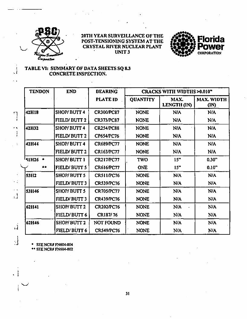
TABLE VI: SUMMARY OF DATA SHEETS SQ 8.3CONCRETE INSPECTION.
TENDON END BEARING CRACKS WITII WIDTHS >0.010"
PLATE ID QUANTITY MAX. MAX. WIDTH
I LENGTH (IN) (IN)
12VI SHOP/TOP CR973 NONE N/A N/A
FIELD/BOT. CRI I8/PC58 NONE N/A N/A
23V2 SHOP/TOP NOT FOUND NONE N/A N/A
FIELD/BOT. CRI 14/PC58 NONE N/A N/A
61V21 SHOP/TOP NOT FOUND NONE N/A N/A
FIELD/BOT. NOT FOUND NONE N/A N/A
!D113 SHOP/NEAR 2 NOT FOUND NONE N/A N/A
FIELD/NEAR 6 NOT FOUND NONE N/A N/A
DI5 SHOP/NEAR 2 NOT FOUND NONE N/A N/A
FIELD/NEAR 6 CR919/PC91 NONE N/A N/A
D212 SHOP/NEAR I CR910/PC88 NONE N/A N/A
FIELD/NEAR 3 CR764/PC91 NONE N/A N/A
D304 SHOP/ NEAR 4 NOT FOUND NONE N/A N/A
FIELD/ NEAR 2 NOT FOUND NONE N/A N/A
D311 SHOP/NEAR4 CR846/PC91 NONE N/A N/A
FIELD/NEAR 2 NOT FOUND TWO 24" <0.050
I.4
0*SEE NCRN FN604-016
30
20TH YEAR SURVEILLANCE OF THEPOST-TENSIONING SYSTEM AT THECRYSTAL RIVER NUCLEAR PLANT
ms UNIT 3
TABLE VI: SUMMARY OF DATA SHEETS SQ 8.3CONCRETE INSPECTION.
FloridaPowerCORJPORATION
'~1
TENDON END BEARING CRACKS WITH WIDTHS >0.010"
PLATE ID QUANTITY MAX. MAX. WIDTHILENGTlH (IN) (IN)
421118 SHOP/ BUTT 4 CR300/PC87 NONE N/A N/A
FIELD/ BUTT 2 CR3731PC87 NONE N/A N/A
42H32 SHOP/ BUTT 4 CR2541PC88 NONE N/A N/A
FIELD/ BUTT 2 CP654/PC76 NONE N/A N/A
42H44 SHOP/ BUTT 4 CR689/PC77 NONE N/A N/A
FIELD/BUTT 2 CR163/PC77 NONE N/A N/A
5IIH26 * SHOP/ BUTT I CR217/PC77 TWO 15" 0.30"- ** FIELD/BUTT 5 CR616/PC77 ONE 15" 0.10"
53112 SHOP/BUTT 5 CR51I/PC76 NONE N/A N/A
FIELD/ BUTT 3 CR539/PC76 NONE N/A N/A
53H46 SHOP/ BUTT 5 CR705/PC77 NONE N/A N/A
FIELD/ BUTT 3 CR439/PC76 NONE N/A N/A
62H41 SHOP/ BUTT 2 CR202/PC76 NONE N/A N/A
FIELD/ BUTT 6 CR1 87/76 NONE N/A N/A
62H46 SHOP/ BUTT 2 NOT FOUND NONE N/A N/A
FIELD/ BUTT 6 CR549/PC76 NONE N/A N/A
.1
* SEE NCR# FN604-004** SEE NCR# FN604-002
'I
31

20TH YEAR SURVEILLANCE OF THEPOST-TENSIONING SYSTEM AT THECRYSTAL RIVER NUCLEAR PLANT
UNIT 3
FloridaPowerCORPORATION
* t
'*1
.1
IV. HYDRAULIC JACK CALIBRATIONS
Precision Surveillance has developed a program for calibrating hydraulic jacks utilizing regressionanalysis (PSC Procedure QA 12.8.G-W). This is a process where a straight line is mathematically bestfitted to a set of data points (in this case, force verses gauge pressure). This results in calculating ramarea (slope) and constant (y-intercept) for each jack calibration. Completed calibrations for all of thehydraulic jacks used are contained in Appendix C and are summarized in Table Vii.
A before and after comparison of the stressing jacks' ram areas revealed that none of the jacks'calibrations varied by more than 0.77% indicating that they were in a properly calibrated status.
Note that the force exerted by a jack can be calculated as follows:
Force = Area x Pressure + Constant(F). (in2) (KSI) (K)
I
-a
32

( C C20TH YEAR SURVEILLANCE OF THEPOST-TENSIONING SYSTEM AT THECRYSTAL RIVER NUCLEAR PLANT
UNIT 3
FloridaPowerCORPORAMNON
TABLE VII: HYDRAULIC JACK CALIBRATIONS
JACK BEFORE SURVEILLANCE FORCE AFTER SURVEILLANCE FORCE MAX VARI
ID DATE AREA CONSTANT (Fi) DATE AREA CONSTANT (Ff) PRESSURE %(in') (kips) (in) (kips)
8778 10/9/97 333.423 1.640 1835466.5 1/20/98 333.564 -7.497 1827105 5500 0.46
8833 10/9/97 335.178 -0.321 1843158 1/20/98. 335.008 -3.148 1839396 5500 0.20
9501 12/I 1/97 368.689 1.554 1918736.8 1/20/98 372.715 4.549 1933569 5200 0.77
7702 2/17/98 1.542 0.120 13227 3/23/98 1.552 0.068 13260 8500 0.25
RAM 7702 USED FOR WIRE TESTING

/
20TH YEAR SURVEILLANCE OF THEPOST-TENSIONING SYSTEM AT THE FloridaCRYSTAL RIVER NUCLEAR PLANT POwer'•',/UNIT 3 co"oPA-No
V. TENDON LIFTOFFS AND DETENSIONING
A liftoff is performed on each surveillance tendon to monitor the force exerted by the tendon onto thestructure. PSC Procedure SQ 9.0 (Volume 2, Section 9, Appendix F) details the steps to be taken toperform a liftoff. The results are documented on Data Sheet SQ 9.0 and are summarized inTable VIII.
It should be noted that performing a liftoff has only a localized effect on a tendon; therefore, it isacceptable to use the same jacks for both ends of a tendon by executing the liftoff on separateoccasions.
Vertical tendon liftoffs were found to be above the base value except for 12VI which was above 95%of base, and all dome liftoff averages were above the base value.
Horizontal lifloffs revealed two isolated areas 421130 to 42H36 inclusive and 51 H26, 51 H27 whereaverage tendon lifloffs were between 90% and 95% of base value. Two tendons, 42H35 and 51H26,were found to be below 90% of base value and detensioned for continuity test per FPC requirement.This continuity test revealed that all of the wires were continuous, one wire was removed from eachtendon for testing and one broken wire removed from 51 H26 was also tested. After testing thetendons were restored to base value -0% +6%. All other tendons found between 90 and 95% of basevalue were subsequently restored per procedure to base value -0% +6%.
These low liftoff results were documented on NCR's -010, 011, 012,.013, and 014 for 421-130 - 36 andNCR 005 for 511-126.
All other tendon liftoffs were either above base value or 95% of base value and therefore acceptable.
The average normalized liftoff for each group, vertical, dome and horizontal, exceeded the minimumrequired and is acceptable.
After completion of lifloffs, protruding wires were found to tendons 51 H26(I), 51 H27(2) and62H46(2). These wires, once removed, were found to have broken behind the anchorhead. Nocorrosion was found to indicate wire failure due to deterioration and it is suspected that slight tendonhead rotation while setting back down sheared the wires against the shims. In all cases the brokenwires were on the outer comer edge of the tendon bundle and no gauge movement was noted toindicate failures during liftoff. These wires were probable "pinched" during original installation andadditional work on these tendons has broken the wires. NCR's FN604-003,007 and 015 recordedthese occurrences.
34

K;o . • I:. .•
( C (20TIl YEAR SURVEILLANCE OF THEPOST-TENSIONING SYSTEM AT THECRYSTAL RIVER NUCLEAR PLANT
UNIT 3
FloridaPowerCORPORATION
TABLE VIII: SUMMARY OF DATA SHEETS SQ 9.0TENDON LIFTOFFS
TENDON END EFFECT. JACK PRESS. LIFTOFF AVE. BASE 95%, 90% NORMALIZING ACCEPTWIRES No. LIFTOFF VALUE BASE BASE FACTOR
12VI silopfroP 162 8833 4390 1471 1471 1530 1453 1377 -9 YES
23V2 siloPfroP 163 8778 4820 1609 1609 1482 1408 1333 37 YES
61V21 SHlOPf/OP 163 8833 4550 1525 .1525 1482 1408 1334 38 YES
D113 SIIOP/2 163 8778 4267.5 1424.7 1427 1369 1301 1232 -35 YES
FIELD/6 163 8833 4265 1429 YES
DIIS SIIOP/2 163 8778 4062.5 1356 1380 1347 1280 1213 -12 YES
FIELD/6 163 8833 4190 1404 YES
D212 SHOP/I 162 8833 3820 1280 1335 1317 1252 1186 15 YES
FIELDI3 162 8778 4160 1389 YES
D304 SIIOP/4 163 8778 4810 1605 1598 1397 1327 1258 -64 YES
FIELD/2 162 8833 4748 1591 YES
D311 SIIOP/4 163 8778 4220 1409.5 1408 1335 1269 1202 0 YES
FIELD/2 163 8833 4200 1407 YES

C C (20TH YEAR SURVEILLANCE OF THEPOST-TENSIONING SYSTEM AT THECRYSTAL RIVER NUCLEAR PLANT
UNIT 3
FloridaPowerC01POIA.JO0N
TABLE VIII: SUMMARY OF DATA SHEETS SQ 9.0 - TENDON LIFTOFFS
TENDON END EFFECT. JACK PRESS. LIFTOFF AVE. BASE 95% 90% NOR3MALIZING ACCEPTWIRES No. JLIFTOFF VALUE BASE BASE FACTOR
42HI8 SIIOP/4 163 8778 4690 1565 1476 1495 1420 1346 -56 YES
FIELD/2 163 8833 4137 1386.5 YES
421129 SIIOP/4 163 8778 4500 1502 1448 1445 1373 1300 -7 YES
FIELD/2 163 8833 4160 1394 YES
421130 SlIOP/4 163 8778 4355 1454 1389 1469 1396 1322 -32 NO
FIELD/2 163 8833 3950 1324 NO
421131 SiHOP/4 163 8778 4100 1369 1338 1460 1387 1314 -21 NO
FIELD/2 163 8833 3900 1307 NO
421132 SIIOP/4 163 8778 4320 1442 1355.5 1452 1380 1307 -15 NO
FIELD12 163 8833 3785 1269 NO
421133 SIIOP/4 163 8778 4490 1499 1361 1474 1400 1326 -35 NO
FIELD/2 163 8833 3650 1223 NO
421134 SIIOP/4 163 8778 4240 1415 1377.5 1452 1380 1307 NO
FIELD/2 163 8833 4000 1340 NO

-. 4 .- ,
C (I (20TH YEAR SURVEILLANCE OF TIHEPOST-TENSIONING SYSTEM AT TIHECRYSTAL RIVER NUCLEAR PLANT
UNIT 3
FloridaPowerCORPJMOTI"II
TABLE VIII: SUMMARY OF DATA SHEETS SQ 9.0 - TENDON LIFTOFFS
TENDON END EFFECT. JACK PRESS. LIFrOFF AVE. BASE 95% 90% NORMALIZING ACCEPT
WIRES No. LIFTOFF VALUE BASE BASE FACTOR
421135 SIIOPI4 163 8778 4110 1372 1296.5 1455 1382 1309 -17 NO
FIELD/2 163 8833 3693 1221 NO
421136 SIIOP/4 163 8778 4490 1499 1408 1503 1428 1353 -65 NO
FIELD/2 163 8833 3930 1317 NO
42H37 SIIOP/4 163 8778 4310 1439 1401.5 1452 1379 1306 -14 YES
FIELD/2 163 8833 4070 1364 YES
421144 SI1OP/4 163 8778 4510 1505 1471.5 1427 1356 1285 10 YES
FIELD/2 163 8833 4291 1438 YES
511125 SHOP/I 1 163 8833 4090 1370.5 1363 1401 1331 1261 38 YES
FIELD/ 5 163 8778 4060 1355.5 YES
511126 SHOP/I 163 8833 4190 1403.5 1320 1514 1438 1363 -75 NO
FIELD/5 163 8778 3705 1237 NO
511127 SHOP/1 163 8833 3787 1269 1265.5 1368 1300 1231 71 NO
FIELD/51 163 8778 3780 1262 1 NO

• • ,,d
C ( (20TH YEAR SURVEILLANCE OF THEPOST-TENSIONING SYSTEM AT THECRYSTAL RIVER NUCLEAR PLANT
UNIT 3
TABLE VIII: SUMMARY OF DATA SHEETS SQ 9.0 - TENDON LIFTOFFS
FloridaPowerCORPORAZON
TENDON END EFFECT. JACK PRESS. LIFTOFF AVE. BASE 95% 90% NORMALIZING ACCEPTWIRES No. I LIFTOFF VALUE BASE BASE FACTOR
511128 SHOP/ 1 163 8833 4445 1489.5 1450.5 1518 1442 1367 80 YES
FIELD/5 163 8778 4230 1412 YES
53112 SIIOP/5 163 9501 4400 1624 1611 1424 1353 1281 12 YES
FIELD/3 163 9501 4330 1598 YES
531-146 SHlOP/5 163 8833 4340 1454 1459.5 1472 1399 1325 -35 YES
FIELD/3 163 8778 4390 1465 YES
62H41 SHOP/2 163 8778 4230 1412 1426 1422 1351 1280 16 YES
FIELD/6 163 8833 4297.5 1440 YES
621146 SHOP/2 163 8778 4280 1429 1485 1465 1392 1318 -27 YES
FIELD/6 163 8833 4600 1541 - L YES-. ~--,,

20Tll YEAR SURVEILLANCE OF TIHEPOST-TENSIONING SYSTEM AT-THECRYSTAL RIVER NUCLEAR PLANT
UNIT 3
FloridaPowerCORPORATION
. V. -WIRE INSPECTION AND TESTING
One wire was scheduled for removal from each deiensioned tendon for visual inspection and tensiletesting. PSC Procedure SQ 10.3 outlines the details involved with the wire testing and the data wasrecorded on Data Sheets SQ 10.2 and SQ 10.3 with the results summarized in Table X.
All wire diameters were within the acceptance criteria of 0.27559 ± 0.002". The corrosion condition ofall samples was level I - "bright metal; no visible oxidation" and the Ultimate Strength exceeded theminimum strength criteria of 240,000 psi (240 ksi) for all wire samples tested.
k,,/
.!
*I
40

C. C C20TH YEAR SURVEILLANCE OF TIlEPOST-TENSIONING SYSTEM AT THECRYSTAL RIVER NUCLEAR PLANT
UNIT 3
FloridaPowerCORPORATION
TABLE X: SUMMARY OF DATA SHEETS SQ 10.2 & 10.3 - VISUAL INSPECTION AND TENSILE TESTING OF WIRE
TENDON SAMPLE CORROSION SAMPLE DIAMETER YIELD ULTIMATE *ACCEPTABLENo. LEVEL LOCATION (IN) STRENGTH STRENGTHI
(Fr) (PSI) (PSI)61V21 1 1 20-29 0.275 210,770 249,197 YES
2 1 90-99 0.275 210,251 251,793 YES
3 1 170- 179 0.275 209,212 242,966 YES
D304 1 1 20-29 0.2755 213,614 244,138 YES
2 1 60-69 0.2755 213,614 241,552 YES
3 1 100- 109 0.2755 217,236 250,864 YES
421135 1 1 20-29 0.276 210,286 241,219 YES
2 1 70- 79 0.276 210,802 246,375 YES
3 1 140- 149 0.276 212,864 253,077 YES
51H26 1 1 10-19 0.2745 210,512 254,293 YES
2 1 70-79 0.2745 209,990 248,560 YES
3 1 140-149 0.2745 216,766 243,869 YES
511126 IA. 1 10-19 0.2745 215,202 250,645 YES
2A 1 70-79 0.2745 214,160 253,251 YES
3A 1 146- 155 0.2745 220,415 257,942 YES
621141 1 1 20-29 0.2755 211,545 247,760 YES
2 1 70-79 0.2755 213,614 245,173 YES
_ 3 1 140-149 0.2755 214,390 241,552 YES

20TH YEAR SURVEILLANCE OF THlEPOST-TENSIONING SYSTEM AT TIlE FloridaCRYSTAL RIVER NUCLEAR PLANT Power
UNIT 3 CORPORATION
VII. TENDON RETENSIONING AND RESEALING
Those scheduled tendons that had previously been detensioned for wire removal, (61V21, D304 and62H41) along with additional detensioned tendons 42H35 and 51 H26 were retensioned per PSCProcedure SQ 11.0 (Volume 2, Section 9, Appendix F). The results of the retensioning process wererecorded on Data Sheets SQ 11.0 and the results are summarized in Table XI.
'1
All new elongations were compared to original elongations and found to be acceptable (within +10%) except tendon 51 H26 whose elongation was -11.6%, NCR No. FN604-009 was raised to recordthis. All tendons were locked off at forces greater than those initially found or above base valuewhichever was higher, and all liftoffs were within -0% +6%.
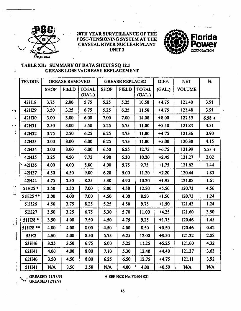
After completion of all inspections, the anchorage components were hand coated with cold grease toensure complete coverage, the cans were reinstalled with new gaskets, torqued to the required value,and the necessary amount of sheathing filler (grease) was added. In all cases, the same amount ormore grease was added than removed. Results of the grease replacement were recorded on DataSheets SQ 12.1 and are summarized in Table XII.
A greater amount than 5% of the duct volume was added to dome tendons D212 (12.12%),D304(18.3%), D311(19.1%) and horizontal tendons42H30(6.58%) and 421134(5.53%). NCR'sFN604-0!8, 019, 020, and 021 were written to record this. All other tendons took an amount less than5% ofthe tendon duct volume.
42

8qll *l *...
C (
FloridaPowercoORPAInON
(
20TH YEAR SURVEILLANCE OF TIlEPOST-TENSIONING SYSTEM AT THECRYSTAL RIVER NUCLEAR PLANT
UNIT 3
TABLE XI: SUMMARY OF DATA SHEETS SQ 11.0TENDON RETENSIONING
TENDON END ORIGINAL OBSERVED % ACCEPT LIFTOFF RETENSIONING % ACCEPTELONGATION ELONGATION VARI. BEFORE VARI._
EACH TOTAL, EACH ITOTAL, RETEN. JACK PRESS. L/OFF
61V21 SHOP - 12.125 11.3 -6.80 YES 1525 8833 4740 1588 +4.13 YES
D304 SHOP - 8.125 3.55 7.95 -2.15 YES 1605 8778 4860 1622 +1.06 YES
FIELD - - 4.40 - - 1591 8833 4837.5 1621 +1.89 YES
621141 SHOP - 10.25 4.75 9.40 -8.29 YES 1412 8778 4460 1489 +5.45 YES
FIELD - - 4.65 - - - 1440 8833 4380 1468 +1.94 YES
TENDONS RE-TENSIONED AFTER WIRE REMOVAL
TENDON END ORIGINAL OBSERVED % ACCEPT BASE RETENSIONING % ACCEPTELONGATION ELONGATION VAR]. VARI.
EACH TOTAL EACH TOTAL VALUE JACK JPRESS. IIOFFI AVE.
421135 SHOP - 10.25 4.80 9.80 -4.40 YES 1455 8778 4597 1534 1539 +5.77 YES
FIELD - - 5.00 - - - - 8833 4610 1545 - -
511126 SHOP - 10.75 4.70 9.50 -11.6 NO 1514 8833 4703 1576 1589 +4.59 YES
FIELD - - 4.80 - - - 8778 4800 1602 - -
* SEE NCR No. FN604-009

C C20TII YEAR SURVEILLANCE OF TIHEPOST-TENSIONING SYSTEM AT TIHECRYSTAL RIVER NUCLEAR PLANT
UNIT 3
FloridaPowerCORPORATION
TABLE XI: SUMMARY OF DATA SHEETS SQ 11.0 - TENDON RETENSIONING
TENDON END LIFTOFF BEFORE RETENSIONING AVERAGE BASE RETENSIONING AVERAGE % ABOVE ACCEPT
JACK PRESSURE LIFTOFF LIFTOFF VALUE JACK PRESSURE LIFTOFF LIFTOFF BASE
421129 SHOP 8778 4500 1502 1448 1445 8778 4500 1502 1493 +3.32 YES.
FIELD 8833 4160 1394 - 8833 4430 1484.5 -
421130 SHOP 8778 4355 1454 1389 1469 8778 4560 1522 1520 +3.47 YES
FIELD 8833 3950 1324 - 8833 4530 1518 -
421131 SHOP 8778 4100 1369 1338 1460 8778 4605 1537 1547.5 +5.99 YES
FIELD 8833 3900 1307 - 8833 4650 1558 -
421132 SHOP 8778 4320 1442 1355.5 1452 8778 4540 1515 1506.5 +3.75 YES
FIELD 8833 3785 1269 8833 4470 1498
421133 SHOP 8778 4490 1499 1361 1474 8778 4490 1499 1513.5 +2.68 YES
FIELD 8833 3650 1223 - - 8833 4560 1528 -
421134 SHOP 8778 4240 1415 1377.5 1452 8778 4520 1509 1512.5 +4.17 YES
FIELD 8833 4000 1340 - 8833 4525 1516 - -
421136 SHOP 8778 4490 1499 1408 1503 8778 4700 1569 1572 +4.59 YES
FIELD 8833 3930 1317 - 8833 4700 1575
421137 SIIOP 8778 4310 1439 1401.5 1452 8778 4570 1525 1521.5 +4.79 YES
FIELD 8833 4070 1364 1 I - 8833 4530 1518 1 1

O•
CC (
20TIi YEAR SURVEILLANCE OF TIlEPOST-TENSIONING SYSTEM AT THECRYSTAL RIVER NUCLEAR PLANT
UNIT 3
FloridaPowerCORPORATION
TABLE XI: SUMMARY OF DATA SHEETS SQ 11.0 -TENDON RETENSIONING
TENDON END LIFTOFF BEFORE RETENSIONING AVERAGE BASE RETENSIONING AVERAGE % ABOVE ACCEPT
JACK PRESSURE LIFTOFF LIFTOFF VALUE JACK PRESSURE LIFTOFF LIFTOFF __BASE
511125 SHOP 8833 4090 1370.5 1363 1401 8833 4250 1425 1442 +2.93 YES
FIELD 8778 4060 1355.5 8778 4370 1459 -
511127 SHOP 8833 3787 1269 1265.5 1368 8833 4145 1389 1399 +2.27 YES
FIELD 8778 3780 1262 - - 8778 4220 1409 -
511128 SHOP 8833 4445 1489.5 1450.5 1518 8833 4645 1557 1563 +2.96 YES
FIELD 8778 4230 1412 - - 8778 47,00 1569 - -

20TH YEAR SURVEILLANCE OF THEPOST-TENSIONING SYSTEM AT THECRYSTAL RIVER NUCLEAR PLANT
UNIT 3
0 FloridaPowerCOR•PORATION
TABLE XII: SUMMARY OF DATA SHEETS SQ 12.1GREASE LOSS Vs GREASE REPLACEMENT
t
TENDON GREASE REMOVED GREASE REPLACED DIFF. NET %
SHOP FIELD TOTAL SHOP FIELD TOTAL (GAL.) VOLUME(GAL.) I (GAL.)
12VI 2.00 36.75 38.75 40.75 0.75 41.50 +2.75 143.46 1.91
23V2 0.75 9.75 10.50 11.50 0.00 11.50 +1.00 142.52 0.70
61V21 0.75 88.50 89.25 20.25 72.50 92.75 +3.50 144.03 2.43
43V04 0.50 0.00 0.50 7.50 0.00 7.50 +7.00 N/A N/A
D113 4.50 4.00 8.50 6.20 3.50 9.70 +1.20 115.11 1.04
-D0115 4.50 4.50 9.00 7.00 4.00 11.00 +2.00 117.17 1.71
D212 6.50 4.00 10.50 20.00 4.50 24.50 +14.00 115.55 12.12.
D304 12.00 7.25 19.25 38.20 0.00 38.20 +18.95 103.68 18.30'
D311 24.00 4.00 28.00 46.50 3.50 50.00 +22.00 115.12 19.104
4 SEE NCR No. FN604-018, 019, 020
o •
45
* 20TII YEAR SURVEILLANCE OF THEPOST-TENSIONING SYSTEM AT THECRYSTAL RIVER NUCLEAR PLANT
dCA UNIT 3
TABLE XII: SUMMARY OF DATA SIlEETS SQ 12.1GREASE LOSS Vs GREASE REPLACEMENT
FloridaPowerCORPORATION
'1
TENDON GREASE REMOVED GREASE REPLACED DIFF. NET %
SHOP FIELD TOTAL SHOP FIELD TOTAL (GAL.) VOLUME
_ (GAL.) _ (GAL.)
42H18 3.75 2.00 5.75 5.25 5.25 10.50 +4.75 121.40 3.91
42H29 3.50 3.25 6.75 5.25 6.25 11.50 +4.75 121.48 3.91
42H30 3.00 3.00 6.00 7.00 7.00 14.00 +8.00 121.59 6.58.
42H31 2.50 3.00 5.50 5.25 5.75 11.00 +5.50 121.84 4.51
42H32 3.75 2.50 6.25 6.25 4.75 11.00 +4.75 121.36 3.90
42H33 3.00 3.00 6.00 6.25 4.75 11.00 +5.00 120.38 4.15
42H34 3.00 3.00 6.00 6.50 6.25 12.75 +6.75 121.99 5.53 *iR~q t t A AAA•E rTL• A f iAA .[ At 1• a)l•Ia •lt
14z r.31.3 .1 .A.,. F..3U 1.I'., ".7v J.3.v hVU.hU •.I't LZI.Z/ 4.v.,---- ---- --_ ------------- .L
'"-42H36 4.00 4.00 8.00 4.00 5.75 9.75 +1.75 121.62 1.44
.4
.1
42H37 4.50 4.50 9.00 6.20 5.00 11.20 +2.20 120.44 1.83
42H44 4.75 3.50 8.25 5.30 4.90 10.20 +1.95 121.08 1.61
51H25 I 3.50 3.50 7.00 8.00 4.50 12.50 +5.50 120.73 4.56
51H25* 3.00 4.00 7.00 4.50 4.00 8.50 +1.50 120.73 1.24
511H26 4.50 3.75 8.25 5.25 4.50 9.75 +1.50 121.43 1.24
51H27 3.50 3.25 6.75 5.30 5.70 11.00 +4.25 121.60 3.50
51H28 * 3.50 4.00 7.50 4.50 4.75 9.25 +1.75 120.46 1.45
51H28* 4.00 4.00 8.00 4.50 4.00 8.50 +0.50 120.46 0.42
53H2 4.50 4.00 8.50 5.75 6.25 12.00 +3.50 121.32 2.88
53H46 3.25 3.50 6.75 6.00 5.25 11.25 +5.25 121.60 4.32
62H41 4.00 4.00 8.00 7.10 5.30 12.40 +4.40 •121.37 3.63
62H46 3.50 4.50 8.00 6.25 6.50 12.75 +4.75 121.11 3.92
51H41 N/A 3.50 3.50 N/A 4.00 4.00 +0.50 N/A N/A
GREASED 11/18197GREASED 12/18/97
* SEE NCR No. FN604-021
46

•[••" " 20THi YEAR SURVEILLANCE OF THlE aPOST-TENSIONING SYSTEM AT TIlE FloridaCRYSTAL RIVER NUCLEAR PLANT -Power
UNIT 3 coRORAMoN
VIII. COMPARISON WITH ORIGINAL INSTALLATION DATA
A comparison of the liftoff forces from this surveillance to the original installation lock-off forces ismade in an effort to detect any evidence of system degradation. The lock-off forces are compared inorder to detect any abnormal force loss which would possibly indicate an underestimation of the creep,shrinkage and/or elastic shortening effects in the Containment Building.
Three tendons were excluded from the results due to inconsistencies. Tendons 23V2 and 53112 bothreported higher liftoffs now than at installation. Both ofthe original reported lifloffs appear to be lowerthan the group average at installation,'the horizontal by almost 5%, which could indicate an error inrecording the original result. Tendon D304 lost only 12 kips from the original recorded liftoff. In no casewere any conditions found that would indicate problems with the wire condition or forces found. Theseresults are not considered detrimental to the structure.
Due to these results being inconsistent with the rest of the results they have been omitted from the groupaverages. The losses for the tendon groups were found to be 9.08% for the vertical tendons, 11.72% forthe horizontal tendons and 16.63% for the dome tendons. Despite two of the horizontal tendons being
Sbelow the expected base value at liftoff (subsequently retensioned to base -0% +6%) these losses are asexpected for a containment of this age and do not indicate any degradation of the system.
The following three pages show the graphs of the normalized average liftoffs taken from page 39 for eachof the tendon groups. These trend graphs allow a high degree of confidence that the liftoff values willremain above the minimum requirement throughout the next surveillance.
I
47

20TH YEAR SURVEILLANCE OF TIHEPOST-TENSIONING SYSTEM AT THECRYSTAL RIVER NUCLEAR PLANT
UNIT 3
FloridaS~Powerep..304CORPOR~ATION
TABLE XIII: COMPARISON OF ORIGINAL LOCKOFF FORCES TO AS FOUND FORCES
•t
TENDON LIFTOFF FORCE LOSS PERCENTAGE AVERAGE
ORIGINAL @ 20 YEARS (kips) % _PERCENTAGE12VI 1675 1471 204 12.18
23V2 1598 1609 +11* 9.08
61V21 1622 1525 97 5.98
D113 1676 1427 249 14.86
Dl15 1700 1380 320 18.82
D212 1600 1335 265 16.56 16.63
D304 1610 1598 12*
D311 1682 1408 274 1629
421118 1664 1476 188 11.30
421132 1626 1356* 270 16.61
42H44 1605 1472 133 8.29
51H26 1661 1320 ** 341 20.53 11.72
53H2 1555 1611 +56*
53H46 1628 1560 68 4.18
621141 1609 1426 183 11.37
621146 1645 1485 160 9.73
t
* REMOVED FROM THE AVERAGES DUE TO INCONSISTENCIES.
48

S -- 4.
C (
(Page 1 of 3)LME HISTORICAL TRENDS
DOME TENDONS
FPC - Cry=Iat RivWr Unit #3Tendon Surveillance ProgramDome Group Trend of Los2es
MUE AFTER AVERAGE DATEI
06000 Aq. An rate". In S~ku.
OoUE PLACME4T (YARS)10
OF CONCRETE
1- 400.
9 130-
1100
SP-182 (Total Rewrite)
>
>rn<.r./m
a 8 t to to 21 30 35 41
SCWEDULIED SURVEULA•CE- PERIOD (YEADS AFTER SfT)
Rev. 13 Page 92
201do C
W(O

( C CENCO(Fage f3
TEN-ON HISTORICAL TE
FIPC - Cryatol River Unit J3-Tendon Surveillonce ProgramVertical Group Trend of Losses
1U£E AFTER AVERAGE
AMg Al Vnes Ini Swavv.Mmb
DATE OF CONCRC•I WALL PLACEMENT (YEARS)10
t Doc
1600
1400
1200
1000
*4 S S 3I 4
0
e
1 1 4 11 K ~p s -_ _ - S. -=_ - - -
M- 7
am
"X91
~0O
goo~
I I 9 It IS to as " 3S 4
SCREDMuED 5U. VU• CE PERIOD (YArs AFTER SI
SP-182 (Total Rewrite) Rev. 13 Page 93

/-... . . .- 4 41. t- a~.4 ~~-4
(7 CENCLOSU3RE o
HISTRICA TRM(Page 3 of 3)
TEDNHISTORIALTRND
FPC - Crystal River Unit #3Tendon Surveillance Program - A I
Hoop Group Trend of Losses 10W MAW mq= Aw Fame
UJE AFr AVERACIE DATE OF CONCREM WALL PLC:::EJNT (YEARs)
1 10
84
I
-4 wr
0Pot .> r
r. >
1 3 a so@t 20 M0 " 46
SCHIDIJLL SURVEJUANCE P-ERIOD 01CARS AF1M SIT)
SP-182 (Total Rewrtte) Rev. 13 Page 94 (LAST PANE)

INTEROFFICE CORRESPONDENCEAC-XMnLWM
Nuclear Engineeringoffice
NT61)MAC-
240-1511
Telephone
SUBJECT: Crystal River Unit 3Ouality Records Transmittal - Analysis/Caeculation
TO: Records Management - NR2AThe following analysis/calculatlon package Is submitted as the OA Record copy:
DOCNO UPC DOCUM T 1r0 MINT -CATIO NUWM M RV. 5YS1rI• rOrM PMGES TMX• WIn' D
S 95-0082 3 MX 68
6th Tendon Surveillance - Generation of Tendon Force Curves
9WOS S WIW KWORDS FOR LAin AYlTRMEVAU
Tendon, Surveillance
OXRP AEFP CESOR FO IE- UST FWi P RA FRL
REA 97-1975
REA 97-2110
,REA 97-2129VUSO fWENOOS NAMO5v~o oumrIse D~l T8ie:lE Oi'ET OaF
FPC (from Parsons Power) N/A NIATAG
'ART NO0.
COMM0ITS JUBAGE R'SMiNCMONS. PROPIEITANY. ETCJ
Revision by FPC to Parsons Power calculation (using FPC format).
NOTE:Use Tag number only for valid tag numbers (i.e., RCV-8, SWV-34, DCH-99), otherwise; use Part numberfield (i.e.. CSC14599. AC1459). If more apace Is required, write *See Attachment" and list on separatesheet.
"FOR RECORDS MANAGEMENT USE ONLY*Quallty Record Transmittal received end Information entered Into SEEK.
Entered by: Date(Return copy of Quality Docment Transmittal to NOE Supprt Specialist.)
'U) cc: Nuclear Projects Of MARICGWR/PEERE
Return to Sernice RelaledI) E Yes 0 NoSupervisor. Conflg. Mgt. Inlo.Mgr.. Nucl. Operatio.m Eng. lOriginan) wlettach
Calculation Review form Part III actions roquird No(Of Yes, send copy of the form to Nuclear Regutalor Astsurance and acopy of the Calculation to the Responsible Organizatlonls) Identified inPert Ofi on the Calculatlon Review form.1
Pew. 12197

,~4m~a=~eANALYSISICALCULATION SUMMARYAC-UJmM3 -•.
DOCUMMT IDEWTIaiCATION W E FI s 95-0082 3
C1ASS3MBCATION KS(! ONOI[ Safety Related0 Non Safety Related
6th Tendon Surveillance - Generation of Tendon Force Curves NIA:•~mZ WmN/A
VENMMOR DOCUN UM.M
NIA
APPROVAL PRINTEDSIGNATURES NAME
Design Engineer John D. Shubert. Jr.
Date
Verification Engineer1A Lc
Date A__._ __._ _ __,_
Supervisor - Dan Jopling
Date -/ j\ ,'I" Ms ARMVISE
)(see 'Revision Description She"' for revision 31
Determine Tendon Force losses and prepare Tendon Force Curves for additional Tendons requiredJ
for the 6th Surveillance Inspection. The data for the following Tendon's Is added by Revision 3:
Dll, D302. D306. 42H29. 421130, 42H34,
42H35, 421368,42H37, 51H28e 51H29,
62139, 62H43 and 62-44.
diSULTS SUMMiARAdditional Force Curves are plotted and attached.

4...SeAI...CALCULATION REVIEW
cunVJmmPage 1 of 2
S 95-0082 Revision 3
PART I- DESIGN ASSUMPTION/INPUT REVIEW: APPUCABLE [] Yes 0 No
The following organizations have reviewed and concur with the design assumptions and InputsIdentified for this calculation:
Nuclear Plant Technical Support MIASystem Engr t~uw*Vm
Nuclear Plant Operations0OTHtMU
N/A
N/A
&qNIA
PART II - RESULTS REVIEW: APPUCABLE [] Yes 0 No
The following organizations have reviewed and concur with the results of this calculation andunderstand the actions which the organizations must take to Implement the results.
Nuclear Plant Technical SupportSystem Engr
Nuclear Plant Operations
Nuclear Plant MaintenanceQ Yes [ N/A
Nuclear Ucensed Operator Training
NIA
vgwmummmai
S~N/uA~l
D Yes 0 N/A
Manager. Site Nuclear Services- Yes t@ N/A
Sr. Radiation Protection Engineer[] Yeas NIA
Nuclear Plant EOP Group[I Yes 0 NIA
>5 OTHERS:N/A
fty. 12197

CDJ.CAATIOtd NOAMEV.
CALCULATION REVIEWPage 2 of 2
1
S 9"-0082 Revision 3PART IIl- CONFIGURATION CONTROL: APPUCABLE [] Yes 0 No
The following Is a list of Plant proceduresflesson plans/other documents and Nuclear Engineeringcalculations which require updating based on calculation results review:
Document Date Required Responsible Organizetion
m
Upon completion, forward a copy to the Manager, Nuclear Regulatory Assurance Group for tracking of actions Nf_ any Items are Identified In Part III. If calculations are listed, a copy shall be sent to the original file and the
calculation log updated to reflect this Impact.
PART IV - NUCLEAR ENGINEERING DOCUMENTATION REVIEWThe responsible Design Engineer must thoroughly review the below listed documents to assess if thecalculation requires revision to these documents. If "Yes.' the change authorizations must be listedbelow and Issued concurrently with the calculation.
Enhanced Design Basis Document " Yes No UrCA Vendor Oualiflcation Packaegae Yes 0 NoIV/Pa)
FSAR ID Yes 19 No 9Mt~6 Topical Design Basis Doc. [0 Yes 0 No flCiImproved Tech. Specification 03 Yes Ig No f5,w' EISOPM 03 Yea M No M(TCi
Improved Tech. Spec. Bases [3 Yes 0 No Uawf) Other Documents reviewed:Config. Mgmt. Info. System 03 Yes 0 No C 0 Yes Qs No
e I ~(aMMO. DOC. im~tmmNCO
Analysis Basis Document I( Yes 0 No EVC,) _"_ Yes r _ _ No_ni .•iCHMIDC ~ N
Design Basis Document C] Yes 0& No (TCA) 0 Yes [0 No{A~MGI DCC. MMNfJC8K
Appendix R Fire Study 13 Yes 0 No nC¢ 0 Yes [3 No4;CaMM4 ICC.• IIIM/ENCm
Fire Hazardous Analysis E3 Yes 19 No PcO 03 Yes 03 No(aWEmGII DOC. Mlf (OF~CSI
iF A Code Carnce Document 03 Yes [ No (Ic [] Yes [0 No___________tCAAIOU SOC. UhlMJNC8U
PART V - PLANT REVIEWS/APPROVALS FOR INSTRUMENT SETPOINT CHANGEPRC/DNPO approval is required If a setpoint is to be physically changed In the plant through the NEP 213process.
PRC Review Required Q Yes 0 No NIAPRC Chairman /Data
N/ADNPO /Date
/ DNPO Review Required r Yes 0 No
DaS" VMINIDATE OIf.SJGN t4NEER - PWWNTED NAME
John D. Shubert. Jr. I

* M CALCULATION VERIFICATION REPORTCrystal River Unit 3
CALEWYMPMPage 1 of 1
iCALCULATION W"MBIR
S 95-0082 Revision 3
86th Tendon Surveillance - Generation of Tendon Force Curves
YES NO NIA
1. X [3 [ Are Inputs, Including codes, standards, regulatory requirements, procedures, data. and
Engineering methodology correctly selected and applied?
2. [3 Q Have assumptions been Identified? Are they reasonable and Justified? (See NEP 101, V.c,
for discussion on references).
3. 0 0 Q Are references properiy Identified, correct, end complete? (See NEP 101, V.c., for
discussion on assumptions and justification.)
4. 0[1 [3 Have applicable construction and operating experiences been considered?
5.', 0 [3 Was an appropriate Design Analysis/Calculation method used?
6. Q [3 In cases where computer software was used, has the program been verified or reverified in
accordance with NEP 136 for safety related design applications and/or are Inputs, formulas,
and outputs associated with spreadsheets accurate?
Y~ 7. 0 0 • Is the output reasonable compared to Inputs?
8. [ 3 • Has technical design Information provided via letter. REA, IOC or telecon by other
disciplines or programs been verified by that.discipline or program?
9. 0 0 • Has technical design Information provided via letter or telecon from an external Engineering
Organization or vendor been confirmed and accepted by FPC?
10. E] • Do the calculation results indicate a non-conforming condition exists? If 'Yes,* immediately
notify the responsible Supervisor.
11. El ] 0 Do the results require a change to other Engineering documents? If "Yes," have these
documents been identified for revision on the Calculation Review Form?
I have performed a verification on the subject calculation package and find the results acceptable.
VERIFICAK O DATI BUCATS
-A~/ OA$/`

,Florda'Power
COb WO A a I3
INTEROFFICE CORRESPONDENCEA-CxMRlJrVJ
Nuclear EngineeringOffice
fN~j
NT6D
MAC
240-1511
Telephone
SUBJECT- Crystal River Unit 3Quality Document Transmittal - Analysis/Calculation
TO: Records Management - NR2A
The following analysis/calculation package is submitted as the OA Record copv:
D V DYS M TOTAL PACESTPANSMT710
S 95-0082I 2 MX 153
6th Tendon Surveillance - Generation of Tendon Force Curves
KWWS IOIMY MWO F0R LAT1 1.1VIVoMJ
Tendon, SurveillanceD0mET UIW!ThES 0• PIES . IST PI•IRARY PiL2 ERST)
VV0 WVifll" Ma vl!I=N DOCUMfT. ""ER (OXPEPI SUPEMSEDED 0oCoIDnTS (DXRE
FPC (from Parsons Power) N/A NIA
TAG
COUMINTS RSAGE REITRCTION2. PpRIWTAny. ETCJ
Revision by FPC to Parsons Power calculation (using FPC format)
NOTE:Use Tag number only for valid tag numbers (i.e., RCV-8, SWV-34, DCH-99). otherwise; use Part numberfield (i.e., CSC14599. AC1459). If more space is required, write "See Attachmento and list on separatesheet. .0-t.
(W, 1! ý tE I.. f k DATE Ir ot VATE Lppv4s* AR
'9 --1541 .U-Pil 11,4.1 -L
DATE
ý- 2 -?,- 91
.)cc: Nuclear Projects (If MARICGWR/PEERE
Retwn to Service Related) - Yes 0 NoSupervisor. Config. Mgt. Into.Mgt., Nucl. Operations Eng. fOriginall wlattach
CelU1ltlon Review form Par Ila e n 7 Yes [ No(If Yes, send copy of the form I Nuclar egulatory As•rance and aCOPY of the Calculation to the Responsible Orgunlz@tlon(sl Identified InPort III on the Calculation Review form.)
IeN. 3197

1-)VOCUMEHT IDWNIFICATION NUMBER
ANALYSISICALCULATION SUMMARYAMt, n
ICwRNM~ O9 5-0082
, K-"YLE.MS 2
TriLE CUA I'WOT OC-ECK 0N
6th Tendon Surveillance - Generation of Tendon Force Curves 0 saf1ty R•lated
Q Non Safety Related
MARWAOGWMEIRE NUMBM
n/aVUDON OCUMENTI NIJUERI•
APPROVAL PRINTEDSIGNATURES NAME
Design Engineer "' ,C11I• I John D. Shubert, Jr.
Date __ __._ts__i_
Verification Engineer _.a ,p-tmt.1CxzM 4
Date °t-7--arl ^)
Supervisor ___________1__________
Date.9rIEMS P1V15E0
(see aRevisfon Description Sheet' for revision 2)
'VPU• OSE. SUMMARY
Determine Tendon Force losses and prepare Tendon Force Curves
for Tendons for 6th Surveillance Inspection.
RESULIS SUMMARY
Force Curves are plotted and attached.
)
a... SA1

Eladda'WEP.W...e.r. CALCULATION REVIEW
CDACEViJM
CDLCU.A11ON NOJ~EV.
Page 1 of 2
S 95-0082 Revision 2 IPART I - DESIGN ASSUMPTION/INPUT REVIEW: APPLICABLE [Q Yes JR No
The following organizations have reviewed and concur with the design assumptions and inputsIdentified for this calculation:
Nuclear Plant Technical SupportSystem Engr
Nuclear Plant OperationsOTIEIMM
6qnni~a~.
PART II - RESULTS REVIEW: APPLICABLE [] Yes 0 NoThe following organizations have reviewed and concur with the results of this calculation andunderstand the actions which the organizations must take to implement the results.
Nuclear Plant Technical SupportSystem Engr
Nuclear Plant Operations
Nuclear Plant Maintenance[o Yes Q3 N/A
Nuclear Licensed Operator Training13 Yes ON/A
Manager. Site Nuclear Services0 Yes [I N/A
Sr. Radiation Protection Engineer
0 Yes 0 N/A
OTHERS:
owwMaefte
51"IUtMVAt
slwwNbuf
6.gnawNdD.W
)
R", ,?

L.i CAMWUTION HOJREV.
CALCULATION REVIEWPage 2 of 2
I. ~S 95-0082 Revision 2 .i
PART III - CONFIGURATION CONTROL- APPLICABLE 0 Yes [] NoThe following Is a list of Plant procedures/lesson plans/other documents and Nuclear Engineeringcalculations which require updating based on calculation results review:
Document Date Reauired Responsible OrnanizationSP-182 11-1-97 Nuclear Engineering Programs
I
Upon completion, forward a copy to the Manager. Nuclear Regulatory Assurance Group for tracking of actions ifany Items are Identified In Part Ill. If calculations are listed, a copy shall be sent to the original file and the
,_,calculation log updated to reflect this Impact.
PART IV - NUCLEAR ENGINEERING DOCUMENTATION REVIEW
The responsible Design Engineer must thoroughly review the below listed documents to assess if thecalculation requires revision to these documents. If "Yes," the change authorizations must be listedbelow and Issued concurrently with the calculation.
Enhanced Design Basis Document '1 Yes 0 No rTc' Vendor Qualification Package MGMOPA
FSAR [3 Yes 0 No &~I0M1 Topical Design Basils Do. ryes Y* NofICf)
improved Tech. Specification (3 Yes E2 No 9,40) EMSOPM [3 Yes 0 No rTCh)Improved Tech. Spec. Bases r3 Yes 0 No I0-0 Other Documents reviewed:
Config. Mgmt. info. System 0l Yes 0[ No Ioxwl ._ _ Yes 0 No...WANU DOC. tmZco
Analysis Basis Document [3 Yes 0 No fTCJI 0 Yes E3 No,o, 00C. mwaCo
Design Basis Document 0 Yes M No (T") _ _ _ _ Yes E3 No4CW,. DCC. NMFIMNC
Appendx R Fire Stud 1 Yes 0 No Ic~n _-_ Yes El NoIM DWC. WM•4MM
Fro Hazrdous Analysis E Yes N No ITcff [0 Yes [3 No
WFPA Code Conformance Docurenrt [ Yes 10 No MRc __ _ Yes E3 NoG________________ICH"MV¢r r4FMCfJ
PART V - PLANT REVIEWSIAPPROVALS FOR INSTRUMENT SETPOINT CHANGEPRC/DNPO approval Is required If a setpoint Is to be physically changed In the plant through the NEP 213process.
PRC Review Required 9 Yes 10 No
DNPO Review Required 0 Yes
PftC Chairman /Date
ONPO loate0 No
-I DISEW.IN| IR - PRWINTO NAME
17-1-T, John D. Shubert. Jr. IRev. 847

g*spum Ala.
CALCULATION VERIFICATION REPORTCrystal River Unit 3
CALWMP^M
Page I of 1
I CALCULATION tJUMMI
rPRWJECI!TWES 95-0082 Revision 2
6th Tendon Surveillance - Generation of Tendon Force Curves II
!
YES NO NIA
YES NO N/A1.1• D0
2.4 0 0
3.•M 0 0
4.6.
6.
~0010 0
o0 0
Are inputs, Including codes, standards, regulatory requirements, procedures. date, and
Engineering methodology correctly selected and applied?
Have assumptions been Identified? Are they reasonable and justified? (See NEP 101, V.c,
for discussion on references).
Are references properly Identified, correct, and complete? (See NEP 101, V.c., for
discussion on assumptions and justification.)
Have applicable construction and operating experiences been considered?
Was an appropriate Design AnalysislCalculation method used?
In cases where computer software was used, has the program been verified or reverified in
accordance with NEP 135 for safety related design applications and/or are inputs,
formulas, end outputs associated with spreadsheets accurate?
Is the output reasonable compared to inputs?
Has technical design information provided via letter. REA, IOC or telecon by other
disciplines or programs been verified by that discipline or program?
Has technical design Information provided via letter or telecon from an external Engineering
Organization or vendor been confirmed and accepted by FPC?
Do the calculation results Indicate a non-conforming condition exists? If "Yes,"
Immediately notify the responsible Supervisor.
Do the results require a change to other Engineering documents? If "Yes,w have these
documents been Identified for revision on the Calculation Review Form?
8. 0 01
9. 0 0
11.0 t r0
I have performed a verification on the subject calculation package and find the results acceptable.
ION VNGINEER DATES$UP $IJCLEARNGM13MG DATE
P". 3/97 9NrT:-OPOMW lA$1I.IClSI~lWI, 912247

IM 19 UINTEROFFICE CORRESPONDENCEFlorida
PowerCOR fP ON A" ION
Nuclear Engineering Dcsia.nOffice
NA!E 240-3568MAC Telephono
sugMCr: Crystal River Unit 3Quality Document Transmittal - Analysls/Calculatlon
TO: Records Management - NR2A
I)
"he following analysis/calculailon package is submitted as the QA Record copy:DOCNO fFPC DOCUMNu T C•rMT1 AIo4 IuMU [l F. WS, Mp TOTAL PAGES TRIAMM
S-95-00821 MX . .51W
f6t Tendon SurveUlance - Generation of Tendon Force Curves 3
KWa • MOEMY K FO -oR UTTER FMVM)
Tendon Surveillance=iMMcV CM FM - LIU FPUAY PFU FIr
SP-182
VLM a om M0VV NOON #MS TWMEE 8OLW "&Fb
FPC (from Parsons Power) NIA NIA
TAG
COMkt4TS (OWSE RESTIVCTIONS. PAOPFIETARY, ETI
Parsons Power caic revision using FPC format.
NOTLMUse Tag number only for valid tag numbers (I..,RCV-8, SWV-34, DClI-99), otherwise; use Pan number field(i.e.,CSC14599, AC1459)." If more space is required, write *See Attachment" and list on separate sheet.
EMI U0NGIEER DAIl I TERECATON &I(OMNER A DATE
A-.h~~3-?
)%IOffice (1M Rom~eost 13u ye No
"1 ot. Nud. Confmg. MgtMgr., Nucl, Eng. Design
(Orilinal) wlaflach
Plant Dooument Updates R•quired !1 Yes ý,Yo at Yjind copy of M,,Calculation Review form to Nuclesar Lcensing and a copy of the Calculatlon totve Sopo'ah Otgulzon(4 Identfed in Pa i an toe Caulcjon Review fam)
NE 13Y.. ENo(If yes. Transmft w/attach)
AW 6" nw SRS IVFWN. .9 PMsF IF Wuchi'b Wqk.m~

FloridaPowerhoANALYSIS/CALCULATION SUMMARY
,,mFK "m .- , LVE
DOCUMENT IDENTIFICATION NUMBER STRUCTURAL -S-95-0082lCuUlW.A8IWTAflO1HN O
a Safety RelatedPREPARATION 01 TENDON FORCE CURVES FOR 6TH TENDON Q3 Ron Safety ReloeadSURVEILLANCE INSPECTION
REVISION MS REVISED_APPROVALS
Design Engineer LDate
Verification Engineer _ _ _ __._ _._ _ __.... ... .Date/Method* 7- Z/s, ....
Superisor._ _.__....___.._
Date 10 r.I6. 1- _
*VERIFICAION METHODS: Design Review, A - AJtemate Calculation T - Oualiflcatlon TestinO0ICRIS, BELOW OF METhOQ OF WER4FICATION WAS OTHER TH1AN OESIGN REVIEW
DETERMINE TENDON FORCE LOSSES AND PREPARE TENDON FORCE CURVES
FOR TENDOISFOR 6TH SURVEILLANCE INSPECTION
KMLTS UWAWR I
FORCE CURVES ARE PLOTTED AND ATTACHED
K /
9)
r~m. Gin RM Lft of Pwo MW *A1w A 06 1 q

PARSONS POWER GROUP INC. , ,:.r.inaron c4 Gl.be-tConmoq'.-.a In ano Parsons Man
'175 "1,viantrranln Road Rfeao.n9 PA1 7e, -O1,0; 835.2000 - Fax. t610 855-2001
February It, 1997
FCS-14771Contract N00821AD, WA048
Mr. W. W. NisulaContract ManagerFlorida Power Corporation (NAIB)15760 West Power Line StreetCrystal River, FL 34428M6708
Attention: Mr. J. Lese Re: Crystal River Unit 36th Tendon Surveillance Force CurveCalculation
\-)
Dear Mr. Nisula:
Please frind attached calculation S-95-0082 Revision 1, which documents the generation of thetendon force curve.is tO aVtwnh~idtc ihe 1 )1C lMoJ.tJ inspection date of early March 1997.
Included are disks with related electronic files used in the preparation of the data and force curves.
Should there be any questions please feel free to contact Dr. Samir Serhan at (610) 855-3209.
Very truly yours,
Samlr J. Serhan, Ph.D., P.E.Supervising Engineer
Roy W. AdlerProject ManagerRWAISJSIbmb
Attachment
cc: W. W. NLul3 (NAIB)D. L Jopling (NAIE)J. A. Lese (NAIE)R. E. VaughnFPC Records Management (CL Only)R. W. Adler(2)P. 1. HamiltonS. 3. Serhan
I
E PARSONS

FloridaPowerCOMPORAKION
INTEROFFICE CORRESPONDENCENuclear Engineering
OfficeNAlE 240-3568
MAC Telephone
GL.•ecTr- Crystal River Unit 3Quality Document Transmittal - Analysis/Calculation
TO: Records Management - NR2A
)
The following analysIs/calculation package Is submitted as the QA Record copy:
S-95-0082 0 MiX 383
6th Tendon Surveillance - Generation of Tendon Force Curves
KWMI OCNI1Y I~WOIFV POM LAWE1 WAL)4
Tendon SurveillanceD0fF I)PB•CE• OR FM -UUt PMWAR PU FPE M
VEtO KVEOA NAkdc VEOMn OJMENT NU.5 0 I M9MEEO0GUU9 PwI~n
FPC (from Parsons Power) NuA N/A
TAG
PART NO.
MM AMI •f A P EMONTON, 9TC-J
Force Curves for 6th Tendon Survetiillance
NOTE:Use Tag number only for valid tag numbers (i.e., RCV-8, SWV-34, DCH-99), otherwise; use Part number field(i.e., CSC14599. AC1459). If more space h required, write See Attachment" and~ list 9•s Mrate4 slect.
PA, Office (f MAR Relatedo 1I Yeo 9 No Plant Document Updates Required 3 Yes 0 No (1f Ye)Aend colý oftheMgr. Nuct Config. Mgt. Calculation Review forn to Nuclear Uceneing and a copy W the Calculation toMgr., NucL Eng. Deaign the Poimnle OW& (o@ Idleidn h PsU i onhe t Clcuaion PeAwmi
(Orlg"ln wlaftach NE 13 Yes I No(f yea. Tansmilt w/•efac
m,,Nm

CALCULATION REVIEWPage 1 of 2
IC.AA5N.MNO fJJUV.
S-95-0082/Rcvision #0
PARTI - DESIGN ASSUMPTION/INPUTREVIEW
The following organizations have reviewed and concur with the design assumptions and InputsIdcntified for this calculation: e I
Nuclear Plant Technical Support SystemEngr
Nuclear Plant Operations
ontt'n
PART !1 - RESULTS REVIEW
The following organizations have reviewed and r cocr ,with the results of this calculation andunderstand the actions which the organizations must take to implement the results.
Nuclear Plant Technical Support System OIA.Engr
Nuclear Plant Operations
Nuclear Plant Maintenance
Q1Yes IXJ NIA
Nuclcar Uccmcd Operaor Training
- Yes l N/A
Manager, Site Nuclear Services
o Yes IZJ N/A
Sr. Radiation Protection Engineer
O Yes I] NIA
OTHERS:
- F
a- 0/A
U-
a-mb
U-mb
SIg~'~m
YE1r Lie o~f lW NWI. d..e Enlwmpa"

CALCULATION'REVIEW PPage 2 of 2
S-95.0082/Revision #0
PART M - CONFIGURATIONCONTOL
The following is a list of Nuclear Engineering and Plant procedures/lesson planslotber documentswhich require updating based on calculation mults review:
Document Date RMuired Resnonsible Organization
SP-182
)
3/1/98 Nuclear Engineering Design
(A. Petrowsky)
Upon 0"pnCkon, forward a COpy to the MMager, Nucle IJeemW ig for traking of ctonM iffauy items areIdetified In Pt IIL
PARTLY - PLAKrREVIEWS/APPROVALS FOR FIELDSIFPOINT CHANGE
PRC review Is required if a full IOCFRSO.59 Safety Evaluation is performed. DNPO approval is required if asetpoint is to be physically changed In the plant.
PRC Review Required Q Yes F5 NoPRC Cbhakmn 100t4
DNPO Review Required [ Yes NoDNPO /Date
DEON7 4M ~
K;
(JPý &4M~
M': IM. o PRam NO Nude• Enuahom na

AdffAlk
Eladds9=
ANALYSIS/CALCULATION SUMMARY
)
mLE AU11CnAT8 pWlclCWCK0i
•D•',•,~t, # F"/L.•AwFee Cuxvcj. SdaVWde
OR SP- 9,2. ___,__ KAMEN
DU~0I !1IQ V lii V7*L 1.ffti
L9- •-- _ _ _ _ _ _ _ _ __i
Deig •J M nAl nl
,do •_-___ ____
-m rATmON IETnOo " Design I9"ew -A AlPtrmatm CuicutaWf T - OuaIflcaton Totno
:M&AAA/ 4 ZAtl 22MAW/ 6A*EGP
. .(dtL 7IA~fx f!*.tl._ 7 7h, sj ,,• f•.- J•/,-•,,_",•,A ,,1.o.•,_PdA -
77WO aj&.M WW.W*7~t
. • Cc ', ,a A - dM l_, f ,,OAL _•.. ...
cSi im i A'C ArfA
y)
I PiA. e/m

=raOOuDESIGN ANALYSIS/CALCULATION
Crystal River Unit 3VE&A.C.Me
) Page 1
S-950082 3
Revision No.: 3 This page followed by page LAThe follow in Items have been revised in the current revision:
Revised I Affected Add Replace Remove Description/Purpose of RevisionPayes [Sections I I
1 x add *Revision Description Sheet" for revision 3change page number on revision 2 "Revision
X Description Sheet" from page 1 to page 1A and Statethat 'page 1 follows"change page number on revision 1 "Revision
le X Description Sheet" from page JA to page 10 and.state that "page iC follows"change page number of Table of Contents from page
1C X 13 to page IC and add item for Revision 3Description Sheetchange data Input tile names to correspond to
11 X. current names (i.e. DCNER3.XLWI etc) and add notechange data Input file name to correspond to
20 X current name (DOWIR3.XLW), add data for Tendons__ ___Dill. D302, 0306 and state that "page 20A follows"
20A-20B X add spreadsheet and curve for Tendon Dill
49 X state that "page 49A follows"
49A-498 X add spreadsheet and curve for Tendon D302
55 X state that "page SSA follows"
S"SA-SSB X add spreadsheet and curve for Tendon 0306
change data input file name to correspond to63-64 X current name (HOOPER3.XLW) and add data for Tendons
42H29. 42H30, 42H34 thru 42137. 51H28. S2H29.62H39. 62H43 and 62H44
70 X state that "page 70A follows"
JOA-700 X add spreadsheets and curves for Tendons 421129 and42H30
76 X state that "page 16A follows"
76A-7611 X add spreadsheets and curves for Tendons 42H434 thru42H37
94 X state that "page 94A follows"
94A-940 x add spreadsheets and curves for Tendons 511H28 and_5129
112 X state that "page 11ZA follows"
112A-13ZB X add spreadsheet and curve for Tendon 62H39
113 X state that "page LI1A follows"
ISA-118D X add spreadsheets and curves for Tendons 62t143 and62044
159 X Include "Original Stresses data" for Tendons D111,D302 and 0306 and change data Input file name tocorrespond to current name (DOMER3.XLW)
160 X Include "Original Stresses data" for Tendons 42HZ29.42030, 42H34 thru 42137, 51H28, 52H29. 62H39, 62H43and 62H44 and change data Input file name tocorrespond to current name (IIOOPER3.XLW)
894-B010 X add Tendon History Sheets for Tendons DILI, D302.0306. 421129. 42H30. 42H34 thru 42H37, 5128, 52H29,62H39. 621143 and 621144
K2 X change data Input names to correspond to currentnames (i.e. OOKER3.XLW, etc...) and add note
REVISION TYPE' . Superseded by Calculation Number(check one) [3 Full Revision 0 Page for Page
"s~l Itrs: Uk of PntW MESr,. MWOw Ef.gew,"
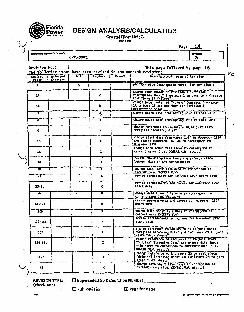
MRodawPower DESIGN ANALYSIS/CALCULATION
Crystal River Unit 3OuS&CJ!I
Page iA.i ,=~f0 N W C ~ O O S 9 ~ 8 ,.at ,v
a - - =
Revision No.: 2 This page followed by page 1.LThe following items have been revised in the current revision:Revised AffeCtSd Add Replace Remove Description/PurPose of RevisionPages] Sections| e -1 x add "Revision Description Sheet' for revision 2
! (Change page "number on revision I "Revision1A X Description Sheeto from page 1 to page 1A and statethaT "eaoe ta follows"
lchange page number of Table of"-Cont'ents from page1B X 1A to page 18 and add Item for Revision 2aescrtdteon fSheoe p3 ... x" change start date froml Spring 1.99? to Fall 1997
8 - X Change Start date from Spring 1997 to Fail 1997-Change reference to Enclosure 30.to 3uS% state9 X Original Stressing Data'
- . -.change start date from March 199? to November 199710 x and change numerical values to correspond toNovember 1997
change data Input file names to correspond to11 X current names (i.e. OCKER2.XLW. etc...)
revise the discussion about the interpolation18 beteen data tn the spreadsheets
20 x change data Inprr file name to correspond tocurrent name (DCNER2.XLW)21 x revise spreadsheet for November 1997 start date
revise spreadsheets and curves for November 199?23-61 X start date64 X change data Input file name to correspond tocurrent name (400.PERZ.XL.revise spretadshee•s and curves for' ovember 199765-124 X start date126 X change data input file name to correspond to
current he" sERTRI._MreviSe spreadsheets and curves for November 199?127-156 X start date
change reference to Enclosure 30 to 3ust stateiS7 1 "Original Stressing Data- and Enclosure 29 to just, _ _state
*data sheets"change reference to Enclosure 30 to 3ust state159-161 X -Original Stressing Data* and change data Inputfile names to correspond to current names (i.e.
____E _.XLW, etc...)change reference to Enclosure 30 to Just state162 X "Orlginal Stressing Data" and Enclosure 29 to justs State "data sheets-change data input -fle names to correspond toK2 x current names (i.e. DOMERZ.XLW. etc...)
M3
/
REVISION TYPE:(check one)
OI Superseded by Calculation Number
o Full Revision 0 Page for Page"I$
OC- wel of O~WN litso, N.aw I -g '06 "

FDESIGN ANALYSISICALCULATIONFlPower Crystal River Unit 3
•,MW, b,,Page %.C cuuLaoT b-J-I5M-0 ] "0Calculation 3-95-0082 3
A3Revision No.: I This page followed by page 1C
This •brrn shall be used to record the purpose or reason for the revision. indicart the revision pages and/oraffected sections and give a short description of the revision. Check (X) the appropriate function to add.r.placc or remove the afiectzsd pages.
d
Revised Affected Add Replace Remove Description/Purpose of Revision
Pages Sections -
1 X -- _ Add revision description sheet.
LA x Change page number from t to MA. Add icmm forrevision description sheet.
"To change start date for the 6th surveillance
...... _ inspection from March 1993 to March 199710 X To change start date for the 6th surveillance
inspection from March 1993 to March 1997
IS X To change start date for the 6th surveillanceinspcction from March 1993 to March 1997
21 X To change start date for the 6th surveillanceinspection from March 1993 to March 1997
23-61 X To change start date for the 6th surveillanceinspcction from March 1993 to March 1997
65-124 x To change start date for the 6th surveillance~inspetion from Martch 1998 to Match 1997
127-156 X To change start date for the 6th surveillance271inspection from Mlarch 1993 to March 1997 A'
- I - --_/ |1 -__ -"
I
I )REVISION TYPE:
1check ow)l
I I SUPERSEDED BY CALCULATION NUMBER
I I FULL REVISION I X I PAGE FOR PAGE
ae? . pq 2 wg4 *dSPh.V , a

I-
1I'
6o0ctmENT DE
y-A.
)
Florida DESIGN ANALYSISICALCULATIONPower Crystal River Unit 3
Page IC1IGA11ON NO. REVIMSN
Calculation S-95-0082 3
CTION TITLE PAGE
CALCULATION COVER SHEET
REVISION #3 DESCRIPTION SHEET 1
REVISION #2 DESCRIPTION SHEET 1A
REVISION #1 DESCRIPTION SHEET 1B
TABLE OF CONTENTS IC
1.0 PURPOSE 3
2.0 DESIGN INPUT 3
3.0 COMPUTER CODES 4
4.0 ASSUMPTIONS 4
5.0 SCOPE AND TENDON SELECTION 4
6.0 CALCULATIONS 9
6.1 GENERAL BACKGROUND & SCHEDULE 9
6.2 FORCE CURVE GENERATION PROCEDURE 11
6.2.1 PREPARATION OF INPUT DATA 11
6.2.2 PROCEDURE FOR DETERMINATION OF TENDON LOSSES 11
6.3 DOME TENDONS 19
TENDONS LISTING & DATA INPUT TABULATION 20
INDIVIDUAL TENDON LOSSES WORKSHEET & CURVES 21
6.4 HOOP TENDONS 62
TENDONS LISTING & DATA INPUT TABULATION 63
INDIVIDUAL TENDON LOSSES WORKSHEETS & CURVES 64
6.5 VERTICAL TENDONS 125
TENDONS LISTING & DATA INPUT TABULATION 126
INDIVIDUAL TENDON LOSSES WORKSHEETS & CURVES 127
6.6 CALCULATIONS SUPPORTING SP-182 157
a-' REt: U. 1 Plaill RgSF~ N~aehuu B~gIn..tinafu" RE1* • of hWR9$P'.WW; 9 "Mtlrlgle

K
DESIGN ANALYSISICALCULATION
Power Crystal River Unit 3
Page 2
Calculation 8-95-0082 -- 7.o
SECTION
7.0
8.0
9.0
A.
F.
C,
D.
E.
F.
G.
H.
L
J.
X.
TIflECONCLUSIONS
REFERENCES
ATTACHMENTS
DESIGN INPUT FOR 6TH SURVEILLANCE
TENDON DATA HISTORY SHEETS
FOR 6TH SURVEILLANCE
TENDON STRESSING SEQUENCES
EFFECTIVE WIRE SUMMARIES
AND TENDON WIRE DATA
ELASTIC SHORTENING REFERENCES DATA
WIRE STRESS RELAXATION REFERENCE DATA
CONCRETE CREEP REFERENCE DATA •
CONCRETE SHRINKAGE REFERENCE DATA
NORMALIZING FACTOR REFERENCE DATA
HOOP GROUP PLOT OF TENDONS
ELECTRONIC FILES INFORMATION & DISKETTES
162
162 to 163
Al TO AI8
BI TO B92
Cl TO C24
DI TO DIO
El TO E9
F1 TO FS
G1 TO GI4
HI TO H8
11 TO 123
Ji TO Js
Kl TO K3
)
jmtLidi PIm RIU•P N. Cm*4'ngrneMU

I
Florida DESIGN ANALYSISICALCULATIONPower Crystal River Unit 3C M 1Mf I
Page 3DOCUtEM•4 DFtm VEMC~InM MQ0 aIEVW
Calculation S-95-0082 2
1.0 PURPOSE AND OBJECTIVE 70e CR3Crs.DoC (Word 6.0)
The purpose of this calculation is to provide tcndon force curves for Florida Power Corporation for theCrystal River Unit 3 facility in support of the upcoming 6th tendon surveillance period scheduled for the Fall lof 1997. Specific tasks to be performed as part of this scope include the following:
A.) Determine the predicted tendon losses and develop forceltimc curves for cach of the sclected tendons forthe upcoming sixth surveillance period. Generate the tendon force curves for the sclected tcndons, thetendons adjacent to the selected tendons, and alternate tendons. Alternate tendons are tendons notspecifically scheduled for this surveillance but force curves are prepared to be available in casc asubstitute tendon should be required during the survcillance. In addition, force curves for a group oftendons deferred/exempted from the previous surveillance will also be prepared. These are discussed indetail in Section 5.0.
B.) In addition to the force curve development, other calculations which are requircd to support Enclosures
included within Surveillance Procedure SP-182 will also be prepared within this same calculation.
2.0. DESIGN INPUT
Design input information has been reviewed and is included as Attachment A to this calculation. Note thatthre ar no significant changes to the basic criteria and related documentation which address the licensing ofthe CR3 plant with respcct to the tendon surveillance program. The previous surveillance efforts complctedvarious studies and addressed the CR3 tendon program and its' compliance with U.S. Regulatory Guide 1.35,Revision 3, since it was formally issued in July 1990. Based on FPC licensing efforts and TechnicalSpecification revisions performed at the time of the last surveillance period, as well as recent discussions withthe NRC, FPC has now committed the CR3 tendon surveillance program to be performed in accordance withU.S. NRC Regulatory Guide 1.35, Revision 3 (Reference 3).
U.S. Regulatory Guide 1.35.1, Revision 0 (Reference 4) is a daughter document referred to by the above Reg.Guide and deals specifically with the calculation of individual tendon losses and the generation of tendon forcecurves. While calculation efforts for the CR3 tendon force curves have followed closely with both of theseRegulatory Guides as they evolved through the 1970's and 1980's, the format and current procedure for thepreparation ofthe force curves is not in exact compliance with Regulatory Guide 1.35.1 Revision 0 as issuedin 1990. The method and approach used in the generation of the CR3 force curves is superior to that of theReg. Guide in that a specific curve is generated for each individual tendon. Based on the discussions held withthe NRC and the results of thcir review, the method and approach used for these calculations shall be the sameas used for previous surveillances. Sec the Attachment A information for further discussion and references torecent correspondence and documentation with the NRC on various issues related to the tendon surveillanceprogram.
Applicable Technical Specification sections, as well as FSAR sections were also reviewed for this effort.They support the position noted above on the FPC commitment to KG. 1.35, Rev. 3 and are discussed andreferenced within the Attachment A information.

Florida DESIGN ANALYSISICALCULATIONSPower Crystal River Unit 3
Calculation S-95-0082 o
3.0 COMPUTER CODES
This calculation package is being prepared using Microsoft Word, Version 6.0 and Microsoft Excel, Version5.0. Spreadsheets from earlier surveillance efforts were prepared using Lotus, 123, Release 2.01 and 3.0 andwere converted to Excel format for this calculation. All input and calculations are manually checked andverified, thercfore, verification of computer programs is not applicable or necessary.
4.0 ASSUMPTIONS
Any assumptions made are noted and contained within the calculation package. None require futureconfirmatio.
5.0 SCOPE AND TENDON SELECTION
Tendons were selected for the sixth surveillance period in accordance with the requirements of Reg. Guide1.35, Revision 3 and using the same methodology as was used in the past surveillance. Basically, a randombut representative sample was selected and checked at the site for accessibility. Specific criteria used for thisselection process is summarized as follows:
1 Tendon Selection Process
The tendon selection process has remained the same as that completed for the last several surveillances wherea random but representative sample is selected for inspection and testing. The intent is to get as many new andnever tested tendons in the sample population, but still keeping one control tendon from each major t=dongroup to be investigated in each surveillance. Note that this current method differs from methods used duringthe early life of the plant where some tendons were repeated for inspection every third surveillance. Basically,the selection criteria and process used considers the following:
1.) Select tendons based on Reg. Guide 1.35 Revision 3Based on the good results of prior surveillances, the Reg. Guide requires a minimum of I I tendons to beinspected, including 5 hoop, 3 vertical and 3 dome. Tendons should be selected which were neverpreviously inspected or tested. Previously deteusioed and retensioned tendons should not be included(unless there is a specific need to investigate the tendon per item 3 below). In addition to being selected atrandom, tendon selection should be representative of various areas and conditions. For example, the hooptendons selection was based on random selection but also considered what tendons were inspected in thepast and in what hoop area. A plot of previously inspected hoop tendons was prepared to track tendonsinspected by grouping (i.e. 13's. 42's, 35's, 46's. 5 l's, and 62's). Therefore, the selection processconsidered those sections not equally represented by as many tendons as completed within other sectionsfrom prior surveillances. See Attachmcnt J for various plots and information of the hoop group. Thesame procedure was applied to the dome group (i.e. 100's, 200's & 300's groups) and to the verticalgroup (i.e. 12's, 23's, 34's, 45's, 56's & 61's & quadrants). See Attachment D for groups information.
I. . . . -
MUT: UI d PNts REUM Nadw EnommuW

Florida DESIGN ANALYSISICALCULATIONPower Crystal River Unit 3
Page 5VOC4MEN1 10's ~nO.M NEWdSinO. •€.l.• Calculation S-96-008 a
2.) Maintain Control Tendons to be completed each surveillance.The Reg. Guide also requires a control tendon from each group to be inspected every surveillance forcomparative purposes. CR3 has rot had control tendons since the first surveillance. The concept wasintroduced probably in the fourth surveillance. Tendons D212, 12VI and 5 1H26 were probably theoriginal control tendons since about the time of the fourth surveillance. They were intended to beinspected during the fifth survo'llance but the group of tndons selected was based on the surveillancebeing performed during an outage. FPC decided to complete the 5th surveillance during normal plantoperation and the original tendons selected were affected because many tendons were located within thearea of the plant steam vent zone. This included the above three control tendons, and three new controltendons, D215, 34V6 and 461129 were selected for completion of that surveillance. A problem with461129 during the 5th surveillance forced the selection of another control tendon, 461121, for the hoopgroup. New control tendons may need to be selected periodically if the tendon has a problem and is everdetensioned and/or retensioned. As earlier surveillances on CR3 did repeat some tendons, the selection ofthese other control tendons was easily done from several good candidate. New control tendons should beselected from those previously inspected as far back as possible and cannot be one previously detensionedand/or retensioned. A tendon inspected in more than one prior surveillance is preferred.Based on the above, It is recommended that both of the above two sets of control tendons be used by FPCas control tendons, with one set of three to be utilized in the 6th surveilance during a plant outage, and for) the other thre to be used in any frture inspections scheduled to be performed on-line.
3.) Consider any tendons with problems or abnormal conditions as reported by plant pcrsonMel.Any leaking tendons or tendons with any reported problems should be considered within the scope of thesurveillance. Also, past inspection reports and records should be checked for open items,recommendations, or noted problem tendons.
4.) In the selection of tendons for detensionin& (oe per group is required per 1LO.) consider the numfber ofeffective wires as recorded in the tendon history sheets and summarized in the effctive wire summary inAttachment D to thii calculation. As any tendon is to be considered lneffective if it has less than 155effective wires per the FSAI, it is therefore not desirable to select a tendon with many missing. cut orineffective wires. Unless there was a specific need to detension that particular tendon, doing so couldtherefore render the entire tendon as out of service. Only a maximum of 3 tendons are allowed out ofservice at one time per criteria in the FSAIL
5.) The reduced force dome tendons are not normal candidates for normal liftoff testing per SP-1 82,Enclosure a.
6.) Tendons adjacent to the selected tendon may require testing and should also be feasible to inspect and test.Adjacent tendons in the dome should not include any reduced force dome tendons. Jump to the nextregular dome tendon for the required adjacent tendon. Also, adjacent tendons of the lowest hoop tendons(#1) shall be considered as the two'directly above the selected tendon. Adjacent tendons of the highesthoop tendons (fi47) shall be considered as the two directly below the selected tcndon.
)7.) One alternate tendon should bc selected from each group, and the two adjacent tendons of these alternates
at least considered for possible inclusion.
IWe: Lf o M"i neaaw. Mckv 0"""~

I
I*M. Florida DESIGN ANALYSISICALCULATIONPower Crystal River Unit 3
Page 6OCM EYWCA1MQN NO RE60
Calculation S-95-0082 e
In addition to the above selection criteria, there are several other factors which have influenced the schedulingof actual ficld inspection and testing. These include:
A.) Steam Vent Zone -Plant steam venting can impose a safety hazard to personnel during plant operation and early modes ofshutdown. Tendon work in the range between 0 and 120 degrees Is affected during plant operation by thepotential steam venting of the plant. Tendon work in this area must be held off until the potential hazardis eliminated or other approval is obtained from plant operations. Note that for the fifth surveillance perFPC operations, this even includes the outside tendon caps of the affecte butresses at 0 and at 120degrees.
B.) Fuel Pool Area-Work over the fuel pool can only be performed while missile shields are in place. (Nureg 0612 rcqmt.)
C.) PlantInteror Work-Work inside some plant areas is difficult due to access problems, high radiation areas, nerences, ramaccessibility, etc.
Ieferred/ExemDted Tendons
After the tendons were selected for the fifth surveillance for an outage survelllance, it was decided that the 5thsurveillance would be completed during normal plant operation. A group of tendons originally selected forinspection during that surveillance had to be exempted florn that surveillance due to their proximity to themain steam vent zone and the associated hazards with wowUing in that area. FPC discussed this issue with theNRC and has documented the following 8 tendons as defrred tendons:
aim nrr~ LI. d Ph.i ~ M~dmt EqbwulngNo RIM•. ue edo PlsM Jqe5. Ifce Frsq! eoes

Florida DESIGN ANALYSISICALCULATIONPower Crystal River Unit 3
1W CONIOMPage 7
Calculation 6.95-0082I o
D1 15 Never inspected in any surveillance.
D212 Inspected in Surveillance 3 and 4.Considered as Control Tendon for outage condtion.
D311 Never inspected in any surveilance.
12VI Previously included for liftoff testing in the 3rd and 4th surveillances.Considered as Control Tendon for outage condition.
421-144 Never inspected in any surveillance.
511126 Previously included for liftoff testing in the 3rd and 4th surveillances.Considered as Control Tendon for outage condition.
53H46 Never inspected in any surveillance.
62H46 Never inspected in any surveillance.
As FPC has comnitted to the NRC to address tbe above tendons within the upcoming 6th survelllance, thesetendons were considered in the scope of this calculation. The 6th surveillance is scheduled to be completedduring an outage. Since three of the above exempted tendons were also previous control tendons, it wasconsidered that these tendons can again be used as control taenons for this surveillance instead of the 3 controltendons used in last surveillance (when the surveillanc was done on-line). Therefbre, the three exemptedcontrol tendons can be considered as three of the 11 tendons required per Reg. Guide. A total of 16 tendonsshould be inspected during the surveillance with three additional alternates selected. Note however that thescope of this calculation will include force curves to be rqgnerated for the other control tendons, D215, 34V6and 461121.
A complete historical record of all tendons included in all prior surveillances, along with the list of selectedadjacent, exempted and alternate tendons which are planned for in the 6th surveillance is provided on thefollowing Table.
K-,
)
!m M Er: ife 40 Pleme RUMSP. Mkee EngmIe

C-
cou TDEIO)I SwcVtLKA)NE I CIIC-ALutmR X4q4
SVVAMLANCZ) P I ST SIVEC.LA)4CE 210 EMV3ELANCK SXD SUMflUANE 4TH StRIEUZAWX 31 fnSIRVUJAWM 47 MIIMUR .ANIClurawnro"M YWO@TO 51%w *111TO31231 2FIPITOIW117 ZIV"To d L9 FAZLLIWI I~
YEARS Al'T0S SIT .*vamilaSclool
gri IT TVYAR iSYEARS S WARS II WARS II WARS 21i W-ai . E)*MARZI ATA
KE4qU3W TO INSECT It YOT.IGUVY.SD 23 TMQT.IUV.SD 21 TOT.101WSVA I I TOT-SIUV.30 II TOT4MIUV.D *II TOT-WT3.3O * .I TO!T-M4VAlD
ACIUALJ* D4SPSCITD 23 ZT-)El.V.41) 231071.UI.W.SD 21 1ur.IG~tv.fl2 I I TOT-511,31Jo s4g11)vV.S* DcL6 IUD va u 33 910TT4)HWV2D
9 BASIS fl-ill) 310-49 SM4in a-in3 M35.3 SP-112 *TOTAL. Itsp.)m "1434 PlY- RVVd IEV? 1XVIDAII
CC PZIORY DATE 3.2740 & 4801 51" Snwn1 311*11SI
DOU1DNOOM Do"? Din Dl23 DIOS ID PIMS P.c *21 Di. CX . 22DOMETENIX)
IDYTMAL Dill P140 P25 It P112 P.C Vol II *M 024 * ?WECTED
SOROWSOV41 Dt 33 un 3 3321 DM U= A Otis . TO DATE
Doom 2805.3203 vur 3332 Din D3 Otis It
DM23 371331 .Dv itl
DIV4 *Dill
VUERIAL1OIDOWS IVI? W13Y1 IIVt SVI D.C 74YE P.C 3M IV .CJ u ~VET. WowoH
144TOTAL tr~im 12V210 at "WV R 34W IS 33 . 4IV21 33 * DISPEC
$GOXMROF24 tivit DIm IdVIt 33 SV3 D3 SIV14 6 2MV TO DATE
IZi4.34D3.45.1 IMVS 31MI 4W16I **1vi A34"4 45V4 5VII
56VI NVI DA
£IIONV.WTAv~toD MUGo M12 3109 ~ n a 13112 IlIt I:8101 I.C. -3 awor oS
210 TOTAL 131139 1381,32 13114 131"4 D 42)11 * 42W3 * 2S5£TED
o(ROlWS0411OI LullS L3*1 411W0 S1106 a Goal2 am") 42113 * DATZ
11, K It46.11.42 131147 S11110 421140 511111 46112 ADI.? 41144, E
STED~ONSKRIl" 511111 S31022 WIN 451139 miug 3.C(II.D #a62119 5183 131914 46100 ADL *401143 P
48W32 33124 $AD$5 4014? 33 Q% 92i
4800o $31012 ""340 62111 * 33*
4601 D ti114" 4"014 ,gU A
TOTALTENDON -50 dams434 461112 441810 33
TUTALINSPEC1W 22 22 21. it 14 i* 16.IAT. 71W TOTAL.
0
C2
0
0•t-
o..
"I
.4S*1
I1WM- A. ALTERNATE AmfADMCEITr CONTRU.L. *EPEMtlVEUSRR3 r21 FIT) SURv. W. 331!ATEP
D. DETE*410NW a 171NSmoE%RIUod4o1
I co

IKjj
Florida DESIGN ANALYSISICALCULATIONPower Crystal River Unit 3cOAWPRAlPae Page 9
DOCUM 10T MVEN11ICAn N0. AEIMIONCalculaUon S-95-0082 2
6.0 CALCULATIONS
6.1 General Background and Schedule Information
General Background
Tendon forces curves are to be prepared for the upcoming 6th tendon survcillnce pcriod at CR3. From thebasic criteria as presnted in the Design Input Section, as well as from several discussions with Mr. Joc Leseof Florida Power & Light, it was determined that the criteria for this surveillance period has not changed sincethe last surveillance efforts. A review of Tech Spec and FSAR criteria confirms the FPC positions withrespect to the tendon program. Supporting work for this survillance period will be based on the same criteriathat was used and accepted in the previous surveillance periods.
Tendon losses have been calculated in the past per the Refcrence 9, 9, 10 and I Idocumcntation. Individualtendon losses include the following-
" Force loss due to elastic shortening of the containment as a result of the prestressing process and theparticular sequcncc of tendon stressing.
" Force loss due to the stress relaxation of the tendon wires.* Loss of prestress force due to the creep characteristics of the concrete structure.
L Loss of prestress force due to the shrinkage of the concrete structure.
Based on some earlier calculations made for tendon losses per the Reference 11 document, Lotus spread sheettemplates were prepared for tendon losses calculations for the 4th tendon surveillance calculations. SeeReferences 9 & 10. These templates were reran and tested for their accuracy and validity for the fifthsurveillance. In addition, the procedure for the gathering of all input data was automatcd in the fifthsurvillance to the format presented herein. Numerous test cases were ran to duplicate force curves prcparedin the past. There were four master templates prepared for the fourth surveillance; one for the hoop tendons,one for the vertical tendons, and two for the dome tendons. The dome tendons are divided into two groups;one for tendons with an original stressing sequence below 27, and the other for tendons with stressingsequences above 27.
Based on the work previously accomplished in the prior surveillances, new spreadsheets were prepared thissurveillance using Microsoft Excel for the collection of input data and for the calculation of tendon lossesneeded for generation of force curves. The generation of the force curves was also automated this surveillanceby using Excel to plot the graphs. The organization of most data used for this calculation was setup intoExcel workbooks with subfiles built and included in each workbook. There is a separate workbook for eachof the three tendon groups and each one contains the following:
# Tabulated input data* Original tendon stressing sequences.
-1 & Eff-ctive wire summaries."Original Stressing Data" calculations for SP-182.
o Separate files including each tendon loss spreadsheet, plot data and an individual force curve.
Additional information on electronic file names etc. used in this calculation is provided in Attachment K.

K0 Florida DESIGN ANALYSISICALCULATIONPower Crystal River Unit 3
Page 10WoWEPu r wEHWCAWoN IM p-wsC
Calculation S-95-0082 2
Schedule Information
The expected timing for the sixth surveillance is Fall 1997. A date of November 1, 1997 will be used as abases for dctermining the predicted values of base, 95% base and 90% base and labeling this information onthe force curves. This allows for field usC and decisions to be made based on the requircmcnts of SurvcillanceProcedure, SP-182.
The scales of the force curves are based upon previous survcillance cfforts. Thc x axis is a log scale in timnrepresenting the time after average date of dome or wall concrete placement, in years. This scale is labeled atthe top of each curve. Force curves arc plotted using the actual log scale points for the x axis (not thescheduled surveillance years after SIT) versus the calculated tendon forces in kips on the y axis. The scale atthe bottom of the curve for scheduled surveillance periods after SIT are for case and rcadability relative toregular scheduled surveillances per Reg. Guidc 1.35, Revision 3.
Most of the CR3 surveillances were performed on the regularly scheduled years, however, the 5th surveliancewas actually performed in the 17th year after SIT. Note that the containment Structural Integrity Test (SIT)was performed in November 1976.
For the dorac tendons force curves, the point on the bottom scale at SIT corresponds to the log scale at the topof 2.5 years. Therefore, a corresponding log scale data point must be determined for curve plotting for theperiod of the 6th surveillance.
Based on a date of November 1. 1997 for the Fall 1997 surveillance, the length of time between November1976 (@ SIT) and November 1, 1997 is 21 years. Since the dome group at SIT is at year 2.5 on the logscale, the 6th surveillance will correspond to (21.0 + 2.5) or 23.5 years on the log scale.
The same procedure must be performed for the hoop and vertical groups as they have different referencepoints on the log scale for time after concrete wall placement. Both hoop and vertical groups arc the samewith SIT corresponding to year 4.4 on the log scale. Therefore, the 6th surveillance period will correspond to(21.0 + 4.4) or 25.4 years on the log scale.
A vertical line will be shown on the force curves at the point of the next surveillance and the calculated valuesof base, 95% base and 90% basc representing points on the curves at that timc will be included on each of thecurves.
L
L
2.
RET: Lt PWi m3rFP: ku=bm

AFlorida DESIGN ANALYSISICALCULATIONPower Crystal River Unit 3
Page 11
Calculation S-95-0082 3
6.2 General Procedure for Force Curve Generation
The same procedure within the calculation for the preparation of the force curves for the fourth and fifthsurveillance pcriods will be followed.
6.2.1 Preparation of Data Input Spreadsheets
In each of the Excel workbooks is a data input file where data from source calculations and current tendonhistory sheets has been tabulated. See DOMER.XLW (DOMEINP), HOOPR3.XLW (HOOPINP) &
vERTR2.xLW (VERTINP). 'The compiled books of tendon surveillance historical information, as updated to include the results of the fifthsurveillance, provide key input data for the dcvelopment of force curves. See References 12, 13 & 14. Theselected tendon history sheets related to this surveillance have been included herein as Attachment B of thiscalculation. The Rcfcrcnce 11 calculation is essentially a source calculation for this procedure with theRefrece 8 & 10 calculations also providing information.
Notes and references related to the tabulation of the data on these spreadsheets are shown on the individualsheets. The data input tabulations are presented as the first sheet within the following Sections 6.3, 6.4 & 6.5.
6.2.2 Procedure for Determination of Individual Tendon Losses
The procedure for the tendon loss calculations, as derived from the reference documentation, is as follows:
I.) Calculate original force in the tcndons
The original force in the tendons is determined as follows:
OC G.R ORCE = 0.7 * F Pressure x FireFactor
Where:4& - 240 Ksi, typical for all CR3 wires.
Wire area - 0.07685 in2 per Appcndix F of the Reference 11 calculation.
F,& (Kip Force)= Tendon Area (in2) x f& (Ksi) - 0.05985 * 240
Tendon Area (in2) = Area/Wire (in2) x No. of Wires. (Considered by wire factor.)
Actual and prcdictcd original liftoff prcssures are obtained from Tendon History Sheets Refcrences 12, 13,. 14, with those within the scope of this calculation attached in Attachment B.
Refer to the Appendix F part of the Reference 11 calculation, for source data of above formula. The aboveexpression was used as the basis for the calculations for all the shop and field end forces calculated on theData Input Spreadsheets. This procedure docs not apply to retcnsiooed tendons.
'U RET Li. ~ Plud KkSP~ Nudest Engww~em tElr: t.• d Ptm RZWP. M•-dsf E•
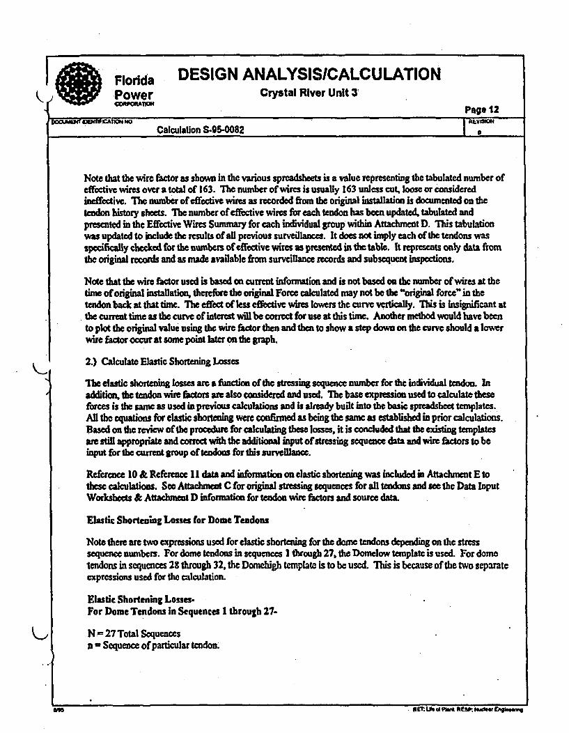
Florida DESIGN ANALYSISICALCULATIONPower Crystal River Unit 3
Page 12
Calculation S-95-0082
Note that the wire factor as shown in the various spreadsheets is a value representing the tabulated number ofeffective wires over a total of 163. The number of wires is usually 163 unless cut, loose or consideredineffective. The number of effective wires as recorded from the original installation is documented on thetendon history sheets. The number of effective wires for each tendon has been updated, tabulated andpresented in the Effective Wires Summary for each individual group within Atacunmnt D. This tabulationwas updated to include the results of all previous surveillances. It does not imply each of the tendons wasspecifically checked for the numbers of effective wires as presented in the table. it represents only data fromthe original records and as made available from surveillance records and subsequent inspections.
Note that the wire factor used is based on current information and is not based on the number of wires at thetime of original installation, therefore the original Force calculated may not be the "original force" in thetendon back at that time. The effect of less effetive wires lowers the curve vertically. This is Insignificant atthe current time as the curve of interest will be correct for use at this time. Another method would have beento plot the original value using the wire factor then and then to show a step down on the curve should a lowerwire factor occur at some point later on the graph.
2.) Calculate Elastic Shortening Losses
The elastic shortening Losses are a function of the stressing sequence number for the individual tendon. Inaddition, the tendon wire ftctors an also considered and used. The base expression used to calculate thesefor•es is the same as used in previous calculations and is already built into the basic spreadsheet templates.All the equations for elastic shorting were confirmed as being the same as established in prior calculations.Based on the review of the procedure for calculating these losses, it is concluded that the existing templatesame still appropriate and correct with the additional input ofstressing sequence data and wire factors to beinput for the current group of tendons for this surveillance.
Refcrcnce 10 & Reference 11 data and information on elastic shortening was included in Attachment E tothese calculations. See Attachment C for original stressing sequences for all tendons and see the Data InputWorksheets & Attachment D information for tendon wire factors and source data.
Elastic Shortening Losses for Dome Tendons
Note there are two expressions used for elastic shortening for the dome tendons depending on the stresssequence numbers. For dome tendons in sequences I through 27, the Domelow template is used. For dometendons in sequences 28 through 32, the Domehigh template is to be used. This is because of the two separateexpressions used for the calculation.
Elastic Shortening Losses-For Dome Tendons in Sequences I through 27-
.j N - 27 Total Sequencesa - Sequence of particular tendon.
6~ NET UU i'w~ R~SP~ IbI~W Mg1n~mgVM 4qg•. 1* 1PW•Itr3MbV $@I• Imwg.pm~

Oa Florida DESIGN ANALYSISICALCULATION* Power Crystal River Unit 3
Page 13GOCUMEW meww"M NO
Calculation S-95-0082
Force Loss due to elastic shortening - Fs.
A, =N- ' x 827 +75]xWireFactor
Elastic Shortening Losses.For Dome Tendons in Sequences 28 through 32-
N - 5 (Sequences 28 through 32)n - Sequence number less 27
i.e. for sequece 29, n - Ifor sequence 29, n = 2for sequence 30, n - 3for sequence 31, n- 4for sequence 32, n - S
FIes = r[N - n x 47.4 - 13.7] x WireFactor
The value for elastic shortening in kips declines as the stressing sequence increases. A review of the data forthe dome group shows that values for the dome group go from 154.6 kips for sequence I tendons down to 75kips for sequence 27 tendons, and further going down to -13.7 kips for the last sequence, sequence 32. Notethat wi factor differmces between individual tendons will cause the calculated result to vary slightly for twotendons within the same stressing sequence.
Elastic Shortening Losses for Hoop Tendons-
N -60 Total Sequencesn - Sequence ofparticular tendon.
Force Loss due to elastic shortening -
Fles= [( xN) 134. 0. x WireFactor
A review of the data for the hoop tendon group shows that the range of values for the calculated elasticshortening go from 127.3 kips for sequence 3 tendons down to 0 kips for the last tendon sequence, sequence60.
K~P.LE. dPbui ME3~~ I~~w Emgmn.a~ngoer:. L" at PWOv REV, km. N A - 4

Florida DESIGN ANALYSISICALCULATIONPower Crystal River Unit 3
Page 14V60jWW "MVAMON NO SR~tWON
Calculation S-95-0082 o
Elastic Shortening Losses for Vertical Tendons -
N 31 Total Sequencesn - Sequence of particular tendon.
Force Loss due to e•atic shortening-
Fles= n) X 735• x WireFactor
A review of the data for the vertical tendon group shows that the range of values calculated for elasticshortening go frm 71.1 kips for sequene I tendons down to 4.7 kips for sequence 29 tendons. Tbcre are atotal of 31 stressing sequences for the vertical tendons.
3.) Calculate Wire Stress Relaxation Losses
Wire stress relaxation losses and the procedure for the determination of these losses for the 4th and 5th) surveillances are addressed In the Reference 10 and 11 calculations. TMe original wire relaxation curve, asprovided by test data from the wire vendor forms the bases for wire relaxation loss values (See also FSARFigure 5-23). It was determined that the same procedures and figures as calculated in those prior calculationsare still applicable for this surveillance. Applicable data from the reference sources was attached andincluded within this calculation as Attachment F.
Note that ther were adjustments made to the original stress relaxation values from the vendor relaxationcurve to allow for some conservatism and for temperature consideration of 100 degrees vs. 68 degrees F.Also, per the original design the wire factor or actual number of effective wires was considered as negligiblefor these losses and was not included. Note that values for stress relaxation range between 40 and 50 kips forthe surveillance period for all three tendon groups.
4.) Calculate Creep Losses
Concrete creep calculations in the Reference I I document are attached in Attachment G. The losses are basedon the curve contained in the reference calculation. Creep values are different for each of the three groups oftendons. For the dome tendons in the coming surveillance period, creep values arc the same and are about 152to 158 kips, hoop values are between 79 and 83 kips, verticals are 36 to 38 kips.
5.) Calculate Shrinkage Losses
Attachment H contains source information for concrete shrnae from Reference 10, pg. I I and Refteence11, cover page & Pages 13 & 14. The straight line shrinkage losses in micro inches per inch as calculatod inthe above two references arc still applicable for this surveillance period. Tabulated values from thesereferences were input into the dome, hoop and vertical spreadsheets. There are no additional variables orconsiderations and the same values are to be used for this calculation. From a review of the outputinformation, the dome values are contant at 8 to 9 kips, hoop values are above 5 kips, verticals are alsoslightly above 5 kips.
WEtMO LIM dPb R ESP. t#uem E Vgiu

K)
K)
)
I
Florida DESIGN ANALYSISICALCULATIONPower Crystal River Unit 3
1WCWfPOftA?"Page 15
9=A*WCNW NICAUn5M rEV $ONCalculation S-95.0082
6.) Total Losses
Calculated force losses for elastic shortening, wire stress relaxatkm, creep and shrinkage arc added for a totalof all losses. Also, a percent of this total of all losses is calculated based on the original average force in thetendon.
7.) Determine Predicted Forces for Base, 95% Base and 90% Base values
The original forcc less the total of losses calculated yields the base predicted value for the subject period ofsurveillance inspection. The 95% and 90% values are then calculated based on the calculated predicted basevalue.
8.) Normalization Factors
Normalization factors arm calculated based on the expressions and the source article contained in Attachment Iof this calculation. This factor usually does not change much over the forty year time span of the calculation.The base expression for the dome nonrmization factor value is presented as follows:
(A - B) x (I - C) + (D - 97.7)
Where-.
A - Average of all Domes groupB - Origina averne tendon forceC = Wir Stress Relaxation PercentageD -Elastic Shortening
As an example, Dome tendon D 112 calculates as follows:
NormallzahonFactor = (163 9 -1676) x (I - 0.0257) + (D - 97.7) o
NF = (-37) x (0.9743) +(-101.9) or
NF - -138 which matches the spreadsheet calculation.
Similar expressions are shown for the hoop and vertical tendons in the information in Attachment I.
Wr LDtd Puwft13 " SW.ad&u EaM..

IK
A
Florida DESIGN ANALYSISICALCULATIONz...............Power Crystal River Unit 3CocTn o~m~rPage 16
Calculation S-95-0082
9.) Plotting of Dam
Only the data from Column B, L, M, & N are tabulated on a separate arca on the side of the spreadshcct. SeeColumns R1 S, T & U; Rows 40 through 50. Only these values are selected for plotting on the force curves.Ths is for case of plotting and has no affect on the quality or accuracy of the plots. An example copy of thisdata immediately follows the first dome tendon.
The plots of all dome curves with all the data points showed the force curve plot line as slightly crooked froma true linear plot. The large scale used showed some inflection points slightly off of linear. Afterinvestigation, the condition was avoided by omitting data points at year 10 and 15 after SIT for the finalplotted figures. This was done only for presentation purposes and there is no affect on the accuracy of theplot or the base values calculated and presented on each curve.
A column by column explanation of the losses calculation worksheet follows:
K
amMP A"Lfed PWai WESF# WcoErqw*WkW

Florida DESIGN ANALYSISICALCULATIONCrystal River Unit 3
~Page 17
Calculation S-95-0082 0
INDIVIDUALTENDON LOSSESLOSSES CALCULATION WORKSHEET
NOTES AND LEGEND
Individual tendon losses are calculated based on the procedure presented in the preceding section. Thefollowing notes explain the spreadsheet process, input and caculations performed for each of the columnspresented. The shaded values on the losses worksheet ar extracted frora the data input worksheet.
Column" ROWRIMn
A. Inspection Period after SITScale based on years after SIT which is shown on the bottom scale of each individual plot. Nowe thatthis information is providcd for easier readability with respect to SIT but is not the actual log scaleused to construct the x axis of the plots.
B. Years after Concrete PlacementScale ofyears after concrete placement as used for the x axis for plotting of the force curves andshown as the upper log scale at the top of each plot.. Note that one year after SIT for the dometendons is 3.5 years on the log scale and for the hoop and vertical taxions is 5.4 ycars. See Section6.1 of this calculation for further information.
C. Elastic ShorteningCalculated based on formulas presented in Section 622 and Attachment E information.
D. Stress Relaxation PercentCalculated based on original wire loss curve percentages modified per the information presented inAttaclhmet F of this calculation.
F. Stress Relaxation ForcesData input from the Reference 11 calculation page 12. See Attachment F.
F. Creep StrainStrain value (x 0.000 IData input from the Reference 11 calculation. See Attacuncnt G of thiscalculation for data.
G. Creep Strain ForceData input from the Reference I I calculation. See Attachment G of this calculation for data.
H. Shrinage ValuesData input from the Reference I I calculation based on the shrinkage curve. See Attachment H of thiscalculation for data.
1. Shrinkage ForceData input from the Reference 11 calculation. See Attachment H of this calculation for data.
i " I M." f-A JP -h

Florida DESIGN ANALYSISICALCULATIONPower Crystal River Unit 3
Page I1BD ~u=M•r EEN.MaAT" NO.
Calculation ,%95-0082 2
1. Total Force Lass
Calculated value, Sum of columns C. E, GA 1
K Total Percent LossTotal loss in percentage, Column J / Average of original forces for shop & field ends calculated andshown above on the sprcadshcet.
L. BaseTMw average original force for thc tendon noted above on the spreadsheet, less the total lossescalculated in Column J. Note that total losses were not calculated on t row for the 17 year period,the 21 year 3 month period, as well as the 21 year period after SIT. These rows represent the fifth,the originally planned sixth and the current sixth surveillance periods and the values of Base werederived through linear intrpolation of above and below data prescnted on the sprmadsh=t. Thequality and accuracy is not affected by this procedure.
M. 95% Base0.95 x Column L for thc same row.
N. 90% Base0.90 x Column L for the same row.
0. Nonralization Factor -Calculated based on formula presented in this calculation and in the information presented inAttachment I.
l'
Ft•, Mkh CA Ph"e RE IP,P %WSW• •.neam"

Florida DESIGN ANALYSISICALCULATIONPower Crystal River Unit 3cofPo. Page 158
Calculation S-95-0082
KJ
Column H & I Calculated force values in Kips which represcnt ram pressure 1500 psi. These forcesrepresent a zero slack starting point for both shop and field ends of each tendon andprovide a basis for the start of any retensioning effort. The following expression is used tocalculate these values:
0.7 0 Tendon Ultimate Strength ' 1500 1 Predicted lift-Off Prcssure at 0.7 TendonUltimate Stren't. See Reference 10 Calculation, page 34.
Calculated force values in Kips which represent forces at 80% ultimate based on thefollowing expression:
(Actual pressure @ 80% ultimate strength (Columns F or G) * 0.7 Tendon UltimateStrength) I Predicted pressure @ 70% Utimate Strength.
Column J & K
Column L & M Actual elongation data, repeated from colnums 1 and C.
)
In additoa, the following calculations support the ultimate strength values provided on these spreadsheets:
Tendon wire ultimate strength Gfa for wire - 240 ksiTendon Ulima Strength = Fg -f, for wire 0 Tendon wire area]
-240 ksi ' (0.05985 * 163 wires) , 2341.3 Kips
0.7 * Fw, - 0.710234.3 = 1639.9 Kips0.8 * F,* - 0.8 02341.3 - 1873 Kips
)
iW. Lf o PIMM KEW- Huaw Erewa*46

S, LORIDA POWER CORPORATION - CRYSTAL RIVER UNIT 3z3UV REACTOR BUILDING PRESTLEMNG SYSTEM
IN St 6th TENDON SURVEILLANCE
DOC 0S-5-0082M•VSION 3PAGC I9
CALCMAT1ONS SUPPORTING SP-182' ORIINALSM•T USW-O DATA FOR THE DOME0-TENDOI(S GROUP
0.7 Tend~on Uqdzna Strength P,6"Kp
F lr D O M E R 3 .X L W _ _ _ T no__ _ _ _ _ _
A:d ldid Ulft-Off S0 o% ee ro rlP-.U "Or' d $s dn Dw Vein*Tmdom I la dm (In.) uplem O j ?.n d w 1 EKI p) Raw a (Mips) Raw 3 (3L)
m 2EE E M :' E v I a(A) " "" ____ (E) (n 1 I) (1)
-Dill 3 $ 68130 _!110 7780 170 341 361 1372 1872 3 5D112 4-14l 5 61800 684( 770 MO 790 -So- 359 1873 3867 4-3/4 s0D133 -4-718 4-34 6400) a84 717 7M9 363 359 1873 1867 4-7/5 4-3/4
0114 3-1.11 4-SAS "m0 6140 777 7790 363 359 187) 1867 $-lie +-3/8b)1is 1 5 6w4 6800 779 7770 339 363 1867 1873 5 30136 4-3/4 S-3/8 6760 4100 77m 775 364 363 18l 138611 4.3/ 5-1/5D3130 S 5 687 6830 7330 7710 358 361 IS63 1372 5 3D131 4-112 4.7/1 6730 6740 7660 7700 366 365 1871 1171 43112 4.7/I
4-32 +1 4.7/8 67630 6800 7720 7750 354 362 3572 18611 4-il_ "is8D211 ".64 S-1) "810 6870 "280 7110 361 351 1572 1863 3-1/4 5-1/l
D21l 4-5/8 4.7/8 6m7 6770 7730 7720 363 363 167£ 159 4-3/0 4-7/S1 2mu 43/V4 4,V/4 1 6M4 600 7"790 777 m" 362 1807 Is" 4-314 *3/4
£3114 4-3/4 4-7134 6670 6740 7600 7680 369 36 38t" 15611 4-3M4 4-7/
0213 4-34 31- ow0 4170 7800 7810 362 358 logo 1863 4112 5-1/40216 S 3 6100 WI10 777 7780 362 361 is?) 1372 S 3
W031 3-3/8 5-7/8 6530 6330 7430 7430 376 378 1870 £371 3-311 S-7/4D3(73 4-1/4 S1134 6760 6770 77M 7730 364 363 187n 1879 4.114 S-3/4
. MD304 43/8 4- 6840 68w3 779 777 359 362 1867 1873 4-11 403m 43/3 4-3/36 6700 64M 76L30 760 -367 363 1867 187 4-218 4.3116
0300 4-3/4 4-3/4 6110 8130 7730 778 361 Sol 1872 137 43/4 4.3140310 3 4-1/2 6770 6770 772 730 363 363 1869 17 .1
0D313 4311116 4-5/8 6100 6840 7770- 7790 362 359 1873 1867 4-11116 4-5180332 4-7/81 4-7/1 14 6840 7M9 777 339 362 r 3867 1873 4-7fi3 4.74
-t
5636mmccih myld rs ula u i3m u puam faASpeu u mjiaA , .
ip-,
I ~
113
-3-
28-Jan-93:64 PM
U*1

k.JnFLORIDA POWER CORPORATION- CRYSTAL RIVER UNIT 3REACTOR BUILDING PRESTRSSIG SYSTEM)6t TENDON SURVEMLLANCE
CALCULATIONS SUPPORTING SP.182 "ORIGINAL STRESSINO DATA* FOR THE 1lOOP TENDONS GRUMP
0.7 Tendon Ultiate Swmngd -0.S Tendon Ultimbte Stent -
Fie: HOOPR3.XLW
DOC I3:S-95-082REVISION 3PAGE 160
it,!
0
Actal Pr.dced IUN-Off 8go U au tw Sfv-sIu 'orgm Struia Dowe-TendMI 1louad (wn) Prwmve 110 Pemn (Wsu) j Raw I (Kips) x" 2 oups) f Rw 3 (In:
42fll -r57 4-5/8 U870 6810 0718 1 017=73180 333 1 36 1163 187 "T 4-5/842HI38 S 5.3/8 68410 6799 7810 77M 359 3Q2 1873 1865 3 5.3/8
42H329 5.3-/2 5.1/8 6170 6310 7810 7780 358 363 1863 1872 5-1/2 5-14842H430 4-7/8 ".34 6870 6790 7810 7750 358 362 1863 1371 4-718 5-3/4421131 51/J4 4-7/8 6870 U820 7830 7780 M5 363 1863 1872 S-1/4 4.7/8421132 3-1i4 5-1/8 68M 6790 7310 7750 358 362 3863 1871 5-1/4 5-1/8422433 5-3/8 5-1/4 6870 "830 7810 7780 358 1 361 2363 1372 5-3M 5-1/44244 5.112 5-3/8 6750 6660 7680 7600 364 36 1865 387 3-1/2 5-3/842)135 5 5-1/4 6830 6770 7760 7720 360 363 11162 1869 5 5-1/4421336 5.1/8 5-1/1 6170 6790 7810 7750) 358 362 1863 2373 5-1118 5-818421137 3-3116 4-7/8 6670 6130 17310 7710 338 361 1843 3872 5 -5/26 4-718421H43 3-142 3-1/8 6870 6810 7110 7710 358 361 1863 1873 "-32 5-1/8421144 5.3/11 s 6790 6140 7750 7700 362 359 1871 1861 5-1/8 5421145 3-7116 5 6870 6810 7810 7780 358 361 186 1372 5-7116 5461320 53-/4 5-1/8 6640 6600 7700CD 7610 370 373 1901 1890 "14/ 5.1/8461121 "is/ S-1/4 6720 6730 7700 7640 366 365 1878 1861 5-2/3 5.1/446242 "a5/ 5.114 672D 6730 7700 7640 366 363 1878 1363 5-M/ 3-1/45 1H25 5 5-3/8 -6770 6100 7720 7750 363 362 3869 1868 3 5-1/8532H26 S-1/2 53-U4 6760 6760 7750 17700 364 364 31179 1861 5-112 543/4
533H27 5-3/2 4-7/8 6740 6670 7680 7600 365 369 3868 1861 "M3/ 4-7/85331221 -1/8 5 6760 6750 7750 7700 364 364 1879 1870 -3/I1 5512H29 5.1/2 4-3/4 68310 6750 7710 7700 361 364 1872 1870 5-1/2 4-3145331 5-3/4 1 -/ 6700 16760 7650 7720 367 1 364 2873 1872 3-3/4 5.1/853112 5-3J4 4-M1 6800 777 7760 7720 362 316 13870 1628 5.3/4 4-4/433H43 53138 4-1/8 6670 6710 7600 7660 369 366 3861 1873 5.3/8 4.1/8
533H45 3.1/4 5.3/4 644) 6800 77M 777 3550 362 1867 1873 3-1/4 5-1/4S3311AA 4-718 5-3/8 6160 6130 7M3 16CA 344 365 33M 1365 4-7/8 5-311531,147 4-3/4 3-M/2 6840 6800 779 7770 339 362 1867 1873 4-3/4 5.2/2621223 3-13/ 4-314 6760 6700 7720 7650 364 367 1872 3871 5-1/8 4-11M621M2 5-5/16 s 6800 6750 7770 7700 362 364 1873 1870 "11/6 5
62)42 3.1/8 F -114 680 6750 7770 1770M 362 364 1873 1370 1 5.2/8 5-1/4623139 3-7/16 5-1/4 610D) 6750 7770 17700 362 36 18173 1870 1 37/16 5-1/4
62H440 5-3/8 4.718 68w0 6750 777D I 7700 362 364 1873 1870 1 5-3/5 4-7/8621141 5-1/4 5 68310I 6750 7770 770 362 364 1873 1870 5.2/4 5623142 5-3/8 5.3/16 6800 6750 7773 7700 362 364 13173 1870 J-3/11 5-2161;62H443 5-3/8 4-7/8 6710 6670 7660 7600 3"6 369 3871 3863 5-3/8 4-718621144 5-1/2 4-7/8 6100 6750 77"0 7700 362 364 1873 1870 S-I/l 6-715621145 5-3/16 5-1/8 6760 6700 7770 7700 364 367 1884 1884 5.3/16 S-1/962H446 5-1/9 5-318 6100 6750 770 7700 362 364 1573 187 5-13/ 3-3Y8,621147 5410/ 1 4.3/2 6680 16640 17620 17M5 368 370 1870 1 1864 1 5.5/ 4-1/2
pi~
IR
IR.
ba Ia m ul.,- imI Ia b wiled 1mw b ml -.d u .ymaimum1J Im ebmuu A b 4
3:24 PM
)

* y2 FLORIDA POWER CORPORATION - CRYSTAL RIVER UNIT 3REACTOR BUILDING PRESTRESSING SYSTEM
- 6th TENDON SURVEILLANCE
Dtot3 M95=a2REAS01 2PAGE 161
CALCULATIONS SUPPORTING SP-182 *ORIGINAL STRESSING DATA" FORTHE VERTICALTENDONS GROUP 1#10.7 Tendon Ultimate Strength r- K39I3ps0.8 Tendon Ultimate Strength E 73Kips
File: VERTR2.XLWActual Predicted Lift-Of 80% Ultimate For SP-182 "Original Stressing Vata'
Tendon ElngIaton (In.) Pressure (psi) Pressure(p) Row 1 (Kips Row 2 (KIps) Row 3 (In.)
ID~ =w Vid Shp Fl--YP -o Shop Fil o il lo ield
23V24 17/8 NIA 6170 N/A 358 N/A 1863 N/A 12-7/8 N/A12VI 12-1/2 N/A 680 N/A 7M7 NIA 362 N/A 1873 N/A 112-1n tI/A12V2 12-112 N/A 6800 N/A 7770 N/A 362 N/A 1173 N/A 12-1/2 N/A23VI 12-1/4 A 600 N/A 7770 WA 362 N/A 1873 NIA 12-1/4 NIA23V2 13-1/3 NIA 6870 N/A '1810 N/A 338 N/A 1863 N/A 13-1/a M/A23V3 13 N/A 6760 N/A 7750 NIA 364 N/A 1879 N/A 13 NA34V5 32-5/8 NIA 6800 N/A 7770 N/A 362 NIA 1873 N/A 12-5/3 N/A34V6 13 N/A 6810 WA 7780 N/A 361 M/A 1872 N/A 13 NIA34V7 12-3/4 N/A 6870 N/A 7810 N/A 358 N/A 1863 N/A 12-3/4 N/A61V9 12-5116 14/A 6860 N/A 7840 N/A 358 N/A 1873 N/A 12-5/16 N/A
61VD10 12-3/4 N/A 6870 N/A 78110 N/A 358 N/A 1863 N/A 12-3/4 N/A61 VII 12-549 N/A 6710 N/A 7600 N/A 366 MIA 1873 N/A 12-5/8 N/A61 V2 12-3I2 N/A 6870 N/A 71110 N/A 358 N/A 1863 N/A 112-1In N/AOIV21 12-1/ NA 6870 N/A 7810 N/A 358 ;NJA 8863 N/ZA 12-1/8 N/A
6V2 12-7/9 M/A 6870 N/A 7810 1N/A 358 N/A 1863 N/A 12-7/8 N/A
197L
U_
Columns A through G are data Input extracted from the tendon history books (applicable sheets contained In Attachment B).Columns H through M are calculated using the expressions noted below.
Column Tendon within the scope of ths surveilbnce.Col.D&C Actual elongation daga taken from wtndon hisory shdets for shop and field ends respectively.
For the verical tendons, only the shop end applies.
CoI.D&E Predicted Liftoff Pressures taken from tendon history sheets for shop and field cnds respecdvely.CoI.F&O 809 Ultimate pressures takenf hom tendon Idsuory sheets for shop and feld ends respectively.
Col H&I Columns H & I - Calculated force values In Kips for Orginal Stressing Data Row I which rqepre ram pressur @ 1500 psi.
These forces represent a zero slack ataning point for both shop and field ends of each tendon and provide a basis for retensmklng efforts.The following expression Is used on calculate the values for Row I data:
0.7 " Tendon Ultimate Strength" 1500 1 Predicted Lift off Pressure at 0.7 tendon Ultimate Surngth.
le. for,23V24: 1639 1500 16870 - 35tColJ&K CalculaWed force values In Kips for Orilinsl Suess Dat Row 2 data which reiwsent forces at 80% Utimate based on the following expression: I
Actual pressure 0 80% Ultimate Strength (Cols. F or G) * 0.7 Ultimate Strength I Predicted pressure @ 70% UIL from Cols. D or E.e. for 23V24: 7810 1639 1670 - 1863
CoI.L& Actual elongation values repeated from Columns B & C for Row 3 of 'Oriinal Stressing Data".i -.12-Sep-979:49 AM
11%1-
'I

Florida DESIGN ANALYSISICALCULATIONPower Crystal River Unit 3
AC 6Page 162Calculation S-95-0082I r2v'
7.0 CONCLUSIONS
Tendon Force/Time Curves have been generated from the results of this calculation. Final force curvesarc presented and attached in Section 6.0 of this calculation.
Force curves for the three control tendons were also gencrated by this calculation and were used forcomparison and verification of data and spread shees with the same curves generated previously for thesame tendons. The comparison was completed and the data sheets and force curve we found to be thesame as that previously gcucratcd.
Other calculations supporting the "Original Stressing Datae and "Data Sheets" in SP-! 82 were completed Iand are presented in Section 6.6 of this calculation.
8.0 REFERENCES
The following refcrences are uscd in the preparation of this calculation:
1. G/C Lettcr to FPC, FCS-14594, Scope Document, Novcznber 24, 1995, for Preparation of TendonForce Curves for the 6th Surveillance and site trip to CR3.
2. G/C Letter to FPC, FCS-12439, August 13, 199 1, Tendon Selection and Recommendations for the
Fifth Surveillance.
3. Reg. Guide 1.35,Revision3
4. Reg. Guide 1.35.1, Revision 0
5. CR3 FSAR, Section 5.2
6. Technical Specification, Section 3.6.1.6 & Section 4.6.1.6.
7. Dcsisn Input for the 5th Surveillance, DI-55220-152.0 SE, Revision 2.
8. G/C Calculation of Force curves for the 5th Surveillance for SP-1 82, Revision 11.
9. Design Input 5500-528-1, Revision to SP-182 Procedure for Tendons and Calculations for Force-Time Curves for Surveillance 4, Revisions 0 and I, Jan.87 and Sept.87.
10. G/C Calculation 5500-528-1, Tendon Loss Calculations for Surveillance 4, Revisions 0 and 1, Jan.87and Sept.87.
1i. GIC Calculation 04-4762-099, Tendon Loss Calculations and Appendices for CR3 Tendons, I.Fultonand G.T.DeMoss, 3/6/87 and 1980 calculations.
12. Dome Tendon History Sheets updated to the 5th surveillance.
13. Hoop Tendon History Sheets updated to the 5th surveillance.
em RELrU•. tc*P w Pim1g n "uE d "w&swIW

~Florida DESIGN ANALYSISICALCULATIONPower Crystal River Unit 3Page 9163
Calculation S-05-0082
14. Vertical Tendon History Sheets updated to the 5th surveillance.
I 5. Effective Wirt Summany information, letter to FPC
16. Prescon Vendor Dmawn
17. SP-182, cv 11.
I S. Surveillance Report for the Fifth Inspection Period, VSL.
19. Engineering Report for the Fifth Tendon Surveillance, G/C Letter to FPC, FCS 14401, 6120/94.
)
mor Lee d Pm owsp. WVffW exomwft

I FloridaPowerco"~Oul
DESIGN ANALYSISICALCULATIONCrystal River Unit 3
Page AlKEWN
Calculation 3-95-00821
ATTACHMENT A
DESIGN INPUT DATAFOR 6TH SURVEILLANCE
K...i
U.)
m: U.t 6 P"ai REVP. Nugmw nf

Florida DESIGN ANALYSISICALCULATIONPower Crystal River Unit 3
cox. ,, _-_ _ -__Page A42
Calculation S-95-=0•2
Design Input Information for the 6th Surveillance
The Gilbcrt/Commonwealth Design Input document prepared for the 5th surveillaUce is stil applicable Since itwas prepared at the time FPC 0d4ressed new licensing and Tech Spec revisions conceing the CP,3 TendonSurefllance Progmm. TM document and some of it's anachments are attacbed beriw. Also. correspondencefrom the NRC esudting from It's review of CR3 tendon program issues is attached for reference.
The following Tech Spec sections were reviewed and are applicable to the tendon surveillance program.
Section 3.6.1.2. Amenadment 149Section 5.6.2.7. Amendment 149
FSR Sections applicable include:Sections 5.2 & 14.2.2Fiue 5-24 and 5-25
K-
I
Ow ',.'l: 9 olt ý IKZSP"; k'4~ ELqwew

hpa A3rs 09 03:6M . A•?V.*ri B.lDG
'* NUCLEAR REGQ,•&el %ll4r,11.
% . UK
IMr. )erc~y N. Beard, Jr.
Senior Vice President,Nuclear Operations (HAZl)
Florida Power CorporationATTNo Managir, Ituclear
Licensing15760 V Power Line StreetCrystal Rtivert Florida 344Z8.-708
117ED STAT28ULATORY COMMISSIONWrON. D.C. "u"&a"
July 28. 199S
".2PA% 8ý
"aFPO%.
WA4-"- q0WA
"So
ldft
Mm
SUBJ EDT ,,, ire sdLh~t
FILE NO.: W .LLLU.
SUDJECT: REVIEV OF THE FIFTH 7TINOO SURVEILLUNCE REPORT - CRYSTAL RIVERIUCLEAR GENERATIN9 PLAJNT UIT 3 (TAC NO. 14O91S)
Dear Mr. Beard:
By letter dated August 12, 1293, as supplemented 0ecember 16, 1994 anday i5, 1!0995 you submitted for Staff review .& report on the "esults for the
Mfth seventeenth year after structUral integrity test (SIT)) thysicalsurveil lance of the Crystal River 3 (CR) Plant contalinmet LI dlg post-tensioning system. Tou performed the surveillance In accordance with therequirements of the original plant technical specifications (TS) for tendonsurveillance and etgulatory IWld (119) 1.35 Revision 3. On the basis of yoursurtiSllance and Inspection of the various elemnts of the post-tensioningsstem, you concluded that the surveillance results demonstrate the intetrityOfthe containment tendon system.
We have copleted our review of your submittal and we concur with yourconclusion vith certain exceptim0s. Your surveillance revealed greaseleakage, corrosion of exchor5eads and bearing plates and spslli and circkingof concrete, all of which could be detrimental to the contaiment tendonsystem. Please submit an action plan to rectify the undesirable conditions asIdentified and to implement apprpriate actions to rectify them before thenext. scheduled inspection. Our evaluation Is- enclosed.
This completes our review undar the TAC No. 1010195 and, therefore, the TAC Is
This requirement effects nine or fewer respondents, and therefore, t Is notsubject to Office of Manloement and Budget review under PL. "-5
L. M sghbv as Project Nilanager "Project Directorate 11-1Division of Reactor Projects _/1l1Office of Nuclear Reactor Regulation
Yr Docket No. 50-302
Enclosure: As shtatd
cc w/enclosume:See next page
n%
AW 29 so 03Q7?Pf ttic AM*IN BLDG
K->.
or, dera N. leaNFloridaPower Corporationcc:•
Rr. .rald A. WilliamsCorporate CounselFlorida Power CorporationMAC-AmP.O. tax 1444tSt. Petersburg, Tiorida 3373?Nr. truce 4. Hickle Girectorlutimler lant operations (Oltk)Florida Pomer CatpoialonCr1stal liver Energ Ctoplex
1760 V. Power Line StreetCrystal River, Florida 34418-5708Nr. Robert 5. lorsumDM Nuclear Technologies1700 Rockville Pikes Suite 525Rockville, Maryland 20852
IsP A4
crystal ,lver Unit No. 3senerating Plant
Kr. •oo 4 ers, DirectorDivision tf Emergoecy Proparednessflhepartsnt of Coinrty Affatir3740 Contervtew DriveTallhassee, Florida 2S24-t100
Modr of County Comissioysers,Citrus County110 Not M Apopka AvenueInverness, Florida 32550
Hr. Larry C. Kelley, DirectorNuclear Operations Site Support
Florfde Power CorporationCrystal Ittver Energy C&Vlex16760 V wowr Line StreetCrystal liver, Florida 34411-706
.Sgitonal Maiistrator, "egion it Senior bsident ltssctorU.So Ncler _Regulatory tomission t•aI-u* VWMI101 •irletts Street N.V., Suite 1900 U.S. Nuclear Reg1latoy CommissionAtluta, U ioyta 30323 741i N. 1111ahassee Road
Crystal lver, IFltorid 34415Mr. s1i1 Passttioffice of ladiation ControlPOop~ % of Health And
1ihab1iitative Services1)17 VIneVood Blvd*,.lallaabuse., Florida 33399-070AAttorney SeneralDepart t of Legal AffairsT1e CapitalTallahassee, Florida 32304
Wr .- U7v 3o4ts, vice Prusident -Nutiaces Pr~noduti Stun)
florida Pomp CrpdoratR 14 iver Enrg coWieX
IN P over Lime Street,crystal liver, florida 344256708
(..

09 'lei Wssiti tc ruqrt 9LDG PW AS
lhe Crystal River 3 (CR3) plant technical speclfications (IS) requireperfoming periodit tendon surveillance Consisting of sheathing fillermaterial Inspection, tendon lift-off force meAsurment. achora e caopoentinspections t U00% Wire InsPection and tensile testing$ grease leage checK,and tendon Metensloning and rettnsioning and reselling for & number ofselected Undons. For the fifth survaillance, In addition to the threecontro1 tendons (on* for each group), you randomly solecte two dome,, twovertical and four hooptendons ad subjected them to liftoffil, with onetendon In each group beig detensioned end reteansiloned. You perfaerd thesurveillance in accordance with the requirements of the original plant IS fortendon surveillance and Regulstory guide (R) 1.3S Revision %. On the basisof your surveillance and tnspection of the various ema"nts of the post-tensioniug systes, you cofcluded that the surveillance results deaonstrats theIntegrity 0f the contailmt tendon system.
On the basis of our review of your submittal, we concur with your conclusionwith certain exeoptions. Your surveillance revealed grease leakage, corrosionof anehorbeads and bearing plates and spaling and cracking of concrete, allof WhiCh could be detrimental to the contalnmeat tendon system. Thesetonditions are evaluated below.
1. Gresse Voids
From the data on grease removed from and grease replaced into the tendonsheathings there appeared tU be an unusually high amount of frease voids orlea19ge1. the amount Of grease added ranged from 93.% to as high as 30S1. Ina letter dated September Uts 19941, we inddicatid that the loss of greaseappears to be unsually high in comparison to other plants with similar
"istresseed oncrete Containment$s ad st-tensioning systas. Your responseindicated that the losses closely matchthose of previous survoillances &W at thoreugh investigation hid viot diteritned a root cause for the abn•mmalityWoweVer, Frho the sYeical test st Individual tendon wires, te chemical •etsof the rouase Itself" and the lift-off tests, the tendon syste is msetainingIts integrity. furtievmors, there his beer no grase leakap observed on theoutside surface of the contairument. On the basis of these observations. youreiterated that, in spite of the abnormally high amount of grease voids, thestructural Integrity of the tendons has not bean affected.
We find, your response to be reasonable. hMwevr, in view of the detrimentaleffects of potential grease leakage, you should monitor more closely thegrease Wnjection procedure in future surveillances and perform a thorough rootcause investigation for grease loss.
2. Anchorage Assembly and lendon Vire
Your surveillance revealed high levels of corrosion on the anchor heads onfive of the tendons (three an the field and and two on both ends) undersurveillance. A Pitting condition existed on localiWed areas of these anchor
)heads, with no sigos of active oxidaticm cr bildp of crust or rust. No free( moisture wais ob$•,¶" within the s•a•al cP3 ;f airy te.rIu. The bulk filler
grease covered all tendon stressing anchor heads except for the top end of one

CAk40g.. S.qs4msZ"), *95 SZ15zM NX Ptc r'&; %Aý Afwhw~., A
lap A4
vertical tendon. Vou believe that this condition has existed since originalinstallttion. You concluded that the observed conditions do not Indicateabnormal degridation Cd will not affect the function of the anchor heads.
Your surveillance also discovered high levels of corrosion on bearing platesoutside the seoled area of the tendon end caps of six tendons (on one and ofthree tendonsm id on both ieds of another three). The corrosion occurredextortor to the O-riag seal and has not progressed to the point of breachingthe Integrity of Uth O-rij and affectiOU the tendon anchorage cWmonents.Repairs were me to the bearing platse to stop further degradation. Theprotection of the antchorage coopontnts Is assured W the function andsntagrity of the bearing plates Is 10aintained.
However, based on our review of tendon surveillance reports of a number ofplants' we find that the types of corrosion of anchorage components have notton observed 14 other facilities and are uniqua to Tehrtforej we
believe that it is necessiry for you to expand the inspection to anchorageassemblies, especially the bearing plites, of other tendons not undersurvoillance to insure timely repair of any adverse conditions.
You Indicated that the cracking and spilling of concrete are Insnt ificant.i fHowever. this requires n#air before causing a further deterioratiso of
concrete, and realforcemnt. It should also be also noted that yo reportprovided call general Stam•ents regarding moisture content and thedetrimental chemical contents and does not give details of water content foreach of the grease suples taken from the specific tendons and free waterdiscovered anW uchorages and grease care. RG 1.35 requires such detailedInformation and should be provided In future surveillance reports.
One wire from each of the detonsioned dome, hoop and vertical tndonswas tested. li addition, Ineffective wires and broken wires were remove forsaPle selection and tettil. All of the tete satples exceeded the requiredminima values for _teld strength and elongation. All but one exceeded therequired miniun ultimate strength. The cause for the broken wires wasdetermined to be of a mechanical nature 6ot due to stress corrosion. Thebuttonhoads wire Inspected for their physical condition ad •ere found to beeffective and acceptable.
3. london Lift-off forces
VOe have roviewed the lift-off forces of three dome, three vertical nad fivehoop tendons and also the Information on the correlation of force andelongation of the three detensioned and retensioned tendons. Uith theexception of one hoop tendon (46M29) which had only s8.1% of the base valum(less thin the 90% of the base value as required), the lift-off forces ofether tendons wter above the lower bound values established for these tendons.Additional hoop tendons were lifted off to meet the requirements In MtU 1.35under such a situation. The forces tno the corresponding elongations for the
) ~~three detensiopid Wr~ ratosisoned tnnd~us wars roviewad, and for each tandon-W& 1: Ir.o •.jir 1ia • ,altA.-n bbq.ween the I-. It spp~irs to us thtat more

cr 9ose-1!P J DMBD C~vem xs~4mW
K,.). ?aww A?
-3-
careful elongation measurements could have provided the required correctInformation and assurance of the quality of the overall tendon s'rvitlllaCeperformed.
The purpose of tandon surveillance Is to determine If the ties dependentprestress losses such as creep and shrinkage of concrete aW relUation oftendon wires are within the predicted range. The trend of such losses can beobtained by performing a reression analysis of the tendon lift-off fOrtes forthe tendons 10 A grouP froe all the surveillances conducted to date after theSIT. before performng the analysis it is .ness ar, to correct the tANseating force. This Is because during tendon installation and toaiotnir itis not possible to anchor all the tendons il a MOp at the sun force leveland at the same tim. The tendons are insta1lh sequentially. VeM thecontainment Is subjected to the tendon force there will be elasticdeformation. The tendon tensioned first will have lover force at completionof tensioning for the group thin those tnsioned list. Therefore, the Seatingforct oust be corrected to reflect the tendon anchor force for the elasticshortening taking into consideration the tendon tensioning sequence. On thetheory that the contetanmnt design Is based on the average tendon force of thegroup, an average of the corrected tendon anchor -forces Is determined. ly.iuoding this avors,: frce b each Individual corrected tendon force, a so-
called nomIllt factor lffit obtaiMd. This NF is used to modify tMlift-off force of the tendoat obltain the average force whitch should becop ared with the required tendon force. The NF for each tendon Is a coi'stantand will be used throughout all the surveillances. This appears to be t0procedure used by a isaber of stilitits. Theoreticaly, anfter rnoliziatoii,all tendons In a group should have the same average value. Due to the methodused In establishiig tUe lF and In obtaining the lift-off forces thetormalized tendon force Is at best approximate; but It should not vary
.appreciably from the average value for the grovp.
In contrast to the KF aproatch, the PS 1.31 asproach-to consider the prestresslosses Is through the use of upper bound and lower bound of tendon fors asdiscussed is RB 1.35.1 and show In iF1. therein. The tverage of the tendonanchor forces tich are the tendon seating forces torretted far lStic l085sesscan be used as the initial prestressing force. A grtah similar to tbat shownin Figt of PA 1.31.1 should be first tonstructed. TIe lift-off forceobtitined for the of tendons vepresented by the graph should be plottedon the graph without any correction, Bly plotting the lift-off forces fromconsecutive tendon surveillance of the group of tendons, It becomes possibleto perform a trending analysis of the tendon forces.
In response our request for additional Information on normalization. you•rovidd a formula for the NF, thich Is actually a tendon force correction andncludee not only prestress loss due to elastic deformation but also the
relaxation of the tendon wire. In view of this, the NF eii be different foreach surveillance since It Involves the time factor. This only coaplicatesthe normalization procedure and does not improve the accuracy. If Ithe HNFinvol.ve' relaxation of tendon wire, it appears the other tims.depondentW.strsr "*;cs 4dvi to crete AM shri•.kAt Should O.o be Included. It is to

Cakddlse S4.C09 ~S C~W1 N. P~It4 ~ALMA. A
-4.
be Woted th•at correction is made to the statin force only for the elasticloss which Is not tim dependent and the normalization factor which is basedon the corrected tendon anchor forces Is used to todify the lift-off force tothe average tendon force of the group. The HF procedure is based on the factthat after correction for elastic shorteaing loss each of the tendon forcesand the average of these tendon forces for the group of tendons inr largetoeared to the time-dependent prestress losses. 7Tirefore, the ratio$ iLe.the KF, between each tendon force vAd the average tendon force for the groupafter correction for elastic shortening loss will not vary asgnificantl fromthat after correction for the tivie-dependsrht o..o.s. The HF procedure sbased on this promise.
In response to our concerns regarding your normalization procedure &M use ofthu average of lift-off forces for the tran! analysiS, you performad analysesfor each of the following cases for each group of tendons:
IIUsing lift-off averages, nomalizedUsing all data points, normaliztdUsing lift-off averages, unmclhcralized
)4) using all data points, namormulized
The information ftr filt cast Weeplotted on a Oraph the sun a that shw. Infig. I of 10 _.n3.1 and a _regrssion analysis was performd for oasci case ineach group. From the results of thoese antlyses we observed Issionificntdifferences between the normalited cases (t ;ah (2) or the unnormlized cases() .and (4), and appreciable differences betmeen the normalized Wd theunaorml lz cdesea. However, based on the trend of all groups of tDoonss, nogroup of tendons vould be expected to go below its minrAm r*equird during the
.4-yair plant life.
Is spite of the favorable outcome of the results as susuarized above, ebelieve that for future surveillances, the lift-off forces should be used forthe trend analysls without averaging and noralization. Etch tendon lift-offforce should be compared with the predetermintd values of base, hS bias, and101 base as required by RO 1.3S.
In cofclusion, we concur with your conclusion that the results of thesurveillance demonstrated the Integrity of the containent tendon system.However, before the etxt surveillance you should resolve the probr* aofmissing greaso and should under'Lke a program of inspection of the anchoragesystem which consists of the anchor heads and the bearing plates to assurethat the pittiang of the anchor heads and the -corrosiot of the bearing plate$uncovered In the surveillance are not wtdespread and would not jeopardize theintegrity of the tendon anchorage system. You should repair the cracking andspilling of concrete so that there will be no further deterioration ofconcrete or reinforcement. for future surveillances, the trend stud.yof the.tendoer forces should be based on the lift-off forces without averagin andnorM11111zjr. In retcnsionir- tendons, the elA aq atiofnis respondirg1 o to e
~ carrul ly-Meawre@ so t2 t-r-u'4feMW t btWt ths; two i Spreserved. "17Ms can serv "is aiNadditional checK-on the tcurt. ty of themeasurem•ts performed.

rFt 27 0% f9942PMi tic ADI"Dr1l ..v Afomew~...
NqRC. aft 1o;d /jd~t"EJ
Mr. Percy N. Beard, Jr.Senior Vice President,
Nuclear Operations (SA)Florida Power CorporationATTN: Manager, Xuclear
Licensing15760 V Pwer Line StreetCrystal River, Florida 34428-6708
SVi3ECT: CRYSTAL RIVER MIXLEA SMIUERAINC PLANT INIT 3 - POSTPORNIENT OFSURVEILLANCE OF E[WIT 7TElIMS EXDIPTEO FROM THE FIFTH TEIQONSURVEILLANCE (TAC NO. M940561
Dear Mr. Beard:
ly letter dated October 23, 119S, you requested staff approval for postponingsurveillance of eight tendons which were exempted from the fifth tendon.surveillance performed in 1193 to the sixth tendon surveillance. You hade imitted to Include the eight tendons In your sixth tendon surveillance whichwas orlginally scheduled to be performed In 123. You now propose to perform-te sixth tendon surveillanhce Is 199S wtich Is less' this Syerfomtififth tendon surveillance which was performed Ise wov er 1 . Accordingly,you are requestin staff approval to postpone the surveillance of the eighttendons to the 1?18 sixth tendon surveillance.
letter dated May 15 1919, you submitted results of your fifth tendonsurveillance to demonstrate Integrity Of the containment tendon systme.In a letter dated July 28, 1935, we forwarded our evaluation of the FifthTendon Surveillance Report, and coftcluded that the trend of all groups oftendons Is such that no group of tendons will go below Its minimn requiredlift-off forces before the 40-yetar plant life. Our July 28, 119s letter alsoIdentified certain undesirable conditions such as grese leakage, anchoraesbearing plate corrosion, cracking and spalling of concrete. In response tothese concerns, you cemuited to perform, during Refuel 10 (In 11%), acomplete valkdown of 549 tendons comprising the containment post-tesioni••gsystem. you also committed to perform visual inspection to monitor externalcorrosion, grease leakage, and monitor for spelling of concrete and takeappropriate corrective actions where warranted.
On the basis of the fifth tendon surveillance results and your couitment toperform visual inspection during the Refuel 10, we find t acceptable toperform the surveillance of the eight tendons duri %lnoT sixin Wuuvirsurveillance scheduled for Refuel 11 In 1398, which Is within the 3 yearsurveillance frequency.
In this matter we also would like to draw your attention to the following.In November 1916, you performed the structural Integrity test (SIT) on theCrystal River 3 (CR3) prestressed concrete contaiment. Per Regulatory guide
1
i

"M 27 '96 09:*42'I ttC n~rejl a= AdM ss e AFarpA10
Mr. Percy W. luerd, Jr. - .
(RG) 1.35, the tendon surveillances are to be performed 1, 3, and S yearsafter SIT mnd ever$ 5 years thereafter. You have tomitted to follow the ft1.35 criteria. omver, a review of the history of your tendon surveillanceindicates that your 3rd, 4th and st tendon surveillances have been performedon Sri approximately 6-yar Interval. 011ie plant technical specificationsallow schedule flexibility (IaZSX inspection interval extaesion for conductingsurvelIncss), #sunh A schedule extension should not be continued on a loft-term basis. Also, the general Industry practice has been a plus or minus 6montts sciedule variance.
This completes our effort under TAD No. 194036 and the TAt Is closed. If youhave any questions, pleast call me at (302) 415-147].Sincersly.,
L.. Raghavan, Project ManagerProject Directorate 11.1Division of Reactor Projects - 1/11y,•) Office of Nuclear Reactor Regulation
@cc:t So. 5tDavitcc: Sue ~e t papa
p

cam s-nm4Afteht" A,10's A I!aghwwl~ng hIUbtaed"me . I
KI)
Y)
Czsa he nt3-ý 5ý5 DI-652045 S2. SE(~)DESIGN INPUT RECORD SUBJECT Tendon. Sumv inace Prop=am prelmntionOf Mic Calc'4atims and Surveillance Phowduw SP-e92
Struczurl 2241 1 PAGE I
REVISION 0 1 2 3
ITEM(S) REVISED
ORIGINATOR ME
DATE 0a Ots q A
RAEMEW
DATE o f3 auq / C
APPROVAL (OCE)
DATE ;V /. -7-t MS,% y,_FUTUJRE CONFIRMATiON MEOWfED? N
M~cROIMWEO / DATE
INMh CQS: tU;E'W/0rnfrruasNOTMAppuC0Am •4rFYITEMSt1IEOUIJN F'1UI•ECONRJMTION Bt CIRCLEORCLOUD IMOMT FYWAS1D INFOI: lON BY• JTiCALuNE INF4GHT MAMI4 AND nEvI*N NUMB USEADOMnONALSHUETS AS NECESSARY.
I eg/jI,A,:, -Z 'kEP/$e2 fr4s /w~ no) Z'sym 14rnwei'~gwr z.
COMMWS1ON RERO
REV. 013cL'LUNEENRSm OTHERSw EOR .El'E- - - - - - - - - - - - - -....
M CIFMSR LA=CrOll Pm OCE DR016- OPAFT
REVIEW
0 x
I X
2 K
x
)
7THIS fS A PERMAN~f.h EStGN R mECORD GAS.=2 2-92V

Aftusu AEfngIn.e.ng InscUon No. I POPe All
DESIGN INPUT RECORD tOCfnMERDJ-5520-12.0 SE
P.MV. 2 ov6DESIGN INPUT FOR: CR3 P 2 o
5TH TENDON SURVEILLANCE PERIOD REM%$ION. 2
CAM, 17NOV93
)
)
1. SCOPE OF THIS DIR; BASIC FUNCTIONS OF SYSTEM, STRUCTURE, ORCOMPONENT:
This DIR presents Design Input documentation related to the 5th Tendon SurveillanceProgram for Crystal River Unit 3. The scope of this DIR is for the preparation of Force(TimeCurves for individual tendons, misc. calculations supporting surveillance activities, as well asfor the revision of Surveillance Procedure, SP-182, for the performance of site inspectionactivities.
Revision 1 of this DIR will address the change in inputs required as a result of the NRC notaccepting the FPC proposed Tech Spec revision for the CR3 Tendon Surveillance Program tocomply With the requirements of AME Section XI, Subsection IWL FPC's discussions withthe NRC concluded that the FPC program requirements should be based on Reg Guide 135,Revision 3, issued July 1990.
Revision 2 of this DIR will address the change In Inputs required as a result of severalmeetings at the CR3 site. FPCs discussions with the NRC concluded that the new EPC TechSpec Program may not be implemented as soon as expected and that the current Tech Specrequirements are to be be addressed for this surveillance within the acceptance criteria of SP-182, Revision 11.
2. CLASSIFICATION; DESIGN CODE(S) AND STANDARDS:
Nuclear Safety Related ClassificationExisting Tech Spec 3.6.1.6 and 4.6.1.6, Amendment 29 & 31.FSAR 52Reg Guide 135, Revision 3, July 1990.
3. PERFORMANCE REOUIREMENTS AND SOURCE:
The Tendon Surveillance Program is controlled by Tech Spec Sections 3.6.1.6 and 4.6.1.6.However, FPC is currently going through a Tech Spec Improvement Program and will possiblybe implementing this Program In mid November in the nuddle of the surveillance. The newTech Spec (See Attachment 1) will commit the Surveillance Program to Regulatory Guide135, Revision 3 criteria. FPC has discussed this with the NRC, and it was agreed that the newacceptance criteria Is acceptable for use for this entire surveillance period. Therefore, theReg. Guide criteria will be the basis for a revision to the existing Revision 10 of SurveillanceProcedure SP-182. P-e .G0 iveet[4,4he-fhequiee.ae~ofh-the-ciurrentexis T pee-wiRnet.ben " ued-4nIherevfisio.o.SP-S24.geo-Atisehffiev*)- It was determined in midNovember that the existing current Tech Spec requirements will have to be addressed in SP-182, Revision I I until the actual implementation of the new Tech Spec program takes place.,T"his acceptance criteria is to be worked into SP-182 in addition to the Reg. Guide 135acceptance criteria already built into the draft version.
S - GCommonwaslh "--ۥuOA.5S: :ze'
T -I -S -P£MM•EM DESQGN R=R1O2 QQ UQZ 12ESTRO

DESIGN INPUT RECORD or•wierDI-SS20-52..O SE
, ~PAGE:~ 3.o46ir4 I DESIGN INPUT FOR: CR3
STH TENDON SURVEILLANCE PERIOD AEVISION: 2
DATM 17NOV93
4. DESIGN MARGINS OR SAFETY FACTORS:
Design margins and safety factors are as included in the above Codes and Standards.
5. DESIGN CONDITIONS AND SOURCE:
There are no design activities.
6. OPERATING CONDITIONS AND SOURCE:
WTiS surveillance will be performed during normal plant operation. Tendons in the areabetween Buttresses I and 3, (00 to 1209) must be avoided due to the safety hazard of the mainsteam vents in that area. After numerous discussions with the site, it was determined thatoutside tendons with the following group/buttress numbers are to be considered inaccessibledue to the steam venting problem: 13HXX, 42HXX, S1HXX, 53HXX, 62HXX. Insidetendons accessiblit~y must be individually confirmed through an FPC walkdown/concurrance.Radiological conditions, safety, and Interference with safety related systems and componentsmay affect the selection of tendons inside the plant. Adequate consideration. must be given tothe potential effects on safety related systems from any surveillance activity.
FPC has been Informed by G/c that the tendon selection process can be sucessfully completedfor this surveillance using the limitations on the tendon population as noted above, however,the next several surveillances caimg be performed during plant operation because of theseeffects on the random tendon selection process.
In addition, the exempted tendons from the selection process of this surveillance must bereviewed and considered for inclusion in the next surveillance. The exact position for theresolution of many exempted tendons will depend on the final accepted position taken by theNRC on the proposed Tech Spec position taken by FPC. See the Attachment 3 letter,Attachment I. This position will not affect remaining work for this surveillance but will needto be considered In future work.
7. AMBIENT CONDITIONS AND SOURCE:
Ambient temperatures and pressures of the Reactor Building during normal operation of theplant are to be considered. Elevated temperature effects on the tendons may need to beconsidered.
S. MATERIAL(S):
Most tendon materials are replacement of original materials. A summary of tendon relatedmaterials can be found in FSAR Section 5,22.33 and In the CR3 Reactor Building DesignBasis Document.
GIlbC uCommonweMCI=
THIS LS a ERMANENT QMN RECORD DO NOT DESTROY

AUbdmk A&Vgln.e"ng InsucVon N4C 1 O. !Ai4
DESIGN INPUT RECORD IDENTIPER_ __,_ _ _ _ __r_...._DI-552CW 10 SE
'//• PACE. 4,1 6
D E S IG N IN P U T F O R : C R 3 . .. ....
STH TENDON SURVEILLANCE PERIOD REVISIOm: 2
____oAM 17NOV93
9. OTHER REQUIREMENTS:
The requirements of Reg Guide 1.35, Revision 3, are essentially the same as the requirementsof ASME Section XI, Subsection IWL In many places, the ASME Code provides a greaterlevel of detail than the requirements of the Reg Guide. The ASME Code document will beutilized as a reference In the interpretation of some Reg. Guide requirements and criteria.
FPC administrative procedures noted In References 16, 17, and 18 are to be followed for therevision of SP-182.
The normal 40 year plant life is to be considered. As yet, no consideration for plant lifeextension has been requested from FPC. Future retensioning or other tendons work may needto consider any FPC plant life extension plans or considerations.
10. REFERENCES:
1. Design Input 5500-528-1, Revision to SP.182 Procedure for Tendons and Calculationsfor Force-Time Curves for Surveillance 4, Revisions 0 and 1, Jan. 87 and Sept. 87.
2. Calculation 5500-528-1, Tendon Loss Calculations for Surveillance 4, Revisions 0 and IJan. 87 and Sept. 87.
3. J. Fulton and G. T. DeMoss Calculation 04-4762-099, Tendon Loss Calculations andAppendices for CR3 Tendons, 3/6/87 and 1980 calculations.
4. Vertical Tendon History Sheets
5. Hoop Tendon History Sheets
6. Dome Tendon History Sheets
7. SP.182, Revision 10.
8. SP-182, Revision 7. (Last surveillance proven revision)
9. ASME B & PV Code, Section XI, Subsection IWL
10. Regulatory Guide 135, Revision 3, Issued July 1990.
11. Regulatory Guide 1.35.1, Revision 0, Issued July 1990.
12. G/C Engineering Study on the CR3 Tendon Surveillance Program, FCS-13670, Marcd5,1993.
- " OGUw/Cowmonnwsallh
OAJT523 2 41 1cTW I "EMANNT ESINBEORDDON IHQ!T
.I.

'I
I
I
Amedwmkm I.•ka
E.gln~wlg Instruavon NO. 1 P"*AJS
DESIGN INPUT RECORD IotNHWIERDI-55S20-L.L. SE
DESIGN INPUT FOR: CR3 PAM• 5o6
5TH IEDON SURVEILLANCE PERIOD vim": 2
OAT• 1-NOV93
13. 0/C Study of ASME Section X), Subsection IWL for the CR3 tendon SurveillanceProgram, FCS-13892, June 2, 1993.
14. G/C Letter to FPC, FCS-12439, August 13, 1992, for Task I deliverables, TendonSelection, General Report and recommendations for the 5th Surveillance.
15. Prescon Vendor Drawings- G/C Vendor Code 4680,Drawing Numbers 52-0026-OOI1A through 52-0026-0043P.
16. FPC Administrative Instructions, AI.402B, Procedure Writing(Except for EP/AP/VP), Revision 8, 10/25/91.
17. FPC Administrative Instructions, AI-400-C, PermanentProcedures Revisions, Revision 10, 11/19/92.
18. FPC Administrative Instructions, AI-701. Conduct of InserviceInspection, Revision 9, 7/11/91.
19. G/C Memo, 10/27/93, D.L. Keiser to M. Marcellus,Calculation references for minimum required prestress forces.
20 Crystal River 3 Reactor Building Design Basis Document.
21. G/C Engineering Report for the 3rd Surveillance, By T.H. Noble, May 19, 1982.
22. G/C Engineering Report for the 4th Surveillance, By J. Herr, March 10,1988.
23. G/C Scope Document Letter to FPC, FCS-13766, 4/2/93.
ATTACHMENTS
1. Proposed and submitted FPC Tech Spec showing compliance toASME Section XI, Subsection IWL, fax received from FPCon 9/24/93.
2. 5/C Letter to FPC, 10/8/93. FCS-14114.M. Marcellus to J. Mascoll/B.Crane/B. Gutherman,Summary of G/C Design Input positions.
3. FPC Letter to the NRC, October 25, 1993, Withdrawat of TechSpec Change 197 with attached revised Tech Spec, Changing fromASME IWL compliance to Reg Guide 1.35, Rev 3 compliance.
Ob.bn/Co~mmnow.ui22 0A423 2. 2 '
WINQT-ESThQY

cd ha-9smaAwaawmsArap A16EMnownl"n If'SUtswuag no0.I
KY)
I
DESIGN INPUT RECORD EWNWDI-S520-t5U. SE
DESIGN INPUT FOR: CR3A"-
STH TENDON SURVEILLANCE PERIOD R O 2
cATL. 17NOV93
0/C Letter to FPC, 10/12/93, FCS.14119, M. Marcellus toJ. Mascoll/B.Crane/B. Outherman, Revised summary of G/CDesign Input positions.
5. G/C Letter to FPC, 10/27/93, FCS-14158, M. Marcellus toJ.'lascoll/B.Crane, with G/C comments on the proposedTech Spec.
K-,)
IG~bwtjComnWmonw.
OAI523 22wore, 53 PrAW-1; t;

diOS.,5400-Mdmw" A"4p A17
GilberlWCmmanmeaith •w, w,,&IWI 0COMM. Cutw. ft.0 NUbsM AL PgWq. PA W10
ROY W. ADLERN,•eur Sutv'c
Mr. R. T. BowlesNudesla Prject Management EngineerFlorida Power CorporationP. 0. Box 14042/C2St. Petaburg Florida 33733
82o .12.o SEATTAC•MENT 4Pagle I
October 12, 1993
FCS-14119Work Order #D4520-152 2z.Contract NPMOOAD, WA 152
&. ne - 7-, ,1A77.,. J'IA X (Q~f APoIs&-
Antentlo: J.0. MA=cB-. Cbm, B. (lutherman
•R P y:al RIver 3Tendon Surveilance Program
ReL VCS.14114 Dated October 7,1993
Action By: FPC- October 13. 1993Review and Comments,Unless N/A
Dear Mr. Bowles:
ey issues and criteria for the tendon surveilance prog-am were reviewed with you im the abovereferenced lener. Since then. the direction for implementation of our work has mif•m•tldydiazied based upon the NRC rejection of the Tech Spec for the Tendon Suzvelluout Prolraf.Based on dimusions with Bruce Crane, we will now perform a&I related tendon swuveillance tasksbased on the following:
1. Revision 11 of SP.182 will now be perfonned to comply with Reg. Guide -1.35 Reviion 3,not ASME Section XI. Subseeton IWL An ealer review of the Reg. GuideMv theCR3 popum condcluded there were no sipfleant Issues oc disadvantages to comn•,mkth" toReg Guide. Revision 3. However. until our review and revision is coMPhte, GIC 13ronimendmg that FPC consider that there are some exceptons likely to be taken ainsvtthe fil conplianc to the Reg. Guide by FMC. O/C will notify FPC as ay aicant=qeton Is identified.
2. The documentation of the above position, acceptance Items and specific interpretations ofthe Reg. Guide acceptance criteria has not been decided at this time. It may be within CP-145. However, an Interim place is to kdude these positions within SP-182. 0/C will nowinclude some of the general positions in the SP-1S2 document, but is uncertai whether allenlie •lic ing positions and acceptance criteria cam be properly placed In SP-182.SP-182 has basicaly addressed site inspection activites in the past and has not addressedengineering/licensing Issues to any level of detail.
"Aift=: PFA IN mtI l.P.P 1V1SAU INOWN I.h WS'7 * Fv. 2375=.2al * 2uR2 i 17M-•" ~SmJIhII Ii. 1Oss~temum wt bin.S ZIO.0ahlgsgt~lP27 30 * tdig: it 21 4-•G * F; ISU1751-,1

AVIdW= A
064M-1 2.0 SEATTACHMENT 4popq
"" OMNI*.lo-*A "ram to Aý M~A * w MVMA,. I M6'•,mam ba
Page 2
3. It Is assumed that the Tech Spec Improvement Propgram wM be in place and accepted by heN14C by November 2nd. With the suweilanc rapidly approaching a Tech Spec revisonpror to that date Is tbqractiL TeM accq m critermi fo the interim period up toNovember 22 was dscwussed. ' d on the established CI3 Tendon Survela=co Pop=mas defined by SP-182 and other documents. it is assumed that this entire tendon surdlancecsn be performed apinst the new critera. Therefo, the saoeptance aitemia within SP.182which Is related to the ctisting Tech Spec positions w0l be removed and replaced by theReg. Guide 135, Revision 3 positions. This wl involve new enclosures and calculasttowitlhn SP-182.
Note that the above direction siplicandy changes m positions noted in the reference letter.However. Items 4,5, 6 and7 of that letter are unchanged for O/C to Implement the required copeof work.
vic concurrece with the iabve positions by October 13 Is required for OjC to complet ow tWksin support of the surveMan. Any revision to the above wil Impact out completion of SP.182.Additional rework, endosures and verification resultn fr this dnge In criteria, as disussedabafe has impacted the schedul. Assuming no further change in basic aieria. SP1•.2 Revision11 will be electroniclly transmitted to FPC on October 26 for review sad comments. In additIon,a copy of the document wi be Federal Ppressed aSt the same time.
Should there be questions or d,,cussion on any of the above items, please feel free to cotaul usat your convedente.
Very trul ymurs
W(. $1.9k4 . ... -M . Marcellus
.9 StrsucmiulTask Enginee
ILW.AdAWPro4ee Manager
IL T. Mascoe
IL Outheman.L Crane
FPC Rfcords Management (CL Onl)P. W. AdM (2)C. N. RentschlerD. D. Krause.
I
I

FloridaPower
AUAIOm
DESIGN ANALYSISICALCULATIONCrystal River Unit 3
Page BI
Calculation S-95-0082
ATTACHMENT B
TENDON HISTORY SHEETSFOR 6TH SURVEILLANCE
I
.)
!oarrTW* ~40 ft"P 0000 "."m m;Gw
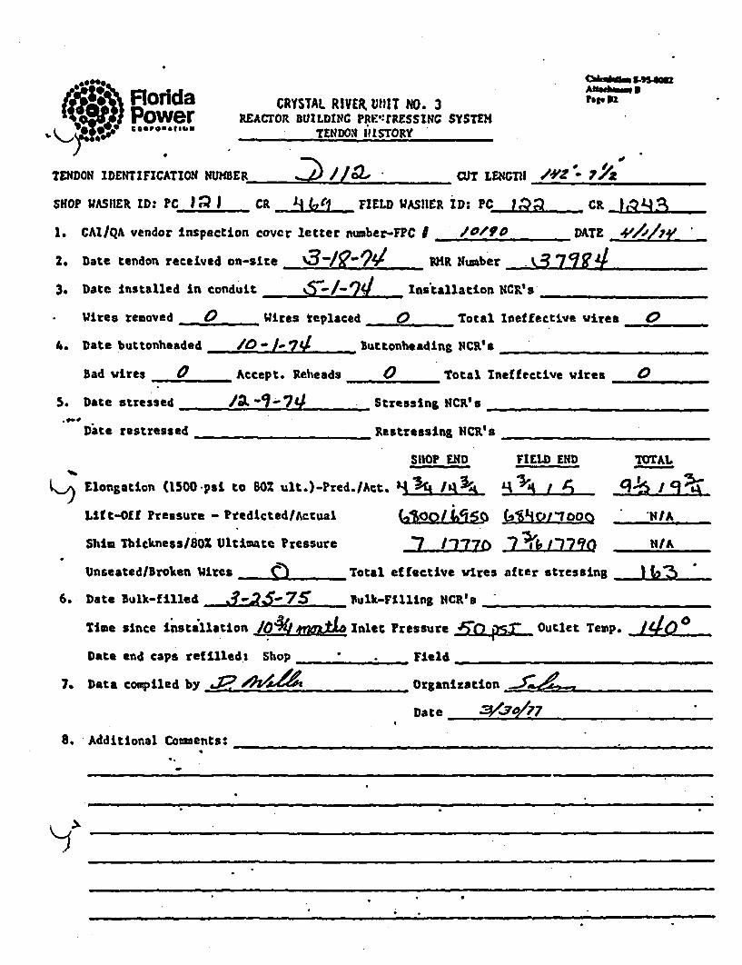
.. ee~Odg_ , . u-~s~aaszFlorida CRYSTAL RIVER U1lT NO. 3 rp P2Power REACTOR BUILDINZC PRE,:rESSNC SYSTE
TENDON( 'ISTORY
TENDON IDENTIFICATION NUBER --2/a CUT LENGTH / -.
SHOP WAS•ER ID: PC 1 l CR j FIELD WASHER ID•: PC )Q _. CR _L4
1. CAI/QA vendor Inspection cover letter number-FPC I /0/VO DATE -,,/i/',; _
2. Date tendon received on-site P3X9 I ~ R Number 0-7-3. Date Installed in conduit S-/-74 installation NcCF'
Wires removed 0 Wires teplaced 0 Total Ineffective wires 0
4. Date buttonheaded L ./-'74 ButtonheadLng NCR's "
Bad wires 0 Accept. Reheads 0 Total Ineff ective wires 0
5. Date stressed 2/- 1-7*J 'Stressing NCR's
Date restressed Restressing NCR's .......
SHOP END FIELD END TOTAL
L)Elongation (1500 psi to 80% ult.)-Pred./Act. -e4 _IqK _1 _L__ _ _ cj?-/
Lift-Off Pressure - Ptedicted/Actual W,00 i&Sl cWiOM VhIA
Shim Thickness/80% Ultimate Pressure 7 J127 211Q 7ff /
Unseated/Broken tires -- An Total effective wires after stressing JJ2 ,
6. Date Bulk-filled 75- 7 " .1ulk-Filling NCR' a
Time since Installation Inlet Pressure ,T,. : O.. utlet Temp.
Date end caps refilled; Shop __ "___ . Field-_-
7. Data compiled by ~2 *A ~Or~ganization_______________
Date
8. Additional Coments:
11

; Florida CRYSTAL RIVER UIN1T NO.. 3 Fr1
Power REACrog BUDI G PRE: MRESSIC SYSTEHK-' * *? oe ,. TENDON itISTORY
TENDON4 IDENTIFICATION NUMBER 2)1/ CUT LEHMn 94
SHOP WASHER ID: PC 11 1 I CR JFIELD WASUER ID: PC - 15Q I CR 1 I 2-.-5._1. CAI/QA vendor inspection cover letter number-FPC I /0/, 90 'DAZE Y../_/__Z
2. Date tendon received on-site ' 3 ..jg-- 7// RH1R Number_____________
3. Date Installed in conduit , -• - 741 Installation NCR's ____
Wires removed 0 Wires replaced 0 Total Ineffective wires 0
4. Date buctonheaded & -_-7M/ ButtonheadIng NCR's _
Bad wires 0 Accept. Reheads 0 Total Ineffective wires 0
54 Date stressed In-aL .- 4 , Stressing NCR's 11 17
bate restressed Restressing CR _NCR'
SHOP END FIELD END T'oAL
Ilongutlon. (1500 psi to BOX ult.;)-Prcd./Act. I_--J1_14'_____
Lif t-Off Pressure. - Predicted/Actual ..AbXJ1NIA
Shim Mhckness/802 Ultimate Pressure -7 it L777 p R "I _V I NIA
Unseated/Broken Wires b Total effective wires after stressing Ha ?
6. Date Bulk-filled .... _,_.__ ___ Bulk-Filling NCR's ____ ... ...
Time since Inst;2lation M" Inlet Pressure Outlet Temp.
Date end caps refIlled: Shop ,_Field __ -- __... ....
7. Data compiled by O Organization
Date _ _ _ _ _ _ _ _ _ _ _ _ _ _ _
B. Additional Comments: _

cakvh w 4.u
Florida CRYSTAL RIVER turqT NO. 3 14
Power REACTOR BUILDING PiLt"TRESSING SYSTEM) ** C,* O*b.DA9.*- TENDON HISTORY
TENDON IDENTIFICATION NUMBER CUT LENcTH
SHOP WASiHER ID: PC_ Ci_ FIELD WASHER ID: PC_ ___ CR .....
1. CAI/QA vendor Inspection cover letter number-FPC I DATE
2. Date tendon received on-site _4R Number
3. Date Installed In cooduit Installation NCR's
Wires removed. Wires replaced Total Ineffective wires
4. Date buttonheaded. ButtonheadnLg HCRO__
Bad vires Accept. Reheada ., Total Ineffective wires
5. Date stressed .__ _ Stressing NCR's
Date restressed _ __ _ Restressing NCR's
SHOP END FIELD END TOTAL
V./'% Elongation (1500 psa to 802 ult.)-Pred./Act. L..
LIft-Off Pressure - Predicted/Actual LN........... K/A
Shim Thickness/80 Ultimate Pressure L .* _ _H/A
Unseated/Broken Wires Total effective wires after stressing
6. Date Bulk-filled -- __ __Bulk-Filling I$CW e .
Time since installation Inlet Pressure Outlet Temp.
Date end caps refilled: Shop ..... ... Yield
7. Data compiled by .1? a 19._ _ OrganIzation
Date __________________
8. Additional Comments: APw ,e ,d^/"
F -IS
n n _- i_ 4

* - -.,Floida CRYSTAL RIVER ur NO. 3-Por lw r REACOR BUILDIN:C PPRS! PE.SSUNG SYSU s5• .•." ~ ~ ~ ~ ~ Tm fi°". •Nt,• ts'loRyr •
END04, I DENT_______101;________D___4_ CUT LEN4GTH I/'/- Zr~
HOP VASE.• ID: PCLRF______ _H 11) -. PC 1,2A CR 4706
* CAI/Q& vendor inspection cover letter number-FPC I _____,._DATE _,____. __.
D Date tendon r.ceived on-sit- a /A - 74 S Number
3. Date Installed in conduit _7_... ____ Installation NCR's ....
Wires removed 0 Wires replaced 0 Total Ineffective vires 40
i. Date buttonheaded 1,0-I-74 ButtonheadLng NC4R's _ , _.__ _.
Bad wires 0 Accept. Reheads 0 Total Ineffective wires 0
i. Date stressed str//. .7-7 Stessing 11CR's /17,'./72
Date restressed /R?-//. 74 'estressIns UCR's
SHOP END FIELD END TOTAL
'ongation (1500. psi. to 60% ult.)-Pred./Act. IIAf ~IA 9"&'~' .. L•..iftOfPressure - PridictedlActual 6 ~" , ?90n/A
Shia ThicknessO80 Ultimate Pressure . 1 Z770 , 6 ,/A
Unseated/Broken Wires , _ ,_Total effective •ires after stressing L/62
6. Date Bulk-filled .3--,5.- 9' sulk-Filling NcR'__
Time gince Installation fi7/Xzd Inlet Pressure -..,4i. Outlet Temp. II
Date end caps refilled: Shop /I-24.7& Field Y/I/2,0 -7
7. Data compiled by___ /_ _ _ _ Organization __ _ __._ .
8. Additional Colents: A tt ______________________dj__,;_
S "S I• I =l I rl • :m-

04M&
Florida$) Powercakmal5."4gAFtarmlu 56A194I636
CRYSTAL RIVER U1117 N0. 3ItEACTOR BUILDINGC VL:TRESSIN4 SYSTEH
TENlDO• l STORY
p
ISHOP WASHER IDN PC_ _ CR FIELD WASHER ID: PC CR.
L. CATIQA vendor inspection cover letter number-FPC I DATE
2, Date tendon received cn-site RHR Humber
3. Date installed In conduit Installation NCR's
Wires removed _ Wires replaced _ Total Ineffective wires
4, Date buttonheaded Buttonheading CRICs
Bad vires ___Accept. Reheads _ Total Ineffective wires
5. Date stressed Stressing NCR's
Date restressed Restressing NCR's
SHOP END FIELD END
Elongation (1500 psi to 80Z ult.)-Pred./Act. . -
Lift-O[f Pressure - Predicted/Actual / ,, -
Shim Thickness/80 Ultimate Pressure I
Unseated/broken Wires Total effective wires after stressing
6. Date Bulk-filled ___Bulk-Fillitn NCRe's
Time since installation Inlet Pressure Outlet Temp.
Date end caps refilled: Shop ...... _Field
7. Data compiled byS-1 Orgailzatlon _
TOTAL/
I/A
N/A
.. ....... ... J I
Date
8. Additional Comments: ".
AO / . A" -,
i /, - lA IP~ - I fs' l _ L / -' (-_ / -/. .)

Florida CRYSTAL RIVER UrT NO. 3 Par-.,7
., Power REA(TOR BUILDING RE:,•rPssI sINCSYS TEMTENDION hISTORY
TENDON IDENTIFICATION ,NUMBER L /_• 1 CUT LENGTH /-le? 7
SHOP WASHER ID: PC_-_---- CR -', FIELD WASHER ID: PC M2 CR
1. CAIIQA vendor inspection cover letter number-FPC I ________,. DATE ______ _
2. Date tendon received on-site I-• -R Number .37 .gg
3. Date Installed In conduit i-o2-1V Ins'tallation NCR's
Wires removed 0 Wires replaced 0 Total Ineffective vires 0
A. Date buttonheaded 9*_.30-__ Buttonheading NCR'_
Bad vires 0 Accept. Reheads 0 Total Ineffective wires 0
5. Date stressed / -/ Stressing NCR's .....
Date restressed Restressing NCR.'s
SHOP END FIELD END TOTAL
I.ongatfon (1500 pat to 80 ult.)-Pred./Act. .. 55 L 5 5Z J 0
Lift-Off Pressure - Predicted/Actual IN"/00v!stm" N/A
Shim Thicknes/80Z Oltimate Pressure Ir--7- N/A
Unseated/Broken Wires (.). Total effective vires after stressing _*"
6. Date Bulk-filled - -•R -•1 Bulk-filling NCR's
Time since installation &Inlet ressure Q _ Outlet Temp.
Date end caps refilled: Shop _. _,_Field _
7. Data compiled by ? Organization_
Date 3/3o/7 7
8. Additional Comments:

Florida CRYSTAL RIVER 1,,11T NO. 3 rage.-sPower REACTOR BUILDUIC PRLTRESSlIV SYSTE '* 006 o.,- TENDON IIISTORY
TENDON4 IDENTIFICATION4 t4UHflR CUOT LENGCTH _______
SHOP WASHER ID: PC_ CR _ _ FIELD WASHER ID: PC_... CR. .
1. CAI/QA vendor Inspection cover letter number-FPC I • DATE ____::_
2. Date tendon received on-site Wi__, _ NR Number
3. Date Installed In conduit .Installation NCR**_,_
Wires removed , Wives replaced Total Ineffective Wires
4. Date buttonheaded Buttonheading NCR's
Bad wires ... . Accept. Rlheads ..... Total Ineffective vires
5. Date stressed Stressing NCR's
Date restressed Restresslng NCR's
SHOP END FIELD END TOTAL
K-' Elongation (1500 psi to 807 ult.)-?red./Act. J . '! .
Lift-Off Pressure - Predicted-/Actual . . , .. ,..I.....A
Shim Thickness/80Z Ultimate Pressure N L/A
Unseated/Broken Wires Total effective vires after stressing .
6. Date Bulk-filled ,__ lk-Fillrng NCR's
Time since Installation Inlet Pressure Outlet Temp.
Date end caps refilled: Shop___ _ Field
7. Data compiled by .. 2 ~Organization_____________
Date Addiiona e.
8a Additional Comments: Al.oe*. ,-. ..
29.4 d &AA ý V 7hf7/
K
I

' Florida CRYSTAL RIVER UNIIT NO. 3 ۥ,,,bfs tof
Power REAcro. BUILDING Ptrrt.SSItG SSTENee*INN 40 I so aB.sO TENDON iti IORf
D'I ON IDENTIFICATION ,UER I-r CUT LENGTH
SHoP WASHER ID: C.c __ _ FIE•W VASHER ID: PC CR
1. CAIIQA vendor inspection cover letter number-FPC I DATE
2. Date tendon received on-site __R Number _
3. Date Installed In conduit Installation lC ___
Wires removed Wi___Lres replaced Total Ineffective vires
4. Date buttonheaded Buttonhesding NCR's
bad wires ...... .... Accept. Reheads Total Ineffective wires
., Date stressed ___,_Stressing NCR's
Date restressed Restressing NCR's
SHOP? END FIELD END TOTAL
Elongation (1500 psi to 802 ult.)-Pred./Act. .-.. , /
K~ Lif t-Off Pressure - Predicted/Actual N - ,/A
Shia Thickness/80 'Ultimate Pressure ...L................N/AUnseated/JBroken Wires Total effective vires after stressing __
6. Date Bulk-filled - Bulk-Fillirg NCCs_
Tim~e since Installation ________Inlet PrelsAsure _____ Outlet Temp. ______
Date end caps r•[ftiled: Shop Field
7. Data compiled 'by Orga.U.ation FPCQVDate 1-30)- 72
8. Additional'Coments-: 1J fZPM AtAW-Tf Iba- -1 157 SUL-%1JC6
SI 907 716

Vakqg.&f s.co• "; • Florida CRYSTAL RIVER V'-IT NO. 3 A le-. 3Power REACTOr• UIJLDVIC Fki: fRESSINIG SYSTEM00*94iTENDION hi1STORY
TENDON IDENT•FZCATION NUMBER CU____ __ T LENGTH _ _/ 0 "-/ _
SHOP WASHER ID: Pc Jj CQ • FIELD WASUER ID: PC ja C
1. CAI/QA vendor inspection cover letter number-FPC . /o/D, DATE __,P/MEL
2. Date tendon received on-site _ /_ Number____ Qe 79;?_3. Date installed in conduit - 9 Installation NCR_'s
Wires removed 0 WIres replaced 0 -Total Ineffective wires -
4. Date buttonheaded Or. 7_- Buttonheading NCR's
Bad wires / Accept. Beheads 0 Total Ineffective wires
S, Date stressed /,2 6- 7 / Stressing ICR's
Date restressed .... Restressint NCR's
SHOP END FIELD END TOTAL
K..' Elongation -(1500 psiL to 80% ult.)-Pred. /Act. _15 ... L±A.1 __.5 5.... 1
Litft-Off Pressure - Predicted/Actual 67 6) .1co 6 ze% NIA
Shim Thickness/80l Ultimate Pressure -7 /7'7.'~o -7'A ,7160~ 14/A
Unseated/Broken Wires (Q Total effective wires after stressing * J•
6. Date Bulk-filled .,-•-'7S Bulk-Filling NCR's
Time since instaillation 816t _122 Inlet Pressure AM -s....Outlet Temp. 0Date end caps refilled: Shop Field ,
7. Data compiled by • Organization ____
Date 3te _/ 17
8. Additional Comments:
-
Ji

Aodda CRYSTAL RIVER U'IIT NO. 3 Ahau1 B
Power REACrOR BUILDING miI,.re-ssiNc sysTE pw alC@-U-UUI .f,, TtI;I)ONH I'[STORY
tENDOtN IDENTIFICATION I4UHER____________ air LENCTH /4Z 2 7
SHOP WASHER ID: PC JJ. I CR Cr1 FIELD WASHER ID. Pc JP'C ) C .R
1. CAI/QA vendor inspection cover letter number-FPC I /42O07 DAfF, 411//1)V
2. Date tendon received on-site ,__"________ IlR Number. .3I'OgO
3. Date Installed in conduit ___,Installation NC 4s,
Wires removed 0 Wires replaced 0 Total Ineffective Wires
4. Date buttonheaded _9 ,0-7j Buttonheading NCR's
bad wires . Accept. Reheads 8 Total Ineffective Wires _,_ _,
5. Date stressed . 3,/-71Z/ Stressing NCR's _ _
Date restressed _ _ . _ _ _estressing NCR's
SHOP"END FIELD ENT) TOTAL
Elongation (1500 psi to 80% ult.)-Pred./Act. LV s jt 4;'"Lift-Off 'Pressure - Predicted/Actual ")of •Q)0 N/A
Shim Thickness/801 Ultimate Pressure 5/7 it I6 1i -,77_%o 1/A_
Unseated/Broken Wires Total ef ective wires after stressing •
6. Date Sulk-filled 4 4 $Bulk-Tilling N4CR's_______________
Time since Installation _1QXmokjL Inlet Pressure "55..p.2.. Outlet Temp. _
Date end caps refilledi Shop .... _ Field
7. Data compiled by0-o..Z__a4 , Organization _ _ _ _ _.
DatedtoaCees
6. Additional Comments:
w~.
/

4 Florida CRYSTAL RIVER UNIT KO. 3 • ,s. 4 'Power R~EACTOR BUILDING V'itt' fRES SING S'YSTEH n t8C0066MA146ftt PV B
cP-.om.',e. TENDON hISTORY
SIDON IDENTIFICATION 11UIMER 7 13 / CUT LENGTH! /A10-
SHOP WASIeR ID: PCJ CR _/ 0 0 FIELD WASHER ID: PC_ 18'- CR 1j-
1. GAI/QA vendor inspection cover letter number-FTC 2. / Io.L DA.T .________
2. Date tendon received on-site OARQ--4 TMR Number M , 01_
3. Date installed In conduit _ ./3-39 Ins tallation NC.'s ....
Wires removed 0 Wires replaced 0 Total Ineffective wires 0
4. Date buttonheaded _ _7_- _ buttonheading NCR's /1 1 ,
Bad wires /1 Accept. Reheads _____ Total Ineffective wires 2..
.5 Date stressed /2 -7!/ Stressing WCR's
Date restressed Restressing NCR's
SHOP END FIELD LZID TOTAL
Elongation (1500 psi to 8o0 ult.)-Pred./Act. .'5•iN ' - "
~I Lift-Off Pressure - Predicted/Actual (U1017 00 67O . L( QD 1N/A
ShIm Thickness/80X Ultimate Pressure M*j~ b NIA
Unseated/Broken Wires * _Total effective wires after stressing . .. .
6. Date Bulk-filled . Bulk-Filling NCR's _.....
TIme since Installation / 40- r1~k Inlet Pressure _3.L)5.... -Outlet Temp. 1
Date end caps refilled: Shop _._ Field • _.
7. Data compiled by . , Organization _- _ _ _ _ _
Date8__________n_______n
S. Additional Comuents:
)
- -.. ~% ~ .w-= ~- -- -.

Florda CRYSTAL RIVER UtIIT NO. 3 AinaebPower PxAcroi BumL= Pn=rassm sysE3:.'j, 0 "°"° t.,rsr
TEN1DON HISTORY
TENDON IDENTIFICATION NUMBC ER/3/ . aeCT LENGTH
SHOP UASEIER ID: PC__ CR FIELD WASHER ID: PC CR
1. CAI/QA vendor Inspection cover letter number-FPC I DATE,
2. Date tendon received on-site __ MR Number
3. Date Instal2ed In conduit Installation NCR'__
Wires removed _ Wires replaced _Total Ineffective wires
4. Date buttonheaded _-_ _ Buttonheadibg NCR's
Bad wires .......... Accept. Reheada ___ Total Ineffective wires
5. Date stressed _____. _ Stressing NCRO'
Date restressed ....... Restressing NCzR'.
SHOP END FIELD END TOTAL
Elongation (1500 psi to 80Z ult.)-Pred./Act.
Lift-Off Pressure - PredictedlActual I .IA
Shim Thickness/802 Ultimate Pressure N 1/IA
Unseated/Broken Wires ._ _ Total effective wires after stressing ....
6. Date Bulk-fIlled __Bulk-Filling NCR'. ._
Time since Installation Inlet Pressure Outlet Temp.
Date end caps refilled: Shop Field
7, Data com~piled by .7Organization _______________
Date 1___ 11117_ _
8. Additional Coments: f 9 •..e feO_ -_
,•,, r 4,,,• -6z /,) ir'"~ • P•.• +"P /60 w/y•,' •i/1Z24)
-. - . -- - -. -

,• *o. Floelda CRYSTAL RIVER UNIT NO. 3 Mb. 00,.. -, P wer IoEARCTOR BUILDI::G PO:SIRESSINCG SYSTEH g3
~Oa.~au.4sTENDQ!I 111SORY
IDENTIFICATION ?uHDE. N 13 .9A, CT LEC ,G'T H -
•.1o0 WASHER ID: PC 42 / _ ___9,3 _ .- ___-_ FIELD xD% C , C__
CAI/qA vendor inspection cover letter number-FPC 0,•O 2._ _ DATE +11//17Y
:. Date tendon-received on-sfte %3 - 7d RMf Number R3 'op " 0
I. Date Installed in conduit . "- L Installation NICR's _
Wires rcoved 0 Vires replaced 4 Total Ineffective wires 07L a _ t NCR's
o. Date buttanheaded __________ sltonhe'dn C' ____________
Bad wires / ,Accept. Reheads 0 Total Ineffective wires __
D. bate stressed --3-74 Stressing NCR'. x .. . .
Date restressed _Restressing NCR's
SHOP END FIELD E:4D TOTAL
OOPNlongation (1500. psi. to BOX ult.)-Pred. /Act. ~. J I
,if t-Otf f ressuzre - Predicted/Actual, 6 Za 700 6&29 6 )60O NIA
Shim Thickness/80Z Ultimate Pressure -,PC, N /A
Unseated/broken Wires 0 Total effective wires after stressing K_ _
Date Bulk-filled B// /" bulk-Frlln, g CR's ......s_
Time since Installation /__,__t_ Inlet Pressure g,,0eS/ Outlet Temp, 160
Date end caps refilled: Shop Field
'. Data compiled by 22 Organization _-,Xe__._.. ..
Date
1, -Additional Co-entst .... ....._
n r_• n H -••

N% .,.ria CRYSTAL RIVER Uiu 110. 3Ac, , -: •¢ l . .;T FIACroa ? 7•V:3:, Et:SS:: SYST'EM
4O"a+ .*.-..s- TFI:oO:' ItISTIY
1M. DENT1FATlo0l NLIER___________ 6i? LL-4(6TH A/'Z - o'
3P UASHER 10: ; PC /AL . a -FIELD UASHER ID: PCJ .• CR /CR
'GlIQ.A vendor inspection cover letter nu-ber-FPC 1 , OZY5 _ DATE •'//o/7 .
Date tendon received on-site :.?Q-7L R Number .__ ._____....
Date installed i:2 ccn.uLt I nstallation NCR 's
Wires rc=oved 0 'Wires ra;laced 0 Total Ineffective vires 0
Date butch•-aded 104-107- Buttoheadin; N4CR's _ -
Bad vwres 0 Accepr. rehoads 0 Total Ineffective vires
Date stresse4 0-07 Stressing NCR's &ell. &42'3
Date.restress4- ._Restressing tiCR's
SHOP E1,D FIELD M.; TOTAL
'".nsation, (1500 psi to 60% ult .)-?:ed./Actb 4 114~ TV' 75 I 9 k f /0 AV
?lf-Ol ressure - fredicted/Actual /QMd7IO~.400 'J4; ll
Shim Thickness/80% Ultirate Pressure WNL2Z47.O N"/I 11IA+I
Unseated/Sroken Vires ._J Total effective wires oafer stressing ,9..-
Date Bulk-filled , gR"t,"'7•' Bulk-Filling N1CR's
Time since Installation - ~~r~ Inlet Pressure Outlet Temp. '
Date end caps refilled: Shop __ ._,_. Field ... ..
0 Data compiled by. Organization _.._..._
Date ./+?/7.
Additional Co-ents: e .

FloridaPowergGAP466900"
CRYSTAL RIVER UNIT HNO. 3REACTOR BUILDIG PRUtESSINC SYSTE)
TENDON •_-1ISTORY _
C~khe .. S4M.OAttatImina SFg.UII
TENDON IDENTIFICATION I.HEER L ZA // 7LT . _E_ _
SHOP WAS•ER ID: PC CR FIELD WASHER ID: PC Ca
1. CAIIQA vendor inspection cover letter number-FPC f __. DATE ____
2. Date tendon received on-site .._ Numiber ,._.
3. Date Installed in conduit Inatallation NCR's
Wires removed Wires replaced Total Ineffective wires ...... .
A. Date bu'ttonheaded .. _ _ uttonheading NCR'e
Bad vires ...... , Accept. Reheads Total Ineffective vires
S. Date stressed . ..... _ Stressing HCDIs
Date restressed __Reatressing NCR'sa
SHOP END FIELD END TOTAL
Elongation (1500 psi to 80% ult,)-Pred.IAct. I. ._
LIft-Off Pressure - Predicted/Actual I
Shim ThicknessIa0 Ultijiate Pressure J -
Unseated/lBrokeu Wires . ... . Total effective vircs after stressing
6. Date Bulk-filled Bulk-FlIling NCR'
Time since Installation Inlet Pressure . _ _ Outlet Tem
Date end caps refilled: Shop Field
7. Data compiled by .. ........ Organization
Date *9 4
IMIlA.
K/A
PO
8. Additional Couments: Pome. •joa,, -
A l -c" /*7 YIr/n.It
n A K
.............
I!

r'.or~daCRYSTAL RIVER MITl NO. 3REZAC,0O1 WLuxLEtC Pr~rE~SslM:: SYSTE-i ?W 817
::M4~ IDEN'TIVICATWIl NtDER___________ CUT LENGTH 4'
OP IWAS1IER 11)D-. P'CJ/ZI_.. Cit J~IZELD VASHER ID: PCj .:. C~
CAI/QA vendor inspecticui cover letter nmiber-IFPC I /OZ__________ DATE 40110Z71'
Date tenidon received oti-sfta A9-7 WiR Num~ber 3 1~4Date installed in cenduit __________Installation NCIK's /4
Wires V=Voed 0 wires replaced 0Total Ineffective wJires 0
Date buttonheaded /-7'gButtonheadin; 1CWs______________
Bad w'ir~er Acceptc. Rcheid~s 0TotaL Ineffective wires /
Date stcessed I'j1 Stressing NCR' s_____________
Date. restressad ______________Restressing l:cR~s________________
SHOP E%*D FIELD END, TOTAL
agoation (1500 psL to 60-4 ult.)-rred~.IAct. Z&~~ /,V 4 -/-
Uýft-'Off Pressure - Predicced/Actual &71LM&A7t G A
Shia IhickaesslSO%. Ultimate Pressuve to1 1,7& NI.i42~ 4A-UnseatedjBrokmu Wires 0Total ef fective wires after stressing 2......
*Date Bulk-M liad bui7' 'k-rillIng ITCits_________________
Time since installation ..~G 4tjLInlet Pressure. L ' outlet Temp. ____
Date end caps ref 1Usd: Shop __________Veld __________________
*Data comtpiled by .~ ~Organization _____________
bate _717 ______0177____
* Additional Co~ents:______________________ __________
I

Chr/iTAd. UWU~l Wil iio. 3UTS l MUIR Lu" NUot In
-_C acmltmlatfJ0, TIMUSt S_ 506 0212 .| !
, S i m o f f " " 11 3 d w . - , l o ol m .."*Wpeuise An. .Ibis l661- Total "p. a .m 11a- ?"*si "".tee lSda.
polld "a lore am Tolew!so ailo. lsfetlva for"o roves TIhicsOs etinl. atftetiv Tweetri¢.e of
S,. . €op S(ki..) .i...)_ .V -AT) WIOr. J(• Mp I.) fit) liv) lt_. hi.W. 4 .. gCm s.
2, 4 9 9 o•a
S tsit '0 ! 31r 4 Sl" -A, ILA ALL
121174 .L 161 100 jL~4 ir ~2 I&L ilL. X&t. AL* JUL .9-A JLt
S it
T 1233 1333 & i14 VIA 162 V1I of&VIA via 6VIA - -
*2 33
L.. Ult-aft 9611
At-ij-
4NA&Z £ni3 Wd& (M7J i5& jdAM IA A I JS'7.4A 6p'
4A"&Ae7TA 79 A4mob
- a - - - . . - - -
- -- - - - - -- - - - --
- -- - - - -
- - - - - -- - - - - - i[[Mi.
I4,

Florida CRYSTAL RIVER UNIr NO. 3 .,B19Power REACTOR BUILD1IC PERESrW•. sNG sYSTE, , TENDOM HISTORY
TENDON IDENTIFICATION N4UMBER 71)a CU OT LENGTH / '*740
SHOP WASHER ID: PC j C R FIELD WASHER ID: PC L ICR 879- .I. CAIIQA vendor inspection cover letter uumber-FC I /Ot*, DATE _J//O/,'
2. Date tendon received on-site %-____ _ -_ . , KR Number .... I43. Date installed In conduit to-/0-24 Installation NC __s
Wires removed 0 , Wires replaced 0 Total Ineffective wires 0
A. Date buttonheaded /0 - /( 7 . Buttonheading NCR's
Bad urtes, 0 Accept. Reheads 0 Total Ineffective wires 0
5, Date stressed 11J18-94 Stressing NCR's _______________
Date restressed Restressing N sCR'__
SHOP END FIELD END TOTAL
I ý~ ongation (1500 psi to 80% ult.)-Pred./Act. 44____ ______ _____
Lift-Off Pressure - Predicted/Actual N/.o1 6 .•Or5t tIA
Shim ThicknessISOZ Ultimate Pressure A LI 7'? 1 7,770 NIA
Unseated/Broken Wires 0 Total effective wires after stressing A(015
6. Date Bulk-filled _, fulk-Filling NCR's
Time *since Installation 9ý vd Inlet Pressure 5/ j Outlet Temp.
Date end caps refilled: Shop_" Field ,
7. Data compiled by Organization _..... .
Date
8. Additional Comments: 0im! dLw34)eIV
• -. . en-
4
KJ-2~

Florida CRYSTAL RIVER VNIT NO. 3Power IEACrOR BUILDIN. OPl "TRESS 6c, ?.p32cS•P@,**,oW ••TtDOR HItSTORY
TENDON{ rDENT1CATION K .. 4 2/3 . o Wu`T H ..__ __.....
SHOP ,•ASHER ID: PC_ __ C. ,_._ . FUELD VASHER ID: PC --. C_
1. GAIIQA vendor Inspection cover letter number-FPC 9 _ _ _ DkTE ....
2. Date tendon received on-site _ TIR Number __.....__ _
3. Date installed In conduit la. t__, ln alltion NCR's ____ __
Wires removed ... .. Wires replaced ,-Total Ineffective vires _-
4. Date buttonheaded Buttouheading NCR's
Bad vires Accept. Reheads Total Ineffective wires _
5. Date stressed Stressin a CR's _
Date restressed Restressing NCR'.
SHOP END FIELD END TOTAL
Elongation (1500 pal to 801 ult.)-Pred./Act. I .
Lift-Off Pressure - ?redLcted/ltual N_/L . _ _ _ _ 14A
Shim Thickness/801 Ultimate Pressure II MIA N/A
Uaseated/Brokea wires___ Total effective wires after stressing _
.6. Date Bulk-filled .... Bulk-Filling NCR' __,,_ _ __
Time since Installation _ Inlet Pressure Outlet Temp. __ -
Date end caps refilled: Shop - F. Field
7. Data compiled by J , Organization __304,4______"
Date'
8. Additional Comeents: A',me ke,, -
- 6
K
t4ere. fi'~ - Id -(7//iY7~)7,
M-9, 711;

S* -on.- CRYSTAL RIVER UNlIr :10. 3Aia5. ~:REJCroR MULIMI= ?ris~rP*::s$I,%%#SYSTCi plapzi
TEUWON' HISTORY
WlIPE.61TF1CATIo:1:1 .-UER CR6____ ILDUS T IMIM _______
~nL AHRID: PC__ _____R /(wGAIIQA. vendor inspection cover letter v'xber-FPC 16 / Y.< DATE __1___0 ___
Date tendon received on-site __________ .'Ru~ber 22___________
Date Installed In CCOdUitL to1-1 installation 11cr's_____________
Wires removecd _. '91res repl~ced 0 Total Ineffective wires /
Date buttonheaded _10 -1(, -1 L4 Butiornheadin; ?:CR~s _____________
Bad wires /Accept. telloads CTotal. Ineffective wires /
Date stressed Ip6-',Stressin;c.s_____________
Date* restressed _____ ________Res tressir-& lNCR $_______________
SHOP ~ FIELD EN~D TOTAL
ptation (1500 psi to 60Z ult.)-Pred./Act. j"/ii$ M~~L~ 1_"9%LIEt-Off Pressure - ?rtdLcteJ/Actuasl "#7Q 14fOAI6~'q 5
Shim Thickness/8011 Ulti~ate Pressure *720 Q 7,6o __ZON/
*Unseated/Droken Wires QTotal, ef f ecti':m wires af ter stressing _24L....A.
*Date Bulk-filled ____________ -7kFiln 6C6 _______________
Time since 17nstallation q netFesre44, Outlet Temp.
Date end caps reftlled: Shop _________ ield___________________
*Data com~piled by _2,;o5ý t62 Organization ______________
Date 3Z'
*Additlonal Co= -ents: & fPIUJ ALMAJ UVAk QdAffIU) UeaLW.

FloridaPowerPt6A em mw ter
CRYSTAL RIVER U1I!T NiO. 3REACTOR IUILDINC ?RE:'IRESSING SYSTEH
TENDON IHISTORY
lag. 8 s-22Pap 822
TENDON IDENTIFICATION •U •_BER z /1z' T0. Unw._m
SHOP WASHER ID: PC__ CR _ ZLD WASHER ID: PC CR_
1. CAZL/QA vendor inspection cover letter number-FlC I DATE
2. Date tendon received on-site I4R Numbe_
3. Date installed in co~dult Installation NCR's
Wires removed . Wires replaced _ Total Ineffective wires .....
4. Date buttonheaded _ _ _Butonheading NCR'siP
Bad wires Accept. Reheads . _ Total Ineffective wires
S. Date stressed Stressing NCR's ______ ____
Date restressed RestreasIng NCR's_
SHOP END FIELD END TOTAL
• Elongation (1500 pst to 802 ult.)-Pred./Act. J -Qd/
Lift-Off.Pressure - Predicted/Actual
Shim Thickness/80Z Ultimate Pressure
Unseated/Broken Wires Total effective vires after
6. Date Bulk-filled ... .... Bulk-FIlling NCR's -
liue since installation_ Inlet Pressure
Date end caps refilied: Shop____ ._,_ Field
7. Data compiled by _ , Organization
Date
N/A
N/A
stressing
Outlet Temp.
8. Additional Coments: 5o•v~ Kee*,Ae "-"
/Z r/- 2 r ... z o
r: rre ... .. ~ce .' _.Zr e _ J -- / (,'1

"'#% Florida CRYSTAL RIVER UNI r HO. 3 A*,mk ,wPower REACrOR BUILDING ?1ESIRESS11G SYSTE M.'a ,,,o, TENDONT 111SI ORY
TENIDONI IDENTIPICATIOII NUHER CUT LENGTH 4CT
SHOP WASHER. lot PC 12.1 CIL _____ IELD WASHER tD: ?C______ C?.______
1. CAI,/QA vendor inspection cover letter number-TMC _ DATE
2. Date tendon received on-site MIR $umbor
3. Date installed in conduit Installation NCR'._
Wires removed ___ _Wires replaced __..__._ Total Ineffective vires __ _
4. Date buttonheaded _uttonheading NCR's
Bad vires - _. Accept. Reheads _ Total Ineffective wires ___
5. Date stressed ... ._ _ Stressing NCR*as
Data rest9resed _Restressian 1NCR't
SHOP E2D FIELD END TOTAL
Elongation (1500 psi to 80% ult.)-Fred./Act. I I
Lift-Off Pressure - Predicted/Mttual M .IA
Shim Thickness/002 Ultimate Pressure NI14A
Unseated/Broken Wires _ Total effective vites after stressing .,
6. Date Bulk-filled ]_ulk-Filliug N4CR*. a
Time since installation _ Inlet Pressure Cu Otlet Temp. _
Date end caps refilled: Shop yield ___----__-
7. Data compiled by k AZ* 7Organization FPC-Date Yo,__ __ __ __ __7_
8, Additional Comments:2 7L) ?4 C 441A 1($1 t /J nS9 34g$W JL 4 CA
Ky
" 907 716

Florida CRYSTAL RIVER UNIT NO. 3 AP•ag 3Po er RAcrOR, oUniLD•I PlttSirESSInt SYSu£m
TENDON hiLSTORY
tENDOR IDENIFICATION NUMER CU--?_ J5 rT LENGMh U/Z I
SHOP IlASIIEa ID: PC MZ i_____ FIELD WASHER ID: PC IVCR1. CAI/QA vendor inspection cover letter number-FPC 0 1/26 .ZY DATE _ _____
2. Date tendon received on-site R__-,.M- '7 -_ Number •M 424.
3. Date installed In conduit 6 -In - 14 Installation NCR's
Wires removed 0 Wires replaced 0 Total Ineffective Vires 0
4. Date buttouheaded /0-kb'941 Buttonheading NCR's
Bad vires 0 Accept. Reheads 0 Total Ineffective wires
5. Date stressed /"-4-7_ Stressing NCR'*__
Daie restressed _Restressung _ _CI__s
SHOP END FIELD END 'TOTAL
*.onsation (1500 psi to 80% ult.)-Pred./Act. ~~9~ 9
LIft-Off Pressure - Predicted/Actual 1,0 )/,9 •.fO t 70O1,&00 z I/A
Shia Ihickness/8OZ 'Ultimaata Pressure - j ~ ~ ~ ~ 7/ /
'lnsestedlBroken Wires 0 Total effective wires after stressing "
6. Date Bulk-fllled __ -,_ -___" Bulk-Filling NCR's
Time since installation Inlet Pressure Outlet Temp. / . .
Date end caps refilled% Shop ._.____...._Field
7. Data compiled by'______________ Organization_______________
Date -V1IF7/7
S. Additional Coments:
0.
K,
--t__ nm , = _

€CIdmhe 595.006
Cakuhideft B• -A
Attathmega 3
Florida CRYSTAL RIVER U111T NO. 3,r ~I!Ih Power REACTOR uxwnc PRtErREssxNc s~sJTI
TENDON HISTORY
TENDON IDENTIFICATIOtNUE 9 _ /• air NUMBER __2_CUT
SHOP WASHER ID: PC_____ CR. __ _ FIELD WASHER ID: PC__ CR -- _
1. CAI/QA vendor inspection cover letter number-FPC | DATE
* 2. Date tendon received on-site __R Humber _
3. Date installed in conduit Installation NCR's
Wires removed __ _Wires replaced _ Total ineffective wires
4. Date buttonheaded _uttonheading ICN8R
Bad wires Accept. Reheads Total Ineffective wires
5. Date stressed Stressing NCRW . .__-.
Date xestressed .... st__ leatressing NCR's __
SHOP END FIELD E 'TOTAL
Elongation (1500 psi to 801 ult.)-Pred./Act. I
Lift-Off Pressure - Predicted/Actual IA
Shim Thickness/80Z Ultimate Pressure I . L.i _ . . ./A
Unseaced/Broken Wires _ Total effective wires after stressing ,
6. Date Bulk-tilled Bulk-FttlogNC KCR's
Time since installation I Inlet Pressure _-Outlet Temp.
Date end caps refilled: Shop Field __,_ .
7. Data compiled by Organization __--__
Date _
B. Additional Comments .,

fie ForoddaI Power
C~kM .1 S46-O41Attfdm B
Per DUCRYSTAL RIVER UNIT NO. 311ACTOR bUILDUIG ESTP, ESSIG SYSTEt
TEINDON HISTORY
M IDEMTXFICAT1O14 1fl_-ER Tb".o IMT -NG
SHOP WASHER ID- PC______ CR _ FIELD WASHER ZD: PC_____ .__ CR _
I. CAZIQA vendor Inspection cover letter nmber-FPC I ,_DATE _
2. Date tendon received on-site _MR Number _
3. Date installed in cotiduit __Installation NC _ __
Wires ramved Wires replaced -_ Total Ineffective vires
* 4. Date buttonheaded Buttonheadinc NCR's
bad wires .__ ,__Accept. Reheads Total Iseffective wires _
5. Date stressed Stressing NCR's
Date restressed Restressing HCWS
SHOP END FIELD END MAOTL
2lOnlatiou (1500 psi to 801 ult.)-Pred./lct. / _
Lift-Of f 8149 Predicted/Atu1al (KMP) /33A. ' I 3%.,/17.?i H/ALOCO -OF* rWIC 5(in4•"
Shia Tbickness/80% Ultimate Pressure / I .IN/A
Vaseated/Broken Wires _ Total effective wires after stressing 6_ _
6. Date bulk-fi1led ..... . ulk-TilliLng 's __NOVa
Tlme since installation _I_ Inlet Pressure _ Outlet Temp. __
Date end caps refilled: Shop Z-6 Field 797. Data compiled by j0I ~O rganizatio a R
Date•~I~-7 .Add l tome,,., Ts era ! j9V.- A 1JAsrE. (L3_-76)
MO) "•0o "iJ)c4--'Q, 14 LS1 jT" b-.
W)0~ 'C~ACKINJ AT- AIrJCH~rLAI-L
)
"li p-

- jf~ S, s
CITIlAL 1V02 WIT O. 223ACM, sUtLsiNO iUEIUUmoa srl 3W
- Tumo-IMMM uuwuSpum av - TOWNll go* 1
lekaItiloperiod a"d
WI! a" mIIT1oWN -Avg. -I- Slh - Ial: TOW Reacto lids.
yore. le.ee 161eblcsl as. hIleegive Porso Pee. Thibmeesj atia. Iloeetivo Teaperature o'E&t
cigtil Z.IA, VA
strassiag
.LLLUz.4 4 670 166 1j 2...1 3Q IM 16 NA VA j iA NAth
I.~ .313.3 ILA- r62 PIA
21170- 16116 14 31140 NtL 163 1054 1,33 4 316" VI 163 92 46
..d 7* VIA VIA r VIA 1. LC,.-off only
.IOI X ..1.. .h1) *.1fM4 VL&" b 16H13 p. NIL 6 W14. . _3 VI 5
.5 1m -__S , o i N A
P I571 tESU I & I P1A A a dI&.3 4&&OED O-C 6e'asc
A23? 722
- -- -- - -
- - - - - - - - - -- - I!!
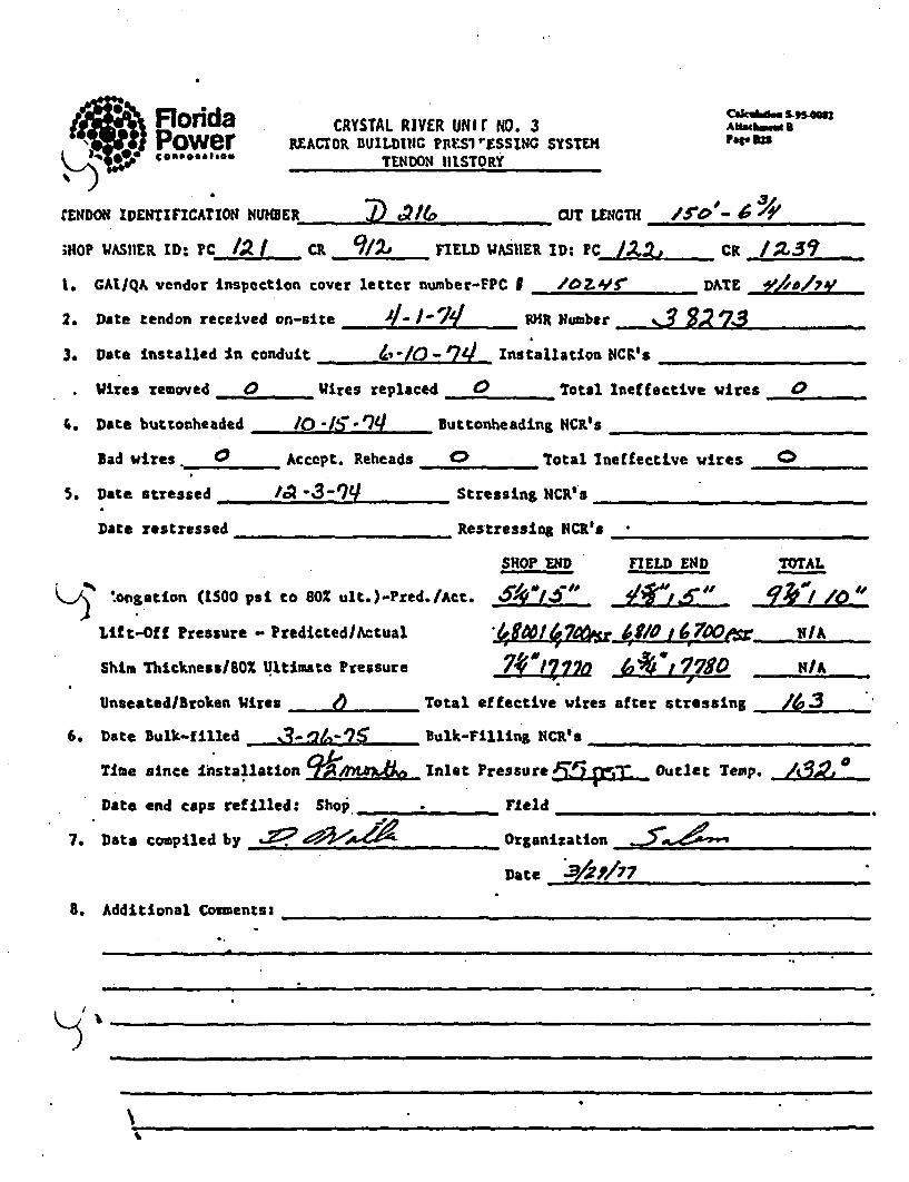
Florida CRYSTAL RIVER UNiTr NO. 3 ,.u --.Power REACtOR BUlLDC ?IESI'F.ssING SYSTE?1 A•U
TENDON HISTORY
rENDON IDENTIFICATION N4UMBER CUT LENGTH /5"0 *~~m p - 6 4'~;HOP hASHER I: IN PC 4 CR 9/Z FIELD WAS'1ER ID: PC LAXI CK /Z3-i
1. GAI/QA vendor inspection cover letter number-FPC I /OZ.'Y DATE 91,1/74P2. Date tendon received on-site 4- I-W RR Number J 9, 73
3. Date installed In conduit - ,-/0-r7A4I Installationt4CI's
Wires removed 0 Wires replaced 0 Total Ineffective wires 0
4. Date buttonheaded /0 '.1/- Buttonheading NCR's
Bad wires. 0 Accept. Reheads 0 Total Ineffective wires 0
5. Date stressed , / "3-_Q Stressing NCR'
Date restzessed Restressing NCR's •
SHOP END FIELD END TOTAL
) oflg5tion. (ISuOOs to BXul.)-red./ct. 4.. V
Lift-Off Pressure - Predicted/Actual I OU to, ,110 N/
Shim ThicknessIBOX Ultimate Pressure 70¼?77 17710 N/A
Unseated/Broken Wires 00 Total effective wires after stressing / ,.
6. Date Bulk-filled _B-'/i-7 Bulk-Fillinz VCR's
Time since Ihstallation 9 Inlet Pressure • 4. ,. Outlet Temp.
Date end caps refilled: Shop' ___ _ __ Field
7. Data compiled by .- ?Organization_______________
Date 3/Z1/77
8. Additional Comments:
I K ;- _ I n '•n
'Io

. *. .;r', . CRYSTAL RIVER UNIi NO. 3 aubdM 'kVua"'S,* .- a REACTO. CUILDt::G Prr;sr-..sst:SS, SYSTE.M•
.gd~wmTl!:rO!' 1l[STCRY
½__ __
'DON. IDENTIFICATIO:1 N-UQER C) 305 W LENIGTHI/5 ?A
IP UAS.ER MD: PC C.| cR FIELD WASHER . D: PC A =/ CR •._•..YL~i"
CAI/Q,\ vendor inspectio-i cover letter numbor-YPC /023 S"7 DATE,. _,/3,_/7,__ __
Date tendon recei-ed on-site LA -in-1•4 'R Number _ _ _l_,_
Date Ins:alled 1.• ccndu ui__ ._ __________l_ Installation IICRI's ,_II
Vires retoved 0 Wires replaced 0 Total Ineffective vires •
Date bucttn.eaded AQ-[•-1-4. Butto...eadina t;CR's
lad vires '. Accept. Reheads 0 Total Ineffective vwijs /
Date stressed I I.l4-P4 Stressing NCR's 'lr) ..
Date restressed Restressing NCR's
SHOP rED FIELD END TOTAL
7,Sg,,, (1500 psi to 60 ult.)-Ped./Act...
IAft-Off Pressure - Predi~cted/Actual, I___________T___N____
Shim Thickness/S0Z Ultimiate Zressure Z720 N/A
Unseated/Broken Wires _ Total effecttile vires after stressing .
Date Bulk-filled ,.3-•'7-7v 7,ulk-rilling . CR's /, .
Time since Installation q4Inlet Pressulre- ~ Outlet Temp.
Date end caps refilled: Shop _F_ Field ____
Data cor-piled by .?Organization __,,
Date *ZeI17 -
Additional Co-ents:
At'
+

Florida CRYSTAL RIVER NlIT NO. 3 AwadhmePower REACTOR BUILDWGC PRErRESSING SVSEI FWD"• P 5Ioh.l~ TENDON HISTORY
TENDON IDENI•FICATIONI 1 E1 30,8 0CUT LE•GTH
SHOP WASHER ID: PC CR ]FIELD WASHER TD: PC_ • CR
1. CAI/QA vendor inspection cover letter number-FIC I DATE
2. Date tendon received on-site __R Number
3. Date Installed In conduit Installation NCR's
Wires removed ,_ __ires replaced Total Ineffective -ires
4. Date buttooheaded __ _ uttonbead" NCR's
bad vires ._ ___ Accept. Rehead. Total ineffective wites
5. Date stressed .... Stressing XCIC's ____
Date restressed _estressing NCRts
SHOP END FIELD END TOTAL
Elongation (1500 psi to 802 ult.)-Pred./Act. / • /
Litft-Of Pressure - Predicted /tual I _ i/A
Shim Thickness/80Z Ultimate Pressure N__/A____ A_ NA
Unseated/Broken Wires -_ Tottal effective wires after stressing __ _
6. Date Bulk-filled _ alk-FIlliag NCR's
Time since installation . _ Inlet Pressure , Outlet Temp.
Date end caps refilled: Shop ,., Field
7. Data compiled by - Organization- _. . ....
Date _____1 _________
8. Additional Comments: ..- 4e. ....ArofeIle.
-~~ ~ zf 5iPP:),/oAn)(zn~de/2'~s9 7O " '9
7
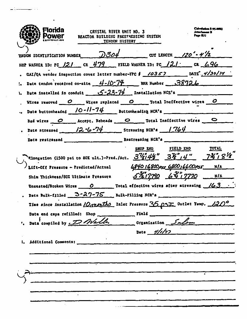
FIorida CRYSTAL RIVER UNIT 140. 3 ,a,,,,.Power REAcTOR BUILDING PISTUSESINC SYSTEft P..,,a ,-"'" TENDON HISTORY
*ENDON ID~ENTIFICATIO14 )4UH39R CUTO4 Q LENGTHI________
190? WASHER ID: PCJ. _ CR 42 9 FIELD ASIER IXD: PC -2- - cm.( 26. GAI/QA vendor Inspection cover letter number-FPC . /03. _7 DATE ._.9/J30/761
:.Date tendon received on-site 4 1........ RIMR Number.______________
1. Date Installed In condutt Installation NCR''s .....
Wires removed 0 Wires replaced 0 Total Ineffective wires 0
Date buttonheaded /0" 1 1-74 ButtodheadInk NCR's
Bad wires 0 Accept. Reheads ......... Total Ineffective wirces _____.,.
*Date stressed I''" 4Stressing NCR's ______710_____/_
Date restressed RestressIng NCR's
SHOP END FIELD END TOTAL
F'.1ongation (1500 psi to 80% ult.)-Pred./Act. %37/1/ 4 1,4 _310& . Pro'"Lif t-Of f Pressure PredictedlActual 4'I/O /10 90/0(000,. N/A
Shia 'Thicknessl8Ol Ultim~ate Pressure 7%'~l 1.7L.Z? MIA
Vnseated/Broken WIires 0 Total effective wires after stressing "
* Date Bulk-filled . S..." •ulk-Fillinzg NCR's
Time since Installation g Inlet Pressure outlet Temp. ... 2...Date end caps refilled: Shop ____Field .....
'. Data compiled by ,z __ Organization____
Date :0',_,_ _.
I. Additional Coments:
,,L.k-i p

41 Florida CRYSUAL RIVER UIT N. 3 A r. NPower REACTOR DumpiLD PRLSiEssiNG sysm4S °"oP'°" _TENDON HISTORY
TENDON IDENTIFICATION ?IUIER Ct '~ UT LENGTHI__________
SHOP WASHER ID: PC CR _ FIELD WASHER ID: PC________ CR
1. CAI/QA vendor Inspection cover letter nwuber-FPC I . DATE _
2. Date tendon received on-site __k_ R Number b
3. Date installed in conduit Installation OCR's .... .
wires removed _--- __Wires replaced Total Ineffective wires
4. Date buttonheaded B___uttonheading NCR's ... .
Bad wires _ Accept. Reheads ____ ___ Total laeffecftive wires ___ _
5. Date stressed Stressing NCR's
Data restressed Restressing NCR's
SHOP END FIELD END TOTAL
Elongation (1500 psi to 60Z ult.)-Fred.(Act. I . . .
Lif t-Off Pressure - Predicted/ActumalL L . U/A
Shim Thickness/802 Ultimate Pressure N/A
Unseated/Btoken i _Wire Total effective vires after stressing __"
6. Date Bulk-filled -__..... .. _Bulk-FIlling NCR's -- _
Time since Installation Inlet Pressure Outlet Temp.
Date end caps refilled: Shop F___ _ Field _.____._
7. Data compiled by,. 4J2 •Organization ,._4=--99_
Date 0____A_____
8. Additional Comments: O&A,,- dYff.#i
11. # A -2.A/ tAe)
r
-- -- __

**:- ~ 4 d ~raCYSTAL RIVER UNIT 10. 3 ~~s-,. , .'vr..r•,Cra DIUILDI::C PST..SSVU SYST£.'t For33
IDENTIF1CAT1OI .'%-U:MER 7) 3 0. CUT LENCDI 1241 tAPIP WAISHER ID:..PC 420 CR F IELD WASHER ID: ?C j CR
GAIIQ& vcnCor Inspection cover lector r~cber-T?C P /0.3 C7 *. DAT E .9/340/79
Date tendofi riceived on-site ________ _I.MR Number
Date 1insta .1e i cenduit __________Installation NCR.'s 4396
wires ve~oved /Wires rc~1aced 0Total Ineffective witres /Date buttcmbeaded /0BI'd uttonheadin;a NCR*&_______________
Bad wires .3 Accept. Rel-hcads / Total Inef fective wires 7.
iLI., • S.r__sing _____-____,________.______T___
bato stressed SrsigNCR's_________________
Date restressad ______________Restressing NCR's ________________
SHIOP END FIELD E:D TOTAL
"Iongatln (1500 psi to 60% ult.)-Pred./Act. Y. . ......
)"'-Llft-Off Pressure - Predicted/Actual ~tI
Shia Thickness/8OX Ultimirate Pressure I Z& NI/A
*Unseated/Broken U11res 0 Total effective wires after stressing O
Date Bulk-f illed ____. ______ bulk-Flilling N.CILs ______________
Time since installation I nlet Pressure ;2%. Outlet Temp. .
Date end caps refilled: Shop _el___d____ Tieldo______ee_____________
Data compiled by -/?--• Organization_ _ _ __$
Date resY1e1s1_ 7ees____
Additional Co=ents:

FloridaPower€S09GAVIgON
CRYSTAL RIVER URIT NO. 3REACTOR BUILDINC nE33REsS1HG SYSTE1
TENDON HISTORYPapS34
TENDON IDENTIFICATION NUMBER /CU 3T' o LENGH
SHOP WASHER ID: PC_ CR F FIELD WASHER ID: PC_ ___ CR .,
1. CAI/QA vendor inspection cover letter number-FPC P , _._ pAT_"
2. Date tendon received on-site -tH___________ aR Number _.
3. Date installed in conduit Installation NCR's
Wý_tres removed Wires replaced _ Total Ineffective wires
4. Date buttonheaded • _,_ ButtonheadIng Nchts ,
Bad wires __Accept. Reheads . _ Total Ineffective w1res _
S. Date stressed Stressing NCR's __
Date Testressed _Restressian NCl K __.
SHOP END FIELD END TOTALdl
L Elongation (1500 psi' to 80% ult.)-Pred./Act. * ,
Lift-Off Pressure - PredictedlActual J.. HI/A
Shim Thickness/80 Ultimate Pressure . H/A
Unseated/Broken Wires Total effective wires after stressing "
6. Date bulk-filled Bulk-FIllIng NCR's
Time since installation Inlet Pressure , Outlet Temp. --
Date end caps refilled: Shop _Fie Feld . ...
7 Data compiled by Organization
Date 7,ý/?
8. Additional Comments:N l m
5- 200 ~ V 2 j~;. , 6~' ,9c2'z%81

Florida CRYSTAL RIVER UNIT NO. 3 owubim.l•Power RrAcOR BUiLD Iu G mlrET1GSSitsi SYSTEH AN.%,,M
COMP646140ft TENDON HISTORYto 3
ZEFIDE CTIFNCATON NUER CUR LHE//"CT L cA1140? WASHER ID: PC /4 Z 6! IL WSE D. CC
GAI/QA veidor Inspection cover letter number-FPC I "' /035 ? . DATE- -f-3# /7 ,
!. Date tendou'recelved on-site P•_________7____ 1PNumber 7__ I__ _ ....
1. Date Installed' in conduit %T-2244.-T Installation NCR's _.
Wires removed 0 Wires replaced 0 Total Ineffective wires 4
a. Date buttonheaded -16-9-74 Buttonheading NCRI's
Bad wires Accept. Reheada 0 Total Ineffective wires /
*. Dote stressed /1-A 7.9. Stressing NCR's. _
Date restressed Restressing NCR's
SHOP END FIELD END TOTAL
',longation (1500 psi to 80% ult.)-Pred.IAct. 7 1 I
ýLf*OfPressure - Predicted/Actual 6,7 4 e7?tI7 6. NLA
Shim Thickness/8o% Ultimate Pressure 16 L N/A
Unseated/Broken Wires _ * Total effective vires after stressing
-nDate Bulk-filled 3 Bulk-Filling NCR's
TMe since Intllto ~ Inlet Pressure 3C if..Out~et Temp,
Date end caps refilled: Shop ,_Field ,_J
I. Data compiled by Z92Organlzation _._ _._
Date ______________z____z_
I. Additional Comnents:

FloridaPower) conpOiA|eft
CRYSTAL RIVER UNIT 140. 3REACTOR BUILDIIC PALSTRESSIiIG SYSTEM
TENDON HISTORY
O 5-95s.00Ant.*ru,u5
TENDON IDENTIFICATION NUMBER . s.-/49 .. . -,CUT LENGTH
SHOP WASHER ID: PC CR FIELD WASHER ID: PC. CR
1. CAI/QA vendor inspection cover letter number-FPC I DATE
2. Date tendon received on-site _ 1M Number
3. Date installed in contduit _Installation NCR!s
Wires removed Wires replaced .. _ Total Ineffective wires
4. Date buttonheaded ¶ Buttonheading NCR's
Bad vires .... _Accept. Reheade Total Ineffective vires
5. Date stressed Stressing NCR's
Date restressed .... ...... Restressiug NCR's
SHOP END FIELD END TOTAL
)%
Elongation (1500 psi to 802 ult.)-Pred.IAct. II
Lift-Off Pressure - Predicted/Actual _ ._ ! N/A
Shim Thickness/80I Ultimate Pressure I , ,/A
Unseated/Broken Wires Total effective vires after stressing
6. Date Bulk-filled bulk-Fill.ng NCR' a
Time since Installation Inlet Pressure ..... Outlet Temp, _ _
Date end caps refilled: Shop __F___ ield
7. Data compiled by organization
Date *V//77
S. Additional Cemmentsz _&0",e ,
I *

* Floidda CRYSTAL RIVER UNIT NO. 3 •"'
Power R.EACTOR BUILDING PILESTatSSlNG SYSTEHTENDON 11IStORY:-.IDENTPOIFICATIONa
,)o A NUMBER C.U .3 soWT LENGTH /.
'HOP WASHiER ID: PCJ ~ CR JlQ FIELD WASHER ID: PCj~ CR
CAI/QA vendor Inspection cover letter number-FPC I /O3 IDATE.. 930/, "
1. Date tendon received on-site __ -_ _' _ 4tR Number 3915:7
3. Date Installed In conduit: Inst'allation NCR's
Wires removed 0 'Wires replaced 0 Total Ineffective vires 0
1. Date buttonheaded _ _ -_*_ __ Buttonheading NCR's _
DBad vires' 0 Accepft. Reheads 0 Total Ineffective wires 0
;. Date stressed j,-il..g Stressing NCR's_
Date restressed Restressing NCR's
SHOP END FIELD END TOTAL
^R.longation (1500 psi to 802 ult.)-Pred./Act. LiI /LI11 in q 1) ,Ift-Off Pressure - Predicted/Actual NIA.Qb/J_9O jI2 b/
Shim Thickness/80% Ultimate Pressure !21s' 7770' J621-17:2 N/A
Unseated/Broken Wires Total effective vires after Stressing • •3
•. Date Bulk-filled B__,__- __ Bulk-Filling NCR'sTime since installation /0fr.0dXL- Inlet Pressure _`9Q) 9= Outlet Temp.
Date end caps refilled: Shop . Field
1. Data compiled by .~ ~Organization_______________
Date _Y///7_7
3. Additional Coments:
K .. ,
• . . -- nn m a am m =-,

Cakuhi. 84.4mFlorida CRYSTAL RIVER UWIT NO. 3 Aft .*homwPower REAcroR BunLDiG Pa.SrREssiNc sysT€oasem*beou TENDON HlISTORY
TENDON IDENTIFICATION NUMBER dO 3 /_ 31 CUT LENGT ,,H_
SHOP WASHER ID: PC C _ FIEL WASHER ID: PC Cl
1. CAIIQA vendor inspection cover letter n=uber-FPC I . DATE
2. Date tendon received on-site I__ HR Number
3. Date installed in condult instaLlation NCRIs
Wires removed Wires replaced -Total lneffective wires
A. Date buttonheaded Buttonheadin$ NCR's ,_, _ __
Bad wires _ Accept. Reheads Total Ineffective wires
5. Date stressed __ _Stressing Ct.R.S
Date restressed _Restressins NCR's. _
SHOP END FIELD END ,OTAL
Elongation (1500 psi to 801 ult.)-Predo/Act. . I
Lift-off Pressure - Predicted/Actual I j NIA
Shim Thickness/lOX Ultimate Pressure IW NA
Unseated/Broken Wires .... _ Total effective vires after stressing .__,_ "_-_-
6. D&teL Sulk-filled Bulk-Filling NCR's. __
Time since Installation Inlet Pressure Outlet Temp....
Date end caps refilled: Shop ...... _Field . . . .._ _
7. Data compiled by Z •Z,4 _ Organization _._•_.• _ _,_
Date _-_
4
K
8. Additional Coments: _._,,'. ,• - .,_ /#L _!
/
)
.LI- . 'e a:-t"n l . "- ./ , • #kf (7f/s rf7€./,L4, !Zr/VvOr '.

,'•X Rorda CRYSTAL RIVER UNir NO. 3 CAktA*&53 MPower REACOR BUILDING rV.S.-rSSING SYSTEH AedawW
, w e ,* o ,,go TENDON )JISTORY . 339
rAL ýKIDENTIFICATION IUNMER 2,3 CU aT LIN=~ /-V ! .- r3/
WFf0 WASHER ID: PCJJ. CR FIELD WASHER ID: PC j Cd5
t. GAI/QA vendor inspection cover letter numbe-,FPC U /03SV7 DATF. ____.__._7_
Z. Date tendon received on-site 4 -IIt'o THR Number , 3g 7S'
3. Date installed In con'duit I__-___ _ . installation NCR's ___,
Wires removed W Uires replaced 0 Total Ineffective wires 0
.. Date buttonheaded /0"9274 Buttonheadlng NCR's
Bad wires 0 Accept. Reheads 0 Total Ineffective wires <
Date stressed Stressing NCR _ _t
Date restressed _____________Restressing NCR's _______________
SHOP END rIELD END TOTAL
r'ý'Elongation (1500 psi to 80Z ult.)-Pred. /Art. 'A~ N ,ILI -, (
If t-Of f Pressure - ProdietedlActual U,7,01Ulo9F N /-A
Shist Thicknesa/SOZ Ultimate pressure 24-17190 . .L2 i:ZOt/Unseated/Broken Wires 0. . Total effective vires after stressing 1:
Date Bulk-filled 3-,2'-'7' Bulk-Filling NCR's _
Time since Installation , O..AA,,• Inlet Pressure 4'e,=5.l Outlet Temp. 4
Date end caps refilled: Shop Field. Data compiled by Oo2- 4-; Organization .
Date _ _ _ _ _ _ _ _
A. dditional Comments:
)
-~r..*r -. r.

Floida CRYSTAL RIVER UNIT NO. 3 ,.,..,Power EAC70oR BUILDINC ,tsus s1 Si STEX
Ra 'P TENDON HI1STORY)I
jIO DFEtTIF1CAIOI iuiw NUMBE J M /Y 7 CUT LENGTH /6_____-f__
SHOP WASHER ID: PC /Z/ cR e74' FIELD WASHER ID: PC / -Z. /_ __
1. CAIIQA vendor Inspection cover letter nu.ber-FPC D 9IZ/ . _//L/7
2. Dote tendon received on-site /2-ZP. 73 VMR HNuber YS'1'r
3. Date Installed In conduit /-_z-7.* 7_ Installation NCR's ....
Wires removed w Wires replaced 0 Total laeffective.wires 0
4. Date buttonheaded _-/7 - 2y buttonheadimg NCR's ,
bad wires _ _ Accept. Reheads 0 Total Ineffective wires
5. Date stressed 2e.. - 7• Stressing NCR's
Date restressed _Restressing NCR's
SROP E•4D FIELD END TOTAL
*?I% Elongation (1500 psi to 801 ult.) -Prod. /Act. IV~ 0.~ Y V~7 D ,(/
Lift-Off Pressure - ?redicted/Actual 6F-70 170•'6 1$'/o !dPO0 IM
Whin Thickness/80X Ultimate Pressure 7 WO 4, 7780 H/A
Unseated/Broken Wires, 0 Total effective wires after stressing /63
6. 'Date Bulk-filled 7-2 oG-719 Bulk-Filling NCR9s
Time sin~e Installation 4:; Inlet Pressure , Outlet Temp. lI
Date end caps refilled: Shop Field _-
7. Da ta compiled b$-Z ~Organization
Date .Z 72 7
8. Additional Coments:
(-T
907 716

• •e• )FIOIkt CRYSTAL RIVER UNIT 0. 3NO.Power REACTOR BUILD11tG PAESTRESSING SYSTEM he, OwGO~eae.'.. ._TENIDON IHISTORY
gON IDENTIFICAT•lON t _ 4,'Z_ /el 2- H CU T /S$ -
SHOP WASVER ID: PC 1Z/ CR 6 /$1" FIELD WASUERID: PC /C-t ca 904o
1, AI/QA vendor Inspection cover letter number-FPC I _.____ DAT_._____
2. Date tendon received on-site 4/2 20 - 7.3 MOR Nimber .7-f -- r
3. Data Installed In conduit /-2Z-7,/' Installation NCR'S ___
Wires removed _ Wires replaced . Total Ineffective wires
4. Date buttonheaded ,/,.7b . uttonheadipg NCR's .
Bad wires 0 Accept. Reheads 0 Total Ineffective wires 0
5. Date stressed 3'4f-7.. Stressing NCR's .
Date restressed Restressing NCR'_s
SHOP' END FIELD END TOTAL
'Z £lang-tion (1300 psi to 813 ult.)-Pri.d..Ac.. SFna
Lif t-Off Pressure - Predicted/Actual 4,00L 17/ 0 4~7" 1*47SO "N/A-
Shim Ihickness/80% Ultimate Pressure 6YI WO7?/ 6 Y3 S-177" ~ K/A
Unseated/Broken Wires 0 Total effective wires after stressing /63
6. Dote Dulk-filled 7- 2 f- / Bulk-Filling NCR's
Time since installation g Inlet Pressure /3 outlet Temp. /'V?
Date end caps reflfled: Shop .... Field
7. Data complied by _ Organization ___ ._ ---- _,_,
Date 1_________________
8. Additional Comments:.
907 716

Caksomm" odd CRYSTAL RIVER UNIT NO. 3 Anuebsa
Power REACTOR SUILDIVIG FI-STRFSSINC SYSTE,TENDO,4 10STORY
.453DOH IDENTIFICATION NUMBER CUT IM9T /7~ anwcr ________
SHOP WASHER ID: PC /Z/ CR 5S YIELD WASHER ID: PC 17- / "CR ./00 2
1. CATIQA vendor inspection cover letter number-FPC ? ?P2f D&TF. _.212_,_
2. Date tendon received on-site ? . o 2 P - 7 ,7 _ RHR Numbet ._ _" ___-___
3. Date Installed In conduit /- 12.-7Y Installation NCRIs
Wires removed _ Wires replaced _ Total Ineffective vires O
4. Date buttonheaded 4-/I'.-7_y buttonheading NCR's
Bad wires " Accept. Reheads 0 Total Ineffective vires 0
So Date stressed z __ -__- _______Stressing NCR_•s_
Date restressed .Restressing NCIRes
SHOP END FIELD END TOTAL
Elongation (1500 psi to 80% ult.)-Pred./Act. 0*0/5/, /o1I /0/y'Lift-Off Pressure - Predicted/Actual 4P70,&?DO 6_f19 0 H/A
Shim Thickness/80Z Ultimate Pressure 7"r,/7 0 -t D j ,77ro
Unseated/Broken Wires 0 Total effective vires after stressing f 3
6. Date Bulk-filled 7-2-C. -790/ Bulk-Filling NCR's O
Time since Installation _.*,"_i; inlet Pressure r Outlet Temp. ,''
Date end caps refilled: Shop Field ....
7. Data compiled _______________ Organization _________________
Date __ _ _ _ _ _ _ _ _ _ _ _ _ _ _
S. Additional Comments:
)
qn7 716

Florda CRYSTAL RIVER UI1T NO.3 NOWPower 1EACrOR BUILDRIC PRESTRESSING SYSThL
TENDON HIISTORY'• eE
.Ij 0H IDENTIFICATION •RUHER 4/2 .13 / aMT 3.I t C5- / A• ,
SHOP WASHE£R ID. PC /Z./ CR 3F W YIELD WASRER ID: PC /22" CiR _'Z3 .
1, CAI/QA vendor inspection cover letter number-FePC I 11S DATE.///r/;3
2. Date tendon received on-site /DV -- Y - 7 . .i 5K Number 33 3 $3 6
3. Date Installed in conduit Z/2 1- 70/ Installation YCRIs
Wires removed 0 Wires replaced _ _ ._ Total Ineffective wires 0
4. Date buttonhesded C •- 25-4a - . Buttonheading NC10s ....
Bad wires 0 Accept. Reheads 0 Total ineffective wires
5. Date stressed 21.3 - 7•_ J Stressing NCR's . . . ..
Date restressed ,_--_ Restressing MCR*s ___
SOP END FIELD END TOTAL
Elongation (1500 psi to 80% ult.)-Prtd.IAct. t, ,fý e. ve /0~4/d, 'OI "
•.) ift-Off Pressure - Predicted/Actual CU.?O /700 •P.'o _ N/A
Shim Ihicknesu/80Z Ultimate Pressure GZ.G ,7t/ J>'Vr77t PO /A
Unseated/Broken Wires 0 Total effective wires after stressing /63
6. Date bulk-filled. 7-.31 -7 4 Bulk-Filling OCR's
Time since installation '. • Inlet Pressure 2_ . Outlet Temp. /780
Date end caps refilled: Shop Field
7. Data compiled organization_____________
Date _ _ _ _ _ _ _ _ _ _ _ _ _
8. Additional Comments: _ .-_._
)
907 716

Rofda CRYSTAL RIVtR ,ITl NO. 3 F"r-SPower REACTOR BUILDI11C P,,STRSSING S.STE1
TENDON HISTORY
ý..ZDOM IDENTIFICATION NUMER 112 H 13 .ZY LENGTH _ _' _ __-
SHOP WASHER ID: PC /Z/ CR 3'6 1 FIELD WASHER ID: PC ,ZC CR /Z
I. CAIIQA vendor inspection cover letter number-FTC F 9?20 DATE.LZ/2 0/7y'
2. Date tendon received on-site . - 7- Number 3.. V
3. Date installed in conduit ___/-_17-7_ _ _ Installation NCR's
Wires removed _ . Wires replaced 4:_ Total Ineffective vires
4. Date buttonheaded _ _-27_-7_/ Buttonheadfing NCR's _
Bad Wires 0 Accept. Reheads _ Total Ineffective Wires
5. Date stressed -2I f- 7.r Stressing MCI's
Date restressed _Retresslug NCR's
SkOP END FIELD END TOTAL
Elongation (1500 psi. to 80! ult.)-Pred./Act. iY~ ~ $ t 1 ~ 4/''ILift-Off Pressure - Predicted/Actual 4C ' A
Shim Thickness/80Z Ultimate Pressure e,,- 7'/o , vo "9 HA
Unseated/Broken Wires 0 Total effective Wires after stressing /63
6. Date Bulk-filled P 7,0/ Bulk-Filling NCR'*
Time since installationZ wo"A"i f,$ Inlet Pressure ._ _0j'_ Outlet Temp. /5777
Date end caps refilled: Shop Field . . ___
7. Data compiled by ., Organilzation _
Date 9/Y• , ,77
8. Additional Comments:
)
I907 716

+ ) ~CW901mbes-tw.4m•Florda CRYSTAL RIVER UNIT NO. 3 hpS4sPower REACTOR BUILDING PiYSTRESSING SYSTEM
(• 42- e C48600949%TENDON II STORY
.-4F •DON lDETIFICATION NUmBER A/2 C3U3 ut LENGTH ,-s -SHOP VASHER ID: PC /Z CR 594 FIELD 'WASHER ID: PC /,/i CR ?34
: -- -
l. GAT/QA vendor inspection cover letter number-jPC 1 7 ,2 0 .DAT_ 51
2. Date tendon received on-site /-1•470 HRLNumber ._ ___,,____
3. Date installed In conduit /-/f " ?e Installation NCR's_ _
Wires removed 0 Wires replaced 0 Total Ineffective wires
4. Date buttonheaded & 2-)7 -71y Buttonheading NCRs'
Bad wires 0 Accept. Reheads 0 Total Ineffective tdires
5. Date stressed 7-/'/o 7r Stressing NCRos
Date restressed __ Restressing NCRts
SHOP END FIELD ENiD TOTAL
Elongation (1500 psi to 80% ult.)-Pred./Act. /,eIfJ d'/ - sr 10, ;"/Y / 10~
Llft-Off Pressure - Predicted/Actual •170 /7000 4f/# 14"1 ToIA
Shim Thickness/8OZ Ultimate Pressure 1/8 /780 W NI/A
Unseated/Broken Wires 0 Total effective wires after stressing /S3
6. Date Bulk-filled $- - 7/ lulk-FiIling NCR's8
Time since installation 7 •#v1-4', inlet Pressure A/A? Outlet Temp. /60
Date end caps refilled: Shop Field
7. Data compiled by 4?d Organization-_______ __ _ _ _
Date , 17
8. Additional Comments:
--- - l_ _ _ l l
) : • - : :"I • "• :

Florda CRYSTAL RIVER UNIT NO. 3 I"p5
Power REACrOR DUILDIC ?PESTRESSI1NC STE.caeo*maow _TENDONt 11STORY
,..TENIDON IDENTIFICATION NUHBER CUT/ 13W LENGTH / s~~SHOP WASHER 1D: PC /Z . CR z• }nELE) WASHER ID: PC /2/ CR 917 r
1. CAIIQA vendor inspection cover letter nunber-F1CI 9 0 DATE- 2/1o/T7
2. Date tendon received on-site /-/4 70/' MR Number 0403/
3. Date Installed in conduit /-2/- 7./ Installation SCR's
Wires removed V Wire replaced 0 Total Ineffective vires
4. Date buttonheaded 7._ _ -,P_ 70/ uttonheading NCR's
Bad wires 0 Accept. Reheads 0 Total Ineffective wires .0
5. Date stressed Z-tf-7" Stressing NCR's
Date restressed Restressintg 1CRI_
" SHOP END FIELD END TOTAL
-longation (1500 pot to 80o ult.)-,red./Act. r'Ary 5A- , rye-' 1/,0,o IY
Lift-Off Tressure - fredicted/Actual ro D/o /7fO 9P7 •H . A
Shim ThLckness/80 Ultimate Pressure 7H/& / 7I'_ . /f I7 H/A
UnseatedlBroken Wires _ Total effective vires after stressing /,3
6. Date Bulk-filled 7.71 - 7-Y. Bulk-FLIling NCIR's
Time since Installation 4 *s,1: Inlet Pressure "P '/ Outlet Temp. /3G.
Date end caps refilled: Shop -yield
7. Data compiled by .. ? ~Organization _______________
Date i
S. Additional Comments:
907 716

Florida CRYSTAL RIVER UNIT lit. 3 Pop bePower 41AcTOR BUZLDUC PR,:STP.SSINC SYSTEH
-,TENDON hIISTORY
'TEtIDOM IDE.NTIFICAT ION NUHfBER 4'2 Cui/ r LEnGm s~ ~
SHOP WAShIIR ID: PC /22. CR /230 FIELD WASIIER ID: PC / - CR _ ____
1. CAI/QA vendor inspection cover letter number-FPC I 9 0 DATE ZA,,/7o_
2. Date tendon received on-site /-/' - 7&/, tR Number 3.7 03/_
3. Date Installed in coniduit /- I - 76/ Installation NCR.'_
Wires removed 0 Wires replaced __....._Total Ineffective wires 00
4. Date buttonheaded 77-/v - 7' Buttonheadlas NCR's
Bad wires 0 -Accept. Reheads 0 Total Ineffective wires 6
5. Date stressed 7. - Z_ 7 _.1" Stressing NCR's
Date restressed Restressing NCR's
SHOP END FIELD END TOTAL
Elontation (1500 psi to 801 uIlt.)-Pred.IAct. sin /I f/'A j _____
) Lif t-Oif Pressure - Predicted/Actual 47?d 164COO 4 f p N/A
Shim Thickness/80Z Ultimate Pressure 6/. /775" 7 1 NIA
Unseated/Broken Wires 0 Total effective wires after stressing "'
6. Date Bulk-filled -J,- 7J Bulk-Filling NCR's
Time since installation 6 #w..W Inlet Pressure 1V ~ -Outlet Temp.~9
Date end caps refilled: Shop ........ . Field
7. Data compiled by . t4 1 Organization_______________
Date __ _ _ _ _ _ _ _ _ _ _ _ _ _ _ _ _
8. Additional Coments_
on? 71m

Flofd8 CRYSTAL RIVER UNIT NO. 3 Arsatn
R RPower RCOR UILDX,,G PP•.STRESSING SYSTEM P*. f,--gS-,.@- TEDOHI hilSTORY
.. TEMDON IDENTIFICATION NUMBER 4'- Z Al-/ . LENGTH ,,/, 7
SHOP IASHE R ID: PC /Z/ CR 5_, ' FIELD WASHER ID: PC /ZZ_ ci _ _ __
I. CAIIQ vendor inspection cover letter nwuber-FPC 1 OM' DA•h_. ____
2. Date tendon received on-site /-/6 - 7Num PHR ?4ber 36 0 3$'
3. Date Installed In conduit /-Z.' 740 Installation NCRts'a
Wires removed 0 Wires replaced 0 'Total Ineffective •ires 0
4. Date buttonheaded 7-/0 - 7%/ Buttonheading NCRI__'s
Bad wires 0 Accept. Reheads 0 Total Ineffective Wires 0
S. Date stressed 7.. -•O -7f' Stressing NCR's _
Date restressed Restressin• NCR's
SHOP END FIELD END TOTAL
_Elongation (1500 pot to 801 ult.)-Pred./Act. '
Lift-off Pressure - Predlcted/Actual P'7/17000 Wr/' /16P4 NI/A
Unseated/Broken Wilres ,, 0 .. Total effective a ires after stressing & .
6. Date Bulk-filled 7o-3/ - 7y' ulk-Flling NCR's ....
Time since installation _ ,.=ýA Inlet Pressure /Z Outlet Tep. /./0
Date end caps refilled: Shop . ... _ Field . ....
7. Data compiled by :2~2~r~Organization _
Date 7
8. Additlonal Comments:
907 716

Florida CRYSTAL RIVER UNIT NO. 3 Ca Sf.t•=.5
Power REACIOR BUILDIZIG PIlrSTRESSINC SYSTEM UTENDON .1ISTORtY fte
SHOP WASHE-R ID: C /Z0 CR 7Y FIEL WASHER ID: PC . CR, //_3 $•'
1. GAI/QA vendor Inspection cover letter number-FEC I ?2W5' DATJ /a13/Z.73
2. Date tendon received on-site 71 -1-7 - 3 RfR Number'. ;t (6
3. Date installid In conduit 1!5 ;-1-/ Installation NCd'
Wires 'removed , Wires replaced 40 Total Ineffective vires 8
4. Date buttonheaded 1 l - 'u -7 L1 . uttonheading NCR's
Bad vires /3 Accept. Reheads /Z- Total Ineffective vires /
5. Date'stressed -7 !j - Str.essin' NCR's
Date restressed Restressing NCR's
SUOP LNID FIELD END TOTAL
| Elongation (1500 pst to 80% ult.)-Prel./Act. C /0, __
-Lif t-Off ?ressure - Predicted/Actual •P /4w¥ 1 463: NIA,
Shim Thickness/80Z Ultimate Pressure 7 '/j' 7700 e . / N/A
Unseated/Broken Wires .- Total effective wires after stressing __- __
6. Date Bulk-filled I - 4 -•I' Bulk-Filling NCR's .... ._'"
Time since Installation J4:1 t iekiInlet Pressure _C).,4i~j Outlet Temp. /_0
Date end caps refilled: Shop I lk - 2l 75 Field ~ /l. ,~
7. Data compiled by Za ize4Organization_______________
8. Additional Comments:
... M - 71s; -

Florida CRYSTAL RIVER UNIT NO. 3 C,.,.. ,..*.Power REroR BUILDItnC PI;STItESSINC SYSTEH AMhmow, co..o...oe :: TENDON HIISTORY e.~
.)4DOM IDENTIFI*CATION M4UNER CU#2 OT LENGTH -______V__
SHOP WASHER ID: PC /20 CR 14Z FIELD WASNER Mr: PCL 122,....... i
1, CAIIQA vendor inspection cover letter number-FPC I _ __DATE_
2. Date tendon received on-site I 0 - I/5 - -73 Number 33( e / 16
3. Date Installid In conduit Ins- • "- " Jntallation NCR's
Vires removed 0 Wires replaced 0 Total Ineffective wires .(t
4. Date buttonheaded 4,/Cf - " 4- Buttonheadtjn; NCR's
bad wires • Accept. Ieheads 0 Total Ineffective vires /
5, Date stressed -72" "7 !" ".,•" Stressing NCR's ,
Date restressed ,_Restressing HCR's _
SHOP END FIELD END4! TOTAL
Elongation (1500 psi to 8D0 ult.)-Pred./Act. 4re/r/ r f,-ý f, /o07y,/ lo .Y
Lift-Off Pressure - Predicted/Actual 47ZO 16700 4730 [•*O Ni/A
Shim ThicknesslO80 Ultimate Pressure r€ll- /7700 S-YI& H7'/O iIA
Unseated/Broken Wires C7 Total effective wires after stressing /47..
6. Date Bulk-f Illed I 1- y- - -7 4 Bulk-Filling CK-' ......
Time since Installation kh rviojjj" Inlet Pressure 45".4pnil.outlet Temp. 3.....Date and caps ref 1Usd: Shop h--75" Field -- 14--'.
7., Data compiled by . 4 S4.LOrganization-______________
Date
S. Additional Comments:
*1I _ 1 L !II I . . . .. :
nn7 71 A

,•• Floflda CRYSTAL RIVER UNIT N. 3 3,.,5W
Power I.&Cr0R BUILDING PRESTRESSING SYSTEMk )_ 6SgOýg~ TENDON HISTORY
TENIDON IDEMTIICATION NUNBER CUT //2/* N RIo
SHOP WASHER- D: PC_ _ _ CIL FIELD WASHER ID: PC- C_
1. GAI/QL vendor Inspection cover letter number-FPC I DATE "
2. Date tendon received on-site . ..... M.. um M tber_.
3. Date installed in conolui_ Installation NCr!' "
Vires reeovod _ Virte replaced Total Ineffeitive irires.
'4. Date buttooheaded __uttoeadling NCRI_,
Bad vires _ Accept. Raheada Total Zuefiective Vixes _
5. Date streased 8treating NCMIR ,.
Date restressed _estressIng NCR's_
SHOP END nELD END 7oTAL
Elongation (1500 psi to 801 ult.)-?red./Act. " -
Lift-oUfPresuwe - redicted/Actual. (an jqZSP, 2S* .1~'S (f ____
Shia Thickness/802 Ultimate Pressure X/A_______I- 640 VLOV.
Unseated/Brokeu Wires Ca.- IT •'•V. Total effective vites after streesing 4 2-.
6. Date Bulk-filled .. Bulk-Tillifg XCR'.
Tine since installation laet Pressute -Outlet Temp.
Date end caps refilled: Shop WYeld ____1_____--___
7. Data compiled by O'rganOrg .izaton .
V bats 5-8. Additional Comzents: %6!57PCff:( MW7- :214VezLg J 4 0 76../O 8
9)~6- _jN2 LCA rOaJ -E -P 9-V4r-- COeRROMTV_Ž)_&ut.-oFP SOR9 (srr o,~A Mw - IS2oV x
00 _-W_ b1RM rJ Or-- C9ALYn~J, Ar- A±JCftfj46E5T
907 716

I
=MYSAL sItM It~t Vi 3SIACTOS 361L315 11531138813 1133
_- w~ ZM -fg tufAci tt9 T aIfO No. _ LGH21
4pOptl loarletvil s6
Avis. WhiE glees- local ha008 Ildi.
Force lforce U1411itit ile itlle ,,w ?..tl itoC O 2hiekaeee atiesf Moittilve tomperoare, of
OvllSMl S-4 1624. St .. liestressing Sl
lot 14 1456 $ 314 U/A 1456 5 314 $/A
7Foi 1541 1502 S 0916 I/A 2163 114 1556 S 9126 VIA 106 41
- . -77/ S L I , -" d'*oetsc Aoupa oaýýSwVr.
- - -- --
- -- - - - - -- - na - -
- - - -- - - -
- - - - - - - - - - - - - - S
i

INTEROFFICE CORRESPONDENCEAC-XMTLWAM
Nuclear EngineeringOffice
NTSDMAC
240-1511
Telephone
SUBJECT: Crystal River Unit 3Quality Records Transmittal - Analysis/Calculatlon
TO: Records Management - NR2AThe following snalysis/celculation package Is submitted as the QA Record copy:
01OC0• PC DOCUMENT o4TlfCATlON NUABI REV. 1 smutClT" OrTAL PAG=STRW4M4rJW
S 95"0082 3 MX 68
6th Tendon Surveillance - Generation of Tendon Force Curves
IWOS OEM" KE••S MR LAT"N RETIrEVAU
Tendon, Surveillance
IDXR FPWWEICU CA FLES - ST -1 FMINY FINSli
REA 97-1975
REA 97-2110
REA 97-2129VUO (INOMMMNAMe E40f DocW4 MMW 1DWF1 mWcsMWW Docu,.UMw 1DXAEF
FPC (from Parsons Power) WIA NIA
TAG
PART 140
CoMmENTS 5J5AWE RSTINUMrO. PNOMAEArMY. UTCJ
Revision by FPC to Parsons Power calculation Juslng FPC format).
NOTE:Use Tag number only for valid tag numbers (i.e., RCV-8, SWV-34. DCH-99), otherwise; use Part numberfield (i.e., CSC14599, AC1459). If more space Is required, write "See Attachment" and list on separatesheet.
"FOR RECORDS MANAGEMENT USE ONLY**Quality Record Transmittal received end Information entered Into SEEK.
Entered by: Date(Return copy of Quality Docment Transmittal to NOE Supprt Speclaltst.)
K2I)
~.1
DA!IVERM1ATtON JýWNEtDT 4(.iEN.)DT
cc: Nuclear Projects (If MAR/CGWR/PEEREReturn to Service Relatled) Yes 0 No
Supervisor. Conflg. Mat. Info.Mgr.. Nucl. Operatihmn Eno. (Originsl" wlsnach
Calculation Review form Part III actions requirld 0'- NoOlf Yes, send copy of the form to Nuclear RegulatorWAssurance and acoPY of the Calculation to the Responsible Organizatlon(a) Identified InPert 0l on the Calculation Review form.1
Paw. 12197

yVh=IOapOANALYSISICALCULATION SUMMARYAC.,SJM lM~
I 1W U CIP,•IODNTROL NO. NlEWSOM ZDOCUMENT IDENTIFCATION NUMBER S 95-0082 3
TI1J CLMIFICATION 2O!Ch= ONO
0 Safety Related0I Non Safety Related
6th Tendon Surveillance - Generation of Tendon Force Curves NIWA M1 MsesNIAVV4O0R IDOCUIMB NWM9E
NIA
Design Engineer John D. Shubert, Jr.
Date
Verification Engineer ,.
Date __.____ 3__ b A__
supervisor Dan Jopling
Date"|MS RVISE.D
-- (see 'Revision Description Sheet" for revision 31
PURPOE SUMMAR
Determine Tendon Force losses and prepare Tendon Force Curves for additional Tendons required
for the 8th Surveillance Inspection. The data for the following Tendon's Is added by Revision 3:
Dll.o D302, D306, 42H29, 42H30, 42H34,
42H35, 42H36,42H37, 51H28, 51H29,
62H39, 621,43 and 62H44.
AdSULTS ionalFoAdditional Force Curves are plotted and attached.

4aM.SAI.. CALCULATION REVIEWCuCfYVM
Page 1 of 2
S 95-0082 Revision 3
PART I - DESIGN ASSUMPTIONIINPUT REVIEW: APPLICABLE j" Yes 0 No
The following organizations have reviewed and concur with the design assumptions and inputsIdentified for this calculation:
Nuclear Plant Technical SupportSystem Engr
Nuclear Plant OperationsO_ _ _ _ _ sL
NIA
Wou0M
WA
PART It- RESULTS REVIEW: APPLICABLE [] Yes []
The following organizations have reviewed and concur with the results of this calculation endunderstand the actions which the organizations must take to Implement the results.
VýNuclear Plant Technical SupportSystem Engr
Nuclear Plant Operations
Nuclear Plant MaintenanceQ Yes 0 NIA
Nuclear Ucensed Operator Training
NIAsGvgw~gt"M
NInfAn~
0 Yes [ NIA
Manager. Site Nuclear Services0 Yes [ N/A
Sr. Radiation Protection Engineer[] Yes ] NIA
Nuclear Plant EOP Group'Yes [ NIA
OTHERS:
NIAftrMuffWWO
>5N/A-V~rwa'
ftv. 12M7

2CALCAATIO MAW.11
CALCULATION REVIEWPage 2 of 2
S 95-0082 Revision 3
PART III - CONFIGURATION CONTROL: APPUCABLE [3 Yes 0 No
The following Is a list of Plant proceduresflesson plans/other documents and Nuclear Engineeringcalculations which require updating based on calculation results review:
Document Date Reaulred Responsible Oreanizatlon
i
Upon completion, forward a copy to the Manager, Nuclear Regulatory Assurance Group for tracking of actions If\. any Items are Identified in Part III. If calculations are listed, a copy shall be sent to the original file and the
calculation log updated to reflect this Impact.
PART IV - NUCLEAR ENGINEERING DOCUMENTATION REVIEWThe responsible Design Engineer must thoroughly review the below listed documents to assess It thecalculation requires revision to these documents. If "Yes." the change authorzatlons must be listedbelow and Issued concurrently with the calculation.
Enhanced Design Basis Document 0 Yes t No CIrc) Vendor Qualification Packagea[ Yes 0 NoIVOPJIFSAR 0 Yes 0 No ce"Kh Topical Design Basis Doc. 03 Yes 0 No Ifcm
Improved Tech. Specification Q3 Yes 0 No 9--8) EISOPM 03 Yes 0 No ,fTca
Improved Tech. Spec. Bases r3 Yes 0 No !In) Other Documents reviewed:
Config. Mgmt. Info. System r Yes 0 No C,1) ____yest U3 Noeea ia& ooc. .,g.cl 'J)
Analysis Basis Document (3 Yes 0 No ITch .0 Yes 03 No., _ ___1CNAMGI DOC. IJMN"CEI
Design Basis Document 03 Yes 0 No TCO) 0 Yes 03 No(OCHAW WOC. rMMMNC
Appenix R Fire Study [] Yes 0 No 0CA 0 Yes 0 No
Fire Hazardous Analysis [3 Yes 0 No IlT) -0 Yes [3 No4£NM4GI SOC mENC
MNPA Code Ccewvmwce Docuenat [3 Yes 0 No ITch 0E3 Yes E3 No_______________
PART V - PLANT REVIEWSIAPPROVALS FOR INSTRUMENT SETPOINT CHANGEPRCIDNPO approval Is required If a setpoint Is to be physically changed In the plant through the NEP 213process.
PRC Review Required [j Yes 0 No tI/APRC Chairman /Data
NIAONPO /Date
/ DNPO Review Required 0 Yes
DES" INESUtATW1
ONo
DO"EWiN
Z-v-1r IJohn D.NER .A-I-NTED NAME
Shubert. Jr. I

CALCULATION VERIFICATION REPORTCrystal River Unit 3~~CA.LWRPJFRM
Page 1 of 1
YES NO N/A
1. rX Are Inputs, Including codes, standards, regulatory requirements, procedures, data. and
Engineering methodology correctly selected and applied?
2. 0[ E3 Have assumptions been Identified? Are they reasonable and justified? (See NEP 101, V.c,
for discussion on references).
3. [ 3 [ Are references properly Identified, correct, and complete? (See NEP 101, V.c., for
discussion on assumptions and justification.)
4. [ 3 [ Have applicable construction and operating experiences been considered?
6. 0 .[3 Was an appropriate Design AnalysislCalculation method used?
6. r [1 In cases where computer software was used, has the program been verified or reverified In
accordance with NEP 136 for safety related design applications and/or are Inputs, formulas,
and outputs associated with spreadsheets accurate?
7_ 7. [3 [3 Is the output reasonable compared to Inputs?
8. D EQ Has technical design Information provided via letter, REA, IOC or telecon by other
disciplines or programs been verified by that.discipline or program?
9. [ 3 "• Has technical design Information provided via letter or telecon from an external Engineering
Organization or vendor been confirmed and accepted by FPC?
10. [3 0 Do the calculation results indicate a non-conforming condition exists? If *Yes," Immediately
notify the responsible Supervisor.
11. [ 3 I] Do the results require a change to other Engineering documents? If 'Yes," have these
documents been Identified for revision on the Calculation Review Form?
I have performed a verification on the subject calculation package and find the results acceptable.
IMATONMR DATI ,TI
K) k /

FloridaPowerCgo 9-0 i &$10
INTEROFFICE CORRESPONDENCEA"-X.IO J
Nuclear EngineeringOffice
NT6DMAC
240-1511
Telephone
SUBJRCT- Crystal River Unit 3Quality Document Transmittal - Analysis/Calculation
TO: Records Management - NR2A
The following analysislcalculation package is submitted as the QA Record copy:
DOCNO 0PC OCCUMENT ,TICATIONUMES .I fiVj, TOTMM PAMtS 41D
S95-0082 2 MX _ TOTALPAoEs 153
TITLE
6th Tendon Surveillance - Generation of Tendon Force Curves
WWS W %ft "M W ORLATERWIMJ
Tendon, Surveillance
D)m•re r CESetm OR PUS - LIST PRIAMARY PILE3. FsT
vC~o iVINMOR NAME) V1N0W DOCUM.NT =tAER CDXRLr SUPMEsED DOCJMTNTS IDXlI..
FPC (from Parsons Power) N/A N/A
TAG
- PAT NO. 7
cOMMENTS ISMA;E RKsCTION3. PRORIKETARY. WTCJ
Revision by FPC to Parsons Power calculation (using FPC format)
NOTE.
Use Tag number only for valid tag numbers (i.e., RCV-8, SWV-34, DCH-99), otherwise; use Part numberfield (i.e.. CSC14599, AC1459). if more space is required, write "See Attachment" and list on separatesheet. ,-- 'A
6. 2-W DATE jr4 DATE M WPP¶ CfLN %ýiRE$41-1541 QA.A~ tc~*WJI WALA~9, DATE
22z97B F • j
cc: Nucloar Pro)ects (if MARICOWR/PEERESaturn to Service Related) r0 Yes ] No
Supervisor. Config. Mgt. info.Mgt., Nucl. Operations Eng. lOrigInati wlattach
Calculation Review form Par I t nxY in.,. 0Yes 0 Nopf Yes. send copy of the form to Nuclear egulatory Assurance and acopy of the Calctiation to the Responsible Orgunization(s) Identified InPort IIl on the Calculation Review form.)
Nov. W,

UE..liork ANALYSIS/CALCULATION SUMMARYA.C~U4JUIR
K ._ I-LN, coIT•.- mV ,•O ug)OCUMEN" IEEIFICATION NUMBER S 95-0082 2Tw LASSM1AO IOCW ONO
6th Tendon Surveillance. Generation of Tendon Force Curves ED Safety Reltedo Non Safety Related
MA~SPMJCGWR•ERE NUER
WleV9moonR OOCMEr NUMBER
n/a
APPROVAL PRINTED
SIGNATURES NAME
Design Engineer -s_ • John D. Shubert, Jr.
Date (.2 €1 -l
Verification Engineer X) & _0_ _ ___ wt___'_____ k
Date
Supervisor_____________________
DateITEMS M•V15EO
(see 'Revislon Description Sheet' for revision 2)
'PUPOSE SUMMARYDetermine Tendon Force losses and prepare Tendon Force Curves
for Tendons for 6th Surveillance Inspection.
RESUTS SUMMARYForce Curves are plotted and attached.
.)

...........CALCULATION REVIEWC, ACJ•EVJWJ
CAICt"'"M NOAM.
Page 1 of 2
) S 95-0082 Revision 2 1PART I - DESIGN ASSUMPTION/INPUT REVIEW: APPUCABLE [Q Yes ED No
The following organizations have reviewed and concur with the design assumptions and inputsIdentified for this calculation:
i
Nuclear Plant Technical SupportSystem Engr
Nuclear Plant OperationsOTno"m
~0~
PART II - RESULTS REVIEW: APPLICABLE [] Yes [a NoThe following organizations have reviewed and concur with the results of this calculation andunderstand the actions which the organizations must take to Implement the results.
Nuclear Plant Technical SupportSystem Engr
Nuclear Plant Operations
Nuclear Plant Maintenanceo3 Yes [1 N/A
Nuclear Licensed Operator Training
0 Yes 0 N/A
Manager, Site Nuclear Services
0 Yes [] NIA
Sr. Radiation Protection Engineer0 Yes O N/A
OTHERS:
Sogtutumse
SVn--*-
ftww"Me
"ftwOes.
SWnW-09
)
PAW. "?

_&0660ý.S
AM1 rki CALCULATION REVIEWPage 2 of 2
S 95-0082 Revision 2
PART IIl - CONFIGURATION CONTROL APPUCABLE M Yes [3 No
The following Is a list of Plant procedures/lesson plans/other documents and Nuclear Engineeringcalculations which require updating based on calculation results review:
Document Date Reaufred Responsible Organization
SP-182 11-1-97 Nuclear Engineering Programs
Upon completion, forward a copy to the Manager, Nuclear Regulatory Assurance Group for tracking of actions Ifany items are Identified In Part III. If calculations are Bated, a copy shall be sent to the original file and thecalculation log updated to reflect this Impact.
. PART IV - NUCLEAR ENGINEERING DOCUMENTATION REVIEW
The responsible Design Engineer must thoroughly review the below Ulsted documents to assess if thecalculation requires revision to these documents. If "Yes," the change authorizations must be listedbelow and Issued concurrently with the calculation.
Enhanced Design Basi Document 03 Yes 0 No ITUI Vendor Ouaflfcation Package 000")
FSAR 03 Yes 0 No L-0) Topical Design Basle Doe. [3 Yes 0 No (coel
improved Tech. Specification Q3 Yes W No "Rer,) E1SOPM 0 Yes 10 No IYcD)
Improved Tech. Spec. Bases [0 Yes 0 No ILA-# Other Documents reviewed:
Conflg. Mgmt. Info. System 03 Yes 0 No iA r_ _ _ _ Yes 0 NoIXWA DOC. PtBWt:K
Analysis Bosis Document 13 Yes M No (rcTn __ Yes "1 No•WG DCC. Ppm~m;c)
Design Basis Document 0 Yes 0[ No ITC2 .. Yes [] NoICANGA DWO. MEOU6IJ
Appendix R Fire Study D3 Yes M No ITC __ Yes 0 NoIOAiIDeC. ANOWlMU•I
Fire Hazardous Analysis E Yes [ No IT' __ Yes [] NoKWG OC . HWEJA
W5PA Code Conformane Doctrnent [] Yes 10 No IrChl __ _ Yes [3 NoI4UO5 00c. WErxiCI
PART V - PLANT REVIEWSIAPPROVALS FOR INSTRUMENT SETPOINT CHANGE
PRCIDNPO approval Is required If a setpoint Is to be physically changed In the plant through the NEP 213process.
PRC Review Required ] Yes 0 No
DNPO Review Required 0 Yes
Of")GIEMT
PRC Chhairman /Date
ONPO M~ate~No
OEMSa. ENGM - PrMTEO NAME
IT-15-"917 IJohn D. Shubert. Jr.-1
Rv, "1?

**sx uea seCALCULATION VERIFICATION REPORT
Crystal River Unit 3CAMW.MPJPM
Page 1 of 1CA&CULATION UMu IRe'S 95-0082 Revision 2
h T'e cef ocTaTrI'• ' '6 th Tendon Surveillance - Generation of Tendon Force Curves
YES NO NIA
1. C t3 Q Are Inputs, Including codes, standards, regulatory requirements, procedures, data, and
Engineering methodology correctly selected and applied?
2. 1 0 Q Have assumptions been identified? Are they reasonable and justified? (See NEP 101, V.c,
for discussion on references).
3. M• 0 Q Are references properly Identified, correct, and complete? (See NEP 101, V.c., for
discussion on assumptions end justification.)
4. 1 Q [ Have applicable construction and operating experiences been considered?
5.0. 0 0 Was an appropriate Design AnalysislCalculetion method used?
6. 0 " 9 In cases where computer software was used, has the program been verified or reverified in
accordance with NEP 135 for safety related design applications and/or are Inputs,
formulas, and outputs associated with spreadshoots accurate?
7. 0 0 Q Is the output reasonable compared to inputs?
8. 0 0 0 Has technical design information provided via letter. REA, 10C or telecon by other
disciplines or programs been verified by that discipline or program?
9. 1 0 0 Has technical design Information provided via letter or telecon from an external Engineering
Organization or vendor been confirmed and accepted by FPC?
10. Q 1 Q Do the calculation results Indicate a non-conforming condition exists? If "Yes,"
immediately notify the responsible Supervisor.
11.0 - ' 0 Do the results require a change to other Engineering documents? If *Yes,' have these
documents been Identified for revision on the Calculation Review Form?
I have performed a verification on the subject calculation package and find the results acceptable.
SVMILA1 I NU DAT RI SOR$ fUC•.AR ENGWNUtwc ,
Ii•ATE
)
Pkv."7 NET.- 0~ NSA MP&SI• NcEftWuI, 912247

W 19 wINTEROFFICE CORRESPONDENCEFlorida
PowerGO 1k P O0A ISONNuclear Engfneering Design
OfficeNA1E 240-3568
MAC Telephono
SUB.C1": Crystal River Unit 3Quality Document Transmittal - Analysis/Calculation
To: Records Management - NR2A
I)
The following analysis/calculatlon package Is submitted as the QA Record copy:000FMC DOCLNAME W iPCAINFIMMMM NME F. "hES OA M ASfiTTEO
n-95-0082 I MX A4T__.15/
6th Tendon Surveillance - Generation of Tendon Force Curves
PEWaSSOMY SEYWOPOS FOA LAM AVElnMA
Tendon Surveillance"mm!P SiPN OnR s Fl *W m P IEm FRE m
SP-182
-tW (f•N Mo•N q - vENoOooIJME4 tb En SWUM=,E DO0MENS 4Dft• )
FPC (from Parsons Power) NIA N/A
TAG
PART NO.
m#AkhTS 5JSAME RMCT iO4 PAOPPRIETAMY. Ell
Parmons Power calc revision using FPC format.
NOTE:Use Tag number only for valid tag numbers (i.e., RCV-, SWV-34. DCII-99), otherwise; use Part number field(i.e..CSC14599, SAC1459). If more space Is required, write *See Attachment" and list on separate sheet.
MOM MR "IP'" DATE IWRIFICATIM&GNEER t DATlEM [i" OI4N'.Ar DAME
K)cc(jAR office OfI MAM Palatal1)e D. ENO
'"Ugr. Nuc. Config. Mgt.Mgr., NucL Eng. Deslgn
(OIgInalo walltach
Plant Document Updates Required 13 Yes OYA O oYea.jmnd copy of the,CaicufatoTn Review form to Nuclear Uceneing Md a coy of the Calcuistion totwe PRontcni Orgatdon(O Ide, d In Part an twe C ulcubmon Review Imn)
NE_ y-_, T_ _ wYtt MNo(if yes. Transmit wlattach)
AM am Asvl ET I. of Plorit FIG Nuclou E 9' -In@
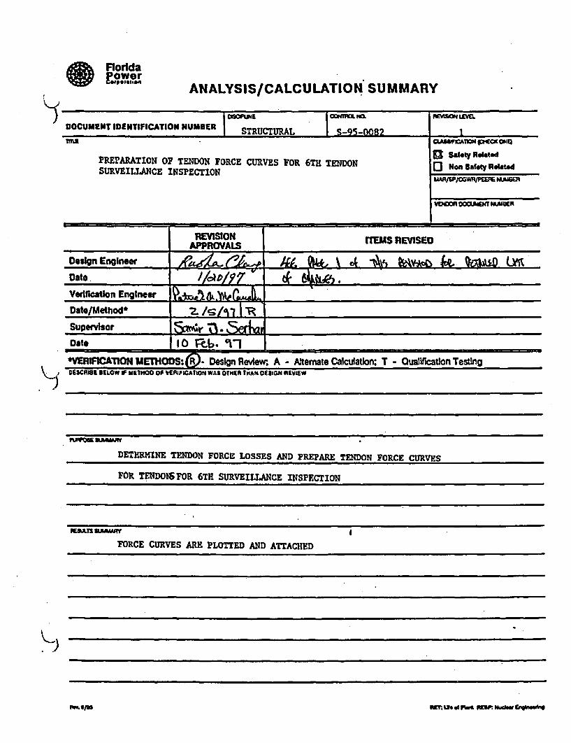
Af FloddaPowa,,erli.~e o n tw
ANALYSIS/CALCULATION SUMMARY
K ,
1 - "--DOCUMENT IDENTIFICATION NUMBER STRUCTURAL -0821
PREPARATION OF TENDON FORCE CURVES FOR 6TH TENDON Ro no Safety RamSURVEILLANCE INSPECTION
VD9=l 0O0AiEMT "UUUR
REVISION rTEMS REVISEDAPPROVALS
.Design Engineer 444 ".. k A ftýLDate./ /IXDAply7 0Verification Engineer _ __-____._ _ _ __ _ __ _
Date/Method'* /5/61 ..... .
Supervisor &4________"a_____________________
Dat* 10 W1-. 1-1'VERIFICATION METHODS:,0. Design Review. A - Alterate Calculation: T - Oualiflcatlon Testing06CARIUI BELOW iF METHOO OF VERIFICATION WAS OTHER 1THAN DEIMON REVIEW
DETERMINE TENDON FORCE LOSSES AND PREPARE TENDON FORCE CURVES
FOR TENDOMIFOR 6TH SURVEILLANCE INSPECTION
REALTS SEIMARf
FORCE CURVES ARE PLOTTED AND ATTACHED
Swaim ~~-.W IjM of~ . P~md VNSP. NSw &tiiln

PARSON5 POWER GROUP INC.,, 4:3.Vna'on c Gbe-tCornmon.-.,a , ano PPlrSon3, Main
,-.:.v' '.J,,ntod' -R0a' •eao.n9 P- I'C7-* .•610;6 35-2000 • FRA. 16101855.2001
February 11, 1997
FCS-14171Contract N00821AD, WA048
Mr. W. W. NisulaContract ManagerFlorida Power Corporation (NAIB)15760 West Power Line StreetCrystal River, FL 34428-6708
Attention: Mr. J. L ese Re: Crystal River Unit 36th Tendon Surveillance Force CurveCalculation
Dear Mr. Nisula:
Please find attached calculation S-95-0082 Revision 1, which documents the generation of the
tendon torce curves io accounumudtc 0he prt)ptI,•ed inspection date of early March 1997.
Included are disks with related electronic files used in the preparation of the data and force curves.
Should there be any questions please feel free to contact Dr. Samir Serhan at (610) 855-3209.
Very truly yours,
Samir J. Serhan, Ph.D., P.E.Supervising Engineer
Roy W. Adler
RWAISISIbmb Project Manager
Attachment
cc: W. W. Nisula (NAIB)D. L Jopling (NA IE)MIJ. A. Lese (NAIE) Dc'R. E. VaughnFPC Records Management (CL Only)R. W. Adler(2)P. 1. HamiltontoS. 3. Serh:m
• PARSONS

FloridaPowercORPpOIAT ION
INTEROFFICE CORRESPONDENCENuclear Engineering
OfficNAIE 240-3568
MAC Telephone
SMET.•E• Crystal River Unit 3Quality Document Transmittal - AnalysislCalculation
To: Records Management - NR2A
)
The following analysis/calculslon package Is submitted as the QA Record copy:?pc f DONAEMT MEWME N REVn0 I SYID0 ThGMaa TPASO
S-95-0082 0 MX 383
6th Tendon Surveillance - Generation of Tendon Force Curves
itDB WC1PY iMW•qWOR LAME RIMMEVAL)
Tendon SurveillanceIP Fu OR PUS -USTMOAWFY FU 'Fl
V"Di IVENDOR "AMPE VE"hI~w WEIEO DOGMEHIS0X3 F
FRC (from Parlons Power) N/A NIA
TAG
PART NO.
COMMOr3 OpBAW IEMUC11ONS, 0#V(JPt,0R. FE1C4*
Force Curves for 6th Tendon Surveuillance
NOTE:Use Tag number only for valid tag numbers (i.e., RCV-8, SWV-34, DCH-99), otherwise; use Part number field(i.e., CSC14599. AC1459). If more space is required, write "See Attachmento andAIist_9i9 8arat0,4 sheet.
Mamr .-. ,.r.e .W.%,r..,,r .r ... n.wH.~.Im~MW-L
W& -ýF9ý0 dA 9411-i;ik4
cumA Office (Nf MAR Related) 13Yoe M NoMgr. NucL Cotdig. Mgt.Mgr., NucL Eng. Design
(Odginal) w/atach
Plant Document Updates Required 13 Yea 01 No Vf Ye eend coPy of theCalculation Review Iofm to Nuclear Licensing and a copy-of the Calculation tot, Flespon~le Orgw(o •a diFd in hP N an toe CaleLudon PAwfw lim)AE DYes I1No
(If yes. Transmlt w/ntach)
CALCULATION REVIEWPage I of 2
c~aw NWV.
S-95-082IRevlsion 10
PART I - DESIGN ASSUMPInON/INPUTREVIEW
The following organizations have reviewed and concur with the design assumptions and inputsidcntfied for this calculation:
Nuclear Plant Technical Support System ,Engr
Nuclear Plant Operations w -m
Ono"mm
PART II - RESULTS REVIEW
The following organizations have reviewed and concur with the results of this calculation andunderstand the actions which the organizations must take to implement the results.
Nuclear Plant Technical Support System 2 /A,Engr
Nuclear Plant Operations
Nuclear Plant Maintenanceo1 yes IK] NIA
Nuclear i.ccnscd Operator Training
1 yes [i] N/A
Manager, Site Nuclear Services
1o Yes [K N/A
St. Radiation Protection Engineer
o Yes KJ N/AOTHERS:
II-
s-IA. 0/A
*flftIinDIA*
g)p.aus~Oaa.
S~gft~
K;-d
m,..i WEE Lie of fmt FKM *Jgaiku CROM90"tn

CALCULATION REVIEWC A GPage 2 of 2
S-950082/Revlslon #0
PART M - CONFIGURATIONCONTROL
The following is a list of Nuclear Engineering and Plant procedures/lesson planslother documentswhich require updating based on calculation results review:
Document Date Rguired Resmzonsible Orianization
SP-182 3/1/98 Nuclear Engineering Design
(A. Petrowsky)
)
)
)
Upon amplction, forward a apy to the Manager. Nuclear UeCeiug for traking of ations ifany items areIdMutified In Par UL
PART IV - PLANTREVIEWSIAPPROVALS FOR FIELDSEMPOINT CHANCE
PRC review Is required If a full IOCF-R0.59 Safety Evaluation is performed. DNPO approval is required if asetpoint is to be physically changed In the plant.
PRC Review Required 0 Yes F] NoaPRO n i
DNPO Review Required Yes NoDNPO /Dot*
9E A-I aDate
• RET: w.h d Piwd swl• Nldain Enahlmi• 'a

Agralk
EloddsLo=
ANALYSIS/CALCULATION SUMMARY
)
- E--- ICOK° m --isI --.oa,. Y 1•o o -a 0
_ _ 4 4 _ _ 6 1M ~WM Mm__ _ _ _ _ _ _ _ _ _ _ _ _
~dg E~guM£ M L 1J77 ffm MOM
v.if.t .fu,.e~z51 .•
VErFATION IE•TI10(•'( Ign "w• w A • Mismate Culculson; T - Quawflatton T*stnoCEM WW *V IiEn=O0F V ErAflnMWA5V1)R W4 OEGNWVW
(~UL~t A4A l'hej AA, Af~ari 7 /a4-kimAun~ -A4d A&PAe.n,
&&.fdPM.r7~Aq C!*.CJLJ477hd 6fAL b2"-Afet -90=6MCe~ .'o
c ..... Awte-/g.. .... 777 fO LW.4...
K)
i!raw. 8/0 N~Mt 5xv of mom "am- hufto choob"

K,)
= rDESIGN ANALYSIS/CALCULATION* "£'a°e't"" Crystal River Unit 3
Page 1
S-95"O82
Revision No.: 3 This page followed by page 1AThe followino items have been revised in the current revision:
Revised Affected Add Replace I Remove Description/Purpose of RevisionPae Secti ons _____ _____I............ ______________________
1 X add "Revision Description Sheet" for revision 3change page number on revision 2 "Revision
1A x Description Sheet" from page 1 to page JA and statethat "page 19 follows"change page number on revision 1 "Revision
18 Description Sheet" from page JA to page 18 andstate that "page IC follows"
change page number of Table of Contents from pageiC X 18 to page IC and add item for Revision 3
_ ____ _ Descri ption Sheetchange data Input tile names to correspond to
11 X- current names (i.e. DOMER3.XLW. etc) and add notechange data input file name to correspond to
20 X current name (DOKR3.XLO), add data for Tendons_____Dill. 0D302, 0306 and state that "page 20A follows"
20A-208 X add spreadsheet and curve for Tendon Dill49 x state that "page 49A follows"
49A-498 X add spreadsheet and curve for Tendon. D302S5 x state that "page SSA follows"
5SA-SSB X add spreadsheet and curve for Tendon 0306change data input file name to correspond to
63-64 X current name (HOOPER3.XLW) and add data for Tendons42H29. 42130, 42M34 thru 42H37, SIH28, 52129,62H39, 62H43 and 62H444
70 x state that "page 70A follows"70A-700 add spreadsheets and curves for Tendons 42HZ9 and
42H3076 X state that "page 76A follows"
76A-76H X add spreadsheets and curves for Tendons 42H34 thru42N37
94 x state that "page 94A follows"
94A-94D X add spreadsheets and curves for Tendons 51H28 and5129
112 X state that 'page 112A follows"1IZA-112B X add spreadsheet and curve for Tendon 62H39
118 X state that "page 118A follows"118A-218D X add spreadsheets and curves for Tendons 621H43 and
62H44159 X Include "Original Stresses data" for Tendons D111,
D302 and D306 and change data Input file name tocorrespond to current name (DOMER3.XLW)
160 x include "Original Stresses data" for Tendons 42HZ9.42830, 42H34 thru 42H37. SH28, S2H29. 62H39. 62H43and 62H44 and change data input file name tocorrespond to current name (It0OPER3.XL)
894-BlI0 X add Tendon History Sheets for Tendons Dli, D302,D306, 421129o 4ZH30. 42H34 thru 42H37, S1H28, 52129,
....... 6 62H39, 621143 and 621144K2 X change data Input names to correspond to current
names (i.e. OOWER3.XLW, etc...) and add note
REVISION TYPE: 0 Superseded by Calculation Number(check one) b runI Revision 0 Page for Page
K'
8126 AIM":U e" d ' msr. M W Inghewe

Power~ DESIGN ANALYSIS/CALCULATIONCrystal River Unit 3•5ACJ•e•JIw
Page 1A/1 S-95-082 -
3 - 1 - ,. - IRevision No.: 2 This page followed by page 16The following Items have been revised in the current revision:Revised Affected Add Replace Remove Descriptloa/purpose of RevisionPage Sections _ ! !ix
add "Revision Description Sheet' for revision 2. .change
page number on revision 1I Revislonx Description Sheet" from page I to page 1A and statethat :Roe Is fallows" "I Change Page number of Table -of-Cont~ents from page18 x IA to page 1I and add item for Revision 2I, _ _ __ SDoscrition Sheet. .. Change start date fro• Spring 1997 to Fall 19973!
x change start aate from Spring 1997 t; Fall 1997change reference to Enclosure 30.to 3usz state9 x 'Original Stressing Data"
- -change. Start date froa March 1997 to November 199710 Xand change numerical values to correspond to___I November 1997change data Input file names to correspond to11, x current OaWs (i.e. OO'ER2.XLW. etc...)revise the discussion about the interpolationsX between data on the spreadsheets
0 x" -change data inpuC file name to correspond to_ current name C(OcERZ.XL.021 X revise spreadsheet for November 1997 start daterevise soreadsheetsand curves for November 199723-61 x start date
64 X change data input file name to correspond to-_ - current name (OPERp.2.xu•)I revise spreadsheets and Curves for Novetmbr 1997G5-124 X start date
1z6 x change data Input file name to correspond tocurrent nare _VERTRZ.Xt.Orevise spreadsheets and curves for N~ovember 1997127-156 X start dateI -change reference'to Enclosur'e 30 to 3ust state151 x 'Original Stressing Data" and Enclosure 29 to just
_ .. _. .... stato *data sheets"-ichange reference to Enclosure 30-lea 3ust state159-161
"Original Stressing Data" and change data Inputfile names to correspond to current names (i.e.-- _DER2.XLW, etc...)
change reference to Enclosure 30 to just statex62 x 'Original Stressing Data" and Enclosure 29 to just!_state 'data sheets"- .'
•~Change data Input file names to correspond tox Current names (i.e. OCERZ.XLW. etc...)
REVISION TYPE:(check one)
o Superseded by Calculation Number
o Full Revision 0 Page for Page445"'S sriOn. Ulf of s P I5P 194-0 5, ."~
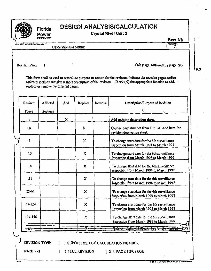
Florida DESIGN ANALYSISICALCULATIONPower Crystal River Unit 3,t On CoM Page J.%
Calculation S-95-0082 3
A3Revision No.: I This page followed by page IC
This fbrm shall be used to mcord &.a purpose or reason for the revision. indicata the rcvision pages and/oraff'ectd sections and give' a short description of the ravision. Check (X) the appropriate function to add.re-placc or remove the affc.tc-d pages.
Revised Affected Add Replace Remove Description/Purpose of Rcvision
Pages Sections -
1 X Add revision description sheet.
LA x Change pane number from t to LA. Add item forrevision description sheet.
3 X To ch.nge start date for the 6th surveillaceinspection from March 1993 to March 1997
10 X To change start date for the 6th surveillance-... inspection from March 1993 to March 1997
Is X To change start date for the 6th surveillance.... _ _ _inspcction from March 1993 to March 1997
21 X To change start date for the 6ft surveillanceinspection from March 1993 to March 1997
23-61 X To change start date for the 6th surveillance___ _ _ Iinspection from Mvarch 1993 to March 1997
6 To change start date for the 6th surveillance....... insp.',-cuon ,ftrom March 1998 to M a tch 1997 ,
127-136 To chang e start date for the 6 th surveillan ce
inspection from Miarch 1993 to March 1997 A
- - 4 -". :" 1
I )REVISION TYPE:
I check ow•|
I I SUPEUSEDED BY CALCULATION NUMBER
I I FULL REVISION I X I PAGE FOR PAGE
a a? . eq 0 ixAM wtsp, r - a"

=
I
K
aDOCLuMEM IDEN7
9E(
)
Florida DESIGN ANALYSISICALCULATIONPower Crystal River Unit 3CO8PORAION Page IC
fUIC.1ION NO. R~ISOKNCalculation S-95-0082 3
CTION TITLE
CALCULATION COVER SHEET
REVISION #3 DESCRIPTION SHEET 1
REVISION #2 DESCRIPTION SHEET IA
REVISION #1 DESCRIPTION SHEET lB
TABLE OF CONTENTS IC R3
1.0 PURPOSE 3
2.0 DESIGN INPUT 3
3.0 COMPUTER CODES 4
4.0 ASSUMPTIONS 4
5.0 SCOPE AND TENDON SELECTION 4
6.0 CALCULATIONS 9
6.1 GENERAL BACKGROUND & SCHEDULE 9
6.2 FORCE CURVE GENERATION PROCEDURE 11
6.2.1 PREPARATION OF INPUT DATA 11
6.2.2 PROCEDURE FOR DETERMINATION OF TENDON LOSSES 11
6.3 DOME TENDONS 19
TENDONS LISTING & DATA INPUT TABULATION 20
INDIVIDUAL TENDON LOSSES WORKSHEET & CURVES 21
6.4 HOOP TENDONS 62
TENDONS LISTING & DATA INPUT TABULATION 63
INDIVIDUAL TENDON LOSSES WORKSHEETS & CURVES 64
6.5 VERTICAL TENDONS 125
TENDONS LISTING & DATA INPUT TABULATION 126
INDIVIDUAL TENDON LOSSES WORKSHEETS & CURVES 127
6.6 CALCULATIONS SUPPORTING SP-182 157
RET: uLe o Plant R93P. N. Almlr Emgln"mat

Aft Florida DESIGN ANALYSISICALCULATIONPower Crystal River Unit 3
Page 2
Calculation S-95-0082 o
5ECTION7.0
8.0
9.0
A.B.
C.
D.
E.
F.
G.
H.
1.J.
K.
TITLECONCLUSIONS
REFERENCES
ATTACHMENTS
DESIGN INPUT FOR 6TH SURVEILLANCE
TENDON DATA HISTORY SHEETS
FOR 6TH SURVEILLANCE
TENDON STRESSING SEQUENCES
EFFECTIVE WIRE SUMMARIES
AND TENDON WIRE DATA
ELASTIC SHORTENING REFERENCES DATA
WIRE STRESS RELAXATION REFERENCE DATA
CONCRETE CREEP REFERENCE DATA.
CONCRETE SHRINKAGE REFERENCE DATA
NORMALIZING FACTOR REFERENCE DATA
HOOP GROUP PLOT OF TENDONS
ELECTRONIC FILES INFORMATION & DISKETTES
162
162 to 163
At TO AIS
BI TO B92
CI TO C24
DI TO DI0
El TO E9
FI TO F8
GI TO GI4
HI TO H8
It TO 123
Ji TO Js
EI TO K2
K~j
)
)I
WfT: Lt d NF% RZ2. 0bclew Ef£ieuqg
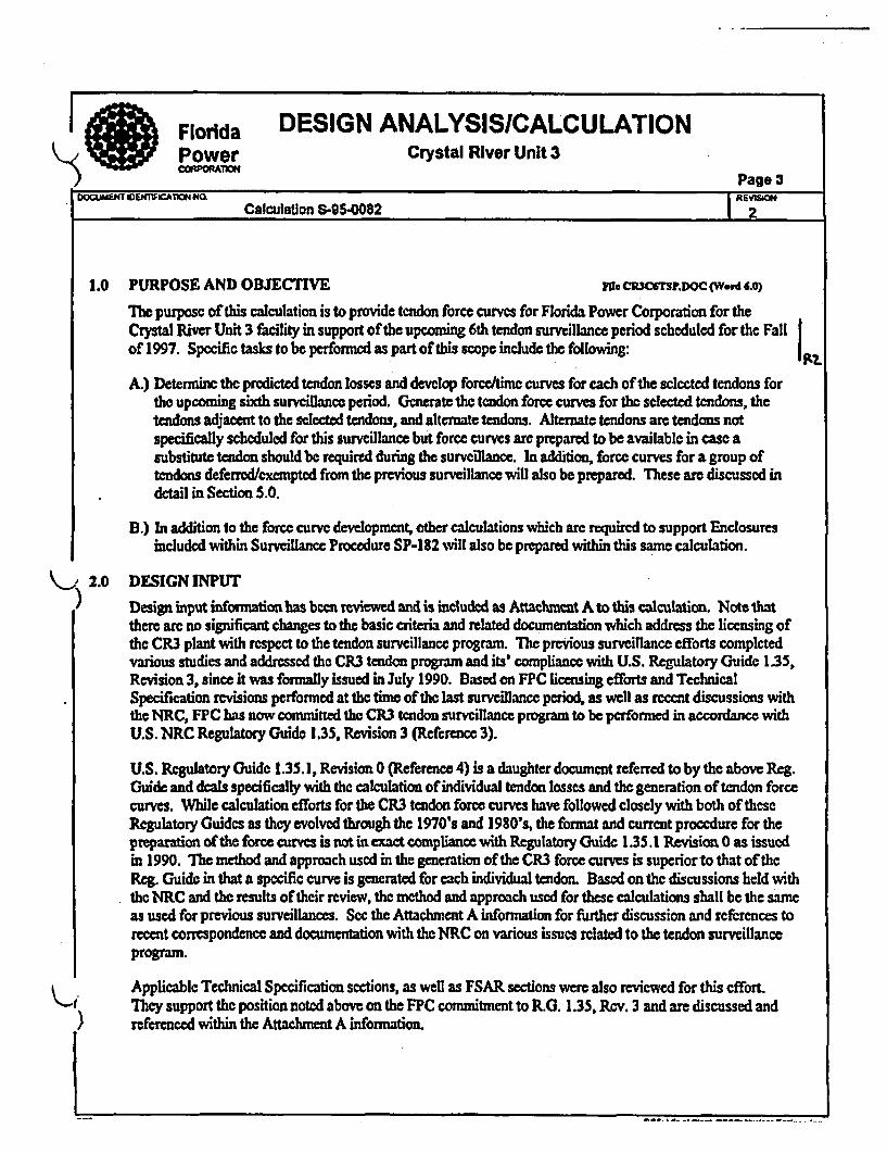
SFlorida DESIGN ANALYSISICALCULATIONPower Crystal River Unit 3DcdVM1A ~Page
3Calculation 8-95-0082 2
1.0 PURPOSE AND OBJECTIVE Me CR3CsP.DOC (Word 4.0)
Th1 purpose of this calculation is to provide tendon force curves for Florida Power Corporation for theCrystal River Unit 3 facility in support of the upcoming 6th tendon surveillance period scheduled for the Fallof 1997. Specific tasks to be performed as part of this scope include the following:
A.) Determine the predicted tendon losses and develop forcedime curves for each of the selected tendons forthe upcoming sixth surveillance period. Generate the tendon force curves for the selected tendons, thetendons adjacent to the selected tendons, and alternate tendons. Alternate tendons are tendons notspecifically scheduled for this surveillance but force curves are prepared to be available in case asubstitute tendon should be required during the surveillance. In addition, force curves for a group oftendons deferred/exempted from the previous surveillance will also be prepared. These are discussed indetail in Section 5.0.
B.) In addition to the force curve development, other calculations which are required to support Enclosuresincluded within Surveillance Procedure SP-182 will also be prepared within this same calculation.
2.0 DESIGN INPUT
Design input information has been reviewed and is included as Attachmnct A to this calculation. Note thatthere arc no significant changes to the basic criteria and related documentation which address the licensing ofthe CR3 plant with respect to the tendon surveillance program. The previous surveillance efforts completedvarious studies and addressed the CR3 tendon program and its' compliance with U.S. Regulatory Guide 1.35,Revision 3, since it was formally issued in July 1990. Based on FPC licensing efforts and TechnicalSpecification revisions performed at the time of the last surveillance period, as well as recent discussions withthe NRC, FPC has now committed the CR3 tendon surveillance program to be performed in accordance withU.S. NRC Regulatory Guide 1.35, Revision 3 (Reference 3).
U.S. Regulatory Guide 1.35.1, Revision 0 (Reference 4) is a daughter document referred to by the above Reg.Guide and deals specifically with the calculation of individual tendon losses and the generation of tendon forcecurves. While calculation efforts for the CR3 tendon force curves have followed closely with both of theseRegulatory Guides as they evolved through the 1970's and 1980's, the format and current procedure for thepreparation of the force curoes is not in exact compiance with Regulatory Guide 1.35.1 Revision 0 as issuedin 1990. The method and approach used in the generation of the CR3 force curves is superior to that of theReg. Guide in that a specific curve is generated for each individual tendon. Based on the discussions held withthe NRC and the results of their review, the method and approach used for these calculations shall be the sameas used for previous surveillances. Sec the Attachment A information for further discussion and references torecent correspondence and documentation with the NRC on various issues related to the tendon surveillanceprogram.
Applicable Technical Specification sections, as well as FSAR sections were also reviewed for this cffort.They support the position noted above on the FPC commitment to R.G. 1.35, Rev. 3 and are discussed and
) referenced within the Attachment A information.
I

Florida DESIGN ANALYSISICALCULATIONPower Crystal River Unit 3CORPOMAO Page 4
Calculation S-95-0082 7
3.0 COMPUTER CODES
This calculation package is being prepared using Microsoft Word, Version 6.0 and Microsoft Excel, Version5.0. Spreadsheets from earlier surveillance efforts were prepared using Lotus 123, Release'2.01 and 3.0 andwere convened to Excel format for this calculation. All input and calculations are manually checked andverified, therefbrc, verification of computer programs is not applicable or necessary. I
4.0 ASSUMPTIONS
Any assumptions made arc noted and contained within the calculation package. None requi e futureconfirmaton.
5.0 SCOPE AND TENDON SELECTION
Tendons were selected for the sixth surveillance period in accordance with the requirements of Reg. Guide135, Revision 3 and using the same methodology as was used in the past surveillance. Basically. a randombut representative sample was selected and checked at the site for accessibility. Specific citeria used for thisselection process is summarized as follows:
Tendon Selection Process
The tendon selection process has remained the same as that completed for the last several surveillances wherea random but representative sample is selected for inspection and testing. The intent is to get as many new andnever tested tendons in the sample population, but still keeping one control tendon from each major tendongroup to be investigated in each surveillance. Note that this current method differs from methods used duringthe early life of the plant where some tendons were repeated for inspection every third surveillance. Basically,the selection criteria and process used considers the following:
1.) Select tendons based n Reg. Guide 1.35 Revision 3Based on the good reults of prior surveillances, the Reg. Guide requires a minimum of I I tendons to beinspected, including 5 hoop, 3 vertical and 3 dome. Tendons should be selected which were neverpreviously inspected or tested. Previously detensioned and retensioned tendons should not be included(unless there is a specific need to investigate the tendon per item 3 below). In addition to being selected atrandom, tendon selection should be representative of various areas and conditions. For example, the hooptendons selection was based on random selection but also considered what tendons were inspected in thepast and in what hoop area. A plot of previously inspected hoop tendons was prepared to track tendonsinspected by grouping (i.e. 13's, 42's, 35's, 46"s. 5 1's, and 62's). Therefore, the selection processconsidered those sections not equally represented by as many tendons as completed within other sectionsfrom prior surveillances. See Attachment J for various plots and information of the hoqp group. Thesame procedure was applied to the dome group (i.e. 100's, 200's & 300's groups) and to the verticalgroup (i.e. 12's, 23's, 34's, 45's, 56's & 61's & quadrants). See Attachment D for groups information.
METI . Uk d P RE up:, Ndoat Emgn~M

Florida DESIGN ANALYSISICALCULATIONPower Crystal River Unit 3COAPORAICP
o__ __ _ _ _ _ _ _ _ _Page65
)
U)
4
Calculation S-9S-0082
2.) Maintain Control Tendons to be completed each surv.llance.The Reg. Guide also requires a control tendon from each group to be inspected erfy survcillane forcomparative purposes. CR3 W not had control tendons since the first surveillance. The concept wasintroduced probably in the fourth surveillance. Tendons D212, 12VI and 5 1H26 were probably theoriginal control tendons since about the time of the fourth surveillance. They were intended to beinspected during the fifth survllance but the group of tendons selected was based on the surveillancebeing performed during an outage. FPC decided to complete the Sth sunrvillance during normal plantoperation and the original tendons selected wcre affected because many tendons were located within thearea of the plant steam vent zone. This included the above three control tendons, and three new controltendons, D215, 34V6 and 46H29 were selected for completion of that surveillance. A problem with46H29 during the 5th surveillance forced the selection of another control tendon, 46112 1, for the hoopgroup. New control tendons may need to be selected periodically if the tendon has a problem and is everdetensioned and/or retensioned. As earlier surveillances on CR3 did repeat some tendons, the selection ofthese other control tendons was easily done from several good candidates. New control tendons should beselected from those previously inspected as far back as possible and cannot be one previously detensionedand/or retensioned. A tendon inspected in more than one prior surveillance is preferred.Based on the above, it is recommended that both of the above two sets of control tendons be used by FPCas control tendons, with one set of three to be utilized in the 6th surveillance during a plant outage, and forthe other three to be used in any future inspections scheduled to be performed on-line.
3.) Consider any tendons with problems or abnormal conditions as reported by plant personnel.Any leaking tendons or tendons with any reported problems should be considered within the scope of thesurveillance. Also, past inspection reports and records should be checked for open items,recommndations, or noted problem tendons.
4.) In the selection of tendons for detcsioning, (one per group is required per R.G.) consider the number ofeffective wires as recorded in the tendon history sheets and summarized in the effective wire summary inAttachment D to thi calculation. As any tendon is to be considered ineffective if it has less than 155effective wires per the FSAR, it is therfore not ddesirable to select a tendon with many missing, cut orineffective wires. Unless there was a specific need to detension that particular tendon, doing so couldtherefore render the entire tendon as out of service. Only a maximum of 3 tendons are allowed out ofservice at one time per criteria in the FSAR.
5.) The reduced force dome tendons are not normal candidates for normal liftoff testing per SP-i 82,Enclosure 8.
6.) Tendons adjacent to the selected tendon may require testing and should also be feasible to inspect and test.Adjacent tendons in the dome should not include any reduced force dome tendons. Jump to the nextregular dome tendon for the required adjacent tendon. Also, adjacent tendons of the lowest hoop tendons(#I) shall be considered as the two'diretly above the selected tendon. Adjacent tendons of the highesthoop tendons (#47) shall be considered as the two directly below the selected tendon.
7.) One alternate tendon should bc selected from each group, and the two adjacent tendons of these alteratesat least considered for possible inclusion.
WE: Lft P0' R" W o mawp NO~ gbiLate

I • Florida DESIGN ANALYSISICALCULATIONk) Power Crystal River Unit 3
-c oricI. Page 6
Calculation S-95-0082
In addition to the above selection criteria, there arc several other factors which have influenced the schedulingof actual field inspection and testing. These include:
A.) Steam Vent Zone -Plant steam venting can impose a safety hazard to personnel during plant operation and early modes ofshutdown. Tendon work in the range between 0 and 120 degrees is affected during plant operation by thepotential steam venting of the plant. Tendon work in this area must be held off until the potential hazardis eliminated or other approval is obtained fiom plant operations. Note that for the fifth surveillance perFPC operations, this even includes the outside tendon caps of the affected butresses at 0 and at 120degrees.
B.) Fuel Pool Area -Work over the fuel pool can only be performed while missile shields are in place. (Nureg 0612 reqint.)
C.) Plant Interior Work -Work inside some plant areas is difficult due to access problems, high radiation areas, interferences, ramaccessibility, etc.
Deferred/Exempted Tendons
After the tendons were selected for the fifth surveillance for an outage surveillance, it was decided that the 5thsurvcillance would be completed during normal plant operation. A group of tendons originally selected forinspection during that surveillance had to be exempted f(rm that surveillance due to their proximity to themain steam vent zone and the associated hazards with woffing in that area. FPC discussed this issue with theNRC and has documented the following 8 tendons as deferred tendons:
W•, Lth d Rant Rer.Ma.Nclow eq 0

ylorida DESIGN ANALYSISICALCULATION
Power Crystal River Unit 3
Page 7..C.lI. 0RIE.V9•..8 NO.
Calculation S-95-0082 rouI
D1 15 Never inspected in any surveillance.
D212 Inspected in Surveillance 3 and 4.Considered as Control Tendon for outage condition.
D3 11 Never inspected in any surveiance.
12VI Previously included for liiftoff testing in the 3rd and 4th surveillances.Considered as Control Tendon for outage condition.
42H44Never inspected in any surve illnce.
511126 Previously included for liftoff testing in the 3rd and 4th surveillances.Considered as Control Tendon for outage condition.
53H46 Never inspected in any surveillance.
621146 Never inspected in any surveillance.
K-I-J
As FPC has mnmittod to t"e NRC to addrcss the above tundon within the upcoming 6th surveliancc thesetendons were considered in the scope of this calculation. The 6th surveillance is scheduled to be completedduring an outage. Since three of the above exempted tendons were also previous control tendons, it wasonidered ta thee tendons can again be used as control tendons for this surveillance instead of the 3 control
tendons used in last surveillance (when the surveilance was done on-line). Therefore, the three exemptedcontrol tendons can be considered as three of the 11 tendons required per Reg. Guide. A total of 16 tendonsshould be inspected during the surveillance with three additional alternates selected. Note however that thescope of this calculation will include force curves to be regenerated for the other control tendons, D215, 34V6and 46-21.
A complete historical record of all tendons included in all prior surveillances, along with the list of selectedadjacent, exempted and alternate tendons which are planned for in the 6th surveillance is provided on thefollowing Table.
)
{8 ET. Life of PW*i ft6P. MA* Enpame"

3LML.14NCZ, PO lT SXU"VERI 3W31RM, =wLA*•m 3 o L 4TM ..U.LM= S ETISUQA= qmxE*TJ. o
33,MM1TP"m Y 2'1TOS1 $OWN1 MW03143" Imunioianiu inmo um* PALL19 34?"kP3I flT7T 3'ifl TO*11111 IIt OIT * l/O I177 l,• OIJN. .. Sr
SI'I'wV76 IvZAR YEARS MARS IIYEARS 7Y..AERS . YIEARS . SUOAyDATA
RInEQV3TO Davd0 21 TOT-101t VO 23T.101.M V.SD 21 "wr.IwcWV.so II 0741U.LIVO I I OT-..VPr . i t TOT-=.."" . ns WT7m. Y.2.11AiAZ.L*INSPECTED 2$ 1TOl'T.IV0irVD Z3104TV*IUrSD 21 iT*ri01UW.s I IITOT-54UV.J.• 1lT410,..D * *Da P T IOT.4I3K[.220
3? BASIS Sp-*13.P4"IP-63 S-2 M1-83 sP*Ill TOTAL- 16
81P*Sfl.31.4454 PJlY- PLEYG RErV? PSISIl II •
cc Rzm DATE 3.27.10 a 4IO v" 5'11r2, vim 4 0
Dcm12TOtu DiI3n Din2 D123 Dios V DI$M P.C 0212 I.Z 22. , 3 TENDONSIDQTAL D225 0140 i215 R W212 PLC 0231 9 * 0204 D . I•sucrm
SGR.OWSSOF41 v2ni D 4 D =212 2 !2 A , O1is * TODATE .nIDiImDM. D2iS 2 .21 0'22 P , D .PI
1340 V.031 A .
lW~tEAL2TPv9 W19 M2V2 l~vo lUvi I.e 1414S P.C * uvo P.CX *2VET.MMONS
144 TOTAL 12V20 2120 f R SV t v4 EI$ D , IV2311 DD • PEC0 GRNMIPF 24 t"V 2m 14V19 V Ii D sm* D ,1 232 , TODATh12.34.545. 413 2MI 3m1 4s136 .62116 A
441' MV4, Ml .
3P0AWNTAL1r, D,*100 131110 12 1 1Mat a 3110 *11to14 P.CIw M as5K1097mm20 TOTAL )I1.i9 131031 0 131444 1M140 D M1*41 Mae 1b]s1 m6(,OROM04110•30 1.3113)? MW*1 423 s11136 9 ea09 c2iwI) . law T* ODATUI,33344. 4, 13111 911110 423144 53313 Ga1in ADL.1 , 421144 E$TENDNS PE11 R I 5313311n sl1msI 51112 4Mt 4m E .IDw L 6203 2
64i0 5111131 51311 d41100 AML , 014I 040w1 ISW?' 53105 4al1 D . I42,6 E .
481137 D 5314" 42134 =12 ATOTALTDOS a So4 4d34s 411142 44n10 D... S .... *.... ,,.,=.- . •=.=.=... .. ... * ,.a .-. -- , .. n .. n.=., , .. .._ .. a.... 8 .. U• *n...
7UTALDtS*gCTW 23 22 21 I1 14 . 16IALT. , T10AL4
1.30214- &.ALTERNATE ADL.ADhACENT ac. C%7RTE A DEEN1014ToV a METNaIONIML. EXE&Gq730PJ!Rzm r10*42M1 Sill. R. RMPATWD 1.31704234v
_______ NJ
9p-
!
C,
Ce.90)
S.5
C.9
U
'a
0m
I-I-

a
I Florida DESIGN ANALYSISICALCULATIONPower Crystal River Unit 3
Page 9
Calculatlon S-95-0082I 2
6.0 CALCULATIONS
6.1 Gcncral Background and Schcdulc Information
General Background
Tendon forces curves are to be prepared for the upcoming 6th tendon surveillance period at CR3. From thebasic criteria as presented in the Design Input Section, as well as from several discussions with Mr. Joe Loseof Florida Power & Light, it was determined that the criteria for this surveillance period has not changed sincethe last surveillance efforts. A review of Tech Spec and FSAR criteria confirms the FPC positions withrespect to the tendon program. Supporting work for this surveillance period will be based on the same criteriathat was used and accepted in the previous surveillance periods.
Tendon losses have been calculated in the past per the Rcfcrcm= 8, 9, 10 and I Idocumcntation. Individualtendon losses include the following.
" Force loss due to elastic shortening of the containment as a result of the prestressing process and theparticular sequence of tendon stressing.
" Force loss due to the stress relaxation of the tendon wires." Loss of prestress force due to the creep characteristics of the concrete structure." Loss of prestress force due to the shrinkage of the concrete structure.
Based on some earlier calculations made for tendon losses per the Reference 1 document, Lotus spread sheettemplates were prepared for tendon losses calculations for the 4th tendon surveillance calculations. SeeReferences 9 & 10. These templates were reran and tested for their accuracy and validity for the fifthsurveillance. In addition, the procedure for the gatering of all input data was automated in the fifthsurveillance to the format presented herein. Numerous test cases were ran to duplicate forcm curves preparedin the past There were four master templates prepared for the fourth surveillance; one for the hoop tendons,one for the vertical tendons, and two for the dome tendons. The dome tendons are divided into two groups;one for tendons with an original stressing sequence below 27, and the other for tendons with stressingsequences above 27.
Based on the work previously accomplished in the prior surveillances, new spreadsheets were prepared thissurveillance using Microsoft Excel for the collection of input data and for the calculation of tendon lossesncedcd for generation of force curves. The generation of the force curves was also automated this surveillanceby using Excel to plot the graphs. The organization of most data used for this calculation was setup intoExcel workbooks with subfiles built and included in each workbook. There is a separate workbook for eachof the three tendon groups and each one contains the following:
# Tabulated input data• Original tendon stressing sequences.• Eff•ctive wire summaries.
) "Original Stressing Data" calculations for SP-182.e Separate fils including each tendon loss spreadshect, plot data and an individual force curve. IgAdditional information on electronic file names etc. used in this calculation is provided in Attachment K.

r
IK
AFlorida DESIGN ANALYSISICALCULATIONPower Crystal River Unit 3) CCAPui1oH .. ,Page 10
DOLUN W• nToN NO. RE~•IQNCalculation S-95-0082 2
Schedule Information
The expected timing for the sixth surveillance is Fall 1997. A date of Novembcr 1, 1997 will be used as abases for determining the predicted values of base, 95% base and 90% base and labeling this information onthe force curves. This allows for ficld usC and decisions to be made based on the requircmcnts of SurveillanceProcedure, SP-182.
The scales of the force curves are based upon previous surveillance efforts. Thc x axis is a log scale in timerepresenting the time after average date of dome or wall concrete placement, in years. This scale is labeled atthe top of each curve. Force curves are plotted using the actual log scale points for the x axis (not thescheduled surveillance years after SrI) versus the calculated tendon forces in ldps on the y axis. The scale atthe bottom of the curve for scheduled surveillance periods afte SIT are for ease and readability relative torcgular scheduled surveillances per Reg. Guide 1.35, Revision 3.
Most of the CR3 surveillances were performed on the regularly scheduled years, however, the 5th surveillancewas actually performed in the 17th year after SIT. Note that the containment Structural Integrity Test (SIT)was performed in November 1976.
For the domc tndons force curves, the point on the bottom scale at SIT corresponds to the log sce at the topof 2.5 years. Therefore, a corresponding log scale data point must be determined for curve plotting for theperiod of the 6th surveillance.
Based on a date of November 1, 1997 for the Fall 1997 surveillance, the length of time between November
1976 (@ SIT) and November 1, 1997 is 21 years. Since the dome group at SIT is at year 2.5 on the logscale, thc 6th surveillance will correspond to (21.0 + 2.5) or 23.5 years on the log scale. LThe same procedure must be performed for the hoop and vertical groups as they have different referencepoints on the log scale for time after concrete wall placement. Both hoop and vcrtical groups are the samewith SIT corresponding to year 4.4 on the log scale. Therefore, the 6th surveillance period will correspond to(21.0+ 4.4) or 25.4 years on the log scale.1 l2
A vertical line will be shown on the force curves at the point of the next surveillance and the calculated valuesof base, 95% base and 90% base representing points on the curves at that time will be included on each of thecurves.
RETZ. WeW Plan RESP: Mkacem Eagveaw

AR& Florida DESIGN ANALYSISICALCULATIONPower Crystal River Unit 3DO W
Page 11
Calculation S-95-0082 3
6.2 General Procedure for Force Curve Generation
The same procedure within the calculation for the preparation of the force curves for the fourth and fifthsurveillance periods will be followed.
6.2.1 Preparation of Data Input Spreadsheets
In each of the Excel workbooks is a data input file where data from source calculations and current tendonhistory sheets has been tabulated. See DOMER3.XLW (DOMEINP), HOOPR3.XLW (HOOPINP) &VERTR2.XLW (VERTInP).
The compiled books of tendon surveillance historical information, as updated to include the results of the fifthsurveillance, provide key input data for the development of force curves. See References 12, 13 & 14. Theselected tendon history sheets related to this surveillance have been included herein as Attachment B of thiscalculation. The Reflrce 11 calculation is essentially a source calculation for this procedure with theRcfcrence 8 & 10 calculations also providing information.
Notes and refcrences related to the tabulation of the data on these spreadsheets arc shown on the individual~sheet. Ile data input tabulations ame presented as the first sheet within the following Secdons 6.3, 6.4 & 6.5.
6.2.2 Procedure for Determination of ndividual Tendon Losses
The procedure for the tendon loss calculations, as derived from the reference documentation, is as follows:
1.) Calculate original force in the tendons
The original force in the tendons is detcrmined as follows:
rActual~lfiqff Pressure1ORIG.FORCE = 0.7 *Pressure x WireFactor
Pr edictedLfloff Pressej
Where:fa - 240 Ksi, typical for all CR3 wires.
Wire area = 0.07685 in2 per Appendix F of the Rcfcrcnec I I calculation.
Fk (Kip Force)= Tendon Area (in2) x f&, (Ksi) - 0.05985 * 240
Tendon Area (in2) = Arca/Wire (in2) x No. of Wires. (Considered by wire factor.)
Actual and predicted original liftoff prcssures are obtained from Tendon History Sheets References 12, 13,Kj 14, with those within the scope of this calculation attached in Attachment B.
Refer to the Appendix F part of the Reference I I calculation, for source data of above formula. The aboveexpression was used as the basis for the calculations for all the shop and field end forces calculated on theData Input Spreadsheets. This procedure does not apply to rctensioned tendons.
IiTr Lac. e PlUW AEeSP NM.M Enok •

I, Florida DESIGN ANALYSISICALCULATIONPower Crystal River Unit 3
CMPMTMPage 12
Calculation S-95-0082
Note that the wire factor as shown in the various spreadsheets is a value representing the tabulated number ofeffective wires over a total of 163. The number of wires is usually 163 uniless cut, loose or consideredineffective. The number of effective wires as recorded from the original installation is documented on thetendon history shoets. The number of effective wires for each tendon has been updated, tabulated andpresented in the Effective Wires Summary for each individual group within Attachment D. This tabulationwas updated to include the results of all previous surveillances. It does not imply each of the tendons wasspecifically checked for the numbers of effective wires as presented in the table. It reprmsents only data fromthe original records and as made available from survcillance records and subsequent Inspections. -
Note that the wire factor used is based on current information and is not based on the number of wires at thetime of original installation, therefore the original Force calculated may not be the "original force" in thetendon back at that time. The effet of less eflfctve wires lowers the curve vrtically. This is insignificant atthe current time as the curve of interest will be cos c for use at this time. Another method would have beento plot the original value using the wire factor then and then to show a step down on the curve should a lowerwire factor occur at some point later on the graph.
2.) Calculate Elastic Shortening Losses
The elastic shortening losses are a function of th stressing scquence number for the individual tendon. Inaddition, the tendon wire factors an also considered and used. The base expression used to calculate theseforces is the same as used in previous calmlations and is already built into the basic spreadsheet templates.All the equations for elastic shortening were confrmed as being the same as established in prior calculations.Based on the review of the procedure for calculating these losses, it is concluded that the existing templatesare still appropriate and omect with the additional input of stressing sequence data and wire factors to beinput for the current group of tendons for this surveillance.
Refcrence 10 & Reference i I data and informatiom on elastic shortening was inchided in Attachment E tothese calculations. See Attachmet C for original stressing sequences for all tendons and see the Data InputWorkshet•s & Attachment D information for tendon fwir factors and source data.
Elastic Shortening Losses for Dome Tendons
Note there are two expressions used for elastic shortening for the dome tendons depending on the stresssequence numbers. For dome tendons in sequences I through 27, the Domelow template is used. For dometendons in sequences 28 through 32, the Domehigh template Is to be used. This is because of the two separateexpressions used for the calculation.
Elastic Shortening Losses-For Dome Tendons in Sequences I through 27-
N - 27 Total Sequencesn - Sequence of particular tendon.
M~ f lPM utRES PJNucbwem~

K)*FFlrid~a DESIGN ANALYSISICALCULATION
Power Crystal River Unit 3C RMAoM
Page 13
Calculation 8-95.0082
Force Loss due to elastic shortening - Fa.
A, N-n x 827 + 75] x reFaddr
Elastic Shortening Losses.For Dome Tendons in Sequences 28 through 32-
N ,5 S (Sequences 28 through 32)n - Sequence m-nber less 27
i.e. for sequence 28, n - Ifor sequence 29, n - 2for sequence 30. n , 3for sequence 31, n - 4for sequence 32, n - 5
Fie$=[Lj,-- x 47A4- 13.7] x c e~co
The value for elastic shortening in kips declines as the stressing sequence increases. A review of the data forthe dome group shows that values for the dome group go from 154.6 kips for sequence I tendons down to 75kips for sequence 27 tendons, and furtie going down to -13.7 kips for the last sequence, sequence 32. Notethat wire factor differences between individual tendons will cause the calculated result to vary slightly for twotendons within the same stressing sequence.
Elastic Shortening Losses for Hoop Tendons-
N -60 Total Sequencesn - Sequence of particular tendon.
Force Loss due to elastic shortening -
Fles = nx 134.0] fieaco
A review of the data for the hoop tendon group shows that the range ofvalues for the calculated elasticshortening go frion 127.3 kips for sequence 3 tendons down to 0 kips for the last tendon sequence, sequence60.
*91 RE1.U.wP~,i RESP~ Ie.acba, Emgmawuwrnoft

Florida DESIGN ANALYSISICALCULATIONPower Crystal River Unit 3oo fn RP•oR Page 14
Calculation S-95-0082
Elastic Shortening Losses for Vertical Tendons -
N -3 Total Sequencesn - Sequence of particular tendon.
Force Lois due to elastic shortening -
F =sn x 73.5] x fracr
A review of the data for the vertical tendon group shows that the range of values calculated for elasticshortening go from 71.1 kips for sequence I tendons down to 4.7 kips for sequence 29 tendons. There are atotal of 31 stressing sequences for the vertical tendons.
3.) Calculate Wire Stress Relaxation Losses
Wire strcss relaxation losses and the procedure for the determination of thes losses for the 4th and 5th)surveillances are addressed In the Reference 10 and I 1 calculations. The original wire relaxation curve, asprovided by test data from the wire vendor forms the bases for wire relaxation loss values (See also FSARFigure 5-23). It was determined that tie same procedures and figures as calculated in those prior calculationsare still applicable for this surveillance. Applicable data fioro the reference sources was attached andincluded within this calculation as Attachmntd F.
Note that there were adjustments made to the original stress relaxatio values from the vendor relaxationcurve to allow for some conservatism and for temperature consideration of 100 degrees vs. 68 degrees F.Also, per the original design the wire factor or actual number of effective wires was considered as negligiblefor these losses and was not included. Note that values for stress relaxation nmgc between 40 and 50 kips forthe surveillance period for all three tendon groups.
4.) Calculate Creep Losses
Concrete creep calculations in the Rcfcrence I I document are attached in Attachment G. The losses are basedon the curve contained in the reference calculation. Creep values are different for each of the three groups oftendons. For the dome tendons in the coming surveillance period, creep values are the same and are about 152to 158 kips, hoop values are between 79 and 83 kips, verticals are 36 to 38 kips.
5.) Calculate Shrinkage Losses
Attachnmnt H contains source infonnation for concrete shrinkage from Reference 10, pg. I I and Reference11, cover page & Pages 13 & 14. The straight line shrinkage losses in micro inches per inch as calculated inthe above two references are still applicable for this surveillance period. Tabulated values from thesereferenccs were input into the dome, hoop and vertical spreadsheets. There are no additional variables orconsiderations and the samc values are to be used for this calculation. From a review of the outputinformation, the dome values are constant at 8 to 9 kips, hoop values are above 5 kips, vcrticals are alsoslightly above 5 kips.
MET. LI. Pft RESP. MA~ce E-hpow.N

Florida DESIGN ANALYSISICALCULATIONy ePower Crystal River Unit 3COM10 . Page 15
/ OC~lrI•.~fnN1FAI~ ft #~o Aro 1 t
Calculation S-95-0082
6.) Total Losses
Calculated force losses for elastic shortening, wire stress relaxatiom, creep and shrinkage are added for a totalof all losses. Also, a percent of this total of all losses is calculated based on the original average force in thetendon.
7.) Determin Predicted Forces for Base, 95% Base and 90% Base values
The original force less the total of losses calculated yields the base predicted value for the subject period ofsurveillance inspection. The 95% and 90% values are then calculated based on the calculated predicted basevalue.
8.) Normalizaion Factors
Normalization factors arm calculated based on the expressions and the source article contained in Attachment Iof this calculation. This fhctor usually does not change much over the forty year time span of the calculation.The base expression for the dome normalization factor value is presented as follows:
) (A -B) x(-C)+(D-97.7)
Where:
A - Averag of all Domes groupB - Original average tendon forceC = Wire Stress laxation PercentagD - Elastic Shortening
As an example, Dome tendon D 112 calculates as follows:
NanmaozahlonFoator = (1639 - 1676) x (I - 0.0257) + (D - 97.7) or
-- = (-3 7) x (0.9743)+(-1•1.9) or
NF - -138 which matches the spreadsheet calculation.
Similar expressions arc shown for the hoop and vertical tendons in the information in Attachment I.
.)

Florida DESIGN ANALYSISICALCULATIONPower Crystal River Unit 3
.,oo.T4" Page 16
Calculation S-95-0082 x
9.) Plotting of Data
Only the data from Column B, L, M, & N are tabulated on a separate area on the side of ft spread•hect. SeeColumns R, S, T & U; Rows 40 through 50. Only these values arc selected for plotting on the force curves.This is for ease of plotting and has no affl o the quality or accuracy of the plots. An example copy of thisdata immediately follows the first dome tendon.
The plots of all dome curves with all the data points showed the force curve plot line as slightly crooked froma true linear plot. The large scale used showed some inflection points slightly off of linear. Afterinvestigation, the condition was avoided by omitting data points at year 10 and 15 after SIT for the finalplotted figures. UTis was done only for presentation purposes and there is no affect on the accuracy of theplot or the base values calculated and presented on each cune.
A column by column explanation ofthe losses calculation worksheet follows:
LIA6 ft". eof PMI tESI' N. vif Engoakip

Florida DESIGN ANALYSISICALCULATIONPower Crystal River Unit 3€oomfo.M IPage 17
7 WkMTWCAWMO NO- mo
Calculation r-95-0082
INDIVIDUALTENDON LOSSESLOSSES CALCULATION WORKSHEET
NOTES AND LEGEND
Individual tendon losses arc calculated based on the procedure presented in the preceding section. Thefollowing notes explain the spreadsheet process, input and calculations performed for each of the columnspresented. The shaded values on the losses worksheet are extracted from the data input worksheet.
Column Racdilign
A. Inspection Period after SITScale based on years after SIT which is shown on the bottom scale of each individual plot. Noie thatthis information is provided for easier readability with respect to SIT but is not the actual log scaleused to construct the x axis of the plots.
B. Years after Concrete PlacementScale of years after concrete placement as used for the x axis for plotting of the force curves andshown as the upper log scale at the top of each plot.. Note that one year after SIT for the dometendon is 3.5 years on the log scale and for the hoop and vertical tendons is 5.4 years. See Section6.1 of this calculation for further information.
C. Elastic ShorteningCalculated based on formulas presented in Section 6.22 and Attachment E information.
D. Stress Relaxation PercentCalculated based on original wire loss curve percentages modified per the information presented inAttachrent F of this calculation.
F. Stress Relaxation ForcesData input from the Reference I 1 calculation page 12. See Attachment F.
F. Creep StranStrain value (x 0.000 IData input from the Reference 11 calculation. See Attachment G of thiscalculation for data.
G. Creep Strain ForceData input from the Reference 1 calculation. See Attachment G ofths calculation for data.
H. Shrinkage ValuesData input from the Reference II calculation based on the shrinkage curve. See Attachment 1H of thiscalculation for data.
1. Shrinkage ForceData input from the Reference 1 calculation. See Attachment H of this calculation for data.
|Peru% of Pam "Sr. toidw Eho~We

I
SFlorida DESIGN ANALYSISICALCULATIONPower Crystal River Unit 3CORPORATlON Page 18
MEWJIIf t, EWW.CA7"ON NO. REV'SW
Calculation S-95-0082 2
3. Total Force LossCalculated valuc, Sum of columns C, E, G& 1.
K Total Percent LossTotal loss in percentage, Column I / Average of original forces for shop & field ends calculated andshown above on the spreadsheet.
L. BaseThe average original force for the tendon noted above on the sprcadsheet, less the total lossescalculated in Column J. Note that total losses were not calculated on the row for the 17 year period,the 21 year 3 month period, as well as the 21 year period after SIT. Thcse rows represent the fifth,the originally planned sixth and thc current sixth surveillance periods and the values of Base werederived through linear interpolation of above and below data presented on the spreadsheet. Thequality and accuracy is not affected by this procedure.
M. 95% Base0.95 x Column L for the same row.
N. 90% Base0.90 x Column L for the same row.
0. Normalization Factor -Calculated based on formula presented in this calculation and in the information presented inAttachment .
IqE L~ IRE ru NUW~ 7WCIW ~IIgWWWW~MWP &ft 40 Phwd RM3P-. MCWW Engm"ma

Florida DESIGN ANALYSISICALCULATIONPower Crystal River Unit 3
,l[Tmm~l Jt usqPage 158
Calculation S-95,M82 ... ý
Column H & I Calculated force values in Kips which represent ram pressure @ 1500 psi. These forcesrepresent a zero slac starting point for both shop and field ends of each tendon andprovide a basis for the cat of any retensloning effort. The following expression is used tocalculate these values:
0.7 * Tendon Ultimate Strength ' 1500 1 Predicted Lift-Off Pressure at 0.7 TendonUltimate Strenrgh. See Reference 10 Calculation, page 34.
Column J & K Calculated force values in Kips which represent forces at 80% ultimate based on thefollowing expression:
(Actual prssure @ 80% ultimate strength (Columns F or () * 0.7 Tendon UltimateStrength) / Predicted pressure @ 70% Ultimate Strength.
Column L & M Actual elongation data, repeated from columns B and C.
In addition, the following calculations support the ultimate strength values provided on these spreadsheets:
Tendon winr ultimate strength- Ca for wire - 240 ksi
) Tendon Ultimat Strength - F, - [fa for wire 0 Tendon wire area] =- 240 ksi (0.05985 * 63 wires) "2341.3 Kips
0.7 * JRh - 0.7 '2341.3 = 1638.9 Kips0.8 * F,h 0.8 02341.3 - 1873 Kips
)

. , LORIDA POWER CORPORATION - c•YSTAL RIVER UNIT 3MUi 1 REACIOR BUILDING PR•STRESSING SYSTEM
IN ST 6th TENDON SURVEILIANCE
CALCILATIONS SUPPOINDOG SP-182 O'RIMALS, SS'HO DATA FOR THE DOME TENDONS GROUP
DOC 1T:S-95-0082RMiSION 3PAGE M9
0.7 Tendon Ultimate Strength -0.9 Tendon Uilmae Sfrenot .
File DOME3.X.LWAduzi d Ift-Of 30% UAad= Fow 51-182 So%1 Sruu DIa"_Dta
Tada M-updm oin.) PIM j PfuMzu4d) Raw I (Kip0 Raw 2 (K~ps) Raw)3 ML.)
-C () () 1-- -- W- m~l) UL (KDili 3 S 6810 6810 7780 7780 361 361 1272 1872 3 30D112 4-3/4 5 6810 644 777 779 3so 359 1873 1367 4-3/4 SD113 dt-7/8 4-3/4 68033 Q140 7m7 7790 3a3 39 1,973 1867 4-7/5 4-314D114 3-111 4-/8 S IM 6440 7770 790 362 3J9 187) 1867 5-118 4-3/31)15 A S 6840 6800 7790 1 7770 359 362 1867 8873 SM16 4-3/4 J-1/ 6760 60 77M "7 364 343 3672 1s" 43
D1o S , 6870 I 681o 7810 7780 38 361 is" 187 5 3
D131 4-1/2 4-7/1 6110 6740 7660 77M 366 365 1871 t87n 4-1/2 4-7/8Din. 4-14 4-7/8 67M0 680 77m 375 3H4 362 187 1808 4-1/2 4-7/3D21 610 68701012 4-54 4-7/8 6770 6770 7730 70 363 363 1871 1 4531 4-7/183233 4-.V4 4-3V4 &M4 "W0 7790 7770 33 349 J867 1873 4-3/4 4-3040214 4-3/4 4-718 6670 4740 700 7610 369 36 Is" 186 4414 47/8
0213 44 S-413 68CO 6870 788 7810 361 358 138 1863 44312 5-1/11D216 S 5 68M "8 70 7M 361 1373 3373 3 3
D=0 3-38 $47/3 6530 65:0 7450 1430 376 1 373 1870 1871 3-5/8 r3-7/8D303 44 1-3/4 6760 6770 77o 7730 364 363 17 1371 4-1/ 3-3/4
.D304 44-/1 4 440 4600 o 790 77 359 362 1967 183 4-1/8 4
I1j
1 R3dr,
.4 D" .4-311 1 4-3116 1 67"0 1 "M8 763 1 71620 1 M? 36 I 1967 I IM 4-3/a I 4"316
D30 3 4-1/4 6770 6m3 718 7730 361 363 1873 3872 4-/ 4-1/4V311 431/116 4-5/8 6800 6840 777 7790 362 359 1373 1867 4-11f16 4-5/5
770 6770I -7/3-, • 4840I 6880 77190 7770I 339.S 3.,,1 I 86 3873 47/5 •,,l 4-7
3 the wwm ~dlkall mxnyletd t la dll mdcl uipe 11 u•a m#t s0plusdla. .Ih4aI smallauom and bCdlwma A SmuO M.
283J6-4M3:54 PM

kY.J FLORIDA POWER CORPORATION - CRYSTAL RIVER UNIT 3REACTOR BUILDING PRESTRESSING SYSTEM6th TENDON SURVEILLANCE
CALCULATION SUPPORIG SP-182 "OIUGINAL STRMSSING DATAO FOR THK nOOP TIEDONS GaOUP
0.7 Tendon UImate Surngth -O.S Tendon Ulbinne Strengdt -
DOC 30:S-95-062REVISION 3PAGE 160
r'. KlpsWeHOOPP.XLW
Aclual P- eded litM-Off 8051 Noimre 1et SP-182 =Orligfd &r now$ DataTendon 1louglom Ou. J4. presu rp) Press0r ( Raow I (Kips) IRw 2 (iops) Rowi (In.)4 - ao Fid - Rp il I -ap P- So I _ Fil Sbp Fed Mp bd
M3 4-8 6871) 6810 7(i 7780 33 361 1263 i-5/ 4-5/8
42HI34s8 33/8 68410 6799 7810 7750 359 362 3873 1868 3 5-3/8421119 534 5 67 680 7810 71 5 6 53 17 ./
421129 5112 5-1/ 6870 6810 7810 77s0 35 361 186 1872 5-1/2 5-1/842H30 4-7/8 5-3/4 1 680 6790 7810 7750 358 363 1563 1871 4.71 $-3/4
421131 5-1/4 4-7J3 1 6170 6810 7310 7730 358 363 1363 1872 $-114 4-7/842H432 S ' 518 16 70 7111 770"tO o 87 -/ -/42H32 5-1/4 3 6870 6790 7810 77 353 362 1863 1373 3.1)44121433 slu/t 5-1/4 6370 6830 7810 7780 3538 361 3863 1373 5.3/8 5-1/442H34 5.1/ $Iva 675 6660 7680 7600 344 369 15w 38m 5-1/2 5-3/8421135 5 5-1/4 130 6770 17760 7720 360 363 3362 3869 -421136 5.14 5-1/3 6170 6790 7610 7750 358 362 1863 3673 5-L1 3/m
421137 5-3116 4.7/3 6870 6130o 7310 7780 358 361 1363 13872 5-s/36 4.74842H43 5-1/2 "/a 4870 6110 7810 7730 358 361 186 1373 "12 5-1/8421144 5T111 5 6790 6140 750 7M 362 359 1871 3367 5.1/8 5
421143 3-7/16 3 670 "40 7810 7780 358 361 1863 1372 3-7/16 5
461120 114 5314 6640 6600 7700 7630 370 373 1901 1890 3-1/4 3-1146I1)2 3-118 5-1/4 6720 6730 7700 7640 366 365 3873 1361 5-1/3 5-1/4-1 -- --o
46H=f 5.5/8 a-1/4 6720D 6730 7700 7640 366 365 5873 1861 5-5/3 5-1/4511S2m S 5-1/8 677 69 7720 7750 363 362 1369 1368 1 3 5.18331426 5-1/2 5-114 6760 4760 7750 7700 364 364 I179 1867 3-M/ 54/14531H27 3-1/3 4-718 6740 6670 7630 7600 365 369 Is"8 1368 5.3/3 4-7/851H231 5.1/3 5 6760 6750 7750 77W0 364 364 1879 1870 "IN 551129 31In 4-3/4 6810 6750 7780 7700 361 364 872 1370 5-1/2 4-3/4
533111 5-3/4 3-118 6700 6760 7650 772 367 364 2871 13872 5-3/4 3-1/853112 "-34 4-M/ 6800 777 7760 7720 362 316 5170 3628 5-3/4 4-5/8
531143 5.3/8 4-3/ 6670 6710 7400 7770 369 3462 1368 3373 53-/8 4-1/833143A 4-714 1-5/4 1 6740 68030 77590 7770 359 362 586 587) 5-5/4 5-3t&
5 3 214,173 5-3/ 3 -/ 6670 67130 7600 7660 369 36 3 1868 1 86747/ 5-3/34-/
531447 4-3/4 5.3/ 1 6340 6800 779 7770 359 362 1367 1873 4-3J4 5.312421121 5-34 4-314 6760 6700 7720 7650 364 367 1372 1873 5-1/3 4-3/4
62152 3-5/16 11 6800 6750 7773) 7700 362 364 3873 3870 "-5/6 S62H423 53-Ail 5-3/4 680 6750 7770) 77W1 362 34 1373 387 5.3/S 3-1/462139 5-7/16 5-114 6800 6750 7770 7700 361 36 3873 1370 5-7/36 5-3/4
621,140 5-3/8 4-718 6100 6750 7770 770 362 364 3873 3870 5-3/3 4-7/84231143 5-34 5 6m 6750 70 77 362 364 3873 1870 5-3/4 562M142 3-3/9 51116 6800 4750 77 770 362 1 364 1373 170 5-318 5-3116
421,14) 5-3/8 4-7/8 6710 6670 7660 7600 366 369 1871 3868 5.3/3 4-7/86=44 5.12 4-7/8 6800 670 7770 7700 362 3" 1873 1870 5-1/2 1 -7/8
621145 53316 5.118 6760 6700 77M0 364 367 1884 5-3/16 311621146 5-3/8 5-319 6800 7770 77W 362 364 1873 2570 5-1/3 5.318
2,1147 5"/s 4-3/2 6680 6640 7620 7550 368 370 1870 3864 1-. 1/2
I m
I p,,
1K
193
IR.
bo. -sgcuw sO w~dppt w dw3wd~ti&ayaiumd~~~ uh28-Janr983:24 PM
)

*.,jFLORIDA POWER CORPORATION - CRYSTMAL RIVER UNIT 3REACTOR BUILDING PRESTRESSING SYSrEM
-.- 6th TENDON SURVEILLANCE
DtI)1S 95•0a2
PEVI 2PAGE3 161
CALCULATIONS SUPPORTING SP-182 "ORIGINAL STRESSING DATA* FOR THE VERTICAL TENDONS GROUP I ?,'0.7 Tendon Ultimate Strength P32KYps0.8 Tcndon Ultimate Strength IL83"Kips
File: VERTR2.NLWActual Predicted Llft-Of 80% Uhimate For SP-182 "Original Streuing Data"
Tendon Elongation (in.) Pressure (p) IPresme Row 1 (Kips Row 2 (Kips) Row 3 (In.)
I ,5top F ikeT, IShop Fid Jip Field I ~- so Field ShpFedhp il
23V24 12-7/8 H 6870 NIA 71T WA 38 WA 1563 N/A 12-7118 IVA12Vl 12-1/2 NIA 60 NIA 70 NA 362 N/A 1873 N/A 12-1/2 NIA
12V2 12-312 NIA 6800 N/A 777 NIA 362 NIA 13 NIA 12-1/2 N/A23VI 12-1/4 N/A 6800 NA 7770 NA 362 NA 1873 N/A 12-114 N/A23V2 13-1/9 NA 6870 NIA 1710 N/A 353 N/A 1863 N/A 13-1/3 N/A23V3 13 N/A 67W N/A 7750 NfA 364 N/A 1179 N/A 13 WA34V5 12-5/8 N/A 6800 N/A 7770 NWA 362 NIA 1873 N/A 12-S/8 N/A34V6 13 NIA 6810 N/A 7730 H/A 361 N/A 1872 N/A 13 N/A
34V7 12-3/4 NA 6970 NIA 7510 N/A 358 NIA 1863 N/A 12-3/4 N/A
61V9 12-5116 N/A 6860 N/A 7840 N/A 355 N/A 1873 N/A 12-3/16 N/A61VIO 12-3/4 N/A 6870 N/A 7810 N/A 358 N/A 1863 N/A 12-3/4 NIA61 VII 12-5/8 NIA 6710 N/A 7660 N/A 366 NIA 1871 N/A 12-S/S N/A61 V20 12-3/2 N/A 6870 N/A 7410 N/A 358 N/A 1863 N/A 12-1/2 NIAOIiV21 12-I/8 N/A 6810 N/A 7810 N/A 358 W/A 1863 N/A 12-1/8 NIA61V22 12-7/S1 N/A 0870 N/A 7810 NIA 358 N/A 3863 N/A 12-7/8 N/A
6 - -
9?-
U
Columns A ltrough G ire data Input extracted from ite tendon history books (applicable shes contained In Attachment B).
Columns H through M are calculated using she expressions noted below.
Column Tendons withn the scope oflls survellabnce.Co.l&C Actual elongation dam taken horn tendon histry sheem for shop and field ends respectively.
For the verical tendons, only fth shop cnd applies.Col.D&E Predicted Liftoff Pressures taken from tendon history sheets for shop and field ends respectively.
Col.r&O sOS Uldmam pressures taken from tendon history sheem for shop and fld ends respectIvely.CoI.H&1 Columns H & I - Calculated force values in Kips for "Original Stressing Daa' Row I which epresent ram pressure @ 1500 psi.
These forces represent a zero slack starting point for both shop mnd field ends of each tendon and provide a basis for retensloning effors.
The following expression is used to calculate the values for Row I data:0.7 * Tendon Uldtmate Strength 0 1500 I Predicted Lift off Plete at 0.7 esudon Ultimate Strength.
le. for23V24: 1639* 130016870 - 358
ColJ&K Calculated force values in Kips for Original S "ess Dam" Row 2 data which rprsem forces at 80% Ultimate based on the foUowing expression: IActual pressure @ $0% Ultimate Stregth (Cols. F or G) * 0.7 Ultimate Strength I Predicted pressure 4 70% UIL. from Cols. D or E.ie. for 23V24: 7810 " 1639167M - 1863I
Col.L& Actual eloatiin values repeated from Columns B & C for Row 3 of Original Stressing Data'.
12-Sep.979:49 AM

Florida DESIGN ANALYSISICALCULATIONPower Crystal River Unit 3COSUoRA Page 162
Calculation S-95-0082 2
7.0 CONCLUSIONS
Tendon Forcedfne Curves have been gcnerated from the results of this calculation. Final force curvesarc presented and attached in Section 6.0 of this calculation.
Force curves for the three control tendons were also generated by this calculation and were used forcomparison and verification of data and spread shects with the same curves generated previously for thesame tendons. The comparison was completed and the data sheets and force curves were found to be thesame as that previously gcncratcd.Other calculations supporting the "Original Stressing Data" and "Data Sheets" in SP-1 82 were completed I
and arc presentcd in Section 6.6 of this calculation.I
8.0 REFERENCES
The following references are used in the preparation of this calculation:
1. G/C Lettcrto FPC, FCS-14594, Scope Document, Novcmbcr 24, 1995, for Preparation of TendonForce Curves for the 6th Surveillance and site trip to CR3.
2. G/C Letter to FPC, FCS-12439, August 13, 1991, Tendon Selection and Recommendations for theFifth Surveillance.
3. Reg. Guide 1.35,Revision3
4. Reg. Guide 1.35.1, Revision 0
5. CR3 FSAR, Section 5.2
6. Technical Specification, Section 3.6.1.6 & Section4.6.1.6.
7. Design Input for the 5th Surveillance, DI-55220-152.0 SE, Revision 2.
8. G/C Calculation of Force curves for the 5th Surveillance for SP-1 82, Revision 11.
9. Design Input 5500-528-1, Revision to SP-182 Procedure for Tendons and Calculations for Force-Tune Curves for Surveillance 4, Revisions 0 and 1, Jan.87 and Sept.87.
10. G/C Calculation 5500-528-1, Tendon Loss Calculations for Surveillance 4, Revisions 0 and 1, Jan.87and Sept.87.
11. G/C Calculation 04-4762-099, Tendon Loss Calculations and Appendices for CR3 Tendons, J.Fultonand G.T.DcMoss, 3/6/87 and 1980 calculations.
12. Dome Tendon History Sheets updated to the 5th surveillance.
13. Hoop Tendon History Sheets updated to the 5th surveillance.
RET. L. CO Pmut R!SP N!3P f EW~ bFeV u

Florida DESIGN ANALYSISICALCULATIONPower Crystal River Unit 3
Page 163bCCVMWb4T'CA1W0 NO.1 REWW4
. ... ± _,~~Calculation ... S-95-0082 _o
14. Vertical Tendon 1-istory Sheets updated to the 5th surveillance.
15. Effective Wure Summary information, letter to FPC
16. Prcscon Vendor Dravwgs
17. SP-182,R zv 11.
IS. Surveillance Report for the Fifth lnspection Period, VSL
19. Engineering Report for the Fifth Tendon Surveillance, GIC Letter to FPC, FCS 14401, 6120/94.
)
~Rft. UJ, dP~ 3 I~A R .uc•. E~knm•g|

4,I)FloridaPower
fORAcm1mOK
DESIGN ANALYSISICALCULATIONCrystal River Unit 3
Page Al
VOGMIM ~~N1IC~fON dO Catcufetion S-95-0082
ATTACHMENT A
DESIGN INPUT DATAFOR 6TH SURVEILLANCE
K-,,
U)
m'. Vie d "am~ RES$: WOWsl &4amnsW

a
DESIGN ANALYSISICALCULATIONCrystal River Unit 3
) .- Page A2"non Na,.E08
I Calculation S-95-=02
Design Input Information for the 6th Surveillance
The Gilbcn/Commonwealth Design Input document prepared for the 5th survillance is still applicable sirne itwas prepartd at the ime FPC adresse new licensing and Tech Spec revisions concerning the CR3 TendonSurvillance Program. The document and some of W's attachments are attacbed herein. Also. correspondencefrm the NRC resulting from It's review of CR3 tendon program issues is attached for reference.
The following Tech Spec sections were rviewed and are applicable to the tendon suroveillance program.
Section 3.6.1.2. Amemdment 149Section 5.6.2.7. Amendment 149
FSAR Sections applicable include.Sections 5.2 & 14.2.2Figures 5-24 and 5-25
N
WI: L4 at Pt" RESP. Modow Engims*'
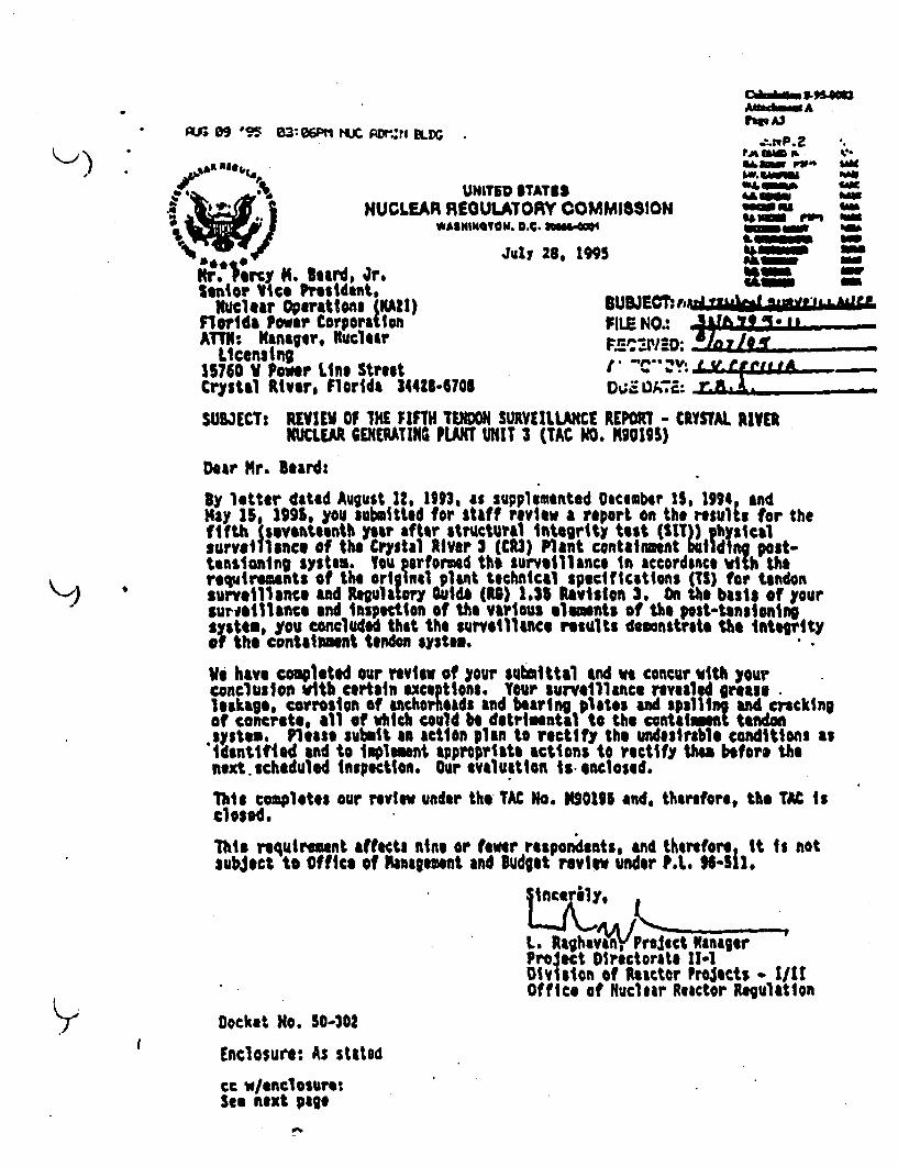
K~)* %U; 09 *095 -3:06Pt1 HLIC ADI VI -R
. N•NUCLEAR REOWILINI14
r. Nery M4. Beard, 4r.ltnior Vice President,
Nucliar Operations (IAZI)Florida Power CorporationATTN:. Kanaptr,, lclear
Licensing15750 V Power Line StreetCrystal River, Florida 344Z8.4708
*ITED ITATISULATORY COMelf a. D.C. "NmOa@4
July 26, 199
POPi A3
*4000ft IAK
IMISSION sno
OUBJECT:.8Jgutdqf~bLAt
FIEN.*1~.L...F2~ C AaED. IL
SUBJECT: REVIEI OF IhE FIFTH TENION SURVEILLANCI REPOXT - CRYSTAL RIVERIUCLEAR GENERATIG PLANT UNIT 3 (TAC NO. K90126)
Dear Mr. Beard:
By letter dated August 12, 1993, as supplemented Deceaber 11, 1991 andMay 15, 1991, you submitted for staff review a report 6n the results for thefifth (seventeenth year after structural Integrity test (SIT) ghysicalsurveillance of the C0stal liver 3 (CR3) Plant cont& inent bulldIng post-tensioning system. Vou performed the surveillance in accordance vith therequireunts of the orl Intl pl&At technical specitfcatlons (tS) for tendonsurveillance and Regulatory auidb (R) 1.35 Revision 3. On the baist of yoursureilllance end inspection of the various alwants of the post tlnlioniftsystem, you .onclWded that the surveillance results demonstrate #*e integrityof the containment tendon system.
We have completed our review of your submittal and we concur Vith yourconclusloi with certain exceptions. Your surveillance revealed great@leakage, corrosion of uichorheaid and bearing plates and ps.1ling aand crckingof concrete, all of which could be detrimental to the containmt terodon
.System$ Please submit in action plan to rectify the umdesirable conditions asidetified and to iplement appropriate actions to rectify thes befor. thenext.scheduled inspection. Our evaluation Is- enclosed.
This completes our review under the TAC No. 020196 and, therefore, the TAC isc1osed,
This requirement effects nine or fewr respondents, andsubject to Office of asntoement and Budget review under
therefore It is notP.A. H-is.
a.Rghavan•,Vreect Namager "ProJect Directorate 11-1Division of Reactor Proests o LittOffice of Nuclear Reactor Regulation
YI
Docket No. 50-302
Enclosure: As stated
cc w/enclosurm:See next page

" 9 90 0310?PI¶ tLJc ArA¶It BLD
Mr. Percy N. leardFlorida Power Corporation
cc:*Nr. Gerold A. VilliaasCorporate CounselFlorida Power Corporation
P.O. tax 1444tSt. Petersburg, ?lorida 33711Mr. truce a. Vlickie DirectorNluclear Pliat Optiraions, (MCIFlorida Imoer Co'orhtIon
Crsa iver Energy, Coolex156 .Pooer Line Street
Crystal River, Florida 34428-6708Mr. Robert 5. loirsumUlf Nuclear Technologies3100 Rockville Pike,, Suits 1225Rockville, Maryland 20852
National Aftiulstrator, Region It
101 Narietts, Stvt N. #I Suits IS04Atlanta,, georia 30)1n
yr. sll pas"attiOffice of Radiation Controlpop~% ~aof Health and
1317 Ulnawood .TallAhuses Florida 32319-07*@Attorney GeneralDeportment of Legal AffairsThe Capitol'Tallahassee, florida, 31304
Anfhmot~ AIsr A4
Crystal liver Unit No,. 3loefirating Plant
Kr. Joe yers Directorcivilian of t roee preparednesssepartasat oC Co nty Affairst749 Centsemve DriveT.3litasssas florifa SS#tMlOG
board of County Comissiouerstitru~s County
110 orth opkaAvenue
Mr. larry C. K~elley, DirectorNuclear Operations Site Support
a~ridIa Power CorporationCrys tal River Dueny Complex
170V Power Line Streetcrystal lisere florida, 34&2t.6Th6Seair Resident losprctir
U.S. Nuc ear latovy comissiowi$741 l l11hassee Road
trystal River, florids 34415Wr. 924r~y Bolatp Vice Prsident -
ftlear Productlou 1S142)florida, Fewer torwratioscrystal River te' EwCo~lex
crystal River, florids 34425-708
K)(.

The Crystal River 3 (C3) plant tehnical specifications (IS) r etmeperforming periodic Utndor surveillance consisting of sheathing fillermaterial inspection, tendon l ift-off force measurement, anchorap compopentinspectiong, ndon wire Inspection and tensile tasting, grease leakage check,and tendon datenslonlng and rtenstioning and resealig for a number ofselected tendons. for the fifth saurvallance In add tion to the threecontrol tendoes (bat for each group), you ranaomly selected tw dome, tovertical and four boopteNc and sub s4Ctd them to lift-offs with onetendo" In each group Ling detensioned and retension•d. You performed thesurveillance In accordance with the requireenta of the original plant 7S fortendon surveillance and Regulatory Guide (Ii) 1.35 Revision S. On the basisof your surveillance and Inspection of the various elements of the post-tensioning systems, yoU cocluded that the surveillance results dombostrute theintegrity of the Coatakimt tendon system.
On the basis of our review of your submittal, ie concur with your conclusionwith certain exteptitns. lour seurveillance revealed grease leakage, corrosionof anthorboads and bearing plates and spelling and cracking of cbncrete, allof which could be detrimental to the contat neont tendon system. Theseconditions are evaluated below.
1. Grease Voids
From the data en grease removed from and groese replaced Into the tendon.hsathings theme appermd to be an untually high amount of freass voids orleSage, aho asount of grease added ramued from 9.5% to as high as 30.4%. In
U letter Watd Septeuber o S11146, us ! dicated that the loss of greaseappears to be nusually high in comparison to other plants with similar
ireatress"d concrete containtente aid post-tensioning syates. Your responseindicated that the losses elosely match rthosn of previous surveillantces & at thorough investti Won had not detemined a toot cause for the abnrmality.Homver, frs the pYSiCal teast of individual tendon wires, the chmical testsof tM grease Itself. and the lift-off tests, the tendon systo is Miateainingits Intigrity. Furthevso I, there has been no gresse leakage observed. .t theout•ide surf$ace of the contaim•ent. On the basis of these observations, y"mreiterated that, Is spite of the abnormally hkgh amunt of grease voids, thestructural Integrity of the tendons has not bean affected.
We find your response 'to be reasonable. However, in view of the detrimentaleffects of potential greass leakage, you should sonitor more closely thegreast injection. procedure in future survillancs tod ptrfom a thorough rootcause investigation fot grease loss.
2. Anchorage Assembly end Tendon Wire
Your surveillance revealed high levels of corrosion on the anchor heads onfive of the tendons (three an. the fitld and and two o4 both ends) uandersurveillance. A pitting condition existed on localted areas of these anchor
) heads, with. no signs of active oxtdaticn er bjldup of crust or rust. No freeSaMoisture wIs obstu•A. within t•e s$Wi. cap, ,f arY t tr,!a. Tbe bulk filler
grease covered all tendon stressing anchor beids except for the top end of one

CMCkA1". 3-93-CMP~ar~~ Ad
vertical tendon. You believe that this condition has existed since originalinstallation. You conclude4 that the observed conditions do not Indicateabrnioal degradation and will riot affect Ithe function Of the anchor heads.
Your surveillance also discovered high levels of corrosion on bearing platesoutside the seed area of the tendot end caps of six tendons (on ones end Ofthree ttndons and ont both ends of another three). The torrosioa ocuttred -exterior to the O-ring seal ad has not progressed to the point of breachingthe Integrity oa te 0-rin and aeffecti o the tendon achorage c.mpoanets.RWpairs were made to the bearing plates to stop further degradation. Theprotection of the anchorage components Is assured and the function andintegrity of the bearing plates Is maintained.
However$ based on our review of tendon surveillance reports of a number ofpliants we find that the types of corrosion of arnhorage components have notbetn observed 14 other facilities and are unique to CR3. therefore; uebelieve that it is necessary for you to expand the inspection to anchorageassemblies, especially the bearing plates, of other tendons not undersurveillance to ensure timely repair of tay adverse conditions.
- You Indicated that the cracking and spalliag of concrete are Insignificant.HoRwver, this requires repair before causing a further deteriorative ofconcrete and eaiforcement. It should also be lsoe aoted that your reportprovided only general stitiftats, regarding moisture content and thedetrimental hemIical contents and does wO, giVldetails of water Content foreach of the grease samples taken from the specific tendons and free waterdiscovered at ed W nchorages and reuse cans. RG 1.35 requires such detailedInformation and should be provided n future surveillance reports.
One wire from each of thO detensioned dam, hoop and vertical tendonswas tested. In addition, Ineffective wires and broken wires were removed forsaple selection and testiol. All of the tested samples exceeded the requiredmtsibmu values for yield strength and elongation. A1 but on# exceeded therequired tintm ultimate strength. -Tht caust for the broken wires wasdetermined to b oft a mecha•ical nature rot dwt to stress corrosion. Thebuttonheads urae inspected for their physical condition and Were found to beeffective and acceptable.
3. Tendon Lift.o-f Forces
We have reviewed the lift-off forces of three dome, three vertical and fivehoop tendons and also the Information on the correlation of force andelongation of the three detentioned and retensioned tendons. With thetxcsptionf of vne hoop tendoo (46M29) which had only 68.1% of the base value(less thin the 90% of the base value as requirsd), the lift-off forces ofother tendons were above the lower bound valuts established for these tandoge.Additional %oop tendons were lifted off to net thu requirements in RG 1.35under such a situation. The forces kvid the Corresponding elongations for the
• three dotensioned sr.d ratonsion!'d tendons wars reviewed, and for each tUndonn 1r ; sto aer.tu y aoflsalmn b Lln hie v it ppoears to us tt|$t more
I
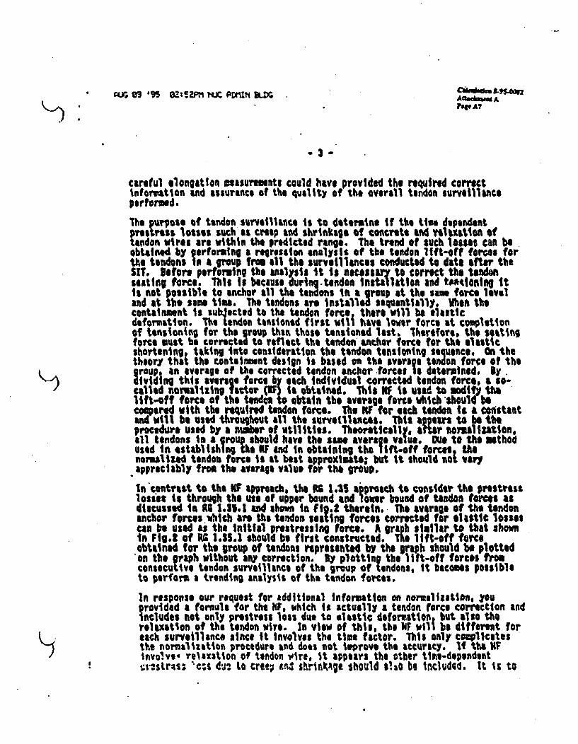
ft4.MM A?
3-3
careful elongation muasuruments could have provided the required correctinformation and assurance of the quality of the overall tendon surveillanceperformed.
The purpose of tendon surveillance is to dteromine If the ties dependenttestross losses such as creep and shrinkage of concrete and eltxltion oftlndon wires are within the predicted range. The trend of such losses can beobtained by ferforming a regression analysis of the tendon lift-off forces forthe tendons l0a group from all the surveillances conducted to date after theSIT. Before perfoming the analysis it is necssary to correct the tenoseating force. This it because during.tendon Inst•llation and tWntionl itIs not possible to anchor all the tendons in a group at the sam force leveland at the same time. The tendons are instaVlx sequentially. Anen thecontainment is subacted to the tendon force there will be elasticdeformation. The'tendon tensioned first wit1 have lowver force at copletionof tensioning for the group than those tensioned list. lhertfore, the settitqforce oust be corrected to reflect the tendon ho, r force for the elasticshortening taking into consideration the tendon tensioning sequence. On thetheory that the containmmnt design is based on the Average tendon force of thegroup, an average of the corrected tendon anchor force* is determined. By.)v iding this average force by each individual corrected tendon force. a so-called nomalizing f I )or lQIFI obtained. Ihis NF is used to modify thelift-off force of the tenm don obtain the average farce Which should becompared with the rq'uired tendon force. The KF for each tendon Is a ca stantand will be used throughout all the survetllances. This appers to be theprocedure used by a niger of utilities. Theoretically, ater mralliZation,all tendons in a group- should have the sam average value. Due to the mothodused In establishingUs KF and In obtainlng the lift-off forces thenormalized tendon force It at best approxtuate but it should not varyappreciably from the average valve 1`r thk 9g;up.
n *contrast to the KF approach, the RS 1.1 tiprsch to consider the prestresslosi: is through the use of upper bound and loaer bound of tandoa forces asdiscussed In AG 1.15.1 and shoum in Fi.2 therein. The mverage Of the endonanchor forces which are the tendon setting forces corrected for 6t1itic lossescan be used as the initial prestressing force. A graph similar to that Shownin Fig.t of PA 1.35.1 should be first constructed. The lift-off tomobftined for the group 0f Utndons represetted by the graph should be plottedon the graph without any correction. By plotting the lift-off forces fromconsecutive tendon surveillance of the group of tendons, It becomes possibleto perfoam a trending analysis of the tendon forces.
In response our request for additional information on normalization, yourovidod a formula for the OF, which Is actually a tendon force correction andecludes not only prestress loss due to elastic deformaton, but also the
relaxation of the tendon wire. In view of thes, the NF will be differet foreach surveillance since It Involves the time factor. This only complicatesthe normalization procedure and does not improve the ascurity. If the hFinvolve- relaxstion of tendon wire, it appears the other time-dependentir-sLr~s: ";s 6^0 to cret; W: .•ri•.•te should s'.io be includGd. It Is to

.LJ e9 S5 ez:s'ft MC PZXI&K BLDG caggkAf A.4
FAS
-4.
be roted that correction Is mide to the setting force only for the elasticloss 0Ich Is not tim dependent and the normalization factor Ahich Is basedon the corrected tondon anchor forcte As used to todify the lift-off force tothe averige tendon force of the group. The NF procedure 11 based on the factthat after correction for elastic shortening loss each of the tendon forcesand the avenrage of these tendoan forces for the group of tendons ire larSeTo#red to the tie-dependent prestress losses. Therefore, the ratio, ei.the 0F, betwen each tendon force and the average tendon force for the groupafter correction for elastic shortening loss will not vary signifileily fromthat after correction for the tmes-dependsrtt lv The U F procedure itbased on this proviso.
in response to our concerns regardig 'bur normalization procedure a sd ne ofthe average of lift-off forces for the trot! analysis, you porf4rmrd analysesfor each of the following cases for each group of tendons:
II Using lift-off averages, normalizedUs no all data points, normalized
3 Using lift-off averages, uocroalized4 using all data points, umormmlied
TMe ifonJtOn f1r each caste was plotted on I graph the sUm Us that shown Infig. I of is l.39.1 and a tgretssion analysis was performed for each caste Ineach group. From the results of these analseat we obiserved Isstlificantdifferences between the nomalized cases (1) a4 (2) or the unnomllzeo cases(5) and (4), and apprecible differences between the nomalized Wd theVtnorMallze4 cases. However, based oan the trend of all groups of tendons, noroup of tendons womld be expected to go below its minimm required during the
a.0rs plant life.
1i spite of the favorable outcome of the results is sumtrlzed above, webelieve that for future surveillances, the lift-off forces should be used forthe trend analysis without averaging and normalization. Each tendon lift-Offforce should be compared with the predetermined values of bats, 955 bste, and501 base as required by R4 1.33.
to tontlosion, we concur with your conclusion that the results of thesurveillance demonstrated the Integrity of the containaent tendon system.Hoever, before the next Surveillance you should resolve the problem ofmissing greaise and should undorta'Me & program of inspection of the anchoragesysteI which consists of the anchor heads and the bWing plates to assuretJath the pitting of the anchor heads and the-corrosion of the bearing platesuncovered in the surveillance are not widespread and would not Jeopardize theIntegrity of the tendon anchorage systa. You should repair the cracJ•ing 4ndspelling of concrete so that there will be no further deterioration ofconcrete or reifforcement. for future surveillances, the trend study.ýaf tha.tender. forces should be based on the lift-off forces witboavt avervint-andnoY I Szllion. In retcnsionir! tendons, the elopgatifis-orroesponddi4 to-.ero-rcez-snugJ.U ca&ul ly-rneasyced so ?1m2rM4,,7h,rII'eWI 01 twohs,Preserved. 'Mia cs'iiserve as iaftaditlonal choe-on the accuracy of themeasurements performed.

(84. ( _NJ (a4
Mr. Percy N. Beard, Jr.,r ziSenior Vice President,
Nuclear Operations (SAA)Florida Paver CorporationATTN: Manager, Nclear
Licenslog15760 V Power Line StreetCrystal River, Florida 34428-6708
SVBIECT: CRYSTAL RIVER NUCLEAA GfIERAIMTG PLANT 1I01T 3 - POSTPONEMENT OFSURVEILLANCE OF E101T TENOIIS EXEMPT0E FROM THE FIFTH TEN1ONSURVEILLANCE (TAC NO. NON)055
Dear Hr. 8erd:
ly letter dated October 23, IS1, rou requested staff approval for postponingsurveillance of eight tendons whic were exempted from the fifth tendonsurveillance performed in 1"3 to the Sixth tendon sureillance. You bad
,) €committed to include the eight tendons In your sixth tewdon surveillance whichwas originally scheduled to be performd in It". You now propose to perform
-the sixth tendon surveillance is 1998 Which Is less thin S ye ars from thefifth tendon surveillance which was performed is Noveber 193. Accordingly,you are requestin staff approval to postpone the surveillance of the eighttendons to the 1?S8 sixth tendon surveillance.
$y letter dated Hay 159 1"5, you submitted results of your fifth tendonsurveillance to demonstrate integrity of the containment Undon system.in a letter dated July 21, 1995, we forwarded our evaluation of the FifthTendon Surveillance Report, and concluded that the trend of all groups oftendons Is such that no group of tendons will go below Its minimam re"uiredlift-off forctes before the 40-year plant life. Our July 28, 115 letter alsoidentified certain undesirable conditions such as greast leakage, ancorasgebearing plate corrosion, cracking and spallinl of concrete. In response tothese concerns, you committed to perform, during Refuel 10 (ti 111), acomplete valkdowm of 549 tendons comprising the containment post-tensioningsystem. You also committed to perform visual Inspection to monitor externalcorrosion, grease leakage, and monitor for spelling of concrete and takeappropriate corrective actions where warranted.
On the basis of the fifth tendon surveillance results and your commitment toperform visual inspection during the Refuel 10, we find It accee table toperform the surveillance of the eight tendons durinolg-nosixinIthenonsurveillance scheduled for Resfuel 11 In 118, which is within the 5 yearsurveillance frequency.
In this matter we also would like to draw your attention to the following.In November 1176, you perforved the structural Integrity test (S1T) on theCrystal River 3 (CR3) prestressed concrete containmnt. Per Regulatory Guide

t"? 27 ,.% 09a:4i t1C ailr* B= Cbkekd.n S-9sPAuerm A
Mr. Percy N. Isard, Jr. - z
(RG) 1.35. the tndon surveillances are to be performed 1, 3. and S yearsafter SIT and every 5 years thereafter. You have comitted to follow the RtG1.35 criteria. owver, a review 6f the history of your tendon surveillanceIsdicates that your 3rd, 4th and Sth tendon surveillances have been performeadon anl Inroxzittely 6-yetr interval, Whlle plnt technical specificationsallow schedule flextblltty (a Z5% tnspctton Interval extension for conductingsurveillanceus, such a schedule extenslon should imot be continued on a IO-term basis. Also, the general industry practice has been a plus or minus 6=nuthS scheule variants.
This camletas our effort under TAC No. K94036 and the IAC Is close. if youhave any questions, please call mu at (302) 4)5.1473.
Sincerely,
L. Raghauan, Project ManagerProject Dlrectorate 11-iDivision of Reactor Projects */Ut
Office of Nuclear Reactor Regulation
Docket No.. 50-302
cc: See Het p1g9

!nghv.wring hautosd" NO.CA 5wks4•Al~em A
K~)
I
monc r w.o. 100m"F
"al River Unit 3 04-5520-12 DI-6520-152.O SE
DESIGN INPUT RECORD SUBJECT Tendon Sumiiance Proam . Preparationof Misc. Calculatious and Survillance Podurc SP-182
CiSCiPuNEStructual 2241 PAE 0I
REVISION 0 1 2 3
ITEM(S) REVISED
ORIGINATOR M. mar_ _ _
DATE a0--3 Oc s-7-cr?.•V •/ q _____
MROIEW
DATE SefAPPROVALP "CE)_______
DATE 7069 ?6 1Z~b 4t vFtUTURE CONFVIRMATION REOUI RED? NO A4
_____
0ACROPILMED / DATE
ITRUCTIONS: USE'NIK FOR IM S NOT APP CAMIL wT1y ITEMS KOUANG FUTURE CONPMTIOM BY CIRLEOR CLOU• WTFY IEVISED ?OPKOIMAON BYVERCAL LNE IN A-HT MARON AND E' ION N"VL USE ADOITIA-SHEETS AS NECESSWA'.
I vReim awi -4 &v(i aZ 7-. xi~ Aft av,) AwED -4rrw/4/Ar-z ,f w A "-IV=7A 7MI/2~T~r4.1 At M;J A-WISED *4rroted4K'ILr 7.
•141 ' " OGebCommAnweaNhaft.=23 2•2I

CdOfltm 5-954NOAUN~md A
Engtin.v Instmion No.1 f Ai2
DESIGN INPUT RECORD toimn.ER•' •DI-52 Z0-M SE
DESIGN INPUT FOR: CR3 P1-- 2 e
STH TENDON SURVEILLANCE PERIOD REMlSiON: 2
DATM 17NOV93
I
)
)
[I
1. SCOPE OF THIS DIR; BASIC FUNCTIONS OF SYSTEM, STRUCTURE, ORCOMPONENT:
This DIR presents Design Input documentation related to the 5th Tendon SurveillanceProgram for Crystal River Unit 3. The scope of this DIR is for the preparation of Force/TimeCurves for individual tendons, misc. calculations supporting surveillance activities, as well asfor the revision of Surveillance Procedure, SP-182, tor the performance of site inspectionactivities.
Revision I of this DIR wpill address the change in Inputs required as a result of the NRC notaccepting the FPC proposed Tech Spec revision for the CR3 Tendon Surveillance Program tocorply with the requirements of ASME Section XI, Subsection IWL FPCs discussions withthe NRC concluded that the FPC program requirements should be based on Reg Guide 1.35,Revision 3. issued July 1990.
Revision 2 of this DIR will address the change In Inputs required as a result of severalmeetings at the CR3 site. FPC's discussions with the NRC concluded that the new FPC TechSpec Program may not be Implemented as soon as expected and that the current Tech Specrequirements are to be be addressed for this surveillance within the acceptance criteria of SP-182, Revision I).
2. CLASSIFICATION; DESIGN CODE(S) AND STANDARDS:
Nuclear Safety Related ClassificationExisting Tech Spec 3.6.1.6 and 4.6.1.6, Amendment 29 & 31.FSAR I.Re; Guide 135, Revision 3, July 1990.
3. PERFORMANCE REQUIREMENTS AND SOURCE:
The Tendon Surveillance Program is controlled by Tech Spec Sections 3.6.1.6 and 4.6.1.6.However, FPC is currently going through a Tech Spec Improvement Program and will possiblybe implementing this Program In mid N ovember in the middle of the surveillance. The newTech Spec (See Attachment 1) will commit the Surveillance Program to Regulatory Guide1.35, Revision 3 criteria. FPC has discussed this with the NRC, and it was agreed that the newacceptance criteria is acceptable for use for this entire surveillance period. Therefore, theReg. Guide criteria will be the basis for a revision to the existing Revision 10 of SurveillanceProcedure SP-182. P-e- det he-ie.eme ,o( he.¢irren,.Ttnh-.Teeh-wR
t-be•ncluded .-the-re~sio4o.SP42.(Se.-Attaehffe1;): It was determined in midNovember that the existing current Tech Spec requirements will have to be addressed in SP-182, Revision I 1 until the actual implementation of the new Tech Spec program takesplace.Ws acceptance criteria is to be worked into SP-182 in addition to the Reg. Guide 135acceptance criteria already built into the draft version.
THI 'S A -fA T - CREbsCommonwRaNlOT ... -
7HI I A E/MA£NTDE(G! RCOID O OTDEST/ROY

Au, odms A5"Inewln" Iftowwoon No. I PWA".
DESIGN INPUT RECORO____ ____ ___ ____ ____ ___ ____ ___ DI-5S20-1S2.O SE
"PAOE 3 .t 6DESIGN INPUT FOR: CR3
5TH TENDON SURVEILLANCE PERIOD nEVWSSON: 2
_DAM 17NOV93
4. DESIGN MARGINS OR SAFETY FACTORS:
Design margins and safety factors are as included in the above Codes and Standards.
5. DESIGN CONDITIONS AND SOURCE:
There are no design activities.
6. OPERATING CONDITIONS AND SOURCE:
This surveillance will be performed during normal plant operation. Tendons in the areabetween Buttresses I and 3, (00 to 1200) must be avoided due to the safety hazard of the mainsteam vents in that area. After numerous discussions with the site, it was determined thatoutside tendons with the following group/buttress numbers are to be considered inaccessibledue to the steam venting problem- 13HXX, 42HXX, 51HXX. 53HXX, 62HXX. Insidetendons accessiblity must be individually confirmed through an FPC walkdown/concurrance.Radiological conditions, safety, and Interference with safety related systems and componentsmay affect the selection of tendons inside the plant. Adequate consideration must be given tothe potential effects on safety related systems from any surveillance activity.
FPC has been Informed by G/C that the tendon selection process can be sucessfully completedfor this surveillance using the limitations on the tendon population as noted above, however,the next several surveillances cannot be performed during plant operation because of theseeffects on the random tendon selection process.
In addition, the exempted tendons from the selection process of this surveillance must bereviewed and considered for inclusion in the next surveillance. The exact position for theresolution of many exempted tendons will depend on the final accepted position taken by theNRC on the proposed Tech Spec position taken by FPC See the Attachment 3 letter,Attachment 1. This position will not affect remaining work for this surveillance but will needto be considered In future work.
7. AMBIENT CONDITIONS AND SOURCE:*
Ambient temperatures and pressures of the Reactor Building during normal operation of theplant are to be considered. Elevated temperature effects on the tendons may need to beconsidered.
5. MATERIAL(S):
Most tendon materials are replacement of original materials. A summary of tendon relatedmaterials can be found in FSAR Section 52233 and In the CR3 Reactor Building DesignBasis Document.
SGbeWCommanwoalh-
AAW~f frC~fM Cf1-QfGAI-SU 24teC

K~)
EMghw..Ingbstucion No. I PoVA14
DESIGN INPUT RECORD IDENTMIER
DI-5520-M12. SE
PAGMs 4 of 6DESIGN INPUT FOR: CR3
STH TENDON SURVEILLANCE PERIOD R•iVsIOm: 2
VATC: 17NOV93
9. OTHER REQUIREMENTS:
The requirements of Reg Guide 135, Revision 3, are essentially the same as the requirementsof ASME Section XI, Subsection IWL. In many places, the ASME Code provides a greaterlevel of detail than the requirements of the Reg Guide. The ASME Code document will beutilized as a reference In the interpretation of some Reg. Guide requirements and criteria.
FPC administrative procedures noted In References 16, 17, and 18 are to be followed for therevision of SP-182.
The normal 40 year plant life is to be considered. As yet, no consideration for plant lifeextension has been requested from FPC. Future retensioning or other tendons work may needto consider any FPC plant lire extension plans or considerations.
10. REFERENCES:
1. Design Input 5500-528-1, Revision to SP-182 Procedure for Tendons and Calculationsfor force-Time Curves for Surveillance 4, Revisions 0 and 1. Jan. 87 and Sept. 87.
2. Calculation 5500-528.l, Tendon Loss Calculations for Surveillance 4, Revisions 0 and IJan. 87 and Sept. 87.
3. J. Fulton and G. T. DeMoss Calculation 04-4762-099, Tendon Loss Calculations andAppendices for CR3 Tendons, 3/6/87 and 1980 calculations.
4. Vertical Tendon History Sheets
5. Hoop Tendon History Sheets
6. Dome Tendon History Sheets
7. SP-182, Revision 10.
8. SP-182. Revision 7. (Last surveillance proven revision)
9. ASME B & PV Code, Section XI, Subsection IWL
10. Regulatory Guide 1.35, Revision 3, Issued July 1990.
11. Regulatory Guide 1.35.1, Revision 0, Issued July 1990.
12. G/C Engineering Study on the CR3 Tendon Surveillance Program, FCS-13670, Marcb5, 1993.
--- - b ,¶/CommonweaIth
G .52N 2I2OCTHI I &ERMW 1ESGNREOD ON17ESB
.1I

Afamam APrag A13EaginewhIn, ktuacln No0.I
I
DESIGN INPUT RECORD sMrl1ERD1-5S2OT4LD SE
DESIGN INPUT FOR: CR3 5
SIM TENDON SURVEILLAINCE PERIOD REMMvS: 2
OAM" 17NOV93
13. G/C Study of ASME Section X), Subsection IWL for the CR3 tendon SurveillanceProgram, FCS- 389Z June 2, 1993.
14. G/C Letter to FPC, FCS-12439, August 13, 1992, for Task I deliverables, TendonSelection, General Report and recommendations for the 5th Surveillance.
15. Prescon Vendor Drawings - (GC Vendor Code 4680,Drawing Numbers 52-W26-000MA through 52-0026-0043P.
16. FPC Administrative Instructions, AI-402B, Procedure Writing(Except for EP/AP/VP), Revision 8, 10/25/91.
17. FPC Administrative Instructions, AI-400-C, PermanentProcedures Revisions, Revision 10, 11/19/92.
18. FPC Administrative Instructions, AI-701, Conduct of InserviceInspection, Revision 9, 7/11/91.
19. G/C Memo, 10/27/93, D.L. Keiser to M. Marcellus,Calculation references for minimum required prestress forces.
20 Crystal River 3 Reactor Building Design Basis Document.
21. G/C Engineering Report for the 3rd Surveillance, By T.H. Noble, May 19,1982.
22. 3/C Engineering Report for the 4th Surveillance, By J. Herr, March 10,1988.
23. G/C Scope Document Letter to FPC, FCS-13766, 4/2/93.
ATTACHMENTS
1. Proposed and submitted FPC Tech Spec showing compliance toASME Section XI, Subsection IWL, fax received from FPCon 9/24/93.
2. W/C Letter to FPC, 10/8/93. FCS-14114.M. Marcellus to J. Mascoll/B.Crane/B. Gutherman,Summary of G/C Design Input positions.
3. FPC Letter to the NRC, October 25, 1993, Withdrawal of TechSpec Change 197 with attached revised Tech Spec, Changing fromASME IWL compliance to Reg Guide 1.35, Rev 3 compliance.
I often/Commmoawft3GXA5=2 242qc
92MLQESTRQY

PAup ASAEnIMMOWW9 Inovvcon me9.I
)DESIGN INPUT RECORD I•N.E
DI-5520-2.0 SE
eFCV. 5 of 6 "I DESIGN INPUT FOR: C" P -
5TH TENDON SURVEILLANCE PERIOD RElIION 2
DAT.M 17NO93
0/C Letter to FPC, 10/12/93, FCS-14119, M. Marcellus toJ. Mascoll/B.Crane/B. Gutherman, Revised summary of G/CDesign Input positions.
5. G/C Letter to FPC, 10/12793, FCS-14158, M. Marcellus toJ.Mascoli/B.Crane, with G/C comments on the proposedTech Spec.
)
*1 oww" /cWAJ523 2 4 Z'o
DO , I ,QM

cdi tmS-4SoAdMOW A7Ta A17
b ~IP OilbartC@MMonMWkahVW"%WW"WM0O',pCwumuCame. R.•lVMuwft. RNiul. PA IN07'
ROY W. A)L!AtNtcjgr S4Incr
Mr. . T. BowlesNudear Pprqec Management EngineerFloda Power CorporationP. . BDc 1404211/lSt. PCtasbur Fgfloid 33733
DW4O20-15L.0 SEATTACHIMENT 4
October 12. 1993
FCS-14119Work Order #04-5520-152Contract NPM00.D. WA 152
4, 7/ e t4JisC1- 7nA*Ar Ma a 1&.
Auention: L 0. MascoUl. Crane, B. Outirman
"1 ya River 3Tendon SurveMance Program
Re FCS14114 Dated October 7,1993
Action By: FPC - October 13, 1993Review and Comments,Unless N/A
Deur Mr. Bowles:
y isses and criteria for the tendon surveillance program were reviewed with you i. the aboverefenced letter. Since then. the direction for implementation of our work has 4ipiiflcadychanged based upon the NRC rejection of the Tech Spec for the Tendon Surveiance Program.Based on discussions with Bnice Crane, we will now perform all related tendon surveillance tasksbased oan the followin.
t. Revision 11 of SP.182 will now be perfamed to comply with Reg. Guide -135 Revisdo 3,SnotASME Section Xl, Subsectim IWL An earlier review of the Reg. Guide veatheCR3 propmt concluded there were no sipfficant issues or disadvantages to commidi to
teg. Guide, Revision 3. Howem, until our review and revision is complete, 0/C Isrecommending that FPC consider that there are some exceptions likely to be taken againstthe full compiance to the Reg. Guide by FPC. G/C will notify FPC as tay *iftificant=eptlon Is identified.
2. The documentation of the above position, acceptance Items and specific interpretations ofthe Ref, Guide acceptance criteria has not been decided at this time. It may be within CP-145. However, an Interim place is to include these positions within SP-182. 0/C wl nowinclude some of the general positions in the SP.182 document, but is uncertain whether allengfncermn/licensing positions and acceptance criteria can be properly placed In SP-181.SP-182 has basically addressed site inspection activities in the past and has not addressedengineerin/Licensing Issues to any level of detail.
IiD An= Sa: lPA •O49&P • %Wt11 0A loamt 690OI .1 r¶snc * far 2137M2.", bl1: )7in -
$k*MVs'xI -~u iWCc'mMF AWbuuSA20A* Mhd~ *~U T*avae;6 413142-I * Pax: 5S4S17-1

PQ A
4sm-1 S2.0 SEATTACHMENT 4
pOPi>5 OUCh.
Psge 2
3. It Is assumed that the Tech Spec Improvement Propam wfl be in place and accepted by theNRC by November Ztn With the surveillance rapidly approacIng, a Tech Sp" isionprior to that date Is imprctical TMw accptance craie foe the interim period up toNovember 22 was discussed. Bused on the established CIO Tendon Surveillwace Proramas dened by SP.182 and other documents, it h amumed that this entire tendon surydlancecan be performed apinst the new criteria. Therefore, the acceptance crheria, within SP.182which Is related to the eisting Tech Spec positions wil1 be removed and repla by theReg. Quid. 135, Revision 3 positions. This will invove. new enclosures and calcladonswithin SP-182.
Note that the above direction sIicantly changes most position noted i the reference letter.However. Items 4, S, 6 and 7 of that letter an umchanged for Q/C to Implement the requied scopeof work.
kpc concurrence wit the above positions by October 13Is required for o/C to complete ow tasksIn support of the surveW•an. Any revsilon to the above will Impact out completion of S1.182.Additional rewofk enclosures and verilation result S ftom t dhaSe in criterIa, as cianmedabove, has impacted the shedue. Assuming no further change in basic criteria, SP182 Revisionit will be electrancafly transmitted to FPC on October 26 for review and comments. Tn addition,a copy of the document wM be Fedea Njpressed at the same tfMe.
Should there be questions or dicusson on any of the above Items% please feet hee to eontact usat your conveniencL
I
R. T. owdes
3. OuthermanR. CrneFM Records Management (CL Only)R. W. Adler (2)C. N. Rentc=hlerD. D. Kraume
Vestruy W yours
PL . Marcehau-StrucnsnlTask Engieer
R.W. AdteroetMAnage
I!
A

ft FloridaPower
mpaUOt4
DESIGN ANALYSiSICALCULATIONCrystal River Unit 3
Page BI0OGUMWf "NnMA1T "a REVOC
ICalculation S-95-0082I
ATTACHMENT B
TENDON HISTORY SHEETSFOR 6TH SURVEILLANCE
K)
4em RKT Lb~ PhE ~P pA~w ~q,~wuq
ou otm W# of ftme f4mp, mxQW fj q & ý ý

e6-eeO , m S-,S4 S
aFloida CRYSTAL RIVER MflIT NO. 3 re 02
Power REACTOR BUILDING PRE-:rRESSlNC SYSTEHimm•-• = o"u .I'" .. .... TENDO !rI ISTORY T...
TENDON IDENTIFICATION NUHBER I la CUQT LENGTH _ _ _ _ _
SHIOP WASHER ID: PC1 I CR J ,iL @AhRZ:P J~ CR
1. CAIIQA vendor Inspection cover letter number-FPC I /O/VD DATE _4,f/i/V
2. Date tendon received on-site __________ XR Number . 7c~/
3, Date Installed in conduit __ Ins'tallation 4CR'_
Wires removed 0 Wires teplaced 0 Total Ineffective wires
4. Date buttonheaded ./01 71, Buttonheading NCR's ___
Sad wires _0 Accept. Reheads 0 Total Ineffective wires 0
5. Date stressed ia " 7j Stressing 1CRts
rDate restressed Restreseing NCR'se
SiOP ?END FIELD END TOTAL
..)Elongation (150O-psi to 80% ult.)-wPred./Act. tihfJ ii 4k $A- q4 9i4Lift-Off Pressure - PtedictedfMtual (PO ED (2NC'F21_I 0tlA
Shim Thickness/80X Ultimate Pressure :.Z.-J-227 -2- _11 0 /
Unseated/Broken Wires -Total effective wires after stressing "
6. Date Bulk-filled w --. ,75 .. alk-Filling IICR#'s
Time since instAllation Inlet Pressure JS'Q..p5Z.. Outlet Temp.
Date end caps refilled: Shop _ ._ _ Field .... .
7. Data compiled by &.? ~Organi zation_______________
Date 1- _ _ _ __77
8. Additional Cotments;
11K

Florida CRYSTAL RIVER UNIT NO. 3 Pr"
Power REACTOR BUILDIG PRE: fRESSIRC SYSTEH) TENDON fiSTORY
TENDON4 IDENTIFICATION NIUMBER_____________ CUT____LENGTH___
SHOP WASHER ID: PC It tI , CR i FIELD WASIER, ID: PC __ I JI CR 10-7-_5
1. CAI/QA vendor inspection cover letter number-FPC I /0.'O DAZE W__,__,711
2. Date tendon received on-site* •'3 Jg,-1.=7 R4R Number "j__ _ _ _ _
3. Date installed in conduit _ ___ '__ Ins'tallation NCR's
Wires removed 0 Wires replaced 0 Total Ineffective wires 0
4. Date buttonheaded _ .,_-_7_ - .- Buttonheading NCR's
Bad wires 0 Accept. Reheads 0 Total Ineffective wires 0
5. Date stressed /-_•./-i4 Stressing NCR's -] 7
bate restressed _____ _ _ _ estressing NCR's
SHlOP END FIELD E1ND TOTAL
KY Ilongation (1500 psi to BOX uit.)-Pred./Act. 4n147-g A'94 ;A
Lift-Off Pressure. - Predicted/Actual CS/1 (jc.L~s&%I MIA
Shia Thickness/80% Ultimate Pressure -~I 7-77n .L ?.D N/A
Unaeated/Broken Wires Total effective wires after stressing Ma ?
6. Date Bulk-filled ,,,3-.Z5-7-- Bulk-Filling NCR's
Time since installation LQ L..inlet Pressure jcý)Outlet Temp. 1
Date end caps refilled: Shop._-_ Field _ _._ _ _ , _,
7. Data compiled by .? Organization_______________
Date8._d__o a___ens_..._.___,___....
8. Additional Comments:___________________________________

Florida.KA..Power) *g¶4*180
SAW
Cokmbm S.9160oAttm "hit 1.4
CRYSTAL RIVER 1111T NO. 3REACrOR BUILDIhC PLTRESSINC SYSTEM
TENDO• HIsToRY
TENDON IDENTIFICATION NUNDER__. __ 3_.._ aJT u:'r __
SHOP WASHER ID: PC_ CR FIELD WAS•ER ID: PC,. CR ....
1% CAI/QA vendor inspection cover letter number-FPC I DATE
2. Date tendon received on-size )R4, Number
3. Date Installed In conlduit Installation NCR.'s
Wires removed Wires replaced 'Total Ineffective wires
4. Date buttonheaded Buttonheading NCR**__
Bad vires Accept. Reheads .. Total Ineffective wires
5. Date stressed .__ __Stressing NC1os_
Date restressed Restressing NCR's
SHOP END FIELD END TOTAL
Elongation (1500 psi to 802 ult.)-Pred./Act. L I I
Lift-Off Pressure - PredictedlActual / XIA
Shim Thickness/80Z Ultimate Pressure N.. t/A
UnsestedlBroken Wires Total effective vires after stressing
6, Date Bulk-filled Bulk-Filling NCRs_
Time since installation . .Inlet Pressure .... _Outlet Temp.
Date end caps refi1led: Shop . Field
7. Data compiled by /2Organization ______________
Date__
8. Additional Comments: a" ,e 4 4A 4 -"~f
- p '1 (f~
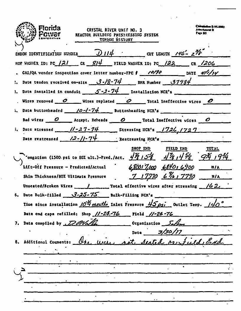
Florida CRYSTAL RIVER uNItr NO. 3 AN -,--..- •*,t Poaw• r REACTOR BUILDINGC RPs' R.SSIG SYSTSEMK
ENDO IDENTIFICATION ER CUT1 1 .. LENGTH /, rP
HOP .ASHEIR ID: PC CR FIELD WASHELR ID: PC /,2 CR 4706,.
C CAIIQA vendor inspection cover letter number-FPC I - /9p DATE
:. Date tendon r-celved on-site d3 /' 74 . R Number o,7F il
3. Date Installed in conduit _ _ _-.2_-_74 installation Na's _
. Wires removed W - ires replaced 0 Total Tneffective wires 0
i. Date buttonheaded 0/4- Buttonheading N4CR's
Bad wires 0 Accept. Reheads 0 Total Ineffective wires 0
. Date stressed //-27- Stressing CRs 1 I '7
Date restressed /42-//"7, Restresslni INCR's
SHOP END FIELD END TOTAL
ongationa (1500. psi. to 80% talt.)-Pred./Act. I/~ y /
K)Lif t-Oif Pressure - PredittedlActual .6,ZLZ ~ o 6 0 MI/A
Shim Thickness/WI Ultimate Pressure •7- 1 Z•70 6 "/77.. A
Unseated/Broken Wires j. _ Total effective vires after stressing /•.,
6. Date Bulk-filled ..%3-P?5:-15 Bulk-Filling NCR' a
Time since Installation 6 eA * Inlet Pressure 46i Outlet Temp. i
Date end caps refilled: Shop /"-2&07.o Field &-2,0-76
7. Data compiled by _______________Organization J1______9540_______
S. Add"itional Coents:tlt 1 1L~r L 'L ~g

Florida CRYSTAL RIVER Utli NIO. 3 ar fl6Power REACTOR BUILDINt G PRETRESSI?4G SYSTE)460P666900 TENtDON H1ISTORY
TENDON IDENTIFICATION IUMEK /j2 C UT LNIcn_
SHOP WASHER ID: PC ____ CR FIELD IASUER ID: PC CR
1. CAMIQA vendor inspection cover letter number-FPC f . DATE
2, Date tendon recelved on-site NIR Number .
3. Date installed In conduit Installation NCR's
Wires removed __ Wires replaced _ Total Ineffective wires
4. Date buttonheaded __ Buttonheading HCR's _
Bad vires Accept. Reheads _ Total Ineffective wires __
5. Date stressed Stressing NCR's
Date restressed Restressing NCR's
SHOP END FIELD END TOTALElongation (1500 psi to 80Z ult.)-Pred./Act. -...
Lift-Off Pressure - Predicted/Actusal N I, tI/A
Shim Thickness/80Z Ultimate Pressure L . - IA,
Unsested/Broken Wires Total effective wires after stressing_
6. Date Bulk-filled Bul____Sulk-Filling NCR's
Time since installation Inlet Pressure Outlet Temp.
Date end caps refilled: Shop Field___
7. Data compiled by .. Orga;.zation
Date _____ 1______________
8. Additional Coments: A042fI
-.-- . .... 6.. -71- -21 -7 -
-20 /iPOi• 1 l i _ i

Florida CRYSTAL RIVER WIT NO. 3 Par 87
Power REACrOR BUILDING P•.':4RESSINC SYSTE M~SBFOAUS@MTENDON AISTORY
TENDON IDENTIFICATION NIIMER .1. /5.CUT LENGTH /0.7 -7:k
SHOP WASHER ID: PC____ CR : ) FIELD WASHIER ID: PC CR _ I
1. CAX/QA vendor Inspection cover letter number-FPC I ,______,,. DATE ________"
2. Date tendon received on-sits _________IH ubr 3:7 qgg4
3. Date Installed In conduit f-,?- / Ins'tallation NCR's
Wtres removed 0 Wires replaced . 0 Total Ineffective wires 0
4. Date buttonheaded .. _ J'o7/ Buttonheading NCR's ._ _...
Bad wires 0 Accept. Reheads 0 Total Ineffective wires 0
5. Date stressed /f-//"7v Stressing NCR's ,_ _
Date restressed Restressing NCR's
SHOP END FIELD END TOTAL
•Iongation (1500 pat to 80 ult.)-Pred./Act. ....,5 5.. I ) 1 10
Lift-Off Pressure - Predicted/Actual H/ -
Shim Thickness/8OZ hiltimate Pressure Pjg :12~jL i qa J tI7 7- /A
Unseated/Broken Wires , • Total effective wires after stressing _
6. Data Bulk-filled , 3 Z57• Bulk-Filling NCR's
Time since 'installation _• Inlet Pressure _a4 Outlet Temp.
Date end caps refilled: Shop . Field
7. Data compiled by 49221 0. 'Organization..."_
Date _241. /7 7
8. Additional Coments:

* '• " Florida CRYSTAL RIVER I-II1T NO. 3 Afl .iPower MAcroR BUILDINC LTRESSIG SYS= Pr
• /TE1DOM HISTORY
TENCOM IDENTIFIC&TION NUMR p--11 __ CUT wNcT _
SHOP WASHER ID: PC_ CR _ _ _ FIELD WASHER ID: PC CR . ......
1. GAI/Q& vendor Inspection cover letter number-FPC I 7W4" DATE _Z '___,_
2. Date tendon received on-site _MR Number _
3. Date installed In conduit InstallatIon NCR`_*
Viares removed _ Wires replaced. _ Total Ineffective wires
4. Date buttonheaded ._Buttonheading HCRPs
bad wires Accept. Reheads Total Ineffective vires
5. Date sttessed Stressing NCR'.s.
Date restressed Restressln NCR's
SHOP END FIELD END TOTAL
Elongation (1500 psi to 80% ult.)-Pred.lAct. " __ _.
Lift-Off Pressure - PredictedlActual . t HLA
Shim Thickness/80X Ultimate Pressure " j _ lA
Unseated/Broken Wires _-_ Total effective vires after stressing _ _.
6. Date bulk-filled ... .. B•uk-Fil1ing NCIVs .__
Time since installation Inlet Pressure Outlet Temp.
Date end caps refilled: Shop _ Field .
7. Data compiled by Organization
Date_ __ _ __ _ __ _
8.Additional Covuenta: £?,Ame,e e -
Z90-rd"&r_.-AV -SA-ap "ft,
K
I
- -/ .06- - ... ... Air X .. .
iN -- - ml -- -

Elorida CRYSTAL RIVER 1'tIT NO. 3REACTOR BUILDItNG PIRrTRrSSING SYSTEMt
TENDON 11L' fORy
ۥ="ftVS.M4tfAaa.o 3ft". so
*iDOtE IDENII~FICATION NUtIMER CUT 11LE N GTHn____________
SHOP VASHER ID: PCJ/",.. cR _ _ _.I VASHER-ID: PC C__ ,
1. CAI/QA vendor Inspection cover letter number-FPC I DATE
2. Date tendon received on-site __R Number
3. Date Installed In conduit Installation NCR's
Wires removed Wires replaced ._._Total lneffective wires
4. Date buttonheaded Buttonheeding NCR's
bad wires .... _Accept. Reheads Total Ineffective wires
3. Date stressed " Stressing NCR's
Date restressed Restressing, NCR's
SHOP END FIELD END TOTAL
Elongation (1500 psi to 802 ult.)-Pred./Act. / /
Lift-Off Pressure - PredictedlActual • ! N/A
Shim Thickness/80 Ultimate Pressure / N/A
Unseated/Broken Wires Total effective vires after stressing __
6. Date Bulk-filled Bulk-Filling NC_•_s
Time since Installation .I,_.._____._ Inlet Pressure Outlet Temp.
Date end caps rdfilled: Shop Field ____
7. Data compiled by 0 4. Organization FPC.QDate 1 -0 72
8. Additional'Comentse.PJ ftPLAA-rrWJ Wa. Jf* SHMrC
I 907 716

• Florida CRYSTAL RIVER V'-IT NO. 3 A
Power RECOR BUILDtIC PitlVFRESsl4G SYSTEH
TENDON IDENTIFICATION NUMER D/2) o CUT LENGTH //0 !- P
SHIOP WASHIER ID: PC a CR FI2 ELD WJASHER ID: PC J CR
1. CAI/QA vendor inspection cover letter number-FPC I /o/9D DATE _,//_ _ _ _
2. Date tendon received on-situ __________ IR wNuber .079__________4_
3. Date InstllaIed in conduit _ "F.e- -2 Installation NCR's
Wires removed. WIres replaced 0 Total Ineffective wires 0
4. Date buttonheaded _ " _0- 7S9 Buttonheading NCR'_s
Bad wires . Accept. Reheads 0 Total Ineffective wires
5. Date stressed /.2.-67- 7V Stressing NCR's
Date restressed _,__ ..... ___ Restressing NCR's
SHOP END FIELD END TOTAL
K.., Elongation .(1500 psi to 80% ult.)-.r.d./Act. .5",LfI j." "
Lift-Off Pressure - Prediceed/Actual 6760 NIA
Shim Thickness/SOZ Ultimate Pressure -7 *'/77ZDo 7 AL..TL26O tIA
Unseated/Broken Wires ....- Q Total effective wires after stressing j(_
6. Date Bulk-filled SE- " 7 Bulk-Filling NCR's
Time since installation 16 t*Mx1I4 Inlet Pressure& p0o Outlet Temp. 64
Date end caps refilled: Shop _ _. Field
7. Data compiled by Jt. Organization __ _ __"__.
Date d70 n/t .
8. Addi~tional. Comments:
I

Florida CRYSTAL RIVER U1IIT NO. 3 A-,m, B
IPower REACrOR BUILDIG PE:..F•EsSING SYSTEH he,,,,Co,0,I0l TCOII04 1"1STO_
TENDON~ IDENTIFICATIONI NUMBER .1/0 CUT LENGTHI /92
SHOP WASHER ID: PC " L CR P11 FIELD 'WASHER ID: PC IC'R) ci -2. .21. CAI/QA vendor inspection cover letter nmbar-FFPC i /oZOL. DAlE v/,,h Y
2. Date tendon received on-site ,3 -ar HNumber .3 'O9-O
3. Date Installed in conduit M_2__"- ___- __ Installation .CR's
Wires removed 0 Wires :eplaced 0 Total Ineffective Wires (
4. Date buttonheaded 9 2 -7/ Buttonhe&dntn NC,4's
Bad wires $ Accept. Reheads _ Total Ineffective Wires .
5. Date stressed L/0-3 -74/ Stressing NCR's ____.
Date restressed _Restressing NCR's
SHOP END FIELD END TOTAL
Eo.ngation (1500 psi to 80Z ult.)-Pred./Act. 1 4 /;
Lft-O~f f Pressure - Predicted /Actual N/A.~fi!
Shim Ihickness/801 Ultimate Prcssure ý5 17p n N7 - IA
Unseated/Broken Wires _0 Total effective wires after stressing .
6. Date Bulk-filled 4 75Bulk-Filliog NCR's ______________
TIme since Installation 10901Aj11 Inlet Pressure j)55...p5z Outlet Temp.
Date end caps refilled: Shop ,_ _ _ld . .. . .
7. Data compiled by-2 e Organization _______________
Date____________ _
8. Additional Coanents: _-.__
A

4 Florida CRYSTAL RIVER UNIT NO. 3 cmk•,,$-.4012Power IEAC"OR BUILDING Titt'•r'T ESSING SYSTEH l'•oico-*o",l~oTENDON 6l1STORY.
4DOI4 IDENTIFICATION UMB . .ER. CUT LENGTH //0- 9/,'
SHOP WASHER ID: PC J) j CR -/002 FIELD WASHER ID: PC__ I '- CR _ • ....1. CAI/QA vendor Inspection cover letter number-FPC % DOE_ ./'/:i
2. Date tendon received on-site _%_3r= _21 WIR Number _ _ _ _ _ _
3. Date Installed In conduit -n -L/.. Intallation tcN,.' .
Wires removed 0 Wires replaced 0 Total Ineffective wires._
4. Data buttonheaded -.. Bb-'7 JuttonheadinS NCR's 1/41
Bad wires / _ Accept. Reheads 9 Total Ineffective wires
5. Date stressed /, "67/ Stressing VCR's
Date restressed ._.. Restressing NCR's _
SHOP END FIELD FND TOTAL
Elongation (1500 psi to 80% uit.)-Pred./Act. ja44 -4 j 2JýZ/i9~5 Lift-Off Pressure - Predicted/Actual (:10'7/bf 6,7o 4 Of (aW
Shin Thickness/BOX Ultimate Pressure /-14 A 20. NIA
Unseated/Broken Wires Total effective -ires after stressing J.j_
6. Date bulk-filled _________ ulk-F Illing NCR's ______________
TIme since Installation /g Inlet Pressure D5M~... -Outlet Temp.
Date end caps refilled: Shop Field__ •
7, Data compiled by V 40<1&Organization J4,4_ _ __
Date _____________
8. Additional Comments:
)
Rp 11

FloridaPowerrompsa~tso~m
CRYSTAL RIVER WIlT NO. 3REACTOR BUI1LDIIG PREaIRESSIHG SYSTEM
"tHDO HISTORY
ANkmm I 'hg* Sl$
iNDON IDENTIFICAT ION NUMBER 9 , /3/ I -. CU w M
SHOP WASHER ID: PC CA. FIELD WASHER 1D: PC CR ___
1. CAI/QA vendor inspection cover letter number-FPC U __DATE._ _
2. Date tendon received on-site _ _ _ _ _ IXR Number _
3. Date installed In conduit .. ...... _Installation NCR's ,,
Wires removed _Wi_ lires replaced Total Ineffective wires
4. Date buttonheaded __ _ ButtonheadibZg NCR9s
Bad wires Accept. Reheads -_--Total Ineffective wires _.
5. Date stressed __Stressing NCR's ___-_
Date restressed Restresaing NRs_
SHOP ENID FIELD END TOTAL
Elongatlon (1500 psi to 802 ult.)-Pred./Act. . -
Lift-Off Pressure - PredLetedlActual I
Shim Thtckness/80Z Ultimate Pressure I
Unseated/Broken Wires Total effective wires aftel
6. Date Bulk-filled __Bulk-FIlling SCR' -
Time since Installation Inlet Pressure
Date end caps refilled: Shop __. __ Field
7. Data compiled by _ . Organization.____
Date
~1~~~~-
~1~~ N IA
r stressing_
Outlet Temp. _
S. Additional Comentsi Vgwo dor/
AZ/vjijA).>/Ao)
I
00-1Prt-e -22 4C 7~t 80 AC &p
- - -- ~~~~.w~--------. -- s -pý 1

ti Florida CRYSTAL RIVER UNIT HO. 3t..o...jot v er REACTOR BUILDI::C Pt:SIRLSSItN SY£H 1 il
TEND03 IllS ORY
x)vO z4 IDEUtIFICATON NUKIER 137 .V or LENG /3'- //' G
'.oP WASHER ID: PC 4/ ,. CR 1 d FIELD WASHER ID: PC /1 CR
CAlqA vendor inspection cover letter nuober-FPC I AP _ - 0 2- __ _ DATE ___/__, _"
. Date tendon received on-site 3'• 2- 7 . R Number ....
5. Date installed in conduit , J.7-,/' Installation NCR's
Wires rcoved 0• ires replaced 4c Total Ineffective wires C)
,. Date buttonheaded Bu-.•O.7LI BitonheadLng NCR's __
bad wires / Accept. Reheads 0 Total Ineffective wires
. Date stressed 1.,-3-7q Stressing NCR$'s.
Date restressed ...... Restressing NCR's$
SHOP END FIELD EIND TOTAL
O'Nloniation (I.500.psi to 6D% ult.)-Pred./Act. JL,ýL -4 d.j/ 9
.t-Off Pressure - Predicted/Actual 674a4700 69",/OO N/A
sim. Thickness,/oZ Ultimatce Pressure Z, "i 7 7,o 777,6 N/A
Unseated/hroken Wires 0 Total effective wires after stressing
Date Bulk-filled B/""/". 1Bulk-Filling NCRP,'s
Time since Installation /__,__,._:_ Inlet Pressure _,_o __; Outlet Temp.
Date end caps refilled: Shop Field
'.Data compiled by e.________________ Organization_______________
Date ______ _ _ _ _ _ _
I., Additional Co-entsz
), l-ii ,

.• ,,;- F~or.ia CRYSTAL RIVER U31T 110. 3 cdl 35mk" * * J ,.0.; EAcrox ?1' r*-*s rqsst::: sysTuL_,.0. T IFIM _ON 11tSW R,, rat .
1D.b IDENTIFICATI0: ?UMIMER_____________________ 0 .. 1 LE4_CD; /'Z 07,
3P WJASHER 10 C /:l. CR 7,2 FIELD WASHIER ID: PC _j ; ca
CAI/QcA vendor Inspection cover letter n=.ber-?PC 1 /0ZA'_' DATE 4'//o74...
Date tendon received on,-site £ 7R Number ______. . ..
Date instal.le! In ccn.uit Z,-J-374 installation tNCR's __
Wires rc=oved 0 Wires ra;lzzed 0 Total Ineffective vires 0
Date butc..eeaded 1 1)" ' Buttonheading NCR's
Bad vwres _ Accept. R.cthcas " Total Ineffective wires
Date stressed _ / 3_ -7_ Stressin; NCR's &tRi • &M/,"
Date.restressal _ PRastress~ns tiMR's ....
SHOP WD 'FIELD END TOTAL
9n-n.o•ti,0n (1500 psi to 60% ult.)-?:ed./Act. • ','$.- - 964',/oe ""
+li.-Of ?'ressure - Predicted/Actual / ' T " 4 1 •. e&,( Ii/A
Shia Thickness/8o%. Ultimate Pressure 174' Y/",7&'-O NIA• ,+
Unseated/Broken Wires Total effective wires after stressing .. L • '
. Date Bulk-filled -2(-7g" Bulk-FlllLnZ NCR's
Ilme since Installation Inlet Pressure UT Outlet Temp.
Date end caps ref illed: Sho . .... . Fleld ____
*Data compiled _______________Organization _ 0__o_______________
* ~~Date A__________________
.. Additional Coiencs: 1V&,tA4gD0

FloridaPowergompea ar 06
CRYSTAL RIVER UNIT NO' 3REACTOR BUILDU4C PRLS,-'ESSINC SYSTE1
TENDON IISTOmy
C . , 4S.C-uAftfaebmm 8PAf oS
TENDON IDENTIFICATION ?IL D Z/1. r CU LENGTH-_
SHOP WASHER ID: PC_____ CR ______FIELD WASHER ID: PC______ CR ______
1. CAI/QA vendor inspection cover letter number-FPC I __ _ DATrE
2. Date tendon received on-site 4P. Number _
3. Date Installed In conduit Installation NCR's
Wires removed ,,, Wires replaced Total Ineffective wires ,,_.....
A. Date butionheaded ___ButtonheadLng NCR's
Bad vires _ Accept. Reheads Total Ineffective vires
5. Date stressed Stressing HCR'sa
Date restressed Restressiug NCR'.s
SHOP END FIELD END 7OTAL
Elongation (1500 psi to 80X ult,)-?red./Act.
LIft-Off Pressure - Predicted/Actual,
Shim Thickness/8OX Ultimate Pressure
inseated/Broken Wires -_ ._ .. Total effective vlres
6. Date Bulk-filled _ Bulk-Filling NCR' s
Time since Installation Inlet Pressure
Date end cups refilled: Shop .. _-. __ Field
7. Data compiled by .22 - Organization
-I-N/A.
after stressing
Outlet Temp.
Date
8. Additional Coments: ArPoi7? ' " A -'""
P A, - f ( II J-I 74I
I

F'.or~da CRYSTAL RIVER WIlT NO. 3A 3
:6 6~.# o -bo IEACMOI I:LuLD::G Pr!:rFTSr~Sl:: SYSTEM ? $1
=4OO IDENTIFICATXM1 NMMER__________ _ aLIr LEIGTH /'V-
OP 1WAS11ZR, 10% PCJJ CR ' FIELD WIASHIER ID.- PC_ CR
GAl IQA% vendor Inspecticri co*.-r lette~r number-FPC /O ___________ DATE '/ '
Date tendon receivad on-sita %3___89-7___- P.IM. Number 53 1? a
Date Installed in conduit __________Installation NCtfs i'Ii
Wires rczoved 0 wires replaced ý0 Total Ineffective wires 0C:
Date buttonheaded 10 -7- ?l Buttonheadin; tC.M's _____________
Bad wicrer Accept. Rehe.ids 0Total Ineffective wires /
Date stressed _____ ______Stressin; ".CR's_____________
Date. restressed ______________Restressing 1:CRs________________
SHOP L'D FIELD ENID TOTAL
ag'oation (1500 psi to 60Z ult.)-rred.IAct. d~go 179019/*~~1i~c-*O&ff Pressure - Predicced/Actual 477o, WA~4Shia Thickness/BOX8 Ultim~ate Pressure N/i,#~~HA
* *Unseaed/Sroke Wires 0Total effective wires after stressing,..2.J..
*Date Bulk-filled S..7 Bulk-Filling liC91 ________________
TIme since installation In~~d~ ltet Pressure * Outlet Temp._____
Date end caps refilled: Shop _________ Ireld___________________
*Data CDrCPIled by 2?~Organization ______________
'Date ___9& ______177___
*Additional Co~ents.:
0 9
I
aJ -] _

C C
I
eISTaL l UilN Tl i. 3I3ACMOTllSI• PItIIlUUI 6111MM
w uamm 3UIVUI.U5 ImsC 1fIDU One D212
, Itl Of ¢ociff1Oi. . ?tICIIIaIIrnpectle. Avg. 8in Lat"- Total Avg. M "10 il00- TOMal stor alas.lPalr sad lotre Io*e I•ktllmieog ,sim 91060"w forev Ifinos TlIeiee.o atios tllotiwe ow *atlvCu of
!se Wae AY2 fbia) _(V It) WIvo (RIP) (%IN#) (Q (it) e l a2 4 1 35e- 1 WO
•lgl lM 6 I31wi 4 _Si & .9L _iLL
1213174 I 6 1612 6/ 471r 162 L l.. .. K & .9L X &, i ll lm I M X &" • Ji U L "
3 Ir .. _..92 6 31._" VIA
V 128S 1336 6 31_. VIA
VIA
162 piA VIA
ulA Uva
TIA VIA 162
1. Lift-off goly
82 53
.YY&W£.n3 p2um ai's .d
.L MIA
AM A& Alm MIA144R1- OFxcCOA"S /e
- - - - - *. - -
- - - - - - - ~n - - --
- - - - - - -
- - - - - - - - a - - - - - 5ffWI

Florida CRYSTAL RIVER UNIr NO. 3 t. B,,
TEHNON HISTORY
TENDON IDENTIFICATION4 NUMBER 71M)in CUT LENGTHI ____________
SHOP WASHER ID:- PC L2 .CR ~ ,FIELD VASHER ID: PC L..... CR 2......I. CAI/QA vendor Lnspection cover letter wumber-FC I /0Z,_r'" DATE _/Ao/ "
2. Date tendon received on-site _ 3_A______9_____ RHR Number __________________
3. Date installed in conduit _-__ -_. _ Installation NCR. __s
Wires removed W • Wires replaced 0 Total Ineffective wires 0
4. Date buttonheaded ICo -Ito - 7(1 Duttonheading NCR's _____________
Bad wires 0 Accept. Reheads 0 'Total Ineffective wires 0
S. Date stressed i11894 Stressing NCR's
Date restressed Restressing NR'1s
SHOP END FIELD END TOTAL
.oongation (1500 pos to 80% ult.)-Pred.Act. _ _ _, _7__v 7_7;E
Lift-Off Pressure - PredictedlActual /g'.o 1 0,VOrSt N/A
Shia Thickness/80% Vitimate Pressure &6 'iLlO 7 ~ s 7770 NI/A
Unseated/Broken Wires. 0 Total effective wires after stressing ,
6. Date Bulk-fllled_ •-.26- 25_ bulk-FtllIng NCR's
Time since Installation C~n Inlet Pressure L p. Outlet Temp.
Date end caps ref'iled: Shop Field
7. Data compiled by : Organization J"_44,
Date V 7-
8. Additional Comments: t ._• cL ,ID•4,)
K;-

-& Florida CRYSTAL RIVER UNIT .N. 3 Athm..M
Power AcrOR BUILDING CAIlTRESSING ST rw
TNDON IDErNrIFCATION NUMBER CU 2./ . . t LENGTH _ __
SHOP WASHER ID: PC_ __ CR __-__ FIELD WASHER ID: PC CR _
1. GAIIQA vendor inspection cover letter number-FPC D D&TE
2. Data tendon received on-site , _ HR Number _ _ .. _.
3. Date Installed In conduit InsZtallation NCR's
Wires removed .... Waires replaced 'Total ineffective wires
4. Date buttonheaded _uttonheading, NCR's
Bad vires _ Accept. Reheads -_ __ ,,, Total Ineffective vires ___.
5. Date stressed Stressing NCR's
Date restressed _Restressing NCR's
Sol•O END FIELD END TOTALElongation (1500 psi to 802 ult.)-Pred./Act. __._________7
Lift-Off Pressure - PredLcted/Actusl N. liA
Shim Thitkness/801 Ultimate Pressure M hIA
Unseatedl/roken Wires __ ____ Total effective wires after stressing
'6. Date Bulk-filled ........ Bulk-Filling MCRs'
Time since Installation Inlet Pressure Outlet Temp.
Date and caps refilled: Shop . ... Field
7. Data compiled by 00 17?Z4S , Organization--- • .. .Date
8. Additional CoumentB: _&p /ý,!rw
,0a A- ,0
K
" " 06 V W.
TqnAl. 7 1

I11o ,. CRYSTAL RIVER U4ur ZO. 3 All'•'SM
.. •:, m ...,jzT ICrO BUIL[DI::G ?r.sgr.::S: SYSu, aO*PO-I#O TEUWO. HItST')RY
MMI IDEN71FICATI03 NUMER CU~i/ ~T LEC~TI /7'/ M'
WASHER ID: PC_ Ci FIELD -ASIIL ID: - C gGAIIQ,/ vendor inspection cover letter number-FPC i /62 -5. DATE _______y_.
Date t endon received on-sfte ,.,,A9__-_ RXMR RKuber R2_'__.6._.
Date Installed in cendui.t t -e 1-4 Installtion NWCR'S
Wires rceoved / Wires replaced 0 Total Ineffective wires
Date bucto.headed L1 - IJ. L4. Buttorhedin.; ?sCR•s
Bad wires * Accec. ulloads 0 Total Ineffective vwres /
Date stressed Ia "(o" 4 Stressin; r.Cu _s
Date restrcss4 _ lestressir. ICnK's
SHOP •IND FIELD END TOTAL
pgation (1500 psi to 609 uit.)-Pred.fjAcc. -a '/ 4-0g 4Af 41,~jt 9 51fg%LIft-Off Pressure - Predicted/Actual q L70 A _904 5 LA 292A1; 6~q f tiN/A
Shim Thickness/80% Ultiiate Pressure ..2..Q d NIA
Unseated/Broken Wires tToial effective vires after stressing _
* Date Bulk-filled ! 3-•24,-7. . Bulk-Tilling NCR's .....
Date end caps refilled: Shop • Yield ....
*Data compiled by Organization ______________
Date L77
Adiina c -ens II-& A " -t tl;-m IIIft WAAL&-

FlridaPower90164459
CRYSTAL RIVER UNIT NO. 3RZACTOR NUILDINC PRMC:RESSING SYSW(
TENDON HISTORY
Crkatre SB2
Fa. 322
TENDON IDENTIFICATIO14 NUMBER jA 2/ ' n LM
SHOP WASHER ID: PC CR FIELD WASHIER ID: PC CR _.
I. CAL/QA vendor inspection cover letter nuber-FPC I . ... DATE__
2. Date tendon received on-site M Numbet
3. Date installed in conduit Installation HCR's
Wires removed Vicres replaced T Total Ineffective vires
4. Date buttonheaded _Ba_-__ _ Dttonheading NCR's
Bad wires _ _ . Accept. Reheade. 'Total Ineffective wires
5. Date stressed ..... Stressming MCR1
Date restressed .... _ Restresolng NCR's
SHOP MNl FIELD END TOTAL
Q,) Elongation (1500 psi to 60? ult.)-Pred./:t. . I
Lit t-Off. Pressure - Predicted/Actual " , TAIA
Shim Thickness/802 Ultimate Pressure _ N/A
Unseated/Broken Wires __Total effective vires after stressing __-_____"
6. Date Bulk-filled ___-_._ Bulk-FIrllug NC'_s
live since installation Inlet Pressure Outlet Temp.
Date end caps reftlledt Shop Field
7. Data compiled by DOrganizatio
Date _ _ _ _ _ _ _ _ _ _ _ _ _ _ _
a.- Additioanal. Comments: _&VP&,e efe, #.,r
X o
.1 _,' ,;/ .,/. .

Florida CRYSIAL RIVER UNI r HO. 3 &-"4M
Power REACOR UILDING PRESTRESSING SYSTVI par W)q*4 tooTto
TENDONI HISIOWY
~Tirot iDEincinCt;O muK314 at 21 CU LENGWTH___________
SHOP WASUER ID PC 2 . I c& T ELDWASHER ID: PC __ _ C&_
1. CA•lqA vendor inspection cover letter ~umber-MPC 0 ,_ DMTE
2. Date tendon received on-Bite M__ R $umber
3. Date Installed In conduit Installation NCR's
Wires removed ____ _ Wires replaced __Total Ineffective wires ,,,_ ,
4. Date buttonheaded __ )uttooheading NCR's
Bad wires .... _Accept. Reheads _ Total Ineffective wires _
5. Datae stressed S__ Stressing NCR's
Date restreused ._ Restressing 14CI's __
SHOP END FIELD END TOTAL
Elongation (1500 psi to 80 ult.)-=red./Act. I z
- Lift-Off Pressure - Predictedl/ctual L NIA
Shim Thitckness/80O Ultimate Pressure I . NIA
UnseatedlBroken Wires Total effective vwies after stressing ._._
6. Date Bulk-filled _ulk-Filling NCR's "_
Time since installation Inlet Presshlae _ Outlet Temp. _
Date end caps ief illed: Shop Field _ _-_ _-_____.. _
7. Data compiled by --Or~:7 ~ gan ization FPC-Date _ _ _ _ _ _ _ _ _ _
8. Additional Couwents: Th' ?,tCA41?A 1TOI) Pie -5.4 r~9JL4JCC
907 716

Florida CRYS7AL RIVER UNIT NO. 3 Aa"b*1 Power REACrOa BUILDINGC PRS, 'ESSlIG SYSTEMt TENDON IILSTORY
W4DON IDENTIFICATION NdUMBER CU-? 5OT LENGTH .~3~d
SHOP WlASHER ID: PC ,/Z ca FI_ lEL WASHER ID: PC /X/ cR
1. CAI/QA vendor inspection cover letter number-YPC I 0 2Y!r DATE _.'./ ,
2. Date tendon received. on-site. _%3ng- 74 Pat Number ________________
3. Date Installed in conduit (-JO)'7 4 Installation NCR's
Wires removed 0 . ires replaced 0 Total Ineffective Vires 0
4. Date buttonheaded /1-/ Q42 d Buttonheadins NCR's _
Bad wires 0 Accept. Reheads 0 Total Ineffective wires •
5, Date stressed _ /.. -'74 Stressing NCR'* ,_,
Daie restressed Restressing NCR's
SHOP et D FIELD END TOTAL
-ongation (1500 psi to 80% ult.)-Pred./Act. .~Li.. ~ i:LIft-Off Pressure - Predicted/Actual 1,0? v 7OI KAA
Shim 7hickness/8O% 'Ultimate Pressure I-4A 1 ,7110 "/AUnsested/Broken Vitres- 0 Total effective waires after stressing
6. Date Bulk-filled . .. L- 7•-Bulk-Filling NCR's .___._ __ _.
Time since installation Z~ L.Inlet Pressure f~!Outlet Temp. ZI
Date end caps refifleds Shop ... ____ Field
7, Data compiled by ...... ..... .. Organization
Date -7/"Z _7Z
8. Additional Coments:
C.
I

FloridarW Power
4g-A6AIxv
Caksu~hg 5-95.006AftwMhmm Uirl"3 25
CRYSTAL RIVER UIIT MD. 3REACTOR BUILINGu PREJREssINC SYSTEMj
TENDON HISTORY
TENDON IDENTIFICATION NUMBER - 42 wlr CUT_ _ __CT_
SHOP WJASIIER ID: PC CR __ _ FIELD WASHER ID: PC__. CR _
t. CAIIQA vendor inspection cover letter number-FPC I ,_DATE
2. Date tendon received on-site _IR Humber
3. Date Installed In conkuit _ Installatiou nC•s _NCs
Wires removed ... _ . Wires replaced ...... Total Ineffective wires
4. Date buttonheaded _Buttonheading VCR's
Bad wires Accept. Reheads Total Ineffective vires
5. Date stressed Stressing NCR'__
Date restressed ,.,_ __ _ Restressing _CR __
SHOP END YIELD END \ TOTAL
-9 Elongation (1500 psi to 802 ult.)-Pred./4ct. ,Liftt-Off Pressure - Predicted/Actual L . 1
Shim Thicknesu/80Z Ultimate Pressure " /
Unseaced/Broken wires Total effective wires after stressing
6. Date Bulk-tilled Bulk-Filling, ?CR's
Time since installation I____nlet .Pressuve Outlet Tean
Date end caps refilled: Shop "___Feld ...ld
7., Data compiled by Organization
Date2
14/A
N/A
p.
k
m
Be Additional Comments: .. --
//.... .. ;o- 1?•o (z/,r/,e)"t
&
,
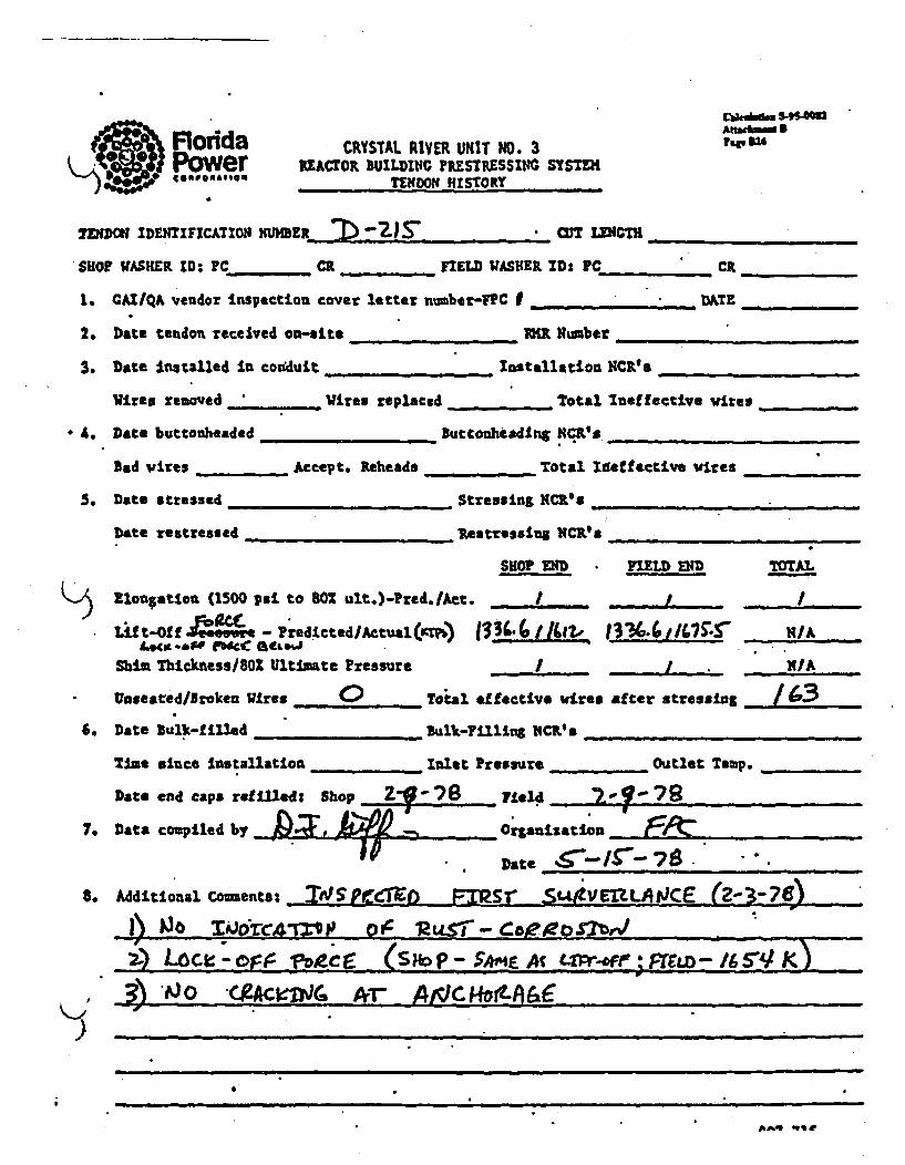
qsusFloddaPowerAt .,eMm3
faor S2CRYSTAL RIVER UNIT NO. 3REACr0l BUILDI•fG PRESTRSSIN SYSTEM
TENONt HISTORY
!DIDM IDNTIFICA-TION UMBER C)2SanT LUNGnI___________
SHOP WASHER ID: PC__ _ CR _ FIELD WASHER IDs PCCR __
1. CAI/QA vendor inspection cover letter number-FlC I DATE_ I ____.....
2. Date tendon received on-site MR Number
3. Date Installed In coudduit _Installation NCR's
Wires removed " _ Wires replaced . _ Total Ineffective •ires
4. Date buttonheaded Buttocheading NCR's_
Bad wires __Accept. Reheada .... Total Ideffective wires __
5. Date stressed Stressing NCIL8s
Date restresee, ___ Restressifu NCR's _
SHOP END FlELD END TOTAL
Rlonlation (1500 psi to 80R ult.)-Pred./Ac. . . _._ _ I_
Lif t-Of f -eesre P redicted /Actual (nftP) 13~ Ica., f3%.,/47:S, N/AL0(.I..Pf FWI ft&J . .'.
Shin Thickness/802 Ultimate Pressure 1 N/A
Unseared/Broken Wires 0 Total effective wires after stressing /636. Date Bulk-filled Bulk-.illing NCR*'_
Time since Installation ..... Inlet Pressure Ou tlet Tamip. ...
Date end caps refilled: Shop Field 7"
7. Data compiled by _ __ _ _ _ Orgauization ______ ___ __
Date I 7 768. Additional Commentes -1~p! S Eor _FT2S I SLLIVMLtU.CE -- 9
00~ --- :Pj--/•-M -.Q" 12y=
2)Loc - o ? r- _,oclE _(SAIP-SAMEA L4 W--I&5V
, _) 'JO "gACleW4 Ar - C LC • •t •L
';i
nAq .me

~-.-
.. d. S, S.
cIrAl. UV1I UUIT go* 3-s cm MU lOINftn MtSU11M U l-fITfd
UVOCIDl InUUYW1tUAKl U*~:Oe3 . ,,nWeo Vao. ns_ •
.mmr ClOMO .110&-50 whim slow A Ialk lool- eg h70 ator alds.
eiod "A foargo Vo. !lg•enas.o ao el*4 gI. t iv v Pt. ltom elaba atlea Iffaetie low eature Olf
_..__m- (kie) (hIp. IIf) (in) vimne (iHa. (tlC ) (li)s (10) _ Vto. _ 8l, 4.. Coug 1
Or"Is.al - 3 A m - VIA- WA VIA
IIIZ& .L. 1670 1667 6 jI SAN S ~ II It*~ 165 AI UIt L
&3 6~a7 VA112 r VIA
• 1616 2644 6 3140 VIA 113 164 13623 4 2140 VIA 163 92 46
- . .. A- 7d VIA VIA 7w VIA 1. Ltfc-off oall
.10.2221 .. L.. .Ih) ..~14 '4~..2LJII. 16 VI WI 362~ VIA. 113 2
If J
$L~ 4E/# 2j.! NIA ellA 03J4 ad.32. Oo~toti' me QCaws4DDItv awa £Cvofwb
4123. 72
- -- a - - a -
- - -- -- - -- -- - - - fitSi
.1*1-

Florida CRYSTAL RIVER UNir NO. 3*Power REACrOR BUILDINlC ,,EsI.ssIN SYST Pa A us
comoa.,g@. TENIDON4 HISTORY
rENDON IDENTrIFICATION~ NUMBER ) icu'r LENG~TH /5 - 6
;HOP WASHER, D: I C /c L CR /2. FIELD WASHER ID: PC/ C /Z3' _
1. GAI/QA vendor inspection cover letter number-FPC I / ]OZ.VS DATE 9',/7V
2. Date tendon received on-site ._!/-_- ___ N,!.,umber 33. Date installed In conduit R ._-/0-94 Insta5atioNCI's
Wires removed 0 , Wires replaced 0 Total Ineffective wiires 0
(.. Date buttonheaded /0 -19-94 Buttonheading NICR's
Bad wires 0 Accept. Reheads 0 Total Ineffective wires 0
5. Date stressed I4 -3-91 Stressing, NCR'"
Date restressed ,_, Restresnsin NCR's
SHOP END FIELD END TOTAL
K} tongation (1500 poi to 80% ult.)-Pred./'Act. 4 0
Lift-off Pressure - Predicted/Actual 7 14 r 4/1 (v 7iomr _N/AA
Shim Thickness/80% Ultimate Pressure V1,2/77a (2~ 1 710 N/I&
Unseated/Broken Uires 00 Total effective wires after stressing /6.3
6. Date Bulk-filled B- 2A-?S 1ulk-Filling NC'.__s
'ZIme since installation Inlet Pressure5 -4 j Outlet Temp.
Date end caps refilled: Shop . Field
7. Data comupiled by 2?4 - Organization_______________
Date / /7
8. Additional Coments_

1"4 .4
: "'.* '-*.) CRYSTAL RIVER U!6IT NO. 3 ckm
* . I xA a O . C U IL D. ::G P rr .• .. s s I ., S Y S T D I A£e i u
MIO IDENrIFzCxrxo:: :IER CU3 3 T LENGTH 4F Y3
o• IAS)TER to : Pc- JAI.o: CR . .... FIELD WASHER ID: PC' C"
CAI/QA vendor inspection cover letter n=bar-FPC 5 /03 57 DATE. YI3 7_?17-*l
Date tendon rice.ved 0--ste L-t-"* 1'R Number _"I _ _,
Date In::a!1ed !-. Ccnduit pp.1 Installation NCICLS ___________
.ires re-oved 0 . Ures replaced Total Ineffective vires C>
Date buttc..n.eaded - lutton•dei~inZ rCR's
Bad w'ires " j Accept. Veheads 0 Total Ineffective vi;:s /
Date stressed_ 1 1-t4-t:-14 StressinS NCR's _ |t"1I
DaCe rest.__ssd_......... Restressing NCR's .....
SHOP rFD FIELD Ee*D TOTAL
vSnsin(1500 Psi to 60% ult.)-Pzed./Act. 3I'1'" 3W,3 ( ..2.L.i....I-Ift O~f Pressure - PrediLcted/Actual -4F 4O~1~b ~~~
Shim Thickness/SO% Ulti-ace Zressure I N /AUnseated/Bro'ken W'ires L.... Total effective vires after stressing .L. - "
Date Bulk-Mled B,-,l-7S' B.ik-ril.ing :cs ' /9/80
Time since installation q~.. fiA Inlet P Temp.
Date end caps refilleds Shop _ Field __
Data cocpiled by .?Organiza tion _____________
Date 1,7__ __.
Additional Co-ents: ___"_ _
A . .. t m mil

FloridaPnswor CRYSTAL RIVER UNIT NO. 3 Awmb~m..At*Wu4Ms4 •
W?" .F* * v.*njNaNu, u•h.LWJ. r1VL,.i .&O•L¶Ijd *j8rui f€~ (F o oN*,l. TENDON HISTORY
T~• D~rrCAZO 9•030,8 w.onz~r~ --n_______TENDON IDENTIFICATION( mW)4ER_____________ __g2!_70_CUT______
SHOP WAS•iER ID: PC CR _ FIELD WASHER ID: PC _ CR __
1. CAI/QA vendor inspection cover letter nusber-FPC I DAT_
2. Date tendon received on-site _MR Nu__ _ Nmber3. Date Installed in conduit Installation lICIVs
Wires removed Wires replaced Total Ineffective wires
4. Date buttonheaded _ ____._Buttonheadin$ NCR's
Bad wires __Accept. Reheads _Total Ineffective vife$
5. Date stressed ____ Stressing MC'SO _a__
Date restressed __ __ _ _estressing NCRs._
SHOP END FIELD END TOTAL
V.NL
Elongation (1500 psi to 80% ult.)-Pred.Act. _ I
) Lift-Off Pressure - Predicted/Actual I j IA
Shia Thickness/=0O Ultimate Pressure / .. _ /A .
Unseated/Broken Wires _ Total effective wires after stressing
6. Date Bulk-filled 'Bauk-Filling NCR's
Time since Installation Inlet Pressure . ... Outlet Temp. _ _.,
Date end caps refilled: Shop Feld
7. Data compiled by Organization
Date /77
8. Additional Comments: .A..e .--4r--
200rje i 4 .Z /,Po "Nez "Zsg/
- ~ T .~.. - Qf7 716

Florda CRYSTAL RIVER UNIT -NO. 3 Aftaek.mi
Power REACrOR BUILDI,,C PiPZS'tSSIH. SYSTME 83,
co,,.om,,o.o,, _ TENDON IHISTO.RY
*NDON IDENTIFICATIOH NUMBER C LENGTH1
HOP WASHER ID: PC.JL CR FI . FELD 'WASHER ID,: PC L1 c 9&,
. CAI/QA vendor inspection cover letter number-FPC I /03."7 DAT .. ,,/36/17Y
. Date tendon received on-site VMR Number __ ___.. ..
1. Date Installed in conduit __________Installation NCR's___________
Wires removed 0 Wires replaced 0 Total Ineffective wires 0
Date buttonheaded /041-i74L Buttonheadink NCR's _____________
bad wires 0 Accept. Reheads 0 Total Ineffective wiries ._____
* Date stressed __.._-_74t_. stressing mcR'.' 1 6__4_ _.'_.
Date restressed ... . RestressIng NCR's
SHOP END FIELD END TOTAL
P.longation (1500 psi to 801 ult.)-Pred.IAct. ________ 4____3AE_
)Lif t*Of f Pressure -Predicted /Actual,4 j ~ s f~~~~ts NIA
Shia 'Thickness/801 Ultimate Pressure 4~~V .L L Z~N/AUnseated/iroken Wires 0 Total effective wires after stressing _
SDate bulk-filled 2 " 1 Sulk-Fillins NCR's
Time since Installation • i Inlet Pressure 3 Outlet Temp.
Date end caps refilled: Shop __ Field
'. Data compiled by Organization
Date __ _ __ _ __ _ _ __ _ __ _ _
I. Additional Counents:

ACbehm. S4Florida CRYSAL RIVER U11IT N4. 3 Page, .34s Power RuAcoOR 1uuma rEithsrissuc SYSTEM•.SP@ PAS • TENDON HISTORY
TENDON IDENTIFICATION N _ . 3ER CUT LENGTH
SHOP VASUER ID: PC____ CR •_ YIELD WASHER ID: PC ____ CR _
I. GAI/QA vendor Inspection cover letter number-FPC I __DATE_ pAT"._ -
2. Date tendon received on-site _ _ _R Number .
3. Date installed in conduit Installation 14CR's _
Vires removed W._ires replaced Total Ineffective wires
4. Date buttotnheaded ButtonheadLnS NCR's
Bad wires Accept. Reheada _ Total Iaeffective wires
5. Date stressed ____ __Strepsing NC ___
Date restressed lestresslog tCK's
SHOP END FIELD END TOTAL
Elongation (1500 psi to.80Z ult.)-Fred./Act. _ _ ..........L. .
Lift-Off Pressure - ?redicted/Actual I . IA
Shim Thickness/802 Ultimate Pressure MIA. ,
Unseated/Broken Wires Total effective vires after stressing __""
6. Date Bulk-filled Sulk-Filling NCR's
Time since installation Znlet Pressure .... __ Outlet Temp. ,_..... __
Data end caps refilled: Shop _Fiel_ ed ,__ _
7. Data compiled by,..5 Organization _ _ _... . ..
.tteAdt-..C,,t/,,.._ .
8. Aditinal ommnts:je~eef
-.----- -r-. -. -
V

•0,.-, '- ,.o da CRYSTAL RIVER uNIT 0. 3 WR "* ',-,-,
RrAC1OR CUILDIN: P E SYSTEM ADI•Iow 5
, c* ,, TEI:MO0 11iSTOIY
IDEN'T ZoFICAT.Z MI','X:.ME.R 7) 3oS" 05 LL-4GXU /CUT PYI
IP WASHER ID:.I'C /O CR Y~ IELD WASHIER ID: PC _1 CR
CAI/Q,% vend.r inspection cover letter r.-'ber-FPC I /03," . DATE.__,' _____,_
Date tenden received on-site I.tR Number i-•7,.
Date ltrstalled + ccnduit __ 67_4_ - 74- " installation m CRs / _ .
Wires reeoved Wi/ lres relaced 0 Total Ineffective vires /
Date buct._hteded /0 -!/--4j _ uttonheadinZ NCR*&
Bad vires _ Accept. Reheads / Total Ineffective wires 7-
Date stressed • _ / , . .-Td tressing NCR's.,
Date restressed . _ Restressing NCR's-
• SHOP ED FIELD E[;D TOTAL
01 4_Ol, ti,, (1500 psi to 60% ult.)-Pred.lAct. '/r JL*.. . I
'L6ft-Off Pressure - Predicted/ActualIIA
Shi Thickness/8OX Ultimate Pressure -6/2 2 ~ NIA
•Unseated/Broken Wires 0 Total effective wires after stressing /60
Date -ulk-filed _ nulk-Fillin NCRs__
Time since Installation &/ ^4 Inlet Pressure JM S Outlet Tem~p.
Date end caps refilled: Shop Yield
Data compiled by, e._;27'ý4 Organization ______________
Date __ __ _ __ __ _ __ __ _ __ __ _
Additional C-e.ents: •"

FloridaPowerC94008A4 so.
CRYSTAL RIVER UNIiT NO. 3REACTOR BUILDINGC PRE3iRESSING SYSTEM
TENDON HISTORY
CPkwapse S45O0mhreS34
TENDON IDENTIFICATION IINMER .2 3ro" anI LENGTHI_________
SHO W4ASHIER ID: PC CR FIELD . ASr1ER ID: PC___ _ CR.
1. GAI/QA vendor inspection cover letter number-FPC I .... ___TE:_,_,_,_.
2. Date tendon received on-site __R Number _
3. Date installed in conduit Installation NCR's
Wires removed Wires replaced __ Total Ineffective vires
4. Date buttonheaded •Buttonheadlng NCR's
Bad wires Accept. Reheads Total Ineffective wires
S. Date stressed .__,_ _ . Scressins NCR's __
Date restressed Restressing KCR's .
SHOP END FIELD END TOTAL
Elongation (1500 psi' to 802 ult.)-Pred.IAct. -- j
Lift-Off Pressure - Predicted/Actual [ , N/A
Shim ThicknessllOZ Ultimate Pressure HIA
Unseated/Broken Wires Toial effective wires after stressing
6. Date Bulk-fAled Bulk-Filling NCR's
Time since installation .... Inlet Pressure , Outlet Temp.
Date end caps refilled: Shop Field
7. Data compiled by , Organization _
Date 9AA_
8. Addtional Counents: _9d'*i__.t'o,...
5
• - 0 - / o 4e- M 2fr'-
_ ~~~~~~j Of L. ,, n . .
•al _ u• - - • ss nu,, n1

Florida CRYSTAL RIVER UNIT NO. 3 C~kvb~md S.9S4MPower .... REACOR BULDING cPsR'E.STESIc SYST.E 3-- --worT..EtDO T HISTORY tgosm
%L•
-ol IDENTIFICATION NUMBER__________ aLIT LEN=1 *''HPWSER ID: C D CI FIELD WASHER I.D: PG (*
.. GAI/QA veidor Inspection cover letter number-FPC 1 /403 SP DATE- 4V/e7,
:. Date tendon'received on-site ___________ M Nkumber X 2762
I. Date Installed in conduit g -7& Installation NCR's
' Wires removed 0 Wires replaced 0 Total Ineffective wires (
o. Date buttonheaded _16- 9-74 Buttonheading NCR's
Bad wires * Accept. )Reheads 0 Total Ineffective wires /
;a Date stressed /1-.7-94 Stressing NCR's .....
Date restressed _Restressins NCR's
SHOP END FIELD END TOTAL
e oneation (1500 psi to 60% ult.)-Pred./AOt. p.
).f ffPressure - Predicted/Actual 6_______ NIA
Shim Thicknessl8O% Ultimate Pressure 27 N/A_______
Unseated/Broken Wires ,... Total ef fectivi wires af ter stressing.
*.Date Bulk-filled ~ '11 . Bulk-Filling NCRes______________
Time since Intlain/ Inlet Pressure ~t ~ Outlet Temp.
Date end caps refilled: Shop __ , _ Field
1. Data compiled by 2 g ý Organization _______-___
Date e ______
3. Additional Comnents: 4 .&4V /

Floddc CRYSTAL RIVER UNIT NO. 3 Afte,,.IPower REACrOR BUILDINC PRLSTRESSINC SYSTEi
TENDON IUSTORY
TENDON IDENTIFICATION NUMBER C U/0 • ct LENGTH
SHOP WASHER ID: PC ____ .._. CR. . FIELD WASHER ID: PC. CR_ _
I. CAI/QA vendor inspection cover letter number-FPC I DAiZ
2o Date tendon received on-site 1__R Number "
3. Date installed in conduit Installation NCL's
Wires removed Wires replaced Total Ineffective vires .......
4. Date buttoaheaded _ _Buttonheadlng NCR.'s
Bad vires Accept. Reheads Total Ineffective vires
5. Date stressed ..... Stressing NCR, __a
Date restressed _Restressing NCRts _
SHOP END FIELD END TOTAL
rN Elongation (1500 psi to 802 ult.)-Pred,/Act. I I
) Lift-Off Pressure - Predicted/Actual f . ! N/A
Shia Thickness/80 Ultimate Pressure N I/A
Unseated/Broken Wires Total effective vires after stressing
6. Date Bulk-filled bulk-Filling NCR's
Time since Installation Inlet Pressure ,, Outlet 7emp.
Date end caps refilled: Shop __ Field,
7. Data compiled by _Organization _ _ _ _ _
Date #//77
8. Additional Comments:-
5-0
I

CRYSTAL RIVER UNIT NO. 3 Aft*&-w o 9
Power REACTOR BUILDING ILSTItESSING SYSTEM top w,.P *~C6POA?@STENDON 11ISlORY
r IDENTIFICATION NUMER CU 3 / T LENGTH /43J t.5
;ao~ WASHE RiD: Pc__C. ~J._e 1 Qf FIELD WASHER ID: PC ,j
.. CAI/QA vehdor inspection cover letter number-FPC I /0357 DAT E. _,_____,_,
1. Date tendon received on-site _ -0 1-_2 aR Number 3R7O3. Date Installed In conduit - Installation NCR's .
Wires removed 0 Wires replaced 0 Total Ineffective wires 0
1. Date buttonheaded _O.--')' . Buttonheading NCR's
Bad wires 0 Accep•o. Reheads 0 Total Ineffective wires
;. Date stressed 11-11-7IL Stressing NCR'sI
Date restressed Restressing NCR's
SHOP END FIELD END TOTAL
"R~longation (1500 psi to 802 ult.)-Pred. /Act. Lj V{14/LNfi. !i7q 13 cj;* 1 ~',
.Aft-Off Pressure - Predicted/Actual (420€1"OJ.O C140.:2 N/ A
Shim Thickness/80Z Ultimate Pressure Ifts 17770 -7290 N/A
Unseated/Broken Wires <3 Total effective wires after stressing 16:3
Date Bulk-filled B_,,_._7- ___ Bulk-Filling NCR'sTime since .installation, /OAr-&X;Zt Inlet PresisureM P= Outlet Temp.
Date end caps refilled: Shop ,-Field
I. Data compiled by 2 .2 Organization"_ _'_....
Date
I. Additional Coments:
nnn i inmlm- w. . - • u _ i _ _ _-

~~Ca..ba ,gf~olFlorida CRYSTAL RIVER OUT N40. 3 Pm t a
Power REAcroR BUnLDiNc ras SYSTEHv€ev e. TENDON I1STORY
TENDON IDENTIFICATION NUMBER .U 3// • N GT
SHOP WASHER iD: PC_ CR . F_ FIELD WASHER ID* PCC _CI
1. CAIIQA vendor inspection cover letter n~uber-F.C I .D. ,ATE ___ ___
2. Date tendon received on-site _._ PMR HNuber
3. Date installed in con'duit Installation NCR!9s ____ __
Wires removed 'Wires replaced Total lneffective wires _
A. Date buttonheaded ......... buttoahe adlg NCRs s
Bad wires _ Accept. Reheads Total Ineffective wires
S. Date stressed S___ .. _ _ tressing NCR' .
Date restressed _Iestressing NC'. __
SHOP END FIELD END 7OTAL
Elongation (1500 psi to 802 ult.)-Pred./Act. , • . . . /
) Lift-Off Pressure - Predicted/Actual N,, . , .. /IA
Shim Thickness/SOX Ultimate Pressure I .L . "/A
Unseated/Broken Wires ..... __ Totsl effective wires after stressing "_
6. Date Sulk-filled __lk-Filliog NCRK's ,,
Time since installation _ Inlet Pressure . . .._ Outlet Temp.
Date end caps refilleds Shop Field .. ..__ ___ ___ .
7. Data compiled by _Organization ___ _ _ _ _ _
8. Additional Commentsz : .'e.~e~~dI-, i~ J~ Z..OF
K2.)
- , - S.- -
- V -- =,, . . . , -_-I.- - .v gv

Florida CRYSTAL RIVER UNmir NO. 3 Cd, B5S-O
Power REAcot BUILDINGC 1Fo.s.-ssINC SYSTE-f,14o..,,o. 49OV611414011 TENDON )JISTORY pa M
rj MIDENTIFICATION UMBER :7D3 ap CU LENGTH vs -
;0H? WASHER IZ: PC... J. CR o, Q FIELD WAS•ER ID: PC. Ci _ 55
t. GAI/qh vendor inspection cover letter number-FPC I /03S7 DATF. _______
Z. Date tendon received on-ste / -I/;.21 MR N be ,3N m7br
3. Date installed In conduit , Installation NCR!'s
Wires removed 0 Wires replaced 0 Total Ineffective wires 0
4. Date buttonheaded _ _ - _-_ Buttonheading NCR's
Bad wires ( Accept. Reheads 0 Total Ineffective wires <
Date stressed Stressing NCR's
Date restressed Restressing NCR's
SHOP END FIELD END TOTAL
OZlongation (1500 psi to 80Z ult'.)-Pred./Att. /I*7 ,a cJIft-Of f Pressure - Predicted Ac tual N/A
Shim Thickness/80Z Ultimate Pressure 62 1"7 770 NIA,
Unaeated/Broken Wires C) Total effective vires after stressing J _ "
* Date Bulk-filled 3.3 -21-75" Bulk-Filling NCR's
Time since Installation J0tAw4MtJo -Inlet Pressure ~ ~~ Outlet Temp. Azh :6~
Date end caps refilled: Shop __Field _ _ _.. ...
' Data compiled by Z . __... Organization ___
Date "//_7_ _
. Additional Comments:
K-7- - - -' N-. -. -flaw
i

Florida CRYSTAL RIVER UNIT NO. 3 Mb,,.3
Power REMO BUILDING PRESTRESSING SYSTYXtosTENDON IIISTORY
jZp0 DI rcEoTIFrC1CA 0i .YHUBEkR 4,,'2 'f 7 On uiic'•ENH .
SHOP W•S•ER ID: C /Z/ / cR 4 74I' tIELD WASHER ID': PC-/ . . cp /•27.
1. CAI•QA vendor inspection cover letter number-FPC D 916/ DAZ t _ ILA7Y
2. Date tendon received on-site /2 -2,P. 73 MR KHuber #?"I
3. Date Installed in conduit /-_27- ?V, - Installation iNc•R's _
Vimes removed 0 Vires replaced 0 Total Ineffective.vires 0
4. Date buttonheaded •-/7- buttonheading HCRs
Bad wires 0 Accept. Reheads _ Total Ineffective wires 0
5. Date stressed o,- - 7r Stressing NCR'S
Date restressed Restressing MICR's
S10? END TIELD END MOTAL
~'!P% Elongation (1500 psi to 80Z ult.)-Pra~d./Act. s/~' IS-Fr 71r ,4V X4 / /0 beý/
Lif t-Of f Pressure - Predict ed/Actual 6P70 17066 7/ 4 ,iPoo N/A
Shim Thickness/80% Ultimate Pressure 7 /?P/0 G, /7780 H/A
Unseated/Broken Wires 0 Total effective wires after stressing /63
6. bate Bulk-filled _7-2 G-7• -_ Bulk-Filling . -CRO_
Time since Installation inlet Pressure 7 Outlet Temp.o/''
Date end caps refilled: Shop Field _
7. Data compiled b CZ Organization
Date 7
8. Additional Coments:_
907 716

ig.re 11 Florkia CRYSTAL RIVER UIlT NO. 3IN4 Power IIcOR sUILDItII rim"LSSu SYSTK 11W 541
oo,,.TENIDON IISTORY-
IDENTlFCATI•N OMER 4,' CUT L•/ _•T1 - V 4,e
SHOP WASHER ID: PC 2/ CR 6 - FIELD WASIIER 1D: PC /212- 1 CR 9
1. CAI/QA vendor Inspection cover letter number-FPC I ____DATE 2/'
2. Date tendon received on-site /2-20" 73 MiRNumber Z
3. Date Installed in conduit /-,2Z-0/ installation NCRIO
Wires removed to Wires replaced _ Total Ineffective wires
4. Date buttonheaded l*/I'71 Buttonheadlft NCR's .... _ _.
Bad wires 0 Accept. Rebeads - Total Ineffective wires 0
5. Date stressed 1 4" 7_r Stressing OCR's .
Date restressed ____Restressing NCR's
SHOP END FIELD END TOTAL
I" Eloangtion, (1300 psi to 8102 ult.)-Prcd./Act. s-SJr, -Lift-Off Pressure - PredictedlActual IWO/'0 1777 N/A7S'0 __ _A
Shim Thlicknessu/0Z Ultimate Pressure 4 I 7MOP L/s; - HIA
UnseatedlBroken Wires " Total effective wires after stressing /63
6. Dote bulk-f illed - 7 26 "74X Bulk-Filling NCR'. _ _......___
Time since Installation .4& ,2!4 . Inlet Pressure 47 Outlet Temp. /'
Date eod caps refilled: Shop Field
7. Data compiled by - Organization .__.___-
Date __ _ _ _ _ _ _ _ _ _ _ _ _ _ _ _
S. Additional Coments:
907 716

Florida CRYSTAL RIVER UNIT NO. 3 Auhm.u3INN Power REACTOR BUILDING PP,'.TRESSM SYSTE- I'
eesa..o..,o Tr~_ND04 11srTOY.
TINDON IDENTIFICATION NUMKBER CUT LENGT 1$'- 7t'l_________
SHOP WASHER ID: PC /Z . CR 5.6T FIELD WASHER IDI Pc /. / CK /V/
1. CAI/QA vendor inspection cover letter number-FPC . 9?2/ DAiTF. 212
2. Date tendon received on-site 2 P- 7. M lR Number 3Y r
3. Date installed In condutt /- 22. - . Installation NCR'S
Wires removed 0 Wires replaced 4= Total Ineffective vires
4. Date buttonheaded £-/I--7.y buttonheadIng NCR's
Bad wires " Accept. Reheads 0 Total Ineffective wires 0
5. Date stressed -•-75. Stressing NC_1_a
Date restressed _ _._ ., Restressing NCR's_
SilOP END FIELD END TOTAL
f"'ElouGation (1500 psi to 80% ult.)-Pred. /Act. Jr*,i fr ' /~4//~4
) Lift-Off Pressure - Predicted/Actual Np/.OADO 6 14/
Shim Thickness/80Z Ultimate Pressure , 17T10 6_ _ _ ro N/A
Unseated/Broken Wires 0 Total effective vir• s after stressing /le-3
6. Date Bulk-filled 2- 4 - 7 , Bulk-Filling NCRs
Time since Installation g **-•# •. Inlet Pressure _ - -Outlet Temp. -
Date end c8ap refilled: Shop __ Field
7. Data compiled W-4?4 e_ Organization _____________
Date I"_/_ _ _ _
8. Additional Comments:
W.n7 716

Florida CRYSTAL RIVER UN1T NO. 3 A•.
Power U^E OR SUILDWCX ?RES-ruSSIoc SysXVMw), €o*.o-.,,eo TENDON H!ISTORY -
.. WPON IDENTIFICATION VUHSER VZ 1131 W? wncm CS 7 AySHOP WASIHER ID: PC fl.I CR 3T FIELD W1ASKER ID: PC /-Z. C, _IZZ 3
I. GAI/QA vendor inspection cover letter nunber-FPC I , ??A8< MTE a/ fr/1;.3
2. Date tendon received on-site /P -Y - 7 3 W1K Nbe 3.3 6
3. Date Instafled in conduit f/ •- Z '7v InstallatIon NCR_'s
Wires removed W0 ires replaced P Toital Ineffective wires 0
4. Date buttonheeded G -2.-7,1/. . Buttonheeding NCR's __, _ .
Bad uires 0 Accept. Reheads 0 Total Ineffective vtres
5. Date stressed 2- ./ - 7J' Stressing NCR's
Date restressed __ _ ,___ Restressing MCR's
SKOP END FIELD END TOTAL
Elonsation (1500 psi to 80% ult.)!-Prtd./Act. t4' -4' _V,r; -, ; i'iI~rei) tt-Off Pressure - Pzedicted/Actuaal U70 P70000 cP/o ,6•O ,I,4A
Shia Ihicknesslfi0l Ultimate Pressure e/.,V jIC. J~ 7 75 P4A
Unseated/lroken Wires 0 'Total effective wires after stressing /63
6. Date Bulk-filled 7--l-.-74 Bulk-Filling NC'__
Time since installation 6 r4wiA Inlet Pressure 2% Outlet Temp. /780
Date end caps refilled: Shop Field
7. Data compiled by Organization _,__ _,
Date e-/ ..77
8. Additional Coments:.
)
907 716

Florda CRYSTAL RIVER UN7 NO. 3Power EAMoR BUILOMIG ?PSTRESSING SYSTEM' o TEDOWI HISTORY
.. Z..TM IDE'rNTIFICATION 14UM)4ER 112 1 HW- LENTH /"' Z'
SHOP WASHER ID: PC /-/ CR 5'/ FIELD WASHER IDS PCm c Z CA /Z3
1. CA11QA vendor Inspection cover letter nber-FPC 1 _Z?20 DAT. •-/2 0/74
2. Date tendon received on-site /7 -Y Wilt umber 3 v ' r rf
3. Date Installed in conduit /-/-7-7'_• lnstallation NCI's ___..___ _
Wires removed 0 W•res replaced 0 Total Ineffective wires 4D
A. Date buttonheaded , -27-74' buttonheadtnt HCR's _
Bad wires , Accept. Rebeads _ Total Ineffective wires .
5. Date stressed 2- -7 . Stressing ICR's __
Date restressed _Restresslag NCR __
SkOP END FIELD END TOTAL
Elongation (1500 psi to 80Z ult.)-Pred./A ct. dL•L / ~ !: ,4-/e'
Lift-Off Pressure - Predicted/Actual 6PIt7 / 67ro -7 ?Og41.O NIA
Shim Thicknessl8O% Ultimate Pressure 6?•7'/o 4'$,77r• N/A
UnseatedlBroken Wires 0 Total effective wires after stressing /6
6. Date Bulk-filled , 7 ,.Y Bulk-Filling, NCR'eTime since installation 27 .w-/4A" Inlet Pressure /5' d Outlet Temp. 1657
Date end caps Tefilledi Shop ,.,_ Field ___
7. Data compiled by Z. Organization __-_
Date___________ _
8. Additional Comments:
--)' .. - . . _..
907 716

Florida CRYSTAL RIVER UNIT NO. 300 . Power REACTOR BUILDIN PPY•STRESSl, •SYSEK-s) TENDON 1hISTORY
.-.4FJDON IDENTIFICATION NIIHBER 'J/2 H-3 3 anwCU T Lon 'sýs f
SHOP VASHIER ID: PC /Z- CR 5'.Y& FIELD WASHER ID: PC /-Z/ ciR 9f74'
1. CAI/QA vendor Inspection cover letter nuaber-FPCI D T2 0 .,ATF 7_
2. Date tendon received on-site /- 7-/ IMt Number 3!r _ ___ __'_ r
3. Date Installed in conduit -- 71 Installation NCR_'s
Wires removed 0 Wires replaced 0 Total Ineffective vires _
4. Date buttonheaded 6-Z7 -79/ Buttonheading NiCR's
Bad wires _ Accept. Reheads 0 Total Ineffective %fires 0
5. Date stressed 7.-/ .7r Stressting Nes .NC.....
Date restressed Restressing NCR's
S HOP END FIELD E11D TOTAL
Elongation (1500 psi to 802 ult.)-Pred./Act. M i O
) 1,4(t-Off Pressure - Predicted/Actu~al 1,870 /70,0 010 14.. 1N/A
Shim Thickness/80Z Ultimate Pressure 7 Ys/70/0 7780 N/A
Unseated/Broken Wires ___ _Total effective vires after stressing /S3
6. Date Sulk-filled - -k Bulk-Filling N4CR's _
Time since Installation 7 &Y-ojov/ Inlet Pressurek/._ Outlet Temp. /60d'
Date end caps refilled: Shop Field
7. Data compiled by _ Organization
Date
8. Additional Coments:
.. . . . . .. --- . _ .-

ceku/m I95.og
Aeddmdme 89"Florda CRYSTAL RIVER UNIT NO. 3Power REACrOR BUILDING ?ESTFESSfING. emet,o .... TENDON 1I1STORY
SHOP UASHER ID: PC /ZA CR .LV nIED WUASHER ID: PC /2/ C 7 7r
1. CAI/QA vendor inspection cover letter number-FC I -?go DATE 2/2o/7Y
2. Date tendon received on-site /-/A 7' R Number ., 03/
3. Date installed in conduit /-2/1-71 Installation N4CRlas
Wires removed 0 Wires replaced t 0 Total Ineffective Wires 0
4. Date buttonheaded 7-,P 70/, Buttonheading NCR's
Bad wires 0 Accept. Reheads 0 Total ineffective vires C
5. Date stressed ...... _Z- _t -7_ _..... Stressing NCR's
Date restressed _Restressing NCR'es
SHOP END FIELD END TOTAL
Elongation (1500 pot to 802 ult.)-1'red.IAct. r'Yi% z f,. j r 1~ .r4/%Li Ct-Off Pressure - ?redictedlActual • 7 ° 1/ 70/0 N/A
Shim ThicknessIaoz Ultimate Pressure 7/ / ?7"I' HIA
UnseatedlBroken Wires 0 Total effective wires after stressin$ / 3 •
6. Date Bulk-filled 7_.71 - 7- lulk-FIlling NCRP's ..__
Time since installation o5ý o'i,.S4 Inlet Pressure /P " . Outlet Temp. /..
Date end caps refilled: Shop __ _ _ eld
7. Data compiled by .? •* - -. Organization
Date_______________
8. Additional Coumments:
907 716

Florida CRYSTAL RIVER UNIT N1). 3 Par an
Power REAcroR. UILDIZIG PRSTP.ESSNC SYSTEM, ./ ~o"'"m TENDON HISTORY
•TERON IDENTIFICATION NUM __ER 4 2 H _ wcu /L$ E. ,
SHOP VASUER ID: PC /ZZ CR /230 FIELD uASHER ID: PC /Z7- CR
1. GAI/QA vendor Inspection cover letter number-FPC I . . b9dt2 0 ___ _o_
2. Date tendon received on-site /',/ - 7&/. INRK •uber. 63
3. Date Installed In conduit 1/ - - 74' Installation NCR'a
Vires removed 0 Wires replaced _ Total Ineffective wires 0
A. Date buttonheaded 74 ' ButtonheadLng NCRes
Bad wires 0 Accept. Reheads 0 Total Ineffective wires .
5. Date stressed Z &-_ _ __ - 7.1 _ Stressing NCR's
Date restressed Restressing NCR's_
SHOP END FIELD END TOTAL
Elongation (1500 psi to 802 ult.)-Pred./Act. c/ri o~r, Jrxr I ____
- Lift-Off Pressure - Predictedl/ctual (470 1 L94" 6 7S.0 N/A
Shim Thickness/80Z Ultimte Pressure 4 7 N /A
Unseated/Broken Wires 0 Total effective wires after stressing / _
6. Date Bulk-filled 7-J/- 7Y Bulk-Filling NCR's , It
Time since installation 6 -vrw*,^4r Inlet Pressure ,______ Outlet Temp. /o
Date end caps refilled: Shop __ _ _ Field -
7. Data compiled by . ~ A t Organization
Date_____________
8. Additional Coments:_
on? 71m

Foriida CRYSTAL RIVER UNIT NO. 3 est 3
le o - ,o 090104NA119TENt)ON HISTORY
..TENDON IDENTIFICATION NUMBER ' A . CUT LEN4GTH /$(
SHOP WASHER ID: PC -/Zo / CR 5-. -FIELD WASHER ID: PC / ,." _c. ,._ _
1. CAI/QA vendor inspection cover letter nunber-FPC I _g. ... _•/II / V
2. Date tendon received on-site /1/4 - 7y 3PR Number J 0 3$-1
3, Date Installed In conduit /2.I. 74V Installation OCR's ......
Vires removed 0 Wires replaced 0 Total Ineffective vWies ,
4. Date but tonheaded 7-/4 - 7%/ Buttonheading NCR's
Bad Wires 0 Accept. Reheads 0 Total Ineffective Wires 0
S. Date stressed Z. 7 .' Stressing NCR's_
Date restressed Restreusing NCR's
SHOP END FIELD END TOTAL
'7'Elongation (1500 pat to 80% ult.)-Pred.IAct. Jj s& fen__S__/0,
LIlft-Off Pressure - Predleted/Actual '7T / 71000 49-1. 1A6t NIA
Shim Thickness/802 Ultimate Pressure 7i/ i 7k/0 6 Yr, 77•? N/A
Unseated/Broken Wires 0 Total effective Wires after stressing ._ ___
6. bate Bulk-filled - . ... ./ 7A bulk-Filling NCR's .... ...
Time since installation £ .4v&=6A . Inlet Pressure /2 Outlet Temp. /o 0
Date end caps refilled: Shop .... _...... Field
7. Data compiled by _______________Organization ________________
Date _5A01y,
8. AddItional Comments:
907 716

i•iL . Florida CRYSTAL RIVER UNIT NO. 3 E~k -s~m uPower REACrOR BUtLDIIC PIaESTRESSINC SYSTEM Ae.,g
TENDON IHISTORY 1pl4
IDNIDENTIMlATlO4 N4UMBER CUTI~f) J LEN=T1 /rS /
SHOP WASHER ID: PC /20 CR 7Y FIELD WASHER ID: PC, /ZC . R 113 V__
1. CAI/QA vendor inspection cover letter number-FEPCI 20 f ... DT ,/3/a.73
2. Date tendon received on-site W..3 .. ?/-_'7 .. RR Number 3 ,2 '1"%
3. Date install8 d In conduit I-is "5'- " I. Installation NCIL'u
Wiree'removed • Wires replaced _ Total Ineffective wires 0
4. Date buttonheaded /c- IC- "7 B luttonheading NCR's _
Bad wires /3 Accept. Reheads /2_- Total In effective wires /
5. Date'stressed '7 ) -7j Stresssing NCR's s,
Date restressed ___ Restressina NCR's
SHOP LID FIELD END TOTAL
fElongation (1500 psi to 802 ult.)-Pte:3./Act. . ' %. /" ,O '/,D40 '
Litft-Otf Pressure - Predicted/Actual • 4•/9 Cf)O 00 1 .... /__a_ _
.shim Thickness/80% Ultimate Pressure 7/ ,7700 e. f 7r-,/ N/A
UinseatedlBroken Wires Z.- Total effective wires after stressing let
6. Date Bulk-filled If - 4 711. Bulk-Filling NCR's
Time since Installation p 3cik Ine ressure Outlet remp.
Date end caps refilled:' Shop "-I- "71'45 Field if /'J-1"
7. Data compiled by Z? ,"'•-. ... Organization __ _ _.--
Date F________77_______
8. Additional Comments:
-q7 "71 -

Florida CRYSTAL RIVER UNIT NO* 3,Q Power REACTOR BUILDIti PPI:STRESSINC SYSTEM
•-q Co " TENDON 110STOPY ho lwe
D4~ON IDENTIFICATION N4UMBER '169121 CUT LECTiH V__ _ __ _ _
SHOP WASHER ID: PC /20 CR 14 Z FIELD WASHER ID: PC /22. CR
1. CAI/QA vendor inspection cover letter number-FPC I _________DAT_
2. Date tendon received on-site I "- I'S - 7 -3 MR Number 3 3 I 1 .
3. Date Insta1l1d In conduit -" '- I4 Installation NCR's
Wires removed 0 Wires replaced 0 Total Ineffective wires 0,
4. Date buttonheaded B - I€f " " . SuttonheadipS NCR's
bad wires Accept. Iteheads 0 Total Ineffective wutes /
5. Date stressed Q) 7 7.5 Stressing NCR's _
Date restressed Restressing NCR's _
SHOP END FIELD END TOTAL
Elongation (1500 psi to 802 ult.)-Pred./Act. -e/r/pr/r J-.-
Lift-Off Pressure - Predicted/Actual _7 70O r&0 6730 N6?$0 UIA
Shim Ihickness/8Ol Ultimate Pressure /r/7700 S'/& I7d NIA
Unseated/Broken Wires C7 Total effective vires after stressing /42-
6. Date Bulk-f 111.4 _j I - y- - -7)p Bulk-Filling NCR' _________________
Time since Installation. k ný_ 1-,. Inlet Pressure .QO..4 ._ outlet Temp. °
Date and caps refeilled: Shop & /4--i79 Field .- _- 14--757. Data compiled by Organization ______________
Date -A
8. Additional Comments:
)
nn7 71i

_ ) Florda CRYSTAL RIVER UNIT RD. 3 CA.II £,oPower ELCOR BUILDINO PRESTRESSING SYSTEM 2.,51S 0t TENION HISTORY
K.
TENDON IDEnTIFICATION EH 2( . arr CT LENGTH
SHOP 'WASHER -ID: PC C& YIELD WASHER ID: 70C_" CR
1. CAI/QA vendor Inspection cover letter uumber-.PC I DATE "
2. Date tendon received ou-site •_ _ Number
3. Date Installed In conlduLt _nstallation NC_•_a
,ires removed ,," Vires replaced Total lueffeii.ve irrer..
'4. Date buttonheaded ._ uttonheading NCs.
Bad vires Accept. Rheadsd Total ZlUeffective vwies _
5. Date stressed ,. Stressing NCR'sa
Date restressed Rsstresstns NCR's
SHOP ED FIELD END 7OTAL
0loutation (1500 psi to 80o ult.)-?red.Ikc:. L.... • _ e ' .•
L11ft-Off Prsi -?redicted/Actual(anV) I'1fZS Hs 7.5# 1ZCIP ( fL .CV-oK f- F----
Shia Thickness/80 Ultimate Pressure "W , , At- 640 POO.
Upseated/Broken Wires )- I F $"". Total' effective wires after utressLuul
6. Date bulk-filled _ulk-FMIin 1CR'._sTine since installation l•.et Pressute Outlet Temp.
Data end caps refilled: Shop yield __.....
7. Data compiled by OrganizatIon _
IV Date __ _ _._ _".
S. Additional Comments:
/rI~!5ŽrC~roAJgAF T4ý- Ce~t
Ži) -adc-FP -- oC (Ste- sA-ý Al /SW-O
1 r-6to 0) 2121~ Il&LbAo SWL&) 0~" On '--AMlAL t, ('
907 716

C
CMT.AL Xrga ,MT W. 3-"L .•hLSIG 1U113M8NG Mg- IN KMrnW- it-Co Tan o. 4G21
leaptIlefruied oao
-tin a"f MMITION STMUWAg. Ibis 111"t- Total AV$*. 4 IE Sitan- Teotl lneits l1ids.
fore fares 7bliehie &ties ltileI ems Pe e te Thiaehaee | itlee ir feotiv lTosperecuw of
Oviglkal 9-6 1624 55 1/ ILL • h* N4Itrekialg
fr 421653 3j63/41* J / &AlL NL A NI& A&A
lot 9-6 1458 3 /4 Xu/A 14•3 S 314 V/A
1-10-78 7- i 1546 1502 3 9/16 VIA 163 1514 1536 5 9/16 VIA ) 106 41
- -7W J I- -! AA Al .1_1 A IA .-.. &..
- uz - - l
Je-vow a.
- - - -- a - -
w - - - - - - -- --- --
- - - -- --
S- - - - - - - - - - -- - -
I!b'311

0
ATTACHMENT ISheet I of I
QA or Vital Records Change Form
FORM RDC-NGGC-0001-1-15
Original Document Number/Description: _.ot O -Zc. Ao. (o J 0 Li3 -01
Original Record Number (RMS (Record Nbr), STAIRS (Din Nbr), SEEK (RAN Nbr):
Original Document Date: 12. 7 '7
Reason For Correction p
. _, _ _G- . ,. -, .. #U, .. Vgaj..•.. CI'&,- ,,,,.,,
S:T. AO/3~ddAI - RAJdII tZA..f~ ~ ~L ~ Iv.i4.,. ,~yjij~jf* •O
S. 1 (Z AC6 OF -I F" r CIO -SVI C
Approved By:
Signature OriginatingOrganization Date
NOTE: When transmitting the Correction or Supplement add "Supplement" to thedocument title field.
QA RECORD
IRDC-NGGC-0001 Rev. 17 1 Page 35 of 66 1

Evaluation and Acceptance of PSC Tendon Surveillance Results (3 0 th Year)
The surveillance was conducted by Precision Surveillance Corporation (PSC) betweenOctober and November 2007 with CR-3 site overview utilizing SP-182 as the controllingsite procedure. The actual procedures used for testing activities were contained in thePSC In-Service Inspection Manual for Progress Energy Crystal River Unit 3 (N1002)Revision 0. This 30V year surveillance met all the requirements of ASME Section XI,subsection IWL as modified by 10CFR50.55(a). The results of this surveillance haveshown that the CR-3 containment structure has not experienced abnormal degradationand is projected to meet its minimum design criteria until the end of its current forty-yearlife.
Code Compliance.
IWL-2400: ScheduleCR-3 performed the Structural Integrity Test in November of 1976. The code requiredthe 30"' year surveillance is to be performed in November of 2006 +1- 1 year. Since the30" surveillance was performed between October and November 2007 this requirementwas met.
IWL-2510: Examination of ConcreteThe concrete was visually examined (VT-3) during the 30'h surveillance period. Forareas that required further evaluation, a detailed visual exam (VT-1) was performed.The data was reviewed by the Responsible Professional Engineer (RPE) and found to
* be acceptable.
IWL-2520: Examination of Unbonded Post-Tensioning SystemsThe random selection for CR-3 resulted in three Dome, three Vertical and, 5 Horizontaltendons being selected. These tendons were D129, D212, D238, 12V01, 45V20,61V17, 46H21, 42H46, 51H34, 62H30 and 13H36. It was later determined that 12V01(identified as a control tendon) was retensioned during the prior surveillance. Per IWL-2521 (b), 61V08 was selected as a substitute control tendon. Although not identified asan exempted tendon the IWL-2524 and IWL-2525 examinations were performed on theoriginal selected tendon (12V01).
IWL-2522: Tendon Force MeasurementsTendon force measurements were performed on the selected sample and adjacenttendons as required. All vertical and dome tendons tested this inspection period werefound to have forces greater than 95% of the corresponding predicted force. Of the hooptendons, 42H46 and 51H34 were observed with forces above 95% of their predictedforce. Tendons 62H30, 46H21 and 13H36 were found to have forces below 95% butabove 90% of their corresponding predicted forces. While monitoring the forces oftendons adjacent to the respective surveillance tendons, PSC NCR's FN1002-001, 002,003, 006, 007, 008, 009, 011 and 012 were generated to document the conditions andwere dispositioned by CR03ENG in AR's 251318 and 252558. After the completion oftesting the adjacent tendons, all tendons with an as-found force below 95% wererestored to an as-left force --0%, +6% of their corresponding predicted force inaccordance with PSC Procedure SQ9.0. The acceptance criteria of IWL-3221.1 weremet for all the tendons with the exception of tendon 62H30, 13H36. and 46H21. Theanalysis of the as-found lift-off forces contained in the PSC final report, demonstratesthat the as-found condition is acceptable for these tendons. Part of the analysis is a

discussion on the calculation of the predicted base value for each tendon. HistoricallyCR-3 has found numerous tendons below the 95% of predicted base value, butdemonstrated the acceptability of the containment with the as-found condition.
IWL-2523: Tendon Wire and Strand Sample Examination and TestingTendons D238. 61V17 and 51H34 were detensioned and a wire removed for testing.The acceptance criteria of IWI-3221.2 were met for all wire samples.
IWL-2524: Examination of Tendon Anchorage AreasA VT-I visual examination was performed for all tendons when the end cap wasremoved. The detailed inspections did not reveal any cracks in the concrete adjacent tothe bearing plates nor in any of the anchorage components. There were severalinstances of missing or broken wires observed. These instances were comparedagainst the acceptance criteria contained in IWL-3321.3 and SP-182 and found to beacceptable. Therefore no further analysis was required for these conditions.
IWL-2525: Examination of Corrosion Protection Medium and Free WaterThere were no instances of free water in the corrosion protection medium. Theacceptance criteria of IWL-3221.4 were met for all samples taken.
IWL-2526: Removal and Replacement of Corrosion Protection MediumThe amount of grease removed and replaced was recorded for each tendon.
1OCFR50.55(a)(b)(viii) Examination of Concrete Containments(a) During the visual exam, all grease caps were examined for leakage and
deformation. No grease leakage or deformation was observed. Minor weepagecontinues to be observed on the intermediate building buttresses. See (d) (3)below for further discussion.
(b) The evaluation of the trend data does not indicate an adverse trend.(c) The elongation of any tendon during restressing did not vary from previously
recorded results by more than 10% and therefore was acceptable.(d) The following items shall be included in the RFO 15 NIS-1 report:
(1) The presence of water in the grease sample. There was no waterrecorded for this surveillance.
(2) The absolute difference between the amount of grease removed andthe amount replaced did not exceed 10% of the net duct volume inany of the tendons.
(3) Detection of grease leakage (if found). During the tendon accessibilitywalkdown PSC noted that small grease/oil leaks were occurring onmultiple tendon caps, which were located inside existing structuresthat adjoin the containment building (adjacent to main steam andfeedwater penetrations). The substance displacing from the tendoncap is actually the oil portion from the original P2 grease that hasseparated. This is a common occurrence that we has been notedthroughout many plants which perform tendon surveillances. Thiscondition does not correspond to the system's degradation. A smallamount of oil can cause a large aesthetically unpleasing condition. Onbuttresses without any coating, the oil is absorbed into the concrete,leaving very little signs of leakage. However, in the existing condition,the coated surface does not allow for the absorption to occur.

0 Therefore, the oil continues to displace down the buttress face. PSCrecommends this condition be monitored and cleaned on a periodic.Gasket replacement can be performed on the tendon cap, howeverthe oil will continue to leak from the cap based on PSC's experience.The labor and material required for the gasket replacement is not costeffective and PSC does not recommend performing such task.
Based on the evaluation of the In-Service Inspection results of the 301h YearContainment IWL Tendon Surveillance performed at CR-3 have been determined tomeet the code requirements and that the containment structure has experience noabnormal degradation of the post-tensioning system. The containment post-tensioningsystem is performing in accordance with the design requirements and is expected tocontinue to do so for the remaining life of the unit.
Prepared By:
Reviewed By:
Rick Portmann (IWE/IWL P ogra Owner)
Joe Lese signated CR3 IWE/IWL RPE)
Loyd Larramore (ANII)
Reviewed By:
0

IIIIIIIIIIIIIIIIII
DOCUMENT NUMBER: CR-N1002-504 REVISION: 0 PAGE: i
DOCUMENT TITLE: FINAL REPORT FOR THE 3OW" YEAR CONTAINMENT IW!. INSPECTION
PROJECT TITLE: 30'" YEAR TENDON SURVEILLANCE AT CRYSTAL RIVER DATE: 01124108
DOCUMENT COVER SHEET
Document No: CR-1002-504
Title: FINAL REPORT FOR THE 30TH YEAR CONTAINMENT IWL INSPECTION
0 Submittal Issue C.E. COX 01/24/08 P.C. SMITH 01/24/08
Prepared By Date Reviewed By DateNo. Description j--__________PSC SIGN OFF
REVISIONS
RETAINED IN HARD COPY2E(--& S3/0(02$

IIIIIIIIIIUIIIIIIII
DOCUMENT NUMBER: CR-NIO02-504 REVISION: 0 PAGE: ti
DOCUMENT TITLE FINAL REPORT FOR THE 30TM YEAR CONTAINMENT M&. INSPECTION
PROJECT TITLE: 30'm YEAR TENDON SURVEILLANCE AT CRYSTAL RIVER DATE: 01/24108
ABSTRACT
The purpose of this report is to present the results of the 2007 3 0 " Year Containment IWL Inspection of the ProgressEnergy Florida Crystal River Unit 3 Containment Structure post tensioning system. The results of this investigationare discussed in detail in the body of this report and are summarized as follows:
1. The sheathing filler (grease) samples were tested and found to have acceptable levels of water-soluble ions,(Chlorides, Nitrates, and Sulfides). All tendon ends had a moisture content within acceptable limits. Allneutralization numbers were above the IWL requirement of 0.0 mg KOHIg value and acceptable. No visiblebreakdown of the grease was noted either by color or consistency for all grease samples tested.
2. No tendon end exhibited water during removal of the grease cap, detensioning or around the tendonanchorage.
3. Acceptable corrosion levels were found on all tendon ends and no cracks were found on any anchoragecomponents. Cracks in the concrete surrounding the bearing plates were all within allowable tolerance of< 0.010"
4. Additional missing or protruding buttonheads were found on two of the inspected surveillance tendons. Theconditions have been reported via NCR's FN1002-004 & FN1002-010 (12V01) and FN1002-005 (61V17) toCR03ENG for disposition.
5. The IWL baseline concrete examination for Unit 3 was required to be completed by September 10. 2001.The subsequent required examination of the containment concrete was performed during this 30e Yearperiod. However, all of the examinations associated with this IWV requirement have been performed by theUtility and the results are reviewed and reported by CR03ENG.
6. The hydraulic jacks used for liftoffs, detensioning and retensioning tendons were calibrated and found to bewithin an acceptable variation of +/- 1.5%.
7. All surveillance tendons monitored for forces this inspection period were found to have forces greater than95% of the corresponding predicted force OR. if found below 95%, had their adjacent tendons inspecteduntil one tendon, on both sides of the original scope tendon, met the lift-off force criteria. All tendons, bothoriginal and adjacent found below 95% were restored to an As left force of -0%, .6% above predicted force.
8. The detensioned tendons were retensioned with acceptable elongations and acceptable force levels. Alltest wires removed from detensioned tendons were found to have acceptable corrosion levels andacceptable yield and tensile tests.
9. All tendons were resealed and regreased to acceptable levels in accordance with S012.1 of the PSCSurveillance Procedure, which is included in Appendix F.
10. A comparison of "As-found" force levels to the original force levels was made in an effort to detect anyevidence of system degradation. The amount of force loss since the original installation is comparable tothe losses of other plants of this age and does not show any evidence of system degradation.
Based on the data gathered during the 2007 300 Year Containment IWL Inspection and reported herein, theconclusion is reached that no abnormal degradation of the Post Tensioning System has occurred at the ProgressEnergy Florida Crystal River Unit 3 Containment Structure.

IIIIIIIIIIIIIIIIIUI
DOCUMENT NUMBER: CR-NlO02-504
DOCUMENT TITLE: FINAL REPORT
PROJECT TITLE: 30'M YEAR TEN
REVISION: 0 PAGE: it
FOR THE 30'," YEAR CONTAINMENT IMA. INSPECTION
DON SURVEILLANCE AT CRYSTAL RIVER DATE: 01124108
fl6-ULFMET COVFR SHEET I
ARqTRAlrT li
1.0 INTRODUCTION I
TABLE 1:30. YEAR SURVEILLANCE SCOPE OF WORK 2TABLE 2: 30Tm YEAR ADDITIONAL SCOPE OF WORK: ADJACENT TENDONS 3
*i n amDyriI I Amirp DoflI'IIID Adlk* V
3.0 SHEATHING.FILLER ANALYSIS a'.5
TABLE 3:TABLE 4:TABLE 5:
VERTICALS-LABORATORY ANALYSIS OF SHEATHING FILLERHOOPS-LABORATORY ANALYSIS OF SHEATHING FILLERDOMES-LABORATORY ANALYSIS OF SHEATHING FILLER
566
74.0 ANCTABLE 6:TABLE 7:TABLE 8:TABLE 9:TABLE 10:TABLE 11:TABLE 12:TABLE 13:TABLE 14:TABLE 15:TABLE 16:TABLE 17:TABLE 18:TABLE 19:TABLE 20:TABLE 21:TABLE 22:TABLE 23:TABLE 24:TABLE 25:
HORAGE COMPONENTS 7VERTICALS - S06.0 - GREASE CAP REMOVALHOOPS - SQ6.0 - GREASE CAP REMOVAL
DOMES - S06.0 - GREASE CAP REMOVAL13H36 ADJACENT HOOPS - S06.0 - GREASE CAP REMOVAL
46H21 ADJACENT HOOPS - S06.0 - GREASE CAP REMOVAL62H30 ADJACENT HOOPS - SQ6.0 - GREASE CAP REMOVALORIGINAL SCOPE - SQ6.1 - INSPECT FOR WATERADDITIONAL SCOPE - S06.1 - INSPECT FOR WATERVERTICALS - S08.0 - ANCHORAGE CORROSION CONDITIONHOOPS - S08.0 - ANCHORAGE CORROSION CONDITIONDOMES - S08.0 - ANCHORAGE CORROSION CONDITION13H36 ADJACENT HOOPS - S08.0 - ANCHORAGE CORROSION CONDITION46H21 ADJACENT HOOPS - S08.0 - ANCHORAGE CORROSION CONDITION62H30 ADJACENT HOOPS - S08.0 - ANCHORAGE CORROSION CONDITIONVERTICALS - S08.0 - BUTTONHEAD COUNTHOOPS - SQ8.0 - BUTTONHEAD COUNTDOMES - S08.0 - BUTTONHEAD COUNT13H36 ADJACENTS - S08.0 - BUTTONHEAD COUNT
46H21 ADJACENTS - SQ8.0 - BUTTONHEAD COUNT62H30 ADJACENTS - S08.0 - BUTTONHEAD COUNT
78899
101011121313141516171818192021
5.0 S08.3 - CONCRETE INSPECTION
TABLE 26: VERTICALS - SQ8.3 - CONCRETE INSPECTION
6.0 TENDON ACCESSIBILITY
TABLE 27: 12V & 23V SERIES - TENDON ACCESSIBILITY MATRIXTABLE 28: 34V & 45V SERIES - TENDON ACCESSIBILITY MATRIXTABLE 29: 56V & 61V SERIES - TENDON ACCESSIBILITY MATRIXTABLE 30: 13H SERIES - TENDON ACCESSIBILITY MATRIXTABLE 31: 35H SERIES - TENDON ACCESSIBILITY MATRIX
TABLE 32: 51H SERIES - TENDON ACCESSIBILITY MATRIX
TABLE 33: 42H SERIES - TENDON ACCESSIBILITY MATRIXTABLE 34: 46H SERIES - TENDON ACCESSIBILITY MATRIXTABLE 35: 62H SERIES - TENDON ACCESSIBILITY MATRIXTABLE 36: l000 SERIES - TENDON ACCESSIBILITY MATRIX
2222
21V
23242526272829303132

IIII
DOCUMENT NUMBER: CR.N1002-504 REVISION: 0 PAGE: iv
DOCUMENT TITLE FINAL REPORT FOR THE 3 0 '" YEAR CONTAINMENT IWI INSPECTION
PROJECT TITLE: 30TM YEAR TENDON SURVEILLANCE AT CRYSTAL RIVER DATE: 01/24/08
TABLE 37: D200 SERIES - TENDON ACCESSIBILITY MATRIXTABLE 38: D300 SERIES - TENDON ACCESSIBILITY MATRIX
7.0 HYDRAU.,LC JACK .CALIBRATIONSTABLE 39: HYDRAULIC JACK CALIBRATIONS
3334
35
35
IIIIIIIIIIIIIII
8.0. TENrTABLE 40:TABLE 41:TABLE 42:TABLE 43:TABLE 44:TABLE 45:TABLE 46:TABLE 47:
)ON UFTOFFSVERTICALS - S09.0 - MONITORING TENDON FORCEHOOPS - S09.0 - MONITORING TENDON FORCEDOMES - S09.0 - MONITORING TENDON FORCE13H36 ADJACENTS - S09.0 - MONITORING TENDON FORCE46H21 ADJACENTS - S09.0 - MONITORING TENDON FORCE62H30 ADJACENTS - S09.0 - MONITORING TENDON FORCEADJACENTS- TENDON FORCE RESTORATIONAVERAGE AS-FOUND NORMALIZED TENDON FORCE
3737383839394041
9.0 WIRE INSPECTION AND TESTING 42TABLE 48: S010.2 & S010.3 -VISUAL INSPECTION AND TENSILE TESTING OF WIRE 42
ir Tuf%1~h DEWTb~eifbLlhIf ALMf 0=0@MA"OMV"V*W
TABLE 49:TABLE 50:TABLE 51:TABLE 52:TABLE 53:TABLE 54:TABLE 55:TABLE 56:TABLE 57:TABLE 58:TABLE 59:TABLE 60:
SQ11.0- TENDON RETENSIONINGVERTICALS - S012.0 - GREASE CAP REPLACEMENTDOMES - SQ12.0 - GREASE CAP REPLACEMENTHOOPS - SQ12.0 - GREASE CAP REPLACEMENT13H36 ADJACENTS - SQ12.0 - GREASE CAP REPLACEMENT
46H21 ADJACENTS - SQ12.0 - GREASE CAP REPLACEMENT62H30 ADJACENTS - S012.0 - GREASE CAP REPLACEMENTVERTICALS - S012.1 - GREASE LOSS VS. GREASE REPLACEMENTHOOPS - SQ12.1 - GREASE LOSS VS. GREASE REPLACEMENTDOMES - S012.1 - GREASE LOSS VS. GREASE REPLACEMENTADJACENTS- S012.1 - GREASE LOSS VS. GREASE REPLACEMENTADJACENTS - SQ1 2.1 - GREASE LOSS VS. GREASE REPLACEMENT
434545464647474849495051
11.0 COMPARISON WiTH ORIGINAL INSTALLATION DATATABLE 61: COMPARISON WITH ORIGINAL INSTALLATION DATA 52
12.0 STFTABLE 62:TABLE 63:TABLE 64:TABLE 65:TABLE 66:TABLE 67:
tESSING TREND ANALYSIS 53VERTICALS - REGRESSION ANALYSIS INPUT DATAVERTICALS - REGRESSION ANALYSIS OUTPUT DATAHOOPS - REGRESSION ANALYSIS INPUT DATAHOOPS - REGRESSION ANALYSIS OUTPUT DATADOMES - REGRESSION ANALYSIS INPUT DATADOMES - REGRESSION ANALYSIS OUTPUT DATA
535455565758
13.0 CONCLUSION 59
IIAA 00r12Pr frWlflfU~klT~ 04II'•FV I -. ~, I

DOCUMENT NUMBER: CR-N1002-504 REVISION: 0 PAGE: v
DOCUMENT TITLE: FINAL REPORT FOR THE 30'" YEAR CONTAINMENT IWL INSPECTION
PROJECT TITLE: 301N YEAR TENDON SURVEILLANCE AT CRYSTAL RIVER DATE: 01124/08
APPENDICES NO. OF PAGES
APPENDIX A: SURVEILLANCE DATA SHEETSAPPENDIX B: LABORATORY ANALYSIS OF SHEATHING FILLERAPPENDIX C: NON-CONFORMANCE REPORTSAPPENDIX D: FIELD CHANGE REQUESTSAPPENDIX E: JACK CALIBRATIONSAPPENDIX F: SURVEILLANCE PROCEDURE
39312142
32247
IIIIIUIIII

IIIUIIIUIIIIUIIIIII
DOCUMENT NUMBER: CR-NI002-504 REVISION: 0 , PAGE: I
DOCUMENT TITLE. FINAL REPORT FOR THE 30'm YEAR CONTAINMENT IWL INSPECTION
PROJECT TITLE: 30'" YEAR TENDON SURVEILLANCE AT CRYSTAL RIVER DATE: 01124/08
1.0 INTRODUCTION
This report details the 30* Year Containment IWL Inspection of the Progress Energy Florida Crystal River Unit 3containment structure. The Containment Structure surveillance program is a systematic means of assessing thequality and structural performance of the post tensioning system and exterior concrete surface.
The tendon surveillance program consists of a periodic inspection of the condition of a selected group of tendons.This program provides confidence in the condition and functional capability of the system, and an opportunity fortimely corrective measures if adverse conditions are detected. Physical tendon surveillance consists of sheathingfiller inspection and testing, anchorage inspection, force monitoring, inspection and tensile testing of removed wiresamples (for detensioned tendons), retensioning of detensioned tendons and replacement of sheathing filler aftercompletion of all inspections.
Crystal River Unit 3 is currently committed to meet the requirements of the American Society of MechanicalEngineers, Boiler and Pressure Vessel Code, Section X1, 1992 Edition with 1992 Addenda. Sub-Section IWL"Requirements for Class CC Concrete Components of Light-Water Cooled Plants". This program is also subject tothe limitations and modifications of 10 CFR 50.55a(b)(2), 10 CFR 50.55a(g)(4), and 10 CFR 50.55a(g)(6).
The 30m Year tendon surveillance at the Crystal River Unit 3 began on October 8, 2007 and ended on December 6.2007. This surveillance period consisted of a Physical Inspection on Unit 3. The Crystal River Reactor BuildingStructural Integrity Tendon Surveillance Program (SP-182), PSC Surveillance Procedures, the Code of FederalRegulations 10 CFR 50.55a and ASME Secton Xl. Sub-Section IW., define the specific requirements for selectionof the inspection tendons as well as specific requirements and acceptance criteria for the performance of theinspection. A copy of the PSC Surveillance Procedures is included in Appendix F of this Surveillance Report. Thetendon selection for the Surveillance is listed in the following Tables 1 and 2.
RETAINED IN HARD COPY~~Ec(X Z$IOo~

IIIIIIIII1IIII
OOCUMENT NUMBER: CR-N1002-504 REVISION: 0 PAGE: 2
DOCUMENT TITLE: FINAL REPORT FOR THE 30'M YEAR CONTAINMENT IWL. INSPECTION
PROJECT TITLE. 30"' YEAR TENDON SURVEILLANCE AT CRYSTAL RIVER DATE: 01I24/08
OTMiý'TA13LE 1: 3 YEAR SURVEILLA'NJC-tiSc'-i:ýýiý6ýIW'dFýKý,r
TENDON
VISUAL PHYSICALVISUAL PHYSICAL
END 0aO3
1* 0.
a/0
a(I)
4.w
ato
C! NYC*
n.U)
('I
CY0*
COMMENTS
12V01 D&G 0 * * * * s STEAM ZONE @ DOME
45V20 D&G * * * * * a ORIGINAL SCOPE
61V17 D&G 0 * a * * a * a a a DETENSION
61V08 D & G 0 0 a * a a * COMMON (REF. FCR-FN1002-O01)
13H36 ST. 1 &3 a * a * * * a42H46 ST. 284 & 4 * * * * a STEAM ZONE @ BT2
46H21 BT. 4 & 6 * 0 * COMMON
51H34 ST. 5 & 1 0 a a a * * a a a a DETENSION, STEAM ZONE @BTI
62H30 ST. 5 & 2 0 * * * STEAM ZONE @ST 2
46H07 T. 4 & 6 ALTERNATE
D129 BT. 3 & 5 0 * a * STEAMZONE @BT3
0212 BT. 1 &3 a a a a COMMON
D238 BT, 4 & 6 0 * * * 0 * * • * a DETENSION
B337 BT. I & 5 ALTERNATE
SO 6.0 - GREASE CAP REMOVALSO 6.1 - INSPECTION FOR WATERSO 7.0 - AQUIRE GREASE SAMPLESSO 8.0 - ANCHORAGE INSPECTIONSQ 8.3 - CONCRETE INSPECTION
SO 90 - MONITOR TENDON FORCESO 10.2 - TENDON WIRE INSPECTIONSO 10.3 - TESTING TENDON WIRESSO 11.0 - RETENSION TENDONSSQ 12.1 - GREASE REPLACEMENT
IIIIIII
II
Once Installed on theContainment Dome, the Framessupport the work platform and ahoist for the hydraulic ram.
U fi 1,9, ,,lJI , kil 11 ,,,-LSt~ I ., fIL#%0~ %.%J~V" 1 I %J.JIlq V..s

IIIIIUIIIIII
DOCUMENT NUMBER CR-NI002-504 REVISION 0 PAGE: 3
DOCUMENT TITLE: FINAL REPORT FOR THE 30T" YEAR CONTAINMENT IWL INSPECTION
PROJECT TITLE. 30'" YEAR TENDON SURVEILLANCE AT CRYSTAL RIVER DATE: 01/24108
ABL 21 VE~ISU OAL SCOPEHYSIC k'ALI
TENDON END q V COMMENTS4O 0 a -
0Y 0 0Y C1 YCo,, ,,a ,o ) to oo,
I
13H33 BT. 1 & 3 * * * 0 0 DUE TO LOW LIFT OFF ON 13H36
13H34 BT.I&3 0 0 0 0 0 0 DUE TO LOW LIFT OFF ON 13H36
13H35 BT. 1 &3 •0 0 * . DUE TO LOWLIFT OFF ON 13H36
13H37 BT. 1 &3 0 * * e DUE TO LOW LIFT OFF ON 13H38
13H38 BT. 1 &3 a 0 0 0 DUE TO LOWLIFT OFF ON 13H38
4OH19 BT. 4 &8 * DUE TO LOW LIFT OFF ON 46H21
46H20 BT. 4 & 6 * a 0 DUE TO LOW LIFT OFF ON 46H21
46H22 BT. 4 & 6 0 DUE TO LOW LIFT OFF ON 46H21
46H23 BT. 4 & 6 0 * 0 DUE TO LOW LIFTOFF ON 46H21
46H24 BT.4&6 * 0 0 DUE TO LOW LIFT OFF ON 461-121
62H29 BT. 6 & 2 * DUE TO LOW LIFT OFF ON 62H3O
62H31 BT. 6 & 2 * DUE TO LOW LIFT OFF ON 62H3O
62H32 BT.6 & 2 a DUE TO LOW LIFT OFF ON 62H30
62H33 BT6 6 & 2 0 0 0 DUE TO LOW LIFT OFF ON 62H3O
62H34 ST.6&2 D DUE TO LOW LIFT OFF ON 62H30
NOTE..Physical inspection of 62H31 & 62H32 were only performed on the Buttress 2 end. Access restictions limited the Buttress 6 to visualinspecions only
IIIIIII
SO 6.0 - GREASE CAP REMOVALSo 6.1 - INSPECTION FOR WATERSO 7.0 - AQUIRE GREASE SAMPLESSQ 8.0 - ANCHORAGE INSPECTIONSO 8.3 - CONCRETE INSPECTION
SO 9,0 - MONITOR TENDON FORCESO 10.2 - TENDON WIRE INSPECTIONSO 10.3 - TESTING TENDON WIRESSQ 11.0 - RETENSION TENDONSSQ 12.1 - GREASE REPLACEMENT
RETAINFD IN HARD COPYb.*-k 30310&,=
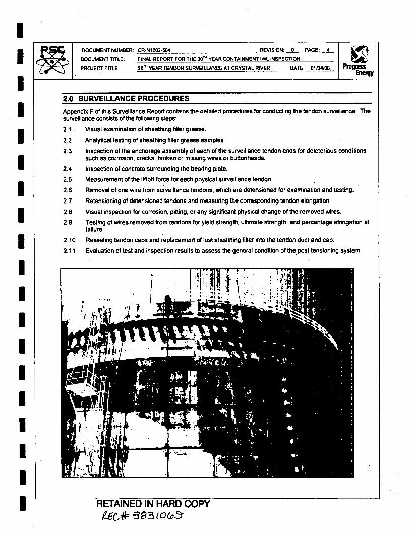
III
DOCUMENT NUMBER:
DOCUMENT TITLE:
PROJECT TITLE:
CR-N1002-504 REVISION: 0 PAGE: 4
FINAL REPORT FOR THE 30"' YEAR CONTAINMENT IWL INSPECTION30r' YEAR TENDON SURVEILLANCE AT CRYSTAL RIVER DATE: 01124108
IIIIIIIIIIIIIIII
2.0 SURVEILLANCE PROCEDURES
Appendix F of this Surveillance Report contains the detailed procedures for conducting the tendon surveillance. Thesurveillance consists of the following steps:
2.1 Visual examination of sheathing filler grease.
2.2 Analytical testing of sheathing filler grease samples.
2.3 Inspection of the anchorage assembly of each of the surveillance tendon ends for deleterious conditionssuch as corrosion, cracks, broken or missing wires or buttonheads.
2.4 Inspection of concrete surrounding the bearing plate.
2.5 Measurement of the liftoff force for each physical surveillance tendon.
2.6 Removal of one wire from surveillance tendons, which are detensioned for examination and testing.
2.7 Retensioning of detensioned tendons and measuring the corresponding tendon elongation.
2.8 Visual inspection for corrosion, pitting, or any significant physical change of the removed wires.
2.9 Testing of wires removed from tendons for yield strength, ultimate strength, and percentage elongation atfailure.
2.10 Resealing tendon caps and replacement of lost sheathing filler into the tendon duct and cap.
2.11 Evaluation of test and inspection results to assess the general condition of the post tensioning system.
RETAINED IN HARD COPY46 93 1O4va

IIIIIIII
DOCUMENT NUMBER: CR-NAL02-504 REVISRPTF: 0 PAGE: 5DOCUMENT TITLE: FINAL REPORT FOR THE 301" YEAR CONTAINMENT IW INSPECTION
PROJECT TITLE: 30'm YEAR TENDON SURVEILLANCE AT CRYSTAL RIVER DATE: 01124=0
3.0 SHEATHING FILLER ANALYSIS
3.1 A sample of sheathing filler (grease) was removed from each end of the surveillance tendons. Chemicaltests were performed on each sample by Suburban Laboratories, Inc. The results are presented inAppendix B and are summarized in Tables 3 thru 5. In Tables 3 thru 5, "N/A" indicates that samples werenot required for testing.
3.2 The maximum acceptable limits are: 10 percent by weight for water content and 10 parts per million forwater-soluble chlorides, nitrates and sulfides. All samples that were tested met the acceptance criteria asstated above.
3.3 The sample testing report also includes the neutralization number of each grease sample. This test isgenerally performed by grease manufacturers on new batches of the product and is a method ofdetermining the overbase additives in the grease. Degradation of the sheathing filler will yield a changein the acidity of the filler material as well as an increase in the ion content. The required neutralizationnumber for the mixture of grease at Crystal River Unit 3 is greater than 0.0 mg KOH/g. This requirementwas achieved by all samples tested.
3.4 No detrimental condition was noted on any grease samples, and no visible breakdown of the grease byeither color or consistency was noted on any of the tendons tested.
IIIIIIIIIII
ION GURN TMUMIO PPM)TENDON END
CHLORIDE SULFIDE NITRATE
WVY, I ilm
CONTENT(%wt)
No. -;,ý_(mag KOHfg)
TOP 40.50 '0.50 '0.50 0.19 71.512V01
BOT 0.50 <0.50 <0.50 0.31 51.9
TOP '0.50 10.50 '0.50 0.19 72.345V20BOT 0.50 '0-50 C0.50 0.34 60.2
TOP 0.50 <0.50 '0.50 0.16 68.461V08
DOT 0.50 '0.50 <0.50 <0.10 48.0
TOP 0.50 <0.50 <0.50 <0,10 61.561V17
BOT 0.50 <0.50 <0.50 <0.10 43.4
ACCEPTANCE LIMITS
ITESWATER SOLUBLE CHLORIDEWATER SOLUBLE NITRATESWATER SOLUBLE SULFIDESWATER CONTENTNEUTRALIZATION NO.
LIMITSLESS THAN 10.OPPMLESS THAN 10-OPPMLESS THAN 10.0PPM
LESS THAN 10% DRY WEIGHTGREATER THAN 0.0 mg KOH/
After the grease cap isremoved, samples ofgrease are taken for alltendons requiring avisual or physicalinspection,
MOTFAIKS~r IKI ILA01fl C'NDIJ
g* 3e I 0v_'3rrr

I
IIIIIIIIIUIIIiIII
DOCUMENT NUMBER:
DOCUMENT TITLE:
PROJECT TITLE:
CR-N1002-504 REVISION: 0 PAGE: 6
FINAL REPORT FOR THE 3 0TH YEAR CONTAINMENT IWL INSPECTION
30'T YEAR TENDON SURVEILLANCE AT CRYSTAL RIVER DATE: 01124/08
ION CONCENTRATION (PPM)
CHLORIDE SULFIDE MwtO (ma KOHlal-- - - ""- - . .
BT 1 0.50 C0.50 '0.50 033 45413H36
ST 3 1.0 <0.50 '0.50 0.10 46,3
BT 2 0.50 <0.50 <0.50 <0 10 40.442H"4
BT 4 0.50 <0.50 C0.50 <0.10 43.1
ST 4 0.50 <0.50 <0.50 <0.10 55.7-46H21
BT6 0.50 <0.50 <0.50 <0.10 62.4
BT 1 <050 <0.50 <0.50 0.12 47.751 H34
BT 5 0.50 <0.50 '0.50 <0.10 40.3
BT 2 0.50 <0.50 <0.50 <0.10 34.062H30
BT 6 0.50 <0.50 '0.50 '0.10 48.2
ACCEPTANCE LIMITS.I MITS
WATER SOLUBLE CHLORIDE LESS THAN 10.OPPMWATER SOLUBLE NITRATES LESS THAN 10.OPPMWATER SOLUBLE SULFIDES LESS THAN 10.OPPMWATER CONTENT LESS THAN 10% DRY WEIGHTNEUTRALIZATION NO. GREATER THAN 0.0 mg KOH/
1UtQOa ND.lON (PPM) %WATER iiiiiiRjL
7ENO~ EN ICoENmT No.- - CHLORDE ýU4J1O NITIRATE t%wt) (mg KoHwo)
BT 3 0.50 '050 <050 0.91 50.2D0129
BT 5 0,50 <050 '0.50 048 42.9
BT 1 0.50 <0.50 0.50 0.17 54,3D212
BT 3 0.50 <0.50 '0.50 0.18 44.0,
ST 4 0.50 '0.50 <0.50 0.17 45.2D238
BT 6 0.50 '0.50 '0.50 '0.10 43.3
ACCEPTANCE LIMITS
TEST LIMITSWATER SOLUBLE CHLORIDE LESS THAN 10.OPPMWATER SOLUBLE NITRATES LESS THAN 10-OPPMWATER SOLUBLE SULFIDES LESS THAN 10 OPPMWATER CONTENT LESS THAN 10% DRY WEIGHTNEUTRALIZATION NO. GREATER THAN 0.0 mg KOH/

IIIIUIIIIIIIIII
III
DOCUMENT NUMBER: CR-N1002-504 REVISION: 0 PAGE 7
DOCUMENT TITLE. FINAL REPORT FOR THE 30" YEAR CONTAINMENT IWL INSPECTION
PROJECT TITLE: 30TM YEAR TENDON SURVEILLANCE AT CRYSTAL RIVER DATE: 01124/08
4.0 ANCHORAGE COMPONENTS
In the following discussion, all procedures referred to are included in Appendix F of this report and all data sheetsare included in Appendix A.
4.1 SQ6.0 - GREASE CAP REMOVAL
4.1.1 Inspection of the anchorage components began by removing the grease cap (PSC Procedure SQ 6.0).Complete grease coating (100%) was found on all tendon ends inspected. The percentage of greasecoverage was recorded on Data Sheet SQ 6.0 with the results tabulated in Tables 6 thru 11.
+4 WBLE6: VRTIAL, ý-;GREASE COATING (%)
TENDON END GREASECAP
BUTTONHEADS
ANCHORHEAD SHIMS BEARING
PLATE
TOP 100 100 100 100 10012V01
BOT 100 100 100 100 100
TOP 100 100 100 100 10045V20
TOT 100 100 100 100 100
TOP 100 100 1030 100 10061V08
BOT 100 100 100 100 100
TOP 100 100 100 100 10061V17
SOT 100 100 100 100 100
Before the Grease Cap is removed,a plastic bag is taped to the concretein order to catch any grease thatmight fall during removal.
Ofto-W-A a& lpr% OIL a a 2 a WW% 10%,O--ýOWLB
-"-r- 1 A1111`411=10 Ill I 1PkML)
9FZ * 5S-5 to &!ý,

IIIIIIIIUIIIII
DOCUMENT NUMBER. CR-Noo02-504 REVISION 0 PAGE: 8DOCUMENT TITLE: FINAL REPORT FOR THE 30"' YEAR CONTAINMENT IWL INSPECTION
PROJECT TITLE: 30 TM YEAR TENDON SURVEILLANCE AT CRYSTAL RIVER DATE: 01124108 Pro
GREASE COATING (%)TENDON END GREASE BUTTON ANCHOR SHWAS BEARING
CAP HEADS HEAD PLATE
BT1 100 100 100 100 10013H36
BT 3 100 100 100 100 100
BT 2 100 100 100 100 10042H46
BT 4 100 100 100 100 100
ST4 t00 100 100 100 10046H21
BTS 100 100 100 100 100
BT1 100 100 100 100 10051 H34
ST 5 100 100 t00 100 100
BT 2 100 100 100 100 10062H30
BT6 100 100 100 100 100
_________ GREASE COATING (%) _
TENDON END REmse BUTTON ANCHOR SHgM , B .AINGCAP HWADS HEAD PLATE
BT 3 100 100 100 100 1000129
BT S 100 100 100 100 100
aT I 100 100 100 100 100D212
ST 3 100 100 100 100 100
BTA4 100 100 100 100 1000238
BT6 100 100 100 100 100
IIIII
Grease Cans are removedusing an impact wrench.While workers take care tosupport the weight of thecan filled with grease.
l•=TAI fI=•l II, LJADrI tEYIDV
~EC,* ~3dO(o~

IIIIUIIIIIIIIIII1II
DOCUMENT NUMBER: CR-N1002-504 REVISION. 0 PAGE: 9
DOCUMENT TITLE: FINAL REPORT FOR THE 30" YEAR CONTAINMENT IW. INSPECTION
PROJECT TITLE: 304 YEAR TENDON SURVEILLANCE AT CRYSTAL RIVER DATE: 01124/08 pW.
GREASE COATINGTENDON END GREASE BUTTON ANCHOR SHIMS BEARING
CAP HEADS HEAD PLATE
BT1 100 100 100 100 10013H33
BT3 100 100 100 100 100
STI 100 100 100 100 10013H34
8T3 100 100 100 100 100
BT1 100 100 100 100 10013H35
BT3 100 100 100 100 100
BT1 100 100 100 100 10013H37
BT3 100 100 100 100 100
BTI 100 100 100 100 10013H38
BT3 100 100 100 100 100
GREASE COATING (9/6)TENDON END GREASE BUTTON ANCHOR SHIMS BEARING
CAP HEADS HEAD PLATE
BT4 100 100 100 100 10046H1 9
BT6 100 100 100 100 100
BT4 100 100 100 100 10046120
3TO 100 100 100 100 100
BT4 100 100 100 100 10046H22
BT8 100 100 100 100 100
BT4 100 100 100 100 10046H23
BT6 100 100 100 100 100
BT4 100 100 100 100 10046H24
BT6 100 100 100 100 100

IIIIIIIIIIIIIIIIIII
DOCUMENT NUMBER, CR-N1002-504 REVISION: 0 PAGE: 10
DOCUMENT TITLE: FINAL REPORT FOR THE 30"h YEAR CONTAINMENT IWL INSPECTION
PROJECT TITLE: 30T" YEAR TENDON SURVEILLANCE AT CRYSTAL RIVER DATE: 01/24108
TABLE ~ ~ *O P.1: *6H0AJCN [HOOP - I0ý.-GýA'*E'-PRrOAiGREASE COAlING (%)
TENDON I END GREASECAP
BUTrONHEADS
ANCHORHEAD SHIIMS BEARING
PLATE
8B2 100 100 100 100 10062H29
BT6 100 100 100 100 100
BT2 100 100 100 100 10062H31
BT6 100 100 100 100 100
6T2 100 100 100 100 10062H32
BT6 100 100 100 100 100
BT2 100 100 100 100 10062H33
BT6 100 100 100 100 100
6T2 100 100 100 100 100620134
8T6 100 100 100 100 100
4.2 SQ6.1 - INSPECT FOR WATER
4.2.1 Water Inspections were recorded on Data Sheet SQ 6.1 and are summarized in Tables 12 and 13. Nowater was found in any tendon inspected or around the tendon anchorage either during removal of thegrease cap or detensioning.
TABLE ~ ~ ~ 12IRGNLStP Q. NPC b'Ag
SIURVEILLANCE TENDONS SURVEILLANCE TENDONS
WATERmlNDON END QUANIMY
(OZ.)TOP 0
12V018OT 0
TOP 045V20BOT 0
TOP 0
BOT 0
61V17 TOP 0
BOT 0
13H36BT 3 0
WATERTENDON END QUANTITY
BT 4 0461H21BT8 0
ST 1 0
511H34BT 5 0
81 2 0
62H30BT 6 .0
D129 BT 3 0ST 5 0
D212BT 1 0
BT 3 0
42H46BT 2
BT 4
0
0D238
BT 4
BT 6
0
0* I I I I I

IIII1IUIII
DOCUMENT NUMBER: CR-NIOO?4504 REVISION: 0 PAGE: 11
DOCUMENT TITLE. FINAL REPORT FOR THE 30'" YEAR CONTAINMENT IWL INSPECTION ýN
PROJECT TITLE: 31T" YEAR TENDON SURVEILLANCE AT CRYSTAL RIVER DATE: 01124/08 Prop
ADJACENT TENDONS ADJACENT TENDONS
WATER WATERTENDON END QUANTITY TENDON END QUANTITY
ST 1 0 " BT 4 013H33 46H23BT 3 0 BT6 0
BT 1 0 BT 4 01 3H34 46H424BT 3 0 BTG a
BT 1 0 BT 2 013H435 62H29BT 3 0 BT6 0
BT 1 0 BT2 013K37 621431BT3 0 BT6 0
STI1 0 BT 2 013H38
62H32
BT 3. 0 BT 6 0
BT 4 0 BT2 0481H19 621433ST 6 0 BT 6 0
BT 4 0 BT 2 0481H20 621434BT 6 0 BT6 0
6T 4 046H22
BT 0 0
IIIIIIII
During all phases of the can removaland inspections, the presence of wateris noted and quantified.
RETAINED IN HARD COPY
RETAINED IN HARD COPYac* 3,2,3 1olv-

IDOCUMENT TITLE: FINAL REPORT FOR THE 30'M YEAR CONTAINMENT IW. INSPECTION
PROJECT TITLE: 30'" YEAR TENDON SURVEILLANCE AT CRYSTAL RIVER DATE: 01/24/08 P1 gus
I 4.3 SQ8.0 - ANCHORAGE CORROSION CONDITON
4.3.1 The anchorage components (anchorhead, buttonheads. shims and bearing plate),were inspected forcorrosion level and cracks per PSC Procedure SO 8.0. The results were recorded on Data Sheet SQ 8.0and are summarized in Tables 14 thru 19. In Tables 14 thru 19, "N/A" indicates the Anchor I.D. was notdetected.
4.3.2 The corrosion level for all of the inspected anchorage assemblies and wire was either:
I - Bright metal; no visible oxidation.
Or2- Metal reddish brown color, no pilling.
4.3.3 No evidence of cracking was observed on any of the anchorage components.ITABLE 14: VERTICAL*S'-:ýtiD6rO'-ýýý!ýtH'OR*6'ttC-ORROSI;ONiCOtiDITION
I HEAD PLATE
I
i
IIIIIIIII
TOP CR650 1 1. NONE 2, NONE 2. NONE12V01
BOT N/A 1 1. NONE 2. NONE 2. NONE
TOP CR650 2 2, NONE 2, NONE 2. NONE45V20
BOT CR260 1 2. NONE 2. NONE 2. NONE
TOP CR933 1 1. NONE 2, NONE 2. NONE61V08
BOT CR300 1 1. NONE 2. NONE 2. NONE
TOP CR943 1 1, NONE 2. NONE 2. NONE61V17BOT CR256 1 2, NONE 2. NONE 2. NONE
INDICATES CORROSION LEVEL INDICATES X OF CRACKS
1 - Bright metal, No visible oxidation.2 - Metal reddish brown color, no pitting.3 - Metal having patches of red oxide

IIIIIIIII-IIIIIIUIII
DOCUMENT NUMBER: CR-NIO02-UM REVISION: 0 PAGE: 13
DOCUMENT TITLE: FINAL REPORT FOR THE 30r" YEAR CONTAINMENT IWL INSPECTION
PROJECT TITLE: 30'" YEAR TENDON SURVEILLANCE AT CRYSTAL RIVER DA7E: 01124108
II 1 I ~ I **' ***'*'11
CORROSION LEVEL, CRACKSTENDON I END ANCHOR
I.D.BUTTONHEADS ANCHOR
HEAD SHIMS BEARINGPLATE
BT I CR618 1 2. NONE 2, NONE 2. NONE13H36
BT 3 CR1167 1 2. NONE 2. NONE 2, NONE
BT 2 CR1170 1 I, NONE 2. NONE 2. NONE42H46
BT 4 CR529 1 1. NONE 2. NONE 2. NONE
BT 4 CR1141 1 1. NONE 2. NONE 2, NONE46H21
BT 6 CR167 1 1. NONE 2. NONE 2. NONE
BT I CR459 1 1. NONE 2. NONE 2. NONE51H34
BT 5 CR943 1 1. NONE 2. NONE 2, NONE
BT 2 CR96 1 1. NONE 2. NONE 2. NONE62H3087 6 CR609 1 1. NONE 2. NONE 2, NONE
INDICATES CORROSION LEVEL " INDICATES # OF CRACKS
1 - Bright metal, No visible oxidation.2 - Metal reddish brown color, no pitting.3 - Metal having patches of red oxide.
T A B6 16: DOE. NONE CO R IN ONE ,IN O
ANCHOR SUtTON cmuwLV*LID. HEADS- ANCHOR B~s~ EARING
HEAD PLATED1293 CR995 1 NONE 2, NONE 2. NONE
ST 5 CR886 2 2. NONE 2. NONE 2, NONE
BT.1 CR1032 1 2. NONE 2. NONE 2. NONE0212
5T 3 CR1214 1 1, NONE 2. NONE 2. NONE
BT 4 CR657 1 1. NONE 2. NONE 2. NONE0238
FT 6 CR1029 1 1. NONE 2. NONE 2, NONE
INDICATES CORROSION LEVEL INDICATES # OF CRACKS
1 - Bright Metal, No visible oxidation.2 - Metal reddish brown color, no pitting.3 - Metal having patches of red oxide.

DOCUMENT NUMBER: CR-N1002-504 REVISION: 0 PAGE: 14
DOCUMENT TITLE: FINAL REPORT FOR THE 30'" YEAR CONTAINMENT IVYL INSPECTION
PROJECT TITLE: 30'm YEAR TENDON SURVEILLANCE AT CRYSTAL RIVER DATE: 01124/08
IIIIIIIIIIIIIIIII
TAL 7:I11i A DAENIPýlt A AN OAE-6R'ý1*0,N6Nb NATENDON
CORROSION LEVEL, CRACKSEND ANCHOR
I.D.BUTTONHEADS ANCHOR
HEAD SHIMS BEARINGPLATE
BT 1 CR518 1 1. NONE 2, NONE 2, NONE13H33
BT 3 CR1200 I 2. NONE 2. NONE 2, NONE
BT 1 CR514 1 1. NONE 2. NONE 2. NONE
13H34ST 3 CR1159 I 1. NONE 2. NONE 2. NONE
BT I CR510 1 1. NONE 2. NONE 2, NONE
13H35ST 3 CR1158 1 2. NONE 2. NONE 2. NONE
BT I CR509 1 1. NONE 2. NONE 2. NONE
13H37BT 3 CR1272 1 1. NONE 2. NONE 2. NONE
BTI CR614 1 1. NONE 2. NONE 2. NONE
131H38BT 3 CR710 1 2. NONE 2. NONE 2. NONE
INDICATES CORROSION LEVEL I I NONE r--. . INDICATES # OF CRACKS
1 - Bright Metal, No visible oxidation2 - Metal reddish brown color, no pitting.3 - Metal having patches of red oxide.
8.2 & 8.3 - CORROSION & CRACK INSPECTION
(8.2.1.1) Buttonheads Level: f(8.2.2.1) Anchorhead Level: !
(8.2.2.1) Shims Level:
(8.2.2.1) Bearing Plate Level:
(8.2.1 & 8.2.2) Cracks
(8.2.1 & 8.2.2) Cracks
(8.2.1 & 8.2.2) Cracks1A'2I A A-2-21 Cradks
o Yes- Yes•
Y es•ElYes
blNo 0QN1A
19No [INIA10 No [INIAtffNo 0QNIA
forrTendon Inspetion
RETAINED IN HAFD LUUVYk~t ý3eI CX-,C

IDOCUMENTr NUMBER: CR-NIO02-504 REVISION: 0 PAGE: 15
DOCUMENT TITLE: FINAL REPORT FOR THE 30'm YEAR CONTAINMENT IWI. INSPECTIONPROJECT TITLE: 30' YEAR TENDON SURVEILLANCE AT CRYSTAL RIVER DATE: 01/24/08 P•pUS
IIIIIIIIIIIIIIIII
I.- . * S. S**:"-I
CORROSION LEVEL, CRACKSTENDON I END ANCHOR
I.D.BUTTONHEADS ANCHOR
HEADSHIMS BEARING
PLATE
BT4 CR1218 t 2. NONE 2. NONE 2. NONE46H19
BT S CR380 1 2. NONE 2. NONE 2. NONE
BT4 CR1138 2 2. NONE 2. NONE 2. NONE46H20
BT 6 CR78 1 1, NONE 2. NONE 2, NONE
BT 4 CR1140 1 2. NONE 2. NONE 2. NONE46H22
ST 6 CR41 1 2. NONE 2. NONE 2. NONE
BT4 CR903 1 2. NONE 2. NONE 2. NONE46H23
BT 6 CR40 1 2, NONE 2. NONE 2. NONE
BT 4 CR1157 1 2. NONE 2. NONE 2. NONE46H24
BT 6 CR14 1 2. NONE 2. NONE 2. NONE
INDICATES CORROSION LEVEL INDICATES # OF CRACKS
1 - Bright Metal, No visible oxidation.2 - Metal reddish brown color, no pitting.3 - Metal having patches of red oxide.
Corrosion Inspectionfor Tendon D2381BT6
8.2 a 8.3 - CORROSION & CRACK INSPECTION
(8.2.1.1) Buttonheads
(5-.22.21) Anchorhead
(8.2.2.1) Shims
(8.2.2.1) Bearing Plate
Level: 1 4" (8.2.1 & 8 2.2) Cracks C] Yes (2)
Level: I - (8.2.1 & 8.2.2) Cracks [] Yes (2)
Level: fit (8 2.1 & 8.2.2) Cracks . C1 Yes ",
Level: , (1 (8.2.1 & 8.2.2) Cracks C1 Yes I"'(1 - Corrosion Levels of 3. 4. 5 or 6 required an NCR.
-1_ r..nm,• A kplkM n othn cracks tn Sketch Sheet 8.0 and iniiate an NCR.
fNo 0 N/A
'S No 0 N/A
1B No O NIA1L.No 0 N/A
Eti:IAINED WN HARD COPY

II
IIIIIIIIIIIIIIII
DOCUMENT NUMBER: CR-N1002-504 REVISION: 0 PAGE: 16
DOCUMENT TITLE: FINAL REPORT FOR THE 30" YEAR CONTAINMENT IW. INSPECTION
PROJECT TITLE: 30'" YEAR TENDON SURVEILLANCE AT CRYSTAL RIVER DATE. 01124108
J'J4~i -.A Lý0ýýFý'I-Jk-'--k 6 tý"O.O'N H kG !-R :'7tNtCNE) ** 0Fbs
CORROSION LEVEL, CRACKSTENDONI END ANCHOR
I.D.BUTTONHEADS ANCHOR
HEAD SHIMS BEARINGPLATE
-iii- -i
BT2 CR393 1 1. NONE 2. NONE 2. NONE62H29BT 8 CR1113 1 1. NONE 2. NONE 2. NONE
BT 2 CR164 1 1. NONE 2, NONE 2. NONE62H31
BT 6 CR958 1 1. NONE 2. NONE 2, NONE
BT 2 CR75 1 1, NONE 2, NONE 2. NONE62H32
BT 6 CR960 1 1. NONE 2. NONE 2. NONE
BT 2 CR77 1 1, NONE 2. NONE 2. NONE62H33
BT 6 CR538 1 1, NONE 2. NONE 2. NONEBT 2 CR25 1 1. NONE 2. NONE 2, NONE
62H34BT 6 CR900 1 1. NONE 2. NONE 2, NONE
INDICATES CORROSION LEVEL - . 1. NONE INDICATES # OF CRACKS
1 - Bright Metal, No visible oxidation.2 - Metal reddish brown color, no pitting.3 - Metal having patches of red oxide.
8.2 & 8.3 - CORROSION & CRACK INSPECTION(8.2.1.1) Buttonheads
(8.2.2.1) Anchorhead
(8.2.2.1) Shims
(8.2.2.1) Bearing Plate
Level: I I
Level:
Level: jLevel: j
(8.2.1 & 8.2.2) Cracks 0 Yes "I
(8.2.1 & 8.2,2) Cracks DYes ' 2 '
(8.2.1 & 8.2.2) Cracks 0 Yes 121
(8.2.1 & 8-2.2) Cracks C Yes rn)
mor 6 required an NCR.tch Sheet 8.0 and inflte an NCR
No
[No
No
O N/AC N/AO N/Ao N/A
Corrosion Inspectionfor Tendon D212/BT1
RETAINED IN MAKU COPYR-Ec*- -ýe-15 04

IDOCUMENT NUMBER: CR-N1002-504 REVISION: 0 PAGE: 17
DOCUMENT TITLE: FINAL REPORT FOR THE 3O•" YEAR CONTAINMENT IWL INSPECTION
PROJECT TITLE: 30"' YEAR TENDON SURVEILLANCE AT CRYSTAL RIVER DATE: 01124108
4.4 SQ8.0 - BUTTONHEAD COUNT
4.4.1 The inspection for protruding and missing buttonheads was performed and documented per PSCprocedure SQ 8.0. The buttonheads were inspected for their physical condition. This inspection isperformed to acquire information on the function of the tendon, since the original installation or previoussurveillance. A missing and/or protruding buttonhead decreases the amount of effective wires in the tendon.All conditions for buttonheads and wires, whether missing or defective, have been documented. The resultsof these inspections are recorded on Data Sheet SQ 8.0, and are summarized in Tables 20 thru 25. InTables 20 thru 25, "N/A" indicates no inspection was performed.
4.4.2 No additional protruding/missing buttonheads were detected on any of the inspected tendon ends excepttendons 12V01 both ends and 61V17 shop (top) end. 12V01 shop was found with I wire protruding thatwas not previously reported, NCR FN1002-010 was written to document this finding. The field end of12V01 was identified as having 3 missing buttonheads not previously reported and was documented onNCR FN1002-004. 61V17 had one (1) additional missing buttonhead that was recorded on NCRFN1002-005. The stated conditions have been submitted to CR03ENG for disposition.
4.4.3 All of the other tendon ends with missing or protruding wires have been previously documented andaccepted, either at original installation or during a previous inspection.
4.4.4 In addition to the nominal 163 stressed wires, the anchorheads have another hole in which a test wirewas originally installed on some tendons. The cases in which the surveillance test wire was found to bemissing or not installed has been documented for all tendons, however a missing test wire has no bearingon the ability of a tendon to carry force. The documentation of this condition is purely for informationalpurposes.
I 2 EORIGINAL AS FOUND AS LEF
IUNDOW N D1 WZ !ALloEt L 0 06 rg
ILTOP 1 0 2 0 2 0 0 161 181
12V01BOT 0 2 0 5 0 5 0 158 158TOP 0 0 0 0 0 0 0 163 163
45V20SOT 0 0 0 0 0 0 0 163 163TOP 0 0 0 0 0 0 0 163 163
61V08SOT 0 0 0 0 0 0 0 163 163
61VI? TOP 0 1 0 2 0 2 1 161 160
BOT 0 0 0 0 0 0 1 163 162
IIII

IIIIIIIIII
ý7_0DOCUMENT NUMBER:
DOCUMENT TITLE:
PROJECT TITLE:
CR.N1002-504 REVISION: 0 PAGE: 18
FINAL REPORT FOR THE 301" YEAR CONTAINMENT PA INSPECTION
30m' YEAR TENDON SURVEILLANCE AT CRYSTAL RIVER DATE: 01/24/08
'--BE2*1:ICOS o(S 0!-iUToNH 3 0OUN'
ORIGINAL AS FOUND AS LEFT
TENDON ENDwuWI-ix OR L 0
0Z
0go 0w.
uZOOw 0 P
&ILCo
0a,w ( w0,W
U.j
BT 1 0 0 0 0 0 0 0 163 16313H36
BT 3 0 0 0 0 0 0 0 163 163
8T 2 0 0 0 0 0 0 0 163 16342H46
BT 4 0 0 0 0 0 0 0 153 163
BT 4 0 0 0 0 0 0 0 163 16346H21
BT 6 0 0 0 0 0 0 0 183 163
BT 1 0 0 0 0 0 0 1 163 16251H34
BT 5 0 0 0 0 0 0 1 163 162
BT 2 0 0 0 0 0 0 0 163 18362H30
5T6 0 0 0 0 0 0 0 163 163
IIIIIIIII
TAL 22 .3bMSý,ý 9SbdIBTOHA ON

iIIIiiiUIIIIIIIIIII
DOCUMENT NUMBER: CR-Nt002-504 REVISION 0 PAGE: 19
DOCUMENT TITLE: FINAL REPORT FOR THE 30"' YEAR CONTAINMENT IVL INSPECTION
PROJECT TITLE: 3 0T" YEAR TENDON SURVEILLANCE AT CRYSTAL RIVER DATE: 01124108
TAL 23 133 ASt.tT 'Q8 :B TOH AWON
ORIGINAL ASIFOUND AS LEFT
00 0
TENDON END a % wswtl1g w w~rE 0
BT 1 0 0 0 0 0 0 0 163 16313H33
BT 3 0 0 0 0 0 0 0 163 163
BT 1 0 0 0 0 0 0 0 163 16313H34
ST 3 0 0 0 "0 0 0 0 163 163
BT 1 0 0 0 0 0 0 0 163 16313H35
BT 3 0 1 0 1 0 1 0 162 162
BT 1 0 0 0 0 0 0 0 163 16313H37
BT 3 0 0 0 0 0 0 0 163 163
BT 1 0 0 0 0 0 0 0 163 16313H38 BT 3 0 0 0 0 0 0 0 163 163
r.
I'rOOOOOO000O00
0000000000000000000000000
0 000000000
000000000 0
o000000oooooo000000ooooo
ooY ooooo
Buttonhead Inspectionfor Tendon D 129/BT5
RETAINED IN HAHU UUrT

IIIIIIIIII
D DOCUMENT NUMBER: CR-N1002-504 REVISION: 0 PAGE: 20
DOCUMENT TITLE: FINAL REPORT FOR THE 30'" YEAR CONTAINMENT MA. INSPECTION
PROJECT TITLE: 30'" YEAR TENDON SURVEILLANCE AT CRYSTAL RIVER DATE: 01124/08
ORIGINAL I AS FOUND AS LEFT
TENDON ENDa
IA.
ii 'Ua
I-
00.
ii0( 0ý1.
--ft
50WE0:0 Win 2
!20161 U.
BT 4 0 0 0 0 0 0 0 163 16346H19BT 6 0 0 0 0 0 0 0 163 163
BT 4 3 0 3 0 3 0 0 160 16046H20
BT 6 0 0 0 0 0 0 0 163 163
BT 4 0 0 0 0 0 0 0 163 16346H22
T" 6 0 0 0 0 0 0 0 163 163
BT4 0 2 0 2 0 2 0 161 16146H23
ST 6 0 0 0 0 0 0 0 163 163
BT 4 0 0 0 0 0 0 0 163 16346H24
BT 6 0 0 0 0 0 0 0 163 163
1IIIIIIIII
/\.2, oooooonot 0 0•o o o
000000000000000000000000000
0o000 0000000
000000000000000000000000000000000000000000 000 00
000(o00oooooooooo. 0 10
tit fAINED IN HARD~ COPYAEC*z se831oloz

IIIIUIIIIIIIIIIIIII
DOCUMENT NUMBER: CR-N1002-504 REVISION: 0 PAGE: 21
DOCUMENT TITLE: FINAL REPORT FOR THE 30'm YEAR CONTAINMENT IW.L INSPECTION
PROJECT TITLE: 30W YEAR TENDON SURVEILLANCE AT CRYSTAL RIVER DATE: 01/24/08 EMU
* em *. *aLTA L 25 623 A IJ INS-S8! ~-T-b HW ;b,
ORMGINAL AS FOUND AS LEFTI C
TENDON ENDZI jO
0E .
w -
o ~0~ WZo ~~ ml
0I40
4u
www
- -i--
BT 2 0 0 0 0 0 0 0 163 16362H29
BT6 0 0 0 0 0 0 0 163 163
BT 2 0 0 0 0 0 0 0 163 16362H31
BT 6 0 0 0 0 0 0 0 163 163
BT 2 0 0 0 0 0 0 0 163 16362H32
BT8 0 0 0 0 0 0 0 163 163
ST 2 .0 0 0 0 0 0 0 163 16362H33
BT 8 1 0 1 0 1 0 0 162 162
BT 2 0 0 0 0 0 0 0 163 16362H34
BT 6 0 1 0 1 0 1 0 162 162
rasi,
^Ivr.b
000000000000000000
0000000000000000oo0000
0000000000000000000000000000000000000000000000000000
o0 ooo0ooooooo\• 00000000000
ýBurttonhead Inspectionfor Tendon D1291BT3
RiETAINED lN HARD GCFLYP-E 4t- S 3 S/O(O0 --

IIIII
DOCUMENT NUMBER: CR-N1002-504 REVISION: 0 PAGE: 22
DOCUMENT TITLE: FINAL REPORT FOR THE 30TM YEAR CONTAINMENT PA. INSPECTION
PROJECT TITLE: 30T1 YEAR TENDON SURVEILLANCE AT CRYSTAL RIVER DATE: 01/24/08
5.0 SQ8.3 - CONCRETE INSPECTION
5.1 A VT-1C Detailed inspection in accordance with PSC Procedure S08.3 was performed on the 24" aroundthe bearing plate. This detailed inspection is performed in order.to detect any cracks in the concretegreater than 0.010" in width. The results were recorded on Data Sheet SQ 8.3 and summarized in Table26.
5.2. None of the inspected tendon ends exhibited concrete cracks exceeding 0.010' around any bearing plateinspected.
C T0 0lqIIIIIIIIIIIIII
TENDON END ING PLA•TECRACKS WITH WIDTHS > 0.010"
QUANTITY L TMAXIMUM I MAXIMUMLENGTH IlNi A IWIDTNinI
TOP NONEFOUND 0 0 012V01
BOT NONE FOUND 0 0 0
TOP NONE FOUND 0 0 045V20BOT PC58 0 0 0
TOP NONE FOUND 0 0 061V08
BOT NONE FOUND 0 0 0
TOP NONE FOUND 0 0 061V17
SOT NONE FOUND 0 0 0
BT I NONEFOUND 0 0' 013H36
BT3 NONEFOUND 0 0 0
BT 2 NONE FOUND 0 0 0421H46
BT4 NONE FOUND 0 0 0
BT4 NONE FOUND 0 0 046H21
STO NONEFOUND 0 0 0
STI NONE FOUND 0 0 051 H34
BT5 NONEFOUND 0 0 0
BT 2 NONE FOUND 0 0 062H30
BT6 NONEFOUND 0 0 0
BT 3 NONEFOUND 0 0 0D129
BT 5 NONEFOUND 0 0 0
BTI NONE FOUND 0 0 0D212
BT 3 NONE FOUND 0 0 0
BT4 NONE FOUND 0 0 00238
BT6 NONE FOUND 0 0 0

II
DOCUMENT NUMBER: CR-N1002-504 REVISION: 0 PAGE: 23
DOCUMENT TITLE- FINAL REPORT FOR THE 30'" YEAR CONTAINMENT IWL INSPECTION
PROJECT TITLE: 30'" YEAR TENDON SURVEILLANCE AT CRYSTAL RIVER DATE: 01124/08
IIIIIIIIII,IIIIII
6.0 TENDON ACCESSIBILITY
6.1 The PSC field personnel performed a general examination for tendon accessibility during this surveillanceperiod. This examination was performed in order to assist CR03ENG in the planning of futuresurveillances. The results are summarized in Tables 27 thru 38.
6.2 During this examination it was noted that small grease/oil leaks were occurring on multiple tendon caps,which were located inside existing structures that adjoin the containment building. The substancedisplacing from the tendon cap is actually the oil portion from the original P2 grease that has separated.This is a common occurrence that has been noted throughout many plants during tendon surveillances.This condition does not correspond to the system's degradation. A small amount of oil can cause a largeaesthetically unpleasing condition. On buttresses without any coating, the oil is absorbed into theconcrete, leaving very little signs of leakage. However, in the existing condition, the coated surface doesnot allow for the absorption to occur. Therefore, the oil continues to displace down the buttress face.PSC recommends this condition be monitored and cleaned on a periodic basis. Gasket replacement canbe performed on the tendon cap, however the oil will continue to leak from the cap based on ourexperience. The labor and material required for the gasket replacement is not cost effective and PSCdoes not recommend performing such task.
TABLE~~~~~~ 27.2 &2VSSiS-TNO ACE5111. TR
0 U)
12V01 TA BL 23V01 T12V02 TB 23V02
12V 01 T & 0 23V 03 TAB
12V 04 TAB 23V 04 TAB
12V 05 TA B 23V 05 TAB12V 04 TAB 23V 06 TAB
12V 07 TAB 23V 07 TAB12V 08 TAB 23V 08 TAB
12V 09 TAB 23V 09 TAB
12V 10 TAB 23V 10 T AB12V10 TAB 23Vll TAB
12V 12 TAB 23V 12 TAB12V 11 TAB 23V 11 TAB
12V 12 TAB 23V 12 TAB12V 13 T&8 23V 13 TAB
12V 14 TAB 23V 14 TAB
12V15 T&B 23V 15 TAB
12V 16 TAB 23V 16 T A B
12V 17 TAB 23V 17 TAB
12V18 TAB 23V18 TAB
12V 19 TAB 23V 19 TAB
12V 20 T& 23V 20 TAB12V 211 TA&B !23V 21 TA&B
12V 22 TAB 23V 22 T&B
12V 23 TAB 23V 23 TAB
12V 24 TAB 23V 24 TABI * * I
T = TOP CAN B - BOTTOM END

IDOCUMENT NUMBER: CR-N1002.504 REVISION: 0 PAGE: 24
DOCUMENT TITLE: FINAL REPORT FOR THE 30IM YEAR CONTAINMENT IWL INSPECTION
PROJECT TITLE: 30TM YEAR TENDON SURVEILLANCE AT CRYSTAL RIVER DATE: 01/24/08
IIIIIIIIIIIIIIIII
-TB E2- 34m5'ER'S * ENO A-ES bLITM TiX
a- US to aac
tL w K 16WU.a . k|00 to U) 0 t
34V 01 T&B 45V 01 T A B
34V 02 TAB 45V 02 T&B
34V 03 T&B 45V 03 TAB
34V 04 T&B 45V 04 T&A
34V 05 TAB 45V 05 TA8
34V 06 T&B 45V 06 TAB
34V 07 T&AB 45V 07 T A B
34V 08 TAB 45V 08 TAB
34V 09 TAB 45V 09 T&B
34V10 TAB 45V10 T&B
34V11 TAB 45V11 TAB
34V12 T&B 45V12 T&B
34V 13 TSB 45V 13 T&B
34V 14 TAB 45V 14 T&B
34V15 TAB 45V15 TAB
34V16 T&B 45V16 T&B
34V 17 T& 1 45V 17 TAB
34V 18 TAB 45V I8 T&B
34V 19 TAB 45V 19 TA B
34V 20 TAB 45V 20 T&B
34V 21 T&B 45V 21 TAB
34V22 T&B 45V22 T&A
34V 23 TAB 45V 23 TAB
34V 24 TAB 45V 24 TABmmý
T TOP CAN B = BOTTOM END

IUUIIIIUIIIIIIIIIII
DOCUMENT NUMBER: CR-N1002-504 REVISION: 0 PAGE: 25
DOCUMENT TITLE: FINAL REPORT FOR THE 3 0 "' YEAR CONTAINMENT IWL INSPECTION
PROJECT TITLE: 30TM YEAR TENDON SURVEILLANCE AT CRYSTAL RIVER DATE: 01/24/08
TrBL:2:.5V, 6VSElk TND N'~-CtýS6I!ITYM TRX.-
- -•o_ U'I I j 4II 4wS2 j U 40 V5; R!Z
56V 01 TAB 61V 01 TAB
56V 02 TAB 61V 02 TAB
56V 03 TAB 61V 03 TAB
56V 04 TAB 61V 04 TAB
56V 05 TAB 61V05 i TAB
56V 06 TAB 61V 06 TAB
56V07 TAB 61V07 TAB
56V 08 TAB eiv 08 TAB
56V 09 TAB 61V 09 TAB
56V 10 TAB 61V 10 TAB
56V 11 TAB 61V 11 TAB
56V 12 TAB 61V 12 TAB
58V 13 TAB 61V 13 TAB
56V14 TAB 61V14 TAB
56V15 TAB 61V15 TAB
Sv is TAB 61V16 T&B
56V 17 TAB 61V 17 T & 856Vis TAB 61V 18 TAB
56V 19 TAB 61V 19 TAB
56V20 TAB 61V 20 TAB
56V21 TAB 61V 21 TAB
56V 22 TAB 61V 22 T A B
56V 23 TAB 61V 23 TAB
56V 24 TAB 61V 24 TAB- a I I i
T " TOP CAN B = BOTTOM END

IUIIIIIIIIIUIIIIIII
DOCUMENT NUMBER: CR-NIO02-504 REVISION: 0 PAGE: 26W DOCUMENT TITLE: FINAL REPORT FOR THE 30"' YEAR CONTAINMENT IWI. INSPECTION
PROJECT TITLE: 30'" YEAR TENDON SURVEILLANCE AT CRYSTAL RIVER DATE: 01/24/08
-30 13 EIS ENO M TI
v =. . Z WZ1- 0
up (4a4 W w U.
l IIL
13H 01 B3 a1 13H 25 818B3
13H 02 81 & 83 13H 26 81 & 83
13H 03 81 & B3 13H 27 B1 & B3
13H404 B1 A 13 13H 28 81 & 83
13H 05 81 83 13H 29 81 & B3
13H 06 81 B3 13H 30 B1 & B3
13H 07 B1 B3 13H 31 81 &B3
13H 08 81883 13H 32 B1 & B3
13H 09 B3 B1 13H 33 81 & 83
13H 10 B3 B1 13H 34 81 &83
13H11 83 81 13H135 , B1 &83
13H 12 03 B1 13H 36 81 &83
13H 13 B3 e1 13H 37 Bi & B3
13H 14 83 Ba 13H 38 B1 & 83
13H 15 B3 81 13H 39 B1 & 83
13H 16 83 B1 13H 40 81 & B3
13H 17 83 e1 13H 41 81 & B3
13H 18 B1 B3 13H 42 81 & 83
13H 19 81 B3 13H 43 81 & 83
13H 20 B1 & B3 13H44 B1 & B3
13H 21 BI&B3 13H145 BI1&83
13H122 e8&83 13H146 81&83
13H 23 81 & 83 13H 47 B1 & B3
13H 24 B1 & S3
81 = BUTTRESS 1 END 83 = BUTTRESS 3 END

I1 ý7. DOCUMENT NUMBER: CR-N1002.504 REVISION: 0 PAGE: 27
FINAL REPORT FOR THE 30TM YEAR CONTAINMENT IW. INSPECTIONDOCUMENT TITLE:
PROJECT TITLE: 30'm YEAR TENDON SURVEILLANCE AT CRYSTAL RIVER DATE: 01124/08
IIIIIIIIIIIIIIIII
S S S U S S S35H 0135H 0235H 0335H 0435H 0535H 0635H 0735H 0835H 0935H 1035H 1135H 1235H 1335H 1435H 1535H 1635H 1735H 1835H 1935H 2035H 2135H 2235H 2335H 24
83 & 85
B3 & B5
B3 & B5
B3 & B5
83 & 65
B3 B5
83 & B5
B3BS
B3 B5
B3
B3
B3
B3 & B5
B3 & 85
83 & e5
B3 & B5
B3
B3
B3
B3
83 & B5
B3 & 85
85
35H 2535H 2635H 2735H 2835H 2935H 3035H 3135H 3235H 3335H 3435H 3535H 3635H 3735H 3835H 3935H 4035H4135H 4235H 4335H 4435H 4535H 4635H 47
B3 & B583&B5B3 & B5838 85
B3& B583&B5
B3& 65
83& 85
83 &B5
83£85
63 & B5
838& 5
63 & 85133 85
B3& B55838& 85
83 & B5
83& B5
83 & B58388 5
B3 & B5
B3& 05838 815
B5
85
85
85
B5
85
I I I I I I83 = BUTTRESS 3 END 85 = BUTTRESS 5 END

IIIIIIIIIIIIIIIIII
DOCUMENT NUMBER: CR-N1002-504 REVISION: 0 PAGE: 28
DOCUMENT TITLE: FINAL REPORT FOR THE 30r YEAR CONTAINMENT IW. INSPECTION
PROJECT TITLE: 3OT" YEAR TENDON SURVEILLANCE AT CRYSTAL RIVER DATE: 01124/08
nABLE m m 5 II I
W z u.a (.I3 W
I I.2 "Zn F: L 5r - . z -i to J r
0) 0I (.J L)cow#j_A. Q U)L j )0 I
51H 01 B9 85 51H 25 & asSIH 02 81 B5 51H 26 91 a 65
511H03 81 85 51H 27" el & 85
51H 04 B1 as 51H 28 91 &85
51H 05 BI 85 51H 29 BI & B5
51H 06 B1 85 51H 30 B1&85
51H 07 91 B5 51H 31 B1 & B5
51H 08 al & 85 51H 32 B1 & Bs
51H 09 01 51H 33 91 & 85
51H 10 8 al 51H 34 B1 & a5
51H 11 Bi&B5 51H 35 a1 & 85
51H 12 91 as 51H 36 81885
51H 13 B1 B5 51H 37 BI & 85
51H 14BI 85 51H 38 B1 & 8551H 154i5H3 1&B51H 15 81 65 51H139 415 &1
51H 1 Bi & 85 511H 41 E1a8551H 18 BI & B5 51H 42 81 & B551H 18 B1 &65 51H 42 B6 &8551H 19 9169B5 51H 43 8168B5
51H 20 91 95 51H44 B1 & B551H121 51 85 511145 9168S5
51H 22 al as 51H 46 B16 85
51H 23 81 & as 51H 47 B1 & B5
51H 24 B1 & 85I I I I i
B1 - BUTTRESS I END B5 = BUTTRESS 5 END

IDOCUMENT NUMBER: CR-NI002-504 REVISION: 0 PAGE: 29
DOCUMENT TITLE: FINAL REPORT FOR THE 30Tm YEAR CONTAINMENT IWL INSPECTION
PROJECT TITLE: 30'M YEAR TENDON SURVEILLANCE AT CRYSTAL RIVER DATE: 01/24/08M k V',4' n,ý-
PiEmw
IIIIIIIIIIIIIIIII
B
It'-1LE 3:42 SEIJS"- T ENO ACSILTYM RX
z 02 84 268
003
42H 03 84 82 421"127 825&84
42H 04 64 82 42H 28 825&84
42H 05 82 84 421129 825&844210 B264 42Hz30 62 & 84
42H 07 82 84 42H 31 825&84
421108 84 82 42H 32 825&8442H09 4 82 42H33 82 & 84
42H10 84 62 4234' 12.1684
42H 11 826 & 4 42H 35 B2 & 84
42H 12 64 &2 42H 36 82 & 24
42H 13 84 82 42H 37 82584
42H 14 84 82 42H 38 B2 A 84
42H 15 84 62 42H 39 B2 & B4
42H 16 84 i 2 42H 40 62 & 84
42H 17 2 &84 42H 41 B2 & 84
42H 18 24 84 42H 42 82 & B4
42H 19 B2484 42H 43 82 & B4
42H 20 B2584 42H44 B2 & 54
42H 121 2 & 84 42H 45 82 & 84
42H 22 B284 42H 46 B2 & 84
42H 123 B2 4 42H 47 B2 & 84
42H 124 5 B2 4 3 B2 & B4
I I I I I i
82 - BUTTRESS 2 END 84 = BUTTRESS 4 END
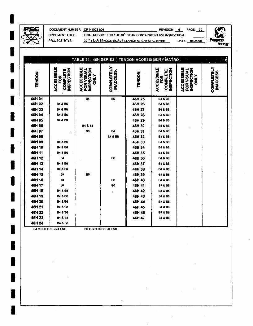
DOCUMENT NUMBER: CR-N1002-504
DOCUMENT TITLE: FINAL REPORT
PROJECT TITLE: 30TH YEAR TEN
REVISION: 0 PAGE: 30
FOR THE 30 YEAR CONTAINMENT IWL. INSPECTION
IDON SURVEILLANCE AT CRYSTAL RIVER DATE: 01124/08
TABL.34 46H SE(E TEDNkC -*S L-Y~R
IIIIIIIIIIIIIIII
z(A0(I) l
0 zL(U. 3
.j~on!Ur
I w LI
004U...
I U * I I46H 0146H 0246H 0346H 0446H 0546H 0646H 0746H 0846H 0946H 1046H 1146H 1246H 1346H 1446H 1546H 1646H 1746H 1846H 1946H 2046H 2146H 2246H 2346H 24
B4 &6
54 &88
84 & B6
B4 & B8
B4 & 88
B4
B4&B6
B4 & B8
84
B4
B4
B4 &888
64 &&BB4 &868
848B6
B548B54&88
54&88
84
84 & B8
06
B6
86
148
54&868
B8
B6
86
46H 2546H 26
46H 27
46H 28
46H 29
46H 3046H 31
46H 32
46H 33
46H 34
46H 35
46H 36
46H 37
46H 38
46H 39
46H 40
46H 41
46H 42
46H 43
46H 44
46H 45
46H 46
46H 47
84886
84 &B8549868
B4 & 86
84&B6
54888BB4 &B8
54&888
84 & 88
B4 & 85B4 & 1684 & 86
B4 & 86
84& 68BA&B6
B4&86B4 &B6
4e& B6
B4& BOB48& B854888
548 B6
* * i a i i84 = BUTTRESS 4 END B6 = BUTTRESS 6 END

IDOCUMENT NUMBER-
DOCUMENT TITLE:
PROJECT TITLE:
CR-NI002-U04 REVISION: 0 PAGE: 31
FINAL REPORT FOR THE 3011 YEAR CONTAINMENT IWL. INSPECTION
30Tm YEAR TENDON SURVEILLANCE AT CRYSTAL RIVER DATE: 01124108
IIIIIIIUIUIIIUIII
ABLE 01:62S~lg 82 & NbB6 62H 25S *B2 8f,Y B6..0w 3o w u
0B. (3 Vg
2H 066 6 0.
62H 01 8286 62H 25 2 &86
62H 02 82 86 62H 26 82 86
62H 03 82 86 62H 27 B2 & 86
62H 04 a6 82 62H28 82 8& 6
62H05 6 8 B6 62H29 82886
62H06 82 8 Be 62H 30 82 & 86
62H 07 86 B2 62H 31 82 86
62H 08 86 B2 62H 32 82 B6
62H09 82 B62 62H 33 B2 886
62H 10 B2 B6 62H 34 B2 8&8S
62H 11 82 86 62H 35 B2 8 B6
62H12 62 9 86 62H36 82 86
62H 13 82 B6 62H 37 B2 8 B6
62H14 62 B6 62H 38 B2 & S6
62H 61 B2 66 62H 439 2 & 86
62H 16 86 B2 62H 40 82 8& 6
62H 17 86 82 62H 41 B28&86
62H18 62 &886 62H 42 628&66
62H419 B2 86 62H 43 828&86
62H 20 62 86 62H44 B28&68
62H 21 B28&65 62H 45 828&86
62H 22 82 &866 62H 46 62886
62H 23 82 8 B6 62H 47 B2 886
62H 24 82 8& 6
B2 - BUTTRESS 2 END B5" BUTTRESS 6 END

I'DOCUMENT NUMBER: CR-N1002-504
DOCUMENT TITLE: FINAL REPORT
PROJECT TITLE: 30'" YEAR TEN•
REVISION. 0 PAGE: 32
FOR THE 3 0 TM YEAR CONTAINMENT IWL INSPECTION
IDON SURVEILLANCE AT CRYSTAL RIVER DATE: 01124108
UIIIIIIIIIIIIIIII
z lIE0
.j
1§1> 11
.jz
ku
C,0 9. moSuJ
.~j
Q) (A..j
I -6 4' 4,D 101D 102D 103O 104D 105
D 106D 107o 108D 109D 110DillD 11201130114D115D 1160 117D 118D 1190120D121D122D 123D 124
B2/3 & B556B213 & B5,'6B2/3 & B5/
82/3 & 8B5
B2/ & B5SB213 & B5
B2/3
B2/3 & B56
B2/3 & 85/8
B2/3 & B54
8213 & B54182/3 & B65
62f3 & 8518B2m3 & B5/8SB213 & B56B
B2/3 & B5/
82/3 & B5/6
B213 & 85/68 213 & B5AB
82/38&85/8
B2/3 & 85/6
B2/3 & B56
B2m3 & 8516
B5/6
0 125o 126
D 127
D 128
D 129
D 130
O 131
D 132
D 133
O 134
D 135
D 136
D 137
D 138D 139
o 140
0 141
2/38 & 85/
am 2& B/8B2/3 & B5/8
B2/3 & B65
82n & 65/8
82n & 85/6
82/38 85/8
B2r41
B241
82n3
82/3am
82/3 & B5
2/36 & 5/6
82/3 & 6515
B5/8
B5/6
85/8B5/6
B5/8
6516
65/6
i m i I I
B213 - BUTTRESS 2-3 END 8516 a BUTTRESS 5-6 END

I
IIIIIIIIIIIIIIIII
DOCUMENT NUMBER: CR-Nt002-504 REVISION: 0 PAGE: 33
DOCUMENT TITLE: FINAL REPORT FOR THE 30T" YEAR CONTAINMENT W& INSPECTION
PROJECT TITLE: 30'm YEAR TENDON SURVEILLANCE AT CRYSTAL RIVER DATE: 01/24/08
I I I UE17 D`206s iR-i-iz
JI-
muj
o go@0 i
.j0S pi
I.02
I.J W
ro!~m.L
140
JI~5
jWu
_____I I__ _ Il I I__ _ _&_ __ _ _ _
D 201D 202D 2030 204D 205D 206D 207o 208o 209D 210D211D2120 213D 2140215D 216D 217D 218D 219D 220D 2210222o 223D 224
B115 & B3/4
B1/6 & B314
B1/6 & 1334
B1/6 & B3/4
81/6 & B314
61168 & 314
8116 & B3/4
8188 & B3/4
8116 & B3/4
B118 A B314
B116 & B3/4
8116 & B314
B116 & 8314B1/888 3/4
911588314B1/6 & B314
B1/8 & B314B116 & B314
8118 &8314B1/6 & 8314118/6 B3/4
83/4
B1168 & 83/4
8116 & B3/4
B1/68 & B3/4
5116 & 83/4
D 225D 22602270 228D 229D 230O 2310 232D 233D 234D 235D 236D 237D 238O 239D 240D 241
B1/6 & B3/4
81/5 & 8314
816 & B3/4
8116 & 83/4
81168 & B314
B1/6&B3/4
B116 & B3/4
B1/8 & 8314
B1/88 & 3/4
B1/8 & B3/4
B1/5 & B3/4
&3/4B1/6 & B3/4
81/6 & B314
BI/6 & B3/4
B1168 & 83/4
B1/6&83/4
B1/e
8116
8116 = BUTTRESS 1-6 END 8314 = BUTTRESS 3-4 END

IIIIIIIIIIIIIIIIIIU
DOCUMENT NUMBER CR-N1002-504 REVISION: 0 PAGE: 34
DOCUMENT TITLE: FINAL REPORT FOR THE 30Tm YEAR CONTAINMENT IWL INSPECTION
PROJECT TITLE 30T' YEAR TENDON SURVEILLANCE AT CRYSTAL RIVER DATE: 01124/08
*ALJE--,S9zo I 65-1661LREI -ýkfit-j j .04AC "ESýrlbiLAITYVýIIIMý 1.
z 4i ,, WZ JZ- JO
0- -- u u.Z>.I
Q j 0- A(o 4L U)0 ))- I
0 301 B1/2 & 68415 D 325 B/2 & B45
302 1/2 & 6415 D 326 81/2 & B4/5
D303 B112 & B415 D 327 81/2 6A415
D 304 61/2 & 64/5 0328 81/2 & 645
D 305 B112 & B415 D 329 81/2 & 64/5
D 306 112 & 84/5 0330 B112 & W5
D 307 B1)2 & B415 D 331 BI62 & 64/5
0 308 B112 A 4)5 D 332 B1/22 & B5
0 309 61/2 & 6415 D 333 B112 B4/5
D 310 11/2 & B4/5 0 334 81/2 8415
D 311 B1/2 & B415 D 335 3112 B4/5
D 312 B112 & B415 0 336 B112 84/5
D 313 611/2 & 64/5 D 337 B112 841/
D 314 81/2 & 64/5 D 338 B112 B4/5
0315 81/2 & B4/5 D 339 612 & B64/5
0316 e112 & B415 0340 B112 &B45
0317 B12 & 86415 D 341 B/2 64/5
0 318 61126&684/5
0319 61/2 & 64/5
D 320 81/2 & 4/5
0 321 B/2 & 6415
0 322 B1/2 & B415
D 323 B1/2 & 6485
0324 81/2 68415
61/2 BUTTRESS 1-2 END 6415 , BUTTRESS 4-5 END
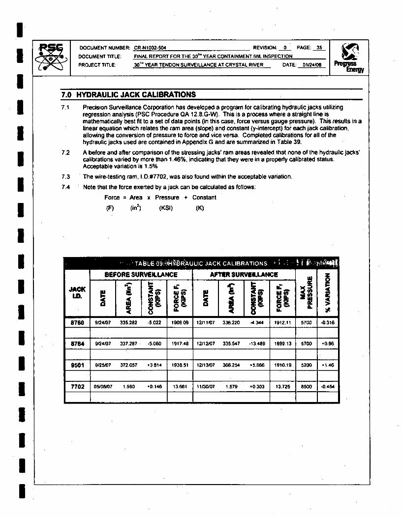
IIIIU
DOCUMENT NUMBER: CR-N1002-504 REVISION: 0 PAGE: 35
DOCUMENT TITLE: FINAL REPORT FOR THE 30'" YEAR CONTAINMENT IWL INSPECTION
PROJECT TITLE: 30'M YEAR TENDON SURVEILLANCE AT CRYSTAL RIVER DATE: 01124/08
7.0 HYDRAULIC JACK CALIBRATIONS
7.1 Precision Surveillance Corporation has developed a program for calibrating hydraulic jacks utilizingregression analysis (PSC Procedure QA 12.8.G-W). This is a process where a straight line ismathematically best fit to a set of data points (in this case, force versus gauge pressure). This results in alinear equation which relates the ram area (slope) and constant (y-intercept) for each jack calibration,allowing the conversion of pressure to force and vice versa. Completed calibrations for all of thehydraulic jacks used are contained in Appendix G and are summarized in Table 39.
7.2 A before and after comparison of the stressing jacks' ram areas revealed that none of the hydraulic jacks'calibrations varied by more than 1.46%, indicating that they were in a properly calibrated status.Acceptable variation is 1.5%
7.3 The wire-testing ram, 1.0.#7702. was also found within the acceptable variation.
7.4 Note that the force exerted by a jack can be calculated as follows:
Force = Area x Pressure + Constant
IIIUIIIIIIUIIU
(F) (in2) (KSI) (K)
-T_______________H_______AULI JAC CAIBAIO* 1flVBEFORE SURVEILLANCE I AFTER SURVEILLANCE
33 =
JACK[a.
* r
&C
0iII.
a8 U.
I4(
'I
*
8780 9W24/0? 335.282 -5.022 1906.09 12111/07 336,220 -4344 1912.11 5700 -0-316
8784 9/24/07 337.287 -5.060 1917.48 12112/07 335.547 -13.489 1899.13 5700 +0.96
9501 9/25/07 372.057 ,3.814 193851 12/13107 366.254 .5.666 1910.19 5200 +1 46
7702 05/08/07 1.590 #0.146 13661 11/30/07 1.579 #0-303 13.725 8500 -0.464

IDOCUMENT TITLE: FINAL REPORT FOR THE 30' YEAR CONTAINMENT IW. INSPECTION
PROJECT TITLE: 30'" YEAR TENDON SURVEILLANCE AT CRYSTAL RIVER DATE: 01124/08U8.0 TENDON LIFTOFFS
3 8.1 MONITOR TENDON FORCES
8.1.1 A liftoff is defined as the force required to lift the anchor head off the shim stack and is representative of theforce held by that tendon. A liftoff is performed on each physical surveillance tendon to monitor the forceexerted by the tendon onto the structure. PSC Procedure SO 9.0 in Appendix F details the steps taken toperform a liftoff. The results were documented on Data Sheet SO 9.0 and are summarized in Tables 40thru 45.
8.1.1.1 It should be noted that performing a liftoff has only a localized effect on a tendon; therefore, it isacceptable to use the same jack for both ends of a tendon by executing the liftoff on separateoccasions.
8.1.2 All of the vertical and dome tendon liftoffs were found to be above the minimum design and above 95%Predicted Force as required by IWL-3221.1. Three of the five horizontal surveillance tendons were foundto be below 95% Predicted Force but above 90% Predicted Force. The liftoff requirement stated in IWLis:
3Tendon forces are acceptable if:
(a) The average of all measured tendon forces, including those measured in IWL-3221 .1 (b)(2),for each type of tendon is equal to or greater than the minimum required prestress specifiedat the anchorage for that type of tendon;
(b) The measured force in each individual tendon is not less than 95% of the predicted forceunless the following conditions are satisfied:(1) the measured force in not more than one tendon is between 90% and 95% of the
predicted force;
(2) The measured forces in two tendons located adjacent to the tendon in IWL-3221.1(b)(1) are not less than 95% of the predicted forces; and
(3) The measured forces in all the remaining sample tendons are not less than 95%of the predicted force.
8.1.3 Based upon the unacceptable horizontal tendon liftoffs, adjacent tendons were monitored for force untilan acceptable liftoff reading was obtained on both sides of the selected tendon- 13H36 required testingof 5 adjacent tendons, 46H21 and 62H30 also required testing of five adjacent tendons. Of thesetendons, six were above 95%, five were between 95% and 90% and four fell just below 90%. All tendonsbelow 95% were restored to Predicted Force - 0%, + 6% and locked off. The restoration of thesetendons is summarized in Table 46.
8.1.4 The average of the As-Found normalized liftoff values was above the minimum requirement, despite thelow liftoffs, and deemed acceptable per PSC Procedure S09.0 Section 10.4.
8.1.4.1 The average normalized tendon force in Unit 3 for each group and their respective minimum design are:
Vertical Tendon: Group Average = 1535.2 Kips Minimum Design = 1149 Kips
Hoop Tendon: Group Average = 1347.4 Kips Minimum Design = 1252 Kips
Dome Tendon: Group Average = 1367.3 Kips Minimum Design = 1215 Kips
8.1.4.1.1 As depicted above, all group averages are above the required group minimum and are thereforeacceptable. The actual values for each tendon and its corresponding group are summarized inTable 47.
8.1.5 Upon completion of the liftoff, a visual verification is performed to identify any changes in the condition ofthe tendon end. No additional or broken wires were noted during or after liftoffs.
I

IDOCUMENT NUMBER:
DOCUMENT TfTLE:
PROJECT TITLE:
CR-N1002-504 REVISION: 0 PAGE: 37
FINAL REPORT FOR THE 30r" YEAR CONTAINMENT IWL INSPECTION
30'" YEAR TENDON SURVEILLANCE AT CRYSTAL RIVER DATE: 01124108
IIIIIIIIIIIIIIIIU
bbEi(WiWt jRýTtC,4LS.'-'ýýS09.b;-"PAONiT'6'Fý IN 64E!Sle,6N(FbWý09+ý
z
I.-U 2I
'U
IA.u'
0
04
'a.~
.jI
ILid.
j2 o
zw
za
40
0'
TOP 14.75 161 8784 1559.9512V01 1559.95 1525 1449 1372 NO 0 YES
BOT 4.00 158 N/A NIA
TOP 12.50 153 8780 1458.8045V20 1456.80 1507 1432 1357 NO 0 YES
BOT 4.00 163 N/A N/A
TOP 13.00 163 8784 1505.9861V08 150598 1491 1416 1342 NO 0 YES
BOT 4.00 163 N/A NIA
TOP 12.00 161 8784 1580,1861V17 1580.18 1498 1423, 1348 NO 0 YES
BOT 4.00 163 N/A N/A I
IL ZL itA~
I I* a Alti 4
BT,1 6.50 163 8784 1344.0813H36 1385.23 1484 1410 1336 YES a NO
BT 3 7,25 163 8780 1428.63
BT 2 5.75 163 8784 1546.4642H46 1558.63 1458 1383 1310 NO 0 YES
ST 4 6.00 163 8780 1570.80
BT 4 5.75 163 8780 1319.344GH21 1330.02 1441 1369 1297 YES 5 NO
BT 6 6.00 163 8784 1340.71
8T 1 8.00 163 8784 1532.9651H34 1464.70 1467 1413 1339 NO 0 YES
ST 5 7.00 163 8780 1396.45
BT 2 6.75 163 8784 1249.6462H30 1290.84 1413 1342 1272 YES 5 NO
BT 6 6.75 163 9501 1332.05

DOCUMENT NUMBER: CR-N1002.504 REVISION: 0 PAGE: 38
DOCUMENT TITLE: FINAL REPORT FOR THE 3 0'" YEAR CONTAINMENT IWL INSPECTION
PROJECT TITLE: 30'm YEAR TENDON SURVEILLANCE AT CRYSTAL RIVER DATE: 01124108
TA* 2 10ME -- 901 6 *OIOý]0if ON 0(RQ
IIIIIIIIIIIIIIII
z
wI-.
X -%
ILus
d
4
AL0 a
SL
0.
'AL
U..0.L.
10
it0
z0IL-"I
(J040
'u
Z Z
0.1-IL
i "i673 ]625 I162 8.780 i1289.1610129 B 3 I 1 1 1289.64 1287 1223' 1159 NO 0 YES
OT 5 6.00 161 8784 1290.12 1
6 I 1 6.38 162 8784 1259.76 I 0 YESD212 12778.1 1305 1240 1175 NO 0 YES
T t3 6.50 162 8780 1295.87
BT 4 7.00 163 8780 1527.21238 1511.53 1348 1281 1213 NO 0 YES
BT6 6.00 163 8784 1495.85
-3H34 -3H6.61 147n -MON -ES -O
13H33 1306-46 1366 1298 1229 YES YES
BT 3 6.75 163 8780 1323.57
BT 1 7.00
163 8784
1310.35
13H37 1309.48 1368 1298 1229 N YES N67T3 6.75 163 8780 1302.057
ST11 7.00 163 8784 1350.831 3H34 1368.61 1475 1402 1328 YES NO
IBT3 7.00 163 8780 1386.39
BT 1 6.56 163 8784 1249.6413H35 1244.25 1373 1304 135 YES No
ST 3 6.38 162 8780 1238.87
ST71 6.88 163 8784 1387.6913H37 B3 57 16 1 s 11.511289.87 11388 1 1299 12311 YES No
61 1 6.60 163 8784 1411.5413H438 BT3 70 6 70 17.7 1395.05 1444 1372 1300 NO YES
L-- --- - -m - ----- - 6- -1

IIII
DOCUMENT NUMBER: CR-N1002-504 REVISION: 0 PAGE: 39
DOCUMENT TITLE: FINAL REPORT FOR THE 30'" YEAR CONTAINMENT IWL INSPECTION
PROJECT TITLE 30'M YEAR TENDON SURVEILLANCE AT CRYSTAL RIVER DATE: 01/24108
1EE11:ifý mini lMNlTt'R1NGk K ~I
Ewl-W
2.l-
C9I-
wa
>'
adc412
CL
it
W6
>.IL~
0)1-0z M
'u
N6II' 9 -~ IN -pi- - I '9-
II
BT 4 7.00 t 163 1 8780 1 1352.8746H?'19 7 14.
6T 6 7.50 163 8784 1364.351358.61 1 1402 1332 1262 1 NO .YES
BT 4 6 75 160 8780 1269.04
46H20 T 1298.13 1467 1394 1321 YES NOBT 6 7-25 163 8784 1327.22
1 46H22BT 4
BT 6
5.75
6.38
163
163
8780
8784
1315.98
1306.98II
III
1311.48 1488 1412 1337 I YES NO
IIIIIIIII
BT 4 6.00 161 8760 1338.10
46H23 1329 97 1425 1354 1283 YES NOSBT6 5.75 163 8784 1323.85
BT 4 6.75 163 8780 1419.9246H24 1425.85 1472 1398 1325 NO YES
BT 6 7.50 163 8784 1431.78
BT~~~~~ 2 6,5 13.8 290
62H23 1-69.3 14-1 1301 1 2-9 NO YE-
BT 6" 6.00 163 N/A NIA
ST 2 7.00 163 8780 1332.7,5632H32 1332.75 1455 1382 `1310 YES NO
BT6* 50 163 N/A NIA
BT2 6519 163 8780 1242.2262H33 1313.39 141 1388 1315 YES NOBT 6 6250 162 1784 1384-56 1
BT 2 7.00 163 8780 139321062H34 1378.71 1432 1360 1289 NO YES
BT 6 6.75 162 8784 136432
- - I - - - - - -I- I* TENDON NOT ACCESSABLE AT BUTTRESS 6.

IIIIIIIII,IIII1III-II
DOCUMENT NUMBER: CR-N1002-504 REVISION: 0 PAGE: 40
DOCUMENT TITLE: FINAL REPORT FOR THE 30'M YEAR CONTAINMENT IWl INSPECTION
PROJECT TITLE: 3 0T" YEAR TENDON SURVEILLANCE AT CRYSTAL RIVER DATE; 01/24/08
"AF qME E AýE;46: 4DJACENTS RESiTiEftTil
AS-FOUND LIFTOFF RESTORATION
2
U'
azwl 06
.j
U.LL
IL
BT 1 8784 1350.83 8784 1479.0013H34 1368.61 1508.13 1475 +2.2% YES
BT 3 8780, 138839 8780 1537.27
ST 1 8784 1249.64 8784 1411.5413H35 1244.25 1417.40 1373 +3.2% YES
BT 3 8780 1238-87 8780 1423.27
BT 1 8784 1344.08 8784 1546.4613H36 1385.23 1555.27 1484 .4.8% YES
BT 3 8780 1426.63 8780 1564.09
BT 1 8784 1387.69 8784 1394.6813H37 1289.87 1415.68 1368 +3.5% YES
ST 3 8780 1212.05 8780 1436.69
BT 4 8780 1269.04 8780 1486.9846H20 1298.13 1494.79 1467 *1.9% YES
BT 6 8784 1327.22 8784 1502.61
BT 4 8780 1319.34 8780 1503.7446H21 1330.02 1501.49 1441 *4.2% YES
BT 6 8784 1340.71 8784 1499.24
BT 4 8780 1315.98 8780 1567.4546H22 1311.48 1538.40 1486 *3.5% YES
BT 6 8784 1306.98 8784 150935
BT 4 8780 1338.10 8780 1486.9846H23 1329.07 1481.30 1425 -4.0% YES
BT 6 8784 1323.85 8784 1475.62
ST 2 8784 1249.54 8780 1443.3962H30 1290.84 1467.71 1413 +3.9% YES
BT 6 9501 1332.05 9501 1492.04
BT 2 8780 1269.04 8780 1488.9862H31 1269.04 1486.98 1475 40.8% YES
BT6 NIA NIA NIA NIA
BT 2 8780 1332.75 8780 14970462H32 1332.75 1497.04 1455 +2.9% YES
BT 6" N/A NA NIA N/A
BT 2 8780 1242.22 8780 1488.9862H33 1313.39 1494.79 1461 +2.3% YES
8784 1384.56 8784 1502.81
* TENDON NOT ACCESSABLE AT BUTTRESS 6 - RESTORATION ONE END ONLY.

IIIIIIIIIIIUIIIIIII
DOCUMENT NUMBER: CR-N1002-504 REVISION: 0 PAGE: 41
DOCUMENT TITLE: FINAL REPORT FOR THE 30'M YEAR CONTAINMENT IW. INSPECTION
PROJECT TITLE: 30'M YEAR TENDON SURVEILLANCE AT CRYSTAL RIVER DATE: 01124/08
AT-iI AN q
TENDON AALV(KIPS)
NORMALIZING I NORMALIZEDFACTOR AALV (KIPS)
NORMALIZEDGROUP AVE.
MIMUMREQUIRED
NORMALIZEDFORCE
ACCEPT.
12V01 1559.95 -9 1550.95
45V20 1456.80 7 1463.80 1535,23 1149 YES
61V08 1505.98 23 1528.98
61V17 1580.18 17 1597.18
131433 130646 62 1388.46
131434 1388.61 -47 1321.61
131135 1244.25 58 1300,25
13H36 1385.23 .56 1329.23
131437 1289.87 61 1350.87
131138 1395.05 -17 1378.05
42H46 1558.63 -28 1530.63
46H19 1358.61 25 1383.61
46H20 1298.13 -39 1259.13 1347.38 1252. YES
46H21 133002 -12 1318.02
460122 1311.48 .57 1254.48
461123 1329.97 4 1333.97
46H24 1425.85 44 1381.85
51H34 1484.70 -59 140570
621129 1369.63 7 1376.63
62H30 1290.84 14 1304.84
62H33 1313.39 -32 1281.39
621H34 1378.71 -5 1373.71
D129 1289.64 34 1323.64
D212 1277.81 15 1292.81 136733 1215 YES
D238 1511.53 -26 1485.53