Reconstruction of skin and tendon defects from wound complications after achilles tendon rupture
Upload
khangminh22Category
view
0download
0
REP-1 098-510 Appendix E, Page 280 of 415
N1091 PSC PROCEDURE SQ 9.0MONITOR TENDON FORCE
09/03/13Page 1 of 8Revision 0
EXELONTHREE MILE ISLAND
UNIT 1 (4 0TH YEAR) PHYSICALCONTAINMENT BUILDING TENDON SURVEILLANCE
PRECISION SURVEILLANCE CORPORATIONIN-SERVICE INSPECTION
QUALITY CONTROL PROCEDURE
MONITORING TENDON FORCE (LIFT-OFFS)
Prepared by
Q.C. INSPECTOR
Title
09103/13
Date
Q.A. MANAGER 09103113
Approved by
Approved by
Title
PRESIDENT
Title
Date
09/03 13
Date
21 SQ 9.0 TMI. 13 ISla
Topical Report 213 Attachment 2 Page 735 of 1008

REP-1 098-510 Appendix E, Page 281 of 415
N1091 PSC PROCEDURE SQ 9.0MONITOR TENDON FORCE
09/03/13P~n• 9 Af A
P-RECISION ANCE Revision 0
1.0 PURPOSE
1.1 This procedure will establish the requirements for monitoring the forces that remain ina tendon for purposes of evaluating the Post-Tensioning System Tendons during the40th Year In-Service Inspection (Surveillance) at Exelon's Three Mile Island-Unit 1.
2.0 RESPONSIBILITY
2.1 In the event of conflict between any TMI Procedure and an SQ, the former governs.
2.2 As stated in PSC Procedure QA 4.0.
3.0 QUALIFICATIONS
3.1 As stated in PSC Procedure QA 4.1.
4.0 EQUIPMENT
4.1 The gauges and test equipment necessary for the Quality Control activities will beitemized in PSC Procedure SQ 4.0.
5.0 PRECAUTIONS
5.1 Review the 1.S.I. Tendon Surveillance Program Safety Comments for the items thatshall apply both for tendon force control and personnel safety.
6.0 QUALITY CONTROL6.1 All Quality Control Documentation (CD points noted in this procedure are Hold
Points. The work shall not progress past or through a QCD without a verbal releasefrom the Inspector. The required information or evaluative data shall be documentedon Data Sheet 9.0 attached to this procedure.
7.0 PREREQUISITES
7.1 The Grease Cap will be removed.
7.2 The Anchorage Inspection of the stressed tendon will be completed.
7.3 The Anchorage threads will have been measured and the coupler verified for threadstrength per SQ 7.1.
7.4 The hydraulic jack has been examined for damage and is in current calibrationstatus.
7.5 Stressing pressure gauge has been calibration checked before use as per PSC
Procedure QA 10.1.
7.6 QCD - Document the tendon identification, Unit #, and tendon end on Data Sheet 9.0
21 SQ 9.0 TMI.13 ISla
Topical Report 213 Attachment 2 Page 736 of 1008

REP-1 098-510 Appendix E, Page 282 of 415
N1091 PSC PROCEDURE SQ 9.0MONITOR TENDON FORCE
09/03/13Page 3 of 8Revision 0
8.0 MEASUREMENTS
8.1 STEEL RULERS
8.1.1 Measurements of shim stack height shall be performed with calibrated steel rulersgraduated in tenths of an inch (0.1"). The measurements shall be recorded to thenearest 0.1".
8.2 PRESSURE GAUGES
8.2.1 Measurements of ram pressure (tendon force) shall be measured by calibratedpressure gauges capable of being read directly to 20 psi or better.
8.2.1.1 View the gauge face from a plane of view directly in front of the indicator needleto avoid parallax errors.
8.2.1.2 Gauge readings may be interpolated to the nearest 10 psi.
8.2.1.3 All pressure gauges used shall have automatic compensation for temperaturevariations between gauge calibration and gauge use during surveillance.
9.0 MONITORING OF TENDON FORCES
9.1 The intention of this operation is to monitor the amount of force remaining on thetendon by taking lift-off readings as the tendon is being stressed. Subsequentevaluation of those lift-off readings with respect to Predicted Forces will determine ifthat force is acceptable or if degradation of the system has occurred.
9.2 Monitoring of Tendon Force can be performed on both ends of a tendon in asimultaneous and controlled manner or on one tendon end at a time, independent ofthe opposite end of the tendon. These procedures have been developed so that theyapply to one end of the tendon. Every effort should be made to measure lift-off atopposite ends of a tendon at the same time. If this is prohibited by plant conditions(i.e., one end is accessible only with the plant operating and the other only when theplant is shut down), then measurements must be made as close together in time aspossible and under similar temperature regimes. Adequate communication shall bemaintained between both ends of the tendon during the taking of lift-off readings forsimultaneous stressing operations. Vertical tendon monitoring of force is to beperformed from one end, top end, only unless the tendon was double end stressedduring original installation.
21 SQ 9.0 TMI.13 ISla
Topical Report 213 Attachment 2 Page 737 of 1008

REP-1 098-510 Appendix E, Page 283 of 415
N1091 PSC PROCEDURE SQ 9.0MONITOR TENDON FORCE
09/03113Page 4 of 8Revision 0
9.2.1 Regardless of the method of monitoring there will probably be variations in theforces detected at each end of the tendon. Because of this, the average force fromboth ends will represent the force that the tendon is holding. If the average forcefor both ends of the tendon meet the Acceptance Criteria cited in Section 10.0 ofthis Procedure, that tendon will be acceptable. If the average force does not meetthe criteria, then the action required of Section 10 of this Procedure shall berequired for the respective condition detected.
9.2.2 All data shall be documented on Data Sheet 9.0.
9.3 QCD - Document the concrete surface temperature near the tendon and the ambientair temperature on Data Sheet 9.0. Also document the thermometer identificationnumber and calibration due date for each thermometer used.
9.4 QCD - The anchorhead and stressing adaptor/stressing rod threads are to beinspected for dirt, burrs, nicks, and damaged threads and measurements taken perSQ 7.1, if any condition precludes proper coupling the condition shall be corrected.Anchorhead threads shall be inspected for deformation before and after anystressing operation and if any deformation is detected Exelon Engineering is to benotified. Document acceptance on Data Sheet 9.0
9.5 QCD - Document the amount of effective wires in each end of the tendon on DataSheet 9.0. Refer to Data Sheet 8.0 for each end of the tendon.
9.6 QCD - Couple the rams to each anchorhead on that tendon (for vertical tendons onlythe top anchorhead is used, unless it was double end stressed during originalinstallation). Document on Data Sheet 9.0 that the stressing coupler/stressing rod isevenly aligned on the anchorhead washer and that full thread engagement isobtained.
9.6.1 Note do not let coupler touch shims.
9.7 QCD - On Data Sheet 9.0 document the ram and gauge identification and thecalibrated status of each. Also document the ram calibration data including its areaand constant, K.
9.8 QCQD - On Data Sheet 9.0 document the dimension of each shim stack height, fromthe bearing plate to the bottom of the anchorage. Document the thickness of eachshim in each shim stack, starting from the Bearing Plate and working up to theAnchorage. Also document the ruler identification and calibration date.
9.9 QCD - Establish the Lift-off Overstress Force (LOSF) for the tendon being monitored.Tendon Lift-off Overstress Force for purposes of Monitoring of Tendon Force shall bethat force less than 1592 kips (based on a tendon with 169 effective wires, 9.425 kipsper wire), which permits placement of the feeler gauges or provides completelooseness of the shim stacks.
21 SQ 9.0 TMI.L13 ISla
Topical Report 213 Attachment 2 Page 738 of 1008

REP-1098-510 Appendix E, Page 284 of 415
N1091 PSC PROCEDURE SQ 9.0MONITOR TENDON FORCE
09/03/13Page 5 of 8Revision 0
9.9.1 Maximum force equals the number of effective wires multiplied by 9.425 kips.
9.10 QCD - On Data Sheet 9.0 document the selected Tendon Predicted Force (PF),document the 95% Predicted Force (0.95PF), and document the 90% PredictedForce (0.9PF), from the Predicted Force Tables of Procedure SQ 9.1. Space isprovided beneath each entry to document the gauge pressures for each forcerequirement.
CAUTION ONCE ACTUAL STRESSING BEGINS, THE RAM MUST NEVER BE EXTENDEDTO THE FULL LIMIT OF ITS STROKE. THE EXTENSION SHOULD BE AT LEAST 1/2" LESSTHAN THE FULL STROKE OF THE RAM.
9.11 TENDON LIFT-OFF (MONITORING)
9.11.1 Gradually pressurize the rams in 20 to 100 psi increments until lift-off is achieved.Carefully observe for signs of rotation. If rotation is noted at any time, stop workuntil shim rotation has stopped. If rotation is noted, pressurizing shall stop untilrotation ceases. Once rotation has ceased and alignment has been verified keepincreasing pressure at prescribed intervals. The intent is to allow rotation to bereleased in a slow and controlled fashion. Do not exceed a Lift-off OverstressForce of 1592 kips (based on a tendon with 169 effective wires, 9.425 kips perwire), if lift-off has not been achieved at this force, then unload the jack, and notifyExelon Engineering for resolution of the condition.
9.11.2 Once the shims become loose, insert two feeler gauges or shim stock, about0.030" in thickness, between the anchorhead and shim. The gauges should belocated about 180 degrees apart and approximately centered.
9.11.3 Reduce the ram pressure until the load is transferred on the shim stack. It shall notbe necessary to return to zero gauge pressure, but at least 2000 psi less than thepressure that was needed to insert the shim stock.
9.11.4 Gradually pressurize the ram while pulling the feeler gages. The point at which thefeeler gauge comes loose and can be withdrawn is the Liftoff Point.
9.11.5 QCD - Document the pressure for each Liftoff of each shim stack. Place a circlearound that Liftoff Value that was the last to have the feeler gauge or shimremoved. (The last shim stack to come loose.) Do not intermix the values for theshim stacks. Stack 1 will always be Stack 1.
21 SQ 9.0 TMI.13 ISla
Topical Report 213 Attachment 2 Page 739 of 1008

REP-1 098-510 Appendix E, Page 285 of 415
N1091 PSC PROCEDURE SQ 9.0MONITOR TENDON FORCE
09/03/13Page 6 of 8Revision 0
9.11.6 Repeat sections 9.11.3, 9.11.4 and 9.11.5 until 3 consecutive Liftoff readings havebeen taken. The three circled readings should be within 25 kips of each other, ifthis is not achieved the feeler gauges may be repositioned, and additional liftoffreadings may be taken until three consecutive readings within 25 kips of eachother are achieved.
9.11.7 The space between the stacks of shim halves for the first shims in direct contactwith the anchorage should not exceed a space of 1/4". The remaining shims in theshim stack may be placed with a larger spacing but should not exceed 1/2".
9.11.8 Slowly decrease the pressure on the jack to allow the stressing washer to reseatonto the shims. No additional shims are to be added at this time.
9.11.9 No part of the anchorhead shall overhang the shim stack. If the anchorhead is notcorrectly positioned after releasing the pressure, gradually re-pressurize the ramand adjust as necessary.
9.11.10 The ram shall be uncoupled from the anchorage.
9.11.11 If the lift-off forces are determined to be acceptable, this tendon shall becompleted by replacing the grease can in accordance with PSC Procedure SQ12.0.
9.11.12 NOTE: Neither end shall be de-tensioned until lift-off has been recorded for bothends.
9.11.13 QCD - Post the Circled Liftoff Values into the Circled Liftoff Value Column. It maybe possible to have the Liftoff occur at the same pressure in each shim stack. Addthe Circled Liftoff Values and divide by 3 to get the end average. Post the endaverage to Data Sheet 9.0. Convert the Average Pressure (PSI) to Force (KIPS)and document results.
9.11.14 QCD - Enter the end average from the opposite end of the tendon if it is availableat this time.
9.11.15 QCQD - Calculate the Average Liftoff Value (ALV) for this tendon by averaging theend averages from both ends.
9.11.16 QCQD - Document the acceptance or non-acceptance of the average liftoff valuefor the condition representative of the tendon on Data Sheet 9.0. Choose one ofthe conditions listed in Section 10.0 as each condition might apply.
9.11.17 QCD - Document the need for Adjacent Tendon Monitoring and the tendonnumbers. Notify Exelon that Adjacent Tendon Monitoring is being performed.
21 SQ 9.0 TMI.13 ISla
Topical Report 213 Attachment 2 Page 740 of 1008

REP-1098-510 Appendix E, Page 286 of 415
N1091 PSC PROCEDURE SQ 9.0MONITOR TENDON FORCE
09/03/13Page 7 of 8Revision 0
10.0 ACCEPTANCE CRITERIA
10.1 The average liftoff value of the forces required to achieve lift-off for each tendon shallnot be less than the 95% Predicted Force obtained from PSC Procedure SQ 9.1.
10.2 If the average value of the end forces required for lift-off fails to meet the acceptancecriteria of Section 10.1, but equals or exceeds the 90% Predicted Force obtainedfrom PSC Procedure SQ 9.1, the tendons designated as adjacent to the defectivetendon and listed in SQ 9.1, Table 3.0 or 4.0 as applicable shall be checked asoutlined in Section 11.0. If both adjacent tendons satisfy the acceptance criteria asindicated in section 10.1, then the original tendon shall be restored to its PredictedForce within a minus 0%, plus 6% tolerance, but in no case, no greater than 0.70GUTS as determined for the number of effective wires, the single deficiency shall beconsidered unique and acceptable.
10.2.1 If either of the adjacent tendons fails to satisfy the acceptance criteria of section10.1, the extent of investigation into the cause, which may include de-tensioningthe deficient tendons, shall be determined by Exelon. This condition does not meetIWL requirements and is considered reportable to the NRC by Exelon.
10.3 If the average value of the end forces required for lift-off falls below the 90%Predicted Force obtained from PSC Procedure SQ 9.1, an investigation is to beconducted by Exelon to determine the extent and cause of the occurrence and therequired course of action to be taken. This condition does not meet IWL requirementsand is considered reportable to the NRC by Exelon.
10.4 The average of all normalized tendon lift-off forces, including adjacent tendons, ifany, for each tendon group shall be equal to, or greater than, the required minimumaverage tendon force for that tendon group. The required minimum average force is1033 kips for vertical tendons,1064 kips for dome tendons, and 1108 kips for hooptendons. This requirement will be verified upon completion of the final surveillancereport
10.5 QCD - Any tendon which has a lift-off force below its specified 95% Predicted Force,and has not been required to be de-tensioned, shall have both ends re-tensioned towithin minus 0%, plus 6% of the specified Predicted Force but in no case, no greaterthan 0.70 GUTS as determined for the number of effective wires. Tendon shall not bedetensioned, however, both ends of a double end stressed tendon, or, one end of asingle end stressed tendon shall be taken to OSF to ensure full transfer of force. Thefinal lift-off force (lock-off) shall be the original predicted force from PSC ProcedureSQ 9.1; Data Sheet 11.0 of PSC Procedure SQ 11.0, shall be completed for all suchtendons.
10.6 If any deformation of anchorage threads is detected before or after any stressingoperation, Exelon Engineering is to be notified.
21 SQ 9.0 TMI.13 ISla
Topical Report 213 Attachment 2 Page 741 of 1008
REP-1 098-510 Appendix E, Page 287 of 415
N 1091 PSC PROCEDURE SQ 9.0MONITOR TENDON FORCE
09/03/13Page 8 of 8Revision 0
11.0 ADJACENT TENDON - MONITORING OF FORCES
11.1 The monitoring of forces in tendons adjacent to the defective tendon shall follow therequirements of this procedure, as each applies.
11.2 It shall be necessary to remove the Grease Cap in accordance with PSC ProcedureSQ 6.0 using Data Sheet 6.0 for the documentation requirements for each adjacenttendon.
11.3 It shall not be necessary to take Grease Samples unless water is detected during theinspection. Grease samples may be taken if requested by Exelon.
11.4 It shall be necessary to perform the anchorage inspection in accordance with PSCProcedure SQ 8.0. Data Sheet 8.0 shall be used to document this information foreach Adjacent Tendon.
11.5 It shall not be necessary to perform the concrete inspection of PSC Procedure SQ8.3.
11.6 Lift-off monitoring shall be performed in accordance with Section 9.11 of thisprocedure and evaluated per Section 10.0.
12.0 NOTIFICATION
12.1 QCD - Exelon shall be formally notified with a nonconformance report when eachone or more of the Acceptance Criteria noted in section 10.0, of this procedure arenot met.
13.0 DOCUMENTATION
13.1 The items requiring documentation in this procedure, shall be documented on DataSheet 9.0.
13.2 Some information from Data Sheet 8.0 of PSC Procedure SQ 8.0, which has alreadybeen started for this tendon, shall require posting onto Data Sheet 9.0.
14.0 ATTACHMENTS
14.1 Data Sheet 9.0
21 SQ 9.0 TMI.13 ISla
Topical Report 213 Attachment 2 Page 742 of 1008

REP-1098-510 Appendix E, Page 288 of 415
N1091 PSC PROCEDURE SQ 9.0MONITOR TENDON FORCE
DATA SHEET 9.009/03/13
Page 1 of 1Revision 0
Project: TMI 4 0 TH YEAR TENDON SURVEILLANCE 0l Unit 1
(7.6)Tendon No.: Tendon End: _lShop El Field
LIFT-OFF INSPECTION CRITERIA Q.C. Signoff
(9.3) Temp. of Concrete: OF Thermometer No.: Recal Date:
Ambient Temp.: OF Thermometer No.: Recal Date:
(9.4) Anchorhead and Stressing Adapter Threads: [] Acceptable U Unacceptable
(9.5) Number of Effective Wires:
(9.6) Anchorhead and Stressing Adapter Engagement/Alignment : El Acceptable El Unacceptable
(9.7) RAM ID: Recal Date: end ofjob RAM Area: K =
Gauge ID: Recal Date: Daily Check:
(9.8) Shim Stack Height: #1 in. #2 in. Ruler ID: Recal Date:
Individual Shims: Stack #1: in. Stack #2: in.
(9.9) Lift-off Overstress Force (LOSF): kips Pressure: psi
(9.10) PF: kips 95% PF: kips 90% PF: kips
psi psi psi
(9.11.5) As-Found Lift-Off (9.11.13) Circled ValuesStack #1: 1) psi Stack #2: 1) psi 1) psi
2) psi 2) psi 2) psi3) psi 3) psi 3) psi
(9.11.13) End Average Force (this end): kips Average: psi
(9.11.14) End Avg. Force (other end): kips (9.11.15) Average Liftoff (ALV) kips
(9.11.16) Liftoff (ALV) Acceptance Criteria:
a) E] Acceptable - ALV is Ž 95% PF.
b) E] Adjacent Tendons to be stressed - ALV is < 95%PF but 2! 90%PF. Document on a NCR.
c) El Unacceptable - ALV is < 90%PF. Document on a NCR.NCR Required El Yes [I No Customer Notified NCR No.:
(9.11.17) Adiacent Tendon Lift-Offs (Note: Use a separate Data Sheet 9.0 to document Liftoff ftrces.)
. Adj Tendon: FU1 Acceptable - ALV > 95% of PF, The original scope tendon SHALL bea) This Tendon: __ restored to within -0/+6% of PF, but in no case, no greater than 0.70 GUTS as
Adj Tendon: __ determined for the number of effective wires.
EXELON Notified: El Yes Ul No Name/Date:
b) _-Adj Tendon: El Unacceptable - ALV < 95% of PF for either tendon. Document the conditionL Adj Tendon: __ on a NCR.
Customer Notified NCR No.:
c) -Adj Tendon: _ _ Unacceptable - ALV < 90% of PF for either tendon. Document the conditionL Adj Tendon: __ on a NCR.
Customer Notified NCR No.:
QC Reviewed: Level: Date:
21 SQ 9.0 TMI.13 ISla
Topical Report 213 Attachment 2 Page 743 of 1008

REP-1098-510 Appendix E, Page 289 of 415
N1091 PSC PROCEDURE SQ 9.1PRESTRESS FORCES
09/03/13Page 1 of 4Revision 0
EXELONTHREE MILE ISLAND
UNIT 1 (4 0TH YEAR) PHYSICALCONTAINMENT BUILDING TENDON SURVEILLANCE
PRECISION SURVEILLANCE CORPORATIONIN-SERVICE INSPECTION
QUALITY CONTROL PROCEDURE
PRESTRESS FORCES
lfrý dCajtL Q.C. INSPECTOR
Title
09/03/13
DatePrepared by
Approved by
Q.A. MANAGER
Title
09/03/13
Date
PRESIDENT 09/03/13
DateApproved by Title
22 SQ 9.1.TM1.13 ISI
Topical Report 213 Attachment 2 Page 744 of 1008

REP-1098-510 Appendix E, Page 290 of 415
N1091 PSC PROCEDURE SQ 9.1PRESTRESS FORCES
09/03/13Page 2 of 4Revision 0
1.0 PURPOSE
1.1 The purpose of this procedure is to provide in table form the predicted lift-off forcesfor the 4 0 th Year In-Service Inspection (Surveillance) at Exelon's Three Mile IslandNuclear Plant.
2.0 SURVEILLANCE TENDON DATA
2.1 The Normalization Adjustment, the Predicted Forces, 90% of the Predicted Forces (.9PF), and 95% of the Predicted Forces (.95 PF) have been obtained from Exelon.
2.2 The Normalization Adjustment, the Predicted Forces, 90% of the Predicted Forces (.9PF), and 95% of the Predicted Forces (.95 PF) to be used during the 4 0 th yearinspection are listed below for each UNIT 1 tendon scheduled for monitoring of force.The same information is provided for the adjacent tendons.
22 SQ 9.1.TMI.13 ISI
Topical Report 213 Attachment 2 Page 745 of 1008

REP-1098-510 Appendix E, Page 291 of 415
N1091 PSC PROCEDURE SQ 9.1PRESTRESS FORCES
09/03/13Page 3 of 4Revision 0
3.0 TMI UNIT 1 - 40TH YEAR PREDICTED FORCES - ORIGINAL SCOPE TENDONS
D-142
D-143
D-144
-21
-47
-11
1,128
'1,153
1,117
1,072
1,096
1,061
1,015
1,038
1,005
H24-23
H24-24
34
-16
1,045
1,095
993
1,040
941
986
D-224 5 1,101 1,046 991
D-225 45 1,061 1,008 1956
D-226 26 1,081 1,027 973
D-236 7 1,100 1,045 990
D-237 19 1,088 1,034 979
D-238 12 1,095 1,040 986
D-302 -9 1,116 1,060 1,004
D-303 -35 1,142 1,085 1,028
D-304 -7 1,114 1,058 1,003
H13-02 -5 1,105 1,050 995
H13-03 -40 1,141 1,084 1,027
H13-04 14 1,086 1,032 977
H13-10 4 11,097 11042 987
H13-11 -54 1,154 1,096 1,039
H13-12 -2 1,103 1,048 993
H24-14 -27 1,128 1,072 1,015
H24-17 NIA 1,051 998 946
H24-17 25 1,076 1,022 968
H35-01 -41 1,142 1,085 1,028
H3"-2 1 8 ~ 1,093 `1,0W8 984
H35-05 -67 1,168 1,110 1,051
H62-25 46 1,054 1,001 949
H62-26 2 1,099 1,044 989
H62-27 47 1,053 1,000 948
V-30 -10 1,179 1,120 1,061
V-32 -7 1,1176 1,117 1,058
V-33 -48 1,217 1,156 1,095
V-107 -6 1,175 1,116 1,058
V-`108 14 '1,165 1,097 1,040
V-109 33 i13,13 1,079 1,022
V-159 20 1,149 1,092 1,034
V-160 -6 1,175 1,116 1,058
V-161 -13 1,182 1,123 1,064
S0
=SURVEILLANCE TENDON --7 = ADJACENT TENDON
a. w
22 SQ 9.1.TMI.13 ISI
Topical Report 213 Attachment 2 Page 746 of 1008

REP-1 098-510 Appendix E, Page 292 of 415
N1091 PSC PROCEDURE SQ 9.1PRESTRESS FORCES
09/03/13Page 4 of 4Revision 0
4.0 TMI UNIT I - 40Tm YEAR PREDICTED FORCES - AUGMENTED SCOPE TENDONS
z00.
aa
H46-33
H48-34
H46-35
H51-39
H51-40
H51-41
N/A
NIA
N/A
N/A
NIA
N/A
1,293
1,232
1,293
1,309
1,198
1,321
1,164
1,170
1,228
1,244
1,138
1,255
1,228
1I10
1,164
1,178
1,078
1,189
V-1 14
V-115
V-116
V- 135
V-136
V- 137
N/A
N/A
N/A
N/A
NIA
N/A
1,332
1,311
1,308
1,347
1,306
1,353
1,265
1,245
1,243
1,280
1,241
1,285
1,199
1,180
1,177
1,212
1,175
1,218
I = SURVEILLANCE TENDON= ADJACENT TENDON
wý22 SQ 9.1.TMI.13 ISI
Topical Report 213 Attachment 2 Page 747 of 1008

REP-1 098-510 Appendix E, Page 293 of 415
N1091 PSC PROCEDURE SQ 10.0DETENSION TENDON
09/03/13Page 1 of 4Revision 0
EXELONTHREE MILE ISLAND
UNIT 1 (4 0TH YEAR) PHYSICALCONTAINMENT BUILDING TENDON SURVEILLANCE
PRECISION SURVEILLANCE CORPORATIONIN-SERVICE INSPECTION
TENDON SURVEILLANCE PROGRAM
DETENSION TENDON
Prepared by
Approved by
Approved by
Q.C. INSPECTOR
Title
09/03/13
Date
Q.A. MANAGER
Title
09/03/13
Date
PRESIDENT
Title
09/03/13
Date
1W
23 SQ 10.0 TMI.13 ISI
Topical Report 213 Attachment 2 Page 748 of 1008

REP-1098-510 Appendix E, Page 294 of 415
N1091 PSC PROCEDURE SQ 10.0DETENSION TENDON
09/03/13Page 2 of 4Revision 0
1.0 PURPOSE
1.1 This procedure will establish the requirements for detensioning tendons for purposes ofvisual inspection, testing and evaluation, during In-Service-Inspections (surveillance) ofPost-Tensioning Systems Tendons at Exelon's Three Mile Island Nuclear Plant - Unit 1.
2.0 RESPONSIBILITY
2.1 In the event of conflict between any TMI Procedure and an SQ, the former governs.
2.2 As stated in PSC Procedure QA 4.0.
3.0 QUALIFICATIONS
3.1 As stated in PSC Procedure QA 4.1.
4.0 EQUIPMENT
4.1 The gauges and test equipment necessary for the Quality Control activities will beitemized in PSC Procedure SQ 4.0.
5.0 QUALITY CONTROL
5.1 There are no Hold Points or documentation requirements for this Procedure.
6.0 PRECAUTIONS
6.1 Do not exceed a jack force of 1592 kips (for a tendon with 169 effective wires, 9.425 kipsper wire). If lift-off has not been achieved at this maximum force. The jack shall beunloaded and Exelon Engineering shall be notified for resolution of the condition.
6.2 Review the I.S.I. Tendon Surveillance Program Safety Comments for the items that shallapply both for tendon force control and personnel safety.
6.3 Verify that the tendon to be de-tensioned is listed in PSC Procedure SQ 2.0 or has beenapproved for de-tensioning by Exelon Engineering.
6.4 No more than one tendon from each group (dome, hoop, vertical) shall be de-tensioned atany given time without Exelon Engineering concurrence.
7.0 PREREQUISITES
7.1 The tendon will have been monitored for tendon force as required of PSC Procedure SQ9.0. The De-tensioning shall continue from that point where the final or third liftoff wastaken. The tendon shall not be de-tensioned until the liftoffs are documented. The ram willstill be coupled to the anchorage.
7.2 De-tensioning of each tendon end may proceed independently of the other end; however,jacks must not be uncoupled until the tendon is completely de-tensioned.
23 SQ 10.0 TMI.13 ISI
Topical Report 213 Attachment 2 Page 749 of 1008

REP-1098-510 Appendix E, Page 295 of 415
N1091 PSC PROCEDURE SQ 10.0DETENSION TENDON
09/03/13Page 3 of 4Revision 0
7.3 To alleviate holding jacks under pressure for period of time, it is recommended that bothends of a tendon be de-tensioned in unison except single end stressed vertical tendonswhich are detensioned from one end. This should assist in correct positioning of theanchor head.
8.0 DETENSIONING THE TENDON
8.1 Where a tendon is specified to require De-tensioning, to permit inspection of the De-tensioned anchorages, wires, shims and bearing plates, the following operations shalltake place.
8.2 With the final liftoff being completed and the load completely off the shims, all the shimsshall be removed. If more clearance is required, the load on the tendon may be increasedup to a maximum jack force of 1592 kips (based on a tendon with 169 effective wires). Ifthe shims can not be removed at this force, then unload the jack, and notify ExelonEngineering to resolve condition.
8.2.1 Keep the shims from each stack separate (The shims are paired and must bestacked in pairs.). This will permit the shims to be replaced without extensive re-matching.
CAUTION AFTER IMPLEMENTING STEP 8.3, A 10 MINUTE WAITING PERIOD SHALL BEIMPOSED TO ALLOW THE DISSIPATION OF ENERGY THT MAY BE TRAPPED WITHINTHE TENDON.
8.3 With the shims removed, the load on the tendon shall be reduced to zero. The maximumde-tensioning rate of the jacks for each tendon shall correspond to a reduction in tendonforce in a slow and controlled manner. Both ends of a tendon shall be de-tensioned inunison unless otherwise directed by the PSC Superintendent. To alleviate holding jacksunder pressure for periods of time, it is recommended that both ends, if applicable, of atendon be de-tensioned in unison.
8.4 Jacks shall not be uncoupled until the tendon is completely de-tensioned.
8.5 Once de-tensioning is complete, anchorage inspection shall be performed per PSCProcedure SQ 8.0 for corrosion, cracks, off-size button heads, missing, broken, and/ordamaged wires and recorded on Data Sheet 8.OA, 8.0B if there is any change inpreviously recorded data.
9.0 CONTINUING OPERATIONS
9.1 Once De-tensioning is complete any number of operations may follow such as:
9.1.1 Continuity Test
9.1.2 Tendon Wire Removal
23 SQ 10.0 TMI.13 ISI
Topical Report 213 Attachment 2 Page 750 of 1008

REP-1098-510 Appendix E, Page 296 of 415
N1091 PSC PROCEDURE SQ 10.0DETENSION TENDON
09/03/13Page 4 of 4
5PRECISINý LANCE Revision 0
9.1.3 Re-tensioning the Tendon
10.0 ACCEPTANCE
10.1 There are no requirements for acceptance or non-acceptance during De-tensioning of aTendon.
11.0 DOCUMENTATION
11.1 Section 8.5 of this procedure to be documented to Data Sheet 8.OA or 8.0B of PSCProcedure SQ 8.0.
23 SQ 10.0 TMI.13 ISI
Topical Report 213 Attachment 2 Page 751 of 1008

REP-1 098-510 Appendix E, Page 297 of 415
N1091 PSC PROCEDURE SQ 10.1DETENSIONED ANCHORAGE
09/03/13Page 1 of 6Revision 0
EXELONTHREE MILE ISLAND
UNIT 1 (4 0TH YEAR) PHYSICALCONTAINMENT BUILDING TENDON SURVEILLANCE
PRECISION SURVEILLANCE CORPORATIONIN-SERVICE INSPECTION
TENDON SURVEILLANCE PROGRAM
DE-TENSIONED ANCHORAGE INSPECTION
-Pý (you'i Q.C. INSPECTOR 09/03/13
DatePrepared by Title
Q.A. MANAGER 09/03/13
DateApproved by Title
PRESIDENT 09/03/13
DateApproved by Title
0w
24 SQ 10.1 TMI.13 ISI
Topical Report 213 Attachment 2 Page 752 of 1008

REP-1 098-510 Appendix E, Page 298 of 415
N1091 PSC PROCEDURE SQ 10.1DETENSIONED ANCHORAGE
09/03/13Page 2 of 6Revision 0
1.0 PURPOSE
1.1 This procedure will establish the requirements for the visual inspection andevaluation of the tendon end anchorages, shims, bearing plate, button heads andwires during In-Service-Inspection (Surveillance) of Post-Tensioning SystemTendons after that tendon has been De-tensioned at Exelon's Three Mile IslandNuclear Plant - Unit 1.
2.0 RESPONSIBILITY
2.1 In the event of conflict between any TMI Procedure and an SQ, the former governs.
2.2 As stated in PSC Procedure QA 4.0.
3.0 QUALIFICATIONS
3.1 The inspector performing this inspection is to be qualified as a Level II examiner asdefined in PSC's written certification practice approved by Exelon and each examinershall be approved by the Exelon Responsible Engineer.
4.0 EQUIPMENT
4.1 The gauges and test equipment necessary for the Quality Control activities will beitemized in PSC Procedure SQ 4.0.
5.0 QUALITY CONTROL
5.1 All Quality Control Documentation (QCD) points noted in this procedure are HoldPoints. The work shall not progress past or through a QCD without a verbal releasefrom the Inspector. The required information or evaluative data shall be documentedon Data Sheet 8.OA or 8.0B of PSC Procedure SQ 8.0 that has already been startedfor this tendon.
6.0 PRECAUTIONS
CAUTION - NEVER STRIKE THE BUTTONHEADS, THE WIRES OR THE ANCHORAGESOF A STRESSED TENDON WITH A HAMMER OR ANY OTHER METAL OBJECT.
7.0 PREREQUISITES
7.1 The Anchorage Cleanup will be completed.
7.2 The tendon will be in a De-tensioned Condition.
24 SQ 10.1 TMI.13 ISI
Topical Report 213 Attachment 2 Page 753 of 1008

REP-1 098-510 Appendix E, Page 299 of 415
N1091 PSC PROCEDURE SQ 10.1DETENSIONED ANCHORAGE
09/03/13Page 3 of 6Revision 0
8.0 ANCHORAGE INSPECTION
8.1 The tendon anchorage, including the shop head, field head and bushing, bearingplate, stressing shims, and wires of all selected tendons shall be visually inspectedfor signs of excessive stress, corrosion, cracks, missing, or broken wires. Buttonheads shall be inspected for cracks, splits and slips.
8.2 Inspect the interior of the bearing plate and trumpet tube for any evidence of voids orincompleteness of the grease coverage. It should be noted that air pockets will beseen, probably in the shape of a cone. This is the typical condition of the grease in asolid condition and must not be construed as a deficiency.
8.3 Inspect the tendon wires from the bottom of the anchorage into the tendon duct forsigns of corrosion. Use PSC Procedure SQ 8.0 Table 1 to evaluate the CorrosionCondition of the wires.
8.3.1 QCD- Document the Corrosion Condition rating for the tendon wires.
8.4 Inspect the bottom side of the anchorages for Corrosion Level rating, using PSCProcedure SQ 8.0 Table 1 to evaluate the anchorages.
8.4.1 QCD- Document the Corrosion Level rating for the anchorages. (9.2 of DS 8.0)
8.5 Inspect the shims and bearing plate for signs of Corrosion using PSC Procedure SQ8.0 Table 1 for evaluation. Clean the shims and bearing plate as necessary toperform this evaluation.
8.5.1 QCD- Document the Corrosion Level ratings for the shims and bearing plate (9.2of DS 8.0).
8.6 Inspect the anchorages, shims and bearing plates for any evidence of crackingduring the Corrosion Level evaluation.
8.6.1 QCD- Document any cracks found on Sketch Sheet 8.0 from PSC Procedure SQ8.0. Include any dimensions that could help to locate or evaluate the cracks.Indicate whether cracks or excessive stress have been found on DS 8.0 (10.1).
8.7 The anchorages shall be pushed back from the ends of the wires toward the bearingplate. This may be accomplished manually or with mechanical devices, just so theanchorages, threads wires are not damaged in any way.
8.8 Inspect the wires from the bottom of the button heads to that point where the bottomof the anchorage was located, for signs of corrosion. The button heads shall bevisually inspected at this time in accordance with the requirements of Section 11.0 ofPSC Procedure SQ 8.0.
24 SQ 10.1 TMI.13 ISI
Topical Report 213 Attachment 2 Page 754 of 1008

REP-1 098-510 Appendix E, Page 300 of 415
N1091 PSC PROCEDURE SQ 10.1DETENSIONED ANCHORAGE
09/03/13Page 4 of 6Revision 0
8.8.1 QCD- If the Corrosion Condition of this area of the wires is the same or betterthan that evaluated in Section 8.3.1 of this procedure, it shall not be necessary toenter any additional information on the Data Sheet.
8.8.1.1 QCD- If the Corrosion Condition is of a lower rating than the original entry in theCorrosion Condition rating area shall be corrected to reflect that lower rating.
8.8.1.2 It shall be acceptable to delay the documentation of Section 8.3.1 until this areaof the wire has been inspected and evaluated. If both ratings are the same, onlyone entry need be made.
8.9 With the anchorages pushed back, protruding wires can be evaluated for Continuitythrough the use of PSC Procedure SQ 10.5.
8.9.1 If it is determined during this inspection that a protruding wire is broken, it shall notbe necessary to perform the Continuity Test on that wire, but that wire shall beremoved and Exelon notified with a nonconformance report.
8.9.2 If it is determined during this inspection that any other wire is broken, that wireshall be removed and Exelon notified with a nonconformance report.
8.9.2.1 QCD- Document the broken protruding wire as required of PSC Procedure SQ10.5 on Data Sheet 8.0.
8.9.2.2 QCD- Additional broken wires shall be documented directly on Data Sheet 8.0in the manner required of PSC Procedure SQ 8.0 Section 12.3.
8.9.2.3 If the amount of broken wires detected in this inspection increases the totalquantity of Broken/Missing Wires/Button heads for the earlier AnchorageInspection of this tendon in a stressed condition to 1 or more during thissurveillance, it shall be necessary to notify Exelon Nuclear of this condition inaccordance with the requirements of Section 9 of this Procedure.
8.9.2.4 It shall be acceptable to continue working to complete all the inspections so thatall the results are available for evaluation. Exelon shall be notified within 24hours of discovery.
8.10 The tendon wire to be used for physical testing shall be removed at this time, inaccordance with PSC Procedure SQ 10.2.
8.11 Damaged or excessively deformed shims shall be replaced at this time. Damageother than would be noted from the load resting on the shims shall be documented.
8.11.1 QCD- Document unusual damage or conditions for any item of the tendon end,on Sketch Sheet 8.0 (PSC Procedure SQ 8.0).
24 SQ 10.1 TMI.13 ISI
Topical Report 213 Attachment 2 Page 755 of 1008

REP-1 098-510 Appendix E, Page 301 of 415
N1091 PSC PROCEDURE SQ 10.1DETENSIONED ANCHORAGE
09/03/13P~n0 f! nf R
ee CSTONRevision 0
8.12 With the completion of this inspection and the required documentation, if all resultsare acceptable, then it shall be permitted to continue working or inspecting thetendons.
8.13 Once the inspections of Procedure SQ 10.1 are completed, if nonconformingconditions are detected and Exelon notified in accordance with Section 9 of thisprocedure, no further work beyond PSC Procedure SQ 10.1 shall be performed onthis tendon without the permission of Exelon, which should include arecommendation for corrective action.
8.14 The tendon ends shall be protected whenever it is not being worked or inspected.This protection shall include a light coating of grease and covering with a plastic bag,plastic sheeting or the grease cap if that tendon is exposed to the weather.
8.15 Prior to pulling the anchorage back to the ends of the wire, the tendon wires shall becoated with grease. The grease may be brushed on or poured on, just so the wiresget coated.
8.16 The anchorages shall be pulled back to the button heads.
8.17 Examine the tendon wires in the tendon duct after pulling back the anchor heads andre-centering the tendon. If the tendon wires in the trumpet tube appear to be a littlethin on grease coating, it shall be acceptable to brush some grease onto the wires asan additional measure of protection.
8.18 That portion of wire extending from the back of the anchorage to the pushed backlocation of the anchorage shall be coated with grease.
8.19 Be prepared to catch any runoff of the grease as it is being applied to the tendon
wires.
8.20 The tendon shall now be ready for Re-tensioning, concluding this procedure.
9.0 NOTIFICATION
9.1 Exelon shall be formally notified when each one or more of the following conditionsare detected as a result of the inspection of a tendon.
9.1.1 CORROSION LEVEL C-when detected for Anchorages, Tendon Wire, Shimsand/or Bearing Plates, Exelon shall be notified with a nonconformance report.
9.1.2 CRACKS-no matter how small, when detected for Anchorages, Shims and/orBearing Plates, Exelon shall be notified with a nonconformance report.
24 SQ 10.1 TMI.13 ISI
Topical Report 213 Attachment 2 Page 756 of 1008

REP-1098-510 Appendix E, Page 302 of 415
N1091 PSC PROCEDURE SQ 10.1DETENSIONED ANCHORAGE
09/03/13Page 6 of 6Revision 0
9.1.3 ADDITIONAL MISSING OR BROKEN WIRES/BUTTONHEADS-when detected fora quantity of 1 or more since the original installation or previous surveillance,Exelon shall be notified with a nonconformance report, but it will not be necessaryto stop work to await approval of the NCR.
10.0 DOCUMENTATION
10.1 The items in this procedure requiring documentation shall be documented on DataSheet 8.0 already started for this tendon from the Anchorage Inspection of PSCProcedure SQ 8.0.
10.2 The Data Sheet references the applicable section number of the procedure for eachQCD point.
24 SQ 10.1 TMI.13 ISI
Topical Report 213 Attachment 2 Page 757 of 1008

REP-1098-510 Appendix E, Page 303 of 415
N1091 PSC PROCEDURE SQ 10.2TEST WIRE REMOVAL
09/03/13Page 1 of 6Revision 0
EXELONTHREE MILE ISLAND
UNIT 1 (4 0TH YEAR) PHYSICALCONTAINMENT BUILDING TENDON SURVEILLANCE
PRECISION SURVEILLANCE CORPORATIONIN-SERVICE INSPECTION
QUALITY CONTROL PROCEDURE
TEST WIRE REMOVAL
IYU&&t dow'u Q.C. INSPECTOR
Title
09/03/13
DatePrepared by
Approved by
Q.A. MANAGER
Title
09/03/13
Date
PRESIDENT 09/03/13
DateApproved by Title
w25 SQ 10.2 TMI.13 ISI
Topical Report 213 Attachment 2 Page 758 of 1008
REP-1098-510 Appendix E, Page 304 of 415
N1091 PSC PROCEDURE SQ 10.2TEST WIRE REMOVAL
09/03/13Page 2 of 6Revision 0
1.0 PURPOSE
1.1 This procedure will establish the requirements for removing a sample wire to be usedfor physical testing, during the 4 0 th Year In-Service-Inspections (Surveillance) of thePost-Tensioning System Tendons of Exelon's Three Mile Island Nuclear Plant - Unit1.
1.2 One continuous and any other discontinuous tendon wires will be removed from thedesignated tendons to have wire removed. Do not remove more than three wiresfrom any one tendon during this surveillance period without TMI Engineeringapproval.
2.0 RESPONSIBILITY
2.1 In the event of conflict between any TMI Procedure and an SQ, the former governs.
2.2 As stated in PSC Procedure QA 4.0.
3.0 QUALIFICATIONS
3.1 As stated in PSC Procedure QA 4.1.
4.0 EQUIPMENT
4.1 Quality Control gauges or test equipment will not be required for this activity, exceptwhere hydraulic devices and gauges are used.
5.0 QUALITY CONTROL
5.1 This procedure contains HOLD POINTS. The work shall not progress past or througha HOLD POINT without a sign-off from the QC Inspector. All Quality ControlDocumentation (QCD) points shall only require documentation of information orevaluation data. The sign-offs and required information or evaluation data shall bedocumented on Data Sheet 10.2 or Data Sheet 8.0 of PSC Procedure SQ 8.0.
6.0 PRECAUTIONS
6.1 When pulling individual wires, never exceed 80% GUTS of that wire when pulling withthe pulling device - 9,425 pounds.
6.2 Discontinuous wires shall not be used to satisfy the requirements for the physicaltesting of this procedure.
6.3 If other Broken/Missing Wires are found in this tendon as a result of this inspection orprevious inspections, it shall be necessary to select a wire from this tendon thatwould tend to balance the forces in that tendon anchorage and try to maintainsymmetry with the missing wires in the hole pattern.
25 SQ 10.2 TMI.13 ISI
Topical Report 213 Attachment 2 Page 759 of 1008

REP-1098-510 Appendix E, Page 305 of 415
" BE SURE THAT THE CORRECT WIRE HAS BEEN LOCATED BEFORE CUTTING.
" BE SURE THAT THIS TENDON REQUIRES SAMPLE WIRE REMOVAL.
" USE CARE TO AVOID DAMAGING OTHER WIRES OR BUTTONHEADS.
* AVOID UNNECESSARY MARKS OR DAMAGE TO THE WIRE WHILE REMOVING.
* USE CARE WHEN COILING THE WIRE AND SECURING IT INTO A COIL. THISWIRE HAS CONSIDERABLE SPRING FORCE AND MUST BE PREVENTED FROMUNCOILING VIOLENTLY.
7.0 PREREQUISITES
7.1 The anchorage inspection will be complete and Data Sheet 8.0 available.
7.2 The tendon will be detensioned; monitoring of forces has been completed.
8.0 WIRE REMOVAL
8.1 A wire shall be selected, preferable from the two outer rows of the anchorage holepattern.
8.2 The Tendon Surveillance Wire Puller shown in Figure 1 of PSC Procedure SQ 10.5shall be attached to the selected wire.
8.3 The wire shall be pulled with the Wire Puller using as little force as possible.
8.3.1 If the wire cannot be moved by hand, it shall be acceptable to use any mechanicaldevice to accomplish that purpose, such as a "Come-A-long", "Chain-Hoist","Chain Pawl" or hydraulic ram.
8.3.1.1 It is unlikely that anything but the hydraulic ram will be able to exert such anamount of force so as to yield or break the wire. Therefore hydraulic devicesshall be controlled for force through a calibrated gauge or controlled formaximum force through a locking valve to control the amount of pressure to beexerted.
8.3.1.2 There remains a possibility that a limited force might not move the wire. It shallbe necessary to abandon that wire and select a new wire, continuing thisprocess until a wire can be moved. All abandoned wires shall be identified onData Sheet 8.0 of Procedure 8.0. All wires shall be considered effective wiresprovided the yield strength of the wire was not exceeded.
8.4 Once a tendon wire is located that can be moved, it shall be witnessed for thatmovement at the opposite end of the tendon to verify that this is a continuous wire.
25 SQ 10.2 TMI.13 ISI
Topical Report 213 Attachment 2 Page 760 of 1008

REP-1 098-510 Appendix E, Page 306 of 415
N1091 PSC PROCEDURE SQ 10.2TEST WIRE REMOVAL
09/03/13Page 4 of 6Revision 0
8.5 Prepare to cut the wire at the opposite end of the tendon from where the wire is to bepulled.
8.5.1 QCD- Document the location of wire removal on Data Sheet 8.0 of Procedure SQ8.0. Once this is posted, document that action on Data Sheet 10.2 of thisProcedure.
8.5.2 Measure back from the buttonhead 1 inch plus or minus 1/16 inch and mark orscribe a line; it shall be acceptable to notch the wire with a file.
8.5.3 Cut the wire somewhere between the buttonhead and the marked line, but not on
the line.
8.5.4 Pull the wire completely through the tendon duct.
8.5.4.1 While pulling, the entire length of the tendon wire shall be visually inspected forpitting, corrosion, or other signs of deterioration and evaluated in accordancewith TMI Procedure 1301-9.1 Rev 23.
8.5.4.1.1 HOLD POINT- Document the Category of Corrosion rating on Data Sheet10.2, for every 10 feet of length.
8.5.4.1.2 If the Category of Corrosion is found to be active as defined in Table 1 of SQ8.0, TMI Engineering shall be notified with a nonconformance report. TMIEngineering shall provide the final corrective action, which could includeremoving additional wires and performing Physical Testing.
8.5.4.2 While the tendon wire is being pulled, it may be cleaned of excess grease andcoiled into coil form of approximately five-foot diameter. Secure the coil fromunwinding. Solvent cleaning may be performed to facilitate cleaning beforeinspection.
8.5.4.2.1 It shall be acceptable to cut the wires into 10 foot lengths if coiling isimpractical. The cut wires shall be identified as required of Section 8.5.5 ofthis procedure.
8.5.4.3 After the tendon wire has been pulled through, it shall be measured for length.
8.5.4.3.1 QCQD- Document the total length of wire on Data Sheet 10.2. Remember toinclude the length of wire that was cut from the opposite end.
25 SQ 10.2 TMI.13 ISI
Topical Report 213 Attachment 2 Page 761 of 1008

REP-1 098-510 Appendix E, Page 307 of 415
N1091 PSC PROCEDURE SQ 10.2TEST WIRE REMOVAL
09/03/13Page 5 of 6Revision 0
8.5.4.4
8.5.4.4.1
8.5.4.4.1.1
8.5.4.4.2
8.5.4.4.2.1
WIRE SAMPLE QUANTITY AND LOCATION REQUIREMENTS
ACCEPTABLE WIRE
8.5.4.4.3
8.5.4.4.3.1
8.5.4.5
8.5.4.6
8.5.4.6.1
8.5.4.6.2
Three specimens shall be tested. One sample shall be taken fromapproximately the middle of the tendon wire length, with the two remainingsamples being taken, one from approximately each end of the tendonwire.
BROKEN WIRE
If Broken Wires require testing, three specimens shall be tested. Onesample shall be taken from the wire length about one foot from either sideof the break. The two remaining samples shall be taken, one fromapproximately each end of the tendon wire.
UNACCEPTABLE CATEGORY OF CORROSION CONDITION
If Unacceptable Category of Corrosion Condition Wires require testing, atleast one specimen shall be tested, with that sample being taken fromwhat is judged to be the worst representative section of the wire length.Other samples may be selected and/or tested at the request of TMIEngineering.
If the wire testing is to be performed on site, it shall be acceptable to cut the 3sample wires while the wire is being pulled out and coiled. Refer to PSCProcedure SQ 10.3 for the control and documentation requirements. Thesample shall be cut from each end and the middle of the wire and as cited inSection 8.5.4.4.1.1 above and shall be about 10' long, unless the wires are tobe cut to the required testing length.
Sample selection shall include areas representative of the most significantCategory of Corrosion if this condition exists on the removed wire. Providesamples of this condition in addition to the original 3 samples required. Samplesshall not contain gripper marks from the pulling device.
As a note of caution, be sure that the wire is moving freely before cutting.Otherwise there could be difficulty in removing the wire, requiring assistdevices that could leave surface marks on the wire.
QCQ - When the wire is cut for samples, document the area of removal onData Sheet 10.2 for later transfer to Data Sheet 10.3 of PSC Procedure SQ10.3. Document each location of sample removal and tag each cut length forarea of removal, tendon identification, pulling direction, date, and plant nameand unit. I
I-
25 SQ 10.2 TMI.13 ISI
Topical Report 213 Attachment 2 Page 762 of 1008

REP-1098-510 Appendix E, Page 308 of 415
N1091 PSC PROCEDURE SQ 10.2TEST WIRE REMOVAL
09/03/13Page 6 of 6Revision 0
8.5.5 Attach a tag to the end of the wire being pulled that identifies the tendon, end ofremoval, pulling direction, date, and plant name and unit. If the wire is cut forsamples during removal, the cut lead or front end of the wire shall be identified bytendon number, end of removal, and location in the total length of the test wire topermit reconstruction of that wire as it existed in the tendon.
8.5.6 The coiled wire, whether a single piece or cut pieces, shall be securely tied andcovered with plastic sheeting or a plastic bag to protect the wire from inclementconditions.
8.6 If it becomes necessary to remove any additional wires from a tendon for physicaltesting, this procedure shall be followed to include the additional documentation. Forexample, Broken Wires or wires with Active Corrosion may be instructed to beremoved by TMI Engineering.
8.7 QCD - Each wire that has been removed for physical testing during this surveillanceshall be documented for location of removal on Data Sheet in TMI Procedure 1301-9.1 Rev 23, using the appropriate Code Symbol. Document the posting of thisinformation on Data Sheet 10.2.
8.8 QCD - Document the identification and recalibration date of the measuring device
and the wire Pulling Ram, if used, on Data Sheet 10.2.
9.0 DOCUMENTATION
9.1 The items requiring documentation in this procedure shall be documented on DataSheet 10.2.
9.2 Some information documented on Data Sheet 10.2 shall require subsequent postingto Data Sheet in TMI Procedure 1301-9.1 Rev 23 and to Data Sheet 10.3 of PSCProcedure SQ 10.3.
9.3 The Data Sheet references the applicable Section or Step number of the procedurefor each QCD or HOLD POINT.
10.0 ATTACHMENTS
10.1 Data Sheet 10.2
25 SQ 10.2 TMI.13 ISI
Topical Report 213 Attachment 2 Page 763 of 1008

REP-1 098-510 Appendix E, Page 309 of 415
N1091 PSC PROCEDURE SQ10.2TEST WIRE REMOVAL
Data Sheet 10.209/03/13
Page 1 of 1Revision 0
Project: TMI 40TH YEAR TENDON SURVEILLANCE [] UNIT 1
Tendon No.: Tendon End: __ Shop E] Field
Removal Date: Inspection Date:
WIRE REMOVAL INSPECTION
CORROSION INSPECTION 0 LENGTH INTERVALS
(8.5.4.1.1) Document the Corrosion Category for each 10' of wire in the increments below. Use Categories described in PSC SQ 8.0.
For Corrosion Level C document condition on an NCR. NCR Req'd: [] NO E] YES NCR#
(8.5.4.3.1) Document the total length of the wire on the diagram below. Completed: 0 NO C3 YES
Buttonhead End
0' 10' 20' 30'
30' 40' 50' 60'
60' 70' 0 90'
90' 100' 110' 120'
120' 130' 140' 150'
150' 160' 170' 180'
180' 190' 200' 210'
210' 220' 230W 240'
240' 250' 260' 270'
270' 280' 290' 300'
300' 310' 320' 330'
Cut End
(8.5.4.6.2) Was the wire cut for samples: E] NO 0i YES document the area of removal above using symbol X.
(8.7) Document the location of wire removed on Data Sheet 8.0, ANCHORAGE INSPECTION: D Completed
(8.8) Measuring Device: ID Number Recal Date:
(8.8) Wire Pull Ram ID Number_
Q.C Level: Date:Inspector
QCReviewed Level: Date:
25 SQ 10.2 TMI.13 ISI
Topical Report 213 Attachment 2 Page 764 of 1008

REP-1098-510 Appendix E, Page 310 of 415
EXELONTHREE MILE ISLAND
UNIT 1 (4 0TH YEAR) PHYSICALCONTAINMENT BUILDING TENDON SURVEILLANCE
PRECISION SURVEILLANCE CORPORATIONIN-SERVICE INSPECTION
QUALITY CONTROL PROCEDURE
TESTING TENDON WIRES
Prepared by
Approved by
Approved by
Q.C. INSPECTOR 09/03/13
DateTitle
Q.A. MANAGER
Title
09/03/13
Date
PRESIDENT
Title
09/03/13
Date
26 SQ 10.3 TMI.13 ISla
Topical Report 213 Attachment 2 Page 765 of 1008

REP-1 098-510 Appendix E, Page 311 of 415
N1091 PSC PROCEDURE SQ 10.3TESTING TENDON WIRES
09/03/130 1) f 13
Revision 0
1.0 PURPOSE
1.1 This procedure will establish the requirements for the Physical Testing of tendonwires removed from Post-Tensioning System Tendons, during the 40"f Year In-Service-Inspections (surveillance) of the Post-Tensioning System Tendons ofExelon's Three Mile Island Nuclear Plant - Unit 1.
2.0 SCOPE
2.1 The intention of this procedure is to provide the means of physically testing anAcceptable Wire removed from a tendon. However, this Procedure shall also applyfor the physical testing of wires which may have been found to be Broken or in anUnacceptable Category of Corrosion.
2.2 An approved Test Laboratory will be utilized for the physical testing.
2.3 Testing is to be done per the requirements of ASTM A370 as noted in ASTM A421.
2.4 The Laboratory that performs the testing shall be responsible for controlling thesamples, performing the testing, documenting the testing on Laboratory letterheadstationery and submitting the reports to:
PRECISION SURVEILLANCE CORPORATION3468 Watling RoadEast Chicago, IN 46312Attention: Quality Assurance
2.4.1 The Laboratory shall further be responsible to utilize trained personnel for thetesting and maintain the calibrated status, traceable to the NIST, for all test ormeasuring devices that may be used in providing test results.
2.4.2 The Laboratory shall provide open access for inspection, survey or audit, as theneed might arise, to PSC or its customers.
2.5 The PSC Quality Assurance Organization shall be responsible for the qualification ofLaboratory sources.
2.6 Where specified in the Contract Documents, the Owner or his Agent shall have theright of approval for Laboratory sources.
2.7 The PSC Quality Control/Quality Assurance and/or Engineering Department shallreview the reports for accuracy and content and for evaluation of the acceptability ofthose results.
2.7.1 This report shall be submitted to the Owner or his Agent with the final SurveillanceReport.
26 SQ 10.3 TMI.13 ISla
Topical Report 213 Attachment 2 Page 766 of 1008

REP-1098-510 Appendix E, Page 312 of 415
EXELONTHREE MILE ISLAND
UNIT 1 (4 0TH YEAR) PHYSICALCONTAINMENT BUILDING TENDON SURVEILLANCE
PRECISION SURVEILLANCE CORPORATIONIN-SERVICE INSPECTION
QUALITY CONTROL PROCEDURE
CONTINUITY TEST
Prepared by
Approved by
Approved by
Q.C. INSPECTOR 09/03/13
DateTitle
Q.A. MANAGER
Title
09/03/13
Date
PRESIDENT
Title
09/03/13
Date
U Uv
27 SQ 10.5 TMI.13 ISI
Topical Report 213 Attachment 2 Page 767 of 1008

REP-1098-510 Appendix E, Page 313 of 415
N1091 PSC PROCEDURE SQ 10.5CONTINUITY TEST
09/03/13
SRSRevision 0
1.0 PURPOSE
1.1 This procedure will establish the requirements for performing a Continuity Test oftendon wires for purposes of visual inspection and evaluation of, usually,Protruding/Unseated tendon wires for Post-Tensioning System Tendons, during the4 0 th Year In-Service-Inspections (surveillance) of the Post-Tensioning SystemTendons of Exelon's Three Mile Island Nuclear Plant - Unit 1.
2.0 SCOPE
2.1 The Continuity Test may be performed at the request of TMI Engineering if additionaltendon wires are found to be Protruding/Unseated since the original installation orprevious surveillance during the Buttonhead Inspection of PSC Procedure SQ 8.0.
3.0 RESPONSIBILITY
3.1 In the event of conflict between any TMI Procedure and an SQ, the former governs.
3.2 As stated in PSC Procedure QA 4.0.
4.0 QUALIFICATIONS
4.1 As stated in PSC Procedure QA 4.1.
5.0 QUALITY CONTROL
5.1 This procedure contains no HOLD POINTS. All Quality Control Documentation(QCD points shall only require documentation of information or evaluation data. Therequired information or evaluation data shall be documented on Data Sheet 10.5.
6.0 EQUIPMENT
6.1 Equipment needed for the continuity test includes a tapeline, the pulling device andjacks or hoisting equipment, calibrated hydraulic devices and gauges.
7.0 PRECAUTIONS
CAUTION - WHEN PULLING INDIVIDUAL WIRES, NEVER EXCEED 80% OF THEGUARANTEED MINIMUM ULTIMATE STRENGTH OF THAT WIRE WHEN PULLINGWITH THE PULLING DEVICE - 9,425 POUNDS.
8.0 PREREQUISITES
8.1 The Grease Cap will be removed and grease samples taken.
8.2 The Anchorage Inspection will be complete, with protruding wires in evidence.
27 SQ 10.5 TMI.13 ISI
Topical Report 213 Attachment 2 Page 768 of 1008

REP-1098-510 Appendix E, Page 314 of 415
N1091 PSC PROCEDURE SQ 10.5CONTINUITY TEST
09/03/13Page 3 of 5Revision 0
8.3 The tendon will be detensioned; it has been monitored for forces.
8.4 Each wire that was determined to be Protruding/Unseated as a result of theButtonhead Inspection of TMI Procedure 1301-9.1 Rev 23 will be adequatelyidentified either by marking, tagging or reference to Data Sheet.
8.5 The anchorages at each end of the tendon will be pushed back about 12 inches.
8.6 QCD - Document the tendon identification, Unit # and tendon end on Data Sheet10.5.
9.0 CONTINUITY TEST
9.1 The Protruding/Unseated wire shall be located.
9.1.1 QCD - Document the location of each wire by marking it on the appropriateanchorhead sketch. Number each mark corresponding with the wire numbers inthe table so as to identify which data is for each wire tested. If more wires need tobe tested on one tendon than will fit on Data Sheet 10.5 it will be acceptable to useadditional sheets and continue the sequential numbering so as not to reuse anynumbers.
9.2 The Tendon Surveillance Wire Puller shown in Figure 1 of this procedure shall beattached to the wire to be tested.
9.3 The wire shall be pulled with the Wire Puller using as little force as possible, but notto exceed 9,425 pounds.
9.3.1 If the wire cannot be moved by hand, it shall be acceptable to use any mechanicaldevice to accomplish that purpose, such as a "Come-A-long", "Chain-Hoist","Chain-Pawl" or hydraulic cylinder.
9.3.2 It is unlikely that anything but the hydraulic cylinder will be able to exert such anamount of force so as to yield or break the wire. Therefore, hydraulic devices shallbe controlled for force through a calibrated gauge or controlled for maximum forcethrough a locking valve to control the amount of pressure to be exerted.
9.3.3 There remains a possibility that a limited force might not move the wire. It may bepossible to break that wire loose with force in excess of 9,425 pounds. Thisattempt shall only be undertaken with the mutual consent of TMI Engineeringresponsible for the In-Service Inspection and the PSC Construction Manager.
9.3.3.1 If it is decided to exceed the control force, the amount of force used to movethat wire shall be documented and evaluated for impact on the strength of thewire and the force to be applied to the Retensioning of the tendon.
27 SQ 10.5 TMI.13 ISI
Topical Report 213 Attachment 2 Page 769 of 1008

REP-1098-510 Appendix E, Page 315 of 415
N1091 PSC PROCEDURE SQ 10.5CONTINUITY TEST
09/03/13Page 4 of 5Revision 0
9.3.3.2 QCD - Document the maximum force used to move the wire on Data Sheet10.5, if over 9,425 pounds.
9.4 The wire shall be considered continuous if it can be observed to move at the oppositeend of the tendon.
9.4.1 QCD - Document that wire as continuous on Data Sheet 10.5.
9.5 If the wire cannot be observed to be moving, it could be broken and the pulling shallcontinue until that wire is removed.
9.5.1 QCD - Document that wire as discontinuous on Data Sheet 10.5. As the wire isdrawn it shall be checked for corrosion condition and to determine the cause ofbreakage, if possible. Document the Category of Corrosion of the wire usingTable 1 in SQ 8.0. Also document, where possible, the reason for breaking.
9.5.2 QCD - If the wire is broken, it shall be shown as broken on Data Sheet 8.0 andadded to the total of Broken/Missing Wires and the Code Symbol modified toreflect that fact.
9.5.2.1 If any or all of the Protruding/Unseated wires since the original installation orprevious surveillance are found to be broken and when added to the amount ofBroken/Missing Wires on Data Sheet totals 1 or more, it shall be necessary tonotify TMI Engineering of this condition in accordance with the requirements ofTMI Procedure 1301-9.1 Rev 23. It shall be acceptable to continue working andnotify TMI Engineering at the earliest opportunity, but within 24 hours ofdiscovery.
9.5.2.2 If any or all the Protruding/Unseated wires have been determined to becontinuous, each shall be re-inspected for Protrusion after Retensioning to seeif they have seated themselves. An evaluation of that condition shall beperformed after Retensioning.
9.5.2.3 QCD - If any or all the Protruding/Unseated wires remain unseated afterRetensioning, it shall be reported as required of TMI Procedure 1301-9.1 Rev23.
9.6 QCD - Document any comments identifying any nonconforming or adverse
observations or conditions
10.0 DOCUMENTATION
10.1 The items requiring documentation shall be documented on Data Sheet 10.5 or toTMI Data Sheet of TMI Procedure 1301-9.1 Rev 23.
27 SQ 10.5 TMI.13 ISI
Topical Report 213 Attachment 2 Page 770 of 1008

REP-1 098-510 Appendix E, Page 316 of 415
N1091 PSC PROCEDURE SQ 10.5CONTINUITY TEST
09/03/13Page 5 of 5Revision 0
11.0 ATTACHMENTS
11.1 Data Sheet 10.5
11.2 Figure 1.0 - Tendon Wire Puller
U *~v27 SQ 10.5 TMI.13 ISI
Topical Report 213 Attachment 2 Page 771 of 1008

REP-1 098-510 Appendix E, Page 317 of 415
N1091 PSC PROCEDURE SQ 10.5CONTINUITY TEST
Data Sheet 10.509/03/13
Page 1 of 1Revision 0 S
Project: TMI 40Tl YEAR TENDON SURVEILLANCE El UNIT 1
(8.6)Tendon No.: Tendon End: [I Shop El Field
CONTINUITY TEST DOCUMENTATION
(9.1.1) (9.3.3.2) Continuous (9.5.1) (9.5.2.3)
Wire Force i Corrosion Broken & (9.6) Comments QC Signoffgreater than (9.4.1) (9.5.1) Condition Posted toNo. 9,425 lbs Yes No _ _ D.S. 8.0
Identify each wire to be tested by labeling it on one of the sketches below. Mark each wire with a number corresponding to the rows above.
Orient the anchorage sketch with the Anchorhead ID. The Comments area is to be used to identify any nonconforming conditions. a
I Row Wires
0000000000000000000
0000000000000000000000000000000000000000
0000000000000000000000000
000000000000000000000000000000000000000000000000000000
00000000000
00000000____
123456789101112131415
78111213141314131413121187
This form can be used to verify upto 17 individual wires in columnarfashion. If more than 17 are to beverified or if the entire row is to beverified, then a row by rowinspection shall be performed.
Orient the anchorage sketch withthe Heat Code Identification andnote the wire number as it appearsin each row starting from the leftside of each row.
The comment area shall be used toidentify particular wires or provideinspection remarks.
,Nw
Q.C Inspector
QC Reviewed
Level:
Level:
Date
DateIbU-
27 SQ 10.5 TMI.13 ISI
Topical Report 213 Attachment 2 Page 772 of 1008

REP-1098-510 Appendix E, Page 318 of 415
N1091 PSC PROCEDURE SQ 10.5CONTINUITY TEST
Figure 1.009/03/13
Page 1 of 1Revision 0
Fiqure 1.0 - Tendon Wire Puller
Figure 1.0 is a represented sample of a wire puller and is not a quality controlled device.The actual wire puller may vary somewhat from this configuration.
27 SQ 10.5 TMI.13 ISI
Topical Report 213 Attachment 2 Page 773 of 1008

REP-1 098-510 Appendix E, Page 319 of 415
N1091 PSC PROCEDURE SQ 11.0RETENSION TENDONS
09/03/13Page 1 of 10
Revision 0
EXELONTHREE MILE ISLAND
UNIT 1 (4 0TH YEAR) PHYSICALCONTAINMENT BUILDING TENDON SURVEILLANCE
PRECISION SURVEILLANCE CORPORATIONIN-SERVICE INSPECTION
QUALITY CONTROL PROCEDURE
RE-TENSIONING TENDONS
Q.C. INSPECTOR 09103/13
DatePrepared by Title
Approved by
Approved by
Q.A. MANAGER
Title
09103/13
Date
PRESIDENT
Title
09/03/13
Date
w28 SQ 11.0 TMI.13 ISI.doc
Topical Report 213 Attachment 2 Page 774 of 1008

REP-1098-510 Appendix E, Page 320 of 415
N1091 PSC PROCEDURE SQ 11.0RETENSION TENDONS
09/03/13Page 2 of 10
Revision 0
1.0 PURPOSE
1.1 This procedure will establish the requirements for Retensioning Tendons after visualinspection, testing and evaluation during the In-Service Inspections (Surveillances) ofthe Post-Tensioning System Tendons at Exelon's Three Mile Island Nuclear Plant-Unit 1.
2.0 RESPONSIBILITY
2.1 In the event of conflict between any TMI Procedure and an SQ, the former governs.
2.2 As stated in PSC Procedure QA 4.0.
3.0 QUALIFICATIONS
3.1 As stated in PSC Procedure QA 4.1.
4.0 EQUIPMENT
4.1 The gauges and test equipment necessary for the quality control activities will beitemized in PSC Procedure SQ 4.0.
. 5.0 PRECAUTIONS
5.1 Review the i.S.I. Tendon Surveillance Program Safety Comments for the items thatshall apply both for tendon force control and personnel safety.
6.0 QUALITY CONTROL
6.1 This procedure contains HOLD POINTS. The work shall not progress past or througha HOLD POINT without a sign-off from the QC Inspector. All Quality ControlDocumentation (LCD) points shall only require documentation of information orevaluation data. The sign-offs and required information or evaluation data shall bedocumented on Data Sheet 11.0 or Data Sheet 9.0 of PSC Procedure SQ 9.0.
7.0 PREREQUISITES
7.1 All inspections required by PSC Procedure SQ 2.0 will be complete and acceptable.
7.2 Ensure that coupler strength verification (SQ 7.1) has been completed for thatcoupler/anchorage combination.
8.0 MEASUREMENTS
8.1 STEEL RULERS
28 SQ 11.0 TMI.13 ISI.doc
Topical Report 213 Attachment 2 Page 775 of 1008

REP-1 098-510 Appendix E, Page 321 of 415
N1091 PSC PROCEDURE SQ 11.0RETENSION TENDONS
09/03/13Page 3 of 10
Revision 0
8.1.1 Measurements of tendon elongation or shim stack height shall be performed withcalibrated steel rulers graduated in tenths of an inch (0.1"). The measurementsshall be recorded to the nearest 0.05". See Sketch 7.0 at the end of thisprocedure.
8.1.2 A steel caliper may be used to take the elongation measurement. One caliperblade shall be placed against the bearing plate and the other blade placed againstthe bottom of the anchorhead. The caliper blades shall be parallel to the tendonduring measurement. When the parallel condition is established the blades shallbe locked and the caliper withdrawn without disturbing the blade setting. Thecaliper blades shall be placed on the steel ruler and the dimension determined.See Sketch 7.0 at the end of this procedure.
8.1.3 Tendon elongation measurement shall be performed by measuring the distancebetween the bearing plate and the bottom of the anchorhead for each end of thetendon.
8.2 PRESSURE GAUGES
8.2.1 Measurements of ram pressure (tendon force) shall be measured by calibratedpressure gauges capable of being read directly to 20 psig.
8.2.2 View the gauge face from a plane of view directly in front of the indicator needle toavoid parallax errors.
8.2.3 Gauge readings shall be interpolated to the nearest 10 psi.
8.2.4 All pressure gauges used shall have automatic compensation for temperaturevariations between gauge calibration and gauge use during surveillance.
9.0 RETENSIONING TENDONS
9.1 The intention of this operation is to stress (retension) those tendons that weredetensioned for wire removal and testing during this surveillance and any othertendons that may have been detensioned for evaluation.
9.2 Retensioning of tendons shall be performed on both ends of a hoop and dometendon, or, single end of a vertical tendon which are only retensioned from the topend. Where it is not possible to perform simultaneous stressing of a tendon, ExelonEngineering shall be notified in writing to provide resolution for such conditions.Adequate communication shall be maintained between both ends of the tendonduring the taking of liftoff readings for simultaneous stressing operations.
9.2.1 All data shall be documented on Data Sheet 11.0.
9.3 QCD - Document the tendon identification, unit # and tendon end on Data Sheet11.0.
28 SQ 11.0 TMI.13 ISI.doc
Topical Report 213 Attachment 2 Page 776 of 1008

REP-1 098-510 Appendix E, Page 322 of 415
N1091 PSC PROCEDURE SQ 11.0RETENSION TENDONS
09/03/13Page 4 of 10
Revision 0
9.4 ,CD- Document the exterior surface temperature near the tendon, ambient airtemperature, identification and calibrated status of the thermometer(s) on Data Sheet11.0.
9.5 HOLD POINT - The anchorhead and stressing adaptor threads are to be inspectedfor dirt, burrs, nicks, and damaged threads, if any condition precludes proper couplingthe condition should be corrected after notifying Exelon Engineering in writing.Anchorhead threads shall be inspected for deformation before and after anystressing operation and if any deformation is detected Exelon Engineering is to benotified in writing. Document acceptance on Data Sheet 11.0.
9.6 QCD- Document the amount of effective wires in each end of the tendon. Refer toData Sheet 8.0 (12.5) for each tendon end. Document on Data Sheet 11.0.
9.7 HOLD POINT - Couple the rams to each anchorhead on that tendon (for single endstressed vertical tendons only the top anchorhead is used). Document on Data Sheet11.0 that the stressing coupler is evenly aligned on the anchorhead washer and thatfull thread engagement is obtained.
9.7.1 Be sure that buttonheads do not protrude a significant distance, about one inch ormore, above the anchorage face. Otherwise full engagement of the stressingadaptor may bend the wire over before the buttonheads seat on the anchorageface.
9.7.1.1 If wires protrude more than 1 inch the stressing adaptor may be coupled aminimum of 2 inches engagement and the tendon stressed to PTF to seatwires.
9.7.1.2 The stressing adaptor must then be removed to ensure protruding wires areless than 1 inch.
9.7.1.3 Recouple and procede.
9.7.2 Be sure that the anchorage does not recess itself inside the stressing adaptorduring coupling. Otherwise the stressing adaptor will seat on the shim stack andwill not be capable of being unthreaded from the anchorage. Anchorage shouldprotrude a maximum of ¼" from coupler face.
9.7.3 QCD- Document the ram and pressure gauge identification number, calibrationdue date of each and the Ram Area and Calibration Constant (K). Document onData Sheet 11.0.
9.8 Determine the Pretensioning Force, Overstress Force and Lock-off (seating) Forceand pressure values for that tendon based on the following definitions:
28 SQ 11.0 TMI.13 ISI.doc
Topical Report 213 Attachment 2 Page 777 of 1008

REP-1 098-510 Appendix E, Page 323 of 415
N1091 PSC PROCEDURE SQ 11.0RETENSION TENDONS
09/03/13Page 5 of 10
Revision 0
9.8.1 Pretensioning Force (PTF) - That force necessary to bring the tendon into a lightlystressed condition to remove slack and seat the button heads. This forceestablishes the base for elongation measurement. The Pretensioning Forcevalues for each tendon to be re-tensioned shall be seen in the Re-tensioning Data,PSC Procedure SQ 11.1.
9.8.2 Overstress Force (OSF) - That force at which maximum elongation is determined.Overstress values for each tendon to be re-tensioned shall be found in the Re-tensioning data, PSC Procedure SQ 11.1.
9.8.3 Lock-off Force (LOF) - That force at which the tendon load is transferred to theshim stack from the ram. If the detensioned tendon had an accepted lift-off forcegreater than its Predicted Force obtained in PSC Procedure SQ 9.0 the Lock-OffForce shall be the as found lift-off force within a tolerance of minus 0% and plus6%. If the detensioned tendon had a lift-off force less than its Predicted Forceobtained in PSC Procedure SQ 9.0 the Lock-Off Force shall be the PredictedForce from PSC Procedure SQ 9.1 within a tolerance of minus 0% and plus 6%.Lock-off Force is not to exceed 70% of G.U.T.S. (1394 kips for a 169 wire tendon,or 8.25 kips per wire).
9.8.4 QCD- Document the calculated PTF, Step 1 (800 Kips), Step 2 (1200 Kips), LOFand OSF forces and pressures. Document the Calculated Elongation for Step 1,Step 2, and Overstress from PSC Procedure SQ 11.1 on Data Sheet 11.0.
9.8.5 The tendon shall never be stressed beyond 80% of the Minimum GuaranteedUltimate Strength (GUTS) of the effective wires remaining in that tendon.
CAUTION-ONCE ACUTAL STRESSING BEGINS, THE RAM MUST NEVER BE EXTENDEDTO THE FULL LIMIT OF ITS STROKE. THE EXTENSION SHOULD BE AT LEAST 1/2" LESSTHAN THE FULL STROKE OF THE RAM.
9.9 TENDON STRESSING (RETENSIONING)
9.9.1 The shim space at each end of the tendon shall be approximately equalized bypressurizing the stressing rams. (Teamwork is especially important from now onuntil the stressing is completed.) The two stressing crews shall verbally confirm theequalization of the space, or adjust it as necessary. This distance from the bearingplate to the back of the anchorhead should be approximately equal at both ends.
28 SO 11.0 TMI.13 ISI.doc
Topical Report 213 Attachment 2 Page 778 of 1008

REP-1 098-510 Appendix E, Page 324 of 415
N1091 PSC PROCEDURE SQ 11.0RETENSION TENDONS
09/03/13Page 6 of 10
Revision 0
9.9.2 During the application of force to a tendon that is being simultaneously stressedfrom both ends, the pressure at one end of the tendon shall not exceed the otherby more than 1000 psi. For example, if End "A" has moved to 2000 psi, thepressure at that end shall be held until the Opposite or "B" End has achieved thatvalue, then both shall progress to the next value. If different size Rams/Jacks arebeing used, contact PSC Engineering or QA for maximum variance.
9.9.3 It may be necessary to multiple stage stress the tendon if the ram stroke is tooshort to accommodate reaching overstress. Stage stressing is accomplished byshimming the load at either end of the tendon when the stroke limit is reached.The pullrod shall be adjusted for the next stressing stage and stressing shallcontinue as cited below.
9.9.4 Once the space is approximately equalized at each end of the tendon, the ram orrams shall be pressurized to the Pre-tensioning Force (PTF) for the amount ofeffective wires remaining in the tendon.
9.9.4.1 QCD- Document the actual force in kips and pressure in psi and the ActualElongation measured at PTF. Document on Data Sheet 11.0.
9.9.5 Continue pressurizing the ram past the PTF to Step 1 (800 kips).
9.9.5.1 QCD- Document the Actual Elongation measured at Step 1 and the ActualForce in kips and pressure in psi observed at Step 1. Document on Data Sheet11.0.
9.9.6 Continue pressurizing the ram past Step 1 to Step 2 (1200 kips).
9.9.6.1 QCD- Document the Actual Elongation measured at step 2 and the ActualForce in kips and pressure in psi observed at Step 2. Document on Data Sheet11.0.
9.9.7 Continue stressing to the Overstress Force (OSF).
9.9.7.1 QCD- Document the Actual Overstress Pressure in psi and Force in kipsreached and measure and document the elongation of the tendon at OSF.Document on Data Sheet 11.0.
9.9.8 QC.D- Calculate Actual Elongation by subtracting the elongation at PTF (9.9.4.1)from the elongation at OSF (9.9.7.1). Document on Data Sheet 11.0.
9.9.9 QCD - Document the other end tendon elongation on Data Sheet 11.0.
9.9.10 QCD- Calculate and document the Total Tendon Elongation by adding theelongation from both ends together. Document on Data Sheet 11.0.
28SQ 11.0 TMI.13 ISI.doc
Topical Report 213 Attachment 2 Page 779 of 1008

REP-1098-510 Appendix E, Page 325 of 415
N1091 PSC PROCEDURE SQ 11.0RETENSION TENDONS
09/03/13Page 7 of 10
Revision 0
9.9.11 HOLD POINT- Calculate the percent variation between the total tendonelongation during surveillance and the total tendon elongation at originalinstallation using the following formula:
TotalTendonElongation( Surveillance) - TotalTendonElongation(Original) x 100%TotalTendonElongation(Original)
9.9.12 The Total Tendon Elongation of the tendon during the Surveillance shall becompared to the Original Installation. Percent variation shall not exceed plus orminus 10%.
9.9.12.1 QCD- Document the percent of variation, and document the identification andrecalibration date of the measuring device. Document on Data Sheet 11.0.
9.9.12.2 If the Total Tendon Elongation, when compared to the original installationelongation is not within the plus or minus 10% tolerance, the shims shall beremoved and the load shall be reduced to zero and Sections 9.9.1 through9.9.12.1 repeated. If the elongation does not meet the specified tolerance afterthe second restressing, the tendon shall be locked off at the required force andExelon Engineering shall be notified of the deficiency as required by Section10.0 of this Procedure.
9.9.12.3 QCD- Document the acceptance or non-acceptance of the elongation and thenotification of Exelon Engineering, if applicable. Document on Data Sheet 11.0.If the elongation variation is acceptable, the work shall continue as follows:
9.9.12.4 Depressurize the ram reducing the force from overstress to a point about 100kips above Lock-off but below overstress and prepare to install the shims. As aguide, the original shim stack height should be considered as the starting pointfor achieving the restoration of force.
9.9.12.5 At any point prior to or during stressing, the field crew shall prepare shim stacksof uniform thicknesses, so that when the shims are placed, the heightdifferential between individual stacks shall not exceed 1/16 inches, therebymaintaining the integrity of the established parallelism between the bearingplate and anchorhead. Badly deformed shims should be replaced by new oracceptable shims of equivalent thickness.
9.9.12.6 After the Target Lock-off point has been reached or slightly higher, the shimsshall be placed between the bearing plate and anchorage in diametricallyopposite pairs. Continue filling this gap with shims until a small enough spaceremains so that the anchorhead can be lowered to the shim stack placing theload transfer within the required lock-off tolerance.
28 SO 11.0 TMI.13 ISI.doc
Topical Report 213 Attachment 2 Page 780 of 1008

REP-1 098-510 Appendix E, Page 326 of 415
N1091 PSC PROCEDURE SQ 11.0RETENSION TENDONS
09/03/13Page 8 of 10
Revision 0
9.9.12.7 HOLD POINT- When inserting split shims, the three inch (3") thick shim isadjacent to the anchorhead and the one inch (1") thick shim is adjacent to thebearing plate. Incremental shims are inserted between the 3 inch and 1 inchshims. The difference in height of the stacks of shim halves shall not differ bymore than 1/16". While the shims are being placed, the space between theeach shim halve for the first shims in direct contact with the anchorage shall notexceed a space of 1/4 inch on either side of the shims. The remaining shims inthe shim stack may be placed with a larger spacing but shall not exceed 1/2inch on either side of the shims. No part of the anchorhead shall overhang theshim stack.
9.10 LOCK-OFF VERIFICATION
9.10.1 To assure that the correct forces have been applied to the tendon, the followinglock-off verification shall be performed.
9.10.2 Insert two feeler gages or shim stock, about 0.030" in thickness, between theanchorhead and shim. The feeler gages should be located about 180 degreesapart and approximately centered.
9.10.3 Reduce the ram pressure until the load is transferred on the shim stack. It shall notbe necessary to return to zero gauge pressure, but at least 2000 psi less than thepressure that was needed to insert the shim stock.
9.10.4 Gradually pressurize the ram while pulling the feeler gages. The point at which thefeeler gauge comes loose and can be withdrawn is the Lock-off Reading.
9.10.5 QCD- Document the acceptable lock-off tolerance range which is calculated inaccordance with section 9.8.3 of this procedure. Indicate with a check which optionis being used. Document on Data Sheet 11.0.
9.10.6 QCD- Document the pressure for each Lock-off Reading of each shim stack. Placea circle around that Lock-off Reading that was the last to have the feeler gauge orshim removed. (The last shim stack to come loose.) Do not intermix the values forthe shim stacks. Stack 1 will always be Stack 1. Document on Data Sheet 11.0.
9.10.7 Repeat sections 9.10.1 through 9.10.5 until 3 consecutive circled Lock-off readingshave been taken, which should be within 25 kips of each other, if this cannot beachieved the feeler gauges may be repositioned and readings attempted again.
9.10.8 QCD- Post the Circled Lock-off Readings into the Circled Lock-off ReadingColumn. It may be possible to have the Lock-off occur in each shim stack. Add theCircled Lock-off Values and divide by 3 to get the Actual End Average. Record theActual End Average. Document on Data Sheet 11.0.
28 SQ 11.0 TMI.13 ISI.doc
Topical Report 213 Attachment 2 Page 781 of 1008
REP-1 098-510 Appendix E, Page 327 of 415
N1091 PSC PROCEDURE SQ 11.0RETENSION TENDONS
09/03/13Page 9 of 10
Revision 0
9.10.9 QCD - Enter the Actual End Average from the opposite end of the tendon.Document on Data Sheet 11.0.
9.10.10 QCD - Calculate the Average Lock-off Value (ALV) for this tendon by adding thelock-off forces from both ends (9.10.8 and 9.10.9) and dividing by 2 to get theaverage. Document on Data Sheet 11.0.
9.10.11 HOLD POINT- On Data Sheet 11.0, document the acceptance or non-acceptance of the ALV in accordance with section 9.8.3 of this procedure. If therequirements cannot be met, notify Exelon Engineering by a NonconformanceReport.
9.10.12 If the Lock-off readings are acceptable, the load shall be transferred to the shimstack and the ram pressure reduced to zero.
9.10.13 With the ram at zero force or pressure, it shall be uncoupled from the anchorage.
9.10.14 A visual examination of the tendon just retensioned, shall be performed todetermine if any wires have broken during stressing. The number of additionalwires or buttonheads that have broken or are missing shall be documented.
9.10.15 QCD - Document additional broken/missing wires/buttonheads on Data Sheet11.0 for later transfer to Data Sheet 8.0. Document on Data Sheet 11.0
9.10.16 QCD - Document additional Protruding/Unseated wires for later transfer to DataSheet 8.0. Document on Data Sheet 11.0.
9.10.17 QCD- Document the shim stack height for the final accepted Lock-off reading.
9.10.18 The Re-tensioning is now concluded and grease cap replacement shall follow.
10.0 NOTIFICATION
10.1 Exelon Engineering shall be formally notified when each one or more of the followingconditions are detected during retensioning of tendons.
10.2 If coupling to a certain tendon or simultaneous stressing from both ends of a hoop ordome tendon is not possible, notify Exelon Engineering in writing.
10.3 If one or more additional broken/missing buttonheads/wires are detected, ExelonEngineering shall be notified with a Nonconformance Report (NCR).
10.4 If the tendon Lock-Off Force cannot be left within minus 0% or plus 6% of the forceas stated in Section 9.8.3 of this Procedure, Exelon Engineering shall be notified by anonconformance report.
28 SQ 11.0 TMI.13 ISI.doc
Topical Report 213 Attachment 2 Page 782 of 1008
REP-1098-510 Appendix E, Page 328 of 415
N1091 PSC PROCEDURE SQ 11.0RETENSION TENDONS
09/03/13Page 10 of 10
Revision 0
10.5 If the variation between the measured elongation at installation and the calculatedmeasured elongation during surveillance exceeds plus or minus 10%, ExelonEngineering shall be notified with a nonconformance report.
10.6 If any deformation of anchorage threads are detected before or after any stressing
operation, Exelon Engineering is to be notified with a nonconformance report.
11.0 DOCUMENTATION
11.1 The items requiring documentation in this procedure shall be documented on DataSheet 11.0.
11.2 The Data Sheet references the applicable section or step number of this procedurefor each QCD or HOLD POINT.
11.3 Some information from Data Sheet 8.0 of PSC Procedure SQ 8.0, which has alreadybeen started for this tendon, shall require posting onto Data Sheet 11.0.
11.4 Some information from Data Sheet 11.0 shall require posting onto Data Sheet 8.0.
12.0 ATTACHMENTS
12.1 Data Sheet 11.0
12.2 Sketch 7.0
- !~
w28 SQ 11.0 TMI.13 ISI.doc
Topical Report 213 Attachment 2 Page 783 of 1008

REP-1098-510 Appendix E, Page 329 of 415
N1091 PSC PROCEDURE SQ 11.0RETENSION TENDONS
DATA SHEET SQ 11.009/03/13
Page 1 of 2Revision 0
Project: TMI 40TH YEAR TENDON SURVEILLANCE 0l Unit 1 [] Unit 2
(9.3)Tendon No.: Tendon End: [I Shop El Field
(9.4) Temp. of Concrete: OF Thermometer No.: Recal Date:
Ambient Temp.: OF Thermometer No.: Recal Date:
(9.5) Anchorhead and Stressing Adapter Threads: 0l Acceptable El Unacceptable
RETENSIONING DOCUMENTATION QC Signoffs
(9.6) Number of Effective Wires: (from Data Sht. 8.0)
(9.7) Anchorhead and Stressing Adapter Engagement/Alignment: El Acceptable E] Unacceptable
(9.7.3) RAM ID: Recal Date: RAM Area: K
Gauge ID: Recal Date: Daily Check:
Calculated Force for Elongation Measurement and Retensioning using formula belowNOTE: Stress during Lift-Off should not exceed 9.425 kips per effective wire or 1592 kips for a 169 wire tendon.
(9.8.4) PTF = kips Pressure: psi
Step I = kips Pressure: psi Elongation: in.
Step 2 = kips Pressure: psi Elongation: in.
LOF = kips Pressure: psi
OSF = kips Pressure: psi Elongation: in.
P=(F-K) x1000 Key: F = Force (kips) 2A A = Ram Area (in)
P = Gauge Pressure (psi)K = Constant factor (kips)(CAUMON: "K" constants can be eitherpositive or negative.)
QC Reviewed: Level: Date:
-W28 SQ 11.0 TMI.13 ISI.doc
Topical Report 213 Attachment 2 Page 784 of 1008
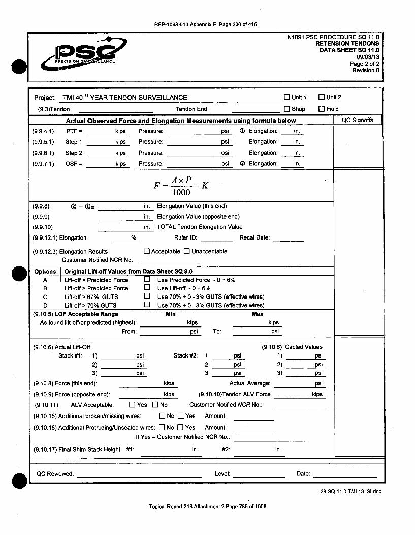
REP-1 098-510 Appendix E, Page 330 of 415
Project: TMI 40TH YEAR TENDON SURVEILLANCE [: Unit I El Unit 2
(9.3)Tendon Tendon End: El Shop El Field
Actual Observed Force and Elongation Measurements using formula below QC Signoffs
(9.9.4.1) PTF = kips Pressure: psi (D Elongation: in.
(9.9.5.1) Step 1 kips Pressure: psi Elongation: in.
(9.9.6.1) Step 2 kips Pressure: psi Elongation: in.
(9.9.7.1) OSF = kips Pressure: psi (D Elongation: in.
F- =AxP+K1000
(9.9.8) ) - (= in. Elongation Value (this end)
(9.9.9) in. Elongation Value (opposite end)
(9.9.10) in. TOTAL Tendon Elongation Value
(9.9.12.1) Elongation % Ruler ID: Recal Date:
(9.9.12.3) Elongation Results El Acceptable [I UnacceptableCustomer Notified NCR No:
Options Original Lift-off Values from Data Sheet SQ 9.0A Lift-off < Predicted Force El Use Predicted Force - 0 + 6%B Lift-off > Predicted Force El Use Lift-off - 0 + 6%C Lift-off > 67% GUTS El Use 70% + 0 - 3% GUTS (effective wires)D Lift-off > 70% GUTS El Use 70% + 0 - 3% GUTS (effective wires)
(9.10.5) LOF Acceptable Range Min MaxAs found lift-off/or predicted (highest): kips kips
From: psi To: psi
(9.10.6) Actual Lift-Off (9.10.8) Circled ValuesStack #1: 1) psi Stack #2: 1 psi 1) psi
2) psi 2 psi 2) psi3) psi 3 psi 3) psi
(9.10.8) Force (this end): kips Actual Average: psi
(9.10.9) Force (opposite end): kips (9.10.10)Tendon ALV Force kips
(9.10.11) ALV Acceptable: El Yes El No Customer Notified NCR No.:
(9.10.15) Additional broken/missing wires: El No [E Yes Amount:
(9.10.16) Additional Protruding/Unseated wires: El No El Yes Amount:
If Yes - Customer Notified NCR No.:
(9.10.17) Final Shim Stack Height: #1: in. #2: in.
QC Reviewed: Level: Date:
28 SQ 11.0 TMI.13 ISI.doc
Topical Report 213 Attachment 2 Page 785 of 1008

REP-1098-510 Appendix E, Page 331 of 415
N1091 PSC PROCEDURE SQ 11.0RETENSION TENDONS
SKETCH 7.009/03/13
Page 1 of 1Revision 0
Elongation Measurement - Sketch 7.0
t, t Distance between blade points.
I .r 2 1 ' ' , 3
After caliper Is removed without disturbing setting, place the caliperon the scale at a convenient point, but not on an uneven end andmake the measurement.
]r
3.15 3.40 3.70 3.90
T T T TI • I I- . L .
I ' I I F I I "I I I.1 .2 .3 A .6 .7.8 .9
3 4
Scale graduated In tenths of an inch (0.10")and estimated to the nearest 0.05 Inches.
a -W28 SQ 11.0 TMI.13 ISI.doc
Topical Report 213 Attachment 2 Page 786 of 1008

REP-1098-510 Appendix E, Page 332 of 415
N1091 PSC PROCEDURE SQ 11.1PSC ENGINEERING DATA
09/03/13Page 1 of 5Revision 0
EXELONTHREE MILE ISLAND
UNIT 1 (4 0TH YEAR) PHYSICALCONTAINMENT BUILDING TENDON SURVEILLANCE
PRECISION SURVEILLANCE CORPORATIONIN-SERVICE INSPECTION
QUALITY CONTROL PROCEDURE
PSC ENGINEERING DATA
lb."a dcvt&) Q.C. INSPECTOR
Title
09/03/13
DatePrepared by
Approved by
Approved by
Q.A. MANAGER
Title
09/03/13
Date
PRESIDENT
Title
09/03/13
Date
29 SQ 11.1.TMI.13 ISI
Topical Report 213 Attachment 2 Page 787 of 1008

REP-1 098-510 Appendix E, Page 333 of 415
N1091 PSC PROCEDURE SQ 11.1PSC ENGINEERING DATA
09/03/13
0 PRECISION ANCE Revision 0
1.0 PURPOSE
1.1 This procedure will establish the PSC Engineering requirements for the Retensioningof Tendons after the tendon has been Detensioned for purposes of AnchorageInspection and Sample Wire Removal from the Post-Tensioning System Tendons ofExelon's Three Mile Island Nuclear Plant - Unit 1.
2.0 SCOPE
2.1 The requirements for the Retensioning of Tendons have been described in TMIProcedure 1301-9.1 Rev 23. While there was some mention of the force values to beapplied to a tendon in that Procedure that was only intended as general information.This Procedure will provide the required Engineering Data for the Retensioningoperation.
2.2 The data shown herein shall establish the requirements for tendon elongation, PTFand OSF for tendon elongation during the Retensioning of Tendons and thePredicted Forces that affect each Surveillance Tendon.
2.2.1 PRETENSIONING FORCE (PTF)
2.2.1.1 The Pretensioning Force (PTF) removes the slack from the tendon andprovides a baseline number for elongation measurement. The Table seen inSection 3 of this Procedure will provide the required data for the Retensioningof Tendons.
2.2.2 OVERSTRESS FORCE (OSF) - FOR ELONGATION
2.2.2.1 The Overstress Force for Elongations is that force which must be achieved inorder to develop the final elongation measurement used in the comparison ofactual tendon elongation to the original or calculated tendon elongation. TheOverstress Force for this surveillance will be the same as used for the OriginalInstallation adjusted for the remaining Effective Wires.
2.2.3 OVERSTRESS FORCE - DO NOT EXCEED
2.2.3.1 At no time shall any tendon be subjected to an Overstress Force which exceeds1592 Kips for a 169 wire tendon. Tendons with less than 169 wires shall bereduced in force by 9.425 Kips for each wire less than 169.
29SQ 11.1.TM1.131SI
Topical Report 213 Attachment 2 Page 788 of 1008

REP-1 098-510 Appendix E, Page 334 of 415
N1091 PSC PROCEDURE SQ 11.1PSC ENGINEERING DATA
09/03/13Page 3 of 5
Revision 0
3.0 RETENSIONING DATA
3.1 TMI Unit 1 - Restressing Data - Original Scope Tendons
D-237 208.3 1518.9
H13-03 208.3 1593
V-159 208.3 1472.8
168 207 1510 4.28 7.16
167 206 1501 4.31 7.22
166 205 1492 4.35 7.27
168 207 1584 4.22 7.07
167 206 1574 4.26 7.12
166 205 1565 4.29 7.17
168 207 1464 5.80 9.72
167 206 1455 5.85 9.79
166 205 1447 5.90 9.86
9.4
9.8
12.3
3.2 TMI Unit 1 - Restressinc Data - Auqmented Scope Tendons
PREVIOUSLY AT RETENSIONING z-12< ý- -0 LL LL LL Z <0 1-- (0 w (n zz IL a 065 wm m o
w 0- CL ý;: [L 2 ýý ýe :2ý cr 09 R Rý R CD :7- CD Z=, 0 (DCr Z) W CD C) -jLi- ý2 Lu
168 199 1579 4.68 7.80
H51-40 199.81588.7 [ 167 197 1570 4.72 7.85 ] 10.75
166 196 1560 4.76 7.91
168 198 1577 4.80 7.99
V-136 199.4 1586.6 167 197 1568 4.84 8.05 11
166 196 1558 4.88 8.11
29 SQ 11.1.TMI.13 ISI
Topical Report 213 Attachment 2 Page 789 of 1008

REP-1098-510 Appendix E, Page 335 of 415
N1091 PSC PROCEDURE SQ 11.1PSC ENGINEERING DATA
09/03/13Do. A MAf~
I ION ANCE Revision 0
3.3 NOTES CONCERNING ELONGATION DATA
3.3.1 The tendons for this project were based on 169 wires.
3.3.2 Pretensioning Force (PTF) for purposes of elongation shall be as shown in thetable above for a 168 or less wire tendon. For each wire less than shown above,reduce PTF proportionately for each tendon using the formula shown in Section3.2.2 of this procedure.
3.3.3 Overstress Force (OSF) for purposes of elongation shall be as shown in the tableabove for a 168 wire or less wire tendon. For each wire less than shown above,reduce OSF proportionately for each tendon using the formula shown in Section3.2.1 of this Procedure.
3.3.4 The Overstress (OSF) Elongation shown above is the Total Elongation for thetendon from Installation or Previous Surveillance. The total elongation fromInstallation or Previous Surveillance shall be compared to the Total ActualMeasured Elongation during this Surveillance.
3.4 FORCES DURING SURVEILLANCE
3.4.1 Overstress (OSF) during Retensioning:
(OSF at Installation) x (# of Wires during Retension)#of Wires during Installation
3.2.2. Pre-Tensioning (PTF) during Retensioning:
(PTF at Installation) x (# of Wires during Retension)
#of Wires during Installation
3.5 USE OF "K" (CONSTANT)
3.5.1 With the use of regression analysis for the calibration of ram area, as seen in thePSC Ram Calibration Procedure where error calculation is also considered withinthe computer program, the ram area no longer reflects the ram size, but insteadprovides an area measurement with a correction factor related to pressure. Thiscorrection factor becomes a "Constant" (K), related only to that ram beingcalculated for area. The constant is a factor that considers the amount of forcenecessary to overcome internal resistance. This Constant will vary from ram toram and could be positive or negative; that is, it may have to be added orsubtracted from the total force to provide the true actual force measurement,whether that force is Pre Tensioning Force, Over-Stress Force, or Lock-Off Force.
29SQ 11.1.TMI.13 ISI
Topical Report 213 Attachment 2 Page 790 of 1008

REP-1098-510 Appendix E, Page 336 of 415
N1091 PSC PROCEDURE SQ 11.1PSC ENGINEERING DATA
09/03/13Page 5 of 5Revision 0
3.6 FORMULA AND WORKING RELATIONSHIPS
3.6.1 The basic formula for determining stressing force or stressing pressure when threefactors are known is:
Key: F = Force (kips)A = Ram Area (in2)
F= Ax P = Gauge Pressure (psi)1000 K = Constant factor (kips)
(CAUTION: "K" constants can be eitherpositive or negative.)
Only P or F could be unknown and remain to be determined. The other threefactors will always be provided before beginning the calculations.
3.6.2
29SQ 11.1.TMI.13 181
Topical Report 213 Attachment 2 Page 791 of 1008

REP-1 098-510 Appendix E, Page 337 of 415
N1091 PSC PROCEDURE SQ 12.0REPLACE GREASE CAP
09/03/13Page 1 of 6Revision 0 a
EXELONTHREE MILE ISLAND
UNIT 1 (4 0TH YEAR) PHYSICALCONTAINMENT BUILDING TENDON SURVEILLANCE
PRECISION SURVEILLANCE CORPORATIONIN-SERVICE INSPECTION
QUALITY CONTROL PROCEDURE
GREASE CAP REPLACEMENT S0
~lLk & dau-) Q.C. INSPECTOR
Title
09/03/13
DatePrepared by
Q.A. MANAGER 09/03/13
DateApproved by Title
PRESIDENT 09/03/13
DateApproved by Title
aw
30 SQ 12.0 TMI.13 ISI
Topical Report 213 Attachment 2 Page 792 of 1008

REP-1098-510 Appendix E, Page 338 of 415
1.0 PURPOSE
1.1 This procedure will establish the requirements for the Replacement of Grease Capsafter visual inspection and evaluation has been completed for the tendon end anchorhead, shims, bearing plates and wires during In-Service Inspections (surveillance) ofPost-Tensioning System Tendons of Exelon's Three Mile Island Nuclear Plant - Unit1.
2.0 RESPONSIBILITY
2.1 In the event of conflict between any TMI Procedure and an SQ, the former governs.
2.2 Precision Surveillance Corporation Field Construction Personnel shall be responsiblefor the physical activities and recording of documentation associated with thisprocedure, as an option a Precision Surveillance Corporation QC Inspector mayrecord the documentation.
3.0 QUALIFICATIONS
3.1 Precision Surveillance Corporation Field Construction Personnel shall be fit by skill,training and/or experience to perform these duties.
4.0 EQUIPMENT
4.1 There is no need for Quality control equipment for this procedure.
5.0 QUALITY CONTROL
5.1 There are no Quality Control Documentation (QCD) points or HOLD Points in thisprocedure.
6.0 PRECAUTIONS
6.1 Be prepared to support the weight of the grease cap.
7.0 PREREQUISITES
7.1 All other work, inspections and evaluations shall be completed with the exception ofGrease Replacement.
7.2 Prior to replacement of grease caps record on Data Sheet SQ 12.0 the informationrequired for tendon number, tendon end and date of grease cap replacement.
8.0 GREASE CAP REPLACEMENT
8.1 Tendon end caps are being installed per TMI Procedure 141 0-Y-83.
8.2 Installation of Hoop, Dome and lower Vertical caps.
30 SQ 12.0 TMI.13 ISI
Topical Report 213 Attachment 2 Page 793 of 1008

REP-1098-510 Appendix E, Page 339 of 415
N1091 PSC PROCEDURE SQ 12.0REPLACE GREASE CAP
09/03/13
00RPRECISION evision 0
8.2.1 Only minor cleaning and brushing should be necessary to prepare the bearingplate and grease cap for remounting to the bearing plate or anchorage.
8.2.2 Prepare bearing plate surface by cleaning with rags and solvent. If detrimentalforeign matter such as mill scale, rust, and dirt is detected on the gasket bearingsurface of the plate, and power tool cleaning is required, then:
8.2.2.1 Make suitable provisions to protect the tendon wires and anchor head threadsfrom accidental rubbing, cutting, or scratching by coming into contact with thepower tool's rotating wire brushes and/or abrasive disks. Sheet metal shroudsaround the tendon and end anchorage may be necessary.
8.2.2.2 Take precautions to keep dirt and other foreign material out of the tendon, andfrom the inside of the trumpet and conduit.
8.2.2.3 Power tools should remove loose mill scale, loose rust, loose or flaking paint,etc. Surfaces must be clean and smooth but not necessarily burnished afterusing power tools.
8.2.2.4 Remove sharp edges, and smooth down remaining mill scale to a "feather-edge".
8.2.3 Fill scratches, nicks, and other sharp depressions in the gasket bearing surfacewith nonmetallic epoxy, such as "Belzona" epoxy if approved by TMI Engineering.Use of epoxy shall be according to manufacture's application instructions.
8.2.3.1 Smooth out epoxy to prevent grease leakage under the gasket.
8.2.4 Remove all dust and loose mater from the vicinity of the tendon and entrance tothe trumplet.
8.2.5 Clean any foreign material from the threaded bearing plate grease cap mountingholes.
8.2.6 Smear, swab or brush a coating of grease over all the exposed portions of theanchor head, bearing plate, shims, buttonheads and wires, if not previously donein another operation or if needed.
8.2.7 A thread chaser or tap may be required to clear the threads of the bearing plate'sgrease cap mounting holes so that the bolts can be sufficiently tightened to bottomin the threaded holes.
8.2.8 Clean and dry the flange and gasket sealing surface of the grease cap.
8.2.9 Record on Data Sheet SQ 12.0 that the bearing plate, grease cap, and gasketmating surfaces and bolt holes have been properly prepared and that foreignmaterial has been controlled so as not to enter the tendon void.
30 SQ 12.0 TMI.13 ISI
Topical Report 213 Attachment 2 Page 794 of 1008
REP-1098-510 Appendix E, Page 340 of 415
N1091 PSC PROCEDURE SQ 12.0REPLACE GREASE CAP
09/03/13Page 4 of 6Revision 0
8.2.10 On hoop and dome caps where the original through-cap mounting bolting is beingreplaced with hold down clamps the through-cap holes shall be plugged with Pop-A-Plugs.
8.2.11 With the grease cap on end, place a new gasket on the grease cap. Pliobond or asimilar industrial adhesive, as approved by TMI Engineering, may be used to holdthe gasket in place.
8.2.12 New gaskets shall be used in the final placement of the grease cap. Old or usedgaskets may be used during temporary placement of the grease caps.
8.2.13 Place the gasket retainer (verticals only) and grease cap over the tendon end andalign the cap by placing it over the two 1" aligning pins. If slotted aligning pins areused, insert the tapered wedges through the slots in the aligning pins to hold thecap in place. Be sure the gasket is in place and not pinched between the gasketretainer and the bearing plate. For vertical tendons, the wedges and pins need notalways be used. The grease cap bolts may be used at this time while using ahoisting device to hold the cap in place temporarily.
8.2.14 Place 1 washer, standard or hardened, over each of the 1" bolts and put the boltsinto the 2 remaining holes of the bearing plate. Tighten by hand until seated.Remove the aligning pins and replace them with two bolts and washers.
8.2.15 Tighten each bolt with a wrench, equalizing the load on each bolt as well aspossible. Tighten until there is evidence of metal to metal contact all aroundbetween the flange, gasket retainer, and bearing plate.
8.2.16 For Horizontal tendons and Dome tendons, the grease cap shall be placed so thatthe bushing (inlet, outlet) is oriented in its highest altitude or toward the top of thecontainment.
8.2.17 After aligning the cap and placing over the anchorage install the four tendon endcap holding down clamps with bolts and washers to the bearing plate and handtighten them.
8.2.18 Reckeck that the gasket has not slipped or become crimped and that the tendonend cap and hold down bolts are aligned properly.
8.2.19 Tighten each bolt, equalizing the load on each as much as possible, to evenlycompress the gasket by approximately 1/8".
8.2.20 Apply a new wrapping of TMI approved sealant to the grease cap filler bushingprior to final insertion and tightening.
8.2.21 Record on Data Sheet SQ 12.0, the completeness of the installation and that thebolts were tightened in incremental passes.
30 SQ 12.0 TMI.13 ISI
Topical Report 213 Attachment 2 Page 795 of 1008

REP-1098-510 Appendix E, Page 341 of 415
N1091 PSC PROCEDURE SQ 12.0REPLACE GREASE CAP
09/03/13Pn'f nf R
PRECISION LANCE *RvsoRevision 0
8.2.22 The replacement is now complete and re-greasing can be performed observing
the requirements of PSC Procedure SQ 12.1.
8.3 Installation of upper Vertical caps
8.3.1 Only minor cleaning and brushing should be necessary to prepare the bearingplate and grease cap for remounting to the bearing plate or anchorage.
8.3.2 Prepare bearing plate surface by cleaning with rags and solvent. If detrimentalforeign matter such as mill scale, rust, and dirt is detected on the gasket bearingsurface of the plate, and power tool cleaning is required, then:
8.3.2.1 Make suitable provisions to protect the tendon wires and anchor head threadsfrom accidental rubbing, cutting, or scratching by coming into contact with thepower tool's rotating wire brushes and/or abrasive disks. Sheet metal shroudsaround the tendon and end anchorage may be necessary.
8.3.2.2 Take precautions to keep dirt and other foreign material out of the tendon; andfrom the inside of the trumpet and conduit.
8.3.2.3 Power tools should remove loose mill scale, loose rust, loose or flaking paint,etc. Surfaces must be clean and smooth but not necessarily burnished afterusing power tools.
8.3.2.4 Remove sharp edges, and smooth down remaining mill scale to a "feather-edge".
8.3.3 Fill scratches, nicks, and other sharp depressions in the gasket bearing surfacewith nonmetallic epoxy, such as "Belzona" epoxy if approved by TMI Engineering.Use of epoxy shall be according to manufacture's application instructions.
8.3.3.1 Smooth out epoxy to prevent grease leakage under the gasket.
8.3.4 Remove all dust and loose mater from the vicinity of the tendon and entrance tothe trumplet.
8.3.5 Clean any foreign material from the threaded bearing plate grease cap mountingholes.
8.3.6 Smear, swab or brush a coating of grease over all the exposed portions of theanchor head, bearing plate, shims, buttonheads and wires, if not previously donein another operation or if needed.
8.3.7 Clean and dry the gasket sealing surface of the grease cap.
30 SQ 12.0 TMI.13 ISI
Topical Report 213 Attachment 2 Page 796 of 1008
REP-1 098-510 Appendix E, Page 342 of 415
N1091 PSC PROCEDURE SQ 12.0REPLACE GREASE CAP
09/03/13Page 6 of 6Revision 0
8.3.8 Record on Data Sheet SQ 12.0 that the bearing plate, grease cap, and gasketmating surfaces and bolt holes have been properly prepared and that foreignmaterial has been controlled so as not to enter the tendon void.
8.3.9 With the grease cap on end, place a new gasket on the grease cap. Pliobond or asimilar industrial adhesive, as approved by TMI Engineering, may be used to holdthe gasket in place.
8.3.10 New gaskets shall be used in the final placement of the grease cap. Old or usedgaskets may be used during temporary placement of the grease caps.
8.3.11 Install the four studs in to the retaining ring attached to the anchor head.
8.3.12 Align the grease cap over the anchorage against the bearing plate using care toavoid damaging or misaligning the gasket.
8.3.13 Install the four end cap hold down nuts (with gasket and washer) on the studs andhand tighten.
8.3.14 Recheck that the gasket has not slipped or become crimped and that the tendoncap is properly aligned.
8.3.15 Tighten each nut, equalizing the load on each stud as much as necessary toevenly compress the main gasket. No torqueing is required.
8.3.16 Record on Data Sheet SQ 12.0, the completeness of the installation and that thebolts were tightened in incremental passes.
8.3.17 The replacement is now complete and re-greasing can be performed observingthe requirements of PSC Procedure SQ 12.1.
9.0 DOCUMENTATION
9.1 The items requiring documentation in this procedure shall be documented by theassigned field construction person of the working crew on Data Sheet SQ 12.0attached to this procedure, as an option a Precision Surveillance Corporation QCInspector may record the documentation.
10.0 NOTIFICATION
10.1 PSC Site Superintendent shall be notified if any problems are encountered during thereplacement of grease caps.
11.0 ATTACHMENTS
11.1 Data Sheet SQ 12.0.
30 SQ 12.0 TMI.13 ISI
Topical Report 213 Attachment 2 Page 797 of 1008

REP-1098-510 Appendix E, Page 343 of 415
N1091 PSC PROCEDURE SQ 12.0REPLACE GREASE CAP
Data Sheet 12.009/03/13
PPRECISION ANCE Page 1 of IRevision 0
Project: TMI 40TH YEAR TENDON SURVEILLANCE
Tendon No.: Tendon End: E] Shop [I Field
ANCHORAGE INSPECTION CRITERIA
S
BEARING PLATE SURFACE PROPERLY PREPARED: Li YES LI NO
GREASE CAP SURFACE PROPERLY PREPARED: El YES El NO
GASKET MATING SURFACE PROPERLY PREPARED: El YES El NO
STUD/BOLT HOLES PROPERLY PREPARED: El YES El NO
FOREIGN MATERIAL EXCLUSION CONTROLLED: El YES El NO
COMMENTS
S0,
CREW FOREMAN SIGNOFF Date:
OC Reviewed: Level: Date: aW/
30 SQ 12.0 TMI.13 ISI
Topical Report 213 Attachment 2 Page 798 of 1008

REP-1098-510 Appendix E, Page 344 of 415
N1091 PSC PROCEDURE SQ 12.1GREASE REPLACEMENT
09/03/13Page 1 of 10
Revision 0
EXELONTHREE MILE ISLAND
UNIT 1 (4 0TH YEAR) PHYSICALCONTAINMENT BUILDING TENDON SURVEILLANCE
PRECISION SURVEILLANCE CORPORATIONIN-SERVICE INSPECTION
QUALITY CONTROL PROCEDURE
GREASE REPLACEMENT
1IflLa Jauj Q.C. INSPECTOR 09/03/13
DatePrepared by Title
Q.A. MANAGER
Approved by
62Co
Title
09/03/13
Date
09/03/13
Date
PRESIDENT
Approved by Title
31 SQ 12.1 TMI.13 ISI
Topical Report 213 Attachment 2 Page 799 of 1008

REP-1 098-510 Appendix E, Page 345 of 415
N1091 PSC PROCEDURE SQ 12.1GREASE REPLACEMENT
09/03/13Page 2 of 10
Revision 0
1.0 PURPOSE
1.1 This procedure will establish the requirements for the Replacement of Grease in thetendon duct after scheduled inspections and evaluation during the 4 0 th Year In-Service-Inspections (Surveillance) of the Post-Tensioning System Tendons ofExelon's Three Mile Island Nuclear Plant - Unit 1.
2.0 SCOPE
2.1 This procedure is intended to provide the Grease Replacement requirements for thewire post-tensioning system. This procedure requires that all tendons worked on shallbe full of grease at the end of the project.
3.0 RESPONSIBILITY
3.1 In the event of conflict between any TMI Procedure and an SQ, the former governs.
3.2 As stated in PSC Procedure QA 4.0.
4.0 QUALIFICATIONS
4.1 As stated in PSC Procedure QA 4.1.
5.0 EQUIPMENT
5.1 The gauges and test equipment necessary for the Quality Control activities will beitemized in PSC Procedure SQ 4.0.
6.0 QUALITY CONTROL
6.1 This procedure contains Quality Control Documentation (_.QC) points. The work shallnot progress past or through a QCD without a sign-off or verbal approval from the QCInspector. The sign-off's and required information or evaluation data shall bedocumented on Data Sheet 12.1. It shall be necessary to acquire the Total GreaseLoss for the tendon from the Data Sheets 6.0 of PSC Procedure SQ 6.0 for each end,if applicable.
7.0 PRECAUTIONS
7.1 During Grease Replacement, the grease may be very hot and pumped underpressure. It is therefore essential to avoid direct contact with the hot grease and tomake sure all connections are secure.
CAUTION - DURING GREASING, BE AWARE THAT THE GREASE IS HOT AND MAY BEPUMPED UNDER PRESSURE.
31 SQ 12.1 TMI.13 ISI
Topical Report 213 Attachment 2 Page 800 of 1008

REP-1098-510 Appendix E, Page 346 of 415
N1091 PSC PROCEDURE SQ 12.1GREASE REPLACEMENT
09/03/13Page 3 of 10
Revision 0
7.2 Spilled grease from hoses and voids could be a slipping safety hazard, during alloperations it should be cleaned up and placed in waste drums.
7.3 Pumping of grease should be stopped immediately if it is suspected or known that thegrease is going somewhere else besides the immediate tendon void.
8.0 PREREQUISITES
8.1 All Inspections, if required per SQ2.0, will be complete.
8.2 The tendon will be in a stressed condition.
8.3 The Grease Cap shall be ready to be installed or already have been installed.
8.4 QCD - Document the type of grease (corrosion inhibitor) being used for the greasingof this tendon. The requirements for acceptable corrosion inhibitor are listed insection 9.1.2 of this procedure.
8.5 QCD - Enter the tendon end designation and quantity of total grease loss from DataSheet 6.0 for one end of the tendon, if applicable
8.6 QCD - Enter the tendon end designation and the quantity of tota I\g~rase loss fromData Sheet 6.0 for the other end of the tendon, if applicable. \?
8.7. QCD - Enter the tendon end designation and any estimated grease Oss that mayhave occurred as a result of leaks from the grease cap or gaskettshnce-tfe originalinstallation or previous surveillance for the first end of the tendon.
8.8 QCD- Enter the tendon end designation and any estimated grease loss that mayhave occurred as a result of leaks from the grease cap or gasket since the originalinstallation or previous surveillance for the second end of the tendon.
8.9 QCD - Calculate the total tendon grease loss by adding 8.5 + 8.6 + 8.7 + 8.8 anddocument the total tendon grease loss on Data Sheet 12.1.
9.0 CONTROLS FOR REFILLING THE TENDON VOID
9.1 All Tendons
9.1.1 The replacement of grease shall be performed prior to demobilization of thetendon surveillance equipment and personnel.
9.1.2 Tendons shall be filled with Tendon Corrosion Inhibitor (Certified) issued by theUtility Quality Program OR drained grease removed from the system ONLY afteracceptable sample testing per Section SQ 7.0 OR upon written approval byExelon.
9.1.3 Grease Temperature required at grease cap inlet: 180°F min., 250°F max.
31 SQ 12.1 TMI.13 ISI
Topical Report 213 Attachment 2 Page 801 of 1008

REP-1 098-510 Appendix E, Page 347 of 415
N1091 PSC PROCEDURE SQ 12.1GREASE REPLACEMENT
09/03/13FO0 ~ J 0 E f/4I PRECISION ANCE Revision 0
9.1.4 Required grease to be drain for Thermal Expansion upon successful pumpthrough: 1 gallon. This will curtail any excess pressure build up which may lead togasket failure. (Vertical tendons bottom end only)
9.1.5 Required hold time at full pressure: 30 minutes if pump through not achieved.
9.1.6 Pumping shall be stopped immediately if it is suspected or known that the greaseis going somewhere else besides the immediate tendon void.
9.2 Hoop and DomeTendons
9.2.1 Maximum pressure at grease cap inlet when pressure pumping: 100 psig
9.2.2 If less than 5 gallons of grease has been lost from the tendon void (duct) at eachend of the tendon, each end shall be poured or hand pumped with hot grease untilfull.
9.2.3 If more than 5 gallons of grease has been lost from the tendon void (duct) at eitherend of the tendon, the tendon shall be pressure pumped with hot grease from oneend until it exits the Opposite End. Pumping may be stopped after 30 minutes ifnothing exits at the Top end.
9.2.3.1 Where there is no grease exiting from the opposite end of a hoop or dometendon, it shall be necessary to hand pump hot grease into the opposite endgrease cap until full.
9.3 Vertical Tendons
9.3.1 Maximum pressure at grease cap inlet when pressure pumping: 110 psig (may bepulsated up to 150 psig to clear any blockage)
9.3.2 If more than 10 gallons of grease has been lost from the tendon void (duct) at thelower end, the tendon shall be pressure pumped with hot grease from the bottomend until it exits the Top End. Pumping may be stopped after 30 minutes if nothingexits at the Top end.
9.3.2.1 Where there is no grease exiting from the top end of a vertical tendon, it shallbe necessary to pour or hand pump hot grease into the top end grease cap untilfull.
10.0 MEASUREMENT OF GREASE REPLACEMENT
10.1 The grease may be in a large storage container or in 55-gallon drums. The largestorage container shall have an automatic thermostat control for temperature, whiledrum heaters shall be used to heat the grease in drums.
31 SQ 12.1 TMI.13 ISI
Topical Report 213 Attachment 2 Page 802 of 1008

REP-1098-510 Appendix E, Page 348 of 415
N1091 PSC PROCEDURE SQ 12.1GREASE REPLACEMENT
09/03/13Page 5 of 10
PRPECISION ANCE Revision 0
10.2 The grease shall be monitored for quantity by measuring the quantity of greaseremaining in the drum or by measuring the drum to determine the quantity that has.been pumped out.
10.3 To provide a grease volume number in gallons based on a standard 55 gallon drum,divide the 55 gallons by the usable height of the drum (31 inches). This provides afigure of 1.77 gallons per inch of drum height. Note that a typical 55 gallon drum is 34inches high, but based on actual observation, grease shrinkage and the depressedlid take up 3 inches of height.
10.4 Take a measurement of the height of the grease in the drum with a clean measuringdevice before installing any grease. It will be acceptable to take the measurementfrom the top of the grease in the drum to the top edge of the drum. Document thegrease height dimension to the nearest .05 of an inch.
10.5 Take a measurement of the height of the grease in the drum after installing thegrease. Document the final grease height dimension to the nearest 0.05 of an inch.
10.6 Calculate and document the Total Quantity of grease replaced into the cap to thenearest tenth (0.1) of a gallon.
10.6.1 EXAMPLE: If the initial grease height was 25.5" and the final grease height was6.25", this is a 19.25" reduction multiplied by 1.77 gallons per inch which equals34.1 gallons pumped in.
10.7 The same methodology may be used for containers of different size or configuration.
11.0 MEASUREMENT OF GREASE WASTE
11.1 When it becomes necessary to determine the volume of grease that was pumped intothe tendon void, it will be necessary to subtract the waste grease outflow, spillage,grease remaining in the pump-in hose, grease remaining in the waste line hose fromthe grease volume that was pumped from the drum into that tendon.
11.2 The 1 gallon of grease drained from the inlet end after a successful pump throughshall be considered waste grease if it is not drained back into the original drum.
11.3 If the waste grease is pumped into a 55 gallon drum, then each inch of drum heightwill equal to 1.77 gallons.
11.4 Smaller containers should be evaluated for size to determine the capacity. Thesetypes of containers would only require a simple estimate for the waste greasecontained therein.
11.5 Before pumping any waste grease into a container, always verify the quantity withinthat container prior to pumping.
31 SQ 12.1 TMI.13 ISI
Topical Report 213 Attachment 2 Page 803 of 1008

REP-1 098-510 Appendix E, Page 349 of 415
12.0 PRESSURE PUMPING
12.1 The grease replacements described in this procedure are for both ends of a tendon.The terms tendon void, tendon conduit, and tendon duct are synonymous.
12.2 If more than 5 gallons of grease has been lost from the tendon void (duct) at eitherend of a hoop or dome tendon, the tendon shall be pressure pumped with hot greasefrom one end until it exits the opposite end. Pumping may be stopped after 30minutes if nothing exits.
12.3 If more than 10 gallons of grease has been lost from the tendon void (duct) at thelower end of a vertical tendon, the tendon shall be pressure pumped with hot greasefrom the bottom end until it exits the top end. Pumping may be stopped after 30minutes if nothing exits.
12.4 Remove the grease cap plug; attach the "Y-Device" to the end of the grease cap tobe pumped. Connect the Y-Device, if necessary, and waste outflow hose to theopposite end of the tendon. Be sure to have a suitable quantity of waste containerson hand to collect the waste.
12.5 Be sure that adequate communication is provided at each end of the tendon so thatthe crew at each end of the tendon will know what actions are taking place.
12.6 QCQ - Document the ambient temperature near the tendon, as well as theThermometer Identification and Recalibration Date.
12.7 QCQ - Document the inlet temperature of the grease as well as the thermometeridentification and its recalibration date.
12.8 Prior to attaching the inlet greasing hose to the Y-Device, circulate hot greasethrough the system to ensure the grease is at sufficient temperature prior to pumpinginto the tendon void. Pressure pump and greasing hose should be fully primed priorto connecting to the Y-Device.
12.9 QCQ - Document the initial grease height dimension to the nearest .05 of an inch.Refer to Section 10.0 for further explanation of grease measurement.
12.10 Commence pressure pumping grease into the tendon in accordance with the controlsstated in Section 9.0.
12.11 If the grease exits the opposite end of a dome tendon, pumping shall continue until aminimum of 1 gallon of clean grease has exited from the opposite end with atemperature of 1400F. The opposite end Y-Device shall then be closed and pressurepumping from the inlet end will continue until maximum pressure is achieved. Uponachievement of maximum pressure, stop pumping and drain 1 gallon of grease fromthe inlet end.
31 SQ 12.1 TMI.13 ISI
Topical Report 213 Attachment 2 Page 804 of 1008

REP-1098-510 Appendix E, Page 350 of 415
N1091 PSC PROCEDURE SQ 12.1GREASE REPLACEMENT
09/03/13Page 7 of 10
Revision 0
12.12 When pump through is not achieved on the initial attempt, the following actionsshould take place in order to maximize the effort of filling the tendon void.
12.12.1 Build pressure to the maximum pressure at the grease cap inlet in accordancewith Section 9.3.1.
12.12.2 Hold pressure for a minimum of 30 minutes. This may require additional pumpingin order to remain at the desired maximum pressure.
12.12.3 If pump through is achieved, continue with step 12.11.
12.12.4 If pump through is still not successful pumping from this end shall be complete. Itshall be necessary to hand pump the opposite end of the tendon by following thesteps in Section 13.0
12.13 Release any pressure from the inlet end before disconnecting any of the hoses fromthe Y-Device. Ensure all shut-off valves are closed before disconnecting any greaseconnections at either end.
12.14 QCD- Once the tendon end has been completed, document the final grease heightdimension to the nearest .05 of an inch. Refer to Section 10.0 for further explanationof grease measurement.
12.15 Remove grease hoses and Y-Devices from both ends and replace the grease capplugs on both ends of the tendon.
12.16 QCD - Calculate and document the quantity of hot grease pressure pumped into thistendon end in accordance with Section 10.6. Also, document the tendon endidentification, either shop/field and/or nearest buttress number to the tendon endbeing pumped.
12.17 QCD - Document whether successful pump through was achieved via exiting greaseat the other end of the tendon. If exit was not achieved, document the pressure andtime held in order to attempt pump through.
12.18 QCD - Document the quantities of waste grease if any, including any exiting outflowgrease. Refer to Section 11.0 of this procedure for explanation on calculating wastegrease.
12.19 QCD - Calculate and document the total amount of grease replaced through thecurrent inlet end of the tendon by subtracting the amount of any waste grease fromthe quantity of hot grease pressure pumped into this tendon end.
12.20 Continue to Section 14.0 for final calculation of quantity of grease replaced if pumpthrough was successful.
31 SQ 12.1 TMI.13 ISI
Topical Report 213 Attachment 2 Page 805 of 1008
REP-1098-510 Appendix E, Page 351 of 415
N1091 PSC PROCEDURE SQ 12.1GREASE REPLACEMENT
09/03/13Page 8 of 10
Revision 0
13.0 POURING AND HAND PUMPING
13.1 The grease replacements described in this procedure are for one end of a tendon,however both ends of the tendon will be documented on the same data sheet. Theterms tendon void, tendon conduit, and tendon duct are synonymous.
13.2 If less than 5 gallons of grease has been lost from the tendon void (duct) at each endof a hoop or dome tendon, each end shall be poured or hand pumped with hotgrease until full.
13.3 If less than 10 gallons of grease has been lost from the tendon void (duct) at thelower end, hot grease shall be poured or hand pumped into the top end until full.
13.4 If pressure pumping is unsuccessful from the end of any tendon hot grease shall bepoured or hand pumped into the opposite end until full.
13.5 Remove the grease cap plug; attach the "Y-Device" to the end of the grease cap tobe pumped or poured. It shall be acceptable to hand pump or pour grease directlyinto the grease cap without the use of a "Y-Device" if the grease cap configuration willallow this.
13.6 QCD - Document the ambient temperature near the tendon, as well as theThermometer Identification and Recalibration Date.
13.7 QCQ - Document the inlet temperature of the grease as well as the thermometeridentification and its recalibration date.
13.8 Prior to attaching the inlet greasing hose to the Y-Device or grease cap, circulate hotgrease through the system to ensure the grease is at sufficient temperature prior topumping into the tendon void. Hand pump and greasing hose should be fully primedprior to connecting to the Y-Device. This step is not necessary if grease is beingpoured into the grease cap.
13.9 QCD - Document the initial grease height dimension to the nearest .05 of an inch.Refer to Section 10.0 for further explanation of grease measurement.
13.10 If grease is being hand pumped, commence pumping grease into the tendon inaccordance with the controls stated in Section 9.0.
13.11 If grease is being poured, transfer grease into secondary (smaller) container andpour into the Y-Device or grease cap until full. Grease replacement must be inaccordance with controls outlined in Section 9.0.
13.12 QQ - Once the tendon end has been completed, document the final grease heightdimension to the nearest .05 of an inch. Refer to Section 10.0 for further explanationof grease measurement.
31 SQ 12.1 TMI.13 ISI
Topical Report 213 Attachment 2 Page 806 of 1008

REP-1098-510 Appendix E, Page 352 of 415
N1091 PSC PROCEDURE SQ 12.1GREASE REPLACEMENT
09/03/13Page 9 of 10
Revision 0
13.13 Remove grease hoses and Y-Devices as necessary from both ends and replace thegrease cap plugs on both ends of the tendon. Verify no grease is leaking.
13.14 QCD- Calculate and document the quantity of hot grease hand pumped or pouredinto this tendon end in accordance with Section 10.6. Also, document the tendonend identification, either shop/field and/or nearest buttress number to the tendon endbeing pumped.
13.15 .QQD- Document whether grease replacement was accomplished by hand pumpingor pouring.
13.16 QCQ - Document the quantities of waste grease if any. Refer to Section 11.0 of thisprocedure for explanation on calculating waste grease.
13.17 QCQ - Calculate and document the total amount of grease replaced through thecurrent inlet end of the tendon by subtracting the amount of any waste grease fromthe quantity of hot grease hand pumped or poured into this tendon end.
13.18 Repeat the steps in Section 13.0 for the other end of a hoop or dome tendon ifapplicable.
13.19 Continue to Section 14.0 for final calculation of quantity of grease replaced whengrease replacement is complete.
14.0 CALCULATION OF GREASE REPLACEMENT
14.1 QCQ- Calculate the total tendon grease replaced by adding the quantities of greasereplaced by pressure pumping each end (combination of 12.19 and 13.17 asapplicable).
14.2 QCQ - Obtain the calculated net volume of the tendon void from PSC ProcedureSQ1 2.2 and post it on Data Sheet 12.1
14.3 QCQ- Compare the total tendon grease replaced (14.1) to the total tendon greaseloss (8.9). Calculate the percent difference by the following formula:
[TOTAL TENDON QUANTITY REPLACED (14.1)]- [TOTAL TENDON GREASE LOSS (8.9)]x 100%NET VOLUME TENDON VOID (SQ 12.2)
14.4 QCQ - Verify that no grease is leaking. If there is some leakage, the deficiency shallbe corrected and cleanup performed. Document the acceptance of leak tightness.
14.5 QCD - Document the acceptability of the refilling. An acceptable refilling is one inwhich the percent difference from Section 14.3 of this procedure does not exceed10% and there are no leaks.
31 SQ 12.1 TMI.13 ISI
Topical Report 213 Attachment 2 Page 807 of 1008

REP-1098-510 Appendix E, Page 353 of 415
N 1091 PSC PROCEDURE SQ 12.1GREASE REPLACEMENT
09/03/13Page 10 of 10
Revision 0
14.6 QCD - Document any pertinent comments, unusual occurrences or references that
could assist in evaluating the refill or for future surveillances.
15.0 NOTIFICATION
15.1 If the absolute difference between the amount of grease removed from the tendonand the amount of grease replaced exceeds 10% of the net duct volume, it shall benecessary to notify TMI Engineering with a nonconformance report within 24 hours.
16.0 DOCUMENTATION
16.1 The items requiring documentation shall be documented on Data Sheet 12.1a or12.lb as necessary. Data Sheet 12.la shall be used when a tendon is pressurepumped and 12.1b shall be used when a tendon is hand pumped from both ends.
16.2 Some information shall be posted from Data Sheet 6.0 of PSC Procedure SQ 6.0onto Data Sheet 12.1 a or 12.1 b as applicable.
16.3 The Data Sheets reference the applicable Section or Step number of the procedurefor each QCD point.
17.0 ATTACHMENTS
17.1 Figure 1.0- PSC "Y" Device
17.2 Data Sheet 12.1a - Pressure Pumping
17.3 Data Sheet 12.1b - Hand Pumping
S
S
SI31 SQ 12.1 TMI.13 ISI
Topical Report 213 Attachment 2 Page 808 of 1008

REP-i 098-510 Appendix E, Page 354 of 415
N1091 PSC PROCEDURE SQ 12.1GREASE REPLACEMENT
Figure 1.0 - PSC "Y" - Device09/03/13
Page 1 of 1Revision 0
Flaiure 1.0 - PSC "Y-Device"
C.
C-3
a•1:1
19
0ý
Us
0
a
4
V
w ~ ,.
P,
a4
to >
31 SQ 12.1 TMI.13 ISI
Topical Report 213 Attachment 2 Page 809 of 1008

REP-1098-510 Appendix E, Page 355 of 415
Project: TMI 4 0th YEAR TENDON SURVEILLANCE Tendon No.:
GREASE REPLACEMENT aC SIGNOFFS
(8.4) Grease Used El NEW El OLD - TEST DATE: El ACCEPTABLE E- APPROVAL LETTER8.0 PREREQUISITES DATED:
(8.5) Total Grease Loss from Data Sheet 6.0 for tendon end: gal.
(8.6) Total Grease Loss from Data Sheet 6.0 for tendon end: gal.
(8.7) Estimated grease losses from leaks for tendon end: gal.
(8.8) Estimated grease losses from leaks for tendon end: gal.
(8.9) TOTAL Tendon Grease Loss: gal.
12.0 INITIAL PRESSURE PUMPING(12.6) Ambient Temp.: OF Thermometer ID: Recal Date:
(12.7) Grease Temp.: OF Thermometer ID: Recal Date:
(12.9) Iitial Grease Height (a) in. (12.14) Final Grease Height (b) in.
(12.16) Total amount of Grease Pumped: gal. (a-b)xl.77 into the end
(12.18) Quantity of Waste Grease: gal. (12.17) Was Exit Achieved? 0 Yes El No
(12.19) Total Grease Replaced this end: gal. If no, Pressure Held for psi min
13.0 HAND PUMPING - SECOND END (if necessary)(13.6) Ambient Temp.: OF Thermometer ID: Recal Date:
(13.7) Grease Temp.: OF Thermometer ID: Recal Date:
(13.9) Initial Grease Height (a) in. (13.12) Final Grease Height (b) in.
(13.14) Total amount of Grease added: gal. (a- b) x 1.77 into the end
(13.16) Quantity of Waste Grease: gal. (13.15) El Poured E] Hand Pumped
(13.17) Total Grease Replaced this end: gal.
14.0 CALCULATION OF PRESSURE PUMPING(14.1) Total Tendon Grease Replaced: gal. (12.19 + 13.17)
(14.2) Net Tendon Duct Grease Volume: gal. Refer to SQ 12.2- GREAsE VOLUMES, for the Tendon Net Duct Volume
Total Tendon Replaced (14.1) -Total Tendon Loss (8.9)(14.3) Percent Difference: x 100 = % DifferenceNet Tendon Duct Grease Volume (14.2)
(14.4) Grease Leaks: El Yes El No
(14.5) Refill Acceptable: [] Yes (less than 1O%) El No (greater then 10%)
If No - Customer Notified NCR No.:
(14.6) Comments:
QC Reviewed: Level: Date:
31 SQ 12.1 TMI.13 ISI
Topical Report 213 Attachment 2 Page 810 of 1008

REP-1098-510 Appendix E, Page 356 of 415
N1091 PSC PROCEDURE SQ 12.1GREASE REPLACEMENT
Data Sheet 12.1b - Hand Pumping09/03/13
Page 1 of 1Revision 0
Project: TMI 40h YEAR TENDON SURVEILLANCE Tendon No.:
GREASE REPLACEMENT QC SIGNOFFS
(8.4) Grease Used El NEW (3 OLD - TEST DATE: El ACCEPTABLE El APPROVAL LETTER8.0 PREREQUISITES DATED:
(8.5) Total Grease Loss from Data Sheet 6.0 for tendon end: gal.
(8.6) Total Grease Loss from Data Sheet 6.0 for tendon end: gal.
(8.7) Estimated grease losses from leaks for tendon end: gal.
(8.8) Estimated grease losses from leaks for tendon end: gal.
(8.9) TOTAL Tendon Grease Loss: gal.
13.0 POURING AND HAND PUMPING - FIRST END(13.6) Ambient Temp.: OF Thermometer ID: Recal Date:
(13.7) Grease Temp.: °F Thermometer ID: Recal Date:
(13.9) Initial Grease Height (a) in. (13.12) Final Grease Height (b) in.
(13.14) Total amount of Grease added: gal. (a - b) x 1.77 into the end
(13.16) Quantity of Waste Grease: gal. (13.15) [1 Poured E] Hand Pumped
(13.17) Total Grease Replaced this end: gal.
13.0 HAND PUMPING - SECOND END(13.6) Ambient Temp.: OF Thermometer ID: Recal Date:
(13.7) Grease Temp.: OF Thermometer ID: Recal Date:
(13.9) Initial Grease Height (a) in. (13.12) Final Grease Height (b) in.
(13.14) Total amount of Grease added: gal. (a - b) x 1.77 into the end
(13.16) Quantity of Waste Grease: gal. (13.15) El Poured E] Hand Pumped(13.17) Total Grease Replaced this end: gal.
14.0 CALCULATION OF PRESSURE PUMPING(14.1) Total Tendon Grease Replaced: gal. (13.17 + 13.17)
(14.2) Net Tendon Duct Grease Volume: gal. Refer to SO 12.2- GREASE VOLUMES, for the Tendon Net DuCt Volume
Total Tendon Replaced (14.1) - Total Tendon Loss (8.9)(14.3) Percent Difference: .x 100 = Total % DifferenceNet Tendon Duct Grease Volume (14.2)
(14.4) Grease Leaks: El Yes [I No(14.5) Refill Acceptable: 0l Yes (less than 10%) El No (greaterthan 10%)
If No - Customer Notified NCR No.:
(14.6) Comments:
QC Reviewed: Level: Date:
- Cv
31 SQ 12.1 TMI.13 ISI
Topical Report 213 Attachment 2 Page 811 of 1008

REP-1 098-510 Appendix E, Page 357 of 415
N1091 PSC PROCEDURE SQ 12.2GREASE VOLUMES
09/03/13Page 1 of 4Revision 0 S
EXELONTHREE MILE ISLAND
UNIT 1 (4 0TH YEAR) PHYSICALCONTAINMENT BUILDING TENDON SURVEILLANCE
PRECISION SURVEILLANCE CORPORATIONIN-SERVICE INSPECTION
QUALITY CONTROL PROCEDURE
GREASE VOLUMES S
1xti~u dau-) Q.C. INSPECTOR 09/03/13
DatePrepared by Title
Approved by
Approved by
Q.A. MANAGER
Title
09/03/13
Date
PRESIDENT 09/03/13
DateTitle
aw
32 SQ 12.2.TMI.13 ISI
Topical Report 213 Attachment 2 Page 812 of 1008

REP-1098-510 Appendix E, Page 358 of 415
1.0 PURPOSE
1.1 This procedure will establish the Net Tendon Duct Grease Volumes to be observedduring the refilling of the Post-Tensioning System Tendons with Corrosion ProtectionMaterial (Grease) during the 40th Year In-Service-Inspection (surveillance) of thePost-Tensioning System at Exelon's Three Mile Island - Unit 1 as provided by TMIEngineering.
2.0 SCOPE
2.1 This procedure shall apply to PSC Procedure SQ 12.1.
32 SQ 12.2.TMI.13 ISI
Topical Report 213 Attachment 2 Page 813 of 1008

REP-1098-510 Appendix E, Page 359 of 415
N1091 PSC PROCEDURE SQ 12.2GREASE VOLUMES
09/03/13Page 3 of 4Revision 0
2.2 Table 7-1 : TMI Unit I - Grease Void Volumes for All Surveillance Tendons
D-142
D-143
D-144
86.9
85.4
84.1
8.69
8.54
8.41
H24-22
H24-23
H24-24
110.1
110.1
110.4
11.01
11.01
11.04
D-224 97.5 9.75
D-225 97.5 9.75
D-226 97.6 9.76
D-236 93.6 9.36
D-237 92.8 9.28
D-238 92.1 9.21
D-302 78.4 7.84
D-303 80.3 8.03
D-304 82.2 8.22
H13-02 109.7 10.97
H13-03 109.7 10.97
H13-04 110.4 11.04
H13-10 110.7 11.07
H13-11 110.6 11.06
H13-12 111.3 11.13
H24-15 110.9 11.09
H35-01 110.3 11.03
H35-02 110.1 11.01
H35-05 110.0 11.00
H62-25 110.3 11.03
H62-26 110.1 11.01
H62-27 110.1 11.01
V-30 119.8 11.98
V-32 120.4 12.04
V-33 120.2 12.02
V-84 120.0 12.00
V-107 119.6 11.96
V-108 120.3 12.03
V-109 119.9 11.99
V-159 119.9 11.99
V-160 119.8 11.98
V-161 120.0 12.00
SURVEILLANCE TENDON =ADJACENT TENDON
32 SQ 12.2.TMI.13 ISI
Topical Report 213 Attachment 2 Page 814 of 1008

REP-1098-510 Appendix E, Page 360 of 415
N1091 PSC PROCEDURE SQ 12.2GREASE VOLUMES
09/03/13Page 4 of 4Revision 0
2.3 Table 7-2: TMI Unit 1 - Grease Void Volumes for All Augmented Scope Tendons
H46-33
H46-34
H46-36
109.7
109.8
109.6
10.97
10.98
10.96
V-1 14
V-115
V-1 16
119.0
119.0
120.3
11.90
11.90
12.03
H51-39 109.6 10.96
H51-40 j 109.1 10.91
H51-41 108.8 10.88
V-135 121.7 12.17
V-136 1121.6 12.16
V-137 122.8 12.28
= = SURVEILLANCE TENDON7= ADJACENT TENDON
32 SQ 12.2.TMI.13 ISI
Topical Report 213 Attachment 2 Page 815 of 1008

REP-1098-510 Appendix E, Page 361 of 415
N1091 PSC PROCEDURE QA 1.0PROGRAM PURPOSE
09/03/13Page 1 of 2Revision 0
EXELONTHREE MILE ISLAND
UNIT 1 (4 0TH YEAR) PHYSICALCONTAINMENT BUILDING TENDON SURVEILLANCE
PRECISION SURVEILLANCE CORPORATIONIN-SERVICE INSPECTION
QUALITY CONTROL PROCEDURE
PROGRAM PURPOSE
Ixt" Q.C. INSPECTOR 09103/13
DatePrepared by Title
Q.A. MANAGER 09103/13
DateApproved by Title
PRESIDENT 09103/13
DateApproved by Title
w33 QA 1.0 TMI.13 ISI
Topical Report 213 Attachment 2 Page 816 of 1008

REP-1098-510 Appendix E, Page 362 of 415
N1091 PSC PROCEDURE QA 1.0PROGRAM PURPOSE
09/03/13Page 2 of 2Revision 0
1.0 PURPOSE
1.1 This section of the Surveillance I.S.1 Manual shall outline the QualityAssurance/Quality Control activities necessary to insure that the In-ServiceInspection operations are performed in accordance with approved procedures andprovide the required quality level, consistent with the project specifications, industrystandards, regulatory code requirements and the Precision Surveillance CorporationQuality Assurance Program.
33 QA 1.0 TMI.13 ISI
Topical Report 213 Attachment 2 Page 817 of 1008

REP-1098-510 Appendix E, Page 363 of 415
N 1091 PSC PROCEDURE QA 2.0PROGRAM SCOPE
09/03/13Page 1 of 2Revision 0 S
EXELONTHREE MILE ISLAND
UNIT 1 (4 0TH YEAR) PHYSICALCONTAINMENT BUILDING TENDON SURVEILLANCE
PRECISION SURVEILLANCE CORPORATIONIN-SERVICE INSPECTION
QUALITY CONTROL PROCEDURE
PROGRAM SCOPE S
Prepared by
Approved by
67C'. A/
Q.C. INSPECTOR
Title
09/03/13
Date
Q.A. MANAGER
Title
09/03/13
Date
PRESIDENT
Title
09/03/13
DateApproved by
aw
34 QA 2.0 TMI.13 ISI
Topical Report 213 Attachment 2 Page 818 of 1008

REP-1 098-510 Appendix E, Page 364 of 415
N1091 PSC PROCEDURE QA 2.0PROGRAM SCOPE
09/03/13Page 2 of 2Revision 0
1.0 SCOPE
1.1 The Quality Assurance Procedures within this Section of the Surveillance ProgramI.S.I. Manual are intended to be supplemental to the Precision SurveillanceCorporation (PSC) Quality Assurance Manual. They are not intended to replace anyCriteria of the Quality Assurance Manual. The Quality Assurance Manual remains asthe highest category of document within the Quality Assurance Program hierarchy ofdocuments.
34 QA 2.0 TMI.13 ISI
Topical Report 213 Attachment 2 Page 819 of 1008

REP-1 098-510 Appendix E, Page 365 of 415
N1091 PSC PROCEDURE QA 3.0QUALITY ORGANIZATION
09/03/13Page 1 of 2Revision 0 A
EXELONTHREE MILE ISLAND
UNIT 1 (4 0TH YEAR) PHYSICALCONTAINMENT BUILDING TENDON SURVEILLANCE
PRECISION SURVEILLANCE CORPORATIONIN-SERVICE INSPECTION
QUALITY CONTROL PROCEDURE
QUALITY ORGANIZATION
Prepared by
Q.C. INSPECTOR
Title
09/03/13
Date
Q.A. MANAGER 09/03/13
DateApproved by Title
PRESIDENT 09/03/13
DateApproved by Title
~Jw35 QA 3.0 TMI.13 ISI
Topical Report 213 Attachment 2 Page 820 of 1008

REP-1 098-510 Appendix E, Page 366 of 415
N 1091 PSC PROCEDURE QA 3.0QUALITY ORGANIZATION
09/03/13Page 2 of 2Revision 0
1.0 ORGANIZATION
1.1 PSC Field Quality Control Inspectors operate under the immediate direction of theLead Field Quality Control Inspector, who in turn reports to the PSC Manager, QualityAssurance.
1.2 The Field Quality Control Inspectors shall have full authority and responsibility in allmatters pertaining to or affecting the quality control function for the Surveillance ofthe Post-Tensioning System. These Inspectors shall have the authority to accept,reject, or recommend changes to the field operations or performance.
1.3 The Field Quality Control Inspectors, and the Quality Assurance personnel shall havethe authority to issue a "Stop Work Order" for any activity, material, or procedure notin conformance with the project specifications, the Quality Assurance Manual or theSurveillance I.S.I. Manual. The stop work action shall be coordinated through thePSC Manager of Quality Assurance.
1.4 The Quality Assurance Procedures section of this manual shall serve to furtheroutline the duties and responsibilities of those personnel engaged in performing thequality control functions for the Surveillance of the Post-Tensioning System.
1.5 All personnel engaged in those activities that affect the quality function for theSurveillance operations, shall be qualified by experience or training, prior to the initialperformance of their assignments.
1.6 Documentation of qualification and/or training shall be maintained in the quality fileson site for those personnel engaged in quality activities.
35 QA 3.0 TMI.13 ISI
Topical Report 213 Attachment 2 Page 821 of 1008

REP-1 098-510 Appendix E, Page 367 of 415
N1091 PSC PROCEDURE QA 4.0RESPONSIBILITY
09/03/13Page 1 of 2Revision 0
EXELONTHREE MILE ISLAND
UNIT 1 (4 0TH YEAR) PHYSICALCONTAINMENT BUILDING TENDON SURVEILLANCE
PRECISION SURVEILLANCE CORPORATIONIN-SERVICE INSPECTION
QUALITY CONTROL PROCEDURE
QUALITY CONTROL RESPONSIBILITY
Prepared by
Approved by
•,•. A
Q. C. INSPECTOR
Title
09/03/13
Date
Q.A. MANAGER
Title
09/03/13
Date
PRESIDENT 09/03/13
DateApproved by Title
36 QA 4.0 TMI.13 ISI
Topical Report 213 Attachment 2 Page 822 of 1008

REP-1098-510 Appendix E, Page 368 of 415
N1091 PSC PROCEDURE QA 4.0RESPONSIBILITY
09/03/13Page 2 of 2Revision 0
1.0 QUALITY CONTROL RESPONSIBILITY
1.1
1.2
1.2.1
1.3
1.4
The responsibility for the Quality Assurance and Quality Control functions for thisproject shall be incumbent on those organizations performing that portion of the workdescribed within the various sections of this manual, or as otherwise agreed to in thecontract documents.
Portions of the work not performed by PSC, but where PSC supplies only theequipment or material, shall be subject to the quality requirements specified withinthe applicable PSC Surveillance I.S.I. Manual, where that Quality Manual has beendeveloped to comply with the project specifications or contract documents.
The development of the Quality Assurance and Quality Control procedures for theSurveillance operations shall be the responsibility of those organizationsperforming that portion of the work, unless otherwise agreed to in the contractdocuments.
PSC Field Quality Control Personnel shall provide the Quality Control actions for thatportion of the work, where PSC or its subcontractors are performing the work or asagreed to in the project specifications or contract documents. All subcontractorsperforming work as an agent of PSC shall be subject to the Quality requirements ofthe project specifications and the applicable PSC Quality Program.
PSC and its subcontractors and vendors, shall maintain open access for Inspection,Survey and Audit by Exelon for all portions of the work being performed for theproject.
36 QA 4.0 TMI.13 ISI
Topical Report 213 Attachment 2 Page 823 of 1008

REP-1 098-510 Appendix E, Page 369 of 415
N1091 PSC PROCEDURE QA 4.1PERSONNEL QUALIFICATIONS
09/03/13Page 1 of 3Revision 0
EXELONTHREE MILE ISLAND
UNIT 1 (4 0 TH YEAR) PHYSICALCONTAINMENT BUILDING TENDON SURVEILLANCE
PRECISION SURVEILLANCE CORPORATIONIN-SERVICE INSPECTION
QUALITY CONTROL PROCEDURE
PERSONNEL QUALIFICATIONS
Q.C. INSPECTOR 09/03/13
DatePrepared by Title
Approved by
Q.A. MANAGER
Title
09/03/13
Date
PRESIDENT 09/03/13
DateApproved by Title
37QA4.1 TMI.13 ISI
Topical Report 213 Attachment 2 Page 824 of 1008

REP-1098-510 Appendix E, Page 370 of 415
N1091 PSC PROCEDURE QA 4.1PERSONNEL QUALIFICATIONS
09/03/13Page 2 of 3Revision 0
1.0 QUALIFICATIONS
1.1 QUALITY CONTROL INSPECTORS
1.2 All Quality Control Inspectors performing Inspections and Tests shall be qualified tominimum of Level II capability in accordance with the requirements of ANSI N45.2.6-1978. Inspectors performing General or Detailed Visual Examinations are to bequalified as a Level II examiner as defined in PSC's written certification practiceapproved by Exelon and each examiner shall be approved by the ExelonResponsible Engineer.
1.3 All Lead Field Quality Control Inspectors shall be qualified to a minimum of Level IIcapability in accordance with the requirements of ANSI N45.2.6-1978.
1.3.1 All Field Quality Control Inspectors performing reviews of Quality ControlDocumentation for the various procedures in the PSC Surveillance I.S.I. Manualshall be qualified to a minimum of Level II in accordance with the requirements ofANSI N45.2.6-1978.
1.3.2 All Quality Control Inspectors shall be certified to specific skill Levels by a QualityControl Inspector who has been qualified as Level III in accordance with therequirements of ANSI N45.2.6-1978.
1.4 PERSONNEL
1.4.1 Precision Surveillance Corporation Field Construction Personnel shall beresponsible for the physical activities associated with the Surveillance of Post-Tensioning System Tendons. Construction Personnel shall be fit by skill, trainingand/or experience to perform these activities.
1.5 SUPERVISION
1.5.1 PSC Supervisory and Field Representative Personnel shall be responsible foradministering the progress of the work and directing PSC Field ConstructionPersonnel as necessary. These Personnel shall be fit by skill, training and/orexperience to perform these duties.
1.5.2 Construction Personnel or Construction Supervision need not be qualified to ANSIN45.2.6 as they are supervised or overseen by a qualified individual participatingin the inspection, examination, or test.
1.6 AUDITORS
1.7 PSC Personnel performing audits of field operations shall be qualified as auditors inaccordance with the requirements of ANSI N45.2.23-1978.
37 QA 4.1 TMI.13 ISI
Topical Report 213 Attachment 2 Page 825 of 1008

REP-1098-510 Appendix E, Page 371 of 415
N1091 PSC PROCEDURE QA 4.1PERSONNEL QUALIFICATIONS
09/03/13Page 3 of 3Revision 0
2.0 DOCUMENTATION
2.1 Records of training and personnel skill certifications shall be documented inaccordance with the requirements of the governing ANSI N45.2 or daughterspecifications and shall be retained on site for those personnel so certified and/ortrained.
S
S37 QA 4.1 TMI.13 ISI
Topical Report 213 Attachment 2 Page 826 of 1008

REP-1 098-510 Appendix E, Page 372 of 415
N1091 PSC PROCEDURE QA 5.0PERSONNEL TRAINING
09/03/13Page 1 of 2Revision 0
EXELONTHREE MILE ISLAND
UNIT 1 (4 0TH YEAR) PHYSICALCONTAINMENT BUILDING TENDON SURVEILLANCE
PRECISION SURVEILLANCE CORPORATIONIN-SERVICE INSPECTION
QUALITY CONTROL PROCEDURE
PERSONNEL TRAINING
Q.C. INSPECTOR 09/03/13
DatePrepared by Title
Q.A. MANAGER 09/03/13
DateApproved by
Approved by
Title
PRESIDENT
Title
09/03/13
Date
38 QA 5.0 TMI.13 ISI
Topical Report 213 Attachment 2 Page 827 of 1008

REP-1 098-510 Appendix E, Page 373 of 415
1.0 TRAINING
1.1 Precision Surveillance Corporation personnel on site involved in the Surveillance ofthe Post-Tensioning System, shall be qualified and experienced in all phases of Post-Tensioning operations.
1.2 All training activities shall be conducted and coordinated by qualified, experienced,PSC personnel.
1.3 At the start of the work and usually at the beginning of each new phase of the Post-Tensioning operations, the field crews shall be instructed to perform the work in asafe manner and in accordance with the approved surveillance procedures manual.They shall further, be trained in the use of the Post-Tensioning equipment for theoperation for which they are being qualified, and for any subsequent actions duringthose operations that may affect the quality or integrity of the Post-TensioningSystem.
1.4 The duration of the training period shall not be of a predetermined period of time, butshall instead be of such a length of time, that the PSC training personnel feelconfident that the personnel being trained are sufficiently knowledgeable in themethods and procedures of the operation for which they are being trained. Eachtrainee shall be oriented by on-the-job training prior to the initial performance of anyquality oriented function and each time he performs a different job assignment notpreviously trained or qualified for.
1.5 A list of the trained and qualified personnel shall be maintained on site, indicating thetraining received and the dates of training. Newly trained personnel shall be added tothe list as the training is completed. This list shall be reviewed and controlled by PSCField Quality Control personnel. Crew proficiency shall be verified during the progressof the work, through the mediums of inspection, surveillance or audit.
1.6 Procedures shall be used for training those personnel not familiar with Post-Tensioning Systems or Surveillance activities.
38 QA 5.0 TMI.13 ISI
Topical Report 213 Attachment 2 Page 828 of 1008

REP-1 098-510 Appendix E, Page 374 of 415
N1091 PSC PROCEDURE QA 6.0PROCUREMENT
09/03/13Page 1 of 2Revision 0
EXELONTHREE MILE ISLAND
UNIT 1 (4 0TH YEAR) PHYSICALCONTAINMENT BUILDING TENDON SURVEILLANCE
PRECISION SURVEILLANCE CORPORATIONIN-SERVICE INSPECTION
QUALITY CONTROL PROCEDURE
PROCUREMENT
Prepared by
Approved by
Q.C. INSPECTOR
Title
09/03/13
Date
Q.A. MANAGER
Title
09/03/13
Date
PRESIDENT 09/03/13
DateApproved by Title
39 CIA 6.0 TMI.13 ISI
Topical Report 213 Attachment 2 Page 829 of 1008

REP-1098-510 Appendix E, Page 375 of 415
N1091 PSC PROCEDURE QA 6.0PROCUREMENT
09/03/13D. ') I ýV
PRECISION LANCE Revision 0
1.0 PROCUREMENT
1.1 SAFETY- RELATED
1.2 The purchase of any safety-related material or service to be used for the Post-Tensioning System or surveillance operation shall be performed by the ProcurementSection of the Precision Surveillance Corporation in accordance with therequirements of the Quality Assurance Program requirements in effect at that timeand the requirements stated below.
1.2.1 Field personnel shall initiate a procurement request by a written or verbal order tothe Construction or Project Management Section.
1.2.2 A requisition shall be prepared and submitted to the PSC Quality AssuranceSection for attachment of applicable quality documents and/or comments andreturned to the Project Management Section.
1.2.3 The requisition shall be sent to the Procurement Section for drafting of thepurchase order, pricing, vendor selection, etc.
1.2.4 The purchase order shall be submitted to the Quality Assurance Section for reviewof quality content, approved vendor selection and sign-off. Other pertinent qualitydocuments may be attached or referenced and then the purchase order shall bereturned to the Procurement Section.
1.2.5 The purchase order shall be submitted to the vendor and copies of the orderdistributed to appropriate personnel.
1.2.6 Changes to the original purchase order shall be provided through the use of aSupplemental Purchase Order, which shall be subject to the same review andcontrol process as the original purchase order.
1.3 NON-SAFETY-RELATED
1.3.1 Miscellaneous non-safety-related field purchases may be initiated by the fieldpersonnel or Procurement Section within the confines of the operating proceduresestablished by the Operating or Construction Departments, independent of thismanual.
39 QA 6.0 TMI.13 ISI
Topical Report 213 Attachment 2 Page 830 of 1008

REP-1098-510 Appendix E, Page 376 of 415
EXELONTHREE MILE ISLAND
UNIT 1 ( 4 0TH YEAR) PHYSICALCONTAINMENT BUILDING TENDON SURVEILLANCE
PRECISION SURVEILLANCE CORPORATIONIN-SERVICE INSPECTION
QUALITY CONTROL PROCEDURE
FIELD CHANGE REQUEST
Prepared by
Approved by
Approved by
Q.C. INSPECTOR
Title
09/03/13
Date
Q.A. MANAGER
Title
09/03113
Date
PRESIDENT
Title
09/03/13
Date
40 CIA 7.0 TMI.13 ISI
Topical Report 213 Attachment 2 Page 831 of 1008
REP-1 098-510 Appendix E, Page 377 of 415
N1091 PSC PROCEDURE QA 7.0FIELD CHANGE REQUEST
09/03/13Page 2 of 3Revision 0
1.0 FIELD CHANGE REQUEST
1.1 The Field Change Request (FCR) shall be the mechanism for requesting rapidevaluation and approval for those operations that must be changed to accommodatefield conditions. The FCR shall be approved by Exelon prior to that change being putinto effect.
1.2 Field Changes that take place prior to the approval of the FCR shall be documentedby a Nonconformance Report (NCR) and subject to a "STOP WORK" order,depending on the magnitude of the change and the impact on the quality program. Itshall not be necessary to generate an NCR where it has become necessary to returnor move to a safe condition of the tendon or personnel.
1.3 Revisions to this manual shall be performed according to the Revision Controlprocedure found in the prologue of the Surveillance I.S.I. Manual. The followinginformation will supplement those procedures for Field Change Request Activity.
1.3.1 When field operating procedures, as stated in this manual, become impractical tofollow exactly for any reason, that portion, and any other affected portion of themanual shall be revised to provide the appropriate procedures. Where possible,revisions shall be made prior to performing the work.
1.3.2 When revisions become necessary, they shall be formally drafted by the PSCQuality Assurance Section and submitted to Exelon for formal approval. Whereapplicable, the responsible PSC Field Quality Control Personnel shall prepare aField Change Request document to expedite approval from Exelon's Field QualityOrganization, Maintenance Engineer or such other authority as designated byExelon, in order to continue operations without extraordinary delays. The changedocument may then be transmitted to Exelon for formal approval or to issue achange order notice type of document.
1.3.3 Approval of the Field Change Request or emergency revision shall be obtainedfrom the appropriate Site Quality Assurance Authority representing Exelon, beforestarting any Field Changes or Revisions.
1.3.4 Copies of the Field Change Request shall be submitted to the PSC QualityAssurance Section for review and where necessary for development of formalprocedures to be included in the Surveillance I.S.I. Manual.
1.3.5 The approval of the FCR shall be considered as the acceptance for the RevisedProcedures unless gross changes occur during the Revision drafting that affectother portions of the Surveillance I.S.I. Manual.
40 QA 7.0 TMI.13 ISI
Topical Report 213 Attachment 2 Page 832 of 1008

REP-1098-510 Appendix E, Page 378 of 415
N1091 PSC PROCEDURE QA 7.0FIELD CHANGE REQUEST
09/03/13Page 3 of 3Revision 0
1.3.5.1 If gross changes occur, the Surveillance I.S.I. Manual affected procedures shallbe submitted for formal review and approval. Otherwise, the FCR Revision shallbe considered as approved and submitted on a controlled basis for inclusion inthe Surveillance I.S.I. Manual.
1.3.6 As the PSC Quality Assurance Section and the Engineering Department areresponsible for drafting Revisions, whether a result of the FCR process orSpecification Changes, it shall not be necessary for either function to provide aformal review and signoff. It shall be necessary for the Originator or PSC FieldQuality Control personnel to call the PSC Home Office to acquire agreement andacceptance of the FCR before submitting it to Exelon. This way Quality Assuranceand Engineering can evaluate the impact of the FCR on Quality Control,Engineering features and other subsequent Surveillance activities.
1.3.6.1 The Originator or PSC Quality Control personnel shall document the review andacceptance of the PSC Home Office personnel by printing the name of theperson accepting that FCR and the date of acceptance at the bottom of theRecommended Change area on the FCR form.
1.3.7 The original FCR shall be maintained with the Field Quality Control records.
1.3.7.1 The remaining distribution shall be completed, using the Distribution Listingshown at the bottom of the FCR form once the FCR is formally approved byPSC and Exelon.
1.3.7.2 The FCR shall be entered into the FCR Index Log for
1.3.7.2.1 FCR Number
1.3.7.2.2 Brief Description
1.3.7.2.3 Date Written
1.3.7.2.4 Date Approved
1.3.7.2.5 Date of Revision (to Surveillance I.SoI. Manual, if applicable)
1.4 DOCUMENTATION
1.4.1 Included with this procedure are the various forms and control sheets described inthis procedure.
2.0 ATTACHMENTS
2.1 Field Change Request Form
2.2 Field Change Request Index Log
40 QA 7.0 TMI.13 ISI
Topical Report 213 Attachment 2 Page 833 of 1008

REP-1 098-510 Appendix E, Page 379 of 415
SPECIAL FIELD REVISION CONTROL FIELD CHANGE REQUEST NO.: FCR
REQUEST BY: TITLE: DATE:
ORIGINATOR: TITLE DATE:
PROCEDURE NUMBER: REV NO.: PROCEDURE TITLE
AFFECTED SECTION: REVISION TO MANUAL REQUIRED: El YES El NO
NCR REQUIRED: 0l YES El NO NCR NUMBER: HOLD TAG NO.:
DETAILED DESCRIPTION OF EXISTING CONDITION: (USE EXTRA PAGES OR WRITE ON BACK)
RECOMMENDED CHANGE:
PSC QA QC ENGINEERINGAPPROVALSIGN & DATE:
EXELON APPROVAL OR COMMENTS:
APPROVED SITE QA AUTHORITY: TITLE: DATE
DISPOSITION PSC QC: HOLD TAG HOLD TAGAPPLIED: REMOVED:
QC INSPECTOR: DATE:
DISTRIBUTION
El EXELON QA 0 EXELON ENGINEERING 0] QC PSCEl QA PSC 0 PROJECT MGR. PSC _ _
El ENGINEERING PSC [I EXELON QC _ _
40 QA 7.0 TMI.13 ISI
Topical Report 213 Attachment 2 Page 834 of 1008

REP-i 098-510 Appendix E, Page 380 of 415
N1091 PSC PROCEDURE QA 7.0FIELD CHANGE REQUEST INDEX LOG
09/03/13Page _ of _
Revision 0
Project: TMI NUCLEAR PLANT - UNIT 1 - 40th Year
FIELD CHANGE REQUEST INDEX LOGFCR# DESCRIPTION DATE DATE DATE
WRITTEN APPROVED REV.
+ 4
& 4 4
* I t
4 4 t .4.
4 4 4 4
4 4 4 4
I .4- 1
4- + 4
4- 4 4
40 QA 7.0 TMI.13 ISI
Topical Report 213 Attachment 2 Page 835 of 1008

REP-1098-510 Appendix E, Page 381 of 415
N1091 PSC PROCEDURE QA 8.0DOCUMENT CONTROL
09/03/13Page 1 of 2Revision 0
EXELONTHREE MILE ISLAND
UNIT 1 (4 0TH YEAR) PHYSICALCONTAINMENT BUILDING TENDON SURVEILLANCE
PRECISION SURVEILLANCE CORPORATIONIN-SERVICE INSPECTION
QUALITY CONTROL PROCEDURE
DOCUMENT CONTROL
Q.C. INSPECTOR 09/03/13
DatePrepared by
Approved by
Approved by
Title
Q.A. MANAGER 09/03/13
DateTitle
PRESIDENT
Title
09/03/13
Date
41 QA 8.0 TMI.13 ISI
Topical Report 213 Attachment 2 Page 836 of 1008

REP-1 098-510 Appendix E, Page 382 of 415
N1091 PSC PROCEDURE QA 8.0DOCUMENT CONTROL
09/03/13Page 2 of 2Revision 0
1.0 DOCUMENT CONTROL
1.1 The responsibility for control and retention of all documentation and records, relatedto the quality control functions for the project within the limitations of the contractdocuments shall be incumbent on those organizations performing that portion of thework and as further stated in PSC Procedure QA 3.0.
1.2 All documentation, which includes inspections, tests, certifications, drawings,purchase orders, specifications, procedures, correspondence and audits, etc. shallbe prepared in accordance with the procedures as described in the applicable jobrelated manuals and procedures.
1.3 All inspection records shall be reviewed, initialed or signed and dated by thepersonnel responsible for the quality control functions.
1.4 All quality related documents pertaining to the project shall be retained in the fieldoffice file, jobsite vault, or both and maintained in such a manner so as to permitretrieval and prevent loss.
1.5 Document distribution or retention shall be in accordance with the requirements ofthe project specifications, or as agreed to in the contract documents.
1.5.1 All documents such as Data Sheets, Nonconformances, verification records,calibration records, certified mill test reports, engineering analyses, etc. generatedduring the course of the In-Service Inspection, shall be included in the Final Reportor appended to that Final Report.
1.6 Copies of Non-Conformance Reports shall be distributed in accordance with theproject specifications or as noted on the Non-Conformance/Corrective Action form;refer to PSC Procedure QA 9.0.
1.7 All records shall be sent to the responsible Quality Control Section for furtherdistribution in accordance with the project specifications, or as agreed to in thecontract documents, or the PSC Quality Assurance Manual.
41 QA 8.0 TMI.13 ISI
Topical Report 213 Attachment 2 Page 837 of 1008

REP-1098-510 Appendix E, Page 383 of 415
N 1091 PSC PROCEDURE QA 8.1REVISION CONTROL
09/03/13Page 1 of 5
PRECISIOýN ANCE Revision 0
EXELONTHREE MILE ISLAND
UNIT 1 (4 0TH YEAR) PHYSICALCONTAINMENT BUILDING TENDON SURVEILLANCE
PRECISION SURVEILLANCE CORPORATIONIN-SERVICE INSPECTION
QUALITY CONTROL PROCEDURE
REVISION CONTROL
1Th~& JWW,-) Q.C. INSPECTOR
Title
09/03/13
DatePrepared by
Approved by
Approved by
Q.A. MANAGER
Title
09/03/13
Date
PRESIDENT
Title
09/03/13
Date
w42 QA 8.1 TMI.13 ISI
Topical Report 213 Attachment 2 Page 838 of 1008

REP-1 098-510 Appendix E, Page 384 of 415
1.0 GENERAL
1.1 The statements within this Manual are representative of the Precision SurveillanceCorporation quality program activities in effect at the time of issue. The constructionphase of the project and other delays have a direct influence on the amount of timethat will transpire between the actual startup of fabrication and termination of theconstruction life of the contract. It may therefore become necessary to review andupgrade or revise the various quality procedures or manuals, as a means ofaccommodating changes in the specifications, codes, operating procedures, materialprocurement, or as a means of transmitting intent, information or clarification.Correction of misspelled words or typographical errors that do not affect intent, shallnot be considered as revisions.
2.0 TRANSMITTAL
2.1 Submittal of revisions to Exelon shall be in conformance with PSC Procedure QA 6.0,Document Control, of the Quality Assurance Manual.
3.0 REVISION CONTROL
3.1 If a revision is submitted where a Surveillance I.S.I. Manual has been issued, onlythose procedures being revised shall be affected for approval status. The remainderof the Surveillance I.S.I. Manual shall still remain approved. The original or previousrevision of the affected procedure shall remain in effect, unless unworkable, until therevised procedure has been approved.
3.2 When a revision is submitted, the entire manual shall then become "Revision One"for example. Included in the revision package are all those documents required tobring the original version of that manual to "Revision One" status.
3.3 A Revision Control Sheet shall show all the documents being submitted, with thecorrect revision status of each page. The Revision Control Sheet provides achronological history of development for the manual while the Index Status Sheetindicates all the original documents contained within the original submittal of themanual.
3.4 The Index Status Sheet shall not be revised to any extent greater than to show adate and revision number in the Revision Status column on the Index Status Sheet.
3.5 It is unlikely that any document within any Surveillance I.S.I. Manual shall be of anunrevised status or of the same revision status as the Manual itself. Therefore, thedocument and manual revision numbers will not be the same. The Index StatusSheet will establish the revision status of each Manual or document issued.
3.6 When a revision is made to a procedure, the entire procedure will revert to thatrevision number, even if there are no editorial or format changes to that page.
42 QA 8.1 TMI.13 ISI
Topical Report 213 Attachment 2 Page 839 of 1008

REP-1 098-510 Appendix E, Page 385 of 415
N1091 PSC PROCEDURE QA 8.1REVISION CONTROL
09/03/13Page 3 of 5Revision 0
3.6.1 Revisions to a Section/Paragraph of a procedure will be identified with a triangleappearing at the left edge of the page near the Section/Paragraph which has beenaffected and revised. Inside the triangle will appear the revision number for thatcurrent change. The triangle will appear only for those Sections/Paragraphs thathave changed.
3.6.2 It will not be necessary to delete the triangle from the previous revision, eventhough it is generally recommended that signs of a previous revision be removedto avoid confusion. It will be acceptable to erase, white-out, or tape over signs ofthe previous revision, where that page has not been revised and is not beingreproduced as a new document.
3.6.3 It will not be necessary to apply a revision number to the top of each of thosepages that comprise the body of the procedure. The revision number and dateneed only appear at the top of the Title Page and Data Sheets.
3.6.4 No Change will be taken to mean, that no changes have occurred to that page andthat the revision number indicates the current status of that page. No dates otherthan the original effective date will appear on individual pages. Only the Title Pageand Data Sheets shall show revision status and date of that revision, along withthe triangle at the bottom of the page.
3.6.5 No Editorial Change or Format Change will be taken to mean, that the text of thatprocedure has not changed and that the change affects the page number,section/paragraph number or that information has shifted from one page toanother. This will be noted along side the triangle at the bottom of the page.
3.7 Where drawings are included in the manual, such as post-tensioning fabricatedcomponents, these drawings shall be controlled through the quality manual for thatproduct, except where otherwise agreed to in writing. This system utilizes thedrawings and procedures from a controlled quality manual for fabrication andinspection control of that component and shall accompany the purchase order to thevendor, where applicable.
4.0 RESPONSE
4.1 Once the revision is received by Exelon the Acknowledgement of Receipt or afacsimile, shall be returned to the Precision Surveillance Corporation, QualityAssurance Section.
4.2 Exelon comments shall be referred to the PSC Quality Assurance Section or thosepersonnel responsible for contract coordination.
4.3 Exelon approval without comments shall be transmitted in writing to either partynoted in Section 4.2 above, however verbal approval shall be sufficient to start workusing the approved revision.
42 QA 8.1 TMI.13 ISI
Topical Report 213 Attachment 2 Page 840 of 1008

REP-1098-510 Appendix E, Page 386 of 415
N1091 PSC PROCEDURE QA 8.1REVISION CONTROL
09/03/13Page 4 of 5Revision 0
4.3.1 Section 4.2 or 4.3 above, may be replaced by other means of control which have
been established and formally agreed to by PSC and Exelon.
5.0 EXELON CONTROL (SUGGESTED)
5.1 As a means of maintaining the controlled manual and revisions at Exelon's facility, itis recommended that the submitted documents be verified for accuracy of inclusion,by comparing them to the Revision Control Sheet. PSC is not immune to errors,regardless of the amount of controls imposed or implied.
6.0 EXPEDITING CONSTRUCTION
6.1 In order to expedite the construction schedule and with Exelon's approval, it maybecome necessary or advantageous to fabricate materials prior to the approval of therevision. All materials fabricated in this situation shall be tagged "Hold" and retainedon that status until approval of the revision. At the time of approval the "Hold" tagshall be removed.
6.2 If, for some reason, the revision is not approved, the material fabricated or installedunder the controls of the revised procedure shall be maintained on Hold status untilthe revision is approved. Adjustments to the material shall be made, where required,after approval.
7.0 VOID DOCUMENTS
7.1 Once approved, the document being revised shall be marked void and dated toreflect the revision date. This void copy will be removed from the manual and placedinto a dead or void file for retention as part of the Quality Assurance records.
7.2 As a temporary measure, the void copy may be turned backwards in the manual, untilremoval to the file.
7.3 Items fabricated or installed with the use of the previous revisions will not require anysubsequent change once fabricated or installed. The date of the document approvalshall determine the point of fabrication change over and therefore, the applicablequality requirements.
7.4 PSC does not require that void documents be returned.
8.0 FORMS/DATA SHEETS
8.1 Any of the forms contained in this Surveillance I.S.I. Manual or any Quality ControlProcedure used as a means of providing quality control or inspection documentation,are subject to change at any time without prior approval of Exelon, providing that theamount of information shown on the original form is not diminished in any way.
42 QA 8.1 TMI.13 ISI
Topical Report 213 Attachment 2 Page 841 of 1008

REP-1098-510 Appendix E, Page 387 of 415
N 1091 PSC PROCEDURE QA 8.11REVISION CONTROL
09/03/13Page 5 of 5
4-:PRECISICON LANCE Revision 0
8.2 These revised forms shall be submitted for approval at the convenience of PSC withthe next revision of that procedure that effects the change, but in no case later than30 days from the first use of that form.
8.3 If the information required of the original or previous revision of that form is to bediminished in any way that form shall be submitted for approval prior to use.
8.4 Forms may be provided at any time where not shown in any procedure in order toprovide the required quality control or inspection documentation, without priorapproval and at the option of the PSC Quality Control or Quality Assurance Sections.
9.0 ATTACHMENTS
9.1 Revision Control Sheet
S
S
aw
42 QA 8.1 TMI.13 ISI
Topical Report 213 Attachment 2 Page 842 of 1008

REP-1098-510 Appendix E, Page 388 of 415
N1091 PSC PROCEDURE QA 8.1REVISION CONTROL SHEET
09/03/13Revision
PRECISION LANCE Page 1 of 1
Project: TMI NUCLEAR PLANT - UNIT 1 - 4 0 th Year Revision #
REVISION CONTROL SHEET
Procedure # Page # Revision/ Submitted Procedure # Page # Revision/ SubmittedDate Date Date Date
_____ I __ I ___ I ___ I _____ 1. __ [ ___ I ___
4 t 1 .4- .4- 4
4 4 4 .4- 4 4
-4- 4 4- + 4- t 4-
Reiino Dat Reiso 1ecito 1 eiinB: I aeApoeRevision Date Revision Description I Revision By: DaeApod
No.IDaeApod
42 QA 8.1 TMI.13 ISI
Topical Report 213 Attachment 2 Page 843 of 1008

REP-1 098-510 Appendix E, Page 389 of 415
N1091 PSC PROCEDURE QA 9.0NONCONFORMANCES
09/03/13Page 1 of 5Revision 0
EXELONTHREE MILE ISLAND
UNIT 1 (4 0TH YEAR) PHYSICALCONTAINMENT BUILDING TENDON SURVEILLANCE
PRECISION SURVEILLANCE CORPORATIONIN-SERVICE INSPECTION
QUALITY CONTROL PROCEDURE
NONCONFORMANCES
Q.C. INSPECTOR 09/03/13
DatePrepared by Title
Approved by
Approved by
Q.A. MANAGER
Title
09/03/13
Date
PRESIDENT
Title
09/03/13
Date
w43 QA 9.0 TMI.13 ISI
Topical Report 213 Attachment 2 Page 844 of 1008

REP-1098-510 Appendix E, Page 390 of 415
N1091 PSC PROCEDURE QA 9.0NONCONFORMANCES
09/03/13Page 2 of 5Revision 0
1.0 NONCONFORMANCE REPORTING
1.1 Any item, service, activity or procedure not conforming to the approved drawings,specifications, instructions or other project requirements as related to the PSCcontract for the project, shall be documented as a nonconformance. A non-conformance report shall be written by the authority responsible for quality,discovering the nonconformance, regardless of the location where the deficiency wasdiscovered or the source of origin.
1.1.1 This reporting shall be completed on a timely basis, preferably immediately upondiscovery and consultation. The reporting action should be within one working dayfrom discovery.
1.2 All nonconforming items shall be removed to a segregated area.
1.3 The nonconformance report shall be distributed to the appropriate parties noted onthe distribution list shown on the PSC Nonconformance/Corrective Action (NC/CA)Report Form, which is shown at the end of this procedure. A typical NonconformanceReport Index shall also be seen.
1.3.1 Exelon shall receive copies of those nonconformance reports that indicate a lossof control for the manufacturing process, field construction, or quality controlsystem and where it has been determined by PSC Quality Assurance, QualityControl, and/or possibly Exelon, that a measure of input shall be required byExelon to resolve the deficiency.
1.3.1.1 The Recommended Corrective Action for the nonconformance reports noted inSection 1.3.1 above, shall be submitted to Exelon for review and approval priorto the execution of that action, for all items to be dispositioned as "Repair" orUse-As-Is.
1.3.1.2 All nonconformance reports shall be submitted to Exelon, whether for reviewand/or approval.
1.4 Acceptance of the nonconforming item, after completion of the corrective action, shallbe by inspection.
1.5 Once the corrective action has been determined, the Quality Control or QualityAssurance personnel shall make arrangements for the completion of thenonconformance, including verification. The completion of this action shall bedocumented in the Disposition area provided on the NC/CA Report Form.
1.5.1 Once the nonconformance has been corrected and the disposition completed onthe NC/CA Report Form, the formal close-out of that report shall be documented inthe NCR Index Log. All nonconformance reports shall be closed-out.
43 QA 9.0 TMI.13 ISI
Topical Report 213 Attachment 2 Page 845 of 1008

REP-1 098-510 Appendix E, Page 391 of 415
N1091 PSC PROCEDURE QA 9.0NONCONFORMANCES
09/03/13Page 3 of 5Revision 0
1.5.2 In some circumstances, the corrective action may be completed on anotherdocument, such as an Exelon nonconformance report. In that case, the PSCNC/CA Report may be closed-out immediately as a result of Exelon's document,and shall be so noted in the Index Log.
1.6 Only Quality Control or Quality Assurance personnel shall have the authority to returnthe nonconforming item to inventory or service, once disposition of the correctiveaction has been completed and accepted by that Quality authority.
1.7 In addition to the normal reporting system for Nonconforming Material and Services,supplemental reports shall be submitted for deficiencies whether a result of design,conformance, fabrication, or performance, that represent a significant breakdown inthe Quality Assurance Program and, were they to remain uncorrected, couldadversely affect the operation of the item at any time throughout the expected lifetimeof the item. These written reports shall be prepared by the PSC Quality Assurance,Quality Control, and/or Engineering Department and submitted to Exelondocumenting the cause of the deficiency and the formal corrective action to preventrepetition.
1.8 The Nonconformance Reports shall be retained in the appropriate Quality file on site.
2.0 DRAFTING THE REPORT
2.1 The following outline shall be used as a guide for developing the NonconformanceReport. Refer to the example at the end of this procedure.
2.2 The Nonconformance Report shall indicate the identification of the nonconformingitem, the deficiency noted, preferably with reference to the requirement in violation, inthe area marked Nonconformance on the NC/CA Report Form.
2.3 The Apparent Cause Known shall be entered onto the form, if it can be readilydiscerned. Overly restrictive or unworkable procedures or specifications may be listedas the cause, as well as changes in working conditions not considered by theprocedures or specifications. If this cannot be satisfactorily resolved by the initiator ofthe report, then it shall be completed by Quality Assurance, Quality Control or theEngineering Department.
2.4 The area marked Recommended Corrective Action on the NC/CA Report Form shallindicate the action necessary to immediately correct the deficiency. Usually noted asUse-As-Is; Repair; Rework; Scrap; and any appropriate commentary to substantiatethat action.
2.4.1 Where nonconforming items are to be corrected by repairing the stated deficiency,the repairs shall be accomplished through the use of an approved repairprocedure. This may be shown directly on the NC/CA Report Form or attached toit as a separate document.
43 QA 9.0 TMI.13 ISI
Topical Report 213 Attachment 2 Page 846 of 1008

REP-1098-510 Appendix E, Page 392 of 415
N1091 PSC PROCEDURE QA 9.0NONCONFORMANCES
09/03/13Page 4 of 5Revision 0
2.4.2 Nonconforming items shall be rejected, repaired, reworked or accepted forcorrective action after evaluation by the PSC Quality Assurance, Quality Control,Engineering and/or Exelon.
2.5 Where possible, the Corrective Action to Prevent Recurrence area of the NC/CAReport Form, shall provide the long range action that may be instrumental inpreventing recurrence of that deficiency entered onto the form.
2.6 The determination of Significant Condition status shall be performed by the QualityAssurance, Quality Control and/or the Engineering Department. The identification ofsignificant conditions adverse to quality, their cause and the appropriate correctiveaction to resolve the condition shall be documented on the NC/CA Report Form or ina separate report as noted in Section 1.7 of this procedure.
2.6.1 A significant condition adverse to quality shall exist if one or more of the followingelements are required:
2.6.1.1 A significant investigation is necessary to determine the cause.
2.6.1.2 Significant redesign, repair or rework of the item.
2.6.1.3 A significant evaluation of the QA/QC Program implementation.
2.6.1.4 Significant evaluation for determining generic implication.
3.0 NONCONFORMANCE REPORT NUMBERING
3.1 All Nonconformance Report Numbers shall be prefixed with the PSC project ContractNumber.
3.2 All Field originated NCR's shall prefix the project Contract Number with the letter "F".
3.3 Non-project oriented NCR's shall be prefixed with QA and shall only be issuedthrough the Quality Assurance Section.
3.4 All NCR's shall be assigned a sequential control number, to follow the prefix number,which shall be applied in ascending order from the previous report and originatingwith the number "I".
4.0 PROCESSING NONCONFORMANCE REPORTS
4.1 This is intended to provide PSC Field Quality Control personnel with the means ofapproving processing or closing out NCR's where they are not in close proximity tothe home office.
43 QA 9.0 TMI.13 ISI
Topical Report 213 Attachment 2 Page 847 of 1008

REP-1098-510 Appendix E, Page 393 of 415
N1091 PSC PROCEDURE QA 9.0NONCONFORMANCES
09/03/13Page 5 of 5Revision 0
4.2 The report may be drafted by independent action or with the assistance of theEngineering or Quality Assurance Sections. Where input has been provided by theassistance of others, the Quality Control person drafting the report shall print thename of that person assisting and the date in the respective area of that Section ofthe Nonconformance/Corrective Action Report Form. The report should be distributedas soon as it is drafted, unless the disposition of the corrective action takes placewithin 5 days after discovery of the deficiency; in this instance, the distribution willprobably take place after the disposition is complete.
4.3 The PSC Approval for QA, QC and/or Engineering may be communicated bytelephone to expedite corrective action. In which case the Quality Control person onsite would print the name of the person approving that action and the date. ThoseNCR's could be initialed at a later date to formally complete the approval actions.
5.0 DOCUMENTATION
5.1 Included with this procedure are the various tags and control sheets described in thisprocedure.
6.0 ATTACHMENTS
6.1 Tags and Sample Logs (Example)
6.2 Sample NC/CA Report
6.3 NC/CAR Form
6.4 NCR Index Form
6.5 Hold Tag Index Log
6.6 Reject Tag Index Log
S
S
a'-p w
43 QA 9.0 TMI.13 ISI
Topical Report 213 Attachment 2 Page 848 of 1008

REP-1 098-510 Appendix E, Page 394 of 415
N1091 PSC PROCEDURE QA 9.0NONCONFORMANCES
TAGS AND SAMPLE LOGS09/03/13
Page 1 of 1Revision 0
NONCONFORMING MATERIALS, PARTS OR COMPONENTS
TAGS
Shown below are typical examples of Hold, Reject and Acceptance tags. They may vary inappearance but, are representative of the format and information to be provided. All but theAcceptance tag, are two-part tags.
HOLD
i'33-
, i= 13309
m~aDDmDCIWREJECTED
I DATOD ~0599
0ACCEPTED
DC I _- - -T-- DATE
SAMPLE LOG ENTRIES
Shown below are typical examples of entries made into each respective log. Note that someare cross-referenced such as HOLD 1100 to Reject 1700; and HOLD 1103 to Reject 1701.
QUALITY ASSURANCE PROGRAMHOLD TAG LOG
Tq N.. DDEPý. ________ _ ~_________
I//O1 s-4 Zbe.v~wnn~J $A,4.1FD -,07P5 5-.g,. cwlbJ
JJ49O 4 4-05 %&S ?ŽJ Ae40l -/~j eLEP o' -~ 3WF6,p0
11.-3 4-1r-as A07Y' IOvX. V~~I'155~J h
QULT ASUR/C PRf- ~.vi OGR 5iA'1M~'J~p..
REJEC TAGl L~.if~i.OG 4IZ-~J'6A
/Pm 6IC .2Jjeo D.4E 5et. 5:
i i i i
43 QA 9.0 TMI.13 ISI
Topical Report 213 Attachment 2 Page 849 of 1008

REP-1098-510 Appendix E, Page 395 of 415
N1091 PSC PROCEDURE QA 9.0NONCONFORMANCES
NC/CAR FORM SAMPLE09/03/13
Page 1 of IRevision 0
NONCONFORMANCE/CORRECTIVE ACTION REPORT FORM - SAMPLE
NONCONFORMANCE I CORRECTIVE ACTION REPORT FORM
HOLD TAG NO.: _______ NC ICA NO.:
NONCONFORMANCE:
Enter the nonConformance pre•fera Areferencing the quality program requirement that has be(
Refer to Section 2.1 of Procedure QA9.
APPARENT CAUSE KNOWN: El YES 0 NO IF YES, DESCRIBE:
May require consultation with QA, CE and/or Eng ng. Refer to Section 2.2 of Procedure 9
Enter NCR Number hereand also into NCR IndexLog. The NCR Numberis the Project Number,prefixed with an "F" (e.g.FN123-001).
iRECOMMENDED CORRECTIVE ACTION:
The immediate corrective action that will be taken to correct e stated nonconformance. One of the followingdispositions Shall be noted for the deficiency as it applies: "'Us As-is", Repair", "Rework", or
Refer to Section 2.3 of Procedure 9.0. I tapplicable. If a tag wasANY NONCONFORMING ITEM TO BE REPAIRED SHALL HAVE AN APPROVED REPAIR PROCEDURE. aplentisrmo l
________________________________________________ in the DispositionCORRECTIVE ACTION TO PREVENT RECURRENCE: Completed block.The long range corrective action that may be useful in eliminating the deficiency or reducing th freqencyRefer to Section 2.4 of Procedure 9.0.
INITIATOR: DATE:I A "Yes" only by or withan evaluation and
SIGNIFICANT CONDmON: 0 a T ] NO IF YES, REFER TO QAM SECTION 4 cT consultation with QA, QEAPPROVAL COMMENTS:I and/or Engineering.
Enter any comments that might be pertinent to effecting the approval of the corrective action.Refer to Section 25. of Procedure 9.0. TO be signed by Dept.
-,C ENGINEI indicated. May beP50 IC *--- CIQAEGNPPROVAL FE E signed by Initiator only if
SIGN & DATE: the Dept. designee wasOWNER I AGENT APPROVAL notified. _
REQUIRED C3 YES [C NO ENGINEER OA__
S1
DATE
COMMENTS:
This area to be Input only by the Owner or his agent.
DATE
Refer to Section 1.3.1.1 of Procedure 9.0.
[- OA SECTIONC3 EE SECTIONEl ENGINEERING
DISTRIBUTO1N
0 VICE PRESIDENT0 CONTR. MrMT.0 OWNER/AGENT
OISPOSITION COMPLETED
o VENDOR SIGE: .] __ . DAE:
To be signed by Initiator
or designee based oncompletion of CorrectiveActions. Ensure NCRIndex Log is updated toreflect closeout.
-I
a,"iwv
43 QA 9.0 TMI.13 ISI
Topical Report 213 Attachment 2 Page 850 of 1008

REP-1 098-510 Appendix E, Page 396 of 415
N1091 PSC PROCEDURE QA 9.0NONCONFORMANCES
NC/CAR FORM09/03/13
Revision 0Page of
NONCONFORMANCE / CORRECTIVE ACTION REPORT FORM
HOLD TAG NO.: NC / CA NO.:
NONCONFORMANCE:
APPARENT CAUSE KNOWN: El YES El NO IF YES, DESCRIBE:
RECOMMENDED CORRECTIVE ACTION:
ANY NONCONFORMING ITEM TO BE REPAIRED SHALL HAVE AN APPROVED REPAIR PROCEDURE.
CORRECTIVE ACTION TO PREVENT RECURRENCE:
INITIATOR: TITLE DATE:
SIGNIFICANT CONDITION: El YES El NO IF YES, REFER TO QAM SECTION 15.
APPROVAL COMMENTS:
PSC QC QA ENGINEERINGAPPROVALSIGN & DATE:
EXELON APPROVALREQUIRED El YES El NO ENGINEER DATE
QA DATECOMMENTS:
DISTRIBUTION DISPOSITION COMPLETED
El QA SECTION El VICE PRESIDENT El VENDOR SIGNED:
El QE SECTION El CONTR. MGMT. El TITLE:
El ENGINEERING El EXELON El DATE:
43 QA 9.0 TMI.13 ISI
Topical Report 213 Attachment 2 Page 851 of 1008

REP-1 098-510 Appendix E, Page 397 of 415
N 1091 PSC PROCEDURE QA 9.0NONCONFORMANCES
NONCONFORMANCE REPORT INDEX LOG09/03/13
Revision 0Page of
Project: TMI NUCLEAR PLANT UNIT I - 40t Year
NONCONFORMANCE REPORT INDEX L G
NCR# IDESCRIPTION DATE [ DATE I DATE 1 DATEWRITTEN [SUBMITTED jAPPROVED jCOMPLETE
1- t 1 t
4 t 1
+ 4 4. 4
+ 4 4 4- +
4 4 1 -~
4 4 4 *t- +
4 4 4 .4- 4
4 4 4 + 4
w43 QA 9.0 TMI.13 ISI
Topical Report 213 Attachment 2 Page 852 of 1008

REP-1098-510 Appendix E, Page 398 of 415
N1091 PSC PROCEDURE QA 9.0NONCONFORMANCESHOLD TAG INDEX LOG
09/03/13Revision 0
Page of
Project: TMI NUCLEAR PLANT UNIT 1 - 4 0th Year
HOLD TAG INDEX LOGDATE DESCRIPTION OF CONDITION DATE ITAG# ISSUED REMOVED C IGNOFF
__ I __ I I ___ I __
4 4 4 4
4 4 4 4
I I I
4 .9- 4 4
4. 4- 4 4
4. .4- 4- 1
-9- -1- 4- 4
+ + 4- 4-
43 QA 9.0 TMI.13 ISI
Topical Report 213 Attachment 2 Page 853 of 1008
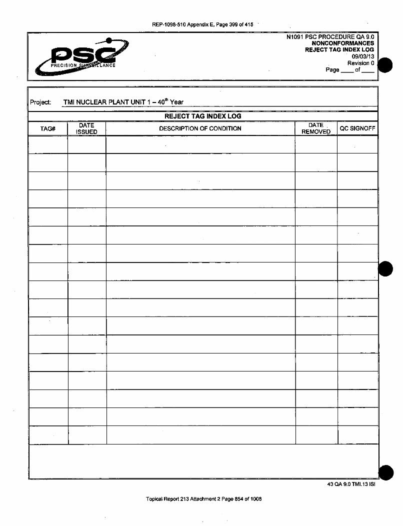
REP-1098-510 Appendix E, Page 399 of 415
N1091 PSC PROCEDURE QA 9.0NONCONFORMANCES
REJECT TAG INDEX LOG09/03/13
Revision 0Page of
Project: TMI NUCLEAR PLANT UNIT 1 - 4 0 th Year
_______ ______REJECT TAG INDEX LOG
TAG# DATE DESCRIPTION OF CONDITION DATVED [QC SIGNOFF
S
S
aw
43 QA 9.0 TMI.13 ISI
Topical Report 213 Attachment 2 Page 854 of 1008

REP-1098-510 Appendix E, Page 400 of 415
N1091 PSC PROCEDURE QA 10.0CALIBRATION
09/03/13Page 1 of 5
PRECISION NERevision 0
EXELONTHREE MILE ISLAND
UNIT 1 (4 0TH YEAR) PHYSICALCONTAINMENT BUILDING TENDON SURVEILLANCE
PRECISION SURVEILLANCE CORPORATIONIN-SERVICE INSPECTION
QUALITY CONTROL PROCEDURE
CALIBRATION OF MEASURINGAND TEST EQUIPMENT
lUa daftsj Q.A. MANAGER
Title
09/03/13
DatePrepared by
PROJECT MANAGER, P.E.
Title
09/03/13
DateApproved by
Approved by
PRESIDENT
Title
09/03/13
Date
44 A 10.0 TMI.13 ISI
Topical Report 213 Attachment 2 Page 855 of 1008

REP-1098-510 Appendix E, Page 401 of 415
N1091 PSC PROCEDURE QA 10.0CALIBRATION
09/03/13P~nn 9 nf '•
PRECISION LANCE Revision 0
1.0 CALIBRATION REQUIREMENTS
1.1 This procedure will establish the requirements for calibration of the Quality ControlTest and Measuring Equipment to be used for inspection, testing and evaluation,during the In-Service Inspections (Surveillance) of the Post-Tensioning SystemTendons.
2.0 CONTROLS
2.1 All calibrated test and measuring equipment shall be controlled for issue by the PSCQuality Control or Quality Assurance Section. The area of issue shall be indicated onthe calibration records. The calibration records shall be maintained by the PSCQuality Control or Quality Assurance Section.
2.2 PSC Quality Control personnel shall maintain a file or list of in-service devicesrequiring calibration, and periodically review those records to prevent any lapse incalibration.
2.3 The Quality Assurance Section shall review calibration records during audits of thatoperation being audited.
2.4 All calibrated equipment shall be documented and identified by a label, tag, or logsheet indicating the status of calibration. The control device shall identify theequipment, the date of calibration, date due for recalibration and the signature orinitials of the person performing or verifying the calibration.
2.5 The identification control of the calibrated equipment shall be of such a nature so thatthe specific traceability of that device will not be lost; usually engraved or marked witha Quality Control code number.
2.6 Any calibrated device that has been damaged, adjusted or repaired before therecalibration due date, shall be recalibrated before initial use, to assure theprescribed accuracy.
2.7 There is no intent to apply calibration requirements on those devices such astapelines, levels, etc. where normal commercial practices provide adequateaccuracy, or where there is no need for accuracy.
2.8 Procedures shall be provided for the calibration of special testing, measuring,inspection devices or other equipment requiring calibration and shall be controlled bythe Quality Assurance Section or included in the Surveillance I.S.I. Manual for theproject.
2.9 The Rams which have been used for Monitoring Force, Detensioning or Retensioningoperations for the In-Service Inspection of the Post-Tensioning System Tendons shallbe verified for calibrated status after the completion of the work.
44 QA 10.0 TMI.13 ISI
Topical Report 213 Attachment 2 Page 856 of 1008

REP-1 098-510 Appendix E, Page 402 of 415
N1091 PSC PROCEDURE QA 10.0CALIBRATION
09/03/13Page 3 of 5Revision 0
2.10 The documents for the calibration of Rams prior to starting the work and aftercompleting the work shall be included with the Final Report for the In-ServiceInspection.
3.0 OUT OF CALIBRATION
3.1 Devices out of calibration shall be processed as nonconformances. Devices out ofcalibration that are determined to have an adverse effect on quality shall have copiesof that nonconformance report submitted to Executive Management for review, andcomments where applicable.
3.1.1 Nonconformance Reports shall be drafted, submitted and distributed inaccordance with the requirements of PSC Procedure QA 9.0.
3.2 Instruments that are found to be out of calibration shall be re-calibrated and acomparison made of the results of the new calibration and the out-of-calibrationvariance, if any. If no significant variation exists, the instrument shall be put back intoservice. In the event that a discrepancy exists, then the Engineering and/or QualityAssurance and Quality Control Sections shall make an evaluation of the discrepancyand the possible effect on the items processed with the out-of-calibration device, withregard to quality, accuracy or reliability. If it is determined that a serious problemexists, then the Quality Assurance Section shall determine what items checked withthe out-of-calibration device shall be rechecked with an effective calibrated device.
3.3 Instruments that are found to be in excess of the required accuracy or tolerance bandafter being returned from Field Service, shall be controlled with NonconformanceReports as required of Sections 3.1 and 3.2 of this Procedure.
4.0 TOOL AND GAUGE CONTROL
4.1 The calibration standards used to calibrate measuring and test equipment shall betraceable to the National Institute of Standards and Technology (NIST) and shall becontrolled to an accuracy not to exceed a limit of 25% of the tolerance of theequipment being calibrated or the smallest used division of that instrument's scale,unless otherwise limited by "State-of-the Art" conditions. Pressure Gauges used forPost-Tensioning System operations shall be excluded from this requirement and shallbe defined for accuracy in separate procedures.
4.1.1 For example, a micrometer that has a smallest scale reading of 0.001" shall becalibrated with a standard or device that has been calibrated to an accuracy or0.00025" or less.
4.2 All measuring and test equipment used for Quality Control Inspections shall havesubdivisions or increments for measurements that are equal to or smaller than thetolerance of the parameter being measured.
44 QA 10.0 TMI.13 ISI
Topical Report 213 Attachment 2 Page 857 of 1008

REP-1098-510 Appendix E, Page 403 of 415
N1091 PSC PROCEDURE QA 10.0CALIBRATION
09/03/13Page 4 of 5Revision 0 a
4.2.1 For example, a part needs to be controlled to a dimension of 9.365" with atolerance of plus or minus 0.001". It would therefore be acceptable to perform thatmeasurement with a device that is capable of measuring to 0.001" or smaller.
4.3 Calibrated Devices may be extended for the stated period of frequency, where thatdevice has been calibrated and placed into storage, rather than into service. Theoriginal frequency period stated in Section 5.2, Equipment List, shall always beobserved.
5.0 EQUIPMENT
5.1 The Equipment List shown in Section 5.2 of this Procedure contains those devicesthat are required for the In-Service Inspection or are used to calibrate devices thatwill be used during the In-Service Inspection. The required accuracy and frequency ofcalibration are stated for each device. It should be noted that the accuracyrequirement is meant to be the tolerance band to which the device is being calibratedand not the original accuracy or the accuracy between calibration frequencies.
5.1.1 The term "DISS" in the Accuracy Column is defined as "Division of thatInstrument's Smallest Scale".
5.1.2 Where an asterisk "*" follows the accuracy dimension, this is meant to be that thedimension shown shall be verified with a Micrometer that reads to 0.0001".
5.1.3 The procedures that are used to calibrate the various types of equipment, gaugesor instruments used during the In-Service Inspection, will accompany thisprocedure in the Surveillance I.S.I. Manual. These procedures provide informationrelative to the calibration of each device and may be used for purposes ofcalibrating these devices in the field, should that become necessary.
w44 QA 10.0 TMI.13 ISI
Topical Report 213 Attachment 2 Page 858 of 1008

REP-1098-510 Appendix E, Page 404 of 415
N1091 PSC PROCEDURE QA 10.0CALIBRATION
09/03/13Page 5 of 5Revision 0
5.2 EQUIPMENT LIST
DEVICE FREQUENCY ACCURACY
Load Cell (3000 Kips) 5 Years +.1% FS Entire SystemLoad Cell (Approx 50 Kips) 8 Years +.1% FS Entire System
Rams/Jacks Beginning & End Calculated to within(Stressing, Testing, etc.) (B & E) of Project + 0.01 square" for Ram Area
Dead Weight Tester 5 Years + 0.10% FSHeise Digital Gauge 3 Years + 0.10% FS
Pressure Gauge-Master (1/4%) 1 Year ± 30 psiPressure Gauge-Stressing (1/4%) 1 Year + 30 psi of HeisePressure Gauges (1/2%) 1 Year + 55 psi of Heise(Not used for Stressing)
Micrometer 6 months + 1 DISSMicrometer-Checking Bar Standard 1 Year 0.0001"
Thickness (Feeler) GauaeUnder 0.005" 1 Year + 0.0005"*0.005" and Over 1 Year +0.001"
(* Verified with a 0.0001" micrometer)
Steel Ruler 1 Year +0.01"
Thermometer 1 Year + 1 DISS
Optical Comparator 1 Year +0.001"
Dial Indicator 1 Year +1 DISS
6.0 DOCUMENTATION
6.1. The various types of documents generated for calibration and/or status of calibrationswill be described in the General Procedures for Calibration or contained within thatprocedure for a particular device. Others may be added as the need arises. QualityControl personnel shall prepare or assist in the preparation of these records. A copyof the calibration record shall accompany the calibrated device to the field.
44 QA 10.0 TMI.13 ISI
Topical Report 213 Attachment 2 Page 859 of 1008

REP-1 098-510 Appendix E, Page 405 of 415
N1091 PSC PROCEDURE QA 10.1CALIBRATION VERIFICATION
09/03/13Page 1 of 5Revision 0
EXELONTHREE MILE ISLAND
UNIT 1 ( 4 0TH YEAR) PHYSICALCONTAINMENT BUILDING TENDON SURVEILLANCE
PRECISION SURVEILLANCE CORPORATIONIN-SERVICE INSPECTION
QUALITY CONTROL PROCEDURE
VERIFICATION OF CALIBRATION STATUSOF HYDRAULIC PRESSURE GAUGES
&cau&,) Q.C. INSPECTOR 09/03/13
DatePrepared by Title
Q.A. MANAGER 09/03/13
DateApproved by Title
PRESIDENT 09/03/13
DateApproved by Title
45 QA 10.1 TMI.13 ISI
Topical Report 213 Attachment 2 Page 860 of 1008

REP-1098-510 Appendix E, Page 406 of 415
N1091 PSC PROCEDURE QA 10.1CALIBRATION VERIFICATION
09/03/13Page 2 of 5Revision 0
1.0 FIELD VERIFICATION OF PRESSURE GAUGES
1.1 The following procedure shall be used to verify the calibration of hydraulic pressuregauges during field operations. These gauges may be used in stressing operationswith the rams or other devices that require a measure of accuracy to produce qualityresults. Frequency and Accuracy of Calibration shall be controlled as stated inSection 5.2 of Procedure QA 10.0 Equipment List. The Verification frequency shall becontrolled as stated in Section 2.5 of this Procedure, while the Verification Accuracyshall be controlled as stated in Sections 3.6 or 3.7.
2.0 GENERAL
2.1 Prior to being used for any work, all gauges shall be calibrated with the use of a DeadWeight Tester or the Heise Digital electronic pressure indicator.
2.2 In addition to the pressure gauges used during the surveillance, one gauge,designated as the Master Gauge or a Heise Digital Gauge, shall be set aside forpurposes of Calibration Verification during the process of the work. Prior to use theMaster Gauge or Heise Digital Gauge used for Calibration Verification shall havebeen calibrated per PSC Procedure Q12.8.C-W with a dead weight tester traceableto the NIST.
2.3 PSC Quality Control personnel shall maintain the controls for distribution and recall ofeach Pressure Gauge being used on site.
2.4 A Pressure Gauge may be verified for calibration or accuracy at shorter frequenciesthan stated in Section 5.2 of Procedure QA 10.0. It is important that verification beperformed any time that the gauge has been damaged, subjected to some physicalabuse or there is some reason to suspect its accuracy.
2.5 Pressure Gauges used for Detensioning or Retensioning (Stressing) tendons of Post-Tensioning Tendon Systems during In-Service Inspections of Nuclear Power Plants,shall be Verified for Calibrated status at least once a day during the operational useof those gauges.
3.0 VERIFICATION OF CALIBRATION
3.1 Clean and remove any dirt, grease or residue that could affect the accuracy of thecalibration or use of the pressure gauge.
3.2 At the option of the PSC Quality Control Section it shall be acceptable to use a HeiseDigital Pressure Indicating Gauge for Calibration Verification of Pressure Gauges,rather than a Master Gauge.
3.3 Attach the Pressure Gauge to the Calibration Pump of the Heise Indicator or MasterGauge.
45 QA 10.1 TMI.13 ISI
Topical Report 213 Attachment 2 Page 861 of 1008

REP-1098-510 Appendix E, Page 407 of 415
3.4 Close the back pressure valves before pressurizing the system.
3.5 Increase the hydraulic pressure to the point of the desired reading on the PressureGauge, usually 1,000 psi plus or minus 100 psi increments. Take a reading of thePressure Gauge and the Heise Indicator and document both on the Pressure GaugeCalibration Form.
3.6 MASTER GAUGE (1/4% Accuracy)
3.6.1 Where a Master gauge is used for verification of calibration, the master gauge andfield gauge to be calibrated shall be connected to a common line (manifold) on ahydraulic pump. The pump shall be pressurized in no greater than 1,000 psiincrements, plus or minus 100 psi, to the highest overstress pressure that shall beencountered during stressing activities; for example, 7,600 psi overstress willrequire calibration on that gauge to at least 7,600 psi. It shall be acceptable to goto 8,000 psi.
3.6.2 The accuracy of a gauge verified in this manner shall be acceptable, if it reads to
within 50 psi of any reading on the Master Gauge.
3.7 HEISE DIGITAL GAUGE
3.7.1 A Pressure Gauge may be verified for calibration by connecting that gauge andthe Heise Digital Gauge to a common line, which is in turn connected to ahydraulic pump and pressurized to the same values noted in 3.6.1 above.
3.7.2 The verification accuracy of that Pressure Gauge shall be acceptable if it reads towithin 30 psi of the Heise Digital Gauge reading for a 1/4 percent accuracy gaugeor 55 psi for 1/2 percent accuracy gauge. As a 1/2 percent gauge cannot beaccurately interpolated to increments of 5 psi it will be acceptable to take thereading to some point equal to or above 50 psi but not to exceed 60 psi.
3.7.3 Pressure Gauges with an accuracy of 1/2 percent or greater shall not be used forMonitoring Force, Detensioning or Retensioning operations of the Post-TensioningTendon System during In-Service Inspections.
3.8 With the Verification and Documentation of the Pressure Gauge being acceptable,
the pump and gauge shall be depressurized and prepared for disassembly.
4.0 UNACCEPTABLE CONDITIONS
4.1 If a Pressure Gauge fails to meet the accuracy requirements of Section 3.6.2 or 3.7.2after being used for Stressing or Detensioning operations, it shall be necessary todraft a Nonconformance Report in accordance with the requirements of Section 3 ofProcedure QA 10.0, to control that Gauge and any Tendons worked with that Gauge.
45 QA 10.1 TMI.13 ISI
Topical Report 213 Attachment 2 Page 862 of 1008

REP-1098-510 Appendix E, Page 408 of 415
N1091 PSC PROCEDURE QA 10.1CALIBRATION VERIFICATION
09/03/13Page 4 of 5Revision 0
4.2 Any Pressure Gauge not capable of meeting the stated accuracy requirements ofSection 3.6.2 or 3.7.2 for the method of calibration being used, shall be returned tothe PSC shop for adjustment or repair. Any repaired or adjusted Gauge shall berecalibrated before use.
4.3 ZERO ALIGNMENT (Zero Beating)
4.3.1 On occasion, the Pressure Gauge Indicating Needle may not be in precisealignment with the Zero mark on the Gauge Face, necessitating realignment.Before calibration the needle is to be realigned to the zero mark, with therealignment completed the Verification shall be performed and documented.
5.0 ACCURACY VARIATIONS
5.1 Even though Pressure Gauges that have been calibrated or verified for calibration,variations in excess of the requirements of Sections 3.6.2 and 3.7.2 may be detectedbetween calibrations or verifications. In an effort to explain and control this deficiency,this Section shall be reviewed before the Verification of any Pressure Gauges.
5.2 The accuracy of the calibration of Pressure Gauges or the verification of calibration ishighly dependent on the accuracy of the reading of the location of the PressureIndicating Needle on the Gauge Face. While there is an attempt to precisely align theneedle with the Gauge Face Indicating Line, it is nearly impossible to maintain thatcontrol. In an effort to explain any variations that could be noted between calibrationsor verifications, it is recommended that a notation be added to the CalibrationDocument to signify that the intended increment was not precisely obtained. At thatincrement it would be noted that the value actually achieved was plus or minus anextrapolated pressure noted during the calibration.
5.2.1 For example: If the target increment on the gauge Face was intended to be 2,000psi and the Indicating Needle was somewhat over the 2,000 psi line, perhapsenough to interpret as 10 psi, the notation on the Calibration Record would read:
2,000 psi +10
5.2.2 The requirements for Stressing or Detensioning Tendons do not require thePressure to be read any finer than 10 psi during the In-Service Inspections. TheHydraulic Ram Calibration Procedure takes the reading error into account forStressing or Detensioning along with any other errors that may occur as a result ofcalibration or gauge reading, thereby maintaining the accuracy or integrity of thework being performed. It is therefore necessary to document any minor variationsduring calibration or verification activities, so as to maintain the integrity of theaccuracy of the Pressure Gauges.
45 QA 10.1 TMI.13 ISI
Topical Report 213 Attachment 2 Page 863 of 1008

REP-1 098-510 Appendix E, Page 409 of 415
6.0 DOCUMENTATION
6.1
6.2
A gauge Calibration Record form shall be prepared for each gauge being calibratedor verified. All pertinent information as required by the form shall be posted duringcalibration or verification.
Calibration or verification documents shall be retained in the appropriate jobsiteQuality file.
7.0 ATTACHMENTS
7.1 Gauge Calibration Record Form.
S
a45 QA 10.1 TMI.13 ISI
Topical Report 213 Attachment 2 Page 864 of 1008

REP-1 098-510 Appendix E, Page 410 of 415
N1091 PSC PROCEDURE QA 10.1GAUGE CALIBRATION RECORD FORM
09/03/13Page _ of _
Revision 0
Project: TMI NUCLEAR PLANT UNIT 1 - 4 0 th Year Job # N1091
GAUGE CALIBRATION VERIFICATION RECORD
DATE CHECKED MASTER GAUGE (PSI) JACK GAUGE (PSI)GAUGE I.D.MASTER GAUGE I.D.
REMARKS
QC SIGN OFF
Project: TMI NUCLEAR PLANT UNIT 1 - 4 0 th Year Job # N1091
GAUGE CALIBRATION VERIFICATION RECORD
DATE CHECKED MASTER GAUGE (PSI) JACK GAUGE (PSI)
GAUGE ID.MASTER GAUGE I.D.
REMARKS
QC SIGN OFF
45 QA 10.1 TMI.13 ISI
Topical Report 213 Attachment 2 Page 865 of 1008

REP-1 098-510 Appendix E, Page 411 of 415
AD N1091 PSC PROCEDURE QA 11.0Q.C. INSPECTION
09/03/13Page 1 of 3
PRECISION ANCE Revision 0 A
EXELONTHREE MILE ISLAND
UNIT 1 (4 0TH YEAR) PHYSICALCONTAINMENT BUILDING TENDON SURVEILLANCE
PRECISION SURVEILLANCE CORPORATIONIN-SERVICE INSPECTION
QUALITY CONTROL PROCEDURE
QUALITY CONTROL INSPECTION
Q.C. INSPECTOR 09/03/13
DatePrepared by Title
Q.A. MANAGER 09/03/13
DateApproved by
Approved by
Title
PRESIDENT
Title
09/03/13
Date
aw
46 QA 11.0 TMI.13 ISI
Topical Report 213 Attachment 2 Page 866 of 1008

REP-1098-510 Appendix E, Page 412 of 415
N1091 PSC PROCEDURE QA 11.0Q.C. INSPECTION
09/03/13Page 2 of 3Revision 0
1.0 QUALITY CONTROL INSPECTIONS
1.1 Where Precision Surveillance Corporation is not acting as the General Contractor forthe Post-Tensioning operations, Quality Control Inspections shall be performed bythe organization responsible for the quality control function of that portion of the workthey are performing, as stated in PSC Procedure QA 4.0 of this manual, or as agreedto in the contract documents.
1.2 It is PSC's intent to provide the Quality Control activities for the SurveillanceInspection of the Post-Tensioning Tendon System as agreed to in the contractdocuments and as stated in the Surveillance I.S.I. Manual.
1.3 Quality Control documents shall NOT BE SIGNED until all information for theinspections or tests for which that document is being generated have been enteredonto that document.
1.3.1 Partially completed inspection or tests, those where the operation cannot becompleted on the same day, shall be initialed and dated by the Inspector for thoseitems that have been completed and require documentation.
1.3.2 Partially completed inspections or tests, those where the operation is interruptedby a temporary condition such as lunch or a break and where the operation shallbe completed the same day, may be initialed completed by the Inspector to thatpoint, for those items that have been completed and require documentation.
1.4 Quality Control documents that are being reviewed for completeness but were notwitnessed by the reviewer shall be signed for that review ONLY AFTER completion ofthe review and NOT BEFORE.
1.5 A Quality Control document is defined as any document or record that contains aQuality Control Inspector signature requirement.
1.6 All inspections shall be documented on the appropriate inspection form for thoseoperations witnessed on that day. All inspection documents shall be signed orinitialed, dated and retained in the appropriate Quality file at the jobsite.
1.7 Quality Control Documentation shall be completed and turned in for review as soonas possible after completion of that Inspection Test or Evaluation.
1.8 Reviews of Quality Control Documentation should be completed within 24 hours ofreceipt or sooner to verify that the information is accurate and complete. Errors ordeficiencies shall be resolved without delay.
46 QA 11.0 TMI.13 ISI
Topical Report 213 Attachment 2 Page 867 of 1008

REP-1 098-510 Appendix E, Page 413 of 415
N 1091 PSC PROCEDURE QA 11.0Q.C. INSPECTION
09/03/13Page 3 of 3Revision 0
1.9 There are a number of Quality Control Documents that may not be completed in oneday or require posting to another document. It is advisable to make reproductions ofthese documents and use these to complete whatever actions are necessary, whileretaining the original document, even though incomplete, in a Quality Control file. Theadditional information can be entered onto the original document until completed.Leave the reproduced copies attached to the back of that document until the reviewis completed, at which time the reproductions may be disposed of.
1.10 It may be necessary to generate more than one original copy of a Quality ControlDocument for an Inspection or Test on a tendon. This shall be acceptable just so thetotal quantity of pages and the page number appear on each document.
2.0 INSPECTION
2.1 The term Inspection is meant to include:
2.2 The witnessing of an operation that generates Quality Control Data which isdocumented by the Inspector.
2.3 The performance of some operation by the Inspector, such as measuring or otherQuality Control Data, which is documented by the Inspector.
S
S
S46QA 11.0 TMI.13 ISI
Topical Report 213 Attachment 2 Page 868 of 1008

REP-1098-510 Appendix E, Page 414 of 415
N1091 PSC PROCEDURE QA 12.0AUDITS09/03/13
Page 1 of 2Revision 0
EXELONTHREE MILE ISLAND
UNIT 1 (4 0TH YEAR) PHYSICALCONTAINMENT BUILDING TENDON SURVEILLANCE
PRECISION SURVEILLANCE CORPORATIONIN-SERVICE INSPECTION
QUALITY CONTROL PROCEDURE
AUDITS
Prepared by
Approved by
Approved by
Q.C. INSPECTOR
Title
09/03/13
Date
Q.A. MANAGER
Title
09/03113
Date
PRESIDENT
Title
09/03/13
Date
47 CIA 12.0 TMI.113 ISI
Topical Report 213 Attachment 2 Page 869 of 1008

REP-1098-510 Appendix E, Page 415 of 415
N1091 PSC PROCEDURE QA 12.0AUDITS09/03/13
p~n•= 9 nf9
' LANCE Revision 0
1.0 AUDITS
1.1 Surveillance operations shall be audited as required by the project specifications oras agreed to in the contract documents, to verify conformance with the approved jobrelated manuals and procedures.
1.2 Audits shall be performed by qualified personnel of the Precision SurveillanceCorporation Quality Assurance Section and who shall be independent of the areabeing audited.
1.3 Audits shall be performed using a checklist prepared prior to the audit, with theresults documented on a Jobsite Audit Summary Sheet and a commentary noted onan Audit Finding Report form or similar type documents.
1.4 Audits shall be performed on a random basis and shall be scheduled when a varietyof operations are being performed or as a specific activity occurs.
1.5 Subsequent audits shall provide a review of previously noted deficiencies or programnon-compliance to ensure appropriate action has been taken to resolve those areasof concern.
1.6 Copies of the audit report shall be maintained in the appropriate jobsite quality filesand distributed in accordance with the project specifications or distribution list on theaudit checklist.
1.7 The audits shall be performed as early in the life of the In-Service Inspection, as ispractical, and must consider the limitations of the scaffolding or platforms.
1.8 The elements to be audited shall be commensurate with the status and importance
associated with the In-Service Inspection activities.
1.9 Exelon has the right of access for the performance of quality audit.
1.9.1 Any findings noted as a result of an Exelon audit shall be addressed by PrecisionSurveillance Corporation on a timely basis with corrective action as approved byExelon.
47 QA 12.0 TMI.13 ISI
Topical Report 213 Attachment 2 Page 870 of 1008

REP-1 098-510 Appendix F, Page 1 of 17
Project TMI NUCLEAR PLANT UNIT I - 40M Year Job # N1091
GAUGE CALIBRATION VERIFICATION RECORD
DATE CHECKED q 2- o MASTER GAUGE (PSI) JACK GAUGE (PSI)GAUGE I.D. CC 13 2'75•' 1600MASTER GAUGE I.D. 4.4 0 15 z .g9REMARKS AoAJI "_ _ _ _ 2-99___0_ I
-70M , 700,0
SQC SIGN OFF -,wafZ af15 ____
Project: TMI NUCLEAR PLANT UNIT 1 -40"' Year Job # N1091
GAUGE CALIBRATION VERIFICATION RECORD
DATE CHECKED I -rq" I -s MASTER GAUGE (PSI) JACK GAUGE (PSI)GAUGE I.D. (z" 13A-76(, - - I 00D 1/000MASTER GAUGE I.D. i4LjOt%3 208b 1 _ _ _ ,OREMARKS :______!P____= 3000
A0n, q0 =00
___ __ ___ __ __ Ll 0 0
QC SIGN OFF C L1ow Lq 4LI 7= __ _ __ _ _ _900__ _ __ _
I45 OA 110.11 TMI.13 I$1
Topical Report 213 Attachment 2 Page 871 of 1008

REP-1098-510 Appendix F, Page 2 of 17
PS AN1091 PSC PROCEDURE QA 10.1
GAUGE CALIBRATION RECORD FORM09103113
Page - of_ _Revision 0
Project: TMI NUCLEAR PLANT UNIT 1 -40&" Year Job # N1091
GAUGE CALIBRATION VERIFICATION RECORD
DATE CHECKED '--- 2.1-13 MASTER GAUGE (PSI) JACK GAUGE (PSI)GAUGE I.D. C.C - 13915, to !130MASTER GAUGE I.D. I440%3 _ •_ _ _ _ _ _ _ _
REMARKS N! 0 NE __ _ _ __ __q__o
q4qqo
• "ra• !000
QC SIGN OFF __ _ _ 2"______......
Project: TMI NUCLEAR PLANT UNIT 1 - 40"' Year Job # N1091
GAUGE CALIBRATION VERIFICATION RECORD
DATE CHECKED 10-1- 20'"15 MASTER GAUGE (PSI) JACK GAUGE (PSI)GAUGE I.D. CC 1-527S& _____________
MASTER GAUGE I.D. LILIES0-3 M___ 96REMARKS _,_ __ _ _ _ -_ _ _ •9i"
QC SIGN OFF 1 , O' I0" /-Z-O_
45 QA 10.1 TMI.1315 1 eTopical Report 213 Attachment 2 Page 872 of 1008

REP-1098-510 Appendix F, Page 3 of 17
Project: TMI NUCLEAR PLANT UNIT 1 - 400 Year Job # N1091
GAUGE CALIBRATION VERIFICATION RECORD
DATE CHECKED /O -Z.- •-013 MASTER GAUGE (PSI) JACK GAUGE (PSI)GAUGE I.D. CCI5r3•S5 1_6_ 0 __ _
MASTER GAUGE I.D. 4_,,_ __ .._ %_5_0 /IgOREMARKS A__ _ _ _ _ sew_ _ 30O
700 D~
QC SIGN OFF ,).
Project: TMI NUCLEAR PLANT UNIT I - 4 0'h Year Job# N1091
GAUGE CALIBRATION VERIFICATION RECORD
DATE CHECKED /.0-3 ZO011 MASTER GAUGE (PSI) JACK GAUGE (PSI)GAUGE I.D. CC I 3% 75!S I OW VMASTER GAUGE I.D. 4LI_%3 190,0REMARKS A_,_ _ _ _ _ _ _ _ C;•0
-7=F 7600
QC SIGN OFF j
I45 QA 10.1 TMI.13 ISI
Topical Report 213 Attachment 2 Page 873 of 1008

REP-1 098-510 Appendix F, Page 4 of 17
N1091 PSC PROCEDURE QA 10.1GAUGE CALIBRATION RECORD FORM
09103113Page,. of__
Revision 0-
Project: TMI NUCLEAR PLANT UNIT 1 - 4 0 0 Year Job # N1091
GAUGE CALIBRATION VERIFICATION RECORD
DATE CHECKED lo -! - 0 I3 MASTER GAUGE (PSI) JACK GAUGE (PSI)
GAUGE I.D. ec 1666 sfoMASTER GAUGE 1.D. .440%3 0e 1990
REMARKS ___ __._ "30 7__ _99O
..... 6oao
QC SIGN OFF (I/Jj/y _ _ _
Project: TMI NUCLEAR PLANT UNIT I - 4 01h Year Job # N1091
GAUGE CALIBRATION VERIFICATION RECORD
DATE CHECKED I 0 - 9-- MASTER GAUGE (PSI) JACK GAUGE (PSI)
GAUGE I.D. I•. •_______ ________/ > u•OMASTER GAUGE I.D. L.LIOW" 26W) 000REMARKS .5 ._ __ _ ,_ _ __ 0
I I00
I045 QA 10.1 TMI.13 ISI
Topical Report 213 Attachment 2 Page 874 of 1008

REP-1 098-510 Appendix F, Page 5 of 17
:IN ANCE
<IM00000
N1091 PSC PROCEDURE QA 10.11GAUGE CALIBRATION RECORD FORM
09/03113Page - of _
Revision 0
Project: TMI NUCLEAR PLANT UNIT I - 40e Year Job # N1091
GAUGE CALIBRATION VERIFICATION RECORD
DATE CHECKED 1 0 -q- 13 MASTER GAUGE (PSI) JACK GAUGE (PSI)GAUGE I.D. r__ _ I, _ "_ _7_s 1000MASTER GAUGE I.D. 4L10%3 9 • g¶3oREMARKS sew _________-__
pimp __qqo__ __ __ __ __ __ __Liggo .
-QC SIGN OFF 4A _/___ 7________
Project: TMI NUCLEAR PLANT UNIT 1 - 4& Year Job# N1091
GAUGE CALIBRATION VERIFICATION RECORD
DATE CHECKED MASTER GAUGE (PSI) JACK GAUGE (PSI)
GAUGE I.D. i DODMASTER GAUGE I.D. LILlo.3 2O)REMARKS _ _ _ _
'7=
QC SIGN OFF
I- ~%
45 QA 10.1 TMI.13 ISI
Topical Report 213 Attachment 2 Page 875 of 1008

REP-1098-510 Appendix F, Page 6 of 17
N10i1 PSO PROCEDURE QA 10.1GAUGE CALIBRATION RECORD FORM
09103113Page - of__
Revision 0
Project TMI NUCLEAR PLANT UNIT 1 - 40u' Year Job# N1091
GAUGE CALIBRATION VERIFICATION RECORD
DATE CHECKED /0 - 14 --201"5 MASTER GAUGE (PSI) JACK GAUGE (PSI)GAUGE I.D. CC13%i•'.: 168O 9%6MASTER GAUGE I.D. .040': 3 ... ItI-I4 2... ...REMARKS ,,_e..,- _1_= ...._,2 m
_____ _____ ____ 3q~ so
660" ___/__0 __6w
OC SIGN OFF _
Project: TMI NUCLEAR PLANT UNIT 1 - 40"' Year Job # N1091
GAUGE CALIBRATION VERIFICATION RECORD
DATE CHECKED /0 - (f' - 2-1 3 MASTER GAUGE (PSI) JACK GAUGE (PSI)
GAUGE I.D. CC /3'R 75 00t qqk
MASTER GAUGE I.D. AL2io . 1.440
REMARKS ,_-5 __ _2q_70
QC SIGN OFF L.,': ? 1o) _ _- __,
045QA 10.1 TMI.13 ISI
Topical Report 213 Attachment 2 Page 876 of 1008

REP-1098-510 Appendix F, Page 7 of 17
Project: TMI NUCLEAR PLANT UNIT 1 - 401 Year Job # N1091
GAUGE CALIBRATION VERIFICATION RECORD
DATE CHECKED W.[! ;- 201 s MASTER GAUGE (PSI) JACK GAUGE (PSI)GAUGE I. D. c 131SS_ 1600 _ _,_o
MASTER GAUGE I.D. L4/0 *% _ _ _ _ _g9r)
REMARKS A_ _ _,,_ 2__ _ _ __ o _ _
_______________46W 369
70cO "___ __ _
QC SIGN OFF t wo. ____
Project: TMI NUCLEAR PLANT UNIT 1 - 4 0" Year Job # N1091
GAUGE CALIBRATION VERIFICATION RECORD
DATE CHECKED it)- 15- 2• •5 MASTER GAUGE (PSI) JACK GAUGE (PSI)GAUGE I.D. (64 In 7'5 1 Ono g.,MASTER GAUGE I.D. 411iL0Z 02L-REMARKS Af-AV 3. .
QC SIGN OFF 4 e ,
I- ~
45 QA 10.1 TMI.13 ISI
Topical Report 213 Attachment 2 Page 877 of 1008

REP-1 098-510 Appendix F, Page 8 of 17
N1091 PSC PROCEDURE QA 10.1GAUGE CALIBRATION RECORD FORM
091/0313Page - of _
Revision 0
Project: TMI NUCLEAR PLANT UNIT I - 40"' Year Job# N1091
GAUGE CALIBRATION VERIFICATION RECORD
DATE CHECKED /10/6-1-3 MASTER GAUGE (PSI) JACK GAUGE (PSI)GAUGE I.D. _i_ _'_,. ; __. 16_ _ _ _ _
MASTER GAUGE I.D. 440%5 .6W _ _ _.
REMARKS A,4ve-. _ _ _ _t_ ,_"_ __ _
OC SIGN OFF A E • _ __ _ _ _
Project: TMI NUCLEAR PLANT UNIT I - 40' Year Job # N1091
GAUGE CALIBRATION VEIRIFICATION RECORD
DATE CHECKED ,bw 'I MASTER GAUGE (PSI) JACK GAUGE (PSI)
GAUGE I.D. ._ _ ___... _100 0. .MASTER GAUGE I.D. 4LI64bI3 200 141DREMARKS A,'Ae.-- --'5_ _ 7929
QC SIGN OFF Jet. _ _
-1045 Q.A 10.1 TMI.13 ISI
Topical Report 213 Attachment 2 Page 878 of 1008
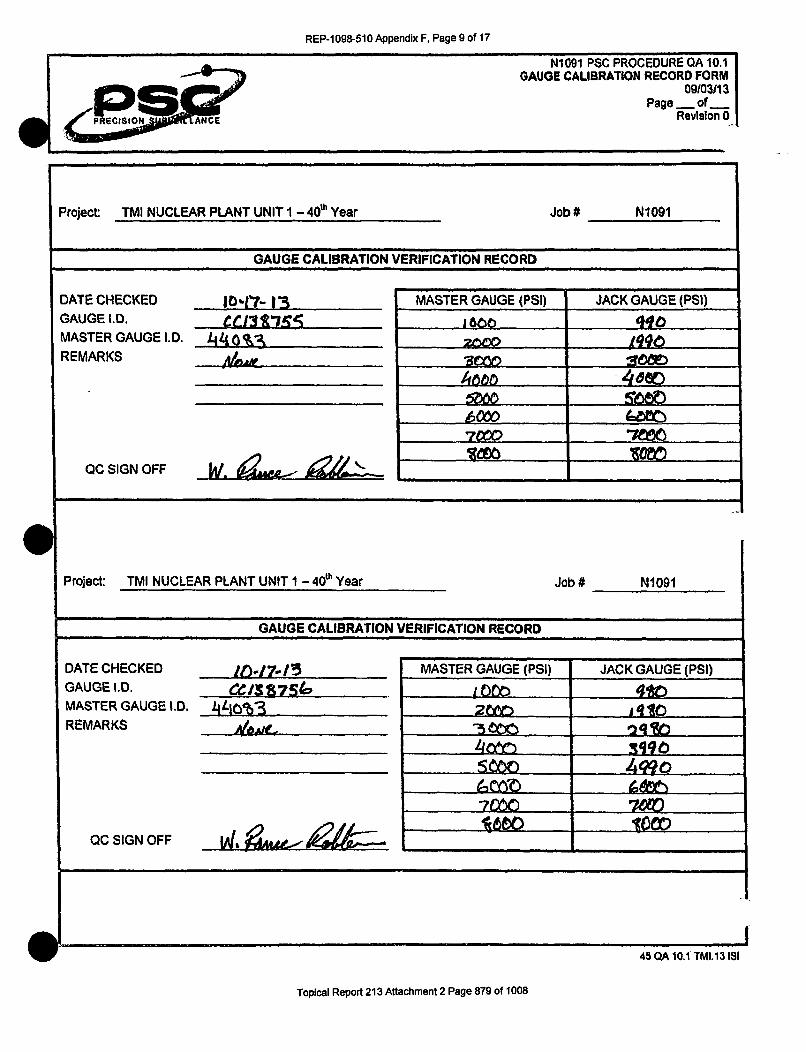
REP-1 098-510 Appendix F, Page 9 of 17
Project TMI NUCLEAR PLANT UNIT I - 40& Year Job# N1091
GAUGE CALIBRATION VERIFICATION RECORD
DATE CHECKED |O,-17- | 3 MASTER GAUGE (PSI) JACK GAUGE (PSI)GAUGE I.D. _ _ _1_5 _ _ i660 bqoMASTER GAUGE I.D. _14_-_0M_"t __lop
REMARKS Aux _ __ _ _ _ .. __ _____
70¢M
OC SIGN OFF W. • • __......__ _ _
Project: TMI NUCLEAR PLANT UNIT 1 - 4d0u Year Job # N1091
GAUGE CALIBRATION VERIFICATION RECORD
DATE CHECKED 16_____.1743 _ _ MASTER GAUGE (PSI) JACK GAUGE (PSI)GAUGE I.D. -C/387Si6 10 U 4totMASTER GAUGE I.D. 4,tin-3 A10___________
REMARKS ,A__ __ _ _. "___"_____ __ __-___ __ __3g19c
QC SIGN OFF LA,!- -- ,O
II45 QA 10.1 TMI.13 ISI
Topical Report 213 Attachment 2 Page 879 of 1008

REP-1098-510 Appendix F, Page 10 of 17I I II I I I
PRE ISION ANCE
icmw
N1091 PSC PROCEDURE QA 10.1 IGAUGE CALIBRATION RECORD FORM I
09103/13 IPage - of I
Revision 0_
Project: TMI NUCLEAR PLANT UNIT 1 - 40e Year Job # N1091
GAUGE CALIBRATION VERIFICATION RECORD
DATE CHECKED /- I i - MASTER GAUGE (PSI) JACK GAUGE (PSI)GAUGE I.D. cc. i30I75WO 1_ _ _ _ _ _ _ _
MASTER GAUGE I.D. /440%3 20 0wREMARKS 3_,_ _________"__
_____ _____4660_ __ __ _ __ __ _ 46
QOC SIGN OFF i.,
Project: TMI NUCLEAR PLANT UNIT 1 - 40"h Year Job # N1091
GAUGE CALIBRATION VERIFICATION RECORD
DATE CHECKED - MASTER GAUGE (PSI) JACK GAUGE (PSI)GAUGE I.D. .e /57 7S ,OIw I'TtoMASTER GAUGE I.D. 4klotj-3 P? l__ _ __ oREMARKS 29W__,_ ,_ , ____)_____)
......__ _ _ ....... ...
QC SIGN OFF __ _ _ _ _ _ _ _ _ __ _ _ _ _ _ _ _ _ _ _ _ _ _ _ _
45 QA 10.1 TMI.13 1S1 0
Topical Report 213 Attachment 2 Page 880 of 1008
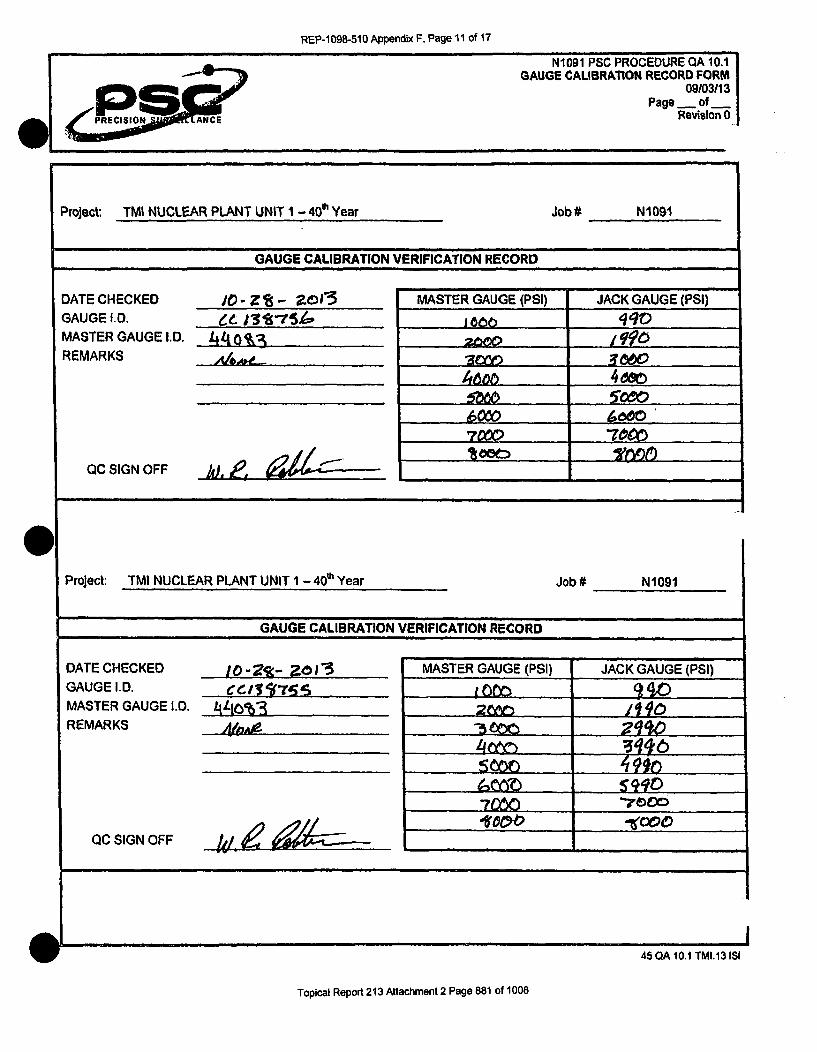
REP-1098-510 Appendix F, Page 11 of 17
N1091 PSC PROCEDURE QA 10.1-~GAUGE CALIBRATION RECORD FORM
09/03113
P S Page - of _PPRECISION ANCE RevisIon 0
Project: TMI NUCLEAR PLANT UNIT 1 - 40e Year Job# NWOWI
GAUGE CALIBRATION VERIFICATION RECORD
DATE CHECKED Jo - Z8 .- 2015 MASTER GAUGE (PSI) JACK GAUGE (PSI)
GAUGE I.D. e. ja5• AS,4 1600qMASTER GAUGE I.D. 4110%:3 2000
REMARKS ,_0_ . l__ ._ _ _ _ _ _ _ _ _ _ _ _ _
_~ o 666 O.,_, '
QC SIGN OFF 1,,t,•
Project: TMI NUCLEAR PLANT UNIT 1 - 40"h Year Job# N1091
GAUGE CALIBRATION VERIFICATION RECORD
DATE CHECKED JO - ? -0) MASTER GAUGE (PSI) JACK GAUGE (PSI)GAUGE I.D. C e_ 1.. _ -5_...MASTER GAUGE I.D. 4L10%-3 ____. ______
REMARKS NVA,
QC SIGN OFF ___ . ...
I- ii
45 QA 10.1 TMI.13 ISI
Topical Report 213 Attachment 2 Page 881 of 1008
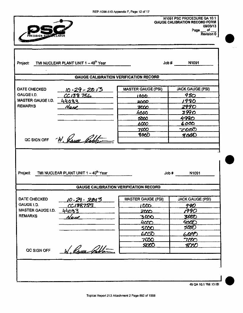
REP-1 098-510 Appendix F, Page 12 of 17
e PRiii A iE
N1091 PSC PROCEDURE QA 10.1 IGAUGE CALIBRATION RECORD FORM I
09103113 IPage _ of___ _
Revision 0-
Project: TMI NUCLEAR PLANT UNIT I - 40dh Year Job # N1091
GAUGE CALIBRATION VERIFICATION RECORD
DATE CHECKED in -2! -- 20! r MASTER GAUGE (PSI) JACK GAUGE (PSI)GAUGE I.D. C 15'2 7_1 q1c 9MASTER GAUGE I.D. _4_4%B =00- /Io'IOREMARKS _ _30____ 291'0'
__3 3990
QC SIGN OFF /t.
Project: TMI NUCLEAR PLANT UNIT i - 40e' Year Job # N1091
GAUGE CALIBRATION VERIFICATION RECORD
DATE CHECKED 10 ,-2 - 3 5 MASTER GAUGE (PSI) JACK GAUGE (PSI)GAUGE I.D. rC,1c32755 1 _ ___ _ _ _ _
MASTER GAUGE I.D. 4L 10 %-3 26 A1490REMARKS ,__ _5,__ =-_ _b________
QC SIGN OFF /4as.- iZ
45 (2A 10.1 TMIA13 151
Topical Report 213 Attachment 2 Page 882 of 1008

REP-1 098-510 Appendix F, Page 13 of 17
Project: TMI NUCLEAR PLANT UNIT 1 - 40' Year Job # N1091
GAUGE CALIBRATION VERIFICATION RECORD
DATE CHECKED (/'/"/. MASTER GAUGE (PSI) JACK GAUGE (PSI)GAUGE I.D. ccI 5n155 1660 991pMASTER GAUGE I.D. 44/__0%3 _191
REMARKS ,mA_ e- 22
• ooo _ _ _ _ _ _ _ _
QC SIGN OFF if' __
Project: TMI NUCLEAR PLANT UNIT 1 - 40"h Year Job# N1091
GAUGE CALIBRATION VERIFICATION RECORD
DATE CHECKED .I - 13 MASTER GAUGE (PSI) JACK GAUGE (PSI)
GAUGE I.D. ___ _J_ _ % _ I_ I_ _.
MASTER GAUGE I.D. L4LJ103 ________,_
REMARKS 4J,_b . --e-_ Y
QCSIGNOFF w _. •,
I- p
45 QA 10.1 TMI.13 ISI
Topical Report 213 Attachment 2 Page 883 of 1008

REP-1 098-510 Appendix F, Page 14 of 17
PRECISION ANCE
N1091 PSC PROCEDURE QA 10.1 |GAUGE CALIBRATION RECORD FORM
09103113 |Page v of nRevision 0|
Project: TMI NUCLEAR PLANT UNIT 1 - 40"' Year Job # N1091
GAUGE CALIBRATION VERIFICATION RECORD
DATE CHECKED II- S 20 201 MASTER GAUGE (PSI) JACK GAUGE (PSI)
GAUGE I.D. ct iM•% e 6 166. _ ___ _--
MASTER GAUGE I.D. -t/4 0 o&3 2000- ZsREMARKS -3=
___ __ __ __ __ __ __ t6bo 09
oc ,___ ____ __F
QC SIGN OFF a. .t--
Project: TMI NUCLEAR PLANT UNIT 1 - 40& Year Job # N1091
GAUGE CALIBRATION VERIFICATION RECORD
DATE CHECKED I1-17-2011 MASTER GAUGE (PSI) JACK GAUGE (PSI)
GAUGE I.D. ____7_•__ t _o__ . 11Q
MASTER GAUGE I.D. Lln-%3 zw 199REMARKS ALA _ 3000 2990
'7=D
QC SIGN OFF (1) e
I045 QA 10.1 TMI.13 ISI
Topical Report 213 Attachment 2 Page 884 of 1008

REP-1 098-510 Appendix F, Page 15 of 17
Project: TMI NUCLEAR PLANT UNIT I - 40" Year Job # N1091
GAUGE CALIBRATION VERIFICATION RECORD
DATE CHECKED .1-3 MASTER GAUGE (PSI) JACK GAUGE (PSI)GAUGE I.D. __ _ 13__ Is_ _ __ 16_ _ TOMASTER GAUGE I.D. 440__0- _ _ .. __9
REMARKS Ag,,e. __ 0w _q__ _
7=~
OC SIGN OFF i__
Project: TMI NUCLEAR PLANT UNIT 1 - 40'h Year Job # N1091
GAUGE CALIBRATION VERIFICATION RECORD
DATE CHECKED "J " 3 '3 MASTER GAUGE (PSI) JACK GAUGE (PSI)GAUGE I.D. ecc|1=5 I 00D......... 1OMASTER GAUGE I.D. JLl0003 20O JqqoREMARKS _ &A__ ,_..... "5__ 2,qqi.
QC SIGN OFF __J __ ____._
45QA 10.11TMI.113l$I
Topical Report 213 Attachment 2 Page 885 of 1008

REP-1098-510 Appendix F, Page 16 of 17
N1091 PSC PROCEDURE QA 10.1GAUGE CALIBRATION RECORD FORM
09/03113Page _ of _
Revis~on 0
Project TMI NUCLEAR PLANT UNIT I - 40"& Year Job# N1091
GAUGE CALIBRATION VERIFICATION RECORD
DATE CHECKED 1 -" 1 MASTER GAUGE (PSI) JACK GAUGE (PSI)GAUGE I.D. cf j347_ K 1660 qqoMASTER GAUGE I.D. 440%3 web__,,_,, 2lf•REMARKS _I&A Z
0C SIGN OFF j•,, _----
Project: TMI NUCLEAR PLANT UNIT 1 - 40" Year Job # N1091
GAUGE CALIBRATION VERIFICATION RECORD
DATE CHECKED It- Ida - 15 MASTER GAUGE (PSI) JACK GAUGE (PSI)
GAUGE 1.D. .z, m - 10m . 9g . .MASTER GAUGE I.D. LILIbq3 _2_ IM'REMARKS No&A -75 0z'00
_CSIGNO FF wt__
-10
45 CIA 10.1 TMI.13 ISI
Topical Report 213 Attachment 2 Page 886 of 1008

REP-1 098-510 Appendix F, Page 17 of 17
ep""RECIION, ANCE
N1091 PSC PROCEDURE QA 10.1GAUGE CALIBRATION RECORD FORM
09103113Page _ of _
Rev-slon 0
Project: TMI NUCLEAR PLANT UNIT I - 40 Year Job# N1091
GAUGE CALIBRATION VERIFICATION RECORD
DATE CHECKED
GAUGE I.D.MASTER GAUGE I.D.
REMARKS
OC SIGN OFF
11-20 -.. 205
... . e -
MASTER GAUGE (PSI) JACK GAUGE (PSI)
260500
bow -_ _
'I
Project: TMI NUCLEAR PLANT UNIT 1 - 41P Year Job # N1091
GAUGE CALIBRATION VERIFICATION RECORD
DATE CHECKED 11- ,Z0 1,3 MASTER GAUGE (PSI) JACK GAUGE (PSI)
GAUGE ID. __ _/_____ 1,0W _91_),_! ___......
MASTER GAUGE ID. iJLIj"3 2680 1990REMARKS _ _ __ __=__y-_ -_ _0_
QC SIGN OFF _,,_ _ _ _
I45 QA 10.1 TMI.13 ISI
Topical Report 213 Attachment 2 Page 887 of 1008

REP-1 098-510 Appendix H, Page 1 of 20
Project: TMI NUCLEAR PLANT UNIT 1 - 40" Year
NONCONFORMANCE REPORT INDEX LOG
NCR# DESCRIPTION DATE DATE DATE DATEWRITTEN SUBMITTED APPROVED COMPLETE
At•'- 2.. Pmo4fud#'.u•, a.t,',. tres aud OA • ?- ,-r•/3 -Z. 7-1
#€•- tA4d;4i.-,'. ,M;-siJ•, ;rc:4i4-÷c..A1169/-60Z- 6A~krv/Fkk."&F.KM V-,1-916DZ-• lt-ZI
mc. ioe~ at V413, 14/qJ-&PsM&WL a oAver 70% 4,k. ,•, It (F-tI3 ____
"r- "i 61 stP0 ,TorP Or, H/04 15 SA/
ANcK Lexessive eN 9,ApA'1 btels I- of*46W101k15.. 141-e"B A-)31-13 Mt-31-11___
ve/ 6Ve 10 OdU !JyM~e.- a~)1 *A4ec6e
tOW.0 r) - :4-. //-13-13t 11-154-J-3oAfw over 10% o, 9f o-t*1 el'l/et'I 11"
Ivk &ver 1&%, *4 q fe4-., te-L ItOf IDoIJ 0l-0-1-5 /im4-I _______
0i~im b__2__
* 4. 1
4 i 4 i I.
I- -I 4- 4
4. i a ~. I
4. r 1 4. I
I
43OA 9.0 TMIA 3 1811,
Topical Report 213 Attachment 2 Page 888 of 1008

, E, - 8-510 A endixH Pag 2of20S 4
RMS1 S=. A14CE
N 1091 PSC PROCEDURE QA 9.0NONCONFORMANCES
NCICAR FORM09103113
Revision 0Page _ of _
Wa -w
NONCONFORMANCE I CORRECTIVE ACTION REPORT FORM
HOLD TAG NO.: 4/• NC I CA NO.: (R-/Viol t -60 (
NONCONFORMANCE: r pse( -Se•. 1'35 jvvx Id. t e ,[. ,ef•dJdJ-
ko, A4.,. hAVe XJOv beeJ .reviuwtly dcu4,xteo4ed Are- do4,L 4 es&Arb,.J5 Iilll.e'C4 ,oAv.4A-A. eCl 4 SkA~t be_ Aot4;4Y'ec& b A NC•e'.. T4D 4()I4rUdcJ,5 w,,&S A.Jeft- POAd
APPARENT CAUSE KNOWN: 0 YES I&NO IF YES, DESCRIBE:
RECOMMENDED CORRECTIVE ACTION: clfe" &4e, _I •4.
ANY NONCONFORMING ITEM TO BE REPAIRED SHALL HAVE AN APPROVED REPAIR PROCEDURE.
CORRECTIVE ACTION TO PREVENT RECURRENCE: .--.- __ %A30
INITIATOR: TITLE DATE:
SIGNIFICANT CONDITION: C3 YES p4-NO IF YES, REFER TO QAM SECTION 15.APPROVAL COMMENTS:
PSC Oc ENQAAPPROVALSIGN & DATE: .L•'-3, A-EXELON APPROVALREQUIRED J YES U1 NO ENGINEER DATE
COMMENTS: _ADATE
DISTRIBUTION DISPOSITION COMPLET[ED
~QA SECTION [ VICE PRESIDENT U VENDOR SIGNED:
[J QE SECTION 0 CONTR. MGMT. __ TITLE:
j ENGINEERING [] EXELON [_ DAT 'E:
43 QA 9.0 TMI.13 ISI
Topical Report 213 Attachment 2 Page 889 of 1008

REP-1 098-510 Appendix H, Page 3 of 20
.. ~ ~ flea 0 NM1091 PSC PROCEDURE SQ 8.0ANCHORAGE INSPECTION
Date ShOet 8.011
Page I of IRavision " 0
Project: TMI 20'13 TENDON SURVEILLANCE UNIT I
(7.3)Tendon NO.: 21 IS 1 Tendon End: , Shop
ANCHORAGE INSPECTION CRITERIA
[ As-Found [] Post De.Tensioning f Pre-Wire Removal [] Post ee-Tensionin•g Q.C. Signoff
9.0 & 10.0 - CORROSION & CRACK INSPECTION(9.2) Buttonheads L.eval: A (10.1) Cracks L- Yes Z) I No E[-I N/A
(9.2) Anchorhead Level:' (10.1) Cracks El Yesi' •I No [1 NtA(9.2) Bushing LUwvl: (10.1) Cracks 1-1 Yes K2) • No C] NIA
(9.2) Shims Level: (10.1) Cracks I] Yes• M No Cl NIA
(9.2) Bearing Plate Level: _ 1) (10.1) Cracks I] Yes( 1[0 No WA N/A11)-Corrosion Level of C requires a NCRI. p7- Compose a sketch of the cracks on Sketch Sheet 8.0 •nd initlnto a NCR.
. -.. . ..
I1..0- UTT0 EAD IO._NSPECTION
• Offsize (Malforined)Protrudinighinseated
W virelbuttonheads,
0 Broken/missirg wireibutionheads
! Previously identilied as missing
]JI Discontinuous - removed thissurveillance
imre(s) being removed during thissurveitlance for testing
Pf2~ -
~/AAD if
&-1Ak~ifýz A
o~J~AC0 ~. ''t•
-'a((ý C ,r )
0 ' C~' C','-
r~)ry~~r> '210(111.2) Anchorhead Ii.DLocated on Sketch: M Yes D] No
Bushing I.D. I 2. &
Located on Sketch: FAj Yes 171 No
(11.4) Missing Buttonheads Found:
0 Yes El No Quantity: t.ý,
Additional Information:.. ..t. .-a--
I~~*tA/
LL
(12.2) Number of Protruding Butllonheads (v): ,. 2- (B.3) Illumination aoufa Ic OU 1(p ,W/A4i'l"(12.3) Number of Missing Butionheads (0, 5.,: '
TI It f EII1213) d Seated: WiTest Rdenueted? i N(12.4) Total of Prot uding + Missing Bullonhoads: . . (i26) Continuity Test Requested ? .. Yes ,,. No(12.5) Total #of Effective Bultonheads Sealed: s1 Wires Identified? y IN-4]Y
1:(2.7 Overall Results (J Acceptable FAUn-Acceplable Customer Nolified MCRA LI M-0. gLoD\i -0t2 I ~ 2~~
QC Reviewed:/ K Levol: Date: 'Z7.t
i8 ISQ ao.TM.13 I15
Topical Report 213 Attachment 2 Page 890 of 1008

REP-1 098-510 Appendix H, Page 4 of 20
N1091 PSC PROCEDURE GA 0.0NONCONFORMANCES
NCICAR FORM09103113
111FCIS IN LANtCE Rvso
NONCONFORMANCE I CORRECTIVE ACTION REPORT FORMHOLD TAO NO.: ,____1A NC I CA NO.:
NONCONFORMANCE: i •"isig k;rC/bu44om eAd 4-AIA- At-6 p5evbbotlyvrefler-eA 1 Per P5 proceeedcre S.0, 4ý.o seet.&~ wh" io r more eql-spiu5 wui&5
or &A" 4oi JcAd t ire- de~-4ec~ed CXeto101 &wj~~5;Sý 0 J6A< A
AtI,'s is a - A& V 13k,APPARENT CAUSE KNOWN: Lj YES 91 NO IF YES, DESCRIBE:
RECOMMENDED CORRECTIVE ACTION:
•'ff'--RUffc Ni6ff'TN Gi~i~•¥OBE "• i•i•-t~ff h•'L• E •fiA•• • fi ••-i°R =-••3•i •.... ...................................
CORRECTIVE ACTION TO PREVENT RECURRENCE: i .f-- 46/ q4ljm
INITIATOR: TITI.E DATE:
SIGNIFICANT CONDITION: El YES L NO IF YES, REFER TO QAM SECTION 15.
APPROVAL COMMENTS: -,
APPROVAL
EXELON APPROVAL .. ...... .... . _ ._.... .... _..
REQUIRED [. YES El NO ENGINEER DATE
QA DATE"......
COMMENTS: .... ................. .
OISTRIBUTION DISPOSITION COMPLETED
QA SECTION - ] VICE PRESIDENT Li VENDOR I SIGNED:
1] CE SECTION Q CONTR. MGMT. El _ TITI.E:
ENGINEERING - EXELON El DATE:
. .... .... ... --..---- - . . . .L '43 OA 9.0 TMI I I ISI
Topical Report 213 Attachment 2 Page 891 of 1008

REP-1098-510 Appendix H, Page 5 of 20
Project: TMI 2013 TENDON SURVEILLANCE [UNIT 1
(7.3)Tendon No.: V - 1_1o Tendon End: ,-1_4.M.L-R ,I Field
ANCHORAGE INSPECTION CRITERIA
(a As-Found 0 Post De-Tensioning / Pre-Wire Removal C) Post Re-Tensioning Q.C. Signoff9.0 & 10.0 - CORROSION & CRACK INSPECTION(9.2) Buttonheads Level: / (10.1) Cracks n Yes J OI No 0 NIA(9.2) Anchorhead Level: (10.1) Cracks C0 Yes R •No 01 N/A(9.2) Shims Level: (10.1) Cracks 0 Yes'4 99 No 0 NIA(9.2) Bearing Plate Level:, - " (10.1) Cracks 0 Yes 3 }No 0 NIA ,o4- I)
(1)- Conrsion Level of C requires a NCR. Compose a sketch of the cracks on Sketch Sheet 8.0 and Initiate a NCR.
1t0 -3UTTrONHEAD INSPECTION
V Offaize (Malformed) -Protrudinglunseated E= Iw lwre/buttonheads
0 Brokenlmnissing wirelbuttonheads0000000
0 Previously Identified as missing 00000000000000000001]Discontinuous -removedlthis 000000000000
surveillance. ,W0000000 _0000wre(s) removed during this 00000000000000wlr~s~moeddrigtiis0000000000000surveillance for testing 0OOOOOOOOOOOO
0000000000000(11.2) Anchorhead I.D. 00000000OO OO OO 0 OO000O0000000000000/
Located onSketch: I(Yes ONO OO 00 0 000000000000(11.4) Missing Buttonheads Found: ,,00(00000 00
0 Yes 0 No Quantity. 0000000
Additional Information:
(12.2) Number of Protruding Buttonheads (w): L (8.3) Illumination source I t, /(12.3) Number of Missing Buttonheads (0, ): _
(12.4) Total of Protruding + Missing Buttonheads: (12.6) Continuity Test Requested? [I Yes 0 No(12.5) Total # of Effective Buttonheads Seated: Wires Identified? [I Yes [ No
(12.7) Overall Results (]Acceptable f4LUn-Acceptable Customer Notified NCR#D: Nr•&:. -iJ1 t-O .--0L-)3
QC Reviewed: Level: Date:
!18 SO 8.TMI. 13 ISI
Topical Report 213 Attachment 2 Page 892 of 1008

N]1091 PSC PROCEDURE QA 9.0NONCONFORMANCES
NCICAR FORM09103/13
Revision 0l Page _ of
NONCONFORMANCE I CORRECTIVE ACTION REPORT FORM
HOLD TAG NO.: NCICANO.: • /-O/O0 INONCONFORMANCE: 34-' 4emdov tv" i.. J /x &L ý-F 14-i /4 14. k-ýs o i ;5 o vetr -mn5%o
of c~uk. Per p w ,eedwe-lAe ±Q 11,6 Seel. q,1.3 e..ork OAP-4brc-. 5eje 7e) %a of 6, Wr7 5. ( 1304 kZps 4w- A j'P doLp, r IK2 wý) ~f fi'fe-
APPARENT CAUSE KNOWN: LV YES (2 NO IF YES, DESCRIBE:
Wt4A~e- bV Q&AI 4y (& ro ;a-spe-4eof.
RECOMMENDED CORRECTIVE ACTION: 6(;eu4A j" " e.4M'-1- =AI '
ANY.NONCONFORMING ITEM TO BE REPAIRED SHALL HAVE AN APPROVED REPAIR PROCEDURE.
CORRECTIVE ACTION TO PREVENT RECURRENCE:
INITIATOR: TITLE DATE:
SIGNIFICANT CONDITION: El YES 1l NO IF YES, REFER TO QAM SECTION 15.
APPROVAL COMMENTS:
APPROVAL Q / A *'!SIGN & DATE:,0'~r
EXELON APPROVALREQUIRED 9) YES El NO ENGINEER DATE
GA ____________DATE_____
COMMENTS:
DISTRIBUTION DISPOSITION COMPLETED
0OA SECTION [ VICE PRESIDENT El VENDOR SIGNED:
E-1 QE SECTION ElCONTR. MGMT. u] - LAfL TITLE:
f• ENGINEERING ' EXELON 0- DATE:
43 OA 9.0 TMI.13 ISI
Topical Report 213 Attachment 2 Page 893 of 1008
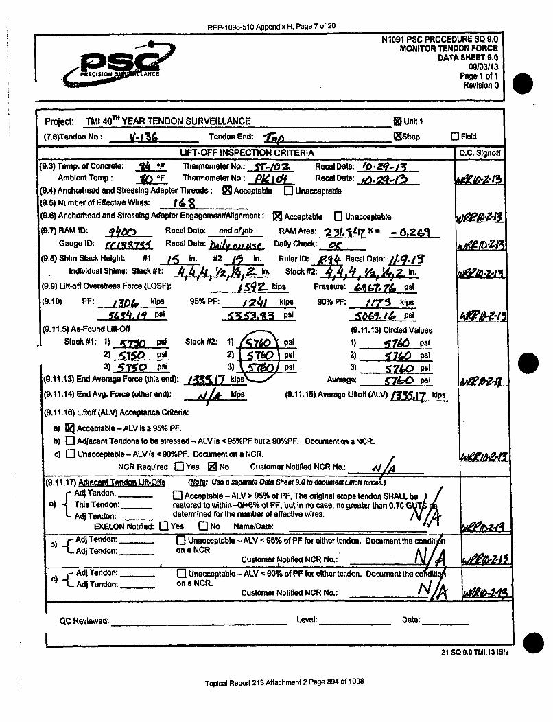
REP-i1098-510 Appendix H, Page 7 of 20
N'1091 PSC PROCEDURE SQ 9.0MONITOR TENDON FORCE
DATA SHEET 9.0P S_ 09103113
PRECISION ANc Page 1 of 1
Revision 0 1
Project: TMI 4eT YEAR TENDON SURVEILLANCE []Unit I
(7.6)Tendon No.: Y- 136 Tendon End: ,re Shop 0 FieldLIFT-OFF INSPECTION CRITERIA Q,.C., S lgnoff
(9.3) Temp. of Concrete: OF Thermometer No.: ST-,. g: Recal Date: /0Z•-IJ
Ambient Temp.: O Thermometer No.: jO Recal Date:(9.4) Anchorhead and Stressing Adapter Threads: [] Acceptable El Unacceptable(9.5) Number of Effective Wires: 16(9.e) Anchorhead and Stressing Adapter EngagementlAlignment: I] Acceptabte [I Unacceptable
(9.7) RAM ID: tim Recal Date: end ofjob RAMArea: 23(,JLI"K= - •,ZA
Gouge ID: ciudi RecOl Date: s 11e DaOly Check: C_(9.8) Shim Stack Height: #1 I• In. #2 in. Ruler ID: A Recal Date: -4
Individual Shims: Stack #1: 4 A.4/, V2. ,.. In. Stack #2: i jn..
(9.9) Lift-off Overstress Force (LOSF): 59 Z_ kips Pressure: 1l 76 psi
(9.10) PF: I kips 95% PF: 24 f kips 90% PF: 1/75 kips
~4g psi 119!0,13 PITa%(&psi(9.11.5) As-Found Uft-Off (9.11.13) Circled Values
Stack#1: 1) T•"'r psi Stack#2: 1) K psi 1) 57461 psi2) 615So psi 2)1 7(0 psi 2) ' pal
3) 51•O psi 3) ý.M ] psi 3) S760 psi(9.11.13) End Average Force (this end): /&S.17 k~p5.,, Average: &7&0 psi
(9.11.14) End Avg. Force (other end): dl& kips (9.11.15) Average Ulftoff(ALV) j 7 kips
(9.11.18) Liftoff (ALV) Acceptance Criteria:
a) 5 Acceptable - ALV Is a 95% PF.
b) [] Adjacent Tendons to be stressed - ALV is < 95%PF but k O0%PF. Document on a NCR.
c) [] Unacceptable - ALV is < 90%PF. Document on a NCR.NCR Required 0 Yes Z No Customer Notified NCR No.: 1A
(9.11.17) Adlacent Tendon I-ft-Offs (NOte: Use a separate Data Sheet 9.0 to document Liftoff flbre)-AdI Tendon: i[ Acceptable - ALV > 95% of PF, The original scope tendon SHALL
a) This Tendon: restored to within -01+6% of PF, but In no case, no greater than 0.7 0 GAdi Tendon: _ determined for the number of effective wires.
EXELON Notified: 0 Yes C0 No Name/Date: _
b)-- Adi Tendon: _ _ Unacceptable - ALV c 95% of PF for either tendon. Document the conditb) ..Adj Tendon: ____ on a NCR.Customer Notified NCR No.: A'_/_
AdI Tendon: _] Unacceptable - ALV < 90% of PF for either tendon. Document the co diilc) L.. Adj Tendon: on a NCR.
Customer Notified NCR No.: 7_AWE&_M
QC Reviewed: Level: Date:
I21 SO 9.0 TMI.13 ISla @I
Topical Report 213 Attachment 2 Page 894 of 1008

REP-1 098-510 Appendix H, Page 8 of 20
PRECISION ANCE
N1091 PSC PROCEDURE SQ 11.0RETENSION TENDONS
DATA SHEET SQ 11.009103113
Page 1 of 2Revision 0
Project: TMI4eTh YEAR TENDON SURVEILLANCE
(9.3)Tendon No.: %-/-M Tendon End: 7',6(9.4) Temp. of Concrete: IL', Thermometer No.: .iv"/0
Ambient Temp.: It °OF Thermometer No.: PK .
(9.5) Anchorhead and Stressing Adapter Threads: IR Acceptable 0 Unacceptable
Unit I
H Shop
Recal Date:
Recal Date:
o Unit 2
[I Field
I RETENSIONING DOCUMENTATION
(9.6) Number of Effective Wires: 14" (from Data Sht. 8.0) ,(9.7) Anchorhead and Stressing Adapter Engagement/Alignment: a4 Acceptable 0
(9.7.3) RAM ID:Gauge ID: &Z0 ..
Recal Date: r4 -r-1- RAM Area: 2. -r K - OARecal Date: Dally Check: gp-
Calculated Force for Elongation Measurement and Retensioning using formula belowNM: Stress during Lift-Off should not exceed 9.425 kips per effecive wits or 1592 kips for a 169 wire tendon.(9.8.4) PTF a II lkips Pressure: %50.%6,psi
Step I a I00 kips Pressure: 3 4_5 1.71 psi Elongation: 4,14 inI.°
Step 2 = -.. 00_ kips
LOF= 1j,33,17 kips
OSF= 161 .kips
Pressure: t i(,q4g, psiPressure: 5760.00 psi
Pressure:
Elongation: i. OS in.
Elongation: I in. ~ee io.2g~
P=(F-K) xlOOOA
Key: F = Force (kips)A = Ram Area (in2)P = Gauge Pressure (psi)K = Constant factor (kips)(cAuTio: *K constants can be eitherpositive or negative.)
64e- t~tv- 1 Odtod l(Arlfjns5 AA&l 4CLS~& lwre-'I- Yekfsio*.
A4 4h ki. se4 .E III5 4.'n-.A1F 1140 604'!eD4/'sAile-, eAJCl-
HT#*5 V: RI1067
101rsaI ,qfo
QC Reviewed: Level: Date:
28 80 11.0 TMI.13 IS4doC
Topical Report 213 Attachment 2 Page 895 of 1008

REP-1 098-510 Appendix H, Page 9 of 20
N1091 PSC PROCEDURE SQ 11.0RETENSION TENDONS
DATA SHEET SQ 11.009103/13
Page 2 of 2Revision I'
Project: TMI 4e~ YEAR TENDON SURVEILLANCE (K Unit 1 0 Unit 2
(9.3)Tendon V.,I 11L Tendon End: J1$........... RShop [3 FieldActual Observed Force and Elongaston Measurements using formula below QC Signofta
(9.9.4.1) PTF= 19f.,f( kips Pressure: 1St) psi D Elongation: f
(9.9.5.1) Step 1 7qqg,(o kips Pressure: Am4 . psi Elongation: !
(9.9.6.1) Step 2 j2860.70 kips Pressure: _1/io pas Elongation: iaf In.(9.9.7.1) OSF= 1574.1. kips. Pressure: A760 psi QD Elongation: /6,.Vin.
1000(9.9.8) CD - (D. 5 in. Elongation Value (this end)
(9.9.9) L//A in. Elongation Value (opposite end)
(9.9.10) /02 1) In. TOTAL Tendon Elongation Value(9.9.12.1) Elongation S Ruler ID: •14 Recel Date: if-I- 1
(9.9.12.3) Elongation Results C Acceptable 0 UnacceptableCustomer Notified NCR No: -L A&
Options Original Lift-off Values from Data Sheet SQ 9.0A Lift-off < Predicted Force 0 Use Predicted Force- 0 + 6%B Lift-off > Predicted Force ij Use Lift-off - 0 + 6%C Lift-off > 67% GUTS 0 Use 70% + 0 -3% GUTS (effective wires)D Lift-off > 70% GUTS 0 Use 70% + 0 - 3% GUTS (effective wires)
(9.10.5) LOF Acceptable Range Min MaxAs found lift-off/or predicted (highest): (,5SiS•j-1 kips I4/•t zI kips
From: 51f,0 psi To: 2 4,5,1/0 PSI
(9.10.6) Actual Lift-Off (9.10.8) Circled ValuesStack #l: 1) 40 IQ psi Stack #2: 1 4.ý :•s 1 1) 101D psi
2) ,OtQ psi 2 s&__]p! 2) (./bA psi3) 404 psi 31 si 3) 0100 psi
(9.10.8) Force (this end): j4cta00 kips Average: .(4, |0W psi
(9.10.9) Force (opposite end): AJ/* kips (9.10.10)Tendon ALV Force 1 ý 1*- kips
(9.10.11) ALV Acceptable: 9,Yes [I No Customer Notified NCR No.:
(9.10.15) Additional broken/missing wires: 1 No C1 Yes Amount:
(9.10.16) Additional Protruding/Unseated wires: K.No 0 Yes Amount:q F762 1 If Yes - Customer Notified NCR No.: _,,74
(9.10.17) Final Shim Stack Height: #1: ,L 4 , 1 44 .1. #2: 1j '" /~fiiZ"|- Reviewed Leve l: -Date
QC Reviewed: ___________________ Level: ________ Date: _________
28 SQ 11.0 TMI.13 ISI.doc
Topical Report 213 Attachment 2 Page 896 of 1008

REP-1098-510 Appendix H, Page 10 of 20
N 1091 PSO PROCEDURE CIA 9.0NONCONFORMANCES
NCICAR FORM
09103113Revision 0
Pago of
NONCONFORMANCE /CORRECTIVE ACTION REPORT FORM
HOLDTAG NO.: IAC I CA NO.:
NONCONFORMANCE: Cm A1 '--4:::F-T'A rTi-pyV•Pe-'i
Of- TEDO ýS 01-01-N/'5 "p ' H IM 140P 4A tUt"V1 /X>H f 4'01%J T-bP sl0cr- OF:-ar ST".P(04<6 •~bu at•oSdt.&W-~~~~~vP Pi~eŽ CV6' 1)kL L4~NT f fr c
APPARENT CAUSE KNOWN: El YES L NO IF YES, DESCRIBE:
RECOMMENDED CORRECTIVE ACTION:
ANY NONCONFORMING ITEM TO BE REPAIRED SHALL HAVE AN APPROVED REPAIR PROCEDURE:.
CORRECTIVE ACTION TO PREVENT RECURRENCE:
INITIATOR- _ _ ITLE DATE:-
SIGNIFICANT CONDITION: El YES I NO IF YES, REFER TO QAM SECTION 15.
APPROVAL COMMENTS: /• , a -" UA-" "' -4?. 14-i -Srr~v~ ea A) /> 6ý W S ,DcA
PSC QA 1 E G ,, :
SIGN & DATE: a 13--- .- -
EXELON APPROVALREQUIRED E] YES Dl NO ENGItIEER .ATE
QA DATECOMMENTS: ,.. ....... ... .........
DISTRIBUTION ojISPOSIrION COMPLETETDCI A SECTION VICE PRESIDENT El VENDOR SIGNED:
CI QE SECTION F] CONTR. MGMT. f'IS_1"._) TITLE:
ENGINEERING , EXELON [] DATE:
43 OA 9 0[MI.3 ISI
Topical Report 213 Attachment 2 Page 897 of 1008

REP-1098-510 Appendix H, Page 11 of 20
Nt1091 PSC PROCEDURE QA 9.0NONCONFORMANCE$
NCICAR FORM09103)13
Revision 0PRECON, L•AN C E Page of
NONCONFORMANCE I CORRECTIVE ACTION REPORT FORM
HOLD TAG NO.: 'd/A NC I CA NO.: i/g'-lVyi 91- 06s
NONCONFORMANCE: ,xcemop_ skA 5A3S #', 43 & , 44 te ss I __d tl k1 /3 ,-68P 7k
ýA IO~ASLAI'e.ý 4 4 4kc +o skkle - e-r PSC.. Pfr-ce-.duhr- 'SQ- 2-se. i'a .7 41$,- cI*+;eje4 I h ýY k.4 WIf
APPARENT CAUSE KNOWN: C1 YES L4 NO IF YES, DESCRIBE:
RECOMMENDED CORRECTIVE ACTION: (Ie4 to /•e"dlee•vi• -,
ANY NONCONFORMING ITEM TO BE REPAIRED SHALL HAVE AN APPROVED REPAIR PROCEDURE.
CORRECTIVE ACTION TO PREVENT RECURRENCE: C.e4 de-4e-rf';i'ae
INITIATOR: TITLE DATE:
SIGNIFICANT CONDITION: 0 YES $ NO IF YES, REFER TO QAM SECTION 15.
APPROVAL COMMENTS:
PSC QC , ENGI EER NGAPPROVAL NIER&GSIGN & DATE: /0-31- -h ,
EXELON APPROVALREQUIRED 01 YES LI NO ENGINEER DATE _
GA -___________ DATE _________
COMMENTS:
DISTRIBUTION DISPOSITION COMPLETED
CQA SECTION 0 VICE PRESIDENT C0 VENDOR SIGNED:
G3 QE SECTION 0 CONTR. MGM`T. Fi te£.,f TITLE:
I] ENGINEERING • EXELON 0 DATE:
________________________________________
043 QA 9.0 TMI.13 IS!
Topical Report 213 Attachment 2 Page 898 of 1008

REP-1098-510 Appendix H, Page 12 of 20
N1091 PSC PROCEDURE SQ 8.0ANCHORAGE INSPECTION
Data Sheet 8.0909103/13
PEISION' LANCE Page 1 of 1Revision"
Project: TMI 2013 TENDON SURVEILLANCE _ _f UNIT 1
(7.3)Tendon No.: H 1,5 - . Tendon End: e L Shop
ANCHORAGE INSPECTION CRITERIA
.As-Fou Post De-Tensioning I Pre-Wire Removal 0 Post Re-Tensioning Q.C. Signoff
9.0 & t0.D -CORROSION R& CRACK INSPFCTIA"N
(9.2) Buttonheads Level: (10.1) Cracks [IYes' ii N/A(9.2) Anchorhead Level: 4(10.1) Cracks 0 Yes |2 NO L N/A
(9.2) Bushing Level: A (10.1) Cracks 0I Yes(t 2 MLIA(9.2) Shims Levl: e 2(9. sLevel: (10.1) Cracks L[ Yes ýt O N/A
(9.2) Bearing Plate Level: (10.1) Cracks Li Yes' NI FN l NIA
- Corrosion Level of C requires a NCR. (21 - Compose a sketch of the cracks on Sketch Sheet 8.0 and initiate a NCR.L& &- ý Yx- --
11 l -k . ITT-MWI-LFfAn I1"MQF:TI'IM
- Oflsize (Maltlomed)
Protruding/unseated' wi relbuttonheads
0 Brokenfmissing vtreebtuttonheads
0 Previously identified as missing
[] I Discontinuous -- removed thissurveillance
cuessi've- dtlipýýAp MC041'
/./
I wire(s) being removed during thisJsurveillance for testing
(11.2) Anchorhead I.D. ion¶"Located on Sketch: FZYes L-1 NoBushing I.0.
Located on Sketch: QQ Yes C1 No
(11.4) Missing Buttonheads Found:
C1 Yes [0 No Quantity:Additional Information: UIOLA __L ,6.
'I,,J .-. 2
'~
(12.2) Number of Protruding Butlonheads (,w):
(12.3) Number of Missing Buttonheads (0,K):
(12.4) Total of Protruding #-f Missing Buttonheads:
(12.5) Total # of Effective Buttonheads Seated:
Z)
-. . ....... . ......... ........ .. . . . .. . .............- . ...... .. .. .... .. . . ........... ......... .. . . . .. . . . . .. I . . . ..
Illumnination source ~ j -r
(12.6) Continuity Test Requested ? Q] Yes aI-,14Wires Identified? Yes n-INo
ustomer Notified NCR#*: ltY,- ~ ~ eb~1(12.7) Overall Results E Acceptable KUn-Acceplablo
.i8s fO t.0. r;1, Is)
Topical Report 213 Attachment 2 Page 899 of 1008

REP-1098-510 Appendix H, Page 13 of 20
Project. Exelon 20-12 TENDON SURVEILLANCE ____~UNIT ij
Tendon No.: 1/13 Tendon Enr. Shop 0 Field
(10.2) Sketch each crack as it appears in the anchorheadsibushings, shims and bearing plates. Identify each Unit by
number; record the location of the anchorhead or bushing identification and apply to the sketch. Use as many SketchSheets as necessary being sure to list the page number below and to apply a Sketch Number to each unit with cracks,
Ensure a Nonconformance Report in accordance with Procedure QA 9.0, NONCONFORMA!NCES, for Ejelon aEgroval
... .. . .. . ... ..• - - ... .. .. .. ..... .T " • ' " - - i -".. ........ . ..
- --- - i,..... . .__ _ ... ... ... ..._ ..... .._ . i ;... .... • ' i. ..... •.....[ .. L...... .. ... ................
.r _ -. .T - .. . .. . . ....... . : . ... .
LA-i4, A 4rd .. .... , _T._ : ....... •... • !'• ,
.. .. •_..._. . .I .i .... .. ---- .......... .• •........ '......i , ii
I"
... .......... .. P ....- We
7. 7-~ -4
LI-I,- •, I ___ I tI-•.... - ...____ _ i--,---.•- ..r ...-.-i,- .-..... ý ..... ... .... ... -..-.-... ... ."...
QC inspector: Level: Date :
III
QC0 Revievicd - Level: Dile:-18 SO 605TMt.13 ISI
Topical Report 213 Attachment 2 Page 900 of 1008

REP-1098-510 Appendix H, Page 14 of 20
N 1091 PSC PROCEDURE SQ 8.0ANCHORAGE INSPECTION
09103/138Page 3 of 8PRECISgON,, rA2CE Revision 0
Revision: 1, 10/04113
7.0 PREREQUISITES
7.1 The Anchorage Cleanup will be completed.
7.2 The tendon will be in a stressed condition.
7.3 QCD - Document the tendon identification and tendon end on Data Sheet 8.OA or8.08, ANCHORAGE INSPECTION.
8.0 ANCHORAGE INSPECTION
8.1 The tendon anchorage, including the anchorhead, bearing plate, stressing shims,buttonheads and wires of all selected tendons shall be visually inspected(Detailed Visual Examination) for signs of corrosion, cracking, missing wires,protruding buttonheads and signs of deformation.
8.2 This inspection is to be performed with light conditions supplemented by auxiliarylight sources if needed.
8.3 QCD - Record the illumination source used on Data Sheet 8.OA or 8.0B asapplicable.
8.4 For Detailed Visual Examinations, access must be sufficient to place the eye within24 inches, at an angle not less than 300 to the surface.
8.4.1 Mirrors may be used to improve the angle of vision.
8.5 QCD - The gap between shim halves for the first set of shims under anchorheadshall not exceed an average of 0.25". A maximum gap of 0.50" is acceptable at one
Agap location if other side of shim halves is in contact. The remaining shims areallowed a maximum gap of 0.50" at each location of shim halves. Exelon Engineeringshall be notified by a Nonconformance Report if the average shim gap exceeds 0.25".A gap of 0.50" on one side and 0" on the other side is acceptable.
h 18SO 8.0.TMI.13 ISI Rev 1
Topical Report 213 Attachment 2 Page 901 of 1008

REP-1098-510 Appendix H, Page 15 of 20
.. -NlO9SC PROCEDURE CIA .0NONCONFORMANCES
aoft NCICAR FORM09/03113
PRECSGISION 'NCE Revision 0:• '" • Page _ of__
NONCONFORMANCE / CORRECTIVE ACTION REPORT FORM
HOLD TAG NO.: 1/A NCI/CA NO.: e-A U tC ....
NONCONFORMANCE: Qrj, 4Tj~ b.1(13 +h~e. jp,,4e. 1ES- -f-i, 3em1se-. m'pIced.i-ffA ~ A~eKee.4 /C)Mo. -T-hr 46444 4o-CPe-rewe Is S9,1 4%. Per I'SC pbevtr e- 5A 1,1' Z5 e C-)6. j5I 'fke.' c~ ; S4-c> e-i 14C W4;A alhy A , R A /,
APPARENT CAUSE KNOWN: N YES • NO IF YES, DESCRIBE:
RECOMMENDED CORREC'VE ACT ION : - -....... .................
ANY NONCONFORMING ITEM -TOBE REPAIRED SHALL HAVE AN APPROVED REPAIR PROCEDURE.
CORRECTIVE ACTION TO PREVENT RECURRENCE: C{M.t " cf=-/fn4 -,
INITIATOR: TITLE DATE:
SIGNIFICANT CONDITION: U YES U NO IF YES, REFER TO QAM SECTION 15.
APPROVAL COMMENTS: -................ . ...
D<t flee * . " .' ,#- "^,,7-••. • F• T•'
APPROVAL ,,, I'•- ' " Lxl A, ,SIGN & DATE: kk/ý°k, = -3 1
EXELON APPROVAL --
REQUIRED 0 YES E] NO ENGINEER DATE
QA DATE 4\
COM M ENTS:~ ~ .... ... .. ........... ......... .... ........ .......COMMENTS:
DISTRiBUTION ... DISPOSrFH, COMPLETED
QA SECTION - VICE PRESIDENT C3 VENDOR - SIGNED:
QE SECTION W CONTR. MGMT. V I TITLE:
J ENGINEERING [.• EXELON U DATE:
.3 QA 9.0 TMI.13 II
Topical Report 213 Attachment 2 Page 902 of 1008

REP-1098-510 Appendix H, Page 16 of 20
#R E G1 IRS 0 N N k,
N 10G91 PSC PROCEDURE SQ 12.1GREASE REPLACEMENT
Data Sheet 12.1a - Pressure Pumping09/03/13
Page I of IRevision 0
Project: TMI 40"' YEAR TENDON SURVEILLANCE Tendon No.: .> - 1
GREASE REPLACEMENT CC SIGNOFFS
(8.4) Grease Used NEW [I OLD -TEST DATE: FI ACCEPTABLE E APPROVAL LETTER
8.0 PREREQUISITES. DATED:
(8.5) Total Grease Less from Data Sheet 6.0 for 1 L tendon end: 15.5 gal.
(8.6) Total Grease Loss from Data Sheet 6.0 for . . . " tendon end: _ t) gal.
(837) Estimated grease losses from leaks for tendon end:
11-12-fl
'-'.3
(8.8) Estimated grease losses from leaks for - tendon end: - .'l gaI.
(8.9) TOTAL Tendon Grease Loss: gal-
1R.0 INITIAL PRESSURE PUMPING
(12.6) Ambient Temp.: "• '•F Thermometer ID: Recal Date:
(12.7) Grease Temp.: .... b IF Thermometer ID: Recal Date: ,._[ .
12.9)i ae. () . (12.14) Final Grease Height (b) Y n
(12.16) Total amountofG, ase Pumped: 7, gal. fa-bX1,.7 intotile
(12.18) Quantity of Waste Grease: 1,0 gal. (12.17) Was Exit Achieved? I1 Yes L\ No
'12.19) Total Grease Re ,.acc.4 this end: "71,& q gal. If no, Pressure 1Held for V .Jpssi _..min Ijg./[-f'j
ID PUMPIN!G - SECOND ENf (if necessary)
(13.6) Ambient TcnPi..• ...... ',F Thermome r D: / Recal Date:
(13.7) Grease Temp.: -•'"9:h, hertomjt _o_•._ Recal Date:
(13.9) Initial Grease Height (a) ____ i.." %~ Final Grease Height (b)in
S(13.1 4) Total amount of Grease added: - al. a-bx.7 -. iath n,,,,,, ~ ---- .. ....-..
(13.16) Quantity of Waste Grease: gal. 13.15) -Poured C.
(13.17) Total Grease ft~ae this end: gal.!__
14.0 CALCULATION OF PRESSURE PUMPING
(14.1) Total Tendon Grease Replaced: 70,f gal. (12. f9 + 13.11)
(14.2) Net Tendon Duct Grease Volume: 5 ,Zj gal. R;e, '.SO 12 2 -•.,pl ' c IC.•
(14.3) Percent Difference: Total Tendon Replaced (14.1)-Total Tendon Loss (%9).ifference
Net Tendon Duct Grease Volume (1421
(14.4) Grease Leaks: LI Yes I No
(14.5) Refill Acceptable: Li Yes gtess thzn Wj No (greate• thnn• ")
If No - Customer Notified NCR No.:
Ilel-11 I
(14.6) Comments:.. ..... ........
. ...... . . ....... - --t-= . o .
I 0C Reviewed: & (1 .1 Level: ______ Dale: id cl/1'..Dale: -.! jA. 3 S
Topical Report 213 Attachment 2 Page 903 of 1008

REP-1098-510 Appendix H, Page 17 of 20
N1091 PSO PROCEDURE 6A 9.0NONCONFORMANCES
NCICAR FORM09103/13
P SoN ERevision 0P:age of
NONCONFORMANCE /CORRECTIVE ACTION REPORT FORM
HOLD TAG NO.: ,A NC/CA NO.: _A e,
NONCONFORMANCE: K
proue (wrc., ~34ý 12I - i 'ee /,-I f IPk4 CleAP( ki Aw . +~
APPARENT CAUSE KNOWN: - l YES D NO IF YES, DESCRIBE:
RECOMMENDED CORRECTIVE ACTION: ,-__,__
ANY NONCONFORMING ITEM TO BE REPAIRED SHALL HAVE AN APPROVED REPAIR PROCEDURE.
CORRECTIVE ACTION TO PREVENT RECURRENCE-: C leAd "b &4e hn7N.
INITIATOR: TITLE DATE:
SIGNIFICANT CONDITION: YES NO IF YES, REFER ro QAM SECTION 15.
PSC QC W T 7 At7QAEAPPROVAL '
SIGN & DATE: //'th43I 4 /nC
REQUIRED E] YES El NO ENGINEER DATE
QA DATE _COMMENT$:
0
DISTRIBUTION DISPOSITION CO'MPLETED
GIA SECTION
,•CI E SECTION
9 ENGINEERING
El VICE PRESIDENT
- CONTR. MGMT.
W- EXELON
[I VENDOR SIGNED:
SiL ATITLE:
I] _ _ - j DATE:________________ __________________ I
t~ 3 A 9. 0 TrN 1.13 1 S
Topical Report 213 Attachment 2 Page 904 of 1008

REP-1098-510 Appendix H, Page 18 of 20
i1N 1091 PSC PROCEDURE SQ 12.1GREASE. REPLACEMENT
Su,. , Dalta Shoet 12.1a- Pressure Pumping09103113
',P PRECIStOrl 4SU.R I PA"CE Page 1 of I<Mý -. Revision 0
= ='==- ~ ~ ... ... ......... •
Project: TMI 40j" YEAR TENDON SURVEILLANCE Tendon No. ".
GREASE REPLACEMENT oC SINOFFS
(8.4) Grease Used T4 NEW E] OLD - TEST DATE: [ ACCEPTABLE EJ APPROVAL LEF-FER IU __ .
8.0 PREREQUISI1ES DATED:
(8.5) Total Grease Loss from Data Sheet 6.0 for tendon end: pal _ , l / f)'((3-s ... ......(8.6) Total Grease Loss from Data Sheet 6.0 for & tendonrend: 1L,6 g•l. .____
(8.7) Estimated grease losses from leaks for _ tendon end: gal.
(8.8) Estimated grease losses fromn leaks for tendon end: g) gal. '•Zl-'
(8.9) TOTAL Tendon Grease Loss: f ga, L. .
12-.0 INITIAL PRESSURE PUMPING
(12,6) Ambient Tremp.: .. -- F Thermometer ID: .. /: _ Recal Date: ib - 1• I
(12.7) Grease Temp.: 2eih Thermometer 10: Recat Dat":
(12.9) Lniti Grese Height (a) • in, (12.14) Einal Grease Height (1) ) ... in.
(12.16) Total amount of Grease P.mpd: • t gal. (A--b)x %.7r into the e end
(12.18) Quantity of Waste Grease: , • gal. (2.17) Was Exit AchieveP? t Yo, ma
1l2.19) Total Grease Rpj~ced this end: gal. If no, Pressure Held for ,psi A,/..min i&_Z -/;•p --'- .. ..... .,~/*'- ....... ,..:___ _ .___ _•
D PUMPING -. SECOND ENO (if necessary)(13.0) Ambient n •F Thermometer ID: Recal ate:,
(13.7) Grease Temp,: __-__ " u-4.bL,~rmom Rocl Dale:
(13.9) Initiql Grease Height (a) in. /(J.?• l Grease Height (b) in_.___.
(13.14) TIotal amount of Greasa added: ,/ /• gal (a - xll'l... I tha end
(13.16) Quantity of Waste Grease: _ gal. (13.15) U] Poured UN Pumped
(13.17) Tolal Grease Liq!L~c__eejd this end: gal. ....
14.0 CALCULATION OF PRESSURE PUMPING(14.1) Total Tendon Grease Replaced: • gal. (I2. 19 13. i?
(14.2) Net Tendon Duct Grease Volume: _ ,'gaI. neeroSQ s; 2-- g, j. 3,-,',E urt..jon,:ec.*g..,: C ,c f
Total Tendon Replaced (14.1) -Tctal Tendon Loss (8.9)(14.3) Percent Difierence. Ne.T l0- )JIu_ %Differonceme edon Duct Grease Volume (14.2) "
(14.4) Grease Leaks: LI Yes [• No
(14.5) Refill Acceptable: Li yeti rass raaa 16." U No tgtreafw'han w.%)
If No - Customer Notified NCR No.: Af -t)~
(14.6) Comments: ._ •:!..-.- -...-........ --.----... _________
SQC Reviewed: Level: ----- -3ate.
Ask S•10 12." TM1,4.13 ISI
Topical Report 213 Attachment 2 Page 905 of 1008

REP-1 098-510 Appendix H, Page 19 of 20
N'1091 PSC PROCEDURE GA 9.0NONCONFORMANCES
NC/CAR FORM09/03/13
Revision 0REMNSLLAE Page of
NONCONFORMANCE/ CORRECTIVE ACTION REPORT FORM
HOLD TAG NO.: NC I CA NO.: A.,. _i__1_
NONCONFORMANCEK: +4 900A- 3 IYS, DCRE .eA:emP d 4
__________ A 14C___ __
APPARENT CAUSE K~NOWN: Uj YES .NOIF YES, DES CRIBE-
RECOMMENDED CORRECTIVE ACTION: C eha io .,fWlAJ•.
ANY NONCONFORMING ITEM TO BE REPAIRED SHALL HAVE AN APPROVED REPAIR PROCEDURE.
CORRECTIVE ACTION TO PREVENT RECURRENCE: Chem4 4,b de.4cm•lve.
INITIATOR: TITLE DATE:
SIGNIFICANT CONDITION: 0] YES E] NO IF YES, REFER TO QAM SECTION 15).
APPROVAL COMMENTS:
PSC QCQA N( -- G
APPROVALSIGN &DATE:
EXELON APPROVALREQUIRED E] YES (] NO ENGINEER ___ ____DAT~E
QA DATECOMMENTS:
DISTRIBUTION
C9 OA SECTION 0] VICE PRESIDENT
1] QE SECTION f CONTR. MGMT.
[ ENGINEERING (•I EXELON
DISPOSITION COMPLETED iF] VENDOR
i e13
SIGNED:
TITLE:
DATE:111
43 QA 9.0 TMI.13 ISI
Topical Report 213 Attachment 2 Page 906 of 1008

REP-1098-510 Appendix H, Page 20 of 20
*~~~1 ( ?RIlS11. 5V1.A4
N 1091 PSC PROCEDURE SQ 12.1GREASE REPLACEMENT
Data Sheet 12.1 a - Pressure Pumping09/03113
Page 1 of 1Revision 0
Project: TMI 40te YEAR TENDON SURVEILLANCE Tendon No.:
GREASE REPLACEMENT QC SIGNOFFS
(8.4) Grease Used [ NEW El OLD - TEST DATE: [3 ACCEPTABLE E] APPROVAL LETTER ,jl -li8.0 PREREQUISITES DATED:
(8.5) Total Grease Loss from Data Sheet 6.0 for _ .tendon end: _
(8.6) Total Grease Loss from Data Sheet 6.0 for lendon end: ,T gal, 1. -6(8.7) Estimated grease losses from leaks for tendon end: ._,• gal. __ _
(6.8) Estimated grease losses from leaks for tendon end: .- gal. .. __
(8.9) TOTAL Tendon Grease Loss: t,_ gal.
12.0 INITIAL PRESSURE PUMPING
(12.6) Ambient Temp.: F Thermometer ID: . Recal ate: ,
(12.7) Grease Temp.: ? , °F Thermometer ID: Recal Date:
(12.9) !In!tia Grease I-light (a) ' f in. (12.14) Ein Grease H-eight(b) ••7 / in,
(12.16B)Total amount of Grease Pumped: (~j a t- 6)x I ?I into the end
(12.18) Quantity of Waste Grease: ,.- gal. (12.17) Was Exit Achieved? i'Yes, LI N[)o
'l2.19) Total Grease Rep.lacod this end: &' 5 37 gal. If no, Pressure Held for , psi e n Ln ,L
PUPN -SCN END (if necessary)(13.6) Ambient lreTp.-.... rF Thermometer ID: Recal Date:
(13.7) Grease Temp.:. ""'F-T4herlnoreter D0: Recal Date:
"(3.9) !utal Grease Height (a) in. r Fl l Grease Height (b) 2in.
(13.14) Total amount of Grease added: gal.a -a I;• "-1,th (2h11d
(13.16) Quantity of Waste Grease: ga. 3., 5) 0I Poured El~aPm~s
(13.17) Total Grease &g~acei this eivd: gal{'1.(,3,.)~~~....... .e0 ,....... ...... .........-14.0 CALCULATION OF PRESSURE PUMPING
(14.1) Total Tendon Grease Replaced: 4,$,'t gal. (12.19+ 13.17)
(14.2) Net Tendon Duct Grease Volume' f) ¢ ' gal. Ro,-3So 1P.? - sww,,tatii: fot :,;:&:,
Totat Tendon Replaced (14.1) -Total Tendon Loss (8.9)(14.3) Percent Difference: M et Tendon Duct Greasea Volume (14.2) 100 2.AL• % Lrf',rcnce .
(14.4) Grease Leaks: [] Yes { No
(14.5) Refill Acceptable: [2Yes ttesWha 101S) No (Ireater than 10%)~~Ii~I
If No - Customer Notified NCR No.: -a-loil 0 6_(14.6) Comments: *..,AAa' .
I
QC Reviewed:-. I
t~.. 4 .,_ •_-__ Level: - .. Da.te.. D : t/.
(. 31 SQ 12.1 Tt•i.13 It
Topical Report 213 Attachment 2 Page 907 of 1008

REP-1098-510 Appendix I, Page 1 of 11
N1091 PSC PROCEDURE QA 7.0FIELD CHANGE REQUEST INDEX LOG
09/03/13Page - of_-_
Revision 0
Project: TMI NUCLEAR PLANT - UNIT 1 - 4&t Year
.... 141FIELD CHANGE REQUEST INDEX LOG
A DESCR NDATE DATE DATEFCR DSCRPTONWRI'TTEN APPROVED REV.
_______ I 4 4
4 I 4
* 1~ t I
-* I
_______ ___________________________________ ________ _______ ____-___I 1~ I
4. .9 I I
_______ I 4
4 K T T
I 1 '9 .9
__ I ___________ I __ __ __
40 GA 7.0 TMI.1~ I~I 040QA 7.0 TMI.13 I8I
Topical Report 213 Attachment 2 Page 908 of 1008

SPECIAL FIELD REVISION CONTROL FIELD CHANGE REQUEST NO.: FCR -614I-,16 1
REQUEST BY: Ii ,,. ',• ,,.V, .TITLE, DA.E: J•LL Ž_ .ORIGINATOR: jd& .An dTiTLE DATE we1~
PROCEDURE NUMBER: , REVNO.: _.J PROCEOURETITLE=
AFFECTEDSECTION: T1 /i4' REVISION TO MARUAL REQUIRED: C" YES 0 NO
NCR REQUIRED: 0 YES 10 NO NCR NUMBER: HOLD TAG NO.. ....
DETAILED DESCRIPTION OF EXISTING CONDITION: (USE EXTRA PAGES OR WRITE ON BACK)
MO~ P..dj ;4 d V4CCeE'3%Ajle. 4?of r(Aiil .1<
RECOMMENDED CHANGE; A~. ~'i~
DCc i ^. k EN- =E
EXELON APPROVAL OR COMMENTS:
APPROVED SITE QA AUTHORITY: • TITLE: DAFE
DISPOSITION PSC QC: HOLD TAG HOLDTAGAPPLIED: ........ REMVED:
QC INSPECTOR: APPLIED:_________DATE:
DISTRIBUTION
C3 EXE'LON QCA 00 EXE.LLI ENGINEERING Q CC PSCCIA P80 OR PROJECT MGR. PSCJ} "..FNGINFERING PSC 1 EXELON DC (0 __ ;"
40 (IA 10 U.11. 13 131
Topical Report 213 Attachment 2 Page 909 of 1018

Gerald Bussone
From:Sent:To:Subject:Attachments:
Nick DarlageThursday, October 17, 2013 3:39 PMGerald Bussone; Paul Smith; Christopher Cox; William Robbins; Dustin EstepFW: Preliminary Tendon Data: FCR Response from TMIFCR N1091-001.pdf; ATT00001.txt
Nick DarlagePrecision Surveillance Corporation
From: Grimm, Michael:(GenCo-Nuc) rniailto:;Michael.Grimmirnxeloncorp.com]Sent: Thursday, October 17, 2013 3:26 PMTo: Stein, Howard:(GenCo-Nuc); Nick Darlage; Taylor, Sean Ryan:(GenCo-Nuc); Espenshade, Marvin H:(GenCo-Nuc)Subject: RE: Preliminary Tendon Data: FCR Response from TMI
Nick,
Attached is the signed FCR. You will receive a TODI formally transmitting the values in this email chain tomorrow.
Thanks,
Mike
Michael GrimmReactor Vessel InternalsISI Programs Engincer. EIT
• ExeionGincycralcn.
'262ý • ,R R:=: M ::J-• =, =1.A I. :5
nc_.a•Lgr l inirne:ehcOn^rp.n•j, ',,_~~••ocr~o
From: Stein, Howard:(GenCo-Nuc)Sent: Thursday, October 17, 2013 3:59 PMTo: Nick Darlage; Grimm, Michael:(GenCo-Nuc); Taylor, Sean Ryan:(GenCo-Nuc); Espenshade, Marvin H:(GenCo-Nuc)Subject: RE: Preliminary Tendon Data: FCR Response from TMIImportance: High
Mike-
Please see Nick's comment below.
Thanks,Howard
I
Topical Report 213 Attachment 2 Page 910 of 1018

From: Nick Darlage (mailto:ndarlageC(pscnuclear.com]Sent: Thursday, October 17, 2013 3:22 PM
* To: Stein, Howard:(GenCo-Nuc)Subject: RE: Preliminary Tendon Data
Thanks Howard.
Can we get Mike to Sign that FCR and reference this information within his response?
Thank you,
Nick DarlagePrecision Surveillance Corporation
From: Stein, Howard:(GenCo-Nuc) (mailto: [email protected]]Sent: Thursday, October 17, 2013 2:15 PMTo: Nick DarlageSubject: FW: Preliminary Tendon Data
Here is info Nick!
From: Grimm, Michael:(GenCo-Nuc)Sent: Thursday, October 17, 2013 2:12 PMTo: Stein, Howard:(GenCo-Nuc)Subject: Preliminary Tendon Data
Howard,
Please distribute this information so we can start on D-146. We need to get the TODI signed off and we have not beenable to get the right people yet this morning. Will get by end of day. Work can proceed at risk with the informationbelow.
Tendon Stressing Data:
Tendon Normalization Predicted Force 95% Predicted 90% PredictedNumber Factor (Kips) Force (Kips) Force (Kips)
D-141 47 1059 1006 953D-146 -4 1110 1055 999D-149 52 1055 1002 950
Tendon Net Duct Volume:
Tendon NumberNet Duct
Volume (GAL)10% Net DuctVolume (GALU
D-141 80.6 8.08D-146 81 8.1D-149 75.84" 7.58*
*Tendon D-149 installation cards are not Included In electronic files and are not readily available. The netduct volume provided Is the minimum value per calculation C-1101-153-E410-033 Revision 0, Dome TendonGrease Void Calculations.
2
Topical Report 213 Attachment 2 Page 911 of 1018

Thanks,
Mike
Michael GrimmReactor Vessel Internals/ISI Programs Engineer. Err
-- ExelonG,'nerat•rn,
232i' i2 3r:! iM?~~ 0
Of1:,52.7 L7 -):13 3306
This e-mail and any attachments are confidential, may contain legal,professional or other privileged information, and are intended solely for theaddressee. If you are not the intended recipient, do not use the informationin this e-mail in any way, delete this e-mail and notify the sender. -EXCIP
3
Topical Report 213 Attachment 2 Page 912 of 1018
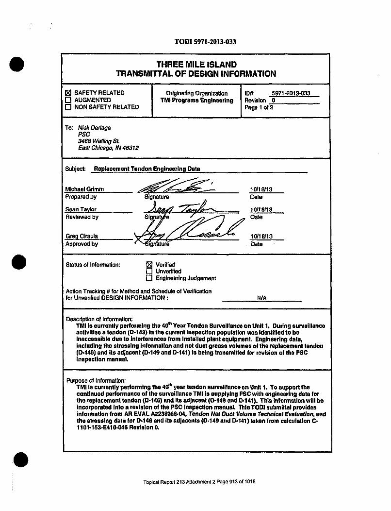
TODI 5971-2013-033
THREE MILE ISLANDTRANSMITTAL OF DESIGN INFORMATION
0 SAFETY RELATED Originating Organization ID# 5971-2013-0330 AUGMENTED TMI Programs Engineering Revision 00 NON SAFETY RELATED Page I of 2
To: Nick DarlageP$C3468 Watling St.East Chicago, IN 46312
Subject: Replacement Tendon Engineering Data
Michael Grimm ,? 10118/13Prepared by Signature Date
Sean Taylor 10/18/13Reviewed by ISignt e Date
Greg Clraula at 10/18/13Approved by "g Date
Status of Information: 0 VerifiedEl Unverified0 Engineering Judgement
Action Tracking # for Method and Schedule of Verificationfor Unverified DESIGN INFORMATION: N/A
Description of Information:TMI is currently performing the 40?' Year Tendon Surveillance on Unit 1. During surveillanceactivities a tendon (D-143) In the current inspection population was identified to beinaccessible due to interferences from installed plant equipment. Engineering data,including the stressing Information and net duct grease volumes of the replacement tendon(D-146) and Its adjacent (D-149 and 0-141) Is being transmitted for revision of the PSCinspection manual.
Purpose of Information:TMI Is currently performing the 4Al year tendon surveillance on Unit 1. To support thecontinued performance of the surveillance TMI Is supplying PSC with engineering data forthe replacement tendon (0.146) and Its adjacent (0-149 and 0-141). This information will beincorporated Into a revision of the PSC Inspection manual. This TODI submittal providesinformation from AR EVAL A2238266-04, Tendon Net Duct Volume Technical Evaluation, andthe stressing data for 0-146 and its adJacents (D-149 and 0-141) taken from calculation C-1101-153-E410-046 Revision 0.
Topical Report 213 Attachment 2 Page 913 of 1018

TODI 5971-2013-033
Tendon Stressing Data:
Tendon Normalization Predicted Force 95% Predicted 90% PredictedNumber Factor (Kips) Force (Kips) Force (Kips)
D-141 47 1059 1006 9530-146 -4 1110 1055 999D-149 52 1055 1002 950
Tendon Net Duct Volume:
Net Duct 10% Not DuctTendon Number Volume (GAL) Volume (GAL)
D-141 80.6 8s06D-146 81 8.1D-149 75.84* 7.58'
'Tendon D-149 installation cards are not Included in electronic files and are not readilyavailable. The net duct volume provided Is the minimum value per calculation C-1101-153-E410-033 Revision 0, Dome Tendon Grease Void Calculations.
PSC to sign and confirm receipt of this Information:
Receipt: Z_________ p~c Q1- )1rxk "vi Date:_t183., •- T
References:1) CC-AA-310, Transmittal of Design Information2) C-l101-153-E410-046, Tendon Force Predictions3) C-1101-153-E410-033, Dome Tendon Grease Void Calculation4) Technical Evaluation A2238266-04, Tendon Net Duct Volume
Supplemental Distribution: Mail: [email protected] 'ard CoMv: EDMS
Topical Report 213 Attachment 2 Page 914 of 1018

V
.RCSO A N CE
N1091 PSC PROCEDURE QA 7.0FIELD CHANGE REQUEST FORM
09103/13Page 1 of IRevision 0
SPECIAL FIELD REVISION CONTROL FIELD CHANGE REQUEST NO.: FCR - ,q 1. 602f
REQUESTBY: bij 4 t&... TITLE: PS. .C DATE: . - 4
ORIGINATOR: We. ,9.A.JCe -V3 TITLE S_ .. DATE: J_•fLj
PROCEDURE NUMBER: _ REV NO.: 0 PROCEDURE TITLE _ 1A!u '
AFFECTED SECTION: , _TM.,__.._____REVISION TO MANUAL REQUIRED: [I] YES . NO
NCR REQUIRED: Cl YES IR NO NCR NUMBER: At 1 HOLD TAG NO.: -. , /f
DETAILED DESCRIPTION 017 EXISTING CONDITION: (USE EXTIRA PAGES OR WRITIE ON BACK~) i~~~1 eiL DUr~e #VV H r~ ij 7 ~A-5 k4 remA -fA04!J, M
14 13 o. r(Aet ,b, eiet oAA/iAd.4KI L/(4(C F
RECOMMENDED CHANGE:AdcIJ n e.- dlueI vol nv.5 At -16c~,~-m)~ c,9i~A4 be) ve,.-
PSC QA/ ~~ QC I N
SIGN & DATE: S V4 .. j/fI 4 0 -isEXELON APPROVAL OR COMMENTS:
APPROVED SITE QA AUTHORITY: TITLE: DATE
DISPOSITION PSC QC: HOLD TAG HOLD TAGAPPLIED: REMOVED:
QC INSPECTOR: DATE:
DISTRIBUTION
Q EXELON QA 0 EXELON ENGINEERING a OC PSCG GA PSC 0 PROJECT MGR. PSC 0 4f ._
f- ENGINEERING PSC G EXELON QC .
I . . ... . .. - - -
40 QA 7 0 TML 13 ISI
Topical Report 213 Attachment 2 Page 915 of 1018

TODI 5971-2013-037
THREE MILE ISLANDTRANSMITTAL OF DESIGN INFORMATION
SSAFETY RELATED I Originating Organization ,D# r71o2)13-...AUGMENTED TMI Programs ngineering Revision 0NON SAFETY RELATED Page 1 of 2
To: Nick DadagePSC3488 Watflng SLEast Chicago, IN 46312
Subject: Additional Grease Voids for 40' Year Tendon Surveillance
Michael Grimm ___
Prepared by =ignature Date
Sean Taylor 2~,14 2WI-- 1=eReviewed by Sig--reW Date
Maurk Torbora _____I_1_.__.__11_--
Approved by Signature Date
Status of Information: VerifiedH UnverifiedEngineering Judgement
Action Tracking # for Method and Schedule of Verificationfor Unverified DESIGN INFORMATION: W/A
Description of Information:TMI Is currently performing the 40P Year Tendon Surveillance on Unit 1. Surveillanceactivies for repair of the tendon end cup for H24-47 and the visual examination of H13-08were not transmitted under the previous TODIM (6971-2013-032 and 033).
Purpose of Information:TMI Is currently performing the 440 year tendon surveillance on Unit 1. To support thecontinued performance of the surveillance TMI is supplying PSC with additional grease voidvolumes for use on tendon H24-47 and H13-0&. H24-47 was added to the outage to repair aleaking end cap. H13-08 was In the original outage scope and was removed due toInaccessibility. The tendon Is having a visual examination performed and the grease voidInformation was not previously transmitted.
Tendon Net Duct Volume:
0Not Duct lONet DuctTendon Number Volume (GAL) Volume(GAL)
H24-47 110.1 11.01H13.08 110.7 11.07
Topical Report 213 Attachment 2 Page 916 of 1018

*. . .. . .... I . .. .
TODI 5971-2013.037
PSC to sign and confirm receipt of this Information:
Receipt: Date:
References:1) CC-AA-310, Transmittal of Design Information2) C-i 101-153-E410-032, Horizontal Tendon Grease Void Calculation3) Technical Evaluation A2238266-02, Tendon Net Duct Volume4) Technical Evaluation A2238266-04, Tendon Net Duct Volume
Supplemental Distdbullon: - Mall: [email protected] HrdQQ: EDMS
Topical Report 213 Attachment 2 Page 917 of 1018

From: Marvin H: Espenshade Matvvin.Espershadie@exeloricor),coniSubject: FW: Grease Void Info
Date: October 31, 2013, 12:13 PMTo: Dustin Estep deSeOl)ypscnuctoar.com
From: Grimm, Michael:(GenCo-Nuc)Sent: Thursday, October 31, 2013 11:24 AMTo: Espenshade, Marvin H:(GenCo-Nuc)Cc: Stein, Howard:(GenCo-Nuc); [email protected]; Taylor, Sean Ryan:(GenCo-Nuc)Subject: Grease Void Info
Butch,
Please pass this info on to Rance. I will send the TODI out with this information once signed.
Just want to make sure you guys have it.
Tendon Number Net Duct 10% Net DuctVolume (GAL) Volume (GAL)
H24-47 110.1 11.01
H13-08 110.7 11.07
Thanks,
Mike
This e-mail and any attachments are confidential, may contain legal,professional or other privileged information, and are intended solely for theaddressee. If you are not the intended recipient, do not use the informationin this e-mail in any way, delete this e-mail and notify the sender. -EXCIP
0Topical Report 213 Attachment 2 Page 918 of 1018

PCItN SURVEILLANCE
REP-1098-510 Appendix J, Page 1 of 70 DATA SHEET SQ 8.409103/13
Page 1 of IRevision 0
VISUAL EXAMINATION - GENERAL VISUAL EXAMINATION
Project TMI ' ,;t / Surveillance# 40TH Year 2013Inspection Area: But,-.S I (,Equipment Used •,!o I-u e-V la Y-
Concrete Surface ConditionConinment Surface (Findings and Descri tonN
'. (' if--
o el V--u
v& . e "'
_b i~p W U . _ i
(Use as many sketch sheets (page 2) as needed to report any Recordable Indication (R) or Information Only(10) findinms for the Pur/ose of documentation and orientation.)
Recordable Indications to be Examined For (PSC Procedure 8.4)Leaching or Chemical Attack Deterioration of any Concrete Coating (if applicable)Abrasion or Erosion Degradation Tendon Grease on Exposed Concrete SurfacesPopouts and Voids Corrosion on Grease Cans, Bearing Plates or AnchorageCracks *Excessive-Corrosion on Exposed Embedded Metal SurfacesScaling *Detached Embedments or Loose BoltingSpalls "Indication of Degradation Due to VibrationCorrosion Staining on the Concrete Surface (* The owner/agent must be notified for these noted conditions.)Exposed Reinforcing SteelSurface Patches or RepairsComments and Disposition by Rbsponsible Engineer 'JAcceptable [J]nacceptableComments:
Inspector & Level: -7 Date:3Responsible E ngineen: --4r. Date: rtI!:AN'l.: __Date:
20 SQ 8.4.TMI113 181
Topical Report 213 Attachment 2 Page 919 of 1008

RCON SSURVECLLAVCE
REP-1 098-510 Appendix J, Page 2 of 70
CONCRETE EXTERIORDATA SHEET SQ 8.4
09/03/13Page 1 Of IRevision 0
VISUAL EXAMINATION - GENERAL VISUAL EXAMINATION
Project -TMi .. Ij Surveillance# 40TH Year 2013Inspection Area:Equipment Used '6'1)o c7' a -e-p T " ' O.. .
Concrete Surface ConditionContainment Surface (Findings and Descrip tion) -NI _R.
' 'd osJ- id le e I%
h;ý q. Aa CV io o of- I0 -- '
Ab ldoostd eWoe aa ,o4,a M
I-,~' ~Vf3~,~IY~Op~ td c~-, 1 I~~s e(~1l-?1 ,(---- •---"--
U
(Use as many sketch sheets (page 2) asneeded to report any Recordable Indication (RI) or Information Only(10) findings for the purpose of documentation and orientation.)
Recordable Indications to be Examined For (PSC Procedure 8.4)Leaching or Chemical Attack Deterioration of any Concrete Coating (if applicable)Abrasion or Erosion Degradation Tendon Grease on Exposed Concrete SurfacesPopouts and Voids Corrosion on Grease Cans, Bearing Plates or AnchorageCracks *Excessive Corrosion on Exposed Embedded Metal SurfacesScaling *Detached Embedments or Loose BoltingSpalls *Indication of Degradation Due to VibrationCorrosion Staining on the Concrete Surface (* The owner/agent must be notified for these noted conditions.)Exposed Reinforcing SteelSurface Patches or Repairs...Comments and Disposition by Responsible Engineer ' ' ° Acceptable -UnacceptableComments:
Inspector & Level: Date:Responsible Engineer: Date:ANII: .Date:
20-SQ a:4.TM('l M1a1
0
Topical Report 213 Attachment 2 Page 920 of 1008

I PPRECISIO! snuaveI%.LANCE
REPm1098-510 Appendix J, Page 3 of 70
CONCRETE EXTERIOR IDATA SHEET SQ 8.4
09103113 iPage 1 ofl IRevision 0'1
... - . IS -
VISUAL EXAMINATION - GENERAL VISUAL EXAMINATION
Project TMi /2j±J" . SurveillanceA 40TH Year 2013Inspection Area: . Vtfr-e...S P,= .dEquipment Used 62126 0
Concrete Surface ConditionContainment Surface (Findins and Description) N. . 10
0 r ao•,v ousf avou aitch,qe-c = -ev'kA .1 0 lie - c 0
OLI Li -F
(Use as many sketch sheets (page 2) as needed to report any Recordable Indication (RI) or Information Only(10) findings for the purpose of documentation and orientation.)
Recordable Indications to be Examined For (PSC Procedure 8.4)Leaching or Chemical Attack Deterioration of any Concrete Coating (if applicable)Abrasion or Erosion Degradation Tendon Grease on Exposed Concrete SurfacesPopouts and Voids Corrosion on Grease Cans, Bearing Plates or AnchorageCracks *Excessive Corrosion on Exposed Embedded Metal SurfacesScaling *Detached Embedments or Loose BoltingSpalls *Indication of Degradation Due to VibrationCorrosion Staining on the Concrete Surface (* The owner/agent must be notified for these noted conditions.)Exposed elenforcing SteelSurface fttches or RepairsCommeniý and Disposition by Responsible Engineer 'ýAcceptable -UnacceptableComments:
Inspector & Level: 7 - Date: fl/1 .f1.3Responsible Engineer+-,, (ý Date: Z%AN0II: Date:
2080Q 8.4.TMI.13 181
Topical Report 213 Attachment 2 Page 921 of 1008

REP-1098-510 Appendix J, Page 4 of 70
PRECISION SURVEILLA CE
CONCRETE EXTERIOR I pitDATA SHEET SQ 8.4 4 1 4W
09103113 "Page 1 of e1 2Revision 0
VISUAL EXAMINATION - GENERAL VISUAL EXAMINATION
Project TMI ,lut I I_ Surveillance # 40TH Year 2013Inspection Area: .. . --3-EquipmentUsed -raie m.e-A ý,.j.a le.e/E.. , /-e. 9.7301144 alde
Concrete Surface ConditionContainment Surface (Findings and Description) NI 10 RI
9d 4a*b iOU /h d aw&.Y f a
~' am -3M
27h' a dI hie? e c y Im's - cgho-fto aoki tein .-- JcPe- vr-Ic~. w,',"- 0.o vb-i C6,
(Use as many sketch sheets (page 2) as needed to report any Recordable Indication (RI) or Information Only_____-___ (10) findIngs for the purpose of documentation and orientation.)I I ,,,
Recordable Indications to be. Examined For (PSC Procedure 8.4)Leaching or Chemical Attack Deterioration oftany Concrete Coating (if applicable)Abrasion or Erosion Degradation Tendon Grease on Exposed Concrete SurfacesPopouts and Voids Corrosion on Grease Cans, Bearing Plates or AnchorageCracks *Excessive Corrosion on Exposed Embedded Metal Surfd esScaling *Detached Embedments or Loose Bolting I
Spalls *Indication of Degradation Due to VibrationCorrosion Staining on the Concrete Surface (* The owner/agent must be notified for these noted conditions.)Exposed Reinforcing SteelSurface Patches or Repai rs&~~~al [,Uacpabe. "
Comments and Dispositon by Responsile Engineer 'a 'n aComments: ,&*,O1ADP ,,l (2'• (,ul/aar=. Fugrzda '/= 0,,-00.-4-k• 4?.u4,/a
Inspector & Level: Date: 123/IResponsible Enginee . Date: 9'~g/~ANII: Date: ,
Topical Report 213 Attachment 2 Page 922 of 1008

NSVI ACE REP-1 098-510 Appendix J, Page 5 of 70
CONCRETE EXTERIORSKETCH SHEET 8.4
09/03/13PageXof, 2 OFRevision 0, q,1
Project: TMI 2013 4 0 T" YEAR TENDON SURVEILLANCE
Inspection Area: V3 ltc $S-. . . .---- --- -.
1. Sketch or attach photographs to provide documentation or additional details as necessary.
O1)CrALkti a icL 7 rOt cey re~clt iWn(oYsfi o kVC 7O s .P
Q) Em~~ M. fr/led eak/q/ {ý4o&4' -014(e O(ý Cck leif-e
QC Inspector: . Level: 7 Date:.
20SQ 8.4.TMI.13 1SI
Topical Report 213 Attachment 2 Page 923 of 1008

... • .. . . : . . ... ...
P ECIS~ON BUIWc~LLA cc
REP-1 098-510 Appendix J, Page 6 of 70
CONCRETE EXTERIORDATA SHEET SQ 8,4
09/03/13Page 1 of 1Revision 0
VISUAL EXAMINATION - GENERAL VISUAL EXAMINATION
Project TMI Uvu t I Surveillance 40TH Year 2013Inspection Area: ?'V -e.'Equipment Used I to g uL' € ,
Concrete Surface ConditionContainment Surface (Findings and Description) N I 10 RI
b-c'0"d-cIn I-7 Li.. ..l -- LELi-
zll p 0" 1!..... .. iq i i eii •
w
(Use as many sketch sheets (page 2) as needed to report any Recordable Indication (RI) or Information Only(10) findings for the purpose of documentation and orientation.)
Recordable Indications to be Examined For (PSC Procedure 8.4)Leaching or Chemical Attack Deterioration of any Concrete Coating (i 'applicable)Abrasion or Erosion Degradation Tendon Grease on Exposed Concrete SurfacesPopouts and Voids Corrosion on Grease Cans, Bearing Plates or AnchorageCracks *Excessive Corrosion on Exposed Embedded Metal SurfacesScaling, *Detached Embedments or Loose BoltingSpalls *Indication of Degradation Due to VibrationCorrosion Staining on the Concrete Surface (* The owner/agent must be notified ror these noted conditions.)Exposed Reinforcing •;teelSurface Patches or R0PairsComments and Dispoiidon by Responsible Engineer ['-Acptable 'UnacceptableComments-
Inspector & LDate: 1/3Responsible Enginee. Date: e..gAN!!: Date: glj.
20 SQ 8,4.TM1.13 ISi
Topical Report 213 Attachment 2 Page 924 of 1008

_ I PRECISION SURVEILLANCE
REP-1 098-510 Appendix J, Page 7 of 70
CONCRETE EXTERIOR I j'•DATA SHEET SQ 8.4 v ,/"
09/03113 "Page I ofr0*1
Revision 0
VISUAL EXAMINATION - GENERAL VISUAL EXAMINATION
Project TMI "0J i Surveillance# 40TH Year 2013Inspection Area: T U a 11&w '•_ a4 ', , ._ F , 0 o,1 * 4ei oV'Alie,Equipment Used 4v'ge.. 1L- -e.e~'4 F7&dj_&0 '1-ohj
Tes t- cht I- f - Mw ep c I I - va 6Concrete Surface Condition
Containment Surface Findings and Descri tion N 10 "
Wqeade co nsll--ve tloz
I la
•0
oullecl
(Use as many sketch sheets (page 2) as needed to report any Recordable Indication (RI) or Information Only(10) findings for the purpose of documentation and orientation.)
Recordable Indications to be Examined For (PSC Procedure 8.4)Leaching or Chemical Attack Deterioration of any Concrete Coating (if applicable)Abrasion or Erosion Degradation Tendon Grease on Exposed Concrete SurfacesPopouts and Voids Corrosion on Grease Cans, Bearing Plates or AnchorageCracks *Excessive Corrosion on Exposed Embedded Metal SurfacesScaling *Detached Embedments or Loose BoltingSpalls *Indication of Degradation Due to VibrationCorrosion Staining on the Concrete Surface (* The owner/agent must be notifiedlr, these noted conditions.)Exposed Reinforcing SteelSurface Patches or RepairsComments and DIsosition by Responhible Engineer 'LAcceptable Unac e tableComments: rAV,& =. -r/
Inspector & Level: . "* Date: iP/L A LSResponsible Engineer. Date:ANII: Date: % U-/ 'jj
20 SO 8.4.TMI.13 181
Topical Report 213 Attachment 2 Page 925 of 1008

F REP- 1098-510 Appendix J, Page 8.of 70
S .C.O .. LLNCce
CONCRETE EXTERIOR iewoSKETCH SHEET 8.4 I
09/0313
Revision 0
Project, TMI 2013 4 0 TH YEAR TENDON SURVEILLANCE
Inspection Area: "B P.., ,
1. Sketch or attach photographs to provide documentation or additional details as necessary.
__ El® El®
ElIEl El]
0#$ftfJ7 e dl LIq-S/rl
Eli El
Cjommren ts: ~ ~ ~
20 SO 8.4.TMI,13 SI
w
Topical Report 213 Attachment 2 Page 926 of 1008

I PSw
PRECISION SURVEILLANCE
REP-1098-510 Appendlx J, Page 9 of 70
CONCRETE-EXTIRIOR lDATA SHEET SQ 8.4
09103113 |Page 1 of 1IRevision 0 f
VISUAL EXAMINATION - GENERAL VISUAL EXAMINATION
Project TM! /u- I Surveillance# 40TH Year 2013*Inspection Area: QP12 ta n M Ad - t te 12't~ CGtjtiJ)Equipment Used 1 ;,1o CU J10.. 0 5
Concrete Surface ConditionContainment Surface (Finding! and Description) , , R
Sv.e gS 5 Jace Is, inge~e.•,4/e. dhe.. vy h 6
... LL ., " W" -,
, a " "t ,/. - "
A 5 -e .
(Use as many sketch sheets (page 2) as needed to report any Recordable Indication (RI) or Information Only(10) findings for the •purpose of documentation and orientation.)
Recordable Indications to be Examined For (PSC Procedure 8.4}
Leaching or Chemical Attack Deterioration of any Concrete Coating (If applicable)Abrasion or Erosion Degradation Tendon Grease on Exposed Concrete SurfacesPopouts and Voids Corrosion on Grease Cans, Bearing Plates or AnchorageCracks *Excessive Corrosion on Exposed Embedded Metal SurfcesScaling *Detached Embedments or Loose BoltingSpalls *Indication of Degradation Due to VibrationCorrosion Staining on the Concrete Surfce (* The owner/agent must be notified for these noted conditions.)Exposed Rein~rcing SteelSurface Patche$ or RepairsComments and' Disposition by Responsible Engineer !Acceptable ClUnacceptabie "Comments:
Inspector & Level: Date: "/Responsible Enginew Date: 'li6ANII: _ _ _ _ _ _ _ _ _ _ _ _ _ __Date: q/,6-/,p
20 SQ 8.4.TMI 13 ISI
Pr 0 1 e, d U /,R- -r,
Topical Report 213 Attachment 2 Page 927 of 1008

P CION SURVSIL LANCEREP-1098-510 Appendix J, Page 10 of 70
CONCRETE EXTERIORDATA SHEET SQ 8.4
09/03/13Page I of 1Revision 0
IL-
VISUAL EXAMINATION - GENERAL VISUAL EXAMINATION
Project TMI J! .J/I.". Surveillance # 40TH Year 2013Inspection Area: '15 VftCA (2~s 6 ao fiýEquipment Used IS 4d 92 4 LP 16 r .-
Concrete Surface ConditionContainment Surface (Findings and Description) N.. .. R _
= 2~~~~~~a,,s.,- ,co-1 A- - R
")ýU- re, V11 V Y 6
w
(Use as many sketch sheets (page 2) as needed to report any Recordable Indication (RI) or Information Only.(I0) finigsfor the purose of documentation and orientation.) 1, 1
Recordable Indications to be Examined For (PSC Procedure 8.4)Leaching or Chemical Attack Deterioration of any Concrete Coating (If applicable)Abrasion or Erosion Degradation Tendon Grease on Exposed Concrete SurflcesPopouts and Voids Corrosion on Grease Cans, Bearing Plates or AnchorageCracks *'Excessive Corrosion on Exposed Embedded Metal SurfacesScaling *Detached Embedments or Loose BoltingSpalls *Indication of Degradation Due to VibrationCorrosion Staining on the Concrete Surface (* The owner/agent must be notified ror these noted conditia.)Exposed Reinforcing SteelSurface Patches or RepairsComments and Disposition by Responsible Enginer 14Acceptable lnUnacceptableComments:
Inspector & Level, Date: L/Responsible Engineer: Date: ,' 9 -•3v -4ANII: Date:
20 SQ 8.4,TMI.13 ISI
0~Topical Report 213 Attachment 2 Page 928 of 1008

P pecisioN SSURVELLNC
REP-1098-510 Appendix J, Page 11 of 70CONCRETE EXTERIOR
DATA SHEET SQ 8.409/03113
Page 1 of 1IRevision 0
VISUAL EXAMINATION - GENERAL VISUAL EXAMINATION
Project iMI W'Lt; t Surveillance # 40TH Year 2013inspection Area: t e -ei . S /' aS. - . atl d I
*Equipment Use(d o/ 0 C. S i t- (V'2 -
Concrete Surface ConditionContainment Surface (Findings and Description)- i O RI
Do- 9 Y4.. dl eJ ee v :4?ý -14, rI, ý• -p _vl rkc, ,-
W- Theeip r0'J-,;47%,sC 'el- Alea,- V1/Y oe,,o,,-e-'__
(Use as many sketch sheets (page 2) as needed to report any Recordable Indication (RI) or Information Only(10) findings for the purpose of documentation and orientation.)
Recordable Indications-to be Examined For (PSC Procedure 8.4)Leaching or Chemical Attack. Deterioration of'any. Concrete Coating (if applicable)Abrasion or Erosion Degradation Tendon Grease on Exposed Conciete SurfacesPopouts and Voids Corrosion on Grease Cans, Bearing Plates or AnchorageCracks *Excessive Corrosion on Exposed Embedded Metal SurfacesScaling *Detached Embedments or Loose BoltingSpalls *Indication of Degradation Due to VibrationCorrosion Staining on the Concrete Surface (* The owner/agent must be notified for these noted conditions.)Exposed Reinforcing SteelSurface Patches or RepairsI.Comments and Disposition by Responsible Engineer . . Acceptable -[UnacceptableComments:
Inspector & Level: F , "'- I . Date:.Responsible Engineer: 1 -2 A9 . Date: IV.ANII: Date: . .%.n"4
20 SQ 8"4.TM.113 1S1
0Topical Report 213 Attachment 2 Page 929 of 1008

PR INV S-a-aLA =C E
REP-1098-510 Appendix J, Page 12 of 70
CONCRETE EXTERIORDATA SHEET SQ 8.4
09/03/13Page I of IRevision 0
VISUAL EXAMINATION - GENERAL VISUAL EXAMINATION
Project TMI Surveillance # 40TH1' Year 2013Inspection Area: .Betwe•e'-, .it,+f. J ,, 1,L2 -:sdeEquipmentUsed •&"locýla c • , -
Concrete Surface ConditionContainment Surface (Findin and Descritdon)
Ra k ,,7,-cL - e
e. a
Saone1 u
(Use as many sketch sheets (page 2) as needed to report any Recordable Indication (RI) or Information Only(10) findinms for the purpose of documentation and orientation.)
Recordable Indications to be Examined For (PSC Procedure 8.4)Leaching or Chemical Attack Deterioration of any Concrete Coating (if applicable)Abrasion or Erosion Degradation Tendon Grease on Exposed Concrete SurfacesPopouts and Voids Corrosion on Grease Cans, Bearing Plates or AnchorageCracks *Excessive Corrosion on Exposed Embedded Metal SurfacesScaling *Detached Embedments or Loose BoltingSpalls *Indication of Degradation Due to VibrationCorrosion Staining on the Concrete Surface (* The owner/agent must be notified for these noted conditions.)Exposed Reinforcing SteecSurface Patches or Repair'Comments and Dispositioh by Responsible Engineer "Acceptible UnacceptableComments:
Inspector & Level: ae:ZResponsible Enginee.R• ,• 4 - Date: OakANJI: _ - _ _ _ _ _ _ _ _ _Date:.
20 8 8.47TM1.13 181
Topical Report 213 Attachment 2 Page 930 of 1008

PECI5t SU R;VP-I LLA kc
REP-1 098-510 Appendix J, Page 13 of 70
CONCRETE EXTERIOR IDATA SHEET SQ 8.4 I
09/03/13Page l of 1Revision 0
VISUAL EXAM.INATION - GENERAL VISUAL EXAMINATIONProject TMI .. • ] Su. eillance 4 40TH Year 2013_
Equipment Used . i~:•.'J + :-~•".. ?,=•.~ ii...
Concrete Surface Condition
Containment Surface (Findin and Description) N I o R
e. -, • 3==.
CC 'R4 -i.
• ~ d lll9• 14 da 1' O"a e l •.. ... .l 1
*'- eV o t¢O"is4/ C.Lfo f-el
(Use as many sketch sheets (page 2) as needed to report any Recordable Indication (RI) or Information uil00 0Ls) findins for the purpose of documentation and orientation.)
Recordable Indications to be Examined For (PSCl Procedure 8.4)Leaching or Chemical Attack Deterioration of any Concrete Coating (if applicable)Abrasion or Erosion Degradation Tendon Grease on Exposed Concrete SurflcesPopouts and Voids Corrosion on Grease Cans, Bearing Plates or AnchorageCracks *Excessive Corrosion on Exposed Embedded Metal SurfacesScaling *Detached Embedments or Loose BoltingSpalls *Indication of Degradation Due to VibrationCorrosion Staining on the Concrete Surface (* The ownerlagent must be notified for these noted nditedns.)Exposed Reinforcing Steel ~n~~n.Surface Patches or RepairsComments and Disposition by Responsible]Engineer . Acceptable lnacceptableComments:
Inspector & Level: 7 t Date: //. 3'Responsible Engineer Date: /ANII: Date:
20 $0 8.4.TMl. 13 181
Topical Report 213 Attachment 2 Page 931 of 1008

P ReCIS'IO SUVCLLA kCREP-1098-510 Appendix J, Page 14 of 70
CONCRETE EXTERIORDATA SHEET SQ 8.4
09/03/13Page 1 of 1
Revision 0
VISUAL EXAMINATION - GENERAL VISUAL EXAMINATION
Project TMI 1t1L I/ Surveillance # 40TH Year 2013inspection Area: " 0" ,-- f7,.•S- "-.- :g t: = 1iTv.7=s' )Equipment Used 1 o u l #
Concrete Surface ConditionContainment Surface (Finding! and Description) I R
Ps!R ' et" de c " Cy1' 0 " -,O e,. . " ..
in. n 0 ,4 P> 0,0 g f! V k .. le-'" r• o.... "q e-0,•,,,.. -ii;• / ,( '•A elg t I
. , .. F e o o . . __I M
• ,,• . .... . • ,-b=-.El
• . ... ,.,_,L
!0(Use as many sketch sheets (page 2) as needed to report any Recordable Indication (RI) or hformation Only
.- (10) findinRs for the purpose of documentation and orientation.)Recordable Indications to be ,Examined For (PSC Procedure 8.4)
Leaching or Chemical Attack Deterioration of any Concrete Coating (if applicable)Abrasion or Erosion Degradation Tendon Grease on Exposed Concrete SurfacesPopouts and Voids Corrosion on Grease Cans, Bearing Plates or AnchorageCracks * Excessive Corrosion on Exposed Embedded Metal SurfhcesScaling *Detached Embedments or Loose BoltingSpalls *Indication of Degradation Due to VibrationCorrosion Staining on the Concrete Surface (* The owner/agent must be notified for these noted conditions.)Exposed Reinforcing SteelSurface Patches or RepairsCoinments and Disposition by Responsible Engineer .. Acceptable -UnacceptabieComments:
-Insp-ector & Level: Date:. C DatRes~ponsible Engineer: Date:ANII: Date:
.. y./&.U/
20 SQ 8,4.TMI.13 ISI
0Topical Report 213 Attachment 2 Page 932 of 1008

RECISION SURVEILLANCE
REP-1 098-510 Appendix J, Page 15 of 70
NCRETE PATERIORDATA SHEET SQ 8.4 ziyp,09/03113 J°j+
Page I o tARevision 0pa'reI 1 0F -
14)iJ
VISUAL EXAMINATION - GENERAL VISUAL EXAMINATION rT- IC.Project TMI UAit I Surveillpnce 9 40TH Year 2013InspectionArea: Coa#4Ic-ýS 51i_ e_ Wks 1 '0
I n
Equipment Used atvN 06k- U4LS t v- SA/ CI - 2
Concrete Surface ConditionContainment Surface (Findings and Description) ... t/
Akaiite i 4 pr 4i iiO v+"h' C.eo' /1Cvot' ]
•114: I ,e 1 rdefr c k t afCA 20PKP Ce(ok-oi
E•hd .o*r-e -'o-f7a •A oP
(Use as many sketch sheets (page 2) as needed to report any Recordable Indication (RI) or Information Only. .(10) findings for the purpose of documentation and orientation.)
Recordable Indications to be Examined For (PSC Procedure 8.4)Leaching or Chemical Attack Deterioration of any Concrete Coating.(if applicable)Abrasion or Erosion Degradation Tendon Grease on Exposed Concrete SurlhcesPopouts and Voids Corrosion on Grease Cans, Bearing Plates or AnchorageCracks *Excessive Corrosion on Exposed Embedded Metal SurfacesScaling *Detached Embedments or Loose BoltingSpalls *indication of Degradation Due to VibrationCorrosion Staining on the Concrete Surface (*The owner/agent must be notifled ror these noted conditions.)Exposed Reinforcin• Stee I•,
Surface Patches or R pairs ......Comments and Dis sition by Responsible Engineer :]di-t" ncet-J
Comments: AW W",LA2.DW~gi/ i f' A. "M .A r/p V _0 6 A.(.AI
Inspector & Level: I<--- "7 Date: I / !6Responsible Enginee 64..W. Date:ANII: Date: q".. 21/
203SO 8.4TMI.13 ISI
Topical Report 213 Attachment 2 Page 933 of 1008
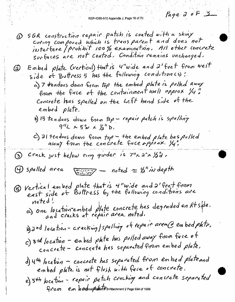
REP-1098-510 Appendix J, Page 16 of 70
Cuve,,n,7 cor ,,4.ii kIdh is J ,vl-,r'5 Oa ,t"en .. ,d Oe-s 9 -
;) Aj f,,,,ofe s 1911 tqh-e-t "C- veluf,& , '•e,,i/,
c,..,, 5 , ',,f not Co•I#•?,cw cC,,.Jqt,' 7 ',un.nch",ryeJ,
~ Ee~h. m o/-th Cve4ze4 fic'I 0Ag LI"vVý- 0 and ;2'peeV.f vS±
(v -nle Diff. e ss h•,.., .h-e- (ýIo wl 7" C v n 0 f~l 4s
' 4. c/+ ' - "'/I~io~/
c) t o Ae-'Y - dpwe oi -i, M to+-e f4 /eJ /ale A 001k-cl,4'0
•M6e pd lae.
b) Vi3te~n ioa Jlow ý40ý tojo - elr9 4-?1 4 /0-ia& V,?1//i
C~) ~I C ,zioi Jot1 v x-o~ 5 'ýO X-1? ebil k as7 'J
SCrltc~k JVI- btiow) ru-i 2 jjJ~ qi'c-eP 71ya
59 see//ed avl~eaVpA Je
~ V-~A,~~I ~e- -e Ita-eJ ~ 4h~kal q w~.d-e a., -Q1?fdoir~~-ir- 6j1? A--he- Eýolbw,42 LO,1d, lo4-, av,-e-
o)'One rie- hOa{ oa~d& e~t LJ~C(k~ d44cil
C)3do alo -ýe
(iie ote hs,-iIca )/~~ 4 'e..v
COVICI'tQ oviip#' h'? ea dQOsen~Joa
14 4ýh /0C', C Ot 01,Co.tte Aag S 'ýep CL {V'Oz 1eIýo/
,em-nd plott'e-i nof II4ýA to 1P Qprte.p of CO,7cv -eie
0T al pgfh,/1 CI~AY(-A4/ a-vid Con c(1? Ph seoatne/?al
*.to Mi erA Jo e-ca#04il3Attuachment 2 Page 934 of 1008
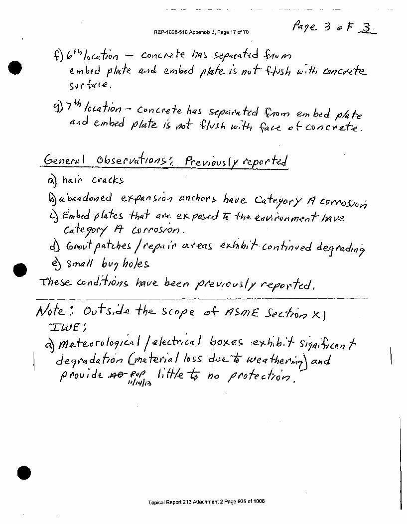
REP-. 098-510 Appendix J, Page 17 of 70 3_3uv
-emb Led p/Jth aodJ e&4ed ,oleek is noAf ý-Jvs/I to 7~ al4~4? cve p
" , rla(( (,.e -
'7' h. / 10C4IC0 - CviO ji_ a Sveav1t AeJ V1or7 e_,, be i4 l
a•in e -i'4l ser lprl i& T.: {/,Lb ti., >z C ,.7f"C'' -e
Ck2) ha.t' Cvek
d.a•ido• ~~'r~o. 1 anc .hti.C+eoy/U-M eiym'OS-J 4Ife 1Je+ Aje4Momeibve
COta~esor /9' e~ 60r' £YlýS -A'4e
Thes-~e C-04J1 6,7&; ivive b-eern ý0'.'vovsly r've&~e
tnoJf e- ~ vcyo r4 o9/) /o~o 5IY C
c(Mg ,Zieod5?C' .-Ielrc-~ we 6c) e rA0Uje4 _ 40-; pvie+ep I h& ff- toi e e c ~
"IL-1,1.41a
Topical Report 213 Attachment 2 Page 935 of 1008

PCISIo N SURVEILLANCE
REP-1 098-510 Appendix J, Page 18 of 70
CONCRETE EXTERIORDATA SHEET SQ 8.4
09/03/13Page 1 of 1Revision 0
VISUAL EXAMINATION - GENERAL VISUAL EXAMINATION
Project TMI Ut.Mv Surveillance #4 40TH Year 2013Inspection Area: e- 6 J~ ~fra- Ie -T ~ (t~'•EquipmentUsed . -e C ,4) c -.
Concrete Surface ConditionContainment Surface (Findings and Description) .. ..
be- ^t J~ej q 'ev v"- tor, e- "S•
Jac,0vA -1' 1ed#2j-7Ml
44PIA e.V 00I1j r--ortF' Cnt71ý
"~~~ ~ ........r' fo,,4,.. ... .i . ..
LI .... .............. ... . ..................... .... ......................... ........... ..
(Use as many sketch sheets (page 2) as needed to report any Recordable Indication (RI) or Information Only.(0) findings for the purpose of documentation and orientation.)
Recordable indications to be Examined For (PSC Procedure 8.4)Leaching or Chemical Attack Deterioration of any Concrete Coating (if applicable)Abrasion or Erosion Degradation Tendon Grease on Exposed Concrete SurfacesPopouts and Voids Corrosion on Grease Cans, Bearing Plates or AnchorageCracks *Excessive Corrosion on Exposed Embedded Metal SurfacesScaling *Detached Embedments or Loose BoltingSpalls *I ndication of Degradation Due to VibrationCorrosion Staining on the Concrete Surface (* The owner/agent must be notified ror these noted conditions.)Exposed Reinforcing SteelSurface Patches or RepairsComments and Disposition by Responsible Engineer '.Acceptable L[UnacceptableComments:
Inspector & Level: Date:Responsible Engineer. Date:ANII: Date: W65.. .' ,.,,
20 SQ 8.4.TMI.13 ISI
0Topical Report 213 Attachment 2 Page 936 of 1008

P PeCISION 0SURVEICLLA CE
REP-1i098-510 Appendix J, Page 19 of 70CONCRETE EXTERIOR
DATA SHEET SQ 8.409/03/13
Page 1 of IRevision 0
B
VISUAL EXAMINATION - GENERAL VISUAL EXAMINATION
Project TMI L4,ih -, Surveillance # 40TH Year 2013Inspection Area: C$rn ai • m.e-1 bo ,,.EqulpmentUsed FpS*_a., S0 A ' " ,CI -./, &lo ... J, k, A
Concrete Surface ConditionContainment Surface (Findings and Description) N , R.1
&bk 4 de% clZ6ý.,1 F-1 AfLiG~t -t! .~~I4 o c/W1? I4e4cz*v Codpei r-& tiIAJJ7 MV )6g CI, IC- ag".&--L4 .. s , o e _. .. _
LL
iv'on ~ a~e~ tVfg~L
(Use as many sketch sheets (page 2) as needed to report any Recordable Indication (RI) or Information Only(10) findings for the purpose of documentation and orlentation.)
Recordable Indications to be Examined For (PSC Procedure 8.4)Leaching or Chemical Attack Deterioration ofany Concrete Coating (if applicable)Abrasion or Erosion Degradation Tendon Grease on Exposed Concrete SurfhcesPopouts and Voids Corrosion on Grease Cans, Bearing Plates or AnchorageCracks *Excessive Corrosion on Exposed Embedded Metal SurfacesScaling *Detached Embedments or Loose BoltingSpalls kIndication or Degradation Due to VibrationCorrosion Staining on the Concrete Surface (* The owner/agent must be notified ror these noted €ondit ons.)Exposed Reinforcing SteelSurface Patches or RepairsComments and Disposition by Responsible Enginker .Acceptable MUnacceptableComments:
Inspector & Level: I .... ..- 1.. Date: - 1 I• f/"Responsible Enginee. Date:ANII: Date:
20 80 8.4,TM1.13 ISI
Topical Report 213 Attachment 2 Page 937 of 1008

PeCISIo N SURVEILLANCE
REP-1098-510 Appendix.J, Page 20 of 70 DATA SHEET 8Q 8.409/03/13
Page 1 of I|Revision 0
VISUAL EXAMINATION - GENERAL VISUAL EXAMINATION
Project TMI J__ Surveillance# 40TH Year 2013Inspection Area: -2J_/P- s'il-eEquipment Used bi'oedlar5j 'fest c0,' 5/" $i -a/c-Op
Concrete Surface ConditionContainment Surface (Finding! and Description)
• .•i, t,. .~ - 1 -..- -19,.ae.,,
ATh00 l Igna to eSePe /V R - .ft
S"Oa Is O
0(Use as many sketch sheets (page 2) as needed to report any Recordable Indication (RI) or Information Only
- (0) &ndinfs or the urpose o documentation and orientation.)Recordable Indications to be Examined For (PSC Procedure 8.4)
Leaching or Chemical Attack Deterioration of any Concrete Coating (if applicable)Abrasion or Erosion Degradation Tendon Grease on Exposed Concrete SurfacesPopouts and Voids Corrosion on Grease Cans, Bearing Plates or AnchorageCracks *Excessive Corrosion on Exposed Embedded Metal SurfacesScaling "Detached Embedments or Loose BoltingSpalls *Indication of Degradation Due to VibrationCorrosi n Staining on the Concrete Surface (* The owner/agent must be notified for these noted conditions.)Exposel Reinforcing SteelSurface atches or RepairsCommehts and Disposition by Responsible Engineer . ,[Acceptabie InUnacceptableComments:
Inspector & Level: z c Date:Responsible Engineer: Date:ANIh: .,Date: .
20 S6 8.4.TMI13 IS)
Topical Report 213 Attachment 2 Page 938 of 1008

PRECISION SURVEIULANCE
REP-1 098-510 Appendix J, Page 21 of 70
10- .INCRETE EXTERIOR IDATA SHEET SQ 8.4 I
09/10/1-3
Revlsion 0
p~iIoF~
VISUAL EXAMINATION - GENERAL VISUAL EXAMINATION
Project TMI Surveillance # 40TH Year 2013 ,Inspection Area: 17i it L1," C; ~ ei7'a. I'8. 355, 353sr%EquipmentUsed -"lI•h -. i5 k•d h .,=
a..i /,~u/4's, T-eSfr,h4,nvs SAI, Q~flJ'O.6Concrete Surface Condition
Containment Surface (Findings and Description) [0 RI
. ..o ' .e.c . .a
i-
(Use as many sketch sheets (page 2) as needed to report any Recordable Indication (RI) or Information Only(10) findings for the purpose of documentation and orientation.)
Recordable Indications to be Examined For (PSC Procedure 8.4)Leaching or Chemical Attack Deterioration of any Concrete Coating (if applicable)Abrasion or Erosion Degradation Tendon Grease on Exposed Concrete SurfacesPopouts and Voids Corrosion on Grease Cans, Bearing Plates or AnchorageCracks *Excessive Corrosion on Exposed Embedded Metal SurfacesScaling *Detached Embedments or Loose BoltingSpalls *Indication of Degradation Due to VibrationCorrosion Staining on the Concrete Surfhce ("The owner/agent must be notified for these noted coaditions.)Exposed Reinforc ing SteelSurfhce Patches Ol Rep!irs .Comments and Di~position by Responsible Engineer .Acceptable E]UnacceptableComments:
Inspector & Level: Lt z Date: ItIua•I/.'JResponsible Engineer: " ./4 , " Date: .4 1 !ýLANII: Date-
20 SQ 8,4.TM1.13 ISI
Topical Report 213 Attachment 2 Page 939 of 1008

REP-1 098-510 Appendix J, Page 22 of 70 • -o
pTh q-In.ri,,ef/Io'4Oa +S) Vc71•,e.' - o j,-o r'c' POe 4-
on + e aIo y, iv•? I .. a.e?/ -... w. -k s ,;-ed
,h-e d. o ov, e y a,,
Al'bte* -T l
ob-s-(etw ae-e
,%O k4
/ISaJrtc4( & 716-h Can oýIo'>- no/eJ/
d /X "
.....' E/I a]/. =.........................
c/~v'k)"~ rk:aV%$
-/Fr•' e l4HI,-,o: - boor Y r-,/a&
)Porof~s/ kLhO/e5r 6nii:>or)j6 4a64,.,do ..et Ct or7L--fre.--eA,a,,.I/o4 4vlbO"..
Topical Report 213 Attachment 2 Page 940 of 1008
0
k

REP-
,) W q// .r7
C), Mloo," j• ol+-
-1098-510 Appendix J, Page 23 of .70
C),Oo ir .X o L
4.... 3' ." - 9
,4) epoz,/ -oe , '. Y',,,', ?,•/ , /e4,t, J I,/dei_ 9' i"
i- i E/c.v/o; .- cdroojo, uo
6~ V-/bl/0' / /ie4(~>~Ioo~d e-4~ m f4e~ - ý 1Io/
vei o4a1-,o ieJ ~ ),i 1 q'-,v~c e.47Cho/e
v'e k1 4ov •,• , Ia,.J t •, c) 3•
"- joe , 0,, 10,-.4ýs A40o
Topical Report 213 Attachment 2 Page 941 of 1008

REP- 098-510 Appendix J, Page 24 of 70
q - -:f~e
E"3 ' -Ek"d',r/- p ro e ,,4 #, e, ,s,MVlwov, fýy'ouS v-i bvyhol/es.C
CI)0, IJf4e s& 5 4e n on s-A1eFo eCO Y1qý +~, ki -e e, UW11f.
vo hoy? T) v /ý isess "' /
3 D.kI-v '/ e "Q0&.0%) minoe buy. hoA,.
hat'r II'V,4P , ,,Q ý
E1c),I 0enB ~
CI
9)
m,,,Qo," •,: h~o/e- c~v P~c~5
Tq o-p ica, epot 23 A me,.I•,014 6v,? oles aod- po;(,q74..
Topical Report 213 Attachment 2 Page 942 of 1008
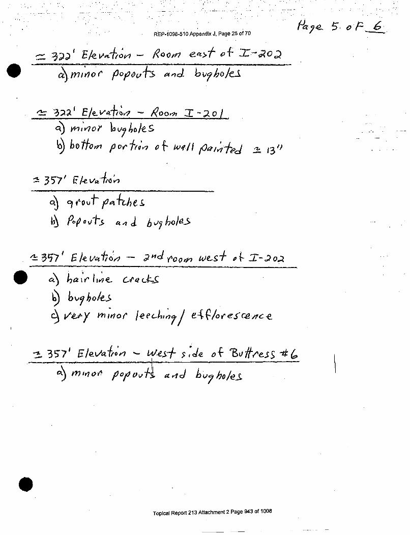
RýEP-i 098-510 APpendix J, Page 25 of 70
.' .. E/e v.--,,4i4 'o
3; bka~O oi~yho/e.S'
q) YP7 I' 1V7 po0IIk ?{ bI/ V7ai 4~ 2I3
C~) 9 4 ffpa 4+cbe i
~ '..
. . . . . . ..5.
c~ e~mk-~hri Ieeciia C/o re-scedce e
-i~3~ 5 /~I'r 7 et$ce { ~ -~
Topical Report 213 Attachment 2 Page 943 of 1008
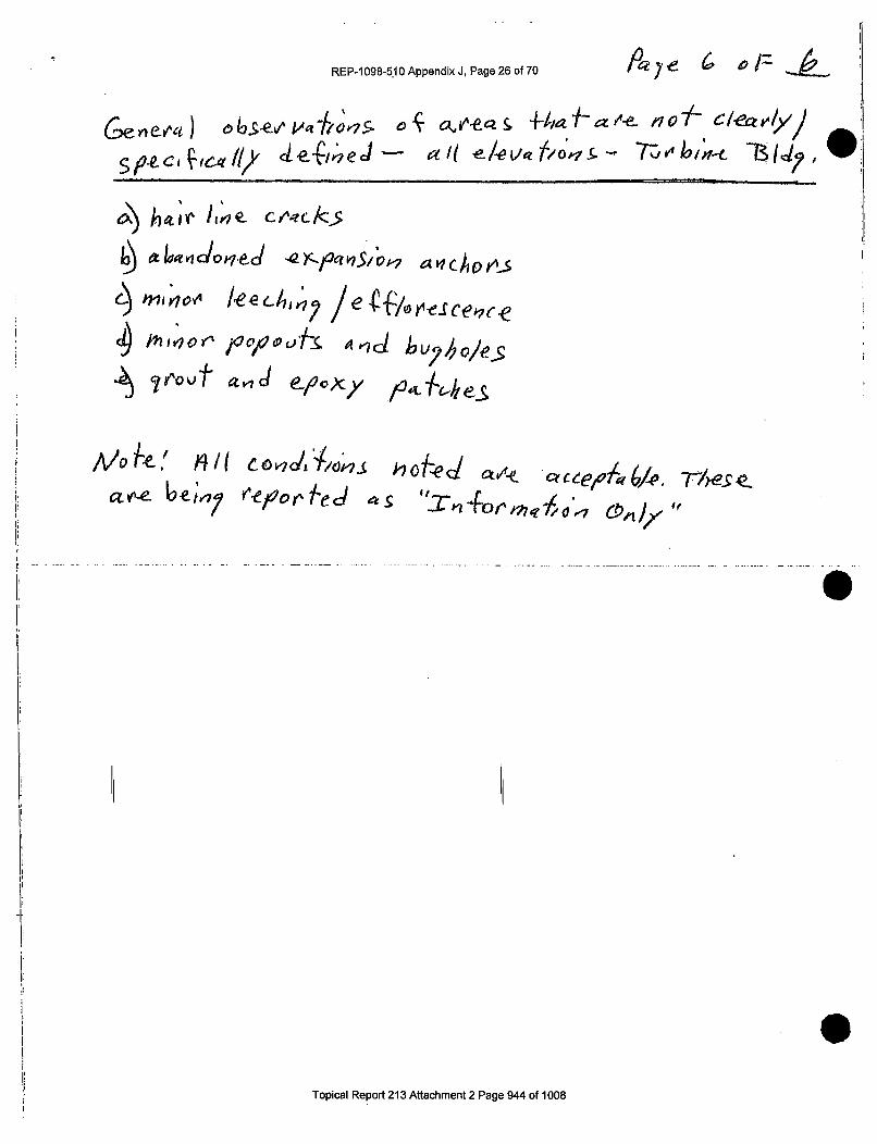
REP-1098-5.10Appendix J, Page 26 of 70 /026
h41"'Ck" 114e CVZZ/Z
Ai evezit obs-1 ezox
ap-eJ Uew rezorl'e 4
h..........k.
Topical Report 213 Attachment 2 Page 944 of 1008

PRECISiON SURVEILZC
REP-1098-510 Appendix J, Page 27 of 70
CONCRETE EXTERIORDATA SHEET SQ 8.4
09/03/13Page 1 of IRevision 0
I
VISUAL EXAMINATION - GENERAL VISUAL EXAMINATION
Project TMI Surveillance # 40TH Year 2013Inspection Area: 1en A5 l t//e i -3?aov' do '2Equipment Used -; / j, Cv' g
Concrete Surface ConditionContainment Surface (Findings and Descri tion •
_ o ,l. s Ar 0e 1 4' .." e, "-- 1.? a
> 0 04' .M -// 4?I V 0 / qle tPoiagj~ ~ *7-
• • e., ..A , -I r ., -,"-h , Y'/c + o"
kaea
y I:o• ..,, ..
(Use as many sketch sheets (page 2) as needed to report any Recordable Indication (RI) or Information Only(IO) findings for the purpose of documentation and orientation.)
Recordable Indications to be Examined For (PSC Procedure 8.4)Leaching or Chemical Attack Deterioration of any Concrete Coating(I f applicable)Abrasion or Erosion Degradation Tendon Grease on Exposed Concrete SurfacesPopouts and Voids Corrosion on Grease Cans, Bearing Plates or AnchorageCracks *Excessive Corrosion on Exposed Embedded Metal SurfacesScaling *Detached Embedments or Loose BoltingSpalls *Indication of Degradation Due to VibrationCorrosion Staining on the Concrete Surfhce (* The owner/agent must be notlred for these noted conditions.)Exposed Reinforcing qteelSurface Patches or Re, irs ..Comments and Disposhion by Responsible Engineer .Acceptable [31UnacceptabteComments:
Inspector & Level: L eove/ 7Z Date. :Responsible Engineer: Date: I AANH: Date:
20 SQ 8.4.TMI.13 181
Topical Report 213 Attachment 2 Page 945 of 1008

9191014 SURVE!"LLNCE
REP-1 098-510 Appendix J, Page 28 of 70
PF --- /
CONCRETE EXTERIORDATA SHEET SQ 8.4
09/03113Page 1 of 1Revision 0
, ii.
VISUAL EXAMINATION - GENERAL VISUAL EXAMINATION
Project T"MI Surveillance # 40TH Year 2013Inspection Area: Q~f 9It4 rfh -,- wi 13,- V,Equipment Used -
o Concrete Surface Condition
Containment Surface (Finding and Descrition)
c . -. ... ... .. .. ..
,, ,I....e4 ,ov, ..e.., ' •. --e. •#••,m .'• ,• tbs'--I~,ýLi 4144 i04, eA CK . 0 t,. -. y Xe -I~ ,0 o --, "¢ o e: • a C¢ ) s
S& D-6-
-. 1
4 , .• ..- ,e i t /- , . . . .% -
a 5
(Use as many sketch sheets (page 2) as needed to report any Recordable Indication (RI) or Information Only(10) findings for the purpose of documentation and orientation.)
Recordable Indications to be Examined For (PSC Procedure 8.4)Leaching or Chemical Attack Deterioration of any Concrete Coating (if applicable)Abrasion or Erosion Degradation Tendon Grease on Exposed Concrete SurfacesPopouts and Voids Corrosion 0n Grease Cans, Bearing Plates or AnchorageCracks *Excessive Corrosion on Exposed Embedded Metal SurfacesScaling *Detached Embedments or Loose BoltingSpalls *Indication of Degradation Due to VibrationCorrosion Staining on the Concrete Surface (* The owner/agent must be notified for these noted conditions.)Exposed Reinforcing SteelSurface Patches or RepairsComments and Disposition by Responsible Engineer RIAcceptable -]UnacceptableComments:
Inspector & Level: Date: ///50./,3Responsible Engineer** Date:ANII: Date:
20 SQ 8.4.TMI,13 151
STopical Report 213 Attachment 2 Page 946 of 1008

REPo.09-i o0 AppendiX J, page 29 of 70 3 -3 o5 /1
* D ' T - ? V~oi.,,k a .,e .HR b-"?l 4y C-evi+
eei~ -- ~eiO~.rhelt £1li9~i1
0 e- t7T , -e -7 w es
hair 350'04,1>d
J"3V ° •1 o&d ,. .o
340
Imp
& Topi/alepor/e2134ttchmnt
Pag
a 4, d o i o d i1o to ,~ g h s b o I /v A *-hled , r e-5f
an d7,,-0 0rtPJA~ kle-s'ý1 eq•i'Olu-~eCZ8/ ~ 3,Y~a x ~" -appeatte t7 A-- ai-m
Tap~ca l eo~ 2 Alahet 3ae97a 008

REP71098-51OAppendxJ, Page 30 of 70 -3 -oIV19- ,q- 335".- o/lc :
C) 1jiOe- I, k.pofi A 67' l zu... 270O+W0-# wht' 0i'
(w.e.). 1eecA7•,rI7_ lrv k-bc tial,, T/-1 odjerhe,/,• crack/ -be.
Iee h,, * / e / orre cevae- iiofe .
I IPta~o" &ie.c, on., tvq' H a,,?d•,• •t,•,",t'G I ra,.,ae c
(et, "i II -6 Iai•,/)
ci) H'Le,,o•,e•' LU-.,•t. , .,,,s•/..dod /a ,,,
tvzezl~% no fed
!I ) ate "4vvc L'.~f~ y/
cý (4et1 16,) yq, , 0i 10ne As-7'-S4 ~C~1 Veel Yh~?Ole /-
Topical Report 213 Attachment 2 Page 948 of 1008

* * EP-I 098-510 Appendix J, Page 31 of 70 10 .9
co CotJ&io'n ulD+-e-jCd 6) v,1r~ess
vev /, m w vr'1~c b le 5~
0 0C1 -e jC4P-s andwell
Ce ~ ~ ~ a 0-)5/xAe_;
./000,4414u
t eec4In ) vcv' ~'t;'4 Ae ld /ye,.
* aI) 6£~opqlci
On ioo l- (pre k i_ dke~~;ce. ~~
repo.,K+~eJ anvd jnol 4oq44en-f- Ch1 ~pýe~ i~ 1-4v- cc 1 4(.9rr
Topical Report 213 Attachment 2 Page 949 of 1008

REP-1098-510 Appendix J, Page 32of 70
PRECISO URELANCS
CONCRETE EXTERIORDATA SHEET SQ 8.4
09103113Page 1 of IRevision 0
VISUAL EXAMINATION - GENERAL VISUAL EXAMINATION
Project ifL 41;t"z - Surveillance # 40TH Year '2013Inspection Area.' _itjait ý df- of tlyteC *3 - 'z,05 elev tlJvY,( 3-1J!9Equipment Used "T A' .[-OAp
Concrete Surface ConditionContainment Surface (Findings and Descrip tion)ý I 10 'i
. o1 0 , 1l I g-e~ 9 L , •,f,1A.• '4,,
S•ms I.-- *
- - :o i I IsI .
(Use as many sketch sheets (page 2) as needed to report any Recordable Indication (RI) or Information Only) findings for the purpose fdocumentation and orientation.)Recordable Indications to be Examined For (PSC Procedure 8.4)
Leaching or Chemical Attack Deterioration ofany Concrete Coating (if applicable)Abrasion or Erosion Degradation Tendon Grease on Exposed Concrete SurfacesPopouts ýnd Voids Corrosion on Grease qans, Bearing Plates or AnchorageCracks *Excessive Corrosion on Exposed Embedded Metal SurfacesScaling ,Detached Embedme its or Loose BoltingSpalls *Indication of Degradation Due to VibrationCorrosion Staining on the Concrete Surface (i The owner/agent must be notified for these noted conditions.)Exposed Reinforcing SteelSurface Patches or RepairsComments and Disposition by Responsible Engineer .Acceptable -UnacceptableComments:
Y,-1 / ..... .. •_Inspector & Level:Responsible Engineeer:ANiI:
Date:Date:Date:
2~LILL~
iYL~d~i
20OSQ 8.4TMI1 iIS]
Topical Report 213 Attachment 2 Page 950 of 1008

REP-1098-510 Appendix J, Page.33 of 70
PRECISION SURVEI
CONCRETE EXTERIOR IDATA SHEET SQ 8.4
09103I1 3Page 1 of IRevision 0
VISUAL EXAMINATION - GENERAL VISUAL EXAMINATION
Project TMI /7Au; f I-Surveillance# 40TH Year 2013Inspection Area: ua Vt fs q e_ ge. Ay6 2 ZeeEquipmentUsed FI, chI• 1":E 4ad 7i rg" !/ a(2_
Concrete Surface ConditionContainment Surface (Findings and Desc ition
"twi- r -1
.. . .2 ae-indig ef ito
I~ ~~~~~ L .. .• _J.....
(Use as many sketch sheels (page 2) as needed to report any Recordable Indication (RI) or Information Only(0)J fining for the purpose ofdocumentation and orientation.2
Recordable Indications to be Examined For (PSC Procedure 8.4)Leaching or Chemical Attack Deterioration of any Concrete Coating (if applicable)Abrasion or Erosion Degradation Tendon Grease on Exposed Concrete S rftcesPopouts and Voids Corrosion on Grease Cans, Bearing Plats or AnchorageCracks *Excessive Corrosion on Exposed Em edded Metal SurtfcesScaling *Detached Embedments or Loose Bolting'Spalls *Indication of Degradation Due to VibrationCorrosion Staining on the Concrete Sprface (* The owner/agent must be notified for these noted conditions.)Exposed Reinforcing SteelSurface Patches or RepairsComments and Disposition by Responsible Engineer ,IAcceptable [JUnacceptableComments:
Inspector & Level: 60 7 Date; I.X / V -Responsible Enginee.P r Date: 'ANIh: Date:
20 SO 8.4.TMI.13 ISI
Topical Report 213 Attachment 2 Page 951 of 1008

REP-1 098-510 Appendix J, Page 34 of 70
PREC1S810 RVILAC
CONCRETE EXTERIORDATA SHEET SQ 8.4 I
09/03/13Page I of iRevision 0
VISUAL EXAMINATION - GENERAL VISUAL EXAMINATION
Project TMI Ak. "i Surveillance # 40TH Year 2013FIn~s~pection Area: _B wtv'e S '4 OL 81 e I 'eli V7 M. s /,Yes e.cxEquipment Used glad"r ,S". 0C/-" Yl
Concrete Surface ConditionContainment Surface (Findings and Description).. N. _' 0 RI
C fo t 5k10-f,ro W? S e '•e,,•an-
y-/ Vadl'ý a lrh Vol-•VO Fe f --Q e
wll0s1 Cw .. 0•;,,,zfe•" -k•a,,,, j ,a, ... /,tYed--- =
. .. ... rb - '- " ,_=-- I
...... I a se s e e
(Use as many sketch sheets (page 2) as needed to report any Recordable Indicatlon (RI) or Information Only(107) findln~s for the nurnos~e of doicumantation and orientation.)
Recordable Indications to be Examined For (PSC Procedure 8.4)Leaching or Chemical Attack Deterioration of any Concrete Coating (if applicable)Abrasion or Erosion Degradation Tendon Grease on Exposed Concrete SurfacesPopouts and Voids Corrosion on Grease Cans, Bearing Plates or AnchorageCracks *Excessive Corrosion on Exposed Embedded Metal SurfacesScaling *Detached Embedments or Loose BoltingSpalls *Indication of Degradation Due to VibrationCorrosion Staining on the Concrete Surface (* The owner/agent must be notified ror these noted conditions.)Exposed Reinfbrcing SteelSurface Patches or RepairsComments and Disposition by Responsible Engineer RAcceptable []UnacceptableComments:
Inspector & Level: N -4 1Date: la j 3.Responsible Engineer: Date:ANII: -- Date: --c -"
20-ýQTAJM`113-3-181
Topical Report 213 Attachment 2 Page 952 of 1008

REP-1 098-510 AppendIx J, Page 35 of 70
ER-AA-335418Revislon 0
Page 17 of 17
i,
ATTACHMdENT 4ASWIE IWL (Class CC) con~t~Ainent Concrete Detailed or Geua Visual Examinafat~n
NOE Report Re apacle 6V D-/1
Staion -/l nt I Date:_ /4 ?31 Repait No:ISytern: " c omet~ ~<LW~4Localton: aul1din:- 16 d. W/-?~ 4Cd.: V/A- Row. It//fAzuRaiEnum Type: a Datailed VisuW ' Type of Exam: Uoluct 1W] _Azmt1ek
-22991 4e Genera~la Visue1 7 A
sDfealnrwt OD 0mZo 10 VtuamI Coponnt T~aed [LM _M' 9)10
liu naio uw 7a y e.IvE x paao h roaet__ __ __ __ __ R1 d E
2mscing Or Eh Afand -8P Co __ __ _ __ _ __ _ __ _ __ _ __ __2_
______ ______ ______ ____
Emm~a Lewenob a
OwExuiadnI em/aResult O Ltgalgd1R &atodbsfatau R eRcudIl n~aoa1-ljonie nSuppleiu enttenomr~q ~sU~USec pooO~o0OhriecIu
W1 C O e
Exwminer k: -, a. P'-41 Levet Oak&: %___Furter Evaluaton Requinsd- J1 esE NoAddfflonal Acttons: RC--Mgi i0C !.0 CWMe-A dA-bV1 bd$7A/& A7- dZrg &1i (RZ
(Acft Raeumd, ikudarmp Rf@(O.W m~r tva* A ~opumd~ms d W) c~mtt~ed~p nye RsvpablatWm
Review . A/A4{ Ot
ANII:F 'J ~M-
,.x- x. Jfq IkV jo--o omed re nell &J4A 44-e- a'J of6lo-44
iLo Cof? (IS 40 jpal 901 I&~Attachm~oWq 91xý

REP-1098-5l0Appendix J, Page 36 of 70
rOIIO CUVrILLANCE
CONCRETE EXTERIORSKETCH SHEET 8.4
09103/13Pagexof.,tRevision 0 1
Project: TMI 2013 40T" YEAR TENDON SURVEILLANCE
Inspection Area:- uire-s$ :
1. Sketch or attach photographs to provide documentation or additional details as necessary.
.11 -o
""5 3
Lii H 3- 05
Comments:. ~C yc#o- e-~
QC Inspector: Level: 2 Date: 1.713h3
20 SQ 8.4.TM1.13 ISI
Topical Report 213 Attachment 2 Page 954 of 1008

REP-1 098-510 Appendix J, Page 37 of 70
ER-AA-335-019Revision 0
Page 17 of W7
I.
ATTACHMENT 4ASME IWL (Class CC) Containment Conremte Detailed or General Visual Examination
NDE ReportPase Iot - ..
St-auo-n:' -rm. r Wrt: I Date: 1111,51 1 Reeart NO.system: K"Ir; cor I nn -Omp Bvfi~e 1. We) WO Nos-.: 1 7/ 1/3 6,0
Locafflon: I 6unidI: lconf1 EtP/4: /2Jt o.-R-Of I AzImuthIPscJUsaz~-/-fExam Type:. (3 Deailed Visual Type Of Exam: Qr3MectMd ye 0
J~l~qwqWWUd IserrideDesig nDmrigln 1, 7'lh Z - 0/9' // Vsal Aids: -1 Bv~esurface:, OD 0ID ISurftce ICome erlCoated: YES NOIgurifnauon Used \h1I, __l1ý -/ 11 yle
A~rbi RU tRI tO ExpaafortiCammnrnrtsCggZ(ChaiMcte~zantd Sip) __ " 4. /4. d0cefe
tagaMMt Or gMhW~Ia Atla - -
Sewamefab rD~cin
P o-Uts yaStS. L.sbaeIl 0'l IviO' ov W -
Abravign. Cavftaoon. Wear__ _ _ _ _ _ _ _ _ _ _ _ _ _ _ _ _ _
off~t fa(Erlan) :w 4bo.C~ eT 4-4401 al'Ofl iiResufts Legent* RI - Reawodal Madoanio NRI . No Recordebte 11"ndhcos 110 - Ifftmteatto OnlSupplemental In"ertIo: Eyes &~No 0 S13swch~ Ohoto Q3VIdeao QOther(Dwacibe)-
lJ • ~. -,
Exwrarie ¼.. (~~~I:~~ Leve -L- Wae: !q/513
Further Evatudatn Requhed: EL yes .tAdditonl Actins:
(Adk~elAy~O Mdkc Cmcf Acftae) Supade kmge adM be d ftiW~rkw by a Re~paftkIaan&t¶
ANII: OaE- -I - -
Page Of o1
Topical Report 213 Attachment 2 Page 955 of 1008

REP-1098-510 Appendix J, Page 38 of 70
ER-A-~35r-olsRev~slon 0
Page17 of 17
ATTACHMENT 4AStE PWL (Class CC)-Contatnment Concrete Walled or General Vlsual 5•Ixm Uaton
NDE Reportpane I • f .I....
Station: rn r Da~twe~ M-6 Resod Kozz
Exam Type:Q3Deta~ledVleuef TtyeOf~xam: Dkrec Mau.Type:Cnre~Deal~ era nDwn 'lau-l EftVisua I b~ C c
§acachNl 01 0r Clec ID Atic ______________coted:_Q______________
Po~~- yu Sod. is- j a
Co0 Eamnt gr &WsCa U OhNa SsnnkigZoT- zi~o
softke I OusuingCamIn Daweiorulkm
lV" I Bug HoleE~fm
ew (MVI-I,Resv9Las fsgr* IPRIRwwsd"SnbleldoWir R K so=beI~af b O-(~ruta s
Isuppiementoo tntb-m,~m~: Olyes WIBM 0 SklohOhoto Q3vtdoo 13 Other Oesctbe
0
Examiner 1CL- Level: {%W.te ".4 ;'5Further Evaluadon Requked: 0J Yes No '/~'io y I-d,4(Acdfttanal Acftiow r*na g,, -ihe same
ANI I:
i1/
Page ..LoLL
Topical Report 213 Attachment 2 Page 956 of 1008

REP-1098-510 Appendix J, Page 39 of 70 Revision 0Page W7 of 17
ATTACHMENT 4ASME IWL (Class CC) ContaInment Concrete Detailed or General Visual Examination
NOE Report• I of I
AStlln dI IUft.IItaeS11 //m3~o 1 CamwtodNOSysem .$ C oze o 10 .eS5 ( IWO 4e.oN d 15 i~oL
Locatosdlai flo COL: IOIQ tlk-- Azmlioi AOExamTye:o [3 Detiled Veisual TV"__OfExam:__________Type:_0_4_Cede-
.2290 a4~ -0n
LsU~raoifIn Use Ihmla A&I-Viko- - -U i'b.efmei OrbU FDeRItecliocwcmml
DoCmks (Chogaorke andKalTai G) "e. elk o 172 4,,9M2 B&Nou.a~s SW e I
___________ 0eft oL'q jay a i ý7, wT 7n
Coldsoc J tag n-"
Abwsfon, CMs&oc. Weer_____________________
ResufIs Legend: I-Rsea.kdw R t M KRaccrObintboIdoaffor' 10- (nfonuamowOnIrd
Set~~~entat, Inaon 3e No Sch ORGhOo O3VWdOC00 1er (eecube
ExmWirmr 0 6, Loge Dab /3: _FudhIer Evaluation Requked: [3 Yes NoAcdmoanal Action: 1
OmnReqmas, wor OtdawCRe. t OMCmitaa" MOO 4wAd ke adI be ce~bp.aR4PaaUby!a M
ANFI: Oat&ia
Page...Lot L
R.
! Topical Report 213 Attachment 2 Fage 957 of 1008

REP-1 098-510 Appendix J, Page 40 of 70
ER-AA.33"-19Revisioni 0
Page 17 of 17
ATTACHMENT 4ASME IWL (Class CC) Containment Concrts Detailed or General Visual Examinaian
NDE Reportpatio 1ofI
Steio-n. 7r- Date:J4i 1311 -Reortt Io
Exames MTalWo C3m Detailed RA YPO)xm;[
Menem nh~Of Mad. mY-Laad9ignOmwngs Chea T AX V N 1\al Aids.____________________
Col~d Joink (ui. _____________________
mgmVoig Or Bug HOM
2Momakn snf
Resufte Lsgart71rw RI cod"btAadkttoW NJ- K. of ute oalindinmdoes 90 -1 thwttoo OrSupplemental I f~iton: CV.. AOM [3&2ct OIPhoto Ofiea 03 Othe (Descnbs)
Extne A~-- 7 Level. : a Date:__
Further Svualulon Requed:, 13 yes ;W No/AddalonaAoffow:
(,ct It ~~w~Wo It OW W~eI Wi Camu~m AcIWaa Stqspd Alm*dtou Aapah b osibyub R9Ma nt gLap
ANII:If r .
Page J....ofj...
Topical Report 213 Attachment 2 Page 958 of 1008

REP-1 098-510 Appendix J, Page 41 of 70
ER-M4-3S-OiRevislon 0
Page 17 of 17
ATTACHMENT 4ASME IWL (Class CC) Coftatu•menst Concrete Detailed or General Visual E'xamlnaton
.DE Report J01410Pade IofAr 01 2/3/15
DeslnD~wF gaa Date:o 4A /ua?/13~ 11 R' KaI-'4
urSce:w OD El t Surcke/Caom wntr.Coated: YES NIHurdnatlon uwe 1'hwi 9 fm__ Sm, ,
AttrtbR1 NRI toI10mefCrack~s LCharacteitz and Siza
e~tasd Raftnrri~Ssa
jokdecM Or QW~a(Aftck _______________
Sowmenub Or~ 00asdioe029pde-dPam m- SorE &W-m 0. Lov ýfv or?
Spiaft 7a- aitgFk? Wf7r
Coplemd w Joi t mmyoes Oyes______E____________________________MU
fet
cowe4ft4C
Li ..- ' ,.~
Exen'ner Level1:L,-L- .J DOW.tB ,
Purter Evalusdon Required: A Yes 0 WoAddmrtanl Mom rie rK G M Cd~&4'~ D ~r/ ~v ~I
AM ;ii Oatiu19 /AN~~( - - -
ly-e,,, 6 o,,A e
2 A.11a f 19/9 0 Ve 4r I A/3/1 3ý41

' T .', t ' • ' ' ' ' '
; . . .. I ý . :
SRECISIO SU YEILLANCE
REP-1 098-510 AppendIx J, Page 42 of 70
GONCRETE EXTERIORSKETCH SHEET,8.4
09/03/13Page 1 of 1Revision 0
FProject; TMI 2013 40TH YEAR TENDON SURVEILLANCEIn sp ectio n A rea: , • • " r . • L
1. Sketch or attach photographs to provide documentation or additional details as necessary.
"• °'- L i • L__i
.•- -III I-
.. F, o-- 1 13
Comments:
®1 Conls#'e gj.i~r Se-~ Cm Q eo c -e d
~ii E~4,eI jro r V , 7 fý4O~in C
Inspector: (2,, Level: D ate: ,.Z./
20SQ 8.4.TM1.13 iS!
0!
0t
STopical Report 213 Attachment 2 Page 960 of 1008

REP-1 098-510 Appendix J, Page 43 of 70
ER-AA-335-019Revision 0
Page W7 of 17
ATTACHMENT 4ASME IWVL (Class CC) Containment Concrete Detailed or General Visual Examination
NOE ReportPa..e I of I
0
Station: uni r Date. 1013 0 FRe oot No.-
System: Comm t IS, ,tig., 1t 'BlfJs 6 £ *] Wo N s).: R,711 3bc06Location: BI BlR [Co t A' o:R¶ v4Azim ~sIt u !L
Exam Type: 0 Deta~led Visual Type Of Exam: 013IFUCt Ma.Tye CflGeneral Visual Tye:co cede
Surface: X D 0 1 Surface! Comrn rits Coated: C3YES MNO
il~unations -:qA I
cCmfCharcWaceand Sil g_ /1 4 La 01
_____ ____ gm A11t h07: !0 62j
Wt-0 or ORWeM
Paportse cftM mtou-ater sn1~e a ~i
Resuft Leant I~ RI... Racodam In Wton NRIU-& Rcrdbaleindictuons t0- Infamiattom O'*Supplemental Infargatact : l:Yes EMot 0 Sketch QPhoto t2Video 0 other (Desuebs):
ExeMlrter K- &~ ~~ ee Dafs:/0 "7/Further Evaluation RequWe: E3. Yes~ NoAddiftioa Act~ons:
(A9 an 3 s~*tk Wo4~. ~riAv Acvwaa W4ped Ann O bii) ucOSloM4f bye Respamft Enfumw
Reviewer44e~ wwva ýANII: Oi ..,44 aW W
Page...L of -I
Topical Report 213 Attachment 2 Page 961 of 1008

REP-1098-510 Appendix. J, Page 44 of 70
F.R-AA-236-018Revision 0
Page 17 of W7
ATTACHMENT 4ASWIE IWL (Class CC) Conitainment Concrete Detailed or General Visual Examination
NOE ReportPane 'I ofI..
-taw I ti nt ate: 110iis Rwo it~w.
Lacala: I00~cn-,Io EWIDt IM.I iAoWI Rnaow. f4AYEn~hF
maeonmmaUl Mau Type:
lgftariatam Coated, rE S!
Eow Of bi_ _ _ _ _ _ _ _ _ _ _ _
ISeOXMng Ofuict fa~
PAliu Vakb a I pj cxi
Supplements& rnro ailau- Elves lENo Ske(ch Ophqtc, [lVtdo [3 (tter (Deanbo
Exw~~Irtr __ _ _ _ __ _ _ _ __ _ _ _ Levet:_ _ _ ODteL I/I/ h P
Further Evatuailan Requind! 03 YeasqAddft~onal AM=fns
Reviewer 6Kmy
Pluge...ot I
Topical Report 213 Attachment 2 Page 962 of 1008

REP-1098-510 Appendix J, Page 45 of 70
I.
ER-A-33-019Revision 0
Page V7 of W7
ATTACHMENT 4ASME IWL (Class CC) Contatinment Concrete Detailed or Genral Visual Examlninan
NOE Report... ...... I of .I ... .Stalion: 7-n Date: 1///j h/3. Report No'
Location. BEupidin: Co tt Eew.: z Com UIP /1 -Row. I MmutiIVedum (
SMeME 422tna 1 O' Visual Aldo: I oC9,l 0 C
Surfaqw. PA O D~tau __,_Q._I_____________________C3_YESN
Lsffumrig 1r Ct1*s 4 AU '9 S .7J1"
,OaitMd Poiihe ftr Rirn joakae
S~ID~sRo
_
____
sewmwf Or~ CCL.ASuppwentezIntR=maU:Ie o5 E~ooOle ~hr1srb
Exw~ne CL -Further evaluatlan Requinid: [I Yes Na
LSAve ____Va:1f/2/-7--
Addftinal Aotion&ftft~~)SaetAxsil pe~he yee~anu
Reviw r lrcc~ m jDauqte9j~ANtI: caw
Page Iof 4aa ,LaT pThesea Report 213 A e eV1,f0 1008
W et~e 4~,0eTopical Report 213 Attachment 2 Page 963 of 1008

REP-I1098-510 Appendix J, Page 46 of 70
ER-AA-335-019Revision~ 0
Page 17 of 17
ATTACHMJENT 4ASME IWL (Class CC) Containmntsn Concrete Detailed -or Geneirall Visual Examination
NOE ReportPoe lOf I
Station;z ~TZunit q' Date: 1// 1~ 3 Retogg No,system: 1'ýjAg 4 4$1C=Pro~t: I J4,,idios~/e she// WO Nots).:ILocatiom: I SuildIflg- 1i4~ I Mau-~ I A'-d hot - - "/ -I 4 row 1 &6/0 IAlutielu
Exam TyrW, etie ir/kZ l Type9 Of Exam:~ jd 901eg
Cradls (Chaaeete and $tae
Erfacw O D [Iaa.eeg (D__ISurfaceI ____________________0_)as-____
Ey~lemc Of 2Mo Msbfr
R&M~n Of tshtoemo
-~n e~eor 01% [Loa
Air6 Vok 20a ~~___ ___ __ ___ __ GU !
ResubteLeger* RI U- Recoe~dabt edaIMOM NRIN-MoRecoidabte indc;affonm 0C- (ufomttee Onl'Supifewental Inlx lin -oyes Mw 20 sketch OPhoto Qvtiedlo 03 Other (esarbe)'
Exandner 6 Level: no___Dte:ýWF~urther Evaluatlon RequWd [3 yes AýAddltoard Actloiw:
(Adm eqn% bitCk a wd"W=Qa Aceft) Swa AmeousaIbp dlw0npo~n4byv Rwpamftb~iI&sw
e2 P. 4-*JI46 I•TJSg/A?6X
ANtII: gJ.-Data:
Page I oft._L
Topical Report 213 Attachment 2 Page 964 of 1008

REP-1 098-510 Appendix J, Page 47 of 70
ER-AA-336-019Revision 0
Page 17 of 17
ATTACHMENT 4ASME IWL (Class CC) Containment Concrete Detailed or General Visual Examination
NDE Report1ae of1
Statiort: W1r#LIntt L . I Date: 110.r R~rtaSystem: 1W1qIcomniotort Ir73i+wsee. 'Bvfi-/e-s 2 J ~cI I Wo No~s).: IR(RI9,3Location: Iuldn '2 EFw. C=t otc w. 4 AlUthIRSdk 4
ExmTyW. :3Detailed Visual Type Of Exam: ~rect mid. 7iw O/ C, r c -+e.- Bl~~Genral VisUal S 10 I
Surfacw: R D 0 D SurfaeeIComponytteCoated: QYg -_ tQ-
11~II mionut Used UADU i&I
Ci~cIC~h~cettzan~SlJet_
EW evwm Of Ntolabu_ _ _ __ _ _ _ __ _ _ _ __ _ _ _
LEut-ug Or~h~la MM** d __ Vy iro '
Ajr~.' V"I 4g.Hk
ResultsLegat* Ro11onlldfabsteiaon R eRoeatInctos10(numtmGuSUPPlenmental inroQT!on:- INeS E~o 2 SIAMt OfPhoto QIVdeo L3 Other (Duecba):
Examiner~ E== CUKL Lavat - Date: /S
Further Svaluabon Require: E3 yes No'Additinal ActPns
(ACSM Reqtanwaeotodr.t R )Sespad Aie ahzl bffdiaptilked by a RePapm5' rAW
Reviewe. gw -e6 W A Date:/
ANII: Data &25I
page J-of I
Topical Report 213 Attachment 2 Page 965 of 1008

REP-1098-510 Appendix J, Page 48 of 70
ER-AA-335419Revision 0
Page 17 of 17
ATTACHMENT 4ASME IWL (Class CC).Coqltanment Concrete Detailed or General Visual Examlnftln
NOE Report
Station: Tin Z- Taoe I/ I o.1
I System: ~ I Com~onent I f7a;~,. 7~#~','c ~ ~ ~-Ja I WO NetLql I'~ii~ 3~o~I ocation: I eo=)M 72"Ih.:p -I Cn~ - ---g-4 %Nfl- I'49 3*E 1, 1Row. 0%/I Mmuthmsadm VdExam Tywe: 0 Deta~led VIsal Troe of Exam: MDIMIc
NGeneralwisual MOOe
Suufkee: D fComameritsCoated: -5- No11u~mination Used r
Ci~d% (Charucteulz M9 M1ze
Exooed Kgft 10M Iwms KTFeq
WRSctin Or qwnlpal Attack
Seara ed et he or ReoeS!q
Papous voids, KswCAMb
Cold joint Lr_ _ __ _ _ __ _ _ _ __ _ _ __ _ _ _
Ccwafon Swa"n~ ___________________
ScafltIOutn
Abroston aft~r. WeerAir MI Bug ~
Supple~ MOP -nop~~o : Eles M 13 80ch Ofht,01 Q3Vtdo0Ote Oecba
E=Wn~rer (Lel:DOta- 1"3Further Evaluation Requiwed: [2 Yes Nof~~~4~1 e~RTC,Add~tonal Aftona;4e1a/ 4 ~Y
Reviewer~ 17.~ DOWLi hAANII; r L !~45-
r-
page I..-OfI
Topical Report 213 Attachment 2 Page 966 of 1008

REP-1 098-510 Appendix J, Page 49 of 70
ER-AA3-019Revision 0
Page V7 of 17
ATTACHM4ENT 4ASME IWL (Class CC) ConeaInment Concrete Detailed or General Visual Examination
NDE ReportPa feltofi.
Station.: ,nl - / "late: L/,,, h i Repot m. I1ytm 9'~Cmoei ~~Rh4.C~-" W~~~
Location: IBuildinI do, oI- EteV.: I COL.: I I' ROW. 1240 ANmuUiiWaIMu 1,
Exam~ ~ ~ ~ ~ ~ ~ ~~~~~eso TyeI3Dtie la yeOfEm:[0et mdTp t CommenCrc~(hMete*ot ~ u OInmot I Ie
iDoedg Drawingorstn 5sI / 0//Aiea,
M"rele Pahe Ir NA Iaamea
CotqLd Reotit ý WacilI ~~~ ~ F cooso Synic ______________________
Evalna 21 D OUada_ _ _ _ _ _ _ _ __ _ _ _ _ _ _ _ _ _
AbwctNf WtOr Ch W e&Iar _ _ _ _ __ _ _ _ _ __ _ _ _ _
Real"~d~If or Owdecr- I
OL =!M= - 1 -1r-ffiw~alarIAm nbov jkede~,lj /
j I Oki,4II
"A do-o4 A 4 o ariroAn (ah;.r-= lk==" A -Resub~ Leaesnd IRIff- Rmacdw"l - Ito fecau$&bts trwaidaont 10 Inkamulaw 0*Supplemental IntroRuit~o . clyes [C [:]Sketch O3ftoto 3V~deo 03 Other (Duaodb6)
.. . . I•IL I
// -. -~ IExardrner~ /S-. (d f-'.-C-7 La L4*- Daeb-
Further Evaluation Requift4: (3 Yes X NoAdditinal Aftion
(A~RwdWl kocCeinw* Adcua* SuadAwea * bedispofteu bye ReqniftMbown~a
ANJI:Of
paget..L of -L
& •,.,,-.•s ,•o•,-. 14 .-) ,,,.-icl/,' '// 7 .TopicalTopical "eeport13 At;ment• Page 9 of0a

REP-1098-510 Appendix J, Page 50 of 70
9E-R-AA-335019
Revision 0Page W7 of 47
ATTACHMENT 4ASWVIE IWL (Class CC) Containmuent Conmiles Detailed or General Visual ExalinlnatiOn
MDRE ReportPage ell.
Statn:, T lu.t•e Date: T,,,ii kw, Ivi: t a i, "Mn t rnw~ I' - A.Mt" A~ho f i- Osd. woNatm-.: Wi/936 I
Location, Building. C0.1t IEte 2a CCIL; ' Rw:#A~uhRdExam Type: 0 Dea~lesd Visual IType Of Exam: Qoirect Mau Type:
gGensmhl Visual IeracteDeaf n~awf a .'~o/ I Vlaual Alde:Cu .
Jsurfae:w OD QID. Su kicom nartats coated: QYLS, $ Noillumination~l PId4.t__ 'L
A~kltftuf RI NN t
qmcfte RaLwMi*L ga~g M 1, Cq
jggfta gEall ghwiam (0UL40 0 Greas tta_____________________
Ablfmdan. CtOm We~er IoI.
fttt eem P Rcol aidk.o NRI No i~rabt Idincartams to- (nf~matrloaQ*~Supptementat inrarmatqpq, Ova SNOe 0t [3OIt oto [QVifea[30Other(0esunb*
0
,., I
Further Smiattailn Required: (3 yes ) I' o /AcfdfttnstActinons
(A ~kaa R M* t"MAaIta) SQas~ect d4u~ b&,dl 1mpiUo bye ftpqbajigtZMf
~~ ~pe,9jxsjtge.~ CAWM
13
Page..L of.L
Topical Report 213 Attachment 2 Page 968 of 1008

I . .REP-1 098-510 Appendix J, Page 51 of 70
ER-AA-35-019Revskon 0
Page 17 of 17
ATTACHMENT 4ASME IWL (Class CC) Contatnent Concrete Detailed or General Vlsual Examinatlon
NOE Reportpase ofi1
(stalion: T/5n Unit: Date: IReamt No'System: d-'l,13 1 ~n ~ (s'%-OM- WO 1. 73.)9~6o
Location: I udIng~: 1 e, t -/v/4 I! Cot.:I,// Row N1'V AzkmuUhsRastu TA144Exam Type- 0 Detailed Visual Type Of Excam~ IDkfct
enemI~sua7emote
DesignwrtaTmVO~ VIsu Alids:- ICdfrA#; i ~'i ha
Afttrbuft RIl NRI 0 xtnattrnlCammeWt
Laachwn Or Chw~ ~*______________________2etEme DeletgWd
Camlanor S~nftg
Coaft~ Dsledoratkm I _ _ _ _ _ _ _ _ _ __ _ _ _ _ _ _ _ _
Abrulan. Caveflon. Wr
Supplemental InforVotto - Wes [2mo 01 Swech [OPhota OIVcldo [IOther (iesdbe)
Furter &vatuuon Requked: Yes [3 kAc ovff0&v./ nfuu A- 4 fAddftonal Actions: Z00 VVC~t4A!VA- I=fV/-JAe L7Gt3J AZ7 4a2 C :
(AaiknRa A. Ifua owCmd cf)S~dAn" &dsafnAb Rstpmft Eonnaw
ANI: atas~~
e•,t - 0.4
C, iS
Nge J- of -a
Topical Report 213 Attachment 2 Page 969 of 1008

REP-1098-510 AppendIx J, Page 52 of 70
C'-Aea'7 C'oi•o 4 J tu.,D h,' iS t• 5e" , -ui .,d-oes 40
(,,p ýj c, e- 5 av,.. -e-.n.v t -C o ÷ a--_ J"/ , a~ JJtj;
4~4o~n 4Ij b 40+ 4*ha Cý anrl ~~I ~d~X/
'S r- vn
a) 7I a'v Jowe., -c ,,-C) o V h•om t,( e,,,, & ,,g/ e, : a ,/k-
ý4om I,, ýe((,e J l/V - ,4,Copcal Report 23tcfl0
en~ 6-e"I.94r J~ p~ pkd'
b~) i' t 0oEfo- ý/4' o -P a,-,l rl c"id ie, / ~I~ I.y~ /C
Jv~ 213o Attahmen 2I1- Page 970Xo 10

* -. / , , 3 .
REP-I1098-510 Appendix J, Page 53 of 70
-fe v -e hq ( -ec .
Co,,C'e•.ce,. has &e•,,d,- I , -C,,, e, be J
G-e n erva1 Io LS e eVa{/Or75 Prvet'( vi soepo vcI
) hat" Cracks
hqve Cqorlp rl y 5/eolr J.phe A Se s/ A. " qfV- ,o ,,ose.
.rh&se. cjnd,4,o&,# • •. b-een ,K r p levlovsl/l er oy7ted,
MZIO E,€
/ o0,, . I,+/ - no ,co'e o e c~.r1"4E"
Topical Report 213 Attachment 2 Page 971 of 1008

REP-1 098-510 Appendix J, Page 54 of 70
ER-AA-336-019Revision 0
Page 17 of 17
ATTACHMENT 4ASWIE IWL (Class CC) Containment Concrete Detailed or General Visual Examinaton
NOSE ReportPage 1ofI
StationE 'T,r - Unit: ,ato: Reo.,t No:Svuter,: W+.,'.L, l comoone, I ew,,,., 3.,1-,i, i I'-A _WO#,: 1,1936606WWI=lon Ieulding Co.ell, CeI.: I ~ CO.; I VJYI Row. -1j5 ALmmuthlfadwu:d/9
CiWwW AChrds:t~ bn Size V' C -)L ,-
Sur~e: Me~~f OD~e 10 oatd, N
At~Iftea e Or resffn ________toI___ _______ ____I__ ______
OM Rentb ~
Exosed Joint Uuearm
Abrasion. 2giite±o.Wa
Mgd~kn ,da'lez aiah24
Rnub Laerak II InroReamtjgtdan: NN Recovdahte indioallari co-O-Eon4=a0*Supperin Re blfwI:IS 101. ~irI &E pht vie oteoncie
0
Further Evalud~on Requkad 0l Yes XNo '&(&~O4 e'A~dd~ana( Aokionw.
Review er: okOjIoe a*I da ~dAe* tw c(9g..ne byr 2 a Rwofts Om
ANP: - _ aitaYLZL
Page -L ofI
Topical Report 213 Attachment 2 Page 972 of 1008

REP-1098-510 Appendix J, Page 55 of 70
ER-AA-335-01Revision~ 0
Page V7 of 17
ATTACHMENT 4ASME IVL (Class CC) Containment Concrete Detailed or General Visual Examination
NOE Report Rf 11r 3pare 1 4 17... .Station: Unit= : 1/ 1 Date: Ii 1A-51 Repott NO-
Syte: = &.c I wneýnt Vr-d, &jzlery 8Zque- I~ W~o aoi.:
Loain I ~v. Bufl±. ,V, Co. ' Row: M6k 1AZlmuthIRmdm WExam Typw. E Detailed\1isual 1WOt Exam: Nict MatI.Type: Conec r~ete-
ftbtrbe_ Rd NRI 0oE~nCrretCmcks QClhamdefted~ an tA e ___
Exuosed Re orcino SW AJ z si-exrposeg tmewao Itwo (Othe
gytd8I Of V9114t6 w~u 6 Lun wae 1 e 0,7140 ( -two =PC. ,ORý
I 11.acmod Or Qge~l A0 -r L bed gs,
Qearaed Patdtes or ReoaIMrlO 9 4t.7e1, Emiots Voids. Hoayoot av ub kuble 9&
RMa COý o t,'Ld W16,ghV fw temcold joint Lines ________________________
§Scfti I ousb - -.
CoatNa Datetoraft___________________Abrasion. 2SM&eon WeaAk \fob@ I Sun Hota
ResuVW Leageu PI - fteoawabts lWWI=~o NM - No Recordablte lnedtaffami CO- Infatmet~a OnlySupplemental lnrar~an: Waes EDd [3 Sketch [OPhoto [3fdmo E3 Other Oecndbe):
Exarmrter KCl a- - Level: Data._
Fufther Evaludatn Requkvd: 13 Yesa NoLAddftonal Acttoiw
Revlewer:7.2' Umr-AAe Dalt~ e. Iq
ANIN: _______________OAiK4fj~r -
Page -L of -1
Topical Report 213 Attachment 2 Page 973 of 1008

f~e~Z oI~~LREP-1 098-510 Appendix J, Page 56 of 70
,,S
1,eih/e/~eteahu~y ~ct-mvu//,, nofeJ6&Q 2ePcofC)
Imo4-e & ,,u~e444eo. belioeer cae/,viy 'r-ld w411 e/&4/6f,~
-~J ee ~ 7/{f~v'&~eke lo-Wc rqnc/omly~ -3&oo av-oIPaJ tetn<)vr17,9/*'e
This C-OadIbo'0i iO' ppeV',OUSly kl+J~, 1_4hJ1oLeM~t 01S
remor Tvoý cewH-y roa-ry WCC nofed a± / 0 e-flýr? i/i 11
bhoie V- /51 k- P/0' ~vou/S n'ot vi)fe..dY4(, I0
@9 0 VI$SC oc/ pe~ii~ reya ;-r 'r Yc; "t ,~ 7-A -ile i
peeviový4y reor be,
0Topical Report 213 Attachment 2 Page 974 of 1008

REP-1 098-510 Appendix J, Page 57 of 70
ER-AA43S-1Revislon 0
Page 17 of 17
ATTACHMENT 4ASME IWL (Class CC) Containment Corncmte Detailed or General Visual Examirmton
NDE Report i•e, _. . .. ~~~Pa U0s , 1K" - ,,"/•'/v•. .. .. . ..
station: P97 r A-rtIDate: ///s//3 LR eoa No: -
Systaem: 0 opoen ID~ f 81J2ce~a 0,,f C 1a WOY NO(S'IV3 FI nLocation: lJuedin.ýw:It-Z Ic - o. ,O IAiuh~d
EamTp Dtarilued V RIa NTyp Of Exm ff~mt a.Tyw ornelsEinesradba .elntoellna I
Pdj NRI -L0 Eoliation'I ComilfSetleneit Or&M efletfa and_ _ __ _ _ _ __ _ _ _ __ _ _ _
DEaraENd Pu~misurRck _ _ _ _ _ _ _ _ _ _ _ _ _ _ _ _
Poizou its= (Q226a~hos-Se-~ &e ,pSaabt
WAd JoklstuKoa I
RuaublQ[% ~ I,-Reoal alao R K eeaIM nises 1- aaita ni
Supp(aen~,tafIntuor it: Mas ONo g SWeCh [Opholo [OVtdoo Q0 ther (0ewcdbs)
Exmne f ~(~ 7 Level ;L Datm11ZFurther E-Valuaton Required: 1l Yes aAdd~tornalAftins:
(lAadRe4S~ WC*9 f tllkis IRWIMI t Aca)SwpcMea afb eU~tbnQ4 byo PwNnbEn~I~~w
Revi aurlsANIII: a
page I of.±a
Topical Report 213 Attachment 2 Page 975 of 1008

(~7~...
. ~REp.1098.510 Appen'dix J. 3355~ 7 " •/ • •1 ' '-. 0 q(• •,l s io•'[ c af~ o , i i" 1rr, %Th• o ec hJt",4J -
+h- 4 -O 1., I , ,
4 ,a, W-1 1/ KP
r K,The. k-11.ý11 Was
Iee.,..•,: o o Il
e, I Iee f 4', 6/e..{.--oV s•.4,ha 'ý~"e It v~z /-eL~ III j-/ we u 350,77I, 3
f t•z ,1d•, q -v I o - J,,;i Z_ 4O2t" 4#h-.. o A. 3 c/o
Tt e )-o ,, 7 le-.o ý. 3'kd spea o ? .Coe,
hairar -ý s 1 *e~y4 si a #2, PL$4h -
~ ~~ bT ,,,,:to/o,i4 Cd, 4/o # ? /-. , W&•-e- k oh, b r,§Fw ee _ ?•J -½e.
,,p #o V/• ý 'O'4 /0,73'0 0 , .. ,• ,,,1 ) 1 e.'t ' 4 e CA l,, L ,,, .3 3 o
Th9-4 /ef/Ow t1VL 4 oW e'{oe Ie.cA 'S / ee t"- C/ y
7, (-o
Ill"
1e-.S4 LSoV
a & pica Report 23 Attachment 2 Page 976 of 1008
p

REP-1 098-510 Appendix J, Page 59 of70 /4 t,11e 33-oc
O0C) Nj2,(, Ii>i,e -',cq vioitA e llzunvA 27o'-+Wvo beowe oil
(we4) Ifec~hwn? Hiru Atje~vgall 7-Ae ol-er ba/ii7e ceack. fb/et9it Is
, ee ih,'r,,/e ev,",,c e c 4 o, o fr ,eJ,, .,
1~) 'I/ 4O'7'ect On tq 1/ I &?c/ ed r-e ae c~o,
(,~ ±Qe~q 'O#IreSý 5 40dc L/ -t-he 4 W/o//p,ý CO`Ji#,'OASSi(LeAe.no+'eL
14 I P 1/7 qrka7/ z
e-)r/•Deesce4cg.v
"• J'l" o "r- Kt n e-Ap•n 0& ,, t,
C) g'cC•) .a d , amwcror' ho/eS h',',,7
l6-/4- 4elon #ed,-e ýpyec
Topical Report 213 Attachment 2 Page 977 of 1008
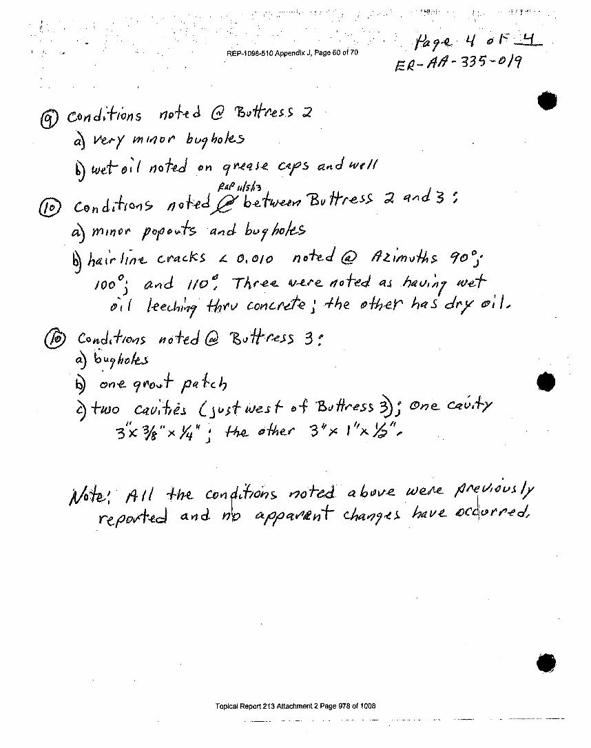
REP-1 098-510 Appendix J, Page 60 of 70
~ $~n/4o U? bLoyJ6.5
n 0 r-4 e? j-0 C4(.$ a4 've'/Aledo jl/5T
4. CohH""1$ 4° ° "'" •t>,y•1
/0V 5,c 1/,7V~/S' O~/~
a), MuM/OP k O15adbohl
CIO noW P Z ree5
I
reh,9," tt'ecJ~<• ,• oha o''. ,zmg•q°
Topioal Repovrtl 21 A
C-0
Topical Report 2"13 Attachment 2 Page 978 of 1008

j.
REP-1098-510 AppendIx J, Page 61 of 70
ER-AA-33O19Revision 0
Page W7 of 17
ATTACHMENT 4ASME IWL (Class CC) Containment Concrete Detailed or General Visual Examination
NOE Report A
StationI T/7 ZJ UnIt: I Data: Whal 3 Repo No:system: Cv.261 I nen lConfi q fnn~1 Bid? (T W01406).- R;W33o6.Location: uI~ EI:JS In 1- 9 Elew Iq A CL: W4IJ Row. /4 AzMuth/Ra~u A4/~
Exam Type: 0 Detaled Visual Type. Of Exaii: NakhedUGenral Vual meoeIMad.Type: Coa.cr-e
Oeafr nOralt 1 ifIIoI]aAfde: I S-ee &.b 0 1surftce: EOD [2- Surfuel ICo l~ents Coated: 0YCS NO
Ifuiatio Utse 1 0dEplnfi12 omet
CmcIk8 LCharacteitt gagd ;ieEMM makdaftnbam test _ _ See. af-Mdizoil hiciTe
-Evt~ckmOf.iaeLkus K----* __ --
go-omeafts of aeglsdions
Coalng Datedorele__ _ _ __ _ _ __ _ _ __ _ _ __ _ _
Abtaalof. Caalwhr-. Wear ________________
ftsvAklLegend*J iU.-Rmvudelads dloo INRI - k. Recordahte Indications 10 Icnuamaticn 0*lSupplemental 1nýRatlor: Ives []No_ [I Sech fOftoto O3vidso 0Other(Descfbe)
NeJ
Exwarter ?Lowe: Dt:__Further Evaluation Requked: 0 Yes 4 NoAddiwtioa Action:
t~tn ow*OnwReadt, Mw1vCaneQei Acdao) SaspaciAne "li be dlopoftonedbya Rnspbis~njew
Reviewer 0-17 86 6cAW4CfADac 2QDaf N
Page ..L of ..'01viJ -~f C440f S/lOVI~
Topical Report 213 Attachment 2 Page 979 of 1008

REP-1 098-510 Appendix J, Page 62 ofO •0
C -1 7-hi 0hasP eF v-r,'•- -eo f./OO0? 7S-, S.
p ,• / k .¢ety/) )q d•cc. .s ,a,,,.,o -I,/ (¢,en
_-" s8!i E aev•'e/~.- "3~OL~eo L £Q'-~ /o 8"zv'c.j~f
at pia R r1 th 2 d.,ge o
obs)vz Poa/7~oe-e Cem~o v r zs omrlje ý
6o cde/*~O4c Co e ~t~ WefpaAo e-c/
R4T opia epr 21 /tahen04ae98 f10

REP-1 098-510 Appendix J, Page 63 of 70 3' cA
Wdh pagof4._J
c)0Y rrojv 7 b
0 or X - 0 /o
Q) epoFt, / ;eOa , ,.
L
;ii, E /" V , X..... 6a-- k--vS-, o: J re -Cýl -& ,,,.., m w..bL,?bo,.., o,,,,
6) ,,,yi no Wov, C0o1$ "OýIk
~ip-
10bp~A
Topical Report 213 Attachment 2 Page 981 of 1008
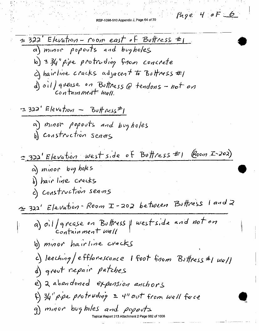
REP-1 098-510 Appendix J, Page 64 of 70
W R ',- l " ,-v _ p ,'ot - ,, ,r o ?' .xr.S- o,,. F '1 ,.,f.,, ,. .MLa) MEkvI~y" pový5.~~b
cI ) ely/!te,,._ or S,5 +LeP 44don s - ,, ,
CA) Mor (10oviv&4,"1dI hv 2 ho/es.
min nio,,or •,,- hoes.
)_ (-D ha .v..C4f- , , _5, -& C
,-- 3 oL -, ,, ý,, -. R o.. ,,X 5,tn 5 f
io)
d~)
9)
mnoV' o ,I-e-- kVwC..
Toa Rvtpical rR,' eor 2 Atac h
,.•.o, bcholeS qod acy)4vv7:_iTopical Report 213 Attachment 2 Page 982 of 1008
q

REP-I 098-510 Appendix J, Page 65 of 70
c,• Mx',,v-7 - /•OO,1 Op,/0
C) J0IY7 V r 17 0
Q) c,'A~ o v rt Wi?/1 e ~ ~ ?4~ I
bý Ap'o vtp a" Ih o/es
fiy.e.. ~
-~TZ - ie e - ------------
vt, rnrjo, Ieec-4,.7/ e'/ýCoee~sCe',vC.e.
---,zý 357, F/evetilo", - wzs-ý- S(ýJ-O- 0ý 'Bu
0/0 0oo~ a lelJ
Topical Report 213 Attachment 2 Page 983 of 1008

JL 7 2 j ~ - -,*
REP-1O98-51OAppendixJ, Page 66of 70 ~ )~
h~er il C."eOA
ch~EY j'ryO&F 4elc
Topical Report 213 Attachment 2 Page 984 of 1008

REP-1 098-510 Appendix J, Page 67 of 70
ER-AA-33"1O9Revision 0
page 17 of 17
ATTACHMENT 4ASME IWL (Class CC) Containment Concrete Detailed or General Visual Examination
NDE ReportPate I of I
;a-r-n. nit'Date: 11I12i 1 Resod o:
SyDerfn:mi~ 1yeTlfl1:-OE / I Viua]is (&5, tCu e 4fW'o. 29306
Surfaae: 0 OD0 to ~ Surface I Compnentfs Coated-, J SM9Iffurttination tram I A)41Zrj2 L..A -L If
MEMOi~ Pj NRI t LxawIpnar I cormtnifts
~ - --- - -------------
Leaclnu Or ChegMW Afttck____________________Setffemeab of Detdw~ian ___________________
PapoutsWKofts lKoraycqm O4 ohl-iA*SRI&F
Kasub egemJ RI -andebi Dadlowaon NRI -NaOftsc~rdobtq lvircuiados to - Ifotimwton r* Spplemental InIkradaony-M s WHO 0 Skst5P)Photo Q]Vtdeo 0tther (MesU):
.. / /ExnIer#S -L-a J- - I iLaval: -J44 DaW
Further Evaluation Requilred: 03 Yes .0 NoAddftinal Actins
(AOMnRe~iwaI i . R 44 df1,6AMSM.AQWCG 8iiagidAMeS OA~ b.dCupoii5naby a RaMaobi &*,or
lKavlowe r2 A-, ?
ANI afta
Page Iof-L
Topical Report 213 Attachment 2 Page 985 of 1008

REP-1098-510 Appendix J, Page 68 of 70 Revision (Page 17 of 17
ATTACHMENT 4ASME IWL (Class CC) Cofi(nmerit Concrete Detailed or General Visual Examinatin
ODE Report..... _______ teIof I
Unit I - ate:, I y/ Bma Reot Ho:System: ,JRrlr~ I PscJ q + e v vtes IWONow.: LeaZ 4
iLacation: l.u1 Uding- I t. I Eie.: 1 -30 51 ~co:lAM I vjt I At-Izmuh~du IAzExam TyW. 0 Detailed visual Typ~ of mmm Ma3.T kce re
Mensill V'Sua eot- De w~I~() TiI'oolq I V4iauuIAlds. ~~ 7 T~e's tca4f O.CI-6aL~
Surfare:w. C I I0 ecI imoetoad:UYS Nohffumftatf Used ih ars 69ht 7~
AftrUiuts RI N4 101E~ln~n~metCracia LGftaipca gW aAdS3e
Kexh-Ww" Lqmk~at Cfw - -EykIrtnag O eane Le"M ~ K--'
EAewawm Of QMolabumac
Sedismebofto 0618ctkne
Dearb'ad pahseeok
COWt 4oin Uties
sumiamenweo~ iaCrnyMUap: Q3Yes 11w [I $keh OPhoo lvkidea Other (Veacctbs)I -,' lip. 1.1
ExwWrfter - 1=-.. CA.evl .-LU OawtEs Y-F'urther Evaluation Requksd: (3 yes NJ 40Acd~ealAcl
urn e~a~8erQ0M*AdtuaQ)Sz8u*dAzeerdatt b d("th5n1 bria ~P"Mewtram. .I) ul 9 C-4/RA'dr& Date: 4~
ANII. amsV
Page J-of I
eTopical Report 213 Attachment 2 Page 986 of 1008

REP-1 098-510 Appendix J, Page 69 of 70
F.R-AA-335-019ROvislon 0
Page 17 of 17
ATTACHMENT 4ASM4E IWL (Class CC) Conteavxnment Concimite Detailed or General Visual ExamintafJon
NOE ReportPage 'I of I
(stuon InUnl Oas:IAM/3 IReport No: I
wi~vtem: comr~onent hgf~- q4 %i ;Iu w9 -Rd~ WO o -s.: a/360Lociatin: I ultdri: EW' I A Ca: I ',~ NIA I' R A zUVsI 'Exnm Typec C1 Used VtuWL TyOt Emxarn3131ect e
D~einrawn emu T/flnZ-O owj Isua!Alds: dAAýA Te7 agoFO1 QSurato: 1 0 t Surkmc I Carn ante Coated: ES K[wgrnalltiom I4v OC-kI t-aJ7-S-Ca
A9tuU~ula or NCads ~ ~ ~ ~ ~ ~ butJ /Aance~z a-i 00tzte ____________________
Exuasf Rsntrcit 4Ste.-Pamud~~iuIes O~~ _ _ _ _ _ __ _ _ _ _ _ _ _ _ _ _
LCM Iowt arma twc
adigg-.9 1 od .e J arftdw~w NRIeck -I. RDci~at -ROMas C. [fna~sOi
SuixtemereInto Mfnt -aRea: 4s ] OSIM"o O3Phato E3WG0 Io QOther anbe,.-.f'P' . I
Exanhner I"f CA LaveL -U Oak' SWFurther EVatudton Requted: E3 Yfes A AtoAddftorad AcdiNa
(AsaR~ M&2~I4a~rwa c~~~~.so~,~t~spt~s~q
Rwse~e e'•~ ? fLAcJ& ae%ANU., DaNe __
Topical Report 213 Attachment 2 Page 987 of 1008

REP-1098-510 Appendix J, Page 70 of 70
ER-AA335419Revision~ 0
Page 17 of 17
ATTACHMENT 4'ABME IW.L. (Class CC) Contarnment-Conorete Detailld or General VIsual ExaminationHOIE Report
Paeofiotatm. : gIt Data I Reo Nio:
system: ~~ ~W~ Symoe~[/h.~qj~ - g,;4j WO woN(q)-.: 1Ii?4912oP&" tam:ln urknIi u . ~ ? Cr ~ 4- I R~ /, w mih n~~ A~
RAP.HAeera Voarae I dBuu IVt
ffwCES&npVrU 01. M r
Surface. 00 IDI Sfa- K RCantGt Im o ai YES 13 Nneni O _ ttmutwttuonusedt Inoto: Ok a U Seth 1-- g-f h otoA Q1icto 00h.'(u
&WbsRt P- 10 Lmg I .,ot
0
ExamIner &z --' LAVei' -LL. am/ýFurther 9vlmiuofi Reqthd, E3YsRw
(dSoarta Acwu CUI I*Mc aa's~ .uaeff@bu hUI
PAtWbWO., fA#4d'6Z 1 4ff g~AKIIN-f
r IT .Page I.o Of..
Topical Report 213 Attachment 2 Page 988 of 1008

REP-1098-510 Appendix K, Page 1 of 20i
7PR CISgOw 8UR ILLANCE
N1091 PSC PROCEDURE SO 8.5GREASE CAP INSPECTION
Data Sheet 8.509103/13
Page 16 of 20Revision 0
TMI UNIT 1 TENDON ANCHORAGE GREASE CAP INSPECTION
TENDON LOCATION EVIDENCE EVIDENCE EVIDENCE OF EVIDENCE INSPECTOR'SOR OF FREE OF GREASE CAP OF INITIALS AND
ID BUTTRESS WATER GREASE DEFORMATION CORROSION DATELEAKAGE*
YES/NO YES/NO YES/NO_____YES/NO YES/NO__
v-1 - -,• At A tj .,-'.1V-2 _ _ _ _ _ All At AS ____ , -V-3 r" At itV-4 1RM a A_ A A# 12 -1V-15 .. T N, A P t ,24.5.v-6 _r_ 0_ Al 0 Al ____._
V-7 Al __ _____-_
V-8 14 IN I,,l5V-29 .. L PL At At A'1-10 ;r a
',V-12 1" At A N AtV-213 -r 8• li AN At At -15V-214 " ir 4(4 61 Al ,1 ,1 2-4.-
V-15 -r• A /4 Al ij M, _124,13
'1-16 -V-17 At__M____
V-I18 A At... Aj
1-1 9 Al AtAlAt2..
V1-21 Al 14 At I Z-11
V-23 graeas Al At o moV-24V-25 4j. 13 A AV1-26 h.S 11 lAV-27 -rt A J la-,
V1-30 1Z48 9L V~ LFV-31 -Ir 41'1-32 r4A ASV1-33 AA/#V1-34 IAl4AV1-35 AV1-36 a _____
Evidence of oil at threaded connection is acceptable providing it is not excessive. This is oil that has separatedfrom grease and is common.
This is evidence of corrosion that resulted In metal loss and wastage that may affect the ability of the greasecap to contain the sheathing filler grease.
20b SQ 8.5 TMI.13 ISI
Topical Report 213 Attachment 2 Page 989 of 1008

REP-1 098-510 Appendix K, Page 2 of 20
-/PRECIS1 ION8RCILANCE
N1091 PSC PROCEDURE SQ 8.5GREASE CAP INSPECTION
Data Sheet 8.509103113
Page 17 of 20Revision 0
20b 808.5 TMI.13 ISI
Topical Report 213 Attachment 2 Page 990 of 1008

REP-1098-510 Appendix K, Page 3 of 20
PRECISION SURVEILLANCE
N1091 PSC PROCEDURE SQ 8.5GREASE CAP INSPECTION
Data Sheet 8.609103113
Page 18 of 20Revision 0
TMI UNIT I TENDON ANCHORAGE GREASE CAP INSPECTION
TENDON LOCATION EVIDENCE EVIDENCE EVIDENCE OF EVIDENCE INSPECTOR'SOR OF FREE OF GREASE CAP OF INITIALS AND
ID BUTTRESS WATER GREASE DEFORMATION CORROSION DATELEAKAGE "
YES/NO YES/NOYYES/NO YESINO
V-73 . At l At N 12-4-1V-74 -"____ 9 A AtI 12-4-13V-75 1-r At V N1-4-A
V-77 t2____ - -JV-78 ,- A dtAV-79 j /,x- &- rAV-80 " T !- - iSV-81 TrEa..J X A, . At A "1-.4-I1V-82 -T- ____ Ft A &f.je 12- 4, IsV-83 -r ,F- f- AtV-84 T-61% I 'V Al At
V-85 T4, •. N At- A-t
V-87 $16 AtA/0AV-88 -r- N At /VV-89 1-& At- A#. A____V-"0 N N 0 1 V At -Il.V-91 V_415 I At_ Al a -1_V-92 "I"Ji N A R Al - 3V-93 & A at.,•-!.•V-94 - -V-95 - A mA 4AV-96 _______At _A
V-98 "4 ,-V-99 ri.____V-100 At"•• N,/ =,.V-101 A I A # -, -it-isV-102 I- --R A 1 -At 14• -4.0
V-103 1"IL I N At NV JV W&g i-4l-1V-1o0s At IV-1 06 A/1-41V-108 ___12__"
* Evidence of oil at threaded connection is acceptable providing it is not excessive. This is oil that has separatedfrom grease and is common.
This is evidence of corrosion that resulted in metal loss and wastage that may affect the ability of the greasecap to contain the sheathing filler grease.
20b SQ 8.5 TMI.13 ISI
Topical Report 213 Attachment 2 Page 991 of 1008

REP-1 098-510 Appendix K, Page 4 of 20
7P8RCI O:,s~v!CCNCN1091 PSC PROCEDURE SO 8.5
GREASE CAP INSPECTIONData Sheet 8.5
09103/13Page 19 of 20
RevisIon 0
i
.....
Q .. .....
>" PR•CI$10N SURfEIt'
I" AN CE
TMI UNIT I TENDON ANCHORAGE GREASE CAP INSPECTION
TENDON LOCATION EVIDENCE EVIDENCE EVIDENCE OF EVIDENCE INSPECTOR'SOR OF FREE OF GREASE CAP OF INITIALS AND
ID BUTTRESS WATER GREASE DEFORMATION CORROSION DATELEAKAGE*
YES/NO YES/NO YESINO YES/NO
V-110 4 i A. -4V-111 6" 13 Al 4V-1I12 AI- &.. Ai IV ___ N i.J'IIV-1 13 1" & A, t• AtNI d,,• 1 .t1
V -1 15 eL 66,9 t4A
V-1 16 r- L N Nq 4-14V-117 Arl ri M 1• Z/il
V-1 18 Al t4 al N L L &IV-1 19 .AL. LA l AtLV-120 "- & t• I & HV-121 -r A A All & a -4 -V-122 At Af At Al• ,•.-t ~-.
V-124 At'L .....V-123 0or N .• Alf.V7-1276 "r Is AtJ M /•. •1•
V-131 T"k AJ At AN "-V-1 32 -r -#- At AV-133 _ ......-'•N tA 4 Al * -V-1 34 _r;: 1 4 AL .V.135 " "sf N A A At -V-138 -ir' 1 A-AtV,137 -r e- 1 N AtV-138 r N A N L ,V-1 39 ", 4.1 a N At I Z..N .1V-140 Lr1 1L. i4L-t1V-141 -r ia 1- Au.- N - -
V-143 A A I At" ZAV-1-44 z'r ,i"s I ,,j' I Al• •2.•~'
* Evidence of oil at threaded connection is acceptable providing it is not excessive. This is oil that has separatedfrom grease and is common.
* This is evidence of corrosion that resulted in metal loss and wastage that may affect the ability of the greasecap to contain the sheathing filler grease.
20b SO 8.8 TM1.13 ISI
Topical Report 213 Attachment 2 Page 992 of 1008

REP-1 098-510 Appendix K, Page 5 of 20
PRECI810N SURy•ILLANCe
N1091 PSC PROCEDURE SO 8.5GREASE CAP INSPECTION
Data Sheet 8.509/03/13
Page 20 of 20Revision 0
TMI UNIT 1 TENDON ANCHORAGE GREASE CAP INSPECTION
TENDON LOCATION EVIDENCE EVIDENCE EVIDENCE OF EVIDENCE INSPECTOR'SOR OF FREE OF GREASE CAP OF INITIALS AND
ID BUTTRESS WATER GREASE DEFORMATION CORROSION DATELEAKAGE *
YESIS/NYESINO YESINOV-145 A-ll t JjJ Ai At Arr 12,-/•IJ
V-146 '1t ML All/ , Al J1)2-4-8•
V-147 Al i j Al 13V-148 -r" P. At At /tVN ~ z.,V-149 A At Al At, AtV-150t ;, 15 ,1 4 At fv . 13- 1,V-151 "I- At At Al A- 1V-152 T .. ,l P N ,A - ;V.153 7 -IL. Jq AV-154 "r-, A At tj • /''.IV-155 -r - j, At Al J.V-158 -" L I I 4 A)
V-157 "Tf R W At
V-1 59Al A 1-i AV-160 L..., . ALt Al A)
V-162 I A .,Al -N -.. .-
V-184 Al Al At.- -iV.165 tZIII Al At.....V-166 Z"T At
* Evidence of oil at threaded connection is acceptable providing it is not excessive. This Is oil that has separatedfrom grease and is common.
This is evidence of corrosion that resulted in metal loss and wastage that may affect the ability of the greasecap to contain the sheathing filler grease.
20b SQ 8.5 TMI.13 ISI
Topical Report 213 Attachment 2 Page 993 of 1008

REP-1098-510 Appendix K, Page 6 of 20
N1091 PSC PROCEDURE SQ 8.5GREASE CAP INSPECTION
Data Sheet 8.6Pe ia 09103113IClN ANCE Page 1 of 20
Revision 0
TMI UNIT I TENDON ANCHORAGE GREASE CAP INSPECTION
TENDON LOCATION EVIDENCE EVIDENCE EVIDENCE OF EVIDENCE INSPECTOR'SOR OF FREE OF GREASE CAP OF INITIALS AND
ID BUTTRESS WATER GREASE DEFORMATION CORROSION DATELEAKAGE*
YES/NO YES/NO YESINO YESINO
0101 5 t 1, __t4•&____ _ _ 23-0/ •l •-D102 t.- AZ_ ,_ ,•l_.D103 - ,q&.. J A4'", ,).At3D109 k1 A.l.- . , • . 0_LAt-
D10 IJ- Alf- P.W a. OZ A) .,J&.a
D113 A • d/.2 /• / zD101 51 Al a t4 AtD192 0, W .- N&F. At 1b a•-23•ID1210 - A/ & At A( At f i,-2- 1 ••3-tD1`12 19.0. ,VF- At A t1 At •••/PZCi0126 0W, t N _ _ _ AZ/, we••zx-
0117 ,ld F. N _________ L. 4t•./3LI-
0130______ N __ ,,_____, '? /o-Z •'-I
DI~~~~ 13 lJA.9 dd L .D12 14I t - If_____ A)... &.0 o.15.
0121 e, 4 N Ai /V 14 R?', z 7-1012 1 hf-AIj AlL AlJDZ
0124 a,&~j /4 At .0125 L, AjE NL At 14 -Ag~-y
D121 k?, A16 d 9 4 WL.... A
0132 4W- J N Al A A At N A/6--710131 5 AJ) Al A/ A/ I/•. Z z 1-l3
01325 A Al 4 ~4~i-1
D134 At Al 4iiI /a- If
*Evidence of oil at threaded connection Is acceptable providing it is not excessive. This Is oil that has separatedfrom grease and is common.
"This Is evidence of corrosion that resulted in metal loss and wastage that may affect the ability of the greasecap to contain the sheathing filler grease.
20b SO 8.5 TMI.13 ISI
Topical Report 213 Attachment 2 Page 994 of 1008

REP-i1098-510 Appendix K, Page 7 of 20
PRECISION UREIC ANCE"•.• ,•;..: , A.•-F R•
N1091 PSC PROCEDURE SO 8.5GREASE CAP INSPECTION
Data Shoot 8.609103113
Page 2 of 20Revision 0
TMI UNIT 1 TENDON ANCHORAGE GREASE CAP INSPECTION
TENDON LOCATION EVIDENCE EVIDENCE EVIDENCE OF EVIDENCE INSPECTOR'SOR OF FREE OF GREASE CAP OF INITIALS AND
ID BUTTRESS WATER GREASE DEFORMATION CORROSION DATELEAKAGE*
YESINO YESINO YESINO YES/NO
D 13 5 S L4 -g- Al¢ At J 4• •• • 109 I - 2 1- 1i
D136 I..A /L N A # &dg ID-3-Is
D138 _k-Af ALt A At AL.. wie klb1-D139 S j.#E A/ At Al f --
D0145 s IA AtAL.. Ai A -
02031 q j-Alp --'L."
0202 " N N - .V d' 02•
0203 J. k/ Al• i t.-.-D2094 Uj ,4 A/Nl4 ••i,•-•02105 IIL.. L. N Al' a/_ O,
0208A A~.i~ & Al t ji 1.W
0201 j. A& Al A d•-
0208 SWM A A Al
0209 5~ AL~j NL A/ A a -zs
0210 t-<U- AL9 4 A j *IJV -D21 k A La....... •Al M e,0't1lj0212 _ Al P At Al M D.
D023 19 Aj Al 4L.. d
D214 - ML L At L. "AA.&&-,i.D21 5 - Al t At L t -i .II
D026 Z- -W A( idA A g10
D2107 g-jg N At i . hi p 0ij -l-i
0219 1 4 ,,
D220 6.. k- At A /•),• .F-
•Evidence of oil at threaded connection is acceptable providing it is not excessive. This is oil that has separatedfrom grease and is common.
9This is evidence o corrosion that resulted In metal loss and wastage that may affect the ability of the grease
cap to contain the sheathing filler grease.
20b SO 8.5 TMI.13 ISI
Topical Report 213 Attachment 2 Page 995 of 1008

REP-1098-510 Appendix K, Page 8 of 20
/ P~'.I..OQ EIJREIL ANCE
N1091 PSC PROCEDURE SQ 8.5GREASE CAP INSPECTION
Data Sheet 8.509103/13
Page 3 of 20Revision 0
20b SQ 8.5 TMI.13 ISI
Topical Report 213 Attachment 2 Page 996 of 1008

REP-1 098-510 Appendix K, Page 9 of 20
TMI UNIT 1 TENDON ANCHORAGE GREASE CAP INSPECTION
TENDON LOCATION EVIDENCE EVIDENCE EVIDENCE OF EVIDENCE INSPECTOR'SOR OF FREE OF GREASE CAP OF INITIALS AND
ID BUTTRESS WATER GREASE DEFORMATION CORROSION DATELEAKAGE*
YES/NO YESINO YESINO YESINO
0308 A/ A At ,o ,.- I-:D309 Al! M _____ Atd.1-A-I10310 Af- 5 N At A A -=J12 /a.2_ 11D311 At-.1 At Ir 14 " k•fA io-11-l•D312 g- S A( A) At At l--D313 Af- N N Al A.j.& -4-P 1I5D314 A#-5 0 IN_.At I__o.D315 q- r4 A t 1ll , O.UZIliD316 _ _. q A Al At-a-JD317 A-N SN A 14 1-D318 Ai. s N At Al . .t t• ,D-•30319 At o4 .. d. N a AZ0LI-•..l 3A0320 j-. s .tjL At ,,, . 4LJAb-W.-L
0323 N,3 Al AD324 At-IS Ai At ij4j1- .•-D325 A f N A 0 1,31
D326 Al. A l /, At 14J.-2113
D328 ,A#- s d r4 At• L••Z•I
0332 At ,4 A# ., /0-.-1R I0333 ,jJS Al N epqa.-I
0334 jf-S A A Al At kLlezy-0•3D335 4l- Al bfD336 N-,S I At.0337 A,. A 1
Ujjo A4 - A 4 Al 11 A) 16 -W 1 3Z~D339 At- 5 14 , A NAl i b- "l"I0340 & A[e~~~ ~ .. M N 110-e4~25-150341 A S 0 4 4 &L. L. •IS.fl.15,D342 p t14 . e _(______-
D343 4-5 ,4 ,0 L _/
Evidence of oil at threaded connection is acceptable providing it is not excessive. This Is oil that has separatedfrom grease and is common.
This is evidence of corrosion that resulted In metal toss and wastage that may affect the ability of the greasecap to contain the sheathing filler grease.
20b S 8.5 TMI.13 ISI
Topical Report 213 Attachment 2 Page 997 of 1008

REP-1098-510 Appendix K, Page 10 of 20
.RECISION, tilt:SU R ICE
N1091 PSC PROCEDURE SO 8.5GREASE CAP INSPECTION
Data Shoot 8.509103/13
Page 5 of 20Revision 0
TMI UNIT 1 TENDON ANCHORAGE GREASE CAP INSPECTION
TENDON LOCATION EVIDENCE EVIDENCE EVIDENCE OF EVIDENCE INSPECTOR'SOR OF FREE OF GREASE CAP OF INITIALS AND
ID BUTTRESS WATER GREASE DEFORMATION CORROSION DATELEAKAGE *
YESINO YESINO YESINO__________YESINO YSN
D344 _l 4 4 ifJ- I:iQ1 ]D345 _ A 1, AA l, 4L _iZL.D346 A(. A l Al A t -
D347 -, At At At,1, i-D348 At t4 At V.D349 t. 1 5 Al .%1 b 1 n// -I1-. o
'Evidence of oil at threaded connection Is acceptable providing it Is not excessive. This is oil that has separatedfrom grease and is common.
This is evidence of corrosion that resulted in metal loss and wastage that may affect the ability of the greasecap to contain the sheathing filler grease.
20b SQ 8.5 TMI.13 ISI
Topical Report 213 Attachment 2 Page 998 of 1008

REP-1098-510 Appendix K, Page 11 of 20
1 'PRGCISION SUD~V~ILLANCE
N1091 PSC PROCEDURE SQ 8.5GREASE CAP INSPECTION
Data Shoot 8.809/03/13
Page 6 of 20Revision 0
TMI lIMIT I Tl=kln N AKIr-WOPA 9: P1_=_AQ9: CAP IKJQ0F:rTlnKl
TENDON LOCATION EVIDENCE EVIDENCE EVIDENCE OF EVIDENCE INSPECTOR'SOR OF FREE OF GREASE CAP OF INITIALS AND
ID BUTTRESS WATER GREASE DEFORMATION CORROSION DATELEKAG*
YESINO LEKG*YESINOYES/NO YESINO
H13-1 [14/ M , At I.Q d.H13-2 14 1-73 1 At Al 1_1"81H13-3 jV M - N13 1 -'Lj. .4t
H13-4 At A -R V A ,l,•//•qH13-5 11% ., , t. AtgI.zaHI 3-6 2Iq .1 A/ Al- A ^I
H13-14 r- 1-,3 #V At At/• i.lH13-15 3 d-• a A/ýN•Ho.,
H13-9 - At # AlH13-10 1- - A I I -*A f (
H1 3-11 _ "q At/ •/j/r/ •---
HI 3-12 A/ fly ~ Z ZHi13-13 A L-. 1,41 Af hI Atf - -
H13-14 1 I-2 Al A A___ At 1-0•3H13-15 t , i-k . L . At .. t -3 N IAt.t4_-__H13-16 J•I- L. A/ AAt ik/ Aler Ak"HI13-17 JV 'A AtHI13-17 At AtZ~i~ 4
H13-18 L, "1 -t -At A?• * •"-
H13-19 1.-, At Al Af Al
H13-20 ,; -.. f -At-AH1 3-21 AS A/ A/H13-22 S.JI- L. AA i-Hi13-23 4' I AtN .t.Vý*nHi 13-24 Ajj I *#% A tA f&HI 3-25 j3 1.-3_ 61 N t nH13-26 -, Al Alt4/ #Ar
H 13-27 Al4. Al Al
H13-29 W
H13-30 tNH13-31 4zz_3Al6H13-32 A____1__
H13-33 At ~ 'AHI13-34 A;Hi13-35 A/____ _____ _______
* Evidence of oil at threaded connection is acceptable providing it is not excessive. This is oil that has separatedfrom grease and is common.
* This is evidence of corrosion that resulted in metal loss and wastage that may affect the ability of the greasecap to contain the sheathing filler grease.
20b SO 8.5 TMI.13 ISI
Topical Report 213 Attachment 2 Page 999 of 1008

REP-1098-510 Appendix K, Page 12 of 20
PCISION IANCE.
N1091 PSC PROCEDURE SQ 8.5GREASE CAP INSPECTION
Data Sheet 8.609/03113
Page 7 of 20Revision 0
TMVI UNIT' INSPECTION
TENDON LOCATION EVIDENCE EVIDENCE EVIDENCE OF EVIDENCE INSPECTOR'SOR OF FREE OF GREASE CAP OF INITIALS AND
ID BUTTRESS WATER GREASE DEFORMATION CORROSION DATELEAKAGE *
YESINO YES/NO YESINO
H13-36 /19 1--3 , At tJ L•IA#..Hi13-37_ ~J9 I - AH13-38 * 4.-".. • Al -H13-39 iq I -,,-, - -H13-40 /a If •-I A• At t a4a L3H1 3-41 5 z. -A Al 1±1, ZH13-42 i -43 0i ,Hi13-43_ 1-~:5- tL. A -H13-44 A N -..•2 0- AlHI13-45 -A/- 4 A "A l-z4-,H13-46 L1J- /I.L -/H13-47 All- . iL .H13-48 e-A i -A AJ A Lt At At'--- .Hi13-49 jffi4 d _AL.(..z
H-13-50 A~ Al. .3AHi13-51 tj.z y AAt .. IH13-52 /£ I-3 z4 .tJ.0-2...H13-53 Al-3J La I,Hi 3-54 i 3 A.(I O'Z..H13-55 /--A 4• Y AAOAX S ,tW I, 6,-Zq 5O'J,
H24-1 Al ti~ At L ._H24-2 73 Z -4f A• Al U•IZIH24-3 Ps Z- At . ALH24-4 o, zq • 2 IH24-5 A / .• 1H24-7 2- A •J " -
H24-8 AL.. 2- 0-i-
H24-10 8 z.4 AN 14 . .-H24-121 z t m•t Pi____-
H24-13 _ ___-_At'At ___H24-14_ 13 N z ---- 9!H24-15_ 13 z•-I t•" A , Al ,Al, " )~• "l-
* Evidence of oil at threaded connection Is acceptable providing it is not excessive. This is oil that has separatedfrom grease and is common.
This is evidence of corrosion that resulted in metal loss and wastage that may affect the ability of the greasecap to contain the sheathing filler grease.
20b SQ 8.5 TMI.13 ISI
Topical Report 213 Attachment 2 Page 1000 of 1008

REP-1098-510 Appendix K, Page 13 of 20
RENCISJO!N SUREltANGE
N1091 PSC PROCEDURE SQ 8.5GREASE CAP INSPECTION
Data Sheet 8.609/03/13
Page 8 of 20Revision 0
TMI UNIT 1 TENDON ANCHORAGE GREASE CAP INSPECTION
TENDON LOCATION EVIDENCE EVIDENCE EVIDENCE OF EVIDENCE INSPECTOR'SOR OF FREE OF GREASE CAP OF INITIALS AND
ID BUTTRESS WATER GREASE DEFORMATION CORROSION DATELEAKAGE*
YES/NO YES/NO YES/NO______YES/NO YSN
H24-16 R :2-/. M A) Al 1%) 12-• 4Zl,H24-18 A .2.l AJ A 1
H24-19 AA 2lt • •t 2 -H24-21 A. 2, . . iE -A-)H24-23 -2-4 I M ^IH24-224 -L_
.h/H24-23 Al i - .,
H124-24 j3 f 2. it At A# A/AH ,24-25 f AL.. A A) At
1124-30 i 2- 4 A AtH24-27 is 2-Lq f "A, Al qH24-283 •5 .. 4 At Al N AtH24-29 A 2: A-I A1 Al.H24-30 217- N.- L IL 24-tH24-31 8 M At N l.4-A
H24-32 1Jj Al At h L. Al .
H24-33 -2.4 4• • .At. t-H24-341 A 2,4 Al 6oA AlH24-32 5 2-il AJ z __ At A/H24-3 - J AlAt /_ _ Al
H24-3944 -L AJ /dA ,- k/L. Id.al4LH 2-46 10 A l
H24-47 t -• .-4 A) A , Al g I.
H24-48 3 2.-q A) tl NJ AtH24-439 8 24 Pi All l AllH24-40 A: ?--it ,N 14 tj M' 12./'=
H24-41 f.R 2./ I At ,A) J •e1.19/"
H24-494 "-2-4 pi• A) Ay •••-•1
H24-51 r %-A M ,-
• Evidence of oil at threaded connection is acceptable providing it is not excessive. This Is oil that has separatedfrom grease and Is common.
This is evidence of corrosion that resulted in metal loss and wastage that may affect the ability of the grease
cap to contain the sheathing filler grease.
20b SO &5 TMI.13 ISI
Topical Report 213 Attachment 2 Page 1001 of 1008

REP-1 098-510 Appendix K, Page 14 of 20
PR ISUR WEILANCE
N1091 PSC PROCEDURE SQ 8.5GREASE CAP INSPECTION
Data Sheet 8.509103113
Page 9 of 20Revision 0
TMI UNIT 1 TENDON ANCHORAGE GREASE CAP INSPECTION
TENDON LOCATION EVIDENCE EVIDENCE EVIDENCE OF EVIDENCE INSPECTOR'SOR OF FREE OF GREASE CAP OF INITIALS AND
ID BUTTRESS WATER GREASE DEFORMATION CORROSION DATELEAKAGE* *,
YESINO YES/NO YESINOH24-52 _ A 2 -4 At At/ A/ d• -fl l -i 13-tt'
H124-53 2 4A Al INH24-54 2_._4.." 4 At -A A A/91Z -1H24-55 A Al A-/ w 2.1b-2-.j3
H35-3 1 --H35-2 _- At At_ - .AtAJ4 -.- L1H35-5 ^5 - 5 At At -t lA iH35-14 3-5 -, 4• AtH35-7 1i3 L5 At At q .& 04J5.
H35-11 jAE *H35-12 1 .5 - AH135-13 3 -4 5:i At 4l At~-~~ aie' iC)-24-4
1135-17 43 Ale it 041135-18 -'s At~ At ~ jJW A
H 36-22 Af A- - i-AJH135-23 _ A&H135-24 N - 1AfAfAH135-15f2-8dNA ( &l,4
'Evidence or ot itrae onCinSacpapOin oecessie )as separafrom grease and is common.
•*This is evidence of corrosion that resulted in metal loss and wastage that may affect the ability of the greaseC cap to contain the she~athing filler grease. A.lI ke=_~IL&d~
H35-17 is 5-5 9 1 At Al 4d
UI 20b SQ &5 TMI.13 ISl
Topical Report 213 Attachment 2 Page 1002 of 1008

REP-1098-510 Appendix K, Page 15 of 20
( PRECISIO !USR IU.ANCE
N1091 PSC PROCEDURE SQ 8.5GREASE CAP INSPECTION
Data Sheet 8.609/03113
Page 10 of 20Revision 0
TMI UNIT I TENDON ANCHORAGE GREASE CAP INSPECTION
TENDON LOCATION EVIDENCE EVIDENCE EVIDENCE OF EVIDENCE INSPECTOR'SOR OF FREE OF GREASE CAP OF INITIALS AND
ID BUTTRESS WATER GREASE DEFORMATION CORROSION DATELEAKAGE
YESINO YESINO YESINO YESINO
H35-27 4 . At IV . ,'."H35-28 3-S At A d - rM &.24v3H35-29 1 -- Al At /,4 A&0Z211415H35-30 13 5 3 -! All A , 'M F 1 " 0-13H35-31 3 -05 A t At Al At m,& 0 0 -'•I•
H35-32 3j •. IJ - At-At 0,0H135-33 .A i. s- At____ At. .. At JI! I4-415
H35-35 A 35 id d. IV N iW 0-1Z4.11AH35-36 A 3-5 At At A L _ Z443_H35-37 is N. At At wL. iJOZ4-IH35-38 ,3 3 " At. At At Jim /&&3•
H35-39 • At Al At tbjIv/ ion- i/••|0••H3540 Al_•__-_ ,t1 - . 4 z-- 4J,,LDL1-H35-41 A_ At W LP-H35-42 9j A - ApeA io-A-dH135-43 19 3-15 At At AtL Lia IV-AH35-44 Iq 3-L eq Al AtOR -______
H35-46 8j 3-5 At A At it. 4
H35-47 z& 3- A- -H35-51 AA At -L1 1L2IH35-49 'IAlA"d1
H35-53 Aj~ Jj-! At At Al -6.
H35-54 .... N. A W JdaA ob-,4i/H35-55 a " A/t N I W
Evidence of oil at threaded connection is acceptable providing it is not excessive. This is oil that has separatedfrom grease and is common.
This is evidence of corrosion that resulted in metal loss and wastage that may affect the ability of the greasecap to contain the sheathing filler grease.
20b SO 85 TMI,13 ISI
Topical Report 213 Attachment 2 Page 1003 of 1008

REP-1098-510 Appendix K, Page 16 of 20
PRECgSIONJ URy ILIANCE
N1091 PSC PROCEDURE SO 8.5GREASE CAP INSPECTION
Data Sheet 8.609103/13
Page 11 of 20Revision 0
TMI UNIT TENDON ANCHORAGE GRFASF CAP INSPECTION
TENDON LOCATION EVIDENCE EVIDENCE EVIDENCE OF EVIDENCE INSPECTOR'SOR OF FREE OF GREASE CAP OF INITIALS AND
ID BUTTRESS WATER GREASE DEFORMATION CORROSION DATELEAKAGE * EIN
YESINO YESNOYESINO
H46-1 - , A/
H46-3 18 At jl - -4------H46-4 .. 4-4 I Z At / .t A t
H46-5 L--H46-6 A Is. - A/
H46-11 •, At A
H46-12 0 Ad 4 .-to
H46-14 _ 4f J
H46-12 "A 4-1 At Al A .- 0
H146-20 4• •- j 4 •ltl./H46-22 -A 4,-. , A At i'MW-5
H46-14 1 .~4.. - L d*1 -. 0
H46-25 i & At At AllH46-26 . - f- A At d :AllI. M 111.144H46-27 L 4"-? & d A 1.,L.N
H146-18 1. V A t tA 09-
H46-29 A 4&. AH146-30 A -& d
H462-341 ý:. -C A
H46-33
H46-_H146-34 A_!L-4_4_1 All
* Evidence of oil at threaded connection Is acceptable providing it Is not excessive. This is oil that has separatedfrom grease and is common.
This is evidence of corrosion that resulted In metal loss and wastage that may affect the ability of the greasecap to contain the sheathing filler grease.
20b SO 85 TMI.13 ISI
Topical Report 213 Attachment 2 Page 1004 of 1008

REP-1098-510 Appendix K, Page 17 of 20
N1091 PSC PROCEDURE SO 8,5GREASE CAP INSPECTION
Data Sheet 8.609103113
Page 12 of 20Revision 0
TMI UNIT I TENDON ANCHORAGE GREASE CAP INSPECTION
TENDON LOCATION EVIDENCE EVIDENCE EVIDENCE OF EVIDENCE INSPECTOR'SOR OF FREE OF GREASE CAP OF INITIALS AND
ID BUTTRESS WATER GREASE DEFORMATION CORROSION DATELEAKAGE *
YES/NO YESINO YES/NO_____YESINO YE___INO_
H146-37 is -t #j J /4~A&H46-38 9 It -A& AlA.l 4 /0ŽZH46-39 t3 .• •1//P ,'••;•-•H46-40 24 •.- x ,I• eZ.•H46-41 "' T 1 -9 R40 At/ J', .2.1WAR.A 9 ., .I .1 mr--IZLjltH46-43 ' A•/L.•MR- .H46-44 - go to .0h4..O"j.H46-45 A Allm.zIr3H46-46 At t AtH46-47 AS 9-" A' A(
H46-46 1344it
H46-49 .. &S -41 At. _____
H46-52 4 -3 Al A a• .,2 a
H46.541 #-- Al M . 1 ,H46-52 is 4 0 llA
H4tiia 1 AA)_H4 I A 2-2 I-
H51-1 Aj .!5L. Al Al .-
H51 -2 A •.. t..L. 1 "f I- S Z
H51-12 i• ,,, A_-_I__ ,C- I At At,__
H51-14 J-( 3WN A At ,l
H51-15 A.... -1zz _____ At - All . OFAP~
* Evidence of oil at threaded connection Is acceptable providing it is not excessive. This Is oil that has separatedfrom grease and is common.
"This Is evidence of corrosion that resulted in metal loss and wastage that may affect the ability of the greasecap to contain the sheathing filler grease.
20b SO 8.5 TMI.13 ISI
Topical Report 213 Attachment 2 Page 1005 of 1008

REP-1098-510 Appendix K, Page 18 of 20
SP$CPRECISION 8UIJVEI.l(ANCE
N1091 PSC PROCEDURE 80 8.5GREASE CAP INSPECTION
Data Sheet 8.609/03/13
Page 13 of 20Revision 0
TMI UNIT I TENDON ANCHORAGE GREASE CAP INSPECTION
TENDON LOCATION EVIDENCE EVIDENCE EVIDENCE OF EVIDENCE INSPECTOR'SOR OF FREE OF GREASE CAP OF INITIALS AND
ID BUTTRESS WATER GREASE DEFORMATION CORROSION DATELEAKAGE tYES/NO YES/NO YESINO
H51-16 i14 A"/ . •1t . I - 4 4I3lH51-17 A At "Aekp--•0.241T'lH51-17 9 6L. .l. At -•,HSI -18 43j 6' J tt tAtP01H51-20 14 ! -I- l N NL .. .. d .. .&2z&d
H51-20 A J .. M. Is. 14 A/ At jv:z4-.l3H51-22 -q dc - il1l#A.H51-23 -J4 - I A"At04_'4.H51-24 A.. !j dA
H51-26 1-9 C At A A ia-ii
H51-30 1 54 -| Alf A L .•... A ,Zi12
H51-31 A4.-1f A A a -041_______
H151-2 61 Al.HSI-30 fik S- Al PiA
H51-35 5A o N
H51-38 A3..-1 2L....%..1. - - L• Al AtH51-33 A• &" =L_ At N Af U 16041)I=
H51-341 5 • -, At. -H51 -38 'IS _____ AtaA
H51-43 -AIS -111 A Al Al 10.9 •!HSI-42 A=, 6-•A d A At p-215H151-403 - Al At___ ___
H51 -44 5.1...At -AtAH151-46 9-a 4 0*Z. 'H51-45 A-t At
H51-4! 8 r- I N PIV 1,-i1151-49 &..L. C- At___ AtiL-P2
1151-40 j&...!.L..I At ' Al Alj-,4
H151-51 icj I Ii~iI A_____ d11* Evidence of oil at threaded connection Is acceptable providing it is not excessive. This is oil that has separated
from grease and Is common.
This is evidence of corrosion that resulted In metal loss and wastage that may affect the ability of the greasecap to contain the sheathing filler grease.
20b SQ 815 TMW.13 ISI
Topical Report 213 Attachment 2 Page 1006 of 1008

REP-1098-510 Appendix K, Page 19 of 20
P?810,ýR C"N1091 PSC PROCEDURE SQ 8.5
GREASE CAP INSPECTIONData Sheet 8.5
09103113Page 14 of 20
Revision 0
TMI UNIT I TENDON ANCHORAGE GREASE CAP INSPECTION
TENDON LOCATION EVIDENCE EVIDENCE EVIDENCE OF EVIDENCE INSPECTOR'SOR OF FREE OF GREASE CAP OF INITIALS AND
ID BUTTRESS WATER GREASE DEFORMATION CORROSION DATELEAKAGE*
YESINO YESINO YESYNO
H51-523 13 C. I N 4 At
H51-54_ •• I At At Jq ANA -AD,-2*4o7ýH51-55 5Pj W At A' l1t
H62-1 • ,"7- At A/ A/ A/ l_/-•L
H62-2 ,k L,.. .6Z A). At-.
H62-3 6-7. AtH62-4 .- IL M A/ Al &AIAP 1 , 1
H62-105 .2 At.r N N . ±. At/ Al ML.. t .H62-11 a N AI I Af AtH62-12 &-ZA, At. .... o At Wf&IkLfz-.'H62-13 b. - 2-_AtAt At___
H62-14 & .7. At At Al At - -----H62-10 a f N At A AtH62-1 6 ý. Al A NlH62-12 L ?. Z, N ... ,L -L.H62-21 1 AL N--
H62-14 )5 4_2___lA( At OZ
H62-24 AS At N , .- ,
H62-17 15 4-7-, A A_. • aL-11H62-218 ( a-2, At APH62-19 4v N A
H162-20 4.2- At At'V111-H162-21 J& 16 2 At Al AH162-21 Ai to d. 2ZZ1Z Ali Al _H62-22 & 1k AL AIAtA
H62-27 AI N At7iZ At~ ~ ~
Evidence of oil at threaded connection is acceptable providing it is not excessive. This is oil that has separatedfrom grease and is common.
This Is evidence of corrosion that resulted in metal loss and wastage that may affect the ability of the greasecap to contain the sheathing filler grease.
20b SQ 8.5 TMI.13 181
Topical Report 213 Attachment 2 Page 1007 of 1008

REP-1098-510 Appendix K, Page 20 of 20
N1091 PSC PROCEDURE SO 8.5GREASE CAP INSPECTION
Data Sheet 8.509/03113
SPRECISION.. .... 6LANCE Page 15 of 20Revision 0
TMI UNIT 1 TENDON ANCHORAGE GREASE CAP INSPECTION
TENDON LOCATION EVIDENCE EVIDENCE EVIDENCE OF EVIDENCE INSPECTOR'SOR OF FREE OF GREASE CAP OF INITIALS AND
ID BUTTRESS WATER GREASE DEFORMATION CORROSION DATELEAKAGE*
YESINO YESINO YESINO YESINO
H62-31 a 6-7. P1 A) 41 &P-0H62-32 4j J a t Al ID-24-Z.
H62-33 , ,H62-34 At A,..hN l• 4••/.9443'H62-35 t4 &__,• ___,•_ A,,ll
K62-36 A AL- . a-
H-62-38 &-I 'V AtA
H62-41 4 2AH62-4 2 A•IL• .......H6243_ Al A
H62-44 AS (aZ... " 7 4 Al -t4ZIIZIH62-45 . At .. N 5.,
H62-53 A N A- •WLL 11H62-51 N At - ..H62-52 A/ Al4
H62-55 t-AJ- .
'Evidence of oil at threaded connection is acceptable providing it is not excessive. This is oil that has separatedfrom grease and is common.
*This is evidence of corrosion that resulted in metal loss and wastage that may affect the ability of the greasecap to contain the sheathing filler grease.
0
20b SQ 8.5 TML13 ISI
Topical Report 213 Attachment 2 Page 1008 of 1008

ATTACHMENT 3
Exelon Approval of PSC Procedures and Personnel
Table of Contents
1. Designation of Responsible Engineer p02
2. Approval of PSC Surveillance Procedure N1091 Revision 0 p03
3. Approval of PSC Surveillance Procedure N1091 Revision 1 of SQ 8.0 AnchorageInspection p07
4. Approval of PSC Quality Control Inspector Rance Robbins and Clinton West
5.
6.
Approval of PSC Quality Control Inspector Ronald Perry
Vendor Qualification Records
plO
p11
p12
ffoplcal.Report.213. Ltaica.Reort21 -.Aftachment.3.Page-1-of-l 54

Exelon Generation, Memorandum
Date: March 28, 2014
To: File
Cc: Topical Report 213Mark TorborgJohn PiazzaSean Taylor
From: Michael Grimm
Subject: Documentation of Responsible Engineer for TMI Pre-stressed ContainmentInspection
No. of Pages: 1
This memorandum serves to document that Howard Hill; P.E. (CA license # C22265) hasbeen designated as the Responsible Engineer (R.E.) for the Three Mile Island NuclearGenerating Station's 4 0 1h year In-Service Inspection of the Unit 1 Reactor Building Pre-stressed Containment System. Mr. Hill's qualifications have been reviewed and determinedto meet the requirements set forth by the American Society of Mechanical Engineers(ASME) Boiler and Pressure Vessel Code, Section XI, Subsection IWL, 2004 edition noaddenda. Mr. Hill's responsibility for serving in this capacity is documented and outlined inExelon Generation Contract number 502247.
Michael Grimm, ISI Program Engineer
Mark Torborg, Manager - Programs Engineering
0Topical Report 213 Attachment 3 Page 2 of 154

PRECISION
LANCE
f000*
N1091 TENDON SURVEILLANCE PROGRAMACCEPTANCE FORM
09/03/13Page 1 of IRevision 0
This page shall be removed, and mailed or faxed to:
Precision Surveillance Corporation Phone: 219-397-5826Quality Assurance Fax: 219-397-58673468 Watling StreetEast Chicago, IN 46312
The signed return of this Acceptance form will indicate approval of the Precision SurveillanceCorporation In-Service Inspection Tendon Surveillance Manual for document control purposes.
RETURN OF THIS FORM CONSTITUTES APPROVAL OF THE CONTENTS HEREIN.
Date: / ' /
Signature:
Company: ZreJoa /-'T IF
Project: TMI 40T' YEAR SURVEILLANCE
Contract:
In-Service Inspection Manual
Issue Date 09-03-13
Revision
000 ACCEPTANCE FORM
Topical Report 213 Attachment 3 Page 3 of 154

N1091 TENDON SURVEILLANCE PROGRAMACKNOWLEDGEMENT OF RECEIPT FORM
09103113Page 1 of 1Revision 0
This page shall be removed, and mailed or faxed to:
Precision Surveillance Corporation Phone: 219-397-5826Quality Assurance Fax: 219-397-58673468 Watling StreetEast Chicago, IN 46312
The return of this Acknowledgement form from Control Manual Number. J io, (will Indicate acknowledgement-of-receipt for document control purposes. Failure to return this pageor otherwise provide similar acknowledgement, SHALL be just cause for terminating the controlledstatus of this manual.
RETURN OF THIS FORM DOES NOT CONSTITUTE APPROVAL OF THE CONTENTS HEREIN.
If this page is stamped "UNCONTROLLED MANUAL", it is not necessary to return.
Date of Submittal: q/ 6 / z 3Date of Receipt: g~(6,'[ ,/%'Z £ •
The individual acknowledging Name: A (6 13receipt will be considered the Name:
permanent holder of this manual. Signature:
For more information regarding Title: ZQ Th-. tresponsibility of the attendant of )2;2•&36_ _Lea_%_this manual, refer to the Manual Company: EXELONJ
Control Policy Statement.Project: TMI 4 0 TH YEAR TENDON SURVEILLANCE
Contract:
In-Service Inspection ManualIssue Date 09/03/13
Revision _ _ _
Topical Report 213 Attachment 3 Page 4 of 154
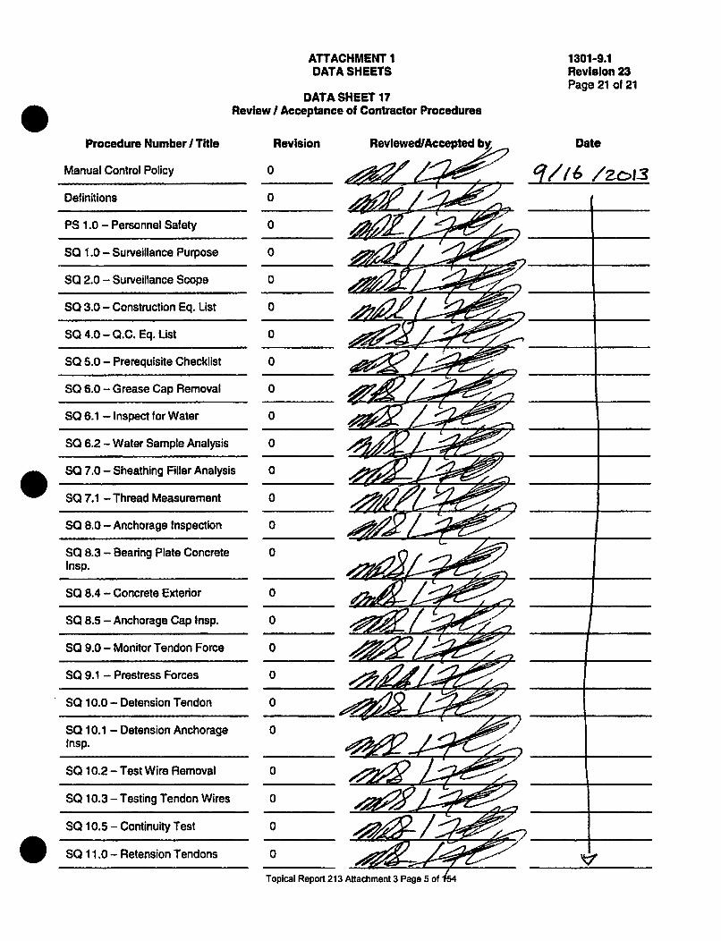
ATTACHMENT 1DATA SHEETS
DATA SHEET 17Review / Acceptance of Contractor Procedures
1301-9.1Revision 23Page 21 of 21
Procedure Number I Title
Manual Control Policy
Definitions
PS 1.0 - Personnel Safety
SQ 1.0- Surveillance Purpose
SQ 2.0 - Surveillance Scope
SQ 3.0 - Construction Eq. List
SQ 4.0 - Q.C. Eq. Ust
SQ 5.0 - Prerequisite Checklist
SQ 6.0 - Grease Cap Removal
SQ 6.1 - Inspect for Water
SQ 6.2 - Water Sample Analysis
. SO 7.0 - Sheathing Filler Analysis
SQ 7.1 - Thread Measurement
SQ 8.0 - Anchorage Inspection
SQ 8.3 - Bearing Plate ConcreteInsp.
SQ 8.4 - Concrete Exterior
SQ 8.5 - Anchorage Cap Insp.
SQ 9.0 - Monitor Tendon Force
SQ 9.1 - Prestress Forces
SQ 10.0 - Detension Tendon
SQ 10.1 - Detension AnchorageInsp.
SQ 10.2 - Test Wire Removal
SQ 10.3 - Testing Tendon Wires
SQ 10.5 - Continuity Test
. SQ 11.0 - Retension Tendons
Revision
0
0
0
0
0
0
0
0
0
0
0
0
0
0
0
0
0
0
0
0
0
0
0
0
0
Reviewed/Accepted Date
1116 /2c13
jV,
- - v
Topical Report 213 Attachment 3 Page 5 of 44

ATTACHMENT IDATA SHEETS
DATA SHEET 17Review I Acceptance of Contractor Procedures
1301-9.1Revision 23Page 21 of 21
Procedure Number I Tite
SQ 11.1 - PSC Engineering Data
SQ 12.0 - Grease CapReplacement
SQ 12.1 - Grease Replacement
SQ 12.2 -Grease Volumes
QA 1.0 - Program Purpose
QA 2.0 - Program Scope
QA 3.0 - Quality Organization
QA 4.0 - Q.C. Responsibility
QA 4.1 - Personnel Qualifications
OA 5.0 - Personnel Training
OA 6.0 - Procurement
OA 7.0 - Field Change Request
OA 8.0 - Document Control
OA 8.1 - Revision Control
QA 9.0 - Nonconformances
GA 10.0 - Calibrations
OA 10.1 - Calibration Verification
QA 11.0 - Q.C. Inspection
OA 12.0 - Audits
Revision Reviewed/Accepted by
0_ _
0
0
0
0
0
0
0
0
0
0
0
0
0
0
0
0
0
0 //
Date
Topical Report 213 Attachment 3 Page 6 of 154

N1091 TENDON SURVEILLANCE PROGRAMACCEPTANCE FORM
09/03/13Page 1 of 1Revision 0
Revision: 1, 10104/13
|i
This page shall be removed, and mailed or faxed to:
Precision Surveillance Corporation Phone: 219-397-5826Quality Assurance Fax: 219-397-58673468 Watling StreetEast Chicago, IN 46312
The signed return of this Acceptance form will indicate approval of the Precision SurveillanceCorporation In-Service Inspection Tendon Surveillance Manual for document control purposes.
RETURN OF THIS FORM CONSTITUTES APPROVAL OF THE CONTENTS HEREIN.
Date: ilL//? ,/
Name: - I
Signature: Irm o '
Title: Pie & Amn a if
Company: EAap 6 G!t5'eA •;eo1
Project: MI 40T' YEAR SURVEILLANCE
Contract:
In-Service Inspection ManualIssue Date 09-03-13
Revision 10/04113
000 ACCEPTANCE FORM Rev I
Topical Report 213 Attachment 3 Page 7 of 154

fPREC1'611 ANCE
N1091 TENDON SURVEILLANCE PROGRAMACKNOWLEDGEMENT OF RECEIPT FORM
09103113Page 1 of 1Revision 0
Revision: 1. 10104/13
This page shall be removed, and mailed or faxed to:
Precision Surveillance Corporation Phone: 219-397-5826Quality Assurance Fax: 219-397-58673468 Watling StreetEast Chicago, IN 46312
The return of this Acknowledgement form from Control Manual Number All .
will indicate acknowledgement-of-receipt for document control purposes. Failure to return this pageor otherwise provide similar acknowledgement. SHALL be just cause for terminating the controlledstatus of this manual.
RETURN OF THIS FORM DOES NOT CONSTITUTE APPROVAL OF THE CONTENTS HEREIN.
If this page is stamped "UNCONTROLLED MANUAL", it is not necessary to return.
Date of Submittal: /Y/1 5Date of Receipt: g~/D /•/
The individual acknowledgingreceipt will be considered the Name: " r
permanent holder of this manual. Signature: ,q
For more information regarding Title:responsibility of the attendant of _P _o, q_ r_ ___ Enq_____1_.this manual, refer to the Manual Company: EXELON
Control Policy Statement.Project: TM1 4 0 T" YEAR TENDON SURVEILLANCE
Contract:
In-Service Inspection ManualIssue Date 09103/13
Revision l1, 10/04/13
Topical Report 213 Attachment 3 Page 8 of 154

ATTACHMENT 1DATA SHEETS
DATA SHEET 17Review I Acceptance of Contractor Procedures
Procedure Number I Title Revision Reviewed/Accepted by
•~~O- -cLa 1i / 4~7f
1301-9.1Revision 23APage 21 of 21
Date
49
Topical Report 213 Attachment 3 Page 9 of 154

ATTACHMENT 1 1301-9.1DATA SHEETS Revision 23
Page 20 of 21DATA SHEET 16
Examiner Qualification
Name of Examiner Employer Method Level
pse 6e'd VST z__._D_____
!
I have reviewed the records relevant to the experience and training of the above named Individuals and have, asnecessary, trained these Individuals In the requirements applicable to the performance of visual examinations of thecontainment concrete surface. Based on this review and, If applicable, training, I find that these Individuals arequalified to perform said examinations.
Responsible Engineer. Name , . ''
Registration C 2 gV " : 0¢ostate Licen 0. Expiration
Exaeon NOE Services Concurrence ,, 7z Date 1 b3
ANII Concurrentce Date 2./L3...
48
Topical Report 213 Attachment 3 Page 10 of 154
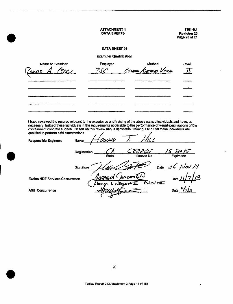
ATTACHMENT IDATA SHEETS
1301-9.1Revision 23
Page 20 of 21
Name of Examiner
DATA SHEET 16
Examiner Qualification
Employer Method Level
I have reviewed the records relevant to the experience and training of the above named individuals and have, asnecessary, trained these individuals in the requirements applicable to the performance of visual examinations of thecontainment concrete surface. Based on this review and, if applicable, training, I find that these Individuals arequalified to perform said examlinations.
Responsible Engineer-. Name /Registration •4 C •, /,5 /,.S ,,/
State License No. Expiration
Signature " . . "• Date • ,,,.AlO 2L •.
Exelon NDE Services Concurrence DateAI Concurr14,Ao~.i 0 o C.onur nce Date i .° iLL
20
Topical Report 213 Attachment 3 Page 11 of 154

asl,2 •
S
SS
QUALIFICATION OF QUALITY CONTROL IMSPECTORS-PROC. QA 2.10.6.1.1.
CSRTIPICATION FORK QA 2.10.6.1.1.B.
CERTIFICATB OF QUALIFICATION
This is to certify that
hNI R~ic~ Ro3e,, ~ S 8s3
has been qualified through on-the-Job experience and formal training tomeet the requirements of ANSI U45.2.6-1973 and 1978 as:
QUALITY CONTROL INSPECTOR LEVEL '- with the following limitations
£?_VZT r:•' •~t FbiL A . i•-•P.c-r•., .F" Po s -m•Jt ,j • / j'• t ,,•.• • S *!= rieb CFog A-I-( 457O4S7or
This certifLcation will qualify the named individual to perform qualitycontcol inspections*, examinations and testing for the various manufact-ured products or services, supplied, to meet the requirements of theprojects far the Pcecision Surveillance Corporation end within thelimitations of this qualification.
This qualification becomes effective 61/).1- and shall remain ineffect until the recertification date of, 4.4/.q .. • or untilsuch time that the named individual leaves the employment of PSC, givesjust cause for termination of the certification or requires additionaltraining to maintain a proper Quality Control disposition.
Physical Requirements: E Date I/"I,/J- to
Exam Date t
4L~AL
44by QP-rbM617-RlS7-
by4P L'tsC-
by oT~Z~Exam Date f to 00/a_.
96ýApproved by:
Quality Control Inspector Level
Date: a.1__ /_ , _.
.0025Q
Topical Report 213 Attachment 3 Page 12 of 154 1033N

PQUALI'FICATION OF QUALITY CONTROL INSPECTORS-PROC. QA 2.10.6.1.1.
CERTIFICATION FORM QA 2.10.6.1.1.B.
CERTIFICATE OF QUALIFICATION
This its to certify thatR,^. rJCC- Ro¢ e ,, .as
has been qualified through on-the-job experience and formal training tomeet the requirements of ANSI U45.2.6-1973 and 1978 as:
QUALITY CONTROL INSPECTOR LEVEL ý with the following limitations
CtT zm teib Lha As Pec-1.. OE oF-P0o5r-'1 l-9JSl ',,6- j1,.J'CCP~oe4S
This certifLcation will qualify the named individual to perform qualitycontrol inepection, examinations and testing for the various manufact-uved products or services. supplied, to meet the requirements of theprojects far the Peecision Surveillance Corporation and within thelimitations of this qualification.
This qualification becomes effective . and shall remain ineffect until the recertification date of L/4/.h . or untilsuch time that the named individual leaves te "employment of PSC, givesjust cause for termination of the certification or requires additionaltraining to maintain a proper Quality Control disposition.
Physical Requirements: Exmn Date /i/1.to il/ by -Q0-?IbMG.T7l-
Exam Date to by Nh -"
Exam Date 101 to ______ by coP7?,Ji)1Z1SJ
Approved by: 4zAkld-7..)
Quality Control Inspector Level
Date: ;0/g2//a
0025Q
Topical Report 213 Attachment 3 Page 13 of 154 1033Y

4r, AI.' 1 I oral;':..(
Il•3009 l(:V I (W11 OIN V0101 OA 7. 10. I . I .
CR,.,V:UTI.F'<ATl: Ole QUALI ,G.LCATlON
has been qualified through on. the..job experienco and formalmeet the requirements of ANSI i45.2.6--1973 and 1978 as:
tLrainintig L.y
QUAL1TY CONTROL INSPECTOR LEVIfL -_- with the following limitations
C fiLl Oe)MTIOiS-.
This certification will qualify the named Individual to perform qualitycontrol inspections, examinations and testing for the various manuscst-ured products or services supplied, to meet the requirements of theprojects for the Precision Surveillance Corporation and within thelimitations of this qualification.
This qualif Ication becomes effective _a/9 *. and shall remain ineffect until the recertification date of , lor untilsuch time that the named individual leaves the employment of PSC, givesjust cause for termination of the certification or requires additionaltraining to maintain a proper Quality Control disposition.
Physical Requirements: Exam Date . t .
Exam Date L o to LL
Exam Date .3/1 41.. to "_. e, f -.
by M7,f -ý
by 0M' ?-,T/S1I
by 'r-i .Ap) ctx)Lg2D,
Approved by: ,_., _ ____O ______._._
Quality Control Inspector Level
Date:_____
0025Q
1033NTopical Report 213 Attachment 3 Page 14 of 154

-PSC Formcety* Inryco Suncjitance
PSC Form+dyInryco 5ui•eillanc¢QUALIFICATION OF QUALITY CONTROL INSPECTORS-PROC. QA 2.10.6.1.1.
I I
PERFORMANCE EVALUATION FORM QA 2.10.6.1.1.A.
SPERFORMANCE EVALUATION FOR QUALITY CONTROL rNSPSCTOHS
To be performed at periodic intervals not to exceed three years. Thisevaluation shall constitute continuation of certification r A. A
QinmLi321 CWjJ1126L Jki5Pt4:jbfi W/LXVL
This is to certify that the performance of Quality Control In Level __Name W. RAIJCG 90o88As Social Security No. hasbeen evaluated by the Undersigned on this date a.- 13
Performance ts
l 3 iadl AA cki
evaluated as follows:
AgLM&,& A~iQ0 1 k '46 41+),2 #Ad4,4/r&s,%J-i a44
Waa44dA i V L)
Z Porformance is satisfactory.
PeVeor'nsnco Is unsatisfactory and requires additional training in theEolloving areas:
0C
This individual has been removed from inspection,activities effective r-.ht
examination and testing
A ~~~cf2 4~±~<~Signed:
Title:
Approved
~A )Mc~4~.*4
Date: a-ly-11 3
Date: ;q-J13ItManager, Quality Assurance
This document shall be placed into the certification file for the Inspectorbeing evaluated.
0025Q
1033NTopical Report 213 Attachment 3 Page 15 of 154

In--tf SVrwvllnI
QUALIFICATION OF QUA16ITY CONTROL INSMCTORSI-PROC. QA 2.10.6.1.1.
PRFORHANCE oVALUATION FORM QA 2.10.6.1.1.A.
SRPnFORAKC3 EVALUATION FOR QUALITY CONTROL IMSPRITORB
To be performed at periodic intervals not to exceed three year#. Thisevaluation s8all constitute continuation of certification • A .5 A
2u ALIt C4IJdrOL 14,P,-MiT , LEVC-.L =
This is to certify that the performance at quality Control Levelntame . A"l/,Crz RaduJI Social Security Wo. hasbeen evaluated by the Undersigned on this date '
Performance is evaluated as follows:
I
S. SPerfonaunce is satisfactory.
- p:rozenae is uneatinLactory and requires additional training in theE/lowing •areasea
This individual bas been removed from inspection, examination and toetingactivities effective ,.JIA 0
signed:
Titlesc2-Q~ VA,49 cbt1r401e
Date: V4//,--.,
Date: 4-1/ /I,3•F I
Approved$Hnadser, Quality Assurance
This document shell be placed into thebeing evaluated.
ceartificatlon file for the Inspector
0025Q
1033N
Topical Report 213 Attachment 3 Page 16 of 154

PSC Folmaelyintvwa 94r1vlllanfle
QUALI'FCATION- OF QUALITY CONTROL ZNBPSCTORS-PfO, . QA 2.,0.6.1. 1.
PBRFORHANCR BVALUATIOH PORN QA 2.10.6.1.1.A.
SPOFORAH08 EVALUATION FOR QUALZTl COWNROL IHSPICTORS
To be performed at periodic intervals not to exceed three years. Thisevaluation shell constitute continuation of certification Dr ...ASAQ~aL1',1 Co,%FPZOL )big GMpo nLtro
This is to certify that the perfomance of Quality Control t o•r Leveltame W•gAJ•,C R.n&JS Social Security NoHe.0 hasbeen evaluated by the Undersugned on this date ahi,1
performance is evaluated ao
.- .ew
followsl
V Pfocmtean.e satisfactory.
- eformanee IV unsatis.fetory end requires addItional training in thefollowing areas a
This Individual has been removed from inspection, examination and teetingactivities effective bl ')A
S.5
At A4 &arSigned:
Aptles
Approved
QA ~Dates A l/H .
Date: 1Is
Kegartaee quality Aesurance
This document shell be placed into the certification file for the Inapectorbeing evaluated.
0025Q
1033N
Topical Report 213 Attachment 3 Page 17 of 154

InryMo StweeltllnceQUALIFICATION OF QUALITY, CONTROL UNSPCCTORO-PROC. QA 2.10.6.1.1.
PERFORNANOC EVALUATION FORB QA 2,10.6.1.1.A.
PIBRORMAKCB EVALUATION FOR QUALITY CONTROL WSPICTIOS
To be performed at periodic intervals not to exceed three years. Thisevaluation hall constitute continuatLon of certification ... .
AS A QVAw4t • dMCo,, L WSP-ma .L jrL .
This is to certify that the performance of Quality I Ins actor Level-J_name W. jl tAsC •.... Social security No. hasbeen evaluated by the Undersignad on this data 8#0I"o
Performance is evaluated as follows:
&4.04MA 466eAJ AZVýW. %ec ALChA A4oC414-dw-
2f0ZijA~3 d£44 ' •Jw ""Ik "--~ "
I~a(Perfoemance Le satisfactory.I Ie'foo:wanoe is uneabLefactory and rsquiLes additional tvainins in the
following sreies
This individual has been removed from inspection, examination and testingactivities effective /, 1A 0
signed: keckl' 'i1aoi..L_-
Titles ["14 e
Dates a 9 1
Dates: lglt• ; :- •. •l • •' , ...
ApprovedsHanager, quality Assurance
This document shall be placed into the certification file for the Inspectorbeing evaluated.
0025Q
1033H
Topical Report 213 Attachment 3 Page 18 of 154

QU~f .I~iCJ¶1(J IV QA) .' v. i OTJv i can1 'l -Nlj'K~jqT()HI. tiiirn. Q4 1. ...
tOX~IMMUMANUIT' 11VA),UAV11 ON (1W0H Qh A . to, . J!. I . 4.
'to be pa.Thunad at. VnrJiodte Inttovva~luita t. to oxcnoil tLu= yosiri. ThinavalJuation sihall . onHIUl uts n.ontinual.lon of~ nowtA fication .Or
This to to certify that the performnance of Quality Conteal I spector Level JVRama~ Social Security Noe. hasbeen evraluated by tho Underigne~nd on thin dateM
Performance ts evaluated as follows:
51rerformance Is satisaeat~ory.
E Prfoemance to unsatisfactory and requires additional training in the,
This individual has been removed from Inspection, examination and testingact ivities effective - -1
00
signed: Ax:I, -L 4--ua*.tTitle:
Approved: U44~E ~-
Date; -or t A
Date: J- / LO
Lifleation file f or the Inspector
Kl&&or, Quality Assurance
This document shall be placed into thebeing evaluated.
0025Q
1033N
Topical Report 213 Attachment 3 Page 19 of 154

.. PSC FaimrtyInlyto SusV,1ei|in8e
QUALIFICATION OF QUALZIT CONTRO INS•FECTORS-PROC. QA 2.10.6.1.1.
PBRFOOUANCB EVALUATION FORM QA 2.10.6.1.1.A.
0 PERFORMANCE EVALUATION FOR QUALITY CONTROL INSPECTORS
To be performed at periodic Intervals not to exceed three years. Thisevalutto shall constitute continuatioyi of certification .W_Aý W- 1Q ALtr-It ege,'-itOL PIM-g.oi PbL UNt-LimU
This ig to certify that the performance of Quality cont f lName "Aairtc COARuif S00ocial Security No.been evaluated by the underslined on this date
Level m-has
i0
Porfor•uince is evaluated as follows:
06.) ad q14~6X t 4 a ~jid~iL
0 U•, ))
L Performance is satisfactory.
JPerformance is unsatisfactory and requires additional training in thefollowing areas:
This individual •ta been reffovod from inspection, examination and tootingactivities effective - A &
Signed:
Title:
Approved:
Date: /.- I/ot
Date:, .a ~f-17L~L.flaneger, Quality Assurance
*This document shall be placed into the certification file for the Inspectorbeing evaluated.
0025Q
1033H
Topical Report 213 Attachment 3 Page 20 of 154

PSC FormerdyIncyco surveillanu" PSC PROCEDURS QA 2.10.6.1.1.1
PHYSICAL QUA61FICATION-INSPECTORSJULY 31, 1986PAGE 7 OF 7
@P@ 7. ~:.FPHYSICAL TESTING FORH OA 2.10.6.,1,1I
PSC rmaady
~WS~I~C~78Yifa Or USPEMIXU-PROC, QA .10.6.A.1.1.
PhII1AJ TeB'n0 FRM QA 2.TW.I.Y.O.1
mum n , za.,"oA A-i.,u.l Date .4-i-II1 lateste _to
title Qulu&~a wasc. aisasse _______________
e-
2. yjC -FtARwaa Tst Devlic
Conmtent A/i. ,.
2. YIZAU A- ME&AMO .Test nvc k aVision rattag ad L. j'%2-1 /2- a___ 080n ___
CorimAI*. el Op A -P-CP(
A I~ c..4. COMB PuncuiTr Test Davide, f! 41tL 1''A8
11 12 13 4 1i
dScsal it ofra 1 0 peption h ar, K"
ftoDa thall not be less then 10 to be acceptable for pereoption.
Capability.
Exaniner PCGCVP'1P1 Title 0A &d - Date _________
0028QI
0028Q/7
Topical Report 213 Attachment 3 Page 21 of 154

r PSC PROCEDURE VTI.FORMSCERTIFICATION OF EXAMINERS
EXHIBIT ARevision 0, April 26, 1999
Page I of 1Revision 1, 4128199: Revision 2. 7/6/99; Revision 3. 2124/05;
Revision 4,08131/07: Revision 5, 811/08; Revision 6. 09104108
LEVEL II CERTIFICATION RECORD
SocialSecurityNumber:
CertificationDate: 05/17/12Name:
VisualMethod:
W. Rance Robbins
CerlificationLevel:*VT-1 11
*VT-1 Cuerulfcution Is limited to tendon related activities
Level 11
General 95%
Specific 95%
Practical 100%
100%
Practical Ave.: 100%
Date 05/1 5/12
Date 05115112
Date 05116/12
05/16112IlI
Composite 96.67% Date 06117112
The composite grade shall be an equally weighted average of allapplicable examination grades for each category.
Training Courses CompletedType Given By Location Hours Date Instructor
General n/a nra n/a n/a n/a
Specific n/a n/a n/a n/a n/a
Practical n/a nla n/a n/a n/a
We certify that the above named employee meets all of the qualification requirements of the PSC Procedure
IWL VTI.CERT for certificallonrecertificato as a VT-i Examiner , L.M.11_ .II 7 Ile?
IIThis certificate expires after 05/17/2015 Approval Signature:
6vtl.forms.doc
Topical Report 213 Attachment 3 Page 22 of 154

PSC PROCEDURE VTI.FORMSCERTIFICATION OF.EXAMINER
EXHIBIT FRevision 0. April 26, 1999
Page 1 of 2Revision 1, 4128199; Revision 2, 715199; Revision 3, 2J24105;
Revision 4, 08131/07; Revision 5, 08101108; Revision 6.09104/08.1 -W
LEVEL II RECORD OF EXPERIENCE
Mr./Ms W. Rance Robbins has worked at PSC Since 12/2005 to date.Location
During that time he/she has participated In the following activities which involve visual examinations similar to the Visualinspection VT-1 examination required by ASME, Section XI, Subsection IWL.
OPERATING NUCLEAR STATION(S)
Visual Examination(s): V.C. Summer Nuclear Plant, Arkansas Nuclear One, Calvert Cliffs Nuclear Plant
Turkey Point Nuclear Plant, Fort Calhoun Nuclear Plant, South Texas Project, Millstone Nuclear Plant
Point Beach Nuclear Plant, Palisades Nuclear Plant, LaSalle Nuclear Plant, Braidwood Nuclear Plant
Repair I Replacement:
Modification(s):
Periodic test(s): I
MANUFACTURING, CONSTRUCTION, FABRICATION OR INSTALLATION
Visual Examination(s):
Dimensional Verification:
S
The above also meets the following Level II PSC Procedure VT1.CERT requirement:
X High School Graduate1 year
Completed by (Candidate):
Social Security Number:
Two-Year Associate Degree6 months
W. Rance Robbins
,o:PSC P.E -, o
Four-Year College Degree3 months
05115/12
Date
Verified and Accepted by:05/17112
Date S6vtt.forms.doc
Topical Report 213 Attachment 3 Page 23 of 154

0 PRECISION SURVEILLANCE CORPORATIONVISUAL EXAMINATION TRAINING
NAME: W.. Rmw .. 'kb;rS, DATE: _-14-!20Iz-.
SOCIAL SECURITY
EXAM: VISUAL GENERAL LEVEL II FOR VT-I
GRADE:957 GRADED BY:-/iI"E5/./6- - - .1' /-I ,J .-- -
I have neither givcn, received nor observed any aid or inrormation regarding this exam prior to
or during its administration that could compromise this exam's integrity. I also understand my
obligation to report any exam compromise by others prior, during, or subsequent to the exam
administration.
I acknowledge that this examination is a way of demonstrating my knowledge of the subject
associated with this examination and that I have had the opportunity, on my request, to review
this entire examination with the instructor to ensure my understanding of the subject matter.00
I have read and understand the above statements: Id. g & - S. A~-2O AZ-...... .r• .......
Student Signature Date
FILL IN ONE CIRCLE AS THE ANSWER FOR EACH QUESTION
A B C O A B C D A B CD A B CD1 0 0 0 0 6 0 0 00 11 0 0 00 16 0 00 020000 7 0 * 0 0 12 0 00 0 17 0 0 • 0
0 00 8 0 0 00 13 010 0 18 0 10 04-0•00 I 9 _ 000 140 00 0 1!2 0 10 0oo500010 1000 1 01 OO@O 20 0 0 00
SV I IGI~NMItALMIAN! FORM 051412
Topical Report 213 Attachment 3 Page 24 of 154

May 14, 2012
VT-1 GENERAL EXAM
1. What type of containment Is not inspected to IWL?
A. Concrete ContainmentB. Steel Containment
2. What is the character height of the lower case letters for VT-I?
A. 0.500"B. 0.044"C. 0.105"D. 0.010"
3. Per IWL what tendon anchorages are exempt from VT-1 examination?
A. Inaccessible due to structural obstructionsB. Inaccessible due to radiological hazardsC. Inaccessible due to safety concernsD. All of the above
4. PSC Procedure for VT-1 Level II certifications comply to?
A. ACI 301. 0B. IWL 2001 edition with 2003 addenda.C. IWE 92.D. IWL 98.
5. Level II minimum education required for certification is:
A. No education.B. One year of college.C. High school or equivalent.D. MBA degree.
6. VT-1 Level II minimum education required for certification is?
A. High school or equivalent.B. MBA degree.C. No education.D. One year of college.
S
Topical Report 213 Attachment 3 Page 25 of 154

May 14, 2012
7. At a two unit site such as Braidwood Station, what reduction in ContainmentTendon System anchorage inspection examination frequency is permitted?
A. Can be reduced if the Utility can not afford to expend the money for itB. None; each unit must have selected tendon anchorages VT-1 examined every5 yearsC. Reduction is permitted only If both containments are post-tensionedD. Each unit is examined only once every ten years
8. PSC Procedure for Level Ii certifications comply to:
A. IWE 92.B. IWL 2001 edition with 2003 addenda.C. IWL 98.D. ACI 301.
9. Which subsection of ASME Section XI applies to VT-1 examinations ofContainment Post Tensioning Systems?
A. IWLB. IWEC. IWCD. IWB
10. Level II minimum education required for certification is?
A. High school or equivalentB. MBA degreeC. No educationD. One year of college
11. What Is an optical comparator?
A. A device to measure surface lighting intensityB. A device to evaluate visionC. A device to determine color resolutionD. None of the above
Topical Report 213 Attachment 3 Page 26 of 154

May 14, 2012
12. Who may perform VT- I examinations without VT-1 certification?
A. A manager or supervisor of ISI programsB. Level Ii ISI personnelC. QC PersonnelD. None of the above
13. What amendment to 10 CFR 50 incorporated by reference the requirementsof ASME Section xiA 2001 Edition with 2003 Addenda?
A. Appendix AB. 10 CFR 10.30C. 1992 AddendaD. 10 CFR 50.55a
14. How often is VT-1 Level II re-certification required?
A. Every 5 years.B. Every 3 months.C. Every year.D. Every 3 years. 015. When should the character height of near-distance test charts be measured?
A. When a Relevant Condition is foundB. After the inspectionC. Before use of itD. When requested by the Registered Engineer
16. For VT-1 examinations what is the minimum near distance vision acuity theexaminer must have?
A. at least 20/25 Snellen in at least one eye.B. NoneC. 20/20D. 40/40 or better
Topical Report 213 Attachment 3 Page 27 of 154

May 14, 2012
17. PSC's Procedure for Level II certifications complies to?
*A. ACI 301B. IWE 92C. IWL 2001 edition with 2003 addendaD. IWL 98
18. For nuclear plants that completed their Structural Integrity Test 20 years agohow often must the Containment Post-Tensioning System VT-1 examination oftendon anchorages be performed on tendons selected for in-service inspectionper IWL?
A. Every 6 monthsB. Every 5 yearsC. Every 3 yearsD. Every 2 years
19. Which of the following conditions Is typically recorded as a RecordableCondition during a VT-1 examination of tendon anchorages?
A. Broken wiresB. Missing button headsC. Cracks in anchor heads
* D. All of the above
20. VT-1 inspection is required to be performed on?
A. Jacks/Rams used for stressingB. All of the aboveC. Tendon AnchoragesD. Exterior Containment concrete surface and grease cans
0
Topical Report 213 Attachment 3 Page 28 of 154

May 14, 2012
VT-1 GENERAL EXAM ANSWER KEY
1.B 2.B 3ID 4..B 5.C 6.A 7.B 8.B 9.A 1O.A 11.D12. D 13. D 14. D 15. C 16. A 17. C 18. B 19. D 20. C
0
0
0
Topical Report 213 Attachment 3 Page 29 of 154

A5
(i
PRECISION SURVEILLANCE CORPORATIONVISUAL EXAMINATION TRAINING
NAME: V4. I•%, . . )ATE: ,11g- g. 17
SOCIAL SECURITY NUMBER: _
EXAM: VISUAL SPECIFIC LEVEL -I FOR VT-I...
GRADE: GRADED BY:" ,ý/,A"J:-I, - ;,-= ~
I have ncidtcr given, received nor observed any aid or information regarding this exam prior to
or during its administration that could compromise this exam's integrity. I also understand my
obligation to report any exam compromise by oihcrs prior, during, or subsequent to thc exam
administration.
I acknowledge that this examination is a way of demonstrating my knowledge of the subject
associated with this examination and that I have had the opportunity, on my request, to review
this entire examination with the instructor to ensure my understanding of the subject matter.(
I have read and understand the above statements,: ~q -14- ~wzStudent Signature Date
FILL IN ONE CIRCLE AS THE ANSWER FOR EACH QUESTION
AB C D - A B C D A BIC D A B C D2 0 O 6O 0 0 600 0 11 O Ol 0 16 0 0 0O 0
2 0 0 0 0 700 0 0 12 0 * 0 0 17 0 0 0 03 0 * 0 0 8 0 0 0 13 0 0 0 0 18 0 00 040 0 0 0 9 0 0 0 0 14 0 0 0 0 19 0 0 0 0500O0O0l 100000 O 15 o * o 1 20 0 100
EXAM "05/14/12"
(
VT I PEIFIC E~XAM FORM 051412
Topical Report 213 Attachment 3 Page 30 of 154

May 14. 2012
VT-1 SPECIFIC EXAM
1. Subsection IWL contains requirements for a Responsible Engineer. He mustbe an experienced Registered Professional Engineer. What is he responsiblefor?
A. Submittal of the report to the Owner documenting results of examinations andrepairs.B. Evaluation of examination results.C. Approval, instruction, and training of concrete examination personnel.D. Development of plans and procedures for examination of concrete surfaces.E. All of the above.
2. Per ASME Section XI, subsection IWL what are to be given a VT-1examination?
A. Containment tendon strand wedges or wire button headsB. The safety shoes craft personnel are wearingC. None of the aboveD. The condition of hard hats worn by personnel
3. What is VT-1 examination used to detect on Containment Post TensioningSystems (tendon anchorage) selected for In-service inspection?
A. Grease coverage on the concreteB. Protruding wiresC. Bushing diameterD. Thread tolerance
4. A VT-1 examination requires the inspector to be within how many inches of thesurface being examined?
A. 3 inchesB. 24 inchesC. 90 inchesD. 60 inches
5. What is VT-1 examination used to detect on Containment Post TensioningSystems (tendon anchorage) selected for in-service inspection?
A. Dissolved water in the greaseB. Amount of grease in the grease canC. Grease can grease levelD. Evidence of free water ,h
Topical Report 213 Attachment 3 Page 31 of 154

May 14. 2012
6. The tendon bearing plate is to be given what kind of visual inspection?
A. VT-3CB. CursoryC. VT-1CD. VT-1
7. What is the typical PSC procedure used for Anchorage Inspection?
A. SQ 2.0B. SQ 12.1C. SQ 8.0D. SO 4.0
8. The tendon wire button heads are to be given what kind of visual inspection?
A. GeneralB. VT-1C. VT-1CD. VT-3C
9. Following the re-tensioning of a tendon that has been de-tensioned a VT-1inspection is used to detect:
A. Broken wires or strands.B. Amount of nitrates in the grease.C. Temperature of the concrete.D. If the grease can has been galvanized.
10. Which of the following is not typical equipment used for VT-1 examination?
A. Pressure gageB. FlashlightC. CameraD. Optical Comparator
11. Mirrors and supplemental lighting are aids for?
A. General visual inspection.B. VT-2B inspection.C. VT-1 inspection.
*D. VT-3 inspection.
Topical Report 213 Attachment 3 Page 32 of 154

May 14,2012
12. Following the re-tensioning a tendon that has been de-tensioned a VT-1Inspection is used to detect:
A. Amount of sulfides in the grease.B. If proper shim gaps have been maintained.C. Time re-tensioning was completed.D. If tools have been cleaned up from the area.
13. Per PSC Procedures for VT examinations who approves the qualifications ofVT Examiners?
A. Responsible Engineer (P.E.)B. VT SupervisorC. Project Manager0. Project Superintendent
14. What is VT-1 examination used to detect on Containment Post TensioningSystems (tendon anchorage) selected for in-service inspection?
A. Broken wiresB. Concrete finishC. All of the aboveD. Wire diameter
15. What is VT-1 examination used to detect on Containment Post TensioningSystems (tendon anchorage) selected for in-service inspection?
A. Type of galvanizing on Grease canB. Gasket seal on Grease CanC. Cracks in anchorage hardwareD. None of the above
16. Per ASME Section XI, subsection IWL what are to be given a VT-1examination?
A. Temperature of the anchorheadB. Containment tendon shimsC. All of the aboveD. Temperature of the concrete
Topical Report 213 Attachment 3 Page 33 of 154

May 14.2012
17. On tendons selected for in-service inspection VT-1 Inspection is used to* detect:
A. Missing button heads.B. Protruding wires.C. Broken wires.D. All of the above.
18. What is VT-1 examination used to detect on Containment Post TensioningSystems (tendon anchorage) selected for in-service inspection?
A. Chemistry of shim materialB. Material type of shim materialC. Displacement of shimsD. Diameter of Shims
19. What is VT-1 examination used to detect on Containment Post TensioningSystems (tendon anchorage) selected for in-service Inspection?
A. Shim finishB. Missing button headsC. Anchor head finishD. Bushing hardness
20. Tendon shims are to be given what kind of visual inspection?
A. VT-3CB. CursoryC. VT-1CD. VT-1
SS
Topical Report 213 Attachment 3 Page 34 of 154

May 14,2012
VT-1 SPECIFIC EXAM ANSWER KEY
1.E 2.A 3.13 4.B 5.D 6.D 7.C 8.8 9.A12. B 13. A 14. A 15. C 16. B 17. D 18. C 19. B 20. D
10. A 11.C S
0S
0S
Topical Report 213 Attachment 3 Page 35.of 154

0PRECISION SURVEILLANCE CORPORATION
Visual Examination TrainingPRACTICAL EXAMINATION CHECKLIST
NAME: W•.1CAI-A 26 N- DATE: SA - 2iZ-
SOCIAL SECURITY NUMBER:
EXAM METHOD V-Ir VT-IC or VT-3C EXAM NUMtR:
GRADE: Iz4.NSTRUCTOR/ GRADED BY:/ A
I have neither given, received or observed any aid or information regarding this examprior to or during its administration that could compromise this exam's integrity. I alsounderstand my obligation to report any exam compromise by others prior, during, orsubsequent to the exam administration.
I acknowledge that this examination is a way of demonstrating my knowlcdge of tilesubject associated with this examination and that I have had the opportunity, on myrequest, to review this entire examination with the instructor to ensure my understandingof the subject matter.
I have read and understand the above statements: 9 44m= &,- S-- /4-,-)Dlz
S Student Signature Date
POINT VALUE INSPECTION POINTS POINTS GRANTED/COMMENTS10 Select procedure
Verify revision _ _ _ _ _ _
10 Select formVerify revision _ ___ _
5 Select equipmentVerify calibration/resolution
5 Verify adequacy of lightingPrior to and during inspection _ ... _
5 Record part/item numberOn inspection form
Is Inspect component/partIdentify discontinuities
15 Compare discontinuities toRecording criteria in procedure _ _ __.__-
25 Correctly recorddiscontinuities _ _ _ _ __ _ _
5 Sign and date form ÷.._'-5 Complete form
Accurate and legible
00vsps:ctel.pmticti
Topical Report 213 Attachment 3 Page 36 of 154

N1076 PSC PROCEDURE SQ 8.0ANCHORAGE INSPECTION
Data Sheet 8.0January 10. 2012
PRECISION SURVr"ttANCE Page 1 of IRevision 0
Project: UTURKEY POINT 40" YEAR TENDON IqUNIT 3 - UNIT 4
Prjc: SURVEILLANCE
(7.3)Tendon No.: i L0 Tendon End: , Shop • Field
ANCHORAGE INSPECTION CRITERIA
Jq As-Found El Post De-Tensioning I Pre-Wire Removal 0 Post Re-Tensioning QC. Signoff
9.0 & 10.0. CORROSION & CRACK INSPECTION
(9.2) Buttonheads Level: A (10.1) Cracks 0 Yes a) I(Zo 0 NIA
(9.2) Anchodhead Level: (10.1) Cracks 0 Yes ( iiiNy NIA(9.2) Shims Level: (10.1) Cracks 0 Yes 0o N "NIA(9.2) Bearing Plate Level: (10.1) Cracks E0 Yes t(1 ULVNo 0 NIA • S-I -1z.Refer to SQ 10.1 - areNSoONEOAIucHoRAAewNsPEcroN(8.3.1)Wire Coating: Corrosion Level: tjlA A//A
I-)- Corrosion Levels of 3,4 or 5, or E require an NCR. "I'Compose a sketch of the cracks on Sketch Sheet 8,0 and Inillate an NCR.
11.0 BUTTONHIAQ INSPECTION
I Offslze (Malformed) , i...e f 2.2-"
Protruding/unseated Spf•. AiAJ:•
wirelbuttonheads p- 14'A00S0 Brokenimissing wireibuttonheads 0 00 00 0 o* Previously Identified as missing
Discontinuous- removed
mis0
(11.2 ) Ahrhemovd durin thi 0 L
Located on SketchFIAJ Yes I NO 00 00(11.4) Missing Buttanheads Found:0 00 0
0 Yes 0 No Quantfi.y 0 0 0 00 0 0 0
Additional Information:
(12.2) Number of PrOtruding Butlonheads(.): _ (8.3)Llght Meter ID: /4•.A41 Cal Due: q-/;;9(12.3) Number of Missing Buttonheads (0, d: 0(12.4) Total of Protruding + Missing Buttonheads: 1 (12.0) Conlinully Test Requested? 0 Yes a No(12.5) Total # of Effective Buttonheads Seated: 10 Wires Identifled?* Yes O No
(12.7) Overall Results M Acceptable El Un-Acceptable Customer Nolifled NCR#: ,•/S- .1
aC Reviewed: Level: Dale:
0
0
1Q9so 8,0.TP. I ISI
Topical Report 213 Attachment 3 Page 37 of 154

PRECISION SURVEILLANCE CORPORATIONVisual Examination Training
PRACTICAL EXAMINATION CHECKLIST
NAME: W. Ruce_ •.kg1jm, DATE: s- 14" 2-2.
SOCIAL SECURITY NUMBER: ffmEXAM METtIOD:FVT-I or VT-IC or VT-3C EXAM NUMPER:_/ * 2"GRADE: JI~,.NSTRUCTORI GRADEDBY2
PSC P.'E I.
I have ncither given, received or observed any aid or information regarding this examprior to or during its administration that could compromise this exam's integrity. I alsounderstand my obligation to report any exam compromise by others prior, during, orsubsequent to the exam administration.
I acknowledge that this examination is a way of demonstrating my knowledge of thesubject associated with this examination and that I have had the opportunity, on myrequest, to review this entire examination with the instructor to ensure my understandingof the subject matter.
I have read and understand the above statements: 9 9w- 9&Z =-, s. 14-200Student Signature Date
POINT VALUE INSPECTION POINTS POINTS GRANTED/COMMENTS10 Select procedure
Verify revision10 Select form
Verify revision A/Q5 Select equipment
Verify calibration/resolution _
5 Verify adequacy of lightingPrior to and during inspection ,
5 Record part/item numberOn inspection form _ _ _-_"
15 Inspect component/partIdentify discontinuities _ ._,,__-"
i5 Compare discontinuities toRecording criteria in procedure "/_ __"
25 Correctly recorddiscontinuities ___ _
5 Sign and date form _ ,5 Complete form
Accurate and legible r..
0VIpscic.=limcIjcn|
Topical Report 213 Attachment 3 Page 38 of 154
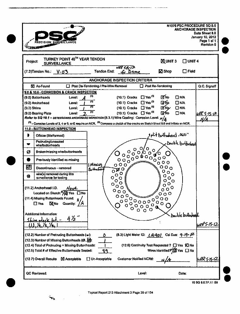
N1076 PSC PROCEDURE SQ 8.0ANCHORAGE INSPECTION
Data Sheet 8.0January 10, 2012
Page I of IPRCSO U BNAC Revision 0
Project: TURKEY POINT 40 T6 YEAR TENDON ELUNIT 3 r] UNIT 4
SURVEILLANCE
(7.3)Tendon No.: V_ 0"3 Tendon End: wee bow . [ Shop r0 Field
ANCHORAGE INSPECTION CRITERIA
1 As-Found 0 Post De-Tensioning I Prm-Wire Removal 0 Post Re-Tensioning Q.C. Signoff
9.0 & 10.0- CORROSION & CRACK INSPECTION(9.2) Buttonheads Level: ______(10.1) Cracks [ Yes (3 [3'No [3 NIA
(9.2) Anchorhead Level: (10.1) Cracks Q[IYes 2) [1 ]NIA(9.2) Shims Level:.- i (10.1) Cracks 0 Yes 41) I N9 0 N/A(9.2) Bearing Plate Level: W' (10.1) Cracks OTYesW [-IS-NAARoee to SQ 10.1 - amermsiONEo ANCHORAGE INsPwrCoN (8.3.1) Wire Coating: Corrosion Level: A11A
! Corosion Levels of 3. 4 or 5. or E require an NCR. (21
Compose a sketch of the cracks on Skotch Sheet 8.0 and Initiate an NCR.
11.0 BUTTONHEAD INSPECTIO.
) Offsize (Malformed) . 1J1+ IIAIO:Ac, "
Protrudingfunseated b-,Jbe.bA4Uw wlrefbttonheads b~t
.0 Bmrkenlmlsslng wireibultonheads
* Previously Identified as missing
I• Discontinuous - removed 0,000
wire(s) removed during this00 0___surveillance for testing 00 )00
(11.2) Anchorhead I.D. AgVA0- 00 0 0
Located an Sketch:& Yes 0 No00 0 0(11.4) Missing Buttonheads Found: 0
IjYes XJNo Quantity: '1A 0 000000 000 00
Additional Information: bue k6sk, M -- .
(12.2) Number of Protruding Buttonheads (w): _ (8.3) Light Meter ID: jA• 1 CalDue: q1-tZ- ,
(12.3) Number of Missing Buttonheads (0. l: . J(12.4) Total of Protruding + Missing Bultonheads: I (12.6) Continuity Test Requested ? 0 Yes Ki No
(12.5) Total # of Effective Buttonheads Seated: J0 Wires Identified"2//l Yes No
(12.7) Overall Results E Acceptable [I Un-Acceptable Customer Notified NCR#: j1/4rJ £ 15-)
OC Reviewed: Level: Date:
0C
19so 8.o.TP.11 ISI
Topical Report 213 Attachment 3 Page 39 of 154

All=
PSC PROCEDURE VT1CI3C.FORMSCERTIFICATION OF EXAMINER
EXHIBIT ARevision 0. Aprill28, 1999
Page 1 of IRevision 1. 4128/99; Revision 2 716199; Revision 3, 2/24/05;
Revision 4, 08131/07; Revision 5,08/01/08; Revision 6. 09104/08-E
-U
LEVEL II CERTIFICATION RECORD
SocialSecurityNumber:
CertificationDate:Name:
VisualMethod:
W. Rance Robbins 05/17112
CertificationLevel:VT-1CI3C 11
6I
Level II
General 90% Date 05/1 5/12
Specific 95% Date 05/15/12
Practical VT-I C: 98% Date 05/16112VT-1 C: 98% 05/16/12VT-3C: 96% 05/16/12
VT-3C: 100% 05/16/12Practical Ave: 98%0/
Composite 94.33% Date 05117/12
The composite grade shall be an equally weighted average of allapplicable examination grades for each category.
Training Courses CompletedType Given By Location Hours Date Instructor
General n/a n/a n/a n/a n/a
Specific n/a n/a n/a n/a n/a
Practical n/a n/a rda n/a n/a
We certify that the above named employee meets all of the oualification recuirements of the PSC Procedure
IWL VT1CI3C.CERT for certification ecertifcaton as a VT-1C/3C Examier Level II.
Approval Signature: J 0_&____II This certificate expires after 05/17/15 IPSC P.E. I'
60110c~cforms~doc
Topical Report 213 Attachment 3 Page 40 of 154
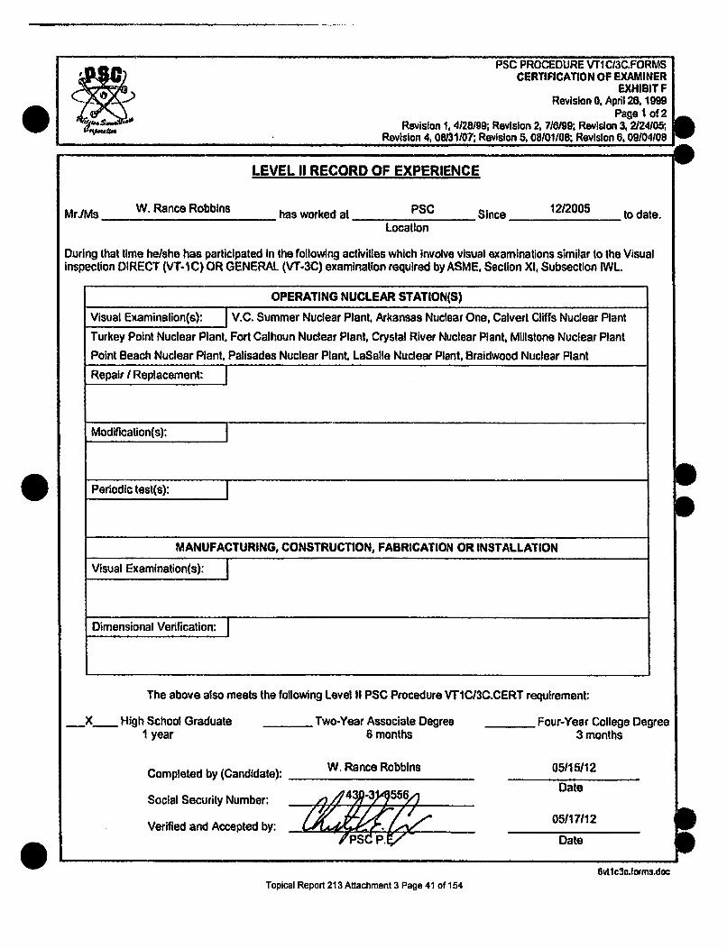
PSC PROCEDURE V"IC/3C.FORMSCERTIFICATION OF EXAMINER
EXHIBIT FRevision 0, April 28, 1999
Page 1 of 2Revision 1, 4128199; Revision 2, 716199; Revision 3, 2124105;
Revision 4, 08131/07, Revision 5, 08/01108. Revision 6,09/04/08IIIhI
'U -W
LEVEL 11 RECORD OF EXPERIENCE
Mr./Ms W. Rance Robbins has worked at PSC Since 1212005 to date.Location
During that time he/she has participated In the following activities which involve visual examinations similar to the Visualinspection DIRECT (VT-iC) OR GENERAL (VT-3C) examination required by ASME, Section XI, Subsection IWL.
OPERATING NUCLEAR STATION(S)
Visual Examinalion(s): V.C. Summer Nuclear Plant, Arkansas Nuclear One, Calvert Cliffs Nuclear Plant
Turkey Point Nuclear Plant, Fort Calhoun Nuclear Plant, Crystal River Nuclear Plant, Millstone Nuclear Plant
Point Beach Nuclear Plant, Palisades Nuclear Plant, LaSalle Nuclear Plant, Braidwood Nuclear Plant
Repair I Replacement:
Modification(s):
Periodic test(s):
MANUFACTURING, CONSTRUCTION, FABRICATION OR INSTALLATION
Visual Examination(s): I
Dimensional Verification:
q
The above also meets the following Level II PSC Procedure VT1C/3C.CERT requirement:
_X_ High School Graduate1 year
Completed by (Candid
Social Security Numbe
Verified and Accepted
Two-Year Associate Degree6 months
ate): W. Rance Robbins
ir .4- ? d4 .
Four-Year College Degree3 months
05/15/12
Date
05117112
DateIp/PSC~ P.V
6vtlc3c.forms.docTopical Report 213 Attachment 3 Page 41 of 154

S PRECISION SURVEILLANCE CORPORATIONVISUAL EXAMINATION TRAINING
NAME: WJiU;Af t •Ibn•5 DATE: -- IA - -
SOCIAL SECURITY NUMBER:Ei
EXAM: VISUAL GENERAL LEVEL II FOR VT-IC/3C /] /
GRADE: z _-,• GRADED BY:_
I have neither given, received nor observed any aid or information regarding this exam prior to
or during its administration that could compromise this exam's integrity. I also understand my
obligation to report any exam compromise by others prior, during, or subsequent to the exam
administration.
I acknowledge that this examination is a way ot'demonstrating my knowledge of the subject
associated with this examination and that I havc had the opportunity, on my request, to review
this entire examination with the instructor to ensure my understanding of the subject matter.
I have read and understand the above statements: W. iL A!. • 5 1/4 '°2012-
0
Student Signature Date
FILL IN ONE CIRCLE AS THE ANSWER FOR EACH QUESTION
A B C D A B C D A B C D A B C D2 0 0 0 6 0 0 0 0O 670 16 0 0 0 0
2 0 0 0 0O 7,0 0 0 0 12 0 0 *0 0 17 0 0 0 0
3 0 0 00 k r 0 0 13 0 0 0 0 18 0 0 0 04~~ 0 0 0"9 O 010 1 141 10 10 1 0 114100 900•00 oo0 190 0 0 015V010010 3IN0'0 10 151000 1"10 200 000I
S ~ ~~V ll0C'3CUINIRALEtXAM FRMi~ 051412
Topical Report 213 Attachment 3 Page 42 of 154

May 14,2012
VT-C GENERAL EXAM
1. What Is the function of the ANII?
A. To verify compliance with NRC regulationsB. To provide another approval signature on formsC. To ensure nuclear safetyD. To verify compliance with applicable requirements of the ASME Code
2. What is the character height of the lower case letters for VT-1 C?
A. 0.010"B. 0.105"C. 0.044"D. 0.500"
3. PSC's Procedure for Level II certifications complies to?
A. ACI 301B. IWL 2001 edition with 2003 addendaC. IWL 98D. IWE 92
4. What are some examples of aids used for "remote" VT-3C visualexaminations?
A. None of the aboveB. Binoculars, telescopes or transitsC. MirrorsD. Feeler gauges
5. What is an optical comparator?
A. A device to determine color resolutionB. A device to evaluate visionC. A device to measure surface lighting intensityD. None of the above
Topical Report 213 Attachment 3 Page 43 of 154
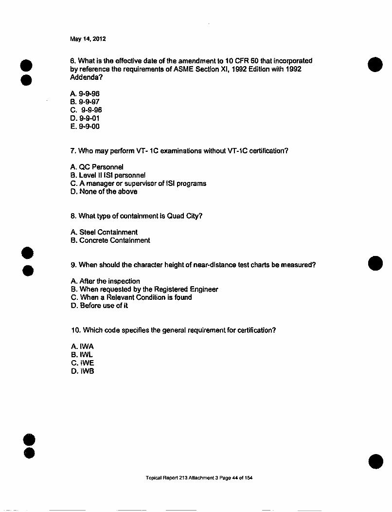
May 14, 2012
S 6. What is the effective date of the amendment to 10 CFR 50 that incorporatedby reference the requirements of ASME Section XI, 1992 Edition with 1992Addenda?
A. 9-9-96B. 9-9-97C. 9-9-96D. 9-9-01E. 9-9-00
7. Who may perform VT- 1C examinations without VT-1C certification?
A. QC PersonnelB. Level II ISI personnelC. A manager or supervisor of ISI programsD. None of the above
8. What type of containment is Quad City?
A. Steel ContainmentB. Concrete Containment
9. When should the character height of near-distance test charts be measured?
A. After the inspectionB. When requested by the Registered EngineerC. When a Relevant Condition is foundD. Before use of it
10. Which code specifies the general requirement for certification?
A. IWAB. IWLC. IWED. IWB
0
S
Topical Report 213 Attachment 3 Page 44 of 154

May 14, 2012
11. What amendment to 10 CFR 50 incorporated by reference the requirementsof ASME Section XI, 1992 Edition with 1992 Addenda?
A. 1992 Addenda 0B. 10 CFR 50.55a.C. Appendix AD. 10 CFR 10.30
12. Which subsection of ASME Section XI applies to VT-1C/3C examinations ofconcrete containments?
A. IWEB. IWAC. IWLD. AWL
13. Section XI, IWL exempts what areas of concrete surfaces of containments tobe examined:
A. Areas covered by the steel liner, foundation material or backfill, or areotherwise obstructed by adjacent structures, components parts, orappurtenances.B. Areas as determined by the ANIIC. Areas requiring the use of a ladder, chair or other equipment to reach them.D. Areas as determined by the Responsible Engineer
14. For VT-3C examinations what is the minimum far-distance vision acuity theexaminer must have?
A. 40/40 or betterB. NoneC. at least 20/25 Snellen in at least one eye.D. 20/20
15. VT-3C visual examination is required to be performed on?
A. All of the aboveB. Tendon buttonheadsC. Jacks/Rams used for stressingD. Exterior Containment concrete surface and grease cans
Topical Report 213 Attachment 3 Page 45 of 154

May 14. 2012
16. Mirrors and supplemental lighting are aids for?
A. General visual inspectionB. VT-3 InspectionC. VT-1C inspectionD. VT-2B inspection
17. What are the methods of visual inspection PSC certifies it's examiners to?
A. VT-1B. VT-1CC. VT-3CD. All of the above
18. How often is Level II re-certification required?
A. Every 5 yearsB. Every 3 yearsC. Every 3 monthsD. Every year
19. For VT-1C examinations what is the minimum near distance vision acuity theexaminer must have?
A. at least 20/25 Snellen in at least one eye.B. 40/40 or betterC. 20/20D. None
20. Level II minimum education required for certification is?
A. MBA degreeB. High school or equivalentC. No educationD. One year of college
S
Topical Report 213 Attachment 3 Page 46 of 154

May 14, 2012
VT-C GENERAL EXAM ANSWER KEY
1. D 2. C 3.6 4. B 5. D12. C 13. A 14. C 15. D 16. C
0Ol6. C 7. D 8. A 9. D17. D 18. B 19. A 20. B
1O.B 11.B
00
Topical Report 213 Attachment 3 Page 47 of 154

S PRECISION SURVEILLANCE CORPORATIONVISUAL EXAMINATION TRAINING
NAME: J• ,, '
SOCIAL SECURITY NUMBER:
EXAM: VISUAL SPECIFIC LEVEL 11 FOR VT-I
DATE: !C 1- -
GRADE:
I have neither given, received nor observed any aid or information regarding this exam prior to
or during its administration that could compromise this exam's integrity. I also understand my
obligation to report any exam compromise by others prior, during, or subsequent to the exam
administration.
I acknowledge that this examination is a way of demonstrating lay knowledge of the subject
associated with this examination and that I have had the opportunity, on my request, to review
this entire examination with the instructor to ensure my understanding ofthe subject matter.
~vI have read and understand the above statcments: 4* 11-6fým
Student Signature Date
FILL IN ONE CIRCLE AS THE ANSWER FOR EACH QUESTION
A B C D A B C D A B C D A B C D
10 0 00 _6 0 00 0 11 0 0 0 0 16 0 0 0 _200060 000OO 12 0000 ! 170000O
2 0 0 0 0 90 0 0 14 0 0 19 O 0 0 03 0'0 0 1 0 0 0 00s0 20 0 00
50EXAM "05/14/12"' 1
VrlSIECII:IC EXAM FORM O0 1412
SS
Topical Report 213 Attachment 3 Page 48 of 154

May 14, 2012
VT-C SPECIFIC EXAM
1. Per PSC Procedures for VT examinations who approves the qualifications ofVT Examiners?
A. VT SupervisorB. Responsible Engineer (P.E.)C. Project ManagerD. Project Superintendent
2. What degradation is defined by the breaking away of small portions of aconcrete surface due to localized internal pressure which leaves a shallow,typically conical depression?
A. Exudation.B. Laitance.C. Popout.D. Encrustation.E. Stratification.
3. Visual concrete exams are performed under the direction of what qualifiedindividual? 0A. Corporate Vice PresidentB. Responsible Engineer 0C. Job SuperintendentD. Project Manager
4. VT-3C inspection is required to be performed on:
A. Exterior Containment concrete surface and grease caps.B. All of the above.C. Tendon button heads.D. JackslRams used for stressing.
5. Per ASME Section X1, subsection IWL what are to be given a VT-3Cexamination?
A. Tendon anchor headB. Roof of turbine buildingC. Containment tendon bearing platesD. Containment concrete walls 0
0
Topical Report 213 Attachment 3 Page 49 of 154
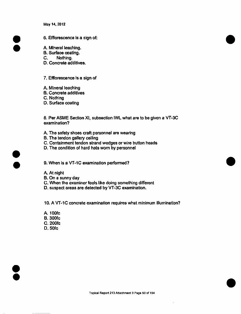
May 14, 2012
6. Efflorescence is a sign of:
A. Mineral leaching.B. Surface coating.C. Nothing.D. Concrete additives.
7. Efflorescence is a sign of
A. Mineral leachingB. Concrete additivesC. NothingD. Surface coating
8. Per ASME Section XI, subsection IWL what are to be given a VT-3Cexamination?
A. The safety shoes craft personnel are wearingB. The tendon gallery ceilingC. Containment tendon strand wedges or wire button headsD. The condition of hard hats worn by personnelS9. When is a VT-1C examination performed?
A. At nightB. On a sunny dayC. When the examiner feels like doing something differentD. suspect areas are detected by VT-3C examination.
10. A VT-1C concrete examination requires what minimum Illumination?
A. 100fcB. 300fcC. 200fcD. 50fc
Topical Report 213 Attachment 3 Page 50 of 154

May 14, 2012
11. Detailed VT-1C inspection can apply to:
A. Tendon force level.B. Proper torque applied to bolts.C. Concrete cracks.D. Back filled section of containment.
12. In tendon anchorage areas, acceptable cracks in the concrete adjacent to thebearing plates do not exceed.
A. 0.010 inch in width.B. 0.100 inch in width.C. 0.001 inch in width.D. 1.000 inch in width.
13. When may devices for remote VT-1C examination be used?
A. Health physics considerations make direct VT-1 C examination inaccessibleB. NRC allows remoteC. Health physics allows remoteD. When it is raining 014. A detailed VT-1 C concrete Inspection requires what maximum examinationdistance?
A. 7 feetB. 2 feetC. 35 feetD. 4 feet
15. How often is a vision test required for VT Examiners?
A. Every other monthB. Every 5 yearsC. Every 12 monthsD. Every 10 years
Topical Report 213 Attachment 3 Page 51 of 154

May 14. 2012
16. What kinds of concrete deterioration and distress are defined in ACI 201.1 R-68 & 92?
A. Concrete cracking.B. Concrete deterioration.C. Concrete spalling.D. All of the above.
17. At a Nuclear Unit how may dirt, contamination or other debris that couldinterfere with the concrete examination be removed?
A. Mechanical cleaning methods or approved solvents if approved by theResponsible EngineerB. Acid if approved by the ANIIC. Fire hoseD. All of the above
18. What type of degradation often initiates as microscopic cracking at thereinforcing steel-to-concrete bond interface, resulting from periodic applicationsof load or stress?
A. Abrasion/erosion.B. Cement-aggregate reactions.C. Fatigue.D. Irradiation.
19. Which of the following degradation mechanisms to rebar is associated withchanges in the permeability of concrete, presence of an electrolyte, ormicrobiological attack?
A. Irradiation.B. Fatigue.C. Corrosion.D. Thermal effects.
20. VT-3C visual examination is required to be performed on?
A. Jacks/Rams used for stressingB. Exterior Containment concrete surface and grease cansC. Tendon buttonheadsD. All of the above
Topical Report 213 Attachment 3 Page 52 of 154

May 14, 2012
VT-C SPECIFIC EXAM ANSWER KEY
1. B 2. C 3. B 4. A 5. D 6. A 7. A 8. B 9. D 10. D 11. C12. A 13. A 14. B 15. C 16. D 17. A 18. C 19. C 20. B
0C
00
Topical Report 213 Attachment 3 Page 53 of 154

PRECISION SURVEILLANCE CORPORATIONVisual Examination Training
PRACTICAL EXAMINATION CHECKLIST
NAME: tAI, /•AN aA&- DATE: 144- 2w
SOCIAL SECURITY NUMBER:
EXAM METHOD: VT-I o r~~jr VT-3C EXAM NUMBER:
GRADE:2 INSTRUCTOR/ GRADED BY1%4laiI AeA r/iia•PSC 1P.EI
I have neither given, received or observed any aid or information regarding this examprior to or during its administration that could compromise this exam's integrity. I alsounderstand my obligation to report any exam compromise by others prior, during, orsubsequent to the exam administration.
I acknowledge that this examination is a way of demonstrating my knowledge of thesubject associated with this examination and that I have had the opportunity, on myrequest, to review this entire examination with the instructor to ensure my understandingof the subject matter.
I have read and understand the above statements: V1/. , , •'-I-
Student Signature Date
POINT VALUE INSPECTION POINTS POINTS GRANTED/COMMENTS10 Select procedure
Verify revision10 Select form
Verify revision5 Select equipment
Verify calibration/resolution5 Verify adequacy of lighting
Prior to and during inspection5 Record part/item number
On inspection form ___ _
15 Inspect component/partIdentify discontinuities
15 Compare discontinuities toRecording criteria in procedure
25 Correctly recorddiscontinuities
5 Sign and date form _ -,_ _
5 Complete formAccurate and legible ,__ _
Viputev.pmcical
Topical Report 213 Attachment 3 Page 54 of 154

.... N1076 PSC PROCEDURE SO 83BEARING PLATE INSPECTION
I •DATA SHEET SO 0.3N" ~January 10,12012
P R CISIO§NSU VM.AN CEPaeIoIRevision 0
Project: TURKEY POINT 4 01h YEAR TENDON SURVEILLANCE • UNIT 3 0 UNIT 4
Tendon No.: Tendon End: ) K Shop 0 Field
(7.4) Bearing Plate Identification M: L~uAW# 'fe I /2
1. Orient the bearing plate with the sketch below.
2. Locate the bearing plate identification and document the location on the sketch.
3. Sketch all cracks, Including other defects, existing on the concrete In the area surrounding the tendon anchorage for a distance of24 Inches from the edge of the bearing plate.
4. For cracks equal to or wider than 0.010 inches. document condition on a Nonconformance Report In accordance with ProcedureQA 9.0. NONCONFORMANCES. for Florida Power & Light approval.
C14EK -- 5
4J(raioia Oir $90K
> "~k Is t. Xd44
/c 44Acr/4. OLJ< oe/1 w
On Hoop and dome this edge Isup.
Vertical Tendon, this Is toward thecenter of the containment. I
I " b4 ,0
A
4010, .0
BII
4 b
16,11J. ~ ~ ~ ~ iA &'(Ivir%4 1264 las wD/cjmcrtk
~'A~i.AID~tA1.4.'i ql f*6h .b~IL~ Ai.~/1J2AA.a.J.AfPfd~PI
Light Conditions 50fc or greater: IN 4es-] No Auxiliary Ught Source used: E3 Yes; No Describe: oA(7.3) Light Meter ID: L-A 90( Date due calibration: q- 11 IDA T(7.5) Cracks a 0.010 t@ Yes [I No Ouantity: . Max. Width: oo' Max Length: . NCR#: M [
QC Inspector: tc. .a.- 0 " Level: jW Date: , .. , 2-AIa
OC Reviewed: Level: Dale: qw20SOIL3TP~ii ISI0
Topical Report 213 Attachment 3 Page 55 of 154

PRECISION SURVEILLANCE CORPORATIONVisual Examination Training
PRACTICAL EXAMINATION CHECKLIST
NAME: W. RAAt -DATE: S.1A-2OI-
SOCIAL SECURITY NUMBER:
EXAM METHOD: VT-i oj¶§V~C EA
GRADE: INSTRUCTOR/ GRADED B. A-/ e eL
/ PSC P.E , .- •
I have neither given, received or observed any aid or information regarding this examprior to or during its administration that could compromise this exam's integrity. I alsounderstand my obligation to report any exam compromise by others prior, during, orsubsequent to the exam administration.
I acknowledge that this examination is a way of demonstrating my knowledge of thesubject associated with this examination and that I have had the opportunity, on myrequest, to review this entire examination with the instructor to ensure my understandingof tie subject matter.
I have read and understand the above statements: W, &ce, IV14-- _,ýU ý-2619Student Signature Date
00 POINT VALUE INSPECTION POINTS POINTS GRANTED/COMMENTS
10 Select procedure ,,
,,_________Verify revision "/" _ _ _10 Select form
Verify revision "/65 Select equipment
Verify calibration/resolution5 Verify adequacy of lighting
Prior to and during inspection5 Record part/item number
On inspection form 4
15 Inspect component/partIdentify discontinuities
15 Compare discontinuities toRecording criteria in procedure _ _/_ _ _
25 Correctly recorddiscontinuities ,_ _ _,_.._
5 Sign and date form -.5 Complete form
I Accurate and legible I".-_
0Topical Report 213 Attachment 3 Page 56 of 154

PRECSION -sRvSII!LAC
N11076 PSC PROCEDURE SQ 8.3BEARING PLATE INSPECTION
DATA SHEET SQ 8.3January 10. 2012
Page 1 of 1Revision 0
IProject: TURKEY POINT 40d YEAR TENDON SURVEILLANCE [] UNIT 3 - UNIT 4
Tendon No.: V.03 Tendon End: U tetu N-l Shop Field
(7.4) Bearing Plate Identification #: Luw%66..- 4 e, to -4 Le
1. Orient the bearing plate with the sketch below.2. Locate the bearing plate identification and document the location on the sketch.3. Sketch all cracks, including other defects. existing on the concrete in the area surrounding the tendon anchorage for a distance of
24 Inches from the edge of the bearing plate.4. For cracks equal to or wider than 0.010 inches. document condition on a Nonconformance Report In accordance wilh Procedure
QA 9.0. NOCONFOnMANCES, for Florida Power & Light approval.
Ck t,4eJ "j3/L.JC .O0,'vO Cu|
b01 k 7",., On Hoop and dome this edge is W.
" • "' "K a• W.
Vertical Tendon, this Is toward thecenter of the containment.
ve:l~ros 1L.K
W4- bý rom A;emiiqa teem
2f4 "SA 6/046MJ ae 11y .15 -121f LiI& w f f~ 570 eA C A *n 4 -IQ121zj'LAU( O&dAW 4.e8* 1s *i. i.Light Conditions 50tc; or greater. JO YasO No Auxiliary Light So-urce used: 0 YesfZ No Describe:
(7.3) Light Meter I D: Li q Date due calibration: q14-2/
(7.5) CracksI 20.010" ,Yes C-No Quantity: Max.Width: ass."Max Length: aj, NCR#: o _
oCInspector. . • Level: Date:
OC Reviewed: Level: Date:
00
00
020 SO 63TP.11 ISI
Topical Report 213 Attachment 3 Page 57 of 154

0
PRECISION SURVEILLANCE CORPORATIONVisual Examination Training
PRACTICAL EXAMINATION CHECKLIST
NAME: W4 Ateg* A mmsV DATE:6.IE-26 17-
SOCIAL SECURITY NUMBER:EXAM METHOD: V'r-I. orVT-WoCi EXAM NUM.ER:.4 !
GRADE: ~ ~ ~ ~ INTRCTR/GRDE.B:E
I have neither given, received or observed any aid or information regarding this examprior to or during its administration that could compromise this exam's integrity. I alsounderstand my obligation to report any exam compromise by others prior, during, orsubsequent to the exam administration.
I acknowledge that this examination is a way of demonstrating my knowledge of thesubject associated with this examination and that I have had the opportunity, on myrequest, to review this entire examination with the instructor to ensure my understandingof the subject matter.
I have read and understand the above statements:Student Signature Date0
POINT VALUE INSPECTION POINTS POINTS GRANTED/COMMENTS10 Select procedure +
Verify revision _" __ _10 Select form
Verify revision •"Jo
5 Select equipmentVerify calibration/resolution
5 Verify adequacy of lightingPrior to and during inspection
5 Record part/item numberOn inspection form _ _ _,_
15 Inspect component/partIdentify discontinuities
15 Compare discontinuities toRecording criteria in procedure
25 Correctly recorddiscontinuities 1c- ]
5 Sign and date form5 Complete form
Accurate and legible ",5
0V(~Ec(ag.p1ucIicaI
Topical Report 213 Attachment 3 Page 58 of 154

N1076 PSC PROCEDURE SQ 8.4CONCRETE EXTERIOR
DATA SHEET SQ 8.4January 10, 2012
P t Page 1 of 1Revision 0
VISUAL EXAMINATION - GENERAL VISUAL EXAMINATION
Project Turkey Point Surveillance IO2 •LYear 40th
lInspcction Area: TOO O r
iEquipmnent Used LlAq 4l 4t.A,. Q.I.12-IAL' Fib £4.e ,jI./4- F-11- &/
Concrete Surface ConditionContainment Surface (Findings and Dcscriptiot) NI 10 RI4 A,.,,t 6",-*,j;. ,,am n I• El/p 7" sm.j oo p ,, 'u s :F W I• E
NI 4L r.rk MAel 0 E
-1 Ell]
SB . ..-
El E
0
0
(Use as many sketch sheets (page 2) as ineeded to report any Recordable Indication (RI) or Information Only(!0)&indings for the purpose of documentation and oriezltation.)
Recordable Indications to be Examined For (PSC Procedure 8.4)Leaching or Chemical Attack Dcterioration of any Concrete Coating (if applicable)Abrasion or Erosion Degradation Tendon Grease on Exposed Concrete SurfacesPopouls and Voids Corrosion on Grease Cans, Bearing Plates or AnchorageCracks *Excc..,ivc Corrosion on Exposed Embedded Mceal SurracesScaling *Detached Embedments or Loose BoltingSpalls *lndication of Degradation Due to VibrationCorrosion Staining on the Concrelc Surface (*The ownerlagent must be notified for these noted condli Ions.)E~xposed Reinforcing SteelSurface Patclics or RepairsComments and Disposition by Responsible Engineer []Acceptable []UnacceptableComments:
Inspector & Level: hi, v Date: /Responsible Engineer: Date:ANII: Date:
I *
21 SO 8.4.TP.11 ISI
Topical Report 213 Attachment 3 Page 59 of 154

PRECISIONTURY&LANCE
N1076 PSC PROCEDURE SQ 8.4CONCRETE EXTERIOR
SKETCH SHEET 8.4January 10, 2012
Page 1 of 1RevisIon 0
010
SS
21 S 8.4.TP.11 ISI
Topical Report 213 Attachment 3 Page 60 of 154

PRECISION SURVEILLANCE CORPORATIONVisual Examination Training
PRACTICAL EXAMINATION CHECKLIST
NAME: A LYS DATE: !- j4- 0 I V-
SOCIAL SECURITY NUMBER:EXAM METHOD: VT-! or VT-IC or• EXAM NUMBER:;t" _- ...
... PSz"P.•K-'-
I have ,neither given, received or observed any aid or information rcgarding this examprior to or during its administration that could compromise this exam's integrity. I alsounderstand my obligation to report any exam compromise by others prior, during, orsubsequent to t(le exam administration.
I acknowledge that this examination is a way of demonstrating my knowledge of thesubject associated with this examination and that I have had the opportunity, on myrequest, to review this entire examination with the instructor to ensure my understandingof the subject matter.
I have read and understand the above statements: k/. 11.2612Student Signature Date
POINT VALUE INSPECTION POINTS POINTS GRANTED/COMMENTS10 Select procedure
Verify revision r10 Select form
Vcrify revision "/05 Select equipment
Verify calibration/resolution _ _ __"
5 Verify adequacy of lightingPrior to and during inspection _ "_"
5 Record part/item numberOn inspection form__
Is Inspect component/partIdentify discontinuities
15 Compare discontinuities toRecording criteria in procedure t/5•
25 Correctly recorddiscontinuities _ _ ___ _
5 Sign and date form "5 Complete form
Accurate and legible "5
S0
Vi~tlmustr~ial
Topical Report 213 Attachment 3 Page 61 of 154

N1076 PSC PROCEDURE SO 8.4CONCRETE EXTERIOR
DATA SHEET SQ 8A4January 10 2012
P RECISIW, 3~ 2AN CEPaeIoIRevision 0
VISUAL EXAMINATION - GENERAL VISUAL EXAMINATION
Project Turkey Point Surveillance # .0 Year 40thInspection Area: r0)02-Equipment Used .SL.J "d , LM-let eAd. JuL 9.t4.12i/eft•P -. b Ap,.'11lg-12./
oCWfI to~pAiA4aI Ot. l' ti, I4. /• .",,, i -/ jA. ,. 70 CAL:" 'd 11.. 114iConcrete Surface Condition
Containment Surface (Findings and Description) NI 1 I
L1I
HE [I. E]flTH'Ti..7 =B
' / " "
S10
SIS
(Use as many sketch sheets (page 2) as needed to report any Recordable hidicalion (RI) or Informnation Only(O)0fIndings for the purpose of documeistation and orientahion.)
Recordable Indications to be Eixamined For (PSC Procedure 8.4)Leaching or Chemical Attack Deterioration or any Concrete Coating (if applicable)Abrasion or Erosion Degradation Tendon Grease on Exposed Concrete SurfacesPopouts and Voids Corrosion on Greasc Cnm, Bearing Plates or AnchorageCracks *Excessive Corrosion on Exposed Embedded Metal SurfacesScaling *Dctached Embedments or Loose BoltingSpalls *Indication of Degradation Due Io VibrationCorrosion Staining on ilte Concrete Surface (* The ownerlagent must be notified for these noted conditions.)Expos•d Reinforcing SteelSurface Patches or RepairsComments and Disposition by Responsible Enginccr -]Acccptable -Ut nacceplablcComments:
Inspector'& Level: J' 46z-. Date: j - ,f1-202,"Responsible lingineer: Date: _
ANII: Date:
21 SO 8A.TP.1I ISI
Topical Report 213 Attachment 3 Page 62 of 154

p8~h/ PRECISION SU 6:IL "ANCE£ :._
N1076 PSC PROCEDURE SO 8.4CONCRETE EXTERIOR
SKETCH SHEET 8.4January 10. 2012
Page 1 of 1Revision 0 0
0
0
21 So 8.4.TP.I1 ISI
Topical Report 213 Attachment 3 Page_63 of 154

QUALIFICATION OF QUALITY CONTROL INSPECTORS-PROCEDURE QA 2.10.6.1.1
CERTIFICATION FORM QA 210.6.1.1 B
61
CERTIFICATE OF QUALIFICATION
This is to certify that:
Clinton West SSNhas been qualified through on-the-job experience and formal training to meet the requirements of
ANSI N45.26-1973 and 1978 as:
QUALITY CONTROL INSPECTOR LEVEL il with the following limitations.
0
Inspections and Calibrations associated with Post-Tensioning Systems and Components.
This certification will qualify the named individual to perform Quality Control inspections,examinations and testing for the various manufactured products or services supplied, to meet theRequirements of the projects for the Precision Surveillance Corporation and within the limitationsof this qualification.
This qualification becomes effective 8/21/13 and shall remain in effect until theRecertification date of 8/21/16 or until such time that the named individual leaves the employmentof PSC, gives just cause for termination of the certification or requires additional training tomaintain a proper Quality Control disposition.
PHYSICAL REQUIRMENTS: Eye Exam Date 6/17/13 to 6117114 by Optometrist
Eye Exam Date to by
Eye Exam Date to by
APPROVED BY: _ _ _ _ __,_
Quality Control Inspector Level *7
Date: LA,!/13I t
00
Topical Report 213 Attachment 3 Page 64 of 154

QUALIFICATION OF QUALITY CONTROL INSPECTORS-PROCEDURE QA 2.10.6.1.1
QUALIFICATION LIMITATION FORM QA 2.10.6.1.1 C
The named individual is hereby certified to perform Quality Control inspections, examinations andtests for the products of the Precision Surveillance Corporation and shall be limited in practicingthose skills to those activities for which qualified as shown.
Name Clinton West SSN
Quality Control Inspector Level 11 per ANSI N45.2.6 - 1973 or 1978
ACTIVITIES
POST TENSIONING SYSTEM:
SHOP: N/A
VENDOR: N/A
FIELD: All
TESTING: N/A
OTHER: N/A
REINFORCING STEEL
SHOP: N/A
CONSTRUCTION METALS:
STRUCTURAL FAB: N/A
WELDING: N/A
PAINTING-ANSI 101.4: N/A
OTHER: N/A
GENERAL QUALITY ASSURANCE:
DOCUMENT CONTROL: Yes
TEST REPORT APPROVAL; Yes
PURCHASE ORDER APPROVAL: No
NONCONFORMANCE REPORTING: Yes
CALIBRATION: Yes
I0CIR21 Yes
IOCFR50 and PSC QUALITY ASSURANCE: Yes
APPROVED 4:,- DATE: .Quality Control Inspector Level IF1
Topical Report 213 Attachment 3 Page 65 of 154

PROFESSIONAL SUMMARY
A. NAME: CLINT WEST
B. POSITION: FIELD SUPERINTENDENT
Responsible for set-up, supervising and managing field crew as assigned for special constructionprojects with or without labor.
C. EDUCATION:o 1985: Graduated from Belleville High School- Belleville, AR
0 1985-1986: Attended Bryan Institute of Computer Programming
o 1987-1991: U.S. Navy Aviation Machinist Mate 3rd Class (Jet Engineer Mechanic). Variouscommendations and medals. Assigned to U.S. Navy SEABEE Unit 406 Steel Workers
D. CERTIFICATIONS:O Journeyman Ironworker, Local 321
o3 Certified Four Position Welder
o OSHA 30 Hour Training
* [0 Qualified Rigger
E. WORK EXPERIENCE:O 8/1991-12/1991: William's Construction
o 12/1991-1211995: Truck Driver
o 1/1996-6/2000: Maintenance/Milwright at Wayne Farms- Danville, AR
O 8/2000-12/2000: Laborer at Arkansas Nuclear One Unit 2 SGR
O 612001-5/2004: IronWorker Local 591-Shreveport, LA- Several Foreman Positions, IW Steward- Numerous Structural Jobs
O 5/2004-Present: Iron Workers Local 321-Little Rock, AR- 5/2004-7/2005: Boyd Sanders Construction- 7/2005-1/2006: ANO Unit 1 SGR. Stone & Webster and SGT- 3 Reactor Head Changes with Bigge Crane and Rigging- San Leandro, CA- Superintendent on job in Bahamas rebuilding an oil transfer station off shoredestroyed by Hurricane Katrina.
O 4/7/2008-Present: Precision Surveillance Corporation-East Chicago, IN-Worked as General Foreman, Foreman, Rigger, and Welder at variousNuclear Sites throughout the United States. Superintendent as of 9/2008.
03460 WknruN8 Smxf, EAsr C.m.wA- IN • 46312
P (219) 397-826- F 1219) 39'7-SBI'7.www.Psc2um.uR.Cmo
Topical Report 213 Attachment 3 Page 66 of 154

0F. NUCLEAR JOBSITE ACTIVITY
Involvement in Construction Management and/or supervision of post-tensioning or structural systemsfor the following nuclear projects:O ANO-Arkansas Nuclear One
o VC Summer Nuclear Plant
o Ginna Nuclear Station
o Millstone Nuclear Power Plant
O Byron Nuclear Plant
0 Brunswick Nuclear Plant
o Fort Calhoun Nuclear Plant
O Point Beach Nuclear Plant
O Vogtle Nuclear Plant
o Palo Verde Nuclear Plant
o Braidwood Nuclear Plant
0 Crystal River Nuclear Plant
o Palisades Nuclear Plant
o Waterford Nuclear Plant 0
03468 WjmAU STRK'mr. -EAr CH=Ann * IN .46312
P (219) 397•SB26. F (219) 397-5B67, wwwi.mcmcumzaRm.
Topical Report 213 Attachment 3 Page 67 of 154

PSC PROCEDURE VT. ~ORMSCERTIFICATioN OF XMNR
EXHIBIT 0S iRevision 0. April.28. 1999PREISI.N.S•.JfILLANCE Revision . 4128W990 Revision 2,71619; ae 1s o
..... Revision 4. 0831 751N9; Revision 3, 2024105;Revs~o 4,8131W; Revision 5, 0=19108; Revision 6,09W10408
-------------- -
PHYSICAL TESTING OF INSPECTORS-PROC. QA 2.10.681.1.1PHYSICAL TESTING FORM QA 2.10.6.1.1.1
Name:
Title:rc/I [ bie-5-J Date -/1-12. Retest Date
Wears Glasses . .
I. PHYSICAL CHARACTERISTICS IIRating:
Comments/ 40.0 PdJ Limitations- e3/r, r 4 /
-Ajz> Iq
E
t 2. VISUAL.- FAR RANGE
Vision Rating %: /,0 Left
Comments
it,
3. VISUAL -NEAR RANGE
Vision Rating Grade .'•/ ,0 Left
Comments
S4. COLOR PERCEPTION
61 1 .. ... . .. ..
Score Of 14
Score shall not be less than 10 to be
Comments . . t
.VRALL RATING•Capability .. C .y ..
Test Device
,1 -/ Right i
......J .. ..27
12
Test Devicc3
8
13
..... . . .. . ..
49 10
14 15
............................
.... .. - : : : : .......... . ........ ..... .- ..:: : :
Perception /(÷_
acceptable for perception.
..............-.....
-~9b~rhG7/Date
T opical R~eport 213s Attacment 3s Page 68 of 1~

Precision Surveillance Cororation 0
PRECISION SURVEILLANCE CORPORATION
TRAINING SHEET
TIlE PSC PERSONNEL LISTED BELOW I lAVE BEEN PROVIDED AN OVERVIEW AND) INDOCrRINATED TO PRECISIONSURVEILLANCE CORPORATION'S QUALITY ASSURANCE MANUAL REVISION 5 (ALL SECTIONS)
NAME SIGNATURE SS# DATE
1w NT- CS -U t Z/.
TRAIN ER:~
DATE: 42AL...
0Training Sheet
Topical Report 213 Attachment 3 Page 69 of 154

( Precision Surveillance Corporation
Training Sheet ANSI
Topical Report 213 Attachment 3 Page 70 of 154

I
OACf
OJ2W~4I ~I~LJZ PRA~ A-_
Dmr of "up& -- ------.M Ap wbm ~r
191( tY.Wf Gc&k'M j gyzgf- 2Ga&Le I 19E I' 01 -lf,=
C-.w
•q •" ".I. I I -&2- .~ I. ~ 4 I I I a . p . I- Y4
-f- Irp- I % n[ 1- I'l WI-- al mub'Il " ,
V/ ýk) W!-!o iiý/ -ýrft m ý,, I FA I T.:I=- E: K:3 ]7-I[L) I I!LýL
I ;n- it a W- F; -3 7'-'m FA-77- =1711111-EA.7-ArmL,4mf .in . I its. I C
- ~ 4h~I~.Ih~1]|1 dlr -_..-.. 1, 1 c - a;_=_.. W-4 I
3
CVV-
0:
0.
9/5MAX
P. ,1'. Ir,. 1 ZKA A-. '~I~IJ ,Il J,_Plipt 4 lwl"K "a 9--A%"d 1q, W-MIS-NAMMIlk 12C 1
P- W- U I R X-, IF - I& IA l;Zjj I tL& -JAIkiyo l2AAlktffwh lcýpJ L . Mmnc Lh * I
_-z ______A___I£.-d-r ~ ~ 19P ,~ 9 rd
a-
CdCd
CdwCd
CdC-
0)
0Cd
CdCd.5C',C
5-%U"s AftvW Fm 2s
0;
0 90 g0

,,08/04/2013 09:08 478 413 4111 VYC ELEMENTARY 8220T P. 002/002
WESTERN YELL COUNTYELEMENTARY SCHOOL.
PO Box 808 l lellevillo, Afkteae 72U24Phone: 47914934100 - Fax: 479/493-4117
Keith Jones, Pd idpaW Uea Lawrence, Counsefe-mall: joreakfwot*d iea.kl.w .us a-ml:lawenoel@wolverlntkl2,ar.us
Jults Los, Curdcutum Cowrdinator Cait George, SecreisilRel" Strare'mail: lanueJ@valvedn as,k12.Ar.a e-maf [email protected]
June 4,2013
To Whom I May Concern:
ClInt West gi aduated from Belleville High School on May 24,1985.
I was Clint's school secretary as well as a family friend. He and my son wereclassmates.
We do not t ave documentation other than the Transcript.
Sincerely,
Carol Georne
Topical Report 213 Attachment 3 Page 72 of 154

---------------
5/31/ 13
Carol GeorgeWestern Yell County Elementary300 North Grand AvenuePO Box 250Belleville, AR 72824
Oear Mrs. George,
Thank you for sending Clinton West's High School Record. Unfortunately, it does not state whether hecompleted High School. Therefore, we would also like to request any documentation/records that you may haveof him completing/graduating High School. You may also provide a letterverifying he did graduate. Clint West Isour employee and we need this information for his personnel file.
If you need any information from me, please call me at (219) 397-5826. Thankyou in advance for your promptattention to our request.
Sincerely...
Melissa LaraAdministrative Assistant
0
3459 WATuNa TSCLT- WATCWC~iAo* IN - 4531 2P 13 191397-5926 f12 191397-5867 -mYM-P35a1tgRnme
Topical Report 213 Attachment 3 Page 73 of 154

PSC QC INSPECTOR TRAINEE: C L I N'T \A e1 L T DATE:M 6- 11- 1Oj
TEST SCORE: /0000o PSC INSTRUCTOR: wA 4 .4U 17Le0 -i/
PRECISION SURVEILLANCE CORPORATIONQUALITY CONTROL INSPECTOR TRAINING PROGRAM
EXAM
1) What is the proper way to correct an error recorded on a data sheet ie: typo, obviousomission?
( Write in changes or correct dateAny changes made, one line initial and date
c) Write a nonconformance
2) When performing inspections what documents should you have with you?
a) Quality Assurance Manual@ Applicable Inspection Proceduresc) Calibration reports on inspection tools
3) Quality Control Inspectors shall be completely independent from the pressures of
a) Customersb) Quality Assurance
(Q Production
4) The distance a tendon/wire stretches when being stressed is called,
a) Liftoffb) Relaxation@ Elongation
5) During stressing operations, which of the following cautions shall be observed?
a) Do not stand behind the jack when it is under loadb) Keep fingers out of any pinch areasc) Be alert during shim placement and removal
(r All of the above
Topical Report 213 Attachment 3 Page 74 of 154

6) The tendon shall never be stressed beyond % of the minimum guaranteedultimate tensile strength (Guts) of the effective wires remaining in that tendon
a) 60%3(80%c) 100%
7) When tendon stressing is performed from both ends simultaneously the pressure at
one end of the tendon shall not exceed the other by more than 1000 psi.
(,• Trueb) False
8) The minimum temperature for grease being pumped into a tendon end isdegrees.
120 degrees150 degrees
c) 160 degrees
9) When cracks are detected for Anchor Heads, Shims or Bearing Plates, Turkey PointEngineering shall be notified by a nonconformance report.
Qý True
b) False
10) The Field Quality Control Inspectors operate under the immediate direction of:
a) Field Superintendent(J Lead Quality Control Inspector
c) PSC Manager Quality Assurance
11) Field Quality Control Inspectors and the Quality Assurance personnel have theauthority to issue a "Stop Work Order" for any activity, material, or procedure not inconformance with:
a) Project specificationsb) Quality Assurance Manual
( Surveillance I.S.I. ManualAll of the above
12)
Field Changes that take place prior to the approval of a Field Change Request shall bedocumented on a N 0
Topical Report 213 Attachment 3 Page 75 of 154

13) Prior to applying ANY FORCE to a tendon the stressing adaptor must be fullyengaged.
0 Trueb) False
14) To find the actual liftofftlock-off at a particular end of a tendon a 0.030" thickfeeler gauge (shim stock) is inserted into the shim stack until consecutiveliftoff/lock-off readings have been taken.
Two (2)Three (3)Four (4)
15) Steel rulers are calibrated every:
g 6 monthsSlyear
c) 5 years
16) When should Quality Control Documents be signed by the inspector?
a) Before the next stepb) At the end of the day
0 After all information for the inspections have been entered
17) Who controls the Measuring and Test Equipment used by PSC Inspectors?
a) PSC Superintendentb) Utility employees
(@ PSC Quality Control or Quality Assurance personnel
18) Where are all quality related documents pertaining to the project kept?
a) In the inspector's deskField office file orjobsite vault
c) With the PSC Superintendent
19) All Lead Field Quality Control Inspectors shall be qualified to a minimum of Level- capability in accordance with the requirements of ANSI N45.2.6.
a)~lI
c) [II
Topical Report 213 Attachment 3 Page 76 of 154

20) The person responsible for recording inspection information on Data Sheets is the 0
Craft Crew MemberPSC QC Inspector
c) Foremand) Any of the above
0
0
Topical Report 213 Attachment 3.Page 77 of 154

0
0
Document: FRM-POR-001
IWL VISUAL EXAMINER Revision: 0CERTIFICA7VON RECORD Date: July 16, 2013(EXHIBITA) Document Type: Corporation Standards
Page: I Of 1
IWL GENERAL AND DETAILED VISUAL EXAMINER CERTIFICATION RECORD
Training Requirements Initlals(ExamineeIlnstructor) Date
Training In Section Xl, Subsection IWL (4 hours minimum)Training shall include requirements for inservice and preservice examinations
and reporting criteria for the following:(2 hours minimum)
1) Concrete (conditions such as those described in ACI-201.1) CU /L 'ZL
2) Reinforcing steel
3) Post-tensioning system items (e.g., wires, strands, anchoragehardware, corrosion protection medium, and free water) _ ,_________b/_ _
Written Examination Grade DateWritten examination covering Section Xl. Subsection IWL requirements and
plant-specific procedure requirements for visual examination containing at least15 questions in the following:
1) Concrete and Reinforcing Steel 93.3,2) Post-tensioning system components(i.e., wires, strands, anchorage
hardware, corrosion protection medium, and free water .. 072
Practical Examination Grade Date
A practical examination using test specimens with flaws or Indications to bedetected by the following visual examination techniques:
1) General and detailed visual examination of concrete .4,
2) Detailed visual examination of reinforcing steel
3) Detailed visual examination of post-tensioning system components (i.e..wires, strands, and anchorage hardware) ______________
Passing grades for visual examinations shall be as follows: Final Grade Date
An average combined grade of 80% for written and practicalexaminations25-A minimum grade of 70% for each written and practical examination -
Precision Surveillance Corporation certifies that the following individual meets the minimum qualifications set forth in theCorporation Standard Document STD-POR-001 "Personnel Qualification Requirements for General and Detailed Visual
Examinations for Nuclear Power Plants".
IWL Visual Examiner (Print Name): O/k,1 /, 6.. "- s VIWL Visual Examiner (Signature): (1 LA '
SS #(Last Four Digits) m
Certification Date: 00 l-
Certification Expiration Date: - ./ . IP.S.C. Professional Engineer Approval(Name)
P.S.C. Professional Engineer Approval(Signature) /___ _ ._ _ _ _-_ __-
Topical Report 213 Attachment 3 Page 78 of 154

IWL-2000 Document: EXM-PQR-001
WRITTEN EXAMINATION Revision: 0Date: July 16,2013
CONCRETE & REINFORCING STEEL Document Type: Corporation Standards
I Page: 1d3
NAME:__________________-DATE: e-2-313
SOCIAL SECURITY NUMBER:
GRADE: ~~~~GRADED BY:-242 ~A~~v
I have neither given, received nor observed any aid or information regarding this exam prior to or during its
administration that could compromise this exam's integrity. I also understand my obligation to report any exam
compromise by others prior, during, or subsequent to the exam administration.
I acknowledge that this examination Is a way of demonstrating my knowledge of the subject associated with this
examination and that I have had the opportunity, on my request, to review this entire examination with the instructor to
ensure my understanding of the subject matter.
I have read and understand the above statements: _ _ _/_______.& "-"__
Student Signature Date
FILL IN ONE CIRCLE AS THE ANSWER FOR EACH QUESTION
0
0
I
EXM-POR-OO1 RO
Topical Report 213 Attachment 3 Page 79 of 154
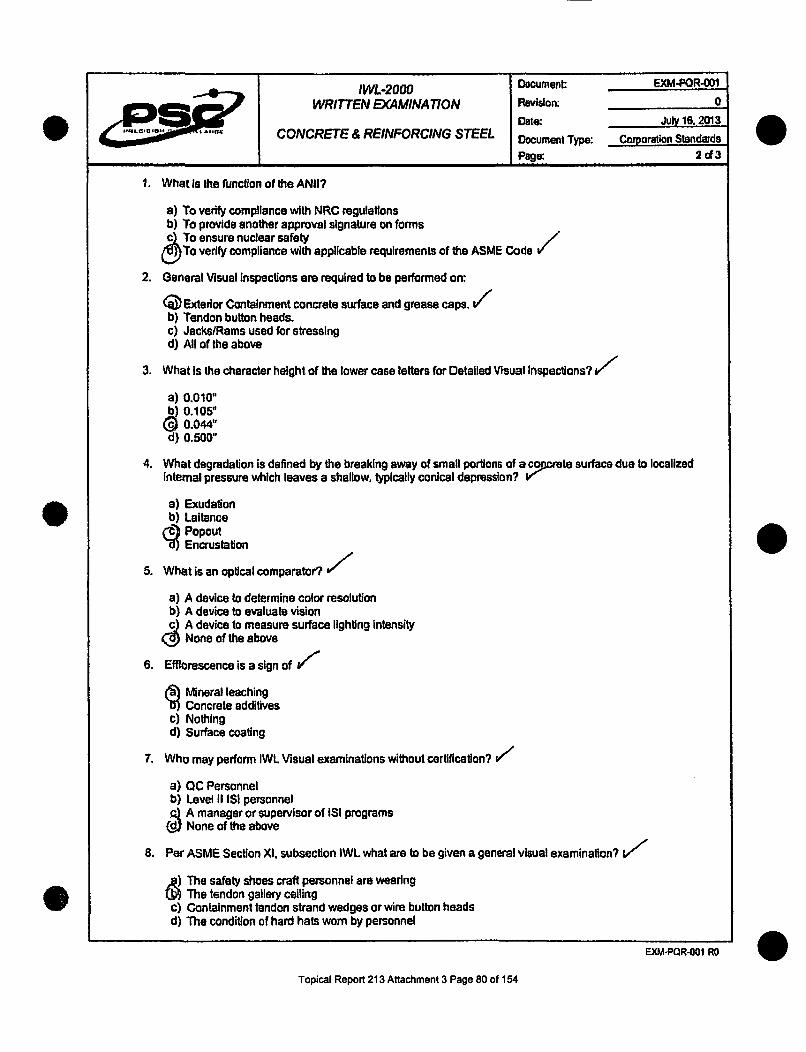
IWL-2000 Document EXM-POR-O01
WRITTEN EXAMINATION Revision: 0Date: July 16. 2013
CONCRETE & REINFORCING STEEL Document Type: Corporation Standards
Page: 2d3
1. What Is the function of the ANII?
a) To verify compliance with NRC regulationsb) To provide another approval signature on formsc5 To ensure nuclear safetyjU))To veiycmlac ihapplicable requirements ofthe ASME Cod
2. General Visual inspections are required to be performed on:
(j) Extedor Containment concrete surface and grease caps.b) Tendon button heads.c) Jacks/Rams used for stressingd) All of the above
3. What is the character height of the lower case letters for Detailed Visual Inspections?
a) 0.010"b) 0.105"(D0.044-
d) 0.500"
4. What degradation is defined by the breaking away of small portions of a co cete surface due to localizedinternal pressure which leaves a shallow, typically conical depression? V
a) Exudationb) Laltance.d)P°Pout
Encrustation m
5. What is an optical comparator?
a) A device to determine color resolutionb) A device to evaluate visionc A device to measure surface lighting intensity
None of the above
6. Efflorescence is a sign of
i Mineral leachingConcrete additives
c) Nothingd) Surface coating
7. Who may perform IWL Visual examinations without certification? if/
a) QC Personnelb) Level II ISI personnel
6 A manager or supervisor of ISI programsNone of the above
8. Per ASME Section XA, subsection IWL what are to be given a general visual examination?
The safety shoes craft personnel are wearingThe tendon gallery ceiling
c) Containment tendon strand wedges or wire button headsd) The condition of hard hats worn by personnel
EXM-PQR-001 R O
Topical Report 213 Attachment 3 Page 80 of 154

IWL-2000 Document: EXM-POR-O01WRITTEN EX4MINATION Revision: 0
Date: July 16, 2013CONCRETE & REINFORCING STEEL Document Type: Corporation Slandards
Page: 3 oi3
0
9. When should the character height of near-distance test charts be measured?
a) After the inspectionb) When requested by the Registered Engineerc) When a Relevant Condition is found
(9 Before use of it
10. In tendon anchorage areas, acceptable cracks in the concrete adjacent to the bearing plates do not exceed.
(9 0.010 inch In widthb) 0.100 inch in widthc) 0.001 inch in widthd) 1.000 Inch in width
11. What amendment to 10 CFR 50 Incorporated by reference the requirements of ASME Section Xl, 1992Edition with 1992 Addenda?
1992 Addenda10 CFR 50.55a.
c) Appendix Ad) 10 CFR 10.30
12. A detailed visual inspection requires what maximum examination distance?
7 feet2 feet
c) 35 feetd) 4 feet
13. How often is Level II re-certification required?X
a Eve 5( PEveiry 3 years
c) Every 3 monthsd) Every year
14. Which of the following degradation mechanisms to rebar Is associpted with changes in the permeability ofconcrete, presence of an electrolyte, or microbiological attack? V
a) IrradiationP Fatigue
gC~orrosiond) Thermal effects
15. Level II minimum education required for certification Is?
-q) MBA degreeHigh school or equivalentNo education
d) One year of college
EXM-POR-001 RO
Topical Report 213 Attachment 3 Page 81 of 154

1L-2000 Document: EXM-PQR-002WRITTEN EXAMINATION Revison 0
Date: July 16, 2013POST-TENSIONING COMPONENTS Document Type: Corporation Standards
Page: .. d3
NAME:Q ektb DATE: 6-2,3-1-7SOCIAL SECURITY NUMBER- ______________
GRADE:4d--- ZZ GRADED BY: A 5 ~Phii,3
I have neither given, received nor observed any aid or information regarding this exam prior to or during its
administration that could compromise this exam's Integrity. I also understand my obligation to report any exam
compromise by others prior, during, or subsequent to the exam administration.
I acknowledge that this examination is a way of demonstrating my knowledge of the subject associated with this
examination and that I have had the opportunity, on my request, to review this entire examination with the instructor to
ensure my understanding of the subject matter.
0
I have read and understand the above statements: .LV& Ph-/ 4Z -21-13. - •- w
Student Signature Date
FILL IN ONE CIRCLE AS THE ANSWER FOR EACH QUESTION
I. I $ II I I
EMt-POR-002 RO
Topical Report 213 Attachment 3 Page 82 of 154

IWL-2000 Document: EXM-PQR-002
WRI7TEN EXAMINATION Revision: 0
Date: July 16, 2013POST-TENSIONING COMPONENTS Document Type: Corporation Standards
I Page 2do3
1. Per IWL what tendon anchorages are exempt from Detailed Examination?
a) Inaccessible due to structural obstructionsb) Inaccessible due to radiological hazards
(• Inaccessible due to safety concernsAll of the above
2. Subsection IWL contains requirements for a Responsible Engineer. He must be an experienced Registered 1Professional Engineer. What is he responsible for?
a) Submittal of the report to the Owner documenting results of examinations and repairsb) Evaluation of examination results
A pproval, Instruction, and training of concrete examination personnelAll of the above
3. PSC Qualification for IWL Examiners certifications comply to: V"
a) [WE 92b) IWL 2001 edition with 2003 addenda) IWL 2010 edition with 2011 addenda2)AC1 301
4. What Is detailed examination used to detect on Containment Post Tensioning Systems (tendon anchorage)/selected for In-service inspection?
a) Dissolved water in the greaseb) Amount of grease in the grease canc) Grease can grease level
Evidence of free water
5. The tendon bearing plate is to be given what kind of visual inspection?
a) Close-Upb) General
D) etailedNone
6. What is the typical PSC procedure used for Anchorage Inspection? t/
a) SO 2.0b) SQ 12.1
r) SQ 8.0d) SQ 4.0
7. Following the re-tensioning of a tendon that has been da-tensioned a Detailed inspection is used to detect
0 Broken wires or strands.b) Amount of nitrates in the grease.c) Temperature of the concrete.d) If the grease can has been galvanized.
8. Which of the following is not typical equipment used for IWL examination?a( ) Pressure gageb) Flashlightc) Camerad) Optical Comparator
EXM-POR.002 RO
Topical Report 213 Attachment 3 Page 83 of 154

IWL-2000 Document: EXM-PQR-002
WRITTEN EXAMINATION Revision: 0
Date: July 16,2013POST-TENSIONING COMPONENTS Document Type: Corporation Standards
Page: 3d3
9. Following the re-tensioning of a tendon that has been de-tensioned a Detailed inspection Is used to detect
q Broken wires or strands.Amount of nitrates In the grease.
c) Temperature of the concrete.d) If the grease can has been galvanized.
10. Per PSC Qualification for IWL examinations who approves the qualifications of the Examiners? V/
Q Responsible Engineer (P.E.)b) IWL Supervisorc) Project Managerd) Project Superintendent
11. What is General Examination used todjetect on Containment Post Tensioning Systems (tendon anchorage)selected for In-service inspection? V
a) Type of galvanizing on Grease cand Gasket seal on Grease Can
Cracks In anchorage hardwared) None of the above
12. What is Detailed Examination used t0 detect on Containment PostTensioning Systems (tendon anchorage)selected for in-service inspection? v
a) Chemistry of shim materialI Material type of shim material
() Displacement of shimsDiameter of Shims
13. What is Detailed Examination used t detect on Containment Post Tensioning Systems (tendon anchorage)selected for in-service inspection?
1 Shim finishMissing button heads
c Anchor head finishd) Bushing hardness
14. For General and Detailed Examinations what is the minimum near distance vision acuity the examiner musthave?
G) at least 20/25 Snellen in at least one eye.b) Nonec) 20/20d) 40/40 or better
15. For nuclear-plants that completed their Structural Integrity Test 20 years ago how often must the ContainmentPost-Tensioning System IWL Examination of tendon anchorages be performed on tendons selected for In-service inspection per IWL?
ýa Every 6 monthsEvery 5 years
ccEvery 3 years
16 d) Every 2 years
EXM-PQR-002 RO
Topical Report 213 Attachment 3 Page 84 of 154

IW-2000 Document: EXM-PQR-005DETAILED VISUAL EXAMINATION OF Revision: 0
POST-TENSIONING SYSTEMCOMPONENTS Date: July 16,2013
Document Type: Corporation StandardsPRACTICAL EXAMINATION CHECKLIST Page: 1 oC3
NA-ME: 1~s,7A J DATE: 0•"•.&-i3
II.AO~a.SOCIAL SECURITY NLu'VULI'.o
EXAM NUMBER:
GRADE: INSTRUCTOR/GRADED BY: A __................ ..L- f /- I I
I have neither given, received nor observed any aid or information regarding this exam prior to or during itsadministration that could compromise this exam's integrity. I also understand my obligation to report any examcompromise by others prior, during, or subsequent to the exam administration.
I acknowledge that this examination is a way of demonstrating my knowledge of the subject associated with thisexamination and that I have had the opportunity, on my request. to review this entire examination with the instructor toensure my understanding of the subject matter.
I have read and understand the above statements:DateStudent Signature
POINT VALUE INSPECTION POINTS POINTS GRANTEDICOMMENTS
10 Select procedureVerify revisionSelect form10 Verify revision "/t)
Select equipmentVerify calibration/resolution " -,5Verify adequacy of lightingPrior to and during inspection ' "Record part/item numberOn inspection form ..........
15 Inspect component/partIdentify discontinuitiesCompare discontinuities to /__ _
Recording criteria in procedure " //25 Correctly record discontinuities
5 Sign and date form
5 Complete formAccurate and legible _ _ _ _ _ _
TOTAL +
0
Topical Report 213 Attachment 3 Page 85 of 154

N1078 PSC PROCEDURE SQ 8.0ANCHORAGE INSPECTION
Data Sheet .OBFebruary 29, 2012
4 PRECISII I Page I of IRevision 0
Project: FARLEY 2012 TENDON SURVEILLANCE f] UNIT I El UNIT 2
(7.3)Tendon No.: . Tendon End: -So-- El Shop
ANCHORAGE INSPECTION CRITERIA
09 As-Found 0 Post De-Tensioning I Pre-Wire Removal 0J Post Re-Tensioning Q.C. Signoff
9.0 & 10.40- CORROSION & CRACK INSPECTION
(9.2) Buttonheads Level: 13 ( (10.1) Cracks 0'Yesm 0 No [" N/A
(9.2) Anchorhead Level: ?• ( (10.1) Cracks "Yesl 0 No I N/A(9.2) Bushing Level: R ' (10.1) Cracks 0 Yes M R] No [IN/A
(9.2) Shims Level: • (10.1) Cracks C3-Yes (a No 0NWA
(9.2) Beaing Plate Level: 7T>i (10.1) Cracks [l Yes P9 No 0ON/A(_ Corrosion Leve) of C requims a NCR. )_-Corrnpae a sketch of the cracks on Ske"ch Sheet 110 and Initiate a NCR.
11.0 - BUTTONHEAD INSPECTION
I Offsize (Malformed)
Protruding/unseatedW wire/buttonheads
0 Broken/missing wimibuttonheads / "i• • 00000000) Previously identiffed as missing 00000000OO OO
0000000000000Discontinuous - removed 00 00 00 00 0 0000
wire(s) being removed during this 0000000000000Ssurveillance forteasting S c.-- oo0 oo0 ooooo0 oo00 oo00000000000000
(11.2) Anchorhead I.D. 0000000000000RX0 \ t 0000000000000!
Located on Sketch: I@Yes []No 0000000000000M 0ý"1 00000000000
Bushing I.D. W3 l AIP 0000000000000Q0 000
L~aeon.et Dj~ o ONO\0%0oooo%-(11.4) Missing Buttonheads Found: V i
SYes [ No Quantity:jAdditional Information: _j SW-V-k
4& 4. Li /I 6G¶ 5P -'- 8-4 -3
(12.2) Number of Protruding Buttonheads (w): Z (8.3) Light Meter ID: .,(/A Cal Due:
(12.3) Number of Missing Buttonheads (0 ,): a -(12.4) Total of Protruding + Missing Buttonheads: • (12.6) Continuity Test Requested ? [] Yes 0 No
(12.5) Total # of Effective Buttonheads Seated: 10-1 Wires Identified? 0 Yes [ No
(12.7) Overall Results 0 f Acceptable 0 Un-Acceptable Customer Notified NCR#: _ _ _JA t-a--
QC Reviewed: Level: Date:
POTE, 3-11M bnAv -M WIDE OW ONIZ SIDE'. U 17 SQ 8.0.FA.12 ISI
Topical Repo213 Attachment 3 Page 86 of 154

.... ......
IWL-2000DETAILED VISUAL EXAMINATION OF
REINFORCINGrSTEEL
PRACTICAL EXAMINATION CHECKLIST
Document:
Revision:
Date:
Document Type:Page:
EXM-PQR-004
0
July 16, 2013
Corporation Standards163
NAME- C4lý~r pes- DATE:
SOCIAL SECURITY NUMBER: ___
IEXAM NUMBER: Ir.
ED Y'ArlGRADE: R1- INSTRUCTOR/GRAtD Q/IJL!~1- / .-. .1'. / /
I have neither given, received nor observed any aid or information regarding this exam prior to or during itsadministration that could compromise this exam's integrity. I also understand my obligation to report any examcompromise by others prior, during, or subsequent to the exam administration.
I acknoweldge that this examination Is a way of demonstrating my knowledge of the subject associated with thisexamination and that I have had the opportunity, on my request, to review this entire examination with the instructor toensure my, understanding of the subject matter.I .. ,']#• :l ._.,AI have read and understand the above statements: - _.V/IN
i " S-tudent Skfnatu're: -ON~ I
Date
POINT VALUE INSPECTION POINTS POINTS GRANTEDICOMMENTSS10 Select procedure10 Vedfy revision /6
Select form10 Ve revision
Select equipment_ Verify calibration/resolution
Verify adequacy of lightingPrior to and during inspection
5 Record part/item number ,•On inspection formInspect component/part -
15 Identify discontinuitiesI 15 Compare discontinuitles to15Recording criteria in procedure
25 Correctly record discontinuities ._ __/_-_,,__
5 Sign and date form
5 Complete form __ __ _,_.
Accurate and legible
TOTAL "- 9
Topical Report 213 Attachment 3 Page 87 of 154

N1078 PSC PROCEDURE SO 8.3BEARING PLATE INSPECTION
DATA SHEET SQ 8.3February 29, 2012
Page 1 of 1Revision 0
0I
Project: FARLEY 2012 TENDON SURVEILLANCE f UNIT I 0 UNIT 2
Tendon No.: I Tendon End: ,E'/S "-9-e S //p/A..-Bflel&
(7.4) Bearing Plate Identification #: P7D I b -- /
1. Orient the bearing plate with the sketch below.2. Locate the bearing plate Identification and document the location on the sketch.3. Sketch all cracks, Including other defects, existing on the concrete in the area surrounding the tendon anchorage for a distance of
24 Inches from the edge of the bearing plate.4. For cracks equal to or wider than 0.010 Inches, document condition on an Nonconformance Report In accordance with
Procedure QA 9.0. NONCONFORMANCES, for Southern Nuclear ap roval.1,2A.15.,•so4" io *O top V,-X. 0 1 X.o90
~~Leo
On Hoop and dome this edge Is IX, J0up.
t
Vertical Tendon, this Is toward the
e PFL D) ENS E' center of the containment.
4.Ar 1-0- thejr~
Light Conditions 50fc or greater. J• YesQ No Auxillaiy Ught Source used: 0] YesfLNo Describe: A/9(7.3) Light Meter ,D: ///4 Date due calibration: / ...
(7.5) Cracks 0,010" IBYes 0iNo Quantity: 1 M ax. Width:,A 80 Max Length: . .. NCR#: (-" ,
QC Rpeviewed Level:44(7C3 Reigh ewerD: Leel Date: cllrlln
18 SQ 8.3 FA.12 ISI
Topical Report 213 Attachment 3 Page 88 of 154

IWL-2000 Document: EXM-PQR-003
GENERAL & DETAILED VISUAL Revision: 0EXAMINATION OF CONCRETE Date: July 116,2013
PRACTICAL EXAMINATION CHECKLIST Dacument Type: Corpration StandardsIPage: 1 d 3
0
NAME. /J~ArlD 14 1A:3F-r< DATE:__-____- - IL3 .i •
SOCIAL SECURITY NUMBER:
EXAM NUMBER:
GRADE: M INSTRUCTOR/GRADED BY______________I "/ I -If -
I have neither given, received nor observed any aid or information regarding this exam prior to or during itsadministration that could compromise this exam's integrity. I also understand my obligation to report any examcompromise by others prior, during, or subsequent to the exam administration.
I acknowledge that this examination is a way of demonstrating my knowledge of the subject associated with thisexamination and that I have had the opportunity, on my request, to review this entire examination with the instructor toensure my understanding of the subject matter. ., •
I have read and understand the above statements: l/ '- - dr- I J
Student Signature Date-
POINT VALUE INSPECTION POINTS POINTS GRANTEDICOMMENTSSelect procedure
10 Verify revision ..
10 Select formVerify revision 1Select equipment _V 9Verify calibrationlresolution
5 Verify adequacy of lightingPrior to and during InspectionRecord part/item numberOn inspection form __ _ _
Inspect component/part15 Identify discontinuities15 Compare discontinuities to
Recording criteria In procedure
25 Correctiy record discontinuitiesso
5 Sign and date form
Complete form5 Accurate and legible t _5_
TOTAL t ýZ
Topical Report 213 Attachment 3 Page 89 of 154

0N1078 PSC PROCEDURE SQ 84
CONCRETE EXTERIORDATA SHEET SQ 64
P February 29, 2012Page 1 of IRevision 0
VISUAL EXAMINATION - GENERAL VISUAL EXAMINATION
Project Farley Surveillance # t...... Year 2012Inspection Amea v.EquipmentUsed Rg tZ r" , gg5J_ t,,,. fiP ML C4,&Am4h+1t,, k /
Concrete Surface ConditionConjinment Surface (Findings and Description) NIJ 1 RI
I4F/d [ SOLA 6• OI < WAJ , ,.I
I L II(Use as many sketch sheets (page 2) as needed to report any Recordable Indicadon (RI) or Information Only
,(0) findins for the purpose of documentation and orientation,)Recordable Indications to be Examined For (PSC Procedure 8A)
Leaching or Chemical Attack Deterioration of any Concrete Coating (ifapplicable)Abrasion or Erosion Degradation Tendon Grese on Exposed Concrete SurfacesPopouts and Voids Corrosion on Grease Cans, Bearing Plates or.AnchorageCracks *Excessive Corrosion on Exposed Embedded Metal SurfacesScaling *Detached Embedments or Loose BoltingSpalls *Indication of Degradation Due to VibrationCorrosion Staining on the Concrete Surface (* The ownerlagent must be nofified for these noted conditions.)Exposed Reinfbrcing SteelSurface Patches or RepairsComments and Disposition by Responsible Engineer [iAcccptable ElUnacceptableComments:
Inspector,& Level: 0UAj L '!-4'5 (/4)/-T Date: S-2v- /2Responsible Engineer. Date;ANII: Date:
ISa SO 8,4.FA. 12 ISI
Topical Report 213 Attachment 3 Page 90 of 154

/PRECISION JS9IL LANCE
Nt 078 PSC PROCEDURE SQ 8.4CONCRETE EXTERIOR
SKETCH SHEET 8.4February 29, 2012
Page 1 of IRevision 0
Project: FARLEY NUCLEAR STATION 2012 TENDON SURVEILLANCE
Inspection Area: 2,
1. Sketch or attach photographs to provide documentation or additional details as necessary.
L0C-L OAM•4 ,.)- .r 1,,
M&!• 1e ci' 14 , , ;4 1 g~401
QPoK lit *Hf
Comments:
OC Inspector. )f~~ Level: Date: ,
0
i8a SQ 8.4.FA.12 SI
Topical Report 213 Attachment 3 Page 91 of 154

PRECISION SL SLLANCE
N1078 PSC PROCEDURE SO 8.3BEARING PLATE INSPECTION
DATA SHEET SQ 8.3February 29, 2012
Page 1 of 1Revision 0
0
0s
Project FARLEY 2012 TENDON SURVEILLANCE [4 UNIT 1 C] UNIT 2
Tendon No.: ._.. Tendon End: W .Q--- Shp A/A -//Field-
(7.4) Bearing Plate Identification #: DME
1. Orient the bearing plate with the sketch below.2. Locate the bearing plate Identification and document the location on the sketch.3. Sketch all cracks, including other defects, edxstng on the concrete In the area surrounding the tendon anchorage for a distance of
24 inches from the edge of the bearing plate.4. For cracks equal to or wider than 0.010 Inches, document condition on an Nonconformance Report In accordance with
Procedure QA 9.0, NONCOwORm aS, for Southern Nuclear approval.
On p and dome thls edge Is
2~. JVertical Tendon, this Is toward thecenter of the containment.
/IC
- /LC 1-"'5
I Spe tTOf 30T 1*6
(7.3) Ccght Meter ID: s 1A N Date due Malabrathon::
QC Inspector: 6LI Level: Date:
QC Reviewed: Level: Date:
18 SO 8.3 FA.12 ISI
Topical Report 213 Attachment 3 Page 92 of 154

Document: FRM-POR-O01
IWL VISUAL EXAMINER Revisorrn 0CERTIFICATION RECORD Date: July 16,2013(EXHIBITA) Document Type: Corporation Standards
Page: I of
IWL GENERAL AND DETAILED VISUAL EXAMINER CERTIFICATION RECORD
Training Requirements Inltials(Examlneellnstructor) Date
Training in Section Xl, Subsection IWL (4 hours minimum)Training shall include requirements for inservice and preservice examinations
and reporting criteria for the following:(2 hours minimum)
1) Concrete (conditions such as those described In ACI-201.1) 10 Ij, / .. ,8,113
2) Reinforcing steel foe8/1
3) Post-tensioning system items (e.g., wires, strands, anchorage 1011St3hardware. corrosion protection medium, and free water) I2ZK I(,L -/____
Written Examination Grade Date
Written examination covering Section XI, Subsection IWL requirements andplant-specific procedure requirements for visual examination containing at least
15 questions in the following:
1) Concrete and Reinforcing Steel 86.6% 10/18113
2) Post-tensioning system components(l.e.. wires, strands, anchorage 86.6% 10118113hardware, corrosion protection medium, and free water 66_6%_______3
Practical Examination Grade Date
A practical examination using test specimens with flaws or Indications to bedetected by the following visual examination techniques:
1) General and detailed visual examination of concrete 93% o101813
2) Detaied visual examination of reinforcing steel 9301% 101111
3) Detailed visual examination of post-tensioning system components (i.e.,wires, strands, and anchorage hardware) 95%
Passing grades for visual examinations shall be as follows: Final Grade Date
An average combined grade of 80% for written and practical 90.8% 10118113examinations IA minimum grade of 7O0/a for each written and practical examination
Precision Surveillance Corporation certifies that the following Individual meets the nminimum qualifications set forth in theCorporation Standard Document STD-PQR-001 'Personnel Qualification Requirements for General and Detailed Visual
FyJmmin~Iinn• t'rw NtawIlstr Pnwar PlrznI="
IWL Visual Examiner (Print Name): Ronald A. Perry
IWIL Visual Examiner (Signature): Z•--!Q. Q.
SS #(Last Four Digits) (7
Certification Date: 10/18,13 7 r8:
Certification Expiration Date: 49//0#- 1 PF 1 WS9!,LF
P.S.C. Professional Engineer Approvail(Name) C • •t • .. It
P.S.C. Professional Engineer Approval(Signature) 1 " A el
Topical Report 213 Attachment 3 Page 93 of 154

QUALIFICATION OF QUALITY CONTROL INSPECTORS-PROCEDURE QAZ.10.6.1.1
CERTIFICATION FORM QA 2.10.6.1.1 B
CERTIFICATE OF QUALIFICATION
This is to certify that:
Ronald Perry SSNhas been qualified through on-the-job experience and formal training to meet the requirements of
ANSI N45.26-1973 and 1978 as:
QUALITY CONTROL INSPECTOR LEVEL It with the following limitations.
Inspections and Calibrations associated with Post-Tensioning Systems and Components.
This certification will qualify the named individual to perform Quality Control inspections,examinations and testing for the various manufactured products or services supplied, to meet theRequirements of the projects for the Precision Surveillance Corporation and within the limitationsof this qualification.
This qualification becomes effective 10/17/13 and shall remain in effect until theRecertification date of 10/17/16 or until such time that the named individual leaves theemployment of PSC, gives just cause for termination of the certification or requires additionaltraining to maintain a proper Quality Control disposition.
PHYSICAL REQUIRMENTS: Eye Exam Date 10/17/13 to 10/17/14 by PSC
Eye Exam Date to by
Eye Exam Date to by
APPROVED BY:
Quality Control Inspector Level 2
Date: to/f 1//3
Topical Report 213 Attachment 3 Page 94 of 154

QUALIFICATION OF QUALITY CONTROL INSPECTORS-PROCEDURE QA 2.10.6.1.1
QUALIFICATION LIMITATION FORM QA 2.10.6.1.1 C
The named individual is hereby certified to perform Quality Control inspections, examinations andtests for the products of the Precision Surveillance Corporation and shall be limited in practicingthose skills to those activities for which qualified as shown.
Name Ronald Perry SSN
Quality Control Inspector Level II per ANSI N45.2.6 - 1973 or 1978
ACTIVITIES
POST TENSIONING SYSTEM:
SHOP: N/A
VENDOR: NIA
FIELD: All
TESTING: N/A
OTHER: N/A
REINFORCING STEEL:
SHOP: N/A
CONSTRUCTION METALS:
STRUCTURAL FAB: N/A
WELDING: N/A
PAINTING-ANSI 101.4: N/A
OTHER: N/A
GENERAL QUALITY ASSURANCE:
DOCUMENT CONTROL: Yes
TEST REPORT APPROVAL: Yes
PURCHASE ORDER APPROVAL: No
NONCONFORMANCE REPORTING: Yes
CALIBRATION: Yes
IOCFR21 Yes
10CFR50 and PSC QUALITY ASSURANCE: Yes
APPROVED: Qai on Ined DATt: 0 /-7/13Quality Control Inspector Level III
Topical Report 213 Attachment 3 Page 95 of 154

TSSD
SUMMARY:
TECHNICAL SKILLS:
Mr. Perry is a Program Engineering, Quality Assurance and NDEprofessional with exceptional organization, communication andleadership capabilities. Proven record of working Independently
and as part of a team to reach company goals. Solid problem
solving and analytical thinking skills used daily to drive continuousImprovement. Knowledgeable of ASME Codes, ASTM Standards,
SNT-TC- 1 A and ANSI Standards.
Certified Lead Auditor per NQA-I and ANSI N 45.2 Auditor;
PSI / ISI Development;Engineering Program Development;NDE Level III In three disciplines (PT, MT and VT);
Training Instructor in accordance with Systematic Approach to
Training (SAT);Procedure Development.
PRAIRIE ISLAND NUCLEAR GENERATING PLANT
AssessorPerform assessments of Maintenance and Radiation Protection;
Perform assessment of SGR activities of contractor personnel /
programs;
Prepare and implement assessment report;
Generate CAP for nonconformances.
NUCRANE MANUFACTURINGOC Supervisor
Supervised QC Inspector personnel in Mechanical, Electrical,
Coating, NDE and CWls;Supervised Receipt Inspection of safety-related and non- safety -
79 AVIATOR PLACE, OAKLAND, MAINE 04963
1-877-965 -TSSD (8773) [email protected]
EXPERIENCE:07/13 - Present
08/12 - 03/13
Topical Report 213 Attachment 3 Page 96 of 154

TSSDL7 RONALD A. PERRYPae2o Page 2 of 5
08/10 - 08/12
11/09-07/10
12/07 - 11/09
related parts / items;Revised (streamlined) Inspection procedures and associatedInspection forms:Interface with suppliers to resolve material and documentationdeficiencies;Interface with Engineering on resolution of material deficiencies(NCRs);Review customer specification for compliance;Assisted on an NQA-1 audit as a Technical Specialist.
MOX PROJECTQA Specialist 5Perform surveillance of suppliers (Internationally) to ensurecompliance to their QA program (ISO and NQA-I);Review supplier procedures for compliance tocodes/standards/specifications;Prepare surveillance and supplier deficiency reports as required;Verify corrective actions are effective and close-out deficiencyreports;Lead Auditor In accordance with the requirements of NQA-1;Level II Receipt inspector.
PEGASUS STEELNuclear Quality ManagerDevelop and implement a Nuclear Quality Program;Developed and obtained ASME U and R stamp;Responsible for housekeeping and 5-S initiatives;Maintain Nuclear Approved Suppliers List;Establish, delineate and review organizational quality policies;Review Purchase Orders and establish flow down requirements;QA Manager for ISO 90001.
MOX PROJECTGA SpecialistCertified Lead Auditor per NQA-1;Certified Level II Receipt Inspector;
Topical Report 213 Attachment 3 Page 97 of 154

TSSDL-7 RONALD A. PERRY Page 3 of S
08/07-11107
01107- 05/07
09/06-11/06
02/06- 03/06
Prepare and Implement audit and surveillance checklists;Perform audits and surveillances at MOX site and vendor / suppliershops;Prepare audit and surveillance reports;Review vendor / supplier procedures for compliance (both foreignand domestic);Review Engineering and Procurement documents for compliance;Review vendor I supplier QA Manuals for compliance;Initiate Condition Reports;Verify effective corrective has been Implemented;Familiar with commercial Grade Dedication process.
WELDING SERVICES INC. (WSI)QC I NDE InsoectorDevelop surveillance checklists and establish QC hold points;Perform NDE as a Level II In MT, PT and VT disciplines;Prepare outage summary manuals for client;Perform surveillance activities at vendor / supplier shop.
NATIONAL ENRICHMENT FACILITY
Perform audits;Prepare and perform surveillances of subcontractor activities;Review subcontractor procedures for compliance.
TAI (TOURGEE & ASSOCIATES, INC.)QC / NDE InspectorPerform visual and ultrasonic thickness examinations on Tanksand peripheral equipment;Prepare examination reports for submittal to client;Interface with client regarding examination results and establishedexamination priorities.
LIMERICK GENERATING STATIONISI CoordinatorPrepare examination packages;
Topical Report 213 Attachment 3 Page 98 of 154

TWODL7 RONALD A. PERRYPae4o Page 4 of S
03/05 - 04/05
12/02- 02/05
1983-2002
Assign NDE technicians to perform ISI examinations;Review NDE reports for accuracy prior to submittal to the client;
Track NDE reports and Initiate nonconformance reports asrequired;Develop 90 Day Summary Report for client for submittal to theNRC.
NINE MILE POINT NUCLEAR STATION
NDE TechnicianPerform NDE examinations in support of refueling outage and
prepare NDE reports
DAVIS BESSE NUCLEAR POWER STATIONSenior Nuclear Specialist - BACC Program OwnerTook worst Boric Add Corrosion Control Program In nuclear
history to the best;Develop and implement a compliant BACC Program;Track and trend boric acid leakage;
Developed and implemented inspection procedures;
Initiate and prepare responses to Condition Reports;Developed and implemented a training and qualification programfor BACC inspection personnel.
BEAVER VALLEY POWER STATIONAdvanced Nuclear Soecialist - QA Lead Auditor (I 999 - 2002)Prepare audit checklists and MAPS for continuous auditing;Perform audits on Operations, Maintenance. Construction,Licensing, Health Physics, Engineering, Document Control /Records Management, Measuring &Testing Equipment Program;Prepare audit reports;
Initiate Condition Reports and verify effective corrective actionshave been implemented;Perform and evaluate Self-Assessments.
Supervlsor NDE and NDE level III (1983 - 1999)
Supervise / direct NDE personnel in the conductance of PSI and ISI
Topical Report 213 Attachment 3 Page 99 of 154

L7 RONALD A. PERRY PageSof S
examinations;
Supervise / direct the development and Implementation of NDEprocedures;
Supervise / direct the development and Implementation of atraining and qualification program;Interface with regulatory personnel (NRC, ANI and ANII);Training Instructor per Systematic Approach to Training (SAT);
Prepare and implement training (NDE) per SAT;
Supervise / direct the implementation of an M&TE Program for NDEequipment;
Attend and participate in ASME Section XI Code committee
meetings;Prepared initial IWE/IWL program plan (Level II Visual Examiner forIWE / IWL).
1969- 1979 UNITED STATES AIR FORCE
NDE Technician / SuerylsorPerform and supervise NDE personnel In the conductance of UT.MT, PT, RT, ET and VT examinations;
Received USAF Commendation Medal.
EDUCTION:University of MarylandBachelor of Science Business Management - 1981;
Instructor Training (SAT);Root Cause Analysis;NDE Training USAF, Chanute AFB, Rantoul, IL.;
Systems Training (PWR);
Graduate of Dale Carnegie.
PASSPORT:Number 307319512, expires 2016
0Topical Report 213 Attachment 3 Page 100 of 154

PSC PROCEDURE VrI.FORMSCERTIFICATION OF EXAMINERS
EXHIBIT BRevision 0. Api 28. 1999
Page I of IRevision 1, 4/28/99; Revision 2, 716199; Revision 3,2124105;
Revision 4,08131/07*. Revision S. 08/0(108; Revision S, 09104108
PHYSICAL TESTING OF INSPECTORS-PROC. QA 2.10.6.1.1.1PHYSICAL TESTING FORM QA 2.10.6.1.1.1
Name:
Title: L&N-E&ADate ) Retest Date
Weears Gas'i- P., I !
1. PHYSICAL CHARACTERISTICS IRating: "P._____________
C m nting:si -,Aa LimitationsComments " ,~ ,.,I•TJ
2. VISUAL-FAR RANGE Test Device jb71 3g --r.l ,b
Vision Rating %: Left Right Both ..
Comments
3. VISUAL-NEAR RANGE Test Device a I_, ,-)e
Vision Rating Grade: Left J Right _J Both J
Comments ,Luw .
4. COLOR PERCEPTION Test Device p - e ,
Plate: 1w,, 2 • 3 4 5
6 7 8 8 9 1- 010
11 - 12 -. 13 iL. 14 15Score f6 Of 14 Perception____ __________
Score shall not be less than 10 to be.acceptable for perception.
Comments
6.OVERALL RATING
Capability
Examiner,,leL. C 61ý01e Title la,-,% _, ýCkA ow-1)1i.e
Date dr,4I.6vt1l.forms.doc
Topical Report 213 Attachment 3 Page 101 of 154

PRECISION SURVEILLANCE CORPORATION
TRAINING SHEET
THE PSC PERSONNEL LISTED BELOW HAVE BEEN PROVIDED AN OVERVIEW AND INDOCTRINATEDTO PRECISIONSURVEILLANCE CORPORATION'S QUALITY ASSURANCE MANUAL REVISION 5 (ALL SECTIONS)
NAME SIGNATURE SS#t DATE
POP14 I A. Q~~w~ C, P 7___
TRAINER:
DATE: 1,1/,-7i
ITraining Sheet -OAM new logo 0
Topical Report 213 Attachment 3 Page 102 of 154
PRECISION SURVEILLANCE CORPORATION
TRAINING SHEET
TI IE PSC PERSONNEL LISTED BELOW 14AVE BEEN PROVIDED AN OVERVIEW AND INDOCTRINATED TO THEFOLLOWING STANDARDS AND DOCUMENTS:
I1CFR50 APPENDIX B, I0CFR PART 2 1, ANSI N45.2, ANSI N45.2.6, ANSI N45.2. I0 AND THE PRECISION SURVEILLANCECORPORATION QUALITY ASSURANCE PROCEDURES.
*I
NAME SIGNATURE SS# DATE
I
I I I
TRAINER:,
DATE:
Training Sheet Standards new logo
Topical Report 213 Attachment 3 Page 103 of 154

PSC QC INSPECTOR .TRAINEE: /160 /J /14 A.-Orl&Z DATE:__________
TEST SCORE: PSC tNSTRUCTOR:,__'_4_ _ _ _
PRECISION SURVEILLANCE CORPORATIONQUALITY CONTROL INSPECTOR TRAINING PROGRAM
EXAM
1) What is the proper way to correct an error recorded on a data sheet ie: typo, obviousomission?
a) Write in changes or correct date0 Any changes made, one line thru, initial and date
c) Write a nonconformance
2) When performing inspections what documents should you have with you?
a) Quality Assurance Manual0 Applicable Inspection Proceduresc) Calibration reports on inspection tools
3) Quality Control Inspectors shall be completely independent from the pressures ofl;n,?- -mam~a m---+J P'4010rt4corl
a) Customersb) Quality Assurance
Production
4) The distance a tendon/wire stretches when being stressed is called,
a) Liftoffb) Relaxationo Elongation
5) During stressing operations, which of the following cautions shall be observed?
a) Do not stand behind the jack when it is under loadb) Keep fingers out of any pinch areasc) Be alert during shim placement and removal
( All of the above
Topical Report 213 Attachment 3 Page 104 of 154
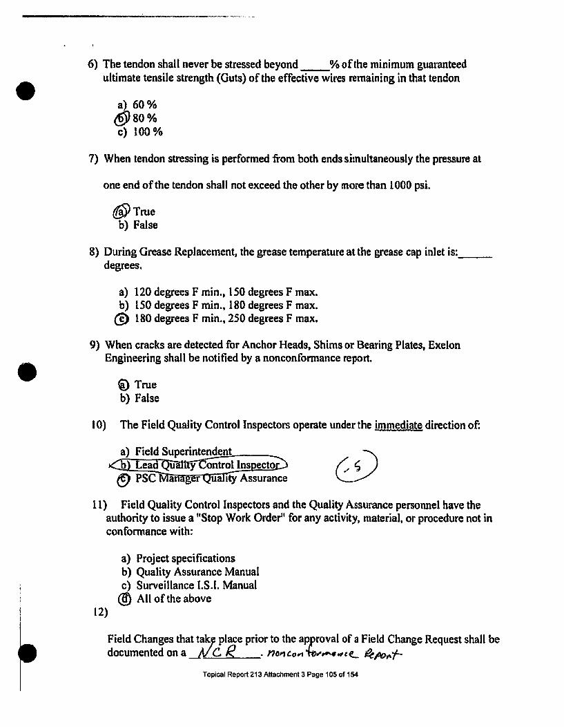
6) The tendon shall never be stressed beyond % of the minimum guaranteedultimate tensile strength (Guts) of the effective wires remaining in that tendon
a) 60 %&V80%c) 100%
7) When tendon stressing is performed from both ends simultaneously the pressure at
one end of the tendon shall not exceed the other by more than 1000 psi.
(V Trueb) False
8) During Grease Replacement, the grease temperature at the grease cap inlet is:degrees.
a) 120 degrees F min., 150 degrees F max.b) 150 degrees F min., 180 degrees F max.
(g 180 degrees F min., 250 degrees F max.
9) When cracks are detected for Anchor Heads, Shims or Bearing Plates, ExelonEngineering shall be notified by a nonconformance report.
Q True
b) False
10) The Field Quality Control Inspectors operate under the immediate direction of:
a) Field Superintendent nsebLý d'ea ualt v ontrol Ins ecto
PSC ana r ua ity Assurance
11) Field Quality Control Inspectors and the Quality Assurance personnel have theauthority to issue a "Stop Work Order" for any activity, material, or procedure not inconformance with:
a) Project specificationsb) Quality Assurance Manualc) Surveillance I.S.I. Manual
(g) All of the above12)
Field Changes that tak: place prior to the aproval of a Field Change Request shall bedocumented on a __ pa c )•prior
Topical Report 213 Attachment 3 Page 105 of 154

13) Prior to applying ANY FORCE to a tendon the stressing adaptor must be fullyengaged.
(0 Trueb) False
14) During Tendon liftoff monitoring of a tendon, a 0.030" thick feeler gauge (shimstock) is inserted into the shim stack until consecutive liftoff/lock-offreadings have been taken.
a) Two (2)g Three (3)c) Four (4)
15) Steel rulers are calibrated every:
a) 6 months(0 lyear ± ,c) 5 years
16) When should Quality Control Documents be signed by the inspector?
a) Before the next stepb) At the end of the day
0 After all information for the inspections have been entered
17) Who controls the Measuring and Test Equipment used by PSC Inspectors?
a) PSC Superintendentb) Utility employees9 PSC Quality Control or Quality Assurance personnel
18) Where are all quality related documents pertaining to the project kept?
a) In the inspector's desk(9 Field office file orjobsite vaultc) With the PSC Superintendent
19) All Lead Field Quality Control Inspectors shall be qualified to a minimum of Level- capability in accordance with the requirements of ANSI N45.2.6.
c) RllTopical Report 213 Attachment 3 Page 106 of 154

20) In the event ofconflict between any TMI procedure and an SQ procedure, whichgoverns?
•c The SQ ProcedureThe TMI Procedure OwoletyNeither
Topical Report 213 Attachment 3 Page 107 of 154

w lfd-aPt J
b
-10
V.
Pr
0M0
0
Afra6&eA/Aut4f049
I*AsW
ewA~fe4 24 t2
um

0
-40
*0
7,0
"0
CD
Co
DEPARTMENT OF THE AIR FORCETHIS IS TO CERTIFY THAT
THE AIR FORCE COMMENDATION MEDALHAS BEEN AWARDED TO
STAFF SERGEANT RONALD A. PERRY
FORMERITORIOUS SERVICE
26 AUGUST 1973 - 20 APRIL 1977
GIVEN UNDEH MY HAND IN THk GITY OF WASHINGTONTHIS 5TH DAY OF APRIL 1977
JAM E. NILLIE HART GENERAL, USAF
OMNANO ENR A
Q~ ,.
8Ec*CTAnV of ?N lift @ro~
AF FoM U.4 ML

PESMA. cROX&, LtO -NRE MUT DL1r 946 Oct 042,2
&J'st I. VEAX ~M`f~a DAD RAWE DAC OF
19-5 A".0 1976 Jan .01.AIR EORCE'ReBA1ekAW.WW N aR
S8gta. zmaciwenvg c u~teaIumazm IS. 2d9LECVI% SEVICE LOCAL. 11BOAR NOIAOSS. CITE. STATS -it . iONS op aCCR TOI4i OF many 4NTo ACwIv9*6mfiC9
LT M Westbrook. ME-& WYP% OF 9CPARATION .. -. .61 O O i? VOMA NlEEPCS
Discharge-. ... .- .Travis AP CA943-6 Aufmlol ANm ii u-
-- - - - - - -- -- - 91Y
CIIANCIEROF -1979
HOMO11RA&3L3 -' . DD Yor. 256AY _______
1 1. LAW?0? tia maOriNEN mal ift eoImANU... . - I& C0.11,10,110 "IUNMACN tomwilmse
51. ms AA. *N _______
11 TERUINAL. 1ATE OF RZSAtv? &A FI.ACE OF "MOTR INTO WC 11ft~ihiACTW mwSE~ aw w* QW0 OIs. CMEIEU
16£ PEIMAT UPKCIlwi musmBE AND amms ACLATED CO wtUM r OCCUPI&ONJUL 0IS
42772-No'adea trutimtve pi -=m"iaf. s0.31 ;11 ~2q
MA~~~PW IbvtHfAVfIV& 1ERVICE A n
IV OSNINAO ORASRnCZA AtO^TS . "wifAt
U~~~lTSU~t Qt 5.~as. SCIiAaRX~TIIION L2n
dayse Q "a. 751 *- _2*p(
NO TD. LOT0-E1
C3 Q Etaoo i.' H&ON . *KMTMC Ar693110aco~v.OECOAAtOmiS Bun ts. w~t~s ama" cm iI ATcSS AND CAPaCOmd RANSOMS AwARDED OR AUTNomixED
AYLSA v/1OLC AYR. 900-48; APOGk w/20LC- (28' Ma14r .75-27:lMar .7)APR 900-48;AUM SO G-35 RQ Eislith AF (SAC) 5 Apr ..77-T..
1~~
,..'@
Mr. RMUARKR
DAFSC:42772/Sve Scools:.mgt for A! Supervisors (Hgt-1) Jan 76; 8 A? NCO LeadershipSchool May .76; Defense Spectrometric Oil Aualysis Operatorttvaluator Crs AL42752May 77/Bsood Group:A.Posativetlndividual requests a copy of 'DD Tomn 21*Refitem 25a:Security :learaice filed DOD NAC, file #98-5198/
22 Lassell St. ] - ,k
Portland, ME1 (Cwut~erland Co.) 04072 V'i/. Q Lz30. T¶FILO NAME. 05*05 ',IO Tent OF AUTHOOSIttNO OrpraCER 3 1. SIGNATURE OF OFflCE. Ato MI4IQRI TO SIOS
Wallace R1. Rtley, 14Sgt$ USAFHCOIC,, Separationi; Unit ___________________
iDO ".~ 214 PNCIVIAUS COiTIOKS Or TIMIS THIS5 IS A. MP~ Or.% -rE REPORT OF SEP'ARATION FROM ACTIVE DUTY
1. - 1.Topiat Report2l¶3 Afachffi~hl aP-age-11Oof'154 - .-

Rn. AS.61 IA
Du7A UIf
Certificateof
Qualification
NaIe Employee # Social Security #RONALD A PERRY 1 4297 1
This individual is certified in accordance with Duquesne Ught Company ProcedureQSP 2.12, Rev. 0, "Wrtten Practice for Qualification and Certification of VisualExamination Personnel for Class MC and Metallic Liners of Class CC Componentsand Class CC Concrete Componentsr Visual Examination Level III VT-1C and VT-3C
ExaminatIon ResultsDate 7-18-1990* Basic Examination Grade 92Date 7-27-1992 * Method Examination Grade 81Date 2-2-1999 Specific 93
Date 2-2-1999 Practical 93 Average 93 Grade 93Average 88.66
Certfication Date certification Expiration Date
2-17-1999 2-17-04Initial Certification in this Method Recertilicaticn in'this M~ethod
YES NOEye Examination date at time of certification
10-9-1998RestrictionslUmitations
TCredit for the Basic Examination and Visual Method is being applied as permitted byQSP 2.12 paragraph 3.4.2 (H) (1) (2) (3).
IWEJIWL training was provided by EPRI on 211-212, 1999. General, Specific and Practical(Level It) examinations were administered. Scores are documented on the EPRI trainingrecord (attached).
Responsible Engineer. PE / Date NDE S Irgsar/Date
I /
Topical Report 213 Attachment 3 Page 111 of 154

RTL A6.1 I A
SAVJLeCertificate
ofQualification
NmIEmployee#4Sca ScrtName Ronald A. Perry 4e97
This individual is certified in accordance with Duquesne Light Company ProcedureQSP 2.3, Rev. 5, "Written Practice for Qualification and Certification ofNondestructive Examination and Tasting Personnel', and is qualified to performexaminations in the following capacity: NDE Level III in LIQUID PENETRANTTESTING
Examination ResultsDate 08119192" Basic Examination Grade* 97.30%Date 09104197 Method Examination Grade 89.23%Date 07129197 . Specific 94.6% IDate 09104197 Practical 100% Average 97.3 Grade 97.30%
Average 94.6%
Certification Date Codtif[icton Fxpirtion Date09/06/1997 091051l2002
Initial Cerliffcatton In this Method Recertification in this MethodNo Yes
Eye Exanination date at time of certificatlon'9125196
Restrictlons/LlmitatlonsNone
"Note: Basic Examination still valid in accordance with Code Case N-489 and QSP2.3, Revision 5
NDE Level Ill/Date
f - 4-lit 9-5-97NDE;7v~rfate.Manager. Quality Services I Date
YDEZ6117
I / I
Topical Report 213 Attachment 3 Page 112 of 154

RU. A6.61 I A
D0 P44Certificate
ofQualification
Name RnlA.PryEmployee# ~ socialjjjj#Ronald A- Perry 1 4297 1
This individual is certified in accordance with Duquesne Light Company ProcedureQSP 2-3, Rev. 5, "Written Practice for Qualification and Certification ofNondestructive Examination and Testing Personnel", and is qualified to performexaminations in the following capacity: NDE Level IN in LIQUID PENETRANTTESTING
Examination ResultsDate 08119/92* Basic Examination Grade* 197.30%Date 09/04197 Method Examination Grade 19.23%Date 07/29/97 Specific I194.6%gDate 09104197 Practical 100% Average 97.3 Grde e1730%
Average 94.6%
Certification Date Certification Expiration Date0910511997 0910512002
Indtia) Certification in this Method Receiftcation In this MethodNo Yes
Eye Examination date at time of certifieation9125196
Restrictions/Limilations.None
*Note: Basic Examination still valid in accordance with Code Case N-489 and QSP2.3, Revision 5
NDE Level IlliDate
I 9-5-97 __
NDE rv Dup e . Manager. Quality Serilcs I Date
X wk9/ 1 /ýZ f51,97I /
Topical Report 213 Attachment 3 Page 113 of 154

RTLA.6 ASI A
DuqdearmL111
Certificateof
Qualification
Names Employee P Socia Soc #un•Ronald A. Perry 4297This individual is certified in accordance with Duquesne Light Company ProcedureQSP 2.3, Rev. 4, "Written Practice for Qualification and Certification ofNondestructive Examination and Testing Personnelr, and Is qualified to performexaminations using the following NDE method: Level II Ultrasonic Limited*
Examination Results
Date General Score (Gg) Weight Oft) Scare
1-16-98 93.3 .3 28Date Speciflc Score (Gs) Weigh! (VIM) Score
1-16-98 100 .3 30Date Practical Score (Gp) Witght (ft) Score
1-25-96 92 .4 36.8Composita Grae (Go)
94.8
Cerltifcation Date Cerltification Expirabtio Date1-25-96 1-25-99
Initial Certifcallon In this Method Recertification In ftivMelhodNO YES
Eye Examination date at time of certllicatlon9-29-95
RetritlonalUmltattons*Limited to ultrasonic thickness measurements using straight beamtransducers In combination with digital readout UT Instruments (KrautkramerDME, DM Scope and Panametrics 5222).
L e v e l Ill S ig n atu r e/O a te -- .g - 96
Topical Report 213 Attachment 3 Page 114 of 154

0 0-~ I
I. LAS5Y NAME - FIRST NAME - MIDDLE INITIAL
PERRY, RONALD A.
SU#MARY STUDENT RECORD OF INDIVIDUAL TRAINING
AFSN
1191698822 Oct 46
ode 26 Mar 73
GRADG
Amn27 4ar 69
TAMO 0PAFSC 50'
2. h"a"I sQUADRO"
i0mMU4
IL ARRIVAl, DATE 4. ENTRY DATV
690514 6907233. SOURCE 6. ASG STATUS
Lackland Pipeline7. ORGANIZATION tP•anJ)CHANUTE AFB, ILM.Q 6. APTITUDE AFOT SCORES
ZENERAL 6 ADMINISTRATIVE vu
MECHANICAL. qU ELECTRONICS 1 :1RADIO OPERnATOR AFQT f•
S. EDUCATION (CIMI. ba4ge1a CONpWetd)'J34sglag,• li ,, , , 4 WS) t
0
0
a
I-.IwI
1. ERAN. DATE ' . DATE DEPART
3. EL.IMINATED taime..4~40-j-- 0 WITH PREJUDICE
i3 -WITHOUrT PREJUDICE
" O3 NON ACADEMICO 4. TRANSFERRED TO
eAP CA6'
I. COURSE TITLE A NUMBER
NOM-DESTRLJCTIVE IMSPECTION SPECIALIST COURSE. 3A•BR53630"' CLASS NUMBER r. ACTIVITY ASSIGNED
c/pV7?2-3 I Dept of WSSTI K tallurav Branch-9. ATTENDANCE 4. 7. 11 I.
4. BLOCK TITLES$t In RT T S2545 TES IEST a" II $• 8 OR GR
I. Introduction to Non-Destructive 1 1 60 g.. 7inspection, Basic Metallurgy &OfptIual Insp•-et ion
Particle I. Penetrant _rnspect.on -
Ill. Theory of Radiography, Radio- 60graphic Equipment
IV. Radlographic Inspection 60 ',I zm
V. Ultrasonic Insoection & Leak 60 a ,Detect I on
Vl, Ultrasonic Thickness Measurement MR_ q1._& Eddy Current Insaocgton
-- U%, E -' I H lll " . I... .. DRADE
C,C.LA3S AND PRROGN•S GRGAND ES
CL.ASS' I ATr•ATG REASON
z.C'a
I * 'Chief. 'Metallurgy arancnq it. FINAL. C•OURSE| IRADC• P72I- 6- I *
$1 66156PREVIOUS EDITIONS OBSOLETE

Mis is to certify that RoP ld A. Ferry Is qualified to perform viexazinations.
Satisfactory trining' has been o•qpleted in &acdanCe with A4.2 (WrittenPractice for Qualification and Certification of Yordestzuctive Eamination andTestitq Persor~e1) .
Level of certificaticn :
Date of certification :
Expiration Date
InI
8/6/90
8/5/95
Sunuay of Owaificatio
Examination Results:
Basic 92
Method 81
Specific 91
Plentile Weight
Percentile Weight
Percentile Weight
caqxisite Score
(.3)
(.3)
(.4)
27.6
24.3
36.4
88.3
Eye Examination Expiration Date: 8/23/90
certified By: 4S 4, LIý h,President, Nuclear Grcup
Date
Topical Report 213 Attachment 3 Page 116 of 154

CERTIFICATE OF RETRAINING %L
Awarded By
ELECTRIC POWERRESEARCH INSTITUTE
NONDESTRUCTIVE EVALUATION CENTER1300 Hams Blvd. - P.O0. Box 217097
CHARLOTTE, NC 28221I..,
.Ronald•Perry
Participated in the Retraining of the Course
-VisuaExamination Technofogy 103_July23-27, 1990
and is therefore entitled to this certificateof classroom retraining as approved by the EPRI NDE Center
(axmun smu d desil of co= ==Int availal from the EM NDE Cecnw)
Presenrd By ~ EPRI NCDTE Cent er(SP-a4 on Ogmzazn)
T&YhinigMuac
CONTINUING EDUCATION UNITS
Awarded By I'
ELECTRIC POWERRESEARCH INSTITUTE
_ NONDESTRUCTIVE EVALUATION CENTER1300 Harris Blvd. - P. O. Box 217097
V CHARLOTTE, NC 28221
Xona (di. Ae,.,,u Attended the Continuing Education Course
Level III Basic CourseyutJy 16-1&, 1990
and is therefore entitled to this certificateof classroom training as approved by the EPRI NDE Center
(Exammszimi ~ s orn abd daail of coutua am= ilabIt ftn sho EPR ME Ccdlc)
Presea2d.By EJ[ N.E Cenlter
0 0

CenrRPerformance Documentation Summary
EPPR NDE Center
Visual Exatination Technology 102IWE/IWL
Level II Visual ExaminationName: Ronald A. Perry.
Date: February 2,1999
Type of Number of Number of PointsVisual Examination ' Reportable Indications (20 Points Each
Indications Found' Section)80 Points Total
Bolting 2 2 17
Coated Surfaces 1 1 19
Concrete 3 3 19
Weldment J 2 2 19
*This practical examination required that you identify Percent of Percent of80% of the conditions listed above. Failure to record Indi6ations Composite80% of the known indications will result in failureregardless of composite practical examination score. Practical
Found: 100 % Score 93 %
This information is provided for informational purposes only. Official scores are only recordedon the transcript supplied by the EPRI NDE Center, 1300 Harris Blvd., Charlotte, NC 28262 -7041547-6110
8071d
fbmu~ve2d-pds.doc
Topical Report 213 Attachment 3 Page 119 of 154

CERTIFICATE OF RETRAINING-.. 121Awarded By
1300 Harris Blvd. * P.O. Box 217097CHARLOTTE, NC 28221
Ronald A. Pery
C
CD
C
N)
'4)
02
2*iCD
C.,
-u03
cCCD
N)00.
n
Attended the Continuing Education Course
M'Eual Examination - Level III
July 24-28, 2000
and is therefore entitled to this certificateof classroom training as approved by the EPRI NDE Center
(Ob-Thnioa == a dcmils of co=cwa•n availabkftz s1 NDEME Cmaa)
Presented By EPRI NDE Center
MhCau=MI 4 1 J
(~mnq Ogamzadnn)
M~ffNDE2~2h~
0 0

CONTINUING EDUCATION UNITS L SXDE, C4
Awarded By
ELECTRIC POWERRESEARCH INSTITUTE
NONDESTRUCTIVE EVALUATION CENTER1300 Haris Blvd. * P. O. Box 217097
S CHARLOT'E, NC 28221
Ca
.. t~!I?_onald PerryMAttended the Continuing Education Course"U
IN DE Instructor TrainingJune 7-11, 1993
and is therefore entitled to this certificateof classroom uaining as approved by the EPRI NDE Center
prCow By EUI NDE Center
4.0CrUs Awnada H-* A Utv. A
TciUbh•as, , .

el.SIaw:AREVA
THIS IS TO CERTIFY THATZponald perry
'00
M
0
IS HEREBY QUALIFIED AS ALead Auditor
This certification is based on an evaluation of employee qualifications in accordancewith ANSIIASME-NQA-1. The employee's education, experience, training, and abilityhave been evaluated and summarized on a qualification form. This form and recordsto substantiate qualifications are on file In the MOX Services Project Record Center.
Date &=X Senuces Quality A"Unwae Manager
0

PIASUS-
Record of Lead Auditor Qualifieatiom
NAME: Ronald A. Perry DATE: 20 Nov. 09
QUALIFICATION POINT REQUIREMENTS CREDITS
EDUCATION: UNIVERSITY/DEGREE/IDATE UNIV. of MARYLAND, MID 1981 4CREDITS MAX 2I. UNDER GRADUATE2. GRADUATE
EXPERIENCE: COMPANYiDATES A 9CR •TMAX
I. TECHiNICAL (0- CREDITS) and 16 YEARS CONSTRUCTIONANDNOE 52. NUCLEAR INDUSTRY ( I CREDIT). or3. QUALITY ASSURANCE (2 CREDITS). or4. AUDITING (3 CREDITS)S. NUCLEAR QUALITY ASSURANCE (3 CREDITS) or6. NUCLEAR QUALITY ASSURANCE AUDITING (4 Credits) 8 YEARS OF AUDITING 4
PROFESSIONAL ACCOMPLISHMENT: CERTIFICATE i DATE 2 CRDnS MAXI. P.E.2. SOCIETY
MANAGEMENT: JUSTIFICATION I EVAi.uArOR S DATE I CREDi"S MAX
(uINI•UM CREDITS r P,QURPD 10) TOTAL CREDITS IlAUDIT COMMUNICATION SKILLS EVALUATED BY:
AUDIT TRAINING COURSES COURSETITLE ANDTOPIC DATECOMPLETEI. J-E-T.S, INC. LEADING EFFECTIVE ASSESSMENTS NOV. 199S2.
AUDIT PARTICIPATION:LOCATION AUDIT (PROJECT I ACTIVITY) DATE PERFORMED
I. SAVANNAH RIVER SITE DCS-03-AGI 2S FEB. 092. SAVANNAH RIVER SITE DCS-08.AIO 1) OCT. 083. CLEVELAND. OH DASF-08-VEIIS 22 SEPT. 084. CLEVELAND. OHl ERICO-08-VE1 19 16 SEPT. 0S. ARNPRIOR.ON CANADA NUT-09-VCOI 27 JAN 09
EXAMINATION:TYPE: ORAL SCORE: 96 DATE.: 20 NOV. 09
AUDITOR CERTIFIED BY:!!.ý..SIGNATURE ITITLE D--"E: 20NOV.09
ANNUAL EVALUATIONSIGNATURE / DATE
Topical Report 213 Attachment 3 Page 123 of 154

WELDING SERVICES, INC.CERTIFICATE OF QUALIFICAIION
We hereby cettify that EMPLOYEE Ronald A. Perry SSN: 6is qualified to perfonn the duties and assume responsibility of Vigual ,gld and Mechanical InspectionLEVEL _.JL Effective: 08-24-2007 to 08-24-2010
THIS CERTIFICATION IS BAS MD ON THE FOLLOWhNG. AS CHECKEDI. X RECORD OP EDUCATION, IHXPERIENCI AND TRAINING2. 1( QUALIFICATION EXAMINATIONS
SECTION GRADEGENERAL 89.7SPECIFIC 92.0PRACTICAL 94.0COMPOSITE GRADE 91.9
The above-named individual has satisfactorily complcted training requirements of WSI QAP 2. Rev.L3.Supporting documents are maintained by WSI and may be examined by Authorized Client, Regulatory andInsurance Company representatives.
EXPERIENCE: US-Argq: 1969.1979. NDE Soecielist with experience in P NIT. RT. ,-T. EM. and vW including andQualitv Control. CE Nucleni:Currently Certifiei Level II PT. MT. VT-I =0ndVT-Z. OOwvlcanigmviaedcc in NDE andOQialiiv conirol functions with extensive NOE RExrienee In ihe NMiclyar Power Itdusty,.TRAINING i.QInjig)aahj.c:Iuiou. l-vel It and Ill, USAP. 4 Hours refMrsher Iraiire. WSI. 7fl007.8DUCATION: IHS Dilorn. tlnliversi of Marvland. Ihelr rof Science D,,ere. Aurst. I191.TriltS C ERTIFICATION 1B'rETS ASNT/CP -819)-9 V. ASNIE M &PV COe Sec.jL , IVY. WAZ.3-00, it SNT"-TC-IA
RýM il NDEDATE
B. Greene, V. , Quality Assurance DrATE
VISION EXAMINATION DATES AND RL3SULTSEXAMINATION DUE DATE RESULTS EXAMINER
DATE=412007 08t2312008 SalisfacLory R.R. Leimenstoll. NDE Level Ill
RESULTrS OF PERIODIC EVALUATIONDATE RESULTS INSPEFIiON ACTIVITIES EVALUATOR
Topical Report 213 Attachment 3 Page 124 of 154

AShaWlAR EVAMOX SERVICES. LLC CERT
AH
WE HEREBY CERTIFY THAT EMPLOYEE
MOX SERVICESIFICATE OF QUALIFICATIONNS1 N45.2.6/NQA- I - QUALITY
ISName
QUALIFIED TO PERFORM THE DUTIES AND ASSUME THE RESPONSIBILITIES FOR INSPECTIONS AND TESTSIN THE FOLLOWING ACTIVITIES/IASKS WITHIN THE QUALITY DISCIPLINE:
LEVEL ACTIVITWTASK CERTIFICATION RESTRICTIONSBASIS .. e Remarks)
435 M&TE Equipment DYES O 0NOII 445 Recipt Inspction/Preventative Maintenance 1. 2 and 3 ' 3YES ONO
D460 Shop Inspection 1YES 0NO461 Mechanical DYES ONO
__ 462 Electrical * DYES ONO463 Civil/Structuml * IDYES ONO
L-._.. 464 Weldina DYSS ONOU 470 ANSI Level ill Designee _DYES 0NO
Project Specific Certification when required
!I
EFFECTIVE PERIOD OF CERTIFICATION: FROM • Q 0A TO o2tL L
THIS CERTIFICATION IS BASED UPON SATISFACTORY COMPLETION OF THE REQUIREBIENTS OF PP 3-27.REVISION IN EFFECT AT THE TIME OF CERTIFICATION. THE BASIS FOR CERTIFICATION IS:
I. RECORD OF EXPERIENCE, EDUCATION, AND TRAINING
2. WRITTEN OR ORAL EXAMINATION
3. PROFICIENCY DEMONSTRATION (PRACTICAL EXAMINATION)
SUPPORTING DOCUMENTS ARE MAINTAINED BY QUALITY ASSURANCE AND MAY BE EXAMINED..AUTHORIZED CLIENT, REGULATORY AND_.NSt&ANCE COMPANY REPRESENTATIVES.
Signed:
Signed:
Date
Dor
PP3-27ERevision Ip
Topical Report 213 Attachment 3 Page 125 of 154

Topical Report 213 Attachment 3 Page 126 of 154

PORTLAND CEMENTASSOCIATION
CERTI FICITOF
ACH1E\1EMEINTikea/d 4k&ed P"'
has completed the 5-day course
Level I Inspection Technician (Nuclear)conducted by the Portland Cement Association in accordance withAppendix VII, ASME Section 11, Diuision 2, Code for Concrete ReactorVessels and Containments, couering the Reinforcing MaterialTechnician and Concrete Material Technician as described byAppendix E of the Code and has successfully passed the examinationand performance demonstration. In recognition of that acc mplishrnent,this Certificate of Achieuement is awarded this day of
~~ 1911.
LEVELII O4NGNEPORTLA CEMENT ASSOCI TION
PRESIDENTPORTLAND CEMENT ASSOCIATION
Topical Report 213 Attachment 3 Page 127 of 154

RTL ASA.10E
FENOCrL&D, A Wa, A -.A f ~t,, Ccnmmy Nuclear Quality Assessment
LEAD AUDITOR CERTIFICATION RECORDE&IPWLYBE IDENTIFICATIONI NA .E "SOCIALSw YhUNUMBE I EMPLOYEENUMIER
IRonald A. Pony 1 4297OUALIF-CATION REQU•MtRMrrS (RESUME ON FILE.- intbd Dc , Db- -.ofEDUCATION 04 PONTS MXIUNDERORADUATE SCIOOL DEGREE DATE POINTSUniverty orMafunami B.S. Buslaingemenlm &M30IUNDERGRADUATE SCiIOOL DEGREE DATE 2
GRADUATE SCIHOOL DEGREE DATE POINTS
ORADUATE SCHOOL DEGREE DT7E
EXPER/ENCE (9 POINTS MAXIMU)INDUSTRY (I POINTS MAXIMUM) COMPANY DATES POINTSAND Commonwealth Edison 7/80 10 V81INUCLEAR INDUSTRY (NI)- I POINT Duqcueo Light Company end FENOC 5183 TO Pram $OR,QUALITY ASSURANCE (QA) - 2 POINTS COMPANY DATES POINTSOR Duqem Ligit Company (Auditdg 1/289•47 iOAUDITINO (AU) -2 POINTS 4/'9194) DATES POINTSOR Duquam UgS Company (Auditlng 211419%70NUCLEAR QA(NQA) -3 POINTS 4V23196) DATES POINTSOR lugeme LJSht Company/ FENOC (Auditb W1" TOCOMBINED NQA. AJ"-"4 POINTS Presen) DATES POINTs
1194 TO Preset 4
PROPESSIONAL ACCOMPLISHMENT I2 POINTS MAXIMUM)PROFESSIONAL ENGINEER DATE POINTS
SOCIETY DATE SOCIETY DATE POINT jMANA3EIENT JUSTIFICATION S POINTS &AXIMMt)
IEXPLANATION Mr. Penybo atmcanlally ournpledec the Land Auditor Qualitication Lxnatmkioiu nd has demonaslmte! tIM obility to IPOINTSeffectively conduct quality assurnce audila 1 2
TOTAL POINTS E
AUDIT PARTICIPATIONLOCATION AUDIT DATEBeaver Valley Power Station BV-C-9906 MO•.unini md Test Equilpaent PEoMini 5110 -6125199LOCATION AUDIT DATEBeaver olley Power Staljon BV-C-99.13 QC INDE Proimms 7116-9113i99LOCATION AUDIT DATEBeaver Valley Power Station BV-C-99.12 Envr4omn l ftiya 918-10127199LOCATION AUDIT DATEBeaver Valley Power Station BV-C-99-I5 Timinina 1026-12411199LOCATION AUDIT DATEBeaver Valley Power Station BV.YO-OI Secuity and AessAuthroation Ir0I -3/13/2000
1 CERTIFICATION AS A QUIFIED AUDITOREXAMINATION DATE I CERTIFIED BIY(TD*•ATURE) TITLE -DATE111195 Y414 =01~' AU'A I~' - /-,/ 0 1 jM
Topical Report 213 Attachment 3 Page 128 of 154

FirstEnergy Nuclear Operating CompanyEMPLOYEE BIOGRAPHICAL DATA
~ ~ 2. I..9~l.1"FORMAT I' r ,1. NAME 2. SOCIALSECUMTYNO.
Ronald A. Perry3. JOB TITLE 4. oEPARTMENr
Senior QA Specialist Qualit Services Audit and SurveillancesS. COMPANY LOCATION
Beaver Valley6. (Nor-ATE THE DEGREES YOU HAVE EARNED (CHECK ALL THAT APPLY) AND THE OEGREE TYPE.
High School or Equivalent. Major. Falmouth HS, Falmouth, ME CollegeAssociate's Degree. Major:Bachelors Degree. Major: Bachelor of Science Business Managemenl, University of Maryland 1981Master's Degree. MajorDoctorate. Major.
7. LIST PROFESSIONAL CERTIFICATIONS, LICENSES, OR MEMBERSHIPS YOU HOLD.
NDE Level III - Visual Examination method (VT). This Includes 1C and 3C per ASMEXI IWEIIWLNDE Level III - Penetrant Examination method (PT)NDE Level III - Magnetic Particle Examination method (MT)NDE Level IlL- Ultrasonic Examination method (UT)
S. LIST ANY SPECIAL TPAININO ANJIOR EDUCATION YOU HAVE RECEIVED.EPRI VT Level II training for ASME XI IWFJIWL (Visual examination of Containment) - Feb. 1999EPP Training 1998-1999Thermal Infrared Testing - Level I - Infrared Education Center (40 hours) Jan. 1997Lead Auditor Training - 1996Dale Carnegie Course - Jan. 1996EPRI Level III Visual Examination Training - 1990 and 1995NDE Instructor Training - EPRI NDE Center (40 hours) June, 1993ISI of Nuclear Plant Components - Technical Seminars (21 hours) May, 1988Systematic Approach to Training (SAP) for Instructor- DLCo - 1988
-,....:" . Ii.SKILLS'ADWORK EXPERIENCE- . '!.
g. LIST YOUM CURRENT AND PREVIOUS WORK EXPERIENCE. BEGINNING WITH YOUR CURRENT POSITION. IfCUOE- START DATE. ENDDAME .10B TITLE.COMPANY. DEPARTMENT AND MAJOR RESPONSIBIUTIES•ASSIONMENTS. ALSO. UST ANY SPECIALSKILLS. KNOWLEDGE. OR EXPERTISE YOU POSSESS.
May 16 to Present - SR QA Specialist, DLCo., QSASPerform Audits and Surveillances of BVPS site groups as directed by QSAS Supervisor.Participate on Blue Team EPP In the capacity of Information CoordinatorMay 16,1983 to May 16, 1999 - NDE Specialist/ NDE SupervisorPerform and direct NDE examinations at BVPS. Maintain NDE Level il and III certifications as noted above.Responsible for establishing a training program for the certification of NDE personnel. Prepare and implement training
programs in support of qualification and certification of site personnel.
Review and acceptance of NDE reports, interpret examination results, and prepare Condition Reports for unsat conditions.
Maintain familiarity with ASME Codes.
Prepare 90 Day Summary Report.
Assist in the development and Implementation of an ASME XI IWE/IWL Program.
Prepare and implement NDE procedures.
Topical Report 213 Attachment 3 Page 129 of 154

I. Skills and Work Experience - Continued _
9: Contifted
Provide NDE training to contractor personnel performing examinations at BVPS.
..... ACOOMPLISHMEN's .....
10. OESCRIBE YOUR MOST SIGNIFICANT CAREER ACCOMPLISHMENTS OR SUCCESSES.
Maintain Level III certificalions. Perform the majority of NDE training and certilficeon at BVPS.
Developed and Implemented technical and administrative procedures for the 1$1 department
Participated on various working groups on the ASME XI CodeCommendation Medal while serving in the United States Air Force 1976
Maintenance Supervisor for over 300 aircraft maintenance personnel at Loring AFB. ME
K1. PROVIDE ANY ACDTONAL COMMENTS OR INFORMATION NOT AOORESSEO IN OTHER SECTIONS UHAT YOU BELIEVE WOULD BE OF INTEREST.
Familiar with ASME Code as well as site administrative procedures. Continually upgrade myself by volunteering myservices and expertise.
I CERTIFY THAT THE INFORMATION GIVEN ON THIS DOCUMENT W ACCURATE AND COMPLETE TO THE BEST OF MYKNOWLEOGE.
Employee Signature __ Dale _
Topical Report 213 Attachment 3 Page 130 of 154

Document: FRM-PQR-•1
IWL VISUAL EXAMINER Revision: 0CERTIFICATION RECORD Date: July 16, 2013(EXHIBIT,) Document Type: Corporation Standards
Page: 1dl
IWL GENERAL AND DETAILED VISUAL EXAMINER CERTIFICATION RECORD
Training Requirements Inltials(Examineelinstructor) Date
Training in Section XI, Subsection IWL (4 hours minimum)Training shall Include requirements for Inservice and preservice examinations
and reporting criteria for the following:(2 hours minimum)1) Concrete (conditions such as those described in ACI-201.1) /zoi4 lw/• 10,18,13
2) Reinforcing steel 1C. ,018113
3) Post-tensioning system items (e.g., wires, strands, anchorage , e 10118113hardware, corrosion protection medium, and free water) R Z L4, - _"_-_"
Written Examination Grade DateWritten examination covering Section XI, Subsection IWL requirements and
plant-specific procedure requirements for visual examination containing at least15 questions in the following:
1) Concrete and Reinforcing Steel 86.6% 101101132) Post-tensioning system components(i.e., wires, strands, anchorage
hardware, corrosion protection medium, and free water 86.6% 1011181113
Practical Examination Grade DateA practical examination using test specimens with flaws or indications to be
detected by the following visual examination techniques:1) General and detailed visual examination of concrete 93% 10118113
2) Detailed visual examination of reinforcing steel 93% 10118113
3) Detailed visual examination of post-tensioning system components (i.e.,wires, strands, and anchorage hardware) 95% 10/18/13
Passing grades for visual examinations shall be as follows: Final Grade DateAn average combined grade of 80% for written and practical 90.8% 10118113examinationsA minimum grade of 70% for each written and practical examination
Precision Surveillance Corporation certifies that the following Individual meets the minimum quarifications set forth in theCorporation Standard Document STD-PQR-001 'Personnel Qualification Requirements for General and Detailed Visual
Examinations for Nuclear Power Plants'.
IWL Visual Examiner (Print Name): Ronald A. Perry
IWL Visual Examiner (Signature): [ _ C.y s..-,- -
SS #(Last Four Digits) 1
Certification Date: 10/18113
Certification Expiration Date: 10/17/,!6 /7
P.S.C. Professional Engineer Approval(Name) Cxr t
P.S.C. Professional Engineer Approval(Signature)________________________
Topical Report 213 Attachment 3 Page 131 of 154

Document: FRM-POR-006
IWL VISUAL EXAMINER RECORD OF Revision: 0EXPERIENCE Date: July 16, 2013(EXHIBIT F) Document Type: Corporatlon Standards
__Page: 1d2
IWL VISUAL EXAMINER RECORD OF EXPERIENCE
Name Electronic SS# Work ExperienceeSignature (last four digits) Verification DateSignature (last____ __our_ _ dgs mmfdd/yyw
IWL Visual Examiner Ronald Perry ________"_____ 1011812013
PS P.E. Approval Christopher E. Cox z9/ i/n 10/18113Nog: By signing the above. I acknowledge that the fd hwlnlUducatImT and work experience is valid and true to thebest of my knowledge. The work experience may be the same or similar to the General and Detailed VisualExamination. requirements set forth by ASME. Section XI, Subsection IWLFill in the form below with the datestmmk tri/vvvv'• that are annlicable to the tvna of v ork nerformed.Fill In the form below with the dates(mm/ddAfvvvl that are annlicable to the tvna of work nerformed.
EIa!
MIEU
E
CL
M5CL
0
LEI
(8
I-U
a*000.
*148 (8
II'U
A
(8
.1(a
.75a10
Z
Level II DimensionalOconee MechanicaL Verification of2007 VT.PTMT sleevesWSI
Catawba Level It2007 Mechanical,WSI VTPT.MT
Mere Plant Level i1PharmaceultI VT of Tanks2008
Umerick Level It2006 VTPT.MT
Topical Report 213 Attachment 3 Page 132 of 154

Document FRM-PQR-006
IWL VISUAL EXAMINER RECORD OF Revision: 0EXPERIENCE Date: July 16, 2013
. (EXHIBIT F) Document Type: Corporation Standards
Page: lof2
IWL VISUAL EXAMINER RECORD OF EXPERIENCE(ADDITIONAL SHEETADDED FOR WORKEXPERIENCE)
Work ExperienceName Electronic SSu Verification Date
Signature (last four dgts) mmld/
IWL Visual Examiner Ronald Perry ,z 10/1812013SAp/1 //h e11eEi
P SC P .E A pproval IC h ristop he ., C ox 1'/j " •• J• J fl01811
notge: fy signing me above, i acKnowieoge mat vie bilowini education and worx experience is valid and true to mebest of my knowledge. The work experience may be the same or similar to the General and Detailed VisualExamination, requirements set forth by ASME, Section XA, Subsection IWLFill in the form below with the dates(tmm l/dvvvv) that are aoollcabla to the Lvoe of work oerf'ormed.
Filnth _or _elwwihth________ivy)tatae nllalet the______ . - -ve of wor nerf e..
C
Ag 0~C
C CC-
4. C I4)
1 1 1 1 1 T TLevel II
Nine Mile VT.PT.MTPoint2005
First Energy Level Ill1986-2005 VTPT.MT
I 4 9 4 6 4 4
I 4 4 -4 1 .4 .4
I .5. .5. .4 1 .4 1
Topical Report 213 Attachment 3 Page 133 of 154

Document: FRM-POR.008
IWL VISUAL EXAMINER RECORD OF Revison: 0SP EXPERIENCE Date: July 16, 2013
(EXHIBIT F) Document Type: Corporation StandardslPage: 2d2
Please initial the following section that is most applicable to your level of education and
experience.
I am a high school graduate or have an equivalent degree with a minimum of one-year experience in IWL related or similar activities.
I am a high school graduate or have an equivalent degree with a completed two-year associates degree In the construction or science field and a minimum of 6 monthsexperience In IWL related or similar activities.
x I am a high school graduate or have an equivalent degree with a completed four-year bachelor's degree in the construction or science field and a minimum of 3 monthsexperience in IWL related or similar activities.
Please fill in the Work Experience Form as thorough as possible. Dates should be notedas month/day/year(mm/ddlyyyy).
Work Experience Form
Company: Responsibilities:
Welding Services incorporated Perform ISI examination as a Level It In PT. MT& Vr
Location:Oconee/Catawba
To: tI 1r2007
Company: Responsibilities:
Tourgee & Associates Perform examination of tanks and peripheral eqWpment as a VT Level II
Location:Marc Plant In Danville. PA
From: W111106
To: 1111`1106
Company: Responsibilities:
Sonic Systems International ISI Coordinator-Level It VT. MT. PT
Location:Linterick:
From: 02/2006ITro: 03/006
Topical Report 213 Attachment 3 Page 134 of 154

Document: FRM-POR-W6
IWL VISUAL EXAMINER RECORD OF Revision: 0
EXPERIENCE Date: July 16,2013(EXHIBIT F) Document Type: Corporation Standards
Page:. 2 of 2(ADDITIONAL SHEET ADDED FOR WORK EXPERIENCE)
Please initial the following section that is most applicable to your level of education andexperience.
I am a high school graduate or have an equivalent degree with a minimum of one-year experience in IWL related or similar activities.
I am a high school graduate or have an equivalent degree with a completed two-year associates degree in the construction or science field and a minimum of 6 monthsexperience in IWL related or similar activities.
x I am a high school graduate or have an equivalent degree with a completed four-year bachelor's degree in the construction or science field and a minimum of 3 monthsexperience in IWL related or similar activities.
Please fill in the Work Experience Form as thorough as possible. Dates should be notedas month/day/year(mm/dd/yyyy).
Work Experience Form
Company: Responsibilities:Sanic Systems International Perform ISI examlnatton as a Level I In PT, MT & Vr
Location:Nine Mile Point
From: 03r31011
To- 042o005
Company: Responsibilities:
First Energy4Duquesne Liglh QA Audiler NOE Specialist- NDE Supervse'r-Supenrised the development and implementation
Location: oe a NOE ISI Department. Developed NDE related and administrative procedures. Level III in
Beaver Valley. Davis Besse PT, MT and VT. Level I1 In UT. As a CA Lead Audiler performed assessment of maintenance.
licensing, engineering, construction, radiation protection, operations, document controllrecords
From. 0511611983 management. M&TE Program-prepare audit reports and Initiate deficrency reports as reqd.TTo: 021151200S
Company:. Responsibilities:
Location:Limerick
To:
Topical Report 213 Attachment 3 Page 135 of 154

IWL-2000 Document: EXM-POR-001
WRITTEN EXAMINATION Revision: _ _ 0
P S Date: July 16, 2013CONCRETE & REINFORCING STEEL Document Type: Corporation Standards
I Page: I of 3
NAME:
SOCIAL SECURITY NUMBE:
GRADE: •ALC - .7 7. GRADED BY:A
DATE,
I have neither given, received nor observed any aid or information regarding this exam prior to or during its
administration that could compromise this exam's integrity. I also understand my obligation to report any exam
compromise by others prior, during, or subsequent to the exam administration.
I acknowledge that this examination is a way of demonstrating my knowledge of the subject associated with this
examination and that I have had the opportunity, on my request, to review this entire examination with the instructor to
ensure my understanding of the subject matter.
k,2nO0-,t iilJ4113I have read and understand the above statements:
/Student Signature Date
FILL IN ONE CIRCLE AS THE ANSWER FOR EACH QUESTION
A B CID AIB C D A B C D1 0 00 6 ti 0 _ )0 oo-
2 000/7 0000 120. 00/_ooo aooo 130 o000
@0oo0.,rooo0 15 osio~~~~ [ * 0 o10 1o•oi!I
EXM-PaR-001 RO
Topical Report 213 Attachment 3 Page 136 of 154

IWL-2000 Document: EXM-PQR-001WRITTEN EXAMINA TION Revision: 0
Date: July 16 2013CONCRETE & REINFORCING STEEL Document Type: Corporation Standards
Page: 2c(3
1. What is the function of the ANII?
a) To verify compliance with NRC regulationsb) To provide another approval signature on formsc) To ensure nuclear safety(@ To verify compliance with applicable requirements of the ASME Code
2. General Visual inspections are required to be performed on:
E xterior Containment concrete surface and grease caps.Tendon button heads.
c) JackslRams used for stressingd) All of the above
3. What is the character height of the lower case letters for Detailed Visual Inspections?
a) 0.010"0.105"
T 0.044") 0.500"
4. What degradation is defined by the breaking away of small portions of a concrete surface due to localizedInternal pressure which leaves a shallow, typically conical depression?
a) Exudationb) Laltance
PopoutEncrustation
5. What is an optical comparator?
A device to determine color resolution S;2. £ 0 z . t.elteIp.'A device to evaluate vision
vtcaJ,&ývl?ýasure surface lighting intensity
6. Efflorescence is a sign of
b@) Mineral leachingb) Concrete additivesc) Nothingd) Surface coating
7. Who may perform IWL Visual examinations without certification?
a) OC Personnelb) Level II ISI personnelr A manager or supervisor of ISI programs
None of the above
8. Per ASME Section X1. subsection IWL what are to be given a general visual examination?
a).e shoes craft oersonnel are wearing6 Te tendon gallery ceilinn..a)
'Containment tendon strand wedges or wire button headsI The condition of hard hats worn by personnel
EXM.PQR.001 RO
Topical Report 213 Attachment 3 Page 137 of 154

IWL-2000 Document EXM-POR-001
WRITTEN EXAMINATION Revision: 0
Date: July 16, 2013CONCRETE & REINFORCING STEEL Document Type: Corporation Standaids
I Page: 3d3
9. When should the character height of near-distance test charts be measured?
a) After the inspectionb) When requested by the Registered Engineer( When a Relevant Condition is found
Before use of it
10. In tendon anchorage areas, acceptable cracks In the concrete adjacent to the bearing plates do not exceed.
) 0.010 inch in width0.100 inch In width
c) 0.001 inch In widthd) 1.000 inch in width
11. What amendment to 10 CFR 50 incorporated by reference the requirements of ASME Section XI. 1992Edition with 1992 Addenda?
1992 Addenda10 CFR 50.55a.Appendix A
d) 10 CFR 10.30
12. A detailed visual inspection requires what maximum examination distance?
a) 7 feet6 2 feet
35 feetd) 4 feet
13. How often is Level II rn-certification required?
@9 Every 5 yearsb) Every 3 yearsc) Every 3 monthsd) Every year
14. Which of the following degradation mechanisms to rebar is associated With changes in the permeability ofconcrete, presence of an electrolyte, or microbiological attack?
a) Irradiationb Fatigue
9 Corrosiond) Thermal effects
15. Level I1 minimum education required for certification is?
q MBA degreeHigh school or equivalent
c) No educationd) One year of college
EXM-PQR-O01 RO
Topical Report 213 Attachment 3 Page 138 of 154

J IWL-2000 Document, EXM-PQR-002
WRITTEN EXAMINATION Revision: 0Date: July 1% 2013
POST-TENSIONING COMPONENTS Document Type: Corporation Standards
I Page: 1 3
NAME P074tc /9 PE, P P
SOCIAL SECURITY NUMBER:
DATE:
GRADE: 115 .L GRADED BY:/QL!/Y Aze /,/Ap/AJ L-~ / -/ U ~
I have neither given, received nor observed any aid or information regarding this exam prior to or duflng its
administration that could compromise this exam's integrity. I also understand my obligation to report any exam
compromise by others prior, during, or subsequent to the exam administration.
I acknowledge that this examination Is a way of demonstrating my knowledge of the subject associated with this
examination and that I have had the opportunity, on my request, to review this entire examination with the instructor to
ensure my understanding of the subject matter.
cl lvi,,,I have read and understand the above statements:
SStudent Signature Date
FILL IN ONE CIRCLE AS THE ANSWER FOR EACH QUESTION
. . . . . . . . . . . . . . .A BOC D A BOC D A BOC D
1 0 00 lo v/ 610i 1 .:O -67 11 0 0•••J2 o o oO*/ 7 000 oo'/T- i-o o0 o,
3 0000,/ 00 1i30 004000oo 19 oo/ 14*ooo
S00 01 10 0 00 H 15 0 0 _V
/
/
EXM-PQR-002 RO
Topical Report 213 Attachment 3 Page 139 of 154

IWL-2000 Document EXM-PQR-002
WRITTEN EXAMINAriON Revision: 0Date: July 16.2013
POST-TENSIONING COMPONENTS Document Type: Corporation Standards
I Page: 2of3
1. Per IWL what tendon anchorages are exempt from Detailed Examination?
a) Inaccessible due to structural obstructionsb) Inaccessible due to radiological hazards
( Inaccessible due to safety concernsAll of the above
2. Subsection IWL contains requirements for a Responsible Engineer. He must be an experienced RegisteredProfessional Engineer. What is he responsible for?
a) Submittal of the report to the Owner documenting results of examinations and repairsb) Evaluation of examination results
Approval, instruction, and training of concrete examination personnelAll of the above
3. PSC Qualification for IWL Examiners certifications comply to:
a) IWE 92b) IWL 2001 edition with 2003 addenda
I) WL 2010 edition with 2011 addendaAC1 301
4. What is detailed examination used to detect on Containment Post Tensioning Systems (tendon anchorage)selected for in-service inspection?
a) Dissolved water in the greaseb) Amount of grease in the grease can
( Grease can grease levelEvidence of free water
5. The tendon bearing plate is to be given what kind of visual inspecdon?
a) Close-Upb General
DetailedNone
6. What is the typical PSC procedure used for Anchorage Inspection?
a) SQ 2.0b) SO 12.1
SSQ 8.0S04.0
7. Following the re-tensioning of a tendon that has been de-tensioned a Detailed inspection Is used to detect
B roken wires or strands.Amount of nitrates in the grease.
c) Temperature of the concrete.d) If the grease can has been galvanized.
8. VtbroLthe-followingq s not typical equipment used for IWL examination?
b) Flashlightc Camera
Optical Comparator
EXM-POR-OD2 RD
Topical Report 213 Attachment 3 Page 140 of 154

IWL-2000 Document: EXM-PQR-002
WRITTEN EXAMINATION Revision: 0
Date: July 16, 2013POST-TENSIONING COMPONENTS Document Type: Corporation Standards
Page: 3 d 39. Following the re-tensioning of a tendon that has been de-tensioned a Detailed inspection is used to detect:
( Broken wires or strands.Amount of nitrates in the grease.
c) Temperature of the concrete.d) If the grease can has been galvanized.
10. Per PSC Qualification for IWIL examinations who approves the qualifications of the Examiners?
Responsible Engineer (P.E.)IWL Supervisor
c) Project Managerd) Project Superintendent
11. What Is General Examination used to detect on Containment Post Tensioning Systems (tendon anchorage)selected for In-service Inspection?
a), ..ITýp.ptggLvanIzhngn Grease can-' b rese.Cý
7gLJ Cracks in anchorage hardware'•d) None of the above
12. What is Detailed Examination used to detect on Containment Post Tensioning Systems (tendon anchorage)selected for In-service inspection?
a) Chemistry of shim matedalb) Material type of shim material
D isplacement of shimsDiameter of Shims
13. What is Detailed Examination used to detect on Containment Post Tensioning Systems (tendon anchorage)selected for in-service Inspection?
Shim finishMissing button heads
c) Anchor head finishd) Bushing hardness
14. For General and Detailed Examinations what is the minimum near distance vision acuity the examiner musthave?
at least 20/25 Snellen In at least one eye.None
c) 20/20d) 40/40 or better
15. For nuclear plants that completed their Structural Integrity Test 20 years ago how often must the ContainmentPost-Tensioning System IWL Examination of tendon anchorages be performed on tendons selected for in-service Inspection per IWL?
cj) Every 6 monthsW Every 5 yearsc) Every 3 yearsd) Every 2 years
EXM.PQR.002 RO
Topical Report 213 Attachment 3 Page 141 of 154

IWL-2000 Document: EXM-P0R-003
GENERAL & DETAILED VISUAL Revislon: 0
P S EXAMINATION OF CONCRETE Date: July 16, 2013
PRACTICAL EXAMINATION CHECKLIST Document Type: Corporation Standards
NAME: 120 &1 & /i XA ,r'y DATE: _0_///__
SOCIAL SECURITY NUMBER:_________
EXAM NUMBER: C..
GRAD E..., INSTRUCTORGRADED BY:___
I have neither given, received nor observed any aid or information regarding this exam prior to or during Itsadministration that could compromise this exam's Integrity. I also understand my obligation to report any examcompromise by others prior, during, or subsequent to the exam administration.
I acknowledge that this examination Is a way of demonstrating my knowledge of the subject associated with thisexamination and that I have had the opportunity, on my request, to review this entire examination with the instructor toensure my understanding of the subject matter.
ý at 1'9-.e-qI have read and understand the above statements: t # • f- |I - ý
Student Signature I Date
POINT VALUE INSPECTION POINTS POINTS GRANTEDICOMMENTS10 Select procedure
Verify revision __ _ _ ....Select form
10 Verify revsion */5Verify calibrationlresolution r )Verify adequacy of lightingPrior to and during InspectionRecord part/Item numberOn inspection form
15 Inspect component/partIdentify discontinuities
15 Compare discontinuities toRecording criteria in procedure
25 Correctly record discontinuities
Sign and date form
Complete formAccurate and legible
TOTAL721#
S
0Topical Report 213 Attachment 3 Page 142 of 154

N1101 PSC PROCEDURE SO 8.4CONCRETE EXTERIOR
DATA SHEET SQ 8.409103/13
fRIECIOOOW ANCE Page 1 of 1
Revision 0
VISUAL EXAMINATION - GENERAL VISUAL EXAMINATION
Project TMI Surveillance # 40TH Year 2013Inspection Area: (I°,_Equipment Used
Concrete Surface ConditionContainment Surfhcc (Findings and Description) N 10 11
fie~ t apu L-!K OL 11-4 -.A ~ 3 k640seeuf 4 .00 n 040edon n
M&I lCLA h4,14ej. vf t m 4.1 -EN aec r-
I - I
(Use as many sketch sheets (page 2) as needed to report any Recordable Indication (RI) or Information Only(10) fIndings for the purpose of docunmentation and orientation.)
Recordable Indications to be Examined For (PSC Procedure 8.4)Leaching or Chemical Attack Deterioration of any Concrete Coating (if applicable)Abrasion or Erosion Degradation Tendon Grease on Exposed Concrete SurfacesPopouts and Voids Corrosion on Grease Cans, Bearing Plates or AnchorageCracks *Excessive Corrosion on Exposed Embedded Metal SurfacesScaling * Detached Fmbedments or Loose BoltingSpalls *Indication of Degradation Due to VibrationCorrosion Staining on the Concrete Surface ( The ownser/agent must be natiried for these noted conditions.)Exposed Reinforcing SteelSurface Patches or RepairsComments and Disposition by Responsible Engineer []Acceptable I-UnacceptableComments:
Inspector & Level: on I'(' e Date: /10h 4W0i/Responsible Engineer: Date:ANII: Date:
20 SO 8.4.TMI.13 ISI
Topical Report 213 Attachment 3 Page 143 of 154

N1091 PSC PROCEDURE SO 8.4CONCRETE EXTERIOR
SKETCH SHEET 8A09103/13
Page I of IRevison 0
RevIsion 0
Project: TMI 2013 4W" YEAR TENDON SURVEILLANCE
Inspection Area: C -,
1. Sketch or attach photographs to provide documentation or additional details as necessary,
)' ' i '
,\A
Comments: \ ', ')
oC Inspector Leao.: awt,: iw 3
20 SO M4.TMI.13 IS1
Topical Report 213 Attachment 3 Page 144 of 154

N1091 PSC PROCEDURE SQ 8.4CONCRETE EXTERIOR
DATA SHEET SQ SA09103113
PMCISIOZ4 ANCE Page 1 of IRevision 0
VISUAL EXAMINATION - GENERAL VISUAL EXAMINATION
Project TMI Surveillance # 40TH Year 2013Inspection Area: _-
Equipment Used (F-.g a -) NI 10 R
Concree Surface ConditionCnanetSurface (Finding and Description) NI 1 1R
";.-fe. mpfi eewtdm v.
-mw'
I I
-A I E
(Use as many sketch sheets (page 2) as needed to report any Recordable Indication (RV) orInfonnation Only(0) findings for the purpose of documentation and orientation.)
Recoidable Indications to be Examined For (PSC Procedure 8.4)Leaching or Chemical Attack Deterioration of any Concrete Coating (if applicable)Abrasion or Erosion Degradation Tendon Grease on Exposed Concrete SurfacesPopouts and Voids Corrosion on Grease Cans. Bearing Plates or AnchorageCracks *Excessive Corrosion on Exposed Embedded Metal SurfacesScaling *Detached Embedmentsor Loose BoilingSpalls *Indication of Degradation Due to VibrationCorrosion Staining on the Concrete Surface (* The owner/agent must be notified for these noted conditions.)Exposed Reinforcing SteelSurface Patches or RepairsComments and Disposition by Responsible Engineer []Acceptable [UnacceptableComments:
Inspector & Level: ra m H Date: 10/JI/ 3Responsible Engineer: Date:ANII: Date:
20 SO 8.4.TMI.13 ISI
Topical Report 213 Attachment 3 Page 145 of 154

N1091 PSC PROCEDURE SQ 8.4CONCRETE EXTERIOR
SKETCH SHEET 8.409103/13
Page I of IRevision 0
Project: TMI 2013 4 0 TH YEAR TENDON SURVEILLANCE
Inspection Area: C, - I.
1. Sketch or attach photographs to provide documentation or additional details as necessary.
ir it!)
t5A,-
Comments~, ýrdeufv, nov Vvvs~d0jo2 #.q ao 'eq du4.. d~oi~ ~
POP0 f Ls e, - ýfL V-$.etin ow I t% MI e4e I w A te *12-fnskjoy(iS* .'k Le 7 ef A4 , y",v giW
OC Inspector: t4OL~ ii Level: ~JDate: 11Y~
20 SO &4.TMI.13 ISt
Topical Report 213 Attachment 3 Page 146 of 154

IWL-2000 . Document: EXM-PQR-O04
DETAILED VISUAL EXAMINATION OF Revision: 0REINFORCING STEEL Date: July 16.2013
PRACTICAL EXAMINATION CHECKLIST Document Type: Corporation StandardsPage_. 1 d3
NAME: R0o J iq, 41 r.Y DATE: ,o/,0Ac
SOCIAL SECURITY NUMBER:
EXAM NUMBER:
GRADE: INSTRUCTORIGRADED BY J~f - 0 /&P// 0 , f •
I have neither given, received nor observed any aid or Information regarding this exam prior to or during itsadministration that could compromise this exam's integrity. I also understand my obligation to report any examcompromise by others prior, during, or subsequent to the exam administration.
I acknowledge that this examination is a way of demonstrating my knowledge of the subject associated with thisexamination and that I have had the opportunity, on my request, to review this entire examination with the instructor toensure my understanding of the subject matter.
I have read and understand the above statements: (' C.-- /0 19/J3 I+
Student Signature / Date
POINT VALUE INSPECTION POINTS POINTS GRANTED/COMMENTS
10 Select procedureVerif rev Ilon +/10 _Select formlo Verify revision ......
5Select equipmentVerify callbr ationresolution .. IC)Verify adequacy of lightingPrior to and during Inspection "Record pariiitem number5On inspection formInspect component/part
15 Identify discontinulties +
Compare discontinuities to15 Recording criteria In procedure
25 Correctly record discontinuities .
5 Sign and date form +
Complete formAccurate and legible .5"
TOTAL ?
Topical Report 213 Attachment 3 Page 147 of 154

N1 091 PSC PROCEDURE SQ 8.3BEARING PLATE INSPECTION
DATA SHEET S806.309103113
PREC ISION AN ar 5 Page lof I4? C+'/ 6'4. Revision 0
Project TMI 2013 TENDON SURVEILLANCE El UNIT I
Tendon No.: 9- /Tendon End: [3 Shop 0 Field
(7.4) Bearing Plate Identification # . . . - • A •. "-- - a
1. Ortent the bearing plate with the sketch below.2. Locate the bearing plate Identification and document the location on the sketch.3. Sketch all cracks, Including other defects, existing on the concrete In the area surrounding the tendon anchorage for a distance of
24 Inches from the edge of the beartng plate.4. For cracks equal to or wider than 0.010 inches, document condition on an Nonconformance Report In accordance with
C-V'7C-~z M;S51 I7..
St~~~~~~ 3O43P15 C k- 1 Aý j
On Hoop and dome this edge isup.
Vertcal Tendon, this Is toward thecenter of the containment.
¾~
/
I
(1
0
Auxiliary Light Source used: 0 YesO No
(7.3) Illuminationsource; ov,֥ofs
(7.5) Cracks 0.010" WYes [-]No Quantity: Max. Width: $" Max Length: NCR#:
OC Inspector: .. Level: Date:
QC Reviewed: Level: Date:
19 SQ 8.3 TMI.13 ISI
Topical Report 213 Attachment 3 Page 148 of 154

NI 091 PSC PROCEDURE SO 8.3BEARING PLATE INSPECTION
DATA SHEET SQ 8.309103113
Pagel of 1
Pr -V I Revision 0
Project: TMI 2013 TENDON SURVEILLANCE f UNIT I
Tendon No.: Tendon End: __....-.]_...... 0 Shop 0Field(7.4) Bearing Plate Identification M: - -':0 We
(." .... *-- -.... )•,'\
1. Orient the bearing plate with the sketch below.2. Locate the bearing plate Identification and document the location on the sketch.3. Sketch all cracks, Including other defects, existing on the concrete In the area surrounding the tendon anchorage for a distance of
24 Inches from the edge of the bearing plate.4. For cracks equal to or wider than 0.010 Inches. document condition on an Nonconformance Report In accordance with
Procedure QA 9.0. NONcowoRmA.cs. for Exelon approval.
711
0. o~35k.
'0''
jt3 efos*4,ed e,1 J a •i'4e On Hoop and dome thls edgelsup.
-jtzq joy Vertical Tendon, this Is toward thecenter of the containment.
1-&3 (:tLAuxiliary Light Source used: M Yesr3 No VIrekl, 7 ?h r
(7.3) illuminationsource;
(7.5) Crecks a 0.0101 5Yes FINo Quantity: • Max. WIdth: o. MaxtLenglh: S NCR#: .
QC Inspector< _ Level: Date: /oo, P!
QC Reviewed: Level: Date:
19 SQ 83 TM1.3 ISI
Topical Report 213 Attachment 3 Page 149 of 154

IWL-2000 Document EXM-POR-005DETAILED VISUAL EXAMINATION OF Revidon: 0
POS T-TENSIONING SYSTEMsCOMPONENTS Date: July 18, 2013
Document Type: Corporation StandardsPRACTICAL EXAMINATION CHECKLIST Page: 1 d3
NAME:A /, /9~ 4~", Y DATE:___ _O__b_
SOCIAL SECURITY NUMBER:
EXAM NUMBER:
GRADE: INSTRUCTORIGRAOEO BY. 16________________ I
I have neither given, received nor observed any aid or information regarding this exam prior to or dudng Itsadministration that could compromise this exam's integrity. I also understand my obligation to report any examcompromise by others prior, during, or subsequent to the exam administration.
I acknowledge that this examination is a way of demonstrating my knowledge of the subject associated with thisexamination and that I have had the opportunity, on my request, to review this entire examination with the instructor toensure my understanding of the subject matter. A
I have read and understand the above statements: '01/9 3Student Signature er Date
POINT VALUE INSPECTION POINTS POINTS GRANTEDICOMMENTS
10 Select procedureVerify revi~sion t•/0
10Select form10 Verify revision _ _._ _ _
Select equipmentVerify calibration/resolution "> "Verily adequacy of lighting /__ _
Prior to and during inspection *Record part/item numberOn Inspection form -t-5Inspect component/part
15 IdentifV discontinuities 1.215 Compare discontinuities to
Recording cdteda in procedure _ _"_ _ _
25 Correctly record discontinuities
5 Sign and date form,+3 /( c ,)
Complete form '• /
5_ _ _ Accurate and legible ...... (-1.1TOTAL 9-
Topical Report 213 Attachment 3 Page 150 of 154
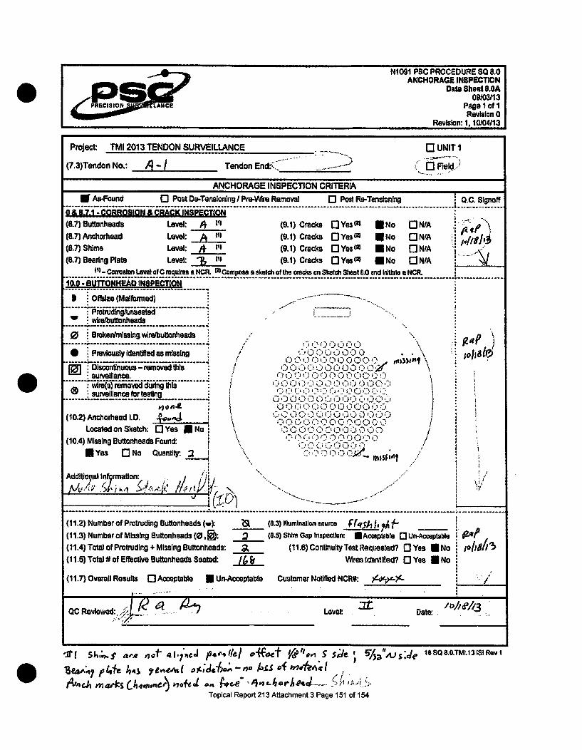
N1091 PSC PROCEDURE SO 8.0ANCHORAGE INSPECTION
Date Sheet 8.0AS09/0313P•CISION ANC of
Revision 0Revision: 1, 10104113
Project: TMI 2013 TENDON SURVEILLANCE 0 UNIT I
(7.3)Tendon No.: j-1 Tendon End•:•... .- Field)
ANCHORAGE INSPECTION CRITERIA
ffAS-Found [0 Post Oe-Tensloning/ Pro-Wre Removal 0 Post Re-Tensioning 1 Q.C. Signoff.................................................. . ....................... ...............0 & 8.7.1 - CORROSION & CRACK INSPECTION(817) Buttonheads Level: 4 W (9.1) Cracks n3Yesm n No WN/A(8.7) Anchorhead Level: A (t) (9.1) Cracks DYesm N No 0 NIA(8.7) Shims Level: A i (9.1) Cracks DYes(m ENo nNIA(8.7) Bearing Plate Level: ", in (9.1) Cracks DYes'• UNO OlN/A
(I" CM6810111 LOWe OfC eqUIrSs 8 NCRt M Campoa a Sketch of the cracks on Sketchi Shoal &0 and Inthiss a NCR.............-..... ?..... c.. . . . . ..... .................. ......... ... ..... ... ......... ......... ...............10.0 - BUTrONKEAD INSPECT[ON
-- - - - - -.. . -- - - - - - -.. . . . . . . . . . . .. . .. . .
... ... ... ..I Offalze (Malformed)
:ProtrudingAunseated
W wirelbutonheads
0 Broken/missingwirelbuttonheads. ..... .o.. ........ . .... ......... .....
: Previously identifiedasmissing
( -- Discontinuous- removed thisurveillance." P"• • '•••5• ...........wis) removedidunc ngott~ ssurveillance Ibirtesting
L...._:_,_J
f/0' 0 0 C) f-) 0 0 ()f 0 01
0 II C)000(-- 0C ,/
-), 0 C 0 1)' 0 0iI
I~jn1 14
(10.2) Anchlotead1.D. , ,. , ,-Located on SketCh: [3 Yes XNo \1.
(10.4) Missing Buttonheads Found: C, i)"
MEYes r3No Quantity:. i
Additional Inkralon:MY"W7 "7 "ý- I -i•.... .................... ............ ......... .............................................. ..... ... .... ........................
gap
(11.2) Number of Protruding Buttonheads (w): (8.3) 111uminalion source FIq 2h 11 A(11.3) Number of Missing Buttonheads (0, ): 3 (8.5) Shim Gap Inspection:. Acteptable r3 Un-Acceptable(11.4) Total of Protruding + Missing Buttronteads: , (11.6) Continuity Test Requested? n Yes ON No 1011815(11.5) Total # of Effective Buttonheads Seated: J Wresldentlifed? nYes lNo
(11.7) Overall Results 0 Acceptable U Un-Acceptable Customer Notified NCRW. ,4*-*$.
OC Revlewed: ' Level: . Date ,
-t s,, =,. .of" 4i.a i 4 / 1Ie/ fo ef-o '/",,r s S;ife "/,i'Dv 18 SQ 8.0.TMI.13 ISI Rev I
BToicl ep4fe 4r432 7ev13AU( /) A achme 3 Pge 11Afl
Topical Report 213 Aftacthment 3 Page 151 of 154

NI 091 PSC PROCEDURE SQ &0ANCHORAGE INSPECTION
Sketch Sheet 6.009103/13
pop IloflRevision 0
Revision: 1.10/04113
Project Exelon 2013 TENDON SURVEILLANCE 0 UNIT I
Tendon No.: Tendon End: __ Shop 0 Field
(9.2) Sketch each crack as It appears in the anchorheads/bushlngs, shims and bearing plates. Identify each Unit bynumber, record the location of the anchorhead or bushing Identification and apply to the sketch. Use as many SketchSheets as necessary being sure to list the page number below and to apply a Sketch Number to each unit with cracks.Ensure a Nonconformance Reoort In accordance with Procedure QA 9.0. NONCONFORMANCES. for Exelon asnroval.
! II T-P!- FIT F"]- I I I F--! 1' 1 " F-II I TI I 1 1 I-F1'I.-I-I- I- I~. I' 1. 1- 11TI.--- 1 i~ --4-i-- --1 1.i--i---- - lI'll
SIl1l i. *l/i ....1UI I-H ." -- t1 V. t• !
0lF I I
II I I III_t7-j Ir
FL I-I1~I~ I~ ~I1-TTII I LLLIi LI II; I
I I i I I I I iI I L EL
11111 I I'III i /I111
I- - in
-iT77E[I~I j t 3ZrLLZYTT t l LL_[.I..J_._• .-•EI-J JIELII h. l
C Inspectoc r0 Level: • Date: , o /
OC Reviewed: Level: Date:
18 SQ 8.O.TMI.13 ISl Rev I
Topical Report 213 Attachment 3 Page 152 of 154

N1091 PSC PROCEDURE SO 8.0ANCHORAGE INSPECTION
Data Shoot U.0A09/03113
PRECISION ANCE Pag I of IRevision 0
Revision: 1, 10104/13
Project: TMI 2013 TENDON SURVEILLANCE 0 UNIT I
(7.3)Tendon No.: A TTendon End:RT
ANCHORAGE INSPECTION CRITERIA____n As-Found n Post Oe-Tensitnlng I Pre-V*f Removal [I Post Re-Tensloning I O.C. Signoff
------------------------ ^----------------- - -1.* -0 & 8.7.1 -CORROSION & CRA•ICK INSPE•CTION
(8.7) Buttonheads Level (9.1) Cracks Q-Yes(l) R No O-N/A
(87)Anchorhead Level: (9.1) Cracks O-Yes(w *No 0N/A W A
(8.7) Shims Level: ) (9.1) Cracks 0 Yesl1 I No ONIA(8.7)BearngPIate Level ) (9.1) Cracks I-YesW ENo QNIA
(1)-.Conalcn Lewi o C requresa NCR. MComposea sketch of fte padcson Sketch ShWe&80 and Iritlate a NCR.
Orfsize (Malformed) .. . - -
wire/buttonheads -x,~' ~ .~ii~..... - ,• •... ...... ........ .0-.9-". .•.,,_•@ Jt
....-.... ..w........................ "". • / o0 . Dreken/mlssing wlre/buttolheads '• ,),¢, - 1 ,i"I
* Prelou slyIdentified as missing / 0 01. C C."''• ,........................ 0 Q 0 0 ID t" ,D>
Discontlnuous-removed thls 0 0 0 0 0 0 0 0 C0 0 G0 Dsurveilance. o0 0o 00o0 0(0 ),: , C ,
v~r~s)reove duin ths ....... t) 0 ©0 , 3 010" 0 , 'D"•- 0;7
• surve•llancefortesdng . . . ...... . . .D000 000 ID" 00 d
(10.2)Anchaoteadl.D. .o0u O0 0 00 0C, 0C .0 ,, ~~~~~0 G 0 0 0 CI f.T ?0 -.00Located on Sketch: PIYes r]No 0 O000Q00001c: 0 0 D 0
(10.4) Missing Buttonheada Found: \ 0 00 00 . i. 4 /IYes [I No Quantity. Q 0 r ."
Additi no[,, /"'" ] /I
.. .. .. .. .. .. ... .. .. .. .. .. ... .. .. .. .. .. ... .. .. .. .. .. ... .. .... .. .. ... .. .. .. .. .. ....-.. .. .. .. .(11.2) Number of Protruding Buttonheads (w): : (8.3) Iluminat.on sourcs
(11.3) Number of Missing Buttonheads (0, 1): (8.5) Shim Gap lnspectIon 0 AMxwptable IUn-Accaplable
(11.4) Total of Protruding + Missing Buttonheads: 1 (11.8)Continuity Test Requestaed? nYes 0-No
(11.5) Total # of Effective Buttonheads Seated: Ib7 WVresldentilied? []Yes []No,
(11.7) Overall Results ] Acceptable M Un-Acceptable Customer Notified NCR#: ) ..-
QC Reviewed: Level: Date: ,ofie/a
n1 n_ __ __n_ ___._ ___n
S1,, .q.,N&~? ,J almsot-iu~a. S eil 94f £a Pia 1k 10 SO8.C.TMI.13 ISI Rev I
Topical Report 213 Attachment 3 Page 153 of 154

NI 091 PSC PROCEDURE SO 8.0ANCHORAGE INSPECTION
Sketch Sheet 8.009103113
fPage 1 of IP/ECI[tOR ANCE Reviln 0Revision: 1. 10104113
Project Exelon 2013 TENDON SURVEILLANCE 0 UNIT I
Tendon No.: Tendon End: r0 Shop 0 Field
(9.2) Sketch each crack as It appears In the anchorheadsibushings, shims and beadng plates. Identify each Unit bynumber, record the location of the anchorhead or bushing Identification and apply to the sketch. Use as many SketchSheets as necessary being sure to list the page number below and to apply a Sketch Number to each unit with cracks.Ensure a Nonconformance Report In accordance with Procedure QA 9.0. NONCONFORMCES,for Exeton approval.
tr I i I1 I i 1!-rln - i- I Tl I I I FIl- r I F F F 1 I M I I I I !-I-j--
LI
L: U K, ri ui,W LLLLU; vr.IwL: , htI'jih
t ! l ! i llll
HH I Hspcto LHevel* Date:
OC Reiewe: Level: Date: -
1 R eviewe: eve:- Da Re :1
1850Reviewed:3LevelRevate:
Topical Report 213 Attachment 3 Page 154 of 154
Copyright © 2022 FDOKUMEN