
\ FIFTH TOPICAL MEETING on the [ft TECHNOLOGY OF ...
547
PROGRAM AND SUMMARIES CONP-830406—Absts. DE03 004943 \ FIFTH TOPICAL MEETING on the [ft TECHNOLOGY OF FUSiON ENERGY Knoxville Hilton and Holiday Inn- Wqrld 's Fair Knoxville, Tennessee April 26-28, 1983 < sponsored by' American Nuclear Society Oak Ridge-Knoxville Section of the American Nuclear Society Office Of Fusion Energy of the U.S. Department of Energy Oak Ridge National Laboratory „ Electric Power Research Institute ION! £
-
Upload
khangminh22 -
Category
Documents
-
view
0 -
download
0
Transcript of \ FIFTH TOPICAL MEETING on the [ft TECHNOLOGY OF ...

PROGRAM AND SUMMARIES CONP-830406—Absts.
DE03 004943
\ FIFTH TOPICAL MEETINGon the
[ft TECHNOLOGY OF FUSiON ENERGY
Knoxville Hilton andHoliday Inn- Wqrld 's Fair
Knoxville, TennesseeApril 26-28, 1983 <
sponsored by'
American Nuclear SocietyOak Ridge-Knoxville Section of the
American Nuclear SocietyOffice Of Fusion Energy of the
U.S. Department of EnergyOak Ridge National Laboratory „Electric Power Research Institute
ION!
£

PROGRAM SUMMARY
ORAL SESSIONS' POSTER SESSIONS'"
Tuesday, April 268:15-noon
Plenary Session: "Progress in FusionTechnology"Welcome, L Manning Muntzing, President,
American Nuclear SocietyKeynote, John F. Clarke, U.S. Department
of Energy
United States: Inertial Confinement FusionJapan: Magnetic FusionEuropean Community: Magnetic FusionUnited States: Magnetic Fusion
1:30-5:00 Concurrent Sessions
2A: U.S. Next-Generation Tokamak andTandem Mirror Programs (invited)
2B: Tritium
2:30-5:00
2C-1: Plasma Engineering2C-2: Hybrids and Nonelectric Applications2C-3: Operations and Maintenance2C-4: Alternate Fuels2C-5: Fusion Systems Studies
Wednesday, April 278:15-noon Concurrent Sessions
3A: Large Construction Projects (invited)3B: Alternate Fuels
9:30-noon
3C: Neutronics and Shielding
1:30-5:00 Concurrent Sessions4A: Fusion System Studies4B: Plasma Heating, Impurity Control,
and Fueling (invited)
6:30 Reception and entertainment (cash bar)7:30 Banquet
Speaker: Rep. Marilyn Lloyd
:15-noon Concurrent Sessions5A: Magnet Engineering5B: Incrlial Confinement Fusion
9:30--noon
3D-l: Tritium3D-2: Materials Engineering3D-3: Blanket and First Wall Engineering3D-4: Plasma Engineering3D-5: Environment and Safety
2:30-5:00
4C-1: Tritium4C-2: Materials Engineering4C-3: Blanket and First Wall Engineering4C-4: Neutronics and Shielding4C-5: Incrtial Confinement Fusion
Thursday, April 28
:30- 5:00 Concurrent Sessions6A: Blanket ard First Wall Engineering6B: Alternate Concepts
9:30-noon
5C-1: Impurity Contol and VacuumTechnology
5C-2: Next-Generation Devices5C-3: Blanket and First Wall Engineering5C-4: Environment and Safety5C-5: Ncutronics and Shielding
2:30-5:00
6C-1: Magnet Engineering6C-2: Plasma Heating, Impurity Control.
and Fueling6C-3: Power Conversion, Instrumentation
and Control
•All oral sessions, receptions, and the banquet will be at the Knoxville Hilton.kAU poster sessions will be at the Holiday Inn-World's Fair.

CONF-830406—Absts.
PROGRAM AND SUMMARIES
FIFTH TOPICAL MEETINGON THE
TECHNOLOGY OF FUSION ENERGYt •;• iT
a -a i * i
B e a r o a > , nS 2 E "
Knoxville Hilton and Holiday Inn-World's FairKnoxville, Tennessee
April 26-28,1983
Date Published - Apri l 1983
i-S a
i t•a s & s g
: • § •
•IflihSIfi3
iSliUI|11liil
.£•
Sponsored by
American Nuclear Society •Oak Ridge-Knoxville Section of the American Nuclear Society •
Office of Fusion Energy of the U.S. Department of Energy •Oak Ridge National Laboratory •
Electric Power Research Institute •
PORTIONS or
possible availability
prepared by OAK RIDGE NATIONAL LABORATORY Oak Ridge, Tennessee 37830
operated by UNION CARBIDE CORPORATION for the DEPARTMENT OK ENERGY
WSTRTBUTTOVOFTH^ <IS UNL1MI

SPONSORS
American Nuclear SocietyOak Ridge-Knoxville Section of the American Nuclear Society
Office of Fusion Energy of the U.S. Department of EnergyOak Ridge National Laboratory
Electric Power Research Institute
ORGANIZING COMMITTEE
General Chairman: J.L. Scott, Oak Ridge National LaboratoryAssistant General Chairman: J. Sheffield, Oak Ridge National Laboratory
Technical Program Chairman: C.A. Flanagan, Westinghouse Electric Corporation
TECHNICAL PROGRAM COMMITTEE
M.A. Abdou, Argonne National Labov toryN.A. Amherd, Electric Power Research InstituteJ.L. Anderson, Los Alamos National LaboratoryJ.E. Baublitz, U.S. Department of EnergyW.R. Becraft, General Electric CompanyLA. Booth, Los Alamos National LaboratoryD.L Cook, Sandia National
Laboratories-AlbuquerqueCD. Henning, Lawrence Livermore National
LaboratoryR.A. Krakowski, Los Alamos National
Laboratory
LG. Masson, Idaho National EngineeringLaboratory
J.R. Powell, Brookhaven National LaboratoryP.H. Sager, General Atomic CompanyT.E. Shannon, Oak Ridge National LaboratoryW.M. Stacey, Georgia Institute of TechnologyF.H. Tenney, Princeton Plasma Physics
LaboratoryT.C Varljen, Westinghouse Electric Corporation
LOCAL ARRANGEMENTS COMMITTEE
Publicity and Registration: P.N. Haubenreich, Oak Ridge National LaboratoryArrangements: N.A. Uckan, Oak Ridge National Laboratory
Publications: W.R. Becraft, Gensral Electric CompanyFinance: J.R. Hickey, Oak Ridge National Laboratory
Posters: P.L. Walstrom, Oak Ridge National LaboratoryTours: R.J. Colchin, Oak Ridge National Laboratory
Guest Program: J.B. Scott
. . . / <jm//f

REGISTRATION
The registration fee for the meeting, includingsocial events and proceedings, is $160 for mem-bers of the American Nuclear Society and $175for nonmembers. To encourage student attend-ance, iull-time students will be charged only S10,but this will not include the banquet or a copy ofthe proceedings.
The registration desk, in the Ballroom Foyerof the Knoxville Hilton Hotel, will be open at thefollowing times:
Monday, April 25 5:00-10:00 p.m.Tuesday, April 26 7:00 a.m -5:00 p.m.Wednesday, April 27 8:00 a.m.-4:30 p.m.Thursday, April 28 8:00 a.m.-noon
Pre-registered attendees can pick up their partic-ipant's package at the registration desk.
Before the banquet Wednesday evening, therewill be a reception in the Ballroom Foyer of theHilton featuring live entertainment and a cashbar. The event will begin at 6:30 p.m. Thebanquet, which is scheduled for 7:30 Wednesdayevening in the Hilton Ballroom, promises to beextraordinary. The food, with accompanyingwine, has been planned and will be prepared bythe Hilton's Master Chef, who is a graduate ofthe Cordon Bleu in Paris. Following your diningexperience, one of the prime movers in the U.S.Congress, Rep. Marilyn Lloyd of Tennessee, willaddress the assembly. Representative Lloyd isespecially knowledgeable and authoritativebecause of her experience as Chairman of theEnergy Research and Production Subcommitteeof the House Committee on Science andTechnology.
COMMUNICATIONS
Participants can receive messages at the meet-ing registration desk or at either of the hotels atthe following telephone numbers:
Knoxville Hilton 615-523-2300Holiday Inn-World's Fair 615-522-2800
There will also be a message board in theBallroom Foyer of the Knoxville Hilton. Duringthe hours the meeting registration desk is open,the staff will accept messages and post them onthe board. For this service, call the KnoxvilleHilton and ask for "The Fusion Meeting Desk!'Public telephones are located in the BallroomFoyer and in the lobbies of both hotels.
SOCIAL EVENTS
After registering Monday evening, you areencouraged to linger in the Ballroom Foyer ofthe Hilton and mingle with other "early birds"while enjoying light refreshments from 6-9 p.m.During morning and afternoon breaks each dayof the meeting, coffee will be available at bothhotels and light refreshments will be served atthe Holiday Inn in the area adjacent to theposters.
Although no special events are planned forTuesday evening, information will be availableabout the sights and culinary delights of Knox-ville. You will be free to explore the area at yourleisure.
TECHNICAL PROGRAM
The theme of the meeting is Progress in FusionTechnology, with the emphasis on progress. Theopening plenary session will consist of invitedpapers by leaders of fusion programs in theUnited States, Japan, and Europe. In subsequentsessions, attendees will present more than 240papers. Each morning and afternoon there will betwo concurrent oral sessions in the KnoxvilleHilton and a poster session in the Holiday Inn.Subjects have been grouped to minimize competi-tion for an audience and, when possible, theposter sessions will continue after the oral sessionsare concluded. A schedule of sessions, a completelisting of titles and authors, summaries of eachpaper, and an author index follow.
ORNL FUSION ENERGY TOUR
Fusion energy experiments and developmentfacilities at the Oak Ridge National Laboratorywill be viewed on this Friday morning tour. TheISX-B tokamak, the Elmo Bumpy Torus ma-chine, and the Large Coil Test Facility will befeatured. Buses will leave the Knoxville hotels at8:30 and return by 12:30. Because the fusionfacilities are within the Y-12 Plant area, nocameras are allowed. There is no additionalcharge for this tour, but participants must sign upat the meeting registration desk no later thanTuesday, April 26.

PROCEEDINGS
Proceedings of the Fifth Topical Meeting onthe Technology of Fusion Energy will be pub-lished as a special issue of the American NuclearSociety's Nuclear Technologyy'Fusion journal.All papers presented at the meeting, either orallyor as a poster, will be included provided theauthor submitted a manuscript by March 31that satisfied the publication requirements.Manuscripts will have been reviewed before themeeting and comments will be available in apublications review room at the KnoxvilleHilton. The proceedings should be available inSeptember 1983.
GUEST PROGRAM
On each of the three mornings of the meeting,registered guests are invited to enjoy a continentalbreakfast in a guest hospitality room at theKnoxvillc Hilton. Registered guests are also in-vited to participate in the Monday evening mixerand the Wednesday evening reception. In addi-tion, they are welcome at all technical sessionsand to partake of morning and afternoon refresh-ments. The fee for the guest registration is $20.
Any guest, registered or not, who wishes toattend the banquet on Wednesday evening canpurchase a ticket for $25. In addition, there willbe a daily special event for guests for whichseparate tickets will be sold.
Wednesday, 9:30-4:00 AppalachianFrontiers—Then and Now
First on this tour is a visit to John Rice Irwin'sMuseum of Appalachia. Several historic logbuildings contain a comprehensive collection ofthe tools and furniture of the people who wresteda living from the land before the days of TVA andOak Ridge. Next is a picnic lunch in a scenic spotnear Norris Dam, the first power plant and floodcontrol reservoir built by the Tennessee ValleyAuthority. After lunch, the group will visit theAmerican Museum of Science and Energy inOak Ridge. This unusual museum has fascinatingdisplays of the entire spectrum of energy systemsin this country, including nuclear fusion. The lastpart of the tour will take you for a drive along oneof Knoxville's scenic Dogwood Trails ($12, includ-ing lunch).
Thursday, 10:00-2:00 Historic Knoxville
Guests will stroll from the Knoxville Hilton tothe James White Fort, which was where Knoxvilleoriginated. They will then proceed to BlountMansion, the first frame house built west of theAppalachians and the home of the first governor ofthe State of Tennessee. The tour concludes withlunch high in the Sunsphere, symbol of the 1982World's Fair, overlooking downtown Knoxville andthe University of Tennessee campus ($12.50,including admissions and lunch).
Tuesday, 9:00-5:00 Smoky Mountains andGatlinburg
This tour combines mountain scenery andunique shopping opportunities. The Great SmokyMountains National Park provides intimate viewsof spring wildflowers and foliage along secludedpaths in addition to magnificent vistas. You willhave plenty of time for shopping and lunch inGatlinburg, Tennessee's outstanding holiday townin the foothills of the mountains ($7, not includinglunch).
vi

PROGRAM

P-,

.TUesday, April 26,1983
8:15 a.m. Plenary SessionSummary
PROGRESS IN FUSION TECHNOLOGY (invited) J^L.Welcome
L. Manning Muntzing. President, American Nuclear Society
Keynote AddressJohn F. Clarke. U.S. Department of Energy
Inertia] Fusion Program in the U.S 5Richard L Schriever, U.S. Department of Energy
The Fusion Technology Program in Japan 7Yasuhiko ho, Japan Atomic Energy Research Institute
The Fusion Programme of the European Community 9Donato Palumbo, Commission of the European Communities
Progress in Fusion Technology in the U.S. Magnetic Fusion Program 11Robert J. Dowling, U.S. Department of Energy
P-3

Ifaesday
1:30 p.m. Session 2A (oral)
Summary
U.S. NEXT-GENERATION TOKAMAK ?"*<AND 1ANDEM MIRROR PROGRAMS (invited)
Overview of Magnetic Fusion Advisory Committee Panel Findings on Tandem Mirrorsand Tokamaks 15J.R. Gilleiand, GA Technologies, Inc.
Physics Basis For an Ignited Long-Pulse Tokamak 17P.H. Rutherford. Princeton Plasma Physics Laboratory
Tokamak ETR Objectives, Characteristics, and Critical Issues 19W.M. Stacey, Jr., Georgia Institute of Technology
Next Tokamak Facility 21J.A. Schmidt, Princeton Plasma Physics LaboratoryC.A. Flanagan, Westinghouse Electric Corp.
Overview and Directions in the Tandem Mirror Program 23K.I. Thomassen, Lawrence Livermore National Laboratory
Fusion Power Demonstration 25CD. Henning, B.G. Logan, G.A. Carlson, and W.S. Neef, Lawrence Livermore
National LaboratoryR. Botwin, Grumman Aerospace Corp.R. Campbell. TRW, Inc.
Tandem Mirrors for Neutron Production 27J.N. Doggett, Lawrence Livermore National Laboratory
P-4

Tuesday
1:30 p.m. Session 2B (oral)Summary
TRITIUM Pa&
The Status of Tritium Technology Development for Magnetic Fusion Energy (invited) 31J.L Anderson, Los Alamos National Laboratory
The TRIO-01 Experiment (invited) 33R.G. Clemmerand R.F. Malecha, Argonne National LaboratoryJ.T. Dudley, Oak Ridge National Laboratory
Analysis of the Tritium Requirements for a Power Reactor 35F. Carre and A. Rocaboy, Centre d'Etudes Nucleaires de Saclay
The Effects of Tritium Contamination in the FED/1NTOR Reactor Hall 37P.A. Finn, Argonne National LaboratoryM.L Rogers. Monsanto Research Corporation—Mound Facility
Tritium Monitoring Requirements of Fusion Reactors and Ontario Hydro Experience:A Comparison 39S.B. Nickerson and D.P Dautovich, Ontario Hydro
Tritium Monitoring Within the Reactor Hall of a D-T Fusion Reactor 41R.A. Jalbert, Los Alamos National Laboratory
Radiation Catalyzed Conversion of Tritium Gas to Tritialed Water 43C.E. Easterly and M.R. Bennett. Oak Ridge National Laboratory
Tr i t ium R e m o v a l f rom C o n t a m i n a t e d W a t e r via Inf ra red Lase r Mul t ip l e -Pho ton Dissociat ion . . . 4 5J.L. Maienschein. F. Magnotta, I.P. Herman. FT. Aldridge. and P. Hsiao, Lawrence
Livennore National Laboratory
P-5

Tuesday
2:30 p.m. Session 2C-1 (poster)- Summary
PLASMA ENGINEERING -^«L_
A Program for Calculating Forces on Limiter and First Wall Due to Plasma Disruption 49M.H. Foss, Argonne National Laboratory
Fast Alpha Diffusion and Thermalization in Tokamak Reactors 51S.E. Attenberger and W.A. Houlberg, Oak Ridge Nationai Laboratory
Control for Fusion Thermal Stability 53/. Maya, General Atomic Co.H.D. Campbell, University of Florida
Preliminary Temperature Profiles on the PDX Inner Toroidal Limiter 55M. Ulrickson and H, W, Kugel, Princeton Plasma Physics Laboratory
Parametric Study of LH Current Drive in FED-A Design 57H. lida, Japan Atomic Energy Research InstituteD.A. Ehst, Argonne National LaboratoryY-I..M. Peng, Oak Ridge National Laboratory
P-6

Tuesday
2:30 p.m. Session 2C-2 (poster)Summon'
HYBRIDS AND NONELECTRIC APPLICATIONS la^ **»*
Hybrid Reactor Development Planning 61 6D.H. Berwald, R. Campbell, S. Freije, J.K. Garner, S.L. Salem. W.G. Steele, and
R.H. Whiiley, TRW, Inc.
A Comparison of Fusion Breeder/Fission Client and Fission Breeder/Fission Client Systems forElectrical Energy Production 63 7R.J. Land and T.A. Parish, Texas A&M University
Aqueous Slurries Containing Thorium Oxide as Blankets in Fissile Fuel ProducingFusion Reactors 65 8T.C. Geer and T.A. Parish, Texas A&M University
Tritium Assisted Deuterium-Based Fusion Breeders 69 10E. Greenspan andG.H. Miley, University of Illinois, Urbana
Performance Requirements of an Inertial Fusion Energy Source for Hydrogen Production 71 11J. Hovingh, Lawrence Livermore National Laboratory
A Thermochemical Hydrogen Production System Based on a High-Temperature FusionReactor Blanket 73 12/. Maya, LC. Brown, and K.R. Schultz, General Atomic Co.RW. Goodrich. Northeast Utilities Service Co.B.K. Jensen, Public Service Electric and Gas Co.
The HYFIRE Reactor Design 75 13J.A. Fillo, J.R. Powell, and R. Benenati, Brookhaven National LaboratoryF. Malick, M. Sniderman, and E. Somers, Westinghouse Electric Corp.
P-7

Tuesday
2:30 p.m. Session 2C-3 (poster)Summary
OPERATIONS AND MAINTENANCE Pa* ****
First Plasma Operation of TFTR 79 14M.D. Machalek, Princeton Plasma Physics Laboratory
Maintenance and Disassembly Considerations for the Technology Development Facility 81 15P.T. Spampinato, Grumman Aerospace Corp.
T.F. Coil Replacement Considerations for the FED Baseline Configuration 83 16I. Dietz. Grumman Aerospace Corp.
General Design and Maintenance of TASKA—A Tandem Mirror Test Facility 85 17A. Support, Kemforschungszentrum Karlsruhe GmbHI.N. Sviatoslavsky, University of Wisconsin
Application of Mockups to the Resolution of Fusion Reactor Remote MaintenanceDesign Issues 87 18LS. Masson and K.D. Watts, EG&G Idaho, Inc.
Remote Vacuum Joint Concept for Fusion Reactors 89 19E.R. Hager and David W. Doll, GA Technologies, Inc.
A Remote Joint Concept for Large Vacuum Ducts 91 20D.B. Hagmann and J.B. Coughlan, Remote Technology Corp.
In-Vessel Maintenance Concepts for Tokamak Fusion Reactors 93 21J.D. Berger, V.P. Kelly, andJ.A. Yount, Westinghouse Hanford Co.
Central Cell Blanket Module Maintenance Approach for the MARSHigh-Temperature Blanket 95 22N. Young, Ebasco ServicesD. Sutliff, D. Tait, R. Siebert, andJ. Coulahan, General DynamicsJ.K. Garner andJ.D. Gordon, TRW, Inc.
P-8

TUesday
2:30 p.m. Session 2C-4 (poster)Summary
ALTERNATE FUELS ^ ****
Effects of Enhanced Ion/Electron Equilibration Power on Cat-D Tokamak Ignition 99 23J. Galambos and G.H. Miley. University of Illinois
D-D Tokamak Reactor Assessment 101 24D.C. Baxter, A.E. Dabiri, D. Dobrott, J.E. Glancy, H. Gurol. W.K. Hagan, J.B. McBride.
andS. Tamor, Science Applications, Inc.R.N. Cherdack, Burns and Roe, Inc.
A D-D Tandem Mirror Reactor With Central-Cell Potential Modification 103 25G. W. Shuy and D. Dobrott, Science Applications, Inc.
Experimental Investigation of Muon-Catalyzed Fusion 105 26S.E. Jones, AJ, Caffrey, J.B. Walter, and K.D. Watts, Idaho National Engineering
LaboratoryJ.L Anderson, ,7.7V. Bradbury, P.A.M. Gram, M. Leon, and M.A. Paciotti, Los Alamos
National Laboratory
The Influence of Engineering Constraints on Confinement Time Requirements of Advanced FuelFusion Reactors 107 27J.R. Roth, University of Tennessee
High Field Tokamaks with DD-DT Operation and Reduced Tritium Breeding Requirements 109 28L Bromberg, D.R. Cohn, N. Diatchenko, R. LeClaire, J. Meyer, andJ.E.C. Williams,
Massachusetts Institute of Technology
P-9

TUesday
2:30 p.m. Session 2C-5 (poster)Summary
FUSION SYSTEMS STUDIES _*£_ Booth
The Effective Cost of Tritium for Tokamak Fusion Power Reactors with Reduced TritiumBreeding Ratios 113 29J.G. GUligan, University of IllinoisK. Evans. Jr, andJ. Jung, Argonne National Laboratory
Mirror Advanced Reactor Study (MARS) End Plasma Technology Development 115 30W. Barr and R. Moir, Lawrence Livermore National LaboratoryV. Calia, J. Erickson, S. Fixler, R. Herbermann, T. Luzzi, andD. Sedgley, Grumman
Aerospace Corp.
Availability Analysis of Fusion Power Plants 117 31Z. Musicki and C. W. Maynard, University of Wisconsin
Utility Evaluation of the D-T Starfire and D-D Wildcat Reactors '. 119 32B.K. Jensen and R.D. Endicott. Public Service Electric and Gas Co
P-10

.Wednesday, April 27,1983
8:15 a.m. Session 3A (oral)Summary
LARGE CONSTRUCTION PROJECTS (invited) Pa*<JT-60 and Its Present Status 123
Af. Yoshikawa, Japan Atomic Energy Research Institute
The Mirror Fusion Test Facility 125V.N. Karpenko, Lawrence Livermore National Laboratory
The Present Status of the Joint European Torus (JET) 127H.O. Wuster, Joint European Torus
Construction of the Tokamak Fusion Test Reactor 129J.W. French, L.E. Shaw, B. Fedor, and M. Sabado, Ebasco Services, Inc.
P-ll

Wednesday ^_i
8:15 a.m. Session 3B (oral)Summary
ALTERNATE FUELS **
Alternate Fuels in Fusion Reactors (invited) 133D. Dobrott, Science Applications, Inc.
Viability of the "B(p, a) 2a Cycle 135J.D. Gordon, T.K. Samec, S.A. Freije, and B.I. Hauss, TRW, Inc.
Approaches to Near-Term Alternate Fuel Experiments (invited) 137B. Coppi, Massachusetts Institute of Technology
P-12

Wednesday
9:30 a.m. Session 3C (oral)Summary
NEUTRONICS AND SHIELDING *
Streaming and Shielding Analysis for the NBI System of TDF 141M.E. Sawan, University of Wisconsin
Assessments of Tritium Breeding Requirement and Breeding Potential for theStarfire/Demo Design 143J. Jung and M. Abdou, Argonne National Laboratory
Monte Carlo Calculations of Neutron and Gamma-Ray Energy Spectra for Fusion ReactorShield Design: Comparison With Experiment 145R.T. Santoro and J.M. Barnes. Oak Ridge National Laboratory
Low-Cost Shield For Tokamak Fusion Reactors 147Y. Gohar, Argonne National Laboratory
Monte Carlo Neutronic Analysis for the TFTR Lithium Blanket Module 149B.A. Engholm, General Atomic Co.
P-13

Wednesday
9:30 a.m. Session 3D-1 (poster)Summary Booth
TRITIUM -Im
The Wall Tritium Concentration as a Factor in Fusion Reactor Hall Design 153 1P.A. Finn and R.A. Leonard, Argonne National LaboratoryM.L Rogers and CJ. Sienkiewicz, Monsanto Research Corporation-Mound Facility
Transient Tritium Transport in a Solid Breeder-Blanket 155 2D.R. Hanchar and MS. Kazimi, Massachusetts Institute of Technology
Some Basic Studies on Tritium Processing in CTR Solid Blanket 157 3F. Ono. S. Tanaka, T. Tera', M. Inoue, M. Nakazawa, Y. Takahashi, R. Kiyose, and
M. Kanno, University of Tokyo
Tritium Recovery From Liquid Lithium-Lead by Vacuum Degassing 159 4K.E. Plute, EM. Larsen, and D.K. Sze, University of Wisconsin
P-14

Wednesday
9:30 a.m. Session 3D-2 (poster)Summary
MATERIALS ENGINEERING _Page_ Booth
Comparison of the Waste Management of PC A and V15CR5T1 First Wall Materials 165 6S. Vogler, MJ. Steindler, andJ. Jung, Argonne National Laboratory
Materials Compatibility Considerations for Fusion-Fission Hybrid Reactor Design 167 7J.H. DeVan and P.F. Tortorelli, Oak Ridge National Laboratory
Lifetime Analysis of Beryllium Balls in a Hybrid Fusion Blanket 169 8LG. Miller. J.M. Beeston, P.Y. Hsu. and B.L Harris, EG&G Idaho, Inc.
Comparison Between Measured and Predicted Performance of a High Speed, Free SurfaceLiquid Jet Flowing Along A Curved Wall 171 9J.A. Hassberger, Westinghouse Hanford Co.
Analysis of Blanket-Structure Lifetime for the Tandem Mirror Hybrid Reactor (TMHR) 173 10N.M. Ghoniem, University of California, Los AngelesD.H. Berwald. TRW, Inc.
P-15

Wednesday
9:30 a.m. Session 3D-3 (poster)Summary
BLANKET AND FIRST WALL ENGINEERING ** ***
MHD Pressure Drop of NaK Flow in a Stainless Steel Pipe 177 11K. Miyazaki, S. Kotake, N. Yamaoka, andS. Inoue, Osaka UniversityY. Fujii-e, Nagoya University
Disruption Induced Voltages and Loads on Torus Sectors 179 12R.J. Thome, R.D. Pillsbury, and W.R. Mann, Massachusetts Institute of Technology
Electromagnetic Effects on the INTOR Limiter 181 13LR. Turner and M.H. Foss, Argonne National Laboratory
Transient Analysis of Starfire Coolant-Blanket System with Athena Code 183 14S.Z. Rouhani. J. Jones, andJ.S, Herring, EG&G Idaho, Inc.
Effect of Temperature on Magnetic Field Perturbation from the FerromagneticBlankets in MARS 185 15H. Atiaya and G.L Kulcinski, University of Wisconsin
Dynamic Response and Stability of Inport Tubes in ICF Reactors 187 16R.L. Engt Istad and E.G. Lovell, University of Wisconsin
Control of Nsutron Albedo in Toroidal Fusion Reactors 189 17B.J. M, cklich and D.L. Jassby, Princeton Plasma Physics Laboratory
Experimental Study of the Enhancement of Critical Heat Flux Using TangentialFlow Injection 191 18J. Weede and V.K. Dhir, University of California, Los Angeles
P-16
Wednesday
9:30 a.m. Session 3D-4 (poster)Summary
PLASMA ENGINEERING *»* *2*
Plasma Engineering Analysis of an EBT Reactor Operating Window 195 19R.T. Santoro, N.A. Uckan. andJ.M. Barnes, Oak Ridge National Laboratory
Plasma Physics and Engineering During S tar tup and Shutdown of Tandem Mirror Reactors . . . . 197 20R.W. Conn, F. Najmabadi. F. Kantrowitz, DM. Goebel, and T.K. Mau. University of
California, Los Angeles
Assessment of Energetic Ion Rings Versus Electron Rings for an EBT Reactor 199 21J.B. McBride, Science Applications, Inc.N.A. Uckan, Oak Ridge National LaboratoryR.J. Kashuba, McDonnell Douglas Astronautics Co.
Analysis of Alpha Particle Behavior in EBT Reactors 201 22M.E. Fenstermacher. University of MichiganN.A. Uckan, Oak Ridge National Laboratory
Transport Scaling Studies for EBT Reactor 203 23T. Uckan. E.F. Jaeger, and N.A. Uckan. Oak Ridge National Laboratory
Plasma Engineering for MARS 205 24G.A. Carlson, W.L. Barr. B.M. Boghosian, RS. Devoto. G.W. Hamilton, B.M. Johnston,
W.N. Kumai, and B.G. Logan, Lawrence Livermore National LaboratoryR.B. Campbell, TRW, Inc.
Particle Confinement in EBT Reactors with Noncircular Mirror Coils 207 25L. W. Owen and N.A. Uckan, Oak Ridge National Laboratory
P-17

Wednesday
9:30 a.m. Session 3D-5 (poster)Summary
ENVIRONMENT AND SAFETY * »
Risk Considerations for Fusion Energy 211M.S. Kazimi, Massachusetts Institute of Technology
Relative Public Health Effects from Accidental Release of Fusion Structural Radioactivity 213 28S.J. Piet. EG&G Idaho, Inc.M.S. Kazimi and LM. Udsky, Massachusetts Institute of Technology
Risk Assessment Techniques for the Evaluation of Tritium Accident Mitigation 215 29S.Z. Bruske and D.F. Holland. EG&G Idaho, Inc.
Safety Analysis Report for the Tritium System Test Assembly 217 31R.V. Carlson, Los AJamos National Laboratory
Environment and Safety—Major Goals for MARS 219 32R.C. Maninger, Lawrence Livermore National Laboratory
Safety Considerations in the Design of the Fusion Engineering Device 221 33R.J. Barrett. Burns and Roe, Inc.
P-18

.Wednesday
1:30 p.m. Session 4A (oral)Summary
FUSION SYSTEM STUDIES Pa*<
The Mirror Advanced Reactor Study (MARS) (invited) 227B.G. Logan. LLNL, Laurence Livermore National Laboratory
Conceptual Design of Fusion Experimental Reactor (FER) 229T Tone, N. Fujisawa, Y.Seki. H. lida, K. Tachikawa, M. Sugihara, A. Minato. S. Nishio.
T. Yamamoto, K. Kitamura, K. Ueda, S. Saito, R. Shimada. Y. Matsuda, Y. Naruse,S. Shimamoto, S. Tamura, M. Yoshikawa, and K. Tomabechi. Japan Atomic EnergyResearch Institute
Demonstration Tokamak Power Plant 231M. Abdou, C. Baker, J, Brooks, R. Matlas, and D. Smith, Argonne National LaboratoryD. DeFresce. G.D, Morgan, andC. Trachsel McDonnell Douglas Astronautics Co.AT. Barry, The Ralph M. Parsons Co.
Fusion Breeder Reactor Design Studies 233R.W. Moir, J.D. Lee, M.S. Coops, FJ. Fulton, and W.S. Neef, Jr., Lawrence Livcrmore
National LaboratoryDM. Berwald, R.B. Campbell, B. Flanders. J.K. Garner, J.R. Ogren, Y. Saito, A. Slomovik,
and R.H. Whitley, TRW, Inc.R.P. Rose andJ.S. Karbowski, Westinghouse Electric Corp.K.R. Shultz, E.T. Cheng, G. Benedict, R.L. Creedon, I. Maya, V.H. Pierce, andJ.B. Strand,
GA Technologies, Inc.J.H. DeVan and P. Tortorelli. Oak Ridge National LaboratoryN. Hoffman, Energy Tecnhology Engineering CenterN. Ghoniem, University of California, Los AngelesL.G. Miller. P.Y.S. Hsu, and J.M. Beesinn, Idaho National Engineering Laboratory
PulseStar: A Pool-Type Reactor for Inertial-Fusion Electric Power 235M.J. Monster, Lawrence Livermore National Laboratory
Tokamak Reactor Systems Code 237D.C. Baxter. A.E. Dabiri. J.E. Glancy, and W.K. Hagen, Science Applications, Inc.
Superheated Steam Cycle for a D-D Tokamak 239K.C. LeeandR.N. Cherdack, Burns and Roe, Inc.
Conceptual Design Summary for Modifying Doublet HI to a Large Dee-shaped Configuration .. 241L Davis, General Atomic Co.
Overview of the Influence on Tandem Mirror Reactor Design of Startup, Shutdown andTransient Operation 243R.WConn,N.M. Ghoniem.S.P. Grotz, M.Z. Youssef. J.P. Blanchard, V.K. Dhir, and
K. Taghavi-fafreshi, University of California, Los Angeles
P-19

Wednesday
1:30 p.m. Session 4B (oral)Summary
PLASMA HEATING, IMPURITY CONTROL, FUEUNG (invited) fty
The Technology of Neutral Beam Injection Based on Positive Ion Sources 247M.M. Menon, Oak Ridge National Laboratory
Summary of the Status of Negative-Ion-Based Neutral Beams 249W.S. Cooper, Lawrence Berkeley laboratory
RF Coupler Technology for Fusion Applications 251DJ. Hoffman, Oak Ridge National LaboratoryD.G Wwiifj, Princeton Plasma Physics LaboratoryF. Blau, General Atomic Co.
Radio Frequency Energy in Fusion Power Generation 253J.O. Lcmson, Princeton Plasma Physics Laboratory
Key Issues of FED/INTOR Impurity Control System 255M.A. Abdou, Argonne National Laboratory
Development of Hydrogen Pellet Injectors at ORNL 257S.K. Combs, S.L. Milora. C.A. Foster, WA. Houlberg, D.D. Schuresko. S.E. Attenberger,
Oak Ridge National Laboratory
P-20

2:30 p.m. Session 4C-1 (poster)Summary
TRITIUM »
Implantation Measurements to Determine Tritium Permeation in First Wall Structures 261D.F. Holland. EG&G Idaho, Inc.R.A. Causey and M.L Sattler, University of Virginia
Development of Tritium-Protective Clothing in Canada 263J. Stephenson, K.Y. Wong, Ontario Hydro
Gamma Radiation Effects on Tritium Penneation and Rentention 265G.R. Longhurst, G.A. Deis, P.Y. Hsu. and LG. Miller, EG&G Idaho, Inc.R.A. Causey, University of Virginia
Optimization of a Large-Scale Gas Chromatograph to Separate Tritium and DT FromOther H Isotopes 267H. Weichselgartner, H. Frischmuth, J. Perchermeier, and A. Stimmelmayr.
Max-Plank-Institut fur Plasmaphysik
Operational Test of the TSTA Emergency Tritium Cleanup System 269R. V. Carlson and F.A. Damiano. Los Alamos National Laboratory
P-21

Wednesday
2:30 p.m. Session 4C-2 (jXKtcr)Summary
MATERIALS ENGINEERING _5l«L_ ****
FMIT—A Facility for Fusion Materials Qualification 273 6A.L Trego. J.W.Hagan, R.J. Burke, andE.F. Parker, Westinghouse HanfordCo.
The Nuclear Design of a Very Low Activation Fusion Reactor 275 7£.7: Cheng and G.R. Hopkins, General Atomic Co.
Selection of High Current Contact Materials for Tokamak Devices 277 8D.C. Banker, McDonnell Douglas Astronautics Co.
First Wall Coating Candidates for Inertial Confinement Fusion Reactor Chambers Using Dry WallProtection Only 279 9D.A. Sink, Westinghouse ARD
Corrosion Behavior of Materials Selected for FMIT Lithium System 281 10G.D. Bazinet, Westinghouse Hanford Co.M.G. Down, Westhinghousc R&D CenterD.K. Matlock, Colorado School of Mines
The Fusion Materials Irradiation Test (FMIT) Facility Lithium System—A Design andDevelopment Status 283 11P.J. Brackenbury, G.D. Bazinet, and W.C. Miller, Westinghouse Hanford Co.
P-22
2:30 p.m. Session 4C-3 (poster)Summary
BLANKET AND FIRST WALL ENGINEERING *
Flow and Heat Transfer Characteristics in Lithium Loop Under Transverse Magnetic Field 287 12K. Miyazaki, Y. Shimakawa, S. Inoue, and N. Yamaoka, Osaka UniversityY. Fujii-e, Nagoya University
Mirror Advanced Reactor Study (MARS) Solid Breeder Blanket and PowerConversion System 289 13R. Bulk's, I. Clarkson. L Deutsch, R. Micich, M. Rossi, M. Stauber, and P. Suh, Grumman
Aerospace Corp.
FELIX Construction and Experimental Program 291 14LR. Turner, W.F. Praeg, M.J. Knott, RJ. Lari, and R.B. Wehrle, Argonne National
Laboratory
Mechanical and Thermal Design Aspects of the Blanket, and Maintenance Considerations of theCentral Cell in MARS 293 15Y. T. Li, D.K. Sze, and I.N. Sviatoslavsky, University of Wisconsin
TPE-II Scoping Tests Results: Solid Breeder Heat Transfer and Stability 295 16A.R. Veca, L Yang, K.R. Schultz, and C.P.C. Wong, General Atomic Co.
FWBS Program Element II: Blanket and Shield Testing 297 17K.R. Schultz and A.R. Veca, General Atomic Co.G.A. Deis andP.YS. Hsu, EG&G Idaho, Inc.R.E. Nygren and H. Herman, Argonne National Laboratory
Limits on Transient Power Variations During Startup and Shutdown of Li-Pb CooledTMR Blankets 299 18N. Ghoniem, K. Taghavi-Tafreshi, J. Blanchard, andS. Grotz, University of California,
Los Angeles
Emergency Cooling of the MARS LiPb Blanket 301 19D.K. Sze and A. White, University of Wisconsin
Thermomechanical Testing of First Wall Test Pieces in ESURF 303 20J.R. Easoz, J.W.H. Chi, R. Bajaj, M.D. Nahemow, and R.E. Gold. Westinghouse
Electric Corp.
Large Area Surface Heating Facility (ASURF) and Test Program for First WallDesign Concepts 305 21H.D. Michael, J. Lempert, J.W.H. Chi, and R.P. Rose, Westinghouse Electric Corp.
Pre-Test Analysis of the Solid Breeder Integral Simulation Test for PE-II 307 22G.A. Deis. EG&G Idaho, Inc.
P-23

Wednesday ,
2:30 p.m. Session 4C-4 (poster)Summary
NEUTRONICS AND SHIELDING Pa» ****
Fusion Reactor Blanket—Neutronic Studies in France 311 23F. Bane, F. Gervaise, and L. Giancarli, Centre d'Etudes Nucleaires de Saclay
Nucleonics of a Be-Li-Th Blanket for the Fusion Breeder 313 24J.D. Lee, Lawrence Livermore National Laboratory
Aqueous Siurres as Tritium Breeding Blankets for D-T Fusion Reactors 315 25T.A. Parish. R.D. Erwin, and M.J. Schuller, Texas A&M University
A Benchmark Experiment on Tritium Production and Radiation Heating in theLiF Assembly 317 267: Iguchi, M. Nakazawa, and A. Sekiguchi, University of Tokyo
The Dependence of Neutron-Induced Radioactivity in Fusion Reactors on GeometricDesign Parameters 319 27G.P. Lasche and J.A. Blink, Lawrence Livermore National Laboratory
Neutronics Analysis of the Modular Stellarator Power Reactor UWTOR-M 321 28LA. El-Guebaly, Univesity of Wisconsin
Neutronics Analysis for the MARS Li-Pb Blanket and Shield 323 29J.H. Huang and M.E. Sawan, University of Wisconsin
Cross Section Sensitivity Study for U.S. Fusion Engineering Device (FED) 325 305. Pelloni, Swiss Federal Institute for Reactor ResearchE. T. Cheng, General Atomic Co.
P-24

Wednesday
2:30 p.m. Session 4C-5 (poster)Summary
INERTIAL CONFINEMENTFUSION *w* Booth
Vaporization of Pb and Li Films in ICF Reaction Chambers 329 31AM. Hassanein, Argonne National LaboratoryCD. Croessmann and G.L. Kukinski, University of Wisconsin
Concept and Design of ICF Reactor SENRI-II 331 32N. Nakamura and H. Omura, Ishikawajima-Harima Heavy Industries, Ltd.S.ldo. S. Nakai, and C. Yamanaka, Osaka UniversityK. Kitamura, Toyohashi University of TechnologyH. Nakashima, Kyushu UniversityH. Katsuta, Japan Atomic Energy Research InstituteK. Miya, University of Tokyo
Target Explosion Generated Fireballs in the Nitrogen Filled Target Chamber of the Light IonFusion Target Development Facility 333 34R.R. Peterson and G.A. Moses, University of Wisconsin
Inertial Confinement Fusion with Direct Electric Generation by Magnetic Flux Compression . . . 335 33G.P. Lasche, Lawrence Livermore National Laboratory
First Wall Materials Selection for the Light Ion Fusion Target Development Facility 337 35R.R. Peterson. E.G. Loveli, K.J. Lee, R.L Engelstad, G.L. Kulcinski, and G.A. Moses,
University of Wisconsin
Dynamic Stress Analysis of Light Ion Fusion Target Development FacilityReaction Chambers 339 36E.G. Lovell and R.L. Engelstad, University of Wisconsin
Neutron Activation and Shielding of the Light Ion Fusion Target Development Facility 341 37K.J. O'Brien, A.M. White, and G.A. Moses, University of Wisconsin
An ICF Reactor Concept Using 3He-AFLINT Targets 343 38G.H. Miley, J. Stubbins, M. Ragheb, and C. Choi. University of IllinoisG. Magelssen, Los Alamos National LaboratoryR. Martin. Argonne National Laboratory
P-25

Thursday, April 28,1983
8:15 a.m. Session 5A (oral)Summary
MAGNET ENGINEERING p^
Japanese Progress in the Large Coil Task and the High-Field Cluster Test Program (invited) 3475. Shimamoto and K, Yasukochi, Japan Atomic Energy Research Institute
Design of the 24 Tesla Axicell Magnets for MARS 349R.W. Baldi, J.F. Partner. WE. Tqffolo, K.L Agarwal, S. Dharmarajan, R.A.Sutton,
S.D. Peck, CM. Powers, G.D. Magnuson, andJ.L. Sounders,General Dynamics-Convair Division
Manufacture of TFTR TF Coils 351R.L Fuller, Jr. andAJ. Jarabak, Westinghouse Electric Corp.M. Sabado, Ebasco Services, Inc.E. Stern, Grumman Aerospace Corp.
Conceptual Design of Superconducting Helical Coil of Heliotron-G 3535. Kakiuchi, Y. Kazawa. K. Kuroda, and H. Ogata, Hitachi, Ltd.O. Motojima, A. liyoshi, and K. Uo, Kyoto University
Effects of Plasma Elongation on Magnetics of Continuous-Coil Tokamak Reactors 355E. Bobrovand L Bromberg, Massachusetts Institute of Technology
Safely of Superconducting Magnets with Internally Cooled Conductors 357LR. Turner, Argonne National Laboratory
Progress in Large Superconducting Pulsed Conductors and Coils for Tokamaks at JAERI 359S. Shimamoto. T. Ando, T. Hiyama, H. Tsuji. Y. Takahashi, E. Tada, M. Nishi, K. Yoshida,
K. Okuno, K. Koizumi, H. Nakajima, T. Kato, and K. Yasukochi, Japan Atomic EnergyResearch Institute
Ohmic Heating Solenoid Design Utilizing Force Cooled Windings 361V.C Srivastava. General Electric Co.
Poloidal Field Superconducting Ring Coil Case and Support Structure Design 363B.L Hunter and RJ. Hooper, General Electric Co.
P-26

Thursday
8:15 a.m. Session 5B (oral)Summary
INERTIAL CONFINEMENT FUSION .Jml
Repetitive Pulsed Power Technology for Inertial Confinement Fusion (invited) 367K.R. Prestwich and M.T. But tram. Sandia National Laboratories
Novetle Pulse Power System Description 369K. Whitham. D.J. Christie, D.G. Gritton, R.W. Holloway. B.T. Merritt, andJ.A. Okies,
Lawrence Livermore National Laboratory
Light Ion Fusion Target Development Facility Pre-Conceptual Design 371G.A. Moses, R.R. Peterson, R.L Engelstad. E.G. Lovell, G.L Kulcinski. K.J. O'Brien,
A.M. White, and JJ. Watrous. University of WisconsinD.L C(x>k, Sandia National Laboratories
Cascade: A Centrifugal-Action Solid-Breeder Reaction Chamber 373J.H. Pitts, Lawrence Livermore National Laboratory
Design Considerations for Direct-lllumination-Driven Inertial Fusion Reactors 375J. Hovingh, Lawrence Livermore National Laboratory
The Sceptre High-Temperature Reactor Concept for [nertial Fusion 377MJ. Monsler and W.R. Meier, Lawrence Livermore National Laboratory
Technical Risk Assessment for Inertial Confinement Fusion 379W.G. Steele. T.J. McCarville, D.H. Berwald, S.L Salem, andJ.D. Gordon, TRW, Inc.
P-27

Thursday
9:30 a.m. Session 5C-1 (poster)
IMPURITY CONTROL AND VACUUM TECHNOLOGY
Divertor Target Design for the UWTOR-M Modular Stellarator Power Reactor 383R, Sanders and I.N. Sviatoslavsky, University of Wisconsin
Evaluation of Helium Cn/opumping Using Charcoal Sorbent 385A. Tobin and D. Sedgley, Grumman Aerospace Corp.
Preliminary Design of iiic MARS Halo Plasma Scraper 387J. Erickson, T. Luzzi, and D. Sedgley, Grumman Aerospace Corp.
MARS End Plasma Technology—Design of a Large Vacuum End Tank 389J.L Erickson, Grumman Aerospace Corp.
FED Pumped Limiter Configuration Issues 391J.R. Haines and G.M. Fuller, McDonnell Douglas Astronautics Co.
P-28

Thursday
9:30 a.m. Session 5C-2 (poster)
NEXT GENERATION DEVICES " ' w «"•<"<
A Long Pulse Igniled Test Experiment (LITE) 395 7
L Bromberg, D.R. Cohn, andJ.E.C. Williams, Massachusetts Institute of TechnologyD.L Jassby, Princeton Plasma Physics Laboratory
Design of the Alcator-DCT Tokamak at MIT 397 SJ.H. Schult: and D.B. Montgomery, Masachusetts Institute of Technology
Driven Current Tokamak (DCT) Scoping Study 399 9R.L Reid. Oak Ridge National Laboratory
Desirable Engineering Features of the Next Generation Tokamak Device 401 10T.G. Brown, Grumman Aerospace Corp.C.A. Flanagan, Westinghouse Electric Corp.
Alternative Technological Pathways for Tokamak Fusion 403 11G. Gibson, D.A. Sink, and L. Green, Westinghouse ARD
Engineering Testing Requirements in FED/1NTOR 405 12M.A. Abdou and R.E. Nygren, Argonne National LaboratoryG.D. Morgan and C.A. Trachsel, McDonnell Douglas Astronautics Co.G. Wire, E. Oppermann. and R. Puigh, Hanford Engineering Development LaboratoryR.E. Gold. Westinghouse Electric Corp.
FED-R—A Fusion Engineering Device Utilizing Resistive Magnets 407 13D.L Jassby, Princeton Plasma Physics LaboratoryS.S. Kalsi, General Electric Co.
P-29

Thursday
9:30 a.m. Session 5C-3 (poster)Summary
BLANKET ANDFIRST WALL ENGINEERING _ ^ * L _ *v»!i
Mechanical Design and Thermal Hydraulic Considerations for a Self-Cooled Li-Pb Blanket . . . . 411 14B. Misra andD.L. Smith, Argonne National LaboratoryG.D. Morgan, McDonnell Douglas Astronautics Co.
The Gas-Cooled, Li20 Moderated Canister Blanket for Fusion-Synfuels 413 15R.W. Werner, Lawrence Livermore National Laboratory
Fusion Breeder Blanket Design Considerations 415 16C.P.C. Wong, R.L. Creedon, I. Maya, and K.R. Schultz, General Atomic Co.
Design of Superheated Steam Producing Blanket for a DD Tokamak 417 17A.E. Dabiri. J.E. Glancy, and H. Gurol, Science Applications, Inc.R.N. Cherdack, Burns and Roe, Inc.
Fluidized Bed Design for ICF Reactor Blankets Using Solid Lithium Compounds 419 18E.W.Sidcov, F.S. Malick, L Green, andB.O. Hall, Westinghousc Electric Corp.
Neutron-Transparent First Wall for Module Testing 421 19G.M. Fuller, B.A. Cramer, J.R. Haines, andJ. Kirchner, McDonnell Douglas
Astronautics Co.B.A. Engholm, General Atomic Co.M. Seki, Japan Atomic Energy Research Institute
An Electrically Conducting First Wall for the FED-A Tokamak 425 21B.A. Cramer, G.M. Fuller, J.R. Haines, and V.D. Lee, McDonnell Douglas Astronautics Co.Y. Gohar, Argonne National LaboratoryF.W. Wiffin, Oak Ridge National Laboraiory
Conceptual Study of a Lithium-Lead Eutectic Blanket for a Power Reactor 427 22F. Carre, Z. Tilliette, andJ. Remoleur, Centre d'Etudes Nucleaires de Saclay
Design Optimization of the MARS LiPb Blanket 429 23L..J. Perkins, University of Wisconsin
P-30

Thursday
9:30 a.m. Session 5C-4 (poster)Summary
ENVIRONMENT AND SAFETY ?<>*•Modeling of Fusion Activation Product Release and Reactor Damage from Rapid
Structural Oxidation 433 24S.J. Piet, EG&G Idaho, IncMS. Kazimi. and L.M. Lidsky, Massachusetts Institute of Technology
Pressurized-Water Cooling Tube Ruptures in a Fusion Blanket 435 25P.A. Roth andJS. Herring, EG&G Idaho, Inc.
Cost Optimization of Tritium Control Systems 437 26D.F. Holland, EG&G Idaho, Inc.
High-Temperature Oxidation and Mobilization of Activated Structural Species 439 27S.P. Henslee, EG&G Idaho, Inc.
On the Development of Accident Sequences in Fusion Reactors 441 28G. Apostolakis, R. fV. Conn, A. Madrid, and D. Sanzo, University of California, Los Angeles
Alternative Dispositions for Irradiated Superconducting Magnet Materials 443 29/. Maya, H.E. Levine, D.D. Peterman, S. Strausberg, and K.R. Schultz. General Atomic Co.
The Influence of Steel Type on the Activation and Decay of Fusion Reactor First Walls 445 30J.A. Blink, and G.P. Lasche, Lawrence Livermore National Laboratory
Modelling of Lithium-Lead/Water Interactions 447 31M.L Corradini and D.K. Sze, University of Wisconsin
Safety and Environment Tritium Problems in a Tokamak Reactor, Optimisation of Workers andPublic Protection and the Robotics Challenge 223 31AD. Leger, J.L. Rouyer. andJ. Vertut, Commissariat a l'Energie Atomique
P-31

Thursday —
9:30 a.m. Session 5C-5 (poster)Summon-
NEUTRONICS AND SHIELDING _. *HL -
EBT-P Gamma Ray Shielding Analysis 451K Gohar, Argonne National Laboratory
Measurements of Angular Flux on Surface of Li,O Slab Assemblies and Their Analysis by aDirect Integration Transport Code "Bermuda" 453H. Maekawa, Y. Oyama. T. Suzuki, Y. Ikeda. and T. Nakamura, Japan Atomic Energy
Research Institute
MARS Axicell Radiation Damage and Shielding Analysis 455L El-Guebaly, LJ. Perkim, and C.W. Maynard, University of Wisconsin
On Isotopic Tailoring for Fusion Reactor Radioactivity Reduction 459A/.Z. Youssef and R. W. Conn, University of California, Los Angeles
Neutron Activation in EBT-P 461/).£. Driemeyer, McDonnell Douglas Astronautics Co.
Intercomparison of Nuclear Data Library Sources, Group Structures and Collapsing SpectraforlNTOR-EC 463.9. Pelloni and J. Stepanek, Swiss Federal Institute for Reactor ResearchD. Dudziak, Los Alamos National Laboratory
Development of the Two-Dimensional Cross-Section Sensitivity and Uncertainty Analysis CodeSENSIT-2D with Applications to the FED 465M.J. Embrechts, D.J. Dudziak, and HT Urban, Los Alamos National Laboratory
P-32

Thursday
1:30 p.m. Session 6A (oral)Summary
BLANKET AND FIRST WALL ENGINEERING * LOverview of First Wall, Blanket and Shield Technology and Progress (invited) 469
RE. Nygren, ArgonneNational Laboratory
Fusion Power Burst Facility—A Distributed 14 MeV Neutron Radiation Facility forEngineering Scale FW/B Component System Testing and Development 471P.Y Hsu. L.G. Miller. YD. Harker, A.J. Scott. T.S. Bohn. F.J. Wheeler. D.E. Wessol.
G.A. Deis, and K.D. Watts, EG&G Idaho, Inc.
The TFTR Lithium Blanket Module Final Design and Materials Development 473D.W. Graumann, R.L Creedon, B.A. Engholm, J.R. Lindgren. andL Vang,
General Atomic Co.
Progress in Studies of LIl7PbHj as Liquid Breeder for Fusion Reactor Blankets 475G. Casini. Commission of the European Communities
MARS High Temperature Blanket 477J.D. Gordon. DH, Berwald, B.A. Flanders, J.K. Garner. andS.C. Mortenson, TRW, Inc.J.F. Partner. C.A. Sink. J.C. Yu, K.L Agarwal, andS. Dharmarojn, General DynamicsN.M. Ghoniem, University of California, Los AngelesN J. Hoffman, Rockwell International
Design of High Temperature First Wall and Blanket for a DD Compact Reversed FieldPinch Reactor (CRFPR) 479A.E. Dabiri and J.E. Glancy, Science Applications, Inc.
High Performance Breeding Blankets for ICF Facilities 481i.R. Larson and I.O. Bohachevsky, Los Alamos National Laboratory
Low Activation Fusion Reactor Design Studies 483G.R. Hopkins. E.T. Cheng. R.L. Creedon. K.R. Schultz. P. Trester, and C.P.C. Wong.
General Atomic Co.
Lifetime Analysis of Fusion Reactor Components 485R.F. Xfattas Argonne National Laboratory
P-33

Thursday
1:30 p.m. Session 6B (oral)Summary
ALTERNATE CONCEPTS /'««<Compact Fusion Reactors (invited) 489
R.A. Krakowski. Los Alamos National LaboratoryR.L. Hagenson, Technology International, Inc.
Recent Developments in Stcllarator Physics (invited) 491J.L Johnson, Princeton Plasma Physics Laboratory
Engineering Design of a Compact RFP Reactor (CRFPR) 493R.L Hagenson, Technology International, Inc.R.A. Krakowski, Los Alamos National Laboratory
Experience with the Modular Design Concept of the OHTE Experimental Device During InitialAssembly, Operations, and the Mid-experiment Upgrade 495D. W. Graumann. General Atomic Co.
OHTE Reactor Embodiments Based on Preliminary' RFP Experimental Results 497R.F. Bourque, General Atomic Co.
Design of the ATF-1 499R.L Johnson. O.B. Adams, T.C. Jernigan. J.F. Lyon. B.E. Nelson, and P.B. Thompson,
Oak Ridge National Laboratory
A Design Study of a Heliotron Power Reactor 501/. Yanagisawa, N. Ueda, and M. Yamada, Mitsubishi Atomic Power Industries. Inc.M. Tomita. Mitsubishi Heavy Industries, Ltd.R. Saito and T. Yamada, Mitsubishi Electric Corp.H. Nakashima, Kyushu UniversityO. Motojima, M. Nakasuga, A. liyoshi, and K. Uo, Kyoto University
Modular Stellarator Reactor Conceptual Design Study 503R.L. Miller, C.G. Bathke, and R.A. Krakowski, Los Alamos National LaboratoryF.M. Heck. LA. Green. J. Karbowski, J.H. Murphy, and R.B. Tupper. Westinghouse
Electric Corp.R.A. DeLuca, A. Moazed, and R.A. Terry, Stone and Webster Engineering Corp.
Physical and Engineering Constraints for Tokamak Reactors with Helical Coils 505/?./;. Potok. DR. Cohn. H. Becker, L Bromberg, N. Diatchenko, D.B. Roemer, and
J.E.C. Williams, Massachusetts Institute of Technology
Exploratory Studies of Negative Tandem Mirror Reactors 507F. Kantrowitz, E. Zawaideh, and R.W. Conn. University of California, Los AngelesD. Dobrott, S. Tamor, and D.C. Baxter, Science Applications, Inc.
EBT Reactor Characteristics Consistent With Stability and Power Balance Requirements 509N.A. Uckan and R.T. Santoro. Oak Ridge National Laboratory
Conceptual Design of a Heliotron Reactor ^j IS. Kakiuchi. Y. Kazawa. M. Nishi, and T. Okazaki, Hitachi Ltd.O. Motojima, A. liyoshi. andK. Uo. Kyoto University
P-34

Thursday
2:30 p.m. Session 6C-1 (poster)Sunmiary
MAGNET ENGINEERING J*Toroidal Field Resistive Magnet Design for Tokamak Test Reactors 515 I
R.J. Hooper andSS. Kalsi. General Electric Co.
A Minimum-Thickness Low-Activation Toroidal Field Coil Concept for Fusion Reactors 517 2H".}: Chen and E. T. Cheng. General Atomic Co.
Structural Design Consideration for the FED 50 kA Pool Bath Cooled Conductor(PBCC) Coils 521 4C>. Buchanan and J.G. Bennett, Los Alamos National Laboratory
A Unified Study for Determining Poloida] Field Coil Locations for a tokamak 523 5I '.C. Srivastava andS.S. Kalsi, General Electric Co.
Ripple Reduction Coils for Tokamak Reactors 525 6(i. Bateman. Georgia Institute of Technology
Hysteresis Loss Calculations for the Tokamak Fusion Reactor Through FieldsHarmonics Content 527 7K. Denno, New Jersey Institute of Technology
Design and Fabrication of the Iron Core for the OHTE Experimental Machine 529 8B. Curwen and L.H. Franklin, General Atomic Co.
Nondestructive Testing of Metallic Sheath for Superconducting Cable 531 9R.W. McClung, KV. Cook. CV Dodd. andJ.H. Smith, Oak Ridge National Laboratory
Long-Term FED/INTOR Magnet Testing in Support of DEMO 533 10K.V. Shah. J.S. Herring, andS.Z. Rouhani. EG&G Idaho, Inc.
F.BT-P Quench Detection Technique in a Magnetically Noisy Environment 535 1 ]DM'. Lieurance, S.M. Cunningham, and H.G. Arrendale, General Dynamics-
Convair Division

Thursday
2:30 p.m. Session 6C-2 (poster)Summary
PLASMA HEWING, IMPURITY CONTROL AND FUELING *v ?ES!!L
MARS Heating Systems 539 12S.A. Freije and D.M. Goebel. TRW, Inc.L.J. Perkins, University of WisconsinG.W. Hamilton, Lawrence Livermore National LaboratoryJ.H. Fink. Negion, Inc.
Engineering Design of the Quasi-Optical ECRH Injection System for the MirrorAdvanced Reactor (MARS) 541 13LJ. Perkins, University of WisconsinS.A. Freije. TRW, Inc.
Design of Central Cell Neutral Beamlines forTDF 543 14J. Vetrovec. A. Cole, and H. Boehmer, TRW, Inc.
Doublet-Ill Neutral Beam Injector System: Performance Versus Design 545 15J. Kim and A.P. Colleraine, GA Technologies, Inc.
Engineering Aspects of Lower Hybrid Microwave Injection into the Alcator C Tokamak 547 16J.J. Schuss. M. Porkolab, S. Barilovits, M. Besen, C. Bredin, G. Chihoski, D. Griffin,
H. Israel. N. Pierce, D. Reiser, and K. Rice, Massachusetts Institute of Technology
An Efficient, Radiation-Hardened, 800-keV Neutral Beam Injection System 549 17O.A. Anderson, W.S. Cooper, D.A. Goldberg, L. Ruby, and L. Soroka, Lawrence
Berkeley LaboratoryJ.H. Fink, Negion, Inc.
Development of a Long-Pulse (30-s) High Energy (120-keV) Ion Source for NeutralBeam Applications 551 18C.C Tsai, G.C. Barber, C.W. Blue. W.K. Dagenhart, W.L. Gardner, H.H. Haselton.
E.F. Marguerat. M.M. Menon. J.A. Moeller. N.S. Ponte. P.M. Ryan.D.E. Schechter, W.L. Stirling, J.H. Whealton, and R.E. Wright, Oak RidgeNational Laboratory
Experimental Database and Design Concept for a 1-MW, 200 keV Neutral Beam Line Based on aSITEX Negative Ion Source 553 19W.K. Dagenhart, W.L Gardner, G.G. Kelley, W.L. Stirling, andJH. Whealton. Oak Ridge
National Laboratory
Free Electron Maser for ECRH 555 20D. Arnush, H. Boehmer, M.Z. Caponi. and C.C. Shih. TRW, Inc.
Development of a Reactor Relevant ICRH Launching Structure 557 21J. W. Davis and C.A. Trachsel, McDonnell Douglas Astronautics Co.
Microwave Transport in EBT Distribution Manifolds Using Monte Carlo RayTracing Techniques 559 22R.A. Ullie. T.L. White. T.A. Gabriel, and R.G. Alsmiiler. Jr.. Oak Ridge
National Laboratory
P-36

.Thursday
SummaryPage Booth
The Design Method for a Control Process for Multiple Source Electron Cyclotron ResonanceHeating for the Elmo Bumpy Torus—Proof of Principle Device 561 23T.L Weaver, McDonnell Douglas Astronautics Co.
Design for the National RF Test Facility at ORNL 563 24W.L. Gardner, D.J. Hoffman, W.R. Becraft, G.A. Byington, C.W. Blue, S.K. Combs,
W.K. Dagenhart, H.H. Haselton, G.G. Kelley, J.A. Moeller, P.M. Ryan, andWL Stirling, Oak Ridge National Laboratory
Analysis of Drift Ducts for TDF Neutral Beam Injectors 565 25J. Veirovec, TRW, Inc.
Computational Simulation of Spheromak Plasma Heating 567 26/?.£. Olson and G.H. Miley, University of Illinois
P-37

Thursday
2:30 p.m. Session 6C-3 (poster)Summary
POWER CONVERSION, INSTRUMENTATION AND CONTROL *»»
Thermal-Structural Analysis and Design of the MARS Direct Converter 571 27T.E. Luzzi, S.Z. Fixler, and V. Calia, Grumman Aerospace Corp.
Carbon Fiber Composite Plasma Direct Converter 573 28H. Gurol, G. W. Shuy, A.E. Dabiri, R.B. Dirling, Jr.. and DA. Eitman,
Science Applications, Inc.
Measured Parameters for Instrumentation and Control of Tandem Mirror FusionReactor Operation 575 29M.Z. Youssefand V.K. Dhir, University of California, Los Angeles
Real-Time Thermal Control of Fusion Reactor Blankets 577 30S. Gralnick, M. Stauber, and P. Suh, Grumman Aerospace Corp.D.L Jassby, Princeton Plasma Physics Laboratory
Energy Losses on Tokamak Startup 579 31J.G. Murray and G. Bronner, Princeton Plasma Physics LaboratoryK. Rothe. Oak Ridge National Laboratory
Coaxial Test-Fixture and Pulsed Power Supply for Contact Material Screening Tests 581 32W. F. Preag and D.F. McGhee, Argonne National LaboratoryC.A. Trachsel and H.S. Zahn, McDonnell Douglas Astronautics Co.
Software Design for the Tritium Systems Test Assembly 583 33G.W. Claborn, R.T. Heaphy, P.S. Lewis, LW. Mann, and C.W. Niehon. Los Alamos
National Laboratory
Use of Advanced Programmable Logic Controllers to Monitor and Control the Elmo-BumpyTorus—Proof of Principle Device 585 34B.A. Boyd, McDonnell Douglas Astronautics Co.
Thermal and Mechanical Design of a Double-Walled Steam Generator 587 35D.C. Schluderberg. Babcock and Wilcox Co.J.H. Huang, L. Pong, and D.K. Sze, University of Wisconsin
P-38

SUMMARIES

Plenary Session
PROGRESS IN FUSION TECHNOLOGY(oral)
Chairmen
J.L Scott, Oak Ridge National LaboratoryCA. Flanagan, Westinghouse Electric Corporation
Organizer
CA. Flanagan
Tuesday, April 26 8:15 a.m.

THE FUSION TECHNOLOGY PROGRAM IN JAPAN
Yasuhiko Iso
JAPAN ATOMIC ENERGY RESEARCH INSTITUTE
The fusion reactor development program of Japan is being carried out as
one of the national projects. Major near-team objective is to demonstrate
reactor grade plasma in tokamak confinement by means of JT-60 now under
construction. This objective was set forth in 1975 as a Special Project
of the Nuclear Energy, defined by Japanese Atomic Energy Commission.
JT-60 was designed to realize the break-even condition of plasma with T ^
10 KeV, n 'V 10ll*/cm3 and T 1 sec. JT-60 machine and auxiliary equipments
have been under fabrication at the factories, and most main components are
almost all completed ready for shipping. Meanwhile the site preparation
and the buildings for JT-60 machine and equipments are near completion at
the site of Naka in Ibaraki prefecture. Installation of the power supplies
and the control systems have been carried out since April 1982. The instal-
lation of JT-60 machine i.e. coils and vacuum vessel and frames are sched-
uled to be commenced at the spring of 1983. JT-60 is to be completed in
March 1985 followed by the ohmic heating experiment and the attachment of
NBI and RF heating equipments, thus the break-even plasma condition would
sure be expected in 1986-87.
This main line project is accompanied and supplemented by wide areas of
research activities by JAERI, National Institutes and Universities. Nuclear
Fusion Council has been taking a role of coordinating and collaborating
among each research and development program. Last October NFC proposed
the Long-term Project of the Nuclear Fusion Reactor Development, and the
basic idea was taken into the new Long-term Program for Nuclear Energy
Development and Utilization in Japan revised by JAEC in June 1982. Japan
will try to establish the self-sufficient technology based on its own de-
velopment as well as international collaboration, for the plausible-demon-
stration of fusion reactor expected in early 21st Century. The target
of the next stage is the engineering feasibility, to attain the
7

self-ignition condition and to exhibit the denifite possibility of realizing
the fusion reactor. This target is to be achieved by the Fusion Experimen-
tal Reactor (FER) in late 1990's. It was also proposed to promote progres-
sively the necessary research and development, presuming the tokamak-type
FER, and its design should be finalized by late 1980's. Wide varieties of
research work in alternative plasma confinement concept is being carried
out mostly at Universities. These must also be promoted and should be com-
pared with tokamak mainline after showing their perspective of the energy
break-even and the plausibility of the reactor concept.
Along with this national program, energetic activities in research and
development both in plasma phisics and engineering are being carried out
in each research organization. JFT-2M in JAERI, R tokamak project in ipp,
Heliotron in Kyoto University, Tandem Mirror in Tsukuba University, Laser
Fusion in Osaka University, S.C. turbulent heating tokamak in Kyushu Uni-
versity are the main plasma physics equipments underway. Reactor engineer-
ing research and development, are also underway by means of 14 MeV Neutron
Sources mainly for fusion neutronics, tritium handling laboratories, S.C.
magnet testing equipments at JAERI and Universities and National Institutes.
FER design work is being done by JAERI with assistance of industries, which
corresponds with INTOR design workshop.
International collaboration is getting more important to contribute to the
world research and development in fusion. US-Japan bi-lateral agreement in
fusion is one of the most promising examples of collaboration. D-III joint
project showed successful results giving high 3 experimental date with the
world biggest tokamak plasma. Technology collaboration for FER/FED develop-
ment are being promoted as a new joint planning subject. LCT project of
IEA is progressing, Japanese LCT coil has been completed and showed the
expected test results and is going to be sent to ORNL.
Japanese fusion R&D is progressing on steady steps as is projected, with
tight collaboration with other nations.

THE FUSION PROGRAMME OF THE EUROPEAN COMMUNITY
D. PALUMBOCommission of the European Communities
200, Rue de la Loi, B-1049 Brussels (Belgium)
The European fusion programme is essentially based on the magnetic confine-ment approach and is constituted by the fusion research activities in themember states of the European Communities, the associated programmes ofSweden and Switzerland, and the contributions of the Community's JointR3search Center.
The main emphasis at present is on the Tokamak line. The principal resultsobtained in European Tokamaks are reviewed and the scientific programme ofthe nearly completed JET machine is outlined.
As alternatives to the Tokamak, the confinement schemes of the Stellaratorand of the Reversed Field Pinch are pursued in Europe. For each, a majorexperimental programme has been initiated.
Recently, an important European team has been set up to start studying NET,Next European Tokamak, conceived as the major step after the JET experiment,towards the fusion reactors. The NET study starts from the ideas developedfor INTOR and the activity is later expected to become the focus of theEuropean fusion effort.
The development of fusion technology is primarily aimed at future needs ofNET. Major areas of technological development are: superconducting magnetsfor the toroidal and poloidal fields of NET; the tritium systems for NET;the breeding blanket, which is of particular interest for Europe; remoteoperation techniques for NET; irradiation behaviour of structural andother materials in NET and more advanced fusion devices; and the study ofthe safety problems and of the environmental impact of fusion.
The European fusion programme is co-ordinated by EURATOM and is implementedby means of Association Contracts between EURATOM and different organizationsin the member states and associated states, and by the JET Joint Undertaking.Because of the multinational character of the programme the management andorganization structures are quite complex.
Europe is actively co-operating with other large fusion programmes of thewould, either through international organizations like the IAEA and the IEA,or via bilateral agreements.
9//0

PROGRESS IN FUSION TECHNOLOGY
IN THE U.S. MAGNETIC FUSION PROGRAM
Robert J. DowlingDirector
Division of Development and TechnologyOffice of Fusion EnergyOffice of Energy ResearchU.S. Department of Energy
The goal of the U.S. Fusion Technology Program is to develop theengineering and technology base needed to support the demonstration ofengineering feasibility of magnetic fusion. This is planned to beaccomplished through a broad program with the design, construction andoperation of the Engineering Test Reactor as the principal facility. Inaddition, as the program moves forward, industrial involvement in fusiontechnology development will expand in order to develop an adequatebase of support for future development of this energy resource. Finally,technical support is provided for current fusion experiments and possibleupgrades of our major machines.
There has been a significant amount of progress in the last few years inthe development of reactor-scale fusion technologies. For example, in thearea of gyrotron development for radiofrequency (RF) heating, 28 gigahertz(GHz) gyrotrons at 200 kw continuous wave (cw) and 60 GHz gyrotrons at 124kw cw have been operated. Present plans call for continuing development of100 GHz gyrotrons at higher power levels. In the magnetics area,construction of the Large Coil Test Facility will be completed and initialoperations with two coils should begin in 1933. The other four large coilsshould be delivered to permit full 6 coil torus testing to begin in 1984.
The research and development plans for the Magnetic Fusion Energy Programare contained in the Fusion Engineering Development Plan which was issuedrecently. In order to assure that the activities described in the FusionEngineering Development Plan are consistent with the overall fusion programstrategy and to optimize resource allocation recognising budgetconstraints, the Fusion Technology Program has prioritized its activities.The first priority is placed on engineering development issues related toselection of a reactor confinement concept for the Engineering Test Reactorand operation of that reactor in the 1990's. First priority is alsoassigned to technology feasibility questions for the Engineering TestReactor and for critical fusion power reactor issues that will not beaddressed by the Engineering Test Reactor. The second priority is assignedto the optimization of technologies whose feasibility has already been orwill soon be established and on development needs which are required forfusion power reactors but not for the near term Engineering Test Reactor.

INERTIAL FUSION PROGRAM IN THE U. S.
R. L. SchrieverDi rectorOffice of Inertial FusionU. S. Department of Energy
The goal of the U. S. Inertial Fusion program is to establish within thenext few years the driver and target requirements for ignition. Thecurrent program plan emphasizes completion of three major facilities --the ANTARES carbon dioxide laser system at Los Alamos, the NOVA neodymiumglass laser at Lawrence Livermore, and the Particle Beam Fusion AcceleratorII at Sandia, Albuquerque -- and seeking a more complete understanding oftarget interaction physics before proceeding with the next step in theprogram. Experiments using these facilities and those of the three majorsupporting laboratories -- KMS Fusion, the University of Rochester, and theNaval Research Laboratory -- will provide much of the data base for acomprehensive program evaluation planned to occur in 1987.
In the near term, the ICF program is providing data to support nuclearphysics research and development at the national nuclear weaponslaboratories. Developing an understanding of the requirements fortarget ignition and efficient fuel burn will also establish the potentialof ICF as a civilian energy technology.

•*a*t. »*•*. ' * •
Session 2A
U.S. NEXT-GENERATION TOKAMAK ANDTANDEM MIRROR PROGRAMS
(oral)
Chairmen
P.M. Stone, Office of Fusion Energy,U.S. Department of Energy
IE . Shannon, Oak Ridge National Laboratory
Organizer
IE. Shannon
Tuesday, April 26 1:30 p.m.
til*

OVERVIEW OF MFAC PANEL FINDINGS ON TANDEM MIRRORS AND TOKAMAKS
J. R. Gill^land, GA Technologies Inc.
In the spring of 1982, the Magnetic Fusion Advisory Committee was formedby the Secretary of Energy to advise the Department on fusion researchand development. In response to specific requests from the Director oftnergy Research, the committee is formulating findings and recommenda-tions on several key issues. Charges to special study groups includeformulation of an integrated tokamak and tandem mirror research plan, anoverall review of alternate concept development, analysis of possibleupgrades of TFTR and MFTF-B, and critical look at the best use of uni-versities, industry, and national laboratories in fusion development.
This talk concerns itself principally with the observations,conclusions, and recommendations of the Review Panel on Tokamaks andTandem Mirrors. The Panel reviewed the physics bases, reactor embodi-ments, and development plans for both devices. Findings of the Panelwere closely couplod to prescribed funding assumptions. The principalconclusions of the Panel were:
o The objective of the noxt phase of the magnetic fusion programib to create the scientific and technological data base for a commer-cially attractive fusion reactor.
• At present, the tandem mirror and tokamak concepts can beembodied in viable reactor designs of roughly similar characteristics.In both reactor designs, there are scientific and technological assump-tions that remain to be validated by experiment. Roth designs also havethe potential for significant further improvement through technical in-novations that are in the exploratory phase.
• In the case of the tokamak, the existing data base implies thefeasibility of net power production. Demonstration of the achievabilityof sufficiently high power density and long pulse length for commercialattractiveness is addressed by the proposed experimental program.Steady state current drive at low recirculating power is a promisingoption for concept improvement.
• Tandem mirror research is in an earlier phase of its develop-ment. The current experimental program is addressing the feasibility ofnet power production; in this context the demonstration of the thermalbarrier technique is of particular importance. The tandem mirror con-cept offers the possibility rf steady state, high beta operation.
• The TFTR facility is expected to demonstrate the scientificfeasibility of magnetic fusion power during the mid-80's. In order tocontinue high level tokamak experimental progress during the first partof the 90's, a significant upgrade of the TFTR facility should be con-sidered for operation in this period. (This topic is being addressed bythe Review Panel on TFTR.)
15

• The development of the required data base for the tandem mirrorreactor concept should be pursued vigorously. Essential to this is thetimely completion of the MFTF-B facility now under construction. Futureupgrades of MFTF-B are now under study.
• The relative promise of the tandem mirror and tokamalc reactorconcepts should be reassessed periodically on the basis of new experi-mental data. A preliminary assessment can be made at the end of 1984.A more substantive assessment can be made at the end of 1987. The pro-gram funding balance should be readjusted as may be appropriate on thebasis of these technical assessments.
• If technical developments continue to be favorable, the decisionto proceed with the construction of an ETR of either the tokamak or tan-dem mirror type could be made following the 1987 assessment, with D-Toperation scheduled for the late 90's. Competing conceptual designstudies should be undertaken soon, with intensified efforts as appropri-ate following the 1984 assessment.
• The technical decision points will serve to focus effort on onemainline reactor program, but substantial incremental funding will beneeded, especially beginning in FY-88, in order to move forward to anETR and to the demonstration of commercial feasibility.
• The technical status and rate of progress in the tokamak andmirror areas are favorable to the timely development of an attractivecommercial reactor, provided that future funding is program-drivenrather than budget-constrained. In FY-S4, the $600M level approximatesthe program-driven case; the $500M level implies a significant curtail-ment of productivity; the $400M level would require dismantling keyelements of the present goal-oriented national magnetic fusion program.
The speaker will discuss the potential impact of favorable new physicsresults, u well as recent funding trends, on the Panel findings.
16

PHYSICS BASIS FOR AN IGNITED LONG-PULSE TOKAMAK
Paul H. RutherfordPrinceton University Plasma Physics Laboratory
Princeton, NJ 08544
Recent advances in tokaraak research have led to an improved understandingof the plasma requirements for achieving long-pulse ignited burn in atokamak plasma. This paper will present an assessment of these require-ments in the areas of plasma energy confinement, plasma stability atmoderately high beta-values, particle and impurity control, plasma heatingand non-inductive current drive.
The scaling of energy confinement in tokamak plasmas subjected to strongneutral-beam heating is found to differ from that in ohmically-heatedplasmas, and to depend mainly on the plasma current. This dependence onplasma current results in a variation of confinement with the shape of theplasma cross-section, elongated cross-sections being strongly favored. If,in addition, the plasma is bounded by a magnetic soparattlx and plasmarecycling is removed from the main chamber, as in the case of a poloidaldivertor, energy confinement is further improved — for reasons which arenot yet well understood.
Recent experiments in circular cross-section tokamaks appear to have suc-ceeded in reaching a limit on plasma beta-value (6=8Trp/B^), and thephenomenology of enhanced transport which occurs as this limit is approachedis becoming clear. Experiments in tokamaks with shaped cross-sections haveverified the theoretically-predicted improvement of beta with elongationand, at values of about 4,5%, a beta-limit does not appear to have beenreached. With rather extreme cross-sect?onal shaping, including cross-sections indented on the inboard side, theoretical calculations indicatethat very high beta-values may be achievable — perhaps as high as 10-20%.
Conceptual advances in our understanding of particle and impurity controlin long-pulse tokamaks have been based partly on the experimental successesof tokamaks with magnetic divertors, and partly on the development ofdetailed computational models of plasma and neutral-gas flow in a divertorchannel and in the vicinity of a mechanical limiter. At the present time,it appears that the requirements for particle and impurity control in along-pulse ignited tokamak can be met with a magnetic divertor, at the costof considerable added complexity in the magnetic configuration. From apractical viewpoint, a mechanical "pumped" limiter is greatly to be pre-ferred, but further experimental investigations will be needed before thisconcept can be regarded as a proven option.
Plasma heating by radiofrequency waves in the ion cyclotron range offrequencies has been demonstrated to be as effective as neutral beam heatingin raising ion temperatures to the multi-keV range, and has substantialtechnological advantages. Antenna and wave-guide launchers suitable forapplication to a large ignition tokamak are in the conceptual developmentstage* but there appears to be a wide variety of viable options.
17

Non-inductive current drive using higher frequency (lower hybrid) rf waveshas been demonstrated to be effective in low-to-moderate density tokamaks,with an efficiency about equal to theoretical predictions. The directapplicability of this technique to plasmas with reactor densities andtemperatures in problematical, due to lowered efficiency at higher densityand difficulties in wave penetration at high temperature. A number oftechniques have been proposed for utilizing current drive only at reducedplasma density, for example in current initation and ramp-up, to achievesome of the technological advantages of true steady-state operation, inparticular reduced electromagnetic transients and very long burn pulses.
If high duty-factor and significant neutron fluence is not an objective,the tokamak physics basis is sufficient to support a superconducting-coillong-pulse ignition experiment of rather moderate size and cost. Ifcopper magnets are used, the size and cost of such a device becomes veryattractive, especially if high plasma beta can be realized.
This work was performed under the auspices of the U.S. Department of EnergyContract No. DE-AC02-76-CH03073.
18

NEXT TOKAMAK FACILITY John A. Schmidt, Princeton Plasma Physics LaboratoryC. A. Flanagan, Fusion Engineering Design Center/Westinghouse This papersummarizes the status of the most recent efforts to determine the approp-riate next step for the tokamak program. A broad research base exists topermit confident predictions about the future of tokamak physics. Tokamakconfinement values of ni have been achieved that are within an order of_magnitude of reactor level values. Values of nt in the mid 1013 cm 3 srange are expected to be achieved in the near-term devices TFTR and DIII-D.A confinement time of about one second is expected to be achieved in JET.Experiments have been performed in which the volume-averaged beta valuesachieved are nearly equal to those needed for ignition in typical reactordesigns. Although this progress is encouraging, at the time of initialoperation of the next tokamak facility, there will still be many un-answered reactor physics questions since at present there is no directinformation on alpha particle physics. The issues of alpha heating,stabilization of the thermal runaway after ignition conditions areestablished, and maintaining the equilibrium burn point must all beresolved by next-generation devices.
In the tokamak technology area, the requirements can be confidentlystated. All of the reactor design studies of recent years have tendedto converge on reasonably common views about the technologies to be em-ployed and the desirable mechanical configuration features to be in-corporated. There is general agreement that the magnet systems shoulduse superconducting coils so as to be on the path to development ofreactor-relevant systems. There is also increasing agreement to use RFtechnologies for plasma heating. System experience is required to demon-strate that these systems can be made to work reliably and with accept-able efficiency. Impurity control and exhaust remain key areas requiringexperimental concept verification. Design studies have led to relativelyattractive modularized approaches for the use of either a poloidaldivertor or pumped limiter. Related technology issues are associatedwith the ability to accommodate the heat and particle loads as well as anydisruption effects. There are many nuclear systems technology areas thatneed to be resolved for fusion power demonstration. The degree to whichthese issues can or should be addressed in the next tokamak facility ispresently a matter of debate.
The recent Magnetic Fusion Advisory Committee Panel 3 stated as part ofits findings that "Without a significant physics and technology step inthe tokamak program beyond TFTR, commitment to a tokamak ETR that wouldachieve net power generation at reasonable availability would probablynot be technically justifiable." The Panel recommended that the tech-nically preferred option is a superconducting, long-pulse, ignitiondevice. Design studies on such a device, called the Toroidal FusionCore Device (TFCD), have been underway by the Fusion Engineering DesignCenter and Princeton Plasma Physics Laboratory with additional broadcommunity involvement. The physics and technology objectives of thisdevice are given in Table 1. A key feature of the TFCD i . the studies
21

to achieve high performance at minimum capital cost is the incorporationof a hybrid toroidal field coil system in which superconducting toroxdalfield coils are complemented with copper coils integrated into eitherthe shield structure or into the superconducting coil structure. Such acombination permits high field plasma operation at reduced capital cost.Although the goal of TFCD would not be to achieve significant fluencecapability, the neutron wall loading is 2 MW/m2 which would permit manyattractive nuclear tests to be performed, such as those associated withneutronics* heat recovery, plasma surface effects, tritium recovery, andsystems integration. However, relevant tests related to long-termradiation effects would be precluded.
Table 2 presents key parameters for the present TFCD studies. Thedesirability of an early project to perform design and construction of ademonstration toroidal field coil which could benefit the device designand could confirm design choices before final production is being explored.The physics and engineering issues associated with selection of the nextattractive high performance device at the most beneficial capital costare being pursued. The intent is to initiate a capital project in thenear future if warranted by results of the present studies.
TABLE 1TFCD Physics and Technology Objectives
• To develop and demonstrate ignited plasma conditions
• To develop and demonstrate rf heating to ignition
• To investigate long-pulse discharge operation withequilibrium burn conditions
• To develop and demonstrate noninductive plasma currentinitiation
• To develop and demonstrate long-pulse energy andparticle control and plasma handling
• To develop and use superconducting technology
• To develop and test a reactor configuration that iscompatible with normal tokanak operation
• To demonstrate plasma control with reactor-relevantelectromagnetic features
• To demonstrate the maintainability of a reactor-relevantconfiguration
TABLE 2TFCD Parameters
GEOMETRYMajor radiusMinoT radiusPlasma elongation
PLASMAPlasna temperatureElectron densitySafety factorPlasaa currentTotal betaField on axisf\
PnT fusion power
L p ) neutTon wall loading
SUPERCONDUCTING TF COILNumbeT of TF coilsTF field at the coilCurrent densityAmp turnsClear bore, width by height
COPPER INSERT COILCurrent densityAmp turnsClear bore, width by heightCopper insert resistive powerCopper insert inductive powerCopper insert charge time
PF COILSTotal PF aap turnsTotal V-sec from PFV-sec required for startupCurrent rise time (low beta)Current density EF and OH coils
PLASMA HEATINGICRF powerLHRH powerRF power (startup)
3.6 m0.8 m1.6 -
10 keV2.2 1020
2.256.C MA3.9*7.0 T
3C0 m
1.9 MW/m2
16 -10 T2200 A/CB 2
92 MAT3.6 by 5.2 m
1400 A/cm2
34 MAT3.0 by 3.9 a137 MN62 MK20 sec
50.2 MAT40 Nb67 Nb6 sec1500 A/cm2
20 MW10 HK1 MM
22

TOKAMAK ETR OBJECTIVES, CHARACTERISTICSAND CRITICAL ISSUES
Weston M. Stacey, Jr.Georgia Institute of Technology
Atlanta, Georgia
This paper reviews the work on near-term tokamak reactor experimentsthat has been performed worldwide over the past several years and drawsconclusions therefrom about the appropriate objectives, characteristicsand critical issues for a tokamak ETR to operate in the 1990s.
More than 1000 man-years of effort has been devoted to conceptualdesign and data base assessment for first generation tokamak reactorswith a significant technological mission. This effort began in thiscountry In 1974 with the EFR studies and has progressed through the TNSand ETF studies to the FED study in 1981-82. National Btudies have beencarried out in the USSR and Japan over the same period of time. Internationally,the USA, USSR, Japan and Europe have collaborated on an intensive fouryear INTOR study from 1977-82.
These studies were based on modest extrapolations from the currentdata base and have evolved interactively with the plasma physics andtechnology advances. They have evolved in a more-or-less continuousfashion (the penchant for changing acronymns notwithstanding) over morethan eight years, until now there exists a rather high degree of inter-national consensus on the objectives and physical characteristics of afirst-generation experimental reactor to operate in the 1990s and on therequired supporting R&D. A set of objectives and physical characteristicswill be presented, based on the latest recommendations from the FED-INTORActivity, and the impact thereon of an intermediate device will be discussed.
There are a number *of critical technical issues which effect thetokamak ETR. Some of these, such as /-limits, confinement and supercon-ducting magnet development are longstanding and well understood issuesthat are being addressed by the R&D program. The importance andcharacteristics of other, equally crucial, issues have only recentlyemerged, principally through the Phase 2A INTOR work, which was carriedout in this country as the FED-INTOR Activity. The results of thePhase 2A INTOR work on: 1) impurity control and high heat flux components;2) limitations on pulsed operation; 3) constraints on tritium breedingand recovery; and 4) tritium permeation will be summarized.

8-*
OVERVIEW AND DIRECTIONS IN THE TANDEM MIRROR PROGRAM
K. I. ThomassenLawrence Livermore National Laboratory, University of California
Livermore, CA 94550
Since the invention of the tandem mirror, that concept has been evolving intoa better reactor than the standard tandem proposed five years ago. Both thethermal barrier and axicell improvements have accomplished the desired goal ofsimplifying the end plugs and making them less costly. Both improvements arenow incorporated in MFTF-B and in the current MARS (Mirror Advanced ReactorStudy). The thermal barrier allows end plug potentials to be constructed inregions of lower density (compared to the central cell), and as a consequencewith lower beam voltages and plug magnetic field strengths than needed in thestandard tandem.
With the incorporation of the axicell, further quantitative improvements weremade. Field strengths and densities in the end plugs were lowered evenfurther, and the power losses in the end plugs were thereby reduced, leadingthen to a higher Q and better economics.
In the axicell tandem the primary reactor regions, those where the density ishigh and where the neutrons are produced, are axisymmetric and modular. Sincethe majority of the cost is now in the systems associated with theseaxisymmetric portions one is presumably approaching an ideal fusion reactorconfiguration. Part of this paper describes these improved features as nowincorporated into MFTF-B.
With the physics direction in the program set we have been exploring how tobest address the engineering feasibility demonstration for tandem mirrors.The National Mirror Fusion Program Plan calls for a two phase device, theFusion Power Demonstration (see the paper by Henning in this session) tofollow MFTF-B. The FPD is an aggressive step in the mirror program, and onecan reduce technical risk and expedite both phases of the machine by thejudicious choice of possible upgrades of MFTF-B and by complementaryfacilities like the Technology Demonstration Facility (TDF) (see accompanyingpaper by Doggett). The TDF could provide early nuclear technology testing atmodest fluence levels and save time and money in the second phase of FPD(power cycle demonstration phase).
The TDF, and neutron producing upgrades of MFTF-B, are based on the Kelley("wetwood burner") mode of operation. In this mode, a high neutron flux isproduced over a limited surface (<10 m ) area. The total neutron power istypically 10 MW, so the cost can be kept relatively low. Tandem mirrors areunique in this ability to provide high flux at low power, and therefore waysto take advantage of this feature are under continuous study. This paperdescribes the Kelley mode of operation in MFTF-B, and explains how variousupgrades would operate in this mode.
•Work performed under the auspices of the U.S. Department of Energy by theLawrence Livermore National Laboratory under contract number W-7405-ENG-48.

FUSION POWER DEMONSTRATION*
C. D. Henning, B. G. Logan, G. A» Carlson, W. S. Neef
Lawrence Livermore National Laboratory
R. Botwin, Grumman
R. Campbell, TRW
As a satellite to the MARS (Mirror Advanced Reactor Study) a smaller,near-term device has been scoped, called the FPD (Fusion PowerDemonstration). Envisioned as the next logical step toward a powerreactor, it would advance the mirror fusion program beyond MFTF-B andprovide an intermediate step toward commercial fusion power. Breakevennet power capability would be the goal so that no utility power wouldbe re'quired to sustain the operation. A phased implementation isenvisioned with a hydrogen checkout first to verify the plasma systemsbefore neutron activation has occurred. Major tritium-relatedfacilities would be installed with the second phase to producesufficient fusion power to supply the recirculating power to maintainthe neutral beams, ECRH, magnets and other auxilliary equipment.
The FPD is a tandem mirror fusion device using magnetic and electro-static plugs to confine a steady-state plasma in a 75-meter-longsolenoid. The magnet set has the full radial dimensions of the MARSreactor but is shorter in length to reduce cost and utility power.Further savings in utility power for start-up are made by reducing theplasma radius. The result is a device with a utility power requirementcomparable to MFTF-B, but retains the possibility of future upgradestoward a net-power demonstration reactor. At the reduced radius, theneutron-wall loading is about 2 MW/m^, sufficient for testing ofnuclear components such as blankets. High-plant availability is notexpected initially so that neutron fluences for materials testing aremodest.
Shown in the Table are the baseline FPD parameters. Efficiencies andparameters of the neutral beams, ECRH, and magnets have been deratedbecause of the nearer-term schedule of FPD. For example the 69%electrical efficiency of the anchor-neutral beams in MARS requiredphoto-detachment methods for neutralization. For FPD, a gas cell isassumed, reducing the efficiency to 50%. Likewise, the ECRHefficiencies have been reduced from 65% to 50% by eliminating depressedcollector operation. Relatively inefficient charge-exchange barrierpumping is used for trapped ion removal. Even so, negative-ion beamsat 475 kV for sloshing ions in the end cells and high-field 20 T, 1/2meter bore magnets will require aggressive development programs.
*Work performed under the auspices of the U.S. Department of Energy by theLawrence Livermore National Laboratory under Contract Number W-7405-ENG-A8.
Prefer Oral Presentation.
25

FUSION POWER DEMONSTRATIONBASELINE PARAMETERS
Lc
Bml
BQ, Axicell
8m2pFusion
Rc, Rfw
Tfw
Q
Trapped Injected Powers/Electrical Input Powers
pAxicellpPumppAnchorPECRH, Point APECRH, Barrier
Copper Coil Input Power
Auxiliary input Power
( NeutronsGross Electric from s
( Charged
Total Gross Electric
Recirculated Power
Net Power
75 m
20 T
15 T
17.5 T
400 MW
0.22 m, 0.39 m
1.74 MW/m2
4.8
6.7 MW/16 MW
52 MW/106 MW
2.0 MW/20 MW
1.1 MW/2 MW
22 MW/43 MW
60 MW
30 MW
175 MW
104 MW
279 MW
277 MW
•v, 0 MW
26

TANDEM MIRRORS FOR NEUTRON PRODUCTION
James N. DoggettLawrence Livermore National Laboratory, University of California
Livermore, CA 94550
Two mirror machines are being studied as early-time, low-cost neutron devices fortesting and demonstrating reactor-relevant fusion technology. The first of thesedevices is a small, driven, steady-state D-T reactor, named the TechnologyDemonstration Facility (TDF). The second is an upgrade to the MFTF (MirrorFusion Test Facility) machine, also driven and running for pulse lengths of somehours, named MFTF-B+T. Both devices operate in the Kelley mode, thereforerequiring only modest physics improvements from TMX-U (Tandem MirrorExperiment Upgrade).
TDF (Fig. 1) produces IB MW of fusion power and has a central-cell length of B m, afirst wall radius of 0.25 m, and steady-state, uncollided, neutron flux of1.4MW*m~2. After subtracting beam access space and the area covered by themagnets, about 8 m2 of directly accessible test space at the first wall is available.This test space, combined with reactor-level neutron fluxes and steady-stateoperation, provides a fully representative test bed for power reactor blankets.
The technology and physics applied in the TDF are those that should be readilyavailable by the end of this decade. We employ niobium-titanium superconductorswith magnetic fields limited to 8 T; the neutral beams operate continuously at80 kV. The physics employed is that to be demonstrated in TMX.
The total power consumption of the facility is about 250 MW, it consumes 0.1 gm oftritium per hour, and the estimated total cost (direct plus indirect) is about $1000M.
TDF, by the nature of its size and neutron flux, can provide a fully representativetest facility for fusion reactor systems at modest cost and, within limits, carry outmaterial testing and qualification programs.
CENTRAL CELL•EAMLINE
CHOKE COIL (CU.)
CENTRAL CELLSOLENOIDtS.C.
METERS
HELIUM PUMP
SLOSHING ION SEAMLINE
•ANCHOR COIL
Figure 1. The TDF machine.
27

The MFTF-B+T device (Fig. 2) is an upgrade to the MFTF-B machine presentlyunder construction. This device addresses a programmatic need similar to the taskof TDF on a shorter time scale and for less cost, but with much lower neutronfluence.
A shortened (5.6 m) version of the TDF central cell is introduced into the center ofthe MFTF-B machine. When this section is driven by the appropriate neutral beamsit will produce about 16 MW of fusion power and a first-wall neutron flux of about1.4 MW*nv2. In order to be compatible with the limitations of the MFTF, hardwareoperations are limited to a number of ten-hour pulses.
The principle technology revisions to convert to this device are: 1) a tritiumsystem; 2) steady-state, 80-kV neutral beams; 3) continuous cryopumps; and4) appropriate maintenance systems.
The power consumption is compatible with what is available for MFTF-B, tritiumconsumption is modest for these s ort pulses, and the cost is in the order of $200Mto $250M. Construction can be parallel to the operation of MFTF-B, therebyminimizing the schedule to complete.
This device provides a test bed for some blanket concepts and, possibly moresignificantly, would demonstrate the integration of all fusion-power-reactorsubsystems into a neutron-producing device.
Figure 2. The MFTF-B+T machine.
Both of these devices offer valuable testing capability to the fusion program, notonly for blankets, but for the other reactor subsystems that must in the long run becapable of operating with high reliability in the hostile environment of a fusionreactor.
Work was perform^ und£r the suspjses o»" t.'-.e U.S. Department of Energy by theLawrence Livermore National Laboratory under contract number W-7405-ENG-48,and represents design studies principally performed by the following organizations:Lawrence Livermore National Laboratory; Fusion Engineering Design Center, OakRidge National Laboratory; TRW; General Dynamics, Convair Division; Universityof Wisconsin; Science Applications, Inc.; and Bechtel.
28

THE STATUS OP TRITIUM TECHNOLOGY DEVELOPMENTFOR MAGNETIC FUSION ENERGY
J. L. AndersonLos Alamos National Laboratory
The development of tritium technology for the magnetic fusion energyprogram has progressed at a rapid rate over the past two years. Thefocal points for this development have been the Tritium Systems TestAssembly at Los Alamos and the FED/INTOR studies supported by the FusionEngineering Design Center at Oak Ridge. This paper will present an over-view of the tritium technology program. Many of the areas mentioned inthis paper will be covered in greater detail in subsequent papers at thismeeting.
The Tritium Systems Test Assembly1 (TSTA) is a facility charged withdeveloping and demonstrating the processes and equipment for handling thefuel and exhaust from a magnetic fusion reactor using deuterium and trit-ium as the fuel. The TSTA facility became operational in 1982 and is nowinto the testing and evaluation of the many subsystems required to purify,separate, circulate and reuse the deuterium/tritium gas recovered fromthe reactor vacuum system. At TSTA the reactor is simulated by a largevacuum vessel into which the mixtures of deuterium, tritium and variousimpurities (He, CH4, H2O, NH3, C2H2, etc.) are injected in theproportions expected to be present in the actual exhaust gas in a reactor.This mixture is then exhausted through the vacuum systems, reprocessed andprepared for reinjection into the front end. This fuel reprocessing fa-cility comprises a large vacuum system for exhausting the reactor, a fuelcleanup system for removing the chemical impurities, an isotope separationsystem for separating the hydrogen isotopes and the necessary transfer andcirculating pumps for moving the gas mixture through the cycle. Coupledwith the fuel reprocessing system are the necessary personnel and environ-mental safety and protection systems. These include secondary containmentof all tritium wetted components in the fuel reprocessing cycle, an emer-gency tritium cleanup system, a tritium waste treatment system and an ex-tensive tritium monitoring system. The entire facility is under computercontrol. The facility has an on site inventory of 150 g and is capable ofprocessing tritium through the fuel cycle at the rate of 1000 g per day.This is essentially a full scale cycle for the anticipated first genera-tion deuterium/tritium burning fusion machine. The experimental plan forTSTA will be discussed and the results of early experiments and te£.ts willbe presented.
The recent thrust of the FED/INTOR studies has been related to questionsof tritium contamination of the primary coolant by permeation through thefirst wall and contamination of the reactor hall. Studies at the IdahoNuclear Engineering Laboratory by EG&G, Idaho and Sandia National Laboratorya1: Livermore, CA, have focused on the question of tritium permeationthrough t^e first wall and the limiter/divertor and the equilibrium trit-ium inventory in the structural material. While there are great
This work is supported by the Office of Fusion Energy, US DepartmentEnergy.
31

uncertainties here, the current estimates2 are in the range of 102 to104 Ci/day migrating to the coolant of the first wall, limiter and di-vertor with an estimated steady-state inventory of 0.1 - 1.0 kg in thefirst wall, limiter and divertor. Rogers3, at the Mound Facility haslooked at potential methods of separating tritium from this coolant waterto an equilibrium level of <10 Ci/liter. A method based on a combinedelectrolysis/catalylic exchange (CGCE) followed by cryogenic distillationis recommended. Capital and operating costs of this tritium removal sys-tem are closely tied to tritium migration rates through the structuralmaterial into the coolant.
Tritium contamination in the reactor hall was evaluated to determine thelimitations presented by the tritium to personnel access for maintenanceafter reactor shutdown. The major source term during normal operationwas expected to be the water coolant system. Therefore, a recommendedoperating strategy was the use of separate coolants for the first wall/limiter/divertor and for the blanket. This reduced the volume of coolantwhich has to be processed and also the magnitude of the leakage and/oraccident source. Using this strategy the estimated range for total trit-ium leakage from all sources to the reactor hall under normal conditions,was estimated at 1 to 100 Ci/day. Under maintenance conditions, the rangewas 20-1000 Ci/day with most of the tritium being released during removalof the torus and other component sections.
The present predictions for failure rates and failure modes in FED/INTORimply that -70% of maintenance operations were completed in a short time.Therefore, the "wait time" for activation gamma-ray decay and detritiationof the reactor building atmosphere was a significant penalty in terms ofdevice availability. Maximizing the use of robotic units during the waittime was therefore advisable. Personnel access after the wait time wouldrequire bubble suits at tritium levels above 50 x 10~® Ci/m-*. The resul-tant reduction in the productivity of maintenance personnel due to the useof bubble suits should be included in the availability estimate for FED/INTOR if personnel access is assumed.
REFERENCES1. J. L. Anderson, "Tritium Handling Requirements and Development for
Fusion," Proc. of the IEEE, j>9, No. 8, 1069 (1981).
2. M. I. Baskes, K. L. Wilson, and W. Bauer, "Tritium Permeation -Calculational Models and Analysis," FED-INTOR/TRIT/82-2, Sec. 2.2(July 1982).
3. M. Rogers, "Methods for Tritium Separation," Sec. 2.4, ibid.
32

THE TRIO-01 EXPERIMENT*
R. G. Clemner, R. F. MalechaArgonae National LaboratoryArgonne, I l l i n o i s 60439
and
J. T. DudleyOak Ridge National LaboratoryOak Ridge, Tennessee 37S3O
The TRIO-01 experiment is a comprehensive test of in-situ tritium removingfrota a miniaturized solid breeeder blanket assembly. Other solid breederblanket performance factors such as thermal hydraulics, tritium permeation,and gas phase chemistry will be tested as well. The capsule assembly will beirradiated beginning in late 1982 in the A2 core position of the Oak RidgeResearch Reactor (ORR). Tritium release and recovery will be tested bypassing a He sweep gas through the solid breeder capsule and measuring andcollecting the tritium in the sweep stream. Experimental conditions andparameters (Table I) were selected to simulate our best understanding of anoperational fusion reactor blanket, e.g., STARFIRE.*- The TRIO-01 experimenthas extensive on-line monitoring and instrumentation including: 1) a sweepgas analysis system which monitors tritium levels and the chemical form oftritium as well as impurities; 2) measurement of temperatures and temperaturegradients in the solid breeder using ten thermocouples; 3) direct measurementof neutron flux with three self-powered neutron detectors; and 4) measurementof tritium permeation from primary to secondary containment in the capsule.The experiment will test solid breeder performance under a wide range ofconditions by controlled variations of three experimental parameters: temper-ature, sweep gas flow rate, and sweep gas composition.
In preparation for the experiment, a considerable amount of developmentwork and verification testing was performed. In conjunction with modellingstudies, a specific "engineered microstructure" having a bimodel pore distri-bution was developed for the y-LiA102 solid breeder. Extensive chemicalanalyses were performed, and it was found that trace contaminants can havesignificant effects. For example, the L1A102 has 0.2 wppia of U, givinga 235y content of less than one atomic part per billion. However this mayproduce enough activity of Ne and Kr isotopes to give a significant signalin the gas analysis system. A gas loop mockup was used to verify performanceof components for the TRIO-01 gas analysis system. Neutron fluxes and spectraas well as tritium production rates in a sample of the TRIO-01 Y~LiA102 wereperformed in the TRIO-01 core mockup test. It was found that the measuredtritium production in samples of TRIO-01 y -LiAlO2 having an isotopic contentof 0.55% &Li were in excellent agreement (within 3%) of the calculated valuesbased upon dosimetry wires.
*Work supported by the U.S. Department of Enengy, Office of Fusion Energy
33

Table I . TRIO-01 Selected Parameters
Breeder Material
Density
Microstructure
Temperature/Thermal Hydraulics
Pellet Diraensions
Pellet Analysis
Y-LiAlO2
2.615 gra/3
Biraodal Pore DistributionGrain Size: 0.1-0.2 ymAgglomerate Size: 50-100 MaTheoretical Density: 60-65%
Temperature Range (STARFIRE): 500-900°CTemperature Range (TRIO-01): 4OO-95O°CAT (TRIO-01): 100°CThertaal Conductivity of •y-LiAK^: 1-2 W/ra'K
Geometry: Hollow CylinderInner Diameter: 0.624 in.Outer Diameter: 1.000 in.Length (total): 3.5 in.
Metal Impurities: < 100 wppm per cationChloride: 15 wppmLithium Isotopy: 0.55% 6Li, 99.45% 7Li
The capsule temperature and pressure design parameters were satisified usingthe ASME code. Fabrication quality and acceptability were determined bydestructive examination of sample weld pieces. A safety review in accordancewith required procedures provided assurance that the experiment could be runwith confidence.
The full paper will present an overview of the following: 1) the design ofTRIO-01; 2) development work and verification testing; 3) experiences indeveloping, fabricating, and assembling the experiment; and 4) experimentalresults from the TRIO-01 experiment.
References
1. Baker, C. C., et al, "STARFIRE - A Commercial Tokamak Fusion Power PlantStudy," Argonne National Laboratory Report ANL/FPP/80-1 (1980).
2. Smith, D. L., R. G. Clemmer, V. Z. Jankus, and J. Rest, "Analysis of in-situ Tritium Recovery from Fusion Reactor Blankets", Fourth ANS TopicalMeeting on the Technology of Nuclear Fusion, King of Prussia, PA, Oct.14-17, 1980, USDOE Report CONF-801011, 560-569 (1981).
34

ANALYSIS OF THE TRITIUM REQUIREMENTSFOR A POWER REACTOR
by F. CARRE and A. ROCABOY
Centre d'Etudes NuclSaires de SaclayService d'Etudes des RSacteurs et de Mathe*matiques AppliquSes
91191 GIF-sur-YVETTE CEDEX
SUMMARY
Effective tritium regeneration and minimization of the blanketinventory are often mentioned among the requirements, that the power reactorblanket studies must meet. However the effective regeneration within theblanket is not a strong enough requirement to ensure the continuous refue-ling of the reactor since the tritium loss and the time scale associatedwith the tritium processing operations may imply a minimum breeding capabi-lity and an initial tritium supply to start up the reactor, that may be outof reach. Like wise, the minimization of the tritium inventory within theblanket is not an objective in itself since it makes the recovery at a lowerconcentration more difficult and consequently leads to an increased inven-tory in the processing unit. The minimization of the global tritium inventorywithin the whole plant (blanket + processing units) is, in return, a more de-sirable option, since it simultaneously minimizes the initial tritium provi-sion.
The purpose of the present work is to analyse the tritium circula-tion with a synthetic model, where the processing units for the blanket andthe plasma exhaust are characterized by a mean residence time and an inhe-rent tritium loss accounting for the complexity of the recovery operationsand for the radioactive decay. This simplified model is applied to investi-gate the reactor start up with a continuous or batchwise extraction : it isable to predict, the needs for the initial tritium supply, the minimumrequired breeding performance and the doubling time associated with higherbreeding ratios.
Some conclusions of interest for the blanket design studies aresummarized below :
1) Assuming a typical law of chemical exchanges to derive an expression forthe mean processing time as a function of the extracted fraction, yields theminimum inventory in the total blanket circuit, when the mean residencetimes (i-e the inventories) are about equal in the blanket and the associa-ted processing unit.
2) Recent detailed studies of the tritium recovery units for INTOR [I] assessmean residence times ranging from a few days to two weeks. Minimization ofthe blanket circuit inventory may then be achieved by considering about thesame residence time within the blanket. For the case of liquid blankets,this parameter can be controlled over the blanket life time by an appropriateregulation of the breeder circulation. For the case of ceramic blankets, thisparameter depends on the nature of the breeder, on the temperature and on thesize of the elementary grain ; it is fixed once only, and cannot be adjustedover the life time.
35

3) The initial tritium supply depends closely on the fractional burn up ;it also can be considered as proportional to the mean residence time withinthe plasma exhaust and blanket processing units. It exhibits in return avery low sensitivity to the breeding ratio. This emphasizes the need for aquick tritium recovery to keep the doubling time within an acceptable limitof 10 years with realistic breeding ratios (5 1.10).
4) The time after the reactor start-up, when the minimum tritium storage isobtained (after burning the initial provision and before accumulating thebred tritium) i proportional to the mean processing time (T) but not sensi-tive to the breeding ratio ; it is about 5 times T in all conditions.
5) The tritium loss associated with the plasma exhaust processing, puts aminimum requirement on the breeding ratio ; this waste must imperatively bekept at a level of a few percent of the fractional burn up, in order tomake this requirement compatible with achievable breeding ratios (<_ 1.10).
The influence of a variable power level on the tritium extractionfrom a solid blanket is examined. The use of helium versus water as coolant,exhibits major advantages to keep the breeder in the required temperaturerange for the tritium extraction. The consequences of power cycling areinvestigated, with the pessimistic assumption, that the tritium is trappedduring the low power operation. The conclusions show, that compared to thesteady operation at the nominal power, the blanket inventory can be increa-sed by the ratio of the low power operation period to the mean residence timewithin the blanket (i-e by 20 to 100 Z according to the cycles considered forthe fission plants and the published ceramic data).
The above considerations prove, that the performances of the tri-tium processing units may put severe constraints (loss of tritium and timeconstants) upon the exchanges between the various tritium sources (blanket,plasma exhaust, coolant and others) and the refueling system ; in addition,these constraints strongly react upon the minimum required reactor charac-teristics (breeding ratio, initial tritium supply, doubling time), that maybe unrealistic or beyond of reach for some peculiar blanket concepts or forall of them. The analysis of these requirements can therefore be consideredas a valuable criterion for the evaluations of the candidate blanket concepts,with respect to their possible extrapolation to the commercial power reactor.
[I] INTOR. Phase II . European contributions to the 5 workshop-meeting(Vol. II - INTOR TRITIUM SYSTEM).
This work was performed in the frame of the European Blanket TechnologyGroup and received preferential support of EURATOM.
36

THE EFFECTS OF TRITIUM CONTAMINATIONIN THE FED/INTOR REACTOR HALL*
P. A. FinnArgonne National Laboratory
M. L. RogersMonsanto Research Corporation-Mound Facility
The purpose of this study was to determine what constraints are imposed on the(FED/INTOR) fusion plant by tritium contamination in the reactor hall. [1]However, to get a broad perspective, the limitations imposed by the gamma doselevels and the maintenance philosophy adopted were included. The followingtasks were performed: (1) Tritium source terms were evaluated to determinethe average tritium leak rate undei normal, maintenance, and accident condi-tions. (Ranges were necessary since both FED and INTOR were preconceptualdesigns.) (2) Tritium concentration levels (5 uCi/m3, 50 uCi/m3, and500 (jCi/m3) which might be maintained in the reactor building were evaluatedto determine their impact on worker efficiency, on the environment, and onreactor availability. (3) The cost (capital and operating) required tomaintain a given tritium concentration level for different leak rates wasevaluated. (4) The consequences of a given maintenance strategy within theabove constraints were evaluated for tritium dose limitations, for gamma doselimitations, and for reactor availability limitations.
Under normal operation, the estimated tritium leak rate was < 50 Ci/d withmost of the tritium coming from the water coolant system. During maintenance,most systems could release > 50 Ci/d. If several systems were being servicedsimultaneously, the tritium release rate could be 103 Ci/d. Releases of upto 105 Ci could occur as a result of an accident. An average value used tosize the atmosphere detritiation system required was 100 Ci/d. In Table 1,the consequences of a given detritiation strategy with limited manpower and atritium leak rate of 100 Ci/d is presented. As seen, the capital cost of thedetritiation equipment needed to maintain levels of 5 pCi/m3 are prohibi-tive. In Fig. 1, the time advantage achieved with the use of robotic unitsimmediately after reactor shutdown versus contact maintenance is shown.
The results of this study were as follows: (1) The limiter/divertor and firstwall coolant systems were separated from the blanket/shield coolant systems.This reduced the volume containing potentially high concentration. Also, thisstrategy reduced the size of the tritium removal system. (2) The largestdetritiation system was required if 5 uCi/m3 was maintained with averagetritium losses of 100 Ci/d. (3) The total cost for ten years of operation forthis detritiation system to maintain levels of 5, 50, and 500 uCi/m3 was $360,$60, and $18 million. (4) Maintenance levels < 50 pCi/m3 did not appearjustified from cost considerations. (5) The use of bubble suits required forextended exposures at 50 uCi/ra3 did not adversely affect reactor avail-ability. However, it increased manpower needs by a factor of two whichincreased occupational doses at the site by a factor less than or equal totwo. (6) The environmental impact from the stack release associated with agiven reactor hall tritium concentration was 0.1 to 50 Ci/d at a level of50 yCi/ra3. (7) The gamma level contributed > 50% of the total worker dose aday after reactor shutdown. (8) Under non-ideal conditions (limitedmanpower), robotic maintenance operations achieved the design availability,
37

whereas manned maintenance operations did not. (9) Under ideal conditions ofunlimited manpower, robotic maintenance as a strategy increased availabilitysignificantly over manned operation.
MaintenanceForce
Table 1. Consequences of a Given Detritiation Strategy withLimited Manpower and a Tritium Leak of 100 Ci/d
Concentration(pCl/a3)
Dctrltlatlon System*Cott
Capital<5M)
Operating(/
EnvironmentalRelease(Cl/d)
OccupationalDose
(mrcm/d)
MaintenanceTime Required
(h)Availability
(X)
5 nen10 men10 aea5 roboticunits
550
500.10
> 210> 30> 10> 30
> 15
> 3
5 0.8I 3
0.1 to 50.1 to 500.5 to 5000.1 to 50
125140250
48484824
88820
Effect of tritium soaking not considered; metallic liner assumed.Range represents different efficiencies of ventilation systen.
500 /iCi/tn 5*
€-WORK EFFICIENCY RELATIVE TO ANUNSUITEO WORK CREW
# -CONCENTRATION OF TRITIUM (AS HTO)IN REACTOR BUILDING ATMOSPHERE ~
• 'INCLUDES A 24 HOUR DELAY PERIODAFTER SHUTDOWN FOR DECAY OF -GAMMA BACKGROUND ANO ««IOO%
J_ I Li 1 ll I I I
Fig.
2 4 6 8 1 0 20 4 0 6 0 1 0 0TIME REQUtRED FOR UNSUUEO V»RK CREW TO COMPLETEMAINTENANCE/ REPAIR, hour!
1. The effects of different maintenance strategieson time required for task completion.
References
[11 M. Abdou, e t a l . , "Tritium and Blanket," Chapter VIII, FED-INTOR/TRIT/82-5(1982).
*Work supported by the U. S. Department of Energy.
38

TRITIUM MONITORING REQUIREMENTS OF FUSION REACTORS ANDONTARIO HYDRO EXPERIENCE? A COMPARISON*
S.B. Nickerson and D.P. Dautovich, Ontario Hydro,800 Kipling Avenue, Toronto, Ontario, M8Z 5S4
The presence of tritium in the moderator water of Ontario Hydro heavywater CANDU nuclear reactors gives rise to the same health physics prob-lems that will occur in D-T burning fusion ignition experiments andfusion reactors. The tritium monitoring experience that Ontario Hydrohas gained and will continue to gain is, therefore, of considerableuse to the fusion community.
A study has been done of the tritium monitoring requirements of fusionreactors and fusion research facilities. For health and safety reasonsthere will be the need for airborne-tritium monitoring in secondary con-tainment areas (such as glove boxes) and tertiary containment areas(such as the fuel cycle enclosure or auxiliary service rooms). Severaltypes of instruments will be needed - from small personal survey metersto large fixed area monitors. The large area monitors will have to beable to distinguish between HT and HTO against a gamma and activatednoble gas background, in real time. The small survey meters will beless sophisticated and less accurate since their main function is towarn of acute leaks. There will be other health related tritium moni-toring requirements such as surface, bulk, effluent and environmentalmonitoring. Process monitoring will be required in the fuelling system,fuel reprocessing system and systems for the recovery of tritium frombreeder materials.
A survey of commercially available tritium monitors that are suitablefor fusion facilities has been conducted. The most commonly availablecommercial monitors are for area monitoring and based on ion chambers orproportional counters. Other types of commercial monitors measure tri-tium in liquid streams and on surfaces. A worldwide survey of tritiuminstrumentation research has also been conducted. It was found that theresearch is about evenly split (in quantity) between North America andthe rest of the world.
Ontario Hydro at present has installed heavy water reactors producing5.3 GWe and plans to have installed another 8.96 GWe by 1990. Tritiumis produced in the moderator water by various mechanisms, the mostimportant being the neutron activation of D2O. The rate of productionis currently about 1.3 kg/year. The present concentration of tritiumin the moderator water at Pickering nuclear generating station is30 Ci/kg and there is a theoretical equilibrium concentration of 85 Ci/
Ontario Hydro has and will continue to gain practical experience withtritium monitoring that is applicable to fusion reactor requirements.In Bruce 'B1 nuclear generating station (1984) there will be five air-borne-tritium monitors, one for each reactor building and one for thecentral service area. Gamma compensated ion chambers will be used andthere is discrimination against activated noble gases. Since the tri-tium exists mainly in the oxidized form there is no need to discriminate
39

between the oxidised and gaseous species.
In 1985 there will be a tritium removal system (TRS) installed atPickering which will extract a maximum of 4 kg/year and store it as atritide. Tritium removal systems will subsequently be built for othergenerating stations as well. The tritium will be present in the TRSin the form of an oxide, gas or a tritide. The tritides can be filteredout so the area monitors will have to be able to distinguish between thegaseous and oxide forms in the presence of a gamma background, in realtime. A monitor that can do this has.been developed at Chalk RiverNuclear Laboratories based on the properties of the polymer Nafion(DuPont). Chalk River Nuclear Laboratories has also developed a smallportable (1 kg) survey monitor for use in the nuclear generating stationsand the TRS. It is gamma compensated (dual ion chambers) and capable ofmeasuring down to 10 JiCi/m3. Licensing arrangements have been made witha manufacturer (Scintrex) and it will soon be available commercially.
In summary, this paper presents a comparison between the tritium moni-toring experience at Ontario Hydro and the tritium monitoring require-ments of D-T burning fusion ignition experiments and fusion reactors.Also given are the results of a survey of commercially available tritiummonitors and current research programs.
*This work has been sponsored by the Canadian Fusion Fuel TechnologyProject
40

TRITIUM MONITORING WITHIN THE REACTOR HALL OF A DT FUSION REACTOR
Roland A. JalbertLos Alamos National Laboratory
Los Alamos, New Mexico
Active monitoring for tritium releases within the reactor hall of a DT-fueled fusion reactor is very desirable since early detection of a releasemay lead to correction or control of the problem before (further) damage isdone and/or additional tritium is released. Chronic releases expectedwithin the reactor hall are still another reason for having continuousactive monitoring of the room atmosphere.
To be monitored are the atmosphere within the inner radiation shieldimmediately surrounding the reactor and the atmosphere outside of theshield but still within the reactor hall. The atmosphere within the shield(assumed to be air) is subject .to Lrutense average neutron fluxes withresultant high concentrations of N, N, and Ar. Outside of the shieldthe average concentrations from direct activation are expected to be threeor more orders of magnitude lower, depending on the design of the shieldand the dimensions of the reactor hall. If the air within the shield isventilated to, and mixed.with, thje rest of the reactor hall air, theaverage concentrations of N and Ar would be higher by factors relatedto the volumes involved and the ventilation scenario.
For purpos^ of illustration, the maximum average concentrations of N,N, and Ar expected within the shield and remaining reactor hall of
TFTR, assuming no ventilation, are given in the table that follows.
MAXIMUM CONCENTRATIONS AT TFTR (PCi/m3)
Inner Shield
Reactor Hall
1100
1100
shotshots/8
shotshots/8
hrs
hrs
2.02.0
390390
16N
x 10,x 10
1.55.2
2.27.4
I3N
x 10j.x 10
IT
3.3100
7.22.2
!Ar
x 10~^x 10
At a next generation reactor like a FED or INTOR, the concentrations willbe higher—at least within the shield—the extent depending on the fluenceper pulse and the pulse rate.
To avoid damage to the instruments and activation of the detectors, tritiummonitors will of necessity be located outside of the inner shield at somedistance from the reactor and the sampling within the shield done by hoses( 2<j>g ft. long in the case of TFTR). This would enable the concentrationof N (with its 7s half-life) to decay to a,more manageable level at thedetector. However, the concentrations of °N and rAr will continue torise witj^that of N (10 min half-life) leveling off within an hour andthat of Ar (110 min half-life), within a working day.
41

Conventional tritium monitors for room air use flow-through ionizationchambers which do not discriminate between different radioactive gases.Thus a tritium release immediately following or during operation of thereactor would be impossible to detect with such instruments unless it wassufficiently large to be easily and unmistakenly detected above the b.-ok-ground of activated air. Two instruments that may be considered for moni-toring room air for tritium in a background of N/ Ar are theproportional counter and the recently developed concentric double-chambertritium monitor.
Proportional counters employ guard chambers and coincidence/anti-coinci-dence circuitry for discriminating against high energy beta emitters.Although having high sensitivity, they have a number of drawbacks includingcost and complexity and a requirement for a continuous supply of countinggas. They might be. considered for stack montoring if high sensitivity isdesired (<0.1 yCi/m ) but because of saturation problems, these instrumentswould be unsuitable for monitoring high concentrations of tritium or inhigh concentrations of background gases.
The double-ion-chamber monitor is an instrument using current subtractionto achieve discrimination.' It was conceived and developed at the LosAlamos National Laboratory and recently tested at the RTNS-2 facility atthe Lawrence Livermore National Laboratory. Measurements at Los Alamos andLivermore confirmed its predicted detection limit (for tritium) of lessthan \£cf pCi/m where C is the concentration of the contaminant gas inpCi/m . Its maximum,sensitivity is that of conventional ion chamberinstruments (1-2 tiCi/m ).
Another technique that has potential for DT-burning fusion reactors is pre-sently under development at the Chalk River Nuclear Laboratories and theArgonne National Laboratory. The technqiue uses semipermeable membranes toseparate and thus differentially monitor HT and HTO. Neither of the twoapproaches described earlier lends itself easily to permit discriminationbetween the two common species of tritium (HT and HTO). However, it shouldbe possible with semipermeable membranes to be able to accomplish bothobjectives of discriminating between HT, HTO, and the background gases.This is contingent on low permeabilities of Ar and the radioactivenitrogen gases in the membrane. Preliminary measurements of thesepermeabilities have been encouraging but more work needs to be done.
This work was sponsored by the Department of Energy, Office of FusionEnergy.
42

RADIATION CATALYZED CONVERSION OF TRITIUM GAS TO TRITIATED WATER*
+ | |Clay E. Easterly and M. R, Bennett
Health and Safety Research DivisionI jChemistry Division
Oak Ridge National LaboratoryOak Ridge, Tennessee 37830
Conversion of tritium gas (T2) to tritiated water (T2O) is of importancebecause of the increased biological hazard of the water form; tritiatedwater is taken up by the body approximately 10,000 times more efficientlythan in the gaseous form. The overall process for forming tritiatedwater is known to be influenced by many factors such as tritium concentra-tion, the radiation environment, the reacting gas mixture, temperature,and the materials in contact with the tritium. The conversion processis actually the result of many different reactions each of which may beinfluenced differently by the factors mentioned. However, the degree ofdependence on these factors is not known with adequate certainty overthe range of importance to fusion for any of these variables. Thepresent paper contains results of work done to characterize radiationcatalyzed formation of tritiated water in dry and moist air startingwith tritium concentrations which might occur in an unplanned incident,i.e., yielding air concentrations of .0.1 to 1 Ci/m3.
Experiments were performed by filling glass reaction flasks with tritiumgas, backfilling with air and irradiating the gas mixture. The amountof tritiated water formed was determined by collecting and assaying thetritiated water. Two types of radiation fields were used: (1) theneutron-gamma field of a bare core fission reactor and (2) a pure gammafield from 60Co. The first approximates a partially slowed down fusionneutron flux (plus the y-rays which would be present due to the decay ofactivated materials) while the second approximates conditions whichwould prevail when the reactor is not operating but decay of activationproducts is occurring.
For both radiation types, there appears to exist a radiation "steadystate" conversion level. This level, approximately 1% conversion of T2to T2O, using dry air mixtures, occurs at a total dose of approximately2000 rads for both radiation fields and appears to be nearly independentof exposure rate. The use of moist air at about 100% relative humidityincreases the conversion by about a factor of 2. Radiation, then doesnot act merely as a catalyst for inducing the reaction
T2 + 1/2 02 •> T20
since normal, unirradiated room temperature kinetics would drive thereaction to nearly 100% completion.
Research supported by the Fusion Safety Program, EG&G Idaho under UnionCarbide Corporation contract W-7405-eng-26 with the U.S. Department ofEnergy.
43

The extent of conversion has been found to be linear with depositedenergy only for a low amount of total absorbed energy (low dose).Between 0 and 500 rads, the fraction of T2 converted to T2O is approxi-mately linear and consistent with theoretical relationships relatingnumber of ion-pairs produced with number of water molecules formed.However, above about 2,000 rads for neutron exposures, the amount oftritiated water produced decreases with increasing total dose to lessthan 0.1% of the available tritium. With gamma rays, the amount ofwater produced above 2,000 rads is nearly independent of dose.
For tritium-in-air concentrations in the range of 0.1 to 1 Ci/m3,a tentative relationship between water formed under 60Co irradiation anddose or dose rate is given by
[T20] = 0.01 x [T 2] o (1 e"A " D) ,
where [T2] is the initial concentration of tritium in air. For a fixedtotal dose°in the range of 2,000 rads, I) is dose rate and A - 0.0014.For a fixed dose rate in the range of 6,000 rads/hr, JD is total dose andA * 0.0009. These unexpected results have several interesting applications.The first is related to the form of tritium (hence potential hazard) towhich operational personnel may be exposed or which may be releasedunder accident conditions. The second is related to the form of tritiumlikely to be present within blanket structures containing oxygen-bearingbreeding materials.
44

Session 2B
TRITIUM(oral)
Chairmen
M.L Rogers, Mound LaboratoriesJ. Bartlit, Los Alamos National Laboratory
Organizer
J.L Anderson, Los Alamos National Laboratery
Tuesday, April 26 1:30 p.m.

TRITIUM REMOVAL FROM CONTAMINATED WATER VIA INFRARED LASER MULTIPLE-PHOTON DISSOCIATION J. L. Maienschein, F. Kagnotta, I. P. Herman, F. T.Aldridge, and P. Hsiao, University of California, Lawrence LiverooreNational Laboratory, P. 0. Box 808, Livemore, California 94550. Laserisotope separation offers a novel way to recover tritium from thecontaminated light or heavy water found in fission and fusion reactors.We are presently examining tritium-from-deuterium recovery because the7 ppm T/D concentration of DTO in D2O presently found in active heavywater fission reactors (e.g., Savannah River) is higher than desirable.There is also interest in T/H recovery at LLNL, as well as elsewhere.
The overall cycle of the process under investigation entails initialtritiation of the fully deuterated working molecule, chloroform, bycatalyzed chemical exchange with the contaminated heavy water, followed byisotopically-selective, room temperature, sas phase, pulsed infrared lasermultiple-photon dissociation (MPD) of only tritiated chloroformmolecules. In the MPD interaction, the resonant molecule absorbs 30 ormore infrared quanta and then dissociates. The tritium-enrichedphotoproducts are easily removed from the reactant mainstream by physicalseparation means. Then, the cycle continues with retritiation of thephotochemically-detritiated working molecule.
Chloroform is photochemically well-suited for this process. In studies of12 yra NH3 laser MPD of 200 ppm CTCI3/CDCI3 mixtures, we havemeasured a lower limit to the single-step T/D enrichment factor of 165.The low fluence optical absorption selectivity at 12 pm is >6500.
We have begun engineering analysis of the overall process. As part ofthis study, we have measured the rate of exchange and equilibrium constantfor base-catalyzed T/D exchange in CDCI3/DTO mixtures.
We will present a more detailed account of our recent accomplishmentsalong with program goals.
*This work was performed under the auspices of the U.S. Department ofEnergy by Lawrence Livermore Laboratory under contract No. W-7405-Eng-48.

Session 2C-1
PLASMA ENGINEERING(poster)
Chairman
R.T. Santoro, Oak Ridge National Laboratory
Organizer
F.H. Tenney, Princeton Plasma Physics Laboratory
Tuesday, April 26 2:30-5:00 p.m.

A PROGRAM FOR CALCULATING FORCES ON LIMITER & FIRST WALL DUE TO PLASMADISRUPTION*
M. H. Foss, Argonne National Laboratory
A disruption is represented by a plasma current which decreases linearly withtime but does not change position. The poloidal field coils carry currentswhich are not altered by the disruption and the toroidal field is assumed tobe inversely proportional to radius.
The conducting elements in the first wall and limiter are represented bycircular wires. Each wire represents an arbitrary portion of the limiter orfirst wall. The self inductance is calculated from the size of the piece, andthe resistance from the amount of conductor and circumference.
To perform the calculations, time is divided into suitable steps. The currentin each wire at the next time step is calculated from the applied voltages andthe inverse of the mutual inductance matrix. The applied voltages are thosedue to the plasma disruption and the resistive losses in the wires. Ifdesired an extra bucking voltage may be applied to all of the limiter wires sothat the sum of the limiter currents is zero. This is used to represent aliroAter with a single radial cut. These equations are unstable for large timesteps. The stability is improved by correcting for the change in resistivedrop during r> time step.
Tabulated and graphic results are produced.
* Work supported by the U.S. Department of Energy
49

FAST ALPHA DIFFUSION AND THERMALIZATION IN TOKAMAK REACTORS*
S. E. Attenberger and W. A. HoulbergOak Ridge National LaboratoryOak Ridge, Tennessee 37830
Radial diffusion of the fast alpha particles during thermalization can bean important consideration in assessing fusion reactor performance.Classical thermalization leads to a fast alpha density profile, nfa, which
is strongly peaked on axis since the source profile, S a « n2<av>, and the
thermalization time, tgp « T3/2/n, both increase toward the plasma center
giving n f a <* S aT S D. Even a small radial diffusion coefficient, when
combined with the large gradients of n f a in the plasma core, can produce a
significant radial flux and broaden the heating profile.
A multi-energy group radial diffusion model for the fast alphas can becoupled to the usual set of fluid transport equations to examine thesensitivity to diffusion and thermalization processes. Let n . designate
the fast alpha density in energy group j. Neglecting upscattering events,the continuity equations for the highest (j = 1) and lower (j > 2) energygroups can be written as:
where
_L + J__cl TanTsj Tsj
Research sponsored by the Office of Fusion Energy, U.S. Department ofEnergy, under contract W-7405-eng-26 with the Union Carbide Corporation.
51

is the time for a particle in energy group j to downscatter to group j+1.
For collisional energy relaxation, T£J, is only a function of the
background plasma parameters and the energy interval around Ej, i.e.,
interactions between fast alpha particles can be neglected. Anomalousenergy relaxation processes are represented by the terms involving T|J.The simplest form for the particle flux is to assume that the main drivingterm for raj is the density gradient for that energy group, then:
Evolution of the fast alpha energy and spatial distribution is followed ineach of the following applications.
We first examine the effects of fast alpha diffusion in terms of an energyindependent diffusion coefficient, D ^ = D^, and find that valuescomparable to the diffusion of thermal species (D = 5000 cm2/s) can leadto significant broadening of the alpha heating profile if the energyrelaxation remains classical. Anomalous thermalization processes areshown to reduce the sensitivity to radial diffusion losses by reducing thefast alpha population and are also expected to lead to greater energytransfer to the thermal ions.
Physical models for ripple diffusion and low mode number Alfve"n modes arethen analyzed. Both lead to significant broadening of the heating profilewhen coupled to classical therrnalization. The ripple diffusion processleads to a loss of banana-trapped particles with the diffusion coefficientincreasing as v^. Since the energy relaxation can still be classical,this model leads to the most serious losses. One moderating factor isthat the fraction of fast alpha particles which are on banana-trappedorbits vanishes at the plasma center where the source strength is at amaximum.
52

CONTROL FOR FUSION THERMAL STABILITY*
I* Maya, General Atomic Company, San Diego, CAH. D. Campbell, Dept. of Nuclear Engineering, U. of Florida, Gainesville, FL
A review of the literature on the problem of fusion thermal stability showsthat many control mechanisms have been proposed, implemented and analyzedwhich permit operation of the plasma thermal balance in otherwise unstabletemperature regimes (e.g., Refs. 1 through 5). Though these control mech-anisms can achieve the goal of stabilizing the thermal balance, the issuesof overall system response have not been addressed. Certainly stability isa necessary condition for operation, but perturbations in component partsand system disturbances will additionally require that the integrated systempossess certain desirable characteristics and properties, such as acceptableovershoot, adequate speed of response, etc.
A formal classical control theory formulation of the thermal stabilityproblem has been performed which extends the application of control theorybeyond a simple eigenvalue or roots of the characteristic equation analysis.The present formulation duplicates previous work*>2 on the determination ofthe critical temperature for the onset of thermal instability with goodagreement. In addition to determining the stability of the system, theextended analysis has resulted in the evaluation of the response character-istics of the thermal balance of a fusioning plasma as a control system.
A model of the fusioning plasma thermal balance was developed and cast in theform of a classical second order system, and analytical expressions for thesystem characteristics and specifications were derived in terms of the plasmaconditions. Expressions were derived for the system characteristics of gain,natural frequencies, damping ratio, and damping factor. Expressions were alsoderived for the system specifications of time-to-peak, peak overshoot, set-tling time, etc. These were evaluated for the cases of no neutral beam injec-tion and 75 keV neutral beam injection, for constant and inverse-temperaturetransport laws. Only the Bohm-like transport results are presented herein.
By observing the behavior of the poles of the system (similarly to Ref. 3),the critical temperature for thermal stability was found to be 14 keV withno neutral beam injection and 10 keV with 75 keV injection. The naturalfrequency of the thermal balance was determined to be in the range of 0.05to 0.3 sec"*, corresponding to a time scale for thermal response on theorder of 3 to 20 seconds. The actual frequency of oscillations is dependenton the damping modes. For no neutral beam injection energy, the system isunderdamped in the vicinity of the critical temperature, increasing withtemperature to the range of 0.5 to 0.6 above 30 keV. With 75 keV injection,the system damping increases sharply with temperature, becoming greater than1.0 (overdamped) above 20 keV.
The effect of the system characteristics on the performance of the open-loopthermal balance was evaluated via the system specifications. With no neutral
*Work performed at Univ. of Fl. as part of author's doctoral dissertation.
53

beam injection, the system exhibits unacceptably high overshoot (generallygreater than 25%) for all temperatures of interest in the range of 14 to40 keV. The speed of response is also poor, with a time-to-peak of 15 to 20sec and a setting time to 5% of the final value in 30 to 60 sec. With 75 keVinjection energy, acceptable overshoot is found starting at 15 keV, withaccompanying settling times of less than 30 seconds.
Though the system response is improved via the use of injection energy,the response can be further improved through the use of closed-loop feedbackcontrol. Other advantages to the use of closed-loop feedback include itspowerful stabilizing action, and its reduction of the system sensitivity toexternal perturbations. Thus, these improvements were investigated forproportional feedback using the fuel feedrate and injection energy.
With proportional closed-loop feedback, the critical temperature decreases'to 11 keV with no neutral beam injection, and to the ignition temperature,5 keV, with 75 keV injection. The feedback fractions can be used to varythe natural frequency by factors of 3 to 5 over the open-loop values, andessentially any damping ratio from 0 to 1 can be obtained by proper selec-tion of the feedback coefficients. A broad range of control over the systemperformance is thus available. The high overshoots present in open-loopoperation with zero injection can be reduced to acceptable levels at temper-atures as low as 20 keV, with a simultaneous decrease in the settling timeto under 30 seconds. With 75 keV injection, acceptable overshoot can beobtained at temperatures as low as 10 keV, with the time-to-peak below 20seconds and settling times less than 30 seconds.
In conclusion, this work represents an anlysis of the thermal balance of afusioning plasma from a control system aspect. The response of the thermalbalance has been evaluated using standard inputs, and the results show thata stable equilibrium may possess response characteristics which may be unac-ceptable in the presence of perturbation that are an inherent part of real-world systems. The results also demonstrate the significant improvements insystem response that are possible using closed-loop feedback. It is recom-mended that the radiation enhanced control used in Ref. 4 to achieve astable operating point, and the promising ripple-transport control mechanismproposed in Ref. 5 be analyzed using control theory methodology to ensureacceptable temporal behavior of the plasma output power.
References1. Mills, R. G., "The Problem of Control of Thermonuclear Reactors," Proc.
of Symp. on Engineering Problems of Fusion Research, April 1969.2. Ohta, M., et al., "Thermal Instability and Control of Fusion Reactor,"
Fourth Int. Conf. on Plasma Physics and Fusion Research, 1971.3. Stacey, W. M., Jr., "Operating Regions of Controlled Thermonuclear
Reactors and Stability Against Fundamental-Mode Excursions in ParticleDensities and Temperatures," Nuclear Fusion 13, 1973, pp. 843-861.
4. Baker, C. C , et al., "STARFIRE - A Commercial Tokamak Fusion Power PlantStudy," Argonne National Laboratory Report, ANL/FPP-80-1, Chapter 6.
5. Petrie, T. W., and J. M. Rawls, "Burn Control Resulting from ToroidalField Ripple," Nuclear Fusion 20, No. 4, 1980.
54

PRELIMINARY TEMPERATURE PROFILES ON THE PflX INNER TOROIDAL LII1ITER
M. Ulrickson and H. W. Kugel, Princeton University
The temperature profiles which result from plasma operation on the PDX innertoroidal limiter have been measured during both ohraic and neutral beam heateddischarges. The temperatures were measured using an infrared camera (Infra-metrics model 310), which operates in two wavelength ranges, 3-5y and 8-12\i.The device was used in a line scan mode where the temperature along a singleline is recorded. The time response of the system is about 125ys, and a scanwas taken every 3 msec. The camera was calibrated using standard black-body sources. The emissivity of the limiter surface was determined by uni-formly heating the limiter and comparing the camera signal to the limiterthermocouple signals. It was found that the emissivity was different for thetwo wavelength bands.
A typical temperature profile, following a A.I vsn neutral beam heated discharge,is shown in Figure 1A. The shift of the thermal pattern below the midplane(distance = 0 is the midplane in Figure 1) is unexplained at this time. Theassymetry of the two peaks may be due to the directed momentum of the beamparticles, but additional studies are needed to confirm this hypothesis. Theasymmetry is only seen following neutral beam shots. Figure IB shows thetemperature profile following a minor disruption for an OH heated discharge.Note that the deposition is still shifted down, but the peaks are nearlysymmetrical. The profiles of power deposition remain to be determined, butthe temperatures are consistent with 25 to 50% of the input power going to thelimiter.
If the power flow to the liniter is assumed to be according to the model ofSchmidt , then the separation of the peaks is a measure of the scrapeoff thick-ness (the downward shift must be ignored). The inferred scrapeoff lengths areA= 1.0cm for the neutral beam discharge, and ^=0.5cm for the disruption. Thesevalues are consistent with other measurements'^ made on PDX. It should also benoted that some single peaked deposition profiles are observed to precede andto succeed the double peaked deposition profiles observed for disruptions.Recent results will be presented.
References
1. J. Schmidt, Comments on Plasma Physics and Controlled Fusion .5, 225 (1980).
2. D. M. Manos, R. Budny, T. Satake, S. A. Cohen, presented at the 5thInternational Conference on Plasma Wall Interactions, Gatlinburg, Tennessee(1982).
*Work supported by U.S.D.O.E. Contract DE-AC02-76-CH03073.
55

#82P0256
-24.75 -19.25 -13.75 -8.25 -2.75 2.75DISTANCE ALONG LIMITER(cm)
8.25
-24.75 -19.25 -13.75 -8.25 -2.75 2.75DISTANCE ALONG LIMITER(cm)
8.25
56

PARAMETRIC STUDY OF LH CURRENT DRIVE IN FED-A DESIGN
H. Iida1, D. A. Ehst2 and Y-k. M. Peng3
-.. Division of Large Tokamak Development,Japan Atomic Energy Research Institute2. Fusion Power Program, Argonne National Laboratory3. Fusion Engineering Design Center, Oak Ridge National Laboratory
In the design of FED-A (1), quasi-steady state operation concept is conceivedin which the plasma current is generated by the transformer coil in theburning phase and by the lower hybrid wave in the transformer-rechargingphase. Parametric study was made to obtain optimum plasma and waveparameters in the recharging phase.
The following items are taken as essential for deciding optimum parameters.1. The same level of plasma current as in the burning phase (4.1 MA) must be
sustained in the recharging phase. Since recharging of transformer coilcauses anti-plasma current, a little larger level of plasma current thanin the burning phase should be generated by the rf wave.
2. The profile of the generated current distribution must be centrallypeaked in order to avoid the tearing mode instability.
3. The current drive efficiency, which is defined as the ratio of theinduced current to the input wave power, should be maximized.
Infinite cylindrical plasma model and cold plasma dispersion relation areemployed for wave accessibility calculation. Absorption of wave energyand momentum is estimated following N. J. Fisch's quasi-linear formulation(2),(3). The quasi-linear diffusion coefficient is assumed to be constantin a certain range of wave phase velosity (the width of wave spectrum).
The following conclusions are obtained.1. There is a current saturation when rf wave power increases. In order
to avoid a hollow current distribution we should choose the rf powerlevel which gives current saturation.
2. Higher saturation current requires higher plasma density and largervalue of nj| (parallel index of refraction), while higher currentdrive efficiency requires lower density and smaller n(|. The optimumplasma density and n(| are determined so that the saturation currentreaches tot\> 5MA and the efficiency is maximized.
3. The saturation current is very sensitive to the width of wavespectrum. Wider width gives higher saturation current allowing usto choose lower plasma density which leads to the higher currentdrive efficiency. Efficient shaping of wave spectrum will beimportant for the effective current drive.
57

References
(1) Y-k. M. Peng,et al. "Plasma Analysis of a Tokamak Fusion EngineeringDevice (FED)" 9th International Conference on Plasma Physics andControlled Nuclear Fusion Research, Baltimore,U.S.A. 1-8 Sep. 1982.
(2) N. J. Fisch,"Confining a Tokaraak Plasma with rf-Driven Current",Phys. Rev. Lett. 41, 873 (1978).
(3) C. F. F. Karney and N. J. Fisch,"Numerical Studies of CurrentGeneration by Radio-Frequency Traveling Waves", PPPL-1506 (1979).
58

HYBRID REACTOR DEVELOPMENT PLANNING
D. H. Berwald, R. Campbell, S. Freije, J. K. Garner, S. L. Salem,W. G. Steele, R. H. Whitley, TRW Energy Development Group
The goals of EPRI's Alternative Technological Pathways Program involvethe definition of integrated development plans for fusion-fission hybirdapplications and a comparison of the hybrid development plans with asimilar set of plans for fusion electric applications. The overall studyencompasses three fusion drivers (tokamak, tandem mirror, and light ionICF) and two generic types of hybrid blankets (fast fission and suppressedfission). TRW is investigating the tandem mirror and light ion drivers.Westinghouse, in a companion contract, is investigating tokamak drivers.
A principal focal point of the study is the definition of hybridengineering test reactors (HETR) to operate in the early-to-mid 1990's.The HETR requirements are based upon the testing of key blanket and fuelcycle technologies to be used in a hybrid demonstration reactor plant tobe constructed after the HETR. As a design basis, the HETR concept isbased upon reasonable scaling of demonstrated fusion technologies and onplasma performance to be demonstrated in currently committed experimentalfacilities.
Importantly, it is not required that the HETR be the sole facility leadingto the demonstration plant. Specifically, the HETR could provide a nucleartesting capability with concurrent experience in the operation of D-T fueledsystems. Parallel advances in plasma engineering and reactor scale fusiondriver technologies could be provided in facilities fueled by D-D orhydrogen. In its most ambitious form, an HETR for nuclear testing wouldprovide sufficient neutron flux and fluence over a large enough area toenable low risk scaling of blanket technologies tested on the HETR todemonstration and commercial scale operation.
The above perspective on hybrid development can be illustrated using ourbaseline case, the reference tandem mirror hybrid reactor developed aspart of the FY81 DOE Fusion Breeder Program. The reference blanket, alsopresented at this meeting (1), is constructed of ferritic steel (HT-9) andfunctions in the suppressed fission mode with beryllium as the non-fissioningneutron multiplier and liquid lithium as the coolant.
The nuclear test requirements of the reference blanket are shown in Table 1.These are broken into eight categories of increasing difficulty withrespect to the required flux, test volume, and fluence. The key nuclearfacilities shown indicate the type of facility which is required to providea substantial portion of the required data in a given test category. HostImportantly, the long term integrated tests and structural lifetime testswhich are required for low risk demonstration reactor operation cannot beprovided except in a fusion reactor. The choice, then, is to provide this
61

TABLE 1. Nuclear Test Requirements Categories
CATEGORY
1. NEUTRONWS
II . TRITIUM BREEDING/EXTRACTION
II I . FUEL CYCLE EQUILIBRIUM
IV. IRRADIATION CHEMISTRY
V. IRRADIATION DAMAGE/BASIC OATA
VI. THERMAL-HYDRAULICTHERMAL -MECHANICAL
VI I . INTEGRATED MANKET QUALIFICATION
VI I I . LIFETIME TESTING FOR BLANKET STRUCTURE
W FOR DEMO (CONFIRMATION!
(M FOR PROTOTYPE
NC - NOT CRITICAL PARAMETER
EQUIVALENT FUSION ENVIRONMENTREQUIRED
MMVNEUTRON
WALLLOADING
NC
> U
£0*
COS
NC
> 0 J
21.0
IVIV
to to
TEST LENGTH
ANOSOKDUTY FACTOR
FLUENCEPER RUN
i -»* ~»«-io*
HO0-10,000 hr ~0.1-1
1000-10^00* -0 .1-1
• -Myf - i - M
0.1-ilw NC
1-Oyf - 1 - 1
~4yf ~3~S»f ~*
KEYNUCLEARFACILITY
POINT D-TSOURCE
FISSION T E HREACTOR
FISSION TESTREACTOR
FISSION TESTREACTOR
ACCELERATOR
SOURCE
FUSIONREACTOR
FUSIONREACTOR
FUSIONREACTOR
capability in a small, low Q, driven facility (cost ^$1B) which couldoperate in the early 1990's, or to omit such a facility and plan a largerstep, directly towards an integrated, multi-purpose demonstration reactor(cost ^$2-3B).
In the case of the tandem mirror, we have identified an HETR candidatebased upon Kelley mode operation of an axi-cell configuration (2) with amicrostable end plug plasma. The above physics basis is expected to bedemonstrated in the very near future by operation of the TMX-U experimentat LLNL. The following performance should be achievable prior to 1993 givena decision to fund in 1988: Fusion Power * 30 MW, Plasma Q « 0.6, First WallRadius « 50 cm, Neutron Wall Load • 1.1 MW/m2, Lifetime Fluence ^7MW-yr-m2,Duty Factor *\»50Z, Direct Cost ^700 $M.
To achieve the above performance the principal developmental items will besteady state (-MOOGHz, 200 KW) gyrotron tubes, 15T hybrid coils (Nb-Sn+Cu),and continuous cryopumping technologies.
References:
1. D. H. Berwald, et al., "Fusion Breeder Reference Design Overview",Proc. Fifth Top. Mtg. Tech. Fusion Energy, Knoxville (1983)
2. X. I. Thomassen, "An Axicell Design for the End Plugs of MFTF-B",UCID-19318, Lawrence Livermore National Laboratory (1982)
Work sponsored by EPRI (Project Number RP-1662-1)
62

A COMPARISON OF FUSION BREEDER/FISSION CLIENT ANOFISSION BREEDER/FISSION CLIENT SYSTEMS FOR ELECTRICAL ENERGY PRODUCTION
R. J. Land and T. A. ParishNuclear Engineering Department
Texas ASM UniversityCollege Station, Texas
Demand for fissile fuel will continue to increase as LWR's are deployedthroughout the world. LMFBR's offer one possible solution to a fissile fuelshortage. Fusion-based fissile fuel breeders may also have the capacityto mitigate fissile fuel shortages; however, they would probably not bedeployable in as short a time frame as LMFBR's. If either LMFBR's or fusionbreeders are developed and deployed, then there will almost certainly be atransitional phase during which the powar industry will consist of bothfissile producing breeders and fissile consuming clients (for exampleLWR's). The economics of these breeder-client systems are the subject ofthis study.
A system analysis approach was used to evaluate the performance ofbreeder-client systems. The systems were analyzed by extending a previouslyreported model to allow fissile fuel to be loaded to the breeder and toimprove the computation of finance charges for fissile fuel*. In the model,the breeders and the clients are coupled using the stockpile approach todetermine the system doubling time.
Since the actual capital costs of the breeders (LMFBR'or DT fusion reactors)are uncertain, a precise prediction of the cost of a breeder was notattempted. Instead, the maximum allowed capital cost of the breeders(relative to the capital cost of the clients) was determined. The allowedcapital cost of the breeder was established by equating the cost ofelectricity from the breeder-client system to the cost of electricity from asystem consisting of clients alone with fuel supplied from a conventionalsource. A convenient figure of merit, the breakeven capital cost ratio,emerges as the ratio of the capital cost of the breeder to the capital costof the client (on a per unit electrical power basis). Since a fusionbreedercould possibly be a net electricity consumer (the quality of plasmaconfinement is uncertain and costs tend to scale more closely with thethermal output of the fusion devices),the capital cost ratio was convertedto a per unit thermal power basis. According to the aiodel, the cost ofelectricity from both the breeder and client reactors is assumed to havefour components; these are 1) capital costs, 2) fuel costs, 3) operation andmaintenance costs, and 4) stockpile finance charges.
The economic analysis was performed on two breeder-client systems. Thefirst consisted of an LMFBR with LWR clients. The LMFBR was assumed toemploy a Pu-U fuel cycle with a heterogeneous core design and the LWRclients were taken to operate with Pu recycle2. The second system consistedof a D-T fusion device with a U 2 3 8 fission suppressed blanket and LWRclients employing Pu recycle. The economics of each system was studied as afunction of the cost of conventional fissile fuel. Low, medium, and highcosts were used; these were 10%, 20%, and 30% of the client capital costs.
63

The LMFBR-LWR system achieved relatively small breakeven capital cost ratios(thermal power basis), the maximum ratio was approximately 2.2 (achieved for thehighest conventional fissile cost). The relatively poor economic performance 1sprimarily attributed to the large energy release per excess fissile atom produced.Even with the relatively poor economic performance of this system, it probablyremains a viable choice since the technological problems associated with 1t havebeen solved.
The D-T reactor-LWR system attained a maximum breakeven capital cost ratio(thermal power basis) of 4.5. The DT fusion breeder does have the disadvantage ofrequiring a plasma quality of approximately three before it becomes a netelectricity producer. If the technological problems associated with OT fusiondevices can be solved sufficiently to achieve relatively large Q values (>5), thissystem appears to be an interesting option for the middle to long term (25-50years) energy requirements.
Acknowledgement
This research was supported by the Texas Engineering Experiment Station at TexasA&M University.
References
1. T. A. Parish, "Time-Dependant Fissile Material, Energy, and EconomicConsiderations For Fusion-Fission Combinations," Final Report, EPRI RP-1463-3,(1981).
2. A. E. Walter and A. B. Reynolds, Fast Breeder Reacotrs, *Pergamon Press (1981).

AQUEOUS SLURRIES CONTAININGTHORIUM OXIDE AS BLANKETSIN FISSILE FUEL PRODUCING
FUSION REACTORS
T.C. Geer and T.A. ParishNuclear Engineering Department
Texas A&M UniversityCollege Station, Texas
Fissile fuel producing blankets employing aqueous slurries have beeninvestigated for application to both D-D and D-T fusion reactors. Thepurpose of the study was 1) to determine whether this concept isneutronically feasible and 2) to ascertain the attractiveness of thistype of blanket relative to other fissile fuel producing bankets (forexample molten salts) that have been proposed.
In the aqueous slurry concept, the blanket of the reactor is taken toconsist of a flowing mixture of heavy water and thorium oxide. Thethorium oxide is assumed to occupy only a few percent of the mixture'svolume, and it is assumed to be in the form of microspheres withdiameters of approximately 5 microns1. Neutronic evaluations of theslurry blanket concept have been carried out for both D-D and D-T fusionreactors2. The quantities determined were the optimum amount of Th£O inthe slurry, the number of fissile atoms produced per fusion neutron, thefission rate, and the irradiation time before reprocessing to recover the233 ancj 233
The neutronic calculations were performed using cross sections collapsedfrom the VITAMIN-C package and the XSDRNPM computer code"5. Theblanket layout for the D-D reactor was as follows: 1) a 2cm thick vacuumwall made of Zircaloy, 2) a 100cm thick region containing the slurry (95%by volume) and Zircaloy (5% by volume), and 3) a 25cm thick graphitereflector. For the D-T reactor, this blanket was modified to include aneutron multiplying region located immediately after the vacuum wall.The neutron multiplying region was 10cm thick and contained beryllium(75% by volume), slurry {20% by volume), and Zircaloy (5% by volume).The concentration of the ThO2 ™ tne slurry was varied from 50 to 1000grams per liter for both blankets.
The optimum ThOg concentration for both the D-D and D-T blankets wasfound to be approximately 300 grams per liter. For the D-D blanket thenumber of fissile atoms bred per fusion neutron was determined to be.95. No tritium was bred in the D-T blanket end the number of fissileatoms produced per fusion neutron was found to be 1.45. In the D-Tblanket, the additional fissile production was achieved by virtue of the(n,2n) reactions in beryllium. The fissile production ratio (1.45) isadequate to replenish the fusion reactor's tritium supply only if theLWR's that are supplied with fissile fuel can produce tritium at a rategreater than .66 tritons per fissile atom consumed. It was alsodetermined that an irradiation period of 5-6 days would allow the ?33pa

concentration in the thorium to rise to .2 atom per cent while thefission rate (from both 232Th and 2 3 3U) was maintained at less than .01fissions per fusion neutron.The success of this study Indicates that the slurry concept warrantsfurther investigation. It Is also conceivable that tritium could beproduced in the aqueous slurry by Including solid lithum compounds, inaddition to the ThO2» *n the slurry's solid component.
Acknowledgment '
This research was funded by the Texas Engineering Experiment Stationat Texas A&H University.
References
1. J.A. Lane, H.G. MacPherson, and F. Mai an, Fluid Fuel Reactors,Addison-Wesley Publishing Company, Reading, Mass. (1958).
2. T.C. Geer, "Thorium Oxide Slurries As Blankets In Fissile ProducingFusion-Fission Hybrids", Masters Thesis, Nuclear Engineering Department,Texas ASM University (August 1982).
3. "RSIC, Computer Code Col lection-MARS," Radiation ShieldingInformation Center, Oak Ridge National Laboratory, Oak Ridge, Tennessee.
66

Session 2C-2
HYBRIDS AND NONELECTRIC APPLICATIONS(poster)
Chairman
J.R. Powell, Brookhaven National Laboratory
Organizer
J.R. Powell
Tuesday, April 26 2:30-5:00 p.m.

TOKAMAK FISSION-SUPPRESSED BREEDERS
D. Grady, D. Berwald, and C. Garner, TRW; J. Karbowski, Westinghouse;D. L. Jassby, PPPL; J. D. Lee and W. S. Neef, LLNL; J. DeVan, ORNL;K. Schultz and C.P. Wong, General Atomic
Paper withdrawn

TRITIUM ASSISTED DEUTERIUM BASED FUSION BREEDERS
by
Ehud Greenspan and G. H. Mi leyFusion Studies LaboratoryUniversity of Illinois103 S. Goodwin Avenue
Urbana, IL 61820
This study investigates the economic prospects of T-assisted D-basedFusion Breeders (FB's) in comparison with a "conventional" D-T FB. TheD-based driver uses the Tritium - Catalyzed-Deuterium (TCD) mode ofoperation") where the 3He leaking out from the plasma is convertedinto T in the blanket (by neutron capture). The T produced is then addedback to the plasma. TCD operation is selected because it offers asignificantly higher neutron yield and support-ratio than the "standard"Catalyzed-D. It offers also higher neutron yield and better plasma energybalance than the "standard" Semi-Catalyzed-D mode.H).
The DT and TCD FB's are based on the STARFIRE^2) andWILDCAT'3) designs, respectively. The capital costs of the FB's areestimated by scaling the cost of pertinent components of these base designsto account for the fissile-fuel producing blanket and for differences inpower levels and recirculating power requirements. To avoid aneconomy-of-scale bias, the D-T FB power is reduced -15%.
The properties of the TCD driver are scaled from the WILDCAT Cat-Dplasma using a simple 0-D plasma particle and energy balance model. TheTCD WILDCAT is designed to have the same confinement conditions (nx, B, 6,and T) as the Cat-D version. The resulting TCD plasma has a Q of ~9 vs.24 for the D-T case, requiring an increase in RF heating from 90 to 300MW.
The blankets considered for the D-T and TCD FB's are modelled afterthe Be/Th0/Li20 fission suppressed blanket benchmark of Ref. 4.Using the LLNL design parameters, the optimal cone"ntration of the blanketconstitutents was determined for each of the fusion drivers. The resultingTCD F/M is~65% higher than that of the D-T driven blanket.
Selected characteristics of the D-T and TCD FB's are summarized inTable 1. The fissile fuel production rate of the TCD FB's is 50% higherthan that of the D-T FB, but its electricity (net) production rate is ~13%lower (due to enhanced plasma heating requirements) and its capital cost is~ 40% higher (due, primarily, to the larger size of the WILDCAT driver).
Two economic figure-of-merits are considered: (1) The ratio of thenet annual income to the total annual costs, where the income comes fromthe sale of electricity and fissile fuel at their market value, (2) thefissile fuel production costs in the FB - obtained by crediting the FB forthe sale of electricity (at the market value) and charging against thefissile fuel the remaining cost of running the FB plus the fuelreprocessing and refabrication costs.
69

Even though the economics of the TCD FB's appears (see Table 1) does notsurpass that of the D-T FB's, we believe that T-assisted D-based FB's have theprospect of becoming more attractive than D-T FB's as their performanceis improved by designs with more compact, higher power density fusion drivers.Additional merits of the T-assisted D-based FB's are a significantly higher(~50%) support ratio and a source of 3He for future D- He fusionreactors.'5)
TABLE 1.
Parameter
CHARACTERISTICS OF THE D-T AND
D-T"
TCD FUSION BREEDERSReactor
TCD
Fusion power (MW^) 2923Blanket power (MWt) 1717Net power to grid (MWe) 1461Yearly fissile fuel production (Kg/yr) 6690Total capital cost(j*5 3408Total annual costslb) 570Gross annual income ($M/yr)
Sale of e lec t r i c i t y^ !Sale of f iss i le fueHd)
Net annual income ($M/yr)Net annual incomeTotal annual costs
368 , ,489/355/221(c)287/153/19
0.50/0.27/0.03
273019101266
10,6004736
752
332771/560/349351/140/-71
0.47/0.16/-0.09
41.8/61.8/81.8Fissile fuel production costs ($/gr) 32.2/52.2/72.2
(a) All costs are in the year 1986 million dollars
(b) Calculated following the methodology of Refs. 2 and 3. 0 & N costswere increased by 20% to allow for the presence of fissile fuel and fissionproducts in the system. The relative 0 & M cost for the TCD is somewhatlower than for the D-T hybrid due to the estimated longer first-walllifetime (e.g., 20 years for WILDCAT vs. 6 years for STARFIRE).
(c) In the notation x/y/z, x pertains to fuel reprocessing andrefabrication costs of $2/yr, y to $22/yr and z to J42/yr, representing useof molten salt, metal and oxide fuel, respectively.^)
K") The cost of elcmills/kWh, while 2~
•tricity is assumed, after3U is priced at $75/grJ4)
ACKNOWLEDGMENTS
Refs. 2 and 4, to be 40
This work was supported by the U. S. DOE under contract DOE DEAC0276ET52040. The assistance of Dr. M. Ragheb (U.I.) with the blanketcalculations and suggestions by Dr. R. W. Moir and Dr. J. D. Lee (LLNL) aregratefully acknowledged.
REFERENCES
1. E. Greenspan and G. H. Miley, Nucl. Techno 1/Fusion, 2, 590 (1982).2. C. C. Baker et al., "STARFIRE," ANL/FPP-80-1 (1980)."3. K. Evans, Jr. et al., "WILDCAT," ANL/FPP/TM-150 (1981).4. J. D. Lee, R. W. Moir et al., "A Fission-Suppressed Tandem-Mirror
Hybrid Reactor," UCID-19327 (1982).5. E. Greenspan and G. H. Miley, Nucl. Technol/Fusion, I, 43 (1962).
70

PERFORMANCE REQUIREMENTS OF AN INERTIAL FUSION ENERGY SOURCEFOR HYDROGEN PRODUCTION
Jack HovinghLawrence Livermore National Laboratory
University of CaliforniaLivermore, California 94550
SUMMARY
The production of hydrogen as a relatively non-polluting fuel forindustry and transportation may be necessary in the long-term future. Weare investigating the use of inertial fusion as the energy source for ahydrogen production plant. Inertia] fusion reactors have many design andmaterial options available. The absence of magnetic fields will allowthe use of flowing liquid metals. In addition, since plasmacontamination is not a problem, the inertial fusion cavity can operate atpressures limited only by the requirements on driver beam transmission.These options make inertial fusion attractive as an energy source formany applications. In this paper, we examine the performancerequirements for an inertial fusion energy source for hydrogen production.
There are three important figures of merit for a fusion-driven hydrogenproducer: the system gain, the production fraction, and the electricconsumption ratio. For a system producing no net electric power, thesystem gain is defined as the ratio of the heat rate of hydrogenproduction to the fusion-reactor circulating electric power requirements,which is a rough ratio of the revenues from the hydrogen produced to theoperating cost of the fusion-energy source. The production fraction isthe ratio of the heat rate of hydrogen production to the fusion power,which is roughly proportional to the ratio of the revenues from thehydrogen produced to the capital cost of the plant. The electricity-consumption ratio is the ratio of the reactor circulating power to thegross electric power produced by the system. This ratio is a relativecomparison of the cost of electricity for running the fusion plant withthe cost of electricity to run the total system.
Performance of an inertial fusion system for the production of hydrogenis compared to the LLNL/University of Washington tandem mirror systemhydrogen producer1 in order that we can use their designs for H£production portion of the plant, with inertial fusion replacing mirrorfusion. Both systems use the GA sulfur-iodine hydrogen productioncycle2 and produce no net electric power to the grid. The componentperformance of the two system is given in Table I. The performanceparameter for the inertial fusion reactor driven hydrogen productionplant is the fusion energy gain n.Q» where n. is the laser efficiencyand Q is the pellet gain.
An ICF-driven hydrogen producer will have higher system gains and lowerelectrical-consumption ratios than the design point for the tandem-mirrorsystem if the inertial-fusion energy gain nQ > 8.8. However, for theICF system to have a higher production fraction than the tandem-mirrorsystem requires that nQ > 17. For nQ < 17, the tandem mirror
71

TandemMirror
404.00.031.12555511.60.01.890.330.57
InertialFusion
404.00.031.124-8N.A.
100-3000.01-5
.20-.35.3-.8
system has an advantage due to the direct converter (see Table I) whichsupplies all the tandem-mirror injection power requirements.
Table I. Performance comparison for tandem-mirror-drivenand fusion-driven hydrogen-production systems.
Component System
Thermoelectric conversion efficiency, %Heat-to-electricity ratio for hydrogen plantAuxilliary heat fractionBlanket neutron-energy multiplierPlasma heat efficiency, %Direct converter efficiency, %Plasma gainNet electric powerSystem gainHydrogen production fractionElectric consumption ratio
Three examples of the requirements for an inertial fusion energy sourcefor a hydrogen production plant producing 5.8 kg-moles/s of Hg wereconsidered. For a fusion energy gain r\Q of 8.8 and a given laserefficiency of 7%, the pellet gain Q required is 126. The minimum driverenergy for a "best estimate" gain of 126 is 4 MJ. The pulse repetitionfrequency required is 11 Hz. Reducing the laser efficiency to 4.4% willrequire a pellet gain of 220. The minimum driver energy for a "bestestimate" gain of 220 is 10 MJ with a prf of 2.5 Hz. For a fusion energygain of 17, and a driver efficiency of 7%, the required pellet gain is240. Using a 10-MJ driver will require that the pellet performanceslightly exceed the "best-estimate" gain.
An inertial fusion energy source utilizing realistic pellet and laserperformances can compete in terms of system performance with tandem mirrorenergy source for producing hydrogen. The freedom for materials selectionand cavity environment intrinsic to inertial fusion will ensure that ICFcan contribute to the production of hydrogen in the long-term future.
ReferencesY. R. W. Werner, et al., Synfueis From Fusion-Producing Hydrogen With
Tandem Mirror Reactor and Thermochemical Cycles, Lawrence LivermoreNational Laboratory, Livermore, CA, UCID-18909 (1981) vols. I and II.
2. G. E. Besenbruch, et al., "Hydrogen Production by the GASulfur-Iodine Process: A Progress Report," in Hydrogen EnergyProgress, T. N. Veziroglu, K. Fueki, and T. Ohta, eds. (PergamonPress, Oxford, England, 1980) vol. 1, p. 243.
Work performed under the auspices of the U.S. Department of Energy byLawrence Livermore National Laboratory under contract no. W-7405-ENG-48.
72

A THERMOCHEMICAL HYDROGEN PRODUCTION SYSTEM BASEDON A HIGH-TEMPERATURE FUSION REACTOR BLANKET*
I. Maya, L. C. Brown, K. R. Schultz, General Atomic Company, San Diego, CAR. W. Goodrich, Northeast Utilities Service Company, Hartford, CNB. K. Jensen, Public Service Electric and Gas Company, Newark, NJ
A conceptual fusion synfuel production system has been developed with theunique features of: (1) a fusion blanket producing high-temperature (1250°C)process heat, and (2) the General Atomic sulfur-iodine (S-I) thermochemicalwater-splitting cycle. Design solutions were developed to these technicalproblem areas, and the energy balance and cost of the product hydrogen wereevaluated. The major concerns addressed in the study include*:
• Developing a realizable high-temperature blanket design with reasonableprojections of present day technology.
• Minimizing the tritium permeation into the product hydrogen.• High-temperature heat transfer to the water-splitting process.• Establishing a good heat-line match to the synfuel process.
The central requirement for the successful application of fusion energyin the present usage is the development of a viable blanket design. Theresultant design,2 shown in Figure 1, integrates considerations of materialscompatibility, neutronic performance, and mechanical simplicity. The designincorporates a two-zone blanket, and achieves a tritium breeding ratio of 1.1while delivering a high fraction (30%) of the fusion heat at high tempera-tures (1250°C). Lii7Pb83 contained in Nb-lZr tubes was chosen as the breed-ing material in a medium-temperature (<700°C) zone. SIC tiles were chosenfor the high temperature zone. Incone1 718 was identified as the preferredpressure-boundary material on the basis of its excellent swelling-tolerantbehavior. The two-coolant stream system design provides for a high degree ofsafety in preventing and responding to loss-of-coolant events.
The important issue of tritium contamination of the hydrogen product isspecifically addressed in the present system. Tritium management, includingtritium production and recovery in the blanket, and the control and isolationof tritium from the process stream provided strong motivation for the chosentwo-coolant loop design. The multiple barriers to tritium permeation in thedesign permit the hydrogen product to meet 10CFR20 regulatory requirementswithout stringent requirements on the tritium recovery systems.^
The benefits of using a high-temperature blanket to generate the energyrequired by the synfuel process are accompanied by the difficulties of high-temperature heat transfer. The critical component is a heat exchanger fortransferring the heat from the high-temperature coolant to the highly corro-sive process mixture. A ceramic heat exchanger, incorporating SiC tubes andheaders to contain the process stream and a cooled, Inconel 718 pressureshell to contain the heliun, was designed for this task.3
*Work supported by Triparty Agreement among Northeast Utilities ServicesCompany, Public Service Electric and Gas Company, and General Atomic.
73

A good heat-line match of the blanket heat-source temperature distribution tothe requirements of the thermochemical plant was attained under the dual goalof maximizing process efficiency and minimizing the hydrogen cost. The proc-ess was optimized to the heat delivery characteristics of the two-coolantstream blanket. Optimum use was made of the high available temperature toeliminate the requirements of expensive catalysts and costly vapor recom-press ion stages, and to simplify liquid quenches. The results are an overallprocess efficiency of 45Z and a cost of hydrogen of $10 to 12 per Gigajouleof hydrogen. This cost compares favorably with that obtained in previouswork.^
In summary, a conceptual fusion-supplied production system has been developedbased on the use of high temperature heat from a fusion reactor blanket usingthe S-I thermochemical cycle. Design solutions were developed addressing theareas of concern, and an integrated reactor/synfuel process system was devel-oped with a cost of product hydrogen which is quite competative with that ofalternative sources.
References1. Cheng, E. T., et al., "Thermochemical Hydrogen Production Using Fusion
Energy," Trans. Am. Nucl. Soc. 38, 1981; also GA-A15831, October 1981.2. Maya, I., et al., "A High-Temperature Fusion Blanket for Thermochemical
Hydrogen Production," 17th IECEC, August 1982; also GA-A16754, May 1982.3. Maya, I., et al., "Utility Fusion Synfuel Design Study," GA-A16813,
October 1982.4. Werner, R. W., et al., "Synfuels from Fusion-Using the Tandem Mirror
Reactor and a Thermochemical Cycle to Produce Hydrogen," UCID-19311,February 1982.
COOLSTREAM HOT
STREAM3 cm
COOLSTREAMINPLENUM
Nb-IZr SHEETMETAL
3 cm OUTER SHELL-INCONEL 718
1 cmFIBERBRAXINSULATION \
Nb-IZr TUBES-Pbg3U17 FILLED
3mmFIRSTWALL-\INCONEL 718 x
24 cm RADIUS
Figure 1. Two coolant stream high-temperature blanket lobe
74

TOE HXFIRE REACTOR DESIGN
T.A. Fillo, J.R. Powell, R. BenenatiDept. of Nuclear Energy, Brookhsven National Laboratory, Upton, New York
andF. Malick, H. Sniderman, E. Sewers
Fusion Engr, Adv. Reactor Div., Westinghouse, Madison, Pa.
Brookhaven National Laboratory has been engaged in a design study, designat-ed as HTFIRE, to investigate the potential merits of coupling a fusion re-actor with a high-temperature blanket to a high-temperature electrolysis(HIE) process to produce hydrogen and oxygen. Westinghouse has assisted inthis study in the area of systems design integration, plasma engineering,balance-of-plant design, and electrolyzer technology.
The HYFIRE design is obtained by scaling the basic STARFIRE design toachieve a blanket power of 6000 K?Cth). HTFIRE represents the tenth of akind first generation plant. STARFIRE technology assumptions and designfeatures were to be used to the extent possible to permit concentration onhigh-temperature blanket and balance-of-plant design issues. The HTFIREblanket is required to provide high-tempertaure steam for the electrolysisprocess, thermal energy for efficient generation of electricity to operatethe plant, and to breed sufficient tritium to compensate for burnup and pro-cess losses. Two types of blanket modules have been designed to meet theserequirements, a steam-cooled HTE module backed by a separate tritiumbreeding zone and a He-cooled tritium breeding power module. The designhas at least two structural steel boundaries to minimize the potential oftritium leakage into the HTE steam circuit.
In addition to the requirement for tritium self-sufficiency, an importantground rule for the studies was that hydrogen would be the only productproduced for sale. Thus, the electrical generation equipment and the over-all power conversion process were sized to exactly provide the elecricalenergy required to operate the Tokamak, electrolysis plant, and balance-of-plant systems.
The steam-cooled HTE blanket is based on a thermally insulated, refractoryoxide (Zr(>2 or AI2O3) region which provides high temperatureO1000OC) steam rt moderate pt ^sures (-20 atm) to the HTE units. Nate-rials compatibility tests in steam and steam/hydrogen indicate that Zr(>2and AI2O3 are suitable for long-term service at temperatures at leastto 1400<>C. As with all blanket materials at this time, the integrity ofZr(>2 and AI2O3 with respect to long-term irradiation by high energyneutrons is uncertain.
The interior region of the He-cooled tritium breeding power blanket con-tains two distinct zones: a) an inboard zone containing a Be multiplier aswell as LiA102, and b) an outboard zone consisting of SiC and LiA102.Since interior structural materials are minimized, the blanket may operateat relatively high temperatures (~700o to 800<>C) which promotes tritiumremoval as well as efficient power conversion. The primary He stream (at~30 atm) exchanges heat with secondary He power conversion stream at
75

-70 atm is mall heat exchangers omtboard of the blanket. Monte Carlo neu-trosics calculations show that an overall breeding ratio (including limit-ers, rf wave guide penetrations, etc.) of ~1.1 can be achieved with thecurrent design.
Process design calculations indicate that there is a 50/50 split betweenthe two blanket types. In each case, the first wall and blanket structuralmaterial is PCA (Prime Candidate Alloy) stainless steel as in STARFIRE;however, in HTFIRE, the steel shell is cooled by pressurized water(~300°C). The Modules are arranged along toroidal field lines since thisminimizes differences in overall blanket configuration and associated main-tenance procedures between STARFIRE and HYFIRE.
In view of thermodynamic efficiency limits on theraal-to-electrical powerconversion cycles, it is clearly desirable to operate water decompositionprocesses such that the ratio of thermal energy input to electrical energyinput is maximized, consistent with practical technological constraints.The ratio of thermal-to-electrical energy increases linearly with electrol-ysis temperature. The successful development, on a laboratory scale, ofhigh-temperature fuel cells at Westinghouse, offers the opportunity to con-sider the use of this technology for efficient HIE.
The solid-oxide electrolyte fuel cell technology developed by Westinghousehas been tested satisfactorily for thousands of hours at operating tempera-tures of 1000OC. By operating in reverse, with dc power applied, thesecells have the potential for very high fusion to hydrogen energy conversionefficiencies.
Two design points have been studied; one consistent with a peak HTE inlettemperature of ~1300<>C which is an extrapolation of present experience,while the second is based on current laboratory experience at ~1100oC.In the former case, the cost of the helium product has been calculated tobe i5.87/MBtu while in the latter case, it is $7.14/MBtu in constant 1981dollars. These costs are to be compared with the price of % from natu-ral gas and coal which range from $4 to i7/MBtu.
In summary, the technical integration of fusion and high-temperature elec-trolysis appears to be feasible and that overall helium production effi-ciencies of 50 to 55% seems possible.
76

Session 2C-3
OPERATIONS AND MAINTENANCE(poster)
Chairman
L.S. Masson, EG&G Idaho, Inc.
Organizer
L.S. Masson
Tuesday, April 26 2:30-5:00 p.m.
77/W

FIRST PLASMA OPERATION OF TFTR* M. D. Machalek, Princeton Plasma PhysicsLaboratory, Princeton, N.J., 08544 On December 24, 1982 at 3:06 a.m. firstplasma was achieved in the Tokamak Fusion Test Reactor (TFTR).
Contributing to the success of attaining first plasma were a number of newand innovative procedures and techniques. A program of Subsystem Testingwas carried out on individual hardware components, i.e. power supplies,vacuum systems, cooling water systems, etc. Formal subsystem test proce-dures were written and approved prior to each test and a test directornamed for each test. A formal program of Integrated Systems Testingbrought together individually.tested subsystems into increasingly complexconfigurations. The last integrated systems test was, logically, the pro-duction of first plasma. Procedures written for the 29 integrated systemtest configurations were reviewed and signed off in a formal manner priorto each test. A test director for each of the integrated systems testaconducted the test within the guidelines of the approved procedure. Aformal First Plasma Operational Readiness Review (FPORR) was conductedover a 2nnonth period prior to first plasma. An international committeeof experts from various disciplines related to fusion research examinedin detail the first plasma readiness of TFTR in areas of hardware,personnel, procedures, management and overall safety. A number of recom-mendations made by the committee were instituted prior to proceeding withfirst plasma.
A unique Operations/Information Center has been established for the TFTRproject. The Center is a combination library, meeting room and communica-tions center. Housed in the Center are the project documents needed dur-ing testing and operations, such as all 15000 TFTR drawings, vendormanuals, component test results, design specifications, etc. A completeset of TFTR operating and maintenance manuals written, approved andprinted prior to first plasma production is on file in the Center. Acomputerized, cross-referenced index of Center documents is being compiled.The Center also posts the daily operational status of the project on tele-vision monitors throughout the site, provides a daily recorded projectstatus message on a special telephone line and has a "red phone" foremergency communications.
Because of the magnitude and significance of the TFTR project, new andmore formal techniques and procedures have been devised for testing andoperation. These techniques and procedures have already contributed tothe successful meeting of the first plasma milestone and will continuebeing used during routine plasma research operations, looking toward theprimary goal of achieving fusion "breakeven" on TFTR in 1986.
*This work was performed for Princeton Plasma Physics Laboratory,Princeton University, under U. S. Department of Energy Contract,DE-AC02-76-CHO-3073.
79/00

MAINTENANCE AND DISASSEMBLY CONSIDERATIONS FOR THE TECHNOLOGY DEVELOPMENTFACILITY* P. T. Spampinato, Fusion Engineering Design Center/GrummanAerospace Corporation, Oak Ridge, Tennessee 37830 The Technology Develop-ment Facility (TDF) is a tandem mirror concept carried out under thedirection of Lawrence Livermore National Laboratory. It was conceivedas a near-term device with a mission of developing engineering technologyin a D-T fusion environment. Overall maintenance and component disassemblywere among the responsibilities of the Fusion Engineering Design Centerduring conceptual design. A configuration evolved which was based onthe operational requirements of the components as well as the require-ments for their subsequent replacement. In addition, it was determinedthat the need for remote handling equipment followed within one and onehalf years of initial startup.
Maintenance and disassembly of the major TDF systems was a prime driver ofthe configuration development, particularly with regard to access and handling.At the start of the TDF program, a maintenance philosophy was establishedto provide guidelines for the development of a configuration and itsconstituent components. The major aspects of this philosophy are listedbelow:• contact maintenance operations twenty-four hours after device
shutdown at the shield boundary;• capability to accomplish all maintenance and disassembly operations
remotely under emergency conditions;• modularized component installations; and• utilization of proven remote maintenance equipment technology.
Many of the major components will require scheduled maintenance or replace-ment during the device lifetime, and any component may require an unscheduledreplacement. Provisions for these unscheduled replacements were consideredin developing the baseline configuration, although the emphasis discussedhere is for scheduled maintenance operations. A number of components havebeen identified as requiring periodic replacement. The design of these com-ponents as veil as their position on the device was determined by consideringaccess and modularity. Figure 1 shows many of these components at theirfirst required replacement, as a function of calendar time. Note that theassumed availability distribution and the calendar time yield operatingtime in full power years (FPY). An operating time of 5.4 FPY is achievedafter the fifteen-year device lifetime.
In developing the component lifetimes, the choke coil was estimated to have0.25 FPY of life which indicates that its first replacement occurs afterapproximately 2.5 calendar years. If the life of this component can beextended to 1.0 FPY, its first replacement is delayed to the sixth calendar
*Research sponsored by the Office of Fusion Energy, U.S. Department ofEnergy, under contract W-7405-eng-26 with the Union Carbide Corporation-Nuclear Division.
81

year. For this component, an extended life means that its total replace-ments are reduced from 21 to 4. This example demonstrates the importanceof extended component life wherever possible.
A number of specific component replacements were studied to test theviability of the configuration and to determine equipment handling needsto first order. The following replacements were investigated:
Test ModulesChoke CoilsNeutral Beam DumpsBeamlinesCryopanelsEnd Cell Particle DumpsHelium PumpsMagnet Vacuum Vessel
The results of this work indicate that the TDF configuration meets therequirements established by the maintenance philosophy, and that theconfiguration embodies the requirements for component replacements. Inaddition, an investigation of component lifetime estimates shows thatmaintenance handling equipment will be needed early in the operating lifeof the device. Finally, it behooves the component designers to strivefor long-life components wherever possible, because the frequency ofscheduled component replacements may be reduced significantly.
ORNL-OWG 82-3331 FED
OPERATING YEARS
AVAILABILITY
CALENDAR YEAHS
0.1
10%
0.3
15%
1 2 3 4
1.0
25%
5 6 1 B 9 10
4.0
50%
11 12 13 14 15
BEAMLINE C H 0 KE COIL*SOURCES i
TEST MODULES CRYOPANELS
SUPERCONDUCTINGCOILS
BEAM DUMPS HELIUM PUMPS
PELLET INJECTOR
CHOKE COIL
PARTICLE DUMP
THE FIRST REPLACEMENT OF A CHOKE COILWHICH MEETS THE DESIGN OBJECTIVE OF1 FPY OCCURS AFTER APPROXIMATELY 6CALENDAR YEARS.
Figure 1. First-time replacements of major components.
82

T.F. COIL REPLACEMENT CONSIDERATIONS FOR THE FED BASELINE CONFIGURATION
Louis Dietz, Grumman Aerospace Corporation
The objective of this study is to establish the tasks and special equipmentrequired to remove and replace a Toroidal Field Coil from the FED baselineconfiguration and to identify, if need be, critical design features whichnight require improvement to facilitate maintenance procedures and assurethat T.F. Coil removal and replacement is a credible and viable option.
The approach employed was to establish the major tasks- (or steps) requiredand to arrange tham in a sequential order. Each major task was subjected toengineering scrutiny of sufficient depth to enable a thorough understandingof substeps involved, to identify the prerequisites to each step and whateverspecial equipment might be required and to recognize problem areas and theirpossible solution. Figure 1 shows an elevational cross-section of the FEDdevice.
There are nineteen major tasks which must be accomplished prior to T.F. Coilremoval. All are difficult, expensive and time consuming. Four areas,however, deserve special discussion because of their outstanding degree ofdifficulty. They are the removal and replacement of all four control coils,the two inboard E.F. coils, the Cryostat Structure and two "sections" of theTorus "Spool" assembly.
As illustrated in Figure 1, all four control coils are within the bore of theT.F. coils. It will be necessary to cut them into pieces eight to nine feetlong and to transport each piece to a removal window. The only possible re-placement procedure appears to be an in-situ assembly of many conductorsegments bolted together.
Internal E F Coil maintenance is essentially the same procedure. Its scope,however, is made more difficult because of the larger coil size and weight.
The Cryostat consists of a number of relatively heavy guage steel panelsstructurally welded together. To sever the panels, a cutting machine mustprovide a weld preparation cut for hundreds of meters. An automatic weldingmachine must travel twice this distance to provide the "root" and "filler"passes required for structural welds.
The Torus "Spool" assembly requires fully remote removal and replacement ofmore than 200 large diameter bolts and the fully remote cutting and sub-sequent remote welding of 66 meters of vacuum seal.
The time required for the removal of a T.F. coil is shown in Figure 2. Theestimated replacement time is at least twice as long.
The accumulation of all the major and minor tasks and especially thefour major problem areas create a total task of such proportion thatT.F. Coil removal and replacement can not be considered a crediblenor a viable option. To make it so, design reconsideration must begiven to the baseline configuration. The four major problem areasare further explored and specific recommendations are made. Solutions
83

to these proble* areas are attainable. Iaplenentation can significantlyfacilitate FED Maintainability.
O < 2 3 4 S
•CTcm
FIGURE 1
TF COIL REMOVAL FLOW CHARTWEEKS
2| •i •! 10 111 IS 17 IS I t 20 21 23 24
PREPARATORY OPERATIONS j
LI L UPUMPLMMTERDUCTI
CRVOSTAT PANELS f
)UPPERPfCOeU
] LOWER I>F COILS
1 SECTORS
sraoc AStrsr
cii
FIGURE 2
84

GENEKAL DESIGN AND MAINTENANCE OF TASKA -
A TANDEM MI1R0R TEST FACILITY
A. SuppanKernforschungszentrum Karlsruhe GmbHfottfach 3640, 0-7500 Karlsruhe, FIGI.N. SviatoslavskyUniversity of WisconsinMadison, Wisconsin.53706, USA
INTRODUCTION
TASKA (Tanden Spiegelmaschine Karlsruhe) is the study of an engineeringtest facility on the tandem mirror concept /I/. One of the sain objectiveswas to develop a preconceptual design of a facility that could provideengineering design information for a Demonstration Power Reactor.Successful operation of a test facility can be achieved if the shutdowntine can be maintained at a level consistent with the assumed availability.Therefore, this paper will describe the general design of the central cellas well as maintenance concepts.
CENTRAL CELL DESIGN
The central cell in TASKA consists of a long cylindrical structure whichsurrounds the plasma and is made up of blankets, vacuum chamber, reflector,and shield (Fig. 1). This structure fits inside three superconductingsolenoids which provide the confining field. On either end of the centralcell there is an ion cyclotron frequency range heating (ICRF) sectionfollowed by the barrier region with electron cyclotron resonance heating(ECRU). The coils are supported independently and are capable of beingtranslated on tracks. The vacuum chamber surrounds the blankets. In thisway the chamber wall is effectively protected from radiation damage.Rectangular flanged openings alternate from one side to the other andallow the blanket modules to be inserted and removed from the vacuumchamber. Farts of the reflector and shield are attached to the blanketmaking a seal with the vacuum chamber flange.
MAINTENANCE CONCEPTS
To get an overview of maintenance tasks as well as of necessary equipment,the major subsystems and components are categorized into four classesranging from operation over the design life of the system to short lifetime.To demonstrate the practicability of maintenance tasks, four typical caseshave been selected; i.e. the replacement and repair of blankets, neutralbeam injector components, central cell coils, and barrier insert coils.Reasons for this selection were the frequency of required replacements inthe first two cases and che complexity of the replacement in the other cases.
To allow the handling of blankets roller rails are *• stalled, and a specialtransportable support structure with a screw driven carriage can be adaptedat the test facility. The lifting traverse supports the blanket afterwithdrawal and in combination with the load attachment device serves asa blanket auxiliary structure (see Fig. 2) at the same time.
Gas pumping panels at the neutral beam injectors must be exchanged at leastevery two years. To replace the panels, the cover assembled, with the maincomponents must be removed after the duct valve between injector and test
85
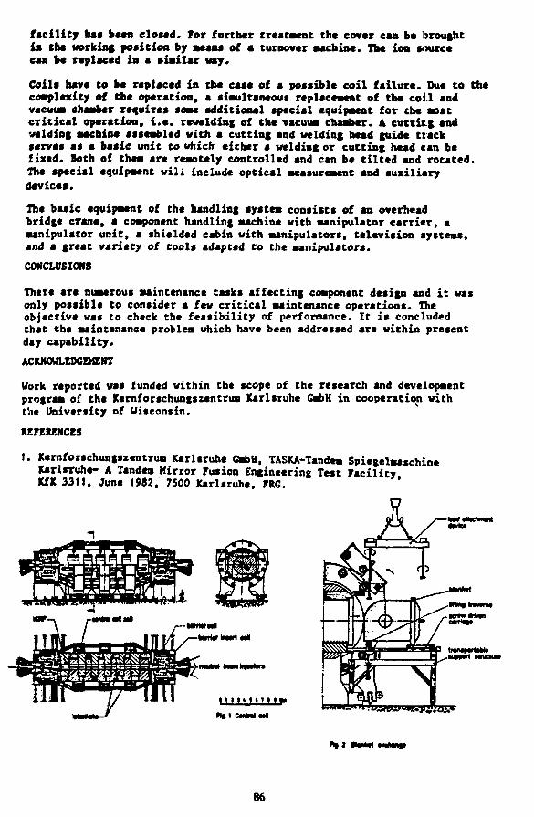
facility has keen dosed. For further treatment the cover can be broughtill the working position by scan* of a turnover machine. The ion sourcecan be replaced in a similar way.
Coils have to be replaced in the case of a possible coil failure. Due to thecomplexity of the operation, a simultaneous replacement of the coil andvacuum chamber requires some additional special equipment for the mostcritical operation, i.e. rcwelding of the vacuum chamber, A cutting andwelding machine assembled with a cutting and welding head guide trackserves at a basic unit to which either a welding or cutting head can befixed. Both of them arc remotely controlled and can be tilted and rotated.The special equipment wili include optical measurement and auxiliarydevices.
The baaic equipment of the handling system consists of an overheadbridge crane, a component handling machine with manipulator carrier, amanipulator unit, a shielded cabin with manipulators, television systems,and a great v*riaty of tools adapted to the manipulators.
CONCLUSIONS
There are numerous maintenance tasks affecting component design and it wasonly possible to consider a few critical maintenance operations. Theobjective waa to check the feasibility of performance. It is concludedthat the maintenance problem which have been addressed are within presentday capability.
ACKNOWLEDGEMENT
Work reported was funded within the scope of the research and developmentprogram of the Kernforschungszentrum Karlsruhe GmbH in cooperation withthe University of Wisconsin.
REFERENCES
1. Xernforschungszcntrum Karlsruhe GmbH, TASKA-Tandem SpiegelmaschincKarlsruhe- A Tandem Mirror Fusion Engineering Test FacilityKfX 3311, June 1982, 7500 Karlsruhe, FRG.
H niinmi
86

APPLICATION OF MOCKUPS TO THE RESOLUTION OFFUSION REACTOR REMOTE MAINTENANCE DESIGN ISSUES
L. S. Masson and K. D. WattsEG&G Idaho, Inc.
To achieve the availability required for commercial applications, fusionreactors will require levels of reliability and maintainability which are notachievable under the current technology. As a consequence, the development ofhighly maintainable configurations and associated handling equipment is recognizedas one of the key issues in proceeding into the commercial phase. One veryvaluable tool in developing the required base technology is the use of mockupsto generate and verify design configurations. The purpose of the work describedby this paper is to perform an in-depth study of the role of mockups in theresolution of key fusion reactor maintainability issues. More specifically to:(a) identify and prioritize maintenance related problem areas; (b) establishwhich of these lend themselves to solutions using mockup techniques; (c) establishgeneral scaling requirements, environmental conditions to be simulated, etc.;and (d) generate design concepts for mockup systems which encompass (a), (b),and (c).
To be effective in developing and verifying designs, mockups must be highlyrepresentative in that they duplicate all size, weight, and environmentalconditions which effect remote maintenance operations. In addition they mustbe employed in advance or' the design such that they can be used to develop thedesign rather than to be accommodated to it as in the normal case. Under theseconditions, a rigorous mockup program can have numerous advantages including:(a) Generic issues common to a multiple of reactor configurations can be addressed.(b) A high degree of flexibility can be built in to achieve optimum designsolutions. (c) All handling operations can be performed and verified onmockups and valuable reactor down time can be saved. (d) Off design, or failure,situations can be simulated, (e) Design solutions can be developed and verifiedto provide a base technology to guide the designs. (f) A more focused andcontinuous development plan will result.
As an illustration of the use of mockups, one of the more challenging remotemaintenance operations may be considered. This is the removal and replacementof a torus sector from a Tokamak. Severe configurational requirements whichare imposed which result from the requirement to remotely remove and replace atorus sector include: (a) the basic configurations of the sector, magnets,cryostats and structures to permit access and clearance for torus handling;(b) methods for supporting and positioning the torus sector in the torus structure;(c) seal systems including welded seals, mechanical seals, buffered seals,inflatable seals, etc.; (d) flange fastener systems; (e) interfacing equipmentwithin the vessel; (f) sector transport systems; (g) contamination controlsystems.
Figure 1 illustrates a preliminary concept of a mockup system for developingand verifying sector handling design configurations. As shown, it consists ofa fixed portion which simulates the torus structure and a movable portion whichsimulates the sector. The fixed structure is equipped with a vacuum system anda heating system to duplicate operating requirements. The fixed and movablestructures are equipped with a flanged surface which enables mounting of varioustypes of flange and seal configuration for testing. This will enable such
87
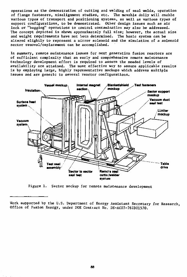
operations as the demonstration of cutting and welding of seal welds, operationof flange fasteners, misalignment studies, etc. The movable dolly will enablevarious types of transport and positioning systems, as well as various types ofsupport configurations, to be demonstrated. Other design issues such as airlock or "bagging" operations to control contamination may also be addressed.The concept depicted is shown approximately full size; however, the actual sizeand weight requirements have not been determined. The basic system can bealtered slightly to represent a mirror solenoid and the simulation of a solenoidsector removal/replacement can be accomplished.
In summary, remote maintenance issues for next generation fusion reactors areof sufficient complexity that an early and comprehensive remote maintenancetechnology development effort is required to assure the needed levels ofavailability are attained. The most effective way to assure applicable resultsis by employing large, highly representative mockups which address multipleissues and are generic to several reactor configurations.
Vessel mockup iInsulatiorK
Internal magnet , Blankesection, /mocku
Blanket/shieM .Test fastenersP /
Surface heatsystem
Vacuumsystem
Sector supportmockup/Vacuum duct
/ seal test
Li.niter/ mockup
Sector to sectorseal test
Remcftsealcuttarfwekiersystem
Figure 1. Sector mockup for remote maintenance development
Work supported by the U.S. Department of Energy Assistant Secretary for Research,Office of Fusion Energy, under DOE Contract No. DE-AC07-76ID01570.
88

REMOTE VACUUM JOINT CONCEPT FOR FUSION REACTORS*
E. Randolph Hager and David W. Doll, GA Technologies, Inc.
In 1981, a survey* of existing remotely maintainable connectors was con-ducted as a part of the fusion First Wall Blanket Shield (FWBS) Engineer-Ing Technology Program. A significant finding was that no joint systemdirectly applicable to large non-circular vacuum closures for fusion sys-tems was identified, The survey was conducted as a part of FWBS Engi-neering Technology Program Element IV (PE IV) managed at Argonne NationalLaboratory. McDonnell Douglas Astronautics Company, as prime contractorfor PE IV, subcontracted to GA Technolgies, Inc. the task of conceptuallydesigning a joint which may be utilized on large non-circular vacuumducts in fusion systems which require remote maintenance.
Based on a mini workshop held at Argonne on March 25, 1982, a list ofdesign requirements and objectives was developed. A basic decision in-volved the decoupling of the design of a structural attachment subsystemfrom the other mechanical elements of the joint. This action serves tolimit the scope of the design task to match the limited budget available.Another important criteria chosen involved the use of dual Helicoflexseals as the designated seal for this design task. These seals are ofthe same type being utilized for the Tokamak Fusion Test Reactor andrequire a very high seal loading (clamping force). Other chosen designfeatures, including vacuum duct thickness and shield configuration, com-bine to reduce the design scope to that of the joint closing and clampingmechanism (structural attachment subsystem).
The proposed application for the resulting joint concept is the largerectangular vacuum duct for the Fusion Engineering Device (FED) design.The design may be scaled up or down as required for other applications.Design objectives included: minimum assembly time, minimum access enve-lope, good reliability, and minimum capital cost.
The joint concept developed by GA Technologies under this subcontractcon'sists of a mechanical linkage driven by six shafts. The shafts arearranged in a transverse direction across the four sides of the rectangu-lar duct and are driven with an external power source (e.g., an impactwrench handled by a manipulator). The linkage provides a greatly multi-plied axial force applied with compression piston members against onejoint flange. Latch mechanisms engage the mating joint flange and reactthe seal clamping force. Figure 1 is an end view of the removable ductshowing the latch and sealing compression piston arrangement. The 32latches and 28 pistons provide a relatively uniform clamping force to theseals.
Shielding must be removed locally for access to the piston drive shaftends. An electro-mechanical manipulator with a 1220 N-m (10800 in-lb)
*Uork supported by the U.S. Department of Fnergy via Argonne NationalLaboratory under McDonnell Douglas Astronautics Company, St. LouisDivision, Purchase Order Y1E147.
89

rated wrench is used to rotate the shafts. An additional 11 N-m(100 in-lb) rated wrench is used to actuate the latches in the disconnect•ode* The manipulator is mounted on a telescoping arm to provide thenecessary -4m reach. Remote operation time is estimated at -110 minutesfor. assembly and -186 min. for disassembly. Assembly is completed in ashorter period because the latches are self actuated in this direction.
Design analyses included linkage optimization, stress and bearing•aterial selection. A computer program was written which relates linkagecomponent notion to seal load/deflection data. Stresses were calculatedfrom these relationships and compared with ASME Code Section III allow-ables for sizing of components. A special alumina bearing coating with atransition layer of nickel alloy is recommended for its maintenance-freecharacteristics. This material was developed for use in the TFTR fusiondevice as a vacuum compatible bearing material which exhibits low fric-tion coefficient along with adequate wear resistance and load capability.
I-4J5OTYP.
;/V-------""--:4-s»-"-
E>JD VIEW-STRUCTURAL ATTACHMENT JOINT
Figure 1
Xeference1. E- R. Hager and R. E. Field, "Remotely Maintainable Connectors for
Fusion Development," Transactions of the American Jfaclear Society1°32 Annual Meeting, Los Ar.-eles, CA, J-^e 6-10, 1??2.
90

A REMOTE JOINT CONCEPT FOR LARGE VACUUM DUCTS*
D. B. Hagmann and J. B. CoughlanRemote Technology Corporation
Oak Ridge, Tennessee
One of the more difficult generic tasks encountered in the performance offusion reactor maintenance is the remote removal and replacement of largeradioactive vacuum ducts. This problem is being studied as part of theArgonne National Laboratory's (ANL) First Wall/Blanket/Shield (FWBS)program1.
Effort has been concentrated on methods to mechanically connect theselarge duct flanges since the problem is a key to the development of remoteduct section maintenance operations. A comprehensive survey of allspecially designed and commercially available connecting techniques wasperformed to identify desirable characteristics.
An optimized joint concept was developed from the above results. Itconsists of a simple two-jaw clamp that is opened and closed by screws,Fig. 1. Each clamp contains two or more captive screws. The maximumnumber of screws is determined by the allowable clamp weight which isestablished by the capacity of the robotic manipulator used to handle theclamp. The preferred location for the clamp applications is inside thevacuum duct, Fig. 2. This provides access space for a robotic manipulatorand decreases the space needed for handling operations exterior to theduct.
The joint is unique in that it is low cost; applies forces directly to theseal, permits leak testing of the seal annulus, is highly reliable, canbe removed and replaced by a robotic manipulator and is usable on avariety of other applications.
REFERENCE
1. Zahn, H. W., "Remotely Maintainable Fusion Wall Blanket and Shield,"30th Conference on Remote Systems Technology (1982).
*Work performed on subcontract to McDonnell Douglas Astronautics Co.,St. Louis.
91

CAPTIVE SCREW CLAMP
DUCT KUNMING 2ND
DOUBLE SEAL
ALIGNMENT FIN
DUCT STANDING END
PATENT PENDING
FIG. 1 CLAMPED JOINT
IMPACTvJRENCH MANIPULATOR
FIG. 2 INTERNAL JOINT OPERATIONS
92

IN-VESSEL MAINTENANCE CONCEPTS
FOR TOKAMAK FUSION REACTORS
J. D. Berger, V. P. Kelly and J. A. YountWestinghouse Hanford Company
Maintenance studies of fusion energy devices show that use of a remotehandling system for in-vessel inspection, replacement of components andother tasks is one of the important maintenance techniques to be considered.This paper reports the results of a study to develop concepts for an in-vessel remote handling system capable of maintaining a tokamak reactorof the type represented by the Tokamak Fusion Test Reactor (TFTR). Assemblyand initial startup of the TFTR was recently completed by the PrincetonPlasma Physics Laboratory.
TFTR features a torcidal vacuum vessel with a circular shell about 2 min diameter. For in-vessel maintenance, the remote handling system (RHS)is required to deploy an in-vessel handling machine (IVM) into the toroidalvacuum vessel through ar. access opening about 1 meter square in size.The study was specifically directed towards developing concepts for anIVM which would be guided and supported by an internal rail system.
In-vessel maintenance operations range from the light-duty, requiringhigh-dexterity, low-capacity manipulators for tasks such as removal andreplacement of protective tiles, to the ueavy duty. Heavy duty operationsrequire high load-capacity manipulator arms capable of handling more mas-sive components such as pumped limiter panels which may weigh up to 600 kg.Two basic concepts for the RHS were developed in the study:
1) A RHS featuring a rail-mounted IVM deployed by an ex-vessel arm totravel around the vessel interior while suspended from tails mountedin the top of the vessel (Figure 1). This device uses remotelyreplace-able rails designed to jurvive plasma off-nonaal events sothat the rails remain in the vessel during plasma operation. Thedesign accommodates a range of manipulators, including force reflectingservomanipulators- A central power arm is used for two tasks: 1)handling of the heavier loads such as pumped limiter panels, and 2)insertion of the IVM into the vacuum vessel. In the latter case,the IVM power arm clamps the end of an ex-vessel boom and the IVMis inserted through the vessel access port. Rotation, rail attachment,and disengagement from the boom are performed under remote controlusing the IVM TV cameras for viewing.
2) A RHS featuring an IVM with a similar arrangement for the manipulatorsand remote viewing systems but with the IVM supported and guided feyrails installed in the bottom of the vessel (Figure 2).
93

TOKAMAKVACUUMVESSELSHELL
IVMSUPPORT
RAILS
Bi-LATERALSERVO
MANIPULATORS
ACCESSPORT
TOKAMAKVACUUMVESSELSHELL
MEPL tm-*t 2
\ \ SUPPORT %.\ \ FRAME '
PUMPEDLIMITERPANEL
ACCESS" PORT
IVMSUPERVISION
RAILS
Bi-LATERALSERVO
MANIPULATORS
Figure 1. Upper Rail Concept Figure 2. Lower Rail Concept
Evaluation of variations on the two basic concepts was made based on factorssuch as functional capability, machine reliability, capacity for recoveryfrom off-normal events, and cost including the development program requiredto verify system performance. Two major conclusions resulted from thestudy:
1) The RHS featuring a track-mounted IVM should be developed for TFTR-typetokamak reactors provided the vessel interior can be arranged to accom-modate a track or rail system.
2) The bottom track-mounted IVM is preferred over the top rail-mountedIVM because of the greater flexibility provided in arranging the IVMto perform its maintenance tasks.
94

CEMERAL PRT.T. BLANKET MODULEMAINTENANCE APPROACH FOR THE MARS
HIGH TEMPERATURE BLANKET
N. Young, Ebasco Services; D. Sutliff, D. Tait, R. Siebert,J. Coulahan, General Dynamics; J. K. Garner, J. D. Gordon,TRW Energy Development Group
The principal objective of the MARS program is the establishmentof an economically and environmentally attractive tandem mirrorreactor design with efficient electricity production as theprimary product.
The objectives of the blanket module maintenance systems on MARS isto minimize machine down time for normal and off-normal events whilesafely removing and replacing the blanket modules. Remote, manual,and autanated handling methods will be used depending on radiationlevels and the task. Since blnaket replacement is a yearly mainten-ance oepration, considerable effort is being expended to design themodules and module handling systems for rapid removal and replacement.The use of remote techniques increase the time required to performany task. Therefore, it is prudent to maximize the number ofoeprations that can be performed "hands-on". By selectively increasingthe shielding in certain high maintenance areas, maintenance time canbe reduced. The machine availability is maximized by moving a smallnumber of large integral units on a fixed rail or roller system. Thenumber of operations, their complexity and the cost of equipment isalso reduced. All central cell components are designed for rapid re-placement. Failure of any component, including a central cell super-conducting magnet, will not result in excessive downtime.
In general, blanket module components weighing several hundred tons orless will be handled with an overhead (gantry) crane. "Items in excessof this weight will be moved on a track or roller system specificallydesigned for and incorporated into the MARS facility. Use of severalmobile transporters will eliminate the need to have a transport systembuilt into each of the 24 modules. This recolts in considerable costsavings and reduced machine complexity. Such a system requires thatcoolant piping, bus systems and all service lines must approach themachine from one side and from the top of the machine. Disconnectionand make up of these connections is a candidate for hands-on maintenance.
The detailed blanket removal and replacement procedure is based onthe specific high temperature blanket design selected for MARS. Atthis time, a preliminary removal and replacement scenario has beendeveloped. It includes both remote and hands-on operations with initial
95

remote operations starting during machine cool down, Initial remoteoperations prior to module removal include the following:
- Drain coolant and gas from the module- Start af terheat removal system- Disconnect main coolant lines- Bring system up to atmospheric pressure- Position •transport vehicles in the cell- Deliver temporary shielding as required to the work site
Following initial activation cooldown, maintenance teams can enter thecell. Six work teams will begin preparing the assemblies to be removedfrom the central cell. Hands-on operations during this time consist ofthe following:
- Disconnect magnet coolant and electrical systems- Release structural attachments to building and adjacent modules- Engage rail transporters if required
At this point the module is free of the machine and building except forthe vacuum vessel seal. Access to the seal requires the removal ofnodule shielding and therefore personnel are excluded from the celland operations performed remotely. Final operations include the following:
- Remove seal shield- Disconnect vacuum vessel seal- Remove module with transporter
Magnets will then be removed and mounted on the replacement modules.Automated handling techniques are being investigated for this operation.
A separate Blanket Maintenance Cell, apart from the machine containmentarea -must be provided for module repair work. This cell will be capableof handling sufficient modules simultaneously to accomplish replacementof the six (6) blankets within the one year period between changeouts.Vfcork on the modules to replace the blanket structures will proceedduring machine operation. Each of the hot bay areas will be equipped withoverhead cranes for handling large components. Manipulators systems willbe provided where required for disassembly operations and specializedequipment and fixtures will be utilized.'
Structural components removed from the modules will be highly activated.These sturctures must be prepared for shipment off site in shieldedcontainers or for on-site storage. High level waste requiring off-sitestorage will probably be compacted to permit easier and more economicalpackaging. It may also be possible to dilute wastes for on-site lowlevel storage. To accomplish this, a waste preparation area has beenproposed for the maintenance area. This area would be equipped to furtherdisassemble and cut up the activated structures by totally remote means.A packaging and package decontamination area will also be provided.
Acknowledgment
This work was funded under LLNL Contract No. 5299101.
96

EFFECTS OF ENHANCED ION/ELECTRON EQUILIBRATION POWERON CAT-D TOKAMAK IGNITION
byJohn Galambos and George H. Mi ley
Fusion Studies LaboratoryUniversity of Illinois103 S. Goodwin AvenueUrbana, IL 61802
This study investigates how magnetic field corrections to the ion/electron equilibration power influence the ignition criteria, nr|ig, forCat-D tokamaks. It has been found that the magnetic field can enhanced)the ion/electron equilibration power for conditions anticipated for Cat-Dtokamak operation. Unfortunately, this enhancement is detrimental tobenefits expected from operation in the Hot Ion Mode (HIM) (2»3). HIMoperation requires that Ti/Te > 1. This condition can be created throughincreased electron energy losses (compared to the ions) and enhancedfusion-product energy deposition to ions via Nuclear Elastic Scattering(NES)(2j or assumed anomalous slowing downw). Energy losses from theions to electrons (i.e. the equilibration power) sets a limit on theobtainable Tj/Te ratio. As T-j/Te increases, the ignition criteria de-creases due to the smaller electron losses for a given Tj. The presentanalysis, however, indicates that the equilibration power is enhanced upto 20% when magnetic field effects are included, which further limits theT-j/Te ratio obtainable.
The catalyzed-deuterium (Cat-D) fuel cycle is used here as an exampleof these trends since electron power losses are relatively large at Cat-Dburn temperatures (Ti > 30 keV), and hence it especially is sensitive toprocesses that affect T-j/Te. Similar trends should occur for other fuels,however.
The magnetic field affects the energy transfer of ion-electroncollisions when the electron gyroradius is less than the Debye length.Under this circumstance, an accurate treatment of the spiralling motionof the electron must be included in the analysis of the collision event.Previous studies on magnetic field corrections to equilibrationpower (4,5) predicted enhanced ion-electron energy transfer, but only atfield strengths larger than would be expected for any near-term fusionapplication (i.e. f° r B » 100 KG). However, these studies were based onan analysis of an "average" thermal electron. This procedure missesimportant contributions from slow electrons (near the ion thermal speed)which are affected much more strongly than those at the average electronspeed. Hence the earlier models that use an average electron speed areinaccurate and a new model which includes the magnetic field effects ateach particular electron speed is used in the present analysis. This modelpredicts a net increase in the equilibration power between ions and elec-trons of ~ 25% for ratios of Tn7Te < 1.5 and B < 100 kG, typical of con-ditions expected for Cat-D tokamaks. Scaling of the magnetic field effectsvs, macroscopic plasma parameters will be presented.
The ignition requirements presented here are evaluated with the samemodel used in Ref. 2, and are based on parameters from the WILDCAT tokamakstudy.VD) Figure 1 shows the resultant ignition requirements for a
99

calculation where the magnetic field enhanced equilibration power has beenneglected (designated Classical lnAje) compared to a case where enhance-ment is included (designated ln*Ajp). Also included are cases where NESeffects are included. It is seen that the enhancement (ln*Aei) increasesthe ignition requirements by >50% at 75 keV. When NES is also included,there is a decrease in nr ),•_ of >60X at 75 keV compared to the ( I n * ^ )case without NES. Thus the gain by NES is, in effect, partially offset byenhanced ion-electron energy transfer due to magnetic field effects.
In summary, it is found that the magnetic field enhancement ofequilibration power causes an increase in ignition requirements for Cat-Dtokamaks, due to the lower T.j/Te ratios attainable. However, theeffects of NES can offset these increases nx Jjg, resulting in a slight(~10%) net decrease in the ignition requirements.
REFERENCES1. Galambos, J. "Magnetic Field Effects of Ion/Electron Equilibration,"
Report No. C00-2218-258, Fusion Studies Laboratory, Univ. of 111. (1982).2. Galambos, J., Stroud, P., Gilligan, J., Greenspan, E. and Mi ley, G. H.,
"Discrete Nuclear Elastic Scattering Effects in Cat-D and D-3He
3.4.5.6.
3He FusionScatteringPlasmas," Trans. Am. Nuc. Soc, November, 1982.Clarke, J. F., Nuc. Fus., 20, 563 (1980).S i l i n , V. P., JETP, 16, 5 (1963) 1281.
Ichimaru, S. and Rosenbluth, M., Phys. of F lu ids, 13, 2778 (1970).
Evans, K. E., et a l . , "D-D Tokamak Reactor Studies," Report No.ANL/FPP/TM-138, Argonne National Laboratory (1980).
I017
4
2
£lO16
u
o> 4
2 2
10'
IO1
FSL-I2-2S4
20
"clossicol"
NO NESWITH NES
40 60 80ION TEMPERATURE (keV)
100
Fig. 1. Ignition requirements for a Cat-D tokamak with(ln*Aje) a n d without (classical lnA ie)enhancement of equilibration power.
100

D-D TOKAMAK REACTOR ASSESSMENT*
D.C. Baxter, A.E. Dabiri, D. Dobrott, J.E. Glancy, H. Guroi,W.K. Hagan, J.B. McBride, S. Tamor, Science Applications, Inc.
and R.N. Cherdack, Burns and Roe, Inc.Science Applications, Inc. (SAI) is assessing alternate fusion fuel cyclesfor the Department of Energy's Office of Fusion Energy. The ultimateobjectives of this assessment are to quantitatively determine the netbenefits and costs of fusion reactors burning alternate fuels relative todeuterium-tritium (d-t) burning reactors, and to compare different magneticconfinement concepts as alternate fuel reactors. The first phase of thework was an assessment of a d-d fueled tokamak fusion reactor.
The assessment is organized into three parts: (1) Physics, (2) Engineer-ing, and (3) Cost and Safety.
Physics AsesessmentThe key physics leverage issues for the d-d tokamak are: (1) synchrotronradiation; (2) Nuclear Elastic Scattering effects (NES); (3) Refueling andStart-up; (4) Steady-State Current Drive; and (5) Theoretical Prospects forHigh 3 Tokamaks. Synchrotron transport was modelled with SAI's CYTRAN codeand we find that proper modelling is required to predict the effect on tem-perature profiles and power balance. More specifically, the reduction inthe temperature gradient- improves localized interchange stability andimpacts maximum beta. Our conclusions regarding NES are that it is not aquantitatively important effect for d-d plasmas that operate at tempera-tures less than 60 keV. Refueling simulation studies indicate that al-though the d-d plasma is larger, denser, and hotter than d-t tokamakplasmas, refueling via pellets or neutral beams appears feasible. Forsteady state current drive, the power requirement for Alfven waves are morethan an order of magnitude lower than for the lower hybrid waves proposedfor d-t tokamaks, but a concern is the interaction of the plasma with theAlfven wave launching structure. High beta is an economic requirement ford-d tokamaks and a survey of theoretical studies uncovered no fundamentalreasons why p £ 19 percent could not be achieved.
Engineering AssessmentThe first wall, limiter, blanket, and shield technologies are the keyissues associated with d-d tokamaks. The d-d blanket is designed for hightemperature, high neutron energy multiplication, full reactor lifetime, lowactivation, and low cost. These are very different than d-t blanket designgoals. A d-d blanket that meets these goals was designed and coupled to athermal power cycle to achieve thermal efficiencies of 40.5-43.5%. This is4.5 to 7.5 points higher than the d-t Starfire system. Other technologyareas of importance are: (1) tritium containment and recovery; (2) mag-nets; (3) vacuum; and (4) rf for current drive. Tritium is produced andburned in the d-d plasma at a rate of 150 g/day for the 1200 MW reactor.The plasma burn probability is only 28% but with 90% recycling from thewall, the overall tritium burn-up of the reactor is 79%. This leaves 39
*Work supported by the Department of Energy, Office of Fusion Energy.
101

g/day of tritium that Is exhausted, purified, separated, and recycled forrefueling. Thus, a tritium processing plant Is required. The tritiumpermeation and Inventories for the d-d tokamak are very small however.
Cost and SafetyA reactor systems code was used to do cost trade-off studies, especially toexamine the impact of higher a on d-d reactor cost. He found that as 6approaches 15% the d-d reactor approaches Starfire size and cost. Welooked at reducing the magnetic fields of the d-t reactor to see if higher8 would be beneficial (holding the power density constant). The net resultis that there is an insignificant drop in the d-t reactor cost for high e.
The inventory of activation products is approximately equal for d-d and d-treactors but the d-d tritium inventory is 100 times lower. The storedenergy for d-d is much higher if the d-t reactor is assumed to have a solidbreeder. If liquid lithium is used, it's stored chemical energy dominatesother energies. The accident scenarios for d-d and d-t are roughly equi-valent, unless a liquid metal/water reaction accident is postulated for aliquid breeder d-t reactor. The consequences of accidents releasingactivation products are small and approximately the same for d-d and d-t.However, the consequences of tritium release are larger and could be 500times higher for d-t than for d-d.
ConclusionsA final conclusion on the comparison of d-d and d-k tokamak reactors willdepend on the final plasma physics parameters that can be achieved.However, the following preliminary conclusions can be reached at this time:
(1) The current costing algorithms used for superconducting magnets don'tproduce a large cost penalty for d-d tokamaks that strive for highB-field to overcome low reactivity. If less optimistic algorithmsprove to be more correct, then high field d-d tokamaks could beprohibitively expensive.
(2) Using non-optimistic physics assumptions for e (6-9%), neither d-t nord-d reactors produce electricity at costs less than fission reactors,but d-d reactors are more expensive. Using optimistic physics assump-tions (e^l5%) d-d and d-t reactors cost approximately the same andproduce electricity that is more expensive than fission reactors.
(3) Although the technology requirements for d-d tokamaks are quantita-tively more severe than for d-t tokamaks, no qualitatively new tech-nology or R4D is required.
(4) d-d tokamaks are significantly safer than solid breeder d-t tokamaksprimarily due to the lower tritium hazard, but both are significantlysafer than fission reactors. If liquid breeding is required for d-ttokamaks, then d-d reactors are clearly inherently safer.
Thus, although there is considerable uncertainty in the assumptions leadingto this conclusion, d-d tokamaks potentially offer the most attractive re-actor option when physics, technology, cost, and safety are all considered.
102

A d-d TANDEM MIRROR REACTOR WITH CENTRAL-CELL POTENTIAL MODIFICATION*
G. W. Shuy and D. DobrottScience Applications, Inc.La Jolla, California 92038
Positive central-cell ambipolar potentials are typically used to confinecentral cell electrons electrostatically (Ref. 1). Under this operating mode(see Figure l.A), it is estimated (Ref. 2) that a d-d fueled tandem mirrorreactor (TMR) will require neutral beam energies of above 700 keV to createan electrostatic plug for central cell ions. An alternative design (Ref. 3)(see Figure l.B), using a negative central cell potential to confine centralcell ions, relaxes this technological requirement but exacts similarconstraints on ECRH power to produce the electron plug. To optimize thetechnology requirements on both neutral beams and ECRH, a third alternative(see Figure l.C) is presented wherein the central cell potential 8f, is keptnear ground. This operating mode is an improvement of those studied in bothRefs. 2 and 3.
This alternative mode retains the axi-cell for high mirror ratio and anoutboard yin-yang for MHD stability The electron plug is maintained in theaxi-cell by ECRH to trap electrons and passive pumping (Refs. 4-6) and lowenergy neutral beams to pump ions. The ion plug is maintained in theyin-yang by modest energy neutral beams and ECRH. This plug separationprovides greater design flexibility in power and size requirements and allowsfor better reactor Q. Variations on these designs that may be necessary toaccommodate certain trapped particle instabilities (Refs. 7,8) are alsopossible. Such a model, where both the i-plug and the e-plug to be built inyin-yang, is shown in Figure l.D.
A zero-dimensional plasma physics model has been developed to describe theaverage macroscopic properties in various regions of the TMR. This modeldescribes the kinetic interactions in velocity space between species, and theeffect of particle and energy sources which come either from other regions inthe TMR or are externally supplied. The development of this plasma modelprovides a self-consistent set of equations, supported by physics theory andexperiment. These equations have been coded for rapid solution by computerto calculate all of plasma dimensions, densities, energies, potentials andconfinement times in a TMR.
The reactor performance with respect to power balance is significantlyaffected by the potential operating mode. This is illustrated in Figure 2.The plasma Q calculated for 2000 MW d-d/TMR is shown to be best when thecentral cell potential is near ground. The impact on ion plug neutral beamand electron plug ECH requirements are shown in Table I. The positiveoperating mode requires high neutral beam energy, which has a very poortrapping fraction (% 7Z), thus requiring high power systems. On the otherhand, the negative operating mode requires high ECH power, which isexpensive. The neutral operating modes (central cell potential near ground)provide design flexibility in optimizing the neutral beam and ECH systemrequirements.
103

1. B. G. Logan et al., "Tandem Mirror Reactors," Proc. 7th InternationalConference on Plasaa Physics and Controlled Nuclear Fusion Research,Innsbruck 1978, Vol. Ill, 40 (1979).
2. R. W. Conn et al., "SATYR, A d-d Fueled Axisymmetric Tandem MirrorReactor," UCLA Report PPG-576 (1981).
3. D. Dobrott et al., "Preliminary Assessment of a d-d Fueled Tandem MirrorReactor," Proc. Annual Sherwood Controlled Fusion Theory Conference(1982).
4. D. E. Baldwin, APS, Invited Paper, New York (1980).5. J. B. McBride, "Estimate of Barrier Drift Pump Power Requirements," SAI
Report APS 1-80 (1980).6. B. G. Logan et al., "Mirror Advanced Reactor Studies," LLNL Report,
UCRL-53333 (1982).7. M. N. Rosenbluth et al., "Fast Growing Trapped Particles Modes,"
Proc. Annual Sherwood Controlled Fusion Theory Conference (1982).8. D. Pearlstein et al., "Stabilization of Tandem Mirror Trapped Particle
Modes by Incomplete Cancellation of Particle Drifts," Proc. AnnualSherwood Controlled Fusion Theory Conference (1982).
*Work supported by the Department of Energy, Office of Fusion Energy.
Cut I - Poaitit* (Q « 1S.1)
i
"IN
-v n
•MUM* V
KWTIVC on«*i<«« W M
irwuNt IJU
IVr6U«J| IM
Cue II - SlijMly •••itiv* (Q « 31.4)
Ci» III - Slightly n>]itii* (Q * 24.2)
.J—V^tMCti* IV - Nigitit* (8 > ll.T)
f * " V * ~ ~ ™ ~ - - — — " " A " •*•*•• Moatrw»a(tiiATiM«Moecimi
rifur* *. Htulmt *t rwkr rtrHrmf m |HtMI>Ha tmr a— iliMtnu (ftWiall f Hwkr rtrHm m | > f"t
FlfVI 1. » H t 'OK t*UU*t •— —rt—t MMkl wrath* a<tf HrM utmmlrrtr rtKUr HI«MnIla« M . (thijl rt •» (Ik.)
Tible IThe Iinpict of Potential Operating Hade on Neutral turn and ECK Requir«nentt
AverageHot ElectronEneriy
ECRH tatMr
E1 n j
• M H Pmmr
Fosftive
363 keV
«2 m
775 keV
14.6 Nf
SlightlyPositive
615 key
73 m
375 kcv
7.7 m
SlightlyNegative
659 keV
75 m
300 keV
5.4 HU
Negative
B41 keV
104 MM
100 key
z m
104

EXPERIMENTAL INVESTIGATION OF MUON-CATALYZED FUSION*
S. E. Jones, A. J. Caffrey, J. B. Walter, K. D- WattsIdaho National Engineering Laboratory
andJ. L. Anderson, J. N. Bradbury, F. A. M. Gram, M. Leon, M. A. Paciotti
Los Alamos National Laboratory
Introduction
Data will be presented from the first experimental determination of the totalfusion energy yield of the muon-catalyzed fusion reaction:
4u + d + t •»• u + H e + n + 17.6 MeV. (1)
In this reaction, an elementary particle known as the muon induces fusionwithout being affected by the reaction. Thus, it serves as a catalyst of thisnuclear reaction. The amon catalyzes many fusion reactions before decayinginto an electron and neutrinos. The process is known as "cold" fusion sinceit proceeds rapidly for temperatures in the range from room temperature toabout 800° C. An obvious advantage over thermal fusion approaches is thatthere is no plasma to contain. On the other hand, the muons which drive thereaction must be continually produced using a particle accelerator.
Define n to be the average number of fusion reactions catalyzed by a muonduring its lifetime. Then, since each fusion releases 17.6 MeV and the mass-energy of each muon is 106 MeV, energy breakeven between fusion output anddriver energy input is reached when
106 MeV , ,„.
\ = IT TieV = 6' &
The energy breakeven point is surpassed in this proof-of-principle experiment.However, in view of inefficiencies in creating muons by conventional tech-niques, a much larger value (n > 100) is required for commercial feasibility.1
Only one previous experiment'' has been done investigating reaction (1). High-energy neutrons were observed, providing evidence for muon catalysis of nu-clear fusion. However, no attempt was made to measure the absolute numberof fusion cycles catalyzed per muon in this early work.
Experimental Method
The apparatus for this experimentJ is shown schematically in Figure 1. Muonsentering the deuterium-tritium target are counted using plastic scintillationdetectors. We require that only one muon be in the chamber at a time for avalid event. As muons catalyze fusion reactions, resulting 14.1 MeV neutronsare counted using three 5"-diameter NE213 scintillation detectors arrangedsymmetrically around the target capsule. Corrections to the neutron countare made, for the geometrical acceptance of the detectors and their neutron
*Work supported by the U.S. Department of Energy, Director of Energy Research,Office of Basic Energy Sciences, under DOE Contract No. DE-AC07-76ID01570.
105

detection efficiency. Since each d-t fusion generates one neutron, thenumber of fusion cycles catalyzed by a single muon Cn ) is just the correctedneutron ccunt averaged over a large number of muon-cafalysis events. Timeand energy spectra of fusion neutrons are also recorded to provide informa-tion on factors which affect the magnitude of n . Data from approximatelyone million events are recorded for each set of experimental parameters(temperatures in the range 77-600°K, deuterium:tritium ratios from 9:1 to1:9, and pressures from 2X10⁷ Pa to 1X10® Pa). The experiment uses the muonbeam at the biomedical channel of the Los Alamos Meson Physics Facility.
Since this experiment involves pressures to 10& Pa and up to 52,400 curiesof tritium, safety considerations arc paramount. The target capsules weremade from age-hardened A-286 austenitic stainless steel and internally gold-plated to inhibit tritium permeation. All capsules undergo thorough testingbefore being filled with tritium. Finally, each deuterium-tritium filledtarget capsule is mounted inside an evacuated secondary containment vesselduring data-taking runs. This is one of very few fusion experiments toactually use tritium.
Experimental Results and Significance
Data-taking is scheduled to begin in October, 1982, so results are not yetavailable. However, data-analysis programs have already been written toassure that the experimental data will be analyzed soon after data-taking.
The average number of deuteron-triton fusions catalyzed by a muon duringits lifetime will be announced at the meeting. This is the first experi-mental measurement of this quantity. The implications of this finding ononion-catalyzed fusion as an energy source will be briefly discussed.
REFERENCES
1. Yu. V. Petrov, Nature, 285, 466 (1980).2. V. M. Bystritsky et al.. Phvsics Letters B. 94B, 276 (1980).3. S. E. Jones, Spokesman, "Measurement of the Efficiency of Muon Catalysis
in Deuterium-Tritium Mixtures at High Densities," Los Alamos MesonPhysics Facility Research Proposal #727, EG&G Idaho, Inc. (1982).
COUIMATOt
-MUON COUNTS
COUNTS 2
SKONDAITCONTAMMfNT
omcrota OF a
Figure 1. Layout of the Muon-Catalyzad Fusion Experiment
106

THE INFLUENCE OF ENGINEERING CONSTRAINTS ONCONFINEMENT TIME REQUIREMENTS OF ADVANCED FUEL FUSION REACTORS
J- Reece RothDepartment of PhysicsUniversity of Tennessee
Knoxville, Tennessee 37996
A survey of large-scale DT Tokamak powerplant design studies shows thatthe confinement time required to achieve self-sustaining operation can bemuch less than that predicted by the recently reported modification ofAlcator scaling (ref. 1). The latter predicts substantially longer con-tainment times than Bohm or previous versions of Alcator scaling. In sucha reactor the confinement time would have to be spoiled by deliberatelyimpairing confinement. Even without invoking better confinement mech-anisms than those responsible for the recent version (ref. 1) of Alcatorscaling, it appears likely that there will be available, for most exist-ing reactor designs, a substantial "excess" containment time withoutengineering or physics penalty. Probably the most constructive use whichcan be made of this excess containment, assuming that "Neo-Alcator" sca-ling remains valid for advanced fuel cycles, is to burn advanced fuelsinstead of the DT reaction, and thereby reap the practical benefits ofreduced tritium inventory, lower neutron fluxes, reduced materials prob-lems, etc. which can be anticipated as a consequence. At the same time,this excess containment time is of little value to DT reactors, reduc-tions in size and total power of which are limited by wall loading con-siderations (refs. 2,3).
Satisfaction of the Lawson criterion by advanced fusion fuel cycles re-quires values of the number density - containment time product nT and/orion kinetic temperature which are significantly higher than the valuesappropriate to the DT reaction. Earlier work on the effects of wallloading limitations (ref. 2) and of other engineering constraints (ref.3) on the feasibility of advanced fuel fusion reactors have shown thatsuch reactors appear possible if confinement concepts capable of betagreater than 15% are available. These studies showed that the valuesof number density and ion kinetic temperature required to meet reasonableengineering constraints were each about a factor of two to four higherthan the values required by the DT reaction. These rather modest in-creases in density and kinetic temperature imply a higher value of theplasma stability index, beta, than is required for the DT reaction, wherethe 6 = 5% of Tokamaks is adequate. In this paper it is shown that themain burden of meeting the value of the Lawson parameter nT required fora self-sustaining reaction with advanced fusion fuel cycles can be placedon increasing the required confinement time to values consistent withNeo-Alcator scaling. At these long containment times, the engineeringimplications are less serious, and do not require otherwise unnecessaryincreases in the number density or kinetic temperature, which have unfav-orable consequences for both the engineering and physics aspects of ad-vanced fuel reactors.
107

REFERENCES
1. R.R. Parker, "Energy Confinement in Alcator C: Neo-Alcator Scaling,"APS Bulletin, Vol. 27, No. 8, p. 986 (1982).
2. J.R. Roth and H.C. Roland, "The Effect of Wall Loading Limitationsand Choice of Beta on the Feasibility of Advanced Fuel Fusion React-ors", J. of Fusion Energy, Vol. 1, No. 2, pp. 117-127 (1981).
3. J.R. Roth, "The Impact of Engineering Constraints on the Feasibilityof Advanced Fuel Fusion Reactors", Nuclear Technology/Fusion, Vol. 2,pp. 29-42 (1982).
108

HIGH F1KLDT0KAMAKS WITHDD-DT OPERATION AND REDUCED
TRITIUM BREEDING REQUIREMENTS
L. Brombcrg, D.R. Colin, N. Diatchcnko, R. LcClairc, J. Meyerand J.E.C. Williams
Plasma Fusion Center*Massachusetts Institute of Technology
The potential of the high field tokamak for production of very high values of rn and fusion powerdensity makes possible DD-DT operation which can be used to reduce tritium breeding requirements. InDD-DT operation, neutrons ircm both the D + T -* He -f n and D + D -> He3 + n reactions areused to produce the tritium. The plasma tritium breeding requirement 7, defied as
no. of neutrons produced in the plasmano. of externally supplied tritons '
is between zero and one. The tritium/deuterium ratio (RT/MJO) in the plasma is <1 (the ratio for DT opera-tion) but greater than the ratio in DD operation where tritium produced by D + J D — + T + p reaction isburned (n^/no «* 0.003). A continuous range of tradeoffs between reduced breeding requirements andincreased requirements on nrt for ignition and reduced fusion power density is possible1.
The advantages of DD-DT operation include:• Insurance of self sufficiency in tritium production•Increased flexibility of blanket and first wall design due to decreased neutron economy require-
ments•high tritrium burn-up in the plasma•increased availability of neutrons for fissile fuel breeding, tritium production for makeup or startup
fuel for DT reactors, synfuel productionIn Uiis report we discuss trade offs between the breeding ratio requirement 7, plasma performance
requirement and the machine size and c >st. Two different types of machines have been considered. Oneis a relatively near term device that utilizes resistive magnets. It would serve as an engineering/materialstest reactor with self-sufficiency in tritium production. We refer to this device as an Advanced FusionTest Reactor (AFTR) device. The second machine is a device that utilizes superconducting magnets. Itwould be used as a commercial reactor which would produce electricity with blankets that arc optimizedfor considerations other than neutron economy. We refer to this device as an Advanced Fuel CommercialReactor (A FCR).
For both AFTR and AFCR type devices, the machine size and cost.increase significantly as 7 isdecreased. Table I shows the effect on machine size as 1 — 7 is varied for AFCR type devices withconstant neutron wall loading (Pwnu = 2.2 MW/m2). The machine parameters arc given in terms ofthe dependence upon 1 —y, which represents the margin in the required tritium breeding ratio. Theoperating temperature is varied to obtain optimum operating conditions at each value of 1 — 7. Theconfinement scaling law T ~ na2 is assumed in determining the requirements for ignition 2.
Illustrative designs have been developed for the AITR and AFCR type devices. The illustrativeAITR design is a moderate size device (major radius = 4.8 m, minor radius = 1.2 m) which would serveas an engineering/materials test reactor with self sufficiency in tritium production2'3. Table II gives theparameters for the illustrative design. An AFTR device might also be used to produce tritium for otherreactors or to produce fissile fuel. The illustrative AI-VR design is a considerably larger machine (majorradius = 9.6 m, minor radius = 2.4 m) which uses NbuSn superconducting magnets. The pulse length
109

provided by the OH transformer is 1 hour. In addition in possible use for electricity production, AFCRmight also be used to produce excess tritium. Another possible application is synfucl production.
REFERENCES
L Greenspan, E, Blue, T. and Miley, G.H., Proceedings of the Fourth Topical Meeting on theTechnology of Controlled Nuclear Fusion, King of Prussia, Pa. (1981).
2. Cohn, D.R.. Bromberg, L, Williams, J.E.C., Becker, H., LcCIairc, R. and Yang, T., Proceedings ofthe Third Technical Committee Meeting and Workshop on Fusion Reactor Design and Technology,Tokyo, Japan, October (1981).
3. Bromberg, L, Cohn, D.R., Williams, J.EC, Becker, K., LeClaire, R. and Yang, T., Proceedings of9th Symposium on Engineering Problems of Fusion Research, Chicago, Illinois, October, 1981.
* Supported by U.S.D.O.E
Table I.DEPENDENCE OF AFCR MACHINE PARAMETERS UPON 1 — 7
1 - 7
MAJOR RADIUS (m)MINOR RADIUS (m)FIELD ON AXIS (T)AVERAGE/?FUSION POWER (GW)MAXIMUM FIELD AT
TF MAGNET (T)MAGNET STORED ENERGY (GJ) 13.
Table n.MAIN PARAMETERS OF ILLUSTRATIVE AFTR AND AFCR DEVICES
0.01.06.61.64.10.0621.54
7.713.
0.120.0678.42.16.50.0622.3
11.256.
0.200.0399.62.47.00.0623.1
11.989.
0.270.02510.72.77.50.0623.9
12.3131.
0.370.01612.33.18.00.0625.2
12.7206.
1 - 7MAJOR RADIUS (m)MINOR RADIUS (m)PLASMA ELONGATION (m)AVERAGE BErA(%)PEAK ELECTRON TEMPERATURE (keV)ION DENSITY (m-3)PLASMA CURRENT (MA)FIELD ON AXIS CDFUSION POWER (GW)TF MAGNET RESISTIVE
POWER (MW)NEUTRON WALL LOADING fMW/m2)
AFTR0.074.81.21.5
6.2525
1.8 X 10²⁰
11.18.52.8
6008
AFCR0.29.62.41.5
6.2535
1.2 X 1O20
18.77.03.1
__2.2
110

Session 2C-4
ALTERNATE FUELS(poster)
Chairman
S.A. Freije, TRW, Inc.
Organizer
G.H. Miley, University of Illinois
Tuesday, April 26 2:30-5:00 p.m.

FUSION SYSTEMS STUDIES(poster)
Chairman
DA. Sink, Westinghouse Electric Corporation
Organizer
A. Opdenaker, Office of Fusion Energy,U.S. Department of Energy
Tuesday, April 26 2:30-5:00 p.m.
\

THE EFFECTIVE COST OF TRITIUM FOR TOKAMAK FUSION POWER REACTORSWITH REDUCED TRITIUM BREEDING RATIOS
J. G. Gilligan* K. Evans, Jr., J. Jung1"University of Illinois Argonne National LaboratoryUrbana, IL 61801 Argonne, IL 60439
The possibility of operating fusion reactors in a plasma burn mode wherery = nj/nn, < 1, implying blanket tritium breeding ratios (TBR) < 1, isvery real because of uncertainties in nuclear breeding blanket performance andrecovery of bred tritium. In addition, plans for near-term devices (INTOR/FED)call for purchases of tritium (from outside vendors) to "makeup" for that notdesigned to be bred in the blanket. In both bases the effective cost value oftritium will be determined by the tradeoffs between blanket nuclear breedingperformance and that of the plasma, and reflected in the final cost-of-electricity (COE). The purpose of this work is to explore these tradeoffs andquantify the results by undertaking a series of ignited reactor designs in arange of required TBR between the previously designed STARFIRE* (D-T, TBR1.0, rT = 1.0) and WILDCAT
2 (Cat-D, TBR = 0.0, r T - .005) tokamakreactors. In this way it will be possible to determine the higher COE forreduced TBR operation and directly relate it to value of tritium.
The general procedure used to scope out designs for both STARFIRE andWILDCAT is followed here. A profile-averaged, steady-state, reactor analysiscode, TRAC-II, is used to determine the basic plasma parameters. Specifiedprofiles are averged over to obtain the global multispecies particle and energybalance equations solved by TRAC-II. The averaging is done over the actual fluxsurfaces of the MHD equilibrium, and the power and particle balance and the MHDequilibrium are handled consistently. A charged particle slowing-down modelcalculates energy deposited in thermal ions or electrons by superthermal fusionproducts. Superthermal fusions are also accounted for. A detailed toroidalfield coil model is used to size the toroidal field superconducting magnets.The neutronics analysis for calculation of the tritium breeding ratio andshielding requirements has employed the one-dimensional code ANISN with theP3Sg approximation. The cross-section libraries for the particle transportand the nuclear response function used for the analysis consist of 46 neutrongroups and 21 gamma groups. The reactor activation analysis has been performedby the RACC code based upon the Gear stiff matrix method.
In Fig. 1, an approximate COE is plotted as a function of TBR (number oftritons required to be bred and reinjected, per neutron produced) for 0.9880 >TBR > 0.9944 (0.1 > rj > 1.0). The COE is approximated in a straightforwardmanner by assuming the STARFIRE COE (35 mills/kWh) at a TBR of 0.9944 (D-Dreactions included) and adjusting the COE by the reduction in total reactorelectric power as the TBR is decreased, keeping the size and magnetic fieldconstant. Thus, the same capital equipment and operating costs are assumed, butonly the generated electric power is decreased. This approximation should bevalid in the regime close to STARFIRE. At a TBR of 0.983 the COE has risen toabout 40.5 mills/kWh. Hence, a decrease in TBR of only 0.0064 increases the COEby more than 5 mills/kWh (~15<). This is indeed a high price to pay for theslight inability to breed or recycle tritium.
*Work performed at ANL while a Summer Faculty Research Participant, 1982.•"Work supported by DOE Contract W-31-109-Eng-38.
113

Also plotted in Fig. 1 1s the makeup tritium (in g/day) that is needed tooperate at full,50-50 D-T {tj * 1). If one were to purchase this tritium at1 x 103, 2 x 10³, or 3 x 10³ $/g (assuming availability from an outside vendor),then the COE would be as shown in Fig. 1. One might consider tritium-depletedoperation if the cost of tritium is >2000 $/g. Since the present (1982) costof tritium is about l(r $/g, it is unlikely that any tritium could be purchasedat the needed low rates, so that the cost penalties of reduced TBR operationmust be viewed as a severe.
Designs have been completed for the series of reactors between STARFIREand WILDCAT. Unlike the results of Fig. 1, the COE does not increase indefinitelyas the TBR is decreased, but approaches the WILDCAT COE (-62 mills/ kWhr)asymptotically. This is a result of increasing the operating temperature, theexternal magnetic field and reactor size consistent with the design constraints(gt * 10%, heat load at first wall * 1 MW/m
2, total power * 4000 MWt,Bmax~14T). Costing analysis is consistent with both STARFIRE and WILDCAT designs.
In conclusion, preliminary results indicate that the cost penalty for notbreeding sufficient tritium to maintain a 50-50 D-T fuel mixture is severe.However, if it is possible to trade decreased nuclear blanket performance forincreased plasma performance, then the trend can be minimized. Indeed, excesstritium might be a product of such a "tritium-depleted" reactor and sold as adeliverable product. These options are also being examined.
References
1 . C. C. Baker, e t a l . , "STARFIRE-A Commercial Tokamak Fusion Power PlantStudy," Argonne National Laboratory Report, ANL/FPP-80-1 (1980).
2. K. Evans, J r . , et a l . , "WILDCAT: A Catalyzed D-D Tokamak Reactor," ArgonneNational Laboratory Report, ANL/FPP/TM-150 (1981).
s»s=**=J
O.M« 0.994
•0
Fig. 1. COE and Tritium Makeup versus required TBR.
114

MIRROR ADVANCED REACTOR STUDY (MARS) END PLASMA TECHNOLOGY DEVELOPMENT
W. Barr, R. Moir, Lawrence Livermore National LaboratoryV. Calia, J. Erickson, S. Fixler, R. Herbermann, T. Luzzi, D. SedglcyGrumnan Aerospace Corporation
Tandem Mirror reactors exhibit imperfect end plug confinement whichresults in substantial leakage of charged particles out the ends. Theend plasma technology effort is aimed at controlling these chargedparticles, directly recovering as much energy as possible from themin an electrostatic converter and using the remaining thermal energyin a heat cycle. Additionally, this effort focuses on those ancillarysystems required to support the direct converter and plasma scraper.The plasma in the central cell has two distinct regions; the hot orcore plasma and the cold or halo plasma. This halo plasma being nearthe wall is not confined by the potential peaks in the end cells andis free to stream into the end tank where it is collected on the haloscraper neutralized and pumped out by the cryopumping system. Thehalo plasma contains particles which have drifted radially outward fromthe core plasma including many of the alpha particles born by the fusionreaction and impurities which come off the wall and are ionized in thehalo plasma. The halo plasma functions as a very efficient pump forthe central cell rapidly moving particles to the end tanks where theyare removed. The halo scraper, cryopumping system and end tanks arealso included in the end technology package.
The principal direct energy recovery system or direct converter consistsof components at both ends of the reactor. The ion end has an entrancegrid repeller grid and collector plate as well as the halo scrapers andcryopumping system. The electron end is similar in design byt smallerand contains only one repeller grid.
Selective leakage of cttarged particles is accomplished in the centralcell by applying different confining potentials at each end. Thedifference in this potential must be such that the up scattering ofparticle energy in a single transit of the central cell will notexceed this potential difference. This causes almost all the ionsto go to one end (the ion end) of the reactor. Electrons are notselectively leaked but the repeller grid at the ion end being main-tained 100 KV more negative than the entrance grid turns the electronsaround and sends them back down the reactor to the electron collector.This effectively separates the charge and allows for direct conversionby returning the ion collector to the electron collector through theload.
The MARS reactor developing 3500 MW of fusion power has 863 MW ofcharged particle power. The direct converter, including currentfrom the halo scraper, recovers 445 MW electric and absorbs 418 MWof thermal power. The design of the ion end of the reactor is drivenby the power density on the grids. It was decided to limit powerdensity on the grids to an average of 2.5 MW/M2 and construct thegrid with an oapacity of 5 percent. The plasma charged particlepower density was mapped fxora the circular central
115

cell to Che end plasma fan and power densities for various coordinatesin the fan were calculated. This showed a peak power density at thecenter of 7.5 MW/M2 at the center dropping off toward the edges. Thislead to a water cooled grid tube 1 en in diameter, five meters long andhaving a wall thickness of .159 cm. The cooling water flow for thegrids is 1072 6PM at a pressure of 2100 PSI and the pumping power is20 kW. The grids are made of AMAX-MZC copper for its combination ofhigh thermal conductivity and high allowable stress level. The exitwater temperature is 215°C. The ion ends grids contain 325 tubes.
Using the allowable power density the spacing necessary to meet fieldrequirements and desired capacity the area of the collector plate wasdetermined to be 240 M . The plate receives 170.6 MW of thermal energyand requires 3400 6PM of water at a pressure of 1550 PSI with a pumpingpower of 3 1 kW. The collector as well as the halo scraper is made ofAMAX-MZC copper.
The halo scraper collects 40.15 MW (each end) of thermal power andrequires 820 6PM of cooling water at 2450 psi with a pumping powerof 1.73 kW.
The total charged particle count which is neutralized and then must bepumped by the cryopumping system is 8.32 x 10²' molecules/sec. Thisis accomplished by using 160 M of pumping panels. One sixth of thecryopanels are regenerating and there are 67 grams of T~ on the panelsat any one time.
The entire ion end of the machine is housed in a vacuum tank with avolume of approximately 17500 M^, which is in turn supported by Tensionrods to a concrete shell. This permits a much thinner wall on thevacuum vessel since the concrete structure takes most of the load.
Tandem mirrors require large amounts of recirculating power and theability of the direct converter to supply most or all of this power hastwo distinct advantages; it increases the overall plant efficiencyand since this power becomes available as soon as fusion takes placeit can supply power for start up before the turbines begin generating.
116

AVAILABILITY ANALYSIS OF FUSION POWER PLANTS
Z. Musicki and C.W. Maynard (University of Wisconsin)
The purpose of this work is to assess the operational availability offuture fusion power plants and its impact on the economics of electricityproduction, and to suggest design changes for improvement.
The present fusion power plant designs have many parts that have not beentested or built full scale. The sheer complexity and quantity of theseengineering systems will present reliability problems.
If availability of such plants is low, their operation may prove uneco-nomical compared to alternative energy sources; the utilities will have toincrease capital costs and must buy replacement power to offset this lowavailability. Increasing the availability (e.g. through redundancy), how-ever, may entail increased capital costs.
A computer program has been developed which can be used to:
1) calculate approximate availability of a given design, or calculate a"worst case" and a "best case" availability.
2) compare different designs or different power plant concepts (e.g.,mirror vs. tokamak) from the availability and economics standpoint.
3) suggest improvements in design for optimum cost of electricity. Thiseconomic optimum exists, because availability can be increased at theexpense of increased capital costs.
4) identify the parts of a power plant that are availability drivers.Employment of availability drivers in power plants may then be mini-mized or resources can be concentrated on such components to bringabout a reduction in their failure rates and repair times.
5) "apportion" failure rates and repair times for the subsystems so thatan overall availability can be achieved.
The computer model for availability analysis uses the Monte Carlo approachto assess availability of each subsystem in a power plant. The subsystemsare then combined in a logic diagram of the power plant (using logicgates) to find the availability of the whole plant. An economic model isemployed to find the cost of electricity. The model can handle redundan-cy, m-out-of-n operation, maintenance timelines, limited maintenance fa-cilities, idle operation, etc. It can also be made to handle transientanalysis and aging of components if the need should rise and if appropri-ate data can be found.
There are obvious difficulties in obtaining the necessary data (failurerates and repair times) for the computer program input. Several avenuesof approach have been considered:
117

- use data already available from Industrial experience (e.g., pumps,steam generators).
- use data for analogous components (e.g., use accelerator data forneutral beam ion source).
- find data in design studies (STARFIRE, ETF availability apportionment,etc.)
- solicit data from the workers in the field who are familiar withcertain subsystems and who may have a sense as to which numbers arereasonable and what are the uncertainties involved.
Using these sources, one ends up with the "best guess" data, as well asreasonable worst case and best case scenarios.
A study has been made on the UW-designed WITAMIR-I mirror reactor. De-pending on design modifications, a range of availabilities between 18% and35% has been computed. The availability drivers with the most signifi-cance are the magnets (especially the central cell coils) followed by theneutral beam injectors and ECRH system. Adding an extra central cell coilfor online redundancy increases the availability and reduces the busbarcost of electricity by 30%, hence this addition is justified. In anotherstudy, a preliminary design of the MARS reactor, decreasing the failurerate of plug magnets by an order of magnitude improves availability from16% to 20%. Halving the repair time of neutral beam injectors or ECRHincreases the availability to 30%. Tokamak reactors are expected to havesimilar availability problems.
These numbers do not represent what we believe is truly achievable infusion. We intend to show that improved design, quality control andmaintenance procedures can lead to acceptable availabilities for bothmirror and tokamak reactors.
In conclusion, a Monte Carlo computer code has been devised to calculatethe availability of a power plant, given the logic interconnection of thesubsystems in it. This computer code can handle redundancy, m-out-of-noperation and both scheduled and unscheduled maintenance. The calculatedavailability is incorporated into the economics code to compute the busbarcost of electricity. This can be used in comparison studies of differentdesigns and reactor concepts. Availability drivers can also be identi-fied.
In preliminary runs for the recent mirror reactors, a 20-30% availabilityhas been calculated and magnet coils and neutral beams and ECRH systemhave been identified as availability drivers.
Acknowledgment
Support for this work has been provided by Wisconsin Electric Ut i l i t iesResearch Foundation and the U.S. Department of Energy.
118

UTILITY EVALUATION OF THE D-T STARFIRE AND D-D WILDCAT REACTORS*
B. K. Jensen, R. D. EndicottPublic Service Electric and Gas Company, Newark, New Jersey
Two conceptual fusion power plant designs were recently completed byArgonne National Laboratory. The first, Starfire, is based on thedeuterium-tritium (D-T) fusion reaction, the other. Wildcat, is based onan alternate fuel, deuterium-deuterium (D-D). Public Service Electricand Gas Company (PSE&G) examined these two designs and attempted toassess the relative attractiveness to a .utility of the D-T fusion powerplant as compared to the D-D fusion power plant.
Both the D-T Starfire and the D-D Wildcat are tokamak-type fusionreactors. The Wildcat produces electricity at a higher cost than doesStarfire and its fusion conditions are more difficult to obtain.Alternate fuel concepts however, offer the promise of having moreattractive environmental and safety features than the D-T fueled fusionsystems. Consequently, the relative attractiveness of the D-T Starfireand D-D Wildcat wz's expected to be determined mainly by the differencesin the areas of siting, licensing, and safety. This study examinedthese aspects of the Wildcat and Starfire designs.
In the early part of the work the criteria to be used for making theassessment of the Starfire and Wildcat design were defined. The keyfeatures of the criteria are: the selection of a standard for thecomparison; the examination of the interrelationships among the siting,licensin: and safety areas; and the identification of the key parametersimpact!'",;: siting, licensing and safety. During the study the data onthe enviironnental differences between Wildcat and Starfire wero compiledand the assessment performed.
The asti:S3iient was performed utilizing existing regulations ant judgmentbased on the history of the power generating indusry, rather LJ an on"ease of licensing" numerical formulas, since such formulas do :otexist. Th-j conclusions represent the consensus of opinions of - groupof people experienced in power plant siting and licensing, and attemptto provide utility feedsack to the fusion engineering community.
The results of the stud/ show that the environmental differences betweenStarfira a.v3 Wildcat are more quantitative than qualitative. The mostnotable: differences between the Wildcat and Starfire designs ar^ in theamount of the environmental parameters to be handled. The type of para-meters arc" how they are processed as well as the postulated accioentsare similrr for the two designs. Wildcat does appear to enjcy an edgeover St/t;ire as far as safety, siting, and licensing are concerned inthat b o - the "normal" and accidental radiation releases are lower forWildcat This paper will discuss these results and the environmental,licens:. c,, and safety similarities and differences between the twodesigns,
* This \ic:ck was sponsored by the Electric Power Research Institute.
Poster .:c-5sion Preferred 119//&.O

Session 3A
LARGE CONSTRUCTION PROJECTS(oral)
Chairmen
T.C. Varljen, Westinghouse Electric CorporationRJ. Reardon, Brookhaven National Laboratory
Organizer
T.C. Varljen
Wednesday, April 27 8:15 a.m.

THE MIRROR FUSION TEST FACILITY
Victor N. KarpenkoLawrence Liveraore National Laboratory
The Mirror Fusion Test Facility (MFTF) at Lawrence Liveraore NationalLaboratory (LLNL) was conceived in 1976 as the first large airrorfacility to address the issues surrounding airrer-fusion physics andtechnology* In 1980, results froa the Tandea Mirror Experiaent (TMX)were so proaising that the MFTF Project was upgraded to a tandea device,MFTF-B. Now, after two years of alternative concept studies, the MFTF-Bhas been reconfigured to the axicell aagnet array; this configurationaatches aore closely the future Mirror Advanced Reactor Study (MARS)design. Figure 1 shows an artist's concept of the MFTF-B vessel, cutaway to display the aagnet coils in the axicell configuration.
The MFTF-B provides a aagnetic-airror fusion device with a capability ofoperating very near the scientific breakeven point (Q) for a deuteriuaand tritiua (D-T) fuel: Q « 1. That is, in a driven experiaent, thefusion energy output froa the plasaa will be coaparable to the heatinginput to the plasaa. However, in MFTF-B pure deuteriua will be usedrather than a D-T coabination; this experiaent will yield a D-Tequivalent of Q • 0.5 to 1.
The present configuration aeasures 58 a in length, including two17-a-long end vessels (10.8 a in diaa) and the central cell (8 a indiam). Within each end vessel is a yin-yang anchor aagnet with its twocenters pulled 40-a apart.
The facility has a aagnet array of 26 superconducting coils; each halfconsists of yin-yang anchor coils, two transition quadrupole C-coilsinboard of each yin-yang, two high-field circular axicell coils, oneniobium-tin insert coil, and six 5-a-diam solenoidal coils in the centralregion. The axicell region will produce between 6- and 12-T airrorfields on-axis; the solenoids will yield 1.6 T.
In MFTF-B cryopanel pumping reaches 4.7 K to yield gas particle densitiesas low as 5 x 10? particles per cm^. The vacuum pressure has a basevalue of 10~8 Torr and rises to 10*"° Torr outside the plasaa duringexperimental plasaa operations.
During each experimental shot, 15 plasma-streaming guns aounted on eachend vessel provide a target plasma for neutral-beam charge-exchange orionization capture along the magnetic field lines. The 20-kV startupneutral beams—five in each anchor region—inject deuterium into theminimum magnetic field (1 T). There are two 80-kV, 0.5-s beams and one80-kV, 30-s beam in each yin-yang region. In each axicell region thereis two 80-kV beams, one at 30-s and one at 0.5-s. Electron-cyclotron-resonance-heating (at 28, 35, and 56 GHz) is used to raise the electrontemperature in each yin-yang anchor.
The central cell has ten 80-kV, 0.5-s pulse neutral beams to supply addedgas density. Heating in this region is supplied by ion-cyclotron-resonanceheating at a frequency near 17 MHz.
125

The machine will run for 30 « with six 80-kV and two 40-kV neutral-beaminjectors to fuel, beat, and pump various regions of the confinedplasma. Radius of the plasma in the central cell will reach 30 cm. Mostof the fusion reactions will occur in this central region.
All systems are operated by an hierarchical control and data handlingsystem in a building separate from the nachine. The actual device issupervised or controlled through touch panels on the computer operatingconsoles in this building. Specifically, a subsysten diagram withcontrol blocks is displayed, permitting the operator to adjust levels,throw switches, and set ranges by merely touching the console panels.The supervisory minicomputers interface with local controlmicrocomputers, and the local-control computers communicate through fiberoptics links to CAMAC crates. At the same time diagnostics data fromeach shot is sent through the shared memory to the distributed data basein the nine-computer supervisory system, which includes two diagnosticdata processing minicomputers.
An overall availability goal of 70Z has been set for the total facility.Subsystem availability requirements will include the effects ofmaintenance, repair time, and spare parts inventory.
By the end of 1981, construction of the original single-cell machine(MFTF) had progressed to allow integrated tests of several key systemsand specific technology demonstrations before the fabrication of MFTF-Bbegan early in 1982. These integrated tests included the magnet,cryogenic, vacuum, fusion chamber (vessel), and local and supervisorycontrol systems.
Construction of MFTF-B is now 562 complete; it is due to be finished inJanuary 1986. Current status (*s of October 1982) indicates thatconstruction funds are 802 committed, and the operating funds thatinclude research and development Mre 302 committed. The total budget is1400 million. The new axicell configuration will require development oflong-pulse neutral beams, gyrotrons, and the high-field 12-T axicellcoils.
Although a driven experiment, MFTF-B is a giant step—more than an orderof magnitude—from earlier magnetic-mirror experiments to a workingmirror-fusion reactor. It is expected that the Lawson criteria ofn * 10*^ cm~3 s will be nearly achieved for D-T equivalent operation,thus reaching Q • 1 or scientific breakeven. The next step after MFTF-Ewill be construction of an engineering test facility or a demonstrationreactor like MARS during the 1990s.
Fig. 1. Artist's concept of MFTF-B vessel.
126

THE PRESENT STATUS OF THE JOINT EUROPEAN TORUS (JET) H.O. Wuster, TheCouncil of Ministers of the European Conununities in 1978 decided tobuild the Joint European Torus (JET) as the principal experiment of theEuratom fusion programme. To implement the project the JET Joint Under-taking was formally established for a duration of 12 years.
The decision states that the JET Joint Undertaking's mandate is to"construct, operate and exploit as part of the Euratom fusion programmeand for the benefit of its participants in this programme a large torusfacility of tokamak-type and its auxiliary facilities in order to extendthe parameter range applicable to controlled thermonuclear fusion experimentsup to conditions close to those needed in a thermonuclear reactor."
The members of the JET Joint Undertaking are: Euratom, all its associatedpartners in the frame of the fusion programme and Ireland which has noContract of Association with Euratom.
The expenditure of the Joint Undertaking is borne ly Euratom 80%, andthe United Kingdom Atomic Energy Authority (UKAEA) 10%. The remaining10% is shared between all Members other than Euratom having Contracts ofAssociation with Euratom in proportion to the Euratom financial partici-pation in the total costs of the Associations.
The project Team is formed in part by personnel put at the disposal ofthe Undertaking by the associated institutions other than the UKAEA, orfrom other organizations, and in part by staff made available by theUKAEA (Host Organization). The first are recruited by Euratom as temporaryagents: 150 such positions are foreseen in the Council decision. Theothers remain employees of the UKAEA. Each Member having a Contract ofAssociation with Euratom undertakes to re-employ the staff whom itplaced at the disposal of the Project and who were recruited by theCommission for temporary posts as soon as the work of such staff on theProject has been completed.
It was decided that the device would be built on a site adjacent to theCulham Laboratory, the nuclear fusion research laboratory of the UKAEA,and the the UKAEA would act as Host Organization to the Project.
JET is a large tokamak (see Table I) with dimensions (minor radii1.25 n> * 2.1 m D-shaped, major radius 2.96 m) within a factor 2 or 3 ofthose expected in a future reactor. On completion JET will have agreater performance capability than any other tokamak in the world.Experimental results continue to indicate that by exploiting the fullperformance capability of JET plasma, conditions approaching those ofthermonuclear ignition could be obtained. Such plasma conditions arenecessary for fusion reactor operation. Successful completion of theJET programme should provide essential information on the reactor potentialof the tokamak system and is a prerequisite for the next stage of reactordevelopment.
127

Two of the key technological issues in the subsequent development of afusion reactor will be faced for the first time in JET, i.e., the use oftritium and the application of remote maintenance and repair techniques.The physics basis of the post-JET programme will be greatly strengthenedif the experiments of the JET-generation of tokamaks (JET, TFTR (USA), andJT-60 (Japan)) are successful. The way will then be clear to concentrateon the engineering and technical problems involved in going from an advancedexperimental device like JET to a prototype power reactor.
Table IMain JET Parameters
Plasma minor radius(horizontal) a
Plasma minor radius(vertical) b
Plasm* nt&jos ndius R o
Flat top pulse lengthWeight of the vacuum vesselWeight of the toroidal field
coilsWeight of the iron core
Toroidal field coil power(peak on 13 s rise)
Total magnetic field atplasma centre
Plasma cunenr.circular plasmaD-shape plasma
Volt-seconds available todrive plasma current
Additional heating power
l-25m
2 1 0 m
2%m20s
1081
384128001
Basic*
250 MW
2-8 T
2-6 MA3-8 MA
25 Vs5MW
FullDeafn*
380 MW
3-5 T
3-2 MA4-8 MA
34 Vs25 MW
*Basic performance refers to that mode of operation characterized bythe parameters given. A staged increase of the power supplies willmake possible the mode of operation referred to as full design performance.This refers to that mode of operation which seeks to exploit the fulldesign capability of the machine. Additional funds will be required forthe full design performance.
128

CONSTRUCTION OF THE TOKAMAK FUSION TEST REACTOR
J. W. French, L. E. Shaw, B. Fedor, M. SabadoEbasco Services, Inc.; Princeton, New Jersey
The Tokamak Fusion Test Reactor (TFTR) achieved first plasmaoperation at 3:00 a.m. December 24, 1982. This represented theculmination of a program launched in 1975 and a constructionproject initiated in 1976 at the Princeton Plasma Physics Labora-tory. The program included, as major participants, an agency ofthe Federal Government, a major research laboratory, and a majorindustrial subcontractor consisting of an Architect Engineer -Aerospace Manufacturing team.
The paper reviews the project in three significant phases - Con-ceptual/Preliminary design; Final Design/Procurement; and Install-ation/Assembly. Project organization and responsibilities of allparticipants is described as it grew and changed during each phaseof the program. A brief discussion on Management Philosophy andcontrol including Budgets, Schedules, Costs and Funding is alsoincluded.
Discussion of the initial phase of the project highlights keyinitial design issues, physics vs. engineering tradeoffs, designapproval and control, and related research and development programsconducted under the project.
Discussion of the Final Design/Procurement phase focuses on engi-neering evolution and design changes including selected componentproblems and materials development peculiar to Fusion devices andelements of design/procurement control generic to large constructionprojects. Also cited are specific examples chosen from among the400 subcontracts which comprised some 150 million dollars of hardwareand services for TFTR.
The installation assembly phase of TFTR is described in its signifi-cant operations including assembly plans and methods; the role ofcraft labor in construction of the device, and the problems inherentin large component-close tolerance construction where "time is of the
A general evaluation of original technical cost and schedule objectivesversus actual experience is included. The program is reviewed in lightof this experience and a summation of "lessons learned" is presented.
l29//3t>

JT-60 AND ITS PRESENT STATUS
M. YOSHIKAWA
Japan Atomic Energy Research InstituteNaka-machi, Naka-gun, Ibaraki-ken, Japan
Under the long-term plans of the Atomic Energy Commission, Japan AtomicEnergy Research Institute is carrying out a fusion program in Tokamak ap-proach, which constitutes the mainline of Japanese fusion program. As acenterpiece of the program, the JT-60 Project aims at achieving the breakeven plasma condition and making an integrated assessment of plasma physicsand fusion technologies at this stage. In this program JT-60 is designedto be a non-DT large Tokamak device, while research programs on alternativeconcepts and development programs of fusion technologies are conducted inparallel. Features of JT-60 are as follows: (1) circular plasma crosssection with high equilibrium beta limit of 4Z, (2) long pulse capabilityof 5-10 sec, (3) installation of a magnetic limiter, (4) high-power supple-mentary plasma heating by neutral beam injection (NBI) at 20 MW (net) andradio frequency (RF) at 10 MW (net). Both LHRF and ICRF heating will beapplied and part of the LHRF power will be applied for current drive, and(5) preparedness for the studies of first wall materials and plasma-wallinteractions.
Construction of JT-60 was started in April 1978 and is in progress. Two ofits major buildings, the control and the power supplies building are com-pleted, and one of the three motor-generators is being installed. The as-sembly of the Tokamak machine will start in early 1983 and JT-60 as a wholewill be completed in March 1985. The prototype unit of the neutral beaminjection system was completed and successfully operated at full ratingand the klystrons for the LHRF power system are being developed and tested.Fabrication of the JT-60 NBI and RF heating systems will start in 1982, andthey will be ready for operation at full power in 1986. As for the diag-nostic system an order was placed for all subsystems and their fabricationis in progress.
The full paper will describe the mission and scientific objectives of JT-60as well as its design and technical issues. The present status of con-struction, development, organization and manpower allocation and the exper-imental plan are also presented in more detail.
123

ALTERNATE FUELS IN FUSION REACTORS
D. DobrottScience Applications, Inc.La Jolla, California 92038
The use of fuels in fusion reactors that are based on fuel cycles other thanthe conventional d-t cycle has been strongly advocated because of apparentsafety and environmental advantages (see, for example, Ref. 1)* Such fuelcycles include the deuterium-based fuels, with the d-d and d- He reactions,and the proton-based fuels, with the p- Li and the p- B reactions. Todetermine the potential of these alternate fuels for fusion reactors,assessments are required of the relevant physics, engineering, cost andsafety issues. In addition to these general issues, there are specificattributes that impact the assessment of each fusion concept.
Detailed studies of some or all of the key issues have been carried out forthe tokamak (Refs. 2,3), the tandem mirror (Refs- 4,5), the reversed-fieldpinch (Refs. 6*7), for reactors fueled by d-d or d- He and for the multipolefueled by p- B (Ref. 8). The general conclusion one may draw from thesestudies is that alternate fuels, because of their reduced reactivity, placemore stringent requirements on the plasma core. For example, reactivityenhancement, that may occur naturally by nuclear elastic scattering or largeangle Coulomb collisions or may be induced by the polarization of nuclei,will probably be a requirement for p-based reactors for plasma core powerbalance alone (Ref. 8). Study on the appropriate reaction kinetics iscontinuing. Plasma size, magnetic field strength and particularly pJLasmabeta tend to be larger for d-d reactors than for d-t. The cost of d-dreactors is considerably reduced with increasing beta (Ref. 3). For betas of15%, the cost of a d-d tokamak reactor is comparable to that of STARFIRE(Ref. 2). The impact of high beta on plant availability is a subject ofcontinued study.
Certain technical advantages, such as the fact that a d-d reactor may notrequire tritium breeding, tend to off-set the apparent physics disadvantages.For example, in addition to the higher neutron energy multiplication in theblanket, a conceptual design of a high temperature blanket has been suggested(Ref. 3) so that the reactor plant requires no steam generator. Generallyspeaking the results indicate that d-d first wall and blanket will last forthe life of the plant. Similar technical flexibility is suggested in recentstudies (Ref. 9) of combined d-d and d-t operation to reduce tritium breedingrequirements.
A preliminary systems study of a d-d tandem-mirror reactor (Ref. 4) suggeststhat a magnet system may be utilized with no more stringent requirements thanthat being currently considered for a d-t reactor. Compact reversed-fieldpinch reactor studies (Ref. 6), optimized to cost, suggest the cost ofelectricity for such d-d and d-t reactors is comparable.
Expected environmental and safety advantages of fusion reactors operating onalternate fuels do occur. However, care must be taken to achieve theseadvantages. In addition to these safety issues, system studies suggest that
133

alternate fueled reactors may offer a technological alternative to theconventional fusion reactors.
1. Choi, C. K., Editor, "Proceedings of the Review Meeting on Advanced-FuelFusion," EPRI ER-536R (1977).
2. Evans, K., Jr., et al., "Wildcat: A Catalyzed d-d Tokamak Reactor,"ANL/FPP/TM-150 Argonne National Laboratory (1981).
3. Baxter, D. C , et al., "d-d Tokamak Reactor Assessment,"SA1250-82-213LJ, Science Applications, Inc., August 1982.
4. Conn, R. W., et al., "SATYR, A d-d Fueled Tandem Mirror Reactor Study,"UCLA Report PPG-576 (1981).
5. Dobrott, D., et al., "Preliminary Assessment of a d-d Fuelled TandemMirror Reactor," Proc. Annual Sherwood Meeting, Santa Fe, NM (1982).
6. Hagenson, R. L., and Krakowski, R. A., "An Advanced Fuel Reversed-FieldPinch Reactor (RFPR)," 9th Symposium of Engineering Problems of FusionResearch, Chicago, Illinois (1981).
7. Hagenson, R. L., et al., "A Compact Reversed-Field Pinch Reactor(CRFPR): A High-Density Approach to Magnetic Fusion Energy," 9thIntl. Conf. IAEA, Baltimore, MD (1982).
8. Gordon, J. D., et al., Mp- UB Multipole Evaluation," EPRI-RP-1663-1(1982).
9. Bromberg, L., et al., "High-Field Tokamaks with d-d and d-t Operationand Reduced Tritium Breeding Requirements," 5th Topical Meeting on theTechnology of Fusion Energy, Knoxville, Tennessee (1983).
134

VIABILITY OF THE nB(p,a) 2a CYCLE
J. D. Gordon, T. K. Samec, S. A. Freije, B. I. Hauss, TRW Energy Development Group
The proton -11boron advanced fuel fusion cycle has been studied for severalyears. The motivation for this work has been the very low neutron yield ofthis fuel and the goal of developing a fusion cycle with minimum direct andinduced radioactivity. The principal questions to be addressed are whetherthe fuel is capable of ignition or high gain operation and whether the radio-activity associated with the cycle is indeed insignificant.
For a Maxwellian ion energy distribution, the p- uB cycle is not sufficientlyreactive for commercial reactor operation. The fusion product alpha particles(1.5 - 5.8 MeV) interact with the proton background to drive a non-Maxwellianhot ion tail. The effect of this tail is to enhance the cycle reactivityabove the Maxwellian averaged value. The amount of proton promotion andthus, the amount of reactivity enhancement, are key to obtaining viable cycleenergetics.
The amount of reactivity enhancement has been estimated by various researchers(1-3) with results ranging from a few percent to as high as 70%. Thereason for these variations is the difficulty of the calaculation and thenumber of physical processes that must be included. We have performedMonte Carlo calculations that show that the enhancement is less than 10%and believe these to be definitive.
Analysis of the p - n B cycle for ion temperatures of 200 to 300 keV andratios of protons to B between 5 and 10:1 has been calculated with andwithout synchrotron losses. The amount of reactivity enhancement that isrequired for p-1JB ignition is a vital quantity that must be understood toquantify the importance of new physics effects in making the p-11B cycleenergetically viable. A lower bound on the required enhancement wasfound to be 100 percent if synchrotron losses are neglected and 135 percentwhen synchrotron losses are added. For all of the plasma conditions evaluated,the equilibrium electron temperature is about a factor of two below theion temperature demonstrating that a hot ion burn mode can be maintained.Also, the ratio of fusion power to bremsstrahlung or bremsstrahlungplus synchrotron (Q) does not approach unity. At least a factor of twoincrease in reactivity would be required for ignition. The synchrotronresults are for an electron energy confinement time of 12 seconds.Inclusion of this loss mechanism lowered the cycle gain, Q, by about 60%.This result demonstrates the importance of synchrotron losses for hightemperature advanced fuels even for the conditions of high beta, large nx,and high wall reflectivity. These data lead us to the conclusion thatreactivity enhancements on the order of 50% are not sufficient to makethe cycle viable for commercial energy production.
Detailed synchrotron losses have been calculated for p-^B fuel withmultipole confinement. For the multipole, an equal current octupoleconfiguration was used with Te - 160 keV, ne 2 x 10
14 cm"3, B s e p - 7Tand the density and temperature parabolic in magnetic flux. The engineeringbeta for this device is greater than 60%. The radiation cooling time wasfound to be 12 seconds with a wall reflectivity, r, of 90%. To put theseresults in perspective, spontaneous emission in a 7T field causes theelectrons to cool with a 50 ms time constant. In the octupole configuration,
135

the weak field over the bulk of the plasma volume increases the tineconstant by a factor of 12 to 0.62 seconds. Including reabsorptionof the radiation in the plasma causes another factor of 8 increase in thecooling time to 4.9 seconds. Finally, we estimated that the cooling timewould be about 30 seconds if a 99% wall reflectivity could be obtained.Because of holes for fueling, heating, limiters and other in-vesselcomponents, there will be some direct loss of synchrotron radiation.In addition, the loss spectrum is peaked at wavelengths less than 0.1 mm.Maintaining high reflectivity at these wavelengths may be difficult.
Neutrons and radioactive fusion products are produced primarily throughthe reactions
p + U B •*• n + n C
o• + n B •* n + 1£*N.
The fraction of energy released as neutrons is only 0.16%. However,this level is sufficient to cause significant structural activation.With a steel or titanium first wall, hands-on maintenance is not possible.Limited hands-on maintenance (45-day wating period and 20 hour exposureperiod) is possible with a TZM wall. Another radiological hazard isproduction of n C . The short half-life, 20.38 minutes, causes anequilibrium activity of 1.7 x 10⁶ Ci/GWf. Release of all of thisactivity would be a severe hazard. However, only 5% of the C ispresent in the plasma, the remainder is embedded in the first wall,limiters and vacuum system surfaces. The reactor design must limit thevulnerable 1 ]C to that present in the plasma and eliminate mechanisms thatcould cause release. We conclude that the radiological hazard of the cycle,while being orders of magnitude lower than that of P-T, still requiresserious consideration in the reactor design.
References
(1) CONN, R. W., et al., Paper CN-38/V-5, Proceedings of the EightInternational Conference on Plasma Physics and Controlled NuclearFusion Research, IAEA, Brussels, July 1980.
(2) WEAVER, T., ZIMMERMAN, G., and WOOD, L., "Exotic CTR Fuels: Non-Thermal Effects and Laser Fusion Applications", UCRL-74938,October, 1973.
(3) DAWSON, J., et al., "Enhanced Reactivity in Fusion Reactors",Presented at Alternate Fuels Fusion Reactor Workshop, December 1981.
Supported by the Electric Power Research Institute under RP-1663-1.
136

Session 3B
ALTERNATE FUELS(oral)
Chairmen
C. Choi, University of IllinoisC. W. Maynard, University of Wisconsin
Organizer
G.H. Miley, University of Illinois
Wednesday, April 27 8:15 a.m.

APPROACHES TO NEAR-TERM ALTERNATE FUEL EXPERIMENTS
B. CoppiMassachusetts Institute of Technology
Cambridge, Massachusetts
Summary not available for publication
137//3*

STREAMING AND SHIELDING ANALYSISFOR THE NBI SYSTEM OF TDF
M.E. SawanUniversity of Wisconsin
Department of Nuclear EngineeringMadison, Wisconsin 53706
Fusion reactors are required to accommodate a variety of penetrations. Propershielding is required to protect the vital components in the penetration fromexcessive radiation damage caused by radiation streaming. Differentpenetrations exist in the Technology Development Facility (TDF) tandem mirrorfusion device. A major penetration in the central cell, where most of thefusion neutrons are produced, is the neutral beam injector (NBI) duct whichhas a duct opening size at the first wall of 0.3 m x 0.6 m. There are foursuch penetrations at each end of the central cell and they must fit betweenthe central cell solenoids. Radiation streaming can lead to adverse effectsin the superconducting magnets and hence, it is essential to providesufficient shielding between the duct wall and the magnets. In this work,detailed streaming and shielding analysis for the NBI system of TDF ispresented.
The MCNP continuous energy coupled neutron gamma Monte Carlo code was used tomodel the reactor geometry. The neutron source was sampled from the neutronlinear source density distribution along the machine axis. The source densitywas normalized to a central cell neutron wall loading of 2 MW/m at a radiusof 0.25 m. A trapping surface was located at the entrance surface to the NBIduct. At this surface all particles entering the duct were counted accordingto energy and angle bins. The results were stored to serve as sourcedistributions in later modelling of the NBI duct itself. Cross section databased on ENDF/B-V were used in the calculations. 3.1 x 10 neutrons and5.6 x 10 gamma photons were found to stream per second into the duct withaverage energies of 6.9 and 1.44 MeV, respectively. The angular distributionof streaming radiation reveals that a large fraction of it will go directlytowards the ion source at the end of the duct.
Fig. 1 gives the geometrical model used for modelling the NBI system in TDF.Only the corner of the central cell solenoid, which has the largest radiatoneffects from streaming particles, was modelled* The magnet case, cryostat andvacuum vessel surrounding the winding pack have a total effective stainlesssteel thickness of 0.125 m which was modelled in the calculation. The shieldconsists of 56 v/o Fe-1422, 26 v/o B4C, 14 v/o Pb and 4 v/o H20. The optionof replacing Fe-1422 by tungsten in the 0.35 m thick shield zone at the magnetcorner was considered to provide adequate magnet shielding. The deflectionmagnet, aluminum cryopanels and 0.05 m thick superconductive shield wereincluded in the model. The MACOR insulator in the ion source is concealedfrom direct line of sight of neutrons by an effective 0.1 m thick stainlesssteel structure. An extra 0.1 m thick tungsten shield, with holes allowingfor the beams to go through, is used to provide adequate radiation protectionfor the MACOR. The NBI system model, together with the neutron and gamma
141

surface sources at the duct opening, were used in the three-dimensional MonteCarlo calculation. An angular source biasing technique was used to providestatistically adequate estimates of the quantities of interest. An MCNP runof 50,000 histories was carried out resulting in statistical uncertaintiesless than 20%.
Winding Magnet c u ec i y o * u l
SiipcicuiKJuclivc Ncatnm 'ttKot*shield /shield / in source
X(m)
Sieel Tungsten Duel From Deflection Ron Sluil sum:luce Iconshield skidd lining ciyopucl nugnei cryopuni in ion sowee cap
Fig. 1 Geometrical Model for the NBI System in TDF
The shielding requirements for the superconducting central cell solenoids aredetermined by a number of radiation limits. The dpa rate in the copperstabilizer should not exceed 5.5 x 10~5 dpa per full power year (FPY). Theradiation dose in the polyimide insulator should not exceed 5 x 10 rad afteran estimated reactor lifetime of 5.4 FPY. The limit on the peak heat load isconsidered to be 0.06 mW/cm . Since in this analysis only radiation effectsresulting from radiation streaming into the NBI duct are considered, a factorof two lower radiation limits are required to allow for the extra contributionthrough the magnet bulk shield. Using tungsten shield over a length of 0.6 mof the duct at the magnet corner (option III in Fig. 1)- was found to provideadequate magnet shielding. Acceptable values for the peak heat load in thesuperconductive shield and aluminum cryopanels of 0.47 and 0.96 mW/cm ,respectively, were obtained. The dose rate in the MAC0R insulator of the ionsource was found to be 2.17 x 10b rad/FPY implying that it will last 2.77 FPYas far as radiation is concerned. In conclusion, the NBI penetration shielddesign in TDF will provide adequate protection for the central cellsuperconducting magnets and other vital components in the system.
Funding for this work was provided by the U.S. Department of Energy.
142

ASSESSMENTS OF TRITIUM BREEDING REQUIREMENT AND BREEDINGPOTENTIAL FOR THE STARFIRE/DEMO DESIGN
J. Jung and M. AbdouArgonne National Laboratory9700 S. Cass Ave., Bldg. 205
Argonne, IL 60439
This paper presents assessments of tritium breeding requirement and breedingpotential for the STARFIRE/DEMO design.^1 ' The lithium-containing materialsstudied include: two solid breeders, Li20 and a-phase LiAlO-; and two liquidbreeders, lithium and 17Li-83Pb.
(A) Tritium Breeding Requirement
The requirement for tritium breeding ratio (BR) that must be attained in theblanket exceeds unity and may be written as:
BR = 1 + A + B
The determination of A involves basically four parameters for a given fusionpower system; (1) blanket tritium inventory, Iv; (2) processing system tritiuminventory, I ; (3) fractional fuel burnup, fb; and (4) doubling time, t^. Bdepends on computational uncertainties associated with the currently availabletechniques for the evaluation of BR. These include possible errors and/or un-certainties in: (1) transport method; (2) geometrical simulation; (3) nucleardata; and (4) incompleteness of design definition.
It is difficult to make a precise prediction of A at present. One of themajor uncertainties is associated with the blanket tritium inventory,particularly in solid-breeder blanket designs. An attempt is, therefore, madeto evaluate A based on desired design goals. The doubling-time goal isobviously related to the future growth rate of fusion power economy. Thehistorical growth of the power industry has shown a t. of — 10 y. Safetyconsiderations concerning tritium hazard suggest that the tritium inventory bekept less than - 10 kg in any single tritium-bearing system of power plant,i.e., both 1^ and I < 10 kg. For a fractional tritium burnup in the plasma(ffe) of > 5%, td ~ lOy, and total tritium inventory < 10 kg, A is - 0.01.Much lower values of f, and/or larger values of tritium inventory lead torapid increase in A. According to a recent study,^ ' the B shown above isestimated to be 5 to 6% in order to compensate for a possible shortfall intritium breeding due to the combined effects of uncertainties in designdefinition, calculations and nuclear data. These considerations lead to atritium breeding requirement of BR > 1.06 that must be achieved in theneutronics evaluation using the state-of-the-art calculations and data for awell-defined engineering design.
(B) Tritium Breeding Potential
Table ; shows the BR's obtained with the STARFIRE/DEMO configuration for fourcandidate breeders. The computation is based on a three-dimensional Monte-Carlo method by MORSE-CG. Each breeder has been examined for two blanketsystems; full breeding blanket (Case-A); and no inboard breeding with theliraiter penetration through the outboard breeding blanket (Case-B).
143

Table 1.Tritium Breeding Ratio with and without Inboard Blanket and Liititer
Full Blanket Coverage,No Penetrations (Case-A)
No Inboard Blanket,Limiter PenetrationIncluded (Case-B)
Liquid BreederLithiima 17Li-83Pbb
1.25
1.09
1.48
1.26
Solid BreederLi2O
a LiA102C
1.19
1.06
0.88
Natural enrichment.^b90% %i enrichment.c60% Li enrichment (no neutron multiplier).
The highest breeding potential is offered by 17Li-83Pb with BR's of 1.48 inCase-A and 1.26 in Case-B. These margins are large enough to judge tritiumbreeding feasibility with 17Li-83Pb to be almost certain. The BR's for liquidLi are 1.25 (Case-A) and 1.09 (Case-B) indicating that the risk of attainingthe breeding feasibility is also low to medium. The BR for Li20 is 1.19 forthe full breeding blanket while the breeding margin in excess of unity becomessomewhat marginal (— 0.06) upon the implementation of the non-breeding inboardblanket as well as the liraiter system. Beryllium can be used to enhancetheir tritium breeding capability. However, the Li20 blanket designs withoutneutron multiplier deserve further elaboration for more precise breeding eval-uation. The effort is vital to the ultimate decision on whether the inboardblanket should be utilized for tritium production or not. Evidently theLiAlOo system cannot meet the BR requirement without use of a neutron multi-plier. A study of neutron multipliers shows that beryllium is the only non-fissionable material capable of significantly enhancing the breeding potentialof LiAlO^ (and all other solid breeders). There are a number of seriousissues concerning the use of beryllium in fusion reactors. The most importantof these are the limited resources and toxicity.
References
1. M. A. Abdou, et al., "A Demonstration Tokamak Power Plant Study," ArgonneNational Laboratory, AML/FPP/TM-154 (1982).
2. M. A. Abdou, "Tritium Breeding in Fusion Reactors," InternationalConference of Nuclear Data for Science and Technology, Antwerp, Belgium(1982).
144

MONTE CARLO CALCULATIONS OF NEUTRON AND GAMMA-RAY ENERGY SPECTRAFOR FUSION REACTOR SHIELD DESIGN: COMPARISON WITH EXPERIMENT*
R. T. Santoro and J. M. BarnesOak Ridge National Laboratory, Oak Ridge, Tennessee 37830
Integral experiments that measure the neutron and gamma-ray energyspectra resulting from the interactions of 14-MeV neutrons inmaterials being considered for use in fusion reactor shields havebeen performed at the Oak Ridge National Laboratory. The purposeof these experiments is to provide measured data for verifying theradiation transport methods and cross-section data that are beingused in the nuclear design calculations for fusion reactors.This paper compares measured and calculated neutron and gamma-rayspectra as a function of the thickness and composition of Type-304stainless steel and borated polyethylene, an-i as a function ofdetector location behind these materials. The calculated datawere obtained using the Monte Carlo code MCNP.1
The experiments were performed using M.4-MeV neutrons producedfrom the interactions of 250-keV deuterons in a 4 mg/cm2-thicktitanium-tritide target via the D-T fusion reaction. Neutronand gamma-ray pulse-height distributions were measured using anNE-213 liquid scintillator with pulse-shape discriminationmethods to isolate neutron and gamma-ray events in the detector.Neutrons with energies greater than 850 keV and photons withenergies greater than 750 keV were measured and normalized tothe absolute neutron yield from the target determined by asso-ciated particle counting methods. The neutron and gamma-rayenergy spectra were resolved from the measured pulse-heightspectra using spectral unfolding methods with neutron and gamma-ray response functions determined from measurements at theOak Ridge Electron Linear Accelerator.
For the calculations the experiment was modeled in a two-dimensional cylindrical geometry with symmetry about thedeuteron beam-tritium target axis. This geometry was selectedso that direct comparison could be made with a previous analysisof the experiment by the discrete ordinates method, which islimited to two dimensions. The experimental facility was con-structed so that two-dimensional analyses could be made.
The Monte Carlo code MCNP used in this work is a general-purpose,continuous energy, generalized geometry, time-dependent, coupledneutron-photon transport code. ENDF/B-V transport cross sectionswere used to simulate the materials comprising the experiment.The cross-section data were treated in considerable detail ingrids that are continuous in energy and tailored for eachisotope, whereas for the analysis reported in Ref. 2 multigroupcross-section data were used. The calculations take into accountthe angle-energy distributions of the neutrons emitted from theD-T reactions in the target and include appropriate samplingtechniques to track particles emitted in the forward and backward
145

directions. The neutron and gamma-ray fluences were calculatedusing point estimators with Russian Roulette and particlesplitting to reduce the variance of the calculated fluxes.
The measured and calculated neutron and gamma-ray energy spectraare compared for three shielding configurations ranging from15 cm of SS-3O4 to 45.7 cm of SS-304 plus 10.2 cm of boratedpolyethylene. The spectra calculated using MCNP are also com-pared with the spectra calculated using the discrete ordinatesradiation transport methods. The differential and integralneutron energy spectra calculated using the MCNP Monte Carlocode agree with the measured spectra within Vj to VjO%, dependingon neutron energy, and are in similar agreement with the datacalculated previously. Similar agreement is also observed amongthe differential and integral gamma-ray energy spectra.
These results demonstrate the merits of the Monte Carlo methodfor analyzing radiation transport in fusion reactor shields andthey provide a basis for comparing the relative merits of thediscrete ordinates and Monte Carlo methods.
REFERENCES
1. "MCNP - A General Purpose Monte Carlo Code for Neutron andPhoton Transport," LA-7396-M (Rev.) Version 2B, Los AlamosMonte Carlo Group, Los Alamos National Laboratory (1981).
2. R. T. Santoro, R. G. Alsmiller, Jr., J. M. Barnes andG. T. Chapman, "Calculation of Neutron and Gamma-RayEnergy Spectra for Fusion Reactor Shield Design:Comparison with Experiment," Nucl. Sci. Eng. 78, ""259 (1981).
Research supported by the Office of Fusion Energy,U.S. Department of Energy, under Contract No.W-7405-eng-26 with Union Carbide Corporation.
146

LOW COST SHIELD FOR TOKAMAK FUSION REACTORS
Y. GoharArgonne National Laboratory
9700 South Cass AvenueArgonne, IL 60439
The development of a low cost shield for Tokamak fusion reactors has evolvedfrom a strong incentive to reduce the capital cost of the shield system whichrepresents 8 to 16% of the total direct cost and the desire to improve thereactor maintainability and performance. Based on this motivation, a shieldsystem for the Demonstration Tokamak Fower Plant (DEMO)^1' was optimized basedon cost with the constraints of performing several functions and satisfyingthe design constraints. The main function during reactor operation is toreduce the neutron and photon leakage intensities from the shield to: a)protect the different reactor components from radiation damage and excessivenuclear heating, b) reduce the neutron reaction rates in the reactorcomponents which produce undesirable radioactive isotopes, and c) protect theworker and the public from radiation exposure. Another requirement is toattenuate the decay gamma rays to permit persononel access to the reactorbuilding with all shields in place within one day after shutdown. Thepersonnel access to the reactor building significantly reduces the reactordowntime and the capital cost of the remote equipments required formaintenance.
The material selection for the shield system developed from the tradeoffanalyses and the results of the previous designs*' »'. The selection of thereference materials is based on cost, resource, and performance. Thereference shield system has a 68% ordinary concrete, 9% lead, 6% boroncarbide, 7% Fel4Mn2Ni2Cr steel alloy, and 102 water by volume. Ordinaryconcrete and water are the main shielding materials for the outboard andpenetration shield. Water and Fel4Mn2Ni2Cr steel alloy are the coolant andstructural material for the whole shielding system. Also, Fel4Mn2Ni2Cr isemployed for the inboard shield wehre a material with high shieldingperformance is required. The low concentration of nickel and chromiummotivated the use of Fel4Mn2Ni2Cr steel alloy. Low nickel concentrationreduces the dose equivalent after shutdown and the production of long-livedisotopes. Low chromium concentration is a desirable feature to minimize theconsumption of strategic materials. Boron carbide is employed in smallamounts as a neutron absorber to reduce the activation in the reactorcomponents and structure materials. A density factor of 0.7 is used for theboron carbide to avoid the fabrication cost required for higher density. Leadis used as a gamma ray attenuator at the outer most surfaces of the outboardand penetration shield to reduce the dose equivalent in the reactor buildingafter shutdown. Since the contribution to the dose equivalent comesessentially from the 5 to 15 cm of materials located at the outermost regionof the components located in the reactor building. The inboard blanket andshield thickness is 1.1 m. This thickness includes 7-cm vacuum gap and 27-cmLi20 blanket. The outboard shield is 200-cm behind a 50-cra Li20 blanket. Thepenetration shield for the vacuum lines and the relativistic beam ducts hasthe outboard shield composition with a thickness varying from 60 to 95 cm.
The inboard shield composition and arrangement were optimized to achievemaximum protection for the TF coils constrained by the use of low cost
147

materials. Table 1 gives the maximum radiation response parameters for thereference design based on 2.12 MW/m2 neutron wall loading and 21.2 MW-y/mz
integrated neutron wall loading at the first wall. The first four zones ofthe outboard shield were designed to perform several functions: a) protectthe ordinary concrete against radiation damage, b) act as a neutron reflectorto enhance the tritium breeding ratio and energy multiplication factor, and c)reduce the average neutron energy entering the concrete shield to minimize theproduction rate of long-lived Isotopes which are generated mainly by highenergy neutrons such as (n,2n) (n,p), and (n,a). The maximum nuclear heatingin the ordinary concrete is ~ 1 mW/cm3 which satisfy the design criterion forprotection "gainst loss of water, temperature effects, radiation absorptioneffects, and thermal stress conditions. The activation analysis shows thatabout 95% of the outboard shield is classified as a low level waste at the endof life based on the radioactivity concentration. The cost of this shieldsystem is ~ 80% less than the cost of equivalent traditional steel and boroncarbide shield.
REFERENCES
1. Abdou, M. A., et al., "A Demonstration Tokamak Power Plant Study - InterimReport," Argonne National Laboratory, ANL/FPP/TM-154 (1982).
2. Gohar, Y., and Abdou, M. A., "INTOR Radiation Shielding for PersonnelAccess," Proceedings of the Ninth Symposium on Engineering Problems ofFusion Research, Chicago, IL, October 26-29, 1981.
3. Baker, C. C , et al., "STARFIRE - A Commercial Tokamak Fusion Power PlantStudy," Argonne National Laboratory, ANL/FPP-80-1 (1980).
Table 1Maximum Response Parameters for the Reference Design Based on 2.12 MW/mNeutron Wall Loading and 21.2 Mtf-y/m2 Integrated Neutron Wall Loading at
the First Wall
Fluence in the superconductor material, E > 0.1 MeV, (n/cnr)Induced resistivity in the copper stabilizer (fl'cm)Atomic displacement in the copper stabilizer, (dpa)Nuclear heating in the superconductor material, (W/cm )Nuclear heating in the magnet case, (W/cm3)Nuclear heating in the magnet including the case, (W/cm)Dose in the insulator, (rads)Nuclear heating in the ordinary concrete (W/cnr)Dose equivalent in the reactor building, (mrem/h)
during operationone day after shutdown
one week after shutdownDose equivalent outside the reactor building duringoperation, (rarem/h)Neutron flux at the outermost surface of the outboardshield, (n/cmZ#s)
148
7.055.303.598.674.634.181.051.15
2.510.410.360.10
1.37
XX
XXX
X
X
X
X
10 1 7
10"8
10~4
10 *10~*
109
10~3
10*
106

MONTE CARLO NEUTRONIC ANALYSIS FOR THE TFTR LITHIUM BLANKET MODULE*
B. A. EngholmGeneral Atomic Company
P.O. Box 81608, San Diego, California 92138
The Lithium Blanket Module (LBM) program, which is funded by Electric PowerResearch Institute (EPRI) and directed by Princeton Plasma Physics Labora-tory (PPPL), has as Its objective the testing of a reactor-relevant Li2Oblanket module in the tokamak fusion test reactor (TFTR), during D-T as wellas D-D operation. This paper will report on the neutronic analysis associ-ated with the LBM final design. Reference 1 presents a description of theLBM preliminary design, including the neutronic analysis.
Neutronics objectives in the LBM final design included implementation ofcoupled Monte Carlo techniques, further perturbation (sensitivity) studiesto validate the TFTR/LBM geometric model, cell calculations to evaluatestreaming, and dosimeter foil response calculations.
Los Alamos recently developed a surface-source version of their MCNP MonteCarlo code^ which can be used for coupled calculations; it is named MCNPS.The TFTR/LBM configuration is ideally suited to this type of treatment,because one would like to perform repetitive detailed calculations on theL±2O module itself without having to run the entire TFTR geometry each time.Therefore, the problem was divided as shown in Figure 1, with a long initialrun to generate the neutron sources on the LBM surfaces, followed by shorterruns to obtain detailed fluxes, tritium production rates, and foil responsesinside the module.
Another variation of MCNP, called MCNPERT, has been utilized to performsensitivity studies on the TFTR/LBM system. This version of the code han-dles two or three problem variations simultaneously. For instance, theeffect of a shield wedge at the side of the LBM was investigated. The coderuns all histories once, except for cases where a neutron enters the wedgeregion. This history is then run twice: once with the wedge region empty,and once with the region occupied by shielding material. The resulting tal-lies provide the effect of the perturbation to a high degree of accuracy,along with the fractional standard deviation (FSD) of the difference, and aconsiderable saving in running time is realized. Perturbations investigatedinclude wedges, a neutral beam port, stiffener rings, vacuum vessel thick-ness, presence of igloo shield, etc. An interesting result was that addingNB ducts to both sides of the module decreased tritium production in the LBMby only 5%. Hence, the problem of asymmetry caused by the presence of an NBduct on only one side is minor, compared with the overall calculationaluncertainty goal of 15Z.
*Work supported by the Electric Power Research Institute, Research Project1748, under subcontract S-01778A from Princeton University Plasma PhysicsLaboratory.
149

Cell calculations on the LBH were directed at evaluating streaming in thetricusp channels between the L^O rods, and possible flux depressions causedby foil holders. The streaming calculation consisted of a comparison of aheterogeneous cell with a homogenized cell. Little or no difference influxes or tritium production was observed. In the case of the foil holdercalculation, the concern was the amount of steel associated with the foilholder and the threaded joint in the rod. The results indicate a fluxdepression of 15Z at most, an effect which can easily be corrected in themeasurement/analysis program.
The LBH neutronic analysis will be continued during the fabrication phase in1983, with Increasing emphasis on preanalysis and other preparation for themeasurement program in 1985-6.
REFERENCES
1. "TFTR Lithium Blanket Module (LBH) Program Preliminary Design Report,"General Atomic Report 6A-A16616, December 1981.
2. "HCNP — A General Monte Carlo Code for Neutron and Photon Transport,"Los Alamos National Laboratory Report LA-7396-M, April 1981.
SURFACE SOURCE
CENTRALREGION^
BUFFERREGION
SURFACE SOURCE
2ND CALCULATION TOOBTAIN DETAILED FLUXESAND REACTION RATES INLi,0 REGION
1ST CALCULATION TOOBTAIN SURFACE SOURCESAROUND Li20 REGION
Fig. 1. HCNP coupled calculation.
150

*&M
Session 3C
NEUTRONICS AND SHIELDING(oral)
Chairmen
C. Choi, University of IllinoisC. W. Maynard, University of Wisconsin
Organizer
MA. Abdou, Argonne National Laboratory
Wednesday, April 27 9:30 a.m.
fMfc.'<.;: • i f . - ; •" .•

Session 3D-1
TRITIUM(poster)
Chairman
P.A. Finn, Argonne National Laboratory
Organizer
J.L Anderson, Los Alamos National Laboratory
Wednesday, April 27 9:30 a.m.-noon
%^

THE WALL TRITIUM CONCENTRATION AS A FACTOR INFUSION REACTOR HALL DESIGN*
P. A. Finn and R. A. LeonardArgonne National Laboratory
M. L. Rogers and C. J. SienkiewlczMonsanto Research Corporation-Mound Facility
For the study of tritium contamination of the FED/INTOR reactor hall,[l] experi-mental evidence on the extent of tritium soaking, i.e., buildup of surfacetritium concentration, was not available. The calculational models used, TSOAK-Ml [2] and one derived for concrete,[3] indicated that the walls could be asignificant source term, especially in the case of concrete. In addition, thesize and type of atmospheric detritiation system used, the nature of the buildingstructure (concrete or metal liner), and the type of worker protective clothingrequired are influenced by the surface tritium concentration.
Calculations indicated the following behavior. A concrete wall could serve asa sink for tritium leaks present in the fusion reactor hall. Outgassing fromthe wall would occur even after removal of the leak. Metal surfaces would alsohave a surface tritium concentration; however, outgassing should not be aproblem. Workers within the reactor hall would require protective clothing,both with concrete walls and with metal walls. Therefore, it was consideredadvisable to confirm the calculational results with experimental data.
A study was begun which will correlate the surface tritium concentration andatmospheric tritium levels. The surface concentration will be measured as afunction of tritium concentration, of tritium form (HT and HTO), of materialcomposition, and of time in contact with tritium. Surveys will be taken ofsurface contamination levels in hoods, gloveboxes, rooms, etc., after exposureto known tritium releases. The effect of extended exposures to a range ofconstant tritium levels will also be determined. The data will be compared tothat predicted from calculational models, TS0AK-M1 [2] and one for concrete.[3]
Preliminary results obtained were the following. The average surface concen-tration within three large-size tritium processing gloveboxes containing HTOat an atmospheric concentration of ^ 980 pCi/m3 was 320 jiCi/m2. The maximumsurface concentration was 650 yCi/m2. For a reactor hall the size of FED/INTOR (y 1.5 x 10⁵ m3) , this is equivalent to a total wall concentration of6-12 Ci. The calculated value [2] at atmospheric levels of 500-900 yCi/m3
(HTO) was ^ 12 Ci. As seen, the agreement between experimental and calculateddata is good. However, this represents the best case scenario for a FED/INTORreactor hall, i.e., a non-permeable metal liner on all the reactor walls. Theworst case was that for bare concrete walls. The complete results of thissurvey plus the model predictions should indicate the options possible forfusion reactor hall design.
153

References
[1] M. Abdou, et al., "Tritium and Blanket," Chapter VIII, FED-INTOR/TRIT/82-5(1982).
[2] R. H. Land, V. A. Maroni, and M. Minkoff, "TS0AK-M1: A Computer Code toDetermine Tritium Reaction/Absorption/Release Parameters from Experi-mental Results of Air Detritiation Tests," Argonne National Laboratory,ANL-79-82 (1982).
[3] R. A. Leonard, "An Assessment of the Effect of a Concrete Wall on theTritium Concentration Level," Appendix VIII.D.3, FED-INTOR/TRIT/82-5(1982).
*Work supported by the U. S. Department of Energy.
154

TRANSIENT TRITIUM TRANSPORT IN A SOLID BREEDER-BLANKET
D.R. Hanchax and M.S. Kazimi
The environmental acceptability of presently conceived DT fueled fusion
power plants Kill depend in large part on the ability to contain and handle
tritium within the reactor building and to control tritium releases to the
environment without incurring exorbitant costs. In order to analyze the time
evolution of the blanket tritium inventories beginning with reactor start-up,
a transient tritium permeation model was developed. The proposed model is
perhaps the first attempt at providing an analytical method for calculation
of the time-varying concentration of the tritium in various subsystems of a
simplified conceptual fusion reactor design.
The major design features depicted in the model are a solid breeder, a
low pressure (helium) purge gas in the blanket, and a high pressure (helium)
primary coolant. The bred tritium is assumed to be in the form of gas atoms
inside the breeder pellets, where its transport is influenced by both diffusion
and solubility effects. However, a simplifying assumption of separability
of the two effects for the solution to the blanket tritium concentration, was
made in the mathematical formulation of the model. Consequently, the diffusive
hold-up of tritium must dominate over that which is held in equilibrium solution.
The average pellet concentration ^C (x,t)\ is then given by:
<Ov{r,t)> - Gsol(t) + £ f0 IT n=l
where S. is the tritium generation rate per unit volume, D, is the diffusion
coefficient and r is the pellet radius. The time dependence of the solubility
concentration G ,(t) is determined from a transient mass balance on the purge
gas system.
The model was applied to a blanket representative of the STARFIR3-Interim
Refernce Design. A LioO breeder tritium inventory on the order of grams was
calculated from the model, when the pellet radius for the LipC was taken to be
10 J cm. The breeder pellets reach their steady-state tritium content in approx-
imately l.k x 10 sec from system start-up, assuming continuous full power
155

operation. Hence, this relatively short time (« 4 hrs) is unlikely to lead to
any substantial effect on tritium storage requirements.
Several other solid lithium compounds were considered for comparative
purposes. As more experimental data become available, the results for breeder
tritium inventories as shown in the accompanying figure will necessarily be
revised. In general, increasing the solid breeder pellets' operating tempera-
ture will release more tritium.
The tritium permeation model predicted a large primary coolant tritium
partial pressure accounting for tritium losses greater than 10 Ci/day through
the heat exchanger. The addition of oxygen gas to the primary coolant loop was
required in order to keep these losses to within the design goal of O.i Ci/day.
o
io2-l
10M
iO3-i
10',-1.
10',-2-
io-3-!
io-*
Kejr:
0 650 *C
U 5 5° *C
H 450 *C
1I
'edge
527 «C
327
LiA102 UA1
Figure 1: Effect of Operating Temperature on Tritiur. Inventoryin Several Lithium Solid sreeder'(Note: Pellet radius (r ) » 10-5 CT)
156

SOME BASIC STUDIES ON TRITIUM PROCESSING IN CTR SOLID BLANKET
Futaba Ono, Satoru Tanaka, Takayuki Terai, Masahiro Inoue,Masaharu Nakazawa, Yoichi Takahashi, Ryohei Kiyose andMasayoshi Kanno
Faculty of Engineering, University of Tokyo
At the tritium laboratory in the CTR Blanket Engineering researchfacility, Faculty of Engineering, University of Tokyo, some basicexperimental studies related to the tritium fuel cycle in a CTRBlanket have been performed.
(1) Recovery of Tritium from Irradiated Solid Lithium Compounds
In the development of a solid blanket-gas cooled CTR, an importantelement is the selection of blanket material. Many kinds of solidlithium compounds have been proposed. However, no material has beenfound which satisfies all the criteria such as tritium solubility,diffusivity, stability, compatibility with other material, etc. Wehave performed experiments on tritium recovery from somewhat newmaterials such as graphite-lithium intercalation compounds (Li-GIC)as well as LiF, Li2C2, etc. and the possibility of their use in a CTRblanket has been estimated. Irradiated Li-GIC (LiCx, x«6, 12, 18 •••)was observed to release tritium gas at about 300^600°C. Details arenow under investigation.
The recovery of dilute tritium gas in helium as an effluent wasstudied with the use of potassium graphite-intercalation compounds(KCx), which has been known to have very high hydrogen-sorption power,as well as high isotope separation efficiency, at liquid nitrogentemperaturef1'. The effluent gas containingVL-5% hydrogen gas wasmade to flow through a column containing KCx and it was found thatalmost all the hydrogen gas was recovered in the KCx.
(2) Tritiated Water Vapor Adsorption by Molecular Sieves
In many tritium processes, such as in a tritium clean-up system andin tritium recovery in the gas-cooled blanket, adsorption of tritiatedwater vapor by molecular sieves will be widely used. However, indeveloping these processes, many basic studies are necessary such asisotope effect, isotopic swamping, exchange reaction between adsorbedtritiated water and water vapor in the gas phase, and efficiency inadsorbing tritiated water vapor of very low vapor pressure. Some ofthese have been studied as follows;
In a previous meeting^2), we presented the experimental results of anequilibrium partition coefficient of H2O-HTO between adsorbed phaseon molecular sieve 5A and surrounding liquid phase. Following these,the partition coefficient of H2O and HTO between adsorbed phase andsurrounding gas phase for molecular sieves 4A, 5A and 13X have been
157
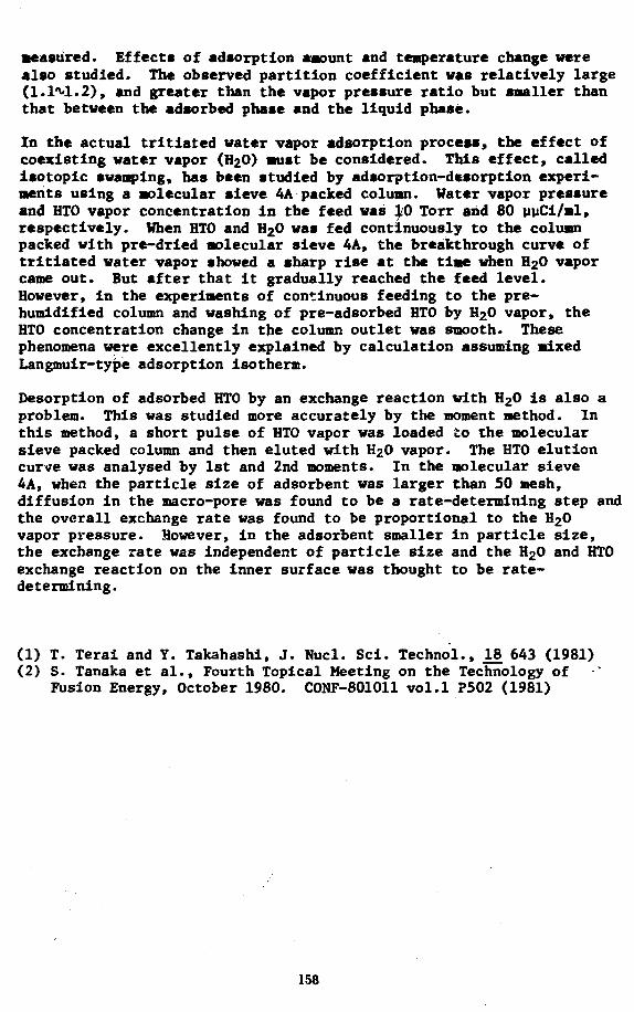
measured. Effects of adsorption amount and temperature change werealso studied. The observed partition coefficient was relatively large(1.1^1.2), and greater than the vapor pressure ratio but smaller thanthat between the adsorbed phase and the liquid phase.
In the actual tritiated water vapor adsorption process, the effect ofcoexisting water vapor (H2O) must be considered. This effect, calledisotopic swamping, has been studied by adsorption-desorption experi-ments using a molecular sieve 4A packed column. Water vapor pressureand HTO vapor concentration in the feed was ^0 Torr and 80 yyCi/ml,respectively. When HTO and H2O was fed continuously to the columnpacked with pre-dried molecular sieve 4A, the breakthrough curve oftritiated water vapor showed a sharp rise at the time when H2O vaporcame out. But after that it gradually reached the feed level.However, in the experiments of continuous feeding to the pre-humidified column and washing of pre-adsorbed HTO by H20 vapor, theHTO concentration change in the column outlet was smooth. Thesephenomena were excellently explained by calculation assuming mixedLangmuir-type adsorption isotherm.
Desorption of adsorbed HTO by an exchange reaction with H2O is also aproblem. This was studied more accurately by the moment method. Inthis method, a short pulse of HTO vapor was loaded to the molecularsieve packed column and then eluted with H2O vapor. The HTO elutioncurve was analysed by 1st and 2nd moments. In the molecular sieve4A, when the particle size of adsorbent was larger than 50 mesh,diffusion in the macro-pore was found to be a rate-determining step andthe overall exchange rate was found to be proportional to the H20vapor pressure. However, in the adsorbent smaller in particle size,the exchange rate was independent of particle size and the H20 and HTOexchange reaction on the inner surface was thought to be rate-determining.
(1) T. Terai and Y. Takahashi, J. Nucl. Sci. Technol., 18 643 (1981)(2) S. Tanaka et al., Fourth Topical Meeting on the Technology of
Fusion Energy, October 1980. CONF-801011 vol.1 ?502 (1981)
158

TRITIUM RECOVERY FROM LIQUID LITHIUM-LEAD BY VACUUM DEGASSING
K.E. Plute, E.M. LarsenDepartment of Chemistry
D.K. SzeFusion Engineering ProgramUniversity of Wisconsin
Madison, Wisconsin 53706
A liquid metal breeding blanket using the lithium-lead eutectic with moleratio LijyPbg3 has been designed for the Mirror Advanced Reactor Study(MARS). In this paper the tritium removal system for the MARS lithium-lead banket is presented. The tritium is removed by a vacuum degassingtechnique. Various vacuum removal schemes such as pumping on agitatedpools, sparging with an inert gas and introducing a droplet spray into anevacuated vessel are discussed and compared.
Both molten salt extraction and vacuum degassing have been considered fortritium removal from lithium-lead alloys.^ ' Vacuum methods areattractive because the solubility of tritium in Li^yPbg, is very low^ 'and, therefore, a reasonably high pressure can be established above thealloy without a large tritium Inventory. In the MARS baseline design, asteady state tritium pressure of 1 x 10~ torr corresponding to aconcentration of 5.1 x 10~ wppm was chosen. The tritium inventory inthe 10 kg of lithium-lead in the coolant loop is 5.1 g. At 10 torrtritium pressure, special containment measures such as a double-walledsteam generator and secondary enclosures around liquid metal handlingequipment will be used.
In MARS the lithium-lead is circulated at a rate of 1.4 x 10 kg/s andthe tritium flow rate is 7.1 x 10 kg/s in the liquid metal. In orderto recover tritium at the breeding rate of 6.8 x 10~b kg/s, 9.6% of thetritium is continuously extracted. The vacuum extraction unit isassumed to be 50% efficient and, therefore, 19% of the lithium-lead(2.7 x 10 kg/s) is sent to the tritium recovery system. The pumpingspeed required to remove tritium at the breeding rate is approximately 2x 10 t/s at 500°C. Lithium and lead vapors are condensed at a rate of2.8 x 10~5 g/s and 3.2 x 10~2 g/s, respectively, before reachingcryopumping surfaces.
Presently there are no experiments on vacuum removal of gases fromlithium-lead alloys and no mass transport data exists. There isconsiderable experience on the large scale degassing of liquid steels toremove hydrogen and other volatile impurities.^ ' Three of the methodsused in steel purification have been analyzed as possible tritium removalsystems.
(1) Liquid metal pools. The simplest removal system would be to pump ona liquid metal pool while maintaining a constant concentration in thepool interior by providing agitation. The rate determining process forthe transport of tritium from the pool is dependent on the mass transfercoefficient, B, which has units of cm/s» The value of 3 is unknown. Avalue of 3.9 x 10 cm/s for hydrogen in liquid Al at 7 0 0 ° C ^ and 1 ca/efor hydrogen in liquid steel at 1600°Ct:>J gives an idea of the order of
159

J2.
magnitude. If the mass transfer coefficient is small, B < 10 , therequired surface area (> 10 ca ) and residence tines (> 100 s) would betoo large for pool degassing to be practical. For g « 1, a pool withsurface area ~ 2 i 10 ca and depth 150 ca evacuated for 100 s withagitation would be required for the MARS tritium recovery unit. Althoughthis is not unreasonable, the mass transport can be improved by the twomethods described below.(2) Stream Degassing. In stream degassing the liquid metal is forcedthrough a nozzle and forms a stream of droplets which fall from apredetermined height through a vacuum. The diffusion cogffigient forhydrogen in liquid metals is generally found to be ~ 10 cm /s. Usingthis value, calculations show that 60Z of the tritium can be removed fromdroplets with 1 am radii in 0.5 s. This process can achieve a highdegree of degassification in a short time period. The chamber volumemust be minimized to reduce heat losses and cost.
(3) Gas Sparging. Helium gas sparging of liquid pools has also beeninvestigated. Preliminary analyses indicate that the gas bubbles improvethe mass transport primarily by causing agitation and equalizing theconcentration in the melt interior and by enhancing the surfaceremoval. Very little tritium is removed from the melt interior by thebubbles unless large helium flow rates are used. Although the spargingimproves the transport, it adds the additional step of separating heliumand tritium at large Ee/^ ratios.
The primary tritium extraction system for MARS is based on the streamdegassing model. Stream degassing appears to be the most effective wayof creating a large surface area for transport and ainimizing heatloss. Continued work is being done to assess gas sparging as a secondarytritium removal system. In general, the use of vacuum techniques fortritium removal froa LijjPbg^ is very promising.
Acknowledgement
This work supported in part by the Department of Energy.
References
(1) B. BadgeT, et al., "WITAMIR-I, A Tandem Mirror Reactor Study",University of Wisconsin Fusion Design Memo, UWFDM-400 (September,1980), Chapter XI.
(2) E. Veleckis, Argonne National Laboratory, private communication(June 1981).
(3) K. Ruttiger, "Vacuum Degassing in the Liquid State", VacuumMetallurgy, 0. Winkler and R. Bakish (Eds.), Elsevier Pub. Co., NewYork (1971), 337-463 and references therein.
(4) R.D. Pehlke and A.L. Bement, Jr., Trans. AIMS 224^ 1239-1242 (1962).
(5) C.B. Alcock, Principles of Pyrometallurgy. Academic Press, Net* York,305-312 (1976).
160

TRITIUM PROCESSING AND SAFETY ASPECTS OF TDF-TYPE MIRROR DEVICES*S. K. Ghose, Bechtel Group, Inc.,/Fusion Engineering Design Center, OakRidge, Tennessee, and D. Pence, Science Applications, Inc., 10401 RoselleStreet, San Diego, California
Paper withdrawn
161

Session 3D-2
MATERIALS ENGINEERING(poster)
Chairman
EJ. Cheng, GA Technologies, Inc.
Organizer
D.L Smith, Argonne National Laboratory
Wednesday, April 27 9:30 a.m.-noon

COMPARISON OF THE WASTE MANAGEMENT OF PCA AND V15CR5TI FIRST WALL MATERIALS*
S. Vogler, M. J. Steindler, and J. JungArgonne National Laboratory
9700 S. Cass Avenue, Argonne, Illinois 60439
A comparison has been made of the first wall and structural materials inthe high flux region for two different fusion reactor types. One systemis the STA5FIRE1 reactor with a PCAt/LiA102 first wall and blanketand the other is a reactor based on the STARFIRE design with V15Cr5Ti asthe first wall and structural material and circulating molten lithium asthe breeder/coolant. The activation of these materials is compared andthe recycling or disposal of these materials is evaluated*
Based on current designs 7.5 x 10^g (75 MT) of PCA alloy is removed annually.Along with the alloy, the breeder, neutron multiplier and neutron reflectormust also be handled. For the vanadium containing reactor, A.7 x 10'g (47 MT)have to be processed annually. The radioactivities in these materials havebeen derived from calculations based on a radioactivity calculation code RACC^along with the associated activation data libraries. The radioactivitieswere calculated as a function of time of removal from the fusion reactor. Acomparison of the radioactivities of the two materials is shown below.
Radioactivity of First Wall (Ci/cm3)at Indicated Time (Y)
0 1 5 10 30 50
PCA 3.8x10² 1.4xlO2 44 12 0.37 0.20
V15Cr5Ti 1.0x10² 4.3 2X10"1 6xlO"3 2xl0"4 9.3x10⁻⁵
At one year decay the radioactivity in the vanadium is 3 percent that inthe PCA decreasing to 0.05 percent at ten years decay. Along with thetotal activities the specific radioactivities remaining in each of themetals have been identified.
The disposal of radioactive materials in shallow land burial is controlledby the proposed NRC rule 10 CFR 61.3 The radionuclides from fusionreactors that limit disposal of materials are l 4 C , 5 9Ni, 9 4Nb, % , 6 0Co,and 63Ni; the limit for 94Nb is particularly low at 0.2 yCi/cm3 (0.2 Ci/m3).
*Work supported by the U.S. Department of Energy, Office of Fusion Energy,
tprime candidate alloy, a titanium modified austenitic stainless steel.
165

After 50 years decay the radioactive content of PCA exceeds the limits for9*Nb and 6 3Ni. The PCA contains 0.2 Ci/cm3 or 2 x 10⁵ Ci/m3 which isprobably too high for shallow land burial* Sone nore restrictive isolationtechnique (geologic medium) would be required. For the vanadium alloyafter 50 years decay, all radionuclides are below the specified Units,except for 94Nb which exceeds the limit by a factor of three.
For the vanadium alloy the radioactivity is low enough that recycle canbe considered. Dose rate calculations indicate that the contact doserate for a one-meter sphere is 600 mrem/h after 30 years decay, too highfor effective hands-on operation. At that time the 9*Nb content becomescontrolling and the dose rate is constant. If the 9 % b can be reduced orremoved (by removing the 9 % b impurity) the dose rate decreases with time,reaching a value of about 10 mrem/h at 70 years making consideration ofhands-on operation feasible.
If disposal of vanadium were considered some decay period is necessary.A standard 55 gal drum used as the package would contain 0.05 m 3 ofmaterial and 2.2 x 10^ Ci/drum at one year decay. Disposal costs arebased on a unit volume and an excess activity surcharge. The disposal costfor each drum is $90 plus an activity surcharge of ^$5700 per drum. Furtherdecay for ten years would erase the activity surcharge* The total cost fordisposal would then be $60,000 per year. Disposal at one year would cost$1,000,000. Thus, for vanadium disposal, an assessment would have to bemade comparing the cost of providing storage space for hot materials duringdecay against the cost of disposing of the more radioactive vanadium.
For PCA disposal, canisters are 0.61 m x 3.05 m (2 ft x 10 ft) and44 canisters are required annually. It is assumed that 15 round tripswill be required, using a shielded cask, to deliver the material foremplacement. The cost of emplacement in a geologic medium is roughly$100,000 per canister yielding a total cost of disposal of approximately5.3 million dollars.
The annual disposal costs for the vanadium alloy are approximately 1Zof the costs for the disposal of the PCA.
REFERENCES
1. C. C. Baker, et al., "STARFIRE - A Commercial Tokamak Reactor ....,"ANL/FPP-80-1, 1980.
2. J. Jung, "Theory and Use of the Radioactive Code RACC," ANL/FPP/TM-122,1979.
3. 10 CFR 61, "Licensing Requirements for Land Disposal of RadioactiveWaste," Proposed Rule 1982.
166

MATERIALS COMPATIBILITY CONSIDERATIONS FORFUSION-FISSION HYBRID REACTOR DESIGN*
J. H. DeVan and P. F. TortorelliMetals and Ceramics DivisionOak Ridge National LaboratoryOak Ridge, Tennessee 37830
The Tandem Mirror Hybrid Reactor (TMHR) is a fusion reactor concept thatincorporates a fission-suppressed breeding blanket for the production of2"u to be used in conventional fission power reactors. The blanket designincorporates a cylindrical module with a beryllium multiplier in mobilepebble form, thorium metal snap-ring overlays (possibly coated) on theberyllium pebbles, and a liquid lithium or sodium coolant which is pumpeddirectly through the pebble bed. Such a concept presents a complicatedcompatibility matrix with the possibilities for both solid-solid and liquidmetal-solid interactions. This matrix has been examined to identifypossible reactions under relevant operating conditions and their effects onblanket integrity and performance. Solid-solid interactions include thefollowing:
1. Be — structural alloy (currently HT-9)2. Th — structural alloy3. Be — Th (plus possible barrier coating)
In addition, self-welding may occur at contact points between the berylliumpebbles (Be-Be) or thorium rings (Th-Th). Liquid metal interactions arethose of molten lithium or sodium with the thorium, steel, and beryllium.Mass transfer of these materials in lithium or sodium under temperature andconcentration gradients may be an important problem and may be acceleratedby impurities in the solid and liquid blanket materials (principally 0, N,C, and T). Although this matrix of potential compatibility concerns islarge, the maximum operating temperature in the present reactor concept isrelatively conservative (<500°C) in terms of conventional liquid metal heattransfer systems (for example, fast breeder reactors).
The present paper reports on compatibility considerations related to theblanket design based on an examination of many of the possible inter-actions theoretically and/or experimentally. In the former case, ther-modynamic and existing compatibility data were used to assess the severityof the expected reactions. Experimentally, compatibility reaction coupleswere exposed in static lithium at 350, 450, and 550°C. The specific pur-pose of these experiments was to examine the reactions between berylliumand stainless steel in direct contact and across a molten lithium gap.
Of highest priority among solid-solid compatibility considerations are theself-welding reactions, because these will determine whether barriercoatings must be applied to the pebbles to guarantee their removability.Possible coatings for the thorium metal are TI1O2, ThC, or TiC. Possiblecoatings for the beryllium metal are Bej^Fe, Be^Cr, or Bei2Mo« Next inpriority are the possible reactions of beryllium with thorium. The samecoating candidates listed above could also be used to reduce the extent ofthe latter reaction. Last in priority are the reactions between berylliumand HT-9, which preliminary experiments have shown to be slow at 450°C.
167

In the area of liquid-solid interactions, major concerns are(1) temperature gradient mass transfer of the containment alloy (HT-9)and/or breeding materials by lithium or sodium with attendant reduction ofthe blanket fluid passages by chromium, iron, or beryllium deposition and(2) mass transfer of metallic and nonmetallic (impurity) elements among thechemically dissimilar blanket and structural materials. The use of astructural steel of low nickel and chromium activity and the relatively lowoperating temperature (<500°C) will each reduce the severity of masstransfer of the containment material by liquid metals. The beryllium masstransfer problem can be approached by using the same coating techniques asproposed for reducing solid-state beryllium reactions. Impurities in thelithium, particularly, nitrogen, can adversely affect compatibility byaccelerating corrosion of the steel by lithium and promoting the formationof Be3N2« Again, a coating on the beryllium could prevent the latter reac-tion. Another impurity of potential importance is oxygen. Any oxygen pre-sent on the as-fabricated beryllium surfaces will be dissolved by lithiumand, at concentrations above 5 ppm in lithium, would react with thorium toform ThO2. This is not of concern from the standpoint of compatibility,but an oxygen trapping system will probably be required to avoid the depo-sition of Li20 in colder regions of the lithium circuit. One additionalliquid metal corrosion reaction of importance to mechanical design concernscarbon transport. Both thorium and beryllium are strong carbide formersand may act to decarburize HT-9 by lowering the carbon activity of theliquid metal. However, except for relatively thin cross-sections, thedecarburization of the HT-9 is sufficiently slow that it should not degradethe properties of the steel over the proposed reactor lifetime.
•Research sponsored by the Office of Fusion Energy, U.S. Department ofEnergy under contract W-7405-eng-26 with the Union Carbide Corporation.
168

LIFETIME ANALYSIS OF BERYLLIUM BALLS INA HYBRID FUSION BLANKET
L. G. Miller, J. M. Beeston, P. Y. Hsu, B. L. HarrisEG&G Idaho, Inc.
Introduction
The low density, high specific heat, high modulus of elasticity, (berylliumhas highest modulus to density ratio of any metal), and relatively high meltingpoint^ are not properties which under irradiation limit the lifetime of theberyllium balls used as a neturon multiplier in the hybrid reactor blanket.Rather the limited ability of the metal to undergo plastic deformation restrictingthe redistribution of localized stresses is likely to be responsible. Resultsof analyses will be presented which predicts the lifetime of beryllium ballsin the hybrid blanket at about one year. Techniques for extending this lifetimewill be considered.
The question of failure and lifetime hinges upon the ductility of the irradiatedberyllium balls, but the irradiated data basis is sparse. Indications frompost-irradiation annealing tests-*- and high temperature irradiation tests^'^suggest that the defects may agglomerate with retention of some ductility.The retention of some ductility is necessary so that the balls do not act asindenters with one another producing Hertzian contact cracking^ and prematurefailure. Assuming sufficient ductility the lifetime of the balls is estimatedon the basis of the maximum stress theory wherein failure occurs when one ofthe principal stresses from loading reaches the minimum yield strength of theirradiated beryllium. However, surface cracks, and defects that may propagatemust be stable according to the stress intensity factor and fracture toughnessof the irradiated beryllium. The depth of a surface defect that would be stablefor the tensile stress was estimated from fracture mechanics principles.
The latest Hybrid Reactor blanket measuring 0.40 m wide is divided into two0.20 m thick annular zones filled with beryllium balls (spheres) of 0.03 mdiameter. A hole through the spheres accommodates a thorium slug as fertilematerial in both fueled zones. The spheres and slugs are cooled by liquidlithium which flows across the annular zones in the 0.4 m width direction.The stress analysis considers the forces due to lithium flow and sphere stackingheight and the internal stresses due to thermal expansion and differentialswelling. Because of scanty data at temperatures of 400-500°C, swelling,strength, and ductility values were estimated for these temperatures.Values for stresses in three annular positions: (1) near the first wall,(2) near the center, and (3) near the back wall are given in Table 1.
According to the failure theory stated above and the total internal stressesshown in Table 1, the estimated life of the hollow beryllium balls near thefirst wall is slightly more than one year provided the surface defects areless than 0.024 in. deep. The beryllium balls near the center of the blankethave almost one and one-half years average life and those near the back wallhave almost six years average life. The surface of the balls must be free ofdefects > 0.024 in. deep.
169

Considerations for increased lifetime of the beryllium balls are important toreduce the cost of replacement. There are, however, other conditions whichwill affect the cost such as automated fabrication and recycling of reconditionedberyllium. Factors which affect the ductility of irradiated beryllium willaffect the lifetime. These factors are complex because of the sensitivity ofthe mechanical properties of the metal beryllium to such things as fabrication,anisotropy, grain size, purity, percent BeO, etc. In general, beryllium offully dense low BeO content, fine grain, hot pressed has the best anisotropicductility. However, preferred orientation by extrusion increases the ductilityin the extruded direction, so that considerations of the behavior of theberyllium in the irradiation, stresses, and temperature environment may changethe ductility assessment.
Table 1. Internal stresses for the hollow sphere for one year irradiation.
Position Thermal
in Blanket (ksi)
Near First Wall 5.6
Near Center 3.4
Near Back Wall 1.1
References
1. G. E. Korth and J. M. Beeston, Interim Report of Post-Irradiation Resultsof ATR Beryllium Surveillance Program, IN-1397 May 1970 also in Metallurgyand Materials Science Branch Annual Report Fiscal Year 1970, IN-1437November 1970 and internal reports.
2. G. P. Walters, Effect of Neutron Irradiation on the Mechanical Propertiesof Hot-Pressed and Extruded Beryllium, J. Less-Common Metals, 11, 1966,pp. 77-88.
3. J. M. Beeston, Gas-Release and Compression Properties in Beryllium Irradi-ated at 600 and 75QQC, Effects of Radiation on Structural Metals, ASTMSTP 426 (1967) pp. 135-148.
4. B. R. Lawn, S. M. Siederhorn, and H. H. Johnson, Strength Degradation ofBrittle Surfaces: Blunt Indenters, Journal of American Ceramic Society,54, No. 9-10 September-October 1975, pp. 428-432.
Swelling(ksi)
27.2
24.6
6.0
Total(ksi)
32.8
28.0
7.1
Work supported by the U.S. Department of Energy Assistant Secretary for Research,Office of Fusion Energy, under DOE Contract No. DE-ACO7-76ID0157O.
170
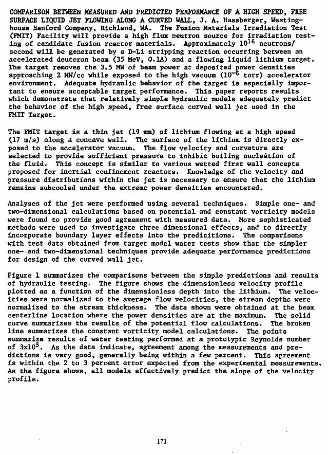
COMPARISON BETWEEN MEASURED AND PREDICTED PERFORMANCE OF A HIGH SPEED, FREESURFACE LIQUID JET FLOWING ALONG A CURVED WALL, J. A. Hassberger, Westing-house Hanford Company, Richland, WA. The Fusion Materials Irradiation Test(EMIT) Facility will provide a high flux neutron source for irradiation test-ing of candidate fusion reactor materials. Approximately 1016 neutrons/second will be generated by a D-Li stripping reaction occurring between anaccelerated deuteron beam (35 MeV, 0.1A) and a flowing liquid lithium target.The target removes the 3.5 MW of beam power at deposited power densitiesapproaching 2 MW/cc while exposed to the high vacuum (10~6 torr) acceleratorenvironment. Adequate hydraulic behavior of the target is especially impor-tant to ensure acceptable target performance. This paper reports resultswhich demonstrate that relatively simple hydraulic models adequately predictthe behavior of the high speed, free surface curved wall jet used in theFMIT Target.
The FMIT target is a thin jet (19 mm) of lithium flowing at a high speed(17 m/s) along a concave wall. The surface of the lithium is directly ex-posed to the accelerator vacuum. The flow velocity and curvature areselected to provide sufficient pressure to inhibit boiling nucleation ofthe fluid. This concept is similar to various wetted first wall conceptsproposed for inertial confinement reactors. Knowledge of the velocity andpressure distributions within the jet is necessary to ensure that the lithiumremains subcooled under the extreme power densities encountered.
Analyses of the jet were performed using several techniques. Simple one- andtwo-dimensional calculations based on potential and constant vorticity modelswere found to provide good agreement with measured data. More sophisticatedmethods were used to investigate three dimensional effects, and to directlyincorporate boundary layer effects into the predicitions. The comparisonswith test data obtained from target model water tests show that the simplerone- and two-dimensional techniques provide adequate performance predictionsfor design of the curved wall jet.
Figure 1 summarizes the comparisons between the simple predictions and resultsof hydraulic testing. The figure shows the dimensionless velocity profileplotted as a function of the dimensionless depth into the lithium. The veloc-ities were normalized to the average flow velocities, the stream depths werenormalized to the stream thickness. The data shown were obtained at the beamcenterline location where the power densities are at the maximum. The solidcurve summarizes the results of the potential flow calculations. The brokenline summarizes the constant vorticity model calculations. The pointssummarize results of water testing performed at a prototypic Reynolds numberof 3xlO5. As the data indicate, agreement among the measurements and pre-dictions is very good, generally being within a few percent. This agreementis within the 2 to 3 percent error expected from the experimental measurements.As the figure shows, all models effectively predict the slope of the velocityprofile.
171

Curvature of the measured velocity profile is observable in the figure.None of the predictions completely model this curvature. It is interestingto note that the observed curvature is that predicted by the potential flowmodels near the solid backwall, and is predicted by the constant vorticitymodel near the free surface. As the flow continues alpng the curved wall,the free stream vorticity decays and the fluid velocity profile more closelyapproaches that predicted by the potential flow model.
The agreement observed between simple predictions and measured data minimizesthe need for more complex models for most of the applications required forFMIT target design. This agreement also suggests such models will be appli-cable to other high speed film flows along curved walls, including wettedwall Controlled Thermonuclear Reactor concepts.
This work was completed at the Hanford Engineering Development Laboratoryfor the United States Department of Energy under Contract Number DE-AC06-76FF-2170.
1.2
1.1
Ia
I0.9
0.8
JET PARAMETERS:THICKNESS: 2.0 cmWALL RADIUS: 11.0 cmREYNOLDS NUMBER: 3 x 10s
PREDICTIONS: ONE DIMENSION POTENTIAL FLOWTWO DIMENSION POTENTIAL FLOWONE DIMENSION CONSTANT VORTICITY FLOWTWO DIMENSION CONSTANT VORTICITY FLOW
O MEASUREMENTS
rFREESURFACE
I
BACKWALL
1 " \
0.0 0.2 0.4 0.6 0.8
NORMALIZED DEPTH INTO JET. d/t
1.0
HEDL C W I H
FIGURE 1. Summary Comparison Between Measured and Predicted Velocitiesin a High Speed Curved Wall Jet
172

ANALYSIS OF BLANKET-STRUCTURE LIFETIMEFOR THE TANDEM MIRROR HYBRID REACTOR (TMHR)
N. M. Ghoniem, University of California, Los Angeles; D. H. Berwald, TRWEnergy Development Group
Lifetime estimates of blanket components are recognized as important designconsiderations, since the blanket module lifetime impacts both operationcosts and system reliability. Furthermore, maintenenace considerations anddesign decisions are influenced by lifetime analysis. In this paper, wedescribe a design analysis by which more reliable estimates can be madefor blanket structural modules.
Our study focuses on the use of HT-9, a martensitic alloy, in the blanketmodules of the reference tandem mirror hybird reactor described in detailin an accompanying paper (1). Briefly, the reference blanket breeds 2 3 3Ufrom thorium using a packed bed of beryllium/thorium pebbles (y20 to 1volume ratio) as a suppressed fission neutron multiplier. The coolant,liquid lithium, is pumped directly through the bed. The first wallstructure consists of two cylindrical pipes, each corrugatedcircumferentially and tied together with axial ribs. The first wall isfurther supported by radial plates which are tied to a thick back wall.
This paper utilizes the irradiation data base for the commercial alloyHT-9 to develop approximate design equations for void swelling, theshift in the-ductile-to-brittle-transition temperature (DBTT), and thermalcreep rupture at high temperature. A swelling design equation is developedwhere the swelling rate is expressed as a function of the accumulateddisplacement damage dose, the temperature, and the chromium concentrationof the alloy.
One of the most serious concerns in our study is the embrittling effectof neutron irradiation because it produces brittle fracture even atrelatively high temperature. The composition, heat treatment, and impuritycontent of the steel are all factors that influence the embrittlementbehavior. Assuming that such effects are controllable, a design equationis developed for the irradiation induced shift in DBTT of HT-9. The blanketdesign provides a margin of safety by setting the operating structuretemperature above the DBTT. This is more conservative than fracture mechanicsapproaches using fracture toughness measurements in crack quench ratecalculations.
At high temperatures, structural failure results from the slow deformationunder creep conditions. Unfortunately, most high-temperature designs requirethat components have services lives greater than those for whichexperimental data are available. As yet, there is not universally acceptable"best" procedure for extrapolating creep data. The design equationsdeveloped by Ghoniem and Conn (2) are used to determine the allowabledesign stress at any operating temperature and for various target lifetimes.
173

A conservative approach is shown in which the moderate shifts in the DBTTare eliminated during scheduled maintenance periods. Pressure vesselannealing data are used for the development of an expression for the fractionof the shift in DBTT recovered as function of both annealing temperatureand time. The results are in reasonable agreement vith the KAKEL (3)annealing computer code. It is recommended that the structure temperaturebe held constant at 450*C for a period of ~60 hours during every scheduledmaintenance period. This will insure >9QX recovery of the shift in DBTT.
The results of calculations for the accumulated axial strain in the HT-9first wall as a function of temperature at different irradiation timesindicate that the total axial strain after six years of operation is 2.1Zat the maximum front wall temperature of 410*C.
The choice of a low-swelling martensitic alloy added great advantages tothe present design. To realize the maximum potential of HT-9, the followingfeatures are adopted:
1. HT-9 is used in a relatively low temperature design (below 500°C) togive an allowable design stress of 24 KSI for a maximum creep rupturelifetime of 14 years.
2. A minimum structure temperature of 365°C ensures a good margin ofsafety against neutron embrittlement during operation.
3. The moderate DBTT shifts during irradiation are eliminated by a 450°Canneal for 50-60 hours.
4. In elastic radial strains can easily be accommodated.
The total average displacement rate is estimated at 0.9 cm/year, for a dutyfactor of 0.7. Assuming a module-to-module clearance of 10 cms, theestimated lifetime is around 10 years.
References
1. D. H. Berwald, et al., "Fusion Breeder Reference Design Overview",Proc. Fifth Top. Mtg. Tech. Fusion Energy, Knoxville (1983)
2. N. M. Ghoniem, R. W. Conn, "High Temperature Evaluation of FerriticSteels for Fusion Reactors", ANS Trans., Vol. 41 (1982) p. 294
3. J. F. Mancuso, J. A. Spitznagle, R. P. Shogan, 6. M. Joursis,"Irradiation Annealing of Pressure Vessel Steels", ANS Trans. Vol. 38,(1981), p.305
This work funded under LLNL contract 5623001
174

MHD Pressure Drop of NaK Plow in Stainless Steel Pipe
Keiji MIYAZAKI, Shoji XOTAKE, Nobuo YAMAOKA, Shoiji INOUE
Department of Nuclear Engineering, Faculty of Engineering,
Osaka University
Yamadaoka, Suita-shi, Osaka, Japan 565-00
and
Yoichi FDJII-E
Institute of Plasma Physics, Nagoya University
Furocho, Chikusa-ku, Nagoya, Japan 464-00
Research Summary :
In order to accumulate the basic data necessary for designing
a liquid metal cooling systems of fusion reactor blanket, an experi-
mental and theoretical study was performed on the MHD pressure drop
of liquid metal flow in a circular pipe with conductive Wall under
transverse magnetic fields. The experiment was conducted, with a
test section fitted to the NaK-Blowdown MHO Experimental Facility,
by the Nuclear Power Research Group of Osaka University.
Experiment: The test section, shown in Fig. 1, was made -of a 45:3mra
toner diarat-er;aud-l .65mra thick 304-stainless steel circular pipe.
The pressures-*were measured at two points in the uniform magnetic
field section by TObar-rating semiconductor resistance-piezo type
transducers by correcting the magnetic effect. The ranges of the
experimental parameters were the applied magnetic flux density: B,«
0.3*1.75 T, the wean velocity of NaK fluid: S=2M5 m/sec, Reynolds
number: Re«8.xlO5»».6.'2x10* and Hartmann number: Ha=740M150.
Theory: The velocity distribution over the circular cross-section
was assumed to be u(r)= u,{l-(r/a)n}, (1)
where a denotes the inner radius of the pipe and n the index.
Maxwell's and Ohm s equations were combined with Eq.(l). The
electric potential V and the pressure gradient 3p/3z were obtained
by solving the equations on an assumption of uniform magnetic field
and under the boundary conditions: (1) Jr*0 at r*b, (2) )0 Jydy=O at
6*0, and (3) Vf*Yw at r»a.
The mean fluid velocity is u=u,n/(2+n) and u+u, as n-»-«, i.e. uniform
177

Results and Discussion: The theoreticalanalysis resulted in the following.The tangential distribution of potentialat the outer wall:
2 a2b uBfsin8 (2)
Pressure gradient along the flow:°w
2
32 afuB, (3)
where o w and of are the elctricconductivities of wall and fluid,b: the outer radius of the pipe.
MAOCT
B. *POTEMTUt I«P
fDSITKMSSECI1OH »-» '
Fig.l Experimental setup
The experimental data of potential are plotted in Fig. 2 withthe theoretical prediction and those of pressure drop in Fig. 3.Appreciably good agreements.between the experiment and the theoryare demonstrated both in the potential and the pressure drop exceptfor a low OfTJB region. The deviation from the line predicted*" byEq.(3) will be attributable to the transition from laminar to turbu-lent flow regimes with decreasing the electromagnetic interaction.
too
310-
•10 -» -X
Fig. 2 Tangential distributionof electric potential
IS 20 JS » 35
Fig. 3 Pressure drop between,the two pointsl35mmapart
178

DISRUPTION INDUCED VOLTAGES AND LOADSON TORUS SECTORS
R.J. Thome, R.D. Pillsbury and W.R. MannMIT Plasma Fusion Center
The rapid decay of magnetic flux associated with a plasma disruptioninduces voltages and currents in electrically conducting bodies whichare nearby. Recent FED/INTOR designs utilize toroidal shells or shellsegments near the plasma which are divided into sectors for assemblyand maintenance purposes, but which may have electrically conductingpaths toroidally to provide vacuum boundaries. The generation of volt-ages across sector gaps is a potential problem in the form of arc ini-tiation with material damage. In addition, the induced currents mayinteract with the toroidal field to generate large net torques on asector. A finite element model was used to estimate the induced sectorgap voltages and net overturning moments following a disruption. Severalcases were run, based on different assumptions concerning number ofshells, toroidal continuity, shell thickness and resistivity. Sequen-tial time plots of flux and of field lines allow considerable insight tobe gained into the effects of the different assumptions.
Flux decays for four cases are shown in Figures 1 to 4. The t < 0distribution is the steady state flux generated by the plasma with acenter at "c". The first wall is located at "b" and "d" and the shieldouter boundary is at "a" and "e".
Other curves show the flux at times after disruption. The sudden col-lapse of flux in the center in each case arises from the decay of thosefield lines which are generated by the plasma in the steady state, butwhich do not link any walls or conducting material. The "kinks" in theflux pattern at points "a", "b", "d" and "e" occur from eddy currentsinduced in the walls at those locations. Fig. 1 is based on two shellswhich are connected and sectored so that the sum of the eddy currents inthe shells is zero through an rz-plane. This is a worst case and leadsto a large flux change in the sector gaps. Fig. 2 uses the two sectoredwalls of the first case together with a complete third shell which istoroidally continuous and able to carry net current through an rz-plane.The result is a substantially reduced flux change at all points. Points"b" and "d" are the primary points of concern since they represent thefirst wall sector gap locations facing the plasma. Figures 3 and 4 aresimilar to the second case except that the complete third shell is re-placed by a partial shell which is still toroidally continuous; however,it is either inboard (Fig. 5) or outboard (Fig. 4). A comparison of thecases indicates that the presence of a toroidally continuous path has asubstantial effect and that the inboard portion is most effective.
179

figure 1- * va radius at selected instants of tine In th« » - 0plane for two thclla without net current flow.(I - 5.4 HA; n o t c f l ) /
Fljure 3 - • vs rntlius at tolcrted Instant* of tint In the l » 0plane fur shells 1 and 2 with no net current and athird partial miicll inboard capable of nit currentflow (I • 5.4 HA; not.:{-I ).?
P P
oo©
BCr.)
uTt 2- 4 vi rndiua at tflrctcd Instants of time in the x •plane for Hirer shpllk vlirrc chelli 1 And 2 arermirlctcd to no net current and fheil 3 it allowedto have net current. (1 • 5.4 KA; note!*«I ).
• v« radlut in tho i • 0 plane •( aclcclcd instants«f tine for shells 1 and 2 with no net current anda third partial vlicll outboard eap.-iulu of net currentflow <I - i .4 MAj notc:4-X ) .*

ELECTROMAGNETIC EFFECTS ON THE INTOR LIM1TRR
L. R. Tu-ner and M. H. FossArgonne National Laboratory
As the plasma current decays during a plasma disruption, currents and voltagesare induced in the first wall and limiter of INTOR. These currents can inter-act with the poloidal and toroidal fields to produce large forces andtorques. The voltages can lead to arcing between segments of the litnJter.The objectives of this study are to determine how the forces, torques, andvoltages depend on such system parameters as the first wall electromagnetictime constant, the limiter material (particularly its electrical resistivity),and the degree of toroidal segmentation. In the study, the system consists ofa double-bladed liraiter located below the plasma, an electrically continuousfirst wall, poloidal field coils with fixed locations and currents, and aplasma current decaying linearly to zero in 20 ins. A computer code has beendeveloped to model the induced currents in the blade and first wall asfunc tions of time.
This code, in which the first wall and limiter are represented by coaxialcircular current loops, does not lend itself to a treatment of segmentationeffects. The first step toward segmentation, a single cut In the limiter, canbe modelled by imposing an additional voltage term on the liraiter wiresonly. The voltage is made large enough to make the sum of the liaiitercurrents vanish.
Results show how the forces, torques, and voltages in the liraiter vary withtoroidal segmentation, first wall time constant, and resistivity of limitermaterial. In each case, three forces and one torque are considered. F- isthe radial force per unit length of limiter due to interaction of the inducedtoroidal current with the vertical component of poloidal field. F^ is thevertical force per unit length of limiter due to interaction of the inducedtoroidal current with the radial component of poloidal field. N is the torqueper unit length of limiter, about an axis in the toroidal direction, resultingfrom F^ and F-. ^ c ut *
s t n e vertical force of interaction between thetoroidal field and the radial currents which flow wherever the limiter has apoloidal cut.
Four cases have been analyzed for the effects of electrical discontinuities:(1) a continuous copper toroidal limiter, ignoring effects from the firstwall; (2) a toroidal liraiter with a single jjoloidal cut; (3) a continuoustoroidal limiter Including the first wall with 100 ms time constant; and (4) atoroidal liraiter with a single poloidal cut including the first wall. Table 1summarizes the peak forces for these four cases.
As expected, the lii.iiter without a cut and without a first .wall exhibits thehighest forces, which.peak at the end of the plasma current quench. Thepresence of the first wall and a single cut in the limiter providessubstantial protection from mechanical forces.
It is possible to give a physical argument to estimate the forces on a seg-mented limiter on the basis of the forces on a limiter with a single cut andthe increased resistance of current paths in a segmented limiter. For 72segments, six per TF coil, the vertical force drops from 1.26 MN to 0.3 MN.Support against a force of 0.30 MN is manageable.
181

Lirai terLimiterLirai ter
and 1Lirai ter
withwithwith
?irstwith
and First
Table
No CutCutNo CutWallCutWall
1. Summary
Peak RadialForce(N/m)
820,000120,000500,000
21,000
of Induced Force
Peak VerticalForce(N/m)
500,00040,000
260,000
14,000
Calculations
Peak Torque(Nm/m)
200,00085,000
110,000
12,000
Peak VerticalForce on Cut
(MN)
03.500
1.26
A series of computations was performed for a copper limiter with a singlepoloidal cut. Time constants of T = 0, 10, 30, 100, and 1000 ms were used.For T « 20 ms, the plasma current decay time, the force is largelyindependent of T. The decrease of force with increasing T is strongestfor T - 20 ms. Finally, for T » 20 ms, the force decreases more weakly withincreasing T.
Concern has been expressed that the voltage induced by plasma disruptions maylead to arcing between limiter segments. In the computations for a limiterwith a single cut, the zero net current condition is imposed by finding theelectrical potential which reduces the circulating current to zero. For alimiter with a single cut, this potential represents the voltage across thecut. For a limiter with n segments and n cuts, the voltage across each cut isgiven approximately by dividing the potential by n.
The variation of voltage with first wall time constant is found to be similarto the variation of force with time constant: virtual independence for T «20 ms, rapid decrease with increasing T for T ~ 20 ms, and slow (inversesquare root) decrease for T » 20 ms. For T = 100 ms and 72 segments, thevoltage is below 10 V.
Several conclusions can be drawn from these studies: (1) The electricalresponse of the limiter is sensitive to the electrical behavior of the firstwall and cannot be studied independently from it. (2) For a first wall timeconstant of 100 ms and a limiter segmented into 72 pieces, the forces,torques, and voltages are manageable. (3) For a shorter first wall timeconstant or fewer segments, electromagnetic considerations may strongly affectthe design of the limiter. (4) There is a characteristic variation of limiterforces and voltage with first wall time constant T. (5) Induced forces andtorques vary inversely with the square root of limiter resistivity; voltagesare virtually independent of limiter resistivity. (6) In light of theimportance of segmentation effects, an analysis which treats segmentation moredirectly is required.
*Work supported by the U. S. Department of Energy.
182

TRANSIENT ANALYSIS OF STARFIRECOOLANT-BLANKET SYSTEM WITH ATHENA CODEa
S. Z. Rouhani, J. Jones, J. S. HerringEG&G Idaho, Inc.
ABSTRACT
Public acceptance of fusion reactors as a viable source of power will dependnot only on the cost of such facilities, but more so, on their safetyrelated issues. A characteristic feature of these reactors, which ensuresan inherent safety compared to LWRs and LMFBRs, is their massive thermalcapacity combined with a relatively low rate of afterheat production. Thiscombination allows for a considerably longer time than would be availablein LWRs for mitigation in case of any off-normal incident.
The present report demonstrates the time-dependent response of the thermalpower generation and removal system of the STARFIRE fusion reactor in caseof a total power loss. This is a case involving the loss of all circulationpumps on the primary and secondary sides of the coolant system.
The STARFIRE fusion reactor system, which is based on a continuously operat-ing TOKAMAK concept, is designed to employ forced circulation of pressurizedwater at 15.2 MPa for cooling the breeding blanket. The design involvesusing 24 D-shaped blanket sectors, each packed with a number of coolantmodules. For safety and redundancy, each module is cooled by forced flowfrom two separate loops, which supply coolant to alternate layers of hori-zontal tubes. Each D-shaped blanket sector is connected to the coolantinlet and outlet lines of the two loops, both at the top and the bottom.The four-pipe connection to the top supply coolant to the elements in theupper half (above the midplane) and the connections to the bottom supplycoolant to the modules below the midplane. Within each module, the tubesare embedded in the heat generating tritium breeder (Lithium Aluminate) atvarying distances from the first wall. A major part of the total heat isgenerated at the first wall and behind the neutron multiplier. These arealso cooled by the pressurized water circulation system. Each primarycoolant loop includes, in addition to alternate rows of coolant tubes inevery other blanket sector, two steam generators, parallel circulation pumpsand a pressurizer. The steam generators are of the once-through type, pro-ducing superheated steam at about 7.0 MPa pressure. The secondary side ofsteam generators is fed by condensate through the feed pumps. The thermalpower to be removed from the blanket is 3800 MWt and the total reactor poweris 4000 MWt.
The transient analyses are performed with the ATHENA (Advanced ThermalHydraulics Energy Network Analysis) code. This is a fast running computercode for solving mass, momentum, and energy conservation equations for two
a. Work supported by the U.S. Department of Energy Assistant Secretary forResearch, Office of Fusion Energy, under DOE Contract No. DE-ACO7-76IDO157O.
183

fluids (liquid and vapor) in any arbitrary combination of hydraulic loopswhich are interconnected directly or indirectly (through heat exchangers).The code employs flow regime-dependent constitutive relations for exchangeof mass, momentum and energy between two phases. For heat transfer fromchannel walls, the code uses a variety of correlations covering differentprocesses from single-phase convection by liquid to subcooled and nucleateboiling, CHF, film boiling, and postdryout convection. Transient tempera-ture distribution and heat conduction in solid walls are calculated onedimensionally. The main features of ATHENA are identical with those ofRELAP5 for LWR analysis.
The modeling of the STARFIRE blanket coolant systems had to be done suchthat it represented the main features of modules, their relative spatialarrangement (extreme differences in height) and the alternating nature oftube connections to each loop. Yet, there was a need to keep the nodaliza-tion scheme for hydraulics analysis at a manageable size for practicalreasons. In this respect, the whole blanket was modeled by eight coolantmodules representing two alternate types of the D-shaped sectors. Eachsector was represented by one module at the top, one immediately above themidplane, and a symmetrical pair below the midplane. Each external coolantloop is represented with one pump, one steam generator, and a pressurizer.
The computations involved, firstly, the determination of an initial steady-state distribution of flows, pressures and temperatures at full power.These were obtained by using special control features in ATHENA. Thetransient was then assumed to start by loss of power to the pumps and theirsubsequent coastdown, followed by reactor shutdown after some time.
The preliminary results of this transient analysis indicate that a top over-pressurization occurs at 40 s following the pump trip. This pressurizationresponse requires a power scram within approximately 35 s to maintain theintegrity of the primary coolant loops. The subsequent pump coastdown took50 s to reach essentially zero coolant flow in the loops.
As expected, natural circulation proved dominant in the upper-most blanketmodule with vertically upward oriented tube connections. The afterheat inthis module was readily removed by the natural circulation which developedwith only slight voiding in the tubes. The equilibrium temperaturesreached by the first wall is 900 K (after 400 s).
The lower-most modules, with vertically downward connected tubes, show nocirculation. These modules show a first- and second-wall dryout and sub-sequent meltdown of both walls at about 800 s after the power scram.
The modules close to the midplane, with horizontal connecting tubes, showlittle circulation and coolability. Their transient response was more likethat of the lower-most modules. The maximum temperature increases in thebreeder material at different points were limited to 100 to 180 K. Theseoccurred at the initial part of the transient. Similar temperatureincreases in the reflector were limited to 80 to 120 K.
184

Effect of Temperature on Magnetic Field Perturbationfrom the Ferromagnetic Blankets in MARS
H. Attaya and G.L. KulcinskiNuclear Engineering Department, University of Wisconsin
Madison, Wisconsin 53706
Because of its high resistance to irradiation damage, the ferritic steelalloy HT-9 is proposed to be used as the structural material in the MARSblanket. Many questions, however, have been raised about the interactionof this ferromagnetic material with the magnetic field. One of thesequestions arises from the fact that the magnetization is a function of thetemperature and because the temperature (hence the magnetization of theHT-9) in the blanket varies with position. Hence, the question addressedhere is "will that variation of the magnetization produce any magneticeffect in the plasma region?"
Temperature and Magnetization Distribution in MARS Blanket. In the MARSblanket the LiPb coolant enters form the top of the blanket at 330°C andleaves the bottom of the blanket at 500°C. The temperature T at any angle6 is,
T - 330 + (500-330) 9/n (1)
where 9 is the angle measured as shown in Fig. 1. Since the magneticfield on the plasma axis in the central cell is about 4.7 tesla and is inthe z direction, the magnetization of the HT-9 reaches its saturationvalue Mg and is in the direction of the field. The value of Mg is a vary-ing function of the tmeperature and is zero at the Curie temperature ofHT-9 which is about 700°C. To a very good approximation in the tempera-ture range between 330°C - 500°C the magnetization in the left half of theblanket could be written as
M - MS2 - (A - B9)2 (2)
where the constants A and B can be determined by knowing the value of Mat the inlet and the outlet temperatures, and z is a unit vector in the zdirection.
Magnetic Field Due to Magnetized Structure. If one knows the distributionof the magnetization in the magnetized structure, one can estimate thefield due to such structures (outside it) by using either the correspond-ing distributions of the magnetic pole densities given by:
surface pole density • (n • M), and (3)volume pole density • - V » M (4)
or by corresponding distribution of the Anperian current densities givenby
surface current density • £-n £ M), and (5)volume current density « (V x M) . (6)
185

Consider first the case where no temperature variation exists, i.e., the_magnetization is uniform and constant (M * M J ) . In this case both V • Mand 7 x M vanish. Thus, we could simulate_tne_effect of the magnetizedblanket by either a surface pole density (n • M), which will have valuesonly at_ the end faces of the blanket, or by surface current densities(-n x M) which will have equal but opposite values on the outer and theinner surfaces of the blanket. It appears directly from using any ofthese two models that the field due to the magnetized structure will beonly at the far ends of the blanket.
Now consider the case in which the magnetization obeys Eq. 2. The volumecurrent density exists and has a value in the radial direction only i.e.,
V M » V x (M z) - (-S IT
~ B / r
by using Eq. (2). If this value is multiplied by an infinitesmal volumedv - rd9drdz, the result will be -Bf drd6dz and this is equal and oppositeto the difference between the surface current at 0 which is M (8)f drdzand the surface current at 9 + d8 which is -(M + (dM /d6) • dB)i drdz,i.e., -(dMg/d9)d6 r drdz. Thus, the volume current density cancels the netradial current which is due to the variation of the magnetization, and theeffect appears only at ends of the blanket as before but in a differentway._ This conclusion could be reached directly using the pole model whereV • M is zero, but the current model shows more clearly how the tempera-ture effects disappear at the center of the central cell*
The conclusion, based on this simple model, is that the variation of themagnetization of the ferromagnetic structure will be only at the end ofthe blanket. Numerical calculations showing the field at the ends of theblanket will be presented.
W.F. Brown, "Magnetostatic Principles in Ferromagnetism," North-HollandPubl. Co., 1962.
T» 33O*C
M
T«3OO#C
Fig. 1. Schematic cross section for the blanket. The arrows in theInfinitesimal area show the directions of the surface current densities(•ni x_M) at each side, and the direction of the volume current density(V x M).
186

DYNAMIC RESPONSE AND STABILITYOF INPORT TUBES IN !CF REACTORS
Roxann L. EngelstadEdward G. Loveil
University of Wisconsin - Madison
A persistent problem in the development of inertia! confinement fusionreactors is protection for cavity structural walls from target debris,X-rays and neutrons. For this purpose a novel design has been proposedfor the heavy ion beam fusion reactor HIBALL, a conceptual design jointlydeveloped by the UW Fusion Engineering Program and the Kernforschung-szentrum Karlsruhe, FRG. As shown below, the general configuration ofthe reactor chamber is cylindrical with the cavity first wall masked byan annular tube bank through which liquid Li-,7Pb83 flows. Individual
REMOVABLE SHIELDSEGMENT
-X-
PELLET INJECTOR
VACUUMPUMPS
COOLANTSUPPLY^jJJ-
SHIELD
UPPER i REFLECTORBLANKET
FINAL FOCUSINGQUADRUPOLES
tubes, named INPORT units (Inhibited Flow/Porous Tube), are fabricatedof porous woven SiC. Liquid LiPb flows primarily through the units, butwith the wall porosity a protective layer (1 mm thick) is formed on thesurface. This layer protects the INPORT by absorbing target debrisand X-rays. Film vaporization from this energy deposition'produces areactive impulse on the tube. This paper is concerned with the responseand stability of SiC tubes from this loading.
Analysis of the mechanical response of the INPORT units involves bothstiffened and unstiffened tubes. In the former, the woven tubes arerigidized by chemical vapor deposition of SiC. Such members resist
187

transverse loading by flexural action, similar to structural beams. Ageneral formulation is developed for natural frequencies, stresses anddeflections including the effects of the LiPb flow. For uniform impul-sive pressure, design data is presented which identifies the mechanicalcharacteristics of these elements. Unstiffened tubes require separateanalysis since these units resist lateral loading by tensile force actionalone, i.e., having negligible shear and bending resistance. For thedynamic response, two support modes are considered. The first involvessuspension from the upper end with the lower free to move while thesecond has the bottom end constrained in addition. For an impulse of600 dyne-sec/cm?, displacements are found to be quite large for singlesuspension, but acceptable for two point suspension. The results shownare for sequential impulses applied at 5 Hz.
INPORT TUBE MECHANICAL RESPONSE INPORT MECHANICAL RESPONSE
350 "
300
250
200
150a.
<=> 100a.p 50
j SEQUENTIAL600 dyne
IMPULSES- secxcm2
r UNSTIFFENED TUBES:3cmx 10 m
Pi ONE POINT
/ \ 20% //prV-DAMPING/
1 2 \J3
SUSPENSION -
\ 0 % /\— DAMPING/
4 W 6
SEQUENTIAL IMPULSES600 dyne- sec/cm2
UNSTIFFENED TUBES!3 cm x 10 m
TWO POINT SUSPENSION
TIME (sec)0.4 0.8 1.2 I.S 2.0
TIME (sec)2.4 2.8
Forced vibrations produce another response of the INPORT units - non-planar motion. When the tubes are driven by a force near the fundamentalfrequency, large amplitude oscillations become unstable and the tubedisplays a component of vibration in a direction perpendicular to theplane of the force. In essence, the tube begins to whirl, tracing atubular path. Amplitude-frequency relationships are determined for bothplanar and nonplanar motion, showing regions of instability.
The analysis of the INPORT units shows that the vibration and deflectioncharacteristics are generally compatible with the HIBALL design. Theresults identify the feasibility of the concept and guide the design fortube placement and their mechanical assimilation in ICF reactors.
188

CONTROL OF NEUTRON ALBEDO IN TOROIDAL FUSION REACTORS
B. J. Micklich and D. L. Jassby, Princeton Plasma Physics Laboratory,Princeton, NJ — The neutron flux spectrum at the plasma vessel wall ofa toroidal reactor has two components: (1) the uncollided fusion neutrons,and (2) neutrons scattered from reactor hardware. This study investigatesthe variations that can be effected in the collided neutron component in-cident on selected outboard blanket modules by altering the neutron albedoof portions of the reactor. Physical methods of implementing these changesand the consequences for several practical applications are examined.
Figure 1 shows the calculated energy distributions of neutrons scatteredfrom slabs of candidate materials of 20 cm thickness backed by 40 cm ofstainless steel when these materials are irradiated by an isotropic DT fus-ion neutron source. In the scattered fast-neutron energy range from 1 to 5MeV, Pb has the highest albedo while H20 and
6LiH have the lowest. At verylow scattered energies (E < 20 keV), Be has the highest albedo while *"B^Cand 6LiH have the lowest.
The information derived from data such as given in Fig. 1 has been used todetermine how to change the flux spectrum of neutrons incident on the vesseloutboard wall by appropriate choice of materials behind the inboard wall.The uncollided current at the outboard wall is typically 25% larger than atthe inboard wall for tokamaks with aspect ratios in the range 3 to 5. Byusing 6LiH, " B ^ C , or H20 as the inboard material, the effective outboard-directed current in the source energy group (13.5 to 15 MeV) can be made aslarge as 77% of the total outboard current, IT, while the current of fastneutrons (E>0.5 MeV) is 90 to 95% of IT. With Pb or Be on the inboardside, I-j- is greatly increased, but the effective current of uncollided neut-rons is reduced to about 0.5 IT. For Pb most of the collided neutrons arefast (E>0.5 MeV), while for Be they are relatively slow (E<0.5 MeV).
Changes in inboard materials can be implemented by the use of vertical ductsinstalled in a space 20 to 30 cm deep just behind the inboard wall. Theneutron albedo is varied by admitting liquid Pb, liquid Li, or H20 intothese ducts. Materials can also be introduced in the form of pebbles ormicrosphe.res, gravity fed from the top of the reactor into the ducts andretrieved from the bottom. An alternative approach is to support slabs ofdifferent materials by vertical cables in the inboard space.
One important application of albedo modification is the maximization of localtritium breeding in outboard blanket modules. The 1-D results summarized inRef. 1 showed that overall TBR greater than 1.5 can be obtained with no in-board breeding, in the absence of penetrations, by a combination of Pb andZircaloy structure in the inboard region. Three-dimensional Monte Carloanalyses give similar results when the outboard blanket is extended to coverapproximately 2/3 of the top and bottom of the rectangular plasma vessel.
Reference 1. B.J. Micklich et al., Trans. Am. Nucl. Soc. 41 (1982), 172-3.
Acknowledgment. Work supported by the U.S. Dept. of Energy Contract No. DE-ACO2-76-CH0-3073 and Electric Power Research Inst. Contract RP-1748-1. B.J.Micklich was supported by a Fannie and John Hertz Foundation Fellowship.
189

Figure 1. ENERGY DISTRIBUTION OF SCATTERED NEUTRONS
• Isotroplc 14-MeV Neutron Source
• Ir - Total Albedo « Number of ScatteredNeutrons Per Incident 14-HeV Neutron
H20
I r - 0.129
....J M,J , ,,,-1 ,,,iJ .,,J
10'
10
10
X T 7 W * I0"6 X)- 4 Xl'3 Kl"2 III"1 Ml" 10' XI2
Llthlum-6 Hydride
\r = 0.376 r,10"
"• 10"* XT* X'J X)'MiUOtOOCI IK1£V
Stainless
Steel-315
l r = 0.86S
10,-2
10,-3
• •) . ,.,,1 .,[,,1 ,,,,,1 ,,,,rl i .....I . ' mn' in.rj .....
» " ' W * 10"5 10"* 1('"3 10~2 I0"1 ID0 101 102
mmDca I£V
-: 1
-1
-2
-3
Boron-10 carbide [ -
'r ' °-"18 „ J :
i • n
il
i
J ...J .,_j ..^ ..—
^ 10 ' <-
- m " 3
10',-2
10-3
l',-.' I,,J ......I 1..,^ ..,,J ,.,.J ,|,J ,1.,-i ,.,.
to"6 10"5 10"4 Ki"3 1(l"2 10"' 10° 10' M 2
KUHOHOBSX IHIfV0 10 K 1(l
KUHOHOBSX IHIfV
Berylllun
l r = 1.231
-=)10
10"
10"
r J . . , . - ' ..|.J ..i^l Miir) I n»J lllJ lllllJ lli».
» - ' 10"* I0"4 Xf4 W"3 I0"2 10"' 10° 10' 11*MUIHHDDSI IMI£V
lj Illirj iiurl . ...r' .i.,J iiiiJ . . .J ni.J .niJ . . .
10"' 10-* 10"* TO"* M"3 XT* 10"' 10° ID1
NUnUDBSt IHltV
10
190

EXPERIMENTAL STUDY OF THE ENHANCEMENT OF CRITICAL HEAT FLUX USINGTANGENTIAL FLOW INJECTION
J. Weede, Research Assistant, UCLA, School of EngineeringV. K. Dhir, Professor, UCLA, School of Engineering
The aim of this investigation is to study the enhancement of the criticalheat flux in vertical tubes by injecting fluid tangentially into the tubes.
Until recently, high heat fluxes in fusion devices have been removed byrelying on the heat capacity of the various components with which theplasma comes in contact. Due to steady improvement in the temperatureand confinement of thermonuclear plasmas, it has become clear that moreefficient means of heat removal must be developed.
An important parameter to consider in the design of high heat flux re-moval devices is the critical heat flux (CHF). The CHF condition in sub-cooled, forced flow boiling occurs when the area adjacent to the heattransfer surface becomes blanketed with vapor bubbles, hindering thereplenishment of liquid to the surface. This condition results in a sharpincrease in the surface temperature as the CHF value is reached, and de-struction of the surface may result.
Numerous studies of the critical heat flux and enhancement of the CHF arecited in the literature, but relatively few have been performed with highvelocity, highly subcooled liquids. An early study by Gambill et al. [1]on the enhancement of CHF using vortex flow did investigate the effect ofthese parameters. The authors reported CHF values for vortex flow rangingfrom 2.5-17 kw/cm^. Compared on a constant pumping power basis, thesevalues represent 2.0-3.A times the CHF values obtained for axial flow.However, the tubular test sections used were of small dimensions withlengths from 0.5 to 3.2 inches. Although it is generally excepted thatthe Lube length does not affect the CHF at longer lengths (>24 in.), thishas not been shown to be true for short tubes.
A later study, again by Gambill et al. [2] examined the enhancement of CHFdue to twisted tape induced swirl flow. Values of CHF from 1.0-11.8kw/cm2 with enhancement ratios (at constant pumping power) of 2.0-2.5were obtained. Data was reported over a relatively wide range of tubelengths, but no attempt was made to systematically determine the effectof heated length on the CHF.
In the present study, the effect of heated length on the CHF has been in-vestigated through a systematic variation of both length and subcooling.In addition, the concept of tangential flow injection is used as a meansof CHF enhancement. This concept utilizes jets which enter the testsection tangentially and at an angle to the tube axis, at several posi-tions along the tube. Data are taken with and without the jets to deter-mine the relative enhancement. Parameters investigated in this studyare listed in Table 1. Figure 1 shows data taken for a test sectionwith jets at two different locations along its length. The enhancementratio at constant pumping power is about 1.2, but to achieve the same CHFwith axial flow would require a four-fold increase in pumping power.
191

In summary, in this work the critical heat flux in geometries and underconditions of interest to fusion devices is investigated. In addition,a novel approach to CHF enhancement is utilized and found to enhance theCHF without requiring an increase in pumping power.
60-Table 1. Experimental Parameters
FIGURE I . CHF VS. F'.OWPOWER DISSIPATION
Test Section Material
Inside Diameterx Wall Thickness (lc)
Heated Length (in)(variable)
Working Fluid
Flow Velocity ( f t / s )
Exit Pressure (psia)
Inlet Subcooling CO
CKF Range (W/ca2)
Inconel 600
0.68 x 0.035 wall
6-24
Freon 113
4.4-30.8
30
25-60
30-84
56-
1?-S2H—sU-X
4 8 -
(
E—-
0 II
1i/
/
8
ei_OW
/ s- (8 PSIA
xiN=~0.l0
^ AXIAL FLOW
O ONE JET ON
Q TWO JETS ON
12 6 20 24 28POWER DISSIPATION ;w,
Work supported by Sandia Laboratories, Albuquerque, New Mexico.
References
1. W. R. Gambill and N. D. Greene, "Boiling Burnout with Water in VortexFlow", Chem. Engr. Prog. Symp. Series 54, 1958, pp. 68-76.
2. W. R. Gambill, R. D. Bundy, and R. W. Wansborough, "Heat TransferBurnout, and Pressure Drop for Water in Swirl Flow Through Tubeswith Internal Twisted Tapes", Chem. Engr. Prog. Symp. Series 321960, pp. 127-137.
192

PLASMA ENGINEERING ANALYSIS OF AN EBT REACTOR OPERATING WINDOW*
R. T. Santoro, N. A. Uckan, and J. M. BarnesOak Ridge National LaboratoryOak Ridge, Tennessee 37830
A plasma engineering analysis based on recent advances in EBT physicshas been carried out to determine the boundaries of the physics andengineering operating space within which an EBT reactor is expected tooperate. The analysis was performed using a systems code that is beingdeveloped specifically for EBT reactor design studies. A uniquefeature of this code, which differs from those used previously, is thecoupling of the ring and core plasma properties and the self-consistenttreatment of the stability-ring power balance requirements. This paperdescribes the models used in the physics subroutines of the code andillustrates the flow of calculations. The initial operating window isdefined primarily by the limitations imposed by physics constraintswithin the allowable limits of engineering and technology constraints.Additional limitations are imposed by the total electrical power outputof the reactor, neutron wall loading, recirculating power fraction,cost of electricity, etc.
The basic EBT operation requires a toroidal array of simple magneticmirrors with an energetic electron ring contained in each mirrorsection (in the midplane) for the stability of the overall plasmaconfiguration. The stability of the core and that of the ring plasmaare closely coupled. The stability of the core plasma requires hotelectron rings for its stability, and the maximum allowable core betais limited by the core pressure-driven interchange [Lee-Van Dam-Nelson(LVN) limit] near the ring location and is given by 3 c o r e < 2A/RC where
2A is the ring width and Rc is the magnetic field radius of curvature.The ring stability, on the other hand, is governed by the hot electroninterchange and requires a sufficient amount of core plasma density forstability (e.g., large n
c o r e/n h o t) • Because of the coupling of the
core beta with the ring dimensions and the coupling of the ring andcore stability, a self-consistent analysis of any EBT system(experiment or reactor) requires consideration of these couplingprocesses.
The features that contribute to reactor advantages arise from theconfinement physics of the EBT concept. These include provensteady-state operation, neoclassical confinement scaling (nx ~ A 2T 3 ,where A is the magnetic aspect ratio), and identical modules withsimple circular magnets in a high aspect ratio configuration.
Research sponsored by the Office of Fusion Energy, U.S. Department ofEnergy, under contract W-7405-eng-26 with the Union CarbideCorporation.
195

The systems code incorporating these features has been designed todetermine the sector geometry, the stability criteria, the powerbalance requirements, and the device size for an EBT reactor asfunctions of specified input parameters. These include the mirrorratio, plasma minor radius, core beta, magnetic field properties, andring beta and temperature. The range of stable operating ring and coreplasma densities is determined by the LVD limit, the hot electroninterchange, and the constraints imposed by the microwave cutoff. Thepower required to sustain the ring (calculated for both electron andion rings to compare the merits of each) can be determined sincepring = Pringtocold^hot'P'^rlng*' The core P 0"^ b a l a n c e is also
calculated for the range of acceptable densities specified fromstability. The analysis to this point is performed for the geometry ofa single sector specified by the mirror ratio, magnetic field, plasma,and coil dimensions. Finally, transport and confinement scalingdetermine the aspect ratio of the reactor along with the major radiusand the number of coils required for an ignited or driven reactor. Thenet power production, recirculating power fraction, etc. are alsodetermined.
Reactors characterized by &core ~ 6-10%, wall loadings of 1-3 MW/m2,
and a recirculating power fraction (for rings only) of 5-10% are withinthe operating window. The incorporation of ion rings rather thanelectron rings (assuming stability constraints are equally valid forboth) suggests that lower values of recirculating power are attainableif ion and electron ring volumes are equivalent.
196

PLASMA PHYSICS AND ENGINEERING DURING STARTUP AND SHUTDOWN OF TANDEM MIRRORREACTORS*, R.W. Conn, F. Najmabadi, F. Kantrowitz, D. M. Goebel, and T.K.Mail, Fusion Engineering and Physics Program, School of Engineering and Ap-plied Science, University of California, Los Angeles, CA, 90024. Duringinitial startup, fusion power reactors will pass through several phasesfrom pre-operational testing to hot functional testing and low power oper-ation, and finally to staged power increases to full power. Experiencewith commercial nuclear fission reactors has shown that non-scheduled shut-downs are not rare and occur as much as once each quarter. Thus, control-led operation is required both during fresh startup and during subsequentshut-downs and restarts throughout the life of the machine. Core plasmastartup and operation at various power levels and in various operatingmodes must be accomplished in a manner consistent with the physics of theconfinement scheme, the constraints imposed by the operation of the en-gineering systems during transients, and the capabilities of the plasmatechnology systems, such as the neutral beam, ECRH and ICRH, plasma directconvertor, and the vacuum and magnet systems. Furthermore, initiation andmaintenance of the core plasma require power input and additional plasmaheating equipment which are used solely during the startup. The plasmacore startup procedure should be chosen to minimize both additional powerand equipment needs.
In this paper, we report initial investigations of plasma operation duringstartup and shutdown in tandem mirror reactors. In particular, we discussthe operation and testing phases of plasma technology systems, identify theconstraints imposed by both engineering and plasma technology systems, andinvestigate the core plasma startup and operation in various operatingmodes and at various power levels. Generally a startup scenario for afusion power plant can be divided into four phases: 1) Plasma initiationwith the production of a target plasma suitable for use with the plasmaheating systems. Use of plasma guns and low energy neutral beams in thisphase (as is done in today's experiments) is probably not suitable for areactor because of the large plasma chamber volume, the high cost of auxil-iary low energy neutral beam injectors, and the presence of the direct con-vertor system in the end regions where plasma guns would normally belocated; 2) Plasma heating to a stand-by mode with the plasma at fusiontemperature and density. This phase is to be implemented quickly to mini-mize input power. We find that by starting the plasma at small radius andlow density, auxiliary startup heating equipment and input power can besharply reduced. During this period, the proper plasma potential distribu-tion throuqhout the TMR is established; 3) Operation in the stand-by modewith a fusion and thermal power output of 1 to 5% of full design value.This phase is similar to the stand-by operating mode in fi ..ion reactors,where criticality is achieved but output power is small; 4) Staged powerincreases from the stand-by mode to full power, where the time constant forpower changes and the time at various fractions of full power (5%, 20%,etc.) are determined by the operating constraints of the engineering sys-tems and the need to establish test results at prescribed operating powerlevels. A typical shutdown scenario can be envisioned as the reverse ofthe above startup scenario, that is, staged power decreases to the stand-bymode followed by a reduction in plasma stored energy until the plasmaenergy can be dumped repeatedly and safely.
197

We have identified three modes of operation during plant startup and stagedpower increases: 1. H-Mode; 2. D-Mode or Stand-by Mode; and 3. DT-Mode orPower Operating Mode. During initial reactor equipment testing and start-up, it is desirable to minimize the levels of radioactivity in the system.Hence, most tests of plasma technology systems should be carried out usinga hydrogen plasma (H-mode). Since a high level of input power is requiredto maintain the plasma in the H-mode, most tests should be carried out us-ing pulsed plasma operation (<30 seconds). Furthermore, most tests can becarried out only when the plugs are operational.
In the stand-by mode or D-mode, the thermal conversion system of thereactor is not operational. Thermal power from the fusion core and powerfrom the auxiliary equipment such as pumps are dumped or used to heat theblanket-shield components. It is possible in a TMR to choose plasmaparameters for the stand-by mode such that the power required to sustainthe plasma can be fully supplied from the direct convertor system. Werefer to this special situation as the Self-Sufficient-D or SSD-mode.While we find that a 50-50 mixture of DT can be used during the SSD-mode,the thermal power is about 10% of full power. This may be too large fortrue stand-by mode operation. A fuel fixture rich In deuterium has beenfound to permit SSD-mode operation with 1-3% of full power. This SSD-mode,which is possible only because of the direct convertor system, may prove tobe unique to TMR's relative to toroidal devices.
Finally, to reach full power, the tritium fraction in the fuel mixture isincreased (DT-power mode) and plasma parameters (i.e., input power, plasmaradius, density, etc.) are adjusted to produce the required output power.
Since the time constants during staged power increases are generally muchlonger than the plasma response time, we have investigated both the SSDand the DT-modes of operation using a quasi-steady state power balanceanalysis and we have considered the constraints imposed by the operatingrequirements of plasma technology and engineering systems (e.g., the needto operate the direct convertor at approximately constant perveance)."Windows" found in plasma parameter space for allowable SSD and DT-power-mode operation will be presented.
*Work supported by USDOE.
198

ASSESSMENT OF ENERGETIC ION RINGS VERSUSELECTRON RINGS FOR AN EBT REACTOR
J. B. McBrideScience Applications, Inc.La Jolla, California 92033
N. A. UckanOak Ridge National Laboratory
Oak Ridge, Tennessee 37830
R. J. KashubaMcDonnell Douglas Astronautics Company
St. Louis, Missouri 63166
This paper presents the results of an assessment of energetic ion rings foruse in an ELMO Bumpy Torus (EBT) reactor. The properties of ion rings arecompared with those of "conventional" hot electron rings [formed by electroncyclotron heating (ECH) and used in all EBT experiments to date to achievegross plasma stability] to determine if there are potential advantages (fromphysics, engineering, technology, and cost considerations) sufficient toconsider replacing ECH-formed hot electron rings with ion rings to stabilizethe EBT configuration and to improve its reactor performance. Theelectrical power required to maintain these (electron or ion) rings isimportant in a reactor since it influences the recirculating power fractionand affects the economics.
Our analysis of the physical properties of ion rings includes considerationof (1) device size and magnetic field strength required for their adiabaticconfinement, (2) energy loss processes, from which a model for ion ringpower balance has been developed, and (3) stability requirements of therings and the ring-core plasmas. The power balance model has been madeconsistent with these stability constraints.
From considerations of device size, it is concluded that stable, adiabaticconfinement of ion rings (using the criterion p/L < 0.05, where p is theenergetic ion gyroradius and L is the magnetic field scale length) wouldrequire experiments with dimensions and magnetic field strengths comparableto those envisaged for EBT reactors designed to operate with electron rings.
The stability constraints imposed on the ion rings are found to be similarto those of hot electron rings for the usual curvature-driven modes, whichdetermine ring and toroidal core plasma beta limits, as well as the relativering and core plasma densities. In addition, modes driven by diamagneticeffects (which could affect ring size) and ring temperature anisotropy(which could affect ring energy loss) are also considered.
*Research sponsored by the Office of Fusion Energy, U.S. Department ofEnergy, under contract W-7405-eng-26 with the Union Carbide Corporation.
199

The energy loss processes for ion rings are very different from those ofelectron rings. For reactor parameters, power loss from the electron ringsis mainly dominated by synchrotron radiation, with non-negligiblecontributions from scattering and drag losses. Power loss from the ionrings, on the other hand, is found to be dominated by Coulomb drag coolingof energetic ions on background core electrons, although drag and scatteringby background ions are not entirely negligible. At the ion ring energies(>1 HeV) required for stable, adiabatic confinement, charge-exchange lossesare shown to have a small effect on the power balance.
Results of power balance studies show that macrostable, steady-state reactoroperating windows exist for both electron and ion rings with acceptablepower requirements. The power per unit volume required to offset ion ringdrag losses on the background electrons is (in nks units with T in keV)pion (MW/m3) = 103yRI3CorePring
B't/Tl-core» w n e r e a 1 1 quantities are evalu-ated at the ring location. Here, yR = mR/mp is the ring ion to proton massratio. Operating at large values of 0 c o r e to optimize fusion power density
(Pfusion ~ ^GoreB't<av>/Tcore^> r i n^ Power loss can be minimized for opera-
tion at high background core electron temperature, Te_core, and at the mini-
mum Sririg required for ring stability. Note also that if Pcore scales with(pion ~ ^ore 8^' t h e n Pion/Pfusion i s independent of |3core and B.
For the electron ring, the required power per unit volume is (mks units)P e l e c t r o n (MW/m3) = O.iepringBVy). where g(y) is a function ofrelativistic factor y = 1 + Te_ring/inoc
2, and for a ring electron tempera-ture of about 2 MeV, g(y) ~ 10. For typical reactor cases the ratio of thepower per unit volume required for an ion ring to that required for anelectron ring is Pion/Pelectron ~ 2Core
(10/Te-core) ' w h i c h is on theorder of ~ 0.1-0.5. In comparing total ring power requirements (ion ringsversus electron rings), we find that there can be quantitative advantages inusing ion rings to stabilize the EBT configuration if the ion ring volumedoes not greatly exceed the volume of electron ring [e.g., volume (ionring) < (2-10) x volume (electron ring)].
Even in cases where total ion ring power requirements are comparable tothose for electron rings, there may be other advantages (e.g.,engineering/technology/cost) that could be the determining factors. In thisrespect, the EBT systems analysis code has been used to evaluate reactordesigns using either ion or electron rings consistent with physics,engineering, and technology constraints. Parametric trade-off studiesindicate that within the present physics constraints the largest relativeadvantages of ion rings come from considerations other than power balance(e.g., engineering/technology) if, for example, ion rings can be stablyformed and sustained by ion cyclotron heating in comparison to ECH-formedelectron rings. If, on the other hand, physics constraints become morerestrictive for electron rings, advantages in power balance will be theoverriding consideration. Results of these sensitivity studies will also bepresented.
200

ANALYSIS OF ALPHA PARTICLE BEHAVIOR INEBT REACTORS
M. E. FenstermaeherUniversity of Michigan
Ann Arbor, Michigan 48109
N. A. UckanOak Ridge National Laboratory
Oak Ridge, Tennessee 37830
A crucial component in the design and operation of any fusion reactoris the behavior of the alpha particles that are born from thedeuterium-tritium fusion reaction. The number of alpha particlesconfined in the fusion reactor affects the plasma particle balance, andthe fraction of the alpha energy that is transferred to the backgrondplasma electrons and ions affects the power balance of the fusionplasma. The present work focuses on the problem of alpha particleretention (or loss) and alpha energy deposition in an ELMO Bumpy Torus(EBT) reactor.
A formalism has been developed in terms of a drift kinetic equationwith a Fokker-Planck collision operator to calculate alpha particleloss and energy deposition rate coefficients for one position in spaceand for steady-state operating conditions. Pitch angle and energyscattering terms were retained in the collision term so that theanalysis provides information on alpha particle behavior due to pitchangle scattering into loss regions in velocity space and information onalpha energy deposition during slowing down in the device.
A bounce-averaged drift kinetic equation is expressed in invariant
variables E = v2/2 and X - V^B MJJ J/V2B(£) and is used with energy
scattering and pitch angle scattering terms in the collision operator.The alpha particle distribution function is expanded in terms of energycoefficients and pitch angle eigenfunctions. For the case of a squarewell magnetic field shape, the pitch angle eigenfunctions are theLegendre polynomials. Up to seven eigenfunctions are retained for thecalculations. An expression for the alpha particle distribution isformed and the particle loss rates and energy deposition rates arecalculated by taking the zeroth and first-order energy moments,respectively, of the drift kinetic equation using this distribution.
•Research sponsored by the Office of Fusion Energy, U. S. Department ofEnergy, under contract W-7405-eng-26 with the Union CarbideCorporation.
201

The mathematical details of the problem, including the form of thealpha distribution function, the particle loss rate coefficients, andthe energy deposition rate coefficients will be presented. Thefinite-difference scheme is used to solve the eigenvalue problem in thepitch angle variable.
For typical EBT reactor parameters, initial results show that 1-2% ofthe alpha particles are retained in *he background plasma as fusionash, 80-90% are scattered into a pitch angle loss region and lost fromthe device, 5-1 OS encounter crescent-shaped drift orbits during slowingdown and diffuse from the device on transport time scales, and 2-5% areborn in a pitch angle loss zone. However, the same calculations showthat about 70% of the alpha particle energy is deposited in the coreplasma and the remainder of the alpha energy is distributed as follows:1-2% to alphas retained in the plasma as ash, 15-25% to alphasscattering into loss zones, 2-5? to alphas diffusing on transport timescales, and 2-5% to alphas born in the pitch angle loss zone.
Parametric studies are performed, and sensitivity to plasma potential,pitch angle, width of loss regions, etc., and computational proceduresare analyzed. From these studies it was observed that the particle andenergy rate coefficients are sensitive to the plasma electrontemperature in the device, only somewhat sensitive to the plasmapotential and pitch angle width for transitional particles, andinsensitive to the background steady-state alpha density. Thesensitivity study of the number of eigenfunctions used in the expansionof the alpha distribution function showed that the accuracy of thecalculated coefficients increased with the mmber of eigenfunctions andthat values which were accurate within 3% could be obtained using fiveeigenfunctions. Trends in this study supported the earlier assumptionsthat the first term in the expansion yields the dominant contribution.Ideas for further parametric studies, upgrades of the numericalcalculation, and extension of the calculation to radially dependent ortime-dependent coefficients are also presented.
202

TRANSPORT SCALING STUDIES FOR EBT REACTOR*
T. Uckan, E. F. Jaeger, and N. A. UckanOak Ridge National LaboratoryOak Ridge, Tennessee 37830
This paper presents the results of transport simulation and modelingstudies for the ELMO Bunpy Torus reactor (EBT-R). The operatingparameter space of EBT-R is investigated by using both time-dependent0-D and 1-1/2-D transport calculations. The effects of differenttransport scaling assumptions and/or operating modes on reactor size,plasma parameters, and available steady-state, stable operating windowsare analyzed. The time-dependent 0-D model is used extensively forparametric burn studies to examine the global plasma performance overlarge regions of density and temperature space and variations of thesewith plasma size, transport assumptions, and operational scenarios. Incontrast, the time-dependent 1-1/2-D radial transport code is U3ed foraccurate determination of density, temperature, and arabipolar potentialprofiles and the role of these profiles in reactor plasma performance.
The particle and energy containment times and the variations of thesewith plasma and device parameters are critical in determining thedetailed energy balance of a reactor. In existing EBT devices, thecore plasma losses are largely governed by the neoclassical electrontransport, leading to a simple scaling nx ~ A2Tj'2f(e$/Te, profiles),where A is the magnetic aspect ratio and e$ is the ambipolar potential.Because the neoclassical electron losses dominate the experimentalbehavior, it is difficult to make comparisons between the theoreticalneoclassical ion losses and experimental observations. Scaling lawsgoverning ion behavior are important in a reactor. At present, iontransport principally determines the radial electric field (E = -v>}needed to maintain ambipolarity. Variations over neoclassical iontransport are also considered in the study to test the sensitivity ofreactor parameters.
The particle and energy balance equations solved are of the form (forthe jth species, j = e, D, T, ...)
+ v . rj = s p j ,
a[(3/2)njTj]/3t + 7 • Qj = P E j
where S_ is the net particle source (sink) and Pg is the net energysource (sink). Here P and Q are the particle and energy fluxes,respectively, and their radial components can be written (for each jwith charge q) as
Research sponsored by the Office of Fusion Energy, U.S. Department ofEnergy, under contract W-7405-eng-26 with the Union CarbideCorporation.
203

rr = - Dn(Vn - qnEr/T) -
Qr = - KT7T - K^Vn - qnEr/T) ,
where the D's and K's are transport coefficients.
In the experiments, the observed radial electric field points in adirection opposite to the radial magnetic field gradient inside thering (e.g., E,. < 0). As a result, radial electron transport isdominated by nonresonant processes, whereas ion transport (at lowcollisionalities, v/ft < 1) is dominated by resonant processes.Although in the present experiments (Te > T^) E r < 0 in the centralplasma column, Ep > 0 is also possible if the roles of ions andelectrons are interchanged (T^ > T e ) , which is favored in a reactorplasma. In this case ions are nonresonant and electrons are resonant(for small v/$2). Recently,1 analytic transport coefficients have beenderived for finite electric fields in EBT (which reduce to Kovrizhnykh2
coefficients in the large electric field limit) for both nonresonantand resonant particles. With these coefficients, the resjlts from1-1/2-D transport calculations are in good agreement with theexperiments. 1 The same diffusion coefficients are used for reactorcalculations to predict reactor performance.
In a global analysis with Ep < 0 (which leads to the simple scalingnx ~ A 2 T 3 / 2 ) , it is observed that large device sizes (A > 20) arerequired ior ignition. Analysis with the 1-1/2-D transport simulationcode, on the other hand, has provided much better results giving animportant new insight on confinement scaling of EBT in going frompresent experiments (EBT-S) to EBT-R. It is observed from the 1-1/2-Dcode that in the EBT-S -»• EBT-R sequence, profile effects near the outeredge of the hot electron ring lead to enhanced confinement beyond thesimple scaling that is obtained from the global analysis (which omitsthese profile effects). Profile effects suggest that confinementexceeds the simple scaling by at least a factor of 2-5. (A similarenhancement factor of 2-5 is also observed to be possible with Er > 0.)This in turn implies that ignition is possible in a device smaller thanthat predicted by global (0-D) analysis. It should be pointed out thatthe radial profiles of core plasma density and temperatures (or corepressure) obtained from 1-1/2-D transport calculations are similar tothose theoretically required for stability. Benchmark calculations arecarried out to modify weighted averages in the 0-D code to reproducethe results of the 1-1/2-D code. The physics involved in theseweighted averages will be discussed and detailed results from the studywill be presented.
*C. L. Hedrick et al., "Theory of Transport and Heating in EBT,"IAEA-CN-41, paper V-11 (1982).2L. M. Kovrizhnykh, Sov. Phys.-JETP 24, 175 (1969).
204

n
PLASMA ENGINEERING FOR MARS*
G. A. Carlson, W. L. Barr, B. M. Boghosian, R. B. Campbell,**R. S. Devoto, G. W. Hamilton, B. M. Johnston, W. N. Kumai, B. G. Logan
Lawrence Liverraore National Laboratory, University of CaliforniaLivermore, California 94550
SUMMARY
Two areas of emphasis for plasma engineering in the Mirror AdvancedReactor Study (MARS) are the physics constraints of the magnetic config-uration and plasma performance modeling. Work in these areas has set thephysics basis for the interim MARS design (at the midpoint of the two-year study), and continued work will lead to the final design parameters.
The MARS magnetic configuration consists of a 150-m-long central cell, ateach end of which is an axicell, a transition region, and a yin-yanganchor/end plug (see Fig. 1). The axicell is an axisymmetric mirror celladjacent to the central cell. The purpose of the axicell is to limit thepassing of central cell ions to the end plug, and thus reduce therequirement for trapped particle pumping. The two coils following theaxicell are transition coils. The transition is of the double-ellipsetype, as evidenced by the flaring of the flux bundle, first horizontally,then vertically. The final coil pair is the yin-yang anchor, which mapsthe elliptical flux bundle of the second transition coil through aminimum-B mirror cell. This cell provides the primary good magneticcurvature for MHD stability and is also the location of the thermalbarrier and the confining potential peak.
To limit radial transport, the MARS transition is adjusted to null themagnetic field line integral of geodesic curvature,
potential peak
ds = 0 (1)
axicell
The MHD flute interchange stability criterion is given by
L
- ^ * ds > 0 (2)B
-L
where Jl is the normal curvature of the field line. We also requirethat B be symmetric about the anchor midplane tc ensure that the m = 1ballooning limit will approach the interchange limit.
*Work was performed under the auspices of the U.S. Department of Energyby the Lawrence Livermore National Laboratory under contract numberW-7405-ENG-48.**TRW, Inc., Redondo Beach, California 94550
205

We use a zero-dimensional, multi-region fluid code to determine theparameters of the MARS plasma. The axial plasma potential profile,consistent with the particle and energy balances, is shown in Fig. 2,along with the magnetic field profile. We bias the potential near zeroin the central cell and negative in the transition region to satisfyconstraints imposed by central-cell plasma rotation and radial transport.
The central-cell plasma has a centerline DT density of 4.2 x 1014 cm"3
and ion temperature of 35 keV and produces 3500 MW of fusion power. Thefirst wall neutron loading is 5.0 MW/m2.
The MARS plasma heating systems consist of neutral beams and ICRH andECRH microwave systems. The anchor neutral beams inject 20 A of 475 keVdeuterium into each anchor to sustain the sloshing ion distribution there.The charge-exchange pump beams inject 740 A of 97 keV deuterium into eachtransistion regie-.. Beam neutrals that undergo charge-exchange withtrapped ions perform the desired pumping function: the new neutral islost to the wall, while the new ion fuels the central cell. The axicellmirror-confined plasma is sustained by ICRH heating. The ICRH frequency,180 MHz, is the second harmonic for tritium at the axicell minimumfield. The injected power is 23 MW per end. ECRH heating is used forsustenance of the hot mirror-confined electrons at the barrier locationand the warm electron population at the location of the potential peak.Fundamental frequencies at the vacuum magnetic fields are 64 and 96 GHz,respectively. Finite 0 and relativistic effects will tend to lower therequired frequencies.
The plasma Q for MARS, fusion power divided by total absorbed injectedpower, is 14.2. This plasma performance, along with the presentlyestimated performance of all of the other reactor systems, results in arecirculated electrical power that is about 30Z of the gross electricalpower of the reactor. The highest leverage area for future improvementof the MARS power balance is in the design of the trapped particle pumpsystem. Our continuing work on MARS plasma engineering will investigateradial drift pumping, a process that appears to require very little powerinput. Incorporation of drift pumping into MARS could nearly double Qand halve the electrical power recirculated to the plasma heating systems.
CENTRAL CELL AXI-CELL TRANSITION YIN YANC MCHOR/PLU6
Fig. 1. Magnet configurationwith one quadrant ofmagnetic flux blundle. Fig. 2. B field and potential profiles.
206

PARTICLE CONFINEMENT IN EBT REACTORS WITH NONCIRCULARMIRROR COILS
L. W. OwenUCCND Computer Sciences at Oak Ridge National Laboratory
andN. A. Uckan
Fusion Energy DivisionOak Ridge National LaboratoryOak Ridge, Tennessee 37830
Methods of improving single particle confinement in the vacuum magneticfield of an EBT reactor have heretofore focused on enhancement of theeffective magnetic aspect ratio through the addition of relatively lowcurrent supplementary coils to the basic EBT configuration oftoroidally-linked circular mirror coils. Recently the Nagoya Bumpy Torus(NBT) Group has investigated confinement with noncircular mirror coils inthe planned NBT-II experiment. The parameters describing thenoncircularity are similar to those of typical tokamak D-shaped TF coils.In a bumpy torus, however, the vertical "straight" leg is optimally locatedon the outside of the torus rather than on the inside, i.e., the coil i3inverted from that in the tokamak configuration. In a toroidal array ofthese coils, this orientation results in a partial cancellation of thevertical drift that arises from the toroidicity. The purpose of the workreported h'.sre is to examine possible reactor applications of noncircular (D)coils, with particular emphasis on comparisons with supplementary coiltechniques of aspect ratio enhancement.
A critical parameter in the assessment of any EBT reactor magneticsconfiguration is the radial distance 5 between the first wall of the reactorchamber and the mirror coil windings. This space is occupied by the firstwall, blanket/shield assembly, coil dewar, expansion voids, thermalinsulation, etc. Reactor neutronics calculations indicate that 5 = 1.0 to1.5 m is typically required for adequate neutron shielding and acceptablebreeding ratio. It is instructive to compare the ratio of 5 to the meancoil radius Rc for present and near-term experiments with that for areactor. In EBT-I/S <5 is just the coil bobbin thickness and <5/Rc
= 1/8,while for the proposed EBT-P experiment with superconducting magnets,<5/R0 ~ 1/4. Assuming Rc = 3 m for the mirror coils gives 5/Rc ~ 1/3 to 1/2for a reactor. Alpha particle first orbit losses and efficient plasmavolume utilization are primary considerations in an assessment of the impactof large 6/Rc on reactor economics and performance. Without supplementarycoils to modify the vacuum magnetic field in the reactor chamber, a largevalue of <S leads to a large reactor volume (either large mechanical aspectratio or major radius so that the orbits are more well-centered, or largeminor radius and correspondingly smaller 6/Rc).
It was shown in Ref. 1 that the use of symmetrizing (SYM) coils, withcircular mirror coils and with 6 = 1.5 m, resulted in a magnetic field
Research sponsored by the Office of Fusion Energy, U.S. Departmentof Energy, under contract W-7405-eng-26 with Union Carbide Corporation.
207

geometry within the reactor chamber in which the midplane mod-B wassymmetric across the minor axis at the ring location. The correspondingmagnetic aspect ratio enhancement factors were approximately 2 (1.5) fortrapped (passing) particles. Similar results were obtained withaxis-encircling aspect ratio enhancement (ARE) coils. Both ARE and SYMcoils improve volume utilization and single particle confinement bylengthening the magnetic field lines on the inside of the torus relative tothose on the outside, with SYM coils being the more efficient in terms ofmagnetic field utilization.
Does the use of D-coils alone in the basic EBT configuration permit asignificant reduction in the size of an EBT reactor? To answer this questionand to isolate the effects of noncircularity, consider a system of givenmajor radius, number of sectors, mirror ratio, etc. in which the circularmirror coils are replaced with D-coils whose diameter, ellipticity, andtriangularity are chosen to give the same mirror ratio on axis. The meandiameter of the D-coils across the equatorial plane is typically ~ 80% ofthat of the circular coils for ellipticity and triangularity values of 1.75and 0.7, respectively. If the mechanical aspect ratio is defined as themajor radius of the torus divided by the mean coil radius in the equatorialplane, then the aspect ratio of the D-coil system is ~ 25% larger than thatwith circular coils. Even though, for a given 5, the minimum plasma clearbore dimension (plasma diameter in the equatorial plane at the coil center)is significantly reduced with D-coils, the "window11 for high energy passingparticles is approximately the same as that for a system of circular coilshaving 25% larger major radius. In addition, D-coils are extremelyeffective in symmetrizing mod-B in the midplane, thereby giving good trappedparticle confinement and reactor volume utilization.
In conclusion, noncircular or D-coils represent an attractive alternative tothe supplementary coil technique of aspect ratio enhancement. Even thoughthe aspect ratio enhancement factors (~ 1.25 to 1.5) are less than thoseobtained with ARE and SYM coils, the resulting magnetics system issignificantly less complicated with D-coils. In addition, assembly,maintenance, and access should not be adversely affected, as it is withsystems in which there are two supplementary coils per sector.
REFERENCES
1. L. W. Owen and N. A. Uckan, Journal of Fusion Energy, Vol. 1, No. 4,1981.
2. A. Tsushima, H. Tsuchidate, T. Kamimura, M. Fujiware, and H. Ikegami,"Noncircular Bumpy Torus," Report from IPP, Nagoya University, Nagoya,Japan.
206

RISK CONSIDERATIONS FOR FUSION ENERGY
M. S. KazimiDepartment of Nuclear Engineering
Massachusetts Institute of Technology
In this paper, the risk associated with fusion energy is evaluated andcompared to other long-term energy options.
Public Health Risk-Routine Effects
A fusion plant has many potentially dispersible toxic materials, includingtritium, radioactive corrosion products entrained in the coolant, airactivation products, and non-radioactive toxic chemicals such as lithium,beryllium, and lead. During normal operations, tritium will probablybe the principal radioactive substance released from the plant which willhave a significant public health effect. This risk assessment assumes arelease rate of 10 Ci/day.
Piet and Kazimi (1) found dose estimates using the release rate of 10 Ci/day,local dispersion models, global dispersion models, and two representativeU.S. sites (Rancho Seco and Indian Point LWR sites). The combined dose fromlocal and global dose commitments range from 13 to 700 man rem/yr. Assumingthese dose commitments are based on the operation of a 1000 MWe plant at 70%capacity, the dose commitment is 0.0186-1.00 man rem/MWe-yr. For thepresent purpose, the figure 2x10 cancers/man rem whole body dose (50% ofthe cancers fatal, 100 man days lost per non-fatal cancer) can be used. Thepublic health effects are (0.02 - 1.00) x 10"^ fatal ity/MWe-yr and (1.86-100)x 10~4 MDL/MWe-yr. These effects are substantially less than thoseassociated with coal fired plants and somewhat less than those of fissionplants.
Both low-level radioactive waste (LLW) and high-level radioactive waste(HLW) will be generated in a D-T fueled fusion plant. Almost all waste isproduced on the power plant site. This is not the case for fission wherefuel acquisition and processing generate substantial amounts of waste.Taking the STARFIRE design as a reference, the routinely generated volumeof low level and high level waste due to power plant operation is foundto be similar to fission reactors. However, the biological hazardpotential (BHP) of fission wastes appears to be substantially more thanfusion wastes. Furthermore, the radioactivity of fusion structures is notin a form readily dissolvable in water.
Public Health Effects-Accidental Releases
It can be shown that mobilization of a significant fraction of first wallradioactivity will require difficult to achieve conditions, involvingeither a large-scale lithium fire (2) or a continued plasma heating forover a minute after a loss of coolant (3). The fraction of the firstwall that would be mobilized under realistic lithium fire conditionswas found small compared to the tolerable limits (2). Hence, it isassumed here that the accident generated risk is small compared to thatof the WASH-1400 calculated fission reactor risk.
211

Health Effects of the Total Fuel Cycle
An assessment can also be made of the risk to worker health implied inthe utilization of fusion reactors as a source of electricity. In thismethod the risk is measured in terms of days lost due to occupationalinjuries and diseases and deaths of workers resulting from all componentsof the fuel cycle.
Comparison to risk with coal, LWR, soJar thermal and solar-photovoltaicplants has been undertaken. Three major sources of data on risk were used:the revised Inhaber study (4), Holdren et al. (5) and IAEA/IASA study (6).The results are shown in Table I. It is seen that, compared to otherfuel cycles, fusion is in a favorable position with respect to risk.
TABLE I: Risk
Coal: IASAInhaberHoldren
LWR: IASAInhaberHoldren
Solar IASAThermal: Inhaber*
HoldrenSolar IASAPhoto: Inhaber*
HoldrenFusion: This work
from Alternative Power Sources per MWe-yr
Occupational
InjuriesMDL
4.2-4.45.2-7.71.80.570.25-0.90.41-0.448.517.2-28.81.39-3.0
45.7-481.23-2.840.57-0.86
10~3 Deaths
1.18-1.282.3-10.11.10.59-0.660.23-1.320.152.120.92-8.850.49-0.76
15.4-18.30.35-0.680.16-0.24
Public
Injuries &IllnessesMDL
0.61-0.745.15-1080NA0.0060.011NA0.0770.5-7.5NA
0.69-0.99NA0.0002-0.01
_310 Deaths
3.77-23.382.8-152NA0.27-0.340.03-0.29NA0.1-0.550.51NA
0.1-0.72NA0.002-0.1
*Without backup energy sources.
REFERENCES
1. S. Piet and M. Kazimi, "Implications of Uncertainties in Modeling ofTritium Releases from Fusion Reactors," Proc. Conf. Tritium Technology inFission, Fusion and Isotopic Applications (1980).
2. M. Kazimi and R. Sawdye, "Radiological Aspects of Fusion Energy,"J. Fusion Energy, 87-102, Vol. 1, No. 1 (1981).
3. S. J. Piet, M. S. Kazimi and L. L. Lidsky, "Potential Consequences ofTokamak Fusion Reactor Accidents: The Materials Impact," PFC/RR-82-19 (1982).
4. H. Inhaber, Risk of Energy Production, 2nd Edition AECB-1119 Rev. 1 (1978),
5. J. Holdren et al., "Environmental Aspects of Renewable Energy Sources,"Ann. Rev. Energy, 5, 241-291 (1980).
6. S. Black and F. Nichaus, "Comparison of Risks and Benefits amongDifferent Energy Systems." in Interaction of Energy and Climate, W. Bachet al. (eds.), D. Reidel Publishing Company (1980).
212

RELATIVE PUBLIC HEALTH EFFECTS FROM ACCIDENTALRELEASE OF FUSION STRUCTURAL RADIOACTIVITY*
S. J. Piet**EG&G Idaho, Inc.
M. S. KazimiMassachusetts Institute of Technology
L. M. LidskyMassachusetts Institute of Technology
Analytical tools are needed to estimate public health effects from releasedfusion radioactivity for both safety studies and comparison of the hazardsassociated with candidate structural materials. The relative acute and latenthealth effects from 316 SS, Vanadium alloy, and TZM have been calculated andcompared using the FUSECRAC1 code. This code is a modified version of CRAC2,with a fusion-isotope data base. The evolving CRAC code is a product of theReactor Safety Study-^ and represents the state-of-the-art in accident conse-quence assessments. This paper summarizes the key reasons, problems, andresults of the FUSECRAC comparison.
Public health effects from accidental release of fusion radloisotopes havebeen estimated and compared using several methods. The most common have beenthe radioactivity (in curies) and the Biological Hazard Potential (BHP).Since the toxicity of isotopes varies, the radioactivity measure alone isinadequate and inappropriate to compare hazards associated with differentmaterials. The BHP of an isotope is the activity divided by the maximumpermissible concentration, MPC. The level of steady-state contamination ofthe environment (air or water) resulting in a specified dose to one isotope-dependent critical organ determines the MPC. Transient behavior effects fromatmospheric dispersion and ecological movement are ignored. Only internalexposure pathways (inhalation, ingestion of water) are considered. Sinceactual health effects are caused by exposure to all organs with differingsensitivities from all pathways, the BHP is inadequate to assess accidentalrelease hazards.
Fission accident health assessments generally use some version of the CRACcode (Calculation of Reactor Accident Consequences) or other similar code whichincludes transient behavior and sums over all organs, all isotopes, and allexposure pathways (ingestion, inhalation, groundshine, and cloudshine). Witha code modification for tritium and a fusion-isotope data base, the FUSECRACcode was developed to calculate fusion accident health consequences. Theuncertainties in the data base, primarily ecological transfer values and someorgan-specific internal dose factors, limit the accuracy. However, the errorsare believed small enough to allow comparison of different structural materials.
* Work supported by the U.S. Department of Energy Assistant Secretary for Research,Office of Fusion Energy, under DOE Contract No. DE-AC07-76ID01570.
**For part of the study, author was supported by a Magnetic Fusion Energy Tech-nology Fellowship administered for the U.S. Department of Energy by Oak RidgeAssociated Universities.
213

Several alloys were compared as part of an overall study of the materialsimpact on the consequences of potential fusion accidents*. The results weresomewhat unexpected; whereas BHF measures show 316 SS and TZM hazards to beabout a factor of ten higher than Vanadium-alloy, the FUSECRAC comparison(Table 1) shows that 316 SS hazards are much higher than either TZM orV-15Cr-5Ti*.
TABLE 1
Relative Latent Health Effects Per Unit Volume of First Wall Released
Early Exposure Chronic Exposure Total Exposure
V-15Cr-5Ti 1 1 1
TZM 2 2.5 >2
316 SS 6 150 >100
The poorer 316 SS performance is understandable due to the presence of signi-ficant amounts of several isotopes (60Co, 58Co, 57co, 55 F e > 54}fa) with half-lives between ^ . 5 and ^5 years. Shorter*lived isotopes generally decay fastenough to minimize exposure to man. The amounts of longer—lived isotopes inTZM and 316 SS nay be a waste disposal problem, but environmental processesreduce their contribution to accidental health effects.
In summary, a new tool exists for estimating public health effects of fusion-specific isotopes which is a substantial improvement over past methods.Potential hazards from 316 SS are found to be orders of magnitude higher thanV-15Cr-5Ti and TZM per unit volume of activated first wall released.
References
1. S. J. Piet and V. J. Gilberti, "FUSECRAC: Modifications of CRAC forFusion Application," PFC/RR-82-20, MIT Plasma Fusion Center, June 1982.
2. "Calculation of Reactor Accident Consequences - CRAC Computer Code User'sManual," USNRC, 1977.
3. N. C. Rasmussen, et al., Reactor Safety Study, WASH-1400, 1975.
4. S. J. Piet, M. S. Kazimi, and L. M. Lidsky, "Potential Consequences ofTokamak Fusion Reactor Accidents: The Materials Impact," PFC/RR-82-19,MIT Plasma Fusion Center, June 1982.
Acknowledgement
Work was performed at the MIT Department of Nuclear Engineering and PlasmaFusion Center.
214

RISK ASSESSMENT TECHNIQUES FOR THE EVALUATIONOF TRITIUM ACCIDENT MITIGATION
S. Z. Bruske, EG&G Idaho, Inc.D. F. Holland, EG&G Idaho, Inc.
The risk assessment methodology provides a means to systematically examine thepotential for accidents that may result in a release of hazardous materials.It can also be used to compare various design options and once a system orplant design has been chosen, the risk assessment methodology can be used todemonstrate compliance with safety criteria.
To demonstrate the risk assessment methodology, a study has been performed onthe Tritium Systems Test Assembly (TSTA) at the Los Alamos National Laboratoryto examine the potential for accidents leading to a tritium release.1 Thispaper concentrates on the evaluation of tritium accident mitigation which isone of the major steps in a risk assessment.
The TSTA consists of tritium processing equipment (Figure 1) that simulatesthe proposed fuel processing system for a fusion facility. For the purposesof the study, only those systems that will be typical systems for a fusionfacility were analyzed. These systems were the vacuum pumping system, fuelcleanup system, isotope separation system, tritium waste treatment system, andthe emergency tritium cleanup system. Relevant portions of secondary andinterfacing systems, such as the tritium monitoring system and secondarycontainment, were evaluated as necessary. The master data acquisition andcontrol (MDAC) system was shown as an interface, but was treated as a "blackbox" in the evaluation.
The risk assessment was performed in five steps. The first step determinedthe accident initiators, that is, those events that could result in an un-desired radiological release if not checked or mitigated. Fault tree analysiswas used to identify the barriers that must fail for a release to occur andthe mechanisms (accident initiators) that could cause failure of each barrier.In the second step, an event tree was developed for each of the importantcategories of accident initiators identified. An event tree is a logic diagramthat depicts all meaningful outcomes, or accident sequences. The accidentsequences are a result of each applicable safety feature, either responding ornot responding to a given accident initiator. The third step was event treequantification. To quantify the accident sequences, the probability of failureof the systems that make up the event tree was determined. The fault treemethod was used to determine system failure probabilities by identifying andrecording various combinations of component faults that could result in apredefined undesired state of the system. The fourth step was the determinationof the release magnitudes. Each accident sequence identified in an event treeresults in a release magnitude. Determination of release magnitudes requiredassessing the radioisotope inventory, the distribution of the activity, andkey release processes. The fifth step required assigning the consequences tothe accident sequences and deriving probability-consequence curves for riskcomparisons. A probability-consequence curve plots the frequency of an eventoccuring against the magnitude (consequence) of the event.
215

The study confirms that the TSTA was designed to enhance safety. Redundantequipment was used to sense critical parameters, the fail-safe state wasemployed where possible, and secondary containment was provided for systemshandling large tritium inventories. However, the study was identified singlefaults that negate redundancy of the component level. Loss of MDAC may have asignificant effect on the system failure probability, but this is highlydependent on the assumed MDAC failure probability.
References
1. Tritium Systems Test Assembly Final Safety Analysis Report, Draft,December 1981.
Work supported by the U.S. Department of Energy Assistant Secretary for Research,Office of Fusion Energy, under DOE Contract No. DE-AC07-76ID01570.
Neutral
inte
1
rface
Impurities
Torusmoc k-up
i
Storage
Experimentalcontaminationstudies
Vacuumsystem
He
Di
D2
DT
T2
Tritiumwastetreatmentsystem
Fuel
ciean-upsystem
i
DT
isotopeseparationsystem
D2
Emergency tritium clean-up systemGas analysisWaste disposalTritium monitoringInventory controlMaster data acquisition and control
INEL 2 1385
Figure 1 . Main process loop and auxiliary sysiems.
216

SAFETY ANALYSIS REPORT FOR THE TRITIUM SYSTEM TEST ASSEMBLY*
R. V. CarlsonLos Alamos National Laboratory
One of the primary objectives of the Tritium Systems Test Assembly (TSTA)is to demonstrate the safe operation of the technologies associated withthe deuterium-tritium fuel cycle of future fusion reactors. During thedesign and construction phase of TSTA, safety analyses were performed onthe various subsystems that constitute TSTA and the integrated TSTA systemto help assure that TSTA will be operated safely, without causing signifi-cant risks to the operating personnel, the general public or the environ-ment. The safety analyses were initally documented in the PreliminarySafety Analysis Report released in March of 1980. In September of 1982the Final Safety Analysis Report (SAR) was approved by the Department ofEnergy and the Los Alamos National Laboratory.
The SAR is an indepth safety analysis of TSTA performed by the TSTA designteam. It contains enough detail on the design and construction of TSTAto assure a firm basis for the evaluation of the safety of the system.Each of the subsystems was analyzed in detail with a Failure Modes andEffects Analysis (FMEA) to evaluate the adequacy of the safety featuresof the design, to identify critical failure modes, and recommend alterna-tives or precautions that would mitigate the probability or the effectsof the failure. Compound and common mode failures were also addressed.Qualitative probability, based on practical experience, and risks wereassigned to each failure. In the analysis, only failures of major com-ponents (safety related) were analyzed. It was beyond the scope of theanalysis to do a more detailed probabalistic risk analysis or event/faulttree analysis. The latter analysis techniques are being applied to ageneric type of TSTA system by EG&G Idaho National Laboratory. The ef-fects of failures induced by outside forces (external to the operation ofTSTA) both man-made and caused by natural phenomena were also determined.
In this paper we will present a summary of the significant results andconclusions of the SAR. The following topics were included in the SAR:
Safety Assessment of Site,Description of the Facility,Facility Operation,Accident Analysis,Critical Safety Systems,Air and Water Pollution Control,Environmental Monitoring Program,Waste Handling Storage and Disposal,Quality Assurance and Acceptance Program,Health, Safety and Environment Management Program,Summary of Emergency Plan,Summary of Employee Training,
This work is supported by the Office of Fusion Energy, US Departmentof Energy.
217

Summary of Operating Procedures,Operational Safety Requirements.
Specifically, we will discuss results of the postulated accident analysiswhich includes quantity of tritium released, site boundary dose, workerdose rate and probability of occurrence. This is given for both naturalphenomena-caused accidents and accidents initiated by failures in the TSTAsystem. It is shown that, except for accidents whose probability of oc-currence is so small they can be assumed they will not be experienced, theconsequences of the accidents are below the TSTA design dose commitments.
218

Session 3D-5
ENVIRONMENT AND SAFETY(poster)
Chairman
R.J. Barrett, Bums & Roe, Inc.
Organizer
L.S. Masson, EG&G Idaho, Inc.
Wednesday, April 27 9:30 a.m.-noon

ENVIRONMENT AND SAFETY - MAJOR GOALS FOR MARS.*
R. Carroll ManingerLawrence Livermore National Laboratory, Livermore, CA 94550
The current strong support in the U.S. for the fusion energy program isbased upon the general consensus that controlled fusion reactions can beachieved, that fusion will provide an inexhaustible energy source, andthat fusion will be a benign energy source with respect to health, safetyand the environment. Continuing progress in fusion research reinforcesthe consensus that fusion will work. This confidence in turn has beenthe motivation for several conceptual design studies of fusion powerreactors to begin defining areas where engineering and technology develop-ment will be needed to realize the full benefits from fusion power. TheMirror Advanced Reactor Study (MARS) is cne of the latest conceptualdesign studies.
One of the efforts in MARS is to consider the impacts of design andmaterials selections upon generation of radioactive wastes by neutronactivation. A numerical index for classifying activated materials hasbeen devised to rate quantitatively the performance of reactor designsand materials with respect to radioactive waste management. The ratingsare based upon predicted activation products for any given material anddesign and upon existing and prospective trends in regulations for radio-active wastes. The results ot applying these ratings to the first walland blanket designs will be given not only for MARS but also for severalprevious conceptual designs of fusion reactors.
A conclusion based upon this effort is that fusion power systems will notbe benign to health, safety, and the environment unless there is dedicatedand substantial engineering effort in new materials development andselection in the very early phases of reactor design. For this reason,one of the important goals of MARS is to provide design guidance so thatfusion reactors can indeed meet reasonable expectations for a benignenergy source.
Work performed under the auspices of the U.S. Department of Energy bythe Lawrence Livermore National Laboratory under contract numberW-7405-ENG-48.
219

SAFETY CONSIDERATIONS IN THE DESIGNOF THE FUSION ENGINEERING DEVICE*
R. J. BarrettFusion Engineering Design Center/Burns & Roe, Inc.
Oak Ridge National LaboratoryOak Ridge, Tennessee 37830
Safety considerations play a significant role in the dasign of a near-termFusion Engineering Device (FED). Safety of the general public, the plantworkers, and the fusion device are considered. For the safety of the generalpublic and plant workers, the radiation environment caused by the reactingplasma is the dominant consideration. The safety of the device is dictatedby the economics of device repair and operation.
I)'rect radiation protection is provided by the device shield and the reactorbuilding walls. Radiation from the activated device components and the tritiumfuel are to be controlled with shielding, contamination control, and ventilation.Since FED is being designed under the cognizance of the DOE, the DOE regulationsand guidelines for radiation protection have been reviewed and are beingapplied to the device design.
The safety of the general public and environmental impacts have required thatparticular attention be paid to the potential release of tritium from the plant.This consideration has influenced the selection of reactor building shape andthe specification of scne ventilation system parameters. These considerationsare expected to exert a significant influence on the building structural designas they are translated into reliability requirements to accommodate potentialtritium release scenarios.
The safety of the plant workers is effected primarily by the radiation from theactivated device components and from plasma chamber debris. The potentialfor tritium contamination of components and building atmospheres is also havinga significant impact on building and facility design. For example, the thicknessof the outboard device shield is established to allow worker entry into thereactor building for device maintenance 24 hours after shutdown. The highlyactivated device components require that all maintenance activities in thereactor building be designed to be capable of totally remote operations. Thehot cell facility design has evolved as a totally remote maintenance facilitywhere personnel entry will be precluded due to the high radiation levels ofthe device components. Safety considerations are also affecting maintenanceequipment and internal building design as design techniques are applied forcontrol of radioactive contamination and tritium. The potential for tritiumcontamination of coolant systems requires establishing stringent leak ratecriteria and consideration of enclosures around cooling system components inorder to help keep the reactor building clean enough for personnel entry.
In summary, the paper will address the important safety considerations in thedesign of FED and give some examples of impact of these considerations on thepreliminary design activities.
*Research sponsored by the Office cf Fusion Energy, U.S. Department of Energy,under contract W-7405-eng-26 with the Union Carbide-Nuclear Division.
221
Session 3D-4
PLASMA ENGINEERING(poster)
Chairman
F.H. Tenney, Princeton Plasma Physics Laboratory
Organizer
F.H. Tenney
Wednesday, April 27 9:30 a.m.-noon

SAFETY AND ENVIRONMENT TRITIUM PROBLEMS IN A TOKAMAK REACTOR, OPTIMISATIONOF WORKERS AND PUBLIC PROTECTION AND THE ROBOTICS CHALLENGE
D. LEGER, J.L. ROUYER, J. VERTUTCommissariat a 1'Enei.gie Atomique, France
Handling of safety and environment tritium problems in a tritiumbreeding fusion reactor is not an easy task because of large inventories andpresence of tritium throughout the facility. In accordance with ICRPprinciples, a realistic optimisation of protection of workers and the publicmust be made with designers and tritium technologists.
This work, which has received support from CEA and the EuropeanCommunities, compares numerous design and technical options which are alleligible for correct reactor operation, including in maintenance andaccidental situations.
The options vary along with tritium circuits and containmentstightness, tritiated containments volumes, number and sizes of detritiationand ventilation equipments, partition of robotics and contact maintenance,tritiated waste management strategies.
Values for the basic parameters are taken out from an enquiry atoperators of French facilities and from a litterature survey. This searchfor data revealed for example that leakage rates from heavy water circuitscan rather easily get below 200 kg per year.
A modelization has then been made to simulate the configurationsstudied. Optimisation referred to ICRP principles : the best solutions arethese with the lowest total costs. All significative costs within the limitsof the tritium containment and trapping system has been taken into account :equipements, man power, wastes, man-rems, reactor avaibality.
Qf COr>teiGUfl*Tit»JS STUDISD
223

The results show the dominating weight of equipment costs, tritiumshadow price and machine availability. The interest for tight containments,limited tritiated volumes and low relative humidity atmospheres isdemonstrated. However, ALARA aspect alone cannot justify clean handoperation in tritium contaminated atmospheres.
Low tritium concentration in the atmospheres of the reactor is promotedby total waste management considerations and cost of man power. Providedthat limits are respected, dose related costs alone do not weigh very much,but costs of tritiated wastes (frogmen suits, large volumes of contaminatedwastes) and diminution of workers efficiency are significant.
The utilization of robotics is promoted by better availability of thereactor because it allows to continue the work in places where tritiumconcentration and irradiation can get high levels. This availabilityadvantage should pay off a development of robotics applied to fusion in anoptimal combination with contact maintenance. For that, computer aidedteleoperation must first reach a time efficiency closely equivalent tocontact maintenance. Time efficiency of about four or five to one time cleanhand operation is demonstrated yet, which is about twice frogmen operatingtime. The next step is to get a factor two or more improvement via computeraided planning and computer aided teleoperation. Such a challenge isconsidered for fuel reprocessing remote maintenance on new facilities butappears extremely difficult on existing power reactors. Joint effort forrobotics applied to fusion is then very important.
224

n
THE MIRROR ADVANCED REACTOR STUDY (MARS)*
B. Grant Logan, MARS Program LeaderLawrence Livermore National Laboratory, Livennore, CA 94550
The Mirror Advanced Reactor Study (MARS)* is at the midpoint of a majortwo-year study of a commercial tandem mirror reactor, conducted by theLawrence Livermore National Laboratory (LLNL) for the U. S. Department ofEnergy, with TRW as a prime industrial partner, General Dynamics, EBASCO,and SAI as subcontractors, and the University of Wisconsin as a universitypartner. Grumman Aerospace Corp. is also contributing a significantportion of the engineering effort. The main objectives of MARS are:(1) to design an attractive fusion reactor producing electricity and syn-fuels in a 10th of a kind commercial stage of development, (2) to identifykey development and technology needs for the commercial tandem mirrorreactor and its forerunner, the Fusion Power Demonstration reactor (themirror ETR), and (3) to exploit the potential of fusion for safety, lowactivation and simple disposal of radioactive waste.
MARS is a-linear tandem mirror fusion device using electrostatic, thermalbarrier plugs^ to confine a steady-state fusion plasma in a longsolenoid (typically 150 meters long to produce 3500 MW fusion power,yielding about 1500 MWe net). The main fusion plasma in the central cellis pellet-fueled and energetically sustained by alpha heating (ignition),while continuous injection of 90 kV and 475 kV neutral beams and 60 GHzECRH maintains the plug confining potentials of 150 kV for the ions and200 kV for the electrons. The plasma exhaust and vacuum pumping isaccomplished in large vacuum tanks at the ends, where direct conversionof escaping ion and electron energy recovers about as much electricity(i» 500 MWe) as consumed by the plug beams and ECRH. Alternative drift-pumping of the thermal barriers currently being considered may halve thisrecirculating power. Alpha ash and impurities diffuse into an outerradial plasma zone, or halo, which is not electrostatically plugged. Thisnatural diverter sweeps the impurities into the large direct convertertanks, thus minimizing plasma bombardment and surface heating of the firstwall in the central cell.
The MARS end plug magnets, all steady state, are the same axicell type asin MFTF-B,^ using proven yin yang magnets for high-beta MHD stability,and double quadrupole transitions to circularize the central cell fluxtube and to control radial transport in the transitions. The MARS yinyang size and field are comparable to the MFTF-B yin yang recently testedat LLNL. High central cell density (nc = 4 x 10*^ Cm~^) and first wallloading (Fn = 5 MW/m^) is made possible by increasing the peak axicellsolenoid field to 24T by resistive, unshielded normal coil inserts (16T
coil at rj = 1.4 m + 8T Cu insert at r^ = 0.3 m).
Significant advances have been made in designing higher temperature,higher efficiency blankets with low tritium inventory and reduced activa-tion for MARS. Building on previous work from the UW-Witamir design,^ asimple blanket of tubes flowing 500°C Lij7Pbg3 eutectic has been improvedand optimized by the University of Wisconsin for lowest-cost electricityproduction in MARS, by using high blanket energy multiplication (1.39)
227

and an efficient double-wall heat exchanger design. To achieve highertemperatures for efficient electricity production and/or synfuelsproduction, TRW has designed a silicon carbide pebble bed blanket cooledby 900°C, 80 atm helium, contained by 480°C ferritic steel wallsseparately cooled by LijyPb83« Also, Grumman :;as designed a dry,He-cooled solid L12O blanket at lower He temperature to be compatiblewith the high wall loadings of the MARS central cell.
We have made a preliminary assessment of the potential of various steelalloys to satisfy 10CFR61 NRC guidelines for near-surface burial of classC low-level waste. Assuming suitable alloys could be developed forcommercial reactor application, we will explore simplifications of on-siterad waste processing than could result.
Future work in the MARS study will concentrate effort, for a singlereference case for electricity production, on end plug heating systems,remote maintenance (both end plugs and central cell), balance of plantdesign, and assessment of reactor availability, safety, and economics.In addition, we will design another blanket and balance of plant for MARSfor production of synfuels, to sufficient detail to make a rough costcomparison.
(1) MARS Executive Committee: B. G. Logan, C. D. Henning, and G. A.Carlson (Lawrence Livermore National Laboratory; J. D. Gordon andJ. A. Maniscalco (TRW Company); G. L. Kulcinski and L. J. Perkins(University of Wisconsin). "Mirror Advanced Reactor Study(MARS)-Interim Design Report," LLNL report UCRL-53333 (to bepublished).
(2) D. E. Baldwin, et al. "Studies in Tandem Mirror Theory,"Proceedings of the 8th International Conference on Plasma Physicsand Controlled Nuclear Fusion Research, Brussels 1980, paperIAEA-CN-381F-4, Vol. I, p. 133.
(3) K. I. Thomassen and VN. Karpenko. "An Axicell Design for the EndPlugs of MFTF-B," LLNL report UCID-19318.
(4) B. Badger, et al. "WITAMIR-I, A Tandem Mirror Reactor Study," Univ.of Wisconsin report UWFDM-400 (1980).
*,'Work performed under the auspices of the U.S. Department of Energy bythe Lawrence Livermore National Laboratory under contract numberW-7405-ENG-48.
228

CONCEPTUAL DESIGN OF FUSION EXPERIMENTAL REACTOR(FER)
T.Tone, N.Fujisawa, Y.Seki, H.Iida, K.Tachikawa, M.Sugihara,A.Minato, S.Nishio, T.Yamamoto*1, K.Kitamura*2, K.Ueda*3,S.Saito*", R.Shiisada, Y.Matsuda, Y.Naruse, S.Shimamoto,S.Tamura, M.Yoshikawa, K.Tomabechi
Japan Atomic Energy Research InstituteNaka-machi, Naka-gun, Ibaraki-ken, Japan
Conceptual design studies of the Fusion Experimental Reactor (FER) have beenperformed at JAERI in line with a long-range plan for fusion reactor develop-ment recently laid out in the new long-term program of the Atomic EnergyCommission. The FER is an experimental tokaraak reactor succeeding a largetokamak device JT-60 with a major mission of realizing ignited DT plasmas anddemonstrating engineering feasibility of fusion reactors including tritiumbreeding. The design of FER is conducted under the following guidelines:(1) to reach a DT ignition condition with a rather moderate neutron wallloading, (2) to aim at a breeding ratio of about unity and (3) to be designedwith cost/benefit considerations.The reference design of the FER is based on a dee-shaped tokamak plasma con-figuration with a double-null divertor. The major design parameters arelisted in Table 1. The heating is provided by neutral beam injection (NBI)and radiofrequency heating (RF). The superconducting coil system with thepoloidal coils placed external to the toroidal coils is enclosed in a semi-permanent common cryostat vacuum chamber (belljar type). Plasma parameterswere determined by optimization studies with plausible plasma-physics andengineering restrictions such as confinement scaling, beta limit, divertorconfiguration and maximum magnetic fields on superconducting magnet. Priorityis given to the divertor concept for impurity control and ash exhaust in viewof its credible physics data base. A double-null divertor configuration,instead of the single-null, is employed to reduce the major reactor radiusand also to improve the coupling between OH coils and the plasma, since itwill have a thinner scrape-off layer at the inboard plasma surface. Tritiumbreeding blanket with Li20 as breeding material is installed all around theplasma and at the back sides of divertor chambers to enhance breeding ratio.In parallel with the reference design have been initiated design studies foradvanced reactor concepts such as pumped limiter and RF current drive, andfor single-null divertor/limiter and water shield. Intercomparison of thesereactor concepts is in progress to search for an optimal reactor concept withconsiderations of physics, engineering and cost.
*l On leave from Fuji Electric Co.,Ltd*2 On leave from Toshiba Corporation*3 On leave from Mitsubishi Electric Co.,Ltd**• On leave from Hitachi,Ltd
229

Table 1 Major Design Parameters
PowerFusion power (MW)Average neutron wall loading (MW/m2)
OperationBurn time (s)Duty factor (Z)Availability (Z)
PlasmaMajor radius (m)Plasma radius (m)Plasma elongationBurn average beta (total) (Z)Plasma current (MA)Average ion temperature (keV)Average ion density (m~3)Energy confinement time (s)Toroidal field on plasma axis (T)
HeatingNBZ power (MW)RF power (MW)
Impurity ControlMethodPower to divertor plate (MW)
Breeding BlanketStructural materialBreeding materialBreeder temperature (°C)Tritium breeding ratioCoolant
Toroidal Field Coils (TFC)NumberConductorMaximum field (T)
Poloidal Field Coils (PFC)LocationConductorMaximum field (T)
4401.0
10050-WO25^50
5.51.11.545.3101.4 x io20
1.45.7
3030
double-null poloidal divertor45
316 SSLi20400 *> 10001.05H20
14Nb3Sn, NbTi12
external to TFCNbTi'8
230

DEMONSTRATION TOKAMAK POWER PLANT
M. Abdou, C. Baker, J. Brooks, R. Mattas and D. SmithArgonne National Laboratory
D. DeFreece, G. D. Morgan and C. TrachselMcDonnell Douglas Astronautics Company
K. BarryThe Ralph M. Parsons Company
A design study was carried out to identify the major characteristics and theR&D requirements for a tokamak-based fusion demonstration reactor. The studyfocused on four critical features: (1) current drive for steady-state oper-ation, (2) impurity control and exhaust, (3) tritium breeding blanket, and (4)reactor configuration and maintenance as well as the development of an overalldesign concept. Some preliminary considerations on facilities and initialcost estimates will also be presented. The major reactor parameters for DEMOare shown in Table 1.
Table 1. DEMO Major Parameters
Net Electric Power, MWeGross Electric Power, MWeFusion Power, MWThermal Power, MWOverall Availability, %Average Neutron Wall Load, MW/mMajor Radius, mPlasma Half-Width, mPlasma Elongation, b/aInboard Blanket/Shield Thickness, mPlasma Current, MA*Average Toroidal BetaToroidal Field on Axis, TMaximum Toroidal Field, TNumber of TF CoilsPlasma Burn ModePlasma Heating MethodCurrent Drive MethodImpurity ControlTritium BreederBreeding Ratio, NetMaximum Component Weight, Mg
39043010691290502.15.21.31.61.28.680.0754.8108
ContinuousRelativistic Electron BeamRelativistic Electron Beam
Pumped LimiterLi2O1.05440
A survey of current drivers was conducted. The driver power requirements havebeen compared on several levels: as the normalized current to power densityratio, j/p; as total current to power dissipated, I/?aux; and as the netelectric power, Pn, vs. plasma temperature. The relativistic electron beam(REB) is the most efficient driver if resistivity is greatly enhanced due tonon-linear wave processes during pulsed injection. The main concern with theREB is electron penetration; neoclassical orbits do not allow centrally peakedcurrent density. Theoretical work on pulsed power injection for wave andneutral beam drivers is presently under way.
231

Impurity control is provided by a pumped limiter system which is located atthe outer midplane of the reactor. Since the limiter is anticipated to have alower lifetime than the first wall and blanket, the limiter is designed to bereplaced separately as part of the limiter/blanket module. The li.nd.ter con-sists of a double-bladed structural core, which provides support and containsthe coolant passages, upon which a surface material is bonded. The limiter isshaped to produce a roughly uniform heat load of 2.0 MW/m2 to the surfaceexposed to the plasma. The maximum heat load to the leading edges is~ 1 MW/BI2. The total power handled by the limiter is about 100 MW, which isabout 50% of the cr-particle power. The remaining energy is radiated to thefirst wall. Two surface materials are required to achieve an extended limiterlifetime. Beryllium and tantalum have been selected as the front surface andleading edge coating material, respectively. Sputtering/redeposition calcula-tions indicate a net erosion rate of ~ 0.7 cm/y at 5OX duty factor for the Beand zero for tantalum at the leading edge.
The DEMO study focused on the definition of materials and design issues forfirst wall/blanket concepts using two different breeders: (1) solid lithiumoxide (Li2O); and (2) a liquid metal, the lead-rich Li-Pb eutectic (17 at. 7.Li, 83 at. % Pb). Pressurized water (260-300°C) was selected for the firstwall and blanket coolant for the LijO blanket design. The range of operatingtemperatures required for acceptable U^O performance is very limited, and,thus, the low AT characteristic of pressurized water systems appears necessaryfor a satisfactory design. An advanced austenitic stainless steel (designatedPCA), similar to Type 316, was selected as the structural material. Tritiumrecovery is considered to be a key feasibility issue for II2O as a tritiumbreeder material. The difficult design problems arise from the limited oper-ating temperature range projected for U^O and the relatively low thermalconductivity. Analyses indicate that, in the absence of radiation effects,the blanket tritium inventory can be maintained at relatively low levels(< 50 g in U ^ O ) . However, radiation effects are expected to substantiallyincrease the tritium inventory.
Liquid Li-Pb alloys have several attractive properties for use as a tritiumbreeder in a fusion reactor, viz., excellent tritium breeding performance andacceptable tritium recovery characteristics. The most important initialconsideration for the blanket design is whether to use Li-Pb as both breederand coolant (i.e., self-cooled) or to use a separate gas or liquid coolant.The most important materials-related concerns pertinent to the design evalu-ations are: (1) the high density of Li-Pb, which increases blanket structuralrequirements (and pumping power requirements if used as a coolant); (2) themaximum allowable structural temperature, set at ~ 400°C for ferritic steelbecause of compatibility concerns; and (3) the low solubility of tritium inLi-Pb, which impacts both tritium containment and tritium recovery.
DEMO has incorporated features which enhance reliability and minimize replace-ment time. The most important design feature for enhanced reliability issteady-state operation. The major configuration features that lead to reactorsimplification are: (1) a 4°K anti-torque structure, (2) one limiter/blanket/shield sector per TF coil, (3) eight TF coils, (4) a combined TF coil andplasma boundary, and (5) a segmented anti-torque structure.
*Work supported by the U. S. Department of Energy.
232

FUSION BREEDER REACTOR DESIGN STUDIES*
R.W. Moir, J.D. Lee, M.S. Coops, F.J. Fulton, W.S. Neef, Jr., Lawrence Liver-more National Laboratory, P.O. Box 5511, L-644, Livermore, CA 94550; D.H.Berwaid, R.B. Campbell, B. Flanders, J.K. Garner, N. Ghoniem (Consultant,UCLA), J. Ogren, Y. Saito, A. Slomovik, R.H. Whitley, TRW, Inc., Redondo Beach,CA 90278; K.R. Scbuitz, G.E. Benedict, E.I. Cheng, R.L. Creedon, I. Maya, V.H.Pierce, J.B. Strand, GA Technologies, Inc., San Diego, CA 92138; R.P. Rose,J.S. Karbowski, Westinghouse Electric Corp., Pittsburgh, PA 15236; J.H. DeVan,P. Torterelli, Oak Ridge National Lab, Oak Ridge, TN 37830; L.G. Miller, P.Y.S.Hsu, J.M. Beeston, Idaho National Engineering Lab (INEL-EG&G), Idaho Falls, ID83401; N.J. Hoffman, Energy Technology Engineering Center, Canoga Park, CA 91304
The purpose of the fusion breeder (fusion-fission reacto.-) is the produc-tion of fissile fuel for use in fission reactors. Fission-suppressed fusionbreeders promise unusually good safe y features and can provide make-up fuelfor up to 11, 15 or 18 LWR's of equal nuclear power on one of the followingfuel cycles: 1) U-Pu cycle, 2) 233j mixed with 2 3 8U and recycling Pu, or3) 233u and thorium. Even more heavy water or gas-cooled graphite-moderatedreactors can be supported. The high support ratio and good safety character-istics result from the use of beryllium rather than 238jj to multiply neutronsin the blanket.
The high support ratio would allow a large number of fission reactors tobe constructed and operated based on the knowledge of an assured future fuelsupply. This would allow utility planners to use mined uranium as long as itwas economical and then switch over to fuel from the fusion breeders. Thispath could avoid an early, major, and expensive commitment to fission breeders**which, being primarily power producers, would otherwise replace conventionalfission reactors on a one-for-one basis.
The increased revenues from sales of both electricity and fissile materialmight allow the commercial application of fusion technology significantlyearlier than would be possible with electricity production from fusion alone.If fast fission hybrid designs are acceptable from a safety point of view, aprimitive fusion reactor with a smaller fusion power and a lower Q value wouldbe economical and thus make this application of fusion even earlier.
A study is underway to determine the feasibility of the fusion breederbased on both a tokamak and a tandem mirror fusion neutron source. The teamis developing promising design concepts, identifying key technological issues,carrying out system studies and doing small scale experimental work. Thereference blanket design,1 shown below, is constructed of ferritic steel,uses a packed bed of beryllium as a non-fissioning neutron multiplier, liquidlithium as a coolant and tritium breeder, and thorium metal as a fertile fuelform. It produces power efficiently and produces 5600 kg of 233u per y e ar,enough to support about 21 LWRs on the denatured thorium fuel cycle.
The critical issues, for which small scale experiments to resolve theseissues are being carried out or planned, are: 1) material compatibility,2) beryllium feasibility, 3) MHD effects, and 4) pyrochemical reprocess!ng.Beryllium feasibility seems to rest on neutron multiplication being as presentcodes predict (T + F = 1.7) rather than substantially lower as some integralneutronic experiments suggest (- 20% or more) and on the radiation resistanceof neutron irradiated hot-pressed beryllium (samples are being analyzed atINEL-EG&G). Pyrochemical reprocessing should add, at most, approximately 5$/gto the cost of fissile production, whereas conventional aqueous reprocessing
233

(Purex or Thorex) would add $20/g or more to the product cost. Our presentdesigns are based on liquid lithium cooling; however, our calcuiational abilityis presently Inadequate to predict the MHO resulting pressure due to pumpingthe Li coolant. Experiments In this area are needed. Compatibility tests areunderway at ORNL to guide the design team in choice of materials and operatingtemperatures. Materials of special interest are thorium, beryllium, lithiumand ferrit1c steel.
The 30-year discounted average cost of the material produced In thereference design based on a 3000 MWfusion tandem mirror plant is 70$/g, whichis equivalent to a 30-year discounted average cost of 165$/fcg U3O8. If thecost of U3O8 escalates by 3% per year above inflation, then the breakevencost of U3O8 in the first year of operation is only 96f/kg. The systemelectricity cost is 37 mills/kwh which is S% above that for LWRs using 55$/kgU3O8 (with reprocessing and full fissile recycle).
The citical path item for the fusion breeder appears to be fusiontechnology rather than other issues. Development sequences have been con-sidered where a high neutron fluence engineering test reactor of about 40 MWof fusion can be built based on mirror fusion technology. A demonstrationreactor with a fusion power of about 400 MW could produce about 1200 kg offissile material per year (at a capacity factor of 50X this would be 600 kgeach year).
LHhMmaMM
1. 0. H. Berwald et a!., "Fission-Suppressed Hybrid Reactor-The FusionBreeder," Lawrence Liver-more National Laboratory Report UCID-19638 (1982).
*Work performed under the auspices of the U.S. Department of Energy by theLawrence Livermore National Laboratory under contract number W-7405-ENG-48.
**,He argue that the fusion breeder, to be followed by pure fusion, willultimately be preferred over the fission breeder. However, we recognize thatfusion feasibility is not even proven, whereas the fission breeder is proven(although in a somewhat costly form) and its development should be carried upto the point where deployment is possible because of the possibility that itwill both be needed and fusion will not be available when needed.
234

PulseStar: A POOL-TYPE REACTOR FOR INERTIAL-FUSION ELECTRIC POWER
Michael J. MonslerLawrence Livermore National Laboratory
University of CaliforniaLivermore, California 94550
The ambitious goal of the PulseStar study is to design a pure-fusionreactor that can compete economically with fission breeders orfusion-fission hybrids while showing superior safety potential for bothutility investment and public health. The slow deployment rate and pooracceptance of fission and solar electric power in the U.S. demonstratesclearly that technical feasibility alone is not sufficient to guaranteethe acceptance of a new technology. Fusion must be safe and affordable tobe acceptable. The PulseStar concept directly addresses these factors.
We have assumed the highest performance potential allowed by the physicsof inertial fusion using deuterium-tritium (DT) fuel; i.e., pellet gainsof 300 with 2 MJ of short wavelength light. This will allow us to answer,through our design studies, the following question: Even if inertialfusion approaches its highest potential performance over time, can powerplants be designed that society will want? By focusing the PulseStarstudy on reactor cost and safety, we hope to make a significantcontribution to assuring an affirmative answer to the question.
PulseStar required a new design approach to both the reactor cavity andthe plant. A liquid-metal-wall type of reactor cavity is used in whichthe first surface facing the target is damage-proof in that it isreestablished after each shot. We use the Pbs3Li17 eutectic for asafe liquid-metal blanket to perform the functions of wall protection,tritium breeding, neutron moderation, energy multiplication, and heattransfer. To avoid the seismic problem associated with piping such aheavy liquid over long distances, we use a pool-type configuration inwhich the liquid metal is gravity-pumped through a porous blanket thatforms a spherical shell around the reaction chamber. This porous blanketis constructed of steel honeycomb that is 1-m thick, has a 4-m insideradius, and has a solidity of 5%. The honeycomb structure is totallyimmersed in the pool of PbLi eutectic alloy. The cell size of thehoneycomb (approximately 2 mm) is chosen to regulate the inflow of PbLi sothat the reactor cavity operates as a chamber with a porous wall. Theflow rate is just equal to the combined total of the liquid ablated byx rays and debris and the liquid ejected into the chamber on each shot bythe response to neutron deposition.
Neutronics calculations have been performed, indicating that we can expecta tritium breeding ratio of 1.27 and an energy multiplication of 1.25 forthis blanket. It is difficult to set a criterion for total allowableneutron dose for the steel honeycomb structure. Because it is not muchcompromised by swelling or other neutron damage, it should last severalyears without replacement. Replacement, when necessary, is designed to beaccomplished quite simply in a small fraction of the downtime required toreplace a first wall and blanket structure in a magnetic fusion reactor.
235

All the liquid-metal components (e.g. pumps and heat exchangers) are alsoimmersed in the pool of PbLi, in a configuration similar to an LMFBR.However, in PulseStar, a molten salt is continuously bubbled up throughthe pool to collect the hydrogen isotopes that diffuse through the wallsof the components. The molten salt is an effective collector because ithas a higher affinity for tritium than does either PbLi or water. Buildupof the tritium in the molten salt is not a problem because theconcentration can be kept below 1 wppm by established extractiontechniques. Thus, we can conceptually solve the two most notoriousproblems of using PbLi—that its low affinity for tritium drives thetritium through the piping and components; and that it is costly inpumping and piping.
To reduce cost, we use a standard pressurized-water heat-transfer systemwith a water intermediate heat exchanger. This is allowed because we usethe molten salt to trap tritium at its source. To further reduce cost, wemust drastically reduce the size and complexity of the containmentbuildings envisioned for fusion. We are exploring a unique strategy fordoing this: eliminating all the overhead space used for traveling cranesin each reactor; and using a common reactor-services building. In thePulseStar design, up to four l-GW(e) reactors share the same laser orheavy-ion driver, fuel-pellet factory, and reactor-services building.Thus, each reactor needs only a building large enough for the reactorcavity and heat-transfer equipment and strong enough for seismic support.When a porous blanket or steam generator needs replacement, the liquidmetal is drained to storage tanks, the cover of the reactor is lifted offby an outside crane, and the component is transferred to thereactor-services building. Should this strategy be accepted, there isleverage to dramatically reduce the capital cost of the fusion plant. Acompetitive cost, in conjunction with a significantly reduced risk topublic safety and utility investment, will greatly enhance the prospectsthat inertial fusion will be deployed.
Work has been performed under the auspices of the U.S. Department ofEnergy by Lawrence Livermore National Laboratory under contract No.W-7405-ENG-48.
236

TOKAMAK REACTOR SYSTEMS CODE*D.C. Baxter, A.E. Oabiri, J.E. Glancy, W.K. Hagan,
Science Applications, Inc.
This paper describes the development of a tokamak reactor system code andsome results of using the code. The development goal was to produce asystem code for use in reactor parameter surveys, conceptual designevaluation, and analysis of synergism between different reactor systems.The approach to this development was to analyze existing separate codes asmuch as possible. This allowed the choice of the best code for eachgeneral area, thereby maximizing the quality of the resultant systems code.A physics code developed at Argonne National Laboratory was thereforecoupled to an engineering code developed at the Fusion Engineering DesignCenter to form the basic framework. In addition to coupling these codes,modifications and additions have also been made. The new features are inthe areas of first wall and limiter modeling and shutdown dose calculation.
The first wall and limiter module contains simple models for calculatingpower deposition, volumetric heating rate due to neutrons, and DPA at theedge of each inboard and outboard component. The improvements made in thismodule are: (1) thermal hydraulic analysis, (2) stress analysis, (thermal,creep rupture and fatigue) including consideration of maximum allowablestresses, (3) swelling estimate and (4) physical sputtering. All theseanalyses are based on a generic configuration for the first wall which iscooled by pressurized water.
The systems code has also been modified to estimate the neutron inducedactivation dose as a function of time since shutdown. This is an importantquantity because the maintenance, operation, ar d access to the machine maybe determined by limits on the activation dose rate. Recent activationdata from PPL have been combined with a point kernel technique to yielddose rate data on the outside surface of the machine. The dose rate is afunction of the pulse length and repetition rate. Dose rates are reportedfrom shutdown to five years after shutdown.
The new plasma engineering module is based on TRAC-II (Tokamak ReactorAnalysis Code, Ref. 2), developed at Argonne National Laboratory, andmodified at SAI, for the physics module of the FEOC code. This module wasused in the Starfire and Wildcat reactor studies at ANL. This module cansolve for a two dimensional MHD equilibrium and assume various one dimen-sional profiles for the plasma density and temperature as functions of themagnetic flux function, PSI. Reactivity for deuterium - deuterium reac-tions, and deuterium - helium 3 reactions, in addition to deuterium -tritium reactions are calculated so D-T, Cat-D, and D-He3 operation can bemodeled. Particle and power balance are satisfied by finding appropriatetemperatures and densities for electrons, the three species of hydrogen andthe two species of helium. Up to two impurities are also included.
The pre-existing code, developed at the Fusion Engineering Design Center,has separately compiled and executable modules to model approximately 20subsystems in an experimental fusion reactor. The modeled subsystems
*Work supported by R&D program of Science Applications, Inc.
237

include plasma engineering, first wall and shielding, toroidal field andpoloidal field coil systems, neutral beams, RF heating, vacuum systems, andcosting, among others. The subsystem models are simple and fast runningyet contain the important effects. The code is easy to use, flexible andquick running (<5 sec) on the MFE CRAY computers.
Several cases of interest have been studied with the code. By way ofbenchmarking the code, representative TFTR cases were run. The outputs ofthe code, including plasma performance, neutron effects, magnetics, plasmaheating, energy storage, heat transport, and cost, were found to beconsistent with other TFTR models. Upgrades of TFTR were then exploredwith the main emphasis on machines with either increased heating capabilityor toroidal magnetic field or both. The recently proposed TFTR upgrade(TFET) was analyzed in this series of runs and the results show how it fitsinto the family of considered upgrades.
References
1. Reid, R.L., FEDC Systems Code User Instructions, Fusion EngineeringDesign Center, Oak Ridge National Laboratory. FEDC-M-82-PE-0G7, 1982
2. Evans, K.E., et al., D-D TOKAMAK REACTOR STUDIES, Argonne NationalLaboratory, ANL/FPP/TM-138, November 1980.
238

SUPERHEATED STEAM CYCLE FOR A D-D TOKAMAK*
K. C. LEE AND R. N. Cherdack, Burns and Roe, Oradell, N.J. 07649
A relatively high temperature superheated steam cycle was designed tobe compatible with a D-D tokamalc blanket to help identify some of thebenefits of using the D-D fuel cycle. Since tritium does not have tobe bred in the blanket more flexibility is allowed in choice of mater-ials and their operating temperatures. Also the lower concentrationof tritium in the first wall and its absence in the blanket will prob-ably allow the use of primary coolant directly in the steam cycle.Both these factors result in higher cycle temperatures and efficiencies.
The turbine generator system is a 6-flow cross compound unit consistingof 1 high pressure (HP), 1 intermediate pressure (IP), and 3 lowpressure (LP) turbine sections. The inlet steam flowrate at the HPturbine section is 1499 kg/sec at a temperature of 811K and 12.5 MPa.The steam exhausts from the LP turbine section with a backpressure of50.8 mm Hga, resulting in the production of 1460 Mtfe. The condensateflows through a series of 6 feedwater heaters and returns to thereactor at a temperature of 531K. On the basis of calculations usingtypical turbine thermodynamic characteristics the overall cycle effi-ciency is expected to be 40.52. The heat balance for this cycle isshown in Figure 1.
There are two major differences between the above-mentioned cycle andthat of a conventional fossil fuel plant cycle. These differenceswere due to our attempt to reduce the design problems that a reactordesigner would face. The first major difference is the use of 12.5 MPasteam in a such a large plant. Typical conventional fossil fuelplants above 300 MWe capacity use an initial steam pressure of 16.7 MPa.Our deviation from conventional practice allows the use of thinner wallsin the coolant channels, resulting in lower thermal stresses while main-taining hoop stresses within allowable limits. This is particularlyimportant for the first wall and limiter. On the other hand, a higherpressure would result in the neighborhood of 1% higher cycle efficiency.
The second major difference involves reheating the steam. In a conven-tional fossil fuel plant, the steam exhausting from the HP turbinesection is normally routed through the boiler, where it is generallyreheated (direct reheat) to the original steam temperature. The re-heated steam then enters the IP turbine section, where the added heatincreases the electrical output generated by this section. In theD-D tokamak cycle, the principle of reheat is used; however, the ex-haust steam is reheated after it leaves the IP turbine section, notafter it leaves the HP turbine -section and the reheat is accomplishedby using high pressure main steam as the heat source. The steam-to-steam reheat reduces the size and complexity of the blanket, particu-larly in view of the low density and *oor h*at transfer characteris-tics of the steam to be reheated. Moreover, the reheat line penetra-tions through the reactor cell are eliminated. However, the use ofdirect reheat would have increased the cycle efficiency by about 1%.
239

Reheating of the steam is accomplished in two stages. The first stageraises the IF exhaust steam from 493K to 597K while the high pressuremain steam is cooled from 611K to 600K and condensed. The second stageraises the IP exhaust steam from 597K to 657K while the high pressuresteam is cooled from 811K to 611K. The condensate from the high pres-sure side of the first stage of the reheater passes through a pressurereduction station before entering Feedwater Heater Numbers 4,5, and 6.
The exhaust from IP turbine, rather than the exhaust from the HP tur-bine, was chosen for reheating because it could be reheated using thelatent as well as sensible heat from the main steam, thus reducing theamount of main steam required to an acceptable level (13% of the totalflow.) The relocation of the reheating! required substantial changesfrom the conventional designs to most of the important operating param-eters of the IP turbine. Brief discussions with a turbine manufacturerindicated that there probably would be no fundamental difficulties inproducting either the IP turbine or the two stage reheater despitetheir somewhat unconventional nature.
The HP turbine section contributes 28% of the total electrical outputwhile the IP turbine section contributes 20%. The rest is produced bythe 3LP turbine sections.
The cycle described yields substantially higher electrical output perunit reactor thermal power than the PWR type cycles currently discussedfor D-T reactors. This higher output may be used to justify some of thehigher costs associated with D-D reactors.
* Work supported by DOE through subcontract with Science Application,Inc.
HUT au.mct <m «1.i—ly
240FMtME I

CONCEPTUAL DESIGN SUMMARY FOR MODIFYING DOUBLET IIITO A LARGE DEE-SHAPED CONFIGURATION*
Larry Davis, General Atomic Company
Doublet III, now in its fifth year of operation, is to be modified in 1985by exchanging its present doublet-shaped vacuum chamber with one of a largedee-shaped cross section. Such a modification, termed Big Dee, is madepossible by demountable toroidal field coils and the large, low-ripplevolume they enclose. The Big Dee project is presently entering the detaildesign phase.
Doublet III presently is operated in a mode where various plasma shapes arecontained in the upper lobe of the present vessel. Included are circularand dee-shaped plasmas as well as single null magnetic limiter (divertor)and expanded boundary discharges. Present operational capabilities (nearterm upgrades added parenthetically) can be summarized by: Bj = 2.6 T;Ip = 1.0 (1.5) MA; <j> = 5.0 (5.6) V-s; a = 45 cm; RQ = 1.43 m; < = 1.8;pbeams = ? (10) MW; PECH = 1 MW; discharge flattop duration ~ 1 sec (exceptbeams are ~0.5 sec rated).
The design capability of the Doublet III device and facility allows signif-icantly enhanced performance above the present operation. The ohmic heat-ing coils and field shaping coils were originally designed and built foroperation at 10 V-s and Ip = 5 MA (albeit in doublet plasmas). The toroidalfield coil was likewise designed for 4.0 T and 10 V-s operation. Motorgenerator stored energy of 3 GJ allows for adequate long pulse capability.Three duel-source neutral beamlines, each rated at 3.6 MW at 80 keV, willbe operational in 1983 (two are operational at present), with a fourth onstandby. Therefore, 14 MW of neutral beam power is available. Also, asecond megawatt of ECH is funded and becomes available on a timetable con-sistent with Big Dee.
By utilizing this vast store of existing capabilities and by exchangingvacuum vessels to maximize size (and therefore plasma current) and replacingwhere necessary poloidal field coils, Doublet III will become an even moresignificant test bed for hydrogen plasma physics and reactor-relevant toka-mak concepts. Big Dee can be characterized in planned ultimate capabilityas follows: B? = 2.1 T (on axis - no upgrade); Ip = 5 MA; <j> = 10.5 V-s;a = 0.68 m; Ro = 1.70 m; K = 2.0; Pbeams =
1 4 MW; P E C H > 2 MW; PICRF > 14 MW;discharge duration = 1.5 sec at 5 MA to ~10 sec at ~3 MA. ICRF is not yetfunded but its specification is necessary to design the vessel. Initialoperation will be limited to 2.5 MA, 7.5 V-s, perhaps 4 MW of ICRF and gener-ally short pulses. Phased upgrades leading to the above ultimate capabilitycan be accomplished as funding allows.
Research supported by the United States Department of Energy ContractDE-AT03-76ET51011.
241

The vessel itself has been sized as large in diameter as allowed by theouter poloidal field coils, which are in turn as large in diameter asallowed by the existing toroidal field coils. Reasonable clearances areincluded for manufacturing tolerances, thermal growth and insulation. Theheight of the vessel is similarly limited by existing poloidal field coilsabove and below the vessel, only two of which will be replaced. Construc-tion of the vessel will be similar to the existing vessel, i.e., all-welded,Inconel 625, corrugated, sandwich walls. The vessel will be capable ofwithstanding 5 MA disruptions and will be supported at its midplane. Thevessel will be gas or convectively cooled for initial short pulse operation.
The new poloidal field coils will be of the same construction as otherexisting coils: water-cooled copper, insulated with Kapton and fiberglassand vacuum impregnated with epoxy. In order to strengthen the new outercoils and to minimize support frequency, these coils will be potted instainless steel jackets which will remain as part of the coil structure.
A new structural concept has been adopted for the support of the new coilsand vessel. Vertical plane beam structures located inboard of every othertoroidal field coil will attach to the new coil jackets and to the existingupper and lower coil support structures. The vessel will be supported asrequired at its midplane by this same structure that will allow the vesselto grow unrestrained thermally.
Primary limiters will be provided for 20 MW of plasma heating power forshort pulse operation (1.5 sec), and will consist of coated, water-cooled,graphite tiles on poloidally oriented blades located at the outer vesselwall and will be pumped. Disruption protection limiters of Inconel will beprovided poloidally around the vessel at several toroidal locations.
Armor necessary to protect the vessel during diverted plasma operation willalso be included. The construction will depend on local heat load levelsbut will espouse the same basic concepts as the limiter tiles and coolingsubstructures. Armor will also be provided to protect the vessel from neu-tral beam shinethrough and disruption incidence. Its construction will alsobe similar to the primary outboard limiter.
Long pulse operation of Big Dee is assured in the component designs wheresubsequent upgrade would be prohibitive. All new poloidal field coils aredesigned to support pulse lengths consistent with available volt-secondsand the capabilities of the remaining coils. Long pulse operation at highpower, ~20 MW, requires later upgrades to the limiter and divertor armor(not beam armor as the long pulse heating will be rf rather than beams),although longer pulses at lower power are feasible. A phased high power,long pulse, pumped limiter development program is planned. Similarly, longpulses at high power result in vessel wall temperatures that are unaccept-able operationally as well as structurally. It is, therefore, planned toadd water cooling as high power rf heating becomes available. Provisionsfor such cooling are to be included in the vessel design.
242

OVERVIEW OF THE INFLUENCE ON TANDEM MIRROR REACTOR DESIGN OF STARTUP, SHUT-DOWN AND TRANSIENT OPERATION*, R.W. Conn, N.M. Ghoniem, S.P. Grotz, M.Z.Youssef, 3.P. Blanchard, V.K. Dhir, and K. Taqhavi-Tafreshi, Fusion En-gineering and Physics Program, School of Engineering and Applied Science,University of California at Los Angeles, CA 90024. The influence ofstartup, shutdown, and transients on the design of fusion reactors has notreceived detailed attention in conceptual design studies. Yet it is wellknown that in fossil and nuclear power plants, lengthy, detailed proceduresare reguired to insure the sound operation of system components. In thisoverview, the objective is to identify a general startup program for a TMR,develop specific phases of a startup or shutdown program, and provide aframework for specific research on the technical issues of startup andshutdown. In particular, the long range objective is to develop startupand shutdown scenarios for fusion reactors that are consistent with theengineering design and operation of the system components.
In general, two key objectives of the initial startup test program are: 1)to establish proof-of-agreement between test results and design predic-tions; and 2) to demonstrate proper plant construction and assembly. Sub-sequent shutdown and restart of the reactor may be reguired to meet theseobjectives and will be reguired to follow a procedure consistent with thedesian and performance capabilities of the reactor subsystems. The work todate has been based upon existing procedures for fossil and nuclear powerplants and on the WITAMIR-I (D conceptual reactor design. We are in theprocess of relating this work to the Mirror Advanced Reactor Study (MARS)project.(2)
Four startup phases include:
Phase I: Cold Hydrostatic Testing and Preparation, during which period allpressurized or evacuated components are tested to determine if they canwithstand the design pressure or vacuum. The aim is to insure initialnlrint. integrity. We find a key issue here is whether or not the primaryvacuum seals can be made without bringing the blanket to a hot, standy con-dition.
Phase II: Hot Functional Testinq, during which period the coolant (in thecases of w.lTAMIR-1 and MARS, a Li-Pb eutetic) is introduced and the blanketrind shield components are brought to operating pressure and temperature.No plasma is generated durinq this phase but the vacuum seals can be madeonce the system has reached desiqn temperature. The need to pre-heat pip-inq has become clear and a detailed analysis of preheating and initialcoolant, loading into the piping and blanket system is reported in a compan-ion paper.'^) We find that thermal expansion of both the coolant andstructure must he accommodated and the axial expansion of blanket tubes(~ 2.3 cm) will require the use of "floating" coolant headers and mani-folds. After heating the blanket structure and coolant, the entire primaryloop is filled and constant temperature maintained. We find that the heatgenerated by the coolant pumps is sufficient for this purpose. At thispoint, the primary seals are made for the vacuum system throughout the cen-tral cell and plugs. Tests can be performed on primary coolant flow, pres-surizer pressure and level control, primary coolant instrumentation, steam
243

dump and by-pass systems, and initial turbine roll. Further, the magnetsystem is energized and tested to insure that all liquid metal flows andtests are at magnetic operating conditions similar to full power opera-tion. At the end of Phase II, all plasma core supporting technologies,such as neutral beam lines, ECRH and ICRH RF-systems, the direct convertor,and the vacuum/gas handling systems, are prepared for operations.
Phase III: Initial Plasma Operation and Testing. This and Phase IV areequivalent to fuel loading and testing in nuclear power plants. Initialoperation with hydrogen plasmas will produce essentially no radioactivityand permit ready access for maintenance. This is, however, only possibleduring first, initial startup. During any subsequent restarts, the reactorradioactivity will preclude hands-on maintenance and deuterium plasmas canbe used for major tests of plasma performance, system instrumentation andcontrol, and the performance of plasma-supporting technologies (NBI's,ECRH, etc.). Calculations relating to the various modes of plasma perform-ance during startup or shutdown is reported in another companion paper.
Phase IV: D-T Core Operation and Staqed Power Increase to Full Power.Power production begins in this phase so that the blanket/shield and directconvertor are operational. As we report elsewhere,W a self-sustainingD-mode of operation appears to be possible in TMR's in which low power(< 5%) operation of the device is supported electrically by power from thedirect convertor, prior to electrical power production from the blanketthermal cycle. Major tests during this phase are performed on the primaryand secondary heat transport systems, the blanket tritium processing andfuel recycling systems, and the steam generators and turbines. In addi-tion, safety system tests for incidents such as loss of off-site power,loss of decay heat removal capability, or plasma technology system fail-ures, such as the loss of fractions of the neutral beam or RF power, are tobe completed. Following such tests at various power levels achieved instages, the reactor would be ready for full power on-line service.
*Work supported by USDOE.
(1) B. Badger, et al., "WITAMIR-I, A University of Wisconsin Tandem MirrorReactor Design," Univ. of Wisconsin Report UWFDM-400, Sept. 1980.
(?) MARS Review Meeting at LLNL, April 27-28, 1982, TRW Publications, TRW-MARS-82-050.
(3) N. Ghoniem, et al., "Limits on Transient Power Variations DuringStart-up and Shutdown of Li-Pb Cooled TMR Blankets," 5th TopicalMeeting on the Technology of Controlled Nuclear Fusion, Knoxville, TN,April 1983.R.W. Conn, et al., "Plasma Physics and Engineering During Start-upand Shutdown of Tandem Mirror Reactors," 5th Topical Meeting on theTechnology of Controlled Nuclear Fusion, Knoxville, TN, April 1983.
244

Session 4A
FUSION SYSTEM STUDIES(oral)
Chairmen
A Opdenaker, Office of Fusion Energy,U.S. Department of Energy
C.C. Baker, Argonne National Laboratory
Organizer
A. Opdenaker
Wednesday, April 27 1:30 p.m.

Session 3D-3
BLANKET AND FIRST WALL ENGINEERING(poster)
Chairman
R.E. Gold, Westinghouse Electric Corporation
Organizer
F.H. Sager, GA Technologies, Inc.
Wednesday, April 27 9:30 a.m.-noon

Session 4B
PLASMA HEATING, IMPURITY CONTROL,AND FUELING
(oral)
Chairmen
H.S. Staten, Office of Fusion EnergyU.S. Department of Energy
H.H. Haselton, Oak Ridge National Laboratory
Organizer
W.R. Becraft, General Electric Company
Wednesday, April 27 1:30 p.m.

THE TECHNOLOGY OF NEUTRAL BEAM INJECTIONBASED ON POSITIVE ION SOURCES*
Madhavan M. MenonOak Ridge National Laboratory
Oak Ridge, TN 37830
The present status of the technology of neutral beam injectors basedon the neutralization of intense positive ion beams is examined withparticular reference to the United States program. It is shown thatwith the adoption of energetic neutral i jection as a means of heatingthe fusion plasma in most major magnetic confinement devices, thetechnology of producing intense beams of hydrogen or deuterium hasadvanced greatly in recent years. Currently, an important goal inthe neutral beam development program is to extend the pulse lengthof the multi megawatt beams to several seconds. Long-pulse ionsources capable of producing 50-60 A hydrogen or deuterium beams,at energies in the 50-120 keV range, are under development in severallaboratories. Other R&D activities include improving the atomicspecies content and the optical quality of the beam. Advances madein each of the above areas are outlined. The paper concludes withan assessment on the applicability of positive ion based neutralbeam injection as a means of heating a reactor sized fusion plasma.
*Research sponsored by the Office of Fusion Energy, U.S. Department ofEnergy, under contract W-7405-eng-26 with the Union Carbide Corporation.
247

SUMMARY OF THE STATUS OF NEGATIVE-ION-BASED NEUTRAL BEAMS
W. S. Cooper, Lawrence Berkeley Laboratory, University of California,Berkeley, CA 94720
Neutral beams can be used to fuel and heat both tokamak and mirrorreactors. In addition, they can be used to drive current in tokamakreactors and to establish the desired potential distributions inmirror reactors. Power inputs required are in the range of 50-100 MW;beam energies required are from 400 to 1000 keV. Since it is not pos-sible to convert positive ions to neutral atoms efficiently at theseenergies, we must develop neutral beam systems based on negative ions,which can be efficiently converted to neutrals.
Three recent developments have greatly enhanced the prospects for de-veloping reactor-grade neutral beam systems based on negative ions.They are a) the successful operation of d.c. negative ion sources hav-ing outputs within a factor of two of what is required for reactorapplication, b) the advent of electrostatic strong-focussing accelera-tion and transport structures capable of transporting the negative ionbeam around bends in a channel through the neutron shielding, and c)the approaching development of high-power chemical lasers capable ofconverting 95% or more of the negative ions to neutrals by photo-detachment of the electron.
The development of negative ion sources in this country has beencarried out primarily at BNL, LBL, and ORNL. These sources, producenegative ions on the surface of a cesiated electrode in contact with ahydrogen or deuterium plasma. They have operated steady-state at H~current densities of the order of 100 mA/cm^, have produced totalH~ currents of 1 A or more, and appear scalable to higher currents.The electron content in the accelerated beam has been shown to be lessthan 5%, and the gas efficiency is satisfactory for practical systems.Development is underway both in this country and abroad on next-gene-ration negative ion sources that promise the production of negativeions without the addition of Cs in the source. A small but activetheoretical program is concentrating on understanding and optimizingthe surface-conversion and volume-production sources. Beams of about1 A of H~ have also been produced by double electron capture of H+ions in a metal vapor jet, but this work is not now being activelypursued in this country.
Electrostatic accelerators offer the possibility of the highest over-all system power efficiency. Effort in this area is being concentra-ted on accelerator designs that use electrostatic strong focussing;this type of accelerator offers the highest current-carrying capa-bility and (probable) resistance to breakdown of the whole accelera-tor column. The most promising candidate at the moment is the TFF(Transverse Field Focussing) accelerator, which uses transverseelectrostatic fields alternating in direction to transport andaccelerate a sheet beam.
249

This approach also offers the possibility of bending the sheet beamwith a short enough radius (~ 0.5 m) that the beam can be transportedthrough a sinuous duct of reasonable length in the neutron shielding,to greatly attenuate the neutron flux and alleviate problems of activa-tion of the source and accelerator. Other concepts, such as the ESQ(Electrostatic Quadrupole) and RFG (Radio-frequency Quadrupole)accelerators could be used if the TFF concept should prove unsuitable.
The accelerated negative ions can be converted to neutral atoms in gasor metal vapor, plasma, or photon targets. Gas targets are straight-forward, but convert only about 60% of the negatives to neutrals, andsubstantially increase the pumping requirements. For that reason,work is concentrated on the other two approaches. Plasma targetsoffer over 80% conversion efficiency if the plasma is highly ionized.Passage of the Ion beam through the cavity of a high-power laser toproduce neutrals by photodetachment of one electron offers the mostexciting possibility; conversion efficiencies of 95% or more are pos-sible. The best candidate laser for this task seams to be the oxygen-iodine chemical laser, which operates at 1.3 y . This laser is underactive development under Department of Defense auspices; it is proba-ble that "spin-offs" from these programs will benefit the HFE negativeion effort.
Studies are underway of beamlines based on these concepts and capableof injecting into a reactor 10-25 MW per beamline at 400-800 keV; oneof these studies will be reported at this meeting. These studies sofar have not uncovered any unsurnountable obstacles to the developmentof practical negative-ion-based neutral beam systems. Overall systemefficiencies of 60%, and possibly as high as 80% appear possible.
There is a national program, within the Development and TechnologyDivision of the Office of Fusion Energy, D.O.E., for carrying out thedevelopment outlined above. Part of this plan includes the designa-tion by OFE of the Lawrence Berkeley Laboratory as Lead Laboratory forthe development of negative-ion neutral beams. Conversion of a posi-tive-ion test facility to negative-ion use is underway at LBL. Itshould be possible to demonstrate TFF transport and acceleration of a1-2 A H~ beam to 160 keV by early 1985, and demonstration of asuitable laser photoneutrallzer module (probably developed by indus-try) with beam could occur during 1986. An aggressive developmentprogram would lead to application of negative-ion—based neutral beamsystems on an ETR in 1994.
Acknowldegment:This work was supported by the Director of Energy Research, Office ofFusion Energy, Development and Technology Division of the U.S. Depart-ment of Energy under Contract No. DE-ACO3-76SF00098.
250

RF COUPLER TECHNOLOGY FOR FUSION APPLICATIONS
D. J. HoffmanOak Ridge National Laboratory
D. G. HwangPrinceton Plasma Physics Laboratory
F. BlauGeneral Atomics
Summary not available for publication
251

Radio Frequency Energy in Fusion Power GenerationJ. 0. Lawson
Princeton Plasma Physics LaboratoryEarly in the studies of controlled thermonuclear fusion, circa 1953,
proposed methods of heating generally included heating by means of very lowfrequency radio waves. In 1957, Dr. T. Stix of Princeton proposed and demon-strated a high frequency RF system for heating in which energy at the IonCyclotron Resonance of the plasma coupled efficiently to the plasma ions andshould certainly be a strong candidate for reactor heating. Problems ofconfinement and impurity Influx which plagued plasma studies for the nextdecade limited RF heating studies to low power levels. Although some signi-ficant source developments were made, the high power RF sources were usedinfrequently and for the most part used at the low power levels. In manyparts of the world since 1975, major commitments have been made to heatplasmas by means of ICRH, Hybrid and ECRH high power sources at fusion labor-atories. Success in varying degrees has been achieved. The future of radiofrequency energy in fusion power generation includes not only heating, butcurrent drive, possible start up, and profile control. To accomplish theseends in a reactor, additional tube and component developments will be requiredfor more cost effective sources. Development of new techniques to raise theoperating efficiency, of whatever sources are ultimately used, will also berequired to minimize reactor operating costs.
253/^4

KEY ISSUES OF FED/INTOR IMPURTY CONTROL SYSTEM
Mohamed A. AbdouArgonne National Laboratory
9700 South Cass AvenueArgonne, IL 60439
A key part of the FED/INTOR activity over the past year has focused onexamining the critical issues and developing credible physics and engineeringsolutions for the impurity control system^1 '. The primary emphasis of thework was on the edge-region physics, plasma-wall interaction, materials,engineering and magnetic considerations of the poloida" divertor and pumpHmiter.
The key materials issues involve the selection of a plasma-side material forthe limiter or divertor plate and the methods for fabricating and attachingthe material to a structural heat sink. The choice of material for thesurface of a limiter or divertor plate depends upon the pre-sheathtemperature, T g, in front of the surface. The pre-sheath temperature isapproximately the same as the plasma edge temperature (T ) except that T g <T in the case of the divertor when T is low (< 100 eV) because of cooling intrie divertor channel. Detailed erosion/redeposition calculations show that:1) most of the materials sputtered from the limiter or divertor plate surfacesare redeposited near the origin; 2) medium- and high-Z materials result inattractive engineering solutions if Tg < 50 eV; 3) only low-Z materials areviable for T g > 50 eV because of unacceptable self sputtering for medium- andhigh-Z materials; 4) low-Z materials result in acceptable design solutions atT g > 700 eV; 5) acceptable design solutions in the range 100 eV < T g < 400 eVrequire delicate balance, as predicted, between erosion and redeposition.
Plasma transport calculations have been performed to evaluate the mostprobable values of T g and Tg. The most probable edge temperature range is 100eV < T < 300 eV. Low edge temperatures (T < 50 eV) require high-edgeradiation while high-edge temperatures (T ? 700 eV) require pellet fuelingand high vacuum pumping.
For Tg < 50 eV, tantalum and tungsten are the preferred plasma-sidematerials. Erosion by sputtering is small and these high-Z materials are mostresistant to plasma disruptions. Tantalum is preferred over tungsten becauseof superior fabrication properties.
Beryllium is the preferred plasma-side material for T g > 50 eV because allother materials appear to have a serious flaw in at least one area. Recentresults on chemical sputtering of graphite require that its maximumtemperature be limited to < 500°C. This temperature limit combined with ther- ..lid decrease in the thermal conductivity of graphite under irradiation implya small tile thickness and a short lifetime (~ 0.6 y) under FED/INTORconditions. Boron is rejected because of extremely poor fabrication andthermophysical properties. Boron carbide suffers from poor thermal shockresistance. A key issue for silicon carbide is whether its self sputteringyield will exceed unity at particle energies > 500 eV. In addition, SiC haspoor thermophysical properties. The newly developed SiC with high thermalconductivity appears to lose its advantage under irradiation. The thermalconductivity is predicted to decrease within ~ 1-2 month of irradiation to afinal low value that seems to be independent of the initial value.
255

The key problem for beryllium is melting under plasma disruptions. UnderFED/INTOR conditions, the lifetime of beryllium tiles on the surfaces oflimiter and divertor plate is " 3.8 years if the melt layer does not erode.This lifetime is reduced to ~ 1.8 years if all the melt layer erodes and thethennal-quench time constant for plasma disruptions is 20 ms. A much shortertime constant results in substantial reduction in the lifetime.
The impurity control system appears to present some of the most difficultdesign issues for tokamaks. The two leading candidates, a poloidal divertorand pump limiter, each have considerable uncertainties. The divertor appearsto have advantages in impurity control and helium pumping but addsconsiderable mechanical and magnetic complexity to the reactor. Uncertaintiesin the scrapeoff conditions, erosion by physical sputtering, disruptions andarcing, and in redeposition of eroded materials make prediction of the t
lifetime of the limiter and divertor plates very difficult.
References
1. W. M. Stacey, et al., USA Final Phase 2A Report.
2. J. Schmidt, et al., Chapter VI, "Impurity Control Physics," ibid.
3. M. A. Abdou, et al., Chapter VII, "Impurity Control and First WallEngineering," ibid.
256

DEVELOPMENT OF HYDROGEN PELLET INJECTORS AT ORNL*
S. K. Combs, S. L. Milora, C. A. Foster, W. A. Houlberg,D. D. Schuresko, S. E. Attenberger+
Oak Ridge National Laboratory, Oak Ridge, Tennessee 37830
The introduction of high speed hydrogen and deuterium pellet injectorscapable of injecting multiple pellets has allowed pellet fueling toprogress beyond the demonstration stage. In this paper we describevarious aspects of the Oak Ridge National Laboratory (ORNL) PelletFueling Program, including the development of pneumatic and mechanicalinjector types, plasma fueling experiments, and the numerical resultsof pellet ablation and transport studies.
The objectives of the Pellet Injector Development Program (PIDP) are(1) the short-term development of pellet fueling systems based on thepneumatic and mechanical acceleration approaches for use in the Depart-ment of Energy's experimental magnetic confinement program and (2) thelong-term development of one or more practicable systems to meet theanticipated deuterium-tritium (DT) pellet fueling needs of the proposedfusion devices typified by the Fusion Engineering Device (FED). ThePIDP, in consultation with the Fusion Engineering Design Center (FEDC)at ORNL, has adopted as design goals for the FED the parameters of 4-mmpellet diameter, 2000-m/s pellet velocity, 10-s"1 delivery rate, andtritium or mixed DT operation. Numerical simulations using empiricaltransport models and pellet ablation codes benchmarked on the ImpurityStudy Experiment (ISX) [1] and the Poloidal Divertor Experiment (PDX)[2] indicate that (1) nearly 70% of the FED plasma volume will beaccessible to pellets in the size and speed ranges chosen and (2) thefueling rate will satisfy the requirements of all current particleexhaust options. The applicability of the two injector approaches tothe FED will be tested in 1982 with the completion and operation ofdedicated pneumatic and mechanical injector facilities designed tooperate in an intermediate parameter regime with pellets 2 mm in diam-eter, velocities of 1-2 km/s, and delivery rates of 10-50 s"1. Bothinjectors will be able to operate in a steady state using high speedsolid extrusion technology developed at ORNL.
Research sponsored jointly by Princeton Plasma Physics Laboratory, MITPlasma Fusion Center, and the Office of Fusion Energy, U.S. Departmentof Energy, under contract W-7405-eng-26 with the Union Carbide Corpora-tion.
ruCC-ND Computer Sciences at ORNL.
257

Closely associated with the PIDP is the Confinement Systems ApplicationProgram (CSAP). The objectives of this program are (1) the developmentof specific pellet injection systems for the Department of Energy'smagnetic confinement program and (2) the coordination and implementationof pellet injection experiments on a national level. The results ofthis research complement the development program by providing timelyinsight into critical physics issues such as pellet size, velocity, andfeed rate. The development of the prototype single-pellet pneumatic [3]and multipellet mechanical injectors and their subsequent use on 1SX andPDX are examples of this symbiosis. Recent developments in this programinclude extension of the single-pellet pneumatic approach to four-pelletcapability and operation of four-pellet systems on PDX, Alcator-C, andISX-B. Based upon results of exploratory single-pellet transport exper-iments [2], the four-pellet experiment to be conducted in 1982 isexpected to clarify the potential differences between edge and centralfueling under quasi-steady conditions. A modified version of the ORNLfour-pellet injector is under construction at the Massachusetts Instituteof Technology for use on the Alcator-C device. An important goal ofthis experiment, which is to begin in 1982, is the investigation of theeffects of density profile modification on the confinement parameter.Finally, a similar four-pellet device is under construction at ORNL foruse in the ISX-B high beta scaling studies.
REFERENCES
[1] MILORA, S. L. et al., Nucl. Fusion 2U (1980) 1491.[2] MILORA, S. L. et al., Bull. Am. Phys. Soc. 25_ (1980) 927.[3] MILORA, S. L., FOSTER, C. A., Rev. Sci. Instrum. 50 (1979) 482.
258

IMPLANTATION MEASUREMENTS TO DETERMINE TRITIUMPERMEATION IN FIRST WALL STRUCTURES
D. F. HollandFusion Safety ProgramEG&G Idaho, Inc.
R. A. CauseyDepartment of Nuclear Engineering
University of Virginia
M. L. SattlerDepartment of Materials Science
University of Virginia
A principal safety concern for a D-T burning fusion reactor is release oftritium during routine operation. Tritium implanted into first wall structuresand subsequently permeating into coolants, is potentially an important sourceof tritium loss . This paper presents an experimental study of permeationresulting from implantation and an analysis of the significance of the resultsfor a fusion reactor.
To simulate tritium implantation, an experiment was developed to implantdeuterium into a 304 stainless steel sample and measure permeation. Theapparatus is shown in Figure 1. The ion gun produces a deuterium beam offrom 1 to 5 x lO1^ atoms/(cm22s) with energies of 3 to 5 keV per ion. Thesample was heated from the outside by a resistance heater with thermocouplesattached to the sample to maintain a center temperature of 480°C. The ceramicinserts allowed the sample itself to be used as a Faraday cup for ion beamcurrent measurement. A quadrupole mass spectrometer, with standard leaksources for calibration, was used to measure the permeation rate. Operationof the ion source resulted in a deuterium pressure of 2.66 Pa upstream fromthe sample which was measured by a baratron pressure sensor.
To determine the effect of implantation, the permeation rate was measured forvarious operating histories of the ion beam. Figure 2 shows the results fora virgin sample without previous implantation. The prominent feature shownin the figure is the initial peak and subsequent decay of the permeationrate. After six hours of operation with an accumulated fluence of 1 x 10^-^atoms/cm2, the affect of the implantation was strongly diminished. Partialrecovery of the higher permeation rate with implantation was achieved byleaving the sample at 480°C overnight at a background pressure of 10"^ Pa.
To examine the significance of these results, tritium movement resultingfrom implantation was modelled using the Tritium Migration AnalysisProgram (TMAP)l. Since tritium diffuses in a metal in atomic form, TMAPsolved dissociation and recombination rate equations for change to themolecular form at the surface. Based on the experimental results, therecombination rate on the upstream surface was determined to have increasedby a factor of 250 when the fluence reaches 1 x 10^^ atoms/cm2. Usingthis value, the loss rate of tritium for a fusion reactor was determined.The enhanced front surface recombination rate limited loss of tritiuminto the reactor coolant and consequently reduced concern about environmentaleffects of tritium operation.
261

References
1.
2.
D. F. Holland and B. J. Merrill, "Analysis of Tritium Migration andDeposition in Fusion Reactor Systems," 9th Symposium on EngineeringProblems of Fusion Research, Chicago, October 1981.
R. Bastasz and 6. J. Thomas, "Surfact Analysis of Sputtered StainlessSteel," Journal of Nuclear Materials 76 & 77, pp. 183-187, 1978.
Work supported by the U.S. Department of Energy Assistant Secretary forResearch, Office of Fusion Energy, under DOE Contract No. DE-AC07-76ID01570.
Standard leak
Ceramic insulators
Baratron
INEL2 3294
Quadrupole mass spectrometerVacuum
PumpFigure 1: Diagram of deuterium implantation experiment.
10Atom flux [1015 atoms/(cm2 • s)J
ft01
2 ' 0 T 2 r 0 1 4 ' 2 ' 0
Sample exposed to 2.66 PaO2 from t = 0.
180 240
Time (min.)
300 360 420
INEL23480
Figure 2: Permeation rate for the implantation flux shown in the Figure.
362

Session 4C-1
TRITIUM(poster)
Chairman
S. Ghose, Bechtel Group, Inc.
Organizer
J.L. Anderson, Los Alamos National Laboratory
Wednesday, April 27 2:30-5:00 p.m.

DEVELOPMENT OF TRITIUM-PROTECTIVE CLOTHING IN CANADA
J. Stephenson and K.Y. Wong
Ontario Hydro
Summary not available for publication
263 &

GAMMA RADIATION EFFECTS ONTRITIUM PERMEATION AND RETENTION
G. R. Longhurst, G. A. Deis, P. Y. Hsu, L. G. MillerEG&G Idaho, Inc.
R. A. CauseyUniversity of Virginia
The permeation and retention of tritium in fusion reactor structures exposedto the plasma will be influenced by many factors. Surface cleanliness andmorphology, temperature, material properties, and particle implantationcharacteristics will all influence the rate of permeation and the retainedinventory of tritium in first wall, limiter, and divertor plate structures.The effects of neutron and gamma radiation on these processes have yet tobe determined.
Experimental evidence collected to date by several researchers have suggestedthat gamma radiation serves to release trapped tritium from its trappingsites and stimulate the desorption of atomic tritium from the materialsurface. The mechanism for this activity is not well understood but appearsto invoLve Compton scattering of photons on the electrons of the hostmaterial. The excited electrons then interact with the binding fields toeffect the release. This process appears to be fairly efficient in nonmetals, but is less important than thermal activation in hot metals.Because the surfaces of fusion reactor structures will probably be coatedwith impurities such as carbides and oxides(l) it is possible that gammaradiation may influence the rate of release of sorbed tritium. The crosssections for photodesorption from typical structural materials are notwell known but appear to be in the 10~18 to 10~2^ cm^ ranged,3) s p o r a
photon flux of 10 1 8 photons/cm2-s(4). This corresponds to a surface rateof .01 to 1 monolayer of sorbed gas atoms per second. If this is comparedwith the predicted 10^-^ tritium atoms/cm2-s or so entering a first wallstructure from the plasma and being released at nearly the same rate bynormal surface recombination, it must be concluded that photodesorption isnot important for expected operating conditions.
To see if gamma radiation effects ordinary gas permeation, experiments wereconducted in the gamma facility of the Advanced Test Reactor at the IdahoNational Engineering Laboratory. Low pressure (10~5-10~3 pa) tritium incirculating helium with varying amounts of protium (1-1300 Pa) was allowedto diffuse through 0.071 cm thick 316 stainless steel. Tritium concentrationswere monitored on upstream and downstream sides of the permeation surfaceusing ion chamber detectors furnished by Monsanto Mound Facility havingsensitivities of 10~4 and 10" ? Ci/iar respectively. The permeation fixturewas exposed to gamma radiation fields of 5 x 10-* and 5 x 10^ R/hr comingfrom activated fission reactor fuel elements placed nearby. Permeationrates were predicted by _p
h (kT} PTJT = — — — ^ — - (1)
where J™ is the tritium permeation flux (atom cm" s ) , BL, is a permeationcoefficient whose literature value for clean austenitic stainless steel is1.66 x 1016 atom cm~2s~lpa~'s, E is an activation energy with a published
265

value of 0.71 eV for this material, k is the Boltzmann constant, T is thewall temperature, and Px/pH a r e Partial pressures of tritium and protiumrespectively (Pa). Permeation rates should be lower for contaminatedsurfaces.
For the temperature range 588-773K, the measured permeation rates agreedwith predicted values to within a factor of 3 when the system had beenpreviously conditioned by soaking in H2 at 773K for several hours. Agree-ment factors tended to be within the range 1-2 for high gamma field testsand were usually 2-3 for the low field tests with measured rates alwaysless than predicted. The somewhat higher permeation under gamma irradiationmay be due in part to gamma heating effects.
When the permeation surface was oxidized by exposure to air, the tritium wasfound to oxidize very quickly. Permeation rates were not much lower thanprevious values, however. Measurements were more varied, probably due tovarious states of surface reduction by the hydrogen. In other tests, HTOin H2O and He only was placed on the upstream side, and similar resultswere observed. The apparent activation energy E was 0.96 eV, and Kpappeared to be 2.8 x 10-^ atom cm~2s~lpa~^ for the low gamma HTO tests.Apparently the HTO dissociates efficiently on the metal oxide with thetritium (or protium) then being absorbed. The higher gamma radiation leveldid not appear to significantly alter the result except for an apparentincrease of 64 percent in Kp.
These results suggest gamma radiation will have at most a minor effect ontritium permeation in fusion reactor structures, but more definative experi-ments should be conducted to verify and explain the increases observedhere.
REFERENCES
(1) K. G. Tschersich and J. vonSeggern, J. Nucl. Mater., Ill & 112,489-492, (1982).
(2) R. Dobrozemsky, Nucl. Instr. and Meth., 118, No. 1, 1-37, (1974).
(3) T. Toepker and J. Anno, Nucl. Technol., 46, 127-133, (1979).
(4) W. Stacey, et al., "U.S. INTOR, The U.S. Contribution to the Inter-national Tokamak Reactor Phase-1 Workshop, Conceptual Design," INTOR/81-1, (1981).
Work supported by the U.S. Department of Energy, Director of Research,Office of Fuion Energy under Contract No. DE-AC07-76ID01570.
266

OPTIMIZATION OF A LARGE-SCALE GAS CHROMATOGRAPH TO SEPARATETRITIUM AND DT FROM OTHER H ISOTOPES
H. Weichselgartner, H. Frischmuth, J. Perchermeier, A. Stimmel-mayrMax-Planck-Institut fur Plasmaphysik, D-8046-GarchingEURATOM - Association
In tritium burning fusion experiments of the present genera-tion some hundreds of milliliters of tritium and DT are to beprocessed after each plasma discharge. For this task the useof cryogenic distillation /1/ is not reasonable due to itshigh tritium inventory.
Therefore we investigated the separation of hydrogen isotopesby gas chromatography, because this process works without anydead inventory and shows a high separation efficiency /2/.
In order to increase the sample volumes, it is necessarya) to increase the dimensions of the separation
column (length, cross section)b) to adjust the carrier gas flow andc) to optimize the packing of the column.
For this purpose we designed a pilot rig which may be equippedwith various columns and in addition which allows to work withtwo columns at the same time. To recover the separated speciesthe pilot rig has been equipped with three uranium getterswhich can be switched automatically to the separation columnsby electropneumatic valves. These valves are actuated inresponse to a detector signal or a time program.
The gas volumes which can be separated by one column depend1) on the composition of the initial gas mixture2) on the number of components of the initial mixture and3) on the required purity of the single isotope.
Maximum values for one column are:400 ml (STP) of a three-component mixture (H?, HD and D_)with a purity of 99.5 - 99.8%.
Due to a carrier gas flow of 10 1 He/min in the pilot plant, avelocity of about 250 cm/sec results within the uranium get-ters. The H-isotope concentration will be depleted by theuranium to values better than 2 vpm.
The aim of the study is to optimize the pilot plant in orderto further increase the total sample volume. Fig. 1 showsthe block circuit diagram of the pilot plant. When the devicewill be operated with tritium, for safety reasons it will beinstalled within a glove box ( l x w x h = 2 x 1 . 2 x 2 . 5 m )which is connected with a specially designed detritiationsystem /3/. The pilot plant itself is designed to be remotelyoperated from outside the T-Lab.
267

Fig. 1 Block circuit diagram of the pilot rig
References/1/ Bartlit, J.R., Sherman, R.H. , Stutz, R.A., Denton, W.M.;
Hydrogen Isotope Distillation for Fusion Power Reactors,Cryogenics, May 1979, p. 275
/2/ Perchermeier, J., Weichselgartner, H., Evaluation ofLarge-Scale Gaschromatography for the Recovery and Sepa-ration of Tritium from the Exhaust of Tritium-BurningTokamak Fusion Experiments, 11th SOFT, Oxford 1980, p. 571
/3/ Weichselgartner, H., The TROC Process - Tritium Removalwith Organic Compounds, 12th SOFT, Jiilich 1982
268

OPERATIONAL TEST OF THE TSTAEMERGENCY TRITIUM CLEANUP SYSTEM*
R. V. Carlson and F. A. DamianoLos Alamos National Laboratory
Tritium burning fusion reactors will be required to have a system whichwill remove tritium from the atmosphere of the tritium handling areas inthe event of an accidental release into those areas. The Tritium SystemsTest Assembly (TSTA) is equipped with a room air detritiation system, theEmergency Tritium Cleanup system (ETC), which will reduce the probabilityof significant quantities of tritium escaping the TSTA building into theenvironment after an accidental release into the building. An importantsecondary function of the ETC will be to provide experimental test dataen the operation of a large room air detritiation system.
The ETC tritium removal is based on the catalytic conversion of elementaltritium (T2) to the oxide form (T2O) with subsequent removal of theoxide from the air by both condensation into storage tanks and dryingwith molecular sieve. The primary components of the system are
Compressors One of two compressors draws contaminated airfrom selected locations in the TSTA building,compresses the air to 40 psi and heats the airto 177°C,
Catalyst bed Converts molecular hydrogen isotopes to theoxide form. Additional H2 can be added toincrease the efficiency of the conversion,
Cooler Precools the contaminated air to approximately38°C,
Refrigerated Dryer Removes most of the water from the contaminatedair by condensation,
Storage Tanks Selectively stores tritium contaminated waterfrom dryer in one of three tanks,
Molecular Sieve Beds Removes most of remaining moisture before theair is recycled or stacked,
Recycle System Most of the exhaust air is returned to theroom with only enough routed to the stack tomaintain the normal negative room pressure,
The tritiated water is presently collected in tanks and then can be un-loaded onto molecular sieve. In the future using a tritium compatibleelectrolyzer, the water can be electrolzed and the hydrogen isotopesseparated in the hydrogen isotope seperation system at TSTA. The ETCwill also demonstrate the feasibility of insitu regeneration of molecularsieve by drying a bed with heated nitrogen and collecting the water inthe storage tanks. However, in the normal mode of operation saturatedmolecular sieve will be drained and replaced with fresh sieve.
The system is designed to have a tritium decontamination factor of 106.For a postulated release of 100 grams of T2 into the TSTA building lass
This work is supported by the Office of Fusion Energy, US Department ofEnergy.
269

than one Curie would be released to the atmosphere. Approximately 74 gransof tritium would be collected in 34 gallons of water and the remaining26 grams collected on the molecular sieve beds. This analysis neglectsthe losses due to adsorption on walls and losses through the ventilationsystem or building.
In this paper we will present actual results of the operational testing ofthe ETC. The following tests will be discussed.
• Efficiency of catalytic reactor as a function of pressure, temp-erature flow rate and hydrogen addition.
• Water removal efficiency by the refrigerated dryer as a functionof temperature/ pressure, input humidity and flow rate.
• Moisture removal efficiency of the molecular sieve beds.• Insitu regeneration tests of molecular sieve beds.
270

mat - A FACILITY FOR FUSION MATERIALS QUALIFICATION, A. L. Trego, J. W. Hagan,R. J. Burke, E. F. Parker, Westinghouse Hanford Company, Richland, Washington.The Fusion Materials Irradiation Test (FMIT) facility will be constructed atthe Department of Energy's Hanford Engineering Development Laboratory (HEDL),and operated to provide an intense field of high-energy neutrons for investi-gation of materials damage effects characteristic of those associated withfuture operation of fusion power systems. The principle behind the FMIT opera-tion is illustrated in Figure 1 where an accelerator will provide a continuousbeam of 35 MeV deuterons to impinge upon a flowing lithium stream. The inter-action of deuterons on the lithium target will result in a stripping reactionin which a forward directed high-energy beam of neutrons is generated. Theseneutrons are then available for materials irradiations which, due to theresultant high-energy spectrum, will be directly correlatable to the damageeffects predicted in deuterium-tritium fusion power systems.
FUSION MATERIALS IRRADIATION TEST FACILITY (FMiTJPROVIDE A FUSION UKt HIOH ENERGY NEUTRON ENVIRONMENT fOR IRRADIATION TESTINO
Of MATERIALS AND COMPONENTS IN DEVELOPMENT OF FUSION POWER SYSTEMS.
UTHI'JM TARGET
HIGH FLUX TEST VOLUME
-10 cm3 > W ^ n / c m 1 ! (>IO4p«/r» AND IQHa/dptl• (00cm*> W " n U ^ i• HIGH ENERGY NEUTRON OAMAGE TYPICAL
OF THAT IN A FUSION REACTOR
Figure 1. Fusion Materials Irradiation Test Facility (FMIT).
Construction and operation of the facility will be conducted under the manage-ment direction of the Westinghouse Hanford Company. The program is expectedto include international participation through agreements now under discussionwithin the framework of the International Energy Agency (IEA). Key to thesediscussions is recognition of the mutual benefit of engineering technologyforthcoming from materials and component irradiations once operations begin in1988.
The building design is complete and construction readiness reviews will beconducted once the collaborative agreements are in place. The overall arrange-ment of the facility is shown schematically in Figure 2.
273

Figure 2. Overall Arrangement of the FMIT.
Key development activities have been conducted in support of the FMIT design.Deuteron injector operation has been demonstrated and operation of critical lowpower accelerator components to 2 and 5 MeV is planned at Los Alamos. Opera-tion of a full-scale lithium system has demonstrated component and targetperformance to full flow conditions. Remote handling operations have beendemonstrated in full-scale mockups of critical components. Lithium corrosionand erosion potentials have been verified to be acceptably low under FMIT con-ditions .
Engineering studies have been conducted in parallel with the FMIT design, par-ticularly in the areas of radiation protection and shielding, neutron physics,and systems availability. With the intense, high energy neutron field gener-ated in the FMIT, radiation shielding and contamination control have been majorconsiderations in the facility design. Radiation shielding studies, whichconstituted a major input to the Draft Safety Analysis for the facility, con-firm that the facility structures are conservatively designed and operationswill not constitute any undue risks. Nuclear physics assessments predict thatthe flux-volume objectives shown in Figure 1 will be met with the design out-put current of the accelerator and with the present lithium target design.Systematic engineering assessments of potential failure modes, projected fre-quencies of occurrence, and anticipated repair times for such events have shownthat the established availability goal of 65% can be met.
To assure that the FMIT will meet the projected needs of the fusion materialscommunity, a reference test matrix of first-round irradiations has been devel-oped based upon input from the materials technologists. Studies consistentwith the projected facility availability have shown that the first round ofapproximately 15,000 test specimens can be irradiated to MOO dpa within thefirst four years of FMIT operation.
FMIT developmental and engineering activities are continuing in order Cofinalize design features in preparation for construction and assure an optimumdesign schedule once construction and major component procurements commence.
274

THE NUCLEAR DESIGN OF A VERY LOW ACTIVATION FUSION REACTOR*
E. T. Cheng and G. R. HopkinsGeneral Atomic Company
P.O. Box 81608, San Diego, California 92138
An investigation to reveal aspects of a very low activation fusionreactor has been conducted recently under the support of the Department ofEnergy.*»2 The general feature of a very low activation fusion reactor isthat the quantity of radioactive materials to be disposed of and the corre-sponding radiation dose rate levels can be reduced by up to six orders ofmagnitude compared to a fusion reactor design such as the reference STARFIREdesign^ that employs conventional materials for the structure. In generalthe very low activation materials such as SiC, MgO, and Aluminum possessless neutron and gamma-ray attenuating capability compared to the conven-tional structural and shield materials such as stainless steel, lead andtungsten. Hence it is essential that a study of the radiation shieldingproperties of the very low activation materials be conducted. It was foundin that study that the limited space available for installing the inboardblanket and shield in a tokamak reactor creates a potential problem inemploying the very low activation materials for the structural, shield, andmagnet components. Therefore it is the purpose of this paper to discuss thenuclear design of the inboard region of a very low activation fusion reactoradapted to the STARFIRE reference design keeping in mind that all dimensionsin the reference STARFIRE design are to be maintained.
The inboard nuclear design study investigated the tritium breeding in thevery low activation fusion blanket employing Li20 breeder and SiC structureand cooled by helium.2 Calculations revealed that a tritium breeding ratioof only about 0.99 tritons per D-T neutron is attainable without employinga neutron multiplier such as beryllium and lead. With a 5 cm BeO multipli-cation region in the inboard blanket only, the tritium breeding ratioincreases to about 1.06 tritons per D-T neutron. It can be furtherincreased to about 1.15 if 5 cm of metallic beryllium is used.
The nuclear attenuation properties of SiC and MgO were investigated andcompared to those of Pb and W. It was found that additional thicknessesneeded for the SiC/B^, MgO/B^, and Pb/B^ shield designs are 1.0, 0.64,and 0.55 meters, respectively, if the radiation dose on the S/C magnetinsulators is maintained at the same level as the reference STARFIREdesign.
Based on the above results, a reference very low activation fusion reactordesign has been completed. It employs a helium cooled blanket that incor-porates Li£0 breeder and SiC structure, with BeO in the inboard region asthe neutron multiplier. It has five layers of removable tungsten plates,each is 6 cm thick, inserted in aluminum tanks and cooled by water, thatmust be removed to shielded storage before maintenance in the inboard regioncan be attempted. All the structural materials in the shield are to bereplaced with very low activation aluminum alloy. The superconducting (S/C)
275

(S/C) magnet employs epoxy-reinforced graphite fiber as the coil case andis designed based on the minimum thickness low activation S/C nagnet designconcept.^ Final neutronic calculations showed that this design is able toachieve the fusion reactor requirements while having a very low radioactiv-ity inventory in the reactor structures. The radiation dose to the S/C mag-net insulators after 30 full power years reaches about 5.5 x 10⁷ Gy which isabout a factor of 5 higher than that in the reference STARFIRE design. How-ever, this can be mitigated by employing more radiation resistant organicinsulation material such as polyimide.
In conclusion, a low-activation tokamak fusion reactor design can beachieved that enjoys the basic principle of low-residual radioactivity andsatisfies the fundamental nuclear design requirements of adequate tritiumproduction and acceptable shielding of the superconducting magnets.
REFERENCES
1. Project Staff, "Low Activation Materials Design Study - Annual Reportfor Fiscal Year 1981," General Atomic Report GA-A16426, September 1981.
2. Hopkins, G.R., et al., "Low Activation Fusion Reactor Design," papersubmitted to this meeting; also see "Low Activation Materials DesignStudy - Annual Report for FY 1982," General Atomic Report GA-A16874,September 1982.
3. Baker, C.C., et al., "STARFIRE - A Commercial Tokamak Fusion Power PlantStudy," Vols. I and II, Argonne National Laboratory Report ANL/FPP-80-1(1980).
4. Chen, W.Y., and Cheng, E.Tn, "A Minimum Thickness Low ActivationToroidal Field Coil Concept for Fusion Reactors," paper submitted tothis meeting.
*Work supported by the Department of Energy, Contract DE-ATO3-76ET51011.
276

SELECTION OF HIGH CURRENT CONTACT MATERIALSFOR
TOKAMAK DEVICES*
Dennis C. BankerMcDonnell Douglas Astronautics Company - St. Louis Division
In tokamak fusion energy devices the current generated in the plasma duringoperation is large., usually in the megampere range. One of the many require-ments is that of providing reliable electrical contact between these segmentsduring a plasma disruption. In recent designs greater emphasis is beingplaced on maintainability, with easily replaceable torus segments being aprime consideration. An easily separable connector that can handle largecurrents is required for this service. Such a connector requires contactsurfaces that tolerate much abuse. The amount of current that can be safelycarried depends on certain characteristics. For example, the size of thecontacts, the contact pressure and their physical properties (melting point,conductivity, oxidation resistance, etc.) are of most interest. The natureof the applied current (transient vs. steady state, pulse ramp up time, etc.)will also greatly influence the choice of material.
This paper will analyze the available contact materials and their operatinglimitations, identify candidate materials, define a procedure for testingthe most promising candidates, and discuss the initial test results.
The anticipated operating parameters and environment for the connector con-tact materials are listed below.
o A maximum of approximately 600,000 A/meter of first wall peripheryin the poloidal plane.
o One plasma disruption pulse/day, 150 ms duration.
o Radiation environment from DT reaction plasma.
—2 —6o Operate in vacuum at 10 to 10 torr.
o Exposure to facility atmosphere during maintenance.
o Not required to make/break contact under load.
o Operating voltage - 10V to 20V but must survive spikes to 1,000V.
o 300°C ambient temperature; resulting from thermal, radiation andmagnetic field energy.
o Should be bakeable with minimum materials outgassing.
* Work supported by Argonne National Laboratory
277

Available information provides very little data on the behavior of high current(100 kilo-amperes or greater) connectors. Therefore, a series of tests havebeen designed to screen various candidate materials. Four materials have beenselected for testing from a list of candidate contact materials. These arecopper/tungsten, silver/molybdenum, silver/tungsten carbide and silver lead.The tests consist of subjecting the selected materials to operating conditionssimilar to those previously mentioned. The current density, low atmosphericpressure environment, and low operating voltage are considered of primaryimportance.
The test procedure involves placing a known surface contact pressure of from10 to 300 psi on several pairs of contact material specimens and passing acurrent of from 30KA to 300KA through them. Specimen deterioration becauseof welding, melting, etc., is noted. During the test the specimens are con-tained in a vacuum chamber at a pressure of 10~3 torr. This atmosphericpressure is considered the maximum that can be tolerated between torus segmentswithout allowing arcing and would be a realistic estimate of the pressure thatcan occur at this point in the system. Thus, it is a more demanding environmentthan a base pressure of 10"^ torr. The specimens are instrumented with sensorsto measure temperature, induced strain, and voltage or resistance across thespecimen junctions. The current and pulse duration also are measured. Thetests will determine that current density at which welding occurs and how thiswill vary with contact pressure and size.
At present, 55 tests have been conducted, and of these 9 produced welds.These are the results and conclusions based on the data taken to date:
o The refractory/conducting mixture of metal looks favorable as aa connector concept.
o Copper/tungsten specimens welded least often,o Silver/tungsten carbide specimens welded most readily,o Welds that did occur were very weak (0-7 lb. shear force),o Connector operating parameters based on data taken to date:
Size Pressure Range Current Range
.75 inch dia. 300 psi or greater 0-50 KA1.125 inch dia. 40 psi or greater 0-270 KA1.625 inch dia 20 psi or greater 0-300 KA
Additional testing is planned to attain increased statistical confidence andan increased peak current to 500KA.
278

FIRST WALL COATING CANDIDATES FOR INERTIAL CONFINEMENTFUSION REACTOR CHAMBERS USING DRY WALL PROTECTION ONLY
D. A. Sink, Westinghouse ARDFusion Engineering, Madison, PA 15663
Twenty pure netals were considered ts potential candidates for first wallcoatings of ICF (Inertial Confinement Fusion) reactor chambers. Sevenwere found to merit further consideration based on the results ofcomputer code calculations of figures-of-merit. The seven are rhenium,iridium, molybdenum, chromium, tungsten, tantalum, and niobium (listed inorder of decreasing values of figures-of-merit). The calculations arebased on mechanical, thermal, and vacuum vaporization engineeringconstraints. A number of alloys of these seven aetals are suggested asadditional candidates.
The engineering solutions to the protection of the first solid surface ofICF reactor chambers include the potential applications of flowing liquidmetals, thin liquid metal film6, high density gases, magnetic fields, andthin metallic coatings, as well as various combinations of each of theseschemes. Only the scheme having metallic coatings uses another solidmaterial to protect the chamber structural wall. Such coatings mustsimultaneously satisfy mechanical, thermal, and vacuum vaporizationengineering constraints during reactor operation, and these constraintsseriously limit the number of materials to be considered. If theseconstraints are then coupled to considerations of costs,manufacturability, coating technology development, and irradiation damageat elevated temperatures under pulsed loadings, the potential candidatesfor first wall coatings will more than likely be restricted to a merehandful of materials.
Using the CANDID code, 20 pure metals wert investigated for potentialapplication as first wall coatings for ICF reactor chambers. This codewas developed for this study for compiling physical data andfigures-of-merit (FOM) on the candidate coatings. The data base ofmaterial properties included 19 physical parameters for each of the 20candidate metals. Based on a number of these parameters as well as onseveral key ICF device parameters, six FOM were calculated using CANDIDfor each candidate. By taking weighted sums of the six FOM values,overall FOM values were obtained. The 20 pure metal candidatesinvestigated were aluminum, silver, gold, beryllium, chromium, copper,iron, iridium, molybdenum, niobium, nickel, platinum, rhenium, silicon,tantalum, thorium, titanium, vanadium, tungsten, and zirconium.
The candidate materials recommended for further consideration as firstwall coatings are:
Rhenium (Re) Iridium (Ir) Molybdenum (Mo) Niobium (Nb)Chromium (Cr) Tungsten (W) Tantalum (Ta)
where the list is in rank order based on FOM values. Tantalum is thematerial previously selected for the ICF dry wall design.**' Based onthe relative rankings of these seven materials in each of the six areas
279

where FOM values were calculated the following observations are made: 1)W and Mo are especially suited as resisting surface melting, the firstFOM, 2) Cr and Re are excellent candidates for maintaining snailtemperature changes at the interface with the structure wall, the secondFOM, 3) Ir and W are the most compatible of the seven in terms ofmatching the natural frequency of the structural wall, the third FOM, 4)Re, Mo, and Nb are the best candidates in terms of withstanding bothmechanical and thermal loads, the fourth and fifth FOM, 5) Ir and Cr areparticularly suited for wall conditioning by evaporation at elevatedtemperatures, the sixth FOM.
Some basic weaknesses in the properties of the seven candidates include:1) Low FOM in performance under pulsed loading for Ir, Cr, and W, 2) LowFOM in the matching of natural frequencies with that of the structuralwall for Ta and Nb, where a mismatch would weaken the bond due to tensileforces arising from the resulting vibrational motion, 3) Low FOM in bulktemperature rises for Ta and Nb, 4) Low evaporation rates at elevatedtemperatures for Nb. High evaporation rates are required during wallconditioning operations which would remove materials built up on the wall.
Overall, rhenium has component FOM values which are relatively high inall areas investigated. Molybdenum has FOM values which are good to verygood in all areas and has no areas with low FOM values. All the othercandidates show weaknesses in one or more of the areas examined. Thecandidate selected for an ICF dry wall study^^ i.e., tantalum,continues to show promise, but there are areas of potential weakness inthat three of the six FOM values placed Ta in the lower half of theranking when considering all 20 candidates.
In collecting temperature-dependent data for this study and for CANDIDinput, very little data was found for high temperatures. For fivecandidates (Mo, Nb, Ta, W, and Ir) enough data was collected to permit alimited temperature-dependent study. The FOM values were found to bestrong functions of temperature, and were found to have changes withtemperature which do not follow any characteristic pattern for the fivematerials studied. At the highest temperature (1273 K) all FOM valueswere much lower than at 20°C, indicating the importance of using data atthe elevated temperatures expected in the ICF reactor. Alloys whichshould be included in further studies are Mo-Re, W-Re, Pt-Ir, Mo-W, TZM,Ta-W, and Nb-Zr. For additional studies, the number of FOM could beincreased to include cost, fabricability, and irradiation effects. Thenumerical results of FOM values and candidate rankings will be presented.
1. L. H. Taylor and E. W. Sucov, J. of Nucl. Materials, W (1982) 245.
2. E. W. Sucov, et al., Proceedings of the Fourth Topical Meeting on theTechnology of Controlled Nuclear Fusion, CONF-801011, October 1980,pp. 1197-1204.
Work supported by U.S. Department of Energy under ContractDE-AC08-81DP40146.
280
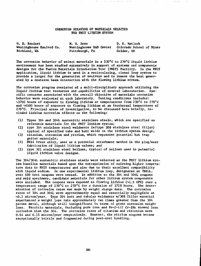
CORROSION BEHAVIOR OF MATERIALS SELECTEDFOR FMIT LITHIUM SYSTEM
6. D. Bazlnet M. G. Down D. K. MatlockWestinghouse Hanford Co. Westinghouse R&D Center Colorado School of MinesRichland, WA Pittsburgh, PA Golden, CO
The corrosion behavior of select materials in a 230°C to 27O°C liquid lithiumenvironment has been studied extensively in support of systems and componentsdesigns for the Fusion Materials Irradiation Test (FMIT) Facility. In the FMITapplication, liquid lithium is used in a recirculating, closed loop system toprovide a target for the generation of neutrons and to remove the heat gener-ated by a deuteron beam interaction with the flowing lithium stream.
The corrosion program consisted of a multi-disciplinary approach utilizing theliquid lithium test resources and capabilities of several laboratories. Spe-cific concerns associated with the overall objective of materials corrosionbehavior were evaluated at each laboratory. Testing conditions included:^3700 hours of exposure to flowing lithium at temperatures from 230°C to 270°Cand M>500 hours of exposure to flowing lithium at an isothermal temperature of270°C. Principal areas of investigation, to be discussed here briefly, in-cluded lithium corrosion effects on the following:
(1) Types 304 and 304L austenitic stainless steels, which are specified asreference materials for the FMIT lithium system;
(2) type 304 stainless steel weldments (w/type 308 stainless steel filler)typical of specified tube and butt welds in the lithium system design;
(3) titanium, zirconium and yttrium, which represent potential hot trapgetter materials;
(4) BN14 braze alloy, used as a potential attachment method in the plug/seatfabrication of liquid lithium valves; and
(5) type 321 stainless steel bellows, typical of bellows used in potentialliquid lithium valve designs.
The 304/304L austenitic stainless steels were selected as the FMIT lithium sys-tem baseline materials based upon the extrapolation of existing higher tempera-ture data to FMIT temperatures and also due to their excellent compatibilitywith liquid sodium. In one experimental lithium loop, designated as 7BELL,over 100 test coupons were tested. In addition to the 304 and 304L couponsand weld specimens, candidate materials for other lithium system componentswere included. The coupons were exposed to flowing lithium O1.5 GPM) over atemperature range of 230°C to 270°C for a duration of 3718 hours. The deter-mination of corrosion rates was made by weight change data. The corrosionrates of 304 and 304L were approximately equal and essentially negligible at^0.2 micron/year. Type 304 butt and tubular weldments w/308 filler materialexperienced a weight loss rate approximately two times greater than the 304parent metal, although still insignificant in terms of gross corrosion weightloss. Ferritic materials, including pure iron and Fe-2-1/2 Cr-lMo showed lesscorrosion than the 304. The corrosion rates of titanium and zirconium were0.04 and 0.25 micron/year respectively. However, the yttrium coupons becameexceptionally brittle and fragmented during post-test handling.
281

Subsequent analyses on the yttrium specimens disclosed that embrittlement wascaused by transformation of the specimens to yttrium dihidride (YH2). In aseparate laboratory, corrosion behavior of 304 and 304L materials was alsoevaluated after 4000 hours of lithium exposure using two independent experi-mental approaches; one using a lithium recirculation loop of 12 gallon capacitywith an isothermal test leg @ 270°C, while the other involved specimens at-tached to a rotating disc in static lithium in order to develop higher lithiumvelocities (up to 24 m/s) and evaluate the contributing effects of erosion ontotal material loss. The results in this testing substantiated those of the7BELL testing in that corrosion rates, as determined by weight change, were. less than 0.5 micron/year. Moreover, the results from the rotating discexperiment showed that although significant surface chemistry and topographi-cal changes were noted over the velocity regime studied, no evidence was foundto indicate attack by an erosive mechanism.
Another phase of the corrosion test program involved test activities conductedin a larger (1300 gallon capacity), recirculating lithium loop designated asthe experimental lithium system (ELS), and utilized primarily for FMIT compo-nents development. The ELS is a computer controlled lithium loop capable ofcontinuous, unattended operation, having operated isothermally at an averagemain loop temperature of 270cC for over 8000 hours. Metallographic examina-tion of several piping welds from a 4-inch, 304, U-bend piping section of theELS main lithium loop was completed to alleviate concerns of intergranularlithium attack in the heat affected zone (HAZ) of 304 weldments. After ^6500hours of isothermal (270°C) operation, there was no detectable evidence oflithium attack on any of the weldments examined.
A 304 SS valve body, w/Stellite 6B seat insert attached by brazing, was testedin the ELS to provide corrosion data. Testing of several coupons in the 7BELLtest loop discussed previously was inconclusive, however testing of the samebraze alloy in ELS for an equivalent lithium exposure (M000 hrs @ 270°C) dis-closed a very definite lithium attack ("v60 microns depth).
Destructive examination was performed on a 1-inch, 316 SS, valve after <v5800hours of exposure to 270°C lithium and 10,000 cycles of operation. This exam-ination showed no lithium attack on the 316 SS components (bellows, stem,adapter, valve body and seat) and the Stellite 6B plug insert, consistent withthe corrosion rate data on similar alloys from other testing.
Another separate test facility/program evaluated the fatigue resistance of type321 stainless steel bellows in static lithium at 270°C. Four seam-welded type321 SS bellows and four seamless type 321 SS bellows, typical of those used ina 1-inch valve, were tested. Two seam-welded bellows failed in the weld areaat ^5000 cycles in lithium, while two identical units tested in argon at thesame temperature and frequency showed no evidence of fatigue failure after5000 cycles. Additional cycling in argon to 12,500 cycles (@ 27O°C) was com-pleted without failure. Conversely, all four seamless bellows completedfatigue-cycling in lithium at 270°C (12,500 cycles) without failure or evidenceof fatigue damage.
The results and conclusions achieved by the various studies associated withcorrosion behavior of materials in a liquid lithium environment were signifi-cant in supporting the basic concerns and decisions regarding FMIT lithiumsystems and components designs.
282

THE FUSION MATERIALS IRRADIATION TEST (FMIT) FACILITY LITHIUM SYSTEM - ADESIGN AND DEVELOPMENT STATUS, P. J. Brackenbury, G. D. Bazinet, V. C.Miller, Westinghouse Hanford Company, Richland, WA. An update is providedon the status of the ongoing design and development applicable to the FusionMaterials Irradiation Test (FMIT) Facility lithium system since it was lastreported. W
The lithium system serving the FMIT facility will be, upon its completion, in1987, the largest lithium loop in the world. Acting as the terminus of thedeuteron beam from the FMIT accelerator, this system both carries away the3.5 MW of deposited beam energy and supports the proton stripping reactionproducing the intense, high energy neutron field for irradiation testing.
The design of the piping system is complete and has undergone a rigorous inter-nal review. As shown in Figure 1, it is comprised of a recirculating loopwith the heat deposited in the target region being rejected to a secondarycoolant in the lithium heat exchanger (LHX). The design duty factor stipu-lates that lithium flow to the target be maintained on an uninterrupted basisfor periods as long as 7000 hours, although 2000 hours will be more typical.
The heart of the system, the target, establishes a thin centrifugally pressur-ized jet of lithium for optimal interaction with the deuteron beam. The tar-get acts as the interface between the liquid metal environment of the lithiumsystem and the high.vacuum environment of the accelerator. Because of theintensity of the interaction between the beam and the lithium in the target,it has been the most rigorously analyzed and tested lithium component.^)Lithium testing of the first generation target design has been proceeding forover a year in the Experimental Lithium System (ELS).{3) The ELS MK II target,a second generation design incorporating the accumulated lessons of over threeyears of testing and analysis, is scheduled for completion in 1983 followed byinstallation and testing in ELS.
The design includes special features for remote operations once facility opera-tion commences. High gamma fields from activation products will accumulateafter the facility is operated and necessitate special features for remoteinspection, maintenance and repair of key components. In addition, specialsafety features have been incorporated to address unlikely events such as lith-ium or secondary coolant leaks inside the isolation of the lithium systemvault.
The LHX is a conventional two pass U-bend type with two special features. Toeliminate lithium (shell) side crevices, the tube-to-tubesheet joint is inter-nal bore welded to'spigots integral with the tubesheet. Also, the designaddresses the special requirements of remote access for maintenance and inspec-tion.
A prototypic-sized main electromagnetic pump, an annular linear induction type(ALIP), has been both designed and fabricated by HEDL personnel. Its fullscale predecessor has successfully operated in the ELS in excess of 10,000hours. The new pump is essentially identical to the EMIT pump. The smallerchemistry loop ALIP is designed and awaiting fabrication.
283
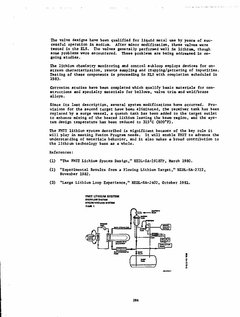
The valve designs have been qualified for liquid metal use by years of suc-cessful operation In sodium. After minor modification, these valves weretested in the ELS. The valves generally performed well in lithiua, thoughsome problems were encountered. These problems are being addressed in on-going studies.
The lithium chemistry monitoring and control subloop employs devices for on-stream characterization, remote sampling and trapping/gettering of impurities.Testing of these components is proceeding in ELS with completion scheduled in1983.
Corrosion studies have been completed which qualify basic materials for con-structions and specialty materials for bellows, valve trim and weld/brazealloys.
Since its last description, several system modifications have occurred. Pro-visions for the second target have been eliminated, the receiver tank has beenreplaced by a surge vessel, a quench tank has been added to the target outletto enhance mixing of the heated lithium leaving the beam region, and the sys-tem design temperature has been reduced to 315°C C600°F).
The FMIT lithium system described is significant because of the key role itwill play in meeting Fusion Program needs. It will enable FMIT to advance theunderstanding of materials behavior, and it also makes a broad contribution tothe lithium technology base as a whole.
References:
(1) "The FMIT Lithium System Design," HEDL-SA-1918FP, March 1980.
(2) "Experimental Results from a Flowing Lithium Target," HEDL-SA-2722,November 1982.
(3) "Large Lithium Loop Experience," HEDL-SA-2402, October 1981.
FMIT LITHIUM SYSTEMOVERFLOW SYSTEMARGON/VACUUM SYSTEMFIUK I
K
284

Session 4C-2
MATERIALS ENGINEERING(poster)
Chairman
D. Berwald, TRW, Inc.
Organizer
D.L. Smith, Argonne National Laboratory
Wednesday, April 27 2:30-5:00 p.m.

Session 4C-3
BLANKET AND FIRST WALL ENGINEERING(poster)
Chairman
J.R. Haines, McDonnell Douglas Astronautics Companv/
Organizer
P.H. Sager, GA Technologies, inc.
Wednesday, April 27 2:30-5:00 p.m.

Flow and Heat Transfer Characteristics in Lithium LoopUnder Transverse Magnetic Field
Keiji MIYAZAKI, Yoshio SHIMAKAWA, Shoji INOUE, Nobuo YAMAOKA and Yoichi FUJII-E
Department of Nuclear Engineering, Faculty of Engineering, Osaka UniversityYamadaoka 2-1, Suita-shi, Osaka, Japan 565-00
Abstract
In order to gain basic information on the MHD pressure drop and the MHD effect
on the heat transfer characteristics and to have experiences on handling and loop
operation of liquid lithium metal, a small-scale forced circulation loop of lithium
was constructed in the Nuclear Power Experimental Facilty of Osaka University. A
schematic diagram of the lithium loop is shown in Fig. 1. The loop and its
principal components are enclosed in the casing frame which is movable on the floor
coated with fringed steel plate, and provided with two parallel test sections: one
is for heat transfer experiment and the other for MHD pressure drop measurement.
Each test section can be fitted to the magnet by moving the frame of loop. The
maximum operating temperature is 600°C and the maximum flow velocity of lithium
is 5.0m/sec in the test section. The entire loop is contained in a steel plate case
filled with Ar gas, except for a cooler , a cold trap etc., for protection against
lithium fire in the event of leakage. The outlines of the principal components for
the the loop are as follows
Electromagnetic pump A.C. induction linear type, 40Vmin, 3bar rating.
Magnet D.C., Magnetic flux density: 2TPole faces: 150x500mm, interpole gap: 80mm.
Test section for heat 19.05mm O.D., 15.75mm I.D., 316-S.S. cui-atransfer experiment heater pin of 7.6mm O.D and 300mm heating length
heat flux: 250W/cm»-attached with 9 thermocouples of 0.5mm O.D.316-S.S. sheathed ungrounded junction type
Test section for MHD 19.05mm O.D., 15.75mm I.D., 316-S.S. tubepressure drop Attached with 2 strain gage type pressure transducers
for high temperature use
The experiment on the following subjects were conducted and the data are
now being arranged to obtain the general findings.
(1) Magnethydrodynamic effects on heat transfer characteristics
Heat transfer coefficient and flow velocity were measured as a function of
magnetic field strength B, to obtain the relation between Nusselt nad Reynolds
numbers with Hartmann number as parameter.
* Institute of Plasma Physics, Nagoya University, Furocho, Chikusaku, Nagoya, Japan
287

(2) Magnetohydrodynamic pressure drop; Measurement and analysis.
The exerimental conditions were
Magnetic field strength B= 0-1.0T
Lithium flow velocity u= 0.2-5.0m/sec
Heat flux g= 0 - 120W/an
Lithium temperature T= 350-400*C
As for the pressure drop, good agreements were obtained between the experimental
data and the theoretical prediction based on the uniform velocity model.
The heat transfer was decreased with increasing the magnetic field strength, but
not monotonically in a weak magnetic field region of 0.1-0.4T where a singular
phenomenon was observed.
Buffer tank
To vac.pump
n StorageJ tank
Fig. 1 Lithium circulation loop
288

MIRROR ADVANCED REACTOR STUDY (MARS) SOLID BREEDER BLANKET AND POWERCONVERSION SYSTEM
R. Bullis, I. Clarkson, L. Deutsch, R. Micich, M. Rossi, M. Stauber, F. SuhGrumnan Aerospace Corporation
The MARS project has the objective of designing a commercial Fusion PowerReactor based on the Tandem Mirror concept. As such, it must include a blanketcapable of converting the captured fusion neutrons into thermal energy whilesimultaneously breeding tritium.
Since many breeding blanket concepts exist and it was not clear that anyparticulat design had superiority over all others, it was decided to studyseveral blanket designs. This paper describes one of those designs; in-corporating a solid breeding material , lithium oxide (L12O), cooled byhelium which, in turn, powers a conventional steam-electric generating cycle.
The breeding blanket assembly consists of the first wall, blanket and shield,which surrounds the 150 meter long central cell of the reactor and accepts a5 MW/M2 neutron wall loading. The blanket/shield must protect the central cellcoils from radiation and heating as well as providing protection to the sur-roundings .
Maintenance and fabricability considerations led to the selection of a sixmeter long modular configuration (see Figure 1) incorporating two magnets, ashield assembly and a blanket assembly with associated support structure.Each module weighs 781 tons and can be installed and removed from the reactoras a unit.
The primary structure of the module which forms the pressure vessel and supportstructure is ferritic steel. The breeding material (Li20) is contained inbundles of thin wall tubes arranged parallel to the plasma axis. These tubes,along with their support structure, must endure temperatures of up to 700°Cand this led to selecting a vanadium alloy for this service.
The entire breeding portion of the blanket is cooled wi.h helium. The gas,at a pressure of 30 ATM,, is distributed in circumferential passages in thefirst wall. From there it bleeds into the breeding zone and flows over theLi£0 bundles. Bred tritium migrating from the breeder rods enters the gasstream at this point and is processed out in a slip stream outside of theblanket. A separate water circuit cools the shield.
The neutronics analyses utilized the one-dimensional discrete ordinate codeANISN, with a 100 neutron/21 gamma group structure and the cross sectionlibrary EPR, and were conducted in the P3S8 approximation for cylindricalgeometry.
A number of parametric variations in factors affecting the neutronics per-formance were explored. These included breeding material selection (L12O vs.Li^Pb2), blanket thickness, Li-6 enrichment, the use of a reflector (steel,SiC or graphite), and of a beryllium multiplier for Li20 blankets. In general,it was found that the blankets would have to be over a meter thick to avoidsignificant energy leakage into the shield. The effects of Li-6 enrichmentwas complex but minor and reflectors showed no advantage in their use.
239

Beryllium multipliers has a profound effect, achieving breeding ratios as highas 2.0, but were not incorporated in the design due to resource limitations.The selection of I^O over Li7Pb2 as a breeding material was made due to aslightly higher sintering temperature limit, however, Li7Pb2 remains as a strongalternative. The selected configuration had a predicted tritium breeding ratioof 1.25 and an energy multiplication of 1.1.
The thermal/hydraulics analysis was based on cooling the first wall and breedingzones with a series flow of helium and to keep the HT-9 portions of the structureunder about 500°C, while maintaining the L12O in a temperature band of 410° -700°C and still supplying the highest possible temperature to the power cycle.To balance the exponential variation in heat deposition with depth in the blanketand maintain a uniform breeding material temperature a gradation in breedingrod diameters was incorporated. The coolant inlet temperature was set at 300°Cand the outlet temperature was 630°C. A pressure drop analysis indicated that264 MW of power would be required to pump the helium (8.6Z of the blanketthermal power). The high temperature helium flows to the power conversionsystem where it produces superheated steam in a double wall heat exchangerto prevent tritium permeation into the steam system. Since the steam temper-ature produced is very close to that obtained in present-day fossil steamplants, a state-of-the-art regenerative reheat steam cycle was selected witha gross cycle efficiency of 42.5X.
This study has demonstrated the feasibility of providing a gas cooled solidbreeding blanket for a tandem mirror reactor with a high neutron wall loading,with only a modest advance in present technology.
HA6NET
SHIELD
FIGURE 1
Solid Breeder
Blanket Module
VANADIUMALLOY TUBESWITH LITHIUHOXIDE PELLETS
HELIUM COOLANT
rawsSOLID BREEDER
BLANKET
290

FELIX CONSTRUCTION AND EXPERIMENTAL PROGRAM
L. R. Turner, W. F. Praeg, M. J. Knott, R. J. Lari and R. B. WehrleArgonne National Laboratory
FELIX (Fusion JJLectroraagnetic _Induction experiment) is an experimental testfacility being constructed at Argonne National Laboratory (ANL) for the studyof electromagnetic effects in the first wall/blanket/shield (FW/B/S) systemsof fusion reactors. The FELIX program is part of the FW/B/S EngineeringTechnology P'rogram, administered by ANL. This paper reports on theconstruction of FELIX, which will soon be complete, and the program ofupcoming experiments.
FELIX will provide a steady horizontal magnetic field of 1.0 T and a pulsedvertical field of 0.5 T over an experimental volume of 0.76 m . The pulsedfield decays at rates up to 50 T/s. Several aspects of the FELIX facility arenow different from the preliminary design.[1] Coil reoptimization has reducedthe size of the coils and has reduced the energy stored in the solenoid anddipole fields by 36% and 32%, respectively. The six large solenoid coils havebeen replaced by 24 two-layer pancake coils. The cross section of the dipolecoils has been reduced by 25%. Axial tie rods across the coils and spacersare prestressed to withstand the internal forces and moments from the coilreactions. FELIX now has two support pillars instead of four to give greaterexperimental access at a reduced cost. Highlights of the construction,including developments in coil winding techniques which should be of generalinterest, will be discussed in the paper.
The first series of experiments to be performed when the facility is completedwill study eddy-current effects in flat plates. These two-dimensional (2D)geometries will be the easiest to instrument and record data from and theeasiest to simulate with computer codes. Some of the objectives of the 2Dexperiments will be to study the 2D eddy-current pattern and the resultingfields, forces, torques, stresses, and heating; to study the perturbingeffects of slits, holes, and other geometrical features; and to evaluate 2Dcodes.
The test piece consists of a rectangular aluminum plate 1 m by 0.8 m and 1 cmthick, perpendicular to the dipole field.
To determine field distortion by the eddy currents, field probes will beplaced at several points on and around the plate. Also, pairs of search coilswill be placed above and below the plates to measure the value of the localcurrent density. Current patterns also can be inferred from measurements oftemperature rise; such measurements can be nade globally with infrared viewingand locally with thermistors.
The currents, fields, temperatures, forces, and torques to be effected in theplate have been computed with the code EDDYNET. In the uniform magneticfields, there is no net magnetic force, but a net torque peaking at 76 kNm and15 ms is predicted for pulsed and steady fields of 0.5 T and 1.0 T,respectively. In carrying out the experiment, a solenoid field much less than1.0 T will be used to make the torque more manageable; the full solenoid fieldwill be needed in later experiments with smaller or segmented test pieces.
291

Contour plots of temperature rise in the plate as a function of tine were alsocalculated with EDDYNET for several different tines. At all tines, thehighest temperature is in the center of the long edge; the peak temperature is5.1°G above ambient and occurs 140 ms after the start of the pulse.
After the plate experiments (including the effect of holes and slits in theplate) are completed, subsequent experiments will deal with three-dimensional(3D) geometrical effects. Test pieces will include a hollow conductingcylinder and an array of conducting bricks. The effects of segmentation andthe separation between segments will be studied. The goals of the 3Dexperiments will be to study the eddy-current shielding by continuous and slithollow cylinders; to study the current patterns, heating, and forces in suchcylinders and bricks; and to evaluate 30 codes.
Later experiments will include component concepts, component models, and,finally, component prototypes. Other studies may deal with arcing, electricalcontacts between FW/B/S sectors, and melt layer behavior.
As a typical test piece will experience no net force and a net torque onlyabout an axis perpendicular to both the dipole and solenoid fields, the testpieces will be supported on non-metallic tubes along that axis. The tubeswill pass through two horizontal holes in the facility. Torques are measuredby strain gauges on the tube, located outside the high magnetic fields. Thedynamic response of the support must be known and must be flat for thefrequency range of interest.
In selecting instrumentation for FELIX, many sensor types have been evaluated;the types and quantities needed for the first FELIX experiment are beingchosen. The harsh electrical and magnetic environment of FELIX presents atest bed for the sensors themselves as well as for the electromagneticeffects.
The measurement of mechanical strain in the FELIX environment appears torepresent the most severe instrumentation problem area of the project.Several different phenomena have been used to translate strain into a usablesignal; several of these were studied for FELIX. Both local temperatures andoverall temperature patterns are to be measured in the FELIX experiments usingthermistors and infrared imaging. Magnetic currents produced by eddy currentswill be measured with both search coils and Hall probes.
FELIX construction soon will be complete, and testing of the components forthe experimental program will begin at that tlrae.
References
[11 W. F. Praeg, et al., "FELIX: An Experimental Facility to StudyElectromagnetic Effects for FW/B/S Systems," Proc. 9th Symposium onEngineering Problems of Fusion Research, Chicago (1981), pp. 1763-1766.
*Work supported by the U. S. Department of Energy.
292

MECHANICAL AND THERMAL DESIGN ASPECTS OF THE BLANKET,AND MAINTENANCE CONSIDERATIONS OF THE CENTRAL CELL IN MARS
Y.T. Li, D.K. Sze and I.N. SviatoslavskyFusion Engineering Program
Nuclear Engineering DepartmentUniversity of Wisconsin
MARS is a conceptual design of a tandem mirror fusion power reactor. Aprimary objective of the blanket design is to take maximum advantage ofthe linear geometry of the tandem mirror in order to achieve astraightforward maintenance approach which can be performed rapidly byremote control. This paper briefy describes the mechanical and thermalblanket design aspects, then addresses the maintenance concept of thecentral cell.
Figure 1 shows a cross section of the central cell which is a linearcylinder ~ 150 m long in which most of the energy is produced. In thisdesign the blanket structure is HT-9 and the breeding material isLi1yPbg3. The breeding material is fed at 330°C through a supply header,is distributed axially in the upper manifold, then flows through tubularand rectangular section beams to the lower manifold, finally exiting at500°C through a discharge header. The blanket is divided axially intomodules which have individual supply and discharge headers. A gap isprovided between the blanket modules and the reflector to allow axialtranslation of the modules within the central cell. There are no sealsbetween adjacent blanket modules, instead a vacuum barrier is provided atthe reflector boundary along the whole central cell. The modules aresupported on rails attached to the reflector with the load path goingthrough the shield to the floor supports.
The motion of a liquid metal perpendicular to a strong magnetic field ischaracterized by laminar flow with a constant velocity profile and a verythin boundary layer. Heat transfer in such a system is dominated byconduction. The temperature distribution in the blanket tubes can becalculated by solving a set of finite difference equations. For thisdesign, the maximum structural temperature is 550°C.
The MHD pressure drop through each blanket section is the sum of theHartman and the end of the loop pressure drops. This pressure drop isdetermined to be 1.32 MPa, which corresponds to a pumping power of 40 MWfor the whole central cell, if a 50% efficiency is assumed. The maximumpressure in the blanket is only 0.9 MPa.
The maintenance philosophy is to achieve a high reactor availability byminimizing the downtime due to routine blanket changeout. Becausemaintenance will be performed remotely, this concept avoids welding orcutting of headers, reflector or shield segments and requires no axialtranslation of central cell coils.
Access to the blanket is provided through twelve so called servicestations as shown in Fig. 2. These stations are equipped with a
293

removable supply header, vacuum lid and an upper reflector/shieldsegment. Each station is capable of servicing seven blanket modules, theone Immediately below and three on either side. Once the supply anddischarge headers are disconnected, blanket modules are translatedaxially to the service station, then lifted out vertically by an overheadcrane. The axial length of the blanket modules was determined by takinginto account the space between central cell coils and the size andlocation of the breeding material headers which -jo through this space.Advantage is taken of the excellent soldering capability of Lij^Pbg^ todesign truly simple remotely maintainable header connections.
Unexpected maintenance of other central cell components such as thecoils, shield and reflector segments is also addressed.
Figure 1 CENTRAL CELL
1°Jim
mLJ
uju
o
5
294

TPE-II SCOPING TEST RESULTS: SOLID BREEDER HEAT TRANSFER AND STABILITY*
A. R. Veca, L. Yang, K. R. Schultz, and C. P. C. WongGeneral Atomic Company
P.O. Box 81608, San Diego, California 92138
Program Element II (PE-II) of the First Wall Blanket Shield (FWBS) Programis directed toward developing a thermomechanical and thermal-hydraulicengineering data base for blanket and shield components of magnetic fusionreactors. During Phase 0 of TPE-II, the critical blanket/shield data needswere identified, simulation techniques were investigated, and a DetailedTechnical Plan written for tests to be done as part of Phase 1. A seriesof single effects scoping tests was defined, aimed at investigating theprimary data needs of the blanket and shields. One of the fundamental dataneeds is to develop an understanding :>f the thermomechanical behavior of asolid breeder blanket. A second data need which requires early investiga-tion is to determine the heat transfer characteristics at the interfacebetween the solid breeder pellet and the 316SS coolant tubes. This infor-mation is required in order to assure that the narrow operating temperaturerange of 410° to 660°C in the Li20 breeder material is achievable. Thispaper reviews the designs of the two scoping experiments which addressthese needs and the results from the initial tests.
Heat Transfer Scoping Test
This test investigates the effect of temperature, gap size, and contactpressure on the thermal conductivity across the gap (gap conductance)between the Li20 solid breeder material and the 316SS coolant tube. Aresistance to heat flow exists at this interface which arises because of theimperfections of the mating surfaces causing uneven contact. This "gap con-ductance" is dependent upon gap/pressure between solid materials, surfacefinish of the materials, contact temperature, and composition of the gasat the interface.
The general arrangement drawing of the heat transfer scoping test is shownin Figure 1. The drawing is a schematic of the major components and theirrelative position with respect to each other. This drawing also shows thelocations of the various instrumentation used to monitor the testvariables.
Two types of tests were run for the initial testing phase. The firstconsisted of the condition where various sized gaps exist between thebreeder material and the stainless steel and the second is the conditionwhere known contact pressures exist between the breeder and the stainlesssteel. Correlations were developed based on the temperature readings takenduring the tests and are reviewed in this paper.
*Work supported by U.S. Department of Energy, Office of Fusion Energy undersubcontract 31-109-38-6430 from Argonne National Laboratory.
295

Purge Flow Scoping Test
A series of three 1000 hr tests are to be perforned at different tempera-tures to investigate the effect on the physical characteristics of U.2Obreeder pellets of time at temperature in a simulation fusion reactor blan-ket environment with a helium purge flow. The effects of concern are sin-tering, thermomechanical racheting or cracking, vapor phase transport in thepurge flow stream, and interaction between the Li20 and its container.
The general arrangement drawing of the Purge Flow Scoping Test is shown inFigure 2. The initial test consisted of a 1000 hr test on Li20 pelletswhich were pressed and sintered to a theoretical density of 75 ± 1%. Thetest temperature was 800°C. Ten thermal cycles from 800°C to room tem-perature were performed at various times during the test duration.
After the completion of the test, the H2O pellets were examined forphysical integrity and cracks and weighed to determine the loss of materialsdue to the flow of the purge gas. The microstructures of two pellets wereexamined for any cracks and changes in grain size and pore distribution dueto material transport. The stainless steel containment was examined for anyreaction with L^O in the hot zone and any condensation of materials in thecold zone. Details are reported in the paper.
r«i wt*m**m
296

FWBS PROGRAM ELEMENT II: BLANKET AND SHIELD TESTING*
X.R. Schultz and A.R. Veca, General Atomic Conpany, San Diego, CAG.A. Dels and P.Y.S. Hsu, EG&G, Idaho,, Idaho Falls, ID
R.E. Nygren and H. Hernan, Argonne National Laboratory, Argonne, IL
The First Wall/Blanket/Shield (FWBS) Engineering Technology Prograa, led byArgonne National Laboratory, has the goal to provide the engineering develop-ment and component testing required to design and construct functional, reli-able, maintainable, and environmentally acceptable FW3S systems for magneticfusion reactors. Program Element II (PE-II) of this program is to develop thethermal-hydraulic and thenaomechanical engineering data base for blanket andshield components. During Phase 0 of PE-II, the critical blanket/shield dataneeds were identified, alternate techniques to simulate fusion neutron bulkheating were evaluated, and a detailed technical plan was developed for teststhat are now being carried out as part of PE-II Phase 1.
The data needs assessment was performed to determine the critical data neededto proceed with concept feasibility assessment, concept selection and designof fusion reactor blankets and shields** Two broad categories of testingneeds were found, the first concerned with basic concept feasibility evalua-tion that must be investigated as early as possible to allow decisions andselections to be made, the second concerned with design verification. Thedata needs of solid breeder blankets were identified as the most critical toconcept evaluation and were prioritized for early investigation:
Solid Breeder Blanket Prioritized Data Needs
Thermal-Hydraulic Data:• Thermal contact resistance• Heat transfer behavior changes with -Ime and temperature• Effective thermal conductivity• Purge flow characteristics
Thermomechanical Data:• Thermal stresses• Thermal sintering, creep, ratcheting
An evaluation and comparison of alternative techniques to simulate fusionneutron bulk heating effects was carried out.2 Included in this evaluationwere discrete source heating, direct resistance heating, induction heating,microwave heating, and nuclear heating. It was found that the material elec-trical and thermal conductivities are most significant In determining whichnon-nuclear simulation can be useful in a given saterial. For non-nuclearthermal-hydraulic tests, dlscrete-aource electrical resistance heating wasfound to be the most effective. For non-nuclear thermomechanical tests,direct resistance heating Is the first choice for conductive materials,microwave heating for nonconductive materials, and discrete source heating
*Work supported by the U.S. Department of Energy under subcontract fromArgonne National Laboratory.
297

for testa containing both materials. Non-nuclear simulation techniques werefound to have significant limitations in simulation of fusion neutron bulkheating. Fission nuclear testing can effectively sinulate fusion heating andis recommended for inclusion in the blanket/shield testing plans.
A detailed technical plan was developed to guide the PE-IZ testing program.3The initial focus is on the critical engineering feasibility issues of solidbreeder blankets. Three experiments are currently in progress, two singleeffect scoping tests* to determine the heat transfer characteristics and ther-momechanical stability of the solid breeder bed and an integral test5 to simu-late all the non-nuclear aspects of the blanket. The heat transfer character-istic test is investigating the effects of gaps and/or contact at thebreeder/coolant tube interface. The breeder bed stability test has beendesigned to investigate the effect of tiae at temperature in a purge flowenvironment upon the solid breeder. The objective of the integral simulationtest is to investigate the combined thenaal-hydraulic and theraomechanicalcharacteristics of the solid breeder blanket. These tests will allow assess-ment of the engineering feasibility of the non-nuclear aspects of solidbreeder blankets. Future PE-II testing will investigate alternate solidbreeder blanket materials and configurations and flow testing will also beInitiated. The non-nuclear integral tests could lead to fission reactor in-pile nuclear testing of similar configurations, allowing very realistic simu-lation of fusion neutron bulk heating and evaluation of the effects ofcritical nuclear phenomena.
Tie critical thermal-hydraulic Issues of using liquid metal blanketconcepts in a magnetic field will also be evaluated in the future, includingturbulence suppression heat transfer effects and the thermal hydraulic effectsof flow of liquid metals through realistic fusion blanket geometries in amagnetic field."
In conclusion, a program is now under way to provide the data base for thedesign, evaluation, selection and qualification of blanket and shield systemsfor fusion reactors. PE-II will allow near-term progress to be made on theengineering design of fusion blankets and shield and assist in the focusing ofresources on the most promising approaches.
References1. Veca, A. R., E. Hoffmann and C. P. C. Hong, "TPE-II Data Needs
Assessment Report," General Atomic Company Report GA-A16693, April1982.
2. Deis, G. A., et al., "Evaluation of Alternative Methods of SimulatingAsymmetric Bulk Heating in Fusion Reactor Blanket/Shield Components,"EG&G, Idaho Report EGG-FT-5603, October 1981.
3. Veca, A. R., et. al., and G. A. Deis, et al., "Detailed Technical Planfor Phase I of TPE-II," Joint General Atomic Co. and EG&G, Idaho ReportGA-A16725, April 1982.
4. Veca, A. R., et al., "PE-II Scoping Test Results: Solid Breeder HeatTransfer and Stability," this conference.
5. Deis, G. A., "Pretest Analysis of the Solid Breeder Integral SimulationTest for PE-II," this conference.
298

LIMITS ON TRANSIENT POWER VARIATIONS DURING STARTUP AND SHUTDOWN OF Li-PbCOOLED TMR BLANKETS, N. Ghoniem, K. Taghavi-Tafreshi, .1. Blanchard, and S.flrotz, Fusion Physics and Engineering Program, School of Engineering andApplied Science, University of California at Los Angeles. The design andsafe operation of power plants are well recognized to be affected by start-up and shutdown considerations. In a fusion power plant, one of the mostsensitive components during transient power variation is its blanket. Thepurpose of this work is to establish the limits on transient power changes
. for the safe operation of Li-Pb cooled TMR blanket modules. In particular,our analysis considers the MARS Li-Pb cooled power blanket described indetail elsewhere [1], The blanket modules are constituted of banks of thintoroidal tubes encircling the plasma and made of HT-9, a martensitic steelalloy.
Our study considers the following conditions:
(a) Thermal shock analysis of tube material upon flooding with hotLiPb in an initial startup;
(b) Determination of the conditions leading to freezing or blockageof tubes during initial flooding;
(c) Establishment of pre-heating requirements for Li-Pb cooled blan-kets.
The largest thermal shock is predicted to occur at the tub*, entrance wherean initially cold tube will be suddently exposed to hot coolant from in-side. Transient temperature distributions throuah the tube wall are ob-tained analytically by solving the time-dependent heat equation. The cal-culations are applied to a wide range of conditions for different tubethicknesses and other alloy systems. The thermal stress history of thepipe wall is subsequently determined with the use of plate theory. The in-stantaneous additional axial and hoop stresses are given by:
o (x) = a (x) = _§*!_ (T-T(x)]Z y (
1 h
T = I / T(x)dxh o
where, T = temperature difference from zero stress conditionh = pipe thickness
Fin. (D shows the results of sample calculations for HT-9, where thethermal stress is plotted as a function of time for various tube thickness-es. It is shown that on the coolant side of the tube, the compressivestress exceeds the yield strength of the material. This leads to plasticdeformation and strain ratcheting over several cycles. Fatigue failure ispredicted for the severe conditions investigated in this example. Anotherpossible failure mode is the propagation of small cracks through the wail.If the crack propagation is faster than the rate of stress relaxation, thestructure is likely to fail. Crack growth rates are determined for thefollowing parameter variations:
299

1. Different tube thicknesses;2. Different pre-heating conditions;3. As a function of irradiation time, for changing material proper-
ties.
Calculations are performed for the determination of possible hot Li-Pbfreezing upon initial flooding of HT-9 tubes of lower temperature. For theextreme conditions of cold module tubes (room temperature), a hot Li-Pbcoolarit is predicted to partially freeze. Following Ozisk and Hulligan'swork [2], where the inner wall temperature is assumed to be constant, thefollowing preliminary conclusions are determined:
i) At x = 15 cm along the tube, the steady-state blockage is 30%after a time period of 10-60 seconds;
ii) At x - 280 cm along the tube (tube exit), the steady-state block-age is 80% after a time period of 60-300 seconds.
The calculations of initial flooding of cold HT-9 tubes indicate that twoproblems may arise: (1) structural failure due to thermal shock; (2) pos-sible freezing of the Li-Pb coolant. These conclusions emphasize the nec-essity of blanket preheating. In this respect, two preheating methods areconsidered:
(1) Resistive or inductive electrical preheating;(2) Hot helium qas preheating.
The study will demonstrate the limits on tube preheating with the twomethods. Finally, recommended rates of power variations will be establish-ed for the MARS power blanket modules.
STRESS IN A PIPE WALL AFTER A STEP CHANQE
IN THE TEMPERATURE OF ONE SURFACE
->80
•Work supported by USDOE.
ReferencesIT) MARS Review Meeting at LLNL, April 27-28, 1982, TRW Publication, TRW-
MARS-82-050.[2] Ozisik, M.N. and Mulligan, 3.C., "Transient Freezing of Liquids in
Forced Flow Inside Circular Tubes," Journal of heat Transfer, Vol. 91,1969, p. 385-390.
300

EMERGENCY COOLING OF THE MARS LiPb BLANKET
D.K. SzeA. White
University of WisconsinNuclear Engineering DepartmentMadison, Wisconsin 53706
The thermal response and cooling requirement of the MARS LiPb blanket dueto the afterheat, loss of coolant and loss of flow are reported here.Ths affects of the accident, if proper cooling is not available, is alsodiscussed. The most critical accident may occur is the loss of coolantwhile the plasma is still on. The first wall will suffer permanentdamage in ten seconds, and it will melt in ~ 35 seconds.
The afterheat is calculated by ANISN and DKR codes. A forward 25 neutron21 gamma group ANISN run was done in order to obtain the steady stateflux throughout the blanket and shield region. This output was then fedinto the DKR program. This produced a delayed gamma source spectrum andalso gave the total beta heat produced in each zone. The gamma sourcewas then fed back into the ANISN program and a forward 21 group gammatransport problem was run. In this calculation, activation crosssections were used to determine the heat deposition in each region, andin each material. This calculation was performed for each after shutdowntime and was performed for both the case of the LiPb remaining in thereactor and the case of LiPb drained from the blanket. In all, a totalof JL2_ ANISN runs were made. Finally, the beta heat from the DKR and thegamma heat from ANISN were summed up to give the total afterheat in eachzone. The results of these calculations are given inFig. 1.
It should be noticed the very high afterheat in the reflector atshutdown. This is due to the 56Mn in Fe-1422. The half life of 56Mn is2.6 hrs and, therefore, the afterheat of the reflector decays rapidly inthe first day. After one day, the reflector can be used as the heat sinkfor radiation cooling of the blanket. The blanket needs active coolingfor the first day. It can be cooled effectively after that and maximumtemperatures due to afterheat may reach 390°C.
The temperature responses of the first wall due to loss of flow and lossof coolant accident are calculated and shown in Fig. 2. The rate of thefirst wall temperature rises are very similar in the two cases. Thereason for this unexpected result is due to the much higher volumetricheat capacity for steel Cp =3.6 J/cm -^C) than for theLil7Pb83 (pc * 1*5 J/cm -^8). Therefore, in the loss of flow accidentcase, the temperature rise of the kijjPbgj * s actually faster than thestructural although the volumetric heating rate is less. The coolantwill heat up the first wall and, consequently, the first wall is heatedup faster than the loss of coolant accident case. As time reaches ~ 20seconds, the Lij^Pbgo further away from the first wall and, consequently,with a much lower volumetric heating, start to cool the first wall byconduction. This explains the cross over point of the two temperature
301

response curves.
If loss of flow or loss of coolant occurs, the blanket will sufferpermanent damage if the plasma is on for ten seconds. If the plasma isnot stopped in ~ 35 seconds, the first wall will melt.
In a liquid metal flow system, a surge tank is always provided tomaintain a free surface. The Li,yPbgo in the surge tank can be used asthe emergency coolant by using gravitational force to pump. A coolantvelocity of 7 cm/sec can be reached by using the gravitational head. Thetemperature response of the first wall is shown in Fig. 3 and will reacha maximum of 800°C in ~ 30 sec. The coolant flow rate required is 5m /sec for the entire reactor. The total emergency cooling time providedhas to be optimized between surge tank cost and accident detection time.
Acknowledgement
This work is supported by DOE. The work by Gail Herrington in preparingthe manuscript is much appreciated.
O 400 -
1
0
io - '
o-*
0-3
o-*
io-»
10"*
V*
io-«
lr
\
-
-
-
1 * , ..»1 1
\^ * .
v
t (
Iffi l y r1 t
\ \
Shitld\
I I
lOyrsi i
-
V'Blonlitt\
\
y— -
300 -
IE
-I
<
su.
200 -
0 10 20 30TIME AFTER ACCIDENT OCCURS. Jtc.Figure 2 Temperature response
of the f irs t vail
1 10 K)2 10* 10* 10* 10*TIME AFTER REACTOR SHUT0OWN.hr
Afttr h*ot in different region with L | 7Pb,3
Figure 1
"0 » 20 SO
TIME AFTER ACC10ENT OCCURS, i tc.
Figure 3 Teaperaturc responseof the first wall withgravitational coolant flow
302

THERMOMECHANICAL TESTING OF FIRST WALL TEST PIECES IN ESURF
J. R. Easoz, J. W. H. Chi, R. Bajaj, M. D. Nahemow, and R. E. GoldWestinghouse Electric CorporationMadison, Fennsulvania 15663
This paper reports work performed under Test Program Element I (TPE-I) ofthe First Wall/Blanket/Shield Engineering Technology Program (FW/B/S ETP).*The principal objective of the engineering testing of first vail designconcepts is to support the design of generic fusion reactor first vails andthe verification of analytical techniques and design tools. Westinghousehas designed and built two test facilities for use in TPE-I: the ElectronBeam SURface Heating Facility (ESURF) and the Large Area SURface HeatingFacility (ASURF). This paper describes the vork performed to date In theESUKF, while a companion paper describes ASURF and the ASURF test program.
ESURF consists of a point source, 50 kW electron beam (mounted on top of avacuum chamber) and a 1000 psia vater loop for active cooling of testpieces. Long pulse ''steady state" surface heat loads are simulated byrastering the beam in two dimensions, while disruption heat loads are simu-lated by imposing a defocused, stationary beam for a fixed length of timeon the target area. Initial test pieces consist of stainless steel (type316) tubes and stainless steel (type 316) flat plate panels. Preliminarytests have included steady state heating cycles (up to 500), disruptionheat load simulations and combined disruption and steady state heat loadswith low numbers of cycles. The purpose of these tests is to study theeffect of disruption heat loads on surface melting and crack formation, andthe effect of thermal stresses on crack formation/propagation.
Surface melt phenomena were studied by SEM and metallographic evaluationsof transverse sections of the resolidified material. The preliminary testresults showed that the molten material tends to buildup above the orig-inal surface (reinforcement). At a high steady state heat load of 1 MW/m^,large cracks were found in the resolidified material. Cracks covering oneto two grain boundaries were also found in the substrate below the melt-solid interface. With 500 steady state cycles and no disruption simu-lations, photomicrographs showed precipitation near the surface where thetemperature is the highest. Analyses of the fracture mechanics show thatunder the same test conditions, cracks caused by disruptions may propagatein relatively low numbers of thermal cycles.
Comparison of the depth of melt penetrations measured with those predictedby a computer analysis shoved reasonably good agreement for the limiteddata obtained to date. The melt phenomena observed are similar to thosefound in electron beam welding. The basic difference is the much higherthermal stresses encountered in these tests as a result of active coolingof the test piece. Thus surface melting as a result of disruption heatloads can introduce surface cracks as the melt resolidifir .. The degree ofpropagation of such cracks by a large number of cycles needs to be testedto confirm the analytical predictions.
*This program is sponsored by the Department of Energy, Office of FusionEnergy under Contract 31-109-6427. The program is managed by the Manage-ment Technical Coordinating Center - Argonne National Laboratory.

Session 4C-4
NEUTRONICS AND SHIELDING(poster)
Chairman
D. Dudziak, Los Alamos Nationa! Laboratory
Organizer
M.A. Abdou, Argonne Nationa! Laboratory
Wednesday, April 27 2:30-5:00 p.m.

LARGE AREA SURFACE HEATING FACILITY (ASURF)AND TEST PROGRAM FOR FIRST WALL DESIGN CONCEPTS
H. D. Michael, J. Lempert, J. W. H. Chi, and R. P. RoseWestinghouse Electric Corporation
Advanced Reactors DivisionMadison, Pennsylvania 15663
The Large Area Surface Heating Facility (ASURF) is one of two test facil-ities at the Westinghouse Electric Corporation dedicated to Test ProgramElement I (TPE-I) of the First Wall/Blanket/Shield Engineering TechnologyProgram (FW/B/S ETPf. This paper describes ASURF, its capabilities andthe near-term test program.
ASURF is located at the Waltz Mill test site of the Westinghouse ElectricCorporation. It consists of a vacuum chamber (1.83 m in diameter and 2.44 min length) and a low voltage (16 kV), 100 kW distributed electron beam(linear gun) heat source system. It is planned to upgrade the heat sourceto 400 kW and then to 1 MW. The facility incorporates an existing highpressure water loop (2200 psia and 300°C max) and a cooling tower that iscapable of rejecting 2 MW of heat. The vacuum system, consisting of aVarian 18 inch vacuum pusro with a two-stage forepump, is capable ofachieving and maintaining an internal vacuum pressure less than 10~5 torr.The present ASURF capabilities and planned upgrades are shown in the tablebelow.
Specifications for ASURF and ASURF Upgrades
Total Heat Source PowerCapability
Steady State Heat Flux, 0.2-1.0MW/m2
Test Piece Target Area
Disruption Target Area,cm2
Coolant Flowrate 30 gpm 60 gpm 60 gpm
The low voltage e-beam has a number of advantages including high cathodelife. This and the corresponding high availability of the facility pro-vides the important capability for high cycle (>103 cycles) thermal fatiguetests. Both the test pieces and the linear e-beam gun will be mountedvertically. This target orientation permits the testing of orientation-sensitive first wall design issues such as the effect of dead weightstresses on large first wall panels and their attachments.
ASURF100 kW
0.2-1.0
1000 cm2
10
FacilityASURF-1400 kW
0.2-1.0
4000 cm2
10 or 100
ASURF-21 MW
0.2-1.
lm2
10 or
.0
100
*This program is sponsored by the Department of Energy, Office of FusionEnergy under Contract 31-109-6427. The program is managed by the Manage-ment Technical Coordinating Center - Argonne National Laboratory.
305

The line source consists of a tungsten filament mounted between twoparallel electrode structures. The cup-shaped cathode produces a con-verging electric field which reduces the width of the rectangular-shapedbean as it leaves the cathode and is accelerated through a slit in theaccelerating anode. After the beam traverses the anode slit, it is de-flected periodically to increase the effective width of the target areaand the uniformity of the power deposited. Because of the relativelylong time between plasma disruption events and the high energy densitiesdesired, a condenser discharge is being designed to simulate disruptionheat loads.
Near-term test plans include the testing of a stainless steel, 3-tubepanel, a stainless steel flat plate panel, and a graphite armor tile.The purpose of these tests is to study the effects of a large number oflong pulse ("steady state") thermal cycles on crack propagation andthermal fatigue. Future plans include boiling and burnout studies forasymmetrically heated first wall coolant channels under high temperaturesand high pressures.
306

PRE-T-EST ANALYSIS OF THE SOLID BREEDER INTEGRAL SIMULATION TEST FOR PE-II*
G. A. DeisEG&G Idaho, Inc.
Introduction
Program Element-II (PE-II) of the Office of Fusion Energy/Argonne NationalLaboratory First Wall/Blanket/Shield Engineering Technology Program addressesthermal-hydraulic and thermomechanical testing of blanket/shield assemblies.The PE-II Solid Breeder Integral Simulation Test is an experiment to be conductedduring 1983 to examine the thermal-hydraulic/thermomechanical operationalcharacteristics of a water-cooled solid breeder blanket concept. This paperpresents results of the pre-test analyses performed to develop the test piecedesign and predict the operational characteristics of this experiment.
Summary
The Solid Breeder Concept Integral Simulation Test is the third experiment tobe undertaken in PS-II.1 Two previous scoping tests have examined gap conductancefrom breeder material to coolant tube, and the stability of the breeder materialunder long-term high temperature operation.^ The Integral Test will employ atest piece and operating conditions prototypical of an actual water-cooledsolid breeder blanket concept, such as STARFIRE or STARFIRE/DEMO. Specifically,the test piece consists of a central water-cooling tube surrounded by anannulus of Li20. This test piece is subjected to an external heat flux whichshould produce temperature profiles in the breeder material similar to thosein an actual bulk-heated blanket.
The current test piece design features a 1.27 cm OD cooling tube, surroundedby an annulus of Li20 1.46 cm ID and 8.92 cm OD, all enclosed in a stainlesssteel outer containment of 9.0 cm ID. Small holes (2 mm diameter) through thebreeder material accommodate a purge flow of helium, to simulate that in anactual blanket. Arrays of thermocouples embedded in the breeder material andattached to structural parts will allow determination of actual temperatureprofiles in the test piece. The current design was developed such that breedertemperatures of 410 C at the inner diameter and 670 C at the outer diameterare produced for a surface heat flux of 33.1 watts per centimeter of axiallength. This test piece is similar in size to a unit cell near the rear of atypical water-cooled Li20 blanket.
The steady-state temperature profile anticipated in the breeder material inthe test piece is shown in Figure 1, along with the profile expected in asimilar breeder annulus (operating between the same temperature limits) withbulk heating. This similarity in temperature profiles leads to good agreementin thermal stress profiles as well. Figure 2 shows the comparison in radialand tangential stress between the test piece and a similar bulk-heated breederannulus operating between the same temperature limits. It can be seen thatthe steady-state peak stresses in the test piece are within about 10 percentof those in the bulk heated piece. The high tangential stress at the innerradius can be substantially reduced by a single cut through the pellet wallthickness. Transient analyses have also been performed, and these show goodagreement between the response of the surface-heated test piece and an actualbulk-heated piece.
Work supported by the U.S. Department of Energy Assistant Secretary forResearch, Office of Fusion Energy, under DOE Contract No. DE-AC07-76IDO157O.
307

For this pre-test analysis, we feel confident chat the TPE-II Solid BreederIntegral Simulation Test will provide a good simulation of the thermal-hydraulic/thermomechanical conditions in an actual water-cooled solid breeder blanketand will therefore produce meaningful results of importance to many areas ofblanket technology.
References
1. K. R. Schultz, et al., Program Element II: Blanket and Shield Testing,this conference.
2. A. R. Veca, et al., PE-II Scoping Test Results: Solid Breeder HeatTransfer and Stability, this conference.
600
f500 -
I ' ' I ' ' 1 I
4001 I I I I
Surface heat flux
Bulk healing
I r I I i . i i I
Radius (cm) INEL2272I
Figure 1. Steady-state temperature profilein surface-heated test piece andin a similar bulk-heated piece.
0.015
0.010
» 0.005s35
•0.005
I ' ' ' ' I ' ' ' ' I ' '
^____- Tangenlial stress, bulk heating
'Tangential stress, surface heating
^ Radial stress, surlace heating
i ! i i i i I i i t i I t2 3
Radius (cm)5
INEL2J729
Figure 2. Thermal stress profiles in thesurface-heated test piece and ina similar bulk-heated piece.
308

FUSION REACTOR BLANKETNEUTRONIC STUDIES IN FRANCE
by F. Barre, F. Gervaise and L. Giancarli
Centre d'Etudes Nucleaires de SaclayService d1Etudes de Reacteurs et de Mathematiques Appliquees
91191 GIF-sur-YVETTE CEDEX
The use of the fusion energy DT requires- recovering and output ing the heat- producing at least as much tritium as the fusion burns
This is accomplished in a lithium containing blanket that circumscribes theplasma.
Fusion Reactor Blanket studies are performed in CEA for a Tokamak geometryand electrical power of 1200 MW.If the Blanket recovers all the plasma-neutrons, the Tritium Breeding Ratio(TBR) must exceed one because
- radioactive decay during the period between production and use- inventory for start-up of other fusion reactor (doubling time)- loss of coverage
In fact TBR must be at least equal to 1.3 to 1.4.
Such a TBR can be got by the reactionsT7 Li7 (n, n
1 a) T (TBR7)T 6 Li 6 (n, a) T (TBR6)
Then we need the multiplying neutrons reactions N2N. In a first step we haveselectionned various materials with regard to the neutronic cross sections.The calculations are performed in slab geometry.
- calculations of TBR6 and TBR7- multipliers study- competition between TBR7 and N2N
In all these cases, we injected one 14 MeV-Neutron on a first wall, 1.5 cmthick, followed by the material wich we want study.
- Multipliers study' . Zrc Pbo T B R6 m a x = I'-*? f° r 10 cm. Zr = 1.27 10 cm. Pb 0 =1.36 14 cm. Pb =1.7 10 cm
In a compound Li/Pb, TBR is equal to 1.7 for Li < 75 % at. Afterwards itdecreases to 0 (TBR = 1.48 in Li 17 Pb83).
The study of the beryllium is more difficult because it is a very goodmultiplier but the neutrons are immediately captured. With 4 cm Be beforeL12O, TBR increases from 1.41 to 1.59
- Tritium BreedingWith a 140 cm Thickness of liquid lithium,TBR is equal to 1.7. The enrich-ment of the lithium reduces only the captures in the structures materials.In the LiPb the enrichment permits to reduce the Blanket thickness (e =116 cm with Li nat, e = 92 cm with Li enrich. 33 %
311

A multiplier is necessary with che following materialsLi2O A12O3Li20 SiO2
LiAl (50 %Li2 TiO3
Li2 ZrO3
Li4 SiO4LiAl5OgLi5 AIO4
TBR
- 50%)
= C.93 without Pb0.970.871.041.081.10.771.19
TBR = 1.39 with 10 cm Pb1.421,361.38
1.491.271.43
- Influence of the coolant in the first wallThe water slow downs the neutrons below the threshold of the reactions T7and N2N.2 cm H20 decreases TBR about 4 % before Li and 24 Z before L i ^ Pb832 cm D20 decreases TBR about 2 % before Li and 9 Z before Li 1 7 Pb83
- Codes - Cross Sections - Sensitivity - Covariance MatrixAll these calculations are performed with the codes ANISN and DOT. The Nu-clear Data come from ENDFB4 : VITAMINC for the transport and MACKLIB IVfor the dosimetry.The sensitivity profiles are performed by the code SWANLAKE.
. REACTION T7 : if T7 reaction rate was reduced 15 %dTBR/TBR = - 2.5 Z in lithiumdTBR/TBR = - 0.5 Z in LiPb
. REACTION N2N of the lead : with more recent measurements of cross-section than ENDFB4 we obtain in Li|7Pbg3- with nat. Lead dTBR/TBR = - 5 Z
Pb 206 - 8 ZPb 207 - 3.6 ZPb 208 - 4 Z
Covariance Matrix is performed from these measurements
In a second step we have studied some models where materials, coolant andstructures are realistic.Heating sources, damages, gas production are calculated for a 14 MeV neutronflux 101* n/cm2.s on the first wall.
Liquid blanket studies are performed with poloidal coolant for liquid lithium,He cooled (TBR = 1.3) and Lij7Pb83 water cooled (TBR = 1.4).
It is very difficult to get TBR equal to 1.25 in a power reactor with 10 cmof lead as multiplier in front of a solid blanket.On the other hand, solid blanket with about 80 Z beryllium as multiplierwith toroidal cooling by heavy water give good results :
. LiAl with 2.56 % Li enriched TBR =1.4 but problem of burn-up
. LiA102 TBR = 1.5
. Li20 TBR > 1.5Some 2-dimensional calculations permits to think that all these TBR will besmaller but still reasonrble with T-dimensional calculations.
Conclusion : At the prese it time the main results appear to be the following:- with liquid breeders (Lii7Pb83, Li) a reasonable value of the TBR can bereached between 1.3 and 1.4 .
- with solid breeders the beryllium seems to be the best multiplying mate-rial, leading to a TBR between 1.4 and 1.5 .
312

NUCLEONICS OF A Be-Li-Th BLANKET FOR THE FUSION BREEDER*
J. D. LeeLawrence Livermore National Laboratory, University of California
Livermore, California 94550
SUMMARY
A blanket composed of Be pebbles ( 50 v/o) for neutron multiplication,Li 0v40 v/o) for T breeding and cooling, Th (%3 v/o) for U233breeding, plus steel structure is a candidate for a fission-suppressedblanket for the Fusion Breeder.
This paper deals with the nuclear design and analysis of this conceptualblanket. Mechanical and other aspects of this blanket design are treatedin companion papers.
Tritium and U233 breeding, energy multiplication, power density, fissilebuildup, and criticality are nuclear parameters important in the designand evaluation of blankets for fusion breeders. The basic nuclearobjective of a fission-suppressed blanket is to maximize fissile breedingwhile breaking even in tritium (T 1.0) and suppressing fission ofboth the fertile and bred fissile materials. In addition to the nuclearobjectives, blanket structure, heat transfer, and fuel handlingrequirements must be met. Thus an interactive and iterative designprocess is used.
If nuclear performance was the only requirement, the blanket wouldconsist of beryllium (Be) plus a few atom percent Li6 and Th, and itsbreeding ratio (T + F) would be about 2.7.(D Thus the potentialnuclear performance of the be blanket is high. To estimate how much ofthis potential performance can be achieved when structure, heat transfer,and other blanket engineering requirements are met, the blanket nuclearperformance must be analyzed with appropriate models and methods.
The principal method used for nuclear analysis of the blanket is TARTNP,a coupled neutron-photon, 3-D Monte Carlo transport code, and 175 groupconstants generated from ENDL, the Livermore evaluated nuclear datalibrary.(2»3>
Four types of geometric models were developed and employed to predict theblanket's nuclear performance. The first is a radial-zoned cylinder, thesecond a radial- and axial-zoned cylinder, the third a radial-zoned
*Work was performed under the auspices of the U.S. Department of Energyby the Lawrence Livermore National Laboratory under contract numberW-7405-ENG-48.
313

spherical unit cell, and the fourth a cylindrical segment containing unitfuel cells imbedded within homogenized fuel zones. These models evolvedduring the course of the study as the mechanical design and understandingof the nucleonics evolved.
The first model is used to predict the integral performance of theblanket. The additional models were developed to examine effects thebasic model did not address. Results generated using these additionalmodels were used to modify results from the basic model to arrive at amore accurate estimate of performance.
Performance parameters predicted for this blanket are:
• Net breeding rafio (tritium + U233) = 1.68.
• U233 net production rate = 8035 kg/year (from 3000 MW fusion).
• Blanket energy multiplication:• 1.30 (3 0 a/o U233,• 2.00 @ 0.25 a/o V233,• Where a/o U233 is the atomic percent U233 in thorium.
These performance parameters are subject to some change as more rigorousanalysis is done. Improvement is especially needed in calculating U233fission versus U233 content by simultaneously treating the finite andheterogeneous aspects of the blanicet.
REFERENCES
1. J. D. Lee, The Beryllium/Molten Salt Blanket, Lawrence LivermoreNational Laboratory, Livermore, CA, UCRL-82663 (1979); alsopublished in Proceedings of the 3rd Symp. on Fusion-Fission,Princeton, NJ (1979).
2. TARTNP: A Coupled Neutron-photon Monte Carlo Transport Code,Lawrence Livermore National Laboratory, Livermore, CA, UCRL-50400,Vol. 14 (July 1976).
3. The LLL Evaluated Nuclear Data Library (ENDL): EvaluationTechniques, Graphical Displays and Descriptions of IndividualEvaluations, Lawrence Livermore National Laboratory, Livermore, CA,UCRL-50400, Vol. 15 (Sep. 1975).
314

AQUEOUS SLURRIES AS TRITIUMBREEDING BLANKETS FOR D-T FUSION
REACTORS
T. A. Parish, R. D. Erwin, and M. J. SchullerNuclear Engineering Department
Texas A4M UniversityCollege Station, Texas
A preliminary study has been conducted to investigate the usefulness ofaqueous slurries as blankets for D-T fusion reactors. Tritium breedingis accomplished by incorporating lithium in the solid component of theslurry; the lithium might be in the form of relatively insolublecompounds (for example, LiF or Li'2CO3) or glass beads. A detailedevaluation has been conducted on blankets that employed either light orheavy water as the liquid component and LiF as the lithium containingsolid component. Aqueous slurry blankets are potentially attractivesince 1) water is inert and could offer safety advantages relative toother circulating blanket concepts, 2) the concept is flexible and itcould be applied to D-T reactors and D-T or D-D fusion-fission reactorsby including ThO2 in the solid component, 3) the blanket 1s liquid, henceradiation damage is not a concern, and 4) a module based on this conceptmight be tested with relative ease on experimental fusion devices.
The neutronic feasibility of the aqueous slurry concept was investigatedusing the XSDRNPM code and the VITAMIN-C cross section libraryl. Thecalcuiational model *of the blanket is depicted in Figure 1; the slurrywas assumed to consist of LiF in either light or heavy water. Struc-tural material was included in the blanket model and it was taken to beeither zircaloy or stainless steel. The LiF concentration in the slurrywas varied to determine its affect on the tritium breeding ratio.
The LiF in the slurry was assumed to be in the form of microspheres. Therange of the tritons, formed as a result of Li6 (n, « ) reactions, is 40microns in LiF. Using this range, a computer program has been developedto determine the amount of tritium that would escape from the LiF micro-spheres as a result of recoil. The program can also compute the neutronflux and tritium (after recoil) profiles inside the nticrosphere. Thesecalculations indicated that about 95% of the tritium formed would beretained if the microspheres have diameters greater than approximately1000 microns. The tritium which does not escape should be largelyretained in the LiF if the microspheres are maintained at low temperature(<250°C)2. Tritium can be recovered from the L1F by heating it (in aprocessing facility outside of the blanket) to a temperature near itsmelting point (870°C).
The optimum LiF concentrations for the heavy water slurries were det-ermined to be 25 g/liter if zircaloy walls and structure were used and250 g/liter if stainless steel walls and structure were used. For theseblankets, the tritium breeding ratios (based on tritium bred and retainedin the 1000 micron diameter microspheres) were 1.07 and 1.04,respectively. When light water was employed as the liquid component of
315
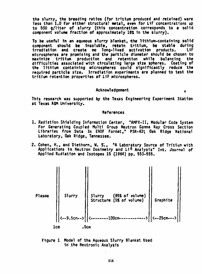
the slurry, the breeding ratios (for tritium produced and retained) wereless than 1.0 for either structural metal, even for L1F concentrations upto 500 g/liter of slurry (this concentration corresponds to a solidcomponent volume fraction of approximately 18% In the slurry).
To be useful In an aqueous slurry blanket, -the 11th1um-conta1n1ng solidcomponent should be Insoluble, retain tritium, be stable duringIrradiation and create no long-lived activation products. L1Fmicrospheres are promising and the particle diameter should be chosen tomaximize tritium production and retention while balancing thedifficulties associated with circulating large size spheres. Coating ofthe lithium containing microspheres could significantly reduce therequired particle size. Irradiation experiments are planned to test thetritium retention properties of L1F microspheres.
Acknowledgement ,
This research was supported by the Texas Engineering Experiment Stationat Texas ASM University.
References
1. Radiation Shielding Information Center, "AMPX-II, Modular Code SystemFor Generating Coupled Multi Group Neutron Gamma Ray Cross SectionLibraries from Data In ENDF Format," PSR-63; Oak Ridge NationalLaboratory, Oak Ridge, Tennessee.
2. Cohen, H., and Diethorn, H. S;, "A Laboratory Source of Tritium withApplications In Neutron Dosimetry and Li 6 Analysis" Int. Journal ofApplied Radiation and Isotopes IS (1964) pp. 553-555.
Plasma Slurry
<—9.5cm-->
lcm
Slurry (95X of volume)Structure (5% of volume)
•100cm—
Graphite
< — 2 5 c m — >
.5cm
Figure 1 Model of the Aqueous Slurry Blanket Usedin the Neutronic Analysis
316

A BENCHMARK EXPERIMENT ON TRITIUM PRODUCTION ANDRADIATION HEATING IN THE LIF ASSEMBLY
T. Iguchi, M- Nakazava* and A. Sekiguchi
Department of Nuclear Engineering, University of TokyoHongo 7-3-1, 3unkyo-ku, Tokyo, Japan
*Nucloar Engineering Research Labolatory, University of TokyoTokai-mura, Ibaraki-kea, Japan
In the blanket design of a D-T fusion reactor, the estimation of thetritium breeding and the energy multiplication is an important step havinga great influence on the overall design and cost. It is expected, therefore,to have experimental verification of the accuracies of these two designparameters obtained from the radiation transport code system in a currentdesign use. For this verification, direct and indirect measurements oftritium production rate and radiation heating rate in the Lithium Fluoride(LiF) have been made as one of the integral benchmark experiments.
Fig. 1 shows the present experimental procedure to estimate tritium produc-tion rate and radiation heating rate in the LiF assembly. The assembly usedin the experiment is a slab of 50 cm X 50 cm X IT cm thickness, density of2-55 g/cm3 and natural isotopic abundance of Lithium. Detectors such asactivation foils have been two dimensionally arranged assuming a cylindri-cal model and have been irradiated by an ordinary D-T neutron point sourceon the central axis of the assembly.
Direct measurement of the tritium production rate distribution have beenmade by the standard Dierckx's method using Li2CO3 pellets. Unfoldingtechnique for multi-activation foils has been applied to obtain the infor-mation of neutron spectrum and also to indirectly estimate tritium produc-tion rate and neutron components on radiation heating rate. LiF thermo-luminescence dosimeters (LiF-TLD) of the same constituents as the assemblyhave been used to obtain the total absorbed dose of both neutron and gamma-ray, and to experimentally determine secondary gamma-ray heating rate bycorrection for. neutron heating components estimated using the results ofactivation foils.
An analysis of these experimental data has been carried out by using thetwo dimensional transport code DOT3-5(+GRTUNCL) that has been often appliedto the current neutronic designs of the fusion reactor blanket. The group-wised cross section libraries, GICX series, have been used, that wasproduced especially for the nuclear designs of the fusion reactor and gener-ated through the NJOY code system from ENBF/B-IV and POPOP^ data libraries.Calculated neutron fluxes have been also used as an initial guess flux forthe unfolding code NEUPAC including the uncertainty analysis basing onENDF/B-V dosimetry files.
As for the distribution on the central axis, calculated values of tritiumproduction rate has a tendency to be systematically larger than experimentalvalues, and also gamma-ray components in calculation of radiation heatingrate has been comparatively overestimated. As for the radial distribution,a tendency to underestimate higher energy components of the calculated
317

neutron flux has been appeared with going to outer radius. The results ofactivation foils indicate that calculation has in general overestimated thelower energy components of the neutron flux. These discrepancies areconsidered to be caused by not only uncertainty of nuclear data but alsoinadequate treatment of neutron scattering anisotropy in the transportcalculation.
Finally, the significance of the present study is summarized as follows.
1) Benchmark data of tritium production rate and radiation heating ratehave been obtained for the LiF material in a D-T neutron field.
2) Availability of multi-foil unfolding technique estimating variousintegral values has been confirmed in the fusion neutronic experiment.
3) The present accuracies and problems of current fusion neutronic designshave been made clear through an analysis using the two dimensionaltransport code system.
References
1) T. Iguchi et.al."Neutron spectraand TritiumProduction RateMeasurements inthe One Dimen-sional LiF SlabGeometry as aFusion ReactorBlanket Bench-mark Experiment"Uth M S TopicalMeeting on theTechnology ofControlledNuclear Fusion(1980)
2) M. Nakazawa"The BasicReports of Jl-Unfolding code:NEUPAC"UTNL-R 0096(1981)
UJCOJ Pellet
\ /
Activation Foils"Ni(n.2n) l'Ni{n,p)"Co(n,2n) l l tIn(n,n1)
l"Au(n,2nJl"Au(ntT)
LiF-TLDTLD-600TLD-700TtD-100
\f
Determination oc lAMeV Neutron Yields by AssociatedPacticle Method and Normalization Factoc : S
Unfolding TechniqueNEUPAC
Total Dose Rateof TLD (n+T)
{R**Co equivalence/S)
Neutron Spectrum
JLTcitius
ProductionCross Section
Kerraa Factoc(neutron)
TritiumProduction
BateU/atiVS)
Neutron Besconseof TID
f
\f
Heutcon Dose Date(R"Co equivalence/S)
T-cay Dose Bate(S"Co equivalence/S)
ConversionCoefficient
(R"CO equival«nc«/MeV/cm!
\ /
NeutronBeatingBate
(MeV/an'/S)
ray Heating Sate(MeV/cra'/S)
Fig. l Experimental Procedure
318

THE DEPENDENCE OF NEUTRON-INDUCED RADIOACTIVITY IN FUSION REACTORSON GEOMETRIC DESIGN PARAMETERS
George P. Lasche1 and James A. BlinkLawrence Livermore National Laboratory
University of CaliforniaLivermors, California 94550
SUMMARY
The potential radiological hazard of fusion reactors is an increasinglyimportant issue in light of recent difficulties with social acceptabilityof fission power. Nevertheless, the task of calculating the radioactivehazard of proposed fusion reactors is usually performed after many of thefinal design parameters have been chosen. This is because, in order toaccurately calculate neutron-induced activation of the structuralmaterials with computer codes, final design details are needed. At earlystages of design it would be useful to understand how, in a general way,the total plant radioactivity will be affected by geometric designparameters such as first wall thickness, first wall radius, first wallshape, source neutron distribution, reactor power level, etc. Inaddition, for those reactor designs for which neutron-activation analyseshave not been made, scne method of estimating their radiological hazard £priori is needed if comparisons to other designs are to be made.
Neutron-induced activation in a fusion reactor is a highly non-linearproblem whose "exact" solution requires th?i use of neutron transport codesand neutron activation and decay codes. However, based on certain linearassumptions, a number of simple arguments can be made which identify theparametric dependence of the radiological quantities in fusion reactorsfor various reactor configurations. These arguments lead to usefulscaling rules with which the radioactivity, thermal decay power, orbiological hazard of various proposed fusion reactor designs can becompared. In addition, they show how the choice of design parameters willaffect final radioactivity before computer calculations can be performedbased on a detailed design.
Because these rules rely heavily on assumptions of linearity and of thesmallness of second-order effects, they must be compared to computationalresults before confidence can be placed in them. Therefore, we haveconducted computer experiments to investigate the extent to which thepredictions of these scaling rules are valid. In each experiment, oneparameter was changed while all others were held equal. A Monte-Carloneutron transport code was then run in order to determine the neutron fluxspectrum, from which flux-averaged cross sections for neutron activationwere calculated using the ACTL cross section library. Next, a neutronactivation and decay code was run in order to determine the activityduring both an assumed thirty-year lifetime of the reactor and the decayactivity for the first hundred years following decommissioning. Becausegeneral parametric dependencies were to be investigated, the computersimulations were one-dimensional and, in each case, the first wallmaterial (a ferritic steel) remained unchanged.
319

The parameters that were varied for comparison of activation and decaywere:
t reactor power level.• first wall thickness.• neutron source distribution.• first wall radius.• reactor configuration (spherical/cylindrical).
In addition, we have• compared the total radioactivity of the first wall with that of a
structural wall located behind a lithium blanket.• investigated the effect of elimination of the first wall (as in the
case of liquid-metal-wall ICF reactors).• investigated the importance of reflected neutron flux on activity
by comparing total radioactivity of the first wall to a case in which thelithium blanket is replaced by a perfect absorber.
We have found that the scaling rules are in agreement with the computedresults to within a few percent. In short, we have found that the totalradioactivity in the first wall (hence also thermal decay power andbiological hazard potential)
t scales approximately linearly with first wall thickness.• is approximately independent of first wall radius.• scales approximately linearly with total plant power.0 increases for a more distributed neutron source.• increases as reactor first wall area/volume ratio increases (as the
configuration departs from the spherical).
Stronger departures from these results occur for late decay times and forextreme parametric values. We describe these results and their departuresquantitatively and explain them, where applicable, using the same logicused to develop the scaling rules.
1 Supported as a Fellow of the John and Fannie Hertz Foundation.
Work performed under the auspices of the U.S. Department of Energy byLawrence Livermore National Laboratory under contract no. W-7405-ENG-48.
320

NEUTRONICS ANALYSIS OF THE MODULARSTELLARATOR POWER REACTOR UWTOR-M
L.A. El-GuebalyUniversity of Wisconsin
Nuclear Engineering DepartmentMadison, Wisconsin 53706
Radiation streaming through penetrations in fusion reactors has significantimpact on important reactor parameters such as tritium breeding ratio (BR) andenergy multiplication (M). The UWTOR-M modular stellarator power reactordesign utilizes large divertor penetrations for impurity control. A verticalcross section of the reactor is shown in Fig. 1. Neutronics and photonicsanalysis for UWTOR-M was carried out to assess radiation streaming effects onreactor performance. The breeding blanket consists of three segments withdifferent cross-sectional areas. The radial neutron source densitydistribution peaks at the center of the triangular plasma zone. Some of thesource neutrons will stream through the divertor slots which occupy ~ 5% ofthe solid angle. A significant number of lower energy secondary neutrons thathave been moderated in the blanket and reflector will also stream through theslots along with some gamma photons that are produced in neutroninteractions. Therefore, shielding materials are used in the divertor targetsto protect vital components in the toroidal hall and to recover part of theenergy carried by streaming radiation.
10
a
6
4
2
2
- 2
- 4
. ; ; • • .
4 > f
-
10 1 • I* .
• .' •
. . .
/ / ,
/A7Im
1
C M
^ 4
•
VACUUMPUMPINGSTATION
— —
—^p-"
Kirmr
—<V•
• »
V
•
-
CV«CU«ICDKtACTOM• W L t I M *
34 3#m«t*r« . •
•
• •
ACCESS' DOOR
A
Fig. 1 Vertical Cross Section of UWTOR-M Reactor
321

The blanket design is aimed at achieving the largest energy multiplicationwith adequate tritium breeding. The Monte Carlo code MCNP with data based onENDF/B-V was used to determine the proper blanket design. The effect the Lienrichment in the Li^Pbg-j breeder has on radiation streaming wasinvestigated. The streaming of down-scattered neutrons and secondary gammarays increases as the enrichment decreases because of the decreased blanketattenuation. The results show that in the space available for the blanket thelargest M that can be obtained is 1.15. This is achieved by using a Lienrichment of 35% and structural content of 9 v/o HT-9 in the blanket. Thecorresponding BR is 1.08.
Magnet shield optimization was performed using the discrete ordinates codeONEDANT to design a shield which provides adequate protection for thesuperconducting magnet utilizing the limited shielding space available. Theshield consists of water cooled layers of Fe 1422, B^C and lead. Among thedifferent magnet radiation limits, the 10 rad dose limit in mylarsuperinsulator in front of the magnet was found to drive the shieldoptimization as other magnet components are further protected by a 25 cmstructural case.
The radiation streaming calculation procedure was divided into two parts bymodelling the geometrical configuration of the reactor in two separateproblems using MCNP. The blanket, reflector, and shield is considered as oneproblem and the divertor targets and associated shield as the other. Trappingsurfaces were locatd at the entrance of the three divertor regions where allparticles crossing the surfaces are counted according to angle and energybins. This information was then stored to serve as surface source in lattermodelling of the divertor region itself. For each D-T fusion event, the totalneutrons and gamma photons streaming through the divertor slots are 0.214 and0.024, respectively, carrying a total power of 176 MW which represents 5% ofthe neutron fusion power. Fortunately, most of this energy is recovered bythe divertor targets- About 20% of the streaming neutrons are primaryneutrons and they carry 83% of the streaming energy.
The pumpout ports are located appreciably off the direct line of sight of theflowing particles from the divertor region entrance. This is of importance inreducing radiaton streaming through ports. The results indicate thatconsiderable attenuation and spectrum softening result from neutroninteractions with divertor targets. The total power carried by radiationstreaming through all pumpout ports of the reactor is 6 MW representing only0.18% of the neutron fusion power. Radiation streaming raises the biologicaldose level outside the reactor. A 3.1 m thick toroidal tunnel wall made ofreinforced ordinary concrete was found to result in an acceptable lose of 2.35mrem/h in the toroidal service hall during reactor operation.
In conclusion, despite the large radiation, streaming through the divertorslots in a stellarator reactor, proper choice of blanket materials andcomposition can provide adequate tritium breeding ratio and energymultiplication. High performance divertor targets can be used to interceptand recover most of the streaming radiation energy.
This work was funded by the United States Department of Energy.
322

NEUTRONICS ANALYSIS FOR THE MARSLI-PB BLANKET AND SHIELD
J.H. HuangM.E. Sawan
University of WisconsinDepartment of Nuclear Engineering
Madison, Wisconsin 53706
The MARS (Mirror Advanced Reactor Study) fusion power reactor design employs along central cell consisting of a number of blanket modules. Neutronicsanalysis has been performed to determine the blanket design which yields thelargest energy multiplication (M) with adequate tritium breeding ratio (T).This will have an impact on reducing the overall cost of producedelectricity. This analysis is aimed also at designing a shield which providesadequate radiation protection for the superconducting magnets. The Li-Pbblanket of MARS uses Lii7pbgo a s t h e breeder and coolant and the ferriticsteel HT-9 for structure. The blanket consists of a front tube zone and aback zone of rectangular beams which provide the structural support. Theblanket is followed by a water cooled stainless steel reflector. The energydeposited in the blanket and reflector is recovered and represents thereactor's thermal power.
The continuous energy Monte Carlo code MCNP was used with cross secton databased on the ENDF/3-V evaluation to determine the appropriate composition andthickness of the blanket and reflector. The continuous energy treatment ofMCNP was used to eliminate energy group structure effects. Our results showthat both T and M are sensitive to the group structure in a Li-Pb system-Furthermore, data based on ENDF/B-IV tend to overestimate T and underestimateM when compared to ENDF/B-V data. 4,000 histories were used in'thecalculations resulting itv statistical uncertainties less than 1% for thequantities of interest.
The results show that neutron multiplication through the Pb(n,2n) reactionsaturates to a value of ~ 1.75 at a blanket thickness of ~ 30 cm. Thisimplies that, from the point of view of neutron multiplication, the lead inthe back region of the blanket is ineffective. Hence, a thin blanket design,in which the lithium is enriched to 90% Li, was considered and compared to athick blanket design in which natural Li is used. A saving of 49 cm(38.2 versus 87.2 cm) in blanket thickness is achieved for the same T. Thisresults in reducing the central cell cost because of the associated smallermagnet size. Furthermore, the blanket has less weight and can be easilychanged out. However, a smaller M is obtained from the thin blanket when HT-9is used as a reflector. Several attempts have been made to enhance the energymultiplication while preserving the advantages associated with the thinblanket design.
Increasing the Li-Pb content in the beam zone of the blanket was found toincrease M. A beam zone consisting of 85 v/o Li^Pbgg and 15 v/o HT-9 hasbeen chosen. Further enhancement of M can be achieved by appropriate choiceof reflector material. For a thin blanket, a relatively large fraction ofenergy is deposited in the reflector and the overall energy multiplication is
323

sensitive to the choice of reflector material and thickness. Materialsconsidered in this analysis include HT-9, 316-SS, graphite and Fe-1422. Fe-1422 was found to yield the largest M, primarily due to the large gaaaaproduction in Mn. Increasing the reflector thickness was found to furtherincrease M. A schematic of the MARS Li-Pb blanket, shield and magnet is givenin Fig. 1. This blanket design results in a tritiua breeding ratio of 1.13and an overall energy multiplication of 1.39 which exceeds that obtained inthe thick blanket design.
«l
e •3i,
Oxgo°|u -
o
- » _
5 0
• 0> NO »O
10
« K> <o r- • 2^ = 2 222 S S
ae a.o _
THICKNESS (cm )
RADIUS (cm)
Fig. 1 Schematic of Blanket, Shield and Magnet
The shielding requirements for the 8 Tesla central cell superconductingmagnets are determined by a number of radiation limits. The dpa rate in Cushould not exceed 2.2 x 10 dpa per full power year (FPY). This is based on20% increase in resistivity and a minimum period of one FPY between magnetanneals. The peak dose in the polyimide insulator should not exceed5 x 10' rad after an estimated reactor life of 21 FPY. The limit on the peakheat-load in the magnet was considered to be 0.06 mW/cm . A water cooledshield consisting of layers of Fe-1422, B4C and Pb was considered. The shieldconsists of four zones as shown in Fig. 1. Al-6061 is used as structuralmaterial in zone D to reduce the activation and yield acceptable biologicaldoses at the back of the shield after shutdown. For a wall loading of 5MW/m , this shield configuration was found to satisfy all design criteria.
We conclude that the thin Li-Pb blanket design for MARS results in a largerenergy multiplication, a smaller magnet size and a better overall economicfigure of merit as compared to the thick blanket design. Other attractivefeatures of this design are the ease of maintenance and the reduced activatedwaste. The shield design for MARS provides adequate proteciton for themagnets and allows for hands-on maintenance at the back of the shield aftershutdown.
Funding for this work was provided by the U.S. Department of Energy.
324

CROSS SECTION SENSITIVITY STUDY FOR U.S. FUSION ENGINEERING DEVICE (FED)
S. Pelloni, E.T. Cheng a>Swiss Federal Institute for Reactor Research (EIR)a) General Atomic Company (GA)
In the nuclear design of a fusion reactor, it is important that the nucle-onic parameters be calculated within reasonable accuracy. These parametersinclude tritium breeding ratio, blanket energy multiplication, and radia-tion damage parameters in various reactor components. The most determentalradiation damage parameters are probably those associated with damage tothe toroidal field magnets, namely radiation dose at the insulators andatomic displacement in the copper stabilizer. Damage to the insulatorscannot be recovered, although damage to the copper stabilizer can partial-ly be recovered upon annealing. However, nucleonic parameter calculationsare often sensitive to the method employed and to uncertainties in thenuclear data. In this study we have chosen the U.S. Fusion Engineering De-vice (FED) in order to investigate the above-mentioned uncertainties. TheFED is primarly aimed at developing experience with the practical problemsof creating and maintaining a burning plasma. The neutronic model of thisdevice consists of a plasma zone, first wall, blanket/shield zone, andsuperconducting magnet. The first wall ov the device which maintains thevacuum chamber is composed of stainless steel and water. The blanket/shieldzone consists of both water and stainless steel. Neutronics calculationswere performed using the one dimensional discrete-ordinates transport codeANISN (Ref. 1) with P3S6-approximation. An albedo equal to 0.3 for allenergy groups was used on the external boundary of the system. The nucleardata used is from the DLC-41 library (Ref. 2) and consists of coupled 25neutron and 21 gamma ray groups. Atomic displacement rate in the TF coilcopper stabilizer, nuclear heating in the epoxy-based insulation materialand TF coil, and energy multiplication in the inboard and outboard blanket/shield were estimated. The sensitivity analysis was performed using theORNL developed sensitivity code, SWANLAKE (Ref. 3), which is based on thelinear perturbation theory. The direct and adjoint flux distributions re-quired to perform the sensitivity calculation were computed using ANISN(Ref. 1). The results show that the above-mentioned important design para-meters are most sensitive to the iron inelastic cross sections (see Tables1-3). They are also sensitive to other reactions such as elastic scatteringor (n,2n) reactions, and also to other materials S"jch as chromium andnickel, but these sensitivities are smaller in magnitude. The uncertain-ties in the copper atomic displacement in the TF coil and the nuclearheating in the insulation material and TF coil are found to be + 24%, + 21%and + 12,5% respectively. If they are to be known within 10%, the iron,chromium and nickel cross sections in the energy range between 12 and 14MeV should also be known within + 10%. The uncertainties on these crosssections are presently + 15% for iron, chromium and nickel. Thus, if theadditional accuracy in magnet dpa and heating is needed for FED, improvedmeasurements of these cross sections will be needed.
325

TABLE 1:
TABLE 2:
TABLE 3:
SENSITIVITIES OF PARTIAL CROSS SECTION UNCERTAINTIES TO COPPERDPA FOR THE FED (Percent per 1% Cross Section Increase)
Cross SectionType
(n.n)(n,n-)(n.2n)(n.y)
Iron
-0.956-2.684-0.916-0.011
Nickel
-0.219-0.479-0.060
Chromium
-0.300-0.744-0.222
lHydrogen
-1.311
SENSITIVITIES OF PARTIAL CROSS SECTION UNCERTAINTIES TO TOTALNUCLEAR HEATING IN THE INSULATION MATERIAL IN THE INBOARD OF FED(Percent per 1% Cross Section Increase)
Cross SectionType
(n.n)(n.n')(n,2n)(n.y)
Tron
-1.013-2.215-0.706-0.221
Nickel
-0.251-0.388-0.046
Chromium
-0.320-0.604-0.170
Hydrogen
-1.275
SENSITIVITIES OF PARTIAL CROSS SECTION UNCERTAINTIES TO TOTALNUCLEAR HEATING IN THE TF COIL IN THE INBOARD OF FED(Percent per 1% Cross Section Increase)
Cross SectionType
(n.n)(n.n')(n.2n)(n.Y)
Iron
-0.978-1.414-0.337-0.502
Nickel
-0.271-0.228-0.022
Chromium
-0.316-0.358-0.080
Hydrogen
-1.111
Copper
0.018-0.0030.001
References
1. Engle, W.W., Jr., "A User's Manual for ANISN", K-1693, Oak RidgeGaseous Diffusion Plant (1967).
2. "VITAMIN-C: 171 Neutron, 36 Gamma Ray Group Cross Sections for Fusionand LMFBR Calculations", RSIC, Oak Ridge National Laboratory, DLC-41(1978).
3. Bartine, D.E., F.R. Mynatt, E.M. Oblow, "SWANLAKE: A Computer CodeUtilizing ANISN Radiation Transport Calculations for Cross SectionsSensitivity Analysis", ORNL-TM-3809 (May 1973).
326

VAPORIZATION OF Pb AND Li FILMS IN ICF REACTION CHAMBERS
A.M. Hassanein*, C D . Croessmann, and 6.L. KulcinskiNuclear Engineering Department, University of Wisconsin
Madison, Wisconsin 53706
The use of liquid Li and/or PbLi alloys have been recently proposed toprotect ICF solid first walls from intense radiation following the ex-plosion of a fusion target. The target spectra consist of neutrons,x-rays, and energetic ions but only the latter two-pose a problem withrespect to the melting and vaporization of solid first walls. The liquidmetals intercept the x-rays and ion debris at energy densities of 10-50J/cnr which are deposited in times ranging from lO^5 sec for the x-rays upto 10~I) sec for the ion debris. The amount of Pb or Li which is vaporizedby this radiation depends on several factors; the energy spectra of the x-rays and ions, the initial temperature of the liquid, and, of course, thepower to the wal1.
The code A*THERMAL has been used to compare the amount of Pb or Li that isvaporized from a wall 10 meters away from "typical" 175 and 350 MJ ICFtarget explosions. Two different target compressions were studied foreach metal: pR = 3 and 6 g/cnr. The larger the initial compression ofthe target, the larger the energy in ions and x-rays, and hence the moreradiation that must be handled on the first liquid surface. The ionspectra consists of several types of light and heavy ions incident simul-taneously on the liquid rail. These spectra are assumed to be Maxwellianin shape with different keV/amu tnd different energy content for eachtarget compression. The x-ray energy spectrum is assumed to be a black-body distribution with characteristic temperatures of 0.5 and 1.0 keV forthe two target compressions of pR = 3 and pR = 6, respectively.
Figure 1 shows the temperature behavior of the exposed surface of liquidPb for the two targets and it shows that the maximum temperature increaseof the Pb varies by a factor of 1.5 between the two values of pR. Figure2 shows the difference in surface temperature?of the Li and Pb film ex-posed to the same target spectra (pR = 3 g/cm ). It can be seen that Lidoes not have an initial temperature increase due to the x-rays because ofits low absorption cross section.
For the case of pR = 3 gm/cm2, 1150 cm3 (i2 kg) of Pb is evaporated andfor Li 2200 cnr (1.1 kg) is vaporized. More information on the targetspectra and thermal response of the liquid will be included in the paper.
*Present address at Argonne National Laboratory.
329

Figure 1
TEMPERATURE INCREASE IN LIQUID LEAD FILM AFTER
TN BURN
tO'7 I0"6 KT5 K>~4
SECONDS AFTER TN BURN10-5
Figure 2
TEMPERATURE INCREASE IN LIQUID METAL FILMAFTER TN BURN
sc 2 .0 -
w"ooo
SECONDS AFTER TN BURN
330

CONCEPT AND DESIGN OF ICF REACTOR " SENRI-II "
N. Nakamura, H. Omura, K. Kitamura*, H. Nakashima**, H. Katsuta***
K. Mlya#, S. Ido##, S. Nakai##, C. Tananakaff
Ishikawajima-Harima Hevy Induaties Co., Ltd.Isogo, Yokohama, 235
and Karunouchi, Tokyo, 100, JAPAN
*) Department of Energy Engineering, Toyohashi Dnivesity of Technology,
Toyohaahi, Alchi, 440
**) Department of Nuclear Engineering, Kyushu University, Hakozaki, Higa-
shi-ku, Fukuoka, 812
***) Molten Materials Laboratory, Japan Atomic Energy Research Institute,
Tolcai, Ibaraki, 319-11
I) Nuclear Engineering Research Laboratory, Faculty of Engineering,Univer-
sity of Tokyo, Tokai, Ibaraki, 3 9-11
##) Institute of Laser Engineering, Osaka University,Suita, Osaka, 565
Design features of a laser fusion reactor concept SENRI-II are reviewed
and discussed. The unique feature of ICF reactor SENRI-I is utilization
of magnetic field to guide and control an inner Li flow (1).
SENRI-II is designed to use metal mesh ( or porous metal ) as the inner
Li flow guide. Basic design parameters of SENRI-II are shown in Table 1.
Items to be discussed are performance of liquid Li flow, material consi-
deration and neutronics comparing with SENRI-I.
Design study of the ICF reactor SENRI-II has been carried out for about
2 years as the alternative design to SENRI-I "in Research Committee of
ICF Reactor, Institute of Laser Engineeglng, Osaka Univeslty (2).
Assign feature of SENRI-II is the utilization of metal mesh guided Li
flow as an inner blanket to moderate the pulsive fusion energy to release
from a highly compressed DT plasma. An inner Li flow through metal mesh
used as a coolant and tritium breeder reduces the first wall loading by
neutrons released from a pellet. The ICF reactor SENRI-II with an inner
331

liquid Li flow is slaple in reactor structure and useful system with engi-
neering feasibility. Especially Materials can be chosen among usual materials
used In current industrial plant such as ferr.tic steel, austenitic stainless
steel etc.
Li Blanket and Flow : Liquid Li flows down through the metal mesh which
arranged inside cylindrical wall of reactor. Its mean velocity is about 0.1
(m/s) depending on its porosity. Metal mesh layer can be put at a distance
from the wall of reactor, pulsive force on the vail be released and prevents
potentially from material corrosion by liquid Li.
Material consideration : It is desirable metal mesh material to be chosen
as ceramics such as TiC. In the design of SENRI-II, strucrural material is
evaluated in view of induced activation and compatibility with liquid Li.
Neutronics rTritium breeding ratio, energy deposition rate and irradiation
damage analysis is performed by code of MORSE-E. In case of 100cm blanket
thickness, tritium breeding rate is calculated by 1.46 and O.16 dpa/year.
In the same case, He-production rate is 0.85 appm/year.
Table 1 Basic design parameter of SENRI-II
Output power 1000 - 3000 MW ( thermal )Reactor vessel with metal mesh guided inner Li flow
Container ( cylindrical )SUS 1 R - 6mInner Li flow d « 0.5 - lmCavity R » 5 - 5.5m
Li loop Ti - 500 - 550*C, T£ » 400*C
REFERENCES :
(1) C. Yamanaka, et al.t 'Conceptual Design o 1240 Mtfth '.«se. Jusion
Reactor in ILE Osaka', ILE-7913p (1979)
(2) C. Yamanaka, et al., 'Concept and Design of ICF Reactor "SENRI-I",
IAEA (1982)
332

TARGET EXPLOSION GENERATED FIREBALLS IN THE NITROGEN FILLEDTARGET CHAMBER OF THE LIGHT ION FUSION TARGET DEVELOPMENT FACILITY
R.R. Peterson and G.A. Moses (University of Wisconsin)
The response of a nitrogen target chamber gas to fusion target explosionsis considered for the light ion beam driven target development facility(TDF). Targets are considered with yields of 200 MJ, 400 MJ and 800 MJ.In each of these cases, 70% of the yield is assumed to be in hard x-raysand neutrons with the remainder being soft x-rays and target debris ions.These ions are stopped in a very short distance in the nitrogen gas whichwe assume has a density of 7.07 x 10 N2 molecules/cm • We have assumedthat the soft x-rays are absorbed in 30 cm of target chamber gas. Theenergy of the soft x-rays and ions thus creates a hot spherical "fireball"30 ca in radius which can propagate to the first wall of the targetchamber, subjecting the wall to fluxes of low energy photons and shockpressure pulses.
The propagation of these fireballs have been simulated with a Lagrangianradiation transport hydrodynamics computer code FIRE [1], which usesaquations of stara and optical data for No generated with the computercode MIXERG [2]. N2 was chosen as a target chamber gas for its compati-bility with first wall materials, for the ease in handling the tritium-nitrogen compounds, and for the ability to efficiently create laser.guidedplasma channels in N2 [3]. The results of these simulations in N2 foryields of 200 MJ, 400 MJ and 800 MJ are shown in Table I for a 3 meterradius target chamber. The heat flux and shock pressure at the first wallfor a 200 MJ shot are shown in Figure 1. One should notice that in allcases only a very small fraction of the fireball energy escapes as radiantenergy but that the shock pressures are large.
These simulations have shown that the first wall must mainly be protectedagainst the mechanical shock of the fireball because the heat loads arelow in all three cases. The yield strength of the wall is not exceeded bythe higher yield shots so that a wall designed for 15,000 shots of 200 MJwill withstand a few at 400 and 800 MJ.
References
T.J. McCarville, R.R. Peterson and G.A. Moses, "Improvements in theFIRE Code for Simulating the Response of a Cavity Gases to InertialConfinement Fusion Target Explosions," University of Wisconsin FusionEngineering Program Report UWFDM-407 (Feb. 1982); accepted for publi-cation in Computer Physics Communications.R.R. Peterson and G.A. Moses, "MIXERG - An Equation of State aridOpacity Computer Code," University of Wisconsin Fusion EngineeringProgram Report UWFDM-464 (March 1982); accepted for publication inComputer Physics Communications.R.R. Peterson, G.A. Moses and G.W. Cooper, "Cavity Gas Analysis forLight Ion 3eara Fusion Reactors," Nuclear Technology/Fusion 1, 377(July 1981).
333

Table I. fireball Propagation: in TDF Target Chamber
TargetYield(MJ)
200
400
800
InitialFireballEnergy(MJ)
60
120
240
ChamberRadius(m)
3
3
3
ChamberGas
N2
N2
N2
Gas Density(atoms/cm )
1.4 x 10¹⁸
1.4 x 10¹⁸
1.4 x 10¹⁸
Max. WallPressure(MPa)
1.38 @
0.39 msec
3.06 @
0.29 msec
6.32 @
0.21 msec
EnergyRadiatedto Wall(MJ)
2.3 @
1.5 msec
7.4 (3
1.5 msec
28.8 <?
1.5 msec
PRESSURE AND HEAT FLUX AT FIRST WALL
aa.
I
Id< r=>COenLUa:a.
1.41.3
1.2
1.11.00.90.80.70.60.5 -0.4 -0.3 -0.2 -0.1 -
0
i I I r
R«3m20 Torr N2
Initial Energy=60 MJ(200 MJ Yield)
0.2 0.4 0.6 0.8
TIME (msec)1.0 1.2 14
1413121110987654321
0
(M
a
Is.
5LJ
Figure 1. Heat flux and shock pressure at a 3 meter radius f i r s t wall dueto a 200 MJ shot in N«.
334

INERTIAL CONFINEMENT FUSION WITHDIRECT ELECTRIC GENERATION BY MAGNETIC FLUX COMPRESSION -
George P. Lasche^Lawrence Livermore National Laboratory
University of CaliforniaLivermore, California 94550
SUMMARY
A liquid-metal-wall laser fusion reactor concept is investigated in whichthe kinetic energy imparted to the liquid metal (lithium) is maximized,rather than minimized. In turn, this kinetic energy is converted directlyto electricity with, potentially, very high efficiency (>* 60%) bycompression work done against a pulsed magnetic field applied to theexterior part of the wall.
The kinetic energy originates from high internal pressures caused by thedeposition of neutron energy in the lithium, as well as from the work doneby the expansion of both the post-fusion plasma and the central portion oflithium which has been heated to the gaseous state (e = 24 MJ/kg).Therefore, even some of the neutron energy is subject to direct generationof electricity in this reactor concept.
Because lithium is a good conductor of electricity, the magnetic field iseffectively excluded from the liquid lithium if the field rise time(= 3 ms) is short compared to a characteristic field diffusion time(= 7 to 22 s). Thus, most of the energy in the applied magnetic fieldmay also be directly recovered as electricity.
Because the pulsed field is applied for a short total time (= 6 ms)compared to the period between laser fusion pulses (- 1 s), the averagedohmic power losses could be a small fraction of the total plant electricpower. For this reason, the magnets need not be superconducting, greatlysimplifying the design.The magnetic field serves the additional purpose of distributing the totalimpulse imparted to the reaction chamber vessel over time. If the timeover which the impulse is delivered is sufficiently long, then the wallwill not be stressed beyond acceptable fatigue life limits.
Because the applied magnetic field will not be able to restrain the motionof liquid metal along the direction of the field lines, the kinetic energyof the liquid metal with a velocity vector in the two directions parallelto the field will be converted directly to electricity by a separate MHOgenerator.
The outer surface of the liquid metal wall will develop fluteinstabilities. Although such instabilities would be catastrophic in asteady state system, in a pulsed system they can be dealt with by choosinga design such that the critical instability growth times are long comparedto the time required to stop the motion of the liquid lithium.
335

In order to maximize kinetic energy, the liquid lithium may be configuredinto a sphere, perhaps three meters in radius, having a hollow sleeve ofsolid lithium through its center for the access of laser beams. Thesphere of liquid would presumably be formed and dropped from above thechamber by a "ice cream scoop" apparatus. No external tritium breedingblanket would be required.
At such radii, the fusion neutrons would be required to traverse severaltimes the number of mean free paths of lithium that they do in otherfusion reactor designs. As with other liquid metal wall reactor designs,there is no structural metal interposed between the fusion neutron sourceand the lithium absorbing medium. For these reasons, the neutron-inducedradioactivity of reactors based on this concept may be extremely low.
It appears from initial calculations that the liquid metal may be arrestedby magnetic fields of reasonable strengths (3 to 11 T); that theinstability growth rates can be overcome; that the power loss from inducededdy current heating is not severe (= 63 MW); and that the metalvelocities (= 133 m/s) are sufficient to provide efficient electricgeneration by magnetic flux compression and by magnetohydrodynamic means(RM is = 700 before expansion). Computational experiments have beenaccomplished using LASNEX (a hydrodynamic code capable of radiationtransport), designed to test the validity of analytical models and toaccurately describe the shock wave propagation in the liquid lithium andthe interaction between the liquid metal and the applied magnetic field.
1 Supported as a Fellow of the John and Fannie Hertz Foundation.
Work performed under the auspices of the U.S. Department of Energy byLawrence Livermore National Laboratory under contract no. W-7405-ENG-48.
336

FIRST WALL MATERIALS SELECTION FOR THELIGHT ION FUSION TARGET DEVELOPMENT FACILITY
R.R. Peterson, E.G. Lovell, K.J. Lee, R.L. Engelstad,G.L. Kulcinski, and G.A. Moses (University of Wisconsin)
The light ion fusion target development facility [1] (TDF) is an experi-mental facility designed to test high yield light ion beam driven ICFtargets. Its operation will follow the successful completion of experi-ments on PBFA-II. A critical element in the design of the facility is thereaction chamber in which the fusion micro-explosion must be contained-The reaction chamber walls consist of panels, supported from behind by astructural frame. The calculated mechanical response of this structure isreported by Lovell and Engelstad in these proceedings [2].
In this paper, a survey of seven common metal alloys is made with regardto their viability as a first wall material for the TDF. The criteria in-clude: cost, fatigue strength, thermal shock resistance, neutron acti-vation, and compatibility with N2 gas. The materials are listed in Table1 with their physical properties- Radiation damage resistance anri heattransfer to a coolant were not considered important because the TDF shotrate is only 10 shots/day and the structure is completely immersed in awater shield at room temperature.
Figure 1 shows typical results for Al 6061, where the first wall panelthickness was determined to be 3 cm for a lifetime of 10 shots- All ofthe candidate materials were found to be acceptible as a first wall ma-terial with aluminum being chosen as the best material. The two mostimportant criteria were thermal shock resistance and neutron activation.The latter is discussed by O'Brien et al., in these proceedings [3].Thermal shock resistance is a combination of high conductivity and lowthermal expansion. The high strength alloys like steel and Ti have poorthermal shock resistance and this fact outweighs their great strength.Hence the lower strength Al is the best candidate.
This work war, supported by Sandia National Laboratory under contractnumber DE-AS08-81DP40161.
References
1. G.A. Moses et al., "Light Ion Fusion Target Development Facility Pre-Conceptual Design," these proceedings.
2. E.G. Lovell and R.L. Engelstad, "Dynamic Stress Analysis of the LightIon Fusion Target Development Facility Reaction Chamber," these pro-ceedings.
3. K.J. O'Brien, A.M. White, and G.A. Moses, "Neutron Activation andShielding of the Light Ion Fusion Target Development Facility," theseproceedings.
337

Table 1 Therwl and Mechanical Properties of Selected Metal Alloys (Roon Tepperature)
NcUl
Alloyi
HI <0fl
«l SOW
304 Si
HT-f
K-MI-tf
C«-U
(C172OO)
C « - l .
(C17M0I
T«««r In*
n
H34
AMMlc*
SoUtlMTrMtrt M«A«M Ur
I BOO
INO
U)
2.70
2.W
i.a
7.7S
* .«]
1.2S
1.75
HHt (C,)
J/I-M
O.M
O.M
0.40
O.S»
O.i7
0.42
0.42
TainMlCmajftlYiy
(Hi
«/•-*>
1*7
127
li.2
2f
t . l
H i
230
DiffuslvHy
(K/»c,)
af/ttc
0.M7
0.530
0.040S
0.0*34
0.0222
0.340
O.t2t
HtltlHf
•c
tS2
HO
137S
- 14W
1427
- I4»2
IMO
MO
loca
Tlwrsal EX#*AS1M
CMrridnt <•)
lO-'/'K
23 .t
23.*
17.2
10.6
8 . *
li.7
K . 7
(v)
0.33
0.33
0.29
O.MS
0.33
0.3
0.3
Town'sNMViui
(t)
at(KSI)
i l
(10.000)
71
(10.3UO1
193
Ut.OUtt)
200
ut.vm110
(lt.OW)
121
1H.S00I
12B
111.500)
(.,)
(«5I)
27i
(40)
2SS
(37)
Hi
(».»)
442
(M)
1070
(1SS)
213
141)
173
125)
»1 - v)
V/m-ir,
W.7
SO
J.4
10
4.7
3«.7
7S.S
i i» jMl - »). t
w/a
3792U
2SMW
1740
W7U
1WJ0
2USO
(Itfs.: U Hculs m»#mt, 9tk id.. MtrlcM S«l«ty fw Mtuls. Mitils Put. Mio (1979).21 Strwunl Allcvs H M * « I , titUlW's OlyaVit (jktr>Urt«. Cslvkas. Okla (1911).3) Atntftct Strwbiril • t u l i XinaMot, MKkMlca) rr>Mrt<« Oiu Cntir. hlfwr StiilM. I K . . Tr»4) C.C. ttttr tt • ! . . 'STMFIK • A ClMlilMal Tot«Ht faifxi tMtr PlMt Stu*." V ) 0 M K>tl«Ml It*
:nt City. mcklfM I197S. m l ) ,mttiy (IMO).
oa.
CO
wUJtr
Fig. 1
XUJ
500
400
300
200
100
X<
I T TA I 6061Fmax*l.7l MPa(70 Torr Xe
+ 0.5%Cs)60 MJ FIREBALL
SOLID PLATE3 meter CAVITY200cm X 47 cm PANELS
I0 4 CYCLES TO FAILURE
YIELD STRESSJQ
\ I01
0 1 2 3 4 5 6 7
PLATE THICKNESS (cm)
338

DYNAMIC STRESS ANALYSIS OF LIGHT ION FUSIONTARGET DEVELOPMENT FACILITY REACTION CHAMBERS
Edward G. LovellRoxann L. Engelstad
University of Wisconsin-Madison
The reaction chamber of the proposed Target Development Faci l i ty shown inthe figure below is a capped cylindrical shel l , reinforced by circum-ferential ribs and axial stringers. The most important sources of stressare heat flux and mechanical shock transmitted by the cavity gas. Theresults reported in this paper focus on the mechanical overpressure prob-lem and include details of analysis methods and associated design con-siderations for the structural system.
For a design using a large number of stringers, the sections of un-supported shell wall can be considered to be very shallow curved plates.As a f i r s t approximation, curvature effects are ignored and flexuralstress and deflection calculations are based upon f l a t plate theory. Thedynamic response of wall plate components is determined by multiplyingthe quasi-static stress and deflection by dynamic load factors or dynamicload functions. Such amplifiers depend upon the characteristics of thepressure pulse (r ise time and decay strength), natural vibration f re -
ENERGY STORAGESECTION - OIL
PULSE FORMINGSECTION - WATER
SHIELDINGPOOL - WATER
RETURN LINETRANSMISSION LINEPULSE FORMING LINEINTERMEDIATE STORAGE CAPACITORBEAM MARX GENERATORCHANNEL MARX GENERATOR
339

quencies of the plate, wall material and level of damping. A computercode has been developed for this purpose and has also been coupled witha thermal stress code for the determination of the total stress historyin the chamber wall. An improved shell theory model has also been devel-oped which includes the effects of curvature, in-plane (membrane) forces,twist and shell flexural stresses. For shallow panels (e.g. subtending9°) the differences between shell theory and flat plate theory are minor.
The response results shown correspond to the specific case of a 200 NJtarget yield and xenon cavity gas at 70 torr with 0.52 cesium. The wallcomponent is solid aluminum with 2.5% critical damping and height, widthand thickness of 200, 47 and 3 cm, respectively. The fundamental fre-quency of this component in flexural is 768.5 Hz and the overpressure is1.71 HPa. The circumferential stress history is shown for a point at thecenter of the concave surface of the shell. The first flexural stresspeak is compressive and adds directly to the compressive thermal stressfrom the heat flux. Near the ribs and stringers, flexural stress willinitially be tensile and will be counteracted by compressive thermalstress.
PRESSURE PULSE ANDPLATE STRESS wt TIME RIB FLEXURAL STRESS v«. TIME
COCOl lJ
Iu
55
I
too -
so -
•00
-100 -
PLATE, — Al
I F"
1
2OxO.4TxO.O3m6061/9066
. -171 MPaDAMPING'2.9%
I I
2 0
- I.O
-10
IbJ
(AWLJtca.
2 0 40 60
TIME (mt)
20
2SO
~ 200
= 190COV)
£ wo
90
0-90
RIB: 8x3x3/8(in.)AIC06I/9OM
>/\/VVWvw»^.
8 0 1.0 2.0 30TIME (ms)
4.0 SO
The rib and stringer analysis involves techniques which are very similarto that used for the plates. The design primarily involves the deter-mination of cross section characteristics such that mechanical stressesare within acceptable limits and deflections are not excessive. Atypical stress history is shown for an aluminum rib with a hollow rec-tangular cross section.
The procedures developed and corresponding numerical results indicatethat a first wall structural system can be designed to carry the dynamicpressures and heat flux anticipated in this facility.
This work was supported by Sandia National Laboratories, Albuquerque, N.M.
340

NEUTRON ACTIVATION AND SHIELDING OF THELIGHT ION FUSION TARGET DEVELOPMENT F\CILITY
K.J. O'Brien, A.M. White, and G.A. Moses (University of Wisconsin)
The light ion fusion target development facility [1] (TDF) is an experi-mental nuclear facility operated at an average power level of 23 kW (ten200 MJ shots per day). It also requires easy access for maintenance. Toaccomplish this, low activation materials, aluminum, have been used forthe target chamber, and a borated water shield fills the space occuppiedby the magnetically insulated transmission lines of the pulsed powermachine. This arrangement is shown schematically in Fig. 1, where thewater level is shown lowered to allow access through the top end cap ofthe target chamber. The water level is raised during operation.
Neutron activation calculations were performed for the first wall candi-date materials and the resultant dose levels at the first wall are sum-mar Lzed in Table 1. It is seen that Al and Cu-Be are much preferred overthe Fe based alloys and Ti. Hands-on maintenance is possible after 1 weekfor the Al target chamber whereas this is probably not possible for the Febased alloys. The water shield very effectively attenuates the neutronsand gammas during operation.
Following a target explosion, the vibrating target chamber createsacoustic waves in the water shield. To attenuate these waves before theyreach the water filled section of the pulsed power generator, air bubblesare introduced into the shield region, see Fig. 1. Calculations have beenperformed to determine the reflection, attenuation, and transmission ofacoustic waves from bubble filled regions. A result of these calculationsis shown in Fig. 2 where the transmission fraction is plotted as afunction of the bubble void fraction for different bubble screen widths.Bubble "screens" will very effectively block the acoustic waves frompropagating outward, but if not properly designed, they will simply re-flect the waves back inward toward the target chamber. Hence the bubblescreen detailed design is important to the achievement of the desiredeffect.
This work was performed for Sandia National Laboratory under contractnumber DE-AS08-81DP40161.
References
1. G.A. Moses et al., "Light Ion Fusion Target Development Facility Pre-Conceptual Design," these proceedings.
341

T»bl« 1. Do«« at Flrtt Wall (w/hr)
Material
Al 6061
HT-9
33-304
T1-6A1-4V
Cu-Be
0
2,100
489
481
515
1,060
T I M After Shutdown1 day
260
114
109
177
Z04
' 1 week
1.65
101
105
66
7.
Figure 1
Figure 2
POWER TRANSMISSION RATIO
SCREEN WIDTH 0.4,..., 1.0 maters
0.0005 0.001
VOID FRACTION0.0015 0.002
342

AN ICF REACTOR CONCEPT USING 3He-AFLINT TARGETS
G. Miley, J. Stubbins, H. Ragheb, C. ChoiFusion Studies Laboratory, University of Illinois, Urbana, IL 61801 USA
G. MagelssenLos Alamos National Laboratory, Los Alamos, NM 87544 USA •
R. MartinArgonne National Laboratory, Argonne, IL 60440 USA
All Inertia Confinement Fusion (ICF) reactor concepts studied to date have beenLased on the use oT D-T fueled targets combined with a "Conventional" tritium breedingblanket. However, some "alternate fuel" configurations could enable the tritium to bebred within the target itself, thus eliminating the complication of a tritium breedingblanket. Indeed, prior studies " ) have developed the possibility of a 0-fueled target(termed the "AFLINT" concept) that employed shock implosion of a small D-T core regionto ignite the deuterium. In the present paper we examine the AFLINT concept in moredetail and discuss an approach to a reactor chamber designed to capitalize on itsunique features.
The present studies attempted to achieve a minimum energy input requirement whileachieving a tritium self-sufficient target design. AFLINT utilizes spark ignition witha 0-T core which results In burn propagation into an outside deuterium layer. Tritiumfrom D-D reactions that Is left unburned after the implosion-burn is extracted in theburn-chamber exhaust, chemically separated from other species, and then returned to thetarget "factory" to manufacture subsequent 0-T micro cores. Assuming losses of < 102,a Tritium Breeding Ratio (TBR) of about 1.1 should provide a closed cycle. (TBR isdefined as the amount of tritium contained in the chamber exhaust divided by that re-quired to manufacture the original target, including the D-T core.)
Present calculations began with a study of the AFLINT design described in Ref. 1.However, in order to improve the target performance (especially to obtain a higher TBR)the concept was modified to also Include auxiliary 3He. This added 3He is bred fromD-D reactions and Is also "redrculated" from the exhaust plasma. This improves thetarget burn since, at the densities and temperatures employed, the D-3He reaction rateis higher than the D-D rate during the Initial burn propagation phase. More importantly,the energy released per D-3He reaction is 5 times larger than that of D-D. A practicaltarget containing 3He presents some manufacturing problems. In the present "3He-AFLINT"concept, 3He is diffused throughout the target fuel while a thin coating of an appropriatehigh-Z material is used on the Inner surface of the tamper to contain the 3He.
For reactor studies we consider two different target ignition conditions that resultin significantly different driver energy requirements. For the first scenario we assumethe base case target concept with a pr of 8.9, a fuel density at ignition of 5,000 timessolid, and a radius of 100 urn. The target gain is approximately 50 and the driver energyrequired Is - 5 HJ.
'The second target scenario assumes the fuel density at ignition to be 2,500 timessolid. The driver energy requirement is 20 MJ and the gain is again -50. However, be-cause of the reduced compressional energy and symmetry requirements in this case, thisestimate for the gain Is felt to be conservative and the actual yeild might, in fact,be somewhat higher. These two cases are summarized in Table I and, for reference, arecompared with the target used in the recent HIBALL conceptual design study I'J. Forperspective, estimates of characteristic heavy-ion beam parameters are included.
Compared to HIBALL, the 3He-AFLINT has a somewhat lower gain due tc the smallerfusion cross-section for D-D reactions. This disadvantage must be balanced against thebenefit of internal tritium (and 3He) breeding. Another major difference associated withusing a D-D burn is the reduction In energy carried by neutrons and gammas and increasedenergy carried by x-rays and charged particles.
343

Table I. Reactor Target ConceptsTarget Par erne ter
Target Yield (MJ)Target GainComposition:
0 (mg)T (ng)3He (mg)Tamper (ing)
Driver Beam:Number Energy (MJ)
Debris Energy Spl i t :Neutron and GammasX-raysCharged Particles
°He-AFLINTI (5000x)
22044
3.42.5xlO-2
0.1836 (Au)
20;5
0.100.560.34
I I (2500x)1000
50
13.6io-i0.72
144(Au)
40;20
D-THI BALL39683
1.62.4
-288(Pb)
20;4.8
0.720.220.06
The reactor chamber for the 3He-AFLINT targets no longer needs to use lithium orlithium compounds as coolants/breeders. Consequently, other liquid metals, e.g. leadbismuth-lead, and sodium, can also serve as coolants. The use of a liquid metal isstill a preferred method for first-wall protection which is especially important withthe large x-rays and charged-particle yield from the AFLINT targets. For D-T designs,a lithium or Li-Pb blanket thickness of about 1 m is typically required for the pro-tection of the first structural wall against neutron damage and for Li breeding. Asignificant reduction in the thickness is possible in the present case, both due tothe reduced neutron flux and the softer energy spectrum of the neutrons. This approachoffers the additional advantage of increased energy density in the reactor coolant cyclesince most of the target energy 1s deposited in a relatively small volume of liquidmetal Inside chamber.
The present conceptualization of the reactor chamber for 3He-AFLINT employs dualliquid falls. A thin Inner liquid fall absorbs the x-ray and charged particles energy.It is mostly vaporized by the microexplosion, but re-establishes itself quickly due toa favorable height/diameter ratio. Another thin outer fall serves the triple purpose ofrecondensing the vaporized liquid, protecting the first structural wall against neutrondamage, and absorbing the radial momentum transfer from the disintegrating inner wall.Those two falls pour Into a pool at the bottom of the cavity. Their flow is fed fromthe top of the cavity through an annular liquid region fed with liquid from the pool byan electromagnetic pump. A graphite reflector behind the annular liquid region reflectsback any leaking neutrons, and Is surrounded by the vacuum vessel. Vacuum pumps main-tain a vacuum of-10'4 Torr for heavy ion beam propagation. Note that in the presentconcept a secoicary. coolant-shield region is placed outside the inner reactor chamber,instead of Inside the chamber which is common for D-T fueled, liquid metal protectedICF designs. The liquid-metal pumping power requirements are minimized through the re-duced mass of circulating liquid and the use of the pool concept. A heat exchanger isimmersed in the liquid pool and a gaseous or liquid coolant is circulated through it.Even though tritium must be extracted from the coolant, a relatively small tritiuminventory is possible, offering potential advantages in terms of minimization of tritiumleakage under normal operating conditions as well as in accident situations. Because ofthe low inventory, tritium leakage problems Into the coolant can be controlled withcoatings rather "than the more expensive double-walled approach. The first structuralwall can be extracted regularly from the top of the cavity, and annealed rather thanreplaced.REFERENCES1. G. H. Miley, "The Potential Role of Advanced Fuels in Inertial Confinement
Fusion," Proceedings, Fifth Workshop on Laser Interaction and Related PlasmaPhenomena, University of Rochester 09791.
2. B. Badger, et al., UWFDH-450/KfK-3202, University of Wisconsin (1981).
This work was supported by the Electric Power Research Institute.
344
Session 4C-5
INERTIAL CONFINEMENT FUSION(poster)
Chairman
J. Hovingh, Lawrence Livermore National Laboratory
Organizers
D.L. Cook, Sandia National Laboratories-AlbuquerqueM.J. Monsler, Lawrence Livermore National Laboratory
Wednesday, April 27 2:30-5:00 p.m.

JAPANESE PROGRESS IN THE LARGE COIL TASK AND THE HIGH-FIELD CLUSTER TESTPROGRAM, S. Shimamoto and K. Yasukochi, Japan Atomic Energy ResearchInstitute, The Japan Atomic Energy Research Institute (JAERI) is develop-ing large superconducting coils for the Fusion Experimental Reactor (FER),which is the next tokamak after the JT-60. Major programs for FER toroidalcoils at JAERI are the Large Coil Task (LCT) and the Cluster Test Program(CTP).
JAERI is one of the participants in the LCT, an international program beingconducted under the auspices of the International Energy Agency (IEA), toestablish design criteria for superconducting tokamak toroidal coils.In the LCT, 8-T, 4.5-m x 3.5-m, D-shaped coils are being developed.In the CTP, JAERI has already constructed and successfully tested twoCluster Test Coils, which are 7-T, 1.5-m-dia., NbTi coils. Using theseCluster Test Coils, JAERI is now developing high-field test module coils.The first Test Module Coil, which is a 10-T, 1.1-m-dia., Nb3Sn coil, hasbeen constructed and the second 12-T coil is under design. Two backupcoils in addition to Cluster Test Coils for the 12-T testing have also beenconstructed. These coils are called the Cluster Backup Coils, and they are-10-T, 0.7-m-dia., Nb3Sn coils.
In 1978, JAERI started the detailed design and verification tests toachieve the required characteristics of the Japanese LCT coil. In a fewyears of research and development, the critical current density at 8 T ofJapanese superconducting cables was doubled and a mechanically and chemi-cally treated conductor surface, which has a heat transfer five times asmuch as that of a flat surface was developed. These and many otherachievements have enabled to construct the Japanese LCT coil and it wasfinished in April 1982. Before bringing it to the U. S., JAERI carried outthe domestic test of it at the Superconducting Engineering Test Facility(SETF)o In this domestic test, the Japanese LCT coil was cooled in thedesigned 120 hours and successfully charged and tested. There was few signof wire movement and no training happened in the full charging up to 10,220A. In the stability test, we heated a half turn of the winding at thehighest field part up to 20 - 30 K to normalize the conductor. At therated current, this normal zone length quickly decreased by the speed of2 ra/s and the coil was fully stable. We also carried out fast dumping ofthe coil from 100-% current by the time constant of 20 seconds. Even inthis full dumping, the energy loss was almost the same as was predicted andno problem in the coil was found.
347

DESIGN OF THE 24 TESLA AXICELL MAGNETSFOR MARS*
R. W. Baldi, J. F. Farmer, W. E. Toffolo, K. L. Agarwal,S. Dharmarajan, R. A. Sutton, S. D. Feck, C. M. Powers,
6. D. Magnuson and J. L. Saunders
General Dynamics-Convair DivisionSan Diego, CA 92123
This paper describes the conceptual design of the axicell magnets forMARS (Mirror Advanced Reactor Study). The axicells are placed betweenthe central region of the reactor and the end cell coils. Each axi-cell produces the high magnetic field that confines the plasma.
A hybrid coil design was adopted based on economic and technical con-siderations, and also the compatibility with the overall reactorsystem. Each axicell consists of a superconducting solenoid that pro-duces a background magnetic field of 15 tesla, and two resistiveinsert coils that increase the field up to 21 and 24 tesla, while con-suming 60 MW.
The design of the superconducting solenoid utilizes advanced super-conductor concepts now under development. The winding incorporatesfour regions of graded conductors with current densities from 1050 to1640 A/cm2. The inner region has a peak field of 16 tesla and usesTitanium doped Nb3Sn superconductor. The next region employs Nb3Snand the two outer regions NbTi. All conductor is stabilized with one-half hard copper and reinforced with stainless steel to support theLorentz hoop forces. The coil is layer wound and is insulated withpolyimide-glass, a material that tolerates radiation doses of 5 xrads. The magnet is cooled with LHe II at 1.8°K. Its outer diameteris 5.5m, its length, 5.8m and it weighs 930 tonnes. The magnet isprotected against radiation damage by an optimized radiation shieldthat reduces the magnet's peak neutron heat input to 6 x 10~5 w/cm3.The maximum neutron fluence in the ffl^Sn superconductor is to be lessthan 2 x 1 0 ^ n/cm^, and the maximum radiation damage to the copperstabilizer is limited to 1.9 x 10"* dpa. This will allow for 24 FPYs(full power years) of operation with five room temperature annealingsof the magnet.
The resistive insert magnets incorporates materials that maximizemagnet life in a severe radiation environment. The polyhelix wind-ings are wound with MZC copper conductor loaded to a peak stress of300 MPa (43,000 psi). The neutron heat load in the windings is about4.5 MW per magnet. This is about 15% of the ohmic heat load. Neutrondamage to the conductor increases the average conductor resistivity by20% in 2 FPYs, with the resistivity of the inner layers increasing by60%. The conductor is internally cooled with pressurized water flow-ing at 10 m/sec. Conductor temperature is limited to 200°C to preventloss of conductor strength from recrystallization. Electrical in-sulation is made of spinel (Al2HgO4), a radiation resistant ceramicthat will have less than 3% neutron induced swelling during the magnetlifetime. Because copper is an excellent neutron shielding material,
349

the resistive inserts also provide some of the radiation shielding forthe superconducting magnet.
The superconducting magnet is designed to produce magnetic fields sub-stantially higher than those obtained with present superconductingtechnology, and the resistive inserts have a design lifetime about oneorder of magnitude higher than that of externally cooled high fieldmagnets presently in operation.
*Work supported by DOE, Lawrence Livermore National Laboratory, undersubcontract to TRW.
350

MANUFACTURE OF TFTR TF COILS
R. L. Fuller, Jr. - A. J. Jarabak — M. Sabado - E. SternWestinghouse Electric EBASCO Grumman AreospaceCorporation Services, Inc. Corporation
Through this paper, we will reflect back on the effort and note what hasbeen accomplished and learned during the manufacture of toroidal fieldcoils for the Tokamak Fusion Test Reactor which has now been assembled atthe Princeton Plasma Physics Laboratory.
These large (greater than 4.26 meters in diameter) copper coils were com-pleted by developing and implementing some unique manufacturing processesand procedures. In addition, a high degree of manufacturing projectcontrol was needed to ensure that these processes and procedures werestrictly followed by maintaining quality control standards as well asschedular, and budget considerations.
Conductors for these coils were fabricated by joining together 40 footlengths of hollow copper bars as part of the winding process. A specialjoint and process was developed to maintain properties in the transitionbetween bars. This joint involved machining a dovetail edgewise in thebars, and by a combination of alloy selection, joint preparation, andprocess procedures we produced quality results which completely met therequirements.
Winding of these coils was done on a vertical mandrel using a clampingtechnique. There were several considerations during the winding procedureincluding springback allowance, and accurate radial and circumferentiallocation of the water connection parts and lead block. For instance, thewater connection at the start of winding was 115 ft. from the winder andhad to be located circumferential, within + .188 inches. This provedespecially difficult since it was not possible to sufficiently tension thewinding to prevent a clock-spring effect occurring.
Impregnation followed the winding. The coils were placed in a multi-purpose mold assembly and vacuum-pressure impregnated. This impregnationprocess required specific vacuum levels, temperatures, and heat rates.The set-up also required a unique "milking" step to ensure that no bubbleswould be present in the coil after impregnation. This first impregnationwas extremely important because it provided much of the coils mechanicalstrength through the turn-to-turn bond. This effort required considerableprocess development.
Nose machining was then performed to allow the coil to fit into the caseconfiguration. This machining decreased the coil width at the nose by40%, and exposed the copper in this area.
Taping was then applied using an E-glass tape to both install groundwalland meet drawing dimensions.
351

A second vacuum-pressure impregnation, similar to the first impregnation,was performed to complete the insulation and mechanical design of thecoil. The coil I.D. and occasionally the O.D. were then machined to meetfinal dimensions and prepared for installation into the stainless steelcase.
Installation of the coil into the stainless steel case is made with anominal clearance of .050 inches. The case having been previously coatedwith mold release to prevent coil bonding to the case.
Potting the coil in the case required some preparation. This pressurepotting procedure involved both permanent and temporary seals to preventleakage or the creation of air pockets or bubbles in the potting. Aftersealing in the case, the coil was pressure potted using a resistance-induction heating system to maintain close differential temperatures,heating rates, and cycle time. This unique system yielded high quantityresults under strict constraints. After potting, a side cover which had atemporary seal was then removed for installation of a shim which wouldpermit the coil room for growth.
Tests were performed at each critical phase to ensure integrity. Theseelectrical tests include D.C. hipots, A.C. corona and various other teststo measure insulation resistance and detect shorts. A complete series ofphysical inspection points was also developed to ensure quality andproduct conformance to standards.
Control and monitoring of the manufacturing operations were important.The criticality of the TF coils and their schedule needs required that asystem of project and production controls be developed to monitor andcontrol operations. Implementing this system required daily meetings andproblem solving sessions involving management, technical and non-technicalpersonnel, developing a method for following each coil in respect to itsproduction schedule and process. This project was also challenging inthat the design and the manufacturing were performed by two separateorganizations and required a high level of interface between the two. Themanufacturing responsibility developed a system to facilitate this two waycommunications.
This paper will be both a historical record and a guide for performance onfuture projects of this nature.
This project was sponsored by DOE through the Princeton Plasma PhysicLaboratory. Westinghouse manufactured the coil under contract throughEbasco Services, Inc.
352

CONCEPTUAL DESIGN OF SUPERCONDUCTINGHELICAL COIL OF HELIOTRON G
Shunji Kakiuchi, Yoshiaki Kazawa,Kunishige Kuroda*), Hisanao Ogata^,
Osamu Motojima3), Atsuo Iiyoshi3), and Koji Uo3)Hitachi Works, Hitachi, Ltd., 3-1 Saiwai-cho, Hitachi, Japan
1) Hitachi Research Lab., Hitachi, Ltd., Moriyama-cho, Hitachi, Japan2) Mechanical Engineering Research Lab., Hitachi, Ltd., 502 Kandatsu-cho,Tsuchiura, Japan 3) Plasma Physics Lab., Kyoto Univ., Gokasho, Uji, Japan
Heliotron type reactor, which has continuous superconducting helicalcoil, has number of merits comparing with Tokamak reactor. One of themost difficult technological problems in Heliotron reactor project is toconstruct a superconducting helical coil system because of its three-dimensional structure. It is, therefore, necessary to research the tech-nological possibility of superconducting helical coil systems. In thispaper, three examples of superconducting helical coil design in HeliotronG (experimental and prototype reactor) are proposed. The specificationsof Heliotron G are summarized in another paper in this meeting.
The helical coil considered here was designed to minimize connectionpoints. Demountable and modular helical coil systems have been investi-gated, but were not adopted. The former system brings too much heat lossat the connection points, and in the case of modular system, the physicalrequirement is not satisfied. The helical coil is designed to be woundcontinuously and the cryostat is constructed in a body with plasma vacuumvessel. If trouble occurs in the helical coil or cryostat, the repair-ment will be done on the section by remote handling.
In Fig. 1, cross section of helical coil is shown. The main designparameters of helical coil are shown in Table 1. Taking into account apossible improvement in superconducting magnet technology, three types ofhelical coil are designed, i.e., (a) bath cooling type, (b) forced flowcooling type, and (c) superfluid cooling type. The key issues of eachtype are summarized as follow: For the former two types, (a) bath cool-ing and (b) forced flow cooling, single-layered coil is designed so as toguarantee the insulation and the accuracy of helical current positionand to make easy to fabricate. For the latter type,(c) superfluid cool-ing type, multi-layered coil is considered because cooling channel can befreely designed.
The design of superconductor is based on the idea of fully cryostableconductor in each case. Main design parameters are also shown in Table1. For types (a) and (b), large current conductor is designed to getsufficient cooling area. The number of turns can be decreased. However,such a large current conductor (more than 100 KA) has not actually beenmade yet. For type (c), rather small conductor is considered, which isavailable by present technology. However, the total number of turns be-comes extremely large.
A rough electromagnetic analysis is made. Maximum field strenght inthe superconductor is estimated to be 9T. Electromagnetic force on the he-lical coil is calculated using a simple model. It shows that the electro-magnectic force is maximum at inner side of the torus, which amounts to5x10? N/m. Heat load for cryosystem is also estimated. In any type, totalheat load including nuclear heat from fursion plasma does not exceed 30KW.
In the final manuscript, details will be presented.
353

NUCLEAR SHIELD
FIG. 1 CROSS SECTIONAL VIEW OF HELIOTRON-G(PERPENDICULAR TO HELICAL COIL.AT »»W)
THERMAL RADIATION SHIELD
SUPPORT LIQ. Ht CHAMBER
Table 1 Main design parameters of helical coil of Heliotron C.
(Bath cooled) (Force flow cooled) (Superfluid bath cooled)
(4.2K) (4..5K) U.*K)
(1) Coilmajor radius (m)
minor radius (m)
helical pitch
centerline field (T)
maximum field (T>ampere turn (AT)winding number
inductance(H)
stored energy (GJ)
coil length Xm)coil cross section (m2)
coil current density
(A/mm2i
(2) Superconductor
materialstabilizerdesign current (kA)
critical current (kA)
size (mm)equal area (lux (W/cin2)
13.6
2.55
7.5
0.59
3.06x10*
6!
0.95
4320,060
1.4
22.7
NbTi
Cu}00
502
l3WJt300''
0.75
13.62.55
7.5
4.5
93.06x10*
2S
0.16
43S.260
1.4
14.6
NbTiCu
72J1131
50Wxl000h
0.72
13.6
2.35
7.5
4.5
93.06x10*
2400
11943
708,0001.4
2«.J
NbTi
Co8.}
12
12.5Wx2.5h
1.0
354

EFFECTS OF PLASMA ELONGATION ONMAGNETICS OF CONTINUOUS-COILTOKAMAK REACTORS
E. Hobrov and L. BroinbergMassachusetts Institute of Technology
Plasma Fusion Center
It is widely believed that plasma elongation results in larger plasma pressures. This effect has beenused in reactor studies |1]. The effect of elongation on magnetics has been widely studied as it affectsthe poloidal field system, which provides the elongation. Problem areas lie in the well known verticalinstability which may require some form of feedback stabilization; in the larger requirements of thevertical field system, resulting in increased stored energy and in the need of locating poloidal fieldcoils in the bore of the toroidal field magnet
The effects of elongation on the toroidal field magnet have not been studied as extensively. This is be-cause of the use in these reactor studies of D-shapc coils, which allow for relatively large elongationswithout resulting in larger toroidal field coils (in these coils, the height of the magnet is determinedby toroidal field ripple requirements or by maintenance schemes, which in turn arc determined by thelocation of the outer leg of the magnet).
For continuous magnets, the tradeoffs arc not as clear. 'Die continuous coils arc positioned so closeto each other that the toroidal field ripple is almost negligible and both die inplanc and out-of-planeloads, as well as the structural reaction to them can be considered as entirely rotationaliy symmetric.
In a continuous coil, the TF coil can be placed as close as possible to the plasma (allowing spacing forfirst wall, blankets and shields). The plasma elongation has ;i direct effect on the shape of the magnet.As a consequence, the stresses in Hie thro.U of the magnet and the shearing stresses resulting from thetorque action from out-of-plane forces arc affected by the plasma elongation.
In this paper, a parametric study for continuous magnets with varying elongation is performed, [norder to perform this study, the neutron wall loading and the stresses in the throat of the magnet arekept constant. The OH system requirements arc calculated and the main engineering parameters ofthe central solenoid have been kept constant. The toroidal field magnet is analyzed using a thick shellmodel [2].
In doing the parameter variation, it is assumed that the plasma /? (the ratio between the plasmapressure and the magnetic field pressure) scales as
whcre« = b/a is the elongation and 4 is the aspect ratio.
The result of the parametric scan indicates that for continuous torodal field coils, plasma elongationdoes not result in a significantly smaller or simpler reactor. The plasma advantages obtained withelongation arc balanced by increased requirements in the toroidal field magnet. Reactor designswith comparable performance (wall loading and stress) with different elongations (1.2 < K < 1.6)result in similar machines (in terms of weight of magnet, stored energy and, for normally conducting
355

magnets, resistive power dissipation).
[1] Baker, C.C., Proceedings of the 1EI-E, 69 (917).
[2] Bobrov, E and Shuitz, J., MIT, Plasma Fusion Center Report PFC/JA-82-10.
356

SAFETY OF SUPERCONDUCTING MAGNETS WITH INTERNALLY COOLED CONDUCTORS*
L. R. TurnerArgonne National Laboratory
The computer code developed by V. D. Arp [1] for internally cooled conductors(ICC) has been modified and incorporated into the TASS (Thermal Analysis forSafety and Stability) code [2] developed at ANL. ICC experiments of Lue andMiller [3] have been modeled, and the safety of the toroidal field (TF) coilsof the Fusion Engineering Device (FED), which use ICC, has been analyzed.
ICC aye highly stable against short heat pulses even when the coolant, atsteady state, is movirg at low velocity or is stagnant. The increasedtransient cooling is attributed to the transient flow of helium followinglocal heating and pressure rise. Vincent Arp developed a computer code forthe stability of ICC, which incorporates one-dimensional energy, mass, andmomentum balance within the helium and predicts the high-velocity, high-pressure helium flows, which are not predicted by simpler models. Arp's codehas been modified and combined with the TASS code to form the code SSICC(Safety and Stability of Internally Cooled Conductor).
Studies of heat transfer to supercritical helium and other fluids in turbulentflow have generally supported the correlation
Nu = const. (Re)4^5 (1)
where the Nusselt number Nu is the non-dimensional heat transfer coefficientand the Reynolds number Re is the non-dimensional flow velocity. However,the stability experiments of Lue and Miller with ICC were better fit by
Nu = const. (Re) 4 / 1 5. (2)
In the analyses to be described, both correlations were used, with the con-stant chosen so that Eq. (1) and (2) give the same value for Nu at Re = 10^.
The SSICC code has been applied to the experiments of Lue and Miller and,with Eq. (2), gave good general agreement on current and stability marginfor a i m heated region of triplex conductor at 7.0 T, but did not reproducethe multiple stability regions observed in those experiments. The FED TFcoils were also analyzed. A single channel of FED TF coil conductor, 173 min length, was modeled at 8.0 T. A heat pulse of 200 mJ/cm^ was applied tothe metal of the central 6 m of conductor in 10 ms. Steady-state conditionswere first determined; the inlet temperature, pressure, and velocity werespecified; and the outlet temperature and pressure and the mass flow ratewere determined. In every case considered, the 200 mJ/cm^ heat pulse resultedin a quench for the heat transfer coefficients governed by either Eq. (1) orEq. (2). The temperature and pressure rise during the 10 ms heat pulse,then fall to a minimum (pressure a minimum at 15 ms, temperature at 20 to 25
and then rise steadily thereafter, as shown in Fig. 1.
357

0.04 0.08 0.12
TIME, s
0.16 0.20
Figure 1. Pressure and temperature variation in first 0.2 s.
References
[1] V. D. Arp, "Stability and Thermal Quenches in Force-Cooled Super-conducting Cables," Proc. 1980 Superconducting MHD Magnet DesignConference, Massachusetts Institute of Technology (1980), pp. 142-157.
[2] L. R. Turner, "Safety of Superconducting Magnets for Fusion: Thermal
Analysis of Large Cryostable Magnets," IEEE Trans. Magn. MAG-17 (1981),pp. 463-466.
[3] J. W. Lue and J. R. Miller, "Heated Length Dependence of the Stabilityof an Internally Cooled Superconductor," Proc. 9th Symp. on EngineeringProblems of Fusion Research, Chicago (1981), pp. 652-659.
*Work supported by EG&G Idaho, Inc., and the U. S. Department of Energy-Idaho Operations Office, under contract DE-AC07-76 ID0 1570.
358

Session 5A
MAGNET ENGINEERING(oral)
Chairmen
CD. Henning, Lawrence Livermore National LaboratoryP.N. Haubenreich, Oak Ridge National Laboratory
Organizer
CD. Henning
Thursday, April 28 8:15 a.m.

PROGRESS IN LARGE SUPERCONDUCTING PULSED CONDUCTORS AND COILS FOR TOKAMAKSAT JAERI, S. Shimamoto, T. Ando, T. Hiyama, H. Tsuji, Y. Takahashi,E. Tada, M. Nishi, K. Yoshida, K. Okuno, K. Koizumi, H. Nakajima, T. Kato,and K. Yasukochi, Japan Atomic Energy Research Institute, The JapanAtomic Energy Research Institute (JAERI) is developing the large super-conducting coils for the Fusion Experimental Reactor (FER), which is thenext tokamak after the JT-60. For FER poloidal coils, JAERI is developinghigh-current pulsed conductors and pulsed magnets for testing of pulsedconductors. Major objective of this work is to develop large pulsed coilswith a high current of around 50 kA, for a pulsed operation of about 10T/s, with a diameter from 2 m to 20 m, with fatigue strength against200,000 cyclic operations, and with a sufficiently low pulsed field lossso as to reduce the power consumption to refrigerate the coils.
For these purposes, JAERI is developing two pool-cooled 50-kA pulsedconductors (JA-50 and JB-50) and a forced-cooled 30-kA pulsed conductor(JF-30). JA-50 has a stainless steel flat core inside cables and JB-50has stainless steel structures inside and outside of cables to increase themechanical strength of winding. JF-30 is a cable-in-conduit conductor,which was designed under a collaboration between JAERI and Oak RidgeNational Laboratory. By a triplex testing of JF-30, the stability marginwas measured in function of operating current, helium pressure, and flowrate. The result showed that helium flow highly increase its stability.
As a pulsed coil for testing of conductors described above, Pulser-C wasnewly constructed and successfully tested. It has the winding ID of 500mm,winding 0D of 820 mm, and height of 270 inn. The maximum field is 5.4 T andit is designed to be stable at the pulsed operation of 10 T/s. A NbTi-CuNi-Cu mixed-matrix, 3-kA conductor was developed for the Pulser-C. Asthe Pulser-C has thick FRP structure, it was cooled down by computercontrol in 50 hours. By the maximum sweep rate of the power supply, 3.2 kAand 300 V, it was charged to the rated current in 3 seconds with a negligi-ble pulsed loss. It was dumped by the time constant of 0.75 second withoutany problem.
Using Pulser-C, a 10-kA pulsed coil, called Pulser-D, was tested success-fully, achieving its designed .characteristics. Pulser-D was fabricated forthe verification of a 10-kA pulsed conductor, called JA-10, developed byJAERI. By the maximum sweep rate of the power supply for the Pulser-D,Pulser-C and Pulser-D were charged to the operating point, (3 kA, 10 kA,6.7 T, and 1.6 MJ), in 6 seconds. Although the cables of JA-10 was not sorigid, no serious wire movement was found during charging. Pulser-D wasdumped from 6.7 T by the maximum pulsed field of -13 T/s, and the corre-sponding pulsed field loss was negligibly small.
359/i

OHMIC HEATING SOLENOID DESIGN UTILIZING FORCE COOLED WINDINGS* VishnuC. Srivastava, Fusion Engineering Design Center/General Electric CompanyThe design of an ohmic heating central solenoid employing forced cooledwinding is described. The forced cooled winding could be potentiallymore compact and can perform better than a pool boiling cooled winding.The forced cooled solenoid is designed to operate at 8T peak field. Thewinding does not require a leak tight helium vessel which is difficultto design.
A schematic of the ohmic heating solenoid is shown in Fig. 1. Thesolenoid is sized for the fusion engineering device (FED) and is dividedinto three modules (OHj, EF5, and OHo). Each solenoid module is poweredwith a separate pair of leads located in the central bore region. Theoperating current for the solenoid is 21,300 A, which is 60% of thecritical current for the conductor at 8T. Key design features of the
vrgw~
fe-OH,
Fig. 1. Central solenoid layout and other details.
•Research sponsored by the Office of Fusion Energy, U.S. Dept. ofEnergy, under contract W-7405-eng-26 with Union Carbide Corp.
361

solenoid are described here. The 01^ and EF5 modules are layer woundwith transition joints (splices) made at the top of the winding. Thesplices for the layer wound 0H2 are located at the bottom of the winding(see Fig. 1). The splices are made between the terminations from adjoin-ing layers by bending the conductor out of the plane of the winding.Helium inlet connections are made at the splice, and the metallic tubingfrom this connection is brought to the manifold located in the centralbore region. An insulating tubing is employed for electrically isolatingthe helium port at the conductor splice from the common helium manifold.At the bottom of the modules OHx and EF5, the helium outlet connectionsare made by attaching metallic tubing to the conductor conduit. Noconductor-to-conductor splice is made on this end. The helium manifoldsand splices can be accommodated within a 20-cm axial gap between adjacentmodules. The solenoidal modules OHx and 0H2 are layer wound with twoconductors in hand in order to limit the helium pressure drop to lessthan 3 atm in the cooling path length of roughly 360 m. The EF5 coilis wound with a single conductor in hand. The layer winding approachfor these coils has the advantage of reducing the number of splices andthe helium manifolding as compared to the pancake winding approach. Allwindings are epoxy impregnated. These windings are cooled with super-critical helium (T « 4.0 K, P - 5 atm, T - 4.5 K, P «2 atm). These inli£xf5d outlet cotillons for the°fillium are chSgln toprovide adequate heat removal capability under normal pulsed operationand plasma disruption for cryostable operation.
The cable-in-conduit type internally cooled cabled superconductor (ICCS)is used in the central solenoid (Fig. 2). The conduit thickness islimited to 3 mm to assure leak free closure welds. The conduit canwithstand a maximum quench pressure of 285 atmospheres. The individualconductors are supported by a c-shaped stainless steel channel
-Cu
-NbTt FILAMENT ( 5 > M )
CuNi BARRIER (iJUm)
COPPEROXIDE INSULATION ' (SJ,*)
1—MSB (NbTi«Cii»CvMi; STRANDS[—'INSULATION O.C5MM
[ - S S CHANNEL 37MM
•—SS CONDUIT 3 . 0 3 MM
41.2MM 425MM
Fig. 2. ICCS conductor dimensions and configuration.Preference: Oral session
362

POLOIDAL FIELD SUPERCONDUCTING RING COIL CASE AND SUPPORT STRUCTUREDESIGN* B. L. Hunter and R. J. Hooper, Fusion Engineering DesignCenter/General Electric Company This paper describes the electromag-netic loads acting on the superconducting ring coils in the class oftokamaks being evaluated at the Fusion Engineering Design Center (e.g.,FED, INTOR), the philosophy adopted for structural support of thesecolls, approximate design rules useful in conceptual reactor studies,and a specific application to the FED baseline device.
Electromagnetic loads on poloidal field ring coils arise from threesources: 1) clamping forces due to the self-field of the coil, 2) axisym-etric in-plane and out-of-plane forces due to the local field producedby the other poloidal field coils, and 3) circumferentially periodic in-plane and out-of-plane forces caused by the fringing of the toroidalfield. The amplitudes of the uniform and spatially varying componentsare of the same order, so that consideration of the associated bendingeffects is an important aspect of structural design of these coils.
The bending component has a strong influence on the design approach forequilibration of forces on a single turn. It is found to be impracticalto design conductors to be self-supporting under the action of theelectromagnetic forces; consequently, forces on individual turns accumulatefrom turn to turn and must be transmitted to a structural case whichprovides the necessary structural support. The case is designed toreact all of the self-equilibrating electromagnetic forces; these includethe in-plane dilational force and both the in- and out-of-plane bendingforces. The out-of-plane uniform component of load is not self-equili-brating and must be transmitted to the supporting structure.
Computational models used for initial sizing of the structural elementsand evaluation of the winding pack stresses are described. These modelslend themselves to hand calculations and are particularly useful inconceptual design studies where speed and insight are the objectivesrather than extreme accuracy.
The design methodology described is applied to the FED baseline as anillustration.
*Research sponsored by the Office of Fusion Energy, U.S. Department ofEnergy, under contract W-7405-eng-26 with the Union Carbide Corporation.

Session 5B
INERTIAL CONFINEMENT FUSION(oral)
Chairmen
D.L Cook, Sandia National Laboratories-AlbuquerqueMJ. Monsler, Lawrence Livermore National Laboratory
Organizers
D.L. CookMJ. Monsler
Thursday, April 28 8:15 a.m.

REPETITIVE PULSED POWER TECHNOLOGY FOR INERTIAL CONFINEMENT FUSION*
K. R. Prestwich and M. T. ButtramSandia National Laboratories
Albuquerque, NM 87185
Successful demonstration of inertial-confinement fusion in the laboratorycould lead to economic operation of small (200 MWe) to large (2 GWe) powerplants* Extensive engineering developments will be required to achievethese goals. One element of this development would be to extend the drivertechnology into the high average power regime.
In an economic power reactor, approximately 10% of the power generated willbe recirculated. Estimated driver efficiencies are 20% for ions and 5%for lasers. The required pellet energy gain will be about 125 for ionbeams and about 500 for lasers. To achieve these gains at least 4 HJ ofions or 10 HJ of laser light must be delivered to the target in less than10 ns. A typical ion beam system would deliver 4 MJ to a target from a20 MJ energy storage and operate at 1-10 Hz to deliver 180-1800 MW to thepower grid. A laser system would deliver 10 MJ to a target from a 200 MJenergy storage and operate at 1 Hz to deliver 1.3 Gtf to the grid. Theseexamples indicate pulse generators producing 20-200 MW of average powerwill be required.
The recirculating power would be used to store energy in either capacitorsor rotating machines. This energy is then transferred through severalstages of energy storage in successively shorter times until the desiredpeak power is achieved. Time compression of 2-4 can be achieved withlight ion beam bunching and 30-50 with angular multiplexing or Ramancompression with lasers. The final electrical power pulse would be20-40 ns for light ions and 300-500 ns for lasers.
Constraints on reactor vessel design will limit the number of beams to20-40. Thus, a light ion beam reactor may have twenty 200 kJ beamsdelivered to the target. Each of the beams will be generated with eitherthe full energy or a substantial fraction of it and gain the remainderwith post acceleration. The key issue in the light ion beam reactor programwill be the ability to develop an ion beam diode and transport systemsuitable for repetitive operation. A high brightness ion beam source thatwill maintain its properties for 10 - 10 pulses will be difficult toachieve.
High voltage switching is another area where extensive development will berequired. Gas-dynamic spark gaps are one candidate for these switches. Aconfiguration that would give low prefire rates, nanosecond jitter and longlife is needed. An alternate solution is to use saturable magnetic coresfor switches. The switching is accomplished with rapid change in inductance
*This work supported by the U. S. Department of Energy under ContractDE-ACO4-76-DP00789.
367

when the magnetic Material saturates. Major problems to overcome withthese systems will be synchronization, jitter and a relatively small timecompression per stage*
The high voltage required for these systems would be generated by a Marxgenerator or pulse transformer with the output time of the voltage sourcebeing typically one microsecond for a Marx and several microseconds to milli-seconds for a transformer depending on whether the initial energy store is acapacitor bank or rotating machine. Marx generators have been operated at10 kJ, 1 MV, 1 Hz for sustained runs. Transformers have been run to S kJ,1.5 MV, 20 Hz.
An alternate system for medium or heavy ions that utilizes pulse power tech-nology is the induction linac. In this case a large number of acceleratinggaps will be used to gradually increase the energy of the beam. Each pulsepower module would deliver a small fraction of the energy of the above lightion beam system but the total number of components would be proportionatelylarger.
A typical fusion laser candidate is an electron beam pumped short wavelengthexcimer device, e.g., KrF. This requires a large area (~12 M ) low currentdensity (~10 A/cm2), high voltage (1 MV), 300 to 500 ns electron source.Stability of the electron beam generation process (cathode emission stability)is an issue together with the durability of the the foil anode through whichthe beam is extracted into the lasing medium. The electrical pulse compressionrequired is less than in the ion beam case, but due to the lower efficiencyfive times more energy storage is required.
Although extensive development will be required before a high average powerdriver could be incorporated into an ICF system, no fundamental limitationsexist that would block this development if resources were available tosupport it.
368

NOVETTE PULSE POWER SYSTEM DESCRIPTION*
K. Whitham, D.J. Christie, D.G. Gritton,R.W. Holloway, B.T. Merritt, and J.A. Oicles
Lawrence Livermore National LaboratoryP.O. Box 5508, L-494Livermore, CA 94550
(415) 422-5940
SUMMARY
Novette is a large, two beam, two wavelength laser facility at
Lawrence Livermore National Laboratory. The Novette laser projected
performance exceeds that of the 20 arm Shiva laser and the frequency
multiplying capability provides more efficient target interaction.
Novette is comprised of the two arms of the Nova laser. New designs
allow these two arms to exceed the performance of the 20 arms of Shiva.
Assembling these two arms on an accelerated schedule allow the
experimental program to continue with minimum interruption. The laser is
currently operational.
More efficient laser amplifiers allowed the performance to be
achieved with half the capacitor bank used on Shiva. The pulse power for
Novette uses high-density capacitors, instrumented dual ignitron
switches, 100 KVA power supplies and a control system based on LSI/11
FEP's and fiberoptic links. The bank contains II MJ of stored energy at
22 KV. Construction of the pulse power took a year. The laser was
completed in about 18 months.
*This work was performed under the auspieces of the U.S. Department ofEnergy by the Lawrence Livermore National Laboratory under Contract No.W-7405-ENG-48.
369
This paper is a summary of the pulse power systems for Novette; the
flashlamp power system described briefly above, the pulsers for the
various optical shutters and the various optical shutters and the pulse
power control system.
The paper gives a general description of the Novette laser system and
discusses each of the pulse power systems in greater detail, giving
description and operating experience.
370

LIGHT ION FUSION TARGET DEVELOPMENT FACILITY PRE-CONCEPTUAL DESIGN
G.A. Moses, R.R. Peterson, R.L. Engelstad, E.G. Lovell, G.L. Kulcinski,K.J. O'Brien, A.M. White, J.J. Watrous (University of Wisconsin)
D.L. Cook (Sandia National Laboratory)
The light ion fusion target development facility (TDF) will be used totest high yield (~ 50-200 MJ) light ion beam driven ICF targets. Thisfacility has a designed lifetime of 15,000 shots over five years (10shots/day) and is expected to be built following the successful operationof PBFA-II. This places the TDF operation in the 1990-95 time frame anddemands that the design rely upon modest extrapolations beyond state-of-the-art technology. A conceptual drawing of the TDF is shown in Fig. 1and a list of its operating parameters are given in Table 1.
The pulsed power generator for TDF is a modest extension of PBFA-I and IItechnology to higher levels of stored energy and more power per beam line.There are 40 individual diodes and 20 return current terminals located be-hind the reaction chamber first wall with 8 MJ of EM pulse energy de-livered to the diodes•
The reaction chamber is filled with 20 torr of N£ gas to support the for-mation of z-pinch plasma channels. These plasma channels are formed byfirst firing a laser along the channel path to pre-ionize or excite thecavity gas and then discharging a capacitor into the channels. Ions arefocused into these plasma* channels at the first wall and propagate throughthem to the target. The exploding target creates a fireball in the N2 gasand this fireball creates a transient overpressure and heat flux at thefirst wall. This overpressure is accommodated by a first wall design con-sisting of panels supported from behind by a tubular frame. The firstwall material is Al 6061 and was chosen from a study of seven differentmetal alloys (Al 6061, Al 5086, Cu-Be C17200, Cu-Be C17600, HT-9, SS 304,Ti-6A1-4V) as the best for meeting the- combined criteria of: strength,thermal shock resistance, neutron activation and cost. The first wall isconservatively designed to withstand both the maximum possible over-pressure as well as the maximum possible heat flux from a 200 MJ targetexplosion for 15,000 shots. These two conditions will in practice neveroccur simultaneously and the nominal expected values for 20 torr of N2 gasare comfortably bounded by these extremes.
The reaction chamber is shielded by a borated water shield that very ef-fectively attenuates the neutron and gamma fluxes. It can be easilydrained to gain access to the target chamber. Acoustic waves in thewater, created by the vibrating chamber following an explosion, areattenuated by introducing air bubbles in the water shield in a preciseway, so as to avoid reflection back toward the target chamber.
This work was supported by Sandia National Laboratory under contractnumber DE-AS08-81DP40161.
371

Table 1. Target Development Facility Operating Parameters
Target
Energy requirement
Yield
Radius
Driver
Energy in store
Energy at diodes
Diode voltage
Power at diodes
Pulse width at diodes
Plasma Channels
Length
Current
Number
Radius at firing time
Cavity Gas
Type
Cavity
Shape
Height
Figure 1
< 4 MJ
50-200 MJ
0.5 cm
15 MJ
8 MJ
4-30 MV
200 TW
40 ns
4. m
85 kA
60
0.5 cm
20 Torr N2
cylindrical
6 m
Light Ion Beam
Diameter 6 m
Max. overpressure atwall
Kax. energy flux
Shot rate
First Wall
Material
Thickness
Design
Number of panels
Panel Width
Panel height
Fatigue life
Shield
Type
Target Development
1.7 MPa
53 J/cmZ
10/day
Al 6061
3 cm
Solid plate
panels sup-ported byframe
60
0.47 cm
2 m
1.5 x 10*
Boratedwater withair bubblesto suppressacousticwaves
Facility
ITAMtTCIUMMIt
IDUCMOnKPOItTtHAMMAKX
OBOKATOH j*cnoN-wwra
372

Cascade: A Centrifugal-Action Solid-Breeder Reaction Chamber
John H. PittsLawrence Livermore National Laboratory
University of CaliforniaLivermore, California 94550
SUMMARY
The Cascade concept represents a fresh approach to developing anultrasafe, easily fabricable reaction chamber in which the energy releasedby inertial-confinement fusion can be captured and used for producingcommercial power. In the Cascade concept (see figure), the reactionchamber rotates along a horizontal axis, and solid Li20 pebbles areinjected tangentially through each end of the chamber at a peripheralspeed approximately equal to that of the adjacent pebbles inside thechamber. The pebbles are held against the wall of the chamber bycentrifugal action and cascade axially from the smaller radii at the endsto the larger radius at the center. Here, the solid Li;?0 pebbles areflung out of the chamber through apertures into a stationary pebblecatcher. The pebbles are then transported to heat-transfer loops, to atritium-removal facility, and to a reprocessing facility; finally, thepellets are reinjected into the chamber.
As the pebbles cascade axially toward the center, they follow a helicalpattern and experience an increasing centrifugal force that isproportional to the chamber radius. The shape of the chamber wall isdesigned so that the largest slope is present at each end. Hence, thevelocity of pebbles along the chamber wall in the axial direction islargest at each end, and a constant pebble thickness adjacent to the wallexists to satisfy continuity of pebble flow. This constant thickness(about 1 m) offers nearly uniform protection of the wall from thehigh-energy neutrons generated in the fusion process.
A vacuum is maintained inside the chamber, and fusion-fual pellets, eachwith a nominal yield of 600 MJ, are injected horizontally from one end ata rate of five pellets per second. Laser or ion beams, focused from eachend on the center of the chamber and pulsed as each pellet reaches thefocal point, are used to ignite the fuel pellets.
This paper discusses the conceptual design of the Cascade chamber. Weshow that shock propagation to the chamber structural wall, resulting fromthe deposition of x rays, debris, and neutrons in the solid Li^Opebbles, produces only moderate stresses that are within the limitspermitted with present-day materials. Some breakup of the pebbles due tox-ray and neutron deposition is expected, but this will produce only smalleffects on the operation of the chamber and will actually ease the removalof tritium from the pebbles. Although Li^O was selected because it hasa very high tritium breeding ratio (TBR) of about 1.4, other solidbreeders (e.g., LiAlOg with a TBR of about 0.9) are feasible if neutronmultipliers are incorporated. We show that stresses produced due to theweight of breeding material and chamber rotation (about 30 rpm) areacceptable. Heat transfer between the solid pebbles and the chamber wall
373

is small enough to permit flexibility in design of the wall. Presentlyavailable steel may be used with nominal external cooling, or more exoticmaterials may be used without external cooling.
One major advantage of the Cascade concept is its inherent safety: itdoes not use liquid lithium, a major component in many other inertial-fusion reaction-chamber concepts with potential safety hazards. TheCascade concept also offers the potential for improved power-plantefficiency because the high maximum Li^O blanket temperature (up toabout 900°C) permits possible use of a helium gas-turbine topping cycle.In addition, the inherent safety of Cascade permits use of waste heat forlow-grade industrial processes and space heating in a cogeneration mode.
A number of issues remain to be resolved. Experiments may be required toquantitatively determine erosion of the chamber wall by the solidpebbles; however, we are encouraged by the fact that large gravel-crushing and ore-grinding equipment has a reasonable lifetime.Minimization of tritium inventory in the solid Li^O blanket andeconomical tritium recovery methods need to be examined. Power conversionequipment needs to be optimized to take advantage of the high temperaturepotential of the chamber.
In sum, the Cascade concept offers a new option for developing safe,efficient, and flexible inertial-fusion reaction chambers for futurecommercial-power generation.
Pebble catcher
L L O pebblefeed
Laser or ion beamsPellet
injectionPower drivefor rotationand support
Li2O outletto heat transfer
loops and T- removalfacility
Cascade: A Centrifugal-Action Solid-Breeder Reaction Chamber
Work performed under the auspices of the U.S. Department of Energy byLawrence Livermore National Laboratory under contract no. W-7405-ENG-48.
374

DESIGN CONSIDERATIONS FOR DIRECT-ILLUMINATION-DRIVENINERTIAL FUSION REACTORS
Jack HovinghLawrence Livermore National Laboratory
University of CaliforniaLivermore, California 94550
SUMMARY
Inertial fusion reactors for power generation require high energy driversto compress and ignite the fusion fuel pellet. There are two techniquesfor irradiating the fuel pellet: radiation-driven pellets, anddirect-i11umination-driven pel 1ets.
The radiation-driven pellets have a high-Z radiation case and convert thedriver beam energy to x rays. This radiation case provides ahohlraum-like region which results in relatively uniform irradiation ofthe pellet with as few as two driver beams. The direct-illumination-driven pellets absorb the driver energy in the expanding plasma from thefuel capsule. Direct drive pellets require a large number of globallydistributed driver beams to produce sufficiently uniform coupling of thedriver energy to the spherical ablator shell of the pellet. Velocityasymmetries must be kept to less than about 4%.
Recent conceptual designs for inertial fusion power reactors areconfigured for the radiation-driven targets. These designs usuallyfeature high f/number driver beams entering the reactor cavity fromessentially two sides. The purpose of this study is to parametricallyexamine the implications on inertial fusion reactor design of the use ofdirect drive pellets as an alternative to the radiation-driven targets.Although the gains for direct-illumination targets are expected to beless than rad-driven targets, we took them to be equal for the samedriver wavelength and energy until the current physics experimentsclarify the situation. We have examined the impacts of directillumination on mirror damage constraints, reactor neutronic performance,and system energetics and cost.
A parametric analysis of damage to the final focusing mirror from boththe laser light and the fusion x-ray energy was performed. The use of 10Torr-m xenon gas will protect the mirror surface from both the pelletdebris and x rays. If neutron damage determines the lifetime of themirrors, the use of low f/number optics for direct-illumination targetswill require more change-outs than the high f/number optics associatedwith radiation-driven targets. This will reduce the plant availabilitywith a resultant loss of revenue.
The neutronic performance of both a lithium and a Li-|7Pbs3 blanketwas analyzed. The maximum solid angle of beam penetrations through theblanket will be limited by the tritium breeding ratio. The fusion energylost through the beam ports represents a substantial loss of revenue fromthe power plant.
375

A comparison of the performance of a direct-iHum'nation-driven ICF powerplant using 20 beams and f/3 final optics with a radiation driven powerplant using 2 beams and f/50 final optics using either a lithium or aL117pb83 blanket is shown in Table I. The LiyPbg? blanketresults in an unacceptable tritium breeding ratio less than one in thedirect illumination system. For a fixed fusion energy gain (nQ) of 10,where n is the laser system efficiency and Q is the pellet gain, theratio of the net power to the gross power produced is about 10% less forthe direct illumination system than for the radiation driven system.Thus, for the same cost of electricity, the allowable capital cost of thedirect-illumination-driven power plant must be 10% less than that of aradiation-driven power plant, which for a $28 plant, represents $200M.
The target factory of a direct-illumination plant will be less expensivethan that for a radiation-driven plant because the direct-illuminationtargets are less complex than the radiation-driven targets. However, thedirect-illumination-driven power plant will require a more complex andcostly reactor and containment structure to accommodate the globallydistributed laser beams and optics than a radiation-driven power plant.This complex reactor eliminates several design options for protecting thefirst wall from the fury of the fusion reactions.
We conclude that the capital costs for low f/number, direct-illumination-driven inertial fusion power plants are required to be significantly lessthan those for the radiation-driven power plants to produce electricityat the same cost. High f/number direct illumination solves the neutrondamage problem and doesn't degrade the tritium production or blanketperformance. But it does suffer from the extra costs of globallysituated optics and lack of reactor concepts.
Table I. Comparison of Direct-Drive Reactor SystemWith Radiation-Driven Reactor System
Optics
Number of beams
Tritium breeding ratioLithiumLil7pb83
Blanket multiplicationLithium
Net/gross power ratio (nQLithiumLii7Pbo-i
= 10)
Direct Drive
f/3
20
1.00.6
0.900.87
0.590.58
Radiation Drive
f/50
2
1.31.1
1.21.3
0.660.67
Work performed under the auspices of the U.S. Department of Energy byLawrence Livermore National Laboratory under contract no. W-7405-ENG-48.
376

THE SCEPTRE HIGH-TEMPERATURE REACTOR CONCEPT FOR INERTIAL FUSION
Michael J. Monsler and Wayne R. MeierLawrence Livermore National Laboratory
University of CaliforniaLivermore, California 94550
SUMMARY
SCEPTRE is fundamentally a gas-cooled high-temperature inertial-fusionreactor that borrows heavily from HTGR fission technology. It offers thepotential for (1) generating electricity at 50% efficiency, (2) providinghigh temperature heat (850°C) for hydrogen production, or (3) producingfissile fuel for light-water reactors. The chamber configuration isintrinsically free of catastrophic fire or tritium-release hazards.
The key to the SCEPTRE concept is the encapsulation of a lithium-bearingcompound in small particles, each of which is coated with alternate layersof pyrolytic carbon on SK. These coatings serve both as a diffusionbarrier and a pressure vessel. Similarly coated fissile-fuel particles[^ 0.03 cm in diameter), capable of containing all fission- productgases, are within current operating experience in the U.S. and GreatBritain. Layers of a suitable oxide, such as BeO, may be added to form atritium barrier, and an unburnable outer layer of SiC will ensure firesafety in any postulated accident sequence. The design of a particle withsuitable tritium-migration barriers is the first crucial issue, still tobe worked out.
The geometry of the reactor (shown in the figure) is that of a spherewithin a cylinder. The spherical reactor cavity consists of a porousf?rst-wa7 7 structure, through which flows pure liquid lead. The x ray anddebris energy is deposited in the liquid lead, and a spray of liquid lead,in the space just outside the spherical shell, cools and condenses hotvaporized lead. The shell is surrounded by a neutron blanket whichconsists of a dense array of vertical 20-cm-diam pipes filled with thecoated lithium-oxide tritium-breeding particles and headed by toroidalinlet and outlet manifolds for the helium coolant. The pipe array formsthe cylindrical portion of a right circular cylinder; this is a convenientgeometry for easily replacing the inner first-wall structure withoutdisassembling the neutron blanket. The top and bottom blankets of thereactor are neutron reflectors made of He-cooled graphite. Two-dimensional neutronic calculations were performed to demonstrate thattritium breeding in only the radial zones was sufficient. The entirereaction chamber is housed in a prestressed concrete reactor vessel(PCRV), similar to an HTGR.
The blanket configuration appears to be immune to a liquid-metal firehazard, which could involve the release of tritium or activated materials,because (1) the lithium is in the form of a high-temperature ceramic, (2)the tritium inventory is encapsulated in 10^ independent ceramicparticles, and (3) the first-wall coolant of liquid lead has a negligibleaffinity for dissolved tritium.
377

Automatic devices for continuous supply and removal of breeding particlesare located in the upper and lower helium manifolds; they assure a veryslow, but steady, gravity flow of coated spheres fay gravity through thehelium pipes. Removal of tritium from the particles will be accomplishedeither by raising the temperature or, if necessary, by crushing theparticles. While crushing solves the difficult problem of in-situ tritiumrecovery from solid lithium compounds, it may result in a significantfuel-cycle cost.
SCEPTRE will operate at a fusion power of 3 GW with a driver energy of3 to 4 MJ, gains of 150 to 200, and repetition rates of 5 Hz. Anadvanced gas-turbine cycle and steam-bottoming cycle is envisioned to havean effective efficiency of 50%, resulting in a net output power near 1400MW(e).
First wall structure .' •'.consists of porous •. •:
slats,saturated •>.•with liquid lead
Strongback for- ''first wall structure ^
. V Feed-in forf " " " " t = = - breeding particles
\tj M / . - • it _« et
-Helium pipes containing; packed-bed of smallbreeding particles
. r Dt iver beams: / . (2 to 4)
Reflector &C-.;.;••'•/moderator V'.V •"."''.
-Prestressed;• concrete reactor' vessel
i ' '"-Breedingparticlefrr*'- outlet
turbine
Work has been performed under the auspices of the U.S. Department ofEnergy by Lawrence Livermore National Laboratory under contract No.W-7405-ENG-48.
378

TECHNICAL RISK ASSESSMENT FORINERTIAL CONFINEMENT FUSION*
W.G.Steele, T.J. McCarville, D.H. Berwald, S.L. Salem, J.D. Gordon,TRW Energy Development Group
A study is underway to define a research and development plan leadingto the commercialization of inertial confinement fusion. This planis directed toward a small scale commercial demonstration plant ( 150MW ) possibly by 2010. The R&D plan will examine the major ICFdriver options (KrF laser, light ion diode, heavy ion accelerator)and examine the potential alternative application of a hybridreactor. A funding sensitivity will be analyzed to determine thetechnology limited rate at which ICF can be developed. This summarypaper will discuss the large effort exerted to date that has establishedthe basis for formulating the R&D plans.
The basic groundwork on this project has been to establish the develop-mental goals and to identify and rank the technical uncertaintiesfacing ICF. This uncertainty ranking is the basis for personal inter-views to be performed within the ICF relevant technical community.The experts will provide opinions on the magnitude of the developmentaleffort required on these critical issues.
Since there is no commercial ICF program at present, and the currentDOE program is directed toward military applications with singleshot drivers, the characterization of ICF development consists oflogical scenarios that might be followed^). Attractive characteristicsof an ICF plant around 2010 have been developed. An electrical outputof 150 MW was chosed to allow for a compact system to be designed.A factor of six from commercial size has some historical basis forfission reactors and it is of sufficient size to demonstrate scalability.The important product of driver efficiency, r\, and pellet gain, G, isa critical performance indicator that must be demonstrated to insurecommercial viability. A hybrid application is still practical ata lower nG value, which allows for reduced system performance thatstill results in an economical system. An economical means of massproducing pellets is an absolute must at this development point. Thereactor should demonstrate a potentially high availability and isexpected to operate for an extended period to demonstrate somecomponent lifetimes and system safety. The major addition for thehybrid application is to fully demonstrate the complete fuel cycle.
For the technical uncertainty ranking process, an existing ICF systemscode(2) w a s modified to perform relevant systems sensitivity studies.HYLIFE^3), HIBALL(4), EAGLE^5) and HYLIFE-hybrid^6) reactor conceptswere characterized and incorporated as models in the systems code.
*Performed for the Electric Power Research Institute underContract No. RP 1972-1
379

The computer studies highlighted the design sensitivity to numeroussystem parameters (e.g., pellet gain, driver efficiency, cavity pro-tection scheme). The most complete figure of merit for the studieswas determined to be $/kWe installed. Although some detail is lostthrough the integration of subsystems performance into a globaleconomic figure of merit, economic concerns will determine the ultimateattractiveness of ICF. The fundamental issues confronting ICF weredetermined to be the most crucial to its development. These are pelletgain, driver development and energy transport efficiency, and pelletfabrication. Also very important are issues related to the cavityprotection scheme; most notably the reestablishment of conditions.Items of lesser importance are treated in a generic fashion. These arepellet injection/tracking, pellet debris cleanup, and materials life-time issues.
The final input to the ICF R&D plan is to interview the leading expertsin the previously identified technical fields to extract important R&Dinformation. An interview process has been developed and successfullytested. The interview results have been found to provide valuableestimates on developmental times. The interview process also providesdetailed information concerning the speed with which the subsystemscan develop. These rate limiting steps are the key uncertainties andare at the heart of an R&D plan.
References
1. T. G. Frank, C. E. Rossi, "Technology Requirements for CommercialApplications of Inertial Confinement Fusion", Nucl. Tech./Fusion, 1 ,359 (1981).
2. D. H. Berwald, W. R. Meier, "Reactor Systems Modeling for ICFHybrids", in Proc. 4th Topical-Mtg. of the Tech. of Controlled Nucl.Fusion, pg. 1487, King of Prussia , Penn., (Oct, 1980).
3. M. Monsler, J. Maniscalco, J. Blink, J. Hovingh, W. Meier andP. Walker, "Electric Power from Laser Fusion: The HYLIFE Concept",in Proc. of IECEC Conf., Aug., 1978, San Diego, Calif.
4. B. Badger, et. al., "HIBALL - A Conceptual Heavy Ion Beam DrivenFusion Reactor Study", UWFDM-450 (1981).
5. W. 0. Allen, et. al., "Phase I: Engineering Test Reactor GoalSpecification Final Report", EPRI-1517 (1982).
6. D. H. Berwald, et. al., "Suppressed Fission Blanket Concepts forInertial Confinement Fusion", in Proc. 4th Topical Mtg. of the Tech.of Controlled Nucl. Fusion, pg. 1505, King of Prussia, Penn.,(Oct, 1980).
380

DIVERTOR TARGET DESIGN FOR THEUWTOR-M MODULAR STELLARATOR POWER REACTOR
R. Sanders and I.N. SviatoslavskyUniversity of Wisconsin
Department of Nuclear EngineeringMadison, Wisconsin 53706
Modular stellarators offer a unique opportunity for innovative divertortarget designs by virtue of the discreteness of their diverted fluxbundles. Well focussed flux bundles leave the separatrix at discretelocations emerging from the toroid between the coil legs and then reenterthe toroid.
UWTOR-M' ' is a 4800 MWth modular stellarator power reactor with 18twisted coils and 108 divertor slots. Each divertor slot has twocylindrical divertor targets as shown in Fig. 1. The cylinders arenominally 2.5 m long and 60 cm in diameter. The divertor targets consistof stationary actively cooled shield cores which have rotating graphitesurfaces surrounding them as shown in Fig. 2. The graphite shells aresupported at both ends by bearings and are driven at ~ 100 RPM. Theyabsorb the brunt of the surface heating, while the streaming neutrons areattenuated by the shielded cores. This high grade energy is thenconverted at a high efficiency in the power cycle.
Finite difference methods were used in a computer code to study the heattransfer from the shells. Because of the large surface area of thetargets, the average surface flux is only 31 W/cm . Depending on theassumed emissivity of the graphite, its surface temperature falls between1500-1600 C. Thermal conductivity of graphite has a range of 0.015 -2.0 W/cm C depending on the type of graphite and its directionalorientation. Thus, the surface temperature fluctuation can be anywherefrom 30 C to 300 C, depending on the assumptions made. Changing therotational speed from 50-200 RPM has a marginal effect on the temperatureprofile. It was found that a simple graphical relationship between twodimensionless variables could predict, with reasonable accuracy, themagnitude of the surface temperature fluctuations.
The external graphite layer is separated from a metallic structural frameby carbon insulation. Most of the energy is radiated from the surfacewith very little conduction inwards. Because of this, the surfacetemperature is insensitive to the thickness of the outer graphitelayer. Surface erosion due to sputtering and chemical reactions, evenunder the most pessimistic assumptions, does not pose a problem.Sufficient graphite thickness can be provided to last between scheduledmaintenance periods of approximately three full power years.
Space for bearings and drives is provided by the discreteness of the fluxbundles. It would be impossible to implement such a scheme on any othermagnetic fusion concept.
383

References
1. B. Badger, et al., "UWTOR-M, A Conceptual Modular Stellarator PowerReactor", UWFDM-550, Fusion Engineering Program andTorsatron/Stellarator Lab., University of Wisconsin, Oct. 1982.
ROTATING SHELL.
PUMPOUT
SHIELD
STATIONARY
PUMPOUT PORT
^CHARGEDPAHTICLrS
Figure 1 CROSS SECTION OFOIVERTOR TARGETS
6-
ROTATING SHELL:STRUCTURE7.5 mm CARBON INSULATION2mm GRAPHITE
METALLIC COVERACTIVELY COOLEO SHIELO
MOT TO SCALE
Figure 2
CROSS SECTION THROUGH LENGTH of DIVERTER TARGET
384

EVALUATION OF HELIUM CRYOPUMPING USING CHARCOAL SORBENT
A. Tobin and D. SedgleyGrumman Aerospace CorporationBethpage, New York 11714
The production of helium in a deuterium-tritium fusion reactor represents avacuum system throughput of unprecedented proportions. The rate is more than15 torr-liters per second for each 1000 MW of fusion power, so that the totalpumping speed for a reactor such as STARFIRE or MARS is projected to be a inthe millions of liters per second. The most viable method and perhaps theonly possible method for pumping large helium quantities is to cryopump onsurfaces near the ambient boiling temperature of helium.
Methods of helium cryopumping studied include the use of cryotrapping with aworking fluid such as argon gas, and use of cryogenically cooled sorbents,such as molecular sieves and charcoals. Although none of the alternativemethods has been optimized, the charcoal concept produces pumping performanceand capacity comparable to or better than others.
Recent work performed at BNL (Ref. 1 and 2) has shown the potential of"activated" charcoal as a helium sorbent. Two techniques used to bondcharcoal granules to cryopumping backing were evaluated but neither of thesetechniques proved to be entirely satisfactory. In the present investigation,attempts were made to improve both charcoal particle size distributions andbonding methods in order to optimize the charcoal performance for pumpinghelium. In addition, efforts are being made to identify alternative grades ofactivated charcoal for helium cryopumping that might show improved pumpingcapacities.
Three grades of activated charcoal have been examined for bonding Thesegrades have internal surface areas ranging from 1100 - 1300 m2/g. Two of thegrades are based on coconut charcoal, and the particles are irregularlyshaped. The third contains cylindrically shaped particles of varying heightand is of unknown origin. Optimization studies of particle size distributionshave shown that the largest particle sizes for each type yield the highestsurface mass densities (i.e. g/cm ) of charcoal.
The bonding schemes for attachment of the charcoal particles to thecryosupport substrate include brazing, inorganic adhesives and mechanicalretention.The charcoal particles were brazed to a metallic substrateExcellent wetting and bonding of the braze alloy to the charcoal and to thesubstrate were observed; however, flow of the braze into fissures in thecharcoal was also noted. This bonding scheme is shown in Fig. 1a. Cooldownof the brazed composite to liquid nitrogen temperatures had no effect onadhesion of the brazed particles to the substrate.
Two approaches were employed using inorganic adhesives for the retention ofcharcoal granules. The first involved mixing of the charcoal with the bondingagent as a binder and curing at elevated temperatures. This is shown in Fig.1b. The second method involved the preparation of a thick film of ceramicbinder which was painted onto a support substrate. The charcoal particles
385

were embedded into the surface of the ceramic paint, air dried at ambienttemperature and subsequently heat cured. This is shown in Pig. 1c. Cooldownto liquid nitrogen temperature did not result in significant debonding of thecharcoal particles.
Mechanical retention of the charcoal particles involved use of a metallicscreen. Strips of titanium sheet were spot welded along the sides of atitanium back plate to form a 0.25 in. high retaining wall for the charcoalgranules. A 0.25 in. layer of charcoal granules was poured in the spaceconfined by the retaining walls and a stainless steel screen was spot weldedto. the retainer walls.
Specific pumping speed vs pumping capacity data will be presented for eachcharcoal bonding method and comparisons with published results for otherhelium cryopumps will be made.
References
1. Hseuh, H.C. and Worwetz, H.A., "Performance of BNL-TSTA CompoundCryopump," J. Vac. Sci. Technol. 18 (3) 1981.
2. Hseuh, H.C., Chou, T.S., Worwetz, H.A., and Halama, H.J., "CryosorptionPumping of He by Charcoal and a Compound Cryopump Design for TSTA,"Proceedings of the 8th Sympo^J J on Engineering Problems of FusionResearch, 1568, November 1979.
(a)
Fig. 1 (a) Brazed Charcoal, (b) Charcoal mixed With binder,(c) charcoal embedded in binder (10x)
386

PRELIMINARY DESIGN OF THE MARS HALO PLASMA SCRAPER
J. Erickson, T. Luzzi, D. Sedgley, Grumman Aerospace Corporation
The Mirror Advanced Reactor Study (MARS) is a design of a first generacion,3500 MWe commercial tandem mirror reactor. This paper discusses the pre-liminary design of a halo plasma scraper. The purpose of the halo plasma isto prevent high 2 impurities from entering the core plasma of the reactorcentral cell and to remove most of the helium ash of the DT reaction from thereactor. The scraper design consists of a conductance channel, target andvacuum pumping equipment. The target will remove the energy of and neutralizethe scraper flux. The conductance channel limits the flow of the neutralizedflux back into the direct converter chamber.
The configuration of the halo plasma scraper is quite unusual. It is determinedby the magnetic field configuration, the desired heat flux on the leading edge,and especially by the requirements for vacuum pumping at the correct pressure.For this exercise we assumed that the charged particle power is uniformly dis-tributed in the halo plasma, so that the power density at any point is equalto 40.15MW divided by the halo area. The halo area is determined using magneticflux conservation, i.e. the product of field strength and area is always constantfor the halo.
The halo scraper is a blade that defines an 8.8m channel into which the haloplasma flows. It completely surrounds the main direct converter flux. Theleading edge of the blade is located on the boundary between the main plasmaand the halo plasma at a constant magnetic field strength and sees lMW/m ofpower density. The blade then follows the main/halo plasma boundary for thefull channel length which is determined by the vacuum pumping requirements.
The halo scraper blade requires support struts to stiffen -it because it isvery long and thin with little out-of-plane stiffness. The struts are ofvarious lengths but each must pass through the halo plasma. Therefore, theheat load on them is high and they effect the conductance of the channel forthe particle flow calculations.
A thermal analysis of the four halo scraper components was conducted. Thecomponents are the target, conductance channel support struts, the scraperleading edge and the channel wall. The material considered for the scraperis AMAX-copper and the coolant scheme is turbulent flowing water. For thecomponents, two types of cooled surfaces are considered, one has a fullycooled back and the other a back with spaced coolant channels. An analyticalmodel was developed to determine the spatial variation of the material tempera-ture for the two-dimensional spaced channel case. The conductance channelleading edge and the support struts experience the most severe heating loadsand are, therefore, fully cooled designs. The target can either be fully-cooled or have spaced channels depending upon its location along a magneticflux line in the direct converter. The channel wall experiences a relativelylow heating rate. Reference design and performance criteria are given for thescraper and an analysis of the design was conducted at various locations along
387
the Magnetic flux lines. There are 1320 coolant channels in the scraper.The coolant flow is 820 GPM and the pumping rower is 1.7kw. A halo scraperthermal system study was made for the reference design at the reference designscraper location. The five performance variables of maximum surface temperature,system pressure, coolant flow rate, coolant pumping power and the combined thermaland pressure stresses was determined with varying coolant outlet temperature. AnInteresting result if the behavior of the system pressure with increasing coolantoutlet temperature. The pressure required to prevent boiling rises with increasingcoolant outlet temperature. The pressure drop falls with increasing coolant outlettemperature due to decreasing coolant flow rate. The combined effect results ina system pressure that is flat to about 120°C and then rises steeply.
The vacuum pumping system is designed to remove continuously the gas load whichpasses from the reactor central cell in the halo plasma to the halo scrapers inboth end tanks. The gases are helium from the fusion process and deuterium-tritiumwhich aust be pumped because of inefficiencies (low franctional bumup) of the pro-cess. The halo particle load is equally distributed between the halo scrapers inthe electron tank and the direct converter tank ends. The performance required ofthe continuous cryopumping system was calculated for the halo scrapers. The pumpspeed is 1.62 X 10 liter/s in each of the halo scrapers. The halo effectivespeed is based on a total pressure of 10~4 torr maintained in the scraper. Thispressure value was selected for the given plasma conditions as a compromise be-tween the required effective speed which varies inversely with the pressure, andthe size of the scraper which increases with the pressure. Cryopumps were chosenas the preferred method because of their ability to be configured for the specifiedhigh pumping speeds. Excess capacity is included in each pumping module for regen-eration. Alternative configurations were evaluated prior to selection of thebaseline cryopumping system. The evaluations included alternative cryopump conceptsand halo scraper configurations. Three pump concepts were evaluated to determinethe one most appropriate for the MARS baseline: Two compound pumps, each with twoimpedances; and a single stage, single impedance pump. Compound pumps are so-called because helium and. hydrogen isotopes are pumped on separate surfaces. Inthe single stage pump, helium and hydrogen are pumped on one surface. The effectof the three alternative pump configurations on pumping speed was evaluated. Thesingle stage cryopump design concept was selected as the MARS baseline because ofits simplified design and improved pumping speed (smaller pumping units). A studywas made to determine the practicality of reducing pumping speed to a range wherealternative pumping concepts such as turbomolecular pumps could be considered. Toreduce pump speed while maintaining a scraper size comparable to the baseline, theplasma density and heat flux must increase. Two arbitrarily selected plasma con-ditions were picked for comparison to the baseline. The consequences of the lowpump speed option are presented.
This paper presents the first preliminary design of a halo plasma scraper systemfor a tandem mirror power reactor.
388

MARS END PLASMA TECHNOLOGY - DESIGN OF A LARGE VACUUM END TANK
John L. Erickson, Grumman Aerospace Corporation
The MARS conceptual design of a 3500 MVe tandem mirror reactor includesa plasma direct converter and halo plasma $crapcr system to handle834 MW of charged particle power. The vacuum tanks located at each endof the machine are major cost items requiring innovative design tocontrol costs while meeting the technical requirements. The end tankat the ion collector end is especially large (J7,50Om3) and odd-shapedi.e. flat instead of cylindrical.
In order to handle the power to the end, the end leakage plasma mustbe expanded sufficiently that the heat load on direct converter com-ponents is -acceptable. In the MARS design, the plasma fan is expandedin a vacuum tank to map onto a grid area of 240m2. Ultimately, thisexpansion tank and component housing must be 10m x 32.5m x 60m.
Other design requirements are placed on the end tank in addition tovacuum integrity. Foremost among these is access for remote main-tenance of the halo scraper, vacuum pumps, and direct convertercomponents. Grid lifetime is expected to be on the order of first walllifetime. Another critical issue is the cost of the end tank whichcould be estimated to cost as much as $100 million.
The atmospheric force on a vacuum wall the size of the top and bottom ofthis tank is 200 x 306N (44 x I06#). The most direct way to react thesecrushing loads is by compression members passing from one wall to theother through the plasma fan. However, these members would introduceother problems such as severe heating of the column members, the effectof placing grounded structure in the cold plasma, and losses in systemefficiency due to interception of a fraction of the beam. Withoutcompression members, supporting these loads across a 32.5 m span is aformidable task.
Several options were considered for supporting the flat-plate vacuumboundary including: a flat plate design stiffened by reinforcedconcrete members; a steel truss design; a bridge-like suspensionsystem; and a concrete barrel shell design. The steel-stiffenedand truss designs are the most expensive while the concrete-stiffened and suspension designs make allowing for remote maintenanceaccess more difficult. Therefore, the concrete barrel shell supportingthe vacuum loads on a flat-plate vacuum boundary through tensionmembers is the chosen design.
The plasma fan expands rapidly as it leaves the outer anchor coilwhich is a cee-coil centered at Z - 96m with a major radius of 2$m.The leading edge of the halo scraper is located on a constant aagneticfield strength line at the boundary between the main plasma and thehalo plasma. Since the scraper inlet is 8.8m long with pumping
389

plenums located at the end of the inlet, it is a major factor defining therequired end tank size. Due to the rapid expansion of the plasma fan in thehorizontal plane, the interface between the cylindrical end cell vacuum tankand the flat end plasma tank is in the vicinity of the yin-yang anchor coils.This has a severe effect on the maintenance procedures for these coils andcomplicates the design of the barrel shell support foundation.
The tank itself is made up of welded 1.9 cm(3/4") stainless steel plate.Mechanically fastened to the plates are back-to-back stainless channels toserve as stiffeners and to transfer the vacuum loads from the plates to thetension members leading to the barrel shell. The back-to-back channels runacross the 32.5m dimension of the tank and are spaced on 3m centers. The 3mspacing between stiffeners provides for access ports through which directconverter components are moved and cryopumping modules are mounted.
The support-structure is a ,5m thick concrete shell stiffened by integralreinforced concrete beams to which the tension members from the vacuum tankare attached. It has been designed using 2500 psi as the peak stress in theconcrete. Since the vacuum loads on the upper and lower surfaces of the tankare identical, the barrel shell is symmetric about the mid-plane except forsome variation in the foundations. The tension members on the lower side ofthe tank are compression members due to gravity loads when the vacuum is notpulled. Remote maintenance of components located in the end tank is accom-plished using access ports on the ends and on top of the tank. Overheadcranes run on rails mounted on the barrel shell between the tension membersand are used primarily for maintaining the modular cryopumps which hang fromthe upper tank wall.
A preliminary cost estimate for this end tank and support structure is $55million of which $50 million is for the tank itself and $5 million is forthe barrel shell structure. The cost of the end tanks and support structuresfor housing the MARS end plasma technology subsystems is therefore a majorcost element both in terms of capital outlay and in real estate. The needfor an innovative approach to supporting such a large area vacuum vessel isclearly a part of the quest for a cost effective tandem mirror reactor. Onesuch approach is the reinforced concrete barrel-shell support of a flat platevacuum boundary summarized here.
390

FED PUMPED LIMITER CONFIGURATION ISSUES*
J. R. Haines and G. M, FullerMcDonnell Douglas Astronautics Company/
Fusion Engineering Design CenterOak Ridge National LaboratoryOak Ridge, Tennessee 37830
Impurity control in the Fusion Engineering Device (FED) is providedby a toroidal belt pumped limiter. The key limiter design featureswhich affect limiter performance are: (1) poloidal location of thelimiter belt; (2) poloidal shape of the limiter surface facing theplasma; and (3) single- or double-edged blade for plasma particlepumping from either one or two sides. Evaluation of these pumpedlimiter design features was performed in support of the FED/INTOR designeffort. Since the feasibility of using a pumped limiter depends uponwhether a reasonable erosion lifetime can be achieved, identifying theoptimum limiter location and configuration was essential. Also, becausethe plasma edge conditions are highly uncertain for FED, a limiterdesign that is tolerant of a wide range of plasma edge conditions isdesirable. The sensitivity of the pumped limiter heat and plasmaparticle fluxes to changes in plasma edge conditions for various loca-tions and configurations is the subject of this paper.
Three toroidal belt limiter locations were considered for FED,including the outboard vertical facet, the outboard 45° facet, and thebottom facet. The bottom location was found to offer increased toleranceto plasma edge conditions. The cause of the lower heat and plasmaparticle loads for the leading edge of the limiter located at thebottom of the device is the spreading of the magnetic flux surfaces inthis region.
Assuming that the plasma edge conditions are known, a limiter canbe contoured or shaped to maintain either a constant heat flux or particleflux. A contoured limiter is more sensitive to changes in plasma edgeconditions (changes in the heat flux e-fold distance, \Q, for example).
The benefit of a lower heat flux at the reference plasma edge conditions(i.e., conditions used for contouring the limiter) can be lost if theactual conditions are different. For example, if the actual XQ is one-half of the reference \Q used for designing a contoured limiter, then
the heat flux on the contoured limiter with a single leading edge willbe greater than on the flat limiter. However, despite its largersensitivity, compared to the flat limiter, a contoured limiter with twoleading edges has lower heat fluxes for the full range of uncertainty inplasma edge conditions.
•Research sponsored by the Office of Fusion Energy, U.S. Department ofEnergy, under contract W-7405-eng-26 with the Union Carbide Corporation-Nuclear Division.
391

The ability to adjust the amount of pumping has been identified asa desirable feature for FED. Therefore, the sensitivity of the fractionof particles that pass into the limiter pumping slot (and, therefore,can potentially be pumped) to movement of the plasma relative to thelimiter was determined. Particle pumping with two leading edges isinsensitive to this type of movement. Movement of the plasma towardsone leading edge increases the pumping at that leading edge but decreasesthe pumping at the other leading edge by about the same amount. However,the amount of pumping (or leading edge heat flux) can be significantlyincreased or decreased for a single-edge configuration. For example,moving the plasma relative to the single leading edge by +5 cm (cor-responds to a major radius change of 5 cm for a bottom location limiter),changes the fraction of particles passing behind the single-edged limiterby about ±4%, compared with a 10% particle pumping fraction at thereference plasma/lioiter location.
Results of these studies were used to support the design selectionfor the FED pumped limiter. The FED toroidal belt limiter is poloidallyflat and located at the bottom of the device with a single leading edge.Advantages of this design, which are established in this paper, arerelatively low sensitivity to changes in plasma edge conditions (i.e.,changes in heat flux e-fold distance) and the ability to adjust leadingedge conditions (particle pumping fraction and heat flux).
392

Session 5C-1
IMPURITY CONTROL AND VACUUMTECHNOLOGY
(poster)
Chairman
R. Mattas, Argonne National Laboratory
Organizer
W.M. Stacey, Georgia Institute of Technology
Thursday, April 28 9:30 a.m.-noon
311

Session 5C-2
NEXT-GENERATION DEVICES(poster)
Chairman
G. Gibson, Vfestinghouse Electric Corporation
Organizer
T.E. Shannon, Oak Ridge National Laboratory
Thursday, April 26 9:30 a.m.-noon

A LONG PULSE IGNITKD TEST EXPERIMENT (MTK)
L. Brombcrg, D.R. Cohn and J.E.C. WilliamsPlasma Fusion Center*
Massachusetts Institute of Technologyand
D.L. JassbyPrinceton Plasma Physics Laboratory *
Princeton University
High performance resistive magnets can be used to minimize the size and cost of a tokamak which has thecapability of long pulse operation. In this paper we describe the design features of such a device calledLITE, for Jong-pulse ignited test experiment.
Tiic objectives of LITE are:• Demonstration of ignition (plasma heating supplied entirely by fusion alpha particles)•Long pulse (~ 30 sec) operation at or near ignition with substantial power production ( > 100 MW)•Very long pulse (e.g. 1000 sec) operation in reactor-grade hydrogen plasmas; tests of curent drive
LITE could provide engineering experience with a prototypical nuclear core (reacting plasma and firstwall), as well as important blanket and shield investigations. This experience would include:
•Use of particle and power handling technologies for long pulse operation•Control of burning plasmas•Tritium systems and remote handling•High flux blanket component testing
A high machine performance/cost ratio is obtained in LITE by the use of high performance resistive mag-nets with little or no shielding between die plasma and tine inboard side of the toroidal field (TF) magnetThe Bitter design utilizes quasi-continuous copper plates which provide stiffness that facilitates high fieldoperation. In addition, it provides a much larger amount of conductor dian wound magnets, resulting insignificantly reduced resistive power requirements. The Bitter design could also result in longer insulationlife under irradiation since the stresses on die insulator are mainly coniprcssive, and sheets of insulationcould be used; an insulator life of— 105 s may be possible with no shielding.
Illustrative parameters for LITE are given in Table 1. Steady state water cooling is usei for deuterium-tritium (DT) plasma experiments with modest ignition margins and for very long pulse hydrogen plasmaexperiments, lnertial cooling with liquid nitrogen would be used for a relatively small number of DT shotsto provide the highest fields and ignition margins.*
For nominal DT operation die magnet field on axis is 6.2 T. The total resistive power requirement forthe water cooled TF and EF magnets is 230 MW. This power requirement is relatively modest for themagnetic field strength and plasma size due to the maximization of conductor in die Bitter magnet.
With inertial cooling starling at liquid nitrogen temperature a magnetic field on axis of 8.1 T and a densityof 5.0 X 10Hcm~~3 can be obtained.
Since the illustrative LITE design has about the same physical dimensions as TFTR, the difference innr will result mainly from differences in average density n and current / . The density and current inLITE will be higher than that in TFTR bodi because of higher field operation and the assumption thatdie LITE plasma can achieve /? = 0.05, while the circular TFTR plasma will be limited to /? = 0.03.If we make the pessimistic assumption diat die energy confinement time, r, does not improve with nor / , then [nrfuTE/inrfrFTn «* nuTiz/nTFTR ~ 3. If on the other hand, r ~ n, as is used in1NTOR scaling, then {nr)ur{-:l{nT)TFTR *** n^LiTE/nrrrit> an<* for a density of 5.0 X 10 2 0 m~ 3
[nr)uTE/[nT)rFrR "** 20 in the highest field case. Table 1 gives the margin of ignition, MI, for INTORscaling (MI = (nr)//vroH/(nT)/c;/v/77o/\/ where {nr)iHTon is the nr value predicted by INTORscaling and {nT)jaNiTioN is the nr value required for ignition for To = 15 keV).
395

Very long pulse experiments with hydrogen plasmas would be carried out at reduced fields. At a field of4.2 T the total resistive power requirement for the water cooled TF and EF magnets is 105 MW,
The TF magnet can be run cither with power from the line or from motor generator flywheel (MGF) sets.For water cooled operation, the magnet pulse length will be limited if MGF sets are used. For incrtiallycooled liquid nitrogen operation the pulse length is also limited by magnet heating.
Approximately 30MW of rf power would be used for plasma heating and for current drive experiments.Sixteen side ports provide approximately 6 m2 of clear space for heating, pumping, diagnostics, andremoval of blanket test modules.
'I'hc LITE design concept shows promise for demonstrating sustained operation with a high ratio of fusionpower to external plasma heating power, the basic scientific fcasability requirement for electricity produc-tion from fusion. A range of variations about the illustrative design are possible and should be explored inorder to maximize the potential utility of the LITE concept.
* Supported by U.S.D.O.E.* Forced flow liquid nitrogen cooling could also be used in a LITE type device. The advantage ofthis mode of operation is a substantially reduced resistive power requirement for long pulse operation.However, this advantage may be offset by increased complexity and nitrogen liquificr costs.
Mag. field on axis (T)Plasma current (MA)Av. Plasma density
(10 2 Om- 3)Pulse Length from
OH Transformer (s)
TF and EF MagnetResistive power (M W)
TF magnet flat top (s)
Fusion power (MW)Membrane stress in
TF magnct(MPa)Volt-second Capability of
OH transformer (V-s)Margin of ignition
(r ~ na2 K)
Table 1Illustrative Parameters
Major Radius (m)Minor Radius (m)Mb/a = 1.4)Inboard Shielding (m)Outboard Blanket/Shield
Thickness (m)
DT PLASMA
(Nominal Op. WithWater Cooling)
6.25.8
3.0
200
230limited by
power supply370
140
42
2.5
2.70.8
0.050.1
0.3
OPERATION
(Peak Op. WithLN2 Inertial Cooling)
8.17.6
5.0
limited byTF coil heating
66(at80K)6
1100
240
54
7.4
H PLASMA OP.
(Water Cooling)
4.24.0
1.3
400
105limited by
power supply—
64
42
—
396

DRIVEN CURRENT TOKAMAK (DCT) SCOPING STUDY* R. L. Reid, Fusion Engineer-ing Design Center, Oak Ridge National Laboratory, Oak Ridge, Tennessee37830 The present DOE plan calls for the construction of an EngineeringTest Reactor (ETR) that is to be the last experimental device prior tothe commercialization of fusion power. The plasma driver of the ETR isto be either a long-pulse tokamak or a tandem mirror machine. Thepossibility of using the TFTR facility to consolidate the physics andtechnology data base for the tokamak version of the ETR has been considered.This paper addresses two of the options being considered, namely (1) asuperconducting coil-hydrogen plasma alternative and (2) a superconductingcoil-high Q alternative. Both options assume essentially steady-stateoperation through the application of rf current drive.
The performance and direct capital cost of the superconducting coil-hydrogen plasma tokamaks, ranging in size from a PLT-size plasma up toan ignition-size plasma, if operated in D-T, were generated using theFusion Engineering Design Center (FEDC) system code. These machineswere all sized for a maximum TF field of 8 T and for major radii selectedto provide PF systems capable of supplying adequate flux linkage to theplasma for inductive current startup. Capital cost was seen to beessentially a linear function of major radius. The DCT-2 is designatedthe tokamak consistent with LCP-size TF coils and would be chosen if theoption to develop the nonnuclear technology and physics required for aminimum cost ETR machine were pursued. The direct capital cost of DCT-2is estimated to be 317 M$; however, taking credit for existing equipmentand buildings at the TFTR site could reduce this value to 202 M$. Thiscost is in 1981 dollars and does not include indirect costs (engineering,installation, contingency) nor escalation.
The superconducting coil-high Q option considered features a superconducting-copper-toroidal field coil system which allows high plasma performanceat minimum size and cost. The water-cooled copper coil serves a dualfunction; it supplies magnetic field on axis and it acts as shielding toattenuate neutrons. This magnetic field arrangement allows a reductionin plasma minor radius since the TF coil is effectively moved closer tothe plasma and therefore delivers a higher field on axis for the samemaximum TF field at the coil. Two basic operating scenarios are envisioned;a long-pulse (approximately steady-state) driven mode operation utilizingonly a 10-T superconducting TF coil and a shorter pulse (MOO seconds)ignited mode operation using field augmentation by the copper insertcoils. This device combines the long-pulse objective of a superconductingtokamak with the nuclear technology and physics objectives of a D-Tburning experiment. Several tokamak configurations were evaluated forthis option using the FEDC system code; among them are: (1) the locationof the copper coil (in the cryostat or in the shield), (2) the inclusion
•Research sponsored by the Office of Fusion Energy, U.S. Department ofEnergy, under contract W-7405-eng-26 with the Union Carbide Corporation-Nuclear Division.
399

or omission of a bucking cylinder, and (3) the plasma current startupscenario (by purely inductive means or by rf assist). The chosen devicefor this option, designated DCT-8, features a copper insert coil embodiedin the shield, the inclusion of a bucking cylinder, and rf-assistedcurrent startup (by the equivalent of 27 webers). Major machine parametersinclude a major radius of 3.6 m, a minor radius of 0.8 m, a field onaxis of 7.0 T (5 T from the superconducting coil, 2 T from the copperinsert coil), 6.0 MA of plasma current, an elongated ignited plasma, anda fusion power level of 360 MW. The copper coils require 135 MW ofpower during the pulse when the copper insert coils are energized. Inthe long-pulse superconducting mode of operation a value of Q of approximately3 is obtained at a fusion power level of 100 MW. A value of directcapital cost of 631 M$ is estimated for DCT-8 at a new site. If thisdevice were located at the TFTR site, a credit of 109 M$ is estimatedfor existing buildings and equipment reducing the new direct capitalinvestment to 522 M$.
Of the two options considered in this study, the superconducting coil-high Q option appears to be the most cost-effective approach and thebest suited to supply the necessary physics and technology data base forthe tokamak ETR.
400

DESIRABLE ENGINEERING FEATURES OF THE NEXT GENERATION TOKAMAK DEVICE*T. G. Brown (FEDC/GAC) and C. A. Managan (FEDC/W) Tokamak designconcepts have been developed over the past several years that have paidparticular attention to the incorporation of attractive engineeringfeatures. The goal of these studies has been to develop a reactorconcept with engineering features that lead to a minimum of complexityand still satisfy all assembly and maintenance requirements. For reactors,these features must not only be feasible from an engineering perspectivebut must permit operation at high levels of availability and must resultin a cost-effective product.
To provide for practical assembly and maintenance, a number of principleshave evolved from these reactor studies which have significantly influencedthe emergence of the current tokamak configuration which incorporatesnumerous desirable engineering features. The first is that of accessibility;all of the systems and subsystems must be designed so that easy accessis provided to the device and to each major system within the device. Asecond guiding principle is the concept of modularity; the major systemsand components of the device are assembled from modular pieces. Thethird principle is the desirability of providing hands-on maintenancecapability at the outside of the device within a day following shutdown.Finally, it is recognized that some systems suffer from more degradationduring operation than others and may need relatively frequent repair orreplacement; other systems should last the lifetime of the device.Recognizing which components are in which lifetime category is an importantfactor in making decisions about the overall configuration arrangement.
In designing the tokamak configuration to achieve the desired goal andto satisfy the preceding principles, a few key systems dominate thedesign. These are primarily the toroidal and poloidal field coils, theassociated magnet support structure, the torus structure, the vacuumsystem and the control system. It is these systems that must be designedto provide the desirable engineering features. In addition, it isprimarily these systems that interact with one another and must bedesigned both individually and in an integrated fashion to achieve thedesirable features. As the result of reactor systems studies such asthose for ETF/FED/INTOR and for STARFIRE, the following configurationfeatures have been determined to be desirable and together represent thepresent best tokamak design configuration not only for a power reactor,but also for the next-generation tokamak. These desirable features havebeen developed to maximize access and to simplify maintenance operations.
• The design should employ a few (8-12), large superconductingtoroidal field coils. The proper combination of number and sizeprovides for sufficient access to the torus and torus componentsand at the same time satisfies the plasma edge ripple requirement.
"Research sponsored by the Office of Fusion Energy, U.S. Department ofEnergy, under contract W-7405-eng-26 with the Union Carbide Corporation.
401

a The poloidal field coil system should be comprised of a few coilsall located external to the toridal field coils.
• The intercoil structure for the magnet systems must be located toreact all of the imposed loads and still provide open space betweenthe outboard legs of the toridal field coils to provide access tothe torus.
• Adequate shielding must be provided to establish capability forhands-on maintenance; at the same time fully remote maintenancemust be possible if needed.
• Separate structural systems should be provided for the cold andwarm components.
• The plasma chamber vacuum closure should be located outboard of thedevice torus.
• A single combined vacuum boundary should be provided between theplasma chamber and the superconducting magnet system.
• A simplified gravity support system should be provided for the torusshield and vacuum system.
The latest tokamak designs incorporate these design features. In thesedesigns, the entire blanket and first wall, together with essentiallyall of the bulk shield, can be removed by individual extraction of eachof the torus sectors using simple, linear, radial motion. Each torussector is designed to be highly modular with plug-in auxiliaries such asheating, testing and impurity control. The poloidal field coils arelocated to permit removal for maintenance by simple vertical motion.The toroidal field coils can each be removed for repair or replacementif necessary.
As part of recent studies to explore options for the next-generationtokamak, a series of superconducting driven current tokamak (DCT) deviceshas been examined in a scoping study. This series of devices range froma PLT-size plasma device through an ignition-size D-T device. Thesmallest device is distinguished by the choice of a TF coil size comparableto that of the large coil test facility. The largest device is about70% the size of FED.
It has been concluded from these studies that the majority of the desirableengineering features previously described can be incorporated into anyof the family of designs explored in the scoping study, including thesmallest size device with LCP-sized TF coils. The feasibility of thesedesirable engineering features must be demonstrated by constructing andoperating a device that incorporates them. The construction of such adevice would provide an excellent benchmark for reactor application.
402

ALTERNATIVE TECHNOLOGICAL PATHWAYSFOR TOKAMAK FUSION
G. Gibson, D. A. Sink, L. GreenWestinghouse ARD
Fusion EngineeringMadison, PA 15663
The development of technology requirements for the evolution of thetokamak, both as a fusion electric and a fusion-fission hybrid reactor,are under study. In order to characterize the developments, variationsof key figures-cf-merit (FOM) associated with the technologies requiredby tokamak driver systems, blanket systems, and the fuel (fissile andfusile) cycles over the period 1970-1990 are being examined in detail. Aformat has been designed so that the development of each technology canbe summarized in a uniform way. A compendium ot the developments of thetokamak technologies is being assembled; TRW will provide similarmaterial for the tandem mirror technologies that will be included in thecompendium. In addition, the sequence of devices leading to commercialfusion electric and fusion hybrid reactors are being identified. (Intreating the hybrid, both fast fission and fission suppressed blanketsare being considered). These sequences are consistent with thedevelopmental levels defined for the technologies. In identifying thesesequences particular attention is being paid in specifying features andgoals of the hybrid engineering test reactor (HETR), i.e., the hybriddevice that would be built in the 1990's time frame. Finally, anintegrated sequence of fusion electric and fusion hybrid devices will beidentified.
In identifying the sequence of devices leading to commercial fusion, thenext generation of tokamaks—TFTR, JET, JT-60, and T-15—and existingreactor concepts already developed in previous studies will beincorporated. For fusion electric tliese concepts include FED, INTOR,TORFA, STARFIRE/DEMO, and STARFIRE; for fusion hybrid, the TCT Hybrid(EPRI RP 473), DTHR, and CTHR as well as HETR will be included.
The technology data base assessment which will characterize thedevelopment of technology requirements for tokamaks and be assembled in acompendium of FOM is being organized according to an index oftechnologies covering all the key areas required. For the fusion driverthe index consists of the following: 1) plasma heating, 2) magnetics,3) plasma particle control, 4) instrumentation and control, and 5) energystorage and transfer. For the blanket systems, the index is as follows:1) component development, 2) performance specifications, 3) coolanttransport systems, and 4) remote handling. In the fuel cycle areas, thefissile cycle index consists of the following: 1) mining and milling,2) fabrication, 3) reprocessing, 4) waste management, 5) safety; and forthe tritium systems, the following applies: 1) extraction and removal,2) tritiated gas purification and containment, and 3) tritium safety.
In establishing a sequence of devices leading to commercial hybridfusion, special attention has been made to defining the HETR. Thefeatures and goals of HETR are based on assuming a reasonable scaling of
403

demonstrated technologies associated with the next generation tokamaks(TFTR, JET, JT-60, and T-15) and on assuming a sustained D-T burnoperation and a demonstration of fuel cycle capabilities. The programsand goals of the next generation tokamaks are described in variousreports and journal articles and are summarized in Ref. 1. A combinationof the most attractive reactor-grade features of these devices wouldinclude: 1) a high-field superconducting tokamak, 2) an elongated,D-shaped, D-T burning, plasma, 3) moderately high Q operation (Q ^ 3),4) injection of high levels of auxiliary heating ( 40 MW), 5) theactive control of impurities and plasma ash, and 6) long pulses. Thecombination represents a significant, but realistic, advancement intokamaks if applied to a single device, i.e., HETR. Using scaling lawsfor plasma confinement and beta limits which predict the performances ofpresently operating tokamak devices, the HETR, as defined by the abovecombination of features, could be operated at temperatures in the rangeof 5-10 keV and provide high neutron wall loadings (>1 MWm~2). Basedon a three-phase mode of operation, the goals of HETR were developed toallow experience in the operation of a hybrid reactor which will beapplicable to a demonstration plant following HETR, i.e.,
• Long pulse operation of a fully-integrated fusion power sourcefueled with deuterium-tritium
• Operation of hybrid blankets at high wall loadings
• Safe operations at high availability levels.
HETR would provide key engineering data applicable to the design andoperation of a hybrid demonstration plant, including: prototypicalblanket modules, neutronics at high radiation levels, thermal/hydraulics,thermalmechanics, fuel/clad/coolant compatability, remotehandling/maintainability, remote fueling, and reliability/safety.
The hybrid pathway for tokamaks is an application of fusion which canmost effectively utilize near term technologies in a plan based on a1990's device having these technologies as well as currently demonstratedplasma performance as key design features. The indices of fusiontechnologies, the FOM compendium, the HETR concept and parameters, anddevelopment program options and technology targets will be presented.
1. A. Ogato, "Physics Programmes, and Goals of Large Tokamak Experiments,"Japan Atomic Energy Research Inst., Tokai, Ibaraki, JAERI-M-9228, December1980, 37p.
Work supported by the Electric Power Research Institute under Project RP1662-2.
404

ENGINEERING TESTING REQUIREMENTS IN FED/INTOR
M. A. Abdou and R. E. Nygren (ANL)G. D. Morgan and C. A. Trachsel (MDAC)G. Wire, E. Oppermann, R. Puigh (HEDL)
R. E. Gold (W)
The FED/INTOR critical issues activity has addressed^ » ' three key testingrequirements that have the largest impact on the design, operation and cost ofFED/INTOR. These are: 1) the total testing time (fluence) during the devicelifetime, 2) the minimum number of back-to-back cycles, and 3) the neutronwall load (power density in the first wall/blanket). The testing programactivities were structured into three tasks in order to define the benefits,and in some cases, costs and risks of these testing requirements. The threetasks were carried out with wide participation of experts from a number oforganizations in the United States. Similar effort was performed by Japan,the European community and the Soviet Union.
Structural Material Testing
This task is concerned with estimating the benefits and risks to DEMO based onstructural material tests in FED/INTOR as the goal fluences for such testsincreases from 0 to 6 MW-y/m . The "benefit" is simply the reduction ofuncertainties in predicting materials' performance in DEMO that would resultfrom higher test fluences (greater device lifetime) in FED/INTOR. The risk isthe probability that the structural material will not achieve its designlifetime and performance goals in the DEMO.
Stainless steel and a vanadium alloy (representative of an advanced alloy notcontaining nickel) were considered separately. The main difference, betweenthe two classes of materials are the availability of data and the usefulnessof simulating the fusion radiation environment in fissioi: reactors. For eachof these two materials, two scenarios were considered basea on whether FMIT isavailable for high energy neutron irradiation.
A simplified summary on recommended test fluences in FED/INTOR is given in thetable below.
Stainless Steel
Advanced Alloys
With FMIT
2-3 MW-y/m2
Low Risk
3-5 MW-y/ra2
Medium Risk
Without FMIT
3 MW-y/m2
Low-Medium Risk
3 + 6 MV-y/m2
High + Modium Risk
405

Blanket Tests
The results of the analysis show that the minimum useful wall load for blankettests in FED/INTOR is ~ 0.4 MW/m2 with a substantial incentive for higher wallloadings in order to adequately simulate the DEMO conditions. Specimens/components that are duplicates of the DEMO blanket will not provide usefultest information if operated under FED/INTOR conditions. Special designs oftest elements are necessary in order to account for the differences in powerdensity, plasma duty cycle and other operating conditions between FED/INTORand DEMO.
Solid breeder blankets require considerably longer "continuous" test time thanliquid metal blankets. The minimum continuous operating time for tritiumrecovery of solid breeders is estimated to be 65 hours for a neutron wall load(Pw) of 1.3 MW/m
2, 200-s plasma burn and 20-s dwell time. Much longer time isrequired for lower wall loads, shorter burn time and for the deeper regions ofthe blanket module.
The benefits of testing blanket modules in FED/INTOR to fluences above 0.2 MW-y/m2 cannot be quanitifed at present. The primary reason is the predictionthat fission reactor tests of solid breeders produce essentially the sameresults as fusion reactor tests at the same fiuence. Fission reactor testscan be performed for fluences » 0.2 MW-y/m2 before FED/INTOR blanket teststake place.
Long-Term Component Operation
The long-term operation of FED/INTOR will provide useful data on life, failurerates and failure modes (i.e., reliability) of FED/INTOR components (e.g.,magnets, auxiliary heating system, etc.). Testing for 3 to 5 times therequired mean-time-between-failure of a component will in general createadequate confidence in reliability data. The FED/INTOR analysis shows thatreliability data can be derived for most major reactor systems during a totalreactor operating time of ~ 20,000 hours (i.e., ~ 3 MW-y/m ).
References
1. W. M. Stacey, et al., Final Phase 2A Report.
2. M. A. Abdou, et al., "Engineering Testing," Chapter XII, ibid.
406

FED-R - A FUSION ENGINEERING DEVICE UTILIZING RESISTIVE MAGNETS*D. L. Jassby, Princeton Plasma Physics Laboratory, S. S. Kalsi, FusionEngineering Design Center/General Electric Company The principal pur-pose of the FED-R tokamak facility is to provide a substantial quasi-steady flux of fusion neutrons irradiating a large test area in order tocarry out thermal, neutronic and radiation effects testing of experimentalblanket assemblies having a variety of configurations, compositions, andpurposes. The design of the FED-R device1 also permits the straightforwardimplementation of an upgrade that could be employed as a full-scaledemonstration reactor for some specific fusion neutron application whenrequired.
The emphasis on reliable nuclear testing capability demands that theplasma physics characteristics and technological features of the fusionmachine be chosen as close to mid-1980s' state-of-the-art as possible.Hence the specified plasma parameters for initial (Stage I) operationare selected to be near those expected in TFTR or Dill-Upgrade, with theimportant exception that FED-R demands high-duty-factor operation usinga single-null poloidal divertor for particle control and heat removal.Neutral-beam injection is used for plasma heating and current drive inthe steady state, as well as for partial fueling and for enhancingfusion neutron production.
The plasma has major and minor radii of 3.5 m and 0.85 m, repectively,with a vertical elongation of 1.5. The nuclear test region is locatedon the outboard side of the plasma, and is 80 cm deep with approximately60 m2 of exposure area (see Fig. 1). For maximum flexibility, the testregion is located outside the vacuum boundary. The outboard vesselwall2 is a stainless steel double wall with 20-atmos. helium coolantthat gives more than 80% transmission of 14-MeV neutrons with adequateheat removal and acceptable stresses caused by the atmospheric pressureload and a steady thermal load up to 60 W/cm2.
The toroidal-field coils3 are fabricated of water-cooled copper platesinsulated with magnesium aluminate, and are sufficiently massive so thatthey can be operated steady state with a power dissipation of 180 MW inStage I (0.4 MW/m2 at Q = 1.5) or 280 MW in a Stage II upgrade (1.3MW/m2 at Q = 2.5). Thl TF coils have demountable joints to facilitateaccess to all the in-bore components for maintenance, and to allowinstallation of outsized nuclear assemblies. The demountable jointsalso permit an option for the Stage II upgrade wherein the coil bore isenlarged for installation of a new vacuum vessel with nearly completeblanket coverage for full-scale demonstration of a compelling fusionneutron application whose feasibility will have been verified in Stage I.*Research sponsored by the Office of Fusion Energy, U.S. Dept. of Energy,under contract W-7405-eng-26 with Union Carbide Corp.
407

The total electrical power consumption of the FED-R facility is approxi-mately 425 MW in Stage I and 600 MW in Stage II. The total direct costfor Stage I is estimated to be $810 million (1982), with an additional$220 million of direct cost required for Stage II upgrade with the sameTF coil bore.
References
"FED-R, Fusion Engineering Device Utilizing Resistive Magnets,"Fusion Engineering Design Center Report (October 1982).G. M. Fuller et al., "Neutron-Transparent First Wall for ModuleTesting," summary in these transactions.R. J. Hooper and S. S. Kalsi, "Toroidal Field Resistive MagnetDesign for Tokamak Test Reactors," summary in these transactions.
OflNL-DWG 12-3004 FED
i
-•L-X.-X «•*• s r . - J i
1 2 3 4 6
Figure 1.
METERS
Elevation view of FED-R.
408

DESIGN OF THE ALCATOR-DCT TOKAMAK AT M.I.T.
Joel H. Schultz and D. Bruce MontgomeryM.I.T., Plasma Fusion Center
Cambridge, Massachusetts 02139 (USA)
INTRODUCTION
Alcator-DCT is a high aspect-ratio tokamak with a 2 meter major radius, anda baseline central field of 7 T with all superconducting magnets, proposedto be built at M.I.T., in order to determine the best method of steady-statecurrent drive in hot tokamak plasmas. The device is designed to maximizethe use of existing facilities at M.I.T. in order to build a machine largeenough for simultaneous heating and current drive experiments at low cost.:
SUMMARY
The toroidal magnet system consists of 1 meter diameter circular coils inrectangular cases, utilizing the Westinghouse/Airco Nb3Sn LCP conductor.Nb3Sn is selected as the only technique providing large energy safety mar-gins against disruptions. A possible upgrade, at a predicted safety mar-gin of one, could increase the field at the magnets from 9 to 11 tesla,allowing a central field at the plasma of 8.5 T.
The poloidal and equilibrium field magnet system are also superconduct-ing. The ohmic heating system consists of a central solenoid and two flux-following coil pairs near the equilibrium field coils. The equilibriumfield coils include an inner and outer pair of circular windings with rec-tangular cross-sections.
The device vacuum system includes an inner and an outer vacuum vessel. Theinner vacuum vessel consists of actively-cooled thick wall and double bel-low sections. All welds are made away from the plasma side of the wall.The thick walled sections include mounting slots for internal components,such as rails, limiters and antennae. The outer vacuum case includes com-mon thermal insulation for the TF, EF and two pairs of the OH magnet system.
The TF magnet structure approaches the monolithic wedged design of theAlcator devices as closely as possible. Solid wedge pieces are insertedvertically between the inside case legs of each TF coil and between everyother outer case leg. Horizontal and vertical ports are included betweenevery other TF coil. The out-of-plane forces are supported by intercoilstructure between every other coil, and by wedges above and below the ports.
CONCLUSIONS
Alcator-DCT provides an inexpensive solution to the magnet and auxiliaryheating system design problems, which allows adequate space for heatingtokamak plasmas to high temperatures and driving high currents, while pro-viding a central field higher than any previously proposed for a supercon-ducting system in a structurally efficient manner.
Work supported by the Department of Energy, Office of Fusion Energy.
397/iT? f

Session 5C-3
BLANKET AND FIRST WALL ENGINEERING(poster)
Chairman
K. Schultz, GA Technologies, Inc.
Organizer
P.H. Sager, GA Technologies, Inc.
Thursday, April 28 9:30 a.m.-noon
M

MECHANICAL DESIGN AND THERMAL HYDRAULIC CONSIDERATIONSFOR A SELF-COOLED LI-PB BLANKET*
B. Mlsra and D. L. SmithArgonne Nat ional Labora tory
G. D. MorganMcDonnell Douglas A s t r o n a u t i c s Company
.Liquid lithium-lead eutectic alloy (17 at. % Li-83 at. % Pb) is currentlybeing considered as a candidate breeding material for fusion reactors.[1,2]Important considerations in the design of a Li-Pb blanket are compatibilitywith the structure, tritium containment and recovery, and safety. Additionaldesign complexities arise because of the high density of Li-Pb, the relativelyhigh melting temperature (235°C), and the high tritium overpressure associatedwith this alloy. In this study, the lithium-lead eutectic was considered bothas the breeder and as the coolant. Thermal hydraulic and stress analyses wereconducted to assess the technical feasibility of using lithium-lead eutecticas the breeding material. Ferritic steels and vanadium alloys are beingconsidered as the leading candidate for the structure. Utilizing the limitedcorrosion data base for the Li-Pb alloys and extrapolation of compatibilitydata from other liquid metal systems, the upper temperature limits forcirculating Li-Pb systems are projected to be 400°C and 550°C for ferrit icsteel (HT-9) and vanadium alloy (V-15Cr-5Ti), respectively.
The first wall/blanket design is based on the elongated radial-flow cellconcept similar to that proposed for liquid lithium in a previous study.[3]The semi-ellipsoidal heads that form the first wall appear to offer somedesign advantages compared to the ORNL/Westinghouse [4] and the ANL/MDAC [3]helium-cooled cylinders. The first wall is assumed to have a berylliumcoating for plasma impurity control. The parametric studies consideredvariations in the thickness of the structural material, coolant channel width,diameter of the blanket modules, interfacial contact resistance between theberyllium coating and the structural material, coolant inlet temperature, andcoolant temperature rise. The steady-state temperature distribution wasestablished utilizing a general purpose computer code capable of analyzingthree-dimensional heat conduction with temperature dependent physicalproperties.
The high density of the 17Li-83Pb leads to two stress-related concerns forlarge non-cylindrical nodules filled with Li-Pb: (1) relatively high internalpressures (static head), resulting primarily from interconnection of moduleswithin a blanket sector; and (2) reaction of gravity loads from the breedermass, for all nodules except those at the bottom of the sector. To determinethe stuctural requirements for the double-head module concept, a preliminarystress analysis was performed for a typical blanket module to determine therequired structural arrangement and thicknesses, and to determine theallowable relationships among various design parameters. Coolant pressure wasassumed to be 1.4 MPa (200 psi, including pumping head pressure). Temperacuredistributions from the thermal hydraulics analysis were used to determinethermal stresses. Allowable stresses for both HT-9 and V-15Cr-5Ti were basedon ASI1E Boiler Code Section III , Division I, Class 2.
411

The results of the parametric studies indicate the coolant outlet temperatureto set the upper temperature limit for the structural material. If 400°C isassumed to be the upper temperature limit for HT-9, then the coolanttemperature rise would be limited to 100°C for a coolant inlet temperature of300°C. For the vanadium alloy, the allowable temperature rise may be as highas 200°C. This provides additional flexibility in the blanket design. Thethickness of the Be coating was assumed to be 3 mm, which resulted in amaximum temperature of 485°C for 30 cm diameter blanket modules with 3 mmthick structural material. On the b.-isis of temperature alone, thicker coatinj.can be used if necessary for plasma impurity control. By using wider coolantchannels, which reduces the required coolant velocities, MHD pressure lossescan be minimized. For all cases considered, the coolant flow is in theturbulent regime assuring adequate flow distribution along the coolantchannels and behind the baffle plates.
The module configuration using either HT-9 or V-15Cr-5Ti appears adequate toprovide sufficient strength for the assumed pressures and coolanttemperatures. However, the structure is complicated by the internal frameswhich are necessary to react pressure loads on the flat side walls. This maymake the structure more difficult or more expensive to fabricate. Use of theV-15Cr--5Ti alloy allows increased cooling efficiency or a reduction in thenumber of internal frames due to its better mechanical and thermalproperties. From the results of the thermo-mechanical analyses, it may beconcluded that the elongated cylindrical blanket modules made from either HT-9or V-alloy appear to offer a viable first wall/blanket design concept.
References
H) C. C. Baker," e t a l . , "STARFIRE - A Commercial Tokaraak Fusion Power PlantStudy," Argonne National Laboratory, ANL/FPP-80-1 (1980).
[2] M. A. Abdou, e t a l . , "A Demonstration Tokamak Power Plant Study (InterimReport)," Argonne National Laboratory, ANL/FPP/TM-154 (1982).
[31 D. L. Smith, e t a l . , "Fusion Reactor Blanket/Shield Design Study,"Argonne National Laboratory, ANL/FPP-79-1 (1979).
14] "Tokamak Blanket Design Study - Final Report," Oak Ridge NationalLaboratory, ORNL/TM-7049 (1980).
*Work supported by the U. S. Department of Energy.
412

THE GAS-COOLED, U2O MODERATED CANISTER BLANKET FOR FUSION-SYNFUELS*
Richard W. WernerLawrence Liverrnore National Laboratory, Universi ty of Cal i forn ia
Livermore, Cal i fornia 94550
SUMMARY
Fusion power holds the promise of supplying not only electricity, butalso portable fuels to meet the energy needs of the U.S.A. in a balancedway.
A new integrated power and breeding blanket is described for fusionreactors. The blanket incorporates features that make it suitable forsynthetic fuel production. In particular, it is matched to the thermaland electrical power requirements of the General Atomic water-splittingprocess for producing hydrogen. The net result of the G.A. cycle, asFig. 1 illustrates, is the thermochemical decomposition of water to makehydrogen and oxygen, using only water as the feedstock.
The fusion reactor is the tandem mirror (TMR) of the Lawrence LivermoreNational Laboratory. This machine, with its linear topology and outputof both thermal energy and high voltage dc electrical energy, hasadvantages for this Synfuel application.
The physics of the TMR is that of the MARS.
The blanket, which we identify as a "Canister," is basically a pressure-balanced, cross-flow heat exchanger contained within a low-activity,independently-cooled, first-wall structural envelope. Some of thefeatures of this blanket are shown in Fig. 2.
In this Canister blanket we have elected to use a combination of lithiumoxide as the moderator and helium as the coolant, in the belief thatgas-cooled, "dry" blankets offer distinct advantages of simplicity,safety, and ease of startup and shutdown over those blankets using somecombination of water, liquid metals, and/or molten salts. We also use"in-situ" tritium control, rather than slip-stream processing, to assurethat our hydrogen product is tritium free. In-situ tritium controlisolates the tritium from the main helium flow. Recovery of the tritiumis by an independent purge circuit.
The four candidate structural materials we examined were 316 S.S.,2 1/4 Cr - 1 Mo, Inconel, and Tenelon. The structural material selectedfor the blanket is Tenelon (a steel using manganese instead of nickel),chosen for its low residual radioactivity. The waste disposal rating(WDR) of Tenelon is 0.40, which means tha.t surface disposal of spent
*Work was performed under the auspices of the U.S. Department of Energyby the Lawrence Livermore National Laboratory under contract numberW-7405-ENG-48.
413

blankets is acceptable and deep burial is not requiredt Tenelon alsc hasvery attractive neutronic performance and structural properties.
We believe this blanket to be particularly adapted to synfuels, butequally useful for electricity production or co-generation.
THE GENERAL ATOMIC
SULFUR-IODINE CYCLE
S O j t H 2 0
AQUEOUS.' H2S04 + ZHI , I
JSULFURICACID
HYDROGENIODIDE
Fig. 1 The General Atomic
(T) Li2O Breeder Material
(?) Low Tritium Inventory < 1 kq
(?) No Startup Problems
(A) LOW Activity, Independtly-Cooled
First WallStructural Envelope ="The Cool Container"-*^
(¥) MaximumEnvelope Material
Temperature = 730 K
(c) Combined Stress< 0.5 Yield Stress
( Q) Maximum TubeTemperature = 962 K,
Minimum = 666 K
Qj)Maximum Stressin Tubes =
5.6 MPa-(800 psi)
Fig. 2 Cross Section Through the CanisterFeatures
(HYDROGEN)
Sulfur-Iodine Cycle
4) Helium Gas CoolingConstant Ti
Pressure-BalancedHeat Exchanger
©In-SituTritium Control =Tritium-FreeH2 Product
Tritium Breeding> 1.25
8,) Blanket EnergyMult. > 1.2
9)Neutron Mult.Possible Here toGet T.B. % 1.44 forAxial-Zoned HighTemperature System
D)2 MW/m? WallLoad (Design)5 MW/m? (Capibil i ty)
Blanket Showing I t s Main
414

FUSION BREEDER BLANKET DESIGN CONSIDERATIONS*
C. P. C. Wong, R. L. Creedon, I. Maya, and K. R. SchultzGeneral Atomic Company
P.O. Box 81608, San Diego, California 92138
The Fusion Breeder Program is a DOE funded program directed by LawrenceLivermore National Laboratory; the other participants in this hybrid fusionreactor design are TRW Company, General Atomic Company, Westinghouse Cor-poration, and Oak Ridge National Laboratory. General Atomic Company isresponsible for the following areas of reactor design: blanket thermalhydraulics, blanket thermal power conversion, fuel handling, blanket andreactor safety, and reprocessing of the bred fuel. The design of the firstfour areas will be reported in this summary.
The selected reference blanket is cooled by liquid lithium which flowsradially outward from the first wall of the Tandem Mirror Reactor, througha packed bed of balls. These are composite balls containing the correctvolume fractions of thorium and beryllium metals. The thermal-hydraulicsaspects of using liquid lithium as the coolant for the reactor were of keyconcern because of magnetohydrodynamic (MHD) effects. The available MHDmodels were reviewed and a calculational model developed for the referencedesign. Due to the lack of an experimentally verified analytic model forthe MHD effects associated with liquid metal flow through a packed bed ofballs under a magnetic field, different models were developed for the pump-ing power and heat transfer considerations. A realistic and yet conser-vative model that identifies the direction of current densities was usedas the reference packed bed pressure drop model. The pressure drops ofthe blanket circuit indicate that the principal contributions are from thepacked bed and turning effect MHD pressure losses. A pressure of 1.7 MPa(250 psi) was recommended as the first wall pressure that the mechanicaldesign has to accommodate. Because of this high pressure and its corre-spondingly important effects on mechanical design and neutronics perfor-mances, and the uncertainty associated with the MHD model, we recommend thatMHD experiments be performed to verify the analytic models for futureblanket design evaluations.
The thermal power conversion system permits the thermal energy deposited inthe blanket to be converted into electricity. We have selected a conven-tional Rankine cycle using water as the secondary coolant and sodium as theintermediate coolant for this system, relying heavily on previous designsfor fission liquid metal reactors. The design, however, is optimized forthe Fusion Breeder Reactor. The thermal cycle design was based on therequirements of high reliability, credible selection of components and theminimization of first wall pressure. The selected power conversion systemhas a net blanket power conversion efficiency of 36.7% and an electricalpower output of 1881 MW.
There are two purposes ascribed to the fuel handling system. They areprimarily the removal of appropriately enriched thorium from the blanketand its replacement with fresh thorium, and the inspection and agitation ofthe beryllium neutron multiplying material. The fuel/multiplier is a 3 cm
415

diameter ball with a thorium pin of less than 1 cm diameter installed in acentered hole. The pin stops in an eccentric position, thus causing theball to have an offset center of gravity for self orientation in the thoriumpin punch-out and replacement machinery. The ball handling circuit includesthe batch tank, the dump tank, the mobile storage tank and the pin changeout machinery and other equipment. This circuit was designed in full coor-dination with the requirements of the safety related systems, and is used asan integral part of the residual heat removal and fuel dump systems.
In the area of blanket and reactor safety aralysis, safety criteria for thefission suppressed blanket were defined, the selection of the safety systemwas made and a preliminary safety analysis of the reference safety systemwas performed.
In selecting the safety system components and configuration, the principalobjective is to ensure the safety of the general public and to prevent dam-age to the reactor during both normal and off-normal events. The workfocused on those safety systems which would have significant impact at theconceptual design stage due to their uniqueness (requiring special designeffort), interface requirements or cost. These systems include the ballhandling circuit, the fuel dump system, redundant pumps and heat exchangers,and the residual heat removal system. The key uncertainties in designingthe safety systems were identified and the required supporting analysesnoted.
With the identification of key safety systems for the reference reactordesign, a failure modes and effects analysis (FMEA) of the primary coolantsystem was performed to systematically identify and categorize the failuremodes requiring design attention. Thermal analysis was then performed onthe design to determine the effect of particular event sequences identifiedby the FMEA. The results of the safety analysis showed that natural con-vection circulation will adequately cool the blanket only when the magneticfield is off. With resonable and conventional engineered safety systems,the reactor and public can be adequately protected from accidents caused bythe primary failure nodes.
*Work supported by the Department of Energy, TRW Subcontract M18365DHIE.
416

DESIGN OF SUPERHEATED STEAM PRODUCING BLANKET FOR A DD TOKAMAK*
A.E. Dabiri, J.E. Glancy, H. Gurol, Science Applications, Inc.R.N. Cherdack, Burns and Roe, Inc.
As part of an assessment of the engineering and technological differencesbetween DD and DT fueled tokamak reactors is the design of a first wall/limiter/blanket which would take full advantage of the absence of tritiumbreeding in the DD reactor. Features sought for the first wall/limiter/blanket included: use of conventional technology to the greatest extentpossible; production of heat suitable for use in a high efficiency generat-ing cycle; minimization of the quantity of radioactive material produced;lifetime on the order of thirty years; high neutron energy multiplication;and reasonable costs.
The design chosen represents a series of compromises in trying to providethese features. However we did attempt to avoid using advanced materialsor unconventional applications and try to focus the attention on changes indesign strictly related to the difference in fuel cycles. The limiter ismade of AMAX, a high temperature copper alloy, the first wall is made ofthe titanium modified austenetic stainless steel called PCA, and theblanket consists of four alternate layers of alumina wrapped PCA stainlesssteel tubes and graphite.
The limiter is cooled by feedwater flowing in channels formed by a corru-gated face plate and a flat backing plate. The feedwater enters at 250°Cand leaves at 288°C. The feedwater then flows to a portion of the firstwall where it again flows in channels between corrugated and flat plateswhere it is heated to saturation (327°C at 12.5 Mpa).
The feedwater is combined with a recirculation flow and directed to theremainder of the first wall and most of the first bank of tubes in theblanket where the mixture isothermally boils to a quality (steam weightfraction) of 25%. The steam is collected and distributed among the re-mainder of the first tube bank and the three other tube banks where it issuperheated to 538°C in mixed parallel and series flow. A steam cycle withsteam-to-steam reheat yielding about 40.5 percent efficiency is compatiblewith this design.
Thermal analyses indicates-that the maximum temperature in the AMAX of thelimiter based on 5.2 MW/m is 430°C, which is below the range where theallowable stress drops rapidly* The maximum temperature in the PCA of thefirst wall, based on 1.2 MW/m , is 460°C, which is quite acceptable. Themaximum temperature of the stainless steel in the blanket is 630°C at whichtemperature the allowable stresses are still fairly high (430 Mpa). Thisoccurs at the outer surface of the superheater tubes. The inner surface isabout 20°C cooler.
The alumina layers between the coolant tubes and the graphite in theblanket keep the graphite temperature at 1500°C to eliminate swelling thatcould result from neutron radiation damage.
*Work supported by the Department of Energy, Office of Fusion Energy.
417

Stress analyses of the PCA first wall indicate that the combined thermaland pressure related stresses are about half the ultimate strength of 640Mpa. The maximum primary tensile stresses are 135 Mpa which will result ina time to rupture by creep rupture stress of more than 30 years. Thestainless steel tubes in the blanket will have maximum primary stresses of56 Mpa, well below creep rupture limits, and total stresses (includingthermal stresses) of 131 Mpa are well below the ultimate strength of thematerial.
A review of the response of the first wall and blanket materials tostresses and thermal effects and radiation induced effects such as heliumswelling and displacements indicated the following:
o The first wall swells by 5% (volume change) after 20 full power years
o Blanket tube ductility loss should be acceptable for 20 or more fullpower years
o Swelling of the graphite is virtually eliminated
o Operating the AMAX-MZC at a temperature of 430°C should reduce swelling in the Mmiter to low levels.
The nuclear analysis on which much of the foregoing design and evaluationis based was performed using ANISN. The tokamak was modeled as a cylinderwith a 3m first wall radius. The FLUNG cross section library and MACKLIB-IV response function library were used. The neutron source was modeled asa shell source normally incident on the first wall divided equally between14.06 MeV and 2.45 MeV neutrons.
418

FLUIDIZED BED DESIGN FOR ICF REACTOR BLANKETSUSING SOLID LITHIUM COMPOUNDS
E. W. Sucov, F. S. Malick, L. Green, B. 0. HallWestinghouse Electric Corporation
Madison, PA 15663
The purpose of the work reported here was to devise a safe, practical andfeasible design for an ICF reactor blanket, based on the STARFIRE^1) studyfor a tokamak blanket using solid lithium compounds, which could be eval-uated as an alternate to the original design for the Westinghouse(2) ICFreactor blanket. In contrast to most other ICF reactor designs(3,4,5) whichplace liquid lithium inside the reactor chamber between the explosion andthe first wall, the Westinghouse design utilizes a "dry" tantalum coatedsteel first wall with heat removal and tritium breeding performed behind thewall in liquid lithium flowing through pipes and channels.
The issues to be resolved by the new design are volume heat removal andtritium breeding and removal. The fluidized bed concept, in which grains oflithium compound are suspended in a stream of helium gas, provides for con-tinuous heat and tritium removal and avoids the problems identified in thestationary packed bed design. The tritium inventory in the grains was cal-culated using a time-dependent bulk diffusion model. This analysis showedthat tritium could not be removed from the grains in the gas phase; tritiumremoval had to be accomplished by removing the grains themselves. This isvery easily accomplished in a fluidized bed by varying the helium flow rate.
MECHANICAL DESIGN
The reaction chamber is a right circular cylinder standing on end. Theblanket which forms the cylindrical wall of the chamber is made up of thirtysix tall steel tanks which run the full thirty meter height of the chamber.Each of these tanks forms the containment for an individual fluidized bed ofsintered lithium oxide pellets having a maximum diameter of one millimetersuspended in helium gas at 50 psi. The blanket has a radial thickness oftwo meters. Neutrons give up their onergy to the suspended particles whichare in turn continuously withdrawn from the top of each tank to carry theheat to a fluidized bed heat exchanger which serves as a steam generator.The cooled particulates are then returned to the bottom of the fluidized bedtank. A small part of the neutron energy is carried away by the fluidizinggas. Horizontal fluidized beds two meters deep, contained in tanks twometers wide, form the top and bottom of the cylindrical reaction chamber.Again the heat is removed from the fluidized beds by withdrawing the hotparticles.
NEUTRONIC ANALYSIS
One dimensional (spherical) coupled neutron-photon transport calculationswere performed for the fluidized bed design. The tritium breeding/heattransfer material was Li20, with HT-9 ferritic steel the structural materialused throughout. The separate first wall structure followed the STARFIREdesign, with pressurized water flowing in corrugated panels. The lmm thicktantalum coating providing protection against the x-ray induced temperature
419

spike is on the corrugated surface facing the microexplosions. Neutronenergy loss in the burning pellet was approximated by starting the neutronsuniformly inside a compressed equimolar D-T mixture, with the density ad-justed to give a radius-density product (pR'z of 3g/cm2.
The parameters calculated included tritium breeding, energy deposition, andradiation damage. Separate calculations were performed for the sides, top,and bottom of the reactor chamber, and the results appropriately combined.The tritium breeding ratio was found to be adequate (>1.1), and over 98% ofthe available energy is deposited in the first wall and blanket. Radiationdamage lifetime of the support structure is consistent with the five yearlifetime goal. Confirming mul:i-dimensional calculations will be necessarybefore proceeding to the next level of design detail.
The design concept described above provides a means for continuously re-moving heat and tritium from an ICF reactor blanket with a "dry" first wall.It is simpler, cheaper, easier to maintain, safer, and less likely to breakdown than other ICF reactor blanket designs which use flowing liquid/metal.
REFERENCES
(1) C. C. Baker, et al., "An Overview of the STARFIRE ReferenceCommercial Tokamak Fusion Power Reactor Design," Proc. Fourth Top.Meeting on Tech. of Contr. Nucl. Fusion, 1980.
(2) E. W. Sucov, et al,, "The Westinghouse ICF Power Plant Design Study,"Proc. Fourth Top. Meeting on Tech. Contr. Nucl. Fusion, 1980.
(3) J. A. Maniscalco, et al., "A Laser Fusion Power Plant Based on aFluid Wall Reactor Concept," Proc. Fluid Top. Mtg. on Tech. Contr.Nucl. Fusion, 1978.
(4) G. Kulcinski, et al., "HIBALL, A Conceptual Heavy Ion Beam DrivenFusion Reactor Study," U. Wise. UWFDM-450, 1981.
(5) J. H. Pendergrass, et al., "A Modified Wetted Wall ICF Reactor Con-cept," Proc. Fourth Top. Meeting on Tech. Contr. Nucl. Fusion,October 1980, p. 1131.
This work was supported by contract DE-AC08-81DP40146 with the U.S. DOE,Office of Inertial Fusion.
420

NEUTRON-TRANSPARENT FIRST WALL FOR MODULE TESTING*
G. M. Fuller8, B. A. Cramer8, B. A. Engholm
J. R. Hainesa, J. Kirchner8, M. Sekic
Fusion Engineering Design CenterOak Ridge National LaboratoryOak Ridge, Tennessee 37830
The toroidal first wall of one of the tokamak FED concepts1 forms thevacuum vessel for the plasma. Test modules are located outboard of thevessel wall. A design goal is to maximize the uncollided 14-MeV neutronflux to these test modules. However, the vessel must withstand externalatmospheric pressure loads and loads caused by coolant pressure andsurface heating. Tradestudies were performed to determine the maximum14-MeV neutron transparency for combinations of structural and coolantmaterials. Stainless steel and aluminum are compared as candidatestructural materials for the toroidal vacuum vessel. Water, helium(gaseous), and sodium potassium (NaK 22/78) are compared as candidatecoolants.
Transmission of 14-MeV neutrons through each of the materials is shownin Fig. 1. These results are based on neutronics calculations performedusing the Los Alamos MCNP Monte Carlo code. The source consisted of apure D-T fusion spectrum entering the first wall with a cosine distribution.Transmitted neutrons are those which remain in the 13.5-16-MeV energygroup. Energy spectra for each material were also calculated.
The thermal hydraulic performance was examined for a surface heat fluxof 0.60 MW/m2. It was shown that the vessel could be adequately cooledwith any of the three coolants. Pumping powers are 8.7 MW for helium(inlet pressure of 2.0 MPa), 60 MW for sodium potassium (inlet pressureof 11 MPa), and 0.2 MW for water (inlet pressure of 0.7 MPa).
Structural analyses established wall depths required to preclude instabilityfailure of the vacuum vessel. The skin thickness must be adequate totake the hoop compression loads caused by the one atmosohere externalpressure and to take local bending stresses caused by the coolant pressure.Increasing skin thickness decreases both hoop compression and localbending stresses. However, increases in skin thickness result in increasedthermal stresses. Therefore, both minimum and maximum skin thicknesslimits were considered.
*Research sponsored by the Office of Fusion Energy, U.S. Department of Energy,under contract W-7405-eng-26 with the Union Carbide Corporation-NuclearDivision.
McDonnell Douglas Astronautics Company.
General Atomic CompanycJapan Atomic Energy Research Institute*The study was performed for the FED-R device.
421

A helium-cooled stainless steel wall provides a combination of maximumtransmission of 14-MeV neutrons and an acceptably low pumping power. Itwas shown that, although lower pumping power can be obtained with ahelium-cooled aluminum wall, this is at the expense of lower neutrontransmission. Figure 2 shows the combined results of structural, thermalhydraulic, and neutron transmission performance for both stainless steeland aluminum vessels with helium coolant. For stainless steel with a2.0-MPa helium inlet pressure, the neutron transmission is 82%. Thepumping power for an aluminum vessel is larger than that for a stainlesssteel vessel for neutron transmissions greater than 77%. The design forhelium coolant in a stainless steel wall is a minimum skin thickness(0.24 cm) with an associated large wall depth (4.5 cm) to provide structuralstability. The cross section is shown in Fig. 2.
For a water-cooled shell, the maximum obtainable transparency is approximately55% with either stainless steel or aluminum. The design for water coolant isa minimum depth wall (to minimize the water) with associated maximum skinthickness consistent with thermal stress and surface temperature limits.
Sodium potassium is not a desirable design option. Its thermal hydraulicperformance is significantly lower than either helium or water. The maximumneutron transmission for a vessel with sodium potassium coolant is only 65%.
100 r f ORNI.-DWGI2-3O62A FED
" HELIUM- COOLANT
ORNL-DOG t Z - 3 0 4 8 * FED * 20STAINLESS STEEL
STRUCTURE
P«2MPoi
8 MPo
0.5 1.0 1.5 2.0 2.5MATERIAL THICKNESS (cm)
3.0 s.s *.o
P-0.7MP0
I MPo
02446 cm
ALUMINUM lOMPa* 'S T R U C T U R E - '
20 MPo fl'
2 MPo
3 MPo
MPo - •
rui
DLRJ
WALL CROSS-SECTIONMAXIMUM TRANSMISSION (STAINLESS STEEL)
WATER COOLANT SYSTEM ° 8 Z TRANSMISS-ION
0.6 07 0.8 0.9NORMALIZED TRANSMISSION OF
<4 MeV NEUTRON FLUX
1.0
Fig. 1. 14-MeV neutrontransmission.
Fig. 2. Vacuum vesselperformance tradeoff.
422

AN ELECTRICALLY CONDUCTING FIRST WALLFOR THE FUSION ENGINEERING DEVICE-A (FED-A) TOKAMAK*
B. A. Cramer,* G. M. Fuller/ J. R. Haines,*
V. D. Lee,* F. W. Wiffen.b and Y. Goharc
Fusion Engineering Design Center/Oak Ridge National LaboratoryOak Ridge, Tennessee 37830
The first wall of the FED-A tokamak device Bust satisfy two conflictingrequirements. These are high eddy current decay tine and high neutrontransmission ability. These requirements were established to ninimizeplasma disruptions and maximize testing capability, respectively. Athick wall satisfies the first requirement because it results in ahigh electrical conductivity, which increases eddy current decay time.A thickness that provides a one-half-second or greater toroidal eddycurrent decay time was established for the FED-A. A thin wall satisfiesthe second requirement because it maximizes the transmission of neutrons.The r.eutronic transmission was characterized by a design goal of achiev-ing a tritium breeding ratio of at least 1.20 for a Li2<3 blanket module,without a neutron multiplier. A copper first wall was defined whichprovides the best compromise between electromagnetic performance andneutronic performance.
The results of the tradeoff between tritium breeding ratio and toroidaleddy current decay time are shown in Fig. 1. A copper alloy (MZC), analuminum alloy (5083), and a stainless steel alloy (316) were studied.Three limits are shown in the figure. The first limit is the point atwhich Belting of the first wall occurs during plasma disruptions. Thisestablishes a lower limit on the thickness and results in a lower boundon the toroidal eddy current decay time. The second limit is the thick-ness at which the temperature gradient through the wall causes excessivethermal stresses. The temperature gradient is 100#C for copper. 75*Cfor aluminum, and 140*C for stainless steel. This places an upper limiton the wall thickness. The third limit is the maximum allowable struc-tural temperature for the material. These are 350*C for copper, 200*Cfor aluminum, and 400*C for stainless steel. The allowable thermal gradientplaces an upper limit on the wall thickness for copper and the maximumallowable structural temperature places an upper limit on the wall thick-ness for aluminum. Therefore, the structural requirements define theupper limit on eddy current decay time.
•Research sponsored by the Office of Fusior Energy, L.S. Department ofEnergy, under contract W-7405-eng-26 with the Union Carbide Corporation-Nuclear Division.'McDonnell Douglas Astronautics Company - St. Louis Division.
Oak Ridge National Laboratory.
Argonne National Laboratory.
425

This analysis showed that stainless steel will not work (see Fig. 1).Stainless steel cannot operate below a decay tine of 0.14 s because ofdisruption-induced Belting or above a decay tine of 0.05 s because thetemperature gradient through the wall exceeds the 140*C linit.
Both aluminum and copper cone close to providing the desired combinationof breeding ratio and eddy current decay tine. Copper shows the bestperformance. However, the difference between performance of the twoMaterials is within expected scatter of properties used. Using copper,the design consists of a 15-non-thick, double-wall shell, including 5 mmof cooling water. The toroidal eddy current decay time is 0.55 s, andthe tritium breeding ratio is 1.22, both satisfying the FED-A requirements.The copper shell is approximately elliptical in cross section and is divided,foT maintenance purposes, into 12 toroidal sectors. These sectors havepoloidal flanges on each end which bolt together to form an electricallycontinuous first wall.
ORNL-DWG 82-4164 FED
o:o5UJUJtr.m
1.4
1.2
1.0
O.8
0.6
0.4
0.2
Cu(AMAX-MZC)
DECREASING THICKNESS
DISRUPTION MELTING LIMITTHERMAL STRESS LIMITMAX. TEMPERATURE LIMIT
NOTE•ALL RESULTS INCLUDE0.5 cm COOLANT (WATER)
0.01 0.1 1.0 10
TOROIDAL EDDY CURRENT DECAY TIME ( s )
100
Fig. 1. Electromagnetic and neutronic performance tradeoff results.
426

CONCEPTUAL STUDY OF A LITHIUM-LEAD
EUTECTIC BLANKET FOR A POWER REACTOR
by F. CARRE^ , Z. TILLIETTE^ and J. REMOLEUR( '
Centre d'Etudes Nucleaires de Saclay(1) Service d'Etudes des Reacteurs et de Mathematiques Appliquees
(2) Departement des Etudes Mecaniques et Thermiques91191 GIF-sur-YVETTE CEDEX
SUMMARY
The CEA recently undertook an evaluation of the candidate blanketconcepts, with respect to their possible extrapolation to the commercialpower reactor. The aim of this study is not to propose readily availablesolutions for a reactor to be built in a few ten years but rather topropose a consistent orientation of the Fusion Technology programme. Watercooled Li._Pb_. blankets exhibit major advantages, provided that an accep-table breeder coolant chemical compatibility is demonstrated. The follo-wing presentation is an engineering reflexion about the blanket arrangement,that tentively realizes the best technological compromises in terms oftritium breeding (minimization of water content), coolant manifolding(minimum coolant cross section, minimum number of connections and easyaccess for maintenance) and adaptation to the steep irradiation gradientstypical of Li.?Pb and crucial for a power reactor.
The 1200 MWe reactor characteristics are derived from the experienceof the French Controlled Fusion Department of FONTENAY-aux-ROSES (CEA).The following parameters are used as input data : R = 10 m, a = 3 m,B = 7T, 12 TF coils and Pn = 2 MW/m2 to the first wall.
Reasonable design criteria have been a priori selected : AISI 316as structural material, 100 MPa as maximum primary stress, 450 and 550 °Cas maximum temperatures in the first wall region and within the blanketand water coolant operating between 280 and 320 °C under 15 MPa.
The proposed design consists in 5 rows of tubular breeder containerswound around the plasma chamber along a half poloidal circle (about 10 mlong and 13 cm in diameter The coolant circulates in 1 cm diameter pres-sure tubes organized in bundles inside each container. The coolant densityis adjusted to the needs of heat removal by varying the number of coolingpipes in each row.
An independent first wall is necessary to reduce the power generatedwithin the first row and to protect the plasma chamber against a possiblecontamination by Li._Pbo_.
The impetus for such a design is briefly motivated below :
1) The tritium recovery from a liquid breeder may be considered as achievablesince it is uncoupled from the blanket operating conditions and takes placeex situ. The choice of Li|7Pbft>, makes it possible to use mater to cool thefirst wall and the limiter. a j
427

2) The choice of water as coolant (light or eventually heavy water forneutronic reasons) provides a satisfactory low temperature range (350 ;450) whithin the structure ; the swelling problems (and the stressesassociated with the gradients are limited in the highly irradiated firstwall region. The tritium permeation to coolant is also limited. Addi-tional advantages of water relate to low pumping power to heat removalratio (0.3 %) and reasonable coolant cross section (about 1/3 of thatrequired for helium in the same conditions).
3) The poloidal cooling direction provides a satisfactory adaptation tothe toroidal geometry with uniform heated lengths (at the contrary tothe toroidal direction) and easy access to the manifolds located at thetop and the bottom of the vessel ; direct consequences are a satisfactorymodularity and standardization and a facilitated maintenance of the heatexchanger (plugging of the failed coolant tubes may even be envisaged).The poloidal direction also provides the longest single pass heated lengthand consequently minimizes the coolant cross section associated with agiven coolant proportion within the blanket.
Additional arguments relate to the absence of natural convection,that occurs within horizontal (toroidal) heat exchangers and to the advan-tages of the quasi vertical direction to meet the requirements of liquidmetals : need for a free surface with an inert gas pressure, need for adraining system.
4) The blanket segmentation into rows of breeder is expected to limit theweight of each independent container for maintenance operations, to limitthe consequences of a breeder container failure and also to accommodatethe steep radial heat generation and irradiation gradients associated withLi17Pb83.
Blanket optimization proves that reasonable thermal efficiency (30 %)and tritium breeding (1.3 local) may be achieved with the proposed design ;however, this iast figure may be considered as questionable to meet thegoal of effective tritium regeneration.
The present work may be understood as an extension of the EuropeanLi._Pb_, INTOR [I] blanket concept to the commercial reactor. The studyproves, that the breeder temperature ( 420 °C) and the associated corrosionproblems are about the same as those considered in the cold blanket designs ;in return, steep heat generation and irradiation gradients put specificrequirements in homogeneous water distribution, consequent degradation ofthe breeding capability, accommodation to the stress associated with thegradients), that are seldom considered into cold blanket studies. PoloTdalcooling direction, long heated length (half a turn) and segmentation intothe radial direction (breeder rows) provide some answers to these preoccu-pations and could be recommended for the next step liquid blanket studies,in order to anticipate the problems of the commercial reactor.
_ _ _ _ _ _ _ _ _____________________
[I] INTOR. Phase II . European contributions to the 5 workshop-meeting(Vol. II).
This work was performed in the frame of the European Blanket TechnologyGroup and received preferential support of the EURATOM.
428

DESIGN OPTIMIZATION OF THE MARS LiPb BLANKET*
L. John PerkinsFusion Engineering Program
Nuclear Engineering DepartmentUniversity of Wisconsin
Madison, Wisconsin 53706
The Mirror Advanced Reactor Study1 (MARS) is a major conceptual design studyof a commercial tandem mirror reactor currently being conducted by LawrenceLivermore National Laboratory in association with the University of Wisconsinand wittf TRW as the prime industrial contractor. One of the objectives ofthis study was the design of a LiPb blanket, comprising a flowing liquidLi17Pb83 breeder/coolant contained in HT-9 ferritic steel structure. Theblanket was required to be simple in concept, easy to fabricate and providefor convenient maintenance. However, given these initial constraints, thefollowing important question was posed: For a fixed neutron power from thefusion plasma, how should both the structural and neutronic designs proceed inorder for the economic performance of the blanket to be optimized?Accordingly, a self-consistent design optimization procedure wasestablished. Ths procedure is not necessarily specific to MARS and hasgeneral applicability to fusion reactor blanket design optmization.
In the initial stages of blanket design, it is necessary to consider a complexset of issues and requirements which are often conflicting. For example:what value of tritium breeding ratio is required? What is the maximum neutronenergy multiplication factor (M) attainable for this blanket concept? Shouldwe design a thick blanket in order to maximize M or should we design a thinblanket in an attempt to minimize overall central cell costs (includingradiation shield and magnets, etc?) Would a thin blanket and correspondingthick radiation shield be more expensive than a thick blanket with acorresponding thin shield? Would a thin blanket result in a larger energydeposition in the reflector/shield with an associated economic penalty inthermal cycle efficiency? How do superconducting magnet radiation limitsinfluence the economics of the blanket, reflector and shield, etc?
In examining optimization questions such as those above, it was determinedthat all constraints and requirements must be formally integrated into asystematic design optimization procedure such that progress in the LiPbblanket design could be assessed in terms of improved eocnomic performance.This design procedure is necessarily iterative and requires the minimizationof an economic figure of merit F for the overall reactor system. Theprocedure can be summarized as follows:
1. Establish a self consistent economic figure of merit F for overall systemoptimization (see below).
2. Specify the required tritium breeding ratio (TBR) for the blanket system.
429

3. Establish a blanket and reflector point design by specifying dimensions,volume fractions of LiPb and HT-9 structure, Li enrichment, etc. Performneutronics analyses on this design to obtain the blanket multiplicationfactor (M) and fractional energy deposition in the reflector for therequired constant TBR.
4. Determine gross thermal efficiency n and LiPb pumping power for thethermal hydraulic (heat transfer) system.
5. Determine neutronic design constraints for central cell magnets andrequired external radioactivity conditions at shutdown. Design blanketshielding so that all conditions are satisfied and, thereby, determineminimum inside radius of magnet winding pack.
6. Determine magnet winding pack dimension and magnet center-center spacingso that the desired magnitude and ripple of the central cell magneticfield are obtained. Ensure magnet configuration is consistent withblanket maintenance requirements.
7. Cost all reactor items which depend on either the blanket multiplicationfactor M or thermal cycle efficiency n (e.g., blanket, reflector, shield,magnets, thermal hydraulic system, turbine and electrical plant equipment,etc.)
8. Compute the economic figure of merit parameter F.
9. Iterate the above procedure from step 3 and, by variation of the pointblanket/reflector design, minimize the figure of merit parameter F.
Establishment of this self-consistent figure of merit parameter F required adetailed sensitivity analysis for the system. Through this it was determinedthat F must explicitly incorporate the overall capital cost of the reactor(both blanket-dependent and non-blanket-dependent items) normalized by the netelectrical power (MWe) of the system (i.e., total MWe produced from theblanket and from the direct convertor minus the recirculating powerrequirements).
Application of the iterative optimization procedure resulted in a blanket ofsmall radial thickness of ~ 38 cm containing highly enriched (90%) °Li. Smallradial dimensions enabled other central cell dimensions and capital costs(e.g., for reflector, shield, magnets, etc.) to also be kept small. At thesame time, optimization of the LiPb/structure volume fractions andcorresponding radial zoning enabled the attainment of a large blanketmultiplication factor M of ~ 1.4, for a constant tritium breeding ratioof ~ 1.1. The resulting minimization of the figure of merit parameter Fyielded a LiPb blanket design for the MARS tandem mirror reactor, exhibitingoptimum economic performance. A detailed description of this final optimizeddesign may be found elsewhere in these proceedings.
•Funding for this work was provided by the U.S. Department of Energy.
l"Mirror Advanced Reactor Study (MARS) Interim ]Lawrence Livermore National Laboratory (1982).
lfiMirror Advanced Reactor Study (MARS) Interim Design Report", UCRL-53333,
430

HIGH PERFORMANCE BLANKET FOR A SUPPRESSEDFISSION ICF HYBRIO
W. R. Meier and M. J. MonslerLawrence Livermore National Laboratory
University of CaliforniaLivermore, California 94550
D. H. Berwald, J. 0. Gordon, T. C. McCarville, and W. G. SteeleTRW, Inc.
Redondo Beach, California 90278
Paper withdrawn

Session 5C-5
NEUTRONICS AND SHIELDING(poster)
Chairman
J.D. Lee, Lawrence Livermore National Laboratory
Organizer
M.A. Abdou, Argonne National Laboratory
Thursday, April 28 9:30 a.m.-noon

EBT-P GAMMA RAY SHIELDING ANALYSIS
Y. GoharArgonne National Laboratory
9700 South Cass AvenueArgonne, IL 60439
An elaborate study' » ' was performed for the coil and biological shield ofthe ELMO Bumpy Torus Proof of Principle (EBT-P) device for four differ* \toperating scenarios. First, a one-diinensional scoping study was carried outto define appropriate shielding materials and determine the required shieldingthickness. The main objective of the radiation shield is to achieve a doseequivalent of 0.25 rarem/hr during operation outside the outer shield wall ofthe EBT-P device. The scoping study considered several different shieldingoptions, but a detailed analysis was performed for only three of theoptions. The shielding materials for these options are: a) ordinaryconcrete, b) heavy concrete, and c) iron-scrap-based concrete. The use of ahigh-Z material such as lead, tungsten or tantalum was excluded from thescoping study for the following reasons: a) the high-Z materials have a highphotoneutron cross section. For example, lead has about 500 mb (Y,xn) crosssection at 14 MeV photon energy. The photoneutrons and the secondary gammarays produced by these neutrons increase the dose equivalent by two to threeorders of magnitude for the lead shield options/ ' b) the photoneutronsgenerate radioactive materials in the different components of EBT-P devicewhich affects the hand-on maintenance and accessibility of the torus area, andc) the unit cost of the high-Z materials is excessive compared to theconcrete.
The results from this part of the study show the following conclusions: a)the gamma ray source from the upgrade configuration with aluminum liraiter, 2-MeV ring temperature, and 2% aluminum impurity gives the highest doseequivalent relative to the other three operating scenarios, b) the shieldthickness required for the pessimistic case (ignoring the shielding affect ofthe different components inside the machine room) to reduce the doseequivalent to 0.25 mrem/hr is 261 cm of ordinary concrete, c) the use of heavyconcrete saves ~ 0.4 of the required ordinary concrete shield thickness toachieve an 0.25 mrem/hr dose equivalent, and d) the ordinary concrete optionhas the lowest cost followed by the iron-scrap-based concrete to achieve the0.25 mrera/hr dose equivalent.
Next, a three-dimensional scoping study for the coil shield was performed todefine the heat load for each component in the system and check the compliancewith the design criterion of 10 W maximum heat load per coil from the gamma-ray source. Also, a detailed biological dose survey was performed whichincludes: a) the dose equivalent inside and outside the building, b) the doseequivalent from the two mazes of the machine room, and c) the skyshinecontribution.
In order to perform this part of the study, two different three-dimensionalgeometrical models for the device including the building were developed. Thefirst model utilizes the symmetry of the torus around the z-axis byconsidering a half cavity sector which includes all the major components ofthe EBT-P device. The second model describes the whole device (36 cavities,ring support structure, floor, roof, walls, mazes, etc.) in detail where 1293
451

surfaces were used to describe 536 zones included in the geometry. The roofand wall thicknesses are 1.5 and 2.4 m of ordinary concrete, based on thefirst part of the study. The floor thickness between the upper and lower partof the machine room is 0.15 m of ordinary concrete with a central hole of 1.83m radius. The concrete ring has a rectangular cross section of 0.78 x 0.61 m.
The MCNP-B general Monte-Carlo code for neutron and photon transport was usedto perform all the photon transport calculations. The ganuna-ray source energyand spatial distribution of the upgrade configuration mentioned before wereused explicitly in the calculations with a continuous energy representationfor the gamma-ray interaction cross sections.
In the reference design, the coil shield thickness is 1.5 and 3.8 cm of leadin the throat area and on the sides of the coil, respectively. The heat loadis 1.6 W per coil in the liquid helium system which satisfy the 10 W designcriterion.
The dose equivalent was calculated inside and outside the machine room onspatial grid using the track length estimator technique. The dose equivalentin the lower floor varies from 400 to 2300 rem/hr. The dose equivalentreaches a maximum of ~ 17500 rem/h arc-md the first wall. The maximum doseequivalent outside the machine room through the 2.4 m of ordinary concreteis ~ 0.3 mrem/h (fractional standard deviation = 0.029) including the skyshinecontribution. The 1.5 m of ordinary concrete roof thickness reduces theskyshine dose equivalent to _< 0.025 rarem/h. The use of "U" shape maze of 0.90m width "or personnel access reduces the dose equivalent at the exit to 0.25mrem/h.
REFERENCES;
1. Y. Gohar, "One-Dimensional Gamma Ray Shielding Analysis for EBT-P,"Argonne National Laboratory, ANL/TM-151 (1981).
2. Y. Gohar, "EBT-P Gamma-Ray Shielding System," Argonne National Laboratory,ANL/J.M-152 (1981).
3. R. A. Lillie, et al., "One-Dimensional Gamma-Ray and PhotoneutronShielding Calculations for the ELMO Bumpy Torus Proof of PrincipleDevice," Nucl. Technol./Fusion 1, 542 (1981).
4. Los Alamos Monte Carlo Group, "MCNP-B General Monte Carlo Code for Neutronand Photon Transport, Version 2B," Los Alamos National Laboratory, LA-7396-Rev. (1981).
452

MEASUREMENTS OF ANGULAR FLUX ON SURFACE OF Li^O SLAB ASSEMBLIES AND THEIR
ANALYSIS BY A DIRECT INTEGRATION TRANSPORT CODE "BERMUDA"
Hiroshi MAEKAWA, Yukio OYAMA, Tomoo SUZUKI, Yujiro IKEDA and Tomoo NAKAMURAJapan Atomic Energy Research InsutituteTokai-mura, Ibaraki-ken, 319-11 Japan
As the D-T fusion blanket will have many light nuclei and 14 MeV neut-rons enter it from the core plasma via the first wall, it is very importantto study the anisotropic scattering in the fusion neutronics and shielding.The Fusion Neutronics Source (FNS), having powerful pulsed beam, hii 1 beencompleted in May 1981 at JAERI. Angle-dependent neutron leakage spectrafrom Li.O slab assemblies were measured by the time-of-flight method usingthe FNS to provide the benchmark data for the examination of the data andmethod in the neutronics and shielding.[1] Lithium-oxide is a promising<. ndinate for the blanket material due to high Li atom density and hence isadopted in a fusion experimental reactor design at JAERI.[2]
The sizes of Li 0 assemblies were 31.4 cm in equivalent: radius and5.06, 20.24 and 40.48 cm in thickness. The Li 0 bricks were made from Li 0powder by cold pressing. Three types of blocks were made to sizes of 5.06cm x 5.06 cm x 5.06 cm, x 10.2 cm and x 20.3 cm long. They were manufac-tured by sealing one, two and four bricks,respectively, in a 0.2 mm-thickstainless steel box. Density of Li C bricks was 75.5 % of theoretical den-sity. Lithium-oxide blocks were stacked to form a pancake cylinder in aframe composed by stacking thin-walled aluminum square tubes. The targetwas located at 20 cm from the one side of the slab, and fast neutron leak-ing from the central area of another side was measured by an NE 213 liquidsintillator of 5.08 cm0 x 5.08 cm size at the angles of 0°, 12.2°, 24.9°,41.8° and 66.8°. The detector was locatec 7.6 m away from the target in aheavy shielding. An air-cooled 10 Ci Ti-T target was set at the end of 80°beam line in the large target room of che FNS. Deuteron beam energy, pulsewidth, peak current and repetition rate were 350 keV, 3 ns, 16 nA and 500kHz, respectively. Absolute neutron yield was estimated by counting theassociated cx-particles of D-T reaction.
As the good n-Y discrimination can he realized in case of high biasfor high energy neutrons, the two-bias method to measure with two discri-mination levels at tho same time was adopted in this experiment. Measuredenergy range was above 0.5 MeV. Absolute detector efficiency was measuredand evaluated by D-T and Cf-252 neutron sources and Monte Carlo calcula-tion. Thi. neutron leakage area at the surface of assembly defined by colli-mator was measured using above two neutron sources. The result was comparedwith the calculation which treated optically a pair of cylindrical colli-mators considering the finite source valume. The difference between thecalculational and experimental effective areas was 4 %- The effective areawas determined to be about 5 %. The overall signal-to-background ratio ofthis system was about 10 for 14 MeV neutrons.
A new Lwo-dimentional transport code "BERMUDA-2DN" has been developedrecently at JAERI in order to apply the analysis of this experiment.[3JIn the BERMUDA code, time-independent transport equation is solved fortwo-dimentional, cylindrical, multi-regional geometry using the direct
453

integration method in a multi-group model. In addition, group-transferencekernels are accurately obtained from the double-differential cross sectiondata, without the Legendre polyncainal expansion, but with the energy andscattering angle correlation. A 51-group cross section set was obtainedfrom the ENDF/B-4 file. Its energy range was above 0.44 MeV.
A typical observed angular flux spectrum is shown in Fig. 1 along withthe calculated one. The measured source spectrum was used in the calcula-tion. The experimental errors of energy and flux were estimated to be 44^7X and -3 to +5 Z for systematic error, and 44.5 % and +.(5 to 20) % forrandom error, respectively. Though the results were compared absolutelyand their exist discrepancies partially, the calculational spectra agreefairly well with the experimental ones in the whole. It is clear that theBERMUDA code was demonstrated to be able to apply the fusion neutronics andshielding calculations.
References
[1] OYAMA, Y., MAEKAWA, H., TOF Measurements of Angle-Dependent FastNeutron Leakage Spectra from Li?0 Pseudo-Cylindrical Slab Assemblies,To be published in JAERI-M
[2] SAKO, K., et al., Conceptual Design of a Gas*- Cooled Tokamak Reactor,Nucl. Fusion, Special Suppl., Fusion Reactor Design Problems, 27&9J4);JAERI-M 5502, (19731; JAERP-M 7300, (1977) (in Japanese)
[3] SUZUKI, T., et al., BERMUDA- 2DN : A Two-dimentional Neutron TransportCode, 6th Int. Conf. on Radiation Shielding, Tokyo, May 16-20, 1983
id3
=3a>
- -4§ 10
en
a
Id5
o
o
10-7
\ Li20 Slab
; t = 20.24 cm
0 = 12.2°
: ~ Exp.' 0--0--0 QQI
if M• i
1 • i 1 r . . • , f , i | | i i
•
D
i i
, 1
11
1,
i i i i i
105 5 106 5 107
Neutron Energy (eV ]
108
Fig. 1 Typical angle-dependent neutron leakage spectrum in Li_0 assembly
454

MARS AXICELL RADIATION DAMAGE AND SHIELDING ANALYSIS
Laila El-Guebaly, L. John Perkins, and C.W. MaynardNuclear Engineering Department, University of Wisconsin
The MARS tandem mirror reactor employs a high field axicell to mirror-confine plasma particles without radial drift. This region presentsimportant magnet and shield problems to the designers. The field on axisat the highest point is 24 Tesla. Production of this large magnetic fieldrequires the use of a hybrid solenoids where outer superconducting (S/C)coils produce ~ 14 Tesla of the required axial field, while inner normalconducting insert coils supply the balance. Figure 1 illustrates the geo-metric configuration of the MARS axicell coils. The two inner normal con-ducting coils are positioned with their inner bore behind the first wallwith no intervening shielding and are located coaxially with respect tothe outer superconducting coils. Shielding is placed between the normaland S/C coils and ensures the operational integrity of the latter.
Mi COIL M2 COIL
S/CCOILS
INSERTCOILS>
' PkPeakNeutron
ource
77 78 79 60 82 83 84 85 Z(m)
Fig. 1. Geometrical configuration of MARS axicell coils.
The radiation transport problem is modeled as an infinite cylinder anddiscrete ordinates calculations are carried out using ONEDANT to investi-gate the various responses of interest. In the normal coils there isconcern with both electrical and mechanical degradation of the ceramicinsulation and the electrical resistivity of the copper conductor dueprimarily to transmutations. An additional potential problem is radi-olytic decomposition of the water coolant leading to corrosion productformation. Problems of concern in the S/C coils are the dose to thepolyimide insulation, heating in the S/C magnet, and dpa to the copperstabilizer of the conductor. The final problem concerns the difficultiesof shielding the S/C magnets in the presence of penetrations since clear-ances are always tight between coils.
455

The wall loading in the axicell is over 4 MW/m2. This results in a peakfluence of neutrons above 0.1 MeV in the Spinel used as insulator for thenormal coil of 3.5 x 10 2 2 n/cm2/FPY. Mechanical integrity of the insu-lator manifests itself in this case by swelling and the amount of swellingthat can be tolerated is a design parameter which raist be set. Transmu-tations in the copper winding produce impurities which increase the resis-tivity and in turn increases the ohmic heat to be removed by the coolingsystem. The limiting value is again a design parameter which must be setbut it will limit the useful coil life. These two limits combine toinsure the necessity of replacement of the normal coils on the order oftwo years unless shielding is introduced in front of the coils.
In order to keep the S/C coils as small as possible the shield is opti-mized for a 75 cm shield thickness using the three responses mentionedabove. The result was a 73 cm tungsten region backed by a 2 cm B^Cregion. This actually provided somewhat more shielding than the designgoals and to make the shield somewhat less expensive without redesign ofthe magnets we replaced the last 14 cm of tungsten with Fe-1422 stainlesssteel.
In order to assess the shielding problem posed by the neutral beam in-jection (NBI) duct, a three-dimensional radiation transport model wasimplemented using the Monte Carlo code MCNP. The NBI duct is located mid-way between the two coils. The duct injection angle is 90 degrees and theduct opening is 32.5 by 48 cm and the first wall radius is at 30 cm at thelocation of the duct. The S/C winding pack is located at 130 cm from theplasma centerline, the equivalent thickness of steel provided by the mag-net case and the cryostat is 5.8 cm which left 33.75 cm available for theshield between the duct wall and the S/C magnet. The calculatipnal re-sults indicate a peak dpa in the copper stabilizer of 3.6 x 10~ dpa/FPY.In order to limit anneals of the S/C windings a limit of 1.9 x 10 dpaafter 5 FPY has been adopted. Thus the shield is inadequate on thisbasis. An estimate was made as to the required shield leading to a needfor a 46 cm shield. This led to the abandonment of the use of neutralbeam injection in this region in later versions of MARS.
One major conclusion here is that it is possible with proper design toplace normal coils immediately behind the first wall provided one is pre-pared to change out the coil in about two operating years. In addition itshould be noted that considerable care should be taken to provide adequateclearance between coils if NBI's are to be used in high neutron sourcezones.
llfMirror Advanced Reactor Study (MARS) Interim Report," UCRL-53333,Lawrence Livermore National Laboratory (1982).
This work was funded by the United States Department of Energy.
456

14-MeV NEUTRON ACTIVATION EXPERIMENT*
F. Y. Tsang and B. L. RushtonEG&G Idaho, Inc.
Idaho Falls, ID 83415
Paper withdrawn
457

Session 6A
BLANKET AND FIRST WALL ENGINEERING(oral)
Chairmen
R.E. Nygren, Argonne National LaboratoryGM Fuller, McDonnell Douglas Astronautics Company
Organizer
P.H. Sager, GA Technologies, Inc.
Thursday, April 28 1:30 p.m.

ON ISOTOPIC TAILORING FOR FUSION REACTOR RADIOACTIVITY REDUCTION*, M.Z.Youssef and R.W. Conn, Fusion Engineering and Physics Program, School ofEngineering and Applied Science, University of California at Los Angeles.Isotopic tailoring can be a means to reduce long-term radioactivity ievelsin fusion reactor structures. (^ In this paper, we identify those natu-ral isotopes for each possible structural constituent that produce the low-est theoretical radioactivity level, biological hazard potential (BHP), andafterheat, both at shutdown and at very long times after blanket disposal(10 year). Isotopes that contribute little to long-term activity levelsmay produce large radioactivity and/or BHP levels at shutdown. To minimizehazards, the present work shows which natural isotopes to select in usingisotopic tailoring.
In our analysis, the flux spectrum in the first wall (3 cm) of the d-d tan-dem mirror reactor, SATYR,^) is used. The constituents of ferriticsteel (HT-9) are treated separately and the radioactivity indices are eval-uated for each naturally occuring isotope.
96For molybdenum, we find that Mo gives the lowest activity at shutdown andat very long times. Other studies suggested Mo for isotopic tailoring ina d-t reactor C ) . The Nb and Zr radioisotopes are the main contri-butors to long-term radioactivity level in the Mo case, resulting fromthe (n,t) and (n,a) reactions, respectively. The 14-.1 MeV neutron cross-section for these reactions are low (~qj3x10~
ano% 0-01 barns, respective-ly). In addition, the Q-value for the 9bMo (n,t) reaction is ~9.3 MeV andis thus energetically possible only at high energy. For comparison, whentailorinq Mo to a 100% Mo, the main contributor to the long-term radio-activity level is Tc. It comes from a double neutron capture in Mowith an effective cross section of ~50 barns (higher than the Mo tailor-ing-case). However, with Mo tailored to a pure ^Mo, the BHP value atshutdown is two orders of magnitude less than the case where Mo is tail-ored to pure Mo.This is due primarily to the large MPC for Mo. How-ever, for times larger that a month after shutdown, the BHP level for theMo case falls below the corresponding value for the Mo case (see Fig.
(1).
We have completed this type of analysis for other constituents (Ni, Fe, V,Cr, Si, C, W,) and the results show diversity in natural isotope selectionto achieve low levels at and after shutdown. An on-going evaluation is inprogress to produce similar information in a d-t reactor spectrum. Optimalchoice for isotopic tailoring may require including two or more naturalisotopes for a particular constituent with predetermined ratios to achievelow radioactivity parameters both at shutdown and at long-times after blan-ket disposal. In addition, tailoring elements that occur in high percent-age (i.e., Fe) may be economically unreasonable. Whether or not isotopictailoring is practically feasible will ultimately depend upon the cost perseparative work unit (or cost per SWII). This in turn will depend upon thetechnology employed (laser isotope separation, centrifuge, plasma separa-tion process, etc.), the isotope and its abundance, and the percentage ofthe element in an alloy. The results presented here provide the referencedata on radioactivity levels by isotope to permit detailed economic evalua-tions as a function of separation technology now or at a latter date whenthe technology of separating isotopes has developed further.
459

*Work supported by USDOE.
(1) R.W. Conn, et al., Nucl. Technology, 41, 389 (1978).(2) M.Z. Youssef and R.W. Conn, "Induced Radioactivity and Influence of
Materials Selection in DD and DT Fusion Reactors," a paper acceptedfor publication in Nuclear Technology (1982).
c3
cr
Ul
oa.oa:<N<X
oao_j
om
92Mo(89ZD
l00Mo("Mo)98 DO
- Mo( 8Mo)96Mo(96Nb
_i5Mo(96Nb)
—97Mo(99Mo, 96Nb) Molybdenum( Natural)^
98Mo(99TO
97M0(99Tc)Isotopes in parenthesesare main contributors Inindicated time range
96Mo(94Nb)
96Mo<93Zr 94N
-710 L/
111 1H ID 1 Mo 1Y 10Y 10 Y iff Y 104Y
J, , t , t , f , f , f , T . t , t ,1 0 1 0 1 0 1 20 10' 104 106 10*
TIME AFTER SHUTDOWN (sec)
Fig. (1) : Biological Hazard Potential inthe Naturally Ocurring Isotopesof Molybdenum After Shutdown.
460

NEUTRON ACTIVATION IN EBT-P
D. E. DriemeyerMcDonnell Douglas Astronautics Company, St. Louis, MO 63166
During the upgrade (90 GHz) phase of EBT-P operation shields are neededto protect the superconducting coils from excessive heating by x-raysgenerated in the high temperature (1-2 MeV) electron rings that are neededfor plasma stability. Lead makes an attractive, low cost, minimum thick-ness coil shield, but may cause a neutron activation problem due to itslow threshold energy for photoneutron production. The objective of thisstudy is to investigate photoneutron production and device activation forthe planned operating scenario in order to determine if the use of lead asa coil shield material causes any restrictions on device access. Thisanalysis thus provides the basis for a decision either to retain the leadshielding or to replace it with a more expensive material having a higherthreshold energy for photoneutron production.
In order to better represent the actual geometry of the EBT and its effecton photoneutron production, a two-dimensional transport calculation wasperformed using the model shown in Figure 1. This model represents the EBTas an infinite bumpy cylinder surrounded by a concrete wall (which is notshown on the figure) located at R = 410 cm. Initially the model was usedto determine the hard x-ray flux in the various structural components.Photoneutron production was then calculated by representing it as a fissionprocess; hence, the neutron flux distribution was a natural extension ofthe x-ray transport model. The transport calculations were carried outusing an S-16 angular quadrature in order to minimize ray effects and a P-lLegendre scattering expansion since the forward scattered component doesnot strongly influence the final result.
36.0
32.0
28.0
24.0
200
16.0
12.0
8.0
4.0
0
X-RAY~~ SOURCE ^
-
-
-
VACUUM*- LINER \
-
-
I I
lII;:;:• COIL
i l l i I
-***'*~CAVITY
^^-^^SHIELD
DEWAR ^. H
_^, BOBBIN H
1 i l l60 120 18.0 24.0 30.0 36.0 41.0 48.0 54.0 600
R POSITION - CM
FIGURE 1 SPATIAL CONFIGURATION OF THE EBT-P VACUUM VESSEL. COIL SHIELD, ANDCOIL AS REPRESENTED IN THE TWOTRAN MODEL
461
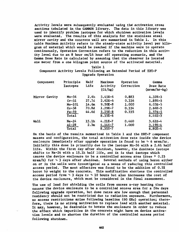
Activity levels were subsequently evaluated using the' activation crosssections tabulated in the GAMMON library. The data in this library wasused to identify problem isotopes for which shutdown activation levelswere evaluated. The results of this analysis for the stainless steelmirror cavity and the concrete wall are summarized in Table 1. In thistable Maximum Activity refers to the steady-state activity level per kilo-gram of material which would be reached if the machine were to operatecontinuously, Operation Correction refers to the reduction in this activ-ity level due to an 8 hour on/16 hour off operating scenario, and theGamma Dose Rate is calculated by assuming that the observer is locatedone meter from a one kilogram point source of the activated material.
Table 1Component Activity Levels Following an Extended Period of EBT-P
Upgrade Operation
Component
Mirror Cavity
Hall
PrincipleIsotopes
Mn-56Cr-51Mo-101Co-58Fe-59Total
Na-24Al-28Total
HalfLife
2.6h27.7d14.6m70.8d44.6d
15. lh2.3m
MaximumActivity(Ci/kg)
5.45E-62.62E-69.50E-81.29E-75.25E-88.35E-6
4.21E-74.14E-78.35E-7
OperationCorrection
0.8830.3361.0000.3340.335
0.4601.000
GammaDose Rate
(mrem/hr-kg)
4.32E-31.89E-56.03E-52.66E-51.37E-54.44E-3
3.61E-43.19E-46.80E-4
On the basis of the results summarized in Table 1 and the EBT-P componentmasses and configuration, the total activation dose rate inside the deviceenclosure immediately after upgrade operation is found to be ^ 6 mrem/hr.Initially this dose is primarily due to the isotope Mn-56 with a 2.6h halflife. Within the first day after shutdown, however, the dominate isotopeshifts to Na-24 with a 15.lh half life, and it is that isotope whichcauses the device enclosure to be a controlled access area (dose > 0.25mrem/h) for *\» 3 days after shutdown. Several methods of using boron eitheron or in the walls were investigated as a means of reducing this controlledaccess period. The most effective was found to be the addition of 0.5%boron by weight to the concrete. This modification shortens the controlledaccess period from ^ 3 days to ^ 10 hours but also increases the cost ofthe device enclosure, which must be considered in the final assessment.
The use of lead for shielding the coils from excess x-ray heating thuscauses' the device enclosure to be a controlled access area for a Tew daysfollowing upgrade operation, but dose rates are low enough that personnelresidency should not be restricted due to radiation exposure. Furthermore,no access restrictions arise following baseline (60 GHz) operation; there-fore, there is no strong motivation to replace lead with another material.It may, however, be desirable to borate the enclosure in order to reducethe effect which impurities in the concrete might have on device activa-tion levelB and to shorten the duration of the controlled access periodfollowing shutdown.
462

INTERCOMPARISON OF NUCLEAR DATA LIBRARY SOURCES, GROUPSTRUCTURES AND COLLAPSING SPECTRA FOR INTOR-EC
S. Pelloni, J. Stepanek, D. Dudziaka^
Swiss Federal Institute for Reactor Research (EIR)a) On leave from Los Alamos National Laboratory to EIR
Previous work has shwon large variations in predicted tritiumbreeding ratio for the European INTOR design (1) (INTOR-EC),depending upon the nuclear data base selected. The present studywas undertaken to compare various generally available nuclear datalibraries, and to evaluate them relative to a reference 171-neu-tron and 36-gamma group library. Using the group structures andcollapsing spectra of other fewer-group libraries, the effects ofthese parameters could be evaluated. Also, any discrepancies in thefewer-group libraries could be identified for further study. Nucleardata selected for the study were transport cross sections and res-ponse functions from the Los Alamos MATXS library, transport crosssections and response functions from the DLC-37 library. The MATXSlibrary had been generated at Los Alamos with the NJOY code fromENDF/B-IV and Los Alamos internal evaluations of pointwise microscopicdata. For the present study the generally available 30-neutron and12-gamma group Los Alamos MATXS library (3) was used without modifi-cation or further collapse. However, the reference VITAMIN-C (DLC-41)library was used both uncollapsed as a reference and after collapsewith the group structures and weighting schemes used by Los Alamosand by General Atomic Co. (GA) in producing their respective fewer-group libraries. Further comparison were then made with previous cal-culations performed (1) at GA, where the DLC-37, DLC-41 and MACKLIB-IVlibraries had been collapsed into GA's 25-neutron and 21-gamma groupstructure.
Tritium breeding ratios were calculated with the various libraries fortwo alternative INTOR-EC breeder blanket designs, one employing Lii7Pbe3and the other Li2SiO3 with a Pb multiplier. Results are presented inthis summary for the former design, where the model consists of a 250-cminner radius cylindrical first wall of 3-cm thick Al (20u/o H2O), followedby a 40-cm breeding region of 80u/o Lii7Pb83, IOU/0H2O and 10u/oSS-316,and finally a 12-cm reflector of solid SS-304. Calculations were per-formed at EIR using the SURCU surface flux transport code with double P2spatial and P3 scattering approximations, and with the ONEDANT discrete-ordinates code in S8P3 approximation.
Table 1 shows sample results for the breeding ratios. Principal conclu-sions from the table and other results to be presented are that thegroup structure choice has only about a 1 % effect (cases 3 and 5 vscase 1), as does the weighting spectrum (cases 3 vs 4 and 5 vs 6), butin all cases the Los Alamos group structure and weighting spectrum aremost accurate in reproducing the reference calculations.

Also, attempts to reproduce the 6A collapsed data were unsuccessful,and those GA data gave large (>4X in table 1 and up to 23 % for U2SO3)deviations from the reference results. The discrepancies were narrowedto the 6Li (n,t) ''He reaction in the thermal energy region, where mostreactions occur, but the response functions also differ significantlyin the higher energy region, implying that the GA weighting functionactually deviated considerably from 1/E.
Table 1 TRITIUM BREEDING RATIOS FOR INTOR-EC Li17Pb83BLANKETUSING DIFFERENT NUCLEAR DATA SETS
Tritiumproduction
Transport codeused
30 %Enrich,6Li
6Li(n,t)
7Li(n,nt)
TOTAL
Case
1
SURCU
1.275
0.013
1.288
Case
2
ONEDANT
1.269
0.013
1.282
Case
3
SURCU
1.283
0.013
1.296
Case
4
SURCU
1.294
0.013
1.307
Case
5
SURCU
1.290
0.013
1.303
Case
6
SURCU
1.294
0.013
1.307
Case
7
ANISN
1.322
0.013
1.335
Case 1: VITAMIN-C library (171 neutron + 36 gamma groups)Case 2: LANL-NJOY library (30 neutron + 12 gamma groups)Case 3: VITAMIN-C collapsed to LANL 30 + 12 group structure using
LANL weighting spectrumCase 4: VITAMIN-C collapsed to LANL 30 + 12 group structure using
1/E weighting spectrumCase 5: VITAMIN-C collapsed to GA 25 + 21 group structure using
LANL weighting spectrumCase 6: EIR calculation performed using VITAMIN-C collapsed to GA
25 + 21 group structure using 1/E weighting spectrumCase 7: GA calculation performed using DLC-37 library collapsed to
GA 25 + 21 group structure using 1/E weighting spectrumREFERENCES
1. S. Pelloni, "Cross Section Sensitivity and Uncertainty Analysisfor European INTOR and U.S. FED Designs",General Atomic Co. report GA-A16685 (1982)"171 Neutron, 36 Gamma Ray Group Cross Sections forFusion and LMFBR Calculations", Radiation ShieldingInformation Center library DLC-41 (1978)"The MATXS-TRANSX System and the CLAW-IV Nuclear
R.E.Mac Farlane Data Library", Proc. Intl. Conf. on Nucl. Cross Sectionsfor Technology, Knoxville, TN, 22-26.10.1979, NBS Spec.Pub. 594, p. 213
464
2. "VITAMIN-C
3. R.J.Barrett

DEVELOPMENT OF THE TWO-DIMENSIONAL CROSS-SECTION SENSITIVITY ANDUNCERTAINTY ANALYSIS CODE SENSIT-2D WITH APPLICATIONS TO THE FED
M. J. Embrechts, D. J. Dudzlak, and W. T. Urban, Los Alamos NationalLaboratory, Los Alamos, New Mexico, 87545
The calculation of nuclear design parameters is often limited in accuracydue to errors resulting from calculational methods and the cross-sectiondata utilized. Cross-section sensitivity analysis has become a widelyapplied design tool which allows the user to pinpoint the most crucialcross sections in a specific energy range for a particular design. Across-section sensitivity analysis leads to a broader interpretation of theresults from a transport calculation and, in conjunction with anuncertainly analysis, provides a way to estimate errors for a particularresponse (e.g., nuclear heating, radiation damage, etc.). Consequently, itcan be determined where improvements in the nuclear data and/or the designare needed to reduce that uncertainty. The complicated geometry of afusion reactor makes che capability to undertake a two-dimensionalsensitivity analysis in a toroidally symmetric system highly desirable.
A two-dimensional code, SENSIT-2D1, which can nodel a toroidal geometry,was developed and has been applied to a conceptual design for the FEDblanket/shield. SENSIT-2-D has the capability for cross-sectionsensitivity and uncertainty analyses, secondary-energy-distribution (SED)sensitivity and uncertainty analyses, and design sensitivity analyses. Thealgorithms utilized are based on first-order perturbation theory. The codeallows (x,y) or (r,z) geometry options and accepts group dependentquadrature sets. SENSIT-2D is intended to be used in conjunction with thetwo-dimensional multigroup, discrete-ordinates transport code TRIDENT-CTR.2
Two-dimensional and one-dimensional cross-section and SED sensitivity anduncertainty analyses of the heating and the copper d.p.a. in the inboardtoroidal field coil of the FED conceptual design were performed. An (r,z)geometry representation for the FED is reproduced in Fig. 1. Although thecalculated uncertainties in this case for the 2-D model are of the sameorder of magnitude as those for the 1-D model, there is no a priori way todetermine if there might be severe differences. The more complex thegeometry the more compulsory 2-D analysis becomes. Specific 2-D resultsfor the FED shield and toroidal field (TF) coil show that the majorcontribution to the cross-section uncertainty are chromium and iron, withrelative standard deviations of 96.7% and 47.3Z, respectively, in the TFcoil integral heating. Corresponding values for the SED uncertainties are4.92 and 18.4%. Contributions to the total uncertainty were smaller fornickel, copper, hydrogen and carbon. Results for a similar study of thehot-spot heating in the TF coil were within 2% of those for the integralheating. All analyses were performed with the Los Alamos 42-group MATXScross-section library (ENDF-BV), and the COVFILS3 covariance matrixlibrary. The large uncertainties due to chromium result mainly from largecovariances for the chromium total and scattering cross sections.
Work performed under the auspices of the USDOE.
465

This paper will highlight the features of SENSIT-2D and will give detailedresults for the 1-D and 2-D sensitivity analysis for the heating and copperd.p.a. of the TF coil for the FED conceptual design.
3.0
IX)
OMi
S<ruclur«SS3J6
r 2 0 % SS3W
TITCoil
Mogntt
Void Shield
7 Outboard SMoM
Void
Plasma
I(.78 2JO 3.0 4.0
Radius (m)
&0 6.0 6.66
REFERENCES
Fig. 1. FED calculational model.
1. M. J. Embrechts, "Two-Dimensional Cross-Section Sensitivity andUncertainty Analysis for Fusion Reactor Blankets," Los Altmos NationalLaboratory report LA-9232-T (1982).
2. T. J. Seed, "TRIDENT-CTR User's Manuel," Los Alamos ScientificLaboratory report LA-7835-M (1979).
3. D. W. Muir and R. J. LaBauve, "COVFILR A-30-Group Covariance LibraryBased on ENDF/B-V," Los Alamos National Laboratory report LA-8377-MS(1981).
466

OVERVIEW OF FIRST WALL, BLANKET AND SHIELD TECHNOLOGY AND PROGRESS
R. E. NygrenArgonne National Laboratory
9700 S. Cass AvenueArgonne, Illinois 60439
Progress in recent years in plasma physics, materials research and designanalysis has brought a better understanding of the general engineeringobjectives for developing nuclear systems for advanced fusion reactors. Thisoverview will focus primarily on the areas of heat rejection, electromagneticeffects and remote maintenance, and will touch on related efforts in reactordesign and materials research. The first portion of the presentation (andpaper) will summarize technical issues using examples from recent designstudies (FED/INTOR, DEMO MARS, STARFIRE, etc.) and will briefly describe thescope of ongoing experimental programs. The second portion will review theresults from two programs, the First Wall/Blanket/Shield EngineeringTechnology Prograra (FWBS Program) and the TRIO Blanket Processing Program.Brief descriptions of these programs are given below:
The FWBS Program is an experimental program, broad in scope, with the overallobjective of providing engineering data that will define performanceparameters for nuclear systems in near-term and advanced fusion reactors. Theprogram comprises four separate elements: 1) thermotnechanical and thermal-hydraulic testing of first wall component facsimiles with emphasis on surfaceheat loads; 2) thermomechanical and thermal-hydraulic testing of blanket andshield component facsimiles with emphasis on bulk heating; 3) electromagnetictesting of first wall, blanket, and shield component facsimiles with emphasison transient field penetration and eddy current effects; and 4) studies ofassembly, maintenance, and repair with emphasis on remote handlingtechniques. Program Elements (PE) 1, 2 and 4 above are performed byindustry. PE-3 is performed by Argonne National Laboratory (ANL), which hasresponsibility for overall technical direction of the program.
In PE-1, surface heating is simulated using rastored electron beams.Westinghouse began surface heating tests in December 1981 using a 50 kW e-beamsource (ESURF). In June of 1982 a more powerful 100 kW facility (ASURF) cap-able of accommodating test pieces of 1 m m in size was completed. Theexperimental data from tests in ESURF and ASURF will support the developmentand verification of analytical models that can accurately describe thetemperatures, gradients, distortions and hydraulic behavior of advanced heatrejection components.
PE-2 initially has focused on solid breeding blankets. Araong the criticalengineering issues with high priority identified by General Atomic and EG&G,Idaho for resolution in PE-II are (1) the rate of heat transfer from a(ceramic) solid breeder to a (stainless steel) heat sink i.e., the "gapconductance problem' and (2) the long term configuratlonal stability of solidbreeders operating in a system with terperature gradients and flowing purgegas. Scoping tests in both areas were underlay in the fall of 1982.
469

In PE-3, construction of a large magnet facility, the Fusion ElectromagneticInduction Experiment (FELIX), is in progress at ANL and operation is expectedin the spring of 1983. FELIX will be the test bed for benchmark experimentsin electromagnetic effects and will support parallel development of thecalculational tools for analyses of eddy currents that can reduce fieldpenetration or can produce body forces on reactor components. Our analyticalcapability must develop sufficient sophistication to treat the segmented,inhomogeneous configurations of fusion reactors.
In PE-4 McDonnell Douglas and Remote Technology have been working together in1981 and 1982 to identify key issues in remote maintenance appropriate for theprogram's resources. The twofold approach will (1) seek out and compileexisting useful information in a Designer's Guidebook and (2) proceed with aseries of tasks involving limited development of test hardware such as (a)remotely activated fasteners for vacuum joints and (b) remotely activatedelectrical contacts that provide a preferred current shunt between adjacentfirst wall sections.
The blanket processing program at ANL emphasizes development of solid orliquid lithium-bearing materials as the tritium breeding media for fusionreactor blankets. Current efforts are focused on an in-pile test of tritiumrecovery from solid breeders, i.e., the TRIO-01 experiment. TRIO-01 is acomprehensive test of a miniaturized blanket assembly. Irradiation in the OakRidge Research Reactor began in November 1982 and was scheduled to run throughApril 1983. The experiment is designed to test continuous, in-situ recoveryof tritium from the solid breeder (LiA102) which is in the form of a hollowcylinder. Helium purge gas sweeps past the inside surface and collectstritium which has migrated out of the breeder. The sweep gas lines passupward through the top of the reactor tank to a gas analysis station wheretritium levels and chemical compositions of the sweep gas are measured.
Both of the programs above began experimental work in 1982 and results werenot yet available (in October). Results from TRIO and from several firstround tests in the FWBS Program will be available at the time of the Knoxvillemeeting. This paper will provide an overview of selected results and detailswill be covered in other papers.
470

FUSION POWER BURST FACILITY - A DISTRIBUTED 14 MeV NEUTRON RADIATION FACILITYFOR ENGINEERING SCALE FW/B COMPONENT SYSTEM TESTING AND DEVELOPMENT
P. Y. Hsu, L. 0. Miller, Y. D. Harker, A. J. Scott, T. S. BohnF. J. Wheeler, D. E. Wessol, G. A. Deis, K. D. Watts
EG&G Idr.ho, Inc.
A distributed pulsed 14 MeV neutron source is described which utilizes thehigh powered (270 GW) and large test volume (8" diameter x 28" length) Power BurstFacility (PBF) at the Idaho National Engineering Laboratory. The concept ofutilizing existing fission test reactors for fusion FW/B components andsystems have been adequately documented.^ In all previous scenarios, thenormal fission spectrum including tailoring were shown to produce adequateheating profiles and to some extent tritium breeding. However, one recognizedshortcomings is the absence of the 14 MeV neutron component. This work describesa scheme whereby the fission neutron from an existing reactor are configuredto include the production of a 14 MeV component.2,3
Preliminary calculations shows that using existing PBF components for shortpulses starting at 5 msec, a li MeV flux of the order of 2.5 x 10 ^ n/sec/cmcan be produced. If on the other hand the ^-inch wall thickness inconel in-pile tube is replaced by one made of zircaloy, an additional order of magnitudein 14 MeV neutron yeild can be otabined. It should be pointed out that thecost of such a changeover is relatively small. Thus a fusion power burstfacility (FPBF) capable of producing 14 MeV neutrons in excess of 1 MW/m"1 wallloading can be realized in the near term.
This large volume distributed 14 MeV neutron source is shown to be pertinentto near-term (TFTR) and the next pulsed fusion machine such as the FED. Ascurrently conceived, the FPBF has the highest potential to provide a testspace large enough to accommodate engineering scale components whose behaviorcan be correlated between fission based testing with a representative 14 MeVfusion neutron environment.
The following aspects of the FPBF are envisioned to provide an engineeringdata base for low-level dosimetry development for TFTR application. TheLithium Blanket Module scheduled for TFTR^ seeks to demonstrate the range ofblanket technology from a distributed neutron source which will be representativeof future fusion machines. However, testing to date have used exclusivelyseparate 14 MeV point source and hard spectrum from fission reactors such asCFRMF.5 At a minimum, it is suggested that a representative LBM moduleplaced in the FPBF will provide invaluable data prior to testing on TFTR.Moreover, this preliminary step of using FPBF will provide added confidence toa large range of the TFTR technology development activities, since a fusiontypical environment will be available.
A second example (others will be discussed in the paper) involves the behaviorof solid breeders in a fission spectrum. One of the critical issues involvesthe ^Li burnup and self shielding of test modules inside a fission spectrum.It is suspected that the °Li reaction will produce non-representative heatingprofile,6 thereby raising questions on the stress characteristics of componenttesting for thermal hydraulic and therraomechanical experimentation. Theproposed FPBF will be able to adequately address this uncertainty by providingin-situ, both features, an environment characteristic of a fission system andone with the full fusion spectrum.
471

References
1. Hsu, P. Y., et al., "Role of Fission Reactor Testing Capabilities in theDevelopment of Fusion Technology," 9th Symposium on Engineering Problemsof Fusion Research, October 26-29, 1981.
2. Frigerio, N. A., "Conversion of Reactor Neutrons to 15 MeV with LiD,"Radiological Applications of Neutron Radiation, IAEA, Vienna, 1972.
3. Miller, W. H., et al., "Thermal Neutron Driven 14.1 MeV Neutron Generators,"Nuclear Instruments and Methods, September 1982.
4. Jassby, D. L., et al., "Design of Tritium Breeding Experiment for theTFTR," Proceedings of Tritium Technology in Fission, Fusion and IsotopicApplications, April 29 - May 1, 1980, Dayton Ohio.
5. Harker, Y. D., et al., "Neutron Dosimetry fcr the Lithium Blanket ModuleProgram," Proceedings of the Fourth ASTM-EURATOM Systems on ReactorDosimetry, March 22-26, 1982, NBS, Washington, DC.
6. Scott, A. J., et al., "Heating Rates for I^O Water Cooled Test in PBF"to be published.
Work supported by the U.S. Department of Energy Assistant Secretary for Research,Office of Fusion Energy, under DOE Contract No. DE-AC07-76ID01570.
472

THE TFTR LITHIUM BLANKET MODULEFINAL DESIGN AND MATERIALS DEVELOPMENT
D. W. GRAUMANN, R. L. CREEDON, B. A. ENGHOLM, J. R. LINDGREN, andL. YANG, General Atomic Company, San Diego, CA
A Lithium Blanket Module (LBM) representative of a fusion reactor blanketnodule has been designed by General Atomic Company and EG&G Idaho undercontract to Princeton Plasma Physics Laboratory with the sponsorship of theElectric Power Research Institute.1 Fabrication of the LBM is expected bythe end of 1983. The LBM will be tested using the toroidal neutron sourceof the Tokamak Fusion Test Reactor (TFTR) beginning in late 1984, and mea-surements of spatial integral neutronics and tritium production throughoutthe LBM will be compared with analytical predictions of Monte Carlo neu-tronics codes* Adequate neutronics and tritium breeding data for compari-son with theoretical predictions can be obtained both with the relativelylarge number of low fluence (~ 10*0 n/cm^ per shot) D-D and D-T runs andwith the small number of high fluence (~ 10*2 n/cm^ per shot) D-T runsplanned for TFTR operation in 1984 to 1986. The LBM program is also pro-viding operational experience in several critical areas of fusion blankettechnology, including fabrication of breeding elements, blanket dosimetrymeasurements in a tokamak reactor environment, and electromagnetic isola-tion of blanket modules from the tokamak plasma.
TABLE I. MATERIALS AND DESIGN SELECTIONS FOR THE LBM
Applicable inPower Reactor
Breeding material Li£O (with natural isotopic content) /Coolant (15% void) Air (corresponding to helium) /Structural material Stainless Steel 316 /Breeder element Sintered Li20 pellet, 2.5-cm diam, 2.5-
cm length, and 80% theoretical density /Cladding Stainless Steel 316, 0.3-mm thick /Breeder lattice 923 close-packed radially oriented rods,
60-cm breeder section /Sample retrieval 1) Thirteen removable breeder rods in
central region2) Selected buffer-zone rods removable
Neutron dosimetry 1) Wires between rods /2) Foils in rod pockets
Neutron multiplier Provision for 500-kg slab at front faceNeutron reflector Stainless Steel 316, 20-cm deep /
The geometric and physical characteristics of the breeder, structure andcoolant arrangement of the LBM were selected to be applicable to the blan-ket nodules of a power reactor as indicated in Table I. The LBM consistsof a cubical array of 923 radially oriented cylindrical breeder rods, 2.54en in diameter. Each rod consists of a 60-cm long section of lithium oxidepellets contained in a 0.3-nm wall stainless steel tube followed by a 20-cnlong solid stainless steel neutron reflector rod. Lithium oxide was selec-ted as the tritium breeding material because it can provide a tritium
473

breeding ratio greater than 1.0 in the case of a complete coverage blanketwithout the use of an independent neutron multiplier, and because of theelimination of competing materials due to safety considerations, tempera-ture constraints, or lack of basic data.2 Certain breeder rods are speci-ally designed to incorporate activation foils for neutron dosimetry and/oraluminum clad pellets for tritium dosimetry. In addition, provisions forinserting dosimetry wire bundles into the tricusp spaces between rods havebeen included. The 20 cm diameter central zone of the LBM contains theprimary test elements and can incorporate up to 13 instrumented rods and 25wire bundles. Selected locations in the surrounding buffer zone can alsoaccommodate dosimetry rods and wires. The removable instrumentation isretained by two doors at the rear of the LBM.
Procedures for mass producing 25,000 2.50 cm diameter x 2.54 cm longlithium oxide pellets have been developed. An automated press with hopper-feed capability and a tungsten carbide die is used to cold press the pel-'lets to a green density of ~ 75% in a slightly oversized configurationusing minus 100 mesh LI2O powder. These pellets are then sintered on nick-el trays at a peak temperature of 1100°C for four hours in batches of ~ 500using a cold-wall vacuum furnace. Sintered pellets with densities suffi-ciently close to the desired 80% and diameters within a few tenths of amillimeter of the required 2.50 cm are thus obtained. The pellets, whichare stored in a controlled dry atmosphere, are subsequently assembled intothe breeder rods.
Neutronics analyses performed in support of the final design includedimplementation of coupled Monte Carlo techniques and cell calculations.The TFTR configuration was found to be ideally suited to coupled calcula-tions because a series of detailed calculations can be performed on themodule itself without having to repeat the part of the calculations relatedto neutron transport in the TFTR. In the coupled calculations, a long ini-tial run of the overall TFTR/ LBM was made to determine the neutron fieldsincident on the LBM surfaces, followed by shorter runs of the LBM itselfusing these neutron fields to obtain details of neutron fluxes, tritiumproduction rates and foil responses.
Passive dosimeters consisting of foils and wires that are activated by neu-trons in the LBM were selected to provide integral reaction rate data.Dosimetry feasibility demonstration experiments have been performed at EG&6Idaho to qualify the dosimetry for D-D and D-T neutron operation in TFTR.Tritium dosimetry will be performed by the thermal extraction method, heat-ing the II20 pellet to ~ 950°C in a purge flow stream of helium. Thismethod is expected to give the lowest uncertainty of any method in deter-mining the small tritium concentrations in the LBM breeder pellets follow-ing each D-D or D-T run (0.1 to 10 nanocuries per gram of lithium).
This work is being performed under subcontract number S-01778-A fromPrinceton University Plasma Physics Laboratory under the sponsorship of theElectric Power Research Institute, Research Project 1748.
References1. TFTR Lithium Blanket Module (LBM) Program Preliminary Design Report,
General Atomic Company Report No. GA-A16616, December 1981.2. Summary Report -TFTR Lithium Blanket Module Program, EPRI Research
Project RP-1748, April 1982.
474

PROGRESS IN STUDIES ON Li,,Pbo, AS LIQUID BREEDER FOR FUSION REACTOR BLANKETS1 / S3
by
6. CASINI
Commission of the European Communities
J.R.C.-Ispra Establishment
Italy
A relevant effort is being pursued at JRC-Ispra to assess the feasibility
of the eutectic Li]7Pbg3 as a liquid breeder for experimental and power
fusion reactors. The activities in progress are comprehensive of :
- experiments for data base acquisition and implementation
- design studies on blanket concepts.
Data_Base- Acquisition
Calorimetric measurements of the Li^Pbg^ eutectic mixture have been per-
formed in the temperature range (25-3OO°C). Melting temperature, enthalpy
of fusion and specific heats at constant pressure have been measured.
The solubility of hydrogen isotopes in liquid Li]7Pbs3 has been investiga-
ted in collaboration with the University of Cagliari. A strong dependence
of the Sievert's constant from the gas pressure was found, which calls for
new experiments.
The chemical reaction of Li^Pbgj with air was found to be mild. It was im-
possible to cause self-ignition of the heated samples. Experiments"where
the eutectic was dribbled in water in a closed crucible have shown a gas
pressure increase corresponding to a reaction of about 15% of the alloyed
lithium.
Two types of compatibility experiments between Li Pb and steel are in17 83
progress:- static corrosion tests with AISI-316 L and Mn-Cr steel in the temperature
range 400-600°C up to 6000h
- tensile tests on notched specimens treated at low temperature (3O0-35O°C)
under constant load.
The results insofar obtained indicate that, in case of AISI-316, no corro-
sion problems are expected if the maximum temperature does not exceed 400°C.
On the other side, liquid metal embrittlement can not be excluded at low
temperature ( d 300°C).
Blanket_Conceptual Design
A blanket design with Li]7Pbg3 as liquid breeder and water as coolant has
been studied in the frame of the INTOR project. The proposed design is com-
posed of a thermal panel (first .wall) and separated breeding units, arranged
along the poloidal direction. A reactor segment contains 24 breeder units.
Each unit is constituted by a steel vessel, containing the breeder and the
cooling tubes. In the table are shown the main features of the proposed blan-
ket units.
475

Breeder Lij7Pb83 (30Z Li-enr.)
Coolant H2O
Structure AISI-316
Radial thickness, mm 460
Coolant tube ID/OD, mm 18/21
In/out coolant temperature, °C 240/260
Coolant pressure, MPa 5
Max. vessel temperature, °C 370
Max. breeder temperature, °C 355
Max. Von Mises stress, MPa 110
Local breeding ratio at 1.25
This design looks satisfactory for standard operation conditions; however,
the problem of the breeder vessel integrity associated to a coolant tube
rupture appears serious and deserves further investigation. Simulation ex-
periments of this type of accident (water-breeder interaction) are in pro-
gress at Ispra.
The method of continuously removing the tritium produced by an inert gas
flowing in an extractor outside the blanket, in countercurrent with the
liquid breeder, appears attractive but requires experimental verification.
First calculations show that, in order to maintain a tritium inventory of
200 g in the blanket, for an extractor column of 1.7 x 15 m, a gas flow of
about 9 1/s is needed.
The problem of keeping the breeder always liquid during the reactor opera-
tion has been investigated on the basis of the experience acquired from
fast fission reactors. The conclusion is that the plant layout looks fea-
sible and then this aspect is not considered a critical issue for the use
of Li Pb as breeder in fusion reactors.17 83
476

MARS HIGH TEMPERATURE BLANKET
J. D. Gordon, D. H. Berwald, B. A. Flanders, J. R. Garner, S. C.Mortenson, TRW Energy Development Group; J. F. Partner, C. A. Sink,J. C. Yu, K. L. Agarwal, S. Dharmarajn, General Dynamics; N. M.Ghoniem, U.C.L.A.; N. J. Hoffman, E.T.E.C., Rockwell International
The MARS high temperature blanket is designed for the dual applica-tions of either high efficiency electricity production or processheat for synthetic fuel production. Other blanket design goalsare tritium self-sufficiency, low tritium inventory, more than 40%of the blanket energy extracted at high energy, long lifetime inthe neutron environment, no use of reactive liquid metals, minimiza-tion of long term activation and use of characterized materials andfabrication techniques. This challenging set of goals has been metwith a novel blanket design that uses radial zoning and the uniqueproperties of the lead-lithium eutectic, Pbg3Li;u, as a coolant/neutron multiplier/breeder. During the first year of MARS, theblanket design was optimized for electricity production. A reopti-mization for the synthetic fuel application is in progress.
Twenty-four blanket modules, each 6.32 meters long, make up thetandem mirror central cell. An isometric of the module is shownin the figure. The modular design allows rapid changeout of allcentral cell components. The blanket is radially zoned to maintainthe metallic structure at moderate temperature. The front zone ofthe blanket has an HT-9 ferritic steel structure cooled by Pb83Lii7.HT-9 was chosen because of its excellent mechanical properties, lowswelling, compatibility with Pb33Lii7 and relatively low long termactivation. The Pbg3Lii7 cools the structure to a maximum temperatureof 520°C while also serving as a neutron multiplier and supplementaltritium breeder. About 52% of the energy incident on the blanket isdeposited in the front radial zone. A small heat leak from thehigh temperature zone, causes 54% of the energy to be extracted inthe Pb33Lii7 coolant. The Pbg3Lii7 enters the blanket at 372°C andexits at 482°C. The upper temperature was chosen for HT-9/Pbg3Li]7compatibility and for thermal creep reasons. The lower temperaturewas chosen to minimize radiation embrittlement of the steel. The keyradiation effects problem is shift of DBTT or radiation embrittlement;this problem is amelioriated by sixty hours of annealing at a uniformtemperature of 450°C performed during an annual maintenance period.
The high temperature blanket zone is composed of 12 circumferentialHT-9 pods that are thermally Insulated from the energy absorbingmaterial. A porous silicon carbide (80% TD) pebble bed impregnatedwith 2 atomic % enriched LIAIO2 is used for energy absorption.Placing the tritium breeding material in the high temperature zoneincreases the fraction of high temperature heat. Enriching thebreeding material to 90% in "Li allows it to be present in low
477

concentration and eliminate sintering of the breeder. The zone itcooled by SO atmosphere helium with an outlet temperature of 900*C.The maximum pebble temperature la about 980*C. Thia high temperatureincrease* the speed of tritium diffusion and allows moderate LIAIO2grain sizes of 50 van. The preclusion of thermal sintering and theinsolubility of tritium in SiC along with fast thermal diffusionresults In an estimated tritium inventory in the blanket of 25 g for3500 MW of fusion power. This new concept of enriched LIAIO2 in aSiC matrix has significantly improved the performance of high temper-ature blankets.
The MASS blanket is designed for a neutron wall loading of 5 MW/m*accompanied by a surface heat flux of 6 W/co2. Neutronics analysesshow that the tritium breeding ratio at beginning of life is 1.13;the TBR decreases to 1.06 after 4 years. Energy multiplication is1.15. About 90Z of the tritium breeding occurs in the LJLAIO2 withthe r»st occuring in Pb83^*17« Radiation damage to the first wallla at 70 dpa/full power year* However, the radiation resistance ofHT-9 combined with a swelling-tolerant design should allow a lifetimein excess of 200 dpa or 4 calendar years.
The blanket has been Integrated with a combined Brayton and Rankineenergy conversion cycle to produce electricity with a thermalefficiency greater than 45% including helium compression and pumpingand lead-lithium pumping. The combination of high thermal efficiencyand reasonable blanket costs result in a relatively low cost ofelectricity. Blanket costs are dominated by the cost of siliconcarbide. Blanket produclbility studies have shown that the design isfabricable with standard techniques that are in current practice.
Work funded under LLNL Contract 5299101.
MARS HIGH TEMPERATURE BLANKET
478

DESIGN OF HIGH TEMPERATURE FIRST WALL AMD BLANKET FOR A DDCOMPACT REVERSED FIELD PINCH REACTOR (CRFPR)*
A.E. Dabiri, J.E. Glancy, Science Applications, Inc.
A part of the assessment of the engineering and technological differencesbetween DD and DT fueled Reversed Field Pinch (RFP) reactors is the designof a first wall/blanket which would take full advantage of the absence oftritium breeding in the DD reactor. The primary objective for the firstwall/blanket design are: use of conventional technology to the greatestextent possible; production of high temperature heat suitable for use in ahigh efficiency generating cycle; minimization of the quantity of radio-active material produced; high neutron energy multiplication; and reason-able cost.
The RFP assessment focuses on compact reactors because the annual generat-ing cost of electricity for a compact reactor is projected to be signifi-cantly lower than that of an equal capacity conventional fusion reactor(Ref. 1). Two design points for a DD/CRFPR have been proposed (Ref. 2):(1) /ully "cost optimized" design with a first wall thermal load of 17MW/m and neutron wall loading of 10.6 MW/m ; and (2) a "cost degraded"with^a first wall thermal load of 4.87 MW/m and neutron wall loading of 3MW/m . The degraded design is obtained by reducing the power density ofcost optimized design until the first wall surface heat flux is equal tothe "cost optimized" DT/CRFPR.
Compact reactor first wall and blanket design requirements differ fromthose of conventional fusion reactors in the following respects: (1) thereis no limiter and the full particle energy load is absorbed by the firstwall, (2) the thermal wall loads are considerably higher and therefore thebanket power density is higher (factor of 5-15), and (3) the neutron wallload is higher and therefore the blanket power density is higher (factor of5-15).
The thermal hydraulic analysis of a first wall made of AMAX, a high tem-perature copper alloy, consisting of channels formed by a corrugated faceplate and a flat-backing plate resulted in the following conclusions:
o For the cost degraded reactor (first wall power of 5 MW/m ) and for12.5 Mpa (1800 psia) coolant pressure, a 3 mm first wall thicknessresults in an operating life of 10,000 hours before creep ruptureoccurs. The creep rupture life could be increased by a factor ofmore than 10 if the coolant pressure is reduced by a factor of 2.
o For -the fully cost optimized reactor (first wall loading of 17MW/m ), the creep rupture strength is substantially reduced due tothe high operating temperatures (600-700°C), and therefore, the AMAXfirst wall cannot withstand the stresses even using low coolantpressure (6.2 Mpa) and thick first walls (3 mm).
The above conclusions assumes no neutron irradiation effects. However, itis known that neutron radiation accelerates creep rupture and shortenscreep rupture lifetime.
*Work supported by the Department of Energy, Office of Fusion Energy.479

Based on these conclusions, the first wall/blanket was designed for thecost degraded reactor with a coolant pressure of 6.9 Mpa (1000 psia) tomaintain a long creep rupture life. The first wall is made of AMAX and theolanket consists of four banks of titanium modified austenetic stainlesssteel tubes (PCA) and separated by a graphite layers.
The first wall is partially cooled by feedwater flowing in channels formedby a corrugated face plate and a flat backing plate. The feedwater entersat 250°C and it is heated to saturation (285°C and 6.95 Mpa). The feed-water is combined with a recirculation flow and directed to the remainderof the first wall, first bank of the tubes and part of the second bank Ofthe tubes of the blanket where the mixture is thermally boiled to a quality(steam weight fraction) of 25%. P.e steam is collected and distributedamong the remainder of the second tube bank and the two other tube bankswhere it is superheated to 538°C in series flow. A steam cycle withsteam-to-steam reheat yielding about 38 percent efficiency is compatiblewith this design.
Thermal analyses indicate that the maximum temperature in the AMAX of thefirst wall is 430°C, which is below the range where the allowable stressdrops rapidly. The maximum temperature of the stainless steel in theblanket is 610cC and at this temperature the allowable stresses are stillfairly high (430 Mpa). Temperature peaks at the outer surface of thesuperheater tubes. The inner surface is about 70°C cooler.
Stress analyses of the AMAX first wall indicate that the combined thermaland pressure related stresses are about one third the ultimate strength of400 Mpa at 430°C. The maximum primary tensile stresses were 106 Mpa whichwill result in one percent creep after around 100,000 hours of operation.The stainless steel tubes in the blanket will have maximum primary stressesof 38 Mpa, well below creep rupture limits, and total stresses (includingthermal stresses) are well below the ultimate strength of the material.
A review of the response of the first wall and the blanket materials tostress and thermal effects and radiation induced effects such as heliumswelling indicated the following:
o operating the AMAX-MZC at a temperature of 430°C should reduceswelling in the first wall to low levels,
o swelling of the graphite is low since the operating temperature rangeof graphite layers are about 1300-1600°C (.5%/dpa final volume changeat 1300°C and virtually eliminated at 1600°C).
o blanket tube ductility loss should be acceptable for minimum 6 fullpower years.
References
1. R.A. Krakowski, J.E. Glancy, and A.E. Dabiri, "Technology of CompactFusion Reactor Concepts," presented at National Science FoundationWorkshop, Washington D.C., September 30 - October 1 , 1982.
2. R.L. Hagenson and R.A. Krakowski, "Compact Reversed-Field PinchReactors (CRFPR), Sensitivity Study and Design Point Determination,"Los Alamos National Laboratory Report L.A. 9389-MS, July 1982.
480
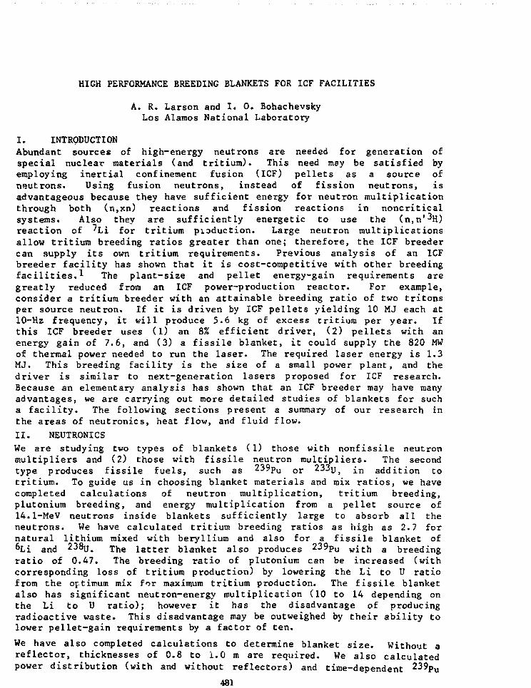
HIGH PERFORMANCE BREEDING BLANKETS FOR ICF FACILITIES
A. R. Larson and I. 0. BohachevskyLos Alamos National Laboratory
I. INTRODUCTIONAbundant sources of high-energy neutrons are needed for generation ofspecial nuclear materials (and tritium). This need may be satisfied byemploying inertial confinement fusion (ICF) pellets as a source ofneutrons. Using fusion neutrons, instead of fission neutrons, isadvantageous because they have sufficient energy for neutron multiplicationthrough both (n,xn) reactions and fission reactions in noncriticalsystems. Also they are sufficiently energetic to use the (n,n'%)reaction of 'Li for tritium production. Large neutron multiplicationsallow tritium breeding ratios greater than one; therefore, the ICF breedercan supply its own tritium requirements. Previous analysis of an ICFbreeder facility has shown that it is cost-competitive with other breedingfacilities.* The plant-size and pellet energy-gain requirements aregreatly reduced from an ICF power-production reactor. For example,consider a tritium breeder with an attainable breeding ratio of two tritonsper source neutron. If it is driven by ICF pellets yielding 10 MJ each at10-Hz frequency, it will produce 5.6 kg of excess tritium per year. Ifthis ICF breeder uses (1) an 8% efficient driver, (2) pellets with anenergy gain of 7.6, and (3) a fissile blanket, it could supply the 820 MWof thermal power needed to run the laser. The required laser energy is 1.3MJ. This breeding facility is the size of a small power plant, and thedriver is similar to next-generation lasers proposed for ICF research.Because an elementary analysis has shown that an ICF breeder may have manyadvantages, we are carrying out more detailed studies of blankets for sucha facility. The following sections present a summary of our research inthe areas of neutronics, heat flow, and fluid flow.
II. NEUTRONICS
We are studying two types of blankets (1) those with nonfissile neutronmultipliers and (2) those with fissile neutron multipliers. The secondtype produces fissile fuels, such as 239pu o r 233us i n addition totritium. To guide us in choosing blanket materials and mix ratios, we havecompleted calculations of neutron multiplication, tritium breeding,plutonium breeding, and energy multiplication from a pellet source of14.1-MeV neutrons inside blankets sufficiently large to absorb all theneutrons. We have calculated tritium breeding ratios as high as 2.7 fornatural lithium mixed with beryllium and also for a fissile blanket of&Li and 238u. The latter blanket also produces 239po with a breedingratio of 0.47. The breeding ratio of plutonium can be increased (withcorresponding loss of tritium production) by lowering the Li to U ratiofrom the optimum mix for maximum tritium production. The fissile blanketalso has significant neutron-energy multiplication (10 to 14 depending onthe Li to U ratio); however it has the disadvantage of producingradioactive waste. This disadvantage may be outweighed by their ability tolower pellet-gain requirements by a factor of ten.
We have also completed calculations to determine blanket size. Without areflector, thicknesses of 0.8 to 1.0 m are required. We also calculatedpower distribution (with and without reflectors) and time-dependent 239Pu
481

buildup. The latter effect enhances tritium breeding and energyproduction. Calculations show that addition of zirconium structure andcladding (required for fissionable multipliers) reduces net tritiumproduction by 7Z.
III. THERMAL ANALYSIS
Blankets with fission multipliers generate 200 MeV of thermal energy perneutron captured in the multiplier. This energy is useful for generatingelectrical energy to run the laser; however, it must be considered inblanket design. With 238JJ a s multiplying (and breeding) material in theblanket, the fission-generated power is sufficient to cause breakage of themultiplier elements by thermal stress. However, when the multiplyingmaterial is powdered and contained in capsules, blankets with usefulcapsule diameters (~1 cm) and cavity diameter (3 m) can be designed toaccommodate the heat flow without melting the multiplier material. Cycliceffects will be small at 10-Hz pellet frequency.2 We have analyzedmultiplier capsules with powdered 238u Or 238uc in zirconium, whichcontains both the multiplier material and radioactive fission gasses thatwill be produced.
IV. FLUID FLOW
We have calculated fluid flow rates required to remove 1000 to 2000 MW ofthermal power from a blanket with a fission multiplier. This power can betransported from the blanket to a heat exchanger with flow velocities of 1m/s in the blanket and 40 m/s in 0.5 m diameter feed pipes. For thisconfiguration the temperature differences between the inlet and outletpipes can be less than 100 C.
V. CONCLUSIONS
Elementary calculations have shown that ICF pellets may be an economicalsource of neutrons for generating tritium and special nuclear materialsfrom abundant materials such as deuterium, lithium, depleted uranium, orthorium. Pellet-gain requirements for this application are within therange of values believed to be attainable by simple volume ignition.Driver-energy requirements, at useful repetition rates, are withinprojected technology. In our studies of blankets for ICF breeders,neutronics calculations have indicated that breeding ratios required foreconomical production are attainable. Calculations of fission-multipliercapsule performance have defined constraints on capsule design. Fluid flowcalculations show no problems in obtaining a useful high-performanceblanket designs. Future work in blanket design can use much of theknowledge available from fission-reactor research.
REFERENCES
1. I. 0. Bohachevsky, L. A. Booth, and T. G. Frank, "Utility of a LowGain ICF Facility," invited paper, Am. Nucl. Soc. 1982 Wintermeeting, Washington, DC, November 14-19, 1982 (Los Alamos NationalLaboratory, LA-UR-82-1969).
2. I. 0. Bohachevsky and R. N. Kostoff, Cyclic Temperature and ThermalStress Fluctuations in Fusion Reactors," Nuclear Technology/Fusion J I687-699 (1982).
482

LOW ACTIVATION FUSION REACTOR DESIGN STUDIES*
G. R. Hopkins, E. X. Cheng, R. L. Creedon,K. R. Schultz, P. Trester, and C. P. C. Wong
General Atomic CompanyP.O. Box 81608, San Diego, California 92138
* de&ign study to investigate the implications of incorporating low-activation materials In fusion power reactors has been done.* The STARFIREtokamak reactor design was used as a reference starting point. The conven-tional iron and nickel based materials are replaced with materials less sub-ject to activation by fusion neutrons. The tokamak components of limlter,first wall, blanket, shield, and superconducting toroidal fiela magnets havebeen included in the design studies.
A toroidal, belt-type pumped limiter was used for the low-activation design.Aluminum alloy, reinforced with SiC fibers (NICALON)** was selected as thematerial to provide a useful coolant outlet temperature. A schematic isshown in Figure 1. The steady state heat flux peaks on the hemisphericaltip at 4 MW/m^ and decreases to 0.9 MW/rn along the sides. The temperaturelimit of the Al/SiC fiber composite is ~350°C and this provides a 250°C out-let temperature with water coolant. The composite material thus allows rea-sonably efficient power conversion, not possible with aluminum alloys alcne,where outlet temperatures are limited to only 75°C.
The first wall and blanket design are shown in Figure 2. The first walltubes, blanket shell, and blanket coolant thimble tubes are all solid SiC.This design features low tensile stress and few mechanical^constraints sothe high-temperature, high-neutron-fluence components ran accommodate smallvolumetric changes and movement without high strains or stresses on theceramic parts. The first wall and thimble tubes are helium cooled and theblanket shell radiation cooled. The module is a cube with approximately0.5 m sides, and provides a tritium breeding ratio greater than one withonly Li£0 as the breeding material. The first wall SiC is specially con-strained to operate with material temperatures between 750° to 1050°C inhigh heat flux (0.85 MW/m^) regions to minimize radiation-induced stressescaused by differential swelling across temperature gradients. NICALON/aluminum composite materials would be used for structure in the plenum andsupport region at the rear of the module.
Aluminum, SiC, carbon, magnesium and boron are all candidate low-activationshielding materials, and while less efficient absorbers than tungsten andiron, can be used in the outboard region where adequate space exists. Theinboard shield region utilizes 0.3 m of higher activation tungsten. Per-sonnel access to this region is, however, achieved by removing tungsten toshielded containers during reactor shutdown periods. The nuclear design andshielding details are given in a companion paper at this conference.2
*Work supported by the U.S. Department of Energy, Office of Fusion Energy,under Contract Number DE-AT03-76ET-51011.
**A product of Nippon Carbon Company, Tokyo, Japan.
483

The least restricted personnel access is gained by employing low activationsuperconducting toroidal field coil magnets. The Nb3Sn and NbTi supercon-ducting materials have no low-activation substitutes but comprise only 5% ofthe magnet material and their activation is not troublesome. High-purityaluminum provides an excellent replacement for the usual copper stabilizerand aluminum alloy can be used for structural support in the inner 20 cmregion. The outer structure of stainless steel is not highly activated inthe low neutron fluxes there. A helium vessel of high strength fiber rein-forced epoxy provides low-activation construction. These provide a minimum-thickness low-activation toroidal field coil and are described in acompanion paper at this conference. 3
A low-activation fusion reactor conceptual design has been studied where allthe components within the toroidal field coils are constructed of low acti-vation materials. All components meet the requirements of the STARFIREdesign. The low-activation design provides reduced safety restrictions andmuch reduced long term waste disposal requirements. Direct contact person-nel access to all regions except the inner plasma chamber is available fol-lowing about two weeks after shutdown. The ultimate potential of fusion asan extremely safe, environmenally benign power source is achieved throughthe low-activation design concept.
REFERENCES
1. Hopkins, G. R., et al., "Low-Activation Materials Design Study, AnnualReport," GA-A16426, October 1981 and GA-A16874, September 1982.
2. Cheng, E. T., and G. R. Hopkins, "A Minimum Thickness Low ActivationToroidal Field Coil Concept for Fusion Reactors," Fifth Topical Meetingon the Technology of Fusion Energy, April 26-28, 1983.
3. Chen, W. Y., and E. T. Cheng, "The Nuclear Design of a Very LowActivation Fusion Reactor," Fifth Topical Meeting on the Technology ofFusion Energy, April 26-28, 1983.
-THIE HHTFIUXSiCTUIEHtCOOLEDFIRST WALL
SILICON CARIIDE- CERAMIC CONCENTRIC
PRESSURE TUIES
COLD U K
-CLAMPINGWEOCES
-INSULATION: WATER COOLED' INSULATED PRESSURE
VESSEL-ALUMINUM/SiC COMPOSITE
EM CAW
Fig. 1. Schematic of a low activationlimiter fabricated from a SiCfiber reinforced aluminum alloy.
Fig. 2. A fusion reactor blanketand first wall moduleschematic using low-activation materials.
484

LIFETIME ANALYSIS OF FUSION REACTOR COMPONENTS
Richard F. MattasArgonne National Laboratory
9700 South Cass AvenueArgonne, IL 60439
A one dimensional computer code has been developed to examine the lifetime offirst wall and impurity control components. The code incorporates theoperating and design parameters, the material characteristics, and theappropriate failure criteria for the individual components. The majoremphasis of the modelling effort has been to calculate the temperature-stress-strain-radiation effects history of a component so that the synergysticeffects between sputtering erosion, swelling, creep, fatigue, and crack growthcan be examined. The general forms of the properLy equations are the same forall materials in order to provide the greatest flexibility for materialsselection in the code. The individual coefficients within the equations aredifferent for each material. The code is capable of determining the behaviorof a plate, composed of either a single or dual material structure, that iseither totally constrained or constrained from bending but not from expansion.
A flow diagram for the code is shown in Figure 1. The code first calculatesthe temperature, stress, and strain distribution through a plate based uponthe selected operating and design parameters. Property changes are thendetermined for a specific time increment, and the effects of those changes onthe initial distributions are evaluated. This process is repeated untilfailure occurs or the designed lifetime is reached.
The code has been utilized to study the behavior of the first wall forFED/INTOR and DEMO operating conditions. The first wall designs andconditions are substantially different from one another, as shown in Table1. The major differences are in the coolant temperature, wall thickness, useof beryllium, and number of operating cycles. The peak, wall operatingtemperature in FED/INTOR is only 225°C, and the peak operating temperature inDEMO is 360°C. The thinner wall and the use of beryllium in DEMO results inreduced stresses in the first wall structure. The low stresses and reducednumber of cycles mean that fatigue is not considered to be a major concern inDEMO. On the other hand, the FED/INTOR design is very close to the allowablefatigue limits such that increases in either the thickness, heat flux, ornumber of cycles cannot be tolerated. Radiation creep is expected to causestress relaxation during operation. The thermal stresses are predicted torelax out of the FED/INTOR first wall in - 1.6 y, and they are predicted torelax out of the DEMO first wall in ~ 0.7 y. During stress relaxation,stresses of equal magnitude to the thermal stresses but opposite in sign occurdur.'pg the reactor dwell periods. In both cases, radiation swelling isprea^cted to be insignificant (.02% in FED/INTOR vs. 0.27% in DEMO). This isdue to the fact that both designs operate at temperatures which are well belowthe swelling peak fo.r 20% cold worked, Type 316 stainless steel. The porosityin the 70% theoretical density beryllium is assumed to accommodate the heliumgenerated during irradiation so that the predicted swelling in beryllium iszero. The uniform elongation of the stainless steel is predicted to dropbelow 1% after - 10 y and ~ 4 y of operation for FED/INTOR and DEMO,respectively. The major conclusions of this particular study are thatradiation swelling should not be a concern for near term devices, that fatigue
485

and crack growth is the primary concern for a high cycle device such asFED/INTOR, that loss of ductility could be a concern towards the end of lifefor both devices, and that the DEMO first wall appears to have a largeoperating safety margin in terms of permissible heat loads and operatingcycles.
Table 1.Design and Operating Conditions for FED/INTOR and DEMO First Walls
Parameter FED/INTOR DEMO
Material
Thickness
Coolant Temperature
Surface Heat Flux
Neutron Wall Load
Availability
Lifetime Goal
Lifetime Cycles
Lifetime Fluence
20% CW Type 316 SS
12 mm
90°C
.11 MW/m2
1.3 MW/m2
50%
10 y
7 x 10⁵
52 dpa
BE (70% TD) on20% CW Type 316 SS
2 mm (Be)4 mm (SS)
280cC
0.25 MW/m2
2.1 MW/m2
50%
10 y
250
84 dpa
Fig. 1. Flow diagram for lifetime code.
486

COMPACT FUSION REACTORS41
Robert A. Krakowski, Los Alamos National Laboratory, Los Alamos, NewMexico, 87545Randy L. Hagenson, Technology International, Inc., Ames, Iowa 50010
The development and utlimate commercialization of magnetic fusion energy isbeing pursued in the U. S. through two mainline concepts, the tokamak andthe tandem mirror, with a number of promising but less developed approachesbeing pursued as alternative fusion concepts (AFCs). The engineeringdevelopment needs for t\xa tokamak have been quantified by detailedconceptual design studies of first-generation engineering devices,1
demonstration pilot plants,2 and commercial power reactors.3 Similarstudies of the tandem mirror reactor4, as well as studies of nearer-termengineering devices5, have been reported. Complementing these studies arereactor designs for a range of AFCs, which along with the tokamaks andtandem mirrors have been subject to recent reviews.6'7 Although based onconsiderably different confinement physics and geometry, the reactorembodiments of both the mainline and alternative fusion concepts share acommonality of largeness in size, low system power density, large super-conducting magnets, and a dominance of the fusion power core (FPC, i.e.,first-wall, blanket, shield, and coils) and related Reactor Plant Equipment(RPE) systems in the plant direct cost. These "conventional" fusionsystems nevertheless project competitive energy costs because of optimisticassumptions related to the unit costs, construction time,interest/escalation/inflation rates, and plant availability used toestimate the cost of electricity. Past experience with projecting costs ofother energy systems has shown overestimates by as much as a factor of 2.5are not uncommon.8 Concern over the dominance in mass and cost of the FPCfor many of these conventional fusion approaches has led recently toserious consideration of higher-power-density "compact" options for boththe mainline and alternative fusion concepts, in order to reduce mass andcost of the FPC, in which is embodied a majority of the physics,technological, and costing uncertainty associated with fusion power.
Generally, the compact option is defined by a reactor embodiment that, onthe basis of extended rather than new technologies, project competitiveCOEs using realistic if not pessimistic costing procedures by demandinghigher FPC performance while maintaining high plant factors and lowrecirculating power. Table I summarizes and compares characteristics beingsought for the compact reactor option. Generally, the compact option willrequire the extension of existing technologies to accommodate the higherheat fluxes, power densities, and in some instances higher magnetic field1
needed to operate the FPC with enhanced system power densities and massutilizations. The major technological challenge, therefore, rests withachieving reliable operation of a high-availability FPC that is moreseverely "stressed" relative to conventional fusion approaches. In return,a power system emerges in which the basic physics and technology unknownsassociated with the FPC exerts a considerably reduced economic leverage onthe total plant and energy costs. Other equally if not more importerbenefits accrued through the compact option are related to the. development,installation, operation, and maintenance of FPCs that are at least an orderof magnitude less massive than those presently being pursued by theconventional MFE approaches.
*Work performed under the auspices of the USDOE.
489

After presenting the economic and development rationale for the compactreactor option, existing fusion reactor designs of both mainline andalternative concepts that adopt the compact, high-power-density option arereviewed. The unique technology needs for these compact reactors aresummarized and related to performance levels presently being achieved inother high-power-density energy systems. Both concept-specific and generictechnology issues/problems are discussed within the categories of plasmaengineering, first-wall systems, blanket and shield, magnets, and remotemaintenance, as related to the compact reactor option.
REFERENCESl . C . A. Flanagan, D. Stelner, and Go E. Smith, "Fusion Engineering
Device Design Description," Oak Ridge National Laboratory ReportORNL/TM-7948 (December 1981).
2. H. A. Abdou, et_ aJL, "Design Study of a Tokamak Demonstrations PowerReactor," paper E-l-1, 9th Inter. Conf. on Plasma Physics and Con-trolled Nucl. Fus. Research, Baltimore, MD (September 1-8, 1982).
3. C. C. Baker (Principal Investigator), et aJU, "STARFIRE - A Com-mercial Tokamak Fusion Power Plant Study," Argonne National LaboratoryReport ANL/FPP-80-1 (September 1980).
4. C. Henning and B. G. Logan, "Mirror Advanced Reactor Study (MARS),"Lawrence Livermore National Laboratory (1982).
5. T. K. Fowler and B. 6. Logan, "Tandem Mirror Technology Demonstra-tion Facility," Lawrence Livermore National Laboratory Report UCID-19193 (September 1981).
6. C. C. Baker, G. A. Carlson, and R. A. Krakowski, "Trends and De-velopment in Magnetic Confinement Fusion Reactor Concepts," Nucl.Technology/Fusion, , 5-78 (January 1981).
7. Report on the Third IAEA Tech. Committee Meeting and Workshop onFusion Reactor Design-Ill, Tokyo, Japan, October 5-16, 1981, Nucl.Fus. 2£, 671-719 (1982).
8. E. W. Merrow, S. W. Chapel, and C. Worthing, "A Review of CostEstimation in New Technologies: Implications for Energy ProcessPlants," Rand Corporation report, R-2481-D0E (July 1979).
TABLE ICHARACTERISTICS SOUGHT FOR COMPACT REACTOR OPTION
High system power density (MWt/m3)Acceptable total power (MWt)Low FPC<a) aass utilization (tonne/MWt)High neutron first-wall loading (MW/m2)High blanket power density (MW/m3)Low FPC cost sensitivity RPE/TDC<b)Little or no passive magnet shieldAcceptable recirculating power fraction
CONVENTIONAL0.3-0.5> 40004"-101-51-50.50-0.75SC0.15
COMPACT5-15< 40000.3-1.010-20> 30< 0.3N0.15
ppC fusion power core, includes first-wall/blanket/shield systems.'"'Ratio of Reactor Plant Equipment (RPE) costs to Total Direct Costs
(TDC).
490

RECENT DEVELOPMENTS IN STELLARATOR PHYSICS*
John L. Johnson*, Plasma Physics Laboratory, Princeton University,Princeton, New Jersey 08544
The stellarator concept is one of the oldest and best understood schemesfor thermonuclear confinement. It was deemphasized in the late 1960'sin favor of the tokamak approach because of experimental observation ofpoor energy confinement time, theoretical predictions of enhancedtransport in the reactor regime, and pessimistic conclusions fromreactor studies due to the necessarily complicated interconnectedcoils. Recent developments have provided improvement in all three ofthese areas and have led to a revived interest in stellarator research .*
The availability of high-power auxiliary heating has made current-freeoperation with reasonable plasma parameters possible. Devices haveoperated with 10 cm density, 1 keV temperature, and nx values of3 x 10 cm' sec . Both ion and electron thermal conductivities areconsistent with neoclassical predictions . Confinement is comparablewith, or better than, that observed In tokamaks of the same size and thelosses are smaller than in discharges with Ghmic heating current .
The theoretical understanding of stellarators which is obtained with MHDtheory has also improved . This work has clarified the equilibrium andstability limitations of stellarators. Both analytic and computationaltechniques have been refined . The results lead to a desire for systemswith a large number of magnetic field periods', either a large shear tolocalize magnetic islands or a flat irrational rotational transform toavoid theni, and shaped magnetic surfaces to reduce the Pfirsch-Schlutercurrent and to provide an average magnetic well. Design ofconfigurations which satisfy these needs and have reasonable equilibriumand stability beta limits is possible .
The ability to work in magnetic field coordinates and the introductionof Monte Carlo techniques has provided a new understanding of particleconfinement and transport . Transport behavior is found to be stronglymodel dependent . Kith reasonable care', systems with adequate transportproperties can be obtained . Ai encouraging result is that magneticconfigurations designed to obtain high equilibrium beta limits haveoptimized transport properties .
Reactor studies have also progressed . Work on Heliotron H at Kyoto hasincorporated sufficient mechanical design to demonstrate the viabilityof continuous-coil torsatron configurations . A Wisconsin study,UWTOR-M, has emphasized engineering aspects and has shown that acredible modular-coil design and overall systems integration can beestablished. The studies of modular stellarators at Los Alamos, MSR,have been based on a parametric approach in order to understand theinfluence of the key physics parameters and assumptions on reactor size,performance, and cost . Potentially attractive design points are beingsubjected to more detailed analysis . These generally conservativestudies, taken collectively, demonstrate credible, competitive solutionsto the problems that contributed to the earlier deemphasis ofstellarator reactor work .
491

This improved stellarator outlook has led to preliminary study andproposal aimed at building three new experimental devices . WendelsteinVII-AS, at Garching, is a modular-coil system designed to optimize theequilibrium beta limit by reducing the Pfirsch-Schluter current. Itscritical beta is expected to be five to ten per cent. ATF, at OakRidge, is an A • 2, continuous-coil torsatron which should support abeta of four per cent and be capable of confining high-temperatureplasma with nearly reactor properties. Heliac, at Princeton, couldinvestigate the properties of a high-beta configuration with a highlynonplanar magnetic axis and shaped magnetic surfaces. These devices,together with Heliotron E, the torsatron Uragan III which is nowcommencing operation in Kharkov, and several smaller systems, shouldprovide an understanding of the improved confinement properties that canbe obtained by eliminating Ohmic heating current and of the limitationsthat are imposed by the concomitant loss of symmetry .
This improved understanding of the engineering options available forconstructing three-dimensional systems and of the nature of plasmaconfinement in them, together with the results obtained from the nextgeneration of large tokamaks, should provide a solid foundation for thedesign of an optimized toroidal device .
Supported by the U.S. Department of Energy under Cbntract No. DE-AC02-76-CHO3O73 ."•"On loan from ffestinghouse Research and Development Center .
1J. L. Johnson, Nuclear Technology/Rision 2, 340 (1982).
492

ENGINEERING DESIGN OF A COMPACT RFP REACTOR (CRFPR)*
R. L. Hagenson, Technology International Inc., Ames, Iowa, 50010R. A. Krakowski, Los Alamos National Laboratory, LOB Alamos, New Mexico,87545
Potential Reversed-Field Pinch Reactor (RFPR) design points were recentlysurveyed1 using a parametric systems model that couples magnetics, plasmaengineerings and costing models. Key tradeoffs were examined and finalsystem designs were chosen having the lowest predicted.cost of electricity(COE). This cost-optimized Compact Reversed-Field Pinch Reactor (CRFPR)would operate with fusion power cores (FPCs, i.e., first-wall/blanket/shield coils) that are at least a factor of 10 smaller thanconventional (superconducting) fusion systems generating the same netelectric power; system power densities are nearly equivalent to fissionreactors. The CRFPR approach to "compact" fusion reactors2 is particularlyattractive, requiring low-field efficient resistive coils. Remarkably,this system may operate on catalyzed-DD fuel using resistive coils at DT-like power densities if poloidal betas do not fall far below 0.2. Betavalues of 0.1-0.2 have already been achieved experimentally, witheconomically attractive DT reactors operating with betas of 0.04.Transport scalings from existing and planned experiments of at least T E •I.r 2, or in magnitude equal to 10-20X of Alcator, are needed for thereactor. The most promising result from these studies is the resiliency ofthe RFP approach in maintaining attractive designs within realistic physicsand technology constraints for widely diverse reactor systems using DT orDD fuel having net electric powers of 250-1250 MWe. An engineering designof a 1000-MWe(net), DT-fueled CRFPR is described.
The DT-fueled CRFPR design concentrates on key engineering issues relatedto high-power-density, high-availability plant operation. Ease ofmaintenance is a primary design goal, which is realized in a compact systemby "block" removal of major FPC system components. The entire FPC would beremoved as a single unit and replaced by a complete, pretested FPC. Therealization of high-power-density fusion systems involves high-heat-fluxfirst walls (4-5 MWt/m2), the control of plasma/wall interactions, a high-power-density breeding blanket (~ 200 MWt/m3, peak), and design forradiation effects in room-temperature exo-blanket coils and associatedelectrical insulation located outside the breeding blanket.
Design options for the first wall include water-cooled copper alloyoperating at ~ 500-600 K or a liquid-metal-cooled refractory metal (e.g.,TZM or Nb) operating near the liquid-metal blanket temperature of700-840 K. The simplicity of the liquid-metal-cooled first wall isattractive, although uncertainties of material compatibility in thevacinity of rapidly flowing (5-10 m/s) liquid metals at these blankettemperatures has led to the water-cooled copper first wall as a firstdesign choice. As a minimum design constraint the water-cooled first wallwould be doubly contained from the liquid-metal-cooled breeding blanket.No serious thermomechanical problems are encountered for surface heatfluxes of 4-5 MWt/m2 when using high-strength water-cooled copper alloys;relatively poorly resolved radiation effects, however, remain to be fullyincorporated into the design. Heat flux per se is not the problem, whereasplasma/wall interaction is the key issue presently under study. A dense
Work performed under the auspices of the USDOE.
493

gas blanket or possibly (but less desirably) a magnetic divertor for first-wall protection and refueling may be required.
The applicability of solid tritium breeders operating at power densitiescomparable to an LWR fission core is questionable, depending primarily onpoorly resolved theraophysical properties of these ceramics. For thisreason, the lithium-lead [Pbg^Lijy^OZ 6Li)J blanket appears particularlyattractive. The inherently low magnet fields in the RFP result in MHDpumping losses of only 1-3Z of the gross electric, using uninsulatedstainless-steel coolant ducts. Tritium breeding ratios in excess of 1.13are achieved with a 0.5-m-thlck blanket backed by a 0.1-n-thicktungsten/B*C shield. Blanket energy multiplication of 1.3 is achieved withless than 2Z of the energy leaking into the magnet coils. Operating theblanket at 700 K, an overall cycle efficiencies in the range 32-37% can beachieved for first-wall coolant exit temperatures of 453 and 573 K,respectively. Increasing the blanket temperatures to 840 K gives overallcycle efficiencies in the range of 36-422 for the same first-wall coolanttemperatures.
Neutron leakage into the room-temperature exo-blanket toroidal-field coilsgenerates 12.3 dpa/yr and 0.03Z/yr impurity (Ni and Zn) for a first-wallneutron current of 19.5 MW/m2. The corresponding Cu resistivity increaseis < lZ/yr, while the expected volumetric swelling of the electricalinsulator (MgA^O^) is only O.lOZ/yr. Even though the toroidal field coils(159 tonne, total) are removed on a yearly basis along with the first walland blanket (277 tonne, total), they could be reused and have a lifetimegreater than 10 years. The poloidal field coils (729 tonne) are positionedfurther from the FFC and are considered life-of-plant items.
The entire FPC is located within a common vacuum chamber. Maintenanceprocedures require the breaking of a single vacuum seal and removing acontinuous steel plate which covers the FPC. Upon lifting the poloidalcoils (~ 200 tonne) immediately above the machine as a single unit, the FPC(436 tonnes) can be removed as a single unit. Four inlet/outlet water andliquid-metal connections and the toroidal-field coil electrical connectionsmust be made (16 connections total) to ready the new prechecked FPC unitfor operation.
Continuing work on the CRFPR includes study of thermomechanical designs,magnetics, neutronics and neutron damage effects, reliability analysis, andgeneral plant maintenance procedures. Emphasis is placed on understandingthe extended technology and potentially added costs needed to assure high-availability operation of a FPC that is more highly "stressed" than FPCsprojected for conventional fusion reactors. At this stage of the study,the CRFPR appears very promising, requiring relatively conventionaltechnology in a small machine that is expected to require a COE that isappreciably below the predictions being made for convention fusionapproaches.
REFERENCES
1. R. L. Hagenson and R. A. Krakowski, "Compact Reversed-Field PinchReactors (CRFPR): Sensitivity Study and Design-Point Determination,"Los Alamos National Laboratory report LA-9389-MS (1982).
2. R. A. Krakowski and R. L. Hagenson, "Compact Fusion Reactors," (to bepresented at 5th Topical Meeting on the Technology of Fusion Energy,Knoxville, TN April 26-28, 1982).
494

EXPERIENCE WITH THE MODULAR DESIGN CONCEPT OF THE OHTEEXPERIMENTAL DEVICE DURING INITIAL ASSEMBLY,OPERATIONS, AND THE MID-EXPERIMENT UPGRADE
D. W. GraamannGeneral Atomic Company, San Diego, CA 92138
The modular design concept of the OHTE confinement experimental device hasproven valuable in allowing flexibility during initial construction, inminimizing downtime during maintenance operations, and in providing opportu-nities for paralleling machine modifications during the mid-experimentupgrade.
The 1.24 m major radius OHTE experimental device was constructed in 1980 andhas operated since early 1981, exploring the operating parameters of OHTEand RFP plasma configurations. The modular design as originally constructedis shown in Fig. 1 and consists of a pedestal assembly, lower and uppercartwheel and poloidal coil assemblies, the E-coil solenoid and the torusassembly which includes the plasma chamber, conducting shell and helicalcoils. During construction, the different assemblies were fabricated andassembled individually away from the machine (except for the pedestal assem-bly). This paralleling of assembly operations yielded a significantlyshorter construction time. Final machine assembly consisted of locating andinterfacing the individual modulesto the mating subassenbly with thecrane, match-drilling bolt holes,and bolting the modules together.
5 ) E COIlSOLENOID
During the first year of experi-ments, two machine maintenance/modification operations providedopportunities to demonstrate theversatility of the modular approach.In June 1981, an arc occurred acrossthe shell insulating break, anddamaged it. The machine was dis-assembled in two days; the torusassembly, upper cartwheel, and sole-noid placed at different locationsin the machine room; and a number ofparallel maintenance operations wereperformed. On the torus assembly, asmall leak in the plasma chamber wasrepaired, a new insulated break wasdesigned, fabricated and installed,and magnetic diagnostics on theshell were replaced. The poloidalcoil insulation was upgraded on bothcartwheels, and the solenoid wasmodified for higher voltage opera-tion. Total downtime was five weeks
) UPPERCARTWHEELAND COILASSEMBLY
\t)t\"QESTALASSEMBLY
Fig. 1. OHTE Modular Design Concept
495

and was paced not by disassembly/ assembly operations but by design andfabrication time for the new insulated break.
In January 1932, an air leak developed in the plasma chamber due toplasma-wall interaction. The machine was disassembled, the torus assemblydismantled down to the chamber, and the damaged bellows section was cut outand replaced with a welded-in pipe section. The disassembly-repair-assembly work was completed and plasma operations were resumed within twoweeks. The modular design minimized downtime by allowing rapid disassemblyof large modules in both cases, and by permitting maintenance operations toproceed in parallel on four subassemblies in the first incident.
During the summer of 1982, a major planned upgrade was performed on theOHTE device. During this 2-'/2 month shutdown of experimental operationsall of the five major subassemblies were modified and a sixth, an ironcore, was added. Again disassembly was rapid; the device was literallydismantled to the bare floor in three days. Modifications to the torus andpedestal assemblies were performed in the OHTE experimental building, whilethe remaining subassemblies were moved to other locations on site for up-grading to provide more working space, to utilize special facilities(cranes and machine tools), and to utilize support personnel from other in-house organizations. The modifications were major, A portion of the plas-ma chamber was removed and replaced by one incorporating graphite tiles forwall protection. Six diagnostic ports were modified or added to the cham-ber. Eight gas feed lines were symmetrically installed about the chamberfor fast gas puffing and radiation cooling experiments. Thirty-two trimcoils and 64 helical coil support blocks were installed. Four poloidalcoils were removed, two were relocated, and six new ones were added. Allremaining poloidal coils were reinsulated. Three quarters of the pedestalassembly was removed and replaced with a new system. And, finally, a 100-ton modular iron core was incorporated. These modified subassemblies werethen reassembled into the experimental device in a manner similar to ini-tial construction.
In summary, the modular construction of the OHTE experimental device hasproven to be an important factor in maximizing experimental time. In bothmajor upgrade and minor maintenance activities, disassembly and reassemblyoperations have been accomplished in a matter of days. When modificationson several parts of the machine were required, these activities were accom-plished in parallel, with subassemblies moved to locations where additionalfacilities, work space and personnel were available. It is anticipatedthat this design approach can and will be utilized in next-generationexperimental devices.
This work was supported by Phillips Petroleum Company and General AtomicCompany under Joint Research and Development Agreement (GA Reference No.01341).
4%

ORTE REACTOR EMBODIMENTS BASED ONPRELIMINARY RFP EXPERIMENTAL RESULTS
Robert F. Bourque
General Atomic CompanySan Diego, California 92138
OHTE is a type of reversed field pinch which employs helical coils aroundthe plasma to create additional pitch reversal for plasma stability. Asmall confinement test experiment has been underway at General Atomic forabout two years. Recent results from this and other RFP's throughout theworld indicate that plasma resistance goes like I~3/2, where I is the plasmacurrent. From this one may deduce the following scaling law for electronenergy confinement time in ohmically-heated plasmas:
Ee
where n and T are the central electron density (ra~3) and temperature(eV) , a is the cean plasma radius (ra), and I is the plasma current (amps).In addition, volume-averaged poloidal beta values of up to 40 percent havebeen observed.
These results, along with the assumption of neoclassical ion confinement,have been incorporated into the OHTE reactor systems code in order to assessreactor viability under the assumption of extrapolation to reactor regimes.The code uses zero-D time-dependent plasma power balance with correction forprofile effects. Also included are engineering of the coils, blanket andfirst wall, reactor auxiliaries, and balance of plant. Costs are estimatedin order to weigh the relative importance of reactor subsystems.
Four configurations have been examined: (1) ignition test reactor (ITR), (2)electricity producer, (3) process heat plant, and (4) fissile fuel pluselectricity producer. The reactors have aluminum poloidal coils and copperhelical coils, all at room temperature. All but the ITR have 0.6 m thickneutron absorbing blankets of which about 0.1 m is between the helical coiland the first wall. The blankets use flowing liquid Pbg^Li^y in insulatedchannels for both tritium breeder and coolant.
Ohmic heating to ignition is possible in all cases provided anomalousresistivity is at least 2-3 times classical. The most critical case is thesmall ignition test reactor. It requires about 10 MA plasma current forohmic heating to ignition, which is a 40 percent overshoot. Once ignited,current is trimmed back while a thermal excursion occurs until a beta limitof 0.4 is reached. This is maintained by varying fueling rates so as toprovide the reduction in confinement required for steady operation. In theITR, this reduction is under a factor of two, which indicates the smallconfinement margin available. It is estimated that this ITR could be builtfor around $60 million for the reactor itself and $300 million for theentire facilitv.
497

The three larger plants have greater ignition and burn tnargin but stillrequire a substantial plasma current excursion for ohmic heating toignition* The power consumption by the poloidal circuit therefore dominatesthe recirculating power. Also, the cost of the poloidal coils and theirpower supplies and energy storage is typically half to two-thirds the totalreactor plant equipment cost. Fortunately, these items are existingtechnology and so can be accurately costed.
High power densities and neutron wall loadings are possible with the primarylimitation being the heat flux that the first wall can absorb. With a coldwater-cooled aluminum alloy first wall of about 1 cm thickness, thermalstress limits this to 3-4 MW/m2 average, which allows about a factor of twofor hot spots. The corresponding neutron wall loading is around 14 MW/m2.Even with the high neutron flux, replacement of the first wall, helicalcoils, and empty blanket canister (the liquid metal is drained and reused)need be no more than annually.
Despite high recirculating power fractions, the economics appear favorablefor the electricity producer, tolerable for the process heat plant, and veryattractive for the fuel factory. Typically, an 800-900 MW(e) net electri-city producer would have 45 percent recirculating power and cost out ataround $2300/kW(e). Electricity costs, including operation and maintenance,would be around 45 mills/kWh using a public-utility-based capital recoveryfactor of 10 percent. The process heat plant should be able to producearound 1500 MW(th) of process heat at $13-14 per million BTU using aprivately-funded capital recovery factor of 20 percent. This plant wouldalso produce enough electricity to satisfy its internal needs.
The fuel factory is the most exciting option because it combines the best ofboth worlds: a compact fusion device with a deeply subcritical fissileblanket in which fertile fuel particles are suspended in the flowing liquidmetal. It can supply fuel for over 20 equivalent-power HTGR burners. Whenits net electricity is sold at nominal rates, the fuel can almost be givenaway, even with the 20 percent capital recovery factor, and fertile fuelresidence time in the reactor is much less than in an LMFBR.
These results are very sensitive to details such as plasma confinement,maximum beta, density and temperature profiles, and plasma resistivity. Theextrapolation from the existing plasma parameters is substantial, and moredata over a much wider range is required before judgement can be passed onthe viability of OHTE as a reactor embodiment. However, this preliminaryevaluation does indicate potential attractiveness for a variety of fusionapplications.
Work supported by Phillips Petroleum Company and General Atomic Companyunder Joint Research and Development Agreement (GA Reference No. 01341).
498

DESIGN OF THE ATF-1 R. L. Johnson, 0. B. Adams, T. C. Jernigan, J. F. Lyon,B. E. Nelson and P. B. Thompson; Oak Ridge National Laboratory. TheAdvanced Toroidal Facility-1 (ATF-1) is a large torsatron being proposed byORNL to replace the ISX-B tokamak. Proposed parameters are R = 2.1 m,
a = 0.48 m, B = 2T, I = 2, m = 12. Design choices for the coil configu-rations, support structure, and vacuum vessel will be discussed. Thehelical field coils are to be built in segments and assembled into continu-ous coils by means of demountable joints. This is done to allow parallelconstruction on all systems and minimize the overall schedule. The antici-pated operational date is 1986 with a construction cost goal for the deviceitself of =$18M» The present ISX-B facility including auxiliary heating,diagnostics, and power supplies would be used.
*0perated by Union Carbide Corporation under contract W-7A05-eng-26 withthe U.S. Department of Energy, OFE.
499

Session 6B
ALTERNATE CONCEPTS(oral)
Chairmen
N.A. Amherd, Electric Power Research InstituteR.L. Miller, Los Alamos National Laboratory
Organizers
N.A. AmherdR.A. Krakowski, Los Alamos National Laboratory
Thursday, April 28 1:30 p.m.

A DESIGN STUDY OF A HELIOTRON POWER REACTOR
I. Yanagisawa*, N. Ueda*, M. Yamada*R. Saito**, T. Yamada**, M. Tomita***
Mitsubishi Group
H. NakashimaDepartment of Nuclear Engineering, Kyushu University
0. Motojima, K. Nakasuga, A. Iiyoshi, K. UoPlasma Physics Laboratory, Kyoto University
A conceptual design study of a heliotron power reactor has been developed.The key technical objective of this study is to present a viable design ofthe heliotron power reactor consistent with credible engineering solutionsof design problems. Particular attention has been given to developing de-sign concepts which are consistent with assembly and maintenance consider-ations.
The major parameters are listed in Table 1. The reactor has a 21 m majorradius and produces 1200MW of electric power. A current-less steady-state operation is the basic concept of the heliotron reactor. Majorcharacteristics are as follows.
The coil system is composed of a continuous helical coil and verticalfield coils. The vertical field coils are required to compensate verti-cal field in the plasma region generated by the toroidal turns of the hel-ical coil current. In this design study a modified continuous helicalcoil is considered.The winding law is 0= -r "4)+ asin(-r*4>) , where 0 and <f> are the polidal and
toroidal angle, respectively, a is a parameter which represents the de-gree of the modification from the conventional winding law. We take a =0.15. With this value, we can reduce the magnetic forces to a suitablelevel adjusting the coil currents. Then the helical coil can be support-ed only by the coil can. The physical design bases are conserved throughthis minor modification.
The weight of the coil is supported by hydraulic cylinders on rigid sup-port rings installed every quarter pitch length of the coil and thus thethermal deformation of the helical coil is accommodated free.Since Bmax on the helical coil reaches 9.0 Tesla, NbTi with subcooled He(1.8 K) cooling is used because of its good fabricability.
* Mitsubishi Atomic Power Industries, Inc.** Mitsubishi Electric Corporation
*** Mitsubishi Heavy Industries, Ltd.
501

The blanket utilizes Li«O as breeding material and pressurized water asthe coolant with inlet and outlet temperatures of 280°C and 320°C, re-spectively. Continuous helical coil configurations require modularblankets and divertors to be extracted from the inside of the vacuumvessel without disturbing the superconducting coil. 2D neutronics cal-culations show that the breeding ratio can be greater than unity with-out multipliers. They show that the coil shield structure has suffi-cient shielding ability to satisfy the design criteria for SCM.
Ash particle exhaust is based on the built-in divertor concept.Considering short lifetime of the divertor plate compared with that ofblanket, divertor plate should be replaced independently from the blan-ket. Therefore, we use a local divertor concept which consists ofneutralizer plates and exhaust duct. The local divertor is installedevery one-eighth pitch length of the coil. This concept makes use ofthe favorable characteristics of the magnetic lines of force in the hel-iotron divertor region, so that the heat flux to the local divertor issufficiently dispersed. The local divertors can prevent other reactorcomponents from charged particle bombardment.
In this design study we indicate new and important directions for the de-velopment of the heliotron reactor in particular to enhance the potentialas a power reactor.
Table 1. Major Design Parameters of Heliotron Power Reactor
Thermal power, MwNet electric power, MwMajor plasma radius, m «Average plasma density,/mAverage plasma temperature, KeVAverage Beta, %Magnetic field on axis, TeslaHelical coil major radius, m
minor radius, mcurrent, MAT
winding law
Z numberm numbera value
Vertical field coil radius, mcurrent, MAT
Tritium breeding material
Blanket coolant
3400120021
1.2 x 10 2 0
10.36.04213.228
e=|-<j>+asin(™.<{>)
2150.1534
12.5 x 2Li2O
pressurized water
502
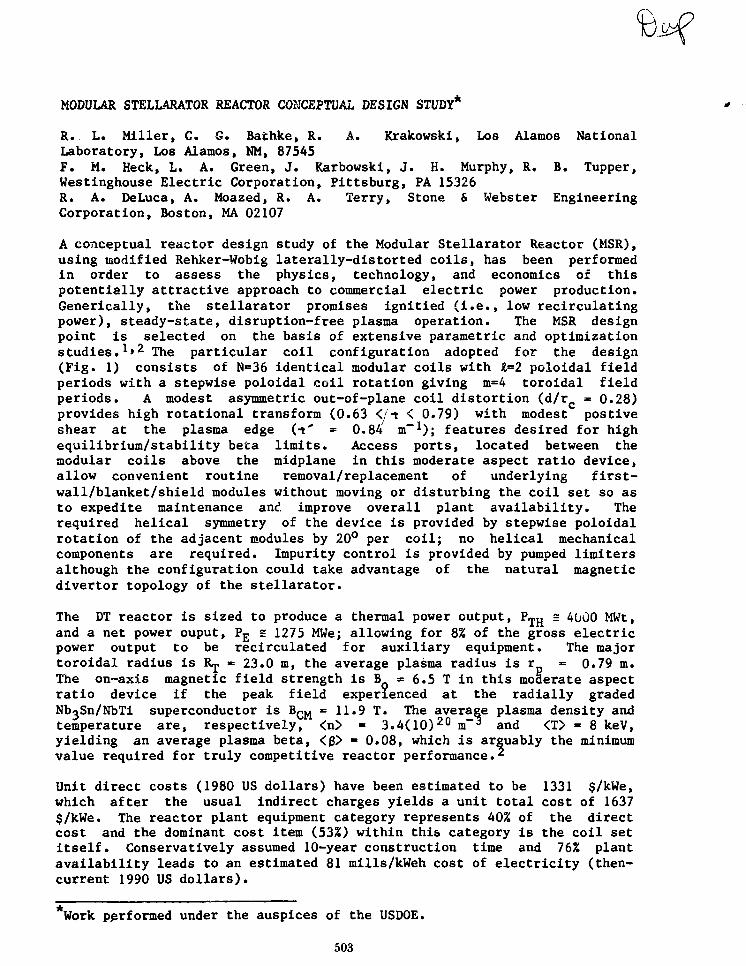
MODULAR STELLARATOR REACTOR CONCEPTUAL DESIGN STUDY*
R. L. Miller, C. G. Bathke, R. A. Krakowski, Los Alamos NationalLaboratory, Los Alamos, NM, 87545F. M. Heck, L. A. Green, J. Karbowski, J. H. Murphy, R. B. Tupper,Westinghouse Electric Corporation, Fittsburg, PA 15326R. A. DeLuca, A. Moazed, R. A. Terry, Stone & Webster EngineeringCorporation, Boston, MA 02107
A conceptual reactor design study of the Modular Stellarator Reactor (MSR),using modified Rehker-Wobig laterally-distorted coils, has been performedin order to assess the physics, technology, and economics of thispotentially attractive approach to commercial electric power production.Generically, the stellarator promises ignitied (i.e., low recirculatingpower), steady-state, disruption-free plasma operation. The MSR designpoint is selected on the basis of extensive parametric and optimizationstudies.1'2 The particular coil configuration adopted for the design(Fig. 1) consists of N=36 identical modular coils with 1=2 poloidal fieldperiods with a stepwise poloidal coil rotation giving m=4 toroidal fieldperiods. A modest asymmetric out-of-plane coil distortion (d/r « 0.28)provides high rotational transform (0.63 </t < 0.79) with modest postiveshear at the plasma edge (t* = 0.84 m " 1 ) ; features desired for highequilibrium/stability beta limits. Access ports, located between themodular coils above the midplane in this moderate aspect ratio device,allow convenient routine removal/replacement of underlying first-wall/blanket/shield modules without moving or disturbing the coil set so asto expedite maintenance and. improve overall plant availability. Therequired helical symmetry of the device is provided by stepwise poloidalrotation of the adjacent modules by 20° per coil; no helical mechanicalcomponents are required. Impurity control is provided by pumped limitersalthough the configuration could take advantage of the natural magneticdivertor topology of the stellarator.
The DT reactor is sized to produce a thermal power output, P ^ s 4000 MWt,and a net power ouput, P£ = 1275 MWe; allowing for 8% of the gross electricpower output to be recirculated for auxiliary equipment. The majortoroidal radius is Rj =•= 23.0 m, the average plasma radius is r = 0.79 m.The on-axis magnetic field strength is B = 6.5 I in this moderate aspectratio device if the peak field experienced at the radially gradedNboSn/NbTi superconductor is BQ^ = 11.9 T. The average plasma density andtemperature are, respectively, <n> * 3.4(10)20 m~* and <T> = 8 keV,yielding an average plasma beta, <$> = 0.08, which is arguably the minimumvalue required for truly competitive reactor performance.2
Unit direct costs (1980 US dollars) have been estimated to be 1331 $/kWe,which after the usual indirect charges yields a unit total cost of 1637$/kWe. The reactor plant equipment category represents 40% of the directcost and the dominant cost item (53%) within this category is the coil setitself. Conservatively assumed 10-year construction time and 76% plantavailability leads to an estimated 81 mills/kWeh cost of electricity (then-current 1990 US dollars).
Work performed under the auspices of the USDOE.
503

VACUUM DUCT
Hi PURGE PIPES
COOLANT PIPES
MANIFOLD ANDPLENUM ZONE
LIMITER
Fig. 1. Plan view of Modular Stellarator Reactor (MSR) coil configurationwith major radius R™ « 23 m and typical removable firstwall/blanket/shield module.
The following conclusions have emerged from the MSR study:
• Overall reactor performance is critically coupled through beta to themagnetics performance of the modular-coil-set. The available(limited) physics data base (e.g., Ref. 3) supports the design choicesmade for the MSR, which are generally conservative and subject toimprovement.
• Engineering choices/options implemented for the conceptual designprovide a credible, maintainable design.
• The MSR is economically competitive with other mainline fusionapproaches (e.g., tokamak and tandem mirror) if <f$> = 0.08.
REFERENCES
1. R. L. Miller and R. A. Krakowski, "The Modular Stellarator FusionReactor Concept," Los Alamos National Laboratory report LA-8978-MS(August 1981).
2. R. L. Miller, R. A. Krakowski, and C. G. Bathke, "ParametricSystems Analysis of the Modular Stellarator Reactor (MSR)," Los AlamosNational Laboratory report LA-9344-MS (May 1982).
3. J. F. Lyon, et.al.., "Stellarator Physics Evaluation Studies," 9thIAEA Inter. Conf. on Plasma Phys. and Controlled Nucl. Fus.Research, Baltimore, USA, IAEA-CN/41-Q3 (September 1-8, 1982).
504

PHYSICAL AND ENGINEERING CONSTRAINTSFOR
TOKAMAK REACTORS WITH HELICAL COILS
R.E. Potok, D.R. Cohn, H. Becker, L. BrombergN. Diatchcnko, D.B. Roemcr and J.E.C. Williams
Massachusetts Institute of TechnologyPlasma Fusion Center
A analytical and numerical analysis of a tokamak reactor with a set of helical coils added in orderto eliminate plasma disruptions is presented. A number of design options for the helical coils arcconsidered (resistive or superconducting coils, placement internal or external to the toroidal fieldmagnets, continuous or modular coils, and type of winding law). The optimum helical configuration isfound to be a sot of resistive, continuous, I -= 2 stcllarator coils which arc internal to the toroidal fieldcoils. A set of scaling laws is then developed for this optimal configuration, and a scries of parametricscans arc done with varying assumptions for the force on the helical coils and the ratio of helical coilI ransfurm to plasma transform (M').
The option space available for reactor designs involves large forces on die helical coils, low q plasmaoperation, and moderately low M'. We compare data from experimental devices run in the tokamak-slcllarator mode (J1PP-T-II and Pulsator) with field tracing data. There is good agreement betweenthe results of the experiments and the field line tracing. These results show that too low a value of M'(3 to 5) will cause a destructive resonance interaction between the plasma and helical coil transforms.M' must bo kept a modcnucly low levels (4 to (>), though, if the forces on the helical coils and theirpower dissipation are to be acceptably small. There is thus only a narrow region in parameter spacewhere an attractive reactor design can be built, and this region only exists if the helical coils enable thereactor to operate in a low q regime [qCd,,c — L5).
Under the above mentioned constraints, an illustrative tokamak-stcliarator reactor design is developed.A moderately large major radius is required (/?„ = 14.31 m), since the external transform scales a s i ^ .The large major radius allows for much higher ilux storage in the OH coils (for the same OH energystorage) that is found in conventional tokaniaks, and burn times on the order of 12 hours appearfeasible.
The illustrative design is based upon a remote maintenance scheme in which removable, modularunits of the reactor consist of: two toroidal field coils, sectors of helical coils, and sectors of theblanket/shield region and first wall. Figure 1 shows a side view of the illustrative design. The resistivehelical coils arc water cooled and arc clamped together at tlic module interfaces. The helical coils aresupported by a reinforcing structure external to the helical coils and internal to the toroidal field coils.
505

,T-~-^~^p^g
FIGURE 1.0SIDE VIEW OF ILLUSTRATIVE LITE DESIGN
506

EXPLORATORY STUDIES OF NEGATIVE TANDEM MIRROR REACTORS* F. Kantrowitz, E.Zawaideh and R.W. Conn, Fusion Engineerinq and Physics Program, School ofEngineering and Applied Science, University of California at Los Angeles.D. Dobrott, S. Tamor and D.C. Baxter, Science Applications, Inc., Oolla,CA. The purpose of this study is to determine the feasibility of negativetandem mirror reactors. Negative tandem mirrors*1' can be formed bycombining hot electron end ceils with a central cell at fusion conditions.An equilibrium zero-dimensional power balance model has been developed toestimate parameters for both d-t and d-d negative TMR's. Performance para-meters for both positive and negative TMR's have been calculated. End celldesigns vary significantly from those appropriate to positive-barriersystems. ECRH requirements due to synchrotron radiation are found from arelativistic model which includes wall reflection. MHD flute stability iscalculated for the optimized parameters to determine anchor requirements.
Higher 0. values are found for a negative TMR with an optimized end cell ascompared to a positive machine when no high energy pump beam is required.The reason is that the potential well from which trapped ions must be pump-ed is deeper in the negative case, resulting in pump beams with a lowerratio of charge exchange to ionization cross section. The deeper potentialwell is needed to confine central cell electrons, as compared to the posi-tive case where the potential isolates central cell electrons from plugelectrons.
Q vs. 0encj ceix f°r various values of the outer end cell magnetic field
Fig. 1. 0 vs. vwrtr i l cell beta
S -

peak is shown in Fig. 1. As P is increased from low values Q increases dueto the improved confinement of hot electrons. If the electrons become toohot, however, synchrotron radiation losses dominate and the ECRH power re-quired to maintain the hot electrons causes Q to decrease. An optimumvalue is found for end cell beta values between 10 and 30 percent depend-ing on the size of the outer end cell magnetic field peak. As this is in-creased from its optimum value (see dashed line in Fig. 1) synchrotron los-ses cause a slight decrease in Q. As it is decreased, loss of electronconfinement causes a decrease in Q.
A magnetic configuration based on the axicell concept has been designedusing the code EFFI. Magnet sizes are constrained by requirements forshielding, support and superconductor current density. Central cell para-llel currents have been minimized. The resulting configuration has beenchecked for MHD flute stability. The required anchor beta has been calcu-lated for a given central cell and end cell beta (Pp). The results areshown in Fig. 2.
The primary advantage of negative TMR's over positive machines is thatsloshing ions are not needed to form the peak potential, although theymay be needed in an MHD anchor.
•Work supported by USOOE
1. P, Poulsen, et al., LLNL Report UCID-193^ (1982).
.6 l.C
Fig. 2. Central cell vs. end cell beta506

EBT REACTOR CHARACTERISTICS CONSISTENT WITHSTABILITY AND POWER BALANCE REQUIREMENTS
N. A. Uckan and R. T. SantoroOak Ridge National LaboratoryOak Ridge, Tennessee 37830
Present EBT reactor studies differ from earlier ones primarily byincluding theoretical stability criteria developed in the past severalyears [particularly the Lee-Van Dam-Nelson criterion for core beta(LVN) limit] and their coupling to the ring power requirements. Theprincipal result is that these criteria and other physics andtechnology constraints permit a broad operating window for reactordesign optimization. Within this operating window, physics andengineering systems analysis and coat sensitivity studies indicate thatreactors with <3Core
> ~ 6-10%, P ~ 1200-1700 HW(e), wall loading~ 1.5-2.5 MW/m2, and recirculating power fraction (total including ringsustaining power and all other reactor auxiliaries) ~ 10-15% arepossible and are competitive with other fusion reactors (e.g.,tokamaks). While these results are obtained in a straightforwardextrapolation of the basic principles of the EBT concept from theexisting theoretical/experimental physics base (as well as theengineering/technology base), a number of concept improvements havebeen proposed that are found to offer the potential for furtherimprovement of the reactor size and parameters.
The physics rationale for this recent study includes: (1) equilibrium,particle orbits, and magnetics; (2) confinement/transport scaling; (3)stability (6 limits); and (4) ring power requirements. While most ofthe results in this paper center on stability and ring powerrequirements (not treated consistently in the past) and their impact onreactor operating space, we consider briefly some of the otherhighlights.
The spatial position of hot electron rings [formed near contours ofconstant |Bi in the midplane] is critical to efficient utilization ofthe magnetic volume within the vacuum chamber. Recent studies indicatethat centering of raod-B (centering of ring) through symmetrizing (SYM)or inverse D (ID) magnetic configurations can be more efficient thancoil configurations [i.e., axis-encircling aspect ratio enhancement(ARE) coils] assumed in previous studies.
The present experimental data base and results from 1-1/2-D transportcalculations continue to give favorable projections for a reactor. Theradial profiles obtained from these calculations are found to besimilar to those required for stability. Moreover, consideration ofthese profile effects leads to confinement estimates significantlybetter than those estimated (and used) in the earlier studies.
Research sponsored by the Office of Fusion Energy, U.S. Department ofEnergy, under contract W-7405-eng-26 with the Union CarbideCorporation.
509

Limitations imposed by stability constraints on core beta and pressureprofiles, ring scale lengths, and power balance are critical in EBT inthe determination of the operating windows for and in the assessment ofdesirability of a reactor. Present stability theories indicateexistence of several modes that may limit the reactor performance.Among them, the hot electron interchange (which sets a lower limit on
anc* ^he core pressure-driven interchange-LVD limit (whichlimits core beta near the ring, 3 c o r e < 2A/RC, where 2A is the ring
width and Rc is the radius of curvature) are found to be mostrestrictive for reactor applications. Because these stabilityconstraints apply near the outer edge of the ring region, radialprofiles of the core pressure (which are assumed to be constant inearlier calculations) are shown to play an important role in bothfusion and ring power balance. The maximum stable core pressuregradients that can be supported in the core plasma (inside the ring)have been examined using both MHD and a kinetic theory that takes intoaccount ring-core coupling. Since the magnetic fields in EBT vary bothradially and axially, for constant pressure profiles <3core> is muchsmaller than (less than one-fourth) the calculated value near the ring.However, the key result of the profile consideration is that volumeaverage core beta <Pcore> is comparable to the theoretically calculatedcore beta at the center of the ring, which permits sufficiently highfusion power density for sufficiently small ring width.
Coupling of core beta with ring volume (through the ring thickness A)and with ring power losses (through the relative core/ring densityratio) affects reactor power balance. Minimizing ring power requiresthin (small A) rings whereas high beta (~ fusion power density)requires thick (large A) rings; this implies opposing constraints.Taking into account the various stability constraints (LVN limit,etc.), profile effects, and other physics and technology constraints,it is shown that a comfortable operating window exists with acceptablering power losses (recirculating power fraction) in a reactor.Boundaries of this window are determined from the stabilityconstraints, microwave cutoff, beta limit, and net power productionrequirements. Parametric analyses with physics and engineering systemcodes are carried out to determine the reator characteristics andperformance within this stable operating window. The sensitivity ofthe results to variations in physics and engineering parameters and/orassumptions is also studied.
510

CONCEPTUAL DESIGN OF HEL10TRON REACTOR
Shunji Kakiuchi, Yoshiaki Kazawa,Hitachi Works, Hitachi, Ltd., 3-1 Saiwai-cho Hitachi, Japan,
Masatugu Nisai*), Takashi Okazaki*),1) Energy Research Lab., Hitachi, Ltd. Moriyama-cho, Hitachi, Japan
Osamu Motojima^), Atsuo Iiyoshi, and Koji Uo^)2) Plasma Physics Lab., Kyoto Univ., Gokasho, Uji, Japan
Design studies on Heliotron F (break-even reactor) and G (experimentaland prototype reactor), which are the next generation devices of HelitronE, are reported.
Main design parameters of Heliotron F and G are shown in Table 1. InHeliotron F project, two kinds of devices are considered. The one, Fl,is for demonstration of the break-even condition by H plasma, and theother, F2, by D-T burning plasma. In Heliotron G project, the mostimportant target is to get self-ignited steady state plasma. Electricalpower of 10 MW is generated. From economical point of view, it is de-sired to make the reactor configuration as compact as possible. Theplasma parameters in Table 1 are, therefore, determined on the basis ofan advanced confining scaling of heliotron H device.
The schematic view of Heliotron G reactor core is shown in Fig. 1. Thekey issues are as follows:1. Vaci. m vessel and superconducting helical coil with cryostat are con-
structed as one-body structure.2. Disassembling, assembling, and repairing of core components such as
first wall and diverter plate are undertaken through port spacesbetween the slots of helical coil, using remote handling equipments.
3. Breeding blanket is set as much as possible to cover the fusion plasma.The covering area is about 80% of whole plasma surface.
The nucleonic calculation based on this structure is attempted. The mainresults are; (a) breeding ratio of tritium is about 0.9, (b) nuclearheating power in the cryosystem is about 1.5 KW.
The system composition of Heliotron Fl and F2 is studied, i.e., reactorcore, primary and secondary cooling system, fueling system, vacuumsystem, power supply system, and refrigiration system. In the case ofHeliotron G, generator system is added.
In the final manuscript, details will be presented. Superconductinghelical coil is described in another paper.
511
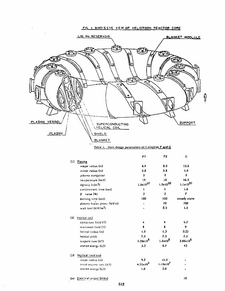
FIO. 1 BIROS EYE VIEW OF HELIQTMON REACTOR CORE
LIQ. He RESERVOIR BLANKET M O D L U L E
PLASMA VESSEL/
PLASMA
Table 1. Main design parameter; of hcliotron F and G
Fl F2
(1) Plasma
major radius (m)
minor radius (m)
plasma elongation
temperature (ksV)
density (n/m^)
confinement time (sec)
£ value {%)
burning t i :nt (sec)
pUismj fusion power (MWth)
wall load (M'*7m2)
(2) Helical coil
centcrliric field (T)
maicimuin field (T)
lichcal rcdius (in)
helical pitch
ampere t.irn (AT)
stored energy (GJ)
.0) Vertical field coil
major radius (>n)
H'l.il ,III\;HTC iiim (AT)
Stored energy (CD
{«) Clet^rj'"al o«ilj>ut (MVr'e)
6.4
O.S
2;n
1.0x10"
1
J
100
.
-
S
1.27.5
l.2KxlO*
i.i
8.0
0.8
2
10
l.OxlO20
1
5100
70
6.3
li
Z
1.57.5
1.6x10*
6.7
13.6
1.0
2
16.5
l.lxJO20
1.6
7
steady state
700
1.2
4.5
3
2:55
7.53.06xl0S
43
9.2
4.72x10*
1.0
11.5
l . l i x l O 7
2.0
10
512

TOROIDAL FIELD RESISTIVE MAGNET DESIGN FOR TOKAMAK TEST REACTORS R. J.Hooper and S. S. Kalsi, Fusion Engineering Design Center/GeneralElectric Company This paper describes the design of resistive coppertoroidal field (TF) coils for use in a near-term tokamak fusion device(FED-R). The mission of the device is to provide a quasi-steady statesource of 14 Mev neutrons irradiating a large test area, in order toperform nuclear testing of experimental blanket assemblies.
A design requirement on the TF coils is that they contain readily demount-able joints to facilitate replacement of components inside the bore ofthe coil. This requirement leads to selection of water-cooled resistivecopper TF coils.
The TF coils are designed to provide a field of 4.0 T on the plasma axisduring Stage I operation (6000 pulses) and a field of 5.0 T during StageII operation (3300 pulses); these fields correspond to peak fields atthe TF coils of 7.0 T and 8.75 T, respectively.
The TF coils and their associated support structure are designed accord-ing to structural criteria which are used for all magnet system componentsfor which the FEDC has design responsibility. These criteria are similarto those used in other large magnet programs and are described in Ref. 1.
Each of the 12 TF coils is fabricated from rectangular window frameplates with 1 m radius fillets in the inside corners. Each coil contains17 turns each fabricated from CDA-110 copper plate segments 6.1 cmthick. In the inboard region, the 12 TF coils nest together providingwedging action which is the principal means of reacting the net centeringforce on the coils. To achieve the required fitup of the plates in theinboard region, the plates must be machined to a tapered thicknessranging from 6.1 cm to 2.2 cm at the most inboard point.
Each of the 17 plates in each TiT coil is made up from 11 segments, whichare joined using three types of joints: manufacturing lap joints,electrical joints, and demountable finger joints, as shown in Fig. 1.Also shown in Fig. 1 are the coolant slots milled into both sides ofeach plate in the stack; the cooling system is sized to accommodate thecombined heat load resulting from resistive power dissipation and nuclearheating.
In order to reduce the major radius of the machine, the radiation fluencelimit is established at 10 1 1 rads. This fluence is orders of magnitudeabove the level at which organic insulators such as G-10 lose most oftheir mechanical strength; consequently, a ceramic turn-to-turn insulatoris used. Magnesium aluminate (MgAlgO^) has been selected because it canbe applied by plasma arc spraying and is, therefore, well suited to theFED-R spatial configuration.*Research sponsored by the Office of Fusion Energy, U.S. Dept. of Energy,under contract W-7405-eng-26 with Union Carbide Corp.
515

-» t
(ttMN-TO-TUDN TMMtnWH )
Figure 1. Joints and coolant lines in FED-R TF coil plates.
The copper plates in the TF coils are self-supporting against the Lorentzforces acting in the plane of the coil, although additional supportstructure is needed to withstand the out-of-plane loads and the resultingoverturning moments. A Nitronic 33 coil case supports the portion of thecoil outboard of the demountable joint. In addition, intercoil supportstructure in the form of deep box-like modules is used to equilibrateoverturning moments. A vertical window opening 5.4 m high is maintainedbetween TF coils to permit replacement of torus sectors.
Reference
1. R. J. Hooper and B. L. Hunter, "Structural Design Procedures for FEDMagnets," Proc. 9th Symposium on Engineering Problems of Fusion Research,Vol. I, pp. 539-542, Chicago, Illinois, October 1981.
516

A MINIMUM-THICKNESS LOW-ACTIVATION TOROIDAL FIELD COIL CONCEPTFOR FUSION REACTORS
W. Y. Chen and E. T. ChengGeneral Atomic Company
P.O. Box 81608, San Diego, California 92138
In designing a low-activation fusion reactor, it is essential that alow-activation toroidal field coil be developed. This paper discussesa minimum-thickness, low-activation, toroidal field coil concept for theSTARFIRE-type commercial tokamak fusion reactor. The STARFIRE TF coil ref-erence design* is based upon a Cu-stabilized conductor with stainless steel(SS) interwound support. The winding insulation is mainly glass epoxy(G-10), and the helium vessel is 316 SS. The superconductor will be Nb3Snat high field (9 to 11 T) and NbTi at lower fields. Stainless steel,copper, and niobium are the high-activation components.
Since there is no other commercially-proven superconductor which hasperformance comparable to Nb3Sn or NbTi, it is not possible to eliminatesuch materials from the coil. However, to achieve an otherwise low-activation design, two alternative approaches are possible:
1. Replace the copper stabilizer with high-purity aluminum, and thestainless steel support strip with low activation aluminum alloy suchas Al-6063.
2. Replace the copper stabilizer with pure aluminum, and the stainlesssteel support strip with silicon carbide (SiC) fiber (NICALON)1
reinforced aluminum alloy.
For either option, the conductor insulation will still be G-10 or polyimide-based material, and the helium vessel should be constructed with highstrength fiber (glass, graphite, or SiC) reinforced epoxy to reduce thepulsed field heating.
A scaling study was carried out on the required cross sectional area ofSTARFIRE TF coils if the above low-activation design principles are fol-lowed. The purpose of the study was to find out the consequences of adopt-ing a low-activation design in a commercial-size tokamak reactor such asSTARFIRE. References 2 and 3 contain the main basis of data utilized in thescaling.
Results Indicated that the low-activation aluminum-alloy-supported,aluminum-stabilized TF coil requires a cross sectional area of 26.3x 10^ cm^ as compared to the 18.7 x 10^ cm^ for a stainless steel-supported,copper-stabilized coil, or equivalently, a 41% increase. The increasedstructural material area is due almost entirely to lower strength. Resultsfor a TF coil supported by S1C-A1 composite are similar.
*Work supported by the Department of Energy, Contract DE-AT03-76ET51011.
517

It is expected that such an increase in the TF coll cross-section will notbe acceptable because of the resultant economics penalty imposed on thereactor. One alternative is to replace the first 10 to 20 CM of coil wind-ing at the plasna side with low-activation construction, since this is theregion where most activation reaction will take place, leaving the balanceof the coil conventional stainless steel structure. The stabilizer through-out the entire coil will be pure aluminum, and the helium vessel will begraphite epoxy. Such a scheme will result in an activation level withinacceptable limits. If only the conductor support in the first 10 to 20 cmof coil winding is replaced by aluminum alloy, then the net cross sectionalarea and the radial build of the coil will be actually less than the all-stainless steel reference design. Such an area reduction results partlyfrom the savings in the stabilizer area required, and partly from thesmaller helium vessel thickness due to the higher strength of the graphiteepoxy. In fact, the savings in the aluminum stabilizer area can allow upto the first 20 cm of conductor support to be replaced by aluminum alloywithout causing any increase in the coil cross sectional area.
REFERENCES
1. "STARFIRE - A Commercial Tokamak Fusion Power Plant Study," ArgonneNational Laboratory Report ANL/FPP-80-1, Vol. 1, September 1980.
2. NICALON is a trade name for SIC fibers manufactured by Nippon CarbonCompany, Tokyo, Japan.
3. Chen, W.Y., et al., "Design of an Al-Stabilized Superconductor forTokamak Toroidal Field Coils," Advances in Cryogenic EngineeringMaterials, Vol. 26, p. 514, 1980.
518

Session 6C-1
MAGNET ENGINEERING(poster)
Chairman
S.S. Kalsi, General Electric Company
Organizer
CD. Henning, Lawrence Livermore National Laboratory
Thursday, April 28 2:30-5:00 p.m.

CONSTRUCTION AND TESTING OF THE Nb3Sn COILSFOR THE HIGH-FIELD TEST FACILITY*
R. M. Scanlan, D. N. Cornish, J. P. Zbasnik,R. L. Leber, J. E. Johnston, and M. R. Chaplin
Lawrence Livermore National Laboratory, University of CaliforniaLivermore, California 94550
Paper withdrawn

STRUCTURAL DESIGN CONSIDERATIONFOR THE FED 50 kA POOL BATH COOLED CONDUCTOR (PBCC) COILS
George BuchananJoel G. Bennett
Los Alamos National Laboratory
ABSTRACT
This paper reports the analysis and subsequent design of an equilibrium
field coil that is referred to as EF2. Basically, the coil consists of four
pancakes with 31 turns of conductor per pancake. The overall dimensions of
the EF2 ring coil that was studied were approximately 28.1 in (0.714 m) in
the axial direction and 24.5 in. (0.622 m) in the radial direction. The
radius of the coil with respect to the center of the reactor was assumed as
475.0 in. (12.065 m) based upon a recommendation contained in Ref. 1. The
coil loading was divided into four separate components, two radial components
and two axial components and evaluated according to Ref. 2 as
F = 15990 - 22270 sin (106) lb/in. of coil, and
Fz = -3426 + 20210 sin (106) lb/in. of coil.
The ring coil loading configuration is affected by the presence of 10
poloidal field coils that are symmetrically positioned to produce a repeated
loading pattern e\iery 36 degrees around the coil. The coil is supported
vertically, in the axial direction, e\/ery 36 degrees but is essentially free
to deform radially.
Several concepts concerning the structural design were to be investigated.
o Determine the feasibility of a structural support system that could
be co-wound with the conductors.
o Determine guideline dimensions for a supporting frame or box-beam
type of supporting structure.
The computer analysis was performed at Los Alamos using the A8AQUS
computer code. The preliminary analysis was accomplished using axisymmetric
finite elements and assuming a constant radial loading. The asxisymmetric
model gave excellent results for the tangential stress or hoop stress. Both
of the structural support systems were analyzed as axisymmetric with constant
521

radial load. The preliminary analysis indicated that the frame-type supportsystem was superior to the co-wound structural system. As a check on theformulation and analysis using the axisymmetric model a plane strain model ofa section of the coil was analyzed. The results using the plane strain modelverified the analysis using an axisymmetric model.
Since the loading was essentially three dimensional and both axisymmetricand plane strain analyses represent two-dimensional problems, a more generalrepresentation of the ring was deemed necessary. The total ring structure wasmodeled using three-dimensional beam elements. The ring was assumed to besupported by a column every 36 degrees and accordingly was fixed to preventaxial movement of each support. The support condition in the radial directionwas modeled as an elastic spring representing the stiffness of the supportingcolumns. The beam elements were fixed at each support against rotation abouttheir longitudinal axis. All other reactions were allowed to occur at eachsupport. The beam section properties were computed using standard methods.The general loading produced a hoop force and bending moments about each beamaxis. Elementary stress formulas were used to compute the combined stress.The results for hoop stress and bending moments were fairly insensitive tochanges in the section properties, however, the final stresses weresignificantly affected by slight variations in the beam area and moments ofinertia. Several different box-type frame configurations were shown torepresent a possible structural support system for the equilibrium field coil.
REFERENCE
1. Hunter, B. L. Memorandum to J. 6. Brown, FEDC-M-82-E/M-125, FED
Baseline-Independent Support and Vacuum Vessel for Superconducting Ring
Coils, June 24, 1982.
2. Hunter, B. L. Memorandum to S. S. Kalsi, FEDC-M-82-E/M-066,
FED-Application of Forced Flow Conductor to Superconducting Ring Coils,
April 19, 1982.
522

A UNIFIED STUDY FOR DETERMINING POLOIDAL FIELD COIL LOCATIONS FOR ATOKAMAK* Vishnu C. Srivastava and Swarn S. Kalsi, Fusion EngineeringDesign Center/General Electric Company. The PF coil configuration has amajor impact on the cost and maintenance of a tokamak device. A strongdependence also exists among plasma shaping requirements, the PF systempower supply needs, and magnetic and structural design of TF coils. Thefinal PF coil locations are obtained on the basis of a number of iterationsusing the MHD equilibrium code. The starting point for these iterationswas the idealized PF coil configuration (see Figure) with a large number(fifty) of coils located along the outside perimeter of the TF coils.The selected configuration satisfies the plasma requirements with limiteroption. The next set of iterations is performed with a specified centralsolenoid and with a few discrete coils — each coil replaces many coilscarrying similar currents in its vicinity. Next, these discrete coilsare positioned at locations dictated from the overall mechanical configura-tion. This represents final PF coil configuration with limiter. Togenerate divertor action, PF coil currents, with the exception of thecentral solenoid current are varied to obtain appropriate separatrixlocation and scrape off regions. At each iteration, plasma and mechanicalconfiguration requirements are satisfied.
The PF configuration studies are made for INTOR utilizing large andreduced size TF coils as an example for this study. PF configurationsare developed for limiter and single null poloidal divertor. These
1st MHD run with distributed colls(without divertor)
2nd NHD run with discrete coll locations(without divertor)
3rd MHD run with discrete colls withdivertor
4th MHO run with coll locations consistentwith mechonlcal configurations
*Research sponsored by the Office of Fusion Energy, U.S. Dept. ofEnergy, under contract W-7405-eng-26 with Union Carbide Corp.
523

configuration studies include the impact of parameters such as totalampere turns, total ampere meter of conductor, stored energy, volt-seconds, coil cost, and power supplies cost for high £ and low & plasmaoperations. The PF coils are assumed to be located outside the TF coilsin all the cases studied. Structure cost is included as a percentage ofthe winding cost. The power supply cost is calculated on the basis ofstored energy (E) in each coil and MVA required during startup and burnphases. FF system cost and other pertinent parameters (total ampere-turns, ampere meters of conductor, stored energy in the magnets andvolt-seconds delivered to the plasma) are all calculated by utilizingcomputer codes.
The procedure and methodology developed in the present studies appear tobe adequate, for optimization of the PF coil distribution. The coil andpower supply cost are minimum for the smallest number of PF coils. Thesestudies also indicate that the total cost of the PF system increasesappreciably in going from idealized PF configuration (with discretecoils) to practical configuration. The system integration requirementsare the major drivers for the PF coil locations and cost. The PF systemwith poloidal divertor costs ^50% more than a system without the divertoraction (limiter).
524

RIPPLE REDUCTION COILS FOR TOKAMAK REACTORS
by Glenn BatemanGeorgia Institute of Technology
4 October 1982
A conceptual design is presented using a combination of superconductingRipple Reduction Poloidal Field (RRPF) coils fl,2] and normal saddle coils inan INTOR-size tokamak reactor consisting of 8 toroidal field (TF) coils with6.6 m by 9.2 m bore. A cross section of the design is shown in Fig. 1. TheRRPF coils consist of dipole magnetic coils placed between the TF coils andthe neutron shielding, 3.8 m above and below the plasma midplane, in order toproduce part of the shaping field needed for a D-shaped plasma equilibriumand to reduce magnetic ripple near the top and botton of the plasma. Theyare designed to share the TF coil cryostat and support structure, withoutobstructing access to the shielding, blanket or first wall. The normal (ie,water cooled copper) saddle coils are attached to the outer edge of theshielding, one meter away from the first wall. They carry 0.6 MA turn eachand consume less than 16 MW power all together to reduce magnetic rippleprimarily near the midplane of the plasma. A field line following code wasused to show that magnetic field lines are well confined in spite of the lackof axisymmetry in the coil currents.
In this design with 8 moderately sized TF coils, magnetic ripple is reducedfrom more than 5% at the outer edge of the plasma to less than 0.3% through-out the plasma. The TF coil size was determined so that each sector of theshielding, blanket and first wall could be pulled straight out along a line55 degrees relative to the nearest TF coil. With a six TF coil set of thesame size, access is easier but more than twice as much current is needed inthe saddle coils to reduce ripple.
Since the superconducting RRPF coils are intended to be pulsed, in responseto changing plasma equilibria a conditions, they must be designed so that themaximum field strength at their surface is everywhere less than 8 tesla.This constraint poses quite a challenge since the ambient toroidal fieldexceeds 7 tesla at the inner edge of the RRPF coiils. The challenge was metwith the following design: Each RRPF coil carrying i.6 MA turns of currentis 0.1 m thick, 0.8 m wide, and extends two and one half toroidal sectors(112.5 degrees) around the torus. These thin coils overlap each otheralternately two and three deep so that the average current in the toroidallegs is 4.0 MA turn. The coils, with semicircular radial legs, are staggeredbetween the TF coils to reduce the ripple by 1.4% near the top and bottomedge of the plasma. The EFFI code was used to show that the maximum field atthe RRPF coil surface at full current is about 8 tesla. The RRPF coils inthis design are primarily responsible for shaping the plasma equilibrium,while the saddle coils provide independent control over the magnetic ripple.
The Princeton equilibrium code was used to determine what coil currents areneeded to produce appropriate axisymmetric plasma equilibria. The RRPFcoils alone produce much of the vertical field needed for positioning theplasma along the major radius as well as hexapole and some quadrupole fieldneeded for a D-shaped plasma. With the RRPF coil current fixed, additionalpoloidal field coils placed outside the TF coils were used to control
525

plasma position and elongation. It was found that less than 2.6 MA turns ofcurrent is needed in the elongation FF coil (at 2*6.2 m and R»4.6 n) toproduce a plasma elongation exceeding 1.8 at the separatrix and 1.4 near themagnetic axis. The outer PF coil (at z»4.0 m and R=10.0 ra) needs to carryabout 3.2 MA. turns of current in order to hold a plasma with 5.1% averagebeta. With fixed RRPF coil current, the plasma shape is remarkably insensi-tive to changes in the elongation PF coil current.
References
1. 6. Bateman, "Ripple Reduction Poloidal Field Coils for Tokamaks",Georgia Tech Fusion Report GTFR-26 (March, 1981).
2. G. Bateman, "Ripple Reduction Poloidal Field Coils for TokamakReactors", Ninth Symposium on Engineering Problems of Fusion Research,Chicago, 26-29 October 1981; and Georgia Tech Fusion Report GTFR-28(October, 1981).
Research supported by US DOE under contract no DE-AS05-78ET-52025 withthe Georgia Institute of Technology.
Fig. 1. Cross section of tokamak reactor with D-shaped plasma chambersurrounded by blanket and shielding with saddle coils on the outboardedge, RRPF coils above and below, TF coils, and additional PF coils.
m
-r- 2
-- 1
-0
m526

HYSTERESIS LOSS CALCULATIONS FOR THE TOKAMAKFUSION REACTOR THROUGH FIELDS HARMONICS CONTENT
BY
K. DennoNew Jersey Institute of Technology
For the Tokamak Fusion Test Reactor (TFTR) at Princeton as wellas the multistage Elmo Bumpy Torus hybrid reactor at ORNL, periodicalas well as any time changes in various coil currents, will inducesignificant adverse transient effects coupled with subsequenthysteresis power loss in the reactor metal content. Previous workcarrierd out by this author with respect to eddy current loss pre-sented electromagnetic fields calculations in the Tokamak using theconcept of Helmoholtz field radiation function with conventionalMaxwells field equations taking into consideration changes in thevertical as well as the control fields coil systems, namely the r/-ignition, the true ignition, the burning phase and shutdown.
This paper presents new phase of calculations involving the dynamicscope of hysteresis power loss carried out in connection with the analysisof harmonic contents for various electromagnetic field coils system appli-cable to the TRTR and the E-BT. Results have been secured for the inducedelectric and magnetic fields within the reactor ferromagnetic materialcontents, frequency spectrum of the propagating seperating plane in thickand thin materials as well as the surface impedance expressed explicityat the fundamental field frequencies as well as wide range of harmonicscontent.
Solutions for hysteresis power losses applicable across the entirefrequency spectrum have been obtained for the periodic duration of everyfield coil system as well as for the concurrent changes of all field coilsystems. And finally unified theory for electromagnetic field calculationstogether with the concept of eddy current-hysteresis losses is establishedcombining Helmholtz function with harmonic content analysis. Developmentof the unified theory is another step forward in solving operational prob-lems of eddy-current and hysteresis power losses calculation for the TFTKand the E-BT reactors, as well as their hysteresis losses.
References:
1. Agarwal, P.D. - "Eddy-Current Losses in Solid and Laminated Iron",AIEE Transactions, Pt-1, vol.78, 1959.
527

2. Denno, K. "Special Eddy-Current Theory for The Tokamak Fusion Reactor",Proceedings of 8th Symposium on Engineering Problems of Fusion Research,1979.
3. Denno, K. "Eddy-Current Calculations for The Tokamak Fusion ReactorThrough Fields Harmonics Content", Proceedings of 9th Symposi'ua onEngineering Problems of Fusion Research, 1981.
528

DESIGN AND FABRICATION OF THE IRON COREFOR THE OHTE EXPERIMENTAL MACHINE
B. Curwen and L. H. FranklinGeneral Atomic Company, San Diego, CA 92138
OHTE, a toroidal pinch magnetic confinement plasma experiment, has been inoperation at General Atomic since February 1981. In its original form,plasma current was induced by an air core induction or ohmic heating coildriven by a capacitor bank. Preliminary study revealed that greater plasmacurrents and pulse lengths could be achieved more cheaply by converting toan iron core than by installing additional capacitors. Therefore, an ironcore with a 3 volt-second capability and a stepped configuration wasdesigned, fabricated and incorporated into the OHTE experimental device aspart of a planned upgrade.
T4.2 m
n
A
Uppersegments
\ _ Lowersegments
136 mm(TyP)
j-S 4.2 m aH
Sect. A-A
Figure 1
To facilitate handling and installation, the iron core was fabricated in 28segments consisting of 14 lower and 14 identical upper segments (see Fig.1). Each segment was continuously wound in a "clockspring fashion" around aformer using Armco electrically oriented steel 0.35 mm thick and 136 xm.wide. Interspaced between each lamination is insulating paper 0.02 mm thickand 136 mm wide. The assembly is bonded together using a structural epoxyadhesive continously applied during winding. This fabrication techniqueresulted in a stacking factor (percentage of iron in the assembly) ofapproximately 902. After winding, each assembly was cut into two identicalhalves on a large vertical milling machine. The halves were bonded to asupport saddle consisting of hardwood and aluminum. To eliminate electricalshorts, all machined surfaces vere chemically etched with a diluted nitricacid solution, then painted with moisture repelling high dielectric strengthepoxy spray paint to eliminate lanination-to-lamination creepage and futuresurface corrosion.
529

Laminated assemblies weighing as much as 10500 lbs were shipped to the siteflat where they were set upright using a specially designed fixture. Analuminum base and support brackets were designed to assemble the individuallaminated assemblies in their correct location with respect to the plasma,the major loading for all support structures being seismic. Prior to finalassembly, a trial fit of the lower half of the iron core was made to checkout clearances and to determine the center of mass of the assembly*
Installation of the iron core and torus assembly were completed in October1982 and experimental operations were resumed.
This work was supported by Phillips Petroleum Company and General AtomicCompany under Joint Research and Development Agreement (GA Reference No.01341).
530

NONDESTRUCTIVE TESTING OF METALLIC SHEATH FOR SUPERCONDUCTING CABLE*
R. W. McClung, K. V. Cook, C. V. Dodd, and J. H. SmithMetals and Ceramics DivisionOak Ridge National LaboratoryOak Ridge, Tennessee 37830
As part of the quality assurance effort for the Oak Ridge NationalLaboratory (ORNL) Large Coil Program (LCP), ultrasonic and eddy-currenttechniques and equipment have been developed for examination of themetallic JBK-75 alloy sheath for superconducting cable. Specifically,ultrasound was used for the examination of the strip before forming intothe sheath, and eddy currents were used to examine the linear seam weldafter the sheath had been formed around the superconductor cable. Thecable was being fabricated by Airco for use in the large coil developed byWestinghouse.
ULTRASONICS
After consideration of many approaches, ultrasonic techniques wereselected as the optimum method for examination of the strip prior toforming into the sheath. It was anticipated that commercial ultrasonicinstrumentation could be applied; a survey disclosed that there was nomechanical scanning equipment available that would be appropriate for thelarge coils of 78-mm-wide by 1.6-mm-thick (3.07- by 0.063-in.) strip. Asturdy mechanical system was developed that was capable of handling theheavy (180 kg) coils and feeding the approximately 120 m (400 ft) of strip(on each coil) through the inspection station. Rotating heads of largewelding fixtures were modified to accommodate and control the large coilsat both the unspooling and respooling stations on either end of thewater-filled ultrasonic inspection tank. A system of urethane-coatedwheels was used to establish and maintain the uncoiled strip in precisionposition under the ultrasonic transducers. Additional capabilitiesincorporated in the system were for cleaning and drying the inspectedstrip, and interleaving with paper as the strip was rewound into a coilfor reshipment.
After technique selection and development, five ultrasonic transducers(and inspections) were applied concurrently to the length of each strip asit fed through the system. Three transducers were used to transmit andreceive shear waves to detect and evaluate longitudinal flaws (parallel tothe strip) with a depth of 0.28 mm (0.011 in.). An ultrasonic frequencyof 1 MHz was appropriate for detection of such flaws across the width ofthe strip except for a narrow zone along each edge where the 1 MHz hadinadequate resolution. A 2.25 MHz transducer was used for each edgebecause of the improved resolution for detecting flaws near the edge
•Research sponsored by the Office of Fusion Energy of the U.S. Departmentof Energy under Contract W-7405-eng-26 with the Union Carbide Corporation.
531

(the attenuation was too high to allow the use of 2.25 MHz across theentire strip width). In addition, two 5 MHz transducers were used (onealong each edge) to detect laminations as small as 1.6 am (0.063 in.) thatcould adversely affect subsequent welding. For the lamination detection,longitudinal wave ultrasound was transmitted perpendicularly through thestrip and reflected from a plate underneath the strip. Fifty-four coilswere examined with no rejectable discontinuities detected.
EDDY CURRENTS
Eddy-current techniques and equipment were developed for on-lineevaluation of the longitudinal seam weld in the sheath after formingaround the superconductor. Early studies by others had encounteredsignificant problems due to the inability to separate signals related toproperties of interest from "noise" signals caused by the superconductorvariation in weld contour, coil-to-specimen spacing, et al. Conventionaleddy-current techniques, which use only a single-frequency withmeasurement of magnitude and phase of the signal, offer the potential forseparating only two variables. However, prior work at ORNL in boththeoretical and experimental studies had developed the capability forsolving such multiparameter problems using multifrequency techniques. Theavailability of computer-based multifrequency instrumentation for ongoingDOE and NRC projects for examination of steam generator tubing offered apromising solution for the seam-weld examination. Computer programs weredeveloped using both theoretical models and experimental measurements onspecimens of seam-welded sheath containing flaws. These programs acceptedthe raw data of magnitude and phase at each of the three eddy-currentfrequencies and performed the necessary calculations with the complexequations to permit display of the properties of interest (i.e., flaws,thickness, etc.) without the ambiguity caused by background variables. Amechanical system was developed to reciprocate the eddy-current probetransversely across the weld seam and heat-affected zone (UAZ) as the weldis advanced linearly through the inspection station. After installationon the welding line at the Alrco plant, a supplementary manual techniquewas developed to allow examination of regions that had been weld-repairedafter the initial on-line detection. Airco personnel were trained in theoperation of the equipment and it has been used on-line (only a few feetafter the welding station) to detect flaws as small at 0.5 mm deep(0.020 in.). This prompt detection allows adjustment of weldingparameters if necessary.
SUMMARY
Ultrasonic and eddy-current techniques and equipment have been developedfor the evaluation of the sheath strip and seam welds respectively. Theapplication of the technology contributed to the confidence in theintegrity of the superconductor cable for the Large Coil Program.
532

LONG-TERM FED/INTOR MAGNET TESTING IN SUPPORT OF DEMO1
V. N. Shah, J. S. Herring, S. Z. RouhaniEG&G Idaho, Inc.
Long-term irradiation of materials at cryogenic temperatures in FED/INTOR willbe necessary to obtain conclusive reliability data for the design of super-conducting magnets for DEMO. A study carried out by EG&G Idaho^, has evaluatedthe data needed and the duration of the long-term tests required to providethis information.
The toroidal field (TF) magnets of a tokamak reactor will be intimately inter-wined with the first wall, blanket and shield. The ohmic heating (OH) andequilibrium field (EF) coils are also difficult to repair because of theirlocation and size. The high-induced radioactivity in the first wall andshield will require that maintenance be done remotely. All these factorscombine to require that the superconducting magnet systems be extremelyreliable and maintenance-free. Therefore, the Large Coil Program (LCP) hasbeen established to provide a separate non-radioactive facility in which toverify and improve magnet performance.
The FED/INTOR will differ from LCP in several important aspects. The FED/INTORmagnets will be approximately three times larger than those in LCP. Themaximum field at the conductor in LCP is 8 T while FED/INTOR could possiblyhave 10 T as the maximum field. The presence of a high-temperature plasmawill produce neutron and gamma radiation damage, as well as fluctuations inthe magnetic field produced by the plasma which will interact with the super-conducting magnets.
Available operating experience indicates that the predominant causes for earlyfailure are improper structural support of the conductor and locally inadequatecooling of the winding. Improper support results in movement of the conductorgenerating frictional heat and causing a growing resistive zone. Inadequatecooling is the result of poorly designed coolant flow or changes in the coolantchannel geometry due to conductor or insulator movement.
These early failures are the result of design deficiencies which should befound during the first year of operation. The real benefits to DEMO fromlong-term FED/INTOR operation are in following the effects of conductor,stabilizer and insulation degradation on magnet performance and in identifyingother unanticipated failure modes.
The present data base for predicting the change of magnet component propertieswith neutron and gamma radiation is inadequate, particularly for radiationeffects at cryogenic temperatures (=5 K) and at high magnetic fields.
Failure criteria and the rates of property changes in combination with thepredicted neutron and gamma radiation intensities at the position of super-conducting magnets are used to estimate the lifetime of the different magnetcomponents.
The timetable to meet FED/INTOR objectives have been established by the FEDC.The first three years of operation consist of an integrated system checkout,followed by two years of operation with hydrogen and deuterium plasmas.During this early, essentially nonradioactive phase, the integrated performanceof the magnet system components will be demonstrated.
533

The thermal and mechanical design of the conductor, leads, dewars, and cryo-genic system will be extensively tested before assembly. During the integratedsystems checkout phase interactions with other components of the FED/INTORreactor will be intensively examined. These tests will include verificationof the design requirements for conductor stability against quench propagation,conductor and lead performance under slightly degraded cooling conditions andmagnet response to upsets in other parts of the cryogenic system.
The interactions between a hot plasma and a set of superconducting magnetswill be seen for the first time in FED/INTOR. The introduction of a DT plasmawill increase the temperature and kinetic energy to the plasma about an orderof magnitude. The beginning of 10 T operation will increase the energy by50 percent, and will push the conductors closer to their stability limits.
The most important long-term damage to the materials in FED/INTOR will comefrom neutron and gamma radiation. To evaluate the changes in insulator,stabilizer, and conductor properties, coupons will be placed at variouslocations for removal at specified intervals. It is important that the couponsbe irradiated at cryogenic temperatures and tested without being heated toroom temperature. Coupon location within the shield will allow for acceleratedirradiation.
Any magnet testing done must not endanger overall availability of the machine.Magnet testing should be limited to gather operating experience and to monitoringthe effects of radiation and plasms interactions on coil performance.
Material behavior can be predicted based upon the condition of coupons irradiatedin the shield and coils of the FED/INTOR and samples of the same materialsearlier irradiated in fission reactors at cryogenic temperatures. Long-termtesting will provide mechanical and thermal design verification and data onthe irradiated properties of magnet materials which permits projection of amaximum lifetime. Additionally, it will identify design or manufacturingflaws which lead to premature failure. It will not, however, identify afailure rate with enough statistical significance to permit prediction of thereliability of a DEMO magnet.
Work supported by the U.S. Department of Energy Assistant Secretary forResearch, Office of Fusion Energy, under DOE Contract No. DE-AC07-76ID01570.Long-term FED/INTOR Magnet Testing in Support of the Demonstration FusionReactor, EG&G Informal Report.Proceedings of the Meeting on Electrical Insulators Fusion Magnets, CONF-801237, pp. 7.1-7.32, November 1981.
534

EBT-P QUENCH DETECTION TECHNIQUE INA MAGNETICALLY NOISY ENVIRONMENT
D. W. Lieurance, S. M. Cunningham, H. G. ArrendaleGeneral Dynamics Convair Division, San Diego, California
The Elmo Bumpy Torus Proof of Principal (EBT-P) magnetic systemcontains thirty-six (36) superconducting mirror coils connected inseries during operation. Each coil stores approximately 1.5 mega-joules at full charge. Should a normal zone develop along a coil con-ductor, it is imperative to remove the coil from the system and dumpthe energy as soon as possible. Circuitry has been designed to providethis protection function.
The most critical function of this circuitry is the detection of nor-mal zones in the presence of large magnetic interferences. The princi-pal source of this magnetic noise are large electron currents, or rings,circulating around the axis of the mirror coils. The contents of thispaper deals with the required analysis of the magnetic couplings betweenthese electron currents and the various components which make up theEBT-P mirror coil and the resulting design for detection of normal zoneswithin this environment.
Discrimination of the normal zone signal from the similar waveformelectron ring noise is accomplished by partitioning the coil into sub-coils -- the induced signal in one section of the coil being used tocancel the induced signal in another coil section. Partitioning, gains,and interconnections for cancellation are very critical as the sourceof noise changes position with respect to the sub-coils- and the coilsare wound slightly asymetrically.
The procedure has been to model the electron rings and coil componentsas intercoupled inductances. Several ring dimensions and locations havebeen considered. The ring is modeled as two current sheets, one atradius Ri and the other at Ro both with length I. The 1200 turn mirrorcoil has been partitioned at several inductances by considering separatelayers, including the pancake layer.
The structural shells of the helium vessel, vacuum vessel, X-ray shield,and vacuum liner have been considered as one turn inductances of charac-teristic resistances for the materials involved.
An analysis of the above models was then performed using the computerprogram SPICE (version 2E.0, 1/18/78) for Ring Transients of 4.5volt • sec, Bulk Plasma Transient of 6.75 volt • sec, and PeriodicRing Fluctuations at 2.25 volt • sec
The results of the above runs have been used to develop a four input(5 tap) coil pickup circuit which will filter and cancel the effects ofmagnetic noise while still responding to a rising voltage across themirror coil due to a normal zone.

' 'M&Szbr,, -«k*.- 'o
Session 6C-2
PLASMA HEATING, IMPURITY CONTROL,AND FUELING
(poster)
Chairman
W.R. Becraft, General Electric Company
Organizer
W.R. Becraft
Thursday, April 28 2:30-5:00 p.m.
I

MARS HEATING SYSTEMS*
S.A. Freije, D.M. GoebelEnergy Development Group, TRW, Inc., Redondo Beach, CA 90278
L.J. PerkinsNuclear Engineering Dept., Univ. of Wisconsin, Madison, WI. 53706
G.W. HamiltonLawrence Livermore National Laboratory, Livermore, CA 94550
J.D. FinkNegion, Inc., 4023 East Ave., Hayward, CA 94542
The Mirror Advanced Reactor Study (MARS) addresses a commercial tandemmirror reactor. The reactor is a linear magnetic fusion device with anaxicell configuration. MARS utilizes electro-static plug to confine asteady-state fusion plasma in the solenoidal central cell. Two mainobjectives of MARS are to design an attractive fusion reactor producingelectricity and synfuels in a 10th of a kind commerical device and toidentify key development and technology needs for the commercial tandemmirror reactor and its forerunners. The reactor produces 1750 MWe for acentral cell length of 150 meters.
Each endcell requires a number of heating systems to produce the necessarypotential, pressure and density profiles, thus ensuring stability, con-finement and overall desirable operating characteristics. Three distinctregions make up the endcell: transition, anchor and plug. The heatingsystems have a large impact on both the capital cost and the recirculatingpower requirements of the reactor. They presently include: (1) and (2) ahigh energy neutral beam system and an electron cyclotron resonance heat-ing (ECRH) system in the plug to maintain the potential barrier which isa positive, potential peak to confine central cell ions, (3)another ECRHsystem to maintain a mirror trapped electron distribution in the thermalbarrier which is a potential depression to isolate central cell electronsfrom those in the potential barrier, (4) and (5) an ion cyclotron reson-ance heating (ICRH) system and a modest neutral beam system in the anchorto provide a hot plasma for pressure weighting of the geodesic curvaturewhich ensures stability. The basic characteristics of each of thesesystems are presented as well as their integration in the endcell geometry.
The sloshing ion neutral beam systems in the plugs must deliver a totalof 19A at 475kV and are oriented 90° with respect to the plasma axis. Thelow efficiency of a positive ion system at this energy and the low currentrequirement has lead to the selection of a negative ion system. The base-line includes LBL self-extraction sources, whose cesiated surfaces convertpositive ions formed by an rf plasma generator, into negative ions. Mul-tiple sources in each beamline form ribbon beams for the accelerator. Thesource ions are pre-accelerated to 80kV by a standard DC multiple grid setbefore being injected into a four stage transverse field focusing (TFF)accelerator and TFF transport system. The TFF system consists of properlyshaped and oriented grids such that the ribbon beam is guided throughrippled or curved channels in neutron shielding material to decrease neu-tron streaming. A folded resonator laser photodetachment neutralizer
539

provides >90% neutralization efficiency.
The two ECRH systems deliver 80.6MW at the 48-113GHz range and 6.6MW inthe 35-84GHz range. Theoretical studies must be performed to determinethe frequencies for optimum wave penetration and absorption; a beta effectand the relativistic shift could force a decrease in the injected frequen-cies from the vaccum values which are denoted by the upper value of eachrange. An extensive trade study analysis was performed to determine themost efficient economical ECRH system within the technology developmentconstraints of MARS. The basic system consists of a single high power HVDCconvertor power supply, MW gyrotrons with depressed collectors, and quasi-optical launchers and transmission systems. The power supply has its tech-nology base in the power grid's HVDC transmission systems; the quasi-opticallauncher is a dual-mode conical horn/paraboloidal reflector.
There are a number of physics constraints that combine to require a hotplasma in the anchor magnetic well, and also demand that the high pressureregion be produced by the injection of a hydrogen neutral beam at ^5kVwhich is selectively heated by ICRH. Both systems are relatively low power.
The ICRH system delivers -v9.5MW at either 55MHz or 110MHz. Calculationswill determine whether the heating rate at the second harmonic of H isadequate for confinement constraints, or whether fundamental heating ismandated. Second harmonic heating of H offers several advantages: 1) theheating of H would be more selective than at the fundamental since thesecond harmonic of H concides with the 4th harmonic of D, and 2) the high-er frequency would open the option of waveguide launching. The fundamentalsystem would have to utilize an antenna launcher. The remainder of theICRH system is independent of the launcher, i.e., conventional coaxialtransmission system with multi-stub tuning and a multi-stage amplifierchain with associated power supplies and equipment.
Each of two positive neutral beamlines provide 21A at 4.75kV. Although notsimple, the design and operation of a steady-state source for a system withthese characteristics is considered existing technology. Accelerator issueswith respect to extraction efficiency and beam divergence at the low energyare being addressed. The neutralization efficiency is very high, >91%, sothat a beam dump is adequate for the collection of the unneutralized por-tion of the beam.
The five heating systems must be integrated with all the other endcellsystems. The endcell configuration and layout are presented. The totalheating power delivered to the plasma is 106 MW, and the heating system re-circulating power requirement is 170 MW.
*TRW work supported by Lawrence Livermore National Laboratory contract No.5299101, University of Wisconsin and Livermore work funded by the U.S.Department of Energy.
540

ENGINEERING DESIGN OF THE QUASI-OPTICALECRH INJECTION SYSTEM FOR THE MIRROR
ADVANCED REACTOR (MARS)*
L. John PerkinsFusion Engineering ProgramNuclear Engineering Dept.University of WisconsinMadison, WI 53706
Steven A. FreijeTRW Energy Development GroupOne Space ParkRedondo Baach, CA 90278
A complete high-power steady-state ECRH injection system has beendesigned for the MARS tandem mirror reactor and is presently beingoptimized for overall economic performance. The system consists of aGraetz bridge AC-DC 90 MW power supply, 1 MW gyrotrons with depressedcollector operation and a novel quasi-optical launching system for thecombination and transmission of the ECRH power from the individualgyrotrons to the plasma.
The Mirror Advanced Reactor Study (MARS) is a major two year conceptualdesign study of a commercial tandem mirror reactor. It is currentlybeing conducted by Lawrence Livermore National Laboratory in conjunctionwith the University of Wisconsin and TRW as the prime industrialcontractor. Electron cyclotron resonance heating (ECRH) is an essentialrequirement in WARS for the maintenance of the potential peaks andthermal barriers in each of the end plug yin-yangs of the device. In thecurrent baseline design, 53 MW of ECRH power at 64 GHz produces acollisionless mirror-trapped hot electron population at the minimum-Bpoint (2.3 Tesla) and is required for the formation of the thermalbarriers. Similarly, a further 2 MW of ECRH power at 96 GHz contributesto the maintenance of the confining electrostatic potential peaks at the3.A Tesla point. ECRH systems on current and projected near-termexperimental devices exhibit powers of only ~ 80-200 kW at 28, 35 or 50GHz and, furthermore, are not steady state. These systems typicallycomprise charged capacitative pulsed power supplies, gyrotron units of up
2NO. MRABOLIC"MIRROR Fig.l SCHEMATIC OF THE MARS ECRH
QUASI-OPTICAL LAUNCHING SYSTEM
541

to only 200 kW and metallic waveguide transmission systems. However,such systems become inefficient, expensive and impracticable when scaledto the reactor requirements of MARS which call for CW-mode ECRH power inth:? -range 50-60 MW. Accordingly, a complete steady-state 55 MW ECRHinjection system has been configured for this reactor.
Fig. 1 shows schematically one of the 64 GHz quasi-optical launchers forMARS. The ECRH field is launched in a beam-mode (rather than the wave-mode of conventional metallic waveguides) by an array of dual-mode hornsfed by gyrotron sources after appropriate mode conversion. Propagationproceeds via the lowest loss TEM mode with a radial Gaussiandistribution of the electric field. The beam-mode is transported to theplasma via a phased array of hyperbolic and parabolic mirrors arranged inan offset Cassegrain configuration.
The quasi-optical launching system offers several distinct advantagesover the more conventional overmoded waveguide systems and affords a lowloss (~ 11%) combination of gyrotron sources to multi-MW levels withminimal space requirements. In particular, since the ECRH propagates ina Gaussian beam-mode rather than a wave-mode, power density constraintsare alleviated and the system can be operated in vacuum without the needfor ceramic windows.
The 1 MW gyrotron with depressed collector was selected as the base-casemicrowave source for this system and has specified operatingcharacteristics of 150 kV at 8.5 A, a collector voltage of -40 kV and anestimated net efficiency of ~ 80%. A Graetz bridge AC-DC convertorsupplies ~ 600 A DC at 150 kV to the gyrotron cathodes and was chosen onthe grounds of both economics and reliability. The launcher in Fig. 1contains a total of 17 gyrotrons including two for reducing purposes andhas a design power of 13.25 MW. Two such launchers are, therefore,required at each and of the machine giving a total ECRH injected power of53 MW at 64 GHz. Some characteristic dimensions of this launcher are atotal length of ~ 20 m with hyperbolic and parabolic mirror diameters of0.38 and 0.54 m, respectively.
In conclusion, the quasi-optical system provides a very attractive methodof launching ECRH into the Mirror Advanced Reactor and avoids many of theproblems of conventional metallic waveguide systems. In addition, acomparative trade study of the capital cost and recirculating powerrequirements for a number of ECRH configurations for MARS has concludedthat, given the current and projected development programs, the Graetzbridge power supply together with the 1 MW gyrotron with depressedcollector will provide a near optimum system in terms of economics,reliability and performance.
^•"Mirror Advanced Reactor Study (MARS) Interim Design Report",UCRL-53333, Lawrence Livermore National Laboratory (1982).
•Funding for this work was provided by the U.S. Department of Energy.
542

DESIGN OF CENTRAL CELL NEUTRAL BEAMLINES FOH TDF
J. Vetrovec, A. Cole, H. BoehmerEnergy Development Group, TRW, Inc., Redondo Beach, CA
The proposed Technology Development Facility (TDF) is a large DT fuel burn-ing mirror machine providing a strong neutron source (l.SMW/m^) for com-ponent and system evaluation. The TDF concept uses powerful neutral beamsystems to heat and fuel the Central Cell plasma. This paper describes theoverall design rationale and its evolution into a specific beamline design.
The design encompassed the selection of an optimum neutral beam systemconfiguration that includes shine through dumps and is capable of providing52MW of power into the plasma. The design of TDF Central Cell neutral beaminjectors is based upon state-of-the-art beamline components but each oneis carefully selected for their capability to operate in a CW mode, tosurvive the hostile radiation environment and to provide easy access forservicing and maintenance. One of the major problems, the direction andmagnitude of the local magnetic field, required a special solution whichevolved into a novel design based upon superconducting shells.
543

DOUBLET-III NEUTRAL BEAM INJECTOR SYSTEM: PERFORMANCE VERSUS DESIGN*
J. Kim and A. P. Colleralne, GA Technologies, Inc.
The Doublet-Ill neutral beam heating program Is based on three, near-perpendicular, co-injection beamlines, each employing two 80 kV/80 ALavrence Berkeley Laboratory (LBL) sources. The design was a collabora-tive effort of GA Technologies, Inc., LBL and TRW. Currently two beam-lines are routinely operating at 70-75 keV levels with injected powers upto 5 MW for high-3 experiments in nor»-circular plasmas, and the thirdbeamline is ready to be installed oi the tokamak.
A number of problems, howeveri had *"o be solved before both beamlinesbecame routinely operational. In this paper, we present not only theperformance results of the neutral beam injection system (NBIS), but alsothe problems encountered and the deviations from the design expectations.The discussion of credibility question of any NBIS design has not beenseriously treated before, although it is certainly deemed as a necessarystep for furthering NBIS technology.
The Doublet III NBIS employed several unique features including the cryo-panels, the reflection magnet, magnetic shieldings, and extensive bafflesfor differential pumping. In general, all these features worked verywell. However, a few short-comings in performance have been observed,such as inferior beam power transmission efficiencies (about 85% of thedesign expectation), some under-designed power supply hardwares, someelectric logic circuits subject to the noises, and ion sources exhibitingreduced beam perveances. Detail discussions of all the subsystem per-formances, corrective measures, and unique idiosyncracies are presented.
*Work supported by U. S. Department of Energy Contract DE-AT03-76ET51011.
545/5-4C

ENGINEERING ASPECTS OF LOWER HYBRID MICROWAVE INJECTIONINTO THE ALCATOR C TOKAMAK*
J. J. Schuss, M. Porkolab, S. Barilovits*, M. Besen, C. Bredin, G. Chihoski,D. Griffin, H. Israel™, N. Pierce, D. Reiser, K. Rice
Plasma Fusion CenterMassachusetts Institute of Technology
Cambridge, Massachusetts 02139
We describe a 1 MW lower hybrid rf system operating at 4.6 GHz that isbeing used for heating and rf current drive studies in the Alcator C toka-nak. This system is one of four quadrants being installed on Alcator Cwith a total rf power capability of 4 MW. It consists of four 250 kW rfpower output klystrons, each of which has its beam voltage individuallyregulated by a separate modulator tetrode tube and circuit. The fourklystrons are driven by a single 4.6 GHz oscillator source, which alsoprovides phase-locked 4.601 GHz and 1 MHz output signals for phase measure-ment. The 3 mW oscillator output power is amplified by a travelling wavetube amplifier and split four ways. Each arm of the splitter providesapproximately 0.7W drive to a klystron and has both mechanical and electro-nic phase shifters for individual phase control of its corresponding kly-stron. The output of each klystron is then passed through a low passfilter and a circulator, after which it is split to power the four wave-guides of a column of the 16 waveguide array. (Each column is orientedperpendicular to the toroidal magnetic field.) There is an approximately25% rf power loss in the waveguide run and components between the klystronoutput window and the plasma, including a 9% loss in the stainless steelwaveguide array. However, this latter loss could be reduced by a factorof 6.5 by silver plating the waveguide interior. Each of the array's 16individual stainless steel waveguides (inner dimensions of 0.8 cm x 5.75cm) has a BeO ceramic vacuum window brazed in place 10-12 cm from thewaveguide's mouth1. This array would be expected to launch an n^ spectrum(n(| = kn c/u, kn= k • B/|l|) peaked at 3 when the columns are phased0, ir, 0, T:, and an ri;| spectrum extending from 1 to 2.5 when phased0, ii/2, it, 3it/2. Using this system up to 650 kW of net rf power hasbeen injected into the tokamak plasma, corresponding to a record rf powerdensity of 9 kW/cm2 at the waveguide array nouth. Approximately 50 -100 hours of rf conditioning of the array in vacuum was necessary in orderto achieve this rf power throughput.
The rf system provides for both fault protection and for analysis and ar-chival of rf data. The forward and reflected rf power is monitored oneach waveguide along with the forward rf phase. The instrumentation pro-duces an amplified crystal detector output voltage approximately proportion-al to rf power and a 0-4V voltage proportional to each forward phase.These signals are monitored by a CAMAC data module during each plasma shotand then passed to a PDP 11/34 computer over fiber optic data links foranalysis. The resulting processed data is displayed between plasma shotsand archived to an RP06 disk. The forward and reflected powers in eachwaveguide are also compared electronically; if the power reflectivity
547

exceeds ~ 50% the total rf power is shut down in At < 5 usec. This faultsystem has been successful in preventing damage to the array from micro-wave arcing. In addition, the rf pulse is terminated upon detection of avisible arc at the klystron window, a high VSWR at the klystron output, ora high klystron body current.
During plasma experiments it was found that good waveguide-plasma coup-ling (reflectivity R < 10X), which is required for high rf power densitythroughput, is obtained when the plasma density at the waveguide mouth is10-50 x n e c , where nfic « 2.6 x lO^cm""
3 and corresponds to w - u_e.This is in qualitative agreement with waveguide-plasma coupling calcula-tions. In order to maintain this density at the waveguide mouth, theradial position of the array and sometimes the in-out plasma position arevaried. During rf current drive operations, it is helpful to slowlyturn on the-rf (it ~ 30 msec) in order to maintain this edge densityduring the rf pulse for proper waveguide-plasma matching. During experi-ments with a smaller 4 waveguide array, it was also found that waveguidearcing would occur at rf power densities < 1 kW/cn^ unless the electroncyclotron layer in the array was pressurized with nitrogen.
Rf injection into Alcator C at the 0.5 MW level has shown rf current driveat line averaged plasma densities ne up to 5 x 10
13cm~3. Up to 200 kAof toroidal plasma current has been maintained by the rf power alonewith zero loop voltage; at B T * 10T (here R « 64 era) it was found thatn (1011* cm"3) I-(A)/ Prf(A) «• .19 during current drive. At higher plasmadensities (ne ~
Pl x 10 1 4 cm"3) approximately a 300 eV electron and 100 eVion temperature rise was obtained due to a transition to electron heating.These experimental results have been discussed elsewhere2'3.
A second MW rf quadrant is now being started up into the Alcator C plasmawhich should double the presently available rf power. A total of 4 MW ofrf power is scheduled to be available for rf current drive and heatingexperiments by the fall of 1983.
*Work supported by U. S. Department of Energy Contract Ho.DE-AC02-78ET51013.
JThe window array was fabricated by Mr. P. Spallas of Varian Associates,Inc., Palo Alto, California.
2M. Porkolab, J.J. Schuss, Y. Takase, et al., 9th International Conferenceon Plasma Physics and Controlled Nuclear Fusion, Baltimore, MD, Sept.1982, paper C-4.
3J. Schuss, Bull. Am. Fhys. S o c , 2J_, 962 (1982).
'Now at Johns Hopkins University,t^ at Raytheon Corporation.
548

AN EFFICIENT, RADIATION-HARDENED, 800-keV NEUTRAL BEAM INJECTION SYSTEM
0. A. Anderson, W. S. Cooper, D. A. Goldberg, L. Ruby, L. Soroka,Lawrence Berkeley Laboratory, University of California, Berkeley, CA94720, and J. H. Fink*, Lawrence Livermore National Laboratory,University of California, Livermore, CA 94550
Tokamak reactors will operate essentially steady-state, and will requiresome means of sustaining the circulating current that provides plasmaconfinement. In principle, this current can be driven by RF Waves or byneutral beams injected tangentially into the plasma. We have recentlystudied the feasibility of developing a suitable 800 keV negative-ion-based neutral injection system; the proposed application is for currentdrive and heating of the FED-A Tokamak.*• Recent advances and new con-cepts in negative ion generation, transport, acceleration, and neutrali-zation make it appear likely that an efficient, radiation-hardened neu-tral beam injection system could be developed in time for this proposedapplication. These new developments include the operation of steady-state H~ ion sources at over 5 A per meter of source length2, theconcept of using strong-focussing electrostatic structures for low-grad-ient DC acceleration of high-current sheet beams of negative ions and thetransport of these beams around corners,3»4 and the development ofpowerful oxygen-iodine chemical lasers which will make possible the ef-ficient conversion of the negative ions to neutrals using a photodetach-ment scheme in which the ion beam passes through the laser cavity.5
A beamline capable of delivering 25 MW of 800 keV neutral deuterium atomsto the plasma uses two banks of three negative ion sources each; eachsource is 1.1 m high, and produces 5.5 A of D~ ions (this is approxi-mately 502 higher in current per unit length than has been achieved withexisting LBL ion sources). These sheet beams are accelerated to 200 keVby a conventional electrostatic accelerator. After acceleration to 200keV, the beams are transported through a pumping and matching section byan electrode system that uses electrostatic strong focussing provided byalternating transverse electric fields3'6 (this is the TFF, or Trans-verse Field Focussing concept). The beams are accelerated to the finalenergy of 800 keV by the main TFF accelerator, which uses the same con-cept. TFF transport sections are also used to transport the 800 keVsheet beam, about 1.5 cm wide at this point, through multiple 90-degreebends in a channel through the neutron shielding. These bends preventline-of-sight streaming of neutrons and greatly attenuate the neutronflux. Preliminary calculations indicate that the flux of 14 MeV neutronsthrough the beam duct will be attenuated by about a factor of 10^, andthat the flux of lower-energy streaming neutrons will be attenuated by asimilar factor.
After the sheet beams exit from the neutron shield, they merge and passthrough a series of laser cavities where 1.3 micron radiation from anarray of shielded oxygen-iodine chemical lasers removes one electron
*0n assignment from Negion, Inc.
549

from the negative ions and converts approximately 972 of them into neu-tral atoms. The remaining ions are swept from the beam by an electro-static deflector.
The beamline vacuum vessel is a double-walled chamber constructed oflow-activation 5254 aluminum alloy; the volume between the walls isfilled with water for neutron moderation and absorption. Pumping is bycryopumps capable of on-line regeneration, of the type under developmentat LLNL.7
A single such beamline would be capable of continuous injection of 25 MWof 800 keV neutral deuterium atoms into the plasma. Because of the highefficiency of the laser photo detachment process, and the use of narrowlaser cavities with thin sheet beams to minimize losses in the laser,the overall power efficiency of the system is expected to be approxi-mately 70Z.8
Ac knowledgement:This work was supported by the Director, Office of Energy Research,Office of Fusion Energy, Development and Technology Division of the U.S.Department of Energy under Contract No. DE-AC03-76SF-00098.
References
1. 0. A. Anderson, W. S. Cooper, D. A. Goldberg, L. Ruby, and L.Soroka, "Negative-Ion-Based Neutral Beam Systems for FED-A CurrentDrive," Lawrence Berkeley Laboratory Report LBL-14880 (August 1982).
2. K. W. Ehlers and K. N. Leung, "Self-extraction H" or D" IonSource," to be reported at the 24th Annual Meeting of the APSDivision of Plasma Physics, New Orleans, LA, November 1-5, 1982.
3. 0. A. Anderson, "The TFF Accelerator for Fusion Reactor Injection,"ibid.
4. W. S. Cooper, 0. A. Anderson, D. A. Goldberg, and J. Fink, "ImprovedNegative-Ion Based Neutral Injection System," ibid.
5. H. W. McGeoch, Proceedings of the 2nd International Symposium on theProduction and Neutralization of Negative Hydrogen Ions and Beams,Brookhaven National Laboratory, Upton, NY (1980); page 304.
6. P. T. Kirstein, G. S. Kino, and W. E. Waters, Space-Charge Flow,McGraw-Hill Book Co., New York (1967), page 255.
7. I. H. Batzer and W. R. Call, "A Continuous Cryopump for Steady-StateMirror Fusion Reactors," Lawrence Livermore National LaboratoryReport UCRL-87732 (September, 1982); to be presented at the Am. Vac.Soc. 29th National Symposium, Baltimore, MD, November 16-19, 1982.
8. J. H. Fink, "Evaluating Laser Neutralized Negative Ions as a Sourceof Neutral Beams for Magnetic Fusion Reactors," submitted to Nuc.Tech.; LLNL Report UCRL-87301 (September, 1982).
550

EXPERIMENTAL DATABASE AND DESIGN CONCEPT FOR A 1-MW, 200-keVNEUTRAL BEAM LINE BASED ON A SITEX NEGATIVE ION SOURCE*
W. K. Dagenhart, W. L. Gardner, G. G. Kelley,W. L. Stirling, and J. H. Whealton
Oak Ridge National LaboratoryOak Ridge, Tennessee 37830
A new negative ion source called SXTEX (Surface Ionization with Trans-verse Extraction) has been developed and successfully tested at theOak Ridge National Laboratory (ORNL). Its principle operating parameterspermit it to be scaled to supply ions for a 1-MW, 200-keV neutral beamline for long pulse and steady-state applications.
The plasma generator employs a Penning discharge generated between adirectly heated hot cathode and a cold reflecting cathode in a 1-kGmagnetic field. For the present configuration, optimum beams areobtained with 25-A, 75-V discharges for 10 s. The negative ion gener-ation is accomplished on a biased cesium-coated molybdenum surfaceconverter placed directly behind the positive plasma column. Cesiumadmitted to the discharge chamber coats the temperature-controlledsurface converter to 2/3 of a monolayer for optimum H~ generation. Thecesium also forms Cs+ ions in the discharge, which bombard the H2adsorbed on the converter, and forms H~ ions by a sputtering mechanism.In addition, some H~ ions are formed by an H* reflection mechanism atthe converter surface. The converter shape, plasma grid shape, extractionand acceleration grid shapes, and potentials are chosen for optimum H~generation and for good beam optics. Negative hydrogen beams of 625 mA,10 s, and average extraction current densities of 125 mA/cm2 have beenaccelerated to 18 keV. Table I gives the present set of operatingparameters and an extrapolated set necessary for a 1-MW, 200-keV H°/D°neutral beam line.
The SITEX source has been integrated into a 1-MW, 200-keV beam lineconcept. Only beam line elements that have been proven are employed.This conservative approach yields a practically sized and functionalbeam line of a size close to that of the Princeton PLT/PDX neutral beamlines. The source magnet provides momentum selection, yielding a verypure, narrow energy band for the beam with all heavy element impuritiesanalyzed out. A standard gas cell is employed, and a standard magnet isused to remove the positive and negative ion fractions emerging from thegas cell. The gas cell should provide a neutral fraction of 62%. Beamoptics of ±0.4° have been calculated for this system. Electrons associ-ated with both beam extraction from the plasma discharge and beam accel-eration in the high voltage column are recovered at reduced energy,
Research sponsored by the Office of Fusion Energy, U.S. Department ofEnergy, under contract W-7405-eng-26 with the Union Carbide Corporation.
553

providing efficient bean operation and saving beam line components fromsevere electron heat loads. This beam line can incorporate such newconcepts as laser or plasma neutralizers as they are proven, but it doesnot depend on them for a practical design. The low ion source dischargepressures coupled with an extraction current density >100 mA/cm2 permita directly coupled acceleration system, providing a much more compactbeam line than is possible with other sources.
Table I. Present operating parameters and an extrapolated setof parameters for a 1-MW, 20C-keV, H°/D° neutral beam line
Present(H-)
Extrapolated(H-/D-)
Beam voltage (kV)
Beam current (A)
Pulse length (s)
Extraction current density(mA/cm2)
Beam divergence (°RMS)
Source pressure (mtorr)
Source power/amp H~/D" (kW/A)
Extracted electron to H~/D~ ionratio
Electron recovery efficiency (%)
H~/D~ beam power/input power
Beam energy width (%V .,)
Beam impurities (%)
18
0.625
9
125
<±2
4
5.2
0.2
>99
97
3
<0.001
200
13
30 to dc
200
<±0.A
3
3
0.06
>99
97
3
<0.001
554

FREE ELECTRON MASER FOR ECRH
D. Arnush, H. Boehmer, M. Z. Capon!, and C. C. Shih
Energy Development Group, TRW, Inc.Redondo Beach, CA 90278
The conceptual design of a Free Electron Maser (FEM) Is discussed that canbe used as a high power (1-10 MW) high frequency (50-500 GHZ), and highefficiency (>50%) microwave power source for ECRH.
It is apparent from a review of supplemental heating systems for fusiondevices that electron cyclotron resonance heating (ECRH) could have a keyrole in a Fusion Engineering Device (FED) as well as in advanced mirrormachines and EBT(P). It also has potential for current drive and disrup-tion control. The economics of ECRH, however, show that it is presentlythe most expensive in terms of $/W versus ion cyclotron heating or lowerhybrid heating. Part of the reason for the relatively high cost of ECRHis the cost of the millimeter wave generating device. It is our contentionthat the FEM could decrease significantly the cost of ECRH and could expandthe usable parameter range to higher frequencies.
In a Free Electron Laser (FEL) or Free Electron Maser (FEM) device, a rela-tivist ic electron beam interacts with an external electromagnetic or mag-net ost at ic source or "pump" to transform the electron beam kinetic energyinto tunable coherent electromagnetic radiation. An external rippled mag-netic field (zero frequency pump) can be used as a "pump". In that case,the output wavelength X is related to the wavelength Xw of the rippled mag-netic field structure, also called the wiggler, by the relationship
; I 2 1X - X (c/v. )/ Y^ (1 - v. /c)
' L || Jwhere
1-1/2
Yll - U - (vb/c)2]
and v-fr is the axial beam velocity. Hence, the FEL/M can be tuned by vary-ing the electron beam mean parallel kinetic energy. Because of the highbeam voltages, the FEL/M is inherently a high power device.
The advantage of the FEM as a source for ECRH in fusion plasmas can belisted as follows:
1. High output power in a single device: Since no mode andfrequency defining cavities are necessary, wall loadingproblems are greatly reduced.
555

2. High gain: the FEM can operate either as a superradiator orwide band amplifier which means that the high intracavitypower levels necessary for an oscillator can be avoided.
3. Tunability with beam voltage: fusion reactor startuprequires a frequency chirp (>20Z) while the plasma 6 isincreased from zero to its final value. Different resonancelayers can be successively addressed for plasma mode control.One spare source can be used to replace sources for differentfrequencies.
4. Quasioptical microwave beam transport and plasma coupling:depending on the wavelength, the FEM interaction can takeplace either in a waveguide with, for example, a TEn modein a circular guide, or with a diffraction limited Gaussianmode.
5. Low cost power supplies: using charge and beam energyv recovery, power supply requirements are greatly reduced.
6. Scalability to shorter wavelength: shorter wavelengthscan be achieved by simply scaling the beam voltage.Although gain and efficiency will be somewhat reduced,free space wave propagation will reduce wall loading.
In order to adapt the FEM concept to ECRH in fusion reactors, TRW has de-veloped a configuration that is based on two key ideas. First, the useof a high quality (low energy spread Ay/y, and low emittance e) electronbeam of moderate current (<100A) together with a large amplitude magneticwiggler. FEM operation is then in the "Strong Pump" regime which is char-acterized by high single pass gain and moderate efficiency. Second, sincethe pencil-like "spent" beam still has a relatively low energy spread, ahighly efficient current and energy recovery system can be used. Thisscheme permits the use of a low current and hence low cost high voltagepower supply.
556

DEVELOPMENT OF A REACTOR RELEVANTICRH LAUNCHING STRUCTURE
J. W. Davis and C. A. TrachselMcDonnell Douglas Astronautics Company - St. Louis
Fusion reactor designs that are based on the D-T fuel cycle will requireplasmas which will operate at temperatures as high as 10 keV(100,000,OOOK). To achieve these temperatures will require the use ofsupplemental heating such as neutral beams or R.F. This paper examinesthe design and material selection requirements for a reactor relevant RFsystem. In this study we selected the ICRH concept primarily because ofthe successful heating results both at Princeton and ORNL. The ICRHsystem consists of a transmitter, transmission line, tuning network, andlaunching structure. The transmitter is essentially a wave generator andis responsible for generating the RF signal at the required power leveland frequency and to maintain this signal through the start-up phase ofthe reactor duty cycle. The RF signal is then transported through atransmission line, which for ICRH can be a coaxial cable to the tuningmaterials which is responsible for adjusting the system impedence tooptimize the power delivered to the plasma. Delivery is accomplished bya loop antenna or a wave-guide which is located at the first wall. It isin the launcher of the ICRH system where the greatest challenges in designand material selection can be found. This is because the launcher iscalled upon to continuously transmit the required energy while beingsubjected to the full brunt of the plasma radiation. A problem common toboth the loop antenna and wave-guide launchers is the design of theFaraday shield which is needed to keep the ionizing radiation and neutralgas away from the antenna or wave-guide. An additional constraint on theFaraday shield is that it must either be fabricated from a low "Z"material or be coated with a low Z material in order to minimize plasmacontamination. The Faraday shield must be a conductor which is illumin-ated by the launcher wave energy. The wave-guide walls or loop antennashould also have a high electrical conductivity to minimize power lossdue to heating. In addition the material used in the conductor needs tobe resistant to radiation damage particularly with respect to swellingwhich can cause distortion of the conductor and degrade its performance.The third area of concern is the electrical insulator which is used toelectrically isolate the conductor from the blanket/shield structure orwave-guide. The primary properties of interest are: 1) a low dielectricloss tangent which if sufficiently degraded by irradiation can result inarcing, and 2) adequate strength to maintain physical integrity partic-ularly under electromagnetic and thermal loading.
Reactor relevant designs are being developed and will be presented.These designs are useful in providing guidance in the development of nearterm ICRH experiments. In general, the large access areas afforded incommercial reactors makes the problem wave-guide design less severe thanfor a near term experimental machine. For example, the access area forTFTR in which a wave-guide can fit will be 74 x 89 cm whereas in acommercial reactor the opening can be as large as 4 x 4 meters. However,some of the benefit of increased duct sizes is offset by increased
557

neutron streaming and shielding requirements. The injected power for acommercial machine is roughly 10 times larger than anticipated near termexperiments such as TFTR. The reactor relevant designs developed inthis study are based on 50 MW of 75 MHz energy transmitted to the plasma.Comparison of these designs were made with regard to their effectivenessin limiting the neutral gas transmission, arcing potential, transmissionpower loss, and component lifetimes. Preliminary results indicate that1) gas transmission can be reduced significantly provided vacuum pumpingis included behind the Faraday shield; 2) transmission power losses tothe Faraday shield are small even when high resistance materials such &sstainless steel are used; and 3) helium coolants can be used for designsutilizing a liquid metal coolant.
558

MICROWAVE TRANSPORT IN EBT DISTRIBUTION MANIFOLDSUSING MONTE CARLO RAY TRACING TECHNIQUES*
R. A. Lillie, T. L. White, T. A. Gabriel and R. G. Alsmiller, Jr.Oak Ridge National Laboratory, Oak Ridge, Tennessee 37830
Plasma heating in the Elmo Bumpy Torus1 is accomplished throughthe injection of microwave power into each of its twenty-fourmicrowave cavities. For optimal performance, the microwave dis-tribution system must provide uniform microwave heating togetherwith minimum power loss. A critical component in the distribu-tion system is the microwave manifold which splits the microwavepower source many times and feeds the power to the plasma. Micro-wave manifolds consist of an input feed port, a scattering wedge,and a number of output ports or coupling irises which feed powerto e?ch torus cavity. The design of the scattering wedge andthe sizing of the coupling irises are crucial since these quan-tities dictate both power loss and injected power uniformity.In this paper, Monte Carlo ray tracing techniques which can simu-late microwave transport in EBT microwave manifolds will bedescribed, and the results of calculations performed to aid inthe upgrading of the existing EBT-S manifold and the design ofthe proposed EBT-P manifold will be presented.
The need for a Monte Carlo type procedure to analyze microwavemanifolds arises because of their complex shapes. The EBT-Smanifold is a torus having a major radius of 1.02 m and a minorradius of 0.102 m. Twenty-four coupling links exit uniformlyfrom the top of the manifold at an angle of 45° relative to theplane of the torus. The coupling iris or opening within eachlink has a maximum dia. of 0.15 m. Six feed ports having a dia.of 0.13 m and entering vertically are positioned uniformlyaround the top of the manifold. The nroposed EBT-P manifoldconsists of six sections. Each section is comprised of two0.102 m I.D. cylindrical pipes intersecting at an angle of 30°.A 0.06 m dia. horizontal feed port is located at these inter-sections and six 0.06 m dia. horizontal coupling links exiteach section. Because of alignment considerations with regardto the EBT-P cavities, the coupling links exiting each sectionare not uniformly spaced nor do they exit at the same anglerelative to the manifold centerline.
The applicability of Monte Carlo ray tracing techniques requiresthat the characteristic dimensions of the microwave manifoldbe much larger than the microwave wavelengths. Both the EBT-Sand EBT-P manifolds satisfy this criteria. Under this condi-tion, the interaction of the microwaves with the manifold sur-faces can be treated as plane waves reflecting off plane sur-faces and ray tracing techniques can provide an acceptablerepresentation of these phenomena.2
The ray tracing calculations performed for the EBT-S and EBT-Pmicrowave manifolds were carried out using a modified versionof the MORSE Monte Carlo code.3 The microwave manifolds were
559

modeled in detail using the MORSE combinatorial geometrypackage. The procedure employed in the calculations con-sisted of monitoring the reflected power of each microwaveafter a surface reflection. This was accomplished byproperly accounting for the polarization of the microwavesas described in Ref. 4.
In all of the Monte Carlo calculations, the microwave sourcewas placed at an input feed port. For each configurationanalyzed, e.g., various iris opening sizes, input feed portsizes, scattering wedge angles, and corrogated or flatscattering wedge surfaces, four different microwave sourcetreatments were employed. The four treatments consisted ofrepresenting the microwave source using an isotropic pointsource and a normal disk source and considering simultaneouslyperpendicular or parallel polarized incoming microwaves. Allfour treatments were required since an accurate descriptionof the microwave source is not known. However, the resultsof these calculations indicate that the polarization of theinput microwaves has very little if any effect on both thepower losses within the manifold or the distribucion ofpower out the coupling irises. Differences in these quanti-ties do arise when the scattering wedga angle or surfaceshape is varied with the normal source because of focusingoff the wedge surface.
Comparisons between the calculated and measured output powerdistributions for the EBT-S manifold for a number of differentconfigurations indicate that reasonable results can be ob-tained using Monte Carlo ray tracing techniques. These com-parisons together with calculated results for the proposedEBT-P microwave manifold will be presented and discussed.
REFERENCES
1. J. C. Glowienka, J. Vac. Sci. Technol., 18, 1088 (1981).2. T. L. White, ORNL/TM-8127, Oak Ridge National Laboratory
(1982).3. M. B. Emmett, ORNL-4972, Oak Ridge National Laboratory
(1975).4. J. A. Stratton, Electromagnetic Theory, pp. 507-508,
1941.
Research supported by the Office of Fusion Energy,U.S. Department of Energy, under Contract No.W-7405-eng-26 with Union Carbide Corporation.
560

THE DESIGN METHOD FOR A CONTROL PROCESS FOR MULTIPLE SOURCE ELECTRONCYCLOTRON RESONANCE HEATING FOR THE ELMO BUMPY TORUS - PROOF OF PRINCIPLEDEVICE Tom L. Weaver McDonnell Douglas Astronautics Company The baselineEBT-P has two plasma heating systems, one to heat electrons and one to heations. The Electron Cyclotron Resonance Heating system (ECRH) pressnts themost interesting control problem. It required a double, top-down analysis;one of the physical system to be controlled and one of the control process.Here is presented the method used to develop the control process for the60 GHz ECRH system of EBT-P.
The design of any control system consists of two parts; the design of whatthe system will be and the design of how it will work. The latter designis the subject of this paper, but the former must be summarized because thetwo parts of the design process must develop together and supply informa-tion to each other.
For EBT-P the design was carried out in the following way. During the Pre-liminary Design phase a study was made of what the ECRH system consists ofand what it is supposed to do. That study found that the 60 GHz ECRH sys-tem for EBT-P consists of six gyrotrons which must be controlled simultane-ously. The output state and the physical integrity of each gyrotron J.Svery sensitive to the input conditions. It was seen that the most costeffective method for carefully controlling the ECRH system is to use themost recent generation of industrial programmable Process Controllers(P.C.).
In the Detailed Design phase, and with the control hardware decided upon,the development of control algorithms was started. The algorithm develop-ment was begun by first establishing what was known and what the end pro-ducts were to be.
The following were the initial known facts for the ECRH system.
1. It consists of multiple identical units.
2. The units must be operated in concert.
3. Each unit has hundreds of control and monitor points.
4. Each unit is very sensitive to some of its control points; lesssensitive to others.
5. The physical structure of each unit is subject to change.
The required end product is a set of process instructions which can be en-tered into the P.C. However, there are two forms in which the P.C. can useinstructions. The first form is a logical expression for each item (e.g.valve, contactor) in ECRH. The second form consists of state tables defin-ing the condition of each ECRH item at a set of well defined times.
The logical expression method had a number of drawbacks, including:
1. A large number of expressions would be needed.
561

2. The expressions could be large and complicated.
3. Changes to the system would require rewriting the directlyaffected expressions and making smaller changes to most of therest of the expressions.
4. To develop the expressions would require a substantial analysis.
The state table method has corresponding advantages.
1. A table would be needed only for each unique, stable state of thesystem.
2. The tables will be large, but simple, being little more thanlists of ECRH items and their states.
3. Changes to the system would only require deleting old lines fromthe tables and adding new lines. Parts of the tables not con-taining items altered by the change will not be affected.
4. An orderly, top-down method for developing such tables wasclearly apparent.
The state table was selected as the desired end product. It, and the fivestarting point facts, particularly numbers 3 and 5, led directly to a top-down design method. The top-down method selected has two parts, a physi-cal analysis and a process analysis.
In the physical analysis, the ECRH system was analyzed from its mostgeneral to its most specific structure. That resulted in a list of thesignals in and out of the ECRH system and gave information about how thesignals were physically grouped. That makes it possible to see what sig-nals 2xist and how they are grouped into sets which may be controlled as agroup. It also makes for a modular analysis to which making changes is asimple procedure.
In the process analysis, ECRH operation was analyzed from its most generalto its most specific form. That resulted in a set of stable states and astate table for each. It also gives the normal sequence of states, thegrouping of states into higher order processes and makes it possible todetermine the necessary system response to specific faults.
This double top-down analysis method provided the information necessary todevelop the three different parts of the ECRH control process.
The analysis provided the information needed to program the F.C. for nor-mal ECRH operation and for fault detection and correction. It profided theinformation needed to develop the CRT displays for the ECRH operators. Itprovided the information needed to develop-the secondary control consolesfor ECRH.
Work performed under Subcontract 22X-21099C to Union Carbide Corporation -Nuclear Division, for the U. S. DOE.
562

DESIGN FOR THE NATIONAL RF TEST FACILITY AT ORNL*
W. L. Gardner, D. J. Hoffman, V. R. Becraft, G. A. Byington,C. W. Blue, S. K. Combs, W. K. Dagenhart, H. H. Haselton,G. G. Kelley, J. A. Moeller, P. M. Ryan, and W. L. Stirling
The conceptual and preliminary engineering design for the National rfTest Facility at ORNL has been completed. The purpose of this facilitywill be to provide a unique and flexible environment for the developmentand testing of the high-power rf components and systems needed to heatlarge confinement devices such as TFTR. The facility will be comprisedof a single mirror configuration embodying two superconducting develop-ment coils from the EBT-P program on either side of a cavity designedfor full-scale antenna testing. This configuration is depicted sche-matically in the accompanying figure.
The coils are capable of generating a 4.4-T field at the axial midpointof each coil, and a 1.2-T field at the axial midpoint between the coilsseparated by 100 cm. The vacuum vessel will consist of a large centralcavity connected through each coil to an end cell containing a particledump and pumping port. The central cavity will be a stainless steel,water-cooled structure with an 85-cm radius. Numerous ports will beavailable for diagnostic access. Adequate cooling will be provided tohandle an average wall heat flux of 10-15 W/cm2, with additional coolingincorporated in the end cell particle dumps. Total cooling capabilityfor the vacuum structure will be 2.5 MW. Initially, vacuum pumpingwill be provided by two 3000 1/sec turbopumps. Should it become nec-essary, cryopumping of the order of 100 kl/sec can be made available.
A wide range of rf sources will be available to the experimenter.Initially all sources are to be cw and will include a 100-kW sourcetunable from 2 to 30 MHz, a 50-kW source tunable from 175 to 215 MHz,a 600 kW source at 80 MHz, and a 100 kW source at 28 GHz.
To provide the wide range of plasma environments likely to be encounteredin large confinement devices several plasma sources are being consid-ered. Of these, designs now exist for a pulsed washer gun, and a dc arcstructure. Furthermore, a conceptual design exists for the incorporationof the 28 GHz source into an electron resonance breakdown configuration.With these plasma sources densities ranging from 1011 to 1013 #/cm3 attemperatures of *20 eV will be available for rf component testing.
Research sponsored by the Office cf Fu. '.on E.'.argy U.S. Department ofEnergy, under contract W-7405-eng-26 with the Union Carbide Corporation.
563

In 8unmary, the integration of the above design features into an rfcomponent and systen development facility will provide unique andcritical support to the physics of high-power rf heating.
SUPERCONDUCTINGMAGNETIC COILS
TURBOPUMPS
564

ANALYSIS OF DRIFT DUCTS FOR TDF NEUTRAL BEAM INJECTORS
J. VetrovecEnergy Development Group, TRW Inc., Redondo Beach, CA
Neutral beams are injected into fusion devices through narrow transition ductsthat are permeated by strong magnetic fields. As a result, some of the beamparticles undergo reionizing collisions with thermal gas molecules within theduct and are deflected by the magnetic field onto duct wall. This phenomenain conjunction with other related effects has been responsible for significantreduction in the ammount of beam power reaching the plasma. This paper descri-bes the development of a self-consistent model of beam transport through theduct that was extensively used in the design of TDF neutral beam injector system.
The main requirement governing the drift duct design was the need to inject veryhigh power levels (up to 16 MW per duct) without compromising the neutron shield-ing protecting the superconductive coils of the TDF device. Preliminary neutronanalysis indicated a need for long and narrow ducts penetrating the shield. Anadditional complication was caused by a gas source due to shine through neutralbeam dumps. This posed an interesting problem of optimizing the duct shape andsize to avoid intolerable beam loss. Monte Carlo technique often used to studythe beam transport was identified as extremely inflexible for iterative designprocess where a quick analysis of many different configurations is essential.This situation prompted a development of accurate model which would be easilyadaptible to a variety of drift duct geometries.
The model was based on particle balance equations which incorporated all of theknown phenomena related to beam attenuation in drift ducts. These included theso-called Culham effect, the PLT effect, direct illumination of the duct by thebeam, intake of beam dump generated gas and desorption of wall impurities.A few of these phenomena have been treated separately by other authors (1),{2),(3). Using this model it was possible to derive an integro-differential equa-tion which was solved by numerical methods and yielded a gas pressure distribu-tion along the duct. For each configuration the final output was a plot of thevariation in beam transmission factor with duct conductance obtained by varyingthe duct cross-section. Optimum duct design yielded a stable high value of beamtransmission at least conductance, i.e., compromising the least ammount of shiel-ding. Typical example is shown below.
. > CHOKING
o •*
8 «
OVtMCIU
*• M m m m
Duct Conductance (thousands of 1/sec)
565

This Model can be easily adapted to study other neutral bean injector con-figurations.
References:
(1) H.W. Kugel, H.F. Dylla, E.P. Eubank, T.A. Kozub, R. Moore, G. Schilling,L.D. Stewart, A. von Halle, M.D. Williams: FOX Neitral Beam Ionizationlosses; Proceedigs of the 1981 Symposium of the American Vacuum Society.
(2) A.C. Riviere and J. Sheffield: Transfer Efficiency of Intense NeutralBeams; Nucl. Fusion 15:944, (1975).
(3) R.S. Harnsworth: Enhanced Reionization Loss For Neutral Beams in MagneticFields; Laboratory Report (CLM-R152 (1976)).
566

COMPUTATIONAL SIMULATION OF SPHEROMAK PLASMA HEATING
R. E. Olson and G. H. MileyFusion Studies LaboratoryUniversity of Illinois103 S. Goodwin Avenue
Urbana, Illinois 61801
Recent conceptual design studies in the U.S. and Japan underline theinherent attractive features of compact tori (e.g., spheromak, field-reversedmirror, field-reversed theta pinch) reactor systems. At the same time,considerable progress -has been made in experimental demonstrations of theformation and gross stability of compact tori (especially spheromak) plasmas.Ona of the general assumptions involved in the conceptual reactor studies hasbeen that a compact toroid can achieve thermonuclear-level temperatures withoutthe use of auxiliary heating methods. In the laboratory, however, the plasmasare actually still quite cold. The purpose of the present work is to help fillthis "gap" in the technology and to address some of the important questionsconnected with the heating of a spheromak plasma.
Our basic approach in the Study has been to develop and utilize a 1-1/2dimensional computational model'*' that is specialized to the case ofspheromak-type plasmas. This code (named SPTR for spheromak transport) makesuse of arbitrary aspect ratio, integral transform soTutions o7~~Grad-Shafranovequilibrium equation to determine the 2-D spacial positioning of the poloidalflux surfaces within the plasma separatrix. These solutions are then coupledwith a computational package that solves the 1-D ^-dependent flux surfaceaveraged moment equations for advancing the electron and ion temperatures anddensities with time. The moment equations are self-consistently solved via a4x4 block tridiagonal setup and the results are utilized in a 2-D repositioningof the poloidal flux surfaces.
From a heating standpoint, there are two features of the spheromakequlibrium solution that are quite noticeable—first, that current densitiesare ~10x greater than in a comparable tokamak equilibrium; and second, that thelack of hardware in the center of the plasma "doughnut" makes is possible tocompress the plasma in the toroidal direction. Consequently, the computationalmodel has been set up in a fashion that will allow simulation of both ohmicdecay with a static applied field and/or adiabatic compression via a rapidbuildup of the applied equilibrium field.
We have begun the study with an attempt to computationally simulate two ofthe small experimental plasmas presently under study (the PS-lc at Prince-ton^) and the Beta-II at Livermore)'3)) and, particularly, to explainthe observed clamping of electron temperature and rapid decay of the poloidalflux surfaces. Computational simulation of these experiments with a purelyclassical transport model and static applied fields predicts that the plasmashould exist for times exceeding 100 s with temperatures approaching the 100eV level—a behavior quite different from what is actually observed. Toexplain this discrepancy, we have considered several models that could accountfor enhanced losses. The first model, and the most likely candidate forexplaining the early PS-lc and Beta-II results, includes heavy impurityradiation. With a modest (.5% Fe, 1.5% 0) impurity level we observe anelectron temperature that is clamped at levels below 20 eV with completepoloidal flux surface decay occurring on a ~30ps timescale. This is in linewith actual experimental results. Plasma cleanup, of course, could remove suchbarriers.
567

With an eye towards future developments, we have also pursued twoadditional enhanced energy loss mechanisms—soft beta limit losses andresistive interchange transport. The soft beta limit model is set up so as toanomalously dump energy from a flux surface region in which the increase inpressure gradient leads to a local violation of the ideal Mercier criterion.The resistive interchange model depicts a random walk transport across alocally braided magnetic field.
The ability to simulate a time dependent applied equilibrium field allowsus to propose and study a combined heating scenario in which time-steppedadiabatic heating and ohmic heating is used to overcome enhanced losses of thetype described above. Preliminary studies, for example, indicate that any ofthe above three temperature clamps could be overcome in a S-l size plasma bymeans of a staged adiabatic and ohmic heating scenario. In fact, our earlierglobal studies of heating in a reactor-size spheromak indicated that an ohmicheating to ~1 keV followed by an adiabatic compression could toleratesignificantly enhanced loss rates ( "l/lOO1^ Bohn) and still lead tothermonuclear-level temperatures.
In summary, the examination of spheromak plasma heating provides a logicalbridge between the present-day experimental studies of compact torus formationand the futuristic conceptual studies of the spheromak and moving ringreactors. In the near term, the work helps in understanding the temperatureclamping in present-day experiments and provides some insight into how toovercome this obstacle (i.e., impurity cleanup). In the longer term, the workalso provides some insight into other possible temperature clamping problems(i.e., soft beta limit and resistive interchange) and allows us to propose andstudy methods for overcoming them.
References
1. H. Grad, "Survey of 1-1/2 D Transport Codes," U.S. ERDA Rpt C00-3077-154,(1978).
2. M. Yamada, et al., Phys. Rev. Lett., 46, 188 (1981).
3. W. C. Turner, et al., Proc. Third Symp. on Compact Toroids in the MagneticFusion Program, Los Alamos, NM, LA-8700 (1980).
568

DEVELOPMENT OF A LONG-PULSE (30-s) HIGH ENERGY (120-keV)ION SOURCE FOR NEUTRAL BEAM APPLICATIONS*
C. C. Tsai, G. C. Barber, C. W. Blue, W. K. Dagenhart, W. L. Gardner,H. H. Haselton, E. F. Marguerat, M. M. Menon, J. A. Moeller,N. S. Ponte, P. M. Ryan, D. E. Schechter, W. L. Stirling,
J. H. Whealton, and R. E. Wright
Multimegawatt neutral beams of hydrogen isotopes are needed forfusion machine applications such as MFTF-B, TFTR-U, DIII-U, and FED(INTOR or ETR). For MFTF-B applications, an Oak Ridge National Labora-tory (ORNL) duoPIGatron ion source is being developed to produce highbrightness deuterium beams at a beam energy of 80 keV for pulse lengthsup to 30 s. Other applications require beam energies 5*120 keV and pulselengths of many seconds. Based on the performance of various ORNLduoPIGatron ion sources being developed, the requirements of suchapplications can be fulfilled with modest effort. In this paper we willdescribe and discuss some significant characteristics of 120-keV beamsand the 30-s source plasmas. The reliability and the longevity of ionsources will also be discussed.
Research sponsored by the Office of Fusion Energy, U.S. Department ofEnergy, under contract W-7405-eng-26 with the Union Carbide Corporation.

Session 6C-3
POWER CONVERSION,INSTRUMENTATION AND CONTROL
(poster)
Chairman
C.A. Trachsel, McDonnell Douglas Astronautics Company
Organizer
C.A. Flanagan, Westinghouse Electric Corporation
Thursday, April 28 2:30-5:00 p.m.

THERMAL-STRUCTURAL ANALYSIS AND DESIGN OF THE MARS DIRECT CONVERTER
T.E. Luzzi, S.Z. Fixler, V. CaliaGrumman Aerospace Corporation
A thermal and structural design and an analysis of tritium permeationand holdup are presented for the grid tubes and collector plate of theplasma direct converter (FDC) of the MARS tandem mirror reactor. ThePDC recovers the high energy of the mirror end loss plasma by directcurrent collection and by thermal means. Certain design objectiveswere addressed in the study, i.e., ease of maintenance, ease ofmanufacturing and full recovery of the thermal power. In the caseof the collector plate, the internal channel configuration is de-signed such that external coolant inlet and outlet piping config-uration is as simple as possible. Two independent coolant designconcepts are presented, a liquid coolant case with low coolant outlettemperature and a gaseous coolant cas with high coolant outlet temp-erature.
The grid tubes were designed to facilitate the recovery of the electricalpower from the end-loss plasma and thereby improve the efficienty of themachine. The final grid design evolved out of a study of grid coolingmethods, configuration optimization, and material suitability considera-tions. The question of passive (radiation) versus active cooling had tobe resolved at an early state because of the considerable differencesin system complexity of the two modes of cooling. A study was conductedto determine the feasibility of a radiation cooled grid system. Tungstenwas considered as the grid tube material because of its high temperature _capability. It was concluded that a peak design power density of 7.6 MW/Ma radiation-cooled grid system will be less than marginal. In the nextstage of the analysis 3 water-cooled grid tube point desigs were inves-tigated. The objective was to maximize the coolant outlet temperaturewithin the material constraints, in order to maximize the thermal recoveryof the direct converter. The outcome of these investigations led to thebaseline design.
The baseline grid design consists of two grid arrays with 325 tubes inthe repeller grid spaced at 20cm intervals. The repeller grid array islocated on the projection of the 81.3 Gauss surface on to the MARS Y.-Zplane over a length of 64.94 meters. The longitudinal axes of theindividual tubes are located in the MARS X-Y plane. The entrance gridarray is located 50cm inboard of the repeller grid array. Each gridtube is 5 meters long, one cm O.D., watercooled, and is made of AMAX-MZCcopper alloy for the baseline design.
Temperature distributions, thermal gradients and combined stresses arepresented for the baseline design. Erosion due to physical sputteringis shown for the entrance grid, repeller grid and the collector platefor copper and beryllium.
Other materials and gaseous cooling media were also investigated. Heliumwas selected as the first alternate cooling medium to be studied for thedirect converter. Pumping power ratios are shown for several gases as afunction of system pressure and temperature. The materials investigated
571

included: A copper alloy (AMAX-MZC), a molybdenum alloy (TZM) aniobium alloy (FS-85), and stainless steel (HT-9). Temperature andstress distributions in these materials are shown for a helium-cooledgrid system.
For installation and maintenance convenience, both the liquid and gaseouscooled collector plate is design as individual sector panels. Eachpanel is 1.5m wide and 6m high. There are forty collector sectors,twenty on each side of the centerline.
For the liquid cooled converter plate, five coolant channel config-urations sets were considered. One configuration set has a partiallycooled back and the other four are fully cooled. Three have horizontalcoolant channels while two have vertical channels. One configurationset has all channels in parallel vhile four are a combination of seriesand parallel flow. To accommodate material temperature requirementssome of the sets require multiple sector designs. The performanceof each set in terms of material temperature and coolant pumping powertogether with ease of manufacture and design commonality will be dis-cussed. A rationale for the reference design chosen will be given.Reference design performance parameters will be given. A systemsstudy is conducted showing the effect of coolant outlet temperatureson maximum material temperature, system pressure, coolant flow rateand pumping power.
For the helium coolant collector plate concept two designs were ex-amined. The first has the coolant inlet at the bottom, of the sectorand the outlet at the top. The second, the reference design, has thecoolant inlet at the center and outlets at the top and bottom. A de-tailed temperature analysis was made of the collector center sectorfor five materials. Of those examined, only three can meet all therequirements of temperature and yield strength or creep rupture strength.Performance parameters will be given and a system study conducted.
Studies have been made of the Tritium permeation into grid tubes andcollector plate. The study was based on the recommended approach ofBaskes et al (ref. 1). Calculated results are presented and methodsfor reducing the permeation loss are suggested for further investigation.In the analysis the tritium flux variation was approximated by averagevalues over each of the forty sectors. For the grids two cases wererun, one with a constant temperature for all tubes in the array and acase where each tube has a different constant temperature. Theseresults differ by only 20% in the permeance. Another detailed cal-culation was made of the permeation the center collector sector. Againthe detailed calculation did not differ greatly from the average valuecalculation.
Ref. 1 - Baskes, M., Bauer, W., Wilson, K., Sandia Report. SAND 82-8698 June 1982
572

CARBON FIBER COMPOSITE PLASMA DIRECT CONVERTER*
H. Gurol, G.W. Shuy, A.E. Dabiri, R.B. Dirling, Jr., D.A. EitmanScience Applications, Inc.
A large portion of the power generated by tandem mirror reactors will beobtained by direct electrical conversion of energetic ions leaking into theend cells. This is especially true for alternate-fueled reactors, since agreater fraction of the fusion energy is in charged particle form. Conven-tional plasma direct converters (PDC) use liquid cooled grids and collectorplate. In the Mirror Advanced Reactor Study (MARS) (Ref. 1) the grids andcollector plate are made of the copper alloy AMAX-MZC, and water is used asthe coolant. A number of difficulties can be identified with conventionalPDC designs. The major ones are: tritium permeation into the grid tubes,physically very large end tank, and about 10% efficiency degradation due tointerception of the ion current by the grid tubes.
In this paper we investigate the feasibility of a compact PDC with radia-tively cooled grids and collector plate made of carbon/carbon fiber compo-site. This material is commercially available, and is being used in anumber of high temperature applications, most notably for missile nose tipcones, and the heat shield for NASA's solar probe vehicle. When comparedwith pure graphite, the composite material has excellent structural proper-ties; furthermore, its thermal and electrical properties can be tailored tosuit a given application.
It is possible to construct the grids in modular form, each module consist-ing of very thin (^2mm) grid elements. This thickness will reduce theintercepted ion fraction from ^5% per grid (in conventional PDC's) to *1%.The radiative energy is emitted from the sides of the grid elements whichare <r2 cm deep. The grids will also be tapered in design, with a front toback-side area ratio of 15:1 to accommodate the small spread in incidention directions. This tapering and the subsequent alignment of the gridelements with respect to the magnetic field is necessary to eliminatehighly damaging grazing collisions.
Since graphite has high emissivity and high melting point, it can accom-modate a very high heat flux, allowing the grids and collector plate to belocated much closer to the end plug. Furthermore, the allowable heat fluxfor a given grid operating temperature can be adjusted by changing theratio of the radiative to the frontal area. Expected peak temperatures inthe repeller grid are 1800°C. At these high temperatures, thermionicemission and chemical sputtering have been identified as the major poten-tial problems for a radiatively cooled carbon composite PDC.
For temperatures above >rl000°C formation of acetylene compounds (C2H2,C2 D2' C2 T2^ on the grid surface is tne major source of material loss. Mostof xhe experimental data is based on using a thermal ion beam. On theother hand the ion energies near the repeller grid are .MOO keV. Theexisting high ion energy data is at low temperatures (<1000°C). Because
*Work supported by the Department of Energy, Office of Fusion Energy.
573

of the lack of high energy and high temperature data, we have extrapolatedthe thermal data and used a theoretical surface kinetics model (Ref. 2) toestimate the grid erosion rate. This calculation indicates a possibly higherosion rate. Experimental verification of the actual erosion rate underthese operating conditions has been planned. An alternative solution,given a high erosion yield, will be to coat the front side of the grids(where the energetic ions impinge) with coatings such as SiC, TiC, TiB2,which seem to be resistant to chemical reactions with hydrogen.
At elevated temperatures electron emission from the repeller grid surfacecan degrade direct converter efficiency. An efficiency based criteria hasbeen derived for the allowable thermionic current. Using the power balanceparameters for the MARS reactor, the maximum allowable current is '260amperes. The thermionic current is calculated to be less than 120 amperes,and possibly as low as 10 amperes, depending on the fraction of cold ionsreaching the repeller grid.
In summary, a compact radiatively cooled PDC, constructed of carbon/carboncomposite appears to be a feasible candidate for use in tandem mirrorreactors. The major advantages of this design are:
o Because of the radiative cooling, no tritium permeation intocoolant loops,
o Thin grid design minimizes the intercepted ion fraction. Thisincreases the direct converter efficiency by '8%.
o Compactness; a volume reduction by a factor of ^10 may be possible.
References
1. "Mirror Advanced Reactor Study" (MARS), LLNL Study, in progress.
2. M. Balooch and D.R. Olander, J. Chem. Phys., 63, 11(1975), p. 4772.
574

MEASURED PARAMETERS FOR INSTRUMENTATION AND CONTROL OF TANDEM MIRROR FUSIONREACTOR OPERATION1", M.Z. Youssef and V.K. Dhir, Fusion Engineering andPhysics Program, School of Engineering and Applied Science, University ofCalifornia at Los Angeles. Safe startup, operation and shutdown of fusionpower plants will depend on the extent of reliability of the Instrumenta-tion and Control (I&C) system to detect and response to possible plantcomponents malfunction. In this paper we attempt to identify those para-meters that require continuous monitoring and/or measurements to assuresafe operation. We have chosen for our analysis the tandem mirror lithium-lead cooled reactor, WITAMIR-I.^1) Safety-related systems broadly in-clude the Plant Protection System (PPS) and the safety related display in-strumentation. The PPS includes all equipment required to initiate andcarry to completion, reactor heat transport and plasma auxiliary systemshutdown, decay heat removal, and containment isolation. We place particu-lar emphasis on the first category.
The reactor shutdown system may consist of two independent and diverse sys-tems, either of which is capable of reactor shutdown. Each protective sys-tem has 3 redundant sensors to monitor a physical parameter. Their outputsare amplified and converted for transmission to comparators where they arecompared to specific limits. The primary shutdown system can be configuredin general coincidence logic while the second system may use the localcoincidence logic. In the first case, each instrumentation channel compar-ator outputs its trip or reset signal to a single 1 out of m logic modulewhere m is the number of parameters measured. The instrument channels feed3 redundant logic trains which are coupled to shutdown system in 2-out-of-3configurations (see Fig. 1).
We have identified key parameters, suggested instruments, location, andpurpose of measurements in both shutdown systems* for Heat Transport (HTS)and Flux Monitoring System (FMS). The FMS parameters include high fluxmonitoring to assure that sustained operation will not occur with blanketcomponents near maximum design limits and flux-delayed flux monitoring tolimit thermal transient caused by rapid change in power. The flux ismeasured at the blanket back edge where neutron leakage indicates fluxlevel. The HTS primary shutdown system parameters include: primary cool-ant inlet pressure, HX primary outlet temperature, primary/secondary pumpspeed*, primary/secondary electronics*, feed water flow*, and superheatsteam pressure*. The HTS secondary shutdown system parameters include:flux-primary coolant total flow\ primary/secondary flow ratio*, loss ofcondenser vacuum*, and rupture disc operation. The HTS parameters areselected to detect imbalance in heat removal capability. Trip signal forsome parameters (indicated with an asterisk) can be bypassed at low powerlevel (~10% full power) to allow for normal reactor startup/shutdown.Coolant leak to air and coolant/water interaction can be detected by con-tact detectors, aerosol monitors and by rupture disc operation, respective-ly. However, leak to plasma can early be detected through plasma diagnos-tics. Pumping each blanket module by gas after plant shutdown can indicateleak location.
Parameters to measure in other plant subsystems have been identified. Forexample, I&C of the 500 keV NBlv1"2' requires monitorinq gas flow rat-** in
575

the ion source, power^supply to filament, collector temperature in thedouble- charge-exchange cell, voltage supply to the accelerator columnelectrodes, and inlet and outlet temperature of coolant to the ion dump.
Each plant subsystem has an anticipated failure rate and time to repair asindicated in Ref. (3). Based on this data, we found that plant availabil-ity at full power is sensitive to NBI failure rate. Plant availability ashigh as ~75* is evaluated when the plant is run on hydrogen only duringearly startup phase.
fWork supported by USDOE.
(1) B. Badger, et al., "WITAMIR-I, a University of Wisconsin Tandem MirrorReactor Design" UWFDM-400, University of Wisconsin (1980).
(2) G.A. Carlson, et al., "Tandem Mirror Reactor with Thermal Barrier,"UCRL-52836, Lawrence Livermore Laboratory (1979).
(3) C.W. Maynard and Z. Musicki, "Availability Analysis of Fusion PowerPlants," UWFDM-461, University of Wisconsin (1982).
Hlik FlmFlaK-Palayai
Prkaary Caalaal Mat Fraaaiva
HX ftlmttf Oatlal Taaiaaratvra
'rla>ary/laeai><ary fum» •aaaa'
rlmai ^ aaeaa#ary * • « • Clactrcalai
aaa4 Watac Flax
awaarkaat aiaaat Praaaura
Nol«: I»C for plaana au>lllary i i i n n al Ik* alkac slant «••can b* fncl«O4 In Ika aacandary akyKawn ayalaa
End Plvt CaNaMO K.V N*t» • KaV NBI110 KaV NBIra CaMal«.« MW ECKH• 2 MW ECRHOkaet CamarlwVacuwa (akayataxF«al takairalaaiCcrafaM* tvkayalaai
Primary Shutdown Syatam Logic Diagram
(Baaad on Qanaral Coincadanca Logic)
576

REAL-TIME THERMAL CONTROL OF FUSION REACTOR BLANKETS
S. Gralnick, M. Stauber, and P. Sun, Grumman Aerospace CorporationD.L. Jassby, Princeton Plasma Physics Lab.
Real-time control of fusion reactor blanket temperature and local power density and neutron flux is re-quired for many reasons: (1) Plasma instabilities and the slow shifting of plasma position will result invariations in plasma neutron production and in spatial distribution of fusion neutron wall loading. (2)Thermal profiles should be tailored to reduce coolant and structure design constraints, for example bythe leveling of power density and tritium breeding profiles. (3) The temperature of solid lithiumbreeding compounds must be kept within a relatively narrow temperature range for in situ tritiumrelease. (4) It is desirable to have load-following capability without requiring changes in plasmaparameters. (5) The useful life of structural materials can be increased by reducing thermal ratchetingdue to small fractional temperature variations.
Two types of blanket control have been investigated. The first is based on altering the blanket nuclearreaction profile locally, as required, by inserting depleted or natural uranium using movable controlrods.1 When the neutron production rate in the plasma decreases, the U rod is quickly inserted into theblanket enhancing both neutron flux and power production. The rods are withdrawn when the fusionplasma is able to return the blanket parameters to their nominal operating values. The second and com-plementary method relies on altering coolant flow rates in response to measured variations in neutronflux and temperature.
Figure 1 illustrates the conceptual blanket design used in this study, a helium-cooled lithium oxide latticethat incorporates the uranium control rods. The uranium is cooled by water or a liquid metal. Thevariations in radial and axial heat deposition profiles and neutron fluxes associated with use of the con-trol rods has been determined with 1-D and 2-D discrete ordinates neutronics analyses. A thermalanalysis to develop an appropriate set of blanket thermal response functions has been performed and acontrol system concept to develop algorithms for implementing blanket thermal control has beendesigned.
The control system design is illustrated schematically in block diagram form in Figure 2. The fourmeasured variables are the fusion neutron flux, the local neutron fluxes in the blanket, the local blankettemperature, and the local heat deposition. Each variable when compared to a specific demand valuedetermines the amount of deviation from the nominal operating point. By determining how effectivelyblanket thermal control can be accomplished, it has been possible to specify what ranges of plasma fluc-tuations in density, temperature and position away from the normal operating points are acceptable.
1) D.L. Jassby, "Movable Uranium Rods & Stringers for Reactivity control of Fusion ReactorBlankets," Princeton Report PPPL-TM-355 (July 1982)
577

VACUUMVESSEL *""-»«—
REACTIfPLASMA
• • • • • • • •#•• * •• • • • • • # • / • • • • «
. ' . : ' . • . ' . • / . • . ' . ' . ' . • .
FUSIONNEUTRONS
P82-1253-003D
BLANKETMODULE
\
VOID ORLIQUID METAL
s/ -URANIUM
JIT y S SLUG
* f ^ 5 S KS NjJ ^ ^ ES
CONTROLLED IN & OUT MOTION
PARTIALLY INSERTEDENHANCEMENT ROD(SSORZIRCALOYTUBEI
/
COOLANT IN
~ 1.5 cmDIA.
Fig. 1 Uranium Control Rod Concept
FLUX tIMOft
WOMMITIONCONTBOL.
OVNMMCI
MOOPOMTION. UHANIUM
MIATGfMBATIOK
COOLANT FLOW
COOLANT FLOWTOILAMKIT
FIIOMCKCONTHOLSVSTIW
OCMAHO
Fig. 2 Control System Block Diagram
578

COAXIAL TEST-FIXTURE AND PULSED POWER SUPPLY FOR CONTACT MATERIAL SCREENINGTESTS*
W. F. Praeg and D. F. MeGhee, Argonne National Laboratory
C. A. Trachsel and H. S. Zahn, McDonnell Douglas Astronautics, Co.
In fusion energy devices such as tokamaks, torus concepts, and mirrorreactors, the current required to confine and maintain the plasma is verylarge, usually in the megampere range. In recent designs greater emphasis isbeing placed on maintainability, with easily replaceable torus segments beinga prime consideration. One of the many problems to overcome is that ofproviding reliable electrical contact between these segments. An easilyseparable connector that can handle large currents requires contact surfacesthat tolerate much abuse. The amount of current they can safely carry dependson certain physical characteristics. The size of the contacts, the force atwhich they are pressed together and their physical properties (conductivity,melting point, oxidation resistance, etc.) are of most interest. The natureof the applied current (transient vs. steady state, pulse rarap-up-time, etc.)will also greatly influence the choice of material. For the experimentalevaluation of candidate contact material alloys a test fixture was developedwhich provides the following features:.
1. Test samples form the inner cylinder of a fixture made from two,coaxially arranged cylinders.
2. Magnetic forces keep the current distribution in the cylinderssymmetrical with respect to the cylinder axis.
3. There are no external magnetic forces produced by the coaxialcylinders.
4. The fixture is built as a vacuum vessel; the vacuum is adjustabledown to 10~° torr.
5. Contact pressure is adjustable up to 300 psi.
6. Contact area of test samples can be as large as 50 cm .
7. Ambient temperature is adjustable up to 300° C.
A capacitor discharge circuit provides 60 Hz half sinewave current pulsesadjustable from 0 to 300 kA peak. A future upgrade to 600 kA with a 200 msflattop is planned.
* Work supported by the U.S. Department of Energy.
581
The purpose of the material screening tests is to determine the maximumcurrent density and pulse that a particular material can absorb withoutsticking (welding), melting or jumping apart.
The parameters measured as a function of current, contact pressure andspecimen shape are:
• voltage drop across specimen junctions during current pulse,
• temperature rise of specimen during current pulse, and
• specimen strain during pulse.
This paper will describe the test fixture, the pulsed power supply and theinstrumentation. Test results are reported in a separate paper.
582

ENERGY LOSSES ON TOKAMAK STARTUP* John G. Murray and George Bronner,Princeton Plasma Physics Laboratory, and Kristin E. Rothe, FusionEngineering Design Center/Oak Ridge National Laboratory. The purpose ofthis work was to provide data to support the selection of conceptualdesigns for the torus electrical structure for a reactor-relevant tokamak.
Energy losses in fusion power reactors using OH-Induced voltage forinitiating the plasma will be a dominant design factor. Torus designscannot be based on structures which minimize the electrical toroidalconductivity as they are on present experimental devices. Fusion reac-tors are subject to damage due to an uncontrolled fast shutdown such asa disruption. The thermal energy and the magnetic stored energy due tothe plasma current loop is several hundred megajoules, which can producemelting of the torus wall. To prevent excessive damage, a low-resis-tance passive circuit must be provided close to the plasma edge. It isalso desired to make all vacuum seals as far away from the plasma aspractical to maximize maintainability. Thus, the reactor torus designshave essentially an inner low-resistance shell and an outer high-resis-tance shell. In addition, the superconducting dewar and coil supportstructures provide additional paths for toroidal currents to flow.
In general, the torus design should have as good an internal shell con-ductance as can be practically obtained. This is limited by the start uptime and the desire to have good penetration of the neutrons into theblanket material and the heat exchangers. The shell conductivity is alsoaffected by the divertor, vacuum piping, instrumentation penetration,fueling, auxiliary heating systems, and the shield requirements. Theouter shells do not provide a <y electromagnetic advantages and, hence,should be as high a resistance as practical.
During the start up of a tokamak reactor using poloidal field (PF) coilsto induce a plasma current, the conducting structures also carry inducedcurrents. The associated energy losses in these structures must be pro-vided by the PF system.
The computer code used in this study to obtain solutions to the systemof differential equations for the plasma and the structure circuitsincludes the variation in the plasma resistance as well as the self- andmutual impedances as the plasma grows off the wall and moves to its finalposition during start up.
The energy losses in the structures have been determined for variousstructural thicknesses. The results support a FED or ETR torus design,which has:
(1) an internal shell or liner with up to 5-cm of stainless steelor a structure of equivalent resistance, and
(2) an outer shell or vacuum seal boundary of less than 0.25-cm ofstainless steel or equivalent resistance. This maintains outershell energy losses equivalent to the inner shell losses.
•Research sponsored by the Office of Fusion Energy, U.S. Department ofEnergy, under contract W7405-eng-26 with the Union Carbide-NuclearDivision.
579

SOFTWARE DESIGN FOR THETRITIUM SYSTEMS TEST ASSEMBLY*
G.W.Claborn, R.T.Ueaphy, P.S.Lewis,L.W.Mann and C.W.Nielson
Los Alamos National LaboratoryLos Alamos, NM
ABSTRACT
The overall structure of the fault-tolerant control and dataacquisition software designed for the Tritium Systems Test Assemblyproject (TSTA) is described. The TSTA project is a prototype of thetritium fuel handling facility which will be necessary for theoperation of a practical fusion reactor. Its principal objective is todemonstrate the safe handling of large amounts of tritium on a routinebasis. The facility operates under automatic control with a minimum ofoperator interaction. The software provides all of the system controland operator interface. All operator interaction with the systemoccurs through programmed commands on color graphics terminals.
The facility is controlled by a process computer system consistingof two Data General minicomputers and four local controllers. Asecond, separate safety system consisting of two Digital Equipmentminicomputers acts as a watchdog and can bring the facility into a safestate in case of failure in the process computer system.
The software has been structured in layers. Each software layeris built on the underlying layers to form more complex and specializedvirtual machines. The lowest layers deal with the handling of physicaldevices and interfaces. The middle layers deal with the actualmeasurement and control points and the interactions of the variouscomponents in the system. This software is generally table driven.
The upper level software structure parallels that of the physicalsystem. The facility is divided into subsystems. Each of thesesubsystems is controlled by a separate software package that handlesall aspects of the subsystem. In this manner evolutionary change to asubsystem will have a limited Impact on the software. This highestlevel of software defines how the subsystems will be controlled. Todesign the software at this level a methodology has been developed toaid in the interaction with the physical subsystem designers. Thismethodology is based on structured flowcharts and provides a means ofexpressing high level control algorithms that non-programmers canunderstand and validate.
•Work performed under the auspices of U.S. Dept. of Energy
583

USE OF ADVANCED PROGRAMMABLE LOGIC CONTROLLERS TO MONITOR AND CONTROL THEELMO-BUMPY TORUS - PROOF OF PRINCIPLE DEVICE Bruce A. Boyd, McDonnellDouglas Astronautics Company The Elmo-Bumpy Torus - Proof of Principledevice (EBT-P) has been designed with an instrumentation and control systembased upon the use of advanced programmable logic controllers as well as anetwork of mini- and micro-computers. These programmable logic controllersor PLC's incorporate many advanced programming features not available inearlier PLC's intended for application to conventional relay logic replace-ment. The additional power and flexibility of these modern PLC's isespecially applicable to an experimental device such as EBT-P which is madeup of several complex inter-related subsystems whose operational character-istics will be evolving throughout the lifetime of the device. The ration-ale for the selection of advanced PLC's for EBT-P and the approach taken todesign of the software to be developed to control EBT-P are the topics tobe covered in this paper.
Initially, three control system options were considered for EBT-P: hard-wired relay-implemented interlock logic with manual control, a CAMAC-basedmini- and micro-computer network with programmed control, and programmablecontroller driven interlock and control feeding a micro-computer based dataacquisition system. The manual system was eliminated from considerationduring preliminary design due to limitations in flexibility to handlechanges in the operating requirements of the EBT-P device. Proposed up-grades to the EBT-P for increased microwave heating and RF heating wouldhave resulted in extensive redesign and rewiring of a relay-based interlocksystem. Furthermore, the complexity of a manual control system would haverequired many more operating personnel than the project could realisticallyafford. Consequently, an "intelligent" control system based upon computersor programmable controllers was considered the only viable alternative.The decision to select PLC's over computer control was based upon the fol-lowing considerations: reliability, ease of programming, interface to in-strumentation, and operator interface.
In order to take full advantage of the power and flexibility of the PLC itwas decided to go beyond the normal relay-replacement capability of the PLCto design software using matrix and file functions to implement a generictable-driven process control system. The EBT-P instrumentation and controlsystem was designed to use as many as six interconnected PLC's, each con-trolling a single device subsystem: vacuum, cryogenics, superconductingmagnets, microwave heating, RF heating, and device utilities. One of thegoals of the software design was to design a generic program which couldrun in all of the subsystem PLC's. Any differences between the subsystems,such as the number and type of sensors and actuators, control panel displayscreens, or process sequences would be contained in a separate table orconfiguration file in each PLC. The major elements of this generic soft-ware design are described below.
The software context is divided into five major processes: sensing thecurrent device state, display of the current state at control consoles,transmission of the current state to the data acquisition system compu-ters, determination of the next control output state, and control of theoutput points. Each major process is controlled by tables in the config-uration file which allow the known configuration of the EBT-P subsystem tobe mapped into the memory and I/O structure of the PLC. The main
585

difference between the normal relay logic of a FLC and the table-drivensoftware design Is found in the process which determines the control outputstate for a given input state. It makes use of an Actual State Vector madeup of bits set by the state of input sensors and by control panel switches.The Actual State Vector is compared, bit by bit, with a Current Step Vectorfrom the configuration file which contains the expected setting of each bitin the Actual State Vector. If the two vectors match exactly, the processis allowed to proceed to the next sequential step. If the two vectors mis-compare, a jump is made to an exception handling routine to process thechange in state. Tables similar to the Current Step Vector are used byeach of the major processes to customize the FLC sequencing to the specificdevice subsystem. In addition, multiple configuration files may be genera-ted to allow the same PLC to control various operational sequences on thedevice subsystem. For example, one file may define a start-up sequence,another a steady-state operating mode, another a pulsed operating mode, andyet another a shut-down sequence. The same generic software will still beused to control all of these operational scenarios. Changes to accommodateimprovements to the EBT-P device or to modify operating procedures as ex-perience is gained will not require the development of new control software.Only the configuration file tables will be modified to accommodate changes.A high-level text editing system on the data acquisition system micro-com-puters will be used to generate and maintain the PLC configuration filetables. The micro-computer will then down-load the tables to the PLC.
Work performed under Subcontract 22X-21099C to Union Carbide Corporation,Nuclear Division for the U. S. DOE.
586

Miller, L.G. 169, 233, 265, 471Miller, R.L. 503Miller, W.C. 283Milora, S.L. 257Minato, A. 229Misra, B. 411Miya, K. 331Miyazaki, K. 177,287Moazed, A. 503Moeller.J.A. 551,563Moir, R.W. 115,233Monsler, M.J. 235,377Montgomery, D.B. 397Morgan, G.D. 231,405,411Mortenson, S.C. 477Moses, G.A. 333, 337, 341, 371Motojima, O. 351,501,511Murphy, J.H. 503Murray, J.G. 579Musicki, Z. 117
Nahemow, M.D. 303Najmabadi, F. 197Nakai,S. 331Nakajima, H. 359Nakamura, N. 331Nakamura, T. 453Nakashima, H. 331, 501Nakasuga, M. 501Nakazawa, M. 157, 317Naruse, Y. 229NeefW.S., Jr. 25,233Nelson, B.E. 499Nickerson, S.B. 39Nielson, C.W. 583Nishi, M. 359,511Nishio, S. 229Nygren, R.E. 297, 405, 469
O'Brien, K.J. 341, 371Ogata, H. 353Ogren, J.R. 233Oicles, J.A. 369Okazaki, T. 511Okuno, K. 359Olson, R.E. 567Omura, H. 331Ono, F. 157Oppermann, E. 405Owen, L.W. 207Oyama, Y. 453
Padotti, M.A. 105Palumbo, D. 9Parish, T.A. 63, 65, 315Parker, E.F. 273Parmer, J.F. 349,477Peck,S.D. 349
Pelloni, S. 325,463Peng, Y-K.M. 57Perchermeier, J. 267Perkins, L.J. 429, 455, 539, 541Peterman, D.D. 443Peterson, R.R. 333, 337, 371Pierce, N. 547Pierce, V.H. 233Piet, S.J. 213,433Pillsbury, R.D. 179Pitts, J.H. 373Plute, K.E. 159Pong, L. 587Ponte, N.S. 551Porkolab, M. 547Potok, R.E. 505Powell, J.R. 75Powers, CM. 349Praeg.W.F. 291,581Prestwich, K.R. 367Puigh, R. 405
Ragheb, M. 343Reid, R.L. 399Reiser, D. 547Remoleur, J. 427Rice, K. 547Rocaboy, A. 35Roemer, D.B. 505Rogers, M.L. 37, 153Rose, R.P. 233,305Rossi, M. 289Roth, J.R. 107Roth, P.A. 435Rothe, K. 579Rouhani, S.Z. 183,533Rouyer, J.L. 223Ruby, L. 549Rutherford, P.H. 17Ryan, P.M. 551,563
Sabado, M. 129, 351Saito, R. 501Saito, S. 229Saito, Y. 233Salem, S.L. 61,379Samec, T.K. 135Sanders, R. 383Santoro, R.T. 145, 195, 509Sanzo, D. 441Sattler, M.L. 261Saunders, J.L. 349Sawan, M.E. 141,323Schechter, D.E. 551Schluderberg, D.C. 587Schmidt, J.A. 21Schriever, R.L. 5Schullcr, M.J. 315
594
Schultz,J.H. 397Schultz, r.R. 73, 295, 297, 415, 443, 483Schuresko, D.D. 257Schuss, J.J. 547Scott, A.J. 471Sedgley, D. 115,385,387Seki, M. 421Seki, Y. 229Sekiguchi, A. 317Shah, V.N. 533Shaw, L.E. 129Shih, C.C. 555Shimada, R. 2295himakawa, Y. 287Shiraamoto, S. 229, 347, 359Shultz, K.R. 233Shuy, G.W. 103,573Siebert, R. 95Sienkiewicz, C.J. 153Sink, C.A. 477Sink, D.A. 279,403Slomovik, A. 233Smith, D.L. 231,411Smith, J.H. 531Sniderman, M. 75Somers, E. 75Soroka, L. 549Spampinato, P.T. 81Srivastava, V.C. 361, 523Stacey, W.M., Jr. 19Stauber, M. 289,577Steele, W.G. 61,379Steindler, M.J. 165Stepanek, J. 463Stephenson, J. 263Stern, E. 351Stimmelmayr, A. 267Stirling, W.L. 551, 553, 563Strand, J.B. 233Strausberg, S. 443Stubbins, J. 343Sucov, E.W. 419Sugihara, M. 229Sun, P. 289,577Suppan, A. 85Sutliff, D. 95Sutton, R.A. 349Suzuki, T. 453Sviatoslavsky, I.N. 85, 293, 383Sze, D.K. 159, 293, 301, 447, 587
Tachikawa, K. 229Tada, E. 359Tait, D. 95Takahashi, Y. 157,359Tamor, S. 101,507Tamura, S. 229Tanaka, S. 157
Terai,T. 157Terry, R.A. 503Thomassen, K.I. 23Thome, R.J. 179Thompson, P.B. 499Tilliette, Z. 427Tobin, A. 385Toffolo, W.E. 349Tomabechi, K. 229Tomita, M. 501Tone,T. 229Tortorelli, P.F. 167,233Trachsel, C.A. 231, 405, 557, 581Trego, A.L. 273Trester, P. 4fc>3Tsai, C.C. 551Tsuji,H. 359Tupper, R.B. 503Turner, L.R. 181, 291, 357
Uckan, N.A. 195, 199, 201, 203, 207, 509Uckan, T. 203Ueda, K. 229Ueda, N. 501Ulrickson, M. 55Uo, K. 353,501,511Urban, W.T. 465
Veca, A.R. 295,297Vertut, J. 223Vetrovec, J. 543,565Vogler, S. 165
Walter, J.B. 105Watrous, J.J. 371Watts, K.D. 87, 105, 471Weaver, T.L. 561Weede,J. 191Wehrle, R.B. 291Werner, R.W. 413Wessol, D.E. 471Whealton, J.H. 551,553Wheeler, F.J. 471White, A.M. 301,341,371White, T.L. 559Whitham, K. 369Whitley, R.H. 61,233Wiffin, F.W. 425Williams, J.E.C. 109, 395, 505Wire, G. 405Wong, C.P.C. 295, 415, 483Wong, K.Y. 263Wright, R.E. 551Wuster, H.O. 127
Yamada, M. 501Yamada,T. 501Yamamoto, T. 229
595

Yamanaka, C. 331 Young, N. 95Yamaoka, N. 177,287 Yount, J.A. 93Yanagisawa, I. 501 Yousief, M.Z. 243,459,575Yang, L. 295,473 Yu, J.C. 477Yasukochi, K. 347,359Yoshkla, K. 359 Zahn, H.S. 581Yoshikawa, M. 123,229 Zawaideh, E. 507
596

AUTHOR INDEX

HOLIDAY INNWORLD'S FAIR
CLINCH AVENUE
COVERED WALKWAYACROSS HENLEY ST.
I-
>UJ_ lZLU
I
MILLER'SDEPARTMENT
STORE
KNOXVILLEHILTON
CHURCH AVENUE
HOLIDAY INNPoster Sessions
DISPLAY AREA
D OnSTEPS TO MAIN LOBBY
Q>. REGISTRATION AREA |
KNOXVILLE HILTON
Oral Sessions, Receptions, Banquet
REGISTRATION AREA/BALLROOM FOYER
COMFERENCEROOM NO 3
CONFERENCE rCONFERENCEROOM NO. 1 ROOM NO. 2
\ COATS .~v,-fl