
Camp Atterbury Ammunition Supply Point External Standard ...
Upload
khangminh22Category
view
3download
0
AM C PAMPHLET AM CP 706-188
ENGINEERING DESIGN HANDBOOK
MILITARY PYROTECHNICS SERIES
PART FOUR
DESIGN OF AMMUNITION FOR
PYROTECHNIC EFFECTS
HEADQUARTERS, US ARMY MATERIEL COMMAND MARCH 1974
CORRECTEDCOPY

AMCP 7 0 6 -1 8 8
DEPARTMENT OF THE ARMY • HEADQUARTERS UNITED STATES ARMY MATERIEL COMMAND
5001 E i s e n h o w e r A v s } A l e x a n d r i a YA 2 2 2 0 4
AMC PAMPHLETNO. 706-188 March 1974
ENGINEERING DESIGN HANDBOOK MILITARY PYROTECHNICS SERIES
PART FOUR, DESIGN OF AMMUNITION FOR PYROTECHNIC EFFECTS
TABLE OF CONTENTSParagraph Page
LIST OE 1LLUSTRATIONS .......................... . xiiLIST OF TABLES ........................................... . xviiLIST OF SYMBOl S ......................................... . xixPREFACE ........................................................ . xxvi
CHAPTER 1. INTRODUCTION
l - l Scope .............................................................. i - i1-2 Purpose.............................................................. . i - i1-3 Role of Pyrotechnic Ammunition................... . i - i
CHAPTER 2. BASIC PRINCIPLES SECTION 1. VISIBLE AND NONV1SIBLE RADIATION
2 I Illumination Properties........................................ 2 12—1.1 In tensity ......................................................... 2—12—1.2 Brightness......................................................... 2 -22 1.3 Surface Illum ination..................................... 2 • 22' 1.4 Contrast ............................................................ 2 -22 -2 Spectral Distribution............................................ 2—42—2.1 Discrete Spectra .............................................. 2—42 2.2 Continuous Spectra.................. ....................... 7 52—2.3 Color Effect:..................................................... 2—52—3 Infrared and Ultraviolet Radiation ...................... 2—72—4 Transmission of L ig h t.......................................... 2 -92-4.1 Reflection........................... 2 -92-4 .2 Absorption ....................................................... 2 -92—4.3 Attenuation.................................................. 2—10
SECTION II. HEAT
2—5 Thermal Properties . . . 2-10
i

AMCP 706-188
T A B LE OF CONTENTS (Con't.)
2—5.[ Quantity of H eat.............................................. 2—102 5.2 Tem perature..................................................... 2 -102 5.3 Heat Capacity ................................... 2-112-5.4 Phase Changes................................................... 2-112—5.5 Heats of Reaction ............................................ 2—112—6 Transfer of Heat Energy ....................................... 2—112-6 . i Conduction...................................................... 2— IE2—6.2 Convection ....................................................... 2—122—6.3 Radiation ......................................................... 2-13
SECTION HI. SOUND
2—7 In tensity ............... ............................ ................... 2-142 -8 Wavelength ........................ 2—142—9 Effect of the Medium ........................................... 2—15
References ................ 2—17
Paragraph Page
CHAPTER 3 PYROTECHNIC TERMINAL EFFECTS SECTION 1. VISIBLE LIGHT
3 I Illumination........................................................... 3— I3- l.l Requirements ................................................... 3 — 13—1.2 Effect of Field Conditions ............................. 3-13 1.3 Effect of Flare Height and Intensity .............. 3-53 1.4 Multiple Source Illumination ........................ 3—73 1.5 Flare Location................................................... 3 -93 1,6 Estimates of Flare Size...................................... 3 93 1.7 Typical Illuminating Candles ....................................... 3-113-2 Signaling, Marking, and W arning............................. 3 — 123-2.1 Types of Device .............................................. 3-123 -2.2 Visibility Considerations.................................. 3—143-2.3 Height Considerations............ ......................... 3-153—2.4 Typical Devices................................................ 3-163 3 Tracking .................................................... 3 — 173 4 Photography .............................................................. 3 — 183—4.1 G eneral.......................................................... . 3—183—4.2 Sensitive Films ................................................. 3—183 -4.3 Light Source Requirements.......... .................. 3-193-4.4 Synchronization ............................................... 3 -203—5 Simulation 3—21
SECTION II. NONV1SIBLE LIGHT
3 -6 IR Radiation......................................................... 3-213 -6.) G eneral................................................ 3-213 6.2 Considerations for IR Pyrotechnic Devices . . 3-22

AMCP 706-188
TABLE OF CONTENTS (Con't.)
Paragraph Page
3-6.3 1R Targets.............................................■ . 3-223 -7 Tracking ........................................................... . 3-223 -8 Photography ..................................................... . . 3-233-8.1 General .......................................................... . 3-233-8.23-8.3
|R Films ....................................................... .. 3-23Light Sources ............................................... . 3-23
SECTION III. SMOKE
3—9 Marking, Signaling, and W arning...................3—9.1 Physical Characteristics of S m oke..............3 -9 .) .1 Particle Size.............................................3-9.1.2 Visibility...................................... ! ____3-9.1.3 Colored Smokes ....................................3 9.1.4 Total Obscuring Power ..........................3 9.2 Typical Devices...........................................3-10 Tracking ..........................................................3—10.1 Use and Characteristics...............................3 10.2 Tracking Devices.........................................3 1 I Screening............................................ . . . .3-11.1 Properties of Screening Smokes ...............3—11.2 Smoke Generation ....................................3 -1 1.2.1 Oil Smokes .............................................3-11.2.2 Zinc Chloride Sm okes.............................3 - 1 1.2.3 White Phosphorus Smokes ...............3—11.2.4 Liquid Smoke Agents ............................3 - t 1.2.5 New Developments in Screening Smokes3 12 Simulation ......................................................3 13 Riot C o n tro l...................................................3—13.1 Smoke Generation ..........................3 - I 3.2 Formation of Dispersed Phase.........3-13.2.1 Condensation Process ..................3 -13.2.2 Dispersion Process ............. ..3-13.2.3 Combined Process ......................3-13.3 Devices .............................................
3-24 3-24 3-24 3-25 3-27 3-28 3-28 3 3) 3-31 3-32 3-33 3- 33 3—35 3-35 3-36 3-36 3-38 3-40 3 -40 3-41 3 41 3-41 3-41 3-41 3-41 3-42
SECTION JV. HEAT AND GAS
3-14 Igniters and Primers................ . . .3— i4.1 Initiation .....................................3 14.1.1 The Initiation Process...........3—14.1.2 Electric Initiators ..................3—14.1.3 Mechanical Initiation ...........3— 14.1.4 Input Requirements................3—14.2 Initiation of Pyrotechnic Delays3-14.2.1 Vented Delays........................
3-433-433-433-433-443-443-443—44
iu

Paragraph
TABLE OF CONTENTS (Con't.)
3—14.2.2 Obturated Delays. ..............................3-14.3 Igniters ....................................................3-14.4 Ignition of Pyrotechnics Compared With
That of Solid Propellants...................3-15 Incendiaries...................................................3-15.1 Small Arms Incendiaries.........................3-15.2 Incendiaries for Ground Application ..3-15.3 Special Incendiary Devices .....................3 -1 6 Batteries ..................................................3-16.1 Battery Types and Requirements............3-16.2 Thermal battery ..................................3 —17 Gas Actuated Devices . ............................3—17.1 Typical Devices.......................... ............3—17.2 Method of Operation .............................3—18 Gas Producing Devices................................
SECTION V. FUZING AND TIMING
3 19 Fuzes ................................... ..........3-19.1 Purpose of a F u z e ........................3—19.2 Timers for F uzes............... .. . .3-19.3 Environmental Sensors.............3—19.3.1 The Arming Environment . . .3 19.3.2 The Functioning Environment3-19.4 Input and O u tp u t ........................3 -20 Fuses ...............................................3 21 Delays..............................................3—21.1 Space Lim itations........................3 21.2 Vented Delays..........................3 21.3 Obturated Delays..........................3 21.4 Delay Compositions......................3—21.4.1 Black Powder ..........................3—21.4.2 Gasiess Compositions ..............3 21.5 System Design and Performance
SECTION VI. OTHER EFFECTS
3-22 Sound ..............................................................3-22.1 Use of Sound-producing Pyrotechnics .. . .3-22.1.1 Training of Troops and Observers.........3 22.1 2 Decoy and Deception of Enemy Troops3-22.1.3 Warning and Signaling............................3 22.1.4 Military Protocol............... .....................3 -2 2 .1.5 Sounding..................................................3 22.2 Blast E ffec t..................................................3—22.3 Whistle Effect .............................................
3-43 3 45
3-453-46 3-46 3- 47 3-48 3-50 3-50 3 -5 ! 3-52 3-52 3-S3 3-53
Page
3-56 3 -56 3-56 3-57 3-57 ■■ -57 5-57 3-58 3-60 3-60 3 60 3 61 3-62 3-62 3 62 3-63
3-64 3 - 65 3-65 3-66 3-67 3 57 3-67 3 67 3 - 67
iv

AMCP 706-188
3-23 3-24 3-24.1 3-24.2
3-24.33-24.4
3-24.53-253—263-26.13 ib . :3-2h.33-26.43-27
Paragraph
4- - I 4-1.14 1.2
4- 2 4-2.1 4-2.1.1 4 2.1.2 4 - 2 . 1.3 4- 2.1.4 4-2.2 4 - 2.2.1 4—2.2.2 4-2.3 4-2.3.1 4-2.3.2 4 2.3.3 4-2.4 4-2.4.1 4 2.4.2 4 - 2.4.3 4 - 3 4-3.1
T A B L E O F CO N TEN TS (Con't.)
Luminescence ....................................................Ionization............................................................
Creation of Artificial Comet T a il...................Study of Interplanetary Magnetic Field
Lines............................................................Production of Artificial Electron Clouds . . . . Removal of Electrons from the Normal
Ionosphere .......................................... . . .Production of Vaporized Metals ....................
Deslrucl Elements .............................................Weather Modification .........................................
Techniques of Producing Nuclei ........ ..........Burning Agl Complex With a Fuel ...............Impregnated Wick Generator ........................Pyrotechnic Type Agl Generators .............
Combination of Effects ....................................References ........................................................
CHAPTER 4. DESIGN CONSIDERATIONS
Introduction........................................................G eneral......................................... .. .............Ballistic Matching .........................................
SECTION I. DELIVERY MODES AND DESIGN CONSTRAINTS
Delivery M odes............... ....................................1 ubes ..............................................................
M ortar..........................................................Recoilless Rifle ...........................................Gun and Howitzer .....................................Small A rm s.................................................
Launchers........................................................Rocket..........................................................Other ..........................................................
Aircraft Launched .......................... . . .Bomb Release.............................................Aerodynamic Heating ..............................Characteristics of Pyrotechnic Devices . .
Other Delivery Modes . . ..............................Ejector..........................................................Submarine Launched ................................Manual........................................................
Design Constraints .............................................Performance Requirements............................
3-68 3-6 9 3-6<?
3-693-70
3-70 3-70 3-71 3 71 3-71 3-72 3-73 3-73 3-74 3 74
P.ige
4 14- 1 4- 2
4 2 4 2 4 2 4 2 4 3 4 4 4-4 4-4 4 4 ■ ! o 4- (> 4 7 4 -8 4 -8 4 8 4-8 4 9 4 9 4 9
V

T A B L E OF C O N TEN TS (Con't.)
4—3.1,1 Target and Terminal Ballistic Needs..................... 4—94—3.1.2 Environmental A spects............................. 4—104—3.1.3 Acceleration ............................... ................ 4-114-3.1.4 Timing and Sequencing ............................. 4-124-3.2 Payload Configuration........... ......................... 4 -134-3.2.1 Weight........................................................... 4 -134-3.2.2 S iz e ............................................................... 4 134 3.2.3 Geometry ..................................................... 4 134-3 .3 Material Choices ............................................. 4 -134-3.3.1 Compatibility .............................................. 4 -134 -3 3 .2 Sealants ....................................................... 4-15
SECTION II. IGNITION AND BALLISTIC CONSIDERATIONS
4—4 Ignition................................................................. 4 -164-4.1 Ignition Train ................................................. 4 -164—4.2 Methods of Initiation ..................................... 4—164 -5 Interior Ballistics.................................................. 4—174-5.1 G eneral............................................................. 4 -174-5 ,2 Setback Forces ............................... ................. 4 -184 - 5.2.1 Setback in the Weapon ................................ 4 184-5.2.2 Effects of Acceleration on Delay
Elements.................................................. 4 -194-5.3 Spin Forces ...................................................... 4 -194-5.4 Combined Setback and Spin ........................... 4 -204-5 .5 Example of Design Procedures......................... 4-214—5.5.1 Bearing Stress Between Base Plug and
Projectile B o d y ....................................... 4 -224-5.5.2 Combined Stress in the Projectile Body . . 4-234-5.5.3 Force Required of the Ejection System
To Release the Base Plug . ....................... 4 244—5.6 Hydrodynamic Forces...................................... 4—254 5.7 Propellant Characteristics ............................... 4-254-5.7.1 Grain Com position..................... 4—264-5.7 2 Grain Size .......................................... 4 264-5.7.3 Grain Configuration................................... 4 -264-5.7.4 Density of Loading...................................... 4 -264 -6 Exterior Ballistics ................................................ 4 —274—6.1 G eneral . 4 -274-6 .2 Trajectories....................................................... -r-274-6.3 Stability 4—294-6.4 Subprojectile Deployment .............................. 4 -304 -7 Terminal Ballistic Considerations......................... 4-314-7.1 Payload Deployment ................................. 4-314-7.1.1 Light Producing Payloads .............................. 4-31
Paragraph Page
AMCP 706-188
T A B L E OF CO N TEN TS (Con't.)
4—7.1.2 Smoke Producing Payloads......................... 4—334—7.1.3 Chemical Agent and Smoke Producing
Payloads ........................................... 4—334—7.2 Flotation........................................................... 4—334—8 Parachutes and Other Decelerators .................... 4—344—8.1 Parachutes ...................... 4—344—8.1.1 Parachute Types and Nomenclature............ 4—344-8.1.2 Drag................................................................ 4-364—8.1.3 Canopy Loading ........................................... 4—374—8.1.4 Canopy Size.................. 4—374—8.1.5 Variable Payload Weight .............................. 4—394-8.1.6 Stability ....................................................... 4-394—8.1.7 Peak Force Limitations................................ 4—404-8.1.8 Reefing.......................................................... 4—404—8.1.9 Deployment Techniques.............................. 4—404—8.1.10 Bulk and Weight ........................................... 4—424—8.1.1 I Typical Applications .................................. 4—424—8.2 Balloons ........................................................... 4—434—8.3 Rjgid Decelerators ........................................... 4-434— 8.4 Dynamic Decelerators...................................... 4-43
References , _ ...................................................... 4—45
CHAPTER 5. INSTRUMENTATION
5— 1 G eneral...................... .......................................... 5 — 15 -2 Transducers and Detectors ................................. 5—15—2.1 General ............................................................. 5-15—2.2 Piezoelectric Transducers ............................... 5 — 15-2.3 Magnetoelectric Transducers ............. .. . 5—2S-2.4 Photovoltaic Transducers................................. 5—25—2.5 Thermal Electric Transducers ......................... 5 -25—2.6 Resistive Transducers ...................................... 5—25—2.6.1 Thermoresistive Transducers ..................... 5—35—2.6.2 Mechanovariable Resistive Transducers . . . 5—35—2.6.3 Electrolytic Cells.......................................... 5—35—2.6.4 Photoresistive C e lls ...................................... 5—35—2.7 Variable Capacitance ...................................... 5 -35—2.8 Variable Inductance.......................................... 5—45—2.9 Photoemission.................................................. 5 -45-2.10 Photographic Techniques................................. 5—45—3 Light Detectors .................................................. 5—45—3.1 General Detectors of Light ................ 5—45—3.2 Thermal Detectors .......................................... 5—55—3.3 Photon Detectors.............................................. 5—65—3.4 Cell Construction.............................................. 5—75—3.5 Calibration ....................................................... 5 _g
Paragraph Page
vii
T A B L E OF CO N TEN TS (Con't.)
5—4 Smoke Detectors.................................................. 5—85-5 Heat Detectors....................................................... 5-105 -6 Pressure Transducers ........... .............................. 5—It5—7 Sound Detectors .................................................. 5 II5 -8 Signal Conditioning and Recording.................... 5 -135- 8.1 General Conditioning and Recording
Equipment ................................................. 5-135 -8.2 linage Converters.............................................. 5 -165 -8.3 M eters............................................................... 5 -lf)5-8 .4 Chart Recorders and Oscillographs................. 5 165 -8 .4 .1 Light Beam Galvanometer and Photo
sensitive Paper (Oscillograph) ............... 5 — 175—8.4.2 Electrodynamic Pen Motor Using Ink on
Ordinary Chart Paper .............................. 5 1 75 8.4.3 Electrodynamic Pen Motor Using
Temperature Sensitive Paper ............... 5—175 -8.4.4 Potentiometer Recorder ............................. 5-175-8.4.5 Sampling Recorder Using Electrosensitive
Paper ...................................................... 5-175 8.4.6 Magnetic Tape R ecorder............................. 5 -175 8.4.7 Cathode Ray Oscilloscope ......................... 5-185-8.5 Time Measurement and R ecording................. 5 185 -9 Systems ................. 5 195 - 9 .1 General Aspects of Systems............................. 5—195-9.2 Field Systems ................................................... 5 -195 - 9.3 Laboratory and Range Systems ...................... 5—20
References .......................................................... 5—20
CHAPTER 6. TESTING
6 I General Discussion .................. 6—16 - 1.1 The Testing Program ..................................... 6 — 16-1.2 Kinds of T e s ts ................................................... 6—16 1.2.1 Development T e s ts ...................................... 6-10 -1 .2.2 Evaluation Tests .......................................... 6 -46—1.2.3 Service T e s ts ................................................. 6 -46 -1 .2.4 Surveillance Tests ...................... 6 -46-1.2.5 Malfunction T e s ts ...................................... 6 -46 1.2.6 NATO Tests................................................... 6 -56—2 L ight...................................................................... 6 -56-2.1 G eneral...................................................... 6 -56-2.2 Laboratory T ests............................. ................. 6 56-2.3 Field Tests .................................................... 6 -76-2.4 Color Measurement.......................................... 6—86 -3 Sm oke.................................................................. 6—96—3.1 General ........................ 6 -9
Paragraph Page
AM CP 706-18S
T A B L E O F CONTENTS (Con't.)
6- 3.2 Laboratory T ests.............................................. 6—96—3-3 Field Tests ...................................................... 6 - 1 I6—3,4 Photographic Techniques............................... 6-126 -4 Meat............................................ ......................... 6-126—S Gas-operated Devices .......................................... 6 136—6 Chemical A gents................................................... 6 -146 -7 General Sensitivity T es ts ............................. .. 0-156 7.1 Test Lim itations.............................................. 6—IS6—7.2 Impact............................................................... 6 -166—7.3 Electrostatic Sensitivity ................................. 6 166-7 .4 Explosion Temperature ............................... 6 -166-7.5 Stability ........................................................... 6-176— 7.6 Reactivity......................................................... 6-17
References .......................................................... 6—18
CHAPTER 7. HUMAN FACTORS ENGINEERING
7 - 1 V ision................................... ................................ 7 17—1.1 The Human Eye ........................................... 7-17-1.2 Illumination ............ ........................................ 7 -27 - 1.2.1 Contrast ....................................................... 7 -27 -1 .2.2 Visual Acuity ............................................. 7 -27—1.3 Color Perception.................................... . . . 7 37-1.4 Factors in Response.......................................... 7-57-1 .4 .1 A daptation................................................... 7 57-1.4.2 Flash and Flicker.......................................... 7 -57 -1.4.3 Other Visual Phenomena............................... 7 -67 -2 Hearing................................................................. 7 -77—2.1 Use of Sound ................................................... 7—77-2.2 Threshold of Hearing ...................................... 7—87—2.3 Frequency Effects ......................................... 7 -97—2.4 Sound Localization.......................................... 7 97—2.5 Variations in Hearing Ability ......................... 7 -97—3 Physical Measurements .................................... 7 97-3.1 Male Human Body Measurements . . . . • .......... 7 97—3.2 Strength ........................................................... 7—97- -4 Identification Codes and Operating
Instructions...................................................... 7—127-4.1 Identification ................................................... 7-127— 4.2 Instructions............................. ......................... 7 — 14
References .......................................................... 7 15
CHAPTER 8. GENERAL CONSIDERATIONS
8- I General Properties of M aterials.......................... 8 18-1.1 Gas Laws........................................................... 8-1
Paragraph Page

AMCP 706-188
Paragraph
8-1.2 8 -1 .2 .18-1.2.2 8-1.2.3 8-1.2.4 8-1.2.5 8-1.2.6 8-1.2.7 8-1.2.8 8-1.3 8-1.3.1 8-1.3.1.1 8-1.3.1.2 8-1.3.1.3 8-1.3.2
8 - 1.3.2.1 8-1.3.2.2 8-1.3.2.3 8-1.3.3
8 -28- 2.18- 2.28-2.38-2.48-38-3.1
8-3.28 -48-S8-5.18-5.28-5.38-5.48 -6
TABLE OF CONTENTS (Con't.)
Strength of Materials ....................................Properties of Sections................................Load Analysis.............................................Safety Factors.............................................Load Factors ....................... , .................Margin of S a fe ty .........................................Allowable Stress .........................................Thin-wall Cylinder ....................................Plastics................... ......................................
Chemical Compatibility ................................Corrosion of Metallic Components ...........
Corrosion Processes................................Types of Corrosion................................Methods of Protection............................
Deterioration of NonmetallicComponents ...........................................Plastics .................................... .............Natural and Synthetic R ubbers.............Ceramics..................... ............................
Degradation and Sensitization ofPyrotechnic Materials ............................
Safety ........... ......................................................Hazard Classification ............................... . . .Handling..........................................................Storing..............................................................Shipping ..........................................................
Reliability ..........................................................Considerations During Research and
Development .............................................Considerations for the Stockpile...................
Maintenance ........................................................Manufacturing......................................................
Control of Raw Materials................................Controlling Processes .....................................Loading ..........................................................Assembly .................................... ...................
Packaging ............................................................References ................... ......................................
8 -38 -48-58 -78-88 -88 -88 - 88-9
8-108-108-138-148-16
8-198-198-198-23
8-238-238-24S-258-268-278-27
8-288-308-308-308-318-318 -3 )8-328-328-33
Page
APPENDIXES
APPENDIX A. FLARE DESIGN INFORMATION
References ..........................................................
APPENDIX B. PYROTECHNIC COMPOSITIONS
References ............................
A—3
B-9
x

AM CP 706-188
APPENDIX C. METHODS FOR INTERIOR BALLISTIC CALCULATIONS FOR SMALL ARMS
C -l Empirical Method ................................................. C—IC—2 Graphical Method ................................................ C—3
References .....................................- .................. C—6
INDEX ................................................................ 1-1 ■
T A B L E OF CO NTENTS (Con't.)
Paragraph Page
xi
LIST OF ILLUSTRATIONS
Figure Title Page
1 I Pholoflash Cartridge, M I 1 2 ......................................2 I Relationship of Surface Illumination Variables . . .2 -2 Thresholds of Brightness Contrast for Five
Angular Fields......................................................2 3 Planck's Law: Radiance as a Function of
Wavelength for Various Temperatures...............2—4 Dimensions of the Psychological Color Solid . . . .2—5 Additive Mixture of Primary Colors .....................2 -6 Tristimulus Values of the Spectrum Colors
According to the 1931 I.C.I. StandardObserver ..............................................................
2 7 I.C.I. Chromalicity Diagram ................................ ..2 .x A Complete Spectrum o f Electromagnetic
Radiation ...........' ...............................................2 -9 Comparison of Temperature Scales........................2—10 Concept of Thermal Conductivity in a Slab...........2 - 11 Concept of Sound Wavelength, Pitch, and
In tensity ..............................................................2 12 Attentuation of Sound in Air in Decibels per
Meter as a Function of Frequency ...................2- 13 Molecular Attenuation in Air as a Function of
Relative Humidity .............................................3 - 1 Visibility Nomograph ..............................................3 -2 Target Illumination Variables ................................3 -3 Relationship of Flare Height and Radius (Rangej
of Illumination for Various Values of 1 /E .........3 -4 Linear, Symmetrically Distributed Source
Geometry ....................................... .....................3-5 Flare, Aircraft, Parachute, Mk 5 ............................3 6 Illuminating Artillery Load, Mk 7 ......................3 7 Illuminating Hand Grenade, Mk I Mods l and 2 .3- 8 Visibility of Signals...................................................3 -9 Aircraft Illumination Signal, Mk 6 ........................3 -10 Marine Location Marker. AN-Mk 1 .......................3—1 I Marine Location Marker, Mk 2 ............................3— I 2 Typical Characteristics of Black and White
Negative Material ...............................................3 - 13 Diagram of Bomb Burst and Trail A ngle.......... .. . .3 - 14 The Photographic Active Regions of the
Electromagnetic Spectrum ................................3 15 105 mm Colored Smoke Projectile, M 84...............3 -16 4.2-in. Colored Marker Projectile, Colored
Smoke. E 75 ................................ ........................3-17 Signal. Smoke. Ground: Red, M 62........................3 18 Signal. Smoke, Ground: While. XM 1 6 6 ...............3 19 Smoke Tracking Device. Mk I Mod 0 ...................
! 22-3
2-4
2-62 - 62-6
2-72 - 7
2 82 1 I 2 12
2 - 15
2-16
2-163 2j 6
3 - 6
3- 83 - 10 3-113 12 3 -14 3-16 3 16 3 17
3 - 19 3-19
3 23 3 29
3- 29 3-30 3-31 3 - 32
XII

L IST OF IL L U ST R A T IO N S (Con't.)
Figure Title Page
3 20 Type 47 Tracking Flare .......................................... 3-323 -21 Typical Venturi Thermal Generator ...................... 3-343-22 Typical Oil Smoke Pot (F loating)............... .. . . . . 3-343-23 Typical Oil Smoke Pot (Training)......................... 3 -343- 24 HC Smoke I land Grenade, A N -M 8........................ 3-353 25 HC Smoke Pot, Mk 3 Mod 0 ................................... 3 -353 26 WP Smoke Hand Grenade, M 15 ............................ 3-373—27 Piston Smoke Grenade ........................... 3—403-28 Cartridge. 2-W RD..................................................... 3-423 -29 CN Riot Hand Grenade. M25A 1 ............................. 3-423 - 30 Charge Holders ................................. ...................... 3 443 -31 Typical Cal .50 Incendiary Bullet . ............... 3—463—32 Typical 20 mm High Explosive Incendiary
Projectile.............................................................. 3 463-33 100-lb Smoke or Incendiary Bomb. AN-M47A4 .. 3—473 34 Typical Incendiary Grenade .................................... 3 503 35 TH1 Safe Destroying Incendiary, M1A 2 ................ 3 503—36 Till Equipment Destroying Incendiary, M2AI . . . 3-503—37 File Destroyer Incendiary. M 4............ ................... 3—513-38 Dimple Motor, M4 ................................................... 3-523-39 Thruster, M3 A l ....................................................... 3 523-40 Put Puller.............. ..................................................... 3-533-41 Mechanically Operated Initiator, Mk 9 Mod 0 . . . . 3 543-42 Gas Operated Initiator, Mk 10 Mod 0 ..................... 543-43 Gas G enerator............................................................ 3—553—44 Types of Safety Fuse .............................................. 3-593-45 Fuse Lighter, M2 ..................................................... 3-593-46 Fuse Lighter, M60 ................................................... 3 593-47 Sealing of Vented Delay Element ..................... 3-613-48 Typical Baffled Delay Column ............................... 3-613-49 Delay Element, Obturated, M 9 ................................ 3-623 SO Projectile Air Burst Simulator, M74A I ................... 3-653 —51 Firecracker, M80 ..................................................... 3 -653 52 Whistling Booby Trap Simulator. MI 1° ................ 3-663-53 Projectile Ground Burst Simulator, M115 ........... 3-663—54 Effect of Tube Length on Frequency of Burning
Whistle Compositions ......................................... 3-683-55 20 mm Charged Body Projectile. HEIT-SD.
XM 246E5..................... 3 -703—56 Area of Effectiveness-temperature Relationship
for Fuel-supported Agl Generators................... 3—723 -57 Area of Effectiveness-temperature Relationship
for Pyrotechnic Agl Generators ........................ 3-723 - 58 Marine Smoke and Illumination Signal, Mk 13 . . . 3 734— 1 Candidate Projectile Configurations for
Ballistic M atching................................ 4—2
xiii
L IST O F IL L U ST R A T IO N S (Con't.)
Figure Title Page
4—2 Bomb Trajectories .................................................. 4—74—3 Pressure-travel (solid lines) and Velocitydravc)
(dotted lines) Curves ........................................ 4—174 -4 Typical Acceleration Functions vs Time
(Artillery Projectile) ........................................... 4—)84—5 Uniform and Increasing Rifling Twist Rates.......... 4—204—6 Nomogram for Determining Spin Velocity of a
Projectile.............................................................. 4—214—7 Internal Restoring Forces on Particle Within a
Projectile.............................................................. 4-224 -8 Forces on Base Plate of Illuminating Round ........... 4—244—9 Effects of Varying Grain Size for Equal Charge
Weights ............................................................. . 4—264-10 Typical Shapes of Propellant Grains ...................... 4 -264— 1 I Effects of Grain Configuration on Pressure-travel
Curves for Equal Charge Weights........................ 4 -264 - 1 2 Relative Areas of Burning as a Function of
Percent of Individual Grain Consumed forSeveral Typical Grain Shapes ............................ 4—27
4—13 Effects of Projectile Velocity on Drag.................... 4—284—14 Range Chart for Subsonic Projectiles .................... 4 -294-15 Center of Pressure Trails Center of Gravity -
Fin-stabilized Projectile ..................................... 4 -304— 16 Center of Pressure Leads Center of Gravity —
Spin-stabilized Projectile.................................... 4—304—17 Signal, Illuminating Marine, AN-M75 .................... 4—324— 18 Conditions of Stability and Instability of a
Floating Object ............................ 4 -344—19 Solid, Flat, Circular Parachute................................. 4-354—20 Parasheet.................................................................... 4—364—21 Shaped Parachute ..................................................... 4 -364—22 Variation in Drag Coefficient With Vertical
Descent Rate for Solid Flat Circular Canopy . . . 4—374—23 Parachute Descent C h a rt.......................................... 4 -384—24 Parachute Suspension System Showing Effects
of Force, Velocity, and Diameter at VariousStages of Development ...................................... 4—41
4—25 Typical Reef-disreef Sequence................................. 4 -424—26 Other Reefing Methods ........................................... 4 -424—27 Free Type and Full Bag Deployment Techniques. . 4—434—28 Operation of Typical Aircraft Parachute Flare . . . . 4—444—29 Spherical Decelerator .......................................... . 4—454— 30 Relative Wind Drift Stability of Aircraft Flare
Suspensions.......................................................... 4—465— 1 Typical Thermocouple Circuit................................. 5—55—2 Basic Operating Circuit of a Bolometer................... 5 -6

AMCP 706-188
5-35-45-5
5-65-75-85-95 - 106 - 1 6 -2 6-3 6 -4
6-56—6
6 -76-8
6 - 9
7 - 1 7 -2
7-3
7-4
Figure
7-57 -6
7 -7
7 -87 -9
7-107-11
7 - 128 - 18-2
8 -3
Title
Generator Equivalents of Bolometers ...................Golay C e ll................... ............................................Typical Photometer for Obscuration
Measurements.....................................................Test Setup for Obscuration Measurements ..........Typical Signal Conditioning Circuits.....................Simplified Strain Gage Circuits ............................Counter Chronograph Block Diagram ................. .Functioning Time Measurement ............................Typical Range Tunnels for Flare Testing...............Typical Outdoor Flare Test Facility.......................Photocell Layout at MAPI Test Site .....................Chamber for Preliminary Observation of Smoke
Producers ............................................................Laboratory TOP Measurement Cham ber...............Factors for Long Time Exposures (Panatomic X
Film) ..................................................................Diagram of Cascade Im pactor.............................. .Efficiency Curves for Four Stages of a Cascade
Im pactor............................ ..................................Schematic Drawing of Electrostatic Sensitivity
Tester ...................................................................Horizontal Section of the Right Human Eye . . . . Distribution of Rods and Cones in the Human
Retina (Right Eye) .............................................Range of Response of the Human Eye to Various
Levels of Luminance...........................................Relationship Between Visual Acuity and
Brightness Contrast for Various Levels ofBrightness............................................................
Thresholds of Radiant Flux for Vision .................Adaptation to Backgrounds of Different
Luminances..........................................................Time Factors in Viewing a Stimulus of Medium
Intensity and Duration ......................................Threshold of Hearing as a Function of Frequency . Relationship Among Frequency, Intensity, and
Loudness..............................................................Loss in Hearing Ability for Men of Various Ages . . Key for Male Human Body Dimensions in
Table 7 -3 ..............................................................Arm Reach Envelopes.............................................Typical Tensile-test Diagrams ................................A Three-dimensional Right-hand System of
Coordinate A x e s .................................... .............Free Body Diagram of Container.............„ ............
L IST OF IL L U S T R A T IO N S (Con't.)
5 -65 -6
5 -95 - 9
5-12 5-15 5-185 - 186 - 6 6 -7 6-7
6-96 - 9
6 - 116-14
6 15
6-167 - 1
7-1
7 -3
Page
7 -37 -4
7-5
7 -67-8
7-87 - 9
7-107-11
8 - 3
8-58 -6
xv
L IST OF IL L U S T R A T IO N S (Con't.)
Figure Title Page
8 4 The Container of Fig. S-3 in Orthogonal Formfor Equation Derivation ..................................... 8—6
8-5 Curve Indicating a Relationship BetweenAllowable Stress and Load Cycles............... 8 -7
8 -6 Thin-wall Cylinder .................................................. 8—98 7 Critical Buckling Stress as a Function of r/i . . . . 8 — 108 -8 Factors Affecting Choice of an Engineering
Material .................................................................. 8-138—9 Case Cracking Due to Dezincification.................... 8-168 - 10 Example of Several Mixes In One Device................ 8-238—1 I Fault Tree: Accidental Ignition of Decoy Flare,
EX 48 Mod 0 ........................................................... 8-298 — 12 Distress Signal Packaging tor Level A Protection . . 8-33A I Nomogram - Burning Rate of Mg/NaN03 Flares
With Laminae Binder and Paper Cases............... A 1A-2 Nomogram Candlcpower of Mg/NaN03 Flares
With Laminae Binder and Paper Cases............... A - 2C I Empirical Curves for Small Arm Design ................ I -2C 2 Chart for Interior Ballistic Calculations by the
Scheme of S trittm ater......................................... C 5
AMCP 706188
1 I \ 12 -I3 !
3 2■> iJ — O
3-43-5
3 -6
3-73-83-9
3-10
J - l I
3 - I 23-1 1
3-14
3 15
3— 16 3-17 3 -18 3-19 3 -2 0 3 -2! 3-22 3 23 3-243 25 3 -26 3-273 - 28 5-294 - 1 4 -2 4 -34 4
Tabic
LIST OF TABLES
Tick
Typical Pyrotechnic Devices..................................Methods of Classifying Pyroteeluiics.....................Noise Levels from Common Sources...................Total Diffuse Luminous Reflectance of Various
Natural Objects ...............................................Sky Brightness..........................................................Visibility, Meteorological Range, and Attenuation
Coefficient for Typical Weather Conditions. . . .Types and Examples of Illuminating Flares........Increase in Illumination Required for Positive
Recognition..........................................................Some Dyes Which Have Been Used in Burning-
type Colored Smoke Munitions .......................Typical Smoke Compositions ................................Total Obscuring Power of White Smokes.............Weight of Smoke Agents Required To Produce
1,000 ft3 of Standard Smoke .........................Weight of Smoke Produced Per Unit Weight of
Smoke Agent at 75% Relative Humidity...........Characteristics of Typical Ejection-type Colored
Smoke Devices.....................................................Characteristics of Typical Oil Smoke Pots ...........Variation of Burning Time of Tvpe-C HC Smoke
Mixture With Aluminum Content .....................Characteristics of Typical Devices Using HC'
M ixture............................................. ...................Characteristics of Typical Devices Using
Phosphorus Filling .............................................Screening Devices Summary ..................................Properties of Smoke Agents ............................ . .Simulator Summary’ .................................................Typical Small Arms Incendiary Mixtures.............Composition of PT Incendiary M ixtures...............Composition of IM Incendiary M ixtures...............Typical Incendiary Bombs ....................................Comparative Data for Initiators ............................Comparative Data lor Gas Generators...................General Characteristics of Timers ..........................Gasless Delay Compositions in Current Use...........Sound Producing Compositions ..........................Compositions Producing a Whistle Effect .............Typical Pyrotechnic Seeding Mixtures...................Summary of Mortar Characteristics........................Summary of Rccoilless Rifle Characteristics . . . . Summary of Gun and Howitzer Characteristics . . . Summary of Small Arms Characteristics...............
1 31 3
2 - 14
3-33 -4
3 43 - 13
3-15
3 25 3-26 3-28
3-28
1 2£ >
3-305-33
5—3t>
Page
3-37 3-38 3-39 3 -40 3-48 3 -49 3 ■ 49 3 -49 3-55 3 55 3-58 3 -63 3 b? 3-68 3-73 4 -3 4 -3 4 - 3 -1 4
XV)j

LIST OF TABLES (Con't.)
4-5 Summary of Rocket Characteristics......................... 4 - 54 — 6 Summary oT Hand-manipulated Pyrotechnic
Device Characteristics......................................... 4—54 -7 Summary of Pyrotechnic Bomb Characteristics .. . 4 -84—8 Summary of Submarine-launched Pyrotechnic
Device Characteristics......................................... 4—94—9 Summary of Manual Pyrotechnic Device
Characteristics...................................................... 4—104—10 Values of Acceleration in Ammunition.................. 4—114-11 Compatibility of Common Explosives and Metals . 4—144 - 12 Characteristics of Some Parachute Supported
Flares (Aircraft Released).................................. 4—435 - 1 Main Classes of Transducers. . . ........... ................. 5 — )5—2 Transmission Characteristics of Common Optical
Materials for infrared Instruments ................... 5—85—3 Characteristics of Common Pressure Transducers. . 5 -105— 4 Signal Conditioning Required for Various
Transducer Types ............................................... 5-136— 1 Tests Utilized in the Development of Pyrotechnic
Items ................................................................... 6 -26 - 2 Summary of Tests for Stability of Explosive
M aterials.............................................................. 6 -177— 1 Threshold illuminance Values for White and
Colored Lights at Night ..................................... 7—47—2 Duration of Saccadic Eye Movements.................... 7 -77— 3 Male Human Body Dimensions............................... 7—138- I Constants of the Beattie-Bridgeman Equation of
State ..................................................................... 8 -28—2 Properties of Plastics................................................ 8-118—3 Electromotive Series.............................................. 8-138—4 Galvanic Couples ............................................. .. 8 — 158—5 Prevention of Dissimilar Metal Corrosion................ 8—178—6 Specifications for Metallic Coatings........................ 8—188—7 Organic Materials........... ........................................... 8—208-8 Property Comparisons — Natural and Synthetic
Rubbers .............................................................. 8-218—9 Minimum Test Criteria Tor Determining Hazard
Classification of Pyrotechnics............................ 8 -248-10 Storage Categories of Typical Pyrotechnic
Items and Materials............................................. 8—258-11 Excerpt from Quantity-distance Tables ................ 8—26A— 1 Comparison of Efficiencies of Various Light
Sources................................................................. A--2
Table Title Page

AMCP 706-188
LIST OF SYMBOLS*
A - bore area, in.2
A = surface area, m2 or in.2
Aa = Bealtie-Bridgeman constant
a = acceleration, ft sec 2
a = factor, dimensionless
ar - radial acceleration, ft sec'2
B = object brightness, c-rrf2
BQ = Beattie-Bridgeman constant
BR - burning rate, in. sec'1
BT - burning time, sec
B' = backgroundbrighfness, c-m'2
b = distance from center of gravity to center of pressure, ft
b - excluded volume of molecules, in.3
b - Wien displacement constant, 2897 ju-°K
C = capacitance, F
C - concentration of smoke, lb ft’3
Cb - brightness contrast, dimensionless
Cc - color contrast, dimensionless
C0 = overall contrast, dimensionless
Cy = vertical smoke dispersion coefficient, dimensionless
CP = candlepower
C - deceleration factor, f t '1
■Symbols that bear units or subscripts other than those shown here are defined in their immediate context.

AMCP 706-188
d
dl
d„i>
dP
E
E
E
E
£x
e
F
F
F
E,
F
= factor, dimensionless
= speed of light. 3 X 10‘ 0 cm sec'1
= diameter, in.
= constructed diameter of parachute, ft
= groove diameter, in.
= calculated diameter of parachute, ft
- projected diameter of inflated parachute, ft
= energy. J
= energy level of an atom or a molecule, erg
= illumination, 1m m'2
= Young’s modulus, dyn cm'! or psi
= energy fraction lost by reflection, dimensionless
= energy fraction lost by transmission, dimensionless
= energy distribution. W (sr-m/a) 1
= thermodynamic efficiency, dimensionless
= factor, dimensionless
- force, lb
- luminous flux, 1m
= axial force, lb
= crosswind force, lb
= drag force, lb
= gage factor, dimensionless
= centrifugal force, lb
= shear force, lb
L IST O F SY M BO LS (Con't.)
xx

AMCP 706-188
Ff = total force, lb
/ - f-stop number of camera, dimensionless
/ = frequency of light emitted, Hz
G = glare scattered and reflected in the same direction as light from the object by particles. Ini m'2
g - acceleration due to gravity, ft sec 2
h = constant, dimensionless
h - height, ft
h - Planck constant, 6.63 X l O'2 7 erg-sec
h - heat transfer coefficient, cal cm'2-0C 1
1 - current, A
I = intensity, c
/ - moment of inertia, lb-scc2-ft
Ia = axial moment of inertia, lb-sec2-ft
L = initial intensity without smoke, c
IQ = intensity normal to the source, c
= transmitted light intensity, c
Ai = luminous efficiency, dimensionless
Kd - normalized drag, dimensionless
k ~ Boltzmann constant, 1.38 X 10'16 crg0K''
k = coefficient of thermal conductivity, ca! (cm2-°C-sec-cm)'1
k = factor, dimensionless
L - inductance. H
L = lcngtl'i, in
M = Mach number, dimensionless
L IST O F SY M BO LS (Con't.)
XX)

AMCP 706-188
M ~-
LIST OF SYMBOLS (Con't.)
= overturning moment, ft-lb
M ~-= projectile mass, slug
MP -= mass of part, slug
N == rate of spin, rad sec"1
n =■ factor, dimensionless
n =: number of moles of gas
n -: number of sources
n “; rifling twist, cal rev'1
n =: Sutton's stability parameter, dimensionless
0SR =; optical slant range
P =■ pressure, dyn cm'2 orpsi
Pf =: pressure when the projectile is at the muzzle, psi
pm =: peak pressure, psi
Q =: quantity of heat, cal
R =: resistance, ohm
R =; universal gas constant, 1543 Ft-lb (°R-)b mole)'1
R -= vector distance from muzzle to projectile, ft
«c == calibrating resistance, ohm
/?F =- range factor
r -= energy ratio, dimensionless
7" “1 output, dimensionless
r -= radius, m or ft
5 == stress, psi
= bearing stress, psi
xxii

AMCP 706-188
Sb = buckling stress, psi
S = combined stress, psi
Sh = hoop stress, psi
= longitudinal stress, psi
T - temperature, °C; or absolute, °K
T = stagnation temperature, “K
TO?= total obscuring power, lb ft’2
t - thickness, in.
/ = time, sec
/ = time to consume pyrotechnic, sec
u - projectile travel, in.
V- - film exposure, m-c-sec
V - meteorological range, mi
V = volume, in.3
V = voltage, volt
Vb - battery voltage, V
V„ = initial free volume, in.3
Vs = signal voltage, V
VF = visibility factor
= visibility function, dimensionless
v = velocity,cm sec'1 o rftse c '1
vm = muzzle velocity, ft sec'1
v = equilibrium parachute descent rate, ft sec'1
W - rate of emission, W m'2
L IST OF SY M BO LS (Con't.)
xxiii

AMCP 706-188
W = radiated power, erg sec'1
W = weight, mg or lb
W = parachute canopy weight, lb
W = effective projectile weight, lb
Wp = weight of pyrotechnic, lb
Wx = monochromatic emissive power, erg (sec-cm2 -cm)'1
Wx = radiant flux emitted per unit area per unit increment of wavelength, W (cm2-/a)'1
x = distance, m or ft
x = magnesium content, %
x = volume expansion ratio, dimensionless
x m = maximum plume width, m
x m = travel to muzzle, in.
Y = smoke yield ratio, dimensionless
y = height, m or ft
y - pressure ratio, dimensionless
y = maximum plume length, m
Z = impedance, ohm
z = piezometric efficiency, dimensionless
A = deflection, in.
6 = angle of yaw, rad
rjo = actual response quantum efficiency, dimensionless
rjs = effective response quantum efficiency, dimensionless
e = emissivity of the surface, dimensionless
e = scattering or extinction coefficient, ft2 lb '1
LIST OF SYMBOLS (Con't.)
xx iv

AMCP 706-188
e = strain, in. in.'1
9 = angle, rad
X = slant range, m
X = wavelength, cm
Xm = wavelength at the point of maximum emission, cm
p = density, g cm'3 or slug ft'3
p = radius of gyration, in.
po = density of gas at equilibrium pressure, g cm'3
a = Stefan-Boltzmann constant, 5.67 X 10'5 erg (cm2-sec-°K4)"1
a = scattering coefficient, m '1
<t> = angle of elevation, rad
<jJ = angular velocity, rad sec'1 or rev sec1
LIST OF SYMBOLS (Con't.)
xxv
AMCP 706-iaa
PREFACE
The Engineering Design Handbook Series of the Army Materiel Command is a coordinated senes of handbooks containing basic information and fundamental data useful in the design and development of Army materiel and systems The handbooks are authoritative reference books of practical information and quantitative facts helpful in the design and development of Army materiel so that it will meet the tactical and technical needs of the Armed Forces.
I his handbook. Design o f Ammunition for Pyrotechnic Effects, is Part Four of the Military Pyrotechnics Senes which includes:
Part One, Theory and Application. AMCP 706 I 85
Part Two. Safety, Procedures and Glossary. AMCP 706-186
Part Three, Properties o f Materials Used in Pyrotechnic Compositions AMCP 706-187
Pan Four, Design o f Ammunition for Pyrotechnic Effects. AMCP 706-188
Pan Five, Bibliography, AMCP 706-189.
Ib is handbook was written by The Franklin Institute Research Laboratories, Philadelphia. Pennsylvania. All material was prepared for the Engineering Handbook Office of Duke University. Technical guidance was provided by an interservice committee with representation from Pieatinny Arsenal, Edgewood Arsenal, and Krankford Arsenal of the Army Materiel Command, and Eglin Air Force base, Naval Ammunition Depot {Crane) and Naval Weapons Center (China Lake) Mr Leo Frey of Pieatinny Arsenal served as committee chairman.
I he 1 ngineering Design Handbooks fall into two b;:dc categories, those approved for release and sale, and those classified for security reasons. The US Army Materiel Command policy is to release these Engineering Design Handbooks to other DOD activities and their contractors and other Government agencies in accordance with current Army Regulation 7U-3), dated 9 September 1966. It will be noted that the majority of these Handbooks can be obtained Horn the National Technical Information Service (NT1S). Procedures for acquiring these Handbooks follow
a. Activities within AMC, DOD agencies, and Government agencies other than DOD having need for the Handbooks should direct their request on an official form to
XXVI

AMCP 706-188
CommanderLetterkenny Army Depot ATTN: AMXLF.-ATD Chambersburg, PA 17201
b. Contractors and universities must forward their requests to:
National Technical Information Service Department of Commerce Springfield, VA 22151
(Requests for classified documents must be sent, with appropriate "Need to Know” justification, to Letterkenny Army Depot.)
Comments and suggestions on this Handbook are welcome and should be addressed to:
CommanderCS Army Materiel Command ATTN: AMCRD-TV Alexandria, VA 22304
(DA Forms 2028, Recommended Changes to Publications, which are available through normal publications supply channels, may be used for comments/suggestions.)
xxvji/xxviii


AMCP 706 188
DESI3N OF AMMUNITION FOR PYROTECHNIC EFFECTS
CHAPTER 1
INTRODUCTION*
1-1 SCOPE
This handbook embraces the areas to be considered in the design of pyrotechnic ammunition with emphasis on the engineering aspects of the terminal effects. Associated topics to be considered during the design - such as light, sound, heat, ignition, and ballistic considerations-are covered briefly with the expectation that the reader will use pertinent references in this and the related handbook scries for detailed information. Consideration is given not only to design with respect to performance but also to produci- bility, reliability, maintainability, cost,safety, and human factors.
1-2 PURPOSE
The purpose of this handbook is to provide a reference of fundamental design information to facilitate generation and evaluation of new designs. Approaches arc presented that have been used In the past and which are likely to result in successful conclusions and thereby conserve time, materials, anti money. The subject matter should serve as a refresher for lhe more experienced designer and as a basic guide for those not familial with this type of ammunition.
1-3 ROLE OF PYROTECHNIC AMMUNITION
Pyrotechnic munitions are used u> produce terminal effects that arc audible, visible,
■Prepared by Raymond t . Amiconc; majot coniiibuiors were i mother i.'ohn, Chatle* T Have), and Michael C. Kelly
thermal, mechanical, or physiological as required in offensive or defensive military tactics and during military training. The complexity of military operations demands close coordination among aircraft, vehicles, ships and troops under all environmental conditions; and reliable pyrotechnic devices are often the most appropriate means of creating the necessary effect. A wide variety of pyrotechnic devices is in use ranging from simple candles to sophisticated munitions. Typical applications are shown in Table l-l A ty pical device is illustrated in fig. 1-1 that shows Photoflash Cartridge, Ml 12. used for night photography. Pyrotechnics may be classified in several different ways as shown in Table 1- 2.
Trom the applications listed in Table 1-1 one can imagine the variety of compositions and devices that fall into the pyrotechnic classification. Under conditions of high confinement, or initiation by shock, some pyrotechnics such as pholoflash compositions can react very rapidly and explode; however, pyrotechnic compositions as a rule will react cxolhcrmally at relatively slow rates upon ignition fas compared with explosives) in a self-sustaining manner to produce various forms of energy or products. Although it may appear that there is considerable overlapping in the areas of pyrotechnics, propellants, and explosives, there arc distinctions to be noted. Explosives and propellants may consist of one homogeneous substance, pyrotechnics are normally heterogeneous, self-sufficient mixtures of at least two finely divided solid materials. Pyrotechnic mixtures contain
AMCP 70&-188
Figure 1-1. Photo ft ash Cartridge, M l 12
1-2

AMCP 706-188
Devices
TABLE 1-1TYPICAL PYROTECHNIC DEVICES
General Function (Effective Time Period) Applications
Flares
Flares
Signals
Photoflash bombs, cartridgesTracersIncendiariesGas generators
Illuminate targets or areas (minutes) Reconnaissance, bombardment, identification of targets, parachute operations, prevention of enemy infiltration
Serve as visible location marker (minutes) Target location, bomb release lines, missilelocation, decoys
Provide visual communications with light Used by ground troops and aircraft, search and (seconds to minutes) and smoke (minutes rescue operations to hours)Provide high-intensity light (milliseconds) Aerial night photography
Mark projectile flight (seconds) Generate intense heat (minutes)
Missile tracking, fire control Destroy targets, documents, equipment
Produce gas to perform mechanical work Mechanical motions, cut reefing lines
TABLE 1-2METHODS OF CLASSIFYING PYROTECHNICSClassification
Tactical use Effect produced
Device
Method of projection
Speed of descent
TypesGround, aircraftllluminants, smokes, etc., see Table 1-1Flares, signals, cartridges, bombs, etc., see Table 1-1Hand-launched, projectors, pistols, mortars, gunsFree falling, parachute
powdered fuel and oxidizer, which, upon ignition will interact at a relatively slower rate than the rapid decomposition of propellants or explosives. Also, ammunition designated as the pyrotechnic type is normally intended to produce the terminal effects died in Table 1-1 rather than purely propulsive or shattering actions that fall within the province of propellant and explosive classifications, respectively.
1-3/I -4


AMCP 706-188
CHAPTER 2
BASIC PRINCIPLES
SECTION I VISIBLE AND NONVISIBLE RADIATION
2-1 ILLUMINATION PROPERTIES
2-1.1 INTENSITY
Light is a form of radiant energy that extends from the ultraviolet to the infrared range of the electromagnetic spectrum. The intensity of a point source is determined by measuring the radiant flux emitted from the direction of the source per unit solid angle in watts per steradian.
Visible light is that portion of the radiant energy that is capable of producing visual sensation. The human eye cannot perceive the ultraviolet at the short wave side of the spectrum nor the infrared at the long wavelengths. Human perception of light is discussed more fully in par. 7-1.
Since visual sensation varies with wavelength, a measurement unit of luminous flux designated as the lumen is used to take into account tiie limitation of the response of a standard observer to radiant flux. One lumen is defined as the luminous or visible flux emitted within a unit solid angle (one steradian) by a point source having a uniform luminous intensity of one candle1 *. If the source has an energy distribution £ x = /(X), and the visibility function is Vx - g(X), then the luminous flux, F (lumens) may be expressed as follows
F = 685 f Vx Ex dX, Im (2-1)
Kx has a maximum value of unity at a
''Superscript numbers refer lo References listed ai the end of each chapter.
wavelength of 555 m/i. EK = dX is the radiant flux emitted in the wavelength interval dX containing the wavelength X.
The total radiated power (per steradian) W in watts is
W - J £x dX, watt sr'1 (2-2)
and the luminous efficiency K is
658 J Vx Ex dX 0
K ^ = w (2‘3)J ~ E X dX
whereF - luminous flux, Im
= energy distribution, W sr' 1 mxi'’
^x - visibility function, dimensionless
X = wavelength, m/J
VJ = total radiated power, W sr"1
K - luminous efficiency, dimensionless
Recent definitions of luminous intensity, based on the radiation from a blackbody at the solidification temperature of molten platinum has resulted in a larger coefficient (given in Eq. 2-3) and a redefinition of the candle (c)2. The term candela (cd) often is
2-1
AMCP 706-188
used instead of candle to distinguish it from the older definition based on a series of carbon filament lamps1.
The intensity of a point source is
2-1.3 SURFACE ILLUMINATION
For a spherical surface concentric about a point source of light, the illumination E of the inside surface of the sphere is
whereI - intensity, c
F = luminous flux, 1m
(2-4)
co = unit solid angle, sr
Sources which have a Finite area are sometimes given an intensity value by the use of Lambert's Law which stated mathematicallyis
_ _ 4rr/A 47m2 , Im m'2
whereE - illumination, 1m m‘2
F = luminous flux, Im
! = intensity, c
A = surface area, m2
r = radius of the sphere, m
( 2-6)
/ = / cosa, c (2-5)
where/ = intensity at angle a, c
a angle subtended between a normal to the radiating surface and a ray from the source center to the point of observation, rad
If a point source of intensity / candles illuminates a plane surface at a distance x meters from the source and the angle between the ray from the source and a normal to the surface is 0 radians, then the illumination of the surface is
E = cos 6 (2-7)x
I = intensity normal to the source, c
Eq. 2-5 must be used to correct for the reduction in intensity at angles other than normal. Point sources are considered to have uniform intensity.
2-1.2 BRIGHTNESS
Brightness is a term applied to describe the magnitude of a light source of a finite size in terms of intensity per unit area. A light source may be considered either as a self-luminous object or an object which diffuses light by reflection or transmission.
This equation is normally applied to objects that are small compared with the distance of the object from the light source as shown in Fig. 2-1. If the object $i2e (width) is approximately equal to the distance of the source, as could be the case with large illuminated surfaces, then the surface will not be illuminated uniformly. Under these conditions it is necessary to take into account the differences in the source to object distance and the angle between the ray from the source and the surface. This is true for flares at various altitudes as discussed in par. 3-1.3.
2-1.4 CONTRAST
The unit for brightness is the lamberi which is l/(47r) c-cm'2 which is equivalent to 1 Im cm'2.
Optical contrast between two or more materials is the result of differences in either brightness or color. Contrast is most often the

AMCP 706-188
Figure 2- 1. Relationship of Surface Illumination Variables
result of differences in reflected light. The brightness contrast Ch of an object may be expressed as
C6 a-3)
whereCb - brightness contrast, dimensionless
B - object brightness, c-m'2
B' = background brightness, c-m'2
It has been found that brightness contrastplays a more important role in the ability to distinguish an object than color contrast3 Overall contrast CQ is given by
= (C2 + C j)1/2 (2-9)
whereC0 - overall contrast, dimensionless
Ch = brightne < contrast, dimensionless
Cc = color contra i dimensionless
Color contrast contributes let . than 0.25 in most instances; and where color contributions are this large, brightness contrast is usually over 0.25. Visibility under field conditions is
primarily dependent upon brightness contrast. Normally color contrast is not considered in the design of illuminating devices.
The angle that an object subtends from the eye is important in terms of brightness contrast. The larger the object, the lower the least perceptible brightness contrast. Fig. 2-2 is a plot of brightness and least perceptible contrast for five values of subtended viewing angle. Note that an object subtending an angle of 121 minutes of arc requires approximately four orders of magnitude less brightness than an object subtending 3.6 minutes of arc for the same threshold of brightness contrast.
Visual acuity is often expressed as the reciprocal of the angle in minutes of arc for which an object can be distinguished under norma) (daylight) lighting conditions. An accepted value for normal acuity is one. Thai is to say, an object that subtends one minute of arc can be distinguished by the average human observer. This permits one to express- the height y of an object that can be seen as a function of distance under average conditions
y = -v tan 6. m (2 - 1 Of
wherey = height of the object, m
x = distance from the observer to the object, m
6 - angle, rad
For angles as small as one minute, the tangent of the angle is equal to the angle in radians which in this case is 0.00029 Thus
y = 0.00029*, m (2-11)
At a distance x of 1000 m an object 0.29 m in diameter and with average contrast (0 .1 to 0.2 ) should be visible under daylight conditions (10s cd/m2). Objects subtending less than I minute of arc may be visible under ideal conditions.
2-3
AMCP 706-188
Figure 2-2. Thresholds o f Brightness Contrast for Five Angular Fields
2-2 SPECTRAL DISTRIBUTION
2-2.1 DISCRETE SPECTRA
Discrete spectra are those radiant energies which divide light in distinct, separate patterns of wavelength or color. Discrete spectra are generally further divided into line spectra and band spectra4 . A line spectrum is characteristically produced from atoms that are in a gaseous state. When gases are excited to a state of producing light, the spectral lines are bright against a darker background when viewed spectroscopically. If the gas is in the path of a light comprised of many frequencies, and this light is examined spectro- graphically then the lines appear dark. The atoms of the gas have extracted energy selectively from the source light, resulting in
absorption spectra. Thus isolated atoms absorb radiation as well as emit it, at discrete wavelengths.
Band spectra appear wider m frequency range than line spectra and are most generally produced from molecules tn a gaseous state. The band spectrum of a compound is in reality made up of closely spaced line spectra that appear as groups. The lines comprising bands in a band spectrum become more crowded toward one end of the spectrum.
Line and band spectra occur because of the distinct energy levels that exist in the atom-ic and molecular structure. Excitation of the atoms and molecules result in the release of energy as described by the equation
2-4
AMCP 706-188
A / = £ ‘1 - £ , , e rg (2- 12)
where£ , = higher energy level of an atom or
molecule, erg
£, = lower engrey level of an atom ormolecule, erg
h - Planck constant, 6.63 X I0'21 erg-sec
/ = frequency of light emitted, Hz
Since the- structure of the atoms of a specific element are the same, then the energy levels of a specific element are the same and identification of the element may be made by examination of its spectrum.
2-2.2 CONTINUOUS SPECTRA
Continuous spectra occur when solids are heated to incandescence. They have no observable line or band structure .and are considered to contain all possible frequencies.
The continuous visible spectrum from a solid begins with a red glow as the solid is heated; and as heating is continued, changes from red through orange, yellow, and finally white as the temperature is increased3.
Predictions of the spectral distribution and intensity of radiation produced front a heated solid body are based on a “blackbody" radiator. A blackbody is defined as one that will absorb all of the radiation incident upon it and is, therefore, a theoretically idealized object. The radiation emitted by a perfect blackbody radiator at any temperature is given by the Stefan-Boltzmann law
W - oAT* , erg sec' 1 (2-13)
whereW - radiated power, erg sec 1
o = Stefan-Boltzmann constant, 5.67X I0's erg (cm3-sec-0 K4)’ 1
A = area of emitting surface, cm3
7' = absolute temperature. °K
The intensity of radiation from a blackbody at a given temperature varies with the wavelength according to Planck’s equation
= ----- rvri m — .(ergsec' 1 cm-3) cm’ 1x5[eAC/<AA7). ,] ’
(2-14)
where= monochromatic emissive power,
(erg sec’ 1 cm'3 ) cm' 1
c = speed oflight,3X I010 cm sec' 1
k = Botzmann constant, 1.38 X I0' 16 erg 0 K’ 1
\ = wavelength, cm
This equation is plotted in Fig. 2-33 for temperatures from I 500* through 3000°K in 500 deg K increments5. Observe that the wavelength of maximum incident flux density decreases (the Frequency increases) as the temperature is increased.
2-2.3 COLOR EFFECTS
Spectral characteristics are related with color effects, and predominance of a particular color may be of importance in the application of light. Physically, colors are associated with particular wavelengths. Physiological concepts of color involve the human as a receiver of these wavelengths3. Color is comprised of hue, saturation or purity, and brightness—all of which influence color perception. One concept of the relationship oT these properties is preseiv-.ed in Fig. 2 ^ 3. Hue refers to the color itself, i.e.. blue, green, or red, represented by points along the circumference of the hue circle. Brightness is associated with objects from black to while along a line perpendicular to the circular surface of the hue circle and through its
2-5

ra
dia
nt
T
LU
X
DE
NS
ITY
, w
/cm
2
AMCP 706-188
Oe
WAVELENGTH, micron
Figure 2-3. Planck's Law: Radiance as a Function o f Wavelength for
Various Temperatures
center. Saturation depends upon the extent to which a hue differs from a gray value of the color and is represented by the length of the radius extending perpendicularly from the brightness tine. Note that saturation involves essentially monochromatic light. Colors may be added to produce any desired hue by the addition of primary colors green, blue-violet, and red as indicated by the additive color circles of Fig. 2-53. Proper mixtures of blue and red produce magenta; red and green produce yellow; and blue and green, cyan. Complementary colors, e.g., red and cyan, when added produce white.
The subtraction quality of color comes into play in transmission, absorption, and reflection. in transmission, the light transmitted will be the complement of the color if the incident light is white. A red transmitting filter will strongly absorb cyan. Similarly, opaque reflecting bodies absorb the complement of the color that is actually seen (reflected) from incident white light.
While
Figure 2-4. Dimensions o f the Psychological Color Solid
Figure 2-5. Add itive M ixture o f Primary Colors
The trichromatic color matching theory states that over a wide range of conditions almost any color may be matched by additive mixtures of three fixed primary colors. The relative light intensity of the three primary colors (usually X , - 700.0 nm, X =v rca aicen
2-6

TRIS
TIM
ULU
S V
ALU
ES
AMCP 706-188
Figure 2-6. Tristimulus Values o f the Spectrum Colors According to the 1931 I.C.I.
Standard Observer
546.) nm, X,, = 435.8 nra) needed tobluematch almost any wavelength in the visible spectrum is shown in Fig. 2-63. The relationship in this Figure is that adopted in 193) by the Internationa) Commission on [lluminatiori (I.C.I.) Tor a “standard observer” .
This standard permits a direct comparison of color observations and permits more simple compulations. A chromatic diagram may be drawn using the tristimulus values X, Y, and Z from Fig. 2-6 as primary standards. The X, Y. and Z values are the amounts of the three l.C.l. primaries required to match a unit amount of energy having the indicated wavelength. The coordinates for the chromaticily diagramed are defined by
Since only two of these arc required, x and y are plotted to form a diagram of the type illustrated in Fig. 2-73.
Figure 2-7. I.C.I. C hrom atid ty Diagram
The “purple line” forming the base of the triangle extends from 380 to 700 nm. No readily perceptible colors exist along this line. All other points on the triangle are the loci of monochromatic colors. The center C of the triangle is the white point designated by the I.FT as the light produced by “ llluminant C” coi responding closely to average daylight. Complementary colors fall on the periphery of the color triangle at points where a straight line intercepts llluminant C. Amy color, say G. failing on a straight line from C to a point on the triangle, say D. may be considered a mixture of illuminant C and the light at the wavelength D. This wavelength at D is called the dominant wavelength. A mixture of two colors represented by points located anywhere on the diagram will result in a color located on a straight line connecting the two points (colors).
x = X YX + Y + Z
ZX + Y + Z
y X + Y + Z ’
(2-15)
2-3 INFRARED AND ULTRAVIOLET RADIATION
In par. 2-1.! the term luminous efficiency
2-7
AW1CP 706-188
cm
from oscillating electric circuits
v - from light sources
fromx-ray tubes from radioactivity
and cosmic rays
Reprimed with permission from R. D. Rusk, In tro d u c t io n to C ollege Physics, AppIeton'Century-Crofts, New York.
Figure 2-3. A Complete Spectrum o f Electromagnetic Radiation
is defined, comparing the energy radiated in the visible spectrum to the total radiated energy. Normally incandescent light sources arc not very efficient, a majority oT the radiated energy being outside the visible limits, in the infrared'1. Wavelengths longer than 0.75 micron and shorter than 0.4 micron are not visible but they play an important role in natural phenomena as well as providing “illumination’'. Their spectral regions are shown in Fig. 2-8*. Infrared systems are covered in another handbook5.
Infrared (1R) radiation is emitted by an incandescent object at a temperature far lower than that at which radiation is seen by the human observer. While the unaided eye cannot perceive 1R radiation, many electronic devices are capable of detecting differences in the magnitude of radiation. More detailed information is given about these detectors in par. 5-2 . IK is generated by heating a source. If IR alone is to be produced, then the temperature of the body must be kept low enough so that no appreciable visible light is emitted. An alternative is to heat the object to a temperature higher than that producing IR alone and to filter the radiation that is not desired.
Yhe wavelengths included in the infrared spectrum extend from 0.75 micron to about 1 mm. The longer wavelength overlaps the Spectral range of microwave energy in an area that is not clearly defined. The- infrared
spectrum is often subdivided into three regions: ( 1) the photoelectric infrared covering a range from 0.72 to 1.5 microns, (2) the near infrared covering a range from 1.5 to 20 microns, and (3) the far infrared that extends from 20 microns to I mm.
Tire photoelectric infrared region is amenable to the use of most of the same instruments used in the visible range with the exception of human vision. Photographic emulsions can respond to wavelengths up to 1.2 microns and photoelectric cells can be made that are responsive up to 10 or 15 microns.
In the near infrared transparent materials are readily available and are used jn optical instruments to provide prisms and lenses. In this region as well as in the far infrared, radiation must be detected by the heating effect on a detector element.
There are very few solid materials that readily transmit energy in the far infrared region. Optical systems using the far infrared generally rely upon reflection techniques made possible by appropriate choices of gratings and optical components.
The photometry of the IR and UV regions is the same as that for visible light in that source power i$ normally expressed in watts and reception of radiation is normally stated in watts per unit of area.
2-8
AMCP 706-188
Ultraviolet radiation begins at a wavelength of approximately 0.4 micron and extends into the region of shorter wavelengths overlapping longwavelength X rays at around 0.09 micron. The solar spectrum is cut off below 0.29 micron due to absorption by ozone in the outer atmosphere. Oxygen and water vapor in the air strongly absorb wavelengths below 0.2 micron and those wavelengths are known as the vacuum ultraviolet, because their transmission requires a vacuum. For wavelengths in the vacuum UV shorter than 0.1 micron, there is no known transparent solid.
given to the ability of a material to transmit light, and it is defined ;is the ratio of the intensity 7; of the transmitted light to the intensity f of the incident light, hence the transparency is always less than unily in practice, i.e.,
jtransparency - ~j < 1 (2-16)
f
Opacity is the reciprocal of transparency and optical density is the log, 0 the opacity, i.e.,
2-4 TRANSMISSION OF LIGHT
2-4.1 REFLECTION
Light travels in straight lines in space at a speed of 3 X I08 m sec' 1 and, in the absence of any inhomogeneity or particulate matter, is relatively unatlenuated. The illumination is reduced only by spreading of the light from its source as shown by Eqs. 2-6 and 2-7. When light strikes a surface appreciably different from ihe one in which it is traveling, it may be reflected, absorbed, or transmitted, or all three of these may occur to some degree at the same time. The interface between different media through wliich light is passing usually results in reflection, the amount and type of which is dependent upon the condition of the interface6.
opacity = transparencyI.I
optica] density = log, 0
(2-17)
(2-18)
The atmospheric scattering is of mam interest to the designer of pyrotechnic devices. Absorption however becomes important in parts of the ultraviolet and infrared portion of the spectrum. Light passing through a distance of atmosphere is attenuated by art amount dependent on the scattering coefficient o
F = Foe °x , lm (2-19)
whereF - observed luminous flux, lm
Specular surfaces are considered ideally flat and free of irregularities; these, of covirse, are not normally found in practice. A glossy surface approaches the specular surface. Mane surfaces tend to be more diffuse reflectors and either semi-gloss or semi-nmne arc somewhere between glossy and matte. Diffuse surfaces tend to reflect light equally in all directions because the surface is rough and causes light to scatter.
2-4.2 ABSORPTION
Absorption occurs as light passes through any real medium. Transparency is a term
FQ = initial luminous flux, lm
o = scattering coefficient, in' 1
* = length of path through atmosphere,m
Small droplets preferentially scatter the shorter wavelengths and, as a consequence, the transmitted light under these circumstances is red. Larger particle sizes selectively scatter the red light, if the particles are slightly larger than the longest red wavelength, with the result that the transmitted light is blue or green.
2-9

AMCP 706-188
2-4.3 ATTENUATION
Scattering is a part of the attenuation of light that arrives at an object, and therefore iias an effect on the ability of a human to see an object. Tontrast is also attenuated because of the effects these factors have in light interaction between the object and an observer. As would be expected, the apparent contrast of an object when viewed through a medium which absorbs and scatters Jight is reduced. The reduction in contrast is brought about by an imbalance in the attenuation of light reflected from the object and the background and by additional light supplied from scatieiing in the atmosphere between the object and the observer.
The apparent brightness contrast C of an
object when viewed at a distance of x meters is given by
C CB - B 'y ox B‘c ox + G
( 2- 20)
whereCx = brightness contrast at distance w
B - brightness ol the object. Im in
B' = brightness of the background, 1m m'2
o - scattering coefficient, nV’
G = glare scattered and reflected in the same direction as light from the object by paiticles, Iiri m‘2
SECTION II HEAT2-5 THERMAL PROPERTIES
2-5.1 QUANTITY OF HEAT
Heat is a form of energy and conversion factors are available to permit expressing the quantity in equivalent mechanical or electrical terms. Units of heat currently in use are calorie (cal), kiln* ah me (kcal), and British thermal un/7'fBUt),
The gram-calorie is the amount of heat required to raise the tempera lure of a mass of one gram of water one degree centigrade. The specific temperature range of 14.5" to 15.5°C is often specified because specific heat of water is not completely uniform over the entire temperature range'. This measure of heat energy is sometimes referred i<j as the I 5-degree calorie. The Ihu is the heal energy required to raise the temperature of one pound of water one degree on the Fahrenheit scale. I; is sometimes specified as the average value in the interval from ice to steam to introduce more precision
2-5.2 TEMPERATURE
Temperature is a second fundamental
quantity in heat measurement, the first being quantity of heat. Increase in heat energy does not necessarily call for an increase in temperature, c.g., increased application of heat to an ice-water mixture does not necessarily change the temperature.
Temperature lias been defined as that quantity which determines whether a body is in thermal equilibrium with one or more ofiler bodies. Temperature difference determines the direction of heat flow. Heat will always flow from a body with a higher temperature to one with a lower temperature when the bodies are in contact. If the bodies are al the same temperature, then there is no heat flow and the bodies are said to be at thermal equilibrium.
Historically, several temperature scales have been used jn temperature measurements. These are illustrated in Fig. 2-9. While the centigrade or Celsius and Fahrenheit scales establish their zero near oi at the freezing point of water, the Kelvin and Rankine scales base their zero point on absolute zero in temperature. Recently an international scale of temperature was established based on the triple point of water that has been sealed in a
2-10
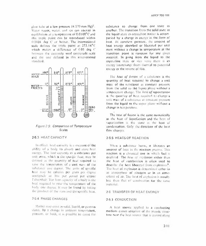
AMCP 706-188
glass tube at a low pressure (4.579 mm Hg)2. Water vapor, water, and ice can coexist in equilibrium at a temperature of 0 .0 100°C and this triple point can be reproduced within 0.0001 cleg C or better. The international scale defines the triple point as 273.I6°K which makes a difference of (1.01 deg C between the currently used centigrade scale and the one defined in this international standard.
Figure 2-9. Comparison of Temperature Scales
substance to change from one state to another. The transition from the solid state to the liquid state in crystalline matter is accompanied by a change in energy in the form of heat. At constant pressure, the amount of heat energy absorbed or liberated per unit muss without a change in temperature at the transition point is constant for any given material. In going from the liquid to the crystalline state or vice versa there is an energy interchange from thermal to potential energy or the reverse of this.
The heat o f fusion of a substance is the quantity of heat required to change a unit mass of the substance at constant pressure from the solid to the liquid phase without a temperature change. The heat o f vaporization is the quantity of heat required to change a unit mass of a substance at constant pressure from the liquid to the vapor phase without a change in temperature.
The heat of fusion is the same numerically as the hear of liquefaction and the heat of vaporization is the same as the heat of condensation. Only the direction of the heat flow- changes.
2-5.3 HEAT CAPACITY 2-5.5 HEATS OF REACTION
In effect, heat capacity is a measure ol the ability of a body to absorb and store heat energy. The heat capacity of a substance per unit mass, which is the specific heat, may be defined as the quantity of heat required to raise the temperature of a unit mass of the substance one degree. The units of specific heal may be calories per gram per degree centigrade or Bin per pound per degree Fahrenheit The heal rapacity of a body is the heat required to raise the temperature of the body one degree. It may be found by taking the product of the mass and the specific heat.
When a substance burns, it liberates an amount of beat in the reaction process. This reaction is a chemical one in which fuel is oxidized. The heat oj explosion rather than the heat of combustion is often used to describe the heal liberated front explosives*. The heat of explosion is determined either in an atmosphere of nitrogen or in an atmosphere ol air. The heat of explosion is usually less than that of combustion for the same material.
2-6 TRANSFER OF HEAT ENERGY
2-5.4 PHASE CHANGES 2-6.1 CONDUCTION
Matter may exist in solid, liquid, or gaseous states. By a change in ambient temperature, pressure, or both, it is possible to cause the
A heat source applied to a conducting medium causes agitation of the atomic structure near the heat source that is passed along
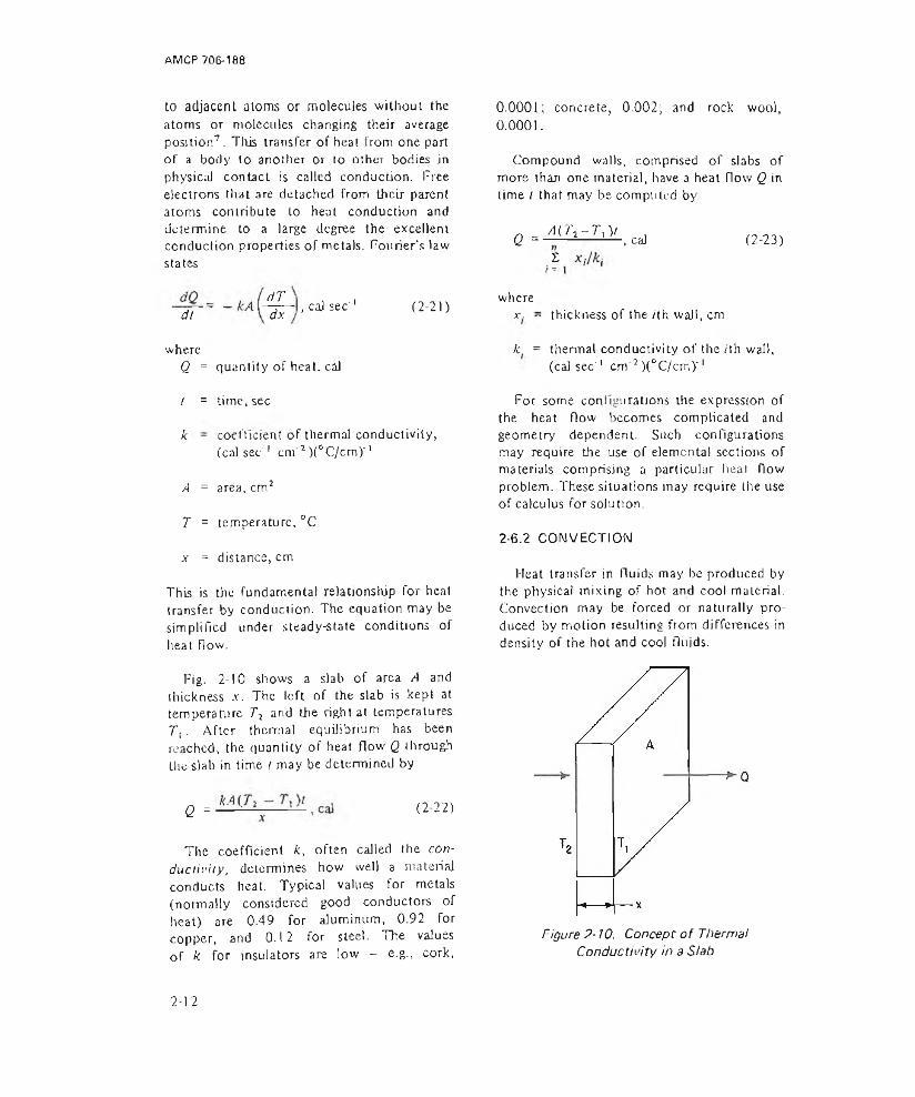
AMCP 706-188
to adjacent atoms or molecules without the atoms or molecules changing their average position7. This transfer of heat from one part of a body to another or to other bodies in physical contact is called conduction. Tree electrons that are detached from their parent atoms contribute to heat conduction and determine to a large degree the excellent conduction properties of metals. Fourier's law states
0.0001; concrete, 0.002; and rock wool,0.0001.
Compound walls, comprised of slabs of more than one material, have a heat flow Q in time I that may be computed by
_ A ( l \ - T, )/Q ------------------,caJ
Z(2-23)
dt(17dx , cal sec' 1 ( 2-21)
wherex. - thickness of the /th wall, cm
whereQ = quantity of heat, cal
k = thermal conductivity of the /th wall, (cal sec' 1 cm'7 )(°C/cm)'1
/ = time, sec
k - coefficient of thermal conductivity, (cai sec' 1 cm 1 )(&C/cm)‘ 1
A = area, cm1
T = temperature, °C
x = distance, cm
This is the fundamental relationship for heat transfer by conduction. The equation may be simplified under steady-state conditions of heat flow.
Fig. 2-10 shows a slab of area A and thickness x. The left of the slab is kept at temperature T2 and the right at temperatures. T | . After thermal equilibrium has been reached, the quantity of heat flow Q through the slab in time i may be determined by
Q = ( 2-22)
The coefficient k, often called the conductivity, determines how well a material conducts heat. Typical values for metals (normally considered good conductors of heat) are 0.49 for aluminum, 0.92 for copper, and 0.12 for steel. The valuesof k for insulators are low — e.g., cork.
For some configurations the expression of the heat flow becomes complicated and geometry dependent. Such configurations may require the use of elemental sections of materials comprising a particular heat flow problem. These situations may require the use of calculus for solution.
2-6.2 CONVECTION
Heat transfer in fluids may be produced by the physical mixing of hot and cool material. Convection may be forced or naturally produced by motion resulting from differences in density of the hot and cool fluids.
Figure 2-10. Concepr of Thermal Conductivity in a Slab
2-12

AMCP 706 188
Convcclive transfer3 of heat is expressed by
Q - h'AAT, cal (214)
whereQ = quantity of heat transferred, cal
h = heat transfer coefficient, cal cm'2° C l
,4 = area, cm2
AT = temperature difference, °C
The coefficient h( in Eq. 2-24 is complicated by a number of factors and must usually be obtained experimentally under conditions closely approximating those of the desired configuration. For this reason convective processes are seldom analyzed in great detail on a strictly theoretical basis.
Boltzmann law* which is expressed by the relation
W = eaT4, watt m' 2 (2-25)
whereW = rate of emission, watt m'2
e = emissivity of the surface, dependent upon material and temperature, dimensionless
a - Stefan-Boltzmann constant, 5.670 X 10'8 W m'2 °K'4
T = absolute temperature, °K
The value of the emissivity varies from 0 to ), depending upon the nature of I he surface of the radiating material. A perfect radiator would have an emissivity of one. Generally, rough surfaces have a higher emissivity than smooth surfaces.
2-6.3 RADIATION
Radiation differs from either conduction or convection in that heat is transmitted by electromagnetic waves, requiring no medium for transfer7. Radiation of heat is like that of light, radio waves, and X rays, differing only in the wavelength of frequency.
Wien discovered that the maximum radiation from a blackbody occurred at a given specific wavelength for a given temperature, and Wjen's displacement law relates the wavelength in terms of the temperature and a constant
Xm = b/T. ju (2-26)
When radiant heat energy reacts with a surface that is not transparent, the energy is absorbed and the surface becomes wanned. The nature of the surface, mainly the color and the roughness, determine haw efficiently the radiant energy is transformed into heat. Similarly, the radiator is affected by the color, roughness, and temperature. The energy radiated per unit urea and per unit time is determined by these factors.
At lower temperatures of the radiator, the rate of emission per unit area ami per unit lime is small and the wavelength of the radiant energy is relatively long. Fig. 2-3 shows the distribution of emission” for various temperatures for a blackbody radiator. As the temperature is increased, the rate of emission W increases very rapidly following the Slefan-
where\ m = wavelength at a point of maximum
emission, p
b = Wien displacement constant, 2897 P°K
T - absolute temperature of the source, °K
Planck’s theoretical equation determines the flux emitted per unit area and per unit wavelength by a blackbody. In this sense Planck’s equation provides a most versatile
•Both the Stefan-Boltzmann and Planck equations are presented in par 2-2.2 in a slightly different form. The equal [-.ms and constants presented lien; ate more amenable to radiation work and for lhal reason are repealed in this form.
2-13
AMCP 706-188
means of determining the radiation produced from a source that may be considered a blackbody. Planck’s equation is
cW, = ■----- -----!-------- , watt cm'2 p l (2-27)* Xs k C2( x r ) _ M’ H k ;
where= radiant flux emitted per unit area
per unit increment of wavelength, watt cm’2 p '1
C, = 2nc2 h = 3.741 X 10' 12 W cm2
SECTION III
2-7 INTENSITY
The intensity of a traveling sound wave is defined as the time average rate at which energy is transported by the wave per unit area through a surface perpendicular to the direction of propagation7 . Mathematically the intensity is given by
r j°2 X I 0-7f -------------- . Wc m ' (2-28)1Pov
where/ = intensity. W cm"2
P = pressure, dyn cm'2
p0 = density of the gas at equilibrium pressure, g cm'3
v = speed of propagation, cm sec' 1
Since for air. pQ and i' are often considered constant, / « P- and hence a measurement of pressure is also a measure of intensity. Intensity is usually expressed in decibels (dB). The dB sound level is the logarithm of the ratio of the ambient sound intensity / to some reference intensity 10 that is generally accepted as 10 6 W cm'2 . The intensity corresponds to a pressure of 0.0002 dyn cm"2. The intensity level, dl3 of sound, may be determined by
dB = 10 log , 0 ( 7 ) (2-29)
c = speed of light, 3 X 10,U cm sec' 1
h - Planck constant, 6.625 X 1 O'34 W sec2
C2 , = hc/k ■= 1.438 cm°K
k = Boltzmann constant, 1.38054X I0'23 W sec °K''
X = radiation wavelength, p
T = absolute temperature, “K
SOUND
The reference intensity level is chosen because this level is 2lso the threshold level of human hearing. This sound level is that which the average human being can just begin to hear. As a matter of interest, some typical dB intensities of noise levels were collected by the N.Y, City Nojse Abatement Commission that provide some idea of the meaning of the term dB as shown in Table 2-17.
TABLE 2-1NOISE LEVELS FROM COMMON SOURCES
Source or Description of Noise Noise Level,dB
Threshold of pain 120Riveter 95Elevated train 90Busy street traffic 70Ordinary conversation 65Quiet automobile 50Quiet radio in home 40Average whisper 20Rustle of leaves 10Threshold of hearing 0Repnr>ied with permission from U n iv e rs ity Physics, Third Edition, Sears and Zamansky, Addison-Wesley Publishing Co,, Reading, Mass,
2-8 WAVELENGTH
One of the basic concepts of sound is wavelength. The product of the wavelength
2-14

AMCP 706-188
and the frequency is the propagation velocity. In a single, uniform medium and under identical conditions, sound velocity is a constant. Since the velocity is constant, then wavelength varies inversely as frequency; accordingly high-frequency sounds have shorter wavelengths than low-frequency sounds.
Concepts of wavelength, pitch, and intensity are illustrated in Fig. 2-I l9 . In this figure, pitch is used in place of frequency; they are related. The sound source is shown as a cantilever beam that has been plucked and is vibrating. The shorter beam of the same cross section and niaterial results in a higher frequency, and Lhis is a generally true condition in structures that are subject to vibration.
2-9 EFFECT OF THE MEDIUM
Sound conducting media determine how far a sound may be conducted with enough energy content to still be heard or detected. In addition, some media have different values of aitenuation throughout the spectral range.
The speed of sound v in a solid medium is given by
, cm sec' 1 (2-30)
wherev = speed of sound, cm sec' 1
£ - Young’s modulus of the medium, dyn cm'2
p = density of the medium, gem '3
For a gas such as air, the speed of sound is given by
IA P (2-31)
wherev = velocity of sound, m sec' 1
P - pressure, N rrf2
p = density, kg m"3
The attenuation in air may be computed by classical methods, and the result is the attenuation characteristic plotted in Fig. 2-1210. Curve C shows the theoretical value of attenuation for dry air. Measurements in dry air yield the results shown in curve B. Note that
x - w a v e l e n g t h
( A ) NORMAL ( B ) HIGHER INTENSITY ( C ) HIGHER PITCH
Figure 2■ 11. Concept o f Found Wavelength, Pitch, and Intensity
2-1 S
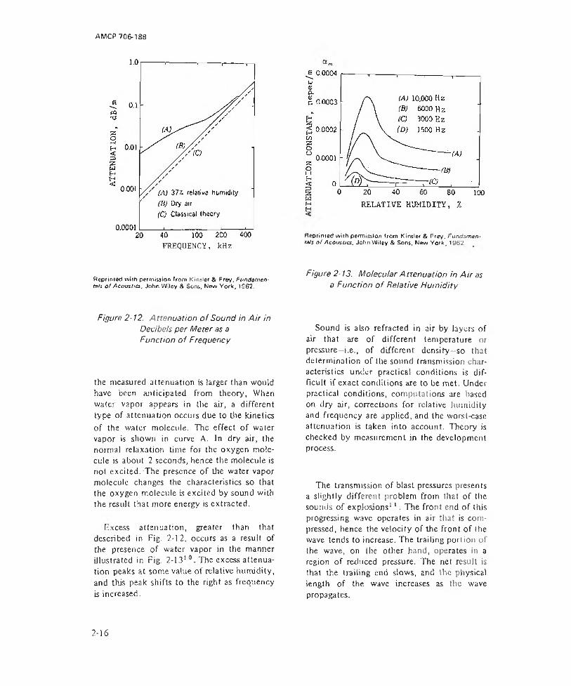
AMCP 706-188
FREQUENCY, kHz
Reprirned wiih permission from Kinsler & Frey, Fundamentals o f Acoustics, John Wiley & Sons, New York, 1962.
Reprinted with permission from Kinsler & Frey, Fundamentals o f Acousocs. John Wiley & Sons, New York, 1962.
Figure 2 13. Molecular A nenuation in A ir as a Function o f Relative H um id ity
Figure 2-12. Attenuation o f Sound in A ir in Decibels per Meter as a Function o f Frequency
the measured attenuation is larger than would have been anticipated from theory, When water vapor appears in the air, a different type of attenuation occurs due to the kinetics of the water molecule. The effect of water vapor is shown in curve A. In dry air, the norma] relaxation time for the oxygen molecule is about 2 seconds, hence the molecule is not excited. The presence of the water vapor molecule changes the characteristics so that the oxygen molecule is excited by sound with the result that more energy is extracted.
[excess attenuation, greater than that described in Fig. 2-12. occurs as a result of the presence of water vapor in the manner illustrated in Fig. 2-131 The excess attenuation peaks at some value of relative humidity, and this peak shifts to the right as frequency is increased.
Sound is also refracted in air by layers of air that are of different temperature or pressure—i.e., of different densify-so that determination of the sound transmission characteristics under practical conditions is difficult if exact conditions are to be met. Under practical conditions, computations are based on dry air, corrections for relative humidity and frequency are applied, and the worst-case attenuation is taken into account. Theory is checked by measurement in the development process.
The transmission of blast pressures presents a slightly different problem from that of the sounds of explosions11. The front end of this progressing wave operates in air that is compressed, hence the velocity of the front of lhe wave tends to increase. The trailing portion of (he wave, on lhe other hand, operates in a region of reduced pressure. The net result is that the trailing end slows, and the physical length of the wave increases as the wave propagates.
2-16

AMCP 706-188
REFERENCES
1. RCA Phototubes and Photocells. Radio Corporation of America, Technical Manual PT-60, 1963.
2. Rogers D. Rusk, Introduction to College Physics, Appleton-Century-Crofts, Inc., New York, 1960.
3. AMCP 706-185. Engineering Design Handbook. Military Pyrotechnics Scries. Part One, Theory and Application.
4. G. R. Harrison, R. C. Lord, and i. R. Loofbourow, Practical Spectroscopy. Prenttce-Hall, Inc., New York, I 948.
5. AMCP 706-127, Engineering Design Handbook, Infrared Military Systems, Pan One.
6. Arthur C. Hardy and Fred IT. Perrin, The Principles o f Optics, McGraw-Hill Book Co., Inc., New York, 1 932.
7. F. W. Sears and M. VC Zemansky, University Physics. Addison-Wesley Publishing Co., Inc., Reading, MA, 1964.
8. AMCP 706-177, Engineering Design Handbook, Properties o f Explosives o f Military Interest.
«10. L. E. Kinsler and A. R. Frey,
Fundamentals o f Acoustics, John Wiley and Sons, Inc., New York, 1962.
9. Robert Markgraf, A Portable Sound Analysis Laboratory for Small Arms Weapons. Report R-1878, Frankford Arsenal. Philadelphia PA. Nov. 1967.
11. J. G. Pruitt, Grenade Explosions in the Upper Atmosphere. IVoc. of the Second National Conierence on Atmospheric Acoustic Propagation, 1964 (AD-451446).
2-17/2-18

AM CP 706-188
CHAPTER 3
PYROTECHNIC TERMINAL EFFECTS
SECTION I VISIBLE LIGHT
3-1 ILLUMINATION
3-1.1 REQUIREMENTS
A large and important class of pyrotechnic devices are those which are used for illumination1'1. Artificial illumination may be needed to observe enemy troops, weapons, or vehicles, to aid in the accomplishment of a search or rescue task; for night photography; and other similar tasks. Visual inspection dependent on artificial illumination for military purposes may be roughly divided into three categories.
1. Detection consists of merely recognizing the presence of an object or target within the Field of the observer’s vision. Detection of targets of relatively high contrast may be accomplished with, illumination levels of 0.1 footcandle or less. Since target motion and the use of peripheral vision enhance target detectability, this level of illumination is not absolute.
2. Recognition generally requires between 0.1 and l footcandle and involves the ability of the observer to identify the shape or size of a target after it has been detected.
3. Identification requires illumination levels high enough to allow the observer to distinguish enough details to make a “friend or foe” type of decision.
. Actually, the illumination levels needed for detection, recognition, or identification will vary considerably—depending on the size, range, and contrast of the target; environ
mental conditions including haze, glare, and battle conditions; and the ability and physical condition of the observer. It is generally conceded that illumination levels between 0.1 and 10 footcandles will satisfy most visibility requirements provided that the target contrast exceeds 0.1 footcandle and that target size subtends a visual angle of 5 min of arc or greater. For comparison a full moon provides 0.02 footcandle, a clear, moonless night sky provides about 0.0001 footcandle of illumination, and a heavy overcast daytime sky about 10 footcandles.
The illumination levels recommended for detection, recognition, and identification are merely guidelines for average field conditions—i.e., normal visibility (5 or 6 miles), average contrast targets (at 0.1 footcandle), average size target (subtends 5 min of arc), and no excessive battle fatigue. If unusual Field conditions are encountered, the recommended illumination levels may have to be increased by an order of magnitude or more. Colored targets and moving targets will aid in detection and thus require slightly less illumination.
3-1.2 EFFECT OF FIELD CONDITIONS
The visibility nomograph in Fig. 3-11 serves as an aid in estimating the necessary light levels for various field conditions. To use this nomograph the designer must know or estimate the target contrast, the size of the target, the sky-ground ratio, the meteorological visibility, and the liminal optical slant range of the target.
3-1
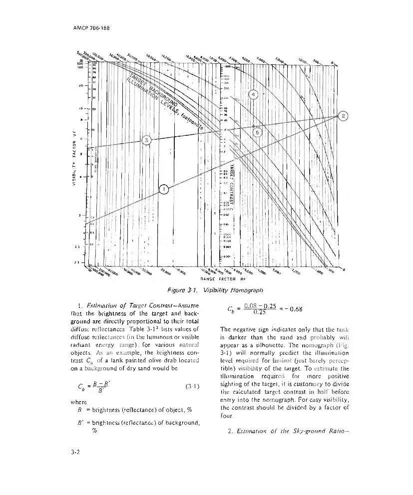
AM CP 706-188
diffuse reflectances- Table 3-12 lists values of diffuse reflectances (in the luminous or visible radiant energy range), for various natural objects. As an example, the brightness contrast Ch of a tank painted olive drab located on a background of dry sand would be
r - B - B 'S S' (3-1)
where .B ~ brightness (reflectance) of object, %
S' = brightness (reflectance) of background,%
The negative sign indicates only that the tank is darker than the sand and probably will appear as a silhouette. The nomograph (Fig.3-1) will normally predict the illumination level required for liininal (just barely perceptible) visibility of the target. To estimate the illumination required for more positive sighting of the target, it is customary to divide the calculated target contrast in half before entry into the nomograph. For easy visibility, the contrast should be divided by a factor of four.
2. Estimation o f the Sky-ground Ratio—
3-2
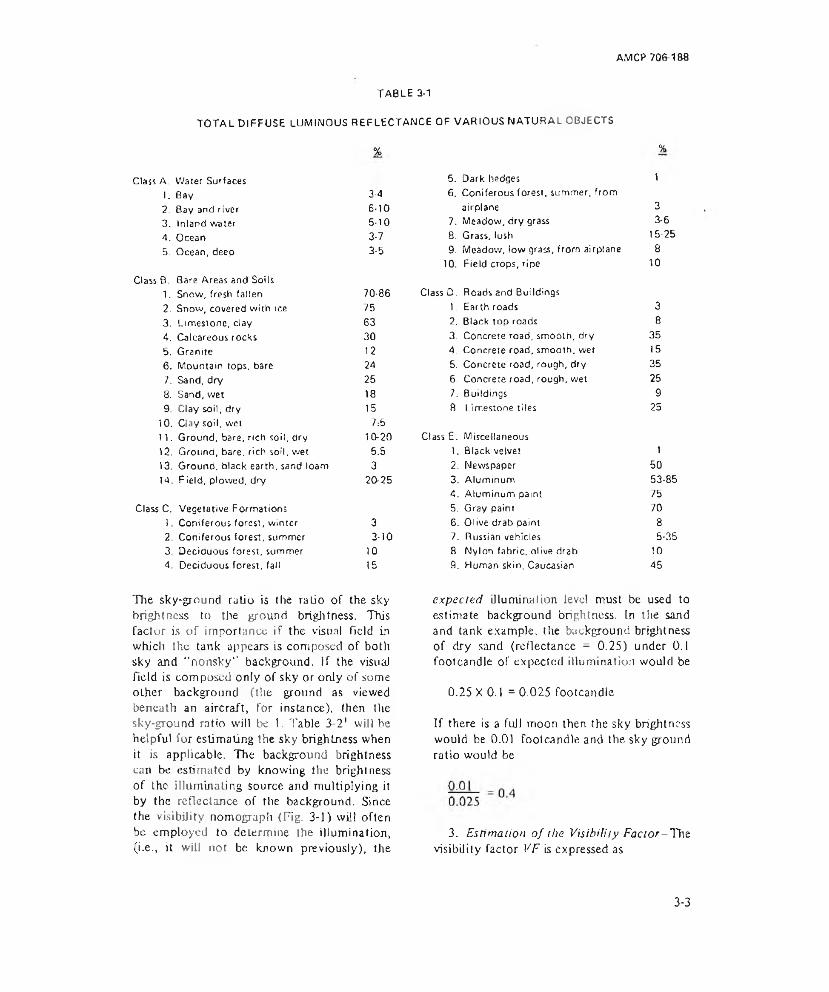
AMCP 706-188
TABLE 3-1TOTAL DIFFUSE LUMINOUS REFLECTANCE OF VARIOUS NATURAL OBJECTS
%
Class A. Water Surfaces1. Bay 3-42. Bay and river 6-103. Inland water 5-104. Ocean 3-75. Ocean, deep 3-5
Class B. Bare Areas and Soils1. Snow, fresh fallen 70-862. Snow, covered with ice 753. Limestone, clay 634. Calcareous rocks 305. Granite 1 26. Mountain tops, bare 247. Sand, dry 258. Sand, wet 189. Clay soil, dry 1510. Clay soil, wet 7:511. Ground, bare, rich soil, dry 10-2012. Ground, bare, rich soil, wet 5.513. Ground, black earth, sand loam 314. Field, plowed, dry 20-25
Class C. Vegetative Formations!. Coniferous forest, winter 32. Coniferous forest, summer 3-103. Deciduous forest, summer 104. Deciduous forest, fall 15
%
5. Dark hedges 16. Coniferous forest, summer, fromairplane 3
7. Meadow, dry grass 3-68. Grass, lush 15-259. Meadow, low grass, from airplane 810. Field crops, ripe 10
ClassD. Roads and Buildings1. Earth roads 32. Black top roads 83. Concrete road, smooth, dry 354. Concrete road, smooth, wet 155. Concrete road, rough, dry 356. Concrete road, rough, wet 257. Buildings 98. Limestone tiles 25
Class E. Miscellaneous1. Black velvet 12. Newspaper 503. Aluminum 53-854. Aluminum paint 755. Gray paint 705. Olive drab paint 87. Russian vehicles 5-358. Nylon fabric, olive drab 109. Human skin. Caucasian 45
The sky-grnnnd ratio is the ratio of the sky brightness to the ground brightness. This factor is of importance if the visual field in which the tank appears is composed of both sky and “nonsky” background. If the visual field is composed only of sky or only of some other background (the ground as viewed beneath an aircraft, for instance), then lire sky-ground ratio will be I . Table 3-21 will be helpful for estimating the sky brightness when it is applicable. The background brightness can be estimated by knowing the brightness of the illuminating source and multiplying it by the reflectance of the background. Since the visibility nomograph (Fig. 3-1) will often be employed to determine the illumination, (i.e., it will not be known previously), the
expected illumination level must be used to estimate background brightness, in the sand and tank example, Ihe background brightness of dry sand (reflectance = 0.25) under 0.1 footcandle of expected illumination would be
0.25 X 0.1 = 0.025 footcandle
If there is a full moon then the sky brightness would be 0.01 footcandle and the sky ground ratio would be
3. Estimation of the Visibility Factor-Tnz visibility factor VF is expressed as
3-3
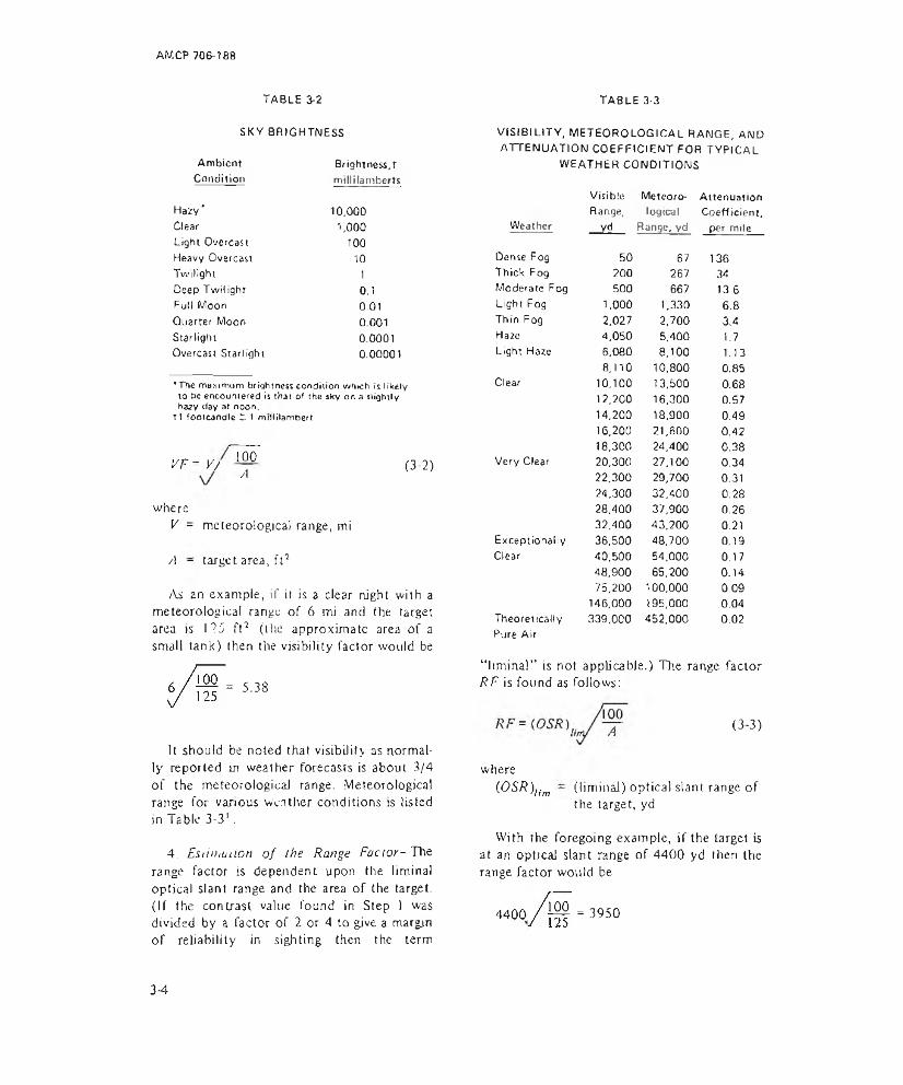
AM CP 706-188
TABLE 3-2 TABLE 3-3SKY BRIGHTNESS
AmbientCondition
Hazy'ClearLight Overcast Heavy Overcast Twilight Deep Twilight Full Moon Quarter Moon StarlightOvercast Starlight * V
Brightness, T millilamberts
10.0001,000
10010
10.10.010.0010.00010.00001
•The maximum brightness condition which is likely to be encountered is that of the sky on a slightly hazy day at noon.
T1 footcandle L t mrllilambert
VF = V/ 100A (3-2)
whereV = meteorological range, mi
A - target area, ft1
As an example, if it is a dear night with a meteorological range of 6 mi and the target area is 125 ft (the approximate area of a small tank) then the visibility factor would be
- 5.38
It should be noted that visibility as normally reported in weather forecasts is about 3/4 of the meteorological range. Meteorological range for various weather conditions is listed in Table 3-31.
4. Esiiihution o f the Range Factor-Vets range factor is dependent upon the liminal optical slant range and the area of the target. (If the contrast value found in Step 1 was divided by a factor of 2 or 4 to give a margin of reliability in sigh ting then the term
VISIBILITY, METEOROLOGICAL RANGE, AND ATTENUATION COEFFICIENT FOR TYPICAL
WEATHER CONDITIONS
WeatherVisible Meteoro- AttenuationRange, logical Coefficient,yd Range, yd per mile
Dense Fog 50 67 136Thick Fog 200 267 34Moderate Fog 500 667 13.6Light Fog 1.000 1,330 6.8Thin Fog 2,027 2,700 3.4Ha2e 4,050 5,400 1.7Light Haze 6,080 8,100 1.13
8,110 10,800 0.85Clear 10,100 13,500 0.68
12,200 16,300 0.5714,200 18,900 0.4916,200 21,600 0.4218,300 24,400 0.38
Very Clear 20,300 27,100 0.3422,300 29,700 0.3124,300 32,400 0.2828,400 37,900 0.2632,400 43,200 0.21
Exceptio nally 36,500 48,700 0,19Clear 40,500 54,000 0.17
48,900 65,200 0.1475,200 100,000 0.09146,000 195,000 0.04
Theoretically 339,000 452,000 0.02Pure Air
“ liminal” is not applicable.) The range factor RF is found as follows:
(3-3)
where(OSR)lim (liminal) optical slant range of
the target, yd
With the foregoing example, if the target is at an optjeal slant range of 4400 yd then the range factor would be
4400 100 = 3950
3-4
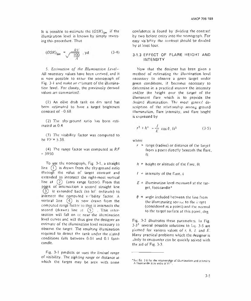
AMCP 706-188
It is possible to estimate the (0SR)lim if the illumination level is known by simply revets- ing this procedure. Thus
vHI ■ wA
5. Estimation o f the lUumimlion Level— Ail necessary values have been derived, and it is now possible to enter the nomograph of Fig. 3-1 and make an estimate of the illumination level. For clarity, the previously derived values are summarized:
(1) An olive drab tank on drv sand has been estimated to have a target brightness contrast of —0 .68.
(2) Tire sky-ground ratio has been estimated as 0.4.
(3) The visibility factor was computed to be Vh' - 5.38.
(4) The range factor was computed as RF = 3950.
To use the nomograph, Fig. 3-1, a straight line (T) is drawn from the sky-ground ratio through the value of target contrast and extended to intersect the right-most vertical line at (T) (zero range factor). From tbs point of intersection a second straight line
is extended back (to lef: ordinate) to intersect the computed v.Ability factor. A vertical line (7) is now drawn from the computed range factor so that it intersects the second (drawn) line at (T) . This intersection will fall on or near the illumination level curves and will thus give the designer an estimate of the illumination level necessary to observe the target. The resulting illumination required to detect the tank under the stated conditions falls between 0.01 and 0.1 foot- candle.
Fig. 3-1 predicts or uses the liminal range of visibility. The sighting range or distance at which tire target may be seen with some
confidence is found by dividing the contrast by two before entry into the nomograph. For easy vis'bi'ity the contrast should be divided by at least four.
3-1.3 EFFECT OF FLARE HEIGHT AMD INTENSITY
Now that the designer has been given a method of estimating the illumination level necessary to observe a given target under given conditions, it becomes necessary to determine in a practical manner the intensity and/or the height over the target of the illuminant flare which is to provide the desired illumination. The most genera! description of the relationship among ground illumination, flare intensity, and flare height is expressed by
+/ri = -L cos6 ft2 (3-5)t
wherer = range (radius) or distance of the target
from a point directly beneath the flare, ft
h = height or altitude of the flare, ft
/ = intensity of the flare, c
E = illumination level measured at the target, footcandle*
$ - angle included between the line from the illuminating source to the h rget (considered as a point) and the normal to the target surface at this point, deg
Fig. 3-2 illustrates these parameters. In Fig,3-32 several possible solutions to Lq. 3-5 are plotted for various values of r, h, /. and E. Many practical problems which the designer is akely to encounter can be quickly solved with the aid of Fig. 3-3.
*Sce JBq. 2-6 for (he relationship of illumination and intensity. A footcandle h In units of ft*3.
3-5
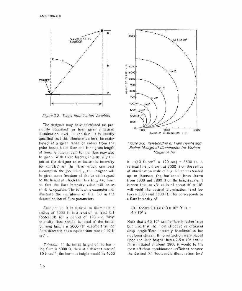
AMCP 706-188
Figure 3-2. Target Illum ination Variables
The designer may have calculated (as previously described) or been given a desired illumination level. In addition, it is usually specified that this illumination level be maintained at a given range or radius from the point beneath the flare and fora given length of time. A descent rate for the tlare may also be given. With these factors, it is usually the job of the designer to estimate the intensity (in candles) of the flare which can best accomplish the job. Ideally, the designer will be given some freedom of choice with regard to the height at which the flare begins to hum so that the Hare Intensity vaiue will he as small as possible. The following examples will illustrate the usefulness of Fig. 3-3 in the determination of flare parameters.
SANGE OF ILLUMINATION i , (I
Figure 3-3. Relationship o f Flare Height and Radius lRange) o f Illum ination fo r Various
Values o f f/E
ft - (10 ft sec' 1 X 120 sec) = 3800 ft. A vertical line is drawn at 3000 ft on the radius of illumination scale of Fig. 3-3 and extended up to intersect the horizontal Lines drawn from S000 and 3800 ft on the height scale. It is seen that an ljE ratio of about 40 X 106 will yield the desired illumination level between 5000 and 3800 ft. This corresponds to a flare intensity of
Example I: Tt is desired to illuminate a radius of 3000 Tt to a level of at least 0.1 footcandle for a period of 120 see. What intensity flare should be used if the initial burning height is 5000 ft? Assume that the flare descends at an equilibrium rate of 10 ft sec 1.
Solution: If the initial height of the burning flare is 5000 ft, then at a descent rate of 10 ft sec'1, the burnout height would be 5000
(0.1 footcandle) X (40 X 10* f t '1) =4X 10⁶ c
Note that a 4 X 10⁶ candle flare is rather large but also that the most effective or efficient drop height/flare intensity combination has not. been chosen. If no restriction were placed upon the drop height then a 2.5 X J 06 candle flare initiated at about 2800 ft would be the most efficient combination—efficient because the desired 0.1 footcandle illumination level
3-6

AM CP 706-188
out to the 3000-ft radius would be maintained with the smallest possible intensity or flare size.
Example 2: What is the maximum radius of illumination which can be maintained at 0.1 footcandlc with, a 2 X I06 candle flare which is suspended in a relatively stationary position from a helicopter? Also, what is the best height for the Hare to be suspended?
Solution: The l/E ratio is
2 X I06 candle/0.1 footcandle =20 X 106 f f
Referring to the curves of Fig. 3-3, it is seen that the maximum radius of illumination is about 2800 ft if the flare is suspended at 1900 ft.
Additional information on flare brightness is contained in Appendix A.
3-1.4 MULTIPLE SOURCE ILLUMINATION
The use of multiple sources may be desirable as a means of reducing the high contrast between light and shadow areas which characterizes a single source, a$ a method of increasing the illuminance when single sources of adequate intensity are unavailable, and as a way to increase the duration of illumination2. The last case can be considered as a special instance of the single source if the overlap in duration is not too great. The use of multiple sources to increase the illuminance requires as high a degree of simultaneity in functioning as possible. A multiple launch is to be preferred because sequential launching not only destroys the simultaneity of functioning but also distributes the units over an area. If the space separation is controlled by circling the launch vehicle, this may be minimized. The effect of space separation is not too severe if the distance between the units and the center of mass of the group does not exceed 10 percent of the source height. This separation may be difficult to achieve by sequential
launch at relatively low altitudes if the aircraft ground speed is of the order of 500 kt. At 2000-ft altitude, the desired 200-ft separation would necessitate launching every 0.25 sec, This short interval is difficult to obtain with large flares which suggests that simultaneous launch (or a single larger flare) should be used only if point source illumination is essential. IF it is not important to simulate a single source but it is required to increase the illuminance over an area, much larger distances between sources can be accepted.
Two situations are commonly encountered with respect to the pattern in which the sources arc distributed, "i iiese two conditions will now be discussed in some detail.
If a long, narrow path is to be illuminated, the number and spacing of the flares is calculated from
EP = — (Ft cosMi + F2cos3/42 IF+ F3coF A 3 + . . . . Fncos3/f(i) (3-6)
where= illuminance at point F, footcandle
7 = intensity of flare, c
h = source height, ft
Fi = factor, dimensionless
A.1 = angle between vertical at the s o u r c e S. and the D oin t P. radl - >
The point P{ for which Ep is computed is directly below one of the sources. The value of F will be 0, 1, or 2 depending on the position of P with respect to the first and last source S ( and S . respectively, as shown inFig. 3-42.
When two sources S2 and are located symmetrically with respect Lo a source above the point P, the value of F is 2. If only one source exists, as 51, , the value of F is !, When no source exists the value of F is zero
3-7

Aft/)CP 70fi J88
Figure 3-4. Linear, Symmetrically Distributed Source Geometry
Illumination is maximum directly below a flare and minimum hall" way between the flares. From a consideration of the vaJues taken by cos3/l, as A increases it is evident that four terms of the series are sufficient for many practical problems, and corresponds to selecting a point located midway of a seven- source string. The minimum value of Ep may be estimated as 80 percent of Ep for reasonable values of height and separation. While individual cases may arise in which a detailed calculation is required, in many cases a separation equal to 40 percent of the source altitude will be found quite useful. For this separation, the value of Ep is the following at the center of a 7-flare string (in this particular configuration. Af = 0,4 h(i — l)//i)
En (1 + 2(0.83) + 2(0.47)
2(0.26)] = 4.12 . footcandle
An increase in the number to nine flares increases the coefficient from 4.12 to 4.42. The increase of almost 30 percent in the number of flares used will increase the maximum illumination by only 7.5 percent.
If a circular path is followed and the sources are again uniformly distributed, the illuminance at a point on the ground below the center of the circular path will depend on the number of sources. In the general case, the relation is
£ = }n , footcandleP (fri + rJ ) ' (3-7)
whereE = illuminance at point A the center of P
circle on ground, footcandle
n - number of sources
3-8

AMCP 706-1S8
/ = intensity of Dare, c
h - source height on circumference of circle, ft
r ~ radius of circle, ft
b = slant range (/r2 + r2) ' /2 , ft
For a radiusr ~ 0.4/j, the relation becomes E = 0Sn //h2.
3-1.5 FLARE LOCATION
Not only the level of the illumination but its direction has a strong influence on visibility of a target2. This arises from the degree to which long, confusing, deep shadows, or metallic glints from semispecular surfaces are produced by changes jn the azimuth and elevation of the source with respect to the target-observer axis. Typically, studies of the optimum location of the source have shown that it should be either in front of or behind the target. An advantage of the order of 3x can result from source positioning in either location, which is of enough value to justify some effort to secure it.
In order to utilize this advantage, an observer will most often find it desirable to locate the source somewhere near, and behind, himself. If it cannot be placed behind the observer, the source must be thoroughly shielded on the observer's side to minimize the interference produced by glare. The change in the state of adaptation of the eye will occur in about 0 .1 sec. It is, therefore, important to avoid even momentary exposures of the observer to the unshielded source. The need for this caution is further emphasized when it is recalled that the discrimination of brightness contrast is a function of the background luminance to which the eye is adapted. When the luminance level is below O.l footcandle, the ability to discriminate brightness differences decreases very rapidly. A level below 0.) footcandle would be commonly encountered in night reconnaissance.
3-1.6 ESTIMATES OF FLARE SIZE
In the design of a flare, the diameter and length of the illuminant composition necessary to meet the required candlepower and burning time must be established. One approach to this problem is as follows:
(1) Multiply the product of the candle- power and burning time by 1.3. (The factor provides 30% excess of integrated illumination to allow for variations in candlepower and burning rates in individual illuminants.)
(2) Assume a cross-sectional area for the illuminant composition and divide the product of 1.2 times the candlepov.v- by this assumed area. (This step gives the canchc- power requirement, with a 20% excess, of one square inch of burning surface.)
(3) From the compilation of data on various compositions, pick the composition producing the closest candlepower per square inch and determine the volume using the following formula:
Volume (illuminant composition) -! {CF){RT){BR) . 3 (3'8)' (cp) ,in
whereCP = candlepower required
BT = burning time required, sec
BR = burning rate of composition, in. sec' 1
cp - candlepower of candidate composition from ) in.2 of burning area, in.'2
This equation is not exact , a difference of 30 percent may result.
(4) Length (illuminant composition) = volume./area, in.
3-9
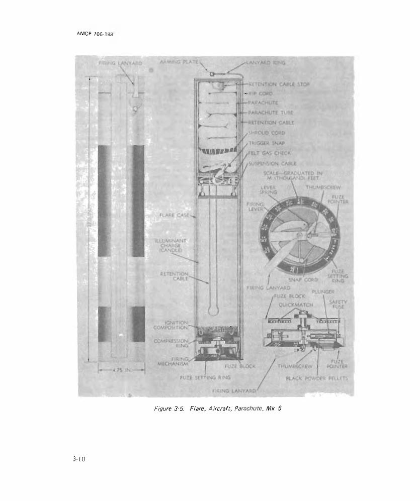
AMCP 706-188
?A#ACHi>T£parachute ti'SEretention cable
IRiSGCV SNAP
QLilC* MATCH
( IRJNG MECHANISM humbvCkC
Figure 3-5. Flare, Aircraft, Parachute, Mk 5
3-10

AM CP 706-188
PARACHUTEASSEMBLY LOWERSUPPORT SPLITWASHER ILLOMINANT CONTAINER ASSEMBLY UPPERSUPPORT-BAFFLE GASKET8AFFLE PLATE
BAFFLE SPACING WASHER
EXPELLING CHARGE 8AGEXPELLING CHARGEIGNITION COMPOSITION
PARACHUTE / SW eP'NPAD PLATE SHROUDATTACHMENT
CENTERTUBECOMPOSITION “A”
RELEASE SLEEVE AND CENTER WIRE ASSEMBLYFigure 3-6. Illum inating A rtille ry Load, Mk 7
(5) if the length is not compatible with the overall flare size repeat steps (2), (3), and (4).
The weight of the illuminant composition is then obtained by multiplying the volume by the density.
Representative examples of illuminating flares are listed in Table 3-43'4 and illustrated in Figs. 3-53, 3 -6 \ and 3-74.
3-1.7 TYPICAL ILLUMINATING CANDLES
In genera), a pyrotechnic illuminating flare must provide from 0.05 to 10 footcandles of essentially white light for a time of at least 30 sec and in some instances 2 to 3 min’ . Some of the air dropped flares may provide up to 2 million candlepower whereas a small hand- launched grenade may provide less than55,000 candlepower to illuminate a nearby area (Table 3-4).
Although white, light is often difficult to produce, it provides the best illumination for the greatest range of possible field conditions. For long burning flares (i.e., long burning as
opposed to photoflash and tracer pyrotechnics), white or near white ligi.L is obtained with mixtures oT a fuel which are usually magnesium and oxidizer such as sodium nitrate, potassium perchlorate, or potassium nitrate.
A binder is usually added to ihe fuel- oxidizer mixture to prevent segregation of particles when blending and loading, and to increase the mechanical strength of the finished candle. The bindei may also, in some cases, enhance the burning efficiency, do crease friction and static sensitivity of the mixture, and provide additional control of burning rate. But probably the mosl important added feature the binder can give is good bonding to the case, which helps to promote laminar burning of the surface of the candle and avoid erratic burning along the side or breakup of the candle.
Resins, waxes, plastics, and oils have been used for binding agents. The most frequently used combination (see Appendix B for others! is magnesium/sodium nitrate/binder which produces a yellow-tinted white light of
3-11
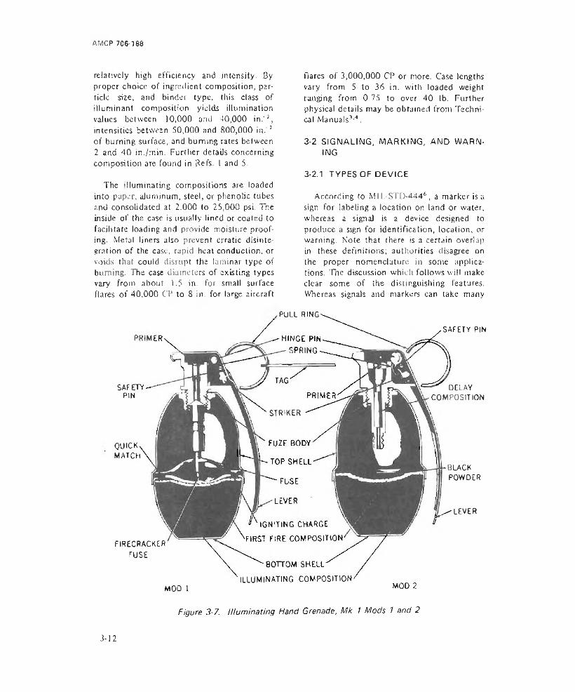
AMCP 706-188
relatively high efficiency and intensity. By proper choice of ingredient composition, particle size, and binder type, this class of illuminant composition yields illumination values between 10,000 and 40,000 in.'2, intensities between 50,000 and 800,000 in.'2 of burning surface, and burning rates between 2 and 40 in./min. Further details concerning composition are found in Refs. I and 5.
The illuminating compositions are loaded into paper, aluminum, steel, or phenolic tubes and consolidated at 2.000 to 25,000 psi, The inside of the case is usually lined or coated to facilitate loading and provide moisture proofing. Metal liners also prevent erratic disintegration of the case, rapid heat conduction, or voids that could disrupt the laminar type of burning. The case diameters of existing types vary from about 1.5 in. for small surface flares of 40.000 CP to 8 in. for large aircraft
flares of 3,000,000 CP or more. Case lengths vary from 5 to 36 in. with loaded weight ranging from 0.75 to over 40 lb. Further physical details may be obtained from Technical Manuals3,4.
3-2 SIGNALING, ING
MARKING, AND WARN-
3-2.1 TYPES OF DEVICE
According to MIL.-STD-4446 , a marker is a sign for labeling a location on land or water, whereas a signal is a device designed to produce a sign for identification, location, or warning. Note that there is a certain overlap in these definitions; authorities disagree on the proper nomenclature in some applications. 'The discussion which follows will make clear some of the distinguishing features. Whereas signals and markers can take many
PULL RING-
SAFETY PIN
QUICKMATCH
DELAY COMPOSITION
SAFETY PIN
BLACKPOWDER
LEVER
FIRECRACKER FUSE
BOTTOM SHELL' ILLUMINATING COMPOSITION'
MOO 1 MOD 2
Figure 3-7. Illum inating Hand Grenade, Mk 1 Mods 1 and 2
3-12
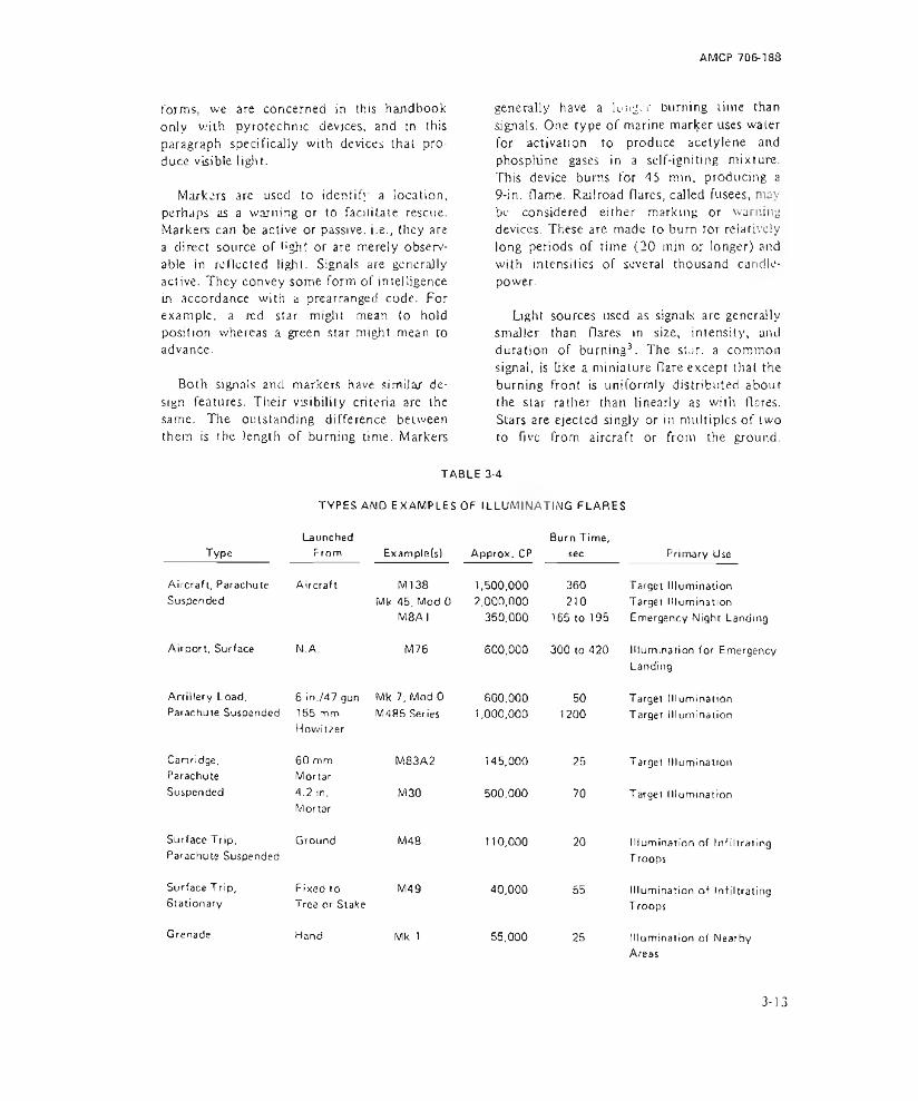
AMCP 706-188
forms, we are concerned in this handbook only with pyrotechnic devjces, and in this paragraph specifically with devices that produce visible tight.
Markers are used to identify a location, perhaps as a warning or to facilitate rescue. Markers can be active or passive, i.e., they are a direct source of light or are merely observable in reflected light. Signals are generally active. They convey some form of intelligence in accordance with a prearranged code. For example, a red star might mean to hold position whereas a green star might mean to advance.
Both signals and markers have simitar design features. Their visibility criteria are the same. The outstanding difference between them is the length of burning time. Markers
generally have a lunger burning time than signals. One type of marine marker uses water for activation to produce acetylene and phosphine gases in a self-igniting mixture. This device burns for 45 min. producing a9-in. flame. Railroad flares, called fusees, may be considered either marking or warning devices. These are made to bum tor relatively long periods of rime (20 min or longer) and with intensities of several thousand candle- power.
Light sources used as signals are generally smaller than flares in size, intensity, and duration of burning3. The star, a common signal, is like a miniature flare except that the burning front is uniformly distributed about the star rather than linearly as with flares. Stars are ejected singly or in multiples of two to five from aircraft or from the ground.
TABLE 3-4TYPES AND EXAMPLES OF ILLUMINATING FLARES
LaunchedType From Example(s)
Aircraft. Parachute Suspended
Aircraft Ml 38Mk 45. Mod 0
M8AIAirport, Surface N.A. M76
Artillery Load, 6 in./47 gun Wlk 7, Mod 0Parachute Suspended 155 mm
HowitzerM485 Series
Cartridge.Parachute
60 mm Mortar
M83A2Suspended 4.2 in.
MortarM30
Surface Trip, Parachute Suspended
Ground M48
Surface Trip. Stationary
Fixed to Tree or Stake
M49
Grenade Hand Mk 1
Burn Time,Approx. CP sec Primary Use1,500,0002,000,000350,000
360210
165 to 195Target Illumination Target Illumination Emergency Night Landing
600,000 300 to 420 Illumination for Emergency Landi ng
600,0001,000,000
501200
Target Illumination Target Illumination
145,000 25 Target Illumination500,000 70 Target Illumination
110,000 20 Illumination of Infiltrating T roops
40,000 55 Illumination of Infiltrating Troops
55,000 25 Illumination of Nearby Areas
3-13
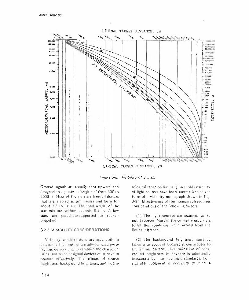
AMCP 706-188
•%&. <A>.LIMINAL TARGET DISTANCE, yd
LIMINAL TARGET DISTANCE, yd
Figure 3-8. V isib ility o f Signals
Ground signals arc usually shot upward and designed to operate at heights of from 600 to 2000 ft. Most of the stars are free-fall devices that are ejected as snhmissiles and burn for about 2.5 to lOsec. The total weight of the star mixture seldom exceeds 0.5 lb. A few stars are parachute-supported or rocket- propelled.
3-2.2 VISIBILITY CONSIDERATIONS
Visibility considerations are used both to determine the limits of already-designed pyrotechnic devices and to establish the characteristics that to-be-designed devices must have to operate effectively. The effects of source brightness, background brightness, and meteo
rological range on liminal (threshold) visibility of light sources have been summarized in the form of a visibility nomograph shown in Tig.3-81. Effective use of this nomograph requires considerations of the following factors:
(1) The light sources are assumed to be point sources. Most of the currently used stars fulfill this condition when viewed from the liminal distance.
(2) The background brightness must be taken into account because it contributes to the liminal distance. Determination of background brightness in advance is admittedly inaccurate by most technical standards. Considerable judgment is necessary to select a
3-14
INTE
NSIT
Y
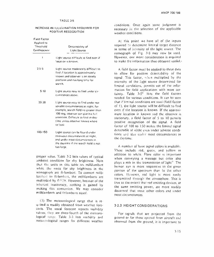
AMCP 706-188
TAeLE 3-5INCREASE IN I LLUlVi I NATION REQUIRED FOR
POSITIVE RECOGNITIONField Factor Applied to Threshold Candlepower
Detectability of Light Source
1 Light source difficult to find even iflocation is known.
2.5-5 Light source moderately difficult tofind if location is approximately known and observer is on steady platform and has long time for search.
5-10 Light source easy to find under circumstances above.
20-30 Light source easy to find under reasonable circumstances at night, for example, search field no greater than )00 deg, observer can give his full attention. Difficult to find in daytime unless observer knows where to look.
100-150 Light source can be found under strenuous circumstances at night, and under most circumstances in the daytime if the search field is not too large.
proper value. Table 3-2 lists values of typical ambient condition for sky brightness. Note that the units in this table arc millilamburt while the nniis for sky brightness in the nomograph are ft-lambert. To convert milli- lambert to ft-lambert, the millilamberts are multiplied by 0N29. However, because of the inherent inaccuracy, nothing is gained by making (his convulsion. We may consider miliiUmberts and ft-lamberts equal.
(3) The meteorological range that is required is readily obtained from weather forecasts. The usual forecast reports visibilityvalues; they are three-fourth of the meteorological range. Table 3-3 lists visibility andmeteorological ranges for different weather
conditions. Once again some judgment is necessary in the selection of the applicable weather conditions.
At this point we have all of the inputs required to determine liminal target distance in terms of intensity of the light source. The nomograph of Fig- 3-8 may now be used. However, one more consideration is required to make the information thus obtained useful.'
A field factor must be applied to these data to allow for positive detectability of the signal. Tibs factor, when multiplied by the intensity of the light source determined for liminal conditions, permits use of the information for field applications with more certainly. Table 3-51 3 * * * lists the field factors needed for various conditions. It can be seen that if liminal conditions are used (field factor of 1), the light source will be difficult to find even if the location is known. If the approximate location is known and the observer is stationary, a field factor of 5 to 10 permits positive recognition of the signal. A Held factor of 100 to 150 makes the liminal signal detectable at night even under adverse conditions and also under most circumstances in the daytime.
A number of basic signal colors is available. These include red, green, and yellow in addition to white. Flare color is important when conveying a message but color also plays a role in the transmission of Light7 - The human eye is more responsive to the green portion of the spectrum than to the other colors. However, red tight is more easily transmitted through the aLmosphere. This is true to the extent that red emitting devices, at the same emitting power, are more readily discerned that most other colors and under most circumstances.
3-2.3 HEIGHT CONSIDERATIONS
For signals that are projected from the ground or for those ejected from aircraft and observed from the ground, it is important to
3-15

AMCR 705-188
determine the height at which the Hare ignites and to consider how far the observer can see Oris flare. To accommodate for the curvature ol the earth, both the height of the observerand the height of the light source must be considered1. Assuming no obstructions, as would be the case on the ocean or on a prairie, the limiting range for direct line ofsi gh t is
-v = 1.325 (!I + h), mi (3-91
he rex = limiting range for direct line of
sight, mi
p r i m e r
h i n g e p i n
COTTER PIN ' STRIKER
RELEASE LEVER
ELEMENT
EJECTION CHARGE
QUICKMATCH
STAR
H = height of the signals, ft
h = height of the observer, ft
Applying this equation to a star 100 ft in the air observed by a man with his eyes 5 ft off the ground results in a limiting direct line of view distance of 139 mi. This value represents a limiting condition, but does not imply that a man could actually see a flare from this distance nor that signals are designed for this criterion.
In most instances there are obstructions to line of sight. Trees, buildings, hills, and other obstructions limit the range of vision. For this reason, it is desirable to plan on projection heights greater than those allowed for flat, level ground.
CASE
SUSPENSION CABLE
. p a r a c h u t e ’
CLOSING CAP
Figure 3-9. Aircraft Illumination Signal, iVfk 6
ignites the 3-sec delay element. At the end of this delay, the ejection charge fires, propelling Lhe lower portions of the signal skyward and igniting Lhe quickmatch leading to the star composition. A! operational altitude, the parachute opens and (he signal burns for approximately 25 sec. The stars may be red, green, or while having the respective candle- power of 2400, 1500, and 27,000.
3-2.4 TYPICAL DEVICES
A typical aircraft illumination signal is illustrated in Fig. 3-9*. This ground-launched signal for attracting aircraft is designed to be ignited by hand, whereupon it is immediately thrown into the water, where it will right itself; or it can be placed upright on the ground. To operate, the hand is placed around the signal in such a way as to hold the release lever against the body of the signal. The safety C O t t e i pin is pulled and the signal is then thrown or placed. Ignition is accomplished by activation of the primer, that
Pyrotechnic devices utilizing a dye are effective for marking locations on water. The Marine Location Marker, AN-MARK 1 (Fig.3-1Q4) is typical of this group. The device is‘ v - v % ut« iiAiomsct ' cwuunc* f ; cna*ci
DELAY FUZE--------------- -- I MC .r ■ H
Fig. 3-10. Marine Location Marker, AN-Mk 1
3-16
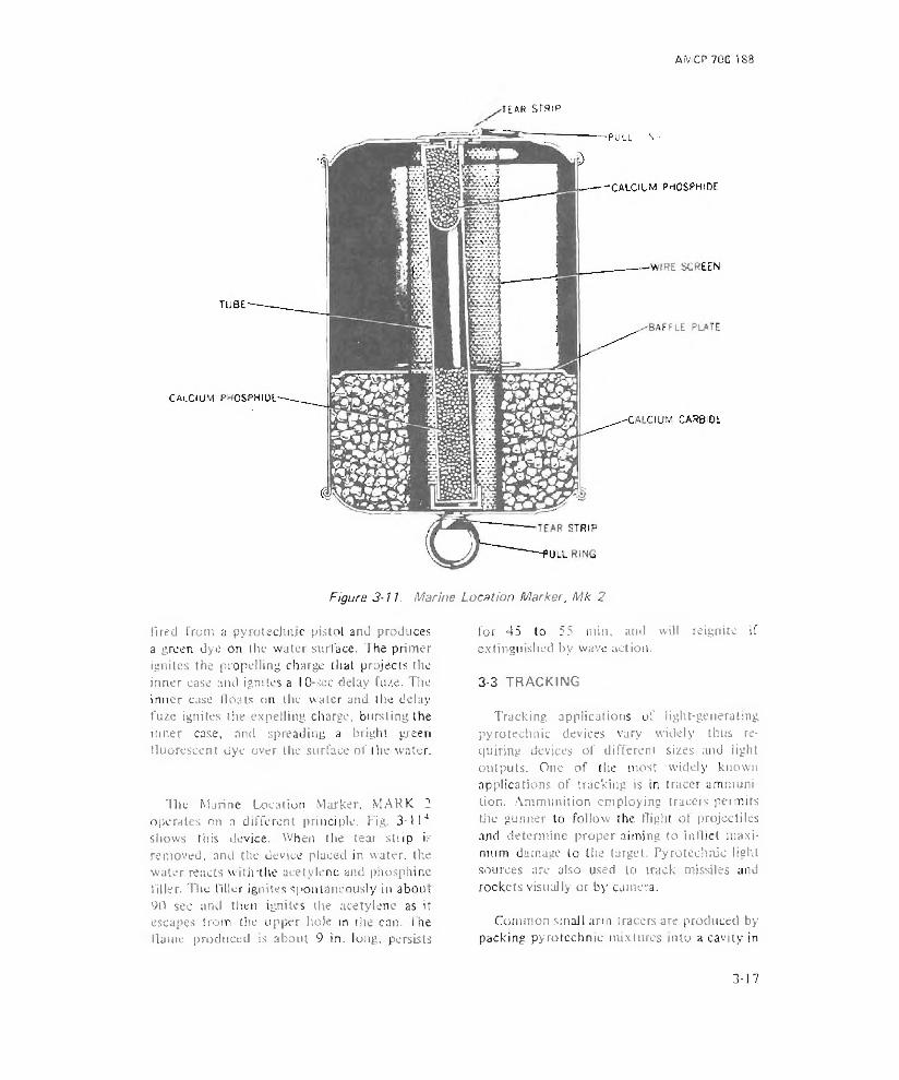
AiViCP 70C 188
TEAR STRIP
Figure 3-11. Marine Location Marker, Mk 2
fired from a pyrotechnic pistol and produces a green dye on the water surface. The primer ignites the propelling charge that projects the inner case and ignites a 10-scc delay fuze. The inner case floats on the water and the delay fuze ignites the expelling charge, bursting the inner case, and spreading a bright green fluorescent dye over the surface of the water.
The Marine Location Marker, MARK 1 operates on a different principle. Fig. 3-114 shows this device. When the tear strip is removed, and the device placed in water, the water reacts with'the acetylene and phosphine filler. The tiller ignites spontaneously in abou, 90 sec and then ignites the acetylene as it escapes from the upper hole in the can. The Hame produced is about 9 in. long, persists
for 45 to 55 min. and will reignite if extinguished by wave action.
3-3 TRACKING
Tracking applications of light-genera ting pyrotechnic devices vary widely thus requiring devices of different sizes and light outputs. One of the most widely known applications of tracking is in tracer ammunition. Ammunition employing tracers permits tlie gunner to follow the flight of projectiles and determine proper aiming to inflict maximum damage to the target. Pyrotechnic light sources arc also used to track missiles and rockets visually or by camera.
Common small arm tracers are produced by packing pyrotechnic mixtures into a cavity in
3-17

AIWCP 706-188
Die base of a bullet. The tracer composition allows tracking of the projectile because the light emitted provides a sharp contrast to background light. Determination of the light intensity required for visibility may be made using the criteria presented in the nomograph for light signals (Fig. 3-8). The visibility of tracer ammunition is generally better than that of other types of signals because the gunner knows where the light will appear and because he has repeated opportunities to observe the light path. These considerations permit use of a smaller field factor.
The necessary burning time for a (racer composition is determined mainly by the range and velocity of the ammunition. Few tracers are required to bum longer than the maximum flight time anticipated for the projectile unless they are also intended to provide incendiary effects, an additional feature of many tracer projectiles (see par. 3-27 on combination effects).
The preferred color for tracer charges is red because of the good transmission qualities of red light but other colors and white also have been used. At times more than one color may be desirable, e.g., when a number of weapons arc being fired at a single target.
Tracking flares are used for tracing the paths of bombs or missiles. In this application, several approaches are used for visual indications. The light output of the tracking flare may also be applied to instrumentation including photography.
duccd on sensitized material by some form of radiant energy8. Photographs are associated with pyrotechnics in (wo main functions —(1) pyrotechnics provide a light source for taking photographs, and (2) photographs provide a means of evaluating pyrotechnic devices and systems using such devices.
Nondaylight photography began with flash powders, which are in reality pyrotechnic mixes. Currently there are a number of applications of photuflash cartridges and bombs in aerial reconnaissance and a number of applications in which photography is used in evaluating pyrotechnic devices. Par. 5-2.10 discusses the aspects of photography that relate to instrumentation and par. 3-3 describes some applications of pyrotechnic photography for tracking purposes.
The general subject of photography, of course, covers a much broader field than that within the scope of tliis handbook. Ref. 8, for example, treats the subject over a broad range, provides details on many general aspects, and furnishes information on specific processes and special equipment such as aerial cameras.
3-4.2 SENSITIVE FILMS
Essential to the process of photography are sensitive materials that convert light or other radiant energy into tire permanent image desired. Film sensitivity may be learned from manufacturers or from military documents that the photographer commonly uses.
The intensity and time needs for the illuminating charges vary' »n eacli application. Intensities for most ot the tracking pyrotechnics. in terms of visibility, may be derived from the signal visibility criteria presented in Fig. 3-8.
3-4 PHOTOGRAPHY
3-4.1 GENERAL
Photography is the record of images pro-
fix tensive tests have been carried out to arrive at a means for expressing the sensitivity of films in such a way that photographers may .use the film effectively knowing only the characteristics of the light source and the values of reflected light from the object being photographed9. These studies resulted in expressions for the speed of a film known as the ASA (after the former American Standards .Association) speed. To arrive at the expression, a point was selected on the density- exposure curve where the slope is 0.3 times
3-18

AMCP 706-188
✓✓
, A/ X“ OlA to X
/
FOG LTV
i m /
r - o o o i
s » VQO
a s a e r w m i t ixo rx * !?S
L _
«_C6 {m j w iu -«**«,»•*
Figure 3■ 12. Typical Characteristics o f Black and Whits Negative Materia!
the average slope of a subject having a range of log luminosities of 1.5. Tire process of determining the ASA speed from this curve is quite simple. Refer to Fig. 3-121 representing a typical black and wiiite negative material. Tie meaning of the curve will become clear when considering the following facts, The density of the developed negative varies with the exposure. The greater the light intensitytime product striking the film, the darker (more dense) the negative. The main, S- shaped curve for this example has an area where only fog level is produced at exposures of less than 0.001 meter candle-seconds (-3 log units) whereas on the upper exposure area, the density becomes greatly increased to the point where there is little differentiation. The shoulder is where this begins lo happen.
The ASA speed is now determined in the following manner. An average slope is determined for the sensitivity curve, in this case a slope of 1 was considered lo be average. A line with 0.3 of this slope is then fitted to the sensitivity curve. The so-called sensitivity point is that point at which the 0.3 slope line becomes tangent to the sensitivity curve. The reciprocal of the exposure at this point IS the film speed. In the example of Fig. 3-12 the exposure E is 0.002 m-c-sec, the film speed S is 500, and the ASA exposure index is 125.
Q = T R A I L A N G L E H = F L I G H T A L T I T U D E
0 - CAMERA HALF-ANGLE h - 6 0 M B B U R S T A L T I T U D E
Figure 3-13. Diagram o f Bomb Burst and Trail Angle
The exposure index is one-fourth of the fdrn speed.
3-4.3 LIGHT SOURCE REQUIREMENTS
In order to provide a light source for photography, some facts must be known about the subject, the camera, and the film. In normal flash photography Lhe reverse is usually true; i.e., the characteristics of the light source, the ASA li'-n speed, and the distance from the camera to the subject are known and govern (lie f-stop setting of the camera to gain proper exposure of the Rim.
In aerial photography, where pyrotechnic light sources are predominantly in use, two important conditions must be mel - (1) the bght source should be out of the Held of view of the camera, and (2) the burst height of the pyrotechnic light source should be 0.6 of the flight altitude. These parameters are depicted in Fig. 3-131.
The intensity / required of a light source is determined by
, _ 6.4 Uf (X/)2 1 ~ -----:--------- * (3-10)
3-19

AMCP 706-188
whereI - intensity of the light source, c
Uj~ film exposure, m-c-sec
X = slant distance from camera to target, in
/ = I'-stop number of the camera, dimensionless
I = exposure lime, sec
The U. value in this equation is best determined experimentally. However, it may be chosen from characteristic curves of the films available (see Fig. 3-12). The center exposure value of the straight portion of the curve is usually selected as the value for U-. In this curve, the exposure level there is about 0.03 m-c-sec.
The main use for photographic pyrotechnic light sources is for nighttime aerial photography. Let us determine the light required for a hypothetical mission. Suppose that an aircraft is Hying at an altitude of 500 m (1640 ft). A photoflash bomb is required that will provide the light source for photographing objects on the surface of the earth from the aircraft within a camera angle of 30 deg. The camera Juts an f/4.5 lens, and the required exposure for the film is 0.03 m-c-sec. The exposure time needed is 0.01 sec.
Substituting these parameters into \q 3-10 the required light intensity is
_ 6.4 X 0.03 X (500 X see 30° X 4,5)21 U.0!
= 130 X 106 c
Examining the characteristics of photoflash bombs from any one of a number of possible sources (e.g.. Ref. 1), we see that a number of devices have the required peak intensity. AH six types of the T9E7, for example, have the required light output, the least intense being 550 X 106 c. Note also the example of the
175-lb photoflasli bomb in Table 4-8 with art intensity of 1.300 X 10⁶ c. The light source chosen could be more intense than that desired. This will require a computation of the f-stop of the shutter, using Ea. 3-10 with the intensity of the chosen source substituted for /.
It should be pointed out that the success of the photographic mission depends largely upon having the camera shutter open during the time that the pyrotechnic fiaslt peaks in intensity. This deals with the next subject, i.e„ synchronization.
3-4.4 SYNCHRONIZATION
Synchronization is provided in a number of ways. Modern devices allow for electronic control of synchronization. A double flash is used in some instances where the first Hash signals a photocell in (lie aircraft that the main flash is about to ignite. The shutter opening and the light intensity of the main flash charge thereby occur nearly simultaneously, allowing for optimum use of light from the main flash charge
A second method of aerial photography allows for self-synchronization. This technique, known as open-shutter, provides for opening the shutter prior to the actuation of Lhe photoflash bomb or cartridge. The open- shutter technique is Limited to events having tow levels of background light.
To reduce this method to a mathematical expression, .q. 3-10 can be rearranged as Follows
J I(t)dt = 6.4 U‘ H)
The difference is that the left-hand term includes the intensiry-time function as art integral. Often this integrated value is tabulated for pyrotechnic light producers in terms of integral light in (he units of millions of candiepowerseconds' (see Eq. 2-6).
3-20
AMCP 706-188
3-5 SIMULATION
Simulation is the act of producing the effects of an event without duplicating the event. In the case of military weapons, simulation may be brought about for two main purposes, for training and for psychological purposes. Normally, simulators do not make use of the full battlefield effects of a weapon nor is their cost generally as great as that of the item for which the effect is being produced, although cost is not the primary consideration3.
Most often simulators mimic battlefield sounds, flashes, and lights produced by service ammunition. In training use, they condition troops for battle without the exposure to the hazard of handling live ammunition.
Air-burst simulators provide a flash of light to simulate the airburst of artillery rounds. The light is accompanied by a sound report, Air-burst simulators may be fired from pyrotechnic pistols or from hand projectors. Generally, a minimum firing angle is specified for the launcher so that functioning will occur at an altitude sufficient to prevent injury to troops. Their main target effects are'. 1 2 3
(1) Simulation of an air-bursting projectile by light and sound production
(2) Minimum production of fragments
(3) Convenient means of projection
SECTION II I
3-6 IR RADIATION
3-6.1 GENERAL
Infrared (IR) radiation has become increasingly important in recent years for such applications as signaling and decoying. The real advantages of infrared radiation are
(4) Adequate delay of burst to achieve proper altitude.
Other simulators employing light as a part of their action include those for ground burst (Like the Ml 15 that is similar to the air-burst simulator), booby trap flash simulators (like, the Ml IT), booby trap illuminating simulators (like the Ml 18), and gunflash simulators (like the M110).
Target effects on light producing simulators depend to a large extent upon timing conditions desired.
Each type of simulator requires considerable study of the effects that are to be reproduced. For Light producers, the influence is mainly that of vision along with association of what is seen with the circumstances surrounding the vision. If, for example, troops know they have no artillery in the area but suddenly see and bear air bursts in the vicinity, the troops will believe that enemy activity includes artillery after aJ). The tide of battle could be changed merely by simulation of artillery air bursts, perhaps by a very limited force.
Target effects on light producing simulators depend to a large extent upon the timing conditions desired. Visibility criteria of simulators are nearly the same as those for light sources in general. These criteria are discussed in par. 3-2. See also Ref. 1.
SIBLE LIGHT
manifold in specific situations but may be summed up as follows:
(1) Radiation occurs in portions of the electromagnetic spectrum not visible to the unaided eye.
(2) Temperatures normally associated with
3-21
AM CP 706-188
radiation in the IK spectrum are lower thansimitar sources producing visible light.
(3) Radiation is capable of greater penetration of fog, smoke, and small particulates.
Some advantages are immediately seen in pyrotechnic applications, perhaps many of them not yet fully utilized. Signals, markers, and warning devices show promise when operated in the inlrured region of the spectrum. These would be detectable only to persons properly equipped to receive energy at the proper wavelength.
Another important military use of infrared radiation rests in the detection of objects higher in temperature and/or emissivity than (heir surroundings. Advances have been made in techniques to accomplish this task to the point where human beings have been observed in a forest background10. This detection capability has nothing to do with pyrotechnics, however, pyrotechnic sources when properly designed and used, can effectively mimic the radiation produced by military targets11.
3-6.2 CONSIDERATIONS FOR IR PYROTECHNIC DEVICES
It is generally believed that sources producing white light from high temperature flames or incandescent sources are good sources of IR energy' 1. This is not necessarily true. Radiation does not depend exclusively upon temperature, but" also upon emissivity. One example indicative of high temperature and low emissivity are pyrotechnic reactions producing metal or metal oxide particles at high temperatures which often produce, less radiation in the IR than lower temperature reactions. Similarly, some gaseous reactions are poor IR radiators even when the reactions proceed at high temperature.
Recently, the most efficient IR flare produces solid exhaust particles that have high emissivity throughout the spectrum.
3-6.3 IR TARGETS
The characteristics of many targets producing IR radiation are described in Ref. I I. Re-entry vehicles cause fR in the shock- heated air in front of the body, the vehicle surface, ablation product, and the wake. The body and its ablation are primary sources, Jet aircraft radiate IR from engine components (the turbine and exhaust), exhaust gases, aerodynamicajly heated surfaces, and from reflected sunlight.
Many targets exhibit differences in day-tonight conditions that are of interest to observers. Tanks, trucks, and industrial centers have [R hoi spots that can be detected.
Simulation of these targets by pyrotechnic measures in the event of attack could introduce confusion to the attacking force.
3-7 TRACKING
In tracking applications, an IR scanner may be used to depict the position of a target emanating an IR signal. The signal may be implanted to provide intentional radiation in the IR spectrum or it may be inherent in the object being observed.
IR scanners of various types have been developed to yield a relative position of a target. Scanner type, requirements, and sensitivity are discussed in another handbook11. Passive scanners for thermal imaging frequently use mechanical scanners operating in wavelengths around 10 microns but wavelengths in the 3- to 5-micron region are also used.
Most scanning devices operate in such a way that a field is dissected by mechanical searching of specific sections in much the same manner as a television camera searches an area. Some arrangement provides for a sweep horizontally and vertically with a single sensor receiving radiation from one portion ol the entire field of view of the scanner at a time. The display is synchronized with the
3-22
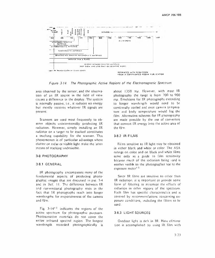
AMCP 706-188
1 3 J = & i 2? - 3- 5=5= i 'kr> I [Too
»oOH<jCrtO* StwSvU<M -"o»rHOOiio>TjC **Aiti
>*KCMtO»<*T>C mAT|»»A1*I O ltNO iO MO s im m v i fANC«‘0 “ Aii<
►000 ilOOMlLU-ltPONj
INIIAIIO IIU |tirM*-! iNM/kUO iiNjjTkvi *ath<a[j
f*u* now ako uuo ohi» <o» jcuwnn< wo««
►n a* r»AM5xi(OH i* ciavi i<ms/sREPRINTED WITH PERMISSIONFROM A COPYRIGHTED KOOAK PUBLICATION
Figure 3-14. The Photographic Active Regions of the Electromagnetic Spectrum
area observed by the sensor; and the observation of an IR source in the field of view causes a difference in the display. The system is normally passive, i.e., it radiates no energy but merely receives whatever IR signals are present.
Scanners are used most frequently to observe objects unintentionally producing IR radiation. However, simply installing an IR radiator on a target to be tracked constitutes a tracking capability for the scanner. This phenomenon is of particular advantage where clutter on radar or visible light make the latter means of tracking undesirable.
3-8 PHOTOGRAPHY
3-8.7 GENERAL
IR photography encompasses many of the fundamental aspects of producing photographic images that are discussed in par. 3-4 and in Ref. 11. The difference between IR and conventional photography rests in the fact that IR photographs reach into longer wavelengths for responsiveness of the camera and film.
Fig. 3 -14 '2 indicates the regions of the active spectrum for photographic purposes. Photosensitive materials do not cover the entire infrared spectral region. The longest wavelength recorded photographically is
about 1350 mp. However, with most IR photography the range is from 700 to 900 mp. Emulsions for IR photographs extending to longer wavelength would need to be continually cooled and even camera temperature and body temperature would fog the film. Alternative schemes for IR photography are made possible by the use of converters that convert IR energy into the active area of the Film.
3-8.2 IR FILMS
Films sensitive to IR light may be obtained in either black and white or color. The ASA ratings on color and on black and white films serve only as a guide to film sensitivity because much of the radiation being used is neither visible to the photographer nor to the exposure meter1 2
Since IR films are sensitive to other than IR radiation, it is important to provide some form of Filtering to minimize the effects of radiation in other regions of the spectrum. Each film has specific character!sties and is covered by recommendations concerning exposure conditions, including the filters to be used.
3-8,3 LIGHT SOURCES
Outdoor light is rich in IR. Haze elimination is accomplished by using IR Film with
3-23

AM CP 706-188
daylight as a source. Ruby lasers have been used to photograph moving projectiles with a light duration of 0.2 /usee.
Photoflash lamps make good IR sources for photography because they produce more IR light in the active range of wavelengths than do service lamps or heat lamps. Photoflash lamps are occasionally coated with an IR transmitting, dark red filter. These lamps are designated R and arc useful when bright, visible light must be restrained.
SECTION I
3-9 MARKING, SIGNALING, AND WARNING
Smoke devices are used in much the same manner as light devices for marking, signaling, and warning except that smoke devjces are more efficient in daytime operations. For a discussion of the differences among marking, signaling, and warning devices, see par. 3-2 l.
Smokes for signaling or marking must be clearly distinguishable from other smokes (and other clouds) produced for different uses. Hence, colored smokes are usually employed for this purpose because white, gray, and blanket smokes are very limited as signals.In addition, the use of several different colors allows more information to be sent and results in a clearer distinction between the smoke signals and a varying background. Important characteristics of a colored smoke include1:
(1) Visibility—condition under which the smoke cloud can be seen and the color recognized.
(2) Duration—time period over which smoke is produced by pyrotechnic ammunition.
(3) Persistence-total time during which a smoke cloud is visible.
Electronic flash units provide an !R output that may be used for IR photography. Their IR efficiency compared with their visible light is about the same as that of photoflash bulbs and they have the advantage of relative coolness, small size, and short exposure time, all important attributes.
Ambient illumination poses littie problem if synchronized photoflash bulbs or electronic flash units are equipped with filters to pass IR in the active range. Information on filters is available from manufacturers of which Ref. 13 is typical.
II SMOKE
(4) Volume—quantity of smoke emitted.
3-9.1 PHYSICAL CHARACTERISTICS OF SMOKE
3-9.1.1 PARTICLE SIZE
The value of a military smoke, regardless of its use, is related to the scattering reflection and absorption of incident radiation by small suspended particles. The number, size, and nature of these particles depend upon the smoke agent, the particular ammunition, and the method of release. Meteorological con- ditions-such as humidity, wind speed, wind direction, and air stability-affect the density, persistency, and subsequent behavior of the smoke cloud.
A smoke is a suspension in a gaseous medium-such as the atmosphere—of small particles that have a relatively low vapor pressure and that settle slowly in a gravity field. Particle sizes ranging from 0.01 to perhaps 5.0 microns in diameter in a gaseous suspension are classified as smokes. Colored smokes are composed of extremely small, primary particles of approximately 0.2 micron in diameter which coagulate into irregular filaments that may reach :> length of several microns1.
3-24
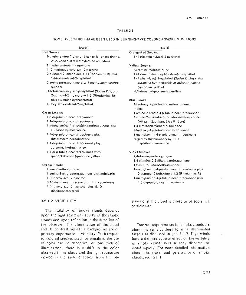
AMCP 706-188
SOME DYES WHICH HAVE BEEN USED IN BURNING-TYPE COLORED SMOKE MUNITIONS Dye(s) Dye(s)___________
TABLE 3-6
Red Smoke:9-diethylamino-7-phenyl-5-benzo (a) phenazinene.Also known as 9-diethylamino rosindone
t methyl am in oamhraquinone1- (2-methoxyphenylazo)-2-naphthol2- quinolyl-2-indandione 1.3 (Rhodamine B) plus1-(4-phenylazo)-2-naphthol
2-aminoanthraquinone plus 1-methylaminoantbra- quinone
0 tolylazo o tolylazo/i-naphthol (Sudan IV); plus 2quinotyl-2-'rndandione-t,3 (Rhodamine B); plus auramine hydrochloride
T(tolylazoxylylazo)-2-naphtholGreen Smoke:
1.8-di-p-toluidinoanthraquinone1.4- di-p-toluidinoan thraquinone1 ■methylamino-4-p-toluidinoanthraquinone plusauramine hydrochloride
1.4- di-p-toluidinoan thraquinone plus dime thylaminoa zo benzene
1.4- di-p-toluidinoan thraquinone plus auramine hydrochloride
1.4- di-p-toluidinoan thraquinone with quinophthalone (quinoline yellow)
Orange Smoke:1-ammoanthraquinone1-amino-8 chloroanthraquinone plus quinizarin 1(4 phenylazo)-2-napb thol 9.10 dianilinoanthracene plus phthaloperinone 1-(4-phenylazo)-2-naphthol plus, 9,10- dtanilinoanthracene
3-9.1.2 VISIBILITY
The visibility of smoke clouds depends upon the light scattering ability of the smoke clouds and upon reflection in the direction of the observer. The illumination of the cloud and its contrast against a background are of primary importance in visibility. With respect to colored smokes used for signaling, the use of color can be deceptive. At low levels of illumination, there is a shift in the color observed if the cloud and the light source are viewed in the same direction from the ob-
Orange Red Smoke:1-(4-nitrophenyla2o)-2-naphthol
Yellow Smoke:Auramine hydrochloride l-(4-dl methytami nophenyl azo)-2-naphihol l-(4-phenylazo)-2-naphthol (Sudan I) pluseither auramine hydrochloride or quinophthalone (quinoline yellow)
N,N-dimethylp-phenylazoanilineSlue Smoke:
l-hydroxy-4-p-toluidinoanthraquinoneIndigo1-ami no-2-bromo-4-p-toluidinoan thraquinone 1-amrno-2-methyl-4-p-toluidinoanthraquinone (Alizarin Sapphire, Blue R. Base)
1.4- di methylaminoanthraquinone l-hydroxy-4-p-toluidinoanthraquinone1-me thylamino-4-p-toluidinoan thraquinone N-(p-dimethylaminophenyl)-1,4- naphtholquinonimine
Violet Smoke:1.4- diaminoanthraquinone1.4- diamino-2,3-dihydroan thraquinone1.5- di-p-toluidinoanthraquinone l-methylamino-4-p-toluidinoanthraquinone plus2 qumolyl-2-indandione-1,3 (Rhodamine B)
1-methylamino-4-p-toluidinoanthraquinone plus1,5-di-p-toluidinoanthraquinone
server or if the cloud is dilute or of too small particle size.
Contrast requirements for smoke clouds are about the same as those for other illuminated targets as discussed in par. 3-1.2. High winds have a definite adverse effect on the visibility of smoke clouds because they disperse the cloud rapidly. For more detailed information about the travel and persistence of smoke clouds, see Ref. I.
3-25

AMCP 706-188
TYPICAL SMOKE COMPOSITIONS
TABLE 3-7
Type Composition, %
WHITE:HC-Type C Hexachloroethane
Zinz Oxide A lum inum (grained)
Modified HC Hexarhlorobenzene Zinc Oxide NH 4 CIO4
Zinc Dust Laminae w/catalyst
M odified HC Dechlorane Zinc Oxide NH 4 CIO4
Laminae w/catalystPlasticized White White PhosphorusPhosphorus (PWP) Plasticizer
(Neoprene 100 parts) (Carbon 75 parts) (Zylene 44 parts) (Litharge 15 parts)
BLACK:KCIO3 (200 mesh) Anthrancene (40 mesh)
COLORED:Red Dye-MIL D-3718
KCIO3
NaHC0 3
SulfurPolyester resin
Red 1-methylamino (AQ )* 1,4-di-p-toluidino (AQ )* KCIO 3 (23p)Sugar, fine (11m )
Red l-(methoxyphenylazo)-2 -naphthol
NaCIRed Dye (R)
KCIO3
(plastic) NaHC03
Sulfur
Polyvinyl acetate in ethyl acetate
ApplicationTypicalDevices
45.5 Screening Smoke pots47.5 and Smoke bombs
7.0 Signaling Grenades34.4 Screening Smokes27.6 and projectiles24.0 Signaling
6 . 2
7.833.9 Screening Smoke37.4 and projectiles20.5 Signaling
8 . 2
65.0 Screening Chemical35.0 (antipersonnel) mortar projectiles
52.0 Screening Grenades, etc48.0
40.0 Signaling Navy floating24.0 d r ift signal17.05.0
14.045.0 Signaling Rocket type
3.0 parachute35.0 ground17.0 signals
A ir marker 90 mm Red80.0 Marking marker2 0 . 0 ground targets projectile40.028.0 Signaling Improved23.0 grenade
5.0 fillings
3.0
*(A Q )—Anthraquinone
3-26

AMCP 706-188
TABLE 3-7 (Cont'd)Typical
Type Composition, % Application Devices
Yellow Benzanthrene 32.0 Signaling Rocket typeIndanthrene GK 15.0 parachuteKCI0 3 (23m) 30.0 groundSugar, fine (11m) 2 0 . 0 signalsNaHC03 (20m) 3.0
Yellow Auramine Hydrochloride 40.0 A ir marker, etc. 90 mm yellowNaCI 60.0 marker projectile
Yellow Dye(Y) 40.0 Signaling Improved(plastic) KCIO3 29.8 grenade
NaHC03 23.2 fillingsPolyvinyl acetate in
ethyl acetate 7.0Green 1,4-di-p-toluidino (AQ)# 28.0 Signaling Rocket type
Indanthrene GK parachute(golden yellow) 1 2 . 0 ground
KCI0 3 (23m) 35.0 signalsSugar, fine (1 1m) 23.0NaHC03 (20m) 2 . 0
Green Dye (G) 40.0 Signaling Improved(plastic) KCIO3 26.0 grenade
NaHC03 24.0 fillingsSulfur 6 . 0
Polyvinyl acetatew/ethyl acetate 4.0
Violet Violet dye. Signaling Rocket typeMl L-D-3691 47.5 parachute
KCIO3 (25m) 28.0 groundSugar, fine (10m) 18.0 signalsNaHC03 (20m) 4.5,Asbestos 2 . 0
Orange 8-chloro-1-amino (AQ)# 39.0 Signaling GrenadesAuramine 6 . 0
KCIO3 22.3Sulfur 8.7NaHC03 24.0
*(AQ) - Anthraquinone
3-9.1.3 COLORED SMOKES (4) Volatilization and condensationcolored material
There are four basic methods of producing colored smokes14 :
(1) Dispersion of finely powdered, colored materials
(2) Chemical reactions resulting in the formation of colored particles
(3) Detonation of an explosive, thereby scattering colored material
The first two methods are not satisfactory because they give smokes of small volume and dull color. The last two methods are feasible only if the coloring material is an organic dye. In general the anthraquinone dyes have proved to be superior in producing colored smoke clouds1. Table 3-61 lists some of the more satisfactory dyes.
3-27
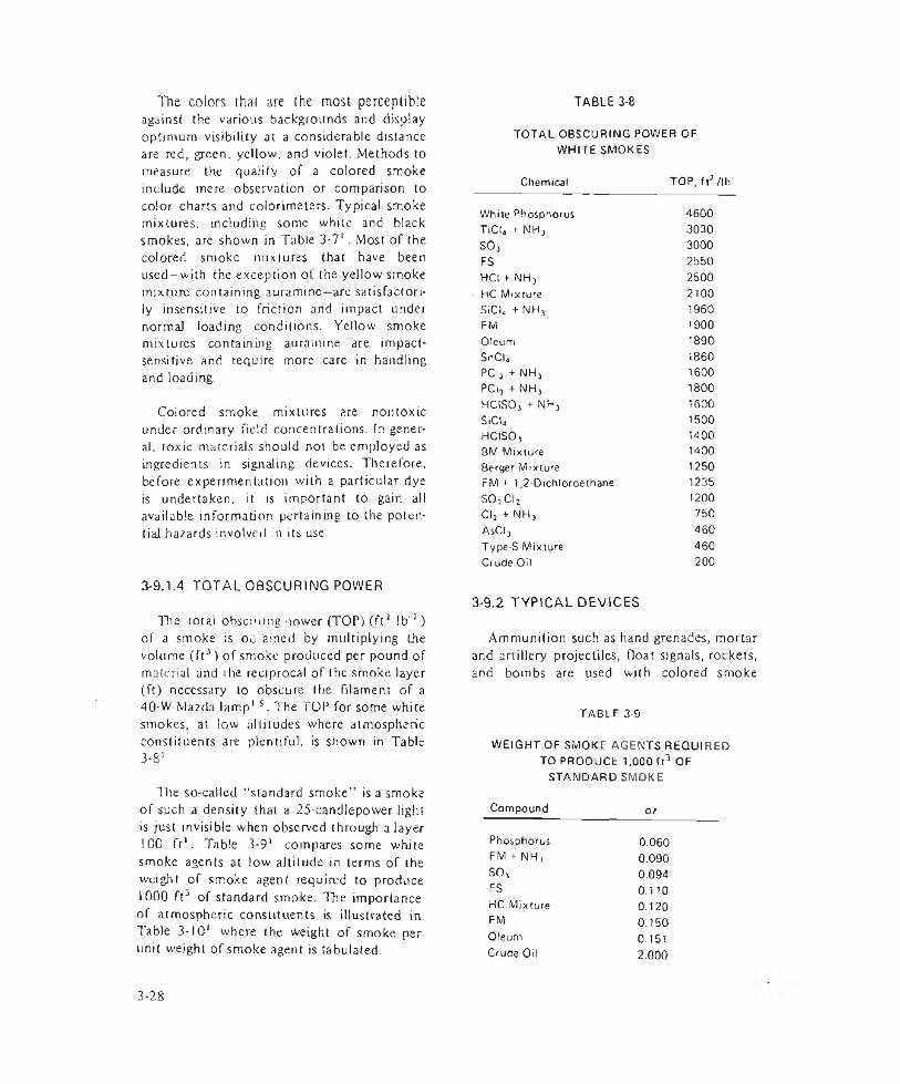
The colors that are the most perceptible against the various backgrounds and display optimum visibility at a considerable distance are red, green, yellow, and violet. Methods to measure the quality of a colored smoke include mere observation or comparison to color charts and colorimeters. Typical smoke mixtures, including some white and black smokes, are shown in Table 3-7'. Most of the colored smoke mixtures that have been used-with the exception of the yellow smoke mixture containing auramine—are satisfactorily insensitive to friction and impact under normal loading conditions. Yellow smoke mixtures containing auramine are impact- sensitive and require more care in handling and loading.
Colored smoke mixtures are non toxic under ordinary field concentrations. In general. toxic materials should not be employed as ingredients in signaling devices. Therefore, before experimentation with a particular dye is undertaken, it is important to gain all available information pertaining to the potential hazards involved in its use.
3-9.1.4 TOTAL OBSCURING POWER
The total obsctmng power (TOP) (ft2 lb '1 ) of a smoke is oljiained by multiplying Lhe volume (ft3) of smoke produced per pound of material and i he reciprocal of the smoke layer (ft) necessary to obscure the filament of a 40-W Mazda lamp1 s . The TOP for some white smokes, at low altitudes where atmospheric constituents are plentiful, is shown in Table 3-8’ .
The so-called “standard smoke” is a smoke of such a density that a 25-candIepower light is just invisible when observed through a layer 100 ft’ . Table 3-9’ compares some white smoke agents at low altitude in terms of the weight of smoke agent required to produce 1000 ft3 of standard smoke. The importance of atmospheric constituents is illustrated in Table 3-101 where the weight of smoke per unit weight of smoke agent is tabulated.
TABLE 3-8
TOTAL OBSCURING POWER OF WHITE SMOKES
Chemical TOP, ft3 /lb
While Phosphorus 4600TiCU rNHj 3030so, 3000FS 2550HCI + NH, 2500
• HC Mixture 2100SICL + NH, 1960FM 1900Oleum 1890SnCU I860PCI, + NH, 1600PCI, + NH, 1800HCISO, + NH, 1600SiCI4 1500HCISO, 1400BM Mixture 14008erger Mixture 1250FM i- 1,2-Dichloroethane 1235SO,C[2 1200Cl, + NH, 750AsCl3 460Type-S Mixture 460Crude Oil 200
3-9.2 TYPICAL DEVICES
Ammunition such as hand grenades, mortar and artillery projectiles, float signals, rockets, and bombs are used with colored smoke
TABLE 3-9WEIGHT OF SMOKE AGENTS REQUIRED
TO PROOUCE 1.000 (t3 OF STANDARD SMOKE
Compound ozPhosphorus 0.060FM + NH, 0.090SO, 0.094FS 0.110HC Mixture 0.120FM 0.150Oleum 0.151Crude Oil 2.000
3-28
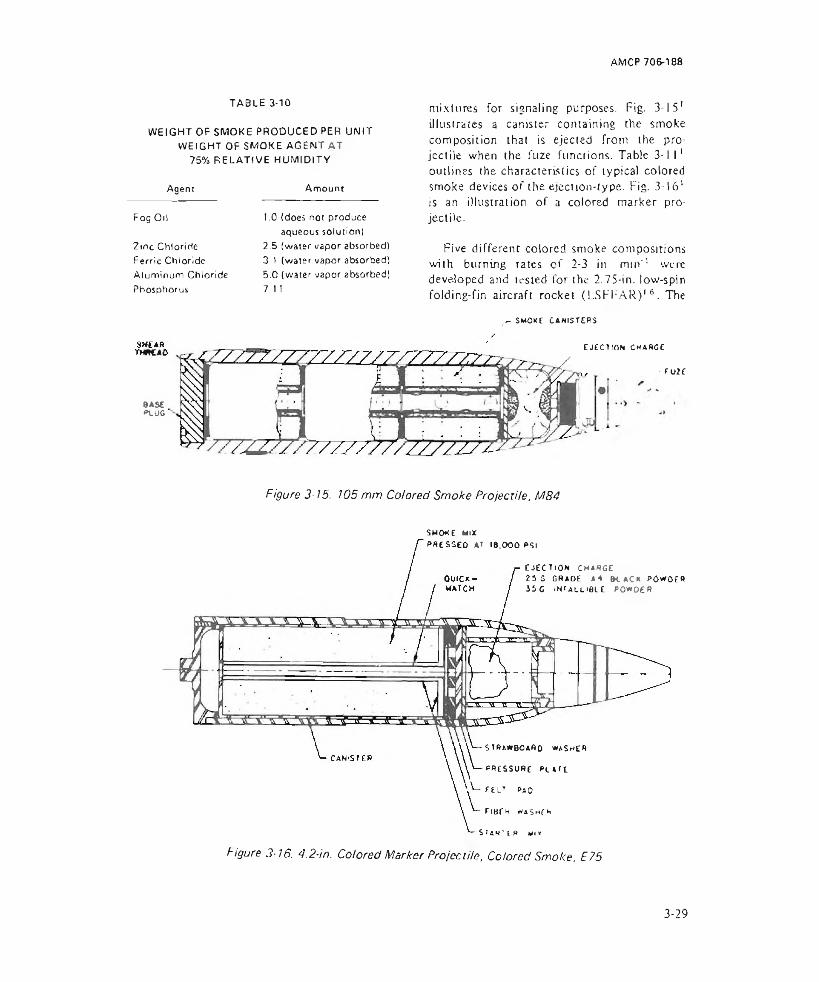
AMCP 706-188
WEIGHT OF SMOKE PRODUCED PER UNIT WEIGHT OF SMOKE AGENT AT 75% RELATIVE HUMIDITY
TABLE 3-10
AgeniFog OilZinc Chloride Ferric Chloride Aluminum Chloride Phosphorus
BASEPLUG
Amount1.0 (does not produce
aqueous solutionl2.5 (water vapor absorbed) 3 t (water vapor absorbed)5.0 (water vapor absorbed) 7 1 I
mixtures for signaling purposes. Fig. 3-1S1 illustrates a canister containing the smoke composition that is ejected from the projectile when the fuze functions. Table 3-1 l 1 outlines the characteristics of typical colored smoke devices of the ejection-type. Fig. 3-16' is an illustration of a colored marker projectile.
Five different colored smoke compositions with burning rates of 2-3 in. mm'1 were developed and tested for the 2.75-in. low-spin folding-fin aircraft rocket (LSFFAR)16. The
- SMOKE c a n is t e r s
EJECTION CHARGE
- EU2E
Figure 3-15. 105 mm Colored Smoke Projecrile, M84
SMOKE MIXp r e s s e d AT 18.000 PSl
EJECTION Ch ar ge2 5 G GRADE A 4 B L A C K POWOER J S G IN F A L L IB L E p o w d e r
-STR aWb o a A d w a s h e r
■PRESSURE P L A f t
■CELT PAD
F I 8 f K WASnf h
SUN1 ir VI r
Figure 3-16. 4.2-in. Colored Marker Projectile, Colored Smoke, E75
3-29
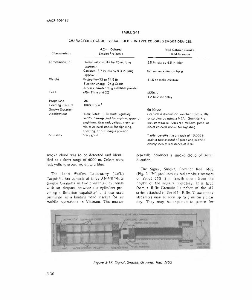
AMCP 706-188
TABLE 3-11
CHARACTER IST ICS OF TYP ICAL EJECTION-TYPE COLO RED SMOKE DEV ICES
CharacteristicDimensions, in.
Weight
Fuie
Propellant Loading Pressure Smoke Duration Applications
Visibility
4.2-in. Colored Smoke Projectile
Overall—4.2 in. dia by 20 in. long (approx.)Canister—3.7 in. dia by 9.3 in. long (approx.)Projectile-23 to 24.5 lb Ejection charge—25 g Grade A black powder 35 g infallible powder M54 Time and SQ
MS18000 lb /in 7
Time-fuzed for air-burst signaling and/or base-ejected for marking ground positions. Uses red, yellow, green or violet colored smoke for signaling, spotting, or outlining a position Very good
M18 Colored Smoke Hand Grenade
2.5 in. dia by 4.5 in. high
Six smoke emission holes
11.5 oz make mixture
M201A)1.2 to 2 sec delay
50-90 secGrenade is thrown or launched from a rifle or carbine by using a M 2A ) Grenada Projection Adapter. Uses red, yellow, green, or violet colored smoke for signaling
Easily identified at altitude of 10,000 ft against background of green and brown; clearly seen at a distance of 3 mi.
smoke cloud was to be detected and identified at a short range of 6000 m. Colors were red, yellow, green, violet, and blue.
The Land Warfare Laboratory (LWL) Target-Marker consists of three AN-M8 White Smoke Grenades in two concentric cylinders with an airspace between the cylinders providing a flotation capability17. It was used primarily as a landing zone marker Tor air mobile operations in Vietnam. The marker
•cujsino re» Manx*
generally produces a smoke cloud of 3-min duration.
The Signal, Smoke, Ground; Red, M62 (Fig. 3-173) produces six red smoke streamers of about 250 ft in length down from the height of the signal’s trajectory. It is fired from a Rifle Grenade Launcher of the M7 series attached to the MI4 Rifle. These smoke streamers may be seen up to 5 mi on a clear day. They may be expected to persist for
WAP VMO»l I ‘■mini
rj*
- Z CC.CHU6
Figure 3-17. Signal, Smoke, Ground: Red, M62
3-30

AMCP 706-188
Figure 3-18. Signal, Smoke, Ground: White, XM166
about 20 sec in a wind of 5 mph.
The Signal, Smoke, Ground: White, Xm 166 is a self-contained unit used by ground troops to signal aircraft or to convey information to each other (see Fig. 3-18*). Tire fuze is ignited by either rubbing the fuze match head with the striker ring or holding a flame close to it. Within 3 to 5 sec, the smoke pellet is ignited, emitting a white smoke cloud that lasts for 13 to 30 sec. The smoke cloud is visible at a slant range of 3280 ft from aircraft flying at an altitude of 1000 ft.
The XM144 Hand-held Ground Signal series was developer to eliminate major deficiencies of the standard M l25 and T133 Signal series. Improvements include flight stablity, increased height of burst, elimination of smoke and luminous trails at launch,
and improved color definition of smoke components18. Maximum altitude of functioning is 750 ft with 60-sec smoke Juration of Smoke Parachute, XMI 50, and a burning time of 7 to 8 sec for the Smoke Streamer, X1V1153'8. Colors of smoke include green, red, yellow, and violet.
3-10 TRACKING
3-10.1 USE AND CHARACTERISTICS
Optical tracking of projectiles, high speed aircraft, and missiles both at sea level and liigh altitudes is aided by the use of smoke producing devices such as generators or tracers. The ability to locate and track vehicles along the flight path is optimized by these devices, and the loss of significant data is minimized. Because of the wide range of
3-31
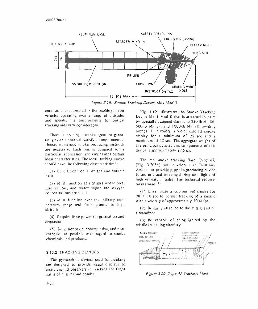
AMCP 706-188
ALUMINUM CASE
BLOW OUT CAP
SAFETY COTTER PINTIRING PIN SPRING
plastic nose
WING NUT/
Figure 3-19. Smoke Tracking Device, Mk 1 Mod 0
conditions encountered in the tracking of test vehicles operating over a range of altitudes and speeds, the requirements for optical Cracking aids vary considerably.
There is no single smoke agent or generating system that will satisfy all requirements. Hence, numerous smoke producing methods are necessary. Each one is designed for a particular application and emphasizes certain ideal characteristics. The ideal tracking smoke should have the following characteristics1:
(!) Be efficient on a weight and volume basis
(2) Must function at altitudes where pressure is low, and water vapor and oxygen concentrations are small
(3) Must function over the military temperature range and from ground to high altitude
(4) Require little power for generation and dispersion
(5) Be as nontoxic, nonexplosive, and noncorrosive as possible with regard to smoke chemicalsund products.
3-10.2 TRACKING DEVICES
The pyrotechnic devices used for tracking are designed to provide visual displays to assist ground observers in tracking the flight paths of missiles and bombs.
Fig. 3-1 illustrates the Smoke Tracking Device Mk 1 Mod 0 that is attached in pairs by specially designed clamps to 250-lb Mk 86, 500-lb 'Mk 87, and 1000-lb Mk 88 low-drag bombs. It provides a violet colored smoke display for a minimum of 25 sec and a maximum of 52 sec. The aggregate weight of the principal pyrotechnic components of this device is approximately 17.5 oz.
The red smoke tracking flare, Type 47, (Fig. 3-2019) was developed at Picatinny Arsenal to provide _a_smoke-producing device to aid in visual tracking during test flights of high velocity missiles. The technical requirements were19 :
(1) Disseminate a copious red smoke for 90 ± 10 sec to permit tracking of a missile with a velocity of approximately 3000 fps
(2) Be easily attached to the missile and be streamlined
(3) Be capable of being ignited by the missile launching circuitry
Figure 3-20. Type 47 Tracking Flare
3-32

AMCP 706-188
CHARACTERISTICS OF TYPICAL OIL SMOKE POTSTypw Device
TABLE 1-12
Size. in.Venturi Orifice Diameter, in.Weight, lbOil AgentFuel Block Composition
Ignition
Burning Time, min Application
Obscuring Power
Floating
13 high by 13 dia
0.0890 14.5 (oil)12.0 (fuel)SGF Wo. 1 or 2 Fast-Burning Top M ix tu re 86% NH NCfi 11% Charcoal 3% Linseed Oil
Stove Burning Base M ixture 82% WH„NOj 8% NH.,CI 7% Charcoal 3% Linseed Oil Bouchon Fuze (M208) "spits" through venturi igniting quickmatch and starter 12 ± 1.5Screening, used singly or in multiple on land or water
Training5.7 high (including fuze) by 2.5 dia0.076 0.24 (oil)0.22 (fuel)SGF No. 1 or 282% NH„ NO}11% Charcoal 4% KNOj 3% Linseed Oil
Bouchon Fuze (M201A1) (similar to floating type)1.2 ± 0.25Grenade type.used for training purposesSingle pot fills a 13,000ft' room and totally obscures objects 4-6 ft away.
(4) Pass environmental and vibration tests.
3-11 SCREENING
3-11.1 PROPERTIES OF SCREENING SMOKES
A screening smoke is an aerosol consisting of very small solid or liquid particles suspended in the atmosphere. Individual particles of the aerosol obstruct light rays by either reflection or refraction. Maximum efficiency
is obtained by the largest possible number of the smallest effective particles10. Optimum size of the particles in a smoke cloud should be 0.5 micron. Screening smokes are usually white and can be used to 1:
(1) Conceal movements, equipment, and installations of friendly forces from ground observation
(2) Blanket installations and friendly aircraft from attack
3-33
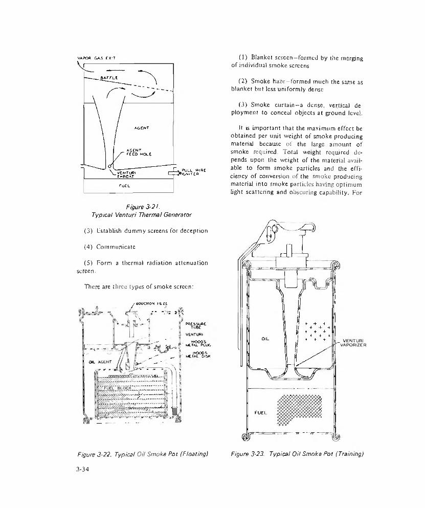
VAPOA GAS EXrT
(3) Establish dummy screens for deception
(4) Communicate
(5) Form a thermal radiation attenuationscreen.
There are three types of smoke screen:
PACS5UAETu6E
WOOO'S wCTa u PLUG
wooesOisx
Figure 3-22. Typical Oil Smoke Pot (Floating)
(1) Blanket screen—formed by the merging of individual smoke screens
(2) Smoke haze—formed much the same as blanket bul less uniformly dense
(3) Smoke curtain—a dense, vertical deployment to conceal objects at ground level.
It is important that the maximum effect be obtained per unit weight of smoke producing material because of the large amount of smoke required. Total weight required depends upon the weight of the material available to form smoke particles and the efficiency of conversion of the smoke producing material into smoke particles having optimum light scattering and obscuring capability. For
Figure 3-23. Typical Oil Smoke Pot (Training)
3-34
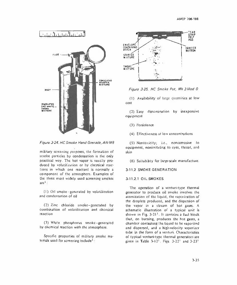
AMCP 706-188
Figure 3-24. HC Smoke Hand Grenade, AN-M8
military screening purposes, the formation of smoke particles by condensation is the only practical way. The hot vapor is usually produced by volatilization or by chemical reactions in which one reactant is normally a component of the atmosphere. Examples of the three most widely used screening smokes are1:
(1) Oil smoke-generated by volatilization and condensation of oil
(2) Zinc chloride smoke-genera ted by combination of volatilization and chemical reaction
(3) White phosphorus smoke—generated by chemical reaction with the atmosphere.
Specific properties of military smoke materials used for screening include1:
EnvElopiCONTAIN INC MATCH
STARTERMIXTURE
SMOKEMIXTURE
Figure 3-25. HC Smoke Pot, Mk 3 Mod 0
(1) Availability of large quantities at low cost
(2) Easy dissemination by inexpensive equipment
(3) Persistence
(4) Effectiveness at low concentrations
(5) Non toxicity; i.e., noncorrosive to equipment, nonirritating to eyes, throat, and skin
(6) Suilabibty for large-scale manufacture.
3-11.2 SMOKE GENERATION
3-11.2.1 OIL SMOKES
The operation of a venturi-type thermal generator to produce oil smoke involves the atomization of the liquid, the vaporization of the droplets produced, and the dispersion of the vapor in a stream of hot gases. A schematic illustration of a typical unit is shown in Fig. 3-211. It contains a fuel block that, on burning, produces the hot gases, a chamber containing the liquid to be vaporized and dispersed, and a high-velocity vaporizer tube in the form of a venturi. Characteristics of typical venturi-type thermal generators are given in Table 3-121. Figs. 3-221 and 3-231
3-35
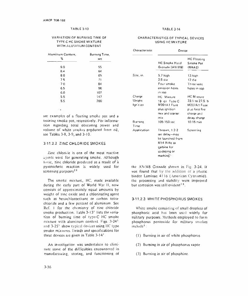
AM CP 708-188
VARIATION OF BURNING TIME OF TYPE-C HC SMOKE MIXTURE WITH ALUMINUM CONTENT
Aluminum Come nr. Burning Time,% sec
TABLE 3-13
9.0 558.4 648.0 657.5 7170 846.5 966.0 1075.5 1475.5 200
are examples of a floating smoke pot and a training smoke pot, respectively. For information regarding total obscuring power and volume of white smokes produced from oil, see Tables 3-8, 3-9, and 3-10.
3-11.2.2 ZINC CHLORIDE SMOKES
Zinc chloride is one of the most reactive agents used for generating smoke. Although toxic, zinc chloride produced as a result of a pyrotechnic reaction is widely used for screening purposes2 1
The smoke mixture, HC, made available during the early part of World War II, now consists of approximately equal amounts by weight of zinc oxide and a chlorinating agent such as he xachlo roe thane or carbon tetrachloride and a few percent of alumjnum. See Ref. I for the chemistry of zinc chloride smoke production. Table 3-13' lists the variation of burning time of type-C HC smoke mixture with aluminum content. Figs. 3-241 and 3-25' show typical devices using HC type smoke mixtures. Details and specifications for these devices are given in Table 3-141.
An investigation was undertaken to eliminate some of the difficulties encountered in manufacturing, storing, and functioning of
TABLE 3-14
CHARACTERISTICS OF TYPICAL DEVICES USING HC MIXTURE
Characteristic Device
HC Smoke Hand Grenade (AN-M8I
HC Floating Smoke Pot (M4A2)
Size, in. 5.7 high 13 high2.5 dia 12 diaFour smoke Three ventemission holes in top
holes in topCharge HC Mixture HC MixtureWeight 19 oz Type-C 23.5 to 27.5 lbIgnition M2D1A1 Fu2e M2G7A1 Fuze
plus ignition plus first firemix and starter charge andmix delay charge
BurningTime
105-150 sec 10 15 minAppl ication Thrown, 1.2-2
sec delay—may be launched from MJ4 Rifle or carbine for screening or markingT
Screening
the AN-M8 Crenade shown in Fig. 3-24. It was found that by the addition of a plastic binder Laminae 41 )0 (American Cyanamid). the processing and stability were improved but corrosion was still evident2 2.
13-11.2.3 WHITE PHOSPHORUS SMOKES
White smoke consisting of small droplets of phosphoric acid h;is been used widely for military purposes. Methods employed to form phosphorus pentoxide for military smokes include' :
(1) Burning in air of white phosphorus
(2) Burning in air of phosphorus vapor
(3) Burning in air of phosphine.
3-36

AMCP 706-188
CHARACTERISTICS OF TYPICAL DEVICES USING PHOSPHORUS FILLING
TABLE 3-15
Characteristic Device
WP Smoke HandProjectile (T91 HE Water
Grenade (M15J Marker)Size, in. 4-1/2 high 12-3/4 long
2-3/8 dia 1-3/4 diaCharge 15 oz PWP 2.6 lb Comp B.Weight 0.661b
Igniti on M206A1 FuzeStabilized Red Phosphorus M500A1 Fuze
HE burster Comp. BScreening Scatters WP Explodes onCapability over a 20 yd impact—50 ft
radius high; 50 ft dia;
Application Thrown, bursting
cloud duration 3 min —25 mph windUsed in 90 min
charge explodes, munliton4-5 sec delay (white marker)
Phosphorus vapor is extremely toxic and causes bone decay; however, it is not present after the smoke is formed. There is little effect on metals by phosphorus smokes.
White phosphorus is used mainly in bursting type ammunition to produce smoke screens. It is the most efficient smoke producer on a weight basis, but screening effectiveness in bursting type munitions is slight. Smoke concentration many times that required for effective screening results because most of the charge burns within seconds following the burst. There is also a temperature rise in the cloud surrounding the burst that makes the cloud tend to pillar. Two ways to improve smoke producing effectiveness are1 :
(1) Reduce the heat of combustion
(2) Control the rate of combustion by
reducing the fragmentation of the phosphorus.
Various methods for controlling the fragmentation of phosphorus have been tried including the addition of steel wool, plastic tubes, and wire screens. Alteration of the physical properties so as to produce a plastic mass with low shattering characteristics is the most promising. Plasticized white phosphorus (PWP) was developed for controlling the fragmentation and the pillaring of the smoke2 3. The characteristics of typical smoke producing devices are summarized in Table 3-15'. Table 3-16'* summarizes typical screening devices most of which use WP as the filler material. Refer to Tables 3-8, 3-9, and 3-10 for total obscuring power, smoke volume, and rate of smoke production per unit weight of phosphorus compounds.
Figure 3-26. WP Smoke Hand Grenade, M l5
3-37
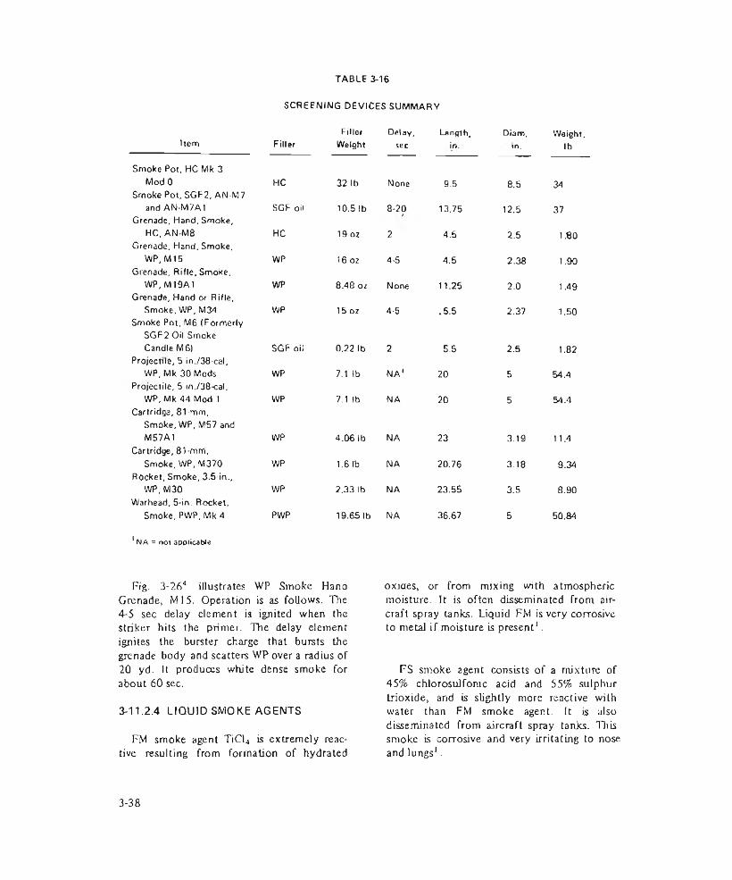
TABLE 3-16
SCREENING DEVICES SUMMARY
Item FillerFillerWeight
Delay,sec
Length,in.
Diam,in.
Weight,lb
Smoke Pot, HC Mk 3 ModO HC 32 lb None 9.5 8.5 34Smoke Pot, SGF2, AN-M7 and AN-M7A1 SGF oil 10.5 lb 8-20 13.75 12.5 37Grenade, Hand, Smoke, HC, AN M8 HC 19 oz 2 4.5 2.5 1.80Grenade, Hand, Smoke, WP, M15 WP 16 oz 4-5 4.5 2.38 1.90Grenade, Rifle, Smoke, WP, M19A1 WP 8.48 oz None 11.25 2.0 1.49Grenade, Hand or Rifle, Smoke, WP, M34 WP 15 oz 4-5 .5.5 2.37 1.50Smoke Pot, M6 (Formerly SGF2 Oil Smoke Candle M6) SGF oil 0.22 lb 2 5.5 2.5 1.82
Projectile, 5 in./38-cal, WP, Mk 30 Mods WP 7.1 lb NA1 20 5 54.4
Projectile, 5 in./38-cal, WP, Mk44 Mod 1 WP 7.1 lb NA 20 5 54.4
Cartridge, 81-mm, Smoke, WP.M57 and M57A1 WP 4.06 lb NA 23 3.19 1 1.4
Cartridge, 81-mm, Smoke, WP, M370 WP 1.6 lb NA 20.76 3.18 9.34
Rocket, Smoke, 3.5-in., WP, M30 WP 2.33 lb NA 23.55 3.5 8.90
Warhead, 5-in. Rocket, Smoke, PWP, Mk 4 PWP 19.65 lb NA 36.67 5 50.84
1NA = nor applicable
Fig. 3-264 illustrates WP Smoke Hand Grenade, M l5. Operation is as follows. The4-5 sec delay element is ignited when the striker hits the primer. The delay element ignites the burster charge that bursts the grenade body and scatters WP over a radius of 20 yd. It produces white dense smoke for about 60 sec.
3-11.2.4 LIQUID SMOKE AGENTS
FM smoke agent TiCl4 is extremely reactive resulting from formation of hydrated
oxjaes, or from mixing with atmospheric moisture. It is often disseminated from aircraft spray tanks. Liquid FM is very corrosive to metal if moisture is present1.
FS smoke agent consists of a mixture of 45% chlorosulfonic acid and 55% sulphur trioxide, and is slightly more reactive with water than FM smoke agent. It is also disseminated from aircraft spray tanks. This smoke is corrosive and very irritating to nose and lungs1.
3-38
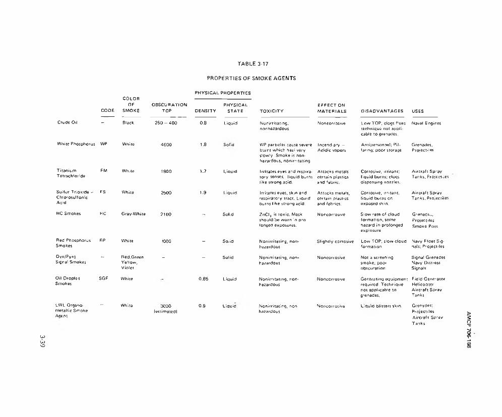
6£~e
TABLE 3-17
PROPERTIES OF SMOKE AGENTSPHYSICAL PROPERTIES
CODE
COLOROF
SMOKEo b s c u r a t io n
TOP DENSITYPHYSICAL
STATE
Crude Oil - Black 2 5 0 - 4 0 0 0.8 Liquid
Whice Phosphorus WP While 4600 1.8 Solid
TitaniumTetrachloride
FM White 1900 1.7 Liquid
Sulfur Trioxide -ChiorosulfonicAcid
FS Whiia 2500 1.9 Liquid
HC Smokes HC Gray-While 2100 - Sohd
Red Phosphorus Smokes
RP White 1000 - Solid
Oye/Pyro Signal Smokes
*- Red,GreenYellow,Violet
- - Solid
Oil Droplet Smokes
SGF White " 0.85 Liquid
LWL Organo metallic Smoke
- White 3000leviimatedl
0.9 Liquid
Act:.'!'.
TOXICITYEFFECT ON MATERIALS DISADVANTAGES USES
Nonirrilatmg. non hazardous
Noncorrosive Low TOP; clogs flues technique not applicable to grenades.
Naval Engines
WP part'd as cause severe burns which heal very slowly. Smoke is nonhazardous, nonirritating
Incendiary - Acidic vapors
Antipersonnel; Pillaring; poor storage
Grenades,Projectiles
Irritates eyes and respiratory senses; liquid burns like strong acid.
Attacks metals certain plastics and fabric.
Corrosive, irritant; liquid burns; clogs dispensing nozzles.
Aircraft Spray Tanks, Projectiles
Irritates eyes, skm end respiratory iract. Liquid burns like strong acid.
Attacks metals, certain plastics and fabrics.
Corrosive, irritant, liquid burns on exposed skin.
Aircraft Spray Tanks, Projectiles
ZnClj is toxic. Mask should be worn in prolonged exposures.
Noncorrosive Slow rata of cloud formation, some hazard in prolonged explosure.
G renada, Projectiles Smoke Pots
Nonirritaiing, nonhazardous
Slightly corrosive Low TOP; slow cloud formation
Navy Floet Signals; Projectiles
Nonirritating, nonhazardous
Noncorrosive Not a screening smoke; poor obscuration
Signal Grenades Navy Distress Signals
Nonirn lating. non* hazardous
Noncorrosive Generating equipment required. Technique not applicable to grenades.
Field Generator Helicopter Aircraft Spray Tanks
Nonirritaiing, non hazardous
Noncorrosive Liquid blisters $k>n Grenades; Projectiles Aircraft Spray Tanks
AMCP 70&-188

M2 0 I FUZE
O' RING SfflL PROPELLANT
LWL SMOKE AGENT
RUPTURE O'SC
N O ZZLE a n d ENO CLOSURE
SMOKEr r v i T
Figure 3-27. Piston Smoke Grenade
3-11.2.5 NEW DEVELOPMENTS IN SCREENING SMOKES
A new orga no metallic smoke agent has been developed by the Army Land Warfare Laboratory (LWL) for use from both helicopters and fixed-wing aircraft24. This agent is superior to present liquid smoke agents (FM and FS) in the generation of high obscurationsmoke screens. The smoke cloud is also nonirritating, nontoxjc, noncorrosive, stable, and less dependent on humidity and temperature than either FM or FS liquid smoke agents. A smoke grenade, Fig. 3-272S, has
been developed to dispense the LWL liquid smoke agent that provides improved performance over devices presently being used. Table 3-1725 compares the new smoke agent with the more common agents.
3-12 SIMULATION
Pyrotechnic devices that produce effects designed to simulate the appearance of combat weaponry are used in training exercises to familiarize troops with battle conditions without exposing them to the dangers of lethal ammunition. In addition, some devices are used in actual combat to mislead or confuse the enemy. There are a number of these devices whose primary effects arc sound and flash but they also emit smoke.
Those devices which emit smoke include detonation simulators, flash artillery simulators, projectile air burst simulators, and atomic explosion simulators. See par. 3-22.1 for more detailed information about these devices.
Care should be exercized in selecting the smoke mixture so that the smoke cloud is nontoxic and nonirritating to personnel. Par. 3-11.2 lists the smoke mixtures that could be
TABLE 3-13SIMULATOR SUMMARY
Length, Diameter, Weight,Item Displ ay in. in. oz
Simulator, Detonati on, Explosive, Mk 2
Flash,Smoke.Sound
2 0.6 0.4
Simulator, Flash Artillery, Ml 10
Flash,Smoke,Sound
7.8 1.9 10.7
Simulator, Projectile, Air Burst, M27A1B1
Flash,Smoke,Report
8.9 1.9 9.3
3-40
AMCP 706-188
used for this purpose. Desirable features of the devices include long shelf life, mass producibility, minimum cost, and optimum effect. Table 3-18' summarizes several of these devices.
3-13 RIOT CONTROL
3-13.1 SMOKE GENERATION
In riot control, agent smokes are produced in much the same manner as in signaling. In many cases, a vaporization process is followed by a condensation process in which the agent condenses to form the disperse phase of the smoke. Agent smokes may be disseminated by a vapor condensation process, a dispersion process, or a combined process. For smoke that is disseminated as a particulate cloud the process usually involves the formation of small particles of the dispersed phase and the distribution of these particles in the air. The physiological effectiveness of materials disseminated depends strongly on the particle size. While visibility of the smoke may or may not be important, the volume of smoke and its duration is important. It is also necessary that the vaporization and condensation processes be efficient and produce a minimum of undesired changes in the agent dispersed.
3-13.2 FORMATION OF DISPERSED PHASE
The dispersed phase can be formed in three ways’ :
(1) Condensation processes in which molecules of the vapor unite to form the particles of the dispersed phase
(2) Dispersion processes in which the particles are formed by the breaking up of a solid or liquid material
(3) Combined processes.
3-13.2.1 CONDENSATION PROCESS
The dispersed phase of most particulate
clouds (smoke) is produced by condensation from the vapor phase and involves the uniting of vapor molecules to form large particles1. The two steps involved in the formation of a dispersed phase by this method are:
(1) Production of the vapor in a supersaturated state
(2) Condensation of the supersaturated vapor.
The supersaturated vapor usually results from the cooling of a warm vapor or a chemical reaction. In either event, the excess vapor will condense to form the particles of the dispersed phase. Condensation of a vapor is facilitated by the presence of foreign particles. Ln many cases of military interest, the evaporation of the substance produces the supersaturated vapor followed by the mixing with cooler air of the relatively warm vapors produced.
3-13.2.2 DISPERSION PROCESS
The dispersion process involves the subdivision of a solid or liquid into line particles. In the case of a solid substance, it may be disrupted and dispersed into Fine particles by application of energy, or the solid may be preground to the desired size and then dispersed into the suspending medium. In the case of a liquid, energy applied to it causes the liquid to break up into small droplets. See Ref. 1 for more details.
3-13.2.3 COMBINED PROCESS
In many instances, the dispersed phase of smokes is obtained by condensation of a vapor phase that is formed by evaporation of the smoke producing agent. To facilitate the transfer of heat to and the removal of the vapor from the surface of the agent, the smoke producing agent is often atomized. Particulate clouds can be developed by the atomization of a solution containing a nonvolatile or slightly volatile solute of a volatile solvent.
3-41
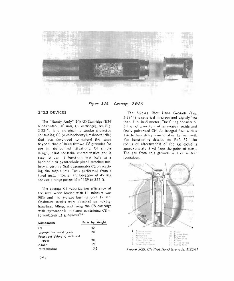
Figure 3-28. Cartridge, 2-WRD
3-13.3 DEVICES
The "Handy Andy" 2-WRD Cartridge (E24 Riot-control, 40 mm, CS cartridge), see Fig. 3-2826, is a pyrotechnic smoke projectiJe containing CS (o-chlorobenzylamalononitrile) that was developed to extend the range beyond that of hand-thrown CS grenades for use in riot-control situations. Of simple design, it has nonletha) characteristics, and is easy to use. 11 fund ions essentially as a hand-held or pyrotechnic-pistoHaunched rubbery projectile that disseminates CS on reaching the target area. Tests performed from a fixed installation al an elevation of 45 deg showed a range potential of 189 to 353 ft.
The average CS vaporization efficiency of the unit when loaded with LI mixture was90% and the average burning time 17 sec. Optimum results were obtained on mixing, handling, tilling, and Tiring the CS cartridge with pyrotechnic mixtures containing CS in formulation LI as follows16:
Components Parts by WeightCS 42Lactose, technical grade 20Potassium chlorate, technicalgrade 26
Kaolin 12Nitrocellulose 3.6
The M25A1 Riot Hand Grenade (Fig. 3-2917) is spherical in shape and slightly less than 3 in. in diameter. The filling consists of 3.5 oz of a mixture of magnesium oxide and finely pulverized CN, An integral fuze with a 1.4- to 3-sec delay is installed in the fuze well. For functioning details, see Ref. 27. The radius of effectiveness of the g^s cloud is approximately 5 yd from the point of burst. Tire gas from this grenade will cause tear formation.
Figure 3-29. CN Riot Hand Grenade, M25A 1
3-42
AMCP 706-188
SECTION IV HEAT AND GAS
3-14 IGNITERS AND PRIMERS
3-14.1 INITIATION
3-14.1.1 THE INITIATION PROCESS
Explosive materials are initiated when energy of an externally applied stimulus is transformed into heat. The view that nonuniformity of heat distribution is essential to the usual initiation process has been called the “hot spot’’ theory of initiation. In explosive initiators, the energy available is concentrated by the use of small-diameter firing pins and, in electrical devices, by dissipating the energy in short and highly constricted paths. The addition of grit to primer mixes serves a similar function. Not only is nonuniformity of energy distribution essential to most initiation processes, but it is an important Factor in the growth and propagation of practically all initiation processes in military devices.
should be applied only to compare the performance of initiators of the same type.
3-14.1.2 ELECTRIC INITIATORS
Hot bridgewire electric initiators are the simplest and most direct illustrations of initiation by heat. Since a bridgewire can be measured, its volume, heat capacify, and resistance can be calculated. Since it is further possible to generate electrical pulses and currents of accurately known characteristics, these can be combined with the bridgewire characteristics to obtain accurate estimates of power, energy, and temperature.
A large number of experiments has been carried out in which the interrelationships of the variables that affect the operation of bridgewire initiators have been investigated. These investigations have verified the following principles2 8 :
The reaction rate inevitably reaches a level such that heat is generated faster than it can be lost. From this point on the reaction is self-accelerating and quite rapidly becomes explosive.
Although a general equation that includes consideration of all of the complicating factors would be completely intractable, the use of simplified models makes possible solutions that contribute to the understanding of the initiation process. However, simplification must be used cautiously. For example, it frequently appears that each explosive has a critical initiation temperature that is independent of dimensions. More detailed analyses have shown this to be an approximation that applies only to a specific class of initiators. Perhaps the most important implication of the foregoing is that the minimum energy required to initiate an explosive device is nearly proportional to the volume of material that is heated by the input energy pulse. It must be stressed that (his approximation
(1) The energy required to fire a hot-wire electric initiator is roughly proportional to the volume of the bridgewire if the energy is delivered in a short enough time.
(2) Qoser analysis shows that the threshold temperature increases with reduced wire diameter. This trend is less marked when the explosive has a high activation energy (like lead styphnate).
(3) The energy required per unit volume also increases somewhat with decreasing bridgewire length, End losses probably account for tliis.
(4) For a specific initiator design, tne energy requirement approaches a minimum as voltage, current, or power is increased. It increases indefinitely as power is reduced to a minimum.
(5) The relationship stated in (4) refers to the average power of a firing pulse. Pulse
3-43
shape has a secondary effect that is not easDy measured.
(6) The current requirement varies approximately as the 3/2 power of the wire diameter and inversely as the resistivity of the bridge- wire metal.
3-14.1.3 MECHANICAL INITIATION
Mechanical initiation is accomplished by means of a stab or percussion firing pin. Mechanical initiation is more difficult to analyze than electrical initiation. The most important function of the firing pin is to convert another form of energy into highly concentrated heat. As in electrical devices, the energy necessary is nearly proportional to the amount of heated material. It has been inferred from experimental data that stab and percussion initiation occur by different mechanisms. Kinetic energy appears to be the determining magnitude for stab initiation, momentum for percussion.
The standard firing pin for stab initiation is a truncated cone. Maximum flat diameter at the tip is 0.01 5 in. In general, the higher the density of the explosive, the more sensitive tire stab initiator. Because the denser explosive offers more resistance to the penetration of the firing pin, the kinetic energy of the moving mass is dissipated over a shorter distance so that a smaller quantity of explosive is heated to a higher temperature.
Contrary to initiation by stab, the percussion firing pin merely dents tbe case and pinches the explosive between anvil and case. Energy must be supplied at a rate sufficient to fracture the granular structure of the explosive. Firing pins with a hemispherical tip have been shown to give greater sensitivity than a truncated cone. Tip radius has little effect on sensitivity but is typically 0.050 in-
3-14.1.4 INPUT REQUIREMENTS
Tire energy required for reliable initiation differs not only for different initiator types
Figure 3-30. Charge Holders
but also for different models of tbe same type. Initiation values are established in input sensitivity tests28. For mechanical initiators, ball weight and drop height are specified; for electric initiators, applicable electrical parameters — such as capacitance, voltage, current, or pulse width — are given. Input specifications for specific initiators are listed in Ref. 29.
3-14.2 INITIATION OF PYROTECHNIC DELAYS
Pyrotechnic delays are ignited by an initiating assembly. Its purpose, whether it is mechanically or electrically activated, is to produce hot gases and particles that will impinge on the delay column. Delays are easily ignited by the flame of a primer; however, slow-burning delays require an igniter. For more details on vented and obturated delays and on delay compositions, see par. 3-21.
3-14.2.1 VENTED DELAYS
The initiator assemblies of vented delays can take several forms. In some instances the assembly contains a charge holder that sits directly on top of the delay column (conventional), allowing very little or no free volume, as shown in Fig. 3-30(A)30. Others use a chimney-type charge holder which may or may not sit on top of the delay column but provides for a free volume in which to vent gases (Fig. 3-30(B)). It also directs and concen-
3-44
AMCP 706-1S8
Irates the hot gases and particles into a definite area.
Another type of pyrotechnic delay assembly frequently uses a configuration employing a primer holder subassembly in which only the primer is held securely. This subassembly is then screwed into, staked into, or otherwise held rigidly in the main delay assembly. The igniter charge is made a part of the main pyrotechnic delay column. Fig. 3-49 illustrates the use of such a primer subassembly.
3-14.2.2 OBTURATED DELAY'S
spit tube of artillery ammunition or like the basket filled with low explosives as used in rockets.
Pyrotechnic charges with ignition temperatures of 500°C or less require little in the way of complicated ignition trains; a primer will do. However, materials with ignition temperatures considerably above 500°C are more difficult to ignite10. Many of the illumination charges fall into this hard-toignik region and usually require some form of energy amplification in the form of intermediate mixes of igniter composition.
When the primer or flash charge is ignited in an obturated system, tire pressure in the enclosed free volume is increased. At first, this happens very quickly and then the pressure is increased progressively by gas liberated by the burning delay column.
As a result, the burning rate accelerates continuously and is usually nearly proportional to pressure. Unless the free volume is increased along witli the delay column length, the delay time docs not increase directly. This requirement for a volume that is nearly proportional to the delay time limits obturated gas producing delays to about 0.4 sec with a column diameter commonly in the range of 0.1 to 0.125 in. In addition to its direct relationship to the free volume, the delay time of an obturated delay element is related inversely to the gas volume and heat of explosion of the primer2 8 -
3-14.3 IGNITERS
In a pyrotechnic ignition train, the igniter is the intermediate component between the primer and the main pyrotechnic charge. It augments the flame output of the primer so as to ignite the main charge with greater reliability. Since many pyrotechnic compositions can he reliably ignited by the flame of a primer alone, igniters are often omitted. When igniters are used, they take many forms. The igniter could be a long cylindrical element filled with an initiating explosive, akin to the
It is a rule of thumb that the igniter charge bum at several hundred degrees higher ihan the ignition temperature of the main charge. Furthermore, the ignition charge must be in intimate contact with the main charge. The production of hot slag or dross of the burning ignition charge then assists in igniting the main charge over relatively large areas.
At times it is difficult to recognize a particular component as an igniter, (n some pyrotechnic devices, a first-fire mixture is used in place of an igniter. Having the same function as an igniter, the first-fire mixture consists of a readily ignitable mix that is loaded on top of the main pyrotechnic charge. Such a charge is used in the incendiary grenade shown in Fig. 3-34.
3-14.4 IGNITION OF PYROTECHNICS COMPARED WITH THAT OF SOLID PROPELLANTS
Ignition of solid propellants used in rockets and guns is similar in many respects to ignition of pyrotechnic mixtures. When raised to their ignition temperature, propellants undergo preignition reactions followed by an ignition reaction. If conditions are favorable, the reaction front moves at a nominally constant velocity.
Since some pyrotechnic compositions are relatively difficult to ignite, an ignition train similar to that used in other explosively
3-45

Figure 3-31. Typical C a l. 50 Incendiary Bullet
loaded items is used to produce the stimulus required to initiate the main pyrotechnic composition. The initiating composition, on burning, produces sufficient heat to initiate an intermediate pyrotechnic composition that forms the second part of the ignition train.
A composite propellant resembles a pyrotechnic mixture in that it is an intimate mixture of a fuel and an oxidizer. In general, for ail solid propellants, the temperature of the propellant a short distance below the burning surface is not affected by the combustion of the propellant. In propagative burning, as the burning surface advances, the unburned propellant is heated, and the temperature of the material increases to the point where the propellant decomposes into volatile fragments. In some instances liquefaction may occur prior to the chemical reactions that comprise the combustion process. For more details on the theory of ignition and propagative burning, see Ref. 1.
3-15 INCENDIARIES
Destructive fires are set off in a large variety of targets by the use of incendiaries. While aircraft, buildings, industrial installations, ammunition, and fuel dumps are among the principal targets for incendiary attack, it has also been used effectively against personnel, armored vehicles, and tanks. Incendiary compositions and devices can be classified based on their composition and use. Three large classes based on their use are1 :
(1) Small arms incendiary ammunition
roizc it,ct uwexi
Figure 3-32.Typical 20 mm High Explosive
Incendiary Projectile
used primarily against aircraft and fuel dumps.
(2) Other incendiary munitions including bombs, grenades, mortar and artillery projectiles. These are used to initiate fires in buildings, industrial installations, ammunition, fuel dumps, and other targets in combat zone.
(3) Special incendiary devices used for the destruction of materials and documents.
3-15.1 SMALL ARMS INCENDIARIES
Small arms incendiaries are used primarily for starting destructive fires in aircraft fuel. They have been developed to meet the needs of the using services and now include ammunition up to 40 mm. The types include incendiary bullets, armor-piercing bullets, and high explosive incendiary projectiles. A typical incendiary cai .50 bullet is shown in Fig 3-3 11. Unfuzed incendiary rounds up to 20 mm are usually initiated by the heat produced when the metal nose crushes on impact. Ammunition, 20 mm and larger, is provided with fuzes that initiate on impact. Fig. 3-321 illustrates a typical 20 mm high explosive incendiary pvojectile that is fuzed.
The target effect in an aircraft depends upomthe amount of energy transferred to the fuel. This is a function of the temperature reached and the characteristics of the
3-46

AMCP 70&-188
Figure 3-33. 100-lb Smoke o r Incendiary Bomb, AN-M47A4
products of combustion, the mode of energy transfer process, and the efficiency with which the energy is absorbed by the fuel. Typical small arms incendiary mixtures are listed in Table 3-19'. See Ref. 1 for further details.
3-15.2 INCENDIARIES FOR GROUND APPLICATION
Ground incendiaries include that class of munitions used for damage, mainly by combustion, to ground targets. Various munitions of this type include bombs, grenades, mortar projectiles, and artillery projectiles.
The amount of energy from these incendiaries serves only to initiate combustion of the target in the oxygen of the air. All of these munitions, except those that are spontaneously combustible, must contain an initiator. Three types of incendiary fillings are used in incendiary bombs — PT, IM, and NP31. Table 3-201 lists the composition of PT mixtures while Table 3-211 lists the composition of IM incendiary gels. Filler NP (oil, incendiary, Napalm Type 1) is a mixture of 88.5 percent
gasoline and 11.5 percent napalm thickener. Napalm thickener is a granular base aluminum soap of naphthenic, oleic, and coconut fatty adds*.
Table 3-2231 lists the characteristics of different sizes of incendiary bombs. A typical incendiary bomb is the AN-M47A4 (see Fig. 3-3331), a 100-lb incendiary or smoke bomb. It uses Igniter, AN49 (white phosphorus or sodium filled) with Burster, AN-M 13 (TNT oi tetryl filled).
Incendiary bombs are deployed from aircraft and are designed for use against combustible land targets such as warehouses, factories, docks, or storage dumps. They are also used over water to ignite oil slicks. When an incendiary bomb, equipped with a sodium igniter, impacts on the water, it bursts and scatters burning gobs of incendiary gel containing particles of sodium. The gobs of gel will float and the sodium will ignite spontaneously with water, thereby insuring the ignition of flammable oil slicks. If a white phosphorus filled igniter is used, the scattering and the ignition of the gel takes place, but
3-47

TABLE 3-19
TYPICAL SMALL ARMS INCENDIARY MIXTURESIM-1150% Magnesium-Aluminum Alloy (50/50) 50% Barium Nitrate1M-21A<58% Magnesium-Aluminum Alloy (50/50) 48% Barium Nitrate 3% Calcium Resinate 1% AsphaltumIM-2350% Magnesium-Aluminum Alloy (50/50) 50% Potassium PerchlorateIM-2850% Magnesium-Aluminum Alloy (50/50)40% Barium Nitrate10% Potassium PerchlorateIM-6850% Magnesium-Aluminum Alloy (50/50) 25% Ammonium Nitrate 24% Barium Nitrate 1% Zinc StearateIM-6950% Magnesium-Aluminum Alloy (50/50) 40% Barium Nitrate 10% Iron Oxide (Fe503)(M-11245% Magnesium-Aluminum Alloy (50/50) 5% Tungsten Powder 50% Barium NitrateIM-13649% Magnesium-Aluminum Alloy (50/50)
49% Potassium Perchlorate 2% Calcium ResinateIM-13910% Magnesium-Aluminum Alloy (50/50)40% Red Phosphorus 47% Barium Nitrate 3% Aluminum StearateIM-14246% Magnesium-Aluminum Alloy (50/50)48% Barium Nitrate 5% Asphaltum 1% GraphiteIM-21450% Zirconium (60/80) (lot 6)25% Magnesium-Aluminum Alloy 25% Potassium PerchlorateIM-24150% Zirconium (20/65)25% Magnesium-Aluminum Alloy 25% Potassium PerchlorateI.M-38549% Magnesium-Aluminum Alloy (50/50)49% Ammonium Perchlorate 2% Calcium ResinateMOX-2B (High Explosive Incendiary Fillers)52% Aluminum Powder 35% Ammonium Perchlorate 6% RDX/Wax (97/3)4% TNT (Coated on the Ammonium Perchlorate) 2% Calcium Stearate 1% Graphite
ignition of the gel on water is not assured31 . Burning gobs of incendiary gel will produce a temperature of 500° to 67 5° C at a height of 3 in. above the flame over a maximum period of approximately 8 min.
3-15.3 SPECIAL INCENDIARY DEVICES
Special incendiary devices are used for the destruction of various materiel. A typical incendiary grenade (Fig. 3-341) is loaded with
thermite. Ignition action is as follows; the fuze spits out a flame that ignites the first fire mixture. This mixture, talcing the place of an igniter, is shaped to cover the top of the thermite charge so as to insure reliable ignition of the entire thermite charge.
The main use of special incendiary devices is the destruction of safes and their documents or other contents to prevent their failing into enemy hands. T ie M1A2 Safe
3-48
AMCP 706-188
TABLE 3-20COMPOSITION OF PT INCENDIARY MIXTURESCode PT-1 PT-2 PT-3Constituent Composition, PercentGoop 49.0 30.0 -
Isobutyl methacrylatepolymer AE 3.0 - -
Magnesium (coarse) 10.0 10.0 30.0(50/50 Mg-AI alloy) 10.0Sodium Nitrate 5.0 8.0 6.5Gasoline 30.0 44.0 37.5Petroleum Oil Extract 3.0 - -
(Bright stock) 10.0GR-S (Buna-Ssynthetic rubber) - 8.0 6.0
Sulfur monochloride(S2Clj) - 0.2 (add) 0.2 (add)
Destroying Incendiary (Fig. 3-3517), a modi- ficaiion of the M IA1 TH I, is aiso used for the sole purpose of destroying cryptographic equipment. It uses the M2 IQ Incendiary Fuze and two floating Smoke Pot Fuzes (M209). The incendiary can be ignited electrically or manually by withdrawing the fuze safety pin.
TABLE 3-22TYPICAL INCENDIARY BOMBS
OverallAssembled Filler Weight Filler Length,Weight, lb or Volume Material in.
4 0.6 lb TH3 21.310 2.8 lb PT1 19.5500 174 lb PT1 59.2100 421b PT1. IM. or
NP51.7
750(Fire Bomb)
no gal gasoline 138
1000(Fire Bomb)
112 gal gasoline,napalm
168
Incendiary Device, M2AI THII (Fig.3-3621) for destroying equipment is similar in construction to the M1A2 but is smaller and has only two fuzes. It is designed to destroy a single item of classified cryptographic equipment. It is fitted with a M210 Fuze, a M209 Smoke Pot Fuze, loaded with 8.5 lb of
TABLE 2-21COMPOSITION OF IM INCENDIARY MIXTURES
CodeIM
Type 1IM
Type 2IM
Typo 3 F-1416 F-1429 F-1431 F-1457Constituent Composition, Percent
Isobutyl methacrylatepolymer AE (IM) 5.0 5.0
Stearic acid 3.0 -
Fatty acids — 2.5Naphthenic acid - 2.5Calcium oxide 2.0 -
Caustic soda (40% solution) Ammonium hydroxide
- 3.0(27% solution) - -
Gasoline 88.75 87.0Water 1.25 _
2.0 3.0 3.0 3.0 3.0- 1 . 0 4.0 3.0 4.53.0 - - - -
3.0 3.0 - 1.0 0.5- 3.1 4.0 3.5 -
4.5 - ~ - -
— _ _ 2.387.5 87.6 86.5 87.3 89.3
- 2.3 2.5 2.2 -
3-49
80DY
FIRST FIRE MIXTURE Figure 3-35.
TH1 Safe Destroying Incendiary, M1A2
3-16 BATTERIES
3-16.1 BATTERY TYPES AND REQUIREMENTS
There are three distinct types of battery.
I . Live primary batteries that consist of electrodes and aqueous electrolyte aJl in place and ready to function when connecting the load to the terminals. The most common type is the dry cell.
Figure 3-36.TH1 Equipment Destroying Incendiary, M2A 1
THEHMITE
Figure 3-34. Typical incendiary Grenade
thermite (TH1) and is ignited either electrically or manually.
Tire M4 File Destroyer is intended primarily to be used to destroy classified material in filing cabinets provided with combination locks. It consists of 44 oxidizer boxes, four igniter boxes, and four racks. Fig. 3-372 7 illustrates this incendiary. The oxidizer is required because a closed file cabinet does not contain sufficient oxygen to sustain combustion. The incendiary is ignited electrically by connecting Ml Squibs in each igniter box in parallel to a power source. The oxidizer boxes are made of celluloid and filled with approximately 26.5 oz of sodium nitrate. The racks are made of interlocking links of heavy wire that allows them to follow the contours of the tops of the papers in the file drawer. This arrangement keeps flie papers compressed while they are burning2 7.
3-50

AMCP 70&-188
Figure 3-37. File Destroyer Incendiary, M4
2. Secondary batteries that have their electrodes immersed in the electrolyte but may not be capable of furnishing instant power to their load. Some types require charging to convert the surfaces of the electrodes electrochemically to the proper composition for power delivery. A common type is the old- style automotive battery.
tbeir high chemical reactivity. On the other hand, the systems stable at moderate to high temperatures have inadequate power densities at low temperatures. Without exception, those systems that produce adequate output at —40°F o t below deteriorate rapidly at high temperatures. Since adequate output at —40°F at least is required, a highly reactive system must be used, with deterioration controlled by using a reserve or secondary power supply. Although storage life of a live primary cell may be extended markedly by storage at low temperatures, this would create a serious problem in logistics, in maintaining cold-storage facilities at depots and in transit, as well as in routine replacement of overaged batteries32. Live batteries, therefore, are not recommended for pyrotechnic ammunition.
Secondary batteries have similar design problems if only to a lesser extent. In addition, they are difficult to activate rapidly and are too large in size. Hence, they are also not recommended for this application.
Reserve batteries, on the other hand, can best fulfill the requirements. They are activated rapidly and capable of withstanding long storage without maintenance. They do have the disadvantages of relatively high cost and one-time use capability.
3. Reserve batteries that have their electrodes in place but the electrolyte is introduced just prior to use. In the thermal type reserve battery, the electrolyte is in the solid, dry state between the electrodes. Tire thermal battery is made active by applying heat to melt the nonaqueous electrolyte.
While all three types of battery are used by the military, there are inherent difficulties with the First two types. The difficulty of designing live batteries to meet all of the requirements is caused by the incompatibility of the requirements with the properlies of electrochemical systems. Those systems characterized by high power density at low temperatures cannot withstand long storage at moderate to high temperatures because- of
3-16.2 THERMAL BATTERY
A thermal battery is basically a primary voltaic cell of the reserve type. It consists of a bimetallic electrode system, a fnsed-salt electrolyte, a heat source to melt the electrolyte, thermal insulation, and an initiating system3 3. During storage, the electrolyte is in an inactive solid state. When heat is applied to the electrolyte (temperature of about 750°F), the electrolyte becomes a liquid ionic conductor.
Although the heat source for activation may be external, a complete thermal battery contains an integral source of heat that is dormant until required for operation. One way of providing heat is to surround the
3-51
AMCP 706-188
CHAM8ER
individual cells with a pyrotechnic material that is ignited by a primer. The activation time (the time for the electrolyte to melt) varies from about 0.5 to 8 sec depending on battery size; the smaller the battery, the faster the activation Lime. Thermal batteries can be designed with a variety of dimensions and with different voltages and currents. Their active life is about I0 min. They are inherently rugged, withstanding all required shock and vibration tests, and have a shelf life of approximately 15 yr.
Tne thermal battery is the only power supply giving assured operation over the military temperature range. It is widely used in nonrotating and slowly rotating projectiles. Current development effort is under way to improve its capability in withstanding spin forces, to lengthen its life within a small package, and to further shorten its activation lime3 2.
3-17 GAS ACTUATED DEVICES
A gas actuated device is one that employs the energy supplied by the gases produced when a pyrotechnic composition bums to accomplish or initiate a mechanical action, other than expelling a projectile. Gas actuated devices are often called propellant actuated devices (PAJO) and formerly were referred to as cartridge actuated devices. The mechanical tasks performed by gas actuated devices include switching, stroking, pin pulling and positing, and cable cutting.
3-17.1 TYPICAL DEVICES
Many gas actuated devices such as switches, dimple motors (see Fig. 3-3829), and bellows motors are relatively small and contain the gas producing pyrotechnic mixture as an integral part of the device. Others, such as catapults or thrusters (see Fig. 3-3934), employ separate power cartridges. Tire cartridge contains its own primer and booster charge and has the general appearance of a shot gun shell.
Another category of gas actuated devices includes those actuated by.sources of gas that have been generated externally by a gas producing device. The pin puller sIio w t i in Fig. 3-4034 is an example of a gas actuated device with no self-contained gas supply. Details and specifications for existing gas actuated devices arc found in Refs. 34 and 35.
Fiaure 3-39. Thruster, M3 A 1
3-52
AMCP 706-188
)
PIN
Figure 3-40.
3-17.2 METHOD OF OPERATION
Basically, gas operated devices contain a chamber of semifixed volume which, when fUJed with a pressurized gas, is able to expand and perform work. The dimple motor, shown in Fig. 3-38 for example, has a small chamber adjacent to a gas generating mixture. Upon application of a sufficient electric current through the resistive bridgewire, the mixture is ignited and the generated gases fill the chamber to such an extent that the chamber itself is forced to expand in order to accommodate the gas. Thus, the dimpled end of the device “pops” out. Tins motion is commonly used to operate a switch. A bellows motor Operates in the same manner except that the gas fills a sealed bellows that is capable of expanding a greater distance than the dimple motor. A l-in. travel is common.
Larger gas actuated devices operate on the same principle. In some devices the chamber is behind a piston that is thrust outward when the chamber fills with gas (Fig. 3-39). The gas for piston-type actuators is usually supplied by cartridges that are fabricated separately and placed in the actuators before rise or by an external source of gas that is piped to the chamber. One advantage of using replaceable cartridges is that the actuator may be reused.
The duration of the power impulse produced by the gas actuated devices varies from milliseconds for dimple and bellows motors to several seconds for large thrusters. Initiation may be electrical, pneumatic, or mechanical.
Pin Puller
Cartridges are usually initiated mechanically by a stab mechanism that is spring-loaded or pneumatically operated.
Gas actuated devices are simple devices containing a minimum number of parts. They must be light in weight, yet strong enough to withstand the maximum pressure created by burning the propellant they contain. The materials selected for use in these parts must be compatible with the propellant, igniter, and primer at the temperatures and in the functional and storage conditions to which the parts are exposed.
Standard parts should be used wherever possible, and when special parts are necessary they should be designed so that they are manufactured easily. Wherever possible, parts should be made nonreversible (i.e., it should be impossible to assemble a component backwards). Much time is saved by using existing cartridges, details of which are found in Refs. 34 and 35. Information on the thermochemical properties of gas generating pyrotechnics (generally referred to as propellants) is contained in Ref. 36.
3-18 GAS PRODUCING DEVICES
A gas producing device is one that generates gas. Many gas actuated devices (see par. 3-17) employ an external source of gas for operation. This external source is a gas producing device using a pyrotechnic mix. It differs from a gas actuated device only in output. Its container is a chamber of fixed
3-53
Figure 3-41. Mechanically Operated Initiator, Mk 9 Mod 0
I . I35 in .d io m . O-SING FIRING PIN CARTRIDGE
Figure 3-42. Gas Operated Initiator, Mk 10 Mod 0
3-54
AMCP 706-180
Figure 3-43. Gas Generator
volume that connects to an outlet port which, in turn, is connected via tubing to the gas actuated device.
There are basically two types of gas producing devices: ( l) short duration (usually less than 0.5 sec) “initiators” and (2) long
TABLE 3-23COMPARATIVE DATA FOR INITIATORS
ChamberWeight. Volume, Delay, Peak Pressure*,
Model lh in.3 sec psi
duration (more than 0.5 sec) “gas generators”, Both devices consist of vented chambers containing cartridges and firing mechanisms. Tire firing mechanisms may be operated electrically, pneumatically, or mechanically. While gas producers are designed primarily to supply gas pressure to operate the firing mechanisms of gas actuated devices, they may also be used as sources of energy for operating piston-type devices such as safety belt releases, safety-pin extractors, and switches. Initiators are used extensively in aircraft to operate the firing mechanisms of propellant actuated devices. They eliminate cumbersome cable-pulley systems and provide a more reliable method of triggering. Initiators are often used as intermediate boosters in systems where the gas actuated device is remote from (he initiator. They are also used to introduce a delay into gas actuated systems where several operations must be properly sequenced. A typical mechanically operated initiator is shown in Fig. 3-413 5 while a gas operated initiator is illustrated in Fig. 3-4235. Comparative data for several initiators are given in Table 3-233<l. Further information is found in Refs. 34 and 35.
MECHANICALLY OPERATEDM4 1.0 2.4 2 600(12)M12 t.O 2.4 1 500(12)M3 0.9 2.3 - 1000(15)M29 1.6 2.3 - 1000(15)M27 0.3 0.6 - 1200(15)T30E1 0.3 0.6 — 1200(15)M30 1.1 2.6 2 5500(15)M32 1.1 2.6 ! 1500 (15)M8 2.2 4 3 - 1800 (30)
GAS OPERATEDM6 1.0 2.4 2 600(12)M33 1.0 2.4 1 600 (12)M5 0.9 2.3 - 1000 (15)M28 0.3 0.6 - 1200(15)T31E1 0.3 0.6 - 1200(15)MIG 1.1 2.6 2 1500(15)M31 1.1 2.6 1 1500(15)M9 1.8 4.3 - 1600(30)"Peak pressure in0.062 in.* gage located at the end nflength of ?>lS*2874T-4 hose. The number following the pressure indicaies the length of hose in feet between the initiatorand the gage.
Gas generators differ from initiators in the duration of the pressure impulse that may last several minutes for a gas generator. Typically, gas generators are used Tor catapults, ejectors, cutters, removers, and thrusters. They have also been used to supply gas flow to spin turbines as well as for supplying pressure to operate pumps that supply hydraulic pressure
TABLE 3-24COMPARATIVE DATA FOR GAS GENERATORS
Chamber Operating OperatingWeight, Volume, Pressure, Time,
Model lb in.3 psi secT3 25 100 2000 90T4 30 50 1500 480XM7 0.75 0.3 SOOT 0.9t At the end o l 2 ft of MS-2874 1-4 hose.
3-55
to missile controls. Comparative data for gas generators are given in Table 3-2434. An example of a gas generator is shown in Fig. 3-4334
The heart of the gas producing device is the cartridge that contains the gas producing
pyrotechnic composition and an ignition element. The characteristics of the complete gas producing device are determined by the design of the cartridge and the chamber with its vents into which the gas expands. Complete design details are given in Refs. 34 and 35.
SECTION V FUZING AND TIMING
3-19 FUZES
3-19.1 PURPOSE OF A FUZE
The word fuze is used to describe a wide variety of devices used with munitions to provide the basic functions of (I) arming, i.e., sensing the environment(s) associated with actual use including safe separation and thereupon aligning explosive trains, closing switches, and/or establishing other links to enable the munition to function; (2) firing, i.e., sensing the point in space or time at which initiation is to occur and effecting such initiation; and (3) safing, i.e., keeping the munition safe for storing, handling (including accidental mishandling), and launching or emplacing.
Because of the variety of types and the wide range of sizes, weights, yields, and intended usage of ammunition, it is natural that the configuration, size, and complexity of fuzes also vary over a wide range. Fuzes extend all the way from a relatively simple device such as a grenade fuze to a highly sophisticated system or subsystem such as a radar fuze for a missile warhead. In many instances the fuze is a single physical entity — such as a grenade fuze while in other instances two or more interconnected components placed in various locations within or even outside the munition make up the fuze or fuzing system. There is also a wide variety of fuze related components, such as power sources, squibs, initiators, timers, safing and arming (integrating) devices, cables, and control boxes that sometimes are developed, stocked, and issued as individual end items
but which in the overall picture constitute a part of the fuzing system.
Inherent to the understanding of the purpose of a fuze is the concept of the progression of action of the explosive train starting with initiation and progressing to the functioning of the main charge. Initiation, as the word implies, starts with an input signal, such as target sensing, impact, or other. This signal must then be amplified by suitable intermediate charges until a proper stimulus is obtained that will set off the main charge, be it photoflash, smoke, or flare. The explosive train is interrupted to provide safety. Present requirements call for at least two independent safing features, wherever possible, either of which is capable of preventing an unintended functioning; at least one of these features must provide delayed arming (safe separation).
The design of fu2es, then, is a complex subject. It is treated in detail in Ref. 37.
3-19.2 TIMERS FOR FUZES
A timer is a programming device; its purpose is to control the time interval between an input signal and an output event or events. There are four essential components in all timers: (!) a start system that initiates the programming action, (2) a power supply that sustains the timing action, (3) a time base or regulator, and (4) an output system that performs the required operation at the end of the desired time interval.
In selecting the components of timing systems, the designer must first determine the
3-56
AMCP 706-188
purpose for which the system is to be used and the factors influencing the selection 01 components. Some of the factors to be considered in the choice of the basic mechanism include time range and variation, accuracy and reliability, input and output signals, and cost.
Military timcm are categorized into main types depending upon the method used to generate the time base. The main types are1
(1) Precision Reference Timers
(2) Electronic Timers
(3) Mechanical Timers
(4) Pyrotechnic Timers
(5) Fluoric Timers
3-19.3 ENVIRONMENTAL SENSORS
If the fuze is to provide safing and functioning actions, it must sense when the environment is right for action. Hence, environment sensing is a basic and critical action of every fuze.
3-19.3.1 THE ARMING ENVIRONMENT
The arming environment is a combination of aJl of the conditions at which tlie fuze is to change from a safe state to one of readiness for functioning. The interior ballistic environment includes setback and spin (see par. 4-5) and the exterior baJlistic environment includes aerodynamic forces (see par. 4T>). Sensing is accomplished by means of sliders, spring-mass combinations, links, and the like. For design details, see Ref. 37.
(6) Electrochemical Timers.
General timer characteristics are listed in Table 3-253S. As a general rule, there is a direct relationship between the accuracy of a limin ’, device, and its output power and cost. Those timing devices that arc most accurate, such as the quartz crystal controlled units and the cesium beam standards, are likely to have the least output power and to be the highest in cost, Those timers that have a lower order of accuracy, such as the pyrotechnic delays and the untuned-escapement mechanical timers, are likely to provide more output power and to be lower in cost.
3-19.3.2 THE FUNCTIONING ENVIRONMENT
Often referred to as target sensing or terminal ballistics, the functioning environment relates to having the pyrotechnic devices accomplish its intended function. Tire target can be sensed by contact when the device touches the target; it can be sensed by influence as with a proximity fuze; action can be preset in a time fuze so that the fuze will function when a predetermined time interval has expired; or it can be sensed by a combination of these or command triggering. For design details, see Ref. 37.
With the exception of precision timers that are reserved for special applications, all of the tinier lypes are in use in fuzes for pyrotechnic devices. Perhaps the most common timer type is the mechanical clockwork making use of a tuned two-center escapement in combination with a gear train. Electronic timers make use of an RC circuit.
The design of timers is discussed in detail in Ref. 38. For a discussion of pyrotechnic delays, see par. 3-21.4.
Occasionally an intermediate action is required of pyrotechnic ammunition, such as ejection of a parachute (see par. 4-8). The intermediate act ions are sensed in (lie same manner as Final actions.
3-19.4 INPUT AND OUTPUT
Fuzes are initiated by a source of energy that produces heat. Mechanical initiators are ignited by a firing pin. Electric initiators arc ignited by a current that heats a bridgewire;
3-57
AMCP 706-188
GENERAL CHARACTERISTICS OF TIMERSTABLE 3-25
FeaturesPrecisionReference Electronic Mechanical Pyrotechnic Flueric
Etectro-Chemicat
Input to start
Voltage pulse Voltage Voltage or mechanical
Voltage, flame, or firing pin
Fluid pressure Voltage, chemical rel ease
Time base Crystal or atomic
Oscillator Escapement, motor, tuning fork
Pyrotechnic burning rate
Oscillator Rate ofchemicalreaction
Time range TO 9 sec to years
10 3 to I03sec
Seconds to days 10'3 to 103 sec 1 to 103 sec Minutes to days
Accuracy 1 part in 104 to 1 part in to '2
±0.1% ±5% to 1 part in 10s
±10% ±1% ±4-10%
Output Voltage pulse or time interval
Voltage Mechanical Flame Fluid pressure, voltage
Chemicalreaction,voltage,chemical
outrent source is a batfery or other power source. Sec par. 4-4 on ignition
For most pyrotechnic devices the output is a flame that will ignite the main pyrotechnic charge to produce light, smoke, heal, gas, or sound. Occasionally, the output is a detonation wave as in a battle effects simulator or an ejection cartridge. Here the explosive train must include a detonator and possible other components I hat augment i he detonation wave. Design details are covered in Ref. 28.
3-20 FUSES
The safety fuse most commonly used contains black powder that is lightly wrapped with Several layers of fabric and waterproofing materials- It is used to transmit a flame along a preselected path to the pyrotechnic charge, where the flame may be used to initiate the charge directly, or it may initiate one or several squibs that are used as charge igniters. Fuse burns slowly at a fairly uniform rate; however, il is likely that Hie burning rate will vary from roli lo roll of the fuse, and il
will vary once a segment has been cut and emplaced for a period of time.
Safety fuse is made with several different burning speed ranges; the two most common burning rates are 30 and 40 see ft 1. both having a tolerance of ± 10',:. Some fuse, made for higher attitudes, may bum slightly slower (nominally 43 sec f r 'h The fuse is usually manufactured in 50-ft lengths, then coiled and wrapped in packages containing two coils.
Two types of fuse are in common use by the U.S- Axmy: (1) blasting time fuse that lias a spiral wrapped outer cover usually colored orange, and (2) Safety Fuse M700 that lias a smooth green plastic cover with length markers of abrasive material (so they can be fejt in the dark). These two types of fuse are shown in Fig. 3~44i 9 .
Safety fuse can be ignited in several ways:
(I) Matches. Ordinary matches are frequently used to light a single line of fuse. The
3-S8

AMCP 706-188
Figure 3-44. Types of Safety Fuse
fuse must be split, taking care not to dislodge tile black powder filler. The match is applied so that its initial flare ignites the fuse.
(2) Military fuse lighters. The military lighters provide a method for positive ignition
-----W
Figure 3-45. Fuse Lighter, M2
of safety fuse even under extreme environmental conditions. Two military fuse lighters in use by the U.S. Army, the M2 and the M60 are shown in Figs. 3-4S37 and 3-4639
(3) Pull wire fuse lighter. This lighter for safety fuse is a commercial product commonly used where positive ignition together with weather protection is required. It is a paper tube, closed at one end, from which a wire with a pul] tab protrudes. In use, the fuse is inserted into the open end until it bottoms and is securely held in this position by an internal gripper. The fu*e is ignited by pulling (he wire.
Safety fuse should be used and stored so as
© FRICTION SEAL WASHER
© STRIKER SPRING
© STRIKER
© PRIMER BASE
( 5) washer
( ? ) WASHER
( 7 ) GROMMET
( a ) SHIPPING PLUG
Figure 3-46. Fuse Lighter, M6Q
3-59
AIWCP 706-188
to prevent contact of the covering from petroleum distillates that will attack the covering and make the fuse unreliable. Twists, kinks, or sharp bends may crack the covering or cause discontinuities in the powder train. Cold weather causes the covering to be less resistant to mechanical movement and additional care is required to maintain its reliability. When safety fuse is used in applications where it is closely confined, its burning rate is .onsiderably increased, the tighter the confinement, the faster the burning rate.
Wanting: It is important to distinguish safety fuse from detonating fuze. Detonating fuze has a high explosive filler with a propagation rate of approximately 21,000 fps. Its intended use is the detonation of high exclusives.
3-21 DELAYS
The delay element consists of a metal tube, usually aluminum or brass, loaded with a delay composition. It is placed between the initiator and the relay or other output charge. Sometimes all three are combined into one unit. Representative de-lays covering various lime ranges have been compiled in a compendium110. No single pyrotechnic delay mechanism is suitable for all applications, lienee, the selection of a delay device must be based on the overall requirements of the particular military application in which it will be used. Considerations differ depending on whether (he delays are vented or obturated, and they must lake into account the space limitations imposed.
3-21.1 SPACE LIMITATIONS
Idle designer of a pyrotechnic device always will be faced with Space limitations when trying to fit it into a military item. Factors affecting the amount of space required arc the length of the delay column (a function of the lime delay and the delay mix), the diameter of the column (.each mix having a particular failure diameter below which propagation is not reliable), wall thick
ness of the confinement, internal volume, the need for baffles and retainers, and the method of initiation (i.e,, mechanical or electrical). For methods of initiation, see par. 3-14.
/VII of these factors must be taken into consideration and each factor balanced against the other so that an inexpensive, reliable, and tugged item results. These topics are discussed in detail in Ref. 38.
3-21.2 VENTED DELAYS
Vented delay elements have openings to permit the escape of gases produced by their functioning. They are used when large quantities of gas are produced by the burning of the delay powder. They may even be necessary for gasless compositions when long delay times are required in order to eliminate the pressure build-up within the delay element and subsequent unpredictable burning rates. Venting exposes the burning delay composition to ambient pressure and. as a result, the burning rate is sensitive to changes in altitude except that manganese delay compositions show no significant effect. In addition, these vents require sealing up to the time of functioning in order to protect the delay element from humidity. Two methods of sealing vented delays—by a disk. Method A. and by a solder plug, Method B-arc shown in Fig. 3-47'.
The burning time of a given quantity of a gas producing material is, in general, nearly directly proportional to pressure. The relationship has been shown to be hyperbolic and can be represented by an empirical equation of the form
= a +J7t ' sec (3-1 2)
wheret = burning time, sec
a - factor depending on mixture, sec
3-60

AMCP 706-188
5(X.OC1»P . - 0soLoesto1N Pv*Ct
Figure 3~47. Sealing of Vented Delay Element
k - factor depending on mixture, dimensionless
P = pressure, lb in."2
n = factor depending on mixture, dimensionless
The numerical values of the factors are a - 0.26, k = 1.0, and n = 0.13 for the 95.4/4.6 barium chromate boron/composition (DP 480). This equation fits many of the data points, however, it is not accurate below a pressure of 10 cm Hg.
The design of a vented delay column must include means to resist forces such as spin, setback, shock, and internal gas pressure if they are present in the sped He application. These forces can cause separation of the delay column and resulting failure, either in the form of no-fire or instantaneous functioning. Means of alleviating separation include threading the inner diameter wall and using retainer rings and disks. A more successful solution is to baffle both ends of the delay column. Tit esc baffles can be in the form of slotted disks, washers, or porous metal disks. A typical baffled delay column is shown in Tig. 3-48‘, ° The baffles are always force fitted Into the delay body with approximately 0.002- to 0.005-in. interference fit.
3-21.3 OBTURATED DELAYS
An obturated delay element is constructed to retain all the gases produced by the functioning of the initiator and delay compo-
POROUS BAFF LE
IGNITER MIX
DELAY MIX
OELAY BODY
IGNITER MIX
SLOTTED BAFFLE
Figure 3-48. Typical Baffled Delay Column
sitjon before I be base or terminal charge is ignited, see Fig. 3-49'.
Delays are considered to be obturated if the gases produced are vented internally into a closed volume in the pyrotechnic device. The effects of ambient pressure and humidity are eliminated in obturated delays because they are sealed from the external environment. Possible harm to other components of the system is prevented because the combustion products are contained. If a short time delay is required, an obturated delay is often used because obturation tends to increase the average burning rate of the delay composition.
Baffles and retainers are included in an obturated design for the same reasons that they are used in the vented design. Design considerations are the same in cither instance, see par. 3-21.2.
Tiie internal free volume is that volume
3-61
Figure 3-49. Delay Element, Obturated, M9
V - enclosed free volume, in.'3
Using this equation, the designer can run through a series of calculations, varying the weights of priming and delay compositions and the free volume in order to obtain a safe pressure.
3-21.4 DELAY COMPOSITIONS
The basic ingredients of a delay composition consist of a fuel, an oxidant, a binder, and a lubricant. Delay compositions react when the proper ratio of oxidant and fuel are intimately mixed and ignited. The rate of burning is dependent on the concentrations of the ingredients, their particle size, composition, temperature, and pressure. For a general discussion of the chemistry and technology of primary explosives, see Ref. 41.
formed by a cavity in the delay housing which is designed to contain the gases produced by the chemical reaction. Containment of the gases makes the delay independent of the effects of pressure or humidity of the ambient atmosphere and the fumes which might damage other components of the system.
In' an obturated system, the time will be greatly increased or the item may not bum through if the pressure rise is sufficient to cause bursting or significant leakage. The pressure can be calculated by defining the thermodynamic relationship between the heat and gas volume liberated by the primer and delay column and the enclosed free volume in which tire gases are confined. A reasonable estimate, for design purposes can be derived from the empirical equation5 8
P =30 (Wn wd) ]b in.‘ (3-13)
3-21.4.1 BLACK POWDER
Black powder is not favored by most engineers for use in new designs. Still there are instances where the unique ballistic properties of black powder are difficult or impractical to duplicate. Formed into compressed pellets, columns, or ring segments, black powder has been used to obtain delay times from milliseconds to a minute.
The advantages of black powder are great sensitivity to ignition even at low temperature. economy, multiplicity of uses, and relative safety in handling. The disadvantages are hygroscopicity and limited stability, excessive (lash and smoke, undesirable solid residue, difficulty in controlling burning rate, poor burning qualities under diminished pressure, and finally, limited supply.
3-21.4.2 GASLESS COMPOSITIONS
whereP = pressure, lb in.’5
Wp = weight of priming composition, mg
Wd = weight of delay composition, mg
To overcome the disadvantages of black powder as a delay composiUon, research was initiated to develop nongaseu us delay powders, making use oT inorganic exothermic reactions similar to those used for thermite mixtures.
3-62

AMCP 706-138
GASLESS DELAY COMPOSITIONS IN CURRENT USETABLE 3-26
Fuel, % Oxidants, %■ Inert, %Manganese Barium Chromate Lead Chromate None30 to 45 0 to 40 26 to 55Boron Barium Chromate Chromic Oxide None4 to 11 89 to 96 —
13 to 15 40 to 44 41 to 46Nickel-Zirconium Barium Chromate Potassium Perchlorate NoneAlloy 25 60 14Nickel -Zirconium Barium Chromate Potassium Perchlorate NoneMix5/31 22 425/17 70 8Tungsten Barium Chromate Potassium Perchlorate Diatomaceous earth27 to 39 59 to 46 9.6 5 to 1239 to 87 46 to 5 4.8 3 to 1020 to 50 70 to 40 10Molybdenum Barium Chromate Potassium Perchlorate20 to 30 70 to 60 10Silicon Red Lead Diatomaceous earth20 80 Max 8 parts by weightZirconium Lead Dioxide28 72
Table 3-261 lists the gasless delay combinations in current use. The range of compositions given for some of the combinations allows for adjustment of the burning rates over wide ranges. Additional delay mixtures are discussed in Ref. 38.
3-21.5 SYSTEM DESIGN AND PERFORMANCE
In delay system design, the delay compositions, being the critical component of the delay element, ideally should have the following characteristics: . (I)
(I) They should be stable and nonhygro scopic; should have the highest purity consis
tent with requirements; should be readily avaiable and inexpensive; and should be compatible with each other.
(2) They should be as insensitive as possible, meaning they should be capable of being blended, loaded, and assembled into an item with minimum risk from impact, friction, moisture, heat, and electrical discharge,
(3) They should be readily igni table, and should change little in performance characteristics with small changes in percentages of ingredients. Their burring rates should be reproducible within each batch and from batch to batch with minimum of variation.
3-63
(4) They should be compatible with their container as well as with other contacting compositions. Performance characteristics should not change appreciably with long term storage.
(5) They should be relatively insensitive to changes in pressure and temperature.
(6) They should be capable of withstanding the vibration and shock of transportation, setback, rotation, and impact: and should be resistant to physical abuse inherent in the loading and firing of ammunition.
Because delay compositions contain all ingredients necessary for a self-propagating reaction, their burning is mctastabJe. The effect of any factor thal tends to cause an increase or decrease in burning rate is magnified. For this reason, satisfactory performance requires accurate control of all such factors. Control must be maintained from the procurement of raw materials until the end item, in which the delay is a component, accomplishes its intended use. The designer should be governed, therefore, by the following rules: (I)
(I) Use delay compositions prepared by a well-established procedure from ingredients of known and controlled characteristics.
practical, use a seal that opens upon ignition.
(4) If a sealed unit is not practical, use delay compositions of demonstrated resistance to conditions of liigh humidif y.
(5) Calculate the effect of cumulative tolerances upon such pertinent factors as external free volume.
(6) Provide for adequate free volume in obturated units.
(7) Analyze stresses induced by both internal and external forces iliat may be anticipated during loading, shipping, launching, and operation-
(8) Make sure that all components will survive these stresses, taking into account the elevated temperatures that result from burning of the delay columns.
(9) Specify adequate loading pressures (at least 60,000 psi for gas producing compositions and at least 30.000 psi for gasless delay powders), and short enough increments (onc- half diameter or less).
(10) Provide for proper support of the delay column.
(2) Use obturated or externally vented construction when practical.
(3) Where obturated construction is im-
(II) Use diameters well above the failure diameter at — 65°F, (Usual practice is 0.2 or 0.25 in. for gasless mixtures; 0.1 or 0.125 in. for black powder.)
SECTION VI OTHER EFFECTS
3-22 SOUND
The production of sound by means of pyrotechnic compositions has found some military applications. These include training of troops and observers, decoy or deception of enemy troops, atmospheric sounding, warning, signaling, and military salutes. In general, two types of sound are produced
with pyrotechnics: (1) single burst or report, and (2) whistle.
The single blast effect is usually produced by the rapid expansion of the gaseous and/or solid products of a pyrotechnic reaction. Tire shock produced by high explosive reactions can also generate burst-like effects. WhistleLike effects are produced by the burning of certain compositions in tubes. The whistle is
3-64
AMCP 706-188
OUTER CASE G*S CHECK WASHER
propelling charge
I------ ----- • !» ■ IN ----- -
Figure 3 -50Projectile A ir Burst Simulator, M 74A 1
produced by the decrepitation and subsequent intermittent burning of the composition42.
The selection of a pyrotechnic system (composition, container, delivery mode) for producing audible effects depends, of course, on the intended use. A discussion of some of the possible uses will clarify this point. The mechanisms of producing sound are covered in pars. 3-22.2 and 3-22.3.
3-22.1 USE OF SOUND-PRODUCING PYROTECHNICS
3-22.1.1 TRAINING OF TROOPS AND OBSERVERS
Although it would be desirable to simulate the sound of typical military items, the requirements of safety and the restrictions on size, weight, cost, and state-of-the-art often make exact duplication impractical. It is sufficient for most training maneuvers if personnel can associate the simulated sound with the real. Some of the sound simulators presently used in training are:
(1) Air burst simulators. These simulate an artillery projectile burst by producing a puff of smoke and a loud report. An example is the M74A1 Projectile Air Burst Simulators shown in Fig. 3-50*.
(2) Booby trap simulators. These devices
Figure 3-51. Firecracker, M80
are used during troop training and maneuvers to provide safe simulation of actual booby traps. Either a loud report or a whistle lasting 3 or 4 sec is produced Training in the installation of actual booby traps as well as the respect for enemy booby traps can thus be accomplished. The M80 Firecracker which simulates an explosive detonation is shown in Fig..3-514. The Ml 19 Booby Trap Simulator is a whistling device and is shown in Fig. 3-521.
(3) Ground burst simulators. These simulate an approaching artillery projectile with a 2 to 4 sec whistling sound followed by a flash and loud report. The ,M I 15 Projectile Ground Burst Simulator shown in Fig. 3-53* is an example.
(4) Hand grenade simulator. This device is approximately the sise of a hand grenade. The fuse bums for 6 to 10 sec after ignition and the simulator explodes with a loud report and mild explosive action. The Ml 16 Hand Grenade Simulator looks very similar to the simulator in Fig. 3-55 except it is only 4.25 in. long.
(5) Nuclear blast simulators. These are training devices that attempt to simulate the flash, sound and mushroom-shaped smoke cloud of a nuclear blast. The XM142E1 Atomic Explosion Simulator is qn example43.
\3-65
AMCP 706-188
SAFETY FUSE
MMlil \TOH. PROJECTILE (.POIND m u s / Ml k i u i m . is s t h i r r i o \ s-
H T M O N f c N * V \ 1 ' C l I f ► U OM I L S I - I 11.1 i , r* f » l i ( \ f lo v f u n s r u ( O H D , s } l l » I N M O s l M V u?-V' 1 » h*«V - * A . r..» - ^
Figure 3-53. Projectile Ground Burst Simulator, M l 15
Figure 3-52. Whistling Booby Trap Simulator, M l 19
(6) Gun-fired blank cartridge. This type of ammunition is provided in small and medium calibers (75, 76, 90, and 105 mm) for simulated heavy gun lire and military salutes. It consists of partially loaded cartridge cases with no projectile.
3-2Z1.2 DECOY AND DECEPTION OF ENEMY TROOPS
Almost all of the devices described in par. 3-22.1.1 can be used to deceive or decoy enemy troops. If gun fire must be simulated under the scrutiny of enemy troops, it is
obvious that some degree of realism must be sought in the simulator. However, the psychological effect of a loud report or whistling sound on an enemy infiltrator—as provided by a booby trap which simulates no particular weapon—is apparent. In this instance it should be noted that unconventional devices can be used to improvise noise makers. Blasting caps, acetylene and oxygen ignited by a spark coil to achieve a machine gun effect, and others have been tried. It has been suggested (' pyrotechnic wliistles might be used unt,v. water to decoy or confuse sonar devices41
FUSE LIGHTERPULL CORD
CAPWHISTLEASSEMBLY
SAFETY CLIP
3-66

AMCP 706-18S
3-2Z1.3 WARNING AND SIGNALING
The so-caJJed railroad torpedo is used to warn the engineer in an'engine cab by means of a loud report that he is approaching an open switch, fork, etc. It is sometimes used by the military for this purpose as well as for simulation. A simulator such as the M 1 17 or Ml 19 Booby Trap Simulator is useful for warning or signaling the approach of the enemy or alerting friendly troops in restricted areas,
3-2Z1.4 MILITARY PROTOCOL
The use of blank small and medium caliber ammunition for military salutes is covered in par. 3-22.1.1.
3-2Z1.5 SOUNDING
The sound levels afforded by pyrotechnic mixes can be used advantageously for aerial sounding. The properties of air which affect sound transmission (density, temperature, etc.) can thus be studied.
3-22.2 blast effect
The production of a blast or single loud report for the purposes mentioned previously is easfly accomplished by the use or pyrotechnic compositions which react or bum rapidly, thereby producing a rapid release of gas. The speed of normally slow-burning compositions, such as black powder, may often 'be increased by confinement thus making them useful for blast effects. In general, Hash signals (see par. 3-2.1) may also function as burst simulators if the distance is not excessive3.
Some typical compositions used in sound producing devices are listed in Table 3-277’43. Note that the compositions are of the extremely rapid burning class. Thus, the production of sound is not necessarily dependent upon confinement.
Black pelletized or loose powder is used in
SOUND PRODUCING COMPOSITIONSWeight,
TABLE 3-27
Ingredients %M U 5 Projectile Ground Burst Simulator
Mg 34Al 26Potassium perchlorate 40
Ml 17 Booby Trap Simulator Mg (Grade A, Type l| 17Antimony sulfide (Grade I or 11, Class C) 33Potassium perchlorate 50
XMI42E1 Atomic Explosion Simulator- (Sound Charge)
Al (pyro black) 20Potassium perchlorate 64Sulfur 8Bran (grain) 8Reprinted with permission from M ili ta ry $ n d C iv ilia n P y ro techn ics, H, Ellern, Chemical Publishing Co,, Mew York, 1969.
blank cartridges, and the sound is produced by the obturation of the cartridge case with a fiber or plastic dosing cap.
3-22.3 WHISTLE EFFECT
Whistle effects are produced by burning compositions containing gallic add; the potassium salts of benzoic acid, of 2, 4, dinitro- phenol, and picric add; and the sodium salt of salicyciic add; combined with potassium chlorate, perchlorate, or nitrate in tubes. Some typical formulas are given in Table 3-28’’’4 i .
The frequency of the whistle compositions is determined to a large extent by the length of the tube into which the compositions are loaded. Fig. 3-54 shows the relationship between frequency and tube length, for two tube diameters loaded with the middle composition of Table 3-28. Frequencies much higher than 5000 Hz have not been encountered.
The burning rate of whistling compositions appears to decrease as the frequency of lhe
3-67

COMPOSITIONS PRODUCING A WHISTLE EFFECT
Weight,Ingredients %
TABLE 3-28
Ml 19 Whistling Booby Trap SimulatorPotassium chlorate 73Gallic acid 24Red gum 3
ExperimentalPotassium perchlorate 70Potassium benzoate 30
ExperimentalPotassium nitrate 30Potassium dinitrophenate 70Reprinted With permission from M ili ta r y a n d C iv ilia n P y to - techn ics. H. Ellern, Chemical Publishing Co., Mew York, 1969: and F o u r th S ym p o s iu m on C o m b u s tio n , Paper ill, W, R, Maxwell. 1953.
whistle is increased RMS pressures at 20 ft have ranged from 3.59 dyn cm'2 for a 0.34-in. diameter tube up to 72 dyn cm'2 for a 3-in. diameter tube. The tube materia] has little effect on the acoustical output. The acoustical output intensity is dependent upon the relative proportions of the ingredients.
It has been theorized that the whistling phenomenon is due to the rhythm;c. intermittent burning of the composition which is enhanced by the resonance of the tube. An alternate but untried method of producing a whistle effect would be to use a gas producing pyrotechnic composition (see par. 3-18) in conjunction with a mechanical type whistle.
3-23 LUMINESCENCE
Luminescence is an emission of light that is not ascribable directly to incandescence and, therefore, may occur at ambient temperatures. It may be produced by physiological (as in the firefly), chernical, frictional, electrical,and radiative action. The uses of luminescent materials as delivered or dispersed or mixed with pyrotechnic compositions are numerous.
Figure 3-54. Effect o f Tube Length on Frequency of Burning Whistle Compositions
The following uses are exemplary:
(1) Marking and Low-level Illumination. Certain organic substances have been used for marking and illuminating trails, airstrips, minefields, and enemy troops at night. One chemiluminescent substance is a liquid aliphatic amine which may be delivered to the target with artillery or other commonly used pyrotechnic vehicles7. Upon delivery and dispersion, the chemiluminescent material solidifies with the aid of a waxy material and thereafter reacts with atmospheric oxygen to produce a glorv lasting up to 7 hr. I or more information about liquid-filled projectile design, see Ref 44.
(2) Upper Atmosphere Studies. Certain materials, when released above altitudes of 80 km, can combine with the atomic oxygen or nitrogen at these levels, or with previously released materials to produce chemiluminescent reactions'15. Some of the materials which have been released into the upper atmosphere are sodium45, ammonia4 s , nitric oxide46, ethylene47, acetylene48, and aluminum compounds46. Of these, sodium and aluminum have been dispersed pyrotechnical- ly7 ; the other materials are mentioned be-
3-68
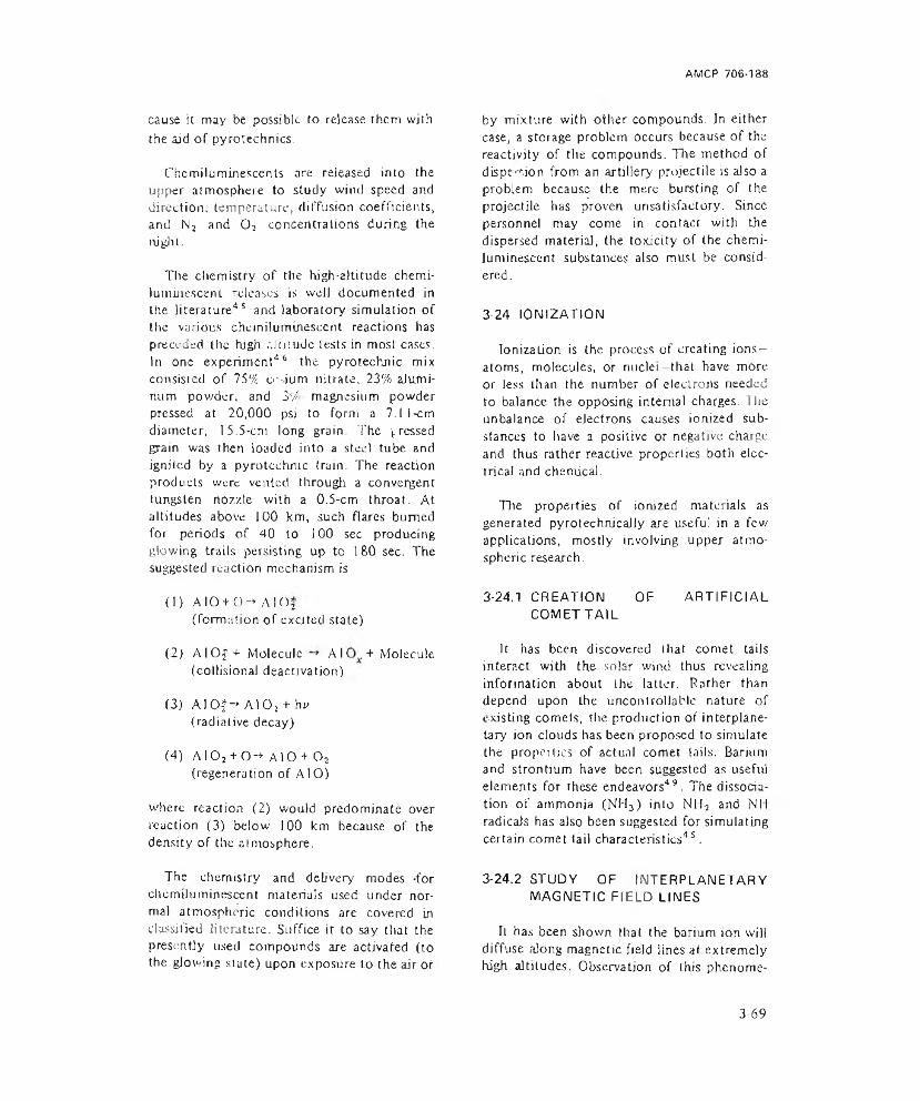
AMCP 706-138
cause it may be possible to release them with the aid of pyrotechnics.
Cherniluminescents are released into the upper atmosphere to study wind speed and direction, temperature, diffusion coefficients, and N2 and 0 2 concentrations during the night.
The chemistry of the high-altitude chemiluminescent. releases is well documented in the literature4 5 and laboratory simulation of the various chemiluminescent reactions has preceded the high nluiude tests in most cases. In one experiment46 the pyrotechnic mix consisted of 75% o- ium nitrate, 23% aJumi- num powder, and 31/ magnesium powder pressed at 20,000 psi to form a 7.11-cm diameter, 15.5-cm long grain. The pressed grain was then loaded into a steel tube and ignited by a pyrotechnic (rain. The reaction products were vented through a convergent tungsten nozzle with a 0.5-cm throat. At altitudes above 100 km, such flares burned for periods of 40 to 100 sec producing glowing trails persisting up to 180 sec. The suggested reaction mechanism is
(1) AIO + Q-» A 1 Oj (formation of excited state)
(2) AlOf + Molecule A I + Molecule (collisional deactivation)
C3) A 10f->A 102 + hu (radiative decay)
(4) A I02 + 0-* A10 + 0 2 (regeneration of A10)
where reaction (2) would predominate over reaction (3) below 100 km because of the density of the atmosphere.
The chemistry and delivery modes -for chemiluminescent materials used under norma) atmospheric conditions are covered in classified literature. Suffice ir to say that the presently used compounds are activated (to the glowing state) upon exposure to the air or
by mixture with other compounds. Jn either case, a storage problem occurs because of the reactivity of the compounds. The method of dispesion from an artillery projectile is also a problem because the mere bursting of the projectile has proven unsatisfactory. Since personnel may come in contact with the dispersed material, the toxicity of the chemiluminescent substances also must be considered.
3-24 IONIZATION
Ionization is the process of creating ions- atoms, molecules, or nuclei that have more or less than the number of electrons needed to balance the opposing internal charges. The unbalance of electrons causes ionized substances to have a positive or negative charge and thus rather reactive properlies both electrical and chemical.
The properties of ionized materials as generated pyrotechnicaJly are useful in a few applications, mostly involving upper atmospheric research.
3-24.1 CREATION COMET TAIL
OF ARTIFICIAL
It has been discovered that comet tails interact with the solar wind thus revealing information about the latter. Rather than depend upon the uncontrollable nature of existing comets, the production of interplanetary jon clouds has been proposed to simulate the properties of actual comet tails. Barium and strontium have been suggested as useful elements for these endeavors49. The dissociation of ammonia (NH3) into NH2 and Nil radicals has also been suggested for simulating certain comet tail characteristics45.
3-24.2 STUDY OF INTERPLANETARY MAGNETIC FIELD LINES
It has been shown that the barium ion will diffuse along magnetic field lines at extremely high altitudes. Observation of this phenome
3-69
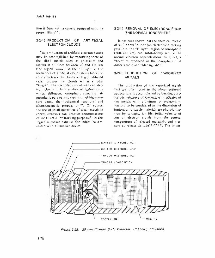
AMCP 706-138
non is done with a camera equipped with the proper fitters*9.
3-24.3 PRODUCTION OF ARTIFICIAL ELECTRON CLOUDS
The production of artificial electron clouds may be accomplished by vaporizing some of the. alkali metals such as potassium and cesium at altitudes between 70 and 130 km (the region known as the “E layer”). The usefulness of artificial clouds stems from the ability to track the clouds with ground-based radar because the clouds act as a radar “target” . The scientific uses of artificial electron clouds include studies of high-altitude winds, diffusion, ionospheric structure, atmospheric parameters, expansion of high-pressure gases, thermochemical reactions, and electromagnetic propagation5 0. Of course, the use of small quantities of alkali metals in rocket exhausts can produce concentrations of ions useful for tracking purposes7. In this regard a rocket exhaust also might be simulated with a flare-like device.
3-24.4 REMOVAL OF ELECTRONS FROM THE NORMAL IONOSPHERE
U has been shown that the chemical release of sulfur hexaflouride (an electronic-attacking gas) into the “F layer” region of ionosphere (200-300 km) can substantiaily reduce the normal electron concentrations. In effect, a “hole” is produced in the ionosphere that distorts radio and radar signals45.
3-24.5 PRODUCTION OF VAPORIZED METALS
The production of the vaporized metals that are often used in the aforementioned applications is accomplished by burning pyrotechnic mixtures of the oxides or nitrates of the metals with aluminum or magnesium. Factors to be considered in the dispersion of ionized or ionizable materials are photoionization by sunlight, ion life, initial velocity of ion or electron clouds from the source, temperature of released materials, and pressure at release altitude45-49 >s The impor-
IGNITER MIXTURE, NO. I
IGNITER MIXTURE, NO.2
TRACER MIXTURE, NO. I
■TRACER COMPOSITION
PROPELLANT -MIX, HEI
Fiaure 3-55. 20 mm Charged Body Projectile, HEIT-SD, XM246E5
3-70

AMCP 706-188-
tance of these factors would depend heavily upon the intended use.
3-25 DESTRUCT ELEMENTS
Self-destruction is required in the design of many munitions such as antiaircraft rounds that may endanger friendly territories by missing and going beyond their intended target. Self-destruct features are also used to deactivate area chemicaj munitions after a specified period. The destruct action is normally initiated by a fuze or a tracer in the round after a time that allows the projectile to reach its maximum effective burst height.
The charged body 20 mm projectile shown in Fig. 3-55 illustrates the principle. The igniter mixes start the burning of the first (racer composition which in turn ignites the second tracer mix. As the latter burns to completion, it generates sufficient heat to ignite the propellant stored in the recessed cavity which initiates the high explosive incendiary mix.
Pyrotechnic units are also used for destroying classified cryptographic equipment, safes, and files. These units normally consist of an incendiary mix such as ihecmite or sodium nitrate and wood flour packaged in a metal case of suitable geometry for the application (see par. 3-15.3).
3-26 WEATHER MODIFICATION
Modification or control of the weather has been the subject of many investigations in the past. Aside from the obvious socio-economic advantages to be gained from such control, the military has interest in hurricane modification (Navy Project STORM FURY), dissipation of all types of low stratiform clouds and fog (Air Force), and the suppression of lightning discharges (Army)51 . Endeavors such as these, if successful, would facilitate or allow tactical operations normally impossible due to weather conditions. The positive control of certain weather conditions also would prove to be a powerful military weapon.
Attempts have been made to control almost all types of meteorological phenomena including winter orographic storms, cumulus clouds, hail, extratropica) cyclones, cold and warm fogs, hurricanes and tornadoes, and lightning. Varying degrees of success have been encountered in these attempts. In most cases the statistical verification of success or failure is difficult due to the lack of proper control specimens. In small scale experiments, especially in fog control at airports, demonstrable results have been produced.
3-26.1 TECHNIQUES OF PRODUCING NUCLEI
A large variety of techniques and substances have been used in weather control attempts. Historically, one of the first cloud seeding experiments was performed in 1946 which succeeded in precipitating ice crystals from a supercooled “cloud” of water vapor by the injection of dry ice (solid C 02) pellets. Chilled metal rods also induced precipitation in this experiment, The mechanism of inducing precipitation was found to be the production of nuclei of 1 to 2 micron diameter upon which the water vapor could condense.
The most frequently used substance for producing ice nuclei in cloud formations is silver iodide (Agl). At temperatures of —6°C and below, Agl will form ice nuclei in supersaturated atmospheres (hereby inducing the formation of ice crystals that may precipitate as rain or snow or that may affect cloud formation or directions. Sodium iodide, lead iodide, certain steroids, amino-acids, phloro- glucinol, ff-phenazjne, and metaldehyde have all been tried as nucleating agents. Advantages sought by the use of agents other than Agl are lower cost, higher nucleating temperatures, less sensitivity to photolytic inactivation, and greater nucleating ability. Successful reduction of the photolytic decay of the nucleating properties of Agl has been shown with the addition of 0-naphthol, bsi-(2-amino phenyl) disulfide, diphenylthiourea, 8-hydro- xyquinoline, and Kodak Anti-Fog No. 2. The efficiency of the nucleating process of Agl has
3-71

ErHi
CTIV
ENES
S, r
ucle
i/g
Agl
AMCP 706-1&8
'°-6 - ro -14 -(6 -22TEMPERATURE. “C
Figure 3-56. Area of Effectiveness-temperature Relationship for Fuel-supported Agl
Generators
temperature, 6cFigure 3-57. Area o f Effectiveness-tempera
ture Relationship for Pyrotechnic Agi Generators
been increased by the deliberate addition of contaminants such as ammonium hydroxide, hydrogen sulfide, and sulfur dioxide.
When dealing with warm water-laden clouds or fogs, different techniques must be used for control or modification. Substances wiiich exhibit hygroscopicity are thought to he useful. Calcium chloride and sodium chloride have been tried; and a pyrotechnic mixture of aluminum powder and hexachlo- roethane, burned to yield aluminum chloride, has been suggested. Olher methods for use in warm fogs and clouds include evaporation by heat from jet engines, asphalt paving, and spraying suspended carbon black;5 1.
In general the seeding agent is dispersed in the form of an aerosol or a smoke, depending on the method of generation: the generator may be ground stationed or air borne. Delivery from the ground is necessarily limited. The major techniques that have been used to disperse nucleating agents are:
(1) Evaporation from an electrically heated wire
(2) Burning a complex of Agl and acetone or isopropylamine with the aid of a fuel such
as propane or fuel oil
(3) Burning a wick impregnated with Agl in a liquid petroleum gas flame
(4) Detonating a mixture containing high explosive and Agl
(5) Burning a pyrotechnic mixture containing Agl or substances which will form Agl upon reaction.
lL has been found that the nucleating ability and the susceptibility to photolytic deactivation vary with the method of dispersion. The dispersion techniques that are important from the pyrotechnic stand pom! arc discussed in pars. 3-26.2 through 3-26.4.
2-26.2 BURNING Agl COMPLEX WITH A FUEL
Typically, the complex consists of 2 or 3% Agl with 0 to 1% Nal in a solution of acetone, isopropylamine, or ammonia52. I bis complex is fed to a nozzle which forms an acrosif Tire aerosol is burned with the aid of a fuel such as propane or fuel oil. In the case of the isopropylamine no fuel is used. The burning
3-72
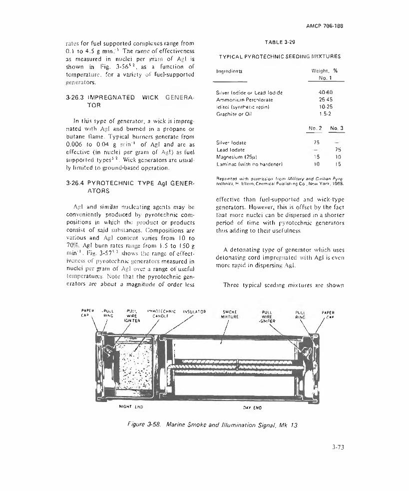
AMCP 706-188
rates for fuel supported complexes range from0.1 to 4 .S g m in .'' The ranee of effectiveness as measured in nuclei per gram of Agl is shown in Tig. 3-56S3, as a function of temperature, for a variety of fuel-supported generators.
3-26.3 IMPREGNATED TOR
WICK GENERA-
Jn this type of generator, a wick is impregnated with Agl and burned in a propane or butane Hame. Typical burners generate from 0.006 to 0.04 g min’’ of Agl and are as effective (in nuclei per gram of Agl) as fuel supported types53 . Wick generators are usually limited to ground-based operation.
3-26.4 PYROTECHNIC TYPE Agl GENERATORS
Agl and similar nucleating agents may be conveniently produced by pyrotechnic compositions in which the product or products consist of said subsLances. Gompositjons are various and Agl content varies from 10 to 70 ’, Agl burn rates range from 1.5 to 150 g min'1. Rig. 3-575 2 shows the range of effectiveness of pyrotechnic generators measured in nuclei per gram of Agl over a range of useful tempera turns. Note that the pyrotechnic generators are about a magnitude of order less
TYPICAL PYROTECHNIC SEEDING MIXTURESIngredients Weight, %________ No. 1
40-60 26-45 10-25 1.5-2
No. 2 No. 3
TABLE 3-29
Silver Iodide or Lead Iodide Ammonium Perchlorate Iditol (synthetic resin) Graphite or Oil
Silver lodate Lead lodate Magnesium (25ju)Laminae (with no hardener)
751510
751015
Reprinted w ith permission horn M ilita ry and C ivilian P yro technics. H. EUern, Chemical Publishing Co .N ew Y o rk . 1968,
effective than fuel-supported and wick-Lype generators. However, this is offset by the fact that more nuclei can be dispersed in a shorter period of time with pyrotechnic generators thus adding to their usefulness.
A detonating type of generator wliich uses detonating cord impregnated with Agl is even more rapid in dispersing Agl.
Three typical seeding mixtures are shown
PAPtH .P u ll CAP v WING
^ hOJECh n ic INSULA7 0 *CAMOlt
$M0xt P uu paper, CAP
NJGur EKD day CKO
Figure 3-58. Marine Smoke and Illumination Signal, Mk 13
3-73

in Table 3-29D Photoflash cartridges have been used successfully for packaging pyrotechnic seeding generators, and special dispensers capable of delivering up to 60 lb of Agl smoke also have been employed.
3-27 COMBINATION OF EFFECTS
It is often desirable to have more than one effect (light, smoke, etc.) available in a single pyrotechnic device. The combination of a smoke and illuminant signal, for instance, is often used in signaling and marking devices
that might be employed either in day or nighttime operations. Fig. 3-58“ illustrates the Mk)3 Marine Smoke and UJuminalion Signal which is hand-launched and produces either an orange smoke for day use or a red flame for night use.
Other devices incorporating combinations of effects are those used for simulation of battlefield effects. The Ml IS Projectile Ground Burst Simulator (described in par. 3-22.1.1) is an example of a combinational device.
REFERENCES
1. AMCP 706-185, Engineering Design Handbook, Military Pyrotechnics Series, Part One, Theory and Application.
2. R. M. Blunt and W. A. Schmeling. Study o f Psychophysical Factors o f Vision and Pyrotechnical Light Sources. Technical Report AFATL-TR 68-17, Air Force Armament Laboratory, Eglin Air Force Base, Florida, 1968.
3. TM 9-1370-200, Military Pyrotechnics, Dept, of Army.
4. OP 2213, JNrotechnic. Screening, and Marking Devices. Dept, of Navy.
5. S. H. Green and R. G. Amicone, Prediction o f Pyrotechnics Performance. The Franklin Institute Research Laboratories, Report FR-C1881-2, March 1969 (AD-856 508).
6. MIL-STD-444. Nomenclature and Definitions in the Ammunition Area, Dept, of Defense.
7. Herbert FI Dm, Military and Civilian Pyrotechnics. Chemical Publishing Co., New York, 1969.
8. TM I 1-401, Elements o f Signal Photography. Dept, of Army.
9. L. Lobe! and M. Dubois, Sensifometry, The Focal Press, New York. 1955.
10. Theory, Application, and Instrumentation for Infrared Non-Destructive Testing. Barnes Engineering Co., 30 Commerce Rd., Stamford, CO, October 1966.
11. AMCP 706-127, Engineering Design Handbook, Infrared Military Systems, Part One.
12. Applied Infrared Photography, Technical Publication M-28, Eastman Kodak Co., Rochester, NY 14650, Oct. 1968.
1 3. Data for Aerial Photography. Publication M-29, Eastman Kodak Co., Rochester, NY 14650, March 1969.
14. L. FinkeJstein, Colored Smokes. Vol. 12 o f History o f Research and Development o f the Chemical Warfare Service m World War i f Army Chemical Center, Edge- wood Arsenal, MD, 31 December DM5 (ATI-207 451).
) 5. S. Gmndemeier, Survey o f Literature o f Chemical Tracking Aids. Report HADC- TR-57-7, Missile Development Center, Holloman Air Force Base, NM, August 1957 (AD-135 001).
3-74
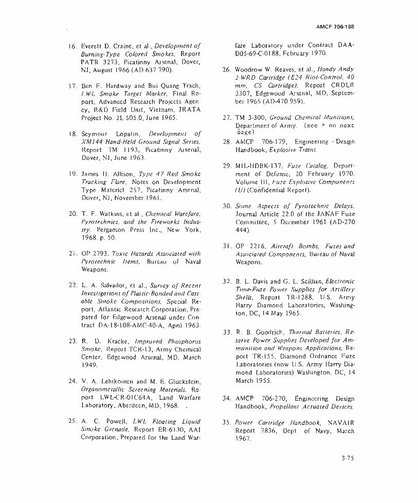
AMCP 706-138
16. Everett D. Craine, et a)., Development o f Burning-Type Colored Smokes, Report PATR 3273, Picatinny Arsenal, Dover, NJ, August 1966 (AD-637 790).
17. Ben F. Hardway and Bui Quang Trach, LWL Smoke Target Marker, Final Report, Advanced Research Projects Agency, R&D Field Unit, Vietnam, JRATA Project No. 2L-505.0, June 1965.
18. Seymour Lopatin, Development o f XM144 Hand-Held Ground Signal Series. Report TM 1193, Picatinny Arsenal, Dover, NJ, June 1963.
19. James H. AJIison, Type 47 Red Smoke Tracking Flare, Notes on Development Type Materiel 257, Picatinny Arsenal, Dover, NJ, November 1961.
20. T. F. Watkins, et a)., Chemical Warefare, Pyrotechnics, and the Fireworks Industry. Pergamon Press Inc., New York, 1968. p. 50.
21. OP 2793, Toxic Hazards Associated with Pyrotechnic hems. Bureau of Naval Weapons.
22. L. A. Salvador, et a)., Survey o f Recent Investigations o f Plastic-Bonded and Castable Smoke Compositions, Special Report, Atlantic Research Corporation, Prepared for Edge wood Arsenal under Contract DA-18-108-AMC-40-A, Apnl 1963.
23. R. D. Kracke, Improved Phosphorus Smoke, Report TCR-13, Army Chemical Center, Edge wood Arsenal, MD. March 1949.
24. V. A. Lehikoinen and M. E. Gluckstejn, Organomeiallic Screening Materials. Report LWL-CR-01C64A, Land Warfare Laboratory, Aberdeen, MD, 1968. . 25 * *
25. A. C. Powell, LWL Floating LiquidSmoke Grenade, Report ER-6130, AAICorporation, Prepared for the Land War
fare Laboratory under Contract DAA- D05-69-C-0188, February 1970.
26. Woodrow W. Reaves, et ah, Handy Andy 2-WRD Cartridge (E24 Riot-Control, 40 mm, CS Cartridge), Report CRDLR 3307, Edgewood Arsenal, MD, September 1965 (AD-470 959).
27. TM 3-300, Ground Chemical Munitions, Department of Army, (see * on next oage)
28. AMCP 706-179, Engineering - Design Handbook, Explosive Trains.
29. Ml L-HDBK-137, Fuze Catalog, Department of Defense, 20 February 1970. Volume III, P'uze Explosive Components ( U) (Confidential Report).
30. Some Aspects o f Pyrotechnic Delays. Journal Article 22.0 of the JANAFEuze Committee, 5 December 1961 (AD-270 444).
31. OP 2216, Aircraft Bombs, Fuzes and Associated Components, Bureau of Naval Weapons.
32. B. L. Davis and G. L. Scillian, Electronic Time-Fuze Power Supplies for Artillery Shells. Report TR-1288, U.S. Army Harry Diamond Laboratories, Washington, DC, 14 May 1965.
33. R. B. Goodrich, Thermal Batteries. Reserve Power Supplies Developed for Ammunition and Weapons Applications, Report TR-155, Diamond Ordnance Fuze Laboratories (now U.S. Army Harry Diamond Laboratories) Washington, DC, 14 March 1955.
34. AMCP 706-270, Engineering Design Handbook, Propellant Actuated Devices.
35. Power Cartridge Handbook, NAVA1R Report 7836, Dept, of Navy, March 1967.
3-75

36. I M 9-13 00- 214. M Hi tary Ex plosives, Depl. of Army. November 1967.
37. AMC'P 706-210, Engineering Design Handbook, Fuzes
46. N. W. Rosenberg and D. Golomb, “Chemiluminescent Techniques for Studying Nighttime Winds in the Upper Atmosphere'’, Journal of Geophysical Research, 68. 3328-33 (1963).
38. AMCP 706-205, Engineering Design Handbook, Tuning Systems and Components.
39. FM 5-25, Explosives and Demolitions. Dept, of Army, October 1963.
40. A Compendium o f Pyrotechnic Delay Devices. Journal Article 30.0 of the JANAF Fuze Committee, 23 October 1963 (AD-474 833).
41. Tadeus/i Urbanski, Chemistry and Technology o f Explosives, Perga mon Press. London. Volume 111. 1967.
42. W. R. Maxwell. "Pyrotechnic Whisiles’’, Fourth Symposium on Combustion, Paper 111, The Williams and Wilkins C’o., Baltimore, MD, 1953. p. 906.
43. J. P. Salmon. XM-J4E1 Atomic Explosion Simulator. Notes on Development Type Materiel 238, Picatinny Arsenal, Dover, NJ. March 1960.
44. AMCP 706-165, Engineering Design Handbook, Liquid-Filled Projectile Design. 45
45. N, W. Rosenberg, “Chemical Releases at High Altitudes” , Science, 152. 1017-27 (1966).
47. M. Zelikoff, F. F. Marmo, ct al, “An Attempt to Measure Atomic Nitrogen by Rocket Release of Ethylene at 105 and143 km” . Journal of Geophysical Research. 63. 31-7 (1957).
48. C. D. Cooper, U.S Air Force Cambridge Research Laboratory Environmental Research Paper, No. 15, Project Fire Fly, 1962.
49. H. Foppl, et al., “Preliminary Experiment for the Study of the Interplanetary Medium by the Release of Metal Vapor in the Upper Atmosphere” , Planetary Space Science, 13. 95-1 14 (1 965 V
50. F. F. Marmo, L. M. Aschenbrand and J. Pressman. “ArtificiaJ Electron Clouds i, 11, 111, IV and V” , Planetary Space Science. 1. 227,291,306 (1959); 2, 17, 174 (I960).
51. Weather and Climate Mollification, Problems and Prospects, Volumes ( and II,I National Academy of Sciences, National Research Council, Publication 1350, Washington, DC, 1966.
52. C. 1. Davis and R. 1. Steele. “ Performance Characteristics of Various Artificial Ice Nuclei Sources” . Journal of Applied Meteorology. 7, 667-73 (1968).
*TM 3-300 , Hand andte c h n ic s .
Ground Chemi c a l Munitions, superseded by TM 9 -1 3 3 0 -2 0 0 , Gr e n a d e s , Rifle; TM 9 -1 3 4 5 -2 0 0 , Land N i n e s ; and TM 9 -1 3 7 0 -2 0 0 , Military Pvro-
3-76
AMCP 706-188
CHAPTER 4
DESIGN CONSIDERATIONS
4-1 INTRODUCTION
4-1.1 GENERAL
Before pyrotechnic ammunition can be designed, it is first necessary to define all of its requirements. A certain terminal effect is desired that must be delineated in detail, including the correct amount of pyrotechnic composition that will achieve the desired effect. To have the ammunition arrive at the target, the delivery mode must be selected and all of its constraints must be taken into account. Next, methods of packaging the pyrotechnic mix in the delivery weapon must be selected -including containers, restraints, and ejection method.
Following the design, all components and finally the complete assembly must be thoroughly tested to assure reliable performance. Particular emphasis must be given to make certain that the pyrotechnic mix will perform as intended over the military temperature range and that the entire pyrotechnic package will survive tire stresses imposed by the delivery system.
Designing ammunition for the delivery mode is further complicated by the fact that design constraints of other payloads must be taken into account. As a result, ammunition may be optimum for, say, both high explosive and pyrotechnic fillers but not for each of these separately. Nonetheless, both kinds of ammunition must perform reliably. The consideration of multiple ammunition is termed ballistic matching.
4-1.2 BALLISTIC MATCHINGProjectiles are ballistically matched if the
impact or burst distribution have the same
mean and equal standard deviations when fired under common conditions'. The conditions stated in this definition can never be completely achieved There will always be some tolerance, the magnitude of which depends on the cost and effort required to achieve a near perfect ballistic match.
The ballistic match is expected to improve accuracy of fire and the responsiveness of fire requests. Improved accuracy can .educe significantly the amount of ammunition required to defeat targets. Ballistic matching also reduces the number and complexity of firing tables required as well as data stored in fire direction computers. Matching greatly speeds delivery of ammunition to the targel when surprise fire is desirable. Each projectile type not matched ballistically would have to be registered individually, requiring about 20 min and 15 rounds.
To illustrate the design problem, let us examine how other projectiles in a family might influence the design of a high explosive projectile. Fig. 4-1 (A)' shows what the HE projectile might look like if there were no requirement for ballistic matching. It is a low drag, high capacity projectile that is easy to manufacture. The top half of Fig. 4-1(B) shows how tire design is influenced by the requirement that the ELE projectile be ballistically matched with a rocket-assisted projectile shown on the lower half. The recess required in the base of the projectile slightly increases the manufacturing costs.
A match with a base-ejection projectile is shown in Fig. 4-1 (C). For proper ejection, the payload of the base-ejection projectile must be cylindrical and to maximize effectiveness,
4-1

AMCP 706-188
the volume must be maximized. Therefore, the optimized base-ejection projectile is longer than the other configurations. To provide aerodynamic stability, the extremities of the projectile must be relatively light. Hence, the base and ogive are made of aluminum, and the steel ogival portion of the steel projectile is thinned out. The effect on the HE projectile is a significant increase in production costs and degraded terminal effectiveness because of less fragmentation metal.
The selection of a final design can be made only by means of a rigorous cost effectiveness analysis confirmed by ballistic firings2. What-
SECTION 1 DELIVERY MODES
4-2 DELIVERY MODES
Several modes of delivery are available to the designer of pyrotechnic devices, including tubes and launchers. For each, the interior, exterior, and terminal ballistic conditions must be known. Methods for computing the forces associated with these conditions are given in pars. 4-5, 4-6, and 4-7, respectively.
The designer must examine the effects of the ballistics of the delivery system on the pyrotechnic device so as to insure that the pyrotechnic will not be degraded by the delivery mode, that it will be delivered to the target selected, and that it will be deployed properly when its function is required. The pyrotechnic device may be degraded in one of two ways: (I) ihe delivery vehicle may not be structurally sound and therefore may collapse or disintegrate, and (2) the pyrotechnic device may be damaged by acceleration or rotational forces imposed by the delivery mode. This paragraph discusses the characteristics of the delivery system that must be taken into account when designing pyrotechnic devices.
4-2.1 TUBES
Pyrotechnic devices may be projected from
Figure 4-1. Candidate Projectile Configurations fo r Ballistic Matching
ever configuration is finally chosen, some penalty must be accepted to achieve the desired results.
AND DESIGN CONSTRAINTS
one of the tube type weapons discussed in the paragraphs that follow. Design procedures are essentially the same for all fired projectiles, only the values of the forces differ in the various weapons. Note that the quantities given are merely typical values that do not take into account mode) to model dif ferences. While they can serve forfirst-cul calculations, the exact values of the actual weapon must be obtained for meaningful design.
4-2.1.1 MORTAR
A mortar is a short weapon designed to be fired at high elevation (up to 65 deg). It is muzzle loaded. The bore may be smooth or rifled. When rifled, a cup-shaped disk of soft metal at the base of the projectile is forced outward by the propellant pressure to act as rotating band. Mortar characteristics are summarized in Table 4-I3 ; complete values are tabulated in Ref. 4. Setback force may be as high as 8000 g but is usually about 600 g lasting For about 3 msec. Spin rate for rotated ammunition is up to 2000 rpm.
4-2.1.2 RECOILLESS RIFLE
As the name Implies, recoilless rifles do not recoil. The recoilless feature is achieved by
4-2
AMCP 706-188
TABLE 4-1
SUMMARY OF MORTAR CHARACTERISTICS
CaliberProjectile Wi, lb
Pyro Filler Wt, lb
Range,yd
Velocity.fpt
Chamber Press, psi
60 mm 4 0.7 '2000 450 600081 mm 11 4.0 2500 700 60004.2 in. 27 8.1 5000 900 6000
having nozzles at the breech end that permit propellant gases to escape rearward to balance the momentum of the forward motion of the projectile. Recoil less rifles are light and mounted on shoulder or tripod, Recoilless rifle characteristics are summarized in Table 4-23; complete values are tabulated in Ref. 4. Setback force is on the order of 10,000 g and spin rate, 9000 rpm.
4-2.1.3 GUN AND HOWITZER
The classification of gun and howitzer no longer conveys the precise meaning it once did. As formerly defined, a gun was a high- velocity weapon firing at low elevation while
TABLE 4-2
SU M M ARY OF RECO ILLESSR IFLE CH ARACTERIST ICS
Projectile
Caliber Wt, lbPyro Filler Wt, lb
Range,yd
Velocity,tps
Chamber Press, psi
57 mm 5 0.5 4900 1200 8,00075 mm 21 1.0 7000 1000 9,00090 mm 13 2.0 2300 700 9,000105 mm 46 4.5 9000 1200 10,000106 mm 41 7.7 3000 1600 10,000
a howitzer was a shorter and lighter weapon firing at higher elevation with less velocity. The distinction is now less marked. Antiaircraft guns fire at high elevations, and increased ranges demanded of howitzers have necessitated longer, heavier weapons. In general considering equal caliber, the gun will have the higher velocity, longer range, and less mobility.
Characteristics of guns and howitzers are summarized in Table 4-33; complete values are listed in Ref. 4. Values of setback and spin
TABLE 4-3SUMMARY OF GUN AND HOWITZER CHARACTERISTICS
Projectile Wt, Pyro Filler Range, Velocity, ChamberCaliber Weapon lb Wt, lb yd fps Press, psi37 mm Gun 2 0.7 9,000 2600 50,00040 mm Gun 2 0.2 9,600 2900 40,00075 mm Gun 19 1.5 14,000 2000 36,000Howitzer 18 1 0 9,600 1250 29,00076 mm Gun 25 1.5 16,000 3200 43,00090 mm Gun 42 2.0 20,000 2700 38,000105 mm Gun 45 7.0 10,000 2400 30,000Howi tzer 42 5.0 12,000 1500 25,000120 mm Gun 50 7 5 25,000 3500 38,000152 mm Gun 49 6.0 9,800 2300 40,000155 mm Gun 100 15.0 26,000 2800 40.000Howitzer 100 15.0 16,000 1800 30,000165 mm Gun 68 20.0 (informationis classified)175 mm' Gun 147 30.0 35,500 3000 35,0008 in. Howitzer 200 36.0 16,000 2000 38,000240 mm Howitzer 360 53.0 25,000 2300 36,000280 mm Gun 600 102.0 31,500 2500 35,000
4-3
AMCP 706-188
TABLE 4-4
SUM M ARY OF SM ALL ARMS CHARACTER IST ICS
Type Caliber WeaponM27, Tracer cal .30 Carbi neMl, Tracer cal .30 RifleM196, Tracer 5.56 mm RifleM62, Tracer 7.62 mm RifleM26, Tracer cal .45 PistolM17, Tracer cal .50 Mach, gunM23,Incendiary cal .50 Mach, gunM220. Tracer 20 mm Mach, gunM53, Incendiary 20 mm Mach, gun
vary considerably with caliber. In general, the smaller calibers have the higher values of these forces. Setback can be as high as 100,000 g and spin rale as high as 120,000 rpm.
4-2.T.4 SMALL ARMS
Projectile Pyro Filler Velocity, ChamberWeight, gr Weight, gr fps Press, psi103 7.0 1SOO 40,000152 16 2700 52,00054 4.2 3200 52,000142 8.5 2750 50,000208 5.5 885 19,000643 55 2860 54,000512 90 3400 58,0001470 31 3380 51,0001546 70 3380 55,000
While they can serve for first-cut calculations, the exact values of the parameters of the actual launcher must be obtained for meaningful design.
4-2.2.1 ROCKET
The small arms family includes a scries of rifles, pistols, and machine guns. It includes in addition, by a convention established for convenience, 20 mm ammunition. The main use of small arms for pyrotechnic application is tracer ammunition. Small arms character- islics are summarized in'fable 4-45. In general setback and spin are lower than corresponding values for guns and howitzers although the values for 20 mm ammunition are among the highest to be found. Details about pyrotechnics for small aims ammunition are contained in Ref. 6.
4-2.2 LAUNCHERS
Launchers are tubes from which ammunition is propelled such as rockets, guided missiles, and special pyrotechnic devices. As a class, launched devices are subjected to much lower forces and have much lower velocities than tube-fired projectiles. As in projectiles, design procedures arc very similar for all of the devices in the launched class. Note that the quantities given in the paragraphs that follow are merely typical values that do not take into account model to model differences.
Rockets are propelled from smooth-bore rocket launchers. A launcher may be a single tube or a number of tubes fastened together in one mount to permit salvo firing. Rockets are fm-stabiljzed. For some rockets the fins fold to allow firing from the tubes but extend into the air slream lor stability after launching. Acceleration and setback forces arc generally much less than those of gun-fired ammunition, resulting in lower velocity. Typical values are: setback, 550 g, and spin rale 350 rpm. Even though the rockets are fin-stabilized, they usually spin slightly so that a small spin component must be allowed for. Rocket characteristics are summarized in Table 4~57-8.
As an example of rockets applied to pyrotechnics, tire 24-tube XM3 Rocket Launcher (2.75 in.) has been modified for smoke use when mounted on a helicopter. The adapter permits laying of a smoke screen up to 1000 m long for periods of I0 min by firing A.N-M8 Smoke Grenades’ .
4-2.2.2 OTHERThere is a wide variety of small, launched
4-4

AMCP 706-188
TABLE 4-5
SU M M A R Y OF ROCKET CHARACTER IST ICS
Size TypeRocketWt, lb
Py/O Filler Wt. lb
Velocity,fps
66 mm 2 0.72.75in. Folding Fin 19 1.5 18003.5 in. — 10 2 SOO4.5 in, 42 6 13005 in. Folding F jrv 107 15 18005 in. High Vel 138 8 2800
pyrotechnic devices including signals, flares, and markers. Most of these are hand manipulated. Characteristics of the hand-manipulated pyrotechnic devices are summarized in Table 4-67 1 0 . Four launching methods are common:
(I) Firing from rifle launcher, revolver, or
a special pistol designed to fire pyrotechnic devices,
(21 Firing from a mortar type launcher that consists of a vertical steel tube fastened to a steel base plate.
(3) Hand thrown (for grenades) and or hand-held combination devices (for single-use launch devices where the case acts as launcher).
(4) L-.jection, primarily for aircraft launched pyrotechnics.
The devices may or may not have delays, depending on their intended use. Ah hand- manipulated devices are light enough to be handled easily; they are subjected to small if any forces. 1 he forces for ejected and
TABLE 4-6
SUMMARY OF HAND-MANIPULATED PYROTECHNIC DEVICE CHARACTERISTICSLaunched
Item fromIlium.signal
Pyro. pistol
Smokesignal
Pyro. pistol
Smoke Riflegrenade launcherSmokegrenade
Hand thrown
Ilium. Hand. Outersignal case is pro
jectorSignal cal .38cartridge revolverAircraftflare
Aircraft
Aircraftsmokesignal
Aircraft
Marinelocationmarker
Aircraft
Total Wt,Display 02 * 10
coloredstars 6parachute-suspendedcolored smoke 16colored smoke 12
colored smoke 23
colored 21stars
colored streak 0.4
colored light 400106 candle-powercolored smoke 50
colored smoke 50
Diameter, Burning Time,in. sec
1.5 7
1.5 301.9 18
2.5 100
1.8 5
0.4 8
5 180
5 3500
3 3500
4-5
launched devices, less than those of mortarammunition, are on the order of 10 g.
Marine location markers have been adapted successfully for use in such terrain as jungles and flooded rice paddies' 1.
An interesting example of a small launched pyrotechnic device is the indoor-outdoor warning system developed for civil defense use12, it was designed as an inexpensive outdoor-mounted alert system that can provide instant audible and visual warning, day or night. The device consists of a small (3-lb) fin-stabilized rocket sealed in a 5 in. metal tube that serves as its launcher. The assembly is mounted atop a pole or building. On signal, the rocket is expelled and rises to 2000 ft. The warning components are an explosive charge, a red smoke cloud, and an intensive red flare, the latter being lowered by parachute. The requirements established for this civil defense signal are extremely rigorous. The units must witlistand temperatures ranging from —65° to 200°F for a minimum of 10 yr and remain operable without maintenance. No other pyrotechnic device has been required to meet standards this high. Design of the device has been completed. It operates by electronic controls from 115-V house current.
4-2.3 AIRCRAFT LAUNCHED
Aircraft launched pyrotechnic devices have the lowest velocities and are subjected to the lowest forces of any delivery mode. This class includes primarily bombs dropped from aircraft. Bombs do not spin. They are not subjected to any setback when merely released from the aircraft but must sustain a small setback force when ejected from a launching tube. Because submarine-launched, stationary, and manual pyrotechnic devices are subjected to similar small forces, it is convenient to consider them in this class as well.
Design procedures are very similar for all pyrotechnic devices in this delivery mode
class. Note that the quantities given in Die paragraphs that follow are merely typical vaJucs that do not take into account model to model differences. While they serve for firsl- cut calculations, the exact values of the parameters actual device must be obtained for meaningful design.
The pyrotechnic devices jn this delivery class do have some unique problems requiring special design features. Bombs are affected by aircrafl travel and aerodynamic heating, and submarine-launched devices must contend with hydrodynamic forces. These topics are covered in the appropriate paragraphs.
The main pyrotechnic device dropped from an aircraft is a bomb. Bombs may be carried inside a bomb bay or suspended from a bomb rack under a wing position. The bombadier releases the bomb by means of an electric signal so that it will drop on the target area. Bombs may be released singly or in clusters depending on the application.
4-2.3.1 BOMB RELEASE
Because the bomb follows the aircraft closely for a short Lime, a risk is involved to personnel and materiel in the delivery of bombs. Fig. 4-213 shows the trajectories of a bomb after release from an aircraft in horizontal flight. The figure labels the following important parameters:
(1) Safe Vertical Drop (SVD). SVD is the vertical distance below release altitude in which the bomb must be safe. Hence it is the distance during which the fuze is not armed. The horizontal component of this distance is called the Minimum Safe Air Travel (MSAT).
(2) Maximum Drop to Arm (MDA). MDA is the vertical distance below release altitude at which the bomb must be ready to function. Hence it is the distance at which the fuze must be armed. This distance is also the minimum altitude at which a bomb may be released and still have an armed fuze upon arrival at the target.
4-6
AMCP 706-188
SVD SA^C V E R T IC A L DROP
WO A i.' t i u u u 0RO P TO a r m
6 • P O S IT IO N OF P L A N E AT BOMB IMPACT
0 - P O S IT IO N OF P LA N E Af BOW RELE A S E
Figure 4-2. Bomb Trajectories
The trajectories shown in Fig. 4-2 present the simple case of horizontal flight in which the drop time is independent, of aircraft velocity. In dive bombing, the situation becomes exceedingly complex. Bomb velocity then becomes a function of release altitude, release angle, and aircraft speed. Aircraft pull-out altitude and velocity are also of concern. Not only do these quantities differ for the operational conditions just cited but they are also a function of different aircraft models and loading. Bomb releases curves for the aircraft considered must be consulted to obtain specific values.
Bomb fuzes generally are armed by a propeller that spins in the air stream. A safety pin prevents the propeller from rotating prior to releasing the bomb. The pin is attached to an arming wire that is fastened to the bomb rack so that the pin is pulled free when the bomb is released.
4-2.3.2 AERODYNAMIC HEATING
The determination of temperature profiles within ammunition items affeeted by aerodynamic heating is difficult, complex, and quite beyond the scope of the present discussion. It is, however, frequently possible for a
designer, by means of a few quick calculations using a simplified model of his system, to obtain a gross answer regarding the need for more detailed calculations, the substitution of pyrotechnics, or their insulation. The discussion that follows is intended as an aid in making such approximate calculations.
The flow conditions about an object moving through the atmosphere are most simple if they are considered in terms of a coordinate system moving with the object. In such a system, the undisturbed air is an infinite stream moving at a velocity of magnitude equal to that of the object in a system of fixed coordinates. Quite clearly, the object impedes this flow of air. By Bernoulli's principle (conservation of momentum) any reduction of the velocity of part of the stream must be accompanied by an increase in pressure. Rapid compression of a gas causes its temperature to trie. The highest temperature which may be anticipated in any point in such a system, called the stagnation temperature, is that of air which has been brought to rest with respect to the object. The formula for the calculation of the stagnation temperature is
Tt = r o ( l + 0 .2M2\ ° K ( 4 - 1 )
whereT = stagnation temperature, °K
T0 = temperature of the undisturbed atmosphere, 0 K
M ~ Mach number
IT the stagnation temperature is below tltal at which the pyrotechnic charge will suffer any ill effects, there is no problem of aerodynamic heating.
A stagnation temperature high enough to have deleterious effects upon the pyrotechnic is not necessarily reason to take special measures. Only a small fraction of the surface of a moving object is exposed to air at the stagnation temperature. The boundary layer
4-7
AMCP 706-183
of air in contact with the surface at points where there is an appreciable tangential How component approaches a recovery temperature that is well below the stagnation temperature. Typical relationships of recovery temperatures to stagnation temperatures are
Tr - T00.8 < ' — < 0-9 (4-2)
' s ' o
wheref - recovery temperature, 0K
The value of this ratio varies with velocity, position, anJ shape of the object.
In most instances, projectiles are subjected only for a short period of time to high velocities during their flight at which the stagnation temperature of the air would have an undesirable effect upon the explosives. The question as to whether the pyrotechnic materials will teach undesirably high temperature during such an interval can be answered only by considering in detail the heat flow into and within each component.
As the stagnation temperatures rise relative to those at which pyrotechnics are stable and as designs become more intricate, the means of resolving doubts regarding whether the charges will survive aerodynamic heating become more laborious and less positive. Tire introduction of a heat barrier may be the only way in which these doubts may be removed.
4-2.3.3 CHARACTERISTICS OF PYROTECHNIC DEVICES
The characteristics of pyrotechnic bombs are summarized in Table 4-7’4 . These bombs neither spin nor are subjected to setback forces. Minimum release altitude for smoko bombs is 250 ft.
4-2.4 OTHER DELIVERY MODES
4-2.4.1 EJECTOR
Rather than merely being released, some bombs are pushed out of a lube by an ejector Cartridge. Ejector firing simulates a rocket launcher. Both single shot Tiring and salvo firing are possible. Setback forces are less than those in a rocket because ejection speed is only about 5-10 fps. Ejected pyrotechnic devices must have a delay (minimum of 5 sec) to clear the aircraft before firing.
4-2.4.2 SUBMARINE LAUNCHED
Pyrotechnic devices are launched from submarines for signaling and marking purposes. The devices are fired from an ejector tube at 250 psi above sea pressure. All of these devices have a safety pin that prevents a trip lever from opening. The pin is pulled before inserting the device into the ejector tube and the lever operates after the device leaves the tube. Water pressure is used to arm percussion-initiated devices or to activate the
TABLE 4-7SUMMARY OF PYROTECHNIC BOMB CHARACTERISTICS
Size, Pyro. Fillerlb Type Wt. lb
250 Identification 66
175 Phoioflash 82100 Smoke 72100 Pyrotechnic 42
Burning Candle-Color Time powerRed 3 min 25.000Yellow 3 min 12,000Greeo 3 min 5,000White 0.04 sec 1.3 x 10'Red -
_ _ —
4-8
AMCP 706-188
TABLE 4 8. 4-3 D ESIGN C O N STRA IN TS
SU M M A R Y OF SUBM AR IN E-LAU N CHEDPYROTECHNIC D E V IC E CH ARACTER IST ICS
Delay,secItem Display
Total Wt, lb
BurningTime
Marinesignal
Colored smoke on surface
4 15 sec
Marinesignal
Parachute-suspendedstars
4 25 sec
LocationMarker
Colored smoke on surface
3 300 sec
Locationmarker
Fluoresceni slick on surface
: 8 Slick persists 90 min
battery of deetricaily-intiated devices. The mechanical devices are operated by spring pressure with a spring force so set that the spring pressure overcomes the hydrostatic pressure at a depth of about 10 ft. Characteristics of submarine launched devices are summarized in Table 4-810 .
4-2.4.3 MANUAL
There is a large variety of manual pyrotechnic devices in the main categories of illumination, signaling, and battle effects simulation. Their characteristics are summarized in Table 4-97.
Each device has, for arming safety, a manual pull pin. The head-held devices are small so as to be conveniently carried and held. ! nrgm devices are emplaced either on the ground or aboard an aircraft and fastened to a simple rig designed to hold the device in the right attitude for functioning. The family of battle effect simulators provides the sound, light, or smoke of ammunition. The devices are similar to the ammunition they simulate except they are often simpler and contain a minimum charge, They are initiated remotely.
Pyrotechnic ammunition is one component of a military system, it therefore must conform to all of the constraints imposed by the system and by tire other components of the system. Ammunition must function reliably and safely in the military environment, must fit the geometry and weight imposed by the other components, and must be compatible with them.
4-3.1 PERFORMANCE REQUIREMENTS
4-3.1.1 TARGET AND LISTIC NEEDS
TERMINAL BAL-
Pyrotedinic ammunition accomplishes its function when it performs as intended at the target. There arc essentially two types of target: (11 remote, and (2),at hand. To reach remote targets, the ammunition must be fired, launched, or dropped from aircraft-often over appreciable distances-while being subjected to various forces, environments, and conditions. Requirements for nearby targets are not as severe. The pyrotechnic devices are hand held or attached to stationary mounts. The devices must still survive the military environment.
Both maximum velocities and ranges continue to increase with improvements in propellants and other design features. The values for tube-delivered ammunition are listed in Tables 4-1 to 4-5. Four aspects of ammunition motion mast be considered by the designer of pyrotechnic charges, namely:
(1) Range and accuracy of Bred and launched ammunition depend upon its aerodynamic characteristics. The external contours dictated by aerodynamic considerations are a limitation upon the si/e and shape of the pyrotechnic system. Sec par 4-6 for external ballistic considerations and par. 4-3,2 on configuration limiiations.
(2) It is sometimes necessary to modify
4-9

AMCP 706-168
TABLE 4-9
SU M M ARY OF M AN U AL PYROTECHNIC DEV ICE CHA RA CTER IST ICS
ItemTotal Wt,
lbllluminant Wt, lb
Delay Time, sec
Burning Time, sec
Candle-powerPhoto flash
cartridge4 2 4 0.04 4 x 10⁶
Aircraft guide flare
12 4 7 60 700,000Aircraftflare
65 31 5-90 1B0 3 x 10‘
Towed aircraft flare
21 15 0 360 80,000
GM tracking flare
2 1 - 90 70,000
Surface trip flare 5 0.7 3 70 100,000Ilium, air craft signal 0.4 0.2 5 13 50,000Smoke and ilium, aircraft signal
15 4 90 3600 650
Marine ilium, signal
3 0.4 50 35 15,000
Ground ilium, signal 1 0.4 5 10 18,000Ground smoke signal
1 0.2 5 8 5,000
Burst simulator 0.3 0.1 0 3
tin: design of pyrotechnic charges in order to distribute the weight properly for flight stability (see par. 4-3.2).
(3) Velocities and flight times of many modem bombs and missiles are such that aerodynamic heating has introduced additional design problems (see par. 4-2.3.1).
(4) Acceleration forces during firing or launching, fligliL, and impact are the main sources of the structural loading of the ammunition (see par. 4-3.1.3).
4-3.1.2 ENVIRONMENTAL ASPECTS
Pyrotechnic devices are subjected to
rigorous environments. For a discussion of the environmental forces caused by the ballistic system, see par. 4-5. The generaJ surroundings are termed die military environment. The military environment influences the design choices, type of materials, design of component parts, and methods of packaging. The main environmental characteristics are:
(1) Operating Temperature. The pyrotechnic device must withstand temperatures ranging from an air temperature of 125°F (ground temperature of I45°F) in hot-day climates to an air temperature of — 50°F (ground temperature of —65°F) in cold climates. Temperatures can drop to -SO^F in bomb bays of high-flying aircraft, and aero-
4-10
AMCP 706-188
dynamic heating can raise the temperature above I45°F for missiles launched from high speed aircraft15.
(2) Storage Temperature. -70° to I60°F, operable after removal from storage
(3) Relative Humidity. 0 to 100%
(4) Water Immersion. For certain applications the pyrotechnic device may be required to be waterproof. In this instance, it must be operable after immersion in water at 70° ± I0°F under a pressure of IS ± 5 psi for 1 hr.
(5) Rough Treatment. Operable after withstanding the rigors of transportation and rough handling
(6) Fungus. The pyrotechnic device must not support fungus growth.
(7) Surveillance. Operable after 10-20 yr storage.
4-3.1.3 ACCELERATION
Ammunition, when Fired, launched, or dropped, is accelerated. In some instances, the magnitudes of the accelerations are great. To the designer of pyrotechnic charges, these accelerations produce structural loading that applies inherently to all masses including the pyrotechnic composition itself. Accelerations associated with changes of momentum along the line of flight are always variable, usually impulsive, while centrifugal accelerations of spin-stabilized projectiles remain nearly steady during the time of flight.
When considering the effects of acceleration on ammunition, its variability must also be considered. On the one hand, it is often possible to reduce peaks by use of shock absorber principles. On the other hand, the rapid changes can result in impact forces of much greater magnitude than those due to the direct effects of gross acceleration. When considering these effects, the designer should obtain the best estimates available of the
VALUES OF ACCELERATION IN AMMUNITIONTABLE 4-10
Ammunition and Condition of Exposure
Typical Peak Acceleration, g Direction
Projectile setback when fired in gun
50,000 Axial
Projectile piercing armor
-150,000 Axial or Oblique
Rocket or missile, gun launch
100 Axial
Rocket or missile, gun launched
30,000 Axial
Missile steering 40 TransverseMissile flight vibration 10 RandomMine water entry -2,500 Axial
time-acceleration function to which his device will be subjected. Table 4-1 O'6 lists the magnitudes of some typical accelerations that ammunition is subjected to. The main types of acceleration in ammunitions are:
(1) Setback.
Setback is the relative rearward movement of component parts in ammunition undergoing forward acceleration during firing or launching. Setback is conventionally assigned a positive value. Setback can be quite large in tube-fired ammunition but is less so in launched ammunition. Values for specific delivery modes are given in par. 4-2.
(2) Set forward
Setforward is negative setback. It occurs when ammunition is decelerated in its forward motion. The largest value of setforward is that associated with impact of hard targets such as armor plate. However, pyrotechnic ammunition is not usually called upon to defeat armor. Setforward also occurs when projectiles arc rammed into an automatic weapon. While weapon designers would like to increase ram velocities, they are presently
4-l l
AMCP 706-188
limited to 1000 g, (he maximum that present fuzes can withstand.
(3) Sideways Acceleration
Sideways acceleration occurs as a result of changes in velocity at right angles to the line of travel. Sideways acceleration is caused in modem automatic weapons due to seating. In practice, perfect alignment of a projectile and the gun axis prior to firing is not consistently achieved. Therefore, upon firing, a sideways force results as the projectile aligns itself with the gun tube, for example, the 175 mm field gun and the 120 min tank gun have such high lateral forces that fuze ogives have broken off. Fhcsc forces have not been measured or calculated to date. In air-gun and drop tests, damage was simulated by accelerations larger than 10.000 g.
Because the accelerations can be large, special care must be taken by the designer to make certain that the ammunition will not fail structurally, an event that would result in failure to perform at the target as intended. Structural failures can result in the failure of metal parts, in unstable flight, or both. Metal part security and flight stability tests are commonly performed to test the adequacy of the design, fo r example, such a test was performed with the 155 mm Projectile, Illuminating. XM45917. The projectile with fuze is 34 in. long and weighs 96 lb. In a previous test, the load bearing area of the body base joint was loaded in a 450-ton hydraulic press to simulate (he setback load resulting from the 10,500-g firing acceleration. The projectile passed this test. Firing tests were then conducted at the excess pressure of 51,000 psi both at ambient and -b5°F temperatures. The projectiles passed
the metal parts security lest but a flight instability was noted. A bulge was produced at the intersection of projectile body and ogive that was believed to be caused by the shifting of the dummy illuminating charge which was loose.
4-3.1.4 TIMING AND SEQUENCING
The designer of pyrotechnic ammunition must consider all aspects that involve placing the device in the desired location with respect to its target, safeguarding against its operation until it gets there, and initiating the action at the desired place and time. The sequencing of these various actions is critical, hi general, the first action is arming; in multistage devices, Stage separation is next; finally the device must function.
(1) A rming
All ammunition must be safe during the entire stockpile to target sequence. It must also be capable of being armed in order to function as intended. Safing and arming devices must have two independent safing features, whenever possible, either of which is capable of preventing an unintended functioning before the ammunition is projected or emplaced’*. The philosophy is based on Lite low probability that [wo features will fail simultaneously. Details of fuze arming features ate discussed in Ref. 13. In all ammunition that is fired, launched, or dropped, an arming delay is provided so that the ammunition wilt safely clear the delivery system. Hand-held or emplaced devices are always provided with a pull pin, and delay is provided whenever feasible.
(2) Staging
Staging refers to an intermediate action required before functioning. The term originated with the stage separation of missiles but is also used for such actions as the operation of dissemination containers or the opening of parachutes. The time delay required is a function of the specific application and cannot be generalized.
(3) Functioning
Functioning delays vary from microseconds to minutes depending on the particular appli
4-12

AMCP 706-188
cation. Mechanical, electronic, pyrotechnic, fluoric, or electrochemical timers arc used to provide time delays as discussed in Ref 19. For some pyrotechnic applications, the functioning must be sequenced, such as when laying a smoke screen. Here successive smoke charges axe sot off at regular intervals that depend on the type of screen desired and the speed of the applying vehicle.
4-3.2 PAYLOAD CONFIGURATION
The pyrotechnic payload must fit into the ammunition for which it was designed, neither impairing the performance of the ammunition nor the operation of the payload. Hence, the payload is limited in weight, size, and geometry. Specific filler weights and sizes for different ammunitions are listed for the various delivery modes in Tables 4-1 through4-9.
4-3.2.1 WEIGHT
The weight available for the pyrotechnic filler depends on the ammunition into which it is to be assembled and on the delivery mode. In general, smaller munitions have proportionally less space than larger ones because the metal parts take up a certain minimum space, Thus. 70';! of the volume of a 100-lb bomb is available fora smoke filler but only 159c of the volume of an Ml6 Rifle Cartridge for ihe tracer bullet is available. Weights for hand-held devices are limited to about 10 lb. beyond which they are difficult to manipulate.
4-3.2.2 SIZE
Like weight, size is a function of the specific ammunition and delivery mode. All lube-fired and launched amiminition have a definite outside diameter that cannot be exceeded lor the ammunition to fit. The diameter available for the pyrotechnic composition is further reduced by the wall thickness of the metal housing. Since most ammunition is longer than its diameter, more space is generally available in the axial direction.
However, other needed components, such as a parachute pack, take up some of this space, hence no generalized statement can be made regarding the available space.
4-3.2.3 GEOMETRY
The rule for hand-held and stationary devices is that any convenient geometry will serve. The pyrotechnic composition can be made to fit or the container can be modified when required; however in propelled ammunition, geometry' is absolutely fixed. Not only must dimensions be adhered to, but the center of gravity must also remain unaltered. This limitation is necessary to permit the ballistic matching (see par. 4-1.2). Hence, the design constraints of the particular ammunition are imposed on the design.
4-3.3 MATERIAL CHOICES
Many materials go into the manufacture of pyrotechnic ammunition. Each must be selected to optimize the entire military system under consideration. For example, it is not optimum to have an "ideaF’ llare mix if it Ls incompatible with the housing material or if it is obscured by smoke under the planned conditions of use. Hence, materials must be selected carefully.
Specific pyrotechnic material are covered in the same paragraphs as their design. Topics of generaJ concern- compatibility and sealants-arc treated in the paragraphs that follow.
4-3.3.1 COMPATIBILITY
Compatibility implies that two materials, such as a pyrotechnic charge and its container, do not react chemically when in contact with or in proximity to each other, particularly over long periods of storage. Incompatibilities may produce either more sensitive or less sensitive compounds, or affect the parts they touch. If the metal container is incompatible With the pyrotechnic charge, coating or plating it with a compatible
4-! 3

AM CP 706-188
material will often resolve the difficulty. The compatibility of two materials may be determined by storing them together for a long time under both ordinary and extreme conditions of temperature and humidity. Table4-1 l 12 lists compatibility relations among various metals and common explosive
materials. The blank spaces indicate no conclusive results to date.
Of the reactions of explosives with metals, that of lead azide with copper deserves special comment. Although this reaction is relatively slow, even jn the presence of moisture, some
TA8LE 4-11COMPATIBILITY OF COMMON EXPLOSIVES AND METALS
Lead LeadAzide Styphnate PETN RDX Tetryl
Magnesium N B NSAluminum A N AN AN VS AN VS A NZinc C N A B VSIron N A BSSteel C N B N VS A VSS C HTin AN A A NCadmium C ACopper D N A B N VS AS S A NNickel C A A NLead N A A NCadmium plated steel B NS VS VS ANCopper plated steel N B N VS B VS VS A VSNickel plated steel N BN VS AN S A NZinc plated steel N B N VS AN S ANTin plated steel N A B VSMagnesium aluminum VS B N SMonel Metal C NBrass D N B N S ASS 8 VSBronze N A A VS18-8 stainless steel AN A AN N A N N A NTitanium N N NSilver N
CODE
N N
A no react ion 8 slight reactionC reacts readilyD reacts to form sensitive materials
H heavy corrosion of metals VS very slight corrosion of metals S slight corrosion of metals N no corrosion
4-14
AMCP 706-188
forms of copper azide are so sensitive as to create a senous hazard even in minute quantities, particularly when in contact with lead azide. For this reason, it is desirable to use .only containers of aluminum and stainless steel.
The compatibility of explosives with a large number of plastics has also been studied20. It was shown that the following lypes of plastic have negligible effect on explosives and are themselves unaffected: acrylates, cellulosics, ethylenes. fluorocarbons, nylon, properly cured unmodified phenolics, and silicones.
An important class of explosive materials is that of mixtures of fuels and oxidants. Many of the oxidants used are nitrates, chlorates, and perchlorates. Water solutions containing these ions are highly corrosive to metals. The alkaline metal salts, with the help of a little moisture, will pit aluminum quickly. The trend away from potassium chlorate in priming mixes is p'art of ihe effort to reduce corrosion. Where explosives are used that contain metallic nitrates, chlorates, or perchlorates in contact with metals, particular attention should be given the exclusion of moisture.
In delay compositions, these corrosion problems have resulted in widespread use of chromates that, in addition to being insoluble, lend to inhibit corrosion.
Mixtures containing chlorates and perchlorates in combination with 'organic materials tend to be quite sensitive. There has been a general reluctance to use such mixtures except as primary explosives. An exception has been ammonium perchlorate.
4-3.3.2 SEALANTS
A sealant is a liquid or paste that is applied to a joint to prevent or reduce the penetration
of gases, liquids, dust, or all of these. Two types of joint on which sealants are often used in ammunition construction are the butt or crimped joint, and the threaded joint. A sealant used on threads must not act as a cement for the threaded joint, but must be easily broken to permit inspection or repair of enclosed components. A sealant for a butt or crimped joint has greater latitude because this type of joint is usually a permanent one and cementing is desired.
The term sealing materials is also one that refers to the sheet stock and molded shapes of resilient character that form the gasket type seals. The materials most often used for this purpose include natural rubber, synthelic rubber, and plastics. Whenever possible, the designer should use this kind of mechanical seal rather than liquid or paste because production quality more readily is assured.
The following factors must be carefully weighed when selecting a sealant or sealing material:
(1) Physical properties. The sealant or sealing material physical properties - such as tensile strength, compression set, elongation, and hardness—must be considered-
(2) Chemical compatibility. The seal must be chemically compatible with the metals, fuels, lubricants, explosives, acids, or other materials to which it may be exposed (see also item 4 following).
(3) Storage characteristics. The sea) must withstand exposure to a wide range of environments over a long period of time in storage.
(4) Outgassing. Any products of out- gassing, especially during the curing process of the sealing material, must not cause particle or organic contamination of electrical contacts nor fouling or corrosion of other parts.
(5) Temperature, The seal must not
4-15
AMCP 706-188
dc&rcdate ai the extremes o f the m ilita rytemperature range.
No sealant or sealing material has all the qualities required. The problem, then, is to choose the best combination of characteristics. Choice is usually based primarily on the overall physical andchemical properties of the materials and secondarily on its aging properties. Other things to be considered before a final decision is made arc availability of materials,
SECTION II IGNITION AND
44 IGNITION
The overall process of ignition involves heating a portion of a combustible material- such as a propellant or a pyrotechnic mix- ture-to its ignition temperature, i.e., the minimum temperature required for a selfsustaining reaction. An ignition stimulus that can be reduced to effect heat absorption starts a sequence of preignition reactions involving crystalline reactions, phase changes, or thermal decomposition of one or more of the ingredients. In many instances, a gaseous phase is formed and combustion starts in the gaseous phase. For more detailed information on ignition of pyrotechnic mixtures see Ref.23.
44.1 IGNITION TRAIN
The ignition train consists of an assembly of explosive elements arranged in order of decreasing sensitivity. The function of the train is to accomplish the controlled augmentation of a small impulse into one of suitable energy to reliably initiate the main pyrotechnic composition. Such a train can be considered as divided into three parts. The first part contains a sensitive initiating composition that can be ignited by a relatively small, mechanical, electrical, or chemical stimulus. This initiating composition, on .burning, produces sufficient heat to ignite an intermediate pyrotechnic composition in the second part of the ignition train. Us output
cost, ease of application, toxicity, useful pot life, and service life~1.
The materials commonly used as sealants include various rubber, neoprene, polyesters, alkyds, phenolics, vinyls, and flexible epoxy resins22. No sealant has been found (hat will produce a joint as tight as a well-soldered joint.
The designer should investigate the present effort made to apply one component sealers in order to avoid pot life problems.
BALLISTIC CONSIDERATIONS
will then initiate the main charge. Often a delay train is included in the second part of the explosive train. See par. 3-21 for details on delays.
Certain chemical reactions have been used for ignition trains. An example is white phosphorus exposed in air. Others include diethyl zinc or Lriethy) aluminum in a glass vial, alkali metals reacting with water, and sodium. The mixture of iron powder, potassium permanganate, and sulphuric acid results in a vigorous chemical reaction. See Ref. 23 for details on heat effects from chemical reactions.
44.2 METHODS OF INITIATION
Pyrotechnic ammunition is initiated with(I) stab. (2) percussion, or (3) electric primers. Stab primers are initiated by a pointed firing pin that punctures the cup. In contrast, the percussion primer is fired without puncturing its container. A blunt firing pin crushes the priming mix against an anvil. Electric initiators differ from stab and percussion primers in that they contain the initiation mechanism as an integral part. A plastic plug holding the initiation mechanism makes up one end of the cylindrical housing. As a group, electric initiators are more sensitive than mechanical primers. While several types of transducers have been employed—viz. hot wire bridge, exploding bridgewire, carbon bridge, conductive mix, and spark gap the
4-16
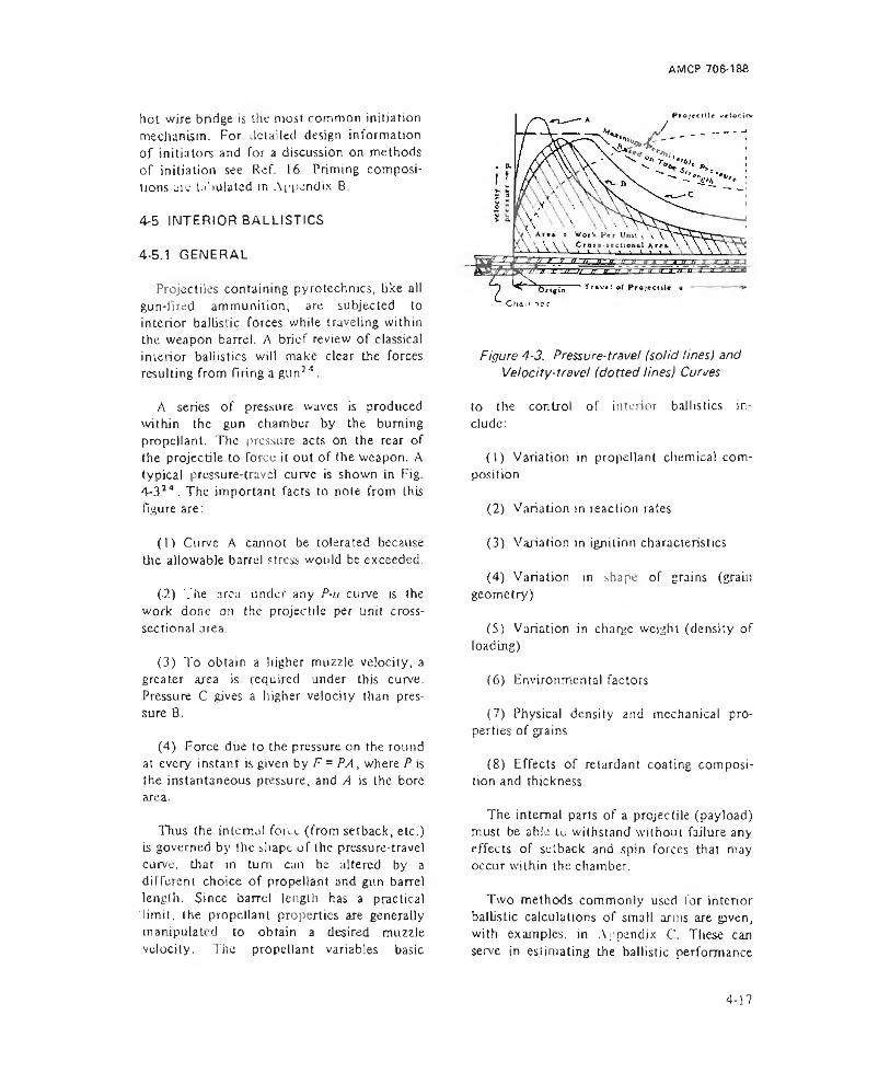
AMCP 706-188
hot wire bridge is the most common initiation mechanism. For detailed design information of initiators and for a discussion on methods of initiation see Ref. 16. Priming compositions arc tabulated in Appendix B.
4-5 INTERIOR BALLISTICS
4-5.1 GENERAL
Projectiles containing pyrotechnics, like all gun-fjred ammunition, are subjected to interior ballistic forces while traveling within the weapon barrel. A brief review of classical interior ballistics will make clear the forces resulting from firing a gunJ4 .
A series of pressure waves is produced within the gun chamber by the burning propellant. The pressure acts on the rear of the projectile to force it out of the weapon. A typical pres sure-travel curve is shown in Fig.4-314. The important facts to note from this figure are:
(1) Curve A cannot be tolerated because the allowable barrel stress would be exceeded.
(-2) '."he area under any P-u curve is the work done on the projectile per unit crosssectional area.
(3) To obtain a higher muz2)e velocity, a greater area is required under this curve. Pressure C gives a higher velocity than pressure B.
(4) Force due to the pressure on the round at every instant is given by F = PA, where P is the instantaneous pressure, and A is the bore area.
Thus the internal force (from setback, etc.) is governed by the shape of the pressure-travel curve, that in turn can be altered by a different choice of propellant and gun barrel length. Since barrel length has a practical limit, the propellant properties are generally manipulated to obtain a desired muzzle velocity. Tire propellant variables basic
P r o j ( d l l < v« lo<rftv
Figure 4-3. Pressure-travel (solid lines) and Velocity-travel (dotted tines) Curves
to the control of interior ballistics include:
(1) Variation in propellant chemical composition
(2) Variation in reaction rates
(3) Variation in ignition characteristics
(4) Variation in shape of grains (grain geometry)
(5) Variation in charge weight (density of loading)
(6) Environmental factors
(7) Physical density and mechanical properties of grains
(8) Effects of retardant coating composition and thickness.
The internal parts of a projectile (payload) must be able tu withstand without failure any effects of setback and spin forces that may occur within the chamber.
Two methods commonly used for interior ballistic calculations of small arms are given, with examples, in Appendix C. These can serve in estimating the ballistic performance
4-17

AMCP 706-188
required of small arm pyrotechnic ammunition.
4-5.2 SETBACK FORCES
4-5.2.1 SETBACK IN THE WEAPON
Setback results from the relative motion between parts on or in the projectile body as the projectile accelerates. When the projectile accelerates, unequal forces are applied to its components. The projectile is normally thought of as being a solid, uniform body, but this is not the case. Most ammunition comprises a number of internal components that are accelerated only because the projectile in which they are contained is accelerated.
In most weapons there is an axial component of acceleration and in some instances a spin component. Typical accelerations are shown as a function of projectile travel within the bore (see Fig. 4-4). The maximum axial acceleration is experienced as the projectile moves down the bore, usually within a few milliseconds after propellant ignition. The axial acceleration force is
Fa = M o = Mn , lb p p \ M ) (4-3)
whereF0 = axial force, lb
a = axial acceleration, ft sec 1
p = pressure in Ihe gun, psi
A = area over which the pressure actsv in.2
K = mass of the part, slug
M = projectile mass, slug
Note in Lq. 4-3 that Fg is directly,rclated to a and varies with the acceleration time curve shown in Fig. 4-4. Fa is a force vector directed opposite to the direction of motion
applied at the mass center of the part being considered.
Axial acceleration may range from hundreds of g’s for some projectiles to tens of thousands of g’s for high-performance weapons (see par.-4-3.1.3). It is important to define acceleration levels that must be met by a pyrotechnic device and then to assure, by design or experiment, that the components used and their supporting structures remain intact.
Structural consideration of the effects of high-acceleration loading requires the application of conventional mechanics and strength of material analysis. The product of the mass of each pyrotechnic component and the number of g’s experienced results in the force to which the component will be subjected. Mechanical failure of components of pyrotechnic ammunition may result in premature firing or in disruption of the pyrotechnic components.
Much has been learned in fuze developments concerning the treatment of high acceleration; some of this experience is pertinent to pyrotechnic applications that require delivery by high acceleration means' 3.
Figure 4-4. Typical Acceleration Functions vs Time (Artillery Projectile)

AMCP 70&-188
Analytical methods of predicting performance have limitations. Among these are incomplete information on the materials being used, particularly their ultimate strength under the conditions of high setback. Hence, designs are completed to the point where prototypes are built and tested, often in air guns or centrifuges to recover the components, to assess their performance under accelerations approaching those of setback. Similar procedures may be used for pyrotechnic payloads.
Quite often it is found that components survive setback more readily in one orientation than they do in another. The orientation in the payload should be adjusted to provide the proper resistance to setback if orientation is found to be critical.
4-5.2.2 EFFECTS OF ACCELERATION ON DELAY ELEMENTS
Delay compositions are consolidated with pressures between 30,000 and 40,000 psi in order to withstand the forces to which they are subjected in use2 3 .
Delay elements are often subjected to very high accelerations while the delay composition is burning. If the structure of the material at or behind the reaction front is too weak, the acceleration may cause the hot reacting materials to lose contact with the unreacted composition or a subsequent charge and extinguish flic reaction. Quantitative data regarding the resistance of delay compositions to this type of failure are not available. However, “slag retention", i,e., the fraction of the weight of the original charge remaining in an open-ended delay column after functioning, has been used as a possible indication of the resistance of a delay element to acceleration forces. The higher the slag retention the greater the setback resistance. Slag retention for some delay compositions is: manganese, 95%: red lead, 90-95%; tungsten, 95%; nickel-zirconium, 80-90%; boron, 59-90%.
Introduction of a binder into the mixtures will improve performance under high acceleration conditions; however, binders tend to produce large amounts of gaseous products so that the system can no longer be considered gasless. Mechanical support of the delay column at both ends tends to reduce variation in burning times by minimizing slag flow.
4-5.3 SPIN FORCES
Some gun bores have helical grooves that act on the rotating band of a projectile and force the projectile to spin, producing the acceleration shown in Fig. 4-4. Spin js important in maintaining projectile stability. Too little spin will cause wobbling and a large deviation from the intended trajectory, while too much spin will tend to keep the projectile nose up during the flight. The spin velocity of the projectile as it leaves the muzzle is related directly to the twist of rifling (measured in calibers per turn) and die speed with which the projectile leaves the gun. Spin velocity reaches a maximum at the muzzle where the spin velocity to is expressed as
247m . .. ..go - ---- — , rad sec ’ (4A)nd
co - — —, rev sec 1 (4-5)nd
wheren ~ twist, cal rev 1
v = instantaneous projectile velocity, ft sec'1
d - bore diameter, in. (the caliber)
Twist varies from weapon to weapon and is specified as “ 1-50’’ which is read as “one revolution of the projectile for 50 calibers (diameters) of travel along the gun barrel'’ - which is 1 jn when applied to Eqs. 4~4 and 4-5. Twist can also be expressed directly as the number of calibers per turn (cal/tum),
While twist is commonly uniform through
4-19

AMCP 706-188
out the travel of the projectile, a few guns use a variable or gain twist. Here the rifling is straight in the breech section of the bore with the twist increasing progressively to its highest value at the muzzle. Uniform and variable twist can be represented graphically as shown in Fig. 4-5. Tins type of presentation allows visualization of the relationships among the travel along the bore, the circumference of the bore, and the angle of twist. Examples of uniform twist and increasing twist are shown in Fig. 4-5(A) and 4-5(B), respectively. The angle of twist <b is the angle between a tangent to the rifling grooves and a line parallel to the center of the bore. For weapons with uniform twist, this angle is a constant. For variable twist the angle is constantly changing. The relation between the angle and twist is
tan 4> = = — (4-6)dx n
Figure 4-5. Uniform and Increasing Rifling Twist Rates
When using Eqs. 4-4 and 4-5 for determining spin rates, the instantaneous values of velocity v and rrjn always must be used.
With uniform twist, engraving of the rotating band occurs only until such time that the entire rotating band enters the rifling and the grooves of the rifling have been formed in the band. With increasing twist, however, portions of tine band are constantly being engraved.
Spin rates of projectiles vary from 0 to 200,000 rev sec"' with no definite relation between caliber and twist. Data for weapons from 20 mm to 250 mm are presented in Fig. 4 -6 '3. This nomogram permits determination of spin velocity given the muzzle velocity, twist, and caliber. While the nomograph is intended for existing weapons, there is no reason why it cannot be used for determining spin velocity for other weapons if the same characteristics are known.
Spin introduces a radial force vector in addition to the force generated as a result of setback (par. 4-5,2). The centrifugal force vector varies directly with the radial distance from the spin axis. This force F is determined from
F = M ar = A* cuV.lb (4-7)
whereI: - centrifugal force, lb
M - mass of the part, slug
ar - radial acceleration, ft sec 2
<u = angular velocity, rad sec’2
r = radial distance from the spin axis to the CG of the part, ft
4-5.4 COMBINED SETBACK AND SPIN
It can be easily seen that both axial forces (from setback) and radial forces (from spin) will occur at the same time in the interior of
4-20
AMCP 706-138
RATES OF TWIST
cun, m j a m?, 2 “> 99 cal/ turn3 7 G U K , M j . M f l , W V M 6 a M 'O , 2 5 C A L / r U * N
J /m m GUN, MIA? 6 V 9 , JO CAL/TUHN ^Om/r. GUN, Ml. JO C*L/Tl>W N 9 7 mm GUN. Ml. JO CAL/TURN7jm<r» GUN. m j . M 4. m £ a Mi897, 25 59 C A t / t U * * 7 GUN. M5A>, 22 CAL/ t vJPN7 !i / n iti H Q * , M J , 2 0 C A L / T U R N
n GUN. M iA2. 52 CAl / T u RN J fN GUN. M i . MG » M 7, 4Q C A L /TU »N
90"*™ GUN, M(. m 2 a MJ. 5? CAl TyfTN<05 mm HOW.. M l, M2. MJ 0 M4, 20 CAl - f pjHNI2 0 « ^ CUN, m i , JO CAL/TURNI5i»nm GUN. M |, 25 CAL/TURNl9 5 » m GUN. M I^ IB U i. ?9 89 C A l/J URN8 in Gu n . m i . 25 c a l 'T j r nfliN hOvj , m i , 25 CAl /T U P n?40m m « 0 w . Ml, 25 C A L /T u RN240iT.m M O *. M J9I6 . 20 CAl t U«N
<000 2000M<j 2ZL£ W C IO CITt k <£►*
3000 4 000
(GOO
ROTATIONAL v El OCIT 1000 9 0 01400 1200
t, r e v /sec GOO 4 0 0 200
Figure 4-6. Nomogram for Determining Spin Velocity o f a Projectile
the barrel. Each of these forces contributes to the overall stress in any one part of the pyrotechnic payload.
The magnitude of the total force /•' due to combined setback force /•" and spin force I \ is
F, = \ A ' / + 1 / ,1b (4-8)
Fig. 4-7 shows the direction of the force acting as a result of these two components. In addition the resultant force vector and the direction of this vector are shown.
At some location, the magnitude of the
total force F will be a maximum. This location will most probably be near the point of maximum setback acceleration where Fg is dominant. Maximum particle stress occurs when the total force /•', is a maximum. However, in order to be thorough, maximum stresses in tension, compression, and sitcar should be computed and these compared with the safe allowable stresses lor the materials.
4-5.5 EXAMPLE OF DESIGN PROCEDURES
The following design procedure is applicable for an illuminating round to he fired from a howitzer. The designer will make
4-21

AM CP 706-188
DIRECTION OF MOTION, VELOCITY V| ACCELERATION 0
Figure 4-7. Internal Restoring Forces on Particle Within a Projectile
preliminary calculations to determine the soundness of his design approach and refine them as the design progresses. The dimensions used were not taken from a specific projectile design, but are of the order of magnitude of those found in a medium caliber (105 mm) base ejection projectile (see Fig. 3-6 for projectile configuration).
Bearing stress of the projectile body on the base plate is determined in order to assure that the projectile (carrier) is not subject to collapse in compression by the driving force of the propellant gas pressure in the bore during firing. A subsequent estimate of the combined stress on the rear section of the projectile determines the effect of the bore pressure and setback forces. These forces tend to cause failure of the projectile body by separation during firing. An additional initial calculation should be made to determine the force which must be generated inside the projectile by the expelling charge in order lo properly eject the payload upon Tuze functioning.
4-5.5.1 BEARING STRESS BETWEEN BASE PLUG AND PROJECTILE BODY
The weight of the projectile body is determined by approximation from a detail drawing. For this example the body is of steel
having a basic outside diameter of 3.9 in. and a basic inside diameter of 3.6 in. with a cavity I 2 in. long to accommodate the candle and parachute.
Weight estimates (lb) for projectile components are:
Fuze 2.2
Cylindrical shell 9.0
Other, including base plug, illuminant, expellant parachute, and holder 23.8
Total projectile 35.0
In determining the bearing stress, weighl of candle, parachute, and expelling charge are ignored because they bear on a much larger surface of the base plate which is not considered a critical area. Because of the machined mating surface at ihe base plate- body junction, the ID at this location isconsidered to be 3.64 in. A bore pressure ofI l ,200 psi is used in calculating the stress. The groove diameter of the barrel is 4.19 in. A more exact estimate of bore pressure may be obtained by the Le Due equations24. These empirical equations express projectile velocity and propellant gas pressure as functions of time or distance in the bore.
4-22
AMCP 706-183
The acceleration a applied to the projectile when fired is
4 W , 8
wherea = acceleration, g
(4-9)
The values of bearing stress calculated in this manner are conservative because we assumed that the driving force of the propellant gas is applied only through the base plug. In practice, however, some of the driving force is applied through the rotating band to the projectile body, thus lowering the stress at the base plug bearing surface.
groove diameter, in.
P = peak pressure, psi
W = weight of projectile, lb
^ 3.14X(4.I9)*X 11,200 4 X 35
The force / ' necessary to accelerate all mass forward of the base plug is
Fb = a lb (4-10)
whereFa ~ accelerating force, lb
a - acceleration, g
Wh = weight of fuze and body, lb
Fg - 44 10 X 1 1.2 = 49,400 lb
The source ot this accelerating force is the propellant gas acting on all surfaces aft of the rotating band including the rear band surface. The force is applied to the bearing surface of the base plug and body. The bearing stress Sb in this area is
r% 0 -
s b
whereSb = bearing stress, psi
(4-11)
A = area of the bearing surface, in.2
49,400S*> 3.14 [(3.9)2 -(3 .6 4 )2]
■ = 3 1,500 psi
4-5.5.2 COMBINED STRESS IN THE PROJECTILE BODY
In making this calculation, the conditions and location chosen are those considered most critical, namely, the stress on the wall just aft of the rotating band. Projectile ID and OD are, respectively, 3.6 and 4.04 in. The analysis is based on the behavior of a thin- walled cylinder. The hoop stress Sh due to the bore pressure is
•S, = P„
where
2rf,2 r 1 r \ ~ r1
, PS] (4-12)
Sh - hoop stress, psi
P - peak pressure, psi
r l = outside radius of projectile body, in.
r7 = inside radius of projectile body, in.
Sh = 1 1,200 2 (2.02)2_ |(2.02)2 - (1.8)2 j
The longitudinal stress S9 is
65 A
000 psi
(4-13)
whereSt = longitudinal stress, psi
F = longitudinal force, lb
A = area under stress, in.2
There are two forces acting in the projectile body in the longitudinal direction, the set-
4-23
back force of (lie con tents applied to the base plate and the driving force applied to the rotating band. Examination indicates these forces are applied so as to oppose each other. We shall arbitrarily designate the setback, force as being positive. Assuming the contents of the project ite weigh 25 lb
(441 n X 25) - 11,20Q ^J . - 1 jjn 19)4 _ (4.04pJ
r.i4 r i— U4.04)5 - (3.6)1
- 37,000 psi
the cross-sectional area of the shear pins calculated.
As an example, the following procedure may be used to determine the size and number of shear pins required. Assuming a gas pressure of 3000 psi from the ejection charge, the shear force Ft on the pins is calculated by
whereThe combined stress Sc in the projectile wall Fduring firing can then be estimated
______ FSc - Vs?. + Si . psi (4-14)
where P
Sc - combined stress, psi F5S,' = hoop stress, psi
= longitudinal stress, psi
- total site a r force, I b
- gas pressure, psi
= diameter of the base plate, in.
3000X 3.V4 (3.6)z 4 30,500 lb
.9. = s/( M 0,000)2 +(37,700)z = 119,000 psi
The results of this design analysis indicate that the critical stress is the combined stress aft of the rotating band. The magnitude of stress indicates that this design may be safely executed in carbon steel, but in iron, only pearlit.ic malleable iron is usable; and careful design and manufacturing procedures are required.
4-5.5.3 FORCE REQUIRED OF THE EJECTION SYSTEM TO RELEASE THE BASE PLUG
The base plug is held tightly in place by shear pins that must be broken by forces produced by the ejection charge (see Fig. 4-8). The design problem at Lhis stage can be solved by several approaches; the diameter and number of the shear pins can be specified and the pressure required from the ejection charge calculated, or the pressure developed by the ejection charge can be specilled and
Figure 4-8. Forces on Base Plate o f Illuminating Round
4-24
AMCP 706-188
Then the cross-sectional area A of the shear pins is calculated
whereA ~ cross-sectional area of the shear pins.
The action of this pressure is comparable in time with the acceleration introduced by setback. The time period is long with respect to the transit time for a shock wave to progress through the explosive column, but short for the transfer of heat from the explosive material to the surroundings. The process, therefore, may be considered essentially adiabatic.
S = ultimate shear strength of the pins, psi
In making this calculation for a design in which steel shear pins are used, the usual practice is to use the factor (0.75) times the ultimate tensile strength of the material as the vjilue for the ultimate shear strength. In this case Sr is estimated at 40.000 psi. Then
A =_ 30,500 _40.000 0.763 in.2
ll three shear pins are to be used, their diameter d , in., is
(4-17)
' 3 x3 . 14 = 0.56 in.
4-5.6 HYDRODYNAMIC FORCES
It is for this reason that long columns and loosely packed explosive materials are undesirable. Voids in cast explosives and interstices in powders experience dramatic rises in temperature during setback.
Furthermore, many explosive materials will fail structurally under high setback forces. The answer to minimizing these effects is to provide adequate support for explosive columns, to precompress materials with high consolidation pressure, and eliminate voids in explosive charges.
Consider a flare composition of initial density pQ - 1.7 g cm'3. 10 in. long. At an acceleration of 30.000 g, the pressure at the base of this column would be about 18,300 psi. Many flare compositions would fail in compression under these circumstances and fluid-bke flow would occur. Adequate support of the composition is imperative under these conditions.
Often explosive materials are considered to behave as fluids'3. If this is the case, the pressure P at the bottom of a cavity containing an explosive charge is given by
P - 0.036 pLa, psi (4-18)
whereP = pressure, psi
p - density of explosive, g cm'3
a = acceleration, g
L - column length, in.
4-5.7 PROPELLANT CHARACTERISTICS
For a given gun system — i.e., projectile mass, diameter, and barrel length-the shape of the pressure-travel curve can be altered by the characteristics of the propellant2 s . In considering the characteristics of the propellant we should know the effects of grain size, composition, geometry, and the density of loading. Although in a final design all factors may be involved, it is of basic importance to note first the independent effects of each variable. Much work has been done in the past to record these effects independently. They are summarized in the paragraphs that follow.
4-25
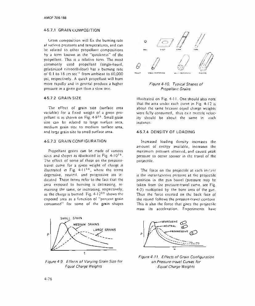
AMCP 706-188
4-5.7.1 GRAIN COMPOSITION
Grain composition will fix the burning rate at various pressures and temperatures, and can be related to other propellant compositions by a term known as the “quickness” of the propellant. This is a relative term. The most commonly used propellant (single-based, gelatinized nitrocellulose) has a burning rate of 0.1 to 18 cm sec'1 from ambient to 60,000 psi, respectively. A quick propellant will bum more rapidly and in general produce a higher pressure in a given gun than a slow one.
4-5.7.2 GRAIN SIZE
Tire effect of grain size (surface area variable) for a fixed weight of a given propellant is as shown on Fig. 4-92 6. Small grain size can be related to large surface area, medium grain size to medium surface area, and large grain size to small surface area.
4-5.7.3 GRAIN CONFIGURATION
Propellant grains can be made of various sizes and shapes as illustrated in Fig. 4-I026. The effect of some of these on the pressure- travel curve for a given weight of charge is illustrated m Fig. 4-1 I26, where the terms degressive, neutral, and progressive are indicated. These terms refer to the fact that the area exposed to burning is decreasing, remaining the same, or increasing, respectively, as the charge is burned. Fig. 4-1 226 shows the exposed area as a function of “ percent grain consumed’’ for some of the grain shapes
Figure 4-9. Effects of Varying Grain Size for Equal Charge Weigh ts
Figure 4-10. Typical Shapes of Propellant Grains
illustrated on Fig. 4-11. One should also note that the area under each curve in Fig. 4-12 is about the same because equal charge weights were fully consumed, thus exit muzzle velocity should be about the same in each instance.
4-5.7,4 DENSITY OF LOADING
Increased loading density increases the amount of energy available, increases the maximum pressure attained, and causes peak pressure to occur sooner in the travel of the projectile.
The Force on the projectile at each instant is the instantaneous pressure at the projectile position in the gun barrel (pressure may be taken from rhe pressure-travel curve, see Fig. 4-3) multiplied by the bore area of the gun. Thus the force exerted on the back face of the round follows the pressure-travel contour. This is also the force that gives the projectile mass its acceleration. Experiments have
Figure 4-11. Effects o f Grain Configuration on Pressure-travel Curves for
■ Equal Charge Weights
4-26
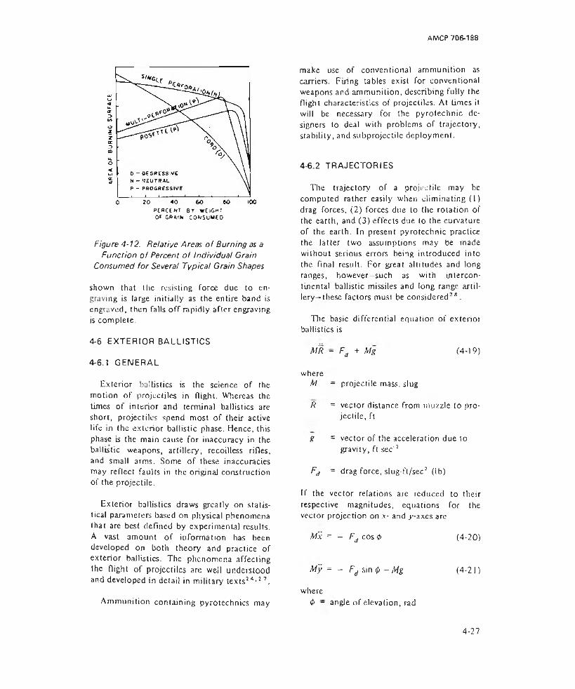
AMCP 706-188
PERCENT by wei gh! OE GRMN CONSUMED
Figure 4-12. Relative Areas o f Burning as aFunction of Percent o f Individual Crain
Consumed for Several Typical Grain Shapes
shown that the resisting force due to engraving is large initially as the entire band is engraved, then falls off rapidly after engraving is complete.
4-6 EXTERIOR BALLISTICS
4-6.1 GENERAL
Exterior ballistics is the science of the motion of projectiles in flight. Whereas the times of inierior and terminal ballistics are short, projectiles spend most of their active life in the exterior ballistic phase. Hence, this phase is the main cause for inaccuracy in the ballistic weapons, artillery, recoilless rifles, and small arms. Some of these inaccuracies may reflect faults in the original construction of the projectile.
Exterior ballistics draws greatly on statistical parameters based on physical phenomena that are best defined by experimental results. A vast amount of information has been developed on both theory and practice of exterior ballistics. The phenomena affecting the flight of projectiles are well understood and developed in delail in military texts24•11.
Ammunition containing pyrotechnics may
make use of conventional ammunition as carriers. Firing tables exist for conventional weapons and ammunition, describing fully the flight characteristics of projectiles. At times it will be necessary for the pyrotechnic designers to deal with problems of trajectory, stability, and subprojectile deployment.
4-6.2 TRAJECTORIES
The trajectory of a projectile may be computed rather easily when eliminating (I) drag forces, (2) forces due to the rotation of the earth, and (3) effects due to the curvature of the earth. In present pyrotechnic practice the latter two assumptions may be made without serious errors being introduced into the Final result. For great altitudes and long ranges, however—such as with intercontinental ballistic missiles and long range artillery-these factors must be considered28.
The basic differential equation of exterior ballistics is
MR - Fd + Mg 14-19)
whereM - projectile mass, slug
R = vector distance from muzzle to projectile, ft
g = vector of the acceleration due togravity, ft sec'2
Fa = drag force, slug-ft/sec2 (lb)
If the vector relations are reduced to theirrespective magnitudes, equations for the vector projection on x- and .y-axes are
Mx = — Fd cos 4> (4-20)
My = - Fd sin <p - Mg (4-21)
where4> - angle of elevation, rad
4-27
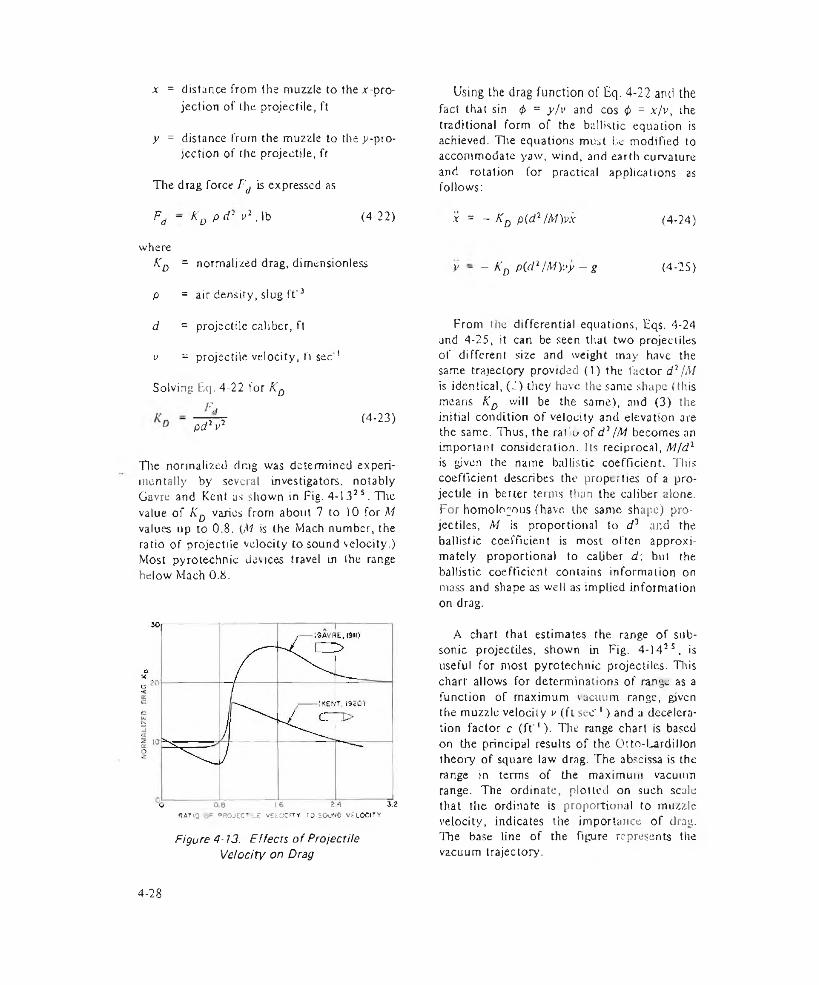
a: = distance from the muzzle to the x-pro- jection of Lhe projectile, ft
y = distance from the muzzle to the ^-projection of the projectile, ft
The drag force F'd is expressed as
Fd - K0 p d- v1, lb (4-22)
whereKd = normalized drag, dimensionless
p = air density, slug ft'3
d = projectile caliber, ft
v = projectile velocity, ft sec 1
Solving Eq. 4-22 for KDE,
pd2 v2 (4-23)
Tire normalized drag was determined experimentally by several investigators, notably Gavre and Kent as Giown in Fig. 4-1325. The value of Kd varies from about 7 to 10 for M values up to 0.8. {M is (he Mach number, the ratio of projectile velocity to sound velocity.) Most pyrotechnic devices travel in lhe range below Mach 0.8.
RATIO f OROJECTU: VELOerry TO SOVNO VELOCITY
Figure 4-13. Effects of Projectile Velocity on Drag
Using the drag function of Eq. 4-22 and the fact that sin $ = y/v and cos <t> = x /v , rhe traditional form of the ballistic equation is achieved. Tire equations must be modified to accommodate yaw, wind, and earth cur/ature and rotation for practical applications as follows:
a = - Kd p(d2/M)vx
> - - Kd p(d2/M)vy - g
(4-24)
(4-25)
From the differential equations, Eqs. 4-24 and 4-25, it can be seen that two projectiles of different size and weight may have the same trajectory provided (1) the factor d2/M is identical, (2) they have the same shape (this means KD will be the same), and (3) the initial condition of velocity and elevation are the same. Thus, the ratio of d2 jM becomes an important consideration. Its reciprocal, M/d2 is given the name ballistic coefficient. This coefficient describes the properties of a projectile in better terms than the caliber alone. For homologous (have the same shape) projectiles, M is proportional to d2 arid the ballistic coefficient is most often approximately proportional to caliber d\ but the ballistic coefficient contains information on mass and shape as well as implied information on drag.
A chart that estimates the range of subsonic projectiles, shown in Fig. 4-1425, is useful for most pyrotechnic projectiles. This chart allows for determinations of range as a function of maximum vacuum range, given the muzzle velocity v (ft sec'1) and a deceleration factor c ( ft '1). Tire range chart is based on the principal results of the Otto-Lardillon theory of square law drag. The abscissa is the range in terms of the maximum vacuum range. The ordinate, plotted on such scale that the ordinate is proportional to muzzle velocity, indicates the importance of drag. The base line of the figure represents the vacuum trajectory.
4-28
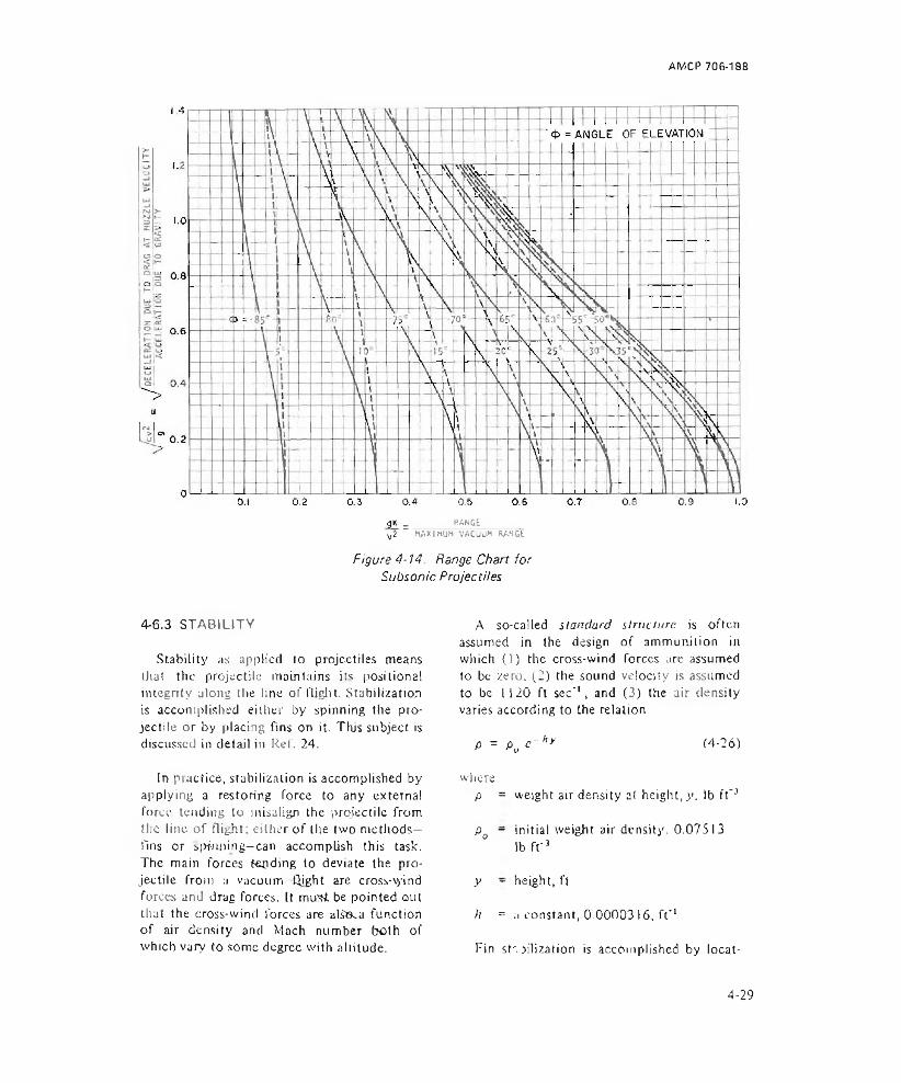
AMCP 706-188
gK _ _______ RANGE________^2 “ MAXIMUM VACUUM RANGE
Figure 4-14. Range Chart for Subsonic Projectiles
4-6.3 STABILITY
Stability as applied to projectiles means that the projectile maintains its positional integrity along the line of flight. Stabilization is accomplished either by spinning the projectile or by placing fins on it. This subject is discussed in detail in Ref. 24.
In practice, stabilization is accomplished by applying a restoring force to any external fore? tending to misalign the projectile from the line of flight: either of the two methods— fins or spinning— can accomplish this task. The main forces tending to deviate the projectile from :i vacuum flight are cross-vyind forces and drag forces. It mu's* be pointed oul that the cross-wind forces are allOca function of air density and Mach number both of which vary to some degree with altitude.
A so-called standard structure is often assumed in the design of ammunition in which (1) the cross-wind forces arc assumed to be zero. (2) the sound velocity is assumed to be I I 20 ft sec'1, and (3) the air density varies according to the relation
P = P0 e - hy (4-26)
wherep = weight air density al height, y. lb ft"3
P0 - initial weight air density. 0.07513lb r r 3
y ~ height, ft
h = a constant, 0.0000316, f t'1
Fin sts hlization is accomplished by locat-
4-29
AMCP 706-188
ing the center of pressure behind the center of gravity of the projectile (as illustrated in Fig. 4-15). At the center of pressure, a force R , the component of cross-wind force F. perpendicular to the direction of motion, and the drag force Fd act to restore the fin-stablized round to alignment with the motion of the center of gravity. Cross-wind forces are the result of unequal pressure on the fins. The drag force is small and is often disregarded.
The structure of the fins is critical in producing good stability. Tbe problem is that any asymmetrical differences in fins may produce a rudder effect causing the projectile to veer off course. This effect is minimized by introducing a roll to the projectile (nominally 5 to 15 rad sec"1), thus distributing any asymmetry. This action allows for wider tolerances in ihe fin construction and to some extent reduces errors due to production, handling, and launching.
Spin-stabilized projectiles, in contrast to fin-stabilized projectiles, have their center of pressure forward of the center of gravity as is illustrated in Fig. 4-16. Note that the same forces exist here through the center of pressure as they did in fin-stabilized projectiles.
A stability factor SF may be calculated for a projectile to predict the degree of stability of a relatively untried projectile
SFfl A 4IM
(4-27)
where/ = axial moment of inertia of the projec
tile, lb sec2 fl
I = moment of inertia about a transverse axis through the center of gravity, lb sec2 ft
N - rate of spin of the projectile, rad sec"1
M ~ overturning moment factor, lb ft
The overturning moment factor is defined by
Figure 4-15. Cen ter o f Pressure Trails Cen ter o f Gravity — Fin-stabilized Projectile
M = b(Fd + Fc cot 5), lb ft (4-28)
whereb = distance from center of gravity' to
center of pressure, ft
Fd = drag force, lb
Fc = cross-wind force, lb
& = angle of yaw, rad
For small angles of attack, Fd and cot 5 usually are ignored.
A stability factor from unity to 2.5 generally indicates that the projectile will perform well with the center of pressure leading the center of the gravity. If the factor is less than one, the projectile will tumble, lose range and is inaccurate. Factors greater than approximately 2.5 produce over stabilization which may result in the projectile landing base first.
Figure 4-16. Center o f Pressure Leads Center o f Gravity — Spin-stabilized Projectile
4-6.4 SUBPROJECTILE DEPLOYMENT
Pyrotechnic devices are often delivered to the target by subprojectiles. Hence, it is
4-30
AMCP 706-188
necessary to activate the pyrotechnic device or the subprojectile at some predetermined time or position. This is done by removing the device from its container which could be a bomb, projectile, or rocket. This action is accomplished in a number of different ways that depend upon the delivery mode, the nature of the pyrotechnic device, and the terminal effects desired.
The design of a pyrotechnic package for an artillery projectile is shown in Fig. 3-6 and described in par. 4-5.5.3, where an ejection charge provides the stimulus to shear pins and the energy necessary to eject the cartridge, including parachute and flare into the atmosphere. This example serves to describe the process of ejection and deployment.
Deployment is sometimes accomplished by drag forces experienced after ejection of the sub projectile. For example, a ribbon is allowed to trail the subprojectile. It creates enough drag force to rip a parachute from the subprojectile package. Details of parachute design and opening devices are covered in par. 4-8.
Ejection charges and their requirements are determined in much the same manner as are charges for other propellant applications as discussed in par. 4-5.7.
The strength of the containers of the pyrotechnic charge is important. However, unlike in the case of gun tubes, only one application of propellant gas pressure is required. General design formulas for thin-wall tubes may be applied to the solution of stresses in the tube walls. Experimental procedures usually follow the design stages of pyrotechnic sub projectiles. Experimental techniques may benefit from measurement of strains in the tube as outlined in par. 5-8.1.
4-7 TERMINAL BALLISTIC CONSIDERATIONS
4-7.1 PAYLOAD DEPLOYMENT
The deployment of the payload is the ultimate objective of ammunition. The
methods of deployment are as diverse as the ammunition itself. For this reason, much of the subject matter in this handbook deals indirectly with the deployment of pyrotechnic payloads. This paragraph, however, discusses deployment specifically. In any design where deployment of a pyrotechnic payload is being considered, see also the paragraphs on the specific effects desired, such as exterior ballistics (par. 4-6), fuzing and timing (pars. 3-9 to 3-21). and parachutes and other decelerators (par. 4-8).
4-7.1.1 LIGHT PRODUCING PAYLOADS
Deployment of light sources having a fixed time delay must be analyzed in advance. In projected devices, if the trajectory and the delay are known, an angle of elevation can be specified that will cause illumination to begin at the desired height. Alternatives for projected illuminating devices are variable-time fuzes, variations in the elevation angle, or changes in the launch velocity. All of these complicate the design or increase the cost.
An example of a projected device that makes use of a fixed time delay is the marine signal shown in Fig. 4-1729. This signal is a hand-held night distress signal for use by aircraft personnel if forced down over water. When held at a specified angle, it ejects two red stars, successively, to a height of about 175 ft, which may be seen for 2.5 to 3 mi on a clear day and 12 to 15 mi on a clear night.
When the firer pulls the retainer fork, the firing pin is released under the force of the firing pin spring. This initiates the primer which in turn ignites the igniter that projects the igniter holder assembly about 10 ft from the signal. This projecting charge also ignites the first delay charge which bums 2 to 4 sec before igniting the ignition charge, the quick- match, and the first ejecting charge. That charge ejects and ignites the first star charge
4-31

Figure 4■ 17. Signal, Illuminating Marine, AN-M75
and ignites ihe second delay charge. The second delay also burns for 2 to 4 sec and then ignites a similar scries of elements to eject the second slar charge, leach star bums for 4 to 6 sec.
Other light producers, such as bombs and aircraft flares, make use of fuze mechanisms to provide variable delay times29. These times normally arc indicated in terms of the drop distance to the deployment of the flare. The aircraft parachute flare shown in Fig. 3-5 is an example of such a device. Setting is accomplished by means of a setting ring. Drop distances are variable from a minimum of 300
ft to a maximum 12,000 ft. Trip of the fuze is accomplished by means of a lanyard attached to the aircraft and the flare. Upon drop, the lanyard pull begins the time sequence in the fuze.
Photoflash bombs are deployed in much the same manner as other bombs, i.e.( they are dropped from bomb racks23. They are timed by fuzing mechanisms set to react at various heights above the ground, but their reaction is different from most pyrotechnic devices. The bomb payload is a consolidated flash powder that must be dispersed rapidly to produce a flash of intense light, t or this
4-32

AMCP 706-188
reason dispersal and reaction of the powder is accomplished by a high explosive core. These devices are treated as high explosive bombs in normal supply, storage, and handling processes.
4-7.1.2 SMOKE PRODUCING PAYLOADS
Smoke producing devices are similar in many respects to light producers i.' cept that the time delay need not be as lightly controlled. Devices that produce smoke normally do so for much longer periods than those producing light. If the delay times are contrasted with those of photoflash units, it is clear that the delay limes for smoke producers are far less critical than those for photoflash applications.
Most smoke producers are either hand held or emplaced. Few are air dropped for marking purposes. Some pyrotechnic devices are designed to produce both light and smoke SO that a dual, day-night function can be served by a single device3 0.
4-7.1.3 CHEMICAL AGENT AND SMOKE PRODUCING PAYLOADS
Chemical agents and smokes are usually deployed by mixing the smoke or agent producers with pyrotechnics. The pyrotechnic serves to vaporize the smoke or agent and to expelt it into the atmosphere whereupon recondensation occurs. The result of this combination of agent and pyrotechnic is a small package having good dispersal, capable of easy handling, and permitting long-term Storage.
Employment normally consists of igniting the pyrotechnic mixture. In the case of smokes and chemical agents, it is desirable to have them disperse over a long period of time Burning rates are controlled for this purpose and to maintain the temperature of the mixture at an optimum value during delivery. These factors are further discussed in pars. 3-1 I and 3-13.
4-7.2 FLOTATION
In applications where pyrotechnic devices are to be used in the waicr, consideration must be given to the process of flotation in addition to the other considerations of preparation for the water environment; i.e., adequate protection of the device from ihe effects of water pressure, corrosion, and leakage.
Archimedes’ principle stales that a body partially or wholly submerged in a liquid is buoyed up by a force equal to the weighs of the fluid displaced3’ . Thus, an object will float if the weight of the liquid displaced is equal to or greater than the weight of the object. Conversely, it will sink if the object weighs more than the liquid displaced. A floating object, therefore, must be less dense than the water in which it is placed. Nominally, fresh water has a density of 62.4 lb ft'3 and sea water has a slightly greater density (64 lb f t'3).
Stability of a floating object depends upon the relationship of three centers of the floating object as depicted in Fig. 4-18, i.e., ( I ) she center of gravity G is the point at which the resultant downward force (the weight) 3cts,(2) the center of buoyancy B is the center of the volume of the displaced water, and (3) the metacentci /!/ is the point ai which the line of action of the buoyant force intersects (he center line of tire floating object.
Two conditions of stability are indicated in the figure. In Fig. 4-18(A) the object is unstable and will tip over because the flotation force F and the weight force W acting at M and G, respectively, represent an overturning moment tending to rotate the object in the direction already taken. In this state of instability, the center of gravity is above the metacenter.
The second condition in Fig. 4-18(B) shows the center of gravity below the metacenter. The torque caused by the forces F and IF, and the acting arm of these forces indicate a
4-33
AMCP 706-188
(A) Unstoble (8) stableConfiguration Configuration
Figure 4-18. Conditions o f S tab ility and Ins tab il ity o f a Floating Object
righting force tending to bring the floating object back to its vertical position.
In practice, flotation considerations can be considerably more complicated than is indicated by these basic principles in that the dynamics of the actions are more difficult to describe and analyze. More detailed information is available in literature on ship design31. However, these basic discussions make certain of the desirable conditions evident. It is desirable to have the center of gravity located as low as is practicable on the floating object. Similarly, it is desirable to have the metacenter very high on the floating object. U is further important to have a relatively large distance between these two points on the object. Such structures have been practically achieved in what are known as “ flip” ships. These are long slender ships that are sailed to their station. They are then partially flooded to give them a vertical attitude. By having a large distance from (he center of gravity to the metacenter, they are extremely free of motion induced by wave action.
Deployment of pyrotechnic devices may take place from boats including submarines, surfaces ships, and life rafts; or it may take place from aircraft. The device may experience immersion during deployment or upon exposure to wave action. It is therefore well to include a restart feature that will re ignite the pyrotechnic, such as is inherent in the design of the Marine Location Marker, Mk 2,
Fig. 3-1 I. Alternatively, the pyrotechnic may be designed for continuous functioning under water.
4-8 PARACHUTES AND OTHER DECEL- ERATORS
Control of the terminal velocity or descent time of pyrotechnic candles and signals over targets can be obtained by proper use of parachutes or oilier decelerators. The type of decelerator chosen for given application is usually based upon consideration of the following interrelated factors:
(1) Drag force required to slow descent
(2) Stability required for the paytoad
(3) Peak force experienced in deployment
(4) Bulk and weight of the decelerator
(5) Environmental conditions
(6) Manufacturing cost
(7) Reliability.
For most applications with a deployment velocity less than Mach 3, parachute systems can provide stability, variation in descent parameters, and a minimum of Storage volume. From Mach 3 to Mach 7, deployable rotors, spheres, cones, and flared skirts can be made stronger than parachutes and are more suitable to provide the drag forces. Generally, more storage volume is required for the latter types. The complexity of parachute and decelerator design limits the presentation in this handbook to general considerations. A comprehensive reference should be consulted for details33 >34.
4-8.1 PARACHUTES
4-8.1.1 PARACHUTE TYPES AND NOMENCLATURE
Fig. 4-I9 illustrates a simple, flat, circular parachute commonly used to decelerate illu-
4-34
AMCP 706-188
Parachute
minating candles. Definitions of some terms associated with parachutes follows:
( 1) Canopy. The drag producing surface (cloth area or sail).
Deployment. The portion of the operational sequence of a parachute occurring from the initiation of ejection to the instant the lines are fully stretched.
(2) Diameter, constructed, d . The design diameter along the radial (main) seam of a parachute or tire maximum diagonal of a parasheet.
(3) Diameter, nominal, dg . The calculated diameter of a canopy equivalent to the diameter of a circle whose total area equals that of the drag producing surface. Vent area larger than l% of the total area is deducted from the total area.
(4) Diameter, projected, dp . The mean diameter of the inflated canopy measured in the plane of maximum cross-sectional area. 5
(5) Gore. Portion of the drag producing
surface between the radial seams (triangular segments in the solid, flat, circular canopy).
(6) Permeability. The measured volume of air that will flow through one square foot of cloth in one minute at a given pressure (in United States a pressure of 0.5 in. of water is used; in Great Britain, I0 in. of water).
(7) Porosity. The ratio of open space to total cloth (including slots and vents) area of the drag producing surface. Also known as geometric porosity.
(8) Riser. That portion of the suspension system between the lower end of a group of shroud lines and the point of attachment to the store. It must be as strong as the total strength of all the shroud lines attached to it. It is also known as the suspension cable.
(9) Squid. A partially opened canopy that is fully deployed and whose pear shape makes it resemble a squid with tentacles. This term is also used as a verb. Squidding occurs if the canopy is deployed above critical opening velocity.
(10) Store. A payload, other than human.
(I I) Velocity, critical closing. The instantaneous velocity above which the parachute will collapse into the squid shape. Also known as the upper critical velocity.
(12) Velocity, critical opening. The velocity at or under which a parachute will fully inflate from a squid shape. Also known as the lower critical velocity.
(13) Velocity, equilibrium. The velocity that a falling body can attain when the drag is equal to the weight, i.e., when the acceleration for all practical purpose equals zero.
Flat parachutes have a canopy made with triangular gores joined to form a regular polygon. The canopy will be flat when spread out. Parasheets consist of parallel fabric sections that form a flat canopy in the shape of a
4-35
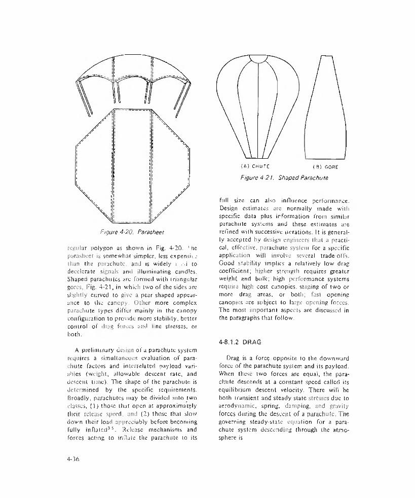
Figure 4-20. Parasheet
regular polygon as shown in Fig. 4-20. 'he parasheet is somewhat simpler, less expensix _■ than the parachute, and is widely \ . .i to decelerate signals and illuminating candles, Shaped parachutes are formed with triangular gores, Fig. 4-21, in which two of the sides arc slightly curved to give a pear shaped appearance to the canopy. Ollier more complex parachute types differ mainly in the canopy configuration to provide more stability, better control of drag forces and line stresses, or both.
A preliminary design of a parachute system requires a simultaneous evaluation of parachute factors and interrelated payload variables (weight, allowable descent rate, and descent lime). The shape of the parachute is determined by the specific requirements. Broadly, parachutes may be divided into two classes, (1) those that open at approximately their release speed, and (2) those that slow down their load appreciably before becoming fully inflated35. Release mechanisms and forces acting to in Hate the parachute to its
(A) CHUTE ( B 1 GORE
Figure 4-21. Shaped Parachu te
full size can also influence performance. Design estimates are normally made witli specific data plus information from similar parachute systems and these estimates are refined with successive iterations. It is generally accepted by design engineers that a practical, effective, parachute system for a specific application wilt involve several trade-offs. Good srability implies a relatively low drag coefficient; higher strength requires greater weight and bulk; high performance systems require high cost canopies, staging of two or more drag areas, or both; fast opening canopies are subject to large opening forces. The most important aspects are discussed in the paragraphs that follow.
4-8.1.2 DRAG
Drag is a force opposite to the downward force of the parachute system and its payload. When these two forces are equal, the parachute descends at a constant speed called its equilibrium descent velocity, There will be both transient and steady state stresses due to aerodynamic, spring, damping, and gravity forces during the descent of a parachute. The governing steady-state equation for a parachute system descending through the atmosphere is
4-36
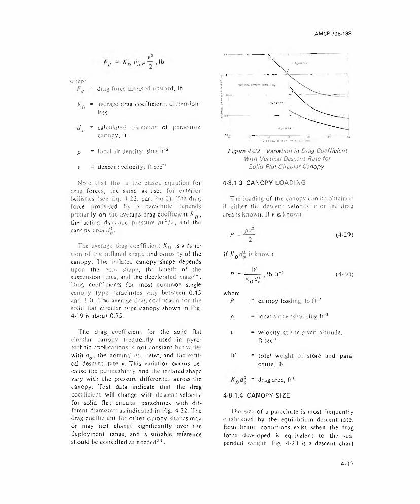
AM CP 706-188
where= drag force directed upward, lb
^D = average drag coefficient, dimensionless
4> = calculated diameter of parachute canopy, ft
P = local air density, slug ft"3
V = descent velocity, ft sec'1
v t a t i c i * N U I K ' **'«. !•
Figure 4-22. Variation in Drag Coefficient With Vertical Descent Rate for
Solid Fiat Circular Canopy
Note that this is the classic equation for drag forces, tire same as used for exterior ballistics (see Eq. 4-22, par. 4-6.2). The drag force produced by a parachute depends primarily on the average drag coefficient KD, the acting dynamic pressure pvJ / 2, and the canopy area d*.
The average drag coefficient Kn is a function of the inflated shape and porosity of the canopy. The inflated canopy shape depends upon the gore shape, the length of the suspension lines, and the decelerated mass34. Drag coefficients for most common single canopy type parachutes vary between 0.45 and 1.0, The average drag coefficient for the solid Hat circular type canopy shown in Fig. 4-19 is about 0.75.
The drag coefficient for the solid flat circular canopy frequently used in pyrotechnic .-.pnljcations is not constant but varies with d the nominal diameter, and the vertical descent rate p. This variation occurs because the permeability and the inflated shape vary with the pressure differential across the canopy. Test data indicate that the drag coefficient will change with descent velocity for solid flat circular parachutes with different diameters as indicated in Fig. 4-22. The drag coefficient for other canopy shapes may or may not change significantly over the deployment range, and a suitable reference should be consulted as needed3 3.
4-8.1.3 CANOPY LOADING
The loading of (he canopy can be obtained if either the descent velocity »* or the drag area is known. If v is known
P = Pv (4-29)
If KDd3 is known
P =W
W llb ff* (4-JO)
whereP = canopy loading, lb f t'3
P = local air density, slug ft'3
y = velocity at the given aitiiude, ft sec'1
W = total weight of store and parachute, lb
= drag area, ft5
4-8.1.4 CANOPY SIZE
The size of a parachute is most frequently established by the equilibrium descent rate. Equilibrium conditions exist when the drag force developed is equivalent to the suspended weight. Fig. 4-23 is a descent chart
4-37

AMCP 706-188
4V>
>2UJO(AU JauOUJt-<a5=>a .
3OUJ
DRAG AREA K o d | , f t !
Figure 4-23. Parachute Descent Chart
showing variation of equilibrium descent rate v with drag area KDd* for a given weight. Variation of drag area with nominal diameter do is also shown for particular values of the drag coefficients KD at standard sea level conditions.
Example
Given: Store or payload weight, I0 lbEquilibrium descent rate, 30 ft sec"' Type of canopy, Hat circular (KD -
0,75)
Find: (!) The drag area required
(2) The nominal diameter of the canopy to provide the desired descent rate 3
(3) The equilibrium descent rate at 30,000 ft above sea level.
Solution
A graphical solution is provided by the parachute descent churl shown in Fig. 4-23. Start with the left ordinate equal to a descent rate of 30 ft sec"1 and find the point of intersection with the curve representing a weight of 10 lb. A vertical line from this point to the abscissa determinines the drag area, 9 ft2 . The intersection of the vertical line with the drag coefficient curve K0 = 0.75 projected horizontally to the left ordinate determines the nominal parachute diameter dQ equal to 3.9 ft. An altitude correction in the equilibrium descent rate can be made by measuring the linear distance on the altitude adjustment scale between sea level and 30,000 ft and adding it to the ordinate at 30 ft sec’1 to obtain a true air speed of 50 ft sec’1.
4-38
AMCP 706-1Q8
4-8.1.5 VARIABLE PAYLOAD WEIGHT
In the case of parachute supported flares, the payload weight decreases as the flare is consumed. For a given chute design, the flare will descend a smaller distance in a given time than if the load remained constant. With constant load the distance y descended in time t can be expressed as
y = '/ 2 W
*1(4-3 l)
wherey - distance descended, ft
IV = weight of parachute and load, lb
d3 = parachute area, ft2
p - air density, slug ft'3 (assumed constant)
K0 = drag coefficient, dimensionless
/ = descent time, sec
which bums at a linear rate and is totally consumed in 180 sec. The parachute and associated hardware weigh 15 lb and the canopy area is 400 ft2. The air density is0 .0 0 2 4 slug ft"3 and the drag coefficient KD =0.75. Find the distance descended in )80sec.
Sol it l ion
The total weight as a function of time from Eq. 4-32
H - / ( , ) = >S + 3 5 - ^ f
The function is substituted into Eq. 4-31 and integrated between 0 and ) 80 sec to obtain
,180 [50 (35180
i/a
y = (400)(0.0024)(0.75)dt
180 2 T / 35 \= - 1.667 X-----{ “ SO- ( - — )/35 I 3 L V180/ J
3/2 ISO
As the pyrotechnic device is consumed, the weight IV must be known as a function of time. If the burning rate is linear with time, the following expression can be used.
VW = /( ,) = {We + Wp) ------- , lb (4-32)'p
whereW - parachute canopy and hardware
weight, lb
IV = consumable pyrotechnic weiglit, lb
tp = time to consume W , sec
t = descent time, sec (valid for / < tp only)
Example
A parachute system contains a pyrotechnic flare with 35 lb of combustible material
= 1690 ft
If the load had remained constant the parachute would have descended 2125 ft in 180 sec.
4-8.1.6 STABILITY
Stability is a measure of how well a parachute system can maintain a descent couise without either lateral oscillations or drift It is always measured in still air. Stabitily is also a measure of the damping of oscillations, i.e., the most stable parachute has tile largest damping factors.
The main factors influencing stability arc Canopy loading and total canopy porosity. High canopy loading parachute applications are in general considered more stable. Low canopy loading may produce a gliding type of instability. However, lateral oscillation usually occurs with high canopy loading. For both
4-39

solid cloth and geometrically porous parachutes, an increase in porosity will lower the maximum angle of lateral oscillation. Frequency of oscillations also will decrease as the porosity of woven fabric parachutes is effectively reduced. This may explain Hie increase in both the angle of oscillation and the increase in frequency of oscillation commonly experienced at high altitudes. In supersonic operation, a design must be of high geometrical porosity such as provided by ribbon type parachutes to avoid extreme fluctuation and inflation instability of the canopy.
Stability is desirable to prevent targe drifts and oscillations for pyrotechnic candles but it is noi sought at the expense of ability to withstand opening shock, low cost, and high drag per unit volume. Flat circular parachutes usually give average oscillations of ±15 deg to £30 deg, which are tolerated as being the current state-of-the-art in most pyrotechnic applications. Parashcets can be -expected to produce average oscillations of ±20 deg to ±35 deg.
4-8.1.7 PEAK FORCE LIMITATIONS
In the deployment and inflation of a parachute system, there occurs a snatch force peak and an opening force peak. The allowable forces on the canopy, shroud lines, and store must be considered. The snatch force peak occurs shortly before the opening shock when the deployed canopy is accelerated to the velocity of the store. Its magnitude depends mainly on the mass of the deployed canopy, the length of the suspension lines, and the difference in velocity between the store and canopy. The magnitude of the force is determined by equating the kinetic energy of the separating masses (canopy and store) to the energy the elastic lines must absorb to bring the masses to zero relative velocity. A detailed reference should be consulted for making snatch force and opening shock calculation33. A typical plot of these forces for aircraft Hares is shown in Fig. 4-24.
The peak forces developed can be appre
ciably large. A I-10 aircraft flare, which contains a 40-lb candle and an I S-ft diameter flat circular parachute, developed an opening shock force of 11,980 II) when it was released at an allitude of 10,000 ft at 390 kt and allowed to fall 5500 ft before ejecting the parachute at a velocity of 530 ft sec'1. The peak stress on the canopy at opening was 55.4 psi.
These forces arc relatively mild for applications such as hand-launched devices in which the parachute is ejected near the apex of the ballistic trajectory.
4-8.1.8 REEFING
In some cases it may be necessary to limit the opening force to meet both canopy strength and payload strength limits. A technique that may be used for this purpose is known as reefing, in which the inflated shape of the canopy is restricted. Disreefing will allow the canopy to assume its full inflated shape. A typical reef-disreef sequence is shown in Fig. 4-25. The reefing line maintains the skirt of the canopy to a fixed size that is smaller than the fully inflated diameter. The reefing line can be cut by mechanically initiated devices containing pyrotechnic delays.
Center line and control line reefing, illustrated in Fig. 4-2633, have also been used in some military applications. In center line reefing, the center of the canopy is held below I he rim (Fig. 4-26(A)). In control line reefing the reefing line is guided through rings inside the canopy similar to the scheme shown in Fig. 4-25. But now a control line is added that connects with two lines from point B to points A (Fig. 4-26(BV). Retraction of the control line reefs the canopy while extension disreefs it.
4-8.1.9 DEPLOYMENT TECHNIQUES
Various approaches arc used to expose the canopy to the airstreams from its storage container. Two frequently used types—the
-1 -40

AMCP 706-188
uloQC.O
L E G E N D
0 - STAGE at pap AC HUT E RELEASE
(2 ) - STAGE AT SNATCH
(5 ) - STAGE DURING SQLMDDING
0 - STAGE AT PARACHUTE OPENING
0 - STAGE DURING STEADY s t a te
( | ) - STACE AS CONSTRUCTED
E0 = SHOCK FORCE AT OPENING
Es = SHOCK FORCE AT SNATCH
W - LOAD FORCE (STEADY STATE)
VELOCITY AT SNATCH
v c - CRITICAL OPENING VELOCITY
V .s TERMINAL VELOCITY (STEADY STATE)
0.3 O.A 0.5 0.6 0.7TIME, RELATIVE INDEX
Figure 4-24. Parachute Suspension System Showing Effects of Force, Velocity, and Diameter at Various Stages of Development
tree type and the full bag—are illustrated in Fig. 4-27.
The free type deployment often is used in military applications involving single or double ejection of the parachute away from the projectile. In this type of deployment there is a rapid deceleration of the canopy sail and the base plug, pilot chute, or wjnd sock combination (enclosed by dotted lines in Fig. 4-27(A)) because these components have low ballistic coefficients (high drag due to shape) compared to the payload. 1 nflalion begins during the deployment process, which increases the mass of the combined sail, and
deployment aids by the amount of air entrapped in the canopy. The free type deployment therefore produces high snatch loads.
Full bag deployment is used to reduce the snatch force. The dotted lines in Fig. 4-27(Bj enclose the mass whose velocity closely approximates that of the pilot drogue chute that provides the deploying force. Solid lines enclose the mass of lines and sail which attains a velocity equal to Lhat of the payload before the snatch load occurs. Full bag deployment offers greatly reduced snatch loads since the canopy is accelerated in increments.
4-41
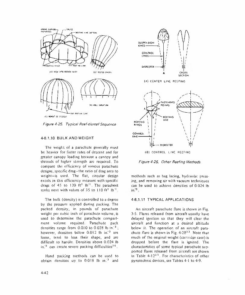
Figure 4-25. Typical Reef-disreei Sequence
4-8.1.10 BULK AND WEIGHT
The weight of a parachute generally must be heavier for faster rates of descent and for greater canopy loading because a canopy and shrouds of higher strength are required. To compare the efficiency of various parachute designs, specific drag—the ratio of drag area to weight—is used. The flat, circular design excels in this efficiency measure with specific drags of 45 to 120 ft2 lb"'. The parasheet ranks next with values of 35 to 110 ft2 lb"1.
i i \ i i i7
CROSSSECTION
(A) CENTER LINE REEFING
(6) CONTROL LINE REEFING
Figure 4-26. Other Reeling Methods
methods such as bag lacing, hydraulic pressing, and removing air with vacuum techniques can be used to achieve densities of 0 024 lb
The bulk (density) is controlled to a degree by the pressure applied during packing. The packed density, in pounds of parachute weight per cubic inch of parachute volume, is used to determine the parachute compartment volume required. Parachute pack densities range from 0.010 to 0.028 lb in."3 ; however, densities below 0.012 lb in."3 are loose, tend to lose their shape, and are difficult to handle. Densities above 0.024 lb in."3 can create severe packing difficulties36.
Hand packing methods can be used to obtain densities up to 0.018 lb in."3 and
4-8.1.11 TYPICAL APPLICATIONS
An aircraft parachute flare is shown in Fig. 3-5. Flares released from aircraft usually have delayed ignition so that they will clear the aircraft and function at a desired altitude below it. The operation of an aircraft parachute flare is shown in Fig. 4-2823 . Note that much of the original weight (cartridge case) is dropped before the flare is ignited. The characteristics of some typical parachute supported flares released from aircraft are shown in Table 4-122 3. For characteristics of other pyrotechnic devices, see Tables 4-1 to 4-9.
4-42

AMCP 706-188
TABLE 4-12CHARACTERISTICS OF SOME PARACHUTE SUPPORTED FLARES
(AIRCRAFT RELEASED)
Burning / Max Speed of
Item Weight, ihTime,
secFail
Velocity, <psAirplane at Time of Release, mph
M8A1 17.6 16 5 - 195 9.0 200M26 52.5 195 ± 15 11.6 150M 26A1 52.5 195 ± 15 11.6 350.M138 (T10E4) 62 360 10 440M139 (T10E6) 62 180 10 440Mk 5 and Mods 18 180 - -Mk 6 Mods 5 and 6 30 180 - -AN-Mk 8 Mods 1 and 2 18 180 8.0 250Mk24 27 185 ■ 7.5 460X M 170 11.5 150 15 -
4-8.2 BALLOONS
A balloon decelerator is a high-drag object fabricated from material with very low porosity. After deployment it is either self-
PILOT CHUTE
L i > * ... j f =>
£ > « ..............
(A) FREE TYPE DEPLOYMENTDEPLOYMENT b a g
(B ) FULL bag d e p l o y m e n t
Figure 4-27. Free Type and Full Bag Deployment Techniques
inflated or force-inflated behind the payload that is to be decelerated. Ltalioon-type deed- era tors should be considered for deployment vehicle velocities up to Mach 10. At supersonic velocities above Mach 2 most parachute decelerators start to exhibit erratic inflation and stability characteristics.
A spherical balloon decelerator is shown in Fig. 4-2933, The toroidal-shaped ring is known as a “burble fence” and is used to provide stability at subsonic speeds.
4-8.3 RIGID DECELERATORS
Rigid decelerators are drag producing shapes made from nonflexible material that are suitable in the supersonic speed range. A special category of rigid decelerators called nonpowered rotors may be useful for applications in which the descent is controlled and a soft (near zero velocity) landing is required. Nonpowered rotors can be constructed employing helicopter-type rotor blades. Drag coefficients can approach those encountered with parachutes and, in addition, a long gliding range may be obtained31.
4-8.4 DYNAMIC DECELERATORS
Several advanced concepts have been
443
AMCP 706-188
A - ARM ING WIRE f - HANGWlRE C -C O V E R0- t e a r w ir e£ -SLEEVEF - - DETACHABLE COVER LOCK G COVER RELEASING C u P H- DETACHABLE COVER
J — PULL OUT CORD K RELEASING CUP DISK L- THRUST SPACER M — SHADE RETAINER SUPPORTn s a p e t y d is kP -SHOCK ABSORBER Q -FRICTION WIRES Of IGNITER R—COWER SPACER AND RIB RETAINER
Figure 4-28, Operation of Typical Aircraft Parachute Flare
4-44

AMCP 706-188
Burble Fence /
Figure 4-29. Spherical Dece/erator
studied recently to improve flare support systems38. The new concepts make use of dynamic decelerators that have the following inherent advantages over parachutes and balloons:
(1) Relative insensitivity to wind drift
(2) Ability to operate continuously at optimum altitude
(3) Small weight and bulk.
Wind drift is a severe problem when using flares deployed by aircraft. This problem is
illustrated in Fig. 4-3G3R. While the dynamic deceleralor is relatively stable, both balloon and parachute tend to drift with the wind. In addition, the parachute descends in altitude anil lends to oscillate.
Stability of the dynamic decclerator is achieved by employing a whirling rotoblade driven by a propellant actuated device (PAD) and an aerodynamic stability fin. Operation is as follows. After flare ejection from the aircraft, the PAD generator extends the rotoblade and its protective cover away from the Clare body and initiates rotation. The long aerodynamic fin, located beneath the Hare body during launch, is then released and positioned by preset springs. The fin provides directional control by pointing the opposite end of the flare directly into the wind much like a weather vane. Minimum wind drill caused by aerodynamic drag is thus realized because the minimum area of the flare is consistently pointed windward. As the burning flare consumes the pyrotechnic grain, flare weight is reduced. At the same time, the rotational speed of the rotoblade is reduced by a drop-off in PAD pressure thus maintaining a constant flare altitude.
Tile advanced concepts studied included flares burning at both ends (as sketched in Fig. 4-30), vertical position flares, flares of airfoil shape arranged in a pinwheel, and flares attached to a spinning disk instead of a rotoblade, The study also includes flare deployment techniques and contains an extensive literature survey38.
REFERENCES
I J. B. Dubin, “ Ballistic Matched Families ol Projectiles” , Paper delivered at U.S. Army Weapons Command Meeting, no dale.
2, R, N. Grosse, An Introduction to Cost- Effectiveness Analysis, Research Analysis Corp., McLean, V.A, July 1965 (AD-622 I 12).
3. AMCP 700-3-3. logistics. Complete Round Charts. Artillery Ammunition. Army Materiel Command.
4. L. D. fleppner, Final Report on Special Study o f Setback an J Spin for Artillery. Mortar, Recoilless, and Tank Ammunition, Report DPA-2611. Aberdeen Proving Ground, MD, TF.COM Project

AMCP 706-188
R e l e a se A1111ude 8 a 1 loon4
2 --
1 -■
Figure 4-30. Relative Wind Drift Stability of Aircraft Flare Suspensions
9-1-0023-27, January 1968 (Released only with TECOM approval).
5. Small Arms Ammunition. Pamphlet 23-1, Prankford Arsenal, Philadelphia, PA, August 1968.
6. J. J. Caven and Thomas Stevenson, Pyrotechnics for Small Arms Ammunition, Report R-1968, Prankford Arsenal, Philadelphia, PA, July 1970.
7. AMCP 700-3-5 Logistics. Complete Round Charts. Grenades. Mines, Pyrotechnics. Rockets. Rocket Motor, Demolition Materiel, Army Materiel Command
8. TO 11-1-30, Tactical Munitions Manual for Rockets and Missiles. Dept, of Air Force. 9
9. Franklin Owens .Adaptor, Troop Landing Smoke Screen, for the XM-3, 2.75 in. Rocket Launcher. Report 64-11, Army Limited Warfare Laboratory, Aberdeen
Proving Ground, MO, December 1964 (AD-453 863).
10. OP 2213, Pyrotechnic. Screening and Dye Marking Devices. Naval Ordnance Systems Command.
I 1. Modified Mk 29 Marine Location Marker. Research and Development Field Unit, Vietnam, Dept, of Defense. Final Report, JRATA Project 2L-505.1, December 1965 (AD-482 144).
12, Pyrotechnic Outside Warning System, Rocket Power, Inc., Final Report 7606-A, Prepared for Office of Civil Defense, March 1963 (AD-403 367).
13. AMCP 706-210, Handbook, Fuzes.
Engineering Design
14. AMCP 700-3-4, Logistics. Complete Round Charts. Bombs. Army Materiel Command.
446

AMCP 706-188
15. AR 70-38, Research, Development, Test and Evaluation o f Materiel for Extreme Climatic Conditions, Dept, of Army, July 1969.
16. AMCP 706-)79, Engineering Design Handbook, Explosive Trains.
)7. Engineer Design Test o f Shell, Illuminating, 155-mm, XM459 and XM4.59EI, Report 3042, U.S. Army Yuma Test Station, AZ, June I963 (AD-419 058L).
18. M1L-STD-I316, Fuze. Design Safety Criteria For. Dept, of Defense.
19. AMCP 706-205, Engineering Design Handbook, Timing Systems and Components.
20. M. C. St. Cyr, Compatibility o f Explosive with Polymers, Report TR 2595, Pica tinny Arsenal, Dover, NJ, March 1959.
21. M l L-H DBK-212, Casket Materials (Nonmetallic). Dept, of Defense.
22. A. Damusis, Ed., Sealants, Reinhold Pub- bshing Corp., New York, I 967.
23. /AMCP 706-185, Engineering Design Handbook. Military Pyrotechnics Series, Part One, Theory and Application.
24. AMCP 706-107, Engineering Design Handbook, Elements o f Armament Engineering, Part Two, Ballistics.
25. Fundamentals o f Ballistics. Special Text9-153, Army Ordnance Center and School. Aberdeen Proving Ground, MD, November 1964.
26. AMCP 706-150, Engineering Design Handbook, Interior Ballistics o f Guns.
27. AMCP 706-242, Engineering Design
Handbook, Design for Control o f Projectile Flight Characteristics.
28. AMCP 706-284, Engineering Design Handbook, Ballistic Missile Series, Trajectories (U) (Confidential Report).
29. TM 9-1370-200, Military Pyrotechnics, Dept, of the Army, Sept. 1966.
30. TM 3-300, Ground Chemical Munitions, Dept, of the Army, August 1956. *
31. J. J. Myers, C. H. Holm, and R. F. McAJlister, Eds., Handbook o f Ocean and Underwater Engineering, McGraw-Hill Book Co., New York, 1969.
32. AMCP 706-350, Engineering Design Handbook, Wheeled Amphibians.
33. ASD-TR-61-579, Performance o f and Design Criteria for Deployable Aerodynamic Decelerators, AFSC Wright Patterson AFB, December 1963.
34. AMCP 706-130, Engineering Design Handbook, Design for Air Transport and A irdrop o f Materiel.
35. T. F. Johns, Parachute Design, Tech. Note ARM 365, Royal Aircraft Establishment, Famborough. Hants, England, December 1946.
36. J. McCarthy, Ed., Handbook o f Parachute Textile Materials and Properties. Report TR 5 5-264, Wright-Palterson AFB, February 1956.
37. Proceedings o f Retardation and Recovery Symposium, Report ASD-TDR-63-329. AFSt . Wright-Patlerson AFB, May 1963.
38. C. J. Litz, Jr., Advanced Concept Studies for Aircraft Flares and Dispensing Systems Part I. Report R-1934, Frank ford Arsenal, Philadelphia, PA, July 1969.
*Superseded b y R e f . 2 9 ; TM 9 - 1 3 3 0 - 2 0 0 , Grenades , Hand and R i f l e ; and TM 9 - 1 3 4 5 2 0 0 , Land M i n e s .
4-47/4-48


AMCP 706-188
CHAPTER 5
INSTRUMENTATION
5-1 GENERAL
In developing and testing pyrotechnic ammunition it is necessary to measure parameters that determine if the round or its components can meet prescribed objectives. Physical properties, the effect of external forces, the timing of sequenced operations and the pyrotechnic output in its specific form may all have to be assessed qualitatively or quantitatively during the course of a development. Simple measurements of length, weight, and strength may be made with conventional measuring equipment Many of the measurements, however, will be of such duration or magnitude that they will be impractical to assess with precision without the aid of special instruments,
In this chapter basic means of converting one physical phenomenon to another are discussed. Most often the conversion is from one physical phenomenon to electrical signals that are easily recorded, transcribed, and amenable to analog and digital techniques. Photography also plays an important role to record events, measure light or particular regions of the spectrum in spectroscopy.
Detectors and transducers, used to sense and convert phenomena from one form to another, are treated in some detail because of their widespread use in pyrotechnic applications. Signal conditioning, calibration, and recording methods are presented to give a broad picture of instrumentation from a system viewpoint.
5-2 TRANSDUCERS AND DETECTORS
5-2.1 GENERAL
A transducer is a device actuated by power
from one system and supplying power in the same or another form to a second system. A detector is a device employed to recover a specific type of signal. When used in instrumentation, the term transducer is frequently used to designate both types of device. The two general groupings of transducers are self-generating (voltage-generating) and passive (variable-parameter) types. Self-generating transducers develop voltage within themselves under the influence of physical or electrical input energy. Their direct voltage output generally permits elimination of one of the stages of data processing that is necessary when using the passive types of transducer. Subordinate classes oi these basic types are shown in Table 5-1.
5-2.2 PIEZOELECTRIC TRANSDUCERS
Piezoelectric crystal transducers generate voltage when the crystal element has its dimensions changed by mechanical force. Some naturally occurring materials are piezoelectric, capable of producing an electrical potential when stressed. A number of synthetic materials have been shown to produce the same effect, often with a more efficient production of electric charge than those occurring naturally. Quartz and most other naturally occurring materials generally show a higher electrical resistance than the synthetics' . The natural types can usually be
TABLE 5-1MAIN CLASSES OF TRANSDUCERS
Saif-generating
PiezoelectricMagnetoelectricPhotovoltaicThermoelectric
PassiveVariable Resistance Variable Capacitance Variable Inductance Photoemissive
5-1

AMCP 706-188
operated at higher temperatures than the synthetics. Both types are suitable for use in transducers and have been so used.
Generally the physical properties of materials will limit the charge which determines the potential and the energy that may be produced. Hence, electrical loading of the output may distort the input-output relation. Piezoelectric materials therefore have been connected to other circuits with minimal loading by using vacuum electrometers and, more recently, field-effect transistors. It is well to operate piezoelectric transducers at frequencies well below any resonances because nominal calibrations do not apply under conditions near resonance. Applications for these transducers include microphones, pressure gages, accelerometers, and force transducers.
5-2.3 MAGNETOELECTRIC TRANSDUCERS
Magneloelectric transducers depend upon the action of a relative motion between a conductor and a magnetic field”2. This is an elementary type of transducer action that is applied to speed measurement and control, dynamic microphones, and generators.
5-2.4 PHOTOVOLTAIC TRANSDUCERS
Photovoltaic or barrier layer cells consist of a semiconductor material having small amounts of impurities deposited on a metal substrate with a light-transmitting film of thin metal applied by evaporation or sputtering to form a second electrode. Light impinging on the film surface causes a current to be generated with no external power required. With small resistive loads, this current is proportional to the light flux on the photocell surface over a wide range. Linearity can be enhanced further by the use of zero-input operational amplifier circuits. Selenium has a maximum spectral response close to that of the standard human eye and varies little from cell to cell. Therefore, it is most easily corrected to the standard eye or ClE response with standard colored glass filters.
A Weston photronic selenium cell presently is used for makjng light measurements of pyrotechnic items in both Army and contractor test facilities. These photocells, as received from the manufacturer, are subjected to spectral sensitivity testing to insure a close CIE match. Temperature effects over normal ambient ranges are usually less than 2% with low resistance loads used in photometric testing. Although the selenium cell is used extensively for the testing of illuminating flares and colored signals, it is deficient in two areas: (1) it has a slow rise lime response to normal illumination (about 5 msec) and (2) it is unable to withstand elevated temperatures.
A silicon photovoltaic cell, on the other hand, is capable of withstanding high temperatures and has a rise time on the order of microseconds. Its spectral response covers the entire visible range and extends into the near infrared, making it more difficult to correct to the 1CI response. A current development program has resulted in excellent IC1 correction of individual silicon cells by hand tailored methods. Experimental photocells have been successfully used at the Yuma, Arizona test facility.
5-2.5 THERMAL ELECTRIC TRANSDUCERS
Thermal electric generators, thermocouples, and thermopiles are discussed in par.5-3.2 particularly in connection with the detection of infrared energy. Additional detailed information is available in the literature3 .
5-2.6 RESISTIVE TRANSDUCERS
Resistive transducers which constitute a large portion of the passive group of elements are used to convert thermal or physical variables into an indicative resistance. The resistive group is further divided into thermoresistive types and mechanical types.
5-2
AMCP 706-1Sfi
5-2.6.1 THERMORESISTIVE TRANSDUCERS
Thermoresist ive devices may be made of either semiconductors or of metais. Metal elements have positive temperature coefficients of resistance while semiconductors generally have negative coefficients. Metallic sensing elements generally have low resistance initially and the change in resistance with respect to temperature is far less than with semiconductor devices, but metal devices are more linear and tend to be more stable. Semiconductors nominally have relatively large initial resistances and the change with temperature is more pronounced1,4
When a thermistor is used in temperature measurement, it is well to operate below its self-heating point to avoid the effects of the measuring current from becoming superimposed on the temperature being measured. The thermistor, being a relatively high resistance device, may be placed remotely from the recording instruments without adverse effects from long electrical leads. In addition, the sensitivity of thermistors makes them ideally suited for.control applications. Little if any amplification is required for most applications.
5-2.6.2 MECHANOVARIABLE RESISTIVE TRANSDUCERS
Mecha no variable resistances include a number of devices-from a simple rotating potentiometer to complex mechanisms that drive strain gages to give an electrical output from a mechanical input. The most widely used type of mechanovariable transducer is the strain gage.
Strain gages are available in metal and semiconductor types, the metal type made of wire or foil being more popular. A strain gage resembles a postage stamp in size and shape with the wire or foil active elements bonded to a substrate. The entire device is cemented to the surface on which strain is to be determined. Strain gages have geen applied to
pressure measurements, weighing equipment, displacement transducers, and many other measuring applications.
5-2.6.3 ELECTROLYTIC CELLS
The electrolytic cell is another variable resistance cell. The change in resistance of this cell depends on changes in length or cross section of the conducting path of an electrolyte between two electrodes. The change in resistance may be produced by movement of one of the electrodes that may be attached to a Bourdon tube element. These cells are not widely used.
5-2.6.4 PHOTORESISTIVE CELLS
Photoresistive cells use a light sensitive material whose resistance is changed by the absorption of light. Tire resistance of these cells in the absence of tight, known as the dark resistance, is a function of potential, temperature, and the rate of change of these variables. Illumination of these cells causes a resistance change that is a function also of wavelength, exposure time, temperature, applied voltage, and previous exposure history5. The desired feature of the cell is that it measures light intensity.
The time response of semiconductor photoresistive devices is generally much longer than that of photoemissive tubes. The relatively slow response imposes limitations on the use of photoresistive devices for measuring light of short duration or rapidly changing intensity. In addition, photoconductors exhibit some instability and deviate from linearity of current with light intensity.
5-2.7 VARIABLE CAPACITANCE
Variable-capacitance transducers basically consist of two conducting plates separated by a dielectric. Current.flow will be proportional to a change of distance between the plates, change of plate area, or chemical or physical changes in the dielectric. Capacitive transducers operate on the basis that the capacitive
5-3
AMCP 706-188
reactance is inversely related to the product of the frequency of the source and the capacitance of the transducer6. When the frequency is fixed, capacitance is the only variable.
5-2.8 VARIABLE INOUCTANCE
Transducers that rely upon inductance for their operation include those that exhibit a change in inductive reactance. The inductive reactance changes with the inductance which may be varied by insertion or removal of a core. Inductive reactance is measured with the result that the core displacement is known. The inductive effect also is related to transformer actions that depend upon inductive coupling from one winding to another for transducer action.
Inductances and capacitors are often combined to form a tuned circuit at a particular frequency1. This type of circuit may be used in at least two ways. The network may be used to control the frequency of an oscillator or it may be used to provide a limit on the amount of signal that is passed through it near resonance. In either case the inductance or the capacitance may be changed.
5-2.9 PHOTO EMISSION
When light strikes a metal surface it can transfer enough energy to dislodge surface electrons. This fundamental mechanism of phoioemission is governed by the intensity and frequency of the incident radiation and the threshold frequency at which the electrons may be emitted by the metal. Emission current is mainly a function of the intensity of the radiation, i.e., the number of light quanta that strike the surface per second. Since light intensity measurements are often desired, the emitted current can be amplified and displayed to give a measure of Light intensity-
5-2.10 PHOTOGRAPHIC TECHNIQUES
Photographic emulsions are commonly
used to detect electromagnetic waves classified as light. Generally speaking, all wave- lengtlis in the spectrum shorter than 13,000 A, can be photographed. A great variety of sensitive photographic materials are available to make measurements in the region 2000-5000 A and techniques for sensitizing emulsions for wavelengths up to 13,000 N are available in the literature7. See also par. 3-4.
5-3 LIGHT DETECTORS
5-3.1 GENERAL DETECTORS OF LIGHT
There are two fundamental means of converting light energy into some other form of energy: (l) the use of thermal effects produced by the light to heat the sensitive material of a transducer, and (2) quantum effects that result from the interaction of photons with the sensitive material. The essential difference between a photon detector and a thermal detector is that the former, in principle, counts the number of effective quanta of radiation absorbed, whereas the response of the latter depends on the total energy absorbed8.
Materials that have a physical or electrical property with a measurable thermal coefficient, resistance for example, can be heated by radiation and used lo supply another type of signal like voltage or current. Thermocouples, bolometers, and Golay cells are examples of thermal detectors.
Since every quantum-operated device has an energy threshold, there are certain frequencies below which quanta will produce no reaction. In today’s technology this limit occurs within Lhe near IR, hence detection of light is restricted to wavelengths shorter than those of the near IR unless the detector is cooled to very low temperatures. Recent advancements in doping of germanimum-sib- con single crystals with antimony have resulted in extension of response to I20p in the far infrared when the detector is operated at liquid nitrogen temperature.
5-4
AMCP 706-188
Pyrotechnic devices generally emit most of their light from the far infrared to the near ultraviolet range, covering the visible range. It is this range of radiation that must be measured in dealing with pyrotechnic devices.
To measure ihe quantity of infrared radiation incident upon an area, many physical phenomena can be employed. The far infrared must generally be measured by thermal effects, which result from radiant heating of the device; and the near infrared may be measured hy quantum effect transducers.
5-3.2 THERMAL DETECTORS
For the thermal-type radiation detector to provide a measure of the radiant energy incident upon it, the device must change in temperature by a measurable amount as a result of the absorption of the radiation. It is generally desirable that the heat capacity of the element he sufficiently low so that equilibrium temperature can be reached quickly to give a short response time3.
One of the earliest types of infrared detector is the thermocouple8 . This detector, see Fig. 5-1, is constructed of two junctions
and J2 between metals A and B. Metal B in turn is connected to a third metal C which serves as a connection to the readout instrumentation. The junctions y3 and are set at a uniform temperature 7 so that these junctions produce no net thermal potentials. The junction y, is connected thermally to a receiver upon which radiation falls, raising the junction temperature by an amount AT" to (T + AT). The temperature difference between junctions J j and J 2 will cause a thermoelectric potential betw een the junctions. Semiconductors can be used that exhibit an electric potential several Limes that of bimetallic types.
Since amplifiers or meters are voltage or current operated devices, it is necessary to pass a current (bias current) through tliis detector so that the resistance change is expressed as a voltage or current proportional
to incident radiation. The bolometer is a radiation detector ihat indicates the presence of radiation by the change of electrical resistance. The resistance change is due to the change in temperature of the element caused by the absorption of the radiant energy.
One circuit sample which can be used to indicate resistance change in the form of a voltage is shown in Fig. 5-2. As can be seen from the diagram, for small currents through the element, the output voltage will be directly proportional to the current. As bias current is increased however, a point is reached where power input to the element in the form of joule heating has a serious influence on the dynamic behavior of the detector. The magnitude of the bias current could be so high as to mask changes resulting from incident radiation.
The temperature coefficient of resistance!* in ohm “K'1 is the essential difference between metal-element bolometers and semiconductors. or thermistors. When used in this application the temperature coefficient is positive for metals and negative for the semiconductors. For bolometers whose behavior can be represented by a simple tinie
+ AT
Figure 5-1. Typical Thermocouple Circuit
5-5
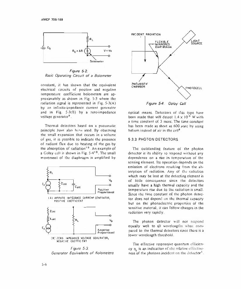
AM CP 706-1 aa
Basic Operating Circuit of a Bolometer
constant, it has shown that the equivaJent electricaJ circuits of positive and negative temperature coefficient bolometers are approximately as shown in Fig. 5-3 where the radiation signal is represented in Fig. 5-3(A) by an infinite-impedance current generator and in Fig. 5-3(B) by a zero-impedance voltage generator9.
Thermal detectors based on a pneumatic principle have also been used. By observing the small expansion that occurs in a volume of gas, it is possible to indicate the presence of radiant flux due to heating of the gas by the absorption or radiation' °. An example of a Golay cell is shown in Fig. 5-4' The small movement of the diaphragm is amplified by
(A) INFINITE - IMPEDANCE CURRENT GENERATOR, POSITIVE COEFFICIENT
tSi ZERO - IMPEDANCE VOLTAGE GENERATOR, NEGATIVE COEFFICIENT
Figure 5-3.Generator Equivalents o f Bolometers
optical means. Detectors of this type have been made that will detect 1.4 x I O'9 W with a time constant of 3 msec. The time constant has been made as short as 600 nsec by using helium instead of air in the cell8 .
5-3.3 PHOTON DETECTORS
The outstanding feature of the photon detector is its ability 10 respond without any dependence on a rise in temperature of the sensing element. Its operation depends on the emission of electrons resulting from the absorption of radiation. Any of the radiation which may be lost at the detecting element is of little consequence since the detectors usually have a high thermal capacity and the temperature rise due to the radiation is small. Since the time constant of the photon detector does not depend on the thermal capacity but on the photoelectric properties of the sensitive material, it can follow changes in the radiation very rapidly.
The photon detector will not respond equally well to all wavelengths when compared to the thermal detectors since there is a lower wavelength threshold.
T h e e f f e c t i v e r e s p o n s iv e q u a n t u m e f f i c i e n
c y r/j i s a n i n d ic a t io n o f t h e r e la t iv e e f f e c t i v e
n e s s o f t h e p h o t o n s i n c i d e n t o n t h e d e t e c t o r 3 .
5 - 6

AMCP 706-188
This quantity is defined as the ratio of the number of incident photons per unit time to the number of output events occurring in the same time
% = % (5-1
where% = effective responsive quantum effi
ciency, dimensionless% = actual responsive quantum effi
ciency, dimensionless= fraction of energy lost by reflec
tion, dimensionless£< = fraction of energy lost by trans
mission, dimensionless
By far the most important class of photon detector materials is that which includes semiconductors. The particular phenomena associated with the reaction of semiconductors to optical radiation are broadly classified as photoconductivity11.
In certain materials, it is possible to excite electrons in the crystal structure by infrared radiation absorption to the extent that they are emitted from the surface of the material and become free to be collected by an externa) anode3. This type of detector is called photoemissive.
The two basic types of photocells used in photometry are the photoemissive and the photovoltaic. The photoemissive cell is generally used where high sensitivity, stability, precision, and proportionality of output to illumination input are more important than portability of the instrument. The photovoltaic cell generally is used when simplicity of the instrument and portability are of importance.
Even though the difference in sensitivity between the photovoltaic cell and the photoemissive cel) is 500 pA lumen’1 and 10 pA lumen'1, respectively, amplification of the output of the photoemissive cell’ 2 can be up to 20 A lumen *.
The phenomenon of secondary electron emission from a material when it is bombarded with high velocity electrons has been used to develop a photocell having high internal amplification. Such a cell is known as a photomultiplier. Electrons ejected from the cathode as a result of light interaction are focused on another electrode where each incident electron produces a number of secondary electrons. These are focused on a third electrode and the process repeated several times. The electrodes at which the secondary electrons are produced are known as dynodes.
The great advantage of the photomultiplier cell is the extreme rapidity of its response to a transient or fluctuating illumination (as fast as I O’1 3 sec). In this respect it is greatly superior to a system consisting of an ordinary two- element photoemissive cell and an amplifier.
5-3.4 CELL CONSTRUCTION
The different types of photon detectors described jn the preceding paragraphs, when used in the visible and the UV regions, use filters or windows to increase or limit their spectral response. The filters used in the visible spectrum are generally of the color type, to limit the response of the detector to a particular type of light. The most commonly used window material in the UV region is lithium fluoride (LiF). Because of its good transmission properties between 1040 and 2000 A, it is often used to the exclusion of all other materials* 3.
Instruments used to measure the properties of IR radiation often require isolation in the form of transparent barriers or lenses or prisms to diffract the light. It is important to know the transmission limits in terms of wavelengths for the materials used in these instruments. Table 5-2 shows the upper limit of wavelength for transmission of a number of materials*.
In the use of any of these materials, it is important to consider the environment in
5-7
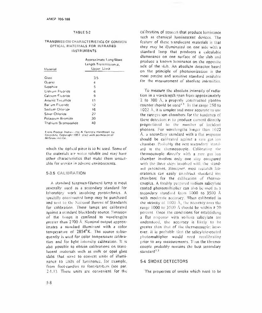
AM CP 706-188
TABLE 5-2TRANSMISSION CHARACTERISTICS OF COMMON
OPTICAL MATERIALS FOR INFRARED INSTRUMENTS
Material
Glass Quartz Sapphire Lithium Fluoride Calcium Fluoride Arsenic Trisulfide Barium Fluoride Sodium Chloride Silver Chloride Potassium Bromide Thallium Bromoiodide
Approximate Long-IAIave- Length Transmission A,
Upper Limit * 4 5 63.5456 9
111216273040
From Process Instrun rn ts A Controls Handbook by Considice. C opyrigh t 1957. LAed w ith permission o f McGravu-HlN Co.
which Hie optical piece is lo be used. Some of the materials are water soluble and may have Other characteristics that make (hem unsuitable For sendee in adverse environments.
5-3.5 CALIBRATION
A standard tungsien-fiJ ament lamp is most generally used as a secondary standard for laboratory work involving pyrotechnics. A specially constructed lamp may be purchased and sent to the National Bureau or Standards for calibration. These lamps are calibrated against a standard biackbody source. Emission of the lumps is confined to wavelengths greater than 2700 A. Nominal output approximates a standard illuminant wjth a color temperature of The source subsequently is used for color temperature calibration and for light intensity calibration. It is also possible to obtain calibrations on translucent materials such as milk or opal gjass slabs that serve to convert units of illuminance to units of luminance, for example, from foot-candies to foot-1 am burs (see par. 2-1.1). These units are convenient for the
ca lib ra tion of sources that produce luminance such as chemical luminescent devices. The feature of these translucent materials is that they may be illuminated on one side with a standard lamp that produces a calculable illuminance on one surface of the slab and produce a known luminance on the opposite side of the dab. An absolute detector based on the principle of photoionizalion is the most precise and sensitive standard available for the measurement of absolute intensities.
To measure the absolute intensity of radiation in a wavelength span from approximately 2 to 300 A, a properly constructed photon counter should be used13. In the range 250 to 1022 A, it is simpler and more accurate to use the rare-gas ion chambers for the tendency of these detectors is to produce current directly proportional lo the number of incident photons. For wavelengths longer than 1022 A. a secondary standard with a flat response should be calibrated against a rare gas ion chamber. Probably the best secondary standard is the thermocouple. Calibrating the thermocouple directly with a rare gas ion chamber involves onjy one step compared with the three steps involved with the standard procedure. Moreover, most research laboratories can easily construct standard ion chambers for the calibration of thermocouples. A freshly prepared sodium salicylate coated photomultiplier can also be used as a secondary standard from 1000 to 3500 A with moderate accuracy. When calibrated in the vicinity of 1000 A, the accuracy over the range 1000 lo 3500 A should be within ± 20 percent. Once (he conditions for establishing a flat response with sodium salicylate are understood, the accuracy is likely to be greater than that of the thermocouple; however. il is probable that the salicylate-coated photomultiplier would need recalibrating prior to any measurements. 7'lius the thermocouple probably remains the best secondary standard13
5-4 SMOKE DETECTORS
The properties of smoke which need to be
5-8
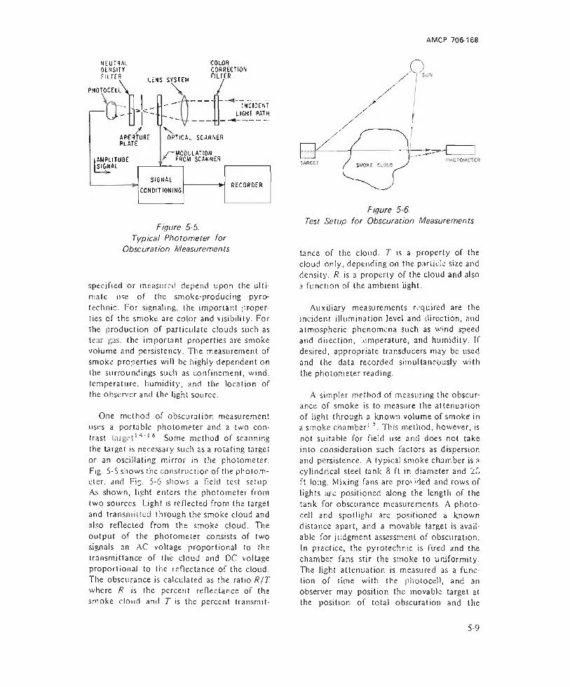
AMCP 706-188
NEUTRALOENSITYFILTER
o
Figure 5-5.Typical Photometer for
Obscuration Measurements
specified or measured depend upon the ultimate use of the smoke-producing pyrotechnic. For signaling, the important properties of the smoke are color and visibility. For the production of particulate clouds such as tear gas. the important properties are smoke volume and persistency. The measurement of smoke properties will be highly dependent on the surroundings such as confinement, wind, temperature, humidity, and the location of the observer and the light source.
One method of obscuration measurement uses a portable photometer and a two contrast target’4' 16 Some method of scanning the target is necessary such as a rotating target or an oscillating mirror in the photometer. Fig. 5-5 shows the construction of the photometer, and Fig. 5-6 shows a field test setup As shown, light enters the photometer from two sources. Light is reflected from the target and transmitted through the smoke cloud and also reflected from the smoke cloud. The output of the photometer consists of two signals an AC voltage proportional to the transmittance of the cloud and DC voltage proportional to the reflectance of the cloud. The obscurance is calculated as the ratio R/T where R is the percent reflectance of (he smoke cloud and T is the percent transmit-
Figure 5-6.Test Setup for Obscuration Measurements
tance of the cloud. T is a property of the cloud only, depending on the panicle size and density. R is a property of the cloud and also a function of the ambient light.
Auxiliary measurements required are the incident illumination level and direction, and atmospheric phenomena such as wind speed and direction, '.emperature, and humidity. If desired, appropriate transducers may be used and the data recorded simultaneously with the photometer reading.
A simpler method of measuring the obscurance of smoke is to measure the attenuation of light through a known volume of smoke in a smoke chamber1 7. This method, however, is not suitable for field use and does not take into consideration such factors as dispersion and persistence. A typical smoke chamber is a cylindrical steel tank 8 ft in diameter and 2C ft long. Mixing fans are pro' 'ded and rows of lights arc positioned along the length of the tank for obscurance measurements. A photocell and spotlight are positioned a known distance apart, and a movable target is available for judgment assessment of obscuration. In practice, the pyrotechnic is fired and the chamber fans stir the smoke to uniformity. The light attenuation is measured as a function of time with the photocell, and an observer may position the movable target at the position of total obscuration and the
5-9
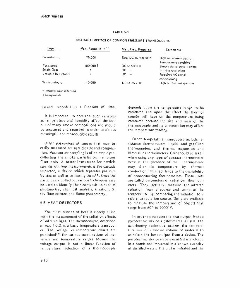
AMCP 706-168
TABLE 5-3CHARACTERISTICS OF COMMON PRESSURE TRANSDUCERS
Type Max. Range, lb in."2 Max. Freq. Response CommentsPiezoelectric 75,000 Near DC to 300 kHz High impedance output.Resistance Strain Gage Variable Reluctance
100,000 t ++■
DC to 500 Hz DC +DC +
Temperature sensitive Simple signal conditioning Infinite resolution Requires AC signal
Semiconductor 40,000 DC to 25 kHzconditioningHigh output, inexpensive
+ Depends upon mourning X Approximate
distance recorded as a function of time.
It is importanl to note that such variables as temperature and humidity affect the output of many smoke compositions and should be measured and recorded in order to obtain meaningful and reproducible results.
Other parameters of smoke that may be easily measured are particle size and composition. Vacuum air sampling is often employed, collecting the smoke particles on membrane filler pads. A better instrument for particle size distribulion measurements is the cascade impactor, a device which separates particles by size as well as collecting them18. Once the particles are collected, various techniques may be used to identify their composition such as photometry, chemical analysis, titration, X- ray fluorescence, and flame photometry.
5-5 HEAT DETECTORS
The measurement of heat is closely allied with the measurement of the radiation effects of infrared light. TTe thermocouple, described in par. 5-3.2, is a basic temperature transducer. The voltage vs temperature charts are published’ 9 for various combinations of materials and temperature ranges because the voltage output is not a linear function of temperature. Selection of a thermocouple
depends upon the temperature range to be measured and upon the effect the thermocouple will have on the temperature being measured because the size and mass of the thermocouple and its composition may affect the temperature reading.
Other temperature transducers include resistance thermometers, liquid- and gas-filled thermometers and thermal expansion and bimetallic thermometers. Care should be taken when using any type of contact thermometer because the presence of the thermometer may alter the temperature by ihermal conduction. This fact leads to the desirability of noncontactmg thermometers. These units are called pyrometers or radiation thermometers. They actually measure the infrared radiation from a source and compute the temperature by comparing the radiation to a reference radiation source. Units are available to measure the temperature of objects that range from 60° to 7000°F.
In order to measure the heat output from a pyrotechnic device a calorimeter is used. The calorimetry technique utilizes the temperature rise of a known volume of material to calculate the heat output from a device. The pyrotechnic device to be evaluated is enclosed in a bomb and immersed in a known quantity of distilled water. The unit is initiated and the
S - 1 0

AMCP 706-188
temperature change of the water is measured. The heat output is obtained by multiplying the temperature change by the effective heat capacity of the calorimeter system.
Heat flux measurements can be made using Specially calibrated temperature transducers. Commercial units are available utilizing foil and thermocouple temperature sensors that operate in the range of 2 to 500 cal/cm2-sec at temperatures up to I 500°F. Care should be exercised in applying calibration information because it is a function of the operating temperalure and the mounting methods.
5-6 PRESSURE TRANSDUCERS
There are many applications where the measurement of pressure is useful. Ejection systems, some flares, gas generators, whistles, and propulsion systems are all characterized by the generation of a gas pressure which may need to be measured and evaluated. Often it is necessary to know the peak pressure inside a casing in order to assess the weight versus safely and reliability aspects of a particular pyrotechnic device. Pressure transducers may also be used to evaluate the pressure of a gas evolved into a closed bomb of known volume. Commonly used types of pressure transducers and their range and frequency responses are shown in Table 5-3. In addition to absolute and gage pressures, transducers are available to measure the pressure differential between two points. Many transducers.are also available with signal conditioning equipment built into the transducers, producing an output voltage proportional to pressure.
The output of a pressure transducer is usually recorded as a function of time on a chart recorder or oscilloscope, depending on the frequency response and recording time required. The most useful parameters are peak pressure attained, time to achieve peak pressure, and duration of pressure. In mounting a pressure transducer-due to the phenomenon being observed-care should be taken to prevent damage to the transducer and yet obtain an accurate representation of the desired
pressure. If there is a g3$ flow in the area to be measured, the opening for the transducer should be at right angles to the flow. For best high frequency response, the pressure measuring element should be flush with the inside of the wall where the pressure is being measured. If necessary to protect the transducer from hot particles or fragments, the transducer may be isolated by means of a small orifice or protected by a coating of zinc chromate, putty, or silicone grease without appreciably affecting the frequency response.
Since all transducers mentioned except the piezoelectric will respond down to zero frequency, a deadweight tester may be used for static calibration. The low frequency response of piezoelectric transducers may be extenden sufficiently by means of high-input-impedance or charge amplifiers to permit static calibration. Calibration also may be accomplished by comparison with a calibrated transducer exposed to transient pressures, such as in a shock tube.
5-7 SOUND DETECTORS
The pyrotechnic applications of sound measurement include the evaluation of impact, vibration, and outpui from whistles, as well as the sounds associated with the firing of a weapon. The basic transducer for sound is the microphone. Common microphones are of the piezoelectric, condenser, or dynamic type. All types may exhibit a frequency response of approximately 20 liz to 20 kHz although special units are available for measurements outside this range, Both the piezoelectric and dynamic microphones are inexpensive and rugged and require only a simple voltage amplifier for signal conditioning. The condenser microphone, operating on the variable capacity principle, is easily calibrated but requires an external power supply and special amplifier. It is not affected by temperature to the extent that the other types are.
Typical measurements on a sound producing device include sound amplitude and frequency as a function of time, as well as

AMCP 706-188
(8 ) PIEZOELECTRIC TRANSDUCER ( Vol loge Generat ing)
Figure 5-7. Typical Signal Conditioning Circuits
5-12

AM CP 706-188
TABLE 5-4SIGNAL CONDITIONING REQUIRED FOR VARIOUS TRANSDUCER TYPES
TransducerTypa Example
Approx. Full Scale Output
Average Excitation, Volt DC
Lightdetector
Photomultipliertube
10 mA 1500
Light Photo- 6 pA Notdetector voltaic
tuberequired
Straingage
Pressuretransducer
10 mV 5
Resistive Pressu re transducer
5 V 5
Semiconductor
Pressuretransducer
100 mV 5
Thermo- Temperature 25 mV Notcouple measuretnerv requiredPiezoelectric
Microphone Notrequired
Pie20- Pressure 10 mV Notelectric tran sducer requiredCapacitor Microphone 150Moving coil Microphone Not
requiredVariablereluctance
Microphone Notrequired
harmonic content20. A typical measuring system can record and analyze sound intensities in the range of 30 to 170 dB. On the same scaie, a common conversation exhibits a sound pressure of 65 dB, the threshold of pain for humans is 120 dB, and the threshold of hearing is 0 dli I he data obtained may consist of a simple amplitude vs time record, or a more complex record of sound level vs frequency. The sound analyzer may also be used to indicate the energy of peel: pressure al each frequency or band of frequencies desired. These data are useful when analyzing structural resonances and noise outputs from rocket motors. A microphone may be calibrated either by comparing it with a microphone of known calibration, or by using a sound source of known characteristics. For
Configuration Amplifier LinearizationShunt load Impedance Not requiredacross P.M. matchinggives volt. onlyoutputVoltage DC Not requiredsource
Bridge DC Not required
Voltage May not be Not requireddivider requiredBridge DC Not required
Voltage DC RequiredsourceVoltage AC Not requiredsourceVoltage High imped Not requiredsource or charge
AC Not requiredVoltage AC Not requiredsourceVoltage AC Not requiredsource
accuracies approaching ±0.3 dB error, the closed coupler reciprocity technique is used.
5-8 SIGNAL CONDITIONING AND RECORDING
5-8.1 GENERAL CONDITIONING AND RECORDING EQUIPMENT
Hie function of signaJ conditioning equipment is to provide an interface between a transducer and a readout device ora recorder. Signal conditioning consists of one or more of Ihe following functions:
(I) Impedance matching and bridge completion
5-13

AJWCP 706-188
(2) Signal amplification or attenuation
(3) Transducer excitation
(4) Signal filtering or linearization
(5) System calibration.
Which of these functions the signal conditioning equipment must provide depends upon the type and range of the transducer, the input parameters of the recorder, the required frequency response, and the signal amplitude, duration, and character.
Typical signal conditioning requirements are shown in Table 5-4 and the signal conditioning equipment for several transducers is shown in Fig. 5-7.
The recorder selected must be capable of faithfully reproducing the highest frequency components of the inpuL signal and yet have sufficient time base length to record the total event. Often there must be compromise in this respect because recorders which have long time bases, such as chart recorders, do not have the resolution or frequency response to record high frequency signals. In cases of long events where is is desired to observe high frequency signals, it may be necessary to restrict the recording to only a portion of the total event by means of appropriate triggering s'gnals.
Impedance matching usually takes the form of an active device having a gain of approximately one, such as a cathode or emitter follower. Field effect amplifiers are also used with very high impedance devices such as piezoelectric transducers. In the case of some strain gage galvanometer-recorder combinations, the impedance matching consists only of resistors for damping and current limiting. A transformer may be used for impedance matching when there is an alternating current output from the transducer. Microphones and variable transformer transducers are representative of devices having an AC output.
Signal amplification includes the active devices necessary to amplify the transducer output so that it is of a magnitude acceptable to the recorder used. The attenuation function provides the range selection so that small signals may be resolved and yet large signals do not overdrive or saturate the recorder. In some situations the amplification and range ■ selection are accomplished in the recorder. A good example of this type of instrument is the cathode ray oscilloscope.
Transducer excitation consists of providing the necessary operating voltage or current to the transducer. For variable resistance, and strain gage devices this is in the range of 5 to 10 V DC. For capacitive devices and some photocells I 50 V DC is required. The photomultiplier tube may require as much as 1500 V DC. Variable reluctance and variable transformer devices require an AC excitation of approximately 5 V.
Signal filtering is used to attenuate or segregate various frequency components of a transducer output signal. For example, a low-pass filter may be used to attenuate high frequency signals which are not necessary for data evaluation and may saturate the recorder or make evaluation difficult. A high-pass filter may be used to suppress a direct current offset or eliminate power supply variations and ripple. Band pass filters are useful for determining amplitude of a signal at a specified frequency. An instrument incorporating a variable band pass filter is known as a wave analyzer and is useful for evaluating sound and vibration data. Signal linearization is used when the output of the transducer is not a linear function of the input parameter. This is the case with thermocouples and hot wire devices such as anemometers. The linearizer may be as simple as a logarithmic converter or as complicated as a computer program operating on digitized data. Often the linearization is done manually using a calibration chart or curves after the data are recorded.
The field calibration of a measuring system usually takes the form of an electrical signal
5 - 14
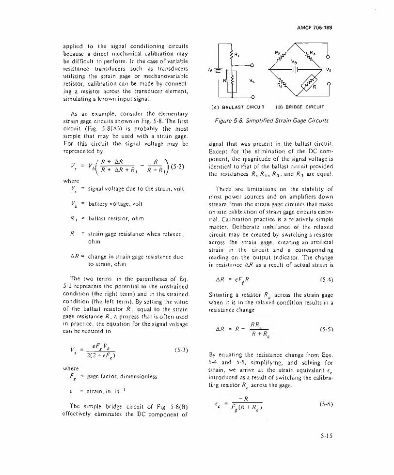
AMCP 706-188
applied to the signal conditioning circuits because a direct mechanical calibration may be difficult to perform. In the case of variable resistance transducers such as transducers utilizing the strain gage or mechanovariable resistor, calibration can be made by connecting a resistor across the transducer element, simulating a known input signal.
As an example, consider the elementary strain gage circuits shown in Fig. 5-8. The first circuit (Fig. 5-8(A)) is probably the most simple that may be used with a strain gage. For this circuit the signal voltage may be represented by
V =s
whereV = s
vb =
* . =
R =
AR =
/ R + AR _ R t>yR + AR+ R, R + R t
signal voltage due to the strain, volt
battery voltage, volt
ballast resistor, ohm
strain gage resistance when relaxed, ohm
change in strain gage resistance due to strain, ohm
Figure 5-8. Simplified Strain Gage Circuits
signal that was present in the ballast circuit. Except for the elimination of the DC component, the ryiagnitude of the signal voltage is identical to that of the ballast circuit provided the resistances R, R ,, R 2, and R? are equal.
The/e are limitations on the stability of most power sources and on amplifiers down stream from the strain gage circuits that make on-site calibration of strain gage circuits essential. Calibration practice is a relatively simple matter. Deliberate unbalance of the relaxed circuit may be created by switching a resistor across the strain gage, creating an artificial strain in the circuit and a corresponding reading on the output indicator. The change in resistance AR as a result of actual strain is
The two terms in the parentheses of Eq. 5-2 represents the potential in the unstrained condition (the right term) and in the strained condition (the left term). By setting the value of the ballast resistor f?, equal to the strajn gage resistance R, a process that is often used in practice, the equation for the signal voltage can be reduced to
AR - eFgR (5-4)
Shunting a resistor R across the strain gage when it is in the relaxed condition results in a resistance change
AR - R — RR.R
(5-5)
V - R b 1 2(2 + eFs )
whereFg ~ gage factor, dimensionless
e = strain, in. in.'1
(5-3)
The simple bridge circuit of Fig. 5-8(B) effectively eliminates the DC component of
By equating the resistance change from Eqs.5-4 and 5-5, simplifying, and solving for strain, we arrive at the strain equivalent ec introduced as a result of switching the calibrating resistor Rc across the gage.
- RF I R +R ) (5-6)
5-15
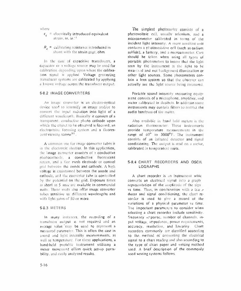
whereef = electrically introduced equivalent
strain, in. in.'1
Rc = calibrating resistance introduced in shunt with the strain gage, ohm
In the case of capacitive transducers, a capacitor or a voltage source may be used for calibration depending upon where the calibration signal is applied. Voltage generating transducer systems are calibrated by applying a known voltage across the transducer output.
The simplest photometer consists of a photovoltaic cell, usually selenium, and a microammetcr calibrated in terms of the incident light intensity. A more sensitive unit contains a photoresistive cell (such ascadium sulfide), a battery, and a microammeler. Care should be taken when using ail types of portable photometers to insure that the light seen by the instrument is the light to be measmed and not background illumination or other light sources. Some photometers contain a lens system so that the observer can actually see the light source being measured.
5-8.2 IMAGE CONVERTERS
An image converter is an electro-optical device used to intensify an image and/or to convert the input radiation into light of a different wavelength. Basically it consists of a transparent, conductive photo cathode upon which the object to be observed is focused, an electrostatic focusing system and a fluorescent viewing screen21.
A common use for image converter tubes is in the electronic shutter. In tliis application, the image converter consists of a conductive photocathode, a conductive fluorescent screen, and a fine mesh electrode or control grid between the anode and cathode. A high voltage is maintained between the anode and cathode, and the converter tube is controlled by the potential on the grid. Exposure times as short us 5 nsec are available in commercial units These units also offer image converter tubes sensitive to different wavelengths and with light gains of 5u or more.
5-8.3 METERS
In many instances, the recording of a transducer output is not required and an average value 'may be used to represent a measured parameter. Tins is often the case in sound and light intensity measurements, as well as temperature. For these applications, a hand-held portable instrument utilizing a meter movement offers quick set-up portability. and easily analyzed results.
Portable sound intensity measuring equipment consists of a microphone, amplifier, and meter calibrated in decibels. In addition some instruments may contain filters to restrict the audio bandpass of the meter.
Also available in hand held meters is the radiation thermometer. These instruments provide temperature measurements in the range of 60° to 3000°F. The i rtstrumeti t consists of an infrared detector and signal conditioning. The output is read on a meter, calibrated in temperature units.
5-8,4 CHART RECORDERS AND OSCIL LOGRAPHS
A chart recorder is an instrument whic converts an electrical signal into a graph representation of the amplitude of Che sign vs time. Thus, in combination with a Irur ducer and signal conditioning, the chart recorder is used to give a record of the variations of a physical parameter vs time. The important parameters to consider when selecting a chart recorder include sensitivity, frequency icsponsc, number of channels, input voltage, impedance, power requirements, accuracy, resolution, and linearity. Chart recorders commonly are classified according to the method of converting the electrical signal to a chan reading and also accordmg to the type of chart paper and writing method used. A brief description of the commonly used writing systems follows.
5-16
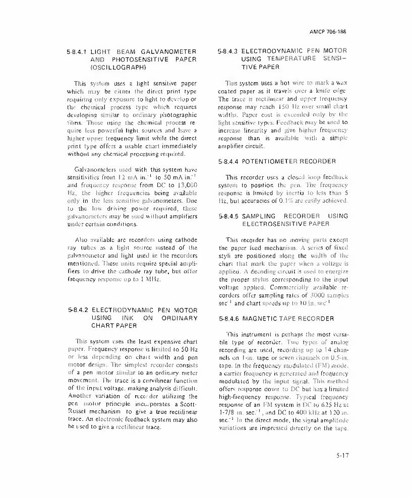
AMCP 706-186
5-8.4.1 LIGHT BEAM GALVANOMETER AND PHOTOSENSITIVE PAPER (OSCILLOGRAPH)
This system uses a light sensitive paper which may be either I he direct print type requiring only exposure to light to develop or the chemical process type which requires developing similar to ordinary photographic films. Those using the chemical process require less powerful light sources and have a higher upper frequency limit while the direct print type offers a usable chart immediately without any chemical processing required.
Galvanometers used with this system have sensitivities from 12 mA in .'1 to 50 mA in.'1 and frequency response from DC to 13,000 Ha, the liigher frequencies being available only in the less sensitive galvanometers. Due to the low driving power required, these galvanometers may be used without amplifiers under certain conditions.
5-8.4.3 ELECTRODYNAMIC PEN MOTOR USING TEMPERATURE SENSITIVE PAPER
This system uses a hot wire to mark a wax coated paper as it travels over a knife edge. The trace is rectilinear and upper frequency response may reach 150 Hz over small chart widths. Paper cost is exceeded only by the light sensitive types. Feedback may be used to increase linearity and give higher frequency response than is available with a simple amplifier circuit.
5-8.4.4 POTENTIOMETER RECORDER
This recorder uses a dosed loop feedback system to position the pen. The frequency response is limiied by inertia to less than 5 Hz, but accuracies of 0 .1 % arc easily achieved.
5-8.4.5 SAMPLING RECORDER USING ELECTROSENSITIVE PAPER
Also available are recorders using cathode ray tubes as a light source instead of the galvanometer and light used in the recorders mentioned. These units require special amplifiers to drive the cathode ray tube, but offer frequency response up to 1 MHz.
5-8.4.2 ELECTRODYNAMIC PEN MOTOR USING INK ON ORDINARY CHART PAPER
Tliis system uses the least expensive chart paper. Frequency response is limited to 50 H2 or less depending on chart width and pen motor design. The simplest recorder consists of a pen motor similar to an ordinary meter movement. The trace is a curvilinear function of the input voltage, making analysis difficult. Another variation of reco: der Utilizing the pen motor principle incorporates a Scott- Russel mechanism to give a true rectilinear trace. An electronic feedback system may also be used to give a rectilinear trace.
Tliis recorder has no moving parts except the paper feed mechanism. A series of fixed sty It are positioned along the width of the chart that mark the paper when a voltage is applied. A decoding circuit is used to energize the proper stylus corresponding to Lhe input voltage applied. Commercially available recorders offer sampling rates of 3000 samples sec'! and chart speeds up to 10 in. sec’1
5-8.4.6 MAGNETIC TAPE RECORDER
This instrumenl is perhaps the most versatile type of recorder. Two types of analog recording are used, recording up to 14 channels on I-in. tape or seven channels on 0.5-in. tape. In the frequency modulated (FM) mode, a carrier frequency is generated and frequency modulated by the input signal. Tliis method offers response down to DC but has a limited high-frequency response. Typical frequency response of an FM system is DC to 625 Hz at 1-7/8 in. sec.1, and DC to 400 kHz at 120 in. sec.'1 In the direct mode, the signal amplitude variations are impressed directly on the tape.
5-17
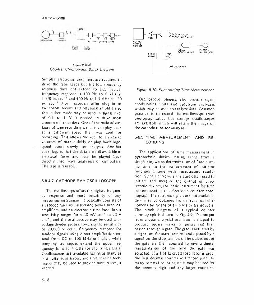
AMCP 706-188
- 0 * 0 0 0 -J j 10 >oo iooo
DfClMiL COUNTING uNHTS
Figure 5-9.Counter Chronograph Block Diagram
Simpler electronic amplifiers are required to drive the tape heads but the low frequency response does not extend to DC. Typical frequency response is 100 Hz to 6 kHz at 1-7/8 in. sec. 1 and 400 Hz to ) .5 MHz at 120 in. sec.'1 Most recorders offer plug in or switchable record and playback amplifiers so that either mode may be used. A signal level of 0.1 to I V is needed to drive most commercial recorders. One of the main advantages of tape recording is that it can play back at a different speed than was used for recording. This allows the user to scan large volumes of data quickly or play back highspeed event slowly for analysis. Another advantage is that the data are still available in electrical form and may be played back directly into wave analyzers or computers. The tape is reusable.
5-8.4.7 CATHODE RAY OSCILLOSCOPE
The oscilloscope offers the highest frequency response and most versatility of any measuring instrument. It basically consists of a cathode ray tube, associated power supplies, amplifiers, and an electronic time base. Input sensitivity ranges form 50 mV cm 1 to 20 V c m 1, and the oscilloscope may be used wit \ voltage divider probes, lowering the sensitivity to 20,000 V c m 1. Frequency response for random signals using direct amplification extend from DC to 100 MHz or higher, while sampling techniques extend the upper frequency limit to 4 GHz for recurring signals. Oscilloscopes are available having as many as 4 simultaneous traces, and time sharing techniques may be used to provide more traces, if needed.
Figure 5-10. Functioning Time Measurement
Oscilloscope plug-ins also provide signal conditioning units and spectrum analyzers which may be used to analyze data. Common practice is to record the oscilloscope trace photographically, but storage oscilloscopes are available which will retain the image on the cathode tube for analysis.
5-8.5 TIME MEASUREMENT AND RECORDING
The applications of time measurement in pyrotechnic device testing range from a simple stopwatch determination of flare burning time to the measurement of initiator functioning time with microsecond resolution. Since electronic signals are often used to initiate and measure the output of pyrotechnic devices, the basic instrument for time measurement is the electronic counter chronograph. If electronic signals are not available, they may be obtained from mechanical phenomena by means of switches or transducers. The block diagram of a typical counter chronograph is shown in Fig. 5-9. The output from a quartz crystal oscillator is shaped to produce square waves or pulses and then passed through a gate. The gate is actuated by a signal on the start terminal and opened by a signal on the stop terminal. The pulses out of the gate are then counted to give a digital representation of the time the gate was actuated. If a l MHz crystal oscillator is used, the first decimal counter will record ,usec. As many decimal counting units may be used for the seconds digit and any larger count re
5-18
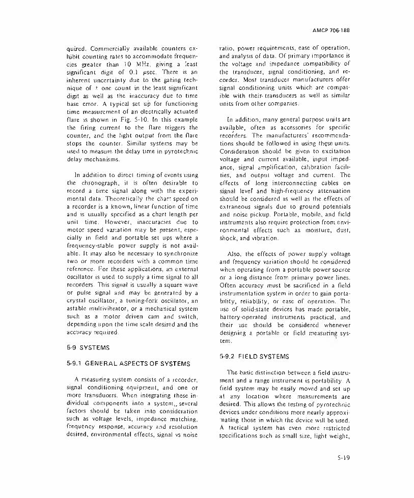
AMCP 706-188
quired. Commercially available counters ex- liibit counting rates to accommodate frequencies greater than 10 MHz, giving a least significant digit of 0.1 jusec. There is an inherent uncertainly due to the gating technique of ± one count in the least significant digit as well as the inaccuracy due to time base error. A typical set up for functioning time measurement of an electrically actuated flare is shown in Fig. 5-10. In this example the firing current to the flare triggers the counter, and the light output from the flare stops the counter. Similar systems may be used to measure the delay time in pyrotechnic delay mechanisms.
In addition to direct timing of events using the chronograph, it is often desirable to record a time signal along with the experimental data. Theoretically the chart speed on a recorder is a known, linear function of time and is usually specified as a chart length per unit time. However, inaccuracies due to motor speed variation may be present, especially in field and portable set ups where a frequency-stable power supply is not available. It may also be necessary to synchronize two or more recorders with a common time reference. For these applications, an external oscillator is used to supply a time signal to all recorders. This signal is usually a square wave or pulse signal and may be generated by a crystal oscillator, a tuning-fork oscillator, an astable multivibrator, or a mechanical system such as a motor driven cam and switch, depending upon the time scale desired and the accuracy required.
5-9 SYSTEMS
5-9.1 GENERAL ASPECTS OF SYSTEMS
A measuring system consists of a recorder, signal conditioning equipment, and one or more transducers. When integrating these individual components into a system,, several factors should be taken into consideration such as voltage levels, impedance matching, frequency response, accuracy and resolution desired, environmental effects, signal vs noise
ratio, power requirements, ease of operation, and analysis of data. Of primary importance is the voltage and impedance compatibility of the transducer, signal conditioning, and recorder. Most transducer manufacturers offer signal conditioning units which are compatible with their- transducers as well as similar units from other companies,
[n addition, many general purpose units are available, often as accessories for specific recorders. The manufacturers’ recommendations should be followed in using th$se units. Consideration should be given to excitation voltage and current available, input impedance, signal amplification, calibration facilities, and output voltage and current. The effects of long interconnecting cables on signal levef and high-frequency attenuation should be considered as well as the effects of extraneous signals due to ground potentials and noise pickup. Portable, mobile, and field instruments also require protection from environmental effects such as moisture, dust, shock, and vibration.
Also, the effects of power supply voltage and frequency variation should be considered when operating from a portable power source or a long distance from primary power lines. Often accuracy must be sacrificed in a field instrumentation system in order to gain portability, reliability, or ease of operation. The use of solid-state devices has made portable, battery-operated instruments practical, and their use should be considered whenever designing a portable or field measuring system.
5-9.2 FIELD SYSTEMS
The basic distinction between a field instrument and a range instrument is portability. A field system may be easily moved and set up at any location where measurements are desired. This allows the testing of pyrotechnic devices under conditions more nearly approximating those in which the device will be used. A tactical system has even more restricted specifications such as small size, light weight,
S - 1 9

and fast, reliable one ration. The basic concept of tactical measuring systems requires that all data analysis also be done in the field. One example of a tactical measuring system is the XM8 Chemical Agent .Alarm22. This unit is designed to give an alarm whenever toxic agents are present. The unit will detect quantities of toxic agent vapor below lethal concentrations in the presence of smoke, dust, motoi vehicle exhaust, or other pollutants normally found on the battlefield. The instrument weighs 18 lb and may operate in temperatures from -4U'J to 120°F for 12 hrI using a sell-contained power supply.
An example of a field used system is the Sound Analysis Laboratory developed by Frankford Arsenal20. This unit consists of a trailer mounted ancchoic chamber, measuring and recording instruments, and a gasoline engine-driven generator. The mobility of this unit enables it to be moved to the test area and set up in a short time. Instruments are available for recording and analyzing the sounds emitted from a pyrotechnic device and also for measuring the velocity of a projectile. Small devices may be mounted in the ane- choic chamber and tested under known acoustic conditions.
5-9.3 LABORATORY AND RANGE SYSTEMS
Although many pyrotechnic measuring
the techniques used may be of interest to anyone faced with a situation requiring measurement of pyrotechnic characteristics. The unique aspects of most systems are the test fixtures or chambers, so the choice of transducer is not restricted to only the make and model specified in the original system. Similar transducers may be used as long as the signal conditioning equipment is adjusted to suit the new transducer.
In the MAPI flare measurement system the transducer consists of an array of photocells which are scanned to give the light intensity at a given location23. Computer techniques are used to compute the candle power at each location and also the average candlepower. The data reduction equipment utilizes an automatic optical reader which analyzes the pulse height from an oscilloscope picture. The output is fed into a card punch which generates data cards in the proper format Tor computer processing.
Many times a measurement system is specified in the Military Specification for the pyrotechnic item. For instance, M1L-C-60303 contains the requirements for a facility to obtain the burning time and particle dispersion of a gas generating device24. Ollier Military Specifications give descriptions and requirements for facilities lor measurement of a specific parameter such as flare candle power without reterence to any particular pyrotechnic item1 5.systems have been developed for specific uses,
REFERENCES
1. D. M. i onsidine. Ed.. Process Instruments and Controls Handbook, McGraw- Hill Book Go.. New York, 1952.
2. R. D. Rusk, Introduction to College Physics, Apple ton-Gentury-Crotts Tnc., New York, Second Edition, 1960.
Jamieson, Plans, Richards. Infrared ing, McGraw-Hill York, 1963.
McFee, Grube, and Ph i sles and Enyfneer- Book Co. Inc., New
4. Application Data, General Characteristics o f Thermistors, Section 3704, Thermistors, General Characteristics, Magnetic Materials Section, General Electric Co., Ed more, ML, no date.
5. C. G. Cannon, Electronics fo> Speciro- scopists. Interscience Publishers Inc., New York. I960.
6. H- E. Thomas and C. A. Clarke, Handbook o f Electronic Instruments and Mea
5-20

AMCP 706-188
surement Techniques, Prentice-Hall, Englewood Clil’fs, NJ. 1967.
7. C. E, K, Mecs. The Theory o f the Photographic Process. "Hie McMillan Co., New York. 1942.
8. Smith, Jones, and Chasmar, The Detection and Measurement o f Infra-Red Radiation. Oxford University Press, Amen House, London, 1957.
9. R. C. Jones, Advances tn Electronics. Vol 5, Academic Press Inc.. New York, 1953, pp. 1-99.
10. M. J. E. Golay. "Theoretical Considerations in Heal and Infrared Detection with Particular Reference lo the Pneumatic Detector". Rev. Sci. Instr. 18, 347 (1947).
11. Breckenridge. Russell, and Hahn. Eds., Photoconductivity Conference, John Wiley and Sons. Inc.. New York, 1956.
12 J. W. T. Walsh, Photometry, Constable and Co., Ltd., London. 1958.
13. J. A. R. Samson, Vacuum Ultraviolet Spectroscopy, John Wiley and Sons. Inc., New York. 1967.
14. Earl S. Rosenlilurn, Feasibility and Exploratory Development o f Procedures and Instrumentation — ETC, Report66- 24G. GCA Corp., Technology Div., Bedford, MA, 1967, AD-81 5 105.
15. Lari S. Rosen blunt. Exploratory Development o f a Contrast Photometer and Its Methods o f Use for Field Evaluation o f Milli tary Obscuration System. Report67- 7-G, GCA Corp., Technology Div., Bedford. M A, 1967, AD-819718.
16. Earl S. Rosenblum. Exploratory Develop
ment o f a Contrast Photometer and Its Methods o f Use for Field Evaluation of Military Obscuration Systems. Report 67-14-G. GCA Corp. Technology Div.. Bedford. MA, 1967. AD-822 305.
17. George A. Lane. Arthur Smith, and Erwin M. Jankowiak. Novel Pyrotechnic Compositions for Screening Smokes. The' Dow Chemical Company, Midland, Ml, no date.
18. Albert Dciner and Merrill E. Milham,Measurement o f the Particle-Size Distribution o f Thermally Generated Smokes, Report EATR 4114, Edgewood Arsenal, MD. 1967.
19. Handbook o f Chemistry and Physics. Chemical Rubber Publishing Co., Cleve-' land. OH, 52nd Edition, 1971-1972,
20. Robert Markgraf. A Portable Sound Analysis Laboratory For Small Arms Weapons. Report R-1S78, Frankford Arsenal, Philadelphia, PA, 1967.
21 J. D. McGee, “Photo Electronic Image lniensificrs”, Reports on Progress in Physics. 24, 1 67 (1967).
22. “Chemical Field Alarm", Ordnance, LIII, 371, Jan.-Feb. 1969.
23. Ronald J. Stovall. General Description o f MAPI Data Acquisition Systems, Naval Ammunition Depot, Crane, IN, 1966, AD-801 278.
24. M!L-C-60303(MU), Cartridge, 40MM, Riot Control, CS. E24. Dept, of Defense, Oct. 1967.
25. MIL-C-18762 (NOrd). Candlepower o f Pyrotechnics; Method o f Measuring and Recording. Dept, of Defense, 29 June 1955.
5-21/5-22

AMCP 706-188
CHAPTER 6
TESTING
6-1 GENERAL DISCUSSION
6-1.1 THE TESTING PROGRAM
Test programs at various stages of the development and manufacture of pyrotechnic devices are required to assure that ammunition delivered for field use is free of defects, safe under all Held conditions, and that it performs as intended.
Tltis chapter presents the tests designed to evaluate safety, reliability of functioning, and the qualitative and quantitative methods currently in use for measurement of pyrotechnic effects.
For personnel unacquainted with pyrotechnic ordnance, purchase descriptions of existing military pyrotechnic devices which contain minimum requirements and instructions arc a guide for tests of similar new developments.
A typical flare Purchase Description1 contains a list of:
(1) Applicable Documents—including specifications, standards, drawings, and other publications
(2) Requirements—quantities and performance characteristics
(3) Quality Assurance Provisions
(4) Preparations for delivery
(5) Special NoLes.
The basic safety and reliability tests are those specified by Military Standard (MIL- STD) designations whicli are approved by the
Department of Defense to assure uniformity of test conditions to judge suitability under conditions of military usage.
A list of applicable Military Standards is contained in Table 6-1. Note that some tests are designed strictly to assess safety, Ammunition need not function after these tests. After the other tests, correct operation is demanded. Each specification listed contains the details needed lo perform the tests. General discussions of the standards are contained in other military handbooks2 3 4 5.
6-1.2 KINDS OF TESTS
The different types of tests used in the process of developing pyrotechnic ammunition are described in the paragraphs that follow.
6-1.2.1 DEVELOPMENT TESTS
Development tests are performed by the designing agency to be sure that component subassemblies or complete ammunition function in the manner for which they were designed. These tests evaluate the latest efforts of the designer and may be repeated until successful results are obtained. The ammunition is subjected to a series of tests that serve to determine that it is safe and reliable, and to ascertain its readiness for test and use by field forces. Part of the task of planning an ammunition development project is to specify the type of test, the order of execution, and other testing details.
Development tests are usually made in the laboratory or developer's testing facility and need not include all of the parts of the complete device.
6-1

AMCP 706-188
Type of Testa. Drop (Impact)
b. Rough Handling
c. Vibration
d. Radiation
e. Aircraft Survivability
TABLE 6-1
TESTS U T IL IZED IN THE DEVELO PM ENT OF PYROTECHNIC ITEMS
Specification Procedure Specification Title or Procedure Title
PassingCriteria
UsingService
MIL-STD-331 Test 103 Forty-foot Drop S A. N. AFMtL-STD-331 Test 111 Five-foot Drop 0 A, AFMIL-STD-331 Test 101 Jolt s A. N, AFMIL-STD-331 Test 102 Jumble s A, N. AFMIL-STD-810 Meth 516 Environmental Test
Methods for Aerospace and Giound Equipment Sh ock
0 AF
MIL-STD-331 Test 104 TransportationVibration
0 A, N, AFMIL-STD-810 Meth 514 Vibration 0 AFMl L-E-5272 XII or XJV 4.7 Vibration TestsDPS-1190 The Development of an
Engineering Taste Standard covering the Transportation Environment of Material
0 A
BUWEPS BUWEPS Code PREN s NInstruction controls all RAD HAZ5101.2A of 26 Apr 1962
Testing
MIL-P-24014 Preclusion of Hazards from Electromagnetic Radiation to Orcfrtance, General Requirements for
s N, AF
MIL-STD-331 Test 201 Jettison (Aircraft safe Drop) (Fuzes)
s A, N. AFMIL-STD-331 test 202 Jettison (Simulated
Aircraft Sale Firing from Ground Launcher) (Rocket Type)
s A, N, AF
MIL-STD-331 Test 203 Jettison (Simulated Aircraft Safe Drop, front Ground Launcher)
s A, N, AF
MIL-STD-331 Test 204 Jettison (Aircraft Firing) Rocket Type
s A, N, AFMIL-STD-331 Test 205 Jettison (Aircraft
Safe Drop) (Fuze System)
s A. N. AF
MIL-STD-331 Test 206 Accidental Release s A. N, AF(Low Attitude, Hard Surface)
6-2

AMCP 706-186
TESTS U T IL IZED IN
Type of Tasi Specification
e. A ircra ft Survivability (corn'd)
Ml L-STD-331
MIL-A-8591
f. Firing Train Interrupter
g. Bullet Impact
Ml L-STD-331
SMUPA-VL 222
h. Kinetic Heating
NAVWEPS WR-50 dtd 13 Feb 64
i. Miscellaneous Ml L STD-331 Ml L-STD-810 Ml L-STD-810 Ml L-STD-810 Ml L-STD-810 Ml L-STD-331 Ml L-STD-331 Ml L-STD-810 Ml L-STD-810 MIL-STD-810 Ml L-STD-331 MIL-STD-331BUWEPS Weapons Requirement WR11
TABLE 6-1
THE DEVELO PM ENT OF PYROTECHNIC ITEMS (Cent-
ProcedureSpecification Title or Procedure Title
PassingCriteria
Test 209 Missile Pull Off from Aircraft on Arrested Landing (Ground Launcher Simulated)
S
Carrier Suitability Remarks (Aircraft Catapult and Arrested Landing Test Conducted by NATC Patuxent River, Maryland)
S
Test 115 Static Detonator Safety S
Standard Procedure (or Rifle Bullet Impact Tests
S
Par. 5.2 Warhead Safety Tests, Minimum for Air. Surface and Underwater Launched Weapons (excluding Mine and Nuclear Warheads) Remark (No Standard tests in use by the Navy. Army or Air Force)
S
Test 105 Temperature Humidity 0Meth 507 Humidity (Cycling) 0Meth 501 High Temperature 0Meth 502 Low Temperature 0Meth 503 Temperature Shock 0Test 106 Vacuum Steam Pressure 0Test 107 Salt Spray (Fog) 0Meth 509 Salt Fog 0Meth 510 Sand and Dust 0Meth 513 Acceleration 0Test 108 Waterproofness 0Test 114 Rough Handling
(Packaged) 0Design and Test of Packaging, Packing, Shipping and Handling Equipment for Weapon System Components
0
d)UsingServiceA. N. AF
N, A, AF
A, N, AF
A
N, AF
A, N. AFAFAFAFAFA, AF A. N AF AF AFA. AFAN
6-3

AM CP 706-1 OB
TABLE 6-1
TESTS U T IL IZED IN THE DEVELOPMENT OF PYROTECHNIC ITEMS (Corn'd)
Type of Test Specification ProcedureSpecification Title or Procedure Title
RailingCriteria
UsingService
i. Miscellaneous Ordnance Part Picatinny Arsenal 0 A(cont'd) 8837375
MIL-STD-331 Test 110 1
Experimental Testing Criteria for Shipping containersFungus (Components 0 AF
MIL-STD-810MlL-STD-810
Meth 508] Meth 512
only)Leakage (Immersion) 0 AF
Tests Not Named >r» Body of Chart;MIL'STD'33l • Fuze and Fuze Components, Environmental and Performance Test for Tests
109, t 12,1 13,207,208,2 (0 ,2 ! 1 , 212, 301. 302, 303.MIL-E-5272 ■ Environmental Testing, Aeronautical and Associated Equipment, General Specification forMIL-R-22449 (W£P) - Requirement (Certification) for Pyrotechnic Items
AH tests except OPS-1190, MIL-STD-331 Test 114, fvUL-STD-810 Method 516, BUWEPS Weapon Requirement WR-t1 and Ordnance Pert 8837375 are performed o n unpackaged items. Packaged as well as unpackaged items are tested under M IL STD-810 Method 514.
Key to last two columns,Passing Catena $- safe O - safe and operable Using Service: A-Army. hJ'Nsvy, AF- Air Force,
6-1.2.2 EVALUATION TESTS
Evaluation tests are made to assess the usefulness of a pyrotechnic system. It is used to expose the characteristics of hardware to observation by personnel experienced with pyrotechnic applications. An evaluation of a flare launcher3, for example, includes a description of the launcher, evaluates projected altitude, illumination duration, effects of water soaking, day and night range, and ability to penetrate foliage; compares the performance of cal .38 with cal .45 cartridges; and makes recommendations.
Evaluation tests are usually carried out at a test center under field conditions using the complete device.
6-1.2.3 SERVICE TESTS
Service tests are intended to determine the suitability of hardware for use by the military under field conditions. They compart the hardware with requirements set down in the documents for the device being tested. The tests are always carried out on the complete device under field conditions.
Acceptance tests are one form of service test.
G-1.2.4 SURVEILLANCE TESTS
Surveillance tests are made on specific lots of ammunition taken from storage to determine if changes are needed in components to provide satisfactory operation as well as to determine the degree of degradation of the original lot4. Such tests should include adequate sampling of the lot to assure true representation and isolation of troublesome components and adequate tests to assure satisfactory performance of renovated ammunition. Tests of this nature will salvage lots of satisfactory ammunition whenever possible.
6-1.2.5 MALFUNCTION TESTS
Malfunction tests are carried out whenever failures have occurred5. The rationale and planning for such tests is usually the responsibility of the investigator. Special tests are applied lo pinpoint the cause of failure and for recommending corrective action.
6 - 4
AMCP 706-188
6-1.2.6 NATO TESTS
NATO tests are prescribed for safety and environmental survival of all ammunition planned for use by NATO countries. Engineering design tests are listed for airborne devices for both unpackaged stores and packaged stores. An approved test series does not currently exist.
6-2 LIGHT
6-2.1 GENERAL
Light producers may be tested by use of human observers, simple electrical light detectors, or complex arrays of light detectors coupled to recording instruments and to computers for analysis of the light intensity and spectra) content as a function of time.
Observers are used in many field situations that are difficult to assess by instrumentation systems and hence play an Important role in the ultimate testing of pyrotechnic light produoers Many lest programs for quality assurance of existing candles and the development of new types are performed indoors at large military installations having flare tunnels. A few instrumented outdoor sites are available to evaluate the light output from complete pyrotechnic ammunition under a semblance of field conditions.
6-2.2 LABORATORY TESTS
The candle of a pyrotechnic device is usually tested as a separate component in development, production, and quality control efforts. Candles with outputs up to 106 candlepower are commonly tested in areas equipped to contain the burning candle safely and to measure (he emitted light under controlled conditions. Fig. 6-16 shows typical hearths or fireplaces and light tunnels used by the military for indoor measurements. These facilities are very well suited for making comparative measurements of burning time and candlepower of flares, but caution is required in relating values to those obtained
in different tunnels, outdoor facilities, and actual end item conditions. Large variations can easily occur depending on the lest system, test procedures, and the inherent variability of the flares. If the candle is tested with its burning surface upward, for instance, it will give a larger reading than if faced downward — due to the resulting differences in flame shape and smoke patterns.
Usually large volumes of smoke issue from the test flare which can reflect light or obscure the flame depending upon the motion of the smoke. Blowers and dampers are used to adjust the wind velocity to maintain control of this variable. Light intensity measurements in tunnels are affected by the following variables:
(1) Power density radiated by flare
(2) Area of the flare in the field of the photocell
(3) Smoke screening the flare from the photocell
(4) Fjcld of view of the photocell optical system
(5) Reflectivity of the background
(6) Accuracy of the spectral correlation
(7) Accuracy of the intensity calibration.
The flare is not truly an iseniropic source as assumed in calculations because flux is not radiated uniformly over the entire burning surface. Radiation from the cylindrical sides may be twice that from end on. Measurements in tunnels normally are made from the side of the flare.
Intensity readings also will be incorrect if the field of the optica) system includes only a portion of the flame produced by the flare. The entire flame produced by the llarc should be in the field of view of the photocell and any light reflected from the smoke in the
6-5
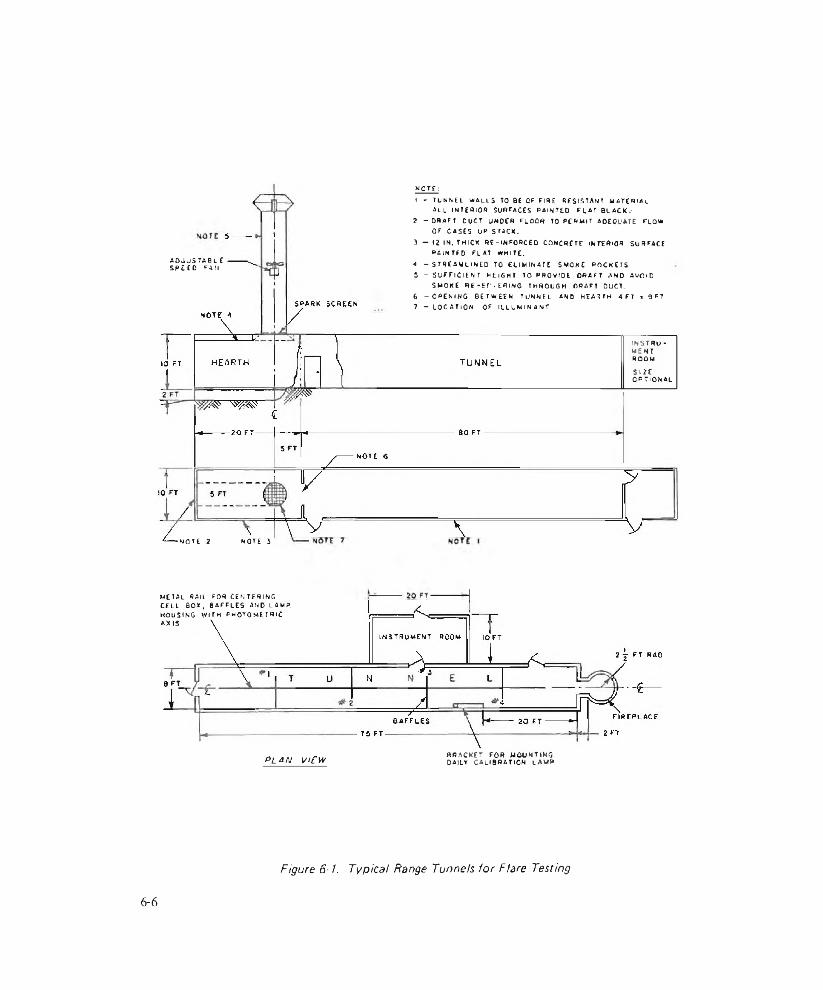
KQT£ ;
adjustableSPEEO FAN
1 - TUNNEL WALLS TO BE OF FIRE RESISTANT MATERIALa l l in t e r io r surfaces p a in t e d f l a t b l a c k .-
2 - DRAFT OUCT UNDER FLOOR TO PERM IT ADEQUATE FLOWOF CASES UP STACK.
3 — (2 IN. THICK R f -INFO RCE D CONCRETE INTERIOR SURFACEPAINTED FLAT WHITE.
A -S T R E A M L IN E D TO ELIMINATE 5 MOKE POCKETS5 - S UFFICIENT HEIGHT TO PROvrDE. DRAFT AND AVOID
SMOKE RE - E f » EflING THROUGH DRAFT DUCT.6 - O P E N I N G BETWEEN TUNNEL a n d HEARTH A F Y x OFT7 - LOCATION OF ILL U M IN A N T
I N S T R U MENTROOM
SIZEo p t i o n a l
-NOTE 2 NOTE }
METAL RAIL FOR CENTERING CELL BO*, BAFFLES AND LAMP. HOUSING w ith p h o t o m e t r ic AXIS.
plan view BRACKET FOR MOUNTING DAILY CALIBRATION LAMP
Figure 6-1. Typical Range Tunnels for Flare Testing
6-6
AMCP 706-188
Figure 6-2.Typical Outdoor Flare Test Facility
vicinity of the burning Hare should be kept to a minimum.
Background reflections can produce particularly large errors in the measurements and should be avoided. Apparent increases up to 40% have been noted by reflections from the tunnel floor. It is necessary to restrict the view of the measuring instrument to that portion of the flare producing the light. Spectral correction conforming to the response of the International Commission of Illumination and intensity calibration with standard sources for the test equipment are also required.
(A) Side v>£w
ri -i
(8) io"> mew
Figure 6-3.Photocell Layout at MAPI Test Site
The light output of small arms tracer projectiles is measured in a spinner that spins the tracer projectiles at high cyclic rales (up to 130,000 rpm) which simulates the down range flight of the projectile. Tracer light is observed by a photocell the signal of which is fed to an oscilloscope. The Irace is then recorded photographically. As a result of these laboratory tests, costly filing programs can be minimized. Typical output exhibited by cal .50 tracer is 600-900 candlepower7. Detailed test procedures arc contained in Ref. 8 .
The practical difficulties in measuring true candle power of pyrotechnic flames makes it desirable to refer to candlepower measured in accordance with a given specification6 , nevertheless, measurements made under comparable conditions are valuable to rate light output and to maintain quality standards.
6-2.3 FIELD TESTS
The flame size and volume of smoke produced by some flares such as the XM165 are too great for indoor tests. Such flares are tested outdoors at test sites that are relatively flat open areas approximately 400 ft in
6-7

AMCP 706-188
diameter and have a means ot suspending the flare al least 80 ft above the center of the plane containing the photocells (Fig. 6-2).
The Mulii-Aspect Assessment of Pyrotechnic Illumination (MAPI) site at Naval Ammunition Depot (NAD), Crane, Indiana, is an example of such a site. It contains a grid work of cells at various angles on a ground plane which are directed at a flare suspended 80 ft above the center of the gridwork between two towers (see Fig. 6-39). The output from the cells is fed to recorders and data processing equipment to determine average candlepower as a function of time and radial distribution about the suspended flare.
Picatinny Arsenal has recently developed instrumentation that will permit dynamic assessment of actual rounds as fired by a variety of launchers. The round is fired over a matrix of detectors which will respond only jf a predetermined light level has been exceeded. The detector field is sampled periodically at a fixed rate and visual presentation of the performance is obtained electronically at a central control station, This facility being installed at the Yuma Proving Ground in Arizona will offer more realistic estimates of the effects of environmental conditions, the contributions made by associated flare hardware. and the effect of the ballistic forces on candle performance.
Often the most practical method of evaluating Light effects is visual observation supplemented with photography. Small arms tracers, for example, arc viewed by two observers located 75 yd perpendicularly to the line of the trajectory10. A camera is located in front of the weapon in such a way that the field of view covers a distance of I 5 to 125 yd on the trace path. Lights are located at the I 5- and 125-yd points along the trace path to serve as markers since the tests are made in darkness. The camera is mounted on a tripod that can be tilted after each shot so that 2S cartridge traces may be recorded on one film plate.
An instrumented test range has been opera
tional since 1970 at the Yuma Proving Ground11. The range permits the evaluation of pyrotechnic flares under dynamic conditions. The output (illumination, duration, and pattern) of the flares is measured under conditions approximating tactical situations.
The light sensing system consists of 361 photocell sensors arranged in a square of 19 by 19 rows with a separation of 450 ft between sensors. The sensors are highly stable silicon solar cells corrected with filters to the response of the human eye. The light received is compared with either a 0.05 or a 0.20 footcandle reference level, as desired. Suitable instrumentation reads the output of the sensors sequentially-it takes about 6 msec to scan the complete field and transmits the output to the display and recording units. At the same lime three cinetheodolites track and record the space position of the descending flares.
The test range has three limitations: (1) the system measures only two threshold levels (0.05 and 0.20 footcandle), (2) testing periods are limited to moonless nights, and (3) data acquisition and reduction man-hours are excessive. However, preliminary tests successfully evaluated pyrotechnic luminants under actual firing conditions. Developments are currently under way to alleviate the limitations.
6-2.4 COLOR MEASUREMENT
Color of light-producing illuminants is assessed by visual observation of flare burning or by the use of instruments ihat can dissect the light into characteristic colors or wavelengths. Quantitative specfral data allow the engineer to observe dilution of a desired color by unwanted colors, thus enabling him to make corrections. These procedures may also be used for quality conirol in the production of flares.
A flare radiometer has been developed by Picatinny Arsenal for rapid and simple specia l examination of illuminating Hares and
6 -8
AMCP 706-188
Chamber for Preliminary Observation of Smoke Producers
similar pyrotechnic devices17. The instrument consists of ten interference filters covering the visible spectral region. The filters are chosen to have a uniform spectral response at a precisely chosen peak wavelength. Miniature photocells positioned behind each of the ten filters have trimming resistors which are adjusted to provide a uniform output across the Spectrum. When the radiometer is directed at a source, each filter is illuminated in sequence from blue to red by a motor-driven elliptical minor. The optics are arranged so that every cell secs precisely the same field of view. A marker cell is provided to identify the beginning of each sweep.
Many modem facilities are equipped to digitalize the analog data of the type described for use in immediate computation or storage on magnetic tape for later use. Present equipment will sample analog data at the rate of 50,000 times per second and provide digital output with a definition of 0.1% (Ref. 13). Up to 30 spectral dislributions per second may be calculated with computers, a task requiring 30 manhours by manual methods. Correction for human eye response is made automatically. Candlepower is computed by integration of the luminous intensity over the wavelength range of interest. Dominant wavelength and purity are determined by multiplying the radiant energy disuibutton hy the three color distributions of the International Commission of Olumina-
Figure 6-5.Laboratory TOP Measurement Chamber
tion, wavelength by wavelength. Chromaticjty coordinates are calculated from the integrals under the three product curves and plotted in a chromaticjty diagram to determine dominant wavelength and purity.
6-3 SMOKE
6-3.1 GENERAL
In early stages of development-when gross effects are sought—much is gained by simple, visual observation of the smoke produced. Visual observation is usually followed with still and motion photography to make better estimates of volume and color. In the case of screening smokes, quantitative measurements of the obscuring power can be made by measuring the attenuation of light by the smoke. Signaling smokes have four properties of importance to the military- color, visibility, duration, and volume.
Since instability is one of the main features of the smoke cloud, its ability to persist is usually judged by comparing it with smoke from a control burned simultaneously within close proximity of the test smoke generator. Care must be taken so that two independent plumes are observed under similar atmospheric conditions. For smoke detection instrumentation see par. 5-4.
6-3.2 LABORATORY TESTS
The test volume of Ihe equipment in use to
6 - 9

AMCP 705-188
measure Smoke production may vary from a few cubic feet to several thousand cubic fee t'4. The test chambers usually provide glove holes for manual manipulations; parts or fittings for air, smoke, and exhaust, and an optical system for obscuration measurement as is shown in Fig. 6-4. Some chambers also provide means for controlling the temperature and humidity of the system.
The screening value of smokes is determined by a figure of merit known as the total obscuring power (TOP), the area in square feet that can be obscured by a pound of smoke formulation.
TOP can be determined either by measuring the light attenuation produced by smoke or by adjusting the position of a target located in the smoke until the target is obscured in chambers similar to the one shown in Fig. 6-5. The light attenuation method changes the concentration of the smoke and maintains a constant distance from the light source to the photocell.
The light transmission method of evaluating obscuring power15 Beer-Lambert relationship
is based on the
/ = c (6-1)
where/ - observed light intensity, c
whereC = concentration of smoke required for
obscuration (the weight of smoke producing formulation used divided by the chamber volume), lb ft'3
Lt - fixed distance between the lamp and the photocell, ft
The concenuation of smoke from Eq. 6-1 is related to the concentration expressed in Eq. 6-2 by the relation
C = YC>; lb f t'3 (6-3)
where Y is the yield or the ratio of the weight of aerosol produced to the unit weight of smoke-producing composition. These three equations, Eqs. 6-1, 6-2, and 6-3, can becombined;
TOP = eY (6-4)
where / is the transmitted light intensity under obscuration conditions. A ratio of 0.0125 for / // has been adopted as the obscuration point by some researchers based on physiological studies of the discriminating capacity of the human eye. Introduction of this limit into Eq. 6-4 yields
TOP t nil,11 n )( In Q A lS K l '
(6-5)
1 = initial intensity without smoke0present, c
C = concentration of smoke, lb ft 3
L - path length, ft
e ~ scattering or extinction coefficient, ft- lb '1
( 0-2)
For fixed chambers and weights of smoke- producing compounds, tlus equation reduces to
TOP = K !og(/(//c ) (6-6)
If dilute smokes arc used, so that particle coalescence is minima), tliis relationship is valid and useful for rating the quality of smoke mixes.
A cylindrical steel tank with dimensions of 28 ft long, and 8 ft in diameter has been used successfully by NAD Crane15. Three mixing fans, equally spaced along one side of the
6-10
AMCP 706-188
chamber, provide for homogeneity of the chamber contents. Two rows of eight 60-W lamps run the length of the chamber to provide illumination for a track-mounted movable target that may be viewed through a port. A flood light, optically in line with a collimator, and a photocell provide for attenuation measurements.
Smoke producers arc activated at the tank center and their product is stirred constantly by the fans. Light attenuation measurements are begun three minutes after activation of the smoke producer; and a minute later visual observations are begun to determine obscuration, usually at five minute intervals. Since a number of units are evaluated, minimum light transmission and maximum target obscuration are used as represen ta five values for the particular device.
Titanium tetrachloride (FM) is used as a standard in this instance for conven'ence and because it is less corrosive than FS (sulfur trioxide-chlorosulfonic acid solution) that is usually used for calibration.
6-3.3 FIELD TESTS
In the field, observers are often used in the assessment of smoke producing ammunition. A number of observers are commonly used in order to obtain statistically significant results. Any person with serious visual defects is eliminated, usually by tests made immediately before the observation. Color blindness of observers is particularly searched out when testing colored smokes. Observers are sometimes supplied with binoculars during tests of smoke. They compare performance with controls having well-known characteristics.
Wind tends to produce both good and bad effects in smoke production and use. In outdoor tests of smoke producers, wind speed and direction are normally recorded. Wind may aid in distributing the smoke for screening purposes. If the smoke is produced continuously, wind often helps to pinpoint a marked area by observing the origin of (he plume. On the other hand, the wind may scatter the smoke.
to'
I0U10’
PROCEDURESet film eating on melee Select F stop Find normal exposure lime (1/10 to 1 /500 sec)Use normal exposure time rind desired filter factor to find required “ Long Exposure"
IIOz I03
" lo n g EXPOSURE" REQUIRED, secIQ- 105
Figure 6-6. Factors for Long Time Exposures (Panaxomic X Filmj
AMCP 706-188
In testing field-ready smoke producers, each sample is numbered; and ignition time and burning time of each sample are recorded16. Comments are recorded to describe out-of-ordinary conditions that may occur during the test-such as excessive sparking upon ignition, flame-ups while burning, and fuze failures.
6-3.4 PHOTOGRAPHIC TECHNIQUES
Smoke plumes have been studied with time-exposure photography17. Long photographic exposures (measured in minutes) of smokes have been applied in a number of technical applications in which diffusion of smoke into the atmosphere is of interest. Time-exposure photography in daybght requires one or more of the following: very slow film, small apertures, or dense filters. If these conditions cannot be obtained, an alternative is to make dispersion photographs under conditions of twilight.
Fig. 6-6' 7 serves as a guide for exposure time, filter requirements, and aperture settings. The Tilter factor on the ordinate represents the light reduction by the action of a filter. A one-percent neutral-density filter has a filter factor of 100. Two of these would combine to have a filter factor of 10,000. A IVratten No. 25 (red) filter has a factor of eight. Each of the plotted lines in the figure is coded with exposure times that are read from a light meter. The corresponding aperture used on the light meter is used in the practice of setting up the camera. The exposure time required for the given aperture and filter factor is read on the abscissa.
The data shown in Fjg. 6-6 were determined by trial and error using Pan atomic X film; however, limited tests with Polaroid, Kodachrome, Plus X, and Microfilm indicate that little or no modification of the curves will, be required for successful results at exposure times of up to 15 min.
Plumes recorded on photographs may be analyzed to determine dispersion coefficients.
This method employs Roberts’ opacity theory to define the visible edge of smoke plumes, maximum plume width and length, and ratios of these to determine dispersion parameters. The vertical dispersion coefficient C is given by y
< 6 - 7 >
wheren = Sutton’s stability parameter
T ^n = ln ( y j y m )
y, = total plume length, m
y = distance from the source to the pointpoint of maximum plume width, m
x - maximum plume width, m
Motion pictures are used in the same manner as time exposures to determine dispersion coefficients.
6-4 HEAT
Incendiary devices are normally evaluated in terms of their ability to inflict specific damage against specific, defined targets such as burning a hole through metal plates18’1'5. The Hand Grenade. Incendiary, TH 3, AN- M14, for example, is required to burn through a steel plate 1/8-in. thick. The burning time (40 sec in this grenade) is another of the parameters that is commonly measured.
Attempts have been made to improve the testing of heat producers by the use of photographic techniques, spectrometers, and radiometers10. The following factors should be measured or assessed qualitatively in tests of flame producers:
(1) Fuel dissemination in terms of “ blob” size, spectral and spatial distribution
(2) Percentage of fuel ignited
(3) The adhesiveness of fuel “blobs” lo
6-12

AMCP 706-188
different surfaces as a function of the type of surface, “ blob” velocity, and altitude
(4) Fuel spread and run-off during burning
(5) Oxygen depletion or contamination
(6) Heating of the air in the vicinity of the target
(7) Damage capability as a function of target type.
Quantitative methods for evaluating all these factors have not yet been devised, Spectroradiometric methods may be useful in some aspects of these problems but are not likely to play a dominant role in evaluation of effectiveness against targets of flame producing weapons.
Photography with infrared film and appropriate fillers can provide an effective means of evaluating the temperature distribution over the surface of a large flame, provided the fuel is relatively homogeneous and the observation path is also homogeneous. The film should be calibrated with a blackbody source of IR, and the calibration Him and recording film should be processed identically.
Small arms incendiary rounds are evaluated by firing them against aluminum target plate. These rou nds are fi red to pene tra te the aluminum plate in rows to conserve target materia). Each shot is photographically recorded for flash characteristics. Acceptance is based on a comparison of the photographic results with photographic standards representing the minimum acceptable flash for that type of round.
6-5 GAS-OPERATED DEVICES
Pyrotechnic gas generators may be designed to produce various quantities of gas at various rates and temperatures and under a variety of loading conditions. H is good practice to test gas generators under conditions nearly the same as those anticipated in use. Special test
fixtures may be necessary for close simulation, but ordinarily closed bomb tests with a fixed volume approximately equal to the volume in the actual application will suffice2 1.
A closed vessel of adequate strength to withstand the pressure released from the gas generator is used with proper instrumentation to measure pressure as a function of time.
Normally, the volume of the closed bomb is fixed but some bombs are made so the volume can be changed by the use of inserts or an adjusting plug. Some test fixtures provide for expansion of the chamber with a movable member as pressure is applied from the pyrotechnic gas producer. This type of test measures the ability of the charge to deliver a certain minimum quantity of work. The pressure in the chamber and the displacement of the movable member are both measured as a function of time. Piezoelectric gages are most often used for pressure measurements and capacitance, inductive, or resistive elements for the displacement measurement.
Similar tests are made on propellant actuated devices used to eject or separate components of pyrotechnic ammunition. Pressure and time are monitored in the charge container as observations are made on system motion Or trajectory.
Piston, dimple, and bellows motors are actuated by expanding gas. These motors are evaluated using force measuring transducers or by working them against springs. These devices are nominally closed and sealed. Testing includes measuring the time (1) from initiation impulse to start of motion, and (2) from start to the end of motion. The designer must be concerned with the input such that the electrical power is sufficient to ignite the explosive material. Also he must consider the output of the explosive material so that excessive pressure is not created in the container that may puncture it or cause leakage at the joints.
6-13
Problems that will be encountered in the testing of gas producers include the provision of adequate seals at the interface of the generator and pressure bomb, and at the pressure transducer. Copper washers are often helpful in both places. Some pressure transducers are fitted with beveled plugs that fit into similarly contoured seats. Further problems will be encountered in providing protection for the face of the pressure transducer that may, in some instances, be exposed to the hot gases or particles from the pyrotechnic gas generator. Manufacturers of pressure gages often recommend lubricants, either semifluid Ot dry, that provide adequate protection of the gage interfaces in these circumstances without materially altering transducer performance.
6-6 CHEMICAL AGENTS
Chemical agents are disseminated in the form of small liquid droplets or small solid particles. The particle size, shape, and concentre I ion of these substances are the important variables in their role as chemical agents12. Particle size and concentration are usually measured to assess effectiveness of pyrotechnic chemical generators, j.e., pyrotechnic munitions that produce clouds of chemical agents. Microscopy, sieving, sedimentation, light scattering, and impaction methods have all been used to determine particle Size with some success23. While particle size in itself is of little value, it is related to a number of other factors that become important in the evaluation of these generators. The human respiratory system is one of the finest aerodynamic classifying systems for airborne particles-rejecting or returning most particles that fall outside the range 1 to S microns. Hence, particle size becomes a critical factor.
Cascade impactors have become a major means of monitoring particle size included in the broad impaction and impingement category. First models of impactors were chambers with an adhesivc-coated slide on one side and an orifice at right angles to the slide. A spring-operated piston sucked samples
Cove< for changing slides
Reprinted wilh permission from Green & Lane, P a rtic u la te C lo u d s : Sm okes a n d M ists , E,F.N. Span Ltd, London,1957.
Figure 6-7. Diagram of Cascade ImpacTor
through a cylinder on the outside of the chamber to produce impact of the sample with the plate. The particles collected on the plate were examined under a microscope to determine particle size and distribution.
A cascade impactor was then developed which maintained a vacuum at a fixed rate. Impact takes place in separate chambers that may vary in number depending upon the design of the instrument24. The sample is passed through progressively smaller orifices, each in a separate chamber and each having its own collection plate, as shown schematically in Fig. 6-724 . This arrangement permits segregation of the contents of the sample by particle si2e. Each plate then has particles within specific statistical variations of sample size, although the size ranges will overlap to some extent as shown in the generalized example of Fig. 6-824.
6-14
AMCP. 706*188
D ta m e te r o f D r o p le t , m ic r o n
Reprinted with jx^rmission fiom Green & Lane, P a n ic u la te O o tid s D usts, S rn o ke s a n d M ists. E.F.N. Spon Ltd, London 1967.
Figure 6-8.Efficiency Curves for Four Stages o f a
Cascade impactor
Limits on particle size for cascade im- pactors arc approximately 200 microns on the upper end o f the scale and particles as small as 0.2 micron have been collected with certain instruments. Considerations in the design of impactors include case of slide removal, portability, ease of use in the field, and particle size range.
Pyrotechnic munitions that produce clouds of chemical agent are tested in chambers with provisions to measure tile burning times of the munition and to sample the resultant cloud quantitatively. The basic facility required is a test tunnel consisting of an inlet plenum, burning chamber, sampling chamber, agent decontaminating chamber, air moving system, and exhaust stack. Operation entails moving air past the functioning pyrotechnic munition into the sampling chamber where aliquots of the agent are collected. The residue is fed from the sampling chamber to a decontamination chamber where the remaining agent is rendered inert or collected, and finally the remaining (low is expelled through the stack.
Criteria have been established for test tunnels that provide some conformity with
out placing unnecessary restrictions on exact configuration. The criteria are to he included in the design of a tunnel used for the testing of pyrotechnic munitions that disseminate chemical agents are:
(1) The test tunnel shall be the dynamic type with once-through air (low.
(2) Tunnel capacity shall be sufficient for 100 g of pyrotechnic agent per test.
(3) A homogeneous air stream shall be maintained in the sample chamber.
(4) Operation shall be in all weathef con- dilions.
(5) Minimum air dilution shall be 2000 ft3 min'1 per pound of agent
(6) Munitions shall be initiated remotely.
(7) Provision shall be made for viewing the burning munition.
(8) Nine samplers shall be provided in the sample plane and equally distributed across the sampling chamber; each sampler shall have a sampling rate of 1.5 to 5 liters min 1 within ± 0.05 liter min"1 of the sampling rate specified.
(9) Sampling time shall be at least 10 min.
(10) The air velocity through the chamber shall be maintained constant and shall be measurable to an accuracy of * 35 .
(11) The test tunnel shall provide test results with an accuracy of ± 5
6-7 GENERAL SENSITIVITY TESTS
6-7.1 TEST LIMITATIONS
It is important to determine the sensitivity of pyrotechnic material to initiation by the input energy: it is also important to determine liie capability of said pyrotechnic material to
6 - I 5

AMCP 706-18S
ignite a subsequent explosive or pyrotechnic chajge (output). This knowledge will permit not only greater safety and reliability but also enable the designer lo pinpoint performance requirements. While a number of different tests have been devised to indicate the sensitivity and output of a given explosive material, most authorities in this field view such tests as being merely indicative of the relative sensitivity or output. Few feel that such tests yield numerical results that may be applied to a specific design problem. To make matters worse, most of the tests employed are designed for testing general explosive materials rather than specific pyrotechnic materials.
In spite of these shortcomings, the general sensitivity tests are valuable in establishing a relative sensitivity of the materials used. Once a specific pyrotechnic has been selected, the sensitivity tests are ideal for quality assurance determinations. If they accomplish nothing more than identifying a safety problem, they have well paid for the effort. Additional details for the Lests that follow are found in handbooks on ex plosives15,2 6117.
6-7.2 IMPACT
Impact tests with the Pjcatinny Arsenal apparatus or with the Bureau of Mines apparatus provide a relative value of the energy required to initiate an explosive17. A known weight is raised a distance above a carefully housed sample of explosive, and the weight is allowed to tail into the assembly containing the explosive sample. Sensitivity is expressed as the minimum height of the weight necessary to cause initiation.
6-7.3 ELECTROSTATIC SENSITIVITY
An electrostatic sensitivity test was developed for the specific purpose of testing the sensitivity of pyrotechnic compositions. The usual apparatus consists of a capacitor, a movable probe or sparking mechanism, a sample holder, voltage controllers, switches, and timing mechanisms arranged as shown schematically in Fig. With this tester
MOVABLE PROBE —
SAMPl E_HEIGHT
------ o \ 0----------
GAP
+10M
HV DC
r■SAMPLE h o l d e r
Figure 6-9.Schematic Drawing of Electrostatic
Sensitivity Tester
capacitance, series resistance, and potential difference can be varied in order to arrive at an energy value indicative of the sensitivity of bulk explosive materials. The series resistor is nominally a short circuit, zero ohms. 'Phis resistance may be increased if splattering of the exp'osive sample occurs. Energy E is computed by
E = 'ACV2 (6-8)
whereE - energy,J
C = capacitance, F
V - potential, volt
6-7.4 EXPLOSION TEMPERATURE
Explosion temperature tests are made by immersing, in a bath of Wood’s metal, metal shells of No. 8 blasting caps that have been previously loaded with the explosive or pyrotechnic mix being tested. The temperature and time to explode arc recorded, and the temperature required to provide firing in 5 sec is determined-usually by a plol of explosion
■ time vs temperature from which the temperature for a 5-sec explosion time is taken.
If the sample fails to explode during the test, the temperature at which decomposition occurs is recorded. Decomposition temperature is defined as the evolution of smoke, gas, or fumes as contrasted to an explosion.
6-16
AM CP 706-188
TABLE 6-2SUMMARY OF TESTS FOR STABILITY OF EXPLOSIVE MATERIALS
SampleTest Name Size,g Process Indicators NotesMaterialStability
10 75°C (or 48 hr loss of weight in excess of water
Observe discoloration, fumes, odors
Heat 10 Determine moisture content
% moisture
0.6 100°C. 48 hr weight loss Precaution: heat each sample inside pipe bomb
0.6 100°C, 100 hr reaction Note whether explosion occursVacuumStability
5 90°, 100°, or 120°C vacuum to 5 mm Hg
gas liberation Room temp , barometric pressure; temp, to £ 0.5 deg C
Surveillance 45 65.5° C liberation of colored gas Time to emit colored gas: 90 days or less, impaired; 20 days or less, destroy
6-7.5 STABILITY
Stability tests generally measure the resistance of an explosive to decomposition by heat. The end point may be the change in color of a blue lest paper or the evolution of oxides of nitrogen. Also, loss of weight of the sample or gas liberation are measured to determine stability, [wo tests commonly used for stability determination are the differential thermal analysis (DI'A) and thermal gravimetric analysis (TGA). They have proven to be valuable tools in the analysis of pyrotechnic materials. The DTA test consists of measuring the tempera lure different iai between (he sample and a thermally inert reference compound while both are heated at a constant rate. Temperature difference is plotted versus sample temperature. An exothermic reaction may lake place due to a phase change in the sample and is identified by a sharp rise jn AT. An endothermic reaction may take place due to a phase change in the sample and is identified by a decrease in AT'26. TGA tests are similar to the DTA in that the temperature of the sample is monitored. It differs in that the weight of the
sample is monitored and is the determining criterion for indicating that the sample has reacted.
Table 6-2 lists some of the tests that are used routinely in determining the stability of pyrotechnic materials and the types of materials to which these tests are nominally applied.
6-7.6 REACTIVITY
Reactivity tests arc made to determine the compatibility of a pyrotechnic material with its container because pyrotechnic materials are always housed in a container that is materially different from the explosive. 'JTie container material may combine with the pyrotechnic to produce a compound far more reactive than the original pyrotechnic mixture. The result could be a compound that ignites spontaneously or with very little need for externa) energy.
Reactivity is measured using the vacuum stability test to compare a combination of the contiguous materials intimately blended with pure, individual samples of the explosive and
6-17

the contact material. Two 2.5 ± 0.01-g samples are made of the pyrotechnic and lire contact- material. One sample of each of the materials is blended with the other. The gas liberated from the mixture is compared with the sum of the gas volumes liberated from the pure samples. All samples are heated at a nominal temperature of 100°C for a period of
40 hr; however, if necessary or desirable, lower or higher temperatures may be used. The usual alternate temperatures are 75°. 90° or )20°C. If the gas liberated by the mixture exceeds the sum of the constituents by 5 cm ' , the reaction is considered excessive; 3 to 5 cm3, considered normal, and 0 to 3 cm3, negligible.
REFERENCES
1- XAS I I46(R). Purchase Description, Candle. Illuminating for Aircraft Flare. MLV-32/HQ9. Naval Air Systems Command, 28 March 1968.
2. AMCP 706-210. Engineering Design Handbook, Fuzes.
3. /: valuation o f the Penguin Flare Launcher and Cal .38 and Cal .45 Flare Cartridge. Report SAWG-TDR-63-14, Air force Weapons Center, November 1963, AD- 422 772.
4. Final Report o f Renovation Test of Cartridge. 81 mm Illuminating, M30IA1 with hue . Time MS4, Report DPS-1 702, Aberdeen Proving Ground, MD. June 1965. AD-465 085.
5. William t. Gaston, Malfunctioning investigations o f Cartridge, JOS mm, Smoke, l/C, BF. M84. Report PAl R 3094, Picatinny Arsenal, Dover, NJ, July 1963.
6. MlL-C-l<S762(NOrd), Candlcpower o f Pyrotechnics. Methods o f Measuring and Recording. Dept, of Navy. 29 December 1945.
7. R. S. Shulman, Factors Affecting Small Arms Tracer Burning, Report R-1287, Frankford Arsenal, Philadelphia, PA, September 1955.
8. AMCR 715-505. Ammunition Ballisiii Acceptance Test Methods, Vol. 3, Test Procedures for 7.62 mm Cartridges. Section 17, Trace Test and Vol. 8, Test
Procedures for 20 mm Cartridges. Section 8, Trace Test, Dept, of Army.
9. Ralph D. Chipman, MAPI Data High Intensity Flares, Report ROTR 78. Naval Ammunition Depot. Crane, IN, 9 June 1965.
10. AMCR 715-505, Ammunition Ball is Ik Acceptance Test Methods. Vol 3, Test Procedures for 7.n2 mm Cartridges. Section 17, Trace Test Dept, of Army.
11. Instrumentation Development lor Determination o f Methodology for Measuring Flare Illumination, letter report, Yuma Proving Ground, Arizona. May 1970.
12. Carlton 1. Davidson. Operating Manual for Flare Radiometer. Picatinny Arsenal, Dover, NJ, May 196 7.
13. James A. Swimson. Colorimetry and Radiometer. Proc. First Pyrotechnic Seminar, Report RDTR 131, Naval Ammunition Depot, Crane, IN. 10 October 1968,p. 419
14. W. H. McLain and R. W. Evans, A New Smoke Screening Chemical for Use in Aerial Smoke Tanks. Report DR I 2304, University of Denver, December 1965. AD-479 680.
15. G. A. Lane, W. A. Smith, and E. M. Jankowiak, Naval Pyrotechnic Compositions for Screening Smokes. Proc. First Pyrotechnics Seminar, Repoi l RDTR 131, Naval Ammunition Depot, Crane,
6-18

AMCP 706-188
131, Rival Ammunition Depot, Crane, IN, I October 1968, p. 265.
16. Calvin C. Consky, Engineering Test o f Cartridge. Signal, Smoke XMI66 (white). XMI67 (great), A'MI 68 (red) and XM169 (yellow), Report 7018, Yuma Proving Ground. AZ, August 1967.
17. Walter M. Culkowski, Time Exposure Photography o f Smoke Plumes, Report OR0-359. U. S. Wen the; Bureau Research Station, Oak Ridge, TN, April 1961.
18. Summary o f Chemical Corps Polar Test Program, Report DPG 345, Dugway Proving Ground, February 19b3. AD-402 492.
19. TM 3-300, Ground Chemical Munitions. Dept, ol' Army, August I 956. *
20. Earl C. Kolubcrt, Field Colorimetryj!R Instrumentation. Block Engineering, Cambridge, MA, October 1965. AD-481 426. 21
21. F. B. Pollard and J. H. Arnold. Eds., Aerospace Ordnance Handbook, Prentice-Mall. Nevv York, 1966.
22. AMCP 706-186, Engineering Design Handbook, Military Pyrotechnics, Part Two. Safety. Procedures and Glossary.
23. A. Deiner and M. E. Milham, Measurement o f Particle Size Distribution o f Thermally Generated Smokes. Report EATR 4114, Edgewood Arsenal, MO, November 1967.
24. H. L. Green and W. R. Line. Particulate Clouds: Dusts. Smokes and Mists. D. Van Nostrand Company. Inc.. New York. 1957.
25. AMCP 706-179, Engineering Design Handbook, Explosive Series. Explosive Trains.
26. Arthur J. Gear, Standard Lai‘oratory Procedures for Determining Sensitivity. Brisunce and Stability o f Explosives, Report PATR 3278, Picatinny Arsenal, Dover, NJ, December 1965, AD-476 513.
27. AMCP 706-177, Engineering Design Handbook, Explosive Series, Properties o f Explosives o f .Military Interest
28. C. D. Lind, Thermal Decomposition Characteristics o f Explosives, Repoit TP2792, Naval Ordnance lest Station, China Lake, CA, February 1962.
'^Superseded bv T't 9 -1 3 3 9 -2 0 0 , Grenades, Hand and R i f l e ; TO 9 - 1 3 45- 200 , Land Mine s; and TM 9-1 3 7 0 -2 0 0 , M i l i t a r y P y r o t e c h n i c s .
6 - 1 9 / 6 - 2 0


AMCP 706-188
CHAPTER 7
HUMAN FACTORS ENGINEERING
7-1 VISION
The factors involved in vision are both physiological and psychological. The physiological factors are those which control the admission of light to the eye, the formation of an image on the retina, translation into neural impulses, and transmission to the brain for processing. The psychological factors are derived from neurological signals in the brain and relate to apparent size, shape, color, motion, and distance of the target object.
7-1.1 THE HUMAN EYE
A horizontal cross section of the human eye is shown in Fig. 7-l ' . Light entering the eye passes through the cornea, the lens, and the vitreous humor (a gel-like substance) finally impinging upon the retina which contains the photo-transducing elements called rods and cones. The distribution of the rods and cones in the retina is shown in Fig. 7-2' . Generally speaking, the cones serve daytime vision and the rods serve in dim illumination. Only the cones are able to distinguish hue (color).
Horizontal Section of the Right Human Eye
The lens of the eye is focused by an Internal eye muscle system enabling it to see clearly at both near and far distances. This adjustment, called accommodation, takes approximately 0.5 sec. For persons over 40 yr of age accommodation takes longer. The eye is protected from excessive illumination by the action of the iris which can contract to its minimum size in approximately I.O sec. Although the protection provided by the iris may not ,be sufficient or fast enough, the eyelid can close in 60 msec.
As soon as an image is formed on the retina of the eye the rods and/or cones respond and send a neural message to the brain causing a conscious perception. Under any given lighting condition (bright, dark, dim, etc.) the ability to perceive an object is dependent upon the contrast sensitivity of the eye. The ability to recognize details and thereby identify the object depends on the contrast, the background luminance, the receptor mosaic
Figure 7-2.Distribution of Rods and Cones in the Human
Retina (Right Eye)
7-l
of the retina, and the interpretive ability of the observer. In addition to these factors an observer may further recognize the color, the distance of the object, and the presence of motion.
7-1.2 ILLUMINATION
Hluminant flares form a large and important part of the family of pyrotechnic devices. Their primary purpose is to aid in the detection of a target or in the accomplishment of a visual task which would not ordinarily be possible due to insufficient illumination. In most of these tasks it is not usually necessary lo distinguish color differences. The detection of the presence of an object (which may be camouflaged) against a background and some object detail are sufficient for most purposes. For this reason the contrast threshold and the visual acuity of the human eye as a lunciion of the illumination level are of primary importance in the design of illuminating Hares1-2. It is often possible to know the range, size, and contrast bright-Iriess of the target and thereby estimate the necessary illumination level in terms of can- dlepower at a given range.
7-1.2.1 CONTRAST
Contrast is an important property of a target, signal, dr object of interest which enables the human observer to detect it. It may be defined as a difference of adjacent parts (within the viewed field) with regard to brightness or color, ll has been shown experimentally that brightness contrast is of greater importance than color contrast for the detection of targets. It is customary to express brightness contrast by the equation (see par. 2-1,4, Eq. 2-8)
B - B' B‘
whereCb - brightness contrast, dimensionless
B' = luminance of the background, c-nr
B - luminance o f the object, c-m ' 2
When B is greater than B'. the contrast is positive and may vary between 0 and<». When B is less than B , the contrast is negative and may change from 0 to -1 . i he contrast threshold, or the minimum detectahle brightness contrast under a given level of illumination, is a sensitive measure of visual performance.
7-1.2.2 VISUAL ACUITY
Visual acuity is an important performance measure that refers to the ability to resolve detail. The size of any object in the visual field can be measured by the angle it subtends at the eye (visual angle) and visual acuity is expressed as the reciprocal of the visual angle in minutes of arc. For example, a visual acuity of unity, or one, indicates an object subtending a visual angle uf one minute of arc can be seen. This value has long been accepted as a standard for normal vision although research has shown that much greater detail can be resolved under certain circumstances (12 seconds of arc or an acuity of 5 >
It is appropriate to distinguish three stages of vision dependent upon the luminance to which the eye is adapted:
(1) Photopic or daytime vision refers to the state of essentially pure cone activity in the eye and is used in luminance levels between 1 millilambert* and the limit of comfortable vision, which may not Ire higher than I04 millilambert.
(2) Scotopic or night vision pertains to the stage of pure rod vision used in luminance levels between 3X 10‘4 millilambert and the vision threshold Gust barely perceptible), approximately 1CT6 millilambert.
(3) Mesopic or twilight vision refers to the intermediate stage in wliieh the activities of both retinal receptor types (rods and cones)
¥ Note i millilambert ^ 1 foot-knnbert
7 - 2
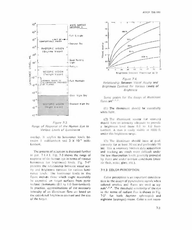
LUM
INA
NC
E L
EVE
L,
AMCP 706-188
10°
10s
I04
I03
I02 -
, o '-
LIMIT or—► - COMFORTABLE VISION
PHOTOPIC VISION ( Day ! ime Vi sioo)
WHITE SURFACE OBSERVEP Hr
- F u l l Smvligki
-Overcast Sky
I uMESOPIC VISION (Twilight Vision)
- Good Reading -> L igh t
■ T w i l i'.'iii
10'
10'lNORMAL RANGE OF I ILLUMINA1I0N PROVIDED
L J by flares .-Full Moonlight
lO'5 -
-10'
10'- -SCOTOPIC VISION
(Night Vision) _
10'
Clear Night Sky
-Oyercasl (light Sky
Figure 7-3.Range o f Response o f the Human Eye to
Various Levels o f Luminance
overlap. It applies to luminance levels between 1 millilambert and 3 X I O'4 milli-l a m b e r t .
Die process of adaption is discussed further in par. 7-1.4.1. Fig. 7-3 shows the range of response of the human eye in terms of various luminance (or brightness) levels. Fig. 7-42 presents the relationship between visual acuity and brightness contrast for various luminance levels. The luminance levels in this figure include those which might reasonably be expected on target surfaces from pyrotechnic illuminanis (0.1 to 1.0 foot-lambert). In practice, approximations of the necessary intensity of an iiluminant flare are based on the calculated brightness contrast and the size of the target.
0 10 i o 40 -flO £0 CO 70 60
Brightness Contract (Express*^ ii> 2)
Figure 7-4.Relationship Between Visual A cu ity and
Brightness Contrast fo r Various Levels o f Brightness
Some guides for the design of iiluminant Hares are1 ■l >3:
(1) The iiluminant should be essentially white light.
(2) The iiluminant source (or sources) should have an inteasity adequate to provide a brightness level from 0.1 to 1.0 foot- lambert. A man is easily visible at 1000 ft under this brightness range.
(3) The iiluminant should burn at peak intensity for at least 30 sec and preferably 90 sec. Til is is necessary because data acquisition and tracking arc much more difficult under the low illumination levels generally provided by Hares and under combat conditions (muzzle Hash, noise, glare, etc.).
7-1.3 COLOR PERCEPTION
Color perception is an important consideration in the design of pyrotechnic signals when colored smokes and flares are used as signals' >4*4. The threshold sensitivity of the eye in the terms of radiant flux is shown in Fig.7-51 for both daytime (photupic) and nightime (scotopic) vision. Color is not neces-
7-3
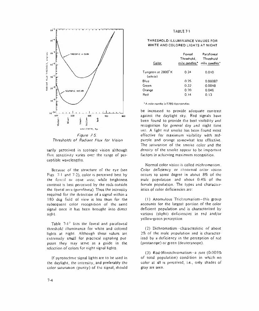
RA
IMA
*!
FlU
* IK
RC
SH
OtO
, C
Aq/^
ec
UAV£l£*GTH,Figure 7-5.
Thresholds of Radiant Flux for Vision
sariiy perceived in scotopic vision although fhix sensitivity varies over the range of perceptible wavelengths.
Because of the structure of the eye (see Figs. 7-1 and 7-2), color is perceived best by the foveal or cone area; while brightness contrast is best perceived by the rods outside the foveal area (parafovea). Thus the intensity required for the detection of a signal within a 180 deg field of view is less than for the subsequent color recognition of the same signal once it has been brought into direct sight-
Table 7-12 lists the foveal and parafoveal threshold illuminance for white and colored lights at night. Although these values are extremely small for practical signaling purposes they may serve as a guide in the selection of colors for night signal lights.
If pyrotechnic signal lights are to be used in the daylight, the intensity, and preferably the color saturation (purity) of the signal, should
TABLE 7-1
THRESHOLD ILLUMINANCE VALUES FOR WHITE AND COLORED LIGHTS AT NIGHT
Foveal ParafovealThreshold, Threshold
Color mile candles* mile candles’Tungsten at 2800°K 0.24 0.010(white)
Blue 0.25 0.00087Green 0.32 0.0040Orange 0.20 0.046Red 0.14 0.13"A mile candle is 5280 footcandles
be increased to provide adequate contrast against the daylight sky. Red signals have been found to provide the best visibility and recognition for general day and night time use. A light red smoke has been found most effective for maximum visibility with red- purple and orange somewhat less effective. The saturation of the smoke color and the density of the smoke appear to be important factors in achieving maximum recognition.
Normal color vision is called trichromatism. Color deficiency or abnormal color vision occurs to some degree in about 8% of the male population and about 0.4% of the female population. The types and characteristics of color deficiencies are:
(1) Anomalous Trichromatism—this group accounts for the largest portion of the color deficient population and is characterized by various (slight) deficiencies in red and/or yellow-green perception.
(2) Dichromatism—characteristic of about 2% of the male population and is characterized by a deficiency in the perception of red (protanope) or green (deuteranope).
(3) Rod-Monochromatism—a rare (0.005% of total population) condition in which no color at all is perceived, i.e., only shades of gray are seen.
7-4

AMCP 706-188
7-1.4 FACTORS IN RESPONSE
7-1.4.1 ADAPTATION
Daytime seeing is done in photopic vision (see Fig. 7-3). At sunset, there may exist mesopic levels in shadowy areas. After sunset seeing is done in the upper mesopic level of vision (I to I O'1 millilambert) and night seeing occurs at the lower level of mesopic vision (10'2 to 10'3 millilambert). The process of change in types of vision with changing illumination levels is know adaptation 1.
Of particular interest in pyrotechnic illumination is the processor adaptation from a low level of luminance, e g., the night sky, to a higher level such as that provided by a suddenly ignited flare. Fortunately, dark to light adaptation is relatively short requiring only 30 to 60 sec to see in bright sunlight after being in a very dark room: Although an observer would not normally have to adapt to a level as bright as sunlight, some time for adaptation (e.g., 15 sec) should be provided in the total burning time of a flare in addition to that needed for target acquisition.
When an observer must adapt from a high level of luminance to a lower level longer periods of time are needed depending on the level to be adapted to. Adaption times to different low levels of background luminances after being exposed to a bright, pre-adapting source for several minutes are shown in Fig.7-6*. In this figure, the criterion used to measure adaptation at any given time after Uie pre-adapting source is shut off is the threshold luminance of the target (always brighter than the background) which just makes it visible. In Fig. 7-6, background A is in the range of photopic vision and the terminal (the maximum) threshold sensitivity is reached in less than I 50 sec; background B is in the mesopic vision range and about 5 min is needed to reach terminal sensitivity; backgrounds CJ.7, and E are various scotopic vision regions and the final threshold sensitivity is not reached until after 15 min. The abrupt
Arrol*rk4 - A recl jul i l lumination unl l . Th*: ret inal 11 lurMnat ion In Trolands equal to the product oft h e p u p i l a r e a (pun) e n d s o u r c e l u mi n a n c e ( c / m2)>
Figure 7-6.Adaptation to Backgrounds of
Different Luminances
change in curves C, D, and E marks the point al which the cones stop participating in the visual process.
7-1.4.2 FLASH AND FLICKER
A light source may exhibit nonsteady characteristics such as a flash or flicker1,2. For flashes shorter than 0.20 sec the empirical photochemical reciprocity law states that the product of intensity and duration is equal to a constant photochemical effect
It = h (7-1)
where! = intensity, c
t = lime, sec
h = constant
There is a time interval between the onset of a stimulus and the onset of its perception.
7-5
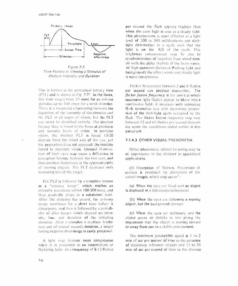
AMCP 706*188
Primary Image
Figure 7-7.Time Factors in Viewing a Stimulus o f
Medium Intensity and Duration
This is known as the perceptual latency time tPTL) and is shown in Fig. 7-71 In the fovea, this time ranges from 35 msec for an intense stimulus up to 300 msec for a weak stimulus. There is a reciprocal relationship between the logarithm of the intensity of the stimulus and the PLT at all stages of vision, but the PLT can never be abolished entirely. The shortest latency tune is found in the fovea at photopic and mesopie levels of vision. In scotopic vision, the shortest PLT is found 15-20 degrees from the visual axis of the eye, yet the perception does not approach the rapidity found in photopic vision. Unequal illumination of both eyes may cause a difference in perceptual latency between the two eyes, and thus produce distortions in the apparent paths of moving objects. The PLT decreases with increasing size of the target.
The PLT is followed by a sensation known as a "primary image” which reaches an intensity maximum within 100-200 msec, and then gradually drops to a substained level. After the stimulus has ceased, the primary image continues for a short time before it dissappears, and then is followed by a periodicity of aftei images which depend on intensity, hue. and duration of the initiating stimulus. After a stimulus a medium brightness and of several seconds duration, a longer lasting negative after-image is easily perceived
A tight may become more conspicuous when it is presented as an intermittent or Hickering light. At a frequency of 8-1 2 flashes
per second the flash appears brighter than when the same light is seen as a steady light. This phenomenon is most effective at a light level of 200 to 300 millilamberts and dark- light distribution in a cycle such that the light is on for 1/3 of the cycle. This brightness enhancement may be due to synchronization of impulses from visual stimuli with the alpha rhythm of the brain waves. At high contrasts (between Hashing light and background) the effect wanes and steady light is more conspicuous.
Flicker frequencies between 3 and 6 flashes per second can produce discomfort. The flicker fusion frequency is the point at which successive light flashes appear to blend into a continuous light: it increases with increasing flash intensities and with decreasing proportion of the dark-light cycle occupied by the flash. The flicker fusion frequency may vary between 12 and 60 flashes per second depending upon the conditions stated earlier in rhis paragraph.
7-L4.3 OTHER VISUAL PHENOMENA
Other phenomena related to seeing may be of importance to the designer in specialized applications.
(1) Perception of Motion. Perception of motion is produced by alterations of the retinal images, which may occur’ :
(a) When the eyes are fixed and an object is displaced in a stationaryenvironment
(b) When the eyes are following a moving object, but the background changes
(c) When the eyes are stationary and the object grows or shrinks in size giving the impression that the object is moving toward or away from one in a stable environment.
The minimum perceptible speed is ! to 2 min of arc per second of time in the presence of stationary reference objects and 15 to 30 min of arc per second of time in the absence
7 - 6

AMCP 706-183
TABLE 7-2DURATION OF SACCADIC EYE MOVEMENTS
Extern of Movement, Duration of Movement,deg rrrsec10 4020 5530 8040 100
of reference objects. Long tracking time and good illumination tend to improve motion perception.
(2) Object Blur. When a motion of the eyes is not able to hold a steady image of the target on the retina, the image becomes blurred and contrast decreases'. Smooth lateral pursuit movements of the eyes are possible up to a target velocity of 30 deg per second. At higher speed, the pursuit movements lag increasingly behind the target and must be accompanied by frequent saccadic eye movements.
(3) Convergence- The act of aiming both eyes at the same point is called convergence and is a function of both internal and external eye muscles4. The average time required to aim the eyes and focus them on a new point displaced in distance is about 165 msec. This act is called fixating or refixating. Beyond 20 ft, convergence needed in order to fixate is negligible.
(4) Saccadic tyc Movement. The simple,1 conjugate movement of the eyes without complication by change of convergence is known as the saccadic eye movement4. These movements are used to change from one fixation point to another. Table 7-2 shows the duration of these movements for various angular eye movements.
(5) Apparent Motion. Lights presented in succession at the proper time interval, distance from each other, and intensity give the impression of movement from one to the other1’4. Apparent motion is also observed
through the successive presentation of two stationary objects juxtaposed in space or through increasing the brightness of a fixed object.
(61 Stroboscopic Effects. During nighttime visual observation, detection of slow moving targets may be enhanced through the use of intermittent flashing of ihe lighi source causing the target to appear at many discrete locations'.
(7) Space Myopia. A condition in which the eyes tend to accommodate for a distance of about 20 ft in front of the observer. Space myopia is due to the lack of something definite on which an observer can focus4. Objects beyond this distance arc consequently out of focus and may not be seen. Such a condition can occur at night as well as in empty space.
7-2 HEARING
7-2.1 USE OF SOUND
Pyrotechnic devices are used to familiarize unseasoned troops with the appearance and sound of battle conditions without exposing them to lethal ammunition. For simulation of rifle fire and explosive charges, hand grenades, booby traps, and land mines, a small firecracker type such as the M80 Simulator may be used (see par. 3-22.1). The degree to which the simulated sound must correspond with the actual device js not critical for training purposes provided that it gives a sharp report sufficient to startle or indicate to the trainee that something has happened. Sophistication of design may increase as attempts are made to reproduce the sound more faithfully, in terms of frequencies, magnitude, and duration. The M115A2 Simulator, for example, produces a high pitched whistle and a flash of light followed by a loud report. Close reproduction of the actual sound becomes more important when the simulator is used under actual combat to confuse the enemy.
Modem sound spectrometers can be used
7 - 7
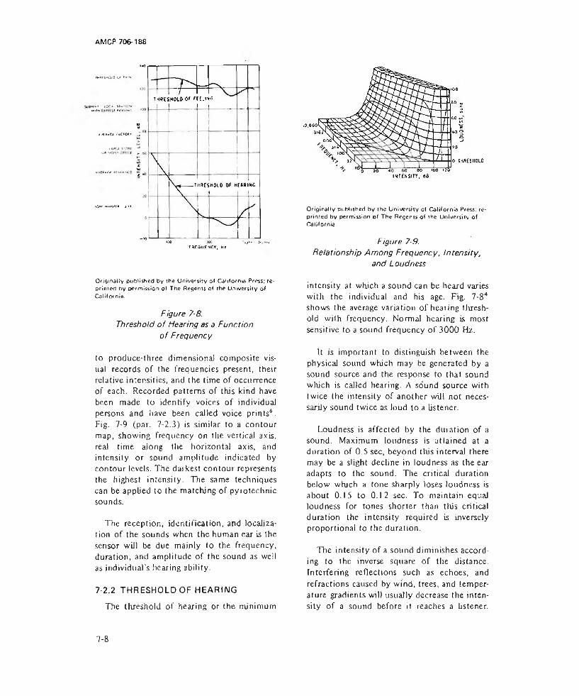
AM CP 706-188
MIVOO u> »*•»
lC-C»> Sl*U . 'V wir* W »*s *“1
*n»AC< ucwi'\**CA VC*f
O* *-00> t
1<>W M*MCV»f« > ' I
Qdginatty published by the University of California Press; re* printed by permission of The Regents of rhe University of California.
Figure 7-8.Threshold o f Hearing as a Function
o f Frequency
to produce-three dimensional composite visual records of the frequencies present, their relative intensities, and the time of occurrence of each. Recorded patterns of this kind have been made to identify voices of individual persons and have been called voice prints6. Fig. 7-9 (par. 7-2.3) is similar to a contour map, showing frequency on the vertical axis, real time along the horizontal axis, and intensity or sound amplitude indicated by contour levels. The darkest contour represents the highest intensity. The same techniques can be applied to the matching of pyrotechnic sounds.
The reception, identification, and localization of the sounds when the human ear is the sensor will be due mainly to the frequency, duration, and amplitude of the sound as well as individual's hearing ability.
7-2.2 THRESHOLD OF HEARINGThe threshold of hearing or the minimum
Originally published by the University of California Press: re* printed by permission of The Regents Of ihe University Of California.
Figure 7-9.Relationship Among Frequency, Intensity,
and L oudness
intensity at which a sound can be heard varies with the individual and his age. Fig. 7-84 shows the average variation of hearing threshold with frequency. Normal hearing is most sensitive to a sound frequency of 3000 Hz.
It is important to distinguish between the physical sound which may be generated by a sound source and the response to that sound which is called hearing. A sound source with twice the intensity of another will not necessarily sound twice as loud to a listener.
Loudness is affected by the duration of a sound. Maximum loudness is attained at a duration of 0 5 sec, beyond tins interval there may be a slight decline in loudness as the ear adapts to the sound. The critical duration below which a tone sharply loses loudness is about 0.15 to 0.12 sec. To maintain equal loudness for tones shorter than this critical duration the intensity required is inversely proportional to the duration.
The intensity of a sound diminishes according to the inverse square of the distance. Interfering reflections such as echoes, and refractions caused by wind, trees, and temperature gradients will usually decrease the intensity of a sound before it reaches a listener.
7-8

AMCP 706-188
Higher frequencies are more likely to be attenuated than lower frequencies.
7-2.3 FREQUENCY EFFECTS
The human auditory response to frequency is commonly accepted as falling between the frequencies of 20 and 20,000 Hz. No clear generalizations can be made concerning the frequency limitations of hearing, however, since intensity has an effect especially near the extremes.
When the intensity of sound is increased to very high levels, frequency components normally considered below or above the usual thresholds can elicit a hearing response. The hearing elicited by these very intense sounds is probably brought about through distortion within the ear which breaks up a portion of the sound energy into components, some of which fall within the range of hearing. Hearing has thus been reported of sounds up to l 00,000 and as low as 5 Hz.
Tire relationship among frequency (measured in Hz), physical sound intensity (measured in dB) and subjective loudness (measured in sone) is shown in Fig. 7-94.
Originally published by Ihe University of California Press; reprinted by permission of The Regents of the University of California-
Figure 7-10. Loss in Hearing A b ility for Men o f Various Ages
7-2.4 SOUND LOCALIZATION
The ability to locate sounds is dependent primarily upon binaural cues, which resolve into differences of loudness, time of arrival, and sound composition. Pure tones, which are relatively rare in pyrotechnics, are not as accurately localized as complex sounds. The greatest errors occur in trying to locate a tone of 2000 Hz.
7-2.5 VARIATIONS IN HEARING ABILITY
Hearing ability varies greatly within the population. Aside from individual differences, age accounts for much of the variation in hearing ability. Fig. 7-1 O'1 shows the changes in hearing sensitivity for men, with the zero point obtained from the median value of the total sample of male and female subjects aged 20 to 29 vr.
Some hearing loss is directly related to past exposure to loud noises. Exposure to noises in excess of 85 dB over long periods of time generally results in permanent hearing impairment.
7-3 PHYSICAL MEASUREMENTS
7-3.1 MALE HUMAN BODY MEASUREMENTS
As an aid in the design of equipment, selected dimensions of the human body (ages 18 to 45) are listed in Table 7-34 and illustrated in Fig. 7-114.
Useful limits for arm reach should be based on those of the small man. In Fig. 7-124, selected data for a man with a 5th percentile arm reach are shown. In Fig. 7-12(A) the subject is in shirt sleeves and not restricted by a shoulder harness. In Fig. 7-12(B) the subject is restricted by a shoulder harness, and in Fig.7-l2(C) the subject wears a pressurized suit.
7-3.2 STRENGTHAs a general rule the weight of hand-held
launching devices and ammunition should be
7 - 9

Originally published by the Uni^rsiiy of California Press, reprinted by permission of The Regents of the University of California.
Figure 7-11. Key for Male Human Body Dimensions in Table 7-3
7-10
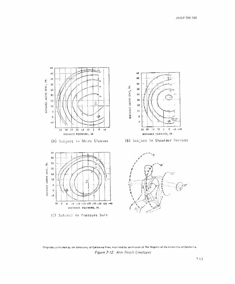
dis
ta
nc
e a
bo
ve s
ea
t,
in.
dis
ta
nc
e a
bo
ve s
eat ,
in
.
AMCP 706-188
(A) Sub ject i n S h ir t Sleeves (B) Subject in Shoulder Harness
(C) Subject in P ressu re Su it
* '25'
i ■ / I.” » : -■■■■■\ j r
Oilgma'ly published by the University ol California Press, reprimed by permission of The Regents of the University of California.
Figure 7-12. Arm Reach Envelopes
7-11

AMCP 706-188
as light as possible to increase the fire power and mobility of troops. For short times the average man can exert forces as large as 450 lb with the leg if his back is supported against a backstop. For design purposes, the maximum weight that individual troops are expected to carry are limited to a maximum 50 lb. Two men can carry 75 ib without difficulty.
When forces must be applied with the knee at a right angle, strain can be expected to occur at about 28 lb.
Devices such as grenades that must be hurled should be limited to less than 2 Ib.
7-4 IDENTIFICATION CODESAND OPERATING INSTRUCTIONS
7-4.1 IDENTIFICATION
Pyrotechnics are identified by lot number and the standard nomenclature common to other types of ammunition. Standard nomenclature is used so that each item may be specifically identified by name. In accordance with Federal item identification guides for supply cataloging, standard nomenclature consists of: item name (a generic term), a colon, and other identification markings such as model number, serial number, etc. Also before Die colon will be included, where necessary, descriptive adjectives such as: dummy, blank, or inert ammunition. The use of standard nomenclature is mandatory for all record purposes.
When ammunition is manufactured, a lot number is assigned in accordance with pertinent specifications. A lot consists of a number of items manufactured under similar conditions, which may be expected to function alike. Tire lot number consists, in general, of the loader’s initials or symbol and the number of the lot.
A model designation is assigned to identify ,a particular design at the time the model js classified as an adopted type. This designation becomes an essential part of the nomenclature
and is included in the marking of the device. The present system consists of letters or a letter followed by an Arabic numeral, for example: An Army device may be marked M1, a Navy device Mk 1, a device used by both Army and Navy ANMI, and a device still in the development stage XM). items which have been modified are marked with a letter or letters followed by the appropriate Arabic numeral, which is placed after the original model designation. The Army generally uses A1 to indicate the first modification. Using the given example, for the Army, a device which has undergone its first modification would be marked (MIAl). The Navy uses the letters (Mod) followed by an appropriate Arabic numeral, for example, Mkl Mod I, would be the mode) designation after the first modification.
Pyrotechnic assemblies are painted in accordance with M) L-STD-709A. They are usually painted white, except those having cases of either aluminum or plastic, or those aircraft signals assembled in a tube of rolled cartridge paper, which are coated with colorless lacquer. Ground flares (Army designation) M49 and M49A1, which have primary roles of giving warning of infiltrating enemy troops and secondary roles as signals, are painted light green.
Pyrotechnics, in general, are marked in black. These markings show the type, model, ammunition lot number, and date of manufacture. Signal types are marked with colored bands and patches to indicate the color of the signal produced. The top of launcher-type and hand-held ground signals are painted the color of the signal and also marked with two embossed letters for identification in the dark. The first letter is the initial of the color. The second letter indicates type “P” for parachute or “S" for star. Thus, “ RP” indicates the signal will produce a parachute-supported red star. Overage flares and those assigned to ranging am stenciled with a 2-in. blue band.
It has been shown that embossed letters
7-12

AMCP 70&-188
MALE HUMAN BODY DIMENSIONS4TABLE 7-3
DIMENSION(in inches except where noted)
DIMENSIONAL ELEMENT Slh PERCENTILE 95th PERCENTILEWeight 132 lb 201 lb
i Vertical reach 77.0 89.02 Stature G5.0 73.0
A 3 Eye to floor 61.0 69.04 Side arm reach from CL‘ of body 29.0 34.05 Crotch to floor 30.0 36.01 Forward arm reach 28.0 33.02 Chest circumference 35.0 43.03 Waist circumference 28.0 38.04 Hip circumference 34.0 42.0
B 5 Thigh circumference 20.0 25.06 Calf circumference 13.0 16.07 Ankle circumference 8.0 10.08 Foot length 9.8 11.39 Elbow to floor 41.0 46.01 Head width 5.7 6.42 Interpupillary distance 2.27 2.743 Heed length 7.3 8,2
C 4 Head height - 10.25 Chin to eye - 5.06 Head circumference 21.5 23.51 Hand length 6.9 8.02 Hand width 3.7 4.4
D 3 Hand thickness 1.05 1.284 Fist circumference 10.7 12.45 Wrist circumference 6.3 7.5
E 1 Arm swing, aft 40 deg 40 deg2 Foot width 3.5 4.0I Shoulder width 17.0 19.02 Sitting height to floor (std chair) 52.0 56.03 Eye to floor (std chair) 47.4 51.5F 4 Standard Chair 18.0 18.05 Hip breadth 13.0 15.06 Width between elbows 15.0 20.00 Arm reach (finger grasp) 30.0 35.0
G 1 Vertical reach 4 5.0 53.02 Head to seat 33.8 38.03 Eye to seat 29.4 33.5'CL = chest line
7-) 3
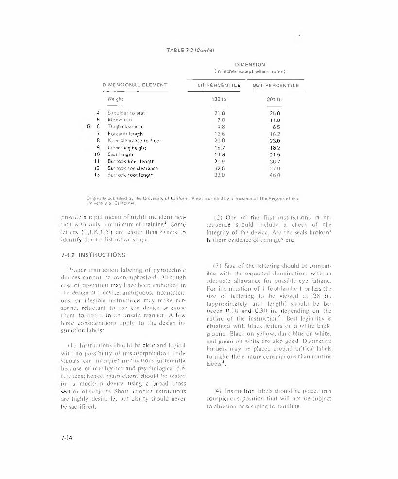
TABLE 7 3 (Cont'd)
DIMENSION(in inches except where noted)
DIMENSIONAL ELEMENT 5th PERCENTILE 95th PERCENTILEWeight 132 lb 201 lb
4 Shoulder to seat 21.0 25.05 Elbow rest 7.0 11.0S Thigh clearance 4.8 S.57 Forearm length 13.G 16.28 Knee clearance to floor 20.0 23.09 Lower leg height 15 7 18,210 Seat length 14.8 21.511 Buttock-knee length 21.9 36.712 Buttock-toe clearance 32.0 37.013 Buttock-foot length 39.0 46.0
Originally published by the University of California Press; reprinted by permission of The Regents of the University of California.
provide a rapid means of nighttime identification with only a minimum of training5. Some letters (T.I.K.l.Y) are easier than others to identify due to distinctive shape.
7-4.2 INSTRUCTIONS
Proper instruction labeling of pyrotechnic devices cannot be overemphasized. Although ease of operation may have been embodied in the design of a device, ambiguous, inconspicuous. or illegible instructions may make personnel reluctant to use the device or cause them to use it in an unsafe manner. A few basic considerations apply to the design instruction labels:
( 1) Instructions should be clear and logical with no possibility of misinterpretation. Individuals can interpret instructions differently because of intelligence and psychological differences; hence, instructions should lie tested on a mock-up device using a broad cross Section of subjects. Short, concise instructions are highly desirable, but clarity should never he sacrificed.
(2) One of the first instructions in the sequence should include a check of the integrity of the device. Are the seals broken? Is there evidence of damage'’ etc.
(3) Size of the lettering should be compatible with the expected illumination, with an adequate allowance for possible eye fatigue. For illumination of 1 foot-lamberl or less the size of lettering to he viewed at 28 in. (approximately arm length) should be between 0.10 and 0.30 in. depending on the nature of the instruction4. Best legibility is obtained with black letters on a white background. Black on yellow, dark blue on wliite, and green on white arc also good. Distinctive borders may be placed around critical labels to make them more conspicuous than routine labels4.
(4) Instruction labels should be placed in a conspicuous position that will not be subject to abrasion or scraping in handling.
7 - 1 4

AMCP 706-188
REFERENCES
]. R. M. Blunt and W. A. Schmeling. Study o f Psychophysical Factors o f Vision and Pyrotechttical Light Sources, Report AFATL-TR-6S-17, Air Force Armament Laboratory, Eglin Air Force Base, FL, 1968.
2. Human Engineering in the Design. Operation, Stowage and Transportation o f Ammunition, Pyrotechnics and Related Material. Phase II, Visibility Data as It Applies to Pyrotechnics, Dunlap and Associates, Inc.. Stand ford, CT. Contract DAJ- 28-01 7-501-ORD-(P)-l 294, April 25, 1955.
3. R. Hilgendorf. Visual Search and Detection Under Simulated Flare Light, Report AMRL-TR-68-1 12, Aerospace Medical Re
search Laboratories. Wright-Patterson Air Force Base. OH, 1968.
4. W. E. Woodson and D. W. Conover.Human Fngitieering Guide for Equipment Designers, University of California Press, CA, (964.
5. B. L. Bucklin, Tactual D i s c r i m i n a t i o n - o f 40MM Ammunition for the M 79 Hand Held Weapons Systems, Report ESL IR 272, Feltman Research Laboratories. Pica- tinny Arsenal, Dover. NJ. June 1966.
6. W. Heaton and C. W. Hargens. Eds., An Interdisciplinary Index o f Studies in Physics, Medicine and Music Related to the Human Voice. Theodore Presser Company. Bryn Masvr, PA, 1968.
7-1 5/7-1 6


AMCP 706-188
CHAPTER 8
GENERAL CONSIDERATIONS
8-1 GENERAL PROPERTIES OF MATERIALS
The ideal gas law is very convenient to use in the form
8-1.1 GAS LAWS
The pyrotechnic designer is faced with the control of materials that react to generate gas at various rates. The generation of gas may be desirable as the source of power for mechanical motion or may be an undesirable result of a pyrotechnic reaction that must be contained or vented. Familiarity with the behavior of gases will permit adequate design' .
At a constant temperature T, the volume V of a given quantity of gas varies inversely as the pressure P to which the gas is subjected. For a perfect (ideal) gas at constant temperature, we have the relationship
PV = k (a constant)
which is the well known Boyle’s Law.
( 8- 1)
At a constant pressure, the volume of a given mass of an ideal gas will increase 1/273 of its volume at 0°C for each degree centigrade rise in temperature, i.e., it is directly proportional to the absolute temperature in °K, This is Diaries’ Law which relates volume to the absolute temperature for a constant pressure
V - k .T ( 8-2)
The two laws are usually combined to give what is known as the idea) gas law
P, V, _ P7 T, ' T7
(8-4)
Although it does not hold strictly for real gases, it is often sufficient for approximations made at high temperatures and low pressures.
Pyrotechnic designs often require solutions for conditions of high temperature and high pressure where intermojecular forces and the physical si2e of actual molecules cause a departure from the behavior expected from an ideal gas. An improved equation of state which specifies the fundamental relationship between pressure, volume, and temperature was proposed by van der Waals in 1873. Cohesive forces are present between the molecules of real gases which tend to reduce the pressure of the gas. These forces are proportional to the square of the density and the reduction in pressure can be written in the form a/ V1 where a is a constan t depending on the exact law of attraction1. The physical space occupied by each molecule ii' it were a hard sphere would reduce the available space by some factor b related to the number of molecules. The two effects were combined by van der Waals to yield what is known as van der Waals’ Equation of State
' p + - j ^ ) (V ~ b ) = RT (8-5)
PV = nRT (8-3)
Qualitatively, the constant b in Eq. 8-5 is the excluded volume due to the size of the molecules and the constant a is a measure of the force of attraction between the molecules.
where the gas constant R has a universal value for all gases, 1543 ft-lb (“Rankine-lb mole)'1, 0.09206 liter-atmospheres (°K-g m ole)1, or 8.31432xl07 ergs C°K-g mole)'1; and n is the number of moles of gas.
Many other attempts have been made to determine equations of state that agree more closely with the response of actual gases since the assumption of hard spherical molecules is not really warranted. The equation by Beattie
8-1
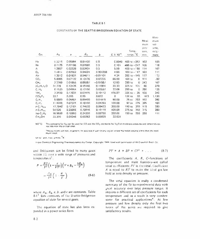
AMCP 706-188
CONSTANTS OF THE BEATTIE-BRIDGEMAN EQUATION OF STATETABLE 8-1
Gas A0 a 89
He 0.0216 0.05984 0.01400Ne 0.2125 0.02196 0.02060A 1.2907 0.02328 0.039310, 1.491) 0.02562 0.04624Air 1.3012 0.01931 0.0461 1CO} 5.0065 0.07132 0.10476CH„ 2.2769 0.01855 0.05587,(C}HS )j 0 31.278 0.12426 0.45446C;H4 6 1520 0.04964 0.12156NHj 2.3930 0.17031 0.03415cci2f2 23.7 0.305 0.59CiH* 5.8800 0.05861 0.09400C;HS 11.9200 0.07321 0 .18 10 0n-C... H [ o 17.7940' 0.12161 0.24620n-C7H16 54.520 0.20066 0.70816lso-C4 Hs 16.9600 0.10860 0.24200CHjOH 33.309 0.09246 0.60362
Mini-
b C X 10‘4Temp.range,
Maxi*mumpressure,atm.
mum volume, cc/g - mole
0.0 0.0040 400 to -252 102 100.0.0 0.101 400 to-217 106 1 180.0 5.99 400 to-150 114 1670.004208 4.80 100 to -1 17 103 1 11
-0.01101 4.34 200 to -145 177 1250.07235 66.00 100 to 0 111 ,82
-0.01587 12.83 200 to 0 243 1670.11954 33.33 325 to 150 90 3700,03597 22.68 200 to 0 286 1250.19112 476.87 325 to - 35 130 3400.622 0 126 to 30 18.5 1,4300.01915 90.00 25 to 250 193 2000.04293 120.00 97 to 275 305 1000.09423 350.00 150 to 300 118 2800.19179 400.00 275 to 350 315 2000.08750 250.00 150 to 250 250 1110.09929 32.031
NOT£i The constants for N? car be used for CO and the CO? constants i h f N ?0 at moderate pressures and temperatures not too near the critical ones.
The equations wilt not, in general, be accurate if used in any region where the molal volume is less than the minimum listed. o
Units atm, liter, g*mole, K
From C hernies! Engineering T h e rm o d y n a m ic s by Dodge. Copyright 1344. Used with permission of McGraw-Hill Bool: Co.
and Bridge man can be fitted to many gases within ]% over a wide range of pressures and temperatures-.
where A 0, Ba, a, b. and c are constants. Table8-13 lists constants of the BeatUe-Bridgeman equation of state for several gases.
The equation of state lias also been ex panded in a power series form
PV = A + BP + CP2 + . . . (8-7)
The coefficients A . B, C-functions of temperature and mole fractions—are called viriaJ coefficients; PV is the virial. Coefficient A is equal to R T to make the ideal gas law hold at zero density or pressure.
The virial equation is really a condensed summary of the fit to experimental data with great accuracy over large pressure ranges. It requires a different set of coefficients for each temperature and as a result is very cumbersome for practical applications4 . At low pressure and low density only the first two terms of the series are required to give satisfactory results.
8 - 2

AMCP 706-188
8-1.2 STRENGTH OF MATERIALS
Any structural material exhibits an elongation when subjected to an external load or force and, within the clastic limit, the elongation A is directly proportional to the load Fs
F sr A ( 8- 8)
If the total deflection or elongation A of the test piece is averaged over the initial unloaded length L. a dimensionless quantity e, the strain, results
e ~ ~j—r in. in. (8-9)
If the applied load F is divided by the cross-sectional area A of the unloaded test specimen, the stress .S' is defined in pounds per square inch
« _ F ■S - - . p s , (8- 10)
A simple relationship is Hooke’s Law, stress is proportional to strain
5 = e£ ( 8- 11)
where £ is the proportionality constant. Young’s Modulus or the modulus of elasticity, with dimensions in pounds per square inch.
Beyond the limits of Hooke’s Law, elongation or strain increases as the force increases, but the linearity of the relationship ceases. Stress plotted against strain for any material gives the tensile-test diagram, Fig. 8-15. Fig.8-l(A) is typical of a ferrous material such as carbon or alloy steel while Fig. 8-1 (B) is typical of some nonferrpus materials, such as brass and aluminum, and of some stainless steels. The important distinction between the two curves is that Fig. 8-1 (A) shows a definite inflection point and change of curvature, whereas Fig. 8-1(B) does not.
Certain points on these curves have been defined and are important material properties. Consider first the stress-strain curve in Fig.8-1 (A). Tlie region from zero to A is a straight
IA> FOR FERROUS METAi_S SUCH AS CARBON OK ALLOY STEEL
t 3 ] FOR BRASS, ALUMINUM, CERTAIN STAINLESS STEELS a similar METALS
Reprinted with permission from ilcciro- Technology, Vol. 73. May 1964
Figure 3-7. Typical Tensile-test Diagrams
line, showing that the material is obeying Hooke’s Law. This leads to the definition of point A as tiic proportional limit. It can readily be seen that the equation of this line is the now familiar .S' = i-ZT where E is the slope.
Beyond point A linearity ceases, and at point H a sudden increase in elongation lakes place with little or no increase in load. This phenomenon is called y i e l d i n g , and point B is called the yield point of the material. The stress associated with this point is the yield stress. Once this point is reached in the material, all load can be removed from the specimen and the stress returned to zero, but a residua] strain, permanent set. will remain. Any permanent set is usually considered detrimental to a structural member.
Beyond point B, stress and elongation continue to increase until the maximum stress, the ultimate s t r e s s , is reached at point C. Rupture of the material occurs at point/.), which is reached without any increase in stress or load in fact, decreasing the load beyond point C will not necessarily avert fracture. Notice that the curve of Fig. 8-1 (A) exhibits this definite, observed yield point, one which can easily be recognized as it occurs during a tensile tesr. The materials represented by Fig. 8-l(B), however, do not exhibit as definite a yield point, although the other points on the curve are defined in the same manner as their counterparts in Fig.8-1 (A). In materials such as those represented by Fig. 8-1(B), it is generally accepted that
8-3
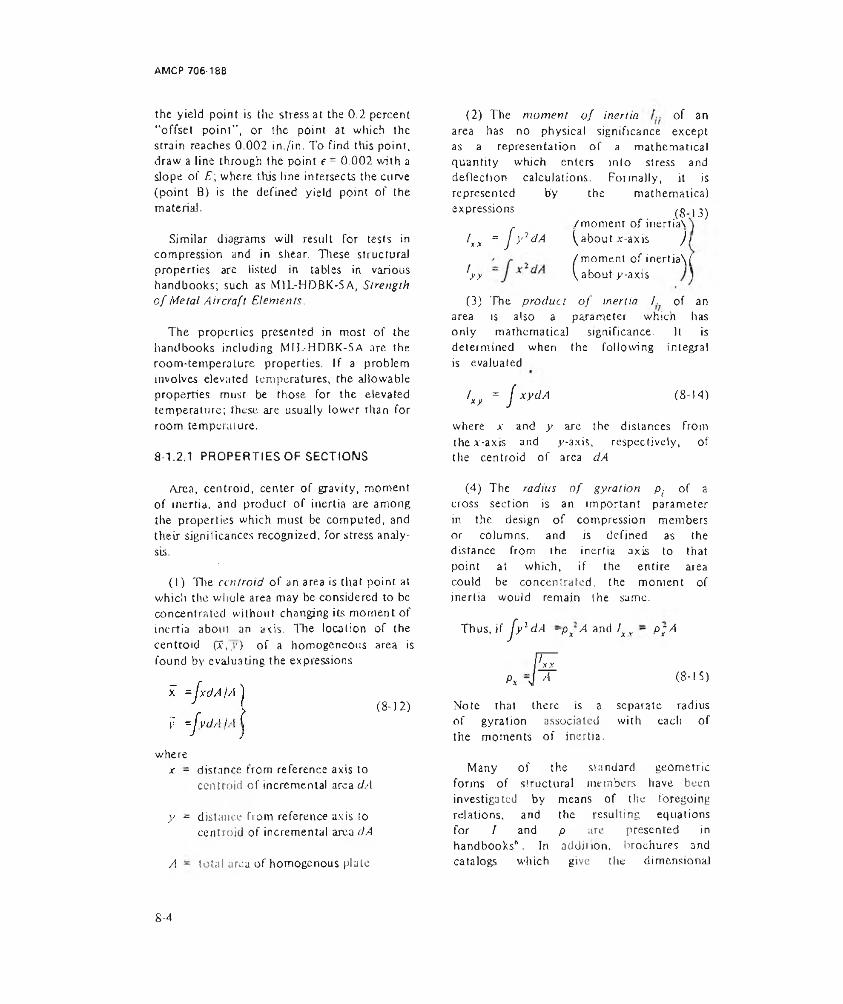
AMCP 706-188
the yield point is the stress at the 0.2 percent "offset point", or the point at which the strain reaches 0.002 in./in. To find this point, draw a line through the point e = 0.002 with a slope of E\ where this line intersects the curve (point B) is the defined yield point of the material.
Similar diagrams will result for tests in compression and in shear. These structural properties are listed in tables in various handbooks; such as M1L-HDBK-5A, Strength o f Metal Aircraft Elements.
The properties presented in most of the handbooks including MIL-HDBK-5A are the room-temperaLure properties. If a problem involves elevated temperatures, the allowable properties must be those for the elevated temperature; these are usually lower than for room temperature.
8-1.2.1 PROPERTIES OF SECTIONS
(2) The moment o f inertia of an area has no physical significance except as a representation of a mathematical quantity which enters into stress and deflection calculations. Formally, it is represented by the mathematical expressions
/ « = J y 'd A
'y >
(3) The product o f inertia !. of an area is also a parameter which has only mathematical significance. It is determined when the following integral is evaluated
lxy = J xydA (8-14)
where x and y are the distances from the x-axis and y-axis, respectively, of the centroid of area dA
. (S-l3)/moment of inertia\^about x-axis Jl
( moment of inertia\( about y-axis
Area, centroid, center of gravity, moment of inertia, and product of inertia are among the properties which must be computed, and their significances recognized, for stress analysis.
(I) 'Hie centroid of an area is that point at which the whole area may be considered to be concentrated without changing its moment of inertia about an axis. The location of the centroid (I,y ) of a homogeneous area is found by evaluating the expressions
(8-12)
wherex - distance from reference axis to
centroid of incremental area dA
y = distance from reference axis to centroid of incremental area dA
A - total area of homogenous plate
(4) The radius o f gyration pj of a cross section is an important parameter in the design of compression members or columns, and is defined as the distance from the inertia axis to that point at which, if the entire area could be concentrated, the moment of inertia would remain the same.
Thus, if J y l dA ~px A and lxr - p fA
Px Al ¥ (8-15)
Note that there is a separate radiusof gyration associated with each ofthe moments of inertia,
Many of the standard geometric forms of structural members have been investigated by means of the foregoing relations, and the resulting equations for / and p are presented in handbooks*. In addition, brochures and catalogs which give the dimensional
8 - 4

AMCP 706 188
data of shapes available on the market will usually include values for the various pertinent geometric properties.
81.2.2 LOAD ANALYSIS
In a complex design in which there are numerous load sources and other design conditions, load analysis is necessary.
In most structures it is found that the same design conditions are not critical for all members; it is the critical conditions which require investigation and definition.
For a load analysis, use the basic equations of equilibrium derived from Newton's Laws:
1. For every action there exists an equal and opposite reaction in the slate of equilibrium.
Reprinted with permission Irom E le c tro -T e ch n o lo g y ,Vol. 73, May 1964.
Figure 8-2. A Three-dimensional Right-hand System of Coordinate Axes
is the definition of the vertical and horizontal directions in the problem. A set of coordinate axes must be defined and carried unchanged throughout the design. Usually a three-dimensional right-hand system is chosen as shown in Fig. S-25.
2. A force F applied to a mass M will impart to it an acceleration a in the direction of the applied force
where n is considered equal to one for the equilibrium equations and for the load analyses.
By applying Newton’s Laws, we can say that a body is in equilibrium if and only if the following three equations are satisfied
ZF = O']V i
OV (8-17)
ZM = 0 ]
wluch state that the sum of all verlical forces Fv, the sum of ail horizontal forces Fh, and the sum of all momentsM acting on the body must be equal to zero at any instant of time. If these conditions do not obtain, the body will experience either translation or rotation, uv both, in accelerated motion. The first step required in the application of these equations
To apply the equilibrium equations properly, it is necessary to understand the most important concept of the “free body”. By definition, a free body is a mass which is in equilibrium and which is divorced from its surroundings in space. All forces on the mass are shown as vectors applied at their points of action.
As an example, consider a rectangular container loaded with a pyrotechnic material that is bolted to a bulkhead. In order to determine the loads which act upon the container, it is considered as a free body as shown in Fig. 8-3s . The container is held in place by four bolts whose locations are numbered on the figure, and its center of gravity is located as shown. No other external forces axe known to exist on the container in this problem.
Fig. 8-4s shows the contamer in three orthogonal projections from which i he equations for the reactions can be derived in terms of its dimensions.
Note that the coordinate axes are shown on the free-body diagrams and all vectors are
8-5
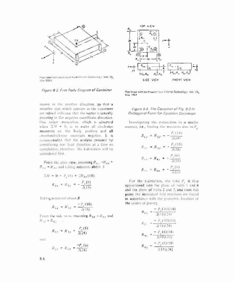
TOP VIEW
Reprinted with permission irom !:it 'C In> -'l\xh n < > !i> v \, Vol. 73, May 1964. SIOE VIEW PROMT VIEW
Figure 8-3. Free Body Diagram of Container Reprinted with pe/mission from L ire iro -T e c h n o lo g y . Vol, 73^ May 1964.
shown in the positive direction, so that a negative sign winch appears as the equations are solved indicates that the vector is actually pointing in the negative coordinate direction. One other convention, which Ls observed when XM = 0, is to make all clockwise moments on the body positive and all counterclockwise moments negative. It is recommended that the analysis proceed by considering one load direction at a time to completion; therefore, the .v-dircction will be considered first.
From the plan view, assuming R t x ~R«X ~ R yx = R AX and taking moments about A
SM = 0 = P (8) + 2 R (18)
/?i* = K3x „ PX2(18)
Taking moments about B- P A 10)
R lx = R ax = — ' ,ix 2(18)
From the side view, assuming R 2, = R and R m — R a ; ■
and
R ,: = R»: =
R i: = R t
P x ( 6 )
2(24)
~PX(0) 2(24)
Figure 8-4. The Container o f Fig. 8-3 in Orthogonal Form for Equation Derivation
Investigating the v-direction in a similar manner, i.e., finding the reactions due to P
R = R = - ^ U4)is. f y n 2y
Rj y - R 4 i'
A',, - RA2
2(24)
= - i Z ^2(24)
_ F A 6)~ ~2(W)
P (.6)R ,z = = “ ‘208)
For the 2-direct ion, the load P, is first apportioned into I lie plane of bolts I and 4 and the plane of bolts 2 and 3, and from this point the individual bolt reactions are found in accordance with the geometric location of the center of gravity.
_ - 101(14)A i -i ~
R : , =
R 32 =
=
2(18)(24)
- PA 101(10) 2(18X24)
- ^ (8 ) 0 4 ) 2(18)( 24)
- /\(8 )(I0 )21.18X24)
8-6
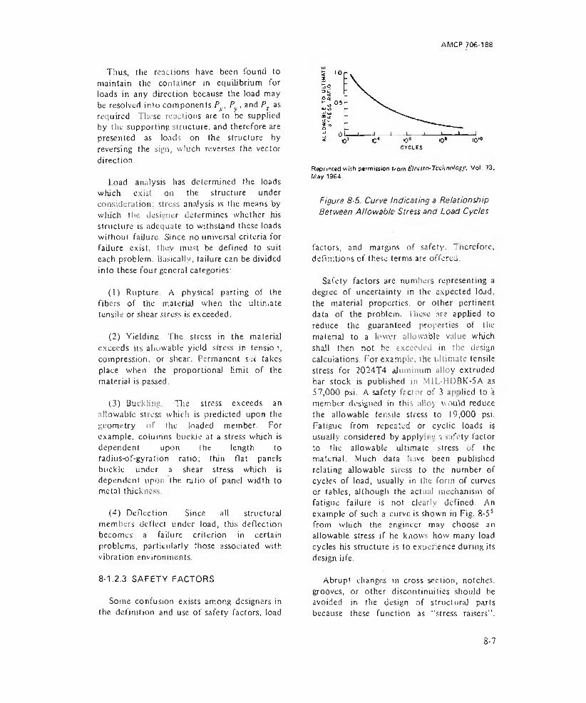
AMCP 706-188
Thus, the reactions have been found to maintain the container in equilibrium for loads in any direction because the load may be resolved into components Px . Py , and Pz as required. These reactions are to be supplied by the supporting structure, and therefore are presented as loads on the structure by reversing the sign, which reverses the vector direction.
Load analysis has determined the loads which exist on the structure under consideration: stress analysis is the means by wluch the designer determines whether his structure is adequate to withstand these loads without failure. Since no universal criteria for failure exist, they must be defined !o suit each problem. Basically, failure can be divided into these four general categories:
(1) Rupture. A physical parting of the fibers of the material when the ultin.ate tensile or shear stress is exceeded.
(2) Yielding. The stress in the material exceeds its allowable yield stress in tensio q compression, or shear. Permanent sit takes place when the proportional limit of the material is passed.
(3) Buckling. The stress exceeds an allowable stress which is predicted upon the geometry of the loaded member. For example, columns buckle at a stress which is dependent upon the length to radius-of-gyration ratio; thin flat panels buckle under a shear stress which is dependent upon the ratio of panel width to metal thickness.
(4) Deflection. Since all structural members deflect under load, this deflection becomes a failure criterion in certain problems, particularly those associated with vibration environments.
8-1.2.3 SAFETY FACTORS
Some confusion exists among designers in the definition and use of safety factors, load
Figure 8-5. Curve Indicating a Relationship Between Allowable Stress and Load Cycles
factors, and margins of safety. Therefore, definitions of these terms are offered.
Safety factors are numbers representing a degree of uncertainty in the expected load, the material properties, or other pertinent data of the problem. These are applied to reduce the guaranteed properties of the material to a lower allowable value which shall then not he exceeded in the design calculations. For example, the ultimate tensile stress for 2024T4 aluminum alloy extruded bar stock is published in MIL-HDBK-SA as 57,000 psi. A safety factor of 3 applied to a member designed in this alloy would reduce the allowable tensile stress to 19,000 psi. Fatigue from repeated or cyclic loads is usually considered by applying n safety factor to the allowable ultimate stress of the material, Much data have been published relating allowable s'uoss to the number of cycles of load, usually in llie form of curves or tables, although the actual mechanism of fatigue failure is not clearly defined. An example of such a curve is shown in Fig. 8-5s from wluch the engineer may choose an allowable stress if he knows how many load cycles his structure is to experience during its design life.
Abrupt changes in cross section, notches, grooves, or other discontinuities should be avoided in the design of structural parts because these function as “stress raisers” .
8-7

AMCP 706-188
When these cannot be avoided, the designer must apply certain safety factors in these local areas. Many handbooks publish tables and examples or guides to the magnitude of safety factor wliich may be used and which is considered adequate.
8-1.2.4 LOAD FACTORS
Load factors are numbers representing multiplying factors applied to the load on the structure. These may be caused by any number of environmental conditions, such as an aircraft in arrested landing or in catapult take-off, a truck proceeding across country on rough or bumpy roads, or a ship subjected to an underwater blast or the firing of its own guns. Load or design factors usually are expressed in terms of g, or gravity units. Since the load analysis has been performed under a l-g condition, the load factors can easily be taken into account by mulitplying calculated loads and reactions by the proper load factor. By this simple means it is easy to take into account different loading conditions in different directions or at different points in the structure without directly affecting the original load analysis.
In this regard, an important definition to remember is the li/nil load factor. This is the load which the structure is expected to experience-it is the limit of the load on the structure. The design load factor is larger than the limit load factor and is used to compute the stress in the structural members. Common practice is to define
design load = 1.5 X (limit load) (8-18)
Although the 1.5 factor may be modified by the individual designer it is recommended that the range of selection remain between 1.5 and 2.0. Larger factors tend to be too conservative and result in an overweight and more costly structure.
8-1.2.5 MARGIN OF SAFETY
Margin of safety MS is expressed as a
percent of the computed stress, or it is the percent increase of the computed stress required to equal the allowable stress. It is computed by the relationship
/allowable stress \ . . (8-19)MS = I----------- — ---- — 11(100)\computed stress /
If the computed stress equals the allowable stress there is obviously a zero margin of safety, and failure may b,e imminent. Therefore a positive margin is desired in ajl design, and experience has shown that a 15 percent margin is adequate for most purposes.
8-1.2.6 ALLOWABLE STRESS
An allowable stress is defined as the stress which a member may be allowed to reach (zero margin) and beyond which failure, as previously defined, is imminent. The allowable stress in all cases, except for yielding, is the ultimate stress of the material whether it be taken directly from the handbook as the ultimate tensile stress or whether it be calculated from a formula such as Euler’s column formula. This means that all computed stress (with the noted exception) must be based upon the design load factor and margin of safety computed on these values. In some special problems where it is specified that the yeild stress shall be used as the failure criterion, the limit load factor should be multiplied by a minimum I.15 factor instead of the 1.5 previously noted to conserve weight and cost. AJ1 problems and examples in this discussion, however, should consider that design load factors and the margins of safety are computed on the ultimate stress. Some sample problems will serve to illustrate the preceding discussion.
8-1.2.7 THIN-WALL CYLINDER
One of the most common containers for pyrotechnic materials is a (tun-wall cylinder (Fig. 8-61). These find such wide use that special analysis methods have been developed for them. For design analysis, the information from structural testing is usually converted to reduction factors that are then applied to the
8-8

AMCP 706-198
Figure 8-6. Thin-wall Cylinder
equations obtained from classical theory. Prior determinations of these reduction factors for radius r to thickness t ratios (r//) above 500 have been based on fairing-in curves through the apparent mean of scattered test data.
The method presented here draws upon these prior studies and a considerable amount of additional test data to provide design curves for a wide range of materials and cross sections. The method is based on the equation
= a ( y ) (8-20)
where a is given by
a = 0 .606-0.546(1 -<?") (8-21)
and n by
n = ' 16V?and
= critical buckling stress, psi
E — Young’s modulus, psi
l = thickness of cylinder, in.
Y = inner radius of cylinder, in
This equation for Sb is simply a modified form of the classical buckling equation based
on small-deflection theory, (n the classical form, the equation contains a constant. 0.605, instead of the term a.
The critical axial (buckling) load P is then determined from
P = SbA (8-23)
where
A - cross-sectional area of the thin-walled cylinder, in.7
Graphical representations of the equation for Sb for various metals is shown in Fig.8-77. For all practical purposes, these curves apply to any alloy of these metals because the relevant property, modulus of elasticity, varies little from alloy to alloy. For high-temperature applications, critical loads can be computed by multiplying the room-temperature critical load by the ratio of elevated-temperature modulus toroom-temperature modulus. Data for such calculations are provided in Fig. 8-7.
8-1.2.8 PLASTICS
Plastics have found widespread use because of their low cost and ease of molding into various forms, plastic ammunition cases being a common example. The strength of materials theory previously discussed is also valid for plastics; however, it should be realized that the properties of plastics can be radically different than those of metals. A summary of the mechanical properties of some plastics is given in Table 8-28.
The American Society for Testing Materials defines a plastic as a material that contains as an essential ingredient an organic substance o f large molecular weight, is solid in its finished slate, and at some state in its manufacturing process it can be shaped by flow 9. Plastics are divided into two classes: thermoplastics and thermosetters. The former softens with increasing temperature and returns to its original hardness when cooled. The
8 -9

35
30ooo 25 ■
1 - Buyll.jrn
Stet
-Titor.rj/r,
un —15 --
10- —u
5
Modu1 us o f E l a s t i c i t y f o r Va r ious Temperatures
TEMPERATURE, t,MATERIAL “F 10s 0.
-Wogrciium
Steel 70 30.00500 2700700 25 00
Alurunvm 70 10.50300 10.10600 7.35
Magnesium 70 6 50300 5.9S600 5.70
Titanium 70 16.40500 13.80700 12.80
Bcr>lltum 70 42 00500 4000700 33.00
o f i i i i : : i i i m i I i i i i~~t~r~r 0 200 600 800 1C03 I2C0 '4C0 1600 1800 200
Ratio r/tReprinted with permission from M achine Design, Vol. 40. 1968, Penton Publishing Co , Cleveland.
Figure 8-7. Critical Buckling Stress as a Function o f r/t
thermosetters harden when heated and remain hard when cooled. They "sot” into permanent shape when heated under pressure. For compatibility of plasties see par. 8-1.3.2.
8-1.3 CHEMICAL COMPATIBILITY
Chemical compatibility is the ability of materials to remain in intimate contact for long periods without harmful chemical reaction. Incompatibility may cause loss of effectiveness, or produce a hazard. This concept is important because pyrotechnic materials are required to have a shelf life as long as 20 yr. Under such a time span, materials normally considered nonreactive can show change.
Compatibility of pyrotechnic materials may be judged under three main categories:
(I) Interactions wilh metallic components (corrosion)
(2) Interactions (deterioration)
with nonmetallics
(3) Interactions of different pyrotechnic substances with each other (degradation or sensitization).
8-1.3.1 CORROSION COMPONENTS
OF METALLIC
In almost every pyrotechnic application involving metals, some form of corrosion is possible. Corrosion of metallic surfaces may affect the integrity of the container, particularly at the joints. Hence, appropriate means of protection from corrosion is required. The designer must know the
8-10
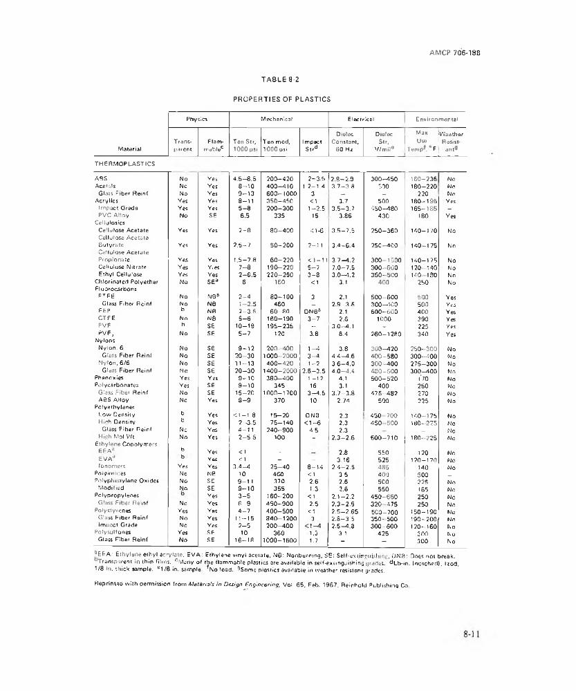
AMCP 706-188
TABLE 8-2
PROPERTIES OF PLASTICSPhysics Mechanical Electrical Environmental
MaterialTransparent
Flammable0
Ton Sir, 1000 psi
Ten mod, 1000 psi
ImpactSlrd
Dioloc Constant,
GO H2
DietacStr,
V/miia__________
Max IvVoathar Use I Ro^st*
T#m p. F ant^____ ___ ___L—---------
THERMOPLASTICS
ABS No Yes 4.5—8.5 200-420 2 -3 .5 2 .8 -2 9 300-4 5 0 160-236 NoAce tel s No Yes 8 -1 0 4 0 0-410 1 2—1.4 3,7—3.8 7.30 180-220 No
Glass Fiber Reinf No Yes 9 -1 3 600-1000 3 — - 220 NoAcrylics Yes Yes 8-11 350—450 <1 3.7 500 180-195 Yes
Impact Grade Yes Yes 5 - 8 200-300 1-2 .5 3.5—3.7 450-480 165-185 _PVC Alloy No SE 6.5 335 IS 3.86 430 ISO Yes
Cel hilosicsCellulose Acetate Ves Yes 2 -8 80-4 0 0 <1-6 3 .5 -7 .5 250-360 140-170 NoCellulose AcetateButyrate Ves Yes 2 .5 -7 50 -2 0 0 2-11 3 .4 -6 4 250—400 140-175 NoCellulose AcetatePropionate Ves Yes LS—7.8 6 0 -2 2 0 < 1 -1 1 3.7—4.2 300 1500 140—175 NoCellulose Nitrate Yes Yies 7 -8 190-220 5 -7 7.0—7.5 300- 500 120- 140 NoEthyl Cellulose Yes Yes 2-C .5 220-250 3 -8 3 .0 -4 .2 350- 500 140- 180 No
Chlorinated Polyether No SEa 6 150 <1 3.1 400 250 NoFluorocarbons
PTFE No NB8 2 - 4 8 0 -1 0 0 3 2.1 500-600 500 YesGlass Fiher Reinf No N8 1- 2.5 460 — 2 9 - 3 .6 300-400 500 Yc5
FEP b NB 2—3.5 6 0 -8 0 DNB8 2.1 500-SQ0 400 YesCTFE No N8 5 -6 160-190 3 -7 2.6 1000 390 YesPVF b SE 10-19 195-235 - 3.0—4.1 - 225 YesPVF, No se 5 -7 120 3.8 8.4 260-1280 340 Yes
NylonsNylon. 6 No SE 9 -1 2 200- 400 1 —4 3.8 300-420 250- 300 No
Glass Fiber Reinf No SE 2 0 -3 0 1000-2000 3 - 4 4 ,4 -4 .6 400-580 300- -100 NoNylon, 6/6 No SE 1 1 -1 3 400—120 1 -2 3.6—4.0 300-4 0 0 275-300 No
Glass Fiber Reinf Ho s e 2 0 -3 0 1400—2000 2.5—3.5 4,0—4.4 480-5 0 0 300-400 NoPhsnoxies Yes Yes 9 -1 0 380-400 1 -12 4,1 500-520 l'70 NoPolycarbonates Yes SE 9 -1 0 345 16 3.1 400 250 No
Glass Fibe* Reinf No SE 15-20 1000-1700 3 -4 .5 3.7—3.8 475—482 270 NoABS Alloy No Yes 8 - 9 370 10 2.74 500 225 No
Polyethylene^Low Density b Yes <1 -1 .8 15-20 ON3 2.3 450 700 140—r 75 NoHigh Density b Yes 2 -3 .5 75-1 4 0 < 1 -6 2.3 450 -500 180- 225 NO
Glass Fiber Reinf No Yes 4 -11 240-900 4.5 2.3 _ NoHigh Mol V'/t No Yes 2 -5 .5 100 _ 2 .3 - 2 6 500-710 180- 225 No
Ethylene CopolymersEEAa b Yes <1 - 2.8 550 120 NoEVAJ Yes <1 — - 3.16 525 120-170 Nofonomers Yes Yes 3 .4-4 2 5 -4 0 8 -1 4 2 .4 -2 .5 485 140 No
Poly imides No NB 10 460 <1 2 5 400 500 _Polyphenylene Oxides No SE 9 -1 1 370 2.6 2.6 500 225 No
Modified No SE 9 -1 0 3SS 1.3 2.6 550 185 NoPolypropylenes Yes 3 -5 160-200 <1 2 .1-2 .2 450-660 250 No
Glass Fiber Reinf No Yes 6 9 4 5 0-900 2.5 2 .3 -2 .S 320 -475 250 NoPolystyrenes Yes Yes 4 -7 4 0 0-500 <1 2 .5-2 .65 SCO—700 150-190 No
GI3SS Fiber Reinf No Yes 11-15 8 40-1200 3 2 .8 -3 5 350- 500 190-200 NoImpact Grade No Yes 2 -5 2 0 0-400 2.5—4.3 300-600 120-160 No
Potysulfones Yes SE 10 360 1.3 3.1 425 300 NoGlass Fiber Reinf No SE 16-18 1000-1600 1.7 - - 300 No
“ EEA: Ethylene ethyl acrylate. EVA: Ethylene vinyl acetate, M6: Nonburning, SE: Self-extinguishing, DNB: Does not break.Transparent In thin films. c Mjny o f the flammable plastics are available in self-extinguishing grades. <*Lb-in. {notched), lyod.
1/8 in. thick sample, e 1 /8 in. sample. No toad. ^Som e plastics available in weather resistant grades.
Reprintad with permission from M a te ria ls in Design eng in ee ring , Vol 65, Feb. 1967, Reinhold Publishing Co
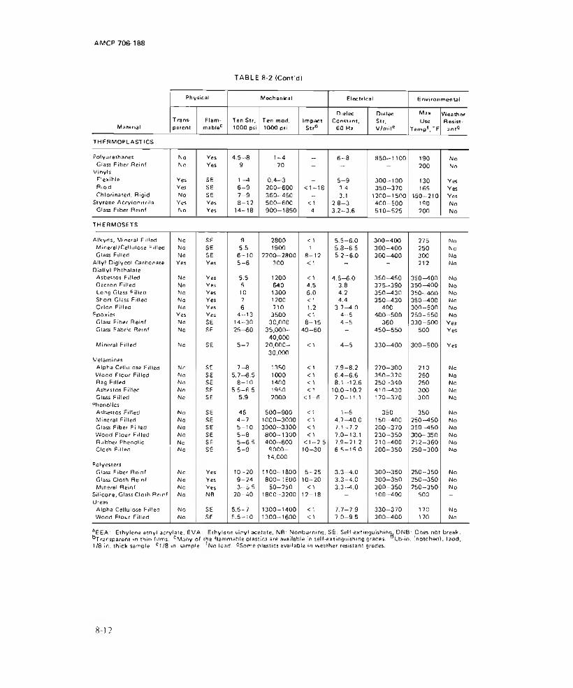
AMCP 706-188
TABLE 8-2 (Cont'cJj
Physical Mechanical Electrical Environmental
Mata rialT rarvs- parent
Flammable0
Ten Str, 1000 psi
Ten mod, 1000 psi
ImpactS«r*
Dielec Constant,
60 Hz
DielecStr,V/miie
MaxUse
Temp*, "’F
WeatherResist
ant^
THERMOPLASTICS
Polyurethanes No Yes 4 .5 -8 1 -4 _ 6 -8 850-1100 190 NoGlass Fiber Reinf
VinylsNo Yes 9 70 ” ' - 200 No
Flexible Yes SE 1 -A 0 .4 -3 - 5 -9 300-1 0 0 130 YesRigid Yes SE 6 - 9 200-600 < 1 -1 8 3 4 350—370 165 YesChlorinated, Rigid No SE 7 - 9 260—450 - 3.1 1200-1500 150-210 Yes
Styrene Acrylonitrile Yes Yes 8 -1 2 500—600 <1 2 .8 -3 4 0 0 -5 0 0 190 NoGlass Fiber Reinf No Yes 14-18 900-1850 A 3.2—3.6 510-525 200 No
THERMOSETS
Alkyds, Mineral Filled No SE 9 2800 <1 5 .5 -6 .0 3 0 0-400 275 NoMineral/Cellulose Filled No SE s .s 1900 1 5.3—6.5 300-4 0 0 250 NoGlass Filled No SE 6 -1 0 2200-2800 8 -1 2 5 .2 -6 .0 300-4 0 0 300 No
Ally! Diglycol Carbonate Yes Yes 5 -6 300 <1 - - 212 NoDiallyl Phthalate
Asbestos Ftried No Yes 5.5 1200 <1 4 .5 -6 .0 350—450 350-400 NoOaeron Filled No Yes 5 640 4,5 3.8 375-3 9 0 3 5 0 -4 0 0 NoLong Glass Filled No Yes 10 1300 6.0 4.2 350-430 350-4 0 0 NoShort Glass Filled No Yes ? 1200 <1 4,4 350—430 350-400 NoOrion Filled No Yes 6 710 1.2 3.7—4.0 400 300—500 No
Epoxies Yes Yes 4 -1 3 3500 <1 4—5 400-5 0 0 250-550 NoGlass Fiber Reinf No SE 14-30 30 000 8 -1 5 4 -5 360 330-500 YesGlass Fabric Reinf No SE 2 5 -6 0 35,000
40,0004 0 -6 0 — 450-5 5 0 500 Yes
Mineral Filled No SE 5 -7 20,00030,000
<1 4 - 5 330-4 0 0 300-5 0 0 Yes
MelaminesAlpha Cellulose Filled No SE 7 -8 1350 <1 7 9 - 8 .2 270-300 210 NoWood Floor Filled No SE 5.7—6.5 1000 <1 6 .4 -6 .6 350-370 250 NoRag Filled No SE 8 -1 0 1400 <1 8 .1-12 .6 250-3 4 0 250 NoAsbestos Filled No SE 5.5-6 .5 1950 <1 10.0-10.2 41 0—430 300 NoGlass Fiiled No SE 5.9 2000 < 1 -6 7.0-11.1 170-370 300 No
Phenol ItsAsbestos Filled No SE 46 500-900 <1 1-6 350 350 NoMineral Filled No SE 4 -7 1000-3000 <1 4 .7-40 .0 160-400 250-4 5 0 NoGlass Fiber Filled No SE 5 -1 0 3000-3300 <1 7.1—7.2 200-370 350—450 NoWood Ftour Filled No SE 5 -8 80 0 -1 3 0 0 <1 7.0-13.1 230-3 5 0 300- 350 NoRubber Phenolic No SE 5 -6 .5 400-600 < 1 - 2 5 7.9-21.2 210-400 212-3 6 0 NoCloth Filled No SE 5 -9 9000
14,00010-30 6 .5 -15 .0 200-350 250-300 No
PolyestersGlass Fiber Reinf No Yes 10-20 1100-1800 5 -2 5 3.3—4.0 300-350 250-3 5 0 NoGlass Cloth Reinf No Yes 9 -2 4 800-1800 10-20 3 .3 -4 .0 300-350 250-3 5 0 NoMineral Reinf No Yes 3 -5 .5 50-250 <1 3.3—4.0 300-350 250-3 5 0 No
Silicone, Glass Cloth Reinf No NB 2 0 -4 0 1800-3200 12-18 _ 100-400 500 -
UreasAlpha Cellulose Filled No SE 5 .5 -7 1300-1400 <1 7 .7-7 .9 330-370 170 NoWood Flour Filled No SE 5.5-10 1300-1600 <1 7 .0 -9 .5 300-400 170 No
aEEA: Ethylene ethyl acrylate, EVA: Ethylene vinyl acetate, NB: Nonburning. S£: Self-extinguishing^ DNB: Does not break. ^Transparent in thin films. °Msny of the flammable olastics are available in self-extinguishing grades. °Lb-io, (notched), l2od, 1/8 in, thick sample, e T /8 in. sample. *No load, QSomeplastics available in lea th er resistant grades.
8 ) 2
AMCP 706-188
Figure 8-8.Factors Affecting Choice of an
Engineering Material
operational requirements of the pyrotechnic device, the environmental conditions that it will encounter in service, and the materials that are available in order that protective measures can be taken. Designers of military hardware must also be aware of combinations of materials, such as copper and lead azide, the reaction of which form sensitive explosive materials. It is difficult to achieve a solution that meets all requirements; therefore, it becomes necessary to balance the corrosion resistant qualities of a particular metal against other factors as illustrated in Fig. 8-810. All these factors are always part of corrosion design, otherwise, the designer would use platinum which is virtually corrosion resistant.
In situations where alternate materials are being considered, it may become necessary to conduct simulated service tests to determine Suitability of the material
8-1.3.1.1 CORROSION PROCESSES
Corrosion is a process involving the transformation of elemental metals to compounds of the metals through electrochemical reaction with their environment1 1.
ELECTROMOTIVE SERIESTABLE 8-3
MetalStandard Electrode Potential V at
25°C, volts EMFao Magnesium -2.340o Beryllium -1.700< Aluminum -1.670<sr Manganese -1.050O Zinc -0.762<A Chromium -0.7104> Iron -0.440
Cadmium -0.402Cobalt -0.277Nickel -0.250
*o Tin -0.136o Lead -0.126n Hydrogen 0.000CJ Copper +0.345a>X> Silver +0.800OZ Mercury +0.854CD Platinum -i 1.200O5 Gold + 1.420
Note:aThese values are obtain&d when the specific metal is placed
in a solution containing one equivalent weight of its ions per liter.
The tendency for a metal to acquire an electric potential when it is immersed in an aqueous solution can be characterized by what is known as the electromotive series of metals (see Table 8-3' M. Hie metals with a very great tendency for forming ions in solution (magnesium, aluminum, manganese, zinc) are at the reactive or less noble end of the series, while metals with little tendency to form ions (platinum, gold) are at ihe noble or unreactjve end of the series. Thus, there is a relationship between the susceptibility of a metal to corrode and ils position in the series
The electrode potential of a metal is dependent on the concentration and type of ions in solution which usually are quite different Irom the arbitrary conditions established for the electromotive series. Metal specimens immersed in solutions containing ions (cations) of that metal only, but of
8-13

AMCP 706-188
different concentrations, will have a higher potential or tendency to dissolve as the concentration of ions in the solution decreases and vice versa.
Further, the nonmelallic ions (anions) in solution also will influence the potential of the metal, depending on whether or not the anions will complex with the metal ions and promote dissolution of the metal. For example, tin is more reactive than iron in dilute citric or oxalic acid solutions owing to the fact that Ihc concentration of tin ions is kept relatively small by the complexing power of the acid. From this it can be seen that reversals of activity of elements in the electron active series are possible under various situations encountered in practice.
Accordingly, Table 8-3 should be used only as a general guide for establishing the relative corrosion behavior of metals in a particular environment.
To account for overall and practical aspects as well as theoretical considerations, another relationship has been devised. It is referred to as Galvanic Couples, shown in Table 8-41 '. In tins table, members of groups connected by lines are considered as permissible couples. However, this should not be construed as being devoid of galvanic action. Permissible couples represent a low galvanic effect. There are several factors which influence and control galvanic action, namely, the effectiveness of the electric circuit, the ratio of anode and cathode areas, and thepolarization of the electrodes.
Galvanic corrosion requires not only a conductive environment but also good electrical contact between the dissimilar metals. If this is not maintained, the galvanic action will subside. Insulation materials-such as nonwicking gaskets, paint and plastic films, and certain inorganic coatings at the mating surfaces of the dissimilar metals will prevent or reduce the galvanic current and theprogress of corrosion. This, of course, brings the designer in direct conflict with accepted
EMR shielding design which requires the best electrical contact possible; therefore, some compromise must be made, if electrical shielding is of concern.
Another deterrent to galvanic corrosion is polarization- Tilts condition can occur either at the anode or cathode and is the result of deposilion through electrolytic action. Corrosion products can accumulate at the anode or hydrogen deposited at the cathode. Either tends to reduce the electrochemical action. The designer must he aware of these contributing factors in order to decide their importance in his application.
8-1.3.1.2 TYPES OF CORROSION
There are a number of types of corrosion which are evidenced hy uniform corrosion attack over a surface of the metal or concentrated attack at local or isolated areas. A brief discussion of types that are of concern with pyrotechnic material follows:
(1) Uniform Corrosion: simplest form of corrosion which can occur in atmosphere, liquids, or in soil. Examples are rusting of iron, tarnishing of silver, and high-temperature oxidation of iron or stainless steels.
(2) Galvanic Corrosion- previously discussed. Corrosion results from grouping of dissimilar metals in a conductive environment.
(3) Concentration-cell Corrosion: caused by nonuniformity of electrolyte or the environment. It is electrochemical in nature and ensues because of differences in ion concentration or of cracks or crevices in the metal surface which deplete electrolyte components because of reactions in confined places.
(4) Stress Corrosion; results from the combined effects of tensile stresses and corrosion. Cold-working, quenching, grinding, or welding may produce internal stresses. Tile most destructive type of stress is that which is
8-14
AMCP 706-188
TABLE 8-4
GroupGALVANIC COUPLES
Metallurgical Category EMF, VGold. Solid and Plated; Gold-Platinum Alloys, Wrought PlatinumRhodium; GraphiteSilver, Solid or Plated; High Silver AlloysNickel, Solid or Plated; Monel; High Nickel-Copper Alloys; TitaniumCopper, Solid or Plated; Low Brasses or 8romes; Silver Solder; German Silver; High Copper-Nickel Alloys; Nickel-Chrome Alloys; Austenitic Stainless Steels (301, 302, 304,309, 316. 321,347)Commercial Yellow Brasses and BronzesHigh Brasses and Bronzes; Naval Brass; Muntz Metal18% Chromium Type Corrosion-Resistant Steels 440-430, 433,446, 17-7PH. 17-4PHChromium, Plated; Tin, Plated; 12% Chromium Type Corrosion-Resistant Steel, 410, 416, 420
—0.45
10 Tin-Plate, Terneplate; Tin-Lead Solders —0.5011 Lead, Solid or Plated; High Lead Alloys -0.5512 Atuminum, Wrought Alloys of the Duralumin
Type, 2014, 2024, 201713 Iron, Wrought, Gray, or Malleable; Plain Carbon
and Low Alloy Steels; Armco Iron14 Aluminum, Wrought Alloys other than Duralumin;
Type 6061,7075, 5052, 5056, MOO, 3003, Cast Alloys of the Silicon Type 355, 356
-0.75
)5 Aluminum, Cast Alloys other than Silicon Type; Cadmium, Plated and Chromated
-0.80
16 Hot-Dip-Zinc Plate; Galvanized Steel -1.0517 Zinc Wrought; Zinc-Base Die Cast Alloys; Zinc.
Plated- 1.10
18 Magnesium and Magnesium-Base Alloys Cast or Wrought
-1.60
'Members of groups connected by lines are considered as permissible couples; However, this should not be construed as being devoid of Galvanic action. Permissible couples represent a low Galvanic effect,
olndicates the most Cathodic member of the series, »An Anodic member, and the arrows indicate the Anodic direction.Refer to Table II. MlL-STD-186, for group amplification of Galvanic couples.
8 - 1 5

local and nonunjform; the stressed lones are subject (o accelerated corrosion.
(5) Fretting Corrosion: term is applied to metal damage caused when two metal surfaces are in contact, under load, and subjected to vibration or relative motion. Corrosion is characterized by surface discoloration, depressions, or pits.
(6) High Temperature Oxidation: direct combination of an oxidizing agent (oxygen, sulphur dioxide, carbon dioxide) with a metal at high temperatures.
(7) Pitting: common and severe form of localized corrosive attack. Thin metal sheets and plates are especially vulnerable; corrosion may result in perforation and subsequent unserviceability.
(8) Corrosion Fatigue: fatigue failure brought about by a corrosive environment. Endurance Emit of metal is lowered as it undergoes stress cycles.
(9) Dezincification: occurs with some brasses. Involves loss of zinc, leaving a residue of one or more other constituents, primarily copper. If not arrested, the entire metal will be reduced Lo a weak spongy mass. An example of dezincification of brass is given in Fig. 8-9' 1 . A brass case was crimped over a lead projectile. In the presence of an ammonium based powder (he dezincification of the brass occurred and it cracked as shown.
(10) Graphitization: occurs in grey cast iron and is similar to dezincification suffered by some brasses. This type of corrosion requires specific conditions which corrode away the iron leaving a matrix which is mostly graphite. 11
(11) Biological: various types of microorganisms, bacteria, yeasts, and molds influence the electrochemical reactions which cause corrosion. The most common result of this influence is pitting.
FROM CORROStOb* B N G iN E gfhN G BY EONt a n a d GREENECOPYRIGHT 1967, USED WITH PERMISSION OFMcGR AW * H I L L BOOK COM PANY*
Figure 8-9.Case Cracking Due to Dezincification
The foregoing constitutes a list of the main corrosion hazards that a designer faces. Ways and means of overcoming these hazards are' the subject of the next paragraph.
8-1,3.1.3 METHODS OF PROTECTION
In the design of. pyrotechnic devices, the corrosive effect of the atmosphere and the pyrotechnic materia] can be minimized by proper choice of materials and use of protective coatings, encapsulation, evacuation, and hermetic seals. Materials which break down or outgas should not be used in devices which are to be evacuated and sealed.
Material selection should be based first on suitability and second on inherent resistance to corrosion. If dissimilar melals are used in contact or near one another, they should be protected against electrolytic corrosion. Preventive measures are listed in Table 8-5 and the specifications for metallic coatings are summarized for reference in Table 8-6' 4
Preference should be given to those metals and alloys which are resistant to both intergranular and stress corrosion. Fabrication operations such as bending, forming, and shaping should be performed on the metals in the annealed conditions.
Hydrogen embrittlement can result in a delayed fracture in those metals which can pick up hydrogen from acid cleaning or plating. If metals must be used which are susceptible to embrittlement, the following techniques can be used to minimize the damage:
8 - 16
AMCP 706-188
PREVENTION OF DISSIMILAR METAL CORROSIONTABLE 8-5
Preventive Measure(1) Select metals which form a
permissible couple in Table 8-4(2) Interpose a metal which reduces the
potential difference between the two metals.
(3) Design the metal contact so the relativearea of the cathodic(more noble) metal is the smaller.
(4) Apply corrosion inhibitor such as zincchromate primer MIL-P-8585 or zinc chromate paste MIL-P-8116.
(5) Interpose an insulating barrier ornonhygroscopic gasket between dissimilar rnetals
(6) Apply insulating organic coatingto surface of each metal
(7) Seal joint area with moisture-proof coating or organic sealant
ExampleUse nickel, not naval brass, in contact with silver,Tin plate brass to be used next to aluminum.
Stainless steel screws in aluminum chassis.
Use zinc chromate inhibitor when assembling steel screws in aluminum.
In structural joints, interpose tape Ml LT-23142 In components, use organic insulants such as conformal coating MIL-1-46058.Coatings such as vinyl zinc chromate primer Ml L-P-15930, epoxy primer Ml L-P-52192, insulating coating MlL-C-46057, MIL-V-173, MIL-l-46058.In structural joints, sealant such as MIL-S-7124. In components, coatings such as-MIL-V-173 or MIL-l-46058-
(1) Use of organic coating, vacuum deposition.
(2) Use of low hydrogen embrittlement baths prior to plating.
(3) EmbritLiement relief after plating (baking)1 s ; with thermal stress relief and mechanical stress relief performed prior to plating.
(4) Elimination of acid or alkaline cathode cleaning methods.
The most effective means of preventing electrolysis, is the application of protective film or coatings. These protective coatings can be described under three main headings: chemical or anodic films, metallic coatings, and organic coatings.
(1) Chemical or Anodic Films
In chemical or anodic treatment, metals and alloys are coated with suitable solutions of chemicals under controlled conditions to form protective surface coatings. This coating is physically integrated with the underlying metal and serves as a barrier against corrosive attack. Coatings commonly used are oxides, phosphates, chromates, or complex compounds of the substrate metal and the components of the metal, and the components of the treatment solutions. These coatings may be formed on iron and steel, aluminum, magnesium, cadmium, and other metals and should be applied after fabrication or machining operations.
(2) Metallic Coatings
8-17
TABLE 8-6
SPECIFICATIONS FOR METALLIC COATINGSMetal Specification
Aluminum, vacuum deposited Cadmium, electroplatedCadmium, electroplated, low hydrogen contentCadmium, vacuum depositedChromium, electroplatedCopper, electrode positedGold, electrodepositedLead, electrodepositedLead, hot dipNickel, electrodepositedNickel-cadmium, diffusedNickel-phosphorus, electrodepositedPalladium, electrodepositedRhodium, electrodepositedSilver, electrodepositedTin, electrodeposited or hot dipTin-cadmium, electrodeposited
Ml L-C-2321? QQ-P-416 AMS 2401 MIL-C-8837 QQ-C-320 MIL-C-14550 tvi I u-G-45204 Ml L-L-13808 Ml L-L-13762 QQ-N-290 AMS-2416 MIL-C-26074 Ml L-P-45209 Ml L-R-4B085 QQ-S-365 Ml L-T-10727 Ml L-P-23408
Metallic coatings should be selected for their suitability for Ihe application involved, wiili attention to prohlems of aging, cracking, diffusion, and corrosion. When metallic coatings are applied by electroplating, hydrogen embrittlement should be avoided. There are recommendations (sue Tabic 8-4) for the prevention of corrosion which should be considered and specifications (see Table 8-5) for the coatings themselves.
Metallic coalings are also applied to some metals by the process of hot-dipping. This is largely confined to the coatings of ferrous alloys with metals and alloys of low melting points. Typical hot-dipping coating materials are zinc, and tin and lead alloys including teme metal. Tinned steel, and zinc-coated or galvanized iron and steel products are the most common hot-dipped products. If corrosion-resistant steels are used, passivation should be done in accordance with QQT-351 5. If steels of the 300 series are used, no further finish is required.
The noble metals (gold, palladium, platinum, and rhodium) and the corrosion-resistant metals (chromium, nickel, tin, tin-lead
solder, and titanium) require no finish other than cleaning.
Applications of aluminum, copper, and magnesium require special treatment unless they are used in hermetically sealed units. Aluminum should be anodized; where tliis is impossible, chemical film treatment in accordance with MIL-C-554116 may be used. Continued exposure of aluminum at liigh temperatures may require the use of metallic coatings. Copper and copper alloys may be black oxide treated in accordance with MILF-49 5 or may be plated or painted. If bare copper is required, a tarnish-preventive thin silicone cured resin Him may be used. Magnesium has very poor resistance to corrosion and therefore it should be anodized. Several coats of alkali resistant primer with one or more coats of compatible top coat should be applied or ii may be given moisture proofing coatings such as epoxy or polyurethane. Furthermore, magnesium used with any oilier metal requires extreme precautions to prevent destructive corrosion.
Cladding is a process for covering one metal with another metal to utilize the superior
8-18

AMCP 706 188 -
corrosion resistant properties of the exposed metal. Cladding may be applied by working, co-rolling, pressure welding, spot welding, explosive welding, and diffusion welding. Principal clad composites produced for industrial purposes are high purity aluminum or aluminum alloys on less resistant aluminum alloys; stainless steel on steel; nonferrous metals including copper, brass, lead, nickel, and nickel alloys on steel. With the advent of explosive welding almost any desirable combination of properties is possible.
Metal coatings can also be applied by metallizing or metal spraying, Metallized coatings are porous, but they provide protection from corrosion mainly because of their thickness. They require sealing or impregnation followed try painting. Metals used to spray coat are zinc, cadmium, and aluminum.
(3) Organic Coatings
Organic coatings are used to protect metal parts, equipment, and structures primarily against atmospheric corrosion. They are applied as liquids and act chiefly as a barrier between the metal to be protected and the environment. The value of the organic coatings depends upon their ability to provide complete and uniform coverage, a good degree of impermeability, good adhesion, cohesion, resistance to mechanical damage, and good chemical inertness.
An example of such a coating employed in pyrotechnic ammunition is the asphalt compound for coating cavities prior to filling with explosives11. Tabic S-71 s tabulates a few of the organic coatings that are available and lists their chemical resistance characteristics.
8-1.3.2 DETERIORATION OF NONME- TALL1C COMPONENTS
When a pyrotechnic material is placed inside a metal container, there may be interactions with nonmetallic parts such as spacer, gaskets, sealants, and potting compounds. The gradual change of these materials is often
designated deterioration rather than corrosion. When considering materials such as plastics, ceramics, and rubbers, the number becomes extremely large too large to list in this brief discussion. Fortunately there are documents that are readily available to aid the designer in selecting the proper choice of materials as discussed in the paragraphs that follow.
81.3.2.1 PLASTICS
A general listing of plastics and their resistance to external attack is shown in Table8-2. Fluorocarbons arc considreed the noble materials of the plastics, just as platinum and gold are for metals, in that they arc generally resistant to most environments. Typical fluorocarbons are Teflon and Kel-F.
To obtain more specific information on a given plastic it is necessary to refer sources that gives detailed information (hood references for this purpose are Refs. 18, lb, and 20. For properties of plastics see also par.8-1.2.8.
8-1.3.2.2 NATURAL AND SYNTHETIC RUBBERS
The outstanding characteristic of rubber and elastomers is resilence, or low modulus of elasticity. However, chemical and abrasion resistance and good insulation qualities also result in many applications. The natural rubbers have better mechanical properties while the synthetics are more resistant to deterioration. Properties are compared in Table 8-818.
Natural rubber is soft but can be made semi-hard or hard by vulcanizing. Synthetic rubber is available in a wide variety of materials including combinations with plastics. Plasticizer fillers and hardeners are compounded to obtain a large range of properties as illustrated in Table 8-8. Note lor example that the temperature resistance of silicone rubber is 580°F. Handbook data are available in Refs. I 8 and 20.
8-19
TABLE 8-7
o r g a n ic MATER IALS
Aik yd Cellulose Epoxy
A lkyd Alkyd Alkyd Alkyd- Styronniod NilfO- Ethyl Epoxy Epoxy Epoxy Epoxy Epoxy Epoxy-
Typa Aik yd A m ir* Phenolic Silicone Urea AJkyd Acrylic cellulose Butyrate Cell..11 Hr-
Amme Ester Furane Me la m ini Phenolic Urea
CHEMICAL RESISTANCEExterior Durability fe E E e E G E E E E G E £ £ E VGSalt Spray . £ VG E E G G E E E E VG E E £ E £
Solvents-Alcohols F G G G G G P G G P Q F E E E £Solvents-Gasoline G £ E £ £ F G G G P £ E E E E £Solvents-Hydrocarbons G e E G £ P F F F F E VG £ E t ESolvent s-E iie rs . Ketones P p P P F P P P P P VG F VG E E VGSolvents—Chlorinated , P p P ? P P P P P P G F E E E E
Salts VG E £ VG E £ VG G VG G E E c E E E
Ammonia P P P P P P P P P G G P E P c PAlkalis . , P P vG.G F.P G.P G.G G.v g G.F P.P P.P G.G E.E E.E E E.E E.E E.E
Acids — Mineral F P.P G.F.P VG.G.F G.P.P P.P.P G.F.P G.F.P E.G.F G.F.P G.F.P E.VG.G G.F.P G E.VG.G E.E.E E.VG.FAci<fe-Qxicji?ino P.P.P F.P.P G.F.P P.P.P P.P.P P.P.P PPP P.P.P P.P.P F .P.P G.P.P F P.P f G.P.P E.VG.P F.P.P
Aci(jS“ Organic (acetic.I'or mic. etc,} P.P.P P.P.P F P P P.P.P P.P.P P.P.P P.P.P P.P .P p.pp G . - . - F.F.P P.P.P P .G G.P.P £ ,E ,VG F.P.P
A c id s —Organic jolaic.stearic.elcJ F G VG G F F F F F - G £ E E E E
Acid Phosphoric . . P P P P P P P E P - G P E G E G
Water Isa!;, ■fresh} F G G G F G £ G E E G VG £ G E G
Typ«
ChlorinatedPolyerh*r
ChlorinatedPoly
propyleneFluoro
carbon Furane Phertohc
Polyamideihyionl
Polyester
—
SilitonvPolyethylene
. RubberChlorinated
Rubber Neoprene Hypalon V iion Ura-th^ng V in y l
CHEMICAL r e s is t a n c e
Exiorior Durability . £ E E G E P E E P E £ E e E ESait. Spray . E E E G E F £ E VG E E E E E ESolvenis-Alcohols . E E E E E G G F £ E 6 - E VG FSoivtrms-Gasolinc . . E F E E E G E F P G G G E F G GSolvents-Hydrocarbons E F £ E E - E G - - G G E E -Sol vents-Esters. Ketones E P P G F - P - P P-F P-F VG.E F-G PSolvents-Chlorinated . E P e c F - P G P P P - F FSalts . E £ E E E - G G P P P P G F PAmmonia , E G £ £ P G P P E £ E E E E EAlkalis . E VG .VG E.E £ P.P G.G P E,F E G G G E P £Acids-M iners E .E.E. E.G.G. E.E.E, E G.F ,P P.P.P E G.G.P P.G E.E E.E E.E E.E VG.F E.EAcids—Ox id lin g . E.C.F E.E.G E.E.E p G.F.P - P P.P.P - E.E.E 6.G.G E.E.G E.E .E G.F.P E.G.GAcitfs-Organit laceiic,
form ic, ere \ t.E .E G PP E.E.E F.G G.F.P P P.P P P.P.P V3.VG.VG E.E .F P.P.P G.G.F E.E.E G.F.P E.VG.GAcids—Organic (oleic.
stearic, etc.) - t G E E E VG F G VC.F.P G.P.P G.F ^ G.F.F G.G.G G.F.P E.P.PAc ids-Phosphoric . . E G £ £ F - F F G f G G G 6 EWater fsaltjreshl . E £ £ E E F G £ VG G VG G G G G
Legend: E"excellent; VC-very good; G-oond, F - Ispt; P-poorReprinted with permission from 1972 Materials Selector. Materials Engineering, Vo I- ?4. No. 4, September 197^. fteinhofd Publishing Co.
8-21
TABLE 8-8
PROPERTY COMPARISONS— NATURAL AND SYNTHETIC RUBBERSType—- Natural Butadie ne- Butadiene- Butyl
Rubber Styrene Synthetic Acrylonitrile Chloroprene (Isobutylene-(Cis-polyisoprene) (GR-S) (Polyisoprane) (Nitrile) (Neoprene) isoprene)
PHYSICAL PROPERTIES ASTMSpecific Gravity ... D792 0.93 0.94 0.93 0.98 1.25 0.90Ther Cond, Btu/hr/sq .... C177 0.082 0.143 0.082 0.143 0.112 0.053
Coef of Ther Exp(cubical), 10‘* per°F . . D696 37 37 - 39 34 32
Electrical Insulation.... Good Good Good Fair Fair GoodFlame Resistance ... . , Poor Poor Poor Poor Good PoorMin Rec Svc Temp,°F .... -60 -60 -60 ■60 ■40 -50Max Rec Svc Temp,°F .... 180 180 180 300 240 300MECHANICALPROPERTIES
Ten Str, psiPure Gum ........ D412 2500-3500 200-300 2500-3500 500-900 3000-4000 2500-3000Black ........ D412 3500-4500 2500-3500 3500-4500 3000 4500 3000-4000 2500-3000
Elongation, %Pure Gum ..... D412 750-850 400-600 - 300-700 800-900 750-950Black D412 550-650 500 600 300-700 300-650 500-600 650-850
Hard ness (durometer) .... A30-A90 A40-A90 A40-A80 A40-A95 A20-A95 A40-A90ReboundCold Excellent Good Excellent Good Very good BadHot ............ Good Excellent Good Very good Very good
Fair Good Fair to good GoodAbrasion Resistance.... Excellent Good to Excellent Good to Good Good to
excellent excellent excellentCHEMICAL RESISTANCESunlight Aging ..... Poor Poor Fair Poor Very good Very goodOxidation ........ Good Good Excellent Good Excellent ExcellentHeat Aging..... . Good Very good Good Excellent Excellent ExcellentSolventsAliphatic Hydrocarbons.... Poor Poor Poor Excellent Good Poor
8-22
TAQL.E D &PROPERTY COMPARISONS— NA1URAL AND SYN ■ HETIC RUBBERS {Coin'd)
Type ' PhTIMtl 3i/tadier»o- □utarticnr- fckin v ill'ibbcr Styrene SynUmie AcrylDP.iir.le C,tikpoi**tv* ! Isobutylene-ICis pc-lyiwpf ene | (GR*$) (KtlybupruinJ I H l f l l:) (Ntoeireru 1 iiaprenel
Aromatic Hydrocarbons .... Poor Poor .'■.■or Good F: lr PoorOxgenated, Alcohols .... Good Good Good Gr od Very good Very good
Oil. Gasoline ..... ...... Poor Poor Poor Excellent Good PoorAnimal, Vegetable Oils......Acids
Poor to good Poor to good Excellent Excellent ExcellentDilute ............. Fair to good Fair to good Fair to good Good Excellent ExcellentConcentrated ......... Fair to good Fair to good Fair to good Good Good Excel lent
Permeability to Gases ..... Low Low Low ' Vory low 1 )w Vor y lowWater Swell Resistance..... Fair Excellent Excellent Excel ent Fair to excellent Excel lent
USES Pneumatic tires and tubes; power Same as natural Carburetor dia- Wire and cable Truck and auto-transmission bells and conveyor lubber .-■hragms, self- belts, hose, ex- mobile tire innerbelts; gaskets; mountings; hose; titling fuel rruded goods. tubes, curing bagschemical tank linings; printing press tanks, aircraft coatings, mold- for tire vulcaniza-platens; sound or shock absorption; hose, gaskets, ed and Sheet tion and molding, steamseals against air, moisture, sound gasoline and oil goods, ad he- hose and diaphragms,and dirt hose, cables. sives, automo* flexible electrical
machinery tive gaskets and insulation, shock,mountings, seats, petroleum vibration absorptionprinting •net chemicalrolls tank linings
Reprinted w ith permission from lUeJtrie h Sctn'iur, ,L ni'.i/t<'en*j.c, Vol. 74, Wo. 4, Septum! ■ » 1971, Reinhold Publishing Co.
AMCP 706-188
8-1.3.2.3 CERAMICS
The class of materials referred to as ceramics includes brick, magnesia, fused silica, stoneware, porcelain, and glass. In general, compared to metals, these materials are inert to chemical action except for hydrofluoric acid; however, they all tend to be rather brittle, weak in tension, and subject to thermal shock.
One technique that permits the use of the chemical inertness of ceramic while overcoming its lack of" strength is to coat the metal or plastic that needs to be protected with the ceramic. This is done by a process referred to as thermal-spraying, flame-spraying, or flame jet coating. Temperatures of the jet are in the order of 30,000°F.
8-1.3.3 DEGRADATION AND SENSITIZATION OF PYROTECHNIC MATERIALS
In some pyrotechnic devices, more than one mix may be used and they may be in contact with each other. As an example, consider the T24E1 Detonator shown in Fig. 8-10. A lead styphnate spot charge is covered by a lead azide charge which, in turn, is in contact with PETN. Experience has shown that these materials arc compatible. Unfortunately there is no convenient source for the designer to find specific information on the compatibility of pyrotechnics. However, some
limited compilations have been made 1 l ,21
8-2 SAFETY
Safe practices in the use, handling, storage, and manufacture of pyrotechnics are ihe result of the experience and knowledge of interested personnel and safety experts. Safe practices are necessary because many of the ingredients and mixtures are toxic, sensitive, and potentially explosive. A thorough knowledge of pyrotechnic ingredients, compositions, and their reactions is an absolute necessity for handling pyrotechnics in (he best and safest manner. Safety cannot be delegated; it is the responsibility of each worker. Supervisors must personally assume responsibility for educating subordinates and promoting safety within then groups. The subject of pyrotechnic safety is treated fully in Ref. 23 while considerations of safety in general are covered in Ihe Safety Manual. Ref. 24.
it is worth noting that there is probably a greater variety of potential hazards arising from pyrotechnics than from ordinary explosives. Some of the basic safety precautions that apply to pyrotechnics ‘may he summarized as follows’ •’ :
( 1) Know the characteristics of (lie ingredients and compositions such as toxicity, sensitivity, reactivity with other materials, safe working limits and storage, and disposal problems. In addition—when dealing with finished pyrotechnic devices such as Hares, smoke screening aids, and simulators one should icnow the output characteristics and the method (or methods) of initiation.
(2) Recognize the dangerous situations that may arise because of potential or actual hazards.
(3) Minimize the hazards by working with or handling small quantities and observing established practices for safeLy equipment, processing, testing, handling, storage, and
8-23
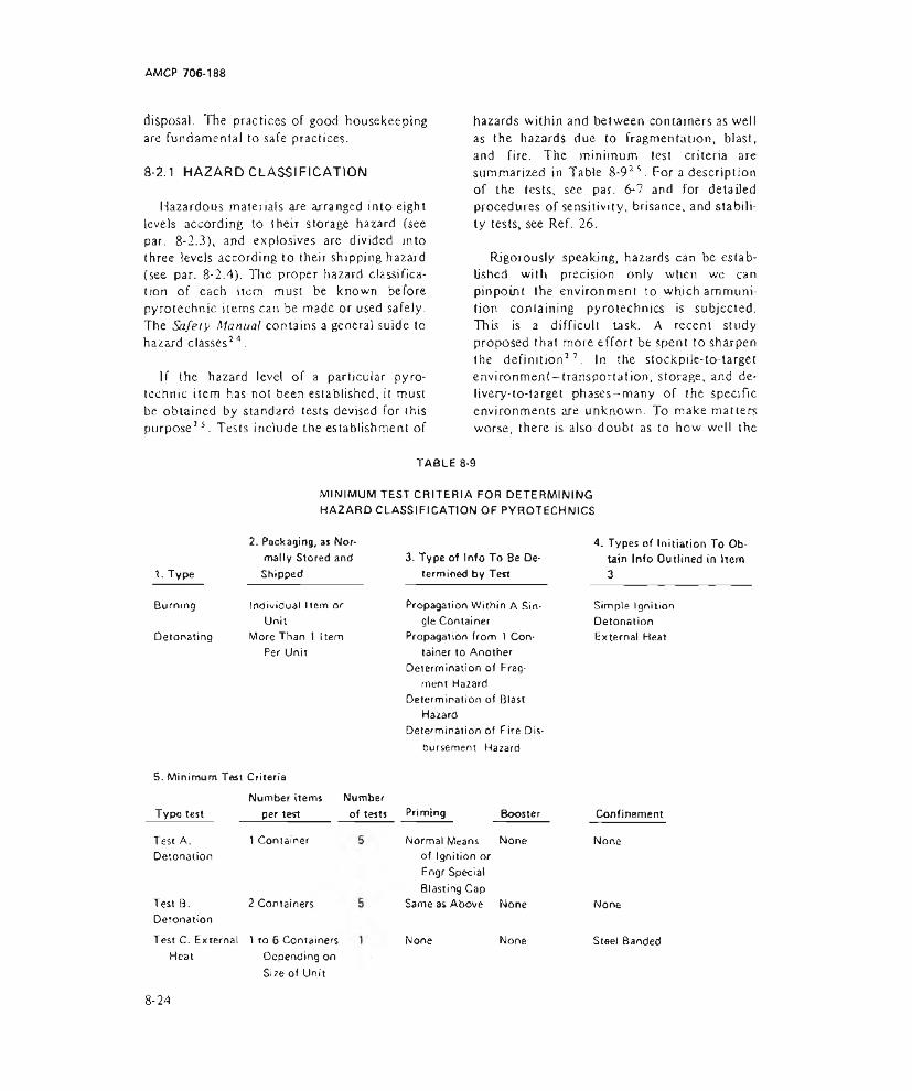
AMCP 706-188
disposal. The practices of good housekeeping are fundamental to safe practices.
8-2.1 HAZARD CLASSIFICATION
Hazardous materials are arranged into eight levels according to then storage hazard (see par. 8-2.3), and explosives are divided into three levels according to their shipping hazard (see par. 8-2.4). The proper hazard classification of each item must be known before pyrotechnic items can be made or used safely. The Safety Manual contains a general suide to hazard classes2 4.
If the hazard level of a particular pyrotechnic item has not been established, it must be obtained by standard tests devised for this purpose15. Tests include the establishment of
hazards within and between containers as well as the hazards due to fragmentation, blast, and fire. The minimum test criteria are summarized in Table 8-915. For a description of the tests, see par. 6-7 and for detailed procedures of sensitivity, brisance, and stability tests, see Ref. 26.
Rigorously speaking, hazards can be established with precision only when we can pinpoint the environment to which ammunition containing pyrotechnics is subjected. This is a difficult task. A recent study proposed that more effort be spent to sharpen the definition11. In the stockpile-to-target environment—transportation, storage, and de- livery-to-target phases—many of the specific environments are unknown. To make matters worse, there is also doubt as to how well the
TABLE 8-9MINIMUM TEST CRITERIA FOR DETERMINING HAZARD CLASSIFICATION OF PYROTECHNICS
1. Type Burning Detonating
2. Packaging, as Normally Stored and Shipped
Individual Item or Unit
More Than 1 Item Per Unit
3. Type of Info To Be Determined by Test
Propagation Within A Single Container
Propagation from 1 Container to Another
Determination of Fragment Hazard
Determination of Blast Hazard
Determination of Fire Disbursement Hazard
5. Minimum Test CriteriaNumber items
Type testTest A. Detonation
Test B. Detonation
per testNumber of tests
1 Container
2 Containers
Test C. External 1 to 6 Containers Heat Depending on
Size of Unit
Priming BoosterNormal Means None of Ignition or Eogr Special Blasting Cap
Same as Above None
None None
4. Types of Initiation To Obtain Info Outlined in Item 3
Simple Ignition Detonation External Heat
ConfinementNone
None
Steel Banded
8-24

AMCP 706-188
tests simulate the actual environments. Further, the present approach for determining how a pyrotechnic responds is to test it in a particular hardware. This makes it difficult to predict the response for similar items in different hardware. For example, a maximum storage temperature of I65°F is widely used. If the rate of heat flow into the item were specified instead, a more meaningful tests could be performed. A small pyrotechnic tem exposed in an oven may require a heat of 130 Btu ft'2 hr’1 to reach and maintain 165° F. However, a large air-launched flare weighing 250 lb may require 450 Btu ft'2 hr 2 to reach and maintain the I65°F temperature in the same oven. Do the two oven exposures simulate identical storage conditions?
In addition to the hazards described thus far, pyrotechnics may also be toxic. Chemical agents, in particular, should be handled with the utmost care. For details, see Refs. 23 and 28.
82.2 HANDLING
Pyrotechnic items must be handled carefully during their entire life from the first laboratory experiments, through manufacturing, and to the stockpile-to-delivery sequence. First, personnel must be familiar with the physical and chemical properties of the pyrotechnic item or materials29. Next, sound safety practices must be utilized2 3.
Safe handling is particularly important during manufacturing where parts are not yet fully assembled. Heat generated by friction, impact, vibration, and static electricity are major sources of hazards. See par. 8-5 for further details,
Handling during operation presents a different safety problem. Pyrotechnic items may be handled by persons who are not familiar with them. Hence, clear and precise labeling is important. Personnel should be trained in safe practices. For information on handling during
TABLE 8-10STORAGE CATEGORIES OF TYPICAL PYROTECHNIC ITEMS
AND MATERIALSITEM Storage
CompatabilityGroup
Quantity-DistanceClass
Slack powder, in charges or containers OBombs, photoflash (Except M122, w/o burster) OBombs, photoflash, M 122, w/o burster C & QCartridges, illuminating ECartridges, photoflash OCutters, reefing line B,E,NDetonation simulator, explosive, M80 OGrenades, illuminating NGrenades, practice, w/spotting charge EGrenades, smoke (except HC, WP & PWP) NPhotoflash powder AProjectiles, illuminating E & NSimulators, M110, M 117, Ml 18, and M1 19 NSimulators. M 115 and XM142 QSimulator, M116 B & QSmoke pots NSpotting charges (cartridge for miniature practice bombs) N
8 -2 5

AMCP 706-188
TABLE 8-11
EXCERPT FROM QUANTITY-DISTANCE TABLES
Material,InhabitedBuilding
Distance, ft Highway & or
Railway Intrnline Above Ground
8-2.4. respectively.
8-2.3 STORING
lb bar.. unbar. bar. unbar. bar. unbar. bar. unbar.Class 1
> Limit 100 100 t o o 80Class 7
1 40 80 25 50t o 90 180 55 1 10 30 40100 190 380 115 230 40 80 28 51
1,000 400 800 240 480 95 190 60 11010,000 865 1730 520 1040 200 400 130 235100,010 1855 3630 1115 2180 415 830 280 510
shipping. SCO pars. 8-2.3 and lists the compalibilily group. Ciromost severe; all items in this group must be stored alone. Items in groups LI through Q may be stored with other items within the same group in any combination.
Basie information on storage is contained in llie Safety Manual24. In addition, two Department of Defense safety manuals contain much of the same information but their arrangement makes them often easier to use. One of the manuals covers agencies30 while the other covers contractors'1.
for the purpse of storage, hazardous materials are arranged into eight classes according to their level of hazard. Ammunition containing pyrotechnics are divided into classes I and 7 depending on their hazard level. Class I items are* those that have a high fire hazard but no blast hazard and for which virtually no fragmentation or toxic hazard exists beyond the lire hazard clearance distance ordinarily specified for high-risk materials. In contrast, class 7 items are those for which most items of a lot will explode virtually instantaneously when a small portion is subjected to fire, severe concussion, impact, the impulse of an initiating agent, or considerable discharge of energy from an external source31. The storage categories of typical pyrotechnic items and materials are excerpted in fable 8-I024. In addition to the hazard class, the table also
Pyrotechnics are stored in accordance with quantity-distance requirements, i hese requirements are defined as "the quantity of explosives material and distance separation relationships which provide defined types of protection. These relationships are based on levels of risk considered acceptable for the stipulated exposures and arc tabulated in the appropriate quantity-distance tables. Separation distances are not absolute safe distances but are relative protective or safe distances” 3 0.
Quantity-distance tables are contained in the safety manuals’ 3 ■'0 J 1 ; a typical excerpt is shown in Table 8-1 I33. The largest minimum distances are required where a hazard exists to personnel, i.e., inhabited buildings. Intraline refers to the minimum distance between any two buddings within one operating line or assembly operation. The magazine distances given in the excerpi are for aboveground storage, which is the least desirable. Earth-covered, arch type magazines are preferred because they are safer: their required separation distances are much less than those
8-26

AMCP 706-188
of above-ground magazines. Note that separation distance is roughly proportional to the quantity of material, and that a barricade of proper construction reduces by one-half the distance used for unbarricaded storage.
Dissatisfaction has recently been expressed with the degree to which safety classes suffice for pyrotechnic materials. Some pyrotechnics are quite lethal, resulting in damage due to a fire ball (radiant heat) and fragments. Damage is certainly greater than that of a Class 1 material. However, reclassification to Class 7 presents two problems: (1) the pyrotechnic does not really qualify under the criterion for detonating solids as established by the Card Gap Test (see Ref. 25), and (2) the commonly used barricades can at times enlarge the. hazard by increasing the distance of thrown fragments and burning debris. Hence, a separate classification for pyrotechnic materials has been suggested32. It should be emphasized, however, that the personnel concerned with pyrotechnics have no choice but to comply with the existing safety regulations as a minimum.
8-2.4 SHIPPING
For the purpose of shipping, materials are divided into three classes according to their level of hazard3 3:
(1) Class A. Chemical compounds, mixtures, or devices (mass detonating, spark initiated, or shock sensitive) with maximum shipping hazard. Examples are black powder, PETN, and explosive ammunition.
(2) Class B. Explosives that function by rapid combustion rather than detonation. Examples are gun propellants and certain rocket motors.
(3) Class C. Devices that may contain Class A or Class B explosives or both, but in restricted quantities, and certain types of fireworks. Examples are electric squibs, explosive bolts, and small arms ammunition.
The safe transport of hazardous materials is the responsibility of the shipper. It has become expedient to pack and label hazardous cargo to meet requirements for all kinds of transportation. The Navy is the largest shipper of military cargo because most of it ultimately ends up aboard ship. If a commercial shipper is used, he should be properly licensed in all states and countries involved. Shipping regulations are complex and a qualified shipper is needed to cope with them.
All safety regulations are enforced in the shipment of hazardous materials to protect life, property, and the cargo itself. All cargo must be properly blocked and braced during shipment. For some hazard classes, the vehicle must be placarded and inspected. Mixed shipments in the same vehicle must be compatible. In case of an accident on any mode of shipping, Form F5800 must be filed with the Department of Transportation when the incident involves death or serious injury, $50,000 property damage, or continuing danger.
Shipping regulations for specific pyrotechnic items are contained in the item specification. General regulations are covered by the Department of Transportation, Code of Federal Regulations, Title 49, Parts 100-99. For detailed information on shipping ammunition containing pyrotechnics, see Ref. 33. It identifies each item by Federal Stock Number and lists hazard class as well as the information of concern to the shipper, such as cube, weight, and labeling requirements. Transportation by rail, motor vehicle, and water carrier is also covered in Ref. 34. In addition to these regulations, state and municipal laws, local ordinances, and harbor regulations must be observed where they apply.
8-3 RELIABILITY
Reliability is the extent to which we may expect a device to perform its intended function for a specified period under stated conditions33. It is often expressed in statistical terms. Since reliability can be no greater
8-27

AMCP 706-188
than the most unreliable component of a pyrotechnic device, it is important to prove the reliability of each component. Moreover, environmental factors such as moisture and vibration, encountered during storage and transportation, can affect reliability and therefore should be taken into account.
Keep in mind that reliability and safety are closely related. While pyrotechnic devices must function as intended (reliability), they must not function under any but the right conditions (safety).
8-3.1 CONSIDERATIONS DURING RESEARCH AND DEVELOPMENT
During the research and development phase, the reliability of individual components is usually examined in detail, and the measure of reliability most often used is probability. Probability is usually expressed as a percentage and it denotes the ratio of occurrence of a given event to total number of events, e.g., if in a test of 100 aerial flares 98 function properly, the probability of proper functioning for these 100 flares is therefore 98%. The confidence interval, a function of sample size, should also be determined.
Predictions of reliability demand a knowledge of the concepts of random sampling, frequency distributions, significant differences, and methods for computing statistical parameters. All these should become a part of the designer’s working vocabulary so that, at the very minimum, he can recognize those situations where a professional statistician is required. The subject of experimental statistics aimed specifically toward military application is the subject of other handbooks36' 40.
A powerful analytic technique for assessing the reliability as well as the safety of pyrotechnic ammunition is the Fault Tree Artal- ysis41. Based on logic diagrams, Boolean algebra, and probability values for individual components, it helps to assess system reliabili
ty and safety by pointing out the weaknesses in design, material, manufacturing process, inspection procedure, or adverse environmental conditions. The technique also obviates the testing of a large number of samples to achieve these purposes experimentally, a task that is often.prohibitively expensive.
A typical example of a fault tree is shown in Fig. 8-11. It diagrams the events and causes that could lead to the accidental ignition of the EX' 48 Mod 0 flare. The fault tree analysis indicated that the most probable causes of accidental ignition are:
1. Heating to auto ignition temperature
2. Mechanical shock
3. Battery activation via an electrolytic fluid leading into the battery cavity
4. Squib initiation due to an intense radio frequency signal.
An analysis of this type is used in determining what tests must be performed to ascertain that none of the environmental conditions that the unit is likely to encounter will cause premature initiation. It also indicates which events are more or less likely to occur. In this instance, the mode of ignition least likely to occur is the accidental initiation of the flare by an RF signal because of the number of events that must occur simultaneously.
A few general suggestions can be made to the designer with regard to reliability2 2:
(1) Whenever possible, use standard components with established quality levels and other reliability criteria at least as high as those required by the application.
(2) Use redundant systems in more complex and expensive materiel but tend to keep overall systems as simple as possible.
(3) Specify materials for which the proper-
8-28
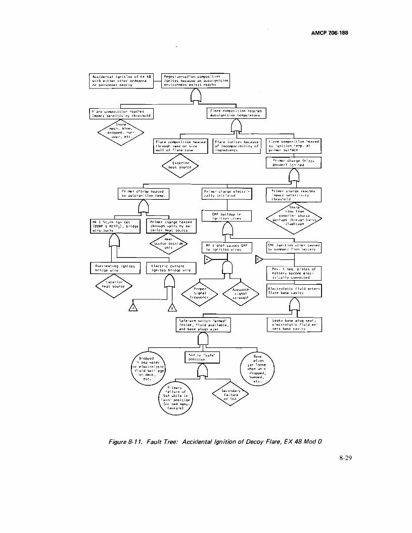
AMCP 706-188
S a f e - a r m s w i t c h " a r m e d " L e a k y b a s e p l u g s e a l ;
i n s i d e , f l u i d a v a i l a b l e , e l e c t r o l y t i c f l u i d e n -
a n d b a s e p l u g s a j a r t e r s b a s e c a v i t y
Figure 8-11. Fault Tree: Accidental ignition of Decoy Flare, EX 48 Mod 0
8 - 2 9

AMCP 706-188
ties of importance to your application are well known and reproducible. Keep in mind that the average value for a parameter may be less important for design purposes than the extreme values. Make specification changes in proven items only with great caution.
8-3.2 CONSIDERATIONS FOR THE STOCKPILE
During manufacturing, the reliability of pyrotechnic items is safeguarded by means of quality assurance procedures. When items reach the stockpile, surveillance programs are applied. Surveillance includes the observation, inspection, investigation, test, study, and classification of pyrotechnic devices and their components with respect to their serviceability, hazard, and rate of deterioration42. The twofold purpose of surveillance is to insure the reliability of items in storage and to provide the designer with a source of data for the improvement of future designs.
One aspect of surveillance is concerned with the order in which pyrotechnic ammunition is used. First priority is given to ammunition that is serviceable but not suited for long-term storage.
8-4 MAINTENANCE
Ideally, pyrotechnic ammunition should be completely maintenance free. It should be so designed that it can be placed on the shelf and perform perfectly when withdrawn for use 20 yr later. Every effort should be made to produce ammunition having optimum properties of handling, storage, shelf life, and serviceability. Design for maintainability requires incorporation of at least the following maintenance principles4 2:
(1) Design to minimize maintenance and supply requirements through attainment of optimum durability and service life of material.
(2) Recognition of field maintenance problems encountered in earlier designed items.
(3) Design for ease of maintenance by assuring accessibility to facilitate inspection, repair, and replacement.
(4) Consideration of field maintenance based on geographical locations and climatic conditions.
(5) Design for maximum utilization of interchangeable components.
(6) Detection of conditions that will adversely affect the conduct of maintenance operations or generate excessive maintenance and supply requirements.
(7) Design to effect maximum compatibility of maintenance operations with contemporary common tools.
(8) Evaluation for ease of packaging, carloading, and shipment.
(9) Design to enable removal of major components as individual units.
(10) Assurance that proper materials and special treatment are used for maximum resistance to deterioration.
(11) Consideration of long term storage with a minimum of periodic checks and maintenance in storage.
8-5 MANUFACTURING
As in any specialized industry, pyrotechnic manufacturing processes involve the use of specialized tools, hardware, and assembly and control techniques. In general, many of the processes used in the manufacture of pyrotechnic ammunition are the same as those used for the manufacture of explosive items.
The production of pyrotechnic items involves a series of steps starting with the selection and processing of the pyrotechnic ingredients, production of metal parts, and ending with final assembly. It is important, in the selection and processing of the ingredients
8-30

that their chemical and physical properties are known jn advance, especially particular hazards to personnel and property caused by the reaction of these materials to various stimuli. For detailed information on the properties of pyrotechnic materials, see Ref. 29. The processing of pyrotechnics is treated in Ref. 23, and the laboratory and plant procedures that must be followed for the safe processing of pyrotechnic items are described in Refs. 21 and 24.
8-5.1 CONTROL OF RAW MATERIALS
As in any processing of chemical materials, quality assurance starts with the selection of the proper ingredients. The physical and chemical reactions that often occur in pyrotechnic mixes are sensitive to control factors. Particle size, in particular, can have a large effect upon burn rate, light output, and efficiency of flare, smoke, and delay compositions. The various methods for determining particle size are covered in the Military Specifications for particular materials and in Ref. 23.
In addition to particle size, other factors that should be controlled are chemical purity, moisture content, and reactivity. Reactivity is a measure of the ability of a compound to react with another substance and can be influenced by grinding processes, particle shape, and the presence of trace impurities.
8-5.2 CONTROLLING PROCESSES
Pyrotechnic raw materials are mixed, ground, weighed, blended, granulated, dried, pressed, or consolidated-depending on the application23. For reasons of safety, processes should be controlled from behind suitable barricades with the minimum possible quantities. Often the process is controlled visually, based on experience, but sampling and subsequent measurement of particle size, moisture content, and performance characteristics are also used.
Whenever possible, processing tools of
metal should be conductive nonsparking. Common nonsparking metals are bronze, beryllium alloys, lead, and monel. Certain tools may a';;o be made from wood, plastic, and rubber. It should be kept in mind, however, that these nonsparking metals can occasionally produce sparks under certain conditions.
When strength or dimensional stability is needed, as in pressing, tool steel is required. Flere it is particularly important that the tools are designed in such a manner that the pyrotechnic being worked is not pinched between sharp edges. In addition, vent holes or other means to prevent pressure buildup in the event of accidents should be provided m molds used in pressing operations.
8-5.3 LOADING
After blending, the pyrotechnic composition is loaded into its container. All loading operations should be performed by remote control with operating personnel behind reinforced protective barricades. For purposes of loading, compositions may be classified into three groups2 3.
(1) llluminants and Smokes. These compositions usually contain a binder, and are loaded by consolidating into a case by a hydraulic press. Incremental consolidation is often used.
(2) Delay Compositions. These are usually loaded in the same manner as illuminants and smokes, except that higher pressures arc used (except where birders are present). Dies are normally used to support the delay body.
(3) Flash and Spotting Compositions. Flash and spotting compositions, because they do not usually contain a binder, are likely to be more sensitive to friction ihan compositions containing a binder. For this reason such compositions are usually loaded by vibrating the item on a vibrating table.
Flash and spotting compositions are usually
S-31
loaded dry. In the other two groups, wet loading and cast loading techniques may also be used.
1~he desire is always to load a specific weight of pyrotechnic. For small test quantities or for some premium quality production, direct reading, one-pan b a l a n c e s are used that provide an accuracy within one percent. The two most common volumetric measuring devices are scoops and charging plates. To obtain the desired weight, the loading plant must adjusl the volume to account for bulk density. In hand operations, scoops are filled and leveled against a rubber band. Careful scooping is accurate within 4%. Qtarging plates lend themselves to production rates22.
Production pressing tools are hardened too) steel (60 Rockwell C is common) and the die is lapped and polished. Cups are supported by close fitting loading tools while the charge is being pressed. A quantity of pyrotechnic can be pressed either to a controlled height (stop laoding) or to the limit of an applied load for a given diameter (pressure loading). Stop loading is faster but not as accurate as pressure loading. In normal production, a reasonable weighing tolerance for pyrotechnic charges is 3 or 4%. In stop loading, if the height of an increment is exactly reproduced, the density may vary as much as 7%. In either type of loading, the density should be checked for each production lot.
Loading pressure varies with the material being pressed. For delays, the pressure is as high as 10,000 psi. Charges may be pressed directly into their containers or, sometimes, pressed into molds and ejected as pellets. When a container of length greater than its diameter is used, the pyrotechnic is usually loaded in increments that are one diameter long2 2.
8-5.4 ASSEMBLY
Assembly methods are many and varied because of the wide variety of pyrotechnic end items. During the assembly operations.
the pyrotechnic charge is brought together with the necessary hardware. Whether common or specialized, hardware is produced by means of conventional manufacture. Different metals, wood, cardboard, paper, and plastics have all been employed. The design and selection of hardware is based on such factors as chemical compatibility, storage life, strength, cost, availability, and reliability.
When pyrotechnic devices are assembled, controlled operations are desirable. The temperature and humidity should be carefully controlled and dusting of the composition should be kept at a minimum. The least practical number of items should be kept in the working area.
While assembled pyrotechnic items are usually safer to handle than the pyrotechnic material itself, safe practices are nevertheless mandatory. To protect the pyrotechnic material from deterioration, special sealing or welding techniques are often employed in assembly, such as ultrasonic welding.
8-6 PACKAGING
Pyrotechnic ammunition - such as flares, signals, fusees, igniters, and illuminants — is packed in much the same way as other types of conventional ammunition. The primary function of any military package is to provide protection against induced environmental factors (shock and vibration) and natural environmental factors (humidity, temperature, rain, dust, etc ), and to provide for ease and safety of handling that may tv encountered during world-wide handling, shipping, and storage.
Since packaging of the ammunition may affect its design, a packaging handbook should be consulted42. The first concern in packaging is to establish the Level (dcg.ee) of protection desired, namely:44
(I) Level A military packages are for unknown overseas destinations and storage conditions. The gross weight of a Level A military
8-32
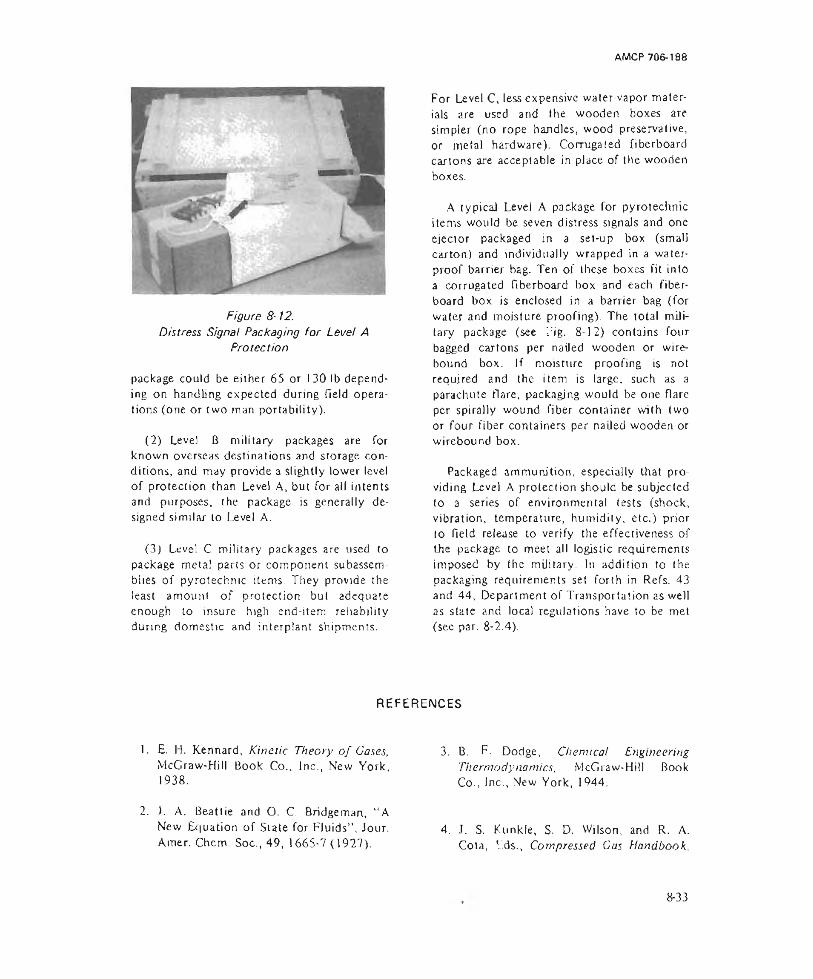
AMCP 706-188
Figure 8-12.Distress Signal Packaging fo r Level A
Protection
package could be either 65 or I 30 lb depending on handling expected during field operations (one or two man portability).
(2) Level B military packages are for known overseas destinations and storage conditions, and may provide a slightly lower level of protection than Level A, but for all intents and purposes, the package is generally designed similar to Level A.
(3) Level C military packages are used to package metal parts or component subassemblies of pyrotechnic items. They provide the least amount of protection but adequate enough to insure high end-item reliability during domestic and interplanl shipments.
For Level C, less expensive water-vapor materials are used and the wooden boxes are simpler (no rope handles, wood preservative, or metal hardware). Corrugated fiberboard cartons are acceptable in place of the wooden boxes.
A typical Level A package for pyrotechnic items would be seven distress signals and one ejector packaged in a set-up box (small carton) and individually wrapped in a waterproof barrier bag. Ten of these boxes fit into a corrugated fiberboard box and each fiber- board box is enclosed in a barrier bag (for water and moisture proofing). The total military package (see Fig. 8-12) contains four bagged cartons per nailed wooden or wire- bound box. If moisture proofing is not required and the item is large, such as a parachute flare, packaging would be one flare per spirally wound fiber container with two or four fiber containers per nailed wooden or wirebound box.
Packaged ammunition, especially that providing Level A protection should be subjected to a series of environmental tests (shock, vibration, temperature, humidity, etc.) prior to field release to verify the effectiveness of the package to meet all logistic requirements imposed by the military. In addition to the packaging requirements set forth in Refs. 43 and 44, Department of Transportation as well as state and local regulations have to be met (sec par. 8-2.4).
REFERENCES
1. E. I I. Kennard, Kinetic Theory o f Gases, McGraw-Hill Book Co,, Inc., New York, 1938.
2. J. A, Beattie and O. C. Bridgeman, “ A New Equation of Slate for Fluids” , Jour. Amer. Chem. Soc., 49, 1665-7 (1927).
3. B. F. Dodge, Chemical Engineering Thermodynamics, McGraw-Hill Book Co., Inc., New York, 1944.
4. J. S. K.unkle, S. D. Wilson, and R. A. Cota, V.ds., Compressed Gas Handbook,
8-33

N ASA SP-3045, National Aeronauticsand Space Admin., 1969.
5. F. A. Eckman,, “ Basic Structural Analy- sis“ , i iectro-1 echnology, 73, 5, 67-90 (May 1964).
6. L. S. Marks, Mechanical Engineers' Handbook Sixth Edition, McGraw-Hill Book Co., Inc.. New York, 1953.
7. J. A. Murtinelli. "‘Safe Loads for Thin Wall Cylinders’’. Machine Design 40,18, 116-7 (August 1. 1968).
8. J. E. Hauck, Ed,, "Engineers’ Guide to Plastics'1, Materials in Design Engineering, 65. 92-3 (Feb. 1967).
9. ASTM. Standards, Plastics — General Methods o f Testing. Nomenclature, Part 27, 1972.
) 6. MIL-C-5541. Chemical Films and Chemical Film Materials for Aluminum and Aluminum Alloys. Dept, of Defense-
17. Ml L-C-45013, Coaling Compound. Bituminous Solvent Type. Black (for Ammunition). Dept, of Defense, 28 September 1965.
18. "1972 Materials Selector", Materials Engineering 74. 4, 355-8, 471-4 (Mid-September 1971).
19. Modern Plastics Encyclopedia. McGraw- Hill Book Co., Inc., New York. 1968, pp. 84-101.
20. N. E. Beach, Compatibility o f Plastics With Liquid Propellants, Fuels and Oxidizers. PLAS'l EC ReporL 25, Picatinny Arsenal, Dover, NJ, January 1966.
10, Conference Digest, “ Design to Control Corrosion", Machine Design, 41. 136-45 (Aug. 7, 1969).
21. OP 3237, Safety Principles for Laboratory and Pilot-Plant Operations. With Explosives. A; lOtechnics. and Propellants. Dept, of Navy. July 1964.
11. M. G. Fontana and N. D. Green, Corrosion Engineering, McGraw-Hill Book Co., Inc, New York, 1967
12. MIL-HDBK-721(MR) Co/rosion and Corrosion Protection o f Metals. Dept, of Defense. November 1965.
13. M1L-S1D-186B. Protective finishing Systems for Rockets, Guided Missiles. Support Equipment and Related Materials. Dept, of Defense, Maich 1964.
22. AMC1’ 706-179, Engineering Design Handbook, Explosives Series. Explosive Trains.
23. AMCP 706-186, Engineering Design Handbook, Military Pyrotechnics Series. Part Two. Safety, Procedures and Glossary.
24. AMCR 385-100, Safety Manual. Army Material Command. April 1970.
14. M1L-STD-1250(MI). Corrosion Prevention and Deterioration Control in Electronic Components and Assemblies, Dept, of Defense, March 1967.
15. QQ-P-35, Passivation Treatments for Austenitic. Ferritic, and Martensite Corrosion-Resisting Steel (Fastening Devices'). Dept, of Defense.
25. TB 700-2, Explosives Hazard Classification Procedures. Dept, of Army, 19 May 1967.
26. A. J. Clear, Standard Laboratory Procedures for Determining Sensitivity, Brisance. and Stability o f Explosives, Report PA i R 3278, Picatinny Arsenal, Dover, NJ, April 1970.
8-34

27. H. C. Schafer, Environmental Criteria Determination for Pyrotechnics, Report NOTS TP 4254, Naval Weapons CenLer, China Lake, CA, April 15)67.
28. OP 2793. Toxic Hazards Associated with Pyrotechnic Items. Bureau of Naval Weapons, 1 November 1963.
29. AMCP 706-187, Engineering Design Handbook, Military Pyrotechnics Series, Part Three. Properties o f Materials Used in Pyrotechnic Compositions.
30. (D eleted)
31. DOD 4 145.26M, DO!) (. ontrac tors' Safety Manual for Ammunition, Explosives and Related Dangerous Material, Dept, of Defense. October 1968.
32. J. 11. McLain. “Pyrotechnic Hazard Classification’’. Proceedings o f the Seventh Symposium on Explosives and Pyrotechnics. The Franklin Institute Research Laboratories. Philadelphia, PA, September 8-9, 1971. pp U-IO-1,-2.
33. OP 2165, Atopy Transportation Safety Handbook. Naval Ordnance Systems Command.
34. Agent R. M. Graziano’s Tariff No. 25 (DoT #25;, Ha znrdous Materials Regulations of the Department o f Transportation, Association of American Railroads, Washington. DC, 1972.
35. MIL-SI D-721 A, Definition o f Terms for
Reliability Engineering Dept, of Defense 2 August 1962.
36. AMCP 706-110, Engineering DesignHandbook, Experimental Statistics. Section I, Basic Concepts and Analysis o f Measured Data.
37. AMCP 706-111, Engineering DesignHandbook, Experimental Statistics. Section 2. Analysis o f Enumerative .and Classificatory Data.
38. AMCP 706-112, Engineering DesignHandbook. Experimental Statistics. Section 3. Planning and Analysis o f Comparative Experiments.
39. AMCP 706-1 13, Engineering DesignHandbook, Experimental Statistics, Section 4, Special Topics.
40. AMCP 706-114. Engineering DesignHandbook, Experimental Statistics. Section 5, Tables.
41. W. F. Larsen, Fault Tree Analysis. Report PATH 3822, Piealinny Arsenal, Dover, NJ. November 1968.
42. AMCP 706-134. Engineering DesignHandbook, Maintainability Guide for Design.
43. AMCP 706-121, Engineering DesignHandbook, Packaging and Pack Engineering.
44. AR 700-1 5, Preservation-Packaging. Packing and Marking o f Items o f Supply. Dept, of Army, 28 May 1968.
8-35/8-36

AMCP 706-188
APPENDIX A
FLARE DESIGN INFORMATION
This Appendix contains the available design aids for flares. Figs. A -l1 and A-21 are nomograms from which the burning rate and candlepower, respectively, can be obtained
for Mg/NaN03 flares. The efficiency of various light sources for flares is compared in Table A-l2.
1%)UtfJWAC SUAWW
PATC(<« /«*3 * I
PAftTlCUStf£
KOWO -
rMO- WO- *00- 4 10
- 420
-
5' 6-
DiRCCTrONS fOR US£STEP ALIGN READ
I 7. a LA« V.Z 4, a m« size3 a CASING 10 burn
ra r E
y jt. E - ■
Standard E rro r o f Estim ate 0 .6 in /m m
CASINGIDUl
r- a t *■ OJ- i o- > l- I 4- It- LI -2.0- 2 2 - t 4 L 2.1
Figure A -1. Nomogram - Burning Rate o f Mg/NaNOi F/aresWith Laminae Binder and Paper Cases
*1PARTICLE
SIZE(ft)
M l
^ ^ LAHINAC1%)
CASING10.(ift.l (%>
MK>
370400
_ -4 l0
- 420
- 460
CAJiOLEPOWER(lOOOcondin/J/i^l
IZ-
10-
1 4 -
1.6 -
2.0 -27.2 4
DIRECTIONS FOR USE
Standard Error ol Estimate 26xl03 candles/in.2
s r e p A L I G N R E A O
1 Mg SIZE a LAM % 4-,
2 4>, a c a s in g i o. 4 ,
3 4>z 6 Mg % CANDLE-POWER
48 '4V30 '.2 M . 38-
JOt-88-68-84-62■60
Figure A-2. Nomogram — Candlepower o f Mg/NaN03 F/e/es With Laminae Binder and Paper Cases
TABLE A-1COMPARISON OF EFFICIENCIES OF VARIOUS LIGHT SOURCES
Item
Luminous Flux, to
Radiant Flux,%
Efliciency, Im W'1
Efficiency, c-sec-(gram metal)’1
Ideal Yellow-Green Line 556 100 680Sun 16.1 100Tungsten Lamp 5000 W 4.7 29Sodium Vapor Lamp 16.4 102ivl 112 Photoflash Cartridge 1.14 7.1 16,700M123 Photo I lash Cartridge 1.11 6.9 16,200M120A1 Photoflash Comb 0.98 6.1 14,500Al + Liquid Oxygen 1.3-1.6 8.1-9.8 20-24,000X-52 0.65 4.05 10,000T86E5 0.55 3.4 8,200TI0E3-4 Flare 10.1 63 110,000T10E5-6 Flare 8.4 52 94,000T90 Photoflare 7.2 45 82,500

AMCP 705-188
Two empirical equations predict the performance of magnesium flares (within the limits of 48-60 / magnesium content and diameters from 1 to 2.25 in.)3. The mean burning time is
/ - S23.20t.04 - 7.5 I 26000* (A-l)- 156.71800/1 i- 2.2476004*r 1 2.25090042 - 0.1 73020004Tv
and the output is
/-= 14685.430 - 2P.29000a- (A-2)- 5658.0000/1 - 14332.500<7
+ 4893.10004c/ + 301.9218142 - 235.217644 V + 41.9630004*+ 225.86000<2.v — 37 095000,1c/*
wheret = mean burning time, see
r - output, dimensionless
A - surface area of magnesium. 10'2 cm2g
d = diameter, in.
a - magnesium content. %
REFERENCES
1. S. H.. ( irecn and R. G. Amicone. Prediction o f Pyrotechnic Performance's. Report P R-C1881-2. The Franklin Institute, for Picatinny Arsenal. Contract DA-28-107- AMC-3309(A). March 1969.
2. Private cominunicntion from G. Wein- garten. Picatinny Arsenal. Dour. NJ.
3. Private communication from S. M. Fasig. Naval Air Development Center. Johnsville, PA.
A-3/A-4


AMCP 706-188
APPENDIX B
PYROTECHNIC COMPOSITIONS
(1) Stab Primer Compositions
(2) Friction Primer Compositions2:
(3) Percussion Primer Compositions:
Ingredients
Composition, % by weightIngredients PA100 NOL130Lead Azide 5 20Potassium Chlorate 53 -Antimony Sulfide 17 15Basic Lead Styphnate - 40Lead Thiocyanate 25 -Terrace ne - 5Barium Nitrate — 20
Composition, % by weightIngredients A B CPotassium Chlorate 63 53 42Antimony Sulfide 32 22 42Sulfur - 9 3Calcium Carbonate - 1 2Meal Powder - - 3Ground Glass * 10 3Gum Arabic 5 5 5
Composition,% by weight M39 PA101 FA70 NOL60
(Ref. 3) (Ref. 1) (Ref. 1) (Ref. 1)FA959 (Ref. 3>*
Lead Styphnate - - - - 35.0Basic Lead Styphnate - 53 - 60 -
Tetracene — 5 - 5 3.1Potassium Chlorate 37.05 - 53 - -
Barium Nitrate 8.68 22 — 25 31.0Antimony Sulfide - 10 17 10 10.3Lead Thiocyanate 38.13 - 25 - -
Powdered Glass 10.45 - - -
Powdered Aluminum - 10 — - —
Powdered Zirconium - - — — 10.3Lead Dioxide - - - - 10.3TNT 5.69 — 5 — —
‘ Reprinted w ith permission from M ilita ry and C ivilian Pyrotechnics, H. E liern, Chemical Publishing Co., Nevu Y o rk , 1969.
B-l
(4} Electric Primer Compositions5:’Composition, % by weight
Ingredients A B C D' —Oiazodinitrophenol (DDNP) 20 75Potassium Chlorate 60 25 55 8.5Lead Thiocyanate — _ 45Lead Mononitro Resorcinate (LMNR) — — — 76.5Charcoal IS _ _ _Nitrocellulose — _ 15.0Nitrostarch(A) Used as primer and fire transfer. IB) Used in Mk1 Mod 0 Squib.(C) Used in M59 Electric Igniter.(D) Used for various electric matches.
5
(5) Conductive Primer Mixes5 : * Ingredients
C u m .
Aposition, % by weight
B CZirconium (<5p) 7.5 6-9 15.0Zirconium (>10ju) 32.5 30-35 —
Zirconium Hydride - — 30.0Lead Dioxide 25.0 18-22 20.0Barium Nitrate 25.0 15-25 15.0PETN - 15-23 20.0(G) High Intensity White Flares5:*
IngredientsComposition, % by weight A B C D
Magnesium (30/50) 58±2 45.5 53 55Sodium Nitrate 371:2 45.5 39 36Laminae 4*y, 9.0 8 9
(7) Mild White Light Source (used in Ml 18 Booby Trap Simulator)5 :*
IngredientsPotassium PerchlorateRed GumDemin
Composition, % by weight 73 21
6
(8) White Star5'Ingredients CompositioMagnesium 25Alurninurn 14Barium Nitrate 42Strontium Nitrate 1 1Asphaltum 5Linseed Oil 3
•Reprinted wuh permission from Military and Cn/ih'an Pyrotechnics. H, Ellern, Chemical Publishing Co .Now Vork. 1969.
(M
AMCP 706-188
(9) High Altitude Flash Charges3:'Ingredients Aluminum (< I7p)Calcium Metal Sodium Perchlorate Calcium Flour.de Potassium Perchlorate
Composition. % by weightA B C D40 31 20— - 30 80— — - 20— 20 - -60 49 50 -
(10) Photoflash Powders: IngredientsAluminumMagnesmrn/Aluminum Alloy MagnesiumPotassium Perchlorate Barium Nitrate
(11) Simulator Mixes'’: *IngredientsMagnesiumAluminumPotassium Perchlorate Barium Nitrate Barium Oxalate Calcium Oxalate Graphite
Composition. % by weightA B45 34- 2635 6015 -3 -
11
(A) Used in Ml 10 Gunflash Simulator.(BS Used in M 115 Projectile Ground Burst Simulator.
(12) Underwater Flare Mix’:*Ingredients Composition, % by weightMagnesium 16Aluminum 12Barium Sulfate 40Barium Nitrate 32
(13) Intensity Flare (FI), Star (St), and Star Tracer (Tr) Mixes3:'Composition, % by weight
Ingredients Red Green YellowFI St Tr _FI_ St. Tr FI St Tr
Magnesium 29 23 46 26 15 48 26 19 49Gilscrtice 2 8 3 2 - 3 2 9 5Oil 2 - - 2 2 - ? - -Hex ichlgrobenaene 4 6 4 1 15 6 5 7 -Powdered Copper - - - - 2 2 - - -Cup, ic Oxide - - - 2 - - - - -
(conci:iuud)"Reprinted with permission fr o m M iii* jrv 3 0 d Civilian P yro tech n ic s , N. EUern. Chemical Publishing Co,, New York, 1969.
B-3

AMCP 706-188
Ingredients FIRed
Tr FIGreenSt Tr FI
YellowSt Tr
Barium Nitrate — — _ 45 66 16 29Strontium Nitrate 34 41 18 — _ _ _Potassium Perchlorate 29 22 29 16 _ 25 23 50 31Sodium Oxalate - - - - - - 13 15 15
(14) Artillery Tracer Mixes3:*Composition, % by weight
Ingredients Red Green Yellow WhiteMagnesium 28 28 41 33 43 34Barium Nitrate - - 28 - 41 60Strontium Nitrate 40 55 — 40 - __Potassium Perchlorate 20 — — — — _
Barium Oxalate - - 16 — —Strontium Oxalate 8 - — — _Sodium Oxalate - - - 17 12 _Sulfur - - - 2 _Polyvinyl Chloride - 17 - — - —
Binder and Fuel - - 15 10 2 6Calcium Resinate 4 - - - - -
(15) Flare Mixes3: *Composition,
% by weight by paitsIngredients A B C D E FMagnesium 21 17.5 30 3-5 8 8Strontium Nitrate 45 45 42 68-70 52 38Potassium Perchlorate 15 25 9 — - -Ammonium Perchlorate - - - - - 15Strontium Oxalate - - - - 8 10Hexachlorobenzene 12 - - 18 -Polyvinyl Chloride - 5 12 23 - 17Calcium Silicide - - - - - 2Charcoal - - - - 1 -Stearic Acid - - - - 13 6G ilsonite 7 7.5 - - - -Laminae - - 7 - -Linseed Oil - - - 8 - —(A) (B) (Cl Used in red Signal flares.
ID) (E) Slow burning red Hare.(F) Used in Mk 43 and Mk 44 Mods 0 D rill Mine Signal.
(16) Green Flare Mixes3: * Composition% by weight by par
Ingredients A ** BMagnesium 35 20
Barium Nitrate 22.5 50
Potassium Perchlorate 22.5 10
Polyvinyl Chloride 13 16(continued)■Reprinted w ith oermirsiorr from M ilita ry and C iyilian Pyrotechnics, H . Ellern. Chemical Publishing Co,, New York. 1969.
“ ’ Error rn nor adding oo ro 100% occurs in Ref. 3.
B-4

AMCP 706-188
LaminaeAsphaltum(A) Typical mix.(B) Used in Mk 39 Mod O Drill Mine Signal.
% by weight A**
by parti B
(17) Yellow Flare Mixes3:* Composition,% by weight by parts
Ingredients A** BAluminum 3.5 3-20Magnesium - 0-11Potassium Nitrate (5.5Strontium Nitrate 15.5 -Barium Nitrate - 63-67Sodium Oxalate 64 8-17Sulfur - 4-5Castor Oil 2 2-3Rosin 5 -
' Error in nor adding up lo 100% occurs in Ref. 3.
(18) Blue Flare Mixture (used in Mk 1 Mod 1 Blue Distress Signal)3:*IngredientsPotassium Perchlorate Barium Nitrate Paris Green Stearic Acid
Composition,% by weight*"38.9 '19 b 32.6
8.2
" "E r ro r in nor adding up to 100% occurs in Ref. 3.
(19) Blue Flare Mixture3:*IngredientsAmmonium Perchlorate Copper Dust Stearic Acid Paraffin
Composition, % by weight 7A2 11.1 11.13.7
(20) White Smoke Mixtures:Composition, % by weight
Ingredients A B C D E F(Ref.4) (Ref. 3)* (Ref.4) (Ref .4) (Ref.5) (Ref .4)
Hexaehtoroeihane 45.5 45.5 - - 30.5 -
Hex ach loroben zene - - 34.4 - — -
Dechlorane - - — 33.9 - —
Zinc Oxide 47.5 45.5 27.6 37.4 31.5 -
Ammonium Perchlorate - - 24.0 20.5 27.0 -
Aluminum 7.0 - - - 4.0 -
(continued)"R eprin ted w ith permission from Military and Civilian Pyrotechnics, H . Eifern, Chemical Publishing Co., New Y o rk , 1969.
B-5

AMCP 706-188
A(Ref.4)
Calcium Silicide Zinc Dust Laminae StyreneWhite Phosphorus Plasticizer(A) HC. Type C (8) HC, TypeB
(C)(D) Modified HC(E) HCM8P Plastic-bonded White(F) Plasticize;! White Phosphorus (PWP)
(21) Black Smoke Mixtures:
Ingredients Potassium Chlorate Anthracene Magnesium Hexachloroethane
B(Ref.3)* 9.0
C(Ref.4)
6.27.8
D(Ref.4)
8.2
Composition, % by weight
E(Ref.5)
3.53.5
F(Ref.4)
6535
A(Ref.4)52.048.0
a(Ref.3)*191962
* Reprinted w ith per mission from M il i ta ry a n d C iv ilia n P y ro te ch n ics , h . - M ' n , Chemical Publishing Co., Nevy York .1 9 6 9 .
(22) Red Smoke Mixtures
IngredientsComposition, % by weight Parts by weightA _BJ
(Ref.2! (Ref.4)C _D
I Ref.4) (Ref.4)Potassium ChlorateSugarSulfur1- methylamino (AQ)‘ 1,4-di-p-toluidino (ACU*1 (methoxyphenytazo)-2- naphthol9-diethylaminorosindone Rhodamine Red Sodium Bicarbonate DextrinPotassium Perchlorate Gum Arabic Antimony Suflide Sodium Chloride
t Standard red used in the M18 Smoke Grenade. * I AO) Anthraqumone
2323
54
30.211.836.0
18.04.0
35.017.045.0 3.0
80.0
20.0
10
B -6

AMCP 706-188
(23) Green Smoke Mixtures:
Ingredients1,4-di-p-toluidine (AQ)'Indanthrene GK fGolden yellow)AuramineMalachite GreenPotassium ChloratePotassium PerchlorateSugarSulfurSodium Bicarbonate Antimony Sulfide Gum Arabic
"t Standard green used in the M18 Sm oke Grenade.
‘ IA Q I A n tliraqu inone
(24) Yellow Smoke Mixtures:IngredientsBezanthrene Inoenthrene GK Auramine Hydrochloride Potassium Chlorate SugarSodium Bicarbonate Sulfur Auramine Sodium Chloride
t Standard ye llow used in Mil 8 Smoke Grenade
Composition, % by weight Parts by weightA C
(Ref.4) (Ref.5) (Ref ,2)28.0 28.3 -
12.0 - -
- 11.7 -- - 103S.0 26.0 -
- - 623.0 - -
- 10.0 -
2.0 24.0 -- 5
1
Composition, % by weightA B C +
(Ref,4) (Ref.4) (Ret.5)32.0 - -
15.0 - -
40.0 -
30.0 - 22.020.03.0 * 31.5- - 8.5- - 38.0- 60.0 —
B-7
C360
{25) Tracer and igniter M ix tu re s6 :
Composition, % by weightft 266 R2B4 ft20C R403 R321 1280 1276 1608 1136 IM11 S200W CS*49 LCA tfl LC No. 1 LC No. 2
Aluminum Magnesium 5 0 /5 0 Magnesium -
A lum in u m AHoy S tro n tiu m N itra te S tro n tiu m Peroxide S tro n tiu m Oxalate Barium Peroxide Gerium Nitrate Potassium Perchlorate Lead D ioxide 0 x 8 m id ePolyvinyl Chloride PerlonC alcium Resinate Zm e Stearate T o lu id ine Red Toner 1 -MethYiamine
AnthrdQuinone Lucite A s p h a l tu r n Silver iodide RDX
26.7 28.0 21.6
33.3 55.0“
26.7 - 65.6SO - -— - 3,4
- : 3,4
- 17.0 “
8.3 _ 6,0
25,2 26,0 15.0
49,5 52,0 -- - 76,5
10,0 - -15.3 16,0 -
- 6,0 -
- - 8.5
15.0 14.1 -
- - 90,0
33.5 79,0 -
- 5.5 -- - 10.01.0 .9 -.5 .5 -
50 - -
- 70 -
50 “ -- - 73,0
- 15
35
17.05.05.0
15.0
76 5 65.0
23.5 20.0
LC No. 3
25.0
40.9
8.915.2
10.0
64

M A C ? 706-188
REFERENCES
1. AMCP 706-1 79, Engineering Design Handbook, Explosive Trains.
2. F. B. Pollard and J. H. Arnold, Jr., Eds., Aerospace Ordnance Handbook, Prentice- Hall, Inc., Englewood Cliffs, NJ, 1966.
3. Herberi Ellern, Military and Civilian Pyrotechnics. Chemical Publishing Co., fnc., New York, I 969, Chapter 47.
4. AMCP 706-185, Engineering Design Hand
book, Military Pyrotechnics Series, Part One, Theory and Application.
5. L. A. Salvador, Survey o f Recent Investigations o f Plastic-Bonded and Castable Smoke Compositions. Atlantic Research Corp., for U. S. Army Chemical R&D Laboratories, Contract DA-18-108- AMC-40A, 1963.
6. Private communication from Frankford Arsenal, Philadelphia, PA.
B-9/B-10


AMCP 706-188
APPENDIX C
METHODS FOR INTERIOR BALLISTIC CALCULATIONS FOR SMALL ARMS
C-1 EMPIRICAL METHOD
A set of graphs prepared by Frank ford Arsenal for use in small arms design is shown in Fig. (.'-I1. These normalized graphs were obtained empirically by reducing experimental data from eleven dilferent small arms weapon systems. Least-square curves were generated to give the best fit io the data. They can be used to relate maximum pressure, propellant weight, projectile weight, expansion ratio, muzzle velocity, and breech pressure at a given projectile travel while the projectile remains in the gun barrel.
i xtunple (liven (he f'mtridge. Caliber .30, bail with the following characteristics;
W ~ projectile weight = 1 50 gr
W - propellant weight - 49.9 gr
A = bore area
= case volume (initial free volume)
x - bullet travel
= 0.0732 in?
- 0.25 in?
= 21.9 in.(barrel length)
Pm = maximum pressure =51.2 kpsi
Find; Exit muzzle velocity v , ft sec"' .
Calculations.
I First determine the ratio of propellantweight W to projectile weight W
'pId
49.9150
= 0.333 (C-1)
2. For the First approximation, the expansion ratio is assumed to be 5, i.e.. I■' /V' =5 where V is the free volume at the muzzle,mand the maximum breech pressure 60 kpsi. Then from Fig. C-1 (A), the muzzle velocity is read as 2610 ft sec'1.
3 This velocity must be corrected for the actual expansion ratio and breech pressure as follows. The actual expansion ratio is
V xA + V_ 21.9 X 0.0732 + 0.25
0.25
= 7.41 (C-2)
4. From Fig. C-llB) at F(J|/F 0 = 7.4), a value for v / 1>5 is read as 1.06.
5. To correct for the difference in breech pressure, use is made of Fig. C-l(C). At 51.2 kpsi a velocity ratio rJJ(/V60 is read as 0.981
6. The true exit muzzle velocity v is then* m
- ■ ■ - (7) C -= 2610 X 1.06 X 0.981 = 2 720 ft/sec
It should be noted that these figures work well for a nearly optimum propellant and primer. In order to select the best propellant for a given system, use is made of the relation
Idiuweb « (C-4)
where W and A are projectile weight and bore
C-1
AMCP 706-188
0.03 0 05 OJ
(A) V e lo c ity a t Vm/V 0 = 5 and pm = 60 *<Ps i as 3 F u n c tio n o f W_/U
(B) R e la t iv e V e lo c ity N orm a lized to U n ity a t an Expansion R a tio o f 5 as a F u n c tio n o f Expansion R a tio
Figure C-1. Empirical Curves for Small Arm Design
C -2

AMCP 706-188
area, respectively, and \>b is the projectile velocity at “all burnt”. This generally occurs in small arms systems at an expansion ratio of about 3.5. For purposes of estimation, the velocity at burnout may be replaced by muzzle velocity, and a new system compared to an existing, well-performing one. This process allows a constant to be established for the given relation so that the web dimension can be determined.
C-2 GRAPHICAL METHOD
where
VJ = effective projectile weight, lb
W - projectile weight, lb
d = bore diameter, in.
x = travel to muzzle, in.m
vm = muzzle velocity, ft sec"1
Numerous schemes have been devised by ballisticians for making fast approximate calculations of certain interior ballistic variables. These schemes utilize a set of parameters chosen so that their form does not involve a knowledge of unknown quantities, such as starting pressures or burning rates. The charts are based in part on simplified theory such as that of Mayer and Hart7, and adjusted to their final form by fitting to numerous firing records. Such a scheme is that formulated by Strittmater3 which utilizes a single working chart that shows the interrelationship of five dimensionless ballistic parameters:
( 1) e = thermodynamic efficiency
(2) z = piezometric efficiency
(3) x = volume expansion ratio
(4) r = energy ratio
(5) y - pressure ratio
If one knows any two of these initially, then the other three can be round. The theory employed is that of Mayer and Hart with an additional assumption that bore friction varies proportionally with chamber pressure. This assumption is used to improve the agreement between the chart and experiment by adjusting the effective projectile weight. The effective weight IV is defined by
= W + SX\(ii d xmlv'lm ,Vo (C-5)
C-23; The ballistic parameters are defined byLhe following equations:
e =(r~ D(W. + Wpl3)ul
2 gFC
(IV + IV /3)n2v e p l * m
2 g P V* in m
* = VnJ Vo
FW.
P Vm o
(C-6)
(C-7)
(C-8)
(C-9)
y =■ (C-10)
where
W - propellant weight, lb
g - acceleration due to gravity, 386 in.sec"7
F = specific energy of the propellant, in.-lb/lb
Pm - space mean peak pressure, lb im3
Vm - free volume at the muzzle, in?
Vo - initial free volume, in3
C -3

= travel to muzzle, in.Pf ~ pressure when the projectile is at the muzzle, lb in'2
11 the maximum chamber pressure P (lb in'2) is given, the space mean peak pressure P is calculated hv
Id + Id / 3---------}/■’.. lb in"2 (C-1 1W + W p l l ) ' v
If Eq, C-3 is substituted into Eqs. C-6 and C-7. assuming the numerical valued 1.30 lor r and expressing the gravitational acceleration g as 386 in. sec'2, the ballistic e and piezometric : efficiencies, respectively, may be expressed as
e = 3 89 X I 0“ (CM2)
lh' + 11^/3)]^ + 5x10s dxu rid
(Id + ld /3)i'2 +5X10sJxp ' in pi2 = --------- L---------------------------- (CM 3)
772/» r/// m
Sob mg Eq. CM2 for i gives
/2 5 7 4 /'ll'.e -5x01sJ.v,
144(11' + u y 3 ), ft sec'1
(CM 4)
The initial Irce volume V is defined by
The free volume at the muzzle Vm is defined by
l'„, = ]'0 +Ax m
where
!■'. = chamber volume, in?
V - specific volume, in3 lb’’
A = ■■■ m-ca, in1
(CM 6)
Now, if any two of the ballistic parameters are known, the other iluvc can he evaluated by means of the chart i fug. (Ml.
Sample Calculation
The data that fullou. are from the firing records for a cal .30 rifle firing a 150.5-gi projectile, propelled by 50 gr of a certain Sot of propellant. The charae(eristics of the propellant and rifle, that constitute pari of the given data, are:
Guirncterisiic Symbol Value Unit
Pro pel Ian I weight WP 0.007)4 lbSpecificenergy F 4.023 X I06 in.-lb lbSpecificvolume V 17.5 in3 lb’1Chambervolume 0.25S in?Area o*" bore A 0.0755 in:Buie diameter d 0.30 in.Travel to muzzle X,n 21.79 in,Project ilc weight W 0.0215 lb
To calculate at least two of the parameters from the given data, one also needs to know either the muzzle velocity or the mean pressure. One or both of these will normally be specified in any gun design problem. In the present problem, the maximum breech pressure P will be assumed to be given and equal to the measured value 35.390 lb inf2. Now we can calculate the following paramelers:
CalculatedCharacteristic Symbol Value Unit byInitial freevolume V0 0-133 in? Eq. CISMuzzle freevolume Vm 1.735 in5 1 q. C l 6Space meanpeak pressure Pm 34,180 lb ini2 Eq. C-! 1
CM
THER
MOD
YNAM
IC
EFFI
CIEN
CY
AMCP 706-188
4 5ENERGY RATIO r
Figure C-2. Chart fo r In te rio r Ballistic Calculations by the Scheme o f S trii tmater
C'-S
AM CP 70S-1M
Characteristic Symbol Value UnitCalculated
by
Volumeexpansionratio X 13.05 - Eq. C-8
Energy ratio T 6.32 - Eq. C-9
Then e, z, and y are read from Fig. C-2:
(1) Thermodynamic efficiency e~ 0.352
(2) Piezometric efficiency . z - 0.566
(3) Pressure ratio y - 0.3 I 6
The muzzle pressure P can now be found by use of Eq. C IO. The muzzle pressure is 10,800 lb inT2 * . The muz2le velocity i> can be solved with Eq. C-14. The muzzle velocity is
REF
1. AMCP 706-1 50, Engineering Design Handbook, Interior Ballistics o f Guns.
2. J. F. Mayer and B. I. Hart, “SimplifiedEquations of Interior Ballistics”, J.Franklin Institute, 240.401-1 I (1945).
2572 ft sec"1. The actual observed velocity for this firing was 2565 ft sec"1.
If the theory represented by Fig. C-2 were exact, the lines representing the five different parameters for any gun-ammunition system would all intersect at a point. When experimental values for the quantities defining the. parameters are substituted into the corresponding equations, the lines so determined do not cross at a single point but form a polygon. If the experimental values are not subject to serious error, the dimensions of this polygon are a measure of the discrepancies involved in using the chart. The triangles shown on the chart are the result of using experimental values to determine e, x, and r for the weapons indicated—as was done for the given example. A similar set of nomograms has been constructed by Kravitz4 .
3. R. C. Strittmater, A Single Chart System o f Interior Ballistics. BRL Report 169, Aberdeen Proving Ground, MD, 1940.
4. S. Kravitz, Nomographs for Interior Ballistics, Report PATR 3035, Pica tinny Arsenal, Dover, NJ, 1963.
C - 6

AMCP 706-188
IN D EX
Absorption, 2—9 Absorption spectra, 2—4 Acceleration, 4— 1 1,4 — I 8 Adaptation to illumination levels, 7—5 Aerial photography, 3— I 9 Aerodynamic heating, 4—7 Air burst simulators, 3-65 Aircraft
delivery mode, 4—6 flare, 3 — 13, 4—43 flare deployment, 4—3 I launched device, characteristics, 4 -4 parachute flare, 4-43 signal, 2-13
Allowable stress, 8—8 Anodic films for metals, 8— I 7 Apparent motion, 7 —7 Arm reach envelopes, 7 -9 Arming, 3—57, 4-1 2 Artillery
ballistic matching, 4—1 flare, 3 — 13smoke projectile, 3-28 subsonic range chart, 4 -28
Assembly of pyrotechnic ammunition, 8—32 Atmospheric studies, 3—68 Attenuation
coefficient, 3—4 of light, 2— 10 of sound, 2—I 6
Ballistic matching, 4— 1 Balloons, 4—43 Band spectra, 2—4 Base plug ejection force, 4—24 Basic principles, 2 - 1 Bearing stress between base plug and
projectile body, 4-22Beattie and Bridgeman equation of state, 8—2Beer-Lambert relationship, 6—10Biological corrosion, 8 - 1 6Black powder, 3—62Blackbody radiation. 2-5Blank cartridge, 3—66Blast, 2-16, 3-67Blur, 7 -7Bolometers, 5 — 5
Bombcharacteristics, 4—8 incendiary, 3—47 release, 4—6 trajectories, 4—6
Booby trap simulators, 3—65 Boyle’s law, 8 — 1 Bridgewire initiators, 3-43 Brightness, 2 -2 , 3—4, 3-14 Brightness contrast, 2—2, 2-10, 3-2, 7-2 Buckling, 8—7, 8—9 Bullet, incendiary, 3—46 Burning time of magnesium flares, A - I
Candela, 2 - 1Canopy loading and Size, 4—37 Cascade impactor, 6-14 Cathode ray oscilloscope, 5—18 Center of pressure, 4 -29 Centrifugal force, 4—20 Centroid, 8—4 Ceramics, 8-23Charge holders for delays, 3—44 Charles’ law, 8-1 Chart recorders, 5 — 16 Chemical
agent deployment. 4—33, 6—14 compatibility, 8—10 properties. See. specific material resistance of ceramics and rubbers, 8—23 resistance of plastics, 8 — 19
Chemiluminescence, 3—69 Chromaticity diagram, 2-7 Classification of pyrotechnic devices, 1 -3 Cloud seeding, 3—7 1 Coatings for metals, 8— I 6 Color
contrast, 2—3 effects, 2—5 measurement, 6—8 of light, 2—5 of smoke, 3— 13 perception, 7-3
Combination effects, 3—74 Comet tail creation, 3—69 Compatibility, 4 - 1 3 ,8 -1 0 Concentration-cell corrosion, 8 — 14 Conduction, 2 - 1 1
1-1

IN D EX (Con't.)
Conductivity. 2—12 Cones in human eye. 7—1 Continuous spectra. 2 5 Contrast, 2-2. 3—1.7-2 Convection. 2 I 2 Conversion in vision, 1 ( orrosion
coatings, 8-1 8 fatigue, 8-16 processes, 8— 1 3 protection methods, S-16 types, 8-14
CS, 3-4 2
Deeelerators, 4-43 Deception of enemy troops, 3—66 Deflection under loud, 8 7 Degradation of pyrotechnics. 8 23 Delays
composition, 3-62 effect of acceleration .4 19general, 3 44, 3 60 loading. 8—31 obturated, 3 45. 3 61 space limitations, 3 60 system dcMgn, 3 -63 vented, 3 44. 3—60
Delivery modesaircraft launched devices. 4—4 bomb, 4—S general, -2 gun. 4—3hand manipulated devices, 4—5howitzer. 4—3manual. 4 -9mortar. 4- 2recoilless rifle. 4 2rocket. 4- 4small arm. 4 -4submarine, 4- S
Density of propellant loading, 4 -26 Descent chart, parachute. 4-39 Design considerations. 4 I, A—I Destruet elements, 3 47. 3 7 I Detection of object, 3 - 1. 7-2 Deterioration of nonmetals. S I 9 Development tests. 6 I Devices. Sec: Pyrotechnic devices
Dezincifieation, 8—16Diffuse reflectance of objects. 3 3Dimple motor, 3-52Discrete spectra, 2-4Dominant wavelength. 2—7Drag force, 4—28. 4—36DTA L-.st, 6—1 7Dyes for colored smoke. 3 25
Ejectors, 4—8, 4 -30 E.lectric initiators, 3 43 Electrodynamic pen motors, 5-17 Electrolytic cell transducers. 5—3 Electromagnetic spectrum, 2—8
photographic active region. 3 23 Electromotive series of metals. 8 - I 3 Electron cloud production, 3 -70 Electrostatic sensitivity tests. 6 16 Environmental aspects, 4 — 10
sensors for fuzes, 3-57 Equipment destroying incendiaries. 3—48 Evaluation tests. 6 4 Explosion temperature tests. 6-16 Exterior ballistics
basic equation, 4-27 general. 4-27 stability, 4 29subprojectile deployment, 4 — 30 trajectories. 4-27
Eye, 7 - 1 .7 - 7
Fieldconditions, 3 - l factors of illumination, 5 14instrumentation systems, 5 — 19 tests. 6 -7 , 6- 1 1
File destroying incendiaries. 3--40 Film
characteristics, 3-18. 3—19 exposure time factors. 6- I 2 infrared, 3-23
Fin stabilization. 4 29 Firecracker. 3 65 Flare
design, 7—3. A I height and intensity. 3—5 illumination candles. 3-11 location. 3 -9

AMCP 706-188
IN D EX (Con't.)
Flare (continued) magnesium, A I mixtures, B 2. LI- 3 parachute. 4 43 purchase description. 6- I size estimates, 3 9 smoke. 3 32 tests. 6 5 trucking. 3 - I 7 types, 3 — 13 typical, 3— I I vision, 7—2
Flash and Dicker. 7 5 Flotation, 4-33 Fourier’s law, 2- 1 2Frank Ford Arsenal small arm design, C— IFree body diagram. R 5Fretting corrosion. 8 16Functioning, 3 37, 4 12Fuse lighters. 3 - 59Fuses. 3 5sFuzes
environmental sensors, 3-57 input and output. 3 57 purpose. 3 -56 timers, 3 - 56
Galvanic corrosion. 8 14Galvanic couples, 8 14Gas
actuated devices, 3 52,6 13 generators. 3 5S.6 13 laws, 8 - 1producing devices, 3 53
Gasless delay compositions. 3 -62 General considerations. 8 I Geometry ol payload. 4— I 3 Golay cell. 5 0 Ground burst simulators. 3 65 Graphiiization. 8 16 Gun characteristics. 4 -3
Hand grenade Dare, 3-13 incendiary. 3 48 riot control. 3 42 simulator. 3 -05
Hand manipulated device characteristics, 4—5
Handling of pyrotechnics, S- 25Hazard classification. 8 24.8 26.8-27!{C smoke mixture. 3 36Hearing, 7 -8Heat
capacity, 2— I I detectors, 5-10 energy transFer, 2 I 1 general, 2-10. 3 43 ot Fusion, 2— 1 I oF reaction, 2— 1 1 oF vaporization, 2-11 tests, 6 - I 2
Height oF signals, 3 5 ,3 -15 1 ligh temperature oxidation. 8 - 16 I lookc’s law, 8—3Hot bridgcwire electric initiators, 3—43 "Hot spot” theory oF initiation. 3-43 Howitzer characteristics, 4 3 Hue. 2-5Human body measurements. 7—9 Human eye, 7 - I Human Factors engineering
hearing, 7 Sphysical measurements. 7- 9vision. 7 - 1
Hydrodynamic Forces, 4 25 Hydrogen embrittlement, 8 16
Identification of object 3 - I Identification of pyrotechnics, 7—12 Igniters. 3—45, B 8 Ignition of pyrotechnics. 3- 45. 4-16 Illuminating candles. 3 - I I Illuminating flares. .$Ve Flares Illumination
adaptation, 7 -5 composition loading. 8 31 efficiency, A— I for positive recognition. 3 -15 For tracking, 3 1n height. 3 -5 ,3 -1 5 infrared, 2—7 level, 3 - 1, 3-5 marine signal, 4-31 multiple sources, 3 - 7 properties. 2 I requirements. 3-1
1-3

AMCP 706-188
IN D EX (Con't.)
Illumination (continued) surface, 2-2 ultraviolet, 2—7 variables, 3—5 visibility, 3 - 1 4 ,7 -2
Ideal gas law, 8-1 !M incendiary mixtures. 3—49 Image converters, 5—16 Impact sensitivity tests, 6 - I 6 Incendiary
bombs, 3-47 destruction devices, 3—48 mixtures, 3-48 small arm devices, 3—46 tests, 6— I 2
Infraredlight sources, 3—23 photography, 3-23. 6-13 pyrotechnic devices, 3-22, 6-13 radiation, 2—7, 3—21 targets, 3-22
Initiation delays. 3-44 electric, 3—43 gas operated, 3-53 input requirements, 3- 44 mechanical, 3—44 process, 3—43, 4 - 1 6
Initiator data, 3—55 Input requirements for initiation, 3—44 Instruction labeling, 7—14 Instrumentation
chart recorders, 5-16 genera), 5-1 heat detectors, 5 - 10 image converters, 5— 16 light detectors, 5-4 meters, 5—16 oscillographs, 5—17 photon cells. 5—7 pressure transducers, 5— I 1 signal conditioning and recording, 5— I 3 smoke detectors. 5-8 sound detectors. 5— I 1 systems, 5 - I 9 time measurement and
recording, 5 — 18 Uansducers, 5— I
Intensityof flares, 3—5, 6—5 of light, 2 -1 ,3 -1 5 , 6-5 of sound, 2-14
Interior ballisticsdesign exam ple , 4 —2 I general, 4 — I 7hydrodynamic forces, 4—25 propellant characteristics. 4 — 25 setback forces, 4— I 8, 4—20 small arms, C— 1 spin forces, 4 -1 9 ,4 -2 0
International Commission on Illumination (I.C.I.). 2 -7 , 6-7
Ionization, 3—69Ionosphere electron removal, 3-70
Labeling of pyrotechnics, 7-14 Laboratory instrumentation system, 5—20 Laboratory tests, 6—5, 6 -9 Lambert's law, 2-2 Light
beam galvanometer, 5—17 detectors, 5 -4 , 6-7 for photography, 3—19 general, 2—1, 3— I payload deployment, 4 - 3 1 source visibility, 3 — 14, A— I tests, 6-5transmission of smoke, 6 -9
Liminal range, 3—5 Line spectra, 2—4 Liquid smoke agents, 3—38 Load analysis. 8 -5 , 8—8 Loading of pyrotechnics, 8—3 I Loudness, 7—8 Luminance, 7—2, 7—5 Luminescence, 3—68 Luminous efficiency, 2-1 Luminous flux, 2— 1, 2—9
Magnesium flare performance. A—I Magnetic field line study, 3—69 Magnetic tape recorder, 5-17 Magnetoelectric transducer, 5 — 2 Maintenance, 8—30 Malfunction tests, 6-4
1-4

AMCP 706-188
IN D EX (Con't.)
Manual pyrotechnic devices, characteristics, 4—9
Manufacturing assembly, 8—32 control of materials, 8—31 loading, 8-3 1
Marker projectile, smoke, 3—28 Marking
labeling, 7— 1 2 location, 3—13, 3—24, 3—68
Marine signals, 3 - 1 7, 4-31 MAPI site. 6—8 Material chorees, 4-13 Materials control in manufacturing, 8-31 Mayer and Hart, interior ballistic design, C-3 Measuring systems, 5-19. See also. Tests Mechanical initiation, 3—44 Mechanovariable resistive transducer, 5 -3 Mesopic vision, 7-2 Metal corrosion. See: Corrosion Metallic coatings, 8— I 6 Meteorological range, 3 -4 Meters, 5— 1 6 Military protocol, 3—67 Military Standards, 6 -2 Mixtures. See' Pyrotechnic mixtures Model designation, 7 -12 Moment of inertia, 8 -4 Mortar characteristics, 4—2 Motion perception, 7 -6 Multiple source illumination, 3-7
Natural rubber, 8-19 Newton’s laws, 8-5 Night vision, 7-2Noise levels from common sources, 2—14 Nomenclature of parachute terms, 4-34 Nonvisible light, 2-1, 3—21 Nuclear blast simulators, 3-65 Nuclei production for weather modification,
3-71
Obscuration detection, 5-9 measurement. 6—10 power of smoke, 3—28, 6 - 10
Obturated delays. 3—4S, 3—61 Oil smokes, 3—35
Opacity, 2—9, 6-12 Operating instructions, 7-12 Organic coatings for metals, 8—16 Oscillographs, 5-17 Outdoor flame test facility, 6— 1 Output of magnesium flares, A - 1
Packagelabeling, 7 — 14 load analysis, 8-5 packaging, 8 -32 .
Parachutes bulk, 4-42canopy loading and size, 4 -37 characteristics, 4—43 deployment techniques, 4-40 desefent chart, 4-39 drag, 4-36 general, 4-34 nomenclature, 4-34 peak force limitation, 4—40 reefing, 4-40 stability, 4 -39 types, 4—34 weight, 4—39, 4—42 wind stability, 4-45
Particle size of smoke, 3-24 Payload
configuration, 4—13 deployment, 4 -3 I
Perceptual latency time, 7—5 Performance requirements
acceleration, 4—11 environmental aspects, 4-10 material choices, 4 - I 3 payload configuration, 4— I 3 target and terminal ballistic needs, 4-1 timing and sequencing, 4 - 12
Phase changes, 2— J 1 Photoemissive transducers, 5-4 Photoflash
bomb deployment, 4-31 cartridge, 1-3 powders, B—3
Photography, 3-18, 3-23, 5-4, 6 - 1 2. 6 - I 3 Photon detector, 5 -6 Photopic vision, 7 -2 Photoresistive cell transducers, 5-3
1-5

IN D EX (Con't.)
Photovoltaic transducers. 5-2 Physical measurements of human body. 7- 9 Physical properties
plasties. 8 I I rubbers. 8 21
Piezoelectric transducers. 5 I Pin puller, 3 5 2 Pilch 2-15 Pit tin", * | hPlanck’s equation. 2 5.2 14 Plastics
chemical icsistance. 8 2U deterioration, X 19 general. 8 9 properties, X 1 I
Potentiometer recorder. 5 17 Pressing of pyrotechnics. X 32 Pressure transducers. 5 1 I Pressure-travel cut ve. 4 I 7 Primary colors. 2 5 Primer compositions. B--1 Primers. 3 43 Projectile body stress, 4 23 Propellant characteristics. 4 25 Properties of sections, X 4 Proportional limit. S -3 Protection again4 corrosion. 8 16 Protocol, 3 o7 Psychological color solid, 2—5 P r incendiary mixture. 3 49 Purchase description tor Hare, f> I Purity of color. 2 5 Purpose. 1 -1 Pyrotechnic devices
combination etToels. 3 74 delays, 3 Ol llares. 3 I 3fuses and fuse lighters, 3 58 gas actuated devices. 3 52 I LC smoke devices, ’ 30 incendiary. 3 46 initiators. 3 55 marine signal, 4 31 parachute flare, 4-43 phosphorus smoke. 3 37 phoioflash. 1 3 riot control. 3 42 screening smoke. 3 38
Pyrotechnic devices (continued’) simulators, 3—40, 3-65 smoke pots, 3 33 smoke producing. 3-30 smoke tracking, 3-52 training, 5 65
Pyrotechnic mixturescloud seeding compositions. 3-67 Hare compositions, H 2, B 3 gusless delays, 3—63 igniter compositions. It " incendiary compositions, 3 48. 3 -49 manufacture, 8 30 primer composition'.. B 1 phoioflash powders. B 3 simulator compositions, B 3 smoke agents. 3 — 39 smoke compositions. 3—26, B 6 smoke dyes, 3 -25sound producing compositions, 3 67 star compositions. B 2 tracer compositions. B—1, B 8 whistle producing compositions. 3 -08
Quantity-distance tables. 8 26
Radiated power, 2 - IRadiation, 2-13Radius of gyration. 8 4Range chart for subsonic projectiles. 4—2Range factor, estimation. 3 4Reactivity. 6 17Recognition of objects. 3 1Recoilless ritle characteristics, 4 -2Reefing parachutes. 4 toReflectances of objects, diffuse. 3 3Reflection. 2-9. 6 -7Reliability, x 27Requirements of illumination. 3 IReserve batteries, 3 50Resistive transducers. 5 -2Rilling twist, 4 19Rigid deeelerators. 4 43Riot control. 3—41Roberts' opacity theory, f t-12Rocket characteristics. 4 4Rods in human eye. 7 lRole of pyrotechnic ammunition, i I
1-6

AMCP 706-188
IN D EX (Con't.)
Rubber, 8— I 9 Rupture. 8 7
Saccadic eye movement, 7-7 Safe destroying incendiaries, 3-48 Safety
factors. 8 -7 .8 8 general, 8 -23 handling, 8-25 hazard classification. 8-24 shipping, 8 2 / storing, 8 26
Sampling recorder, 5 I 7 Saturation of color. 2-5 Scope, 1 -1 Scotopic vision, 7 2 Screening smoke. 3-33, 6 - i 0 Sealants, 4 - I 5 Sensitivity tests, 6-15 Service tests, 6 -4 Setback, 4 11,4-18, 4-20 Set forward, 4 11Shipping oI' pyrotechnics. 8-27 Sideways acceleration. 4 I 2 Sighting range. 3- 5 Signal
conditioning and recording. 5- t 3 height. 3-15signaling. 3—12. 3 24, 3-67 smoke. 3- 30 typical devices. 3 16 visibility. 3 14
Silver iodide lor cloud seeding. 3-72 Simulation of battlefield effects, 3-21, 3-40,
3-65. 7-7, It-3 Size of payload, 4-13 Sky brightness. 3 4 Skv-ground ratio estimation. 3-2 Small arms
clurac teristics. 4-4 incendiaries. 3-46 interior ballistic design. C- I tracer lests. 6 7
Smokecomposition loading, 8-3 1 composilions, 3 26, H-6 detectors, 5 8 .6 —9 dyes, 3-25
Smoke (continued) general, 3 — 24 HC mixture, 3 36 liquid agents, 3 38 measurement, 6 -9 obscuring pov er, 3-28 oil, .■ -25payload deployment. 4-33 physical characteristics, 3- 24 pots, 3-33 riot control, 3 4 ) screening, 3—33 “standard”, 3-28 tests. 6—9 tracking, 3-3 1typical devices. 3-30, 3—36, 3 -38 whin phosphorus. 3 36 zinc chloride, 3 - 36
Snalcii force. 4 40 Sound
compositions, 3 -67. B 3 detectors, 5 - I I frequency. 7-9 hearing. 7 -7 intensity, 2- 14 localization, 7 -9 media, 2--1 5 velocity. 2-15 wavelength, 2 14
Sounding. 3—67 Space myopia. 7-7 Spectral color distribution. 2-4 Spin
forces, 4 - 19, 4- 20 stabilization, 4 29 velocity nomogram. 4 20
Stability, 4 29, 4 -39,0-17 of floating object, 4- 33
Staging 4- 12Stagnation tempera lure. 4 -7 “Standard’’ smoke, 3-28 Stars. 3-13, B -2 Stefan-Boltzmarm law, 2-5, 2 13 Storing of pyrotechnic^, 8—26 Strain. 8 -3 Strain gage. 5 15 Strength
human, 7—9
1-7

AMCP 706-188
IN D EX (Con't.)
Strength (continued) materials, 8 -3 plastics. 8-11 ■ rubber, 8 — 21
Stresscorrosion, 8 - 14 general, 8 -3 in projectile body, 4-23
Strittmatcr interior ballistic design, C-3 Stroboscopic effect, 7—7 Submarine launched device,
characteristics, 4—8 Subprojectile deployment, 4 -30 Surface illumination, 2—2 Surveillance, 6—4, 8—30 Suspension system, parachute, 4—40 Sutton's stability parameter, 6- I 2 Synchronization of illumination and camera
shutter, 3-20 Synthetic rubber, 8 - 19
Targetcontrast, 3-2, 3-4 illumination, 3—5 requirements, 4—9
Temperature, 2 10 Temperature of explosion test, 6— 16 Tensile test diagrams. 8 -3 Terminal ballistics
notation, 4 — 33parachutes and other decelerators, 4—34 payload deployment, 4 -3 1 requirements, 4 —9
Terminal effects, 3 - I Testing
chemical agents, 6-14color measurement, 6—8field, 6 -7 , 6— I Igas operated devices, 6—13genera), 6— Iheat, 6 - 12laboratory. 6 -5 , 6 -9light, 6-5Ml L-STD‘s, 6-2program, 6 - Ipurchase description, 6 - lreactivity, 6— 17safety hazard. 8—24
Testing (continued) smoke, 6—9 tracers, 6-7 types, 6 - I
TGA test, 6-17 Thermal
batteries, 3-50 detectors, 5—5 electric transducers, 5—2 properties, 2 - 10
Thermite grenade, 3—48 Thermocouples, 5—5 Thermoresistive transducers, 5—3 Thin-wall cylinder, 8—8 Threshold
brightness contrast, 2—3 hearing, 7—8 vision, 7—2
Thruster, 3—52Time measurement and recording, 5-18Timers for fuzes, 3—56Tracerammunition,3 — 17,6-7, B-4 , JB-8Tracking, 3 -1 7 ,3 -2 2 , 3-31Training, 3-65Trajectories, 4-27Transducers, 5—1,5—13Transfer of heal energy, 2-11Transmission
common optical materials. 5-8 infrared instruments, 5 —8 light, 2 -9 sound, 2-14
Trichromatism, 7—4Tristimulus values of spectra) colors, 2-7 Typical devices. See Pyrotechnic devices
Ultimate stress, 8—3, 8—7 Ultraviolet radiation, 2 7 Uniform corrosion, 8-14 Universal gas constant, 8— I
van der Waals" equation of state, 8—1 Vaporized metal production, 3-70 Variable capacitance transducers. 5-3 Variable inductance transducers, 5-4 Velocity-travel curve, 4 - 17 Vented delays, 3 -4 4 , 3—60
1-8

AMCP 706-188
INDEX (Con't.)
Visibilityconsiderations, 3-14 factor, estimation, 3—3 nomograph, 3— 1, 3—14 smoke, 3—25
Visible light, 2- 1, 3 - 1 Vision, 7— 1
Weather modification.3 —71 Weight of payload , 4 —13 White phosphorus smokes, 3—36 Whistle effect, 3—67 Wien’s law. 2— 1 3Wind stability of decelcrators, 4—45
Visual acuity, 2—3, 7-2
Warning, 3 -12, 3-24, 3-67
Yielding, 8—3, 8—7 Young’s modulus, 8—3
Wavelength, 2— J4 Zinc chloride smokes, 3—36
1 - 9 / 1 - 1 0


AMCP 706-188
(AMCRD-TV)FOR THE COMMANDER:
Colonel, CSC h i e f , HQ Admin Mgt O fc
DISTRIBUTION:S p e c i a l
JOSEPH W. PEZD1RTZ M a j o r G e n e r a l , USA C h i e f o f S t a f f

Copyright © 2022 FDOKUMEN