Iberville®/Nutek®/Steel City®/Carlon® - Boxes and covers — A
85
Iberville®/Nutek®/Steel City®/Carlon® - Boxes and covers — A
-
Upload
khangminh22 -
Category
Documents
-
view
0 -
download
0
Transcript of Iberville®/Nutek®/Steel City®/Carlon® - Boxes and covers — A

Iberville®/Nutek®/Steel City®/Carlon® - Boxes and covers
— A

— A
Iberville/Nutek/Steel City/Carlon - Boxes and covers

— Table of contentsSection A
Boxes and Covers Iberville/NuTek/Carlon A4
Device boxes A17
4 in. octagonal boxes A35
4 in. square boxes A39
4 11/16 in. square boxes A45
Utility boxes and covers A47
Concrete rings and accessories A49
Concrete rings / mud boxes A50
Masonry boxes and accessories A51
347 V Boxes A52
Power / communication A57
Pre-ganged boxes A59
Extension rings A60
Rework boxes A61
Steel stud boxes A63
Bar hangers and brackets A67
Brackets, clamps, partitions A70
Accessories A71
Low voltage brackets A72
Vapour barriers A74
5 SquareTM boxes A75
NuTek nonmetallic boxes A79
NuTek Extension rings / vapour barriers A82
Carlon curved lid A83

A4 I B E RV I LLE/S TE E L CIT Y/N UTE K /C A R LO N B OX E S A N D COV ER S
—Major types of electical boxesTechnical specifications
There are 10 major types of electrical boxes used in Canada. All these types of boxes serve specific purposes and are offered with various features / characteristics.
Type Purpose Features / Characteristics
Device boxes Flush installation of a device (switch, receptacle, thermostat, ...) From 11 ⁄2 in. deep up to 3 in. deep
Available options: cable clamps, brackets, gangable
For new or old work
Octagonal boxes Wire connections (junction box) 3 depths available: 1 ⁄2 in., 11 ⁄2 in., 21 ⁄8 in.
Light fixture installation Available options: cable clamps, brackets, extensions
Temporary device installation
4 in. Square boxes Wire connections (junction box) 2 depths available: 11 ⁄2 in., 21 ⁄8 in.
Flush or surface device installation (special cover required) Available options: brackets and extensions
411 ⁄16 in. Square boxes Range / Dryer receptacle installation 2 depths available: 11 ⁄2 in., 21 ⁄8 in.
Wire connections (junction box) Available options: brackets and extensions
Flush device installation (special cover required)
Utility boxes Surface installation of a device (special cover required) 2 major models available: BC-1110, BC-2020
Available options: brackets and extensions
347 V Boxes Installation of 347 V switches for commercial / industrial lighting Device mounting holes are 1 ⁄4 in. further apart
Models available for flush or surface installation
Concrete rings Wire connections in concrete slabs 11 ⁄2 in. deep to 6 in. deep
Masonry boxes Device installation in masonry (concrete, bricks, ...) construction 21 ⁄2 in. deep and 31 ⁄2 in. deep
From 1 to 6 gang
Pre-ganged boxes Sturdy boxes for multiple device installation 2 in. deep (special covers required) From 2 to 6 gang
Power / Communication Installation of communication devices (cable TV, telephone, ...) Communication devices concealed within a box or notboxes side by side with power devices 2 gang covers required

A5
—How to select the right boxTechnical specifications
The selection of the proper box for a given job, is a function of 2 major factors: the application and the type of construction.
Application
Type of Construction Device Installation Wire Connection
Flush installation Device boxes and wall plates Octagonal boxes and blank covers
Square boxes and raised covers Square boxes and blank covers
Pre-ganged boxes and covers
Surface installation Utility boxes and covers Octagonal boxes and blank covers
Square boxes and surface covers Square boxes and blank covers
New construction Device boxes and wall plates Octagonal boxes and blank covers
Utility boxes and covers Square boxes and blank covers
Square boxes and covers
Old work Rework device boxes (special brackets) Octagonal rework boxes (special brackets)
Device boxes plus 820-D (“F” clips) Octagonal extensions and blank covers
Switch box extension Square extensions and blank covers
Square extension and cover
Utility boxes and covers
Drywall / Wood stud Device boxes and wall plates Octagonal boxes and blank covers
Square boxes and raised covers Square boxes and blank covers
Drywall / Metal stud Steel stud device boxes and wall plates Steel stud octagonal boxes and blank covers
Steel stud square boxes and raised covers Steel stud square boxes and blank covers
Masonry / Concrete Masonry boxes and wall plates Concrete rings and covers
Pre-ganged boxes and covers
Nonmetallic sheathed Device boxes with “LOOMEX” cable clamps Octagonal boxes with “LOOMEX” cable clamps and blank coverscable Device boxes with KOs and “LOOMEX” connectors Octagonal / Square boxes with KOs and “LOOMEX” connectors
Armoured cable Device boxes with “BX” cable clamps Octagonal boxes with “BX” cable clamps and blank covers
Device boxes with KOs and “BX” connectors Octagonal / Square boxes with KOs and “BX” connectors
Conduit / E.M.T. Device boxes with conduit KOs and E.M.T. connectors Octagonal / Square boxes with conduit KOs and E.M.T.or rigid conduit and locknuts connectors or rigid conduit and locknuts
The selection is also guided by the physical dimensions of the box and, to a certain extent, by some personal preferences.
Physical dimensions:In a flush installation, the depth of the box is limited by the wall thickness. The cubic capacity of the box is also a major factor to consider.According to the C.E.C., only a limited number of conductors are allowed inside a box of a given cubic capacity (see maximum wire fill chart on page A15).
Personal preferences:Device boxes are available either gangable or non-gangable. Gangable means that two or more boxes can be joined together, on the job site, to create a multi-gang box as required. Most boxes are also available with or without brackets.
Boxes with brackets are usually installed with screws running through the bracket mounting holes. There are numerous types of brackets either to satisfy a specific need (steel stud bracket or rework bracket) or simply because of personal preferences.
Boxes without brackets are usually nailed from the outside of the box or screwed in place from the inside.
HOW TO SELEC T THE RIGHT BOX

A6 I B E RV I LLE/S TE E L CIT Y/N UTE K /C A R LO N B OX E S A N D COV ER S
—Catalogue number designationTechnical specifications
Most boxes have a 2 part catalogue number: a prefix...The prefix identifies the Series’ number, which indicates the type of box, its physical dimensions, as well as the properties of each series.
i.e.: BC1104 is the prefix which identifies a:• Device / Box gangable – 21 ⁄2 in. deep (12.5 cu. in.)
Series #: BC or CI as applicable Cu. in. Description
425 10 Gangable rework device box – 2 in. deep
525 12.5 Gangable rework device box – 2 1 ⁄2 in. deep
775 10 Gangable device box – 2 1 ⁄4 in. deep
777 11 Non-gangable rework device box – 2 1 ⁄4 in. deep
1004 15 Gangable device box – 3 in. deep
1018 18 Gangable device box – 3 in. deep
1100 8 Gangable device box – 11 ⁄2 in. deep
1102 10 Gangable device box – 2 in. deep
1104 12.5 Gangable device box – 2 1 ⁄2 in. deep
1110 16.5 Utility box – 17⁄8 in. deep
1141 13 Utility box – 11 ⁄2 in. deep
1151 18.5 Utility box – 2 1 ⁄8 in. deep
1199 18.5 Utility box – 2 1 ⁄8 in. deep
1204 16 / gang 347 V Gangable device box – 2 1 ⁄2 in. deep
1304 14.5 Gangable device box – 2 1 ⁄2 in. deep
1504 15 Non-gangable device box – 2 1 ⁄2 in. deep
1804 18 Gangable device box – 2 1 ⁄2 in. deep
2004 18.5 Non-gangable device box – 2 3 ⁄4 in. deep
2016 18.5 Non-gangable device box – 2 1 ⁄2 in. deep
2018 13 Utility box – 11 ⁄2 in. deep
2020 14 Utility box – 17⁄8 in. deep
2104 12.5 / gang Non-gangable device box – 2 1 ⁄2 in. deep
2304 14.5 Non-gangable device box – 2 1 ⁄2 in. deep
3004 18 Gangable device box – 3 in. deep
3102 12 Gangable device box – 2 in. deep
3104 16 Gangable device box – 2 1 ⁄2 in. deep
4104 12.5 Power / Communication box – 2 1 ⁄2 in. deep
4204 12.5 / gang Power / Communication box – 2 1 ⁄2 in. deep
4304 12.5 Power / Communication box – 2 1 ⁄2 in. deep

A7
Series #: BC or CI as applicable Cu. in. Description
52151 21 4 in. square box – 11 ⁄2 in. deep
52171 30 4 in. square box – 2 1 ⁄8 in. deep
53151 21 4 in. square extension – 11 ⁄2 in. deep
53171 30 4 in. square extension – 2 1 ⁄8 in. deep
54151 15 4 in. octagonal box – 11 ⁄2 in. deep
54171 21 4 in. octagonal box – 2 1 ⁄8 in. deep
54591 72 Concrete rings – 11 ⁄2 in. to 6 in. deep
55151 15 4 in. octagonal extension – 11 ⁄2 in. deep
55171 21 4 in. octagonal extension – 2 1 ⁄8 in. deep
56111 5 4 in. ceiling pan – 1 ⁄2 in. deep
72151 30 4-11/16 in. square box – 11 ⁄2 in. deep
72171 42 4-11/16 in. square box – 2 1 ⁄8 in. deep
73151 30 4-11/16 in. square extension – 11 ⁄2 in. deep
73171 42 4-11/16 in. square extension – 2 1 ⁄8 in. deep
CWB 16 Concrete wall box
mbd 21 / gang Masonry box – 3 1 ⁄2 in. deep
mbd-HV 22.25 / gang 347 V Masonry box – 3 3 ⁄8 in. deep
mbs 14 / gang Masonry box – 2 1 ⁄2 in. deep
mbs-HV 20.25 / gang 347 V Masonry box – 2 3 ⁄8 in. deep
OBex 5 4 in. round extension – 1 ⁄2 in. deep
WBF – Low voltage mounting bracket
—Catalogue number designationTechnical specifications
C ATALOGUE NUMBER DESIGNATION

A8 I B E RV I LLE/S TE E L CIT Y/N UTE K /C A R LO N B OX E S A N D COV ER S
i.e.: L is the suffix which identifies a box having: Cable clamps for nonmetallic sheathed cable.
... and a suffixThe suffix identifies the various features available for each series of boxes (in most cases, the suffix is strictly alphabetical).
Catalogique
B Bracket (nailing style with prongs)
ER Concrete ring extension
HV High voltage
K Concentric knockouts (1/2 in. and 3/4 in.)
KSB Concentric knockouts (1/2 in. and 3/4 in.) and side bracket
KSS1X-1 Concentric knockouts (1/2 in. and 3/4 in.), mounting strap for steel stud installations and integral additional support bracket. Recessed 1in., 1 gang.
KSSX Concentric knockouts (1/2 in. and 3/4 in.), mounting strap for steel stud installations and integral additional support bracket
KSSX-1 Concentric knockouts (1/2 in. and 3/4 in.), mounting strap for steel stud installations and integral additional support bracket. Recessed 1in.
L Clamps for nonmetallic sheathed cable
LA Clamps for nonmetallic sheathed cable or armoured cable
LA-HV Clamps for nonmetallic sheathed cable or armoured cable. High voltage.
LB Clamps for nonmetallic sheathed cable and bracket (nailing style with prongs)
LBA Clamps for armoured cable or nonmetallic sheathed cable and bracket (nailing style with prongs)
LD Clamps for nonmetallic sheathed cable and “Swing-Arms” mounting device
LE Less mounting ears
LF Clamps for nonmetallic sheathed cable. Direct fan to box mounting.
LH Clamps for armoured cable or nonmetallic sheathed cable. Extended sides for external nailing.
LHA Clamps for armoured cable or nonmetallic sheathed cable. Extended sides for external nailing.
LHT Clamps for nonmetallic sheathed cable or armoured cable. Extended sides for external nailing. Positioning tabs and 2 embossed mounting slots for internal screw installation.
LHTQ Clamps for nonmetallic sheathed cable or armoured cable. Extended sides for external nailing. Positioning tabs and 2 embossedmounting slots for internal screw installation. Special 1 screw quick mount feature.
LHTQ-2 Clamps for nonmetallic sheathed cable or armoured cable. Extended sides for external nailing. Positioning tabs and 2 embossedmounting slots for internal screw installation. Special 1 screw quick mount feature. 2 gangs.
LHTQ-3 Clamps for nonmetallic sheathed cable or armoured cable. Extended sides for external nailing. Positioning tabs and 2 embossedmounting slots for internal screw installation. 3 gangs.
LHTQ-4 Clamps for nonmetallic sheathed cable or armoured cable. Extended sides for external nailing. Positioning tabs and 2 embossedmounting slots for internal screw installation. 4 gangs.
LLE Clamps for nonmetallic sheathed cable or armoured cable. Less mounting ears.
LLE-2 Clamps for nonmetallic sheathed cable or armoured cable. Less mounting ears. 2 gangs.
LLE-3 Clamps for nonmetallic sheathed cable or armoured cable. Less mounting ears. 3 gangs.
LLE-4 Clamps for nonmetallic sheathed cable or armoured cable. Less mounting ears. 4 gangs.
LLEA Clamps for armoured cable or nonmetallic sheathed cable. Less mounting ears.
LLEA-2 Clamps for armoured cable or nonmetallic sheathed cable. Less mounting ears. 2 gangs.
LMS Clamps for nonmetallic sheathed cable or armoured cable and mounting strap.
—Catalogue number designationTechnical specifications

A9
Catalogic
LMSA Clamps for armoured cable or nonmetallic sheathed cable and mounting strap
LN Clamps for nonmetallic sheathed cable or armoured cable. Staked nails
LRB Clamps for nonmetallic sheathed cable or armoured cable and pivoting ends for “rework” installation
LRE Clamps for nonmetallic sheathed cable or armoured cable. Recessed ears
LRW Clamps for nonmetallic sheathed cable or armoured cable and spring mounting device for installation in finished walls
LSBA Clamps for armoured cable or nonmetallic sheathed cable and side bracket
LSSA1X-1 Clamps for armoured cable or nonmetallic sheathed cable, mounting strap for steel stud installations and integral additionalsupport bracket. Recessed 1 in.
LSSA-2X Clamps for armoured cable or nonmetallic sheathed cable, mounting strap for steel stud installations and integral additionalsupport bracket. 2 gangs.
LSSA-3X Clamps for armoured cable or nonmetallic sheathed cable, mounting strap for steel stud installations and integral additionalsupport bracket. 3 gangs.
LSSAX Clamps for armoured cable or nonmetallic sheathed cable, mounting strap for steel stud installations and integral additionalsupport bracket.
LSSAX-HV Clamps for armoured cable or nonmetallic sheathed cable, mounting strap for steel stud installations and integral additionalsupport bracket. High voltage.
LSSAX-1 Clamps for armoured cable or nonmetallic sheathed cable, mounting strap for steel stud installations and integral additionalsupport bracket. Recessed 1 in.
LSSX Clamps for nonmetallic sheathed cable or armoured cable, mounting strap for steel stud installations and integral additionalsupport bracket.
LSS2X Clamps for nonmetallic sheathed cable or armoured cable, mounting strap for steel stud installations and integral additionalsupport bracket. 2 gangs.
LSS3X Clamps for nonmetallic sheathed cable or armoured cable, mounting strap for steel stud installations and integral additionalsupport bracket. 3 gangs.
LSSX-1 Clamps for nonmetallic sheathed cable or armoured cable, mounting strap for steel stud installations and integral additionalsupport bracket. Recessed 1 in.
LSS1X-1 Clamps for nonmetallic sheathed cable or armoured cable, mounting strap for steel stud installations and integral additionalsupport bracket. Recessed 1 in. 1 gang box.
LSS2X-1 Clamps for nonmetallic sheathed cable or armoured cable, mounting strap for steel stud installations and integral additionalsupport bracket. Recessed 1 in. 2 gang box.
LSS3X-1 Clamps for nonmetallic sheathed cable or armoured cable, mounting strap for steel stud installations and integral additionalsupport bracket. Recessed 1 in. 3 gang box.
LX Self-locking spring clamps for nonmetallic sheathed cable
P Partition
R Utility box extension
SB Side bracket
SSX Mounting strap for steel stud installations and integral additional support bracket
SSX-HV Mounting strap for steel stud installations and integral additional support bracket. (Mounting ears spaced for high voltage devices)
SSX-1 Mounting strap (offset for 2 x 1 ⁄2 in. drywall thicknesses) for steel stud installations and integral additional support bracket
V V style bracket
VB Vapour barrier1 ⁄2 1 ⁄2 in. conduit knockouts
1 1 in. conduit knockouts
—Catalogue number designationTechnical specifications
C ATALOGUE NUMBER DESIGNATION
When joined together, they identify a particular box and nothing else.Therefore, BC2104-LX represents a non-gangable device box, 2 1/2 in. deep with self-locking clamps for nonmetallic sheathed cable.

A10 I B E RV I LLE/S TE E L CIT Y/N UTE K /C A R LO N B OX E S A N D COV ER S
—Device boxes – available models Technical specifications
Gangable
Depth 11/2 2 2 2 21/4 21/2 21/2 21/2 21/2 21/2 21/2 21/2 3 3
Cu. in. 8.0 10.0 10.0 12.0 10.0 12.5 12.5 14.5 12.5 12.5 16.0 18.0 15.0 18.0
Series # BC/CI 1100 1102 425 3102 775 525 1104 1304 4104 4304 3104 1804 1004 1018
Conduit knockouts
Basic model • • • •B •K •KSSX •KSS1X-1 •LE •SB • •SSX • •Nonmetallic sheathed cable clamps (Loomex, NMD90)
L • • • • • • • •LB • •LD •LH • • • •LHT •LHTQ • • •LLE •LHTQ-2/LLE-2
LHTQ-3/LLE-3LHTQ-4/LLE-4
LMS •LN
LRB
LRE •LRW •LSSX • •LSS2X
LSS3X
LSSX-1
LSS1X-1
LSS2X-1
Armoured cable clamps (BX, AC90)
LX
LA • •LBA •LHA • • • •LLEA
LLEA-2
LMSA •LSBA •LSSAX • • •LSSA-2X
LSSA-3X
LSSAX-1
LSSA1X-1 •

A11DE VICE BOXES – AVAIL ABLE MODELS
Non-Gangable
Depth 3 21/4 21/2 21/2 21/2 23/4 21/2
Cu. in. 18.0 11.0 12.5 14.5 15.0 18.5 25.0
Series # BC/CI 3004 777 2104 2304 1504 2004 4204
Conduit knockouts
Basic model
B
K
KSSX •KSS1X-1
LE
SB
SSX
Nonmetallic sheathed cable clamps (Loomex, NMD90)
L
LB
LD
LH • •LHT
LHTQ •LLE • •LHTQ-2/LLE-2 •LHTQ-3/LLE-3 •LHTQ-4/LLE-4 •LMS •LN •LRB •LRE
LRW
LSSX • • •LSS2X •LSS3X •LSSX-1 •LSS1X-1 •LSS2X-1 •Armoured cable clamps (BX, AC90)
LX • •LA
LBA
LHA •LLEA •LLEA-2 •LMSA
LSBA
LSSAX • • •LSSA-2X •LSSA-3X •LSSAX-1 • •LSSA1X-1
—Device boxes – available models Technical specifications

A12 I B E RV I LLE/S TE E L CIT Y/N UTE K /C A R LO N B OX E S A N D COV ER S
—Other types of boxes – available models Technical specifications
Series # BC or CI as applicable
Conduit knockouts
Basic modelTypes of boxes Depth Cu. in. 1/2 1 1-HV/2 HV 1-HV/4 HV 1-K / 6-K ER HV K KSB KSSX
347 V Device 23/8 16.5 1110 •boxes 21/2 16.0 1204 •
23/8 16.5 MBS •33/8 20.24 MBD •
Octagonal 1/2 5.0 56111 •boxes 11/2 15.0 54151 • • •
21/8 21.0 54171 • •Octagonal 1/2 5.0 OBEX •extensions 11/2 15.0 55151 •
21/8 21.0 55171 • •4 in. Square 11/2 21.0 52151 • • •boxes 21/8 30.0 52171 • • •4 in. Square 11/2 21.0 53151 •extensions 21/8 30.0 53171 •4-11/16 in. 11/2 30.0 72151 • •Square boxes 21/8 42.0 72171 • • •4-11/16 in. Square 11/2 30.0 73151 •extensions 21/8 42.0 73171 •Utility boxes 11/2 13.0 2018 •and extensions 17/8 14.0 2020 •
17/8 16.5 1110 •11/2 13.0 1141 •
Masonry 21/2 14.0 MBS •boxes 31/2 21.0 MBD •Concrete 2 24.0 54531 •
21/2 30.0 54541 •3 36.0 54551 •
31/2 42.0 54561 • •4 48.0 54571 •5 60.0 54581 •6 72.0 54591 •

A13OTHER T YPES OF BOXES – AVAIL ABLE MODELS
Series # BC or CI as applicable
Conduit knockouts NMD90 Clamps AC90 Clamps
Types of boxes Depth Cu. in. KSSX-1 LV SSX-1 R SB L LB LD LF LA LA-HV LSSAX LSSAX-HV
347 V Device 23/8 16.5 1110boxes 21/2 16.0 1204 • •
23/8 16.5 MBS
33/8 20.24 MBD
Octagonal 1/2 5.0 56111boxes 11/2 15.0 54151 • • • • • •
21/8 21.0 54171 • • • • •Octagonal 1/2 5.0 OBEXextensions 11/2 15.0 55151
21/8 21.0 55171
4 in. Square 11/2 21.0 52151boxes 21/8 30.0 52171 •4 in. Square 11/2 21.0 53151extensions 21/8 30.0 53171
4-11/16 in. 11/2 30.0 72151Square boxes 21/8 42.0 72171
4-11/16 in. Square 11/2 30.0 73151extensions 21/8 42.0 73171
Utility boxes 11/2 13.0 2018 •and extensions 17/8 14.0 2020 • •
17/8 16.5 1110 • •11/2 13.0 1141
Masonry 21/2 14.0 MBSboxes 31/2 21.0 MBD
Concrete 2 24.0 54531
21/2 30.0 54541
3 36.0 54551
31/2 42.0 54561
4 48.0 54571
5 60.0 54581
6 72.0 54591
—Other types of boxes – available models Technical specifications

A14 I B E RV I LLE/S TE E L CIT Y/N UTE K /C A R LO N B OX E S A N D COV ER S
—Features, brackets, clamps, knockoutsTechnical specifications
Iberville steel boxes and covers are manufactured from hot dipped galvanized steel sheet. Hot dipped galvanizing is one of the most effective methods of protecting bare steel from corrosion. This zinc coating is uniformly distributed both inside and outside the box, and not only protects the surface of the steel but also sacrifices itself through galvanic action to prevent corrosion at edges, holes (plain or tapped) and possible scratches. The use ofhot dipped galvanized steel sheet ensures full zinc protection for all Iberville steel boxes and covers.
Iberville steel boxes incorporate numerous features which result in boxes rugged enough to stand up against the severest abuse.
Features and benefits• Pre-set positioning tabs for perfectly aligned
installation• Formed stabilizing embosses, which prevent
rocking and will not flatten under the impact of a hammer
• The Wedgelock system, which locks sides even tighter together when installed
• Diamond shaped pryouts, for easy removal• Loomex cable clamps, with supporting legs that
maintain elevation for easier cable entry• Combination “slot / Robertson head” screws,
which allow the use of more than one type of screwdriver
• Large pan head ground screws above two wire retainers
• Various types of brackets for different applications
CI1SCREAR/SCR CI2SCREAR/SCR
—Ears
—Rework mounting systems*
—Knockouts / Pryouts
1 screw D RB LRW
Conduit knockouts
2 screw
Cable pryouts
1/2 in.
7/8 in.
1 in.
1-3/8 in.
3/4 in.
1-3/32 in. 11/16 in.
1/2 in.
* C.E.C. 2012 Rule 12-3010 (2)Where ganged sectional boxes are used, they shall be secured to metal supports orto wooden boards at least 19 mm thick that are rigidly secured to the structural units.

A15
—Brackets
—Clamps
B MS
SB
SS X
Our “LA” cable clamp: This clamp has been designed so that the anti-short bushing and the armour butt-up against a retaining wall built into the clamp.
Our dual usage boxes feature retaining flanges built into the bottom of the spacer, that in unison with the cable clamp, hold the anti-short bushing in place and prevent the armour from penetrating into the box.
Device boxes
Clamp for nonmetallic sheathed cable “Loomex” and armoured cables “BX”.
Clamp for non metallic sheathed cable “Loomex”.
Octagonal boxes
Clamp for armouredcable “BX” & non metallic sheathed cable “Loomex”.N
N
IBERVILLE FE ATURES, BR ACKETS, CL AMPS, KNOCKOUTS

A16 I B E RV I LLE/S TE E L CIT Y/N UTE K /C A R LO N B OX E S A N D COV ER S
—Maximum wire fill chartTechnical specifications
Cubic Inch Capacity *(Milliliter)
Box Series No. (BC or CI as applicable), nonmetallic
Maximum Number of Conductors ** (with 0 or 1 wire connectors)
14 AWG 12 AWG 10 AWG 8 AWG
5 (81) 56111, OBEX 3 2 2 -
8 (131) 1100 5 4 3 2
10 (163) 425, 775, 1102 6 5 4 3
11 (180) 777 7 6 4 4
12 (197) 3102 8 6 5 4
12.5 (204/gang) 525, 1104, 2104, 4104, 4204, 4304 8 7 5 4
13 (213) 1141, 2018 8 7 5 4
14 (229/gang) 2020, MBS 9 8 6 5
14.5 (237) 1304, 2304 9 8 6 5
15 (245) 1004, 1504, 54151, 55151 10 8 6 5
16 (262/gang) 1004-LB, 1204, 3104 10 9 7 5
16.5 (270) 1110, 1110-HV 11 9 7 6
18 (295) 1018, 1804, 3004, 54521, WSW, WSW-BX, WSW-N, WSW-FC, F-WSW, FWSWBX, WSW-US, F-WSW-US
12 10 8 6
18.5 (303) 1151, 1199, 2004 12 10 8 6
20.25 (331/gang) MBS-HV 13 11 9 7
21 (344/gang) 52151, 53151, 54171, MBD 14 12 9 7
22.25 (364/gang) MBD-HV 14 12 9 8
24 (393) 54531 16 13 10 8
25 (410) 2104 (2 gangs) 16 14 11 9
27 (442) 2304 (2 gangs), WOCT, WOCT-FC, FWOCT, WOCT-US, F-WOCT-US
18 15 12 9
30 (491) 52171, 53171, 72151, 73151 20 17 13 10
33 (540) 2-WSW, 2-FWSW, 2WSW-US, 2-FWSW-US 22 18 14 12
36 (590) 54551 24 20 16 13
37.5 (614) 2104 (3 gangs) 25 21 16 13
39.5 (647) 2304 (3 gangs) 26 21 17 17
42 (688) 54561, 72171, 73171 28 24 18 15
50 (819) 2104 (4 gangs), 3-WSW, 3-FWSW 33 28 22 18
52 (853) 2304 (4 gangs), WRD, FWRD, 4-FWSW, 4-WSW 34 29 23 18
• The number of wire connectors in the box• The presence and thickness of flush devices
mounted on a single strap
The table below indicates the maximum number of conductors allowed in a box containing 0 or 1 wire connectors and no fixture stud, hickey or flush device.
The Canadian Electrical Code specifies that the maximum number of conductors to be contained in a box is determined by the following factors:
• The total volume of the box assembly (box, extension, raised cover)
• The size (AWG) of the insulated conductors• The presence of one or more fixture studs or
hickeys
* When a single strap device is more than 1 in. thick, reduce box capacity by:
** 5 cu. in. x thickness of device.
** The maximum number of conductors shown in the table must be reduced in ** each of the following cases:• One conductor, if the box contains one or more fixture studs or hickeys• One conductor for every additional pair of wire connectors (1 conductor for ** 2 or 3 wire connectors, 2 conductors for 4 or 5 wire connectors...)• Two conductors for each single strap flush device up to 1 in. thick• 1 cu. in. = 16.4 milliliter = 16.4 cubic centimeter• 1 cubic centimeter = 1 milliliter = 0.061 cu. in.
Size of ConductorsAWG) (cu. in.) (cu. cm.)
14 1.50 24.6
12 1.75 28.7
10 2.25 36.9
8 2.75 45.1
6 4.50 73.7
—Space for conductors in boxes
A17
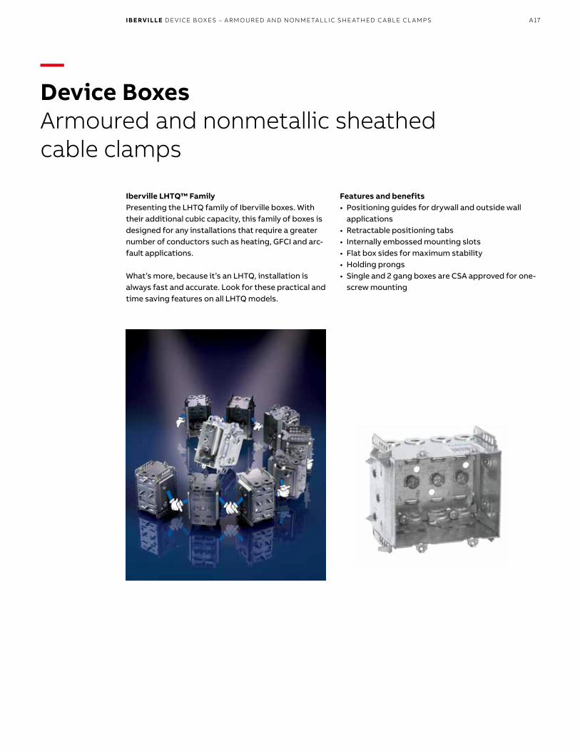
—Device BoxesArmoured and nonmetallic sheathed cable clamps
Iberville LHTQ™ FamilyPresenting the LHTQ family of Iberville boxes. With their additional cubic capacity, this family of boxes isdesigned for any installations that require a greater number of conductors such as heating, GFCI and arc-fault applications.
What’s more, because it’s an LHTQ, installation is always fast and accurate. Look for these practical and time saving features on all LHTQ models.
Features and benefits• Positioning guides for drywall and outside wall
applications• Retractable positioning tabs• Internally embossed mounting slots• Flat box sides for maximum stability• Holding prongs• Single and 2 gang boxes are CSA approved for one-
screw mounting
IBERVILLE DE VICE BOXES – ARMOURED AND NONMETALLIC SHE ATHED C ABLE CL AMPS

A18 I B E RV I LLE/S TE E L CIT Y/N UTE K /C A R LO N B OX E S A N D COV ER S
—Device boxesArmoured and nonmetallic sheathed cable clamps
DimensionsH x W x D (in.)
Volume(Cu. in.)
Gangable Yes or No
Features Pryouts endsCat. No. One screw mounting Pos. tabs Prov. for external nailing
BC1018-LHTQ 3 x 2 x 3 18.0 yes yes yes yes 4
BC1304-LHTQ 3 x 2 x 2 1 ⁄2 14.5 yes yes yes yes 4
BC1304-LHATQ 3 x 2 x 2 1 ⁄2 14.5 yes yes yes yes 4
BC2004-LHTQ 33 ⁄4 x 2 3⁄16 x 2 3 ⁄4 20.5 no yes yes yes 4
BC2304-LHTQ 3 x 2 x 2 1 ⁄2 14.5 no yes yes yes 4
BC2304-LHTQ-2 3 x 3 3 ⁄4 x 2 1 ⁄2 27.0 no yes yes yes 8
BC2304-LHTQ-3 3 x 5 1 ⁄2 x 2 1 ⁄2 39.5 no no yes yes 12
BC2304-LHTQ-4 3 x 7 3 ⁄8 x 2 1 ⁄2 52.0 no no yes yes 16
BC3104-LHTQ 3 x 2 x 2 1 ⁄2 16.0 yes yes yes yes 4
—01 BC1018-LHTQInternally embossed slotsfor screw mounting.Fixed positioning tabs for single 1/2 in. drywallalong with retractable positioning tabs for double 1/2 in. drywall applications. Fixed positioning tabs for outside wall applications. Holding prongs. One screw mounting.
—03 BC2004-LHTQInternally embossed slots for screw mounting.Fixed positioning tabs for single 1/2 in. drywallalong with retractable positioning tabs for double 1/2 in. drywall applications. Fixed positioning tabs for outside wall applications. Holding prongs. One screw mounting.
—05 BC2304-LHTQ-2Internally embossed slots for screw mounting Fixed positioning tabs for single 1/2 in. drywallalong with retractable positioning tabs for double 1/2 in. drywall applications. Fixed positioning tabs for outside wall applications. Holding prongs. One screw mounting.
—02 BC1304-LHTQInternally embossed slots for screw mounting.Fixed positioning tabs for single 1/2 in. drywallalong with retractable positioning tabs for double 1/2 in. drywall applications. Fixed positioning tabs for outside wall applications. Holding prongs. One screw mounting.
—04 BC2304-LHTQInternally embossed slots for screw mounting.Fixed positioning tabs for single 1/2 in. drywallalong with retractable positioning tabs for double 1/2 in. drywall applications. Fixed positioning tabs for outside wall applications. Holding prongs. One screw mounting.
—06 BC2304-LHTQ-3Internally embossed slots for screw mounting. Fixed positioning tabs for single 1/2 in. drywallalong with retractable positioning tabs for double 1/2 in. drywall applications. Fixed positioning tabs for outside wall applications. Holding prongs.
—07 BC2304-LHTQ-4Internally embossed slots for screw mounting. Fixed positioning tabs for single 1/2 in. drywallalong with retractable positioning tabs for double 1/2 in. drywall applications. Fixed positioning tabs for outside wall applications. Holding prongs.
—08 BC3104-LHTQInternally embossed slots for screw mounting. Fixed positioning tabs for single 1/2 in. drywallalong with retractable positioning tabs for double 1/2 in. drywall applications. Fixed positioning tabs for outside wall applications. Holding prongs.
—01
—04—
02
—08
—03
—07
—06
—05

A19
—Device boxesConduit knockouts
Volume(Cu. in.)
Features Knockouts
Cat. No. Ears Bracket 1/2 in. ends 1/2 in. bottom
2 in. deep – gangable – 3 in. x 2 in
CI425 10.0 flush rework 2 –
BC1102 10.0 recessed – 2 –
CI1102-SB 10.0 – “SB” 2 –
CI3102-SSX 12.0 – “SSX” 2 –
2 1/2 in. deep – gangable – 3 in. x 2 in
BC1104 12.5 recessed – 2 2
CI1104-B 12.5 – “B” 2 2
—01 CI425“Screwlok” brackets for rework installation. Max. wall thickness:5/8 in.—02 BC1102Recessed ears—03 CI1102-SB—04 CI3102-SSX“Wraparound” bracket for 1 5/8 in. steel studs. With integralsupport bracket.—05 BC1104Recessed ears—06 CI1104-B
—01
—06
—02
—03
—05
—04
IBERVILLE DE VICE BOXES – CONDUIT KNOCKOUTS

A20 I B E RV I LLE/S TE E L CIT Y/N UTE K /C A R LO N B OX E S A N D COV ER S
—Device boxesConduit knockouts
—01
—04
—03
—07
—06
—05
—08
—05
—01 CI1104-KConcentric knockouts. Recessed ears.—02 BC1104-LELess ears—03 CI1104-SB—04 BCR2000—05 CI3104-KSSXConcentric knockouts. “Wraparound” bracket for 2 1/2 in. and 3 5/8 in. steel studs. With integral support bracket.—06 BC3104-KSS1X-1Concentric knockouts. “Wraparound” bracketfor 21/2 in. and 35/8 in. steel studs. With integral support bracket. Brackets positioned for 2 layers of 1/2 in. Drywall.—07 CI3104-SSX“Wraparound” bracket for 2 1/2 in. and 3 5/8 in. steel studs. With integral support bracket.—08 CI1004Recessed ears
Volume(Cu. in.)
Features Knockouts
Cat. No. Ears Bracket 1/2 in. ends 1/2 in. bottom 3/4 in. ends
2 1/2 in. deep – gangable – 3 in. x 2 in.
CI1104-K 12.5 recessed – 2 2 2
BC1104-LE 12.5 – – 2 2 –
CI1104-SB 12.5 – “SB” 2 2 –
CI3104-KSSX 16.0 – “SSX” 2 2 2
BC3104-KSS1X-1 16.0 – “SSX” 2 2 2
CI3104-SSX 16.0 – “SSX” 2 2 –
3 in. deep – gangable – 3 in. x 2 in.
CI1004 15.0 recessed – 2 2 –
CI3004-KSSX-1.25 18.0 – “SSX” – 1 2
Volume(Cu. in.)
Ground ScrewCat. No. Usage Knockout
2 in. deep – non- gangable – 3 3/4 in. x 4 in. x 2 in.
BCR2000* 18.0 KO 2 2* Supplied c/w one CI4004 connector
—02

A21
—Device boxesNonmetallic sheathed and armoured cable clamps
Volume(Cu. in.)
Features
Cat. No. Ears Bracket Pryouts ends
11/2 in. deep – gangable – 3 in. x 2 in.
BC1100-L 8.0 flush – 4
BC1100-LLE 8.0 – – 4
CI1100-LRE 8.0 recessed – 4
2 in. deep – gangable – 3 in. x 2 in.
CI425-L 10.0 flush rework 4
BC1102-L 10.0 flush – 4
BC1102-LH 10.0 – – 4
—01 BC1100-LFlush ears.—02 BC1100-LLELess ears—03 CI1100-LRERecessed ears—04 CI425-L“Screwlok” brackets for rework installation.Max. wall thickness: 5/8 in.—05 BC1102-LFlush ears.—06 BC1102-LHProvision for external nailing.
—01
—06
—03
—05
—04
—02
IBERVILLE DE VICE BOXES – ARMOURED AND NONMETALLIC SHE ATHED C ABLE CL AMPS

A22 I B E RV I LLE/S TE E L CIT Y/N UTE K /C A R LO N B OX E S A N D COV ER S
—Device boxesNonmetallic sheathed and armoured cable clamps
—01
—07
—02
—08
—03
—09
—04
—10
—05
—11
—06
—12
—01 CI775-LFlush ears.—02 BC775-LD“Swing-arm” rework brackets. Max. wall thickness: 3/4 in.—03 BC777-LRBPivoting ends for rework installation.Max. wall thickness: 11/8 in. * Non-Gangable
—04 CI525-L“Screwlok” brackets for rework installation.Max. wall thickness: 5/8 in.—05 BC1104-LB—06 BC1104-LHTPositioning tabs. Provision for external nailing. Two embossed mounting slots for internal screw installation.
—07 CI1104-LMSMounting strap with prongs. Recessed 1/2 in. —08 BC1104-LFlush ears.—09 BC1104-LRBFlat sides for rework applications.
—10 BC1104-LRWRework bracket for closed wall applications.Max. wall thickness: 1 in.—11 BC1104-LSSX—12 BC1304-LHTQOne screw mounting. Provision for externalnailing. Positioning tabs for 1/2 in. and 3/4 in. drywall.
Volume(Cu. in.)
Features Pryouts Knockouts
Cat. No. Ears Bracket ends 1/2 in. bottom
2 1/4 in. deep – gangable – 3 in. x 2 in. – for use with nonmetallic sheathed cable only
CI775-L 10.0 flush – 4 1
BC775-LD 10.0 flush rework 4 1
BC777-LRB* 11.0 – rework 4 1
2 1/2 in. deep – gangable – 3 in. x 2 in.
CI525-L 12.5 flush rework 4 –
BC1104-L 12.5 flush – 4 –
BC1104-LB 12.5 – “B” 4 –
BC1104-LHT 12.5 – P. Tabs 4 –
CI1104-LMS 12.5 – “MS” 4 –
BC1104-LRB 12.5 flush – 4 –
BC1104-LRW 12.5 flush rework 4 –
BC1104-LSSX 12.5 – “SSX” 4 –
BC1304-LHTQ 14.5 – P. Tabs 4 –
* Non-Gangable

A23
—01
—06
—10
—02
—07
—11
—03
—08
—12
—04
—09
—05
—01 BC2104-LLEHolding prongs and prepositioned depth tabs.—02 BC2304-LHTQOne screw mounting. Provision for external nailing. Positioning tabs for 1/2 in. and 3/4 in. drywall.—03 BC2104-LXSelf-locking spring clamps. Holding prongs and prepositioned depth tabs.Raised ground screws. Approved for nonmetallic sheathed cable only.
—04 BC2104-LNStaked nails. Holding prongs and prepositioned depth tabs.—05 BC2104-LRBFlat sides for rework applications. 1 gang.—06 BC2104-LLE-22 gang. Holding prongs and prepositioned depth tabs.
—07 BC2104-LRB-2Flat sides for rework applications. 2 gang. —08 BC2104-LLE-33 gang. Holding prongs and prepositioned depth tabs.—09 BC2104-LLE-44 gang. Holding prongs and prepositioned depthtabs.
—10 BC2304-LHTQ-22 gang. Holding prongs and prepositioned depthtabs.—11 BC2304-LHTQ-33 gang. Holding prongs and prepositioned depth tabs.—12 BC2304-LHTQ-44 gang. Holding prongs and prepositioned depth tabs.
Width(in.)
Volume(Cu. in.)
Features
Cat. No. Ears Bracket Pryouts ends
2 1/2 in. deep – non-gangable – 3 in. high
BC2104-LLE 2 12.5 – P. Tabs 4
BC2104-LLE-2 33/4 25.0 – P. Tabs 8
BC2104-LLE-3 5-1/2 37.5 – P. Tabs 12
BC2104-LLE-4 7-3/8 50.0 – P. Tabs 16
BC2104-LN 2 12.5 – P. Tabs/Nails 4
BC2104-LX 2 12.5 – P. Tabs 4
BC2304-LHTQ 2 14.5 – P. Tabs 4
BC2304-LHTQ-2 33/4 27.0 – P. Tabs 8
BC2304-LHTQ-3 5-1/2 39.5 – P. Tabs 12
BC2304-LHTQ-4 7-3/8 52.0 – P. Tabs 16
BC2104-LRB 2 12.5 – – 4
BC2104-LRB-2 33/4 25.0 – – 8
—Device boxesNonmetallic sheathed and armoured cable clamps
IBERVILLE DE VICE BOXES – ARMOURED AND NONMETALLIC SHE ATHED C ABLE CL AMPS

A24 I B E RV I LLE/S TE E L CIT Y/N UTE K /C A R LO N B OX E S A N D COV ER S
—Device boxesNonmetallic sheathed and armoured cable clamps
Width(in.)
Volume(Cu. in.)
Features
Pryouts endsCat. No. Ears Bracket
2 1/2 in. deep – non-gangable – 3 in. high
CI2104-LSSA1X-1 2 12.5 – “SSX” 4
CI2104-LSSA2X-1 3 3/4 25.0 – “SSX” 8
CI2104-LSSX 2 12.5 – “SSX” 4
CI2104-LSS2X-1 3 3/4 25.0 – “SSX” 8
CI-2104-LSS-2X 3 3/4 25.0 – “SSX” 8
CI2104-LSS3X-1 5 1/2 37.5 – “SSX” 12
CI-2104-LSS-3X 5 1/2 37.5 – “SSX” 12
CI2104-LSS-4X 7 3/8 50.0 – “SSX” 16
2 1/2 in. deep – non-gangable – 3 in. high
BC1504-LLE 2 1/4 15.0 – P. Tabs 4
—01 CI2104-LSSA1X-1“Wraparound” bracket for 2 1/2 in. and 3 5/8 in. steel studs. With integral support bracket. Brackets positioned for 2 layers of 1/2 in. drywall.—02 CI2104-LSSA2X-1“Wraparound” bracket for 2 1/2 in. and 3 5/8 in. steel studs. With integral support bracket. Brackets positioned for 2 layers of 1/2 in. drywall.
—03 CI2104-LSSX“Wraparound” bracket for 2 1/2 in. and 3 5/8 in. steel studs. With integral support bracket.—04 CI2104-LSS2X-1“Wraparound” bracket for 2 1/2 in. and 3 5/8 in. steel studs. With integral support bracket. Brackets positioned for 2 layers of 1/2 in. drywall.
—05 CI-2104-LSS-2X“Wraparound” bracket for 2 1/2 in. and 3 5/8 in. steel studs. With integral support bracket.—06 CI2104-LSS3X-1“Wraparound” bracket for 2 1/2 in. and 3 5/8 in. steel studs. With integral support bracket. Brackets positioned for 2 layers of 1/2 in. drywall.
—07 CI-2104-LSS-3X“Wraparound” bracket for 2 1/2 in. and 3 5/8 in. steel studs. With integral support bracket.—08 BC1504-LLEHolding prongs and prepositioned depth tabson one side.
—01
—04
—07
—02
—03
—05
—08
—06

A25
—Device boxesNonmetallic sheathed and armoured cable clamps
Volume(Cu. in.)
Features
Pryouts endsCat. No. Ears Bracket
2 1/2 in. deep – gangable – 3 in. x 2 in.
BC3104-LH 16.0 – P. Tabs 4
BC1304-LHT 14.5 – P. Tabs 4
BC3104-LHTQ 16.0 – P. Tabs 4
BC3104-LSSX 16.0 – “SSX” 4
CI3104-LSS1X-1 16.0 – “SSX” 4
CI1804-LH 18.0 – P. Tabs 4
2 3/4 in. deep – non-gangable – 3 3/4 in. x 2 3/16 in.
BC2004-LH 18.5 – P. Tabs 4
BC2004-LHTQ 20.5 – P. Tabs 4
—01 BC3104-LHPositioning tabs. Provision for external nailing.—02 BC3104-LHTQOne screw mounting. Provision for externalnailing. Positioning tabs for 1/2 in. and 3/4 in.drywall.
—03 BC3104-LSSX“Wraparound” bracket for 2 1/2 in. and 3 5/8 in. steel studs. With integral support bracket.—04 CI3104-LSS1X-1“Wraparound” bracket for 2 1/2 in. and 3 5/8 in. steel studs. With integral support bracket. Brackets positioned for 2 layers of 1/2 in. drywall.
—05 BC1304-LHTProvision for external nailing.—06 CI1804-LHPositioning tabs. External nailing. Mounting slots for internal screw installation. X-Cube adds 5.5 cu. in.—07 BC2004-LHProvision for external nailing. Holding prongs and prepositioned depth tabs on one side.
—08 BC2004-LHTQInternally embossed slots for screw mounting. Fixed positioning tabs for single 1/2 in. drywall along with retractable positioning tabs for double 1/2 in. drywall applications. Fixed positioning tabsfor outside wall applications. Holding prongs. One screw mounting.
—01
—05
—02
—03
—04
—07
—06
—08
2-1/2 in.Steel Stud
“X” Bracket(bent)
CI3104-LSS1X-1 Top View
First 1/2 in. Drywall Second 1/2 in. Drywall
IBERVILLE DE VICE BOXES – ARMOURED AND NONMETALLIC SHE ATHED C ABLE CL AMPS

A26 I B E RV I LLE/S TE E L CIT Y/N UTE K /C A R LO N B OX E S A N D COV ER S
—Device boxesNonmetallic sheathed and armoured cable clamps
—01 BC1004-LFlush ears.—02 BC1004-LHPositioning tabs. Provision for external nailing.Two embossed mounting slots for internal screw installation.—03 CI1004-LBSide bracket wood stud.—04 BC1018-LHTQOne screw mounting provisions for externalnailing.—05 BC3004-LHProvision for external nailing.—06 CI3004-LSSX-11 in. recessed brackets for 2 1/2 in. and 3 5/8 in. steel studs. Brackets positioned for 2 layersof 1/2 in. drywall.
—01
—03
—06
—05
—04
—02
Volume(Cu. in.)
Features
Pryouts endsCat. No. Ears Bracket
3 in. deep – gangable – 3 in. x 2 in.
BC1004-L 15.0 flush – 4
BC1004-LH 15.0 – P. Tabs 4
CI1004-LB 16.0 – “B” 4
BC1018-LHTQ 18.0 – P. Tabs 4
BC3004-LH 18.0 – – 4
CI3004-LSSX 18.0 – “SSX” 4
CI3004-LSSX-1 18.0 – “SSX” 4
CI3004-LSSAX-1.25* 18.0 – “SSX” 4
* Brackets positioned for 2 layers of 5/8 in. drywall
2-1/2 in.Steel Stud
“X” Bracket(bent)
CI3004-LSSX-1 Top View
First 1/2 in. Drywall Second 1/2 in. Drywall

A27
—Device boxesNonmetallic sheathed and armoured cable clamps
—01 CI3102-LSSAX“Wraparound” bracket for 1 5/8 in. steel studs. With integral support bracket.—02 BC1104-LAFlush ears.—03 BC1104-LHAPositioning tabs. Provision for external nailing. Two embossed mounting slots for internal screw installation.—04 CI1104-LMSAMounting strap recessed1/2 in.—05 BC1104-LSSAX—06 CI3004-LSSAX-11 in. recessed brackets for 2 1/2 in. and 3 5/8 in. steel studs. Brackets positioned for 2 layersof 1/2 in. drywall.
Volume(Cu. in.)
Features
Pryouts endsCat. No. Ears Bracket
2 in. deep – gangable – 3 in. x 2 in.
CI3102-LSSAX 12.0 – “SSX” 4
2 1/2 in. deep – gangable – 3 in. x 2 in.
BC1104-LA 12.5 flush – 4
BC1104-LHA 12.5 – P. Tabs 4
CI1104-LMSA 12.5 – “MS” 4
BC1104-LSSAX 12.5 – “SSX” 4
3 in. deep – gangable – 3 in. x 2 in.
CI3004-LSSAX-1* 18.0 – “SSX” 4
* Brackets positioned for 2 layers of 1/2 in. drywall
2-1/2 in.Steel Stud
“X” Bracket(bent)
CI3004-LSSAX-1 Top View
First 1/2 in. Drywall Second 1/2 in. Drywall
—01
—03
—06
—05
—04
—02
IBERVILLE DE VICE BOXES – ARMOURED AND NONMETALLIC SHE ATHED C ABLE CL AMPS

A28 I B E RV I LLE/S TE E L CIT Y/N UTE K /C A R LO N B OX E S A N D COV ER S
—Device boxesNonmetallic sheathed and armoured cable clamps
—03
Width(in.)
Volume(Cu. in.)
Features
Pryouts endsCat. No. Ears Bracket
2 1/2 in. deep – non-gangable – 3 in. high
CI2104-LSSAX 2 12.5 – P. Tabs 4
CI2104-LSSA-2X 3 3/4 25.0 – “SSX” 8
CI2104-LSSA-3X 5 1/2 37.5 – “SSX” 12
CI2104-LSSA-4X 7 3/8 50.0 – “SSX” 16
01 CI2104-LSSAX“Wraparound” bracket for 2 1/2 in. and 3 5/8 in. steel studs. With integral support bracket.—02 CI2104-LSSA-2X2 gang. “Wraparound” bracket for 2 1/2 in. and 3 5/8 in. steel studs. With integral support bracket.—03 CI2104-LSSA-3X3 gang. “Wraparound” bracket for 2 1/2 in. and 3 5/8 in. steel studs. With integral support bracket.
—01
—02

A29
—Device boxesNonmetallic sheathed and armoured cable clamps
—01 CI1504-LSSAX“Wraparound” bracket for 2 1/2 in. and 3 5/8 in. steel studs. With integral support bracket.—02 CI3104-LHAPositioning tabs. Provision for external nailing.
—03 BC3104-LSSAX“Wraparound” bracket for 2 1/2 in. and 3 5/8 in. steel studs. With integral support bracket.—04 BC3104-LSSAX-5/8Brackets for use with 5/8 in. drywall.
—05 CI3104-LSSA1X-11 in. recessed brackets for 2 1/2 in. and 3 5/8 in. steel studs. Brackets positioned for 2 layers of 1/2 in. drywall.—06 BC3104-LSSX“Wraparound” bracket for 2 1/2 in. and 3 5/8 in. steel studs. With integral support bracket.
—07 CI2004-LHAProvision for external nailing. Holding prongs and prepositioned depth tabs. —08 CI1004-LHAPositioning tabs. Provision for external nailing.Two embossed mounting slots for internal screwinstallation.
Volume(Cu. in.)
Features
Cat. No. Ears Bracket Pryouts ends
2 1/2 in. deep – non-gangable – 3 in. x 2 1/4 in.
CI1504-LSSAX 15.0 – “SSX” 4
2 1/2 in. deep – gangable – 3 in. x 2 in.
CI3104-LHA 16.0 – P. Tabs 4
BC3104-LSSAX 16.0 – “SSX” 4
BC3104-LSSAX-5/8 16.0 – “SSX” 4
CI3104-LSSA1X-1 16.0 – “SSX” 4
BC3104-LSSX 16.0 – P. Tabs 4
2 3/4 in. deep – non-gangable – 3 3/4 in. x 2 3/16 in.
CI2004-LHA 18.5 – P. Tabs 4
3 in. deep – gangable – 3 in. x 2 in.
CI1004-LHA 15.0 – P. Tabs 4
—03
—04
—05
—06
—07
—08
—01
—02
IBERVILLE DE VICE BOXES – ARMOURED AND NONMETALLIC SHE ATHED C ABLE CL AMPS

A30 I B E RV I LLE/S TE E L CIT Y/N UTE K /C A R LO N B OX E S A N D COV ER S
—Device boxesBoxes for ICF construction
—01
—04
—03
—02
Volume(Cu. in.)
DimensionsH x W x D (in.)
GangableYes or NoCat. No. Features
Device boxes
BC2104-LMS 12.5 3 x 2 x 2 1/2 Loomex/BX Yes
BC2104-LMS-2 25.0 3 x 3 3/4 x 2 1/2 Loomex/BX No
BC2104-LMS-3 37.5 3 x 5 1/2 x 2 1/2 Loomex/BX No
BC2104-LMS-4 50.0 3 x 7 3/8 x 2 1/2 Loomex/BX No
BC2104-LMSA 12.5 3 x 2 x 2 1/2 BX/Loomex No
BC2104-LMSA-2 25.0 3 x 3 3/4 x 2 1/2 BX/Loomex No
BC2104-LMSA-3 37.5 3 x 5 1/2 x 2 1/2 BX/Loomex No
BC2104-LMSA-4 50.0 3 x 7 3/8 x 2 1/2 BX/Loomex No
CI3102-LMS 12.0 3 x 2 x 2 BX/Loomex Yes
CI3102-LMSA 12.0 3 x 2 x 2 BX/Loomex Yes
CI3102-MS 12.0 3 x 2 x 2 Conduit Yes
Volume(Cu. in.)
DimensionsH x W x D (in.)
GangableYes or NoCat. No. Features
Octagonal boxes
BC54151-LMS 15.0 4 x 4 x 11/2 Loomex/BX No
BC54151-LMSA 15.0 4 x 4 x 11/2 Loomex/BX No
Volume(Cu. in.)
DimensionsH x W x D (in.)
Knockouts
Cat. No.1/2 in.sides
1/2 in.bottom
3/4 in.sides
3/4 in.bottom
Conduit knockouts
BC52151-KMS 15.0 4 x 4 x 11/2 4 2 2 2
BC52171-KMS 30.0 4 x 4 x 21/8 4 2 2 2
CI72151-KMS 30.0 4 11/16 x 4 11/16 x 11/2 – 2 4 2
BC72171-KMS 42.0 4 11/16 x 4 11/16 x 21/8 – 2 4 2
BC2104-LMS
BC2104-LMSA
CI3102-LMS
BC54151-LMS
BC2104-LMS-2
BC2104-LMSA-2
CI3102-LMSA
BC54151-LMSA
BC2104-LMS-3
BC2104-LMSA-3
CI3102-MS
BC52171-KMS
BC2104-LMS-4
BC2104-LMSA-4
BC52151-KMS
CI72151-KMS BC72171-KMS

A31
—Device boxesStainless steel wall plates
CI97071
CI97101
CI97401
CI97121 CI97532CI97124 (1 gang to 4 gangs) CI97573 (2 gangs to 7 gangs)
CI97080 (1 gang to 10 gangs)
CI97102
CI97406 (1 gang to 6 gangs)
CI97011
GFCI / Decora
Blank device mounting (2.375 in.) Combination switch / receptacle
Toggle switch
Blank box mounting (3.281 in.)Duplex receptacle
—General usage
IBERVILLE DE VICE BOXES – STAINLESS STEEL WALL PL ATES
Dimensions are in inches.

A32 I B E RV I LLE/S TE E L CIT Y/N UTE K /C A R LO N B OX E S A N D COV ER S
—Device boxesStainless steel wall plates
CI97154-HVCI97154-HVR
For 1204 Series - 1 gang, 2 gangs and 4 gangs For MBD/MBS Series - 1 gang, 2 gangs and 4 gangs
—347 V Blank
* CI97181 3/8 in. opening
* CI97191 5/8 in. opening
CI97091 1-13/32 in. diameter
BC97002 For 4 in. square boxes
CI6851-RF ON / OFF
Telephone Emergency Single receptacle GFCI Conversion kit
—Specialty usage
CI6851-HV CI6854-HV CI6851-HV CI97074-HVR
For MBD / MBS Series - 1 gang to 4 gangsFor 1204 Series - 1 gang to 4 gangs
—347 V Toggle specialty usage
* Not applicable.

A33
—Device boxesStainless steel wall plates
347 V Wall plate
Standard all plate Mounting hole spacings
—Dimensions
3.28
1
1.13
0.2
00
.375
3.28
1
3.81
2
4.50
0
2.62
5
1.312
2.75
CI97011 CI97401CI97181
2.37
5
1.400
2.37
5.9
30
.410
CI97091 CI97101CI97071
CI6851-HV to CI6854-HV CI6852-HV CI97072-HVR to CI97074-HVR CI97072-HVR
2.7505.000
7.2509.500
4.50
0
2.250
4.50
0
2.7504.562
6.3758.188
1.812
MasonryDevice H.V Box
Wallplate
1.812
GangableDevice H.V Box
Wallplate
2.250
4.50
0
1.812
2.37
5
3.28
1
Device mount
HV Box mount
Box mount
3.53
1
IBERVILLE DE VICE BOXES – STAINLESS STEEL WALL PL ATES
Dimensions are in inches.
CI97080

A34 I B E RV I LLE/S TE E L CIT Y/N UTE K /C A R LO N B OX E S A N D COV ER S
—Device boxesStainless steel wall plates
—Selection guide
—Technical specifications
Description 1 Gang 2 Gangs 3 Gangs 4 Gangs 5 Gangs 6 Gangs 7 Gangs 8 Gangs 9 Gangs 10 Gangs
Toggle switch CI97071 CI97072 CI97073 CI97074 CI97075 CI97076 CI97078 CI97079 CI97080
Duplex receptacle CI97101 CI97102
Blank boxes
Mounting 3.281 in. CI97011 CI97012 CI97013 CI97014
Blank device
Mounting 2.375 in. CI97121 CI97122 CI97123 CI97124
GFCI / Decora CI97401 CI97402 CI97403 CI97404 CI97405 CI97406
GFCI Conversion kit BC97002
Combination
Switch / Receptacle CI97532 CI97563 CI97573
15 A Receptacle CI97091
Telephone 3/8 in. opening * CI97181
Telephone 5/8 in. opening * CI97191
Emergency on / off CI6851-RF
347 V Toggle
For 1204 Series CI6851-HV CI6852-HV CI6853-HV CI6854-HV
347 V Blank
For 1204 Series CI97152-HV CI97154-HV
347 V Toggle
For MBD and MBS Series CI6851-HV CI97072-HVR CI97073-HVR CI97074-HVR
347 V Blank
For MBD and MBS Series CI97152-HVR CI97154-HVR
* Not applicable.
Type 430 Stainless steel• 16% chrome• Corrosion resistant• Recommended for industrial, commercial and
institutional applications• Supplied with nickel plated brass screws• 1 to 3 gangs – Vertically brushed• 4 gangs and up – Horizontally brushed

A35
Volume(Cu. in.)
Features Knockouts
Cat. No. Bracket Raised Ground Screw 1/2 in. sides 1/2 in. bottom 3/4 in. sides 3/4 in. bottom1/2 in. deep
BC56111 5.0 – yes – 4 – –
11/2 in. deep
BC54151-K 15.0 – yes 4 4 2 2
CI54151-KSSX 15.0 “SSX” yes 2 4 2 2
BC55151-K 15.0 – yes 4 – 2 –
2 1/8 in. deep
BC54171-K 21.0 – yes 4 4 2 2
CI54171-KSSX 21.0 “SSX” yes 2 4 2 2
CI54171-KSSX-1 21.0 “SSX-1” yes 2 4 2 2
CI55171-K 21.0 – yes 4 – 2 –
Cat. No. Description1/2 in. deep – extensions
BCOBEX Extension for octagonal boxes. 1/2 in. non-adjustable depth. Complete with mounting screws (5 cu. in.)
—4 in. Octagonal boxesConduit knockouts
—01 BCOBEXOctagonal box extension.—02 BC56111Ceiling pan.—03 BC54151-KConcentric knockouts.—04 CI54151-KSSXConcentric knockouts. “Wraparound” bracket for 21/2 in. and 35/8 in. steel studs. With integral support bracket.—05 BC55151-KExtension ring with ground screw.Concentric knockouts.—06 C54171-KConcentric knockouts.—07 CI54151-KSSXConcentric knockouts. “Wraparound” bracket for 21/2 in. and 35/8 in. steel studs. With integral support bracket.—08 CI54171-KSSX-1Mounting strap (offset for 2 x 1/2 in.drywall thicknesses).—09 CI55171-KExtension ring with ground screw, concentric knockouts.
—01
—03
—06
—09
—05
—08
—04
—07
—02
IBERVILLE 4 IN. OC TAGONAL BOXES – CONDUIT KNOCKOUTS

A36 I B E RV I LLE/S TE E L CIT Y/N UTE K /C A R LO N B OX E S A N D COV ER S
Volume(Cu. in.)
Features Knockouts Pryouts
Cat. No. Bracket Raised Ground Screw 1/2 in. sides 1/2 in. bottom Sides Bottom
11/2 in. deep
BC54151-L 15.0 – yes 2 1 4 4
BC54151-LB 15.0 “B” yes 1 1 4 4
BC54151-LD 15.0 rework yes – 1 4 4
CI54151-LF 15.0 – yes 2 1 4 4
21/8 in. deep
BC54171-L 21.0 – yes 2 1 4 4
BC54171-LB 21.0 “B” yes 1 1 4 4
BC54171-LD 21.0 rework – – 1 4 4
CI54171-LF 21.0 – yes 2 1 4 4
—4 in. Octagonal boxesNonmetallic sheathed cable clamps
—01 BC54151-LPrepositioned depth tabs recessed 1/2 in.—02 BC54151-LBSide bracket, with holding prongs and prepositioned depth tabs.—03 BC54151-LDSwing-arm” rework brackets. Max. wall thickness: 3/4 in.. Max.load capacity: 12 lb (5.5 kg).—04 BC54171-L—05 BC54171-LBSide bracket, with holdingprongs.—06 CI54171-LFCeiling fan box. (Supplied with 2 #10-32 machine screws andstar washers.) Max. load capacity: 35 lb (15.6 kg).
—01
—03
—06
—05
—04
—02
For use with nonmetallic sheathed cable only.
Note: CEC 2012 rule 30-302: Subrule (4) requires that a ceiling-mounted luminaire weighing 23 kg or less be supported on a ceiling outlet box attached directly to the building structure.A bar hanger may also be used to attach a ceiling outlet box to the building structure when the luminaire weighs 23 kg or less.

A37
Volume(Cu. in.)
Features Knockouts Pryouts
Cat. No. Bracket Raised Ground Screw 1/2 in. sides 1/2 in. bottom Sides Bottom
11/2 in. Deep
BC54151-LA 15.0 – yes 2 1 4 –
BC54151-LSSAX 15.0 “SSX” yes – 1 4 –
21/8 in. Deep
BC54171-LA 21.0 – yes 2 1 4 –
BC54171-LSSAX 21.0 “SSX” yes – 1 4 –
BC54171-LSSAX-5/8 21.0 “SSX” yes – 1 4 –
—4 in. Octagonal boxesArmoured cable clamps
—01 BC54151-LA—02 BC54151-LSSAX“Wraparound” bracket for 21/2 in. and 3-5/8 in. steel studs. With integral support bracket.—03 BC54171-LSSAX—04 BC54171-L—05 BC54171-LSSAX-5/8
Brackets for use with 5/8 in. drywall.
—01
—03
—05
—04
—02
IBERVILLE 4 IN. OC TAGONAL BOXES – ARMOURED AND NONMETALLIC SHE ATHED C ABLE CL AMPS

A38 I B E RV I LLE/S TE E L CIT Y/N UTE K /C A R LO N B OX E S A N D COV ER S
BC54-C-1
BC54-C-94
BC54-C-6
BC54-COV
CI54-C-64
BC54-COV-1
BC54-C-65
—4 in. Octagonal boxesCovers
Cat. No. Description
4 in. round covers
BC54-C-1 Flat blank
BC54-C-6 Flat with 1/2 in. conduit knockout
CI54-C-64 Flat for 113/32 in. diameter. 15 A single receptacle. Device mounting screws included
BC54-C-65 Flat for duplex receptacle. Device mounting screw included
BC54-C-94 Flat for toggle switch. Device mounting screws included
5 in. round covers (white enamel paint)
BC54-COV Flat with 1/2 in. conduit knockout. Mounting screws included
BC54-COV-1 Flat blank. Mounting screws included

A39
Volume(Cu. in.)
Features Knockouts
Cat. No. Bracket Raised Ground Screw 1/2 in. sides 1/2 in. bottom 3/4 in. sides 3/4 in. bottom
11/2 in. deep
BC52151-K 21.0 – yes 10 4 6 2
CI52151-KSB 21.0 “SB” yes 8 4 4 2
BC52151-KSSX 21.0 “SSX” yes 7 4 3 2
BC53151-K 21.0 – – 10 – 6 –
—4 in. Square boxesConduit knockouts
—01 BC52151-KConcentric knockouts.—02 CI52151-KSBConcentric knockouts with side bracket.—03 BC52151-KSSXConcentric knockouts. “Wraparound” bracket for2 1/2 in. and 3 5/8 in. steel studs. With integral support bracket. Mud / tile ring must be used.—04 BC53151-KConcentric knockouts.
—01
—04
—02
—03
IBERVILLE 4 IN. SQUARE BOXES – CONDUIT KNOCKOUTS

A40 I B E RV I LLE/S TE E L CIT Y/N UTE K /C A R LO N B OX E S A N D COV ER S
Volume(Cu. in.)
Features Knockouts
Cat. No. Bracket Raised Ground Screw 1/2 in. sides 1/2 in. bottom 3/4 in. sides 3/4 in. bottom 1 in. sides
21/8 in. deep
BC52171-HV-KIT* 33.6 - yes 6 - 2 - -
BC52171-KSSXHVKIT* 33.6 “SSX” yes 6 - 2 - -
CI52171-1 30.0 - yes - 4 - 2 4
CI52171-1-SSX 21.0 “SSX” yes - 4 - 2 2
CI52171-1-SSX-1 21.0 “SSX” yes - 4 - 2 2
BC52171-K 30.0 - yes 10 4 6 2 -
CI52171-KSB 30.0 “SB” yes 8 4 4 2 -
BC52171-KSSX 30.0 “SSX” yes 7 4 3 2 -
CI52171-KSSX-1 30.0 “SSX” yes 7 4 3 2 -
BC52171-K 30.0 - - 10 - 6 - -
* Must be purchased as a kit. The tile ring cover alone as well as the box alone are not available.
—4 in. Square boxesConduit knockouts
—01 BC52171-HV-KIT—02 BC52171-KSSXHVKIT—03 CI52171-1-SSX-1“Wraparound” bracket for2 1/2 in. and 3 5/8 in. steel studs. With integral support bracket. Brackets are positioned so the front of the box will be flush with 1/2" drywall.—04 CI52171-11 in. knockout—05 BC52171-KConcentric knockouts.1 in. knockout—06 CI52171-KSBConcentric knockouts with side bracket.—07 BC52171-KSSXConcentric knockouts. “Wraparound” bracket for2 1/2 in. and 3 5/8 in. steel studs. With integral support bracket.Mud / Tile ring must be used.—08 CI52171-KSSX-1Concentric knockouts. “Wraparound” bracket for2 1/2 in. and 3 5/8 in. steel studs. With integral support bracket.Brackets are positioned so the front of the box will be flush with 1/2" drywall.—09 BC53171-KConcentric knockouts.
—01
—04
—07
—02
—05
—08
—03
—06
—09

A41
—4 in. Square boxesMud / plaster ring covers
BC52-C-1
CI52-C-10 to CI-52-C-62
BC52-C-6
BC52-C-0-B
52C31/2-25
BC52-C-00
BC52-C-0
Cat. No. Description
Flat covers
BC52-C-1 Blank
BC52-C-6 1/2 in. conduit knockout
Plaster ring cover
52C31/2-25* Raised 1/2 in. (3.5 cu. in.) Tapped ears on 2 3/4 in. centers
Single device covers
BC52-C-0 Flat
BC52-C-0-B Flat blank cover
CI52-C-10 Raised 1/8 in. (1.0 cu. in.)
BC52-C-13 Raised 1/2 in. (3.6 cu. in.)
CI52-C-14 Raised 3/4 in. (5.7 cu. in.)
CI52-C-14-5/8 Raised 5/8 in. (4.3 cu. in.)
CI52-C-15 Raised 7/8 in. (6.8 cu. in.)
CI52-C-16 Raised 11/4 in. (9.5 cu. in.)
CI52-C-62 Raised 1/4 in. (1.8 cu. in.)
Two device covers
BC52-C-00 Flat
BC52-C-17 Raised 1/2 in. (6.2 cu. in.)
52 C 18* Raised 3/4 in. (9.0 cu. in.)
52C185/8-25* Raised 5/8 in. (7.3 cu. in.)
* UL Listed and CSA certified
IBERVILLE 4 IN. SQUARE BOXES – COVERS
BC52-C-17

A42 I B E RV I LLE/S TE E L CIT Y/N UTE K /C A R LO N B OX E S A N D COV ER S
—4 in. Square boxesTile ring covers
BC52C49-1/2 to CI52-C-51-2 52 C 52 1/2 to 52 C 54 2 52CADJ
Cat. No. Description
One device square cornered tile covers
BC52C49-1/2 Raised 1/2 in. (3.4 cu. in.)
BC52C49-3/4 Raised 3/4 in. (5.3 cu. in.)
BC52-C-49-5/8 Raised 5/8 in. (4.3 cu. in.)
BC52-C-49-1 Raised 1 in. (6.8 cu. in.)
CI52-C-49-1 1/4 Raised 11/4 in. (8.6 cu. in.)
CI52-C-50-1 1/2 Raised 11/2 in. (10.0 cu. in.)
CI52-C-51-2 Raised 2 in. (14.0 cu. in.)
One device square cornered tile covers - adjustable
52CADJ Adjustable from 1/2 in. to 11/2 in. raise (from 3.4 to 10.0 cu. in.)
Two device square cornered tile covers
52 C 52 1/2 Raised 1/2 in. (6.0 cu. in.)
52 C 52 5/8 Raised 5/8 in. (8.3 cu. in.)
52 C 52 3/4 Raised 3/4 in. (9.0 cu. in.)
52 C 52 1 Raised 1 in. (12.5 cu. in.)
52 C 52 1 1/4 Raised 11/4 in. (15.5 cu. in.)
52 C 53 1 1/2 Raised 11/2 in. (19.0 cu. in.)
52 C 54 2 Raised 2 in. (25.5 cu. in.)

A43
—4 in. Square boxesCovers
BC8361
BC8364
BC8362
BC8365
BC8363
BC8366 BC8367
Cat. No. Description3/8 in. raised surface covers (4.6 cu. in.) device mount
BC8361 One toggle switch
BC8362 For 2 5/8 in. diameter 30 / 50 A single receptacle
BC8363 For 1 13/32 in. diameter 15 A single receptacle
BC8364 For 1 19/32 in. diameter 20 / 30 A single locking receptacle
BC8365 One duplex receptacle
BC8366 For 2 9/64 in. diameter 30 A single receptacle
BC8367 Two toggle switches
Complete with device mounting screws
NEMA Configuration
Cover A V Pole Wire Phase Rec. Dia NEMA
BC8363 15 125 2 3 1 1.406 5-15R
BC8364 20 125 2 3 1 1.562 L5-20R
BC8364 20 250 2 3 1 1.562 L6-20-R
BC8364 20 347 2 3 1 1.562 L24-20R
BC8364 20 600 2 3 1 1.562 L9-20R
BC8364 20 125/250 3 3 1 1.562 L10-20R
BC8364 20 250 3 3 3 1.562 L11-20R
BC8364 20 125/250 3 4 3 1.562 L14-20R
BC8366 30 125 2 3 1 2.109 5-30R
BC8364 30 125 2 3 1 1.562 L5-30R
BC8366 30 250 2 3 1 2.109 6-30R
BC8364 30 250 2 3 1 1.562 L6-30R
BC8362 30 125/250 3 4 3 2.647 14-30R
BC8362 50 125/250 3 4 1 2.647 14-50R
IBERVILLE 4 IN. SQUARE BOXES – COVERS

A44 I B E RV I LLE/S TE E L CIT Y/N UTE K /C A R LO N B OX E S A N D COV ER S
—4 in. Square boxesCovers
BC8368
BC8376
BC8371
BC8377
BC8375
BC8378
Cat. No. Description3/8 in. raised surface covers (4.6 cu. in.)
BC8368 2 Decora/GFCI
BC8371 Two duplex receptacles
BC8375 One toggle switch, one duplex receptacle
BC8376 One Decora/GFCI
BC8377 One toggle switch, one Decora/GFCI
BC8378 One duplex receptacle, one Decora/GFCI
GFCI Conversion kits (stainless steel / steel)
BC97002 To install GFCI on 4 in. square boxes. Complete with mounting screws
Complete with device mounting screws.When extra capacity is required, the 8300 Series of 4 in. square covers can be mounted on a 72 Series of 4 11/16 in. square boxes using a CI72-A-52 adaptor. (see page A46)
BC97002
A45
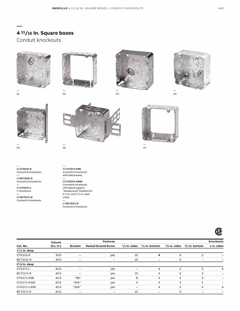
—4 11/16 in. Square boxesConduit knockouts
Volume(Cu. in.)
Features Knockouts
Cat. No. Bracket Raised Ground Screw 1/2 in. sides 1/2 in. bottom 3/4 in. sides 3/4 in. bottom 1 in. sides
11/2 in. deep
CI72151-K 30.0 – yes 10 4 6 2 –
BC73151-K 30.0 – – 10 – 6 – –
21/8 in. deep
CI72171-1 42.0 – yes – 4 2 2 6
BC72171-K 42.0 – yes 10 4 6 2 –
CI72171-KSB 42.0 “SB” yes 8 4 2 2 –
CI72171-KSSX 42.0 “SSX” yes 4 4 4 2 –
CI72171-1-SSX 42.0 “SSX” yes – 4 2 2 4
BC73171-K 42.0 – – 10 – 6 – –
—01 CI72151-KConcentric knockouts.—02 BC73151-KConcentric knockouts.—03 CI72171-11” knockouts.—04 BC72171-KConcentric knockouts.
—05 CI72171-KSBConcentric knockouts with side bracket.—06 CI72171-KSSXConcentric knockouts with lateral support. “Wraparound” brackets for 2 1/2 in. and 3 5/8 in. steel studs. —07 BC73171-KConcentric knockouts.
—01
—06
—07
—02
—03
—04
—05
IBERVILLE 4 -11/16 IN. SQUARE BOXES – CONDUIT KNOCKOUTS

A46 I B E RV I LLE/S TE E L CIT Y/N UTE K /C A R LO N B OX E S A N D COV ER S
—4 11/16 in. Square boxesMud / Plaster ring covers
BC72-C-1
72 C 17
BC72-C-6
72 C 14 5/8
CI72-C-10 / CI72-C-13
72 C 18 5/8 CI72-A-52
Cat. No. Description
Flat covers
BC72-C-1 Blank
BC72-C-6 With concentric 1/2 in. and 3/4 in. conduit knockout
Single device covers
CI72-C-10 Raised 1/8 in. (1.7 cu. in.)
CI72-C-13 Raised 1/2 in. (4.3 cu. in.)
72 C 14* Raised 3/4 in. (5.0 cu. in.)
72 C 14 5/8* Raised 5/8 in. (4.0 cu. in.)
Two device covers
72 C 17* Raised 1/2 in. (6.3 cu. in.)
72 C 18 5/8* Raised 5/8 in. (7.5 cu. in.)
Adaptors
CI72-A-52 To install 4 in. square covers on 4 11/16 in. square boxes. Raised 1/4 in. (3.0 cu. in.)* UL Listed and CSA certified

A47
—Utility boxes and covers
Volume(Cu. in.)
Features Knockouts
Cat. No. Bracket Raised Ground Screw 1/2 in. ends 1/2 in. bottom 1/2 in. sides
1 1/2 in. deep – 4 in. x 2 1/4 in.
CI2018 13.0 – no 2 2 6
CI2018-SB 13.0 “SB” no 2 2 3
1 7/8 in. deep – 4 in. x 2 1/8 in.
BC2020 14.0 – yes 2 2 6
BC2020-R 14.0 – – 2 – 6
Cat. No. Description
Covers – 20 Series
BC20-C-1 For duplex receptacle
BC20-C-3 For 113/32 in. diameter 15 A single receptacle
BC20-C-4 Blank
BC20-C-5 For toggle switch
CI2018
BC20-C-1
CI2018-SB
BC20-C-3
BC2020
BC20-C-4 BC20-C-5
BC2020-R
Note: BC2020-R can be installed on CI2018 / BC2020 SeriesCovers: Device mounting screws included
IBERVILLE UTILIT Y BOXES AND COVERS

A48 I B E RV I LLE/S TE E L CIT Y/N UTE K /C A R LO N B OX E S A N D COV ER S
—Utility boxes and covers
BC1110-SSX
BC11-C-1 BC11-C-2 BC11-C-3 BC11-C-4 BC11-C-5 BC11-C-10 CI11-C-10-HV BC11-C-5-HVBC11-C-4-HV
BC1110-R 1151 (For toggle switch) 1198 (For Decora or GFCI) 1199 (For duplex receptacle)
Volume(Cu. in.)
Features Knockouts
Cat. No. Bracket Raised Ground Screw 1/2 in. ends 1/2 in. bottom 1/2 in. sides
1 1/2 in. deep – 4 in. x 2 1/4 in.
CI1141 13.0 mounting ears no 2 2 6
1 7/8 in. deep – 4 in. x 2 3/8 in.
BC1110 16.5 – yes 2 2 6
CI1110-SB 16.5 “SB” yes 2 2 3
BC1110-R 16.5 – – 2 – 6
BC1110-LSKO 16.5 – yes 2 2 –
BC1110-SSX 16.5 “SSX” yes 2 2 –
2 1/8 in. deep – 4 in. x 2 1/2 in.
1151* 18.5 – yes 2 2 –
1198* 18.5 – yes 2 2 –
1199* 18.5 – yes 2 2 –
* cULus listed
Cat. No. Description Cat. No. Description
Covers – 11 Series
BC11-C-1 For duplex receptacle BC11-C-10 Decora/GFCI
BC11-C-2 For 1 19⁄32 in. diameter 15 A single receptacle CI11-C-10-HV Decora 347 V
BC11-C-3 For 1 13⁄32 in. diameter 15 A single receptacle BC11-C-4-HV Blank 347 V
BC11-C-4 Blank BC11-C-5-HV For toggle switch
BC11-C-5 For toggle switch
Note: Covers: Device mounting screws included
CI1141 BC1110 CI1110-SB BC1110-LSKO

A49
—Concrete rings and accessories
Volume(Cu. in.)
Dimensions Knockouts
Cat. No. H x W x D (in.) 1/2 in. sides 3/4 in. sides 1 in. sides Sketch
Concrete rings
CI54531 24.0 4 x 4 x 2 4 4 – A
CI54541 30.0 4 x 4 x 2 1/2 4 4 – B
CI54551 36.0 4 x 4 x 3 4 4 – B
CI54561 42.0 4 x 4 x 3 1/2 4 4 – B
CI54571 48.0 4 x 4 x 4 4 2 2 C
CI54581 60.0 4 x 4 x 5 4 2 2 D
CI54591 72.0 4 x 4 x 6 4 2 2 D
Extension rings
CI53171-ER 30.0 4 x 4 x 2 1/8 10 6 – –
Cat. No. Description
Accessories
CI54560 Round cover with 5 1/2 in. knockouts
CICBA For quick mounting and alignment of octagonal extension ring (BC55151-K, CI55171-K) on concrete ringNote: One CI54560 cover is supplied with each concrete ring
—01 CI54531Shown with cover installed.)—02 CI54571—03 CI53171-ERExtension ring. Mounts directly on concrete rings.—04 CI54581 / CI54591—05 CI54560—06 CICBA—07 SKETCH AKnockout configuration—08 SKETCH BKnockout configuration—09 SKETCH CKnockout configuration—10 SKETCH DKnockout configuration
—01
—07
—04
—03
—09
—06
—10
—05
—04
—02
—08
—05
IBERVILLE CONCRETE RINGS AND ACCESSORIES

A50 I B E RV I LLE/S TE E L CIT Y/N UTE K /C A R LO N B OX E S A N D COV ER S
—CarlonConcrete rings / mud boxes
—01 A863CFGMud box with ceiling ring.—02 A863SGMud box with one-gangring.—03 A863DGMud box with two-gangring.—04 A863CFGFMud box assemblies with mounting feet.
Volume(Cu. in.)
Hub Sizes
Cat. No. Features 1/2 in. 3/4 in. 1 in.
Concrete rings / mud boxes
A863CFG 41.8 – 4 6 2
A863SG 37.3 – 4 6 2
A863DG 44.0 – 4 6 2
A863CFGF 41.8 Mounting Feet 4 6 2
A863CSGF 37.3 Mounting Feet 4 6 2
A863CDGF 44.0 Mounting Feet 4 6 2
Reducers
A273DE 3/4 in. to 1/2 in. – – – –
A273EF 1 in. to 3/4 in. – – – –
—01
—03
—02
—04
—06
Carlon Mud Box Assemblies w/Mounting Feet are specifically engineered and designed for use in Tunnel Form applications. The mounting feet are located on all four corners and allow the box to attach directly to the wall of the form using pop rivets. The pop rivets help keep the box in position during the pour and provide a safe, secure, and rust resistant mount.
A51
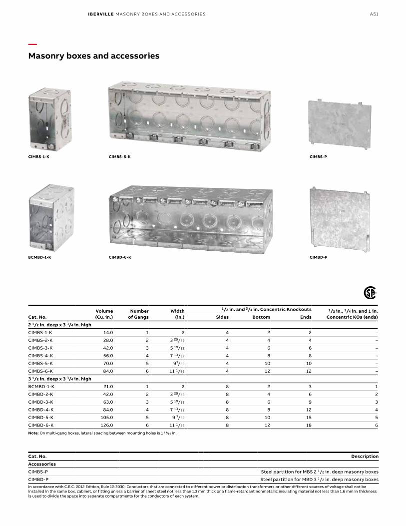
—Masonry boxes and accessories
Volume(Cu. in.)
Numberof Gangs
Width(in.)
1/2 in. and 3/4 in. Concentric Knockouts 1/2 in., 3/4 in. and 1 in.Concentric KOs (ends)Cat. No. Sides Bottom Ends
2 1/2 in. deep x 3 3/4 in. high
CIMBS-1-K 14.0 1 2 4 2 2 –
CIMBS-2-K 28.0 2 3 25/32 4 4 4 –
CIMBS-3-K 42.0 3 5 19/32 4 6 6 –
CIMBS-4-K 56.0 4 7 13/32 4 8 8 –
CIMBS-5-K 70.0 5 97/32 4 10 10 –
CIMBS-6-K 84.0 6 11 1/32 4 12 12 –
3 1/2 in. deep x 3 3/4 in. high
BCMBD-1-K 21.0 1 2 8 2 3 1
CIMBD-2-K 42.0 2 3 25/32 8 4 6 2
CIMBD-3-K 63.0 3 5 19/32 8 6 9 3
CIMBD-4-K 84.0 4 7 13/32 8 8 12 4
CIMBD-5-K 105.0 5 9 7/32 8 10 15 5
CIMBD-6-K 126.0 6 11 1/32 8 12 18 6
Note: On multi-gang boxes, lateral spacing between mounting holes is 1 13⁄16 in.
CIMBS-1-K
BCMBD-1-K
CIMBS-6-K
CIMBD-6-K CIMBD-P
CIMBS-P
Cat. No. Description
Accessories
CIMBS-P Steel partition for MBS 2 1/2 in. deep masonry boxes
CIMBD-P Steel partition for MBD 3 1/2 in. deep masonry boxesIn accordance with C.E.C. 2012 Edition, Rule 12-3030: Conductors that are connected to different power or distribution transformers or other different sources of voltage shall not be installed in the same box, cabinet, or fitting unless a barrier of sheet steel not less than 1.3 mm thick or a flame-retardant nonmetallic insulating material not less than 1.6 mm in thickness is used to divide the space into separate compartments for the conductors of each system.
IBERVILLE MA SONRY BOXES AND ACCESSORIES

A52 I B E RV I LLE/S TE E L CIT Y/N UTE K /C A R LO N B OX E S A N D COV ER S
—347 V Boxes
Volume(Cu. in.) Number of gangs
Width(in.)
Knockouts1/2 in endsCat. No.
2 3/8 in. deep x 4 in. high
CIMBS-1-HV 20.25 1 2 1/4 2
CIMBS-2-HV 20.25 / gang 2 4 1/16 4
CIMBS-3-HV 20.25 / gang 3 5 7/8 6
CIMBS-4-HV 20.25 / gang 4 7 11/16 8
3 3/8 in. deep x 4 in. high
CIMBD-1-HV 22.5 1 2 1/4 4
CIMBD-2-HV 22.5 / gang 2 4 1/16 8
CIMBD-3-HV 22.5 / gang 3 5 7/8 12
CIMBD-4-HV 22.5 / gang 4 7 11/16 16
Note: All HV boxes have tapped holes spaced 3 17/32 in. to accommodate 347 V switches. Standard lateral spacing 1 13/16 in., on pre-ganged boxes. Pre-ganged boxes include fibre partitions
Partitions only
Accessories
CIMBS-HV-PART
CIMBD-HV-PART
CIMBS-1-HV
CIMBD-1-HV
CIMBS-4-HV (1 gang to 4 gangs)
CIMBD-4-HV (1 gang to 4 gangs)

A53
Note: All HV boxes have tapped holes spaced 3 17/32 in. to accommodate 347 V switches. CI1204-2-HV includes CIHVP partition. On multigang boxes lateral spacing 2 1/4 in.When ganged, CIHVP partition must be installed between spacers.* 1/2 in. raised cover. Must be purchased as a kit. The tile ring cover alone as well as the box alone are not available.
BC52171-HV-KIT*
CI1204-LA-HV
BC52171-KSSXHVKIT* CI1204-1-HV CI1204-2-HV
CI1204-LSSAX-HV CI1204-SSX-HV
—347 V BoxesBoxes and kits
Volume(Cu. in.)
Numberof Gangs
DimensionsH x W x D (in.)
Features Knockouts 1/2 in. ends
Pryouts endsCat. No. Ears Clamps Brackets
21/2 in. deep – gangable
BC52171-HV-KIT* 33.6 1 4 x 4 x 2 1/8 – – – 2 –
BC52171-KSSXHVKIT* 33.6 1 4 x 4 x 2 1/8 – – – 2 –
CI1204-1-HV 16.0 1 3 x 2 1/4 x 2 1/2 recessed – – 2 –
CI1204-2-HV 32.0 2 3 x 4 1/2 x 2 1/2 recessed – – 4 –
CI1204-LA-HV 16.0 1 3 x 2 1/4 x 2 1/2 flush BX – – 4
CI1204-LSSAX-HV 19.5 1 3 x 2 1/4 x 2 1/2 – BX “SSX” – 4
CI1204-SSX-HV 19.5 1 3 x 2 1/4 x 2 1/2 – – “SSX” 2 –
CI1204-SS1X-HV 16.0 1 3 x 2 1/4 x 2 1/2 – – “SSX” 2 –
CI1204-LSSAX-HV-1 19.5 1 3 x 2 1/4 x 2 1/2 – BX “SSX” – 4
IBERVILLE 3 47 V BOXES – BOXES AND KITS

A54 I B E RV I LLE/S TE E L CIT Y/N UTE K /C A R LO N B OX E S A N D COV ER S
Note: All HV boxes have tapped holes spaced 3 17/32 in. to accommodate 347 V switches.
Mounting screws included.
CI1110-HV
CI11-C-10-HV
BC11-C-4-HV BC11-C-5-HV
CIFS-1G-1/2-HV / CIFS-1G-3/4-HVIncludes stamped aluminum “FS” cover.
CIFS-9-HV
—347 V BoxesBoxes and covers
Volume(Cu. in.)
Numberof Gangs
DimensionsH x W x D (in.)
FeaturesRaised Ground Screw
Knockouts 1/2 in. endsCat. No.
17/8 in. deep
CI1110-HV 16.5 1 4 x 2 3/8 x 1 7/8 yes 2
347 V “FS” box kits – 1 7/8 in. deep (cast aluminum)
CIFS-1G-1/2-HV 14.0 1 6 x 2 13/16 x 1 7/8 yes 1 x 1/2 hub
CIFS-1G-3/4-HV 14.0 1 6 x 2 13/16 x 1 7/8 yes 1 x 3/4 hub
Cat. No. Description
347 V Utility box covers
BC11-C-4-HV Blank
BC11-C-5-HV One toggle switch
CI11-C-10-HV Decora
Cat. No. Description
347 V “FS” Cover (stamped aluminum)
CIFS-9-HV One toggle switch

A55
Note: Device mounting screws included. Lateral spacing 21/4 in. on CI6852-HV / CI6853-HV / CI6854-HV
CIHVP
CI6852-HV
CISBEX-HV CI6851-HV
CI6853-HV CI6854-HV
—347 V BoxesCovers and accessories
Cat. No. Description
347 V Stainless steel wall plates (for CI1204-HV boxes)
CI6851-HV Single 347 V toggle switch
CI6852-HV Two 347 V toggle switches
CI6853-HV Three 347 V toggle switches
CI6854-HV Four 347 V toggle switches
Cat. No. Description
347 V Partitions (steel)
CIHVP High voltage partition to be used with 347 V boxes (CI1204 series) when ganged
347 V Device box extension
CISBEX-HV 2 in. x 3 in. 347 V – Maximum adjustable depth – 1 7/8 in. – complete with mounting screws
IBERVILLE 3 47 V BOXES – COVERS AND ACCESSORIES

A56 I B E RV I LLE/S TE E L CIT Y/N UTE K /C A R LO N B OX E S A N D COV ER S
—347 V BoxesHV (347 V) vs Regular box spacing
—Extension Rings
CI1204-1-HV
CISBEX-HV
BC1104
CISBEX
3.281”
C to C
3,531”
C to C
3.531”
C to C
3,281”
C to C

A57
Note: 4104, 4304 Series consist of a 21/2 in. deep device box with a 90° folded side incorporating mounting holes for communication outlet and wire holders. The 4104 Series is intended for installation on wood studs, while the 4304 Series is intended for installation on 2 1/2 in. or 3 5/8 in. steel studs. The installation is completed with a standard 2 gang wall plate.
4204 Series intended for commercial or industrial installation on 2 1/2 in. or 3 5/8 in. steel studs, consists of a 2 1/2 in. deep device box (with or without cable clamps), pre-ganged with a concentric knockout box for communication outlet and separated by a steel partition. These boxes may also be used for power / power applications. The installation is completed with a standard 2 gang wall plate.
In accordance with C.E.C. 2012 Edition, Rule 12-3030: Conductors that are connected to different power or distribution transformers or other different sources of voltage shall not be installed in the same box, cabinet, or fitting unless a barrier of sheet steel not less than 1.3 mm thick or a flame-retardant nonmetallic insulating material not less than 1.6 mm in thickness is used to divide the space into separate compartments for the conductors of each system.
BC4104-L
CI4204-KSSX
CI4104-LA CI4304-LSSX CI4304-LSSAX
CI4204-LSSX CI4204-LSSAX
—Power / CommunicationBoxes
Volume(Cu. in.)
Features Knockout Pryouts endsCat. No. Clamps Bracket 1/2 in. ends 1/2 in. bottom 3/4 in. ends
21/2 in. deep – gangable – 3 in. x 2 in.
BC4104-L 12.5 BX/Loomex – – – – 4
CI4104-LA 12.5 BX/Loomex – – – – 4
CI4304-LSSX 14.0 BX/Loomex “SSX” – – – 4
CI4304-LSSAX 14.0 BX/Loomex “SSX” – – – 4
21/2 in. deep – gangable – 3 in. x 4 in.
CI4204-KSSX 14.0 / gang – “SSX” 4 4 4 –
CI4204-LSSX 14.0 / gang Loomex / BX “SSX” 2 2 2 4
CI4204-LSSAX 14.0 / gang BX/Loomex “SSX” 2 2 2 4
CI4204-LSSAX-1 14.0 / gang BX/Loomex “SSX” 2 2 2 4
IBERVILLE POWER / COMMUNIC ATION – BOXES

A58 I B E RV I LLE/S TE E L CIT Y/N UTE K /C A R LO N B OX E S A N D COV ER S
* CIMB-0
* WBF-1
* CIMB-1 CICSB-1
CI1004-P CI1104-P CI2104-P
—Power / CommunicationAccessories
Cat. No. Description
Low voltage mounting brackets
CIMB-0* Flat mounting brackets that provides quick installation of low voltage class 2 communication outlets. Positioning tabs ensure straight installation
CIMB-1* Mounting brackets that provides quick installation of low voltage class 2 communication outlets.Raised 1/2 in. Positioning tabs ensure straight installation
CICSB-1 Mounting brackets that provides quick installation of low voltage communication outlets.May be used with all 21/2 in. deep gangable boxes
WBF-1* Low voltage wall bracket
Device box partitions
CI1004-P Steel partitions for 2 in., 2 1/2 in. and 3 in. deep outlet boxes
CI1104-P† Steel partitions for 2 1/2 in.deep gangable boxes. May be used with all 1104 and 3104 series of boxes
CI2104-P Steel partitions for 2 in. and 2 1/2 in. deep outlet boxes
†Note: Install partition while ganging boxesIn accordance with C.E.C. 2012 Edition, Rule 12-3030: Conductors that are connected to different power or distribution transformers or other different sources of voltage shall not be installed in the same box, cabinet, or fitting unless a barrier of sheet steel not less than 1.3 mm thick or a flame-retardant nonmetallic insulating material not less than 1.6 mm in thickness is used to divide the space into separate compartments for the conductors of each system.
See page A72 for additional class 2 brackets
* Not applicable

A59
3G 1/2 3/4CN SGP 2 GC
—Steel City Pre-Ganged boxesAccessories and covers
Volume(Cu. in.)
Numberof Gangs
Width(in.)
Knockouts
AcceptsCat. No. sides bottom ends
Pre-ganged boxes – 1 5/8 in. deep x 4 1/2 in. high
2G 1/2 3/4CN 45.0 2 6 13/16 4x 1/2; 4x 3/4 3x 1/2; 2x 3/4 2x 1/2; 2x 3/4 2 GC or 3 GC
3G 1/2 3/4CN 58.0 3 8 5/8 6x 1/2; 4x 3/4 6x 1/2; 4x 3/4 2x 1/2; 2x 3/4 3 GC or 4 GC
4G 1/2 & 3/4-CN 70.0 4 10 7/16 6x 1/2; 6x 3/4 6x 1/2; 4x 3/4 2x 1/2; 2x 3/4 4 GC or 5 GC
5G 1/2 3/4CN 85.0 5 12 1/4 8x 1/2; 6x 3/4 6x 1/2; 4x 3/4 2x 1/2; 2x 3/4 5 GC or 6 GC
6G 1/2 3/4CN 98.0 6 14 1/16 8x 1/2; 8x 3/4 6x 1/2; 4x 3/4 2x 1/2; 2x 3/4 6 GC
Volume(Cu. in.)
Numberof Gangs
Width(in.) AcceptsCat. No.
3/4 in. raised covers – 4 11/16 in. high
2 GC 8.5 2 7 2G 1/2 3/4CN
3 GC 13.5 3 8 25/32 2G 1/2 3/4CN or 3G 1/2 3/4CN
4 GC 18.3 4 10 5/8 3G 1/2 3/4CN or 4G 1/2 & 3/4-CN
5 GC 23.0 5 12 7/16 4G 1/2 & 3/4-CN or 5G 1/2 3/4CN
6 GC 28.3 6 14 1/4 5G 1/2 3/4CN or 6G 1/2 3/4CN
3G 1/2 3/4CN or 4G 1/2 & 3/4-CN, all CIGBC covers have tapped holes spaced to accommodate standard switches and receptacles. Lateral spacing 113/16 in.
In accordance with C.E.C. 2012 Edition, Rule 12-3030: Conductors that are connected to different power or distribution transformers or other different sources of voltage shall not be installed in the same box, cabinet, or fitting unless a barrier of sheet steel not less than 1.3 mm thick or a flame-retardant nonmetallic insulating material not less than 1.6 mm in thickness is used to divide the space into separate compartments for the conductors of each system.
Cat. No. Description
Low voltage partitions (steel)
SGP Steel low voltage partition for use with Steel City Pre-Ganaged boxes, when conductors are connected to different sources
STEEL CIT Y PRE- G ANGED BOXES – ACCESSORIES AND COVERS

A60 I B E RV I LLE/S TE E L CIT Y/N UTE K /C A R LO N B OX E S A N D COV ER S
Volume(Cu. in.)
DimensionsH x W x D (in.)
Knockouts
Cat. No. 1/2 in. sides 3/4 in. sides
4 in. octagonal
BC55151-K 15.0 4 x 4 x 1 1/2 4 2
CI55171-K 21.0 4 x 4 x 21/8 4 2
4 in. round
BCOBEX 5.0 4 x 4 x 1/2 – –
4 in. square
BC53151-K 21.0 4 x 4 x 1 1/2 10 6
BC53171-K 30.0 4 x 4 x 2 1/8 10 6
4 -11/16 in. square
BC73151-K 30.0 4 11/16 x 4 11/16 x 1 1/2 10 6
BC73171-K 42.0 4 11/16 x 4 11/16 x 2 1/8 10 6
Utility
BC1110-R 16.5 4-2 3/8 x 1 7/8 6 –
BC2020-R 14.0 4-2 1/8 x 1 7/8 6 –
Concrete
CI53171-ER 30.0 4 x 4 x 2 1/8 10 6
—Extension ringsConduit knockouts
BC55151-K
BC53171-K
CI55171-K BCOBEX BC53151-K CI53171-ER
BC73151-K BC73171-K BC1110-R BC2020-R

A61
—Rework boxes
Volume(Cu. in.)
DimensionsH x W x D (in.)
FeaturesClamps
Knockouts Pryouts
Cat. No. Ends Bottom Ends Sides bottom
Device boxes
CI425 10.0 3 x 2 x 2 – 2 1 – – –
CI425-L 10.0 3 x 2 x 2 Loomex/BX – – 4 – –
CI525-L 12.5 3 x 2 x 21/2 Loomex/BX – – 4 – –
BC775-LD 10.0 3 x 2 x 21/4 Loomex – 1 4 – –
BC777-LRB* 11.0 3 x 2 x 21/4 Loomex – 1 4 – –
BC1004-LRB 15.0 3 x 2 x 3 Loomex/BX – 1 4 – –
BC1102-LRB 10.0 3 x 2 x 2 Loomex/BX – – 4 – –
BC1104-LRB 12.5 3 x 2 x 21/2 Loomex/BX – – 4 – –
BC1104-LRW 12.5 3 x 2 x 21/2 Loomex/BX – – 4 – –
BC2104-LRB* 12.5 3 x 2 x 21/2 Loomex/BX – – 4 – –
BC2104-LRB-2* 25.0 3 x 4 x 21/2 Loomex/BX – – 8 – –
Octagonal boxes
BC54151-LD 15.0 4 x 4 x 11/2 Loomex – 1 – 4 4
BC54171-LD 21.0 4 x 4 x 21/8 Loomex – 1 – 4 4
* Non-gangable
—01
—06
—03
—08
—04
—09
—05
—10
—11
—02
—07
—01 CI425“Screwlok” brackets forrework installation.Max. wall thickness: 5/8 in.—02 CI425-L“Screwlok” brackets forrework installation.Max. wall thickness: 5/8 in.—03 CI525-L“Screwlok” brackets forrework installation.Max. wall thickness: 5/8 in.
—04 BC775-LD“Swing-Arm” rework brackets.Max. wall thickness: 3/4 in.—05 BC777-LRBPivoting ends for rework installation.Non-gangable. Max. wall thickness:1 1/8 in.
—06 BC1004-LRBFlat sides for reworkapplications.—07 BC1104-LRBFlat sides for reworkapplications—08 BC1104-LRWRework bracket for closedwall applications.Max. wall thickness: 1 in.
—09 BC2104-LRBFlat sides for reworkapplications. 1 gang.—10 BC2104-LRB-2Flat sides for reworkapplications. 2 gang.
—11 BC54151-LD“Swing-Arm” rework brackets. Max. wall thickness: 3/4 in.Maximum load capacity:12 lb (5.5 kg)
IBERVILLE RE WORK BOXES

A62 I B E RV I LLE/S TE E L CIT Y/N UTE K /C A R LO N B OX E S A N D COV ER S
—Rework applicationsCI820-DX Mounting instructions
—01 After determining the location for the device, trace a 2 5/16 in. by 3 1/4 in. pattern on the drywall and carefully cut out the pattern keeping within the confines of the lines.
—02 Pull the cables through the opening and secure them to the outlet box.
—03 Snap one CI820-DX into place on each side of the opening.
—04 Push the outlet box into the opening ensuring that the mounting ears are flush to the drywall and do not piggybackonto the flanges of the CI820-DX. Bend the protrusions over the sides of the box and crimp into place.(It is recommended that pliers be used to ensure a strong hold on the box.)
—05 Proceed to wire the device using approvedwiring procedures.
—06 The box issecured in place.
—Device box supports: CI820-DX is suitable for all device boxes incorporating mounting ears.
—01
—04
—05
—06
—02
—03
CI820-DX
3 1/4
3 1/4
2 3/8
2 3/8

A63
—Steel stud boxesDevice boxes
Volume(Cu. in.)
Width(in.)
FeaturesClamps
Knockouts PryoutsendsCat. No. 1/2 in. ends 1/2 in. bottom 3/4 in. ends
Device boxes – 2 in. deep – gangable – 3 in. high
CI3102-LSSAX 12.0 2 BX/Loomex – – – 4
CI3102-SSX 12.0 2 – 2 – – –
Device boxes – 21/2 in. deep – pre-ganged – 3 in. high
CI2104-LSSAX 12.5 2 BX/Loomex – – – 4
CI2104-LSSA-2X 25.0 3 3/4 BX/Loomex – – – 8
CI2104-LSSA-3X 37.5 5 1/2 BX/Loomex – – – 12
CI2104-LSSA-4X 50.0 7 3/8 BX/Loomex – – – 16
CI2104-LSSX 12.5 2 Loomex/BX – – – 4
CI2104-LSS1X-1 12.5 2 Loomex/BX – – – 4
CI2104-LSS2X-1 25.0 3 3/4 Loomex/BX – – – 8
CI2104-LSS3X-1 37.5 5 1/2 Loomex/BX – – – 12
CI-2104-LSS-2X 25.0 3 3/4 Loomex/BX – – – 8
CI-2104-LSS-3X 37.5 5 1/2 Loomex/BX – – – 12
CI2104-LSS-4X 50.0 7 3/8 Loomex/BX – – – 16
CI2104-LSSA-2X
CI3102-LSSAX CI3102-SSX CI2104-LSSAX
CI2104-LSS3X-1
CI2104-LSSX CI2104-LSS1X-1 CI2104-LSS2X-1
CI-2104-LSS-2X CI-2104-LSS-3X CISSX-6
Cat. No. Description
Support brackets
CISSX-6 Support bracket extension for 6 in. metal stud
IBERVILLE STEEL STUD BOXES – DE VICE BOXES

A64 I B E RV I LLE/S TE E L CIT Y/N UTE K /C A R LO N B OX E S A N D COV ER S
—Steel stud boxesDevice boxes
Volume(Cu. in.)
FeaturesClamps
Knockouts PryoutsendsCat. No. 1/2 in. ends 1/2 in. bottom 3/4 in. ends
Device boxes – 2 1/2 in. deep – gangable – 3 in. x 2 in.
CI3104-KSSX 16.0 – 2 2 2 –
CI3104-KSSX-5/8 16.0 – 2 2 2 –
CI3104-KSSX-NG* 16.0 – 2 2 2 –
BC3104-KSS1X-1 16.0 – 2 2 2 –
BC3104-LSSAX 16.0 BX/Loomex – – – 4
BC3104-LSSAX-NG* 16.0 BX/Loomex – – – 4
BC3104-LSSX 16.0 Loomex/BX – – – 4
CI3104-LSS1X-1 16.0 Loomex/BX – – – 4
CI3104-LSSA1X-1 16.0 BX/Loomex – – – 4
CI3104-SSX 16.0 Loomex/BX 2 2 – –
Device boxes – 2 1/2 in. deep – non-gangable – 3 in. x 2 1/4 in.
CI1504-LSSAX 15.0 Loomex/BX – – – 4
Device boxes – 3 in. deep – gangable – 3 in. x 2 in.
CI3004-LSSAX-1 18.0 BX/Loomex – – – 4
CI3004-LSSX 18.0 Loomex/BX – – – 4
CI3004-LSSX-1 18.0 Loomex/BX – – – 4
BC3104-LSSX
CI3104-KSSX CI3104-KSSX-5/8 BC3104-KSS1X-1CI3104-KSSX-NG* BC3104-LSSAX
CI1504-LSSAX
BC3104-LSSAX-NG* CI3104-LSS1X-1 CI3104-LSSA1X-1
CI3004-LSSAX-1 CI3004-LSSX-1 CISSX-6
Cat. No. Description
Support brackets
CISSX-6 Support bracket extension for 6 in. metal stud
* Heavy-duty adjustable bracket that provides solid support even up to 3 1/2 in. away from steel studs and supplied with raised ground screws.
* Heavy-duty adjustable bracket that provides solid support even up to 3-1/2 in. away from steel studs.

A65
—Steel stud boxes347 V Boxes and power communication boxes
Volume(Cu. in.)
FeaturesClamps
Knockouts PryoutsendsCat. No. 1/2 in. ends 1/2 in. bottom 3/4 in. ends
347 V boxes – 2 1/2 in. deep – gangable – 3 in. x 2 1/4 in
CI1204-SSX-HV 19.5 – 2 – – –
CI1204-LSSAX-HV 19.5 BX/Loomex – – – 4
CI1204-SS1X-HV 16.0 – 2 – – –
Power / Communication boxes – 2 1/2 in. deep – pre-ganged – 3 in. x 2 in. / gang
CI4204-KSSX 12.5 / gang – 4 4 4 –
CI4204-LSSX 12.5 / gang Loomex/BX 2 2 2 4
CI4204-LSSAX 12.5 / gang BX/Loomex 2 2 2 4
CI4204-LSSAX-1 12.5 / gang BX/Loomex 2 2 2 4
CI4304-LSSX 12.5 / gang Loomex/BX – – – 4
CI4304-LSSAX 12.5 / gang BX/Loomex – – – 4
CI4204-LSSAX
CI1204-LSSAX-HV CI4204-KSSX CI4204-LSSX
CI1204-SSX-HV
CI4304-LSSX CI4304-LSSAX
CI1204-SS1X-HV CISSX-6
Cat. No. Description
Support brackets
CISSX-6 Support bracket extension for 6 in. metal stud
IBERVILLE STEEL STUD BOXES – 3 47 V BOXES AND POWER COMMUNIC ATION BOXES

A66 I B E RV I LLE/S TE E L CIT Y/N UTE K /C A R LO N B OX E S A N D COV ER S
—Steel stud boxes4 in. and 4-11/16 in. square boxes and 4 in. octagonal boxes
Volume(Cu. in.) Clamps
Knockouts PryoutssidesCat. No. 1/2 in. sides 1/2 in. bottom 3/4 in. sides 3/4 in. bottom 1 in. sides
4 in. square boxes – 1 1/2 in. deep
BC52151-KSSX 21.0 – 7 4 3 2 – –
BC52151-KSSX-NG* 21.0 – 7 4 3 2 – –
4 in. square boxes – 2 1/8 in. deep
BC52171-KSSX 30.0 – 7 4 3 2 – –
BC52171-KSSX-NG* 30.0 – 7 4 3 2 – –
CI52171-KSSX-1 30.0 – 7 4 3 2 – –
CI52171-1-SSX-1 30.0 – – 4 – 2 2 –
4 11/16 in. square boxes – 2 1/8 in. deep
CI72171-KSSX 42.0 – 8 4 4 2 – –
4 in. octagonal boxes – 1 1/2 in. deep
CI54151-KSSX 15.0 – 2 1 2 2 – –
BC54151-LSSAX 15.0 BX/Loomex – 1 – – – 4
BC54151-LSSAX-NG* 15.0 BX/Loomex – 1 – – – 4
4 in. octagonal boxes – 2 1/8 in. deep
CI54171-KSSX 21.0 – 2 4 2 2 – –
CI54171-KSSX-5/8 21.0 – 2 4 2 2 – –
4 in. square – 2 1/8 in. deep
BC52171-KSSXHVKIT 33.6 – 6 – 2 – – –
Volume(Cu. in.)
Features Knockouts
Cat. No. Brackets Raised Ground Screw 1/2 in. ends 1/2 in. bottom 1/2 in. sides
4 in. square boxes – 1 1/2 in. deep
BC1110-SSX 16.5 “SSX” yes 7 4 3
CI72171-KSSX
BC52151-KSSX BC52151-KSSX-NG* CI52171-KSSX-1BC52171-KSSX CI52171-1-SSX-1
BC1110-SSX
CI54151-KSSX BC54151-LSSAX BC54151-LSSAX-NG*
CI54171-KSSX CI54171-KSSX-5/8 BC52171-KSSXHVKIT
* Heavy-duty adjustable bracket that provides solid support even up to 3 1/2 in. away from steel studs and supplied with raised ground screws.
* Heavy-duty adjustable bracket that provides solid support even up to 3-1/2 in. away from steel studs.

A67
—Bar hangers and brackets
MaximumLoad Capacity LengthCat. No. Description
Adjustable bar hangers for 3/8 in., 1/2 in. and 5/8 in. drywall and plaster
6010DW-25 Score marks for drywall and plaster depths. Packaged complete with stud. 50 lb (22.7 kg) 10 1/2 in. to 18 in.
6010ADW-25 Score marks for drywall and plaster depths. Packaged complete with stud. 50 lb (22.7 kg) 14 1/2 in. to 25 in.
6011DW-25 Score marks for drywall and plaster depths. Packaged complete with fastener. 50 lb (22.7 kg) 10 1/2 in. to 18 in.
6011ADW-25 Score marks for drywall and plaster depths. Packaged complete with fastener. 50 lb (22.7 kg) 14 1/2 in. to 25 in.
CI1060
Note: These products replace Iberville BC1041 and BC1042 bar hangers.
Cat. No. Description
Bar hangers
BCBK-01 Adjustable hanger for wood stud. Length: 15.5 in. Height: 2.5 in.
BCBK-20 Adjustable hanger for octagonal boxes for furring channel. Width: 4 1/2 in. x Height: 13/8 in. x Length: 211/8 in.
CI1060 Length: 16 in. Grooved for box ears
BCBK-01 BCBK-20
6011DW-25 / 6011ADW-256010DW-25 / 6010ADW-25
IBERVILLE BAR HANGERS AND BR ACKETS

A68 I B E RV I LLE/S TE E L CIT Y/N UTE K /C A R LO N B OX E S A N D COV ER S
Ceiling fan and light fixture bar hangerThis innovative extruded-aluminum bar hanger was designed for strength. It is cULus Listed for up to 70 lb for fan support and 200 lb for fixture support.
Features and benefits• Gold Glav-Krom™ finish on mounting screws easily
identifies hanger as meeting CEC & cULus requirements for fan or light fixture
• Screwed-on end plates are consistently strong and avoid unsightly welds
• End plates feature temporary fixing spikes for hands-free installation
• Expandable for joints spaced from 14.5 in. to 24 in.
—Steel City Bar hangers and bracketsExtra heavy-duty new work bar hanger
Volume(Cu. in.)Cat. No. Description
54151CFB-NW New work bar hanger with 4 in. octagonal 11/2 in. deep box with NMD90 cable clamps (wood screws included).Maximum load capacity: Fan 70 lb and fixture 200 lb
15.8

A69
Ceiling fan and light fixture bar hangerExhaustive research and development has resulted in an innovative ceiling fan support boxes that give ABB the competitive advantage. Ceiling fan and fixture installation is faster, easier and safer with Steel City ceiling fan support boxes.
Features and benefits• Gold Glav-Krom™ finish on mounting screws easily
identifies hanger as meeting CEC & cULus requirements for fan or light fixture
• cULus Listed up to 70 lb for fan and 200 lb for light fixture
• Square end plates keep the bar parrallel with sheetrock
• Expandable for joints spaced from 14.5 in. to 24 in.
—Steel City Bar hangers and bracketsExtra heavy-duty rework bar hanger
Volume(Cu. in.)Cat. No. Description
54151CFB-OW Rework bar hanger with 4 in. octagonal 11/2 in. deep box with NMD90 cable clamps.Maximum load capacity: Fan 70 lb and fixture 200 lb
15.8
STEEL CIT Y BAR HANGERS AND BR ACKETS – E X TR A HE AV Y- DUT Y RE WORK BAR HANGER

A70 I B E RV I LLE/S TE E L CIT Y/N UTE K /C A R LO N B OX E S A N D COV ER S
—Brackets, clamps, partitions
Cat. No. Description
Rework support brackets
CI820D Device box supports. Max. wall thickness 1 in.
CI820-DX Device box support
CILRW For installing CI1104 series of boxes with ears, in closed wall “rework” applications. Complete with an 8-32 x 11/2 screw
Universal cable clamps (for BX / Loomex)
CILA CLAMP Supplied with screws
Support brackets
CISSX-6 Support bracket extension for 6 in. metal stud
Device box partitions
CI1004-P Steel partitions for 2 in., 2 1/2 in. and 3 in. deep outlet boxes
CI1104-P* Steel partitions for 21/2 in. deep gangable boxes. To be used with CI-1104 / CI-3104 Series of boxes
CI2104-P Steel partitions for 2 in. and 2 1/2 in. deep outlet boxes
*Note: Install partition while ganging boxes
In accordance with C.E.C. 2012 Edition, Rule 12-3030: Conductors that are connected to different power or distribution transformers or other different sources of voltage shall not be installed in the same box, cabinet, or fitting unless a barrier of sheet steel not less than 1.3 mm thick or a flame-retardant nonmetallic insulating material not less than 1.6 mm in thickness is used to divide the space into separate compartments for the conductors of each system.
CISSX-6
CI820-DX CI820D CILA CLAMPCILRW
CI1004-P CI1104-P CI2104-P

A71
—Accessories
Cat. No. Description
Device box extensions
CISBEX 2 in. x 3 in. switch box extension. Maximum adjustable depth is 7/8 in. Complete with mounting screws
CISBEX-HV 2 in. x 3 in. switch box extension. High voltage (347 V) for use with CI1204-HV Series. Maximum adjustable depth is 7/8 in. Complete with mounting screws
CIXCUBE Adds 5.5 cu. in. to any 2 1/2 in. deep gangable device box. Provision for external nailing
Ground screws
GS-1-IB 8-32 x 5/16 in. large combination head screw - ground screw
CI1SCREAR/SCR Box ear and screw only, one hole model
CI2SCREAR/SCR Box ear and screw only, one hole model
Cat. No. Dimensions W x H (in.) Dimensions W x H (in.)
Cable protector plates
CI66 Wood stud protector plate 1 3/8 x 3
CI66-FPP Wood latte (furring) protector plate 2 3/8 x 3-1/2
CI66-PPH Horizontal protector plate 1 1/4 x 3
CI66-SS Steel stud protector plate 4 3/8 x 17/8
CI66-XL X-Large protector plate 4 1/4 x 3-3/4
CI66-XL-2 Double X-Large protector plate 8 1/2 x 3-3/4
CI66-T Protector sleeve or tube 4 1/4 x 3/4
In accordance with C.E.C., 2012 Edition, rule 12-516
CISBEX
CI66
CI66-XL
CIXCUBE
CI66-FPP
CI66-XL-2
CI1SCREAR/SCR
CI66-SS
GS-1-IBCISBEX-HV
CI66-PPH
CI66-T
CI2SCREAR/SCR
IBERVILLE ACCESSORIES

A72 I B E RV I LLE/S TE E L CIT Y/N UTE K /C A R LO N B OX E S A N D COV ER S
—Low voltage bracketsSteel
Features and benefits• Eliminates the need for an electrical box when
installing low voltage Class 2 wiring• For old work or new work• Installs easily with a drywall saw and screwdriver
Cat. No. Description
Low voltage mounting brackets
CIMB-0 Flat mounting brackets that provides quick installation of low voltage class 2 communication outlets. Positioning tabs ensure straight installation
CIMB-1 Mounting bracket that provides quick installation of low voltage class 2 communication outlets. Raised 1/2 in.Positioning tabs ensure straight installation
CICSB-1 Mounting brackets that provides quick installation of low voltage communication outlets. May be used with all 2 1/2 in. deep gangable boxes
WBF-1 Low voltage wall bracket
Dimensions (in.) Hole Size Suggested Application
Cat. No. H W (in.) NMD90 (loomex)
Nailing straps (Zinc plated steel)
CI1544 0.25 0.51 – 14/2-12/2
Nailing straps (Polyethylene)
CI1544-P 0.25 0.49 – 14/2-12/2
CI1546-P 0.25 0.75 – 14/2-8/2
Cable staples (Galvanized steel)
CIS-1 0.25 0.48 – 14/2-12/2
CIS-2 0.44 0.54 – 14/2-10/2; 14/3-10/3; 2 cables 14/2; 2 cables 12/2
CIS-3 0.49 0.70 – 10/2-8/2; 14/3-10/3
CIS-4 0.76 0.86 – 8/3-6/3
Double cable staples (Galvanized steel)
CIS-1X2 0.25 0.48 X 2 – 14/2-12/2
CIS-1X2-FP3 0.25 0.48 X 2 –
CIS-1X2-FP5 0.25 0.48 X 2 –
CIMB-0
CI1544 CI1544P
WBF-1
CIS-2 / CIS-4
CICSB-1
CIS-1X2
CIMB-1

A73
—Low voltage bracketsNonmetallic
Cat. No. Description
Low voltage brackets
SC100A One-gang backless bracket 2.32 in. W x 3.73 in. L
SC200A Two-gang backless bracket 5.35 in. W x 3.81 in. L
SC300A Three-gang backless bracket 8.69 in. W x 7.20 in. L
Old work backless brackets
SC100RR One-gang backless old work bracket w/ swing clamps 2 1/4 in. x 3 1/4 in.
SC200RR Two-gang backless old work bracket w/ swing clamps 3.92 in. x 4.00 in.
Low voltage add-on bracket
SC100SC One-gang add-on bracket 1.80 in. W x 3.68 in. L
One-gang and two gang – low voltage
SC100ADJC One-gang adjustable brackless bracket 3 7/8 in. W x 3 3/4 in. H
SC200ADJC Two-gang adjustable brackless bracket 5 5/8 in. W x 3 5/8 in. HCSA not applicable
—01 SC100A, SC200A, SC300AOpen-backed to easily accommodate the bend radiuses required for low voltage cabling and deep devices such as volume controls, and is designed to fit a standard two-gang three-gang faceplate.It also features an easy nail-on mounting or screw-in bracket, while more hard shell provides increased durability and no racking.—02 SC100RRSwing arm rework bracket.1 gang.—03 SC200RRSwing arm rework bracket. 2 gang.—04 SC100SCThis low voltage bracket provides a low voltageoutlet next to a previously installed high voltageoutlet. For new construction and rework.Attaches easily to most electrical boxes, and isdesigned to fit a standard two-gang faceplate.—05 SC100ADJCNew work adjustable low voltage bracket. 1 gang.
—01
—02
—04
—05
—03
IBERVILLE LOW VOLTAGE BR ACKETS – NONMETALLIC

A74 I B E RV I LLE/S TE E L CIT Y/N UTE K /C A R LO N B OX E S A N D COV ER S
—Vapour barriers
Features and benefits• Made from tough, resistant material which can be
used without cracking at extreme cold temperatures
• Transparent material makes installation easy and safe
• Flange is constructed to ensure a good seal on panel surface
Cat. No. Description
Vapour barriers – soft shell
BCVB-1* For 2 in. x 3 in. single device boxes up to 3 in. deep
BCVB-2* For 4 in. square and 2 gang 2 in. x 3 in. device boxes up to 3 in. deep
BCVB-3* For 3 gang 2 in. x 3 in. device boxes up to 3 in. deep
CIVB-4* For 4 gang 2 in. x 3 in. device boxes up to 3 in. deep
BCVB-54* For octagonal boxes up to 2 1/8 in. deep
Vapour barriers – hard shell
CI1004-VB* For 2 in. x 3 in. single device boxes up to 3 in. deep
CI5254-VB* For 4 in. square and 2 gang 2 in. x 3 in. boxes up to 3 in. deep
CI72171-VB* For 4 11/16 in. square boxes up to 21/8 in. deep
Door switches
CIDS-55 3 11⁄16 in. H x 1 11/32 in. W x 1 1/2 in. deep 4.5 cu. in.Light’s on when door’s opened
Kit contains:• 3 A, 125 V A.C. switch with steel push button
• Steel box and mounting plate• Mounting screws and wire connectors
• Instruction sheet
BCVB-1
CI1004-VB
BCVB-2
CI5254-VB
CIVB-4
CIDS-55
BCVB-54BCVB-3
CI72171-VB
*CSA not applicable

A75
—Steel City 5 Square™ boxesTelecommunication boxes
Cat. No. Volume (Cu. in.) Bracket Knockouts Std. Ctn.
21/8 in. deep, cable management posts
82181T-1-114 64 – 4 sides: (1) 1 in. and (1) 11/4 in.; back: (1) 1/2 in. 20
82181T-1234-1 64 – 4 sides: (1) 1/2 in., (1) 3/4 in. and (1) 1 in.; back: (1) 1/2 in. 20
82181T-1 64 – 4 sides: (2) 1 in.; back: (1) 1/2 in. 20
82181T-1-114-CV 64 CV 3 sides: (1) 1 in. and (1) 11/4 in.; back: (1) 1/2 in. 20
82181T-1234-1-CV 64 CV 3 sides: (1) 1/2 in., (1) 3/4 in. and (1) 1 in.; back: (1) 1/2 in. 20
82181T-1-CV 64 CV 3 sides: (2) 1 in.; back: (1) 1/2 in. 20
82181T-1-114-CV
82181T-1-114 82181T-1234-1 82181T-1
82181T-1234-1-CV 82181T-1-CV
Note: Use on Class 2 and Class 3 remote control, signaling and power-limited circuits only.
STEEL CIT Y 5 SQUARE BOXES – TELECOMMUNIC ATION BOXES

A76 I B E RV I LLE/S TE E L CIT Y/N UTE K /C A R LO N B OX E S A N D COV ER S
—Steel City 5 Square boxesDevice covers
82C-1G-0
82C-1G-1-1/4
82C-2G-5/8
82C-1G-1/4
82C-1G-1-1/2
82C-2G-3/4
82C-1G-5/8
82C-2G-0
82C-2G-1-1/4
82C-1G-1/2
82C-1G-2
82C-2G-1
82C-1G-3/4
82C-2G-1/4
82C-2G-1-1/2
82C-1G-1
82C-2G-1/2
82C-2G-2
Cat. No. Raised (in.) Volume (Cu. in.) Std. Ctn.
Single gang
82C-1G-0 Flat – 20
82C-1G-1/4 1/4 1.5 20
82C-1G-1/2 1/2 3.5 20
82C-1G-5/8 5/8 4.3 20
82C-1G-3/4 3/4 5.3 20
82C-1G-1 1 6.8 20
82C-1G-1-1/4 11/4 8.5 20
82C-1G-1-1/2 11/2 10.5 20
82C-1G-2 2 14.0 20
Double gang
82C-2G-0 Flat – 20
82C-2G-1/4 1/4 3.0 20
82C-2G-1/2 1/2 6.3 20
82C-2G-5/8 5/8 7.8 20
82C-2G-3/4 3/4 9.5 20
82C-2G-1 1 12.8 20
82C-2G-1-1/4 11/4 17.0 20
82C-2G-1-1/2 11/2 20.0 20
82C-2G-2 2 26.0 20

A77
—Steel City 5 Square boxesFire signal boxes and adapters
Cat. No. Raised (in.) Volume (Cu. in.) Std. Ctn.
5 Square to 4 in. square box adapters
82-52E-0 Flat – 20
82-52E-1/4 1/4 3.5 20
82-52E-1/2 1/2 7.2 20
82-52E-5/8 5/8 9.1 20
82-52E-3/4 3/4 10.8 20
82-52E-1 1 14.7 20
82-52E-1-1/4 11/4 18.0 20
82-52E-1-1/2 11/2 21.0 20
Cat. No.Volume (Cu. in.) Bracket Red Knockouts
Std. Ctn.
Fire signal boxes — 27/8 in.deep
82181-12-1 67 — — 4 sides: (1) 1/2 in. and (2) 1 in.; back: (3) 1/2 in. and (2) 3/4 in. 20
82181-1234 67 — — 4 sides: (1) 1/2 in. and (2) 1/2 in. / 3/4 in.; back: (3) 1/2 in. and (2) 1/2 in. / 3/4 in. 20
82181-1234-1 67 — — 4 sides: (1) 1/2 in., (1) 1/2 in. / 3/4 in. and (1) 1 in.; back: (3) 1/2 in. and (2) 3/4 in. 20
82181-1234-RD* 67 — Yes 4 sides: (1) 1/2 in. and (2) 1/2 in. / 3/4 in.; back: (3) 1/2 in. and (2) 1/2 in. / 3/4 in. 20
82181-12-1-CV 67 CV — 3 sides: (1) 1/2 in. and (2) 1 in.; back: (3) 1/2 in. and (2) 3/4 in. 20
82181-1234-CV 67 CV — 3 sides: (1) 1/2 in. and (2) 1/2 in. / 3/4 in.; back: (3) 1/2 in. and (2) 1/2 in. / 3/4 in. 20
82181-1234-1-CV 67 CV — 3 sides: (1) 1/2 in., (1) 1/2 in. / 3/4 in. and (1) 1 in.; back: (3) 1/2 in. and (2) 3/4 in. 20
82181-1234-CVRD* 67 CV Yes 3 sides: (1) 1/2 in., (1) 1/2 in. / 3/4 in. and (1) 1 in.; back: (3) 1/2 in. and (2) 3/4 in. 20
82181-12-1
82-52E-0
82-52E-1
82181-12-1-CV
82181-1234-1
82-52E-1/2
82-52E-1-1/4
82181-1234-1-CV
82181-1234
82-52E-1/4
82-52E-5/8
82181-1234-CV
82181-1234-RD
82-52E-3/4
82-52E-1-1/2
82181-1234-CVRD
Note: Use on Class 2 and Class 3 remote control, signaling and power-limited circuits only.
STEEL CIT Y 5 SQUARE BOXES – FIRE SIGNAL BOXES AND ADAPTERS

A78 I B E RV I LLE/S TE E L CIT Y/N UTE K /C A R LO N B OX E S A N D COV ER S
—Steel City 5 Square boxesBlank covers and box accessories
Cat. No. Red Std. Ctn.
5 Square Blank covers
82C-1 – 20
82C-1-RD Yes 20
82C-1
H16S-82-3
H24S-82-4
82C-1-RD
FSS-82
Cat. No. Description Std. Ctn.
5 Square Box accessories
H16S-82-3 Support bracket for 5 Square 4 in. and 4 11/16 in. boxes; 16 in. stud centers 20
H24S-82-4 Support bracket for 5 Square 4 in. and 4 11/16 in. boxes; 24 in. stud centers 20
FSS-82 Far-side support 20

A79
—NuTek Nonmetallic boxes
WSW
4-WSW
WSW-N
WOCT
WSW-BX
WSW-FC
2-WSW 3-WSW
WOCT-FC WRD
Cat. No.Volume (Cu. in.)
Width(in.)
Edge Height(in.)
Edge Width(in.) Cable Entries Use with
23 /4 in. deep - 3-3 /4 in. high – device boxes
WSW 18.0 2 1/4 – – 4 Nonmetallic sheathed cable
WSW-BX 18.0 2 1/4 5 4 1/4 4 AC90-Armoured cable
WSW-N 18.0 2 1/4 – – 4 Nonmetallic sheathed cable
2-WSW 33.0 4 5 5 1/2 8 Nonmetallic sheathed cable
3-WSW 48.0 5 3/4 5 7 1/2 12 Nonmetallic sheathed cable
4-WSW 67.0 7 5/8 5 8 3/4 16 Nonmetallic sheathed cable
WSW-FC 18.0 2 1/4 – – 4 Nonmetallic sheathed cable
23 /4 in. deep - 3-3 /4 in. high – 4 in. wide – ceiling boxes
WOCT 26.0 – – – 4 Nonmetallic sheathed cable
WOCT-FC 26.0 – 5 1/4 – 4 Nonmetallic sheathed cable
3 in. deep - 4-7/8 in. high – 4-7/8 in. wide – oven and dryer
WRD 61.0 – 6 7/8 6 7/8 4 Nonmetallic sheathed cable
NUTEK NONMETALLIC BOXES
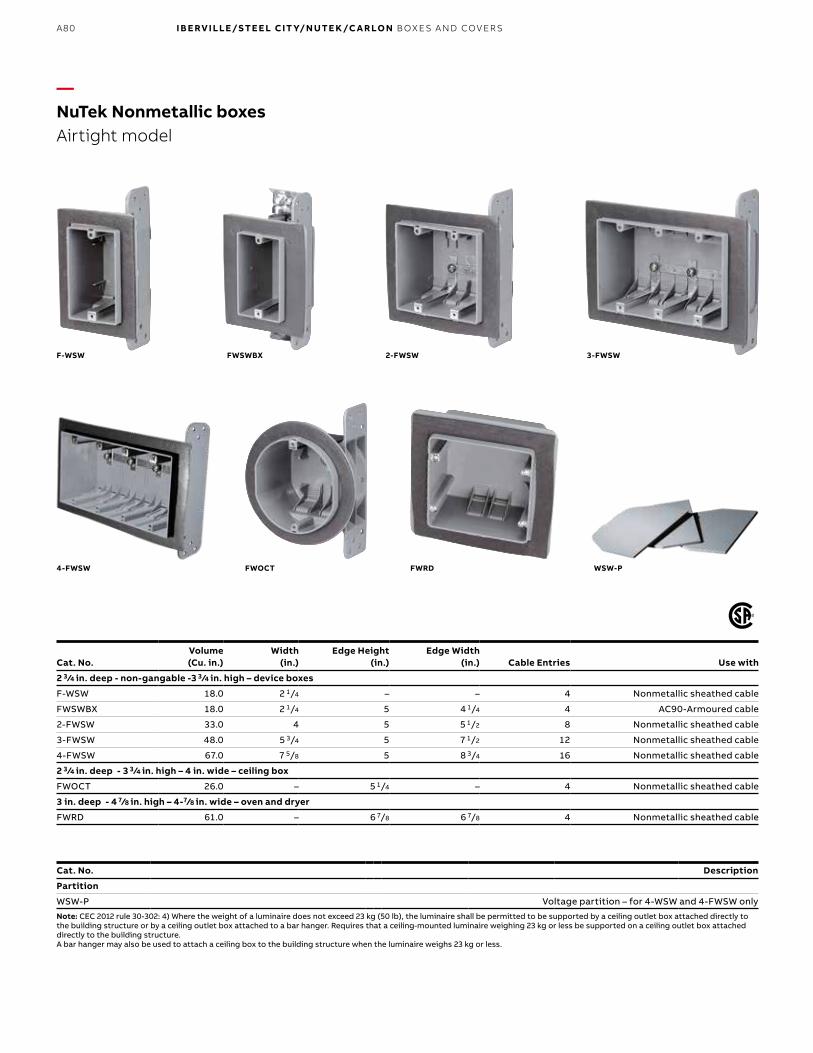
A80 I B E RV I LLE/S TE E L CIT Y/N UTE K /C A R LO N B OX E S A N D COV ER S
—NuTek Nonmetallic boxesAirtight model
F-WSW
4-FWSW
2-FWSW
FWRD
FWSWBX
FWOCT WSW-P
Cat. No.Volume (Cu. in.)
Width(in.)
Edge Height(in.)
Edge Width(in.) Cable Entries Use with
2 3 /4 in. deep - non-gangable -3 3 /4 in. high – device boxes
F-WSW 18.0 2 1/4 – – 4 Nonmetallic sheathed cable
FWSWBX 18.0 2 1/4 5 4 1/4 4 AC90-Armoured cable
2-FWSW 33.0 4 5 5 1/2 8 Nonmetallic sheathed cable
3-FWSW 48.0 5 3/4 5 7 1/2 12 Nonmetallic sheathed cable
4-FWSW 67.0 7 5/8 5 8 3/4 16 Nonmetallic sheathed cable
2 3 /4 in. deep - 3 3 /4 in. high – 4 in. wide – ceiling box
FWOCT 26.0 – 5 1/4 – 4 Nonmetallic sheathed cable
3 in. deep - 4 7/8 in. high – 4-7/8 in. wide – oven and dryer
FWRD 61.0 – 6 7/8 6 7/8 4 Nonmetallic sheathed cable
Cat. No. Description
Partition
WSW-P Voltage partition – for 4-WSW and 4-FWSW only
Note: CEC 2012 rule 30-302: 4) Where the weight of a luminaire does not exceed 23 kg (50 lb), the luminaire shall be permitted to be supported by a ceiling outlet box attached directly to the building structure or by a ceiling outlet box attached to a bar hanger. Requires that a ceiling-mounted luminaire weighing 23 kg or less be supported on a ceiling outlet box attached directly to the building structure.A bar hanger may also be used to attach a ceiling box to the building structure when the luminaire weighs 23 kg or less.
3-FWSW

A81
—NuTek Nonmetallic boxesFire resistance rating: 2 hours
WSW-US
Cat. No.Volume (Cu. in.)
Width(in.)
Edge Height(in.)
Edge Width(in.) Cable Entries Use with
2 3 /4 in. deep - non-gangable -3 3 /4 in. high – device boxes
WSW-US 18.0 2 1/4 – – 4 Nonmetallic sheathed cable
F-WSW-US 18.0 2 1/4 – – 4 Nonmetallic sheathed cable
2WSW-US 33.0 4 5 5 1/2 8 Nonmetallic sheathed cable
2-FWSW-US 33.0 4 5 5 1/2 8 Nonmetallic sheathed cable
2 3 /4 in. deep - 3 3 /4 in. high – 4 in. wide – ceiling boxes
WOCT-US 26.0 – – – 4 Nonmetallic sheathed cable
F-WOCT-US 26.0 – – – 4 Nonmetallic sheathed cable
F-WSW-US 2WSW-US
WOCT-US2-FWSW-US F-WOCT-US
NUTEK NONMETALLIC BOXES – FIRE RESISTANCE R ATING: 2 HOURS
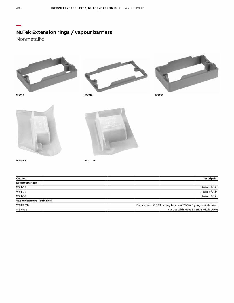
A82 I B E RV I LLE/S TE E L CIT Y/N UTE K /C A R LO N B OX E S A N D COV ER S
—NuTek Extension rings / vapour barriersNonmetallic
WXT12
WSW-VB
WXT58WXT18
WOCT-VB
Cat. No. Description
Extension rings
WXT-12 Raised 1/2 in.
WXT-18 Raised 1/8 in.
WXT-58 Raised 5/8 in.
Vapour barriers – soft shell
WOCT-VB For use with WOCT ceiling boxes or 2WSW 2 gang switch boxes
WSW-VB For use with WSW 1 gang switch boxes

A83
—Carlon Curved lidJ-Box
Anyone who’s worked with parking lot light poles knows the problem. Those tiny integral hand holes for electrical wiring can really slow a project down. But now there’s a better answer for shopping centers, car dealerships, sport arenas, office complexes or anywhere you need pole lighting for large parking lot areas – the Carlon nonmetallic curved lid J-Boxes.
Carlon curved lid J-Boxes meet NEMA 1, 2, 3, 3R, 3S, 4, 4X, 12, 13 ratings. They are available in sizes 8 in. x 8 in. or 12 in. x 12 in. Both the base and lid are made from PVC to eliminate rust and corrosion and are supplied with tamper-resistant screws.
Designed specifically for use with 24 in. diameter concrete piers, J-Boxes are installed, along with all necessary conduit and fittings, when piers are poured. This gives installers a giant junction box at the base of every pole to ease wiring, facilitate circuit management, and provide easy post-installation maintenance. Just take a closer look and you’ll see why our nonmetallic J-Boxes are a better choice for you.
Features and benefits:• NEMA 1, 2, 3, 3R, 3S, 4, 4X, 12, 13• CSA Certified• Printable lid• Dividers available to separate high and low
voltage and can be retrofitted into existing applications
• Lids provide locations to mount weatherproof covers: - 8" x 8" – one location - 12" x 12" – three locations
• Nonconductive and noncorrosive• Designed for a 24" diameter concrete pier
CARLON CURVED LID J - BOX

A84 I B E RV I LLE/S TE E L CIT Y/N UTE K /C A R LO N B OX E S A N D COV ER S
Faster, easier wiring for greater productivityOnce your J-Boxes are installed, you can speed projects along by pre-wiring before poles arrive. Or, you can install poles first and use them to mount cable-pulling equipment – a particular advantage for long, difficult wire pulls. Of course, all the extra hand room our J-Boxes offer makes splicing much easier and faster than working through cramped pole-access holes.
—Easy to install
—03
—04
—05
—06
—03 J-box, with all conduitand fittings placed as desired, is temporarily attached to the concreteform – base and lid inside.
—04 Remove form after concrete has been poured and allowed tocure.
—05 Pop off the J-box lid, leaving an 8" x 8" x 4" or 12" x 12" x 4" access area,depending on the J-box selected.
—06 After wiring is completed, the lid is replaced to complete the installation.
—01 Site lighting plan with J-box—02 Site lighting plan without J-box
—Carlon Curved lidJ-Box
More flexibility, fewer home runs and easier maintenanceExtra room also gives you splicing space for options like zone lighting or to reduce the number of home runs, which can lower trenching and associated materials costs by up to 30%.
In addition, the box lids provide locations to mount receptacles and weatherproof covers for even more flexibility. For easy maintenance, fixture protection can be placed at the base, and if need be, poles can even be removed and replaced in the middle of the circuit without affecting overall lighting.
—01
—02

A85
—Accessories
Cat. No. Size (in.) Std. Ctn. Std. Wt. (lb)
E88C24 8 x 8 x 4 6 28.3
E1212C24 12 x 12 x 4 2 9.7
Cat. No. Size (in.) Std. Ctn. Std. Wt. (lb)
E88L24 8 x 8 1 2.1
E1212L24 12 x 12 1 2.3
J-Box dividers are used to separate high- and low-voltage devices and solvent cement into place.
Cat. No. Std. Ctn. Std. Wt. (lb)
E88DIV (For use with Cat. No. E88C24) 6 2.1
E1212DIV (For use with Cat. No. E1212C24) 2 2.3
—Carlon Curved lidJ-Box
—Replacement lids
—J-Box assemblies
—Dividers The Canadian Electrical Code (CEC) allows electrical conductors to share an outlet box when the conductors and communication cables are separated by a barrier withing the box.
CARLON CURVED LID J - BOX