Table of Contents - Testing Cables and Breakout Boxes
38
Revision Date: 10/10 Testing Cables and Breakout Boxes Connectors . . . . . . . . . . . . . . . . . . . . . . . . . . . . . . . . . . . . . . . . . . . . . . . . . . .5 Connector Contact Removal Kit . . . . . . . . . . . . . . . . . . . . . . . . . . . . . . . . . .5 Socket and Spring Contacts . . . . . . . . . . . . . . . . . . . . . . . . . . . . . . . . . . .5 Instrument Cluster Illumination Bulb Holder Removal Socket . . . . . .6 Relay Holder Disengaging Tool . . . . . . . . . . . . . . . . . . . . . . . . . . . . . . . .6 Circular Connector Lock Disengager . . . . . . . . . . . . . . . . . . . . . . . . . . .7 BMW Plug System Abbreviations . . . . . . . . . . . . . . . . . . . . . . . . . . . . . . . . .7 Plug System D1.5/D2.5 . . . . . . . . . . . . . . . . . . . . . . . . . . . . . . . . . . . . . . . . .8 Circular Plug 7-8 Pin System D2.5 . . . . . . . . . . . . . . . . . . . . . . . . . . . . .8 Circular Plug 20 Pin System D2.5 . . . . . . . . . . . . . . . . . . . . . . . . . . . . . .9 Circular Plug 4-7-10-12-25 Pin System D1.5/D2.5 . . . . . . . . . . . . . .9 In-line Plug 15 Pin System D2.5 . . . . . . . . . . . . . . . . . . . . . . . . . . . . . .10 In-line Plug 8-, 12 Pin System D2.5 . . . . . . . . . . . . . . . . . . . . . . . . . . .10 In-line Plug 20 Pin System D2.5 . . . . . . . . . . . . . . . . . . . . . . . . . . . . . .11 In-line Plug 30 Pin System D2.5 . . . . . . . . . . . . . . . . . . . . . . . . . . . . . .11 Plug System JPT/MDK/DFK . . . . . . . . . . . . . . . . . . . . . . . . . . . . . . . . . . . .12 In-line plug 2 Pin System JPT ELA . . . . . . . . . . . . . . . . . . . . . . . . . . .12 In-line plug 2 Pin System MDK 3 plus 2.8 . . . . . . . . . . . . . . . . . . . . .12 In-line plug 4 Pin System DFK ELA . . . . . . . . . . . . . . . . . . . . . . . . . . .13 Installation Instructions . . . . . . . . . . . . . . . . . . . . . . . . . . . . . . . . . . .13 Plug System Elo/Elo-Power . . . . . . . . . . . . . . . . . . . . . . . . . . . . . . . . . . . . .14 In-line Plug 3-,6 Pin System Elo-Power 2.8 . . . . . . . . . . . . . . . . . . . .14 In-line plug 4-,10 Pin System Elo . . . . . . . . . . . . . . . . . . . . . . . . . . . . .14 In-line Plug 6-,50 Pin System Elo . . . . . . . . . . . . . . . . . . . . . . . . . . . . .15 Plug System MQS/MPQ . . . . . . . . . . . . . . . . . . . . . . . . . . . . . . . . . . . . . . .16 In-line Plug 6-,8 Pin System MQS . . . . . . . . . . . . . . . . . . . . . . . . . . . .16 In-line Plug 2 Pin System MPQ 2.8 . . . . . . . . . . . . . . . . . . . . . . . . . . .16 Control Unit Plug 25-, 35-, 55-,83-,88 Pin . . . . . . . . . . . . . . . . . . . .17 In-line Plug 24 Pin Hybrid System MQS/MPQ . . . . . . . . . . . . . . . . . .17 Socket Housing . . . . . . . . . . . . . . . . . . . . . . . . . . . . . . . . . . . . . . . . .17 Pin Housing . . . . . . . . . . . . . . . . . . . . . . . . . . . . . . . . . . . . . . . . . . . . . . . .18 Socket Housing 42-,43 Pin Hybrid Systems MQS/MPQ . . . . . . . . .19 Installation Instructions . . . . . . . . . . . . . . . . . . . . . . . . . . . . . . . . . . .19 Socket Housing 2x27-, 2x27 Pin Hybrid System MQS/MPQ, Elo/Elo Power . . . . . . . . . . . . . . . . . . . . . . . . . . . . . . . . . . . . . . . . . . . . . .19 In-line Plug 30 Pin Hybrid System MQS/MPQ . . . . . . . . . . . . . . . . . .20 Socket Housing . . . . . . . . . . . . . . . . . . . . . . . . . . . . . . . . . . . . . . . . .20 Subject Page Table of Contents Initial Print Date: 05/01
-
Upload
khangminh22 -
Category
Documents
-
view
0 -
download
0
Transcript of Table of Contents - Testing Cables and Breakout Boxes

Revision Date: 10/10
Testing Cables and Breakout Boxes
Connectors . . . . . . . . . . . . . . . . . . . . . . . . . . . . . . . . . . . . . . . . . . . . . . . . . . .5Connector Contact Removal Kit . . . . . . . . . . . . . . . . . . . . . . . . . . . . . . . . . .5
Socket and Spring Contacts . . . . . . . . . . . . . . . . . . . . . . . . . . . . . . . . . . .5Instrument Cluster Illumination Bulb Holder Removal Socket . . . . . .6Relay Holder Disengaging Tool . . . . . . . . . . . . . . . . . . . . . . . . . . . . . . . .6Circular Connector Lock Disengager . . . . . . . . . . . . . . . . . . . . . . . . . . .7
BMW Plug System Abbreviations . . . . . . . . . . . . . . . . . . . . . . . . . . . . . . . . .7Plug System D1.5/D2.5 . . . . . . . . . . . . . . . . . . . . . . . . . . . . . . . . . . . . . . . . .8
Circular Plug 7-8 Pin System D2.5 . . . . . . . . . . . . . . . . . . . . . . . . . . . . .8Circular Plug 20 Pin System D2.5 . . . . . . . . . . . . . . . . . . . . . . . . . . . . . .9Circular Plug 4-7-10-12-25 Pin System D1.5/D2.5 . . . . . . . . . . . . . .9In-line Plug 15 Pin System D2.5 . . . . . . . . . . . . . . . . . . . . . . . . . . . . . .10In-line Plug 8-, 12 Pin System D2.5 . . . . . . . . . . . . . . . . . . . . . . . . . . .10In-line Plug 20 Pin System D2.5 . . . . . . . . . . . . . . . . . . . . . . . . . . . . . .11In-line Plug 30 Pin System D2.5 . . . . . . . . . . . . . . . . . . . . . . . . . . . . . .11
Plug System JPT/MDK/DFK . . . . . . . . . . . . . . . . . . . . . . . . . . . . . . . . . . . .12In-line plug 2 Pin System JPT ELA . . . . . . . . . . . . . . . . . . . . . . . . . . .12In-line plug 2 Pin System MDK 3 plus 2.8 . . . . . . . . . . . . . . . . . . . . .12In-line plug 4 Pin System DFK ELA . . . . . . . . . . . . . . . . . . . . . . . . . . .13
Installation Instructions . . . . . . . . . . . . . . . . . . . . . . . . . . . . . . . . . . .13Plug System Elo/Elo-Power . . . . . . . . . . . . . . . . . . . . . . . . . . . . . . . . . . . . .14
In-line Plug 3-,6 Pin System Elo-Power 2.8 . . . . . . . . . . . . . . . . . . . .14In-line plug 4-,10 Pin System Elo . . . . . . . . . . . . . . . . . . . . . . . . . . . . .14In-line Plug 6-,50 Pin System Elo . . . . . . . . . . . . . . . . . . . . . . . . . . . . .15
Plug System MQS/MPQ . . . . . . . . . . . . . . . . . . . . . . . . . . . . . . . . . . . . . . .16In-line Plug 6-,8 Pin System MQS . . . . . . . . . . . . . . . . . . . . . . . . . . . .16In-line Plug 2 Pin System MPQ 2.8 . . . . . . . . . . . . . . . . . . . . . . . . . . .16Control Unit Plug 25-, 35-, 55-,83-,88 Pin . . . . . . . . . . . . . . . . . . . .17In-line Plug 24 Pin Hybrid System MQS/MPQ . . . . . . . . . . . . . . . . . .17
Socket Housing . . . . . . . . . . . . . . . . . . . . . . . . . . . . . . . . . . . . . . . . .17Pin Housing . . . . . . . . . . . . . . . . . . . . . . . . . . . . . . . . . . . . . . . . . . . . . . . .18Socket Housing 42-,43 Pin Hybrid Systems MQS/MPQ . . . . . . . . .19
Installation Instructions . . . . . . . . . . . . . . . . . . . . . . . . . . . . . . . . . . .19Socket Housing 2x27-, 2x27 Pin Hybrid System MQS/MPQ,Elo/Elo Power . . . . . . . . . . . . . . . . . . . . . . . . . . . . . . . . . . . . . . . . . . . . . .19In-line Plug 30 Pin Hybrid System MQS/MPQ . . . . . . . . . . . . . . . . . .20
Socket Housing . . . . . . . . . . . . . . . . . . . . . . . . . . . . . . . . . . . . . . . . .20
Subject Page
Table of Contents
Initial Print Date: 05/01

Pin Housing . . . . . . . . . . . . . . . . . . . . . . . . . . . . . . . . . . . . . . . . . . . . . . . .21Socket Housing 5-, 8 Pin System MQS/MPQ . . . . . . . . . . . . . . . . . .21Socket housing 5pin (Hybrid System MQS/MPQ) . . . . . . . . . . . . . .21Socket Housing 8 Pin (MQS) . . . . . . . . . . . . . . . . . . . . . . . . . . . . . . . . .22Socket Housing (Radio Plug) Hybrid System MQS/MPS . . . . . . . . .22Removing MPQ Contacts from Radio Plug . . . . . . . . . . . . . . . . . . . . .22Removing MQS Contacts from Carrier . . . . . . . . . . . . . . . . . . . . . . . .23Removing MPQ Contacts from Contact Carrier . . . . . . . . . . . . . . . . .23
Miscellaneous Connectors . . . . . . . . . . . . . . . . . . . . . . . . . . . . . . . . . . . . .24Fuse Strip . . . . . . . . . . . . . . . . . . . . . . . . . . . . . . . . . . . . . . . . . . . . . . . . . .24ECM Main Relay Connector . . . . . . . . . . . . . . . . . . . . . . . . . . . . . . . . . .24
Solderless Terminals And Connectors . . . . . . . . . . . . . . . . . . . . . . . . . . .25
Electrical Repair . . . . . . . . . . . . . . . . . . . . . . . . . . . . . . . . . . . . . . . . . . . . .26Electrical Repair Kit IV . . . . . . . . . . . . . . . . . . . . . . . . . . . . . . . . . . . . . . . . . .26
Cable Stripper . . . . . . . . . . . . . . . . . . . . . . . . . . . . . . . . . . . . . . . . . . . . . .26Crimping Tool . . . . . . . . . . . . . . . . . . . . . . . . . . . . . . . . . . . . . . . . . . . . . .26
Cable Stripping . . . . . . . . . . . . . . . . . . . . . . . . . . . . . . . . . . . . . . . . . . . . . . .27Crimping Tool . . . . . . . . . . . . . . . . . . . . . . . . . . . . . . . . . . . . . . . . . . . . . . . . .28Prepackaged Wiring Repair Sets . . . . . . . . . . . . . . . . . . . . . . . . . . . . . . . .30Soldering Connections . . . . . . . . . . . . . . . . . . . . . . . . . . . . . . . . . . . . . . . . .31
Soldering Preparation and Procedure . . . . . . . . . . . . . . . . . . . . . . . . . .31
Break Out Boxes and V Cables,Tester and Adapter Sets . . . . . . . .32Breakout Boxes and “V” Cables . . . . . . . . . . . . . . . . . . . . . . . . . . . . . . . . .32
55 pin Breakout Box P/N 81 12 9 425 091 . . . . . . . . . . . . . . . . . . . .3383 Pin Breakout Box (Red Face) P/N 90 88 6 614 420 . . . . . . . . .3388 Pin Breakout Box (Green Face) P/N 88 88 6 614 410 . . . . . . . .33134 Pin SKE Control Module Breakout Box SetP/N 90 88 6 121 300 . . . . . . . . . . . . . . . . . . . . . . . . . . . . . . . . . . . . . . .3426 Pin Breakout Box P/N 88 88 6 611 459 . . . . . . . . . . . . . . . . . . . .3460 Pin Breakout Box P/N 90 88 6 614 390 . . . . . . . . . . . . . . . . . . . .34
“V” Cables . . . . . . . . . . . . . . . . . . . . . . . . . . . . . . . . . . . . . . . . . . . . . . . . . . . .35Tester and Adapter Set for Relays . . . . . . . . . . . . . . . . . . . . . . . . . . . . . . .36
Subject Page

BLANKPAGE
Subject Page

Testing Cables and Breakout Boxes
Model: All
Production: All
After completion of this module you will be able to:
• Recognize and distinguish the various Electrical Repair Kits.
• Use the Connector Removal Kit.
• Recognize the plug configurations and disassemble them properly.
• Repair wiring harnesses and connectors.
• Choose the proper Breakout Box and “V” cable for testing.
• Use the relay testing tool.
4Testing Cables and Breakout Boxes

Connector Contact Removal Kit
The connector contact removal kit providestools for the disassembly of connectors.Proper use of these tools enable the techni-cian to access wiring connectors for repairsequal to factory quality.
Always refer to the latest Service InformationBulletins (Group 04) for up to date informationregarding new tools.
The Connector Contact Removal Kitis used for:
• Releasing round plug housings.
• Pressing out contacts.
• Pulling out indicator lamps.
• Releasing relay carriers.
Socket and Spring Contacts
Socket and Spring contacts compress the springs while the connector is pushed fromthe housing.
5Testing Cables and Breakout Boxes
Connectors
Current P/N 88 88 6 611 150

Flat spring contacts depress the spring allowing the connector to be pushed or gentlypulled from the connector housing.
Instrument Cluster Illumination Bulb Holder Removal Socket
The backlighting illumination bulbs areremoved from the cluster by placing squarehead of the socket on the bulb holder andturning 90° counter clockwise.
The bulb removal socket is used on all instru-ment clusters.
Relay Holder Disengaging Tool
This tool allows the relay holder (2) to disen-gage the relay connector (1).
6Testing Cables and Breakout Boxes

BMW Plug System Abbreviations
D 1.5/2.5 Round contacts of 1.5mm or 2.5mm diameter
MDK 3 Plus Miniature double flat spring contact
JPT ELA Junior Power Timer flat spring contacts with strand sealing
DFK ELA Double flat spring contacts with strand sealing
Elo Electronic contacts with and without strand sealingManufacturer: Siemens
Elo Power Electronic contacts for heavy loads with and without strand sealingManufacturer: Siemens
MQS Micro Quadlock System electronic contacts with and without strandsealingManufacturer: AMP
MPQ Micro Power Quadlock electronic contacts for heavy loads with andwithout strand sealingManufacturer: AMP
Circular Connector Lock Disengager
These tools unlock the circular connector hous-ings allowing the individual connectors to beremoved.
The various sizes are reflected in the part num-bers:
4 pin = 61 1 141
7 pin = 61 1 142
10 pin = 61 1 145
12 pin = 61 1 143
25 Pin = 61 1 144
7Testing Cables and Breakout Boxes

Plug System D1.5/D2.5
Circular Plug 7-8 Pin System D2.5
• Pull off the rubber boot (1).
• Push the retaining lugs (2) of the inner connector section 3 inward carefully to disen-gage the lock notch.
• Push the inner connector section (3) in the direction of the arrow in the illustrationuntil the retaining lugs (2) are in the recessed notch (4) and use the appropriatesized spring contact tool and remove the connector from the housing.
Circular plug 13 Pin System D2.5
• Carefully pull off the rubber grommet (1).
• Pull the lock retainers (2) outward (direction of arrows) to allow the lock notch to dis-engage.
• Pull the inner section (3) upward as shown in the illustration until the lock notches (4)are in the released position of the lock retainers (5) and use the appropriate sizespring contact and remove the connector from the housing.
8Testing Cables and Breakout Boxes

Circular Plug 20 Pin System D2.5
• With the boot pulled back, press the lock tabs (1) of the inner connector section (2)inward.
• Simultaneously, rotate the inner connection section (2) counter clockwise to allowthe lock tabs (1) to engage in the unlocked position and use the appropriate sizedspring contact and remove connector from the housing.
Circular Plug 4-7-10-12-25 Pin System D1.5/D2.5
• Insert the appropriate unlocking tool (determined by the number of pins) into the connector.
• The connector is unlocked when the lock tab (3) is in the unlocked position (1). The connector is locked when the lock tab (3) is in the locked position (2).
• Use the appropriate sized spring contact and remove connector from the housing.
9Testing Cables and Breakout Boxes

In-line Plug 15 Pin System D2.5
• Pull the outer connector section (1) slightly outward in the area of lock tabs (2).
• Simultaneously, slide the inner connector section (3) in the direction of the arrow tothe unlocked position.
• Use the appropriate sized spring contact and remove connector from housing.
In-line Plug 8-, 12 Pin System D2.5
• Slide the upper section (1) and the lower section (2) of the connector in oppositedirections to unlock the connector.
• Using special tool 61 1 132 press the spring latch down and pull the connector (3)from the housing.
10Testing Cables and Breakout Boxes

In-line Plug 20 Pin System D2.5
• Pull locking slide (1) completely out of connector (2).
• Using special tool 61 1 132 press the spring latch down and pull the connector fromthe housing.
In-line Plug 30 Pin System D2.5
• Pull the outer section (1) slightly outward in the area of lock tabs (2).
• Simultaneously, slide the inner connector section (3) in the direction of the arrow tothe unlocked position.
• Use the appropriate sized spring contact and remove connector from housing.
11Testing Cables and Breakout Boxes

Plug System JPT/MDK/DFK
In-line plug 2 Pin System JPT ELA
• Press lock (1) in direction of arrow and slide plug forward.
• Press lock (1) downward and slide out to one side.
• Unlock contact with special tool 61 1 136 and pull out cable (2) and contacttowards rear.
In-line plug 2 Pin System MDK 3 plus 2.8
• Unlock lock (1) on outside at arrester hook and slide out lock (1) side.
• Unlock contact with special tool 61 1 136 and pull out cable (2) and contacttowards rear.
2
2
12Testing Cables and Breakout Boxes

In-line plug 4 Pin System DFK ELA
• Press arrester hook in direction of arrowand remove lock (1).
• Unlock contact with special tool 61 1136 and pull cable and contact outtowards rear.
Installation Instructions
• If necessary, slide lock must also be unlocked with screw driver.
Notes:
13Testing Cables and Breakout Boxes

Plug System Elo/Elo-Power
In-line Plug 3-,6 Pin System Elo-Power 2.8
• Press unlocking hook (1) in direction of arrow and disengage. Then unlock lockinghook (2) and remove lock.
• Press down arrestor hook (3) with screwdriver and pull out cable with contacttowards rear.
In-line plug 4-,10 Pin System Elo
• Slide connector lock (1) off of main connector body.
• Push the lock tab of the connector being removed down (3) with pin or small screw-driver in the primary lock slot(4) and pull the wire out (5) to the secondary lock position (6).
• Push the lock tab down again in the secondary lock position and remove wire com-pletely.
14Testing Cables and Breakout Boxes

In-line Plug 6-,50 Pin System Elo
• Unlock lock (Fig. 14/1).
• Unfasten cable clip (Fig. 14/2).
• Slide connector lock (1) off of main connector body (2) (Fig. 14/3).
• Push the connector plate (3) out of connector shell using a small screwdriverthrough hole on end of connector body (Fig. 14/4).
• Push the lock tab of the connector being removed down (6) with pin or small screwdriver in the primary lock slot (7) and pull the wire out to the secondary lock position(8) (Fig. 14/5).
• Push the lock tab down again in the secondary lock position and remove wire com-pletely (Fig. 14/6).
Fig. 14/1 Fig. 14/2 Fig. 14/3
Fig. 14/4 Fig. 14/5 Fig. 14/6
15Testing Cables and Breakout Boxes

Plug System MQS/MPQ
In-line Plug 6-,8 Pin System MQS
• Press lock (1) in direction of arrow and slide plug forward.
• Press locking hook (2) downward and slide lock (1) out.
• Press down arrester hook (3) with screwdriver and pull out cable with contacttowards rear.
In-
line Plug 2 Pin System MPQ 2.8
• Press catch on outside in direction of arrow and remove towards top.
• Press down arrestor hook (1) with screwdriver and pull out cable and contact (2)towards rear.
3
16Testing Cables and Breakout Boxes

Control Unit Plug 25-, 35-, 55-,83-,88 Pin
• Remove phillips head screws (1) from connector. Gently pivot the connector plate(2) with seal (3) out of the connector shell.
• Remove seal (3) and pull connector plate lock (4) out of locked position.
• Using the appropriate sized spring contact and remove connector (5) from housing.
In-line Plug 24 Pin Hybrid System MQS/MPQ
Socket Housing
• Press locks (1) on cap (2) upwards onboth sides.
• Detach cap from contact carrier (3).
Note: Detaching the cap releases thesecondary lock of the socketcontacts.
Manufactured by AMP: The following contact types without strand sealing can befitted in the plug housings:
MQS (Micro Quadlock System)
MPQ, width 2.8 mm (Micro Power Quadlock)
MPQ, width 5.2 mm (Micro Power Quadlock)
17Testing Cables and Breakout Boxes

• Hold down retaining hook (1) of socketcontact carrier with a small screwdriver.
• Pull wire with socket contact in directionof arrow as far as secondary lock (2).(Fig. 17/1)
• Hold down retaining hook in secondarylock (1) again and pull cable with socketcontact (2) completely out of contact carri-er (3).(Fig. 17/2)
Pin Housing• Press locks (1) on cap (2) upwards on
both sides.
• Detach cap from housing carrier (3)(Fig. 17/3).
Note: Detaching the cap releases thesecondary locks of the pin contactsin the contact carriers.
• Pull contact carrier (1) out of housingcarrier (2) (Fig. 17/4).
• The pin contacts are pulled of a contactcarrier as described under “SocketHousing”.
Fig. 17/1
Fig. 17/2
Fig. 17/3 Fig. 17/4
18Testing Cables and Breakout Boxes
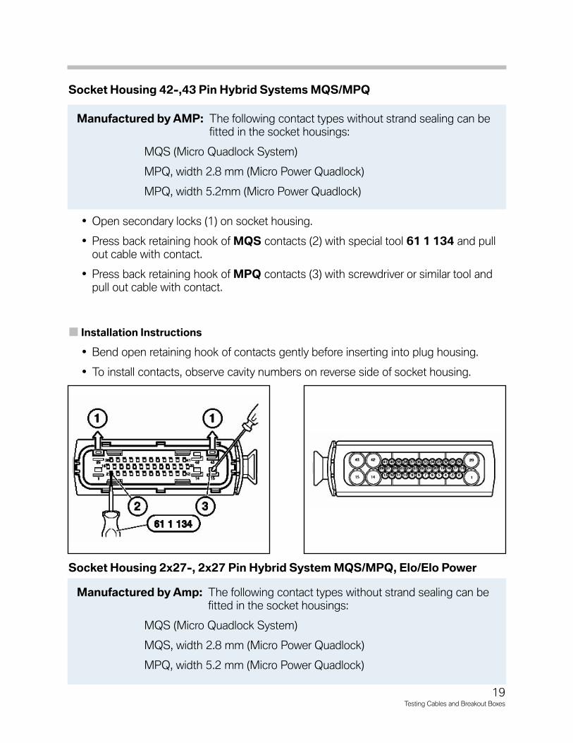
Socket Housing 42-,43 Pin Hybrid Systems MQS/MPQ
• Open secondary locks (1) on socket housing.
• Press back retaining hook of MQS contacts (2) with special tool 61 1 134 and pullout cable with contact.
• Press back retaining hook of MPQ contacts (3) with screwdriver or similar tool andpull out cable with contact.
Installation Instructions
• Bend open retaining hook of contacts gently before inserting into plug housing.
• To install contacts, observe cavity numbers on reverse side of socket housing.
Socket Housing 2x27-, 2x27 Pin Hybrid System MQS/MPQ, Elo/Elo Power
Manufactured by AMP: The following contact types without strand sealing can befitted in the socket housings:
MQS (Micro Quadlock System)
MPQ, width 2.8 mm (Micro Power Quadlock)
MPQ, width 5.2mm (Micro Power Quadlock)
Manufactured by Amp: The following contact types without strand sealing can befitted in the socket housings:
MQS (Micro Quadlock System)
MQS, width 2.8 mm (Micro Power Quadlock)
MPQ, width 5.2 mm (Micro Power Quadlock)
19Testing Cables and Breakout Boxes

• Raise lock (1) on housing (2).
• Push contact carrier (3) from rear out ofhousing.
Note: The second carrier is pushed out inthe same way. Pushing out thecontact carrier releases the sec-ondary locks of the secondary con-tacts.
In-line Plug 30 Pin Hybrid System MQS/MPQ
Socket Housing
• Raise lock (1) on housing (2).
• Push contact carrier (3) from rear out ofhousing (2).
Note: Pushing out the contact carrierreleases the secondary locks of thesocket contacts.
Manufactured by Siemens: The following contact types without strand sealing canbe fitted in th socket housings:
Elo (electronic contact)
Elo-Power 2.8 mm wide (electronic contact for heavy loads)
Elo-Power 5.2 mm wide (electronic contact for heavy loads)
Procedure for removing contacts are same as for other Elo/Elo-Power Systems, refer to those instructions.
Manufactured by AMP: The following contact types without strand sealing can befitted in the plug housings:
MQS (Micro Quadlock System)
MPQ, width 2.8 mm (Micro Power Quadlock)
MPQ, width 5.2 mm (Micro Power Quadlock)
Procedure for removing contacts are same as for other Elo/Elo-Power Systems, refer to those instructions.
20Testing Cables and Breakout Boxes
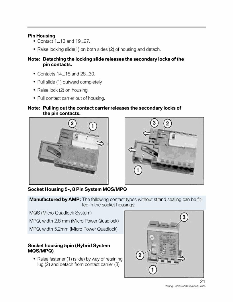
Pin Housing• Contact 1...13 and 19...27.
• Raise locking slide(1) on both sides (2) of housing and detach.
Note: Detaching the locking slide releases the secondary locks of thepin contacts.
• Contacts 14...18 and 28...30.
• Pull slide (1) outward completely.
• Raise lock (2) on housing.
• Pull contact carrier out of housing.
Note: Pulling out the contact carrier releases the secondary locks ofthe pin contacts.
Socket Housing 5-, 8 Pin System MQS/MPQ
Socket housing 5pin (Hybrid SystemMQS/MPQ)
• Raise fastener (1) (slide) by way of retaininglug (2) and detach from contact carrier (3).
Manufactured by AMP: The following contact types without strand sealing can be fit-ted in the socket housings:
MQS (Micro Quadlock System)
MPQ, width 2.8 mm (Micro Power Quadlock)
MPQ, width 5.2mm (Micro Power Quadlock)
21Testing Cables and Breakout Boxes

Socket Housing 8 Pin (MQS)
• Raise fastener (1) (slide) by way of retaininglug (2) and detach from contact carrier (3).
Socket Housing (Radio Plug) Hybrid System MQS/MPS
Removing MPQ Contacts from Radio Plug
• Press lock (1) in direction of arrow, detach secondary lock (2) from radio plug.
• Feed special tool 61 1 135 past side of contact.
• Press special tool 61 1 135 in direction of arrow.
• Pull wire (1) with socket contact out of radio plug(2).
Manufactured by AMP: The following contact types without strand sealing can befitted in the plug housings:
MQS (Micro Quadlock System)
MPQ, width 2.8 mm (Micro Power Quadlock)
MPQ, width 5.2 mm (Micro Power Quadlock)
Procedure for removing contacts are same as for other Elo/Elo-Power Systems, refer to those instructions.
22Testing Cables and Breakout Boxes

Removing MQS Contacts from Carrier
• Press lock (1) in direction of arrow and pull housing (2) out of radio plug (Fig. 22/1).
• Press lock (1) in direction of arrow. Pull contact carrier (2) out of housing (Fig. 22/2).
Note: When the contact carrier is pulled out, the secondary locks of the socketcontacts are raised.
Removing MPQ Contacts from Contact Carrier• Remove contact carrier (1) with MQS contacts from radio plug. Raise lock (2)
on radio plug. Pull contact carrier (3) out of radio plug (Fig. 22/3).
• Press lock (1) in direction of arrow. Pull secondary lock (2) in direction of arrowcompletely out of contact carrier (3) (Fig. 22/4).
• Press special tool 61 1 135 on inside of contact into contact carrier(2). Pull wirewith socket contact (1) out of contact carrier (2) (Fig. 22/5).
Procedure for removing contacts are same as for otherElo/Elo-Power Systems, refer to those instructions.
Fig. 22/2Fig. 22/1
Fig. 22/3 Fig. 22/4 Fig. 22/5
23Testing Cables and Breakout Boxes

Miscellaneous Connectors
Fuse Strip
• Pull appropriate fuse from fuse strip (1).
Note: Mark fuse rating and position for reinstallment.
• Pull locking slide (2) out of fuse strip until stop is felt.
• Using special tool 61 1 136 or 61 1 1
ECM Main Relay Connector
• Unlock wire flap (1) of connector being removed.
• Using special tool 61 1 136 or 61 1 137 press the spring latch down (2) and pullthe connector from the housing.37 press the spring latch down (3) and pull the con-nector from the housing.
24Testing Cables and Breakout Boxes

Solderless Terminals And Connectors
Mechanical strength of solderless terminal design and electrical conductivity must bemaintained at all times. To ensure these characteristics are maintained in the vehicleselectrical system several BMW repair kits are available.
The repair kits listed contain all the approvedconnectors, pins, and tools required for properrepair of BMW's electrical, electronics compo-nents.
• Electrical Repair Kit IV
P/N 90 88 6 619 020
The Electrical Repair Kit IV (Ref. SI. 04 18 92)is used in conjunction with the instructionmanuals and detailed repair manual proce-dures from Group 61, Sub-group 13found in TIS.
These procedures include:
• Disassembling, replacing a plug connection on the various types of connectors.
• Cutting cable to length.
• Crimping stop parts (Contacts).
• Butt connectors for repairing a plug connection.
Operating instructions for special tools and thehandling of individual parts in the repair kit areavailable under PN 61 9 029.
Three previous kits issued by BMW are:
• Electrical Repair Kit I (Black Case)
P/N 81 24 9 408 080
• Electrical Repair Kit II (Blue Case)
P/N 81 24 9 408 300
• Electrical Repair Kit III (Red Case)
P/N 82 11 9 408 400
Electrical repair kits I, II and III are primarily needed for repairing wiring harness and con-nectors of older vehicles (E30 and earlier). Refer to repair kit instructions, SI bulletins andrepair manual microfiche. Operating instructions for special tools in these kits are avail-able under PN 61 8 084.
25Testing Cables and Breakout Boxes

Electrical Repair Kit IV
The Electrical Repair Kits (I,II,III and IV) havegone through various upgrades.
Electrical Repair Kit IV (PN 90 88 619 020)has been developed to handle repairs of thespecialized state of the art wiring and har-nesses of the newest BMW products.
Cable StripperSpecial Tool 61 9 043 Cable stripper withwire cutter for cutting and stripping insula-tion from cables.
Crimping ToolSpecial Tool 61 9 041 Crimping Tool withspecial tool 61 9 044 (matrix) for crimpingcable guide and strain relief device on anten-na elbow plug.
26Testing Cables and Breakout Boxes
Electrical Repair
Caution:The special tools contained in the ElectricalRepair Kits I,II,III are not state of the art and arenot suitable for specialized wiring harnessrepairs.
Use exclusively Electrical Repair Kit IV for thoserepairs.
Electrical Repair Kit IV (61 9 020)Contains the following:61 9 041 Crimping Tool61 9 042 Matrix61 9 043 Cable Stripper61 9 044 MatrixAssorted Individual Parts
Supplementary kits for Electrical Repair Kit IV arereleased periodically. Check the latest Service Bulletinto insure information on latest connectors are avail-able.
Cable Stripping
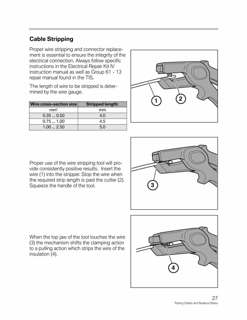
Proper wire stripping and connector replace-ment is essential to ensure the integrity of theelectrical connection. Always follow specificinstructions in the Electrical Repair Kit IVinstruction manual as well as Group 61 - 13repair manual found in the TIS.
The length of wire to be stripped is deter-mined by the wire gauge.
Proper use of the wire stripping tool will pro-vide consistently positive results. Insert thewire (1) into the stripper. Stop the wire whenthe required strip length is past the cutter (2).Squeeze the handle of the tool.
When the top jaw of the tool touches the wire(3) the mechanism shifts the clamping actionto a pulling action which strips the wire of theinsulation (4).
27Testing Cables and Breakout Boxes
Wire cross-section size Stripped length:
mm2 mm
0.35 ... 0.50 4.0
0.75 ... 1.00 4.5
1.00 ... 2.50 5.0

Crimping Tool
Use the wire crimper from the BMWElectrical Repair Kit. This crimper isdesigned for the specific connectors found inBMW automobiles. Proper use of the toolswill provide consistent good quality connec-tor crimps.
The crimper is designed to apply just theright amount of pressure based on the wiregauge and connector size.
The tool has removable crimper jaws (3). Thisfeature allows for an unlimited number ofconnector types for future compatibility. Therepair manual refers to the different sizedcrimping slots as “Nests”. The gauge of thewire being crimped determines which “Nest”is used.
Example:A .75 - 1.0mm gauge wire requires nest 2 forproper crimping.
Throughout the Electrical Repair Kit instruc-tion manual are illustrations of various con-nectors being crimped. The highlighted boxof the 16 box grid in these illustrations refersto the storage compartment in the electricalkit drawers in which that specific connectorcan be found.
Insert the “crimping end” of the connectorinto the appropriate “nest”. Illustration pro-vides example of comb replacement connec-tor (4) and inline splice connector (5).
Nest Wire cross-section size
1 0.35 ... 0.50mm2
2 0.75 ... 1.00mm2
3 1.50mm2
4 2.50mm2
28Testing Cables and Breakout Boxes

Squeeze the tool handle slightly to set thetool in the first ratchet latch position. This willhold the connector in the tool without closingthe crimp (6).
Insert the stripped wire into the receiving endof the crimper tool making sure the wire isinserted far enough to ensure that only thewire insulation will be inside the insulationsupport barrel (7).
Properly crimped connectors exhibit the fol-lowing characteristics:
• The insulation support barrel will becrimped consistently and snug againstthe insulation. The insulation will not becrushed (8).
• A bellmouth crimp will be visible at thewire end of the of the wire barrel (9).
• Wire strands will be visible at the contactend of the wire barrel (10).
• Insulation end will be visible in this area(11) (Fig. 27/1).
The following are examples of unacceptable crimps: (Fig. 27/2)
• Excessive or no wire strands at the contact end of the wire barrel (10).
• Excessive or no insulation end in the acceptable area (11).
Fig. 27/2
29Testing Cables and Breakout Boxes
Fig. 27/1

Prepackaged Wiring Repair Sets
Included with the Electrical Repair Kit IV are avariety of wiring repair sets. These sets con-tain various pre-crimped wiring connectors onassorted gauge wire lengths for simple spliceconnection repair into a wiring harness.
The repair kits also contain:
1. Various gauge lengths of wirewith pre-crimped connectors.
2. In-line splice connectors.
3. Heat shrink tubing.
When used correctly the in-line splice con-nectors provide a BMW factory approved wirecrimp. Use the correct size nest in thecrimper tool and connect one side of the in-line crimp with the wire.
Slide a piece of heat shrink tubing on the wireand crimp the other side of the in-line con-nector.
Use a heat gun to shrink the tube around thesplice connector to provide a moisture resis-tant seal.
Part numbers for the wire sets or any compo-nent of all four electrical repair kits can be re-ordered from:
• The P/N reference card inside eachrepair kit.
• Special tools microfiche.
• The Electrical Repair Kit 1-4 compo-nent catalog (SD 92-036).
As new connectors are developed for new vehicles, the repair kits will be announced byService Information bulletins and sent to dealerships via automatic tools shipment.
30Testing Cables and Breakout Boxes

Soldering Connections
In the event that a wiring connection must besoldered in a vehicle’s electrical system, thereare certain procedures which must be fol-lowed. Improper soldering will result in poorelectrical connections or damage to electricalcomponents.
SAFETY: Adhere to the following basicguidelines when preparing tosolder.
• Safety glasses must be worn.
• Disconnect vehicle battery.
• Cover vehicle trim surfaces.
• Exercise your common sense.
• Provide adequate ventilation,it’s the best safety precaution!
Soldering Preparation and Procedure
• The wire insulation must be stripped toexpose an adequate amount of bare wire(not too little-not to much.)
• The wires and or connectors must beclean and free of grease, dirt, wax, etc.
• A thin coating of rosin core flux must beapplied to the soldering connection.
• Have enough 60/40 (tin/lead) general electrical solder on hand prior to starting.
• If heat transfer to a heat sensitive component is possible use “heat sinks”.
• Use a soldering gun tip that is the right size for the job. Do not use an overly largetip which could melt wire insulation and block your view of what is being soldered.
• The soldering tip must be “tinned”. This means to keep a thin layer of solder on thetip at all times during soldering. This will transfer the heat quickly and allow the sol-der to flow easily into the joint being soldered.
• Preheat the wires or connector. Introduce the solder into the joint not the solderingtip.
• When the solder starts to flow allow it to infiltrate the joint only for a moment.Almost simultaneously, pull the tip off of the joint to prevent overheating.
• A properly soldered joint will be smooth, shinny, and even surfaced.
31Testing Cables and Breakout Boxes

Breakout Boxes and “V” Cables
Breakout Boxes are used to:
• Provide a convenient “tap” into an electrical circuit.
• Minimize the possibility of damage to control unit connections and wire harnessesduring diagnosis of electrical/electronic systems.
• Ensure solid meter connections for proper diagnosis, this in turn will help the tech-nician to be more organized and efficient.
• Provide easier access to circuits for testing with equipment such as, multimeter,DISplus tester or other diagnostic tools.
CAUTION: Breakout box cable connections are universal in order to fit thevarying coded connectors found in the vehicles. Always confirmthat you are connecting the correct control module into the sys-tem harness that is on the other side of the breakout box. Systemdamage will occur if it is not the correct system.
Example: DME and EGS/AGS control modules both utilize an 88 or 134 pin controlmodule. These control modules reside in the same E-Box on most vehicles. The con-trol modules are coded to prevent unintentional cross connecting at the vehicle harness.But, this connector coding is not present on the 88 or 134 pin breakout box(s). Result:A DME control module could be connected to a transmission control system.Damage will result!
Several different types of breakout boxes are available depending on the particular sys-tem being diagnosed.
Break Out Boxes and V Cables,Tester and Adapter Sets
MOTRONICMOTRONIC
32Testing Cables and Breakout Boxes

55 pin Breakout BoxP/N 81 12 9 425 091
Used with control modules that have singlemulti-pin plugs from 25 to 55 pins.
• L-jetronic
• ABS
• Motronic
• EGS
Adapter cables are required.
83 Pin Breakout Box (Red Face)P/N 90 88 6 614 420
When used with ABS/ASC 5 system, noadapter cables are required. See SIB 04 1095 about an adapter harness for use with theTeves Mark IV G ABS system of the E36.
88 Pin Breakout Box (Green Face)P/N 88 88 6 614 410
Used with control units that have up to 88 pins;
• DME
• EGS/AGS
• ZAE/MRS
• LCM
No adapter cables are required when con-nected to a DME or EGS/AGS control mod-ule. See SIB’s 04 26 96 and 04 15 96 aboutadapter harnesses for ZAE/MRS and LCMsystems.
33Testing Cables and Breakout Boxes

134 Pin SKE Control ModuleBreakout Box Set P/N 90 88 6 121 300
The 134 pin modular connector DME andAGS control modules use a combination ofbreakout boxes for troubleshooting. The partnumber above provides three breakout boxesand five adapter harnesses. The two outsideedge connectors use the familiar 26 pinbreakout boxes. The three inside connectorsuse the boxes from the ordered set.
26 Pin Breakout BoxP/N 88 88 6 611 459
Used with system or peripheral control mod-ule that have up to 26 pins. This breakoutbox is used in conjunction with adaptercables called “V” Cables. There are many dif-ferent types of “V” cables for the various con-nectors found on the vehicles.
60 Pin Breakout BoxP/N 90 88 6 614 390
Used for connecting all adapter leads with 27pin to 60 pin plug connections.
34Testing Cables and Breakout Boxes

“V” Cables
“V” cables are available in different versionsdepending on the system being diagnosed.Always refer to the most recent Service infor-mation for the required special tools.
“V” cables are only used with the 26 pin break-out box to access input and output signals ofperipheral modules and systems.
• The appropriate cable is distinguished by the color of the connector end.
• The color will match the particular modules connector color. Unless the colormatches, the cable will not fit the connector on the module being tested.
• Each colored “V” cable has a series of alignment tabs that will only fit it’s particularmodule or system.
“V” cables with ELO connectors are also being used with the 26 pin breakout box.These cables are unique in that they have a locking arm on the component side of thecable. They are light green in color, and the number of pins will vary depending on thesystem being tested.
“V” harness adapters were introduced with the E38. These also have light green ELOconnectors on the component side, but they do not require a breakout box. There is ablack plug on one side with same number of pins as the component being tested. Theplug has numbers stamped on it’s side that corresponds with the pins on that particularcomponent. You access the signals by plugging the test equipment directly into thosepin numbers.
As new systems and components are being introduced, new breakout boxes and cableswill also be introduced.
Always remember to refer to the most recent service information in TIS or ServiceInformation Bulletins for the latest diagnostic tools and procedures.
35Testing Cables and Breakout Boxes

Tester and Adapter Set for Relays
The Relay Adapter provides a platform to test arelay while allowing the relay to remain active ina circuit.
The adapters included enable different pin con-figurations of relays to be tested using a singletester.
Remove relay and compare plug in adapter withplug pattern on relay. Choose correct adapter(Fig. 33/1).
Fit adapter to Measuring bridge, noting themarker arrows (A). Fit the relay to the measuringbridge (Fig. 33/2).
Plug the assemble measuring bridge into thesocket of the relay to be checked. Test using amultimeter. See the circuit diagram, testinginstructions and repair manual for subsequentprocedure (Fig. 33/3).
Fig. 33/1
Fig. 33/3Fig. 33/2
36Testing Cables and Breakout Boxes

Examples of V cablesPart number Description Chassis Use61 1 260 30 Pin V cable E46 Wiring door harness
61 1 270 24 Pin V Cable E46 Connection on seat plug
61 1 460 Set of 8 cables E32,36,38 Door harness and others
61 1 480 Set of 7 cables E30,32,34 Various electrical systems
61 1 490 Set of 2 cables E34 Engine wiring harness
61 2 050 2 Pin V cable (JPT) E31,32,34 Servotronic
61 2 070 Set of 3 cables E36,38,46, Electrical front seat
61 3 030 V cable E38 DSC 3 control module
61 3 150 54 Pin adapter E46 Light module
61 3 190 Test Leads E38,39 EWS
61 3 210 5 Pin V cable E46 Seat heating
61 3 220 8 Pin V cable E46 Power window and interior light
61 3 240 8 Pin V cable E46 Door locks
61 4 350 V cable E38,39,46 Center console switch
61 4 450 20 Pin V cable E30,31,36 LKM and EM convertible top
61 4 460 Set of 4 26 pin cables E31,34,36 Various electrical systems
61 6 020 Set of 6 cables E38 Various electrical systems
61 6 030 Set of 5 cables E38 Various electrical systems
61 6 040 Set of 5 cables E38 Various electrical systems
61 6 050 6 Pin V cable E39,46 Various electrical systems
Important Notes Concerning Airbag Repairs:Only repair those cables which show visible signs of damage. If there is visible damage, make surethat only one cable repair is present after repairing. If no visible damage can be identified, the entirecable must be replaced. When carrying out repairs to the airbag wiring harness use only those partsspecified in the EPC as “Airbag Repair Cable”.
Airbag Repairs
Always refer to the latest SIB for information pertaining to the latestAirbag repair procedures.
SIB 61 02 00
Plug Adapter Relay Tester
Part Number Use61 3 013 Crash Sensor61 3 014 Hazard Warning System61 3 015 Hazard Warning System C261 3 017 Changeover Relay61 3 018 N/O (Normally Open) Relay61 3 019 Rear Window Heater61 3 021 Windscreen Heater61 3 016 ABS
37Testing Cables and Breakout Boxes

NOTESPAGE
38Testing Cables and Breakout Boxes