Utama Cables Sdn Bhd. - npcdn.net
90
Utama Cables Sdn Bhd. was incorporated on July 2001. The factory was then situated at the Pandan Industrial Estate, Johor Bahru, Johor. As the volume of the business advanced further, the company aimed at the expansion of the business, subsequently bought over the existing piece of the industrial land cum the existing factory lot with a total area of approx. 2 hectares on the year 2006 in Malacca. The office and the factory was then relocated on January, 2007. Utama Cables Sdn. Bhd. manufactures and markets a totally integrated line of Low Voltage of Polyvinyl Chloride (PVC) and Cross-Linked Polyethylene (XLPE) cables suitable for a wide variety of application, locally and globally. Our cables are manufactured to meet the stringent standards of quality, performance and functionality, with the ultimate goal of customer’s satisfaction. It has long been capital invested by the company to upgrade and purchasing of new, advanced and sophiscated machinery in order to enhance our productions to meet up with the relevant authority’s respective standards. Our specifications are complied to British Standards (BS), Malaysian Standard (MS), and International Electro-Technical Commission (IEC). Our products has seek the approvals from the authority like SIRIM QAS International (SIRIM), Suruhanjaya Tenaga (ST) and Jabatan Kerja Raya (JKR). Subsequent and special tests can also be arranged outside Malaysia like PSB Corporation of Singapore. Our factory is most strategically located in Merlimau Industrial Estate, Malacca linked by expressways to market centers and ports around the country for prompt delivery and overseas shipments. Our overseas markets so far are Singapore, Indonesia, Thailand, Myanmar, Cambodia.
-
Upload
khangminh22 -
Category
Documents
-
view
0 -
download
0
Transcript of Utama Cables Sdn Bhd. - npcdn.net

Utama Cables Sdn Bhd. was incorporated on July 2001. The factory was then situated at the
Pandan Industrial Estate, Johor Bahru, Johor. As the volume of the business advanced further, the
company aimed at the expansion of the business, subsequently bought over the existing piece of
the industrial land cum the existing factory lot with a total area of approx. 2 hectares on the year
2006 in Malacca. The office and the factory was then relocated on January, 2007.
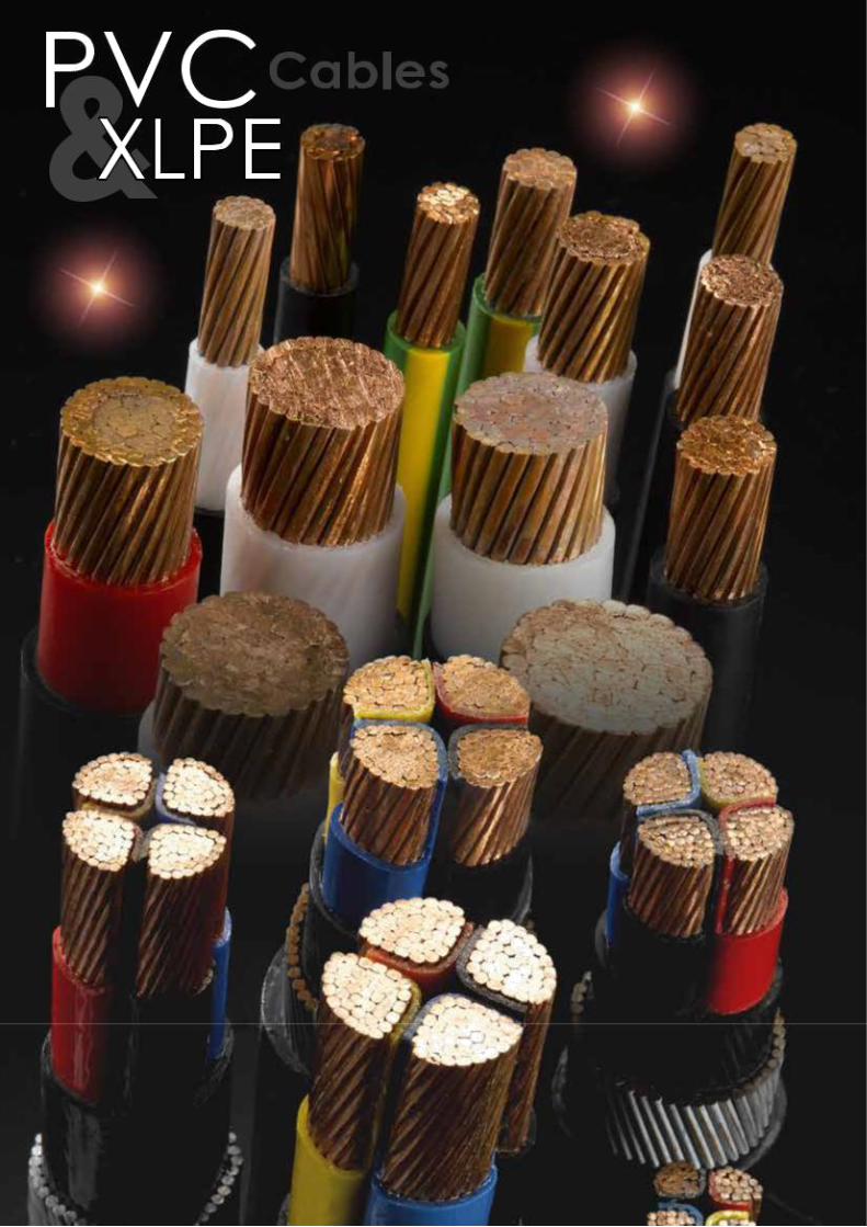
Utama Cables Sdn. Bhd. manufactures and markets a totally integrated line of Low Voltage of
Polyvinyl Chloride (PVC) and Cross-Linked Polyethylene (XLPE) cables suitable for a wide variety of
application, locally and globally.
Our cables are manufactured to meet the stringent standards of quality, performance and
functionality, with the ultimate goal of customer’s satisfaction.
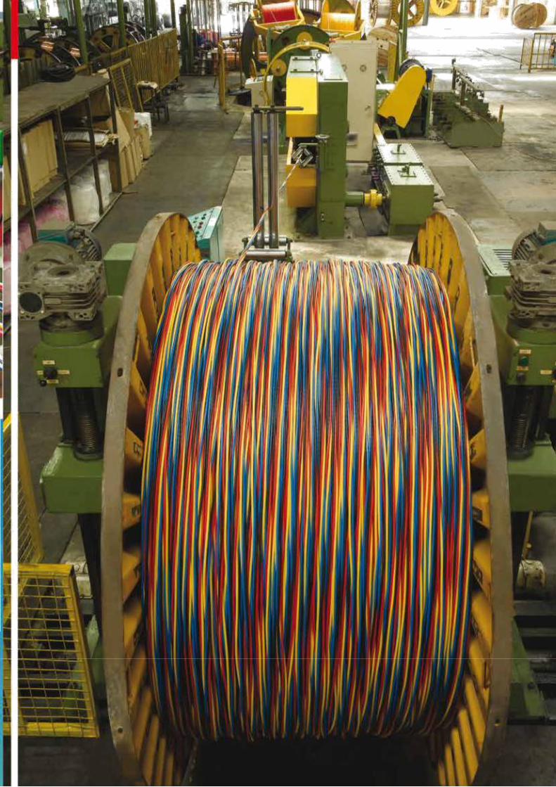
It has long been capital invested by the company to upgrade and purchasing of new, advanced
and sophiscated machinery in order to enhance our productions to meet up with the relevant
authority’s respective standards.
Our specifications are complied to British Standards (BS), Malaysian Standard (MS), and
International Electro-Technical Commission (IEC).
Our products has seek the approvals from the authority like SIRIM QAS International (SIRIM),
Suruhanjaya Tenaga (ST) and Jabatan Kerja Raya (JKR). Subsequent and special tests can also be
arranged outside Malaysia like PSB Corporation of Singapore.
Our factory is most strategically located in Merlimau Industrial Estate, Malacca linked by
expressways to market centers and ports around the country for prompt delivery and overseas
shipments. Our overseas markets so far are Singapore, Indonesia, Thailand, Myanmar, Cambodia.
Our Company Machine & Technical Supports OUR PRODUCTS Product Certifications Marketing & Logistic Supports
PVC INSULATED POWER CABLES ( Non-Armoured )
- For Electric POWER & LIGHTING
GUIDE TO THE USE OF PVC INSULATED CABLES
TECHNICAL DATA - CURRENT RATING
PVC NON-ARMOURED MULTI-CORE ( COPPER )
PVC NON-ARMOURED SINGLE-CORE ( COPPER )
METHODS OF INSTALLATION OF CABLES
PVC INSULATED CABLES FOR ELECTRIC SUPPLY
TECHNICAL DATA - CURRENT RATING
ALLOWABLE SHORT CIRCUIT CURRENT FOR PVC INSULATED CABLES
TECHNICAL DATA
xlpe introduction
construction of xlpe cables
cable structural description & construction data ( armoured & non-armoured )
PERMISSIBLE short circuit currentS
short circuit current rating - aluminium conductors short
circuit current rating - copper conductors construction of
xlpe cables
technical data, continuous current carrying capacity handling
& installation of xlpe cables technical data - wire gauges
APPENDIX TECHNICAL DATA COMMON CONVERSION FACTOR
AERIAL BUNDLED CABLES
1. INTRODUCTION
2. LOW VOLTAGE CONSTRUCTION
2.1 CONDUCTORS
2.2 INSULATION
2.3 TESTS
2.4 SHORT CIRCUIT RATING
2.5 SAG AND TENSION
3. TECHNICAL PARTICULARS FOR AERIAL BUNDLED CABLES
BARE ALUMINIUM CONDUCTOR
- STRANDED ALUMINIUM CONDUCTOR
- ALL ALUMINIUM CONDUCTOR - AAC
- ALL ALUMINIUM ALLOY CONDUCTOR - AAAC
- ALUMINIUM CONDUCTOR STEEL REINFORCED - ACSR
1 - 2 3 - 4 5 - 6 7 - 8 9 -10
11 - 19
20 21
22
23
24 - 25 26 - 38 39 - 45
46
47 - 49
50 51 - 52
53 - 63 64 65 66
67
68 - 70 71
72 - 73 74
75 76
77 - 82
83 - 84
85 - 87


SIRIM LICENCE AWARDS 12
1. MS 136 : 1995
MS 2112-3 : 2009
MS 2112-4 : 2009
PVC INSULATED CABLES FOR
ELECTRIC POWER AND LIGHTING
( NON-ARMOURED )
2. MS 274 : 1995
BS 6346 : 1997
PVC INSULATED CABLES FOR
ELECTRICITY SUPPLY
( NON-ARMOURED / ARMOURED )
3. IEC 60502-1 : 2004
MS 2104 : 2007
MS 2105 : 2007
MS 2106 : 2007
MS 2107 : 2007
XLPE POWER CABLES
( NON-ARMOURED / ARMOURED )
13 PVC power CABLES
P V C I N S U L A T E D C A B L E S
( N O N - A R M O U R E D )
F O R E L E C T R I C
P O W E R & L I G H T I N G
TO MS 2112-3 : 2009 (BS 6004 & MS 136)

PVC INSULATED CABLE 14
CONSTRUCTION
Conductor Plain annealed copper
Insulation General purpose PVC compound PVC/C-70
Colour of cores Red, Black or other colours
PVC INSULATED CABLE MS 2112-3 : 2009
(BS 6004 & MS 136, 450/750V)
Nominal Number/ Thickness Approx. Approx.
area Wire of insulation Overall weight
diameter diameter
of wires
mm2 No./mm mm mm kg/km
1.5 1/1.38 0.7 2.9 21
1.5 7/0.53 0.7 3.1 23
2.5 1/1.78 0.8 3.5 33
2.5 7/0.67 0.8 3.7 35
4 7/0.85 0.8 4.3 51
6 7/1.04 0.8 4.8 72
10 7/1.35 1.0 6.2 120
16 7/1.70 1.0 7.2 180
25 7/2.14 1.2 8.9 283
35 19/1.53 1.2 10.2 280
50 19/1.78 1.4 11.9 510
70 19/2.14 1.4 13.7 720
95 19/2.52 1.6 16.0 990
120 37/2.03 1.6 17.6 1230
150 37/2.25 1.8 19.6 1520
185 37/2.52 2.0 21.9 1900
240 61/2.25 2.2 25.0 2500
300 61/2.52 2.4 27.8 3130
400 61/2.85 2.6 31.2 3980
500 61/3.20 2.8 34.7 4990
630 61/3.65 2.8 38.7 6380

15 PVC INSULATED CABLE
CONSTRUCTION
Conductor Plain Annealed copper
Insulation General purpose PVC compound PVC/C-70
Colour of cores Red, Black or other colours
PVC INSULATED CABLE SINGLE CORE
FLEXIBLE CONDUCTOR CABLES
MS 2112-3 : 2009 (MS 136, 450/750V)
Nominal Nominal No./ Maximum Radial Overall Approx.
area Nominal diameter of thickness of diameter weight
diameter wires insulation
of wire
mm2 mm mm mm mm kg/km
1.5 30/0.20 0.26 0.7 3.1 25
2.5 50/0.25 0.26 0.8 3.7 35
4.0 56/0.30 0.31 0.8 4.5 55
6.0 84/0.30 0.31 0.8 4.8 75
10.0 80/0.40 0.41 1.0 6.2 120
16.0 126/0.40 0.41 1.0 7.2 180
25.0 196/0.40 0.41 1.2 9.0 285
35.0 276/0.40 0.41 1.2 10.5 283
50.0 397/0.40 0.41 1.4 12.0 510
70.0 360/0.50 0.51 1.4 14.0 720
95.0 475/0.50 0.51 1.6 16.5 990
120.0 608/0.50 0.51 1.6 18.0 1230
150.0 756/0.50 0.51 1.8 20.0 1520
185.0 925/0.50 0.51 2.0 22.0 1900
240.0 1221/0.50 0.51 2.2 25.50 2500

PVC INSULATED CABLE 16
CONSTRUCTION
Conductor Plain annealed copper
Insulation General purpose PVC compound PVC/C-70
Colour of cores Red, Black or other colours
PVC INSULATED CABLE SINGLE CORE
FOR INTERNAL WIRING
MS 2112-3 : 2009 (MS 136, 300/500V)
Nominal Number/ Thickness Approx. Approx.
area Wire of insulation overall weight
diameter diameter
of wires
mm2 No./mm mm mm kg/km
0.5 1/0.8 0.6 2.2 8.9
0.75 1/0.98 0.6 2.4 11.8
1.0 1/1.13 0.6 2.5 14.2
1.25 3/0.73 0.7 3.2 20.6
17 PVC INSULATED PVC SHEATHED NON-ARMOURED CABLE
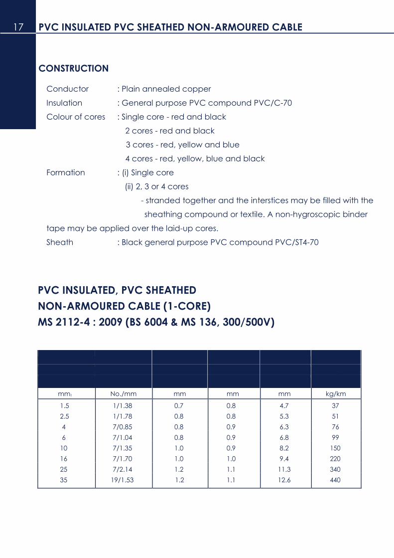
CONSTRUCTION
Conductor : Plain annealed copper
Insulation : General purpose PVC compound PVC/C-70
Colour of cores : Single core - red and black
2 cores - red and black
3 cores - red, yellow and blue
4 cores - red, yellow, blue and black
Formation : (i) Single core
(ii) 2, 3 or 4 cores
- stranded together and the interstices may be filled with the
sheathing compound or textile. A non-hygroscopic binder
tape may be applied over the laid-up cores.
Sheath : Black general purpose PVC compound PVC/ST4-70
PVC INSULATED, PVC SHEATHED
NON-ARMOURED CABLE (1-CORE)
MS 2112-4 : 2009 (BS 6004 & MS 136, 300/500V)
Nominal Number/ Thickness Thickness Approx. Approx.
area Wire of insulation of sheath Overall weight
diameter diameter
mm2 No./mm mm mm mm kg/km
1.5 1/1.38 0.7 0.8 4.7 37
2.5 1/1.78 0.8 0.8 5.3 51
4 7/0.85 0.8 0.9 6.3 76
6 7/1.04 0.8 0.9 6.8 99
10 7/1.35 1.0 0.9 8.2 150
16 7/1.70 1.0 1.0 9.4 220
25 7/2.14 1.2 1.1 11.3 340
35 19/1.53 1.2 1.1 12.6 440
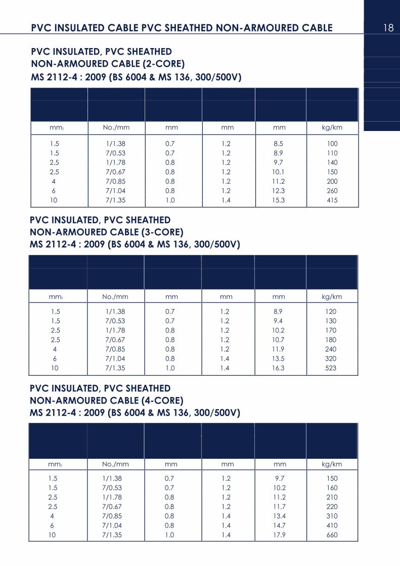
PVC INSULATED CABLE PVC SHEATHED NON-ARMOURED CABLE 18
PVC INSULATED, PVC SHEATHED
NON-ARMOURED CABLE (2-CORE)
MS 2112-4 : 2009 (BS 6004 & MS 136, 300/500V)
Nominal Number/ Thickness Thickness Approx. Approx.
area Wire of insulation of sheath Overall weight
diameter diameter
mm2 No./mm mm mm mm kg/km
1.5 1/1.38 0.7 1.2 8.5 100
1.5 7/0.53 0.7 1.2 8.9 110
2.5 1/1.78 0.8 1.2 9.7 140
2.5 7/0.67 0.8 1.2 10.1 150
4 7/0.85 0.8 1.2 11.2 200
6 7/1.04 0.8 1.2 12.3 260
10 7/1.35 1.0 1.4 15.3 415
PVC INSULATED, PVC SHEATHED
NON-ARMOURED CABLE (3-CORE)
MS 2112-4 : 2009 (BS 6004 & MS 136, 300/500V)
Nominal Number/ Thickness Thickness Approx. Approx.
area Wire of insulation of sheath Overall weight
diameter diameter
mm2 No./mm mm mm mm kg/km
1.5 1/1.38 0.7 1.2 8.9 120
1.5 7/0.53 0.7 1.2 9.4 130
2.5 1/1.78 0.8 1.2 10.2 170
2.5 7/0.67 0.8 1.2 10.7 180
4 7/0.85 0.8 1.2 11.9 240
6 7/1.04 0.8 1.4 13.5 320
10 7/1.35 1.0 1.4 16.3 523
PVC INSULATED, PVC SHEATHED
NON-ARMOURED CABLE (4-CORE)
MS 2112-4 : 2009 (BS 6004 & MS 136, 300/500V)
Nominal Number/ Thickness Thickness Approx. Approx.
area Wire of insulation of sheath Overall weight
diameter diameter
mm2 No./mm mm mm mm kg/km
1.5 1/1.38 0.7 1.2 9.7 150
1.5 7/0.53 0.7 1.2 10.2 160
2.5 1/1.78 0.8 1.2 11.2 210
2.5 7/0.67 0.8 1.2 11.7 220
4 7/0.85 0.8 1.4 13.4 310
6 7/1.04 0.8 1.4 14.7 410
10 7/1.35 1.0 1.4 17.9 660

19 PVC INSULATED PVC SHEATHED CABLE
CONSTRUCTION
Conductor Plain annealed copper
Insulation General purpose PVC compound TI 1 70°C
Sheath Black general purpose PVC compound TM1 70°C
Colour of cores White with numbering
PVC INSULATED, PVC SHEATHED NON-ARMOURED CABLE
(MULTI CORE) AUXILIARY
(BS 6004 & MS 136, 300/500V)
Number Cross- Number/ Thickness Thickness Approx. Approx.
of sectional Nominal of of overall weight
cores area Diameter insulation sheath diameter
of wires
mm2 mm mm mm mm kg/km
7 1.5 1/1.38 0.7 1.2 11.6 215
7 1.5 7/0.53 0.7 1.2 12.2 235
10 1.5 1/1.38 0.7 1.3 15.1 325
10 1.5 7/0.53 0.7 1.3 15.8 340
12 1.5 1/1.38 0.7 1.3 15.2 355
12 1.5 7/0.53 0.7 1.3 16.1 370
19 1.5 1/1.38 0.7 1.3 18.0 530
19 1.5 7/0.53 0.7 1.4 19.0 555
27 1.5 1/1.38 0.7 1.4 21.6 730
27 1.5 7/0.53 0.7 1.5 22.9 770
37 1.5 1/1.38 0.7 1.5 24.0 985
37 1.5 7/0.53 0.7 1.6 25.8 1030
7 2.5 1/1.78 0.8 1.3 13.2 315
7 2.5 7/0.67 0.8 1.3 13.7 330
10 2.5 1/1.78 0.8 1.4 17.0 440
10 2.5 7/0.67 0.8 1.4 17.8 460
12 2.5 1/1.78 0.8 1.4 17.0 500
12 2.5 7/0.67 0.8 1.4 18.0 535
19 2.5 1/1.78 0.8 1.5 20.6 760
19 2.5 7/0.67 0.8 1.5 21.5 800
27 2.5 1/1.78 0.8 1.6 25.5 1090
27 2.5 7/0.67 0.8 1.6 26.0 1140
37 2.5 1/1.78 0.8 1.7 27.5 1440
37 2.5 7/0.67 0.8 1.7 28.8 1500
7 4 7/0.85 0.8 1.4 16.0 515
10 4 7/0.85 0.8 1.5 20.2 680
12 4 7/0.85 0.8 1.5 20.8 800

Guide to the use of PVC - INSULATED cables 20
The cables are suitable for use where the combination ambient temperature and
temperature rise due to load results in a conductor temperature not exceeding
70°C and case of a short-circuit (maximum allowance time is 5 seconds) the
maximum conductor temperature does not exceed 160°C, up to and including 200
sq. mm. and 140°C for sizes above 300 sq. mm.
CABLE TYPE AND USE COMMENTS
Single core, non-sheathed
general purpose.
Installation in surface mounted or Suitable for use in channels with cover.
embedded Suitable for fixed protected installation in
conduits or similar closed systems. or lighting fittings and inside
appliances, up to 1000V ac or up to
750 V to earth, dc.
Single core, non-sheathed,
for internal wiring
Fixed protected installation. Inside Suitable for installation in surface mounted
appliances and in or on lighting fittings or embedded conduits, only for signalling
or control circuits.
Light PVC- sheathed
Fixed installation in dry or damp premises. Unsuitable for outdoor use or
embedding in concrete.
Single core, flat twin and flat 3-core,
PVC-sheathed, with and without
protective conductor.
Fixed installation in dry or damp premises. Suitable for installation in walls, on boards
and in channels, or embedded in plaster.

21 Te ch ni c al data Current Rating
Current rating are based on the following condition
1) Ambient air temperature 30°C
2) Max. conductor operating temperature 70°C
Rating Factors
For Ambient Temperature
25° 30°
35°
40°
45°
50° 55°
60° 65°
Factor (General purpose
1.03 1
0.97
0.94
0.91
0.87 0.84
0.69 0.48
PVC Insulation)
FOR GROUPS
Correction factor (c)
Reference method of installation Number of circuits or multicore cables
2 3 4 5 6 7 8 9 10 12 14 16 18 20
Enclosed bunched and clipped direct to 0.80 0.70 0.65 0.60 0.57 0.54 0.52 0.50 0.48 0.45 0.43 0.41 0.39 0.38
a non- metallic surface
Single layer clipped to Touching 0.85 0.79 0.75 0.73 0.72 0.72 0.71 0.70 - - - - -
a non-metallic surface
Spaced* 0.94 0.90 0.90 0.90 0.90 0.90 0.90 0.90 0.90 0.90 0.90 0.90 0.90 0.90
Single layer multicore on a perforated metal Touching 0.86 0.81 0.77 0.75 0.74 0.73 0.73 0.72 0.71 0.70 - - - -
cable tray, vertical or Spaced* 0.91 0.89 0.88 0.87 0.87 - - - - - - - - -
horizontal
Single layer single- Horizontal 0.90 0.85 - - - - - - - - - - - - core on a perforated
metal cable Vertical 0.85 - - - - - - -
- - - - - - tray, touching
Single layer multicore touching on 0.86 0.82 0.80 0.79 0.78 0.78 0.78 0.77 ladder supports
* ‘Space’ means a clearance between adjacent surfaces of at least one cable diameter (D)
Where the horizontal clearances between adjacent cables exceeds 2D, no correction
factor need to be applied.
Notes 1. The factors in the table are applicable to groups of cables all of one size. The value of current derived from application of the appropriate factors is the maximum continuous current to be carried by any of the cables in the group.
2. If, due to known operating conditions, a cable is expected to carry not more than 30% of
its grouped rating, it may be ignored for the purpose of obtaining the rating factor for
the rest of the group.

PVC Non-Armoured Multi-Core (1.0mm2 To 400mm2 ) -Copper 22
The ratings tabulated apply where the cable is provided with close excess-current
production
Conductor Laid on cable tray Clipped direct to a non-metallic surface
2 core 3 or 4 core 2 core 3 or 4 core
single-phase, ac or dc 3-phase, ac single-phase, ac or dc three-phase, ac
Nominal
cross- Volt drop Volt drop Volt drop Volt drop
sectional No. and dia. Current per ampere Current per ampere Curent per ampere Current per ampere
area (mm) of wires rating per metre rating per metre rating per metre rating per metre
1 2 3 4 5 6 7 8 9 10
mm2 A mV/A/m A mV/A/m A mV/A/m A mV/A/m
1.0 1/1.13 17 44 14.5 38 15 44 13.5 38
{1/1.38}
1.5 {7/0.53} 22 29 18.5 25 19.5 29 17.5 25
{1/1.78}
2.5 {7/0.67} 30 18 25 15 27 18 24 15
4 7/0.85 40 11 34 9.5 36 11 32 9.5
6 7/1.04 51 7.3 43 6.4 46 7.3 41 6.4
10 7/1.35 70 4.4 60 3.8 63 4.4 57 3.8
16 7/1.70 76 2.8 68 2.4 87 2.8 79 2.4
25 7/2.14 119 1.75 101 1.5 112 1.75 1.5 1.5
35 19/1.53 148 1.25 126 1.1 138 1.25 119 1.1
ac dc ac dc
50 19/1.78 180 0.94 0.93 153 0.81 168 0.94 0.93 144 0.81
70 19/2.14 232 0.65 0.63 196 0.57 213 0.65 0.63 223 0.57
95 19/2.52 282 0.50 0.46 238 0.43 258 0.50 0.46 223 0.43
120 37/2.03 328 0.41 0.36 276 0.35 299 0.41 0.36 259 0.35
150 37/2.25 379 0.34 0.29 319 0.29 344 0.34 0.29 299 0.29
185 37/2.52 434 0.29 0.23 364 0.25 392 0.29 0.23 341 0.25
240 61/2.25 514 0.24 0.18 430 0.21 461 0.24 0.18 403 0.21
300 61/2.52 593 0.21 0.145 497 0.185 530 0.21 0.145 464 0.185
400 61/2.85 715 0.185 0.105 597 0.160 634 0.185 0.105 557 0.160

23 PVC, Non-Armoured SINGLE-Core (1.0mm2 To 630mm2) -Copper
The ratings tabulated apply where the cable is provided with close excess-current
production
Conductor Enclosed in Conduit or Trunking Cables Clipped direct to a non-metallic surface
2 Cables 3 or 4 Cables 2 Cables 3 or 4 Cables
single-phase Three-phase single-phase three-phase
Nominal
cross- Volt drop Volt drop Volt drop Volt drop
sectional No. and dia. Current per ampere Current per ampere Curent per ampere Current per ampere
area (mm) of wires rating per metre rating per metre rating per metre rating per metre
1 2 3 4 5 6 7 8 9 10
mm2 A mV/A/m A mV/A/m A mV/A/m A mV/A/m
1.0 1/1.13 13.5 44 12 38 15.5 44 14 38
{1/1.38}
1.5 {7/0.53} 17.5 29 15.5 25 20 29 18 25
{1/1.78}
2.5 {7/0.67} 24 18 21 15 27 18 25 15
4 7/0.85 32 11 28 9.5 37 11 33 9.5
6 7/1.04 41 7.3 36 6.4 47 7.3 43 6.4
10 7/1.35 57 4.4 50 3.8 65 4.4 59 3.8
16 7/1.70 76 2.8 68 2.4 87 2.8 79 2.4
ac dc
25 7/2.14 101 1.8 1.75 89 1.55 114 1.75 104 1.5
35 19/1.53 125 1.3 1.25 110 1.1 141 1.25 129 1.1
ac dc
50 19/1.78 151 1.1 0.93 134 0.85 182 0.95 0.93 167 0.82
70 19/2.14 192 0.72 0.63 171 0.61 234 0.66 0.63 214 0.57
95 19/2.52 232 0.56 0.46 207 0.48 284 0.50 0.46 261 0.43
120 37/2.03 269 0.47 0.36 239 0.41 330 0.41 0.36 303 0.36
150 37/2.25 300 0.41 0.29 262 0.36 381 0.34 0.29 349 0.3
185 37/2.52 341 0.37 0.23 296 0.32 436 0.29 0.23 400 0.26
240 61/2.25 400 0.33 0.18 346 0.29 515 0.25 0.18 472 0.22
300 61/2.52 458 0.31 0.145 394 0.27 594 0.22 0.145 545 0.19
400 61/2.85 546 0.29 0.105 467 0.25 694 0.2 0.105 634 0.175
500 61/3.20 626 0.28 0.086 533 0.25 792 0.185 0.086 723 0.16
630 61/3.65 720 0.27 0.068 611 0.24 904 0.175 0.068 826 0.15

Me tho d s of Installation of Cables 24
Installation Method Examples Appropriate Reference
Number Description Method for determining current-carrying
capacities
1 2 3 4
Open and clipped direct:
1 Sheathed cables Method 1 clipped direct to or
lying on a non-metallic
surface
In conduit :
3 Single-core non-sheathed Method 3 cables in metallic or non-
metallic conduit on
a wall or ceiling
5 Multicore cables having Method 3 non-metallic sheath, in
metallic or non-metallic
conduit on a wall or
ceiling
In trunking :
8 Cables in trunking on a Method 3
wall or suspended in air
9 Cables in flush floor Method 3
trunking
10 Single-core cables in Method 3
skirting trunking
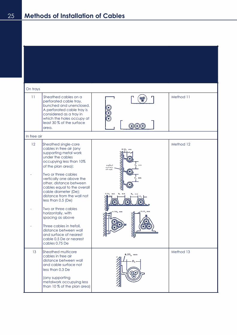
25 Methods of Installation of Cables
Installation Method Examples Appropriate Reference
Number Description Method for determining current-carrying
capacities
1 2 3 4
On trays
11 Sheathed cables on a Method 11 perforated cable tray,
bunched and unenclosed.
A perforated cable tray is
considered as a tray in
which the holes occupy at
least 30 % of the surface
area.
In free air
12 Sheathed single-core Method 12 cables in free air (any
supporting metal work
under the cables
occupying less than 10%
of the plan area):
- Two or three cables
vertically one above the
other, distance between
cables equal to the overall
cable diameter (De);
distance from the wall not
less than 0.5 (De)
- Two or three cables
horizontally, with spacing as above
- Three cables in trefoll,
distance between wall
and surface of nearest
cable 0.5 De or nearest cables 0.75 De
13 Sheathed multicore Method 13
cables in free air
distance between wall
and cable surface not
less than 0.3 De
(any supporting
metalwork occupying less than 10 % of the plan area)

Pvc power CABLES 26
P V C I N S U L A T E D C A B L E S
F O R E L E C T R I C S U P P L Y
T O B S 6 3 4 6 & M S 2 7 4

27 PVC INSULATED PVC sheathed NON-armoured cable
CONSTRUCTION
Conductor Plain annealed copper
Insulation General purpose PVC compound TI 1 70°C
Colour of cores Single core - red and black
2 cores - red and black
3 cores - red, yellow and blue
4 cores - red, yellow, blue and black
Formation (i) Single core
(ii) 2, 3 or 4 cores
- stranded together and the interstices may be filled with
the sheathing compound or textile. A non-hygroscopic
binde tape may be applied over the laid-up cores.
Sheath Black general purpose PVC compound TM1 70°C
PVC INSULATED, PVC SHEATHED
NON-ARMOURED CABLE (1-CORE)
(BS 6346 & MS 274, 600/1000V)
Nominal Number/ Thickness Thickness Approx. Approx.
area Wire of insulation of sheath Overall weight
diameter diameter
mm2 No./mm mm mm mm kg/km
50 19/1.78 1.4 1.4 14.9 610
70 19/2.14 1.4 1.4 16.9 830
95 19/2.52 1.6 1.5 19.2 1130
120 37/2.03 1.6 1.5 20.8 1380
150 37/2.25 1.8 1.6 23.0 1690
185 37/2.52 2.0 1.7 25.5 2100
240 61/2.25 2.2 1.8 28.8 2740
300 61/2.52 2.4 1.9 31.8 3410
400 61/2.85 2.6 2.0 35.4 4310
500 61/3.20 2.8 2.1 39.1 5380
630 61/3.65 2.8 2.2 43.3 6820
800 127/2.85 2.8 2.3 47.8 8590
1000 127/3.20 3.0 2.5 53.1 10760
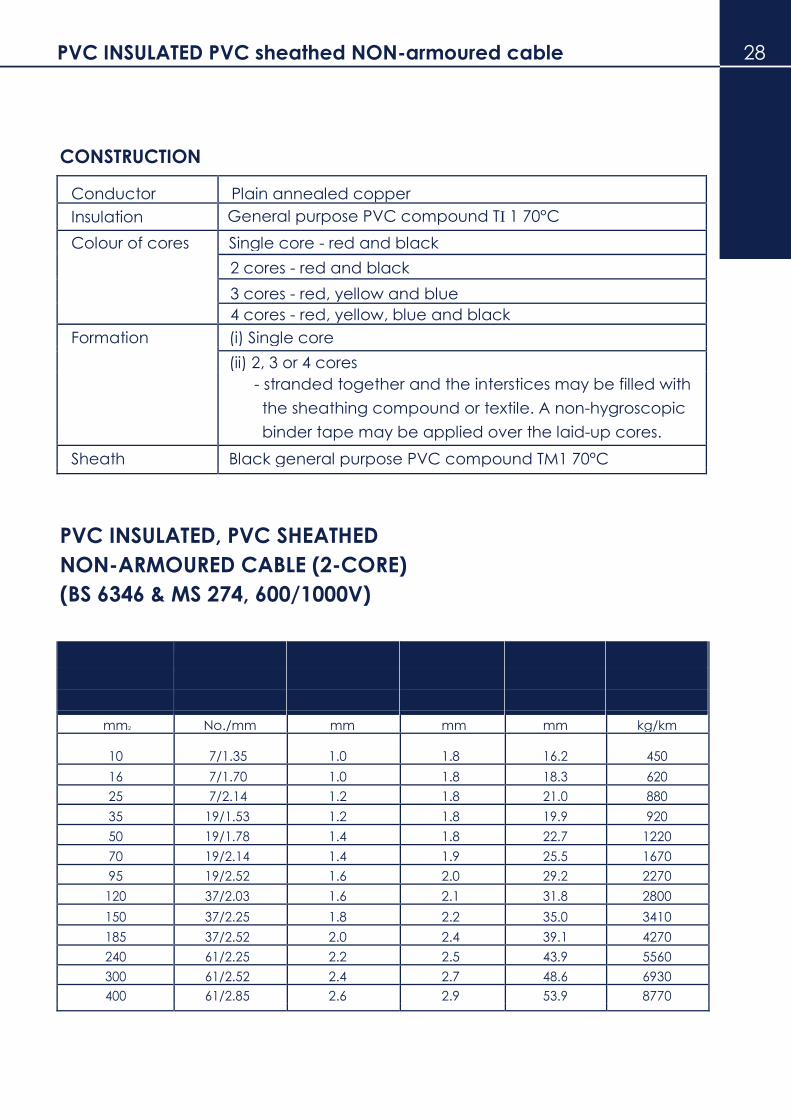
PVC INSULATED PVC sheathed NON-armoured cable 28
CONSTRUCTION
Conductor Plain annealed copper
Insulation General purpose PVC compound TI 1 70°C
Colour of cores Single core - red and black
2 cores - red and black
3 cores - red, yellow and blue
4 cores - red, yellow, blue and black
Formation (i) Single core
(ii) 2, 3 or 4 cores
- stranded together and the interstices may be filled with
the sheathing compound or textile. A non-hygroscopic
binder tape may be applied over the laid-up cores.
Sheath Black general purpose PVC compound TM1 70°C
PVC INSULATED, PVC SHEATHED
NON-ARMOURED CABLE (2-CORE)
(BS 6346 & MS 274, 600/1000V)
Nominal Number/ Thickness Thickness Approx. Approx.
area Wire of insulation of sheath Overall weight
diameter diameter
mm2 No./mm mm mm mm kg/km
10 7/1.35 1.0 1.8 16.2 450
16 7/1.70 1.0 1.8 18.3 620
25 7/2.14 1.2 1.8 21.0 880
35 19/1.53 1.2 1.8 19.9 920
50 19/1.78 1.4 1.8 22.7 1220
70 19/2.14 1.4 1.9 25.5 1670
95 19/2.52 1.6 2.0 29.2 2270
120 37/2.03 1.6 2.1 31.8 2800
150 37/2.25 1.8 2.2 35.0 3410
185 37/2.52 2.0 2.4 39.1 4270
240 61/2.25 2.2 2.5 43.9 5560
300 61/2.52 2.4 2.7 48.6 6930
400 61/2.85 2.6 2.9 53.9 8770

29 PVC INSULATED PVC sheathed NON-armoured cable
CONSTRUCTION
Conductor Plain annealed copper
Insulation General purpose PVC compound TI 1 70°C
Colour of cores Single core - red and black
2 cores - red and black
3 cores - red, yellow and blue
4 cores - red, yellow, blue and black
Formation (i) Single core
(ii) 2, 3 or 4 cores
- stranded together and the interstices may be filled with
the sheathing compound or textile. A non-hygroscopic
binder tape may be applied over the laid-up cores.
Sheath Black general purpose PVC compound TM1 70°C
PVC INSULATED, PVC SHEATHED
NON-ARMOURED CABLE (3-CORE)
(BS 6346 & MS 274, 600/1000V)
Nominal Number/ Thickness Thickness Approx. Approx.
area Wire of insulation of sheath Overall weight
diameter diameter
mm2 No./mm mm mm mm kg/km
10 7/1.35 1.0 1.8 17.2 530
16 7/1.70 1.0 1.8 19.4 750
25 7/2.14 1.2 1.8 22.3 1090
35 19/1.53 1.2 1.8 22.8 1360
50 19/1.78 1.4 1.8 26.1 1810
70 19/2.14 1.4 1.9 29.5 2480
95 19/2.52 1.6 2.1 34.1 3390
120 37/2.03 1.6 2.2 37.1 4180
150 37/2.25 1.8 2.3 40.9 5110
185 37/2.52 2.0 2.5 45.7 6410
240 61/2.25 2.2 2.6 51.4 8360
300 61/2.52 2.4 2.8 57.0 10420
400 61/2.85 2.6 3.1 63.6 13210

PVC INSULATED PVC sheathed NON-armoured cable 30
CONSTRUCTION
Conductor Plain annealed copper
Insulation General purpose PVC compound TI 1 70°C
Colour of cores Single core - red and black
2 cores - red and black
3 cores - red, yellow and blue 4 cores - red, yellow, blue and black
Formation (i) Single core
(ii) 2, 3 or 4 cores
- stranded together and the interstices may be filled with
the sheathing compound or textile. A non-hygroscopic
binder tape may be applied over the laid-up cores.
Bedding Black general purpose PVC compound
Armour Single core - Aluminium wire
2, 3 or 4 cores - Galvanised steel wire
Sheath Black general purpose PVC compound TM1 70°C
PVC INSULATED, PVC SHEATHED
NON-ARMOURED CABLE (4-CORE)
(BS 6346 & MS 274, 600/1000V)
Nominal Number/ Thickness Thickness Approx. Approx.
area Wire of insulation of sheath Overall weight
diameter diameter
mm2 No./mm mm mm mm kg/km
10 7/1.35 1.0 1.8 18.7 700
16 7/1.70 1.0 1.8 21.3 960
25 7/2.14 1.2 1.8 24.5 1400
35 19/1.53 1.2 1.8 25.6 1820
50 19/1.78 1.4 1.9 29.6 2450
70 19/2.14 1.4 2.0 33.5 3350
95 19/2.52 1.6 2.2 38.7 4580
120 37/2.03 1.6 2.3 42.1 5630
150 37/2.25 1.8 2.5 46.6 6920
185 37/2.52 2.0 2.6 51.9 8640
240 61/2.25 2.2 2.8 58.6 11290
300 61/2.52 2.4 3.1 65.3 14110
400 61/2.85 2.6 3.3 72.6 17860

31 PVC INSULATED PVC sheathed armoured cable
CONSTRUCTION
Conductor Plain annealed copper
Insulation General purpose PVC compound TI 1 70°C
Colour of cores Single core - red and black
2 cores - red and black
3 cores - red, yellow and blue
4 cores - red, yellow, blue and black
Formation (i) Single core
(ii) 2, 3 or 4 cores
- stranded together and the interstices may be filled with
the sheathing compound or textile. A non-hygroscopic
binder tape may be applied over the laid-up cores.
Bedding Black general purpose PVC compound
Armour Single core - Aluminium wire
2, 3 or 4 cores - Galvanised steel wire
Sheath Black general purpose PVC compound TM1 70°C
PVC INSULATED, PVC SHEATHED
ARMOURED CABLE (1-CORE)
(BS 6346 & MS 274, 600/1000V)
Nominal Number/ Thickness Thickness Diameter of Thickness Approx. Approx. area Wire of insulation of bedding armour wire of sheath Overall weight
diameter diameter
mm2 No./mm mm mm mm mm mm kg/km
50 19/1.78 1.4 0.8 1.25 1.5 19.4 840
70 19/2.14 1.4 0.8 1.25 1.6 21.4 1090 95 19/2.52 1.6 0.8 1.25 1.6 23.7 1410
120 37/2.03 1.6 1.0 1.6 1.7 26.6 1790
150 37/2.25 1.8 1.0 1.6 1.7 28.6 2120 185 37/2.52 2.0 1.0 1.6 1.8 31.1 2580
240 61/2.25 2.2 1.0 1.6 1.9 34.4 3270
300 61/2.52 2.4 1.0 1.6 1.9 37.2 3970
400 61/2.85 2.6 1.2 2.0 2.1 42.2 5110
500 61/3.20 2.8 1.2 2.0 2.1 45.7 5230 630 61/3.65 2.8 1.2 2.0 2.2 49.9 7760
800 127/2.85 2.8 1.4 2.5 2.4 55.9 9890
1000 127/3.20 3.0 1.4 2.5 2.5 61.1 12180

PVC INSULATED PVC sheathed armoured cable 32
CONSTRUCTION
Conductor Plain annealed copper
Insulation General purpose PVC compound TI 1 70°C
Colour of cores Single core - red and black
2 cores - red and black
3 cores - red, yellow and blue
4 cores - red, yellow, blue and black
Formation (i) Single core
(ii) 2, 3 or 4 cores
- stranded together and the interstices may be filled with
the sheathing compound or textile. A non-hygroscopic
binder tape may be applied over the laid-up cores.
Bedding Black general purpose PVC compound
Armour Single core - Aluminium wire
2, 3 or 4 cores - Galvanised steel wire
Sheath Black general purpose PVC compound TM1 70°C
PVC INSULATED, PVC SHEATHED ARMOURED CABLE (2-CORE)
(BS 6346 & MS 274, 600/1000V)
Nominal Number/ Thickness Thickness Diameter of Thickness Approx. Approx. area Wire of insulation of bedding armour wire of sheath Overall weight
diameter diameter
mm2 No./mm mm mm mm mm mm kg/km
1.5 1/1.38 0.6 0.8 0.9 1.3 11.9 290
1.5 7/0.53 0.6 0.8 0.9 1.4 12.5 310
2.5 1/1.78 0.7 0.8 0.9 1.4 13.3 360
2.5 7/0.67 0.7 0.8 0.9 1.4 13.7 380
4 7/0.85 0.8 0.8 0.9 1.4 15.2 460 6 7/1.04 0.8 0.8 0.9 1.5 16.5 550
10 7/1.35 1.0 0.8 1.25 1.6 20.1 870
16 7/1.70 1.0 0.8 1.25 1.6 22.2 1090
25 7/2.14 1.2 1.0 1.6 1.7 26.2 1610
35 19/1.53 1.2 1.0 1.6 1.8 25.3 1690 50 19/1.78 1.4 1.0 1.6 1.9 28.3 2100
70 19/2.14 1.4 1.0 1.6 1.9 30.9 2640
95 19/2.52 1.6 1.2 2.0 2.1 36.0 3680 120 37/2.03 1.6 1.2 2.0 2.2 38.6 4310
150 37/2.25 1.8 1.2 2.0 2.3 41.8 5060
185 37/2.52 2.0 1.4 2.5 2.4 47.1 6570
240 61/2.25 2.2 1.4 2.5 2.5 51.9 8110 300 61/2.52 2.4 1.6 2.5 2.7 57.0 9790
400 61/2.85 2.6 1.6 2.5 2.9 62.3 11940

33 PVC INSULATED PVC sheathed armoured cable
CONSTRUCTION
Conductor Plain annealed copper
Insulation General purpose PVC compound TI 1 70°C
Colour of cores Single core - red and black
2 cores - red and black
3 cores - red, yellow and blue
4 cores - red, yellow, blue and black
Formation (i) Single core
(ii) 2, 3 or 4 cores
- stranded together and the interstices may be filled with
the sheathing compound or textile. A non-hygroscopic
binder tape may be applied over the laid-up cores.
Bedding Black general purpose PVC compound
Armour Single core - Aluminium wire
2, 3 or 4 cores - Galvanised steel wire
Sheath Black general purpose PVC compound TM1 70°C
PVC INSULATED, PVC SHEATHED ARMOURED CABLE (3-CORE)
(BS 6346 & MS 274, 600/1000V)
Nominal Number/ Thickness Thickness Diameter of Thickness Approx. Approx.
area Wire of insulation of bedding armour wire of sheath Overall weight
diameter diameter
mm2 No./mm mm mm mm mm mm kg/km
1.5 1/1.38 0.6 0.8 0.9 1.4 12.3 320 1.5 7/0.53 0.6 0.8 0.9 1.4 12.9 340 2.5 1/1.78 0.7 0.8 0.9 1.4 13.5 380 2.5 7/0.67 0.7 0.8 0.9 1.4 14.3 410
4 7/0.85 0.8 0.8 0.9 1.4 15.9 530
6 7/1.04 0.8 0.8 1.25 1.5 18.0 750 10 7/1.35 1.0 0.8 1.25 1.6 21.1 1020 16 7/1.70 1.0 0.8 1.25 1.6 23.3 1300
25 7/2.14 1.2 1.0 1.6 1.7 27.5 1930 35 19/1.53 1.2 1.0 1.6 1.8 28.2 2230 50 19/1.78 1.4 1.0 1.6 1.9 31.7 2820
70 19/2.14 1.4 1.0 2.0 2.0 36.3 3900
95 19/2.52 1.6 1.2 2.0 2.1 40.7 4990 120 37/2.03 1.6 1.2 2.0 2.2 43.7 5910 150 37/2.25 1.8 1.4 2.5 2.4 49.1 7530
185 37/2.52 2.0 1.4 2.5 2.5 53.7 9060
240 61/2.25 2.2 1.6 2.5 2.6 59.8 11410
300 61/2.52 2.4 1.6 2.5 2.8 65.4 13780
400 61/2.85 2.6 1.6 2.5 3.0 71.8 16860

PVC INSULATED PVC sheathed armoured cable 34
CONSTRUCTION
Conductor Plain annealed copper
Insulation General purpose PVC compound TI 1 70°C
Colour of cores Single core - red and black
2 cores - red and black
3 cores - red, yellow and blue 4 cores - red, yellow, blue and black
Formation (i) Single core
(ii) 2, 3 or 4 cores
- stranded together and the interstices may be filled with
the sheathing compound or textile. A non-hygroscopic
binder tape may be applied over the laid-up cores.
Bedding Black general purpose PVC compound
Armour Single core - Aluminium wire
2, 3 or 4 cores - Galvanised steel wire
Sheath Black general purpose PVC compound TM1 70°C
PVC INSULATED, PVC SHEATHED ARMOURED CABLE (4-CORE)
(BS 6346 & MS 274, 600/1000V)
Nominal Number/ Thickness Thickness Diameter of Thickness Approx. Approx. area Wire of insulation of bedding armour wire of sheath Overall weight
diameter diameter
mm2 No./mm mm mm mm mm mm kg/km
1.5 1/1.38 0.6 0.8 0.9 1.4 13.0 360 1.5 7/0.53 0.6 0.8 0.9 1.4 13.7 380 2.5 1/1.78 0.7 0.8 0.9 1.4 14.6 450
2.5 7/0.67 0.7 0.8 0.9 1.4 15.2 470
4 7/0.85 0.8 0.8 1.25 1.5 17.9 730 6 7/1.04 0.8 0.8 1.25 1.5 19.2 870
10 7/1.35 1.0 0.8 1.25 1.6 22.6 1200
16 7/1.70 1.0 1.0 1.6 1.7 26.5 1770
25 7/2.14 1.2 1.0 1.6 1.8 29.9 2340 35 19/1.53 1.2 1.0 1.6 1.9 31.2 2810
50 19/1.78 1.4 1.2 2.0 2.0 36.4 3880
70 19/2.14 1.4 1.2 2.0 2.1 40.3 4960
95 19/2.52 1.6 1.2 2.0 2.2 45.3 6400
120 37/2.03 1.6 1.4 2.5 2.4 50.3 8110
150 37/2.25 1.8 1.4 2.5 2.5 54.6 9630
185 37/2.52 2.0 1.6 2.5 2.6 60.3 11700
240 61/2.25 2.2 1.6 2.5 2.8 67.0 14750 300 61/2.52 2.4 1.6 2.5 3.0 73.5 17860
400 61/2.85 2.6 1.8 3.15 3.3 82.7 23110

35 PVC INSULATED PVC sheatheD armoured AUXILIARY cable
CONSTRUCTION
Conductor Plain annealed copper
Insulation General purpose PVC compound TI 1 70°C
Colour of cores White with black numbering
Formation Stranded together and the interstices may be filled with the
sheathing compound. A non-hygroscopic binder tape may
be applied over the laid-up cores.
Bedding Black general purpose PVC compound TM1 70°C
Armour Galvanised steel wire
Sheath Black general purpose PVC compound TM1 70°C
PVC INSULATED, PVC SHEATHED
ARMOURED AUXILIARY CABLE (1.5MM2)
(BS 6346 & MS 274, 600/1000V)
Number Nominal Construction Thickness Thickness Diameter Thickness Approx. Approx.
of core sectional Number/ of insulation of Bedding of armour of sheath overall weight
area Wire wire diameter
diameter
mm2 No./mm mm mm mm mm mm kg/km
5 1.5 7/0.53 0.6 0.8 0.9 1.4 14.5 430
7 1.5 7/0.53 0.6 0.8 0.9 1.4 15.4 500
10 1.5 7/0.53 0.6 0.8 1.25 1.5 19.2 780
12 1.5 7/0.53 0.6 0.8 1.25 1.5 18.6 830
19 1.5 7/0.53 0.6 0.8 1.25 1.6 22.3 1090
27 1.5 7/0.53 0.6 1.0 1.6 1.7 26.9 1600
37 1.5 7/0.53 0.6 1.0 1.6 1.8 29.5 1940
48 1.5 7/0.53 0.6 1.0 1.6 1.9 33.1 2360

PVC INSULATED PVC sheatheD armoured AUXILIARY cable 36
PVC INSULATED, PVC SHEATHED
ARMOURED AUXILIARY CABLE (2.5MM2)
(BS 6346 & MS 274, 600/1000V)
Number Nominal Construction Thickness Thickness Diameter Thickness Approx. Approx.
of core sectional Number/ of insulation of Bedding of armour of sheath overall weight
area Wire wire diameter
diameter
mm2 No./mm mm mm mm mm mm kg/km
5 2.5 7/0.67 0.7 0.8 0.9 1.5 16.4 550
7 2.5 7/0.67 0.7 0.8 1.25 1.5 18.1 750
10 2.5 7/0.67 0.7 0.8 1.25 1.6 21.8 1000
12 2.5 7/0.67 0.7 0.8 1.25 1.6 22.4 1080
19 2.5 7/0.67 0.7 1.0 1.6 1.7 26.7 1640
27 2.5 7/0.67 0.7 1.0 1.6 1.8 30.9 2110
37 2.5 7/0.67 0.7 1.0 1.6 1.9 34.1 2600
48 2.5 7/0.67 0.7 1.2 2.0 2.1 39.8 3520
PVC INSULATED, PVC SHEATHED
ARMOURED AUXILIARY CABLE (4MM2)
(BS 6346 & MS 274, 600/1000V)
Number Nominal Construction Thickness Thickness Diameter Thickness Approx. Approx.
of core sectional Number/ of insulation of Bedding of armour of sheath overall weight
area Wire wire diameter
diameter
mm2 No./mm mm mm mm mm mm kg/km
5 4 7/0.85 0.8 0.8 1.25 1.5 19.1 820
7 4 7/0.85 0.8 0.8 1.25 1.6 20.6 970
10 4 7/0.85 0.8 1.0 1.6 1.7 26.1 1500
12 4 7/0.85 0.8 1.0 1.6 1.7 26.8 1630
19 4 7/0.85 0.8 1.0 1.6 1.8 30.6 2170
27 4 7/0.85 0.8 1.2 2.0 2.0 37.2 3170
37 4 7/0.85 0.8 1.2 2.0 2.1 41.0 3910
48 4 7/0.85 0.8 1.2 2.0 2.2 46.1 4790

37 PVC INSULATED PVC sheathed NON-armoured With Reduced Neutral Cable
CONSTRUCTION
Conductor Plain annealed copper
Insulation General purpose PVC compound TI 1 70°C
Colour of cores Red, yellow, blue and black (neutral)
Formation Stranded together and the interstices may be filled with the
sheathing compound or textile. A non-hygroscopic binder
tape may be applied over the laid-up cores.
Sheath Black general purpose PVC compound TM1 70°C
PVC INSULATED, PVC SHEATHED NON-ARMOURED
WITH REDUCED NEUTRAL CABLE (4-core) (BS 6346
& MS 274, 600/1000V)
Phase conductor Neutral conductor
Nominal Construction Thickness Nominal Construction Thickness Thickness Approx. Approx.
sectional Number/ of insulation sectional Number/ of insulation of sheath overall weight
area Wire area Wire diameter
diameter diameter
mm2 No./mm mm mm2 No./mm mm mm mm kg/km
25 7/2.14 1.2 16 7/1.70 1.0 1.8 24.5 1290
35 19/1.53 1.2 16 7/1.70 1.0 1.8 25.6 1650
50 19/1.78 1.4 25 7/2.14 1.2 1.9 29.6 2250
70 19/2.14 1.4 35 19/1.53 1.2 2.0 33.5 3060
95 19/2.52 1.6 50 19/1.78 1.4 2.1 38.5 4150
120 37/2.03 1.6 70 19/2.14 1.4 2.2 41.9 5160
150 37/2.25 1.8 70 19/2.14 1.4 2.4 46.4 6230
185 37/2.52 2.0 95 19/2.52 1.6 2.5 51.7 7850
240 61/2.25 2.2 120 37/2.03 1.6 2.7 58.4 10190
300 61/2.52 2.4 150 37/2.25 1.8 2.9 64.8 12670
300 61/2.52 2.4 185 3/7/2.52 2.0 2.9 64.8 12940
400 61/2.85 2.6 185 37/2.52 2.0 3.2 72.4 16050

PVC INSULATED PVC sheatheD armoured WITH REDUCED NEUTRAL CABLE
38
CONSTRUCTION
Conductor Plain annealed copper
Insulation General purpose PVC compound TI 1 70°C
Colour of cores Red, yellow, blue and black (neutral)
Formation Stranded together and the interstices may be filled with the
sheathing compound or textile. A non-hygroscopic binder
tape may be applied over the laid-up cores.
Sheath Black general purpose PVC compound TM1 70°C
PVC INSULATED, PVC SHEATHED ARMOURED
WITH REDUCED NEUTRAL CABLE (4-core) (BS
6346 & MS 274, 600/1000V)
Phase conductor Neutral conductor
Nominal Construction Thickness Nominal Construction Thickness Thickness Diameter Thickness Approx. Approx.
sectional Number/ of insulation sectional Number/ of insulation of bedding of armour of sheath overall weight
area Wire area Wire Wire diameter
diameter diameter
mm2 No./mm mm mm2 No./mm mm mm mm mm mm kg/km
25 7/2.14 1.2 16 7/1.70 1.0 1.0 1.6 1.8 29.9 2220
35 19/1.53 1.2 16 7/1.70 1.0 1.0 1.6 1.8 31.0 2630
50 19/1.78 1.4 25 7/2.14 1.2 1.0 1.6 1.9 35.0 3370
70 19/2.14 1.4 35 19/1.53 1.2 1.2 2.0 2.0 40.1 4650
95 19/2.52 1.6 50 19/1.78 1.4 1.2 2.0 2.2 45.3 5980
120 37/2.03 1.6 70 19/2.14 1.4 1.4 2.5 2.3 50.1 7630
150 37/2.25 1.8 70 19/2.14 1.4 1.4 2.5 2.4 54.4 7930
185 37/2.52 2.0 95 19/2.52 1.6 1.4 2.5 2.5 59.7 10840
240 61/2.25 2.2 120 37/2.03 1.6 1.6 2.5 2.7 66.8 13640
300 61/2.52 2.4 150 37/2.25 1.8 1.6 2.5 2.9 73.2 16440
300 61/2.52 2.4 185 3/7/2.52 2.0 1.6 2.5 2.9 73.2 16710
400 61/2.85 2.6 185 37/2.52 2.0 1.8 3.15 3.1 82.3 21260


39 Technical data Current Rating
TECHNICAL DATA
Current ratings are based on the following conditions:
1. Ambient air temperature 30°C
2. Ground temperature 15°C
3. Soil thermal resistivity 1.2°C m/w
4. Depth of laying: (a) For 600/1000V cables 0.5m
(b) For 1900/3300V cables 0.8m
5. Maximum conductor operating temperature 70°C
Rating factors of other temperature:
Cable in air
Temperature 25°C 30°C 35°C 40°C 45°C
Factor 1.06 1.00 0.94 0.87 0.79
Cables in ground
Temperature 15°C 20°C 25°C 30°C 35°C
Factor 1.00 0.95 0.90 0.90 0.80
600/1000V COPPER CONDUCTOR
PVC NON-ARMOURED CABLES (SINGLE-CORE)
Clipped direct Laid in free air
Nominal 2 cables, single-phase 3 or 4 cables 2 cables, single-phase 3 cables,
cross ac or dc 3-phase, ac 3 cables, 3-phase ac 3-phase
sectional Horizontal flat spaced ac trefoil
area of Current Volt Current Volt Current Volt Current Volt
conductor rating drop rating drop rating drop rating drop
mm2 A mV/A/m A mV/A/m A mV/A/m A mV/A/m
50 182 0.95 167 0.82 219 0.97 167 0.82
70 234 0.66 214 0.57 281 0.69 216 0.57
95 284 0.50 261 0.43 341 0.54 264 0.43
120 330 0.41 303 0.36 396 0.45 308 0.36
150 381 0.34 349 0.30 456 0.39 356 0.30
185 436 0.29 400 0.26 521 0.35 409 0.26
240 515 0.25 472 0.22 615 0.31 485 0.22
300 594 0.22 545 0.19 709 0.29 561 0.19
400 694 0.20 634 0.175 852 0.27 656 0.18
500 792 0.185 723 0.16 982 0.26 749 0.16
630 904 0.175 826 0.15 1138 0.25 855 0.15
800 1030 0.165 943 0.145 1265 0.25 971 0.15
1000 1154 0.16 1058 0.14 1420 0.24 1079 0.14

Technical data Current Rating 40
Current ratings are based on the following conditions:
1. Ambient air temperature 30°C
2. Ground temperature 15°C
3. Soil thermal resistivity 1.2°C m/w
4. Depth of laying: (a) For 600/1000V cables 0.5m
(b) For 1900/3300V cables 0.8m
5. Maximum conductor operating temperature 70°C
Rating factors of other temperature:
Cable in air
Temperature 25°C 30°C 35°C 40°C 45°C
Factor 1.06 1.00 0.94 0.87 0.79
Cables in ground
Temperature 15°C 20°C 25°C 30°C 35°C
Factor 1.00 0.95 0.90 0.85 0.80
600/1000V COPPER CONDUCTOR
PVC NON-ARMOURED CABLES (MULTI-CORE)
Clipped direct Laid on cable tray
Nominal
3 & 4-core 2 core 3 & 4-core 2-core
cross single-phase, ac or dc 3-phase, ac Single-phase, ac or dc 3-phase, ac
sectional
area of Current Volt Current Volt Current Volt Current Volt
conductor rating drop rating drop rating drop rating drop
mm2 A mV/A/m A mV/A/m A mV/A/m A mV/A/m
1.5 19.5 29 17.5 25 22 29 18.5 25
2.5 27 18 24 15 30 18 25 15
4 36 11 32 9.5 40 11 34 9.5
6 46 7.3 41 6.4 51 7.3 43 6.4
10 63 4.4 57 3.8 70 4.4 60 3.8
16 85 2.8 76 2.4 94 2.8 80 2.4
25 112 1.75 96 1.5 119 1.75 101 1.5
35 138 1.25 119 1.1 148 1.25 126 1.1
ac dc ac dc
50 168 0.94 0.93 144 0.81 180 0.94 0.93 153 0.81
70 213 0.65 0.63 184 0.57 232 0.65 0.63 196 0.57
95 258 0.50 0.46 223 0.43 282 0.50 0.46 238 0.43
120 299 0.41 0.36 259 0.35 328 0.41 0.36 276 0.35
150 344 0.34 0.29 299 0.29 379 0.34 0.29 319 0.29
185 392 0.29 0.23 341 0.25 434 0.29 0.23 364 0.25
240 461 0.24 0.18 403 0.21 514 0.24 0.18 430 0.21
300 530 0.21 0.145 464 0.185 593 0.21 0.145 497 0.185
400 634 0.185 0.105 557 0.160 715 0.185 0.105 597 0.160

4. Technical data Current Rating
Current ratings are based on the following conditions:
1. Ambient air temperature 30°C
2. Ground temperature 15°C
3. Soil thermal resistivity 1.2°C m/w
4. Depth of laying: (a) For 600/1000V cables 0.5m
(b) For 1900/3300V cables 0.8m
5. Maximum conductor operating temperature 70°C
Rating factors of other temperature:
Cable in air
Temperature 25°C 30°C 35°C 40°C 45°C
Factor 1.06 1.00 0.94 0.87 0.79
Cables in ground
Temperature 15°C 20°C 25°C 30°C 35°C
Factor 1.00 0.95 0.90 0.89 0.80
600/1000V COPPER CONDUCTOR
PVC ARMOURED CABLES (SINGLE-CORE)
Laid on cable tray Laid in free air Laid direct
Nominal 2 cables, single-phase 3 or 4 cables, 3-phase 2 cables, dc cables, 3 phase in ground
cross ac flat & touching ac flat & touching Horizontal space ac trefoil (30°C trefoil)
sectional Current Volt Current Volt Current Volt Current Volt Current
area of rating drop rating drop rating drop rating drop rating
conductor
mm2 A mV/A/m A mV/A/m A mV/A/m A mV/A/m A
50 205 0.95 189 0.84 229 0.93 181 0.82 170
70 259 0.68 238 0.62 294 0.63 231 0.58 208
95 313 0.52 285 0.5 357 0.46 280 0.45 250
120 360 0.43 327 0.43 415 0.36 324 0.37 285
150 413 0.37 373 0.38 479 0.29 373 0.32 314
185 469 0.32 422 0.34 548 0.23 425 0.27 353
240 550 0.27 492 0.3 648 0.18 501 0.23 408
300 624 0.24 547 0.28 748 0.145 567 0.21 450
400 723 0.22 618 0.26 885 0.105 657 0.195 501
500 805 0.21 673 0.25 1035 0.085 731 0.18 544
630 891 0.195 728 0.24 1218 0.068 809 0.17 603
800 976 0.185 777 0.22 1441 0.053 886 0.16 629
1000 1041 0.185 808 0.21 1685 0.042 945 0.16 663
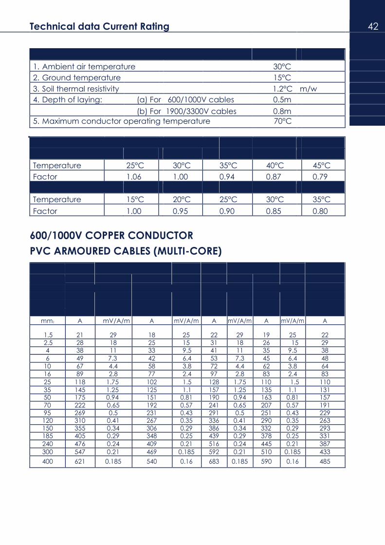
Technical data Current Rating 42
Current ratings are based on the following conditions:
1. Ambient air temperature 30°C
2. Ground temperature 15°C
3. Soil thermal resistivity 1.2°C m/w
4. Depth of laying: (a) For 600/1000V cables 0.5m
(b) For 1900/3300V cables 0.8m
5. Maximum conductor operating temperature 70°C
Rating factors of other temperature:
Cable in air
Temperature 25°C 30°C 35°C 40°C 45°C
Factor 1.06 1.00 0.94 0.87 0.79
Cables in ground
Temperature 15°C 20°C 25°C 30°C 35°C
Factor 1.00 0.95 0.90 0.85 0.80
600/1000V COPPER CONDUCTOR
PVC ARMOURED CABLES (MULTI-CORE)
Laid on cable tray
Laid in free air
Laid direct
Nominal in ground
( 30°C trefoil) cross 2 core 3 & 4 core 2 core 3 & 4 core
sectional Current Volt Current Volt Current Volt Current Volt Current
area of rating drop rating drop rating drop rating drop rating
conductor
mm2 A mV/A/m A mV/A/m A mV/A/m A mV/A/m A
1.5 21 29 18 25 22 29 19 25 22 2.5 28 18 25 15 31 18 26 15 29 4 38 11 33 9.5 41 11 35 9.5 38
6 49 7.3 42 6.4 53 7.3 45 6.4 48
10 67 4.4 58 3.8 72 4.4 62 3.8 64
16 89 2.8 77 2.4 97 2.8 83 2.4 83
25 118 1.75 102 1.5 128 1.75 110 1.5 110
35 145 1.25 125 1.1 157 1.25 135 1.1 131 50 175 0.94 151 0.81 190 0.94 163 0.81 157
70 222 0.65 192 0.57 241 0.65 207 0.57 191 95 269 0.5 231 0.43 291 0.5 251 0.43 229 120 310 0.41 267 0.35 336 0.41 290 0.35 263 150 355 0.34 306 0.29 386 0.34 332 0.29 293 185 405 0.29 348 0.25 439 0.29 378 0.25 331
240 476 0.24 409 0.21 516 0.24 445 0.21 387
300 547 0.21 469 0.185 592 0.21 510 0.185 433
400 621 0.185 540 0.16 683 0.185 590 0.16 485

- Technical data Current Rating
Current ratings are based on the following conditions:
1. Ambient air temperature 30°C
2. Ground temperature 15°C
3. Soil thermal resistivity 1.2°C m/w
4. Depth of laying: (a) For 600/1000V cables 0.5m
(b) For 1900/3300V cables 0.8m
5. Maximum conductor operating temperature 70°C
Rating factors of other temperature:
Cable in air
Temperature 25°C 30°C 35°C 40°C 45°C
Factor 1.06 1.00 0.94 0.87 0.79
Cables in ground
Temperature 15°C 20°C 25°C 30°C 35°C
Factor 1.00 0.95 0.90 0.85 0.80
600/1000V ALUMINIUM CONDUCTOR
PVC NON-ARMOURED CABLES (SINGLE-CORE)
Bunched and Enclosed in Conduit or Trunking Clipped Direct to a Surface or on Cable Tray,
Conductor Bunched and Unenclosed
Nominal 2 Cables, Single-Phase 3 or 4 Cables 3-Phase 2 Cables, Single-Phase 3 or 4 Cables 3-Phase
Cross- ac or dc ac ac or dc ac
Sectional Current Volt Curent Volt Curent Volt Current Volt
Area Rating Drop Rating Drop Rating drop Rating drop
mm2 A mV/A/m A mV/A/m A mV/A/m A mV/A/m
ac dc ac dc
16 60 4.5 4.5 52 3.9 72 4.5 4.5 65 3.9
25 78 2.9 2.8 67 2.5 94 2.8 2.8 85 2.5
35 96 2.1 2.0 83 1.8 115 2.1 2.0 105 1.8
50 120 1.6 1.5 100 1.4 140 1.5 1.5 125 1.3
70 150 1.2 1.0 125 1.0 175 1.1 1.0 155 0.93
95 175 0.93 0.8 150 0.80 210 0.77 0.75 185 0.69
120 205 0.80 0.6 175 0.70 240 0.62 0.6 215 0.56
150 235 0.73 0.5 200 0.64 275 0.51 0.49 245 0.48
185 - - - - - 320 0.42 0.39 285 0.4
240 - - - - - 380 0.34 0.29 340 0.34
300 - - - - - 440 0.29 0.23 390 0.3
400 - - - - - 530 0.25 0.18 475 0.27
500 - - - - - 620 0.22 0.15 550 0.25
630 - - - - - 720 0.20 0.11 640 0.24
4. The Volt drop between consumer’s teminals and any other point in the installation
must not exceed 2.5% of the nominal voltage.

Technical data Current Rating 44
Current ratings are based on the following conditions:
1. Ambient air temperature 30°C
2. Ground temperature 15°C
3. Soil thermal resistivity 1.2°C m/w
4. Depth of laying: (a) For 600/1000V cables 0.5m
(b) For 1900/3300V cables 0.8m
5. Maximum conductor operating temperature 70°C
Rating factors of other temperature:
Cable in air
Temperature 25°C 30°C 35°C 40°C 45°C
Factor 1.06 1.00 0.94 0.87 0.79
Cables in ground
Temperature 15°C 20°C 25°C 30°C 35°C
Factor 1.00 0.95 0.90 0.85 0.80
600/1000V ALUMINIUM CONDUCTOR
PVC NON-ARMOURED CABLES (MULTI-CORE)
Enclosed in Conduit or Trunking Clipped Direct to a Surface or on Cable Tray, Unenclosed
Conductor
Nominal One Twin Cables, Single-Phase One 3 or 4-core Cable One Twin Cables, Single-Phase One 3 or 4 -core Cable
Cross- ac or dc 3-Phase ac ac or dc 3-Phase ac
Sectional Current Volt Curent Volt Curent Volt Current Volt
Area Rating Drop Rating Drop Rating drop Rating drop
mm2 A mV/A/m A mV/A/m A mV/A/m A mV/A/m
ac dc ac dc
16 49 4.6 4.6 43 4.0 58 4.6 4.6 52 4
25 64 2.9 2.9 57 2.6 76 2.9 2.9 67 2.5
35 79 2.2 2.1 70 1.9 92 2.1 2.1 82 1.8
50 99 1.7 1.5 87 1.4 115 1.6 1.5 100 1.3
70 - - - - - 140 1.1 1.1 120 0.93
95 - - - - - 165 0.79 0.77 150 0.63
120 - - - - - 195 0.63 0.61 170 0.54
150 - - - - - 220 0.52 0.50 195 0.45
185 - - - - - 250 0.43 0.40 220 0.37
240 - - - - - 300 0.34 0.31 260 0.3
300 - - - - - 340 0.29 0.25 300 0.25

14 Technical data Current Rating
Current ratings are based on the following conditions:
1. Ambient air temperature 30°C
2. Ground temperature 15°C
3. Soil thermal resistivity 1.2°C m/w
4. Depth of laying: (a) For 600/1000V cables 0.5m
(b) For 1900/3300V cables 0.8m
5. Maximum conductor operating temperature 70°C
Rating factors of other temperature:
Cable in air
Temperature 25°C 30°C 35°C 40°C 45°C
Factor 1.06 1.00 0.94 0.87 0.79
Cables in ground
Temperature 15°C 20°C 25°C 30°C 35°C
Factor 1.00 0.95 0.90 0.85 0.80
600/1000V ALUMINIUM CONDUCTOR
PVC ARMOURED CABLES (MULTI-CORE)
Clipped Direct to a Surface of on a Cable Defined Conditions
Conductor Tray, and Unenclosed
One Twin Cable, Single-Phase One 3 or 4-core Cable Nominal One Twin Cable, Single-Phase One 3 or 4-core Cable Cross- ac or dc Three - Phase ac or dc Three-Phase
Sectional Current Volt Curent Volt Curent Volt Current Volt
Area Rating Drop Rating Drop Rating drop Rating drop
mm2 A mV/A/m A mV/A/m A mV/A/m A mV/A/m
1.5 14 28 13 24 - - - -
2.5 20 17 17 15 - - - -
4 26 11 22 9.1 - - - -
6 32 7.0 28 6.0 38 7.0 32 6.0
10 45 4.1 38 3.6 52 4.1 44 3.6
16 58 2.6 50 2.2 68 2.6 58 2.2
25 76 1.70 66 1.5 91 1.7 77 1.5
35 93 1.2 80 1.0 112 1.2 94 1.0
ac dc ac dc
50 150 0.92 0.92 125 0.81 180 0.92 0.92 155 0.81
70 180 0.65 0.64 155 0.57 220 0.65 0.64 190 0.57
95 225 0.48 0.46 190 0.42 270 0.48 0.46 230 0.42
120 260 0.40 0.36 220 0.34 310 0.40 0.36 270 0.34
150 290 0.32 0.25 250 0.29 355 0.32 0.25 310 0.29
185 340 0.29 0.23 290 0.24 410 0.29 0.23 350 0.24
240 400 0.25 0.18 350 0.2 485 0.25 0.18 420 0.2
300 460 0.23 0.14 400 0.18 550 0.23 0.14 475 0.18
400 520 0.22 0.11 460 0.17 620 0.22 0.11 550 0.17
16 The Volt drop between consumer’s terminals and any otherpoint in the installation
must not exceed 2.5% of the nominal voltage.

Allowable Short Circuit Current for PVC Insulated cables 46
Conductor : Copper Insulation : PVC Curves based on formula - I = 0.1154 A
t
Where —
18 = Short circuit
current (KA) A = Conductor
area t = Time of short circuit (seconds)
CONDUCTOR SIZE (mm2)

20 Technical data
MINIMUM INSULATION RESISTANCE VALUES OF 600/1000V CABLES
CONDUCTOR INSULATION RESISTANCE
SIZE PER KM @ 20°C
sq. mm. MΩ
1.5 10 2.5 9
4 8
6 7
10 7
16 6
25 5
35 5
50 5
70 5
95 5
120 5
150 5
185 5
240 5
300 5
400 5
500 5
630 5
800 5
1000 5
MINIMUM INSTALLATION RADIUS
OVERALL MINIMUM INTERNAL
TYPE OF CONDUCTOR AND CABLE* DIAMETER, D RADIUS OF BEND
mm mm
CIRCULAR COPPER CONDUCTOR, <10mm 3D
NON-ARMOURED
4D >10mm <25mm 4D
6D >25mm
CIRCULAR COPPER CONDUCTOR, ANY 6D
ARMOURED
SOLID ALUMINIUM OR SHAPED COPPER ANY 8D CONDUCTORS, ARMOURED OR
NON-ARMOURED
* Armoured or Non-Armoured

Technical data 48
Maximum Resistance Of Conductor For Single Core And Multicore Cables.
Maximum DC Resistance Maximum DC Resistance Nominal of conductor at 20°C Nominal of Conductor at 20°C
Cross-sectional Copper Aluminium Cross-sectional Copper Aluminium
Area Conductor Conductor Area Conductor Conductor
mm2 No./mm ohm/km ohm/km mm2 No./mm ohm/km ohm/km
1.5 {1/1.38} 12.1 - 120 37/2.03 0.153 0.253 {7/0.53}
2.5 {1/1.78} 7.41 - 150 37/2.25 0.124 0.206
{7/0.67} 4 7/0.85 4.61 7.41 185 { 37/2.52} 0.0991 0.164
6 7/1.04 3.08 4.61 240 { 37/2.88} 0.0754 0.125
10 7/1.35 1.83 3.08 { 61/2.25}
16 7/1.70 1.15 1.91 300 61/2.52 0.0601 0.100
25 7/2.14 0.727 1.20 400 61/2.85 0.0470 0.0778
35 19/1.53 0.524 0.868 500 61/3.20 0.0366 0.0605
50 19/1.78 0.387 0.641 630 127/2.52 0.0283 0.0469
70 19/2.14 0.268 0.443 800 127/2.85 0.0221 0.0367
95 19/2.52 0.193 0.320 1000 127/3.20 0.0176 0.0291
Properties of Conductors
Properties Unit Aluminium Annealed copper
Density g/cm3 2.703 8.89 Volume Resistivity ohm mm3/Km 28.264 17.241
Coefficient of Resistance Per°C 0.00403 0.00393
Melting Point °C 660 1073
Coefficient of expansion Per°C x 10° 25.5 16.8
Ultimate Tensile Strength N/mm2 205 275
Typical Properties of Various Insulation materials
Insulation Specific Relative Thermal Volume Max. Cond. Max. Short
Gravity Permitivity Resistivity Resistivity Temp. Circuit Temp.
(°C m/w) 20°C (ohm-cm) (°C) (°C)
PVC 1.44 5.0 - 8.0 5.0 - 6.0 10 14 70 160
PE 0.92 2.3 3.5 10 16 70 130
XLPE 0.92 2.5 3.5 10 16 90 250
EPR 1.2 3.5 - 5.0 3.5 - 5.0 10 15 90 250
Impregnated
paper 1.1 6 6 10 15 65 - 80 160 - 250

22 Technical data
FORMULA FOR ELECTRICAL CALCULATION
To calculate Given D.C. A.C. single phase A.C. 3 phase
Current ( A) kW A= 1000 x kW A= 1000 x kW A= 1000 x kW
V V x pf 1.73 x V x pf
Current ( A) kVA - A= 1000 x kVA A= 1000 x kVA
V 1.73 x V
Current ( A) hp A= 746 x hp A= 746 x hp A= 746 x
hp
V x eff V x eff x pf 1.73 x V x eff x pf
Power (kW) VA kW = A x V kW= A x V x pf kW = 1.73 x A x V x pf
1000 1000 1000
Apparent Power VA - kVA= A x V kVA= 1.73 x A x V
(kVA) 1000 1000
pf - Power factor of equipment or system under consideration
eff - Efficiency of motor or machinery
V - Line voltage

XLPE INTRODUCTION 50
“Cross-Linked Polyethylene”, one kind of excellent thermosetting plastic insulation material, had come to
be used for all low, medium, high voltage cable recently, and commonly abbreviated “XLPE” or “PEX” .
XLPE molecules bonded in a three dimensional network, it’s different from conventional polyethylene,
therefore, “XLPE” has particular properties in thermic, electrical and mechanical.
“XLPE” Insulation Offers These Advantages
3) Outstanding physical and mechanical toughness
4) Extremely low moisture absorption
5) Excellent ozone resistance
6) Strong resistance to chemicals fumes and gases
7) Low SIC and power factor
8) High impulsed strength
9) High insulation resistance and dielectric strength
10) Capability of carrying and terminating
11) Easy to splicing and terminating
STRUCTURE OF PE and XLPE
Polyethylene
Crosslinked Polyethylene

* C ons tr u ction of XLPE Cable
CONDUCTOR
Conductor shall be made of plain annealed copper wires and hard
drawn aluminium wires complying with IEC 60228.
Maximum resistance of conductor for
single-core and multicore cables (20°C)
Nominal Copper conductor Aluminium conductor cross-sectional area
Ω/km Ω/km mm2
2.5 7.41 -
4.0 4.61 7.41
6.0 3.08 4.61
10 1.83 3.08
16 1.15 1.91
25 0.727 1.20
35 0.524 0.868
50 0.387 0.641
70 0.268 0.443
95 0.193 0.320
120 0.153 0.253
150 0.124 0.206
185 0.0991 0.164
240 0.0754 0.125
300 0.0601 0.100
400 0.0470 0.0778
500 0.0366 0.0605
630 0.0283 0.0469
800 0.0221 0.0367
1000 0.0176 0.0291

52
Insulation shall be XLPE compound complying with IEC 60502-1
Test Voltage Duration 5 minutes
Rated Voltage Uo/U (kV) 0.6/1
Test Voltage r.m.s. (kV) 3.5
Insulation resistance Rated Min insulation resistance at 20°C MΩ-km
Normal
voltage
(Uo/U) 0.6/1
cross (kV)
section area mm2
1.5 2,400 2.5 2,100
4 1,800
6 1,500
10 1,200
16 1,100
25 1,100 35 1,000
INSULATION 50 900
70 900
95 800
120 800 150 800
185 800
240 700
300 700
400 700 500 700
630 600
800 600
1,000 600
Core identification shall be made by different colouring and the colour
scheme shall be as follows 0.6/1 kV Twin : Red and Black
Three : Red, Yellow and Blue
Four : Red, Yellow, Blue and Black

3. CABLE StructurAL DESCRIPTION AND CONSTRUCTION DATA
0 . 6 / 1kV XLPE
INSULATED NON - ARMOURED CABLE
DESCRIPTION
Single core and multi core cables with copper or aluminium conductors XLPE insulated and PVC
sheathed. Cables are rated 0.6/1 kV and conform to IEC 60502-1 : 2004.
CONSTRUCTION
Conductor Plain circular or sector stranded copper or aluminium conductors, conform to IEC 60228 class 2.
Insulation XLPE ( cross-linked polyethylene) rated 90 °C
Colours for core identification Single core - red ( black on request) Two core - red & black
Three core - red, yellow and blue Four Core - red, yellow, blue and black
Assembly Two, three or four insulated conductors are laid up together, if necessary filled with non-hygroscopic
material compatible with the insulation.The filling may be omitted provided the outer shape of the
cable remains practically circular and no adhesion occurs between cores and sheath.
Sheath PVC type ST2 to IEC 60502-1 : 2004 colour black
APPLICATIONS
These cables are designed for general use including underground burial, where they are not likely to
suffer mechanical damage.
NOTE : Cables complying with BS5467 and customer’s specification are available upon request.
Modifications which serve to improve our products will be implemented without notice.

CABLE StructurAL DESCRIPTION AND CONSTRUCTION DATA 54
0.6 / 1kV SINGLE CORE,
XLPE INSULATED, PVC SHEATHED
NON-ARMOURED CABLES
Conductor Approx. cable weight
Nominal Nominal Nominal Approx. cross- thickness thickness overall
Copper Aluminium sectional Shape of insulation of sheath diameter
area
mm2 mm mm mm kg/km kg/km
1.5 c.s. 0.7 1.4 6.1 45 - 2.5 c.s. 0.7 1.4 6.8 60 -
4 c.s. 0.7 1.4 7.1 78 -
6 c.s. 0.7 1.4 7.6 105 -
10 c.s. 0.7 1.4 8.4 153 -
16 c.c. 0.7 1.4 10.1 215 115
25 c.c. 0.9 1.4 10.9 315 160
35 c.c 0.9 1.4 12.0 415 195
50 c.c. 1.0 1.4 13.4 540 240
70 c.c. 1.1 1.4 15.3 755 325
95 c.c. 1.1 1.5 17.2 1020 420
120 c.c. 1.2 1.5 18.9 1270 515
150 c.c. 1.4 1.6 21.1 1560 630
185 c.c. 1.6 1.6 23.2 1955 780
240 c.c. 1.7 1.7 26.0 2540 995
300 c.c. 1.8 1.8 28.7 3160 1220
400 c.c. 2.0 1.9 32.2 4015 1535
500 c.c. 2.2 2.0 35.7 5035 1910
630 c.c. 2.4 2.2 42.5 6530 2485
800 c.c. 2.6 2.3 47.8 8070 2910
1000 c.c. 2.8 2.4 52.6 10380 3870
Notes: c.s - circular stranded conductor
c.c - circular compacted stranded conductor

24 CABLE StructurAL DESCRIPTION AND CONSTRUCTION DATA
0.6/1kV Two Cores,
XLPE INSULATED, PVC SHEATHED
NON-ARMOURED CABLES
Conductor Approx. cable weight
Nominal Nominal Nominal Approx.
cross- thickness thickness overall
Copper Aluminium sectional Shape of insulation of sheath diameter
area
mm2 mm mm mm kg/km kg/km
1.5 c.s. 0.7 1.8 12.1 134 -
2.5 c.s. 0.7 1.8 10.9 155 -
4 c.s. 0.7 1.8 12.0 200 -
6 c.s. 0.7 1.8 13.1 255 -
10 c.s. 0.7 1.8 15.0 365 -
16 c.c. 0.7 1.8 17.2 490 285
25 c.c. 0.9 1.8 17.0 655 330
35 c.c. 0.9 1.8 18.7 845 395
50 c.c. 1.0 1.8 21.0 1110 500
70 c.c. 1.1 1.8 24.0 1540 660
95 s.s. 1.1 1.9 26.9 2040 820
120 s.s. 1.2 2.0 29.9 2570 1030
150 s.s. 1.4 2.2 33.4 3130 1235
185 s.s. 1.6 2.3 37.1 3920 1545
240 s.s. 1.7 2.5 41.7 5050 1900
300 s.s. 1.8 2.6 45.8 6350 2395
400 s.s. 2.0 2.9 51.6 8000 2940
Note: c.s. - circular stranded conductor c.c. - circular compacted stranded conductor s.s. - sectoral stranded conductor, circular conductors can be produced on request.

CABLE StructurAL DESCRIPTION AND CONSTRUCTION DATA 56
0.6/1kV Three Cores,
XLPE INSULATED, PVC SHEATHED
NON-ARMOURED CABLES
Conductor Approx. cable weight
Nominal Nominal Nominal Approx. cross- thickness thickness overall
sectional Shape of insulation of sheath diameter Copper Aluminium
area
mm2 mm mm mm kg/km kg/km
1.5 c.s. 0.7 1.8 10.5 149 -
2.5 c.s. 0.7 1.8 11.4 185 -
4 c.s. 0.7 1.8 12.6 245 -
6 c.s. 0.7 1.8 13.8 320 -
10 c.s. 0.7 1.8 15.8 470 -
16 c.c. 0.7 1.8 17.3 650 345
25 c.c. 0.9 1.8 19.4 935 450
35 c.c 0.9 1.8 21.4 1235 560 50 c.c. 1.0 1.8 24.1 1610 695
70 c.c. 1.1 1.9 27.9 2285 965 95 s.s. 1.1 2.0 31.4 3090 1260 120 s.s. 1.2 2.1 34.9 3875 1560 150 s.s. 1.4 2.3 39.1 4780 1940 185 s.s. 1.6 2.4 43.5 5960 2395
240 s.s. 1.7 2.6 48.8 7810 3080 300 s.s. 1.8 2.8 53.7 9700 3765
400 s.s. 2.0 3.0 60.7 12400 4810
Note: c.s. - circular stranded conductor c.c. - circular compacted stranded conductor s.s. - sectoral stranded conductor, circular conductors can be produced on request.

26 CABLE StructurAL DESCRIPTION AND CONSTRUCTION DATA
0.6/1kV Four Cores,
XLPE INSULATED, PVC SHEATHED
NON-ARMOURED CABLES
Conductor Nominal Nominal Approx.
Approx. cable weight Nominal
cross- thickness thickness overall
Copper Aluminium sectional Shape of insulation of sheath diameter
area
mm2 mm mm mm kg/km kg/km
1.5 c.s. 0.7 1.8 11.3 175 - 2.5 c.s. 0.7 1.8 12.3 225 - 4 c.s. 0.7 1.8 13.6 305 - 6 c.s. 0.7 1.8 15.0 400 -
10 c.s. 0.7 1.8 17.3 595 - 16 c.c. 0.7 1.8 18.9 830 420
25 c.c. 0.9 1.8 21.7 1230 580 35 c.c 0.9 1.8 24.1 1630 730
50 c.c. 1.0 1.9 27.1 2150 935
70 c.c. 1.1 2.0 31.7 3050 1290 95 s.s. 1.1 2.1 35.8 4125 1685
120 s.s. 1.2 2.3 39.8 5158 2100
150 s.s. 1.4 2.4 44.4 6375 2590 185 s.s. 1.6 2.6 49.6 7980 3230 240 s.s. 1.7 2.8 55.8 10455 4150 300 s.s. 1.8 3.0 61.7 13020 5110
400 s.s. 2.0 3.3 68.8 16100 5980
Note: c.s. - circular stranded conductor c.c. - circular compacted stranded conductor s.s. - sectoral stranded conductor, circular conductors can be produced on request.
CABLE StructurAL DESCRIPTION AND CONSTRUCTION DATA 58
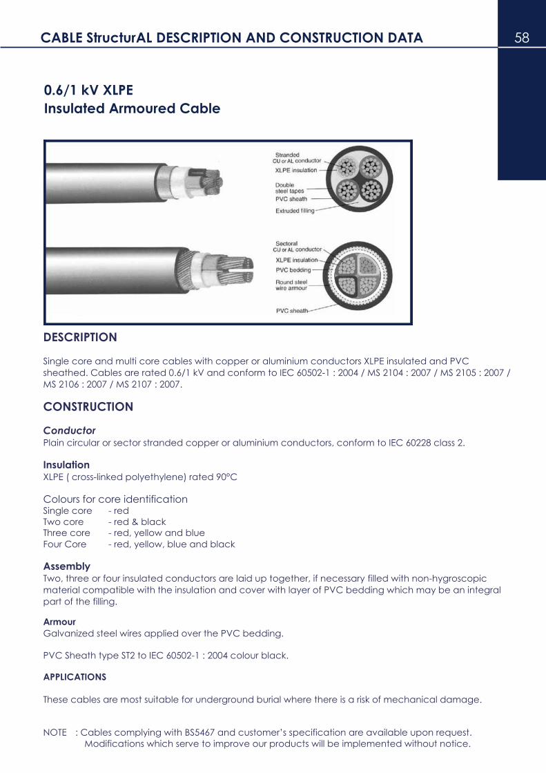
0.6/1 kV XLPE
Insulated Armoured Cable
DESCRIPTION
Single core and multi core cables with copper or aluminium conductors XLPE insulated and PVC
sheathed. Cables are rated 0.6/1 kV and conform to IEC 60502-1 : 2004 / MS 2104 : 2007 / MS 2105 : 2007 /
MS 2106 : 2007 / MS 2107 : 2007.
CONSTRUCTION
Conductor Plain circular or sector stranded copper or aluminium conductors, conform to IEC 60228 class 2.
Insulation XLPE ( cross-linked polyethylene) rated 90°C
Colours for core identification Single core - red
Two core - red & black
Three core - red, yellow and blue Four Core - red, yellow, blue and black
Assembly Two, three or four insulated conductors are laid up together, if necessary filled with non-hygroscopic
material compatible with the insulation and cover with layer of PVC bedding which may be an integral
part of the filling.
Armour Galvanized steel wires applied over the PVC bedding.
PVC Sheath type ST2 to IEC 60502-1 : 2004 colour black.
APPLICATIONS
These cables are most suitable for underground burial where there is a risk of mechanical damage.
NOTE : Cables complying with BS5467 and customer’s specification are available upon request.
Modifications which serve to improve our products will be implemented without notice.
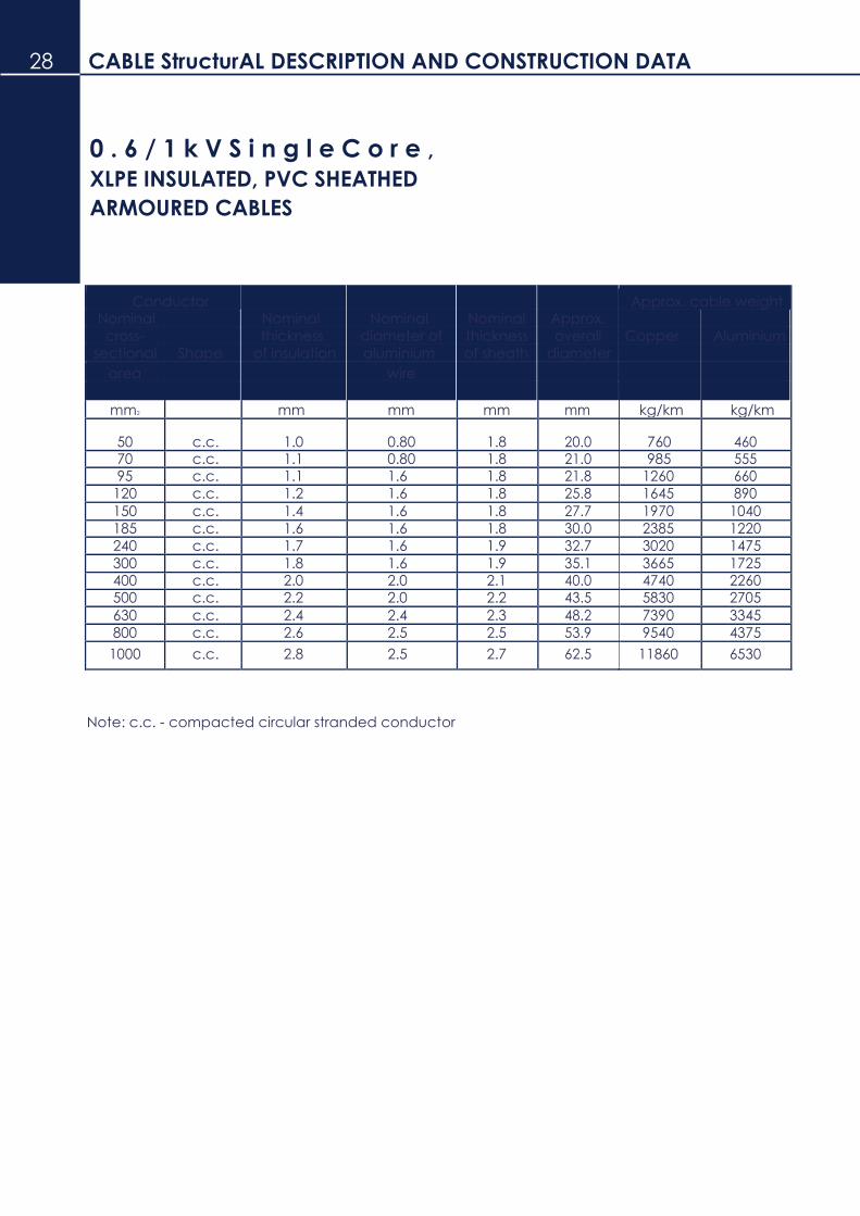
28 CABLE StructurAL DESCRIPTION AND CONSTRUCTION DATA
0 . 6 / 1 k V S i n g l e C o r e ,
XLPE INSULATED, PVC SHEATHED
ARMOURED CABLES
Conductor Approx. cable weight Nominal Nominal Nominal Nominal Approx.
cross- thickness diameter of thickness overall Copper Aluminium
sectional Shape of insulation aluminium of sheath diameter
area wire
mm2 mm mm mm mm kg/km kg/km
50 c.c. 1.0 0.80 1.8 20.0 760 460 70 c.c. 1.1 0.80 1.8 21.0 985 555 95 c.c. 1.1 1.6 1.8 21.8 1260 660
120 c.c. 1.2 1.6 1.8 25.8 1645 890
150 c.c. 1.4 1.6 1.8 27.7 1970 1040
185 c.c. 1.6 1.6 1.8 30.0 2385 1220
240 c.c. 1.7 1.6 1.9 32.7 3020 1475
300 c.c. 1.8 1.6 1.9 35.1 3665 1725 400 c.c. 2.0 2.0 2.1 40.0 4740 2260 500 c.c. 2.2 2.0 2.2 43.5 5830 2705
630 c.c. 2.4 2.4 2.3 48.2 7390 3345
800 c.c. 2.6 2.5 2.5 53.9 9540 4375
1000 c.c. 2.8 2.5 2.7 62.5 11860 6530
Note: c.c. - compacted circular stranded conductor

CABLE StructurAL DESCRIPTION AND CONSTRUCTION DATA 60
0 . 6 / 1 k V T w o C o r e s ,
XLPE INSULATED, PVC SHEATHED
ARMOURED CABLES
Conductor Approx.
Approx.cable weight Nominal Nominal Nominal Nominal
cross- thickness diameter of thickness overall Copper Aluminium
sectional Shape of insulation steel of sheath diameter
area wire
mm2 mm mm mm mm kg/km kg/km
1.5 c.s. 0.7 0.8 1.8 14.0 350 -
2.5 c.s. 0.7 0.8 1.8 14.9 400 -
4 c.s. 0.7 0.8 1.8 16.0 475 - 6 c.s. 0.7 0.8 1.8 17.1 550 -
10 c.s. 0.7 0.8 1.8 19.0 700 -
16 c.c. 0.7 0.8 1.8 20.3 860 655
25 c.c. 0.9 1.6 1.8 23.7 1280 955 35 c.c 0.9 1.6 1.8 24.9 1525 1075 50 c.c. 1.0 1.6 1.8 27.1 1870 1260
70 c.c. 1.1 1.6 2.0 30.5 2450 1570
95 s.s. 1.1 2.0 2.1 34.2 3310 2090 120 s.s. 1.2 2.0 2.2 37.5 4010 2470
150 s.s. 1.4 2.0 2.3 40.9 4740 2845
185 s.s. 1.6 2.5 2.5 45.9 6120 3745 240 s.s. 1.7 2.5 2.7 50.8 7650 4500 300 s.s. 1.8 2.5 2.8 54.8 9115 5160
400 s.s. 2.0 2.5 3.1 61.2 11335 6275
Note: c.s. - circular stranded conductor c.c. - circular compacted stranded conductor s.s. - sectoral stranded conductor, circular conductors can be produced on request.

30 CABLE StructurAL DESCRIPTION AND CONSTRUCTION DATA
0 . 6 / 1 k V T h r e e C o r e s ,
XLPE INSULATED, PVC SHEATHED
ARMOURED CABLES
Conductor Approx.
Approx.cable weight Nominal Nominal Nominal Nominal
cross- thickness diameter of thickness overall Copper Aluminium
sectional Shape of insulation steel of sheath diameter
area wire
mm2 mm mm mm mm kg/km kg/km
1.5 c.s. 0.7 0.8 1.8 14.5 385 -
2.5 c.s. 0.7 0.8 1.8 15.4 450 -
4 c.s. 0.7 0.8 1.8 16.6 535 -
6 c.s. 0.7 0.8 1.8 17.8 640 -
10 c.s. 0.7 0.8 1.8 19.8 830 -
16 c.c. 0.7 0.8 1.8 21.3 1030 725 25 c.c. 0.9 1.6 1.8 25.7 1650 1165
35 c.c 0.9 1.6 1.8 27.7 2015 1340
50 c.c. 1.0 1.6 1.8 30.5 2520 1605 70 c.c. 1.1 1.6 2.0 35.1 3535 2215
95 s.s. 1.1 2.0 2.2 39.3 4565 2735
120 s.s. 1.2 2.0 2.3 42.7 5510 3200 150 s.s. 1.4 2.5 2.5 47.9 6990 4150
185 s.s. 1.6 2.5 2.6 52.7 8120 4555 240 s.s. 1.7 2.5 2.8 58.1 10500 5770
300 s.s. 1.8 2.5 3.0 63.7 12695 6760
400 s.s. 2.0 2.5 3.2 70.3 15540 7950
Note: c.s. - circular stranded conductor
c.c. - circular compacted stranded conductor s.s. - sectoral stranded conductor, circular conductors can be produced on request.
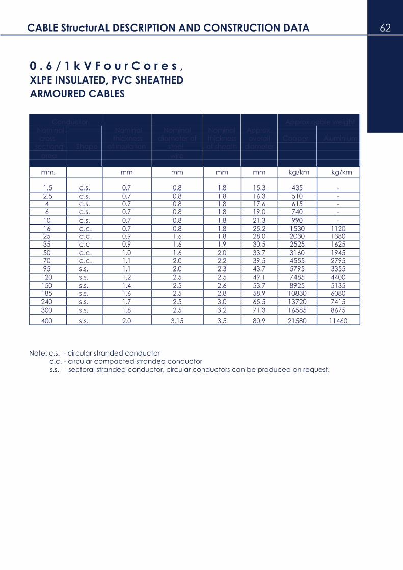
CABLE StructurAL DESCRIPTION AND CONSTRUCTION DATA 62
0 . 6 / 1 k V F o u r C o r e s ,
XLPE INSULATED, PVC SHEATHED
ARMOURED CABLES
Conductor
Approx.
Approx.cable weight Nominal
Nominal Nominal Nominal
cross- thickness diameter of thickness overall Copper Aluminium
sectional Shape of insulation steel of sheath diameter
area wire
mm2 mm mm mm mm kg/km kg/km
1.5 c.s. 0.7 0.8 1.8 15.3 435 -
2.5 c.s. 0.7 0.8 1.8 16.3 510 - 4 c.s. 0.7 0.8 1.8 17.6 615 - 6 c.s. 0.7 0.8 1.8 19.0 740 -
10 c.s. 0.7 0.8 1.8 21.3 990 -
16 c.c. 0.7 0.8 1.8 25.2 1530 1120 25 c.c. 0.9 1.6 1.8 28.0 2030 1380 35 c.c 0.9 1.6 1.9 30.5 2525 1625
50 c.c. 1.0 1.6 2.0 33.7 3160 1945 70 c.c. 1.1 2.0 2.2 39.5 4555 2795
95 s.s. 1.1 2.0 2.3 43.7 5795 3355
120 s.s. 1.2 2.5 2.5 49.1 7485 4400
150 s.s. 1.4 2.5 2.6 53.7 8925 5135 185 s.s. 1.6 2.5 2.8 58.9 10830 6080 240 s.s. 1.7 2.5 3.0 65.5 13720 7415
300 s.s. 1.8 2.5 3.2 71.3 16585 8675
400 s.s. 2.0 3.15 3.5 80.9 21580 11460
Note: c.s. - circular stranded conductor c.c. - circular compacted stranded conductor s.s. - sectoral stranded conductor, circular conductors can be produced on request.

32 CABLE StructurAL DESCRIPTION AND CONSTRUCTION DATA
0 . 6 / 1 k V F o u r C o r e s
With Reduced Neutral Conductor, XLPE
Insulated, PVC Sheathed NON-armoured
Cables
Conductor Approx.cable weight Nominal Nominal Nominal Nominal Approx.
cross- cross- thickness thickness overall Copper Aluminium
sectional Shape sectional Shape of insulation of sheath diameter
area area
Phase Neutral Phase Neutral
mm2 mm2 mm mm mm mm kg/km kg/km
10 c.s. 6 c.s. 0.7 0.7 1.8 17.3 560 - 16 c.c. 10 c.s. 0.7 0.7 1.8 18.9 780 -
25 c.c. 16 c.s. 0.9 0.7 1.8 21.7 1165 580
35 c.c. 16 c.s. 0.9 0.7 1.8 24.1 1515 740
50 c.c. 25 c.s. 1.0 0.9 1.8 27.1 1945 870 70 c.c. 35 c.s. 1.1 0.9 1.9 31.7 2840 1300 95 s.s. 50 c.s. 1.1 1.0 2.1 35.8 3650 1390
120 s.s. 70 c.s. 1.2 1.1 2.2 39.8 4850 1780 150 s.s. 70 c.s. 1.4 1.1 2.3 44.4 5660 2390 185 s.s.. 95 c.s. 1.6 1.1 2.5 49.6 7045 2885
240 s.s. 120 c.s. 1.7 1.2 2.7 55.8 9115 3630 300 s.s. 150 c.s. 1.8 1.4 2.9 61.7 11300 4440
400 s.s. 185 c.s. 2.0 1.6 3.1 68.8 14580 5825
Note: c.s. - circular stranded conductor c.c. - circular compacted stranded conductor s.s. - sectoral stranded conductor, circular conductors can be produced on request.

Permissible Short Circuit Currents 64
XLPE Insulated Conductor
The permissible short-circuit current of a cable as determined by the maximum permissible
conductor temperature and by the duration of the short circuir current. At high peak currents the
dynamic forces between the conductors must be taken into account.
The short circuit capacity of the conductor and metallic shield of a cable are related principally to
their heat capacities and are limited by the maximum temperature permitted under short circuit
conditions . The temperature limits established for XLPE power cables are as follows :-
at conductor 250ºC
The two graphs on provide curves from which the short circuit capacity of copper or aluminium
conductors (based on a temperature rise from 90ºC to 250ºC) can be determined. These curves are
plotted for durations given in cycles ( 60Hz basis)
Logarithmic interpolation between the curves will give estimated values for other durations.
The curves may be used also to determine the amount of conducting material required to carry a
known short-circuit current for given duration.

34 Short circuit current rating for aluminium conductors
Short circuit current rating for COPPER conductors 66

5. Construction

Technical data, Continuous current carrying CAPACITY 68
Continuous Current Carrying Capacity For 600/1000 V XLPE/PVC (PE) Armoured Cable
Conductor Laid in Air Laid Direct in Ground Drawn in To Duct Conductor
Nom.cross Single Core 3 or Single Core 3 or Single Core 3 or 1 sec. 3 sec.
sectional
4 - core
4 - core
4 - core Fault Fault
current current area Trefoil Flat
Trefoil Flat
Trefoil Flat
rating rating
sqmm (A) (A) (A) (A) (A) (A)
(A) (A) (A) (kA) (kA)
Copper Conductors
16 105 125 100 110 115 110 100 105 80 2.3 1.3
25 145 165 130 145 150 140 130 135 105 3.5 2.0
35 175 200 160 170 180 170 155 160 125 4.9 2.8
50 210 240 195 205 210 200 185 185 150 7.0 4.1
70 265 305 245 250 255 245 225 230 185 9.9 5.7
95 320 370 300 295 305 295 280 285 220 13.4 7.7
120 370 430 345 335 345 335 320 325 250 17.0 9.0
150 430 500 395 380 390 375 360 370 285 21.2 12.2
185 495 570 450 425 440 420 410 420 320 26.2 15.1
240 585 680 530 490 510 485 475 485 390 34.0 19.6
300 670 780 605 555 575 545 535 550 435 42.5 24.5
400 780 910 695 630 660 615 610 630 500 56.7 32.7
500 900 1060 795 710 750 690 690 715 560 70.9 40.9
630 1040 1235 900 800 855 770 775 815 630 89.4 51.6
800 1190 1425 1010 890 965 845 865 920 695 113.0 65.0
1000 1345 1620 1105 980 1075 915 945 1020 750 141.9 81.9
Aluminium Conductors
16 85 95 75 90 90 85 80 80 60 1.5 0.9
25 115 130 100 115 115 110 100 105 80 2.3 1.3
35 135 160 125 135 140 130 120 125 95 3.3 1.9
50 165 190 150 160 160 155 140 145 115 4.7 2.7
70 205 235 190 195 200 190 175 180 140 6.7 3.8
95 250 290 235 230 235 235 220 220 170 9.1 5.2
120 290 335 270 260 270 260 250 255 195 11.4 6.6
150 335 385 305 295 300 290 280 285 220 14.3 8.2
185 385 445 350 330 340 330 320 325 250 17.7 10.2
240 455 530 415 385 395 380 370 380 305 22.9 13.2
300 525 605 475 435 450 425 420 425 345 28.7 16.5
400 615 710 555 495 515 490 480 490 395 38.3 22.1
500 715 835 640 565 590 555 545 565 455 47.0 27.6
630 840 980 740 645 675 630 625 645 515 60.6 34.8
800 975 1140 845 730 775 710 705 735 580 76.6 44.2
1000 1120 1320 945 815 875 780 790 830 640 95.7 55.3

- Technical data, Continuous current carrying CAPACITY
The tabulated current rating have been calculated in accordance with IEC 287. They are for single
circuit with the standard conditions as follows : -
5. Maximum permissable conductor temperature at continuous operation is 90°C.
ii ) Ground temperature is 25°C
15 Ambient temperature is 40°C
16 Ground thermal resistivity is 1.2 km/W
17 Cables laying depth is ground : - cable’s voltage up to 1 kV........500mm cable’s voltage above 1 kV .......800 mm
18 Spacing between cables :-
In flat formation........... 2 times of the cable overall diameter In trefoil formation........... cables touching
19 Cable’s sheath or armour solidly bonded at both ends.
20 Cables shielded from direct sun rays
For conditions of operation different from those on which the continuous current capacity tables are based,
ratings can be determined by application of “Rating Factor” in table below.
Rating Factor
Rating Factors For Cables in Air
Ambient air temperature 10 15 20 25 30 35 40 45 50 55 60
Rating Factors 1.26 1.22 1.18
1.1
4 1.10 1.05 1.0 1.0 0.89 0.84 0.78
Rating Factors For Ground Temperature Ground Factors 10 15 20 25 30 35 40 45 50 55 60
Rating Factors 1.11 1.07 1.04 1.00 0.96 0.92 0.88 0.83 0.78 0.73 0.68
Rating Factors for Thermal Resistivity of Ground
Conductor size ( mm2) Thermal Resistivity ( Km/W) 0.8 0.9 1.0 1.2 1.5 2.0 2.5 3.0
Single Core Cable
Up to 150
1.16 1.11 1.07 1.0 0.91 0.81 0.73 0.67
From 185 to 400
1.17 1.12 1.07 1.0 0.90 0.80 0.72 0.66
From 500 to 12000
1.18 1.13 1.08 1.0 0.90 0.79 0.71 0.65
Multicore cables
Up to 16
1.09 1.06 1.0 1.0 1.0 0.86 0.79 0.74
From 25 to 150
1.14 1.10 1.1 1.0 0.9 0.84 0.76 0.70
From 185 - 400 1.1
6 1.11 1.1 1.0 0.9 0.82 0.74 0.68
Rating Factors For Depth of Laying
Depth of laying 0.6 / 1kV cables
70mm2 to 300mm2 above 300mm2
(m) up to 50mm2
0.50 1.00 1.00 1.00
0.60 0.99 0.98 0.97
0.80 0.97 0.96 0.94
1.00 0.95 0.94 0.92
1.25 0.94 0.92 0.90
1.50 0.93 0.91 0.89
1.75 0.92 0.89 0.87

2.00 0.91 0.88 0.86
2.50 0.90 0.87 0.85
3.0 or more 0.89 0.86 0.83
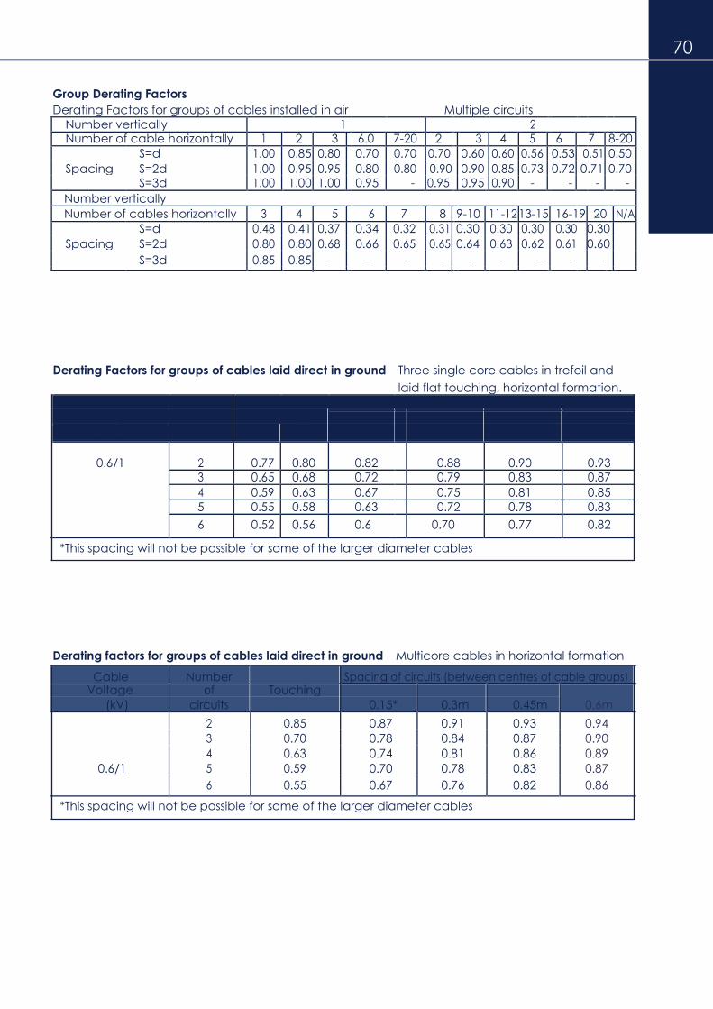
70
Group Derating Factors
Derating Factors for groups of cables installed in air Multiple circuits Number vertically 1 2
Number of cable horizontally 1 2 3 6.0 7-20 2 3 4 5 6 7 8-20
S=d 1.00 0.85 0.80 0.70 0.70 0.70 0.60 0.60 0.56 0.53 0.51 0.50
Spacing S=2d 1.00 0.95 0.95 0.80 0.80 0.90 0.90 0.85 0.73 0.72 0.71 0.70 S=3d 1.00 1.00 1.00 0.95 - 0.95 0.95 0.90 - - - -
Number vertically
Number of cables horizontally 3 4 5 6 7 8 9-10 11-12 13-15 16-19 20 N/A
S=d 0.48 0.41 0.37 0.34 0.32 0.31 0.30 0.30 0.30 0.30 0.30
Spacing S=2d 0.80 0.80 0.68 0.66 0.65 0.65 0.64 0.63 0.62 0.61 0.60
S=3d 0.85 0.85 - - - - - - - - -
Derating Factors for groups of cables laid direct in ground Three single core cables in trefoil and
laid flat touching, horizontal formation. Cable Number Spacing of circuits ( between centres of cable groups)
Voltage of Touching
( kV) Circuits Trefoil Laid flat 0.15m* 0.3m 0.45m 0.6m
0.6/1 2 0.77 0.80 0.82 0.88 0.90 0.93 3 0.65 0.68 0.72 0.79 0.83 0.87
4 0.59 0.63 0.67 0.75 0.81 0.85
5 0.55 0.58 0.63 0.72 0.78 0.83
6 0.52 0.56 0.6 0.70 0.77 0.82
*This spacing will not be possible for some of the larger diameter cables
Derating factors for groups of cables laid direct in ground Multicore cables in horizontal formation
Cable Number Spacing of circuits (between centres of cable groups) Voltage of Touching
0.6m
(kV) circuits 0.15* 0.3m 0.45m
2 0.85 0.87 0.91 0.93 0.94 3 0.70 0.78 0.84 0.87 0.90
4 0.63 0.74 0.81 0.86 0.89
0.6/1 5 0.59 0.70 0.78 0.83 0.87
6 0.55 0.67 0.76 0.82 0.86
*This spacing will not be possible for some of the larger diameter cables

17 Handling And Installation Of XLPE CableS
19 Minimum bending radius and permissible maximum pulling tension For
safety installation without damaging electrical physical properties, the
following minimum bending radius and permissible maximum pulling
tension must be observed :
Minimum bending radius D : Overall dia. of cable
Number of core Single core Multi core
Type of cable Round conductor Four segmental stranded conductor
600 V cable 10D 12D 8D
3,300 V cable and higher 10D 12D 8D
Triplex type cable - - 8D
Corrugated metal armoured cable 10D 12D 8D
Flat tape armoured cable 10D 12D 8D
Wire armoured cable 10D 12D 8D
Lead sheathed cable 10D 12D 10D
Permissible maximum pulling tension
Pulling tool Material of conductor Permissible maximum pulling tension (kg)
Pulling eye Copper 7x ( Number of core) x ( Core-sectional area of conductor)
Aluminium 7x ( Number of core) x ( Core-sectional area of conductor)
Cable grip Copper & aluminium The same as using the pulling eye, but the minimum tension
should be less than two tons
Note: When cable grip is used it should cover more than 500 mm in length of the cable end be
bound to the cable sheath.
21 Side wall pressure to cable Permissible maximum side wall pressure to the cable at bending point during installation is 500kg/m.
Note:
Side wall pressure to cable = Pulling tension (kg)
= T Bending radius (m) = R
23 Pulling tension (kg)
12) Bending radius (m)
3. Removal of sheath or tape Special care must be taken not to harm the insulation when removing the sheath or tapes with knife otherwise it may result in a dialectric breakdown. 4. Cleaning the surface of insulation The surface of insulation should be cleaned to avoid a flash over at the cable termination or joint. 5. Applying of self-adhesive tape When applying a self-adhesive tape after joint or terminating of XLPE cable, stretch it properly
about 1.2 times as long as the original one. If it is over-stretched crack may occur on the tape in the long run and if not stretch properly, tape will not be adhered between each layer. * Water proof treatment for out-door termination
For out-door termination water proof treatment is
necessary to avoid the water penetrating into the
cable and special care must be taken to apply
tapes and terminals. It is desirable to use a
compression or solder type terminal.

Technical data 72
Wire Gauges
Gauge system Diameter Cross-sectional area Weight of Weight of
copper aluminium
A.W.G. S.W.G. mm mil mm2 sq.mil CM kg/km kg/km
6/0 - 14.732 580 170.5 264200 336400 1515 460.2
5/0 - 13.119 516.5 135.2 209500 266800 1202 365.0
- 7/0 12.700 500 126.7 196400 250000 1126 342.0
- 6/0 11.786 464 109.1 169100 215300 969.9 294.6
4/0 - 11.684 460 107.2 166200 211600 953.2 289.5
- 5/0 10.973 432 94.56 146600 186600 840.6 255.3
3/0 - 10.404 409.6 85.01 131800 167800 755.8 229.5
- 4/0 10.160 400 81.07 125700 160000 720.7 218.9
- 3/0 9.449 372 70.12 108700 138400 623.4 189.3
2/0 - 9.266 364.8 67.43 104500 133100 599.5 182.1
- 2/0 8.839 348 61.36 95110 121100 545.5 165.7
0 - 8.252 324.9 53.49 82910 105600 475.5 144.4
- 0 8.230 324 53.19 82450 105000 472.9 143.6
- 1 7.620 300 45.60 70690 90000 405.4 123.1
1 - 7.348 289.3 42.41 65730 83690 377.0 114.5
- 2 7.011 276 38.60 59830 76180 343.2 104.2
2 - 6.544 257.6 33.63 52120 66370 299.0 90.80
- 3 6.401 252 32.18 49880 63500 286.1 86.88
- 4 5.893 232 27.27 42270 53820 242.4 73.63
3 - 5.827 229.4 26.66 41330 52620 237.0 71.99
- 5 5.385 212 22.77 35300 44940 202.4 61.49
4 - 5.189 204.3 21.15 32780 41730 188.0 57.10
- 6 4.877 192 18.68 28950 36860 166.1 50.43
5 - 4.621 181.9 16.77 26000 33100 149.1 45.28
- 7 4.470 176 15.69 24320 30970 139.5 42.37
6 - 4.115 162 13.30 20620 26250 118.3 35.92
- 8 4.064 160 12.97 20110 25600 115.3 35.02
7 - 3.665 144.3 10.55 16350 20820 93.78 28.48
- 9 3.658 144 10.51 16290 20740 93.41 28.37
8 - 3.264 128.5 8.367 12970 16510 74.39 22.59
- 10 3.251 128 8.302 12870 16380 73.80 22.42
- 11 2.946 116 6.818 10570 13460 60.61 18.41
9 - 2.906 114.4 6.633 10280 13090 58.96 17.91
- 12 2.642 104 5.481 8495 10820 48.72 14.80
10 - 2.588 101.9 5.261 8155 10380 46.77 14.21
- 13 2.337 92 4.289 6648 8465 38.13 11.58
11 - 2.305 90.74 4.172 6467 8234 37.09 11.26
12 - 2.053 80.81 3.309 5129 6531 29.42 8.935
- 14 2.032 80 3.243 5027 6400 28.83 8.756
- 15 1.829 72 2.627 4072 5185 23.35 7.093
13 - 1.828 71.96 2.624 4067 5178 23.33 7.085
14 - 1.628 64.08 2.081 3225 4107 18.50 5.618
- 16 1.626 64 2.075 3217 4096 18.45 5.604
15 - 1.450 57.07 1.650 2558 3257 14.67 4.456
- 17 1.422 56 1.589 2463 3136 14.13 4.290
16 - 1.291 50.82 1.309 2029 2583 11.63 3.534
- 18 1.219 48 1.167 1810 2304 10.38 3.152
17 - 1.150 45.26 1.0380 1609 2048 9.226 2.802
18 - 1.024 40.3 0.8227 1275 1624 7.314 2.221
- 19 1.016 40 0.8107 1257 1600 7.207 2.189
- 20 0.9144 36 0.6567 1018 1296 5.838 1.773
19 - 0.9117 35.89 0.6529 1012 1288 5.804 1.763
- 21 0.8128 32 0.5189 804.2 1024 4.613 1.401
20 - 0.8116 31.95 0.5174 801.9 1021 4.600 1.397
21 - 0.7230 28.46 0.4105 636.3 810.1 3.649 1.108

4. Appendix - Technical data
Wire Gauges - Continued
Gauge system Diameter Cross-sectional area Weight of Weight of
copper aluminium
A.W.G. S.W.G. mm mil mm2 sq.mil CM kg/km kg/km
- 22 0.7112 28 0.3973 615.8 784.0 3.532 1.073
22 - 0.6439 25.35 0.3256 504.7 642.6 2.895 0.8792
- 23 0.6096 24 0.2919 452.4 576.0 2.595 0.7880
23 - 0.5733 22.57 0.2581 400.1 509.4 2.295 0.6970
- 24 0.5588 22 0.2452 380.1 484.0 2.180 0.6622
24 - 0.5106 20.1 0.2047 317.3 404.0 1.820 0.5528
- 25 0.5080 20 0.2027 314.2 400.0 1.802 0.5472
- 26 0.4572 18 0.1642 254.5 324.0 1.460 0.4433
25 - 0.4546 17.9 0.1623 251.6 320.4 1.443 0.4383
- 27 0.4166 16.4 0.1363 211.3 269.0 1.212 0.3680
26 - 0.4049 15.94 0.1288 199.6 254.1 1.145 0.3477
- 28 0.3759 14.8 0.1110 172.0 219.0 0.9867 0.2997
27 - 0.3606 14.2 0.1021 158.3 201.5 0.9077 0.2757
- 29 0.3454 13.6 0.09372 145.3 185.0 0.8332 0.2530
28 - 0.3211 12.64 0.08097 125.5 159.8 0.7198 0.2186
- 30 0.3150 12.4 0.07791 120.8 153.8 0.6926 0.2104
- 31 0.2947 11.6 0.06819 105.7 134.6 0.6062 0.1841
29 - 0.2860 11.26 0.06422 99.54 126.7 0.5709 0.1734
- 32 0.2743 10.8 0.05908 91.58 116.6 0.5252 0.1595
30 - 0.2548 10.03 0.05097 79.01 100.6 0.4531 0.1376
- 33 0.2540 10 0.05067 78.54 100.0 0.4505 0.1368
- 34 0.2337 9.2 0.04289 66.48 84.64 0.3813 0.1158
31 - 0.2268 8.928 0.06422 62.60 79.71 0.3590 0.1090
- 35 0.2134 8.4 0.05908 55.42 70.56 0.3178 0.09653
32 - 0.2019 7.95 0.05097 49.64 63.20 0.2847 0.08647
- 36 0.1930 7.6 0.02927 45.36 57.76 0.2602 0.07902
33 - 0.1798 7.08 0.02540 39.37 50.13 0.2258 0.06858
- 37 0.1727 6.8 0.02343 36.32 46.24 0.2083 0.06326
34 - 0.1602 6.305 0.02014 31.22 39.75 0.1791 0.05439
- 38 0.1524 6 0.01824 28.27 36.00 0.1622 0.04925
35 - 0.1426 5.615 0.01597 24.76 31.53 0.1420 0.04313
- 39 0.1321 5.2 0.01370 21.24 27.04 0.1218 0.03700
36 - 0.1270 5 0.01267 19.63 25.00 0.1126 0.03420
- 40 0.1219 4.8 0.01167 18.10 23.04 0.1038 0.03152
37 - 0.1131 4.453 0.01005 15.57 19.83 0.08931 0.02713
- 41 0.1118 4.4 0.009810 15.21 19.36 0.08721 0.02649
- 42 0.1016 4 0.008107 12.57 16.00 0.07207 0.02189
38 - 0.1007 3.965 0.007968 12.35 15.72 0.07084 0.02151
- 43 0.09140 3.6 0.006567 10.18 12.96 0.05838 0.01773
39 - 0.08970 3.531 0.006319 9.794 12.47 0.05618 0.01706
- 44 0.08128 3.2 0.005189 8.042 10.24 0.04613 0.01401
40 - 0.07988 3.145 0.005012 7.768 9.891 0.04456 0.01353
41 45 0.07113 2.8 0.003973 6.159 7.842 0.03532 0.01073
42 - 0.06334 2.494 0.003151 4.884 6.219 0.02801 0.008508
- 46 0.06096 2.4 0.002919 4.524 5.760 0.02595 0.007880
43 - 0.05641 2.221 0.002499 3.873 4.932 0.02222 0.006747
- 47 0.05080 2 0.002027 3.142 4.000 0.01802 0.005472
44 - 0.05023 1.978 0.001982 3.072 3.911 0.01762 0.005351
45 - 0.04474 1.761 0.001572 2.436 3.102 0.01397 0.004244
- 48 0.04064 1.6 0.001297 2.011 2.560 0.01153 0.003502
46 - 0.03984 1.568 0.001246 1.932 2.460 0.01108 0.003365
47 - 0.03548 1.397 0.0009884 1.532 1.951 0.008787 0.002669
48 - 0.03159 1.244 0.0007838 1.215 1.547 0.006968 0.002116
- 49 0.03048 1.2 0.0007297 1.131 1.440 0.006487 0.001970
49 - 0.02813 1.108 0.0006216 0.9635 1.227 0.005526 0.001678
- 50 0.02540 1 0.0005067 0.7854 1.000 0.004505 0.001368
50 - 0.02505 0.9863 0.0004929 0.7641 0.9728 0.004382 0.001331

Appendix Technical Data Common Conversion Factor 74
Equivalent Reciprocal
Mass
1 cwt = 50.802 kg 0.0197
1oz = 28.349 gm 0.0352
1 Ib = 0.4536 kg 2.2046
1 Ib = 0.00454 tonne (metric) 220.26
1 ton ( long) = 1.016 tonne ( metric) 0.09842
Length
1in = 25.4 mm 0.03937
1 ft = 0.3048 m 3.2808
1 yd = 0.9144 m 1.0936
1 mile = 1.6093 km 0.6214
Area
1 in2 = 645.16 mm2 0.00155
1 ft2 = 0.0929 m2 10.7642
1 yd2 = 0.8361 m2 1.196
Volume
1 in3 = 16.387 cm3 (ml or cc) 0.061
1 ft3 = 0.0283 m3 35.3335
1 ft3 = 6.229 gal (Imp) 0.1605
1 ft3 = 28.328 I 0.0353
1 yd3 = 0.7645 m3 1.3079
1 gal (USA) = 0.8327 gal (Imp) 1.2009
Force
1 Ibf = 0.4535 kgf 2.2046
1 kgf = 9.8065 N 0.1019
1 ton ( long) f = 9.964 kN 0.10036
Pressure and Stress
1 atm = 0.1013 Mpa 9.869
1 atm = 1.0133 bar 0.9869
1 Ib/in2 ( psi) = 6.894 kN/mm2 (kPa) 0.145
1 bar = 1.0197 kgf/cm2 0.09806
Energy ( Work and Heat)
1 HP.h = 2544.5 Btu 0.00393
1 Btu = 0.000293 kW.h 3413
1 Btu = 1.0551 kJ 0.9478
1 Btu = 107.59 kgf.m 0.00929
1 cat = 4.187 J 0.239
1 mil = 0.001 in = 0.0254 mm 1 CM(Circular mil) = 0.7854 x 10 in2 = 0.5067 x 10 mm2

73

POLYETHYLENE AND CROSSLINKED POLYETHYLENE
76 INSULATED AERIAL BUNDLED CABLES
1. INTRODUCTION
The concept of insulated aerial bundled cables was developed in the early 1960's in Europe to provide a reliable, safe and economical alternative system of electrification.
The development was accelerated due to progress achieved in the field of synthetic insulating materials such as polyvinyl chloride (PVC) and polyethylene (PE). Crosslinked polyethylene (XLPE) was later added to the list.
National standards from a few European countries have been issued specifically for insulated aerial bundled cables employing designs from experiences and research. Although these are mainly for low voltage installation, standards for high voltage cables have been derived from specifications such as IEC 60502 which incorporates several extruded dielectrics for low voltage cables.
Aluminium and its alloys are used universally as conductors or neutral supports due to their inherent lightness while steel wires, traditionally used in ACSR constructions are used as the supporting catenary especially for heavier cables such as medium and high voltage cables.
2. AERIAL BUNDLED CABLES CONSTRUCTION The low voltage construction usually consists of three insulated phase conductors and one insulated messenger which also acts as the neutral. Street lighting conductor may be included if required.
2.1 CONDUCTORS
The phase and street lighting conductors consists of seven or more hard drawn
aluminium wires, of size and construction to BS 6360 and BS 215 respectively.
The messenger consists of Al-Mg-Si type alloys wires of materials and
construction to BS 3242.
The characteristic before stranding is : - 25 Minimum tensile strength 300 N/mm2
26 Minimum resistivity 3.28 microhm.cm
2.2 INSULATION
The insulation is usually high density polyethylene with a 2 percent nominal
content of carbon black.
Cross-linked polyethylene which has better thermal and mechanical properties, may be provided as an alternative insulation. The nominal thickness shall complied to IEC 60502.
The markings of aerial bundled cable shall be as followed : -
Low voltage
Phase : Numerical 1, 2, 3 Messenger : UTAMA CABLES BERHAD ELECTRICAL CABLE 600/1000 V
Street Lighting : S/L

77
2.3 TEST
Routine tests at works include :
27 Spark Test
The core is subjected to an AC spark test during the insulating process in
accordance to BS 5099.
29 Voltage Test
An AC test voltage of 3.5 kV at 50 Hz applied is between the insulated
conductors for a duration of 5 minutes.
31 Conductor Resistance Test
The D.C. resistance of each conductor shall be measured at room temperature
and after correction to 20˚C, shall not exceed the values given in the technical
particulars.
33 Special Tests :
Other tests which may be requested include Insulation Resistance between
conductors, Mechanical properties and dimensional measurements tests.

78
2.4 SHORT CIRCUIT RATING
The short circuit ratings in Table 1 are calculated using the adiabatic method neglecting the heat loss from the conductor during a short circuit based on the temperatures stated.
The accessories associated with the cable shall be able to withstand the same conditions.
The ratings are given for a fault duration of one second. For other durations, the value shall be divided by the square root of the duration in seconds.
TABLE 1
Insulation Fault temp Rating in Amps for various sizes
(˚C )
type
16 25
35 50 70
95 120 Start/End
HDPE 75 130 970 1510 2110 3020 4230 5740 7250
XLPE 90 250 1500 2300 3250 4450 6200 8600 11200
Caution should be exercised when applying the ratings as high mechanical forces inherent to installation practices may result in deformation at high temperatures sufficient to cause failure.
2.5 SAG AND TENSION
Once a cable is selected, details of sags and tensions will be determined by calculations
based on known parameters and assumptions.
The calculations are derived from established parabolic equations which are usually
sufficiently accurate :
Initial change final conductor + in = conductor
length length length
L + W12L3 + L (t2-t1) + (T2-T1)L = L + W2
2L3
24T12 EA 24T2
2
Subtracting L from each side and multiplying throughout by EA/L.
eqn. (A)
where E
A
t1
t2
W1
WL2
T1
T2
EA (t2-t1) + W12L2EA - T1 = W2 2L2EA - T2 24T1
2 24T22
35 modulus of elasticity (N/mm2) 36 Cross-sectional area (mm2) 37 Linear coefficient of expansion (/˚C) 38 Initial temperature (˚C) 39 Final temperature (˚C) 40 Initial weight (N/m) 41 Final weight (N/m) 42 Span length (m) 43 Initial tension (N)
44 Final tension (N)
eqn. (B)
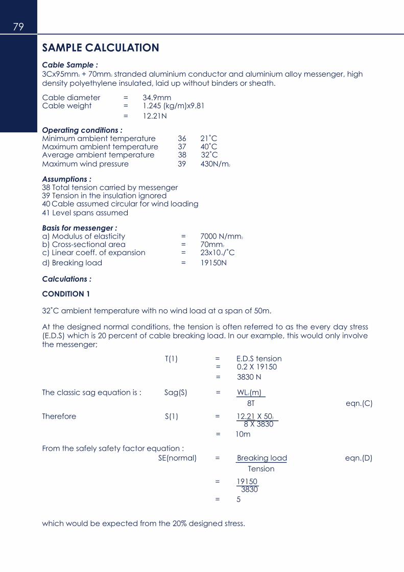
79
SAMPLE CALCULATION
Cable Sample :
3Cx95mm2 + 70mm2 stranded aluminium conductor and aluminium alloy messenger, high
density polyethylene insulated, laid up without binders or sheath.
Cable diameter = 34.9mm Cable weight = 1.245 (kg/m)x9.81
= 12.21N
Operating conditions : Minimum ambient temperature Maximum ambient temperature Average ambient temperature Maximum wind pressure
36 21˚C 37 40˚C 38 32˚C
39 430N/m2
Assumptions : 38 Total tension carried by messenger 39 Tension in the insulation ignored 40 Cable assumed circular for wind loading 41 Level spans assumed
Basis for messenger : a) Modulus of elasticity = 7000 N/mm2
b) Cross-sectional area = 70mm2
c) Linear coeff. of expansion = 23x10-6/˚C
d) Breaking load = 19150N
Calculations :
CONDITION 1
32˚C ambient temperature with no wind load at a span of 50m.
At the designed normal conditions, the tension is often referred to as the every day stress (E.D.S) which is 20 percent of cable breaking load. In our example, this would only involve the messenger;
T(1) = E.D.S tension = 0.2 X 19150
= 3830 N
The classic sag equation is : Sag(S) = WL2(m)
eqn.(C) 8T
Therefore S(1) = 12.21 X 502 8 X 3830
= 10m
From the safely safety factor equation :
SE(normal) = Breaking load eqn.(D)
Tension
= 19150 3830
= 5
which would be expected from the 20% designed stress.

80
CONDITION 2
As above but with wind pressure at 430 N/mm2
Wind load = wind pressure X cable diameter = 430X34.9
1000
= 15N/m eqn.(E)
Effective weight of cable, W2 = √
W12 X (wind load)2
=
√12.212 + 15.02
= 19.35 N/m eqn.(F)
From equation (B): EA (t2-t1) + W11
2L2EA - T1 = W22L2EA - T2
24T12 24T2
2
Separating the elements :
EA (t2-t1) = 70000 X 70 X 23 X 10 -6 X (32-32)
= 0
W12L2
2EA = 12.22 X 502 X 70000 X 70 24T1
2 24 X 38302
= 5190
W22L2EA = 19.352 X 502 X 70000 X 70
24 24
= 1.911 X 10¹¹
Substituting in equation (B) :
5190 - 3830 = 1.911 X 10¹¹ - T2
T2 2
T22(T2 + 1360) = 1.911 X 10¹¹
This is of the form T2(T+A) = B where A and B are known and may be solved by trial
and error using a slide rule or by computing using the iterative method.
Solving. T2(2) = 5340
And sag. S(2) = 12.21 x 502
8 x 5340
= 0.71m
Therefore, SF(2) = 19150 5340
= 3.59

81
CONDITION 3
Wind pressure at 430 N/m2 and minimum temperature of 21˚C
The tension of the cable under these conditions is called the maximum
working tension. The designer will find out from the equations whether the
cable erection will be within the safety factor allowed.
Again, using equation (B).
EA (t2-t1) + W12L2EA - T1 = W2
2L2EA - T2
24T12 24T2
2
Separating the elements : EA (t2-t1) = 70000 X 70 X 23 X 10-6 X ( 21-32)
= -1239.7
W12L2EA = 5190
24T12
W22L2EA = 1.911 X 10¹¹
24
Substituting. –12397 + 5190 – 3830 = 1.911 X 10¹¹ - T2
T22
T22(T2 + 120.3) = 1.911 X 10¹¹
Solving. T2(3) = 5720
And sag. S(3) = 12. 21 X 502
8 X 5720
= 0.67m
Therefore, SF(3) = 19150
5720
= 3.35
A request for a conductor design would therefore, specify the maximum allowable
tension or safety factor, every day stress or normal working tension and if necessary,
the maximum vertical sag limits. The most demanding of these conditions will have
to be established and the rest will then be calculated within the limits.
A complete table for the above example is enclosed with the values of tensions, sag
and safety factors at various span lengths. (Refer Table 2 and Table 3)
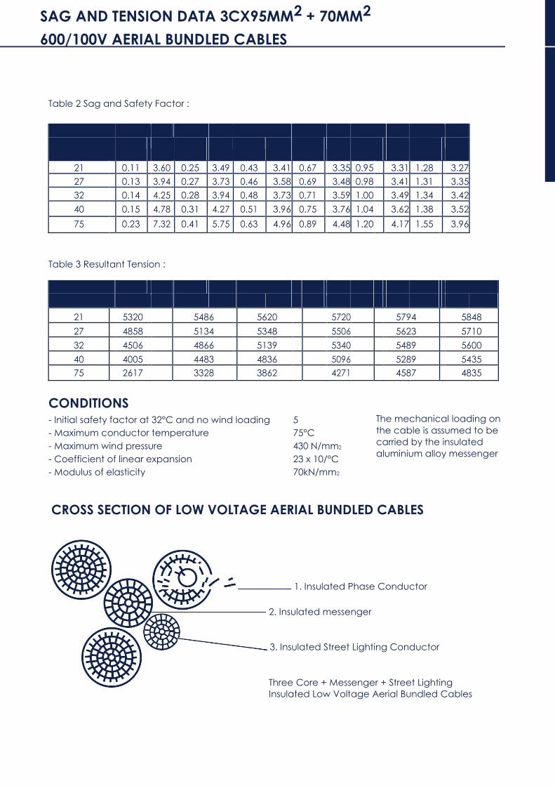
SAG AND TENSION DATA 3CX95MM2 + 70MM2
600/100V AERIAL BUNDLED CABLES 82
Table 2 Sag and Safety Factor :
Span (m) 20 30 40 50 60 70
TEMP (°C) Sag(m) SF Sag(m) SF Sag(m) SF
Sag(m
) SF Sag(m) SF
Sag(m
) SF
21 0.11 3.60 0.25 3.49 0.43 3.41 0.67 3.35 0.95 3.31 1.28 3.27
27 0.13 3.94 0.27 3.73 0.46 3.58 0.69 3.48 0.98 3.41 1.31 3.35
32 0.14 4.25 0.28 3.94 0.48 3.73 0.71 3.59 1.00 3.49 1.34 3.42
40 0.15 4.78 0.31 4.27 0.51 3.96 0.75 3.76 1.04 3.62 1.38 3.52
75 0.23 7.32 0.41 5.75 0.63 4.96 0.89 4.48 1.20 4.17 1.55 3.96
Table 3 Resultant Tension :
SPAN(m) 20 30 40 50 60 70
TEMP(°C) N N N N N N
21 5320 5486 5620 5720 5794 5848
27 4858 5134 5348 5506 5623 5710
32 4506 4866 5139 5340 5489 5600
40 4005 4483 4836 5096 5289 5435
75 2617 3328 3862 4271 4587 4835
CONDITIONS
- Initial safety factor at 32°C and no wind loading 5
- Maximum conductor temperature 75°C
- Maximum wind pressure 430 N/mm2
- Coefficient of linear expansion 23 x 10/°C
- Modulus of elasticity 70kN/mm2
The mechanical loading on
the cable is assumed to be
carried by the insulated
aluminium alloy messenger
CROSS SECTION OF LOW VOLTAGE AERIAL BUNDLED CABLES
1. Insulated Phase Conductor
2. Insulated messenger
3. Insulated Street Lighting Conductor
Three Core + Messenger + Street Lighting
Insulated Low Voltage Aerial Bundled Cables

40 AERIAL BUNDLED CABLE (ABC)
0.6/1.0KV ALUMINIUM AERIAL BUNDLE CABLE
0.6/1.0 KV AL - Aerial Bundled Cable for Overhead Distribution Lines.
BS 2627, IEC 228, IEC 228A, BS 3242, IEC 811, TNB Specification.
S/N Cable Size Standard Packing Phase Conductor Messenger/Neutral Street Lighting Per-drum Conductor
Length Weight No. of Diameter Cross- Max. No. of Diameter Cross- Max. No. of Diameter Cross- Max. Continuous
(m) (Kg) strands (mm) section conductor strands (mm) section conductor strands (mm) section conductor current
area resistance area resistance area resistance rating
(mm2) at 20˚C (mm2) at 20˚C (mm2) at 20˚C at 30˚C
deg deg deg ambient
(ohm/Km) (ohm/Km) (ohm/Km) temp (A)
1
1x 16 mm2
1000 170 7 4.9 16 1.91 7 6.0 25 1.38 - - - - 55 1 x 25 mm2
2 3 x 16 mm2
1000 285 7 4.9 16 1.91 7 6.0 25 1.38 - - - - 50 +1 x 25 mm2
3 3 x 35 mm2
1000 500 7 7.0 35 0.868 7 5.9 25 1.38 - - - - 123 +1 x 25 mm2
4 3 x 50 mm2
1000 680 7 8.4 50 0.641 7 7.0 35 0.99 - - - - 147 +1 x 35 mm2
5 3 x 70 mm2
1000 940 19 9.9 70 0.443 7 8.4 50 0.69 - - - - 164 +1 x 50 mm2
6 3 x 95 mm2
+1 x 70 mm2
500 848 19 11.7 95 0.320 19 9.9 70 0.49 7 4.9 16 1.91 189 +1 x 16 mm2
7 3 x 185 mm2 +1 x 120 mm2
XLPE INSULATED/CU TAPE SHIELDED/PE SHEATHED (ALUMINIUM CABLE)
SINGLE, THREE & FOUR CORE
0.6/1 KV XLPE INSULATED/CU TAPE SHIELDED/PE SHEATHED (ALUMINIUM CABLE) - FOUR CORE (TNB SPEC)
Conductor Electrical Characteristics
Current Rating Conductor Resistance
Nominal Shape Nominal Approx. Approx. In air at In the D.C. at A.C. at Reactance Copper tape
cross- of insulation overall cable 40°C
ground at 20°C 90°C
at short circuit
sectional conductor thickness diameter weight 25°C
50 Hz current for
area
1 sec
mm2 mm mm Kg/Km A A Ω/Km Ω/Km Ω/Km KA
25 0.90 24.21 762 89 100 1.200 1.540 0.079 1.21
70 SHAPED
1.10 35.06 1517 170 180 0.443 0.568 0.075 1.83
120 STRANDED 1.20 42.78 2334 240 240 0.253 0.325 0.072 2.27
185 1.60 52.90 3457 320 310 0.164 0.211 0.073 2.84
300 1.80 64.89 5291 440 415 0.100 0.130 0.072 3.52
Identification of cores - extruded coloured XLPE insulation compound

AERIAL BUNDLED CABLE (ABC) 84
0.6/1.0 kV AL-Aerial Bundled Cable for Overhead Distribution Lines.
IEC 60228 , IEC 60228A , IEC 60811, BS 2627, BS 3242 .
S/N Cable Size Standard Packing
Phase Conductor Messenger/Neutral
Street Lighting
Conductor
Length Weight No. of Diameter Cross- Max. No. of Diameter Cross- Max. No. of Diameter Cross- Max. Continuous
(m) (Kg) strands (mm) section conductor strands (mm) section conductor strands (mm) section conductor current
area resistance area resistance area resistance rating
at 20˚C at 20˚C at 20˚C at 30˚C
deg deg deg ambient
(ohm/Km) (ohm/Km)
mm2
(ohm/Km) temp (A)
mm2 mm2
1
1x 16 mm2
1000 170 7 4.9 16 1.91 7 6.0 25
1.38 - - - - 55 1 x 25 mm2
2
3 x 16 mm2
1000 285 7 4.9 16 1.91 7 6.0 25
1.38 - - - - 50 +1 x 25 mm2
3
3 x 35 mm2
1000 500 7 7.0 35 0.868 7 5.9 25
1.38 - - - - 123 +1 x 25 mm2
4 3 x 50 mm2
1000 680 7 8.4 50 0.641 7 7.0 35
0.99 - - - - 147 +1 x 35 mm2
5 3 x 70 mm2
1000 940 19 9.9 70 0.443 7 8.4 50
0.69 - - - - 164 +1 x 50 mm2
6 3 x 95 mm2
+1 x 70 mm2
500 848 19 11.7 95 0.320 19 9.9 70
0.49 7 4.9 16 1.91 189 +1 x 16 mm2
7 3 x 185 mm2
+1 x 120 mm2
500 1540 37 16.2 185 0.164 19 13.0 120
0.29 7 4.9 16 1.91 279 +1 x 16 mm2
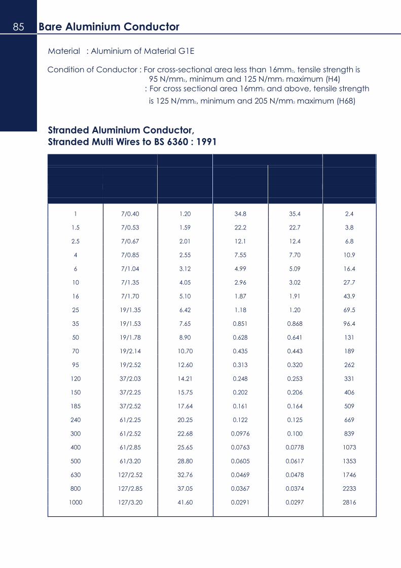
85 Bare Aluminium Conductor
Material : Aluminium of Material G1E
Condition of Conductor : For cross-sectional area less than 16mm2, tensile strength is
95 N/mm2, minimum and 125 N/mm2 maximum (H4)
: For cross sectional area 16mm2 and above, tensile strength
is 125 N/mm2, minimum and 205 N/mm2 maximum (H68)
Stranded Aluminium Conductor,
Stranded Multi Wires to BS 6360 : 1991
Size of Conductor Nominal Maximum Resistance At 20˚C Approx.
Nominal Area No. & size of diameter Single Core Multi Core mass
wire of conductor
mm2 No./mm mm Ω/Km Ω/Km Kg/Km
1 7/0.40 1.20 34.8 35.4 2.4
1.5 7/0.53 1.59 22.2 22.7 3.8
2.5 7/0.67 2.01 12.1 12.4 6.8
4 7/0.85 2.55 7.55 7.70 10.9
6 7/1.04 3.12 4.99 5.09 16.4
10 7/1.35 4.05 2.96 3.02 27.7
16 7/1.70 5.10 1.87 1.91 43.9
25 19/1.35 6.42 1.18 1.20 69.5
35 19/1.53 7.65 0.851 0.868 96.4
50 19/1.78 8.90 0.628 0.641 131
70 19/2.14 10.70 0.435 0.443 189
95 19/2.52 12.60 0.313 0.320 262
120 37/2.03 14.21 0.248 0.253 331
150 37/2.25 15.75 0.202 0.206 406
185 37/2.52 17.64 0.161 0.164 509
240 61/2.25 20.25 0.122 0.125 669
300 61/2.52 22.68 0.0976 0.100 839
400 61/2.85 25.65 0.0763 0.0778 1073
500 61/3.20 28.80 0.0605 0.0617 1353
630 127/2.52 32.76 0.0469 0.0478 1746
800 127/2.85 37.05 0.0367 0.0374 2233
1000 127/3.20 41.60 0.0291 0.0297 2816

Bare Aluminium Conductor 86
All Aluminium Conductors (AAC)
Standard Sizes of All Aluminium Conductors for Overhead Power Transmission
Conductor
Nominal Equivalent Construction
Approx. Calculated Calculated Approx. Code No./Size of Al. copper overall breaking D.C. weight name
area area wire diameter load resistance
at 20˚C
mm2 mm2 No./mm mm KN ohm/Km Kg/Km
22 14.2 7/2.06 6.18 3.99 1.227 64 Midge
50 32.2 7/3.10 9.30 8.28 0.5419 145 Ant
60 38.8 7/3.40 10.20 9.90 0.4505 174 Fly
100 64.7 7/4.39 13.17 16.00 0.2702 290 Wasp
150 96 19/3.25 16.25 24.70 0.1825 434 Hornet
200 130 19/3.78 18.90 32.40 0.1349 587 Chafer
250 162 19/4.22 21.10 40.40 0.10830 731 Cockroach
300 197 19/4.65 23.25 48.75 0.08916 888 Butterfly
400 253 37/3.78 26.46 63.10 0.06944 1145 Centipede
Note : Conductor details of other specifications can be provided upon request.
Bare Aluminium Conductor
All Aluminium Alloy Conductor (AAAC)
Standard Sizes of All Aluminium Conductors for Overhead Power Transmission
Conductor
Construction
Nominal Equivalent No./Size of
Approx. Calculated Calculated Approx. Code Al. copper overall breaking D.C. weight name
area area wire diameter load resistance
at 20˚C
mm2 mm2 No./mm mm KN ohm/Km Kg/Km
25 16.2 7/2.34 7.02 8.44 1.094 82 Almond
30 19.1 7/2.54 7.62 9.94 0.9281 97 Cedar
40 25.8 7/2.95 8.85 13.40 0.6880 131 Fir
50 32.3 7/3.30 9.90 16.80 0.5498 164 Hazel
100 64.5 7/4.65 13.95 33.30 0.2769 325 Oak
150 97 19/3.48 17.40 50.65 0.1830 497 Ash
175 113 19/3.76 18.80 59.10 0.1568 580 Elm
300 194 37/3.53 24.71 101.50 0.09155 997 Upas
Note : Conductor details of other specifications can be provided upon request.

87 Bare Aluminium Conductor
Aluminium Conductor Steel Reinforced (ACSR)
Standard Sizes of Aluminium Conductors Steel Reinforced for Overhead Power
Transmission
Conductor
Calculated
Equivalent
Actual Construction Approx. Calculated
Approx. Weight Code Nominal Sectional No./Size of Wire D.C. name
Al. copper
Al. Steel Al.
Steel
overall breaking resistance
Al. Steel
area area diameter load at 20˚C
mm2 mm2 mm2 mm2 No./mm No./mm mm KN ohm/Km Kg/Km Kg/Km
25 16.0 26.25 4.37 6/2.36 1/2.36 7.08 9.61 1.093 72 34 Gopher
30 19.3 31.61 5.27 6/2.59 1/2.59 7.77 11.45 0.9077 87 41 Weasel
40 25.8 42.41 7.07 6/3.00 1/3.00 9.00 15.20 0.6766 117 55 Ferret
50 32.3 52.88 8.81 6/3.35 1/3.35 10.05 18.35 0.5426 145 69 Rabbit
*60 38.6 63.22 36.88 12/2.59 7/2.59 12.95 52.94 0.4566 175 289 Skunk
70 44.8 73.37 42.8 12/2.79 7/2.79 13.95 61.20 0.3936 203 335 Horse
100 64.0 105.0 13.5 6/4.72 7/1.57 14.15 32.70 0.2733 288 106 Dog
150 96.4 158.1 36.8 30/2.59 7/2.59 18.13 69.20 0.1828 437 289 Wolf
150 96.8 158.7 8.8 18/3.35 1/3.35 16.75 35.70 0.1815 437 69 Dingo
175 111.9 183.4 42.8 30/2.79 7/2.79 19.53 79.80 0.1576 507 335 Lynx
175 112.4 184.3 10.2 18/3.61 1/3.61 18.05 41.10 0.1563 507 81 Caracal
200 129.0 212.1 49.5 30/3.00 7/3.00 21.00 92.25 0.1363 586 388 Panther
200 128.0 210.6 11.7 18/3.86 1/3.86 19.30 46.55 0.13670 580 91 Jaguar
*300 197.0 323.0 15.5 18/4.78 7/1.68 24.16 69.67 0.08914 887 123 Batang
400 262.0 428.9 55.6 54/3.18 7/3.18 28.62 131.90 0.06740 1186 435 Zebra
Note : 1) * Not A Standard Size in BS 215 : Part 2. 2) Conductor details of other specifications can be provided upon request.