MegaLine®, GigaLine® and VarioLine®
280
MegaLine ® , GigaLine ® and VarioLine ® Copper and Fiber Optic Cabling Systems for DataCenter · Office · Industry The Quality Connection
-
Upload
khangminh22 -
Category
Documents
-
view
0 -
download
0
Transcript of MegaLine®, GigaLine® and VarioLine®

MegaLine®, GigaLine® and VarioLine®
Copper and Fiber Optic Cabling Systemsfor DataCenter · Office · Industry
The Quality Connection

LEONI organises its range of data communications products
for the passive cabling infrastructure in buildings and local
networks into three main groups:
n Copper cabling systems MegaLine®
n Fiber optic cabling systems GigaLine®
n Modular system peripherals VarioLine®
MegaLine® from LEONI is a copper system family for all classes
and categories that delivers a sound, future-proof investment.
It incorporates MegaLine® Copper data cables, patch cords and
trunk cables as well as MegaLine® Connect and VarioKeystone®
Connectivity.
GigaLine® allows extremely high bandwidths and long
transmission distances thanks to its fiber optic technology.
GigaLine® Fiber optic data cables, patch cords and trunk cables
as well as GigaLine® Connectivity combine to produce an
extremely efficient system.
VarioLine® is a modular consolidation point and underfloor range.
All connection components can be easily and quickly integrated
into different areas of application and adapted to local conditions.
LEONI also offers a comprehensive service package comprising
data sheets, announcement texts, seminars and certification
programmes.
Issue: November 2012 © LEONI Kerpen GmbHThe contents of this catalogue are protected by copyright. All rights reserved.
All necessary planning documents can be found on the Internet: www.leoni-infrastructure-datacom.com
We reserve the right to make technical modifications; typographical errors and mistakes excepted.
Portfolio
Strong brands, strong service
Datacom system families: a sound, future-proof investment
MegaLine®
Copper cabling systems
MegaLine®
Cu data cablesGigaLine®
FO data cables
VarioKeystone®
Cu connectivity
GigaLine®
FO patch cords/ trunk cables
MegaLine®
Cu patch cords/ trunk cables
MegaLine®
Connect Cu connectivity
GigaLine®
FO connectivity
VarioLine®
Modular system peripherals*
GigaLine®
FO cabling systems
* VarioLine® can be used for both system families
www.leoni-infrastructure-datacom.com
2

Page
n MegaLine® 10
Cu data cables
n VarioKeystone® 72
Cu connectivity
n MegaLine® Connect45 92
Cu connectivity
n ELine 1200® EC7 104
Cu connectivity
n MegaLine® 116
Cu patch cords/trunk cables
n GigaLine® 152
FO data cables
n GigaLine® 182
FO connectivity
n GigaLine® 210
FO patch cords/trunk cables
n GigaLine® 228
DataCenter links
n VarioLine® 236
Modular
system peripherals
•Consolidationpoints(CP)
•Underfloorsolutions(UF)
n Office 264
n Industry 266
n DataCenter 272
Copper (Cu)Cabling systems
Cable and connectivity
Fiber optic (FO)Cabling systems
Cable and connectivity
System peripheralsfor copper and FO
Fields of application
Contents
www.leoni-infrastructure-datacom.com
3

Welcome to the datacom mega store for cable and system solutions
www.leoni-infrastructure-datacom.com
4
LEONI is a leading supplier in the market for structured
cabling systems. In addition to cabling for offices
(LAN Office), the range also includes cabling for industrial
complexes (LAN Industry) and DataCenter infrastructure
(DataCenter).
LEONI's services range from producing our own fibers,
manufacturing data cables in copper and fiber optic technology,
pre-assembled patch cords and trunk cables as well as connection
components through to complete cabling systems.
Everything from a single source
LEONI's range of copper cable and connectivity offers future-
proof cabling systems for building, floor and workstation
cabling.
Fiber optic cable and connectivity is the first choice wherever
broadband data transmission in combination with long
transmission distances in a LAN or MAN are required. LEONI's
GigaLine® fiber optic cables and GigaLine® fiber optic
connectivity offer high-speed data highways for backbone
networks.
LEONI products and solutions are ideal for applications which
demand maximum reliability, quality and durability, even under
harsh and adverse conditions.

www.leoni-infrastructure-datacom.com
5
The cabling systems exceed all relevant European (EN 50173) and
international standards (ISO/IEC 11801) and are designed for key
applications (Office · DataCenter · Industry).
Application Office Industry DataCenter
European standards EN 50173-2 EN 50173-3 EN 50173-5
International standards ISO/IEC 11801 ISO/IEC 24702 ISO/IEC 24764

www.leoni-infrastructure-datacom.com
6
The LEONI Group
Cable expertise for the most varied industrial markets
Your markets – our strength
As diverse as our product and service range are the markets and
sectors LEONI is supplying. We focus our activities on customers
in the fields of Automotive & Commercial Vehicles, Industry
& Healthcare, Communication & Infrastructure, Electrical
Appliances and Conductors & Copper Solutions.
We are among the leading European suppliers in the Communi-
cation & Infrastructure market to which at LEONI as a cable
manufacturer also belong activities in the fields of infrastructure
& data communications, industrial plant projects, solar- and
wind power, energy & telecommunications, irradiation cross-
linking and transportation engineering. Our customers benefit
world-wide from innovative as well as reliable and long-lasting
products of high quality. LEONI – we create the best connection
for your future. for further informations www.leoni.com
Automotive &
Commercial Vehicles
Communication &
Infrastructure
Industry &
HealthcareElectrical
Appliances
LEONI's core markets
Products and services portfolio at a glance
LEONI is a leading supplier of cable systems and related
services for the automotive industry and various other
industrial sectors.
Our group of companies employs more than 63,000 people in
31 countries. Corporate vision, highest quality and innovative
power have made us one of the leading cable manufacturers in
Europe. LEONI develops and produces technically sophisticated
products ranging from wire and optical fibers to cables
through to complete cable systems and also offers the related
services. Moreover, the product portfolio comprises strands,
standardised cables, hybrid cables, glass fiber as well as special
cables, cable harnesses, wiring systems components and
fully assembled systems for applications in various industrial
markets.
Conductors &
Copper Solutions
Services
Optical cablesHybrid cablesCopper cables
Cable systems/Wiring systems
Relay and safety systemsSensorsCable harnesses
ConnectorsOptical fibersWires and strands
Engi
neer
ing

Infrastructure & Datacom Business Unit
LEONI brings together the expertise for power and
communications networks in public buildings, in structural
and civil engineering, in offices, in DataCenters and in industry.
Investors, integrators, planners, installers and businesses can
obtain cables, connectivity and complete cabling solutions
from a single source. The range includes system solutions based
on copper and fiber optic technology as well as halogen-free
power cables with and without total system integrity. Constant
innovations in the areas of safety, environmental compatibility
and energy efficiency offer enhanced customer benefits. Thanks
to on-site consulting services and extensive experience, LEONI is
an internationally recognised partner for your projects.
Datacom
The extensive know-how of all companies belonging to the
LEONI Group and the unique range of products and services they
offer are concentrated in the Datacom business unit. Some of the
companies involved have been working successfully in the field
of cable-bound networks for decades now - particularly LEONI.
The origins
LEONI has been working successfully in the field of cable-bound
networks for many years. As one of the leading manufacturers
in the cable industry, the company has been successfully
meeting the complex needs of international markets for more
than 90 years. The quest for constant improvement is a central
element of the company philosophy and will continue under
the newnameofLEONIInfrastructure&DatacomBusinessUnit.
And it is to the future that we look, producing high-quality,
innovative cable and cabling products which are always well
ahead of the standards of the time.
Trust the best partner for your requirements.
www.leoni-infrastructure-datacom.com
7
Infrastructure & Datacom Business Unit

www.leoni-infrastructure-datacom.com
8
Quality and environmental management
The Quality Connection
LEONI quality management
One of the most important factors in the success of LEONI
was and remains the uniformly high quality of its products over
the decades.
We pay particularly close attention to this through precise
planning, testing and documentation. Quality management
for LEONI's wire and cable production facilities is certified
worldwide in accordance with ISO 9001:2000.
As part of the production process, we use the latest systems
to measure, monitor and regulate the diameter and insulating
capabilities of our cables and wires. The production control group
performs regular spot checks to ensure compliance with the
required limit values. These tests are performed directly in the
production area and guarantee a speedy response to interference.
By combining these quality assurance measures, we are able
to continuously optimise our ambitious quality targets.
LEONI environmental management
New environmental directives have been in force in the European
Union(EU)sinceJuly2006.EUDirective2002/96/ECWEEE
(Waste ElectricalandElectronicEquipment)regulatesthe
disposal of electrical and electronic equipment and components.
EUDirective2002/95/ECRoHS(Restrictionoftheuseofcertain
HazardousSubstancesinelectricalandelectronicequipment)
restricts the use of certain hazardous substances in electrical and
electronic equipment and components.
Cables and wires and the associated connectivity are only
affected by the aforementioned directives insofar as they are
an internal component of the listed devices and components.
Cables and wires and the associated connectivity therefore do
not fall under the aforementioned directives if they are located
outside of electrical and electronic devices. This also applies
to connection cables, connection sockets and other peripheral
products as these are disconnected when a device is to be
disposed of.

www.leoni-infrastructure-datacom.com
9
EU Directive 2002/96/EC
on waste electrical and electronic equipment.
EU Directive 2002/95/EC
on the restriction of the use of certain
hazardous substances in electrical and
electronic equipment.
What does RoHS mean?
RoHS stands for Restrictionoftheuseofcertain
Hazardous Substances in electrical and electronic
equipment.
Even though data and communication cables as well
as the associated connectivity do not fall under the
new directives, LEONI has opted to use RoHS-compliant
materials.
All MegaLine® and GigaLine® brand data cables produced
after January 1, 2006 are free from hazardous substances
as per RoHS. The associated connectivity is also free from
hazardous substances. This is ensured in close cooperation
with suppliers.
This means avoiding the following substances, among others:n Polybrominateddiphenylether(PBDE)n Decabromodiphenylether(DecaBDE)n Perfluorooctanesulfonate(PFOS)n Pentabromodiphenylether(PentaBDE)n Octabromodiphenylether(OctaBDE)n Lead(Pb)n Mercury(Hg)n Cadmium(Cd)n Hexavalentchromium(CrVI)n Polybrominatedbiphenyls(PBB)
LEONI has been operating a certified and practised
environmental management system according to DIN EN ISO
14001 for the development and manufacture of cables and
wires from as far back as 1989. The TÜV certification given by
the German Technical Certification Association is proof of the
company's environmentally friendly product design credentials.
ByensuringtheRoHSconformityofthedataandcommunication
cables as well as the associated connectivity, LEONI Kerpen
GmbH is making a further commitment to environmental
responsibility.

MegaLine®
copper data cables
www.leoni-infrastructure-datacom.com
1010

Office DataCenterIndustry
MegaLine® copper data cables Page
SPACE concept 12
SPACE–Security 13
SPACE–Performance 14
SPACE–Application 16
SPACE–Construction 17
SPACE–EMC 18
Type codes 19
Cable types 20
MegaLine® copper data cables Page
Copper data cables at a glance 22
o dc MegaLine® G12-150 S/F Category "8" Class "G" 22
o dc MegaLine® F10-130 S/F Category 7A Class FA 24
o dc MegaLine® F10-125 S/F Category 7A Class FA 26
o dc MegaLine® F10-115 S/F Category 7A Class FA 28
o dc MegaLine® F6-90 S/F Category 7 Class F 30
o MegaLine® E5-70 S/F Category 6A Class EA 32
o MegaLine® E5-70 F/F Category 6A Class EA 34
o MegaLine® E5-60 U/F Category 6A Class EA 36
o MegaLine® E2-45 U/F Category 6 Class E 38
o MegaLine® E2-30 F/U Category 6 Class E 40
o MegaLine® E2-30 U/U Category 6 Class E 42
o MegaLine® D1-20 SF/U Category 5 Class D 44
o dc MegaLine® F10-120 S/F flex Category 7 Class FA 46
o dc MegaLine® F6-90 S/F flex Category 7 Class F 48
o MegaLine® D1-20 SF/U flex Category 5 Class D 50
i MegaLine® F10-130 S/F (L)2Y Category "7A" Class FA 52
i MegaLine® F10-130 S/F QH Category "7A" Class FA 54
i MegaLine® F10-130 S/F Vö Category "7A" Class FA 56
i MegaLine® F10-115 S/F V Category "7A" Class FA 58
i MegaLine® F6-90 S/F 2Y Category 7 Class F 60
i MegaLine® D1-20 SF/U 2Y Category 5 Class D 62
i MegaLine® D1-20 SF/U HQH Category 5 Class D 64
i MegaLine® F10-120 S/F 11Y flex Category "7A" Class FA 66
i MegaLine® F6-70 S/F 11Y flex Category 7 Class F 68
i MegaLine® D1-20 S/U 11Y superflex Category 5 Class D 70
o Office cables
dc DataCenter cables
i Industrial cables
www.leoni-infrastructure-datacom.com
11
Meg
aLin
e®
Cu d
ata
cabl
es

S Security
P Performance
A Application
C Construction
E EMC
www.leoni-infrastructure-datacom.com
12
LEONI's SPACE concept is based on a pragmatic and clearly
structured matrix. This decision-making aid will help you
to find the right data cable for your application faster.
The concept is based on the classification of the five main
selection criteria for determining the potential overall
performance of a data cable:
Security · Performance · Application · Construction · EMC
It also allows the value for money to be assessed and makes
room for alternative technical and economic scenarios.
The demands made on the segment in question rise in step
with the increaseintheSPACEindex.
Example of a data cable with the code S3 P4 A4 C5 E5 :
S3 It passes the fire test according to IEC 60332-3-24
(Security Level3)
P4 It meets the minimum requirements of the new Class FA
(PerformanceLevel4)
A4 It is dimensioned for applications with more than 10 GbE
(ApplicationLevel4)
C5 ItconsistsofaconductorwithAWG22(ConstructionLevel5)
and thus has low attenuation values and an increased
current rating
E5 Thecouplingattenuationis>80dB(EMCLevel5)
WiththeVDEkitemark(anindependenthallmarkofquality
includingproductionmonitoring),LEONIdocumentsthat
it guaranteestheSPACEquality featuresatalltimes.
SPACE matrix:
Security(firebehaviour)
S1
IEC 60332-2-2
2IEC 60332-
1-2
3IEC 60332-
3-24
4EFP
Grade 1
5EFP
Grade 2
Performance (cablingclass,bandwidth)
P 1> Class E
> 250 MHz
2> Class EA
> 500 MHz
3> Class F
> 600 MHz
4> Class FA
> 1000 MHz
5> Class "G"
> 1200 MHz
Application (Ethernet,TV)
A 1> 100 MbE
2> 1 GbE
3Up to 10
GbE
4> 10 GbE
5> 10 GbE
TV
Construction (conductordimensions,tensilestrength)
C 1AWG 27
2AWG 26/25
3AWG 24
4AWG 23
5AWG 22
EMC (couplingattenuation)
E 1> 40 dB
2> 50 dB
3> 60 dB
4> 70 dB
5> 80 dB
SPACE concept
Finding the right data cable

Office DataCenterIndustry
www.leoni-infrastructure-datacom.com
13
Meg
aLin
e®
Cu d
ata
cabl
es
As a result of the constant increase in the installed basis and
the installation density, the fire behaviour of data cables
is an important safety criterion. When manufactured according
to the legal regulations and installed correctly, data cables
cannot cause a fire. If they do catch fire, however, they can
inflame and spread the fire.
One of the aims here is to prevent the propagation of fire and
the resulting damage by using flame-retardant, halogen-free
cable designs.
The five security levels with regard to fire
propagation/flame retardance:
S1 IEC 60332-2-2
Testing of the vertical propagation in a core or individual cable.
Test method: incandescent flame.
S2 IEC 60332-1-2
Testing of the vertical propagation in a core or individual cable.
Test method: 1 KW flame. A flame is applied to the lower end
of a vertical sample of the cable with a length of approx. 60 cm
for about 60 seconds using a type of Bunsen burner. After
removal of the burner, the flames must go out by themselves.
The parts of the cable damaged by the flames must not reach
its upperend(distance:50mm).
S3 IEC 60332-3-24
Testing of the flame propagation in an arrangement of several
cables, a so-called cable bundle, is carried out according
to IEC 60332-3-24. In this cable bundle test, a flame is applied
to the lower part of the test samples on a vertical ladder with
a length of 360 cm using a high-performance burner. During
and after intensive application of the flame for a test period
of 20 minutes, the cables must not burn higher than 250 cm.
SPACE – Security
Fire behaviour
Security(firebehaviour)
S1
IEC 60332-2-2
2IEC 60332-
1-2
3IEC 60332-
3-24
4EFP
Grade 1
5EFP
Grade 2
SPACEconcept
MegaLine® data cables have improved fire protection
characteristics:n Extremely low smoke development according to IEC 61034
Makes rescue and salvage operations easiern Lowtoxicity(dioxinsarenotproduced)
Reducestheriskofpoisoningn Free from halogens according to IEC 60754-2
No consequential damage to material assets as a result
of corrosionn Low fire load values
Limits the exacerbating effects on the source of the firen Highoxygenindex(OIupto45)
Reducestheflammability
S4 EFP (Enhanced Fire Performance) Grade 1
In this cable bundle test, a flame is applied to the lower part
of the test samples on a vertical ladder with a length of
360 cm using a high-performance burner. During and after
intensive application of the flame for a test period of
20 minutes, only about 1 m of the section to which the flame
is applied may burn. Immediately after removal of the flame,
the self-extinguishing process must start. Only specially
designed data cables can stand up to this exacting fire test.
S5 EFP (Enhanced Fire Performance) Grade 2
This stricter security level is application-specific.
Security levels S3, S4 and S5 are used in particular
where high and very high security measures are required
for the protection of persons or material assets. For example
in hospitals, schools, hotels, airports, train stations, department
stores or in power stations, DataCenters, banks and insurance
companies, alarm systems.

www.leoni-infrastructure-datacom.com
14
Example: MegaLine® F6-90 S/F
better than Category 7 according to EN 50288 and IEC 61156
excellent NEXT, excellent shielding characteristics
(shieldingofpairsandoverallshielding),lowskew
MHz
1200
1000
800
600
400
200
0
F6-80S/F
F6-90S/F
P3 better than Class F (600 MHz)
Indoor cabling is expected to have a service life of 10 to 15 years.
This requires far-sighted planning of the necessary performance
of cabling systems and their components.
The international standards have often not gone far enough
due to the compromises struggled for and in view of the
swiftly increasing transmission rates. Since the development
of 10 Gigabit Ethernet, none of the cabling classes below
Class F can be said to meet the demands of the future.
MegaLine® data cables have excellent transmission
performance. They offer high security reserves
and are always one step ahead of the standard.
MegaLine® – an investment with a future!
The five classes for performance (cabling class, bandwidth)
have very high reserves with regard to the standard involved.
SPACE – Performance
Cabling class/bandwidth
SPACEconcept
Performance (cablingclass,bandwidth)
P 1> Class E
> 250 MHz
2> Class EA
> 500 MHz
3> Class F
> 600 MHz
4> Class FA
> 1000 MHz
5> Class "G"
> 1200 MHz
nClass F
nMegaLine®

Office DataCenterIndustry
www.leoni-infrastructure-datacom.com
15
Meg
aLin
e®
Cu d
ata
cabl
es
Example: MegaLine® E2-45 U/F
better than Category 6 according to EN 50288
and IEC 61156, very good NEXT, low skew
MHz
500
450
400
350
300
250
200
150
100
50
0
E2-30U/U
E2-30F/U
E2-45U/F
P2 better than Class EA (500 MHz)
Example: MegaLine® E5-70 S/F
better than Category 6A according to EN 50288 and IEC 61156
very good NEXT, very good shielding characteristics
(shieldingofpairsandoverallshielding),lowskew
MHz
800
700
600
500
400
300
200
100
0
E5-70F/F
E5-70S/F
P4 better than Class FA (1000 MHz)
Example: MegaLine® G12-150 S/F
better than Category 7A and "8" according to EN 50288 and IEC
61156, excellent NEXT, very low attenuation, excellent shielding
characteristics(shielding of pairsandoverallshielding),lowskew
MHz
1400
1300
1200
1100
1000
900
800
700
F10-130S/F
MHz
1600
1400
1200
1000
800
600
400
200
0
G12-150 S/F
P5 better than Class "G" (1200 MHz)
SPACEconcept
P1 better than Class E (250 MHz)
nClass FA
nMegaLine®
nClass "G"
nMegaLine®
nClass EA
nMegaLine®
nClass E
nMegaLine®
F10-115S/F
Example: MegaLine® G12-150 S/F
better than Category 7A and "8" according to EN 50288 and
IEC 61156, excellent NEXT, low attenuation, excellent shielding
characteristics(shielding of pairsandoverallshielding),lowskew

www.leoni-infrastructure-datacom.com
16
The large security reserves mean that multimedia applications
like TV or transmission protocols with high bandwidth
requirements such as 10 Gigabit Ethernet and 8 Gigabit
Fiberchannel can be transmitted over 100 m. Experts have
calculated that, as far as we know today, MegaLine® Category 7A
data cables allow transmission rates of as much as 100 Gbit/s.
Theuseoflow-lossbroadbandS/FTPcableswithindividual
or overall shielding in conjunction with multimedia cabling
systems such as ELine 1200® EC7 allows so-called cable
or service sharing.
A1 >100 Mbit/s (Fast Ethernet) IEEE 802.3 u
A2 >1,000 Mbit/s (Gigabit Ethernet) IEEE 802.3 ab
A3 ≤10,000 Mbit/s (10 Gigabit Ethernet) IEEE 802.3 an
A4 >10,000 Mbit/s (10 Gigabit Ethernet) IEEE 802.3 an
A5 >10,000 Mbit/s (10 Gigabit Ethernet) and TV
IEEE 802.3 an and Multimedia
The SPACE concept provides five different application levels.
SPACE – Application
Ethernet/TV
SPACEconcept
Application (Ethernet,TV)
A 1> 100 MbE
2> 1 GbE
3Up to 10
GbE
4> 10 GbE
5> 10 GbE
TV
Cables and connectors form a perfect symbiosis: 4 pairs,
4 connecting clips: each with GHz performance. This allows
the parallel, simultaneous use of different applications via
one cable and one connector:
data, voice and images.
Multimedia systems do not need to cost more than conventional
systems, in which an individual cable and an individual
connector is usually required for each service. This allows
savings of up to 50 % of the necessary cables, connectors,
wall outlets and patch panels.
Multipleusereducesthesystemcostsby15–30%(depending
ontheservicesused).Thereductioninthenumberofcables
and wall outlets actually required usually also allows reductions
in the costs for cable ducts, switching cabinets, etc.
But MegaLine® data cables are capable of more
Thesupplyofcurrent(upto350/600mA)andvoltage(up to 48 V)
canbe providedviaPoE/PoE+(accordingtoIEEE802.3a/at).
The current is fed in centrally via the floor distributor or switch.
DevicessuchasIPtelephones,Webcameras,WLANaccesspoints,
etc. are supplied via the telecommunications outlet. The voltage
is tapped via a phantom circuit or two unassigned pairs.
Telephone PC
Video/audio/TV/radio

www.leoni-infrastructure-datacom.com
17
Meg
aLin
e®
Cu d
ata
cabl
es
High-precision conductor and core geometries, optimally
matched lay lengths in the pairs and the use of very high-
quality insulation and sheath materials are the characteristic
features of our range of cables.
Our cables are produced on ultra-modern equipment which
corresponds with the "state of the art" as a result of procedural
innovations. The use of physical foaming in the manufacture
of high-frequency cores allows excellent, uniform electrical and
geometrical characteristics to be achieved. Double skin layers
ensure excellent mechanical stability while patented stranding
techniques demonstrate technical leadership.
SPACE – Construction
Conductor dimensions
SPACEconcept
The designs have low overall diameters, thus allowing high
packing densities and small bending radii. The weight
reductions and the robust cable construction offer advantages
for assembly and installation, even under difficult conditions.
The five different conductor classes describe the permitted
tensile stress during installation and the conductor
resistance.
The current-handling capacity for a maximum ambient
temperature of 60 °C and the maximum installation
lengths in the transmission channel can be derived from
this on request.
Construction (conductordimensions,tensilestrength)
C 1AWG 27
2AWG 26/25
3AWG 24
4AWG 23
5AWG 22
C1 AWG 27 (7x0.14 mm/0.112 mm2)
Tensilestress:max.40/20N(4p/2p)
Conductor resistance: max. 170 Ω/km
C2 AWG 26/AWG 25
C21 AWG 26 (7x0.16 mm/0.14 mm2)
Tensilestress:max.60/30N(4p/2p)
Conductor resistance: max. 145 Ω/km
C22 AWG 25 (7x0.18 mm/0.175 mm2)
Tensilestress:max.70/35N(4p/2p)
Conductor resistance: max. 120 Ω/km
C3 AWG 24 (0.51 mm/0.205 mm2)
Tensilestress:max.90/45N(4p/2p)
Conductor resistance: max. 95 Ω/km
C4 AWG 23 (0.57 mm/0.258 mm2)
Tensilestress:max.110/55N(4p/2p)
Conductor resistance: max. 75 Ω/km
C5 AWG 22 (0.64 mm/0.325 mm2)
Tensilestress:max.130/65N(4p/2p)
Conductor resistance: max. 57 Ω/km
Office DataCenterIndustry

With the MegaLine® SPACE concept, LEONI provides
five different EMC levels to choose from.
The evaluation criterion is the coupling attenuation
(interferencepowersuppression).Asthesumoftheshielding
attenuation and the symmetry attenuation, the coupling
attenuation is the "be-all and end-all" for the assessment
and comparison of the overall EMC behaviour of data cables
with various different constructions.
www.leoni-infrastructure-datacom.com
18
Electromagnetic compatibility (EMC)
This refers to the ability of devices, systems and plants
to function satisfactorily in an electromagnetic environment
without negative effects on other devices, systems or plants.
EMC legislation prescribes the electromagnetic compatibility
of devices, systems and plants. The limits for the emission
of interference and the immunity to interference which
must be observedareregulatedinEN55022(ClassB)and
EN 50082-1/2 / EN 55024.
A data cable must resist electromagnetic influences coming
fromtheoutsidetotheinside(immunitytointerference)
and fromtheinsidetotheoutside(emissionofinterference).
The susceptibility of data cable systems to interference
increases in step with the transmission frequency
and the data rates(currently10GigabitEthernet).
E1 Coupling attenuation >40 dB
Interference suppression exceeding a factor of 100
E2 Coupling attenuation >50 dB
Interference suppression exceeding a factor of 300
E3 Coupling attenuation >60 dB
Interference suppression exceeding a factor of 1,000
E4 Coupling attenuation >70 dB
Interference suppression exceeding a factor of 3,000
E5 Coupling attenuation >80 dB
Interference suppression exceeding a factor of 10,000
Electromagnetic compatibility
Construction U/UTP F/UTP S/FTP
Symmetry characteristics +++ ++ ++
Shielding characteristics low + +++
Influence of the installation environment
high medium low
SPACE – EMC
Coupling attenuation
SPACEconcept
The main danger is increasingly a result of the alien
crosstalk between adjacent data cables. Depending on their
construction, data cables have different capabilities with regard
to the prevention or reduction of interference.
n Unshieldeddatacableshaveverygoodsymmetry
characteristics but are not shielded against internal, external
or adjacent sources of interference. They are endangered to
a high degree by the environment in which they are installed.
n Data cables with individual or overall shielding have very
good symmetry characteristics and good or even very good
shield characteristics. The EMC is very good or even excellent.
Interference coming from the installation environment
(adjacentdatacables)canberuledoutcompletely.
MegaLine® data cables with a dual shielding reach values
of >80 dB up to 1,000 MHz, thus suppressing incoming
or outgoing potential interference by a factor of >10,000.
Cables with individual and overall shielding (S/FTP)
have excellent EMC, making them an obvious choice
for the fail-safe transmission of high data rates such
as those offered by 10 Gigabit Ethernet.
EMC (couplingattenuation)
E 1> 40 dB
2> 50 dB
3> 60 dB
4> 70 dB
5> 80 dB

www.leoni-infrastructure-datacom.com
19
Meg
aLin
e®
Cu d
ata
cabl
es
Type codes
MegaLine® Cu data cables
MegaLine® F10-130 S/F H
Cabling class
Class "G" "G"Class F FClass E EClass D D
Bandwidth acc. to standard (factor 100)
1,200 MHz 121,000 MHz 10600 MHz 6500 MHz 5250 MHz 2100 MHz 1
MegaLine® bandwidth (factor 10)
1,500 MHz 1501,300 MHz 1301,150 MHz 115900 MHz 90800 MHz 80700 MHz 70450 MHz 45300 MHz 30200 MHz 20
TP (twisted pair) design
Overallshielding(copperbraiding)/individualshield(foil) S/FOverallshielding(foil)/individualshielding(foil) F/FUnshielded/individualshielding(foil) U/FOverallshielding(copperbraiding&foil)/unshielded SF/UOverallshielding(foil)/unshielded F/UUnshielded/unshielded U/U
Sheath/armouring
Halogen-free, flame-retardant HPVC YPE 2YPUR 11YSheath (L)2YReinforcedsheathforindustrialapplications VOil-resistant ÖSteel wire braiding Q
The type codes for the MegaLine® copper data cables are
compatiblein structurewiththeSPACEconcept.Thismakes
it easier to assign cables to the old and new cabling classes
and the corresponding categories.
F Acc. to new cabling class FA(1,000MHz)
10 Bandwidth acc. to standard: 1,000 MHz
130 MegaLine® bandwidth: 1,300 MHz
S/F S/FTPdesign
H With halogen-free outer sheath
The type codes also include: n Information about the bandwidth in comparison to the standardn Information about the design according to the international standard n Information about the material used for the sheath
Cu data cable: MegaLine® F10-130 S/F H
Office DataCenterIndustry

Outer sheath
Braided shielding
Cable pair
Foil shielding
Conductor
Outer sheath
Braided and foil shielding
Cable pair
Conductor
Outer sheath
Foil shielding
Cable pair
Foil shielding
Conductor
Outer sheath
Foil shielding
Cable pair
Conductor
Outer sheath
Cable pair
Foil shielding
Conductor
Outer sheath
Cable pairs separated by a cross element
Conductor
www.leoni-infrastructure-datacom.com
20
Cable type x x / x x x
Overall shielding
Foil shielding FBraided shielding SBraided and foil shielding SF
Individual shielding
Unshielded UFoil shielding F
Symmetrical element P
Cable type
There are a large number of different type designations.
The standardisation defined in ISO/IEC 11801 2nd Edition
determines the elements of the design in an unambiguous way.
SF/UTP Cable with overall braided and foil shielding/
with unshielded individual elements
S/FTP Cable with overall braided shielding/
with individual elements with foil shielding
PiMF Pairinmetalfoil(xx/FTP)
S/FTP (PiMFwithoverallshielding) F/FTP U/FTP
SF/UTP F/UTP U/UTP
Cable types
MegaLine® Cu data cables

www.leoni-infrastructure-datacom.com
21
Meg
aLin
e®
Cu d
ata
cabl
es
Office DataCenterIndustry

Construction
www.leoni-infrastructure-datacom.com
22
Conductor Bare copper wire, AWG 22/1
InsulationTwisting element
Cellular-PE,core-diameter:nominalvalue1.6mmPair
Individual shieldingTwisting
Aluminium-bonded polyester foil, metalsideoutside(PiMF)4 pairs
Overall shielding Tinned copper braiding
Outer sheath Halogen-free, flame-retardant compound
MegaLine® G12-150 S/F Type KS-02YSCH4x2xAWG22/1PIMF
Category "8"
S3 P5 A5 C5 E5
Security(firebehaviour)Fire behaviourFlame retardancy acc. to IEC 60332-3-24Halogen free acc. to IEC 60754-1/2Smoke density acc. to IEC 61034-1/2Calorificvalue(approx.) 0.74MJ/m
S 1IEC 60332-
2-2
2IEC 60332-
1-2
3IEC 60332-
3-24
4EFP
Grade 1
5EFP
Grade 2
Performance (cablingclass,bandwidth)PerformanceBetterthanCategory7("8")acc.toEN50288andIEC61156,excellent NEXT, very low attenuation, excellent shielding characteristics (shielding of pairs and overallshielding),lowskew,bandwidth1,500MHz
P 1> Class E
> 250 MHz
2> Class EA
> 500 MHz
3> Class F
> 600 MHz
4> Class FA
> 1000 MHz
5> Class "G"
> 1200 MHz
Application (Ethernet,TV)ApplicationsInstallation cable for use in structured cabling systems acc. to ISO/IEC 11801 and EN50173(2ndedition)andforhomecablingsystemsacc.to ISO/IEC15018and EN 50173-4. Ideal for all applications from Classes D to FAMultimedia(TV,video,data,voice)>10GbEacc.toIEEE802.3an,cablesharing,VoIP,PoE.
A 1> 100 MbE
2> 1 GbE
3Up to 10
GbE
4> 10 GbE
5> 10 GbE
TV
Construction (conductordimensions,tensilestrength)Mechanical characteristicsBendingradius duringinstallation 8xoveralldiameter(min.) afterinstallation 4xoveralldiameter(min.)Tensilestrength(max.) 130NCrush strength 1,000 N/100 mmImpactstrength(numberofshocks) 10
C 1AWG 27
2AWG 26/25
3AWG 24
4AWG 23
5AWG 22
EMC (couplingattenuation)Electromagnetic behaviourTransferimpedanceat10MHz(nominalvalue) 2mΩ/mShieldingattenuationupto1,200MHz(nominalvalue) 80dBCouplingattenuationupto1,200MHz(nominalvalue) 90dB
E 1> 40 dB
2> 50 dB
3> 60 dB
4> 70 dB
5> 80 dB

www.leoni-infrastructure-datacom.com
23
Meg
aLin
e®
Cu d
ata
cabl
es
Electrical characteristics (HF) at 20 °C Frequency
MHzAttenuation
dB/100 mNEXT
dBPSNEXT
dBACR
dB at 100 mPSACR
dB at 100 mELFEXT
dB at 100 mPSELFEXT
dB at 100 mRLdB
typ. Cat. "8" max.*
typ. Cat. "8" min.*
typ. Cat. "8" min.*
typ. Cat. "8"min.*
typ. Cat. "8" min.*
typ. Cat. "8" min.*
typ. Cat. "8"min.*
typ. Cat. "8" min.*
1 1.6 1.9 110 80 107 77 108 78 105 75 109 80 106 77 26.1 23
10 4.2 5.4 110 78 107 75 106 72 103 69 109 74 106 71 32.3 25
100 14.4 17.5 110 76 107 73 96 58 93 55 93 54 90 51 36.2 20.1
200 21.5 25.3 110 72 107 69 88 47 85 46 86 48 83 45 35.5 18
250 24.5 28.5 105 70 102 67 81 42 78 39 83 46 80 43 34.8 17.3
500 34 41.8 105 65.5 102 62.5 71 24 68 21 70 40 67 37 31.8 17.3
600 37.7 46.3 100 64.3 97 61.3 62 18 59 15 64 38.4 61 35.4 28.5 17.3
800 44.5 54.5 95 62.5 92 59.5 50 8 47 5 58 35.9 55 32.9 25.3 16.1
900 48.1 58.4 95 61.7 92 58.7 47 3 44 0 54 34.9 51 31.9 23.8 15.5
1000 49 62 92 61 89 58 43 –1.1 40 –4 49 34 46 31 22.2 15.1
1200 54.9 69 88 59.8 85 56.8 34 –9 31 –12 40 32.4 37 29.4 20.2 14.3
1300 57 – 81 – 78 – 24 – 21 – 35 – 32 – 18.3 –
1400 58.1 – 74 – 71 – 16 – 13 – 30 – 27 – 16.3 –
1500 62 – 73 – 70 – 11 – 8 – 25 – 22 – 12.3 –*EN50288-4-1(2004)/IEC61156-5(2002)/IEC61156-7(2003)
Electrical characteristics (LF) at 20 °C
DC resistance
Insulation resistance
Mutual capacitance
Capacitivecoupling(e)
Signalvelocity(c)
Propagationdelay
Skew at 100 MHz
Characteristic impedance
TestingvoltageUeff
Operating voltage
max.
min.
approx.
approx.
approx.
approx.
approx.
at 100 MHz
max.
57.1Ω/km
5GΩxkm
42 pF/m
1,000 pF/km
0.80
420 ns/100 m
3 ns/100 m
100±5Ω
1,000 V
125 V
Thermal characteristics
For fixed installation
For mobile operation
–20°Cupto+60°C
0°Cupto+50°C
Chemical characteristics
Freefromhazardoussubstancesacc.toRoHS2002/95/EC
Printing on outer sheath
LEONIMegaLineG12-150S/F4PHSPACECode35555
"VDE approval mark" "production lot code" "meter marking"
Colour code
wh/bu, wh/or, wh/gn, wh/bn
Certificates and approvals
Quality mark with production control:
Link performance: LEONI MegaLine® systems and further
commercial connector systems Inspection certificates:
acc. to DIN 55350-18-4.2.1/EN 10204
ConformstoLVD(73/23/EEC):
DimensionsOuter diam.
approx.Weight approx.
Cu content Colour of sheath Order no.
mm kg/km kg/km
4 p 8.6 80 48 RapeyellowRAL1021 LKD 7KS8 0001 0000
Package:Drum1,000m
IndustryOffice DataCenter

www.leoni-infrastructure-datacom.com
24
MegaLine® F10-130 S/F Types KS-02YSCH4x2xAWG22/1PIMF KS-02YSCH2x(4x2xAWG22/1PIMF)Category 7A
Construction 4 p Conductor Bare copper wire, AWG 22/1
InsulationTwisting element
Cellular-PE,core-diameter:nominalvalue1.6mmPair
Individual shieldingTwisting
Aluminium-bonded polyester foil, metalsideoutside(PiMF)4 pairs
Overall shielding Tinned copper braiding
Outer sheath Halogen-free, flame-retardant compound
S3 P4 A4 C5 E5
Security(firebehaviour)Fire behaviourFlame retardancy acc. to IEC 60332-3-24Halogen free acc. to IEC 60754-1/2Smoke density acc. to IEC 61034-1/2Calorificvalue(approx.) 0.70MJ/m(Sx),1.4MJ/m(Dx)
S 1IEC 60332-
2-2
2IEC 60332-
1-2
3IEC 60332-
3-24
4EFP
Grade 1
5EFP
Grade 2
Performance (cablingclass,bandwidth)PerformanceBetter than Category 7A acc. to EN 50288 and IEC 61156,excellent NEXT, very low attenuation, excellent shielding characteristics (shielding of pairs and overallshielding),lowskew,bandwidth1,300MHz
P 1> Class E
> 250 MHz
2> Class EA
> 500 MHz
3> Class F
> 600 MHz
4> Class FA
> 1000 MHz
5> Class "G"
> 1200 MHz
Application (Ethernet,TV)ApplicationsInstallation cable for use in structured cabling systems acc. to ISO/IEC 11801 andEN50173(2ndedition).Ideal for all applications from Classes D to FAMultimedia(video,data,voice)>10GbEacc.toIEEE802.3an,cablesharing,VoIP,PoE.
A 1> 100 MbE
2> 1 GbE
3Up to 10
GbE
4> 10 GbE
5> 10 GbE
TV
Construction (conductordimensions,tensilestrength)Mechanical characteristicsBendingradius duringinstallation 8xoveralldiameter(min.) afterinstallation 4xoveralldiameter(min.)Tensilestrength(max.) 130N(Sx),260N(Dx)Crush strength 1,000 N/100 mmImpactstrength(numberofshocks) 10
C 1AWG 27
2AWG 26/25
3AWG 24
4AWG 23
5AWG 22
EMC (couplingattenuation)Electromagnetic behaviourTransferimpedanceat10MHz(nominalvalue) 5mΩ/mShieldingattenuationupto1,000MHz(nominalvalue) 70dBCouplingattenuationupto1,000MHz(nominalvalue) 85dB
E 1> 40 dB
2> 50 dB
3> 60 dB
4> 70 dB
5> 80 dB

www.leoni-infrastructure-datacom.com
25
Meg
aLin
e®
Cu d
ata
cabl
es
Electrical characteristics (LF) at 20 °C
DC resistance
Insulation resistance
Mutual capacitance
Capacitivecoupling(e)
Signalvelocity(c)
Propagationdelay
Skew at 100 MHz
Characteristic impedance
TestingvoltageUeff
Operating voltage
max.
min.
approx.
approx.
approx.
approx.
approx.
at 100 MHz
max.
57.1Ω/km
5GΩxkm
40 pF/m
1,500 pF/km
0.80
420 ns/100 m
5 ns/100 m
100±5Ω
1,000 V
125 V
Thermal characteristics
For fixed installation
For mobile operation
–20°Cupto+60°C
0°Cupto+50°C
Chemical characteristics
Freefromhazardoussubstancesacc.toRoHS2002/95/EC
Printing on outer sheath 4 p
LEONIMegaLineF10-130S/F4PHSPACECode34455
"VDE approval mark" "production lot code" "meter marking"
Colour code
wh/bu, wh/or, wh/gn, wh/bn
Certificates and approvals
Quality mark with production control:
Link performance: LEONI MegaLine® systems and further
commercial connector systems Inspection certificates:
acc. to DIN 55350-18-4.2.1/EN 10204
ConformstoLVD(73/23/EEC):
DimensionsOuter diam.
approx.Weight approx.
Cu content Colour of sheath Order no.
mm kg/km kg/km
4 p 8.6 80 45 RapeyellowRAL1021 LKD 7KS7 0001 0000
2 x 4 p 8.6 x 17.5 162 90 RapeyellowRAL1021 LKD 7KS7 0002 0000
Package:Drum1,000m
Electrical characteristics (HF) at 20 °C Frequency
MHzAttenuation
dB/100 mNEXT
dBPSNEXT
dBACR
dB at 100 mPSACR
dB at 100 mACRF
dB at 100 mPSACRF
dB at 100 mRLdB
typ. Cat. 7A max.*
typ. Cat. 7A min.*
typ. Cat. 7A min.*
typ. Cat. 7A min.*
typ. Cat. 7A min.*
typ. Cat. 7A min.*
typ. Cat. 7A min.*
typ. Cat. 7A min.*
1 1.7 2.1 105 78 102 75 104 75.9 101 72.9 105 78 102 75 27.1 20
10 4.5 5.8 105 78 102 75 101 72.2 98 69.2 108 75.3 105 72.3 35.2 25
100 15.4 18.5 105 75.4 102 72.4 90 56.9 87 53.9 93 55.3 90 52.3 38.9 20.1
200 22.9 26.5 105 70.9 102 67.9 83 44.4 80 41.4 85 49.3 82 46.3 36.6 18
250 26 29.7 105 69.4 102 66.4 79 39.7 76 36.7 82 47.3 79 44.3 35.3 17.3
500 35.9 42.8 100 64.9 97 61.9 64 22.2 61 19.2 70 41.3 67 38.3 29.4 17.3
600 40.4 47.1 95 63.7 92 60.7 55 16.6 52 13.6 63 39.7 60 36.7 26.6 17.3
700 44.6 51.1 95 62.7 92 59.7 50 11.6 47 8.6 60 38.4 57 35.4 25.8 16.6
800 47.7 54.9 93 61.9 90 58.9 45 6.9 42 3.9 57 37.2 54 34.2 25 16.1
900 51.6 58.5 90 61.1 87 58.1 38 2.6 35 –0.4 53 36.2 50 33.2 23.6 15.5
1000 54.8 61.9 88 60.4 85 57.4 33 –1.5 30 –4.5 48 35.3 45 32.3 22.3 15.1
1100 56.9 – 87 – 84 – 30 – 27 – 44 – 41 – 21.4 –
1300 61.4 – 80 – 77 – 21 – 18 – 39 – 36 – 18.3 –*EN50288-4-1(2004)/IEC61156-5(2002) Configuring multiple single elements can result in attenuation values that are up to 3 % higher and frequency-selective reflections in the case of multi-types.
IndustryOffice DataCenter

www.leoni-infrastructure-datacom.com
26
Security(firebehaviour)Fire behaviourFlame retardancy acc. to IEC 60332-3-24Halogen free acc. to IEC 60754-1/2Smoke density acc. to IEC 61034-1/2Calorificvalue 0.65(approx.value)
S 1IEC 60332-
2-2
2IEC 60332-
1-2
3IEC 60332-
3-24
4EFP
Grade 1
5EFP
Grade 2
Performance (cablingclass,bandwidth)LeistungsmerkmaleBetter than Category 7A acc. to EN 50288 and IEC 61156,excellent NEXT, very low attenuation, excellent shielding characteristics (shielding of pairs and overallshielding),lowskew,bandwidth1,300MHz
P 1> Class E
> 250 MHz
2> Class EA
> 500 MHz
3> Class F
> 600 MHz
4> Class FA
> 1000 MHz
5> Class "G"
> 1200 MHz
Application (Ethernet,TV)ApplicationsInstallation cable for use in structured cabling systems acc. to ISO/IEC 11801 andEN50173(2ndedition).Ideal for all applications from Classes D to FAMultimedia(video,data,voice)>10GbEacc.toIEEE802.3an,cablesharing,VoIP,PoE.
A 1> 100 MbE
2> 1 GbE
3Up to 10
GbE
4> 10 GbE
5> 10 GbE
TV
Construction (conductordimensions,tensilestrength)Mechanical characteristicsBendingradius duringinstallation 8xoveralldiameter(min.) afterinstallation 4xoveralldiameter(min.)Tensilestrength(max.) 110NCrush strength 1,000 N/100 mmImpactstrength(numberofshocks) 10
C 1AWG 27
2AWG 26/25
3AWG 24
4AWG 23
5AWG 22
EMC (couplingattenuation)Electromagnetic behaviourTransferimpedanceat10MHz(nominalvalue) 5mΩ/mShieldingattenuationupto1,000MHz(nominalvalue) 70dBCouplingattenuationupto1,000MHz(nominalvalue) 85dB
E 1> 40 dB
2> 50 dB
3> 60 dB
4> 70 dB
5> 80 dB
MegaLine® F10-125 S/F Types KS-02YSCH4x2x0,62mm/~AWG22/1PIMF Category 7A
Construction 4 p Conductor Bare copper wire, 0.62 mm/~AWG 22/1
InsulationTwisting element
Cellular-PE,core-diameter:nominalvalue1.5mmPair
Individual shieldingTwisting
Aluminium-bonded polyester foil, metalsideoutside(PiMF)4 pairs
Overall shielding Tinned copper braiding
Outer sheath Halogen-free, flame-retardant compound
S3 P4 A4 C5 E5

www.leoni-infrastructure-datacom.com
27
Meg
aLin
e®
Cu d
ata
cabl
es
Electrical characteristics (HF) at 20 °C Frequency
MHzAttenuation
dB/100 mNEXT
dBPSNEXT
dBACR
dB at 100 mPSACR
dB at 100 mACRF
dB at 100 mPSACRF
dB at 100 mRLdB
typ. Cat. 7A max.*
typ. Cat. 7A min.*
typ. Cat. 7A min.*
typ. Cat. 7A min.*
typ. Cat. 7A min.*
typ. Cat. 7A min.*
typ. Cat. 7A min.*
typ. Cat. 7A min.*
1 1.8 2.1 105 78 102 75 104 75.9 101 72.9 105 78 102 75 27.1 20
10 4.7 5.8 105 78 102 75 101 72.2 98 69.2 108 75.3 105 72.3 35.2 25
100 15.9 18.5 105 75.4 102 72.4 89 56.9 86 53.9 93 55.3 90 52.3 38.9 20.1
200 23.5 26.5 105 70.9 102 67.9 81 44.4 78 41.4 85 49.3 82 46.3 36.6 18
250 26.6 29.7 105 69.4 102 66.4 79 39.7 76 36.7 82 47.3 79 44.3 35.3 17.3
500 37 42.8 100 64.9 97 61.9 63 22.2 60 19.2 70 41.3 67 38.3 29.4 17.3
600 41.8 47.1 95 63.7 92 60.7 53 16.6 50 13.6 63 39.7 60 36.7 26.6 17.3
700 45.2 51.1 95 62.7 92 59.7 50 11.6 47 8.6 60 38.4 57 35.4 25.8 16.6
800 48 54.9 93 61.9 90 58.9 45 6.9 42 3.9 57 37.2 54 34.2 25 16.1
900 52.3 58.5 90 61.1 87 58.1 38 2.6 35 –0.4 53 36.2 50 33.2 23.6 15.5
1000 55.2 61.9 88 60.4 85 57.4 33 –1.5 30 –4.5 48 35.3 45 32.3 22.3 15.1
1100 57.6 – 87 – 84 – 29 – 26 – 44 – 41 – 21.4 –
1300 64.9 – 80 – 77 – 15 – 13 – 39 – 36 – 18.3 –
*EN50288-9(draft)/EN50288-4-1(2004)/IEC61156-5(2009)
Electrical characteristics at 20 °C
DC resistance
Insulation resistance
Mutual capacitance
Capacitivecoupling(e)
Signalvelocity(c)
Propagationdelay
Skew at 100 MHz
Characteristic impedance
TestingvoltageUeff
Operating voltage
max.
min.
approx.
approx.
approx.
approx.
approx.
at 100 MHz
max.
65Ω/km
5GΩxkm
42 pF/m
1,500 pF/km
0.80
420 ns/100 m
5 ns/100 m
100±5Ω
1000 V
125 V
Thermal characteristics
For fixed installation
For mobile operation
–20°Cupto+60°C
0 °C up to+50°C
Chemical characteristics
Freefromhazardoussubstancesacc.toRoHS2002/95/EC
Printing on outer sheath 4 p
LEONIMegaLineF10-125S/F4PHSPACECode34455
"VDE approval mark" "production lot code" "meter marking"
Colour code
wh/bu, wh/or, wh/gn, wh/bn
Certificates and approvals
Quality mark with production control:
Link performance: LEONI MegaLine® systems and further
commercial connector systems Inspection certificates:
acc. to DIN 55350-18-4.2.1/EN 10204
ConformstoLVD(73/23/EEC):
DimensionsOuter diam.
approx.Weight approx.
Cu content Colour of sheath Order no.
mm kg/km kg/km
4P 8.1 68 38 RapeyellowRAL1021 LKD 7KS7 0253 0000
Package:Drum1,000m
IndustryOffice DataCenter

Security(firebehaviour)Fire behaviourFlame retardancy acc. to IEC 60332-3-24Halogen free acc. to IEC 60754-1/2Smoke density acc. to IEC 61034-1/2Calorificvalue(approx.) 0.60MJ/m(Sx),1.2MJ/m(Dx), 4.24MJ/m(4p),6.29MJ/m(6p)
S 1IEC 60332-
2-2
2IEC 60332-
1-2
3IEC 60332-
3-24
4EFP
Grade 1
5EFP
Grade 2
Performance (cablingclass,bandwidth)PerformanceBetter than Category 7A acc. to EN 50288 and IEC 61156 excellent NEXT, very low attenuation,excellentshieldingcharacteristics(shieldingofpairsandoverallshielding),lowskew,bandwidth 1,150MHz
P 1> Class E
> 250 MHz
2> Class EA
> 500 MHz
3> Class F
> 600 MHz
4> Class FA
> 1000 MHz
5> Class "G"
> 1200 MHz
Application (Ethernet,TV)ApplicationsInstallation cable for use in structured cabling systems acc. to ISO/IEC 11801 andEN50173(2nd edition).Ideal for all applications from Classes D to FAMultimedia(video,data,voice)>10GbEacc.to IEEE 802.3an,cablesharing,VoIP,PoE.
A 1> 100 MbE
2> 1 GbE
3Up to 10
GbE
4> 10 GbE
5> 10 GbE
TV
Construction (conductordimensions,tensilestrength)Mechanical characteristicsBendingradius duringinstallation 8xoveralldiameter(min.) afterinstallation 4xoveralldiameter(min.)Tensilestrength(max.) 110N(Sx),220N(Dx), 440N(4p),650N(6p)Crush strength 1,000 N/100 mmImpactstrength(numberofshocks) 10
C 1AWG 27
2AWG 26/25
3AWG 24
4AWG 23
5AWG 22
EMC (couplingattenuation)Electromagnetic behaviourTransferimpedanceat10MHz(nominalvalue) 5mΩ/mShieldingattenuationupto1,000MHz(nominalvalue) 70dBCouplingattenuationupto1,000MHz(nominalvalue) 85dB
E 1> 40 dB
2> 50 dB
3> 60 dB
4> 70 dB
5> 80 dB
www.leoni-infrastructure-datacom.com
28
MegaLine® F10-115 S/F Types KS-02YSCH4x2xAWG23/1PIMF KS-02YSCH2/4/6x(4x2xAWG23/1PIMF)Category 7A
Construction 4 p Conductor Bare copper wire, AWG 23/1
InsulationTwisting element
Cellular-PE,core-diameter:nominalvalue1.4mmPair
Individual shieldingTwisting
Aluminium-bonded polyester foil, metalsideoutside(PiMF)4 pairs
Overall shielding Tinned copper braiding
Outer sheath Halogen-free, flame-retardant compound
S3 P4 A4 C4 E5

www.leoni-infrastructure-datacom.com
29
Meg
aLin
e®
Cu d
ata
cabl
es
Electrical characteristics (HF) at 20 °C Frequency
MHzAttenuation
dB/100 mNEXT
dBPSNEXT
dBACR
dB at 100 mPSACR
dB at 100 mACRF
dB at 100 mPSACRF
dB at 100 mRLdB
typ. Cat. 7A max.*
typ. Cat. 7A min.*
typ. Cat. 7A min.*
typ. Cat. 7A min.*
typ. Cat. 7A min.*
typ. Cat. 7A min.*
typ. Cat. 7A min.*
typ. Cat. 7A min.*
1 1.9 2.1 105 78 102 75 104 75.9 101 72.9 98 78 95 75 26.6 20
10 4.8 5.8 105 78 102 75 101 72.2 98 69.2 103 75.3 100 72.3 35.3 25
100 16.3 18.5 105 75.4 102 72.4 89 56.9 86 53.9 89 55.3 86 52.3 39.6 20.1
200 24.3 26.5 105 70.9 102 67.9 81 44.4 78 41.4 82 49.3 79 46.3 36 18
250 27.5 29.7 105 69.4 102 66.4 78 39.7 75 36.7 79 47.3 76 44.3 34 17.3
500 37.9 42.8 100 64.9 97 61.9 62 22.2 59 19.2 67 41.3 64 38.3 29 17.3
600 42.4 47.1 95 63.7 92 60.7 53 16.6 50 13.6 60 39.7 57 36.7 25.4 17.3
700 47.2 51.1 95 62.7 92 59.7 48 11.6 45 8.6 57 38.4 54 35.4 24.6 16.6
800 50.3 54.9 93 61.9 90 58.9 43 6.9 40 3.9 53 37.2 50 34.2 23.5 16.1
900 54.6 58.5 90 61.1 87 58.1 35 2.6 32 –0.4 49 36.2 46 33.2 22.6 15.5
1000 58 61.9 88 60.4 85 57.4 30 –1.5 27 –4.5 44 35.3 41 32.3 21.5 15.1
1150 61.9 – 86 – 83 – 25 – 22 – 39 – 36 – 20.6 –
1200 64 – 85 – 82 – 21 – 18 – 35 – 32 – 19 –*EN50288-4-1(2004)/IEC61156-5(2002)
Electrical characteristics (LF) at 20 °C
DC resistance
Insulation resistance
Mutual capacitance
Capacitivecoupling(e)
Signalvelocity(c)
Propagationdelay
Skew at 100 MHz
Characteristic impedance
TestingvoltageUeff
Operating voltage
max.
min.
approx.
approx.
approx.
approx.
approx.
at 100 MHz
max.
75Ω/km
5GΩxkm
42 pF/m
1,500 pF/km
0.80
420 ns/100 m
5 ns/100 m
100±5Ω
1,000 V
125 V
Thermal characteristics
For fixed installation
For mobile operation
–20°Cupto+60°C
0°Cupto+50°C
Chemical characteristics
Freefromhazardoussubstancesacc.toRoHS2002/95/EC
Printing on outer sheath 4 p
LEONIMegaLineF10-115S/F4PHSPACECode34445
"VDE approval mark" "production lot code" "meter marking"
Colour code
wh/bu, wh/or, wh/gn, wh/bn
Certificates and approvals
Quality mark with production control:
Link performance: LEONI MegaLine® systems
and further commercial connector systems
Inspection certificates: acc. to DIN 55350-18-4.2.1/EN 10204
ConformstoLVD(73/23/EEC):
DimensionsOuter diam.
approx.Weight approx.
Cu content Colour of sheath Order no.
mm kg/km kg/km
4 p 7.5 67 37 RapeyellowRAL1021 LKD 7KS7 0008 0000
2 x 4 p 7.5 x 15.2 136 74 RapeyellowRAL1021 LKD 7KS7 0009 0000
4 x 4 p 19.9 365 148 RapeyellowRAL1021 LKD 7KS7 0161 0000
6 x 4 p 23.6 514 222 RapeyellowRAL1021 LKD 7KS7 0186 0000
Package:Drum1,000m
IndustryOffice DataCenter

www.leoni-infrastructure-datacom.com
30
MegaLine® F6-90 S/F Types KS-02YSCH4x2xAWG23/1PIMF KS-02YSCH2/4/6/8x(4x2xAWG23/1PIMF)Category 7
Construction 4 p Conductor Bare copper wire, AWG 23/1
InsulationTwisting element
Cellular-PE,core-diameter:nominalvalue1.4mmPair
Individual shieldingTwisting
Aluminium-bonded polyester foil, metalsideoutside(PiMF)4 pairs
Overall shielding Tinned copper braiding
Outer sheath Halogen-free, flame-retardant compound
S3 P3 A4 C4 E5
Security(firebehaviour)Fire behaviourFlame retardancy acc. to IEC 60332-3-24Halogen free acc. to IEC 60754-1/2Smoke density acc. to IEC 61034-1/2Calorificvalue(approx.) 0.60MJ/m(Sx),1.2MJ/m(Dx), 4.3MJ/m(4p),6.9MJ/m(6p), 9.6MJ/m(8p)
S 1IEC 60332-
2-2
2IEC 60332-
1-2
3IEC 60332-
3-24
4EFP
Grade 1
5EFP
Grade 2
Performance (cablingclass,bandwidth)PerformanceBetter than Category 7 acc. to EN 50288 and IEC 61156excellent NEXT, excellentshieldingcharacteristics(shieldingofpairsandoverallshielding),low skew, bandwidth 1,000 MHz
P 1> Class E
> 250 MHz
2> Class EA
> 500 MHz
3> Class F
> 600 MHz
4> Class FA
> 1000 MHz
5> Class "G"
> 1200 MHz
Application (Ethernet,TV)ApplicationsInstallation cable for use in structured cabling systems acc.toISO/IEC11801andEN50173(2ndedition).Ideal for all applications from Classes D to F Multimedia (video,data,voice)>10GbEacc.toIEEE802.3an,cablesharing,VoIP,PoE.
A 1> 100 MbE
2> 1 GbE
3Up to 10
GbE
4> 10 GbE
5> 10 GbE
TV
Construction (conductordimensions,tensilestrength)Mechanical characteristicsBendingradius duringinstallation 8xoveralldiameter(min.) afterinstallation 4xoveralldiameter(min.)Tensilestrength(max.) 110N(Sx),220N(Dx),400N(4p), 600N(6p),850N(8p)Crush strength 1,000 N/100 mmImpactstrength(numberofshocks) 10
C 1AWG 27
2AWG 26/25
3AWG 24
4AWG 23
5AWG 22
EMC (couplingattenuation)Electromagnetic behaviourTransferimpedanceat10MHz(nominalvalue) 5mΩ/mShieldingattenuationupto1,000MHz(nominalvalue) 70dBCouplingattenuationupto1,000MHz(nominalvalue) 85dB
E 1> 40 dB
2> 50 dB
3> 60 dB
4> 70 dB
5> 80 dB

www.leoni-infrastructure-datacom.com
31
Meg
aLin
e®
Cu d
ata
cabl
es
Electrical characteristics (LF) at 20 °C
DC resistance
Insulation resistance
Mutual capacitance
Capacitivecoupling(e)
Signalvelocity(c)
Propagationdelay
Skew at 100 MHz
Characteristic impedance
TestingvoltageUeff
Operating voltage
max.
min.
approx.
approx.
approx.
approx.
approx.
at 100 MHz
max.
75Ω/km
5GΩxkm
42 pF/m
1,500 pF/km
0.80
420 ns/100 m
5 ns/100 m
100±5Ω
1,000 V
125 V
Thermal characteristics
For fixed installation
For mobile operation
–20°Cupto+60°C
0°Cupto+50°C
Chemical characteristics
Freefromhazardoussubstancesacc.toRoHS2002/95/EC
Printing on outer sheath
LEONIMegaLineF6-90S/F4PHSPACECode33445
"VDE approval mark" "production lot code" "meter marking"
Colour code
wh/bu, wh/or, wh/gn, wh/bn
Certificates and approvals
Quality mark with production control:
Link performance: LEONI MegaLine® systems
and further commercial connector systems
Inspection certificates: acc. to DIN 55350-18-4.2.1/EN 10204
ConformstoLVD(73/23/EEC):
DimensionsOuter diam.
approx.Weight approx.
Cu content Colour of sheath Order no.
mm kg/km kg/km
4 p 7.4 57 35 RapeyellowRAL1021 LKD 7KS7 0010 0000
2 x 4 p 7.5 x 15.2 117 70 RapeyellowRAL1021 LKD 7KS7 0011 0000
4 x 4 p 18.9 338 148 RapeyellowRAL1021 LKD 7KS7 0114 0000
6 x 4 p 24.9 507 222 RapeyellowRAL1021 LKD 7KS7 0198 0000
8 x 4 p 27.9 674 296 RapeyellowRAL1021 LKD 7KS7 0194 0000
Package:Drum1,000m
Electrical characteristics (HF) at 20 °C Frequency
MHzAttenuation
dB/100 mNEXT
dBPSNEXT
dBACR
dB at 100 mPSACR
dB at 100 mELFEXT
dB at 100 mPSELFEXT
dB at 100 mRLdB
typ. Cat. 7 max.*
typ. Cat. 7 min.*
typ. Cat. 7 min.*
typ. Cat. 7 min.*
typ. Cat. 7 min.*
typ. Cat. 7 min.*
typ. Cat. 7 min.*
typ. Cat. 7 min.*
1 1.9 2 102 80 99 77 101 78 98 75 109 80 106 77 25.4 23
10 4.8 5.7 102 80 99 77 98 74 95 71 108 74 105 71 31.1 25
100 16.4 18.5 102 72 99 69 86 54 83 51 93 54 90 51 33.2 20.1
200 24.5 26.8 102 68 99 65 78 41 75 38 85 48 82 45 33.2 18
250 27.8 30.2 102 66 99 63 75 36 72 33 82 46 79 43 33.4 17.3
450 36.1 41.6 97 63 94 60 61 21 58 18 72 41 69 38 31.4 17.3
500 38.2 44.1 97 62 94 59 59 18 56 15 68 40 65 37 30.5 17.3
600 42.9 48.9 92 61 89 58 49 12 46 9 62 38 59 35 27.6 17.3
700 47.7 – 92 – 89 – 44 – 41 – 59 – 56 – 26.2 –
800 50.8 – 90 – 87 – 39 – 36 – 56 – 53 – 23.9 –
900 55.1 – 85 – 82 – 30 – 27 – 52 – 49 – 21.7 –
1000 58.0 – 80 – 77 – 22 – 19 – 42 – 39 – 18.0 –*EN50288-4-1(2004)/IEC61156-5(2002) Stranding together multiple single elements can result in attenuation values that are up to 5 % higher and frequency-selective reflections in the case of multi-types.
IndustryOffice DataCenter

www.leoni-infrastructure-datacom.com
32
MegaLine® E5-70 S/F Types KS-02YSCH4x2xAWG23/1PIMF KS-02YSCH2x(4x2xAWG23/1PIMF)Category 6A
S3 P2 A3 C4 E4
Construction 4 p
Security(Firebehaviour)Fire behaviourFlame retardancy acc. to IEC 60332-3-24Halogen free acc. to IEC 60754-1/2Smoke density acc. to IEC 61034-1/2Calorificvalue(approx.) 0.60MJ/m(Sx),1.2NJ/m(Dx)
S 1IEC 60332-
2-2
2IEC 60332-
1-2
3IEC 60332-
3-24
4EFP
Grade 1
5EFP
Grade 2
Performance (cablingclass,bandwidth)PerformanceBetter than Category 6A acc. to EN 50288 and IEC 61156 very good NEXT, verygoodshieldingcharacteristics(shieldingofpairsandoverallshielding),low skew, bandwidth 700 MHz
P 1> Class E
> 250 MHz
2> Class EA
> 500 MHz
3> Class F
> 600 MHz
4> Class FA
> 1000 MHz
5> Class "G"
> 1200 MHz
Application (Ethernet,TV)ApplicationsInstallation cable for use in structured cabling systems acc.toISO/IEC11801andEN50173(2ndedition).Ideal for all applications from Classes D to EA up to 10 GbE acc.toIEEE802.3an,cablesharing,VoIP,PoE.
A 1> 100 MbE
2> 1 GbE
3Up to 10
GbE
4> 10 GbE
5> 10 GbE
TV
Construction (conductordimensions,tensilestrength)Mechanical characteristicsBendingradius duringinstallation 8xoveralldiameter(min.) afterinstallation 4xoveralldiameter(min.)Tensilestrength(max.) 110N(Sx),220N(Dx)Crush strength 1,000 N/100 mmImpactstrength(numberofshocks) 10
C 1AWG 27
2AWG 26/25
3AWG 24
4AWG 23
5AWG 22
EMC (couplingattenuation)Electromagnetic behaviourTransferimpedanceat10MHz(nominalvalue) 5mΩ/mShieldingattenuationupto1,000MHz(nominalvalue) 60dBCouplingattenuationupto1,000MHz(nominalvalue) 80dB
E 1> 40 dB
2> 50 dB
3> 60 dB
4> 70 dB
5> 80 dB
Conductor Bare copper wire, AWG 23/1
InsulationTwisting element
Cellular-PE,core-diameter:nominalvalue1.4mmPair
Individual shieldingTwisting
Aluminium-bonded polyester foil, metalsideoutside(PiMF)4 pairs
Overall shielding Tinned copper braiding
Outer sheath Halogen-free, flame-retardant compound

www.leoni-infrastructure-datacom.com
33
Meg
aLin
e®
Cu d
ata
cabl
es
Electrical characteristics (LF) at 20 °C
DC resistance
Insulation resistance
Mutual capacitance
Capacitivecoupling(e)
Signalvelocity(c)
Propagationdelay
Skew at 100 MHz
Characteristic impedance
TestingvoltageUeff
Operating voltage
max.
min.
approx.
approx.
approx.
approx.
approx.
at 100 MHz
max.
82Ω/km
5GΩxkm
42 pF/m
1,500 pF/km
0.80
420 ns/100 m
7 ns/100 m
100±5Ω
1,000 V
125 V
Thermal characteristics
For fixed installation
For mobile operation
–20°Cupto+60°C
0°Cupto+50°C
Chemical characteristics
Freefromhazardoussubstancesacc.toRoHS2002/95/EC
Printing on outer sheath 4 p
LEONIMegaLineE5-70S/F4PHSPACECode32344
"VDE approval mark" "production lot code" "meter marking"
Colour code
wh/bu, wh/or, wh/gn, wh/bn
Certificates and approvals
Quality mark with production control:
Link performance: LEONI MegaLine® systems
and further commercial connector systems
Inspection certificates: acc. to DIN 55350-18-4.2.1/EN 10204
ConformstoLVD(73/23/EEC):
DimensionsOuter diam.
approx.Weight approx.
Cu content Colour of sheath Order no.
mm kg/km kg/km
4 p 7.4 55 30 RapeyellowRAL1021 LKD 7KS6 0024 0000
2 x 4 p 7.4 x 15.0 112 60 RapeyellowRAL1021 LKD 7KS6 0025 0000
Package:Drum1,000m
Electrical characteristics (HF) at 20 °C Frequency
MHzAttenuation
dB/100 mNEXT
dBPSNEXT
dBACR
dB at 100 mPSACR
dB at 100 mACRF
dB at 100 mPSACRF
dB at 100 mRLdB
typ. Cat. 6A max.*
typ. Cat. 6A min.*
typ. Cat. 6A min.*
typ. Cat. 6A min.*
typ. Cat. 6A min.*
typ. Cat. 6A min.*
typ. Cat. 6A min.*
typ. Cat. 6A min.*
1 1.9 2.1 95 75.3 92 72.3 93 73.2 90 70.2 91 68 88 65 26 20
10 5.2 5.9 90 60.3 87 57.3 85 54.4 82 51.4 96 48 93 45 35.9 25
100 17.7 19.1 75 45.3 72 42.3 57 26.2 54 23.2 90 28 87 25 37.2 20.1
200 26.4 27.6 68 40.8 65 37.8 42 13.2 39 10.2 78 22 75 19 33.1 18
250 29.9 31.1 66 39.3 63 36.3 36 8.3 33 5.3 75 20 72 17 30.5 17.3
300 31.9 34.3 65 38.1 62 35.1 33 3.9 30 0.9 72 18.5 69 15.5 29.9 17.3
450 38.9 42.7 63 35.5 60 32.5 24 –7.2 21 –10.2 69 14.9 66 11.9 28.9 17.3
500 41.2 45.3 61 34.8 58 31.8 20 –10.4 17 –13.4 66 14 63 11 28.3 17.3
600 46.2 – 57 – 54 – 11 – 8 – 60 – 57 – 27.2 –
700 51.4 – 54 – 51 – 3 – 0 – 56 – 53 – 26.2 –*EN50288-10-1(draft)/EN50288-5-1(2004)/IEC61156-5(2009)
Office Industry DataCenter

www.leoni-infrastructure-datacom.com
34
MegaLine® E5-70 F/F Types KS-02YS(ST)H4x2xAWG23/1PIMF KS-02YS(ST)H2x(4x2xAWG23/1PIMF)Category 6A
S3 P2 A3 C4 E3
Construction 4 p
Security(firebehaviour)Fire behaviourFlame retardancy acc. to IEC 60332-3-24Halogen free acc. to IEC 60754-1/2 Smoke density acc. to IEC 61034-1/2Calorificvalue(approx.) 0.60MJ/m(Sx),1.2MJ/m(Dx)
S 1IEC 60332-
2-2
2IEC 60332-
1-2
3IEC 60332-
3-24
4EFP
Grade 1
5EFP
Grade 2
Performance (cablingclass,bandwidth)PerformanceBetter than Category 6A acc. to EN 50288 and IEC 61156 very good NEXT, goodshieldingcharacteristics(shieldingofpairsandoverallshielding),low skew, bandwidth 700 MHz
P 1> Class E
> 250 MHz
2> Class EA
> 500 MHz
3> Class F
> 600 MHz
4> Class FA
> 1000 MHz
5> Class "G"
> 1200 MHz
Application (Ethernet,TV)ApplicationsInstallation cable for use in structured cabling systems acc. to ISO/IEC 11801 and EN50173(2ndedition).Ideal for all applications from Classes D to EA up to 10 GbE acc. to IEEE 802.3 an, cablesharing,VoIP,PoE.
A 1> 100 MbE
2> 1 GbE
3Up to 10
GbE
4> 10 GbE
5> 10 GbE
TV
Construction (conductordimensions,tensilestrength)Mechanical characteristicsBendingradius duringinstallation 8xoveralldiameter(min.) afterinstallation 4xoveralldiameter(min.)Tensilestrength(max.) 110N(Sx),220N(Dx)Crush strength 1,000 N/100 mmImpactstrength(numberofshocks) 10
C 1AWG 27
2AWG 26/25
3AWG 24
4AWG 23
5AWG 22
EMC (couplingattenuation)Electromagnetic behaviourTransferimpedanceat10MHz(nominalvalue) 50mΩ/mShieldingattenuationupto1,000MHz(nominalvalue) 60dBCouplingattenuationupto1,000MHz(nominalvalue) 70dB
E 1> 40 dB
2> 50 dB
3> 60 dB
4> 70 dB
5> 80 dB
Conductor Bare copper wire, AWG 23/1
InsulationTwisting element
Cellular-PE,core-diameter:nominalvalue1.4mmPair
Individual shieldingTwisting
Aluminium-bonded polyester foil, metalsideoutside(PiMF)4 pairs
Overall shielding Aluminium-bonded polyester foil, metal side inside and underlayed tinned copper drain wire
Outer sheath Halogen-free, flame-retardant compound

www.leoni-infrastructure-datacom.com
35
Meg
aLin
e®
Cu d
ata
cabl
es
Electrical characteristics (LF) at 20 °C
DC resistance
Insulation resistance
Mutual capacitance
Capacitivecoupling(e)
Signalvelocity(c)
Propagationdelay
Skew at 100 MHz
Characteristic impedance
TestingvoltageUeff
Operating voltage
max.
min.
approx.
approx.
approx.
approx.
approx.
at 100 MHz
max.
82Ω/km
5GΩxkm
42 pF/m
1,500 pF/km
0.80
417 ns/100 m
7 ns/100 m
100±5Ω
1,000 V
125 V
Thermal characteristics
For fixed installation
For mobile operation
–20°Cupto+60°C
0°Cupto+50°C
Chemical characteristics
Freefromhazardoussubstancesacc.toRoHS2002/95/EC
Printing on outer sheath 4 p
LEONIMegaLineE5-70F/F4PHSPACECode32343
"VDE approval mark" "production lot code" "meter marking"
Colour code
wh/bu, wh/or, wh/gn, wh/bn
Certificates and approvals
Quality mark with production control:
Link performance: LEONI MegaLine® systems
and further commercial connector systems
Inspection certificates: acc. to DIN 55350-18-4.2.1/EN 10204
ConformstoLVD(73/23/EEC):
DimensionsOuter diam.
approx.Weight approx.
Cu content Colour of sheath Order no.
mm kg/km kg/km
4 p 7.5 58 23,5 RapeyellowRAL1021 LKD 7KS6 0022 0000
2 x 4 p 7.5 x 15.2 120 47 RapeyellowRAL1021 LKD 7KS6 0023 0000
Package:Drum1,000m
Electrical characteristics (HF) at 20 °C Frequency
MHzAttenuation
dB/100 mNEXT
dBPSNEXT
dBACR
dB at 100 mPSACR
dB at 100 mACRF
dB at 100 mPSACRF
dB at 100 mRLdB
typ. Cat. 6A max.*
typ. Cat. 6A min.*
typ. Cat. 6A min.*
typ. Cat. 6A min.*
typ. Cat. 6A min.*
typ. Cat. 6A min.*
typ. Cat. 6A min.*
typ. Cat. 6A min.*
1 1.9 2.1 95 75.3 92 72.3 93 73.2 90 70.2 91 68 88 65 25.1 –
10 5.2 5.9 90 60.3 87 57.3 85 54.4 82 51.4 96 48 93 45 35.2 25
100 17.7 19.1 75 45.3 72 42.3 57 26.2 54 23.2 90 28 87 25 37.2 20.1
200 26.4 27.6 68 40.8 65 37.8 42 13.2 39 10.2 78 22 75 19 31.1 18
250 29.9 31.1 66 39.3 63 36.3 36 8.3 33 5.3 75 20 72 17 29.5 17.3
300 31.9 34.3 65 38.1 62 35.1 33 3.9 30 0.9 72 18.5 69 15.5 28.3 17.3
450 38.9 42.7 63 35.5 60 32.5 24 –7.2 21 –10.2 69 14.9 66 11.9 26.7 17.3
500 41.2 45.3 61 34.8 58 31.8 20 –10.4 17 –13.4 66 14 63 11 26.3 17.3
600 46.2 – 57 – 54 – 11 – 8 – 60 – 57 – 25.8 –
700 51.4 – 54 – 51 – 3 – 0 – 56 – 53 – – –*EN50288-10-1(draft)/EN50288-5-1(2004)/IEC61156-5(2009)
Office Industry DataCenter

www.leoni-infrastructure-datacom.com
36
MegaLine® E5-60 U/F Types KS-02YSH4x2xAWG23/1PIMF KS-02YSH2x(4x2xAWG23/1PIMF)Category 6A
S3 P2 A3 C4 E3
Construction 4 p
Security(firebehaviour)Fire behaviourFlame retardancy acc. to IEC 60332-3-24Halogen free acc. to IEC 60754-1/2Smoke density acc. to IEC 61034-1/2Calorificvalue(approx.) 0.60MJ/m(Sx),1.2MJ/m(Dx)
S 1IEC 60332-
2-2
2IEC 60332-
1-2
3IEC 60332-
3-24
4EFP
Grade 1
5EFP
Grade 2
Performance (cablingclass,bandwidth)PerformanceBetter than Category 6A acc. to EN 50288 and IEC 61156 very good NEXT, good shieldingcharacteristics(shieldingofpairsandoverallshielding),low skew, bandwidth 600 MHz
P 1> Class E
> 250 MHz
2> Class EA
> 500 MHz
3> Class F
> 600 MHz
4> Class FA
> 1000 MHz
5> Class "G"
> 1200 MHz
Application (Ethernet,TV)ApplicationsInstallation cable for use in structured cabling systems acc.toISO/IEC11801andEN50173(2ndedition).Ideal for all applications from Classes D to EA up to 10 GbE acc.toIEEE802.3an,cablesharing,VoIP,PoE.
A 1> 100 MbE
2> 1 GbE
3Up to 10
GbE
4> 10 GbE
5> 10 GbE
TV
Construction (conductordimensions,tensilestrength)Mechanical characteristicsBendingradius duringinstallation 8xoveralldiameter(min.) afterinstallation 4xoveralldiameter(min.)Tensilestrength(max.) 110N(Sx),220N(Dx)Crush strength 1,000 N/100 mmImpactstrength(numberofshocks) 10
C 1AWG 27
2AWG 26/25
3AWG 24
4AWG 23
5AWG 22
EMC (couplingattenuation)Electromagnetic behaviourTransferimpedanceat10MHz(nominalvalue) 50mΩ/mShieldingattenuationupto1,000MHz(nominalvalue) 55dBCouplingattenuationupto1,000MHz(nominalvalue) 65dB
E 1> 40 dB
2> 50 dB
3> 60 dB
4> 70 dB
5> 80 dB
Conductor Bare copper wire, AWG 23/1
InsulationTwisting element
Cellular-PE,core-diameter:nominalvalue1.4mmPair
Individual shieldingTwisting
Aluminium-bonded polyester foil, metalsideoutside(PiMF)4 pairs
Overall shielding Plasticfoil(optional)andunderlayed tinned copper drain wire AWG 24/1
Outer sheath Halogen-free, flame-retardant compound

www.leoni-infrastructure-datacom.com
37
Meg
aLin
e®
Cu d
ata
cabl
es
Electrical characteristics (LF) at 20 °C
DC resistance
Insulation resistance
Mutual capacitance
Capacitivecoupling(e)
Signalvelocity(c)
Propagationdelay
Skew at 100 MHz
Characteristic impedance
TestingvoltageUeff
Operating voltage
max.
min.
approx.
approx.
approx.
approx.
approx.
at 100 MHz
max.
82Ω/km
5GΩxkm
42 pF/m
1,500 pF/km
0.80
420 ns/100 m
7 ns/100 m
100±5Ω
1,000 V
125 V
Thermal characteristics
For fixed installation
For mobile operation
–20°Cupto+60°C
0°Cupto+50°C
Chemical characteristics
Freefromhazardoussubstancesacc.toRoHS2002/95/EC
Printing on outer sheath 4 p
LEONIMegaLineE5-60U/F4PHSPACECode32343
"VDE approval mark" "production lot code" "meter marking"
Colour code
wh/bu, wh/or, wh/gn, wh/bn
Certificates and approvals
Quality mark with production control:
Link performance: LEONI MegaLine® systems
and further commercial connector systems
Inspection certificates: acc. to DIN 55350-18-4.2.1/EN 10204
ConformstoLVD(73/23/EEC):
DimensionsOuter diam.
approx.Weight approx.
Cu content Colour of sheath Order no.
mm kg/km kg/km
4 p 7.2 53 25 RapeyellowRAL1021 LKD 7KS6 0035 0000
2 x 4 p 7.4 X 15.0 112 50 RapeyellowRAL1021 LKD 7KS6 0036 0000
Package:Drum1,000m
Electrical characteristics (HF) at 20 °C Frequency
MHzAttenuation
dB/100 mNEXT
dBPSNEXT
dBACR
dB at 100 mPSACR
dB at 100 mACRF
dB at 100 mPSACRF
dB at 100 mRLdB
typ. Cat. 6A max.*
typ. Cat. 6A min.*
typ. Cat. 6A min.*
typ. Cat. 6A min.*
typ. Cat. 6A min.*
typ. Cat. 6A min.*
typ. Cat. 6A min.*
typ. Cat. 6A min.*
1 1.9 2.1 95 75.3 92 72.3 93 73.2 90 70.2 91 68 88 65 25.1 –
10 5.2 5.9 90 60.3 87 57.3 85 54.4 82 51.4 96 48 93 45 35.2 25
100 17.7 19.1 75 45.3 72 42.3 57 26.2 54 23.2 90 28 87 25 37.2 20.1
200 26.4 27.6 68 40.8 65 37.8 42 13.2 39 10.2 78 22 75 19 31.1 18
250 29.9 31.1 66 39.3 63 36.3 36 8.3 33 5.3 75 20 72 17 29.5 17.3
300 31.9 34.3 65 38.1 62 35.1 33 3.9 30 0.9 72 18.5 69 15.5 28.3 17.3
450 38.9 42.7 63 35.5 60 32.5 24 –7.2 21 –10.2 69 14.9 66 11.9 26.7 17.3
500 41.2 45.3 61 34.8 58 31.8 20 –10.4 17 –13.4 66 14 63 11 26.3 17.3
600 46.2 – 57 – 54 – 11 – 8 – 60 – 57 – 25.8 –*EN50288-10-1(draft)/EN50288-5-1(2004)/IEC61156-5(2009)
Office Industry DataCenter

www.leoni-infrastructure-datacom.com
38
MegaLine® E2-45 U/F Types KS-02YSH4x2xAWG23/1PIMF KS-02YSH2x(4x2xAWG23/1PIMF)Category 6
S2 P1 A2 C4 E2
Construction 4 p
Security(firebehaviour)Fire behaviourFlame retardancy acc. to IEC 60332-1-2Halogen free acc. to IEC 60754-1/2Smoke density acc. to IEC 61034-1/2Calorificvalue(approx.) 0.60MJ/m(Sx),1.2NJ/m(Dx)
S 1IEC 60332-
2-2
2IEC 60332-
1-2
3IEC 60332-
3-24
4EFP
Grade 1
5EFP
Grade 2
Performance (cablingclass,bandwidth)PerformanceBetter than Category 6 acc. to EN 50288 and IEC 61156 very good NEXT, low skew, bandwidth 450 MHz
P 1> Class E
> 250 MHz
2> Class EA
> 500 MHz
3> Class F
> 600 MHz
4> Class FA
> 1000 MHz
5> Class "G"
> 1200 MHz
Application (Ethernet,TV)ApplicationsInstallation cable for use in structured cabling systems acc.toISO/IEC11801andEN50173(2ndedition).Ideal for all applications from Classes D to E up to 1 GbE acc.toIEEE802.3ab,cablesharing,VoIP,PoE.
A 1> 100 MbE
2> 1 GbE
3Up to 10
GbE
4> 10 GbE
5> 10 GbE
TV
Construction (conductordimensions,tensilestrength)Mechanical characteristicsBendingradius duringinstallation 8xoveralldiameter(min.) afterinstallation 4xoveralldiameter(min.)Tensilestrength(max.) 110N(Sx),220N(Dx)Crush strength 1,000 N/100 mmImpactstrength(numberofshocks) 10
C 1AWG 27
2AWG 26/25
3AWG 24
4AWG 23
5AWG 22
EMC (couplingattenuation)Electromagnetic behaviourTransferimpedanceat10MHz(nominalvalue) 80mΩ/mShieldingattenuationupto1,000MHz(nominalvalue) 50dBCouplingattenuationupto1,000MHz(nominalvalue) 60dB
E 1> 40 dB
2> 50 dB
3> 60 dB
4> 70 dB
5> 80 dB
Conductor Bare copper wire, AWG 23/1
InsulationTwisting element
Cellular-PE,core-diameter:nominalvalue1.4mmPair
Individual shieldingTwisting
Aluminium-bonded polyester foil, metalsideoutside(PiMF)4 pairs
Tape Plasticfoil(optional)andunderlayed tinned copper drain wire AWG 24/1
Outer sheath Halogen-free, flame-retardant compound

www.leoni-infrastructure-datacom.com
39
Meg
aLin
e®
Cu d
ata
cabl
es
Electrical characteristics (LF) at 20 °C
DC resistance
Insulation resistance
Mutual capacitance
Capacitivecoupling(e)
Signalvelocity(c)
Propagationdelay
Skew at 100 MHz
Characteristic impedance
TestingvoltageUeff
Operating voltage
max.
min.
approx.
approx.
approx.
approx.
approx.
at 100 MHz
max.
82Ω/km
5GΩxkm
42 pF/m
1,500 pF/km
0.80
420 ns/100 m
7 ns/100 m
100±5Ω
1,000 V
125 V
Thermal characteristics
For fixed installation
For mobile operation
–20°Cupto+60°C
0°Cupto+50°C
Chemical characteristics
Freefromhazardoussubstancesacc.toRoHS2002/95/EC
Printing on outer sheath 4 p
LEONIMegaLineE2-45U/F4PHSPACECode21242
"VDE approval mark" "production lot code" "meter marking"
Colour code
wh/bu, wh/or, wh/gn, wh/bn
Certificates and approvals
Quality mark with production control:
Link performance: LEONI MegaLine® systems
and further commercial connector systems
Inspection certificates: acc. to DIN 55350-18-4.2.1/EN 10204
ConformstoLVD(73/23/EEC):
DimensionsOuter diam.
approx.Weight approx.
Cu content Colour of sheath Order no.
mm kg/km kg/km
4 p 7.4 55 23,5 RapeyellowRAL1021 LKD 7KS6 0005 0000
2 x 4 p 7.4 x 15.0 114 47 RapeyellowRAL1021 LKD 7KS6 0006 0000
Package:Drum1,000m
Electrical characteristics (HF) at 20 °C Frequency
MHzAttenuation
dB/100 mNEXT
dBPSNEXT
dBACR
dB at 100 mPSACR
dB at 100 mELFEXT
dB at 100 mPSELFEXT
dB at 100 mRLdB
typ. Cat. 6 max.*
typ. Cat. 6 min.*
typ. Cat. 6 min.*
typ. Cat. 6 min.*
typ. Cat. 6 min.*
typ. Cat. 6 min.*
typ. Cat. 6 min.*
typ. Cat. 6 min.*
1 1.9 2.1 95 66 92 64 93 64 90 62 88 66 85 64 25.4 –
4 3.2 3.8 95 65 92 63 92 61 89 59 89 58 86 55 28.6 23
10 5.2 6 90 59 87 57 85 53 82 51 92 50 89 47 33.5 25
16 7 7.6 90 56 87 54 83 49 80 47 98 46 95 43 35.6 25
31.25 9.9 10.7 85 52 82 50 75 41 72 39 98 40 95 37 37 23.6
62.5 13.5 15.5 80 47 77 45 66 32 63 30 95 34 92 31 35.9 21.5
100 17.9 19.9 75 44 72 42 57 24 54 22 88 30 85 27 34.3 20.1
155 22.5 25.3 72 41 69 39 49 16 46 14 81 26 78 23 32.2 18.8
200 26.9 29.1 68 40 65 38 41 11 38 9 75 24 72 21 31.3 18
250 30.4 33 66 38 63 36 36 5 33 3 72 22 69 19 29.2 17.3
300 33.1 – 65 – 62 – 32 – 29 – 69 – 66 – 28 –
450 39.3 – 63 – 60 – 24 – 21 – 64 – 61 – 27 –*EN50288-5-1(2004)/IEC61156-5(2002)
Office Industry DataCenter

www.leoni-infrastructure-datacom.com
40
MegaLine® E2-30 F/U Type KS-2Y(ST)H4x2xAWG23/1
Category 6
S2 P1 A2 C4 E2
Construction Conductor Bare copper wire, AWG 23/1
InsulationTwisting element
PEPair
Twisting 4 pairs separated by a cross element
Overall shielding Aluminium-bonded polyester foil, metal side inside and underlayed tinned copper drain wire
Outer sheath Halogen-free, flame-retardant compound
Security(firebehaviour)Fire behaviourFlame retardancy acc. to IEC 60332-1-2 Halogen free acc. to IEC 60754-1/2Smoke density acc. to IEC 61034-1/2Calorificvalue(approx.) 0.7MJ/m
S 1IEC 60332-
2-2
2IEC 60332-
1-2
3IEC 60332-
3-24
4EFP
Grade 1
5EFP
Grade 2
Performance (cablingclass,bandwidth)PerformanceBetter than Category 6 acc. to EN 50288 and IEC 61156 bandwidth 300 MHz P 1
> Class E> 250 MHz
2> Class EA
> 500 MHz
3> Class F
> 600 MHz
4> Class FA
> 1000 MHz
5> Class "G"
> 1200 MHz
Application (Ethernet,TV)ApplicationsInstallation cable for use in structured cabling systems acc.toISO/IEC11801andEN50173(2ndedition).Ideal for all applications from Classes D to E up to 1 GbE acc.toIEEE802.3ab,VoIP,PoE.
A 1> 100 MbE
2> 1 GbE
3Up to 10
GbE
4> 10 GbE
5> 10 GbE
TV
Construction (conductordimensions,tensilestrength)Mechanical characteristicsBendingradius duringinstallation 8xoveralldiameter(min.) afterinstallation 4xoveralldiameter(min.)Tensilestrength(max.) 110NCrush strength 1,000 N/100 mmImpactstrength(numberofshocks) 10
C 1AWG 27
2AWG 26/25
3AWG 24
4AWG 23
5AWG 22
EMC (couplingattenuation)Electromagnetic behaviourTransferimpedanceat10MHz(nominalvalue) 40mΩ/mShieldingattenuationupto1,000MHz(nominalvalue) 50dBCouplingattenuationupto1,000MHz(nominalvalue) 70dB
E 1> 40 dB
2> 50 dB
3> 60 dB
4> 70 dB
5> 80 dB

www.leoni-infrastructure-datacom.com
41
Meg
aLin
e®
Cu d
ata
cabl
es
Electrical characteristics (HF) at 20 °C Frequency
MHzAttenuation
dB/100 mNEXT
dBPSNEXT
dBACR
dB at 100 mPSACR
dB at 100 mELFEXT
dB at 100 mPSELFEXT
dB at 100 mRLdB
typ. Cat. 6 max.*
typ. Cat. 6 min.*
typ. Cat. 6 min.*
typ. Cat. 6 min.*
typ. Cat. 6 min.*
typ. Cat. 6 min.*
typ. Cat. 6 min.*
typ. Cat. 6 min.*
1 1.8 2.1 93 66 90 64 91 64 88 62 103 66 100 64 24.6 –
4 2.9 3.8 87 65 84 63 84 61 81 59 95 58 92 55 30.8 23
10 5.1 6 80 59 77 57 75 53 72 51 85 50 82 47 36.7 25
16 7 7.6 75 56 72 54 68 49 65 47 78 46 75 43 38.4 25
32.25 10 10.9 71 52 68 50 61 41 58 39 71 40 68 37 37.9 23.6
62.5 13.5 15.5 67 47 64 45 53 32 50 30 65 34 62 31 35.5 21.5
100 17.8 19.9 63 44 60 42 45 24 42 22 60 30 57 27 31.9 20.1
155 22.4 25.3 59 41 56 39 37 16 34 14 53 26 50 23 28.7 18.8
200 26.8 29.1 57 40 54 38 30 11 27 9 48 24 45 21 25.9 18
250 30.4 33 56 38 53 36 26 5 23 3 44 22 41 19 25.5 17.3
300 32.8 – 53 – 50 – 20 – 17 – 38 – 35 – 23.6 –*EN50288-5-1(2004)/IEC61156-5(2002)
Electrical characteristics (LF) at 20 °C
DC resistance
Insulation resistance
Mutual capacitance
Capacitivecoupling(e)
Signalvelocity(c)
Propagationdelay
Skew at 100 MHz
Characteristic impedance
TestingvoltageUeff
Operating voltage
max.
min.
approx.
approx.
approx.
approx.
approx.
at 100 MHz
max.
75Ω/km
5GΩxkm
41 pF/m
1,500 pF/km
0.66
510 ns/100 m
25 ns/100 m
100±5Ω
1,000 V
125 V
Thermal characteristics
For fixed installation
For mobile operation
–20°Cupto+60°C
0°Cupto+50°C
Chemical characteristics
Freefromhazardoussubstancesacc.toRoHS2002/95/EC
Printing on outer sheath
LEONIMegaLineE2-30F/U4PHSPACECode21242
"production lot code" "meter marking"
Colour code
whbu/bu, whor/or, whgn/gn, whbn/bn
Certificates and approvals
Link performance: LEONI MegaLine® systems
and further commercial connector systems
Inspection certificates: acc. to DIN 55350-18-4.2.1/EN 10204
ConformstoLVD(73/23/EEC):
DimensionsOuter diam.
approx.Weight approx.
Cu content Colour of sheath Order no.
mm kg/km kg/km
4 p 7.2 55 21 RapeyellowRAL1021 LKD 7KS6 0004 0000
Package:Drum1,000m/500m,box305m
Office Industry DataCenter

www.leoni-infrastructure-datacom.com
42
MegaLine® E2-30 U/U Type KS-2YH 4x2xAWG 23/1
Category 6
S2 P1 A2 C4 E1
Construction
Security(firebehaviour)Fire behaviourFlame retardancy acc. to IEC 60332-1-2 Halogen free acc. to IEC 60754-1/2Smoke density acc. to IEC 61034-1/2Calorificvalue(approx.) 0.65MJ/m
S 1IEC 60332-
2-2
2IEC 60332-
1-2
3IEC 60332-
3-24
4EFP
Grade 1
5EFP
Grade 2
Performance (cablingclass,bandwidth)PerformanceBetter than Category 6 acc. to EN 50288 and IEC 61156 bandwidth 300 MHz P 1
> Class E> 250 MHz
2> Class EA
> 500 MHz
3> Class F
> 600 MHz
4> Class FA
> 1000 MHz
5> Class "G"
> 1200 MHz
Application (Ethernet,TV)ApplicationsInstallation cable for use in structured cabling systems acc.toISO/IEC11801andEN50173(2ndedition).SuitableforapplicationsfromClassesDtoEupto1GbEacc.toIEEE802.3ab,VoIP,PoE.
A 1> 100 MbE
2> 1 GbE
3Up to 10
GbE
4> 10 GbE
5> 10 GbE
TV
Construction (conductordimensions,tensilestrength)Mechanical characteristicsBendingradius duringinstallation 8xoveralldiameter(min.) afterinstallation 4xoveralldiameter(min.)Tensilestrength(max.) 110NCrush strength 1,000 N/100 mmImpactstrength(numberofshocks) 10
C 1AWG 27
2AWG 26/25
3AWG 24
4AWG 23
5AWG 22
EMC (couplingattenuation)Electromagnetic behaviourCouplingattenuationupto1,000MHz(nominalvalue) 45dB E 1
> 40 dB2
> 50 dB3
> 60 dB4
> 70 dB5
> 80 dB
Conductor Bare copper wire, AWG 23/1
InsulationTwisting element
PEPair
Twisting 4 pairs separated by a cross element
Outer sheath Halogen-free, flame-retardant compound

www.leoni-infrastructure-datacom.com
43
Meg
aLin
e®
Cu d
ata
cabl
es
Electrical characteristics (HF) at 20 °C Frequency
MHzAttenuation
dB/100 mNEXT
dBPSNEXT
dBACR
dB at 100 mPSACR
dB at 100 mELFEXT
dB at 100 mPSELFEXT
dB at 100 mRLdB
typ. Cat. 6 max.*
typ. Cat. 6 min.*
typ. Cat. 6 min.*
typ. Cat. 6 min.*
typ. Cat. 6 min.*
typ. Cat. 6 min.*
typ. Cat. 6 min.*
typ. Cat. 6 min.*
1 1.8 2.1 94 66 91 64 92 64 89 62 102 66 99 64 25.4 –
4 2.7 3.8 88 65 85 63 85 61 82 59 96 58 93 55 30.3 23
10 4.7 6 81 59 78 57 76 53 73 51 85 50 82 47 33.9 25
16 6.6 7.6 76 56 73 54 70 49 67 47 78 46 75 43 33.6 25
32.25 9.5 10.9 72 52 69 50 62 41 59 39 70 40 67 37 33.7 23.6
62.5 13 15.5 68 47 65 45 55 32 52 30 63 34 60 31 34.4 21.5
100 17.4 19.9 64 44 61 42 46 24 43 22 57 30 54 27 33.5 20.1
155 22 25.3 60 41 57 39 38 16 35 14 50 26 47 23 32.2 18.8
200 26.6 29.1 58 40 55 38 31 11 28 9 45 24 42 21 30.5 18
250 30.4 33 57 38 54 36 27 5 24 3 40 22 37 19 29 17.3
300 33.1 – 54 – 51 – 20 – 17 – 37 – 34 – 27 –*EN50288-6-1(2004)/IEC61156-5(2002)
Electrical characteristics (LF) at 20 °C
DC resistance
Insulation resistance
Mutual capacitance
Capacitivecoupling(e)
Signalvelocity(c)
Propagationdelay
Skew at 100 MHz
Characteristic impedance
TestingvoltageUeff
Operating voltage
max.
min.
approx.
approx.
approx.
approx.
approx.
at 100 MHz
max.
78Ω/km
5GΩxkm
50 pF/m
1,500 pF/km
0.67
528 ns/100 m
30 ns/100 m
100±5Ω
1,000 V
125 V
Thermal characteristics
For fixed installation
For mobile operation
–20°Cupto+60°C
0°Cupto+50°C
Chemical characteristics
Freefromhazardoussubstancesacc.toRoHS2002/95/EC
Printing on outer sheath
LEONIMegaLineE2-30U/U4PHSPACECode21241
"production lot code" "meter marking"
Colour code
whbu/bu, whor/or, whgn/gn, whbn/bn
Certificates and approvals
Link performance: LEONI MegaLine® systems
and further commercial connector systems
Inspection certificates: acc. to DIN 55350-18-4.2.1/EN 10204
ConformstoLVD(73/23/EEC):
DimensionsOuter diam.
approx.Weight approx.
Cu content Colour of sheath Order no.
mm kg/km kg/km
4 p 6.4 45 21 RapeyellowRAL1021 LKD 7KS6 0002 0000
Package:Drum1,000m,box305m
Office Industry DataCenter

www.leoni-infrastructure-datacom.com
44
MegaLine® D1-20 SF/U Types KS-02YS(ST+C)H4x2xAWG24/1 KS-02YS(ST+C)H2x(4x2xAWG24/1)Category 5
S2 P0 A1 C3 E3
Construction 4 p
Security(firebehaviour)Fire behaviourFlame retardancy acc. to IEC 60332-1-2Halogen free acc. to IEC 60754-1/2 Smoke density acc. to IEC 61034-1/2 Calorificvalue(approx.) 0.4MJ/m(Sx),0.81MJ/m(Dx)
S 1IEC 60332-
2-2
2IEC 60332-
1-2
3IEC 60332-
3-24
4EFP
Grade 1
5EFP
Grade 2
Performance (cablingclass,bandwidth)PerformanceBetter than Category 5 acc. to EN 50288 and IEC 61156 excellent shielding characteristics, bandwidth 200 MHz
P 1> Class E
> 250 MHz
2> Class EA
> 500 MHz
3> Class F
> 600 MHz
4> Class FA
> 1000 MHz
5> Class "G"
> 1200 MHz
Application (Ethernet,TV)ApplicationsInstallation cable for use in structured cabling systems acc.toISO/IEC11801andEN50173(2nd edition).IdealforallapplicationsfromClassDupto1GbEacc.toIEEE802.3ab,VoIP,PoE.
A 1> 100 MbE
2> 1 GbE
3Up to 10
GbE
4> 10 GbE
5> 10 GbE
TV
Construction (conductordimensions,tensilestrength)Mechanical characteristicsBendingradius duringinstallation 8xoveralldiameter(min.) afterinstallation 4xoveralldiameter(min.)Tensilestrength(max.) 85N(Sx),170N(Dx)Crush strength 1,000 N/100 mmImpactstrength(numberofshocks) 10
C 1AWG 27
2AWG 26/25
3AWG 24
4AWG 23
5AWG 22
EMC (couplingattenuation)Electromagnetic behaviourTransferimpedanceat10MHz(nominalvalue) 10mΩ/mShieldingattenuationupto1,000MHz(nominalvalue) 55dBCouplingattenuationupto1,000MHz(nominalvalue) 70dB
E 1> 40 dB
2> 50 dB
3> 60 dB
4> 70 dB
5> 80 dB
Conductor Bare copper wire, AWG 24/1
InsulationTwisting element
Cellular-PE,core-diameter:nominalvalue1.1mmPair
Twisting 4 pairs
Overall shielding Aluminium-bonded polyester foil and tinned copper braiding
Outer sheath Halogen-free, flame-retardant compound

www.leoni-infrastructure-datacom.com
45
Meg
aLin
e®
Cu d
ata
cabl
es
Electrical characteristics (HF) at 20 °C Frequency
MHzAttenuation
dB/100 mNEXT
dBPSNEXT
dBACR
dB at 100 mPSACR
dB at 100 mELFEXT
dB at 100 mPSELFEXT
dB at 100 mRLdB
typ. Cat. 5 max.*
typ. Cat. 5 min.*
typ. Cat. 5 min.*
typ. Cat. 5 min.*
typ. Cat. 5 min.*
typ. Cat. 5 min.*
typ. Cat. 5 min.*
typ. Cat. 5 min.*
1 2 2.1 75 65 72 62 73 63 70 60 89 64 86 61 24.8 –
4 3.1 4 69 56 66 53 66 52 63 49 84 52 81 49 28.6 23
10 5.1 6.3 62 50 59 47 57 44 54 41 76 44 73 41 33.3 25
16 7 8 58 47 55 44 51 39 48 36 70 40 67 37 34.3 25
31.25 9.7 11.4 53 43 50 40 44 31 41 28 63 34 60 31 33.9 23.6
62.5 13.2 16.5 49 38 46 35 36 22 33 19 58 28 55 25 31.3 21.5
100 17.6 21.3 45 35 42 32 28 14 25 11 52 24 49 21 27.7 20.1
155 22.3 – 42 – 39 – 20 – 17 – 49 – 46 – 24.7 –
200 26.5 – 40 – 37 – 14 – 11 – 45 – 42 – 22.4 –*EN50288-2-1(2004)/IEC61156-5(2002)
Electrical characteristics (LF) at 20 °C
DC resistance
Insulation resistance
Mutual capacitance
Capacitivecoupling(e)
Signalvelocity(c)
Propagationdelay
Skew at 100 MHz
Characteristic impedance
TestingvoltageUeff
Operating voltage
max.
min.
approx.
approx.
approx.
approx.
approx.
at 100 MHz
max.
95Ω/km
5GΩxkm
45 pF/m
1,500 pF/km
0.75
440 ns/100 m
15 ns/100 m
100±5Ω
1,000 V
125 V
Thermal characteristics
For fixed installation
For mobile operation
–20°Cupto+60°C
0°Cupto+50°C
Chemical characteristics
Freefromhazardoussubstancesacc.toRoHS2002/95/EC
Printing on outer sheath
LEONIMegaLineD1-20SF/U4PHSPACECode20133
"production lot code" "meter marking"
Colour code
whbu/bu, whor/or, whgn/gn, whbn/bn
Certificates and approvals
Link performance: LEONI MegaLine® systems
and further commercial connector systems
Inspection certificates: acc. to DIN 55350-18-4.2.1/EN 10204
ConformstoLVD(73/23/EEC):
DimensionsOuter diam.
approx.Weight approx.
Cu content Colour of sheath Order no.
mm kg/km kg/km
4 p 6.0 42 26 RapeyellowRAL1021 LKD 7KS5 0005 0000
2 x 4 p 6.0 x 12.5 86 52 RapeyellowRAL1021 LKD 7KS5 0006 0000
Package:Drum1,000m,box305m
Office Industry DataCenter

www.leoni-infrastructure-datacom.com
46
S2 P4 A5 C2 E5
Construction 4 p
Security(firebehaviour)Fire behaviourFlame retardancy acc. to IEC 60332-1-2Halogen free acc. to IEC 60754-1/2Smoke density acc. to IEC 61034-1/2 Calorificvalue(approx.) 0.38MJ/m(Sx),6.92(8p)
S 1IEC 60332-
2-2
2IEC 60332-
1-2
3IEC 60332-
3-24
4EFP
Grade 1
5EFP
Grade 2
Performance (cablingclass,bandwidth)PerformanceBetter than Category 7 acc. to EN 50288 and IEC 61156 excellent NEXT, low attenuation, excellentshieldingcharacteristics(shieldingofpairsandoverallshielding),low skew, bandwidth 1,200 MHz
P 1> Class E
> 250 MHz
2> Class EA
> 500 MHz
3> Class F
> 600 MHz
4> Class FA
> 1000 MHz
5> Class "G"
> 1200 MHz
Application (Ethernet,TV)ApplicationsConsolidation point cable, connection cable and patch cord for use in structured cablingsystemsacc.toISO/IEC11801andEN50173(2ndedition)as well as ISO/IEC 24764 and EN 50173-5.Ideal for all applications from Classes D to FAMultimedia(TV,video,data,voice)>10GbEacc.to IEEE 802.3an,cablesharing,VoIP,PoE.
A 1> 100 MbE
2> 1 GbE
3Up to 10
GbE
4> 10 GbE
5> 10 GbE
TV
Construction (conductordimensions,tensilestrength)Mechanical characteristicsBendingradius duringoperation 5xoveralldiameter(min.)Tensilestrength(max.) 60N(Sx),400N(8p) C 1
AWG 272
AWG 26/253
AWG 244
AWG 235
AWG 22
EMC (couplingattenuation)Electromagnetic behaviourTransferimpedanceat10MHz(nominalvalue) 5mΩ/mShieldingattenuationupto1,000MHz(nominalvalue) 60dBCouplingattenuationupto1,000MHz(nominalvalue) 85dB
E 1> 40 dB
2> 50 dB
3> 60 dB
4> 70 dB
5> 80 dB
Conductor Bare stranded copper wire, AWG 26/7
InsulationTwisting element
Cellular-PE,core-diameter:max.1.05mmPair
Individual shieldingTwisting
Aluminium-bonded polyester foil, metalsideoutside(PiMF)4 pairs
Overall shielding Tinned copper braiding
Outer sheath Halogen-free, flame-retardant compound
MegaLine® F10-120 S/F flex Types KS-02YSCH4x2xAWG26/7PIMF KS-(02YSCH)8x(4x2xAWG26/7PIMF)Category 7

www.leoni-infrastructure-datacom.com
47
Meg
aLin
e®
Cu d
ata
cabl
es
Electrical characteristics (HF) at 20 °C Frequency
MHzAttenuation
dB/10 mNEXT
dBPSNEXT
dBACR
dB at 10 mPSACR
dB at 10 mELFEXT
dB at 10 mPSELFEXTdB at 10 m
RLdB
typ. Cat. 7 max.*
typ. Cat. 7 min.*
typ. Cat. 7 min.*
typ. Cat. 7 min.*
typ. Cat. 7 min.*
typ. Cat. 7 min.*
typ. Cat. 7 min.*
typ. Cat. 7 min.*
1 0.25 0.29 100 80 97 77 100 80 97 77 100 80 97 80 24 23
10 0.76 0.85 99 80 96 77 99 79 96 77 95 74 92 71 33.9 25
100 2.49 2.78 95 72 92 69 93 70 90 69 69 54 66 51 38.3 20.1
200 3.69 4.01 92 68 89 65 88 64 85 65 65 48 62 45 35.3 18
250 4.18 4.53 90 66 87 63 86 62 83 63 62 46 59 43 32.9 17.3
500 5.6 6.62 83 62 80 59 78 55 75 59 54 40 51 37 29.7 17.3
600 6.74 7.33 81 61 78 58 74 53 71 58 50 38 47 35 30.6 17.3
700 7.32 – 80 – 77 – 72 – 69 – 50 – 47 – 31 –
800 7.89 – 77 – 74 – 69 – 66 – 50 – 47 – 26.7 –
900 8.5 – 75 – 72 – 67 – 64 – 34 – 31 – 28.6 –
1000 9.11 – 74 – 71 – 65 – 62 – 32 – 29 – 27.5 –
1100 9.5 – 72 – 69 – 63 – 60 – 28 – 25 – 26.9 –
1200 9.9 – 70 – 67 – 61 – 58 – 24 – 21 – 26.3 –*EN50288-4-2(2004)/IEC61156-6(2002) Stranding together multiple single elements can result in attenuation values that are up to 3 % higher and frequency-selective reflections in the case of multi-types.
Electrical characteristics (LF) at 20 °C
DC resistance
Insulation resistance
Mutual capacitance
Signalvelocity(c)
Propagationdelay
Skew at 100 MHz
Characteristic impedance
TestingvoltageUeff
Operating voltage
max.
min.
approx.
approx.
approx.
approx.
at 100 MHz
max.
145Ω/km
5GΩxkm
44 pF/m
0.78
440 ns/100 m
2.5 ns/100 m
100±5Ω
1,000 V
125 V
Thermal characteristics
For fixed installation
For mobile operation
–20°Cupto+60°C
0°Cupto+50°C
Chemical characteristics
Freefromhazardoussubstancesacc.toRoHS2002/95/EC
Printing on outer sheath 4 p
LEONIMegaLineF10-120S/Fflex4PHSPACECode24525
"VDE approval mark" "production lot code" "meter marking"
Colour code
wh/bu, wh/or, wh/gn, wh/bn
Certificates and approvals
Quality mark with production control:
Link performance: LEONI MegaLine® systems
and further commercial connector systems
Inspection certificates: acc. to DIN 55350-18-4.2.1/EN 10204
ConformstoLVD(73/23/EEC):
DimensionsOuter diam.
approx.Weight approx.
Cu content Colour of sheath Order no.
mm kg/km kg/km
4 p 5.8 41 23.5 LightgreyRAL7035 LKD 7KS7 0003 0000
8 x 4 p 24 500 188 LightgreyRAL7035 LKD 7KS7 0142 0000
Package:Drum1,000m
IndustryOffice DataCenter

www.leoni-infrastructure-datacom.com
48
MegaLine® F6-90 S/F flex Type KS-02YSCH4x2xAWG27/7PIMF
Category 7
S2 P3 A4 C1 E5
Construction
Security(firebehaviour)Fire behaviourFlame retardancy acc. to IEC 60332-1-2 Halogen free acc. to IEC 60754-1/2 Smoke density acc. to IEC 61034-1/2Calorificvalue(approx.) 0.33MJ/m
S 1IEC 60332-
2-2
2IEC 60332-
1-2
3IEC 60332-
3-24
4EFP
Grade 1
5EFP
Grade 2
Performance (cablingclass,bandwidth)PerformanceBetter than Category 7 acc. to EN 50288 and IEC 61156 excellent NEXT, excellentshieldingcharacteristics(shieldingofpairsandoverallshielding),low skew, bandwidth 900 MHz
P 1> Class E
> 250 MHz
2> Class EA
> 500 MHz
3> Class F
> 600 MHz
4> Class FA
> 1000 MHz
5> Class "G"
> 1200 MHz
Application (Ethernet,TV)ApplicationsConnection cable and patch cord for use in structured cabling systems acc. toISO/IEC11801and EN 50173(2ndedition).IdealforallapplicationsfromClassesDtoFMultimedia(video,data,voice)>10GbEacc.to IEEE 802.3an,cablesharing,VoIP,PoE.
A 1> 100 MbE
2> 1 GbE
3Up to 10
GbE
4> 10 GbE
5> 10 GbE
TV
Construction (conductordimensions,tensilestrength)Mechanical characteristicsBendingradius duringoperation 5xoveralldiameter(min.)Tensilestrength(max.) 40N C 1
AWG 272
AWG 26/253
AWG 244
AWG 235
AWG 22
EMC (couplingattenuation)Electromagnetic behaviourTransferimpedanceat10MHz(nominalvalue) 5mΩ/mShieldingattenuationupto1,000MHz(nominalvalue) 60dBCouplingattenuationupto1,000MHz(nominalvalue) 80dB
E 1> 40 dB
2> 50 dB
3> 60 dB
4> 70 dB
5> 80 dB
Conductor Bare stranded copper wire, AWG 27/7
InsulationTwisting element
Cellular-PE,core-diameter:max.1.0mmPair
Individual shieldingTwisting
Aluminium-bonded polyester foil, metalsideoutside(PiMF)4 pairs
Overall shielding Tinned copper braiding
Outer sheath Halogen-free, flame-retardant compound

www.leoni-infrastructure-datacom.com
49
Meg
aLin
e®
Cu d
ata
cabl
es
Electrical characteristics (HF) at 20 °C Frequency
MHzAttenuation
dB/10 mNEXT
dBPSNEXT
dBACR
dB at 10 mPSACR
dB at 10 mELFEXT
dB at 10 mPSELFEXTdB at 10 m
RLdB
typ. Cat. 7 max.*
typ. Cat. 7 min.*
typ. Cat. 7 min.*
typ. Cat. 7 min.*
typ. Cat. 7 min.*
typ. Cat. 7 min.*
typ. Cat. 7 min.*
typ. Cat. 7 min.*
1 0.26 0.29 95 80 92 77 95 80 92 77 92 80 89 80 21.8 –
10 0.83 0.85 94 80 91 77 94 79 91 77 84 74 81 71 29.7 25
100 2.74 2.78 90 72 87 69 88 70 85 69 70 54 67 51 35 20.1
200 3.9 4.01 87 68 84 65 83 64 80 65 60 48 57 45 33 18
250 4.39 4.53 85 66 82 63 81 62 78 63 56 46 53 43 31.6 17.3
500 6.21 6.62 78 62 75 59 72 55 69 59 52 40 49 37 28.8 17.3
600 6.91 7.33 76 61 73 58 69 53 66 58 48 38 45 35 27.1 17.3
700 7.48 – 75 – 72 – 67 – 64 – 34 – 31 – 26.4 –
800 8.06 – 72 – 69 – 64 – 61 – 34 – 31 – 24.7 –
900 8.62 – 70 – 67 – 62 – 59 – 11 – 8 – 24.4 –*EN50288-4-2(2004)/IEC61156-6(2002)
Electrical characteristics (LF) at 20 °C
DC resistance
Insulation resistance
Mutual capacitance
Signalvelocity(c)
Propagationdelay
Skew at 100 MHz
Characteristic impedance
TestingvoltageUeff
Operating voltage
max.
min.
approx.
approx.
approx.
approx.
at 100 MHz
max.
170Ω/km
5GΩxkm
44 pF/m
0.78
430 ns/100 m
2.5 ns/100 m
100±5Ω
1,000 V
125 V
Thermal characteristics
For fixed installation
For mobile operation
–20°Cupto+60°C
0°Cupto+50°C
Chemical characteristics
Freefromhazardoussubstancesacc.toRoHS2002/95/EC
Printing on outer sheath
LEONIMegaLineF6-90S/Fflex4PHSPACECode23415
"VDE approval mark" "production lot code" "meter marking"
Colour code
wh/bu, wh/or, wh/gn, wh/bn
Certificates and approvals
Quality mark with production control:
Link performance: LEONI MegaLine® systems
and further commercial connector systems
Inspection certificates: acc. to DIN 55350-18-4.2.1/EN 10204
ConformstoLVD(73/23/EEC):
DimensionsOuter diam.
approx.Weight approx.
Cu content Colour of sheath Order no.
mm kg/km kg/km
4 p 5.7 34 17 LightgreyRAL7035 LKD 7KS7 0014 0000
4 p 5.7 34 17 RapeyellowRAL1021 LKD 7KS7 0015 0000
4 p 5.7 34 17 TurquoisegreenRAL 6016 LKD 7KS7 0016 0000
4 p 5.7 34 17 SkyblueRAL5015 LKD 7KS7 0017 0000
4 p 5.7 34 17 FlameredRAL3000 LKD 7KS7 0018 0000
Package:Drum1,000m
IndustryOffice DataCenter

www.leoni-infrastructure-datacom.com
50
MegaLine® D1-20 SF/U flex Type KS-02YS(ST+C)Y4x2xAWG26/7
Category 5
S2 P0 A1 C2 E3
Construction
Security(firebehaviour)Fire behaviourFlame retardancy acc. to IEC 60332-1-2 Calorificvalue(approx.) 0.35MJ/m S 1
IEC 60332-2-2
2IEC 60332-
1-2
3IEC 60332-
3-24
4EFP
Grade 1
5EFP
Grade 2
Performance (cablingclass,bandwidth)PerformanceBetter than Category 5 acc. to EN 50288 and IEC 61156 excellent shielding characteristics, bandwidth 200 MHz
P 1> Class E
> 250 MHz
2> Class EA
> 500 MHz
3> Class F
> 600 MHz
4> Class FA
> 1000 MHz
5> Class "G"
> 1200 MHz
Application (Ethernet,TV)ApplicationsConnection cable and patch cord for use in structured cabling systems acc. to ISO/IEC11801andEN50173(2ndedition).IdealforallapplicationsfromClassDupto1GbEacc.toIEEE802.3ab,VoIP,PoE.
A 1> 100 MbE
2> 1 GbE
3Up to 10
GbE
4> 10 GbE
5> 10 GbE
TV
Construction (conductordimensions,tensilestrength)Mechanical characteristicsBendingradius duringoperation 5xoveralldiameter(min.)Tensilestrength(max.) 60N C 1
AWG 272
AWG 26/253
AWG 244
AWG 235
AWG 22
EMC (couplingattenuation)Electromagnetic behaviourTransferimpedanceat10MHz(nominalvalue) 10mΩ/mShieldingattenuationupto1,000MHz(nominalvalue) 50dBCouplingattenuationupto1,000MHz(nominalvalue) 65dB
E 1> 40 dB
2> 50 dB
3> 60 dB
4> 70 dB
5> 80 dB
Conductor Bare stranded copper wire, AWG 26/7
InsulationTwisting elementTwisting
Cellular-PE,core-diameter:max.1.0mmPair4 pairs
Overall shielding Aluminium-bonded polyester foil and tinned copper braiding
Outer sheath PVC

www.leoni-infrastructure-datacom.com
51
Meg
aLin
e®
Cu d
ata
cabl
es
Electrical characteristics (HF) at 20 °C Frequency
MHzAttenuation
dB/10 mNEXT
dBPSNEXT
dBACR
dB at 10 mPSACR
dB at 10 mELFEXT
dB at 10 mPSELFEXTdB at 10 m
RLdB
typ. Cat. 5 max.*
typ. Cat. 5 min.*
typ. Cat. 5 min.*
typ. Cat. 5 min.*
typ. Cat. 5 min.*
typ. Cat. 5 min.*
typ. Cat. 5 min.*
typ. Cat. 5 min.*
1 0.24 0.32 76 65 73 62 76 65 73 62 91 64 88 61 24.9 –
4 0.44 0.60 71 56 68 53 70 56 67 53 76 52 73 49 29.8 23
10 0.80 0.95 64 50 61 47 63 49 60 47 68 44 65 41 38.2 25
16 1.01 1.21 60 47 57 44 59 46 56 44 64 40 61 37 39.3 25
31.25 1.44 1.71 56 43 53 40 54 41 51 40 58 34 55 31 36.7 23.6
62.5 2.07 2.48 52 38 49 35 50 36 47 35 52 28 49 25 35 21.5
100 2.66 3.2 48 35 45 32 45 32 42 32 47 24 44 21 29.9 20.1
155 3.26 – 45 – 42 – 42 – 39 – 42 – 39 – 26.2 –
200 3.86 – 42 – 39 – 39 – 36 – 37 – 34 – 23.5 –*EN50288-2-2(2004)/IEC61156-6(2002)
Electrical characteristics (LF) at 20 °C
DC resistance
Insulation resistance
Mutual capacitance
Signalvelocity(c)
Propagationdelay
Skew at 100 MHz
Characteristic impedance
TestingvoltageUeff
Operating voltage
max.
min.
approx.
approx.
approx.
approx.
at 100 MHz
max.
145Ω/km
5GΩxkm
47 pF/m
0.69
485 ns/100 m
15 ns/100 m
100±5Ω
1,000 V
125 V
Thermal characteristics
For fixed installation
For mobile operation
–20°Cupto+60°C
0°Cupto+50°C
Chemical characteristics
Freefromhazardoussubstancesacc.toRoHS2002/95/EC
Printing on outer sheath
LEONIMegaLineD1-20SF/Uflex4PYSPACECode20123
"production lot code" "meter marking"
Colour code
whbu/bu, whor/or, whgn/gn, whbn/bn
Certificates and approvals
Link performance: LEONI MegaLine® systems
and further commercial connector systems
Inspection certificates: acc. to DIN 55350-18-4.2.1/EN 10204
ConformstoLVD(73/23/EEC):
DimensionsOuter diam.
approx.Weight approx.
Cu content Colour of sheath Order no.
mm kg/km kg/km
4 p 5.3 32 21 LightgreyRAL7035 LKD 7KS5 0008 0000
4 p 5.3 32 21 RapeyellowRAL1021 LKD 7KS5 0009 0000
4 p 5.3 32 21 Turquoise green RAL 6016
LKD 7KS5 0010 0000
4 p 5.3 32 21 SkyblueRAL5015 LKD 7KS5 0011 0000
4 p 5.3 32 21 FlameredRAL3000 LKD 7KS5 0012 0000
Package:Drum1,000m
Office Industry DataCenter

www.leoni-infrastructure-datacom.com
52
MegaLine® F10-130 S/F (L)2Y
Category "7A"
S0 P4 I4 C5 E5
Construction Conductor Bare copper wire, AWG 22/1
InsulationTwisting element
Cellular-PE,core-diameter:nominalvalue1.6mmPair
Individual shieldingTwisting
Aluminium-bonded polyester foil, metalsideoutside(PiMF)4 pairs
Overall shielding Tinned copper braiding
Inner sheath Halogen-free, flame-retardant compound
Outer sheath AL-PE
Security(firebehaviour)Fire behaviourHalogen free acc. to IEC 60754-1/2 Smoke density acc. to IEC 61034-1/2 Calorificvalue(approx.) 3.04MJ/m
S 1IEC 60332-
2-2
2IEC 60332-
1-2
3IEC 60332-
3-24
4EFP
Grade 1
5EFP
Grade 2
Performance (cablingclass,bandwidth)PerformanceBetter than Category 7 acc. to EN 50288 and IEC 61156 excellent NEXT, low attenuation, excellentshieldingcharacteristics(shieldingofpairsandoverallshielding),low skew, bandwidth 1,300 MHz
P 1> Class E
> 250 MHz
2> Class EA
> 500 MHz
3> Class F
> 600 MHz
4> Class FA
> 1000 MHz
5> Class "G"
> 1200 MHz
Industrial application (Ethernet,TV)ApplicationsInstallation cable for use in structured cabling systems acc. to ISO/IEC 11801 andEN50173(2nd edition)aswellasISO/IEC24702andEN50173-3.Idealforall applications from Classes D to FA Multimedia (video,data,voice)>10GbEacc.toIEEE802.3an,cablesharing,VoIP,PoE.For use outdoors and underground installation.
I 1> 100 MbE
2> 1 GbE
3Up to 10
GbE
4> 10 GbE
5> 10 GbE
TV
Construction (conductordimensions,tensilestrength)Mechanical characteristicsBendingradius duringinstallation 8xoveralldiameter(min.) afterinstallation 4xoveralldiameter(min.)Tensilestrength(max.) 130NCrush strength 2,000 N/100 mmImpactstrength(numberofshocks) 20
C 1AWG 27
2AWG 26/25
3AWG 24
4AWG 23
5AWG 22
EMC (couplingattenuation)Electromagnetic behaviourTransferimpedanceat10MHz(nominalvalue) 5mΩ/mShieldingattenuationupto1,000MHz(nominalvalue) 70dBCouplingattenuationupto1,000MHz(nominalvalue) 85dB
E 1> 40 dB
2> 50 dB
3> 60 dB
4> 70 dB
5> 80 dB

www.leoni-infrastructure-datacom.com
53
Meg
aLin
e®
Cu d
ata
cabl
es
Electrical characteristics (LF) at 20 °C
DC resistance
Insulation resistance
Mutual capacitance
Capacitivecoupling(e)
Signalvelocity(c)
Propagationdelay
Skew at 100 MHz
Characteristic impedance
TestingvoltageUeff
Operating voltage
max.
min.
approx.
approx.
approx.
approx.
approx.
at 100 MHz
max.
57.1Ω/km
5GΩxkm
40 pF/m
1,500 pF/km
0.80
420 ns/100 m
5 ns/100 m
100±5Ω
1,000 V
125 V
Thermal characteristics
For fixed installation
For mobile operation
–25°Cupto+70°C
–10°Cto+50°C
Chemical characteristics
Freefromhazardoussubstancesacc.toRoHS2002/95/EC,resis-
tanttoUVraysacc.toUL1581andISO4892
Printing on outer sheath
LEONIMegaLineF10-130S/F4PH(L)2YSPICECode04455
"VDE approval mark" "production lot code" "meter marking"
Colour code
wh/bu, wh/or, wh/gn, wh/bn
Certificates and approvals
Quality mark with production control:
Link performance: LEONI MegaLine® systems
and further commercial connector systems
Inspection certificates: acc. to DIN 55350-18-4.2.1/EN 10204
ConformstoLVD(73/23/EEC):
DimensionsOuter diam.
approx.Weight approx.
Cu content Colour of sheath Order no.
mm kg/km kg/km
4 p 12 150 45 JetblackRAL9005 LKD 7KS7002U 0000
Package:Drum1,000m
Electrical characteristics (HF) at 20 °C Frequency
MHzAttenuation
dB/100 mNEXT
dBPSNEXT
dBACR
dB at 100 mPSACR
dB at 100 mELFEXT
dB at 100 mPSELFEXT
dB at 100 mRLdB
typ. Cat. "7" max.*
typ. Cat. "7" max.*
typ. Cat. "7" max.*
typ. Cat. "7" max.*
typ. Cat. "7" max.*
typ. Cat. "7" max.*
typ. Cat. "7" max.*
typ. Cat. "7" max.*
1 1.7 2 105 80 102 77 104 78 101 75 105 80 102 77 27.1 23
10 4.5 5.7 105 80 102 77 101 74 98 71 108 74 105 71 35.2 25
100 15.4 18.5 105 72 102 69 90 54 87 51 93 54 90 51 38.9 20.1
200 22.9 26.8 105 68 102 65 83 41 80 38 85 48 82 45 36.6 18
250 26 30.2 105 66 102 63 79 36 76 33 82 46 79 43 35.3 17.3
500 35.9 44.1 100 62 97 59 64 18 61 15 70 40 67 37 29.4 17.3
600 40.4 48.9 95 61 92 58 55 12 52 9 63 38 60 35 26.6 17.3
700 44.6 - 95 – 92 – 50 – 47 – 60 – 57 – 25.8 –
800 47.7 – 93 – 90 – 45 – 42 – 57 – 54 – 25 –
900 51.6 – 90 – 87 – 38 – 35 – 53 – 50 – 23.6 –
1000 54.8 – 88 – 85 – 33 – 30 – 48 – 45 – 22.3 –
1100 56.9 – 87 – 84 – 30 – 27 – 44 – 41 – 21.4 –
1300 61.4 – 80 – 77 – 21 – 18 – 39 – 36 – 18.3 –*EN50288-4-1(2004)/IEC61156-5(2002)
Office Industry DataCenterOffice DataCenterIndustry

www.leoni-infrastructure-datacom.com
54
MegaLine® F10-130 S/F QH Type KS-02YSCHQH4x2xAWG22/1PIMF
Category "7A"
S3 P4 I4 C5 E5
Construction Conductor Bare copper wire, AWG 22/1
InsulationTwisting element
Cellular-PE,core-diameter:nominalvalue1.6mmPair
Individual shieldingTwisting
Aluminium-bonded polyester foil, metal side outside (PiMF)4 pairs
Overall shielding Tinned copper braiding
Inner sheath Halogen-free, flame-retardant compound
Armour Galvanised steel wire braiding
Outer sheath Halogen-free, flame-retardant compound
Security(firebehaviour)Fire behaviourFlame retardancy acc. to IEC 60332-3-24Halogen free acc. to IEC 60754-1/2Smoke density acc. to IEC 61034-1/2Calorificvalue(approx.) 1.53MJ/m
S 1IEC 60332-
2-2
2IEC 60332-
1-2
3IEC 60332-
3-24
4EFP
Grade 1
5EFP
Grade 2
Performance (cablingclass,bandwidth)PerformanceBetter than Category 7 acc. to EN 50288 and IEC 61156 excellent NEXT, low attenuation, excellentshieldingcharacteristics(shieldingofpairsandoverallshielding),low skew, bandwidth 1,300 MHz
P 1> Class E
> 250 MHz
2> Class EA
> 500 MHz
3> Class F
> 600 MHz
4> Class FA
> 1000 MHz
5> Class "G"
> 1200 MHz
Industrial application (Ethernet,TV)ApplicationsInstallation cable for use in structured cabling systems acc. to ISO/IEC 11801 andEN50173(2nd edition)aswellasISO/IEC24702andEN50173-3.Idealforall applications from Classes D to FA Multimedia(video,data,voice)>10GbEacc.toIEEE802.3an,cablesharing,VoIP,PoE.Foruseindoorsandoutdoors(withreservations)andinharshenvironments.With rodent protection.
I 1> 100 MbE
2> 1 GbE
3Up to 10
GbE
4> 10 GbE
5> 10 GbE
TV
Construction (conductordimensions,tensilestrength)Mechanical characteristicsBendingradius duringinstallation 8xoveralldiameter(min.) afterinstallation 4xoveralldiameter(min.)Tensilestrength(max.) 1,400NCrush strength 3,000 N/100 mmImpactstrength(numberofshocks) 50
C 1AWG 27
2AWG 26/25
3AWG 24
4AWG 23
5AWG 22
EMC (couplingattenuation)Electromagnetic behaviourTransferimpedanceat10MHz(nominalvalue) 5mΩ/mShieldingattenuationupto1,000MHz(nominalvalue) 70dBCouplingattenuationupto1,000MHz(nominalvalue) 85dB
E 1> 40 dB
2> 50 dB
3> 60 dB
4> 70 dB
5> 80 dB

www.leoni-infrastructure-datacom.com
55
Meg
aLin
e®
Cu d
ata
cabl
es
Electrical characteristics (LF) at 20 °C
DC resistance
Insulation resistance
Mutual capacitance
Capacitivecoupling(e)
Signalvelocity(c)
Propagationdelay
Skew at 100 MHz
Characteristic impedance
TestingvoltageUeff
Operating voltage
max.
min.
approx.
approx.
approx.
approx.
approx.
at 100 MHz
max.
57.1Ω/km
5GΩxkm
40 pF/m
1,500 pF/km
0.80
420 ns/100 m
5 ns/100 m
100±5Ω
1,000 V
125 V
Thermal characteristics
For fixed installation
For mobile operation
–20°Cupto+60°C
0°Cto+50°C
Chemical characteristics
Freefromhazardoussubstancesacc.toRoHS2002/95/EC
Printing on outer sheath
LEONIMegaLineF10-130S/F4PHQHSPICECode34455
"production lot code" "meter marking"
Colour code
wh/bu, wh/or, wh/gn, wh/bn
Certificates and approvals
Quality mark with production control:
Link performance: LEONI MegaLine® systems
and further commercial connector systems
Inspection certificates: acc. to DIN 55350-18-4.2.1/EN 10204
ConformstoLVD(73/23/EEC):
DimensionsOuter diam.
approx.Weight approx.
Cu content Colour of sheath Order no.
mm kg/km kg/km
4 p 11.7 185 45 SkyblueRAL5015 LKD 7KS7001U 0000
Package:Drum1,000m
Electrical characteristics (HF) at 20 °C Frequency
MHzAttenuation
dB/100 mNEXT
dBPSNEXT
dBACR
dB at 100 mPSACR
dB at 100 mELFEXT
dB at 100 mPSELFEXT
dB at 100 mRLdB
typ. Cat. "7" max.*
typ. Cat. "7" max.*
typ. Cat. "7" max.*
typ. Cat. "7" max.*
typ. Cat. "7" max.*
typ. Cat. "7" max.*
typ. Cat. "7" max.*
typ. Cat. "7" max.*
1 1.7 2 105 80 102 77 104 78 101 75 105 80 102 77 27.1 23
10 4.5 5.7 105 80 102 77 101 74 98 71 108 74 105 71 35.2 25
100 15.4 18.5 105 72 102 69 90 54 87 51 93 54 90 51 38.9 20.1
200 22.9 26.8 105 68 102 65 83 41 80 38 85 48 82 45 36.6 18
250 26 30.2 105 66 102 63 79 36 76 33 82 46 79 43 35.3 17.3
500 35.9 44.1 100 62 97 59 64 18 61 15 70 40 67 37 29.4 17.3
600 40.4 48.9 95 61 92 58 55 12 52 9 63 38 60 35 26.6 17.3
700 44.6 - 95 – 92 – 50 – 47 – 60 – 57 – 25.8 –
800 47.7 – 93 – 90 – 45 – 42 – 57 – 54 – 25 –
900 51.6 – 90 – 87 – 38 – 35 – 53 – 50 – 23.6 –
1000 54.8 – 88 – 85 – 33 – 30 – 48 – 45 – 22.3 –
1100 56.9 – 87 – 84 – 30 – 27 – 44 – 41 – 21.4 –
1300 61.4 – 80 – 77 – 21 – 18 – 39 – 36 – 18.3 –*EN50288-4-1(2004)/IEC61156-5(2002)
Office Industry DataCenterOffice DataCenterIndustry

www.leoni-infrastructure-datacom.com
56
MegaLine® F10-130 S/F Vö Type KS-02YSCHVö4x2xAWG22/1PIMF
Category "7A"
S3 P4 I4 C5 E5
Construction
Security(firebehaviour)Fire behaviourFlame retardancy acc. to IEC 60332-3-24Halogen free acc. to IEC 60754-1/ 2Smoke density acc. to IEC 61034-1/2Calorificvalue(approx.) 0.80MJ/m
S 1IEC 60332-
2-2
2IEC 60332-
1-2
3IEC 60332-
3-24
4EFP
Grade 1
5EFP
Grade 2
Performance (cablingclass,bandwidth)PerformanceBetter than Category 7 acc. to EN 50288 and IEC 61156 excellent NEXT, low attenuation, excellentshieldingcharacteristics(shieldingofpairsandoverallshielding),low skew, bandwidth 1,300 MHz
P 1> Class E
> 250 MHz
2> Class EA
> 500 MHz
3> Class F
> 600 MHz
4> Class FA
> 1000 MHz
5> Class "G"
> 1200 MHz
Industrial application (Ethernet,TV)ApplicationsInstallation cable for use in structured cabling systems acc. to ISO/IEC 11801 andEN50173(2nd edition)aswellasISO/IEC24702andEN50173-3.Idealforall applications from Classes D to FA Multimedia(video,data,voice)>10 GbEacc.toIEEE802.3an,cablesharing,VoIP, PoE.Suitable foruseinharshenvironments thanks to particularly robust H sheath.
I 1> 100 MbE
2> 1 GbE
3Up to 10
GbE
4> 10 GbE
5> 10 GbE
TV
Construction (conductordimensions,tensilestrength)Mechanical characteristicsBendingradius duringinstallation 8xoveralldiameter(min.) afterinstallation 4xoveralldiameter(min.)Tensilestrength(max.) 130NCrush strength 1,000 N/100 mmImpactstrength(numberofshocks) 10
C 1AWG 27
2AWG 26/25
3AWG 24
4AWG 23
5AWG 22
EMC (couplingattenuation)Electromagnetic behaviourTransferimpedanceat10MHz(nominalvalue) 5mΩ/mShieldingattenuationupto1,000MHz(nominalvalue) 70dBCouplingattenuationupto1,000MHz(nominalvalue) 85dB
E 1> 40 dB
2> 50 dB
3> 60 dB
4> 70 dB
5> 80 dB
Conductor Bare copper wire, AWG 22/1
InsulationTwisting element
Cellular-PE,core-diameter:nominalvalue1.6mmPair
Individual shieldingTwisting
Aluminium-bonded polyester foil, metalsideoutside(PiMF)4 pairs
Overall shielding Tinned copper braiding
Outer sheath Halogen-free, flame-retardant compound

www.leoni-infrastructure-datacom.com
57
Meg
aLin
e®
Cu d
ata
cabl
es
Electrical characteristics (LF) at 20 °C
DC resistance
Insulation resistance
Mutual capacitance
Capacitivecoupling(e)
Signalvelocity(c)
Propagationdelay
Skew at 100 MHz
Characteristic impedance
TestingvoltageUeff
Operating voltage
max.
min.
approx.
approx.
approx.
approx.
approx.
at 100 MHz
max.
57.1Ω/km
5GΩxkm
40 pF/m
1,500 pF/km
0.80
420 ns/100 m
5 ns/100 m
100±5Ω
1,000 V
125 V
Thermal characteristics
For fixed installation
For mobile operation
–20°Cupto+60°C
0°Cto+50°C
Chemical characteristics
Freefromhazardoussubstancesacc.toRoHS2002/95/EC,oil
resistantacc.to ICEAS-82-552(60°C)
Printing on outer sheath
LEONIMegaLineF10-130S/F4PHVöSPICECode34455
"VDE approval mark" "production lot code" "meter marking"
Colour code
wh/bu, wh/or, wh/gn, wh/bn
Certificates and approvals
Quality mark with production control:
Link performance: LEONI MegaLine® systems
and further commercial connector systems
Inspection certificates: acc. to DIN 55350-18-4.2.1/EN 10204
ConformstoLVD(73/23/EEC):
DimensionsOuter diam.
approx.Weight approx.
Cu content Colour of sheath Order no.
mm kg/km kg/km
4 p 8.8 84 45 RapeyellowRAL1021 LKD 7KS7 0089 0000
Package:Drum1,000m
Electrical characteristics (HF) at 20 °C Frequency
MHzAttenuation
dB/100 mNEXT
dBPSNEXT
dBACR
dB at 100 mPSACR
dB at 100 mELFEXT
dB at 100 mPSELFEXT
dB at 100 mRLdB
typ. Cat. "7" max.*
typ. Cat. "7" max.*
typ. Cat. "7" max.*
typ. Cat. "7" max.*
typ. Cat. "7" max.*
typ. Cat. "7" max.*
typ. Cat. "7" max.*
typ. Cat. "7" max.*
1 1.7 2 105 80 102 77 104 78 101 75 105 80 102 77 27.1 23
10 4.5 5.7 105 80 102 77 101 74 98 71 108 74 105 71 35.2 25
100 15.4 18.5 105 72 102 69 90 54 87 51 93 54 90 51 38.9 20.1
200 22.9 26.8 105 68 102 65 83 41 80 38 85 48 82 45 36.6 18
250 26 30.2 105 66 102 63 79 36 76 33 82 46 79 43 35.3 17.3
500 35.9 44.1 100 62 97 59 64 18 61 15 70 40 67 37 29.4 17.3
600 40.4 48.9 95 61 92 58 55 12 52 9 63 38 60 35 26.6 17.3
700 44.6 - 95 – 92 – 50 – 47 – 60 – 57 – 25.8 –
800 47.7 – 93 – 90 – 45 – 42 – 57 – 54 – 25 –
900 51.6 – 90 – 87 – 38 – 35 – 53 – 50 – 23.6 –
1000 54.8 – 88 – 85 – 33 – 30 – 48 – 45 – 22.3 –
1100 56.9 – 87 – 84 – 30 – 27 – 44 – 41 – 21.4 –
1300 61.4 – 80 – 77 – 21 – 18 – 39 – 36 – 18.3 –*EN50288-4-1(2004)/IEC61156-5(2002)
Office Industry DataCenterOffice DataCenterIndustry

www.leoni-infrastructure-datacom.com
58
MegaLine® F10-115 S/F V Type KS-02YSCHV4x2xAWG23/1PIMF
Category "7A"
S3 P4 I4 C4 E5
Construction
Security(firebehaviour)Fire behaviourFlame retardancy acc. to IEC 60332-3-24Halogen free acc. to IEC 60754-1/2Smoke density acc. to IEC 61034-1/2Calorificvalue(approx.) 0.7MJ/m
S 1IEC 60332-
2-2
2IEC 60332-
1-2
3IEC 60332-
3-24
4EFP
Grade 1
5EFP
Grade 2
Performance (cablingclass,bandwidth)PerformanceBetter than Category 7 acc. to EN 50288 and IEC 61156 excellent NEXT, excellentshieldingcharacteristics(shieldingofpairsandoverallshielding),low skew, bandwidth 1,150 MHz
P 1> Class E
> 250 MHz
2> Class EA
> 500 MHz
3> Class F
> 600 MHz
4> Class FA
> 1000 MHz
5> Class "G"
> 1200 MHz
Industrial application (Ethernet,TV)ApplicationsInstallation cable for use in structured cabling systems acc. to ISO/IEC 11801 andEN50173(2nd edition)aswellasISO/IEC24702andEN50173-3.Idealforall applications from Classes D to FA Multimedia(video,data,voice)>10 GbEacc.toIEEE802.3an,cablesharing,VoIP, PoE.Suitableforuseinharshenvironments thanks to particularly robust H sheath.
I 1> 100 MbE
2> 1 GbE
3Up to 10
GbE
4> 10 GbE
5> 10 GbE
TV
Construction (conductordimensions,tensilestrength)Mechanical characteristicsBendingradius duringinstallation 8xoveralldiameter(min.) afterinstallation 4xoveralldiameter(min.)Tensilestrength(max.) 110NCrush strength 1,000 N/100 mmImpactstrength(numberofshocks) 10
C 1AWG 27
2AWG 26/25
3AWG 24
4AWG 23
5AWG 22
EMC (couplingattenuation)Electromagnetic behaviourTransferimpedanceat10MHz(nominalvalue) 5mΩ/mShieldingattenuationupto1,000MHz(nominalvalue) 70dBCouplingattenuationupto1,000MHz(nominalvalue) 85dB
E 1> 40 dB
2> 50 dB
3> 60 dB
4> 70 dB
5> 80 dB
Conductor Bare copper wire, AWG 23/1
InsulationTwisting element
Cellular-PE,core-diameter:nominalvalue1.4mmPair
Twisting 4 pairs
Overall shielding Tinned copper braiding
Outer sheath Halogen-free, flame-retardant compound, wall thickness 1.0 mm

www.leoni-infrastructure-datacom.com
59
Meg
aLin
e®
Cu d
ata
cabl
es
Electrical characteristics (LF) at 20 °C
DC resistance
Insulation resistance
Mutual capacitance
Capacitivecoupling(e)
Signalvelocity(c)
Propagationdelay
Skew at 100 MHz
Characteristic impedance
TestingvoltageUeff
Operating voltage
max.
min.
approx.
approx.
approx.
approx.
approx.
at 100 MHz
max.
75Ω/km
5GΩxkm
42 pF/m
1,500 pF/km
0.80
420 ns/100 m
5 ns/100 m
100±5Ω
1,000 V
125 V
Thermal characteristics
For fixed installation
For mobile operation
–20°Cupto+60°C
0°Cto+50°C
Chemical characteristics
Freefromhazardoussubstancesacc.toRoHS2002/95/EC
Printing on outer sheath
LEONIMegaLineF10-115S/F4PHVSPICECode34445
"VDE approval mark" "production lot code" "meter marking"
Colour code
wh/bu, wh/or, wh/gn, wh/bn
Certificates and approvals
Quality mark with production control:
Link performance: LEONI MegaLine® systems
and further commercial connector systems
Inspection certificates: acc. to DIN 55350-18-4.2.1/EN 10204
ConformstoLVD(73/23/EEC):
DimensionsOuter diam.
approx.Weight approx.
Cu content Colour of sheath Order no.
mm kg/km kg/km
4 p 8.1 77 37 RapeyellowRAL1021 LKD 7KS7 0049 0000
Package:Drum1,000m
Electrical characteristics (HF) at 20 °C Frequency
MHzAttenuation
dB/100 mNEXT
dBPSNEXT
dBACR
dB at 100 mPSACR
dB at 100 mELFEXT
dB at 100 mPSELFEXT
dB at 100 mRLdB
typ. Cat. "7" max.*
typ. Cat. "7" max.*
typ. Cat. "7" max.*
typ. Cat. "7" max.*
typ. Cat. "7" max.*
typ. Cat. "7" max.*
typ. Cat. "7" max.*
typ. Cat. "7" max.*
1 1.9 2 105 80 102 77 104 78 101 75 98 80 95 77 26.6 23
10 4.8 5.7 105 80 102 77 101 74 98 71 103 74 100 71 35.2 25
100 16.3 18.5 105 72 102 69 89 54 86 51 89 54 86 51 39.6 20.1
200 24.3 26.8 105 68 102 65 81 41 78 38 82 48 79 45 36 18
250 27.5 30.2 105 66 102 63 78 36 75 33 79 46 76 43 34 17.3
500 37.9 44.1 100 62 97 59 62 18 59 15 67 40 64 37 29 17.3
600 42.4 48.9 95 61 92 58 53 12 50 9 60 38 57 35 25.4 17.3
700 47.2 - 95 – 92 – 48 – 45 – 57 – 54 – 24.6 –
800 50.3 – 93 – 90 – 43 – 40 – 53 – 50 – 23.5 –
900 54.6 – 90 – 87 – 35 – 32 – 49 – 46 – 22.6 –
1000 58 – 88 – 85 – 30 – 27 – 44 – 41 – 21.5 –
1150 61.9 – 86 – 83 – 25 – 22 – 39 – 36 – 20.6 –*EN50288-4-1(2004)/IEC61156-5(2002)
Office Industry DataCenterOffice DataCenterIndustry

www.leoni-infrastructure-datacom.com
60
MegaLine® F6-90 S/F 2Y Type KS-02YSC2Y4x2xAWG23/1PIMF
Category 7
S0 P3 I4 C4 E5
Construction Conductor Bare copper wire, AWG 23/1
InsulationTwisting element
Cellular-PE,core-diameter:nominalvalue1.4mmPair
Individual shieldingTwisting
Aluminium-bonded polyester foil, metalsideoutside(PiMF)4 pairs
Overall shielding Tinned copper braiding
Outer sheath PE
Security(firebehaviour)Fire behaviourHalogen free acc. to IEC 60754-1/2 Smoke density acc. to IEC 61034-1/2 S 1
IEC 60332-2-2
2IEC 60332-
1-2
3IEC 60332-
3-24
4EFP
Grade 1
5EFP
Grade 2
Performance (cablingclass,bandwidth)PerformanceBetter than Category 7 acc. to EN 50288 and IEC 61156 excellent NEXT, excellentshieldingcharacteristics(shieldingofpairsandoverallshielding),low skew, bandwidth 900 MHz
P 1> Class E
> 250 MHz
2> Class EA
> 500 MHz
3> Class F
> 600 MHz
4> Class FA
> 1000 MHz
5> Class "G"
> 1200 MHz
Industrial application (Ethernet,TV)ApplicationsInstallation cable for use in structured cabling systems acc. to ISO/IEC 11801 andEN50173(2nd edition)aswellasISO/IEC24702andEN50173-3.IdealforallapplicationsfromClassesDtoFMultimedia(video,data,voice)>10GbEacc.to IEEE 802.3an,cablesharing,VoIP,PoE.For use outdoors and underground installation.
I 1> 100 MbE
2> 1 GbE
3Up to 10
GbE
4> 10 GbE
5> 10 GbE
TV
Construction (conductordimensions,tensilestrength)Mechanical characteristicsBendingradius duringinstallation 8xoveralldiameter(min.) afterinstallation 4xoveralldiameter(min.)Tensilestrength(max.) 110NCrush strength 2,000 N/100 mmImpactstrength(numberofshocks) 20
C 1AWG 27
2AWG 26/25
3AWG 24
4AWG 23
5AWG 22
EMC (couplingattenuation)Electromagnetic behaviourTransferimpedanceat10MHz(nominalvalue) 5mΩ/mShieldingattenuationupto1,000MHz(nominalvalue) 70dBCouplingattenuationupto1,000MHz(nominalvalue) 85dB
E 1> 40 dB
2> 50 dB
3> 60 dB
4> 70 dB
5> 80 dB

www.leoni-infrastructure-datacom.com
61
Meg
aLin
e®
Cu d
ata
cabl
es
Electrical characteristics (LF) at 20 °C
DC resistance
Insulation resistance
Mutual capacitance
Capacitivecoupling(e)
Signalvelocity(c)
Propagationdelay
Skew at 100 MHz
Characteristic impedance
TestingvoltageUeff
Operating voltage
max.
min.
approx.
approx.
approx.
approx.
approx.
at 100 MHz
max.
75Ω/km
5GΩxkm
42 pF/m
1,500 pF/km
0.80
420 ns/100 m
5 ns/100 m
100±5Ω
1,000 V
125 V
Thermal characteristics
For fixed installation
For mobile operation
–25°Cupto+70°C
–10°Cto+50°C
Chemical characteristics
Freefromhazardoussubstancesacc.toRoHS2002/95/EC,
resistanttoUVraysacc.toUL1581andISO4892,
freefrompaint-wettingimpairmentsubstances(e.g.siliconeoil)
Printing on outer sheath
LEONIMegaLineF6-90S/F4P2YSPICECode03445
"production lot code" "meter marking"
Colour code
wh/bu, wh/or, wh/gn, wh/bn
Certificates and approvals
Link performance: LEONI MegaLine® systems
and further commercial connector systems
Inspection certificates: acc. to DIN 55350-18-4.2.1/EN 10204
ConformstoLVD(73/23/EEC):
DimensionsOuter diam.
approx.Weight approx.
Cu content Colour of sheath Order no.
mm kg/km kg/km
4 p 9.0 70 35 JetblackRAL9005 LKD 7KS7 0169 0000
Package:Drum1,000m
Electrical characteristics (HF) at 20 °C Frequency
MHzAttenuation
dB/100 mNEXT
dBPSNEXT
dBACR
dB at 100 mPSACR
dB at 100 mELFEXT
dB at 100 mPSELFEXT
dB at 100 mRLdB
typ. Cat. 7 max.*
typ. Cat. 7 min.*
typ. Cat. 7 min.*
typ. Cat. 7 min.*
typ. Cat. 7 min.*
typ. Cat. 7 min.*
typ. Cat. 7 min.*
typ. Cat. 7 min.*
1 1.9 2 102 80 99 77 101 78 98 75 109 80 106 77 25.4 23
10 4.8 5.7 102 80 99 77 98 74 95 71 108 74 105 71 31.1 25
100 16.4 18.5 102 72 99 69 86 54 83 51 93 54 90 51 33.2 20.1
200 24.5 26.8 102 68 99 65 78 41 75 38 85 48 82 45 33.2 18
250 27.8 30.2 102 66 99 63 75 36 72 33 82 46 79 43 33.4 17.3
450 36.1 44.6 97 63 94 60 61 21 58 18 72 41 69 38 31.4 17.3
500 38.2 44.1 97 62 94 59 59 18 56 15 68 40 65 37 30.5 17.3
600 42.9 48.9 92 61 89 58 49 12 46 9 62 38 59 35 27.6 17.3
700 47.7 – 92 – 89 – 44 – 41 – 59 – 56 – 26.2 –
800 50.8 – 90 – 87 – 39 – 36 – 56 – 53 – 23.9 –
900 55.1 – 85 – 82 – 30 – 27 – 52 – 49 – 21.7 –*EN50288-4-1(2004)/IEC61156-5(2002)
Office Industry DataCenterOffice DataCenterIndustry

www.leoni-infrastructure-datacom.com
62
MegaLine® D1-20 SF/U 2Y Type KS-02YS(ST+C)H2Y4x2xAWG24/1
Category 5
S0 P0 I1 C3 E3
Conductor Bare copper wire, AWG 24/1
InsulationTwisting elementTwisting
Cellular-PE,core-diameter:nominalvalue1.1mmPair4 pairs
Overall shielding Aluminium-bonded polyester foil and tinned copper braiding
Inner sheath Halogen-free, flame-retardant compound
Outer sheath PE
Construction
Security(firebehaviour)Fire behaviourHalogen free acc. to IEC 60754-1/2Smoke density acc. to IEC 61034-1/2 Calorificvalue(approx.) 1.88MJ/m
S 1IEC 60332-
2-2
2IEC 60332-
1-2
3IEC 60332-
3-24
4EFP
Grade 1
5EFP
Grade 2
Performance (cablingclass,bandwidth)PerformanceBetter than Category 5 acc. to EN 50288 and IEC 61156 excellent shielding characteristics, bandwidth 200 MHz
P 1> Class E
> 250 MHz
2> Class EA
> 500 MHz
3> Class F
> 600 MHz
4> Class FA
> 1000 MHz
5> Class "G"
> 1200 MHz
Industrial application (Ethernet,TV)ApplicationsInstallation cable for use in structured cabling systems acc. to ISO/IEC11801andEN50173(2ndedition)aswellasISO/IEC24702andEN 50173-3. Ideal for all applications from Class D up to 1 GbE acc. to IEEE 802.3ab,VoIP,PoE.For use outdoors and underground installation.
I 1> 100 MbE
2> 1 GbE
3Up to 10
GbE
4> 10 GbE
5> 10 GbE
TV
Construction (conductordimensions,tensilestrength)Mechanical characteristicsBendingradius duringinstallation 8xoveralldiameter(min.) afterinstallation 4xoveralldiameter(min.)Tensilestrength(max.) 85NCrush strength 3,000 N/100 mmImpactstrength(numberofshocks) 50
C 1AWG 27
2AWG 26/25
3AWG 24
4AWG 23
5AWG 22
EMC (couplingattenuation)Electromagnetic behaviourTransferimpedanceat10MHz(nominalvalue) 10mΩ/mShieldingattenuationupto1,000MHz(nominalvalue) 55dBCouplingattenuationupto1,000MHz(nominalvalue) 70dB
E 1> 40 dB
2> 50 dB
3> 60 dB
4> 70 dB
5> 80 dB

www.leoni-infrastructure-datacom.com
63
Meg
aLin
e®
Cu d
ata
cabl
es
Electrical characteristics (LF) at 20 °C
DC resistance
Insulation resistance
Mutual capacitance
Capacitivecoupling(e)
Signalvelocity(c)
Propagationdelay
Skew at 100 MHz
Characteristic impedance
TestingvoltageUeff
Operating voltage
max.
min.
approx.
approx.
approx.
approx.
approx.
at 100 MHz
max.
95Ω/km
5GΩxkm
45 pF/m
1,500 pF/km
0.75
440 ns/100 m
15 ns/100 m
100±5Ω
1,000 V
125 V
Thermal characteristics
For fixed installation
For mobile operation
–25°Cupto+70°C
–10°Cto+50°C
Chemical characteristics
Freefromhazardoussubstancesacc.toRoHS2002/95/EC,
resistanttoUVraysacc.toUL1581andISO4892
Printing on outer sheath
LEONIMegaLineD1-20SF/U4PH2YSPICECode00133
"production lot code" "meter marking"
Colour code
whbu/bu, whor/or, whgn/gn, whbn/bn
Certificates and approvals
Link performance: LEONI MegaLine® systems
and further commercial connector systems
Inspection certificates: acc. to DIN 55350-18-4.2.1/EN 10204
ConformstoLVD(73/23/EEC):
DimensionsOuter diam.
approx.Weight approx.
Cu content Colour of sheath Order no.
mm kg/km kg/km
4 p 8.8 70 26 JetblackRAL9005 LKD 7KS5001U 0000
Package:Drum1,000m
Electrical characteristics (HF) at 20 °C Frequency
MHzAttenuation
dB/100 mNEXT
dBPSNEXT
dBACR
dB at 100 mPSACR
dB at 100 mELFEXT
dB at 100 mPSELFEXT
dB at 100 mRLdB
typ. Cat. 5 max.*
typ. Cat. 5 min.*
typ. Cat. 5 min.*
typ. Cat. 5 min.*
typ. Cat. 5 min.*
typ. Cat. 5 min.*
typ. Cat. 5 min.*
typ. Cat. 5 min.*
1 2 2.1 75 65 72 62 73 63 70 60 89 64 86 61 24.8 –
4 3.1 4 69 56 66 53 66 52 63 49 84 52 81 49 28.6 23
10 5.1 6.3 62 50 59 47 57 44 54 41 76 44 73 41 33.3 25
16 7 8 58 47 55 44 51 39 48 36 70 40 67 37 34.3 25
31.25 9.7 11.4 53 43 50 40 44 31 41 28 63 34 60 31 33.9 23.6
62.5 13.2 16.5 49 38 46 35 36 22 33 19 58 28 55 25 31.3 21.5
100 17.6 21.3 45 35 42 32 28 14 25 11 52 24 49 21 27.7 20.1
155 22.3 – 42 – 39 – 20 – 17 – 49 – 46 – 24.7 –
200 26.5 – 40 – 37 – 14 – 11 – 45 – 42 – 22.4 –*EN50288-4-1(2004)/IEC61156-5(2002)
Office Industry DataCenterOffice DataCenterIndustry

www.leoni-infrastructure-datacom.com
64
MegaLine® D1-20 SF/U HQH Type KS-02YS(ST+C)HHQH4x2xAWG24/1
Category 5
S2 P0 I1 C3 E3
Conductor Bare copper wire, AWG 24/1
InsulationTwisting elementTwisting
Cellular-PE,core-diameter:nominalvalue1.1mmPair4 pairs
Overall shielding Aluminium-bonded polyester foil and tinned copper braiding
Inner sheath 2 layers halogen-free, flame-retardant compound
Armour Galvanised steel wire braiding
Outer sheath Halogen-free, flame-retardant compound
Construction
Security(firebehaviour)Fire behaviourFlame retardancy acc. to IEC 60332-1-2 Halogen free acc. to IEC 60754-1/2 Smoke density acc. to IEC 61034-1/2Calorificvalue(approx.) 2.1MJ/m
S 1IEC 60332-
2-2
2IEC 60332-
1-2
3IEC 60332-
3-24
4EFP
Grade 1
5EFP
Grade 2
Performance (cablingclass,bandwidth)PerformanceBetter than Category 5 acc. to EN 50288 and IEC 61156 excellent shielding characteristics, bandwidth 200 MHz
P 1> Class E
> 250 MHz
2> Class EA
> 500 MHz
3> Class F
> 600 MHz
4> Class FA
> 1000 MHz
5> Class "G"
> 1200 MHz
Industrial application (Ethernet,TV)ApplicationsInstallation cable for use in structured cabling systems acc. to ISO/IEC11801andEN50173(2ndedition)aswellasISO/IEC24702andEN 50173-3. Ideal for all applications from Class D up to 1 GbE acc. to IEEE 802.3ab,VoIP,PoE.For universal use indoors and outdoors.
I 1> 100 MbE
2> 1 GbE
3Up to 10
GbE
4> 10 GbE
5> 10 GbE
TV
Construction (conductordimensions,tensilestrength)Mechanical characteristicsBendingradius duringinstallation 8xoveralldiameter(min.) afterinstallation 4xoveralldiameter(min.)Tensilestrength(max.) 1,200NCrush strength 3,000 N/100 mmImpactstrength(numberofshocks) 50
C 1AWG 27
2AWG 26/25
3AWG 24
4AWG 23
5AWG 22
EMC (couplingattenuation)Electromagnetic behaviourTransferimpedanceat10MHz(nominalvalue) 10mΩ/mShieldingattenuationupto1,000MHz(nominalvalue) 55dBCouplingattenuationupto1,000MHz(nominalvalue) 70dB
E 1> 40 dB
2> 50 dB
3> 60 dB
4> 70 dB
5> 80 dB

www.leoni-infrastructure-datacom.com
65
Meg
aLin
e®
Cu d
ata
cabl
es
Electrical characteristics (LF) at 20 °C
DC resistance
Insulation resistance
Mutual capacitance
Capacitivecoupling(e)
Signalvelocity(c)
Propagationdelay
Skew at 100 MHz
Characteristic impedance
TestingvoltageUeff
Operating voltage
max.
min.
approx.
approx.
approx.
approx.
approx.
at 100 MHz
max.
95Ω/km
5GΩxkm
45 pF/m
1,500 pF/km
0.75
440 ns/100 m
15 ns/100 m
100±5Ω
1,000 V
125 V
Thermal characteristics
For fixed installation
For mobile operation
–20°Cupto+60°C
0°Cto+50°C
Chemical characteristics
Freefromhazardoussubstancesacc.toRoHS2002/95/EC
Printing on outer sheath
LEONIMegaLineD1-20SF/U4PHHQHSPICECode20133
"production lot code" "meter marking"
Colour code
whbu/bu, whor/or, whgn/gn, whbn/bn
Certificates and approvals
Link performance: LEONI MegaLine® systems
and further commercial connector systems
Inspection certificates: acc. to DIN 55350-18-4.2.1/EN 10204
ConformstoLVD(73/23/EEC):
DimensionsOuter diam.
approx.Weight approx.
Cu content Colour of sheath Order no.
mm kg/km kg/km
4 p 11.9 194 26 JetblackRAL9005 LKD 7KS5002U 0000
Package:Drum1,000m
Electrical characteristics (HF) at 20 °C Frequency
MHzAttenuation
dB/100 mNEXT
dBPSNEXT
dBACR
dB at 100 mPSACR
dB at 100 mELFEXT
dB at 100 mPSELFEXT
dB at 100 mRLdB
typ. Cat. 5 max.*
typ. Cat. 5 min.*
typ. Cat. 5 min.*
typ. Cat. 5 min.*
typ. Cat. 5 min.*
typ. Cat. 5 min.*
typ. Cat. 5 min.*
typ. Cat. 5 min.*
1 2 2.1 75 65 72 62 73 63 70 60 89 64 86 61 24.8 –
4 3.1 4 69 56 66 53 66 52 63 49 84 52 81 49 28.6 23
10 5.1 6.3 62 50 59 47 57 44 54 41 76 44 73 41 33.3 25
16 7 8 58 47 55 44 51 39 48 36 70 40 67 37 34.3 25
31.25 9.7 11.4 53 43 50 40 44 31 41 28 63 34 60 31 33.9 23.6
62.5 13.2 16.5 49 38 46 35 36 22 33 19 58 28 55 25 31.3 21.5
100 17.6 21.3 45 35 42 32 28 14 25 11 52 24 49 21 27.7 20.1
155 22.3 – 42 – 39 – 20 – 17 – 49 – 46 – 24.7 –
200 26.5 – 40 – 37 – 14 – 11 – 45 – 42 – 22.4 –*EN50288-2-1(2004)/IEC61156-5(2002)
Office Industry DataCenterOffice DataCenterIndustry

S1 P4 I5 C2 E5
www.leoni-infrastructure-datacom.com
66
MegaLine® F10-120 S/F 11Y flex Type KS-02YSC11Y4x2xAWG26/7PIMF
Category "7A"
Conductor Bare stranded copper wire, AWG 26/7
InsulationTwisting element
Cellular-PE,core-diameter:max.1.05mmPair
Individual shieldingTwisting
Aluminium-bonded polyester foil, metalsideoutside(PiMF)4 pairs
Overall shielding Tinned copper braiding
Outer sheath PUR
Construction
Security(firebehaviour)Fire behaviourFlame retardancy acc. to IEC 60332-2-2Halogen free acc. to 60754-1/2 Smoke density acc. to IEC 61034-1/2 Calorificvalue(approx.) 0.7MJ/m
S 1IEC 60332-
2-2
2IEC 60332-
1-2
3IEC 60332-
3-24
4EFP
Grade 1
5EFP
Grade 2
Performance (cablingclass,bandwidth)PerformanceBetter than Category 7 acc. to EN 50288 and IEC 61156 excellent NEXT, low attenuation, excellentshieldingcharacteristics(shieldingofpairsandoverallshielding),low skew, bandwidth 1,200 MHz
P 1> Class E
> 250 MHz
2> Class EA
> 500 MHz
3> Class F
> 600 MHz
4> Class FA
> 1000 MHz
5> Class "G"
> 1200 MHz
Industrial application (Ethernet,TV)ApplicationsConnection cable and patch cord for use in structured cabling systems acc. to ISO/IEC 11801andEN 50173(2ndedition)aswellasISO/IEC24702andEN50173-3.Ideal for all applications from Classes D to FAMultimedia(TV,video,data,voice)>10GbEacc.to IEEE 802.3an,cablesharing,VoIP,PoE.SuitableforuseinharshenvironmentsthankstoparticularlyrobustPURsheath.
I 1> 100 MbE
2> 1 GbE
3Up to 10
GbE
4> 10 GbE
5> 10 GbE
TV
Construction (conductordimensions,tensilestrength)Mechanical characteristicsBendingradius duringoperation 5xoveralldiameter(min.)Tensilestrength(max.) 60N C 1
AWG 272
AWG 26/253
AWG 244
AWG 235
AWG 22
EMC (couplingattenuation)Electromagnetic behaviourTransferimpedanceat10MHz(nominalvalue) 5mΩ/mShieldingattenuationupto1,000MHz(nominalvalue) 60dBCouplingattenuationupto1,000MHz(nominalvalue) 85dB
E 1> 40 dB
2> 50 dB
3> 60 dB
4> 70 dB
5> 80 dB

www.leoni-infrastructure-datacom.com
67
Meg
aLin
e®
Cu d
ata
cabl
es
Electrical characteristics (LF) at 20 °C
DC resistance
Insulation resistance
Mutual capacitance
Signalvelocity(c)
Propagationdelay
Skew at 100 MHz
Characteristic impedance
TestingvoltageUeff
Operating voltage
max.
min.
approx.
approx.
approx.
approx.
at 100 MHz
max.
145Ω/km
5GΩxkm
44 pF/m
0.78
440 ns/100 m
2.5 ns/100 m
100±5Ω
1,000 V
125 V
Thermal characteristics
For fixed installation
For mobile operation
–40°Cupto+70°C
–10°Cto+50°C
Chemical characteristics
Freefromhazardoussubstancesacc.toRoHS2002/95/EC,
oil resistant acc. to EN 60811-2-1,
resistant to microbes acc. to DIN VDE 0282,
resistant to chemicals,
resistant to hydrolysis acc. to DIN 53504,
freefrompaint-wettingimpairmentsubstances(e.g.siliconeoil)
Printing on outer sheath
LEONIMegaLineF10-120S/Fflex4P11YSPICECode14525
"production lot code" "meter marking"
Colour code
wh/bu, wh/or, wh/gn, wh/bn
Certificates and approvals
Link performance: LEONI MegaLine® systems
and further commercial connector systems
Inspection certificates: acc. to DIN 55350-18-4.2.1/EN 10204
ConformstoLVD(73/23/EEC):
DimensionsOuter diam.
approx.Weight approx.
Cu content Colour of sheath Order no.
mm kg/km kg/km
4 p 6.4 45 23,5 RapeyellowRAL1021 LKD 7KS7 0090 0000
Package:Drum1,000m
Electrical characteristics (HF) at 20 °C Frequency
MHzAttenuation
dB/10 mNEXT
dBPSNEXT
dBACR
dB at 10 mPSACR
dB at 10 mELFEXT
dB at 10 mPSELFEXT dB at 10 m
RLdB
typ. Cat. 7A max.*
typ. Cat. 7A min.*
typ. Cat. 7A min.*
typ. Cat. 7A min.*
typ. Cat. 7A min.*
typ. Cat. 7A min.*
typ. Cat. 7A min.*
typ. Cat. 7A min.*
1 0.25 0.29 100 80 97 77 100 80 97 77 100 80 97 80 24 23
10 0.76 0.85 99 80 96 77 99 79 96 77 95 74 92 71 33.9 25
100 2.49 2.78 95 72 92 69 93 70 90 69 69 54 66 51 38.3 20.1
200 3.69 4.01 92 68 89 65 88 64 85 65 65 48 62 45 35.3 18
250 4.18 4.53 90 66 87 63 86 62 83 63 62 46 59 43 32.9 17.3
500 5.6 6.62 83 62 80 59 78 55 75 59 54 40 51 37 29.7 17.3
600 6.74 7.33 81 61 78 58 74 53 71 58 50 38 47 35 30.6 17.3
700 7.32 – 80 – 77 – 72 – 69 – 50 – 47 – 31 –
800 7.89 – 77 – 74 – 69 – 66 – 50 – 47 – 26.7 –
900 8.5 – 75 – 72 – 67 – 64 – 34 – 31 – 28.6 –
1000 9.11 – 74 – 71 – 65 – 62 – 32 – 29 – 27.5 –
1100 9.5 – 72 – 69 – 63 – 60 – 28 – 25 – 26.9 –
1200 9.9 – 70 – 67 – 61 – 58 – 24 – 21 – 26.3 –*EN50288-4-2(2004)/IEC61156-6(2002)
Office Industry DataCenterOffice DataCenterIndustry

www.leoni-infrastructure-datacom.com
68
Security(firebehaviour)Fire behaviourFlame retardancy acc. to IEC 60332-1-2Halogen free acc. to IEC 60754-1/2Smoke density acc. to IEC 61034-1/2 Calorificvalue(approx.) 0.99MJ/m
S 1IEC 60332-
2-2
2IEC 60332-
1-2
3IEC 60332-
3-24
4EFP
Grade 1
5EFP
Grade 2
Performance (cablingclass,bandwidth)PerformanceBetter than Category 7 acc. to EN 50288 and IEC 61156 excellent NEXT, low attenuation, excellentshieldingcharacteristics(shieldingofpairsandoverallshielding),low skew, bandwidth 700 MHz
P 1> Class E
> 250 MHz
2> Class EA
> 500 MHz
3> Class F
> 600 MHz
4> Class FA
> 1000 MHz
5> Class "G"
> 1200 MHz
Industrial application (Ethernet,TV)ApplicationsConnection cable and patch cord for use in structured cabling systems acc. to ISO/IEC 11801and EN 50173(2ndedition)aswellasISO/IEC24702andEN50173-3.IdealforallapplicationsfromClassesDtoFMultimedia(video,data,voice)>10 GbEacc.to IEEE 802.3an,cablesharing,VoIP,PoE.SuitableforuseinharshenvironmentsthankstoparticularlyrobustPURsheath.
I 1> 100 MbE
2> 1 GbE
3Up to 10
GbE
4> 10 GbE
5> 10 GbE
TV
Construction (conductordimensions,tensilestrength)Mechanical characteristicsBending radius during operation 5xoveralldiameter(min.)Tensilestrength(max.) 100NCrush strength 1,000 N/100 mmImpactstrength(numberofshocks) 10
C 1AWG 27
2AWG 26/25
3AWG 24
4AWG 23
5AWG 22
EMC (couplingattenuation)Electromagnetic behaviourTransferimpedanceat10MHz(nominalvalue) 5mΩ/mShieldingattenuationupto1,000MHz(nominalvalue) 60dBCouplingattenuationupto1,000MHz(nominalvalue) 90dB
E 1> 40 dB
2> 50 dB
3> 60 dB
4> 70 dB
5> 80 dB
S2 P3 I4 C3 E5
MegaLine® F6-70 S/F 11Y flex Type KS-02YSC11Y4x2xAWG24/7PIMF
Category 7
Conductor Bare stranded copper wire, AWG 24/7
InsulationTwisting element
Cellular-PE,core-diameter:nominalvalue1.55mmPair
Individual shieldingTwisting
Aluminium-bonded polyester foil, metalsideoutside(PiMF)4 pairs
Overall shielding Tinned copper braiding
Outer sheath PUR,flame-retardant
Construction

www.leoni-infrastructure-datacom.com
69
Meg
aLin
e®
Cu d
ata
cabl
es
Electrical characteristics (LF) at 20 °C
DC resistance
Insulation resistance
Mutual capacitance
Signalvelocity(c)
Propagationdelay
Skew at 100 MHz
Characteristic impedance
TestingvoltageUeff
Operating voltage
max.
min.
approx.
approx.
approx.
approx.
at 100 MHz
max.
84Ω/km
5GΩxkm
42.5 pF/m
0.72
460 ns/100 m
7 ns/100 m
100±5Ω
1,000 V
125 V
Thermal characteristics
For fixed installation
For mobile operation
–40°Cupto+70°C
–10°Cto+50°C
Chemical characteristics
Freefromhazardoussubstancesacc.toRoHS2002/95/EC,
oil resistant acc. to EN 60811-2-1,
resistant to ozone acc. to EN 60811,
resistant to microbes acc. to DIN VDE 0282,
resistant to chemicals,
resistant to hydrolysis acc. to DIN 53504,
freefrompaint-wettingimpairmentsubstances(e.g.siliconeoil)
Printing on outer sheath
LEONIMegaLineF6-70S/Fflex4P11YSPICECode23435
"production lot code" "meter marking"
Colour code
wh/bu, wh/or, wh/gn, wh/bn
Certificates and approvals
Link performance: LEONI MegaLine® systems
and further commercial connector systems
Inspection certificates: acc. to DIN 55350-18-4.2.1/EN 10204
ConformstoLVD(73/23/EEC):
DimensionsOuter diam.
approx.Weight approx.
Cu content Colour of sheath Order no.
mm kg/km kg/km
4 p 8.8 73 35 RapeyellowRAL1021 LKD 7KS7 0139 0000
Package:Drum1,000m
Electrical characteristics (HF) at 20 °C Frequency
MHzAttenuation
dB/10 mNEXT
dBPSNEXT
dBACR
dB at 10 mPSACR
dB at 10 mELFEXT
dB at 10 mPSELFEXT dB at 10 m
RLdB
typ. Cat. 7 max.*
typ. Cat. 7 min.*
typ. Cat. 7 min.*
typ. Cat. 7 min.*
typ. Cat. 7 min.*
typ. Cat. 7 min.*
typ. Cat. 7 min.*
typ. Cat. 7 min.*
1 0.23 0.29 90 80 87 77 90 80 87 77 90 80 87 77 23.3 –
4 0.4 0.55 90 80 87 77 90 79 87 77 90 80 87 77 25 23
10 0.63 0.85 90 80 87 77 89 79 86 77 90 74 87 71 30 25
16 0.79 1.08 90 80 87 77 89 79 86 77 90 70 87 67 30 25
20 0.91 1.21 90 80 87 77 89 79 86 77 85 68 82 65 30 25
100 2.07 2.78 81 72.4 78 69 79 70 76 69 64 54 61 51 24 20.1
200 3.07 4.01 76 67.9 73 65 73 64 70 65 57 48 54 45 24 18
250 3.43 4.53 74 66.5 71 63 71 62 68 63 53 46 50 43 24 17.3
500 4.77 6.62 70 61.9 67 59 65 55 62 59 45 40 42 37 21 17.3
600 5.23 7.33 68 60.8 65 58 63 53 60 58 42 38 39 35 21 17.3
700 5.65 – 65 – 62 – 59 – 56 – 39 – 36 – 19 –*EN50288-4-2(2004)/IEC61156-6(2002)
Office Industry DataCenterOffice DataCenterIndustry
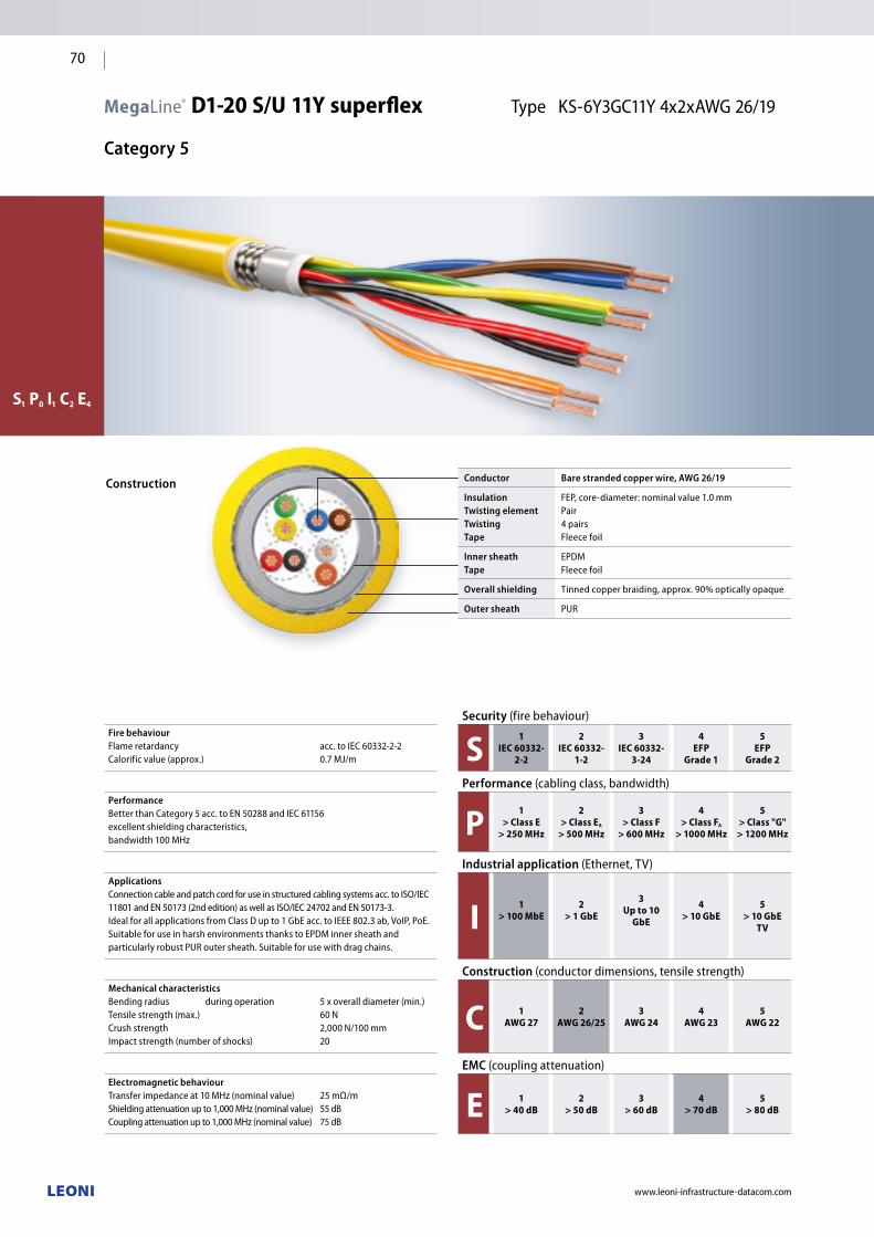
www.leoni-infrastructure-datacom.com
70
MegaLine® D1-20 S/U 11Y superflex Type KS-6Y3GC11Y 4x2xAWG 26/19
Category 5
S1 P0 I1 C2 E4
Construction Conductor Bare stranded copper wire, AWG 26/19
InsulationTwisting elementTwistingTape
FEP,core-diameter:nominalvalue1.0mmPair4 pairs Fleece foil
Inner sheathTape
EPDMFleece foil
Overall shielding Tinned copper braiding, approx. 90% optically opaque
Outer sheath PUR
Security(firebehaviour)Fire behaviourFlame retardancy acc. to IEC 60332-2-2Calorificvalue(approx.) 0.7MJ/m S 1
IEC 60332-2-2
2IEC 60332-
1-2
3IEC 60332-
3-24
4EFP
Grade 1
5EFP
Grade 2
Performance (cablingclass,bandwidth)PerformanceBetter than Category 5 acc. to EN 50288 and IEC 61156 excellent shielding characteristics, bandwidth 100 MHz
P 1> Class E
> 250 MHz
2> Class EA
> 500 MHz
3> Class F
> 600 MHz
4> Class FA
> 1000 MHz
5> Class "G"
> 1200 MHz
Industrial application (Ethernet,TV)ApplicationsConnection cable and patch cord for use in structured cabling systems acc. to ISO/IEC 11801and EN 50173(2ndedition)aswellasISO/IEC24702andEN50173-3.IdealforallapplicationsfromClassDupto1GbEacc.toIEEE802.3ab,VoIP,PoE.SuitableforuseinharshenvironmentsthankstoEPDMinnersheathandparticularlyrobust PUR outersheath.Suitableforusewithdragchains.
I 1> 100 MbE
2> 1 GbE
3Up to 10
GbE
4> 10 GbE
5> 10 GbE
TV
Construction (conductordimensions,tensilestrength)Mechanical characteristicsBendingradius duringoperation 5xoveralldiameter(min.)Tensilestrength(max.) 60NCrush strength 2,000 N/100 mmImpactstrength(numberofshocks) 20
C 1AWG 27
2AWG 26/25
3AWG 24
4AWG 23
5AWG 22
EMC (couplingattenuation)Electromagnetic behaviourTransferimpedanceat10MHz(nominalvalue) 25mΩ/mShieldingattenuationupto1,000MHz(nominalvalue) 55dBCouplingattenuationupto1,000MHz(nominalvalue) 75dB
E 1> 40 dB
2> 50 dB
3> 60 dB
4> 70 dB
5> 80 dB

www.leoni-infrastructure-datacom.com
71
Meg
aLin
e®
Cu d
ata
cabl
es
Electrical characteristics (LF) at 20 °C
DC resistance
Insulation resistance
Mutual capacitance
Signalvelocity(c)
Propagationdelay
Skew at 100 MHz
Characteristic impedance
TestingvoltageUeff
Operating voltage
max.
min.
approx.
approx.
approx.
approx.
at 100 MHz
max.
130Ω/km
5GΩxkm
50 pF/m
0.68
490 ns/100 m
15 ns/100 m
100±5Ω
1,000 V
125 V
Thermal characteristics
For fixed installation
For mobile operation
–40°Cupto+85°C
0°Cto+50°C
Chemical characteristics
Freefromhazardoussubstancesacc.toRoHS2002/95/EC,
oil resistant acc. to EN 60811-2-1,
resistant to ozone acc. to EN 60811,
resistant to microbes acc. to DIN VDE 0282,
resistant to chemicals,
resistant to hydrolysis acc. to DIN 53504,
freefrompaint-wettingimpairmentsubstances(e.g.siliconeoil)
Printing on outer sheath
LEONIMegaLineD1-20S/Usuperflex4P11YSPICECode10124
"production lot code" "meter marking"
Colour code
gr/or, bl/rd, gn/ye, bu/bn
Certificates and approvals
Link performance: LEONI MegaLine® systems
and further commercial connector systems
Inspection certificates: acc. to DIN 55350-18-4.2.1/EN 10204
ConformstoLVD(73/23/EEC):
DimensionsOuter diam.
approx.Weight approx.
Cu content Colour of sheath Order no.
mm kg/km kg/km
4 p 6.8 58 28,6 RapeyellowRAL1021 LKD 7KS5 0051 0000
Package:Drum1,000m
Electrical characteristics (HF) at 20 °C Frequency
MHzAttenuation
dB/10 mNEXT
dBPSNEXT
dBACR
dB at 10 mPSACR
dB at 10 mELFEXT
dB at 10 mPSELFEXT dB at 10 m
RLdB
typ. Cat. 5 max.*
typ. Cat. 5 min.*
typ. Cat. 5 min.*
typ. Cat. 5 min.*
typ. Cat. 5 min.*
typ. Cat. 5 min.*
typ. Cat. 5 min.*
typ. Cat. 5 min.*
1 0.22 0.32 80 65 77 62 80 65 77 62 80 64 77 61 27 –
4 0.56 0.60 67 56 64 53 67 56 64 53 69 52 66 49 26 23
10 1 1.05 63 50 60 47 62 49 59 47 61 44 65 58 30 25
16 1.35 1.45 61 47 58 44 60 46 57 44 56 40 53 37 30 25
20 1.5 1.6 59 46 56 43 58 44 55 43 53 38 50 35 30 25
31.25 1.95 2 57 43 54 40 55 41 52 40 48 34 45 31 30 23.6
62.5 2.95 3 52 38 49 35 50 36 47 35 43 28 40 25 28 21.5
100 3.95 4 45 35 42 32 42 32 39 32 38 24 35 21 26 20.1*BasedonEN50288-2-2(2004)/IEC61156-6(2002)
Office Industry DataCenterOffice DataCenterIndustry

VarioKeystone®
Cu connectivity
www.leoni-infrastructure-datacom.com
72

Office DataCenterIndustry
www.leoni-infrastructure-datacom.com
73
VarioKeystone® Cu connectivity
VarioKeystone® The innovative connection concept. 74
VarioKeystone® One click takes you to the next generation. 75
VarioKeystone® Benefits that speak for themselves. 76
VarioKeystone® No limits. 77
VarioKeystone® System overview 78
o dc i Cable plugs•CableplugCat.7/6A •CrossconnectcableplugCat.7
80
o dc i Jack modules•Jackmodule4K7Cat.7•JackmoduleRJ45Cat.6A
81
o dc i Double modules RJ45•DoublemoduleEthernet•DoublemoduleISDN•DoublemoduleEthernet/ISDN
82
o dc i Link extender Class EA 83
o dc i Telephone patch panel 1RU,25ports 83
o dc i Patch panels 19"•Patchpanel19" fixed 6x4•Patchpanel19" telescopic 6x4
84
dc Modular patch panel 19"/1 RU
For VarioKeystone® single or double modules
85
dcModular patch panel 19“/1 RU
For VarioKeystone® link extenders 86
i DIN rail housing Dual, with double DIN rail clip 87
i Industrial housing IP44 For wall mounting 88
i Industrial housing IP65/67
Han® 3 A, equipped with VarioKeystone® RJ45
88
o dc i Wall outlets For VarioKeystone® jack modules 89
o dc i VarioKeystone® accessories
•Dustprotectivecap•Dummycover•Dustprotectiveplug•MeasuringcablesetTera–Tera•MeasuringcablesetRJ45–RJ45•MeasuringcablesetTera–Crossconnect
90
o dc i Cable assembly tools
•Parallelpliers•UTP/FTP/foilstrippingtool•Stripper•Releasetool•Coppertape•Assemblyset1/2
91
o Office
dc DataCenter
i Industry
Vari
oKey
ston
e®
Cu c
onne
ctiv
ity

VarioKeystone®
The innovative connection concept
The basic configuration consisting of a Category 7 data cable
and cable connector is completed by simply snapping on the
desired jack module.
TheusercanchoosebetweenRJ45jackmodulesaccording
to Category 6A(IEC 60603-7-51)and4K7(interfaceaccording
to IEC61076-3-104)accordingtoCategory7.
Long downtimes and high installation costs are constant
challenges for those in charge of IT when the existing
cabling infrastructure is changed. The problem will
worsen in future as a result of the constantly increasing
requirements for data transmission.
Against this background, cabling systems that allow upgrades
and migrations to be performed in an extremely short time
without costly re-installation take on greater significance.
VarioKeystone® is a cabling system whose modular design
allows migration from Category 6 to Category 7 at any time
without the necessity of re-installing the existing cabling
infrastructure.
www.leoni-infrastructure-datacom.com
74

VarioKeystone®
One click takes you to the next generation
For migration, the new release tool allows the cable plug and
jack module to be separated safely, rapidly and effortlessly
using lever action.
In this way, the existing cabling system can be adapted
to fit the new requirements in a few minutes "with a click".
Easy installation is particularly useful in DataCenters where
system migrations must be achieved with zero downtime.
Pre-assembledtrunkshelptokeepthenecessaryassembly
times to a minimum.
The cable links in the DataCenter are often below the 15 m
mark. The standards speak of a "short link" here, and this
is where the men are separated from the boys in terms
of product technology. The VarioKeystone® system allows
VarioKeystone® release tool – for easy and fast migration "with a click"
extremely short link lengths of one metre to be realised.
The permanent link of Class EA is reached with considerable
reservesoftypically6 dBinnear-endcrosstalk(NEXT).
Modular patch panels, wall outlets, floorbox solutions and
consolidation point housings complete the product range.
VarioKeystone® combines a secure future with flexibility while
ensuring maximum performance and ease of assembly.
www.leoni-infrastructure-datacom.com
75
Vari
oKey
ston
e®
Cu c
onne
ctiv
ity
DataCenterIndustryOffice

www.leoni-infrastructure-datacom.com
76
VarioKeystone®
Benefits that speak for themselves
+ High performance • Forallclasses(DtoF)andcategories(5to7)
incl. Multimedia +40 GbE
• Forpermanentlinkabove1mwithclassEA
• HighEMC,aliencrosstalkbydesign
• PoEandPoEplus
• Extremelysturdythankstosolidmetaldesign
• Excellentstrainrelief
+ Cost-efficiency • Thankstounique,multi-usecableconnection
(maintainsvalue)
• Thankstointerchangeablejackmoduleswithdifferent
performance levels and mating faces
• Thankstomodularandtelescopicpatchpanels
• Thankstolowmaintenanceandservicecosts
• Thankstoshortupgradetimesusingthereleasetool
• Thankstoshortmountingtimes
• Thankstopre-assembledlinks(minimaldowntime)
+ Flexibility • Thankstointerchangeablejackmodules
• Thankstothereleasetool
• Thankstotheextensionoptionwith
the VarioKeystone® link extender
• Thankstomodularandtelescopicpatchpanels
• Thankstopre-assembledlinks
+ Future-proofing • Thankstoavarietyofinterchangeablejackmodules
different performance levels and mating faces
(acc. to standardorcustomer-specific)
• Thankstoupwardanddownwardcompatibility
• Thankstoconformitywithstandards
• Thankstoindependentcertification

www.leoni-infrastructure-datacom.com
77
VarioKeystone®
No limits
Upward compatibilitywhen it comes to performance…
…AND what the future holds.
VarioKeystone® is the innovative connection concept
for structured and universal IT cabling systems.
The modular component design means that jack modules
can be exchanged at any time with minimal effort.
Cat. 5/6 Cat. 6A Cat. 7
Vari
oKey
ston
e®
Cu c
onne
ctiv
ity
DataCenterIndustryOffice

Pre-assembled cable
www.leoni-infrastructure-datacom.com
78
Cable plugsCable
VarioKeystone® is the innovative connection concept
for building cabling systems. The modular design
of the components enables both current and future
requirements to be met.
ThemodulardesignoftheavailableRJ45jackmodulesCat. 6A
(IEC60603-7-51)and4K7(IEC61076-3-104)allowsthem
to be replaced with relatively little effort. This makes it easy
to choose the right mating face.
VarioKeystone® Cu connectivity
System overview
The link extender is an easy means of extending cable links
without any significant reduction in performance.
VarioKeystone® maintains the value of your investments –
in the long term.
Cable plug
Cat. 7MegaLine® G12-150 S/FMegaLine® F10-130 S/FMegaLine® F10-115 S/F
Cable plug
Cat. 6A
Crossconnect cable plugCat. 7

www.leoni-infrastructure-datacom.com
79
Housing
VarioKeystone®wall outlets
VarioLine® CPconsolidation point housing
VarioLine® UFunderfloor systems
VarioKeystone®
modular panel
19"/1RU
Jack modules
Link extender
Class EA
Jack module 4K7
Cat. 7
Jack module RJ45
Cat. 6A
Double module RJ45
Cable plug Jack moduleCat. 7 Cat. 6A Cat. 7 (Tera) Cat. 6A (RJ45) Cat. 5/Cat. 3 (double module RJ45)
see page 80 see page 80 see page 81 see page 81(ETH/ETH)
see page 82(ETH/ISDN*)see page 82
(ISDN/ISDN)see page 82
The following performance
classes are reached with the cable
plug/jack module combination
Class FA (channel)
Class F
Class EA (PL)
Class EA (channel)
Class E
Class D
Class C
Vari
oKey
ston
e®
Cu c
onne
ctiv
ity
DataCenterIndustryOffice

www.leoni-infrastructure-datacom.com
80
Article Cat. Order no.
9.0 mm hole for AWG 23
10.0 mm hole for AWG 22
VarioKeystone® cable plug – white Cat. 7 LKD 9A46 0054 0000 LKD 9A46 0057 0000
VarioKeystone® cable plug – aqua Cat. 6A LKD 9A46 0129 0000 LKD 9A46 0130 0000
Article Category Order no.
VarioKeystone® Crossconnect (9.0mmholeforAWG23) Cat. 7 LKD 9A46 0055 0000
VarioKeystone® Crossconnect(10.0mmholeforAWG22) Cat. 7 LKD 9A46 0058 0000
VarioKeystone® Cable plugs
Category 7/6A
VarioKeystone® Cable plug
Description
Interface to the individually interchangeable VarioKeystone®
jack module. The cable plug enables generic transmission
links far exceeding the requirements for Class F to be achieved.
The mating face can also be identified later without any
additional installation effort.
n Various mating faces available n Easy and quick assembly
Construction
Material
Wiring
Strain relief
Shielding
Electrical values
Full metal; die-cast zinc, nickel-plated
4 pairs via punchdown method
Via cable ties
Large-surface 360° shield connection
Contact block: white/aqua
Category 7/6A
Standards
n ISO/IEC 11801n EN 50173-1
VarioKeystone® Crossconnect cable plug
Description
Interface to the individually interchangeable VarioKeystone®
jack module. The cable plug enables generic transmission
links far exceeding the requirements for Class F to be achieved.
The mating face can also be identified later without any
additional installation effort.
n Various mating faces availablen Easy and quick assemblyn Requiredforextendinglinksincombinationwiththelink
extender
Construction
Material
Wiring
Strain relief
Shielding
Electrical values
Full metal; die-cast zinc, nickel-plated
4 pairs via punchdown method
Via cable ties
Large-surface 360° shield connection
Contact block: red
Category 7
Standards
n ISO/IEC 11801n EN 50173-1
Cable plug Cat. 7white contact block
Cable plug Cat. 6A
aqua contact blockCrossconnect cable plug Cat. 7red contact block

www.leoni-infrastructure-datacom.com
81
VarioKeystone® Jack modules
Category 7/6A
VarioKeystone® Jack module RJ45 Cat. 6A
Description
For transmitting analogue and digital voice, image and data signals.
The performance corresponds to Category 6A up to 500 MHz.
Aufbau
Material
Installation dimen-
sions
Wiring
Connection
Full metal; die-cast zinc, nickel-plated
According to the installation dimensions
of the jack module 4K7 and thus
interchangeable
4 pairs via cable plug
JackRJ45
Standards
n ISO/IEC 11801n EN 50173-1 n IEC 60603-7-51
Accessories see from page 90
Installed by pushing onto the cable plug.
Easy replacement using the release tool.
Article Category Order no.
VarioKeystone® jack module 4K7 Cat. 7 LKD 9A46 0061 0000
Article Category Order no.
VarioKeystone® jackmoduleRJ45–aqua
Cat. 6A LKD 9A46 0128 0000
VarioKeystone® Jack module 4K7 Cat. 7
Description
For transmitting analogue and digital voice, image and data
signals. The performance corresponds to Class F up to 600 MHz
according to EN 50173-1.
Construction
Material
Installation dimen-
sions
Wiring
Connection
Full metal; die-cast zinc, nickel-plated
According to the installation dimensions
ofthejackmoduleRJ45andthus
interchangeable
4 pairs via cable plug
Jack4K7
Standards
n ISO/IEC 11801n EN 50173-1 n EN 61076-3-104
Accessories see from page 90
Installed by pushing onto the cable plug.
Easy replacement using the release tool.
JackmoduleCat. 6A
aqua
Vari
oKey
ston
e®
Cu c
onne
ctiv
ity
DataCenterIndustryOffice

Fig. Article Assignment Category Order no.
1 VarioKeystone® Double module EthernetRJ45jackA 1.2–3.6RJ45jackB 1.2–3.6
Cat. 6 LKD 9A46 0093 0000
2 VarioKeystone® Double module ISDNRJ45jackA 3.6–4.5RJ45jackB 3.6–4.5
Cat. 3 LKD 9A46 0124 0000
3 VarioKeystone® Double module Ethernet/ISDN RJ45jackA 1.2–3.6RJ45jackB 3.6–4.5
JackA Cat.6JackB Cat.3
LKD 9A46 0096 0000
VarioKeystone® Double module EthernetVarioKeystone® Double module ISDN VarioKeystone® Double module Ethernet/ISDN
www.leoni-infrastructure-datacom.com
82
VarioKeystone® Double modules RJ45
Category 6/3
Description
ThedoublemoduleRJ45allowsreversiblecablesharing
by splittingthefourpairsbetweentwoRJ45jacks.
The transmission data corresponds to Cat. 6/3. Subsequent
retrofitting to Cat. 7 is possible at any time if the cable is fitted
with Category 7 cable plugs. The zinc die-cast housing offers
maximum shielding and excellent stability.
n Fits all VarioKeystone® patch panels n Can be used in the VarioKeystone® triple data outlet
in combinationwiththe dummycover(seefrompage89)
Construction
Material
Wiring
Assignment
Electrical values
Full metal; die-cast zinc, nickel-plated
2x2 pairs via cable plug
See table
See table
Standardsn ISO/IEC 11801n EN 50173-1n IEC 60603-7-5, IEC 60603-7-3
Double module Ethernet
Double moduleISDN Double module
Ethernet/ISDN

www.leoni-infrastructure-datacom.com
83
VarioKeystone® Telephone patch panel
1RU,25ports
VarioKeystone® Link extender
Class EA
Article Class Order no.
VarioKeystone®Linkextender(1piece) Class EA LKD 9A46 0062 0000
Article Order no.
VarioKeystone®Telephonepatchpanel(1piece) LKD 9A62 0002 0000
VarioKeystone® Link extender
Description
For extending an existing cable infrastructure to up to 90 m without
transmission losses on the basis of the VarioKeystone® system.
Its small size means that the extender can also be retrofitted
in the cable duct at any time. Note that it is necessary to connect
a standard cable plug on one side and the Crossconnect plug
on the other. This plug differs from the cable plug in that
it has a red LSA insert. Depending on the link used, the link
performance to be achieved is suitable for Class E or Class EA.
Each pair is continued with separate shielding, which means
that the cable transmission data are only affected minimally.
This means that it is possible to continue transferring 10 Gigabit
Ethernet via an extended link.
Construction
Material
Shielding
Electrical values
Full metal; die-cast zinc, nickel-plated
Large-surface 360° shield connection
Class EA
Standards
n ISO/IEC 11801n EN 50173-1
VarioKeystone® Telephone patch panel
Description
Patchpanelfortransmittinganalogueanddigitaltelephone
signals.
With integrated cable management for easy and safe installation.
Construction
Housing
Colour
Labelling
Capacity
Strain relief
Cable entry
Layout
Panel
Steel panel
LightgreyRAL7035
1–25
25 x 8 IDC terminals for max. 100 DA
(AWG 24–AWG23)
Via cable ties
Over the entire width of the cable
management rail
25ports(TERA4p)
44mmx485mmx100mm(HxWxD)
Dimensions
19"/1RU
100 mm installation depth
Vari
oKey
ston
e®
Cu c
onne
ctiv
ity
DataCenterIndustryOffice

VarioKeystone® Patch panel 19"
fixed/telescopic
www.leoni-infrastructure-datacom.com
84
Article Order no.
VarioKeystone®Patchpanelfixed6x4(1piece) LKD 9A67 0006 0000
Article Order no.
VarioKeystone®Patchpaneltelescopic6x4(1piece) LKD 9A67 0000 0000
VarioKeystone® Patch panel 19" fixed 6x4
Description
The patch panel can be equipped with up to 24 jack modules.
Forholdingdifferentmoduletypessimultaneously(RJ45,4K7,
doublemodules).
As a result of its simple construction, this patch panel provides a
reasonably priced alternative to telescopic patch panels.
Construction
Housing
Colour
Capacity
Strain relief
Earthing
Cable entry
Full metal
LightgreyRAL7035
Upto24jackmodules:4K7/RJ45
4jackmodules(ortwodoublemodules)
can be mounted per window
Via cable ties
Via screw on the rear of the panel
Over the entire width of the cable
management rail
Dimensions
19"/1RU
100 mm installation depth
VarioKeystone® Patch panel 19" telescopic 6x4
Description
The patch panel can be equipped with up to 24 jack modules.
Forholdingdifferentmoduletypessimultaneously(RJ45,4K7,
doublemodules).
In the extended state, the drawer can be inclined downwards,
thus making the various jack modules easy to change. Easy
opening and closing of the drawer is ensured by a captive
screw connection accessible on the front.
Construction
Housing
Colour
Capacity
Strain relief
Earthing
Cable entry
Full metal
LightgreyRAL7035
Upto24jackmodules:4K7/RJ45
4jackmodules(ortwodoublemodules)
can be mounted per window
Via cable ties
Via riveted cable shoe on the left-hand
and right-hand side of the drawer
Over the entire width of the cable
management rail
Dimensions
19"/1RU
100 mm installation depth

www.leoni-infrastructure-datacom.com
85
Fig. Article Capacity Ports Order no.
1 VarioKeystone®Patchpanel16EMFor installing 16 single modules:RJ45Cat.6A/4K7(TERA)
For 16 VarioKeystone® ports
LKD 9A67 0019 0000
2 VarioKeystone®Patchpanel24EMFor installing 24 single modules:RJ45Cat.6A/4K7(TERA)
For 24 VarioKeystone® ports
LKD 9A67 0011 0000
3 VarioKeystone®Patchpanel8DMFor installing 8 double modules:Ethernet/Ethernet, Ethernet/telephony, telephony/telephony
For 16 VarioKeystone® ports
LKD 9A67 0022 0000
4 VarioKeystone®Patchpanel12DMFor installing 12 double modules:Ethernet/Ethernet, Ethernet/telephony, telephony/telephony
For 24 VarioKeystone® ports
LKD 9A67 0020 0000
– VarioKeystone® Labelling strip LKD 9A67 0024 0000
VarioKeystone® Modular patch panels 19"/1 RU
for VarioKeystone® single or double modules
VarioKeystone® Patch panel 16 EMVarioKeystone® Patch panel 24 EMVarioKeystone® Patch panel 8 DMVarioKeystone® Patch panel 12 DM
Description
Modular three-part universal patch panel for 16 or 24 Vario
Keystone®ports for installingsinglemodules(EM)ordouble
modules(DM).Modulescan be hot-swapped.
n Allows the integration of an electronic cable management
systemn Can be replaced with single/double modules by changing
the stainless steel front panel
Patch panel set
Consisting of base carrier, cable socket carrier, stainless steel
front panel
Base carrier
n For holding a cable socket carriern Is pre-installed in the cabinet or rack
Labelling
Usinglabellingstripmadefromaluminium,self-adhesive
(mustbeorderedseparately,seetable)
Cable socket carrier
n Unitforcableplugsn Mounted outside the cabinet or base carriern Is inserted into the rear of the base carrier following mountingn Secured using slide latchn PotentialequalisationbymeansoftwothreadedboltsM5
and/or two earth lugs
Stainless steel front cover (depending on design)
Patchpanel16EM
Patchpanel24EM
Patchpanel8DM
Patchpanel12DM
Cut-outs for 16 single modules
Cut-outs for 24 single modules
Cut-outs for 8 double modules
Cut-outs for 12 double modules
Construction
Strain relief
Cable entry
Dimensions
Via cable ties
Over the entire width of the cable
management rail
44mmx483mmx163mm(HxWxD)
Accessories (mustbeorderedseparately–frompage 80)
Singlemodules:RJ45Cat.6A,4K7(TERA)
Double modules: Ethernet/Ethernet, Ethernet/telephony, telephony/telephony
Fig.1Patchpanel16EM,fully mounted Fig.2Patchpanel24EM,
fully mounted
Fig.3Patchpanel8DM,fully mounted Fig.4Patchpanel12DM,
fully mounted
Vari
oKey
ston
e®
Cu c
onne
ctiv
ity
Office Industry IndustryDataCenter

Article Capacity Ports Order no.
VarioKeystone®Patchpanel16EXFor installing extension modules:VarioKeystone® link extender
For 16 VarioKeystone® ports LKD 9A67 0023 0000
VarioKeystone®Patchpanel24EXFor installing extension modules:VarioKeystone® link extender
For 24 VarioKeystone® ports LKD 9A67 0021 0000
VarioKeystone® Labelling strip LKD 9A67 0024 0000
www.leoni-infrastructure-datacom.com
86
VarioKeystone® Modular patch panels 19"/1 RU
for VarioKeystone® link extenders
VarioKeystone® Patch panel 16 EXVarioKeystone® Patch panel 24 EX
Description
Modular three-part universal patch panel for 16 or 24
VarioKeystone® ports for holding the VarioKeystone® link
extender(EX).
n Allows the integration of an electronic cable management
systemn Can be replaced with single/double modules by changing
the stainless steel front panel
Patch panel set
Consisting of base carrier, cable socket carrier, stainless steel
front panel
Base carrier
n For holding a cable socket carrier n Is pre-installed in the cabinet or rack
Labelling
Usinglabellingstripmadefromaluminium,self-adhesive
(mustbeorderedseparately,seetable)
Cable socket carrier
n Unitforholdingthecableplugsn Mounted outside the cabinet or base carriern Is inserted into the rear of the base carrier following mountingn Secured using slide latchn PotentialequalisationbymeansoftwothreadedboltsM5
and/or two earth lugs
Stainless steel front panel
Patchpanel16EX
Patchpanel24EX
Cut-outs for 16 link extenders
Cut-outs for 24 link extenders
Construction
Strain relief
Cable entry
Dimensions
Via cable ties
Over the entire width of the cable
management rail
44mmx483mmx163mm(HxWxD)
Accessories see page 82
VarioKeystone®linkextender(mustbeorderedseparately)
Stainless steel front panel
Cable socket carrier
Base carrier
Patchpanel24EX,fully mounted

www.leoni-infrastructure-datacom.com
87
VarioKeystone® DIN rail housing
Dual, with DIN rail clip
Article Order no.
VarioKeystone®DINrailhousing,dual(1piece) LKD 9A46 0097 0000
VarioKeystone® DIN rail housing, dual
Description
With DIN rail clip for holding up to 2 VarioKeystone®
jack modules.
The housing is mounted by snapping it onto the existing
DIN rails. The metal housing is particularly suitable for use
in industrialenvironments(IP20).
Construction
Material
Colour
Capacity
Steel panel, powder-coated
LightgreyRAL7035
For up to 2 VarioKeystone® jack modules
Dimensions
85mmx35mmx95mm(HxWxD)
Vari
oKey
ston
e®
Cu c
onne
ctiv
ity
DataCenterIndustryOffice
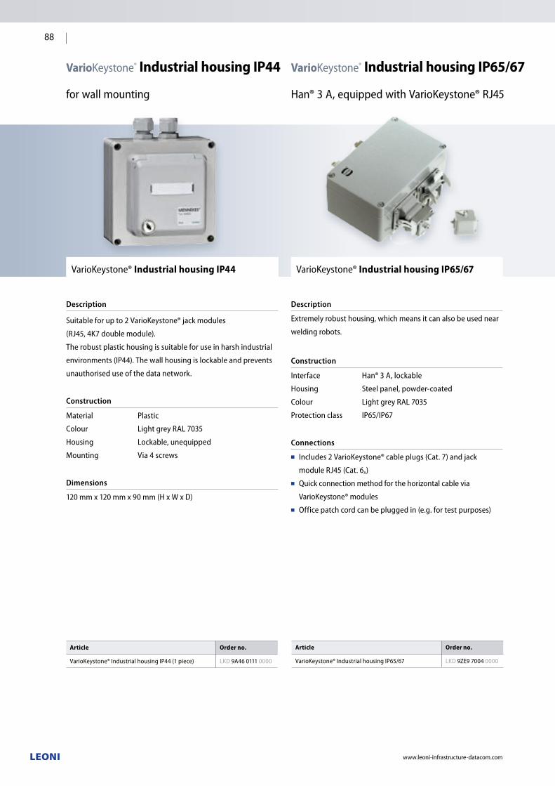
www.leoni-infrastructure-datacom.com
88
VarioKeystone® Industrial housing IP44
for wall mounting
Article Order no.
VarioKeystone®IndustrialhousingIP44(1piece) LKD 9A46 0111 0000
VarioKeystone® Industrial housing IP44
Description
Suitable for up to 2 VarioKeystone® jack modules
(RJ45,4K7doublemodule).
The robust plastic housing is suitable for use in harsh industrial
environments (IP44).Thewallhousingislockableandprevents
unauthorised use of the data network.
Construction
Material
Colour
Housing
Mounting
Plastic
LightgreyRAL7035
Lockable, unequipped
Via 4 screws
Dimensions
120mmx120mmx90mm(HxWxD)
VarioKeystone® Industrial housing IP65/67
Han®3A,equippedwithVarioKeystone®RJ45
Article Order no.
VarioKeystone®IndustrialhousingIP65/67 LKD 9ZE9 7004 0000
VarioKeystone® Industrial housing IP65/67
Description
Extremely robust housing, which means it can also be used near
welding robots.
Construction
Interface
Housing
Colour
Protectionclass
Han® 3 A, lockable
Steel panel, powder-coated
LightgreyRAL7035
IP65/IP67
Connections
n Includes2VarioKeystone®cableplugs(Cat.7)andjack
moduleRJ45(Cat.6A)n Quick connection method for the horizontal cable via
VarioKeystone® modulesn Officepatchcordcanbepluggedin(e.g.fortestpurposes)

VarioKeystone® Wall outlets
For VarioKeystone® jack modules
VarioLine® Wall outlets 50 x 50
Description
Wall outlets for installation in commercially available 50 x 50 mm
cover frames for equipping with VarioKeystone® jack modules.
Housing
Housing body
Colours
Labelling
Full metal; die-cast zinc, nickel-plated
PurewhiteRAL9010
orOysterwhiteRAL 1013
Via labelling field
Installation dimensions
50mmx50mm(HxW),downwardinclinationof30°
Accessories (optional)
VarioKeystone® cover frame, single and double gang
40 mm surface-mounted housing incl. single-gang flush-
mounted cover frame
Spacer frame for single-gang surface-mounted housing, 10 mm
Fig. 1Wall outlet 50 x 50/single gang
Fig. 3Wall outlet 50 x 50/triple gang
Fig. 2Wall outlet 50 x 50/double gang
Fig. Designation Colour Order no. Colour Order no.
1 VarioKeystone®Walloutlet50x50/singlegang(1piece)Oyster white RAL1013
LKD 9A46 0104 0000 PurewhiteRAL9010
LKD 9A46 0107 0000
2 VarioKeystone®Walloutlet50x50/doublegang(1piece) LKD 9A46 0105 0000 LKD 9A46 0108 0000
3 VarioKeystone®Walloutlet50x50/triplegang(1piece) LKD 9A46 0106 0000 LKD 9A46 0109 0000
– Single-gangflush-mountedcoverframe(1piece)
Oyster white RAL1013
LKD 9A41 0002 0000
PurewhiteRAL9010
LKD 9A41 0003 0000
– Double-gangflush-mountedcoverframe(1piece) LKD 9A41 0004 0000 LKD 9A41 0005 0000
–40 mm surface-mounted housing incl. single-gang flush-mounted cover frame(1piece)
LKD 9A46 0087 0000 LKD 9A46 0086 0000
–Spacer frame for single-gang surface-mounted housing, 10 mm (1 piece)
LKD 9A46 0089 0000 LKD 9A46 0088 0000
www.leoni-infrastructure-datacom.com
89
Vari
oKey
ston
e®
Cu c
onne
ctiv
ity
DataCenterIndustryOffice

www.leoni-infrastructure-datacom.com
90
VarioKeystone® Dust protective cap
Descriptionn For modules/link extenders orn For cable plugs
VarioKeystone® Dummy cover
Descriptionn For wall outletsn White or black
VarioKeystone® Dust protective plug
Descriptionn For 4K7 modulen White or black
Designation Version Order no.
VarioKeystone® Dust protective cap
For modules/link extenders (50 pieces)
LKD 9A46 0119 0000
For cable plugs(1piece)
LKD 9A46 0036 0000
Designation Order no.
VarioKeystone® Dummy cover PurewhiteRAL9010(50pieces)
LKD 9A46 0034 0000
VarioKeystone® Dummy cover JetblackRAL9005(50pieces)
LKD 9A46 0083 0000
Designation Order no.
VarioKeystone® Dust protective plugPurewhiteRAL9010(50pieces)
LKD 9A46 0073 0000
VarioKeystone® Dust protective plugJetblackRAL9005(50pieces)
LKD 9A46 0084 0000
VarioKeystone® Accessories
VarioKeystone® Measuring cable set Tera – Tera
Description
n Tera – Teran Length 2 x 3 m
VarioKeystone® Measuring cable set RJ45 – RJ45
Description
n RJ45n Length 2 x 3 m
VarioKeystone® Measuring cable set Tera – Crossconnect
Description
n Tera – Crossconnectn Length 2 x 3 m
Designation Order no.
VarioKeystone® Measuring cable setTera–Tera(2pieces)
LKD 9A04 0166 0000
Designation Order no.
VarioKeystone® Measuring cable setRJ45–RJ45(2pieces)
LKD 9AW3 0020 0000
Designation Order no.
VarioKeystone® Measuring cable set Tera–Tera(1piece)Tera–Crossconnect(1piece)
LKD 9AW3 0023 0000

VarioKeystone® Parallel pliers
VarioKeystone® UTP/FTP/foil stripping tool
MegaLine® Stripper
Designation Order no.
VarioKeystone® Parallelpliers(1piece)
LKD 9AW1 6007 0000
Designation Order no.
VarioKeystone® UTP/FTP/foilstrippingtool(1 piece)
LKD 9AW1 6008 0000
Designation Order no.
MegaLine® Stripper(1 piece)
LKD 9AW1 6043 0000
VarioKeystone® Release tool
Description
n Releasetool,2-part
VarioKeystone® Assembly set 1/2
Description (100 of each)
n Set 1: Shrink-fit tube, silver wire,
copper foiln Set 2: Shrink-fit tube, silver wire
VarioKeystone® Copper tape
Description
n Length 33 m
Designation Order no.
VarioKeystone® Releasetool(1piece)
LKD 9AW1 6039 0000
Designation Order no.
VarioKeystone® Assembly set 1
LKD 9AW1 6020 0000
VarioKeystone® Assembly set 2
LKD 9AW1 6023 0000
Designation Order no.
VarioKeystone® Copper tape(length33m)
LKD 9AW1 6011 0000
Cable assembly tools
www.leoni-infrastructure-datacom.com
91
Vari
oKey
ston
e®
Cu c
onne
ctiv
ity
DataCenterIndustryOffice

www.leoni-infrastructure-datacom.com
92
MegaLine® Connect45Cu connectivity

www.leoni-infrastructure-datacom.com
93
Meg
aLin
e® Co
nnec
t45
Office DataCenterIndustry
MegaLine® Connect45 Cu connectivity 92
MegaLine® Connect45 Connectivity can be so easy 94
MegaLine® Connect45LEO (Light Emitting Outlet) the "pathfinder feature"
95
MegaLine® Connect45 System overview 96
o dcMegaLine® Connect45 cable plugs
•ForAWG24–22•ForAWG27–26
98
o dcMegaLine® Connect45 jack modules in VarioKeystone® format
•Cat.6A ISO/IEC •Cat.6AEIA/TIA•LEOCat.6A ISO/IEC •LEOCat.6AEIA/TIA
99
o dcMegaLine® Connect45 jack modules in keystone format
•Cat.6A ISO/IEC •Cat.6AEIA/TIA•LEOCat.6A ISO/IEC •LEOCat.6AEIA/TIA
100
o dcMegaLine® Connect45 patch panel 19"/1 RU
•HD48Cat.6A
•Unequipped101
o dcMegaLine® Connect45 wall outlets
•Keystone50x50•Keystone45x45
102
o dcAccessories & tools(MegaLine® Connect45)
•LEOdetector•Dustprotectivecap•Mountingtool•Entriegelungswerkzeug
103
o Office
dc DataCenter
i Industry

MegaLine® Connect45
Connectivity can be so easy
Pre-assembledtrunkshelptokeepthenecessaryassembly
times to a minimum.
The release tool is a handy solution for opening modules.
In this way, the existing cabling system can be fitted with
a new module – e.g. with LEO function – in next to no time
"with a click".
Minimum assembly times – maximum performance.
The distances to be covered with cables in DataCenters are often
less than 15 metres. The standards refer to these connections
as "short links" and, because not all products are of the same
quality, it is necessary to separate the wheat from the chaff when
assessing them. The MegaLine® Connect45 system can be used
to implement extremely short link lengths from one metre
upwards. The requirements of the EA permanent link class are
easily exceeded.
The shortest possible installation times and an uncompromising
approach to electrical performance are the key features
of a future-proof cabling system.
With this in mind, LEONI has developed a new copper connection
system, MegaLine® Connect45. The innovative modular system
unites ultimate performance with maximum ease of assembly.
The basic version, consisting of a Category 7/7A data cable and
cable connector is completed by simply attaching the required
jackmodule.YoucanchoosefromRJ45jackmodulesin Category
6A(IEC60603-7-51)andCategory6A(EIA/TIA568-C.2).
Easy assembly – the wires are pressed together and precision-
cut in a single step.
The shortest possible assembly times are achieved by combining
the attachment of the cable plug with the cutting of the wires
to size. Easy assembly is particularly useful in DataCenters where
installation work must be carried out with zero downtime.
Easy assembly – the wires are pressed together and cut to size in a single step.
www.leoni-infrastructure-datacom.com
94

LEO (Light Emitting Outlet)
The "pathfinder feature"
Jack modules are equipped with the LEO function
on an optional basis (LEO = Light Emitting Outlet).
A signal transmitter connected to one side of an installed link
can be used as a convenient way to identify the corresponding
opposite connection by means of a red LED indicator in the jack
module. This feature is particularly useful in environments with
a high packing density, enabling the corresponding modules
to be located quickly and reliably.
TheLEOdetector(ontherightinthephoto)isusedtofeedthelightsignalintothelinksothatthered LED on the corresponding jack module on the other side lights up.
www.leoni-infrastructure-datacom.com
95
Meg
aLin
e® Co
nnec
t45
Office DataCenterIndustry

All components are coordinated for optimum performance: n Quick & easy installationn Maximum performancen Assured functionality for the entire service life
MegaLine® Connect45
System overview
Pre-assembled cable
Cables & cable plugs
MegaLine® Connect45 Cable plug AWG 24–22
MegaLine® Connect45 Cable plug AWG 27–26
MegaLine® G12-150 S/FMegaLine® F10-130 S/FMegaLine® F10-115 S/FMegaLine® F6-90 S/FMegaLine® E5-70 F/FMegaLine® E5-60 U/F
www.leoni-infrastructure-datacom.com
96

High-density panels
Jack modules Housings
Floorbox solutions
Wall outlets
Jack modules with LEO functionKeystone/VarioKeystone® formatCat. 6A (ISO/IEC)/Cat. 6A (EIA/TIA)
Jack modules Keystone/VarioKeystone® formatCat. 6A (ISO/IEC)/Cat. 6A (EIA/TIA)
MegaLine® Connect45 panel high-density Cat. 6A 48 ports
MegaLine® Connect45 panel high-density Cat. 6A 48 ports
VarioLine® UFunderfloor systems
Wall outletsfor MegaLine® Connect45 jack modules
VarioLine® CP6-Bconsolidation point housing Patch panel 19"
www.leoni-infrastructure-datacom.com
97
Meg
aLin
e® Co
nnec
t45
Office DataCenterIndustry

Fig. Article Wire type Colour Order no.
1MegaLine® Connect45 cable plug AWG 24–22 (25pieces)
AWG 24–22 solid and flex Yellow plastic LKD 9A50 4010 0000
2MegaLine® Connect45 cable plug AWG 27–26 (25pieces)
AWG 27–26 solid and flex Transparent plastic LKD 9A50 4011 0000
MegaLine® Connect45 cable plug AWG 24–22MegaLine® Connect45 cable plug AWG 27–26
Description
The MegaLine® Connect45 cable plug has a cutting-clamping
connector and is pressed directly onto the installation cable.
It is the interface to the individually interchangeable MegaLine®
Connect45 jack module.
This means that generic transmission links far exceeding
the requirements for Class EA can be achieved, depending
on the relevant jack module. The jack module can also
be changed later without any additional installation effort.
n Easy and quick assembly
Construction
Material
Wiring
Wire type
Plastic
4 pairs via IDC contacts
acc. to EIA/TIA 568A/B
AWG 24–22 solid and flex or
AWG 27–26 solid and flex
Accessories see page 103
MegaLine® Connect45 dust protective cap
Once attached, the cable plug can be protected from environmental
influences by means of the dust protective cap.
Fig. 1Cable plug AWG 24–22
Fig. 2Cable plug AWG 27–26
MegaLine® Connect45 cable plugs
AWG 24–22/AWG 27–26
www.leoni-infrastructure-datacom.com
98

Fig. 1JackmoduleCat.6A
aqua
Fig. 2JackmoduleCat.6Awhite
MegaLine® Connect45 LEO BM ISO/IECMegaLine® Connect45 LEO BM EIA/TIA
Description
For transmitting analogue and digital voice, image and data
signals. The performance corresponds to Cat. 6A(ISO/IEC)orCat.
6A(EIA/TIA)upto500MHz.TherequirementsoftheClassEA
channel and permanent link according to ISO/IEC 11801 Amd.
1/2 aremetabove1m(Cat.6A)or10m(Cat.6A)respectively.
The lengths relate to the 2-connector model.
Construction
Material
Wiring
Connection
Full metal; die-cast zinc, nickel-plated
4 pairs via cable plug
RJ45jack, with integrated dust protective
flap compatible with VarioKeystone®
Standards
n ISO/IEC 11801 n EN 50173-1 n IEC 60603-7-51/EIA/TIA 568-C.2
LEO function
LEO =
Light Emitting Outlet
Light detection
Signal feed
PatchpanelswithLEOfunction
permit easy link identification during
installation
≤ 200 m
Via the LEO detector
Description see page 95
MegaLine® Connect45 BM ISO/IECMegaLine® Connect45 BM EIA/TIA
Description
For transmitting analogue and digital voice, image and data
signals. The performance corresponds to Cat. 6A(ISO/IEC)orCat.
6A(EIA/TIA)upto500MHz.TherequirementsoftheClassEA
channel and permanent link according to ISO/IEC 11801 Amd.
1/2 aremetabove1m(Cat.6A)or10m(Cat.6A)respectively.
The lengths relate to the 2-connector model.
Construction
Material
Wiring
Connection
Full metal; die-cast zinc, nickel-plated
4 pairs via cable plug
RJ45jack, with integrated dust flap
compatible with VarioKeystone®
Standards
n ISO/IEC 11801n EN 50173-1 n IEC 60603-7-51/EIA/TIA 568-C.2
Article Colour Order no.
MegaLine® Connect45 LEO BM ISO/IEC
aqua opal LKD 9A50 2011 0000
MegaLine® Connect45LEO BM EIA/TIA
white opal LKD 9A50 2021 0000
Fig. Article Colour Order no.
1MegaLine® Connect45 BM ISO/IEC
aqua LKD 9A50 2010 0000
2MegaLine® Connect45 BM EIA/TIA
white LKD 9A50 2020 0000
JackmoduleCat. 6A with LEO functionopal white
MegaLine® Connect45 jack modules in VarioKeystone® format
Category 6A/6A
www.leoni-infrastructure-datacom.com
99
Meg
aLin
e® Co
nnec
t45
IndustryOffice DataCenter

Fig. 2JackmoduleCat.6Awhite
MegaLine® Connect45 LEO BM Keystone ISO/IECMegaLine® Connect45 LEO BM Keystone EIA/TIA
Description
For transmitting analogue and digital voice, image and data
signals. The performance corresponds to Cat. 6A(ISO/IEC)orCat.
6A(EIA/TIA)upto500MHz.TherequirementsoftheClassEA
channel and permanent link according to ISO/IEC 11801 Amd.
1/2 aremetabove1m(Cat.6A)or10m(Cat.6A)respectively.
The lengths relate to the 2-connector model.
Construction
Material
Wiring
Connection
Full metal; die-cast zinc, nickel-plated
4 pairs via cable plug
KeystoneRJ45jack, with integrated
dust protective flap
Standards
n ISO/IEC 11801 n EN 50173-1 n IEC 60603-7-51/EIA/TIA 568-C.2
LEO function
LEO =
Light Emitting Outlet
Light detection
Signal feed
PatchpanelswithLEOfunction
permit easy link identification during
installation
≤ 200 m
Via the LEO detector
Description see page 95
MegaLine® Connect45 BM Keystone ISO/IECMegaLine® Connect45 BM Keystone EIA/TIA
Description
For transmitting analogue and digital voice, image and data
signals. The performance corresponds to Cat. 6A(ISO/IEC)orCat.
6A(EIA/TIA)upto500MHz.TherequirementsoftheClassEA
channel and permanent link according to ISO/IEC 11801 Amd.
1/2 aremetabove1m(Cat.6A)or10m(Cat.6A)respectively.
The lengths relate to the 2-connector model.
Construction
Material
Wiring
Connection
Full metal; die-cast zinc, nickel-plated
4 pairs via cable plug
KeystoneRJ45jack, with integrated
dust protective flap
Standards
n ISO/IEC 11801n EN 50173-1 n IEC 60603-7-51/EIA/TIA 568-C.2
JackmoduleCat. 6A with LEO functionopal white
Fig. 1JackmoduleCat.6A
aqua
MegaLine® Connect45 jack modules in keystone format
Category 6A/6A
Article Colour Order no.
MegaLine® Connect45 LEO BM Keystone ISO/IEC
aqua opal LKD 9A50 1011 0000
MegaLine® Connect45 LEO BM Keystone EIA/TIA
white opal LKD 9A50 1021 0000
Fig. Article Colour Order no.
1MegaLine® Connect45 BM Keystone ISO/IEC
aqua LKD 9A50 1010 0000
2MegaLine® Connect45 BM Keystone EIA/TIA
white LKD 9A50 1020 0000
www.leoni-infrastructure-datacom.com
100

MegaLine® Connect45 patch panels 19"/1 RU
Equipped/unequipped
MegaLine® Connect45 patch panel HD 48 Cat. 6A
Description
For transmitting analogue and digital voice, image and data
signals. The performance corresponds to Cat. 6A(ISO/IEC)
up to 500 MHz. The requirements of the Class EA channel and
permanent link according to ISO/IEC 11801 Amd. 1/2 are met
above1m(Cat.6A).Thelengthsrelatetothe2-connectormodel.
n High packing density at a single leveln Pre-assembledjackmodulesreducetheinstallationeffort
significantly
Construction
Housing
Colour
Capacity
Strain relief
Earthing
Cable entry
Full metal
LightgreyRAL7035/BlackRAL9005
48 jack modules Cat. 6A(ISO/IEC)
Via cable ties
Via screw on the rear of the panel
Over the entire width of the cable
management rail
Dimensions
19"/1RU,121mminstallationdepth
Standards
n ISO/IEC 11801 n EN 50173-1 n IEC 60603-7-51
Article Colour Order no.
MegaLine® Connect45 patch panel 19"
LightgreyRAL7035 LKD 9A50 1200 0000
JetblackRAL9005 LKD 9A50 1201 0000
Article Colour Order no.
MegaLine® Connect45 patch panel HD 48 Cat. 6A (ISO/IEC)
LightgreyRAL7035 LKD 9A50 3214 0000
JetblackRAL9005 LKD 9A50 3215 0000
MegaLine® Connect45 patch panel 19"
Description
The patch panel can be equipped with up to 24 jack modules
in keystone format.
Construction
Housing
Colour
Capacity
Strain relief
Earthing
Cable entry
Full metal
LightgreyRAL7035/BlackRAL9005
Upto24jack modules
Via cable ties
Via screw on the rear of the panel
Over the entire width of the cable
management rail
Dimensions
19"/1RU,110mminstallationdepth
Note
PatchpanelsforjackmodulesinVarioKeystone®formatcan
be found on page 84
www.leoni-infrastructure-datacom.com
101
Meg
aLin
e® Co
nnec
t45
IndustryOffice DataCenter

MegaLine® Connect45 wall outlets
for keystone jack modules
MegaLine® Connect45 wall outlet keystone 50 x 50
German style
Wall outlets for equipping with MegaLine® Connect45 jack
modules in keystone format.
Construction
Housing body
Colours
Labelling
Full metal; die-cast zinc, nickel-plated
PurewhiteRAL9010
Via labelling field
Dimensions
50mmx50mmx30mm(HxWxD),
downward inclination of 30°
Note
Wall outlets in VarioKeystone® format can be found on page 89
MegaLine® Connect45 wall outlet keystone 45 x 45
French style
Wall outlets for equipping with MegaLine® Connect45 jack
modules in keystone format.
Construction
Housing body
Colours
Labelling
Plastic
PurewhiteRAL9010
Via labelling field
Dimensions
45mmx45mmx42mm(HxWxD),
downward inclination of 30°
Fig. 1Wall outlet 50 x 50/single gang
Fig. 4Wall outlet 45 x 45/single gang Fig. 5
Wall outlet 45 x 45/double gang
Fig. 3Wall outlet 50 x 50/triple gang
Fig. 2Wall outlet 50 x 50/double gang
Fig. Designation Order no.
1 MegaLine® Connect45 wall outlet keystone 50 x 50/single gang
LKD 9A50 1100 0000
2 MegaLine® Connect45 wall outlet keystone 50 x 50/double gang
LKD 9A50 1101 0000
3 MegaLine® Connect45 wall outlet keystone 50 x 50/triple gang
LKD 9A50 1102 0000
– 40 mm surface-mounted housing LKD 9A46 0086 0000
– Spacer frame for single-gang surface-mounted housing, 10 mm
LKD 9A46 0088 0000
Fig. Designation Order no.
4 MegaLine® Connect45 wall outlet keystone 45 x 45/single gang
LKD 9A50 1104 0000
5 MegaLine® Connect45 wall outlet keystone 45 x 45/double gang
LKD 9A50 1103 0000
– VarioLine®coverframe45x45(8pieces) LKD 9ZE8 0013 0000
www.leoni-infrastructure-datacom.com
102

Article Order no.
MegaLine® Connect45 LEO detector LKD 9A50 4002 0000
Article Order no.
MegaLine® Connect45 mounting tool LKD 9A50 4001 0000
Article Order no.
MegaLine®Connect45dustprotectivecap(25pieces) LKD 9A50 4003 0000
Article Order no.
MegaLine® Connect45 release tool LKD 9A50 4000 0000
Accessories & tools
for MegaLine® Connect45
MegaLine® Connect45 LEO detector
Accessories
Detector for feeding in the voltage when using a Connect45 jack
module with LEO function.
Housing
Contact
Powersupply
Full metal
RJ45plug
4xLR41batteries(included)
MegaLine® Connect45 dust protective cap
Accessories
For the safe and convenient protection of pre-assembled trunk
cables equipped with MegaLine® Connect45 cable plugs.
MegaLine® Connect45 release tool
Accessories
For quick and easy opening of the MegaLine® Connect45 jack
module.
The cable assembled with the Connect45 cable plug is simply inserted into the dust protective cap and locked
MegaLine® Connect45 mounting tool
Accessories
It takes just a single step to press the contacts of the cable plug
together and remove the excess wires.
www.leoni-infrastructure-datacom.com
103
Meg
aLin
e® Co
nnec
t45
IndustryOffice DataCenter

www.leoni-infrastructure-datacom.com
104104
ELine 1200® EC7
Cu connectivity

Office DataCenterIndustry
www.leoni-infrastructure-datacom.com
105
ELine 1200® EC7 Cu connectivity 104
ELine 1200® EC7Cu connectivityThe passive cabling system for multimedia applications
106
ELine 1200® EC7 System overview 108
o dc EC7 jack and accessories•EC7jack•EC7dustprotectiveplug1p•EC7mountingtool
110
o dc Wall outlet insert 50 x 50 111
o dc EC7 patch panel Telephone patch panel 112
o dc EC7 accessories Telephone termination plug 112
o dc EC7 patch panel 19"•1RUwith24ports•1RUwith48ports•1RUwith24ports,angled
113
o dc EC7 mini patch panel With 6 ports 114
o dc EC7 mounting tool For ELine 1200® EC7 jacks 114
o dcEC7 measuring equipment
•EC7measuringadapter(forFlukeDTX1800)•EC7-EC7plug
115
o Office
dc DataCenter
i Industry
ELin
e 12
00®
EC7 Cu
con
nect
ivit
y

Multimedia in a systematic way
Connection options
www.leoni-infrastructure-datacom.com
106
ELine 1200® EC7 Cu connectivity
The passive cabling system for multimedia applications
Multimedia up to 1.5 GHz via twisted pair
The chamber system of the ELine 1200® EC7 connector is based
on the principle of paired shielding of the 100 Ω data cables
used in the MegaLine® series. The cable and connector form
a perfect combination of four pairs and four chambers with
GHz performance.
The signal paths are separate throughout, which opens
up a wide range of possible uses:
n Cable sharing:
Simultaneous use of two data services from Class A to F with
just one cable and one EC7 jackn Service sharing:
Simultaneousoperationofdifferentservices(e.g.telephone/
data)in parallel-withouttheriskofNEXTproblems
The devices are connected using appropriately matched ELine
1200® EC7 connection cable in one, two or four pairs.
A passive cabling system for multimedia applications –
is that even possible? After all, it is a term that is more
often used in connection with consumer electronics.
ELine 1200® EC7 supports multimedia by allowing different
media to be used in parallel via a structured cabling system:
Data/voice/images/TV signals – in one connection.
This unique copper connectivity from LEONI delivers
a sophisticated system solution, the only one of its kind, geared
towards the needs of the market. ELine 1200® EC7 delivers
multimedia directly to the desktop as a four-lane data highway.

Telephone
Telephone/fax
Mixed telephone and data services2 data services from Class A to F
Cable sharing Service sharing
PCPC PC
www.leoni-infrastructure-datacom.com
107
ELine 1200® EC7 Cu connectivity
The passive cabling system for multimedia applications
TV via twisted pair
Transmitting analogue and digital CATV services via twisted
pair is extremely challenging from a technical point of view.
Transmission frequencies of up to 862 MHz are required
for transmitting all channels, which requires a system with
extremely high performance reserves and, in particular, good
attenuation characteristics.
ELine 1200® EC7 is specifically optimised for this application
and the extensive product range provides all the tools needed
to transmit CATV signals. The twisted pair infrastructure
(100 Ω)isconnectedtotheTVinfrastructure(75 Ω)viapassive
connection cables with integrated balun.
In contrast to previous solutions, the outlets are completely flexible.
For example, a telephone or data outlet can become a TV
connection at any time.
"High tech" and "added value" have their price
The ELine 1200® EC7 system is no more expensive than
conventional systems overall, because separate cables
or connectors are not needed for each service. This allows
savings of up to 50 % of the necessary cables, connectors,
wall outlets and patch panels.
Multipleusealsoreducesthesystemcosts(dependingon the
servicesused)by15–30%.Thereductioninthenumber
of cables and wall outlets actually required usually also allows
reductions in the costs for cable ducts or switching cabinets.
"Service sharing" with ELine 1200® EC7 means saving costs.
The system solution is already successfully in use worldwide,
which means that we can refer to a wide installed base with
testimonials from well-known customers.
Office DataCenterIndustry
ELin
e 12
00®
EC7 Cu
con
nect
ivit
y

ELine 1200® EC7 Cu connectivity
System overview
ELine 1200® EC7 jackn Modular jack for multimedia applications
ELine 1200® EC7 wall outletsn Double-gang wall outlet for up to two modular jacksn Triple-gang wall outlet for up to three modular jacks
ELine 1200® EC7 panelsn Panelwith24ports(standardversion)n 48-port panel with double packing density
at a single level
VarioLine® modular system peripherals
Consolidation points – CP
Underfloor range – UF
MegaLine® Patchn Patchcordn Trunk cable
www.leoni-infrastructure-datacom.com
108
Pre-assembled cable
Cable Jack module
MegaLine® G12-150 S/F
ELine 1200® EC7

www.leoni-infrastructure-datacom.com
109
Office Industry DataCenter
Housings
ELine 1200® EC7 patch panel 1 RU/24 portscan be equipped with ELine 1200® EC7 jacks
VarioLine® housing CP6/CP12/CP24Consolidation point housing for 6, 12 or 24-port module panel
ELine 1200® EC7 patch panel 1 RU/48 portscan be equipped with ELine 1200® EC7 jacks
Floorbox solutions
Wall outlets
VarioLine® UFunderfloor systems
ELine 1200® EC7 Cu wall outlet insert 50 x 50double gang/triple gang
ELin
e 12
00®
EC7 Cu
con
nect
ivit
y

www.leoni-infrastructure-datacom.com
110
ELine 1200® EC7 jack and accessories
Multimedia up to 1.5 GHz via twisted pair
Article Order no.
ELine1200®EC7jack(8pieces) LKD 9ZE4 4444 0000
ELine1200®EC7dustprotectiveplug1p(1piece) LKD 9ZE3 0066 0000
ELine 1200® EC7 mounting tool (1piece) LKD 9ZE3 0007 0000
ELine 1200® EC7 jack
Application
For fast installation in patch panels, floorbox solutions and wall
outlet inserts.
Construction
Jack
Contacts
Insulation displace-
ment contacts
Die-cast zinc, nickel-plated
Gold-plated
Bronze, tinned
Dimensions
Jack
Installation depth
14mmx16mmx36.9mm(WxHxD)
40 mm
ELine 1200® EC7 dust protective plug 1 p
ELine 1200® EC7 mounting tool
Compatibility
VarioLine®CP
VarioLine®UF
Consolidationpointrange(frompage237)
Underfloorsystems/floorboxsolutions
(frompage253)
Accessories
ELine 1200® EC7 dust protective plug 1 p
ELine1200®EC7mountingtool(descriptionseepage140)

www.leoni-infrastructure-datacom.com
111
Matching jacks
ELine 1200® EC7
ELine 1200® EC7 Cu wall outlet insert 50 x 50
Description
Unequippedwalloutletinsertwithdustprotectivecover,for
installation in commercially available 50 x 50 mm cover frames.
Housing
Housing body
Colour
Earth connection
Plastic
PurewhiteRAL9010
Via M4 thread
Dimensions
50mmx50mmx30.5mm(HxWxDempty)
Downward inclination 62°
Installation depth 25 mm
Accessories (optional)
VarioKeystone® cover frame
Order no.: LKD 9A41 0003 0000
n Plasticcoverframe80x80mmn Cut-out 50 x 50 mm, square n Colour:PurewhiteRAL9010n PU:1piece
ELine 1200® Wall outlet insert
for surface or flush mounting, duct and many underfloor systems
Fig. 1Cu wall outlet insert 50 x 50/ double gang, can be equipped with 2 ELine 1200® EC7 jacks
Fig. 2Cu wall outlet insert 50 x 50/ triple gang, can be equipped with 3 ELine 1200® EC7 jacks
Fig. Article Order no.
1ELine 1200® EC7 Cu wall outlet insert/double gang (8pieces)
LKD 9ZE3 0010 0000
2ELine 1200® EC7 Cu wall outlet insert/triple gang (8pieces)
LKD 9ZE3 0041 0000
ELin
e 12
00®
EC7 Cu
con
nect
ivit
y
IndustryOffice DataCenter

www.leoni-infrastructure-datacom.com
112
ELine 1200® EC7 patch panel
Telephone
ELine 1200® EC7 accessories
Telephone
Article Order no.
ELine1200®EC7telephonepatchpanel(1piece) LKD 9ZE1 0221 0000
Article Order no.
ELine1200®EC7terminationplug(1piece) LKD 9ZE1 0104 0000
ELine 1200® EC7 telephone patch panel
Application
Telephone patch panel for operating up to 100 telephone
servicesatasinglelevel(100DA).
Connections
n Completewith25x(1x4)double-corejacksn 25 x 8 LSA connectivity on the rearn IDC terminal connections on 5 x 5 basic modules
Dimensions
Panel
Installation depth
485mmx44mmx106mm(WxHxD)
104 mm
ELine 1200® EC7 termination plug
Application
As a connectable termination in ISDN So bus-networks ELine
1200® EC7.
Construction
n EC7 resistor/termination plug n 2 p n With 2 x 100 Ω terminating resistors

www.leoni-infrastructure-datacom.com
113
ELine 1200® EC7 patch panel 1 RU/24 ports
ELine 1200® EC7 patch panel 1 RU/48 ports
Description
Patchpanel19", unequipped, for holding up to 24 or 48 ELine
1200®EC7jacks(includingamixture).
n Snap-in assemblyn Strain reliefn Earth connection
Housing
Housing
Colour of front panel
Steel panel
LightgreyRAL7035orJetblackRAL9005
Dimensions
19"/1RU 44mmx483mmx98mm(HxWxD)
ELine 1200® EC7 patch panel 19"
1RU,with24/48ports
Fig. Article Colour Order no.
1ELine 1200® EC7 patch panel1RU/48ports(1 piece)
LightgreyRAL7035 LKD 9ZE3 0052 0000
JetblackRAL9005 LKD 9ZE3 0047 0000
2ELine 1200® EC7 patch panel1RU/24ports(1 piece)
LightgreyRAL7035 LKD 9ZE3 0002 0000
JetblackRAL9005 LKD 9ZE3 0046 0000
Article Colour Order no.
ELine1200®EC7patchpanel1RU/24ports, angled (1piece)
JetblackRAL9005
LKD 9ZE3 0061 0000
Fig. 1patch panel with 48 ports, can be equipped with ELine 1200® EC7 jacks
Fig. 2patch panel with 24 ports, can be equipped with ELine 1200® EC7 jacks
ELine 1200® EC7 patch panel 1 RU/24 ports, angled
Description
Patchpanel19" , unequipped, for holding up to 24 ELine 1200®
EC7jacks(includingamixture).
n Snap-in assemblyn Strain reliefn Earth connection
Housing
Housing
Labelling
Colour of front panel
Steel panel
1–24(screenprinting)
JetblackRAL9005
Dimensions
19"/1RU 44mmx483mmx175mm(HxWxD)
ELin
e 12
00®
EC7 Cu
con
nect
ivit
y
IndustryOffice DataCenter

www.leoni-infrastructure-datacom.com
114
ELine 1200® EC7 mini patch panel
with 6 ports
Article Colour Order no.
ELine 1200® EC7 mini patch panel with 6 ports (1 piece)
PurewhiteRAL9010
LKD 9ZE3 0045 0000
ELine 1200® EC7 mini patch panel with 6 ports
Description
Mini patch panel, unequipped, for holding up to 6 ELine 1200®
EC7 jacks.
n Snap-in assemblyn For mounting in a wall, floor, ceiling, furniture, DIN railsn Suitable for industrial environments
Housing
Housing
Colour
Closed, steel panel
PurewhiteRAL9010
Dimensions
35mmx122mmx100mm(HxWxD)
ELine 1200® EC7 mounting tool
for ELine 1200® EC7 jacks
Article Order no.
ELine 1200® EC7 mounting tool (1piece) LKD 9ZE3 0007 0000
ELine 1200® EC7 mounting tool
Description
For easy and secure connection of the ELine 1200® EC7 jacks.

www.leoni-infrastructure-datacom.com
115
ELine 1200® EC7 mounting tool
for ELine 1200® EC7 jacks
ELine 1200® EC7 measuring equipment
Article Order no.
ELine1200®EC7measuringadapter(forFlukeDTX1800)(1pair)
LKD 9ZE3 0038 0000
Article Order no.
ELine1200®EC7-EC7plug(1piece) LKD 9ZE3 0043 0000
ELine 1200® EC7 measuring adapter (for Fluke DTX 1800)
Application
Measuring adapter for testing EC7 cabling systems up to Class F
(600MHz),permanentlinkandchannel.
The measuring probe consists of an EC7-EC7 plug that can
be replaced in case of wear.
ELine 1200® EC7-EC7 plug
Application
ReplaceablemeasuringprobeforClassFmeasurementsEC7for
permanent link and channel measuring adapter Fluke DTX 1800.
Construction
Mating face Both sides EC7, 4 pairs
ELin
e 12
00®
EC7 Cu
con
nect
ivit
y
IndustryOffice DataCenter

MegaLine®
Cu patch cords / trunk cables
www.leoni-infrastructure-datacom.com
116116

Office DataCenterIndustry
www.leoni-infrastructure-datacom.com
117
MegaLine® Cu patch cords / trunk cables 117
o dc Patch cord RJ45/RJ45 Cat. 5/100 MHz 118
o dc Patch cord RJ45/RJ45 Cat. 6/250 MHz 119
o dc Patch cord RJ45/RJ45 Cat. 6/500 MHz 120
o dc Patch cord RJ45/RJ45 Cat. 6A/500 MHz 121
i LED patch cord RJ45/RJ45Cat. 6/500 MHzwith LED signal in the plug
122
i Industrial patch cord RJ45/RJ45 Cat. 5/100 MHz 123
i Industrial patch cord with Han® 3A plugs
•Han3ARJ45/RJ45•Han3ARJ45/IP20RJ45
124
i Industrial patch cord RJ45/RJ45 Cat. 6/500 MHz 125
o dc Patch cord TERATM 126
o dcPatch cord and connection cable EC7
•4pEC7/EC7•4pEC7/RJ45•4pEC7/open
128
o dc Patch cord and connection cable EC7
•2pEC7/EC7•2pEC7/open•2pEC7/RJ45•2pEC7/RJ45Crossover
129
o dcPatch cord and connection cable EC7
•1pEC7/EC7•1pEC7/open•1pEC7/RJ10•1pEC7/RJ11
130
o dc Patch cord and connection cable EC7
•1pEC7/RJ45•2pEC7/RJ45
131
i VarioKeystone® trunk cable, industrial
•Trunkcable•Crossconnecttrunkcable
132
o dc VarioKeystone® trunk cable•Trunkcable•Crossconnecttrunkcable
133
o dc i RJ45 trunk cable, 8 port •TrunkRJ45plug/RJ45plug 134
o dc i VarioKeystone® trunk cable, 4 port/8 port
135
o dc MegaLine® Connect45 trunk cable
•Cat.6A modules•Cat.6Amodules
136
o dc MegaLine® Connect45trunk cable, 8 port
•Cat.6A modules 137
o dc MegaLine® Connect45 CP cable •Cat.6A/Cat. 6A 138
o dc MegaLine® Connect45 CP cable •Cat.7,ClassF 139
o dc Accessories for LED patch cords•LEDcolourclip•LEDdetector
140
o dc Accessories for patch cords •RJ45colourcodingclip 140
o dc Test report For all trunk cables 141
o Office cable
dc DataCenter cables
i Industrial cables
Meg
aLin
e®
Cu p
atch
cor
ds /
trun
k ca
bles

www.leoni-infrastructure-datacom.com
118
Length Article Order no.
m Grey (PVC) Blue (PVC) Green (PVC) Yellow (PVC) Red (PVC)
0.5
MegaLine® Patch5D-RJ45
LKD 9A01 0400 0000 LKD 9A01 0410 0000 LKD 9A01 0420 0000 LKD 9A01 0430 0000 LKD 9A01 0440 0000
1.0 LKD 9A01 0401 0000 LKD 9A01 0411 0000 LKD 9A01 0421 0000 LKD 9A01 0431 0000 LKD 9A01 0441 0000
1.5 LKD 9A01 0402 0000 LKD 9A01 0412 0000 LKD 9A01 0422 0000 LKD 9A01 0432 0000 LKD 9A01 0442 0000
2.0 LKD 9A01 0403 0000 LKD 9A01 0413 0000 LKD 9A01 0423 0000 LKD 9A01 0433 0000 LKD 9A01 0443 0000
2.5 LKD 9A01 0404 0000 LKD 9A01 0414 0000 LKD 9A01 0424 0000 LKD 9A01 0434 0000 LKD 9A01 0444 0000
3.0 LKD 9A01 0405 0000 LKD 9A01 0415 0000 LKD 9A01 0425 0000 LKD 9A01 0435 0000 LKD 9A01 0445 0000
4.0 LKD 9A01 0406 0000 LKD 9A01 0416 0000 LKD 9A01 0426 0000 LKD 9A01 0436 0000 LKD 9A01 0446 0000
5.0 LKD 9A01 0407 0000 LKD 9A01 0417 0000 LKD 9A01 0427 0000 LKD 9A01 0437 0000 LKD 9A01 0447 0000
7.5 LKD 9A01 0408 0000 LKD 9A01 0418 0000 LKD 9A01 0428 0000 LKD 9A01 0438 0000 LKD 9A01 0448 0000
10.0 LKD 9A01 0409 0000 LKD 9A01 0419 0000 LKD 9A01 0429 0000 LKD 9A01 0439 0000 LKD 9A01 0449 0000
MegaLine® Patch cord RJ45/RJ45 Cat. 5/100 MHz
Shielded, Cat. 5, Class D, with coloured moulded boots
MegaLine® Patch 5D-RJ45
Description
The cable type used is suitable for transmission rates
of up to 100 MHz. The pair shielding and the high-coverage
copper braiding as overall shielding ensure excellent NEXT
and impedance values.
The patch cords and connection cables are equipped with
a shieldedRJ45plugandmouldedbootsatbothends.
Applications
IEEE 802.3, 10Base-T, 100Base-T, 1000Base-T, IEEE 802.5 16MB,
ISDN, FDDI, ATM
Construction
EMC
RJ45plug
Electrical values
Assignment
Standards
Foil overall shielding
EN 60603-7
Cat. 5, Class D
1:1
ISO/IEC 11801/EN 50173
Fire behaviour
Flame retardance IEC 60332-1-2
Accessories Description see page 140
MegaLine®PatchRJ45colourcodingclip
In different colours for visual coding of the patch cords

www.leoni-infrastructure-datacom.com
119
Length Article Order no.
m Grey (LSOH)
0.5
MegaLine®PatchRJ45U
LKD 9A05 0027 0000
1.0 LKD 9A05 0028 0000
1.5 LKD 9A05 0029 0000
2.0 LKD 9A05 0030 0000
2.5 LKD 9A05 0031 0000
3.0 LKD 9A05 0032 0000
4.0 LKD 9A05 0033 0000
5.0 LKD 9A05 0034 0000
7.5 LKD 9A05 0035 0000
10.0 LKD 9A05 0036 0000
MegaLine® Patch cord RJ45/RJ45 Cat. 6/250 MHz
Unshielded,Cat.6,ClassE,withgreymouldedboots
MegaLine® Patch 6E-RJ45U
Description
The cable type used is suitable for transmission rates
of up to 250 MHz. The patch cord offers excellent NEXT
and return loss values thanks to its construction.
The patch cords and connection cables are equipped with
an unshieldedRJ45plugandmouldedbootsatbothends.
Applications
IEEE 802.3, 10Base-T, 100Base-T, 1000Base-T, IEEE 802.5 16MB,
ISDN, FDDI, ATM
Construction
RJ45plug
Electrical values
Assignment
Standards
EN 60603-7
Cat. 6, Class E
1:1
ISO/IEC 11801/EN 50173
Fire behaviour
Smoke density
Halogen free
Flame retardance
IEC 61034
IEC 60754-2
IEC 60332-1-2
Accessories Description see page 140
MegaLine®PatchRJ45colourcodingclip
In different colours for visual coding of the patch cords
Meg
aLin
e®
Cu p
atch
cor
ds /
trun
k ca
bles
IndustryOffice DataCenter

www.leoni-infrastructure-datacom.com
120
Length Article Order no.
m Grey (LSOH) Blue (LSOH) Green (LSOH) Yellow (LSOH) Red (LSOH)
0.5
MegaLine® Patch6EA-RJ45
LKD 9A02 1132 0000 LKD 9A02 1152 0000 LKD 9A02 1162 0000 LKD 9A02 1142 0000 LKD 9A02 1172 0000
1.0 LKD 9A02 1133 0000 LKD 9A02 1153 0000 LKD 9A02 1163 0000 LKD 9A02 1143 0000 LKD 9A02 1173 0000
1.5 LKD 9A02 1134 0000 LKD 9A02 1154 0000 LKD 9A02 1164 0000 LKD 9A02 1144 0000 LKD 9A02 1174 0000
2.0 LKD 9A02 1135 0000 LKD 9A02 1155 0000 LKD 9A02 1165 0000 LKD 9A02 1145 0000 LKD 9A02 1175 0000
2.5 LKD 9A02 1136 0000 LKD 9A02 1156 0000 LKD 9A02 1166 0000 LKD 9A02 1146 0000 LKD 9A02 1176 0000
3.0 LKD 9A02 1137 0000 LKD 9A02 1157 0000 LKD 9A02 1167 0000 LKD 9A02 1147 0000 LKD 9A02 1177 0000
4.0 LKD 9A02 1138 0000 LKD 9A02 1158 0000 LKD 9A02 1168 0000 LKD 9A02 1148 0000 LKD 9A02 1178 0000
5.0 LKD 9A02 1139 0000 LKD 9A02 1159 0000 LKD 9A02 1169 0000 LKD 9A02 1149 0000 LKD 9A02 1179 0000
7.5 LKD 9A02 1140 0000 LKD 9A02 1160 0000 LKD 9A02 1170 0000 LKD 9A02 1150 0000 LKD 9A02 1180 0000
10.0 LKD 9A02 1141 0000 LKD 9A02 1161 0000 LKD 9A02 1171 0000 LKD 9A02 1151 0000 LKD 9A02 1181 0000
MegaLine® Patch cord RJ45/RJ45 Cat. 6/500 MHz
Shielded, Cat. 6, Class EA, with coloured moulded boots
MegaLine® Patch 6EA-RJ45
Description
The cable type used is suitable for transmission rates
of up to 500 MHz. The pair shielding and the high-coverage
copper braiding as overall shielding ensure excellent NEXT
and return loss values.
The patch cords and connection cables are equipped with
a shieldedRJ45plugandmouldedbootsatbothends.
Applications
IEEE 802.3, 10Base-T, 100Base-T, 1000Base-T,
suitable for 10GBase-T, IEEE 802.5 16MB, ISDN, FDDI, ATM
Construction
EMC
RJ45plug
Electrical values
Assignment
Standards
Combinedshielding(PiMf+braiding)
EN 60603-7
Cat. 6, Class EA
1:1
ISO/IEC 11801/EN 50173
Fire behaviour
Smoke density
Halogen free
Flame retardance
IEC 61034
IEC 60754-2
IEC 60332-1-2
Accessories Description see page 140
MegaLine®PatchRJ45colourcodingclip
In different colours for visual coding of the patch cords

www.leoni-infrastructure-datacom.com
121
Length Article Order no.
m Grey (LSOH) Blue (LSOH) Green (LSOH) Yellow (LSOH) Red (LSOH)
0.5
MegaLine® Patch6AEA-RJ45
LKD 9A02 3020 0000 LKD 9A02 3030 0000 LKD 9A02 3040 0000 LKD 9A02 3050 0000 LKD 9A02 3060 0000
1.0 LKD 9A02 3021 0000 LKD 9A02 3031 0000 LKD 9A02 3041 0000 LKD 9A02 3051 0000 LKD 9A02 3061 0000
1.5 LKD 9A02 3022 0000 LKD 9A02 3032 0000 LKD 9A02 3042 0000 LKD 9A02 3052 0000 LKD 9A02 3062 0000
2.0 LKD 9A02 3023 0000 LKD 9A02 3033 0000 LKD 9A02 3043 0000 LKD 9A02 3053 0000 LKD 9A02 3063 0000
2.5 LKD 9A02 3024 0000 LKD 9A02 3034 0000 LKD 9A02 3044 0000 LKD 9A02 3054 0000 LKD 9A02 3064 0000
3.0 LKD 9A02 3025 0000 LKD 9A02 3035 0000 LKD 9A02 3045 0000 LKD 9A02 3055 0000 LKD 9A02 3065 0000
4.0 LKD 9A02 3026 0000 LKD 9A02 3036 0000 LKD 9A02 3046 0000 LKD 9A02 3056 0000 LKD 9A02 3066 0000
5.0 LKD 9A02 3027 0000 LKD 9A02 3037 0000 LKD 9A02 3047 0000 LKD 9A02 3057 0000 LKD 9A02 3067 0000
7.5 LKD 9A02 3028 0000 LKD 9A02 3038 0000 LKD 9A02 3048 0000 LKD 9A02 3058 0000 LKD 9A02 3068 0000
10.0 LKD 9A02 3029 0000 LKD 9A02 3039 0000 LKD 9A02 3049 0000 LKD 9A02 3059 0000 LKD 9A02 3069 0000
MegaLine® Patch cord RJ45/RJ45 Cat. 6A/500 MHz
Shielded, Cat. 6A, Class EA, with coloured moulded boots
MegaLine® Patch 6AEA-RJ45
Description
The cable type used is suitable for transmission rates
of up to 500 MHz. The pair shielding and the high-coverage
copper braiding as overall shielding ensure excellent NEXT
and return loss values.
The patch cords and connection cables are equipped with
a shieldedRJ45plugandmouldedbootsatbothends.
Applications
IEEE 802.3, 10Base-T, 100Base-T, 1000Base-T,
suitable for 10GBase-T, IEEE 802.5 16MB, ISDN, FDDI, ATM
Construction
EMC
RJ45plug
Electrical values
Assignment
Standards
Combinedshielding(PiMf+braiding)
EN 60603-7
Cat. 6A, Class EA
1:1
ISO/IEC 11801/EN 50173
Fire behaviour
Smoke density
Halogen free
Flame retardance
IEC 61034
IEC 60754-2
IEC 60332-1-2
Accessories Description see page 140
MegaLine®PatchRJ45colourcodingclip
In different colours for visual coding of the patch cords
Meg
aLin
e®
Cu p
atch
cor
ds /
trun
k ca
bles
IndustryOffice DataCenter

www.leoni-infrastructure-datacom.com
122
Length Article Order no.
m Grey (LSOH) Blue (LSOH) Aqua (LSOH) Yellow (LSOH) Red (LSOH) Red (LSOH) Crossover
0.5
MegaLine® PatchLED6EA-RJ45
LKD 9A09 0100 0000 LKD 9A09 0110 0000 LKD 9A09 0140 0000 LKD 9A09 0130 0000 LKD 9A09 0120 0000 LKD 9A09 0160 0000
1.0 LKD 9A09 0101 0000 LKD 9A09 0111 0000 LKD 9A09 0141 0000 LKD 9A09 0131 0000 LKD 9A09 0121 0000 LKD 9A09 0161 0000
1.5 LKD 9A09 0102 0000 LKD 9A09 0112 0000 LKD 9A09 0142 0000 LKD 9A09 0132 0000 LKD 9A09 0122 0000 LKD 9A09 0162 0000
2.0 LKD 9A09 0103 0000 LKD 9A09 0113 0000 LKD 9A09 0143 0000 LKD 9A09 0133 0000 LKD 9A09 0123 0000 LKD 9A09 0163 0000
2.5 LKD 9A09 0104 0000 LKD 9A09 0114 0000 LKD 9A09 0144 0000 LKD 9A09 0134 0000 LKD 9A09 0124 0000 LKD 9A09 0164 0000
3.0 LKD 9A09 0105 0000 LKD 9A09 0115 0000 LKD 9A09 0145 0000 LKD 9A09 0135 0000 LKD 9A09 0125 0000 LKD 9A09 0165 0000
4.0 LKD 9A09 0106 0000 LKD 9A09 0116 0000 LKD 9A09 0146 0000 LKD 9A09 0136 0000 LKD 9A09 0126 0000 LKD 9A09 0166 0000
5.0 LKD 9A09 0107 0000 LKD 9A09 0117 0000 LKD 9A09 0147 0000 LKD 9A09 0137 0000 LKD 9A09 0127 0000 LKD 9A09 0167 0000
7.5 LKD 9A09 0108 0000 LKD 9A09 0118 0000 LKD 9A09 0148 0000 LKD 9A09 0138 0000 LKD 9A09 0128 0000 LKD 9A09 0168 0000
10.0 LKD 9A09 0109 0000 LKD 9A09 0119 0000 LKD 9A09 0149 0000 LKD 9A09 0139 0000 LKD 9A09 0129 0000 LKD 9A09 0169 0000
Other lengths on request
MegaLine® Patch LED 6EA-RJ45
Description
Specially for use in offices, industrial plants and DataCenters.
The plug contains one red LED. The light signal is activated using
a detector that is placed on a contact pair on the rear of the plug.
Three different signal types can be selected by repeatedly
pressing the detector button:
continuous light/slow flashing/fast flashing
The other end of the LED patch cord then responds with the
identical light signal and in this way can be clearly identified.
Applications
For use in structured cabling systems according
to ISO/IEC 11801 and EN 50173-x. Ideal for all applications
up to Class EA(video,data,telephony)
>10GbEaccordingtoIEEE802.3an,cablesharing,VoIP,PoE.
Construction
Cable type
Outer sheath
Plug
Strain relief
LEONIMegaline®F6-90S/FTP
Halogen-free, flame-retardant compound
RJ45shielded,IEC60603-7,grey
Moulded plug, with separate boot
Performance
Transmission
bandwidth
Electrical values
Max.500MHz(ClassEA)
Cat. 6 acc. to ISO/IEC 11801,
EN 50173-x, IEC 60603-7-5
Fire behaviour
Smoke density
Halogen free
Flame retardance
Fire load
IEC 61034
IEC 60754-2
IEC 60332-1-2
0.33MJ/m(approx.)
MegaLine® LED patch cord RJ45/RJ45 Cat. 6/500 MHz
Shielded, Cat. 6, Class EA, with LED light signal in the plug
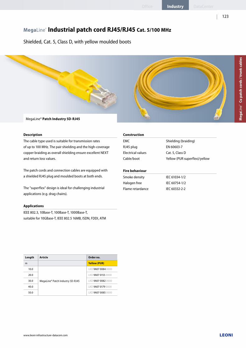
www.leoni-infrastructure-datacom.com
123
Length Article Order no.
m Yellow (PUR)
10.0
MegaLine®PatchIndustry5D-RJ45
LKD 9A07 0084 0000
20.0 LKD 9A07 0155 0000
30.0 LKD 9A07 0082 0000
40.0 LKD 9A07 0179 0000
50.0 LKD 9A07 0085 0000
MegaLine® Industrial patch cord RJ45/RJ45 Cat. 5/100 MHz
Shielded, Cat. 5, Class D, with yellow moulded boots
MegaLine® Patch Industry 5D-RJ45
Description
The cable type used is suitable for transmission rates
of up to 100 MHz. The pair shielding and the high-coverage
copper braiding as overall shielding ensure excellent NEXT
and return loss values.
The patch cords and connection cables are equipped with
a shieldedRJ45plug andmouldedbootsatbothends.
The "superflex" design is ideal for challenging industrial
applications(e.g. drag chains).
Applications
IEEE 802.3, 10Base-T, 100Base-T, 1000Base-T,
suitable for 10GBase-T, IEEE 802.5 16MB, ISDN, FDDI, ATM
Construction
EMC
RJ45plug
Electrical values
Cable/boot
Shielding(braiding)
EN 60603-7
Cat. 5, Class D
Yellow(PURsuperflex)/yellow
Fire behaviour
Smoke density
Halogen free
Flame retardance
IEC 61034-1/2
IEC 60754-1/2
IEC 60332-2-2
Meg
aLin
e®
Cu p
atch
cor
ds /
trun
k ca
bles
Office DataCenterIndustry

www.leoni-infrastructure-datacom.com
124
MegaLine® Industrial patch cord with Han® 3A plugs
Cat. 6, Class E
MegaLine® Patch Han 3A RJ45/RJ45
Description
Pre-assembledsystemcablereadyforconnectionwith
Han® 3A RJ45toHan®3ARJ45.
n Han® 3A interface in metal also offers increased protection
against heat n Mating compatible with many controllers, devices and
automation systemsn WithextremelyrobustRJ45,IP65/IP67cords
Construction
Sheath material
Performance
PUR,LSZH
Acc.toCat.6orforClassE(250MHz)
MegaLine® Patch Han 3A RJ45/IP20 RJ45
Description
Pre-assembledsystemcablereadyforconnectionwith
Han® 3A RJ45to IP20 RJ45.
n Han® 3A interface in metal also offers increased protection
against heat n Mating compatible with many controllers, devices and
automation systemsn WithextremelyrobustRJ45,IP65/IP67cords
Construction
Sheath material
Performance
PUR,LSZH
Acc.toCat.6orforClassE(250MHz)
Length Article Order no.
1.5 m
MegaLine®PatchHan3ARJ45/RJ45
LKD 9A07 0110 0000
3.0 m LKD 9A07 0111 0000
5.0 m LKD 9A07 0112 0000
10.0 m LKD 9A07 0113 0000
Length Article Order no.
1.5 m
MegaLine®PatchHan3ARJ45/IP20RJ45
LKD 9A07 0088 0000
3.0 m LKD 9A07 0089 0000
5.0 m LKD 9A07 0090 0000
10.0 m LKD 9A07 0091 0000

www.leoni-infrastructure-datacom.com
125
MegaLine® Patch Industry 6EA-RJ45
Description
The cable type used is suitable for transmission rates
of up to 500 MHz. The pair shielding and the high-coverage
copper braiding as overall shielding ensure excellent NEXT
and return loss values.
The patch cords and connection cables are equipped with
a shieldedRJ45plugatbothends.
Applications
IEEE 802.3, 10Base-T, 100Base-T, 1000Base-T,
suitable for 10GBase-T,IEEE 802.5 16MB, ISDN, FDDI, ATM
Construction
EMC
RJ45plug
Electrical values
Cable/boot
Combinedshielding(PiMf+braiding)
EN 60603-7
Cat. 6, Class EA
Yellow(PUR)/black
Fire behaviour
Smoke density
Halogen free
Flame retardance
IEC 61034-1/2
IEC 60754-1/2
IEC 60332-2-2
Accessories see page 140
MegaLine®PatchRJ45colourcodingclip
In different colours for visual coding of the patch cords
MegaLine® Industrial patch cord RJ45/RJ45 Cat. 6/500 MHz
Shielded, Cat. 6, Class EA, with black moulded boots
Length Article Order no.
m Yellow (PUR)
0.5
MegaLine®PatchIndustry6EA-RJ45
LKD 9A07 0160 0000
1.0 LKD 9A07 0161 0000
1.5 LKD 9A07 0162 0000
2.0 LKD 9A07 0163 0000
2.5 LKD 9A07 0164 0000
3.0 LKD 9A07 0165 0000
5.0 LKD 9A07 0166 0000
7.5 LKD 9A07 0167 0000
10.0 LKD 9A07 0168 0000
Meg
aLin
e®
Cu p
atch
cor
ds /
trun
k ca
bles
Office DataCenterIndustry

Applications 10BASE-T/100BASE-T2 Token ring ISDN Telephone line
Patchcord
Wiring TERA™ 2-pair to RJ45 TERA™ 2-pair to RJ45 TERA™ 2-pair to RJ45 TERA™ 1-pair to RJ45
www.leoni-infrastructure-datacom.com
126
MegaLine® Patch TERA
Description
ThepatchcordandconnectioncableareequippedwithTERA™
orRJ45plugsas required(theRJ45plughasamouldedboot).
The appropriate cable type for the application is used for
assembly. The cable type F10-120 S/F flex used is designed
for a bandwidth of up to 1,000 Mhz with 4-pair assignment.
MegaLine® Patch cord TERA™
Shielded, with moulded boots
Applications Wiring
n 10BASE-T/100BASE-T2
n Token ring
n ISDN
n Telephone line
n Telephone line
nUser-defined
n 2-pair connecting line
n 4-pair connecting line
TERA™2-pairtoRJ45
TERA™2-pairtoRJ45
TERA™2-pairtoRJ45
TERA™1-pairtoRJ45
TERA™1-pairtoRJ11
TERA™4-pairtoRJ45
TERA™toTERA™
TERA™toTERA™
Length Article Order no. Article Order no.
m 10BASE-T/100BASE-T2 Token ring ISDN Telephone line
1.0 MegaLine®PatchTERA™ 2-pair to RJ45* (F10-120S/Fflex)
LKD 9A04 0000 0000 LKD 9A04 0006 0000 LKD 9A04 0012 0000MegaLine®PatchTERA™ 1-pair to RJ45*(326flex)
LKD 9A04 0022 0000
2.0 LKD 9A04 0001 0000 LKD 9A04 0007 0000 LKD 9A04 0013 0000 LKD 9A04 0023 0000
3.0 LKD 9A04 0002 0000 LKD 9A04 0008 0000 LKD 9A04 0014 0000 LKD 9A04 0024 0000
5.0 LKD 9A04 0003 0000 LKD 9A04 0009 0000 LKD 9A04 0015 0000 LKD 9A04 0025 0000
TERA™ is a registered trademark of the Siemon Company

Applications Telephone line Any 2-pair connecting line 4-pair connecting line
Patchcord
Wiring TERA™ 1-pair to RJ11 TERA™ 4-pair to RJ45 TERA™ to TERA™ TERA™ to TERA™
www.leoni-infrastructure-datacom.com
127
Length Article Order no. Article Article Order no.
m Telephone line User-defined 2-pair connecting line
4-pair connecting line
1.0
MegaLine®PatchTERA™ 1-pair to RJ11*(326flex)
LKD 9A04 0017 0000MegaLine®PatchTERA™ 4-pair to RJ45* (F10-120S/Fflex)
LKD 9A04 0039 0000
MegaLine®PatchTERA™toTERA™ (F10-120S/Fflex)
LKD 9A04 0026 0000 LKD 9A04 0032 0000
2.0 LKD 9A04 0018 0000 LKD 9A04 0040 0000 LKD 9A04 0027 0000 LKD 9A04 0033 0000
3.0 LKD 9A04 0019 0000 LKD 9A04 0041 0000 LKD 9A04 0028 0000 LKD 9A04 0034 0000
5.0 LKD 9A04 0045 0000 LKD 9A04 0042 0000 LKD 9A04 0029 0000 LKD 9A04 0035 0000
TERA™ is a registered trademark of the Siemon Company
Meg
aLin
e®
Cu p
atch
cor
ds /
trun
k ca
bles
Office DataCenterIndustry

MegaLine® Patch 4P EC7/EC7
MegaLine® Patch 4P EC7/RJ45
MegaLine® Patch 4P EC7/open
Patchcordandconnection cable
Equipment at end AEquipment at end B
4-pair EC7 plug4-pair EC7 plug
4-pair EC7 plugRJ45plug
4-pair EC7 plugOpen(e.g.forself-assemblyofanRJ45plug)
Assignment
EC7/EC7: 1/1EC7/RJ45:1/2-4/5, 3/4-7/8, 5/6-2/1, 7/8-3/6
www.leoni-infrastructure-datacom.com
128
MegaLine® Patch cord and connection cable EC7
4-pair, shielded, with yellow boots
Length Article Order no. Article Order no. Article Order no.
m Yellow (LSOH) Yellow (LSOH) Yellow (LSOH)
1.0
MegaLine®Patch4PEC7/EC7(1piece)
LKD 9KEC 1010 0000
MegaLine®Patch4PEC7/RJ45(1piece)
LKD 9KEC 2010 0000
MegaLine®Patch4P EC7/open(1piece)
2.0 LKD 9KEC 1020 0000 LKD 9KEC 2020 0000
3.0 LKD 9KEC 1030 0000 LKD 9KEC 2030 0000
5.0 LKD 9KEC 1050 0000 LKD 9KEC 2050 0000 LKD 9KEC 0050 0000
MegaLine® Patch 4P EC7/EC7
MegaLine® Patch 4P EC7/RJ45
MegaLine® Patch 4P EC7/open
Description
PatchcordandconnectioncableforGigabitEthernet.
Construction
Cable type
Boot
4p,LightgreyRAL7035
Yellow
Plugrear view Plugrear view Plugrear view
Open end
RJ45frontview
1 2 3 4 5 6 7 8

MegaLine® Patch 2PEC7/EC7
MegaLine® Patch 2PEC7/open
MegaLine® Patch 2P EC7/RJ45
MegaLine® Patch 2P EC7/RJ45 Cross over
Patchcordandconnection cable
Equipment at end AEquipment at end B
2-pair EC7 plug2-pair EC7 plug
2-pair EC7 plugOpen(e.g.forself-assemblyofanRJ45plug)
2-pair EC7 plugRJ45plug
2-pair EC7 plugRJ45plug
Assignment
EC7/EC7: 1/1
EC7/RJ45:1/2,3/6for Ethernet
EC7/RJ45:1/2,3/6for Ethernet cross over
1 12 2 3 34 45 56 67 78 8
www.leoni-infrastructure-datacom.com
129
MegaLine® Patch cord and connection cable EC7
2-pair, shielded, with coloured boots
Length Article Order no. Article Order no. Article Order no. Article Order no.
m Grey (LSOH) Grey (LSOH) Yellow (LSOH) Yellow (LSOH)
0.5
MegaLine® Patch2PEC7/EC7(1piece)
LKD 9KE0 1005 0000
MegaLine® Patch2PEC7/open(1piece)
MegaLine® Patch2PEC7/RJ45(1piece)
LKD 9KE0 3005 0000
MegaLine® Patch2PEC7/RJ45Cross over(1piece)
LKD 9KE3 1005 0000
1.0 LKD 9KE0 1010 0000 LKD 9KE0 3010 0000 LKD 9KE3 1010 0000
2.0 LKD 9KE0 1020 0000 LKD 9KE0 3020 0000 LKD 9KE3 1020 0000
3.0 LKD 9KE0 1030 0000 LKD 9KE0 3030 0000 LKD 9KE3 1030 0000
5.0 LKD 9KE0 1050 0000 LKD 9KE0 2050 0000 LKD 9KE0 3050 0000 LKD 9KE3 1050 0000
MegaLine® Patch 2P EC7/EC7
MegaLine® Patch 2P EC7/open
MegaLine® Patch 2P EC7/RJ45
MegaLine® Patch 2P EC7/RJ45 Cross over
Description
PatchcordandconnectioncableforGigabitEthernet.
Construction
Cable type
Boot
2p,LightgreyRAL7035
Grey or yellow
Plugrear view Plugrear view Plugrear view Plugrear view
EC7 rear view
Open end
RJ45frontview RJ45frontview
Meg
aLin
e®
Cu p
atch
cor
ds /
trun
k ca
bles
IndustryOffice DataCenter

MegaLine® Patch 1PEC7/EC7
MegaLine® Patch 1PEC7/open
MegaLine® Patch 1P EC7/RJ10
MegaLine® Patch 1P EC7/RJ11
Patchcordandconnection cable
Equipment at end AEquipment at end B
1-pair EC7 plug1-pair EC7 plug
1-pair EC7 plugOpen(e.g.forself-assemblyofanRJ11plug)
1-pair EC7 plugRJ10plug
2-pair EC7 plugRJ11plug
Assignment
EC7/EC7: 1/1
EC7/RJ10:4/4
EC7/RJ11:6/4
EC71Prear view EC71Prear view EC71Prear view EC71Prear view
Open end
RJ10(4/4)front view
RJ11(6/4)front view
www.leoni-infrastructure-datacom.com
130
MegaLine® Patch cord and connection cable EC7
1-pair, shielded, with black boots
Length Article Order no. Article Order no. Article Order no. Article Order no.
m Black (PVC) Black (PVC) Black (PVC) Black (PVC)
0.5
MegaLine® Patch1PEC7/EC7(1piece)
LKD 9KE7 4005 0000
MegaLine® Patch1PEC7/open(1piece)
MegaLine® Patch1PEC7/RJ10(1piece)
LKD 9KE7 6005 0000
MegaLine® Patch1PEC7/RJ11(1piece)
LKD 9KE7 8005 0000
1.0 LKD 9KE7 4010 0000 LKD 9KE7 6010 0000 LKD 9KE7 8010 0000
2.0 LKD 9KE7 4020 0000 LKD 9KE7 6020 0000 LKD 9KE7 8020 0000
3.0 LKD 9KE7 4030 0000 LKD 9KE7 6030 0000 LKD 9KE7 8030 0000
5.0 LKD 9KE7 4050 0000 LKD 9KE7 5050 0000 LKD 9KE7 6050 0000 LKD 9KE7 8050 0000
MegaLine® Patch 1P EC7/EC7
MegaLine® Patch 1P EC7/open
MegaLine® Patch 1P EC7/RJ10
MegaLine® Patch 1P EC7/RJ11
Description
Patchcordandconnectioncableforanalogueanddigital
telephone systems.
Construction
Cable type
Boot
3-core,JetblackRAL9005
Black
oblique outer edge
oblique outer edge
oblique outer edge
oblique outer edge
oblique outer edge
1 2 3 4 1 2 3 4 5 6

MegaLine® Patch 1PEC7/RJ45
MegaLine® Patch 1PEC7/RJ45
MegaLine® Patch 2P EC7/RJ45
Patchcordandconnection cable
Equipment at end AEquipment at end B
1-pair EC7 plugRJ45plug
1-pair EC7 plugRJ45plug
2-pair EC7 plugRJ45plugwithoutboot
Assignment
For digital telephonyFor analogue telephonyFor terminals with earthing key
EC7/RJ45:3/6,4/5for ISDN
EC71Prear view EC71Prear view EC72Prear view
RJ45frontview RJ45frontview RJ45frontview
www.leoni-infrastructure-datacom.com
131
MegaLine® Patch cord and connection cable EC7
1-pair/2-pair, shielded, with black boots
MegaLine® Patch 1P EC7/RJ45
MegaLine® Patch 2P EC7/RJ45
Description
Patchcordandconnectioncablefortelephonesystems.
Construction
Cable type
Boot
3-core,JetblackRAL9005
Black
Length Article Order no. Article Order no. Article Order no.
m Black (PVC) Black (PVC) Black (PVC)
0.5
MegaLine®Patch1PEC7/RJ45(1piece)
LKD 9KE7 9005 0000
MegaLine®Patch1PEC7/RJ45(1piece)
LKD 9KE8 0005 0000
MegaLine® Patch2PEC7/RJ45(1piece)
LKD 9KE6 7005 0000
1.0 LKD 9KE7 9010 0000 LKD 9KE8 0010 0000 LKD 9KE6 7010 0000
2.0 LKD 9KE7 9020 0000 LKD 9KE8 0020 0000 LKD 9KE6 7020 0000
3.0 LKD 9KE7 9030 0000 LKD 9KE8 0030 0000 LKD 9KE6 7030 0000
5.0 LKD 9KE7 9050 0000 LKD 9KE8 0050 0000 LKD 9KE6 7050 0000
oblique outer edge
oblique outer edge
1 2 3 4 5 6 7 8 1 2 3 4 5 6 7 8 1 2 3 4 5 6 7 8
Meg
aLin
e®
Cu p
atch
cor
ds /
trun
k ca
bles
IndustryOffice DataCenter

www.leoni-infrastructure-datacom.com
132
Article Length Order no.
MegaLine® Crossconnect trunk cable
10.0 m LKD 9A06 0129 0000
15.0 m LKD 9A06 0130 0000
20.0 m LKD 9A06 0131 0000
30.0 m LKD 9A06 0133 0000
40.0 m LKD 9A06 0135 0000
50.0 m LKD 9A06 0137 0000
Standardlengths,furtherlengthsandcabletypes(alsoassembledatoneend)on request
Article Length Order no.
MegaLine® Trunk cable
10.0 m LKD 9A06 0095 0000
15.0 m LKD 9A06 0096 0000
20.0 m LKD 9A06 0097 0000
30.0 m LKD 9A06 0099 0000
40.0 m LKD 9A06 0101 0000
50.0 m LKD 9A06 0103 0000
Standardlengths,furtherlengthsandcabletypes(alsoassembledatoneend)on request
MegaLine® Trunk cable, industrial
VarioKeystone® cable plug Cat. 7, pre-assembled
MegaLine® Trunk cable
Description
The data cable is assembled with cable plugs at both ends.
Ideal for clean rooms or for fast manipulation on site. During
pre-assembly, the cable plug is moulded with a casting
compound that simultaneously protects against bending.
The pre-assembled cable is supplied as a ring.
Construction
Material
Cable
Side A
Side B
Assignment
Shielding
Electrical values
Full metal; die-cast zinc, nickel-plated
MegaLine®F10-115 S/F AWG 23/1
(Orderno.:LKD 7KS7 0008 0000)
VarioKeystone® cable plug Cat. 7
VarioKeystone® cable plug Cat. 7
1:1
Large-surface 360° shield connection
Contact block: white/white
Category 7
Standards
n ISO/IEC 11801n EN 50173-1
MegaLine® Crossconnect trunk cable
Description
The data cable is assembled with cable plugs at both ends.
Ideal for clean rooms or for fast manipulation on site. During
pre-assembly, the cable plug is moulded with a casting
compound that simultaneously protects against bending.
The pre-assembled cable is supplied as a ring.
Construction
Material
Cable
Side A
Side B
Assignment
Shielding
Electrical values
Full metal; die-cast zinc, nickel-plated
MegaLine®F10-115 S/F AWG 23/1
(Orderno.:LKD 7KS7 0008 0000)
VarioKeystone® cable plug Cat. 7
VarioKeystone® cable plug Cat. 7
Crossconnect
Large-surface 360° shield connection
Contact block: white/red
Category 7
Standards
n ISO/IEC 11801n EN 50173-1
TrunkContact block: white/white
Crossconnect trunkContact block: white/red
With documented acceptance measurement on CD on request
(page 79)
With documented acceptance measurement on CD on request
(page 79)

www.leoni-infrastructure-datacom.com
133
MegaLine® Trunk cable
VarioKeystone® cable plug Cat. 7, pre-assembled
MegaLine® Trunk cable
Description
The data cable is assembled with cable plugs at both ends.
Ideal for clean rooms or for fast manipulation on site. During
pre-assembly, the cable plug is moulded with a casting
compound that simultaneously protects against bending.
The pre-assembled cable is supplied as a ring.
n Oil resistant acc. to ICEA S-82-552 (+60 °C)
Construction
Material
Cable
Side A
Side B
Assignment
Shielding
Electrical values
Full metal; die-cast zinc, nickel-plated
MegaLine®F10-130 Vö AWG 22/1
(Orderno.:LKD 7KS7 0089 0000)
VarioKeystone® cable plug Cat. 7
VarioKeystone® cable plug Cat. 7
1:1
Large-surface 360° shield connection
Contact block: white/white
Category 7
Standards
n ISO/IEC 11801n EN 50173-1
MegaLine® Crossconnect trunk cable
Description
The data cable is assembled with cable plugs at both ends.
Ideal for clean rooms or for fast manipulation on site. During
pre-assembly, the cable plug is moulded with a casting
compound that simultaneously protects against bending.
The pre-assembled cable is supplied as a ring.
n Oil resistant acc. to ICEA S-82-552 (+60 °C)
Construction
Material
Cable
Side A
Side B
Assignment
Shielding
Electrical values
Full metal; die-cast zinc, nickel-plated
MegaLine®F10-130 Vö AWG 22/1
(Orderno.:LKD 7KS7 0089 0000)
VarioKeystone® cable plug Cat. 7
VarioKeystone® cable plug Cat. 7
Crossconnect
Crossconnect
Large-surface 360° shield connection
Contact block: white/red
Category 7
Standards
n ISO/IEC 11801n EN 50173-1
Article Length* Order no.
MegaLine® Trunk cable
15.0 m LKD 9A06 0201 0000
20.0 m LKD 9A06 0202 0000
30.0 m LKD 9A06 0204 0000
40.0 m LKD 9A06 0206 0000
50.0 m LKD 9A06 0208 0000
Standardlengths,furtherlengthsandcabletypes(alsoassembledatoneend)on request
Article Length* Order no.
MegaLine® Crossconnect trunk cable
15.0 m LKD 9A06 0231 0000
20.0 m LKD 9A06 0232 0000
30.0 m LKD 9A06 0234 0000
40.0 m LKD 9A06 0236 0000
50.0 m LKD 9A06 0238 0000
Standardlengths,furtherlengthsandcabletypes(alsoassembledatoneend)on request
TrunkContact block: white/white
Crossconnect trunkContact block: white/red
With documented acceptance measurement on CD on request
(page 79)
With documented acceptance measurement on CD on request
(page 79)
Meg
aLin
e®
Cu p
atch
cor
ds /
trun
k ca
bles
DataCenterIndustryOffice

www.leoni-infrastructure-datacom.com
134
MegaLine® Trunk cable, 8 port RJ45
Shielded, Cat. 6, Class EA
Length Article Order no.
20.0 m MegaLine® Trunk RJ45plug/RJ45plug(1piece)
LKD 9A06 0929 0000
Standard length, further lengths on request
MegaLine® Trunk RJ45 plug/RJ45 plug
Description
Pre-assembledtrunkcable,8portsequippedwithRJ45plugs
at both ends.
Construction
Cable type
Side A
Side B
Labels
Whip length
Electrical values
F10-120S/Fflex8x4PAWG26/7
RJ45plug,greyboot
RJ45plug,greyboot
16 x laminated label,
printed according to customer's
specification
0.4 m
Cat. 6, Class EA
Standards
n ISO/IEC 11801n EN 50173-1

www.leoni-infrastructure-datacom.com
135
MegaLine® Trunk cable, 4 port/8 port
VarioKeystone® cable plug Cat. 7, pre-assembled
MegaLine® Trunk cable, 4 portMegaLine® Trunk cable, 8 port
Description
The data cable is assembled with cable plugs at both ends.
Ideal for clean rooms or for fast manipulation on site. During
pre-assembly, the cable plug is moulded with a casting
compound that simultaneously protects against bending.
The pre-assembled cable is supplied as a ring.
Cable
Type
Side A
Side B
Whip length
MegaLine®F10-115S/F4x4PAWG23/1
(Orderno.:LKD 7KS7 0161 0000)
MegaLine®F10-120S/Fflex8x4PAWG26/7
(Orderno.:LKD 7KS7 0142 0000)
VarioKeystone® cable plug Cat. 7
VarioKeystone® cable plug Cat. 7
0.4 m
Construction
Material
Assignment
Shielding
Electrical values
Full metal; die-cast zinc, nickel-plated
1:1
Large-surface 360° shield connection
Contact block: white
Category 7
Standards
n ISO/IEC 11801 n EN 50173-1
With documented acceptance measurement on CD on request.
Article Length* Order no.
MegaLine® Trunk cable 4 port
10.0 m LKD 9A06 1019 0000
15.0 m LKD 9A06 1020 0000
MegaLine® Trunk cable 8 port
5.0 m LKD 9A06 0192 0000
7.5 m LKD 9A06 0193 0000
10.0 m LKD 9A06 0194 0000
15.0 m LKD 9A06 0195 0000
Standardlengths,furtherlengthsandcabletypes(alsoassembledatoneend)on request
Meg
aLin
e®
Cu p
atch
cor
ds /
trun
k ca
bles
DataCenterIndustryOffice

MegaLine® Connect45 trunk cable
Pre-assembledsinglecablewithMegaLine®Connect45jackmodulesCat.6A/Cat. 6A
MegaLine® Connect45 Trunk Cat. 6A modulesMegaLine® Connect45 Trunk Cat. 6A modules
Description
The trunk cable is based on an F6-90 S/F data cable with
a MegaLine® Connect45 jack at both ends.
Thanks to the high quality of the components, the pre-assembled
cable meets all permanent link requirements (>1 m, Cat. 6A
modules) or (>10 m, Cat. 6A modules) from Class EA according
to ISO/IEC 11801 and EN 50173 for 10 Gigabit Ethernet.
The lengths relate to the 2-connector model.
Also available without a jack module – ideal in combination
with high-densitypatchpanels(seepage101).
Standards
n ISO/IEC 11801 n EN 50173-1n IEC60603-7-51(Cat.6A)n EIA/TIA568-C.2(Cat.6A)
Article Jack module format Length* Cat. 6A modules Cat. 6A modules
MegaLine® Connect45 Trunk
VarioKeystone®
5.0 m LKD 9A06 1173 0000 —
10.0 m LKD 9A06 1174 0000 —
15.0 m LKD 9A06 1175 0000 —
30.0 m LKD 9A06 1176 0000 —
90.0 m LKD 9A06 1177 0000 —
Keystone
5.0 m LKD 9A06 1132 0000 LKD 9A06 1127 0000
10.0 m LKD 9A06 1133 0000 LKD 9A06 1128 0000
15.0 m LKD 9A06 1134 0000 LKD 9A06 1129 0000
30.0 m LKD 9A06 1135 0000 LKD 9A06 1130 0000
90.0 m LKD 9A06 1136 0000 LKD 9A06 1131 0000
* Standard lengths/further lengths on request
With documented acceptance measurement on CD on request.
Construction – VarioKeystone® jack modules
Cable
Side A/side B
(version1)
Side A/side B
(version2)
F6-90S/F(4x2xAWG23/1)
MegaLine® Connect45 Cat. 6A(ISO/IEC)
(Orderno.:LKD 9A50 2010 0000)
MegaLine®Connect45Cat.6A(EIA/TIA)
(Orderno.:LKD 9A50 2020 0000)
Construction – Keystone jack modules
Cable
Side A/side B
(version1)
Side A/side B
(version2)
F6-90S/F(4x2xAWG23/1)
MegaLine® Connect45 Cat. 6A(ISO/IEC)
(Orderno.:LKD 9A50 1010 0000)
MegaLine®Connect45Cat.6A(EIA/TIA)
(Orderno.:LKD 9A50 1020 0000)
JackmoduleCat.6Awhite
JackmoduleCat.6A
aqua
www.leoni-infrastructure-datacom.com
136

MegaLine® Connect45 Trunk, 8 port
Pre-assembledmulticablewithMegaLine®Connect45jackmodulesCat.6A
MegaLine® Connect45 Trunk, 8 port Cat. 6A modules
Description
The trunk cable is based on an 8-fold F10-120 S/F flex data cable
with a MegaLine® Connect45 jack at both ends. Thanks to the
high quality of the components, the pre-assembled cable meets
all permanent link requirements
(>1 m, Cat. 6A modules) from Class EA according to ISO/IEC
11801 and EN 50173 for 10 Gigabit Ethernet.
Also available without a jack module – ideal in combination
with high-densitypatchpanels(seepage101).
Construction – VarioKeystone® jack modules
Cable
Side A/side B
Whip length
F10-120S/Fflex(8x4x2xAWG26/7)
MegaLine® Connect45 Cat. 6A
(Orderno.:LKD9A5020100000)
0.4 m
Construction – Keystone jack modules
Cable
Side A/side B
Whip length
F10-120S/Fflex(8x4x2xAWG26/7)
MegaLine® Connect45 Cat. 6A
(Orderno.:LKD 9A50 1010 0000)
0.4 m
Standards
n ISO/IEC 11801 n EN 50173-1 n IEC60603-7-51
JackmoduleCat.6A
aqua
Article Jack module format Length* Cat. 6A modules
MegaLine®Connect45 Trunk, 8 port
VarioKeystone®
5.0 m LKD 9A06 1178 0000
7.5 m LKD 9A06 1179 0000
10.0 m LKD 9A06 1180 0000
15.0 m LKD 9A06 1181 0000
Keystone
5.0 m LKD 9A06 1137 0000
7.5 m LKD 9A06 1138 0000
10.0 m LKD 9A06 1139 0000
15.0 m LKD 9A06 1140 0000
* Standard lengths/further lengths on request
With documented acceptance measurement on CD on request.
www.leoni-infrastructure-datacom.com
137
Meg
aLin
e®
Cu p
atch
cor
ds /
trun
k ca
bles
IndustryOffice DataCenter

MegaLine® Connect45 CP cable
Pre-assembledsinglecablewithMegaLine®Connect45jackmodulesCat.6A/Cat. 6A
Article Jack module format Length* Cat. 6A modules
MegaLine®Connect45CPcable
VarioKeystone®
5.0 m LKD 9A02 3353 0000
10.0 m LKD 9A02 3354 0000
15.0 m LKD 9A02 3355 0000
20.0 m LKD 9A02 3356 0000
25.0 m LKD 9A02 3357 0000
Keystone
5.0 m LKD 9A02 3343 0000
10.0 m LKD 9A02 3344 0000
15.0 m LKD 9A02 3345 0000
20.0 m LKD 9A02 3346 0000
25.0 m LKD 9A02 3347 0000
* Standard lengths/further lengths on request
With documented acceptance measurement on CD on request.
MegaLine® Connect45 CP cable
Description
The consolidation point cable is based on an F10-120 S/F flex
data cable with a MegaLine® Connect45 jack at one end and
a RJ45SmartLockplugattheother.
Thanks to the high-quality components in combination
withaCPLink(>10m),thepre-assembledcablemeetsthe
requirements of the Class EA permanent link according
to ISO/IEC 11801 Amendment 2 for 10 Gigabit Ethernet.
Standards
n ISO/IEC 11801 n EN 50173-1 n IEC60603-7-51
Construction – VarioKeystone® jack modules
Cable
Side A
Side B
F10-120S/Fflex(4x2xAWG26/7)
MegaLine® Connect45 Cat. 6A(ISO/IEC)
(Orderno.:LKD 9A50 2010 0000)
RJ45plug(SmartLockCat.6A)
Construction – Keystone jack modules
Cable
Side A
Side B
F10-120S/Fflex(4x2xAWG26/7)
MegaLine® Connect45 Cat. 6A(ISO/IEC)
(Orderno.:LKD 9A50 1010 0000)
RJ45plug(SmartLockCat.6A)
JackmoduleCat.6AVarioKeystone® format
JackmoduleCat.6A
Keystone format
www.leoni-infrastructure-datacom.com
138

www.leoni-infrastructure-datacom.com
139
MegaLine® EC7 CP cable
Shielded, Cat. 7, Class F
Length Article Order no.
5.0 m
MegaLine®EC7CPcable(1piece)
LKD9KEJ8050 0000
10.0 m LKD9KEJ8100 0000
15.0 m LKD9KEJ8150 0000
20.0 m LKD9KEJ8200 0000
25.0 m LKD9KEJ8250 0000
30.0 m LKD9KEJ8300 0000
MegaLine® EC7 CP cable
Description
Trunk and consolidation point cable, assembled with an ELine
1200® EC7 plug and an ELine 1200® EC7 plug.
Construction
Cable type
Side A
Side B
Electrical values
F10-120S/Fflex1x4PAWG26/7
ELine 1200® EC7 plug
ELine1200® EC7 jack
Cat. 7, Class F
Standards
n ISO/IEC 11801n EN 50173-1
Meg
aLin
e®
Cu p
atch
cor
ds /
trun
k ca
bles
IndustryOffice DataCenter

www.leoni-infrastructure-datacom.com
140
MegaLine® Patch LED colour clip
MegaLine® Patch LED detector
Accessories
Colour clip:
For visual coding of the LED patch cords.
CanbeinstalledbysimplysnappingintotheRJ45plugs.
Detector:
For feeding the light signal for identifying the patch cord.
Batteries included:
4xLR41
Article Colour Order no.
MegaLine®PatchLEDcolour clip (100pieces)
RapeyellowRAL1021 LKD 9A09 0180 0000
FlameredRAL3000 LKD 9A09 0181 0000
SkyblueRAL5015 LKD 9A09 0182 0000
TurquoisegreenRAL6016 LKD 9A09 0183 0000
MegaLine®PatchLEDdetector (1piece)
LKD 9A09 0190 0000
MegaLine® Patch accessories
for LED patch cords
MegaLine® Patch accessories
forRJ45patchcords
MegaLine® Patch RJ45 colour coding clip
Accessories
Colour coding clip for visual coding of the patch cords.
Can be installed by simply pushing on.
Compatibility
MegaLine®Patch5D-RJ45MegaLine®Patch6E-RJ45UMegaLine®Patch6EA-RJ45MegaLine®Patch6AEA-RJ45MegaLine®PatchIndustry6EA-RJ45
Article Colour Order no.
MegaLine®PatchRJ45colourcodingclip(100pieces)
LightgreyRAL7035 LKD 9AW1 6031 0000
TurquoisegreenRAL6016 LKD 9AW1 6032 0000
SkyblueRAL5015 LKD 9AW1 6033 0000
FlameredRAL3000 LKD 9AW1 6034 0000
PastelorangeRAL2003 LKD 9AW1 6035 0000
RapeyellowRAL1021 LKD 9AW1 6036 0000
JetblackRAL9005 LKD 9AW1 6037 0000

MegaLine® Test report
for all trunk cables
Product family Measurement Acceptance measurement Order no.
MegaLine®Connect45
for trunks
PermanentlinkClassEA(withISO/IECjackmodule) LKD 9A50 4020 0000
PermanentlinkClassEA(withEIA/TIAjackmodule) LKD 9A50 4021 0000
Channel Class EA(withISO/IECjackmodule) LKD 9A50 4022 0000
Channel Class EA(withEIA/TIAjackmodule) LKD 9A50 4023 0000
MegaLine®Connect45
forCPcable PermanentlinkClassEA(withISO/IECjackmodule) LKD 9A50 4024 0000
VarioKeystone® for trunks
Channel Class FA LKD 9A46 0132 0000
PermanentlinkClassF LKD 9A46 0123 0000
PermanentlinkClassEA LKD 9A46 0125 0000
Channel Class EA(withCat.6Amodule) LKD 9A46 0131 0000
Channel Class EA(withCat.6module) LKD 9A46 0126 0000
Also order
The measurement carried out prior to delivery can be documen-
ted on CD as a test report and supplied on request.
Measurements for trunks
PermanentlinkClassEA (withISO/IECjackmodule)
PermanentlinkClassEA (withEIA/TIAjackmodule)
Channel Class EA (withISO/IECjackmodule)
Channel Class EA (withEIA/TIAjackmodule)
Measurements for CP cables
PermanentlinkClassEA (withISO/IECjackmodule)
Acceptance measurements
Channel Class FA
PermanentlinkClassF
PermanentlinkClassEA
Channel Class EA (withCat.6module)
Channel Class EA (withCat.6Amodule)
www.leoni-infrastructure-datacom.com
141
Meg
aLin
e®
Cu p
atch
cor
ds /
trun
k ca
bles
IndustryOffice DataCenter

MegaLine®
Acceptance measurement
www.leoni-infrastructure-datacom.com
142

Office DataCenterIndustry
www.leoni-infrastructure-datacom.com
143
Acceptance measurement
of the MegaLine® cabling systems
The acceptance measurement for the MegaLine® cabling
systems for the channel or permanent link is carried out
in accordance with the requirements of SO/IEC 11801
or EN 50173, 2nd Edition Amendment 1/2.
Further standards regarding the acceptance measurement
(measurement procedure):DIN EN 50346 and DIN EN 61935.

www.leoni-infrastructure-datacom.com
144
Frequency/MHz 1 16 100 250 500 600 1000
Channel Class E
Returnloss 19.0 18.0 12.0 8.0
Insertion loss 4.0 8.3 21.7 35.9
NEXT 65.0 53.2 39.9 33.1
PSNEXT/dB 62.0 50.6 37.1 30.2
ACR-N/dB 61.0 44.9 18.2 –2.8
PS-ACR-N/dB 58.0 42.3 15.4 –5.8
ACR-F/dB 63.3 39.2 23.3 15.3
PS-ACR-F/dB 60.3 36.2 20.3 12.3
Runtime/µs 0.580 0.553 0.548 0.546
Runtimedifference/µs 0.050 0.050 0.050 0.050
Channel Class EA
Returnloss 19.0 18.0 12.0 8.0 6.0
Insertion loss 4.0 8.2 20.9 33.9 49.3
NEXT 65.0 53.2 39.9 33.1 27.9
PSNEXT/dB 62.0 50.6 37.1 30.2 24.8
ACR-N/dB 61.0 45.0 19.0 –0.8 –21.4
PS-ACR-N/dB 58.0 42.4 16.2 –3.7 –24.5
ACR-F/dB 63.3 39.2 23.3 15.3 9.3
PS-ACR-F/dB 60.3 36.2 20.3 12.3 6.3
Runtime/µs 0.580 0.553 0.548 0.546 0.546
Runtimedifference/µs 0.050 0.050 0.050 0.050 0.050
Channel Class F
Returnloss 19.0 18.0 12.0 8.0 49.3 8.0
Insertion loss 4.0 8.1 20.8 33.8 52.4 54.6
NEXT 65.0 65.0 62.9 56.9 49.4 51.2
PSNEXT/dB 62.0 62.0 59.9 53.9 3.1 48.2
ACR-N/dB 61.0 56.9 42.1 23.1 0.1 –3.4
PS-ACR-N/dB 58.0 53.9 39.1 20.1 32.6 –6.4
ACR-F/dB 65.0 57.5 44.4 37.8 29.6 31.3
PS-ACR-F/dB 62.0 54.5 41.4 34.8 8.0 28.3
Runtime/µs 0.580 0.553 0.548 0.546 0.546 0.545
Runtimedifference/µs 0.030 0.030 0.030 0.030 0.03 0.030
Channel Class FA
Returnloss 19.0 18.0 12.0 8.0 8.0 8.0 6.0
Insertion loss 4.0 8.0 20.3 32.5 46.7 51.4 67.6
NEXT 65.0 65.0 65.0 59.1 53.6 52.1 47.9
PSNEXT/dB 62.0 62.0 62.0 56.1 50.6 49.1 44.9
ACR-N/dB 61.0 57.0 44.7 26.7 6.9 0.7 –19.6
PS-ACR-N/dB 58.0 54.0 41.7 23.7 3.9 –2.3 –22.6
ACR-F/dB 65.0 63.3 47.4 39.4 33.4 31.8 27.4
PS-ACR-F/dB 62.0 60.3 44.4 36.4 30.4 28.8 24.4
Runtime/µs 0.580 0.553 0.548 0.546 0.546 0.545 0.545
Runtimedifference/µs 0.030 0.030 0.030 0.030 0.030 0.030 0.030
Channel
Class E/EA/F/FA

Office DataCenterIndustry
www.leoni-infrastructure-datacom.com
145
Meg
aLin
e®
Cu d
ata
cabl
esFrequency/MHz 1 16 100 250 500 600 1000
Permanent link Class E
Returnloss 21.0 20.0 14.0 10.0
Insertion loss 4 7.1 18.5 30.7
NEXT 65 54.6 41.8 35.3
PSNext/dB 62 52.2 39.3 32.7
ACR-N/dB 61 47.5 23.3 4.7
PSACR-N/dB 58 45.1 20.8 2
ACR-F/dB 64.2 40.1 24.2 16.2
PSACR-F/dB 61.2 37.1 21.2 13.2
Runtime/µs 0.521 0.496 0.491 0.490
Runtimedifference/µs 0.044 0.044 0.044 0.044
Permanent link Class EA
Returnloss 21.0 20.0 14.0 10.0 8.0
Insertion loss 4 7 17.8 28.9 42.1
NEXT 65 54.6 41.8 35.3 29.2/27.9*
PSNext/dB 62 52.2 39.3 32.7 26.4/24.8*
ACR-N/dB 61 47.6 24 6.4 –12.9/14.2*
PSACR-N/dB 58 45.2 21.5 3.8 –15.7/16.3*
ACR-F/dB 64.2 40.1 24.2 16.2 10.2
PSACR-F/dB 61.2 37.1 21.2 13.2 7.2
Runtime/µs 0.521 0.496 0.491 0.490 0.490
Runtimedifference/µs 0.044 0.044 0.044 0.044 0.044
Permanent link Class F
Returnloss 21.0 20.0 14.0 10.0 10.0 10.0
Insertion loss 4 6.9 17.7 28.8 42.1 46.6
NEXT 65 65 65 60.4 55.9 54.7
PSNext/dB 62 62 62 57.4 52.9 51.7
ACR-N/dB 61 58.1 47.3 31.6 13.8 8.1
PSACR-N/dB 58 55.1 44.3 28.6 10.8 5.1
ACR-F/dB 65 59.3 46 39.2 34 32.6
PSACR-F/dB 62 56.3 43 36.2 31 29.6
Runtime/µs 0.521 0.496 0.491 0.490 0.490 0.489
Runtimedifference/µs 0.026 0.026 0.026 0.026 0.026 0.026
Permanent link Class FA
Returnloss 21.0 20.0 14.0 10.0 10.0 10.0 8.0
Insertion loss 4 6.8 17.3 27.7 39.8 43.9 57.6
NEXT 65 65 65 61.7 56.1 54.7 49.1/47.9*
PSNext/dB 62 62 62 58.7 53.1 51.7 46.1/44.9*
ACR-N/dB 61 58.2 47.7 34 16.4 10.8 –8.5/9.7*
PSACR-N/dB 58 55.2 44.7 31 13.4 7.8 –11.5/12.7
ACR-F/dB 65 64.7 48.8 40.8 34.8 33.2 28.8
PSACR-F/dB 62 61.7 45.8 37.8 31.8 30.2 25.8
Runtime/µs 0.521 0.496 0.491 0.490 0.490 0.489 0.489
Runtimedifference/µs 0.026 0.026 0.026 0.026 0.026 0.026 0.026
* = 3-connector link
Permanent link
Class E/EA/F/FA

System
www.leoni-infrastructure-datacom.com
146
Acceptance measurement Class EA
VarioKeystone®RJ45/MegaLine®Connect45
The measuring device is set to the measuring bandwidth
of 500 MHz for the acceptance measurement according
to Class EA.
Refertotheinstructionsonsettingthemeasuringdevice.
Information can be found under:
www.idealindustries.de/www.flukenetworks.com.
VarioKeystone® RJ45
MegaLine® Connect45
Make sure that the measuring adapter is connected to the
measuring device and firmly engaged. Take the corresponding
measuring cable and make sure that it is firmly plugged in.
If synchronisation is required, this is then carried out according
to the instructions for the device.
Standard acceptance: Channel or permanent link
Ideal LanTEK II/7G(availablefromIdealIndustries)
Ideal LanTEK II/7G(availablefromIdealIndustries)
Fluke DTX 1800(availablefromFlukeNetworks)
Fluke DTX 1800(availablefromFlukeNetworks)
Measuring cable setOrder no.: 9A024414
Measuring cable setOrder no.: 9A024414
Approvedmeasuring cables
Approvedmeasuring devices

System Approvedmeasuring devices
Approvedmeasuring adapters
Approvedmeasuring cables
www.leoni-infrastructure-datacom.com
147
Standard acceptance: Channel or permanent linkStandard acceptance: Channel or permanent link
ELine 1200® EC7 Fluke DTX 1800(availablefromFlukeNetworks)
EC7 measuring adapter (permanent link)(Orderno.:9ZE30038)
ELine 1200® EC7 Ideal LanTEK II/7G (availablefromIdealIndustries)
Measuring cable set(Orderno.:9ZE30057)
EC7 measuring adapter (channel)(availablefromIdealIndustries)
VarioKeystone® 4K7 Ideal LanTEK II/7G (availablefromIdealIndustries)
Measuring cable set(Orderno.:LKD9ZE300530000)
EC7 measuring adapter (channel)(availablefromIdealIndustries)
Acceptance measurement Class F
VarioKeystone® 4K7/ELine 1200® EC7
The measuring device is set to the measuring
bandwidth of 600 MHz for the acceptance measurement
according to Class F.
Refertotheinstructionsonsettingthemeasuringdevice.
Information can be found under:
www.idealindustries.de/www.flukenetworks.com
Make sure that the measuring adapter is connected to the
measuring device and firmly engaged. Take the corresponding
measuring cable and make sure that it is firmly plugged in.
If synchronisation is required, this is then carried out according
to the instructions for the device.
Office DataCenterIndustry

System Approvedmeasuring cables
Approvedmeasuring devices
Approvedmeasuring adapters
www.leoni-infrastructure-datacom.com
148
Standard acceptance: Channel or permanent link
Acceptance measurement Class FA
ELine 1200® EC7
ELine 1200® EC7 Ideal LanTEK II/7G (availablefromIdealIndustries)
Measuring cable set(Orderno.:9ZE30057)
EC7 measuring adapter(availablefromIdealIndustries)
The measuring device is set to the measuring bandwidth
of 1,000 MHz for the acceptance measurement according
to Class FA.
Refertotheinstructionsonsettingthemeasuringdevice.
Information can be found under:
www.idealindustries.de/www.flukenetworks.com
Make sure that the measuring adapter is connected to the
measuring device and firmly engaged. Take the corresponding
measuring cable and make sure that it is firmly plugged in. Next
carry out the field zero adjustment according to the instructions
for the device.

www.leoni-infrastructure-datacom.com
149
Office DataCenterIndustry
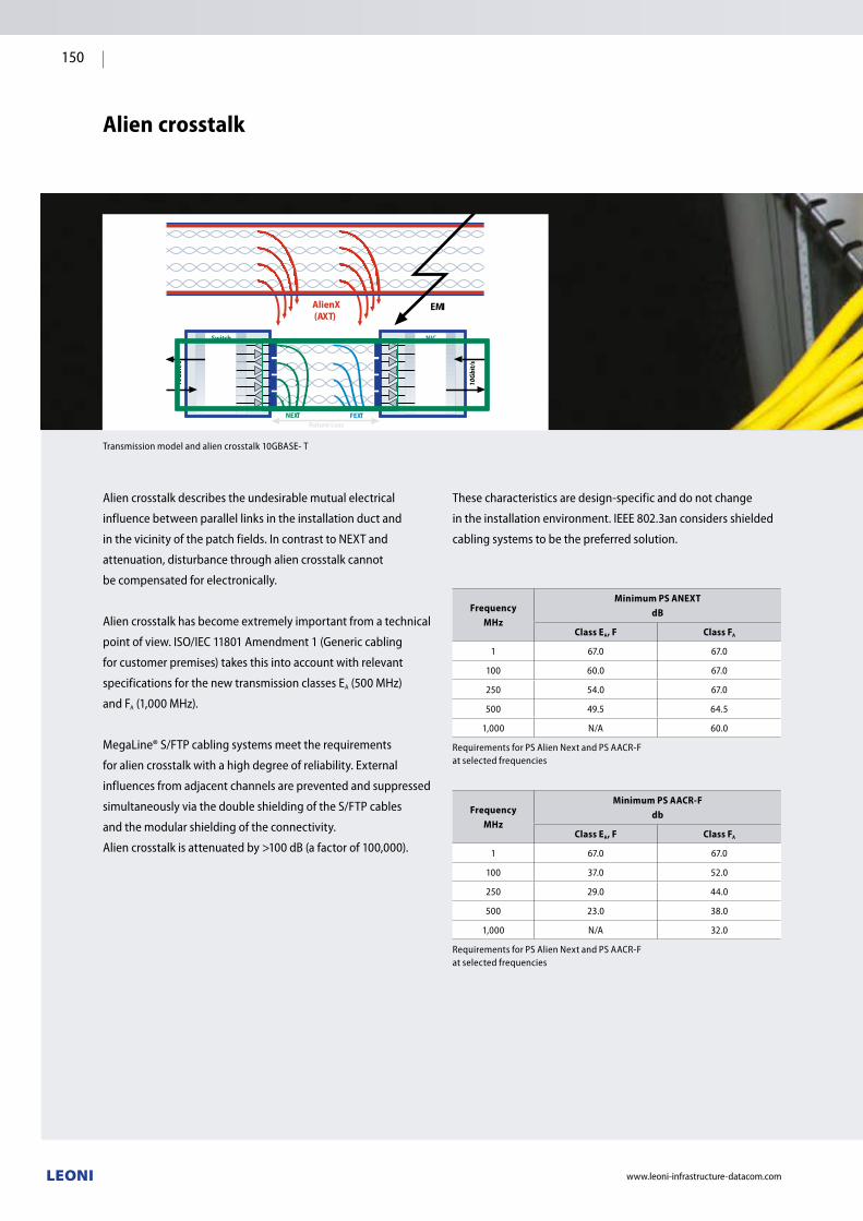
NEXT FEXTReturn Loss
Switch
10Gb
it/s
NIC
10Gb
it/s
AlienX(AXT)
EMI
www.leoni-infrastructure-datacom.com
150
Alien crosstalk
FrequencyMHz
Minimum PS ANEXT dB
Class EA, F Class FA
1 67.0 67.0
100 60.0 67.0
250 54.0 67.0
500 49.5 64.5
1,000 N/A 60.0
RequirementsforPSAlienNextandPSAACR-F at selected frequencies
FrequencyMHz
Minimum PS AACR-Fdb
Class EA, F Class FA
1 67.0 67.0
100 37.0 52.0
250 29.0 44.0
500 23.0 38.0
1,000 N/A 32.0
RequirementsforPSAlienNextandPSAACR-F at selected frequencies
Transmission model and alien crosstalk 10GBASE- T
Alien crosstalk describes the undesirable mutual electrical
influence between parallel links in the installation duct and
in the vicinity of the patch fields. In contrast to NEXT and
attenuation, disturbance through alien crosstalk cannot
be compensated for electronically.
Alien crosstalk has become extremely important from a technical
pointofview.ISO/IEC11801Amendment1(Genericcabling
forcustomerpremises)takesthisintoaccountwithrelevant
specifications for the new transmission classes EA(500MHz)
and FA(1,000MHz).
MegaLine®S/FTPcablingsystemsmeettherequirements
for alien crosstalk with a high degree of reliability. External
influences from adjacent channels are prevented and suppressed
simultaneouslyviathedoubleshieldingoftheS/FTPcables
and the modular shielding of the connectivity.
Aliencrosstalkisattenuatedby>100dB(afactorof100,000).
These characteristics are design-specific and do not change
in the installation environment. IEEE 802.3an considers shielded
cabling systems to be the preferred solution.

www.leoni-infrastructure-datacom.com
151
Coupling attenuation
Coupling attenuation evaluates the overall EMC behaviour
of a cable or individual link. The coupling attenuation consists
of the shielding attenuation and the asymmetrical attenuation
taken together and defines the degree of reduction of electrical
influences on a signal path.
If the coupling attenuation for Class EA is 10.0 dB better or for
Class FA links is 25.0 dB better than in the table below, the
valuesfortheparametersPower SumAlienNEXT(PSANEXT)
andPowerSumAlienACR-F(PS AACR-F)are compliedwith
automatically as a result of the design, making it unnecessary
to demonstrate them explicitly.
MegaLine® test results
All MegaLine® cabling systems with modular or individual
shielding have met the extended requirements for coupling
attenuation according to Class EA. ELine 1200® EC7 and
VarioKeystone® 4K7 even meet the requirements according
to Class FA. It was possible to conclude the comprehensive
assessments with the relevant certifications
Couplingattenuation(ClassEA)ofVarioKeystone®RJ45
Couplingattenuation(ClassFA)ofELine1200®EC7
Class FrequencyMHz
Min. coupling attenuation
dB
D, E, EA, F, FA 30 ≤ ƒ ≤ Note 2 80–20lg(ƒ)
Note 1: Rounddowncalculatedvaluesofgreaterthan40dbto40dB.
Note 2: Coupling attenuation is measured to 1,000 MHz but the limit is determined by the upper frequency of the class being tested.
Requirementsforcouplingattenuation for cabling classes D to FA
Alien crosstalk configuration with MegaLine®:
6 "culprits" and 1 "victim"
Coupling attenuation for Class EA and F:
> 90 – 20 log(f), > 50 dB up to 100 MHz
Coupling attenuation for Class FA:
> 105 – 20 log(f), > 65 dB up to 100 MHz
Due to the coupling mechanisms, this connection only applies
for shielded cablings and not for unshielded ones.
Office DataCenterIndustry

GigaLine®
FO data cables
www.leoni-infrastructure-datacom.com
152

Gig
aLin
e®
FO d
ata
cabl
es
Office DataCenterIndustry
www.leoni-infrastructure-datacom.com
153
GigaLine® FO data cables Page
GigaLine® FO data cables The fiber 154
GigaLine® FO data cables For LAN, WAN and SAN 157
GigaLine® fiber qualities 158
GigaLine® colour codes 159
GigaLine® type codes 160
Jacketing material for optical cables 161
Rodent protection for fiber optic cables 162
Pictograms 163
Handling and safety notices 164
GigaLine® FO data cables 165
o dc GigaLine® indoor cable, duplex fig 8 KL-I-V(ZN)H 2 G/E 165
o dc i GigaLine® indoor cable, duplex fig 0 KL-I-V(ZN)HH 2 G/E 166
o dc GigaLine® indoor cable, mini breakout KL-I-V(ZN)H n G/E 167
o dc i GigaLine® breakout cable KL-I-V(ZN)HH n G/E 168
o dc i GigaLine® universal cable, mini breakout 800 N
KL-U-VQ(ZN)H n G/E 169
o dc i GigaLine® universal cable, central 2,500 N KL-U-DQ(ZN)BH 1xn G/E 170
o dc i GigaLine® universal cable, stranded 4,000 N KL-U-DQ(ZN)BH nxm G/E 171
o dc i GigaLine® universal cable, central 2,500 N KL-U-DQ(ZN)H(SR)H 1xn G/E 172
LEONI "fire secured" FO data cables 173
o dc i GigaLine® "fire secured" universal cable, central with CI
KL-U-D(ZN)BH 1xn G/ETotal system integrity at least 90 min
174
o dc i GigaLine® "fire secured" universal cable, central with CI
KL-U-DQ(ZN)H(SR)H 1xn G/E Total system integrity at least 120 min
175
o i GigaLine® outdoor cable, central 1,750 N KL-A-DQ(ZN)B2Y 1xn G/E 176
o i GigaLine® outdoor cable, stranded 4,000 N KL-A-DQ(ZN)B2Y nxm G/E 177
o i GigaLine® outdoor cable, central 1,750 N KL-A-DQ(ZN)2Y(SR)2Y 1xn G/E 178
o i GigaLine® outdoor cable, stranded 4,000 N KL-A-DQ(ZN)2Y(SR)2Y nxm G/E 179
o i GigaLine® outdoor cable, stranded with sheath 4,000 N
KL-A-DF (ZN)(L) 2y nxm G/E 180
o Office cables
dc DataCenter cables
i Industrial cables

www.leoni-infrastructure-datacom.com
154
GigaLine® FO data cables
The fiber
GigaGrade multimode fibers
GigaGrade G62.5/125 and GigaGrade G50/125 are the reliable
and proven fibers for network technology in industrial
applications and in office cabling in the categories OM1
and OM2.
The right fiber
LEONI offers a comprehensive range of optical fibers tailored to
the various network requirements such as future-proof high-
performance transmission in DataCenters, reliable office
networks and stable industrial networks.
The optimum multimode fiber for every application:
The steady increase in Internet and intranet traffic,
multimedia applications and the establishment of
central storage networks (SAN or Storage Area Networks)
in companies have fundamentally changed the traffic
and load distribution in networks. New media require new,
more powerful passive network infrastructures.
LEONI offers a future-proof cabling system with reserves
well beyond those stipulated in the standards.
Comparison of requirements
for Standard and GigaGrade
Fiber category OM1 G62.5/125 Fiber category OM1 G62.5/125
at 850 nm at 1,300 nm
Standard OM1LEONI OM1e
GigaGrade G62.5/125 MStandard OM1
LEONI OM1e GigaGrade G62.5/125 M
Attenuation 3.5 dB/km 3.0 dB/km 1.5 dB/km 0.8 dB/km
Modal bandwidth 200 MHz x km 250 MHz x km 500 MHz x km 800 MHz x km
Gigabit Ethernet segment length 275 m 500 m 550 m 1,000 m
10 Gigabit Ethernet segment length 32 m 65 m 300 m 450 m
Comparison of requirements
for Standard and GigaGrade
Fiber category OM2 G50/125 Fiber category OM2 G50/125
at 850 nm at 1,300 nm
Standard OM2LEONI OM2
Standard GigaGrade G50/125
LEONI OM2e High Performance
GigaGrade G50/125Standard OM2
LEONI OM2 Standard
GigaGrade G50/125
LEONI OM2e High Performance
GigaGrade G50/125
Attenuation 3.5 dB/km 2.7 dB/km 2.5 dB/km 1.5 dB/km 0.8 dB/km 0.7 dB/km
Modal bandwidth 500 MHz x km 500 MHz x km 600 MHz x km 500 MHz x km 500 MHz x km 1,200 MHz x km
Gigabit Ethernet segment length
550 m 550 m 750 m 550 m 550 m 2,000 m
10 Gigabit Ethernet segment length
82 m 82 m 150 m 300 m 300 m 700 m
GigaGrade GigaGrade OptiGrade 300 OptiGrade 550
OM1 OM2 OM3 OM4
LAN DataCenter
LAN Office
LAN Industry

Gig
aLin
e®
FO d
ata
cabl
es
www.leoni-infrastructure-datacom.com
155
OptiGrade 550 future-proof without comprises
The OptiGrade 550 multimode fiber fulfils the requirements
of the OM4 standard for the serial transmission of 10 Gb/s with
an EMB of 4,700 MHz x km over 550 m. The fiber has been
optimised for applications with 850 nm VCSEL and offers the
possibility of use at higher transmission rates such as 40 Gb/s or
100 Gb/s going into the future. OptiGrade 550 is the first choice
when it comes to speed and high data rates.
OptiGrade 300 for 10 GbE networks
The sophisticated IT cabling in DataCenters and office buildings,
with a 10 Gigabit Ethernet-compatible network, is based on the
laser-optimised OptiGrade 300 OM3 fiber.
Comparison of requirements
for Standard and OptiGrade
Fiber category OM3 G50/125 Fiber category OM3 G50/125
at 850 nm at 1,300 nm
Standard OM3LEONI OM3
OptiGrade 300Standard OM3
LEONI OM3OptiGrade 300
Attenuation 3.5 dB/km 2.5 dB/km 1.5 dB/km 0.7 dB/km
Modal bandwidth (overfilled launch) 1,500 MHz x km 1,500 MHz x km 500 MHz x km 500 MHz x km
EMB (effective modal bandwidth) 2,000 MHz x km 2,000 MHz x km n.a. n.a.
Gigabit Ethernet segment length 550 m 900 m 550 m 550 m
10 Gigabit Ethernet segment length 300 m 300 m 300 m 300 m
40/100 Gigabit Ethernet segment length 100 m 100 m 100 m 100 m
Comparison of requirements
for Standard and OptiGrade
Fiber category OM4 G50/125 Fiber category OM4 G50/125
at 850 nm at 1,300 nm
Standard OM4LEONI OM4
OptiGrade 550Standard OM4
LEONI OM4 OptiGrade 550
Attenuation 2.5 dB/km 2.5 dB/km 1.5 dB/km 0.7 dB/km
Modal bandwidth (overfilled launch) 3,500 MHz x km 3,500 MHz x km 500 MHz x km 500 MHz x km
EMB (effective modal bandwidth) 4,700 MHz x km 4,700 MHz x km n.a. n.a.
Gigabit Ethernet segment length 550 m 1,000 m 550 m 550 m
10 Gigabit Ethernet segment length 550 m 550 m 300 m (LX4) 300 m (LX4)
40/100 Gigabit Ethernet segment length 150 m 150 m 150 m 150 m
Office DataCenterIndustry

www.leoni-infrastructure-datacom.com
156
j-LBL SMF flexible and compatible
The j-LBL SMF as per ITU-T G657.A is a high-performance field-
tested singlemode fiber for applications where the need for
compatibility with installed G.652.D networks is linked with
the requirement for improved bending characteristics for sturdy,
flexible and space-saving installations. The j-LBL SMF offers
maximum transmission performance with minimum attenuation.
Due to the reliably and permanently low attenuation at
1,383 nm, it can be used in the wavelength range from
1,360 nm to 1,480 nm and the fiber is therefore also suitable
for wavelength multiplexing (DWDM and CWDM).
Comparison of requirements for Standard and j-LWP SMF+
Fiber category OS2 E9/125 (G.652.D)
at 1,310 nm at 1,550 nm
Standard OS2IEC 60793-2-50 B6_a
LEONI OS2 j-LWP SMF+
Standard OS2 IEC-60793-2 50-B1.3
LEONI OS2j-LWP SMF+
Attenuation 0.40 dB/km 0.36 dB/km 0.30 dB/km 0.23 dB/km
Attenuation at 1,383 nm < 0.40 dB/km 0.36 dB/km — —
1 Gigabit Ethernet segment length 5,000 m 5,000 m — —
10 Gigabit Ethernet segment length 10,000 m 10,000 m 22,250 m 40,000 m
40 Gigabit Ethernet segment length 10,000 m 10,000 m — —
Comparison of requirements for Standard and j-LBL SMF
Fiber category E9/125 (G.657.A)
at 1,310 nm at 1,550 nm
Standard OS2IEC 60793-2-50 B6_a
LEONI OS2 low bendj-LBL SMF
Standard OS2 IEC 60793-2-50 B6_a
LEONI OS2 low bendj-LBL SMF
Attenuation 0.40 dB/km 0.36 dB/km 0.30 dB/km 0.23 dB/km
Attenuation at 1,383 nm < 0.40 dB/km 0.36 dB/km — —
1 Gigabit Ethernet segment length 5,000 m 5,000 m — —
10 Gigabit Ethernet segment length 10,000 m 10,000 m 22,250 m 40,000 m
40 Gigabit Ethernet segment length 10,000 m 10,000 m — —
100 Gigabit Ethernet segment length 10,000/40,000 m 10,000/40,000 m — —
Bending characteristics
The fiber exhibits excellent splicing properties thanks to its
first-rate uniformity and geometry. This means it is backwards
compatible with already installed conventional singlemode
fibers (to ITU-T G.652.A+B) and low-water-peak singlemode
fibers (to ITU-T G.652 C+D).
Macro-bending losses, bending-induced attenuation
Values Unit
10 bends, radius 15 mm
1,550 nm ≤ 0.03 dB
1,652 nm ≤ 0.20 dB
1 bend, radius 10 mm
1,550 nm ≤ 0.30 dB
1,625 nm ≤ 1.00 dB
30
25
20
15
10
5
08 10 12 14 16 18 20
Bend diameter [mm]
Atte
nuat
ion
[dB]
Bending sensitivity at different wavelengths
1,310 nm1,550 nm1,625 nm
j-LWP SMF+ proven for long links
The low-water-peak singlemode fiber, j-LWP SMF+ as per ITU-T
G652.D or as per EN 50173 OS2, offers the best transmission
performance across the entire wavelength range from 1,260
nm to 1,625 nm. The fiber can be used in the wavelength
ranges from 1,360 nm to 1,480 nm due to the reliably stable, low
attenuation at 1,383 nm. The j-LWP SMF+ is the preferred fiber
wherever maximum flexibility and long transmission lengths are
required. The use of WDM systems enables the full spectrum of
fiber capacity to be used – the prerequisite for flexible network
planning. The fiber is fully compatible with installed singlemode
networks and enables network solutions with maximum
performance and flexibility.

Gig
aLin
e®
FO d
ata
cabl
es
The use of fiber optic data cables is especially
recommended if… electromagnetic influences can occur reliable potential isolation is required a wide transmission bandwidth is required low attenuation and therefore long transmission links
are required crosstalk is not permitted sparking (for areas subject to explosion hazards) is not
permitted low weight and small dimensions are an advantage increased security against interception is required
The product range at a glance: Easy-to-assemble indoor cables with compact buffered fiber
technology for the patch and horizontal areas Universal cables for the backbone area indoors and outdoors Outdoor cables for LAN and WAN applications A wide range of designs such as outdoor cables with
– corrugated steel cladding
– steel band or steel wire armour
– additional lead covering as protection against chemicals
Gigabit, 10, 40 and 100 Gigabit Ethernet – strictest
requirements for the quality of the fiber optic cabling.
The Ethernet protocol is the state of the art today in every
area of structured cabling. The corresponding standards for
transmission rates from 1 Gigabit/s to 100 Gigabit/s are defined
in IEEE 802.3ba.
The process used to manufacture the fibers has been optimised
in such a way that the profile of the multimode fiber is
extremely precise and disturbances in the fiber core are virtually
eliminated. As differential mode delay does not occur under
these circumstances, mode-conditioning patch cords are not
necessary. For more than ten years now, the standard versions
of fiber optic cables with an improved gradient fiber G50/125
from the category "OM2e" have provided bandwidth-length
products of 600 MHz x km in the first window (850 nm) and
1,200 MHz x km in the second window (1,300 nm) as well as
Gigabit Ethernet segment lengths of 750/2,000 m.
GigaLine® fiber optic cables with OM3 and OM4 fibers are
the optimum transmission medium, whatever the future
might hold.
Using the OM4 fibers with a laser bandwidth of 4,700 MHz x km
in the first window enables segment lengths of up to 550 m
with 10 GbE, up to 300 m with 16 GB/s Fiberchannel or up to
150 m with 40 and 100 GbE. This in turn enables cost-effective
realisation of 10 GbE in the backbone of a building in nearly
all cases.
Singlemode fibers must be used over long distances. The
singlemode fibers exceed the current requirements of the
OS2 standard according to EN 50173-1 with attenuation of just
0.36 dB/km at 1,310 nm and less than 0.22 db/km at 1,550 nm.
This means that the wavelength ranges around 1,383 nm can
also be used to increase the transmission capacity. The graph
shows the steadily dropping attenuation curve from 1,300 nm
to 1,625 nm for all singlemode fibers. These characteristics and
the PMD link design value of just 0.06 ps/ km guarantee large
reserves for faster transmission rates over very long distances
and WDM transmission systems.
The use of high-quality optical fibers is the key to managing
future data volumes. GigaLine® fiber optic data cables
are the first step in careful planning and implementation
of a passive network infrastructure.
www.leoni-infrastructure-datacom.com
157
GigaLine® FO data cables
for LAN, WAN and SAN
0.8
0.6
0.4
0.2
0
ITU T 652B
ITU T 652D
1250 1300 1350 1400 1450 1500 1550 1600 1650
Comparison SMF G652B/G652D
Wavelength [nm]
Atte
nuat
ion
[dB/
km]
Office DataCenterIndustry

www.leoni-infrastructure-datacom.com
158
Fiber specificationsGigaGrade G62.5/125
GigaGrade G50/125
GigaGrade G50/125
OptiGrade 300 G50/125
OptiGrade 550 G50/125
j-LWP SMF+E9...10/125
j-LWP SMF+E9...10/125
OptiGrade IEC 11801/EN 50173 OM1e OM2 OM2e OM3 OM4 OS2 OS2 low bend
IEC 60793-2 A1b A1a.1 A1a.1 A1a.2 A1a.3 B1.3 B6_a
ITU-T G.651 G.651 G.651 G.651 G.652.D G.657.A
Attenuation coefficient
dB/km at 850 nmdB/km at 1,300 nm
max. 3.0max. 0.7
max. 2.7max. 0.8
max. 2.5max. 0.7
max. 2.5max. 0.7
max. 2.5max. 0.7
dB/km at 1,310 nmdB/km at 1,383 nmdB/km at 1,550 nmdB/km at 1,625 nm
max. 0.36max. 0.40max. 0.23max. 0.23
max. 0.36max. 0.40max. 0.23max. 0.23
Bandwidth
MHz x km at 850 nm min. 250 min. 500 min. 600 min. 1,500 min. 3,500
MHz x km at 1,300 nm min. 800 min. 500 min. 1,200 min. 500 min. 500
Laser bandwidth
MHz x km at 850 nm min. 2,000 min. 4,700
Dispersion
at 1,310 nm max. 3.5 ps/nm x km max. 3.5 ps/nm x km
at 1,550 nm max. 18 ps/nm x km max. 18 ps/nm x km
Zero-dispersion wavelength 1,302 ≤ λ0 ≤ 1,322 1,302 ≤ λ0 ≤ 1,322
Zero-dispersion slope ≤ 0.092 ps/nm² x km ≤ 0.092 ps/nm² x km
PMD
Fiber < 0.1 ps/ km < 0.1 ps/ km
Link < 0.06 ps/ km < 0.06 ps/ km
Segment length with Gigabit Ethernet
at 850 nm (1000 BASE SX) 500 m 550 m 750 m 900 m 1,000 m
at 1,300 nm (1000 BASE LX) 1,000 m 550 m 2,000 m 550 m 550 m 5,000 m 5,000 m
Segment length with 10 Gigabit Ethernet
at 850 nm (10G BASE-SR/SW) 65 m 82 m 150 m 300 m 550 m
at 1,300 nm (10G BASE-LX4) 450 m 300 m 700 m 300 m 300 m 10,000 m 10,000 m
at 1,550 nm (10G BASE-ER/EW) 40,000 m 40,000 m
Segment length with 40/100 Gigabit Ethernet
at 850 nm 40/100 GBASE-SR4/SR10 100 m 150 m
at 1,310 nm 40/100 GBASE-LR4 10,000 m 10,000 m
Numerical aperture
Nominal value 0.275 0.20 0.20 0.20 0.20 0.12 0.12
Refractive index (nominal value)
at 850 nm 1.497 1.483 1.483 1.483 1.483
at 1,300 nm 1.493 1.478 1.478 1.478 1.478
at 1,310 nm 1.467 1.467
at 1,550 nm 1.467 1.467
Test load
100 kpsi ≥ 8.8 N
GigaLine® Fiber qualities

Gig
aLin
e®
FO d
ata
cabl
es
Wires (with stranded loose tubes)
Counting wire Red
Counting direction wire White
Other wires Green for G50/125
Blue for G62.5/125
Yellow for E9…10/125
Dummy elements Natural colours
The wires are consecutively counted, starting with the wire closest to the counting element. The dummy elements are not counted.
Fibers (in loose tubes) IEC 60304
Fiber no. Colour
1 Red
2 Green
3 Blue
4 Yellow
5 White
6 Grey
7 Brown
8 Violet
9 Turquoise
10 Black
11 Orange
12 Pink
13 Red/black
14 Green/black
15 Blue/black
16 Yellow/black
17 White/black
18 Grey/black
19 Brown/black
20 Violet/black
21 Turquoise/black
22 Natural/black
23 Orange/black
24 Pink/black
Mini breakout cable EIA/TIA 598C
Fiber no. Colour
1 Blue
2 Orange
3 Green
4 Brown
5 Grey
6 White
7 Red
8 Black
9 Yellow
10 Violet
11 Pink
12 Turquoise
www.leoni-infrastructure-datacom.com
159
GigaLine® Colour codes
Office DataCenterIndustry

www.leoni-infrastructure-datacom.com
160
GigaLine® Type codes
for easy assignment of the construction elements in fiber optic cables
Cable type
Communication cable KL
Field of application
Indoor cable I
Universal cable U
Outdoor cable A
Breakout outdoor cable AT
Buffered fiber
Tight buffered loose tube V
Gel-filled loose tube D
Constructional composition
Swelling material, dry, longitudinally watertight Q
Water-blocking gel-filled, longitudinally watertight F
Non-metallic strain relief (ZN)
Steel strain relief (ZS)
Armour B
Corrugated steel tape SR
Cable sheath
PE Polyethylene sheath 2Y
Al + PE PE coated aluminium sheath (L)2Y
FRNC Halogen-free/flame-retardant sheath H
PVC Polyvinyl chloride sheath Y
PA Polyamide sheath 4Y
PUR Polyurethane sheath 11Y
Fiber number and fiber bundling
Number of fibers n
Number of loose tubes x number of fibers per tube nxm
Miscellaneous
n Field diameter/sheath diameter in… E9/125
n Core diameter/sheath diameter in… G50/125 or G62.5/125
Wavelength
850 nm B
1,300/1,310 nm F
1,550 nm H
Bandwidth/dispersion coefficient
in MHz · km with multimode fibers, dispersion parametersin ps/nm · km with singlemode fibers
GigaLine® 1 2 3 4 5 6 7 8 9

Gig
aLin
e®
FO d
ata
cabl
es
Balancing application and fire prevention criteria
The sheath around the cable protects the optical fiber(s) from
the effects of mechanical, thermal and chemical action as
well as the ingress of moisture. In the event of a fire, however,
the cable sheath should prevent a fire from spreading and stop
toxic and corrosive gases from being produced.
The use of halogen-free, flame-retardant materials is advisable
in order to protect equipment and buildings but above all
to protect people. In harsh environments, PUR and PVC,
in particular, are used owing to their high resistance to oils and
their abrasion resistance. PE is also commonly used as a sheath
material for outdoor applications.
However, it is often extremely difficult to meet all the
requirements using just one sheath material. To best satisfy
the prevailing local operating conditions, LEONI offers a choice
of different materials.
Please contact us if the criteria for your particular application
are not met by the cable constructions in this catalogue.
Additional requirements can often be met through customised
measures when making the sheath (e.g. aluminium tape or
special mixtures of sheaths).
Cable sheath material
Material characteristics FRNC PUR PVC PE
Resistance to aging + + + +
Halogen-free + + – – +
Flame retardancy + + – –/
Elasticity – + –
Abrasion resistance – ++ + +/–
Low smoke gas generation ++ – – –/
Low emission of corrosive gases ++ – – +/
Low smoke gas toxicity ++ – – +/
No toxicological risk ++ – +/
General resistance to FRNC PUR PVC PE
UV light 1) 1) 1) 1)
Water absorption – – + +
Gas diffusion – 2) –
Fuels – + +/– +
Petroleum/lubricants – ++ +
Organic solvents – + 3) – + 4)
Alcohol – – + +
Oxidants – – + –
Acids + – – + ++
Alkaline solutions + – – + +
Saline solutions + – + +
1) UV resistance can be increased by adding black colour pigments or UV stabilisers
2) Permeation depends on the type of gas, e.g. Ar, CH4, N2, O2 low gas permeation, CO2, H2, He higher gas permeation
3) Low swelling in saturated hydrocarbons; significant swelling in aromatic hydrocarbons. Aliphatic esters cause swelling, highly polar organic solvents dissolve under the effect of extreme swelling
4) Swelling in aliphatic and aromatic hydrocarbons and in chlorinated hydrocarbons
++ excellent+ good depends on recipe– weak– – inadequate
Jacketing material for optical cables
www.leoni-infrastructure-datacom.com
161
Office DataCenterIndustry

Fiber optic cables are relatively thin and therefore very
susceptible to rodent damage. Depending on the application it is
important that fiber optic cables can offer protection against this
type of damage. There are no national or indeed international
standards or test specifications covering the corresponding
requirement for rodent protection.
The following construction has been customary in the market in
Europe (particularly in Germany, Austria and Switzerland) since
the early 1990s:
For outdoor cables, the usual aramid yarns for strain relief are
replaced with glass rovings. These glass yarns shatter and get
into the mouth and throat of the rodents. The animals associate
gnawing on cables with pain and usually stop.
The general rule is:
The more glass rovings, the greater the protection for
the cable.
The overall diameter should also be as large as possible.
Constructions with stranded loose tubes give even less
favourable leverage in combination with the larger core
diameter. The cable then acts like a gag bit. Before the rodent
reaches the glass rovings, however, it first has to gnaw through
the outer sheath. Constructions with an additional polyamide
sheath (thickness 0.5 mm) have also proven themselves here
as polyamide is very hard and smooth.
This combination of plastic, glass and moisture-absorbing
swelling material has to be gnawed through before rodent
reaches the loose tubes containing the internal optical fibers.
Metal armouring must be recommended as rodent protection
for all applications where rodent damage is to be expected. This
is the case, for example, with installation in shafts or conduits
with a correspondingly large diameter, e.g. along railway lines
or motorways.
The following types of metal armouring are available: Corrugated steel cladding
The most common metal armouring is the 0.155 mm thick
corrugated steel cladding due to its very good flexibility. Steel wire armour
The steel wire armour made from wires with a thickness
of up to 1.25 mm is very robust. Steel band
Steel band sheathing consists of two overlapping layers
of steel band that are wound around the cable.
In the case of cables with two sheaths with sheathing between
them, the ingress of water into the cable core is also prevented
provided the internal sheath is not damaged.
Despite all precautions, however, damage to the outer
sheath can never be fully ruled out.
Rodent protection for fiber optic cables
www.leoni-infrastructure-datacom.com
162

Gig
aLin
e®
FO d
ata
cabl
es
Pictograms
Flame-retardant and halogen-free sheathThe outer sheath of the cable is self-extinguishing and does not propagate fire. The halogen-free sheath material forms neither toxic nor corrosive combustion gases in the event of fire.
Chemical resistanceGenerally good resistance to oil, petrol, acids and alkaline solutions.
Rodent proofThe cable core is protected against damage by rodents with glass rovings.
Note: Despite all the precautions, damage to the outer sheath can never be fully ruled out.
Rodent proofThe cable core is more heavily protected against damage by rodents with two sheaths and metal armouring.
Note: Despite all the precautions, damage to the outer sheath can never be fully ruled out.
Resistance to UV rays The cable outer sheath is resistant to UV rays.
Longitudinal watertightness Water in the cable core cannot spread out in longitudinal direction.
Lateral watertightness Lateral diffusion of water into the cable core is prevented.
www.leoni-infrastructure-datacom.com
163
Office Industry DataCenterOffice DataCenterIndustry

Please note the following when installing optical fibers: Valid installation regulations for optical fibers Valid industrial safety guidelines for handling optical fibers VDE regulations (DIN EN 50174 Parts 1 to 3, Cabling
installation)
The following regulations also apply: The drums must always be stored and transported standing
on their flanges Please note the limit values specified in the respective
data sheet Do not remove the protective packaging from the cable ends
during installation Do not go below the permitted bending radius (see data sheet)
Avoid soiling and mechanical loading of the assembled
connectors Do not exceed the maximum tensile load of the cable in axial
direction during and after installation (use suitable aids) The maximum tensile load only applies in conjunction with
adhesion with the strain relief elements Installation is not permitted if the ambient temperature is
exceeded or gone below (specific value in the data sheet) Cable runs must be selected so as to avoid mechanical loads
as far as possible and also minimise future loads Mechanical stresses, for example caused by movement, must
be prevented, even during provisional installation Compression of the outer sheath, for example by cable ties,
must be avoided when securing the cables After installation: carefully free the cable ends from the
packaging/pull tool
All cable ends must be protected from the ingress of moisture
before, during and after installation Immersion with water must be avoided – the fibers and
connectors must not come into contact with water Optical fibers must be unwound from the coil or ring without
torsion so that no kinks or twists can occur Install optical cables with extreme care. Please make sure
that the fibers are neither overstretched nor compressed –
in addition to immediate damage, this also poses the threat
of problems with the long-term behaviour When installing in protective conduits, please make sure that
these have no sharp edges and that kinks are avoided The attenuation of each cable must be checked immediately
after installation using a suitable calibrated meter, otherwise
warranty claims may arise Body and eye protection must be worn when handling
bare fibers from glass optical fibers, including if the cable
is damaged Please note all regulations relating to eye safety
Handling and safety notices
when using optical cables
www.leoni-infrastructure-datacom.com
164

Gig
aLin
e®
FO d
ata
cabl
es
Description
Connection cable and patch cord for structured cabling acc.
to ISO/IEC 11801 and EN 50173 (2nd edition).
In keeping with the fiber type ideal for all applications from
Classes OF 300 to OF 10000. Suitable for direct connector
assembly.
Installation in dry areas, in cable ducts, on cable trays
or in conduits.
Construction
Two single cables (2.8 mm with 900 µm semi-ight buffered
loose tubes) with strain relief in figure 8 sheath with separator
Strain relief Non-metallic (aramid yarns)
Cable sheath Halogen-free, flame-retardant compound
Sheath colour OS2 Yellow
OM1e/OM2e Orange
OM3 Aqua
OM4 Heather violet
Thermal characteristics
Transport/storage
Installation
Operating temperature
–25 °C up to +70 °C
–5 °C up to +50 °C
–10 °C up to +70 °C
Mechanical characteristics
Min. bending radius static 30 mm
dynamic 60 mm
Max. crush strength long-term 600 N/dm
short-term 1000 N/dm
Fire performance
Smoke density IEC 61034
Halogen free IEC 60754-1
Flame retardancy IEC 60332-1-2, IEC 60332-3-24
GigaLine® Indoor cable, duplex fig 8
Type KL-I-V(ZN)H 2 G/E
Fibernumber
Buffered fibertype
Overall diam.
approx.Weight approx.
Max. strain relief
Fire loadapprox.
Order no.
µ mm kg/km N MJ/m kWh/m OM1e
G62.5/125OM2e
G50/125OM3
G50/125OM4
G50/125OS2
E9…10/125
2 900 2.8x5.7 15.8 600 0.36 0.10 LKD 8DB7 0003 0000 LKD 8DA2 0003 0000 LKD 8DA5 2000 0000 LKD 8DA7 2000 0000 LKD 8DC7 2001 0000
2 600 1.8x3.7 7 400 0.14 0.04 LKD 8XB7 0013 0000 LKD 8XA2 0013 0000 LKD 8XA5 2013 0000 LKD 8XA7 0013 0000 LKD 8XC7 0013 0000
www.leoni-infrastructure-datacom.com
165
Office DataCenterIndustry
Outer sheath
Strain relief elements
Semi-tight buffered fiber

GigaLine® Indoor cable, duplex fig 0
Type KL-I-V(ZN)HH 2 G/E
Outer sheath
Strain relief
Semi-tight buffered
fiber
Subcable sheath
Description
Connection cable and patch cord for structured cabling acc.
to ISO/IEC 11801 and EN 50173 (2nd edition).
In keeping with the fiber type ideal for all applications from
Classes OF 300 to OF 10000. Suitable for direct connector
assembly.
Installation in dry areas, in cable ducts, on cable trays
or in conduits.
Construction
Two single cables (2.1 mm with 900 µm semi-tight buffered
fibers) with strain relief running parallel under one sheath
Strain relief Non-metallic (aramid yarns)
Cable sheath Halogen-free, flame-retardant compound
Sheath colour OS2 Yellow
OM1e/OM2e Orange
OM3 Aqua
OM4 Heather violet
Thermal characteristics
Transport/storage
Installation
Operating temperature
–25 °C up to +70 °C
–5 °C up to +50 °C
–10 °C up to +70 °C
Mechanical characteristics
Min. bending radius static 35 mm
dynamic 65 mm
for single elements 30 mm
Max. tensile force long-term 600 N
Max. crush strength long-term 500 N/dm
short-term 750 N/dm
Fire performance
Smoke density IEC 61034
Halogen free IEC 60754-1
Flame retardancy IEC 60332-1-2, IEC 60332-3-24
Further characteristics:
Cable bending IEC 60794-1-2 E11
Fibernumber
Overall diam.
approx.Weight approx.
Max. strain relief
Fire loadapprox.
Order no.
mm kg/km N MJ/m kWh/m OM1e
G62.5/125OM2e
G50/125OM3
G50/125OM4
G50/125OS2
E9…10/125
2 3.1x5.2 18 600 0.63 0.18 LKD 8DB7 0011 0000 LKD 8DA2 0011 0000 LKD 8DA5 2001 0000 LKD 8DA7 2005 0000 LKD 8DC7 0010 0000
www.leoni-infrastructure-datacom.com
166

Gig
aLin
e®
FO d
ata
cabl
es
GigaLine® Indoor cable, mini breakout
Type KL-I-V(ZN)H n G/E
Outer sheath
Strain relief
Tight buffered fiber
Description
Campus/backbone cabling, suitable for direct connector
assembly. Connection cable and patch cord for structured
cabling acc. to ISO/IEC 11801 and EN 50173 (2nd edition).
In keeping with the fiber type ideal for all applications from
Classes OF 300 to OF 10000.
Construction
Up to 12 semi-tight buffered fibers (900 µm) stranded under
one outer sheath
Strain relief Non-metallic (aramid yarns)
Cable sheath Halogen-free, flame-retardant compound
Sheath colour OS2 Yellow
OM1e/OM2e Orange
OM3 Aqua
OM4 Heather violet
Thermal characteristics
Transport/storage
Installation
Operating temperature
–25 °C up to +70 °C
–5 °C up to +50 °C
–10 °C up to +70 °C
Mechanical characteristics
Min. bending radius static 10 x overall diameter
dynamic 15 x overall diameter
for single
elements 30 mm
Max. tensile force long-term 600 N
Max. crush strength long-term 500 N/dm
short-term 1000 N/dm
Fire performance
Smoke density IEC 61034
Halogen free IEC 60754-1
Flame retardancy IEC 60332-1-2, IEC 60332-3-24
Further characteristics:
Cable bending IEC 60794-1-2 E11
Fibernumber
Overall diam.
approx.Weight approx.
Max. strain relief
Fire loadapprox.
Order no.
mm kg/km N MJ/m kWh/m OM1e
G62.5/125OM2e
G50/125OM3
G50/125OM4
G50/125OS2e
E9…10/125
2 4.2 14 800 0.45 0.13 LKD 8MB7 0011 0000 LKD 8MA2 0011 0000 LKD 8MA5 2011 0000 LKD 8MA7 0011 0000 LKD 8MC7 0011 0000
4 4.8 21 800 0.47 0.13 LKD 8MB7 0012 0000 LKD 8MA2 0012 0000 LKD 8MA5 2012 0000 LKD 8MA7 0012 0000 LKD 8MC7 0012 0000
6 5.9 25 800 0.50 0.14 LKD 8MB7 0013 0000 LKD 8MA2 0013 0000 LKD 8MA5 2013 0000 LKD 8MA7 0013 0000 LKD 8MC7 0013 0000
8 6.1 30 800 0.52 0.14 LKD 8MB7 0014 0000 LKD 8MA2 0014 0000 LKD 8MA5 2014 0000 LKD 8MA7 0014 0000 LKD 8MC7 0014 0000
10 7.0 38 800 0.53 0.14 LKD 8MB7 0015 0000 LKD 8MA2 0015 0000 LKD 8MA5 2015 0000 LKD 8MA7 0015 0000 LKD 8MC7 0015 0000
12 7.0 38 800 0.55 0.15 LKD 8MB7 0016 0000 LKD 8MA2 0016 0000 LKD 8MA5 2016 0000 LKD 8MA7 0016 0000 LKD 8MC7 0016 0000
www.leoni-infrastructure-datacom.com
167
Office DataCenterIndustry

GigaLine® Breakout cable
Type KL-I-V(ZN)HH n G/E
Outer sheath
Strain relief
Central element
Semi-tight buffered fiber
Subcable sheath
Description
Connection cable and patch cord for structured cabling acc.
to ISO/IEC 11801 and EN 50173 (2nd edition).
In keeping with the fiber type ideal for all applications from
Classes OF 300 to OF 10000. Suitable for direct connector
assembly.
Installation in dry areas, in cable ducts, on cable trays
or in conduits.
Construction
Up to 12 single cables with strain relief as breakout elements
(2.1 mm with 900 µm semi-tight buffered fibers) stranded under
one outer sheath
Ripcord under the outer sheath
Strain relief Non-metallic (aramid yarns)
Cable sheath Halogen-free, flame-retardant compound
Sheath colour OS2 Yellow
OM1e/OM2e Orange
OM3 Aqua
OM4 Heather violet
Thermal characteristics
Transport/storage
Installation
Operating temperature
–25 °C up to +70 °C
–5 °C up to +50 °C
–10 °C up to +70 °C
Mechanical characteristics
Min. bending radius static 15 x overall diameter
dynamic 20 x overall diameter
for single
elements 30 mm
Max. crush strength long-term 1000 N/dm
short-term 1500 N/dm
Fire performance
Smoke density IEC 61034
Halogen free IEC 60754-1
Flame retardancy IEC 60332-1-2, IEC 60332-3-24
Further characteristics:
Cable bending IEC 60794-1-2 E11
Fibernumber
Overall diam.
approx.Weight approx.
Max. strain relief
Fire loadapprox.
Order no.
mm kg/km N MJ/m kWh/m OM1e
G62.5/125OM2e
G50/125OM3
G50/125OM4
G50/125OS2
E9...10/125
2 7.0 40 800 1.10 0.30 LKD 8BB7 0011 0000 LKD 8BA2 0011 0000 LKD 8BA5 2011 0000 LKD 8BA7 0011 0000 LKD 8BC7 0011 0000
4 7.0 45 800 1.10 0.30 LKD 8BB7 0012 0000 LKD 8BA2 0012 0000 LKD 8BA5 2012 0000 LKD 8BA7 0012 0000 LKD 8BC7 0012 0000
6 8.2 65 1000 1.18 0.32 LKD 8BB7 0013 0000 LKD 8BA2 0013 0000 LKD 8BA5 2013 0000 LKD 8BA7 0013 0000 LKD 8BC7 0013 0000
8 9.6 95 1000 1.31 0.36 LKD 8BB7 0014 0000 LKD 8BA2 0014 0000 LKD 8BA5 2014 0000 LKD 8BA7 0014 0000 LKD 8BC7 0014 0000
10 11.0 135 1000 1.42 0.39 LKD 8BB7 0015 0000 LKD 8BA2 0015 0000 LKD 8BA5 2015 0000 LKD 8BA7 0015 0000 LKD 8BC7 0015 0000
12 12.5 155 1000 1.57 0.44 LKD 8BB7 0016 0000 LKD 8BA2 0016 0000 LKD 8BA5 2016 0000 LKD 8BA7 0016 0000 LKD 8BC7 0016 0000
www.leoni-infrastructure-datacom.com
168

Gig
aLin
e®
FO d
ata
cabl
es
GigaLine® Universal cable, mini breakout 800 N
Type KL-U-VQ(ZN)H n G/E
Outer sheath
Strain relief
Tight buffered fiber
Description
Campus/backbone cabling, suitable for direct connector
assembly. Connection cable and patch cord for structured
cabling acc. to ISO/IEC 11801 and EN 50173 (2nd edition).
In keeping with the fiber type ideal for all applications from
Classes OF 300 to OF 10000. House connections possible without
additional interconnection points (splices).
Installation indoors and outdoors in dry conduits, on covered
cable trays or in cable ducts. Mechanical pulling in with winches
is only permitted in conjunction with force measuring devices
with a logging feature.
Construction
Up to 24 tight buffered fibers (900 µm) stranded under
one outer sheath
Buffered fiber colour code acc. to EIA/TIA598C
Strain relief Non-metallic (aramid yarns)
Cable sheath Halogen-free, flame-retardant compound
Sheath colour Yellow
Thermal characteristics
Transport/storage
Installation
Operating temperature
–25 °C up to +70 °C
–5 °C up to +50 °C
–25 °C up to +60 °C
Mechanical characteristics
Min. bending radius static 10 x overall diameter
dynamic 15 x overall diameter
for single
elements 30 mm
Max. crush strength long-term 300 N/dm
short-term 500 N/dm
Fire performance
Smoke density IEC 61034
Halogen free IEC 60754-1
Flame retardancy IEC 60332-1-2, IEC 60332-3-24
Further characteristics:
Longitudinal watertightness IEC 60794-1-2 F5
Cable bending IEC 60794-1-2 E11
Fibernumber
Overall diam.
approx.Weight approx.
Max. strain relief
Fire loadapprox.
Order no.
mm kg/km N MJ/m kWh/m OM1e
G62.5/125OM2e
G50/125OM3
G50/125OM4
G50/125OS2
E9...10/125
6 5.9 25 800 0.50 0.14 LKD 8NB7 1003 0000 LKD 8NA2 1003 0000 LKD 8NA5 1003 0000 LKD 8NA7 1003 0000 LKD 8NC7 1003 0000
12 7.0 38 800 0.55 0.15 LKD 8NB7 1006 0000 LKD 8NA2 1006 0000 LKD 8NA5 1006 0000 LKD 8NA7 1006 0000 LKD 8NC7 1006 0000
24 9.4 72 800 0.92 0.25 LKD 8NB7 1009 0000 LKD 8NA2 1009 0000 LKD 8NA5 1009 0000 LKD 8NA7 1009 0000 LKD 8NC7 1009 0000
www.leoni-infrastructure-datacom.com
169
Office DataCenterIndustry

GigaLine® Universal cable, central 2500 N
Type KL-U-DQ(ZN)BH 1xn G/E
Outer sheath
Strain relief
Loose tube, gel-filled
Description
Installation cable, suitable for campus/backbone cabling and
for structured cabling acc. to ISO/IEC 11801 and EN 50173
(2nd edition). Ideal for all applications from Classes OF 300, OF 500,
OF 2000, OF 5000 and OF 10000. Suitable for installation indoors
in applications involving increased mechanical requirements
as well as risk of rodent damage. Suitable for splicing. House
connections possible without additional interconnection points
(splices). Installation indoors and outdoors in conduits, on covered
cable trays, in cable ducts or directly in the ground (in a bed of
sand). Mechanical pulling in with winches is only permitted in
conjunction with force measuring devices with a logging feature.
Construction
Central filled loose tube with max. 24 fibers, up to 12 fibers
diameter 2.9 mm, up to 24 fibers diameter 3.5 mm
Fiber colour code acc. to IEC 60304
Loose tube colour: Yellow (E9/125), green (G50/125), blue (G62.5/125)
Strain relief Non-metallic (glass rovings)
Cable sheath Halogen-free, flame-retardant compound
Sheath colour Black
Thermal characteristics
Transport/storage
Installation
Operating temperature
–25 °C up to +70 °C
–5 °C up to +50 °C
–25 °C up to +60 °C
Mechanical characteristics
Min. bending radius static 15 x overall diameter
dynamic 20 x overall diameter
Max. crush strength long-term 2000 N/dm
short-term 3500 N/dm
Fire performance
Smoke density IEC 61034
Halogen free IEC 60754-1
Flame retardancy IEC 60332-1-2, IEC 60332-3-24
Further characteristics:
Longitudinal watertightness IEC 60794-1-2 F5
Impact resistance IEC 60794-1-2 E4
Cable bending IEC 60794-1-2 E11
Resistance to microbes
Fibernumber
Overall diam.
approx.Weight approx.
Max. strain relief
Fire loadapprox.
Order no.
mm kg/km N MJ/m kWh/m OM1e
G62.5/125OM2e
G50/125OM3
G50/125OM4
G50/125OS2
E9…10/125
1x2 7.6 65 2500 0.95 0.26 LKD 8UB7 00M1 0000 LKD 8UA2 00M1 0000 LKD 8UA500M1 0000 LKD 8UA7 00M1 0000 LKD 8UC7 00M1 0000
1x4 7.6 65 2500 0.95 0.26 LKD 8UB7 00M2 0000 LKD 8UA2 00M2 0000 LKD 8UA500M2 0000 LKD 8UA7 00M2 0000 LKD 8UC7 00M2 0000
1x6 7.6 65 2500 0.95 0.26 LKD 8UB7 00M3 0000 LKD 8UA2 00M3 0000 LKD 8UA500M3 0000 LKD 8UA7 00M3 0000 LKD 8UC7 00M3 0000
1x8 7.6 65 2500 0.95 0.26 LKD 8UB7 00M4 0000 LKD 8UA2 00M4 0000 LKD 8UA500M4 0000 LKD 8UA7 00M4 0000 LKD 8UC7 00M4 0000
1x10 7.6 65 2500 0.95 0.26 LKD 8UB7 00M5 0000 LKD 8UA2 00M5 0000 LKD 8UA500M5 0000 LKD 8UA7 00M5 0000 LKD 8UC7 00M5 0000
1x12 7.6 65 2500 0.95 0.26 LKD 8UB7 00M6 0000 LKD 8UA2 00M6 0000 LKD 8UA500M6 0000 LKD 8UA7 00M6 0000 LKD 8UC7 00M6 0000
1x16 8.2 73 2500 1.06 0.30 LKD 8UB7 00M7 0000 LKD 8UA2 00M7 0000 LKD 8UA500M7 0000 LKD 8UA7 00M7 0000 LKD 8UC7 00M7 0000
1x20 8.2 73 2500 1.06 0.30 LKD 8UB7 00M8 0000 LKD 8UA2 00M8 0000 LKD 8UA500M8 0000 LKD 8UA7 00M8 0000 LKD 8UC7 00M8 0000
1x24 8.2 73 2500 1.06 0.30 LKD 8UB7 00M9 0000 LKD 8UA2 00M9 0000 LKD 8UA500M9 0000 LKD 8UA7 00M9 0000 LKD 8UC7 00M9 0000
www.leoni-infrastructure-datacom.com
170

Gig
aLin
e®
FO d
ata
cabl
es
GigaLine® Universal cable, stranded 4000 N
Type KL-U-DQ(ZN)BH nxm G/E
Outer sheath
Strain relief
Loose tube, gel-filled
GFR central strength
member
Description
Installation cable, suitable for campus/backbone cabling
and for structured cabling acc. to ISO/IEC 11801 and EN 50173
(2nd edition). Ideal for applications from Classes OF 300 to
OF 10000. Suitable for installation in applications involving
increased mechanical requirements as well as risk of rodent
damage. Suitable for splicing. House connections possible without
additional interconnection points (splices).
Installation indoors and outdoors in conduits, on covered
cable trays, in cable ducts or directly in the ground (in a bed of
sand). Mechanical pulling in with winches is only permitted in
conjunction with force measuring devices with a logging feature.
Construction
Stranded filled loose tube with up to 12 fibers
Fiber colour code acc. to IEC 60304
Loose tube colour: Counting wire red, counting direction wire
white, yellow (E9/125), green (G50/125), blue (G62.5/125)
Twisting Loose tubes and if applicable dummy elements
around a central strength member
Cable core Central GFR strength member
Stranded filled loose tubes
Strain relief Non-metallic (glass rovings)
Cable sheath Halogen-free, flame-retardant compound
Sheath colour Black
Thermal characteristics
Transport/storage
Installation
Operating temperature
–25 °C up to +70 °C
–5 °C up to +50 °C
–25 °C up to +60 °C
Mechanical characteristics
Min. bending radius static 15 x overall diameter
dynamic 20 x overall diameter
Max. crush strength long-term 3000 N/dm
short-term 4000 N/dm
Fire performance
Smoke density IEC 61034
Halogen free IEC 60754-1
Flame retardancy IEC 60332-1-2, IEC 60332-3-24
Further characteristics:
Longitudinal watertightness IEC 60794-1-2 F5
Impact resistance IEC 60794-1-2 E4
Cable bending IEC 60794-1-2 E11
Resistance to microbes
Fibernumber
Overall diam.
approx.Weight approx.
Max. strain relief
Fire loadapprox.
Order no.
mm kg/km N MJ/m kWh/m OM1e
G62.5/125OM2e
G50/125OM3
G50/125OM4
G50/125OS2
E9...10/125
2x12 11.4 141 4000 2.95 0.82 LKD 8UB7 1K06 0000 LKD 8UA2 1K06 0000 LKD 8UA5 1K06 0000 LKD 8UA7 1K06 0000 LKD 8UC7 1K06 0000
4x12 11.4 141 4000 2.95 0.82 LKD 8UB7 1K08 0000 LKD 8UA2 1K08 0000 LKD 8UA5 1K08 0000 LKD 8UA7 1K08 0000 LKD 8UC7 1K08 0000
8x12 13.7 200 4000 3.24 0.90 LKD 8UB7 1K11 0000 LKD 8UA2 1K11 0000 LKD 8UA5 1K11 0000 LKD 8UA7 1K11 0000 LKD 8UC7 1K11 0000
12x12 17 300 4000 4.32 1.20 LKD 8UB7 1K13 0000 LKD 8UA2 1K13 0000 LKD 8UA5 1K13 0000 LKD 8UA7 1K13 0000 LKD 8UC7 1K13 0000
Other types on request
www.leoni-infrastructure-datacom.com
171
Office DataCenterIndustry

Fibernumber
Overall diam.
approx.Weight approx.
Max. strain relief
Fire loadapprox.
Order no.
mm kg/km N MJ/m kWh/m OM1e
G62.5/125OM2e
G50/125OM3
G50/125OM4
G50/125OS2
E9…10/125
1x2 11.6 171 2500 1.93 0.53 LKD 8UB7 99K1 0000 LKD 8UA2 99K1 0000 LKD 8UA5 99K1 0000 LKD 8UA7 99K1 0000 LKD 8UC7 99K1 0000
1x4 11.6 171 2500 1.93 0.53 LKD 8UB7 99K2 0000 LKD 8UA2 99K2 0000 LKD 8UA5 99K2 0000 LKD 8UA7 99K2 0000 LKD 8UC7 99K2 0000
1x6 11.6 171 2500 1.93 0.53 LKD 8UB7 99K3 0000 LKD 8UA2 99K3 0000 LKD 8UA5 99K3 0000 LKD 8UA7 99K3 0000 LKD 8UC7 99K3 0000
1x8 11.6 171 2500 1.93 0.53 LKD 8UB7 99K4 0000 LKD 8UA2 99K4 0000 LKD 8UA5 99K4 0000 LKD 8UA7 99K4 0000 LKD 8UC7 99K4 0000
1x10 11.6 171 2500 1.93 0.53 LKD 8UB7 99K5 0000 LKD 8UA2 99K5 0000 LKD 8UA5 99K5 0000 LKD 8UA7 99K5 0000 LKD 8UC7 99K5 0000
1x12 11.6 171 2500 1.93 0.53 LKD 8UB7 99K6 0000 LKD 8UA2 99K6 0000 LKD 8UA5 99K6 0000 LKD 8UA7 99K6 0000 LKD 8UC7 99K6 0000
1x16 12.1 181 2500 2.14 0.59 LKD 8UB7 99K7 0000 LKD 8UA2 99K7 0000 LKD 8UA5 99K7 0000 LKD 8UA7 99K7 0000 LKD 8UC7 99K7 0000
1x20 12.1 181 2500 2.14 0.59 LKD 8UB7 99K8 0000 LKD 8UA2 99K8 0000 LKD 8UA5 99K8 0000 LKD 8UA7 99K8 0000 LKD 8UC7 99K8 0000
1x24 12.1 181 2500 2.14 0.59 LKD 8UB7 99K9 0000 LKD 8UA2 99K9 0000 LKD 8UA5 99K9 0000 LKD 8UA7 99K9 0000 LKD 8UC7 99K9 0000
GigaLine® Universal cable, central 2500 N
Type KL-U-DQ(ZN)H(SR)H 1xn G/E
Strain relief
Outer sheath
Corrugated steel cladding
Loose tube, gel-filled
Description
Installation cable, suitable for campus/backbone cabling and
for structured cabling acc. to ISO/IEC 11801 and EN 50173
(2nd edition). Ideal for all applications from Classes OF 300, OF 500,
OF 2000, OF 5000 and OF 10000. Suitable for installation in
applications involving increased mechanical requirements as well
as risk of rodent damage. Suitable for splicing. House connections
possible without additional interconnection points (splices).
Installation indoors and outdoors in dry conduits, on covered
cable trays, in cable ducts or directly in the ground. Mechanical
pulling in with winches is only permitted in conjunction with force
measuring devices with a logging feature.
Construction
Central filled loose tube with max. 24 fibers, up to 12 fibers
diameter 2.9 mm, up to 24 fibers diameter 3.5 mm
Fiber colour code acc. to IEC 60304
Loose tube colour: Yellow (E9/125), green (G50/125), blue (G62.5/125)
Strain relief Non-metallic (glass rovings)
Inner sheath Halogen-free, flame-retardant compound
Inner sheath colour Black
Armouring Corrugated steel cladding
Cable sheath Halogen-free, flame-retardant compound
Sheath colour Black
Thermal characteristics
Transport/storage
Installation
Operating temperature
–25 °C up to +70 °C
–5 °C up to +50 °C
–25 °C up to +60 °C
Mechanical characteristics
Min. bending radius static 15 x overall diameter
dynamic 20 x overall diameter
Max. crush strength long-term 2500 N/dm
short-term 3500 N/dm
Fire performance
Smoke density IEC 61034
Halogen free IEC 60754-1
Flame retardancy IEC 60332-1-2, IEC 60332-3-24
Further characteristics:
Longitudinal watertightness IEC 60794-1-2 F5
Impact resistance IEC 60794-1-2 E4
Cable bending IEC 60794-1-2 E11
Resistance to microbes
www.leoni-infrastructure-datacom.com
172

Gig
aLin
e®
FO d
ata
cabl
es
A functioning communication system is of vital importance
in the event of a fire. It is therefore vital that a fiber optic cable
maintains its total system integrity. The results of the fire tests
certify that the "fire secured" fiber optic data cables maintain
their total system integrity and their insulation integrity for
90 and 120 minutes respectively in the event of a fire.
LEONI "fire secured" FO data cables
with a fire barrier to protect the fibers in the event of a fire
In particular in public facilities and buildings where large numbers
of people gather (e.g. tunnels, airports, hotels, etc.), fire alarm,
SOS telephone and video monitoring systems are used to coordinate
rescue measures and fire fighting efforts as efficiently as possible.
Also in industrial facilities, processes have to be terminated in
a controlled manner in order to avoid serious secondary damage
to humans and the environment.
Modern communication systems are increasingly using optical data
transmission systems for transmitting data. These are often the only
option given the high requirements for data rates and transmission
paths.
With its "fire secured" universal cables, LEONI offers products which
are tested according to IEC 60331-25 and EN 50200 and protect the
fibers from exposure to fire thanks to their special construction with
a fire barrier.
www.leoni-infrastructure-datacom.com
173
Office DataCenterIndustry

Outer sheath
Ripcord
Loose tube, gel-filled
Strain relief
Inner fire protection
barrier
GigaLine® "Fire secured" universal cable, central with CI
Type KL-U-D(ZN)BH 1xn G/E
Description
Installation cable suitable for campus/backbone cabling
and structured cabling acc. to ISO/IEC 11801 and EN 50173
(2nd edition). Ideal for all applications from Classes OF 300 to
OF 10000. Suitable for installation in applications involving
increased mechanical requirements as well as risk of rodent
damage. Suitable for splicing. House connections possible
without additional interconnection points (splices).
Installation in dry areas, in cable ducts, on cable trays or in conduits.
Construction
Central filled loose tube with max. 24 fibers, up to 12 fibers diam.
3.5 mm, up to 24 fibers diam. 4.0 mm, with fire protection barrier
Fiber colour code acc. to IEC 60304
Loose tube colour: Yellow (E9/125), green (G50/125), blue (G62.5/125)
Strain relief Non-metallic (glass rovings)
Cable sheath Halogen-free, flame-retardant compound
Ripcords under the sheath
Sheath colour Yellow
Thermal characteristics
Transport/storage
Installation
Operating temperature
–25 °C up to +70 °C
– 5 °C up to +50 °C
–25 °C up to +60 °C
Mechanical characteristics
Min. bending radius static 15 x overall diameter
dynamic 20 x overall diameter
Max. crush strength long-term 3000 N/dm
short-term 4500 N/dm
Fire performance
Smoke density IEC 61034
Halogen free IEC 60754-1
Flame retardancy IEC 60332-1-2, IEC 60332-3-22
Further characteristics:
Total system and Acc. to IEC 60331-11 and -25
insulation integrity EN 50200/DIN VDE 0482 Part 1
(90 minutes)
Max. change in attenuation 2.0 dB
Fibernumber
Overall diam.
approx.Weight approx.
Max. strain relief
Fire loadapprox.
Order no.
mm kg/km N MJ/m kWh/m OM1e
G62.5/125OM2e
G50/125OM3
G50/125OM4
G50/125OS2
E9…10/125
1x2 10.3 115 2500 1.03 0.29 LKD 8UB7 00B1 0000 LKD 8UA2 00B1 0000 LKD 8UA5 00B1 0000 LKD 8UA7 00B1 0000 LKD 8UC7 00B1 0000
1x4 10.3 115 2500 1.03 0.29 LKD 8UB7 00B2 0000 LKD 8UA2 00B2 0000 LKD 8UA5 00B2 0000 LKD 8UA7 00B2 0000 LKD 8UC7 00B2 0000
1x6 10.3 115 2500 1.03 0.29 LKD 8UB7 00B3 0000 LKD 8UA2 00B3 0000 LKD 8UA5 00B3 0000 LKD 8UA7 00B3 0000 LKD 8UC7 00B3 0000
1x8 10.3 115 2500 1.03 0.29 LKD 8UB7 00B4 0000 LKD 8UA2 00B4 0000 LKD 8UA5 00B4 0000 LKD 8UA7 00B4 0000 LKD 8UC7 00B4 0000
1x10 10.3 115 2500 1.03 0.29 LKD 8UB7 00B5 0000 LKD 8UA2 00B5 0000 LKD 8UA5 00B5 0000 LKD 8UA7 00B5 0000 LKD 8UC7 00B5 0000
1x12 10.3 115 2500 1.03 0.29 LKD 8UB7 00B6 0000 LKD 8UA2 00B6 0000 LKD 8UA5 00B6 0000 LKD 8UA7 00B6 0000 LKD 8UC7 00B6 0000
1x16 10.8 125 2500 1.28 0.36 LKD 8UB7 00B7 0000 LKD 8UA2 00B7 0000 LKD 8UA5 00B7 0000 LKD 8UA7 00B7 0000 LKD 8UC7 00B7 0000
1x20 10.8 125 2500 1.28 0.36 LKD 8UB7 00B8 0000 LKD 8UA2 00B8 0000 LKD 8UA5 00B8 0000 LKD 8UA7 00B8 0000 LKD 8UC7 00B8 0000
1x24 10.8 125 2500 1.28 0.36 LKD 8UB7 00B9 0000 LKD 8UA2 00B9 0000 LKD 8UA5 00B9 0000 LKD 8UA7 00B9 0000 LKD 8UC7 00B9 0000
www.leoni-infrastructure-datacom.com
174
Total system integrity during exposure to fire for at least 90 minutes

Gig
aLin
e®
FO d
ata
cabl
es
Thermal characteristics
Transport/storage
Installation
Operating temperature
–25 °C up to +70 °C
–5 °C up to +50 °C
–25 °C up to +60 °C
Mechanical characteristics
Min. bending radius static 15 x overall diameter
dynamic 20 x overall diameter
Max. crush strength long-term 2500 N/dm
short-term 3500 N/dm
Fire performance
Smoke density IEC 61034
Halogen free IEC 60754-1
Flame retardancy IEC 60332-1-2, IEC 60332-3-22
Further characteristics:
Total system and Acc. to IEC 60331-11 and -25
insulation integrity EN 50200: 2000 Class PH120
& BS 8434: 2003 Part 2 (120 minutes)
GigaLine® "Fire secured" universal cable, central with CI
Type KL-U-DQ(ZN)H(SR)H 1xn G/E
Outer sheath
Corrugated steel
cladding
Inner sheath
Strain relief
Loose tube, gel-filled
Description
Installation cable suitable for campus/backbone cabling
and structured cabling acc. to ISO/IEC 11801 and EN 50173
(2nd edition). For applications from Classes OF 300 to OF 10000.
Suitable for installation in applications involving increased
mechanical requirements as well as risk of rodent damage.
Suitable for splicing. House connections possible without
additional interconnection points (splices). Installation indoors
and outdoors in dry conduits, on covered cable trays or in cable
ducts. Mechanical pulling in with winches is only permitted in
conjunction with force measuring devices with a logging feature.
Construction
Central filled loose tubes with max. 24 fibers, up to 12 fibers diam. 3.5
mm, up to 24 fibers diam. 4.0 mm, fiber colour code acc. to IEC 60304
Loose tube colour: Yellow (E9/125), green (G50/125), blue (G62.5/125)
Strain relief Non-metallic (glass rovings)
Inner sheath Halogen-free, flame-retardant compound
Armouring Corrugated steel sheath as fire protection
barrier and rodent protection
Cable sheath Halogen-free, flame-retardant compound
Sheath colour Yellow
Fibernumber
Overall diam.
approx.Weight approx.
Max. strain relief
Fire loadapprox.
Order no.
mm kg/km N MJ/m kWh/m OM1e
G62.5/125OM2e
G50/125OM3
G50/125OM4
G50/125OS2
E9…10/125
1x2 12.5 215 2500 2.80 0.78 LKD 8UB7 00C1 0000 LKD 8UA2 00C1 0000 LKD 8UA5 00C1 0000 LKD 8UA7 00C1 0000 LKD 8UC7 00C1 0000
1x4 12.5 215 2500 2.80 0.78 LKD 8UB7 00C2 0000 LKD 8UA2 00C2 0000 LKD 8UA5 00C2 0000 LKD 8UA7 00C2 0000 LKD 8UC7 00C2 0000
1x6 12.5 215 2500 2.80 0.78 LKD 8UB7 00C3 0000 LKD 8UA2 00C3 0000 LKD 8UA5 00C3 0000 LKD 8UA7 00C3 0000 LKD 8UC7 00C3 0000
1x8 12.5 215 2500 2.80 0.78 LKD 8UB7 00C4 0000 LKD 8UA2 00C4 0000 LKD 8UA5 00C4 0000 LKD 8UA7 00C4 0000 LKD 8UC7 00C4 0000
1x10 12.5 215 2500 2.80 0.78 LKD 8UB7 00C5 0000 LKD 8UA2 00C5 0000 LKD 8UA5 00C5 0000 LKD 8UA7 00C5 0000 LKD 8UC7 00C5 0000
1x12 12.5 215 2500 2.80 0.78 LKD 8UB7 00C6 0000 LKD 8UA2 00C6 0000 LKD 8UA5 00C6 0000 LKD 8UA7 00C6 0000 LKD 8UC7 00C6 0000
1x16 12.5 215 2500 2.80 0.78 LKD 8UB7 00C7 0000 LKD 8UA2 00C7 0000 LKD 8UA5 00C7 0000 LKD 8UA7 00C7 0000 LKD 8UC7 00C7 0000
1x20 12.5 215 2500 2.80 0.78 LKD 8UB7 00C8 0000 LKD 8UA2 00C8 0000 LKD 8UA5 00C8 0000 LKD 8UA7 00C8 0000 LKD 8UC7 00C8 0000
1x24 12.5 215 2500 2.80 0.78 LKD 8UB7 00C9 0000 LKD 8UA2 00C9 0000 LKD 8UA5 00C9 0000 LKD 8UA7 00C9 0000 LKD 8UC7 00C9 0000
www.leoni-infrastructure-datacom.com
175
Office DataCenterIndustry
Total system integrity during exposure to fire for at least 120 minutes

GigaLine® Outdoor cable, central 1750 N
Type KL-A-DQ(ZN)B2Y 1xn G/E
Outer sheath
Loose tube, gel-filled
Strain relief and
rodent protection
Description
Outdoor cable for direct installation in the ground, in conduits
and where there is a risk of rodent damage in MAN (city
networks) and LAN (campus/backbone). Suitable for structured
cabling acc. to ISO/IEC 11801 and EN 50173 (2nd edition).
In keeping with the fiber type ideal for all applications from
Classes OF 300 to OF 10000. Easy to install thanks to grease-
free, dry cable core. Suitable for splicing.
Installation indoors, in conduits, on covered cable trays,
in cable ducts or directly in the ground. Mechanical pulling
in with winches is only permitted in conjunction with force
measuring devices with a logging feature.
Construction
Central filled loose tube with up to 24 fibers
Fiber colour code acc. to IEC 60304
Loose tube colour: Yellow (E9/125), green (G50/125), blue (G62.5/125)
Strain relief Non-metallic (glass rovings)
Cable sheath Resistant to PE, UV rays
Sheath colour Black
Thermal characteristics
Transport/storage
Installation
Operating temperature
–25 °C up to +70 °C
–5 °C up to +50 °C
–25 °C up to +60 °C
Mechanical characteristics
Min. bending radius static 15 x overall diameter
dynamic 20 x overall diameter
Max. crush strength long-term 1500 N/dm
short-term 2500 N/dm
Fire performance
Halogen free IEC 60754-1
Further characteristics:
Longitudinal watertightness IEC 60794-1-2 F5
Impact resistance IEC 60794-1-2 E4
Cable bending IEC 60794-1-2 E11
Fibernumber
Overall diam.
approx.Weight approx.
Max. strain relief
Fire loadapprox.
Order no.
mm kg/km N MJ/m kWh/m OM1e
G62.5/125OM2e
G50/125OM3
G50/125OM4
G50/125OS2
E9…10/125
1x2 7.4 39 1750 1.21 0.34 LKD 8AB7 00A1 0000 LKD 8AA2 00A1 0000 LKD 8AA5 00A1 0000 LKD 8AA7 00A1 0000 LKD 8AC7 00A1 0000
1x4 7.4 39 1750 1.21 0.34 LKD 8AB7 00A2 0000 LKD 8AA2 00A2 0000 LKD 8AA5 00A2 0000 LKD 8AA7 00A2 0000 LKD 8AC7 00A2 0000
1x6 7.4 39 1750 1.21 0.34 LKD 8AB7 00A3 0000 LKD 8AA2 00A3 0000 LKD 8AA5 00A3 0000 LKD 8AA7 00A3 0000 LKD 8AC7 00A3 0000
1x8 7.4 39 1750 1.21 0.34 LKD 8AB7 00A4 0000 LKD 8AA2 00A4 0000 LKD 8AA5 00A4 0000 LKD 8AA7 00A4 0000 LKD 8AC7 00A4 0000
1x10 7.4 39 1750 1.21 0.34 LKD 8AB7 00A5 0000 LKD 8AA2 00A5 0000 LKD 8AA5 00A5 0000 LKD 8AA7 00A5 0000 LKD 8AC7 00A5 0000
1x12 7.4 39 1750 1.21 0.34 LKD 8AB7 00A6 0000 LKD 8AA2 00A6 0000 LKD 8AA5 00A6 0000 LKD 8AA7 00A6 0000 LKD 8AC7 00A6 0000
1x16 7.8 45 1750 1.39 0.39 LKD 8AB7 00A7 0000 LKD 8AA2 00A7 0000 LKD 8AA5 00A7 0000 LKD 8AA7 00A7 0000 LKD 8AC7 00A7 0000
1x20 7.8 45 1750 1.39 0.39 LKD 8AB7 00A8 0000 LKD 8AA2 00A8 0000 LKD 8AA5 00A8 0000 LKD 8AA7 00A8 0000 LKD 8AC7 00A8 0000
1x24 7.8 45 1750 1.39 0.39 LKD 8AB7 00A9 0000 LKD 8AA2 00A9 0000 LKD 8AA5 00A9 0000 LKD 8AA7 00A9 0000 LKD 8AC7 00A9 0000
www.leoni-infrastructure-datacom.com
176

Gig
aLin
e®
FO d
ata
cabl
es
GigaLine® Outdoor cable, stranded 4000 N
Type KL-A-DQ(ZN)B2Y nxm G/E
Outer sheath
Water-absorbent fleece
Loose tube, gel-filled
Strain relief
GFR central strength
member
Description
Outdoor cable for direct installation in the ground, in conduits
and where there is a risk of rodent damage in MAN (city
networks) and LAN (campus/backbone). Suitable for structured
cabling acc. to ISO/IEC 11801 and EN 50173 (2nd edition). In
keeping with the fiber type ideal for all applications from
Classes OF 300 to OF 10000. Easy to install thanks to grease-
free, dry cable core. Suitable for splicing.
Installation indoors, in conduits, on covered cable trays, in
cable ducts or directly in the ground. Mechanical pulling
in with winches is only permitted in conjunction with force
measuring devices with a logging feature.
Construction
Stranded filled loose tube diameter 2.4 mm with up to 12 fibers
Fiber colour code acc. to IEC 60304
Loose tube colour: Counting wire red, counting direction wire
white, yellow (E9/125), green (G50/125), blue (G62.5/125)
Twisting Loose tubes and if applicable dummy elements
around central strength member
Strain relief Non-metallic (glass rovings)
Cable sheath Resistant to PE, UV rays
Sheath colour Black
Thermal characteristics
Transport/storage
Installation
Operating temperature
–40 °C up to +70 °C
–10 °C up to +50 °C
–40 °C up to +60 °C
Mechanical characteristics
Min. bending radius static 15 x overall diameter
dynamic 20 x overall diameter
Max. crush strength long-term 3000 N/dm
short-term 4000 N/dm
Fire performance
Halogen free IEC 60754-1
Further characteristics:
Longitudinal watertightness IEC 60794-1-2 F5
Impact resistance IEC 60794-1-2 E4
Cable bending IEC 60794-1-2 E11
Fibernumber
Overall diam.
approx.Weight approx.
Max. strain relief
Fire loadapprox.
Order no.
mm kg/km N MJ/m kWh/m OM1e
G62.5/125OM2e
G50/125OM3
G50/125OM4
G50/125OS2
E9...10/125
2x12 11.5 115 4000 4.10 1.14 LKD 8AB7 0K06 0000 LKD 8AA2 0K06 0000 LKD 8AA5 0K06 0000 LKD 8AA7 0K06 0000 LKD 8AC7 0K06 0000
4x12 11.5 115 4000 4.10 1.14 LKD 8AB7 0K08 0000 LKD 8AA2 0K08 0000 LKD 8AA5 0K08 0000 LKD 8AA7 0K08 0000 LKD 8AC7 0K08 0000
8x12 13.7 165 4000 4.96 1.38 LKD 8AB7 0K11 0000 LKD 8AA2 0K11 0000 LKD 8AA5 0K11 0000 LKD 8AA7 0K11 0000 LKD 8AC7 0K11 0000
12x12 17.0 230 4000 6.19 1.72 LKD 8AB7 0K13 0000 LKD 8AA2 0K13 0000 LKD 8AA5 0K13 0000 LKD 8AA7 0K13 0000 LKD 8AC7 0K13 0000
Other types on request
www.leoni-infrastructure-datacom.com
177
DataCenterIndustryOffice

Fibernumber
Overall diam.
approx.Weight approx.
Max. strain relief
Fire loadapprox.
Order no.
mm kg/km N MJ/m kWh/m OM1e
G62.5/125OM2e
G50/125OM3
G50/125OM4
G50/125OS2
E9…10/125
1x2 11.0 119 1750 3.01 1.08 LKD 8AB7 00L1 0000 LKD 8AA2 00L1 0000 LKD 8AA5 00L1 0000 LKD 8AA7 00L1 0000 LKD 8AC7 00L1 0000
1x4 11.0 119 1750 3.01 1.08 LKD 8AB7 00L2 0000 LKD 8AA2 00L2 0000 LKD 8AA5 00L2 0000 LKD 8AA7 00L2 0000 LKD 8AC7 00L2 0000
1x6 11.0 119 1750 3.01 1.08 LKD 8AB7 00L3 0000 LKD 8AA2 00L3 0000 LKD 8AA5 00L3 0000 LKD 8AA7 00L3 0000 LKD 8AC7 00L3 0000
1x8 11.0 119 1750 3.01 1.08 LKD 8AB7 00L4 0000 LKD 8AA2 00L4 0000 LKD 8AA5 00L4 0000 LKD 8AA7 00L4 0000 LKD 8AC7 00L4 0000
1x10 11.0 119 1750 3.01 1.08 LKD 8AB7 00L5 0000 LKD 8AA2 00L5 0000 LKD 8AA5 00L5 0000 LKD 8AA7 00L5 0000 LKD 8AC7 00L5 0000
1x12 11.0 119 1750 3.01 1.08 LKD 8AB7 00L6 0000 LKD 8AA2 00L6 0000 LKD 8AA5 00L6 0000 LKD 8AA7 00L6 0000 LKD 8AC7 00L6 0000
1x16 11.6 127 1750 3.30 1.19 LKD 8AB7 00L7 0000 LKD 8AA2 00L7 0000 LKD 8AA5 00L7 0000 LKD 8AA7 00L7 0000 LKD 8AC7 00L7 0000
1x20 11.6 127 1750 3.30 1.19 LKD 8AB7 00L8 0000 LKD 8AA2 00L8 0000 LKD 8AA5 00L8 0000 LKD 8AA7 00L8 0000 LKD 8AC7 00L8 0000
1x24 11.6 127 1750 3.30 1.19 LKD 8AB7 00L9 0000 LKD 8AA2 00L9 0000 LKD 8AA5 00L9 0000 LKD 8AA7 00L9 0000 LKD 8AC7 00L9 0000
GigaLine® Outdoor cable, central 1750 N
Type KL-A-DQ(ZN)2Y(SR)2Y 1xn G/E
Outer sheath
Corrugated steel
cladding
Inner sheath
Loose tube, gel-filled
Strain relief
Description
Outdoor cable for direct installation in the ground, in conduits
and where there is an increased risk of rodent damage in
MAN (city networks) and LAN (campus/backbone). Suitable
for structured cabling acc. to ISO/IEC 11801 and EN 50173
(2nd edition). In keeping with the fiber type ideal for all
applications from Classes OF 300 to OF 10000. Easy to install
thanks to grease-free, dry cable core. Suitable for splicing.
Installation outdoors in conduits, on covered cable trays.
Mechanical pulling in with winches is only permitted in
conjunction with force measuring devices with a logging feature.
Construction
Central filled loose tube with up to 24 fibers
Fiber colour code acc. to IEC 60304
Strain relief Non-metallic (glass rovings)
Inner sheath PE
Armouring Corrugated steel cladding as highly effective
rodent protection
Outer sheath Resistant to PE, UV rays
Sheath colour Black
Thermal characteristics
Transport/storage
Installation
Operating temperature
–25 °C up to +70 °C
– 5 °C up to +50 °C
–25 °C up to +60 °C
Mechanical characteristics
Min. bending radius static 15 x overall diameter
dynamic 20 x overall diameter
Max. crush strength long-term 2500 N/dm
short-term 3500 N/dm
Fire performance
Halogen free IEC 60754-1
Further characteristics:
Longitudinal watertightness IEC 60794-1-2 F5
Impact resistance IEC 60794-1-2 E4
Cable bending IEC 60794-1-2 E11
www.leoni-infrastructure-datacom.com
178

Gig
aLin
e®
FO d
ata
cabl
es
GigaLine® Outdoor cable, stranded 4000 N
Type KL-A-DQ(ZN)2Y(SR)2Y nxm G/E
Description
Outdoor cable for direct installation in the ground, in conduits
and where there is an increased risk of rodent damage in MAN
(city networks) and LAN (campus/backbone). Suitable for use
in structured cabling acc. to ISO/IEC 11801 and EN 50173 (2nd
edition). In keeping with the fiber type ideal for all applications
from Classes OF 300 to OF 10000. Easy to install thanks to
grease-free, dry cable core. Suitable for splicing.
Installation outdoors, in conduits, on covered cable trays
or directly in the ground. Mechanical pulling in with winches
is only permitted in conjunction with force measuring devices
with a logging feature.
Construction
Stranded filled loose tube diameter 2.4 mm with up to 12 fibers
Fiber colour code acc. to IEC 60304
Loose tube colour: Counting wire red, counting direction wire
white, yellow (E9/125), green (G50/125), blue (G62.5/125)
Twisting Loose tubes and if applicable dummy elements
around central strength member
Strain relief Non-metallic (glass rovings)
Inner sheath PE, colour Black
Armouring Corrugated steel cladding as highly effective
rodent protection
Outer sheath Resistant to PE, UV rays
Sheath colour Black
Thermal characteristics
Transport/storage
Installation
Operating temperature
–25 °C up to +70 °C
–5 °C up to +50 °C
–25 °C up to +60 °C
Mechanical characteristics
Min. bending radius static 15 x overall diameter
dynamic 20 x overall diameter
Max. crush strength long-term 3000 N/dm
short-term 5000 N/dm
Fire performance
Halogen free IEC 60754-1
Further characteristics:
Longitudinal watertightness IEC 60794-1-2 F5
Impact resistance IEC 60794-1-2 E4
Cable bending IEC 60794-1-2 E11
Outer sheath
Corrugated steel
cladding
Inner sheath
Water-absorbent fleece
Loose tube, gel-filled
Strain relief
GFR central strength
member
Fibernumber
Overall diam.
approx.Weight approx.
Max. strain relief
Fire loadapprox.
Order no.
mm kg/km N MJ/m kWh/m OM1e
G62.5/125OM2e
G50/125OM3
G50/125OM4
G50/125OS2
E9…10/125
2x12 17.5 285 4000 10.62 2.95 LKD 8AB7 0A06 0000 LKD 8AA2 0A06 0000 LKD 8AA5 0A06 0000 LKD 8AA7 0A06 0000 LKD 8AC7 0A06 0000
4x12 17.5 285 4000 10.62 2.95 LKD 8AB7 0A08 0000 LKD 8AA2 0A08 0000 LKD 8AA5 0A08 0000 LKD 8AA7 0A08 0000 LKD 8AC7 0A08 0000
8x12 19.6 345 4000 12.24 3.40 LKD 8AB7 0A11 0000 LKD 8AA2 0A11 0000 LKD 8AA5 0A11 0000 LKD 8AA7 0A11 0000 LKD 8AC7 0A11 0000
12x12 21.5 400 4000 13.80 3.80 LKD 8AB7 0A13 0000 LKD 8AA2 0A13 0000 LKD 8AA5 0A13 0000 LKD 8AA7 0A13 0000 LKD 8AC7 0A13 0000
Other types on request
www.leoni-infrastructure-datacom.com
179
DataCenterIndustryOffice

GigaLine® Outdoor cable, stranded with sheath 4,000 N
Type KL-A-DF(ZN)(L)2Y nxm G/E
Outer sheath
Aluminium tape
Loose tube, gel-filled
Water-blocking gel filling
Strain relief
GFR central strength
member
Description
Water-blocking gel-filled longitudinally and transversely
watertight outdoor cable for installation directly in the ground,
in conduits and where there is a risk of rodent damage in
MAN (city networks) and LAN (campus/backbone). Suitable
for use in structured cabling acc. to ISO/IEC 11801 and EN
50173 (2nd edition). In keeping with the fiber type ideal for all
applications from Classes OF 300 to OF 10000. Suitable for splicing.
Installation indoors and outdoors in conduits, on covered cable
trays or directly in the ground. Mechanical pulling in with winches
is only permitted in conjunction with force measuring devices with
a logging feature.
Construction
Stranded filled loose tube diameter 2.4 mm with up to 12 fibers
Fiber colour code acc. to IEC 60304
Loose tube colour: Counting wire red, counting direction wire
white, yellow (E9/125), green (G50/125), blue (G62,5/125)
Twisting Loose tubes and if applicable dummy elements
around central strength member
Filling Water-blocking gel filling in twist cavities
of the cable core
Strain relief Non-metallic (glass rovings)
Outer sheath Aluminium sheath, resistant to UV rays
(aluminium tape with PE sheath)
Sheath colour Black
Thermal characteristics
Transport/storage
Installation
Operating temperature
–40 °C up to +70 °C
–5 °C up to +50 °C
–40 °C up to +60 °C
Mechanical characteristics
Min. bending radius static 15 x overall diameter
dynamic 20 x overall diameter
Max. crush strength long-term 1500 N/dm
short-term 3000 N/dm
Fire performance
Halogen free IEC 60754-1
Further characteristics:
Longitudinal watertightness IEC 60794-1-2 F5
Impact resistance IEC 60794-1-2 E4
Cable bending IEC 60794-1-2 E11
Other types on request
Fibernumber
Overall diam.
approx.Weight approx.
Max. strain relief
Fire loadapprox.
Order no.
mm kg/km N MJ/m kWh/m OM1e
G62.5/125OM2e
G50/125OM3
G50/125OM4
G50/125OS2
E9…10/125
2x12 12.1 140 4000 4.97 1.38 LKD 8AB7 0406 0000 LKD 8AA2 0406 0000 LKD 8AA5 0406 0000 LKD 8AA7 0A06 0000 LKD 8AC7 0406 0000
4x12 12.1 140 4000 4.97 1.38 LKD 8AB7 0408 0000 LKD 8AA2 0408 0000 LKD 8AA5 0408 0000 LKD 8AA7 0A08 0000 LKD 8AC7 0408 0000
8x12 14.4 200 4000 5.87 1.63 LKD 8AB7 0411 0000 LKD 8AA2 0411 0000 LKD 8AA5 0411 0000 LKD 8AA7 0A11 0000 LKD 8AC7 0411 0000
12x12 17.7 300 4000 7.24 2.01 LKD 8AB7 0413 0000 LKD 8AA2 0413 0000 LKD 8AA5 0413 0000 LKD 8AA7 0A13 0000 LKD 8AC7 0413 0000
www.leoni-infrastructure-datacom.com
180

Gig
aLin
e®
FO d
ata
cabl
es
www.leoni-infrastructure-datacom.com
181
DataCenterIndustryOffice

GigaLine®
FO connectivity
www.leoni-infrastructure-datacom.com
182

Office DataCenterIndustry
www.leoni-infrastructure-datacom.com
183
Gig
aLin
e®
FO c
onne
ctiv
ity
GigaLine® FO connectivity 182
GigaLine® FO cabling systems 184
GigaLine® trunk and splice boxes 187
o dc Fiber optic trunk box• Telescopic trunk box• Fixed trunk box
188189
o dc Fiber optic splice box• Telescopic splice box• Fixed splice box
190192
GigaLine® Compact – fiber optic distribution system 195
o dc Compact fiber optic rack 196
o dc Compact fiber optic moduleFor pre-assembled breakout cables
197
o dc Compact fiber optic module For splicing solutions 198
GigaLine® office and floor distributors 201
o Fiber optic office and floor distributors
• Size A for up to 4 splice cassettes
• Size B for up to 24 splice cassettes
202
203
GigaLine® Fiber-To-The-Desk (FTTD) wall outlets 205
o FTTD wall outlets• For surface mounting• For flush mounting
206
o FTTD wall outlets• Cable reservoir• Splice tray for cable reservoir
207
o FTTD outlet for cable ducts 208
o FTTD mounting bracket for cable ducts 209
o Office
dc DataCenter
i Industry

www.leoni-infrastructure-datacom.com
184
GigaLine® FO cabling systems
High-performance components for building a fiber optic infrastructure
GigaLine® is a perfectly coordinated system made up
of components optimised for performance and quality.
The interplay of high-quality fibers which far exceed the
standard and connectors with high-quality workmanship enable
maximum performance and range for the respective application
(GbE/10 GbE).
The system components are optimised to meet the
requirements for both distance and data rate. That is why LEONI
consistently uses its own j-fiber fibers (cables, pigtails, patch
cords).
The requirements for fibers and connectors differ depending on the field of application.
OM1e OM2 OM2e OM3 OM4 OS2
Industry SC, ST
Office LC, SC
DataCenter LC, MTP/MPO
Campus LC, SC
GigaLine® has components for every field of application.
Gig
aLin
e® w
all
outl
ets
Gig
aLin
e®
wal
l dis
trib
utor
s
Gig
aLin
e®
trun
k an
d sp
lice
boxe
s
Gig
aLin
e®
DCl
ink
Gig
aLin
e®
Com
pact
Industry
Office
DataCenter
Campus
Maximum transmission lengths for 10 Gigabit Ethernet system solutions.
OM2e OM3 OM4 OS2
Max. link length* 150 300 550 10,000
Attenuation budget** 1.8 dB 2.6 dB 2.6 dB 6.2 dB
Max. fiber attenuation 0.37 dB 0.75 dB 1.37 dB 3.6 dB
Number of possible connectors
6 8 6 12
Recommendedconnectors
LC, MTP/ MPO, SC
LC, MTP/ MPO, SC
LC, MTP/MPO, SC
LC, SC
* Based on 10 GbE** All specifications are based on 850 nm or 1,310 nm
The GigaLine® system is determined by the application, required
link length and transmission protocol.
The table below shows the protocol-dependent attenuation
budget according to EN 50173-1 for the 10 Gigabit Ethernet
protocol. From this is derived the number of possible
connections based on the overall link. The following harmonised
components were taken into consideration when putting
together the system:
Fiber optic cables (GigaLine®) with laser/dispersion-optimised
multimode fibers that far exceed the standard and have
appropriate performance reserves (for fiber specifications see
section on GigaLine® fiber optic data cables)
Fiber optic connectors with low insertion losses and high
return losses

www.leoni-infrastructure-datacom.com
185
Office Industry DataCenter
Gig
aLin
e®
FO c
onne
ctiv
ity
Office Industry DataCenter
Graph 1: System reserves of GigaLine® 150, 300 and 550 relative to the standard
Quality is our benchmark
Assembly of fiber optic connectors involves both adjustment of
the fibers in the ferrule as well as time-consuming grinding and
polishing. The aim here is to machine the connector so precisely
by means of optimised processes that the insertion loss and
reflections are kept to a minimum. This is done by means of
PC polishing (PC = physical contact). Spherical polishing of the
ferrule spring mounted in the connector housing produces
a fiber/fiber transition at the end faces. In other words when
two connectors are plugged into one coupling, the spring
pressure pushes out all the air between the mating fibers of
both connectors. The glass/glass transition then has very low
reflections and low attenuation.
To maximise the performance of a PC connector, the surface
parameters of the connectors must be carefully checked during
the polishing process. The interferometer is an indicatory
measuring instrument for this. The overlaps of coherent light
waves are used to measure the quality of optical surfaces
(ferrule surfaces).
The most important parameters are: Apex offset (offset between the highest point and the centre
of the fiber) Radius of the connector interface (fiber/ferrule) Fiber height (undercut, protrusion)
These parameters are decisive for the long-term behaviour and
therefore the quality of a fiber optic connector.
Insertion loss of the connectors used in GigaLine® system components.
Fiber typeInsertion loss
typ.Return
loss
G62.5/125 OM1e 0.2 dB > 40 dB
G50/125 OM2e 0.2 dB > 40 dB
G50/125 OM3 0.2 dB > 40 dB
G50/125 OM4 0.2 dB > 40 dB
E9..10/125 OS2 0.2 dB > 50 dB
E9..10/125 OS2 APC 0.2 dB > 70 dB
Graph 1 shows the system reserves afforded by the high-quality
fibers and connectors in relation to EN 50173.
Decisive advantages of these system reserves are: Longer transmission lengths for certain applications
(100 Mb/s, 1 GbE, 10 GbE, 40 GbE, 100 GbE) The option to insert more patch cords or splices Additional attenuation caused by aging processes
can be curtailed Network extensions can be realised with ease and a certain
level of assurance within the link lengths
LEONI OM4LEONI OM3LEONI OM2eStandard OM3Standard OM2
Distance/km Attenuation-limited
operation
Dispersion-limited
operation
Bandwidth/MHz
Office DataCenterIndustry

www.leoni-infrastructure-datacom.com
186

Office Industry DataCenter
www.leoni-infrastructure-datacom.com
187
Gig
aLin
e®
FO c
onne
ctiv
ity
GigaLine® Trunk and splice boxes
Multifunctional housing technology, 19"
GigaLine® trunk and splice boxes can be used in all areas of
building data cabling. The construction of the components
ensures speed and reliability during initial installation,
maintenance and extension.
All boxes are pre-assembled ready to install and constructed so
that two cables can be inserted via cable glands or two divider
heads can be inserted from above. A breakout panel to which
the cables can be secured using cable ties is available as an
alternative.
Your guarantee for quick and reliable installation: The box body is made from aluminium and therefore very light The boxes are assembled ready to install The permissible bending radii as well as ease of installation
are guaranteed even with high packing densities The telescopic version offers the advantage that all components
are easily accessible for testing and maintenance work
GigaLine® trunk and splice box: Boxes with one rack unit as fixed installation or telescopic
version Boxes with two rack units are always telescopic The front panel is made from galvanised steel panel and
Light grey RAL 7035, powder coated One rack unit can be equipped with up to
24 x SC Duplex, 24 x LC Duplex, 24 x MT-RJ, 24 x E 2000,
24 x ST, 24 x FC couplings

www.leoni-infrastructure-datacom.com
188
Office Industry DataCenter
Multimode
Number of fibers
SC Duplex, beigePlastic/PhBz
LC Duplex, beigePlastic/PhBz
LC Duplex, aquaPlastic/Cer
LC Duplex, heather violetPlastic/Cer
E2000, beigePlastic/Cer
6 LKD 9D32 A022 0000 LKD 9D32 A032 0000 LKD 9D32 A178 0000 LKD 9D32 A181 0000 LKD 9D32 A036 0000
12 LKD 9D32 A023 0000 LKD 9D32 A033 0000 LKD 9D32 A179 0000 LKD 9D32 A182 0000 LKD 9D32 A037 0000
24 LKD 9D32 A000 0000 LKD 9D32 A034 0000 LKD 9D32 A180 0000 LKD 9D32 A183 0000 LKD 9D32 A038 0000
48 LKD 9D32 A024 0000 LKD 9D32 A035 0000 LKD 9D32 A177 0000 LKD 9D32 A184 0000
Other configurations available on request
GigaLine® Fiber optic trunk box
Box 19"/1 RU, telescopic or fixed
GigaLine® trunk box, telescopic
Description
Telescopic fiber optic patch panel for pre-assembled trunk
cables. Suitable for terminating up to 48 optical fibers.
Construction
Box
Front panel and
mounting bracket
Capacity
Labelling
Dimensions
Weight
Aluminium, with dust protective cover
telescopic and removable drawer, depth
continuously adjustable by up to 50 mm
Galvanised steel panel, powder coated
colour: Grey RAL 7035
Installation of up to 2 trunk cables
Channel 1–12/1–24 (screen printing)
A/B coding with SC/ST/FC configuration
19"/1 RU
44 mm x 483 mm x 220 mm (H x W x D)
Approx. 1.7 kg
Configuration
Equipment
Couplings
Available with up to 24 slots
SC Duplex, FC-PC/FC-APC, ST
E2000/E2000 HRL, MTRJ, LC Duplex
Accessories (optional)
Breakout panel For securing cables using cable ties
Singlemode
Number of fibers
SC DuplexMet/Cer
SC Duplex, bluePlastic/Cer
LCD, bluePlastic/Cer
E2000, bluePlastic/Cer
E2000HRL, greenPlastic/Cer
6 LKD 9D32 A039 0000 LKD 9D32 A003 0000 LKD 9D32 A014 0000 LKD 9D32 A017 0000 LKD 9D32 A020 0000
12 LKD 9D32 A040 0000 LKD 9D32 A004 0000 LKD 9D32 A015 0000 LKD 9D32 A018 0000 LKD 9D32 A002 0000
24 LKD 9D32 A041 0000 LKD 9D32 A005 0000 LKD 9D32 A001 0000 LKD 9D32 A019 0000 LKD 9D32 A021 0000
48 LKD 9D32 A095 0000 LKD 9D32 A006 0000 LKD 9D32 A016 0000
Designation Order no.
GigaLine® trunk box, telescopic See table
Breakout panel LKD 9D60 0000 0000

www.leoni-infrastructure-datacom.com
189
Office Industry DataCenter
Gig
aLin
e®
FO c
onne
ctiv
ity
Office Industry DataCenter
Multimode
Number of fibers
SC Duplex, beigePlastic/PhBz
LC Duplex, beigePlastic/PhBz
LC Duplex, aquaPlastic/Cer
LC Duplex, heather violetPlastic/Cer
E2000, beigePlastic/Cer
6 LKD 9D42 A019 0000 LKD 9D42 A027 0000 LKD 9D42 A113 0000 LKD 9D42 A117 0000 LKD 9D42 A030 0000
12 LKD 9D42 A020 0000 LKD 9D42 A028 0000 LKD 9D42 A114 0000 LKD 9D42 A118 0000 LKD 9D42 A031 0000
24 LKD 9D42 A000 0000 LKD 9D42 A029 0000 LKD 9D42 A115 0000 LKD 9D42 A119 0000 LKD 9D42 A032 0000
48 LKD 9D42 A046 0000 LKD 9D42 A050 0000 LKD 9D42 A116 0000 LKD 9D42 A120 0000
Other configurations available on request
Singlemode
Number of fibers
SC DuplexMet/Cer
SC Duplex, bluePlastic/Cer
LCD, bluePlastic/Cer
E2000, bluePlastic/Cer
E2000HRL, greenPlastic/Cer
6 LKD 9D42 A034 0000 LKD 9D42 A003 0000 LKD 9D42 A012 0000 LKD 9D42 A014 0000 LKD 9D42 A017 0000
12 LKD 9D42 A035 0000 LKD 9D42 A004 0000 LKD 9D42 A013 0000 LKD 9D42 A015 0000 LKD 9D42 A018 0000
24 LKD 9D42 A036 0000 LKD 9D42 A005 0000 LKD 9D42 A033 0000 LKD 9D42 A016 0000 LKD 9D42 A002 0000
48 LKD 9D42 A047 0000 LKD 9D42 AXXX 0000 LKD 9D42 A001 0000
GigaLine® trunk box, fixed
Description
Fiber optic patch box for pre-assembled trunk cables. Suitable
for terminating up to 48 optical fibers.
Construction
Box
Front panel
Capacity
Labelling
Dimensions
Weight
Aluminium, with dust protective cover
Galvanised sheet panel, powder coated
colour: Grey RAL 7035
Installation of up to 2 trunk cables
Channel 1–12/1–24 (screen printing)
A/B coding with SC/ST/FC configuration
19"/1 RU
44 mm x 483 mm x 220 mm (H x W x D)
Approx. 1.4 kg
Configuration
Equipment
Couplings
Available with up to 24 slots
SC Duplex, FC-PC/FC-APC, ST
E2000/E2000 HRL, MTRJ, LC Duplex
Accessories (optional)
Breakout panel For securing cables
using cable ties
Designation Order no.
GigaLine® Smart trunk, fixed See table
Breakout panel LKD 9D60 0000 0000

www.leoni-infrastructure-datacom.com
190
Office Industry DataCenter
GigaLine® splice box, telescopic
Description
Telescopic fiber optic patch panel for up to 48 optical fibers. For
terminating fiber optic transmission links with pigtails.
Construction
Box
Front panel and
mounting bracket
Pigtails
Labelling
Dimensions
Weight
Aluminium, with dust protective cover,
telescopic and removable drawer, depth
continuously adjustable by up to 50 mm
Galvanised steel panel, powder coated
colour: Grey RAL 7035
Pigtails ready for splicing and plugged in
(colours acc. to DIN IEC 60304)
Channel 1–12/1–24 (screen printing)
A/B coding with SC/ST/FC configuration
19"/1 RU
44 mm x 483 mm x 220 mm (H x W x D)
Approx. 1.8 kg
Optical characteristics
Insertion loss typ.
Return loss typ.
For all fiber types 0.2 dB
G62.5/125 OM1e > 40 dB
G50/125 OM2e > 40 dB
G50/125 OM3 > 40 dB
G50/125 OM4 > 40 dB
E9..10/125 OS2 > 50 dB
E9..10/125 OS2 APC > 70 dB
Configuration
Equipment
Couplings
Available with up to 24 slots
SC Duplex, FC-PC/FC-APC, ST,
E2000/E2000 HRL, MTRJ, LC Duplex
Accessories
1 x M20 cable gland
Splice cassette
Crimp splice protective holder
Accessories (optional)
Breakout panel For securing cables using cable ties
Designation Order no.
GigaLine® splice box, telescopic See table
Breakout panel LKD 9D60 0000 0000
GigaLine® Fiber optic splice box
Box 19"/1 RU, telescopic

www.leoni-infrastructure-datacom.com
191
Office Industry DataCenter
Gig
aLin
e®
FO c
onne
ctiv
ity
Office Industry DataCenter
Singlemode OS2 E9..10/125
Number of fibers
SC DuplexMet/Cer
SC Duplex, bluePlastic/Cer
LCD, bluePlastic/Cer
E2000, bluePlastic/Cer
E2000HRL, greenPlastic/Cer
6 LKD 9D31 A093 0000 LKD 9D31 A003 0000 LKD 9D31 A014 0000 LKD 9D31 A018 0000 LKD 9D31 A021 0000
12 LKD 9D31 A094 0000 LKD 9D31 A004 0000 LKD 9D31 A015 0000 LKD 9D31 A019 0000 LKD 9D31 A022 0000
24 LKD 9D31 A002 0000 LKD 9D31 A005 0000 LKD 9D31 A016 0000 LKD 9D31 A020 0000 LKD 9D31 A023 0000
48 LKD 9D31 A096 0000 LKD 9D31 A006 0000 LKD 9D31 A017 0000
Multimode OM1e G62.5/125
Number of fibers
SC Duplex, beigePlastic/PhBz
LCD, beigePlastic/PhBz
6 LKD 9D31 A078 0000 LKD 9D31 A089 0000
12 LKD 9D31 A079 0000 LKD 9D31 A090 0000
24 LKD 9D31 A080 0000 LKD 9D31 A091 0000
48 LKD 9D31 A081 0000 LKD 9D31 A092 0000
Multimode OM2e G50/125
Number of fibers
SC Duplex, beige Met/Cer
SC Duplex, beigePlastic/PhBz
LCD, beigePlastic/PhBz
E2000, beigePlastic/Cer
6 LKD 9D31 AXXX 0000 LKD 9D31 A024 0000 LKD 9D31 A035 0000 LKD 9D31 A039 0000
12 LKD 9D31 AXXX 0000 LKD 9D31 A025 0000 LKD 9D31 A036 0000 LKD 9D31 A040 0000
24 LKD 9D31 A180 0000 LKD 9D31 A026 0000 LKD 9D31 A037 0000 LKD 9D31 A041 0000
48 LKD 9D31 AXXX 0000 LKD 9D31 A027 0000 LKD 9D31 A038 0000
Multimode OM3 G50/125
Number of fibers
SC Duplex, beigeMet/Cer
SC Duplex, beigePlastic/PhBz
LCD, aquaPlastic/Cer
E2000, beigePlastic/Cer
6 LKD 9D31 AXXX 0000 LKD 9D31 A042 0000 LKD 9D31 A198 0000 LKD 9D31 A057 0000
12 LKD 9D31 A139 0000 LKD 9D31 A043 0000 LKD 9D31 A199 0000 LKD 9D31 A058 0000
24 LKD 9D31 A000 0000 LKD 9D31 A044 0000 LKD 9D31 A186 0000 LKD 9D31 A059 0000
48 LKD 9D31 A001 0000 LKD 9D31 A045 0000 LKD 9D31A281 0000
Multimode OM4 G50/125
Number of fibers
SC Duplex, beigeMet/Cer
SC Duplex, beigePlastic/PhBz
LCD, heather violetPlastic/Cer
E2000, beigePlastic/Cer
6 LKD 9D31 AXXX 0000 LKD 9D31 A060 0000 LKD 9D31 A200 0000 LKD 9D31 A075 0000
12 LKD 9D31 AXXX 0000 LKD 9D31 A061 0000 LKD 9D31 A295 0000 LKD 9D31 A076 0000
24 LKD 9D31 A229 0000 LKD 9D31 A062 0000 LKD 9D31 AXXX 0000 LKD 9D31 A077 0000
48 LKD 9D31 A230 0000 LKD 9D31 A063 0000 LKD 9D31 AXXX 0000
Other configurations available on request

www.leoni-infrastructure-datacom.com
192
Office Industry DataCenter
GigaLine® Fiber optic splice box
Box 19"/1 RU, fixed
GigaLine® splice box, fixed
Description
Fiber optic patch panel, for up to 48 optical fibers.
For terminating fiber optic transmission links with pigtails.
Construction
Box
Front panel
Pigtails
Labelling
Dimensions
Weight
Aluminium with dust protective cover
Galvanised steel panel, colour: Grey RAL 7035
Pigtails ready for splicing and plugged in
(colours acc. to DIN IEC 60304)
Channel 1–12/1–24 (screen printing)
A/B coding with SC/ST/FC configuration
19"/1 RU
44 mm x 483 mm x 220 mm (H x W x D)
Approx. 1.5 kg
Optical characteristics
Insertion loss typ.
Return loss typ.
For all fiber types 0.2 dB
G62.5/125 OM1e > 40 dB
G50/125 OM2e > 40 dB
G50/125 OM3 > 40 dB
G50/125 OM4 > 40 dB
E9..10/125 OS2 > 50 dB
E9..10/125 OS2 APC > 70 dB
Configuration
Equipment
Couplings
Available with up to 24 slots
SC Duplex/SC Duplex, FC-PC, FC-PC(HRL)
(SM), ST/ST, E2000/E2000, E2000HRL/
E2000HRL (SM), MT-RJ/MT-RJ (MM), LC
Duplex
Accessories
1 x M20 cable gland
Splice cassette
Crimp splice protective holder
Accessories (optional)
Breakout panel For securing cables using cable ties
Designation Order no.
GigaLine® splice box, fixed See table
Breakout panel LKD 9D60 0000 0000

www.leoni-infrastructure-datacom.com
193
Office Industry DataCenter
Gig
aLin
e®
FO c
onne
ctiv
ity
Office Industry DataCenter
Singlemode OS2 E9..10/125
Number of fibers
SC Duplex, blueMet/Cer
SC Duplex, bluePlastic/PhBz
E2000, bluePlastic/Cer
E2000HRL, greenPlastic/Cer
6 LKD 9D41 A100 0000 LKD 9D41 AXXX 0000 LKD 9D41 A018 0000 LKD 9D41 A021 0000
12 LKD 9D41 A080 0000 LKD 9D41 AXXX 0000 LKD 9D41 A019 0000 LKD 9D41 A022 0000
24 LKD 9D41 A081 0000 LKD 9D41 AXXX 0000 LKD 9D41 A020 0000 LKD 9D41 A023 0000
48 LKD 9D41 A159 0000 LKD 9D41 AXXX 0000
Multimode OM1e G62.5/125
Number of fibers
SC Duplex, beigeMet/Cer
SC Duplex, beigePlastic/PhBz
LCD, beigePlastic/PhBz
E2000, beigePlastic/Cer
6 LKD 9D41 AXXX 0000 LKD 9D41 A065 0000 LKD 9D41 A074 0000 LKD 9D41 AXXX 0000
12 LKD 9D41 AXXX 0000 LKD 9D41 A066 0000 LKD 9D41 A075 0000 LKD 9D41 AXXX 0000
24 LKD 9D41 AXXX 0000 LKD 9D41 A067 0000 LKD 9D41 A076 0000 LKD 9D41 AXXX 0000
48 LKD 9D41 AXXX 0000 LKD 9D41 AXXX 0000
Multimode OM2e G50/125
Number of fibers
SC Duplex, beigeMet/Cer
SC Duplex, beigePlastic/PhBz
LCD, beigePlastic/PhBz
E2000, beigePlastic/Cer
6 LKD 9D41 AXXX 0000 LKD 9D41 A024 0000 LKD 9D41 A035 0000 LKD 9D41 A039 0000
12 LKD 9D41 A079 0000 LKD 9D41 A025 0000 LKD 9D41 A036 0000 LKD 9D41 A040 0000
24 LKD 9D41 A169 0000 LKD 9D41 A026 0000 LKD 9D41 A037 0000 LKD 9D41 A041 0000
48 LKD 9D41 AXXX 0000 LKD 9D41 A147 0000 LKD 9D41 A166 0000
Multimode OM3 G50/125
Number of fibers
SC Duplex, beigeMet/Cer
SC Duplex, beigePlastic/PhBz
LCD, aquaPlastic/Cer
E2000, beigePlastic/Cer
6 LKD 9D41 AXXX 0000 LKD 9D41 A002 0000 LKD 9D41 A229 0000 LKD 9D41 A047 0000
12 LKD 9D41 A121 0000 LKD 9D41 A006 0000 LKD 9D41 A230 0000 LKD 9D41 A048 0000
24 LKD 9D41 A077 0000 LKD 9D41 A010 0000 LKD 9D41 A231 0000 LKD 9D41 A049 0000
48 LKD 9D41 AXXX 0000 LKD 9D41 AXXX 0000 LKD 9D41 A232 0000
Multimode OM4 G50/125
Number of fibers
SC Duplex, beigeMet/Cer
SC Duplex, beigePlastic/PhBz
LCD, heather violetPlastic/Cer
E2000, beigePlastic/Cer
6 LKD 9D41 AXXX 0000 LKD 9D41 A050 0000 LKD 9D41 AXXX 0000 LKD 9D41 A062 0000
12 LKD 9D41 AXXX 0000 LKD 9D41 A051 0000 LKD 9D41 A238 0000 LKD 9D41 A063 0000
24 LKD 9D41 AXXX 0000 LKD 9D41 A052 0000 LKD 9D41 A233 0000 LKD 9D41 A064 0000
48 LKD 9D41 AXXX 0000 LKD 9D41 AXXX 0000 LKD 9D41 A234 0000
Other configurations available on request

www.leoni-infrastructure-datacom.com
194

www.leoni-infrastructure-datacom.com
195
Office Industry DataCenter
Gig
aLin
e®
FO c
onne
ctiv
ity
Office Industry DataCenter
GigaLine® Compact – fiber optic distribution system
For maximum packing density and flexibility
GigaLine® Compact is a user-friendly fiber optic distribution
system that can be configured with up to 144 fibers with
conventional couplings such as SC, ST, E 2000 and with
288 fibers with LC Duplex couplings.
The system combines compactness with optimum fiber optic
management. GigaLine® Compact is ideal for applications where
space is tight and maximum flexibility is required.
GigaLine® Compact rack with excess-length drawer 3+1 RU Width: 19"/84 HP Height 4 RU (3 RU rack + 1 RU excess-length drawer) Can be configured with up to 12 modules Excess-length drawer can be pulled out towards the rear,
for holding loose tube reserves and securing the fiber optic
cables, alternatively up to 6 pre-assembled trunk cables with
up to 48 fibers can be secured using cable glands Management panel for patch cord routing and adherence
to the bending radii
GigaLine® Compact module 3 RU/7 HP For up to 24 fibers Available with up to 12 couplings Configured with SC Duplex, ST, E2000, FC-PC, MT-RJ
or LC Duplex couplings Front panel: Aluminium, with mounting screws Including splicing cassette and excess-length cassette Buffered fiber pigtails are inserted, stripped and coloured
(primary and secondary coating) acc. to the DIN IEC 60304
colour code ready for splicing for fast and secure installation Fiber qualities: OM1e, OM2e, OM3, OM4 and OS2 The couplings can be retrofitted at any time
GigaLine® rack with excess-length drawer 3+1 RU
GigaLine® Compact module 3 RU, 7 HP
Office Industry DataCenter

www.leoni-infrastructure-datacom.com
196
Office Industry DataCenter
GigaLine® Compact fiber optic rack
with mounted excess-length drawer 3+1 RU
GigaLine® Compact rack
Description
Rack with 84 HP. The excess-length drawer for the loose tubes
can be pulled out to the rear. Max. 6 trunk cables with 48 fibers
each can be inserted from above or up to 12 loose tube cables
with max. 288 fibers can be inserted from the front.
Construction
Box
Excess-length
drawer
Dimensions
Aluminium with permanently installed
runners for the built-in modules
For clear organisation of the
loose tube reserves and securing,
can be pulled out to the rear
19"/4 RU
176 mm x 483 mm x 295 mm (H x W x D)
Accessories
1 x M20 cable gland
5 x patch cord routing
Designation Order no.
GigaLine® Compact rack LKD 9D50 0000 0000
Loose tube guide plate LKD 9D50 0005 0000
Dummy front panel 7 HP LKD 9D50 0004 0000
Loose tube guide plate
Rack – rear view
Rack for GigaLine® trunk cables – rear view
Accessories (optional)
Loose tube guide
plate
Dummy front panel
7 HP
To protect the loose tubes on the rear,
especially in open racks
To close off unused
module slots

GigaLine® Compact trunk module
Description
Built-in module, available with 3, 6 and 12 slots.
Including excess-length cassette.
Construction
Module rack
Front panel
Capacity
Dimensions
Aluminium
Aluminium, with mounting screws
For up to 24 fibers
7 HP/1 RU
128 mm x 35 mm x 240 mm (H x W x D)
Configuration
Couplings SC Duplex, ST, E2000, FC-PC, MT-RJ,
LC Duplex, LC-Quad
Accessories
Labelling strips
Cable ties
www.leoni-infrastructure-datacom.com
197
Office Industry DataCenter
Gig
aLin
e®
FO c
onne
ctiv
ity
Office Industry DataCenter
GigaLine® Compact fiber optic module
Built-in module for pre-assembled breakout cables, 3 RU/7 HP
Singlemode
Number of fibers
SC Duplex, bluePlastic/Cer
LCD, bluePlastic/Cer
E2000, bluePlastic/Cer
6 LKD 9D52 0000 0000 LKD 9D52 0008 0000 LKD 9D52 0011 0000
12 LKD 9D52 0001 0000 LKD 9D52 0009 0000 LKD 9D52 0012 0000
24 LKD 9D52 0010 0000 (LC-Quad)
Multimode
Number of fibers
SC Duplex, beigePlastic/PhBz
LC Duplex, beigePlastic/PhBz
LC Duplex, aquaPlastic/Cer
LC Duplex, heather violetPlastic/Cer
6 LKD 9D52 0016 0000 LKD 9D52 0024 0000 LKD 9D52 0XXX 0000 LKD 9D52 0XXX 0000
12 LKD 9D52 0017 0000 LKD 9D52 0025 0000 LKD 9D52 0XXX 0000 LKD 9D52 0XXX 0000
24 LKD 9D52 0026 0000 (LC-Quad) LKD 9D52 0036 0000 (LC-Quad) LKD 9D52 0037 0000 (LC-Quad)
Further connectors available on request

www.leoni-infrastructure-datacom.com
198
Office Industry DataCenter
GigaLine® Compact fiber optic module
Built-in module for splicing solutions
GigaLine® Compact splice module
Description
Built-in module, available with 3, 6 and 12 slots.
Including splice cassette and excess-length cassette.
The buffered fiber pigtails are inserted, stripped and coloured
(primary and secondary coating) acc. to the DIN IEC 60304
colour code ready for splicing for fast and secure installation.
Construction
Module rack
Front panel
Pigtails
Dimensions
Aluminium
Aluminium, with mounting screws
Up to 24 pigtails ready for splicing and
plugged in (colours acc. to DIN IEC 60304)
7 HP/1 RU
128 mm x 35 mm x 240 mm (H x W x D)
Optical characteristics
Insertion loss typ
Return loss typ.
For all fiber types 0.2 dB
G62.5/125 OM1e > 40 dB
G50/125 OM2e > 40 dB
G50/125 OM3 > 40 dB
G50/125 OM4 > 40 dB
E9..10/125 OS2 > 50 dB
E9..10/125 OS2 APC > 70 dB
Configuration
Couplings The couplings can be retrofitted
at any time
Accessories
Labelling strips
Cable ties for securing the loose tubes
Crimp splice protective holder
Protective tube for loose tubes 90 cm

www.leoni-infrastructure-datacom.com
199
Office Industry DataCenter
Gig
aLin
e®
FO c
onne
ctiv
ity
Office Industry DataCenter
Singlemode OS2e E9.. 10/125
Number of fibers
SC Duplex, blueMet/Cer
LC Duplex, bluePlastic/Cer
E2000, bluePlastic/Cer
6 LKD 9D51 0003 0000 LKD 9D51 0010 0000 LKD 9D51 0014 0000
12 LKD 9D51 0036 0000 LKD 9D51 0011 0000 LKD 9D51 0015 0000
24 LKD 9D51 0012 0000 (LC-Quad)
Multimode OM1e G62.5/125
Number of fibers
SC DuplexPlastic/PhBz
LC DuplexPlastic/PhBz
6 LKD 9D51 0071 0000 LKD 9D51 0077 0000
12 LKD 9D51 0072 0000 LKD 9D51 0078 0000
24 LKD 9D51 0079 0000 (LC-Quad)
Multimode OM2e G50/125
Number of fibers
SC DuplexPlastic/PhBz
LC DuplexPlastic/PhBz
6 LKD 9D51 0023 0000 LKD 9D51 0029 0000
12 LKD 9D51 0024 0000 LKD 9D51 0030 0000
24 LKD 9D51 0031 0000 (LC-Quad)
Multimode OM3 G50/125
Number of fibers
SC DuplexPlastic/PhBz
LC Duplex, aquaPlastic/Cer
6 LKD 9D51 0039 0000 LKD 9D51 00XX 0000
12 LKD 9D51 0040 0000 LKD 9D51 00XX 0000
24 LKD 9D51 0092 0000 (LC-Quad)
Multimode OM3e G50/125
Number of fibers
SC DuplexPlastic/PhBz
LC Duplex, heather violetPlastic/Cer
6 LKD 9D51 0055 0000 LKD 9D51 00XX 0000
12 LKD 9D51 0056 0000 LKD 9D51 XXXX 0000
24 LKD 9D51 0093 (LC-Quad)
Other configurations on request

www.leoni-infrastructure-datacom.com
200

www.leoni-infrastructure-datacom.com
201
Office Industry DataCenter
Gig
aLin
e®
FO c
onne
ctiv
ity
Office Industry DataCenter
GigaLine® Office and floor distributors
Multifunctional housing for FTTD/FTTO cabling
Network installations are increasingly being implemented
with disturbance-proof fiber optic systems technology
with future capabilities. This allows EMC problems as well
as different earthing potentials to be avoided for cabling
reaching through whole buildings.
When a fiber optic cabling system with a star structure is used
in a building, the long ranges involved make it possible to
dispense with active components on the individual floors. 19"
distributor cabinets and separate security areas (rooms) as well
as the associated power supply are no longer necessary.
The space-saving office and floor distributors are perfectly
suited for the transitions from high-fiber backbone cables to
breakout cables for workplace cabling. They are easy to install
and offer space-saving organisation and optimum protection
for fiber optic systems engineering.
GigaLine® stands for a high degree of flexibility: The GigaLine® office and floor distributors can be optionally
equipped with splice cassettes and/or distributor plates for
holding fiber optical couplings Later modifications to the components used are possible
at any time Holds up to 288 fibers The buffered fiber pigtails are coloured acc. to the DIN IEC
60304 colour code for fast and reliable installation The pigtail buffered fibers in the splice cassette are stripped
and ready for splicing The incoming and outgoing fiber optic cables are fixed
to a strain relief strip in the housing The cable entries are sealed via brush strips or PG cable glands Housings have one removable/lockable swing door Housing colour: Light grey RAL 7035
GigaLine® office and floor distributor
Are tailored to the customer's requirements and supplied
fully assembled
Are available in 2 sizes
Office 1 Office 2 Office 3
Office 4 Office 5 Office 6 Office 7
Basement
Office Industry DataCenter

www.leoni-infrastructure-datacom.com
202
GigaLine® Fiber optic office and floor distributor
Wall distributor for up to 4 or 24 splice cassettes
GigaLine® wall distributor size A
Application
Space-saving distributor cabinets for Fiber-To-The-Office or
Fiber-To-The-Desk cabling systems. Suitable for distributing
up to 24 channels (48 fibers).
Features
For up to 4 splice cassettes with a total of 48 fibers. The buffered
fiber pigtails are inserted, stripped and coloured acc. to the DIN
IEC 60304 colour code (primary and secondary coating) ready
for splicing for fast and reliable installation.
Construction
Powder-coated steel panel, colour Light grey RAL 7035 Cable entry from above and below possible 4 cable entries either as M20/M25 or strip brush Door with lock or bolt Weight approx. 4 kg
Dimensions
Size A 300 mm x 300 mm x 85 mm (H x W x D)
Configuration
Optionally only with couplings for pre-assembled trunks,
as splice box or combined
Accessories
Up to 4 splice cassettes
With crimp splice protective holder, buffered fiber strain relief
and cover
Up to 24 couplings: LCD, SCD or E2000

www.leoni-infrastructure-datacom.com
203
Office Industry DataCenter
Gig
aLin
e®
FO c
onne
ctiv
ity
GigaLine® wall distributor size B
Application
Space-saving distributor cabinets for Fiber-To-The-Office or
Fiber-To-The-Desk cabling systems. Suitable for distributing
up to 144 channels (288 fibers).
Features
For up to 24 splice cassettes for up to 288 fibers. The buffered
fiber pigtails are inserted, stripped and coloured (primary and
secondary coating) acc. to the DIN IEC 60304 colour code ready
for splicing for fast and secure installation.
Construction
Powder-coated steel panel, colour Light grey RAL 7035 Cable entry from above and below possible 4 cable entries either as M20/M25 or strip brush Door with lock or bolt Weight approx. 7 kg
Dimensions
Size B 600 mm x 425 mm x 220 mm (H x W x D)
Configuration
See distributor A
Accessories
Up to 24 splice cassettes with crimp splice protective holder,
buffered fiber strain relief and cover
or up to 96 ST or LCD couplings
or up to 48 SCD couplings with the corresponding number
of splice cassettes

www.leoni-infrastructure-datacom.com
204

www.leoni-infrastructure-datacom.com
205
Office Industry DataCenter
Gig
aLin
e®
FO c
onne
ctiv
ity
Office Industry DataCenter
GigaLine® Fiber-To-The-Desk (FTTD) wall outlets
Compact fiber optic connectivity – high performance,
immunity to disturbances, future capabilities
Of course, the GigaLine® system also includes comprehensive
solutions for fiber-to-the-desk. Here it is possible to use a wide
range of wall outlets with the corresponding installation
materials for surface mounting and installation in ducts.
As a result of a specific outlet design, bending never goes below
the admissible bending radii of the fibers, thus ensuring that
the fiber keeps its full functionality even in the long term: A defined bending radius for the fiber ensures the service life An effective strain relief for cables and pigtails and clean
guidance within the outlet ensure minimum strain on the
fiber and preservation of the physical characteristics The dimensions of the outlets are as small as possible
3020 25 35
100
10 000
1
0,01
0,0001
1510
Lebe
nsda
uer (
Jahr
e)
Biegeradius (mm)
25 Jahre
– 5 loops
– 4 loops
– 3 loops
– 2 loops
– 1 loop
GigaLine® flush-mounted outlet
The flush-mounted outlet can be installed in ducts or,
as the name suggests, mounted flush.
Special features: Can be equipped with up to two duplex or four simplex
couplings Possible types of coupling:
SC Duplex, ST Simplex, E 2000, LC Duplex The bending radius of the fiber of at least 30 mm is ensured
by the cable reservoir and the cable guide The outlet has a downward inclination of 10°. This ensures
optimum protection against mechanical stress The universal carrying frame is compatible with usual
mounting cups All current connecting techniques are supported:
Assembly of fiber optic plugs on site
Use of pre-assembled cables
Splicing of buffered fiber pigtails
GigaLine® flush-mounted outlet
Office Industry DataCenter

www.leoni-infrastructure-datacom.com
206
GigaLine® FTTD wall outlets
for surface/flush mounting
GigaLine® wall outlet for surface mounting
Features
Wall outlet for surface mounting.
Downward outlet direction Splice tray for four splices For 2 SC Duplex or LC Quad couplings Cover with screw as access protection Cable entry for 3–10 mm cables Adherence to the bending radii of approx. 30 mm
thanks to guided fiber paths
Optical characteristics
Insertion loss
typ.
Return loss
typ.
G50/125 OM3 0.2 dB
E9..10/125 OS2 0.2 dB
G50/125 OM3 > 40 dB
E9..10/125 OS2 > 50 dB (PC)
> 70 dB (APC)
Dimensions
120 mm x 80 mm x 25 mm (H x W x D)
Accessories
Cable ties, coupling protection, wall mounting set
GigaLine® wall outlet for flush mounting
Features
Wall outlet for mounting in ducts and for underfloor mounting.
Downward outlet direction (at an angle of 10°) Termination of up to 4 fibers Bending radius > 30 mm in combination with cable
reservoir KR or cable guide KF Colour: Oyster white RAL 1013
Optical characteristics
Insertion loss typ.
Return loss typ.
G50/125 OM3 0.2 dB
E9..10/125 OS2 0.2 dB
G50/125 OM3 > 40 dB
E9..10/125 OS2 > 50 dB (PC)
> 70 dB (APC)
Dimensions
114 mm x 85 mm x 41 mm (H x W x D)
Scope of delivery
Equipped with 2 fiber optic couplings
With labelling insert (enclosed)
Designa-tion
ConfigurationOrder no.
OS2 E9..10/125 OM3 G50/125
GigaLine® wall outlet forsurface mounting(1 piece)
SC Duplex Plastic/Cer LKD 9D71 0020 0000
SC Duplex Plastic/PhBz LKD 9D71 0021 0000
LC Quad Plastic/Cer LKD 9D71 0022 0000
LC Quad Plastic/PhBz LKD 9D71 0023 0000
Without pigtails
GigaLine® wall outlet forsurface mounting(1 piece)
SC Duplex Plastic/Cer LKD 9D72 0020 0000
SC Duplex Plastic/PhBz LKD 9D72 0021 0000
LC Quad Plastic/Cer LKD 9D72 0022 0000
LC Quad Plastic/PhBz LKD 9D72 0023 0000
Designation Configuration Order no.
GigaLine® wall outlet for flush mounting(1 piece)
2 LC Duplex Plastic/PhBz LKD 9FK0 3026 0000
2 SC Duplex Plastic/PhBz LKD 9FK0 3003 0000
2 SC Duplex Met/Cer LKD 9FK0 3006 0000
4 ST Simplex Met/PhBz LKD 9FK0 3001 0000

GigaLine® cable reservoir KR
Features
For flush-mounted outlet to hold excess cable lengths in
the duct and/or safety reserves (up to 4 x 1 m for an overall
diameter of 3 mm).
Min. bending radius > 30 mm Direction-independent cable entry with cable tie strain relief
on entry and exit side
Dimensions
76 mm x 151 mm x 50/55 mm (H x W x D)
50 mm installation depth (KR50), 55 mm installation depth (KR55)
GigaLine® splice tray for cable reservoir KR
Features
For storing fiber optic splices when splicing plug pigtails.
The separate storage of splice reserve and working reserve
protects the sensitive splice area.
Can be equipped with one or two splice holders for 4 fusion
splices or mechanical splice connectors Snaps into cable reservoir KR
Designation Order no.
GigaLine® cable reservoir KR50 (1 piece) LKD 9FK0 3007 0000
GigaLine® cable reservoir KR55 (1 piece) LKD 9FK0 3008 0000
Designation Order no.
GigaLine® splice tray for cable reservoir KR (1 piece) LKD 9FK0 3029 0000
www.leoni-infrastructure-datacom.com
207
Office Industry DataCenter
Gig
aLin
e®
FO c
onne
ctiv
ity
GigaLine® FTTD wall outlets
Cable reservoir/splice tray

GigaLine® outlet EK for cable ducts
Features
Extremely compact outlet for horizontal or vertical installation
in ducts.
Termination of 1 duct/2 fibers.
Outlet direction: Downwards at an angle of 45°, defined
bending radius in conjunction with suitable mounting
bracket MH Strain relief using cable ties Central plate 50 mm x 50 mm
General characteristics
Can be equipped with 1 duplex coupling or 2 simplex
couplings Possible types of coupling:
SC Duplex, E 2000, LC Quad The integrated cable guide guarantees adherence
to the minimum bending radius The universal central plate can be combined with various
switch ranges Both cables with pre-assembled plugs
and plugs assembled on site can be used
www.leoni-infrastructure-datacom.com
208
GigaLine® FTTD outlet for cable ducts
for installation in ducts
Designation Configuration Order no.
GigaLine® outlet EK for cable ducts (1 piece)
1 LC Quad Plastic/PhBz LKD 9FK0 3031 0000
1 SC Duplex Plastic/PhBz LKD 9FK0 3012 0000

GigaLine® mounting bracket MH
Features
For space-saving installation of the outlet EK for cable ducts.
The mounting bracket is easy to install and guarantees
adherence to the required bending radii.
Bracket for horizontal or vertical installation with 50 mm
and 55 mm installation depths available
Mounting options
T-slot mounting Horizontal or vertical,
fits ducts from Thealit, OBO/
Bettermann, ASYCO and Alusor
Design
Height 50 mm (MH50)
Height 55 mm (MH55)
www.leoni-infrastructure-datacom.com
209
Office Industry DataCenter
Gig
aLin
e®
FO c
onne
ctiv
ity
GigaLine® FTTD mounting bracket for installation in ducts
for outlet EK for cable ducts
Designation Order no.
GigaLine® horizontal mounting bracket MH50 (1 piece) LKD 9FK0 3014 0000
GigaLine® horizontal mounting bracket MH55 (1 piece) LKD 9ZK0 3015 0000
GigaLine® vertical mounting bracket MH50 (1 piece) LKD 9FK0 3016 0000
GigaLine® vertical mounting bracket MH55 (1 piece) LKD 9ZK0 3017 0000
Mounting bracket MH for horizontal installation
Mounting bracket MH for vertical installation

www.leoni-infrastructure-datacom.com
210
GigaLine®
FO patch cords / trunk cables

Office DataCenterIndustry
www.leoni-infrastructure-datacom.com
211
GigaLine® FO patch cords / trunk cables 211
GigaLine® FO patch cords
o dc Fiber optic patch cord, breakout 212
o dc Fiber optic patch cord, MiniZip 214
o dc Fiber optic patch cord, LC/PC Uniboot 215
dc Fiber optic patch cord, MTP
• MTP I-F(ZN)H 1x12 • MTP I-F(ZN)HH 2x12
216
GigaLine® Trunk – pre-assembled trunk cables 219
o dc Fiber optic trunk cable, mini breakout 220
o dc i Fiber optic trunk cable, breakout 222
i Fiber optic trunk cable, outdoor 224
o dc i Fiber optic trunk cable, universal 226
o Office
dc DataCenter
i Industry
Gig
aLin
e®
FO p
atch
cor
ds /
trun
k ca
bles
Office

www.leoni-infrastructure-datacom.com
212
Office Industry DataCenter
GigaLine® Patch Figure 0
Construction
Buffered fiber
Strain relief
Cable sheath
Colour of sheath
Dimensions
Two semi-tight buffered fibers with strain
relief as breakout elements (diam. 2.1 mm)
running parallel under one outer sheath
Colour: Orange (multimode),
yellow (singlemode)
Aramid
Halogen-free, flame-retardant compound
OM1e, OM2, OM2e Orange
OS2 Yellow
OM3 Aqua
OM4 Heather violet
Overall cable diameter 3.1 x 5.2 mm
Thermal characteristics
Transport/storage
Installation
Operating temp.
–25 °C up to +70 °C
–5 °C up to +50 °C
–10 °C up to +70 °C
GigaLine® Fiber optic patch cord, breakout Type KL-I-V(ZN)HH
Mechanical characteristics
Bending radius
(over flat side)
static 35 mm
dynamic 65 mm
Single element 30 mm
Optical characteristics (typical)
Insertion loss
Return loss
For all fiber types 0.2 dB
G62.5/125 OM1e > 40 dB
G50/125 OM2e > 40 dB
G50/125 OM3 > 40 dB
G50/125 OM4 > 40 dB
E9..10/125 OS2 > 50 dB
E9..10/125 OS2 APC > 70 dB
Fire performanceFlame retardancy
Halogen-free
Smoke density
IEC 60332-1/IEC 60332-3-24
IEC 60754-1
IEC 61034
Outer sheath
Strain relief
Tight buffered fiber
Subcable sheath
Breakout patch cord OS2equipped with LC Duplex, SC Duplex, SC Simplex, E-2000 Simplex

Lengthm
OM1eG62.5/125 µm
OM2eG50/125 µm
OM3G50/125 µm
OM4G50/125
OS2E9..10/125
Configuration ST-ST (IEC 61754-2)
1.0 LKD 9A12 0290 0000 LKD 9A11 0238 0000 – – LKD 9A13 0237 0000
1.5 LKD 9A12 0291 0000 LKD 9A11 0239 0000 – – LKD 9A13 0238 0000
2.0 LKD 9A12 0403 0000 LKD 9A11 0240 0000 – – LKD 9A13 0239 0000
2.5 LKD 9A12 0292 0000 LKD 9A11 0241 0000 – – LKD 9A13 0240 0000
3.0 LKD 9A12 0404 0000 LKD 9A11 0242 0000 – – LKD 9A13 0241 0000
5.0 LKD 9A12 0293 0000 LKD 9A11 0243 0000 – – LKD 9A13 0242 0000
7.5 LKD 9A12 0294 0000 LKD 9A11 0244 0000 – – LKD 9A13 0243 0000
10.0 LKD 9A12 0295 0000 LKD 9A11 0245 0000 – – LKD 9A13 0244 0000
Configuration SC Duplex/SC Duplex (IEC 61754-4)
1.0 LKD 9A12 0265 0000 LKD 9A11 0201 0000 LKD 9A11 1042 0000 LKD 9A11 1111 0000 LKD 9A13 0768 0000
1.5 LKD 9A12 0266 0000 LKD 9A11 0202 0000 LKD 9A11 1043 0000 LKD 9A11 1112 0000 LKD 9A13 0769 0000
2.0 LKD 9A12 0256 0000 LKD 9A11 0203 0000 LKD 9A11 1044 0000 LKD 9A11 1113 0000 LKD 9A13 0770 0000
2.5 LKD 9A12 0267 0000 LKD 9A11 0204 0000 LKD 9A11 1045 0000 LKD 9A11 1114 0000 LKD 9A13 0771 0000
3.0 LKD 9A12 0401 0000 LKD 9A11 0205 0000 LKD 9A11 1046 0000 LKD 9A11 1115 0000 LKD 9A13 0772 0000
5.0 LKD 9A12 0402 0000 LKD 9A11 0206 0000 LKD 9A11 1047 0000 LKD 9A11 1116 0000 LKD 9A13 0773 0000
7.5 LKD 9A12 0268 0000 LKD 9A11 0207 0000 LKD 9A11 1048 0000 LKD 9A11 1117 0000 LKD 9A13 0774 0000
10.0 LKD 9A12 0269 0000 LKD 9A11 0208 0000 LKD 9A11 1049 0000 LKD 9A11 1118 0000 LKD 9A13 0775 0000
Configuration LC Duplex/LC Duplex (IEC 61754-20)
1.0 LKD 9A12 0278 0000 LKD 9A11 0220 0000 LKD 9A11 1051 0000 LKD 9A11 1103 0000 LKD 9A13 0759 0000
1.5 LKD 9A12 0279 0000 LKD 9A11 0221 0000 LKD 9A11 1052 0000 LKD 9A11 1104 0000 LKD 9A13 0760 0000
2.0 LKD 9A12 0362 0000 LKD 9A11 0222 0000 LKD 9A11 1053 0000 LKD 9A11 1105 0000 LKD 9A13 0761 0000
2.5 LKD 9A12 0280 0000 LKD 9A11 0223 0000 LKD 9A11 1054 0000 LKD 9A11 1106 0000 LKD 9A13 0762 0000
3.0 LKD 9A12 0281 0000 LKD 9A11 0224 0000 LKD 9A11 1055 0000 LKD 9A11 1107 0000 LKD 9A13 0763 0000
5.0 LKD 9A12 0282 0000 LKD 9A11 0225 0000 LKD 9A11 1056 0000 LKD 9A11 1108 0000 LKD 9A13 0764 0000
7.5 LKD 9A12 0283 0000 LKD 9A11 0226 0000 LKD 9A11 1057 0000 LKD 9A11 1109 0000 LKD 9A13 0765 0000
10.0 LKD 9A12 0284 0000 LKD 9A11 0227 0000 LKD 9A11 1058 0000 LKD 9A11 1110 0000 LKD 9A13 0766 0000
www.leoni-infrastructure-datacom.com
213
Office Industry DataCenterOffice Industry DataCenter
Gig
aLin
e®
FO p
atch
cor
ds /
trun
k ca
bles

www.leoni-infrastructure-datacom.com
214
Office Industry DataCenter
GigaLine® Patch MiniZip OS2GigaLine® Patch MiniZip OM3GigaLine® Patch MiniZip OM4
ConstructionCable type
Buffered fiber
Strain relief
Cable sheath
Colour of sheath
Cable diameter
KL-I-V(ZN)H 2G50/125
Two semi-tight buffered fibers with strain
relief in figure 8 sheath with separator
(1.8 mm x 3.7 mm)
Aramid
Halogen-free, flame-retardant compound
OM1e, OM2, OM2e Orange
OS2 Yellow
OM3 Aqua
OM4 Heather violet
1.8 mm
Thermal characteristics
Transport/storage
Installation
Operating temp.
–25 °C up to +70 °C
–5 °C up to +50 °C
–10 °C up to +70 °C
Mechanical characteristicsBending radius
(over flat side)
static 30 mm
dynamic 60 mm
Optical characteristicsInsertion loss
Return loss
Laser bandwidth
For all fiber types 0.2 dB (typical)
Patch cord OS2 > 50 dB (PC)
> 70 dB (APC)
Patch cord OM3/OM4 > 40 dB
Patch cord OM3 2,000 MHz x km
Patch cord OM4 4,700 MHz x km
Fire performanceFlame retardancy
Halogen-free
Smoke density
IEC 60332-1/IEC 60332-3-24
IEC 60754-1
IEC 61034
ConfigurationPatch cord OS2
Patch cord
OM3/OM4
LC Duplex, SC Duplex, SC Simplex,
E-2000 Simplex
LC Duplex, SC Duplex, SC Simplex,
E-2000 Simplex, MU
Cable lengthSee table, other plug types and lengths on request
GigaLine® Fiber optic patch cord, MiniZip Type KL-I-V(ZN)H
GigaLine® Patch MiniZip OS2 E9..10/125
Length 2 x LC/PC Duplex 2 x LC/APC Duplex 2 x SC/PC Duplex 2 x SC/APC Duplex 2 x E2000/PC Duplex 2 x E2000/APC Duplex
2 m LKD 9A13 0033 0000 LKD 9A13 0090 0000 LKD 9A13 0091 0000 LKD 9A13 0092 0000 LKD 9A13 0093 0000 LKD 9A13 0094 0000
GigaLine® Patch MiniZip OM3 G50/125
Length 2 x LC Duplex 2 x SC Duplex 2 x E2000 Duplex 2 x MU
2 m LKD 9A11 0699 0000 LKD 9A11 0700 0000 LKD 9A11 0701 0000 LKD 9A11 0702 0000
GigaLine® Patch MiniZip OM4 G50/125
Length 2 x LC Duplex 2 x SC Duplex 2 x E2000 Duplex 2 x MU
2 m LKD 9A11 0693 0000 LKD 9A11 0694 0000 LKD 9A11 0695 0000 LKD 9A11 0696 0000
MiniZip patch cord OS2equipped with LC Duplex, SC Duplex, SC Simplex, E-2000 Simplex
MiniZip patch cord OM3/OM2e/OM4equipped with LC Duplex, SC Duplex,SC Simplex, E-2000 Simplex, MU

GigaLine® Patch LCD-Uniboot OS2GigaLine® Patch LCD-Uniboot OM3GigaLine® Patch LCD-Uniboot OM4
ConstructionCable type
Buffered fiber
Strain relief
Cable sheath
Colour of sheath
Cable diameter
KL-I-V(ZN)H
Two semi-tight buffered fibers under a
common sheath (round diam. 2.8 mm)
Aramid
Halogen-free, flame-retardant compound
OM1e, OM2, OM2e Orange
OS2 Yellow
OM3 Aqua
OM4 Heather violet
2.8 mm
Thermal characteristics
Transport/storage
Installation
Operating temp.
–25 °C up to +70 °C
–5 °C up to +50 °C
–10 °C up to +70 °C
Mechanical characteristicsBending radius
(over flat side)
Tensile strength
static 30 mm
dynamic 60 mm
300 N
Optical characteristicsInsertion loss
Return loss
Laser bandwidth
< 0,4 dB 0.2 dB (typical)
Patch cord OS2 > 50 dB (PC)
> 70 dB (APC)
Patch cord OM3/OM4 > 40 dB
Patch cord OM3 1,500 MHz x km
Patch cord OM4 4,700 MHz x km
Fire performanceFlame retardancy
Halogen-free
Smoke density
IEC 60332-1/IEC 60332-3-24
IEC 60754-1
IEC 61034
ConfigurationLC Duplex Uniboot
Cable lengthSee table, other plug types and lengths on request
www.leoni-infrastructure-datacom.com
215
Office Industry DataCenterOffice Industry DataCenter
Gig
aLin
e®
FO p
atch
cor
ds /
trun
k ca
bles
GigaLine® Fiber optic patch cord, LC/PC-Uniboot Type KL-I-V(ZN)H
GigaLine® Patch LCD-Uniboot OS2 E9..10/125 GigaLine® Patch LCD-Uniboot
OM3 G50/125 GigaLine® Patch LCD-Uniboot
OM4 G50/125
Lengthm
Configuration 2 x LC Duplex Uniboot Configuration 2 x LC Duplex Uniboot Configuration 2 x LC Duplex Uniboot
1.0 LKD 9A13 0713 0000 LKD 9A11 0866 0000 LKD 9A11 0875 0000
2.0 LKD 9A13 0715 0000 LKD 9A11 0868 0000 LKD 9A11 0877 0000
3.0 LKD 9A13 0717 0000 LKD 9A11 0870 0000 LKD 9A11 0879 0000
5.0 LKD 9A13 0718 0000 LKD 9A11 0871 0000 LKD 9A11 0880 0000
7.5 LKD 9A13 0719 0000 LKD 9A11 0872 0000 LKD 9A11 0881 0000
10.0 LKD 9A13 0720 0000 LKD 9A11 0873 0000 LKD 9A11 0882 0000
Uniboot patch cord OM3 equipped with 2 x LC DuplexUniboot
Uniboot patch cord OM4equipped with 2 x LC DuplexUniboot
Uniboot patch cord OS2equipped with 2 x LC DuplexUniboot
Office Industry DataCenter

www.leoni-infrastructure-datacom.com
216
Office Industry DataCenter
GigaLine® Patch MTP I-F(ZN)H 1x12 GigaLine® Patch MTP I-F(ZN)HH 2x12
Description
Connection-ready MTP patch cord – assembled
at both ends with one or two MTP plugs (female) or one MTP
(female) to six LC Duplex Uniboot plugs.
Construction
Cable type
Strain relief
Cable sheath
Colour of sheath
Cable diameter
KL-I-F(ZN)H 1x1 or
KL-I-F(ZN)HH 2x12
Aramid
Halogen-free, flame-retardant compound
OM3 Aqua | OM4 Heather violet
3.0 mm (for 1x12)
8.9 mm (for 2x12)
Field of application
In DataCenters as a patch cord for applications acc. to
ISO/IEC 11801 and EN 50173 (2nd edition) GigaLine® Patch MTP–6LCDU (fanout) for multimode
applications via two fibers (up to 10GBASE-SR) GigaLine® Patch 1MTP–1MTP for multimode applications
via 2 x 4 fibers (40GBASE-SR4) GigaLine Patch 2MTP–2MTP for multimode applications
via 2 x 10 fibers (100GBASE-SR10)
Thermal characteristics
Transport/storage
Installation
Operating temp.
–25 °C up to +70 °C
–5 °C up to +50 °C
–10 °C up to +70 °C
Mechanical characteristics
Bending radius
KL-I-F(ZN)H 1x12
KL-I-F(ZN)HH 2x12
Tensile strength
KL-I-F(ZN)H 1x12
KL-I-F(ZN)HH 2x12
static 35 mm | dynamic 65 mm
static 35 mm | dynamic 65 mm
300 N
600 N
Optical characteristics (typical)
Insertion loss
Return loss
0.3 dB (MTP) For all fiber types
0.2 dB (LCDU) For all fiber types
OM3/OM4 > 20 dB (MTP)
OM3/OM4 > 40 dB (LCDU)
Fire performanceFlame retardancy
Halogen-free
Smoke density
IEC 60332-1/IEC 60332-3-24
IEC 60754-1
IEC 61034
GigaLine® Fiber optic patch cord, MTP Type KL-I-F(ZN)H/KL-I-F(ZN)HH
MTP/MPO patch cord
Designation Equipment on side A Equipment on side B Order no.
GigaLine® Patch 12 OM3 6 LC/DU–1 MTP* 6x LC/Dx-Uniboot OM3 MTP female 12 OM3 LKD 9R72 1002 0000
GigaLine® Patch 12 OM4 6 LC/DU–1 MTP* 6x LC/Dx-Uniboot OM4 MTP female 12 OM4 LKD 9R72 4002 0000
GigaLine® Patch 12 OM3 MTP–MTP* MTP female 12 OM3 MTP female 12 OM3 LKD 9R71 5xxx 0000
GigaLine® Patch 12 OM4 MTP–MTP* MTP female 12 OM4 MTP female 12 OM4 LKD 9R71 3xxx 0000
GigaLine® Patch 2x12 OM3 MTP–MTP* 2x MTP female 2x12 OM3 2x MTP female 2x 12 OM3 LKD 9R71 6xxx 0000
GigaLine® Patch 2x12 OM4 MTP–MTP* 2x MTP female 2x12 OM4 2x MTP female 2x 12 OM4 LKD 9R71 4xxx 0000
* Logically crossedxxx = Length in m. 1 piece per packing unit.

www.leoni-infrastructure-datacom.com
217
Office Industry DataCenterOffice Industry DataCenter
Gig
aLin
e®
FO p
atch
cor
ds /
trun
k ca
bles
Office Industry DataCenter
GigaLine® Fiber optic patch cord, MTP Type KL-I-F(ZN)H/KL-I-F(ZN)HH
MTP/MPO patch cord

www.leoni-infrastructure-datacom.com
218

www.leoni-infrastructure-datacom.com
219
Gig
aLin
e®
FO p
atch
cor
ds /
trun
k ca
bles
Office Industry DataCenter
GigaLine® Trunk – pre-assembled trunk cables
Safely through "thick and thin"
Ready-to-connect units are at the heart of our fiber optic
system technology. Our pre-assembled cables (GigaLine®
trunk cables) guarantee rapid, reliable and economical
installation. Coordinated system components ensure
the quality of the transmission line. Installations times
are calculable.
A lasting solution
On-site installation frequently takes place under unfavourable
conditions. Moisture, dirt and poorly accessible areas are
nothing unusual. This is why we use an IP67 protection
class wire ripple tube for our GigaLine® trunk cables with
universal or outdoor cable. Thanks to their particularly strong
construction with an encapsulated cable divider and bolted-on
wire ripple tube, our trunk cables are protected against water
spray and non-crush. They are ideal for harsh construction
site environments and outdoor cabling systems. Indoor cables
are fitted with dust protection without strain relief to prevent
soiling of the plugs.
GigaLine® trunk cables ensure that ambient conditions do not
affect the quality of the transmission lines – either during or
after installation. The feeder aid is flexible and has a small cross
section. This enables pre-assembled trunk cables to be easily fed
into tight, twisty manholes and installation channels. A frictional
connection is formed with the divider head. It acts on the strain
relief elements and the sheaths. The fibers thereby remain free
of tension. The divider head design guarantees the stability
of the physical parameters and a long service life.
Time is money
GigaLine® trunk cables stand for reliable and calculable
installation. Installations times are short. All GigaLine® 19"
trunk cable housings have recesses on the back in which the
divider head is mounted to prevent rotation. The fast assembly
minimises any downtime e.g. as a result of an IT system's
temporary shutdown. There is no need for splicing the cables
or fitting the plugs on site, which would sometimes involve
adverse conditions. This also does away with costly outlay on
splicing equipment and specially trained staff. GigaLine® trunk
cables can also be used as a cable pre-assembled at one end.
Fields of application
GigaLine® trunk cables are ideal for backbone cabling in
the primary and secondary segments as well as for collapsed
backbone cabling.
Quality means maximum safety
The plugs are assembled with high quality ceramic ferules
under clean conditions. The plug faces are polished to the
highest standard, thereby ensuring outstanding plug transitions
in reproducible quality (input and return attenuation). A test
certificate with the attenuation readings of each fiber is
supplied with the product. There is also the option of having
OTDR measurements.

www.leoni-infrastructure-datacom.com
220
Office Industry DataCenter
Optical characteristics
Insertion loss typ.
Return loss typ.
For all fiber types 0.2 dB
G62.5/125 OM1e > 40 dB
G50/125 OM2e > 40 dB
G50/125 OM3 > 40 dB
G50/125 OM4 > 40 dB
E9..10/125 OS2 > 50 dB
E9..10/125 OS2 APC > 70 dB
Mechanical characteristics
Bending radius static 10 x overall diameter
dynamic 15 x overall diameter
Fire performance
Flame retardancy
Halogen-free
Smoke density
IEC 60332-1/IEC 60332-3-24
IEC 60754-1
IEC 61034
GigaLine® Fiber optic trunk cable, mini breakout Type KL-I-V(ZN)H
Pre-assembled at both ends
GigaLine® Trunk Mini-Breakout
Construction
Single elements
Strain relief
Cable sheath
Patch element
Dust protection
Protection class
Up to 12 semi-tight buffered fibers
with diameter 0.9 mm
Colour code acc. to EIA/TIA 598C
Blue (1), orange (2), green (3), brown (4),
grey (5), white (6), red (7), black (8), yellow (9),
violet (10), pink (11), turquoise (12)
Aramid threads
Halogen-free, flame-retardant compound
OM1e, OM2e Orange
OS2 Yellow
OM3 Aqua
OM4 Heather violet
diam. 0.9 mm, shortest patch element
55 cm, gradation 5 cm
Protected with plastic tube
Acc. to IP44
Thermal characteristics
Transport/storage
Installation
Operating temp.
–25 °C up to +70 °C
–5 °C up to +50 °C
–10 °C up to +50 °C

Plug SC E2000 LC
Singlemode OS2 E9..10/125
4 LKD 9Vxx x08B 0000 LKD 9Vxx x08L 0000
6 LKD 9Vxx x08C 0000 LKD 9Vxx x08M 0000
8 LKD 9Vxx x08N 0000
12 LKD 9Vxx x08E 0000 LKD 9Vxx x08O 0000
Multimode OM2e G50/125
4 LKD 9Vxx x095 0000 LKD 9Vxx x09F 0000
6 LKD 9Vxx x096 0000 LKD 9Vxx x09G 0000
8 LKD 9Vxx x097 0000
12 LKD 9Vxx x098 0000
Multimode OM3 G50/125
4
6
8
12
Multimode OM1e G62.5/125
4 LKD 9Vxx x10O 0000 LKD 9Vxx x10Y 0000
6 LKD 9Vxx x10P 0000 LKD 9Vxx x10Z 0000
8
12 LKD 9Vxx x10R 0000 LKD 9Vxx x111 0000
xxx = Length in metres, measured from plug side A to plug side BOther plug types and fiber numbers on request
www.leoni-infrastructure-datacom.com
221
Office Industry DataCenterOffice Industry DataCenter
Gig
aLin
e®
FO p
atch
cor
ds /
trun
k ca
bles
Office Industry DataCenter

www.leoni-infrastructure-datacom.com
222
GigaLine® Trunk Breakout
Construction
Single elements
Strain relief
Cable sheath
Patch element
Dust protection
Protection class
Up to 12 buffered fibers with strain relief
under one sheath, diameter 2.1 mm
Aramid threads
Halogen-free, flame-retardant compound
OM1e, OM2e Orange
OS2 Yellow
OM3 Aqua
OM4 Heather violet
Shortest patch element 55 cm,
Gradation 5 cm
Protected with plastic tube
acc. to IP44
Thermal characteristics
Transport/storage
Installation
Operating temp.
–25 °C up to +70 °C
–5 °C up to +50 °C
–10 °C up to +50 °C
Optical characteristics
Insertion loss typ
Return loss typ.
For all fiber types 0.2 dB
G62.5/125 OM1e > 40 dB
G50/125 OM2e > 40 dB
G50/125 OM3 > 40 dB
G50/125 OM4 > 40 dB
E9..10/125 OS2 > 50 dB
E9..10/125 OS2 APC > 70 dB
Mechanical characteristics
Bending radius static 10 x overall diameter
dynamic 15 x overall diameter
Fire performance
Flame retardancy
Halogen-free
Smoke density
IEC 60332-1/IEC 60332-3-24
IEC 60754-1
IEC 61034
GigaLine® Fiber optic trunk cable, breakout Type KL-I-V(ZN)HH
Pre-assembled at both ends

Plug SC E2000 LC
Singlemode OS2 E9..10/125
4 LKD 9Vxx x11D 0000 LKD 9Vxx x11N 0000
6
8 LKD 9Vxx x11F 0000 LKD 9Vxx x11P 0000
12 LKD 9Vxx x11G 0000 LKD 9Vxx x11Q 0000
Multimode OM2e G50/125
4 LKD 9Vxx x127 0000
6
8
12 LKD 9Vxx x12A 0000 LKD 9Vxx x12K 0000
Multimode OM3 G50/125
4
6
8
12
Multimode OM1e G62.5/125
4 LKD 9Vxx x14U 0000 LKD 9Vxx x156 0000 LKD 9Vxx x15I 0000
6
8 LKD 9Vxx x14W 0000 LKD 9Vxx x158 0000 LKD 9Vxx x15K 0000
12 LKD 9Vxx x14Y 0000 LKD 9Vxx x15A 0000 LKD 9Vxx x15M 0000
xxx = Length in metres, measured from plug side A to plug side BOther plug types and fiber numbers on request
www.leoni-infrastructure-datacom.com
223
Office Industry DataCenter
Gig
aLin
e®
FO p
atch
cor
ds /
trun
k ca
bles
Office Industry DataCenter

www.leoni-infrastructure-datacom.com
224
GigaLine® Trunk A-DQ(ZN)B2Y IP67
Construction
Single elements
Colour code
Strain relief
Cable sheath
Divider head
Strain relief
Patch element
Strain relief
Dust protection
Protection class
Up to 48 buffered fibers with strain relief
under one sheath, diameter 1.8 mm
Acc. to IEC 60304
Non-metallic (glass rovings)
PE, resistant to UV rays,
Colour: Black
Aluminium
600 N
Shortest patch element 55 cm,
gradation 5 cm
100 N
Protective tube
Acc. to IP67
Thermal characteristics
Transport/storage
Installation
Operating temp.
–25 °C up to +70 °C
–5 °C up to +50 °C
–25 °C up to +70 °C
Optical characteristics
Insertion loss typ
Return loss typ.
For all fiber types 0.2 dB
G62.5/125 OM1e > 40 dB
G50/125 OM2e > 40 dB
G50/125 OM3 > 40 dB
G50/125 OM4 > 40 dB
E9..10/125 OS2 > 50 dB
E9..10/125 OS2 APC > 70 dB
Size of the divider head
diameter divider
head max.
diameter pull tool
max.
for 2–12 fibers 25 mm
for 16–48 fibers 33 mm
for 2–12 fibers 33 mm
for 16–48 fibers 43 mm
Mechanical characteristics
Bending radius static 15 x overall diameter
dynamic 20 x overall diameter
Fire performance
Flame retardancy
Halogen-free
Smoke density
IEC 60332-1/IEC 60332-3-24
IEC 60754-1
IEC 61034
Other characteristics
Longitudinally
watertight
IEC 60794-1-2 F5
GigaLine® Fiber optic trunk cable, outdoor Type KL-A-DQ(ZN)B2Y
Pre-assembled at both ends

Plug SC E2000 E2000HRL LC
Singlemode OS2 E9..10/125
4 LKD 9Vxx x005 0000 LKD 9Vxx x00J 0000 LKD 9Vxx x00Q 0000
6 LKD 9Vxx x006 0000 LKD 9Vxx x00K 0000 LKD 9Vxx x00R 0000
8 LKD 9Vxx x007 0000 LKD 9Vxx x00L 0000 LKD 9Vxx x00S 0000
12 LKD 9Vxx x008 0000 LKD 9Vxx x00M 0000 LKD 9Vxx x00T 0000
16 LKD 9Vxx x009 0000 LKD 9Vxx x00N 0000 LKD 9Vxx x00U 0000
24 LKD 9Vxx x00A 0000 LKD 9Vxx x00O 0000 LKD 9Vxx x00V 0000 LKD 9V10 0647 0000
48 LKD 9Vxx x00B 0000 LKD 9Vxx x00P 0000 LKD 9Vxx x00W 0000 LKD 9Vxx x01A 0000
Multimode OM2e G50/125
4 LKD 9Vxx x01B 0000 LKD 9Vxx x01P 0000 LKD 9Vxx x023 0000
6 LKD 9Vxx x01C 0000 LKD 9Vxx x01Q 0000
8 LKD 9Vxx x01D 0000 LKD 9Vxx x025 0000
12 LKD 9Vxx x01E 0000 LKD 9Vxx x026 0000
16 LKD 9Vxx x027 0000
24 LKD 9Vxx x01G 0000 LKD 9Vxx x028 0000
48 LKD 9Vxx x01H 0000 LKD 9Vxx x029 0000
Multimode OM3 G50/125
4
6
8
12 LKD 9V10 062A 0000 LKD 9Vxx x62J 0000
16
24 LKD 9Vxx x65G 0000
Multimode OM1e G62.5/125
4 LKD 9Vxx x03G 0000 LKD 9Vxx x03U 0000
6 LKD 9Vxx x03H 0000 LKD 9Vxx x03V 0000
8 LKD 9Vxx x03I 0000 LKD 9Vxx x03W 0000
12 LKD 9Vxx x03J 0000 LKD 9Vxx x03X 0000
16
24 LKD 9Vxx x03L 0000 LKD 9Vxx x03Z 0000
xxx = Length in metres, measured from plug side A to plug side BOther plug types and fiber numbers on request
www.leoni-infrastructure-datacom.com
225
Office Industry DataCenter
Gig
aLin
e®
FO p
atch
cor
ds /
trun
k ca
bles
Office DataCenterIndustry

www.leoni-infrastructure-datacom.com
226
GigaLine® Trunk U-DQ(ZN)H IP67
Construction
Single elements
Colour code
Strain relief
Cable sheath
Divider head
Strain relief
Patch element
Strain relief
Dust protection
Protection class
Up to 48 buffered fibers with strain relief
under one sheath, diameter 1.8 mm
Acc. to IEC 60304
Non-metallic (glass rovings)
Halogen-free, flame-retardant compound
Colour: Black
Aluminium
600 N
diam. 1.8 mm, assorted colours acc. to
IEC 60304, shortest patch element 55 cm,
gradation 5 cm
100 N
Protective tube IP67
Acc. to IP67
Thermal characteristics
Transport/storage
Installation
Operating temp.
–25 °C up to +70 °C
–5 °C up to +50 °C
–25 °C up to +70 °C
Optical characteristics
Insertion loss typ
Return loss typ.
For all fiber types 0.2 dB
G62.5/125 OM1e > 40 dB
G50/125 OM2e > 40 dB
G50/125 OM3 > 40 dB
G50/125 OM4 > 40 dB
E9..10/125 OS2 > 50 dB
E9..10/125 OS2 APC > 70 dB
Size of the divider head
diameter divider
head max.
diameter pull tool
max.
for 2–12 fibers 25 mm
for 16–48 fibers 33 mm
for 2–12 fibers 33 mm
for 16–48 fibers 43 mm
Mechanical characteristics
Bending radius static 15 x overall diameter
dynamic 20 x overall diameter
Fire performance
Flame retardancy
Halogen-free
Smoke density
IEC 60332-1/IEC 60332-3-24
IEC 60754-1
IEC 61034
Other characteristics
Longitudinally
watertight
IEC 60794-1-2 F5
GigaLine® Fiber optic trunk cable, universal Type KL-U-DQ(ZN)BH
Pre-assembled at both ends

www.leoni-infrastructure-datacom.com
227
Office Industry DataCenter
Gig
aLin
e®
FO p
atch
cor
ds /
trun
k ca
bles
Plug SC E2000 E2000HRL LC
Singlemode OS2 E9..10/125
4 LKD 9Vxx x61N 0000 LKD 9Vxx x61T 0000 LKD 9Vxx x61Z 0000 LKD 9Vxx x60H 0000
6 LKD 9Vxx x61O 0000 LKD 9Vxx x61U 0000 LKD 9Vxx x620 0000 LKD 9Vxx x60I 0000
8 LKD 9Vxx x61P 0000 LKD 9Vxx x61V 0000 LKD 9Vxx x621 0000 LKD 9Vxx x60K 0000
12 LKD 9Vxx x61Q 0000 LKD 9Vxx x61W 0000 LKD 9Vxx x622 0000 LKD 9Vxx x60L 0000
24 LKD 9Vxx x61R 0000 LKD 9Vxx x61X 0000 LKD 9Vxx x623 0000 LKD 9Vxx x60M 0000
48 LKD 9Vxx x61S 0000 LKD 9Vxx x61Y 0000 LKD 9Vxx x624 0000 LKD 9Vxx x60N 0000
Multimode OM2e G50/125
4 LKD 9Vxx x61G 0000 LKD 9Vxx x60B 0000
6 LKD 9Vxx x61H 0000 LKD 9Vxx x60C 0000
8 LKD 9Vxx x61I 0000 LKD 9Vxx x60D 0000
12 LKD 9Vxx x61K 0000 LKD 9Vxx x60E 0000
24 LKD 9Vxx x61L 0000 LKD 9Vxx x60F 0000
48 LKD 9Vxx x61M 0000 LKD 9Vxx x60G 0000
Multimode OM3 G50/125
4 LKD 9Vxx x61A 0000 LKD 9Vxx x615 0000
6 LKD 9Vxx x61B 0000 LKD 9Vxx x616 0000
8 LKD 9Vxx x61C 0000 LKD 9Vxx x617 0000
12 LKD 9Vxx x61D 0000 LKD 9Vxx x618 0000
24 LKD 9Vxx x61E 0000 LKD 9Vxx x619 0000
48 LKD 9Vxx x61F 0000 LKD 9Vxx x60A 0000
Multimode OM4 G50/125
4 LKD 9Vxx x60U 0000 LKD 9Vxx x609 0000
6 LKD 9Vxx x60V 0000 LKD 9Vxx x610 0000
8 LKD 9Vxx x60W 0000 LKD 9Vxx x611 0000
12 LKD 9Vxx x60X 0000 LKD 9Vxx x612 0000
24 LKD 9Vxx x60Y 0000 LKD 9Vxx x614 0000
48 LKD 9Vxx x60Z 0000 LKD 9Vxx x613 0000
Multimode OM1e G62.5/125
4 LKD 9Vxx x60O 0000
6 LKD 9Vxx x60P 0000
8 LKD 9Vxx x60Q 0000
12 LKD 9Vxx x60R 0000
24 LKD 9Vxx x60S 0000
48 LKD 9Vxx x60T 0000
xxx = Length in metres, measured from plug side A to plug side BOther plug types and fiber numbers on request
Office Industry DataCenter

www.leoni-infrastructure-datacom.com
228
GigaLine®
DataCenter Links

www.leoni-infrastructure-datacom.com
229
Gig
aLin
e®
Dat
aCen
tre
links
GigaLine® DataCenter links 228
GigaLine® DataCenter links 230
dc DataCenter link• DClink 40/100 OM3 G50/125• DClink 40/100 OM4 G50/125
231
dc DataCenter link• DClink OS2 E9.10/125• DClink OM3 G50/125• DClink OM4 G50/125
232
dc DataCenter MTP module• DC MTP module OS2 E9..10/125• DC MTP module OM3 G50/125• DC MTP module OM4 G50/125
233
o Office
dc DataCenter
i Industry
DataCenterIndustryOffice

www.leoni-infrastructure-datacom.com
230
For transmissions up to 10 Gbit/s, fiber pairs are separated from
the 12x fiber bundle using an MPO to LC duplex fanout (see
Figure) so that 144 channels are available per rack unit.
To retrofit the system for 40 Gbit/s systems (parallel transmission
over 2 x 4 fibers), the fanout simply has to be replaced by simplex
MPO patch cords (see Figure) with 12 fibers (24 systems per
rack unit).
Two simplex MPO patch cords, i.e. 2x12 fibers (parallel
transmission over 2 x 10 fibers) are used for 100 Gbit/s
(12 systems per rack unit).
In contrast to conventional cabling systems in which the
link has to be replaced, GigaLine® DClink offers numerous
advantages: Migratability to all data rates used is possible by simply
replacing the patch cords (no need to modify the permanent
installation) Rapid and economical installation as GigaLine® DClink
is delivered fully assembled High reliability and quality as GigaLine® DClink is tested
before leaving the factory Clear arrangement in spite of high packing density
GigaLine® DataCenter links
Quick & easy solution for ready-to-use links in DataCenters
DataCenters have special requirements since downtimes
there can have catastrophic consequences.
It must therefore be ensured that disruptions are kept to
a minimum, particularly when carrying out renovation work
during operation. LEONI has developed systems for this that
take these requirements into consideration right from the
construction stages of a new DataCenter.
As well as ensuring adherence to the applicable cabling
standards, our systems also offer countless options for quick and
reliable construction and renovation of DataCenters.
DClink 40/100 is a cabling system that is suitable for all
transmission protocols. It is delivered as a tested permanent
FO link and consists of a cable with 8x12 OM3/OM4 fibers that
is already equipped with a partial patch panel at both ends.
The pre-assembled link just has to be installed by snapping
it into the socket provided in the patch panel. This allows three
GigaLine® DClink partial patch panels with 8 MPO couplings
each in the patch panel to be fitted at a single level.
The use of low or medium data rates of up to 10 Gbit/s and
higher data rates of up to 40 and 100 Gbit/s can thus be
realised without modifications to the permanently installed
GigaLine® DClink cabling. This allows the fibers to be used both
individually for applications up to 10 Gbit/s and in parallel for
40 and 100 Gbit/s. Migration or connection to the necessary
transmission technology is carried out via application-specific
patch cords.
VarioLine® DClink sockets with 3 GigaLine® DClink modules 40/100 Gbit/s with 8 MPO each
GigaLine® patch cord MPO-6LC-Dx (fanout)
GigaLine® patch cord MPO-MPO (12 OM3/OM4)

GigaLine® DataCenter link
Connection-ready links up to 100 Gbit/s
Configuration Order no.
GigaLine® DClink OM3 G50/125 GigaLine® DClink OM4 G50/125
8 MTP(male) – 8 MTP(male) LKD 9R31 6xxx 0000 LKD 9R31 nxxx 0000
xxx = Length between the link modules in m. Other configurations on request.1 piece per packing unit.
Designation Cable typeColour Laser
bandwidthStrain relief
Cable sheathSheath diam.
MHz x km N mm
GigaLine® DClink 40/100 OM3KL-I-F(ZN)H(ZN)H 8x12 24 G50/125 2.5B1500 0.7F500(IEC 60793-2 A1a.2)
Aqua 2,0001,000
Halogen-free and flame-retardant
14.0GigaLine® DClink 40/100 OM4
KL-I-F(ZN)H(ZN)H 8x12 24 G50/125 2.5B3500 0.7F500(IEC 60793-2 A1a.3)
Heather violet
2,000
GigaLine® DClink 40/100 OM3 G50/125GigaLine® DClink 40/100 OM4 G50/125
Description
Connection-ready link – one DClink module in a high tensile
strength connection with a high-quality universal cable at each
end. The housing can be opened if necessary and the divider
containing the patch elements removed and pulled through
tight openings (≥ diam. 35 mm) with the help of a pull-in tube.
Field of application
In DataCenters acc. to ISO/IEC 11801 and EN 50173 (2nd edition).
DClink OS3
DClink OM4
For all applications from Classes >
OF-100 (40 and 100 GBE),
OF-300 (10 GbE),
OF-500 (GbE/Fiber Channel)
and OF-2000 (Fast Ethernet)
For all applications from Classes >
OF-100(40 and 100 GBE),
OF-300 (GigaLine 550), (10 GbE),
OF-500 (GbE/FiberChannel)
and OF-2000 (Fast Ethernet)
DClink module
Housing
Dimensions
Configuration
Insertion loss
Return loss
Steel panel, front Jet black RAL 9005
40 mm x 135 mm x 150 mm (H x W x D)
8 MTP/MPO
0.25 dB (typ.)
OM3 > 20 dB
OM4 > 20 dB
Accessories (optional)
GigaLine® DClink pull tool Order no.: LKD 9R00 0008 0000
www.leoni-infrastructure-datacom.com
231
Office Industry DataCenterOffice Industry DataCenter
Gig
aLin
e®
Dat
aCen
tre
links
Office Industry DataCenter

www.leoni-infrastructure-datacom.com
232
GigaLine® DataCenter link
Connection-ready links
Configuration Order no.
GigaLine® DClink OS2 E9..10/125 GigaLine® DClink OM3 G50/125 GigaLine® DClink OM4 G50/125
6 LC Duplex PC – 6 LC Duplex PC* LKD 9R20 8xxx 0000 LKD 9R30 8xxx 0000 LKD 9R10 8xxx 0000
6 LC Duplex PC – 6 SC Duplex PC* LKD 9R20 9xxx 0000 LKD 9R30 9xxx 0000 LKD 9R10 9xxx 0000
6 SC Duplex PC – 6 SC Duplex PC* LKD 9R21 0xxx 0000 LKD 9R31 0xxx 0000 LKD 9R11 0xxx 0000
12 LC Duplex PC – 12 LC Duplex PC* LKD 9R21 1xxx 0000 LKD 9R31 5xxx 0000 LKD 9R11 1xxx 0000
12 E2000 Simplex PC – 12 E2000 Simplex PC* LKD 9R21 2xxx 0000 LKD 9R31 2xxx 0000 LKD 9R11 2xxx 0000
6 LC Duplex PC – 12 E2000 Simplex PC* LKD 9R21 3xxx 0000 LKD 9R31 3xxx 0000 LKD 9R11 3xxx 0000
*Twisted in pairsxxx = Length between the link modules in m. Other configurations on request.1 piece per packing unit.
Designation Cable typeLaser bandwidth
Strain relief
Cable sheathSheath diam.
MHz x km N mm
GigaLine® DClink OS2 KL-U-DQ(ZN)BH 1x12 or 24 E9/125 0.36F3.5/0.22H18 (ITU G652.D) –
1,000Halogen-free and flame-retardant
7.0 (12 fibers) 7.5 (24 fibers)
GigaLine® DClink OM3 KL-U-DQ(ZN)BH 1x12 or 24 G50/125 2.5B1500 0.7F500 (IEC 60793-2 A1a.2) 2,000
GigaLine® DClink OM4 KL-U-DQ(ZN)BH 1x12 or 24 G50/125 2.5B3500 0.7F500 (IEC 60793-2 A1a.3) 4,700
GigaLine® DClink OS2 E9.10/125GigaLine® DClink OM3 G50/125GigaLine® DClink OM4 G50/125
Description
Connection-ready link – one DClink module in a high tensile
strength connection with a high-quality universal cable at each
end. The housing can be opened if necessary and the divider
containing the patch elements removed and pulled through
tight openings (≥ diam. 35 mm) with the help of a pull-in tube.
Field of application
In DataCenters acc. to ISO/IEC 11801 and EN 50173 (2nd edition).
DClink OS2
DClink OM3
DClink OM4
For all applications up to Class OF-10000
For all applications from Classes
OF-300 (10 GbE), OF-500 (GbE/Fiber
Channel) and OF-2000 (Fast Ethernet)
For all applications from Classes >
OF-300 (GigaLine 550), (10 GbE),
OF-500 (GbE/FiberChannel)
and OF-2000 (Fast Ethernet)
DClink module
Housing
Dimensions
Configuration
Insertion loss
Return loss
Steel panel, front Jet black RAL 9005
40 mm x 135 mm x 150 mm (H x W x D)
Fiber optic connector (see table)
0.2 dB (typ.)
OS2 > 50 dB (PC), > 70 dB (APC)
OM3 > 40 dB
OM4 > 40 dB
Accessories (optional)
GigaLine® DClink pull tool Order no.: LKD 9R00 0008 0000

www.leoni-infrastructure-datacom.com
233
Office Industry DataCenterOffice Industry DataCenter
Gig
aLin
e®
Dat
aCen
tre
links
GigaLine® DataCenter MTP module
for installation in DClink frame
Designation Configuration Order no. Configuration Order no.
1 x GigaLine® MTP module OS2 E9..10/125 6 LC Duplex PC* LKD 9R70 0008 0000 6 LC Duplex PC** LKD 9R7G 0008 0000
2 x GigaLine® MTP module OS2 E9..10/125 12 LC Duplex PC* LKD 9R70 0009 0000 12 LC Duplex PC** LKD 9R7G 0009 0000
1 x GigaLine® MTP module OM4 G50/125 6 LC Duplex PC* LKD 9R70 0010 0000 6 LC Duplex PC** LKD 9R7G 0010 0000
2 x GigaLine® MTP module OM4 G50/125 12 LC Duplex PC* LKD 9R70 0011 0000 12 LC Duplex PC** LKD 9R7G 0011 0000
1 x GigaLine® MTP module OM3 G50/125 6 LC Duplex PC* LKD 9R70 0012 0000 6 LC Duplex PC** LKD 9R7G 0012 0000
2 x GigaLine® MTP module OM3 G50/125 12 LC Duplex PC* LKD 9R70 0013 0000 12 LC Duplex PC** LKD 9R7G 0013 0000
1 piece per packing unit. * Logically crossed ** Twisted in pairs
GigaLine® DC MTP module OS2 E9..10/125GigaLine® DC MTP module OM3 G50/125GigaLine® DC MTP module OM4 G50/125
Description
Connection-ready MTP module for installation in a DClink frame.
Field of application
In DataCenters and in structured cabling acc. to ISO/IEC 11801
and EN 50173 (2nd edition).
For all applications from Classes > OF-300 (GigaLine 550)(10 GbE),
OF-500 (GbE/FiberChannel) and OF-2000 (Fast Ethernet).
DC MTP module
Housing
Dimensions
Front side
Configuration
Insertion loss
Return loss
Rear
Configuration
Insertion loss
Return loss
Fiber types
Steel panel, front Jet black RAL 9005
40 mm x 135 mm x 150 mm (H x W x D)
Up to 12 LC Duplex, 6 SC Duplex,
12 SC Simplex, 12 E-2000 Simplex
typ. 0.2 dB
> 50 dB (SM, PC), > 70 dB (SM, APC),
> 40 dB (MM)
1x or 2x MTP® (male)
typ. 0.3 dB
> 55 dB (SM), > 20 dB (MM)
OS2/OM4/OM3

GigaLine®
Acceptance measurement
www.leoni-infrastructure-datacom.com
234

Office Industry DataCenter
www.leoni-infrastructure-datacom.com
235
Office Industry DataCenter
Acceptance measurement
for GigaLine® cabling systems
The acceptance measurement for GigaLine® cabling systems
is carried out in accordance with the requirements of ISO/IEC
11801 or EN 50173-1:2007. DIN ISO/IEC 14763-3 is also relevant
to the acceptance measurement.
For an OTDR measurement, a launch fiber and receive fiber
must be used. These must be longer than the dead zone of the
OTDR being used. For multimode links, the fiber should be at
least 100 m in length; for singlemode links, the fiber should be
at least 500 m in length.
A bidirectional measurement is necessary to avoid or eliminate
measurement errors due to different backscatter coefficients
if the overall link consists of several spliced or patched sublinks.
The set measuring range must be twice as big as the
transmission link to be measured. The pulse width of the OTDR
should be chosen as short as possible. This keeps the dead zones
at reflected events to a minimum.
Index-adjusting materials must not be used.
Maximum attenuation of the transmission links in dB
Class Multimode Singlemode
850 nm 1,300 nm 1,310 nm 1,550 nm
OF 300 2.55 1.95 1.80 1.80
OF 500 3.25 2.25 2.00 2.00
OF 2000 8.50 4.50 3.50 3.50
OF 5000 4.00 4.00
OF 10000 6.00 6.00
Both attenuation meters and OTDR are vital for professional fiber
optic installation. The test engineer must have a valid calibration
certificate for the testing device.
Attenuation meters OTDR Fiber identifiers

www.leoni-infrastructure-datacom.com
236
VarioLine®
Modular system peripherals
Consolidation point and underfloor solutions

Office DataCenterIndustry
www.leoni-infrastructure-datacom.com
237
Vari
oLin
e® M
odul
ar s
yste
m p
erip
hera
ls
VarioLine® Modular system peripherals 236
VarioLine® CP – consolidation point range 239
o Consolidation point housing
• Can be equipped with MegaLine® Connect45 modules
• Can be equipped with VarioKeystone® modules
240
o Consolidation point housing
For 6, 12, 24-port module panels 241
o Module panels with 6, 12, 24 ports
• Can be equipped with ELine 1200® EC7 modules
• Can be equipped with VarioKeystone® modules
• Can be equipped with VarioKeystone® cable plugs
242
o Module panels with 6, 12, 24 ports
• Can be equipped with keystone modules
• Can be equipped with GigaLine™ SC Duplex couplings
• Can be equipped with GigaLine™ LC Duplex couplings
243
o Floor outlet Round/rectangular 244
VarioLine® DC – DataCenter range 247
o DClink frame 19"/1 RU
• For holding up to 3 DClink modules
• DClink dummy cover248
o DataCenter accessories 249
o
DataCenter cable routing panel 19"/1 RU
• With 82 mm metal clips• With 115 mm metal clips• With 78 mm plastic clips
250
VarioLine® UF – underfloor systems 253
VarioLine® UF – underfloor systems/floorbox solutions
System overview 254
o Mounting plates for underfloor systems
• For installing wall outlets• For installing adapter panels
258259
o Adapter panels for underfloor systems
260
o Excess-length module 262
o Splice tray 262
o Cable retainer 263
o Dummy cover 263
o Office
dc DataCenter
i Industry

www.leoni-infrastructure-datacom.com
238

www.leoni-infrastructure-datacom.com
239
Office Industry DataCenter
Vari
oLin
e® M
odul
ar s
yste
m p
erip
hera
ls
The consolidation point range is an efficient and cost-
effective solution for designing highly flexible floor,
DataCenter or industrial cabling systems.
In office cabling (EN 50173-2), consolidation points (CPs)
between floor distributors (FD) and telecommunication outlets
(TO) offer extremely flexible solutions for rapidly changing
office configurations.
The CP can be installed in raised floors, suspended ceilings,
columns or ducts. From there, flexible cables (CP cables) lead
to the data outlets at the workstation.
The CP cabling connects the permanent cabling with modular
or mobile office systems such as partitions or office furniture into
which the TO is already installed. In industrial cabling, a so-called
intermediate distributor (ID) is used to connect the floor
distributor (FD) with the telecommunication outlet (TO) which
for example allows temporary machine cablings (EN 50173-3).
In DataCenters, CPs as local distribution points (LDP) can
provide an additional patching option between a zone
distributor (ZD) and equipment outlet (EO) (EN50173-5).
VarioLine® CP – consolidation point range
for copper and fiber optic connectivity
Office Industry DataCenter
The robust VarioLine® consolidation points are made of galvanised
steel panel and are available in three sizes for 6, 12 and 24 ports.
There are different module panels available for VarioLine®
CP housings: VarioKeystone® modules VarioKeystone® link extenders MegaLine® Connect45 modules ELine® 1200 EC7 modules All common keystone modules GigaLine® LC Duplex GigaLine® SC Duplex
If necessary, the VarioLine® CP range can be expanded by
using additional module panels for copper as well as fiber
optic systems.
Features of VarioLine®: The easy snap-in installation of the cover on the floor or zone
distributor side makes troublesome screwing and the use
of special tools unnecessary. The patch side is covered by a hinged cover with a strip brush. The incoming cables and the patch cords can be held
by cable ties. The housings can be earthed if necessary. The CP cables pass through the raised floor via the necessary
floor outlets which are installed in the base plate. VarioLine® CP floor outlets can be closed flush with the floor
when they are not required and are set upright to pass cables
through. The cover then also protects the cables as they come out.

www.leoni-infrastructure-datacom.com
240
VarioLine® Consolidation point housing
6-port, with DIN rail clip
VarioLine® CP6-B consolidation point housingVarioLine® CPL6-B 6-port VarioKeystone® module panelVarioLine® CPL6-B 6-port keystone module panelVarioLine® CP6-B 6-port protective flap/strip brush
Description
For installation in raised floors or suspended ceilings. CP housing
with strain relief using cable ties (not included in the scope
of delivery). Can be equipped with MegaLine® Connect45
or VarioKeystone® modules.
A protective flap with strip brush can optionally be used
on the patch side.
Modular (interchangeable module panel) Also available with 12/24 ports as an option Robust housing made from galvanised steel panel RoHS-compliant
Fig. Designation Dimensions Order no.
1 VarioLine® CP6-B consolidation point housing 33 x 121.5 x 100 mm (H x W x D) LKD 9ZE6 1007 0000
2 VarioLine® CPL6-B 6-port VarioKeystone® module panel 31 x 121 mm (H x W) LKD 9ZE6 1014 0000
3 VarioLine® CPL6-B 6-port keystone module panel 31 x 121 mm (H x W) LKD 9ZE6 1064 0000
4 VarioLine® CP6-B 6-port protective flap with strip brush 31 x 121 mm (H x W) LKD 9ZE6 1008 0000
Fig. 1Consolidation pointhousing
Fig. 26-port module panelin VarioKeystone® format
Fig. 46-port protective flap/strip brush
Configuration of VarioKeystone® module panel
For up to 6 VarioKeystone® single modules
or up to 3 VarioKeystone® double modules
Configuration of keystone module panel
For up to 6 MegaLine® Connect45 modules
Mounting
The CP housing is attached using the DIN rail mounting
technique (a suitable clip is included) The housing can alternatively be attached using screws
or nailed dowels (not included in the scope of delivery) The module panel is attached by snapping it into the housing The modules are attached by snapping them into
the module panel
Fig. 36-port module panelin keystone format

www.leoni-infrastructure-datacom.com
241
Vari
oLin
e®
Mod
ular
sys
tem
per
iphe
rals
Office Industry DataCenter
VarioLine® CP6/CP12/CP24
Description
For installation in raised floors or suspended ceilings, can be
equipped with 6, 12 or 24-port module panels in different
designs.
The module panel is installed by pushing it into place;
can additionally be screwed.
Bottom plate with hinged flap and dust protective brush
on the patch side Cover can be removed/mounted on the tertiary cable side
without the use of tools Potential equalisation possible (drilled hole diam. 5 mm) The housing can be attached using screws or nailed dowels
(not included in the scope of delivery)
Housing
Housing
Dimensions
Galvanised sheet panel
CP 6 55 mm x 155 mm x 215 mm (H x W x D)
CP 12 55 mm x 290 mm x 215 mm (H x W x D)
CP 24 55 mm x 550 mm x 215 mm (H x W x D)
Accessories see from page 90
6, 12 or 24-port module panels
VarioLine® Consolidation point housing
for 6, 12, 24-port module panels
Fig. 2Consolidation point housingfor 12-port module panel
Fig. 3Consolidation point housingfor 24-port module panel
Fig. 1Consolidation point housing for 6-port module panel
Fig. Designation Configuration Order no.
1 VarioLine® CP6 (1 piece) Consolidation point housing for 6-port module panel LKD 9ZE6 1001 0000
2 VarioLine® CP12 (1 piece) Consolidation point housing for 12-port module panel LKD 9ZE6 1002 0000
3 VarioLine® CP24 (1 piece) Consolidation point housing for 24-port module panel LKD 9ZE6 1003 0000

www.leoni-infrastructure-datacom.com
242
VarioLine® CPL6 VK moduleVarioLine® CPL12 VK moduleVarioLine® CPL24 VK module
VarioLine® CPL6 VK LEVarioLine® CPL12 VK LEVarioLine® CPL24 VK LE
VarioLine® Module panels with 6, 12, 24 ports
for consolidation points
VarioLine® CPL12 VK LE 12-port module panel can be equipped with VarioKeystone® link extenders
VarioLine® CPL6 ELine EC7VarioLine® CPL12 ELine EC7VarioLine® CPL24 ELine EC7
VarioLine® CPL12 ELine12-port module panelcan be equipped with ELine 1200® EC7 modules
VarioLine® CPL12 VK module12-port module panelcan be equipped with VarioKeystone® modules
Designation Order no.
VarioLine® CPL6 EC7* LKD 9ZE6 1031 0000
VarioLine® CPL12 EC7* LKD 9ZE6 1032 0000
VarioLine® CPL24 EC7* LKD 9ZE6 1033 0000
* (1 piece)
Designation Order no.
VarioLine® CPL6 VK module* LKD 9ZE6 1011 0000
VarioLine® CPL12 VK module* LKD 9ZE6 1012 0000
VarioLine® CPL24 VK module* LKD 9ZE6 1013 0000
Designation Order no.
VarioLine® CPL6 VK LE* LKD 9ZE6 1021 0000
VarioLine® CPL12 VK LE* LKD 9ZE6 1022 0000
VarioLine® CPL24 VK LE* LKD 9ZE6 1023 0000
Description
Module panel made from galvanised steel panel for installation
in corresponding CP housing.
The module panel is installed in the housing by pushing
it into place; can additionally be screwed.
Modules or cable plugs are attached by snapping them in Can be equipped with 6/12/24 modules depending
on the version (see table)
Matching modules/ cable plugs
ELine 1200® EC7
VarioKeystone® 4K7
VarioKeystone® RJ45
MegaLine® Connect 45 (VarioKeystone® format)
VarioKeystone® link extender
Module panelCPL6/CPL12/CPL24 ELinefor ELine 1200® EC7 modules
Module panelCPL6/CPL12/CPL24 VK module for VarioKeystone® modules
Module panelCPL6/CPL12/CPL24 VK LE for VarioKeystone® link extender

www.leoni-infrastructure-datacom.com
243
Vari
oLin
e®
Mod
ular
sys
tem
per
iphe
rals
Office Industry DataCenter
Matching couplings MegaLine® Connect45 (keystone)
GigaLine® SC Duplex
GigaLine® SC Duplex/ST
GigaLine® SC Simplex
GigaLine® LC Duplex
GigaLine® E-2000
Module panelCPL6/CPL12/CPL24 Keystone for MegaLine® Connect45 modules
Module panelCPL6/CPL12/CPL24 SC Duplex for GigaLine® couplings
Module panelCPL6/CPL12/CPL24 LC Duplex for GigaLine® couplings
VarioLine® CPL6 keystoneVarioLine® CPL12 keystoneVarioLine® CPL24 keystone
VarioLine® CPL6 SC DuplexVarioLine® CPL12 SC DuplexVarioLine® CPL24 SC Duplex
VarioLine® CPL6 LC DuplexVarioLine® CPL12 LC DuplexVarioLine® CPL24 LC Duplex
VarioLine® CPL12 SC Duplex12-port module panelcan be equipped with GigaLine® SC Duplex couplings
VarioLine® CPL12 LC Duplex12-port module panel can be equipped with GigaLine® LC Duplex couplings
VarioLine® CPL12 keystone12-port module panel can be equipped with keystone modules
Designation Order no.
VarioLine® CPL6 keystone* LKD 9ZE6 1061 0000
VarioLine® CPL12 keystone* LKD 9ZE6 1062 0000
VarioLine® CPL24 keystone* LKD 9ZE6 1063 0000
* (1 piece)
Designation Order no.
VarioLine® CPL6 SC Duplex* LKD 9ZE6 1041 0000
VarioLine® CPL12 SC Duplex* LKD 9ZE6 1042 0000
VarioLine® CPL24 SC Duplex* LKD 9ZE6 1043 0000
Designation Order no.
VarioLine® CPL6 LC Duplex* LKD 9ZE6 1051 0000
VarioLine® CPL12 LC Duplex* LKD 9ZE6 1052 0000
VarioLine® CPL24 LC Duplex* LKD 9ZE6 1053 0000
Description
Module panel made from galvanised steel panel for installation
in corresponding CP housing.
The module panel is installed in the housing by pushing it into
place; can additionally be screwed.
Modules are attached by screwing or snapping
them in (with CPL keystone module panel) Can be equipped with 6/12/24 modules depending
on the version (see table)
Equipped module panels
CPL SC Duplex and CPL LC Duplex module panels can
be supplied equipped on request.

www.leoni-infrastructure-datacom.com
244
VarioLine® CPB1 rectangular floor outlet
Description
For installation in raised floors.
Attached by screwing into the base plate (screws not included
in the scope of delivery).
Rotatable Three positions possible
1. Closed flush with the floor
2. Open
3. Open, flush with the floor with strip brush RoHS-compliant
Housing
Housing
Dimensions
Brushed stainless steel
80 mm x 160 mm x 63 mm (H x W x D)
VarioLine® CPB2 round floor outlet
Description
For installation in raised floors.
Attached by screwing into the base plate (screws not included
in the scope of delivery).
Square frame, round cover Two positions possible
1. Closed flush with the floor
2. Open RoHS-compliant
Housing
Housing
Dimensions
Open
Closed
Brushed stainless steel
60 mm x 140 mm x 140 mm (H x W x D)
47 mm x 140 mm x 140 mm (H x W x D)
VarioLine® Floor outlet
round/rectangular
Designation Order no.
VarioLine® CPB1 rectangular floor outlet (1 piece) LKD 9ZE6 1010 0000
Designation Order no.
VarioLine® CPB2 round floor outlet (1 piece) LKD 9ZE6 1020 0000

www.leoni-infrastructure-datacom.com
245
Vari
oLin
e®
Mod
ular
sys
tem
per
iphe
rals
Office Industry DataCenter

www.leoni-infrastructure-datacom.com
246

VarioLine® DClink frame, 19" Frame
www.leoni-infrastructure-datacom.com
247
Office Industry DataCenter
Vari
oLin
e® M
odul
ar s
yste
m p
erip
hera
ls
The most notable characteristic of the DataCenter range
is that rather than just meeting the current standards and
requirements for DataCenters, it actually exceeds them.
The quick and easy installation ensures uninterrupted
DataCenter operation.
The "true" plug and play solution for copper and fiber optic
applications consists of a VarioLine® DClink frame (19", 1 RU)
for holding MegaLine® DClink and GigaLine® DClink modules.
The DClink modules are simply inserted and audibly clicked
into place from the rear after the links are installed.
VarioLine® DC – DataCenter range
for holding DClink modules
Advantages at a glance: "True" plug and play solution Minimal attenuation Maximum reliability Factory-tested
Office Industry DataCenter
Modules Accessories
VarioLine® DClink dummy cover
VarioLine® DClink release tool
GigaLine® DClink module
GigaLine® DC MTP module
GigaLine® DClink module 40/100

Matching modules/segments
GigaLine® DClink 40/100 GigaLine® DClink GigaLine® DC MTP module GigaLine® DClink dummy cover
www.leoni-infrastructure-datacom.com
248
VarioLine® DClink frame 19"/1 RU
for holding up to 3 DClink modules
Fig. 1DClink frame 19"/1 RU
Fig. 2DClink dummy coverVarioLine® DClink frame 19"/1 RU
VarioLine® DClink dummy cover
Description
For quick, easy and reliable installation of pre-assembled
DClink modules in DataCenters.
Unused module openings are closed off with the dummy cover.
Can be equipped with GigaLine® and/or MegaLine® DClink
modules (see DataCenter links from page 230) For holding up to 3 modules
Housing
Housing
Colour
Powder-coated steel panel
Jet black RAL 9005
Dimensions
19"/1 RU 44 mm x 483 mm x 175 mm (H x W x D)
Accessories (optional)
Dummy cover
For closing off a module opening
42 mm x 133 mm x 39 mm (H x W x D)
Fig. Designation Configuration Order no.
1 VarioLine® DClink frame 19"/1 RU (8 pieces) GigaLine® DClink modules LKD 9R00 0005 0000
2 VarioLine® DClink dummy cover (8 pieces) LKD 9R00 0006 0000

www.leoni-infrastructure-datacom.com
249
Vari
oLin
e®
Mod
ular
sys
tem
per
iphe
rals
Office Industry DataCenter
VarioLine® DataCenter accessories
for DClink
VarioLine® DClink release tool
Description
For easy removal of the DClink modules from the DClink frame.
Construction
Material
Dimensions
Stainless steel
65 mm x 40 mm x 4 mm (H x W x D)
Designation Order no.
VarioLine® DClink release tool (1 pair) LKD 9R00 0002 0000

www.leoni-infrastructure-datacom.com
250
VarioLine® DataCenter cable routing panel 19"/1 RU
for installing copper or fiber optic patch cords
VarioLine® DC CMP1 with metal clips 82 mmVarioLine® DC CMP2 with metal clips 115 mmVarioLine® DC CMP3 with plastic clips 78 mm
Description
For reliable installation of fiber optic and copper patch cords
in the distribution cabinet. With metal or plastic clips depending
on the model.
Construction
Panel
Colours
Powder-coated steel panel
Light grey RAL 9005/Jet black RAL 9005
Dimensions
DC CMP1
DC CMP2
DC CMP3
44 mm x 483 mm x 95 mm (H x W x D)
44 mm x 483 mm x 127 mm (H x W x D)
44 mm x 483 mm x 90 mm (H x W x D)
Fig. Designation Colour Order no.
1VarioLine® DC CMP1 with 82 mm metal clips (1 piece)
Jet black RAL 9005
LKD 9ZE3 0050 0000
–VarioLine® DC CMP1 with 82 mm metal clips (1 piece)
Light grey RAL 7035
LKD 9ZE1 0006 0000
2VarioLine® DC CMP2 with 115 mm metal clips (1 piece)
LKD 9A61 0028 0000
3VarioLine® DC CMP3 with 78 mm plastic clips (1 piece)
LKD 9A61 0020 0000
Fig. 3VarioLine® DC CMP3with 78 mm plastic clips
Fig. 1 VarioLine® DC CMP1with 82 mm metal clips
Fig. 2 VarioLine® DC CMP2with 115 mm metal clips

www.leoni-infrastructure-datacom.com
251
Vari
oLin
e®
Mod
ular
sys
tem
per
iphe
rals
Office Industry DataCenter

www.leoni-infrastructure-datacom.com
252

www.leoni-infrastructure-datacom.com
253
Office Industry DataCenter
Vari
oLin
e® M
odul
ar s
yste
m p
erip
hera
ls
The "VarioLine® UF" underfloor systems (floorbox solutions)
offer an efficient and cost-effective solution for terminating
copper and fiber optic systems.
They offer a high degree of flexibility in the office environment.
Desks can be connected to the power and IT network without
the usual jumble of cables. The modular and universal mounting
plate solutions are available for all common underfloor systems
(e.g. Ackermann or Electraplan).
VarioLine® UF – underfloor systems
Mounting plate solution – modular and universal
The mounting plate replaces the equipment rack, offering
maximum space for the cable feed. The tilted feed-in and feed-out
guarantees secure cable routing, even with very low raised floors.
Adapter plates allow cost-effective and efficient installation
of all LEONI connectivity components, whether copper or fiber
optic.
Office Industry DataCenter
Example of an underfloor solution from LEONI in an Ackermann floorbox

Jack Adapter plate
www.leoni-infrastructure-datacom.com
254
VarioLine® UF – underfloor systems/floorbox solutions
System overview – based on VarioKeystone®/ELine 1200® EC7/keystone modules
VarioKeystone®4K7
VarioKeystone®RJ45
VarioLine® UF AP3 for up to 3 VarioKeystone® modules orfor up to 3 MegaLine® Connect45 modules (in VarioKeystone® format)
VarioKeystone®double module RJ45
MegaLine®Connect45(in VarioKeystone® format)
MegaLine®Connect45(in VarioKeystone® format)
VarioLine® UF APD1for 1 VarioKeystone® double modulefor up to 2 MegaLine® Connect45 modules(in VarioKeystone® format)
VarioLine® UF AP3 EC7for up to 3 ELine 1200® EC7 modules
VarioLine® UF APD3for up to 3 MegaLine® Connect45 modules (in keystone format)
ELine 1200® EC7
MegaLine®Connect45 (in keystone format)

Mounting plate
www.leoni-infrastructure-datacom.com
255
Office Industry DataCenter
Vari
oLin
e® M
odul
ar s
yste
m p
erip
hera
ls
VarioLine® UF TA2for AckermannGES 2, 4, 6, R4, R7
VarioLine® UF TEK3 for Electraplan KDR series (old type)
VarioLine® UF TA3for AckermannGES 9, R7, R9
VarioLine® UF TEV3for Electraplan VQ12, VR12, VR10
Office Industry DataCenter

Jacks Adapter plate Mounting plate
www.leoni-infrastructure-datacom.com
256
System overview – based on GigaLine® couplings
GigaLine®
SC Duplex
GigaLine®
SC Duplex/ST
VarioLine®
UF AP4-SCDfor up to 4 couplings
Dummy coverfor VarioLine® UF mounting plates
VarioLine® UF TA2for AckermannGES 2, 4, 6, R4, R7
VarioLine® UF TEK3 for Electraplan KDR series (old type)
VarioLine® UF TA3for AckermannGES 9, R7, R9
VarioLine® UF TEV3for Electraplan VQ12, VR12, VR10
GigaLine®
SC Simplex
VarioLine®
UF AP4-LCD for up to 4 couplings
GigaLine®
LC Duplex
GigaLine®
E-2000

Strain relief Excess-length module Splice tray
www.leoni-infrastructure-datacom.com
257
Office Industry DataCenter
Vari
oLin
e® M
odul
ar s
yste
m p
erip
hera
ls
VarioLine® UF K1
VarioLine® UF O2 for mounting plates T2
VarioLine® UF-SC2 for excess-length module UM2
VarioLine® UF K2
VarioLine® UF O3 for mounting plates T3
VarioLine® UF-SC3 for excess-length module UM3
Office Industry DataCenter

VarioLine® UF TOA2-2/UF TOA3-2
Description
UF TOA2-2 for mounting up to 2 wall outlets with 50 mm x
50 mm central plate and lateral attachment or one wall outlet
with circumferential ring.
UF TOA3-2 for mounting up to 2 wall outlets with 50 mm x
50 mm central plate and lateral attachment or two wall outlets
with circumferential ring. For installation in Ackermann device inserts
Housing
Mounting plate
Colour
Powder-coated steel panel, 1.5 mm
Jet black RAL 9005
Accessories (optional) see from page 262
Cable retainer for VarioLine® UF K1/VarioLine® UF K2 Adjustable
cable strain relief for up to 9 individual cables
VarioLine® UF TOA3-3
Description
For mounting up to 3 wall outlets with 50 mm x 50 mm
central plate and lateral fastening or two wall outlets with
circumferential ring. For installation in Ackermann device inserts
Housing
Mounting plate
Colour
Powder-coated steel panel, 1.5 mm
Jet black RAL 9005
Accessories (optional) see from page 262
Cable retainer VarioLine® UF K1/VarioLine® UF K2 adjustable
cable strain relief for up to 9 individual cables
Fig. 2Mounting plate VarioLine® UF TOA3-2For Ackermann GES 9, R7, R9
Fig. 3Mounting plate VarioLine® UF TOA3-3For Ackermann GES 9, R7, R9
Fig. 1Mounting plate VarioLine® UF TOA2-2For Ackermann GES 2, 4, 6, R4, R7
Fig. Designation Order no.
1 VarioLine® UF TOA2-2 (1 piece) LKD 9ZE6 0014 0000
2 VarioLine® UF TOA3-2 (1 piece) LKD 9ZE6 0012 0000
Fig. Designation Order no.
3 VarioLine® UF TOA3-3 (1 piece) LKD 9ZE6 0013 0000
www.leoni-infrastructure-datacom.com
258
VarioLine® Mounting plates for underfloor systems
For installing wall outlets

VarioLine® UF TA2/UF TA3
Description
For mounting up to 2 or 3 adapter plates. For installation in Ackermann device inserts
Compatibility
UF TA2
UF TA3
Ackermann GES 2, 4, 6, R4, R7
Ackermann GES 9, R7, R9
Housing
Mounting plate
Colour
powder-coated steel panel, 1.5 mm
Jet black RAL 9005
Accessories (optional) see page 263
Cable retainer for VarioLine® UF K1/VarioLine® UF K2 Adjustable
cable strain relief for up to 9 individual cables
VarioLine® UF TEK3/UF TEV3
Description
For mounting up to 3 adapter plates. For installation in Electraplan device inserts
Compatibility
UF TEK3
UF TEV3
Electraplan KDR series (old type)
Electraplan VQ12, VR12, VR10
Housing
Mounting plate
Colour
powder-coated steel panel, 1.5 mm
Jet black RAL 9005
Accessories (optional) see page 263
Cable retainer VarioLine® UF K1/VarioLine® UF K2 adjustable
cable strain relief for up to 9 individual cables
Fig. 1Mounting plate VarioLine® UF TA2for AckermannGES 2, 4, 6, R4, R7
Fig. 1Mounting plate VarioLine® UF TEK3 for Electraplan KDR series (old type)
Fig. 2Mounting plate VarioLine® UF TA3for Ackermann GES 9, R7, R9
Fig. 2Mounting plate VarioLine® UF TEV3for Electraplan VQ12, VR12, VR10
Fig. Designation Order no.
1 VarioLine® UF TA2 (1 piece) LKD 9ZE6 0001 0000
2 VarioLine® UF TA3 (1 piece) LKD 9ZE6 0002 0000
Fig. Designation Order no.
1 VarioLine® UF TEK3 (1 piece) LKD 9ZE6 0008 0000
2 VarioLine® UF TEV3 (1 piece) LKD 9ZE6 0042 0000
www.leoni-infrastructure-datacom.com
259
Office Industry DataCenter
Vari
oLin
e® M
odul
ar s
yste
m p
erip
hera
ls
VarioLine® Mounting plates for underfloor systems
for installing adapter panels

Matching jacks VarioKeystone® 4K7
VarioKeystone® RJ45
VarioKeystone® Double module RJ45
MegaLine® Connect45 (VarioKeystone)
MegaLine® Connect45 (keystone)
VarioLine® UF APD1 VK
VarioLine® UF AP3 VK
VarioLine® UF AP3 MC45
www.leoni-infrastructure-datacom.com
260
VarioLine® Adapter panels for underfloor systems
for installation in VarioLine® UF mounting plates
VarioLine® UF APD1 VK VarioLine® UF AP3 VKVarioLine® UF AP3 MC45
Description
Adapter panel for installation in VarioLine® UF mounting plates.
For installing up to 3 modules. With self-adhesive labels for personal labelling 2 nut-and-washer assemblies included
Fig. 3 Adapter panel VarioLine® UF AP3 MC45For up to 3 MegaLine® Connect45 modules (keystone)
Fig. 1 Adapter panel VarioLine® UF APD1 VKFor 1 VarioKeystone® double module or up to2 MegaLine® Connect45 modules (VarioKeystone)
Fig. 2 Adapter panel VarioLine® UF AP3 VKFor up to 3 VarioKeystone® modules or up to3 MegaLine® Connect45 modules (VarioKeystone)
Fig. Designation Order no.
1 VarioLine® UF APD1 VK (1 piece) LKD 9ZE6 0040 0000
2 VarioLine® UF AP3 VK (1 piece) LKD 9A46 0118 0000
3 VarioLine® UF AP3 MC45 (1 piece) LKD 9ZE6 0044 0000
Compatibility
UF APD1 VK
UF AP3 VK
UF AP3 MC45
For 1 VarioKeystone® double module
or up to 2 MegaLine® Connect45 modules
(VarioKeystone®)
For up to 3 VarioKeystone® modules
or up to 3 MegaLine® Connect45 modules
(VarioKeystone®)
For up to 3 MegaLine® Connect45
modules (keystone)
Construction
Adapter panel
Surface
Powder-coated steel panel, 1.5 mm
Zn – black, conductive

Matching jacks
ELine 1200® EC7
GigaLine® SC Duplex
GigaLine® SC Duplex/ST
GigaLine® SC Simplex
GigaLine® LC Duplex
GigaLine® E-2000
VarioLine® UF AP3 EC7
VarioLine® UF AP4 SCD
VarioLine® UF AP4 LCD
www.leoni-infrastructure-datacom.com
261
Office Industry DataCenter
Vari
oLin
e® M
odul
ar s
yste
m p
erip
hera
ls
VarioLine® UF AP3 EC7
Description
Adapter panel for installation in VarioLine® UF mounting plates.
For installing up to 3 ELine 1200® EC7 modules. With earth or ground connection With self-adhesive labels for personal labelling 2 nut-and-washer assemblies included
Construction
Adapter panel
Surface
Steel panel, 1.5 mm
Aluminium zinc
VarioLine® UF AP4-SCD/UF AP4-LCD
Description
Adapter panel for installation in VarioLine® UF mounting plates.
For installing up to 4 SC or LC Duplex couplings. With self-adhesive labels for personal labelling 2 nut-and-washer assemblies included
Compatibility
UF AP4-SCD
UF AP4-LCD
For up to 4 SC Duplex or SC Duplex/
ST couplings
For up to 4 LC Duplex, SC Simplex or
E-2000 couplings
Construction
Adapter panel
Surface
Powder-coated steel panel, 1.5 mm
ZN – black, conductive
Fig. 3 Adapter panel VarioLine® UF AP4 LCDFor up to 4 LC Duplex couplings
Fig. 1 Adapter panel VarioLine® UF AP3 ELineFor up to 3 ELine 1200® EC7 modules
Fig. 2 Adapter panel VarioLine® UF AP4 SCDFor up to 4 SC Duplex couplings
Fig. Designation Order no.
1 VarioLine® UF AP3 EC7 (1 piece) LKD 9ZE6 0006 0000
Fig. Designation Order no.
2 VarioLine® UF AP4-SCD (1 piece) LKD 9FZZ 0078 0000
3 VarioLine® UF AP4-LCD (1 piece) LKD 9FZZ 0079 0000

VarioLine® UF O2VarioLine® UF O3
Description
Excess-length module for mounting on VarioLine®UF mounting
plates. Can be mounted without the use of tools.
Compatibility/dimensions (available in two sizes)
UF O2
UF O3
For mounting plates T2
61 mm x 75 mm x 135 mm (H x W x D)
For mounting plates T3
61 mm x 75 mm x 176 mm (H x W x D)
Housing
Excess-length module
Colour
Powder-coated steel panel, 1.5 mm
Jet black RAL 9005
Accessories (optional) see page 263
A cable retainer is required for mounting the excess-length
module
VarioLine® UF SC2VarioLine® UF SC3
Description
Splice tray with cover and splice holder for 12 crimp splices.
For mounting on the underside of the corresponding excess-
length module.
Compatibility/dimensions (available in two sizes)
UF SC2
UF SC3
For excess-length module UM2
10 mm x 75 mm x 113 mm (H x W x D)
For excess-length module UM3
10 mm x 75 mm x 154 mm (H x W x D)
Housing
Splice tray
Colour
Powder-coated steel panel, 1.5 mm
Jet black RAL 9005
Fig. Designation Order no.
1 VarioLine® UF O2 (1 piece) LKD 9FZZ 0080 0000
2 VarioLine® UF O3 (1 piece) LKD 9FZZ 0018 0000
Fig. Designation Order no.
3 VarioLine® UF SC2 (1 piece) LKD 9FZZ 0020 0000
4 VarioLine® UF SC3 (1 piece) LKD 9FZZ 0081 0000
VarioLine® Excess-length module
for underfloor systems
VarioLine® Splice tray
for underfloor systems
www.leoni-infrastructure-datacom.com
262
Fig. 3Splice trayfor excess-length module UM2
Fig. 4 Splice trayfor excess-length module UM3
Fig. 1 Excess-length module for mounting plates T2
Fig. 2 Excess-length module for mounting plates T3

VarioLine® UF K1VarioLine® UF K2
Description
Cable retainer for attachment to VarioLine® UF mounting plates.
Compatibility/dimensions (available in two sizes)
UF K1
UF K2
Depth 45 mm
61 mm x 72 mm x 45 mm (H x W x D)
Depth 64.5 mm
61 mm x 72 mm x 64.5 mm (H x W x D)
Housing
Strain relief
Colour
Powder-coated steel panel, 1.5 mm
Jet black RAL 9005
VarioLine® UF BP-TVarioLine® UF BP-TO
Description
Blind cover for closing off an unused opening in the VarioLine®
UF mounting plate. 2 nut-and-washer assemblies included
Compatibility
UF BP-T
UF BP-TO
For VarioLine® UF mounting plates
For VarioLine® UF mounting plates
For wall outlet inserts
Housing
Mounting plate
Colour
Powder-coated steel panel, 1.5 mm
Jet black RAL 9005
Fig. Designation Order no.
1 VarioLine® UF K1 (1 piece) LKD 9ZE6 0003 0000
2 VarioLine® UF K2 (1 piece) LKD 9ZE6 0004 0000
Fig. Designation Order no.
3 VarioLine® UF BP-T (1 piece) LKD 9ZE6 0005 0000
4 VarioLine® UF BP-TO (1 piece) LKD 9ZE6 0015 0000
VarioLine® Cable retainer
for underfloor systems
www.leoni-infrastructure-datacom.com
263
Office Industry DataCenter
Vari
oLin
e® M
odul
ar s
yste
m p
erip
hera
ls
VarioLine® Dummy cover
for VarioLine® UF mounting plates
Fig. 3 Dummy coverUF mounting plates
Fig. 1 Cable retainer depth 45 mm
Fig. 4 Dummy cover UF mounting plates for wall outlet inserts
Fig. 2 Cable retainer depth 64.5 mm

www.leoni-infrastructure-datacom.com
264
Field of application
Office

Office Industry DataCenter
CD Campus distributor
EI Building distributor
FD Floor distributor
CP Consolidation point
TO Telecommunications outlet
TE Terminal equipment
Structure of a generic communication cable system ISO/IEC 11801 and DIN EN 50173-1/2
FDEI CP TO TECD
Subsystem of the primary
cabling system
Subsystem of the
secondary cabling system
Subsystem of the tertiary cabling system
Generic communication cable system
Equipment connection
cabling system
ISO/IEC 11801 and EN 50173-2
Information technology
Genericcommunication cable systems
Office buildings
ISO/IEC 11801 andEN 50173-1
Information technology
Genericcommunication cable systems
General requirements
ISO/IEC 24702 andEN 50173-3
Information technology
Genericcommunication cable systems
Industry
ISO/IEC 15018 andEN 50173-4
Information technology
Genericcommunication cable systems
Apartments
ISO/IEC 24764 andEN 50173-5
Information technology
Genericcommunication cable systems
DataCenters
www.leoni-infrastructure-datacom.com
265
Fiel
ds o
f app
licat
ion
These days, the future of a company depends to a large
extent on reliable and timely data processing.
The rapid development of data bit rates and the wide range of
applications require a very flexible, high-performance network
infrastructure that will be able to meet the demands for the
next ten years.
High-quality generic IT networks form the backbone of
the business in research & development, banks, insurance
companies, universities, hospitals, hotels, airports and many
other sectors, providing smooth operation and financial success.
Generic cabling in office buildings
The complete cable system, from distribution equipment to workstation
The smart use of fiber optics and copper data technologies for
the backbone and horizontal wiring to the user enables cost-
effective networking of standard resources such as PCs and
printers, with an extension to IP telephony and multimedia
applications. Other applications, such as Power-over-Ethernet
(PoE), support the powering of devices such as web cameras,
wireless LAN access points, IP phones and laptops via the
copper data cabling.
These structured, generic communication cable systems meet
both the international and European standards set by ISO/IEC
11801 and DIN EN 50173-1/2 respectively.

www.leoni-infrastructure-datacom.com
Field of application
Industry

Office DataCenterIndustry
Generic cabling in the industrial environment
ISO/IEC 11801 and EN 50173-2
Information technology
Generic communication cable systems
Office buildings
ISO/IEC 11801 andEN 50173-1
Information technology
Generic communication cable systems
General requirements
ISO/IEC 24702 andEN 50173-3
Information technology
Generic communication cable systems
Industry
ISO/IEC 15018 andEN 50173-4
Information technology
Generic communication cable systems
Apartments
ISO/IEC 24764 andEN 50173-5
Information technology
Generic communication cable systems
DataCenters
Structure of a generic communication cable system in industrial facilities ISO/IEC 24702 and EN 50173-3
Office/IP20 IP67
IDFD/ID TO
Office/IP20 IP67
Automation island
NI
www.leoni-infrastructure-datacom.com
267
Fiel
ds o
f app
licat
ion

Industrial IT cabling
Uniform IT platforms are increasingly used to connect different worlds
The worlds of office and industrial cabling are growing ever
closer. The need for sales departments to receive current
production data or to engage in short-term planning
of production processes requires a uniform group-wide
IT platform.
Manufacturers of automation and control equipment demand
consistent, future-proofed international standards, while users
are looking for secure investments. Ever more applications in
production processes are implemented via Ethernet, reducing
maintenance and operating costs. Existing standards and
applications, such as PROFINET, will still need support in the
years to come.
This results in a requirement for a clear separation between
"application" and "network", which can only be achieved
using a uniform IT platform as a base, combined with generic
communication cabling, in both the office and manufacturing
environments. This requirement has been standardised in the
EN 50173-1, -2, -3 series, and in the ISO/IEC11801 and ISO/IEC
24702 international standards.
A consistent extension of the use of generic
cabling offers enormous advantages, including: Reduction in the assortment of products Deployment and distribution of mass-produced products Standardisation of acceptance measurements Reduction in training costs Easy trouble-shooting Simplification of the network operation, maintenance and
documentation
It is frequently observed these days that the transmission
requirements in industrial environments are less challenging
than those in the office area. This can lead to a reduction in
costs without risking the future requirements of the network.
Since cable laying is expensive, and an expansion of technical
requirements would lead to unnecessary additional costs,
we recommend that data cables should be selected to meet
the highest standards (Category 7 or above).
The connectivity can certainly be limited to the level currently
required, if the equipment used can be adapted cleverly to meet
changing requirements in both transmission rates and building
or manufacturing construction.
This balancing act is easily manageable using the
VarioKeystone® connection system from LEONI.
www.leoni-infrastructure-datacom.com
268

The environmental factor
As well as the electrical or optical transmission channel,
the different conditions in office and industrial settings mean
that the environmental factor also plays an important role.
These environmental conditions are described using four
basic characteristics:
Mechanical Mechanical properties
Ingress Ingress properties
Climatic/chemical Climatic and chemical properties
Electromagnetic Electromagnetic properties
The four MICE criteria are broken down into different
parameters, each with three levels. The higher the level, the
more stringent the requirements: Office environment M1 / I1 / C1 / E1
Factory environment (light duty) M2 / I2 / C2 / E2
Machine environment (heavy duty) M3 / I3 / C3 / E3
The MICE classification can vary over the length of the
transmission link, for example mechanical loads in the office
environment are fairly low and the ingress of liquids or
significant climatic and chemical loads are equally unlikely.
The conditions in buildings used for industrial purposes,
on the other hand, are harsher:
Mechanical loads as well as the risk of ingress of dust, dirt and
liquids; high, quickly changing temperatures; solar radiation and
corrosive substances can affect the components. Electromagnetic
interference also influences the data communication.
MICE Requirement/level Requirement/level Requirement/level
1 2 3
M Mechanical M1 M2 M3
I Ingress I1 I2 I3
C Climatic/chemical C1 C2 C3
E Electromagnetic E1 E2 E3
M1 I1 C1 E1 Telecommunications room
Distributor Cabling channel
M2 I2 C1 E1 Factory floor
M1 I2 C3 E2 Automation area
M3 I3 C3 E3 Automation island
MICE concept
Classification of environmental conditions
www.leoni-infrastructure-datacom.com
269
Office DataCenterIndustry
Fiel
ds o
f app
licat
ion

Cat. 7
Upward compatibility with VarioKeystone® technology
Cat. 6A
Cat. 5/6
Outstanding
performance Just change the plug
for a new interface Dispenses with the need
to strip wires
The VarioKeystone® system from LEONI Kerpen offers a
flexible connection concept with an extremely secure future.
The high-quality components allow transmission links
exceeding the requirements of Class E to be established.
The modular structure makes it possible to change the plug face
from RJ45 to Tera with little effort if required. It is not necessary
to reinstall the data outlets for this purpose.
This makes choosing the required connectivity much easier
and opens the door to a future with high data transmission
rates. If new mating faces come onto the market in future, it will
be possible to adapt to them. VarioKeystone® also offers the
unique option of extending or changing a link – this is especially
important in the case of cabling systems only designed for a few
years of service, for example in the automotive industry.
The cable plugs are assembled on site using common tools; the
only other thing that is required is a set of parallel press pliers.
The jack modules can be pushed onto the cable plugs by hand
and removed again if necessary using a simple release tool.
LEONI offers the following for connections in the office
environment: Fixed and telescopic patch panels Wall outlets 2-port DIN rail housings A modular/universal consolidation point range "VarioLine®
CP" for 6, 12 and 24 channels
VarioKeystone® – One click takes you to the next generation
Industrial IT cabling
VarioKeystone® connectivity
www.leoni-infrastructure-datacom.com
270

Han® 3A industrial outlets
The Han® 3A metal outlet can be used for special mechanical
loads, in which case the plug connection is held by a latching clip.
The watertightness of the class IP65/IP67 is also ensured with
the matching industrial patch cords. As well as robustness and
abrasion resistance, the construction and PUR sheath of the
flexible cables used also offer exceptional chemical properties.
The certified industrial range is being extended for the first
time with a high-quality cabling system whose primary
characteristics are maximum future-proofing and unparalleled
flexibility. No matter how adverse the ambient conditions
(i.e. all MICE classes), it signals the end to problems with
performance, breaker conditions and new mating faces.
Han® 3A industrial outlets
The best choice for use in harsh industrial environments
www.leoni-infrastructure-datacom.com
271
Office DataCenterIndustry
Fiel
ds o
f app
licat
ion
Han® 3A industrial outletRJ45 jack module, equipped

www.leoni-infrastructure-datacom.com
272
Field of application
DataCenter
272

Office Industry DataCenter
ISO/IEC 11801 and EN 50173-2
Information technology
Generic communication cable systems
Office buildings
ISO/IEC 11801 andEN 50173-1
Information technology
Generic communication cable systems
General requirements
ISO/IEC 24702 andEN 50173-3
Information technology
Generic communication cable systems
Industry
ISO/IEC 15018 andEN 50173-4
Information technology
Generic communication cable systems
Apartments
ISO/IEC 24764 andEN 50173-5
Information technology
Generic communication cable systems
DataCenters
The structure
The maximum extension is 2,000 metres. In DataCenters the
main distribution cabling is frequently designed using fiber
optic technology, while in smaller networks the external
network interface (ENI) is connected directly to the zone
distributor (ZD). The standards describe various models for
flexible and fixed connections in and between the subsystems.
The cabling of the main and zone distribution must, according
to ISO/IEC 24764, meet the requirements of Class EA for copper
technology and transmission classes OF-300, OF-500 and
OF-2000 for fiber optic technology as a minimum.
Generic cabling in DataCenters
The standards
Generic communication cable systems are defined
in the standards EN 50173-1 and ISO/IEC 11801.
In addition, specific requirements for DataCenters are defined
in EN 50173-5 and ISO/IEC 24764.
The cabling used in DataCenters consists of three subsystems: Network access cabling Main distribution cabling Zone distribution cabling
ENI External network interface
MD Main distributor
ZD Zone distributor
LDP Local distribution point
(optional)
EO External network interface
EQP Application-specific
transmission equipment
Structure of a generic communication cable system
ZDMD LDP EO EQPENI
Distributor acc. to
EN 50173-1
Networkaccess
Main distribution
cablingZone distribution cabling
Generic communication cable system
Equipmentcabling
www.leoni-infrastructure-datacom.com
273
Fiel
ds o
f app
licat
ion

DataCenter
The DataCenter, the heart of the business, controls the
production and administrative processes. A failure here can
have catastrophic consequences, and the availability of a
DataCenter must be therefore guaranteed more or less around
the clock. The cabling system makes a key contribution to its
operation reliability.
Performance requirements for modern DataCenters Maximum availability, zero downtime maximum reliability Short installation times Maximum performance Minimal space requirement – high packing density Cost efficiency Environmental compatibility – Green IT
The diverse requirements for DataCenters cannot be considered
separately. For example, optimising the environmental
performance will lead to a reduction in costs. Investing in
industrially pre-assembled components is usually associated
with higher costs, but enables installation and testing times to
be reduced, thus reducing the cost associated with downtime.
Requirements and solutions
Fast – high-quality – cost-optimised
High quality
Quality testing at the factory, performance and safety are
already built into LEONI products.
Minimise downtime
Installation and commissioning take a very short time,
with no need for special tools or assembly skills. This keeps
downtime to a minimum.
Cost reduction
The use of GigaLine® DClink results
in cost savings of up to 55 % in
comparison with traditional modular
systems using MPO connection
technology.
Costs per link*
100 %
45 %
Mod
ular
solu
tion
s wit
h M
PO
DCl
ink
* Example: Link length: 30 m, fibers: 24 x OS2e, plugs: LC Duplex
www.leoni-infrastructure-datacom.com
274

GigaLine ® DClink
VarioLine ® CP
GigaLine ® DCflex
MegaLine ® DClink
The advantages
Exceed all requirements with LEONI
LEONI can offer a range of high-quality products that
go well beyond the current standards and requirements
for data centers.
An EC7 plug and the corresponding cable delivers
performance far exceeding Class FA Fiber optic cable systems constructed using LEONI cables
offer enormous reserves for attenuation and bandwidth
The Installation
Plug and play solutions for copper and fiber optic applications
consist of pre-assembled links and the VarioLine® DClink
frame (19", 1 RU) for the DClink modules. The DClink modules
are simply inserted and clicked into place from the rear after
the links are installed.
DClink system solutions
DClink can be used to create fiber optic, copper or mixed
configurations in various categories. This renders on-site
assembly completely unnecessary. The modules can be easily
removed again using a simple release tool.
Ecologically aware cabling
Environmentally sound materials and production methods,
the possibility of recycling or ecologically viable recovery
and, last but not least, the reusability of products if required
guarantee maximum environmental compatibility. Cables
and components are RoHS-compliant.
Optimising attenuation
A GigaLine® DClink offers up to 70 %
less attenuation than conventional
modular systems using MPO
connectivity.
Attenuation per link*
IL = 1.4 dB100 %
IL = 0.4 dB> 30 %
Mod
ular
solu
tion
s wit
h M
PO
DCl
ink
* Example: Link length: 30 m, fibers: 24 x OS2e, plugs: LC Duplex
www.leoni-infrastructure-datacom.com
275
Office Industry DataCenter
Fiel
ds o
f app
licat
ion

Comparison of cabling systems
Single cable vs. multi cable
Single cables –
complex installation and cannot be reused
It is not just installing new cables that is difficult and time-
consuming, but also removing the old cables. The only options
are either to cut them out or simply leave them where they are.
This means that there is no practical way of reusing them and
they are not recycled.
The disorganised way in which the cables are installed obstructs
the flow of cooling air. Only a higher volumetric flow rate and/or
a lower air temperature can help here. Both mean higher costs
and increased environmental impact.
www.leoni-infrastructure-datacom.com
276

Multi cables –
quick and clean installation and can be reused at any time
Pre-assembled multi cable solutions ensure a clean and clear
cabling layout in the raised floor. As well as making installation
easier and therefore quicker, this also helps to improve cooling
air circulation.
Cables and components are RoHS-compliant.
The low volume of the installed multi cables guarantees an
unobstructed flow of cooling air and therefore uses less energy.
www.leoni-infrastructure-datacom.com
277
Office Industry DataCenter
Fiel
ds o
f app
licat
ion

www.leoni-infrastructure-datacom.com
278
Index
Introduction 2
Portfolio 2
Contents 3
Welcome to the datacom mega store for cable and system solutions
4
The LEONI Group 6
Infrastructure & Datacom Business Unit 7
Quality and environmental management 8
MegaLine® Cu data cables 10
SPACE concept 12
SPACE- Security 13
SPACE - Performance 14
SPACE - Application 16
SPACE - Construction 17
SPACE - EMC 18
Type codes 19
Cable types 20
MegaLine® G12-150 S/F 22
MegaLine® F10-130 S/F 24
MegaLine® F10-115 S/F 26
MegaLine® F6-90 S/F 28
MegaLine® F6-80 S/F 30
MegaLine® E5-70 S/F 32
MegaLine® E5-70 F/F 34
MegaLine® E5-60 U/F 36
MegaLine® E2-45 U/F 38
MegaLine® E2-30 F/U 40
MegaLine® E2-30 U/U 42
MegaLine® D1-20 SF/U 44
MegaLine® F10-120 S/F flex 46
MegaLine® F6-90 S/F flex 48
MegaLine® D1-20 SF/U flex 50
MegaLine® F10-130 S/F (L)2Y 52
MegaLine® F10-130 S/F QH 54
MegaLine® F10-130 S/F Vö 56
MegaLine® F10-115 S/F V 58
MegaLine® F6-90 S/F 2Y 60
MegaLine® D1-20 SF/U 2Y 62
MegaLine® D1-20 SF/U HQH 64
MegaLine® F10-120 S/F 11Y flex 66
MegaLine® F6-70 S/F 11Y flex 68
MegaLine® D1-20 S/U 11Y superflex 70
VarioKeystone® Cu connectivity 72
The innovative connection concept 74
One click takes you to the next generation 75
Benefits that speak for themselves 76
No limits 77
System overview 78
Cable plugs 80
Jack modules 81
Double modules RJ45 82
Link extenders 83
Telephone patch panel 83
Patch panel 19" 84
Modular patch panels 19"/1 RU 85
Modular patch panels 19"/1 RUfor link extenders
86
DIN rail housing 87
Industrial housing IP44 88
Industrial housing IP65/67 88
Wall outlets for VarioKeystone® jack modules
89
VarioKeystone® accessories 90
Cable assembly tools 91
MegaLine® Connect 45Cu connectivity
92
Connectivity can be so easy 94
LEO (Light Emitting Outlet) 95
System overview 96
Cable plugs 98
Jack modules in VarioKeystone® format 99
Jack modules in keystone format 100
Patch panels 19"/1 RU 101
Wall outlets 102
Accessories & tools 103
ELine® 1200® EC7 Cu connectivity
104
The passive cabling system for multimedia applications
106
System overview 108
EC7 jack and accessories 110
Wall outlet insert 111
EC7 patch panel 112
EC7 accessories 112
Patch panel 19" with 24/48 ports 113
EC7 mini patch panel with 6 ports 114
EC7 mounting tool 114
EC7 measuring equipment 115
MegaLine® Cu patch cords/ trunk cables 116
Patch cord RJ45/RJ45 Cat. 5/100 MHz 118
Patch cord RJ45/RJ45 Cat. 6/250 MHz 119
Patch cord RJ45/RJ45 Cat. 6/500 MHz 120
Patch cord RJ45/RJ45 Cat. 6A/500 MHz 121
LED patch cord RJ45/RJ45 Cat. 6/500 MHz
122
Industrial patch cord RJ45/RJ45 Cat. 5/100 MHz
123
Industrial patch cord with Han® 3A plugs Cat. 6/Class E
124
Industrial patch cord RJ45/RJ45 Cat. 6/500 MHz
125
Patch cord TERATM 126
Patch cord and connection cable EC7, 4 pairs 128
Patch cord and connection cable EC7, 2 pairs 129
Patch cord and connection cable EC7, 1 pair, shielded
130
Patch cord and connection cable EC7, 1 pair/2 pairs, shielded
131
Trunk cable 132
Trunk cable, industrial 133
Trunk cable, 8-port RJ45 134
Trunk cable, 4-port/8-port 135
MegaLine® Connect45 trunk cable with jack modules Cat. 6A/Cat. 6A
136
MegaLine® Connect45 trunk cable, 8-port 137
CP cable 138
EC7 CP cable 139
Patch accessories 140
Test report 141
MegaLine® Acceptance measurement 142
Acceptance measurement 143
Channel 144
Permanent link 145
Acceptance measurement Class EA 146
Acceptance measurement Class F 147
Acceptance measurement Class FA 148
Alien crosstalk 150
GigaLine® FO data cables 152
The fiber 154
For LAN, WAN and SAN 157
Fiber qualities 158
Colour codes 159
Type codes 160
Cable sheath material for fiber optic cables
161
Rodent protection for fiber optic cables 162
Pictograms 163
Handling and safety notices 164
GigaLine® indoor cable, duplex fig 8 165
GigaLine® indoor cable, duplex fig 0 166
GigaLine® indoor cable, mini breakout 167
GigaLine® breakout cable 168
GigaLine® universal cable, mini breakout 800 N
169
GigaLine® universal cable, central 2500 N 170
GigaLine® universal cable, stranded 4000 N 171
GigaLine® universal cable, central 2500 N 172
LEONI "fire secured" fiber optic data cables 173

www.leoni-infrastructure-datacom.com
279
LEONI news
Our regularly updated information services
such as the LEONI newsletter keep you abreast
of recent developments at LEONI and on the
market.
To request a copy of LEONInews, simply send an
e-mail to: [email protected]
Visit our homepage:
www.leoni-infrastructure-datacom.com
Here you will find the latest information Product and company news Specialist articles Trade fairs, seminars and roadshows Announcement texts Standardisations/certification programmes
GigaLine® "fire secured" universal cable, central with CI, 90 min total system integrity
174
GigaLine® "fire secured" universal cable, central with CI, 120 min total system integrity
175
GigaLine® outdoor cable, central 1750 N 176
GigaLine® outdoor cable, stranded 4000 N 177
GigaLine® outdoor cable, central 1750 N 178
GigaLine® outdoor cable, stranded 4000 N 179
GigaLine® outdoor cable, stranded 180
GigaLine® FO connectivity 182
Fiber optic cabling systems 184
GigaLine® Trunk and splice boxes 186
Fiber optic trunk box 188
Fiber optic trunk box, telescopic 190
Fiber optic splice box, fixed 192
GigaLine® Compact – FO distribution system
194
Compact fiber optic rack 196
Compact fiber optic module 197
Compact fiber optic module, for splicing solutions
198
GigaLine® Office and floor distributor 201
Office and floor distributors 202
GigaLine® Fiber-To-The-Desk (FTTD) wall outlets
205
FTTD wall outlets for surface/flush mounting
206
FTTD wall outlets cable reservoir/splice tray
207
FTTD outlet for cable ducts 208
FTTD mounting bracket for cable ducts 209
GigaLine® FO patch cords/trunk cables 210
Fiber optic patch cord, breakout 212
Fiber optic patch cord, MiniZip 214
Fiber optic patch cord, LC/PC Uniboot 215
Fiber optic patch cord, MTP 216
GigaLine® Trunk – pre-assembled trunk cables
219
Fiber optic trunk cable, mini breakout 220
Fiber optic trunk cable, breakout 222
Fiber optic trunk cable, outdoor 224
Fiber optic trunk cable, universal 226
GigaLine® DataCenter links 228
DataCenter links 230
DataCenter link up to 100 Gbit/s 231
DataCenter link 232
DataCenter link MTP module 233
GigaLine® Acceptance measurement 234
Acceptance measurement 235
VarioLine® Modular system peripherals
236
VarioLine® CP –Consolidation point range
238
Consolidation point housing, 6-port 240
Consolidation point housing, for 6, 12, 24-port module panels
241
Module panels with 6, 12, 24 ports 242
Floor outlet, round/rectangular 244
VarioLine® DC – DataCenter range 246
DClink frame 19"/1 RU 248
DataCenter accessories 249
DataCenter cable routing panel 19"/1 RU 250
VarioLine® UF – Underfloor systems 252
System overview 254
Mounting plates for underfloor systemsfor mounting wall outlets
258
Mounting plates for underfloor systemsfor mounting adapter plates
259
Adapter plates for underfloor systems 260
Excess-length module 262
Splice tray 262
Cable retainer 263
Dummy cover 263
Office field of application 264
Generic cabling in office buildings 265
Industry field of application 266
Generic cabling in industrial setting
267
Industrial IT cabling 268
MICE concept 269
Industrial IT cabling 270
Han® 3A industrial outlets 271
DataCenter field of application 272
Generic cabling in DataCenters 273
Requirements and solutions 274
The benefits 275
Comparison of cabling systems 276

Find out more:
Business Unit Infrastructure & Datacominfrastructure-datacom@leoni.comwww.leoni-infrastructure-datacom.com
LEONI Kerpen GmbH
Zweifaller Strasse 275–287
52224 Stolberg
Germany
Telephone +49 (0) 2402 17 1
Telefax +49 (0) 2402 75154
LEONI Studer AG
Herrenmattstrasse 20
4658 Däniken
Switzerland
Telephone +41 (0) 62 288 82 82
Telefax +41 (0) 62 288 83 83