Characterization and Modelling of Packed-stuffing Boxes
210
Characterization and Modelling of Packed-stuffing Boxes by Mehdi KAZEMINIA MANUSCRIPT-BASED THESIS PRESENTED TO ÉCOLE DE TECHNOLOGIE SUPÉRIEURE IN PARTIAL FULFILLMENT FOR THE DEGREE OF DOCTOR OF PHILOSOPHY Ph.D. MONTREAL, FEBRUARY 17, 2017 ÉCOLE DE TECHNOLOGIE SUPÉRIEURE UNIVERSITÉ DU QUÉBEC Mehdi Kazeminia, 2017
-
Upload
khangminh22 -
Category
Documents
-
view
0 -
download
0
Transcript of Characterization and Modelling of Packed-stuffing Boxes
Characterization and Modelling of Packed-stuffing Boxes
by
Mehdi KAZEMINIA
MANUSCRIPT-BASED THESIS PRESENTED TO ÉCOLE DE TECHNOLOGIE SUPÉRIEURE IN PARTIAL FULFILLMENT FOR THE
DEGREE OF DOCTOR OF PHILOSOPHY Ph.D.
MONTREAL, FEBRUARY 17, 2017
ÉCOLE DE TECHNOLOGIE SUPÉRIEURE UNIVERSITÉ DU QUÉBEC
Mehdi Kazeminia, 2017

This Creative Commons license allows readers to download this work and share it with others as long as the
author is credited. The content of this work may not be modified in anyway or used commercially.

BOARD OF EXAMINERS
THIS THESIS HAS BEEN EVALUATED
BY THE FOLLOWING BOARD OF EXAMINERS Mr. Abdel-Hakim Bouzid, Thesis Supervisor Département de génie mécanique at École de technologie supérieure Mr. Vladimir Brailovski, Member, Board of Examiners Département de génie mécanique at École de technologie supérieure Mr. Tan Pham, Member, Board of Examiners Département de génie mécanique at École de technologie supérieure Mr. Lotfi Guizani, Chair of the jury Département de génie de la Construction at École de technologie supérieure Mr. Ali Benmeddour, External Evaluator Research Officer, CNRC, Ottawa Canada
THIS THESIS WAS PRENSENTED AND DEFENDED
IN THE PRESENCE OF A BOARD OF EXAMINERS AND THE PUBLIC
12 DECEMBER, 2016
AT ÉCOLE DE TECHNOLOGIE SUPÉRIEURE


ACKNOWLEDGMENTS
At first and foremost, I would like to express my sincere gratitude to my research director,
Professor Abdel-Hakim Bouzid for providing the honorable chance to pursue my Ph.D. studies
in the Static and Dynamic Sealing Laboratory, and sharing his experiences and expertise within
my doctorate program. Hereby I appreciate all his valuable supports, mentorships and
guidance.
I would like to express my appreciation to my wife, Maryam, for her help and patience. Thanks
for always being supportive and encouraging me to finish my graduate studies.
Thanks to my parents Parvaneh and Mehrali for their support and understanding despite of
being thousands miles away far from them.
I also would like to present my special thanks to the technicians of the department of
Mechanical Engineering of ÉTS and in particular Messrs Serge Plamondon and Alain Grimard
and to the application engineers Messrs. Michel Drouin and Eric Marcoux for their
collaboration and technical support for the experimental study.
I wish to thanks all my colleagues and friends in the Static and Dynamic Laboratory for their
friendship and support. Heartfelt thanks for all of those good times and company.


CARACTERISATION ET MODELISATION DES PRESSE-ÉTOUPES
Mehdi KAZEMINIA
RÉSUMÉ
Le souci global des changements climatiques et environnementaux et de la réduction des gaz à effet de serre a mené à l’implémentation des réglementations strictes concernant les émissions fugitives. Le secteur industriel contribue massivement à la production des émissions fugitives. Selon l’Agence américaine de protection de l’environnement (EPA), 60 % de ces émissions proviennent des valves. Ainsi, certaines organisations comme l’ISO et l’API ont commencé au début des années ‘90 le développement d’un code de standards pour qualifier l’étanchéité des valves. Cependant, il manque toujours une procédure de conception standardisée pour les valves avec presse-étoupe et pour la sélection de matériels appropriés à l’amélioration de l’étanchéité. L’objectif principal de cette thèse est d’introduire une procédure permettant la caractérisation d’étanchéité et de développer une procédure de conception standard pour les valves avec presse-étoupe. Pour réaliser ces objectifs, une série de modèles théoriques, appuyée par des études expérimentales, ont été élaborées pour caractériser l’étanchéité et les interactions entre les différents composants d’un presse-étoupe. Ces études expérimentales ont été effectuées sur un banc d’essai équipé avec des instruments de mesures standards et de haute précision pour faire des simulations pratiques d’applications réelles et pour rapporter les données concernant l’étanchéité des divers systèmes qui ont été utilisés. Des bagues de garnitures en graphite souple (qui ont servi de scellant), différents niveaux de compression et trois fluides (hélium, azote et argon) ont été appliqués dans le plan de contrôle. Le modèle théorique utilisé pour l’intégrité mécanique est une combinaison de deux théories ; le théorème cylindres épais de Lamé et la théorie de poutres sur fondations à gradient. En outre, trois approches différentes (la loi de Darcy modifiée, les cylindres concentriques et la pression capillaire) ont été utilisées pour caractériser l’étanchéité des bagues de garniture. Les résultats, considérant l’accord significatif entre les théories et les mesures d’essaies, ont établi la fiabilité des procédures proposées pour la caractérisation de l’intégrité mécanique et de l’étanchéité des valves avec presse-étoupes. Également, les résultats témoignent aussi qu’un angle ouvert et conique au mur intérieur du boîtier permet d’améliorer l’étanchéité d’un presse-étoupe. Mots Clés : Valve avec presse-étoupe, étanchéité, micro et nano fluides dans les milieux poreux, modèle constitutif


CHARACTERIZATION AND MODELING OF PACKED-STUFFING BOXES
Mehdi KAZEMINIA
ABSTRACT
The global concern of the climate and environmental changes and the increase of greenhouse gases has led to the adoption of strict regulations on fugitive emissions. The industrial sector contributes significantly to the production of fugitive emissions. Aaccording to the Environmental Protection Agency (EPA), 60% of emissions from equipment devices are attributed to valves. As a result, standard organizations such as ISO and API developed new standard test procedures to qualify the sealing performance of valves. However, there remains lack of standard design procedure for stuffing-box valves and selection of proper materials to improve their sealing performance. The main objective of this thesis is to introduce a procedure to characterize sealing performance and develop a standard design procedure for stuffing-box valves.
In order to fulfill these objectives, theoretical models supported by a series of experimental tests were constructed to characterize the sealing performance and evaluate the integrity of stuffing-boxes. The experimental investigations were carried out on a test bench equipped with high accuracy instrumentation to practically simulate real applications and to record the sealing behavior of the systems. Packing rings made of flexible graphite (which were used as a sealant), various levels of compression stress, and three different fluids (helium, argon and nitrogen) were applied in the test plan. The theoretical model for mechanical integrity was a combination of theories; thick cylinders (Lame) and the theory for beams on elastic foundations. Furthermore, three different approaches (Modified Darcy, concentric cylinders and capillary models) were used to characterize the porosity and its influence on the sealing performance of packing rings.
The results, when considering the significant agreement between the theory and test measurements, proved the reliability of the proposed procedures for the characterization of mechanical integrity and sealing performance of stuffing-boxes valves. The results also demonstrated that an open and tapered angle on the internal wall of the housing is useful in improving the sealing performance of a stuffing-box.
Keywords: Stuffing-box Valve, Sealing Performance, Micro and Nano fluids in porous media, Constitutive model


TABLE OF CONTENTS
Page
INTRODUCTION .....................................................................................................................1
CHAPITRE 1 LITERATURE REVIEW ................................................................................9 1.1 Introduction ....................................................................................................................9 1.2 Standards and documented codes ..................................................................................9 1.3 Analytical studies .........................................................................................................14 1.4 Numerical simulations .................................................................................................25 1.5 Experimental investigations .........................................................................................31 1.6 Conclusion ...................................................................................................................43 1.7 Research project objectives ..........................................................................................45
CHAPITRE 2 EXPERIMENTAL SET-UP ..........................................................................47 2.1 Introduction ..................................................................................................................47 2.2 Packed stuffing box test rig ..........................................................................................48
2.2.1 Packed stuffing box assembly at room Temperature ................................ 50 2.2.2 Packed stuffing box assembly at high temperature ................................... 52 2.2.3 Pressurization system ................................................................................ 56 2.2.4 Hydraulic system ...................................................................................... 56 2.2.5 Leak detection methods ............................................................................ 59
2.3 Instrumentation and control .........................................................................................63 1.1 Data acquisition and control system ............................................................................64 2.4 Test procedure ..............................................................................................................65
CHAPITRE 3 STRESSES ANALYSIS OF PACKED STUFFING-BOXES .........................69 3.1 Abstract ........................................................................................................................69 3.2 Introduction ..................................................................................................................71 3.3 Analytical analysis .......................................................................................................73
3.3.1 Packing ring contact analysis .................................................................... 74 3.3.2 Analysis of the housing ............................................................................. 75 3.3.3 Ring analysis ............................................................................................. 79 3.3.4 Compatibility of displacement and rotation at the junctions .................... 80
3.4 Numerical simulation ...................................................................................................81 3.5 Experimental investigation ..........................................................................................83 3.6 Results and discussion .................................................................................................85 3.7 Conclusion ...................................................................................................................90
CHAPITRE 4 EVALUATION OF LEAKAGE THROUGH GRAPHITE-BASED COMPRESSION PACKING RINGS ........................................................91

XII
4.1 Abstract ........................................................................................................................91 4.2 Introduction and background .......................................................................................93 4.3 Physical model .............................................................................................................97 4.4 Experimental setup.......................................................................................................99 4.5 Correlation and results ...............................................................................................101
4.5.1 Intrinsic Permeability .............................................................................. 102 4.5.2 Diffusivity parameter .......................................................................... 104
4.6 Leak predictions .........................................................................................................105 4.7 Conclusion .................................................................................................................108
CHAPITRE 5 LEAK PREDICTION METHODS THROUGH POROUS COMPRESSED PACKING RINGS: A COMPARISON STUDY ....................................109
5.1 Abstract ......................................................................................................................109 5.2 Introduction ................................................................................................................110 5.3 Physical model ...........................................................................................................113
5.3.1 Capillary model ....................................................................................... 115 5.3.2 Concentric cylinders model .................................................................... 116 5.3.3 Modified Darcy model ............................................................................ 117
5.4 Experimental set up....................................................................................................118 5.5 Exploitation of constitutive parameters .....................................................................121
5.5.1 Porosity parameters of the capillary model ............................................ 121 5.5.2 Porosity parameters of the concentric cylinder model ............................ 122 5.5.3 Parameters of the modified Darcy's model ............................................. 123
5.6 Leak rate prediction ...................................................................................................126 5.7 Conclusion .................................................................................................................129
CHAPITRE 6 EFFECT OF TAPERED HOUSING ON THE AXIAL STRESS DISTRIBUTION IN A STUFFING-BOX PACKING ............................131
6.1 Abstract ......................................................................................................................131 6.2 Introduction ................................................................................................................132 6.3 Theoretical background .............................................................................................133 6.4 Analytical modeling ...................................................................................................134 6.5 FEM simulation .........................................................................................................140 6.6 Results and discussion ...............................................................................................141
CHAPITRE 7 CHARACTERIZATION AND MODELLING OF TIME-DEPENDENT BEHAVIOUR OF BRAIDED PACKING RINGS .................................147
7.1 Abstract ......................................................................................................................147 7.2 Introduction ................................................................................................................149 7.3 Backgraound ..............................................................................................................150 7.4 Physical Model...........................................................................................................151 7.5 Experimental Set-up...................................................................................................156 7.6 Results and discussion ...............................................................................................158 7.7 Conclusion .................................................................................................................161
CONCLUSION AND RECOMMENDATIONS ..................................................................165

XIII
APPENDIX A ….. .................................................................................................................171
BIBLIOGRAPHY. .................................................................................................................175


LIST OF TABLES
Page Table 1.1 Average gaseous emissions (leakage) and valve gaskets
(Heymanns Verlag, C. (2002)) .......................................................... 14
Table 1.2 Determined values from the test apparatus presented in Figure 1.18 .................................................................................................... 34
Table 1.3 The results of the test apparatus designed by Pengyun (Pengyun, 1991) ................................................................................ 37
Table 2.1 Leak measurement techniques and pneumatic valve set-up .............. 63
Table 2.2 Test procedures for leak detection and creep/relaxation tests ........... 68
Table 3.1 Sign coefficients and moment arm .................................................... 80
Table 3.2 The mechanical and dimensional values used in the numerical and analytical investigations .................................................................... 82
Table 5.1 Physical properties of the gases used in experimental investigations ..................................................................................... 120
Table 5.2 Porosity parameters for the two models ............................................ 122
Table 5.3 Parameters of modified Darcy’s model ............................................. 126
Table 6.1 Mechanical and geometrical properties used in the numerical and analytical simulations ........................................................................ 141
Table 7.1 Relaxation modulus of packing ring in different gland stress ........... 161


LIST OF FIGURES
Page
Figure 0.1 Some basic parts in a valve (CRANE CPE) …………………………….. ........................................................... .1
Figure 0.2 Typical distribution of fugitive emission sources in a refineries by
EPA…………………………………………………………………...3
Figure 1.1 Test device for (a) API-622, (b) API-624 and (c) ISO (FSA, Sealing Sense (2012)) ................................................................................... 11
Figure 1.2 A schematic sample of industrial valve with stuffing-box packing ( ISO 15848 / TA-Luft, 2012) ............................................................ 15
Figure 1.3 Sectional view of packed stuffing-box (Diany and Bouzid, 2006) ..... 15
Figure 1.4 Forces acting on a packing element, (a) General model and (b) Simplified model (Pengyun et al., 1998) ......................................... 16
Figure 1.5 Stresses on a packing (Diany and Bouzid, (2006)) ............................. 19
Figure 1.6 Free body diagram of elements in a stuffing-box packing (Diany and Bouzid, 2009(a)) .............................................................................. 20
Figure 1.7 A generalized Maxwell model (Diany and Bouzid, 2012) .................. 21
Figure 1.8 Macroscopic models to study the characteristics of porous media (a) Capillary Model, and (b) the Annular Model (Grine and Bouzid, 2011) ................................................................................................ 23
Figure 1.9 Annular section of a packing ring (Lassaeux et al., 2011) .................. 25
Figure 1.10 FE model of a stuffing box ................................................................ 27
Figure 1.11 The result of lateral pressure coefficient ratio vs gland pressure from (Diany and Bouzid, 2009(a)). Eq.(1) in the figure is Eq. (1.5), Eq.(2) is Eq. (1.8) in the text. ................................................. 28
Figure 1.12 The internal lateral pressure coefficient versus number of packing with variable friction ratio (Diany and Bouzid, 2009(a)) ................ 28

XVIII
Figure 1.13 The comparison of analytical and finite element results for axial and radial contact stresses (Diany and Bouzid, 2009(a)) ................ 29
Figure 1.14 Relaxation curve for a node in different altitudinal locations, top, middle and bottom of stuffing-box packing (Diany and Bouzid, 2009(b)) ........................................................................................... 30
Figure 1.15 Finite element models to study the creep characterization of packing element (Diany and Bouzid, 2012) .................................... 31
Figure 1.16 The relaxation curve from experiment and characterizing packing (Diany and Bouzid, 2012) ................................................................ 32
Figure 1.17 The relaxation curve for three different type of packing materials, (a) for axial compressive stress and (b) for lateral pressure coefficients (Diany and Bouzid, 2012) ............................................ 32
Figure 1.18 The test apparatus for evaluation of analytical model in (Ochonski, 1988) ................................................................................................ 33
Figure 1.19 Test stand for measuring the friction in working condition in a soft packed stuffing-box (Ochonski, 1988) ............................................ 34
Figure 1.20 Distribution of radial stress at packing-housing and packing-stem ... 35
Figure 1.21 Test apparatus designed by Hayashi and Hirasata (Hyashi and Hirasata, 1989). 1- Strain gauges, 2- Load Cell, 3- Packing, 4- Load Cell (Pengyun et al., 1998) ..................................................... 35
Figure 1.22 Test apparatus designed by Pengyun (1991) for the determination of internal and external lateral pressure coefficients. 1- Bottom of the stuffing box housing, 2- down pressure sensor, 3- outer measuring ring, 4- packing, 5- gauge, 6- displacement indicator, 7- inner measuring ring, 8- gland, 9- upper pressure sensor, 10 strain gauge amplifier (Pengyun, S. and et al. (1998)). ................... 36
Figure 1.23 Internal structure of a sealing ring (Roe and Torrance, 2008) ........... 38
Figure 1.24 The stuffing box packing test bench (Diany and Bouzid, 2011) ....... 39
Figure 1.25 Test stands used by Grine, (2012) to characterize the porous parameters of gaskets. (a) UGR and (b) ROTT ............................... 41
Figure 1.26 Test rigs used to determine the (a) radial and, (b) axial permeability and Klinkenberg’s effect (Lasseux et al., 2011) .............................. 42

XIX
Figure 2.1 General configuration of the test rig used for experimental investigations (the items are explained in the text) ......................... 49
Figure 2.2 Packed stuffing-box experimental setup ............................................. 50
Figure 2.3 Displacement measuring mechanism .................................................. 52
Figure 2.4 20 strain gauges attached to the housing external wall ....................... 53
Figure 2.5 The configuration of high-temperature time-dependent test bench and its components; 1- Strain Gauge, 2- Ring, 3- Base plate, 4- Gland, 5- Bottom Support Disk, 6- Top Support Disk, 7- Washers, 8- Support plate, 9- Spacer Cylinder, 10- Finned Tube, 11- LVDT#1, 12- LVDT#2, 13- Ceramic rod #1, 14- Ceramic rod#2, 15- Hydraulic Tensioner, 16- Hydraulic valve, 17- Pressure Gauge, 18- Packing ring, 19- Nut, 20-Stem, and 21-Spacer Bush, 22- Electrical Oven, and 23- Heater Cover head. ............................ 54
Figure 2.6 The configuration of high-temperature leak-detection test bench and its components; 24- Gland, 25- Housing, and 26- Spacer ring. Other items are the same in the caption of Figure 2.5. ................... 55
Figure 2.7 Pressurization circuit (a) assembly on test bench, (b) the circuit (dotted lines are electrical connections) and (c) the LabView program ............................................................................................ 57
Figure 2.8 The hydraulic circuit ........................................................................... 58
Figure 2.9 Pressure decay leak measurement system ........................................... 60
Figure 2.10 The pressure rise leak measurement system (a) picture and (b) its circuit ............................................................................................... 61
Figure 2.11 The chart of leak detection technics .................................................. 63
Figure 2.12 The LabView platform to control the packing test rig ...................... 65
Figure 2.13 A flexible graphite plaited packing ring ............................................ 66
Figure 2.14 A 16-channel module ........................................................................ 66
Figure 3.1 Simplified packed stuffing-box with the main components ................ 73
Figure 3.2 Stuffing box housing subjected to contact pressure. Dimensions are in millimeters ................................................................................... 75
Figure 3.3 Free body diagram of the stuffing box housing .................................. 76

XX
Figure 3.4 FE model of the experimental packed stuffing-box ............................ 82
Figure 3.5 Packed stuffing box test rig ................................................................. 84
Figure 3.6 Comparison of Hoop strains at the housing cylinder outside surface for different gland loads ................................................................... 85
Figure 3.7 Hoop stress distribution at the housing outer surface. ......................... 86
Figure 3.8 Longitudinal stress distributions at the housing outer surface ........... 87
Figure 3.9 Longitudinal stress distributions at the housing inner surface ............ 87
Figure 3.10 Hoop stress distribution at the housing inner surface ........................ 88
Figure 3.11 Longitudinal stress distribution at the housing inner surface ............ 89
Figure 3.12 Hoop strain at the housing inner surface ........................................... 89
Figure 3.13 Radial stress distribution at the housing inner surface ...................... 90
Figure 4.1 General configuration of a packed stuffing box and the sealant axisymmetric area as 2D domain of porous media with its boundary conditions ......................................................................... 98
Figure 4.2 General configuration of the test bench ............................................... 100
Figure 4.3 Leak rate versus gas inlet pressure for helium, argon ......................... 101
Figure 4.4 Apparent permeability for helium, nitrogen and argon at different gland stress levels ............................................................................ 102
Figure 4.5 Intrinsic permeability versus gland stress for Helium, Argon and Nitrogen. .......................................................................................... 103
Figure 4.6 Diffusivity parameter versus inverse of mean pressure using helium as reference gas ................................................................................ 104
Figure 4.7 Measured and predicted leak rate with helium .................................... 106
Figure 4.8 Measured and predicted leak rate with nitrogen .................................. 107
Figure 4.9 Measured and predicted leak rate with argon ...................................... 107
Figure 5.1 Simplified packed stuffing-box with the main components ................ 114
Figure 5.2 packing ring models (a) capillary model, (b) concentric cylinders model, and (c) disordered porosity with modified Darcy model ..... 114

XXI
Figure 5.3 General configuration of the test bench .............................................. 119
Figure 5.4 Leak rates for flexible graphite packing rings for different gases ....... 120
Figure 5.5 Porosity parameters of capillary and concentric cylinder models, and , versus the reciprocal pressure ratio; (a) = 6.9 ,
(b) = 13.8 , (c) = 27.6 and (d) = 41.4 ....... 123
Figure 5.6 Apparent permeability versus inverse of mean gas pressure for helium .............................................................................................. 124
Figure 5.7 Diffusivity parameter versus gland .................................................... 125
Figure 5.9 Prediction and measured leak rates for argon vs gland stresses at different gas pressures ..................................................................... 127
Figure 5.10 Standard deviation for nitrogen and argon ........................................ 128
Figure 5.11 Prediction and measured leak rates for nitrogen versus gland stresses at different gas pressures .................................................... 128
Figure 6.1 Sectional view of the packed stuffing-box configuration with a linearly varying gap ......................................................................... 135
Figure 6.2 Process of gap filling by expansion of the packing ring due to axial compression; a) application of stress to fill in the gap at the external wall, while creating one at the inside diameter and b) additional stress to produce contact at the internal wall .................. 137
Figure 6.3 FE model of a packed stuffing box with a tapered housing ............................................................................................ Erreur ! Signet non défini.
Figure 6.4 Effect of tapered housing on the axial stress distribution with 6 FG packing rings ................................................................................... 142
Figure 6.5 Effect of tapered housing on the axial stress distribution with 6 PTFE packing rings ................................................................................... 142
Figure 6.6 Minimum axial stress in the bottom PTFE packing ring for a 50 MPa gland stress versus housing taper angle ........................................... 143
Figure 6.7 Minimum axial stress in the bottom FG packing ring for a ................ 144
Figure 6.8 Required gland stress to achieve a threshold axial stress of 20 MPa in the bottom FG packing ring ......................................................... 145

XXII
Figure 6.9 Required gland stress to achieve a threshold axial stress,of 20 MPa in the bottom PTFE packing ring ..................................................... 145
Figure 7.1 Simplified packed stuffing-box with the main components at axisymmetric view. .......................................................................... 149
Figure 7.2 Detail configuration of test stand......................................................... 153
Figure 7.3 The configuration of test setup; 1- Strain Gauge, 2- Ring, 3- Base plate, 4- Gland, 5- Bottom Support Disk, 6- Top Support Disk, 7- Washers, 8- Support plate, 9- Spacer Cylinder, 10- Finned Tube, 11- LVDT#1, 12- LVDT#2, 13- Ceramic rod #1, 14- Ceramic rod#2, 15- Hydraulic Tensioner, 16- Hydraulic valve, 17- Pressure Gauge ................................................................................ 157
Figure 7.4 The sectional view of the test bench. ...................................................... . Other components are mentioned in the caption of Figure 7.3. ....... 157
Figure 7.5 Relaxation of axial packing stresses .................................................... 158
Figure 7.6 Hoop strain at ring OD versus time ..................................................... 159
Figure 7.7 Axial compression of packing ring versus time .................................. 160
Figure 7.8 Lateral pressure coefficient versus time .............................................. 160
Figure 7.9 Bulk modulus versus time ................................................................... 162
Figure 7.10 Shear modulus versus time ................................................................ 162

LIST OF ABREVIATIONS
ANSI American National Standard Institute AlTin Chromium Nitride API American Petroleum Institute ASME American Society of Mechanical Engineering CA Compressed Asbestos CF Carbon Fiber EPA United States Environmental Protection Agency ESA European Sealing Association FCI Fluid Controls Institute FSA Fluid Sealing Association FEM Finite Element Method FG Flexible Graphite FSA Fluid Sealing Association GHG Greenhouse Gases IED Industrial Emission Directive ISA International Society of Automation ISO International Standard Organization LMF Laminar Molecular Flow LVDT Linear Variable Differential Transformer ppmv Parts per million by volume PTFE Polytetrafluoroethylene PVP Pressure Vessel and Piping PVT Pressure Vessel Technology ROTT Room temperature Operational Tightness Test UGR Universal Gasket Ring US United States (of America) VDI The Association of German Engineers (In German) VOC Volatile Organic Compounds


LIST OF SYMBOLS AND UNITS OF MEASUREMENTS
MASS Milligram
Kg Kilogram Mt Megatons g/mol Molecular Weight
MASS RATE ppmv Particle per million by volume
ppm Parts per million mg. s Milligram per second / Milligram per second /( ) Milligram per second per meter / Liters per second / Milliliters per second ANGL
Deg Degree Rad Radian
Length/Displacement
Meter milimeters Micro strain
in Inches TEMPERATURE
C Centigrade F Fahrenheit K Kelvin
TIME
S Second H Hours
Pressure/Stress
MPa Mega Pascal GPa Giga Pascal Bars Bars (0.1 MPa)
Psi Pounds per Square Inches


INTRODUCTION
Valves are the most common equipment in process plants and systems. They are extensively
used to control fluid circulation in the nuclear, chemical and petrochemical process plant.
Although a variety of valves exist in industry, the external sealing mechanisms of the valves
are composed of almost the same parts as illustrated in the Figure 0.1. In general they can fulfill
two sealing tasks; the first one, known as internal sealing, is related to the control of the fluid
flow including shut-off. The second one, known as external sealing, is related to the control of
the fluid leakage to the outside boundary of the valve system.
Generally, the performance of the internal sealing is determined by the quality of the disk and
seat interface. The level of valve external sealing, which is the scope of this thesis, is controlled
by the packing material and the amount of radial contact pressures at the interface between the
Figure 0.1 Some basic parts in a valve (CRANE CPE)

2
packing and side walls. The material resistance and sealing performance of the packed stuffing-
box, including yarned packings, are the two most important qualities required for the proper
function of valves.
Any flaw in the performance of a valve might have a significant impact. Accidents, shut-
downs, loss of revenues, health and safety issues and environmental disasters are to name a
few. Despite the long and extensive use of packed stuffing boxes to seal valves, there is not a
standard design procedure and standard test procedures to qualify packings (Diany and Bouzid,
2009(a)). With the recent environmental protection laws and the strict regulations on fugitive
emissions, attention has focused on the development of new packing products that would meet
these requirements in the short and long term.
These restrictions imposed to the industries are aimed at reducing the amount of fugitive
harmful gases and liquids. Climate change is considered as one of the most important
environmental concerns. Scientific studies revealed that the global warming is attributed
largely to human activities in relation to the amount of greenhouse gases and their release to
the atmosphere.
For example the GHG emissions emitted by oil and gas production, including production,
transmission, processing, refining and distribution industries that are major users of bolted
joints and industrial valves, were 163 megatons (Mt) in 2011 in Canada. This amount was the
second-largest contributor of pollution sources (Environment Canada, 2013). Another similar
study conducted by the Environmental Protection Agency of the United State (EPA) gives the
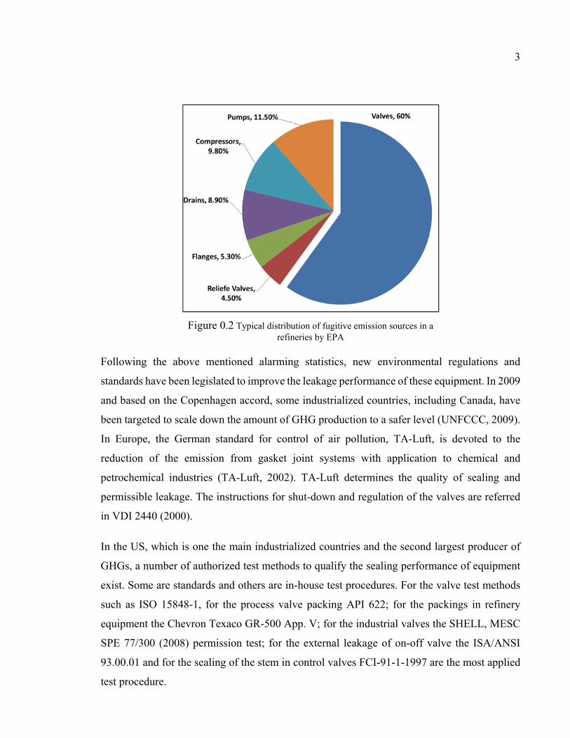
percentage of fugitive emission contribution of each equipment type. The results which are
shown in Figure 0.2 illustrate that bolted joints and valves contribute almost 66 % of the major
pressure vessel components in plants. 90% of these are valves with stuffing-box packing. Close
to 60% of all fugitive emissions comes from valve leaks and packed stuffing-box failures
(Hoyes, J.R. and Thorpe, L.C., 1995).
3
Following the above mentioned alarming statistics, new environmental regulations and
standards have been legislated to improve the leakage performance of these equipment. In 2009
and based on the Copenhagen accord, some industrialized countries, including Canada, have
been targeted to scale down the amount of GHG production to a safer level (UNFCCC, 2009).
In Europe, the German standard for control of air pollution, TA-Luft, is devoted to the
reduction of the emission from gasket joint systems with application to chemical and
petrochemical industries (TA-Luft, 2002). TA-Luft determines the quality of sealing and
permissible leakage. The instructions for shut-down and regulation of the valves are referred
in VDI 2440 (2000).
In the US, which is one the main industrialized countries and the second largest producer of
GHGs, a number of authorized test methods to qualify the sealing performance of equipment
exist. Some are standards and others are in-house test procedures. For the valve test methods
such as ISO 15848-1, for the process valve packing API 622; for the packings in refinery
equipment the Chevron Texaco GR-500 App. V; for the industrial valves the SHELL, MESC
SPE 77/300 (2008) permission test; for the external leakage of on-off valve the ISA/ANSI
93.00.01 and for the sealing of the stem in control valves FCI-91-1-1997 are the most applied
test procedure.
Figure 0.2 Typical distribution of fugitive emission sources in a refineries by EPA

4
With consideration to the sealing performance significance of a valve’s external sealing, a
proper study is required to accord the quality of packed stuffing-boxes with the new
regulations. The primary step required to achieve this target is the furthering of existing
comprehension on the integrity of components in stuffing-boxes and their effect on sealing
performance. This study is focused on this aspect, with two main objectives; to firstly model
the mechanical integrity of the elements in stuffing-boxes and to secondly characterize the
sealing behavior of these components.
The safe operation of industrial plants is dependent on the adequate function and tightness
performance of bolted flanged joints and valves (Klenk et al., 1999). Considering the sealing
process of valves, stuffing-box packings are of great importance. For the development of a
suitable design for packed stuffing-boxes, a proper understanding of the different properties of
the packing material is crucial. For example, lateral pressure coefficients, stiffness, creep,
relaxation, friction, wear and tightness of the packing rings have major impacts on sealing
performance. A more accurate and realistic model that takes into account the aforementioned
parameters would be very useful in providing a comprehensive design procedure for valves.
Along with these parameters that affect valve performance, this study investigates the contact
stress distribution and the characteristics of the porosity in packing materials. These two
influential parameters and their interconnection with other parameters are important in the
prediction of leakage in packed stuffing-boxes and can be used to quantify performance and
develop improvements to sealing quality.
The first objective stems from the need to address the mechanical integrity of a large class of
valve stuffing-boxes which involve the modeling of sealing contact stress distribution between
packing rings and side walls. Given its industrial significance, the determination of the contact
stress distribution has been the object of much research. In the literature, several models have
been proposed to predict contact pressure distribution during initial tightening. However, there
does not exist a comprehensive model capable of determining the mechanical integrity of
packed stuffing-boxes. Furthermore, the elastic interactions of the different elements of
stuffing-box packings and their behavior with temperature have not yet been accurately

5
simulated. In addition, experimental results have not been reproduced analytically or
numerically because of a lack of data for the properties of packing materials.
The second objective arises from the lack of a rigorous constitutive model adequate for the
modeling of the leak behavior of stuffing-box packings. This objective aims to develop a
process that can be exploited to determine the leak property of porous materials used as a seal
in stuffing-boxes. A variety of materials are used for this purpose, such as Teflon, flexible
graphite, fiber based, plated fabrics, or a combination thereof. The most significant and
common property between these materials is their lateral pressure ratio. Although this property
is counted as an advantage in the transfer of axial load to the contact side walls, the problem is
the porosity that allows for high pressure gases or fluids to escape outside of the valves.
A rigorous methodology has been planned to fulfill the objectives of this study, which must
meet certain requirements in order to cover all aspects of packed stuffing-boxes. First, there is
a focus on the ability to handle the broadest range of shapes and materials for stuffing-boxes.
This ability is what leads to the presentation of a comprehensive model that can be exploited
to develop standard design procedures. The second requirement is the robustness of the
proposed method in the evaluation and assessment of the presented models. This requirement
arises from the need to clarify the effect of selected parameters on the sealing performance
among which are the geometrical, physical and material complexities. Finally, this
methodology must be repeatable with standard tools. The second requirement necessitates the
presentation of a model that can be proposed and guarantee that the results are directly
applicable to various circumstances.
A combination of analytical, experimental and numerical investigation techniques were used
to meet the requirements of a comprehensive study. The analytical modeling in this study is
based on the firm physical laws that dictate how to construct a model capable of describing the
behavior of each component. In consideration of the complexity of the interactions between
parameters and their effect on sealing performance, empirical terms are used in the analytical
models. An extensive experimental plan has been conducted to investigate the value of the
empirical parameters. In addition to the abovementioned purpose, the experimental studies
were targeted toward the evaluation of the presented models. The studies were carried out on

6
a well-equipped test bench that had been modified in the laboratory of static and dynamic
sealing at the École de Technologie Supérieure. It should be emphasized that the experimental
set-up and the measuring devices adjusted on the experimental test bench are clearly described
and obtained from standard equipment. The accessibility of the experimental set-up allows for
the creation of an experimental procedure that is repeatable and extendable to other working
environments.
For many engineers and researchers, there is limited access to such standards on which to
conduct their evaluations and further their investigations. Therefore, the methodology is also
limited to numerical simulations that can be carried out with standard commercial Finite
Element Method software (FEM). The advantages of FEM investigations are that it is possible
to verify the presented model faster and much less expensive than experimental investigations,
while also applying to many situations and practical applications where conducting an accurate
experimental investigation would not be possible.
This thesis is presented in seven chapters. The first chapter presents a general literature review
on packed stuffing-boxes and some related aspects such as bolted joints and creep behavior, in
addition to reviews of the common domains of interest in which engineers and researchers
have conducted investigations with similar objectives. Gasket bolted joints, flow in porous
media, and numerical simulations for elastic interactions are to name a few.
Since in this study it is intended to use the results from an experimental investigation for the
verification and characterization of the presented model, it is necessary to set up a test stand
that is capable of demonstrating the real behavior. Thus, the second chapter is entirely devoted
to the description of the experimental set up and the procedures for measuring the targeted
parameters. Few researchers have developed test benches and investigated few parameters that
affect the sealing performance of packed stuffing-boxes. Such investigated parameters are
gland pressure, packing material, temperature effect, and the type of gas. The test stand used
in this study was developed for the purpose of measuring the parameters related to the
objectives of this study.

7
In the third chapter, a structural integrity study of the valve housing is conducted in order its
influence on the contact stress and packing ring leakage behaviour. This part of the study was
presented at the American Society of Mechanical Engineering Pressure Vessel and Piping
conference (ASME-PVP 2014) in the Ph.D. category of the student paper competition. An
extended version of this paper was published in the ASME Journal of Pressure Vessel
Technology in 2015 (Kazeminia and Bouzid, 2015). The objective of this study was to provide
a basis for a standard design procedure of packed stuffing boxes such as the already existing
one on bolted flange connections in the ASME Boiler and Pressure Vessel Code.
The second objective of this thesis is treated in chapters four, six and seven. In the fourth
chapter, a new approach to characterize micro- and nano- flows through the porous structure
of packing rings is presented. The porosity parameters are defined using a developed pseudo
analytical-experimental procedure. The obtained model is used to predict the leak rate through
packing rings. The effect of packing compression and gas pressure; two important parameters
in the prediction of leak rates were investigated. A paper dedicated to this study was presented
at the American Society of Mechanical Engineering Pressure Vessel and Piping conference, in
2015 in Boston. An extended version with additional results was published in the journal of
Pressure Vessel Technology (Kazeminia and Bouzid, 2016).
In the fifth chapter a comparative study between different fluid flow models is presented. The
capillary and concentric cylinder models with first order slip models were compared to a
modified Darcy model adapted for compressed packing materials. In this study the accuracy
of these models and their ability to predict leak were tested by comparison with experimental
measurements. The results of this study have been the subject of a paper submitted to the
Elsevier International Journal of Pressure Vessel and Piping.
In the sixth chapter, presents an article entitled “Effect of Tapered Housing on the axial Stress
Distribution in a Stuffing-Box Packing”, which has already been published in the International
Journal of Advancement in Mechanical and Aeronautical Engineering (Kazeminia and Bouzid,
2014). This paper provides a comprehensive study on the radial stress distribution in a set of
packing rings. Two presented models are proposed to increase the sealing performance of

8
packed stuffing-boxes. The two models are supported analytically and numerically to
demonstrate an improvement of leak performance.
In the last chapter or chapter seven, the time-dependent behaviour of a flexible graphite based
packing ring is presented. This study which is carried on a modified high temperature test
bench, demonstrates the simultaneous effect of creep and relaxation present in packed stuffing
boxes. The results of this study has been published in the proceeding of the ASME pressure
vessel and piping conference (Kazeminia and Bouzid, 2016).
This thesis concludes with a general conclusion of the work conducted during the course of
this Ph.D in addition to few recommendations that are suggested for future work.

9
CHAPITRE 1
LITERATURE REVIEW
1.1 Introduction
Although packed stuffing boxes have been used for decades in the sealing of valves and pumps,
there is no standard methodology that could be useful to design these assemblies. In addition
proper tools to select the right packing suitable for a certain application do not exist. It is only
recently that few standard test procedures have been suggested. These test procedures are
designed to qualify the sealing performance of compressed packings and have recently been
adopted in both North America and Europe. Several researchers have developed both analytical
and numerical models to simulate the behavior of packed stuffing-boxes. The lack of enough
knowledge on material properties of the packed stuffing boxes, the elastic interaction of the
different joint elements, and the nonlinear behavior of yarned packings are the main obstacles
to overcome in the theoretical studies. Therefore, there is a need to characterize packed
stuffing-boxes and validate existing and under development models with experimental studies.
The main challenge with latter is to build an instrumented test rig that can capture the real
behavior of a packed stuffing box.
For the sake of an inclusive review, this chapter is divided into five subsections. After the
introduction in the second part, a general introduction of existing standards and documented
codes is presented. Then a review of existing analytical studies of packed stuffing-boxes is
presented. The fourth part discusses few numerical finite element models used to simulate the
interface contact stresses numerically, and their short term creeps behavior. The fifth part is
dedicated to experimental investigations and discusses existing test rigs and test procedures.
1.2 Standards and documented codes
There is no known standard currently in use that provides step-by-step instructions to design
packed stuffing boxes and select a suitable packing type for a certain application. Also,

10
documented standard test procedures related to the qualification of packed stuffing-boxes are
only recent. API 622 and ISO 15848 are two recent standards that are undergoing major
revisions. Due to the strict legislation on fugitive emissions and the new environmental
protection laws, several standard design codes introduce new criteria based on leakage rate
while valve systems lack a design methodology.
Fugitive emission requirements are one of the critical regulations that the chemical and
petrochemical industries have to comply with. The motivation to develop new standards is ever
increasing to maintain a clean environment. In North America, manufacturers have a great
concern about qualification and certification of their valve products and, in particular, their
compliance with the EPA strict regulations about fugitive emissions. In fact, there is a need to
develop new standards related to the design and testing of valve stem packing because these
components are the main source of fugitive emissions of pressurized equipment (FSA, Sealing
Sense (2012)). Some important standards and in-house test procedures related to valve fugitive
emissions developed after the 90’s are ISO-15848-1 and -2, API-622, API-624, ANSI/ISA
S93.00.01, ANSI/FCI 91-1, TA-Luft VDI 2440, SHELL MESC SPE 77/300, SHELL MESC
SPE 77/312, Chevron SSM-PU-53.02-A and EXXONMOBIL GP 03-12-09.
The ISO-15848 standard for valve fugitive emissions has been issued by International Standards
Organization (ISO) in two parts using a wide range of information from different industries (FSA,
Sealing Sense (2012)). The first part, ISO-15848-1 (ISO 15848-1 (2006)), imposes helium or
methane as a test media and a sample of a test rig that performs such a test is shown in Figure1.1
(c). The test leak detection method used is the one referred as EPA1 method 21 for leak
measurements of the completely assembled valves to address a classification system and
1The abbreviation for “Environmental Protection Agency”.

11
qualification procedure. The range of temperature is between -1960C to 4000C (-320.8F to 752F),
and the criteria for the leakage failure is a predetermined parameter specified by the customer.
Table 1.5 Average gaseous emissions (leakage) and valve
gaskets (Heymanns Verlag, C. (2002))
Table 1.6 Average gaseous emissions (leakage) and valve gaskets (Heymanns Verlag, C. (2002))
Gasket system
Leakage related to the average size
of the gasket [mg/(s
x m)]
Stuffing box with packing 1.0
Stuffing box with cup leather, O-ring
0.1
Stuffing box with packing, stuffing box with cup leather, O-Ring (with "TA Air Certificate" according to
VDI 2440, Section 3.3.1.3)
0.01
Metallic bellows, sealed 0.01
Metallic bellows, sealed (with flat gasket possessing a TA Luft
Certificate according to VDI 2440)
0.001
Stuffing box with packing and sealing medium/suction, metallic
bellows, welded on both sides
No emission proof
Table 1.7 Average gaseous emissions (leakage) and valve
gaskets (Heymanns Verlag, C. (2002))Table 1.8 Average
(a)
(b)
(c)
Figure 1.1 Test device for (a) API-622, (b) API-624 and (c) ISO (FSA, Sealing Sense (2012))

12
The second part of ISO standards for valve fugitive emissions, ISO-15848-2 (ISO 15848-2
(2003)), is a quality control test or a production acceptance test of valves. This part ensures the
production quality of the valves tested in part one and defines a quality control test method to
be followed systematically in the manufacturer’s site. The recommended testing fluid is
helium, and the test should be conducted at a pressure of 6 bars and is supposed to run at room
temperature. Also, this document should indicate the percentage of the total produced valves
for inspection. Presently both parts of this standard are under revision.
The American Petroleum Industries (API) issued two standards for valve fugitive emissions.
The first one is API-622 (API-622 (2011)), the second edition of which has been published in
2011. In addition to the use a specific test rig for fugitive emission testing of valve packings
described in the first edition, it is now permitted to test an assembled valve system instead. The
test bench shown in Figure 1.1(a) uses methane as the testing fluid and the procedure imposes
five thermal cycles from ambient temperature to 260oC (500F) and 1510 mechanical cycles
representing the opening and closing of the valve. Also, this standard considers corrosion of
the packing material and defines a criterion of 15 percent oxidation in 24 hours as per the
procedure of FSA2-G-604-07, method B. Furthermore this standard limits leakage failure to
500 particles per millions (ppm) as imposed by the EPA.
The second API standard for valve fugitive emissions is API-624 (API-624 (2011)) which is
devoted to rotating and rising-rotating stem valves (test bench in Figure 1.1(b)). This document
defines the required test procedure and imposes methane as testing fluid while referring to EPA
method 21 for leak measurements and setting the limit to 100 ppm. The allowed temperature
range is -29 oC to 538 oC (-20F to 1000F). The test procedure requires 310 mechanical cycles
and three thermal cycles. Similar to ISO-15848-1, the sealing materials must be photographed
after valve system disassembly to record any surface changes that can affect the sealing
performance.
2 The abbreviation for “Fluid Sealing Association”.

13
The American National Standard Institute (ANSI) has issued a standard test procedure entitled
“standard method for evaluation of external leakage of manual and automated on-off valves”
with identification number ANSI/ISA-93.00.01-1999 (ANSI/ISA-93.00.01 (1999)). This
standard applies to the classification of valve design and determines the procedure for testing
of valve stems and body seals but cannot apply for production testing and quality control of
valves. Similar to other standards, the purpose of this standard is to establish a unified
procedure to test the compliance of the seal according to volatile organic compounds (VOC)
fugitive emission requirements. The test procedure can be conducted under one of the four
different predefined temperatures, -46 oC (-50F), ambient, 177 oC(377F) and 399 oC(750F).
All tests except the one conducted at ambient temperature must include at least one thermal
cycle.
ANSI issued another most recent standard for qualification of stem seals of the control valves
in collaboration with the Fluid Control Institute (FCI). The identification number of this
standard is ANSI/FCI 91-1-2010, which was originally an FCI standard released in 1991. After
several revisions, in 2010, it was adopted by ANSI as a voluntary standard. By considering the
ability of packing seals to withstand mechanical and thermal cycles under a predetermined
pressure and temperature conditions, this standard classifies the stem seals of the control
valves. It mentions that the results from the test conducted using this standard procedure could
be used to predict the leakage of a valve that operates at the same temperature and pressure
conditions. The number of mechanical cycles defined for valve operation from fully open to
fully closed and back to fully open is between 25000 to 100000. Two allowable leak rate levels
are defined; the first one is up to 100 ppmv and the second one is up to 500 ppmv.
In Germany and some other European countries, the TA-Luft is a well-known adopted standard
for stem sealing (ISO 15848 / TA-Luft (2012)). For the purpose of reduction of fugitive
emissions, a guideline has been provided in compliance with allowable leakage and defines
regulations for inspection according to VDI4 2440 (Riedl, 2007). In this standard, known as
TA-Luft/VDI 2440, the average leakage of different gasket sealing systems are referred to VDI
2440 which is illustrated in Table 1.1. The testing fluids are helium and methane with the
possibility of running the test at a specified temperature.

14
In addition to the standards mentioned above, there are some other in-house tests (SHELL
MESC SPE 77/300, SHELL MESC SPE 77/312, Chevron SSM-PU-53.02-A and
EXXONMOBIL GP 03-12-09) which are developed to evaluate the qualification of a valve
sealing performance with a fugitive emission criteria agreed upon prior to testing. Although all
standards related to valve fugitive emissions have almost similar objectives, they use different
leak measuring methods, fluid, temperature, pressure, the number of mechanical and thermal
cycles and so on. In spite of all these standards, the lack of a comprehensive design procedure
of valve sealing system is still obvious.
1.3 Analytical studies
In general, there are two ways for a high-pressure fluid inside the valve to escape out from
packed stuffing boxes and bolted gasketed joints. The first one is a surface leak that exists at
the interface between packing rings and side walls formed by the housing and stem. The second
one is through the porous structure of the packing materials. Unfortunately, there are limited
Table 1.1 Average gaseous emissions (leakage) and valve gaskets (Heymanns Verlag, C. (2002))
Gasket system
Leakage related to the average size
of the gasket [mg/(s x m)]
Stuffing box with packing 1.0
Stuffing box with cup leather, O-ring 0.1
Stuffing box with packing, stuffing box with cup leather, O-Ring (with "TA Air Certificate"
according to VDI 2440, Section 3.3.1.3)
0.01
Metallic bellows, sealed 0.01
Metallic bellows, sealed (with flat gasket possessing a TA Luft Certificate according to
VDI 2440)
0.001
Stuffing box with packing and sealing medium/suction, metallic bellows, welded on
both sides
No emission proof

15
studies in the literature that accurately distinguished the amount of leak produced by each type
of leak with gaskets and packing made of soft materials. Nevertheless, it is recognized that
leaks through the pores are more important than the surface leaks with soft materials used with
smooth surface finish (Arghavani et al., 2002). This second source of leak depends on the
structure complexity, size and amount of pores inside the packing materials. In the former
source, the amount of leak depends on the ability of the assembly to maintain a minimum
threshold contact pressure between the mating surfaces and surface roughness under the
operating conditions of pressure and temperature.
In contrast to the leak through the pores of packing materials, there is little focus on the contact
stress between the packing rings and side walls. A radial contact pressure distribution is
developed as a result of axial compression provided by the gland, as illustrated in Figure 1.2
Figure 1.2 A schematic sample of industrial valve with stuffing-box
packing ( ISO 15848 / TA-Luft, 2012)
Figure 1.3 Sectional view of packed stuffing-box (Diany and Bouzid, 2006)

16
and Figure 1.3. Based on this concept, Denny (Denny, 1957) proposed the use of a lateral
pressure coefficient defined as the ratio between the radial to axial stresses:
= (1.1)
Where and are axial gland stress and radial contact stress respectively. He also found
that the radial stress is constant once a minimum amount of axial stress is reached for a
particular packing material.
Based on a rigorous analysis and depending on the internal or external friction coefficient
between the packing and the stem or housing, one can distinguish two lateral pressure
coefficients; an internal and an external lateral coefficients and which are discussed in
the literature.
Based on the free body diagram of Figure 1.4 and the boundary conditions, Ochonski
(Ochonski, 1988) proposed a formulation that describes the radial contact stress distribution
along the stem. His proposed analytical model describes the behavior of soft-packed stuffing-
boxes and is supported by experimental results. His analysis leads to, the axial stress
distribution given by the following expression:
(a)
(b)
Figure 1.4 Forces acting on a packing element, (a) General model and (b) Simplified model (Pengyun et al., 1998)

17
= (1.2-a)
Where is the axial position starting from the contact surface between gland and packing and
is defined as
= 4 +− (1.2-b)
Where , , and are friction coefficients, lateral pressure coefficients, internal and
external packing diameters, respectively, and the subscripts i and e refer to internal and external
contact surfaces.
An exponential distribution of the radial contact stress is also obtained by solving the derived
differential equation obtained from the force and moment balance based on a free body diagram
similar to the one in Figure 1.4 (a) with the assumption that the concentrated force acts in the
middle of packing elements in the radial direction. With this analytical model and the
experimental measurements of the housing deformation, they obtained a relationship between
the radial and axial stresses.
Considering a similar model to the one shown in Figure 1.4(b) and assuming the force
distributed uniformly in the radial direction, Pengyun et al. (Pengyun et al., 1998) found a new
expression for the distribution of the axial stress. Applying equilibrium of forces acting at the
mid packing width and moments around the stem axis they derived the expression for the
distribution of axial stress such that
= (1.3-a)
= 16 −( − ) (1.3-b)
Imposing the assumption of analogous conditions to the two contact boundaries and equating
the lateral pressure coefficients and friction ratios, the parameter can be reduced to

18
=−16 − = −8 (1.4)
Where is the wideness of the packing ring. The model described by equation (1.4) was first
suggested by Denny and Turnbull (Denny and Turnnbull, 1960). Pengyun and et al. (1998)
evaluated the applicability of the assumption of the analogous conditions at the two contact
boundaries. They proposed that their model described by equation (1.3) should give the same
distribution of axial stress as in equation (1.2) and consequently the following relationship is
deduced
= 3 + 55 + 3 (1.5)
or
= 1 + 2 4 + 34 + 5 (1.6)
This formula gives the ratio of internal to external lateral pressure coefficients as a function of
dimensions and friction coefficient ratios.
Dianny and Bouzid (Diany and Bouzid, 2006) presented a more rigorous model that gives the
axial stress distribution and determined a new parameter used in equations (1.2) and (1.3).
Considering the free body diagram presented in Figure 1.5, and by taking the moment about
the axis and considering the infinitesimal moment force, they determined that
= (1.7-a)
= 24 −( − ) (1.7-b)
By comparing equations (1.2-a) and (1.3-a), a relationship that expresses the lateral pressure
ratio as a function of friction and geometry is obtained such that

19
= 1 + 2 5 + 77 + 5 (1.8)
The flexibility of the stem and housing is an important factor to consider when simulating the
real behavior of a packed stuffing box. The interaction of the packed stuffing box elements
was studied by Diany and Bouzid (Diany and Bouzid, 2009(a)). Based on the free body
diagram and the flexibility of the different elements of the stuffing-box, as illustrated in Figure
1.6, together with an analysis of compatibility conditions between the packing and side walls
have led to the evaluation of the internal and external lateral pressure coefficients
independently. They found that these coefficients are material and geometry dependent and
made comparisons with other similar results in the literature.
In addition to the surface leak produced at the interface between packing and side walls, there
is a possibility of leakage failure through the porous material of packings. Hisaro and Yoshida
(Hisao and Yoshida, 1991) conducted an experimental study on stuffing-box packing tightness
performance by measuring the total leakage. The main parameters of their study were the total
packing height, the packing compressive stress and fluid pressure. They tested two types of
packing materials: Asbestos and flexible graphite packing rings.
Figure 1.5 Stresses on a packing (Diany and Bouzid, (2006))

20
The initial tightening of a packing set, which generates the required contact pressure to seal,
decreases with time due to the creep-relaxation of the packing material. This fact has fostered
researchers to study this phenomenon for the purpose of predicting the contact pressure drop
and its influence on leakage. Tashiro and Yoshida (Tashiro and Yoshida, 1991) investigated
the stress relaxation of gland packings. They have developed a theoretical model that was
supported experimentally with test data. The tested packing rings made of asbestos and
graphite and modeled as viscoelastic materials describe potentially their relaxation behavior.
The main focus of another study conducted by Diany and Bouzid (Diany and Bouzid, 2012)
was the short-term relaxation of packing rings. Their developed analytical model, based on the
Maxwell generalized model as illustrated in Figure 1.7, relies on the relaxation modulus of the
packing material to predict relaxation. Eight Prony series model the viscoelastic behavior of
the packing elements that the required coefficients of which are obtained from material data
available in the literature.
With the lack of creep data and creep models, the creep constitutive law of packing materials
was investigated by Diany and Bouzid (Diany and Bouzid, 2012). Based on relaxation tests,
the packing materials are assumed to have linear viscoelastic behavior and relaxation was
Figure 1.6 Free body diagram of elements in a stuffing-box packing (Diany and Bouzid, 2009(a))

21
studied in the time domain using stress-strain relations in integral form. Experimental and
numerical studies supported the validity of the developed analytical model.
After some preliminary progress in the modeling and characterization of stuffing box packing,
researchers decided to treat more complex applications. Li and his colleagues (Li et al, 2012)
studied the failure of a packed stuffing box used in a high-pressure compressor. With the help
of a theoretical model and experimental observations, they investigated the reasons for cracks
in the stuffing-box packing subjected to very high pressure.
Since late 1980’s the fluid flow through nano and micro-porous media became a popular
research topic due to its important application in science and engineering such as the micro
electro mechanical system fabrication technologies and biomedical chip systems (Karniadakis
et al., 2000). Fluid flow through porous media became an important subject in engineering
applications such as in oil and gas (Kfoury et al., 2005; Espinosa-Paredes, 2015; Lotfizadeh
and Matsoukas, 2015), and, gas separations (Liang and Weimer, 2015; Jiang et al., 2009).
The mechanism of fluid and gas transportation inside the porous media mostly depends on the
relative size of the pores and the mean free path of the fluid. The mean free path is the average
distance between molecules of a liquid or gas after a collision (Karniadakis et al., 2000).
Knudsen number is a parameter used to quantify this variation and is defined as the ratio
between mean free path and hydraulic diameter, such that
Figure 1.7 A generalized Maxwell model (Diany and Bouzid, 2012)

22
= (1.9)
For ≤ 0.001, the fluid regime is continuous and Navier-Stockes equations may be used to
describe fluid flow and boundary conditions. When 0.001 ≤ ≤ 0.1 a slip flow regime is
present where the number of collisions between molecules and the wall are more important
than the collisions between the molecules. In this case, the Navier-Stockes equations may be
used to describe the fluid flow with slip boundary conditions. The flow regime is transitional
when 0.1 ≤ ≤ 10 in which the various moment methods may be applied to describe fluid
flow. For ≥ 10, a free molecular regime is present and Boltzmann equations can be used
to describe the fluid flow.
Applications, such as bolted flange joints, have been the subject of more investigations in
relation to fluid flow through porous gasket materials. Jolly and Marchand (2009) used Darcy’s
model with the first order slip condition to estimate leak through an annular gaskets. They
assumed that the gasket is made of several parallel disks distributed through the thickness. The
flow of gaseous fluid is assumed in the radial direction taking into account gas compressibility.
Following their studies, Marchand et al. (2005) determined that the type of the regime with
some gasket materials is not only Laminar but intermediate and or early molecular. Hence, to
consider the effect of rarefactions, they applied the filtration velocity with intrinsic
permeability and Klinkenberg’s Effect on the Navier-Stokes equations in the cylindrical
coordinate. The applied first order slip condition at the wall of the channel is
= 2 − (1.10)
They used Helium and Argon as reference gasses and two types of gaskets made from flexible
graphite (FG) and compressed asbestos (CA). The results of this model presented almost the
same accuracy as laminar-molecular flow (LMF). They suggested that using this model would
allow the introduction of more characteristics such as intrinsic permeability and Klinkenberg’s
number. Without characterization of the gas type, they compare the results for the prediction

23
of SF6 and CH4 leak rates. They noted that using Argon as a reference gas gives more accurate
predictions while Helium tend to oversee the leaks.
Grine (Grine, 2012) studied the micro and nano flow through gaskets in bolted joints in his
doctorate thesis. He presented an innovative approach to predict leak rates in gasketed joints
subjected to different contact stresses, gas pressure and gas type (Grine and Bouzid, 2011).
Through their microscopic approach, they characterized the porous properties of the gaskets
by determining the number of the micro or nanochannels and their diameter. As a sealant, the
PTFE based gasket was the porous media while Helium was used as the reference gas to
determine the characteristics of the pores. The results are then used to predict the gas leak rates
for the cases with different gasses.
The capillary and annular models that divide the porous media into micro-channels and parallel
plates are applied in the studies of Lassaeux et al. (Lassaeux et al. 2011) see Figure 1.8. They
concluded that for the leak rates in the range of 10-4 liter per second, the slip flow model
presents better agreements with experimental data while for the range of 10-6 liter per second
the molecular model is more accurate. Also, they determined that using these approaches for
increased gasket compression presents a reduction in the thickness of the micro and nano
channels while the number of paths remains relatively constant.
In another study, Grine and Bouzid (2010) considered the flow of liquids through micro and
nano channels of graphite-based gaskets, where they proposed the capillary model with water
and kerosene, and compared the results of theoretical models to ones obtained through
(a) (b)
Figure 1.8 Macroscopic models to study the characteristics of porous media (a) Capillary Model, and (b) the Annular Model (Grine and Bouzid, 2011)

24
experimental investigations. They exposed very promising arguments, although some
discrepancies in their interpretation of interfacial flow at low pressures was not taken into
account in their capillary model.
The previous study was further enriched through the analysis of high-temperature operational
conditions (Grine and Bouzid, 2013). Two objectives were considered in this study: leak rate
at high temperatures and the correlation between the displacement of the gaskets and the
porous characteristics. The parameters relative to the pore characteristics are the number of
micro and nano channels and their thickness. The capillary slip model was used as the
analytical approach, with the results being comparable with ones obtained from experimental
investigations using helium and nitrogen at a leak rate range of 10-4 liter per second. The results
showed a decrease of leak rate with a temperature increase. A possible justification for this
phenomenon is the fact that increasing temperature soften the gasket causing an increase in
compression and hence a decrease in the diameter of the micro- and nano-channels.
Few papers cover the characterization and prediction of the fluid flow of the porous media
used in the valve stuffing boxes. For example, Tashiro and Yoshida (1991) conducted an
experimental investigation on leakage through the pores of packed stuffing boxes. They used
water as the liquid inside the valve and two types of packing rings made from asbestos and
graphite materials. The main aim for their study was to investigate the correlation between leak
rate versus packing height, packing compressive stress and fluid pressure.
The permeability of packing rings made from exfoliated graphite was investigated by Lasseux
et al. (2011). Because of the high tortuosity of the porous material, they proposed a model
based on Klinkenberg’s effect in its flow characterization. They assumed that a compressible
ideal gas flows isothermally at a low Reynolds number, so the general form of conservation
equation used is:
+ ∇. (ρ V) = 0 (1.11)
Here, the filtration velocity is defined by Darcy’s law to which Klinkenberg’s effect is added:

25
= + . ∇ (1.12)
They studied the radial and axial values of the permeability and Klinkenberg’s number for a
single ring, presented in Figure 1.9. Then, they proposed an experimentally based procedure
in concert with the presented theoretical model to determine these parameters.
The results of these studies show that axial permeability is one order of magnitude greater than
radial permeability. Furthermore, it was revealed that an increase in compression stress causes
a reduction in the permeability, causing a second order correlation, and that Klinkenberg’s
effect decreases with permeability.
1.4 Numerical simulations
Computer simulation is a powerful tool in engineering that helps in the analysis of complex
structures subjected to any loading condition. Using such tools in engineering processes does
have several benefits and drawbacks. In particular, it allows for the analysis of complex and
large scale models at low cost when compared to experimental studies. In addition, it allows
for the solving of complex problems that are sometimes very difficult or impossible to treat
analytically.
Figure 1.9 Annular section of a packing ring (Lassaeux et al., 2011)

26
However, the ability of commercial software to include all material behaviors is limited, and
packing materials happen to fall into this category, therefore, users are cautioned to validate
and verify their results.
The packed stuffing box valve configuration has an axis of symmetry which facilitates its
simulation. The main obstacle in the numerical simulation of stuffing-box packing is the
material modeling of the packing rings and the interaction between the packing ring and the
side walls. Several researchers have already proposed different techniques to simulate the
housing, stem, gland and packing interactions numerically.
Cartraud and Wielcosz (1996) proposed a model for elastoplastic seal material, including non-
linearity. Zerres et al. (1998) compared the mechanical behavior of bolted joints obtained
through both FEM analysis and the approach proposed by the European code EN-1591. They
reviewed the models using the simplifications introduced by the European code EN (Zerres et
al., 1998).
Baogang et al. (1999) conducted a 3D FE model analysis by considering the nonlinearity in
the behavior of the gasket. They compared the results of an analysis of several joints with a
variety of flange thicknesses, thus showing that the performance of a flange joint sealing is
affected by the non-linearity of the stress-strain curve of the gasket.
Sawa et al. (2002) used an elastoplastic model that considered the hysteresis effect and the
nonlinear behavior of a spiral wound gasket to study the effect of the nominal diameter of
flanges on the distribution of contact stress. They found that the variation in the distribution of
the contact stress of bolted joints with large diameters is greater than for those with smaller
diameters. This phenomenon can be explained by the difference in the number of bolts and the
rotational flexibility of the flange. Thus, when internal pressure is applied to the assembly, they
found a reduction in actual sealing surface.
Diany and Bouzid (2006) numerically simulated the mechanical interaction of packed stuffing
boxes using ANSYS software. The model is an axisymmetric configuration with four-node
plane elements used to model the housing and stem, and 2D four-node hyperelastic elements

27
to model the packing rings. They used experimental data to describe the nonlinear behavior of
packing material during the loading phase. However, the load loss pressure and temperature
was not investigated in this study.
In another paper, Diany and Bouzid (2009(a)) exploited a numerical simulation for stuffing-
boxes to evaluate their proposed analytical model. The axisymmetric finite element model,
illustrated in Figure 1.10, was used to study the effect of applied axial stress on the axial
distribution of lateral contact pressure between packing and side walls as a function of the
friction coefficient. The packing material was modeled using the Mooney-Rivlin material
behavior with the two constants, C1 and C2, determined experimentally by curve fitting. The
investigated parameters were the number of packing rings (2 to 8), gland pressure (10 to 50
MPa), and friction coefficient (0.15 to 0.25).
The comparison between the models of equations (1.5), (1.8) and their proposed analytical
model, as well as the results from the finite element model are illustrated in Figure 1.11 (Diany
and Bouzid, 2009(a)). The results show that the ratio of lateral pressure coefficient is almost
independent of the gland pressure, and the analytical results corroborate the results obtained
Figure 1.10 FE model of a stuffing box
packing (Diany and Bouzid, 2009(a))

28
from the finite element analysis. As for the axial stress, the effect of the friction coefficient
was found to be less than 10% for a gland stress of 50 MPa. This result, illustrated in Figure
1.12, confirmed that changes in the friction coefficient, within a certain range, does not have a
significant effect on the level of the contact stress.
Figure 1.11 The result of lateral pressure coefficient ratio vs gland pressure from (Diany and Bouzid, 2009(a)). Eq.(1) in the figure is Eq. (1.5), Eq.(2) is Eq. (1.8) in the text.
Figure 1.12 The internal lateral pressure coefficient versus number of packing with variable friction ratio (Diany and Bouzid, 2009(a))

29
To validate and support their investigation on the relaxation of stuffing boxes, Diany and
Bouzid (2009(a)) conducted a finite element simulation using ANSYS. Their simulation using
Prony Series to model the viscoelastic behavior of packing materials was similar to their
analytical model. A friction coefficient of 0.25 and an initial equivalent displacement was
applied to the packing and gland contact surface to simulate the gland stress. The contact
stresses of the finite element and analytical models were comparable over a relaxation period
of 5.5 hours. The results show that the radial contact stress and the axial stress are comparable
except near the packing to gland contact surface, as illustrated in Figures 1.13(a) and (b). The
comparison between the variation of stresses versus time is presented in Figure 1.14, where
agreement between the two models is evident. The rate of relaxation is strongly dependent on
gland stress. The variation of axial stress with time near the gland is shown in Figure 1.14(b).
In the case of a gland stress of 50 MPa, the axial stress decreases by 30% only after half an
hour. This fact demonstrates the significance of short-term relaxation even at a room
temperature.
To determine the lateral pressure coefficient, Diany and Bouzid (2012) developed a hybrid
numerical-experimental method. They evaluated the contact pressure of one packing ring by
comparing the measured hoop strain on the housing external surface to the one produced by an
equivalent FE model of the housing subjected to a known lateral pressure. Figure 1.15(a) shows
(a) (b)
Figure 1.13 The comparison of analytical and finite element results for axial and radial contact stresses (Diany and Bouzid, 2009(a))

30
the first finite element model used to compare the hoop strains on the external housing surface.
In this finite element analysis, the values of radial contact stress varied from 0 to 50 MPa, and
the corresponding strains were measured on the housing external surface. Then, the lateral
pressure coefficient was deduced through a reverse analysis process that correlates the
measured and calculated strains.
Figure 1.15(b) illustrates the finite element model used to characterize the creep behavior of a
packing element. Three different packing materials, PTFE (polytetrafluoroethylene), CF
(Carbon Fiber) and FG (Flexible Graphite) were simulated using Prony series constants
obtained experimentally to describe the nonlinear behavior of the materials. The relaxation of
CF is less than the other two materials, as shown by the relaxation curves presented in Figure
1.16. After 5 hours, the percentage of relaxation was 2% for CF, 19% for FG and 6.6% for
PTFE.
The variation of the lateral pressure coefficient with time and for different packing materials
is illustrated in Figure 1.17(b). At room temperature, it is it evident that the relaxation of the
material with a higher lateral pressure coefficient is lesser than those with a lower lateral
pressure coefficient. The authors proposed an average value for lateral pressure coefficient at
room temperature for each packing material that could be applied in other studies. Finally, to
(a) (b)
Figure 1.14 Relaxation curve for a node in different altitudinal locations, top, middle and bottom of stuffing-box packing (Diany and Bouzid, 2009(b))

31
evaluate the accuracy of the methodology, a fully packed stuffing box model was investigated
experimentally and the results of the stresses and strains over time were compared with the
experimental results. As shown in Figure 1.16, the results are in concordance, with a difference
of less than 1%.
1.5 Experimental investigations
In a stuffing-box packing, there are a few properties that have a major impact on the final
performance of the valve system. The physical properties and their induced phenomena cause
complex behaviors that are very difficult to model. Experimental investigations are the
preferred method for characterizing the parameters which affect the sealing performance of a
valve, and they can also be used to validate analytical and numerical models.
(a) (b)
Figure 1.15 Finite element models to study the creep characterization of packing element (Diany and Bouzid, 2012)

32
The early studies on stuffing-box packing have been carried out through experimental
investigations that were directed mainly at the effects of initial tightening on leakage
(a) (b)
Figure 1.102 The relaxation curve for three different type of packing materials, (a) for axial compressive stress and (b) for lateral pressure coefficients (Diany and Bouzid, 2012)
Figure 1.16 The relaxation curve from experiment and characterizing packing (Diany and Bouzid, 2012)

33
performance. For example, Thomson (1961) showed that most leaks from a valve are
preventable by choosing an adequate amount of initial tightening.
The validation of the proposed analytical model by Ochonski (1988) was carried out alongside
an experimental investigation, where packing deformation, lateral pressure coefficient, and
friction coefficient were investigated. The test apparatus shown in Figure 1.18 was used to
determine these properties. Sensors were used in the form of thin-walled sleeves at the outer
and inner walls and the deformation of the packing was measured indirectly by a dial indicator
that provided the distance between the flange of the frame and the gland. The packing material
for the tests was white asbestos plaited yarn impregnated with PTFE dispersion and pre-
Figure 1.18 The test apparatus for evaluation of analytical model in (Ochonski, 1988)

34
compressed to 5 MPa; the results of this study are presented in Table 1.2. As this table
demonstrates, the values of internal and external lateral pressure coefficients are not equal
because the plaited packing materials displayed anisotropic behavior. The lateral pressure
coefficient at internal radius of packing is always larger than the external radius one while both
are independent of the gland pressure, with exceptions at low tightening ranges of 1 to 12 MPa
due to the compression of air bubbles inside the porous packing material.
Another testing apparatus was used with thin-walled sleeves on the inside and outside and had
strain gauges attached to six circumferential grooves to determine the radial stress distributions
shown in Figure 1.19. The test was conducted at four different gland pressures and the
Figure 1.19 Test stand for measuring the friction in working condition in a soft packed stuffing-box (Ochonski, 1988)
Table 1.28 Determined values from the test apparatus presented in Figure 1.18
(Ochonski, 1988)
Gland stress per MPa
Coefficient 5.0 10.0 15.0 20.0
0.66 0.75 0.79 0.81
0.54 0.58 0.59 0.60 , 0.010 0.0075 0.0053 0.0034

35
experimental and analytical distributions of gland radial stress corroborate one another. The
result of this test bench are presented in Figure 1.20.
Measurements of the friction forces conducted on another test rig are shown in Figure 1.21. In
this test, water was applied as the reference liquid at varying pressures. Hisao and Yoshida
conducted experimental investigations on the characterization of the packing behavior and
Figure 1.21 Test apparatus designed by Hayashi and Hirasata (Hyashi and Hirasata, 1989). 1- Strain gauges, 2- Load Cell, 3- Packing, 4- Load Cell (Pengyun et al., 1998)
Figure 1.20 Distribution of radial stress at packing-housing and packing-stem
(Ochonski, 1988)

36
used experimental data to validate their proposed analytical model (Hisao and Youshida, 1990;
Hisao and Youshida, 1991). Through an identification and qualification research program,
Aikin (1994) focused on the determination of suitable packings for nuclear applications.
Together, they established standard specifications for each valve service.
Bartonicek and Schoeckle (1996) proposed a new test rig and test procedure to determine
packing factors similar to the ones used for gaskets. In their experimental study, they also
considered the short-term relaxation of the stuffing-box packing and they used the results from
the experiments to develop a method to suggest an initial gland packing stress for adequate
sealing.
Figure 1.22 Test apparatus designed by Pengyun (1991) for the determination of internal and external lateral pressure coefficients. 1- Bottom of the stuffing box housing, 2- down pressure sensor, 3- outer measuring ring, 4- packing, 5- gauge, 6- displacement indicator,
7- inner measuring ring, 8- gland, 9- upper pressure sensor, 10 strain gauge amplifier (Pengyun, S. and et al. (1998)).

37
A survey of different test rigs was presented by Pengyun and his colleagues (Pengyun et al.,
1998). They compared the results obtained from their own test rig (Figure 1.22) with that of
other researchers. For example, they compared the test rig designed by Ochonski (1988),
presented in Figure 1.19, and the test apparatus designed by Hayashi and Hirasata (1989)
shown in Figure 1.21. Finally, the results from three test apparatus were compared with the
analytical model described by Equations (1.5) and (1.6). The results obtained from the test rig
illustrated in Figure 1.22 are presented in Table 1.3.
From the results obtained in their experimental study, Hayashi and Hirasata (1989) concluded
that when the axial gland stress is rather large the theoretical contact stresses obtained by
Equations (1.5) or (1.6) are very close to the experimental results. It was also revealed that
when = either the packing width is very narrow or the stem diameter is very large, with = .
Both Kockelmann and Klenk and their colleagues conducted different experimental
investigations for the purpose of characterization of stuffing box packings (Klenk et al., 1999;
Kockelmann et al., 2009). In an attempt to standardize a test procedure, they proposed a test
method inspired from the German standard TA-Luft/VDI 2440 (Klenk et al. 2001). They
Table 1.3 The results of the test apparatus designed by Pengyun (Pengyun, 1991)
Packing
Plated from asbestos yarn, impregnated with oil pre-
compressed graphite ring, 65 x 45 x 10 (external and
internal diameters, thickness)
1.320, calculated by theory
Asbestos Expanded graphite
Gland stress (MPa) 0.4 11.2 13.7 8.6 10.9 12.2
0.891 0.951 0.913 0.518 0.598 0.633
0.587 0.598 0.580 0.481 0.516 0.523 / 1.52 1.59 1.57 1.08 1.16 1.21 Δ % -13.2 -17 -15.9 22.2 13.8 9.1

38
originally developed the method for bolted flange joints and later adopted it for packed stuffing
boxes.
The process of improving the sealing performance of packed stuffing boxes involves the
development of new packing materials. For example, special applications working under
specific operating conditions require high sealing performance to comply with the new
regulation for fugitive emissions worldwide. Among these novel materials, Schaaf et al. (2005)
tested nonwoven packing material that can support temperatures up to 2800OC. Exfoliated
graphite rings are another type of replacement for asbestos materials that have been banned
due to health issues (Figure 1.23). A study on graphite packing rings was carried out
experimentally, analytically and numerically by Roe and Torrance (2008), whose results
presented a variety of friction coefficients through time.
Veiga et al. (2008) investigated the sealing failure of stuffing-box packing in high-pressure
steam services. They proposed a test rig that simulated valve stuffing box behavior at high
temperatures. Also, they highlighted few specific parameters required for adequate sealing
performance in valve stuffing-boxes. Different braided packing materials, the number of
packing rings, initial compression stress, relaxation, stem torque, and sealability are to name a
few (Veiga et al., 2009).
Few experimental investigations on packing failures with time have been conducted in
conjunction with sealing performance and load relaxation. A study of the long-term behavior
Figure 1.23 Internal structure of a sealing ring (Roe and Torrance, 2008)
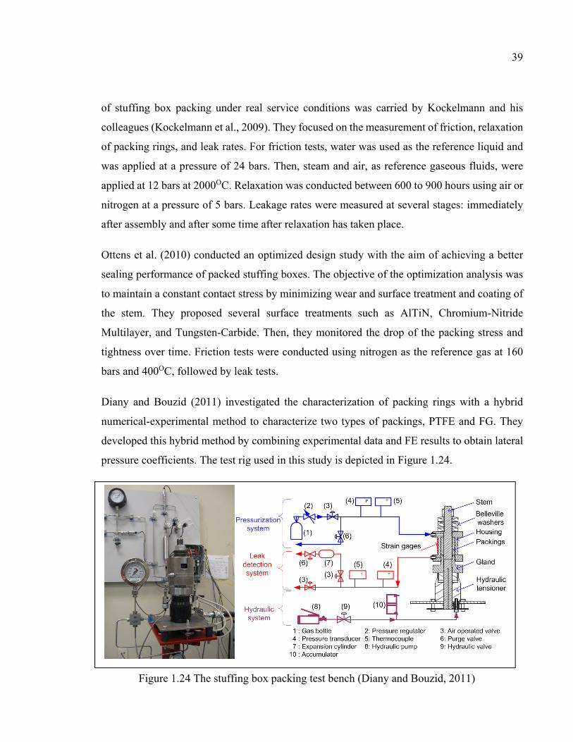
39
of stuffing box packing under real service conditions was carried by Kockelmann and his
colleagues (Kockelmann et al., 2009). They focused on the measurement of friction, relaxation
of packing rings, and leak rates. For friction tests, water was used as the reference liquid and
was applied at a pressure of 24 bars. Then, steam and air, as reference gaseous fluids, were
applied at 12 bars at 2000OC. Relaxation was conducted between 600 to 900 hours using air or
nitrogen at a pressure of 5 bars. Leakage rates were measured at several stages: immediately
after assembly and after some time after relaxation has taken place.
Ottens et al. (2010) conducted an optimized design study with the aim of achieving a better
sealing performance of packed stuffing boxes. The objective of the optimization analysis was
to maintain a constant contact stress by minimizing wear and surface treatment and coating of
the stem. They proposed several surface treatments such as AlTiN, Chromium-Nitride
Multilayer, and Tungsten-Carbide. Then, they monitored the drop of the packing stress and
tightness over time. Friction tests were conducted using nitrogen as the reference gas at 160
bars and 400OC, followed by leak tests.
Diany and Bouzid (2011) investigated the characterization of packing rings with a hybrid
numerical-experimental method to characterize two types of packings, PTFE and FG. They
developed this hybrid method by combining experimental data and FE results to obtain lateral
pressure coefficients. The test rig used in this study is depicted in Figure 1.24.
Figure 1.24 The stuffing box packing test bench (Diany and Bouzid, 2011)

40
Such experimental investigations are necessary to characterize and determine the porous
parameters of packing materials. Based on the complexity of the internal structure and the
effect of tortuosity on the type of the micro and nano-flow, the results achieved by any
numerical simulation do not have enough reliability to extract the parameters and validate the
physical model. Hence, it is necessary to have a rigorous test stand that can simulate the real
application and capture the desired parameters.
Grine and Bouzid (2011) used a special test rig in their studies on fluid flow through gaskets
in bolted joints, as shown in the Figure 1.25. Both liquid and gas fluids can be used by the
universal gasket rig (UGR), which is presented in Figure 1.25(a). Water and kerosene were
applied as liquids and helium and argon as gases. In addition to room temperature leak tests,
this machine is capable of measuring leak rates and creep behavior at high-temperature
operational conditions. The experimental investigation conducted on this test rig was carried
out at low gasket stress levels.
In order to study small leak rates when compressive stress on the gasket is high, the Room
Temperature Operation Tightness test (ROTT) machine is used. This machine is used by Grine
(2012), shown in Figure 1.25(b). The leak detection technique is based on mass spectrometry,
which can detect small amounts of leakage, down to 10-10 mg/s.
For the purpose of characterization of porous packing materials, Lasseux et al. (2011)
conducted experimental investigations using two different test rigs. The permeability and
Klinkenberg’s effect were the two main investigated parameters in their study. The two test
rigs are designed to study leakage in both the radial and axial directions. The test rigs are
illustrated in Figure 1.26. In these experiments the pressure decay method was used to measure
leak rates of a variety of graphite-based packing rings. Through an optimization procedure, the
experimental results were used in conjunction with Darcy Law to determine permeability and
Klinkenberg’s effect.

41
Figure 1.25 Test stands used by Grine, (2012) to characterize the porous parameters of gaskets. (a) UGR and (b) ROTT
a
b

42
Figure 1.26 Test rigs used to determine the (a) radial and, (b) axial permeability and Klinkenberg’s effect (Lasseux et al., 2011)

43
1.6 Conclusion
The studies presented so far cover some aspects of the sealing behavior of stuffing-boxes used
in real applications. Unfortunately the aspects related to structural integrity and the service
conditions are not covered by the literature. The stress analysis of the housing, the effect of
temperature on relaxation and creep, the rigidity of the assembly, the interaction between the
components of the general assembly, and the prediction of the leak rates through the packing
rings are to name a few.
The theoretical models based on the distribution of axial compression stress through packing
rings and the interaction of the side walls is yet to be developed. The lateral pressure
coefficient, a parameter defined by Denny (1957), is globally agreed upon by researchers in
this field. However, the existing literature yields few studies that investigate how the value of
the lateral pressure coefficient varies with gland stress and temperature. Furthermore, the
mechanical properties of the packing material are only defined by linear and nonlinear load
compression behaviour. The viscoelastic behavior is seldom treated in the literature.
Primarily, the experimental studies found in the literatures focused on the transmission of
lateral pressure coefficients by measuring the imposed axial compressive loads and induced
radial contact pressures. Although there were several test apparatus presented in the literature
to determine the lateral pressure coefficient, they all used the same technique to measure the
radial contact stress. Contact stress in the radial direction was determined with the use of strain
gauges glued to the internal side of the housing, or on a metal sleeve on the external surfaces
of the packing assuming that the circumferential deformation is obtained from thin or thick
cylinder theories. Unfortunately, these theories do not take into account any change in the axial
direction and therefore do not reflect the actual behavior of the housing.
Although most recent studies use combined experimental test data and numerical FE analysis
to accurately estimate the lateral pressure coefficients their variation with temperature and time
are not known.

44
A significant flaw in most of these previous test apparatus is in how they are constrained to
operate at a specific range of tightening stress, fluid pressure, leak detection or number of
packing rings. This has restricted the generalizability of the findings and conclusions. The test
bench located at the Static and Dynamic Sealing Laboratory at the École de Technology
Supérieure used by Diany (2011) has the capability of operating at a wide range of tightening
stresses and gas pressures at room temperature, however, the stem does not rotate and it does
not cover high temperature.
In the literature, it was shown that packing viscoelastic properties have a significant effect on
the sealing performance. One recent study (Diany and Bouzid, 2011) determined that even at
room temperature there was a loss of radial and axial stress as a result of relaxation
phenomenon. The models proposed in the literature are uniaxial while the actual behavior of
the sealing in the stuffing-box is three-dimensional. Therefore, it is necessary to develop a
three dimensional model that can reproduce the behavior packing relaxation. This model calls
on a comprehensive study to determine the nonlinear and creep behaviour of packing materials
taking into account the effect of temperature to correctly predict the relaxation of the packing
rings.
Leak through the porous structure of packing rings has rarely been the subject of
comprehensive studies in spite of the permeability of their porous structure. It is important to
characterize the porosity parameters of packing rings and determine the correlation with leak.
So far, a Darcy model based on the filtration velocity of fluid flow in the packing material with
a disordered porosity is presented in the literature. However, the method is tested with material
under high permeability conditions so that the limited pressure decay leak detection method
can be used in order to determine the empirical parameters. It is essential to characterize both
the micro and nano-fluid packing material properties with disordered porosity for a wide range
of rarefication. A comprehensive study that leads to the fabrication of better packing rings and
the selection of suitable materials depending on the application is proposed.

45
1.7 Research project objectives
Due to the new regulations on fugitive emissions, packing and valve manufacturers must
ensure that their products comply with the prescribed levels of fugitive emissions. Another
important issue is the lack of a standard design procedure, similar to those for gasket joints,
which can be used by manufacturers and designers. On the other hand, the above-mentioned
sections highlight the gap in the literature about the sealing performance of stuffing-boxes. The
current level of knowledge on this topic is not sufficient enough to fulfill the main objective
of this study, to develop a standard design procedure. Hence, it is crucial to pursue
investigations which can lead to the characterization of the parameters found in a stuffing box
and how they subsequently contribute to sealing performance.
In fact, several parameters are understood to influence the behavior of the sealing in a stuffing-
box, but they have not yet been characterized and evaluated accurately nor completely.
Because of this, our study targets the mechanical integrity of stuffing-boxes and the
characterization of the porous structure of packing rings.
The first objective is significant as it targets the primary expected function of a stuffing-box,
which is to reach and maintain a threshold amount of contact stress between the packing rings
and side walls. Little attention has been paid in the literature to the mechanical integrity and
the distribution of contact and compression stress through packing rings, and therefore no
standard design code has emerged as there already has for gasket bolted joints.
In addition to the interfacial surfaces between the packing rings and side walls, it is possible
for pressurized fluid to leak out through the porosity of the packing materials. The porous
structure of packing materials is inevitable, as such a quality gives packing material the
capability of transferring the axial compression stress to radial contact stress. With this in
consideration, the second objective is concerned with the characterization of the porous
structure of the packing rings and its effect on the sealing performance.

46
Therefore in order to meet these expectations, analytical and numerical models were developed
and several experimental studies were conducted to verify and validate the results of these
models. These studies aim to:
o Analytically simulate the mechanical integrity of stuffing-boxes, and propose a
standard design code similar to ASME section VIII flange design code;
o Improve the contact stress distribution to increase the sealing performance of stuffed
packing boxes;
o Study the high temperature effect on the load relaxation of a packing ring
o Propose different approaches to characterize the micro and nano-fluid flow in the
porous structure of packing rings;
o Characterize the porosity parameters and measure the leak rates at different gland stress
and pressure levels with graphite packing rings using a standard reference gas such as
helium;
o Develop a suitable model to accurately predict the leak rate for other types of gases
under the same conditions;
o Compare the proposed fluid flow model to other existing permeation models.

47
CHAPITRE 2
EXPERIMENTAL SET-UP
2.1 Introduction
A wide variety of parameters affect the sealing performance of a stuffing box. Stress
distribution, deformation of components, fluid pressure, gland stress, porous structure, number
of packing rings, time-dependent behavior (creep and relaxation), temperature exposure and
corrosion are to name a few. A complex physical correlation between these parameters and the
sealing performance is difficult to establish. An experimental investigation carried out on a
well-equipped test bench could be a reliable approach to investigate the effect of some of these
parameters on the sealing performance.
With regard to the study of the sealing performance of stuffing-box packing, the importance
of a reliable experimental investigation is detrimental to the succes of such study. Firstly, any
physical and numerical models that intend to simulate the behavior of packed stuffing boxes
needs to be verified by comparison with results obtained from experimental tests. Secondly,
based on the complex microscopic behavior of the flow through stuffed box packings, any
model needs experimental investigations to identify the empirical parameters, such as lateral
pressure coefficient, intrinsic permeability or porosity. Thus, the purpose of experimental
studies is to satisfy the following three objectives:
Characterization of the sealing behavior of stuffing box packing;
Identification of empirical parameters to comprehend the macroscopic models;
Verification of the physical/numerical models.
Although there is currently no standard test procedure or standard test bench to test stuffing
box packing, any typical test rig needs to abide by some minimum requirements to satisfy the
above-mentioned objectives. Firstly, it should be able to simulate the true packing behaviour
as found in a real field situation, which requires a comprehensive knowledge of the assembly
and the boundary conditions. Then, it should be instrumented to be able to accurately measure

48
the parameters under investigation. Thus, a test bench equipped with standard mechanical and
leakage measuring devices should be used for this purpose. Finally, the experimental set-up
and the test procedure should be clear enough so that following the instructions would
duplicate the results under the conditions similar to the real field conditions.
So far, there exist few standards, such as TA Luft, ISO or API, that provide the general
guidelines for the acceptable levels of leak rates. There are also few standards that describe
methods to measure leakage for different applications, such as for flanges and valves. For
example, the vacuum method, bagging method, and sniffing method are considered acceptable
by TA Luft and EN ISO 15848-1, depending on the tightness class or leak rate level limit that
is tolerated. These are used for room and high-temperature leak measurements as well as long
term test measurements.
For this study, the packed stuffing box test rig located at the static and dynamic sealing
laboratory was modified to meet the objectives of this thesis. The test rig, previously used by
Diany et al. (2012), can accommodate leak detection and room temperature mechanical tests.
The objectives of this study were set to redirect the work towards an investigation on the
structural integrity of the stuffing box and the pore characterization of the packing rings with
a special focus on graphite-based packing rings at room temperature.
2.2 Packed stuffing box test rig
The general configuration of the packed stuffing test rig used for this study is presented in
Figure 2.1. This test rig is composed of six systems specifically designed to fulfill the
objectives of this study. Section A is the general mechanical assembly of the packed stuffing-
box that simulates the real behavior. The test rig is composed of a well instrumented stuffing
box that can accommodate the testing of up to 6 packing rings of 3/8 of an inch.
System B is a control panel on which three different circuits are installed. The first circuit is
the pressurizing system that is used to apply high pressure fluid to the stuffing box. The second
circuit is a leak detection system that is used to measure leak with different techniques,

49
depending on the leakage level. Finally, the third circuit is the electrical board that supplies
power to the instruments and is connected to a data acquisition system.
Section C is composed of the pressurization system. There are three gas bottles, containing
helium, argon, and nitrogen, that are connected to an electro-pneumatic pressure reduction
regulator. The pressure reduction regulator device is equipped with a feedback control system
and a pressure transducer, which supplies the desired pressure gas to the system.
The electrical circuits and power suppliers are in the box identified in section D in Figure 2.1.
Section E shows the hydraulic system that provides the load to the gland. This system has an
accumulator capable of maintaining a constant gland stress if required. Additionally the set-up
Figure 2.1 General configuration of the test rig used for experimental investigations (the items are explained in the text)

50
can be arranged to use the stem with two tightening bolts to simulate the real creep relaxation
behavior.
The measured test data obtained are collected through the data acquisition and control system
and the computer shown in section F. A program based on the LabView platform was
developed to control the rig and record data in the computer.
2.2.1 Packed stuffing box assembly at room Temperature
A primary design aspect of the experimental test stand is to have a configuration that simulates
the real behavior of a packed stuffing box. The mechanical assembly shown in Figure 2.2
reproduces the real behavior of a stuffing box at room temperature. It has the same components
that are found in real packed stuffing boxes of valves.
Figure 2.2 Packed stuffing-box experimental setup

51
In Figure 2.2, the stem, which is used to open or close the valve or control the rate of the flow
inside the pipe, is labelled as item 1. Depending on the type of the valve, packing rings may
come in different sizes, shapes and materials. A 3/8 of an inch packing with a stem of 1-1/8
inch are adopted. The stem is threaded on both ends in order to accommodate a nut on one end
and the hydraulic tensioner on the other end, so that it can apply the load through the gland
without the need of additional bolts.
Another important part is the housing, indicated as item 2, which contains the packing rings
and the stem. The Belleville washers (item 10) are used as live loads and can be changed to
simulate the desired flexibility found in real applications. The gas pressure is applied through
the inlet (item 13) located at the top of the housing, and the leak is collected from the outlet
located at the bottom.
For sealing purposes and to confine the leaking gas, a leak collection chamber, designed with
O-rings, is placed between the stem and housing (item 16). Special attention was given to the
quality of the surface finishing of the housing and stem to accommodate the packing rings and
o-rings. This is important as there is a small relative movement between the housing and the
gland when the latter is compressed.
The third part is the gland that is used to transfer compression from the hydraulic tensioner to
the packing rings (item 5). A hydraulic tensioner (item 11) equipped with a tensioner nut (item
3) supplies the compression load to the gland. Also, a metal ring (item 15), located between
the gland and packing rings, distributes the load equally around the packing rings and also
prevents the packing materials from being squeezed out between the gland and the side walls.
Two LVDTs are used to measure the relative movement between the gland and the housing to
capture the axial displacement of the packing rings when subjected to compression by the
gland, as illustrated in Figure 2.3. In this system, there are two holders (items 22 and 7) attached
to the gland and housing with screws (item 19), which support the two LVDTs and their
adjustment screws.

52
The stem is fixed to the base plates (items 9 and 8) in order to prevent rotation when the nut
(item 14) is turned. The adapter (item 6) is used to connect the high-pressure oil tubing from
the manual hydraulic pump to the tensioner.
The radial displacement or the hoop strain at the external surface of the housing is measured
by a series of twenty strain gauges that are attached to the housing external wall (item 23). The
general configuration of these gauges is shown in Figure 2.3. The strain distribution measured
by the gauges gives an indication of the radial stresses of the packing rings.
2.2.2 Packed stuffing box assembly at high temperature
Among the affecting parameters on the sealing performance of packed stuffing boxes are
service temperature and exposure time of packing rings. These two parameters have a major
Figure 2.3 Displacement measuring mechanism

53
impact of the ability of the gland to maintain the required compression in order to seal. In fact,
relaxation over time takes place inevitably and sufficient compression during initial tightening
is needed.. This motivation resulted in the development of two test fixtures; the first one is
capable of conducting high temperature mechanical properties characterization including short
term relaxation experiments on a packing ring and the second one is to be used for leak
measurements at high-temperatures.
In the static and dynamic sealing laboratory of ETS, there is a Universal Packing Rig (UPR)
with three different fixtures each capable of conducting specific tests on 3/8 inch 1 ⅛ diameter
packing materials.. The room temperature test fixture is shown in Fig. 2.2 while the two
configurations of the high-temperature test fixtures are presented in Figures 2.5 and 2.6. The
main difference between the high-temperature test fixtures and the room temperature one is
the distance between the hydraulic tensioner and the stuffing box. In the high temperature test
fixtures the design is such to avoid heat from reaching the hydraulic oil in the tensioner which
Figure 2.4 20 strain gauges attached to the housing external wall

54
causes a reduction in the oil viscosity or even oil to catch fire . The dissipation of heat is
carried out by items 9 and 10 which are the spacer cylinder and the finned tube.
To measure compression of the packing ring under the gland pressure, similar to the room-
temperature test stand, two LVDTs are installed on the test fixture, items 11 and 12. For high-
temperature testing and to avoid heat transfer to the measuring devices, the LVDTs are placed
at a distance sufficiently far away from the heater. Ceramic rods, items 13 and 14, at each side
transfer the relative displacement to the strain gauges. Although the rods have a small thermal
expansion ratio, they are thermally compensated.
Figure 2.5 The configuration of high-temperature time-dependent test bench and its
components; 1- Strain Gauge, 2- Ring, 3- Base plate, 4- Gland, 5- Bottom Support Disk, 6-
Top Support Disk, 7- Washers, 8- Support plate, 9- Spacer Cylinder, 10- Finned Tube, 11-
LVDT#1, 12- LVDT#2, 13- Ceramic rod #1, 14- Ceramic rod#2, 15- Hydraulic Tensioner,
16- Hydraulic valve, 17- Pressure Gauge, 18- Packing ring, 19- Nut, 20-Stem, and 21-
Spacer Bush, 22- Electrical Oven, and 23- Heater Cover head.

55
The heating of the system is conducted by a ceramic band heater, item 22, which is isolated at
the bottom and has a cap at the top, item 23. A thermocouple feedback is connected to the PID
control system which is embedded inside the LabView program.
Figure 2.5 shows the mechanical assembly of the high-temperature time-dependent test
fixture. This test fixture is designed to characterize the mechanical and creep behaviour of a
single packing ring at high temperature. Referring to Fig. 2.5, the packing ring is confined
inside a metal ring (item 2) which simulates the wall of the housing. A high temperature strain
gauge fitted with a thermocouple probe are attached to the external surface of the metal ring
that measure accurately the hoop strain of the ring.
The packed stuffing box assembly shown in Fig. 2.6 is a high-temperature version of the one
shown in Fig. 2.2. It is capable of measuring small leak down to 10-8 ml/s at high temperature.
Figure 2.6 The configuration of high-temperature leak-detection test bench and its components; 24- Gland, 25- Housing, and 26- Spacer ring. Other items are the same in the
caption of Figure 2.5.

56
The housing and gland, items 25 and 24, have the same configuration as the room-temperature
fixture version. The three rigorous strain gauges attached to the external housing wall with
thermocouple probes can measure accurately the hoop strain under a wide range of
temperatures.
2.2.3 Pressurization system
The pressurization system used is shown in Figure 2.7. It includes a gas bottle that contains
either nitrogen, helium, or argon depending on the type of study to be conducted. An electronic
air operated pressure regulator (PR), with its pressure transducer (PG2), supplies the desired
pressure to the system. For safety purposes, a pressure gauge is included, which provides a
quick way to visually check the pressure in the system. There are also two relief valves, RV
and MV, with the latter being a purge valve.
LabView is used as a visual programming platform to control the devices and record the data
from the different instruments. Figure 2.7 (c) illustrates the LabVIEW interface used to control
pressure. The pressure is supplied smoothly in small increments in order to allow the operator
to take action in case of leaks in the system.
2.2.4 Hydraulic system
The compressive load of the gland, transmitted via bolts in a practical situation, is applied via
steam using a bolt tensioner and a hydraulic system. The latter is capable of providing a
maximum pressure of 10,000 psi and distributing it uniformly on the first packing ring.
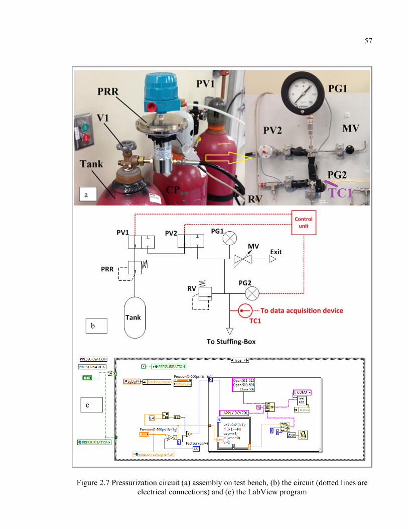
57
Figure 2.7 Pressurization circuit (a) assembly on test bench, (b) the circuit (dotted lines are electrical connections) and (c) the LabView program
a
b
c

58
Figure 2.8 shows the hydraulic circuit and its components. A manual hydraulic pump is used
to apply the pressure and a hydraulic accumulator is present in the circuit to maintain pressure
Figure 2.8 The hydraulic circuit

59
throughout the test. A hydraulic gauge is used to control the level of pressure in the pipes and
tensioner, although the accurate amount of pressure is measured by a Wheatstone bridge strain
gauges attached to the stem.
2.2.5 Leak detection methods
This test bench is equipped with five leak detection measuring techniques in order to cover a
wide range of leak rates. Choosing a suitable technique depends on the rate of the leak and the
duration of the measurement. In general, the leak detection techniques can be divided into two
categories; the pressure decay method and the pressure rise method.
2.2.5.1 Pressure decay method
The pressure decay method is a leak measuring technique that uses a drop in the high pressure
line. Figure 2.9 presents the general circuit that uses this method. The general procedure for
this technique is to close valve PV1 after pressurization and monitor the pressure drop using
the pressure transducer PG2. The rate of leak can be calculated by the following equation
(Bazergui, 2003):
= 1 − 1 (2.1)
Here, and are the standard room temperature and pressure, and is the volume of the
high pressure circuit. is the mean gas pressure and is the mean temperature of the circuit
measured by the thermocouple TC1. The variations of pressure and temperature are measured
through the LabView program after each scan for an appropriate duration time.
2.2.5.2 Pressure rise method
The second leak detection technique is the pressure rise method, which consists of measuring
the pressure increase of the chamber specially designed to collect the leaking fluid. The

60
pressure rise circuit is presented in Figure 2.10. There are two circuits used for the pressure-
rise leak detection; one for fine leaks and the other one for gross leaks.
2.2.5.3 Fine leak
Fine leak detection can be used when the amount of leak rate is low, where a more sensitive
pressure transducer is used to estimate the leak rate accurately. For this case, the volume of the
leak accumulation chamber is much smaller than the gross leak detection.
With reference to Figure 2.10, the temperature is measured by the thermocouple TC2. When
using the fine leak method, the pneumatic valves PV3, PV4, PV5, and PV6 are closed whereas
PV8 is opened. The pressure transducer PG3 measures the pressure of the gas accumulated in
the collective volume of the pipes. In the case of excessive leak, the relief valve activates and
evacuates the pressure from exit EX2.
Figure 2.9 Pressure decay leak measurement system
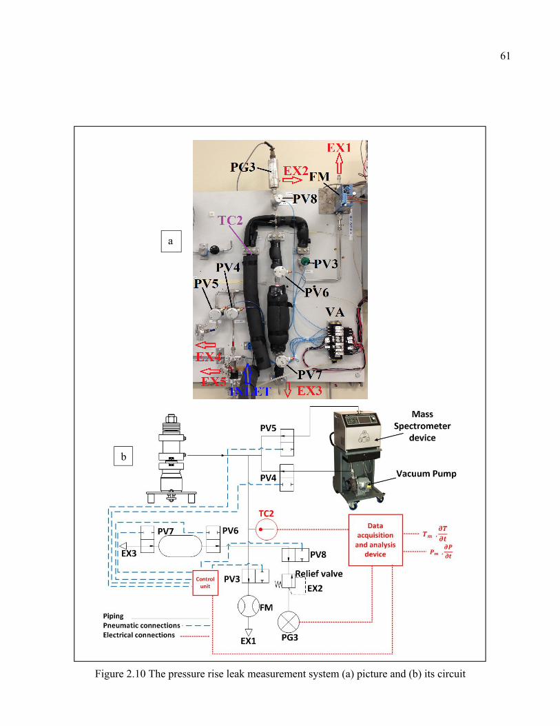
61
Figure 2.10 The pressure rise leak measurement system (a) picture and (b) its circuit
a
b

62
With reference to Figure 2.10, the temperature is measured by the thermocouple TC2. When
using the fine leak method, the pneumatic valves PV3, PV4, PV5, and PV6 are closed whereas
PV8 is opened. The pressure transducer PG3 measures the pressure of the gas accumulated in
the collective volume of the pipes. In the case of excessive leak, the relief valve activates and
evacuates the pressure from exit EX2.
2.2.5.4 Gross leak
In this method, an additional volume cylinder of 1000 ml is added to the circuit to reduce the
rate at which the pressure increases. Based on Equation (2.1), it is possible to estimate fine
leak rates with high accuracy for both cases. While the fine rate leak detection method is
suitable for rates of less than 0.10 ml/s, it is more appropriate to use the gross leak detection
method for the range of 1 to 0.1 ml/s. In the case of large leaks, the cylinder volume is used to
slow the rate of gas accumulation, where PV6 is opened while PV7 is closed.
2.2.5.5 Flowmeter
When the leak rate is greater than 10 ml/s, the flow meter is used. In this case valves PV4,
PV5, PV6 and PV8 are closed and PV3 is opened. The gas exit is EX1, and the flow meter
(FM) measures the leak rate directly. In Figure 2.11 the flow chart presents the leak detection
techniques adopted within this study and Table 2.1 gives the sequence of pneumatic valves for
each leak detection method and their suitable range of measurement use.
2.2.5.6 Helium mass spectrometry
For very small leak rates, helium mass spectrometry is the most suitable choice for leak
detection. This device was not used in this study, although the piping circuit and Lab View
program were prepared for its use. Figure 2.10(a) shows the connections to the mass
spectrometer and the auxiliary vacuum pump. In this circuit, the pneumatic valves PV3, PV6,
and PV8 are closed, and PV4 and PV5 are open.

63
2.3 Instrumentation and control
This test rig is equipped with accurate measurement and control instruments to provide reliable
test results. In general, the instruments can be divided into two categories; the measuring
transducers and the control devices. There are five measuring instruments devices: strain
gauges, LVDTs, thermocouples, pressure transducers, and a flowmeter.
Table 2.1 Leak measurement techniques and pneumatic valve set-up
Applicable
leak rates
Pneumatic control valves (O: Open, C: Close)
PV1 PV2 Pv3 PV4 PV5 PV6 PV7 PV8
Pressure decay All C C O C C C O C
Mass
spectrometer < 0.001 C C C O O C O C
Fine leak 0.001 to
0.01 C C O C C C O O
Gross leak 0.01 to 0.1 C C C C C O C O
Flow meter > 0.1 C C O C C C C O
Figure 2.11 The chart of leak detection technics

64
In the packed stuffing box, the radial stress generated by the transfer of axial stress from the
gland to the packing rings and the side walls plays a major role in sealing mechanism. Due to
friction the axial stress on the packing ring is not uniform. This generates a non-uniform
distribution of contact stress along the stem and housing. A set of twenty strain gauges are
installed on the external wall of the housing to pick up the hoop deformation. Measuring this
deformation can indirectly provide the radial or contact stress distribution and the lateral
pressure coefficient; an important characteristic of packing materials.
The rig is equipped with two LVDTs to measure the axial displacement of the packing rings.
These are fixed to the gland in order to pich-up the relative displacement between the housing
and the gland. This measurement is essentially the axial compressive displacement of the
packing rings due to the gland load. The thermocouples measure the temperature of the pipes
of the pressurization and leak detection circuits, the data of which is imporatnt for the
calculation of leak in equation 2.1. The pressure transducers, PG2 in Figure 2.7 and PG3 in
Figure 2.10, give the pressures required to estimate the leak using equation 2.1.
The control of the different valves through the DAC is required to regulate the direction of gas
leak and determine which type of leak detection technique should be used. Except the two
manual valves, MV and V1 as shown in Figure 2.7, all other valves are pneumatic.
1.1 Data acquisition and control system
All signals received from the different instruments and the instructions and commands given
through the computer are processed through the HP data acquisition and control device.
Section F in Figure 2.1 shows the HP Data Acquisition and Control system. The DAC is
equipped with eight multi-purpose modules. Each module has a slot number in the mainframe
and contains from eight to twenty channels. The numbering of channels is from 0 to 15 for the
16-channel module and 0 to 7 for the 8-channel module and so on. For example, the number
of the first channel in slot one is 100.

65
The first step in setting up the data acquisition system is to define the applications and devices
that are to be connected to the input module. Then, each digital input is configured depending
on its input specifications or output control. For example, the card 100 receives the data from
strain gauges and card 600 is a relay card that controls the pneumatic valves.
Figure 2.12 shows the exposed panel of a typical 16-channel module. The DAC system is
interfaced with a computer to provide, through LabView, a graphical interface for the operator
of the test rig. Figure 2.13 shows the LabView graphical interface, called Pack PackView, for
the test rig.
2.4 Test procedure
The test procedure starts by placing the packing rings inside the housing. The gland with the
attached LVDTs is first mounted on the fixed stem. The packed stuffing box is then placed on
the stem till the packing rings come in contact with the gland. A variety of packing rings made
of different braided materials, such as PTFE and flexible graphite, can be tested (Figure 2.14).
Depending on the test objectives, up to six packing rings can be placed inside the stuffing box.
Figure 2.12 The LabView platform to control the packing test rig

66
Before starting the test, the O-rings for the high and low pressure systems are verified for leak.
Figure 2.13 A flexible graphite plaited packing ring
Figure 2.14 A 16-channel module

67
The quality of the surfaces and the application of sealing grease are essential for the first step.
After mounting and verifying the sealing of the high and low pressure sides of the packed
stuffing box, the second step is to turn on the data acquisition system and run the LabView
platform. At this point, the operator of the test rig should test the instrument readings and
troubleshoot any possible communication errors between the different devices. Then, the initial
values for the compression stress, LVDTs, and strain gauges should be set to zero.
The following steps depend on the type of test and the expected results. Two types of tests can
be conducted with the test rig: a leak detection test or a creep/relaxation test, both at room
temperature. For the leak detection test, the next step is to apply compression stress through
the hydraulic tensioner before applying any gas pressure to the system. As a rule of thumb, the
applied gas pressure to the system should never be more than twice initial gland stress.
The pressurized gas is applied to the system through a regulator valve that is controlled by the
data acquisition system and the LabView program. The flowmeter should always be set as the
leak measurement method at the beginning after application of each gas pressure level. Then,
considering the measured leak rate level, the operator decides which leak detection method
would be the most appropriate for the current leak rate measurement.
A leak detection method to be used depends on the level of the leak rate. This in turn depends
on the gland compression stress, gas pressure, packing material and the number of packing
rings. An important factor when measuring leak is the time duration. This depends on the level
of the leak rate and its stabilization. In general, when the gas pressure is low respective to the
level of gland compression stress, it takes more time for stabilization.
At the end of the test, the steps are repeated in a reversed sequence. First, the gas pressure is
completely relieved from the system before the hydraulic pressure is released by opening both
the high pressure relief valve and the hydraulic pump valve.
For a short time creep test, after assembly and set-up of the data acquisition system, a
predetermined amount of gland stress is applied to the packing rings. The displacements
measured by the LVDTs are recorded with time. The test is completed when the rate of

68
displacement of the packing rings reach a predetermined value. The procedures of the two
possible types of tests that can be carried by this test rig are summarized in Table 2.2.
Table 2.21 Test procedures for leak detection and creep/relaxation tests
Leak detection test Creep test To start test
1- Assemble packed stuffing box with the required number of rings 2- Verify low and high circuit pressure o-rings 3- Start the data acquisition system and Labview platform 4- Apply gland stress using hydraulic pump 5- Apply gas pressure 6- Measure leak rate with flowmeter 7- Determine suitable leak detection method 8- Wait for leak stabilization 9- Record the leak rate and other measurements 10- repeat steps 4 to 9 as much as needed
1- Assemble packed stuffing box with the required number of rings 2- Start the data acquisition system and Labview platform 3- Apply gland stress using hydraulic pump 4- Record measurements through time 5- Wait for rate of displacement to stabilize
To finish test 16- Release gas pressure 17- Remove gland stress 18- Close the data acquisition system
11- Remove gland stress 12- Close the data acquisition system
CHAPITRE 3
STRESSES ANALYSIS OF PACKED STUFFING-BOXES
a Mehdi Kazeminia, b Abdel-Hakim Bouzid2 a Ph. D. student, Mechanical Engineering Department, École de technologie supérieure, 1100
Notre-Dame St. West, Montreal, Quebec, H3C 1K3 b ASME Fellow, Professor, Mechanical Engineering Department, École de technologie
supérieure, 1100 Notre-Dame St. West, Montreal, Quebec, H3C 1K3
email: [email protected]
This article is published in the Journal of Pressure Vessel Technology, volume 137(5),
051205-9, 2015, doi.org.10.1115/1.4029524
3.1 Abstract
Packed stuffing-boxes are mechanical sealing systems that are extensively used in pressurized
valves and pumps. Yet there is no standard design procedure that could be used to verify their
mechanical integrity and leak tightness. It is only recently that standard test procedures to
qualify the packing material have been suggested for adoption in both North America and
Europe. While the packing contact stress with the side walls is predictable using existing
models there is no analytical methodology to verify the stresses and strains in the stuffing-box
housing.
This paper presents an analytical model that analyzes the stresses and strains of all the stuffing
box components including the packing rings. The developed model will be validated both
numerically using FEM and experimentally on an instrumented packed stuffing box rig that is
specially designed to test the mechanical and leakage performance of different packing
materials.
NOMENCLATURE Internal diameter of the packing
Internal diameter of the housing

70
External diameter of the packing
External diameter of the housing
Diameter of the stem
Young’s modulus of packing (in loading)
Young’s modulus of the housing
Young’s modulus of the stem
Height of the one packing ring
Height of the housing ℎ 1 Height of the first ring at top ℎ 2 Height of the second ring at bottom Lateral pressure coefficient
Internal lateral pressure coefficient
External lateral pressure coefficient
1 Length of the first cylinder
2 Length of the second cylinder
Moment at the section
Moment at the section
Number of the packing in the box ( ) Internal pressure function acting on the cylinder part of the housing
Mean radius of the thin cylinder
Radius of the neutral axis in cylinder
Internal radius of the cylinder
External radius of the cylinder
, 1 Internal radius of the first ring at top
, 1 External radius of the first ring at top
, 2 Internal radius of the second ring at bottom
, 2 External radius of the second ring at bottom
Internal radius of the packing
Thickness of the cylindrical part in housing
Thickness of the first ring at top
Thickness of the second ring at bottom @ Displacement of the part “i” at section “j”

71
Shearing force at the section
/
1 , / ,
2 , / ,
z Axial direction @ Slope of the part “i” in section “j”
Applied axial load by gland
Radial stress
Axial stress
Circumferential stress
Friction between packing and stem
Friction between packing and housing
Poisson ratio of the packing
Poisson ratio of the housing
Poisson ratio of the stem
3.2 Introduction
Valves are used to control fluid circulation in the nuclear, chemical and petrochemical process
plants.They are designed to carry-out two sealing duties through; control the fluid flow in pipes
including shut-off and avoiding the fluid leakage to outside. They have a major role in terms
of fluid process control and safety in industrial plants (Bartonicek et al., 2001). According to
the ESA (ESA, 2009), fugitive emissions from European refineries are estimated of up to
10000 tons per year and an estimate of 300,000 tons per year is produced by US power plants.
From this amount of the emission, about 50 to 60 percent are attributed valves (Bayreuther,
2012).
Valve sealing performance, which is considered as second sealing duty, has a significant
consequence on the operation safety of industrial plants. Excessive leaks can cause
environmental damage, injuries, shut downs and loss of revenues (Diany and Bouzid, 2009).
Consequently, improving the design and operation of valves would improve safety and reduce
fugitive emissions, maintenance costs and loss of revenue. Furthermore, in the last decade new
72
and strict environmental regulations have been legislated in the USA through the EPA and in
Europe through other EC organizations. This has forced industries to comply with newly
adopted standards on valve fugitive emissions such as API and ISO (ANSI/ISA-93.00.0, 1999;
API-622, 2011; API-624, 2011; ISO-15848-1, 2006).
The sealing performance of a packed stuffing-box is guaranteed by maintaining a minimum
threshold compressive stress of the packing ring material and the interface contact pressure
with the side walls. Characterization of the design and mounting parameters on the contact
pressure can raise the expertise and hence can be used to predict the failure and improve the
sealing performance of the packed stuffing-box valves.
Most of the research conducted on packed stuffing boxes focuses on the distribution of the
packing contact stress. This is because leakage failure due to insufficient gland stress was of a
prime concern. Bohner et al. (1957) studied the ratio of the radial contact pressure to the axial
gland stress known as the lateral pressure coefficient. Based on experimental data
investigations (Bohner et al., 1957; Hayashi, 1989) these coefficients were found to be constant
and dependent on the tribological properties of the contact areas.
Ochonski (1988) proposed an exponential distribution of axial stress distribution in soft packed
stuffing-boxes by considering the lateral coefficient and friction between the packing elements
and the stem and housing. Later Pengyun et al. (1998) proposed similar model but with slight
variations in the location of the application of the axial force. Diany and Bouzid (2009)
suggested a more rigorous analysis in the development of the packing stress distribution model.
Stuffing box housings are also subjected to failure and yet there is no design procedure to size
them. Xiaohui and Yiliang (2012) reported a crack failure of a stuffing box in a super hyper
pressure compressor and conducted theoretical and experimental researches to evaluate the
cause.
A tentative analytical model to predict the required initial packing axial force was initiated by
Lejeune et al. (2013). Their model considers packing relaxation taking into consideration the
rigidity of bolts but not the housing. The mechanical integrity of the housing is not included in

73
the design analysis. Usually, as per classification of pressure vessels the body of a valve is
treated with thick shell subjected to internal pressure (Jatkar and Dhanwe, 2013). However,
the model does not include geometric discontinuities and edge load effects. This paper presents
an analytical methodology that can be used to analyze the stresses in the different elements of
the packed stuffing box. The developed analytical model is based on the initial gland packing
load. It gives the stress distribution in the packing rings as well as the stem and housing.
3.3 Analytical analysis
The development of packed stuffing box analytical model requires a complementary
understanding of the structural geometry, the physics, the material behavior and the interaction
between them. A general configuration of the packed stuffing-box and the involved
components is presented in Figure 3.1. In all types of the packed-stuffing boxes, there are four
main components; the stem, the housing, the packing rings and the gland.
Figure 3.1 Simplified packed stuffing-box with the main components

74
The mechanism of sealing of the packed stuffing box is insured by adequate compression of
the packing material which reduces the pores and fills the leak paths at the contact interface to
prevent fluid from escaping to the outer boundary. Therefore the packing rings are selected
from materials with low porosity under compression and high load transfer capacity.
3.3.1 Packing ring contact analysis
The analytical development of the complex behavior of a packed stuffing box is limited to the
distribution of the stresses in the packing rings. The simple model used is based on the ratio of
the radial contact pressure to the axial gland stress known as the lateral pressure coefficient.
= (3.1)
Based on the constants and which describe the ratio between radial contact stresses of
stem and housing with the packing axial stress and their frictional properties, the axial
equilibrium of an infinitesimal element (Ochonski, 1988) can lead to the expression of the axial
stress distribution in soft packed stuffing-boxes given by: ( ) = (3.2)
where
= 4 +− (3.3)
The lateral contact pressure q(x) acting on the housing is therefore given by: ( ) = (3.4)

75
3.3.2 Analysis of the housing
Using this simple general model, the interaction of the packing rings with other components
introduces stresses and strains in the latter. At the internal side wall, packing rings transmit a
radial load to the stem which is a circular shaft with linear material behavior (Figure 3.2). At
the external side wall, the radial contact pressure from packing rings is transmitted to the
housing which is essentially a thick cylinder reinforced by a ring at one end or both ends as
shown in Figure 3.3 . The upper ring is optional while the lower ring simulates the stem
positioning and guiding inside the valve. The latter can be made rigid if its thickness is
relatively big to avoid displacement and rotation. The cylinder is also divided into two parts;
the lower part or cylinder 2 which is in contact with the packing rings and hence subjected to
an exponential lateral contact pressure where is given by equation (3.2) and the upper
Figure 3.2 Stuffing box housing subjected to contact pressure. Dimensions are in millimeters

76
cylinder 1 that guides the gland and is not in contact with the packing ring and therefore is not
subjected to any pressure.
Figure 3.3 Free body diagram of the stuffing box housing

77
In order to provide a generalized formulation of the problem, the analytical model of the
housing will include the upper and lower rings, an upper short cylinder and a lower cylinder
subjected to pressure as illustrated in Figure 3.3. The analytical simulation would be
accomplished by considering short cylinders theory and the theory of rings subjected to a
twisting couple. Compatibilities of displacement and rotation will be used between the
different structures at their junctions to determine the edge loads.
The differential equation that governs the radial displacement y of a cylinder subjected to non-
uniform pressure and edge load is treated in most text books under the theory of beams on
elastic foundation (Boresi and Schmidt, 2013) and is given by:
The constant is dependent on the stiffness of the foundation, , such that = / . The
stiffness of the foundation K is defined by the cylinder physical and geometrical properties
such that = / . For a thin plate the bending stiffness is given by = /12(1 − ). The constant for a cylinder is given by:
Bearing in mind that the cylinder housing is not quite thin, the radius rc used for calculating
is that of the centroid of the section and is given by:
The solution of the fourth order linear non-homogenous equation presented in equation (3.5)
has two parts; the homogeneous and particular parts. Considering the housing to behave as a
thin cylinder, the short cylinder theory detailed in the ASME code (ASME Boiler and Pressure
Vessel Code, 2004) can be used to give the homogeneous part of the solution ( ) = 2 + 2 + + (3.8)
+ 4 = ( ) (3.5)
= 3(1 − ) (3.6)
= 2( + + )3( + ) (3.7)
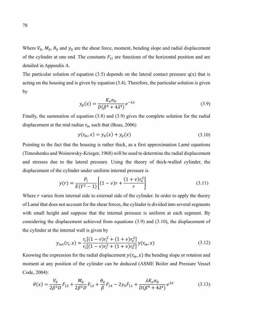
78
Where , , and are the shear force, moment, bending slope and radial displacement
of the cylinder at one end. The constants are functions of the horizontal position and are
detailed in Appendix A.
The particular solution of equation (3.5) depends on the lateral contact pressure q(x) that is
acting on the housing and is given by equation (3.4). Therefore, the particular solution is given
by ( ) = ( + 4 ) (3.9)
Finally, the summation of equation (3.8) and (3.9) gives the complete solution for the radial
displacement at the mid radius such that (Boas, 2006) ( , ) = ( ) + ( ) (3.10)
Pointing to the fact that the housing is rather thick, as a first approximation Lamé equations
(Timoshenko and Woinowsky-Krieger, 1968) will be used to determine the radial displacement
and stresses due to the lateral pressure. Using the theory of thick-walled cylinder, the
displacement of the cylinder under uniform internal pressure is ( ) = ( − 1) (1 − ) + (1 + ) (3.11)
Where varies from internal side to external side of the cylinder. In order to apply the theory
of Lamé that does not account for the shear forces, the cylinder is divided into several segments
with small height and suppose that the internal pressure is uniform at each segment. By
considering the displacement achieved from equations (3.9) and (3.10), the displacement of
the cylinder at the internal wall is given by ( , ) = (1 − ) + (1 + )(1 − ) + (1 + ) ( , ) (3.12)
Knowing the expression for the radial displacement ( , ) the bending slope or rotation and
moment at any position of the cylinder can be deduced (ASME Boiler and Pressure Vessel
Code, 2004): ( ) = 2 + 2 + − 2 + ( + 4 ) (3.13)

79
( ) = + − 2 − 2 + ( + 4 ) (3.14)
Where the last terms in equations (3.13) and (3.14) are coming from the particular solution, or
the effect of distributed non homogeneous contact load. The axial radial and Hoop stresses at
the external side of the housing can be calculated by appreciating the formulation of the
moment, such that (Ugural and Fenster, 2003) ( ) = ( ) − 6 ( ) (3.15)
( ) = − ( ) + ′( ) (3.16)
The second term in the right hand side of equation (3.16) is the axial stress produced by friction
that is generated at the interface between the packing rings and the housing. The frictional
shear stress is given by ( ) = (3.17)
The resulting axial stress is given by integration of equation (3.17) and is given as a function
of the axial position such that:
′( ) = − 1 (3.18)
Obviously, this term for the cylinder without any contact with packing rings would vanish.
3.3.3 Ring analysis
The upper and lower rings of the housing are considered as a circular ring subjected to a radial
load produced by the edge force V and a twisting couple produced by the edge loads V and M.
The radial displacement and rotation of the ring at the junction with the cylinder in terms of
the concentrated force and moment V and M are given by the following matrix equation
= (3.19)
Where the elements of the matrix are constants given by the following:

80
= ,, ℎ ( − 1) (1 − ) + + (1 + ) ,+ − ℎ 6
= 6(ℎ − /2)
= 6
= 6
(3.20)
Where , and are sign coefficients, and is the moment arm about the centroid of
the ring. The sign of is positive when the moment is counter-clockwise and vice versa.
Table 3.1 gives the sign coefficients and moment arms for the treated case.
3.3.4 Compatibility of displacement and rotation at the junctions
The four structural elements that form the housing are joined at three locations as shown in
Figure 3.3. The six unknown edge loads; , , , , and are obtained by considering
the compatibility of displacement and rotation which requires that: , = , , = ,
, = , , = , (3.21)
Table 3.19 Sign coefficients and moment arm
Direction Condition
top > 0 +1 − < 0 -1 −
right ℎ < ℎ +1 +1 ℎ − ℎ ℎ < ℎ +1 -1 ℎ − ℎ
down > 0 -1 − < 0 +1 −
left ℎ < ℎ -1 -1 ℎ − ℎ ℎ < ℎ -1 +1 ℎ − ℎ

81
, = , , = ,
These compatibility conditions help to tie the radial displacement and bending slope of the
cylinders described by equations (3.9) and (3.14), and slope and displacements of the ring
described by equation (3.20) to develop a system of six equations with six unknowns:
× = (3.22)
The arguments of the right hand side column vector are the differences of displacements or
rotational slopes at each junction. They are equal to zero except when a part is subjected to the
contact pressure generated at the packing and housing interface. Part 2 of Appendix A gives
the details of elements of matrix B and the right hand side column vector. The solution of the
system of linear equation (3.23) gives the unknowns. The stresses and strains are then obtained
for validation purposes.
3.4 Numerical simulation
Part of the validation process was to conduct a numerical simulation using finite element
modeling with ANSYS software (ANSYS, 2014). A FE model mesh of the packed stuffing
box shown in Figure 3.1 was generated to simulate the behavior of packed stuffing box and
compare the distribution of axial stress in the packing rings and the distribution of stresses in
the different housing elements. 4-node axisymmetric elements were used to generate the mesh
of the three components of the packed stuffing-box namely the stem, the housing and the
packing rings. Contact elements are used to simulate the relative movement between the
packing ring and stem and the packing ring and housing. Figure 3.4 illustrates the 2D FE
axisymmetric models used for the investigations. The geometry and the physical properties

82
used by both approaches are presented in Table 3.2. The packing material is modeled with
Figure 3.23 FE model of the experimental packed stuffing-box
Table 3.2 The mechanical and dimensional values used in the numerical and analytical investigations ( ) 28.576
( ) 107.95 ( ) 47.624 ( ) 200 ( ) 47.625 ( ) 200 ( ) 57.625 0.3 ( ) 28.575 0.3 ( ) 9.525 0.4205 ( ) 4 ( ) 100 ( ) 174

83
isotropic linear elastic properties for simplification.
With regards to the relative displacement between packing and side walls, the pair target and
contact elements are used to simulate the elastic interaction between components. The packing
rings are made out of flexible graphite, which is a softer material compared to steel for the
housing and stem. Hence in the definition of the contact pairs, the contact elements are adjusted
on the packing rings and the target elements are adjusted on the housing and stem. The friction
ratio between the packing rings and side walls was taken as 0.25 in this simulation. All the
materials in this model are supposed to have linear elastic behavior. The numerical values of
the physical and dimensional parameters used in the simulation and testing are presented in the
Table 3.2.
The gland stress is increased to the target stress in small increments. Three gland stresses are
used; these are 14, 20 and 37 MPa. Due to material nonlinearity, large deformation and contact
analysis, the load step increment is adjusted to avoid divergence of the solution.
3.5 Experimental investigation
The experimental validation of the developed model was also conducted through the
measurement of the housing deformation. An existing test bench (Ochonski, 1988; Bohner et
al., 1957; Hayashi and Hirasata, 1989; Pengyun et al, 1997; Avdeev et al., 2005) that can
simulate the real behavior of a packed stuffing box was used in this study. The interface contact
pressure between the packing rings and the housing and stem side walls was indirectly
measured using a pseudo numerical FEM-experimental procedure (Diany and Bouzid, 2011).
This test bench is also used to conduct creep/relaxation and leak tests of different packing
materials. The test rig and its schematic are presented in Figure 3.5.
In this test apparatus the housing Hoop stress is evaluated by measurement of the Hoop strain
through two 10 elements strain gages placed along the packing length at the housing outside
surface. As illustrated in Figure 3.5, a hydraulic tensioner is used to apply the gland load. An
accumulator is used when necessary to maintain the load and avoid any drop due to

84
creep/relaxation. The gland load is measured through strain gages in a full bridge configuration
glued to the stem. Three experiments with different axial gland loads of 14, 20 and 37 MPa are
carried out at the room temperature.
Figure 3.5 Packed stuffing box test rig

85
3.6 Results and discussion
The results from the developed analytical model presented in this study are compared to those
obtained from numerical simulations and experimental tests whenever possible.
The distribution of the Hoop strain on the outside surface of the whole stuffing box housing is
presented in Figure 3.6. This distribution is given as a function of the housing axial position
which includes the two annular rings shown in Figure 3.2. The ring that guides the stem is
positioned at 0 on the x axis of Figure 3.6. The graphs show a good agreement between the
analytical results and FE results for the three gland load cases. As expected, the Hoop strain
that is related to the radial displacement is greater at the center of the cylindrical part of the
housing.
Figure 3.7 shows a comparison of the Hoop strain of the cylindrical part of the housing given
by the three methods. The predicted analytical and numerical Hoop strains are in good
Figure 3.6 Comparison of Hoop strains at the housing cylinder outside surface for different gland loads

86
agreement with those measured experimentally with strain gages placed at the outer surface of
the housing cylindrical part. These comparisons give confidence to the analytical and
numerical models developed in this paper.
The Hoop and longitudinal stress distributions are presented in Figures 3.7 and 3.8
respectively. As it can be observed, the maximum stress in both graphs is located at the same
axial position on the housing pointing to the critical point to consider in the design of such
housings. This point is located at one third of the packing length as may be appreciated from
the Hoop strain measurement shown in Figure 3.7. It can be noted that the analytical model
does not give the longitudinal stress in the two rings due to the fact that ring theory is limited
to obtaining Hoop stresses only. In general, there is a similar trend of the distribution of stress
between FE and the analytical models. However, there is an important difference at the
junctions of the cylinder and the rings. At these local discontinuities one expects such
differences and would rely on FEM once the rest is comparable.
Figure 3.7 Hoop stress distribution at the housing outer surface.

87
The Hoop strain at the inside surface of stuffing box housing is shown in Figure 3.9. There is
a good agreement between the analytical model and the numerical simulation for the three load
Figure 3.8 Longitudinal stress distributions at the
housing outer surface.
Figure 3.9 Longitudinal stress distributions at the
housing inner surface

88
cases. It is important to note that the values of the strain on the inside surface are greater than
the ones at the outer surface shown in Figure 3.8.
The radial, Hoop, and longitudinal stresses at the housing inner surface are shown in the
Figures 3.10, 3.11 and 3.12. Again, the results from the analytical model and FEM agree with
each other. The radial stress distribution is shown in Figure 3.11. In essence it represents mainly
the packing contact pressure. The general trend of the distribution is of exponential form as
predicted by equation (3.2). The curves of the two models superpose quite well for all three
gland load cases. The contact pressure gives some guidance as to the state of leakage. The
lower value of the contact pressure shown at and axial position of about 25 mm can be
compared to the fluid pressure to verify th e leak condition. However, the relationship between
the leak and contact stress requires a special test procedure that is similar to the proposed ROTT
test (ASTM, Standard Test Methods for Gasket Constants for Bolted Joint Design, Draft 1).
The Hoop and longitudinal stresses are shown in Figs. 3.12 and 3.13. These stresses are slightly
higher than those at the outer surface.
Figure 3.1066 Hoop stress distribution at the housing
inner surface.

89
Figure 3.12 Hoop strain at the housing inner surface
Figure 3.11 Longitudinal stress distribution at the
housing inner surface

90
3.7 Conclusion
In this study a developed analytical model that simulates the behavior of a packed stuffing-box
with the housing subjected to a gland load was validated both numerically and experimentally.
The analytical model is based on the combination of ring theory thin cylinder theory and beam
on elastic foundation theory. The results of the analytical model of a packed stuffing box
subjected to three different load cases were compared with those obtained from experimental
tests. In general, there is a good agreement in the evaluations of the stresses and strains between
the three methods. The methodology and approach used in this paper to model valve packed
stuffing boxes is a step towards developing a design procedure for such an important pressure
vessel component.
Figure 3.13 Radial stress distribution at the housing inner surface

CHAPITRE 4
EVALUATION OF LEAKAGE THROUGH GRAPHITE-BASED COMPRESSION PACKING RINGS
a Mehdi Kazeminia, b Abdel-Hakim Bouzid2 a Ph. D. student, Mechanical Engineering Department, École de technologie supérieure, 1100
Notre-Dame St. West, Montreal, Quebec, H3C 1K3 b ASME Fellow, Professor, Mechanical Engineering Department, École de technologie
supérieure, 1100 Notre-Dame St. West, Montreal, Quebec, H3C 1K3
email: [email protected]
This article is published in the Journal of Pressure Vessel Technology, volume 139(1),
011602-7, 2017, doi.org/10.1115/1.4033937
4.1 Abstract
The prediction of leakage is one of the most challenging tasks when designing bolted
flanged connections and valves. Failure of these pressure vessel components can cause
shutdowns but also accidents, loss of revenue and environmental damages. With the strict
regulations on fugitive emissions and environmental protection laws new tightness-based
standards and design methods are being adopted to improve the sealing performance of bolted
joints and valves. However, there is a practical interest in using a reliable correlation that could
predict leak rates of one fluid by tests carried out with another on compressed packings. The
paper presents an innovative approach to predict accurately and correlate leak rates in porous
braided packing rings. The approach is based on Darcy-Klinkenberg to which a modified
effective diffusion term is added to the equation. Experimentally measured gas flow rates were
performed with a set of graphite based compression packing rings with a large range of leak
rates under steady isothermal conditions. Leakage from three different gases namely Helium,
Nitrogen and Argon, were used to validate the developed correlation. In the presence of the

92
statistical properties of porous packings, the leak rates for different gases can be predicted with
reasonable accuracy.
Nomenclature
Section area, m²
Klinkenberg’s coefficient, Pa
D
A constant normally equal to 1
Diffusion, s-1
Permeability, m²
Knudsen number
Leak rate, m³/s
Diffusion factor
M
Length of packed stuffing-box, mm
Molecular mass, kg
Gas pressure, Pa
Volumetric leak rate, m³/s
Radius of capilary, m
Universal gas constant, m³Pa/mol°K
Radius of the pore in porous media, m
Temperature, °C
Time, s
Gas velocity, m/s
Rarefaction coefficient
Forchheimer coefficient, m-1
Volumetric porosity
Mean free path, m
Gas dynamic viscosity, Pa.s
Gas density, kg/m³
Gland stress, Pa Ω Boundary of porous media
Subscript
Related to apparent value
Effective value

93
Related to inlet of gas flow
Related to intercept value
Related to outlet of gas flow
Down stream
Related to the Forechheimer model ℎ Related to hydraulic value
Mean value
Up stream ∞ Related to intrinsic value
4.2 Introduction and background
The need to predict leakage through different materials in the multidisciplinary engineering
applications including rocks gas extraction from shale reservoirs and pressurized equipment
has fostered a lot of research in the field of gas flow through porous materials. The different
studies are conducted at the micro and nano levels depending on the range of flow or leak to
be considered.
The flow regime of gases through porous media can be classified depending on the interactions
between gas molecules and the wall of the pores. The type of flow regime is dictated by the
Knudsen number (Knudsen, 1909), which for values less than 0.001 is counted as continuum
flow regime, for the range between 0.001 and 0.1, the regime is a mixture of continuum and
slip flow, for the range between 0.1 and 3 transitional flow regime predominates and for values
greater than 3 the flow is considered to be in free molecular regime.
Generally the fluid field of pressure driven compressible fluid flow in porous media can be
determined by considering the mass and momentum conservation with Darcy’s law ( ) + . ( ) = 0 (4.1)
= − ∇ (4.2)

94
is the permeability of the porous media, a parameter that mainly characterises the structure
of the pores. This quantity has been the subject of several studies. It was measured by several
researchers and found to have a wide range of values for the same material depending on the
fluid used (Muskat,1937). Based on the studies of Kundt and Warburg (1875), Klinkenberg
(1941) obtained a relationship between the pore size and the mean free path 4 = (4.3)
Comparing Poiseuille’s flow in a capillary and a model based on Darcy’s law, Klinkenberg
defined the parameter known as slippage effect such that:
= 1 + (4.4)
Where is the intrinsic permeability of the porous media with a large free path of the gas
such that found in low pressure driven flows.
In spite of the significant capabilities of Darcy’s model and the introduction of a parameter to
capture the slippage factor in porous media, it is not accurate enough in high and low velocity
of fluid flows. The effect of inertia on high-speed flows and the effect of different mechanisms
of diffusion at low speed or molecular flow are not well captured by this model. Therefore,
Darcy’s model is not a suitable choice to realistically simulate the variety of flow regimes with
the same quality as slip flow (Civan, 2010).
At higher speeds, the effect of inertia is taken into account by Forchheimer (1901) by
introducing a second term with second order velocity. He found that as the velocity of fluid
flow increases the effect of inertia and friction becomes a predominant factor that contributes
to the drop of pressure in the porous media. Ergun used a similar approach to describe the
pressurized flow through a packed granular porous media (Ergun, 1952). The equation is given
by (Forchheimer, 1901; Chor and Li, 2008)

95
∇ = − − (4.5)
The coefficient is obtained experimentally. For low speeds and higher Knudsen numbers
when the collisions between gas molecules and pore walls are predominant comparatively to
the molecular collisions, one or more types of diffusion mechanisms can take place. In general
the diffusion mechanisms can be categorized into three types; viscous diffusion, Knudsen
diffusion and molecular diffusion. The latter happens when there is relative motion between at
least two different types of gases. In a single gas flow, one or a combination of two first
mentioned mechanisms can occur.
Numerous studies have been conducted on the effect of diffusion combination at higher
Knudsen fluid flows (Sun et al., 2015; Zschiegner et al., 2007; Huizenga and Smith, 1986; Gao
et al., 2014; Lito et al., 2015; Shou et al, 2014; Carrigy et al., 2013). Javadpour et al. (2007)
showed that in the extraction of gases from unconventional sources the flow regime is not
accurately described by Fick’s and Darcy’s law. Before them, Beskok and Karniadakis (1999)
presented a modified Hagen-Poiseuille type equation with additional function to describe the
rarefaction effect, given below
= ( ) 8 Δ (4.6)
In which the additional coefficient is a function of Knudsen number and dependent on the flow
condition. It is given by
( ) = (1 + ) 1 + 41 − (4.7)
Where = / and is the rarefaction coefficient which is a function of Knudsen number
in its own. Few researchers investigated the relevance of this coefficient and proposed their
own models (Beskok and Karniadakis, 1999; Loyalka and Hamoodi, 1990; Tison and Tilford,
1993). One of the main engineering applications of the permeability and fluid flow through
porous materials is the extraction of underground resources where the risk of gas leak to the
ground surface is an issue. The emission of gases such as CO2 and CH4 to the environment and

96
shallow aquifers can cause a serious damage to nature and people. In their study of
environmental effect of greenhouse gases, Plampin et al. (2014) predicted the emission of CO2,
from heterogeneous soil using a 1-D laboratory model and determined the spatiotemporal
relations of CO2 leak into shallow aquifers.
Wang et al. (2014) presented a more rigorous model to separate the Klinkenberg effect from
the variation of permeability under constant effective stress while the gas pressure changes.
The modified model for coal cleat was made on the matchstick model to incorporate the matrix
swelling effect. Khoei and Vahab (2014) studied discontinuities such as closures and openings
in a porous media. They applied an extended FEM approach to numerically evaluate the flow
in an application where a mixture of saturated water is the fluid and soil is the porous structure.
The effect of viscosity of non-ideal gas has been studied by Ma et al. (2014).
In a recent simulation of gas flow in porous media Hooman et al. (2014) predicted the
permeability of the porous structure by considering slip flow in polygonal cross section
channels. The Knudsen and Klinkenberg correction factors were considered by Anez et al.
(2014) in a study on the permeability of nano-micro composite gels. They used water and
Nitrogen as fluid media to study the two effects and discussed the validity of the absolute
permeability evaluation based on the permeability measurements of a gas.
In bolted flange joints, the gaskets are mainly made of sheet materials composed of fibers and
a matrix which form a porous structure. The axial compressive force reduces the pores and
limits the fluid flow or leakage through them. Recent legislations are becoming strict on the
amount of fugitive emissions. The 500 ppm limit imposed by the EPA is a relatively big
constraint and challenge to be met by some gasket and packing manufacturers. Similar
restrictions are imposed by the Industrial Emission Directive (IED) in Europe. As a result,
standards such as TA-Luft, ISO 15848-1 and API 622 and 624 and others are being revised or
created to reflect the new regulations (Schaaf. and Schoeckle, 2009; ANSI/ISA-93.00.0., 1999;
API-622, 2011; API-624, 2011; ISO-15848-1, 2006).
In terms of leakage prediction, the characterization of porous gaskets and packings was carried
out based on different models. Masi and Bouzid (1998) and, Jolly and Marchand (2009)
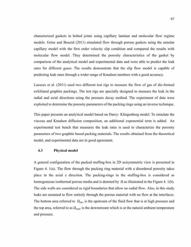
97
characterized gaskets in bolted joints using capillary laminar and molecular flow regime
models. Grine and Bouzid (2011) simulated flow through porous gaskets using the annular
capillary model with the first order velocity slip condition and compared the results with
molecular flow model. They determined the porosity characteristics of the gasket by
comparison of the analytical model and experimental data and were able to predict the leak
rates for different gases. The results demonstrate that the slip flow model is capable of
predicting leak rates through a wider range of Knudsen numbers with a good accuracy.
Lasseux et al. (2011) used two different test rigs to measure the flow of gas of die-formed
exfoliated graphite packings. The test rigs are specially designed to measure the leak in the
radial and axial directions using the pressure decay method. The experiment of data were
exploited to determine the porosity parameters of the packing rings using an inverse technique.
This paper presents an analytical model based on Darcy- Klingenberg model. To simulate the
viscous and Knudsen diffusion composition, an additional exponential term is added. An
experimental test bench that measures the leak rates is used to characterize the porosity
parameters of two graphite based packing materials. The results obtained from the theoretical
model, and experimental data are in good agreement.
4.3 Physical model
A general configuration of the packed stuffing-box in 2D axisymmetric view is presented in
Figure 4. 1(a). The flow through the packing ring material with a disordered porosity takes
place in the axial z direction. The packing-rings in the stuffing-box is considered as
homogeneous isothermal porous media and is denoted by Ω as illustrated in the Figure 4. 1(b).
The side walls are considered as rigid boundaries that allow no radial flow. Also, in this study
leaks are assumed to flow entirely through the porous material with no flow at the interfaces.
The bottom area referred to Ω , is the upstream of the fluid flow that is at high pressure and
the top area, referred to as Ω is the downstream which is at the natural ambient temperature
and pressure.

98
The model used describes the behavior of fluid flow in a unidirectional configuration and is
capable of simulating a variety of fluid regimes dictated by pressure, compressive stress and
nature of gas. Based on Darcy-Klinkenberg’s approach, the pressure drop can be related to the
effective diffusion such that
= − + (4.8)
In which both the viscous and Knudsen diffusions are taken into account. Due to the large
range of operating conditions, the flow regime through packing rings varies widely. This
variation is well captured by a model that incorporates both viscous and Knudsen diffusions.
For the accurate prediction of the effective diffusivity, pore geometrical properties such as size,
distribution and roughness must be known. Nonetheless, the simple approach is to use a mean
pore radius (Xiao and Wei, 1992; Wang and Smith, 1983). In general, the effective diffusivity
is a function of temperature, gas velocity and a geometric factor (Zschiegner et al., 2007;
(a) (b)
Figure 4.1 General configuration of a packed stuffing box and the sealant axisymmetric area as 2D domain of porous media with its
boundary conditions

99
Huizenga, D.G. and Smith, 1986; Gao et al, 2014; Lito et al., 2014; Shou et al., 2014; Burggraaf
and Cot, 1996; Ruthven , 1984). Considering isothermal conditions, a correlation for effective
diffusion can be expressed as = ℊ (4.9)
Where ℊ is a geometrical factor and is a diffusion factor. The exponential part of equation
(4.9) expresses the activated nature of the process, and reflects the probability of having
enough energy in a molecule to pass a threshold energy barrier (Jolly and Marchand, 2009).
Substituting equation (4.9) into equation (4.8) and, considering the diffusion factor equal to
one and = 1/ , gives
∇ = − + (4.10)
The fluid properties through the pores of braided packing rings change depending on the local
pressure, density and velocity of the fluid. The density and velocity are taken at downstream
boundary. The density can be obtained according to the perfect gas law
= (4.11)
and the velocity is simply obtained by quantifying the leak that flows across the porous media
section parallel to fluid flow.
= (4.12)
4.4 Experimental setup
The experimental leak measurements are carried on the stuffing box test bench shown in Figure
4.2, the data from which is processed in order to determine the porosity parameters of a set of
four braided flexible graphite packing rings to validate the model. This test bench has three
main sections; hydraulic tensioner, pressurization system and leak detection system, all of
which have their corresponding instrumentation. The gland stress ranging from 1000 to 6000

100
psi (6.9 to 41.4 MPa) in steps of 1000 psi is applied through the hydraulic tensioner using a
manual hydraulic pump.
For every gland stress level, three gases namely nitrogen, argon and helium are applied to the
packed stuffing-box with pressures ranging from 50 to 400 psi (0.34 to 2.76 MPa) in steps of
50 psi. The housing had a total length of 3.125 inches in height and was filled with four packing
rings of 3/8 of an inch square section. The stuffing-box housing has an outside diameter of 3.125 inches and an inside diameter of 1.875 inches. The stem is also made of steel with a
diameter of 1.125 inches. The displacement of the packing rings due to compression is
measured by two LVDTs installed diametrally opposed. Depending on the level of the leak rate
four different measurement techniques are used; flow meter, pressure decay, pressurized rise
Figure 4.2 General configuration of the test bench
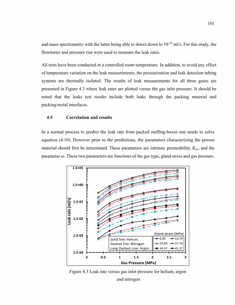
101
and mass spectrometry with the latter being able to detect down to 10-10 ml/s. For this study, the
flowmeter and pressure rise were used to measure the leak rates.
All tests have been conducted at a controlled room temperature. In addition, to avoid any effect
of temperature variation on the leak measurements, the pressurization and leak detection tubing
systems are thermally isolated. The results of leak measurements for all three gases are
presented in Figure 4.3 where leak rates are plotted versus the gas inlet pressure. It should be
noted that the leaks test results include both leaks through the packing material and
packing/metal interfaces.
4.5 Correlation and results
In a normal process to predict the leak rate from packed stuffing-boxes one needs to solve
equation (4.10). However prior to the predictions, the parameters characterizing the porous
material should first be determined. These parameters are intrinsic permeability, , and the
parameter . These two parameters are functions of the gas type, gland stress and gas pressure.
Figure 4.3 Leak rate versus gas inlet pressure for helium, argon
and nitrogen

102
4.5.1 Intrinsic Permeability
This parameter represents the capability of the porous media to let the fluids or gasses pass
through. After establishing a difference in the definition of the permeability of a constant media
encounter with different gases and fluids, some researchers (Muskat, 1937), proposed to
distinguish between the apparent permeability, , and the intrinsic permeability, , and
defined the former as: = 2( − ) (4.13)
The approach used to determine the apparent permeability experimentally is the same as the
one used by Klinkenberg (1941). In his approach, the intercept of the line of the apparent
permeability versus the inverse of the mean pressure defines the intrinsic permeability. The
graphs used to determine are shown in Figure 4.4. The apparent permeability is depicted
versus the inverse of the mean pressure for all three gases at different gland stresses. It can be
observed that for all three gases and for the six stress levels covered, the general trend is the
Figure 4.4 Apparent permeability for helium, nitrogen and argon at different gland stress levels

103
same as the apparent permeability increases with stress and decreases with pressure. The
intrinsic permeability is found to be very sensitive to the stress level but not to the gas type as
the calculated intercept for the three gases are statically the same. Figure 4.5 gives the variation
of the intrinsic permeability as a function of the gland stress for all three gases. Again, the
effect of the gas type is not significant. Therefore one can deduce that the intrinsic permeability
is a function of the level of the gland stress only. The graph of Figure 4.5 suggests that the
relationship is exponential since in the semi-log graph of the curves may be considered as
straight lines. The intrinsic permeability stress relationship is as follows: = (4.14)
Where the constants and are parameters proper to each porous material and can be
evaluated experimentally using a reference gas such as helium or nitrogen. In this study, the
values of these parameters are based on helium used as a reference gas, considering the
availability of the leak detectors in the laboratory. In this case the values of the constants of
equation (4.14) are found to b = 3 × 10 and = 0.211.
Figure 4.5 Intrinsic permeability versus gland stress for Helium, Argon and Nitrogen.

104
4.5.2 Diffusivity parameter
The values of the diffusivity parameter can be found from the experimental results and the
use of equation (4.10) with the gas properties at downstream boundary and intrinsic
permeability known. Figure 6 shows the relationship between the diffusivity parameter and
the inverse of mean pressure. The curves obtained with Helium as reference gas follow straight
lines with approximately the same slope. Therefore introducing a dimensionless pressure
parameter based on the downstream pressure, the slope is given by
ϵ = ∂ (4.15)
The average value of the slope is found to be = 10 for the tested packing set. In Figure
4.6 the intercepts of the trend lines are functions of the stress levels and the gas type. In order
to introduce a parameter with a meaningful physical interpretation one can use the gland stress
Figure 4.6 Diffusivity parameter versus inverse of
mean pressure using helium as reference gas

105
instead of porosity and the mean free path to recognize the effect of the gas type. The mean
free path of a gas is given by (Chastanet, 2004):
= 2 (4.16)
in which the downstream pressure is applied for the calculation. Hence, a correlation for the
intercept of the extrapolated lines shown in Figure 4.6 can be given by:
∝ / (4.17)
The right-hand side of equation (4.17) is related to Knudsen number with a characteristic
geometric length that is adjusted by a coefficient due to the change in the structure at the
macroscopic level (Karniadakis and Beskok, 2009). Accordingly, the intercepts of Figure 6 can
be expressed as follows:
= / (4.18)
Where the coefficient is dependent on the gland stress level and is given by: = 28.936 (4.19)
Combining Eqs. (4.15), (4.18) and (4.19), the correlation for diffusivity parameter can be
expressed as:
= + (4.20)
4.6 Leak predictions
A simple approach based on the modified Darcy model is used to predict the leak rates through
porous packing rings used in stuffing-box. The required porosity and diffusivity parameters are

106
obtained experimentally using a reference gas. The modified model presented in this study can
be used for other braided packing ring materials.
The predicted leak rates as a function of gas pressure are shown in Figures 4.7 to 4.9 for helium,
argon and nitrogen based on the characterization conducted with helium as a reference gas. In
general, a good agreement exists between the predicted and measured leak rates which
demonstrate the accuracy of the modified model. However, at high gland stresses and low gas
pressure upstream, the predicting method underestimate leak rates. This was observed at 6000
psi gland stress level and 50psi pressure. Additional tests are required under these extreme
conditions of high-stress low pressures to determine the limits of the developed approach.
Figure 4.7 Measured and predicted leak rate with helium

107
Figure 4.8 Measured and predicted leak rate with argon
Figure 4.9 Measured and predicted leak rate with nitrogen

108
4.7 Conclusion
In this study, a method based on Darcy model is presented. The method characterizes
adequately the leak behavior of braided packing ring materials under most working conditions.
The experimental investigations carried out on a well-equipped test bench confirmed the
accuracy of the proposed approach. The comparison study between the measured and predicted
leak rates was conducted on a graphite-based braided packing but could be extrapolated to
other materials. The modified Darcy-Klinkenberg technique used in this study is a key
parameter in the prediction of leak rates through packing rings. The developed methodology
based on the determination of the porosity and diffusivity parameters as a function of stress,
pressure and type of gas is being tested presently with PTFE-based braided packing rings. The
limits of the developed model are also being investigated. It is hoped that ease and clarity of
this method would help engineers and designers to estimate leak rates through porous sealing
materials.

CHAPITRE 5
LEAK PREDICTION METHODS THROUGH POROUS COMPRESSED PACKING RINGS: A COMPARISON STUDY
a Mehdi Kazeminia, b Abdel-Hakim Bouzid2 a Ph. D. student, Mechanical Engineering Department, École de technologie supérieure, 1100
Notre-Dame St. West, Montreal, Quebec, H3C 1K3 b ASME Fellow, Professor, Mechanical Engineering Department, École de technologie
supérieure, 1100 Notre-Dame St. West, Montreal, Quebec, H3C 1K3
email: [email protected]
This article was submitted for publication in the International Journal of Pressure Vessel and Piping; On date: 2016-01-11; Reference number: IPVP-2016-9
5.1 Abstract
The prediction of leak rate through packing rings is a significant challenge when designing
valves. With the ubiquitous increase in the strict environmental regulations and safety
protection laws on fugitive emissions, it becomes urgent to develop and implement leakage
based design methods for packed stuffing boxes as is being done with bolted flange gasketed
joints. Although packed stuffing boxes have in general been working satisfactorily, the current
standard design methods are not suitable to ensure the 500 ppm EPA fugitive emission
requirement imposed in North America. Due to the lack of proper design tools, compliance
with this requirement becomes, in essence, a post-design stage problem that often causes a
heavy burden on the end-user
In this study, three methods that can potentially be used to predict leakage through packing
rings are presented. The first two methods are based on capillary models with the first order
slip condition with the first one based on capillary tube geometry and the second one on
concentric cylinders geometry. The third one is a novel method based on a modified Darcy
law. A comparison between the three methods has conducted the ability of the theory of fluid

110
flow through porous media to predict accurately leakage of packed stuffing boxes subjected to
different gasses, pressures, and gland loads.
Nomenclature, Porosity parameters Diameter Factor of diffusivity ℎ Distance between two concentric microchannel cylinders Permeability of Porous Media
Knudsen number Length of the line of packing rings Leak rate Number of microchannels Pressure of the gas Radius at the wall Radius of the tube Stress Absolute temperature Velocity of flow Distance in the thickness direction for the concentric Packing width Axial direction Diffusivity Mean free path Π Outlet over inlet gas pressure ratio Viscosity Density of the gas Slip or tangential accommodation coefficientℛ Specific gas constant
Subscript
Related to concentric cylinders model Apparent value Effective value
Related to capillary model Related to inside boundary
Related to modified Darcy’s model Related to outside boundary Related to the packing ring Related to slip flow Related on the wall ∞ Intrinsic permeability
5.2 Introduction
The rate of emission in Canada is estimated at 550,000 megatons per year while in the
USA it has reached an alarming level of 10 times higher (Chambers et al., 2008). Surveys
worldwide (Shabtai et al., 2012; Bayreuther, 2012) conclude unanimously that leakage from

111
pressurized equipment in processing plants is a major source of fugitive emission and
environmental contamination. The equipment requiring compliance with sealing standards
include valves, pump seals, compressor seals, flanges and fittings, pressure-relief valves,
connectors, open-ended lines and sampling connections, to name a few. In addition to the risk
of environmental contamination and health and safety risks, the costs in terms of lost revenue
and leakage repair are skyrocketing. Hydrocarbon losses from each equipment category are
estimated at 0.2–1 M$ per business per year. A leak may cost a typical refinery $250,000 per
day, the cost of repairing the leak about $350,000 and the repair of a single flange clamp about
$50,000 (Anon, 1998).
Given these statistics, improving the sealing performance of gasketed joints and packed
stuffing boxes is a big challenge for the industry. Therefore sealing technology is an area of
research that needs to emerge and evolve. Packed stuffing boxes have not received as much
attention as required in comparison to gasketed joints. For the past 30 years, substantial gains
have been made in the fundamental understanding of the latter while little emphasis is put on
studying the structural integrity and leak tightness of packed stuffing boxes. Earlier research
conducted mostly at room temperature has not matured to readiness for application to standards
such as ASME and ASTM.
Static sealing of micro and nanoporous materials used in packed stuffing-boxes for sealing of
valves are the general framework of this study. The performance of the valve sealing has a
significant effect on operational safety in a power plant. Environmental damages, injuries,
shutdowns, and losses of revenues can be caused by excessive leaks. Improving the design and
sealing performance of valves would increase the safety and reduce the fugitive emissions,
maintenance, and revenue costs. Furthermore, legislations of strict regulations on the amount
of fugitive emissions forced industries to comply with standards on valve fugitive emissions
such as API and ISO (ANSI/ISA-93.00.0., 1999; API-622, 2011; API-624, 2011; ISO-15848-
1, 2006).
There are two ways to a high pressure confined gas or fluid to escape from inside of a valve
toward the outside. The first way is the interfacial contact surfaces between packing rings and
side walls, and the second one is porosity of packing rings. The first source of sealing can be

112
controlled by maintaining a minimum threshold contact stress between packing rings and side
walls. Several studies have been investigated to characterize the distribution of contact stresses
will respect to other components and compressive stress (Kazeminia and Bouzid, 2014(a);
Kazeminia and bouzid, 2015; Ochonski, 1988; Kazeminia and Bouzid, 2014(b); Diany and
bouzid, 2011; Avdeev, et al., 2005; Bohner et al., 1975). Regarding fluid flow through the
porosity of packing materials, few studies have been conducted. Lasseux et al. (Lasseux et al.,
2011(a); Lasseux et al., 2011(b)) studied the permeability of a packing ring made of exfoliated
graphite. They used a Darcy model with Klinkenberg’s effect as the physical model to predict
leakage. Their studies are limited to single packing rings while pressure decay was used to
characterize their permeability. Other Standard test methods have been used to correlate the
gas leakage in porous packings. Cazauran et al. (2009) applied TA Luft and VDI 2440 test
methods to find the correlation between gas type and leakage. Poiseuille or Knudsen law based
models were used to predict leak. Other researchers (Schaaf Schoeckle, 2011) compared
measurements according to IPPC, ISO and API requirements.
In general, the study of micro- and nano-flow in porous media has attracted lots of attentions
in recent decades based on its several important engineering applications such as the design of
gas-based fuel cells, gas extraction from shale reservoirs, micro-electro-mechanical-systems
(MEMS), etc. In all of these mentioned areas, the crucial object is to characterize and predict
the gaseous or liquid fluid flow through porous media with a variety of structures. The main
difficulty to overcome in such studies is that the confined spaces are small, the operating
conditions vary considerably, and the interactions between gas molecules and micro- and nano-
scale pores are complex (Knudsen, 1909; Kennard, 1938).
Gaskets and compressed packing rings are porous structures used for sealing purposes in bolted
flanged connections and valves. Unlike packing rings, gaskets have been the subject of few
studies related to the leakage prediction through their porous structures. Boqin et al. (2007)
presented a gaseous leakage model which is a combination of laminar flow and molecular flow
regimes. Jolly and Marchand (2009) studied the slip or near transitional flow in gaskets using
Klinkenberg law of diffusion. They compared their model with the laminar molecular flow
model and obtained almost the same results. Grine and Bouzid (2011) conducted a leakage

113
prediction study and were able to estimate leak rates in non-metallic gaskets with reasonable
accuracy. They used capillary and parallel plate models with first-order boundary conditions.
Furthermore, they included the effect of high temperature in their model and were able to
obtain acceptable predictions of leak rates (Grine and Bouzid, 2013).
This study deals with the prediction of leak rates through porous yarned packing rings.
Three different models; capillary model, concentric cylinders model, and a modified Darcy
model are used to predict leakage based on the porosity parameters of the stuffing-box packing
structure deduced experimentally using leak rate measurements of a reference gas. A well-
equipped packed stuffing-box test bench is used to measure the leaks of a flexible graphite
based compressed packing experimentally.
5.3 Physical model
Several methods have been proposed to characterize the fluid flow through porous media.
These methods can be classified based on the interaction between gas molecules and pore
walls. This parameter can be quantified by Knudsen number that is a dimensionless value that
expresses the relative size of the mean free path to the size of the pore. For Knudsen numbers
more than ten the number of interaction between gas molecules and pores walls is more than
the gas on its own, and hence it can be considered as a molecular flow while for values less
than 100 there would be a continuous regime. Further classifications of the flow that are neither
absolutely continuous nor molecular happened at two cases. For Knudsen number between 0.001 and 0.1 the slip flow regime is present and for Knudsen number between 0.1and
the transition flow regime is predominant (Karniadakis e al., 2000). The porous packing
structure used in the experiment is constructed by a set of four packing rings made of expanded
graphite-based braided construction. A general configuration of packed stuffing-box in its
axisymmetric sectional view is shown in the Figure 5.1. The compression force is applied to
the gland situated at the top of the packing rings that are confined in the radial direction in the
stuffing-box between the housing internal wall and stem outside surface. Figure 5.2 shows a
sectional view of three different porous material models that are considered in the prediction

114
of leak rates through packing rings; the capillary model, the concentric cylinders model and
the modified Darcy model.
(a) (b) (c)
Figure 5.2 packing ring models (a) capillary model, (b) concentric cylinders model, and (c) disordered porosity with modified Darcy model
Figure 5.1 Simplified packed stuffing-box with
the main components

115
5.3.1 Capillary model
The concept of this model has been adopted by many researchers in different applications
(Wielhorski et al., 2013; Bianchi et al., 2014; Sreekanth, 1965). With this approach, the porous
media is assumed to be made of a set of uniform diameter capillaries that are distributed parallel
from bottom to the top of packing rings as it is shown in Figure 5.2(a). For a capillary tube,
starting from the equation of momentum conservation in the cylindrical coordinate, the
velocity-pressure relationship is given by 1 = 1 (5.1)
Assuming an isothermal flow and considering first order boundary conditions, the velocity at
the wall is given by
| = −2 − | (5.2)
In which is the slip or tangential accommodation coefficient which according to Albertoni
et al. (1963) has the value of 1.1466 and according to Kogan and Naumovich (1969) is 1.012.
Equation (5.1) is solved with the boundary conditions equation (5.2) to give the velocity as a
function of the radial and axial directions as
= 1 4 − 4 − 2 − 2 (5.3)
The mass flow rate from number of capillaries can be obtained by integrating the velocity
through the area as
= 2 ( ) (5.4)
Substituting for the velocity and using the perfect gas law the mass flow rate is
= (Π − 1)16 ℛ 1 + 16 (2 − )(Π + 1) (5.5)
For this configuration, the minimum pore size can be considered as the capillary diameter and
hence the Knudsen number is given by

116
= 2 (5.6)
While the mean free path is obtained by
= 165 ℛ2 (5.7)
5.3.2 Concentric cylinders model
With this model shown in Figure 5.2(b), the porous media is assumed to be a series of
concentric cylinders equally spaced. In this case, the microchannel flow is unidirectional taking
place between concentric cylinders in the axial direction. Because of the small velocity, the
inertia effects can be neglected. In addition, a large pressure reduction takes place because the
microchannel aspect ratio /ℎis less than 1000, although the Mach number is small. Because
the ratio of the space between two adjacent concentric cylinders to the radius is very small
(ℎ/ ≪ 1) hence the effect of curvature on the momentum equation and boundary conditions
can be neglected and therefore the 2D parallel plates model can be considered. The equation
of conservation of momentum and first order velocity slip at the wall are then given in
Cartesian coordinate as follows (Karniadakis et al., 2005):
= (5.8)
And the boundary conditions at = 0 and = ℎ/2 are given, respectively, by = 0
= −2 − | /
(5.9)
Equation (5.8) is solved with boundary conditions of equation (5.9) to give the velocity as a
function of parallel (z) and normal (y) directions of flow through the channels
( ) = 2 ℎ − ℎ − 2 − (5.10)

117
Where in this case the Knudsen number is defined based on the gap between two adjacent
cylinders, = ℎ (5.11)
The mass flow rate for each microchannel is obtained by integration of the velocity through
the surface between two adjacent cylinders and considering the number and length of the
cylinder channels gives
= 2 ( ) dy (5.12)
Substituting for the velocity and using the perfect gas law the mass flow rate is
= ℎ (Π − 1)24 ℛ 1 + 12 (2 − )(Π + 1) (5.13)
where is the mean radius of the concentric cylinders and when multiplied by 2 ℎ gives
the total area through which the fluid passes.
5.3.3 Modified Darcy model
This model characterizes the fluid flow in the disordered porous packing structure shown in
Figure (5.2-c). In general, at the micro and nano scales the fluid flow follows a disordered path
through the porous structure obeying non-Darcy flow (Ren et al., 2015). Due to the wide range
of operational conditions, the flow regime varies widely. Hence, the representative model
should account for both viscous and Knudsen diffusivity (Kazeminia and Bouzid, 2015(b)). In
this study, a unidirectional flow is assumed through a homogeneous porous media where a
Darcy-Klinkenberg’s approach is used to characterize and quantify the pressure drop in the z-
direction such that = − + (5.14)
The diffusivity of gaseous fluid flow in disordered porous media is a complicated
phenomenon to be formulated. Few efforts have been made to find constitutive correlations

118
between diffusivity and other parameters such as the gradient of gas pressure, the geometrical
properties and tortuosity (Thauvin and Mohanty, 1998; Bagc et al., 2015; Hong et al., 2014).
With yarned packing ring it is suggested to correlate the diffusion as a multiplication of the
three independent functions in addition to the velocity. Each function is dependent of one or
two parameters. Then the effective diffusion can be given using three separate functions. The
molar mass, the geometry of the porous structure, the level of compression and the ratio of the
external versus mean gas pressure are the parameters of which these functions depend such
that:
= ( ) ( ) (5.15)
The proper functions of each parameter in equation (5.17) can be determined by an
optimization curve fitting method using experimental data. Therefore, equation (5.16) can be
written as: = − + ( ) ( ) (5.16)
Having the characteristics of the porous media, equation (5.16) is of a second order form
differential equation the solution of which can lead to the rate of flow passing through the
porous packing as = ( − ) (5.17)
5.4 Experimental set up
The experimental leak detection tests are conducted on the stuffing box test bench shown in
Figure 5.3, the data from which is processed in order to determine the porosity parameters of
a set of four braided flexible graphite packing rings. This test bench has three main fluid
systems; a hydraulic tensioner system, a gas pressurization system, and a leak detection system.
Every system has its instrumentation monitored through a data acquisition system using
Labview software as an interface program between the data logger and the computer. The
housing of a total length of 3.125 inches in height can accommodate up to 6 packing rings of
3/8 inch square section. Only a set of four packing rings were inserted for the purpose of the

119
current test study. The stuffing-box housing has an outside diameter of 3.125 inches and inside
diameter of 1.875 inches. The stem is made of steel with a diameter of 1.125 inches. The
displacement of the packing rings due to compression is measured by means of two LVDTs
installed diametrally opposed. Depending on the level of the leak rate, four different leak
measurement techniques are used; flow meter, pressure decay, pressurized rise and mass
spectrometry with the latter being able to detect down to 10-10 ml/s. For this study only the
flowmeter and pressure rise were used to measure the leak rates.
A gland stress ranging from 1000 to 6000 psi (5.9 to 41.4 MPa) in steps of 1000 psi (5.9
MPa) is applied by using the hydraulic tensioner. The gland stress is deduced from the
measurement of the load through a Whinstone bridged strain gage placed on the stem. For
every gland stress level, pressures ranging from 50 to 400 psi (0.34 to 2.76 MPa) in steps of
50 psi (0.34 MPa) are applied to the packed stuffing-box. Three gazes namely nitrogen, argon
and helium were used in the experiment. The physical values of molecular weight and mean
free path of the gases used in the experimental investigation of this study are presented in Table
5.1. All tests have been conducted under controlled room temperature. In addition, to avoid
any effect of temperature variation on the leak measurements, the pressurization and leak
Figure 5.3 General configuration of the test bench

120
detection tubing systems are thermally isolated. The results of leak measurements for all three
gasses are presented in Figure 5.4 where the leak rates are plotted against the inlet gas pressure.
It should be noted that the leak detection results include both leaks through the packing material
and the packing/metal interfaces.
Table 5.1 Physical properties of the gases used in experimental investigations
Gas type Molecular Weight
(g/mol)
mean free path (× 10 ) Helium ( ) 3.003 17.65
Argon ( ) 39.94 6.441
Nitrogen ( ) 28.01 6.044
Figure 5.4 Leak rates for flexible graphite packing rings for different gases

121
5.5 Exploitation of constitutive parameters
The porosity parameters of the physical models are obtained by curve fitting the above
model with the experimental results. In this study helium is the reference gas used to determine
the porosity parameters that define all physical models. Then the measurements of leak rates
conducted with two other gases namely argon and nitrogen are used to verify the reliability of
the physical models to predict accurate leak rates.
5.5.1 Porosity parameters of the capillary model
Equation (5.3) can be written in a linear form where the porosity related parameter A is
a function of the reciprocal pressure 2/(Π+1) (Jolly and Marchand, 2006)
A = 1 + B 2Π + 1 (5.18)
Referring to equation (5.3) the constitutive parameters are
A = 16 ℛ(Π − 1)B = 82 −
(5.19)
To determine these two parameters, one needs to conduct a leak test with a procedure
where the gas pressure is increased by steps for each level of gland stress. A plot of A versus
the reciprocal pressure at different level of the gland stress is obtained as shown in Figure 5.5.
The slope and intercept of the regression lines of the curves of Figure 5.5 are used to calculate
the radius and number of micro channels. The intercept of the linear regression line gives
and the slope gives B . In this study, a fully diffusive reflection of gas molecules in the
walls is assumed and therefore = 1.

122
5.5.2 Porosity parameters of the concentric cylinder model
Following the same process of capillary model, one may present equation (5.13) in a linear
trend as A = ℎ 1 + B 2Π + 1 (5.20)
With A = 24 ℛ(Π − 1)B = 62 −
(5.21)
The parameter A is also plotted against the reciprocal pressure for different level of
gland stresses as shown in the Figure 5.5. In this case the intercept of the linear regression line
gives ℎ and its slope gives ℎ B . Assuming = 1 and using the definition of Knudsen
number for concentric cylinders model as per equation (5.11), the gap between two concentric
cylinders can be calculated. The values of the parameters related to capillary and concentric
cylinder models using helium as reference gas are presented in Table 5.2.
Table 5.2 Porosity parameters for the two models
Gland stress
(MPa)
Capillary model Concentric
cylinders model
6.98 R 2.5 × 10 h 3.8 × 10
N 9.2 × 10 N 5.14 × 10
13.79 R 8.45 × 10 h 3.06 × 10
N 3.58 × 10 N 1.81 × 10
27.58 R 3.29 × 10 h 3.38 × 10
N 8.83 × 10 N 19.75
41.37 R 1.72 × 10 h 1.17 × 10
N 7.20 × 10 N 22.95

123
5.5.3 Parameters of the modified Darcy's model
Klinkenberg proposed that the intercept of a linear regression line in a plot of apparent
permeability versus the inverse of mean gas pressure gives the intrinsic permeability. The
apparent permeability is defined as (Muskat, 1937)
= 2( − ) (5.22)
A plot of the apparent permeability versus the inverse of mean gas pressure is presented in
Figure 5.6. It has been proved that the intrinsic permeability is independent of the gas type, but
Figure 5.5 Porosity parameters of capillary and concentric cylinder models, and , versus the reciprocal pressure ratio; (a) = 6.9 , (b) = 13.8 , (c) =27.6 and (d) = 41.4

124
it is sensitive to the compression of the porous media like in rocks and in this case the level of
stress at which the compressed yarned packing rings are subjected to. Hence, by plotting the
variation of intrinsic permeability versus gland stress, a relation is proposed (Kazeminia and
Bouzid, 2015) = (5.23)
The diffusivity can also be formulated as a function of the molecular mass, geometry
parameters, stress level and pressure ratio. A Levenberg-Marquardt optimization method is
adopted to find the best fit of the experimental data. The variation of diffusion parameter versus
the ratio of the outlet and mean pressure is shown in Figure 5.7 for helium as the reference gas.
A power law regression is suggested to correlate the first function:
= (5.24)
A similar approach is used to depict the variation of the diffusion parameter as a function of
the gland stress as shown in the Figure 5.8. A sinusoidal-exponential regression can be fitted
for the second function such that:
Figure 5.6 Apparent permeability versus inverse of mean gas pressure for helium

125
Figure 5.8 Diffusivity parameter versus outlet to mean pressure ratio for helium
Figure 5.7 Diffusivity parameter versus gland
stress level for helium
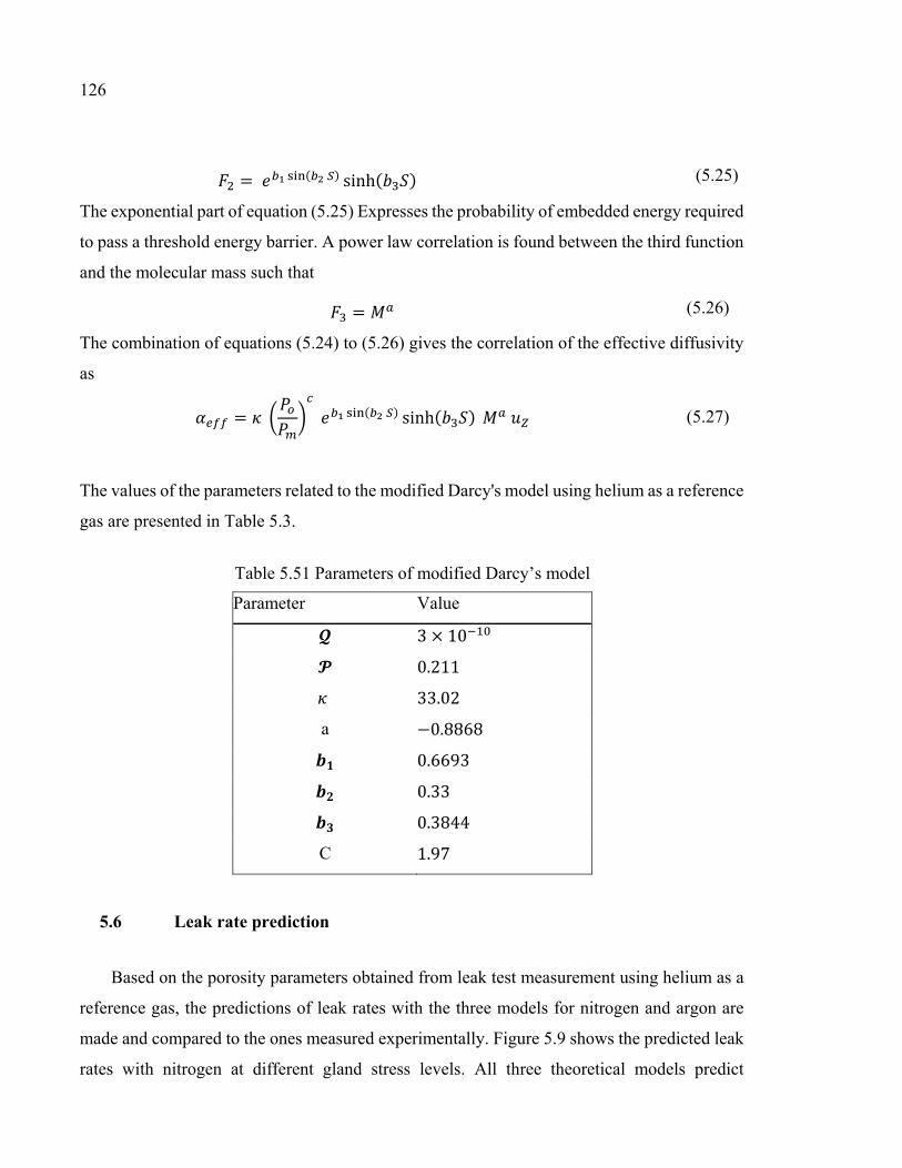
126
= ( ) sinh( ) (5.25)
The exponential part of equation (5.25) Expresses the probability of embedded energy required
to pass a threshold energy barrier. A power law correlation is found between the third function
and the molecular mass such that = (5.26)
The combination of equations (5.24) to (5.26) gives the correlation of the effective diffusivity
as = ( ) sinh( ) (5.27)
The values of the parameters related to the modified Darcy's model using helium as a reference
gas are presented in Table 5.3.
5.6 Leak rate prediction
Based on the porosity parameters obtained from leak test measurement using helium as a
reference gas, the predictions of leak rates with the three models for nitrogen and argon are
made and compared to the ones measured experimentally. Figure 5.9 shows the predicted leak
rates with nitrogen at different gland stress levels. All three theoretical models predict
Table 5.51 Parameters of modified Darcy’s model
Parameter Value
3 × 10
0.211
33.02
a −0.8868
0.6693
0.33
0.3844
C 1.97

127
acceptable nitrogen leak rates as their corresponding curves show good agreement with the
measured values. Nevertheless, a slightly better prediction is observed with the modified
Darcy’s model and in particular at the higher pressures. The same comment can be made to
the predicted leak rates with argon as can be observed from the comparison curves of Figure
5.10.
In order to confirm the better overall performance of the modified Darcy's model, the
variation of deviations of the leak rates from the average values versus gland stress for both
nitrogen and argon are shown in Figure 5.11. In general, for a gland stress less than 20 MPa,
all three models give a similar level of accuracy. While for greater stress levels the accuracy
of prediction can be sequenced from top to down by the modified Darcy, concentric cylinders
and capillary models. Although 20 to 60% differences in the prediction may seem to be high,
in terms of very small leak rate, this is quite acceptable. It can be observed from Figure 5.11
that the predictions are slightly more accurate with nitrogen than argon. This is attributed to
the fact that the difference in molecular masses between the reference gas and argon is higher
than that of nitrogen.
Figure 5.9 Prediction and measured leak rates for argon vs gland stresses at different gas pressures

128
It can be said that in general the modified Darcy's model can better predict leak rates for
Figure 5.11 Prediction and measured leak rates for nitrogen versus gland stresses at different gas pressures
Figure 5.10 Standard deviation for nitrogen and argon.

129
different gasses at higher gland stresses as compared to the other two models. In Figure 5.11
the deviation curves for both nitrogen and argon obtained from modified Darcy's method are
almost constant with the variation of gland stress while for the other two models a linear
increase is observed. Considering the above, the modified Darcy's model might be a better
approach to model leak through packing for a higher level of gland stress or when the molecular
weight of the reference gas is much higher than that of the gas of interest.
Also, the modified Darcy’s model is more comprehensive than the other methods which
can be revealed regarding the number of constitutive used for describing each method.
Considering the process of exploitation of constitutive parameters, the concentric cylinders and
capillary methods need experimental investigations for each gland stress while it is not true for
modified Darcy’s method.
5.7 Conclusion
The increasing strict regulation on fugitive emissions from bolted joints and valves
requires a reliable process for characterization and prediction of leak rates in packed stuffing-
boxes. This process can be useful not only for the characterization of already existing materials,
but also to develop a new type of packing materials with a better sealing performance. The
results show that the three methods almost present the same accuracy, while for nitrogen at
gland stresses less than 20 MPa, the capillary model have a better accuracy and for higher than
that, concentric cylinders model performs better. For argon, the modified Darcy and concentric
cylinders models have higher accuracy for gland stresses more than 20 MPa. The study shows
that the modified Darcy's model gives a better accuracy at the high gland stress level and for
gases with high molecular weight. Additional leak tests with other packing materials to be
conducted with other gases and under higher gland stress levels are necessary before a general
model is to be adopted.

130

131
CHAPITRE 6 EFFECT OF TAPERED HOUSING ON THE AXIAL STRESS DISTRIBUTION IN A
STUFFING-BOX PACKING
a Mehdi Kazeminia, b Abdel-Hakim Bouzid2 a Ph. D. student, Mechanical Engineering Department, École de technologie supérieure, 1100
Notre-Dame St. West, Montreal, Quebec, H3C 1K3 b ASME Fellow, Professor, Mechanical Engineering Department, École de technologie
supérieure, 1100 Notre-Dame St. West, Montreal, Quebec, H3C 1K3
email: [email protected]
This article is published in the International Journal on Advances in Mechanical and
Automation Engineering, volume 1 (3), pp 115-120, 2014; ISBN: 978-1-63248-022-4;
doi.org.10.15224/978-1-63248-022-4-43.
6.1 Abstract
The sealing performance of a packed stuffing-box used in pumps and valves is strongly
dependent on the distributions of the axial stress and the contact pressure between the packing
rings and the side walls. In particular the stress state of the bottom packing ring that is in contact
with the internal fluid which is at its minimum is the leak controlling parameter. This minimum
axial stress and its resultant radial stress control the pore size and therefore dictate the quantity
of leak that passes through the packing rings.
This paper presents a new design feature that improves the stress distributions. The
introduction of a variable gap between the packing and the side walls helps producing a more
uniform distribution of the stresses in the packing rings while increasing the minimum stress.
An analytical model that takes into account the effect of a tapered housing on the distribution
of the axial stress in a stuffed packing box is also developed. The analytical model is validated
by comparison with numerical finite element simulations.

132
6.2 Introduction
Valves are used to control fluid circulation in the nuclear, chemical and petrochemical process
plants. In general, valves are designed to have two sealing functions. The first one is related to
one of the extreme condition of fluid flow control which is the shut-off state and is referred to
as internal sealing. The second one is related to the control of the fluid leakage to the outside
boundary of the valve through the stem and is referred to as external sealing. Packed stuffing-
boxes are the preferred sealing system that is widely used in valves to carry out the second
described sealing task.
There is an increasing concern about the sealing performance of packed stuffing-boxes. A
recent study shows that 40% of all leaking equipment comes from packed stuffing-boxes
(Hoyes and Thrope, 1995). Several standards have recently been developed or improved in
order to reduce valves fugitive emissions (ANSI/ISA-93.00.0, 1999; API-622, 2011; API-624,
2011; ISO-15848-1, 2006) and comply with the new strict regulations worldwide. However,
all standards are related to the qualification of the packing material of valves through special
testing procedures and quality control programs. Currently there is no standard that provides
design rules or design calculation procedure for stuffed packing boxes. Nevertheless, there are
few models to evaluate the axial stress distribution along with the recommendations by
manufacturers to select suitable packing materials. Although several analytical, numerical and
experimental investigations have been carried out, the characterization and modeling of packed
stuffing-box has not matured enough to reach the level of standardization.
There exist few parameters that can improve the sealing performance of packed stuffing-boxes
but not treated in the literature. The introduction of tapered housing that generates a variable
gap between the packing and side walls is a design concept that can have a significant effect
on the distribution of radial contact pressure depending on the packing material. This paper
aims at testing this concept by simulating both analytically and numerically a stuffed packing
box with such a configuration to evaluate the axial stress distribution. This concept can be used
to improve the sealing performance of packed stuffing-box in valve applications.

133
6.3 Theoretical background
Although the use of packed stuffing-boxes as a sealing system in valves is a relatively old
concept that was used in the early steam engines, the analytical and theoretical modeling of its
mechanical and sealing behaviors is rather limited. The very few existing models are limited
to some particular applications and unfortunately they do not reproduce the wide range of
existing experimental data. Several researchers have studied the behavior of packed stuffing
boxes both analytically and experimentally. In 1957, Denny (1957) studied the ratio of the
radial contact pressure to the axial gland stress known as the lateral pressure coefficient. He
found that after some minimum gland pressure this ratio is constant and independent of the
magnitude of gland axial pressure. Ochonski (1988) proposed an equation of axial stress
distribution in soft packed stuffing-boxes by considering the equilibrium of forces on a packing
ring such that:
where = 4 +− (6.2)
He supported the proposed analytical model with experimental investigation using two test
apparatus.
The constants and are lateral pressure coefficients described as the ratio between the
radial contact stress with the stem at the packing internal side wall and, the housing, at the
packing external side wall and the axial stress respectively. These constants depend on the
tribological properties at the interface and can be determined experimentally (Klenk et al.,
1999; Diany and Bouzid, 2011).
Another analytical model has been proposed by Pengyun et al. (1999) by considering moment
equilibrium. The main difference between Pengyun and Ochonski models is the assumption of
the location of the packing axial force. By solving the moment equilibrium equation around
the center of the packing, the latter proposed a similar analytical equation that describes the
( ) = (6.1)

134
axial gland stress in a packed stuffing-box having also an exponential form but with a new β
factor such that: = 16 −( − ) (6.3)
Using a more rigorous analysis, Diany and Bouzid (2009(a)) proposed also an exponential
form for the distribution of the axial stress in soft packed stuffing-boxes but with a different β
factor such that: = 24 −( − ) (6.4)
The above described models do not consider the case of a variable gap between the packing
and the side walls.
6.4 Analytical modeling
The distribution of the axial compressive stress is the most important factor that has a direct
effect on the sealing performance of the packed stuffing-box. This stress is transferred to the
side walls due to the packing ring lateral transmission capacity which induces contact stresses
in the radial direction. The lack of contact stress uniformity makes the packed stuffing box
difficult to seal with time. Although applying higher gland stress might seem to be attractive
to control leakage from the valve, it increases relaxation of the packing material with time
(Diany and Bouzid, 2009(b)) and gradually reduces its sealing performance. Hence the
presence of a variable gap due to a tapered housing could provide a more uniform distribution
of the contact stress distribution. Consequently, there is a sealing advantage to increase the
axial stress in the far most packing ring that is in direct contact with the high pressure fluid
inside the valve.
The introduction of a variable gap between the packing and the side walls produces a more
uniform distribution of the stresses in the packing rings. Such a design helps reduce the
difference between axial gland stress applied at the top packing ring in the stuffing-box, and
the axial stress of the last packing ring in contact with the operating fluid. The stress at this
location is important in the determination of the gland stress and is supposed to be at least,
equal to the pressure of the ambient fluid. Improving the capability of the packing rings to

135
transfer the gland stress to the bottom packing can also be made possible by reducing wall
friction gradually throughout the packing length or creating a gradual contact between the wall
surfaces. This is a costly technique since it involves a sophisticated machining procedure to
alter the tribological properties of the side walls. In addition, the surfaces can increase the
torque during operation while introducing disassembly difficulties.
Following this concept, a simple design of the stuffing-box with a linearly varying gap
between the packing ring and the housing walls is considered, as shown in Figure 6.1.
Before developing the analytical model, few assumptions are made:
• The packing material is isotropic and obeys to Hooke’s law. Its compression modulos
and Poison’s ratio are constant.
• The value of the lateral pressure coefficient is depended on the gland stress, = / .
• The stem and housing are considered to be rigid.
Figure 6.1 Sectional view of the packed stuffing-box configuration
with a linearly varying gap

136
The process of loading the packing is treated analytically based on deformation. Referring to
Figure 6.2, it is divided into three steps;
a) In the first step the applied load from the gland expands the packing materials to fill the gap
between packing and housing side walls without generating lateral forces. During this process
a gap between the stem and the packing is created as a result of the compression.
b) In the second step, the additional gland force generates a side pressure with the housing wall
till the packing inside surface is in contact with the stem.
c) In the third step, the packing being in contact with the side walls, the normal load generates
contact pressure that decreases due to friction forces acting on the side walls. This is considered
in an analysis that can be described by equation (6.1).
Let be the gland axial load to achieve the first step, and be the additional load to achieve
the second step. The required total axial pressure to fill the gap is obtained by = + . (6.5)
Based on the assumption that the packing material behavior is linear, the Hooke’s stress-strain
relationship can be applied to an axisymmetric configuration to give = 1 − ( + )
= 1 − ( + )
= 1 − ( + )
(6.6)
Treating the stem and housing as rigid bodies and the packing ring as a thick cylinder subjected
to only one stress in the axial direction, the strain-displacement relations are, = =
(6.7)
The resulting axial stress to initiate contact between the packing ring and the housing wall, as
presented in Figure 6.2(a) is given by

137
= −2 ( ) (6.8)
This axial compression force causes a displacement at the internal radius of the packing ring
as
( ) = − 2 (6.9)
Substitution of equation (6.8) into equation (6.9) gives ( ) = ( ) (6.10)
The next step is to obtain the additional axial load required to bring the packing to the inside
surface to initiate the contact with the surface of the stem. In this step and referring to Figure
6.2(b), a radial contact pressure, Pc is generated at the housing to packing interface.
Considering Hoop’s strain, the radial displacement at the inside diameter of packing ring is
given by ( ) = 2 − (6.11)
(a) (b)
Figure 6.2 Process of gap filling by expansion of the packing ring due to axial compression; a) application of stress to fill in the gap at the external wall, while creating one at the inside diameter and b) additional stress to produce contact at the internal wall

138
From the theory of the thick-walled cylinder subjected to external pressure, the hoop stress at
this location is given by Lamé (Lamé, G. (1837)) as: = − 2− 1 (6.12)
The contact pressure, is obtained by considering the Hoop strain equal to zero at the packing
ring outside diameter since the contact had already been established at the end of step one.
Therefore using Hooke’s law at the outside diameter of the packing ring gives: = − (6.13)
Where the Hoop stress can be obtained based on the theory of thick-walled cylinder.
Consequently, the relation between contact pressure and the additional axial stress at the end
of this second step is: =− ( + 1)/( − 1) − (6.14)
Substituting equation (6.14) into equation (6.12) and then into equation (6.11) gives ( ) = −2 2(1 − ) + 1 + + 1 (6.15)
Finally substituting equation (6.15) into equation (6.10) gives the additional axial stress
required to close the induced internal gap = 2 ( ) (6.16)
where = 2(1 − ) + 1 + − 1 (6.17)
The total axial gland stress needed to close the initial gap is = + = ( ) (6.18)
where = −2 1 + 1 (6.19)
The effective axial stress that contributes to create the contact stress required to seal the
joint is therefore given by:

139
= − . (6.20)
Where is the gland applied stress. Therefore, the lateral pressure coefficient is given by = . (6.21)
Considering the equilibrium of an element of the packing ring in the axial direction gives
+ = 0 (6.22)
Where can be defined by equation (6.2).
Substituting equation (6.20) into equation (6.22) gives
+ = (6.23)
The solution of this first order non-homogeneous differential equation is
= + (6.24)
Where is a constant that can be obtained by considering the following boundary condition:
= − , = 0 (6.25)
A linearly varying gap between the packing and the housing is introduced such that ( ) = − (6.26)
where is the initial gap at the top side of the packing rings inside the stuffing-box.
Substitution of equation (6.26) into equation (6.24) and evaluating constant A with equation
(6.25) gives the axial stress in a packed stuffing-box with linear gap between the packing and
housing.

140
= − + + + + 1 − (6.27)
6.5 FEM simulation
The numerical simulation is conducted using finite element method with ANSYS software
(ANSYS, 2014) on a stuffed yarn box having a 1-1/8 in. diameter stem used with two sets of
3/8 in. packing rings made of Teflon (PTFE) and flexible graphite (FG). The finite element
model shown in Figure 6.3 was generated to simulate the effect of gap on the distribution of
axial stress in the packing rings. Based on the fact that the configuration of packed stuffing-
box and the applied loads and boundary conditions are all axisymmetric, hence the simulation
can be reduced to a 2D model. For this model, 4-node axisymmetric elements were used to
generate the mesh of the three components of the packed stuffing-box namely stem, housing
FE model of a packed stuffing box with a tapered
Figure 6.3 FE model of a packed stuffing box with a tapered housing

141
and packing rings. Contact elements are used to simulate the relative movement between the
packing ring and the stem and the packing ring and the housing. The geometry and the physical
properties used by both the analytical and numerical approaches are presented in Table 6.1.
The values regarding the mechanical properties of packing rings are cited from (Diany and
Bouzid, 2011). To simplify the analysis all the materials have a linear elastic behavior.
6.6 Results and discussion
In order to demonstrate the effect of the tapered housing on the distribution of the packing
axial stress, four simulations with taper angles ranging from 0 to 2 degrees were conducted
using the two sets of packing rings. The distributions of the axial stress through the packing
length of the stuffed yarn box used with PTFE and FG packing materials are given in Figs. 6.4
and 6.5 respectively. It can be said that a good agreement exist between the results of the FE
numerical simulations and the analytical model which gives an indication on the accuracy of
the developed analytical model. In addition, it can be deduced that by increasing the taper
angle, there is a significant change in the magnitude of the axial stress transferred from the
gland to the last packing which is in direct contact with confined fluid. This is particularly true
with the PTFE packing material with a 2 degrees angle where the stress variation is less
pronounced.
Table 6.21 Mechanical and geometrical properties used in the numerical and analytical
simulations ( ) 36 ( ) 28.576( ) 98 ( ) 47.624 0.46 ( ) 47.625 0.37 ( ) 57.625( ) 200 ( ) 28.575 0.3 ( ) 9.525

142
Figure 6.4 Effect of tapered housing on the axial stress distribution with 6 FG packing rings
Figure 6.5 Effect of tapered housing on the axial stress distribution with 6 PTFE packing rings

143
In a packed stuffing-box, the axial stress on the bottom packing ring that is directly in contact
with the pressurized fluid determines the leakage level. A common practice used as a design
criterion is to adjust the gland stress so that the minimum stress on the bottom packing equals
a multiple of the fluid pressure inside the valve usually between 1 and 2 times the pressure. In
Figures 6.6 and 6.7, the variation of the axial contact stress of the bottom packing ring as a
function of the housing taper angle is given for a set of 4, 6 and 8 packing rings subjected to
50 MPa gland stress. All figures show that the minimum stress is increased when the taper
angle increases. The increase in the minimum axial stress is more important in the case of
PTFE as compared to FG indicating that the former requires less gland stress to seal. However
it should be noted that there is a limit on the amount of the taper angle that can be introduced.
Depending on the packing material, the gland stress and the number of packing, the tapered
Figure 6.6 Minimum axial stress in the bottom PTFE packing ring for a 50 MPa gland stress versus housing taper angle

144
angle
produces a gap at the top packing ring that is in contact with the gland that cannot be closed.
This is way the plots of Figures 6.6 and 6.7 stop after a certain tapper angle.
Figures 6.8 and 6.9 show a required gland stress to produce a minimum axial stress of 20 MPa
for the two packing materials. Depending on the gland stress the taper angle can be selected to
achieve this 20 MPa minimum stress criteria; a value taken arbitrarily for illustration. However
such graphs can be reproduced for different minimum stresses depending on the application
tightness criteria. These are important graphs based on three parameters, gland stress, threshold
axial stresses and taper angle. From the design stand point selecting two parameters can lead
to the third one.
Figure 6.7 Minimum axial stress in the bottom FG packing ring for a
50 MPa gland stress versus housing taper angle

145
Figure 6.9 Required gland stress to achieve a threshold axial stress,of 20 MPa in the bottom PTFE packing ring
Figure 6.8 Required gland stress to achieve a threshold axial stress of 20 MPa in the bottom FG packing ring


CHAPITRE 7
CHARACTERIZATION AND MODELLING OF TIME-DEPENDENT BEHAVIOUR OF BRAIDED PACKING RINGS
a Mehdi Kazeminia, b Abdel-Hakim Bouzid2 a Ph. D. student, Mechanical Engineering Department, École de technologie supérieure, 1100
Notre-Dame St. West, Montreal, Quebec, H3C 1K3 b ASME Fellow, Professor, Mechanical Engineering Department, École de technologie
supérieure, 1100 Notre-Dame St. West, Montreal, Quebec, H3C 1K3
email: [email protected]
This article was presented and published in the proceeding of the American Society of Mechanical Engineering (ASME) the Pressure Vessel and Piping July-2016; PVP2016-
63726, pp. V002T02A014; 8 pages, doi.org/10.1115/PVP2016-63726
7.1 Abstract
The sealing performance of packed stuffing-boxes used in valves and compressors depends on
the ability of the structure to maintain a minimum threshold contact pressure through a
sufficient period of time. Packing rings exhibit combined creep and relaxation behavior due to
internal disordered porous structure and nonlinear material behavior in addition to the
interaction with other structural components. A comprehensive understanding of the time-
dependent behavior of packing rings is essential for increasing the sealing performance. In this
paper, the time-dependent linear viscoelastic behavior of packing material is constitutively
simulated. The experimental investigation is carried out in a special test bench that designed
and developed to study the characteristics of the time-dependent behavior of packing rings.
The results show that the proposed model can successfully be exploited to determine the time-
dependent behavior of packing rings for application in the design of packed stuffing-boxes.
Nomenclature
Physical and dimensional constants

148
Modulus of Elasticity
Shear strain component ℎ Height
Lateral pressure coefficient
Axial displacement
Radial stress
Radius
Strain
Time
Radial displacement
Strain component
Summation of principal strains
Bulk modulus of relaxation
Shear modulus of relaxation
Poison’s ratio
Stress
Relaxation time parameter
Subscripts
Refers to gland
Refers to internal radius
Refers to external radius
Refers to packing
Refers to metallic ring
Refers to radial direction
Refers to stem
Refers to axial direction
Refers to hoop direction
Special Character ̂ Measured quantity

149
7.2 Introduction
The external sealing in a valve is related to the leakage of the pressurized fluid to the outside
boundary. This is achieved by an old concept that consists of compressing packing rings in the
Stuffing-box using a gland and bolts. The packing rings transfer the compression load applied
from the gland to the side walls. The sealing performance of valves depends on the ability of
packed stuffing box to maintain a threshold value of this radial contact stress during operation.
In Figure 7.1 the general mechanism of a packed stuffing box is presented.
In addition to parameters such as gland stress, number and type of packing rings, type and
pressure of the pressurized fluid, and the general configuration, the sealing performance of the
packed stuffing box depend on the variation of the mechanical properties of packing material
with time. In addition, considering to the static or semi-static loading conditions, a combination
of creep and relaxation phenomena takes place.
Figure 7.1 Simplified packed stuffing-box with the main components at axisymmetric view.

150
An inelastic deformation with time of a material subjected to a constant load is known as creep
while a reduction in stress with time under a constant deformation is known as relaxation.
Stress and temperature accelerate these two phenomena. Although in such application live
loading using Belleville springs is used to maintain the load, the loss of the latter with time is
always present due to the compression of the confined packing material with time. Hence, the
general time-dependent behavior of packing rings is a combination of creep and relaxation.
Although, temperature activates the creep and relaxation, the time-dependent flow of material
even at room temperature may cause a considerable effect on the system tightness
performance. A previous study (Diany and Bouzid, 2009(b)) on the stuffing box shows that
even at the room temperature, the time-dependent behavior of packing rings has a significant
effect on the sealing performance of packed stuffing boxes.
This study focusses on the characterization of the time-dependent behavior of packing rings.
For this purpose, a linear viscoelastic model capable of capturing both creep and relaxation of
yarned packing materials is presented. A new test bench equipped with sophisticated and
accurate measurement instruments is used to determine the empirical parameters of the
theoretical model. The significant agreement between analytical and experimental data
supports the reliability of the characterization methodology.
7.3 Backgraound
Few analytical models and characteristic parameters proposed by researchers to study and
model the mechanical behavior of valve packings. Lateral pressure coefficient is one of
characteristic parameters introduced by Danny (1957). This parameter represents the ratio
between axial compression stresses versus the radial contact stress = (7.1)
It is a variable that depends on the range of radial stress distribution in the stuffing-box. The
distribution of the axial compressive stress and hence the radial stress through the stuffing-box
housing length is evaluated by several researchers (Ochonski, 1998; Pengyun et al., 1998;
Diany and Bouzid, 2006; Bohner et al., 1975; Hayashi and Hirasata, 1989; Avdeev et al., 2005;
Diany and Bouzid, 2011; Klenck et al., 1999) and some theoretical models have been proposed.

151
Kazeminia and Bouzid (2015(a)) presented a rigorous study of the stresses and strains in
stuffing-box housing using thick cylinder theory combined with beam on elastic foundation
theory. The proposed developped mothodology is interesting for design purposes, and follows
the philosophy of the ASME boiler and pressure vessel code. They pursue their studies
(Kazeminia and Bouzid, 2014(a)) to improve the sealing performance of stuffing-boxes and
proposed housing modification to produce more uniform distribution of contact stress.
Flitney (1986) experimentally investigated the short-term time-dependent behavior of soft
packing rings at the room and 150 °C temperatures. Pothier (1976) studied stem elongation
and Belleville springs displacement to maintain the load relaxation. Klenk et al. (1999; 2001)
introduced the ratio between the assembly and service stages as a relaxation factor and studied
the load relaxation phenomenon pseudo-experimentally.
Kockelmann et al. (2010) studied the long term sealing performance of stuffing-boxes
subjected to service conditions. They tested two types of packing rings, one made by flexible
graphite and the other one by PTFE. Dinay and Bouzid (2012) studied the creep and relaxation
behavior of packing rings both analytically and using FEM. They simulated the linear
viscoelastic time-dependent behavior of a packing ring in the time domain taking test data from
the literature.
7.4 Physical Model
In this study the packing material considered homogeneous and anisotropic in the cylindrical
coordinate. Hence, a three-dimensional time-dependent integral approach is adopted to capture
the creep and relaxation behavior of the linear viscoelastic material. To drive the equations
from the principle of superposition, the components of stress is linearly relate to the
corresponding strain components. The difference between true and engineering strains and
stresses is neglected by the assumption of infinitesimal linear variation in stress and its
corresponding strain.
Assuming that the summation of principal stresses in cylindrical coordinate defined as =( + + )/3 and the volumetric dilatation as = + + then the stress and strain
relation are given by (Brinson L. and Brinson H., 2008; Lemini, 2014)
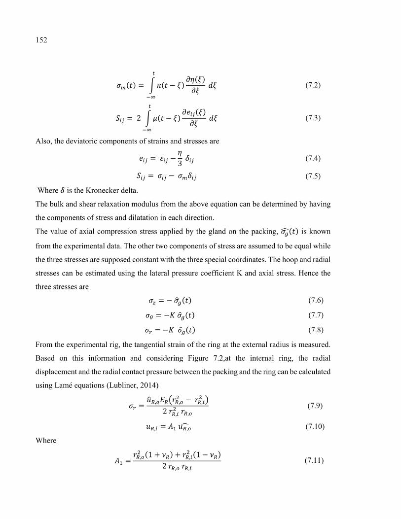
152
( ) = ( − ) ( ) (7.2)
= 2 ( − ) ( ) (7.3)
Also, the deviatoric components of strains and stresses are = − 3 (7.4) = − (7.5)
Where is the Kronecker delta.
The bulk and shear relaxation modulus from the above equation can be determined by having
the components of stress and dilatation in each direction.
The value of axial compression stress applied by the gland on the packing, ( ) is known
from the experimental data. The other two components of stress are assumed to be equal while
the three stresses are supposed constant with the three special coordinates. The hoop and radial
stresses can be estimated using the lateral pressure coefficient K and axial stress. Hence the
three stresses are = − ( ) (7.6) = − ( ) (7.7) = − ( ) (7.8)
From the experimental rig, the tangential strain of the ring at the external radius is measured.
Based on this information and considering Figure 7.2,at the internal ring, the radial
displacement and the radial contact pressure between the packing and the ring can be calculated
using Lamé equations (Lubliner, 2014) = , , − ,2 , , (7.9)
, = , (7.10)
Where = , (1 + ) + , (1 − )2 , , (7.11)
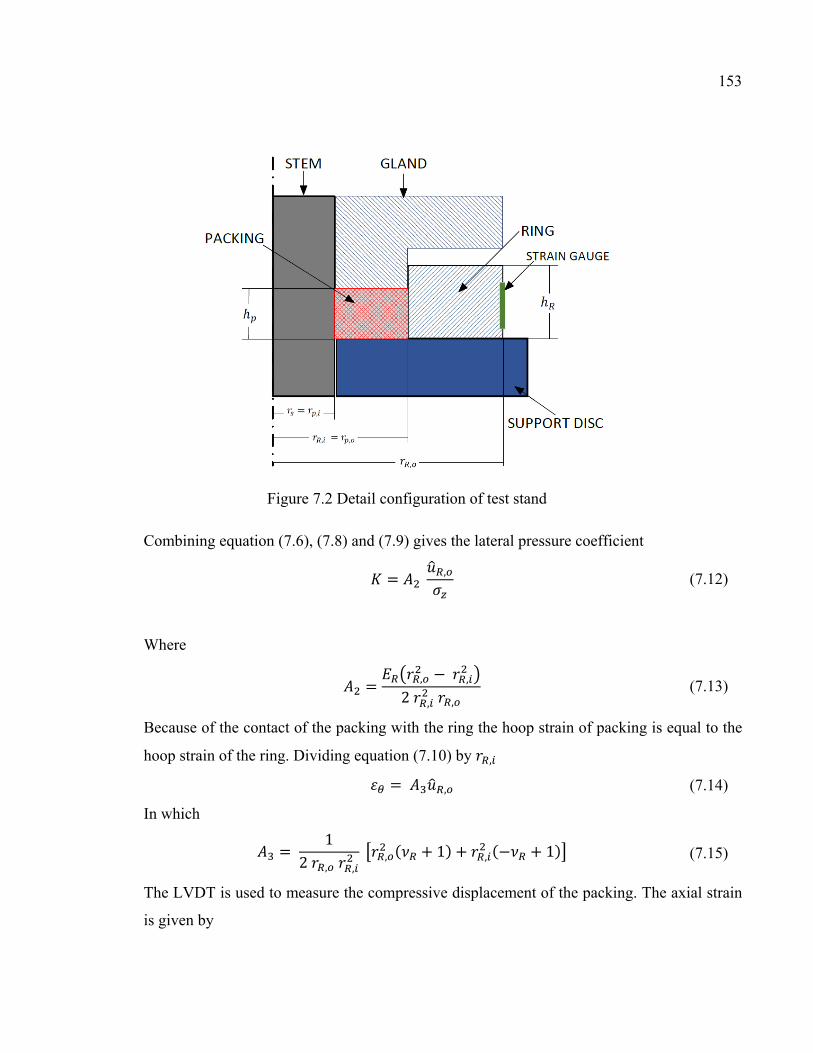
153
Combining equation (7.6), (7.8) and (7.9) gives the lateral pressure coefficient = , (7.12)
Where = , − ,2 , , (7.13)
Because of the contact of the packing with the ring the hoop strain of packing is equal to the
hoop strain of the ring. Dividing equation (7.10) by , = , (7.14)
In which = 12 , , , ( + 1) + , (− + 1) (7.15)
The LVDT is used to measure the compressive displacement of the packing. The axial strain
is given by
Figure 7.2 Detail configuration of test stand

154
= −ℎ (7.16)
Assuming that in the packing, the variation of radial displacement versus radius is constant,
the radial strain can be calculated such that = ≅ ΔΔ = , − ,, − , (7.17)
Considering to the fact that the internal radial displacement of the ring is equal to the external
radial displacement of the packing, hence, , = , (7.18)
In addition the internal radial displacement of the packing is equal to the radial displacement
of the stem. Hence, based on the Hooke’s law (Barber, 2010) and equation (7.12), this
displacement is given by , = , + (7.19)
Where = , ( − 1) (7.20) = − , , − ,,
Combining equations (7.17), (7.18) and (7.20), the radial strain can be calculated. ≅ ( − ) , −, − , (7.21)
Having all the components of stress and strain, the mean value of stress and the volumetric
dilatation are given as ( ) = −13 + 2 , (7.22) ( ) = + , + (7.23) ( ) = − ( ) = , −
(7.24)

155
( ) = − 13 ( ) = 2 − , −
(7.25)
In which =− 1ℎ (7.26)
= +A −Δ (7.27)
=− AΔ (7.28)
Experimental observations indicate that the above packing parameters vary considerably
during a short time just after application of the compressive load. The variation is attenuated
after few hours leading to a more stable behavior. This fact can exploited to assume the initial
strain as a step load and then represent the relaxation moduli of bulk and shear as ( ) = + (7.29)
( ) = + (7.30)
By substitution of equations (7.19), (7.20), (7.24), and (7.25) into equations (7.2) and (7.3),
and applying mathematical simplifications gives
( ) = + ( ) + , ( ) + ( ) (7.31)
( ) = 23 + 2 ( ) − , ( )− ( )
(7.32)
Applying the mathematical simplification and using Dirac delta function gives ( ) = ( ) + + ( ) + ( ) (7.33)

156
( ) = 2/3 ( ) + 2 − ( ) − ( ) (7.34)
Where
( ) = , ( ) (7.35)
( ) = ( ) (7.36)
A numerical scheme is adopted to solve equations (7.33) and (7.34), and determine the
relaxation modulus based on the experimental data. For the derivative operations, the central
difference method with two-point formula is used while for the integrations, the trapezoidal
formulation is adopted. A procedure based on the least square regression method in MATLAB
(R2007a) is used to determine the coefficients of proney series.
7.5 Experimental Set-up
According to the literature the experimental investigations on the time-dependent behavior of
stuffing-box packing have been conducted in different ways. A significant parameter in the
relaxation behavior of packing material is the elastic interaction between packing and other
components such as housing and stem. This fact was not considered in most experimental
studies on packing but very well acquainted for in bolted gasketed joints studies (Nechache
and Bouzid, 2008).
A novel test bench which is dedicated to the characterization study of packing rings is
developed and installed in the static and dynamic sealing laboratory in the Ecole de
Technologie Superieure. The general configuration and the main components of test bench are
presented in Figure 7.3. Also, Figure 7.4 shows a sectional view of the experimental setup.
The test rig can accommodate one packing ring of 3/8 in (9.5 mm) thickness with an external
and an internal diameter of 1 7/8 and 1 1/8 in (47.62 and 29.2 mm) respectively. The packing
is confined between the ring 2 2, and the stem 20. On the external side of the ring, a high
accurate strain gauge is installed to measure the hoop strain from which the radial displacement
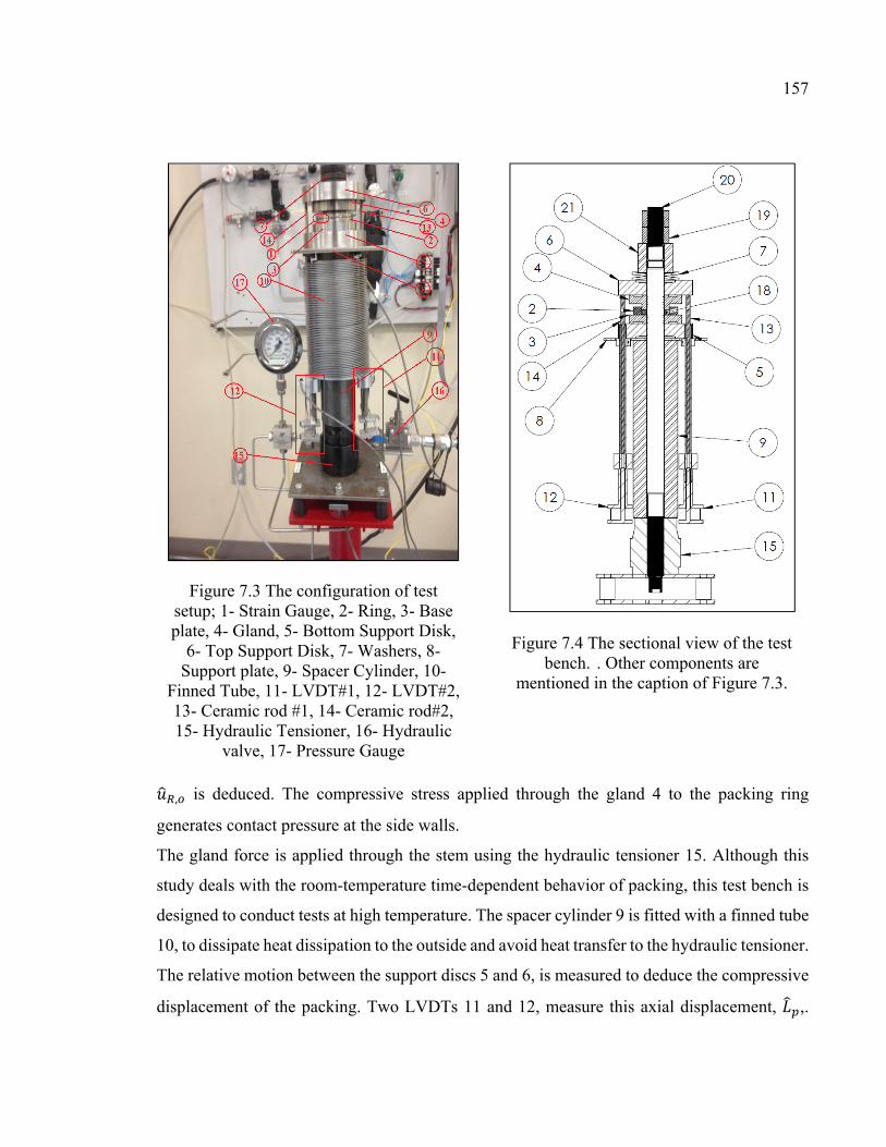
157
, is deduced. The compressive stress applied through the gland 4 to the packing ring
generates contact pressure at the side walls.
The gland force is applied through the stem using the hydraulic tensioner 15. Although this
study deals with the room-temperature time-dependent behavior of packing, this test bench is
designed to conduct tests at high temperature. The spacer cylinder 9 is fitted with a finned tube
10, to dissipate heat dissipation to the outside and avoid heat transfer to the hydraulic tensioner.
The relative motion between the support discs 5 and 6, is measured to deduce the compressive
displacement of the packing. Two LVDTs 11 and 12, measure this axial displacement, ,.
Figure 7.3 The configuration of test setup; 1- Strain Gauge, 2- Ring, 3- Base plate, 4- Gland, 5- Bottom Support Disk,
6- Top Support Disk, 7- Washers, 8- Support plate, 9- Spacer Cylinder, 10-
Finned Tube, 11- LVDT#1, 12- LVDT#2, 13- Ceramic rod #1, 14- Ceramic rod#2, 15- Hydraulic Tensioner, 16- Hydraulic
valve, 17- Pressure Gauge
Figure 7.4 The sectional view of the test bench. . Other components are
mentioned in the caption of Figure 7.3.

158
The tension force in the stem is measured by a full bridge strain gauged system glued to the
stem near the bolt tensioner and used to determine the packing axial stress, .
Four gland stresses, 31, 41.4, 51.7, and 62 MPa (4000, 5500, 7000, and 8500 psi) are applied
to the packing ring through the hydraulic tensioner which is then locked with a level nut. Then
the variation of axial load, hoop strain on the external side of the ring and axial displacement
of the packing are measured and recorded through a data acquisition system and a computer
under the LabView software.
7.6 Results and discussion
The variation of the axial compressive stress, the radial displacement of the ring at its outside
diameter, and the axial displacement of packing subjected to the gland stress are measured with
time for the four initial gland stress levels. Figure 7.5 shows the variation of the axial
compressive stress over a period of 300 minutes or 5 hours. Although the values are recorded
at room temperature, the gland stress drops significantly and in particular for the high initial
stress level. For example for the initial gland stress of 58.6 MPa, the compressive stress reduces
Figure 7.5 Relaxation of axial packing stresses

159
by up to 18%. The percentage drop in the axial compressive stress increases with the initial
gland stress level.
Figure 7.6 shows the variation of ring hoop strain with time. The strain gauge sensitive to
temperature is attached to the external side of the ring and measures the hoop strain of the ring.
The curves in Figure 7.6 show some fluctuation due to electronic noise. Similar to Figure 7.5,
four curves at different initial gland stresses are presented. The reduction in the hoop strain
with time is more important with higher gland stress level.
The axial displacement of the packing measured by two LVDTs is shown to increase slightly
with time before it stabilizes after 100 minutes as is depicted in Figure 7.7. Again the axial
deformation of packing is higher with higher gland stress level.
From the curves of Fig. 6 and equation (7.12) the values for lateral pressure coefficient can be
evaluated. Figure 7.8 shows the variation of lateral pressure coefficient with time. From this
figure it can be deduced that the lateral pressure coefficient decreases with relaxation time.
This is attributed to the fact that while the void size decreases with time the graphite material
becomes more rigid. However the lateral pressure coefficient increases with the gland axial
Figure 7.6 Hoop strain at ring OD versus time

160
stress level. This is because the material resists more compression at the higher stress level.
The lateral pressure coefficient increases with higher gland stress and decreases with time.
Figure 7.7 Axial compression of packing ring versus time
Figure 7.8 Lateral pressure coefficient versus time

161
Using data from Figures (7.5), (7.6) and (7.7) and the resolution of equations (7.33) and (7.34)
leads to the evaluation of the shear and bulk moduli of relaxation. The parameters of Prony
series are determined through an optimization process of curve fitting in MATLAB (R2007a).
The relationships between long-term relaxation moduli quantified by and , and the
elastic moduli and are given by the following equations:
= + (7.37)
= + (7.38)
In Table 7.1 the numerical values of Prony series for bulk and shear modulus are presented for
different initial gland stresses. It can be noted that all parameters increase with gland stress
level increase. Also, the shear modulus is always greater than bulk modulus.
The variations of bulk and shear moduli based on the equations (7.29) and (7.30) are shown in
Figures 7.9 and 7.10 respectively. The variation of the bulk modulus of relaxation decreases
with time but increases with the initial gland stress increase. Nevertheless, the curves of all
stress levels converge to a certain value between 60 to 80 MPa if enough relaxation time is
allocated. The shear modulus shows a more stable variation with time. Similarly, it can be
deduced that the shear modulus converges to a certain value.
7.7 Conclusion
In this study, a novel test bench used in conjunction with an analytical methodology to
characterize the time-dependent behavior of packing rings is presented. The adopted model for
Table 7.11 Relaxation modulus of packing ring in different gland stress
Stress (MPa) 27.6 57.02 70.2 117.5 113.59 37.9 64.69 83.28 119 117.23 48.3 71.84 99.46 125.3 125.58 58.6 76.06 117.86 130.6 134.46

162
flexible graphite packing ring is based on the linear viscoelastic relaxation based on Prony
series of bulk and shear moduli. The experimental tests were carried at room temperature under
Figure 7.9 Bulk modulus versus time
Figure 7.10 Shear modulus versus time

163
four different initial gland stress levels. The parameters of Prony series are determined by
application of the least square curve fitting technique with MATLAB optimization toolbox.
Although the experiments are conducted at room temperature, significant relaxations were
recorded with the time. The characterization methodology presented in this paper can also be
exploited for high-temperature. This test bench designed and developed to investigate the time-
dependent behavior of packing rings can also be used for high temperature.

164

165
CONCLUSION AND RECOMMENDATIONS
Stuffing-boxes are a common sealing system used in valves and compressors. Considering the
quantity of valves in nuclear, chemical and petrochemical processing plants, any failure in the
performance or safe operation of a stuffing-box valve can cause tremendous accidents. In spite
of the long period of time stuffed packing boxes have been used as a mean of external sealing
for valves, there is currently no standard design or selection procedure for packing materials
and there are only a few standard test procedures to qualify leakage of stuffing-box packing.
With the new environmental protection laws and the strict regulations placed on the amount of
fugitive emissions, making valves and pumps compliant with the sealing standards is a very
significant challenge for design engineers.
Global warming, which is the source of several environmental problems such as the melting
polar ice and extreme El Nino events, has become a more critical issue as pollution around the
world continues to increase. Fugitive emissions resulting from human activities are one of the
contributing factors to global environmental changes. Hence, environmental protection
standards are increasing and being tightened to prevent further damage to the environment.
Based on a report from EPA, nearly 60% of fugitive emissions from refineries comes from the
leakage in valve external sealing. This information suggests that improving valve sealing
performance would contribute to a reduction of the amount of air pollution. Hence, a proper
study is necessary to ensure that the quality of packed stuffing-boxes conform to the new
regulations. The first step in achieving this goal is to further the existing comprehension of
how the integrity of components in a stuffing-box affect sealing performance. This study was
directed toward this point with two main objectives:
Modelling the mechanical integrity of the components in a stuffing-box, and
Characterizing the sealing behaviour of these components.

166
To fulfill the above mentioned objectives, a methodology was developed in order to have a
robust procedure and achieve reliable results. A comprehensive study of the literature on
packed stuffing box sealing systems in valves was carried out. In the literature, researchers and
engineers presented their studies, mainly experimental investigations, to characterize the
sealing performance of stuffing boxes in certain applications. Considering the long term use of
stuffing box valves, there are very few published documents regarding sealing performance,
while a majority of the existing literature focuses on specific applications via experimental
observations.
In the early 1990’s, the motivation to study packed stuffing boxes increased as the prohibition
of asbestos as a packing material forced the use of new packing materials, and as legislation
was implemented to reduce the impact of fugitive emissions on global warming. The first
chapter presents a comprehensive review of the existing literature on stuffing box packing,
which demonstrates how the new standardized regulations for the amount of fugitive emissions
from valves has become more globally accepted, and in turn being more restrictive for
industries.
Experimental investigation has a vital role in this study as it is the basis for the validation of
the presented models and serves to determine the empirical parameters. To achieve the
experimental goals, a well-equipped test bench was created and is described in the second
chapter. This test bench was equipped with accurate measurement devices such as strain
gauges, pressure transducers, thermocouples and LVDTs, and with four leak detection
techniques used to cover a wide range of leak rates, from close, to molecular, to continuous
fluid flow.
Experimental observations and the literature review inspired us to present a more rigorous
study on the distribution of the contact stress in packed stuffing boxes. Two methods were then
presented which increased sealing performance by introducing a more homogeneous
distribution of radial contact stress. The results of this study are presented in chapter three,
which demonstrate the efficiency of a tapered shape rather than a multi-pass compression of
the packing rings. It showed that increasing the tapered angle of the internal wall of the housing
caused a reduction of the contact stress between the top and bottom side of the packing rings.

167
This method has some restrictions however, as when the angle is too large the expansion of
the packing ring under gland stress cannot create enough contact stress. Thus, an optimization
study is suggested to characterize the taper angle which would produce the best sealing
performance while still meeting the constraints.
The sealing performance of stuffing boxes is the result of various components working in
concert, with behavior that might change with time. It has been shown that the creep and
relaxation phenomena in packing rings made of viscoelastic materials can even start at room
temperature. In these cases the stiffness of the stuffing box components, such as the housing,
has a significant effect on the load retention and therefore on the sealing performance. The
positive contribution of a flexible structure compensates for the loss of contact pressure due to
creep, but jeopardizes the integrity of the structure as the thicknesses would have to be thinner
to make the assembly less rigid. A comprehensive study on the elastic behavior of the housing
in a packed stuffing-box is presented in the chapter four. This chapter provides an introductory
design code applicable in the design of valves. This study was based on the theory of beams
on elastic foundations in combination with Lamé’s theory for thick cylinders and the results
were presented in ASME format codes, which are similar to the code procedures which have
been applied to the design of pressure vessels for many years.
The internal structure of packing rings has a disordered porosity, which allows for the transfer
of axial compression stress to radial contact stress. This property provides the pressurized
confined liquid another way to escape and causes more leakage in addition to the leakage from
contact surfaces. To characterize the sealing of porous material, a new approach based on
filtration velocity and Darcy's model for fluid flow in porous media is presented in chapter
five. For this model, a diffusive term is added to take into account the tortuosity of disordered
porous media. With this approach, the parameter for diffusivity is presented as a function of
axial compression stress, mean free path in atmospheric pressure, and the characteristic length
of the stuffing box. This approach demonstrated that the variation of logarithmic values for the
diffusivity parameter has a linear relation with the inverse of the mean gas pressure , where the
intercept depends on the gland stress, the slopes of these curves are constant, and is a
characteristic parameter of the packing material.

168
In the proposed test procedure, helium is used as the reference gas to characterize the packing
ring and to determine the empirical parameter in the theoretical model. Then by applying this
model, the leak rates from the same packing ring with other type of gases, such as nitrogen and
argon, are predicted. The results from comparing the predicted leak rates versus the measured
ones demonstrate significant agreement at a wide range of leak rates, from 5 × 10 to 3 ml/s.
For this application, this range included close molecular flow to slip flow in porous gaskets.
In chapter six a comparison study evaluates the predictive accuracy of the Modified Darcy
method and of the capillary and concentric cylinders methods. For the modified Darcy’s
model, a diffusive term was also added with the assumption of the first order slip boundary
conditions for the capillary and concentric cylinders models. As in the previous study, helium
was used as a reference gas to characterize the packing properties and the results were used to
predict the leak with other gases such as nitrogen and argon. All three models presented
acceptable agreement for the measured leak rates. The main difference was that each method
presented different levels of accuracy at certain ranges. For example, for the prediction of
nitrogen under small compression stress the capillary model presented better accuracy whereas
at a higher compression stress the concentric cylinders model was more accurate.
In general, the aim of this study was to characterize the sealing performance of different
stuffing-box packing materials and to provide a design procedure document which could be
useful for designers and engineers. The results of this study provide the necessary introductory
data to satisfy this main objective, and further studies are necessary to fully achieve this goal.
There are other important parameters in stuffing boxes which were found to significantly affect
sealing performance. The variation in the properties of packing material through time is an
important consideration for the sealing industry. The results of one preliminary study
demonstrated that even at room temperature axial compression drop for short term applications
of packing in a stuffing box. Therefore, the characterization of sealing performance while also
taking into account the effect of creep and relaxation should be the subject of further studies.
Therefore a recommended research topic to take the research a step further is the
characterization of sealing performance of packing rings at high temperature. In general
operating at elevated temperature conditions accelerates the creep and relaxation phenomena

169
and packed stuffing box applications are not an exception. Therefore a full experimental
investigation requiring the modification of the test rig for high temperature is the next phase to
achieve for the packing research program there is being conducted at the Static and Dynamic
Sealing Laboratory of ÉTS.

170

171
APPENDIX A
FORMULATION FOR INTEGRITY OF STRUCTURE
SECTION A.1: FUNCTIONS ( ) = 12 ( ℎ( ) ( ) − ℎ( ) ( ) ) (I-1)( ) = ℎ( ) ( ) − ℎ( ) ( ) (I-2)( ) = 12 ( ℎ( ) ( ) + ℎ( ) ( ) ) (I-3)( ) = 12 ( ℎ( ) ( )) (I-4)= −2 − 2 − 2 − 2 (I-5)= 2 + 2 + 2 + 2 (I-6)
Where in the last two equations the indexes 0 and refer to the first and end of the beam.
The other and constants are as follows ( ) = ℎ(2 ) − (2 )2 ℎ ( ) − ( ) (I-7)( ) = ℎ(2 ) − (2 )2 ℎ ( ) − ( ) (I-8)( ) = ℎ(2 ) + (2 )2 ℎ ( ) − ( ) (I-9)( ) = − ℎ( ) ( ) − ℎ( ) ( )ℎ ( ) − ( ) (I-10)( ) = − 2 ( ) ℎ( )ℎ ( ) − ( ) (I-11)( ) = −2 ℎ( ) ( ) + ℎ( ) ( )ℎ ( ) − ( ) (I-12)
SECTION A.2: ARGUMENTS OF MATRIX B Assume that : ( , ) and : ( , ) are functions for displacement in a ring
and cylinder, with the number K at the point i, while only the unit force/moment j is applied. Such that

172
Also for the slope of the profile, assume that : ( , ) and : ( , ) are the
slope functions with the same application. Such that : , = ( ) (I-17) : , = ( ) (I-18) : , = 2 ( ) + ( ) − 2 ( ) (I-19)
: , = 2 ( ) + ( ) − 2 ( ) (I-20)
Where at the first point of a cylinder is zero and at the end point is one. In this study, the
first point is on the top of each cylinder.
Points A, B, and C are by sequent in section A.1, section A.2 and section A.3. All not mentioned arguments of the matrix B are equal to zero. = : ( , ) − : ( , ) (I-21) = : ( , ) − : ( , ) (I-22) = − : ( , ) (I-23) = − : ( , ) (I-24) = : ( , ) − : ( , ) (I-25) = : ( , ) − : ( , ) (I-26) = − : ( , ) (I-27) = − : ( , ) (I-28) = : ( , ) (I-29) = : ( , ) (I-30) = : ( , ) − : ( , ) (I-31)
: , = ( ) (I-13) : , = ( ) (I-14) : , = 2 ( ) + ( ) + ( ) (I-15)
: , = 2 ( ) + ( ) + ( ) (I-16)

173
= : ( , ) − : ( , ) (I-32)= − : ( , ) (I-33)= − : ( , ) (I-34)= : ( , ) (I-35)= : ( , ) (I-36)= : ( , ) − : ( , ) (I-37)= : ( , ) − : ( , ) (I-38)= − : ( , ) (I-39)= − : ( , ) (I-40)= : ( , ) (I-41)= : ( , ) (I-42)= : ( , ) − : ( , ) (I-43)= : ( , ) − : ( , ) (I-44)= : ( , ) (I-45)= : ( , ) (I-46)= : ( , ) − : ( , ) (I-47)= : ( , ) − : ( , ) (I-48)
SECTION A.3: ARGUMENTS OF RHS MATRIX IN EQUATION (3.23) Where and are the arguments and of the matrix A in the Equation (3.20) based on the direction and position of force . and are applied on the bottom ring and are shown in Figure 3.3. is an equivalent concentrated force instead of distributed axial stress from last packing ring on the bottom ring, presented as in the Figure 3.3. These three forces based on their calculation sequence are as follows

174
= 0 (I-49)= 0 (I-50)= ( + 4 ) (I-51)= ( + 4 ) (I-52)= − ( + 4 ) + | | + | | + | | (I-53)
= − ( + 4 ) + | | + | | + | | (I-54)
= 4 ( )( − ) (I-55)= ( − )2 (I-56)= ( + ) + ( + )4 (I-57)
BIBLIOGRAPHY
Aikin, J., (1994). Packing developments improve valve availability. Power Engineering, Barrington, Illinois, vol. 98(1), pp: 29-32.
Albertoni, S., Cercignanni, C., Gotusso, L., (1963). Numerical Evaluation of the Slip Coefficient. Phys. Fluids, 6(7), p 993-996.
Anez, L., Calas-Etienne, S., Primera, J., and Woignier, T., (2014). Gas and Liquid Permeability in Nano Composite Gels: Comparison of Knudsen and Klinkenberg Correction Factors. Microporous and Mesoporous Materials, 200, p. 79-85.
Anon, (1998). Good yarn sealing of valve shafts (in german), Chemie-Technik (Heidelberg)
27 (7) 118{173}.
ANSI/ISA-93.00.0, (1999). Standard Method for the Evaluation of External Leakage of Manual and Automated On-Off Valves. American National Standards Institute.
ANSYS-V 13.0. (2014). Standard Manual, Version 13.0 ANSYS Inc.
API-622, (2011). Type testing of process valve packing for fugitive emissions. American Petroleum Industries.
API-624, (2011). Type Testing of Rising Stem Valves Equipped with Flexible Graphite Packing for Fugitive Emissions. American Petroleum Industries.
Arghavani, J., Derene, M. and Marchand, L., (2002). Prediction of Gasket Leakage rate and sealing performance through fuzzy logic. International Journal of Advanced Manufacturing Technology, Vol. 20, n 8, p 612-620.
ASME-PVP (2013). ASME Pressure Vessel & Piping Conference. www.asmeconferences.org/PVP(2013)/index.cfm
Avdeev, V.V., Il’in, T.E., Ionov, S.G., Bozhko, G.V., Gusak, O.V. and Prodan, V.D., (2005). Deformation Characteristics of Gland Packings Made of Heat-Expanded Graphite. Chemical and Petroleum Engineering, Vol. 41(9-10), p 485-491.
Bagc, O., Dukhan, N., Ozdemir, M., (2014). Flow Regimes in Packed Beds of Spheres from Pre-Darcy to Turbulent. Transport in Porous Media 104(3), 501-520.
Baogang, C., Chenghong, D. and Hong, X., (1999). 3-D finite element analysis of bolted flange joint considering gasket nonlinearity. American Society of Mechanical Engineers, Pressure Vessels and Piping Division (Publication) PVP, v 382, p 121-126, 1.
Barber J. R., (2010). Elasticity. Springer Science + Business Media, B.V.

176
Bartonicek, J. and Schoeckle, F., (1996). Approach to a correct function of stuffing boxes. ASME pressure vessel and technology, Vol. (36), pp: 115-121.
Bartonicek J., Hahn R., Kockelmann H., Ros E. and Schockle, F., (2001). Characteristics of packing for stuffing boxes for the proof of strength function and tightness of valves. Transactions, SMiRT 16, Washington DC.
Bayreuther, D., (2012). Fugitive Emission Testing and Certification for Valves, Valve Manufacturers Association. VMA technical seminar & Exhibit, Houston Texas, Mars 8-9.
Bazergui, A., (2003). Résistance des matériaux : recueil de problèmes. Montréal: Presses internationales Polytechnique ISBN 2553010370 (v. II).
Beskok, A., and Karniadakis, G., (1999). A model for flows in channels, pipes, and ducts at micro and nano scales. Microscale thermophysical engineering, 3 pp. 43-77.
Bianchi, E., Riva, M., Guadagnini, A., (2014). Three-Phase Permeabilities: Upscaling, Analytical Solutions and Uncertainty Analysis in Elementary Pore Struct-ures. Transport in Porous Media, 106(2), p 259-283.
Boas, M.L., (2006). Mathematical methods in physical sciences. 3rd Edition, Hoboken, N.J.: Wiley.
Bohner, K., Blenke, H. and Hinkel, R., (1975). Deformation, and relaxation of stuffing-box soft packings. 7th International Conference on Fluid Sealing, Paper E3.
Boqin, G., Ye, C., Dasheng, Z., (2007). Prediction of Leakage Rates through Sealing Connections with Nonmetallic Gaskets. Chem. Eng., 15(6), p 837-841.
Boresi, A.P. and Schmidt, R.J., (2003). Advanced Mechanics of Materials. New York: John Wiley & Sons.
Brinson, L. C., and Brinson, H. F., (2008). Polymer Engineering Science and Viscoelasticity An Introduction. Springer Science and Business Media. ISBN 978-1-4899-7485-3, New York 2015.
Burggraaf, A.J. and Cot, L., (1996). Fundamentals of Inorganic Membranes Science and Technology. Elsevier: Amsterdam, The Netherlands.
Cartraud, P. and Wielgosz, C., (1996). Numerical modelling of the elastoplastic behaviour of a gasket material . Computational Materials Science, vol. 5, no. 1-3, p.75-81.
Carrigy, N.B., Pant, L.M., Mitra, S., and Secanell, M., (2013). Knudsen diffusivity and permeability of PEMFC microporous coated gas diffusion layers for different polytetrafluoroethylene loadings. Journal of the electrochemical soceity, 160 pp. F81-F89.
177
Cazauran, X., Birembaut, Y., Hahn, R., Kockelmann, H., Moritz, S., (2009). Gas leakage correlation. Proceeding of the ASME 2009 Pressure Vessel and Piping division conference, PVP2009-77882.
Chambers, A., Wootton T, Moncrieff J and McCready P., (2008). Direct Measurement of Fugitive Emissions of Hydrocarbons from a Refinery. Journal of the Air & Waste Management Association 58 (8), p 1047–1056.
Chastanet, J., Royer, P., and Auriault, L., (2004). Does Klinkenberg’s law survive upscaling?. Transport in Porous Media, 56 pp. 171-198.
CHEVRON SSM-PU-53.02-A: (2008). Qualification Testing of Subsea Equipment.
Chor, V. and Li, W., (2008). A permeability measurement system for tissue engineering scaffolds. Meas. Sci. Technol. 18 pp. 208-216.
Civan, F., (2010). Effective correlation of apparent gas permeability in tight porous media. Transp. Porous Med, 82 pp. 375-383.
CRANE CPE, http://www.cranecpe.com/chem-energy/products/valves/gate-valves/cast-iron-gate-valves/crane-iron-gate-valves&page=C7A810F7-C421-AF22-A684249E275C2A22
Denny, D. F., (1957). A force analyze of the stuffing-box seal. BHRA research report No. 550.
Denny, D. F. and Turnbull, D. E., (1960). Sealing characteristics of stuffing-box seals for rotating shafts. proc. Instr. Engrs., V174(6), pp: 271-283.
Diany, M. and Bouzid, A. H., (2006). Evaluation of contact stress in stuffing box packings. ASM pressure vessel and piping division conference, PVP-ICPVT-11-93083.
Diany, Mohammad and Bouzid, Abdel-Hakim., (2009)(a). Analytical evaluation of stresses and displacements of stuffing-box packing based on a flexibility analysis. Tribology International, vol. 42, nº 6. pp. 980-986.
Diany, Mohammad and Bouzid, Abdel-Hakim., (2009)(b). Short term relaxation modeling of valve stem packing. Journal of Tribology, vol. 131, nº 3.
Diany, Mohammad and Bouzid, Abdel-Hakim., (2010). An experimental-numerical procedure for stuffing-box packing characterization. American Society of Mechanical Engineers (ASME) pressure vessel and piping division, Vol. 2, p183-189.
Diany, M. and Bouzdi, A.H., (2011). An experimental-numerical procedure for stuffing box packing characterization and leak tests. Tribology International, Vol. 133, 0.12201.
Diany, M. and Bouzid, A.H., (2012). Creep constitutive law of packing materials based on relaxation tests. Journal of Tribology, vol. 134, nº 1.

178
Environment Canada, (2013). Canada’s Emission Trend . on line access < https://www.ec.gc.ca/ges-ghg/985F05FB-4744-4269-8C1A-D443F8A86814/1001-Canada's%20Emissions%20Trends%20(2013)_e.pdf>
Ergun, S., (1952). Fluid flow through packed columns. Chem. Eng. Prog. 48 pp. 89-93.
ESA, (2009). European Sealing Association, http://europeansealing.com/en/publications/valve-world-publications
Espinosa-Paredes, G., (2015). Diffusive Transport in Naturally Fractured Reservoirs: Averaging Equations. Energy Sources, Part A: Recovery, Utilization, and Environmental Effects. Volume 37, Issue 15.
Flitney, R.K., (1986). Soft packings. Tribology International, v 19, n 4, p 181-183.
Forchheimer, P., (1901). Wasserbewegung durch Boden. Zeitschrift des Vereines Deutscher Ingenieuer. 45 edition (In German).
FSA, Fluid Sealing Association. (2012). What are the current emission standards for valve packings?. http://www.fluidsealing.com/sealingsense
Gao, X., Diniz da Costa, J., and Bhatia, S., (2014). Understanding the diffiusion tourtisity of porous materials: An effective medium theory perspective. 110 pp. 55-71.
Grine, L and Bouzid, A. H. (2010). Liquid leak prediction in micro and nano-porous gaskets. American Society of Mechanical Engineers, Pressure Vessels and Piping Division (Publication) PVP, v 5, p 627-633, ASME (2010) Pressure Vessels and Piping Division/K-PVP Conference, PVP(2010).
Grine, L. and Bouzid, A. H. (2011). Correlation of gaseous mass leak rates through micro and nano-porous gaskets. American Society of Mechanical Engineers, Pressure Vessels and Piping Division (Publication) PVP, v 2, p 41-47.
Grine, L. (2012). Prediction des fuites gazeuses et des fuites liquides dabs les joints d'étanchéité micro et nano-poreux. thèse par articles presentee a L'École de Technologie Superieure.
Grine, L. and Bouzid, A. H., (2013). Prediction of leak rates through porous gaskets at high temperature. Journal of Pressure Vessel Technology, Transactions of the ASME, v 135, n 2.
Hayashi, K., and Hirasata, K., (1989). Experimental derivations of basic characteristics of asbestosis and graphitic packings in mounted condition. 12 Int. Conf. Fluid Sealing, Paper A3.
Heymanns Verlag, C., (2002), TA Luft: Technical Guidelines For Air Pollution Control (TA Luft). TA Luft.

179
Hisao, T. and Yoshida, F., (1990). Stress relaxation of gland packings and its modeling. International Journal of Japan Society of mechanical Engineering, vol. 33(2), pp 219-223.
Hisao, T. and Yoshida, F., (1991). Sealing characteristics of gland packing (5th Report, leakage rate measurement and its evaluation). International Journal of Japan Society of mechanical Engineering, vol. 57(538), pp 2047-2051.
Hong E. D., Shi Y. M., Cun Y.Z., Shang L. Y., (2014). Threshold Pressure Gradient of Fluid Flow through Multi-Porous Media in Low and Extra-Low Permeability Reservoirs. Science China Earth Sciences, 57(11), p 2808-2818.
Hooman, K., Tamay, A., Dahari, M., Safaei, M.R., Togun, H., and Sadri, R., (2014). A Theoretical Model to Predict Gas Permeability for Slip Flow through a Porous Medium. Applied Thermal Engineering, 70, p. 71-76
Hoyes, J.R., and Thorpe, L.C., (1995). The influence of constructional details on the performance of valve stem seals. 1st European Conference on Controlling fugitive Emissions from Valves, Pumps and Flanges, European Sealing Association (ESA), Antwerp, Belgium.
Huizenga, D.G.and Smith, D.M., (1986). Knudsen diffusion in random assemblages of uniform spheres. AlChE Journal 32, pp.1-6.
ISO-1548/TA-Luft, (2012).
ISO-15848-1. (2006). Industrial Valves-measurement, test and qualification procedure for fugitive emissions-Part: 1 Classification System and qualification Procedures for type testing of valves. International Standards Organization.
ISO-15848-2, (2003). Industrial Valves-measurement, test and qualification procedure for fugitive emissions-Part: 2 Production acceptance test of valves. International Standards Organization.
Jatkar, K.H. and Dhanwe Sunil S., (2013). Finite Element Analysis of Gate Valve. International Journal of Engineering and Innovative Technology (IJEIT) Volume 2, Issue 10, pp. 277-281.
Javadpour, F., Fisher, D., and Unsworth, M., (2007). Nano scale gas flow in shale gas sediments. J. Ca. Petrol. Technol 46 (10), pp. 55-61.
Jiang, D., Cooper, V.R., and Dai, S., (2009). Porous Graphene as the Ultimate Membrane for Gas Separation. Nano Lett., (2009), 9 (12), pp 4019–4023.
Jolly, P. and Marchand, L., (2009). Leakage Predictions for Static Gasket Based on Porous Media Theory. Journal of Pressure Vessel Technology, 131, pp. 021203.

180
Karniadakis, G., Beskok, A., and Aluru, N., (2000). Microflows and nanoflows: Fundamentals and simulation. Springer Science and Business Media ISBN 978-0-387-28676-1.
Kazeminia, M., and Bouzid, A., (2014(a)). Effect of Tapered Housing on the Axial Stress Distribution in a Stuffing Box Packing. International Journal of Advancements in Mechanical and Aeronautical Engineering – IJAMAE, 1 (3), p 115-120.
Kazeminia, M., and Bouzid, A., (2014(b)). Analytical and Numerical Evaluation of the Sealing Contact Stress of Different Soft-Packed Stuffing-Box. Configurations, (2014) ASME-Turbo Expo Conference, Vol. 3B: Oil and Gas Applications; Organic Rankine Cycle Power Systems; Supercritical CO2 Power Cycles; Wind Energy, Düsseldorf, Germany, June 16–20.
Kazeminia, M., and Bouzid, A., (2015(a)). Stress Analysis of Packed Stuffing-Boxes. ASME Journal of Pressure Vessel Technology. 137(5), 051205-9.
Kazeminia, M., and Bouzid, A., (2015(b)). Prediction of Leak Rates in Porous Packing Rings. ASME (2015) Pressure Vessels and Piping Conference, Volume 2: Computer Technology and Bolted Joints, PVP(2015)-45241, Boston, Massachusetts.
Kazeminia, M., and Bouzid, A., (2016). Characterization and modeling of time-dependent behavior of braided packing rings.. ASME (2016) Pressure Vessels and Piping Conference, Volume 2: Computer Technology and Bolted Joints, PVP(2016)-63726, Vancouver, BC, Canada.
Kennard, EH., (1938). Kinetic Theory of Gases. New York: McGraw-Hill.
Kfoury, M., Ababou, R., Noetinger, B. and Quintard, M., (2005). Upscaling Fractured Heterogeneous Media: Permeability and Mass Exchange Coefficient. Journal of Applied Mechanics, vol. 73 (n° 1). pp. 41-46. ISSN 0021-8936.
Khoei, A.R., Vahab, M., (2014). A Numerical Contact Algorithm in Saturated Porous Media with the Extended Finite Element Method. Computational Mechanics, 54(5), p. 1089-1110.
Klenk, T., Kockelmann, H., Roos, E., Bartonicek, J. and Schoeckle, F. (1999). Characteristics and testing techniques for stuffing box packings. American Society of Pressure Vessel and Piping, v(32), p 135-143.
Klenk, Th., Hahn, R., Kockelmann, H. and Roos, E., (2001). High grade proof for gaskets according to LA-Luft and VDI 2440. ASME pressure vessel and piping, Vol. 416, pp: 163-167.
Klinkenberg, L.J., (1941). The Permeability of Porous Media to Liquid and Gases. API 11th midyear meeting, Tulsa, Oklahama, API Drilling and Production Practice, p. 200-213.

181
Knudsen, M., (1909). The law of the molecular flow and viscosity of gases moving through tubes. Ann. Phys., 28, p. 75-130.
Kockelmann, H., Bartonicek, J., Roos, E., Hahn, R. and Ottens, W., (2009). Long term behaviour of stuffing box packings under the influence of fluid at high temperature. ASME pressure vessel and piping, PVP(2009)-77059.
Kogan, M.N., Naumovich, M., (1969). Rarefied gas dynamics. Plenum, New York.
Kundt, A., and Warburg, E., (1875). Ueber Reibung und Wärmeleitung Verdünnter Gase. Poggensdorft, Annalen der Physik, 155, p. 337-365.
Lamé, G., (1837). Sur les surfaces isothermes dans les corps homogènes en équilibre de température. J. Math. Pures Appl. , 2, pp. 147–188.
Lasseux, D., Jolly, P., Jannot, Y., Sauger, E. and Omnes, B., (2011(a)). Experimental measurement of the permeability of die-formed exfoliated graphite compression packings. American Society of Mechanical Engineers, Pressure Vessels and Piping Division (Publication) PVP, v 7, p 269-278.
Lasseux, D., Jolly, P., Jannot, Y., Omnes, E. S. B., (2011(b)). Permeability measurement of graphite compression packings. Journal of Pressure Vessel Technology, Transactions of the ASME, v 133, n 3.
Lejeune, H., Ton That, Y. and Sauger, E., (2013). Tool development for design and optimization of valve packing. Proceedings of PVP 2013, 2013 ASME Pressure Vessel and Piping Division Conference, July 14-18, 2013, Paris, France.
Lemini D.G., (2014). Engineering Viscoelasticity. Springer Science and Business Media, ISBN 978-1-4614-8139-3, New York 2014.
Li, X., Zhang, Y. and Xu, (2012). Failure analysis of the stuffing box in a super high pressure compressor. Advanced Material Research, Vols. 415-417, ppm226-2230.
Liang, X. and Weimer, A.W. (2015). An overview of highly porous oxide films with tunable thickness prepared by molecular layer deposition. Current Opinion in Solid State and Materials Science, 19 (2), 115-125.
Lito, P.F., Cardoso, S.P., Rodrigues, A.E., and Silva, C.M., (2015). Kinetic modeling of pure and multicomponent gas permeation through microporous membranes: Diffusion mechanisms and influence of isotherm types. Seperation & Purification Reviews, 44 pp. 283-307.
Lotfizadeh, S., and Matsoukas, T., (2015). Effect of Nanostructure on Thermal Conductivity of Nanofluids. Journal of Nanomaterials, V(2015), Article ID 697596.
Loyalka, S.K., Hamoodi, S.A., (1990). Poiseuille flow of a rarefied gas in a cylindrical tube: solution of linearized Boltzmann equation. Phys. Fluids A 2(11) pp. 2061–2065.

182
Lubliner J., (2014). Introduction to Solid Mechanics: An Integrated Approach. New York, NY: Springer New York; 2014.
Ma, J., Sanchez, J.P., Wu, K., Couples, G.D., and Jiang, Z., (2014). A Pore Network Model for Simulating Non-Ideal Gas Flow in Micro- and Nano-Porous Materials. Fuel, 116, p. 498-508.
Marchand, L., Derenne, M., and Masi, V., (2005). Predicting Gasket Leak Rates Using a Laminar-Molecular Flow Model. Proceedings of the (2005) ASME/JSME, PV. P. Conference, Denver, CO, PVP Vol. 2, Art. No. PVP(2005)–71389, pp. 87–96.
Masi, V., Bouzid, A.H., Derenne, M., (1998). Correlation between Gases and Mass Leak Rate of Gasketing Materials. Analysis of bolted joints. (1998) ASME PVP conference, PVP v. 367, p. 17-23.
Mathworks (R2007a), MATLAB, Version 7.4.0.287, Mathworks Inc., Natick, MA.
MESC SPE 77/300, (2008). Procedure and technical specification for acceptance testing (TAT) of industrial valves.
Muskat, M., (1937). The Flow of Homogeneous Fluids through Porous Media. New York, McGraw-Hill.
Nechache A. and Bouzid A., (2008). On the Use of Plate Theory to Evaluate the Load Relaxation in Bolted Flanged Joints Subjected to Creep. International Journal of Pressure Vessel and Piping, 84 (7), pp. 486-497.
Ochonski, W., (1988). Radial stress distribution and friction forces in a soft-packed stuffing-box seal. Tribology International, 0301-679X/8/010031-08.
Ottens, W., Roos, E., Kockelmann, H. and Hahn, R., (2010). Optimization of stuffing box stem sealing in valves by means of surface treatment and coating. ASME Pressure Vessel and Piping, V 2, pp: 191-201.
Pengyun, S., (1991). Study of radial stress distribution of stuffing-box seal of soft packing. Master thesis, Chengdu Science and Technology University, Sichuan, China.
Pengyun, S., Kuangmin, C. and Zongyun, D., (1998). A theoretical analysis of the lateral pressure coefficients in a soft-packed stuffing-box seal. Tribology international, V(30), No. 10, pp 759-765.
Plampin, M., Illangasekare, T., Sakaki, T. and Pawar, R., (2014). Experimental Study of Gas Evolution in Heterogeneous Shallow Subsurface Formations during Leakage of Stored CO2. International Journal of Greenhouse Gas Control, 22, p. 47-62.

183
Pothier, N.E., (1976). Application of Belleville Springs as Energy Storage Devices on Packed Valve Stem Seals in Candu Power Reactor Service. At Energy Can Ltd AECL Rep, 5555.
Ren, J., Guo, P., Guo, Z., Wang Z., (2015). A Lattice Boltzmann Model for Simulating Gas Flow in Kerogen Pores. Transport in Porous Media, 106(2), p 285–301.
Riedl, A., (2007). Emission measurements of industrial valves according to TA Luft and EN ISO 15848-1. www.valve-world.com.
Roe, M. and Torrance, A.A, (2008) .The surface failure and wear of graphite seals. Tribology International, vol. 41, pp: (2002)-1008.
Ruthven, D.M., (1984). Principles of Adsorption and Adsorption Processes. Wiley: New York.
Sawa, T., and Ogata, N., (2002). Stress Analysis and the Sealing Performance Evaluation of Pipe Flange Connection With Spiral Wound Gaskets Under Internal Pressure. ASME-PVP(2002)-1089, pp. 115-127.
Schaaf, M., Vogel, R., Klenk, T. and Bartonicek, J., (2005). Tightness characteristics of packings. ASMe pressure vessel and piping, V 2, pp: 147-153.
Schaaf, M. and Schoeckle, F., (2011). Measurement of fugitive emmisions in industrial valves. American Society of Mechanical Engineers, Pressure Vessels and Piping Division (Publication) PVP, v 2, p 235-241.
Shabtai A., Elovici Y. and Rokach L., (2012). A Survey of Data Leakage Detection and Prevention Solutions. Springer, New York.
Shou, d., Fan, J., and Mei, M., (2014). An analytical model for gas diffusion though nanoscale and microscale fibrous media. Microfluid Nanofluid, 16 pp. 381-389.
Sreekanth, A.K., (1965). Transition Flow through Short Circular Tubes. Phys. Fluids, 8(11), p 1951-1956.
Sun, H., Yao, J., Fan, D., Wang, C. and Sun, Z., (2015). Gas transport mode criteria in ultra-tight porous media. International Journal of Heat and Mass Transfer 83, pp. 192-122.
TA Luft, (2002). Technical Guidelines for Air Pollution Control (TA Luft). Heymanns Verlag, Cologne.
Tashiro, H. and Yoshida, F., (1991). Sealing characteristics of gland packing. (5th Report, leakage rate measurement and its evaluation). Nippon Kikai Gakkai Ronbunshu, C Hen/Transactions of the Japan Society of Mechanical Engineers, Part C.
Thauvin F., Mohanty K.K., (1998). Network Modeling Of Non-Darcy Flow Through Porous Media. Transport in Porous Media 31(1), p 19-37, (1998).

184
Thomson, J.L., (1961). A theory of sealing with particular reference to the packed stuffing-box. 1st International conference on fluid Sealing, BHRA, Ashford, UK.
Timoshenko, S. and Woinowsky-Krieger, S., (1968). Theory of plates and shells. 2nd Edition, McGraw-Hill Book Company.
Tison, S.A., Tilford, C.R., (1993). Low density water vapor measurements. The NIST Primary Standard and Instrument Response,” NIST Internal Report 5241.
UNFCCC, (2009). Report of the conference of the parties on its fifteenth session. held in Copenhagen from 7 to 19 December 2009.
Ugural, A.C. and Fenster, S.K., (2003). Advanced strength and applied elasticity. Prentice Hall PTR.
VDI 2440, (2000). Reducing Emissions from Mineral Oil Refineries. Beuth Verlag, Berlin.
Veiga, Jose C., Cipollati, C. and Girao, C., (2008). Valve packing sealing stress. ASME Pressure Vessel and Piping, V2, pp: 101-106.
Veiga, Jose C., Girao, C. and Cipollati, C., (2009). The influence of different braided packing materials and number of rings on stem torque and sealability. ASME Pressure Vessel and Piping, V 2, pp: 115-123.
Wang, G., Ren, T., Wang, K. and Zhou, A., (2014). Improved Apparent Permeability Models of Gas Flow in Coal with Klinkenberg Effect. Fuel, 128, p. 53-61.
Wielhorski, Y. Abdelwahed, A.B., Bréard, J., (2013). Theoretical Approach of Bubble Entrapment through Interconnected Pores: Supplying Principle. Transport in Porous Media, 96(1), p 105-116.
Wang, C.T., and Smith, J.M., (1983). Tortuosity factors for diffusion in catalyst pellets. AlChE Journal, 29.
Xiao, J.R., and Wei, J., (1992). Diffusion mechanism of hydrocarbons in zeolites. Theory. Chem. Eng. Sci., 47(5) pp. 1123–1141.
Zschiegner, S., Russ, S., Bunde, A. and Karger, J., (2007). Pore opening effects and transport diffusion in the Knudsen regime in comparision to self- (or tracer) diffusion. EPL, 78, (2000)1.
Zerres, H., M. Perez, et al. (1998). Comparison between the analysis of the mechanical behaviour of bolted joints by the Finite Element method and by the European approach (PR EN 1591). In ASME/JSME Pressure Vessels and Piping Conference. (San Diego, CA, USA, Jul 26-30), vol. 367, p. 69-73. Fairfield, NJ, USA: ASME.