
Multilayer DNA Origami Packed on a Square Lattice
6
Multilayer DNA Origami Packed on a Square Lattice Yonggang Ke, † Shawn M. Douglas, ‡ Minghui Liu, † Jaswinder Sharma, † Anchi Cheng, § Albert Leung, § Yan Liu, † William M. Shih,* ,‡ and Hao Yan* ,† Department of Chemistry and Biochemistry, and the Biodesign Institute, Arizona State UniVersity, Tempe, Arizona 85287, Department of Cancer Biology, Dana-Farber Cancer Institute, and Department of Biological Chemistry and Molecular Pharmacology, HarVard Medical School, Boston, Massachusetts 02115, Wyss Institute for Biologically Inspired Engineering at HarVard, Cambridge, Massachusetts 02138, and National Resource for Automated Molecular Microscopy, The Scripps Research Institute, La Jolla, California 92037 Received August 7, 2009; E-mail: [email protected]; [email protected] Abstract: Molecular self-assembly using DNA as a structural building block has proven to be an efficient route to the construction of nanoscale objects and arrays of increasing complexity. Using the remarkable “scaffolded DNA origami” strategy, Rothemund demonstrated that a long single-stranded DNA from a viral genome (M13) can be folded into a variety of custom two-dimensional (2D) shapes using hundreds of short synthetic DNA molecules as staple strands. More recently, we generalized a strategy to build custom- shaped, three-dimensional (3D) objects formed as pleated layers of helices constrained to a honeycomb lattice, with precisely controlled dimensions ranging from 10 to 100 nm. Here we describe a more compact design for 3D origami, with layers of helices packed on a square lattice, that can be folded successfully into structures of designed dimensions in a one-step annealing process, despite the increased density of DNA helices. A square lattice provides a more natural framework for designing rectangular structures, the option for a more densely packed architecture, and the ability to create surfaces that are more flat than is possible with the honeycomb lattice. Thus enabling the design and construction of custom 3D shapes from helices packed on a square lattice provides a general foundational advance for increasing the versatility and scope of DNA nanotechnology. Introduction One of the prominent goals in molecular and nanoscale engineering is to achieve rationally designed 3D structures with high predictability and efficiency. Conventional methods for 3D nanofabrication thus far have relied on top-down lithographic approaches. For example, ion-beam lithography can produce features with nanometer resolution, 1 but is characterized by slow throughput, which makes it impractical for large-area manu- facturing. DNA-based nanofabrication offers many unique advantages in 3D nanopatterning over conventional methods, due to the fact that DNA is an information-carrying polymer. DNA can be programmed to assume specific robust branched shapes on the nanoscale, and intermolecular interactions of DNA can be programmed using base pairing to link components together to form stick figures, 2D lattices, and 3D lattices that can organize functional chemical species on the nanoscale. 2 Extending the advantage of sequence and spatial address- ability inherent in DNA nanostructures, 2D DNA nanoarrays have recently been used to display custom-designed surface patterns for the purpose of detection and organization of other molecules such as proteins and nanoparticles. 3-7 Ever since the introduction of the DNA-origami concept, 8 it has been an attractive goal to transform the design principle of 2D DNA origami into 3D folding strategies. Recently, successes in this direction have been achieved, for example with the honeycomb- pleated method mentioned above. 9 As another example, origami † Arizona State University. ‡ Harvard Medical School and Wyss Institute for Biologically Inspired Engineering at Harvard. § The Scripps Research Institute. (1) Tseng, A. A. Small 2005, 10, 924–939. (2) Seeman, N. C. Nature (London, U. K.) 2003, 421, 427–431. He, Y.; Ye, T.; Su, M.; Zhang, C.; Ribble, A. E.; Jiang, W.; Mao, C. Nature 2008, 452, 198–201. Zhang, C.; Su, M.; He, Y.; Zhao, X.; Fang, P.; Ribble, A. E.; Jiang, W.; Mao, C. Proc. Natl. Acad. Sci. U.S.A. 2008, 105, 10665–10669. Shih, W. M.; Quispe, J. D.; Joyce, G. F. Nature 2004, 427, 618–621. Winfree, E.; Liu, F.; Wenzler, L. A.; Seeman, N. C. Nature (London) 1998, 394, 539–544. Aldaye, F. A.; Sleiman, H. F. J. Am. Chem. Soc. 2009, 129, 13376–13377. Fu, T. J.; Seeman, N. C. Biochemistry 1993, 32, 3211–3220. Li, X.; Yang, X.; Qi, J.; Seeman, N. C. J. Am. Chem. Soc. 1996, 118, 6131–6140. Rothemund, P. W. K.; Ekani-Nkodo, A.; Papadakis, N.; Kumar, A.; Fygenson, D. K.; Winfree, E. J. Am. Chem. Soc. 2004, 126, 16344–16352. Mathieu, F.; Liao, S.; Kopatsch, J.; Wang, T.; Mao, C.; Seeman, N. C. Nano Lett. 2005, 5, 661–665. Yin, P.; Hariadi, R. F.; Sahu, S.; Choi, H. M. T.; Park, S. H.; LaBean, T. H.; Reif, J. H. Science 2008, 321, 824–826. Goodman, R. P.; Schaap, I. A. T.; Tardin, C. F.; Erben, C. M.; Berry, R. M.; Schmidt, C. F.; Turberfield, A. J. Science 2005, 310, 1661–1665. Chen, J.; Seeman, N. C. Nature (London) 1991, 350, 631–633. Zhang, Y.; Seeman, N. C. J. Am. Chem. Soc. 1994, 116, 1661–1669. (3) Yan, H.; Park, S. H.; Finkelstein, G.; Reif, J. H.; LaBean, T. H. Science 2003, 301, 1882–1884. (4) Park, S. H.; Yin, P.; Liu, Y.; Reif, J. H.; LaBean, T. H.; Yan, H. Nano Lett. 2005, 5, 729–733. (5) Sharma, J.; Ke, Y.; Lin, C.; Chhabra, R.; Wang, Q.; Nangreave, J.; Liu, Y.; Yan, H. Angew. Chem. 2008, 47, 5157–5159. (6) Sharma, J.; Chhabra, R.; Cheng, A.; Brownbell, J.; Liu, Y.; Yan, H. Science 2009, 323, 112–116. Published on Web 10/06/2009 10.1021/ja906381y CCC: $40.75 2009 American Chemical Society J. AM. CHEM. SOC. 2009, 131, 15903–15908 9 15903
Transcript of Multilayer DNA Origami Packed on a Square Lattice
Multilayer DNA Origami Packed on a Square Lattice
Yonggang Ke,† Shawn M. Douglas,‡ Minghui Liu,† Jaswinder Sharma,†
Anchi Cheng,§ Albert Leung,§ Yan Liu,† William M. Shih,*,‡ and Hao Yan*,†
Department of Chemistry and Biochemistry, and the Biodesign Institute, Arizona StateUniVersity, Tempe, Arizona 85287, Department of Cancer Biology, Dana-Farber Cancer
Institute, and Department of Biological Chemistry and Molecular Pharmacology, HarVardMedical School, Boston, Massachusetts 02115, Wyss Institute for Biologically InspiredEngineering at HarVard, Cambridge, Massachusetts 02138, and National Resource for
Automated Molecular Microscopy, The Scripps Research Institute, La Jolla, California 92037
Received August 7, 2009; E-mail: [email protected]; [email protected]
Abstract: Molecular self-assembly using DNA as a structural building block has proven to be an efficientroute to the construction of nanoscale objects and arrays of increasing complexity. Using the remarkable“scaffolded DNA origami” strategy, Rothemund demonstrated that a long single-stranded DNA from a viralgenome (M13) can be folded into a variety of custom two-dimensional (2D) shapes using hundreds ofshort synthetic DNA molecules as staple strands. More recently, we generalized a strategy to build custom-shaped, three-dimensional (3D) objects formed as pleated layers of helices constrained to a honeycomblattice, with precisely controlled dimensions ranging from 10 to 100 nm. Here we describe a more compactdesign for 3D origami, with layers of helices packed on a square lattice, that can be folded successfullyinto structures of designed dimensions in a one-step annealing process, despite the increased density ofDNA helices. A square lattice provides a more natural framework for designing rectangular structures, theoption for a more densely packed architecture, and the ability to create surfaces that are more flat than ispossible with the honeycomb lattice. Thus enabling the design and construction of custom 3D shapes fromhelices packed on a square lattice provides a general foundational advance for increasing the versatilityand scope of DNA nanotechnology.
Introduction
One of the prominent goals in molecular and nanoscaleengineering is to achieve rationally designed 3D structures withhigh predictability and efficiency. Conventional methods for 3Dnanofabrication thus far have relied on top-down lithographicapproaches. For example, ion-beam lithography can producefeatures with nanometer resolution,1 but is characterized by slowthroughput, which makes it impractical for large-area manu-facturing. DNA-based nanofabrication offers many uniqueadvantages in 3D nanopatterning over conventional methods,due to the fact that DNA is an information-carrying polymer.DNA can be programmed to assume specific robust branchedshapes on the nanoscale, and intermolecular interactions of DNAcan be programmed using base pairing to link componentstogether to form stick figures, 2D lattices, and 3D lattices thatcan organize functional chemical species on the nanoscale.2
Extending the advantage of sequence and spatial address-ability inherent in DNA nanostructures, 2D DNA nanoarrayshave recently been used to display custom-designed surfacepatterns for the purpose of detection and organization of othermolecules such as proteins and nanoparticles.3-7 Ever since theintroduction of the DNA-origami concept,8 it has been an
attractive goal to transform the design principle of 2D DNAorigami into 3D folding strategies. Recently, successes in thisdirection have been achieved, for example with the honeycomb-pleated method mentioned above.9 As another example, origami
† Arizona State University.‡ Harvard Medical School and Wyss Institute for Biologically Inspired
Engineering at Harvard.§ The Scripps Research Institute.
(1) Tseng, A. A. Small 2005, 10, 924–939.
(2) Seeman, N. C. Nature (London, U. K.) 2003, 421, 427–431. He, Y.;Ye, T.; Su, M.; Zhang, C.; Ribble, A. E.; Jiang, W.; Mao, C. Nature2008, 452, 198–201. Zhang, C.; Su, M.; He, Y.; Zhao, X.; Fang, P.;Ribble, A. E.; Jiang, W.; Mao, C. Proc. Natl. Acad. Sci. U.S.A. 2008,105, 10665–10669. Shih, W. M.; Quispe, J. D.; Joyce, G. F. Nature2004, 427, 618–621. Winfree, E.; Liu, F.; Wenzler, L. A.; Seeman,N. C. Nature (London) 1998, 394, 539–544. Aldaye, F. A.; Sleiman,H. F. J. Am. Chem. Soc. 2009, 129, 13376–13377. Fu, T. J.; Seeman,N. C. Biochemistry 1993, 32, 3211–3220. Li, X.; Yang, X.; Qi, J.;Seeman, N. C. J. Am. Chem. Soc. 1996, 118, 6131–6140. Rothemund,P. W. K.; Ekani-Nkodo, A.; Papadakis, N.; Kumar, A.; Fygenson,D. K.; Winfree, E. J. Am. Chem. Soc. 2004, 126, 16344–16352.Mathieu, F.; Liao, S.; Kopatsch, J.; Wang, T.; Mao, C.; Seeman, N. C.Nano Lett. 2005, 5, 661–665. Yin, P.; Hariadi, R. F.; Sahu, S.; Choi,H. M. T.; Park, S. H.; LaBean, T. H.; Reif, J. H. Science 2008, 321,824–826. Goodman, R. P.; Schaap, I. A. T.; Tardin, C. F.; Erben,C. M.; Berry, R. M.; Schmidt, C. F.; Turberfield, A. J. Science 2005,310, 1661–1665. Chen, J.; Seeman, N. C. Nature (London) 1991, 350,631–633. Zhang, Y.; Seeman, N. C. J. Am. Chem. Soc. 1994, 116,1661–1669.
(3) Yan, H.; Park, S. H.; Finkelstein, G.; Reif, J. H.; LaBean, T. H. Science2003, 301, 1882–1884.
(4) Park, S. H.; Yin, P.; Liu, Y.; Reif, J. H.; LaBean, T. H.; Yan, H.Nano Lett. 2005, 5, 729–733.
(5) Sharma, J.; Ke, Y.; Lin, C.; Chhabra, R.; Wang, Q.; Nangreave, J.;Liu, Y.; Yan, H. Angew. Chem. 2008, 47, 5157–5159.
(6) Sharma, J.; Chhabra, R.; Cheng, A.; Brownbell, J.; Liu, Y.; Yan, H.Science 2009, 323, 112–116.
Published on Web 10/06/2009
10.1021/ja906381y CCC: $40.75 2009 American Chemical Society J. AM. CHEM. SOC. 2009, 131, 15903–15908 9 15903
of a hollow-box-like structure in cubic10,11 and tetrahedral12
shapes has been demonstrated by linking discrete 2D arraysassembled on a single scaffold such that they collectively enclosea three-dimensional volume. In the latter three examples, as wellas in the original Rothemund-style origami, the helices arearranged on a single layer of a square lattice. Therefore a moredirect extension of these 2D origami to 3D solid structures wouldinvoke stacking of flat sheets of helices in alignment with asquare rather than a honeycomb lattice, although this would befeasible only if the arrangement of charged DNA helices at sucha high density was stable and kinetically accessible. Thus wewere motivated to determine experimentally whether this wouldbe a viable approach.
Design
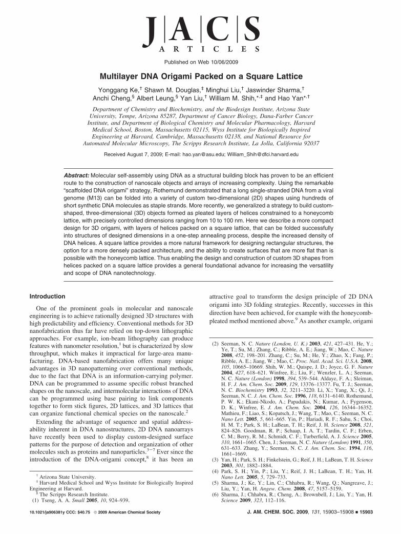
The strategy to assemble the square-lattice DNA solid blocks isdisplayed in Figure 1. For illustration purposes, only a small portionof the cuboid structure is shown, where 12 parallel helices, each32 base pairs (bp) long, are arranged into a 3 by 4 square latticeviewed from the end. This is achieved conceptually by folding aplane of parallel DNA double helices (labeled numerically in Figure1a) into multiple layers such that helices all fall into a square lattice.In turn, this square-lattice arrangement of double helices can be
conceived as the result of first laying down a scaffold strand in araster pattern as an array of antiparallel helices (numberedsequentially in Figure 1b). Next, complementary staple strands arewound in an antiparallel direction around the scaffold strands toassemble B-form double helices that have initial geometricalparameters of 2.0 nm diameter, 0.34 nm per bp rise, and 33.75°per bp average twist (or 32 bp per 3 turns; these parameters canbe adjusted in the spatial model later). This initially imposeddouble-helical twist density implies a slight underwinding comparedto the preferred 34.3° per bp or 10.5 bp per turn; this underwindingwould be predicted to lead to a compensatory global right-handedtwist of the entire structure.13 In the square lattice, each doublehelix has up to four nearest neighbors and is designed to link toeach with antiparallel strand crossovers. For explanatory purposes,here we assume that only staple strands, and not the scaffold strand,cross over between adjacent helices. Every 8 bp, the staple strandof a given double helix completes a rotation of 8 bp/(10.67 bp/turn) ) 0.75 turns. Thus every 8 bp, that staple strand is positionedto cross over to one of its four neighbors; that is, starting from 0bp as “north”, then moving away from the viewer by 8 bp givesa clockwise rotation of 0.75 turns to “west”, moving 16 bp awaygives a rotation of 1.5 turns to “south”, moving 24 bp away givesa rotation of 2.25 turns to “east”, and moving 32 bp away gives arotation of 3.0 turns back to “north”. Thus adjacent helices sharecrossovers every 32 bp, and the positions of the crossovers arerestricted to periodic intersection or “crossover” planes, labeledfrom i to iv, spaced at 8 bp intervals as illustrated in the schemeviews in Figure 1b and section views in Figure 1c. The crossoverpattern in the fifth plane is exactly the same as that of the firstplane; thus it is labeled as i again. As with the honeycomb-pleateddesigns, alternate routing paths of the scaffold strand can be chosento achieve the same overall target structure, as long as everydesigned helix is visited.
(7) Sharma, J.; Ke, Y.; Lin, C.; Chhabra, R.; Wang, Q.; Nangreave, J.;Liu, Y.; Yan, H. Angew. Chem., Int. Ed. 2008, 47, 5157–5159.
(8) Rothemund, P. W. K. Nature 2006, 440, 297–302.(9) Douglas, S. M.; Dietz, H.; Liedl, T.; Hogberg, B.; Graf, F.; Shih, W. M.
Nature 2009, 459, 414–418.(10) Andersen, E. S.; Dong, M.; Nielsen, M. M.; Jahn, K.; Subramani, R.;
Mamdouh, W.; Golas, M. M.; Sander, B.; Stark, H.; Oliveira, C. L. P.;Pedersen, J. S.; Birkedal, V.; Besenbacher, F.; Gothelf, K. V.; Kjems,J. Nature 2009, 459, 73–77.
(11) Kuzuya, A.; Komiyama, M. Chem Commun. 2009, 28, 4182–4184.(12) Ke, Y.; Sharma, J.; Liu, M.; Jahn, K.; Liu, Y.; Yan, H. Nano Lett.
2009, 9 (6), 2445–2447.(13) Dietz, H.; Douglas, S. M.; Shih, W. M. Science 2009, 325, 725–730.
Figure 1. Design of multilayer three-dimensional DNA origami on a square lattice. (a) Helical DNA model of the 3D origami square-lattice structure. Thescaffold strand is in gray and the staple strands are in three shades of blue. This model is equivalent to the cylinder model shown on the right. Eachcylindrical rod represents one DNA double helix. The numbers labeled at the helical ends indicate the order of the scaffold-strand segments that threadthrough the helices. (b) Layout and connectivity of the scaffold strand (gray) and the staple strands (colored), in an unfolded two-dimensional scheme of thetarget shape. Phosphate linkages that form crossovers between adjacent helices are shown as curved lines. The positions of the crossover points of the staplestrands are labeled from i to iv, which are spaced apart at 8-bp intervals. (c) Three-dimensional cylinder model of the folded target shape. The square-latticearrangement of parallel helices is revealed in cross-sectional slices (i-iv) that are parallel to the xy-plane spaced at 8-bp intervals and repeating every 32 bp.Staple crossovers are shown as white lines linking two adjacent helices at each cross section.
15904 J. AM. CHEM. SOC. 9 VOL. 131, NO. 43, 2009
A R T I C L E S Ke et al.
To create a desired cuboid shape, the dimensions of thetarget cuboid first must be specified, and these are determinedby the number of layers, the number of helices per layer,and the length of each DNA helix. The maximum potentialsize of the structure is limited by the length of the scaffoldstrand. Unpaired scaffold bases often are introduced at theends of helices (as unpaired loops) to minimize undesiredmultimerization. A longer unpaired loop is also needed tospan the distance from the starting point of the first helix tothe ending point of the last helix if the scaffold strand has acircular loop topology. Alternatively, if a seam8 composedof scaffold crossovers is implemented on the inside of thestructure, then a circular scaffold path can be accommodatedwithout the need for the long unpaired loop.
Next, the crossovers of the staple strands between neighboringhelices in the cuboid are assigned at the locations of theintersection planes, following the patterns as shown in Figure1b and c. These crossovers are labeled on the 2D scheme (Fig-ure 1b) as thin lines, indicating direct connectivity of thephosphate backbone. Nick points are then introduced to break
the staple strands into appropriate lengths ranging from 32 to45 nucleotides (nt) long. Finally, the actual sequence of thescaffold strand is threaded on the target scaffold path so thatthe Watson-Crick-complementary sequences of the staplestrands can be determined.
Results and Discussion
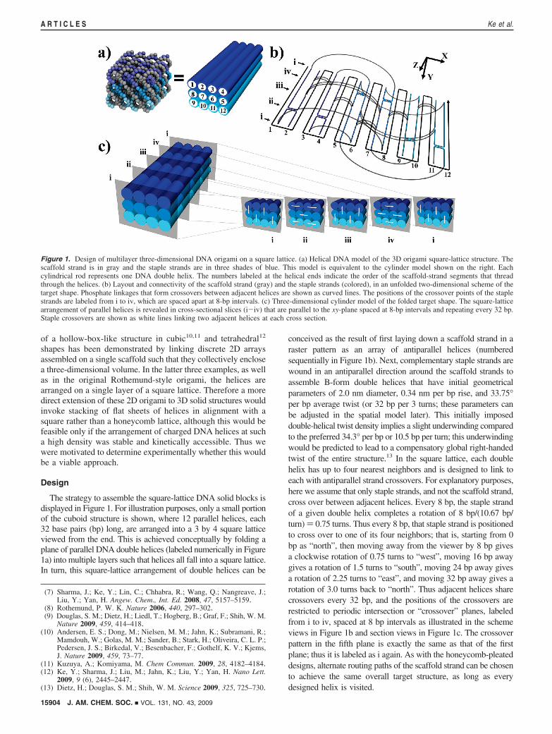
Four different cuboid shapes with various dimensions weredesigned and tested experimentally. The number of folded layersof the DNA helical planes ranges from 2 to 8, as illustrated inFigure 2a-d. The dimensions of the cuboids, m × n × d, wherem is the number of layers, n is the number of helices per layer,and d is the number of base-paired helical turns, are 2 × 21 ×15.75, 3 × 14 × 15.75, 6 × 12 × 7.5, and 8 × 8 × 9.0,respectively, which are translated into the length scale markedin the figures (assuming 3.5 nm per helical turn and 2.0 nm perhelical diameter with no gap between helices). The scaffold usedis the single-stranded M13mp18 (purchased from New EnglandBiolabs, cat # N4040S), which is 7249 nt long, or else a variantwith a site-directed insertion in the multiple cloning site that
Figure 2. 3D DNA origami solid blocks. (a) Two-layer structure. (b) Three-layer structure. (c) Six-layer structure. (d) Eight-layer structure. The 3D perspectivecylinder view and the projections of the top view and the side view are shown. Each cylinder represents a DNA double helix. For the 8-layer block in d, theend-view projection is shown. On the right are the representative transmission electron microscope (TEM) micrographs of negatively stained particlesobserved. The scale bars are 20 nm. For imaging, samples were adsorbed for 30 s onto glow-discharged grids (carbon-coated grid, 400 mesh, Ted Pella) andstained with 0.7% uranyl formate. Excess stain was wicked away by touching with a piece of filter paper, then dried at room temperature. The samples wereimaged with a Philips CM200 microscope, operated at 200 kV in the bright field mode.
J. AM. CHEM. SOC. 9 VOL. 131, NO. 43, 2009 15905
Multilayer DNA Origami A R T I C L E S
results in a final construct that is 8064 nt long.9 Target structureswere designed so that 90-97% of the scaffold strand shouldbe paired with staple strands. The remaining scaffold materialwas designed as unpaired loops at the ends of the helices. The8 × 8 × 9.0 designs were implemented with a custom computerprogram. The 2 × 21 × 15.75, 3 × 14 × 15.75, and 6 × 12 ×7.5 designs were aided by the computer software caDNAno,14
which we modified to support this square-lattice design (theoriginal version only supported the honeycomb-lattice patternof antiparallel helices).
For the formation of each designed DNA cuboid, the 174to 221 staple strands (desalted oligodeoxyribonucleotides,custom ordered on 96-well plates from Bioneer for the 2 ×21 and 3 × 14 designs and from Integrated DNA Technologyfor the 6 × 12 and 8 × 8 designs) were mixed with thescaffold strand in 5-fold or 10-fold molar excess. A one-potreaction (see below for details of thermal ramp) allowedhybridization of the scaffold strand with the hundreds ofstaple strands that direct its folding into the target shape.The annealed mixtures were subjected to agarose-gel elec-trophoresis. Next, rapidly migrating bands corresponding tomonomeric, well-folded species were excised from the geland recovered by physical extraction using a Freeze-N-Squeeze column (see experimental details in the SupportingInformation). The purified structures were imaged by trans-mission electron microscopy (TEM) after negative stainingby uranyl formate or directly imaged by cryo-EM where thenative conformations of the structures might be betterpreserved in vitreous ice during the quick freezing. Successfulfolding for the 6 × 12 and 8 × 8 designs was observed atthe following conditions: 1 × TAE ·Mg buffer (pH 8.0) thatcontains 20 mM Tris · acetate, 1 mM EDTA, and 12.5 mMMg2+, and thermal annealing by rapid heating to 90 °Cfollowed by slow cooling to 4 °C over 48 h (6 × 12 design)or 24 h (8 × 8 design). Successful folding for the 2 × 21and 3 × 14 designs was observed at the following conditions:5 mM Tris + 1 mM EDTA (pH 8.0), 16 mM MgCl2, and athermal annealing ramp from 80 to 60 °C over the course of80 min, followed by a ramp from 60 to 24 °C over the courseof 172 h.
The four objects displayed in Figure 2 demonstrate thegenerality of this square-lattice origami approach in constructingthe multilayered 3D DNA nanostructures, with increasingnumber of DNA layers (2, 3, 6, or 8 layers). TEM images ofnegatively stained samples show both the side view and topviews of the assembled products corresponding to the designedstructures. High-resolution zoom-in images clearly reveal thenumber of helices per layer and number of layers in eachstructure. The images also show increased contrast with increas-ing number of layers, consistent with the expected constructivereinforcement. The top-view images of the two-layer structurehave the lowest contrast due to the thinness of the particles.The estimated yields of each structure were 56%, 89%, 27%,and 59% for two-, three-, six-, and eight-layer structures,respectively (see Supporting Information for methods of esti-mating yield used here in comparison to methods for estimatingyield for previously analyzed honeycomb structures14).
The side views of the two-layer and three-layer structuresdisplay significant global twisting, while the six-layer and eight-layer structures do not. This behavior can be understood on the
basis of a global relaxation in response to local underwindingof double helices.13 In the square-lattice structures, the initiallyimposed double-helical twist density is set as 10.67 bp/turn (i.e.,8 bp per 0.75 turns). If the preferred double-helical twist densityfor B-DNA is 10.5 bp/turn, then the double helices in the squarelattice are underwound. The bundle of double helices will adopta global right-handed twist in order to relieve the strain of thelocal underwinding. The magnitude of the global twist shouldvary inversely with the torsional stiffness of the structure andvary directly with the amount of torque. The torsion constant Jfor a cuboid as a function of cross-sectional dimensions can beapproximated with the following formula:15
where a is the long width of the cross section and b is the shortwidth of the cross section. The torsional stiffness of each objectshould vary inversely with the length. We can estimate thenormalized torsional stiffness of the 2 × 21 × 15.75, 3 × 14 ×15.75, 6 × 12 × 7.5, and 8 × 8 × 9.0 blocks as 1.0, 2.1, 24,and 19, respectively. Thus the 6 × 12 × 7.5 and 8 × 8 × 9.0designs should be about 10 times more stiff than the 3 × 14 ×15.75 design. Furthermore, the total internal torque experiencedby the 3 × 14 × 15.75 design would be expected to besignificantly greater than for the 6 × 12 × 7.5 or 8 × 8 × 9.0designs, since the underwound helices on the extremities of theblock will contribute, by virtue of a larger mechanical advantage,a larger torque than the ones near the middle, and the averagedistance from the center is greater for the extended designs.Taken together, the combination of less internal torque and muchgreater torsional resistance would be expected to manifest asvery little noticeable global compensatory twisting for the 6 ×12 × 7.5 and 8 × 8 × 9.0 designs.
We sought to diminish the global twisting observed forthe 3 × 14 × 15.75 design by introducing targeted deletionsto reduce the initially imposed double-helical twist densityto 10.5 bp/turn. This was implemented by removing a singlebp from all helices in a cross section of the structure every64 bp. TEM imaging revealed that global twisting wasreduced; however a significant amount of global twisting stillwas evident. This was surprising, as 10.5 bp/turn waspreviously found to result in no global twist for honeycomb-lattice designs.13 Next we sought to overwind the doublehelices past 10.5 bp/turn to eliminate the residual globaltwisting. We constructed two more versions of the 3 × 14× 15.75 design, with initially imposed double-helical twistdensities of 10.44 and 10.39 bp/turn, respectively. The formerwas achieved by removing four bp evenly spaced along the192-bp length ((192 - 4)/(24 × 0.75) ) 10.44), while thelatter was achieved by removing five bp evenly spaced alongthe 192-bp length ((192 - 5)/(24 × 0.75) ) 10.39).
To make visualization of global twisting more obvious,we programmed the structures to form ribbons consisting ofhead-to-tail multimers (Figure S2). We folded the structures,gel-purified monomeric particles, and then added staplestrands that bridge the front and back ends such thathomomultimers should form. We verified that the 10.5 bp/turn design retains a right-handed global twist by imagingribbons with the TEM goniometer turned to +40° and then
(14) Douglas, S. M.; Marblestone, A. H.; Teerapittayanon, S.; Vazquez,A.; Church, G. M.; Shih, W. M. Nucleic Acids Res. 2009, 37, 5001–5006.
(15) Young, W. C. Roark’s Formulas for Stress & Strain, 6th ed.; TheMcGraw-Hill Companies: New York, 1989.
J ≈ ab3(13- 0.210
ba(1 - b4
12a4))
15906 J. AM. CHEM. SOC. 9 VOL. 131, NO. 43, 2009
A R T I C L E S Ke et al.
again with the TEM goniometer turned to -40° (i.e.,counterclockwise rotation) and observing the nodes of theribbons moving upward.13 No systematic global twist couldbe discerned with the 10.44 bp/turn and 10.39 bp/turn designs.Why the local double-helical twist density has to be slightlyoverwound to eliminate global twist in square-lattice designsis unclear. One speculative possibility is that global twistingstiffness may have two components, perhaps related to thepresence of crossover junctions: a soft mode for small-amplitude twists and a hard mode for larger-amplitude twists.In this model, when the average double-helical twist densityis 10.5 bp/turn, the sum of right-handed global twisting overthe slightly underwound segments, mainly absorbed by thesoft mode, is not fully compensated by the left-handed globaltwisting of the highly overwound segments, which saturatethe soft mode and enter the hard mode. An analogous modelhas been discussed for two-component stretching of dsDNA.16
To further reveal the 3D conformation of a square-lattice-baseddesign, we investigated the eight-layer DNA-origami structure usingcryo-EM imaging in which the structure might be better preservedin native conformation during quick freezing. We observedinteresting internal structure that we can account for as describedbelow. In our default design strategy, some staple breaks must beimplemented between crossovers 8 bp apart. For the two-layer andthree-layer structures, very few such breaks need to be incorporated.However, for the six-layer design, many such breaks must be used.We observed significantly lower yield for these structures. Intro-ducing these breaks may be destabilizing for the structure.Alternatively, simply having a large number of layers with ourdefault crossover pattern may be destabilizing, irrespective of theposition of the breaks.
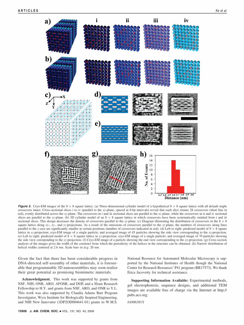
For the 8 × 8 design, we avoided the implementation of suchstaple breaks by omitting many crossovers in the core of theblock (Figure 3b). For this design, we observed a high yield ofwell-folded structures. These results suggest that omittingcrossovers produces more relaxed structures that are easier torealize or else that the omission of staple breaks positionedbetween crossovers 8 bp apart could improve folding qualityas well. Future systematic studies will be required to determinethe relative importance of these staple breaks toward affectingfolding efficiency.
The omission of crossovers we implemented leaves behind anuneven distribution of the remaining crossovers in the 8 × 8 squarelattice (Figure 3c). We define the z-axis as the helical axis, and theother two axes as x and y, respectively. In our design, many helicesthat are adjacent in the x-direction do not share any crossovers;thus electrostatic repulsion will cause them to bow away from eachother. Consistent with our design, the cryo-EM images reveal thatthere are three distinguishable populations of particle views: (1)Particle views corresponding to the xz-projection of the 8 × 8square lattice (Figure 3d). In the averaged cryo-EM image, we canclearly see some larger spaces between two neighboring slices ofDNA helices at the positions with a low number of crossoverssummed along the y-axis (low numbers indicated by red numerals).(2) Particles corresponding to the yz-projection of the 8 × 8 squarelattice (Figure 3e). Due to the even distribution of crossoversbetween helices that are adjacent in the y-direction, the spacesbetween two neighboring slices of helices appear uniform at everyposition. (3) Particle views corresponding to the xy-projection ofthe 8 × 8 square lattice (Figure 3f). This image clearly shows a
90° angle between the rows of helices arrayed along the x- andy-axes. However, only a small number of 8 × 8 structures couldbe found in this orientation; thus we could not generate accurateaveraged images for this class of particle views. On the basis ofthese cryo-EM images, we estimated the effective diameter of thedouble helix in the structures as the width of the cuboids dividedby the number of helix layers, which gives a result of 2.6 nm ((0.1nm SD) per helix. Assuming an unhydrated helical diameter of2.0 nm (although the hydrodynamic helical diameter17 has beenestimated as 2.2 to 2.6 nm), this observation suggests the presenceof interhelical gaps produced by electrostatic repulsion on the orderof 0.6 nm, smaller than the 1.0 nm gap size estimated forRothemund’s flat 2D origami and larger than the one observed inthe 3D origami packed on the honeycomb lattice. This is possiblydue to the longer distances between the crossover points along apair of adjacent helices, i.e., three turns in the square-lattice designand two turns in the honeycomb-lattice design. Apparent differencesin effective helix diameter between architectures may originate inpart from staining artifacts (e.g., cavities where large amounts ofpositively charged stain accumulate, or flattening).13 Here the cryo-EM imaging should better resemble the native parameters.
Discussion and Conclusion
In summary, we have achieved the design and constructionof multilayer 3D DNA nanostructures using the scaffolded-DNA-origami strategy with DNA helices packed on a square-lattice geometry. The new design parameters learned hereprovide us knowledge for building a more diverse set of 3Dnanostructures. We expect that the square-lattice 3D objectsshould be more stable if cross-sectional area or volume is aconstraint, since material density is higher. One might alsoanticipate that square-lattice structures should be moreresistant to compression. Although further studies are neededto better understand their mechanical properties at a single-molecule level, we believe the multilayer structures developedhere may find great potential in controlling the preciseorientation of guest macromolecules by carving geometricallydefined cavities across the layers. For example, arrays ofmicroscopic features comprising different proteins are ex-tremely important for proteomics and bioagent screening.Deposition of proteins onto electrodes has also been used toachieve efficient electron transfer from protein to theelectrode for detection, energy, and environmental applica-tions (e.g., electron transfer plays a pivotal role in biologicalfunctions essential to life, such as photosynthesis, respiration,and metabolic pathways; use of electroactive enzymesrequires good contact of the enzyme with the electrodesurface18). Conventional patterning techniques such as mi-crocontact printing, spot arraying, or dip-pen nanolithogra-phy19 lack precise control of the protein orientation on andthe distance from the surface. As a result, ligand-binding sitespresented by the immobilized proteins can face up, down,or parallel to the surface such that only a small percentageof the protein molecules are functional. We believe ourmultilayer-square-lattice DNA origami nanostructures can beused to direct the organization of protein nanoarrays withprecise control of the protein orientation, height from surface,local environment, and two-dimensional addressable position.
(16) Mathew-Fenn, R. S.; Das, R.; Harbury, P. A. Science 2008, 322, 446–449.
(17) Mandelkern, M.; Elias, J. G.; Eden, D.; Crothers, D. M. J. Mol. Biol.1981, 152, 153–161.
(18) Willner, I.; Katz, E. Angew. Chem., Int. Ed. 2000, 39, 1180–1218.(19) Lee, K.-B.; Park, S.-J.; Mirkin, C. A.; Smith, J. C.; Mrksich, M. Science
2002, 295, 1702–1705.
J. AM. CHEM. SOC. 9 VOL. 131, NO. 43, 2009 15907
Multilayer DNA Origami A R T I C L E S
Given the fact that there has been considerable progress inDNA-directed self-assembly of other materials, it is foresee-able that programmable 3D nanoassemblies may soon realizetheir great potential as promising biomimetic materials.
Acknowledgment. This work was supported by grants fromNSF, NIH, ONR, ARO, AFOSR, and DOE and a Sloan ResearchFellowship to H.Y. and grants from NSF, ARO, and ONR to Y.L.This work was also supported by Claudia Adams Barr ProgramInvestigator, Wyss Institute for Biologically Inspired Engineering,and NIH New Innovator (1DP2OD004641-01) grants to W.M.S.
National Resource for Automated Molecular Microscopy is sup-ported by the National Institutes of Health though the NationalCenter for Research Resources’ P41 program (RR17573). We thankErica Jacovetty for technical assistance.
Supporting Information Available: Experimental methods,gel electrophoresis, sequence designs, and additional TEMimages are available free of charge via the Internet at http://pubs.acs.org.
JA906381Y
Figure 3. Cryo-EM images of the 8 × 8 square lattice. (a) Three-dimensional cylinder model of a hypothetical 8 × 8 square lattice with all default staplecrossovers intact. Cross-sectional slices i to iv (parallel to the xy-plane, spaced at 8-bp intervals) reveal that each slice retains 28 crossovers (short line inred), evenly distributed across the xy-plane. The crossovers in i and iii sectional slices are parallel to the xz-plane, while the crossovers in ii and iv sectionalslices are parallel to the yz-plane. (b) 3D cylinder model of an 8 × 8 square lattice in which crossovers have been systematically omitted from i and iiisectional slices. This design decreases the density of crossovers parallel to the xz-plane. (c) Diagram illustrating the distribution of crossovers in the 8 × 8square lattice along xy-, xz-, and yz-projections. As a result of the omissions of crossovers parallel to the xz-plane, the numbers of crossovers along linesparallel to the y-axis are significantly smaller at certain positions (number of crossovers indicated in red). (d) Left to right: predicted model of 8 × 8 squarelattice in xz-projection; cryo-EM image of a single particle; and averaged image of 45 particles showing the side view corresponding to the xz-projection.(e) Left to right: predicted model of 8 × 8 square lattice in yz-projection; cryo-EM image of a single particle; and averaged image of 70 particles showingthe side view coresponding to the yz-projection. (f) Cryo-EM image of a particle showing the end view corresponding to the xy-projection. (g) Cross-sectionanalysis of the images gives the width of the construct from which the periodicity of the helices in the structure can be obtained. (h) Narrow distribution ofhelical widths centered at 2.6 nm. Scale bars in d-g: 20 nm.
15908 J. AM. CHEM. SOC. 9 VOL. 131, NO. 43, 2009
A R T I C L E S Ke et al.