Multilayer Structure - University of Washington
115
w.wang Multilayer Structure Wei-Chih Wang Department of Mecahnical Engineering University of Washington
-
Upload
khangminh22 -
Category
Documents
-
view
1 -
download
0
Transcript of Multilayer Structure - University of Washington

w.wang
Multilayer Structure
Wei-Chih WangDepartment of Mecahnical Engineering
University of Washington

Reading Materials
• Lecture notes• Additional reading provided in class
w.wang

Materials Covered
• Optical Fiber Fundamental (Ray approach)• Dielectric Waveguide Theory• Optical Fiber Fundamental (Wave approach)• Multilayer interference• Dispersion• Multi-wave interference
w.wang

Optical Fiber Application
w.wang Medicine
Communication
Fiber optic Technology has grown tremendously over the years and toda can be found in many places. Some of applications of fiber optics are shown below
Sensors

Optical Fiber Construction
w.wang
Single fiber construction

Ray Optics Approach
w.wang

Total Internal Reflection
w.wang
w.wang
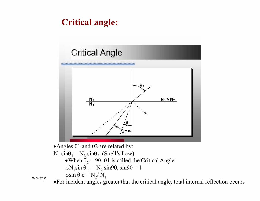
Critical angle:
Angles 01 and 02 are related by: N1 sin1 = N2 sin2 (Snell’s Law)
When 2 = 90, 01 is called the Critical Angle oN1sin 1 = N2 sin90, sin90 = 1 osin c = N2/ N1
For incident angles greater that the critical angle, total internal reflection occurs

w.wang
Total Internal Reflection -- The reflection that occurs when a light ray traveling in one material hits a different material and reflects back into the original material without any loss of light Material A = fiber core Material B = fiber cladding
Total reflection

w.wang
Light travels down the fiber in a pathway called a light guide

w.wang
While discussing step-index fibers, we considered light propagation inside the fiber as a set of many rays bouncing back and forth at the core-cladding interface. There the angle could take a continuum of values lying between 0 and cos–1(n2/n1), i.e.,
Scientific and Technological Education in Photonics
0 < < cos–1 (n2/n1)
For n2 = 1.5 and = 0.01, we would get n2/n 1 ~ and cos –1 = 8.1°, so
0 < < 8.1°
w. wang

w.wang
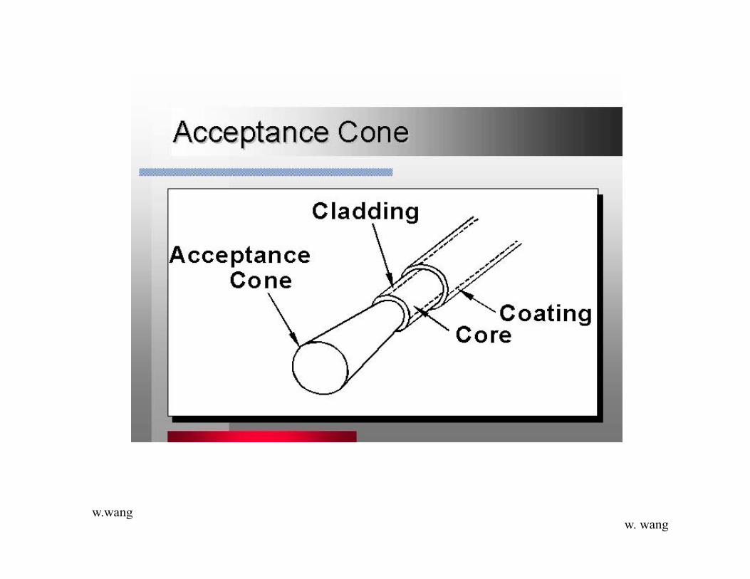
•The Numerical Aperture (NA) of a fiber is the measure of the maximum angle (NA) of the light entering the end that will propagate within the core of the fiber •Acceptance Cone = 20NA •Light rays entering the fiber that exceed the angle NA will enter the cladding and be lost •For the best performance the NA of the transmitter should match the NA of the fiber
n0
w. wang

w.wang
NA derivation
We know and
Since
Assume the NA is the half angle of the acceptance cone,
we get
sinNA=(n12-n2
2)1/2 = n1sqrt(2)
w. wang

w.wang
We define a parameter through the following equations.
When << 1 (as is indeed true for silica fibers where n1 is very nearly equal to n2) we may write
w. wang

w.wangw. wang

w.wang
Single mode fiber critical angle <20o
Multimode fiber critical angle <60 o
w. wang

w.wang
In a short length of an optical fiber, if all rays between i = 0 and im are launched, the light coming out of the fiber will also appear as a cone of half-angle im emanating from the fiber end. If we now allow this beam to fall normally on a white paper and measure its diameter, we can easily calculate the NA of the fiber.
For a typical step-index (multimode) fiber with n1 1.45 and 0.01, we get
so that im 12°. Thus, all light entering the fiber must be within a cone of half-angle 12°.
Example
w. wang

w.wang
Performance parameters

w.wang
Attenuation
dB is a ratio of the power received verses the power transmitted Loss (dB) = 10log (power transmitted / power received)

w.wang
Intrinsic attenuation is controlled by the fiber manufacturer Absorption caused by water molecules and other impurities Light strikes a molecule at the right angle and light energy is converted into heat Absorption accounts for 3-5% of fiber attenuation these is near the theoretical limit

w.wang
The main cause of intrinsic absorption in the infrared region is the characteristic vibration frequency of atomic bonds. In silica glass, absorption is caused by the vibration of silicon-oxygen (Si-O) bonds. The interaction between the vibrating bond and the electromagnetic field of the optical signal causes intrinsic absorption. Light energy is transferred from the electromagnetic field to the bond.

w.wang
Light striking the Ge molecules in the core can be scattered into new pathways out of the fiber Rayleigh Scattering accounts for 95% of fiber attenuation Optical Time Domain Reflectometers (OTDR) use this property to measure loss in a fiber

w.wang
operating between 700-nm and 1600-nm wavelength, the main source of loss is called Rayleigh scattering. Rayleigh scattering is the main loss mechanism between the ultraviolet and infrared regions as shown in absoprtion specturm. Rayleigh scatteringoccurs when the size of the density fluctuation (fiber defect) is less than one-tenth of the operating wavelength of light. Loss caused by Rayleigh scattering is proportional to the fourth power of the wavelength (1/lambda). As the wavelength increases, the loss caused by Rayleigh scattering decreases.

w.wang
If the size of the defect is greater than one-tenth of the wavelength of light, the scattering mechanism is called Mie scattering. Mie scattering, caused by these large defects in the fiber core, scatters light out of the fiber core. However, in commercial fibers, the effects of Mie scattering are insignificant. Optical fibers are manufactured with very few large defects.

w.wang
Extrinsic attenuation can be controlled by the cable installerMacrobend losses are observed when a fiber bend's radius of curvature is large compared to the fiber diameter.

w.wang

w.wang
Microbends may not be visible with the naked eye Microbends may be:
obend related otemperature related otensile related ocrush related

w.wang

w.wang
Index of Refraction is a function of wavelength Since light velocity is a function of index of refraction
olight velocity in a given medium is a function of wavelength Light pulses at different wavelengths will have different propagation times

w.wang
Various modes follow different paths causing pulse broadening

w.wang
Because a light pulse is made up of different colors and modes of light some portions arrive at the end of the fiber before others causing a spreading effect This causes pulses to overlap making them unreadable by the receiver

w.wang
The received pulse must be above the receiver threshold to be detected as an on pulse. Likewise an off pulse must be below the receiver threshold to be detected as an off pulse.
If pulses spread and overlap above the receiver threshold, an off pulse will not be detected and errors in the signal will result

w.wang
Fiber bandwidth is measured in MHz x Km. A length of glass is measured for bandwidth. By convention the bandwidth specification for that fiber is the length of that fiber times the measured bandwidth for that fiber.

w.wang
Multimode fiber allows for more than one pathway or mode of light to travel in the fiber Singlemode fiber allows for only one pathway or mode of light to travel within the fiber at a specific operational wavelength It is impossible to distinguish between singlemode fiber and multimode with the naked eye

w.wang

w.wang
Most commonly used fiber Reduces modal dispersion by equalizing the transit times among the modes The core is layered with the index of refraction increasing toward the center of the core

w.wang

w.wang
In singlemode fiber, there is only one mode at a typical system wavelength; therefore, there is no modal dispersion. This results in much lower dispersion and more information carrying capacity

Wave Optics Approach
w.wang

Consider a uniform dielectric medium with permittivity and permeability and zero conductivity .
The harmonic electric and magnetic fields defined by
obey the Helmholtz equations
A plane wave propagating in the direction
has phase velocity and index of refraction
The index of refraction in optical fiber is similar to that of glass
Reflection and Refraction of Plane Waves in Dielectric Media

Energy Density and Flux
The energy flux in a mode of frequency is given by the real part of the complex Poynting vector
and the energy density

Boundary Conditions and Snell's Law
In a dielectric waveguide the most basic confinement mechanism is Total internal reflection from the interface between the core of the guide and the cladding surrounding it.
Consider a pane wave with wvevector k in the xz plane incident on the plane interface in the xy plane at z= 0

w.wang
Slab Waveguide Theory

w.wang
Light can be guided by planar or rectangular wave guides, or by optical fibers.
w. wang

w.wang
w. wang

w.wangw. wang

w.wangw. wang

w.wangw. wang

w.wangw. wang

w.wangw. wang

w.wangw. wang
-

w.wangw. wang

w.wangw. wang

w.wangw. wang

w.wangw. wang

w.wangw. wang

w.wangw. wang

w.wangw. wang

w.wang=
w. wang

w.wangw. wang

w.wangw. wang
w.wangw. wang
-

w.wangw. wang

w.wangw. wang

w.wangw. wang

w.wangw. wang

w.wangw. wang

w.wangw. wang

w.wangw. wang
w.wangw. wang

w.wang
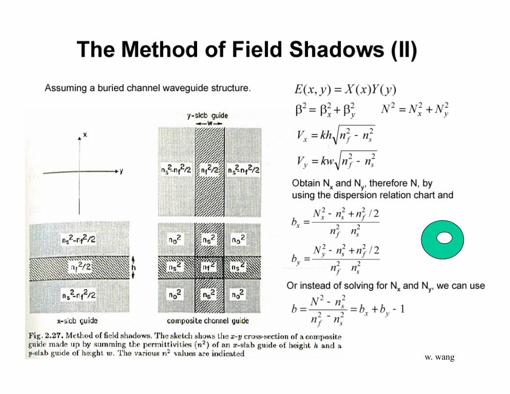
Effective index for rectangular waveguide
w. wang
--

w.wangw. wang

w.wangw. wang

w.wangw. wang

w.wangw. wang

w.wang
Wave Analysis:
Cylindrical dielectric waveguide(step fiber)
assume all fields proportional to ej(t-z)
E = (Er, E, Ez )H = (Hr, H,Hz )
Ei and Hi are function of (r, )
2 E = *H H
But now need to use cylindrical coordinates:
d2Ez/dr2 + 1/r dEz/dr + 1/r2 d2Ez/d2 + (n12k2 – 2)Ez =0
w. wang

w.wang
Assume Ez proportional to E(r) h() separation of variables
Since h(2p + ) = h() =>try h() = sin l cos(l ) ejl
where l= integersSubstitute back into
d2Ez/dr2 + 1/r dEz/dr + [(n12k2 – 2)-l2/r2]Ez =0 => Bessel function
Solutions closer to match physical situation.
w. wang

w.wang
For guided solutions:
In core, solutions must be finiteIn cladding, solutions must approach 0 as r -->
For r < a: E(r) Jl (UR) “ Bessel function of 1st kind”
For r > a: E(r) Kl (WR) “ modified Bessel function of 2nd kind”
UR = (n12k2 –2)0.5 r = a(n1
2k2 –2) 0.5 r/aU R
WR= (2 - n12k2)0.5 a
Let V2 = U2 + W2 = a2 [n12k2 –2 + 2 –n2
2k2] = a2k2[n12-n2
2]
V = a · (2/[n12-n2
2] 0.5 (Normalized frequency)= a · (2/·
w. wang

w.wang
Solution procedure for step-index fiber modes:
1.Ez
= A Jl (UR) ejlej(t-z) r < aHz
= B Kl (WR) ejlej(t-z) r > a
2. Match Ez and Hz at r = a
3. Use Maxwell’s curl equations to find E and H Ez and Hz and E and H must match for r = +a and –a. Solve all four equations simultaneously to yield eigenvalues
w. wang

w.wangw. wang

w.wang
A major simplification in math results if (n1-n2)/n1 <<1(weakly-guiding approximation << 1)
The eigenequations reduces to
Jl+1 (U) / Jl (U) = + (W/U) (Kl+1 (W) / Kl (W) (+ only for l =0)
There are m possible solutions for each value of l
Ulm are solutions
From definition of U, knowing Ulm permits calculation of
lm = (n12k2 – Ulm )0.5
w. wang

w.wang
The resulting system of equations can only be solved graphically. The graphical solutions represent the mode cutoffs for the different modes that can propagate in the fiber for any given V, where V is a convenient parameter determined by the properties of the fiber and wavelength of incident light.
V = 2*/*a*NA
The intersections represent the V numbers at which these two modes turn on in the fiber.
w. wang

w.wangw. wang

w.wang
The normalized wave number, or V-number of a fiber is defined as V = kf a NA. Here kf, is the free space wave number, 20, a is the radius of the core, and NA is the numerical aperture of the fiber, NA = (ncore
2 - ncladding2)1/2 ncore(2)1/2,
with = (ncore-ncladding)/ncore. Many fiber parameters can be expressed in terms of V. The TE and TM modes have non-vanishing cut-off frequencies. The cutoff frequency is found from V = a(2)½/c = 2.405. Only the lowest HE mode, HE11, has no cutoff frequency. For 0 < V < 2.405 it is the only mode that propagates in the fiber. w. wang

w.wang
In the weakly-guiding approximation (<< 1), the modes propagating in the fiber are linearly polarized (LP) modes characterized by two subscripts, m and n. (The longitudinal components of the fields are small when << 1.) The LP modes are combinations of the modes found from the exact theory of the wave guide. The HE11 mode becomes the LP01mode in the weakly-guiding approximation.
w. wang

w.wang
The following table presents the first ten cutoff frequencies in a step-index fiber, as well as their fundamental modes.
w. wang

w.wang
Single mode (SM) fiber is designed such that all the higher order waveguide modes are cut-off by a proper choice of the waveguide parameters as given below.
where, is the wavelength, a is the core radius, and n1 and n2 are the core and cladding refractive indices, respectively. When V 2.405 single mode condition is ensured. SM fiber is an essential requirement for interferometric sensors. Due to the small core size (~4 m) alignment becomes a critical factor.
Single mode fiber
w. wang

w.wangw. wang

w.wangElectric and magnetic fields for eight fundamental modes.
w. wang

w.wang
When the V number is less than 2.405 only the LP01mode propagates. When the V number is greater than 2.405 the next linearly-polarized mode can be supported by the fiber, so that both the LP01 and LP11, modes will propagate.
LP01 LP11
w. wang

w.wangw. wang

w.wang
The SM fiber mentioned above is not truly single mode in that two modes with degenerate polarization states can propagate in the fiber. This can lead to signal interference and noise in the measurement. The degeneracy can be removed and a single mode polarization preserving fiber can be obtained by the use of an elliptical core fiber of very small size or with built in stress. In either case light launched along the major axis of the fiber is preserved in its state of polarization. It is also possible to make a polarizing fiber in which only one state of polarization is propagated. Polarimetric sensors make use of polarization preserving fibers. Thus, multimode fiber, single mode fiber and polarization preserving fiber are the three classes of fibers which are used in the intensity type, the interferometric type and the polarimetric type of sensors, respectively.
w. wang

w.wang
While discussing step-index fibers, we considered light propagation inside the fiber as a set of many rays bouncing back and forth at the core-cladding interface. There the angle could take a continuum of values lying between 0 and cos–1(n2/n1), i.e.,
Scientific and Technological Education in Photonics
0 < < cos–1 (n2/n1)
For n2 = 1.5 and = 0.01, we would get n2/n 1 ~ and cos –1 = 8.1°, so
0 < < 8.1°
w. wang

w.wang
Now, when the core radius (or the quantity ) becomes very small, ray optics does not remain valid and one has to use the more accurate wave theory based on Maxwell's equations.
In wave theory, one introduces the parameter
where has been defined earlier and n1~ n2 . The quantity V is often referred to as the "V-number"
or the "waveguide parameter" of the fiber. It can be shown that, if
V < 2.4045
only one guided mode (as if there is only one discrete value of ) is possible and the fiber is known as a single-mode fiber. Further, for a step-index single-mode fiber, the corresponding (discrete) value of is approximately given by the following empirical formula
We may mention here that because of practical considerations the value of ranges from about 0.002 to about 0.008
w. wang

w.wang
Consider a step-index fiber (operating at 1300 nm) with n2 = 1.447, = 0.003, and a = 4.2 m. Thus,
Thus the fiber will be single moded and the corresponding value of —will be about = 3.1º. It may be mentioned that for the given fiber we may write
Thus, for 0 > 2.958/2.4045 = 1.23 m
which guarantees that V < 2.4045, the fiber will be single moded. The wavelength for which V = 2.4045 is known as the cutoff wavelength and is denoted by c. In this example, c = 1.23 m and the fiber will be single moded for 0 > 1.23 m.
Assignment
w. wang

w.wang
AssignmentFor reasons that will be discussed later, the fibers used in current optical communication systems (operating at 1.55 m) have a small value of core radius and a large value of . A typical fiber (operating at 0 1.55 m) has n2 = 1.444, = 0.0075, and a = 2.3 m. Thus, at 0 = 1.55 m, the V-number is,
The fiber will be single moded (at 1.55 m) with = 5.9°. Further, for the given fiber we may write
and therefore the cutoff wavelength will be c = 2.556/2.4045 = 1.06 m.
w. wang

w.wang
•The Numerical Aperture (NA) of a fiber is the measure of the maximum angle (NA) of the light entering the end that will propagate within the core of the fiber •Acceptance Cone = 20NA •Light rays entering the fiber that exceed the angle NA will enter the cladding and be lost •For the best performance the NA of the transmitter should match the NA of the fiber
n0
w. wang

w.wang
NA derivation
We know and
Since
Assume the NA is the half angle of the acceptance cone,
we get
sinNA=(n12-n2
2)1/2 = n1sqrt(2)
w. wang

w.wang
We define a parameter through the following equations.
When << 1 (as is indeed true for silica fibers where n1 is very nearly equal to n2) we may write
w. wang
w.wangw. wang

w.wang
Single mode fiber critical angle <20o
Multimode fiber critical angle <60 o
w. wang

w.wang
In a short length of an optical fiber, if all rays between i = 0 and im are launched, the light coming out of the fiber will also appear as a cone of half-angle im emanating from the fiber end. If we now allow this beam to fall normally on a white paper and measure its diameter, we can easily calculate the NA of the fiber.
For a typical step-index (multimode) fiber with n1 1.45 and 0.01, we get
so that im 12°. Thus, all light entering the fiber must be within a cone of half-angle 12°.
Example
w. wang

w.wang
For a typical step-index (multimode) fiber with n1 1.45 and 0.01, we get
so that im 12°. Thus, all light entering the fiber must be within a cone of half-angle 12°.
Assignment
w. wang

w.wang
Spot size of the fundamental mode
A single-mode fiber supports only one mode that propagates through the fiber. This mode is also referred to as the fundamental mode of the fiber. The transverse field distribution associated with the fundamental mode of a single-mode fiber is an extremely important quantity. It determines various important parameters like splice loss at joints, launching efficiencies, bending loss, etc. For most single-mode fibers, the fundamental mode-field distributions can be approximated by a Gaussian function, which may be written in the form
where w is referred to as the spot size of the mode-field pattern.
w. wang

w.wang
When r = w, the value of is equal to 1/e of the value A at r = 0. For a step-index (single-mode) fiber, one has the following empirical expression for w [Marcuse]:
where a is the core radius and V is the V-number given by Equation 7-28. We may mention here that the light coming from a HeNe laser (or from a laser pointer) has a transverse intensity distribution very similar to that coming from a single-mode fiber except that the spot size for the HeNe laser is much larger. The quantity 2w is also referred to as the mode-field diameter (MFD) of the fiber and is a very important property of single-mode fibers. In fact, MFD is a more important property than core diameter in the case of single-mode fibers, since it determines the splice loss across a joint, bending loss, dispersion, etc. of single-mode fibers.
w. wang

w.wang
Consider a step-index fiber (operating at 1300 nm) with n2 = 1.447, = 0.003, and a = 4.2 m. For this fiber (see Example 7-12), V 2.28. Using Equation 7-31, with V = 2.28 and a = 4.2 mm, one obtains w 4.8 m. The same fiber will have a V-value of 1.908 at 0 = 1550 nm, giving a value of the spot size 5.5 m. Thus the spot size increases with wavelength.
For a step-index fiber (operating at 1550 nm) with n2 = 1.444, = 0.0075, and a = 2.3 m (see Example 7-13), V 1.65, giving w 3.6 m. The same fiber will have a V-value of 1.97 at 0 = 1300 nm, giving a value of the spot size 3.0 m.
Assignment
w. wang
w.wang

w.wang

w.wang

w.wang

w.wang

w.wang

w.wang