Multilayer Ceramic Chip Capacitor
351
1 Additional information on this product is available from AVX’s catalog or AVX’s FAX Service. Call 1-800-879-1613 and request document #001. Visit our website http://www.avxcorp.com Multilayer Ceramic Chip Capacitor Standard EIA Sizes HOW TO ORDER 0603 5 A 271 J A T 2 A 123456789 1 Size: 0402, 0603, 0805, 1206, 1210, 1812, 1825 2 Voltage: 10V=Z, 16V=Y, 25V=3, 50V=5, 100V=1, 200V=2 3 Dielectric: NP0=A, X7R=C, Z5U=E, Y5V=G 4 Capacitance Code 5 Tolerance: F=±1%(≥50pF), G=±2%(≥25pF), J=±5% K=±10%, M=±20%, Z=+80, -20% 6 Failure Rate: A = Standard 7 Termination: T = Plated Ni and Solder 8 Packaging: 2 = 7" Reel/unmarked 4 = 13" Reel/unmarked 9 Special Code: A = Standard Product L W T L W T 0402 1.0±0.1 (0.039±0.004) 0.5±0.1 (0.020±0.004) 0.6 max. (0.024 max.) 0603 1.6±0.15 (0.063±0.006) 0.8±0.15 (0.031±0.006) 0.9 max. (0.035 max.) 0805 2.0±0.2 (0.079±0.008) 1.25±0.2 (0.049±0.008) 1.3 max. (0.051 max.) 1206 3.2±0.2 (0.126±0.008) 1.6±0.2 (0.063±0.008) 1.5 max. (0.059 max.) 1210 3.2±0.2 (0.126±0.008) 2.5±0.2 (0.098±0.008) 1.7 max. (0.067 max.) 1812 4.5±0.3 (0.177±0.012) 3.2±0.2 (0.126±0.008) 1.7 max. (0.067 max.) 1825 4.5±0.3 (0.177±0.012) 6.4±0.4 (0.252±0.016) 1.7 max. (0.067 max.) Dimensions: millimeters (inches) NP0 X7R Z5U Y5V Type 25V 50V 100V 200V 10V 16V 25V 50V 100V 200V 25V 50V 10V 16V 25V 50V 0402 Min. 0.5pF 0.5pF — — — 100pF 100pF 100pF — — — — 2200pF 2200pF 2200pF 2200pF Max. 220pF 120pF — — — .047μF 6800pF 3900pF — — — — 0.1μF .1μF .022μF 0.01μF 0603 Min. 0.5pF 0.5pF 0.5pF — 100pF 100pF 100pF 100pF 100pF — .01μF .01μF 2200pF 2200pF 2200pF 2200pF Max. 1000pF 1000pF 330pF — .22μF 0.1μF .047μF .015μF 4700pF — .047μF .027μF 1.0μF .33μF .22μF .056μF 0805 Min. 0.5pF 0.5pF 0.5pF 0.5pF 100pF 100pF 100pF 100pF 100pF 220pF .01μF .01μF .01pF .01μF .01μF .01μF Max. 4700pF 2200pF 1000pF 470pF 2.2μF .47μF .22μF .1μF .022μF 1500pF .12μF .1μF 4.7μF 2.2μF 1.0μF .33μF 1206 Min. 0.5pF 0.5pF 0.5pF 0.5pF 1000pF 1000pF 1000pF 1000pF 1000pF 330pF .01μF .01μF .01μF .01μF .01μF .01μF Max. .01μF 4700pF 2200pF 1000pF 4.7μF 1.0μF 1.0μF .22μF 0.1μF 5600pF .33μF .33μF 10.0μF 4.7μF 2.2μF 1.0μF 1210 Min. 560pF 560pF 560pF 560pF — 1000pF 1000pF 1000pF 1000pF 470pF .01μF .01μF .1μF .1μF .1μF .1μF Max. .01μF .01μF 3900pF 1500pF — 4.7μF 2.2μF .22μF .1μF 8200pF .56μF .47μF 22μF 10μF 4.7μF 1.0μF 1812 Min. 1000pF 1000pF 1000pF 1000pF — — — .01μF .01μF — .01μF .01pF — — .15μF .15μF Max. .015μF .01μF 4700pF 3300pF — — — 1.0μF .47μF — 1.0μF 1.0μF — — 1.5μF 1.5μF 1825 Min. — 1000pF 1000pF 1000pF — — — .01pF .01pF — .01μF .01pF — — .47μF .47μF Max. — .022μF .012μF 6800pF — — — 1.0μF .47μF — 1.0μF 1.0μF — — 1.5μF 1.0μF Capacitance Range For maximum capacitance - consult factory. BULK TAPE & REEL 7" 13" 0402 50,000 10,000 N/A 0603 15,000 4,000 10,000 0805 10,000 (T=0.6mm) 4,000 10,000 5,000 (T=1.25mm) 1206 N/A 4,000 10,000 1210 N/A 4,000 10,000 Standard Packaging
-
Upload
khangminh22 -
Category
Documents
-
view
0 -
download
0
Transcript of Multilayer Ceramic Chip Capacitor

1
Additional information on this product is available from AVX’s catalog or AVX’s FAX Service.Call 1-800-879-1613 and request document #001. Visit our website http://www.avxcorp.com
Multilayer Ceramic Chip CapacitorStandard EIA Sizes
HOW TO ORDER0603 5 A 271 J A T 2 A1 2 3 4 5 6 7 8 91 Size: 0402, 0603, 0805, 1206, 1210, 1812, 18252 Voltage: 10V=Z, 16V=Y, 25V=3, 50V=5, 100V=1, 200V=23 Dielectric: NP0=A, X7R=C, Z5U=E, Y5V=G4 Capacitance Code5 Tolerance:
F=±1%(≥50pF), G=±2%(≥25pF), J=±5%K=±10%, M=±20%, Z=+80, -20%
6 Failure Rate: A = Standard7 Termination:
T = Plated Ni and Solder8 Packaging:
2 = 7" Reel/unmarked4 = 13" Reel/unmarked
9 Special Code:A = Standard Product
L
W
T
L W T0402 1.0±0.1 (0.039±0.004) 0.5±0.1 (0.020±0.004) 0.6 max. (0.024 max.)
0603 1.6±0.15 (0.063±0.006) 0.8±0.15 (0.031±0.006) 0.9 max. (0.035 max.)
0805 2.0±0.2 (0.079±0.008) 1.25±0.2 (0.049±0.008) 1.3 max. (0.051 max.)
1206 3.2±0.2 (0.126±0.008) 1.6±0.2 (0.063±0.008) 1.5 max. (0.059 max.)
1210 3.2±0.2 (0.126±0.008) 2.5±0.2 (0.098±0.008) 1.7 max. (0.067 max.)
1812 4.5±0.3 (0.177±0.012) 3.2±0.2 (0.126±0.008) 1.7 max. (0.067 max.)
1825 4.5±0.3 (0.177±0.012) 6.4±0.4 (0.252±0.016) 1.7 max. (0.067 max.)
Dimensions: millimeters (inches)
NP0 X7R Z5U Y5VType 25V 50V 100V 200V 10V 16V 25V 50V 100V 200V 25V 50V 10V 16V 25V 50V0402 Min. 0.5pF 0.5pF — — — 100pF 100pF 100pF — — — — 2200pF 2200pF 2200pF 2200pF
Max. 220pF 120pF — — — .047µF 6800pF 3900pF — — — — 0.1µF .1µF .022µF 0.01µF
0603 Min. 0.5pF 0.5pF 0.5pF — 100pF 100pF 100pF 100pF 100pF — .01µF .01µF 2200pF 2200pF 2200pF 2200pF
Max. 1000pF 1000pF 330pF — .22µF 0.1µF .047µF .015µF 4700pF — .047µF .027µF 1.0µF .33µF .22µF .056µF
0805 Min. 0.5pF 0.5pF 0.5pF 0.5pF 100pF 100pF 100pF 100pF 100pF 220pF .01µF .01µF .01pF .01µF .01µF .01µF
Max. 4700pF 2200pF 1000pF 470pF 2.2µF .47µF .22µF .1µF .022µF 1500pF .12µF .1µF 4.7µF 2.2µF 1.0µF .33µF
1206 Min. 0.5pF 0.5pF 0.5pF 0.5pF 1000pF 1000pF 1000pF 1000pF 1000pF 330pF .01µF .01µF .01µF .01µF .01µF .01µF
Max. .01µF 4700pF 2200pF 1000pF 4.7µF 1.0µF 1.0µF .22µF 0.1µF 5600pF .33µF .33µF 10.0µF 4.7µF 2.2µF 1.0µF
1210 Min. 560pF 560pF 560pF 560pF — 1000pF 1000pF 1000pF 1000pF 470pF .01µF .01µF .1µF .1µF .1µF .1µF
Max. .01µF .01µF 3900pF 1500pF — 4.7µF 2.2µF .22µF .1µF 8200pF .56µF .47µF 22µF 10µF 4.7µF 1.0µF
1812 Min. 1000pF 1000pF 1000pF 1000pF — — — .01µF .01µF — .01µF .01pF — — .15µF .15µF
Max. .015µF .01µF 4700pF 3300pF — — — 1.0µF .47µF — 1.0µF 1.0µF — — 1.5µF 1.5µF
1825 Min. — 1000pF 1000pF 1000pF — — — .01pF .01pF — .01µF .01pF — — .47µF .47µF
Max. — .022µF .012µF 6800pF — — — 1.0µF .47µF — 1.0µF 1.0µF — — 1.5µF 1.0µF
Capacitance Range
For maximum capacitance - consult factory.
BULK TAPE & REEL7" 13"
0402 50,000 10,000 N/A0603 15,000 4,000 10,0000805 10,000 (T=0.6mm) 4,000 10,000
5,000 (T=1.25mm)1206 N/A 4,000 10,0001210 N/A 4,000 10,000
Standard Packaging

2
Additional information on this product is available from AVX’s catalog or AVX’s FAX Service.Call 1-800-879-1613 and request document #002. Visit our website http://www.avxcorp.com
L
W
T
HOW TO ORDER1206 3 E 224 Z A T 2 T1 2 3 4 5 6 7 8 9
1 Size: (L" x W")2 Voltage: 25V = 33 Dielectric: Z5U = E, Y5V = G4 Capacitance Code5 Capacitance Tolerance: Z = +80/-20%6 Failure Rate: A = Not Applicable7 Terminations: T = Plated Ni and Solder8 Packaging: 2 = 7" Reel, 4 = 13" Reel9 Thickness: T = .026" Max.
S = .022" Max.R = .018" Max.
Low Profile ChipsZ5U & Y5V Dielectric
Z5U Y5V25V 25V
Type L W T Min. Max. Min. Max.mm (inches) mm (inches)
2.01 ± 0.2 1.25 ± 0.20.46 (0.018) .01µF .033µF .01µF .082µF
0805(0.079 ± 0.008) (0.049 ± 0.008)
0.56 (0.022) .01µF .056µF .01µF .12µF
0.66 (0.026) .01µF .082µF .01µF .18µF
3.2 ± 0.2 1.6 ± 0.20.46 (0.018) .01µF .082µF .01µF .22µF
1206(0.126 ± 0.008) (0.063± 0.008)
0.56 (0.022) .01µF .15µF .01µF .27µF
0.66 (0.026) .01µF .22µF .01µF .33µF
3.2 ± 0.2 2.5 ± 0.20.46 (0.018) .01µF .15µF .01µF .33µF
1210(0.126 ± 0.008) (0.098 ± 0.008)
0.56 (0.022) .01µF .27µF .01µF .39µF
0.66 (0.026) .01µF .33µF .01µF .47µF

3
Additional information on this product is available from AVX’s catalog or AVX’s FAX Service. Call 1-800-879-1613 and request document #003. Visit our website http://www.avxcorp.com
Low Inductance Chip CapacitorsSpecially Designed MLC Chips for Low Inductance
*Consult factory for details.
Capacitance Range: X7R and Y5V Dielectric millimeters (inches)
AVX 0306 0508 0612Style
Length 0.81 ± 0.15 1.27 ± .25 1.6 ± .25(L) (0.032 ± 0.006) (0.050 ± 0.010) (0.060 ± 0.010)
Width 1.60 ± 0.15 2.0 ± .25 3.2 ± .25(W) (0.063 ± 0.006) (0.080 ± 0.010) (0.126 ± 0.010)
Separation 0.23 (0.009) 0.38 (0.015) 0.50 (0.020)(X)
terminal 0.38 max. / 0.13 min. 0.50 max. / 0.13 min. 0.46 max. / 0.13 min.(t)* (0.015 max. / 0.005 min.) (0.020 max. / 0.005 min.) (0.018 max. / 0.005 min.)
L
X tW
T
Maximum Capacitance Values, (µF)Thickness X7R Y5V
(T) Size 10V 16V 25V 10V 16V 25V0.050 0612 2.2 1.0 0.27 6.8 3.3 1.2
0.0400612 1.5 0.68 0.22 4.7 1.8 .82
0508 0.68 0.27 0.1 2.2 1.0 .47
0.0300612 1.0 0.47 0.12 3.3 1.5 .56
0508 0.47 0.18 0.056 1.5 .56 .22
0612 0.47 0.18 0.056 1.5 .68 .27
0.022 0508 0.22 0.082 0.022 0.68 .33 .12
0306 0.1
10
1.0
.1
.011.0 10 100 1,000
FREQUENCY, MHz
ES
R a
nd IM
PE
DA
NC
E, O
hms
IMPEDANCE
ESR
ESR and Impedance vs. Frequency0612 0.1µF - X7R
Impedance vs. Frequency0805 vs. 0508 0.1µF - Y5V
10
1.0
.1
.011 10 100 1,000
FREQUENCY, MHz
IMP
ED
AN
CE
, Ohm
s 0805
0508
1206
0612
10
1.0
.1
.011 10 100 1,000
FREQUENCY, MHz
IMP
ED
AN
CE
, Ohm
s
0612 vs. 1206
HOW TO ORDER0508 5 C 822 M A T 1 W1 2 3 4 5 6 7 8 91 AVX Style: 0306, 0508, 06122 Voltage: 25V = 3, 16V = Y, 10V = Z3 Temperature Coefficient: C = X7R, G = Y5V4 Capacitance Code: (2 significant digits + no. of zeros)
Examples: 10 pF = 100 100 pF = 1011,000 pF = 102 22,000 pF = 223
220,000 pF = 224 1 µF = 1055 Capacitance Tolerance: M = ±20% Z = +80, -20%,
P = GMV K = ±10%6 Failure Rate: A = Does not apply, H = High, Rel*7 Termination: T = NiGuard Nickel Barrier Solder Plate8Marking Packaging: 9 = Bulk Unmarked, 1 = Reel Unmarked9 Special Code: Thickness: mm (in.)
U = .51 (.020) max., V = .76 (.030) max., W = 1.02 (.040) max.

4
Additional information on this product is available from AVX’s catalog or AVX’s FAX Service.Call 1-800-879-1613 and request document #004. Visit our website http://www.avxcorp.com
Tip & RingMultilayer Ceramic Chip Capacitors
Capacitance Range 0.1µF to 1.2µF(25°C, 1.0 ± 0.2Vrms at 1kHz)
Capacitance Tolerance ±10%, ±20%
Dissipation Factor 2.5% max.(25°C, 1.0 ± 0.2Vrms at 1kHz)
Temperature Characteristic X7R ±15% (0 VDC)
Voltage Rating 250VDC Telco Rating
IR (25°C, at 250VDC) 1000 Megaohm-Microfared min.
Dielectric Strength 250% Rated VDC for 5 seconds at 50mA max. current
General Specifications HOW TO ORDER1812 P C 104 K A T 1 A1 2 3 4 5 6 7 8 91 AVX Style: 1812, 1825, 2220, 2225 2 Voltage: 250VDC Telco Rating3 Temperature Coefficient: X7R4 Capacitance Code:
2 significant digits + no. of zerosExamples: 1,000 pF = 102
22,000 pF = 223220,000 pF = 224
1 µF = 1055 Capacitance Tolerance: K = ±10%, M = ±20%6 Failure Rate: A = Not Applicable7 Termination: T = Nickel Barrier and Solder Plate8 Packaging: 1 = 7" Reel 1,000 pcs.
3 = 13" Reel 4,000 pcs.9 = Bulk 500 pcs.
9 Special Code: A = Unmarked
SIZE 1812 1825 2220 2225Length (L) 4.6 ±0.3 4.6 ±0.3 5.6 ±0.3 5.6 ±0.3
(0.180 ±0.012) (0.180 ±0.012) (0.220 ±0.012) (0.220 ±0.012)Width (W) 3.2 ±0.2 6.35 ±0.4 5.1 ±0.4 6.35 ±0.4
(0.125 ±0.008) (0.250 ±0.016) (0.200 ±0.016) (0.250 ±0.016)Thickness (T) 2.0 max. 2.0 max. 2.0 max. 2.0 max.
(0.080 max.) (0.080 max.) (0.080 max.) (0.080 max.)terminal (t) .63 ±0.38 .63 ±0.38 .63 ±0.38 .63 ±0.38
(0.025 ±0.015) (0.025 ±0.015) (0.025 ±0.015) (0.025 ±0.015)Capacitance 0.10 0.33 0.47 0.47Range µF 0.47 1.0 1.0 1.2
Dimensions: millimeters (inches)
L
T
t
W
Standard Part Number Offering(Others available upon request)
1812PC104KAT1A 1825PC334KAT1A 2220PC474KAT1A 2225PC474KAT1A
1812PC124KAT1A 1825PC394KAT1A 2220PC564KAT1A 2225PC564KAT1A
1812PC154KAT1A 1825PC474KAT1A 2220PC684KAT1A 2225PC684KAT1A
1812PC184KAT1A 1825PC564KAT1A 2220PC824KAT1A 2225PC824KAT1A
1812PC224KAT1A 1825PC684KAT1A 2220PC105KAT1A 2225PC105KAT1A
1812PC274KAT1A 1825PC824KAT1A 2225PC125KAT1A
1812PC334KAT1A 1825PC105KAT1A
1812PC394KAT1A
1812PC474KAT1A
“TIP & RING” Graph

5
Additional information on this product is available from AVX’s catalog or AVX’s FAX Service.Call 1-800-879-1613 and request document #005. Visit our website http://www.avxcorp.com
Military Designation Per MIL-PRF-55681Part Number Example
(example) CDR01 BP 101 B K S M1 2 3 4 5 6 7
1 MIL Style: CDR01, CDR02, CDR03, CDR04, CDR05, CDR062 Voltage Temperature Limits:
BP = 0 ± 30 ppm/°C without voltage; 0 ± 30 ppm/°C with rated voltage from -55°C to +125°C
BX = ± 15% without voltage; +15 –25% with rated voltage from -55°C to +125°C
3 Capacitance Code4 Rated Voltage: A = 50V, B = 100V5 Capacitance Tolerance: J ±5%, K ±10%, M ±20%6 Termination Finish:
M = Palladium Silver U = Base Metallization/BarrierN = Silver Nickel Gold Metal/Solder Coated*S = Solder Coated W = Base Metallization/Barrier
Metal/Tinned (Tin or Tin/Lead Alloy)
7 Failure Rate Level: M = 1.0% R = .01%P = .1% S = .001%
Dimensions: millimeters (inches)
*For CDR11, 12, 13, and 14 see AVX Microwave Chip Capacitor Catalog
MIL Type TC Min. Max. Tolerance WVDCCDR01 BP 10 180 ±5%, ±10% 100
BX 120 3,300 ±10%, ±20% 100BX 3,900 4,700 ±10%, ±20% 50
CDR02 BP 220 270 ±5%, ±10% 100BX 3,900 10,000 ±10%, ±20% 100BX 12,000 22,000 ±10%, ±20% 50
CDR03 BP 330 1,000 ±5%, ±10% 100BX 12,000 33,000 ±10%, ±20% 100BX 39,000 68,000 ±10%, ±20% 50
CDR04 BP 1,200 3,300 ±5%, ±10% 100BX 39,000 56,000 ±10%, ±20% 100BX 82,000 180,000 ±10%, ±20% 50
CDR05 BP 3,900 5,600 ±5%, ±10% 100BX 68,000 150,000 ±10%, ±20% 100BX 220,000 330,000 ±10%, ±20% 50
CDR06 BP 6,800 10,000 ±5%, ±10% 100BX 390,000 470,000 ±10%, ±20% 50
Capacitance Range, pF
MIL-PRF-55681/MLC ChipsMilitary Part Number IdentificationCDR01/02/03/04/05/06
L
D tW
T
BULKCDR01 5,000
CDR02 5,000
CDR03 3,000
CDR04 3,000
CDR05 1,000
CDR06 1,000
Standard Packaging
Tape & Reel QuantitiesAll tape and reel specifications are in compliancewith RS481.
8mm 12mmEmbossed or Punched Carrier CDR01Embossed Only CDR02, CDR03, CDR04, CDR05, CDR06Qty. per Reel/7" Reel 2,000 or 4,000 max. 1,000 max.Qty. per Reel/13" Reel 10,000 max. 4,000 max.
Per AVX Length Width Thickness D Termination MIL-PRF- Style (L) (W) (T) Band (t)55681 Max. Min. Max. Min. Max. Min.CDR01 0805 2.03±.381 1.27±.381 1.40 .508 — .762 — .254
(0.080±0.015) (0.050±0.015) (0.055) (0.020) — (0.030) — (0.010)CDR02 1805 4.57±.381 1.27±.381 1.40 .508 — — .762 .254
(0.180±0.015) (0.050±0.015) (0.055) (0.020) — — (0.030) (0.010)CDR03 1808 4.57±.381 2.03±.457 2.03 .508 — — .762 .254
(0.180±0.015) (0.080±0.018) (0.080) (0.020) — — (0.030) (0.010)CDR04 1812 7.57±.381 3.18±.381 2.03 .508 — — .762 .254
(0.180±0.015) (0.125±.015) (0.080) (0.020) — — (0.030) (0.010)CDR05 1825 4.57 +.508 6.35 +.508
-.381 -.381 2.03 .508 — — .762 .254(0.180 +0.020) (0.250 +0.020) (0.080) (0.020) — — (0.030) (0.010)
-0.015) -0.015)CDR06 2225 5.72±.508 6.35 +.508 2.03 .508 — — .762 .254
(0.225±0.020) (0.250 +0.020) (0.080) (0.020) — — (0.030) (0.010)

6
Additional information on this product is available from AVX’s catalog or AVX’s FAX Service.Call 1-800-879-1613 and request document #006. Visit our website http://www.avxcorp.com
MIL-PRF-55681/ChipsMilitary Part Number IdentificationCDR31/32/33/34/35
Military Designation Per MIL-PRF-55681Part Number Example
(example) CDR31 BP 101 B K S M1 2 3 4 5 6 7
1 MIL Style: CDR31, CDR32, CDR33, CDR34, CDR352 Voltage Temperature Limits:
BP = 0 ± 30 ppm/°C without voltage; 0 ± 30 ppm/°C with rated voltage from -55°C to +125°C
BX = ± 15% without voltage; +15 –25% with rated voltage from -55°C to +125°C
3 Capacitance Code4 Rated Voltage: A = 50V, B = 100V5 Capacitance Tolerance: C ±.25 pF, D ±.5 pF, F ±1%,
J ±5%, K ±10%, M ±20%6 Termination Finish:
M = Palladium Silver U = Base Metallization/BarrierN = Silver Nickel Gold Metal/Solder Coated*S = Solder Coated W = Base Metallization/Barrier
Metal/Tinned (Tin or Tin/Lead Alloy)
*Solder shall have a melting point of 200°C or less.7 Failure Rate Level: M = 1.0% R = .01%
P = 0.1% S = .001%
Per MIL-PRF-55681 AVX Length (L) Width (W)Thickness (T) D Termination Band (t)
Style Max. Min. Max. Min.CDR31 0805 2.00 (0.079) 1.25 (0.049) 1.3 (0.051) .50 (0.020) .70 (0.028) .30 (0.012)CDR32 1206 3.20 (0.126) 1.60 (0.063) 1.3 (0.051) — .70 (0.028) .30 (0.012)CDR33 1210 3.20 (0.126) 2.50 (0.098) 1.5 (0.059) — .70 (0.028) .30 (0.012)CDR34 1812 4.50 (0.177) 3.20 (0.126) 1.5 (0.059) — .70 (0.028) .30 (0.012)CDR35 1825 4.50 (0.177) 6.40 (0.252) 1.5 (0.059) — .70 (0.028) .30 (0.012)
L
D tW
T
Dimensions: millimeters (inches)
MIL Type TC Min. Max. Tolerance WVDCCDR31 BP 1.0 9.1 ±.25pF, ±.5pF 100
10 470 ±1%, ±5%, ±10%BP 510 680 ±1%, ±2%, ±10% 50BX 470 4,700 ±10%, ±20% 100BX 5,600 18,000 ±10%, ±20% 50
CDR32 BP 1.0 9.1 ±.25pF, ±.5pF 10010 1,000 ±1%, ±5%, ±10%
BP 1,100 2,200 ±1%, ±5%, ±10% 50BX 4,700 15,000 ±10%, ±20% 100BX 18,000 39,000 ±10%, ±20% 50
CDR33 BP 1,000 2,200 ±1%, ±5%, ±10% 100BP 2,400 3,300 ±1%, ±5%, ±10% 50BX 15,000 27,000 ±10%, ±20% 100BX 39,000 100,000 ±10%, ±20% 50
CDR34 BP 2,200 4,700 ±1%, ±5%, ±10% 100BP 5,100 10,000 ±1%, ±5%, ±10% 50BX 27,000 56,000 ±10%, ±20% 100BX 100,000 180,000 ±10%, ±20% 50
CDR35 BP 4,700 10,000 ±1%, ±5%, ±10% 100BP 11,000 22,000 ±1%, ±5%, ±10% 50BX 56,000 150,000 ±10%, ±20% 100BX 180,000 470,000 ±10%, ±20% 50
Capacitance Range, pF
BULKCDR31 5,000
CDR32 5,000
CDR33 5,000
CDR34 3,000
CDR35 1,000
Standard Packaging
8mm 12mmEmbossed or CDR31, CDR32Punched Carrier CDR33Embossed Only CDR34, CDR35Qty. per Reel/7" Reel 2,000 or 4,000 max. 1,000 max.Qty. per Reel/13" Reel 10,000 max. 4,000 max.
Tape & Reel QuantitiesAll tape and reel specifications are in compliancewith RS481.

7
Additional information on this product is available from AVX’s catalog or AVX’s FAX Service.Call 1-800-879-1613 and request document #007. Visit our website http://www.avxcorp.com
HOW TO ORDER0603 5 J 120 G A W TR1 23 4 56 7 8
1 Size code2 Voltage: 3 = 25V, 5 = 50V, 1 = 100V3 Temperature Coefficient:
J = 0±30ppm/°CK = 0±60ppm/°C
4 Capacitance Code5 Tolerance:
For C≤5.6pF: A = ±0.05pF, B = ±0.1pF, C = ±0.25pFFor 5.6pF<C<10pF: B = ±0.1pF, C = ±0.25pF,
D = ±0.5pFFor C≥10pF: F = ±1%, G = ±2%, J = ±5%
6 A = Accu-F®
7 Termination:W = Ni/Solder Coated (Sn63, Pb37)
8 Packaging: TR = 7" Tape and ReelTR/3 = 13" Tape and Reel
Microwave Thin-Film Chip CapacitorsAccu-F® Series
B
W
T
L
0603 0805L 1.6±0.1 (0.063±0.004) 2.01±0.1 (0.079±0.004)
W 0.81±0.1 (0.032±0.004) 1.27±0.1 (0.050±0.004)
T 0.63±0.1 (0.025±0.004) 0.63±0.1 (0.025±0.004)
B 0.30±0.1 (0.012±0.004) 0.30±0.1 (0.012±0.004)
Dimensions: millimeters (inches)
L W S T0603 1.0 (0.039) 0.8 (0.031) 0.8 (0.031) 2.8 (0.110)
0805 1.0 (0.039) 1.3 (0.051) 1.0 (0.039) 3.0 (0.118)
Recommended Pad LayoutT
W
L S L
*For other chip sizes please consult factory.
Units: mm (inches)
Temp. Characteristic Temp. CharacteristicJ KSize
25V 50V 100V 25V 50V 100V
0603min. 0.1 0.1 0.1 0.1 0.1 0.1max. 22 15 4.7 22 15 4.7
0805min. 0.1 0.1 0.1 0.1 0.1 0.1max. 47 33 10 100 33 15
Capacitance Range, pF
ESRACCU-F® 0805
TAPE & REEL7" 13"
0603 3,000 10,0000805 3,000 10,000
Standard Packaging
Ohm1
0.1
0.01
1pF
3.3pF
33pF
0 0.5 1 1.5 2 2.5 3GHz
Measured on Boonton 34-A(34-A limits measurements to 3 GHz)
mm (inches)

8
Additional information on this product is available from AVX’s catalog or AVX’s FAX Service.Call 1-800-879-1613 and request document #008. Visit our website http://www.avxcorp.com
HOW TO ORDER1210 5 J 560 G B T TR1 2 3 4 5 6 7 81 Size code2 Voltage: Z = 10V Y = 16V 3 = 25V
5 = 50V 1 = 100V3 Temperature Coefficient:
J = 0±30ppm/°CK = 0±60ppm/°C
4 Capacitance Code5 Tolerance:
For C≤2.0pF: A = ±0.05pF, B = ±0.1pF,C = ±0.25pF, P = ±0.02pF,Q = ±0.03pF
For 2.0pF<C≤3pF: A = ±0.05pF, B = ±0.1pF,C = ±0.25pF, Q = ±0.03pF
For 3.0pF<C≤5.6pF: A = ±0.05pF, B = ±0.1pFC = ±0.25pF
For 5.6pF<C<10pF: B = ±0.1pF, C = ±0.25pF, D = ±0.5pF
For C≥10pF: F = ±1%, G = ±2%, J = ±5%
6 B = Accu-P®
7 Termination: T = Ni/High temperature solder (Sn 96, Ag 4) for 0603, 0805, 1210 W = Nickel/Solder Coated (Sn, Pb) for 0402 size
8 Packaging: TR = 7" Tape and ReelTR/3 = 13" Tape and Reel
Microwave Thin-Film Chip CapacitorsAccu-P® Series
B2
W
T
L
B1
0402 0603 0805 1210
L1.00±0.1 1.60±0.1 2.01±0.1 3.02±0.1
(0.039±0.004) (0.063±0.004) (0.079±0.004) (0.119±0.004)
W0.55±0.07 0.81±0.1 1.27±0.1 2.5±0.1
(0.022±0.003) (0.032±0.004) (0.050±0.004) (0.100±0.004)
T0.40±0.1 0.63±0.1 0.93±0.2 0.93±0.2
(0.016±0.004) (0.025±0.004) (0.037±0.008) (0.037±0.008)
B10.00+0.10/-0 0.35±0.15 0.30±0.1 0.43±0.1
(0.00+0.004/-0) (0.014±0.006) (0.012±0.004) (0.017±0.004)
B20.20±0.1
— — —(0.008±0.004)
Dimensions: millimeters (inches)
Capacitance Range, pF
Ohm1
0.1
0.01
1pF
3.3pF
33pF
0 0.5 1 1.5 2 2.5 3GHz
Measured on Boonton 34-A(34-A limits measurements to 3 GHz)
Ohm1
0.1
0.010 0.5 1 1.5 2 2.5 3GHz
Measured on Boonton 34-A(34-A limits measurements to 3 GHz)
1pF
3.3pF
10pF
33pF
ESRACCU-P® 0805
ESRACCU-P® 1210
TAPE & REEL7" 13"
0402 5,000 20,0000603 3,000 10,0000805 3,000 10,0001210 3,000 10,000
Standard Packaging
Temp. Characteristic Temp. CharacteristicJ K
Size10V 16V 25V 50V 100V 25V 50V 100V
min. max. min. max. min. max. min. max. min. max. min. max. min. max. min. max.0402 0.1 7.5 0.1 10 0.1 12
0603 0.1 24 0.1 12
0805 0.1 33 0.1 27 0.1 8.2 0.1 47 0.1 33 0.1 12
1210 0.1 27 0.1 33 0.1 47 0.1 33

9
Additional information on this product is available from AVX’s catalog or AVX’s FAX Service.Call 1-800-879-1613 and request document #009. Visit our website http://www.avxcorp.com
HOW TO ORDERAQ 11 E M 100 J A 1 B A1 2 3 4 5 6 7 8 9 01 AVX Style2 Case Style: 11, 12, 13, 143 Voltage: 50V=5, 150V=E, 300V=9, 100V=1, 200V=2, 500V=74 Temperature Coefficient: M=+90±20ppm/°C, A=0±30ppm/°C5 (2 Significant digits + no. of zeros)
Examples: 10pF=100, 100pF=101, 1000pF=1026 Capacitance B=±.1pF C=±.25pF D=±.5pF F=±1%
Tolerance: G=±2% J=±5% K=±10% M=±20%7 Failure Rate: A=Not applicable8 Terminations:
1=Pd/Ag, 7=Ag/Ni/Au, J=Nickel barrier: Sn/Pb (60/40)9 Packaging: B=Bulk, M=7" reel, R=13" reel, W=Waffle pack0 Special Code: A=Standard
A101J
WL
T
Case Length (L) Width (W) Thickness (T) Band Width Avail. Termination
AQ061.60±.152 .813±.152 .889 .357±.152
J(0.063±0.006) (0.032±0.006) (0.035) max. (0.014±0.006)
AQ111.40±.381 1.40±.381 .508/1.45 .254+.254-.127
1, 7(0.055±0.015) (0.055±0.015) (0.020±0.057) (0.010+0.010-0.005)
AQ121.40±.381 1.40±.381 .508/1.45 .254+.254-.127
J(0.055±0.015) (0.055±0.015) (0.020±0.057) (0.010+0.010-0.005)
AQ132.79±.508 2.79±.508 .762/2.59 .381±.254
1, 7(0.110±0.020) (0.110±0.020) (0.030±0.102) (0.015±0.010)
AQ142.79±.508 2.79±.508 .762/2.59 .381+.254
J(0.110±0.020) (0.110±0.020) (0.030±0.102) (0.015±0.010)
Microwave Multilayer CapacitorsHigh “Q” - AQ Series
Mechanical Dimensions: millimeters (inches)
Capacitance Range, pF
Typical Performance CurvesQ vs Frequency
BP AQ11/1210000
1000
Q
100
10100 1000Freq. (MHz)
-1pF -15pF -100pF
ESR vs FrequencyBP AQ11/12
1
0.01
0.01100 1000Freq. (MHz)
-1pF -15pF -100pF
ESR (Q)
Q vs FrequencyBG AQ11/12
10000
1000
Q
100
10100 1000Freq. (MHz)
-1pF -10pF -47pF -330pF
ESR vs FrequencyBG AQ11/12
1
0.01
0.01100 1000Freq. (MHz)-3.3pF -10pF -330pF
ESR (Q)
A (0±30ppm/°C) M (+90±20ppm/°C) C (±15%)50V 150V 200V 300V 500V 50V 150V 200V 300V 500V 50V
AQ06min. — — — — — 68 0.1 — — — —max. — — — — — 120 62 — — — —
AQ11min. 110 0.1 — — — — 0.1 — — — —max. 1000 100 — — — — 100 — — — —
AQ12min. 110 0.1 — — — — 0.1 — — — 1000max. 1000 100 — — — — 100 — — — 10000
AQ13min. 1100 510 220 110 0.1 — 510 220 110 0,1 —max. 5100 1000 470 200 100 — 1000 470 200 100 —
AQ14min. 1100 510 220 110 0.1 — 510 220 110 0,1 5000max. 5100 1000 470 200 100 — 1000 470 200 100 10000
TAPE & REEL WAFFLE7" 13"
AQ11 2,000 10,000 100AQ12 2,000 10,000 100AQ13 2,000 10,000 48AQ14 2,000 10,000 48
Standard Packaging

10
Additional information on this product is available from AVX’s catalog or AVX’s FAX Service.Call 1-800-879-1613 and request document #010. Visit our website http://www.avxcorp.com
HOW TO ORDERCDR12 BG 101 A K U M1 2 3 4 5 6 7
1 MIL Style: CDR11, CDR12, CDR13, CDR142 Voltage Temperature Limits:
BG = +90 ± 20 ppm/°C with and without ratedvoltage from -55°C to +125°C
BP = 0 ± 30 ppm/°C with and without rated voltagefrom -55°C to +125°C
3 Capacitance Code4 Rated Voltage: A = 50V B = 100V C = 200V
D = 300V E = 500V5 Capacitance Tolerance:
B = ±.1pF C = ±.25pF D = ±.5pF F = ±1%,G = ±2% J = ±5% K = ±10% M = ±20%
6 Termination Finish (Military Designations):M = Palladium/Silver CDR11/13 onlyN = Silver, Nickel, Gold CDR11/13 onlyS = Solder Coated, Final CDR12/14 onlyU = Base Metallization, Barrier Metal, Solder
Coated (Solder M.P. 200°C or Less)CDR12/14 only
W = Base Metallization, Barrier Metal, Tinned(Tin or Tin/Lead Alloy) CDR12/14 only
7 Failure Rate Level:M, P, R & S
Per AVXLength (L) Width (W)
Thickness (T) Termination Band (TB) AvailableMIL-PRF-55681 Style Max Min Max Min Termination
CDR11 AQ111.40±.381 1.40±.381 1.45 .508 .508 .127
(0.055±0.015) (0.055±0.015) (0.057) (0.020) (0.020) (0.005) M, N
CDR12 AQ121.40±.635 1.40±.381 1.45 .508 .508 .127
(0.055±0.025) (0.055±0.015) (0.057) (0.020) (0.020) (0.005) S, U, W
CDR13 AQ132.79±.508 2.79±.508 2.59 1.47 .635 .127
(0.110±0.020) (0.110±0.020) (0.102) (0.058) (0.025) (0.005) M, N
CDR14 AQ142.79 +.889 -.508 2.79±.508 2.59 1.47 .635 .127
(0.110+0.035,-0.020) (0.110±0.020) (0.102) (0.058) (0.025) (0.005) S, U, W
MIL-PRF-55681/4 RF/Microwave ChipsCDR11/12, 13/14
A470J
100J
W
W
L
L
T
T
CDR11/12 CDR13/14
50V 50V 200/500V 200/300V 200V 100VVoltage-Temp. BG, BP BP BG, BP BG, BP BG, BP BG, BP
CDR11 0.1pF ~ 100pF 110pF ~ 1,000pF
CDR12 0.1pF ~ 100pF 110pF ~ 1,000pF
CDR13 — 680pF ~ 5100pF 0.1pF ~ 100pF 110pF ~ 200pF 220pF ~ 470pF 510pF ~ 620pF
CDR14 — 680pF ~ 5100pF 0.1pF ~ 100pF 110pF ~ 200pF 220pF ~ 470pF 510pF ~ 620pF
Capacitance Range
Dimensions: millimeters (inches)
TAPE & REEL WAFFLE7" 13"
CDR11 2,000 10,000 100CDR12 2,000 10,000 100CDR13 2,000 10,000 48CDR14 2,000 10,000 48
Standard Packaging

11
Additional information on this product is available from AVX’s catalog or AVX’s FAX Service.Call 1-800-879-1613 and request document #011. Visit our website http://www.avxcorp.com
HOW TO ORDER0805 1 U 100 J A T M A1 2 3 4 5 6 7 8 9
1 Case Size2 Voltage: A = 50V B = 100V C = 200V3 Dielectric = Ultra Low ESR4 Capacitance Code5 Capacitance Tolerance:
B=±.1pF C=±.25pF D=±.5pF F=±1%G=±2% J=5% K=10% M=±20%
6 A = Not applicable7 Termination8 Packaging: M = 7" reel embossed tape/marked
R = 13" reel embossed tape/marked9 = Bulk
9 Standard: 2 = 7" reel paper tape/unmarked4 = 13" reel paper tape/unmarked
Size A B C D E
0603 1.52±.25 (0.060±0.010) .76±.25 (0.030±0.010) .91 (0.036) max. .25±.13 (0.010±0.005) .76 (0.030) min.0805 2.01±.2 (0.079±0.008) 1.25±.2 (0.049±0.008) 1.02±.127 (0.040±0.005) .51±.255 (0.020±0.010) .51 (0.020) min.1210 3.2±.2 (0.126±0.008) 2.49±.2 (0.098±0.008) 1.27±.127 (0.050±0.005) .635±.381 (0.025±0.015) 1.02 (0.040) min.
Microwave NP0 Chip Capacitors
A
B
D D
C
E
0603
A
B
D D
C
E
0805
A
B
D
C
E
1210
D
SizeAvailableCap (pF) Tolerance 0603 0805 1210
1.0 BCD 50V 100V 200V1.11.2
m m m m1.31.41.51.61.71.81.92.02.12.22.42.73.03.33.63.94.34.75.1
n5.66.2 BCD n n n6.8 BCJKM 50V 100V 200V
SizeAvailableCap (pF) Tolerance 0603 0805 1210
7.5 BCJKM 50V 100V 200V8.2 u9.1 BCJKM
m m m10 FGJKM11 m1213151618202224273033363943 n47 50V51 N/A5668
m7582 n n n n91 FGJKM N/A 100V 200V
SizeAvailableCap (pF) Tolerance 0603 0805 1210
100 FGJKM N/A 100V 200V110120
m m m m130140150 n160 100V180 N/A200 m220270300330360 n390 200V430 100V470 m510560620680750820910 n n n n1000 FGJKM N/A N/A 100V
Capacitance Range - NP0 (C0G)
BULK TAPE & REEL7" 13"
0603 5,000 4,000 10,0000805 5,000 4,000 10,0001210 5,000 4,000 10,000
Standard Packaging
Dimensions: millimeters (inches)

12
Additional information on this product is available from AVX’s catalog or AVX’s FAX Service.Call 1-800-879-1613 and request document #012. Visit our website http://www.avxcorp.com
GHB2 GHBY GHB3 GHBZ GHB5L=1.27±.254 L=2.03±.381 L=2.03±.381 L=2.03±.381 L=2.03±.381
(0.050±0.010) (.080±.015) (.080±.015) (.080±.015) (.080±.015)W=.508±.127 W=.635±.127 W=.762±.254 W=.889±.254 W=1.27±.254(0.020±0.005) (0.025±0.005) (0.030±0.010) (0.035±0.010) (0.050±0.010)T=.178±.076 T=.178±.076 T=.178±.076 T=.178±.076 T=.178±.076(0.007±0.003) (0.007±0.003) (0.007±0.003) (0.007±0.003) (0.007±0.003)
Gap=.254±.076 Gap=.254±.076 Gap=.254±.076 Gap=.254±.076 Gap=.254±.076(0.010±0.003) (0.010±0.003) (0.010±0.003) (0.010±0.003) (0.010±0.003)
Minimum Max. Cap Max. Cap Max. Cap Max. Cap Max. CapDielectric “K” Capacitance Per Each Per Each Per Each Per Each Per Each
Code Factor Tolerance Cap. Pad Cap. Pad Cap. Pad Cap. Pad Cap. PadpF pF pF pF pF
A (NP0) 75 ±0.25 pF 1.5 3.0 3.5 4.0 6.01200 ±10% 47 68 82 91 130
C 2000 ±10% 68 110 130 150 2204000 ±10% 75 150 200 225 325
B 5000 ±10% 130 270 330 390 510Maxi 20,000 ±10% 320 650 750 900 1250
Microwave Multi-Cap SLC’sMulti-Cap Series
GH–2 GH–Y GH–3 GH–4for 3 Cap Arrays 1.65±.381 (0.065±0.015) 1.65±.381 (0.065±0.015) 1.65±.381 (0.065±0.015) 1.65±.381 (0.065±0.015)or 4 Cap Arrays 2.16±.381 (0.085±0.015) 2.16±.381 (0.085±0.015) 2.16±.381 (0.085±0.015) 2.16±.381 (0.085±0.015)
Length: for 6 Cap Arrays 3.18±.508 (0.125±0.020) 3.18±.508 (0.125±0.020) 3.18±.508 (0.125±0.020) 3.18±.508 (0.125±0.020)Width .508±.127 (0.020±0.005) .635±.254 (0.025±0.010) .762±.254 (0.030±0.010) 1.02±.254 (0.040±0.010)
Pad Size .508±.381 (0.020x0.015) .635±.381 (0.025x0.015) .762±.381 (0.030x0.015) 1.02±.381 (0.040x0.015)Minimum Max. Cap Max. Cap Max. Cap Max. Cap
Dielectric “K” Capacitance Per Each Per Each Per Each Per EachCode Factor Tolerance Cap. Pad Cap. Pad Cap. Pad Cap. Pad
pF pF pF pFA (NP0) 75 ±0.25 pF 0.9 1.1 1.25 1.75
C 4000 ±10% 50 60 75 100B 5000 ±10% 60 75 90 120
Maxi 20,000 ±10% 200 250 300 400
GHB Series: Dual Cap Single Layer Capacitors millimeters (inches)
**For Capacitance below 10pF, C & D tolerance apply.
GH Series: Multi-Cap Array Single Layer CapacitorsMaximum Capacitance Per Each Capacitor Pad, pF millimeters (inches)
HOW TO ORDERGH B 5 5 A 6R8 K N 61 2 3 4 5 6 7 8 91 Type2 Array Code: B = 2, C = 3, D = 4, E = 5, F = 63 Size Code: 2 = .020" W 3 = .030" W 5 = .050" W
Y = .025" W 4 = .040" W S = Special4Working Voltage Code: 5 = 50WVDC, 1 = 100WVDC5 Dielectric Code6 Capacitance: EIA Capacitance Code in pF
First two digits = significant figures or “R” for decimal placeThird digit = number of zeros or after “R” significant figures
7 Capacitance Tolerance: <10pF >10pFA = ±0.05pF (special order) J = ±5%B = ±0.1pF K = ±10%C = ±0.25pF M = ±20%D = ±0.5pF
8 Termination: N = 99.99% pure sputtered gold over Ni.(<1000 Å thickness)
9 Packaging: 6 = Waffle Pack6N = Antistatic Waffle Pack

13
Additional information on this product is available from AVX’s catalog or AVX’s FAX Service.Call 1-800-879-1613 and request document #013. Visit our website http://www.avxcorp.com
HOW TO ORDERGH35 5 A 6R8 C A W1 23 4 5671 Case Size2 Voltage: 5 = 50V, 1 = 100V3 Dielectric Code: (See Table below)4 Capacitance Code5 Tolerance:
<10pF >10pFB = ±0.1pF (Special order) J = ±5%C = ±0.25pF K = ±10%D = ±0.5pF M = ±20%
6 Termination:A = 99.99% pure sputtered gold over Ti/W. (<1000 Å thickness)N = 99.99% pure sputtered gold over nickel. (<1000 Å thickness)
7 Packaging:6 = Waffle pack
6N = Antistatic waffle pack
Gigahertz Single Layer Microwave CapacitorsSingle Layer Ceramic - GH Series
GH10 GH15 GH20 GH25 GH35 GH50 GH70 GH90L=.254±.076 L=.381±.127 L=.508±.127 L=.635±.127 L=.889±.127 L=1.27±.254 L=1.78±.254 L=2.29±.254
(0.010±0.003) (0.015±0.005) (0.020±0.005) (0.025±0.005) (0.035±0.005) (0.050±0.010) (0.070±0.010) (0.090±0.010)W=.254±.076 W=.381 W=.508 W=.635 W=.889±.127 W=1.27±.254 W=1.78±.254 W=2.29±.254
(0.010±0.003) (0.015 ) (0.020 ) (0.025 ) (0.035±0.005) (0.050±0.010) (0.070±0.010) (0.090±0.010)T=.127±.051 T=.127±.051 T=.127±.051 T=.127±.051 T=.127±.051 T=.127±.051 T=.178±.051 T=.178±.051(0.005±0.002) (0.005±0.002) (0.005±0.002) (0.005±0.002) (0.005±0.002) (0.005±0.002) (0.007±0.002) (0.007±0.002)
Dielec- Min.Cap Cap Cap Cap Cap Cap Cap Cap Cap Cap Cap Cap Cap Cap Cap Cap
tric“K”
Cap.Value Value Value Value Value Value Value Value Value Value Value Value Value Value Value Value
CodeFactor
Tol.pF pF pF pF pF pF pF pF pF pF pF pF pF pF pF pF
min max min max min max min max min max min max min max min max
A 14 ±0.1pF* 0.10 0.15 0.10 0.27 0.13 0.47 0.22 0.75 0.47 1.60 0.82 3.60 1.50 3.90 2.40 6.20
37 ±0.1pF* 0.10 0.18 0.16 0.33 0.33 0.68 0.56 1.20 1.20 2.40 2.00 4.30 3.60 7.50 6.20 13.00
75 ±0.1pF* 0.15 0.82 0.33 1.50 0.68 2.40 1.20 3.90 2.40 8.20 4.30 18.00 7.50 20.00 13.00 33.00
4 205 ±0.25pF 0.36 2.20 0.91 3.90 1.80 6.80 3.30 10.00 6.20 22.00 11.00 51.00 20.00 56.00 36.00 82.00
7 370 ±0.25pF 0.68 3.90 1.60 7.50 3.30 12.00 5.60 18.00 12.00 39.00 20.00 91.00 36.00 100.00 62.00 150.00
Y 650 ±0.25pF 1.20 6.80 2.70 13.00 5.60 22.00 10.00 33.00 20.00 68.00 36.00 160.00 62.00 160.00 110.00 270.00
1200 ±5%** 2.20 13.00 5.60 24.00 11.00 39.00 20.00 62.00 39.00 130.00 68.00 300.00 120.00 330.00 220.00 510.00
C 2200 ±5%** 3.90 24.00 10.00 47.00 20.00 75.00 36.00 110.00 68.00 240.00 120.00 560.00 220.00 560.00 390.00 910.00
4400 ±5%** 7.50 47.00 18.00 82.00 39.00 150.00 68.00 220.00 150.00 470.00 240.00 1100.00 430.00 1200.00 750.00 1800.00
E 9000 ±20% 16.00 100.00 39.00 180.00 82.00 300.00 150.00 430.00 270.00 910.00 510.00 2200.00 910.00 2400.00 1500.00 3600.00
G 14000 ±20% 24.00 150.00 62.00 270.00 130.00 470.00 220.00 680.00 430.00 1500.00 750.00 3300.00 1300.00 3600.00 2400.00 5600.00Y5V
Z5U
X7R
Tem
pera
ture
Com
pens
atio
n
T
LW
Termination
(Fine grained high densityceramic dielectric)
Single Layer Capacitor Selection Chart millimeters (inches)
WAFFLEGH10 484GH15 484GH20 400/625GH25 400/625GH35 400/625GH50 256GH70 256GH90 100
Standard Packaging
**= Consult Factory
+.000;-.076
+0.000;-0.003
+.000;-.076
+0.000;-0.003
+.000;-.076
+0.000;-0.003

14
Additional information on this product is available from AVX’s catalog or AVX’s FAX Service.Call 1-800-879-1613 and request document #014. Visit our website http://www.avxcorp.com
Gigahertz Single Layer Microwave CapacitorsSingle Layer Ceramic with Borders - GB Series
WL
T
Termination
(Fine grained high densityceramic dielectric)B
WAFFLEGB10 484GB15 484GB20 400/625GB25 400/625GB35 400/625GB50 256GB70 256GB90 100
Standard Packaging
HOW TO ORDERGB35 5 A 6R8 C A W1 2 3 4 5 6 7
1 Case Size2 Voltage: 5 = 50V, 1 = 100V3 Dielectric Code: (See Table below)4 Capacitance Code5 Capacitance Tolerance:
<10pF >10pFB = ±0.1pF (Special order) J = ±5%C = ±0.25pF K = ±10%D = ±0.5pF M = ±20%
6 Termination:A = 99.99% pure sputtered gold over Ti/W (<1000 Å thickness)N = 99.99% pure sputtered gold over nickel
(<1000 Å thickness)7 Packaging: 6 = Waffle pack
6N = Antistatic waffle pack
GB
GB Series: Single Layer Capacitor with Borders millimeters (inches)
+.000;-.076
+0.000;-0.003
+.000;-.076
+.000;-.076
+0.000;-0.003
+0.000;-0.003
GB10 GB15 GB20 GB25 GB35 GB50 GB70 GB90B=.051±.025 B=.051±.025 B=.051±.025 B=.051±.025 B=.051±.025 B=.051±.025 B=.051±.025 B=.051±.025(0.002±0.001) (0.002±0.001) (0.002±0.001) (0.002±0.001) (0.002±0.001) (0.002±0.001) (0.002±0.001) (0.002±0.001)L=.254±.076 L=.381±.127 L=.508±.127 L=.635±.127 L=.889±.127 L=1.27±.254 L=1.78±.254 L=2.29±.254
(0.010±0.003) (0.015±0.005) (0.020±0.005) (0.025±0.005) (0.035±0.005) (0.050±0.010) (0.070±0.010) (0.090±0.010)W=.254±.076 W=.381 W=.508 W=.635 W=.889±.127 W=1.27±.254 W=1.78±.254 W=2.29±.254(0.010±0.003) (0.015 ) (0.020 ) (0.025 ) (0.035±0.005) (0.050±0.010) (0.070±0.010) (0.090±0.010)T=.127±.051 T=.127±.051 T=.127±.051 T=.127±.051 T=.127±.051 T=.127±.051 T=.178±.051 T=.178±.051(0.005±0.002) (0.005±0.002) (0.005±0.002) (0.005±0.002) (0.005±0.002) (0.005±0.002) (0.007±0.002) (0.007±0.002)
Dielec- Min.Cap Cap Cap Cap Cap Cap Cap Cap Cap Cap Cap Cap Cap Cap Cap Cap
tric“K”
Cap.Value Value Value Value Value Value Value Value Value Value Value Value Value Value Value Value
CodeFactor
Tol.pF pF pF pF pF pF pF pF pF pF pF pF pF pF pF pF
min max min max min max min max min max min max min max min max
A 75 ±0.25pF 0.10 0.50 0.20 1.10 0.50 2.00 1.00 3.10 2.00 7.00 3.75 15.00 7.00 18.50 12.00 31.00
C 4400 ±10%** 5.50 35.00 11.50 52.00 33.00 130.00 52.00 175.00 125.00 400.00 215.00 1000.00 400.00 1100.00 700.00 1700.00
B 5000 10% 6.20 39.00 13.00 56.00 36.00 145.00 56.00 200.00 140.00 450.00 240.00 1100.00 450.00 1200.00 775.00 1900.00
X7U
X7R
Tem
pera
ture
Com
pens
atio
n
**For Capacitance below 10pF, C & D tolerance apply.

15
Additional information on this product is available from AVX’s catalog or AVX’s FAX Service.Call 1-800-879-1613 and request document #015. Visit our website http://www.avxcorp.com
Microwave Single Layer CapacitorsMaxi SLC’s-High Capacitance Single Layer Capacitors
HOW TO ORDERGH 01 5 8 101 K A 61 2 34 5 678
1 Gigahertz2 Case Size3 Working Voltage: 5 = 50 WVDC4 Dielectric Code: 8 = Maxi-SLC5 Capacitance Code: EIA capacitance code in pF
First two digits = significant figuresThird digit = number of zeros
6 Capacitance Tolerance: K = ±10%, M = ±20%7 Termination:
A = 99.99% pure sputtered gold over Ti/W (<2000 Å thickness)N = 99.99% pure sputtered gold overNi (<2000 Å thickness)
8 Packaging: 6 = Waffle pack6N = Antistatic waffle pack
AVX Style GH01 GH02 GH03 GH04 GH05 GH06(L) Length .381 .635 .889 1.27 1.78 2.29
(0.015) (0.025) (0.035) (0.050) (0.070) (0.090)
(W) Width .381 .635 .889 1.27 1.78 2.29(0.015) (0.025) (0.035) (0.050) (0.070) (0.090)
(LW) Tolerance .127 .127 .127 .254 .254 .254(±0.005) (±0.005) (±0.005) (±0.010) (±0.010) (±0.010)
(T) Thickness .178 .178 .178 .178 .178 .178(0.007) (0.007) (0.007) (0.007) (0.007) (0.007)
(T) Tolerance .051 .051 .051 .051 .051 .051(±0.002) (±0.002) (±0.002) (±0.002) (±0.002) (±0.002)
Cap. Cap. Cap. Tol. Cap. Tol. Cap. Tol. Cap. Tol. Cap. Tol. Cap. Tol.pF Code Avail. Avail. Avail. Avail. Avail. Avail.68 680 K/M75 750 K/M82 820 K/M100 101 K/M120 121 K/M150 151 K/M220 221 K/M270 271 K/M330 331 K/M390 391 K/M470 471 K/M560 561 K/M680 681 K/M750 751 K/M820 821 K/M1000 102 K/M1200 122 K/M1500 152 K/M1800 182 K/M2200 222 K/M2700 272 K/M3300 332 K/M3900 392 K/M4700 472 K/M5600 562 K/M6300 632 K/M
Nominal Size/Capacitance (pF)/Tolerance Specifications millimeters (inches)
T
LW
Termination
(Fine grained high densityceramic dielectric)
WAFFLEGH01 484GH02 400/625GH03 400/625GH04 256GH05 256GH06 100
Standard Packaging

16
Additional information on this product is available from AVX’s catalog or AVX’s FAX Service.Call 1-800-879-1613 and request document #016. Visit our website http://www.avxcorp.com
Microwave Single Layer CapacitorsMaxi with Borders SLC’s-High Capacitance
HOW TO ORDERGB 01 5 8 101 K A 61 2 34 5 678
1 Gigahertz with Borders2 Case Size3 Working Voltage: 5 = 50 WVDC4 Dielectric Code: 8 = Maxi-SLC5 Capacitance Code: EIA capacitance code in pF
First two digits = significant figuresThird digit = number of zeros
6 Capacitance Tolerance: K = ±10%, M = ±20%7 Termination:
A = 99.99% pure sputtered gold over Ti/W (<2000 Å thickness)N = 99.99% pure sputtered gold overNi (<2000 Å thickness)
8 Packaging: 6 = Waffle pack6N = Antistatic waffle pack
WAFFLEGB01 484GB02 400/625GB03 400/625GB04 256GB05 256GB06 100
Standard Packaging
AVX Style GB01 GB02 GB03 GB04 GB05 GB06(L) Length .381 ± .127 .635 ± .127 .889 ± .127 1.27 ±.254 1.78 ± .254 2.29 ±.254
(0.015 ± 0.005) (0.025 ± 0.005) (0.035 ± 0.005) (0.050 ± 0.010) (0.070 ± 0.010) (0.090 ± 0.010)
(W) Width .381 ± .127 .635 ± .127 .889 ± .127 1.27 ± .254 1.78 ±.254 2.29 ±.254(0.015 ± 0.005) (0.025 ± 0.005) (0.035 ± 0.005) (0.050 ± 0.010) (0.070 ± 0.010) (0.090 ± 0.010)
(T) Thickness .178 ± .051 .178 ± .051 .178 ± .051 .178 ± .051 .178 ± .051 .178 ± .051(0.007 ± 0.002) (0.007 ± 0.002) (0.007 ± 0.002) (0.007 ± 0.002) (0.007 ± 0.002) (0.007 ± 0.002)
(B) Border .051 ± .025 .051 ± .025 .051 ± .025 .051 ± .025 .051 ± .025 .051 ± .025(0.002 ± 0.001) (0.002 ± 0.001) (0.002 ± 0.001) (0.002 ± 0.001) (0.002 ± 0.001) (0.002 ± 0.001)
Cap. Cap. Cap. Tol. Cap. Tol. Cap. Tol. Cap. Tol. Cap. Tol. Cap. Tol.pF Code Avail. Avail. Avail. Avail. Avail. Avail.43 430 K/M51 510 K/M56 560 K/M68 680 K/M75 750 K/M82 820 K/M100 101 K/M220 221 K/M270 271 K/M330 331 K/M390 391 K/M470 471 K/M560 561 K/M680 681 K/M750 751 K/M820 821 K/M1000 102 K/M1200 122 K/M1500 152 K/M1800 182 K/M2200 222 K/M2700 272 K/M3300 332 K/M3900 392 K/M4700 472 K/M5600 562 K/M
Nominal Size/Capacitance (pF)/Tolerance Specifications millimeters (inches)
WL
T
Termination
(Fine grained high densityceramic dielectric)B
GB

17
Additional information on this product is available from AVX’s catalog or AVX’s FAX Service.Call 1-800-879-1613 and request document #017. Visit our website http://www.avxcorp.com
SMPS CapacitorsSurface Mount and Through-Hole Series (SM0, SM5)
HOW TO ORDERSM0 1 7 C 106 M A N 6501 2 3 4 5 6 7 8 91 AVX Style:
Size: SM0 = UncoatedSM5 = Epoxy coated (add .005" to max. and
NOM dimensions A, B, D & E)2 Size: (See dimensions chart)3 Voltage: 50V = 5, 100V = 1, 200V = 2, 500V = 74 Temperature Coefficient:
C0G = A, X7R = C, Z5U = E5 Capacitance Code6 Capacitance Tolerance:
C0G: J = ±5% X7R: K = ±10% Z5U: Z = +80, -20%K = ±10% M = ±20% P = GMVM = ±20% Z = +80, (+100, -0%)
-20%7 Failure Rate: A = Does not apply8 Termination:
N = Straight Lead J = Leads formed inL = Leads formed outT = Ni Plate Solder plate (Chips only SM04 and SM05
sizes C0G and X7R only)9 Height: (.650 is standard maximum thickness for
5 chip stack see dimensions chart referencedimension A)
D
AB
6.35 (0.250) MIN.
0.508 (0.020) TYP.2.54 (0.100) TYP.
2.54 (0.100) MAX.0.635 (0.025) MIN.
1.397 (0.055)±0.254 (0.010)
"N" STYLE LEADS
0.254 (0.010) RAD. (TYP.)
1.778 (0.070)±0.254 (0.010)
1.27 (0.050)MIN. (TYP.)
"J" STYLE LEADS
0.254 (0.010) RAD. (TYP.)
1.778 (0.070)±0.254 (0.010)
1.27 (0.050)MIN. (TYP.)
"L" STYLE LEADS
Dimensions: millimeters (inches)
AVX Style SM-1 SM-2 SM-3 SM-4 SM-5 SM-6Max. Cap. (µF)*
C0G (NP0)***
X7R
Z5U
No. of Leads/side** 20 15 10 4 3 20
Standard Max. Stack* 5 5 5 5 5 5
50V
5.00
130.0
420.0
100V
3.50
60.0
160.0
200V
1.90
27.0
60.0
500V
0.90
13.0
– –
50V
6.00
200.0
590.0
100V
5.00
90.0
230.0
200V
2.80
42.0
170.0
500V
1.30
20.0
– –
50V
2.30
90.0
200.0
100V
1.90
30.0
75.0
200V
1.00
14.0
30.0
500V
0.45
6.50
– –
50V
0.80
36.0
60.0
100V
0.65
9.00
23.0
200V
0.35
5.50
15.0
500V
0.12
2.00
– –
50V
0.25
12.00
23.0
100V
0.20
3.40
9.00
200V
0.10
1.60
3.60
500V
0.05
0.80
– –
50V
16.0
400
1300
100V
12.0
200
720
200V
6.50
120
460
500V
2.50
45.0
– –
Note: Dimensions A & B are max. dimensions for 5 chip stacks (.120 max. each chip).For SM-5 add .005" to max. and NOM dimensions A, B, D, & E
E
C
CHIP SEPARATION0.254 (0.010) TYP.
0.254 (0.010) TYP.
TraysSM-1 6
SM-2 12
SM-3 20
SM-4 25/40
SM-5 25/70
SM-6 6
Standard PackagingNo. of leadsStyle A (max.) B (max.) C ±.025 D ±.025 E (max.) per side
SM-1 16.5 (0.650) 18.0 (0.710) 11.4 (0.450) 52.1 (2.051) 12.7 (0.500) 20SM-2 16.5 (0.650) 18.0 (0.710) 20.3 (0.800) 38.4 (1.512) 22.1 (0.870) 15SM-3 16.5 (0.650) 18.0 (0.710) 11.4 (0.450) 26.7 (1.051) 12.7 (0.500) 10SM-4 16.5 (0.650) 18.0 (0.710) 10.2 (0.400) 10.2 (0.400) 11.2 (0.440) 4SM-5 16.5 (0.650) 18.0 (0.710) 6.35 (0.250) 6.35 (0.250) 7.62 (0.300) 3SM-6 16.5 (0.650) 18.0 (0.710) 31.8 (1.250) 52.1 (2.051) 34.3 (1.350) 20
* Values given are for 5 chips stacked. For maximum per chip divide by 5. Maximum thickness per individual chip equals 3.05mm (0.120").** Based on 2.54mm (0.100") centers.
*** TC FORMULATIONS AVAILABLE UPON REQUEST.Note: Contact factory for other voltage ratings.
Maximum Capacitance Available Versus Style

18
50V 100V 200V 500V 50V 100V 200V 500V 50V 100V 200V 500V
1.0 .70 .38 .18 1.2 1.0 .56 .26 .46 .38 .20 .09
27 12 5.4 2.6 40 18 8.4 4.0 18 6.0 2.8 1.3
84 32 12 – – 110 46 34 – – 40 15 6.0 – –
Max Cap (µF) Available Versus Style with Height of 6.86mm (0.270")
50V 100V 200V 500V 50V 100V 200V 500V 50V 100V 200V 500V
.16 .13 .07 .02 .05 .04 .02 .01 3.2 2.4 1.3 .50
7.2 1.8 1.1 .40 2.4 .68 .32 .16 80 40 24 9.0
12 4.6 3.0 – – 4.6 1.8 .72 – – 260 140 92 – –
Max Cap (µF) Available Versus Style with Height of 9.91mm (0.390")
50V 100V 200V 500V 50V 100V 200V 500V 50V 100V 200V 500V
2.0 1.4 .76 .36 2.4 2.0 1.1 .52 .92 .76 .40 .18
54 24 10 5.2 80 36 16 8.0 36 12 5.6 2.6
160 64 24 – – 230 92 68 – – 80 30 12 – –
50V 100V 200V 500V 50V 100V 200V 500V 50V 100V 200V 500V
.32 .26 .14 .04 .10 .08 .04 .02 6.4 4.8 2.6 1.0
14 3.6 2.2 .80 4.8 1.3 .64 .32 160 80 48 18
24 9.2 6.0 – – 9.2 3.6 1.4 – – 520 280 180 – –
Max Cap (µF) Available Versus Style with Height of 13.5mm (0.530")
50V 100V 200V 500V 50V 100V 200V 500V 50V 100V 200V 500V
3.0 2.1 1.1 .54 3.6 3.0 1.6 .78 1.3 1.1 .60 .27
81 36 16 7.8 120 54 25 12 54 18 8.4 3.9
250 96 36 – – 350 130 100 – – 120 45 18 – –
50V 100V 200V 500V 50V 100V 200V 500V 50V 100V 200V 500V
.48 .39 .21 .07 .15 .12 .06 .03 9.6 7.2 3.9 1.5
21 5.4 3.3 1.2 7.2 2.0 .96 .48 240 120 72 27
36 13 9.0 – – 13 5.4 2.1 – – 780 430 270 – –
Max Cap (µF) Available Versus Style with Height of 16.8mm (0.660")
50V 100V 200V 500V 50V 100V 200V 500V 50V 100V 200V 500V
4.0 2.8 1.5 .72 4.8 4.0 2.2 1.0 1.8 1.5 .80 .36
100 48 21 10 160 72 33 16 72 24 11 5.2
330 120 48 – – 470 180 130 – – 160 60 24 – –
50V 100V 200V 500V 50V 100V 200V 500V 50V 100V 200V 500V
.64 .52 .28 .09 .20 .16 .08 .04 12 9.6 5.2 2.0
28 7.2 4.4 1.6 9.6 2.7 1.2 .64 320 160 96 36
48 18 12 – – 18 7.2 2.8 – – 1000 570 360 – –
Max Cap (µF) Available Versus Style with Height of 20.3mm (0.800")
50V 100V 200V 500V 50V 100V 200V 500V 50V 100V 200V 500V
5.0 3.5 1.9 .90 6.0 5.0 2.8 1.3 2.3 1.9 1.0 .45
130 60 27 13 200 90 42 20 90 30 14 6.5
420 160 60 – – 590 230 170 – – 200 75 30 – –
50V 100V 200V 500V 50V 100V 200V 500V 50V 100V 200V 500V
.80 .65 .35 .12 .25 .20 .10 .05 16 12 6.5 2.5
36 9.0 5.5 2.0 12 3.4 1.6 .80 400 200 120 45
60 23 15 – – 23 9.0 3.6 – – 1300 720 460 – –
SM91 _ _ _ _ _ _ AN530 SM92 _ _ _ _ _ _ AN530 SM93 _ _ _ _ _ _ AN530 SM94 _ _ _ _ _ _ AN530 SM95 _ _ _ _ _ _ AN530 SM96 _ _ _ _ _ _ AN530AVX
STYLE
C0G
X7R
Z5U
SM91 _ _ _ _ _ _ AN660 SM92 _ _ _ _ _ _ AN660 SM93 _ _ _ _ _ _ AN660 SM94 _ _ _ _ _ _ AN660 SM95 _ _ _ _ _ _ AN660 SM96 _ _ _ _ _ _ AN660AVX
STYLE
C0G
X7R
Z5U
SM91 _ _ _ _ _ _ AN800 SM92 _ _ _ _ _ _ AN800 SM93 _ _ _ _ _ _ AN800 SM94 _ _ _ _ _ _ AN800 SM95 _ _ _ _ _ _ AN800 SM96 _ _ _ _ _ _ A N800AVX
STYLE
C0G
X7R
Z5U
SM91 _ _ _ _ _ _ AN270 SM92 _ _ _ _ _ _ AN270 SM 93 _ _ _ _ _ _ AN270 SM94 _ _ _ _ _ _ AN270 SM95 _ _ _ _ _ _ AN270 SM96 _ _ _ _ _ _ AN270AVX
STYLE
C0G
X7R
Z5U
SM91 _ _ _ _ _ _ AN390 SM92 _ _ _ _ _ _ AN390 SM93 _ _ _ _ _ _ AN390 SM94 _ _ _ _ _ _ AN390 SM95 _ _ _ _ _ _ AN390 SM96 _ _ _ _ _ _ AN390AVX
STYLE
C0G
X7R
Z5U
*Leads styles N, J or L available
SMPS CapacitorsPlastic Case (SM9)
D ±0.254 (0.010) E +.000 (.000)-.254 (0.010)
Height(see table)
0.381 (0.015)±0.127 (0.005)
6.35 (0.250) MIN.
0.254 (0.010)±0.05 (0.002)
C ±0.635 (0.025)0.508 (0.020)±0.05 (0.002)
2.54 (0.100)CENTERS
(TYP.)
Dimensions: millimeters (inches)
HOW TO ORDERSM9 1 7 C 106 M A N 6601 2 3 4 5 6 7 8 91 AVX Style: Size SM9 = Plastic Case2 Size: (See dimensions chart)3 Voltage: 50V = 5, 100V = 1, 200V = 2, 500V = 74 Temperature Coefficient:
C0G = A, X7R = C, Z5U = E5 Capacitance Code: (2 significant digits + no. of zeros)
10 pF = 100 22,000 pF = 223 1 µF = 105100 pF = 101 220,000 pF = 224 10 µF = 106
1,000 pF = 102 100 µF = 1076 Capacitance Tolerance:
C0G: J = ±5% X7R: K = ±10% Z5U: Z = +80, -20%K = ±10% M = ±20% P = GMVM = ±20% Z = +80, (+100, -0%)
-20%7 Failure Rate: A = Does not apply8 Termination: N = Straight Lead J = Leads formed in
L = Leads formed out9 Height: See table below for max cap. per height
Case No. of
Code C D E leadsper side*
SM91 11.4 (0.450) 54.7 (2.155) 0.58 (0.023) 20SM92 20.3(0.800) 41.0 (1.615) 24.1 (0.950) 15SM93 11.4 (0.450) 29.3 (1.155) 14.7 (0.580) 10SM94 10.2 (0.400) 12.3 (0.485) 12.3 (0.485) 4SM95 6.35 (0.250) 9.02 (0.355) 9.02 (0.355) 3SM96 31.8 (1.250) 54.6 (2.150) 36.3 (1.430) 20
Additional information on this product is available from AVX’s catalog or AVX’s FAX Service.Call 1-800-879-1613 and request document #018. Visit our website http://www.avxcorp.com

19
Additional information on this product is available from AVX’s catalog or AVX’s FAX Service.Call 1-800-879-1613 and request document #019. Visit our website http://www.avxcorp.com
1KV 2KV 3KV 4KV 5KV
.610 .170 .079 .044 .037
1.00 .290 .120 .072 .060
7.90 1.80 1.00 .470 .390
1KV 2KV 3KV 4KV 5KV
.210 .065 .029 .015 .012
.340 .100 .045 .025 .020
2.60 .690 .360 .160 .120
1KV 2KV 3KV 4KV 5KV
.064 .020 .009 .0045 .0037
.100 .033 .014 .0072 .0063
.820 .210 – – –
1KV 2KV
.024 .0068
.039 .011
.300 –
1KV 2KV 3KV 4KV 5KV
1.20 .330 .140 .092 .078
1.90 .530 .230 .150 .130
15.0 3.50 2.20 1.00 .850
1KV 2KV 3KV 4KV 5KV
.430 .120 .056 .031 .026
.700 .210 .092 .050 .042
5.50 1.30 .750 .330 .260
AVX Style HV01 HV02 HV03 HV04 HV05 HV06
Max. Cap. (µF)
C0G (NP0)***
N1500
X7R
No. of Leads/side** 4 8 4 4 3 11
Standard Max. Stack* 5 5 5 5 5 5
Maximum Capacitance Available Versus Style
Dimensions: millimeters (inches)
HOW TO ORDERHV 01 A C 104 M A N 6501 2 3 4 5 6 7 8 91 AVX Style2 Size: (See dimensions chart)3 Voltage: 1K = A, 2K = G, 3K = H, 4K = J, 5K = K4 Temperature Coefficient:
C0G = A, X7R = C, N1500 = 45 Capacitance Code6 Capacitance Tolerance:
C0G: J = ±5% X7R: K = ±10% N1500: J = ±5%K = ±10% M = ±20% K = ±10%M = ±20% Z = +80, M = ±20%
-20%7 Failure Rate: A = Does not apply8 Termination:
N = Straight LeadJ = Leads formed inL = Leads formed out
9 Height: (.650 is standard maximum thickness for 5 chip stack see dimensions chart reference dimension A)
D
B A
6.35 (0.250) MIN.
1.397 (0.055)±0.254 (0.010)
0.508 (0.020) TYP.
2.54 (0.100) TYP.
.015 45 CHAM TYP.
x o
E
C
CHIP SEPARATION0.254 (0.010) TYP.
0.254 (0.010) TYP.
"N" STYLE LEADS
2.54 (0.100) MAX.0.635 (0.025) MIN.
0.254 (0.010) RAD. (TYP.)
1.778 (0.070)±0.254 (0.010)
1.27 (0.050)MIN. (TYP.)
"J" STYLE LEADS
0.254 (0.010) RAD. (TYP.)
1.778 (0.070)±0.254 (0.010)
1.27 (0.050)MIN. (TYP.)
"L" STYLE LEADS
High Voltage SMPS CapacitorsSurface Mount and Through-Hole Series
No. of leadsStyle A (max.) B (max.) C ±.025 D ±.025 E (max.) per side
HV01 16.5 (0.650) 18.0 (0.710) 53.3 (2.100) 10.5 (0.415) 54.9 (2.160) 4HV02 16.5 (0.650) 18.0 (0.710) 39.1 (1.540) 20.3 (0.800) 40.6 (1.600) 8HV03 16.5 (0.650) 18.0 (0.710) 27.2 (1.070) 10.5 (0.415) 28.7 (1.130) 4HV04 16.5 (0.650) 18.0 (0.710) 10.2 (0.400) 10.2 (0.400) 11.2 (0.440) 4HV05 16.5 (0.650) 18.0 (0.710) 6.35 (0.250) 6.35 (0.250) 7.62 (0.300) 3HV06 16.5 (0.650) 18.0 (0.710) 53.3 (2.100) 29.0 (1.140) 54.9 (2.160) 11
Note: Dimensions A & B are max. dimensions for 5 chip stacks (.120 max. each chip).
* Values given are for 5 chips stacked. For maximum per chip divide by 5. Maximum thickness per individual chip equals 3.05mm (0.120").** Based on 2.54mm (0.100") centers.
*** TC FORMULATIONS AVAILABLE UPON REQUEST.Note: Contact factory for other voltage ratings.

20
Additional information on this product is available from AVX’s catalog or AVX’s FAX Service.Call 1-800-879-1613 and request document #020. Visit our website http://www.avxcorp.com
SK Series/SMPS CapacitorsProduct Offering – C0G, X7R and Z5U
Maximum Capacitance Values (C0G), µFd Maximum Capacitance Values (X7R), µFd25 50 100 200 500
Style WVDC WVDC WVDC WVDC WVDCSK01 0.015 0.012 0.010 0.0056 0.0018
SK03/SK53 0.056 0.047 0.039 0.022 0.0068SK04/SK54 0.12 0.10 0.082 0.047 0.015SK05/SK55 0.18 0.15 0.12 0.068 0.022
SK06 0.56 0.47 0.39 0.22 0.068SK07 0.68 0.56 0.47 0.27 0.082SK08 1.20 1.10 0.82 0.47 0.15SK09 0.27 0.22 0.18 0.10 0.039SK10 0.68 0.56 0.47 0.27 0.082
25 50 100 200 500Style WVDC WVDC WVDC WVDC WVDCSK01 0.39 0.33 0.27 0.12 0.033
SK03/SK53 2.2 1.8 1.5 0.56 0.18SK04/SK54 4.7 3.3 2.7 1.0 0.33SK05/SK55 6.8 5.6 3.9 1.8 0.56
SK06 15 10 5.6 3.9 1.2SK07 18 14 8.2 4.7 1.8SK08 33 22 15 8.2 3.3SK09 8.2 5.6 3.3 2.2 1.0SK10 18 12 6.8 4.7 1.5
Maximum Capacitance Values (Z5U), µFd25 50 100 200
Style WVDC WVDC WVDC WVDCSK01 1.2 0.82 0.47 0.33
SK03/SK53 5.6 3.30 2.20 1.50SK04/SK54 10.0 8.20 4.70 3.30SK05/SK55 18.0 10.00 6.80 4.70
SK06 47.0 39.00 22.00 15.00SK07 68.0 47.00 27.00 18.00SK08 120.0 100.00 47.00 33.00SK09 27.0 18.00 10.00 6.80SK10 56.0 39.00 22.00 18.00
Style L (max.) H (max.) T (max.) LS (nom.) LD (nom.)SK01 5.08 (0.200) 4.57 (0.180) 3.56 (0.140) 5.08 (0.200) .508 (0.020)
SK03 7.62 (0.300) 7.62 (0.300) 4.06 (0.160) 5.08 (0.200) .508 (0.020)
SK04 10.2 (0.400) 10.2 (0.400) 4.06 (0.160) 5.08 (0.200) .508 (0.020)
SK05 12.7 (0.500) 12.1 (0.475) 4.06 (0.160) 10.2 (0.400) .635 (0.025)
SK06 22.9 (0.870) 15.0 (0.590) 4.06 (0.160) 20.1 (0.790) .813 (0.032)
SK07 27.9 (1.100) 15.0 (0.590) 4.06 (0.160) 24.9 (0.980) .813 (0.032)
SK08 27.9 (1.100) 15.0 (0.590) 7.62 (0.300) 24.9 (0.980) .813 (0.032)
SK09 17.0 (0.670) 13.7 (0.540) 5.08 (0.200) 13.0 (0.515) .635 (0.025)
SK10 23.6 (0.930) 18.3 (0.720) 7.11 (0.280) 20.3 (0.800) .813 (0.032)
Dimensions: millimeters (Inches)
L = Length T = Thickness LS = Lead Spacing (Nominal ±0.031)H = Height M = Meniscus (0.060 max.) LL = Lead Length (2" max./1" min.)
LD = Lead Diameter (Nominal ±0.002)
L
H
M
LDLL
LS
SK01 SK03 - SK10
L H
T
MLD
LS
LL
HOW TO ORDERSK 01 3 E 125 Z A A1 2 3 4 5 6 78
1 Style2 Size: See chart below3 Voltage: 25V = 3, 50V = 5, 100V = 1,
200V = 2, 500V = 74 Temperature Coefficient:
Z5U = E, X7R = C, C0G = A5 Capacitance Code6 Capacitance Tolerance:
Z5U: Z = +80, -20%, P = GMVX7R: K = ±10%, M = ±20%, Z = +80, -20%C0G: J = ±5%, K = ±10%, M = ±20%
7 Failure Rate: A = Does not apply8 Leads: A = Does not apply
BULK REEL (13")SK01 300 2000SK03 200 1000SK04 200 1000SK05 200 750SK06 16 N/ASK07 10 N/ASK08 10 N/ASK09 50 N/ASK10 10 N/A
Standard Packaging

21
Additional information on this product is available from AVX’s catalog or AVX’s FAX Service.Call 1-800-879-1613 and request document #021. Visit our website http://www.avxcorp.com
SMPS Capacitors (European Versions)
Surface Mount and Through-Hole
C0G (µF) X7R (µF)Series 50VDC 100VDC 200VDC 500VDC 50VDC 100VDC 200VDC 500VDC
CH 41-44 0.068 ~ 0.39 0.047 ~ 0.33 0.033 ~ 0.27 0.01 ~ 0.068 1.8 ~ 12 1.2 ~ 10 0.33 ~ 2.2 0.12 ~ 1.0
CH 51-54 0.12 ~ 0.68 0.1 ~ 0.47 0.068 ~ 0.39 0.022 ~ 0.1 3.9 ~ 22 2.2 ~ 15 0.68 ~ 3.9 0.27 ~ 1.5
CH 61-64 0.22 ~ 1.2 0.15 ~ 1.0 0.12 ~ 0.68 0.033 ~ 0.22 6.8 ~ 39 4.7 ~ 33 1.0 ~ 10 0.47 ~ 3.3
CH 71-74 0.39 ~ 2.2 0.27 ~ 1.8 0.22 ~ 1.2 0.068 ~ 0.39 12 ~ 68 8.2 ~ 47 2.2 ~ 12 0.82 ~ 5.6
CH 76-79 0.39 ~ 2.2 0.27 ~ 1.8 0.22 ~ 1.2 0.068 ~ 0.39 12 ~ 68 8.2 ~ 47 2.2 ~ 12 0.82 ~ 5.6
CH 81-84 0.39 ~ 2.7 0.27 ~ 2.2 0.22 ~ 1.8 0.068 ~ 0.56 15 ~ 82 12 ~ 68 2.2 ~ 15 0.82 ~ 5.6
CH 86-89 0.68 ~ 3.7 0.56 ~ 0.33 0.39 ~ 3.3 0.12 ~ 0.82 22 ~ 120 15 ~ 100 3.9 ~ 27 1.5 ~ 8.2
CH 91-94 1.2 ~ 5.6 1.0 ~ 4.7 0.82 ~ 3.9 0.22 ~ 1.2 39 ~ 180 33 ~ 150 8.2 ~ 39 2.7 ~ 18
HOW TO ORDERCH 52 5 C 106 M A 8 O A 01 2 3 4 5 6 7 8 9 0 s1 Avx Series: CH2 Avx Size3 Voltage: 5=50VDC, 1=100VDC,
2=200VDC, 7=500VDC4 Dielectric: A=C0G
C=X7R5 Capacitance Code:
Capacitance in pF 1st two significant digits + no. of zeros. R denotes decimal pointe.g., 102=1000pF
6 Capacitance Tolerance: J=±5% M=±20%K=±10%
7 Specification:A=Failure rate does not apply
8 Finish: 3=Uncoated 4=Varnish8=Varnish & end fill (Multi-Chip Array)
9 Lead Diameter: 0=Dual in-line0 Lead Space: S=CV radial, A=Dual in-line,
s Lead Style:0=Straight dual 5=Low profile ‘L’ 2=2 lead radial Single in-line3=Low profile ‘J’ 7=‘L’ dual in-line
Single Chip 8=‘J’ dual in-line4=4 terminal
Capacitance Ranges
Radial 4 Terminal Dual SMT SMTIn-Line ‘J’ Style ‘L’ Style
For dimensions consult AVX European Sales
11
11

22
Additional information on this product is available from AVX’s catalog or AVX’s FAX Service.Call 1-800-879-1613 and request document #022. Visit our website http://www.avxcorp.com
SMPS Capacitors (European Versions)
Surface Mount “J” LeadHOW TO ORDERRH31 5 C 225 M A 3 0 A 31 2 3 4 5 6 7 8 9 0
1 AVX Series: RH31, RH32, RH41, RH51, RH612 Voltage: 5=50VDC, 1=100VDC, 2=200VDC,
7=500VDC3 Dielectric: C=X7R4 Capacitance Code:
Capacitance in pF 1st 2 significant digits + no. ofzeros. R denotes decimal point e.g., 102=1000pF
5 Capacitance Tolerance:K=±10%, M=±20%
6 Specification: A=Failure rate does not apply7 Finish: 3=Waffle Pack
A=Tape & ReelSMT Only:8 Lead Diameter: 0=Dual in-line9 Lead Space: A=Dual in-line0 Lead Style: See below
Voltage Capacitance (µF)(VDC) RH31 RH32 RH41 RH51 RH61
50 2.2 4.4 2.7 3.3 6.8 - 10.0
100 1.0 ~ 1.5 2.0, 3.0 1.8 2.2 - 3.9 6.8 - 10.0
200 0.33 ~ 0.39 0.66 ~ 0.78 0.47 0.56
500 0.1 0.2 0.27 0.33 - .47
RH31, RH32, RH41, RH51, RH61 Capacitance Ranges
L max
H max
0.25 (0.010)
Typ
h
Bend Radius90° ± 5°
RH31, RH32, RH41, RH51, RH61W max
1.4 (0.055)
TypS
2.54 (0.100) ± 0.05 (0.002)
0.6 (0.024) ± 0.1 (0.004)
1.65 (0.065)± 0.15 (0.006)
M1 = M2 ± 0.5 (0.020)
M2
M1
Style L max. W max. H max. S ± 0.1 hLeadStyle
RH31 7.62 7.00 5.08 5.08 1.78 ±0.25 3(0.300) (0.276) (0.200) (0.200) (0.070±0.010)
RH32 7.62 7.00 8.13 5.08 1.78 ±0.25 3(0.300) (0.276) (0.320) (0.200) (0.070±0.010)
RH41 9.20 8.70 4.90 5.08 1.10 max. 9(0.362) (0.343) (0.193) (0.200) (0.043)
RH51 10.7 10.7 4.90 7.62 1.10 max. 9(0.421) (0.421) (0.193) (0.300) (0.043)
RH61 14.9 13.6 4.90 10.16 1.60 max. 9(0.587) (0.535) (0.193) (0.400) (0.063)
SMT only
millimeters (inches)

23
Additional information on this product is available from AVX’s catalog or AVX’s FAX Service.Call 1-800-879-1613 and request document #023. Visit our website http://www.avxcorp.com
Integrated Passive Components (IPC)0405 2 Cap Array
A
B
C
D
E
Pad Layout Dimensions
W L T BW BL P S0.94±0.15 1.37±0.15 0.66 MAX 0.254±0.06 0.20±0.10 0.64 REF 0.32±0.10
(0.037±0.006) (0.054±0.006) (0.026 MAX) (0.010±0.0025) (0.008±0.004) (0.025 REF) (0.0125±0.004)
Dimensions: millimeters (inches)
WBL
BW C/LOF CHIPCL
T
L
PS S
A B C D E0.69 0.97 1.65 0.30 0.64
(0.027) (0.038) (0.065) (0.012) (0.025)
HOW TO ORDERW 1 A 2 3 C 682 M A T 2 A1 2 3 4 5 6 7 8 9 0s s1 AVX Style2 AVX Size: 1=04053 Array4 Number of Caps 5 Voltage: Y=16V, 3=25V, 5=50V6 Dielectric: A=NP0/C0G, C=X7R,G=Y5V7 Capacitance Code8 Capacitance Tolerance:
J=±5%, K=±10%,M=±20%, Z=+80 -20%
9 Failure Rate: A=Not Applicable0 Terminations:
T=Plated Ni and Solder
s Packaging Code (Reel Size):1=7" Reel Embossed Tape2=7" Reel Paper Tape3=13" Reel Embossed Tape4=13" Reel Paper Tape
s Quantity (Pcs./Reel):F=1,000A=4,000 or 10,000
11 12
11
12
Available Cap ValuesVoltage NP0/C0G X7R Y5V
16V 10pF ~ 100pF 220pF ~ .022µF .01µF ~.12µF0405
25V 10pF ~ 100pF 220pF ~ .0068µF .01µF ~.068µF2 element
50V 10pF ~ 100pF 220pF ~ .0068µF .01µF ~.068µF

24
Additional information on this product is available from AVX’s catalog or AVX’s FAX Service.Call 1-800-879-1613 and request document #024. Visit our website http://www.avxcorp.com
Integrated Passive Components (IPC)0508 4 Cap Array
Available Cap Values
A
B
C
D
EPad Layout Dimensions
W
BL
BW C/L OF CHIPCL
T
L
X X
PS S
L W T BW BL P X S2.03±0.2 1.27±0.2 0.965 0.254±0.1 0.18+0.25 0.508 REF 0.76±0.1 0.254±0.1
(.080±.008) (.050±.008) (.038 MAX) (.010±.004) (.007+.010 ) (.020 REF) (.030±.004) (.010±.004)
Dimensions: millimeters (inches)
-0.08
-.003
A B C D E0.64 1.27 1.91 0.28 0.51(.025) (.050) (.075) (.011) (.020)
HOW TO ORDERW 2 A 4 Y C 103 M A T 3 A1 2 3 4 5 6 7 8 9 0s s1 AVX Style2 AVX Size: 2=05083 Array4 Number of Caps 5 Voltage: 3=25V, Y=16V, Z=10V, 5=50V6 Dielectric: A=NP0, C=X7R, G=Y5V7 Capacitance Code8 Capacitance Tolerance:
M=±20% K=±10%9 Failure Rate: A=Not Applicable0 Terminations:
T=Plated Ni and Solder
s Packaging Code (Reel Size):1=7" Reel Embossed Tape2=7" Reel Paper Tape3=13" Reel Embossed Tape4=13" Reel Paper Tape
s Quantity (Pcs./Reel):F=1,000A=2,000, 4,000 or 10,000
11 12
11
12
Voltage NP0/C0G X7R Y5V16V 10pF ~ 270pF 220pF ~ .056µF .01µF ~.27µF
0508 25V 10pF ~ 270pF 220pF ~ .018µF .01µF ~.18µF
4 element 50V 10pF ~ 270pF 220pF ~ .018µF .01µF ~.10µF
100V 10pF ~ 270pF 220pF ~ .0047µF –
16V 10pF ~ 470pF 220pF ~ .1µF .01µF ~.47µF
0508 25V 10pF ~ 470pF 220pF ~ .033µF .01µF ~.33µF
2 element 50V 10pF ~ 470pF 220pF ~ .033µF .01µF ~.18µF
100V 10pF ~ 390pF 220pF ~ .037µF –

25
Additional information on this product is available from AVX’s catalog or AVX’s FAX Service.Call 1-800-879-1613 and request document #025. Visit our website http://www.avxcorp.com
Integrated Passive Components (IPC)0612 4 Cap Array
WBL
BW C/L OF CHIPCL
T
L
X X
PS S
A
B
C
D
E
A B C D E0.89 1.65 2.54 0.46 0.79(.035) (.065) (.100) (.018) (.031)
HOW TO ORDERW 3 A 4 3 C 103 K A T 3 A1 2 3 4 5 6 7 8 9 0s s1 AVX Style2 AVX Size: 3=06123 Array4 Number of Caps 5 Voltage: Y=16V, 3=25V, 5=50V, 1=100V6 Dielectric: A=NP0, C=X7R, G=Y5V7 Capacitance Code8 Capacitance Tolerance:
J=±5% M=±20%K=±10% Z=+80-20%
9 Failure Rate: A=Not Applicable0 Terminations:
T=Plated Ni and Solder
s Packaging (Reel Size):1=7" Reel Embossed Tape2=7" Reel Paper Tape3=13" Reel Embossed Tape4=13" Reel Paper Tape
s Quantity (Pcs./Reel):F=1,000A=2,000, 4,000 or 10,000
11 12
11
12
Pad Layout Dimensions
L W T BW BL P X S3.20±0.2 1.60±0.2 1.35 MAX 0.41±0.1 0.18+0.25 0.76 REF 1.14±0.1 0.38±0.1
(.126±.008) (.063±.008) (.053 MAX) (.016±.004) (.007+.010 ) (.030 REF) (.045±.004) (0.015±.004)
Dimensions: millimeters (inches)
-0.08
-.003
millimeters (inches)
Available Cap Values – 0612 - 4 ElementsVoltage NP0/C0G X7R Y5V
16V 10pF ~ 470pF 220pF ~ .1µF .01µF ~.47µF
Standard 25V 10pF ~ 470pF 220pF ~ .033µF .01µF ~.33µF
Range 50V 10pF ~ 470pF 220pF ~ .033µF .01µF ~.18µF
100V 10pF ~ 390pF 220pF ~ .0082µF —
Extended 6.3V — .1µF ~ .1.0µF —
Range 10V — .1µF ~ .1.0µF —

Integrated Passive Components (IPC)Multi-Value Cap Array
Pad Layout Dimensions
Dimensions: millimeters (inches)
L W T BW BL P X S3.20±0.20 1.60±0.20 1.22 MAX 0.41±0.10 0.18+0.25-0.08 0.76 REF 1.14±0.10 0.38±0.10(.126±.008) (.063±.008) (.048 MAX) (.016±.004) (.007+.010-.003) (.030 REF) (.045±.004) (.015±.004)
26
Additional information on this product is available from AVX’s catalog or AVX’s FAX Service.Call 1-800-879-1613 and request document #026. Visit our website http://www.avxcorp.com
HOW TO ORDERW 3 A 4 Y C 102 M 104 M A T 3 A1 2 3 4 56 7 8 9 0 ss s s1 AVX Style2 AVX Size: 3=06123 A=Array4 Number of Caps5 Voltage: Y=16V, 3=25V, 5=50V, 1=100V6 Dielectric: A=NP0, C=X7R7 Capacitance Code: Cap 18 Tolerance: M=±20%, Cap 19 Capacitance Code: Cap 20 Tolerance: M=±20%, Cap 2
s Failure Rate: A=Not Applicable
s Termination Code: T=Plated Ni and Solder
s Packaging Code: Reel Size1=7" Reel Embossed Tape3=13" Reel Embossed Tape
s Special Code
11 12 13 14
11
12
13
14
WBL
BW C/L OF CHIPCL
T
L
X X
PS S
A B C D E0.89 1.65 2.54 0.46 0.79
(0.035) (0.065) (0.100) (0.018) (0.030)
A
B
C
D
E
Performance CharacteristicsCapacitance NP0 X7R
Tolerance ±10% ±20%
Dissipation 0.1% max. 5% max.Factor
Insulation 100,000 MΩ min. or 100,000 MΩ min. orResistance 1000 MΩ - µF, 1000 MΩ - µF,
(+25°C, VDC) whichever is less whichever is less
Available Cap ValuespF µF
Capacitance
390
470
560
680
820
1000
1200
1500
1800
2200
2700
3300
3900
4700
5600
6800
8200
.010
.012
.015
16V
25VNP0 50V
100V
16V
25VX7R 50V
100V
10 12 15 18 22 27 33 39 47 56 68 82 100
120
150
180
220
270
330
.018
.022
.027
.033
.039
.047
.056
.068
.082
.100
27
Additional information on this product is available from AVX’s catalog or AVX’s FAX Service.Call 1-800-879-1613 and request document #027. Visit our website http://www.avxcorp.com
HOW TO ORDERW 3 F 1 5 C 223 8 A T 3 A1 2 3 4 5 6 7 8 9 0s s1 AVX Style2 AVX Size: 2=0805, 3=12063 Feedthru4 Number of Elements 5 Voltage: 5=50V, 1=100V6 Dielectric: A=NP0, C=X7R7 Capacitance Code8 Capacitance Tolerance: 8=+50/-20%9 Failure Rate: A=Not Applicable0 Terminations: T=Plated
s Packaging (Reel Size):1=7" Reel Embossed Tape3=13" Reel Embossed Tape
s Quantity (Pcs./Reel):F=1,000A=2,000, 4,000 or 10,000
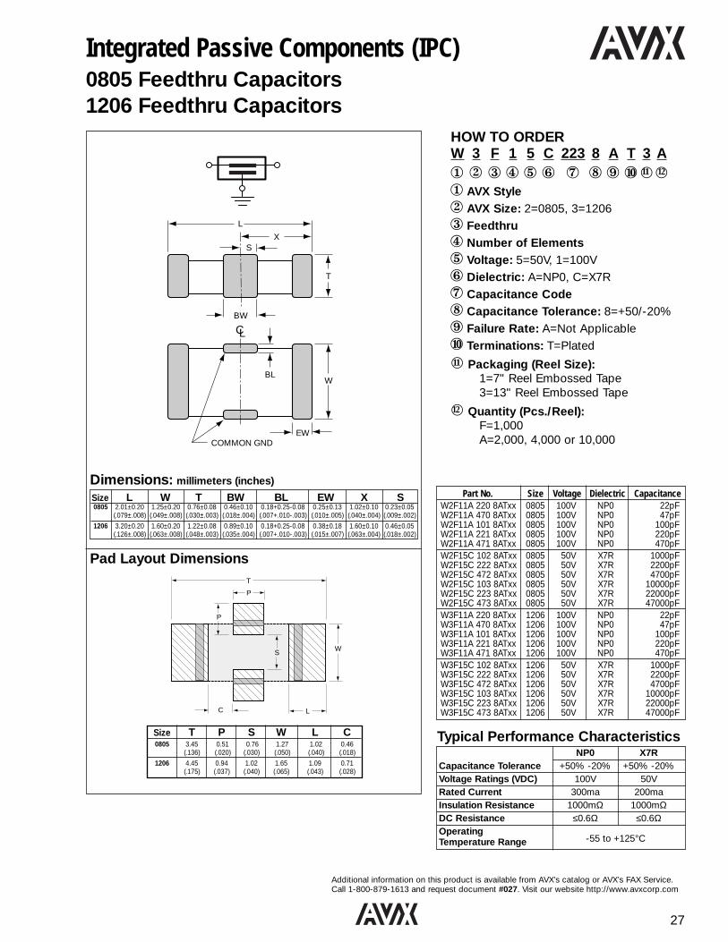
Integrated Passive Components (IPC)0805 Feedthru Capacitors1206 Feedthru Capacitors
L
XS
T
BW
BLW
EWCOMMON GND
CL
T
P
P
S W
C L
Pad Layout Dimensions
Dimensions: millimeters (inches)
NP0 X7RCapacitance Tolerance +50% -20% +50% -20%Voltage Ratings (VDC) 100V 50VRated Current 300ma 200maInsulation Resistance 1000mΩ 1000mΩDC Resistance ≤0.6Ω ≤0.6ΩOperatingTemperature Range -55 to +125°C
Typical Performance Characteristics
11
12
11 12
Size L W T BW BL EW X S0805 2.01±0.20 1.25±0.20 0.76±0.08 0.46±0.10 0.18+0.25-0.08 0.25±0.13 1.02±0.10 0.23±0.05
(.079±.008) (.049±.008) (.030±.003) (.018±.004) (.007+.010-.003) (.010±.005) (.040±.004) (.009±.002)
1206 3.20±0.20 1.60±0.20 1.22±0.08 0.89±0.10 0.18+0.25-0.08 0.38±0.18 1.60±0.10 0.46±0.05(.126±.008) (.063±.008) (.048±.003) (.035±.004) (.007+.010-.003) (.015±.007) (.063±.004) (.018±.002)
Size T P S W L C0805 3.45 0.51 0.76 1.27 1.02 0.46
(.136) (.020) (.030) (.050) (.040) (.018)
1206 4.45 0.94 1.02 1.65 1.09 0.71(.175) (.037) (.040) (.065) (.043) (.028)
Part No. Size Voltage Dielectric CapacitanceW2F11A 220 8ATxx 0805 100V NP0 22pFW2F11A 470 8ATxx 0805 100V NP0 47pFW2F11A 101 8ATxx 0805 100V NP0 100pFW2F11A 221 8ATxx 0805 100V NP0 220pFW2F11A 471 8ATxx 0805 100V NP0 470pFW2F15C 102 8ATxx 0805 50V X7R 1000pFW2F15C 222 8ATxx 0805 50V X7R 2200pFW2F15C 472 8ATxx 0805 50V X7R 4700pFW2F15C 103 8ATxx 0805 50V X7R 10000pFW2F15C 223 8ATxx 0805 50V X7R 22000pFW2F15C 473 8ATxx 0805 50V X7R 47000pFW3F11A 220 8ATxx 1206 100V NP0 22pFW3F11A 470 8ATxx 1206 100V NP0 47pFW3F11A 101 8ATxx 1206 100V NP0 100pFW3F11A 221 8ATxx 1206 100V NP0 220pFW3F11A 471 8ATxx 1206 100V NP0 470pFW3F15C 102 8ATxx 1206 50V X7R 1000pFW3F15C 222 8ATxx 1206 50V X7R 2200pFW3F15C 472 8ATxx 1206 50V X7R 4700pFW3F15C 103 8ATxx 1206 50V X7R 10000pFW3F15C 223 8ATxx 1206 50V X7R 22000pFW3F15C 473 8ATxx 1206 50V X7R 47000pF

28
Additional information on this product is available from AVX’s catalog or AVX’s FAX Service.Call 1-800-879-1613 and request document #028. Visit our website http://www.avxcorp.com
NP0 X7RCapacitance Tolerance +50% -20% +50% -20%Voltage Ratings (VDC) 100V 50VRated Current 300ma 200maInsulation Resistance 1000mΩ 1000mΩDC Resistance ≤0.6Ω ≤0.6ΩOperatingTemperature Range -55 to +125°C
Typical Performance Characteristics
Integrated Passive Components (IPC)1206 4 Element Feedthru Capacitor Array
HOW TO ORDERW 3 F 4 5 C 221 8 A T 3 A1 2 3 4 5 6 7 8 9 0s s1 AVX Style2 AVX Size: 3=12063 Feedthru4 Number of Elements: 45 Voltage: 5=50V, 1=100V6 Dielectric: A=NP0, C=X7R7 Capacitance Code8 Capacitance Tolerance: 8=+50/-20%9 Failure Rate: A=Not Applicable0 Terminations: T=Plated
s Packaging (Reel Size):1=7" Reel Embossed Tape3=13" Reel Embossed Tape
s Quantity (Pcs./Reel):F=1,000A=2,000, 4,000 or 10,000
L
ES
BW
W
P
S
Center Line
X
BL
W
= Feedthru Paths
= Common Ground
L W T BW BL P X S ES3.25±.0.15 1.60±0.2 1.22 MAX 0.41±0.1 0.18+0.25 0.76 REF 1.14±0.1 0.38±0.1 0.41±0.1(.128±.006) (.063±.008) (.048 MAX) (.016±.004) (.007+.010 ) (.030 REF) (.045±.004) (.015±.004) (.016±.004)
Dimensions: millimeters (inches)
-0.08
-.003
11 12
11
12
Part No. Size Voltage Dielectric CapacitanceW3F41A 220 8ATxx 1206 100V NP0 22pFW3F41A 470 8ATxx 1206 100V NP0 47pFW3F41A 101 8ATxx 1206 100V NP0 100pFW3F45C 221 8ATxx 1206 50V X7R 220pFW3F45C 471 8ATxx 1206 50V X7R 470pF

29
Additional information on this product is available from AVX’s catalog or AVX’s FAX Service.Call 1-800-879-1613 and request document #029. Visit our website http://www.avxcorp.com
HOW TO ORDERZ 1 D 1 3 Y 680 M 510 K A T 2 A1 2 3 4 56 7 8 9 0 ss s s1 AVX Style2 AVX Size: 1=0603, 3=06123 D=Discrete, A=Array4 Number of Elements5 Voltage: 3=25V6 Dielectric: Y=500ppm/C7 Capacitance Code8 Capacitance Tolerance9 Resistance Code0 Resistance Tolerance
s Failure Rate
s Termination Code
s Packaging Codes Special Code
11 12 13 14
Integrated Passive Components (IPC)|Z| Chip – 0603 Series Resistor/Capacitor|Z| Array – 0612 4 Element Array
|Z| Chip
|Z| Array
Stock Part ValuesPart Number Capacitance Resistance
Z3A43Y470M101KAT2A 47pF 100 ohms
Z3A43Y680M510KAT2A 68pF 51 ohms
Z3A43Y101M470KAT2A 100pF 47 ohms
Z3A43Y470M470KAT2A 47pF 47 ohms
Impedance Characteristics
100 Ohm 47pF47 Ohm 100pF33 Ohm 150pF
1,000,000
100,000
10,000
1,000
100
100.01 0.1 1 10 100
Frequency (MHz)
Imp
edan
ce (o
hms)
1,000 10,000 100,000
Performance CharacteristicsCapacitance Performance
Dielectric, TCC 0±500 ppm/°C
Capacitor Tolerance ±20%
WVDC 25V
DF (1kHz) 2.5% Max.
Resistor PerformanceTolerance ±10%
TCR ±250 ppm/°C
Ringing in an 80 MHz clock pulse (light line)is eliminated when terminated with a
100pF/47 ohm |Z| Chip (bold line)
Ch 1 2.00V
M 10.0ns/d 1.665ns 1.00nsv
2.00V 2.00ns/d 1.6650ns
|Z| Chip Termination of an 80 MHz Transmission Line
11
12
13
14
Stock Part ValuesPart Number Capacitance Resistance
Z1D13Y470M101KAT2A 47pF 100 ohms
Z1D13Y680M510KAT2A 68pF 51 ohms
Z1D13Y101M470KAT2A 100pF 47 ohms
Z1D13Y151M330KAT2A 150pF 33 ohms

30
Additional information on this product is available from AVX’s catalog or AVX’s FAX Service.Call 1-800-879-1613 and request document #030. Visit our website http://www.avxcorp.com
Capacitance (µF) 0.047 0.1 0.22 0.47 0.68 1.0 2.26.3V
0508 10V16V6.3V
0612 10V16V
Integrated Passive Components (IPC)Inter-Digitated Capacitor0508 / 0612 IDC HOW TO ORDER
W 3 L 1 Y C 105 M A T 3 A1 2 3 4 5 6 7 8 9 0s s1 AVX Style2 AVX Size: 2=0508, 3=06123 Low Inductance4 Number of Caps 5 Voltage: 6=6.3V, Z=10V, Y=16V6 Dielectric: C=X7R7 Capacitance Code8 Capacitance Tolerance: M=±20%9 Failure Rate: A=Standard0 Terminations: T=Plated Ni and Solder
s Packaging (Reel Size):1=7" Reel Embossed Tape3=13" Reel Embossed Tape
s Quantity (Pcs./Reel): F=1,000
11
12
11 12
A
B
C
D
E
Pad Layout Dimensions
Dimensions: millimeters (inches)
Available Cap Values
Comparison of ESL for Various Parts
A B C D E
0508 0.64 1.27 1.91 0.28 0.51(.025) (.050) (.075) (.011) (.020)
0612 0.89 1.65 2.54 0.46 0.79(.035) (.065) (.100) (.018) (.031)
WBL
BW C/L OF CHIPCL
T
L
X X
PS S
(–)
(+) (–) (+) (–)
(+) (–) (+)
L W T BW BL P X S0508 2.03±0.2 1.27±0.2 0.965 0.254±0.1 0.18 0.508 REF 0.76±0.1 0.254±0.1
(.080±.008) (.050±.008) (.038 MAX) (.010±.004) (.007) (.020 REF) (.030±.004) (.010±.004)
0612 3.20±0.2 1.60±0.2 1.14 MAX 0.41±0.1 0.18 0.76 REF 1.14±0.1 0.38±0.1(.126±.008) (.063±.008) (.045 MAX) (.016±.004) (.007) (.030 REF) (.045±.004) (.015±.004)
+0.25-0.08+.010-.003+0.25-0.08+.010-.003
Package Style MeasuredInductance (pH)
0508 IDC 1100612 IDC 175Feedthru 375
0612 5501206 1200
CTE (ppm/°C) X7R: 12.0
Thermal Conductivity 4-5 W / M°K
Terminations Available Plated Nickel and Solder
Thickness 0.038" max* (0508)0.048" max* (0612)
*Thickness will depend on cap value and dielectric.
- + - +
-+-+
Mechanical Specs

31
Additional information on this product is available from AVX’s catalog or AVX’s FAX Service.Call 1-800-879-1613 and request document #031. Visit our website http://www.avxcorp.com
HOW TO ORDERW 1 D 1 5 A 2 4 0 A1 2 3 4 5 6 7 8 9 01 AVX Style: IPC2 AVX Size: 1=0603, 2=08053 D=DRC, T=TRC4 Number of Elements 5 Voltage: 5=50V6 Dielectric: A=NP07 First Resonance Code8 Second Resonance Code9 Third Resonance Code0 Standard Packaging:
7" Paper reel 4,000 pieces per reel
Integrated Passive Components (IPC)Dual & Triple Resonance Capacitor
S21 FORWARD TRANSMISSION
LOG MAG. REF = -19.000dB 5.000dB/DIV
0.1000 GHz 0.0000
1
2
Resonance Code Table0=None2=880 MHz4=1800 MHz6=1900 MHz8=2400 MHz
Typical Performance CharacteristicsFrequency Tolerance 3%Voltage Rating 50V
T
W L
Marker 10.883 GHz-28.203 dB
Marker 21.805 GHz-22.686 dB
Typical Insertion Loss (S21) For 0603 DRC
L W T
0603 1.60±0.15 0.80±0.15 0.90 max.(0.063±0.006) (0.031±0.006) (0.035 max.)
0805 2.00±0.20 1.25±0.20 1.30 max.(0.079±0.008) (0.049±0.008) (0.051 max.)

32
Additional information on this product is available from AVX’s catalog or AVX’s FAX Service.Call 1-800-879-1613 and request document #032. Visit our website http://www.avxcorp.com
0.8 ± .03 (2 plcs)
0.6 ± .100
C4 Balldiameter:0.132 ±.015 mm
Vertical andHorizontal Pitch0.4 ± .02 mm
"Centrality"*j
0.925 ± .03
0.925 ± .03
"W" ± .06 mm
"L" ± .06 mm
Code Face (Optional)
"Ht" = (Hb + .1 mm typ) "Hb" ± .06*NOTE: The C4pattern will bewithin 0.1 mmof the center ofthe LICA body,in both axes.
Code Width Length Height(Body Height) (W) (L) Body (Hb)
1 1.600mm 1.850mm 0.875mm
3 1.600mm 1.850mm 0.650mm
HOW TO ORDER
LICA 3 T 802 P 1 C C 4
1 2 3 4 56 7 8 91 Style and Size2 Voltage: 25V = 33 Dielectric: T = T60T4 Cap/Section
(EIA Code): 102 = 1000 pF 103 = 10 nF104 = 0.1 mF
5 Capacitance Tolerance: M = ±20%, P = GMV6 Height Code: 1 = 0.875mm, 3 = 0.650mm7 Termination: C = C4 Solder Balls-97/3
O = OthersA = Thin-film
8 Reel Packaging:M = 7" Reel C = 4"x4" Waffle PackR = 13" Reel U = Termination Side Up 6 = 2"x2" Waffle Pack In 4"x4" Waffle Pack
9 Number of Caps/Parts: 1 = one, 2 = two, 4 = four
Table 1
C4 and Pad Dimensions: millimeters
D B
CAP
C A
D C B A
25V RatedSingle 0.875 0.6501 Cap/Unit
T60T 130 90
Double Capacitor DesignTypical nanofarads (nF) per section Schematic Code
B1D1
CAP 1
B2D2
CAP 2
C1 A1 C2 A2
D1 C1 B1 A1
D2 C2 B2 A2
Quadruple Capacitor DesignTypical nanofarads (nF) per section Schematic Code
B1D1
CAP 1
B2D2
CAP 2
C1 A1 C2 A2
B3D3
CAP 3
B4D4
CAP 4
C3 A3 C4 A4
D1 C1 B1 A1
D2 C2 B2 A2
D3 C3 B3 A3
D4 C4 B4 A4
Configuration and Capacitance Options (Co)Single Capacitor DesignTypical nanofarads (nF) per section Schematic Code
25V RatedDouble 0.875 0.6502 Caps/Unit
T60T 60 40
25V RatedQuad 0.875 0.6504 Caps/Unit
T60T 25 18
Typical Parameters T60T Units Typical Parameters T60T UnitsCapacitance, 25°C Co Nanofarads Dielectric Breakdown, Min 500 VoltsCapacitance, 60°C 1.4 x Co Nanofarads Rated Voltage 25 VoltsCapacitance, 85°C Co Nanofarads Thermal Coefficient of Expansion 8.5 ppm/°C 25-100°Dissipation Factor 25° 8 Percent Inductance: (Design Dependent) 15 to 120 Pico-HenriesDC Resistance 0.2 Ohms Use Frequency DC to 1 GigahertzIR, Minimum 25° (QUAD) 4.5 Gigaohms Ambient Temp Range -55° to 125°C
Integrated Passive Components (IPC)LICA® Low Inductance Decoupling Capacitor Arrays

33
Additional information on this product is available from AVX’s catalog or AVX’s FAX Service.Call 1-800-879-1613 and request document #033. Visit our website http://www.avxcorp.com
Radial Leads/SkyCap®
SR SeriesHOW TO ORDERSR21 5 E 104 M A A TR 11 2 3 4 5 6 7 81 AVX Style and Size: SR15, SR20, SR21, SR22, SR27,
SR30, SR40, SR502 Voltage: 50V = 5, 100V = 1, 200V = 23 Dielectric: NP0 = A, X7R = C, Z5U = E4 Capacitance Code5 Tolerance: NP0: C = ±.25pF, D = ±.5pF,
F = ±1.0%(>50pF only),G = ±2.0% (>25pF only),J = ±5%, K = ±10%
X7R: J = ±5%, K = ±10%, M = ±20%Z5U: M = ±20%, Z = +80%, -20%
6 Failure Rate: A = Not Applicable, T = CECC Release7 Leads: T = Trimmed Leads, .230"±.030"
A = Long Leads, 1.0" minimum8 Packaging: Bulk = Blank
Tape and Reel = TR1 (Standard 1) orTR2 (Standard 2)
Ammo = AP1 (Standard 1) orAP2 (Standard 2)
See Note
Dimensions: Millimeters (Inches)
Note: Coating clean .784/.031 min. above seating plane
Styles SR15, SR20,SR30, SR40, SR50
Style SR22/SR27
WMax.W
Max.
Max.T
Max.T
+-
+-L.S.
.762/.030
L.S..762/.030
H Max.H Max.
1.0" Min.
1.0" Min.
LDNom.
LDNom.
LDNom.
45o
1.52/.060Max.
W Max.
H
1.00 Min.
.200 ±.030
.031 Clean Above Seat
StyleSR21/SR59/SR65
Dimensions: millimeters (inches)
Capacitance Range
Size Capacitance NP0 X7R Z5URange 50V 100V 200V 50V 100V 200V 50V 100V
SR15 Min. 330pF 100pF 1.0pF 470pF 470pF 470pF .01µF .01µFMax. 1000pF 680pF 220pF .022µF .01µF 3300pF .047µF .01µF
SR20 Min. 1500pF 1000pF 330pF .033µF .015µF 470pF 0.1µF .047µFMax. 8200pF 6800pF 2200pF 0.22µF 0.1µF .033µF 1.0µF .22µF
SR21 Min. 1000pF 330pF 1.0pF 1000pF 1000pF — .01µF .01µFMax. 8200pF 6800pF 2200pF 0.22µF 0.1µF — 1.0µF .22µF
SR22 Min. 1000pF 330pF 1.0pF 1000pF 1000pF — .01µF .01µFMax. 8200pF 6800pF 2200pF 0.22µF 0.1µF — 1.0µF .22µF
SR27 Min. 1000pF 330pF 1.0pF 1000pF 1000pF — .01µF .01µFMax. 6800pF 3900pF 2200pF 0.22µF 0.1µF — 1.0µF .22µF
SR30 Min. .01µF 8200pF — .33µF .15µF 470pF .68µF .33µFMax. .033µF .022µF — 1.0µF .47µF .22µF 3.3µF 1.0µF
SR40 Min. .039µF .033µF — 2.2µF 1.0µF 470pF 4.7µF 1.5µFMax. .068µF .047µF — 2.7µF 1.0µF .39µF 4.7µF 2.2µF
SR50 Min. .01µF .01µF — 1.0µF .33µF 470pF 1.0µF 1.0µFMax. .1µF .068µF — 4.7µF 2.2µF .39µF 4.7µF 2.2µF
AVX Style SR15 SR20 SR21 SR22 SR27 SR30 SR40 SR50
AVX “Insertable” SR07 SR29 SR59 N/A N/A SR65 SR75 N/AWidth 3.81 5.08 5.08 5.08 6.604 7.62 10.16 12.70
(W) (0.150) (0.200) (0.200) (0.200) (0.260) (0.300) (0.400) (0.500)
Height 3.81 5.08 5.08 5.08 6.35 7.62 10.16 12.70(H) (0.150) (0.200) (0.200) (0.200) (0.250) (0.300) (0.400) (0.500)
Thickness 2.54 3.175 3.175 3.175 4.06 3.81 3.81 5.08(T) (0.100) (0.125) (0.125) (0.125) (0.160) (0.150) (0.150) (0.200)
Lead Spacing 2.54 2.54 5.08 6.35 7.62 5.08 5.08 10.16(L.S.) (0.100) (0.100) (0.200) (0.250) (0.300) (0.200) (0.200) (0.400)
Lead Diameter .508 .508 .508 .508 .508 .508 .508 .635(L.D.) (0.020) (0.020) (0.020) (0.020) (0.020) (0.020) (0.020) (0.025)
Marking is as size permits in descending order.(For code identification, see How to Order section)
— Capacitance Code — Voltage Code— Tolerance Code — Temperature Coefficient Code— A (AVX) — 3-Digit EIA Date Code/Lot Code
BULK TAPE & REEL AMMO14"
SR15 1,000 3,500 3,500SR20 1,000 3,000 3,000SR21 1,000 3,000 3,000SR22 1,000 N/A N/ASR27 1,000 N/A N/ASR30 1,000 2,000 2,000SR40 500 2,000 2,000SR50 500 N/A N/A
Standard Packaging

34
Additional information on this product is available from AVX’s catalog or AVX’s FAX Service.Call 1-800-879-1613 and request document #034. Visit our website http://www.avxcorp.com
Radial Leads/Ceralam®
MR04/05/06/07/08HOW TO ORDERMR05 1 A 561 J A A1 2 3 4 5 6 7
1 AVX Style and Size:MR04, MR05, MR06, MR07, MR08
2 Voltage: 50V=5, 100V=1, 200V=23 Dielectric: NP0=A, X7R=C, Z5U=E4 Capacitance Code5 Tolerance:
NP0: D=±.5pF (<10pF only)F=±1.0% (>50pF only)G=±2.0% (>25pF only)J=±5%, K=±10%
X7R: J=±5%, K=±10%, M=±20%Z5U: M=±20%, Z=+80%, -20%
6 Failure Rate:A= Does Not Apply, T = CECC Release
7 Leads: A = Standard SolderableT1 = Trimmed Leads, .230"±.030"
1 Trimmed lead length for the MR05 style willbe measured from the bend in the lead(seating plane).
1.14 (.045)Max.
W
W
L
L
T
T
L.D.
L.D.
L.S.
L.S.
31.7 (1.25)Min.
31.7 (1.25)Min.
Style MR05
Styles MR04, MR06,MR07, MR08
Dimensions: Millimeters (Inches)
Dimensions: millimeters (inches)
AVX Style MR04 MR05 MR06 MR07 MR08Length ±0.25 (±0.010) 4.83 (0.190) 4.83 (0.190) 7.36 (0.290) 12.44 (0.490) 12.44 (0.490)
Width ±0.25 (±0.010) 4.83 (0.190) 4.83 (0.190) 7.36 (0.290) 12.44 (0.490) 12.44 (0.490)
Thickness ±0.25 (±0.010) 2.28 (0.090) 2.28 (0.090) 2.28 (0.090) 3.55 (0.140) 6.09 (0.240)
Lead Spacing ±0.38 (±0.015) 2.54 (0.100) 5.08 (0.200) 5.08 (0.200) 10.16 (0.400) 10.16 (0.400)
Lead Diameter ±0.05 (±0.002) .635 (0.025) .635 (0.025) .635 (0.025) .635 (0.025) .635 (0.025)
Size Capacitance NP0 X7R Z5URange 50V 100V 200V 50V 100V 200V 50V 100V
MR04 Min. 1.0pF 1.0pF 1.0pF 100pF 100pF 100pF .01µF .01µFMax. 8200pF 4700pF 1200pF .15µF .068µF .015µF .39µF .22µF
MR05 Min. 1.0pF 1.0pF 1.0pF 100pF 100pF 100pF .01µF .01µFMax. 8200pF 4700pF 1200pF .15µF .068µF .015µF .39µF .22µF
MR06 Min. .01µF 5600pF 1500pF .18µF .082µF .018µF .47µF .27µFMax. .022µF .015µF 3900pF 1.0µF .68µF .047µF 1.0µF .47µF
MR07 Min. 2200pF 2200pF 2200pF 5600pF 5600pF 5600pF 0.1µF 0.1µFMax. 0.1µF .082µF 4700pF 3.3µF 2.2µF .47µF 4.7µF 2.2µF
MR08 Min. 0.12µF 0.10µF 5600pF 3.9µF 2.7µF 0.56µF 5.6µF 2.7µFMax. 0.15µF 0.12µF 6800pF 4.7µF 3.9µF 1.0µF 10.0µF 3.3µF
Capacitance Range
Marking is as size permits: for code identification seeHow To Order.
— AVX— Capacitance and Tolerance— Voltage Rating— Temperature Coefficient— Date Code— Lot Code
BULK TAPE & REEL AMMO14"
MR04 1,000 2,500 2,500MR05 1,000 2,500 2,500MR06 1,000 2,500 2,500MR07 300 N/A N/AMR08 300 N/A N/A
Standard Packaging

35
Additional information on this product is available from AVX’s catalog or AVX’s FAX Service.Call 1-800-879-1613 and request document #035. Visit our website http://www.avxcorp.com
Two Pin DIP/DIPGuard®
MD01/02/03HOW TO ORDERMD01 5 E 104 M A B1 23 4 5 67
1 AVX Style and Size: MD01, MD02, MD032 Voltage: 50V= 5, 100V = 13 Temp. Coefficient: NP0 = A, X7R = C, Z5U = E,
Y5V = G4 Capacitance Code5 Capacitance Tolerance:
NP0: F = ±1%, J = ±5%, K = ±10%X7R: J = ±5%, K = ±10%, M = ±20%Z5U: M = ±20%, Z = +80%, -20%Y5V: M = ±20%, Z = +80%, -20%
6 Failure Rate: A = Not Applicable7 Assembly Method: B = Automated Assembly
L
SEENOTE 1
SEENOTE 2
.012±.004
.325±.035
.400 max.
TMAX.
MAX.H
MAX.H
.015.148±.028
MIN.
.019 ± .004.0575 ± .0125
12
Note 1 = Leads centered within ±.010"Note 2 = Angle shall be 95°, +10°, -5°
.019 ±.004
.010 MAX.
60° TYP.±20°
AVXDielectricA = NP0C = X7RE = Z5UG = Y5V
Voltage1, 2, or 5
3 Digit CodeFor Capacitance
Tolerance Code
MarkingPart Number ExampleMD015 E 104MAB Top of Unit:
A 5 E 104 M
Dimensions: millimeters (inches)
AVX Style Length (L) Height (H1) Height(H2) Thickness
MD01 6.60 3.43 4.19 2.54(0.260±0.020) (0.135 max.) (0.165 max.) (0.100 max.)
MD02 6.60 4.19 5.08 2.54(0.260±0.020) (0.165 max.) (0.200 max.) (0.100 max.)
MD03 6.60 7.37 8.13 2.54(0.260±0.020) (0.290 max.) (0.320 max.) (0.100 max.)
Capacitance Range
Size Capacitance NP0 X7R Z5U Y5VRange 50V 100V 50V 100V 50V 16V 50V
MD01 Min. 10pF 10pF 220pF 220pF .01µF 1.0µF —Max. 3300pF 150pF 0.1µF .01µF .33µF 3.3µF —
MD02 Min. 4700pF — .15µF — .47µF — 1.0µFMax. .01µF — .22µF — .47µF — 1.0µF
MD03 Min. — — .33µF — .68µF — —Max. — — 1.0µF — 1.0µF — —
±.005.025 ±.002
.123 DIA. THRU 2 HOLES
L
WT
HOHC
HI
WCWIWO
See Table
Standard Packaging: 200 pieces per slide pack.
MD01 MD02 MD03(HO) Overall Height .400 ref. .430 ref. .545 ref.(HC) Channel Height .141 ± .006 .171 ± .006 .295 ± .010(HI) Inside Height .350 .380 .495(WO) Overall Width .540 ref. .540 ref. .600 ref.(WI) Inside Width .490 .490 .550(WC) Channel Width .210 .210 .170(WT) Top Width .350 .310 .300(L) Length 20.073 ± .06 20.073 ± .06 20.073 ± .06
Slide Package Dimensions

36
Additional information on this product is available from AVX’s catalog or AVX’s FAX Service.Call 1-800-879-1613 and request document #036. Visit our website http://www.avxcorp.com
( .019" ) .05mm ( .002")+- +-.483
DMax.
Max.L
Lead LengthMin.
Axial Leads/SpinGuard®
SA SeriesHOW TO ORDER
SA10 5 E 104 Z A A1 2 3 4 5 6 7
1 AVX Styles and Sizes:SA05, SA10, SA11, SA20, SA30, SA40
2 Voltages: 50V=5, 100V=1, 200V=23 Dielectric: NP0=A, X7R=C, Z5U=E4 Capacitance Code5 Capacitance Tolerance:
NP0: C=+0.25pF, D=±.5pF, F=±1%, G=±2%, J=±5%, K=±10%
X7R: J=±5%, K=±10%, M=±20%Z5U: M=±20%, Z=+80%, -20%
6 Failure Rate: A = Not Applicable, T = CECC Release7 Packaging:
A = Standard ReelsB = 1000 piece reels (distributors only, tight
tolerance only)C = AMMO PackD thru J = See Special Lead ConfigurationsL = Twin Coat Leads (95/5 Flash Tin/Lead)
M = 26mm tape and reelN = 26mm ammo pack
MarkingVOLTAGE(5 = 50V)
AVX TC(E = Z5U)
A 5 E
1 0 4CAP CODEAND MULTIPLIER
Z A B
9 1 0 ALPHA-ALPHA,LOT CODE
TOLERANCE AB = LOT #2 IN WEEK(Z = +80, -20%)
YEAR (1999) WEEK (10th)
AVX Style SA05 SA10 SA11 SA20 SA30 SA40Length 3.00 4.32 4.32 6.60 7.37 10.16
(L) (0.118) (0.170) (0.170) (0.260) (0.290) (0.400)
Diameter 2.30 2.54 3.05 2.54 3.81 3.81(D) (0.090) (0.100) (0.120) (0.100) (0.150) (0.150)
Lead .483 .483 .483 .483 .483 .483Diameter (0.019) (0.019) (0.019) (0.019) (0.019) (0.019)
Lead 25.4 25.4 25.4 25.4 25.4 25.4Length (1.000) (1.000) (1.000) (1.000) (1.000) (1.000)
Dimensions: millimeters (inches)
Capacitance Range
Size Capacitance NP0 X7R Z5URange 50V 100V 200V 50V 100V 200V 50V 100V
SA05 Min. — 150pF 1.0pF 8200pF 560pF 220pF 0.01µF —Max. — 560pF 120pF .018µF 6800pF 470pF 0.1µF .—
SA10 Min. 1000pF 150pF 1.0pF 8200pF 560pF 220pF .01µF .01µFMax. 1200pF 1000pF 120pF 0.1µF .015µF .01µF .22µF .047µF
SA11 Min. 1800pF 1000pF — .047µF .018µF — .22µF .1µFMax. 3900pF 2700pF — 0.1µF .039µF — .47µF .1µF
SA20 Min. 1800pF 1000pF — .027µF 8200µF — .047µF .033µFMax. 3300pF 1800pF — 0.1µF .033µF — .22µF .047µF
SA30 Min. 4700pF 1800pF — .056µF .022µF — .47µF .068µFMax. 5600pF 3900pF — .33µF 0.1µF — 1.0µF .33µF
SA40 Min. 8200pF 4700pF — .33µF .12µF — — .15µFMax. .012µF 8200pF — .47µF .18µF — — .47µF
TAPE & REEL AMMO14"
SA05 7,500 4,000SA10 7,500 4,000SA11 5,000 2,000SA20 5,000 4,000SA30 5,000 2,000SA40 5,000 2,000
Standard Packaging
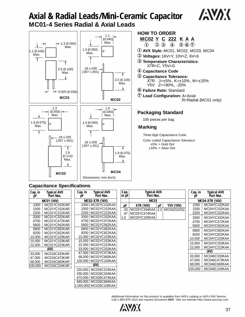
37
Additional information on this product is available from AVX’s catalog or AVX’s FAX Service.Call 1-800-879-1613 and request document #037. Visit our website http://www.avxcorp.com
Cap. in Typical AVXpF Part Nos.
MC02-X7R (16V)1000 MC02YC102KAA1500 MC02YC152KAA2200 MC02YC222KAA3300 MC02YC332KAA4700 MC02YC472KAA5600 MC02YC562KAA6800 MC02YC682KAA8200 MC02YC822KAA
10,000 MC02YC103KAA15,000 MC02YC153KAA22,000 MC02YC223KAA33,000 MC02YC333KAA47,000 MC02YC473KAA68,000 MC02YC683KAA
100,000 MC02YC104KAA(6V)
220,000 MC026C224KAA330,000 MC026C334KAA470,000 MC026C474KAA680,000 MC026C684KAA
1,000,000 MC026C105KAA
1.3 (0.050) Max.
1.9 (0.075)Max.
.18 ±.035(.007 ±.001)
2.9(0.115)Max.
MC03
1.0 (0.040) Max.
1.0 (0.040)Max.
.18 ±.035(.007 ±.001)
1.9 (0.075)Max.
Dimensions: mm (inch)
MC04
HOW TO ORDERMC02 Y C 222 K A A1 2 3 4 5 6 7
1 AVX Style: MC01, MC02, MC03, MC042 Voltages: 16V=Y, 10V=Z, 6V=63 Temperature Characteristics:
X7R=C, Y5V=G4 Capacitance Code5 Capacitance Tolerance:
X7R: J=±5%, K=±10%, M=±20%Y5V: Z=+80%, -20%
6 Failure Rate: Standard7 Lead Configuration: A=Axial
R=Radial (MC01 only)
Axial & Radial Leads/Mini-Ceramic CapacitorMC01-4 Series Radial & Axial Leads
1.3 (0.050)Max.
0.825 (0.030)
1.1 (0.040)Max.
2.5 (0.100)Max.
MC01
1.1 (0.040) Max.
1.3 (0.050)Max.
.18 ±.035(.007 ±.001)
2.5 (0.100)Max.
MC02
Three digit Capacitance Code
Color coded Capacitance Tolerance:±5% = Gold Dot
±10% = Silver Dot
Marking
Capacitance SpecificationsCap. in Typical AVX
pF Part Nos.MC01 (16V)
1000 MC01YC102KAR1500 MC01YC152KAR2200 MC01YC222KAR3300 MC01YC332KAR4700 MC01YC472KAR5600 MC01YC562KAR6800 MC01YC682KAR8200 MC01YC822KAR
10,000 MC01YC103KAR15,000 MC01YC153KAR22,000 MC01YC223KAR
(6V)33,000 MC016C333KAR47,000 MC016C473KAR68,000 MC016C683KAR
100,000 MC016C104KAR
Cap. in Typical AVXpF Part Nos.
MC04-X7R (16V)1000 MC04YC102KAA1500 MC04YC152KAA2200 MC04YC222KAA3300 MC04YC332KAA4700 MC04YC472KAA5600 MC04YC562KAA6800 MC04YC682KAA8200 MC04YC822KAA
10,000 MC04YC103KAA15,000 MC04YC153KAA22,000 MC04YC223KAA
(6V)33,000 MC046C333KAA47,000 MC046C473KAA68,000 MC046C683KAA
100,000 MC046C104KAA
Cap. Typical AVX in pF Part Nos.
MC03µF X7R (16V) µF Y5V (10V).33 MC03YC334KAA 2.2 MC03ZG225Z.47 MC03YC474KAA
1.0 MC03YC105KAA
Packaging Standard100 pieces per bag

38
Additional information on this product is available from AVX’s catalog or AVX’s FAX Service.Call 1-800-879-1613 and request document #038. Visit our website http://www.avxcorp.com
Axial Leads/Ceralam®
MA10/20/30/40/50/60HOW TO ORDERMA10 5 E 104 Z A A1 2 3 4 5 6 7
1 AVX Styles and Sizes:MA10, MA20, MA30, MA40, MA50, MA60
2 Voltages: 50V = 5, 100V = 1, 200V = 23 Dielectric: NP0 = A, X7R = C, Z5U = E4 Capacitance Code5 Capacitance Tolerance:
NP0: F = ±1.0%, J = ±5%, K = ±10%, M = ±20%, D = ±.5pF <10pF only
X7R: J = ±5%, K = ±10%, M = ±20%Z5U: M = ±20%, Z = +80%, -20%
6 Failure Rate: Standard7 Leads: Standard
‡ C tolerance available NP0 from 1.0 to 9.1 pF only. Minimum tolerance for values 10pF - 100pF is D or F, whichever is greater.
Dimensions: millimeters (inches)
AVX Style MA10 MA20 MA30 MA40 MA50 MA60
Length 4.07±.25 6.35±.25 6.09±.25 9.91±.25 12.7±.51 17.53±.51(0.160±0.010) (0.250±0.010) (0.240±0.010) (0.390±0.010) (0.500±0.020) (0.690±0.020)
Diameter 2.29±.25 2.29±.25 3.30±.25 3.56±.25 6.35±.38 8.89±.51(0.090±0.010) (0.090±0.010) (0.130±0.010) (0.140±0.010) (0.250±0.015) (0.350±0.020)
Lead .48±.05 .48±.05 .48±.05 .63±.05 .63±.05 .63±.05Diameter (0.019±0.002) (0.019±0.002) (0.019±0.002) (0.025±0.002) (0.025±0.002) (0.025±0.002)
Lead 25.4 25.4 25.4 25.4 25.4 25.4Length (1.000) (1.000) (1.000) (1.000) (1.000) (1.000)
Size Capacitance NP0 X7R Z5URange 50V 100V 200V 50V 100V 200V 50V 100V 200V
MA10 Min. 1.0pF 1.0pF 1.0pF 220pF 220pF 220pF 1000pF 1000pF 1000pFMax. 1000pF 820pF 180pF .022µF 6800pF 1200pF .1µF .022µF 4700pF
MA20 Min. 82pF 82pF 82pF 220pF 220pF 220pF 3300pF 3300pF 3300pFMax. 1800pF 1500pF 330pF .056µF .018µF 2700pF .12µF .047µF .012µF
MA30 Min. 120pF 120pF 120pF 560pF 560pF 560pF 5600pF 5600pF 5600pFMax. 5600pF 4700pF 1200pF .1µF .047µF 6800pF .47µF .1µF .027µF
MA40 Min. 180pF 180pF 180pF 1000pF 1000pF 1000pF .01µF .01µF .01µFMax. .012µF 6800pF 2200pF .27µF .10µF .022µF 1.0µF .22µF .068µF
MA50 Min. 1000pF 1000pF 1000pF 3300pF 3300pF 3300pF .033µF .033µF .033µFMax .056µF .033µF 8200pF 1.0µF .33µF .068µF 2.2µF .56µF .18µF
MA60 Min. 3300pF 3300pF 3300pF .01µF .01µF .01µF .1µF .1µF .1µFMax. 0.15µF 0.1µF 0.033µF 3.3µF 1.0µF 0.33µF 8.2µF 2.7µF 0.82µF
Capacitance Range
L
LD
D
Lead LengthMin.
Line 1, A (for AVX), 5 = 50 Volts (V is optional), E = TCLine 2, 104 = Capacitance CodeLine 3, Tolerance, 2 digit Lot CodeDate Code: 9 = 1999
10 = WeekFour Digit Date Code Optional
Marking
BULK TAPE & REEL AMMO14"
MA10 100 5,000 4,000MA20 100 5,000 4,000MA30 100 3,000 2,000MA40 100 3,000 2,000MA50 50 950 N/AMA60 50 650 N/A
Standard Packaging
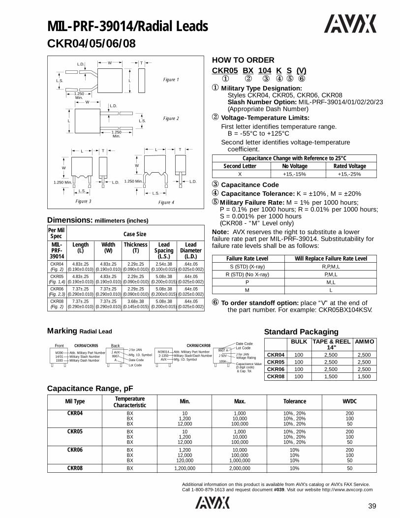
39
Additional information on this product is available from AVX’s catalog or AVX’s FAX Service.Call 1-800-879-1613 and request document #039. Visit our website http://www.avxcorp.com
MIL-PRF-39014/Radial LeadsCKR04/05/06/08
HOW TO ORDERCKR05 BX 104 K S (V)1 2 3 4 5 6
1 Military Type Designation:Styles CKR04, CKR05, CKR06, CKR08Slash Number Option: MIL-PRF-39014/01/02/20/23(Appropriate Dash Number)
2 Voltage-Temperature Limits:First letter identifies temperature range.
B = -55°C to +125°CSecond letter identifies voltage-temperature
coefficient.Capacitance Change with Reference to 25°C
Second Letter No Voltage Rated VoltageX +15,-15% +15,-25%
3 Capacitance Code4 Capacitance Tolerance: K = ±10%, M = ±20%5Military Failure Rate: M = 1% per 1000 hours;
P = 0.1% per 1000 hours; R = 0.01% per 1000 hours;S = 0.001% per 1000 hours(CKR08 - “M” Level only)
Note: AVX reserves the right to substitute a lower failure rate part per MIL-PRF-39014. Substitutability for failure rate levels shall be as follows:
Failure Rate Level Will Replace Failure Rate LevelS (STD) (X-ray) R,P,M,L
R (STD) (No X-ray) P,M,L
P M,L
M L
6 To order standoff option: place “V” at the end ofthe part number. For example: CKR05BX104KSV.
L.D.L.D.
L.D.
L.D.
L.S.L.S.
L.S.
L.S.
WW
W
W
TT
T
LL
L
L
1.250 Min. 1.250 Min.
Figure 1
Figure 2
Figure 4Figure 3
1.250Min.
1.250Min.
Per MilCase SizeSpec
MIL- Length Width Thickness Lead LeadPRF- (L) (W) (T) Spacing Diameter
39014 (L.S.) (L.D.)CKR04 4.83±.25 4.83±.25 2.29±.25 2.54±.38 .64±.05(Fig. 2) (0.190±0.010) (0.190±0.010) (0.090±0.010) (0.100±0.015) (0.025±0.002)
CKR05 4.83±.25 4.83±.25 2.29±.25 5.08±.38 .64±.05(Fig. 1,4) (0.190±0.010) (0.190±0.010) (0.090±0.010) (0.200±0.015) (0.025±0.002)
CKR06 7.37±.25 7.37±.25 2.29±.25 5.08±.38 .64±.05(Fig. 2,3) (0.290±0.010) (0.290±0.010) (0.090±0.010) (0.200±0.015) (0.025±0.002)
CKR08 7.37±.25 7.37±.25 3.68±.38 5.08±.38 .64±.05(Fig. 2) (0.290±0.010) (0.290±0.010) (0.145±0.015) (0.200±0.015) (0.025±0.002)
Dimensions: millimeters (inches)
Mil Type Temperature Min. Max. Tolerance WVDCCharacteristic
CKR04 BX 10 1,000 10%, 20% 200BX 1,200 10,000 10%, 20% 100BX 12,000 100,000 10%, 20% 50
CKR05 BX 10 1,000 10%, 20% 200BX 1,200 10,000 10%, 20% 100BX 12,000 100,000 10%, 20% 50
CKR06 BX 1,200 10,000 10% 200BX 12,000 100,000 10% 100BX 120,000 1,000,000 10% 50
CKR08 BX 1,200,000 2,000,000 10% 50
Capacitance Range, pF
Marking Radial Lead
Front CKR04/CKR05
M390 Abb. Military Part Number14/01 Military Slash Number1593 Military Dash Number
Back
J AVXJ for JAN
9907 Mfg. I.D. Symbol
A Date Code
Lot Code
CKR06/CKR08M39014 Abb. Military Part Number2-1350 Military Slash/Dash Number
AVX Mfg. I.D. Symbol
Date CodeLot Code
9907 AJ for JANJ 50V Voltage Rating
105KCapacitance Value(3 digit code)& Cap. Tol.
BULK TAPE & REEL AMMO14"
CKR04 100 2,500 2,500CKR05 100 2,500 2,500CKR06 100 2,500 2,500CKR08 100 1,500 1,500
Standard Packaging

40
Additional information on this product is available from AVX’s catalog or AVX’s FAX Service.Call 1-800-879-1613 and request document #040. Visit our website http://www.avxcorp.com
MIL-PRF-39014/2 Pin DIPCKR22/23/24
HOW TO ORDERCKR22 BX 104 K R1 2 3 4 5
1 Style:CK = General purpose, ceramic dielectric,fixed capacitors.
R = Established Reliability parts.22 = Remaining two numbers identify
shape and dimension.2 Voltage-Temperature Limits:
First letter identifies temperature range.B = -55°C to +125°CC = -55°C to +150°C
Second letter identifies voltage-temperaturecoefficient.
Capacitance Change with Reference to 25°CSecond No Voltage Rated VoltageLetter
G +30, -30ppm +30,-30ppmH +60, -60ppm +60,-60ppmR +15, -15% +15,-40%X +15, -15% +15,-25%
3 Capacitance Code4 Capacitance Tolerance: D=±.5pF, F=±1%, J=±5%,
K=±10%, M=±20%5 Military Failure Rate:
M=1% per 1000 hours R=0.01% per 1000 hoursP=0.1% per 1000 hours S=0.001% per 1000 hours
Note: AVX reserves the right to substitute a lower failurerate part per MIL-PRF-39014. Substitutability for failurerate levels shall be as follows:
Failure Rate Level Will Replace Failure Rate LevelS (STD) (X-ray) R, P, M, L
R (STD) (No X-ray) P, M, L
P M, L
M L
L
SEENOTE 1
SEENOTE 2
.012 ±.004
.325 ±.035
.400 max.
TMAX.
MAX.HMAX.
H
.015MIN
.019 ±.004
.058 ±.012
12
Note 1 = Leads centered within ±.005"Note 2 = Angle shall be 95°, +10°, -5° .019 ± .004
.010 MAX.
60° TYP. ±20°
SeeNote 3
Note 3 = .140 ± .020 inch (3.56 ±0.51 mm) for standard lead length; .170 ±.010 inch (4.32 ±0.25 mm) for optional longer lead length.
Dimensions: millimeters (inches)
MIL-PRF-39014 Length (L) Height (H1) Height (H2) Thickness
CKR22 6.60 3.25 4.45 max. 2.34(0.260±0.020) (0.128±0.007) (0.175) (0.092±0.006)
CKR23 6.60 3.94 4.95 max. 2.34(0.260±0.020) (0.155±0.007) (0.195) (0.092±0.006)
CKR24 6.60 7.19 8.13 max. 2.34(0.260±0.020) (0.283±0.007) (0.320) (0.092±0.006)
0001 A 907
Date Code (year and week)
Trademark4-Digit Dash Number
Mil Type Temperature Min. Max. Tolerance WVDCCharacteristic
CKR22 CG 1.0 470 D*, F, J, K 200CG 560 2,200 F, J, K 100CG 2,700 10,000 F, J, K 50BX 270 820 K, M 200BX 1,000 10,000 K, M 100BX 12,000 100,000 K, M 50
CKR23 CG 560 1,200 F, J, K 200CG 2,700 3,300 F, J, K 100CG 4,700 10,000 F, J, K 50BX 1,000 10,000 K, M 200BX 12,000 100,000 K, M 100BX 120,000 220,000 K, M 50
CKR24 BR 120,000 150,000 K, M 100BR 180,000 1,000,000 K, M 50
Capacitance Range, pF
* ±0.5pF closest tolerance available for 1.0pF to 56pF.
Marking
Standard Packaging200 pcs/slide pack.

41
Additional information on this product is available from AVX’s catalog or AVX’s FAX Service.Call 1-800-879-1613 and request document #041. Visit our website http://www.avxcorp.com
MIL-PRF-39014/Axial LeadsCKR11/12/14/15/16
HOW TO ORDERCKR11 BX 103 K S1 2 3 4 5
1 Military Type Designation:Styles CKR11, CKR12, CKR14, CKR15, CKR16Slash Number OptionMIL-PRF-39014/05 (Add appropriate dash numberfrom AVX Leaded Catalog)
2 Voltage-Temperature Limits:First letter identifies temperature range.
B = -55°C to +125°CSecond letter identifies voltage-temperature
coefficient.
Capacitance Change with Reference to 25°C
Second No Voltage Rated VoltageLetter
R +15,-15% +15,-40%X +15,-15% +15,-25%
3 Capacitance Code4 Capacitance Tolerance: K = ±10%, M = ±20%5 Military Failure Rate: M = 1% per 1000 hours
P = 0.1% per 1000 hoursR = 0.01% per 1000 hoursS = 0.001% per 1000 hours
L 1.25MIN.
L.D.
D
Dimensions: millimeters (inches)
Per Mil Case SizeSpec
MIL-PRF-39014 Length Diameter Lead Diameter(L) (D) (L.D.)
CKR11 4.07±.25 2.29±.25 .48±.05(0.160±0.010) (0.090±0.010) (0.019±0.002)
CKR12 6.35±.25 2.29±.25 .48±.25(0.250±0.010) (0.090±0.010) (0.019±0.010)
CKR14 9.91±.25 3.56±.25 .63±.25(0.390±0.010) (0.140±0.010) (0.025±0.010)
CKR15 12.7±.51 6.35±.38 .63±.05(0.500±0.020) (0.250±0.015) (0.025±0.002)
CKR16 17.53±.51 8.89±.51 .63±.05(0.690±0.020) (0.350±0.020) (0.025±0.002)
Mil Type TC Min. Max. Tolerance WVDC
CKR11 BX 10 4,700 10%, 20% 100BX 5,600 10,000 10%, 20% 50
CKR12 BX 5,600 10,000 10%, 20% 100BX 12,000 47,000 10%, 20% 50
CKR14 BX 12,000 47,000 10%, 20% 100BX 56,000 100,000 10%, 20% 50BR 56,000 100,000 10%, 20% 100BR 120,000 270,000 10%, 20% 50
CKR15 BX 56,000 100,000 10%, 20% 100BR 120,000 330,000 10%, 20% 100BR 470,000 1,000,000 10%, 20% 50
CKR16 BR 470,000 1,000,000 10%, 20% 100BR 2,200,000 3,300,000 10%, 20% 50
Capacitance Range, pF
Marking
JA100
KS9911AA
M390145-2291
AVX9907AA
J50V104K
CKR122257J
9907AA04222
CKR11 CKR12
CKR14, 15, 16
J for JAN, A for AVXCapacitance Value (3 digit code)K for Cap. Tol. code (K±10%, M±20%)S for failure rate, 2 digit year2 digit week, 2 digit Lot Code
Abb. Military Part NumberMilitary Slash/Dash NumberMfg. I.D. Symbol4 digit Date Code, 2 digit Lot Code“J” Brand Symbol, VoltageCapacitance Value (3 digit code)
and Cap. Tolerance
StyleMilitary Slash/Dash Number “J” or “4 digit Date Code, 2 digit Lot CodeAVX FSCM
BULK TAPE & REEL AMMO14"
CKR11 100 5,000 4,000CKR12 100 5,000 4,000CKR14 100 3,000 2,000CKR15 50 950 N/ACKR16 50 650 N/A
Standard Packaging

42
Additional information on this product is available from AVX’s catalog or AVX’s FAX Service.Call 1-800-879-1613 and request document #042. Visit our website http://www.avxcorp.com
MIL-PRF-11015/Radial LeadsCK05/06
HOW TO ORDERCK05 BX 104 K1 2 3 4
1 Style:CK = General purpose, ceramic dielectric,
fixed capacitors.05 = Remaining two numbers identify shape
and dimension.2 Voltage-Temperature Limits:
First letter identifies temperature range. B = -55°C to +125°C
Second letter identifies voltage-temperaturecoefficient.
3 Capacitance Code4 Capacitance Tolerance: K = ±10%, M = ±20%
Capacitance Change with Reference to 25°C
Second No Voltage Rated VoltageLetter
X +15,-15% +15,-25%
L.D.
L.D.
L.S.
L.S.
W
W T
L
L Figure 1
Figure 2
1.250Min.
1.250Min.
Per MIL Case SizeSpecMIL- Lead LeadPRF- Length Width Thickness Spacing Diameter
11015 (L) (W) (T) (L.S.) (L.D.)
CK05 4.83±.25 4.83±.25 2.29±.25 5.08±.38 .64±.05(Fig. 1) (0.190±0.010) (0.190±0.010) (0.090±0.010) (0.200±0.015) (0.025±0.002)
CK06 7.37±.25 7.37±.25 2.29±.25 5.08±.38 .64±.05(Fig. 2) (0.290±0.010) (0.290±0.010) (0.090±0.010) (0.200±0.015) (0.025±0.002)
Dimensions: millimeters (inches)
Mil Type TC Min. Max. Tolerance WVDC
CK05 BX 10 1,000 10%, 20% 200BX 1,200 10,000 10%, 20% 100BX 12,000 100,000 10%, 20% 50
CK06 BX 1,200 10,000 10%, 20% 200BX 12,000 100,000 10%, 20% 100BX 120,000 1,000,000 10%, 20% 50
Capacitance Range, pF
MarkingCK05/CK06
CK05BX
103K
FrontStyleTemperature CharacteristicCapacitance Value(3 digit code) and Capacitance Tolerance
100VAAAY9907
Back
Voltage RatingA for AVX; Plant ID (X); Lot Code (XX)Date Code
BULK TAPE & REEL AMMO14"
CK05 1,000 2,500 3,000CK06 1,000 2,500 3,000
Standard Packaging
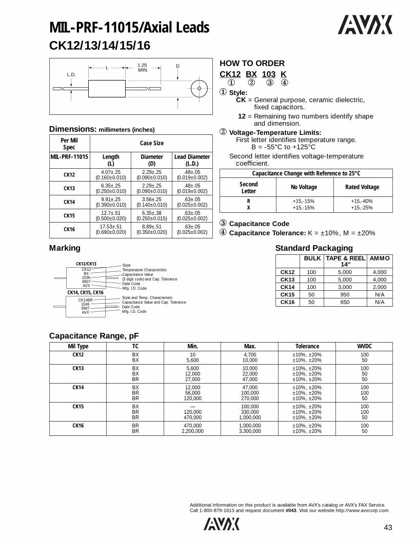
43
Additional information on this product is available from AVX’s catalog or AVX’s FAX Service.Call 1-800-879-1613 and request document #043. Visit our website http://www.avxcorp.com
L 1.25MIN.
L.D.
D HOW TO ORDERCK12 BX 103 K1 2 3 4
1 Style:CK = General purpose, ceramic dielectric,
fixed capacitors.12 = Remaining two numbers identify shape
and dimension.2 Voltage-Temperature Limits:
First letter identifies temperature range. B = -55°C to +125°C
Second letter identifies voltage-temperaturecoefficient.
Capacitance Change with Reference to 25°C
Second No Voltage Rated VoltageLetter
R +15,-15% +15,-40%X +15,-15% +15,-25%
3 Capacitance Code4 Capacitance Tolerance: K = ±10%, M = ±20%
Mil Type TC Min. Max. Tolerance WVDCCK12 BX 10 4,700 ±10%, ±20% 100
BX 5,600 10,000 ±10%, ±20% 50
CK13 BX 5,600 10,000 ±10%, ±20% 100BX 12,000 22,000 ±10%, ±20% 50BR 27,000 47,000 ±10%, ±20% 50
CK14 BX 12,000 47,000 ±10%, ±20% 100BR 56,000 100,000 ±10%, ±20% 100BR 120,000 270,000 ±10%, ±20% 50
CK15 BX — 100,000 ±10%, ±20% 100BR 120,000 330,000 ±10%, ±20% 100BR 470,000 1,000,000 ±10%, ±20% 50
CK16 BR 470,000 1,000,000 ±10%, ±20% 100BR 2,200,000 3,300,000 ±10%, ±20% 50
Per Mil Case SizeSpec
MIL-PRF-11015 Length Diameter Lead Diameter(L) (D) (L.D.)
CK12 4.07±.25 2.29±.25 .48±.05(0.160±0.010) (0.090±0.010) (0.019±0.002)
CK13 6.35±.25 2.29±.25 .48±.05(0.250±0.010) (0.090±0.010) (0.019±0.002)
CK14 9.91±.25 3.56±.25 .63±.05(0.390±0.010) (0.140±0.010) (0.025±0.002)
CK15 12.7±.51 6.35±.38 .63±.05(0.500±0.020) (0.250±0.015) (0.025±0.002)
CK16 17.53±.51 8.89±.51 .63±.05(0.690±0.020) (0.350±0.020) (0.025±0.002)
MIL-PRF-11015/Axial LeadsCK12/13/14/15/16
Dimensions: millimeters (inches)
Capacitance Range, pF
Marking
CK12BX
103K9907AVX
CK14BR104K9907AVX
CK12/CK13
CK14, CK15, CK16
StyleTemperature CharacteristicCapacitance Value(3 digit code) and Cap. ToleranceDate CodeMfg. I.D. Code
Style and Temp. CharacteristicCapacitance Value and Cap. ToleranceDate CodeMfg. I.D. Code
BULK TAPE & REEL AMMO14"
CK12 100 5,000 4,000CK13 100 5,000 4,000CK14 100 3,000 2,000CK15 50 950 N/ACK16 50 650 N/A
Standard Packaging

44
Additional information on this product is available from AVX’s catalog or AVX’s FAX Service. Call 1-800-879-1613 and request document #044. Visit our websitehttp://www.avxcorp.com
HOW TO ORDERCCR06 CG 183 J R V1 2 3 4 5 6
1 Style:CC = Identifies temperature compensating, ceramic
dielectric, fixed capacitors.R = Identifies Established Reliability parts.
06 = Numbers identify shape and dimension.2 Temperature Characteristic:
1/ Not practically measurable.
2/ The ppm/°C values for -55°C were calculated by dividing ppm bynegative 80°C.
3 Capacitance Code4 Capacitance Tolerance:
C = ±0.25 pF, D = ±0.5 pF, F =±1%, G = ±2%, J = ±5%, K =±10%
5 Military Failure Rate:M = 1% per 1000 hours, P = 0.1% per 1000 hours,R = 0.01% per 1000 hours, S = 0.001% per
1000 hours.6 To Order Stand-Off Option: place “V” at the end of
the part number. For example: CR05CG332FSV.
L.D.L.D.
L.D.L.D.
L.S.L.S.
L.S.L.S.
WW
WW
TT
T
LL
LL
1.250 Min. 1.250 Min.
Figure 1 Figure 2
Figure 4Figure 3
Per MIL Case SizeSpec
Lead LeadMIL-PRF-20 Length Width Thickness Spacing Diameter
(L) (W) (T) (L.S.) (L.D.)
CCR05/CC05 4.83±.25 4.83±.25 2.29±.25 5.08±.38 .64±.05(Fig. 1,4) (0.190±0.010) (0.190±0.010) (0.090±0.010) (0.200±0.015) (0.025±0.002)
CCR06/CC06 7.37±.25 7.37±.25 2.29±.25 5.08±.38 .64±.05(Fig. 2,3) (0.290±0.010) (0.290±0.010) (0.090±0.010) (0.200±0.015) (0.025±0.002)
CCR07/CC07 12.19±.51 12.19±.51 3.56±.25 10.16±.51 .64±.05(Fig. 2) (0.480±0.020) (0.480±0.020) (0.140±0.010) (0.400±0.020) (0.025±0.002)
CCR08/CC08 12.19±.51 12.19±.51 6.1±.25 10.16±.51 .64±.05(Fig. 2) (0.480±0.020) (0.480±0.020) (0.240±0.010) (0.400±0.020) (0.025±0.002)
CCR09/CC09 4.83±.25 4.83±.25 2.29±.25 2.54±.38 .64±.05(Fig. 2) (0.190±0.010) (0.190±0.010) (0.090±0.010) (0.100±0.015) (0.025±0.002)
MIL-PRF-20/Radial LeadsCCR05/06/07/08/09
Dimensions: millimeters (inches)
Radials
Mil Type TC Min. Max. Tolerance WVDC
CCR05 CX 1.0 2.0 ±0.25pF 200CK 2.2 3.9 ±0.25pF, ±0.5pF 200CJ 4.3 7.5 ±0.25pF, ±0.5pF 200CH 8.2 18 ±2%, ±5% 200CG 20 330 ±1%, ±2%, ±5% 200CG 360 1,800 ±1%, ±2%, ±5% 100CG 2,000 3,300 ±1%, ±2%, ±5% 50
CCR06 CG 360 1,800 ±1%, ±2%, ±5% 200CG 2,000 4,700 ±1%, ±2%, ±5% 100CG 5,100 18,000 ±1%, ±2%, ±5% 50
CCR07 CG 2,200 4,700 ±1%, ±2%, ±5%, ±10% 200CG 5,600 12,000 ±1%, ±2%, ±5%, ±10% 100CG 15,000 100,000 ±1%, ±2%, ±5%, ±10% 50
CCR08 CG 3,900 4,700 ±2%, ±5%, ±10% 200CG 15,000 18,000 ±2%, ±5%, ±10% 100CG 56,000 68,000 ±2%, ±5%, ±10% 50
Capacitance Range, pF
CC05CH
100G
CC05 & CC09Date CodeA=Lot Letter0=1st Digit of AVX FSCM #4222=Last four digits of
AVX FSCM #FRONT
9907A0
4222
BACK
CCR05CH100GM
CCR05 & CCR09 Date CodeA=Lot LetterJ=”J” or “JAN” Brand0=1st Digit of AVX FSCM #4222=Last four digits of
AVX FSCM #FRONT
9907AJ04222
BACK
CC06CG
102F
CC06Date Code & Lot Letter200V=Rated Voltage04222=AVX FSCM #
FRONT
9907A200V04222
BACK
CCR06CG102
FM
CCR06Date Code & Lot LetterJ=”J” or “JAN” Brand200V=Rated Voltage04222=AVX FSCM #
FRONT
9907AJ200V04222
BACK
CG103G9
AAVX
CC07
CCR07
CharacteristicCapacitance ValueCap. Tolerance & Year Code (9 for 1999)Lot Code & Trademark
JCG103GM9AAVX
“J” Brand (J) and Characteristic (CG)Capacitance ValueCap. Tolerance (G) FR Level (M),
& Year Code (9 for 1999)Lot Code (A); and Trademark (AVX)
CC08CG392KAVX
96095200V 9907A
CC08
Trademark or Manufacturer’s NameSource Code (FSCM)Voltage, Date Code and Lot Symbol
CCR08CG392KM
JAN AVX96095
200V 9907A
“JAN” Brand & Trademark orManufacturer’s NameSource Code (FSCM)Voltage, Date Code and Lot Symbol
CCR08
BULK TAPE & REEL AMMO14"
CCR05 100 2,500 2,500CCR06 100 2,500 2,500
BULK TAPE & REEL AMMO14"
CCR07 100 N/A N/ACCR08 100 N/A N/ACCR09 100 N/A N/A
Standard Packaging
Permissible capacitance change from capacitance at+25°C in ppm/°C
Temp. Characteristic
CX CK CJ CH CG+125°C 1/ ±250 ppm/°C ±120 ppm/°C ±60 ppm/°C ±30 ppm/°C
-55°C 2/ 1/ +246.25 +116.25 +55.00 +27.50-326.25 -166.25 -91.25 -53.75

45
Additional information on this product is available from AVX’s catalog or AVX’s FAX Service.Call 1-800-879-1613 and request document #045. Visit our website http://www.avxcorp.com
MIL-PRF-20/Axial LeadsCCR75/76/77/78/79
HOW TO ORDERCCR76 CG 102 J R1 2 3 45
1 Style:CC = Identifies temperature compensating,
ceramic dielectric, fixed capacitors.R = Identifies Established Reliability parts.
76 = Numbers identify shape and dimension.2 Temperature Characteristic:
1/ Not practically measurable.
3 Capacitance Code4 Capacitance Tolerance:
C = ±0.25 pF, D = ±0.5 pF, F = ±1%, G = ±2%, J = ±5%, K = ±10%
5 Military Failure Rate:M = 1% per 1000 hours, P = 0.1% per 1000 hours,R = 0.01% per 1000 hours, S = 0.001%
per 1000 hours.
L 1.25MIN.
L.D.
D
Dimensions: millimeters (inches)
Per MIL Case SizeSpec
MIL-PRF-20 Length Diameter Lead Diameter(L) (D) (L.D.)
CCR75 4.07±.25 2.29±.25 .48±.05CC75 (0.160±0.010) (0.090±0.010) (0.019±0.002)
CCR76 6.35±.25 2.29±.25 .48±.05CC76 (0.250±0.010) (0.090±0.010) (0.019±0.002)
CCR77 9.91±.25 3.56±.25 .63±.05CC77 (0.390±0.010) (0.140±0.010) (0.025±0.002)
CCR78 12.7±.51 6.35±.38 .63±.05CC78 (0.500±0.020) (0.250±0.015) (0.025±0.002)
CCR79 17.53±.51 8.89±.51 .63±.05CC79 (0.690±0.020) (0.350±0.020) (0.025±0.002)
Mil Type TC Min. Max. Tolerance WVDC
CCR75 CX 1.0 2.0 ±0.25pF 200CK 2.2 3.9 ±0.25pF, ±0.5pF 200CJ 4.3 7.5 ±0.25pF, ±0.5pF 200CH 8.2 18.0 ±0.25pF, ±0.5pF 200CG 20 75 ±1%, ±2%, ±5% 200CG 82 240 ±1%, ±2%, ±5% 100CG 270 680 ±1%, ±2%, ±5% 50
CCR76 CG 82 130 ±1%, ±2%, ±5% 200CG 270 680 ±1%, ±2%, ±5% 100CG 750 1,000 ±1%, ±2%, ±5% 50
CCR77 CG 150 680 ±1%, ±2%, ±5% 200CG 750 2,200 ±1%, ±2%, ±5% 100CG 2,400 5,600 ±1%, ±2%, ±5% 50
CCR78 CG 820 3,300 ±1%, ±2%, ±5%, ±10% 200CG 3,900 12,000 ±1%, ±2%, ±5%, ±10% 100CG 15,000 27,000 ±1%, ±2%, ±5%, ±10% 50
CCR79 CG 3,900 10,000 ±1%, ±2%, ±5%, ±10% 200CG 15,000 39,000 ±1%, ±2%, ±5%, ±10% 100CG 47,000 82,000 ±1%, ±2%, ±5%, ±10% 50
Marking
Capacitance Range, pF
CG101G99
07AAA
CC75, CC76CharacteristicCapacitance ValueCap. Tolerance & 2 digit Year Code2 digit Week, 2 digit Lot Code,
A for AVX
JCG101
GM9907AAA
CCR75, CCR76“J” Brand (J) and Characteristic (CG)Capacitance ValueCap. Tolerance (G) FR Level (M),
2 digit Year Code2 digit Week, A for AVX
CC77CG151F04222
9907AA
CC77Type Designation
FSCM4 digit Date Code, 2 digit LotCode
CCR77CG151FMJ042229907AA
CCR77
Type Designation
“J” Brand and FSCM4 digit Date Code, 2 digit Lot Code
CC78CG821KAVX
04222200V
9907AA
CC78, CC79
Type Designation
Trademark or Manufacturer’s Name
Source Code (FSCM)Voltage4 Digit Date Code
CCR78CG
821KMJAN A04222200V
9907AA
CCR78, CCR79Type DesignationTCCapacitance Tolerance,
Failure Rate“JAN” Brand, A for AVXFSCMVoltage4 digit Date Code,
2 digit Lot Code
BULK TAPE & AMMOREEL14"
CCR75 100 5,000 4,000CCR76 100 5,000 4,000CCR77 100 3,000 2,000CCR78 50 950 N/ACCR79 50 650 N/A
Standard Packaging
Permissible capacitance change from capacitance at+25°C in ppm/°C
Temp. Characteristic
CX CK CJ CH CG+125°C 1/ ±250 ppm/°C ±120 ppm/°C ±60 ppm/°C ±30 ppm/°C
-55°C 2/ 1/ +246.25 +116.25 +55.00 +27.50-326.25 -166.25 -91.25 -53.75

46
Additional information on this product is available from AVX’s catalog or AVX’s FAX Service. Call 1-800-879-1613 and request document #046. Visit our website http://www.avxcorp.com
HOW TO ORDERM123 A 01 BX B 103 K C1 2 3 4 5 6 7 8
1 Mil-Spec Number2 Modification Spec.3 Slash Sheet Number4 Voltage-Temperature Limits:
5 Rated Voltage: 7 Capacitance Tolerance:
6 Capacitance Code8 Termination:
CL
CL
CL
+-+-+-
+-+-
+-
+-
+-+-
+-
1.14(.045)SEE NOTE 4
MAX.
4.83 0.254(.190 0.010)
+-
+-4.83 0.254(.190 0.010)
2.29 0.254(.090 0.010)
31.75(1.25)
MIN.54 .381
100 .015) .635 .051(.025 .002)
5.08 .381(.200 .015)
OF LEADS WITHIN .381 (.015)
OF CASE
CL
CL
+-+-
+-+-
+-
+-
+-+-
7.37 0.254(.290 0.010)
2.29 0.254(.090 0.010)
7.37(.290)
5.08 .381(.200 .015)
.635 .051(.025 .002)
31.75(1.25)
MIN.
OF LEADSWITHIN .762 (.030)
OF CASE
+-+-
(.160)4.06
31.75(1.25)
MIN.
.508 .051(.020 .002)
2.29(.090)
+-+-
(.250)6.35
31.75(1.25)
MIN.
.508 .051(.020 .002)
2.29(.090)
+.002-
MIN.
500
1.250
.025
250
+.002-
MIN.
690
1.250
.025
350
+-
390
1.250 MIN.
.002
140
.020
.020+- +-
+-
+-
+-
+-
+-+-
+-
+
.260 .092 .006 SEE
NOTE 2
.128 .007
.015MIN.
.175MAX.
.148 .028
.058 .012
.090 .004
(SEE NOTE 3)
.012 .004
.325 .035(SEE NOTE 4)
60 20TYP
oo
.010MAX
.019004
.020+- +-
+-
+-
+-
+-
+-+-
+-
+-
.260 .092 .006 SEE
NOTE 3
.155 .007
.015MIN.
.195MAX.
.148 .028
.058 .012
.090 .004
(SEE NOTE 4)
.012 .004
.325 .035(SEE NOTE 5)
60 20TYP
oo
.010MAX
.019 .004
.020+- +-
+-
+-
+-
+-
+-+-
+-
+-
.260 .092 .006 SEE
NOTE 2
.283 .007
.015MIN.
.320MAX.
.148 .028
.058 .012
.090 .004
(SEE NOTE 3)
.012 .004
.325 .035(SEE NOTE 4)
60 20TYP
oo
.010MAX
.019 .004
MIL-PRF-123CKS Series
Capacitance Change with reference to 25°Cover temperature range -55°C to +125°C
Symbol Without Voltage With Rated DC Voltage
BP 0±30 ppm/°C 0±30 ppm/°CBX +15, -15 percent +15, -25 percent
Symbol Rated VoltageVolts, DC
B 50C 100
Symbol Cap. Tolerance±
C 0.25pFD 0.5pFF 1%J 5%K 10%
Symbol Lead CapacitorsTermination Style
C Copper, solder coated(type C-4 or C-5 of MIL-STD-1276
MIL-Spec Test RequirementsTest Description MIL-PRF-123
NDT 100% Ultrasonic Scan or(Non-Destructive Test) Neutron-RadiographyPre-Cap Visual(Pre-Encapsulation 100%Visual Examination)D.P.A. Lot by Lot—Pre-Termination(Destructive Physical Analysis) Lot by Lot—Finished ProductPre-CapTerminal Strength Lot by Lot(Pre-Encapsulation Pull Test)Life Test / (Lot by Lot) Lot by Lot—1000 HoursLow Voltage / Humidity Lot by LotThermal Shock / 100 Cycles Lot by Lot
MIL-PRF-123/Style CKS05,-/01BP-TCVC
Cap Range RVDC4.7-240pF 100270-2,700pF 50
BX-TCVCCap Range RVDC270-4,700pF 1005,600-10,000pF 50
BP-TCVCCap Range RVDC270-2,400pF 1002,700-4,700pF 50
BX-TCVCCap Range RVDC5,600-100,000pF 10056,000-470,000pF 50
MIL-PRF-123/Style CKS06,-/02
MIL-PRF-123/Style CKS11,-/04
BP-TCVCCap Range RVDC47-100pF 100110-560pF 50
BX-TCVCCap Range RVDC100-1,000pF 1001,200-4,700pF 50
MIL-PRF-123/Style CKS12,-/05
BP-TCVCCap Range RVDC110-220pF 100240-470pF 50
BX-TCVCCap Range RVDC1,200-4,700pF 1005,600-10,000pF 50
MIL-PRF-123/Style CKS15,-/07
BP-TCVCCap Range RVDC240-1,000pF 1001,100-6,800pF 50
BX-TCVCCap Range RVDC5,600-10,000pF 10012,000-47,000pF 50
MIL-PRF-123/Style CKS14,-/06
BP-TCVCCap Range RVDC
1,100-2,200pF 1002,400-22,000pF 50
BX-TCVCCap Range RVDC
12,000-100,000pF 100120,000-180,000pF 50
MIL-PRF-123/Style CKS16,-/08
BP-TCVCCap Range RVDC2,400-10,000pF 10011,000-22,000pF 50
BX-TCVCCap Range RVDC120,000-470,000pF 100560,000-1,000,000pF 50
MIL-PRF-123/Style CKS22,-/16
BP-TCVCCap Range RVDC1.0-470pF 200560-2,200pF 1002,700-4,700pF 50
BX-TCVCCap Range RVDC270-820pF 2001,000-10,000pF 10012,000-100,000pF 50
MIL-PRF-123/Style CKS23,-/17
BP-TCVCCap Range RVDC560-1,200pF 2002,700-3,300pF 1004,700-10,000pF 50
BX-TCVCCap Range RVDC1,000-10,000pF 20012,000-100,000pF 100120,000-220,000pF 50
MIL-PRF-123/Style CKS24,-/18
BX-TCVCCap Range RVDC120,000-150,000pF 100180,000-470,000pF 50
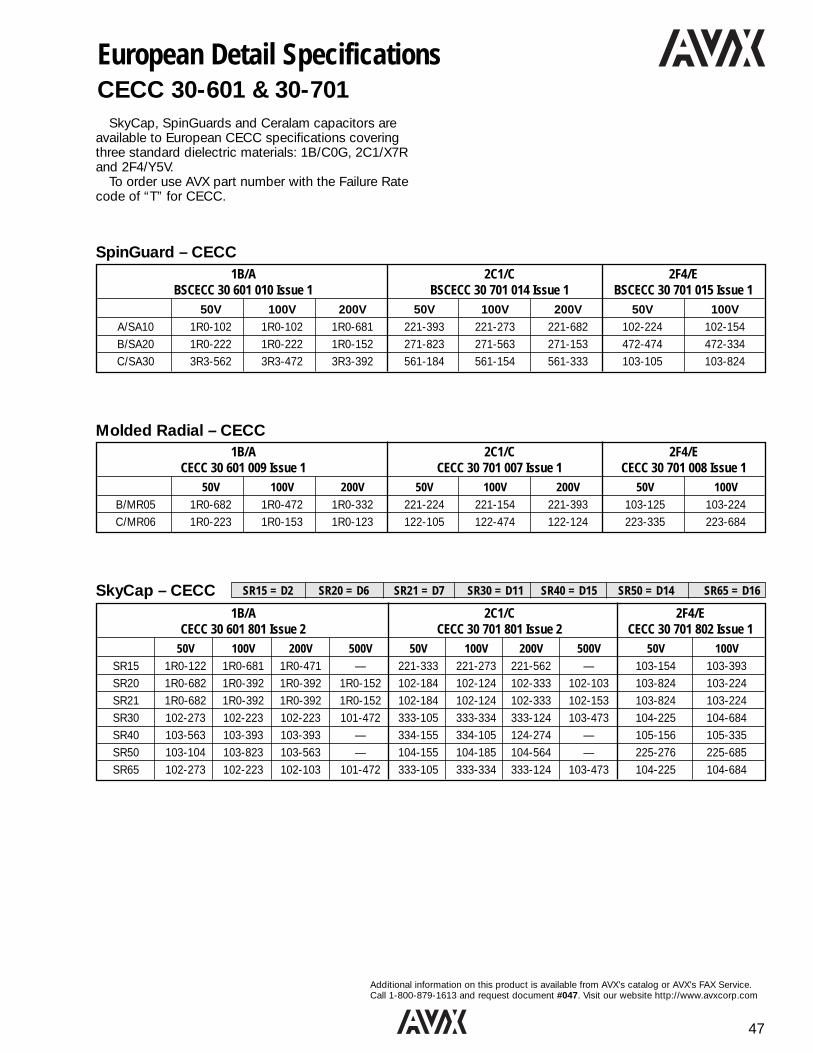
47
Additional information on this product is available from AVX’s catalog or AVX’s FAX Service.Call 1-800-879-1613 and request document #047. Visit our website http://www.avxcorp.com
SkyCap – CECC SR15 = D2 SR20 = D6 SR21 = D7 SR30 = D11 SR40 = D15 SR50 = D14 SR65 = D16
European Detail SpecificationsCECC 30-601 & 30-701
SkyCap, SpinGuards and Ceralam capacitors areavailable to European CECC specifications coveringthree standard dielectric materials: 1B/C0G, 2C1/X7Rand 2F4/Y5V.
To order use AVX part number with the Failure Ratecode of “T” for CECC.
SpinGuard – CECC1B/A 2C1/C 2F4/E
BSCECC 30 601 010 Issue 1 BSCECC 30 701 014 Issue 1 BSCECC 30 701 015 Issue 150V 100V 200V 50V 100V 200V 50V 100V
A/SA10 1R0-102 1R0-102 1R0-681 221-393 221-273 221-682 102-224 102-154B/SA20 1R0-222 1R0-222 1R0-152 271-823 271-563 271-153 472-474 472-334C/SA30 3R3-562 3R3-472 3R3-392 561-184 561-154 561-333 103-105 103-824
Molded Radial – CECC1B/A 2C1/C 2F4/E
CECC 30 601 009 Issue 1 CECC 30 701 007 Issue 1 CECC 30 701 008 Issue 150V 100V 200V 50V 100V 200V 50V 100V
B/MR05 1R0-682 1R0-472 1R0-332 221-224 221-154 221-393 103-125 103-224C/MR06 1R0-223 1R0-153 1R0-123 122-105 122-474 122-124 223-335 223-684
1B/A 2C1/C 2F4/ECECC 30 601 801 Issue 2 CECC 30 701 801 Issue 2 CECC 30 701 802 Issue 1
50V 100V 200V 500V 50V 100V 200V 500V 50V 100VSR15 1R0-122 1R0-681 1R0-471 — 221-333 221-273 221-562 — 103-154 103-393SR20 1R0-682 1R0-392 1R0-392 1R0-152 102-184 102-124 102-333 102-103 103-824 103-224SR21 1R0-682 1R0-392 1R0-392 1R0-152 102-184 102-124 102-333 102-153 103-824 103-224SR30 102-273 102-223 102-223 101-472 333-105 333-334 333-124 103-473 104-225 104-684SR40 103-563 103-393 103-393 — 334-155 334-105 124-274 — 105-156 105-335SR50 103-104 103-823 103-563 — 104-155 104-185 104-564 — 225-276 225-685SR65 102-273 102-223 102-103 101-472 333-105 333-334 333-124 103-473 104-225 104-684
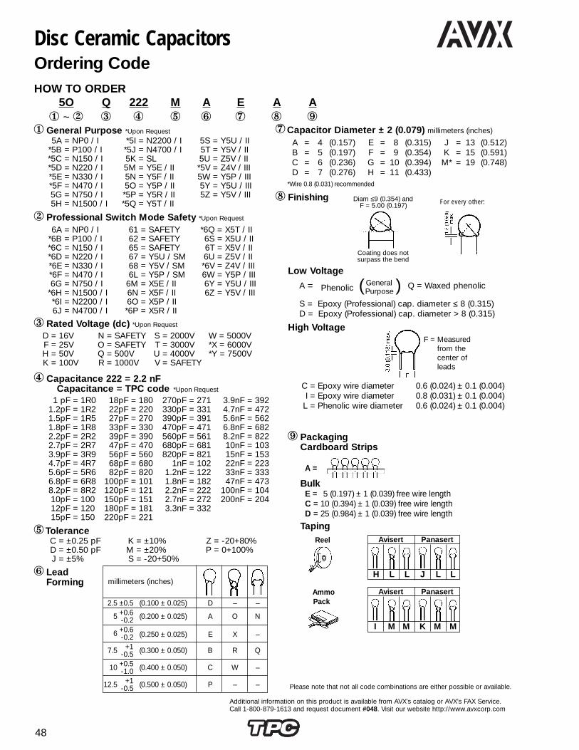
48
Additional information on this product is available from AVX’s catalog or AVX’s FAX Service.Call 1-800-879-1613 and request document #048. Visit our website http://www.avxcorp.com
HOW TO ORDER5O Q 222 M A E A A1 ~ 2 3 4 5 6 7 8 9
1 General Purpose *Upon Request
Disc Ceramic CapacitorsOrdering Code
1 pF = 1R01.2pF = 1R21.5pF = 1R51.8pF = 1R82.2pF = 2R22.7pF = 2R73.9pF = 3R94.7pF = 4R75.6pF = 5R66.8pF = 6R88.2pF = 8R210pF = 10012pF = 12015pF = 150
18pF = 18022pF = 22027pF = 27033pF = 33039pF = 39047pF = 47056pF = 56068pF = 68082pF = 820
100pF = 101120pF = 121150pF = 151180pF = 181220pF = 221
270pF = 271330pF = 331390pF = 391470pF = 471560pF = 561680pF = 681820pF = 821
1nF = 1021.2nF = 1221.8nF = 1822.2nF = 2222.7nF = 2723.3nF = 332
3.9nF = 3924.7nF = 4725.6nF = 5626.8nF = 6828.2nF = 82210nF = 10315nF = 15322nF = 22333nF = 33347nF = 473
100nF = 104200nF = 204
C = ±0.25 pFD = ±0.50 pFJ = ±5%
K = ±10%M = ±20%S = -20+50%
Z = -20+80%P = 0+100%
C = Epoxy wire diameter 0.6 (0.024) ± 0.1 (0.004)I = Epoxy wire diameter 0.8 (0.031) ± 0.1 (0.004)
L = Phenolic wire diameter 0.6 (0.024) ± 0.1 (0.004)
8 Finishing Diam ≤9 (0.354) andF = 5.00 (0.197)
Coating does notsurpass the bend
For every other:
Avisert Panasert
H L L J L L
F = Measuredfrom thecenter ofleads
9 PackagingCardboard Strips
A =
BulkE = 5 (0.197) ± 1 (0.039) free wire lengthC = 10 (0.394) ± 1 (0.039) free wire lengthD = 25 (0.984) ± 1 (0.039) free wire length
TapingReel
AmmoPack
Please note that not all code combinations are either possible or available.
*Wire 0.8 (0.031) recommended
Avisert Panasert
I M M K M M
5A = NP0 / I*5B = P100 / I*5C = N150 / I*5D = N220 / I*5E = N330 / I*5F = N470 / I5G = N750 / I5H = N1500 / I
*5I = N2200 / I*5J = N4700 / I5K = SL5M = Y5E / II5N = Y5F / II5O = Y5P / II*5P = Y5R / II*5Q = Y5T / II
5S = Y5U / II5T = Y5V / II5U = Z5V / II*5V = Z4V / III5W = Y5P / III5Y = Y5U / III5Z = Y5V / III
6A = NP0 / I*6B = P100 / I*6C = N150 / I*6D = N220 / I*6E = N330 / I*6F = N470 / I6G = N750 / I
*6H = N1500 / I*6I = N2200 / I6J = N4700 / I
61 = SAFETY62 = SAFETY65 = SAFETY67 = Y5U / SM68 = Y5V / SM6L = Y5P / SM
6M = X5E / II6N = X5F / II6O = X5P / II*6P = X5R / II
*6Q = X5T / II6S = X5U / II6T = X5V / II6U = Z5V / II*6V = Z4V / III6W = Y5P / III6Y = Y5U / III6Z = Y5V / III
D = 16VF = 25VH = 50VK = 100V
N = SAFETYO = SAFETYQ = 500VR = 1000V
S = 2000VT = 3000VU = 4000VV = SAFETY
W = 5000V*X = 6000V*Y = 7500V
2 Professional Switch Mode Safety *Upon Request
3 Rated Voltage (dc) *Upon Request
4 Capacitance 222 = 2.2 nFCapacitance = TPC code *Upon Request
6 LeadForming
7Capacitor Diameter ± 2 (0.079) millimeters (inches)
2.5 ±0.5 (0.100 ± 0.025) D – –
5 +0.6 (0.200 ± 0.025) A O N-0.2
6 +0.6(0.250 ± 0.025) E X –-0.2
7.5 +1 (0.300 ± 0.050) B R Q-0.5
10 +0.5 (0.400 ± 0.050) C W –-1.0
12.5 +1 (0.500 ± 0.050) P – –-0.5
A = 4 (0.157)B = 5 (0.197)C = 6 (0.236)D = 7 (0.276)
E = 8 (0.315)F = 9 (0.354)G = 10 (0.394)H = 11 (0.433)
J = 13 (0.512)K = 15 (0.591)M* = 19 (0.748)
5Tolerance
Low Voltage
A = ( General ) Q = Waxed phenolicPhenolic Purpose
S = Epoxy (Professional) cap. diameter ≤ 8 (0.315)D = Epoxy (Professional) cap. diameter > 8 (0.315)
High Voltage
millimeters (inches)

49
Additional information on this product is available from AVX’s catalog or AVX’s FAX Service.Call 1-800-879-1613 and request document #049. Visit our website http://www.avxcorp.com
Cap. Disc. Dia. Available Capacitance Range, pFDia. mm (in.)Code D ± 2 T max. NP0 N750 N1500(7) (±0.079) 100VDC 500VDC 1000VDC 2000VDC 3000VDC 4000/5000VDC 100VDC 500VDC 1000VDC 2000VDC 3000VDC 4000VDC 5000VDC 100VDC 500VDC
A4.0 3.0
1.0-15 1.0-15 3.9-5.6 3.9-4.7 – – 1.5-33 1.5-33 – – – – – 6.0-47 6.0-47(0.157) (0.118)
B5.0 4.0
18-39 18-27 6.0-15 5.0-12 – – 39-68 39-56 6.8-27 6.8-22 – – – 50-120 50-56(0.197) (0.157)
C6.0 4.0
– 33 18 15-18 5.6 -7.0 4.7-7.0 82 68 33 27-33 6.8-20 – – – 68-100(0.236) (0.157)
D7.0 4.0
47-50 39-50 20-39 20-33 8.0-15 – 100-150 82-100 39-50 39-50 22-33 – – 150-220 120(0.276) (0.157)
E8.0 4.0
56-82 56-68 47-50 39 18-27 8.0-15 180 120 56-68 56-68 39-56 15-27 – 270 150-180(0.315) (0.157)
F9.0 5.0
100-120 82 56-68 47-56 33-39 – 220 150 82-100 82 68 – – 330 220(0.354) (0.197)
G10.0 5.0
– – – – – 18-27 – – – – – – – – –(0.394) (0.197)
H11.0 5.0
150-180 100-150 82-100 68-82 47-56 33-39 270 180-220 120-150 100-120 82 33-56 15-50 – 270-330(0.433) (0.197)
J13.0 6.0
– – 120 100 68-82 47-50 – 270 180-220 150 100-120 – – – –(0.512) (0.236)
K15.0 6.0
– 180-220 150 120-150 100-120 56 – 330 – 180-270 150-220 68-82 56-68 – –(0.591) (0.236)
M 19.0 7.0 – 270-330 180 – – 68-100 – – – – – 100-120 82-100 – –(0.748) (0.276)
Disc Ceramic CapacitorsTemperature Compensating - Class I
Ø = 0.6 ± 0.1(0.024) (0.004)
Preferred lead spacingF = 5 (0.197)
Dielectric - Class I For Ordering Code See Page 48
Class SL: For Ordering Code See Page 48Cap. Disc. Dia. Available Capacitance Range, pFDia. mm (in.)Code D ± 2 T max.(7) (±0.079) 50V 100V
A4.0 3.0
1.0-220 1.0-220(0.157) (0.118)
B5.0 4.0
270-470 –(0.197) (0.157)
C6.0 4.0
560 270-470(0.236) (0.157)
D7.0 4.0
680-1000 560-680(0.276) (0.157)
E8.0 4.0
– 820-1,000(0.315) (0.157)
100 V → 500 V 1kV → 5kVMeasured at 1.0 MHz @ 1.0 Vrms & 25ºC 1.0 MHz @ 1.0 Vrms & 25ºCDissipation Factor CR ≤ 30 pF → ≤1/CR + 0.07 CR ≤ 30 pF → ≤1/CR + 0.07(%) CR > 30 pF → ≤ 0.1% CR > 30 pF → ≤ 0.1%
ToleranceCR < 10 pF → ±0.25 pF, ±0.5 pF CR < 10 pF → ±0.25 pF, ±0.5 pF
CR ≥ 10 pF → ±5%, ±10% CR ≥ 10 pF → ±5%, ±10%InsulationResistance (IR) @ VR ≥ 10 GΩ @ 500V ≥ 10 GΩ
Dielectric StrengthNOTE: Charging @ VR = 100V → Vt = 250V (DC)current limited @ VR = 500V → Vt = 1.25kV (DC) 1.5 x VR + 500 (DC)
to 50 mAOperatingTemperature -30 → +85 -30 → +85 Phenolic Coated
Range (ºC) -30 → +125 Epoxy Coated
Climatic 30 / 085 / 21 Phenolic Coated 30 / 085 / 21 Phenolic CoatedCategory 30 / 085 / 56 Epoxy Coated
Note: Damp Heat Steady State: 90... 95% R.H. 40ºC / 21 days. No voltage to be applied.
Performance Characteristics
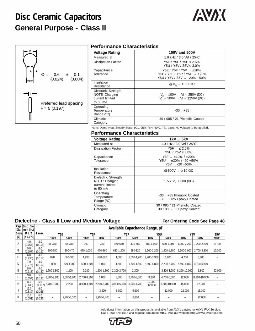
50
Additional information on this product is available from AVX’s catalog or AVX’s FAX Service.Call 1-800-879-1613 and request document #050. Visit our website http://www.avxcorp.com
Disc Ceramic CapacitorsGeneral Purpose - Class II
Voltage Rating 100V and 500VMeasured at 1.0 kHz / 3.0 Vef / 25ºCDissipation Factor Y5E / Y5F / Y5P ≤ 2.5%
Y5U / Y5V / Z5V ≤ 3.0%Capacitance Y5E / Y5F / Y5P → ±10%Tolerance Y5E / Y5E / Y5P / Y5U → ±20%
Y5U / Y5V / Z5V → -20% +50%InsulationResistance
@ VR → ≥ 10 GΩ
Dielectric StrengthNOTE: Charging VR = 100V → Vt = 250V (DC)current limited VR = 500V → Vt = 1250V (DC)to 50 mAOperatingTemperature -30... +85Range (ºC)Climatic 30 / 085 / 21 Phenolic CoatedCategory
Note: Damp Heat Steady State: 90... 95% R.H. 40ºC / 21 days. No voltage to be applied.
Voltage Rating 1kV ... 5kVMeasured at 1.0 kHz / 3.0 Vef / 25ºCDissipation Factor Y5F → ≤ 2.5%
Y5U / Y5V ≤ 3.0%Capacitance Y5F → ±10% / ±20%Tolerance Y5U → ±20% / -20 +50%
Y5V → -20 +50%InsulationResistance
@ 500V → ≥ 10 GΩ
Dielectric StrengthNOTE: Charging 1.5 x VR + 500 (DC)current limitedto 50 mAOperating
-30... +85 Phenolic CoatedTemperature-30... +125 Epoxy CoatedRange (ºC)
Climatic 30 / 085 / 21 Phenolic CoatedCategory 30 / 085 / 56 Epoxy Coated
Cap. Disc. Dia. Available Capacitance Range, pFDia. mm (in.)Code D ± 2 T max. Y5E Y5F Y5P Y5U Y5V Z5V(7) (±0.079) 100V 500V 100V 500V 100V 500V 100V 500V 100V 500V 100V
A4.0 3.0
56-330 56-330 390 390 470-560 470-560 680-1,000 680-1,000 1,200-2,200 1,200-2,200 4,700(0.157) (0.118)
B5.0 4.0
390-680 390-470 470-1,000 470-560 680-1,200 680-820 1,200-2,200 1,200-1,500 2,700-3,900 2,700-3,300 10,000(0.197) (0.157)
C6.0 4.0
820 560-680 1,200 680-820 1,500 1,000-1,200 2,700-3,300 1,800 4,700 3,900 –(0.236) (0.157)
D7.0 4.0
1,000 820-1,000 1,500-1,800 1,000 1,800 1,500-1,800 3,900-6,800 2,200-2,700 5,600-6,800 4,700-5,600 –(0.276) (0.157)
E8.0 4.0
1,200-1,500 1,200 2,200 1,200-1,500 2,200-2,700 2,200 – 3,300-3,900 8,200-10,000 6,800 22,000(0.315) (0.157)
F9.0 5.0
1,800-2,200 1,500-1,800 2,700-3,300 1,800 3,300 2,700-3,300 8,200 4,700-5,600 12,000 8,200-10,000 –(0.354) (0.197)
H11.0 5.0
2,700-3,300 2,200 3,900-4,700 2,200-2,700 3,900-5,600 3,900-4,70010,000-
6,800-10,000 15,000 12,000 –(0.433) (0.197) 12,000
J13.0 6.0
– – – 3,300 6,800 5,600 – 12,000 22,000 15,000 –(0.512) (0.236)
K15.0 6.0
– 2,700-3,300 – 3,900-4,700 – 6,800 – – – 22,000 –(0.591) (0.236)
Dielectric - Class II Low and Medium Voltage For Ordering Code See Page 48
Ø = 0.6 ± 0.1(0.024) (0.004)
Preferred lead spacingF = 5 (0.197)
Performance Characteristics
Performance Characteristics

51
Additional information on this product is available from AVX’s catalog or AVX’s FAX Service.Call 1-800-879-1613 and request document #051. Visit our website http://www.avxcorp.com
Disc Ceramic CapacitorsGeneral Purpose - Class II
Dielectric - Class II High Voltage For Ordering Code See Page 48Cap. Disc. Dia.
Available Capacitance Range, pFDia. mm (in.)Code D ± 2 T max. Y5F Y5U Y5V(7) (±0.079) 1000V 2000V 3000V 1000V 2000V 3000V 4000V 5000V 1000V 2000V 3000V
A4.0 3.0
100-270 100-150 100-150 330-680 – – – – 820-1,200 – –(0.157) (0.118)
B5.0 4.0
330-470 180-270 100-150 820-1,200 330-470 – – – 1,500 – –(0.197) (0.157)
C6.0 4.0
560 330 180 1,500 560-820 – – – 1,800 1,000-1,200 –(0.236) (0.157)
D7.0 4.0
680-1,200 390-560 220-330 1,800-2,700 1,000-1,500 390-1,000 – – 2,200-3,900 1,500-2,200 1,200-1,500(0.276) (0.157)
E8.0 4.0
1,500 680-820 390-560 3,300-3,900 1,800 1,200 100-820 – – 2,700 1,800(0.315) (0.157)
F9.0 5.0
1,800 1,000-1,200 680 4,700 2,200-2,700 1,500-1,800 – – 4,700-5,600 3,300-3,900 2,200-2,700(0.354) (0.197)
G10.0 5.0
– 1,500 820-1,000 5,600 3,300-3,900 2,200 1,000 – 6,800-8,200 – –(0.394) (0.197)
H11.0 5.0
2,200-2,700 1,800 1,200 6,800 4,700 2,700-3,300 1,200-2,200 100-1,000 – 4,700-6,800 3,300-3,900(0.433) (0.197)
J13.0 6.0
3,300 2,200-2,700 1,500-1,800 8,200-12,000 5,600-8,200 3,900-5,600 2,700-3,300 1,200-2,20010,000-
8,200 4,700-6,800(0.512) (0.236) 15,000
K15.0 6.0
3,900 3,300-3,900 2,200-2,700 15,000 10,000 6,800 3,900-4,700 2,700-3,300 22,00010,000-
8,200(0.591) (0.236) 15,000
M 19.0 7.0 – – 3,300-3,900 – – 8,200-10,000 5,600-6,.800 3,900-4,700 – – 10,000(0.748) (0.276)

52
Additional information on this product is available from AVX’s catalog or AVX’s FAX Service.Call 1-800-879-1613 and request document #052. Visit our website http://www.avxcorp.com
Disc Ceramic CapacitorsGeneral Purpose - Class III
Measured at 1.0 kHz / 0.1 Vef / 25ºCDissipation CR ≤ 22 nF → Y5V, Y5U ≤ 7.5%Factor CR > 22 nF → Y5V, Y5P ≤ 5.0%Capacitance Y5P → ±20% / -20 +50%Tolerance Y5U → ±20% / -20 +80%
Y5V → ±20% / -20 +80%Climatic
30 / 085 / 21CategoryInsulation Y5P ≥12 MΩResistance Y5U 4.7 nF...100 nF → ≥ 10 MΩ@ VR 200 nF → ≥ 1 MΩ
Y5V ≥ 100 MΩDielectric Strength Between
Vt = 1.25 VRNOTE: Charging leadscurrent limited Body VR = 25V Vt = 100V (DC)to 50 mA insulation VR = 50V Vt = 150V (DC)OperatingTemperature -30... +85Range (ºC)
Note: Damp Heat Steady State: 90... 95% R.H. 40ºC / 21 days. No voltage to be applied.
Preferred lead spacingF = 5 (0.197)
Ø = 0.6 ± 0.1(0.024) (0.004)
Cap. Disc. Dia. Available Capacitance Range, pFDia. mm (in.)Code D ± 2 T max. Y5P Y5U Y5V(7) (±0.079) 25V 50V 25V 50V 50V
A4.0 3.0
4,700 4,700 4,700-10,000 4,700-10,000 4,700-47,000(0.157) (0.118)
B5.0 4.0
– – 22,000 – 50,000-68,000(0.197) (0.157)
C6.0 4.0
10,000 10,000 33,000 22,000 –(0.236) (0.157)
D7.0 4.0
22,000 – 47,000-68,000 33,000 100,000(0.276) (0.157)
E8.0 4.0
33,000 22,000 100,000 47,000-50,000 200,000(0.315) (0.157)
F9.0 5.0
– 33,000 – 68,000-100,000 –(0.354) (0.197)
G10.0 5.0
47,000-50,000 – – – –(0.394) (0.197)
H11.0 5.0
68,000 47,000 – – –(0.433) (0.197)
J13.0 6.0
100,000 68,000 200,000 – –(0.512) (0.236)
K15.0 6.0
– 100,000 – – –(0.591) (0.236)
Dielectric - Class III For Ordering Code See Page 48
Performance Characteristics

53
Additional information on this product is available from AVX’s catalog or AVX’s FAX Service.Call 1-800-879-1613 and request document #053. Visit our website http://www.avxcorp.com
Cap. Dia. Disc. Dia. T max.Code mm (in.) Available Capacitance Range
±2 (±0.079)
Part Type(1st 3 digits of Part No.) 61V 62O 65N
C6.0 4.0
100-150 100-220 220-470(0.236) (0.157)
D7.0 4.0
220-470 330-680 560-1,000(0.276) (0.157)
E8.0 4.0
560-680 820-1,000 1,200-1,500(0.315) (0.157)
F9.0 5.0
820-1,000 1,200-1,500 2,200(0.354) (0.197)
G10.0 5.0
– 2,200 –(0.394) (0.197)
H11.0 5.0
1,200-2,200 – 3,300(0.433) (0.197)
J13.0 6.0
3,300 3,300-3,900 3,900-4,700(0.512) (0.236)
K15.0 6.0
3,900 4,700 –(0.591) (0.236)
M 19.0 7.0 4,700 – –(0.748) (0.276)
These ceramic capacitors have linear temperaturecoefficient, very low tolerances, low losses, high insula-tion resistance and are specially suitable for tuned circuits, timing and other precision circuits.
Meets IEC 384-8 (1988).
Safety Ceramic Capacitors For Ordering Code See Page 48
Cap. Dia. Disc. Dia. T max. Available Capacitance RangeCode mm (in.) Y5P Y5U Y5V
±2 (±0.079) 1000V 2000V 3000V 2000V 2000V
D7.0 4.0
220-470 220-270 220-270 – –(0.276) (0.157)
E8.0 4.0
560-820 330-390 – 1,000 4,700(0.315) (0.157)
F9.0 5.0
1,000-1,200 470-560 330-390 2,200 –(0.354) (0.197)
G10.0 5.0
– 680 470-560 3,300 –(0.394) (0.197)
H11.0 5.0
1,500-1,800 820-1,200 680 4,700 10,000(0.433) (0.197)
J13.0 6.0
2,200 1,500 820-1,000 – –(0.512) (0.236)
K15.0 6.0
2,700-3,900 1,800-3,300 1,200-2,700 – –(0.591) (0.236)
M 19.0 7.0 – 3,900-4,700 3,300-4,700 – –(0.748) (0.276)
AC and Switch Mode Capacitors For Ordering Code See Page 48
Disc Ceramic Capacitors

54
Additional information on this product is available from AVX’s catalog or AVX’s FAX Service. Call 1-800-879-1613 and request document #054. Visit our website http://www.avxcorp.com
Class I Professional For Ordering Code See Page 48Cap. Disc. Dia. Available Capacitance Range, pFDia. mm (in.)Code D ± 2 T max. NP0 N750 N1500
(±0.079) 100V 500V 100V 500V 100V 500V
A4.0 3.0
1.0-15 1.0-15 1.0-33 1.0-33 6.0-47 6.0-47(0.157) (0.118)
B5.0 4.0
18-39 18-27 39-68 39-56 50-120 50-56(0.197) (0.157)
C6.0 4.0
– 33 82 68 – 68-100(0.236) (0.157)
D7.0 4.0
47-50 39-50 100-150 82-100 150-220 120(0.276) (0.157)
E8.0 4.0
56-82 56-68 180 120 270 150-180(0.315) (0.157)
F9.0 5.0
100-120 82 220 150 330 220(0.354) (0.197)
G10.0 5.0
– – – – – –(0.394) (0.197)
H11.0 5.0
150-180 100-150 270 180-220 – 270-330(0.433) (0.197)
J13.0 6.0
– – – 270 – –(0.512) (0.236)
K15.0 6.0
– 180-220 – 330 – –(0.591) (0.236)
M 19.0 7.0 – 270-330 – – – –(0.748) (0.276)
Cap. Disc. Dia.Available Capacitance RangeDia. mm (in.)
Code D ± 2 T max. X5E X5F X5P X5U X5V Z5V(±0.079) 100V 500V 100V 500V 100V 500V 100V 500V 100V 500V 100V
A4.0 3.0
56-330 56-330 390 390 470-560 470-560 680-1,000 680-1,000 1,200-2,200 1,200-2,200 4,700(0.157) (0.118)
B5.0 4.0
390-680 390-470 470-1,000 470-560 680-1,200 680-820 1,200-2,200 1,200-1,500 2,700-3,900 2,700-3,300 10,000(0.197) (0.157)
C6.0 4.0
820 560-680 1,200 680-820 1,500 1,000-1,200 2,700-3,300 1,800 4,700 3,900 –(0.236) (0.157)
D7.0 4.0
1,000 820-1,000 1,500-1,800 1,000 1,800 1,500-1,800 3,900-6,800 2,200-2,700 5,600-6,800 4,700-5,600 –(0.276) (0.157)
E8.0 4.0
1,200-1,500 1,200 2,200 1,200-1,500 2,200-2,700 2,200 – 3,300-3,900 8,200-10,000 6,800 22,000(0.315) (0.157)
F9.0 5.0
1,800-2,200 1,500-1,800 2,700-3,300 1,800 3,300 2,700-3,300 8,200 4,700-5,600 12,000 8,200-10,000 –(0.354) (0.197)
H11.0 5.0
2,700-3,300 2,200 3,900-4,700 2,200-2,700 3,900-5,600 3,900-4,700 – 6,800-10,000 15,000 12,000 –(0.433) (0.197)
J13.0 6.0
– – – 3,300 6,800 5,600 10,000-12,000 12,000 22,000 15,000 –(0.512) (0.236)
K15.0 6.0
– 2,700-3,300 – 3,900-4,700 – 6,800 – – – 22,000 –(0.591) (0.236)
Class II Professional Low and Medium Voltage For Ordering Code See Page 48
Dielectric - Class III For Ordering Code See Page 48Cap. Disc. Dia.
Available Capacitance RangeDia. mm (in.)Code D ± 2 T max. Y5P Y5U Y5V
(±0.079) 25V 50V 25V 50V 50V
A4.0 3.0
4,700 4,700 4,700-10,000 4,700-10,000 4,700-47,000(0.157) (0.118)
B5.0 4.0
– – 22,000 – 50,000-68,000(0.197) (0.157)
C6.0 4.0
10,000 10,000 33,000 22,000 –(0.236) (0.157)
D7.0 4.0
22,000 – 47,000-68,000 33,000 100,000(0.276) (0.157)
E8.0 4.0
33,000 22,000 – 47,000-68,000 –(0.315) (0.157)
F9.0 5.0
– 33,000 – – –(0.354) (0.197)
G10.0 5.0
47,000,-50,000 – – – –(0.394) (0.197)
H11.0 5.0
68,000 47,000 – – –(0.433) (0.197)
J13.0 6.0
100,000 68,.000 200,000 –` –(0.512) (0.236)
K15.0 6.0
– 100,000 – – –(0.591) (0.236)
Disc Ceramic CapacitorsProfessional Ceramic Capacitors - Class I, II and III

55
Additional information on this product is available from AVX’s catalog or AVX’s FAX Service.Call 1-800-879-1613 and request document #055. Visit our website http://www.avxcorp.com
High Voltage ChipsFor 500V to 5000V Applications
l
T
L
W
High Voltage C0G
High Voltage X7R
BULK TAPE & REEL7" 13"
1206 5,000 4,000 10,0001210 5,000 4,000 10,0001808 500 2,000 4,0001812 500 1,000 3,0001825 500 1,000 3,0002225 500 1,000 3,0003640 100 N/A 1,000
Standard Packaging
Dimensions: millimeters (inches)
HOW TO ORDER1808 A A 271 K A 1 1 A1 2 3 4 5 6 7 8 91 AVX Style: 1206, 1210, 1808, 1812, 1825,
2220, 2225, 36402 Voltage: 500V=7, 600V=C, 1000V=A, 1500V=S,
2000V=G, 2500V=W, 3000V=H, 4000V=J, 5000V=K3 Temperature Coefficient: C0G=A, X7R=C4 Capacitance Code5 Capacitance Tolerance:
C0G: J = ±5% X7R: K = ±10%K = ±10% M = ±20%M = ±20% Z = +80%
-20%6 Failure Rate: A = Not Applicable7 Termination: 1 = Pd/Ag, T = Plated Nickel and Solder8 Packaging:
1 = 7" Reel/Unmarked3 = 13" Reel/Unmarked9 = Bulk/Unmarked
9 Special Code: A = Standard
VOLTAGE 1206 1210 1808 1812 1825 2220 2225 3640500/600 680 pF 1500 pF 2700 pF 5600 pF 0.012 µF 0.012 µF 0.015 µF 0.047 µF
1000 470 pF 820 pF 1500 pF 2700 pF 6800 pF 0.010 µF 0.010 µF 0.018 µF1500 150 pF 330 pF 470 pF 1000 pF 2700 pF 2700 pF 3300 pF 8200 pF2000 68 pF 150 pF 270 pF 680 pF 1800 pF 2200 pF 2200 pF 5600 pF2500 — — 150 pF 390 pF 1000 pF 1000 pF 1200 pF 3900 pF3000 — — 100 pF 300 pF 680 pF 680 pF 820 pF 2200 pF4000 — — — — — — 1000 pF5000 — — — — — — 680 pF
SIZE 1206 1210 1808 1812 1825 2220 2225 3640(L) Length 3.20 ± 0.20 3.20 ± 0.20 4.57 ± .254 4.50 ± .030 4.50 ± 0.30 5.72 ± 0.40 5.72 ± .254 9.14 ± .254
(0.126 ± 0.008) (0.126 ± 0.008) (0.180 ± 0.010) (0.177 ± 0.012) (0.177 ± 0.012) (0.225 ± 0.016) (0.225 ± 0.010) (0.360 ± 0.010)(W) Width 1.60 ± 0.20 2.50 ± 0.20 2.03 ± .254 3.20 ± 0.20 6.40 ± 0.30 5.00 ± 0.40 6.35 ± .254 10.2 ± .254
(0.063 ± 0.008) (0.098 ± 0.008) (0.080 ± 0.010) (0.126 ±0.008) (0.252 ± 0.012) (0.197 ± 0.016) (0.250 ± 0.010) (0.400 ± 0.010)(T) Thickness 1.52 1.70 2.03 2.54 2.54 3.30 2.54 2.54
max. (0.060) (0.067) (0.080) (0.100) (0.100) (0.130) (0.100) (0.100)(t) terminal min. .254 (0.010) .254 (0.010) .254 (0.010) .254 (0.010) .254 (0.010) .254 (0.010) .254 (0.010) .762 (0.030)
max. .762 (0.030) .762 (0.030) 1.02 (0.040) 1.02 (0.040) 1.02 (0.040) 1.00 (0.039) 1.02 (0.040) 1.52 (0.060)
VOLTAGE 1206 1210 1808 1812 1825 2220 2225 3640500/600 0.015 µF 0.027 µF 0.033 µF 0.068 µF 0.015 µF 0.15 µF 0.22 µF 0.56 µF
1000 4700 pF 0.010 µF 0.015 µF 0.027 µF 0.068 µF 0.068 µF 0.082 µF 0.22 µF1500 1200 pF 2700 pF 3900 pF 8200 pF 0.018 µF 0.022 µF 0.027 µF 0.068 µF2000 470 pF 1000 pF 1800 pF 4700 pF 8200 pF 0.010 µF 0.012 µF 0.027 µF2500 — — 1200 pF 2200 pF 5600 pF 6800 µF 8200 pF 0.022 µF3000 — — 560 pF 1200 pF 2700 pF 3300 µF 4700 pF 0.018 µF4000 — — — — — — 6800 pF5000 — — — — — — 3300 pF

56
Additional information on this product is available from AVX’s catalog or AVX’s FAX Service.Call 1-800-879-1613 and request document #056. Visit our website http://www.avxcorp.com
HOW TO ORDERSV01 A A 102 K A A1 2 3 4 5 6 7
1 AVX Style2 Voltage: 1000V = A, 2000V = G, 3000V = H
4000V = J, 5000V = K3 Temperature Coefficient: C0G = A, X7R = C4 Capacitance Code5 Capacitance Tolerance:
C0G: J = ±5% X7R: K = ±10%K = ±10% M = ±20%M = ±20% Z = +80%, -20%
6 Failure Rate: A = Does not apply7 Leads: A = Does not apply
L T
H
S
31.75 (1.25)MIN
BULKSV01 300SV02 300SV03 300SV04 200SV05 200SV06 200SV07 200SV08 50SV09 50SV10 10SV11 10SV12 10SV13 300SV14 200SV15 200SV16 16SV17 10
Standard PackagingDimensions: millimeters (inches)
Maximum Capacitance Value
AVX Style Length Height Thickness Lead Spacing LD (L) max. (H) max. (T) max. ±.030 (S) (Nom.)
SV01 6.35 (0.250) 5.59 (0.220) 5.08 (0.200) 4.32 (0.170) .635 (0.025)SV02 8.13 (0.320) 7.11 (0.280) 5.08 (0.200) 5.59 (0.220) .635 (0.025)SV03 9.40 (0.370) 7.62 (0.300) 5.08 (0.200) 6.99 (0.275) .635 (0.025)SV04 11.4 (0.450) 5.59 (0.220) 5.08 (0.200) 7.62 (0.300) .635 (0.025)SV05 11.9 (0.470) 10.2 (0.400) 5.08 (0.200) 9.53 (0.375) .635 (0.025)SV06 14.0 (0.550) 7.1 (0.280) 5.08 (0.200) 10.2 (0.400) .635 (0.025)SV07 14.5 (0.570) 12.7 (0.500) 5.08 (0.200) 12.0 (0.475) .635 (0.025)SV08 17.0 (0.670) 15.2 (0.600) 5.08 (0.200) 14.6 (0.575) .635 (0.025)SV09 19.6 (0.770) 18.3 (0.720) 5.08 (0.200) 17.1 (0.675) .635 (0.025)SV10 26.7 (1.050) 12.7 (0.500) 5.08 (0.200) 22.9 (0.900) .635 (0.025)SV11 31.8 (1.250) 15.2 (0.600) 5.08 (0.200) 27.9 (1.100) .635 (0.025)SV12 36.8 (1.450) 18.3 (0.720) 5.08 (0.200) 33.0 (1.300) .635 (0.025)SV13 7.62 (0.300) 9.14 (0.360) 5.08 (0.200) 5.08 (0.200) .508 (0.020)SV14 10.2 (0.400) 11.7 (0.460) 5.08 (0.200) 5.08 (0.200) .508 (0.020)SV15 12.7 (0.500) 14.2 (0.560) 5.08 (0.200) 10.2 (0.400) .635 (0.025)SV16 22.0 (0.870) 16.8 (0.660) 5.08 (0.200) 20.0 (0.790) .813 (0.032)SV17 23.6 (0.930) 19.8 (0.780) 6.35 (0.250) 20.3 (0.800) .813 (0.032)
C0G X7R
Style 1000V 2000V 3000V 4000V 5000V Style 1000V 2000V 3000V 4000V 5000VSV01 1000pF 180pF 82pF — — SV01 .012µF 1500pF — — —SV02 3300pF 680pF 270pF 150pF 100pF SV02 .047µF 5600pF 2700pF — —SV03 5600pF 1200pF 470pF 270pF 180pF SV03 .082µF .01µF 4700pF 1800pF —SV04 2200pF 470pF 180pF 100pF 68pF SV04 .033µF 3900pF 1800pF 820pF —SV05 .015µF 3300pF 1200pF 680pF 470pF SV05 .22µF .027µF .12µF 4700pF —SV06 .0068µF 1500pF 560pF 330pF 220pF SV06 .10µF .012µF 6800pF 2700pF 1200pFSV07 .027µF 5600pF 2200pF 1200pF 820pF SV07 .39µF .047µF .027µF .01µF 6800pFSV08 .039µF .01µF 3900pF 2200pF 1500pF SV08 .68µF .082µF .047µF .018µF .012µFSV09 .068µF .015µF 6800pF 3900pF 2700pF SV09 1.00µF .12µF .068µF .027µF .018µFSV10 .056µF .012µF 5600pF 3300pF 2200pF SV10 .82µF .10µF .056µF .022µF .018µFSV11 .082µF .022µF .0082µF 4700pF 3300pF SV11 1.2µF .18µF .10µF .039µF .027µFSV12 .15µF .033µF .015µF 8200pF 5600pF SV12 2.20µF .27µF .15µF .056µF .033µFSV13 8200oF 1800pF 820pF 390pF 270pF SV13 0.10µF .012µF 6800pF 2700pF —SV14 .015µF 4700pF 1500pF 820pF 560pF SV14 0.18µF .022µF .015µF 5600pF —SV15 .033µF .01µF 2700pF 1800pF 1200pF SV15 0.27µF .033µF .022µF 8200pF 4700pFSV16 .068µF .018µF 6800pF 3900pF 2700pF SV16 1.0µF .12µF .068µF .027µF .018µFSV17 .10µF .039µF .012µF 6800pF 4700pF SV17 1.2µF .15µF .082µF .039µF .027µF
High Voltage MLC Radials
Note: Contact factory for other voltage ratings or valuesand for AVX qualifications to DSCC drawings.

57
Additional information on this product is available from AVX’s catalog or AVX’s FAX Service.Call 1-800-879-1613 and request document #057. Visit our website http://www.avxcorp.com
C0G (pF) X7R (nF)Size 1kV 2kV 3kV 4kV 5kV 1kV 2kV 3kV 4kV 5kVCH41 5600 1800 820 390 330 18 8.2 4.7 1.8 1.2
~ ~ ~ ~ ~ ~ ~ ~ ~ ~CV41 15000 4700 1500 820 560 120 15 8.2 4.7 2.7
CH51 12000 3300 1800 1000 680 39 18 10 5.6 3.3~ ~ ~ ~ ~ ~ ~ ~ ~ ~
CV51 33000 10000 2700 1800 1200 270 33 18 8.2 3.9
CH61 22000 6800 3300 2200 1500 100 39 22 10 4.7~ ~ ~ ~ ~ ~ ~ ~ ~ ~
CV61 68000 18000 5600 3300 2200 560 82 39 15 10
CH76 47000 15000 6800 3900 2700 180 100 47 18 12~ ~ ~ ~ ~ ~ ~ ~ ~ ~
CV76 100000 39000 12000 6800 4700 1000 150 68 39 18
CH91 120000 47000 15000 8200 5600 390 180 82 47 22~ ~ ~ ~ ~ ~ ~ ~ ~ ~
CV91 330000 100000 33000 18000 12000 2700 330 180 120 56
L max.T max.
H max.
25 (0.984)±3 (0.118)
S ±0.5(0.020)
Lead Dia.(See table)
High Voltage Capacitors (European Versions)
Radial and Dual In-Line MLC
11
11
W max
W max L max
H max
L max 3.8 (0.149)
max
2.0 (0.079)
max
2.54 (0.100) ± 0.5 (0.020)
2.54 (0.100) ± 0.5 (0.020)
2.54 (0.100)± 0.5 (0.020)
13 (0.512) ± 1 (0.039)
S ± 0.5(0.020)
S ± 0.5(0.020)
L1
L1
L2
L2
Radial – CV
Dual In-line – CH
Dimensions: millimeters (inches)
Capacitance Ranges
Dual In-line only
Lead LeadSize L H S Dia. Dia.
(max.) (max.) (nom.) (nom.) CodeCH41 9.2 (0.362) 8.7 (0.343) 3.8 (0.150) 8.2 (0.323) n/aCV41 10.6 (0.417) 8.7 (0.343) 8.2 (0.323) 0.7 (0.028) 4 (0.157)
CH51 10.7 (0.421) 10.7 (0.421) 3.8 (0.150) 10.16 (0.400) n/aCV51 11.9 (0.469) 10.7 (0.421) 10.16 (0.400) 0.9 (0.035) 3 (0.118)
CH61 14.9 (0.587) 13.6 (0.535) 3.8 (0.150) 14.0 (0.551) n/aCV61 16.5 (0.650) 13.6 (0.535) 15.24 (0.600) 0.9 (0.035) 3 (0.118)
CH76 21.6 (0.850) 16.6 (0.654) 3.8 (0.150) 20.32 (0.800) n/aCV76 22.7 (0.894) 16.6 (0.654) 21.2* (0.835) 0.9 (0.035) 3 (0.118)
CH91 24.0 (0.945) 40.6 (1.600) 3.8 (0.150) 20.32 (0.800) n/aCV91 22.7 (0.894) 40.6 (1.600) 21.2* (0.835) 1.2 (0.047) 1 (0.039)
*Tolerance 0.8mm“T” Max = 3.8mm
HOW TO ORDERCH 61 K C 103 M A 4 O A 71 2 3 4 5 6 7 8 9 0 s1 AVX Series: CH, CV2 AVX Size3 Voltage: A=1KVDC H=3KVDC K=5KVDC
G=2KVDC J=4KVDC4 Dielectric: A=C0G, C=X7R5 Capacitance Code6 Capacitance Tolerance: J=±5%, K=±10%, M=±20%7 Specification: A=Failure rate does not apply8 Packaging:
CV/CH series – 4=Varnished (Single Chip Assy.)9 Lead Diameter: See Table Below0 Lead Space: See Table Below
s Lead Style: 0=Straight Dual-in-line7=‘L’ lead Dual-in-line

58
Additional information on this product is available from AVX’s catalog or AVX’s FAX Service.Call 1-800-879-1613 and request document #058. Visit our website http://www.avxcorp.com
High Voltage Ceramic Capacitors
Capacitance Range
Style Capacitance Voltage Dimensions millimeters (inches)Size CodepF ±20% V DC Dmax Tmax
100 12KVHZ9 150 9KV 9.5 (0.374) 9.0 (0.354)
220 6KV250 12KV
HZ12 330 9KV 12.0 (0.472) 9.0 (0.354)430 6KV500 12KV
HZ16 680 9KV 16.0 (0.630) 9.0 (0.354)820 6KV750 12KV
HZ18 1000 9KV 18.0 (0.709) 9.0 (0.354)1300 6KV1000 12KV
HZ20 1300 9KV 20.0 (0.787) 9.0 (0.354)1800 6KV1250 12KV
HZ22 1600 9KV 22.0 (0.866) 10.0 (0.394)2200 6KV1500 12KV
HZ26 2000 9KV 26.0 (1.024) 10.0 (0.394)2700 6KV
12.7 (0.50)± 2 (.079)
D max T max
Ø 0.8 (.003)
4 (.1
57) m
ax
25.4
(1.0
0)
D +
1.0
(.0
39) m
ax
HZ Type - Strontium-based Dielectric
HP Type - Strontium-based DielectricRated Test AC Corona inception Capacitance Dimensions millimeters (inches)
Style Voltage Voltage Reference voltage (kV) ± 20% D d L hkVdc kVrms <5 pico C 50Hz (pF) ±1 ±1 ±2
HP 30 E Y 0751 M.-.- 750 28 (1.102) 12 (0.472) 23 (0.906) 17 (0.669)HP 40 E Y 0142 M.-.- 1400 38 (1.500) 12 (0.472) 23 (0.906) 17 (0.669)HP 40 E Y 0152 M.-.- 1500 38 (1.500) 12 (0.472) 23 (0.906) 17 (0.669)
20 22 HP 50 E Y 0202 M.-.- 10 2000 48 (1.900) 12 (0.472) 23 (0.906) 17 (0.669)HP 50 E Y 0252 M.-.- 2500 48 (1.900) 12 (0.472) 23 (0.906) 17 (0.669)HP 60 E Y 0302 M.-.- 3000 58 (2.283) 15 (0.591) 23 (0.906) 17 (0.669)HP 60 E Y 0402 M.-.- 4000 58 (2.283) 15 (0.591) 23 (0.906) 17 (0.669)HP 30 E 3 0511 M.-.- 510 28 (1.102) 12 (0.472) 26 (1.024) 20 (0.787)HP 40 E 3 0941 M.-.- 940 38 (1.500) 12 (0.472) 26 (1.024) 20 (0.787)HP 40 E 3 0102 M.-.- 1000 38 (1.500) 12 (0.472) 26 (1.024) 20 (0.787)
30 33 HP 50 E 3 0152 M.-.- 15 1500 48 (1.900) 12 (0.472) 26 (1.024) 20 (0.787)HP 50 E 3 0172 M.-.- 1700 48 (1.900) 12 (0.472) 26 (1.024) 20 (0.787)HP 60 E 3 0202 M.-.- 2000 58 (2.283) 15 (0.591) 26 (1.024) 20 (0.787)HP 60 E 3 0272 M.-.- 2700 58 (2.283) 15 (0.591) 26 (1.024) 20 (0.787)HP 30 E 4 0391 M.-.- 390 28 (1.102) 12 (0.472) 30 (1.181) 24 (0.945)HP 40 E 4 0701 M.-.- 700 38 (1.500) 12 (0.472) 30 (1.181) 24 (0.945)HP 40 E 4 0721 M.-.- 720 38 (1.500) 12 (0.472) 30 (1.181) 24 (0.945)
40 44 HP 50 E 4 0102 M.-.- 20 1000 48 (1.900) 12 (0.472) 30 (1.181) 24 (0.945)HP 50 E 4 0132 M.-.- 1300 48 (1.900) 12 (0.472) 30 (1.181) 24 (0.945)HP 60 E 4 0152 M.-.- 1500 58 (2.283) 15 (0.591) 32 (1.260) 26 (1.024)HP 60 E 4 0202 M.-.- 2000 58 (2.283) 15 (0.591) 32 (1.260) 26 (1.024)HP 40 E 5 0561 M.-.- 560 38 (1.500) 12 (0.472) 35 (1.378) 23 (0.906)
50 55 HP 50 E 5 0102 M.-.- 25 1000 48 (1.900) 12 (0.472) 35 (1.378) 23 (0.906)HP 60 E 5 0112 M.-.- 1100 58 (2.283) 12 (0.472) 35 (1.378) 23 (0.906)HP 40 E 9 0281 M.-.- 280 38 (1.500) 12 (0.472) Following
100 110 HP 50 E 9 0501 M.-.- 50 500 48 (1.900) 12 (0.472) Customers Spec.HP 60 E 9 0851 M.-.- 850 58 (2.283) 12 (0.472) But
> 80mm
h L
0.5 (.02) max.
D
M 5
d
– Tightening torque; 0.3m.daN max.

59
Additional information on this product is available from AVX’s catalog or AVX’s FAX Service.Call 1-800-879-1613 and request document #059. Visit our website http://www.avxcorp.com
High Voltage Ceramic Capacitors
HT/HU Types - Type I Table of Values
h m
axp
L m
axD
± 2
(.07
9)
e
ø
d
h ±
2 (.0
79)
D ±
2 (.
079)
Important: HT typeIn order to improve capacitor mounting, connectionsends are designed with two flats. Thus, tighteningtorque is only applied on the screw (consult chartabove for torque “S” value).
Important: HU typeHandling of uncoated types must be done under strict cleanliness conditions.
Height h: Depending on capacitanceplease consult us
Hardware supplied for capacitormounting2 x screws TCB M5 L8 accordingor TCB M8 L12 to Ø2 x washers
Style Type Dimensions millimeters (inches) Tightening Rated Rated Test Capacitance vs Size D L h [ d p e torque Type Cap. Voltage Voltage Temperature
(ISO) S (m.daN) CR (pF) VR (kV) VE TC(kV/150Hz) (ppm/°C)
HT 3025.5 50 30 8 5 9 7
0.3(1.00) (1.97) (1.18) (0.31) (0.20) (0.35) (0.28)
HT 4038 50 30 8 5 9 7
0.3(1.50) (1.97) (1.18) (0.31) (0.20) (0.35) (0.28)
HT 6056 55 35 12 8 13 10
1(2.20) (2.16) (1.38) (0.47) (0.31) (.051) (0.39)
HU 30 22 —(0.87)
HU 40 30 —(1.18)
HU 60 42 —(1.65)
HT/HU30A 4.7-5.6 17 25HT/HU30A 6.8 10 15HT/HU40A 8.2 17 25HT/HU40A 10-15 10 15 +100 ±100HT/HU60A 18-22 17 25HT/HU60A 27-47 10 15HT/HU30H 10 17 25HT/HU30H 12 10 15HT/HU40H 15-22 17 25 -33 ±60HT/HU40H 27-33 10 15HT/HU60H 39-47 17 25HT/HU60H 56-100 10 15HT/HU30T 22 10 15HT/HU40T 27-33 17 25HT/HU40T 39-56 10 15 -470 ±160HT/HU60T 68-82 17 25HT/HU60T 100-150 10 15HT/HU30U 22-27 17 25HT/HU30U 33-39 10 15HT/HU40U 47-56 17 25 -750 ±250HT/HU40U 68-100 10 15HT/HU60U 120-150 17 25HT/HU60U 180-270 10 15
Style CR VR VE Corona Dimensions millimeters (inches)(pF) (kVrms) (kVrms) level D L l Weight
Reference (kVrms) ±1 ±2 ±1.5 (g)
“HF” HF 60 00 1250M-- 125 15 60 >14 17 (0.669) 81 (3.19) 61 (2.40) 115
HF 60 00 0100M-- 100 15 60 >14 17 (0.669) 81 (3.19) 61 (2.40) 115
HF 60 00 0500M-- 50 15 60 >14 17 (0.669) 81 (3.19) 61 (2.40) 115
HF 60 00 0250M-- 25 15 60 >14 17 (0.669) 81 (3.19) 61 (2.40) 115
HF 60 00 0160M-- 16 15 60 >14 17 (0.669) 81 (3.19) 61 (2.40) 115
HF 40 00 0181M-- 180 11 42 >11 17 (0.669) 60 (2.36) 40 (1.57) 80
HF 40 00 0750M-- 75 11 42 >11 17 (0.669) 60 (2.36) 40 (1.57) 80
HF 40 00 0360M-- 36 11 42 >11 17 (0.669) 60 (2.36) 40 (1.57) 80
HF 40 00 0240M-- 24 11 42 >11 17 (0.669) 60 (2.36) 40 (1.57) 80
HF 30 00 0251M-- 250 8 30 >8 17 (0.669) 50.5 (1.99) 30.5 (1.20) 65
HF 30 00 0101M-- 100 8 30 >8 17 (0.669) 50.5 (1.99) 30.5 (1.20) 65
HF 30 00 0180M-- 48 8 30 >8 17 (0.669) 50.5 (1.99) 30.5 (1.20) 65
HF 30 00 0320M-- 32 8 30 >8 17 (0.669) 50.5 (1.99) 30.5 (1.20) 65
HB 60 00 1250M-- 125 15 60 >14 17 (0.669) — 61 (2.40) 110
“HB” HB 60 00 0100M-- 100 15 60 >14 17 (0.669) — 61 (2.40) 110
HB 60 00 0500M-- 50 15 60 >14 17 (0.669) — 61 (2.40) 110
HB 60 00 0250M-- 25 15 60 >14 17 (0.669) — 61 (2.40) 110
HB 60 00 0160M-- 16 15 60 >14 17 (0.669) — 61 (2.40) 110
HB 40 00 0181M-- 180 11 42 >11 17 (0.669) — 40 (1.57) 70
HB 40 00 0750M-- 75 11 42 >11 17 (0.669) — 40 (1.57) 70
HB 40 00 0360M-- 36 11 42 >11 17 (0.669) — 40 (1.57) 70
HB 40 00 0240M-- 24 11 42 >11 17 (0.669) — 40 (1.57) 70
HB 30 00 0251M-- 250 8 30 >8 17 (0.669) — 30.5 (1.20) 55
HB 30 00 0101M-- 100 8 30 >8 17 (0.669) — 30.5 (1.20) 55
HB 30 00 0180M-- 48 8 30 >8 17 (0.669) — 30.5 (1.20) 55
HB 30 00 0320M-- 32 8 30 >8 17 (0.669) — 30.5 (1.20) 55
HF/HB Types - Type II
l
L
D
l

60
Additional information on this product is available from AVX’s catalog or AVX’s FAX Service.Call 1-800-879-1613 and request document #060. Visit our website http://www.avxcorp.com
Style Dimensions millimeters (inches) TorqueCR VR VE S Weight
Reference (pF) (kVC~) (kVC~) D L h [ d p e (m.daN) (g)
HD 30 0X 0251S-- 250 15 20 26.5 (1.04) 33 (1.30) 16 (.630) 8 (.315) 5 (.197) 9 (.354) 7 (.276) 0.3 30
HD 30 0X 0501S-- 500 15 20 26.5 (1.04) 33 (1.30) 16 (.630) 8 (.315) 5 (.197) 9 (.354) 7 (.276) 0.3 30
HD 40 0X 0102S-- 1000 15 20 39.5 (1.56) 33 (1.30) 16 (.630) 8 (.315) 5 (.197) 9 (.354) 7 (.276) 0.3 60
HD 60 0Y 0202S-- 2000 20 3056.5 (2.22)
45 (1.77) 21 (.827)12 (.472) 8 (.315) 11 (.433) 10 (.394) 1
160
HD 60 0X 0302S-- 3000 15 20 40 (1.57) 19 (.748) 135
HE 30 0X 0251S-- 250 15 20 12 — 8
HE 30 0X 0501S-- 500 15 20 17 — 9
HE 40 0X 0102S-- 1000 15 20 26 — 9
HE 60 0Y 0202S-- 2000 20 30 42 — 12
HE 60 0X 0302S-- 3000 15 20 42 — 9
High Voltage Ceramic Capacitors
Style Dimensions millimeters (inches) TorqueCR VR VE S WeightReference (pF) (kVC~) (kVC~) D D1 L h [ d p e (m.daN) (g)
HR 30 0X 0471S-- 470 16 24 27 (1.06) 25 (0.98) 37 (1.46) 23 (0.91) 8 (0.31) 5 (0.20) 9 (0.35) 7 (0.28) 0.3 32
HR 30 0Y 0471S-- 470 20 30 34 (1.34) 32 (1.26) 40 (1.57) 28 (1.10) 8 (0.31) 5 (0.20) 9 (0.35) 7 (0.28) 0.3 45
HR 40 0X 0102S-- 1000 16 24 39 (1.54) 37 (1.46) 37 (1.46) 23 (0.91) 8 (0.31) 5 (0.20) 9 (0.35) 7 (0.28) 0.3 65
HR 40 0Y 0102S-- 1000 20 30 44 (1.73) 42 (1.65) 40 (1.57) 28 (1.10) 8 (0.31) 5 (0.20) 9 (0.35) 7 (0.28) 0.3 90
HR 60 0Y 0222S-- 2200 20 30 54 (2.13) 52 (2.05) 47 (1.85) 28 (1.10) 12 (0.47) 8 (0.31) 13 (0.51) 10 (.039) 1 180
HR 60 0X 0502S-- 5000 16 24 55 (2.17) 54 (2.13) 40 (1.57) 21 (0.83) 12 (0.47) 8 (0.31) 13 (0.51) 10 (.039) 1 180
HS 30 0X 0471S-- 470 16 24 17 — — 13
HS 30 0Y 0471S-- 470 20 30 19 — — 17
HS 40 0X 0102S-- 1000 16 24 26 — — 14
HS 40 0Y 0102S-- 1000 20 30 29 — — 16
HS 60 0Y 0222S-- 2200 20 30 37 — — 14
HS 60 0X 0502S-- 5000 16 24 42 — — 8
hp
L ±
2 (.0
79)
e
d(ISO)
ø
D1
D
h ±
2 (.0
79)
D ±
2 (.
079)
Important: HR typeIn order to improve capacitor mounting, connections ends aredesigned with two flats. Thus, tightening torque is only appliedon the screw (consult chart above for torque “S” value).
Hardware supplied for capacitor mounting2 x screws TCB M5 L8 accordingor TCB M8 L12 to Ø2 x washers
Important: HD typeIn order to improve capacitor mounting, connections ends aredesigned with two flats. Thus, tightening torque is only appliedon the screw (consult chart above for torque “S” value).
Hardware supplied for capacitor mounting2 x screws TCB M5 L8 accordingor TCB M8 L12 to Ø2 x washers
Handling of uncoated types must be doneunder strict cleanliness conditions.
Handling of uncoated types must be doneunder strict cleanliness conditions.
HR/HS Types - Type II
HD/HE Types - Type II (N)
h p
L ±
2 (.0
79)
D ±
2 (.
079)
e
ø
d
h ±
2 (.0
79)
D ±
2 (.
079)
Important: HE type

61
Additional information on this product is available from AVX’s catalog or AVX’s FAX Service.Call 1-800-879-1613 and request document #061. Visit our website http://www.avxcorp.com
High Voltage Ceramic CapacitorsHV/HW Types – Feed-Thru – Type II
ø 5 (.197)
ø 30 (1.18) ±1 (.039)
Fastening hole 25 (.984±3 (.118)
15 (.590) max 1
(.039
) m
ax
15 (.590)
20 (.787) ø 2 (.079)
ø 11 (.433)
2 nuts 17 on flats. th. = 2
5 (.197)
ø 11.1 (.437)
5 (.197)± 1 (.039)
22 (.866)± 2 (.079)
5 (.197)
HV 30 00 0102 M-- HW 30 00 0102 M--
ImportantHandling of uncoated type must be doneunder strict cleanliness conditions.
• The design of the capacitor assembly can be done bychoosing the desired parameter among the different pos-sibilities listed below. Since not all combinations may be
possible, do not hesitate to consult us for any particularrequirement or information.
How to Design the Stacks
Spacer Style Number of Rated Voltage Size Dielectric Type CapacitanceStyle Number Elements (kVDC) (disc diameter) TPC codes/ε/ class per Disc (pF)
1
2
3
4
5
6
7Encapsulatedversion, high
voltage dedicated
2
3
4
5
6
7
8
9
10
11
12
13
14
8
10
12
16
20
6(0.236)
8(0.315)
10(0.394)
12(0.472)
17.5(0.689)
Z2600X7R 100
120
150
180
220
250
270
330
390
470
680
820
1000
43300Y5T
W7000Z5U
millimeters (inches)
HC Type Custom Designed Cascades – Type II
No. of Discs: 2 to 14Voltage/Disc: 6 to 20kVDC
Disc Dia.: 4 to 15mmCap Value/Disc: 100pF to 1200pF

62
Additional information on this product is available from AVX’s catalog or AVX’s FAX Service.Call 1-800-879-1613 and request document #062. Visit our website http://www.avxcorp.com
Power Ceramic CapacitorsWA Type Plates - Type I / Type IIStyles and Dimensions
Dimensions millimeters (inches) Weight
Style Type D E [ (g) Assembly Parts
max min max M min max
WA02 23 (.906) 15 (.590) 25 (.984) 5 (.197) 12 32
WA03 33 (1.30) 14 (.551) 25 (.984) 5 (.197) 20 50
WA04 45 (1.77) 15 (.590) 25 (.984) 6 (.236) 40 100
WA05 58 (2.28) 15 (.590) 25 (.984) 6 (.236) 50 120
WA06 65 (2.56) 16 (.630) 25 (.984) 6 (.236) 100 200
Type
[ Screw Washer
M5 TCB M5-4.5 AZ 8/1.5
M6 TR M6-6 AZ 11/2
Each capacitor is delivered withtwo silvered fixing screws and twosilvered lockwashers. Washerthickness and screw lengths aredefined in order to avoid any pull upon ceramic plate center and conse-quent destruction of connections.
Capacitance TCType ranges (ppm / °C) VR VE Irms WR max
(pF) ∆θ = 45°C (kVc) (kV ~ / 50 Hz) (A) (kVAR)
WA 02 A0 .... • -- 5.6-15 5 7.5 5 4WA 03 A0 .... • -- 10-33 + 100 ± 100 5 7.5 9 14WA 04 A0 .... • -- 20-56 5 7.5 15 20WA 05 A0 .... • -- 68-110 5 7.5 18 40WA 02 H0 .... • -- 20-27 5 7.5 6 10.8 ... 9.2WA 03 H0 .... • -- 30-68 7/5 7.5 10 24 ... 20WA 04 H0 .... • -- 62-120 – 33 ± 60 7/6 7.5 15 31 ... 26WA 05 H0 .... • -- 120-168 7/6 7.5 18 38 ... 31WA 02 T0 .... • -- 30-56 5 7.5 5 4WA 03 T0 .... • -- 62-120 5 7.5 9 11WA 04 T0 .... • -- 130-240 – 470 ± 160 5 7.5 15 15WA 05 T0 .... • -- 240-330 5 7.5 18 20WA 02 U0 .... • -- 62-100 6.5/5 10 8 30 ... 25WA 03 U0 .... • -- 110-220 7.5/5.5 10 11 35 ... 30WA 04 U0 .... • -- 220-390 – 750 ± 250 6.7/5.5 10 15 38 ... 35WA 05 U0 .... • -- 330-560 7.2/6 10 18 55 ... 50
Type I Plates: Table of Values
Type II Plates: Table of Values
Remarks: When two values are specified for power or voltage the higher value is indicated for min capacitance and the lower value for max capacitance of the range.
Capacitance TCType ranges (ppm / °C) VR VE Irms WR max
(pF) ∆θ = 45°C (kVc) (kV ~ / 50 Hz) (A) (kVAR)
WA 02 W0 0102S -- 1000 3.5 7.5 10 0.25
WA 02 W0 0152S -- 1500 3.5 7.5 10 0.25
WA 03 W0 0222S -- 2200 3.5 7.5 20 0.5
WA 03 W0 0332S -- 3300 3.5 7.5 20 0.5
WA 04 W0 0472S -- 4700 Type II 3.5 7.5 25 1
WA 04 W0 0682S -- 6800 3.5 7.5 25 1
WA 04 W0 0103S -- 10000 3.5 7.5 25 1
WA 05 W0 0103S -- 10000 4 8 30 1
WA 05 W0 0223S -- 22000 3.5 7.5 30 1
WA 06 W0 0223S -- 22000 4 8 35 1

63
Additional information on this product is available from AVX’s catalog or AVX’s FAX Service.Call 1-800-879-1613 and request document #063. Visit our website http://www.avxcorp.com
Dimensions millimeters (inches) Weight
Style Type D E [ (g) Assembly Parts
max min max M min max
WR02 23 (.906) 16 (.630) 20 (.787) 5 (.197) 12 32
WR03 33 (1.30) 16 (.630) 27 (1.06) 5 (.197) 20 50
WR04 45 (1.77) 16 (.630) 28 (1.10) 5 (.197) 40 100
WR05 58 (2.28) 16 (.630) 26 (1.02) 6 (.236) 50 120
WR06 65 (2.56) 16 (.630) 28 (1.10) 6 (.236) 100 200
Type
[ Screw Washer
M5 TCB M5-4.5 AZ 8/1.5
M6 TR M6-6 AZ 11/2
Each capacitor is delivered withtwo silvered fixing screws and twosilvered lockwashers. Washerthickness and screw lengths aredefined in order to avoid any pull upon ceramic plate center and conse-quent destruction of connections.
Power Ceramic CapacitorsWR Type Plates - Type I / Type IIReferences - Dimensions
Capacitance TC VR (kVc) VE Wr maxType ranges (ppm / °C)
Air Oilin oil Irms (kVAR)
(pF) (kV ~ / 50 Hz) (A) ∆U ≤ 45°C
WR03A 4.7 1.5 17 25 9 6WR03A 6.8-10 +100 ± 100 1.5 10 15 9 6WR04A 6.8-10 2 17 25 15 10WR04A 12-18 2 10 15 15 10WR02H 10 1 17 25 5 1.5WR02H 12-18 1 10 15 5 1.5WR03H 12-18 1.5 17 25 9 6WR03H 22 1.5 10 15 9 6WR04H 27 -33 ± 60 2 17 25 15 11.5WR04H 33-47 2 10 15 15 11.5WR05H 56 2.5 17 25 18 20WR05H 68-100 2.5 10 15 18 20WR02T 15-18 1 17 25 5 1.5WR02T 22-27 1 10 15 5 1.5WR03T 33 1.5 17 25 9 6WR03T 39-47 -470 ± 160 1.5 10 15 9 6WR04T 56-68 2 17 25 15 11.5WR04T 82-100 2 10 15 15 11.5WR05T 120-150 2.5 17 25 18 17.5WR05T 180 2.5 10 15 18 17.5WR02U 33 1 17 25 5 1.5WR02U 47-56 1 10 15 5 1.5WR03U 47-68 1.5 17 25 9 6WR03U 82-100 1.5 10 15 9 6WR04U 82-120 -750 ± 250 2 17 25 15 11.5WR04U 150-220 2 17 25 15 11.5WR05U 150-220 2.5 17 25 18 17.5WR05U 270-330 2.5 10 15 18 17.5WR06U 220-270 3 17 25 40 22WR06U 330-470 3 10 15 40 18WR02W 1000 2.5 5 10 0.25WR03W 2200 Type II 2.5 5 10 See 0.50WR03W 3300 See curve 2.5 5 10 curve 0.50WR04W 4700 below 2.5 5 10 below 1WR04W 6800 2.5 5 10 1
Table of Values

64
Additional information on this product is available from AVX’s catalog or AVX’s FAX Service.Call 1-800-879-1613 and request document #064. Visit our website http://www.avxcorp.com
Power Ceramic CapacitorsWT / WF Type Tubes - Type I
Type WT Type WF
Dimensions: millimeters (inches)
Wm Dimensions millimeters (inches)WeightCR TC VR VE Irms ∆u 45°C L D
(A)Reference (pF) (ppm/°C) (kVc) (kV~/50Hz) (A) (kVAR) min max max l1±3 l2±3 Ø
WT09A120-150-160-200
–100 ±100 8.5 12 25 90 80 (3.15) 100 (3.94) 48 (1.89) 46 (1.81) 30 (1.18) 17/26 (.669/1.02) 235220-240-280WT/WF10T 510-560 8.5 12 50 115 80 (3.15) 100 (3.94) 70 (2.76) 50 (1.81) 32 (1.26) 30/36 (1.18/1.42) 480WT/WF11T 680-750 –470 ±160 8.5 12 50 85 (3.35) 110 (4.33) 70 (2.76) 45 (1.97) 22 (.866) 32/37 (1.26/1.46) 510/650WT/WF12T 680-820 8.5 12 50 160 100 (3.94) 120 (4.72) 70 (2.76) 50 (1.81) 22 (.866) 31/37 (1.22/1.46) 660/715WT/WF14T 1000 8.5 12 50 180 110 (4.33) 140 (5.51) 70 (2.76) 55 (2.17) 22 (.866) 35/39 (1.38/1.54) 750WT/WF10U 820-1000 8.5 12 50 75 80 (3.15) 100 (3.94) 70 (2.76) 50 (1.81) 32 (1.26) 30/36 (1.18/1.42) 480WT/WF11U 1000-1200 –750 ±250 8.5 12 50 75 90 (3.54) 110 (4.33) 70 (2.76) 45 (1.97) 22 (.866) 30/35 (1.18/1.38) 510/650WT/WF12U 1500 8.5 12 50 85 100 (3.94) 120 (4.72) 70 (2.76) 50 (1.81) 22 (.866) 33/37 (1.30/1.46) 660/715WT/WF14U 1800-2000 8.5 12 50 100 120 (4.72) 140 (5.51) 70 (2.76) 55 (2.17) 22 (.866) 33/38 (1.30/1.50) 750WT/WF14V 4700 –1500 ± 500 6 8.5 35 35 120 (4.72) 140 (5.51) 70 (2.76) 55 (2.17) 22 (.866) 35/40 (1.38/1.57) 800
References - Capacitance Range
Remarks: Min weights indicate max capacitances and reciprocally.
WT 27 Type Tubes - Type I
References - Capacitance Range / Electrical Characteristics
Remarks:
It is strongly recommended to tighten againconnections after a certain working time. Dim. (mm)
VE With ventilation Reason Dimensions millimeters (inches) MeanCR TC VR (kV~ Irms WR |rms WR Frequen. L weight Flange
Reference (pF) (ppm/°C) (kVc) 50Hz) (A) (kVAR) (A) (kVAR) (MHz) min max D d1 d2 (g) Color
WT27A00331K— 330 12 17 65 300 37 110 (4.33) 130 (5.12) 90 (3.54) 70 (2.75) 64 (2.52) 1500 WhiteWT27A00501K— 500 12 17 65 300 170 (6.69) 200 (7.87) 92 (3.62) 71 (2.80) 58 (2.28) 1800 WhiteWT27A00821K— 820 +100 ±100 18 26 65 450 78 700 33 240 (9.45) 270 (10.62) 91 (3.58) 70 (2.75) 58 (2.28) 2000 WhiteWT27A00102K— 1000 15 21 65 300 240 (9.45) 270 (10.62) 91 (3.58) 70 (2.75) 58 (2.28) 2000 WhiteWT27H00102K— 1000 –33 ± 60 18 26 30 135 240 (9.45) 270 (10.62) 86 (3.39) 66 (2.60) 47 (1.85) 2700 GreenWT27T00152K— 1500 18 26 65 350 240 (9.45) 270 (10.62) 91 (3.58) 74 (2.91) 50 (1.98) 3100 OrangeWT27T00222K— 2200 –470 ±160 15 21 72 375 240 (9.45) 270 (10.62) 90 (3.54) 70 (2.75) 60 (2.36) 2500 OrangeWT27U00222K— 2200 18 26 54 275 70 600 240 (9.45) 270 (10.62) 88 (3.46) 67 (2.64) 47 (1.85) 2900 YellowWT27U00332K— 3300 –750 ±250 15 21 60 275 240 (9.45) 270 (10.62) 90 (3.54) 70 (2.75) 53.5 (2.11) 2400 YellowWT27U00402K— 4000 15 21 60 275 240 (9.45) 270 (10.62) 90 (3.54) 70 (2.75) 53.5 (2.11) 2400 Yellow
Thickness 2 Screw-bolt: M7-L18

65
Additional information on this product is available from AVX’s catalog or AVX’s FAX Service.Call 1-800-879-1613 and request document #065. Visit our website http://www.avxcorp.com
Multilayer Ceramic Chip Trimmer CapacitorsCTZ2 Series
HOW TO ORDERCTZ2 E - 03 A - W 2 - P1 2 3 4 5 6 7
1 CTZ2 Series2 Type: S=Reflow non-washable type, E=Reflow washable type3 Maximum Capacitance:
03=3pF, +100, -0%; 05=5pF, +100, -0%; 10=10pF, +100, -0%; 20=20pF, +100, -0%
4 Temperature Characteristic:A=NP0±500ppm/°C, C=N750±500 ppm/°C
5 Packaging Method:B=Bulk, W=Taping (W direction), X=Taping (X direction)
6 Standard Packaged Quantity: 2=2000 pcs per reel7 Standard: P=Philips adjust
Optional: A=Setting drift ±1% (Philips adjust)I=Ultra thin 1.0mm max.
Note: Bulk packaging = 2,000 pcs
TYPE CTZ2-A
Part No.Min. cap Max. cap TC Voltage
value (pF) value (pF) (ppm/°C) RatingCTZ2s-03A 2 3 NP0±500 25VCTZ2s-05A 3 5 NP0±500 25VCTZ2s-05C 2.5 5 N750±500 25VCTZ2s-10A 3 10 NP0±500 25VCTZ2s-10C 5 10 N750±500 25VCTZ2s-20C 5.5 20 N750±500 25VCTZ2s-30C 7 30 N750±500 25V
Philips Adjustment Dimensions
SpecificationsTYPE CTZ2-P
Part No.Min. cap Max. cap TC Voltage
value (pF) value (pF) (ppm/°C) RatingCTZ2s-03A 2 3 NP0±500 25VCTZ2s-05A 3 5 NP0±500 25VCTZ2s-05C 2.5 5 N750±500 25VCTZ2s-10A 3 10 NP0±500 25VCTZ2s-10C 5 10 N750±500 25VCTZ2s-20C 5.5 20 N750±500 25VCTZ2s-30C 7 30 N750±500 25V
TYPE CTZ2-I
Part No.Min. cap Max. cap TC Voltage
value (pF) value (pF) (ppm/°C) RatingCTZ2s-03A 2 3 NP0±500 25VCTZ2s-05A 3 5 NP0±500 25VCTZ2s-05C 2.5 5 N750±500 25VCTZ2s-10A 3 10 NP0±500 25VCTZ2s-10C 5 10 N750±500 25VCTZ2s-20C 5.5 20 N750±500 25VCTZ2s-30C 7 30 N750±500 25V
0.50±0.1
0.35±0.1
0.27±0.05
0.45±0.15
0.70±0.1
0.72±0.1
1.0±0.1
1.5±0.1
0.25±0.05
0.45±0.1
2.5±0.1
1.0±0.1
0.72±0.1
0.23±0.1
0.23±0.1
1.0±0.1
0.70±0.1
3.0±0.1
1.5±0.1
0.35±0.1
0.7±0.1
0.72±0.1
0.7±0.1
(0.5)
Effective terminal areaUnit: mm1.3 max
(0.55)
2.3+0.15-0.05

66
Additional information on this product is available from AVX’s catalog or AVX’s FAX Service.Call 1-800-879-1613 and request document #066. Visit our website http://www.avxcorp.com
Multilayer Ceramic Chip Trimmer CapacitorsCTZ3 Series
Philips Adjustment Dimensions
Lead Form Dimensions
Specifications
Effective terminal area Unit: mm
0.78
0.6
0.6-0.1+0
0.6-0.1+0
3.0-0.06+0.15
0-0+0.2
0-0+0.2
0.15±0.06
0.32±0.06
0.35±0.06
(0.65)4.5±0.1
2.3±0.1
0.78±0.06
1.1±0.1
1.7±0.1
0.9±0.1
0.5±0.1
1.0±0.1
0.4±0.1
3.2±0.1
0.12±0.060.45±0.1
0.45±0.01
1.8max
(1.8)
(0.09)
(1.0)
(0.1)
Effective terminal area Unit: mm
0.78
0.6
0.6-0.1+0
0.6-0.1+0
3.0-0.06+0.15
0-0+0.2
0-0+0.2
0.35±0.06
0.5±0.05
4.5±0.1
2.3±0.1
0.78±0.05
1.1±0.1
1.7±0.1
0.9±0.1
0.5±0.1
1.0±0.1
0.4±0.1
3.2±0.1
1.8max
0.12±0.060.45±0.1
0.15±0.06
0.45±0.01
TYPE CTZ3-A (max. height - 1.8mm)
Part No.Min. cap Max. cap TC Voltage
value (pF) value (pF) (ppm/°C) RatingCTZ3s-03A 1.5 3 NP0±500 25VCTZ3s-05A 2 5 NP0±500 25VCTZ3s-05C 3 5 N750±500 25VCTZ3s-10A 4 10 NP0±500 25VCTZ3s-10B 2 10 N400± 500 25VCTZ3s-10C 3 10 N750±500 25VCTZ3s-20C 7.5 20 N750±500 25VCTZ3s-30C 7.5 30 N750±500 25VCTZ3s-40C 7.5 40 N750±500 25VCTZ3s-50C 12.5 50 N750±500 25V
TYPE CTZ3-P1.5 (max. height - 1.8mm)
Part No.Min. cap Max. cap TC Voltage
value (pF) value (pF) (ppm/°C) RatingCTZ3s-03A 1 3 NP0±500 25VCTZ3s-05A 1.5 5 NP0±500 25VCTZ3s-05C 2 5 N750±500 25VCTZ3s-10A 2.5 10 NP0±500 25VCTZ3s-10B 1.5 10 N400±500 25VCTZ3s-10C 3 10 N750±500 25VCTZ3s-20C 5 20 N750±500 25VCTZ3s-30C 5 30 N750±500 25VCTZ3s-40C 5 40 N750±500 25VCTZ3s-50C 7 50 N750±500 25V
HOW TO ORDERCTZ3 E – 03 A – W – 1 – P F1 2 3 4 5 6 7 8
1 CTZ3 Series2 Type: S=Reflow non-washable type,
E=Reflow washable type3 Maximum Capacitance:
03=3pF, +100, -0%; 05=5pF, +100, -0%;10=10pF, +100, -0%; 20=20pF, +100, -0%;30=30pF, +100, -0%; 40=40pF, +100, -0%
4 Temperature Characteristic:A=NP0±500ppm/°C, B=N400±500ppm/°C,C=N750±500 ppm/°C
5 Packaging Method:B=Bulk, W=Taping (W direction)X=Taping (X direction option)
6 Packaging Quantity: (per reel)1=1000 pcs, 5=5000 pcs
7 Standard: P=Philips AdjustOptional:
A=Setting drift ±1% (Philips adjust)P1.5=Product height 1.5mm max.
(Philips adjust)PR=Reverse Type (bottom adjust)
8 Standard: F=Lead Form
TYPE CTZ3-P (max. height - 1.8mm)
Part No.Min. cap Max. cap TC Voltage
value (pF) value (pF) (ppm/°C) RatingCTZ3s-03A 1 3 NP0±500 25VCTZ3s-05A 1.5 5 NP0±500 25VCTZ3s-05C 2 5 N750±500 25VCTZ3s-10A 2.5 10 NP0±500 25VCTZ3s-10B 1.5 10 N400±500 25VCTZ3s-10C 3 10 N750±500 25VCTZ3s-20C 5 20 N750±500 25VCTZ3s-30C 5 30 N750±500 25VCTZ3s-40C 5 40 N750±500 25VCTZ3s-50C 7 50 N750±500 25V
TYPE CTZ3-PR (max. height - 1.8mm)
Part No.Min. cap Max. cap TC Voltage
value (pF) value (pF) (ppm/°C) RatingCTZ3s-03A 1 3 NP0±500 25VCTZ3s-05A 1.5 5 NP0±500 25VCTZ3s-05C 2 5 N750±500 25VCTZ3s-10A 2.5 10 NP0±500 25VCTZ3s-10B 1.5 10 N400±500 25VCTZ3s-10C 3 10 N750±500 25VCTZ3s-20C 5 20 N750±500 25VCTZ3s-30C 5 30 N750±500 25VCTZ3s-40C 5 40 N750±500 25VCTZ3s-50C 7 50 N750±500 25V

67
Additional information on this product is available from AVX’s catalog or AVX’s FAX Service.Call 1-800-879-1613 and request document #067. Visit our website http://www.avxcorp.com
Rated Voltage at 85°C
Cap µF Code 2 3 4 6.3 100.47 474 0603j0.68 684 0603j1.0 105 0603j 0603j1.5 155 0603j 0603E 0603E2.2 225 0603j 0603j 0603E 0603E3.3 335 0603j 0603j 0603E 0603D 0805j4.7 475 0603j 0603E 0603E 0603D 0805j6.8 685 0603E 0603E 0805j 0805E10 106 0603E 0805j 0805j 0805E15 156 0805j 0805j 0805D22 226 0805j 0805E33 336 0805E 0805E 0805E47 476 0805E 0805D
AVX Case Capacitance Leakage DF ESR MaxStyle Size µF@120Hz µA (Max) % Max @100kHz
(2 volt)TAC 0603 3.3 0.5 6 10TAC 0603 4.7 0.5 6 10TAC 0603 6.8 0.5 6 10
(3 volt)TAC 0603 2.2 0.5 6 10TAC 0603 3.3 0.5 6 10TAC 0603 4.7 0.5 6 10TAC 0603 6.8 0.5 6 10TAC 0603 10 0.5 6 10
(4 volt)TAC 0603 1.5 0.5 6 10TAC 0603 2.2 0.5 6 10TAC 0603 3.3 0.5 6 10TAC 0603 4.7 0.5 6 10
(6.3 volt)TAC 0603 1.0 0.5 6 10TAC 0603 1.5 0.5 6 10TAC 0603 2.2 0.5 6 10
(10 volt)TAC 0603 0.47 0.5 6 10TAC 0603 0.68 0.5 6 10TAC 0603 1.0 0.5 6 10TAC 0603 1.5 0.5 6 10TAC 0603 2.2 0.5 6 10
Surface Mount Tantalum CapacitorsTACmicrochip
HOW TO ORDERTAC L 225 M 003 R **1 2 3 4 5 6 71 Type: Microchip2 Case: L=0603, R=08053 Capacitance: pF code: 1st two digits represent significant figures,
3rd digit represents multiplier (number of zeros to follow)4 Capacitance Tolerance: K=±10%, M=±20%5 Rated DC Voltage6 Packaging Termination Finish:
X=8mm 4 1/4" Tape & Reel, R=7" Tape and Reel Solder Plated(For Gold Plated, Solder Plated or Waffle Packaging - Consult Factory)
7 Additional characters may be added for special requirements
70
60
50
40
30
20
10
00 1 2 3 4 5 6
Voltage/V
DC
L/nA
Enhancing LeakageCurrent & Battery Efficiency
TACL155M006vs Voltage
(Typical)
Case Size L S W H0603 (1608) 1.6 0.8 min 0.85 0.85
(0.063 ) (0.031) min (0.033 ) (0.033 )0805 (2012) 2.0 1.1 min 1.35 1.35
(0.079 ) (0.043) min (0.053 ) (0.053 )
Capacitance and Voltage Matrix
Dimensions: millimeters (inches) Ratings and Part Number Reference-0603
AVX Case Capacitance Leakage DF ESR MaxStyle Size µF@120Hz µA (Max) % Max @100kHz
(2 volt)TAC 0805 22 0.5 8 6TAC 0805 33 0.7 8 6TAC 0805 47 1.0 8 6
(3 volt)TAC 0805 15 0.5 8 6TAC 0805 22 0.7 8 6TAC 0805 33 1.0 8 6
(4 volt)TAC 0805 10 0.5 8 6TAC 0805 15 0.6 8 6TAC 0805 33 1.3 8 6
(6.3 volt)TAC 0805 6.8 0.5 8 6TAC 0805 10 0.6 8 6TAC 0805 15 0.9 8 6
(10 volt)TAC 0805 3.3 0.5 8 6TAC 0805 4.7 0.5 8 6TAC 0805 6.8 0.7 8 6TAC 0805 10 1.0 8 6
Ratings and Part Number Reference-0805
+0.25-0.15+.010-.006
+0.20-0.10+.008-.004
+0.20-0.10+.008-.004
+0.25-0.15+.010-.006
+0.20-0.10+.008-.004
+0.20-0.10+.008-.004
L
SLt Lt
H
WPolarity Stripe IdentifiesPositive Termination
j = Standard Range s = Extended Range d = Development Range
S
S
S
S
S S
S
S
S
S
S
S
S
S
S
S
S
S
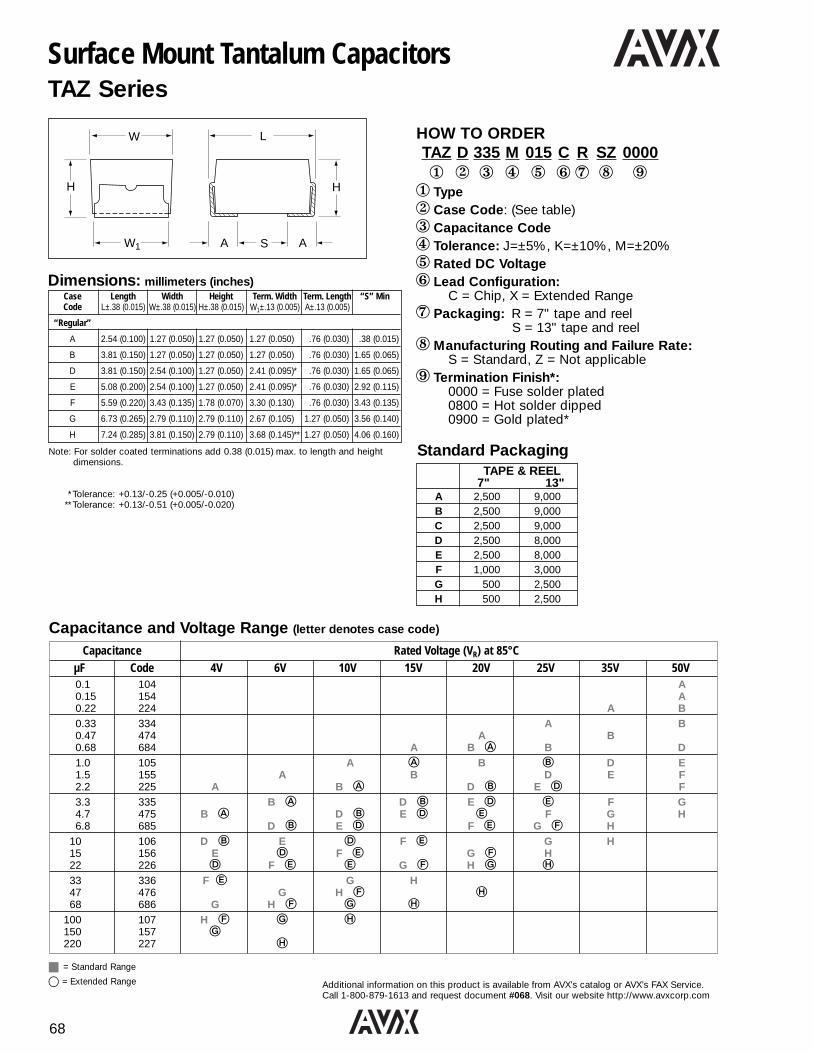
68
Additional information on this product is available from AVX’s catalog or AVX’s FAX Service.Call 1-800-879-1613 and request document #068. Visit our website http://www.avxcorp.com
Surface Mount Tantalum CapacitorsTAZ Series
HOW TO ORDERTAZ D 335 M 015 C R SZ 00001 2 3 4 5 6 7 8 91 Type2 Case Code: (See table)3 Capacitance Code4 Tolerance: J=±5%, K=±10%, M=±20%5 Rated DC Voltage6 Lead Configuration:
C = Chip, X = Extended Range7 Packaging: R = 7" tape and reel
S = 13" tape and reel8Manufacturing Routing and Failure Rate:
S = Standard, Z = Not applicable9 Termination Finish*:
0000 = Fuse solder plated0800 = Hot solder dipped0900 = Gold plated*
W L
H H
A S AW1
Dimensions: millimeters (inches)Case Length Width Height Term. Width Term. Length “S” MinCode L±.38 (0.015) W±.38 (0.015) H±.38 (0.015) W1±.13 (0.005) A±.13 (0.005)
“Regular”
A 2.54 (0.100) 1.27 (0.050) 1.27 (0.050) 1.27 (0.050) .76 (0.030) .38 (0.015)
B 3.81 (0.150) 1.27 (0.050) 1.27 (0.050) 1.27 (0.050) .76 (0.030) 1.65 (0.065)
D 3.81 (0.150) 2.54 (0.100) 1.27 (0.050) 2.41 (0.095)* .76 (0.030) 1.65 (0.065)
E 5.08 (0.200) 2.54 (0.100) 1.27 (0.050) 2.41 (0.095)* .76 (0.030) 2.92 (0.115)
F 5.59 (0.220) 3.43 (0.135) 1.78 (0.070) 3.30 (0.130) .76 (0.030) 3.43 (0.135)
G 6.73 (0.265) 2.79 (0.110) 2.79 (0.110) 2.67 (0.105) 1.27 (0.050) 3.56 (0.140)
H 7.24 (0.285) 3.81 (0.150) 2.79 (0.110) 3.68 (0.145)** 1.27 (0.050) 4.06 (0.160)
Note: For solder coated terminations add 0.38 (0.015) max. to length and height dimensions.
* Tolerance: +0.13/-0.25 (+0.005/-0.010)** Tolerance: +0.13/-0.51 (+0.005/-0.020)
TAPE & REEL7" 13"
A 2,500 9,000B 2,500 9,000C 2,500 9,000D 2,500 8,000E 2,500 8,000F 1,000 3,000G 500 2,500H 500 2,500
Standard Packaging
Capacitance Rated Voltage (VR) at 85°CµF Code 4V 6V 10V 15V 20V 25V 35V 50V0.1 104 A0.15 154 A0.22 224 A B0.33 334 A B0.47 474 A B0.68 684 A B A B D1.0 105 A A B B D E1.5 155 A B D E F2.2 225 A B A D B E D F3.3 335 B A D B E D E F G4.7 475 B A D B E D E F G H6.8 685 D B E D F E G F H
10 106 D B E D F E G H15 156 E D F E G F H22 226 D F E E G F H G H33 336 F E G H47 476 G H F H68 686 G H F G H
100 107 H F G H150 157 G220 227 H
Capacitance and Voltage Range (letter denotes case code)
j = Standard Range
s = Extended Range

69
Additional information on this product is available from AVX’s catalog or AVX’s FAX Service.Call 1-800-879-1613 and request document #069. Visit our website http://www.avxcorp.com
Surface Mount Tantalum CapacitorsTAJ Series - Solid Tantalum Chip Capacitors (EIA Standard)
HOW TO ORDERTAJ B 335 M 016 R *1 2 3 4 5 671 Type2 Case Code: (See table below)3 Capacitance Code:
pF Code: 1st two digits represent significantfigures, 3rd digit represents multiplier (number of zeros to follow)
4 Tolerance:K=±10%, M=±20%(J=±5%, consult factory for details)
5 Rated DC Voltage6 Packaging: R=7" tape and reel, S=13" tape and reel7 Additional characters may be added for
special requirements
Dimensions: millimeters (inches)Code EIA L±0.2 (0.008) W+0.2 (0.008) H+0.2 (0.008) W1±0.2 (0.008) A+0.3 (0.012) S Min.
Code -0.1 (0.004) -0.1 (0.004) -0.2 (0.008)A 3216 3.2 (0.126) 1.6 (0.063) 1.6 (0.063) 1.2 (0.047) 0.8 (0.031) 1.1 (0.043)B 3528 3.5 (0.138) 2.8 (0.110) 1.9 (0.075) 2.2 (0.087) 0.8 (0.031) 1.4 (0.055)C 6032 6.0 (0.236) 3.2 (0.126) 2.6 (0.102) 2.2 (0.087) 1.3 (0.051) 2.9 (0.114)D 7343 7.3 (0.287) 4.3 (0.169) 2.9 (0.114) 2.4 (0.094) 1.3 (0.051) 4.4 (0.173)E 7343H 7.3 (0.287) 4.3 (0.169) 4.1 (0.162) 2.4 (0.094) 1.3 (0.051) 4.4 (0.173)
V — 6.1 (0.240) 7.3 (0.287)3.45±0.3
3.1 (0.122) 1.4 (0.055) 3.4 (0.134)(0.136±0.012)
W1 dimension applies to the termination width for A dimensional area only.
L W
H
A S A W1
TAPE & REEL7" 13"
A 2,000 8,000B 2,000 8,000C 500 3,000D 500 2,500E 400 1,500V 400 1,500
Standard Packaging
Capacitance Rated Voltage (VR) at 85°CµF Code 2V 4V 6.3V 10V 16V 20V 25V 35V 50V
0.10 104 A A0.15 154 A A/B0.22 224 A A/B0.33 334 A B0.47 474 A A/B C0.68 684 A A A/B C1.0 105 A A A B A C1.5 155 A A A A/B B/C A D C2.2 225 A A A/B A/B B A B/C D3.3 335 A A A/B A/B B/C C B D4.7 475 A A A/B B A B/C A C B C/D B D6.8 685 A A/B A/B B/C A B/C C B D C D10 106 A A/B B/C A B/C A C B C/D D C15 156 B A B A B/C A C B C/D B D D C22 226 A B/C A C B A C/D B D C B D C E D33 336 A/B C B A C/D B D C B D C E D D47 476 A B A C/D B D C B D C D C D E68 686 B/C C/D B D C D C E D V E100 107 B/C D C B D C E D D/E150 157 B B C/D E D D E220 227 C/D C/D E D D/E330 337 C E D E D/E/ V E470 477 E/VD E V680 687 D E V1000 108 D E1500 158 E
Capacitance and Voltage Range (letter denotes case code)
BOLD = Standard Range
s = Extended Range
d = Development Range

70
Additional information on this product is available from AVX’s catalog or AVX’s FAX Service.Call 1-800-879-1613 and request document #070. Visit our website http://www.avxcorp.com
L W
H
A S A W1
Surface Mount Tantalum CapacitorsTAJ Series - Low Profile Solid Tantalum Chip Capacitors
HOW TO ORDERTAJ R 105 K 010 R *1 2 3 4 5 6 71 Type2 Case Code: (See table below)3 Capacitance Code:
pF Code: 1st two digits represent significantfigures, 3rd digit represents multiplier(number of zeros to follow)
4 Tolerance:K=10%, M=±20%(J=±5%, consult factory for details)
5 Rated DC Voltage6 Packaging: R=7" tape and reel,
S=13" tape and reel7 Additional characters may be added for
special requirements
Code EIA L±0.2 W+0.2 (0.008) H max. W1±0.1 A+0.30 (0.012) S Min.Code (0.008) -0.1 (0.004) (0.004) -0.1 (0.004)
0805 EquivalentR 2012 2.05 (0.081) 1.3 (0.051) 1.2 (0.047) 1.2 (0.047) 0.5 (0.020) 0.85 (0.033)
Low Profile VersionsS 3216L 3.2 (0.126) 1.6 (0.063) 1.2 (0.047) 1.2 (0.047) 0.8 (0.031) 1.1 (0.043)T 3528L 3.5 (0.138) 2.8 (0.110) 1.2 (0.047) 2.2 (0.087) 0.8 (0.031) 1.4 (0.055)W — 6.0 (0.236) 3.2 (0.126) 1.5 (0.059) 2.2 (0.087) 1.3 (0.051) 2.9 (0.114)Y — 7.3 (0.287) 4.3 (0.169) 2.0 (0.079) 2.4 (0.094) 1.3 (0.051) 4.4 (0.173)
Dimensions: millimeters (inches) - metric dimensions govern
W1 dimension applies to the termination width for A dimensional area only.Pad stand-off is 0.1±0.1.
TAPE & REEL7" 13"
R 2,500 10,000S 2,500 10,000T 2,500 10,000W 1,000 5,000Y 1,000 4,000
Standard Packaging
Capacitance Rated Voltage (VR) at 85°CµF Code 2V 4V 6.3V 10V 16V 20V 25V0.10 104 R/S0.15 154 R/S0.22 224 R/S0.33 334 R/S0.47 474 R/S0.68 684 R/S R/S/T1.0 105 R/S R/S/T R/S/T1.5 155 R/S R/S S T2.2 225 R/S R/S R/S T T3.3 335 R/S R/S S/T T4.7 475 R R/S S/T T R6.8 685 R S/T T T W
10 106 S R/T R T W15 156 T W X22 226 W W Y33 336 W W W47 476 X68 686 W Y W X Y
100 107 W Y Y150 157 W X Y220 227 W X Y330 337 W X Y470 477 X Y680 687 X/Y
1000 108 Y
X = 1.5mm height in a D case footprint
Capacitance and Voltage Range (letter denotes case code)
BOLD = Standard Range
s = Extended Range
d = Development Range

71
Additional information on this product is available from AVX’s catalog or AVX’s FAX Service.Call 1-800-879-1613 and request document #071. Visit our website http://www.avxcorp.com
Surface Mount Tantalum CapacitorsTPS Series - Low ESR Solid Tantalum Chip Capacitors (EIA Standard)
HOW TO ORDERTPS E 107 M 016 R 01001 2 3 4 5 6 7
1 Type2 Case Code: (See table below)3 Capacitance Code:
pF Code: 1st two digits represent significantfigures, 3rd digit represents multiplier (number of zeros to follow)
4 Tolerance:K=10%, M=±20%
5 Rated DC Voltage6 Packaging:
R=7" tape and reel, S=13" tape and reel7Maximum ESR at 100kHz at 25°C in
milliohms (from matrix)
L W
H
A S A W1
TAPE & REEL7" 13"
A 2,000 8,000B 2,000 8,000C 500 3,000D 500 2,500E 400 1,500V 400 1,500
Standard Packaging
Dimensions: millimeters (inches)
Code EIA W+0.2 H+0.2 W1 A+0.3 S Min.Code (0.008) L±0.2 (0.008) ±0.2 (0.012)
-0.1 (0.008) -0.1 (0.008) -0.2(0.004) (0.004) (0.008)
A 3216 1.6 (0.063) 3.2 (0.126) 1.6 (0.063) 1.2 (0.047) 0.8 (0.031) 1.1 (0.043) B 3528 2.8 (0.110) 3.5 (0.138) 1.9 (0.075) 2.2 (0.087) 0.8 (0.031) 1.4 (0.055) C 6032 3.2 (0.126) 6.0 (0.236) 2.6 (0.102) 2.2 (0.087) 1.3 (0.051) 2.9 (0.114) D 7343 4.3 (0.169) 7.3 (0.287) 2.9 (0.114) 2.4 (0.094) 1.3 (0.051) 4.4 (0.173) E 7343H 4.3 (0.169) 7.3 (0.287) 4.1 (0.162) 2.4 (0.094) 1.3 (0.051) 4.4 (0.173)
V 6.1 (0.240) 7.3 (0.287) 3.45 ±0.3 3.1 (0.122) 1.4 (0.055) 3.4 (0.134)(0.136±0.012)W1 dimension applies to the termination width for A dimensional area only.
ESR limits quoted in brackets are in milliohms
Capacitance and Voltage Range (letter denotes case code)
Capacitance Rated Voltage (VR) at 85°CµF Code 6.3V 10V 16V 20V 25V 35V1.5 155 A(3000) B(3000)2.2 225 A(3500) A(3000) B(2500) B(2000)3.3 335 A(3500) A(2500) B(2000) C(700)4.7 475 A(2500) A(2000) A(1800) B(1500) C(600)6.8 685 A(1800) A(1800) B(1200) C(700) C(700) D(500)
10 106 A(1500) A(1800) B(800) B(1000) C(500) D(300)C(700)C(450)15 156 A(1500) A(1000) B(800) C(450) D(300) D(300)
22 226 A(1000) B(700) C(375) C(400) D(200) D(400)B(600) D(300) E(200-300)
33 336 B(600) C(375-500) C(300) D(200) E(175-300) D(300)B(500) C(350) D(200)47 476 C(300) C(350) D(150-200) E(150) D(250)
68 686 B(500) D(150) D(150) E(125-170) V(95-300)C(200)C(100-200) D(125-150) D(175)100 107 C(150) D(65-140) E(100-150) V(85-200)
C(150) D(150)150 157 D(125) D(100) V(75)D (100-150)
220 227 D(100) E(60-150) V(75-150)V(60)
D(100) D(100-150)330 337 E(100-150) E(60-100)
V(60-100) V(60-100)D (100-200)
470 477 V(55-100) E(50-200)E(50-200)

72
Additional information on this product is available from AVX’s catalog or AVX’s FAX Service.Call 1-800-879-1613 and request document #072. Visit our website http://www.avxcorp.com
Surface Mount Tantalum CapacitorsTHJ - High Temperature Series
MARKING
J15µ9901Polarity
1. Voltage Code J for 6.3V2. Capacitance in µF3. Date Code
Range OfferingCapacitance Rated Voltage (VR) at 85°C
µF 4V 6.3V 10V 16V 20V 25V 35V0.10 A0.15 A0.22 A0.33 A0.47 A B0.68 A B1.0 A B1.5 A C2.2 A B C3.3 A B C4.7 A B C6.8 B C D
10 B C D15 B C D22 B C D33 C D47 C D68 C D10.0 D15.0 D22.0
Rated Voltage DC (VR) @ ≤ +85°C: 6.3 10 16 20 25 35
Category Voltage DC (VC) @ +150°C: 3.2 5 8 10 12.5 17.5
Surge Voltage (VS) @ ≤ +85°C: 8.2 13 20.8 26 32.5 45.5
Surge Voltage (VS) @ +150°C: 4.1 6.5 15.4 13 16.2 22.7
Temperature Range: -55°C to +150°C
Technical Specifications
Mechanical Specifications
W
W1
W
W1A
H
S
L
A
Case Size Dimensions
AVX EIA L W H A+0.3 S W1 ±0.2±0.2 +0.2/-0.1 +0.2/-0.1 -0.2 min.
A 3216 3.2 1.6 1.6 0.8 1.1 1.2(0.126) (0.063) (0.063) (0.031) (0.043) (0.047)
B 3528 3.5 2.8 1.9 0.8 1.4 2.2(0.138) (0.110) (0.075) (0.031) (0.055) (0.087)
C 6032 6.0 3.2 2.6 1.3 2.9 2.2(0.236) (0.126) (0.102) (0.051) (0.114) (0.087)
D 7343 7.3 4.3 2.9 1.3 4.4 2.4(0.287) (0.169) (0.114) (0.051) (0.173) (0.094)
HOW TO ORDERTHJ B 156 M 006 R1 2 3 4 5 6
1 Series Name2 Case Size3 Capacitance Code4 Capacitance Tolerance:
K=10%, M=±20%5 Voltage:
004 = 4V 006 = 6.3V 010 = 10V016 = 16V 020 = 20V 025 = 25V035 = 35V
6 Packaging: X = 4 1/4" reelR = 7" reelS = 13" reel

73
Additional information on this product is available from AVX’s catalog or AVX’s FAX Service.Call 1-800-879-1613 and request document #073. Visit our website http://www.avxcorp.com
Surface Mount Tantalum CapacitorsCWR09 Style (MIL-PRF-55365/4)
HOW TO ORDERCWR09 J B 225 J M A \TR1 2 3 4 5 6 7 8
1 Style2 Voltage:
C=4VDC, D=6VDC, F=10VDC, H=15VDC, J=20VDC,K=25VDC, M=35VDC, N=50VDC
3 Termination Finish:B=Gold Plated, C=Hot Solder Dipped, K=Solder Fused
4 Capacitance Code5 Tolerance:
J=±5%, K=±10%, M=±20%6 Failure Rate: Exponential: M=1%/1000 hours
P=0.1%/1000 hoursR=0.01%/1000 hoursS=0.001%/1000 hours
Weibull: B=0.1%/1000 hoursC=0.01%/1000 hours
7 Optional Surge Current:A=10 cycles at 25°CB=10 cycles at -55°C and +85°C
8 Packaging:Bulk (Standard if nothing is specified in this position)
\TR=7" Tape & Reel\TR13=13" Tape & Reel\W=Waffle Pack
Polarity Stripe (+)
Capacitance Code
Rated Voltage"J" for "JAN" Brand
68520J
Marking (military qualified)
The “V” following rated voltage is replacedwith a “J” for JAN Brand.
Range SeriesCapacitance and Voltage Range (letter denotes case code)
Capacitance Rated Voltage DC (VR) at 85°CµF Code 4V 6V 10V 15V 20V 25V 35V 50V0.1 104 A0.15 154 A0.22 224 A B
0.33 334 A B0.47 474 A B C0.68 684 A B B C D
1.0 105 A B C D E1.5 155 A B C D E F2.2 225 A B C D E F
3.3 335 B C D E F G4.7 475 B C D E F G H6.8 685 C D E F G H
10 106 D E F G15 156 E F G H22 226 F G H
33 336 F G H47 476 G H68 686 G H
100 107 H
Note: CWR09 is fully interchangeable with CWR06. Case sizes correspond to TAZ A through H.Contact AVX for latest qualification status.
Note: “C” case size has limited availability. Where possible use “D” case size.
CASE TAPE & REEL WAFFLESIZE 7" 13"
A 2,500 9,000 160B 2,500 9,000 112C 2,500 9,000 90D 2,500 8,000 88E 2,500 8,000 60F 1,000 3,000 48G 500 2,500 50H 500 2,500 28
Standard Packaging
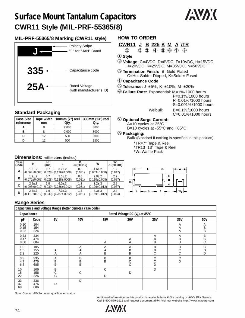
74
Additional information on this product is available from AVX’s catalog or AVX’s FAX Service.Call 1-800-879-1613 and request document #074. Visit our website http://www.avxcorp.com
J
335
25A
Polarity Stripe"J" for "JAN" Brand
Capacitance code
Rated Voltage(with manufacturer's ID)
MIL-PRF-55365/8 Marking (CWR11 style)
Surface Mount Tantalum CapacitorsCWR11 Style (MIL-PRF-55365/8)
HOW TO ORDERCWR11 J B 225 K M A \TR1 2 3 4 5 6 7 8
1 Style2 Voltage: C=4VDC, D=6VDC, F=10VDC, H=15VDC,
J=20VDC, K=25VDC, M=35VDC, N=50VDC3 Termination Finish: B=Gold Plated
C=Hot Solder Dipped, K=Solder Fused4 Capacitance Code5 Tolerance: J=±5%, K=±10%, M=±20%6 Failure Rate: Exponential: M=1%/1000 hours
P=0.1%/1000 hoursR=0.01%/1000 hoursS=0.001%/1000 hours
Weibull: B=0.1%/1000 hoursC=0.01%/1000 hours
7 Optional Surge Current:A=10 cycles at 25°CB=10 cycles at -55°C and +85°C
8 Packaging:Bulk (Standard if nothing is specified in this position)
\TR=7" Tape & Reel\TR13=13" Tape & Reel\W=Waffle Pack
Range SeriesCapacitance and Voltage Range (letter denotes case code)
Capacitance Rated Voltage DC (VR) at 85°C
µF Code 6V 10V 15V 20V 25V 35V 50V0.10 104 A A0.15 154 A B0.22 224 A B
0.33 334 A A B0.47 474 A A B C0.68 684 A A B B C
1.0 105 A A A B B C1.5 155 A A A B B C D2.2 225 A A B B C C D
3.3 335 A B B B C C4.7 475 B B B C C D6.8 685 B B C D
10 106 B C D15 156 C C D22 226 C D
33 336 D47 476 D68 686
Case Size Tape width 180mm (7") reel 330mm (13") reelreference mm Qty. Qty.
A 8 2,000 8000B 8 2,000 8000C 12 500 3000D 12 500 2500
Standard Packaging
Case H H2
L P W W2
Code (min) .3 (±0.012) .1 (±0.004)
A1.6±.2 0.7 3.2±.2 0.8 1.6±.2 1.2
(0.063±0.008) (0.028) (0.126±0.008) (0.031) (0.063±0.008) (0.047)
B1.9±.2 0.7 3.5±.2 0.8 2.8±.2 2.2
(0.075±0.008) (0.028) (0.138±.0008) (0.031) (0.110±0.008) (0.087)
C2.5±.3 1.0 6.0±.3 1.3 3.2±.3 2.2
(0.098±0.012) (0.039) (0.236±0.012) (0.051) (0.126±0.012) (0.087)
D2.8±.3 1.0 7.3±.3 1.3 4.3±.3 2.4
(0.110±0.012) (0.039) (0.287±.0012) (0.051) (0.169±0.012) (0.094)
Dimensions: millimeters (inches)
Note: Contact AVX for latest qualification status.

75
Additional information on this product is available from AVX’s catalog or AVX’s FAX Service.Call 1-800-879-1613 and request document #075. Visit our website http://www.avxcorp.com
Dipped Radial Tantalum CapacitorsTAP Series
CASE H *H1 D CASE BULK T/R 14" AMMOA 8.5 (0.33) 7.0 (0.28) 4.5 (0.18) A 1000 1500 3000B 9.0 (0.35) 7.5 (0.30) 4.5 (0.18) B 1000 1250 3000C 10.0 (0.39) 8.5 (0.33) 5.0 (0.20) C 1000 1250 3000D 10.5 (0.41) 9.0 (0.35) 5.0 (0.20) D 1000 1250 3000E 10.5 (0.41) 9.0 (0.35) 5.5 (0.22) E 1000 1000 2500F 11.5 (0.45) 10.0 (0.39) 6.0 (0.24) F 1000 1000 2500G 11.5 (0.45) 10.0 (0.39) 6.5 (0.26) G 1000 750 2500H 12.0 (0.47) 10.5 (0.41) 7.0 (0.28) H 1000 750 2000J 13.0 (0.51) 8.0 (0.31) J 500 750 2000K 14.0 (0.55) 8.5 (0.33) K 500 500 1000L 14.0 (0.55) 9.0 (0.35) L 500 500 1000M 14.5 (0.57) 9.0 (0.35) M 100 500 1000N 16.0 (0.63) 9.0 (0.35) N 100 500 1000P 17.0 (0.67) 10.0 (0.39) P 100 500 1000R 18.5 (0.73) 10.0 (0.39) R 100 500 1000
i
i
H
D
Dimensions: mm (inches) Standard Packaging
*H1 refers to H dimension on S wire form.
MarkingCapacitance, DC voltage, polarity and an “A” are laser marked onthe capacitor body.
• Polarity • Voltage• Capacitance • AVX logo• ±10% tolerance coded with “K” on reverse side of unit.
Capacitance Rated Voltage DC (VR)
µF 6.3V 10V 16V 20V 25V 35V 50V0.1 A A0.15 A A0.22 A A
0.33 A A0.47 A A0.68 A B
1.0 A A A C1.5 A A A A D2.2 A A A A B E
3.3 A A A B B C F4.7 A A B C C E G6.8 A B C D D F H
10 B C D E E F J15 C D E F F H K 22 D E F H H K L
33 E F F J J M47 F G J K M N68 G H L N N
100 H K N N150 K N N220 M P R
330 P R
Capacitance Range (letter denotes case code)
HOW TO ORDERTAP 475 M 035 SCS1 2 3 4 5
1 AVX Type2 Capacitance Code3 Capacitance Tolerance:
K=±10%, M=±20%,For J=±5% tolerance, please consult factory
4 Rated DC Voltage5 Suffix indicating
wire form and packaging:
Values outside this standard range may be available on request without appropriate release or qualification.
AVX reserves the right to supply capacitors to a higher voltage rating, in the same case size, than that ordered.
D
H
S
d
L
0.079 (2)min
Figure 1
Wire Form C
+
Wire Form B
Figure 2 D
S
d
L
H +0.16 (4)max
1
Figure 3
Wire Form S
D
S
L
d 0.079 (2)min
H0.08 (2.0)max
1
+
Wire Figure Case L S d Packaging
Form Size (see note 1) SuffixesAvailable
C Figure 1 A - R* 16±4 5.0±1.0 0.5±0.05CCS Bulk
(0.630±0.160) (0.200±0.040) (0.020±0.002) CRW Tape/ReelCRS Tape/AMMO
B Figure 2 A - H 16±4 5.0±1.0 0.5±0.05 BRW Tape/Reel(0.630±0.160) (0.200±0.040) (0.020±0.002) BRS Tape/AMMO
S Figure 3 A - H* 16±4 2.5±0.5 0.5±0.05SCS Bulk
(0.630±0.160) (0.100±0.020) (0.020±0.002) SRW Tape/ReelSRS Tape/AMMO
Note 1: Consult factory for other special wire forms.

76
Additional information on this product is available from AVX’s catalog or AVX’s FAX Service.Call 1-800-879-1613 and request document #076. Visit our website http://www.avxcorp.com
Molded Axial CapacitorsTAR Series
Dimensions: millimeters (inches)
D 25 (1) min. L
d
Polarity mark
1
Case L D1 d TypicalSize ±0.25 (0.010) ±0.25 (0.010) ±0.05 (0.020) Weight gQ 6.35 (0.250) 2.16 (0.085) 0.5 (0.020) 0.20
R 7.4 (0.291) 2.5 (0.098) 0.5 (0.020) 0.25
S 8.6 (0.339) 4.3 (0.169) 0.5 (0.020) 0.52
W 10.4 (0.409) 4.3 (0.169) 0.5 (0.020) 0.53
Marking• Polarity • Capacitance • Date Code• Tolerance • Voltage
Standard Packaging
Capacitance Range (letter denotes case code)Capacitance Rated Voltage DC (VR)
µF 4V 6.3V 10V 15V 20V 25V 35V 50V 0.1 Q Q0.15 Q Q0.22 Q Q
0.33 Q R0.47 Q Q R0.68 Q R R
1.0 Q Q R R1.5 Q Q R R S2.2 Q Q R R S S
3.3 Q Q R R R S W4.7 Q Q R R R S S W6.8 Q R R R S S W
10 R R R S S S W15 R R S S W W22 R S S W W
33 S S W W47 S W W68 W W
Values outside this standard range may be available on request without appropriate release or qualification.
AVX reserves the right to supply capacitors to a tighter specification than that ordered.
HOW TO ORDERTAR R 335 M 0151 2 3 4 5
1 Type2 Case Code 3 Capacitance Code4 Capacitance Tolerance:
J=±5%, K=±10%, M=±20%5 Rated DC Voltage
TAPE & REEL AMMO14"
Q 3,000 3,000R 3,000 3,000S 2,000 2,000W 2,000 2,000
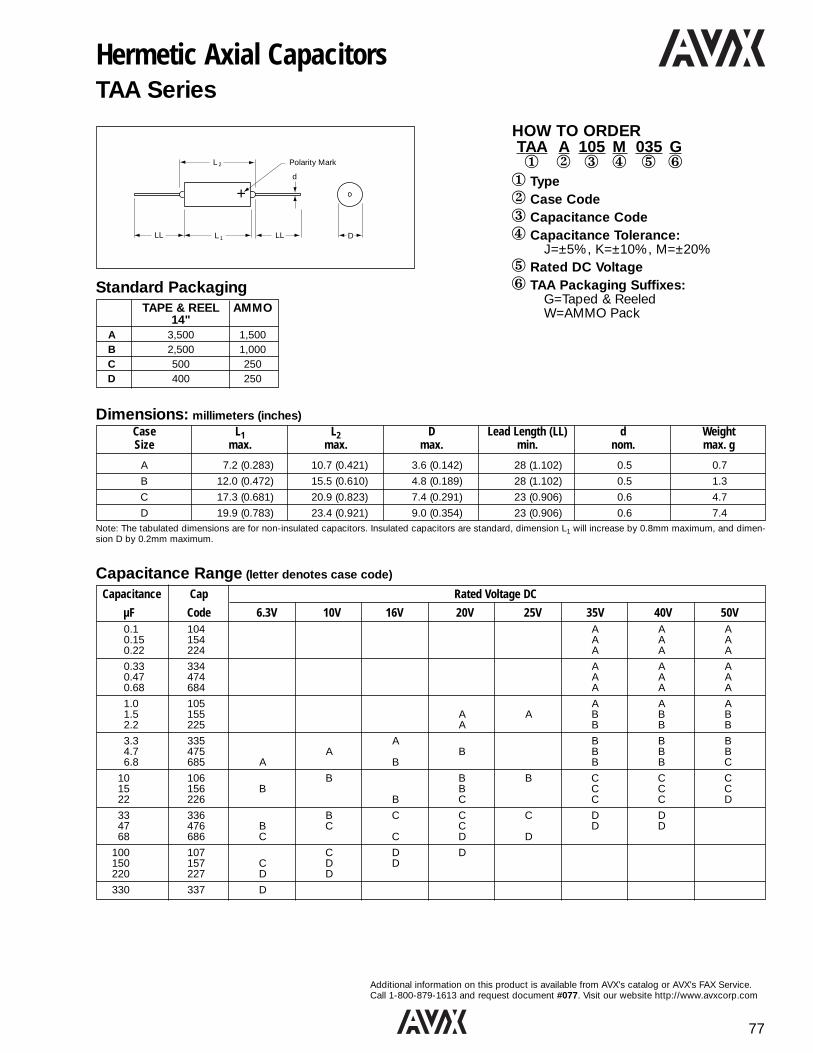
77
Additional information on this product is available from AVX’s catalog or AVX’s FAX Service.Call 1-800-879-1613 and request document #077. Visit our website http://www.avxcorp.com
Hermetic Axial CapacitorsTAA Series
+
L
L
d
D
Polarity Mark2
1LL LL
Dimensions: millimeters (inches)Case L1 L2 D Lead Length (LL) d WeightSize max. max. max. min. nom. max. g
A 7.2 (0.283) 10.7 (0.421) 3.6 (0.142) 28 (1.102) 0.5 0.7
B 12.0 (0.472) 15.5 (0.610) 4.8 (0.189) 28 (1.102) 0.5 1.3
C 17.3 (0.681) 20.9 (0.823) 7.4 (0.291) 23 (0.906) 0.6 4.7
D 19.9 (0.783) 23.4 (0.921) 9.0 (0.354) 23 (0.906) 0.6 7.4Note: The tabulated dimensions are for non-insulated capacitors. Insulated capacitors are standard, dimension L1 will increase by 0.8mm maximum, and dimen-sion D by 0.2mm maximum.
Capacitance Range (letter denotes case code)
Capacitance Cap Rated Voltage DC
µF Code 6.3V 10V 16V 20V 25V 35V 40V 50V0.1 104 A A A0.15 154 A A A0.22 224 A A A
0.33 334 A A A0.47 474 A A A0.68 684 A A A
1.0 105 A A A1.5 155 A A B B B2.2 225 A B B B
3.3 335 A B B B4.7 475 A B B B B6.8 685 A B B B C
10 106 B B B C C C15 156 B B C C C22 226 B C C C D
33 336 B C C C D D47 476 B C C D D68 686 C C D D
100 107 C D D150 157 C D D220 227 D D
330 337 D
HOW TO ORDERTAA A 105 M 035 G1 2 3 4 5 61 Type2 Case Code3 Capacitance Code4 Capacitance Tolerance:
J=±5%, K=±10%, M=±20%5 Rated DC Voltage6 TAA Packaging Suffixes:
G=Taped & ReeledW=AMMO PackTAPE & REEL AMMO
14"A 3,500 1,500B 2,500 1,000C 500 250D 400 250
Standard Packaging

78
Additional information on this product is available from AVX’s catalog or AVX’s FAX Service.Call 1-800-879-1613 and request document #078. Visit our website http://www.avxcorp.com
Minitan CapacitorsTMH Series
C B
A
E
Radial Axial
HOW TO ORDERTMH W 104 M 020 R*1 2 3 4 5 61 Type2 Case Code3 Capacitance Code4 Tolerance:
L=+40/-20%, M=±20%,K=±10%, J=±5%
5 Rated DC Voltage6 Lead Configuration:
R=Radial, A=Axial*Note: Other digits will be added by
factory to identify specificcustomer requirements. Contactfactory for details.
Standard PackagingBulk (100 pcs.)
Dimensions: millimeters (inches)Case Size Applicable Figure A Max B Max C Max E
X Figure 1 1.9 (0.075) 1.3 (0.051) 1.1 (0.043) 0.8±0.4 (0.031±0.016)
W Figure 1 2.5 (0.098) 1.3 (0.051) 1.1 (0.043) 0.8±0.4 (0.031±0.016)
U Figure 1 3.2 (0.126) 1.8 (0.071) 1.1 (0.043) 1.3±0.4 (0.051±0.016)
Figure 1
Case SizesX, W, U
Leads – Leads are solder coated pure nickel wire suitable for soldering or welding.Tested in accordance with MIL-STD-202, Method 211, .010 diameter leads withstand a 1-lb. pull and .007 diameter leads an 8-oz. pull. All lead diameterswithstand 5 rotations twist.
Lead Length: All case sizes: Pos. 41.3±3.2 (1.625±0.125) Lead Diameter: W, X = .178±.025 (0.007±0.001); Neg. 34.9±3.2 (1.375±0.125) U = .254±.025 (0.010±0.001)
Maximum Capacitance, µFCase Size 2VDC 3VDC 4VDC 6VDC 10VDC 15VDC 20VDC 35VDC 50VDC
X 2.2 — 0.33 0.22 0.15 0.1 0.068 — —
W 2.2 — 0.33 0.22 0.15 0.1 0.068 — —
U 10.0 4.7 1.0 — — — 0.22 — —

79
Additional information on this product is available from AVX’s catalog or AVX’s FAX Service.Call 1-800-879-1613 and request document #079. Visit our website http://www.avxcorp.com
Capacitance and Voltage Range: Case Sizes 1812 to 6054 millimeters (inches)
Film Chip Capacitors
HOW TO ORDERCF 04 2 D 0334 J - -1 2 3 4 5 6 71 Type2 Size Code:
1 = 1206; 02 = 1210; 03 = 1812; 04 = 2220;05 = 2824; 16 = 4030; 17 = 5040; 18 = 6054
3 Dielectric Class: 2 = PET4 Voltage Code
50/63 V = D; 100 V = E; 160 V = F; 250 V = G5 Capacitance EIA Code
1st digit: 0 (zero). 2nd & 3rd: 2nd significantfigures of the capacitance value. 4th digit:number of zeros to be added to the capaci-tance value.
6 Tolerance Code: J = 5%; K = 10%7 Suffix
- - = BulkBA = Taped on reel ø 180BC = Taped on reel ø 330
DC Rated Voltage (105°C / 125°C)Capacitance Capacitance 25 V / 19 V 50 V / 38 V 100 V / 75 V
Code Size Code H max Size Code H max Size Code H max1 nF 0102 01 1.1 (0.043) 01 1.1 (0.043) 01 1.1 (0.043)1.5 0152 01 1.1 (0.043) 01 1.1 (0.043) 01 1.1 (0.043)2.2 0222 01 1.1 (0.043) 01 1.1 (0.043) 01 1.1 (0.043)3.3 0332 01 1.1 (0.043) 01 1.1 (0.043) 01 1.1 (0.043)4.7 0472 01 1.1 (0.043) 01 1.1 (0.043) 01 1.3 (0.051)6.8 0682 01 1.1 (0.043) 01 1.1 (0.043) 02 1.6 (0.063)
10 0103 01 1.3 (0.051) 01 1.3 (0.051) 02 1.6 (0.063)15 0153 01 1.3 (0.051) 02 1.8 (0.071) 02 1.8 (0.071)22 0223 01 1.3 (0.051) 02 2.2 (0.087) 02 2.2 (0.087)33 0333 02 2.2 (0.087) 02 2.2 (0.087)47 0473 02 1.8 (0.071) 1.8 (0.071)68 0683 02 2.2 (0.087)
100 0104 02 2.2 (0.087)
DC Rated Voltage (105°C / 125°C)Capacitance Capacitance 63 V / 47 V 100 V / 75 V 160 V / 120 V 250 V / 187 V
Code Size Code H max Size Code H max Size Code H max Size Code H max1 nF 0102 03 1.5 (0.059) 03 1.5 (0.059) 03 1.5 (0.059) 03 1.5 (0.059)1.5 0152 03 1.5 (0.059) 03 1.5 (0.059) 03 1.5 (0.059) 03 1.5 (0.059)2.2 0222 03 1.5 (0.059) 03 1.5 (0.059) 03 1.5 (0.059) 03 1.5 (0.059)3.3 0332 03 1.5 (0.059) 03 1.5 (0.059) 03 1.5 (0.059) 03 1.5 (0.059)4.7 0472 03 1.5 (0.059) 03 1.5 (0.059) 03 1.5 (0.059) 03 1.5 (0.059)6.8 0682 03 1.5 (0.059) 03 1.5 (0.059) 03 1.5 (0.059) 03 1.5 (0.059)
10 0103 03 1.5 (0.059) 03 1.5 (0.059) 03 1.5 (0.059) 03 1.5 (0.059)15 0153 03 1.5 (0.059) 03 1.5 (0.059) 03 1.5 (0.059) 03 2.5 (0.098)22 0223 03 1.5 (0.059) 03 1.5 (0.059) 03 2.0 (0.079) 04 2.0 (0.079)33 0333 03 1.5 (0.059) 03 1.5 (0.059) 03 2.5 (0.098) 04 2.0 (0.079)47 0473 03 2.0 (0.079) 03 2.0 (0.079) 04 2.1 (0.083) 04 3.0 (0.118)68 0683 03 2.0 (0.079) 03 3.0 (0.118) 04 3.0 (0.118) 04 4.0 (0.157)
100 0104 03 2.0 (0.079) 03 3.0 (0.118) 04 3.4 (0.134) 05 3.6 (0.142)150 0154 03 2.5 (0.098) 04 3.0 (0.118) 05 5.1 (0.201) 05 5.1 (0.201)220 0224 03 3.0 (0.118) 04 4.5 (0.177) 05 5.0 (0.197) 16 3.8 (0.150)330 0334 04 3.4 (0.134) 04 4.5 (0.177) 16 3.8 (0.150) 16 5.8 (0.228)470 0474 04 4.0 (0.157) 05 5.4 (0.213) 17 3.8 (0.150) 17 4.6 (0.181)680 0684 04 4.5 (0.177) 05 5.1 (0.201) 17 4.6 (0.181) 18 4.4 (0.173)
1 µF 0105 05 5.0 (0.197) 16 4.8 (0.189) 18 4.4 (0.173) 18 5.7 (0.224)1.5 0155 17 4.6 (0.181) 17 4.6 (0.181) 18 6.2 (0.244)2.2 0225 17 5.5 (0.217) 17 5.5 (0.217)3.3 0335 18 6.2 (0.244) 18 6.2 (0.244)4.7 0475 18 7.0 (0.276) 18 7.0 (0.276)
Capacitance and Voltage Range: Case Sizes 1206 and 1210 millimeters (inches)
Size Code 01 02 03 04 05 16 17 18Equivalent
1206 1210 1812 2220 2824 4030 5040 6054SizeLength (L) mm 3.2 ± 0.3 3.2 ± 0.3 4.5 ± 0.5 5.7 ± 0.5 7.1 ± 0.5 10.2 ± 0.6 12.7 ± 0.6 15.2 ± 0.6
(inches) (0.126 ±0.012) (0.126 ± 0.012) (0.177 ± 0.020) (0.224 ± 0.020) (0.280 ± 0.020) (0.401 ± 0.024) (0.500 ± 0.024) (0.598 ± 0.024)Width (W) mm 1.6 ± 0.3 2.5 ± 0.3 3.2 ± 0.5 5.0 ± 0.5 6.1 ± 0.5 7.6 ± 0.8 10.2 ± 0.8 13.7 ± 0.8
(inches) (0.063 ± 0.012) (0.098 ± 0.012) (0.126 ± 0.020) (0.197 ± 0.020) (0.240 ± 0.020) (0.299 ± 0.031) (0.401 ± 0.031) (0.539 ± 0.031)
0.3 (0.012) ± 0.2 (0.007)
W
H
L
Dimensions: millimeters (inches)

80
Additional information on this product is available from AVX’s catalog or AVX’s FAX Service.Call 1-800-879-1613 and request document #080. Visit our website http://www.avxcorp.com
Metallized PolyesterBF-Film Dielectric Capacitors
Schoop
Metallized film
e
L
0.4
(0.0
16) m
in.
H
5.08 (0.020) +0.6 (0.024)-0.1 (0.004)
4.1
(0.1
61)
± 0.
5 (0
.020
)
HOW TO ORDERBF 01 4 D 0104 K --1 2 3 4 5 6
1 Type and Size: *BF (CPM-83): Std.BH (CPM-N): High Performance
2 Dielectric Class: 4 = PET3 Voltage4 Capacitance Value5 Tolerance6 Suffix
Case L max. H max. e max. ø ± 0.02 Observations
01 7.5 (0.295) 6.5 (0.256) 2.5 (0.098) 0.5 (0.020) 1nF ≤ CR ≤ 220nF
02 7.5 (0.295) 8.0 (0.315) 3.2 (0.126) 0.5 (0.020) 12nF ≤ CR ≤ 330nF
05 7.5 (0.295) 12.0 (0.472) 6.0 (0.236) 0.5 (0.020) 560nF ≤ CR ≤ 2.2µF
06 7.5 (0.295) 9.6 (0.378) 6.0 (0.236) 0.5 (0.020) 47nF / 400V
07 7.5 (0.295) 8.0 (0.315) 5.0 (0.197) 0.5 (0.020) 27nF ≤ CR ≤ 1µF
Dimensions: millimeters (inches)
*STANDARDIZATIONBF (CPM-83):Generic specifications:
CEI 384-1/CECC 30000/UTE 83100Sectional specifications:
CEI 384-2/CECC 30400/UTE 83151Complies with special specification:
CECC 30401-063On the LNZ list:
Complies with type CPM-NRAQ2 production, equivalent AQAP-4 of NATO
Climate Category:-55/100/56
BH (CPM-N):Generic specifications:
CEI 384-1/CECC 30000/UTE 83100Sectional specifications:
CEI 384-2/CECC 30400/UTE 83151On the LNZ list:
Complies with type CPM-NRAQ2 production, equivalent AQAP-4 of NATO
Climate Category:-55/125/56
BF 01/02/05/06/07
* Upon request ** Upon request & only available 50 V (VR)
Capacitance Values (CR) andNominal Voltages (VR) vs Case Size
Capacitance BFRange VR-/VR~
(CR) 63/40 100/63 250/160 400/2001,000 pF BF01 BF01 BF01 BF011,200 BF01 BF01 BF01 BF011,500 BF01 BF01 BF01 BF011,800 BF01 BF01 BF01 BF012,200 pF BF01 BF01 BF01 BF012,700 BF01 BF01 BF01 BF013,300 BF01 BF01 BF01 BF013,900 BF01 BF01 BF01 BF014,700 pF BF01 BF01 BF01 BF015,600 BF01 BF01 BF01 BF016,800 BF01 BF01 BF01 BF018,200 BF01 BF01 BF01 BF01
10,000 pF BF01 BF01 BF01 BF0112,000 BF01 BF01 BF01 BF0215,000 BF01 BF01 BF01 BF0218,000 BF01 BF01 BF01 BF0222,000 BF01 BF01 BF01 BF0227,000 BF01 BF01 BF01 BF0733,000 BF01 BF01 BF02 BF0739,000 BF01 BF01 BF02 BF0747,000 pF BF01 BF01 BF02 BF0656,000 BF01 BF01 BF0768,000 BF01 BF01 BF0782,000 BF01 BF01 BF07
100 nF BF01 BF01 BF07120 BF01 BF01150 BF01 BF01180 BF01 BF07220 nF BF01 BF07270 BF02 BF07330 BF02 BF07390 BF07/BF02* BF07470 nF BF07/BF02* BF07560 BF07 BF05680 BF07 BF05820 BF07 BF05
1 µF BF07 BF051.5 µF BF052.2 µF BF05**
BH 01/02/05/06/07
** (VR = 50 V) * Upon request
Capacitance BHRange VR-/VR~
(CR) 63/40 100/63 250/160 400/2001,000 pF BH01 BH01 BH01 BH011,200 BH01 BH01 BH01 BH011,500 BH01 BH01 BH01 BH011,800 BH01 BH01 BH01 BH012,200 pF BH01 BH01 BH01 BH012,700 BH01 BH01 BH01 BH013,300 BH01 BH01 BH01 BH013,900 BH01 BH01 BH01 BH014,700 pF BH01 BH01 BH01 BH015,600 BH01 BH01 BH01 BH026,800 BH01 BH01 BH01 BH028,200 BH01 BH01 BH01 BH07
10,000 pF BH01 BH01 BH01 BH0712,000 BH01 BH01 BH01 BH0715,000 BH01 BH01 BH01 BH0718,000 BH01 BH01 BH01/BH02* BH06/BH05*22,000 BH01 BH01 BH02 BH06/BH05*27,000 BH01 BH01 BH02 BH06/BH05*33,000 BH01 BH01 BH02 BH06/BH05*39,000 BH01 BH01 BH07 BH0547,000 pF BH01 BH01 BH07 BH0556,000 BH01 BH01 BH0768,000 BH01 BH01 BH0782,000 BH01 BH01 BH06/BH05*
100 nF BH01 BH01 BH06/BH05*120 BH01 BH01/BH07* BH05150 BH01 BH01/BH07* BH05180 BH01 BH02/BH07*220 nF BH01/BH02* BH02/BH07*270 BH02 BH07330 BH02 BH07390 BH07 BH07/BH05*470 nF BH07 BH05560 BH07 BH05680 BH07/BH06* BH05820 BH07/BH06* BH05
1 µF BH07/BH06* BH051.5 µF BH052.2 µF BH05**
Capacitance Values (CR) andNominal Voltages (VR) vs Case Size

81
Additional information on this product is available from AVX’s catalog or AVX’s FAX Service.Call 1-800-879-1613 and request document #081. Visit our website http://www.avxcorp.com
Metallized PolyesterBT-Film Dielectric Capacitors
BT 07/10/15/22/27CPM-85 — 7.5/10/15/22.5/27.5 Radial Leads63/100/160/250/400/630 V-
Schoop
Metallized film
e
L
0.4
(0.0
16) m
in.
H6
(0.2
36)
LS
+ 0
(0.0
00)
– 1
(0.0
39)
HOW TO ORDERBT 10 4 G 0104 K --1 2 3 4 5 6
1 Type and Size2 Dielectric Class: 4 = PET3 Voltage4 Capacitance Value5 Tolerance6 Suffix
Tape and Reel
STANDARDIZATIONGeneric specifications:
CEI 384-1/CECC 30000/UTE 83100
Sectional specifications:CEI 384-2/CECC 30400/UTE 83151
On the LNZ list:Complies with type CPM85 – CPM-R
Nominal Voltage (VR) and Capacitance Values (CR)Depending on the Dimensions
S C DIMENSIONS: Range of Capacitance (CR min. ... max.)i a millimeters (inches) BTz s Max Max Max Ø LS VR-/VR~e e
L H e +10% ±0.4 63/40 100/63 160/80 250/160 400/200 630/2201
9.25 8.0 3.25 0.668 nF ... 220 nF 22 nF ... 150 nF – 6.8 nF ... 47 nF 1 nF ... 22 nF 1 nF ... 3.3 nF(0.364) (0.315) (0.128) (0.024)
210.1 10.0 5.0 0.6
330 nF/470 nF 220 nF/330 nF – 68 nF ... 100 nF – 4.7 nF/6.8 nF07
(0.398) (0.394) (0.197) (0.024) 7.5
C10.1 11.0 5.0 0.6 (0.295)
680 nF – – – – 10 nF(0.398) (0.433) (0.197) (0.024)
D 10.1 12.0 6.0 0.61µF – – 150 nF 33 nF ... 47 nF 15 nF(0.398) (0.472) (0.236) (0.024)
EO12.5 9.0 4.0 0.6
220 nF ... 470 nF 100 nF ... 220 nF 100 nF ... 220 nF 33 nF ... 100 nF 6.8 nF ... 33 nF –(0.492) (0.354) (0.157) (0.024) 10.010
412.5 10.0 5.0 0.6 (0.394)
– – – – 47 nF 4.7 nF/22 nF(0.492) (0.394) (0.197) (0.024)
617.5 10.5 5.0 0.8
680 nF ... 1 µF 150 nF ... 1 µF 330 nF/470 nF 68 nF ... 220 nF 47 nF/68 nF 33 nF(0.689) (0.413) (0.197) (0.031)
717.5 13.5 5.0 0.8
– – – – 100 nF –(0.689) (0.531) (0.197) (0.031)
15 IO17.5 12.0 6.0 0.8 15.0
2.2 µF – 680 nF 330 nF – –(0.689) (0.472) (0.236) (0.031) (0.591)
817.5 13.5 6.25 0.8
– – 1 µF 390 nF 150 nF 47 nF(0.689) (0.531) (0.246) (0.031)
917.5 14.5 8.5 0.8
– – 2.2 µF – – 68 nF(0.689) (0.571) (0.335) (0.031)
1126.25 15.0 7.5 0.8
– 1.5 µF – 470 nF/680 nF 220 nF 100 nF(1.033) (0.591) (0.295) (0.031)
22 1226.25 17.5 7.5 0.8 22.5
3.3 µF 2.2 µF – – 330 nF 150 nF(1.033) (0.689) (0.295) (0.031) (0.886)
1326.25 19.5 10.0 0.8
4.7 µF/6.8 µF 3.3 µF – 1 µF/1.5 µF 470 nF 220 nF(1.033) (0.768) (0.394) (0.031)
1631.25 19.5 10.0 0.8
6.8 µF 4.7 µF 3.3 µF 1.5 µF 470 nF 680 nF 330 nF(1.230) (0.768) (0.394) (0.031)
17* 31.25 22.5 12.5 0.810 µF 6.8 µF – 2.2 µF 1 µF 470 nF(1.230) (0.886) (0.492) (0.031) 27.5
2718*
31.25 26.0 15.0 0.8 (1.083)15 µF 10 µF – 3.3 µF 1.5 µF 680 nF(1.230) (1.024) (0.591) (0.031)
19*31.25 30.0 17.5 0.8
22 µF – – 4.7 µF 2.2 µF 1 µF(1.230) (1.181) (0.689) (0.031)
-0.05

82
Additional information on this product is available from AVX’s catalog or AVX’s FAX Service.Call 1-800-879-1613 and request document #082. Visit our website http://www.avxcorp.com
Metallized PolyesterBG-Film Dielectric CapacitorsBG 07/10/15/22/27CPM-85 – 7.5/10/15/22.5/27.5Boxed Metallized Polyester Capacitor
HMax
e
dLS ±0.4(0.016)
6 (0.24)
L
Lead Spacing (LS) Diameter d7.5 (0.295) 0.6 (0.024)10 (0.394) 0.6(1) (0.024) / 0.8 (0.031)
> 10 (0.394) 0.8 (0.031)
(1): 0.6 (0.024) for capacitors with e ≤ 6 (0.024)
millimeters (inches)
HOW TO ORDERBG 10 4 G 0104 K --1 2 3 4 5 6
1 Type: Pitch 10mm = 10Pitch 15mm = 15
Pitch 22.5mm = 22Pitch 27.5mm = 27
2 Dielectric Class: 4 = PET3 Voltage4 Capacitance Value5 Tolerance6 Suffix
STANDARDIZATIONGeneric specifications:
CEI 384-1/CECC 30000/UTE 83100Sectional specifications:
CEI 384-2/CECC 30400/UTE 83151On the LNZ list:
Complies with type CPM85 – CPM-R
63 V DC / 40 V AC 100 V DC / 63 V AC 250 V DC / 160 V ACCapacitance e H L LS e H L LS e H L LS
0.01 µF0.01 µF 2.5 (0.098) 7.5 (0.295) 10.0 (0.394) 7.5 (0.295)0.015 µF0.015 µF 2.5 (0.098) 7.5 (0.295) 10.0 (0.394) 7.5 (0.295)0.022 µF0.022 µF 2.5 (0.098) 7.0 (0.276) 10.0 (0.394) 7.5 (0.295) 3.0 (0.118) 8.6 (0.339) 10.0 (0.394) 7.5 (0.295)0.033 µF 4.0 (0.157) 9.0 (0.354) 10.0 (0.394) 7.5 (0.295)0.033 µF 3.0 (0.118) 8.6 (0.339) 10.0 (0.394) 7.5 (0.295) 4.0 (0.157) 9.0 (0.354) 13.0 (0.512) 10.0 (0.394)0.047 µF0.047 µF 4.0 (0.157) 9.0 (0.354) 10.0 (0.394) 7.5 (0.295)0.047 µF 3.0 (0.118) 8.6 (0.339) 10.0 (0.394) 7.5 (0.295) 9.0 (0.354) 9.0 (0.354) 13.0 (0.512) 10.0 (0.394)0.068 µF0.068 µF 3.0 (0.118) 8.6 (0.339) 10.0 (0.394) 7.5 (0.295) 5.0 (0.197) 11.0 (0.433) 10.0 (0.394) 7.5 (0.295)0.068 µF 4.0 (0.157) 9.0 (0.354) 13.0 (0.512) 10.0 (0.394) 4.0 (0.157) 9.0 (0.354) 13.0 (0.512) 10.0 (0.394)0.1 µF 5.0 (0.197) 11.0 (0.433) 10.0 (0.394) 7.5 (0.295)0.1 µF 4.0 (0.157) 9.0 (0.354) 10.0 (0.394) 7.5 (0.295) 4.0 (0.157) 9.0 (0.354) 13.0 (0.512) 10.0 (0.394)0.1 µF 4.0 (0.157) 9.0 (0.354) 13.0 (0.512) 10.0 (0.394) 5.5 (0.216) 10.5 (0.413) 18.0 (0.709) 15.0 (0.591)0.15 µF 6.0 (0.236) 12.0 (0.472) 10.4 (0.409) 7.5 (0.295)0.15 µF 4.0 (0.157) 9.0 (0.354) 10.0 (0.394) 7.5 (0.295) 4.0 (0.157) 9.0 (0.354) 13.0 (0.512) 10.0 (0.394)0.15 µF 2.5 (0.098) 7.0 (0.276) 10.0 (0.394) 7.5 (0.295) 4.0 (0.157) 9.0 (0.354) 13.0 (0.512) 10.0 (0.394) 5.5 (0.216) 10.5 (0.413) 18.0 (0.709) 15.0 (0.591)0.22 µF0.22 µF 5.0 (0.197) 11.0 (0.433) 10.0 (0.394) 7.5 (0.295) 5.0 (0.197) 11.0 (0.433) 13.0 (0.512) 10.0 (0.394)0.22 µF 4.0 (0.157) 9.0 (0.354) 10.0 (0.394) 7.5 (0.295) 4.0 (0.157) 9.0 (0.354) 13.0 (0.512) 10.0 (0.394) 5.5 (0.216) 10.5 (0.413) 18.0 (0.709) 15.0 (0.591)0.33 µF 5.0 (0.197) 11.0 (0.433) 10.0 (0.394) 7.5 (0.295)0.33 µF 4.0 (0.157) 9.0 (0.354) 10.0 (0.394) 7.5 (0.295) 5.0 (0.197) 11.0 (0.433) 13.0 (0.512) 10.0 (0.394) 6.0 (0.236) 11.0 (0.433) 13.0 (0.512) 10.0 (0.394)0.33 µF 4.0 (0.157) 9.0 (0.354) 13.0 (0.512) 10.0 (0.394) 5.5 (0.216) 10.5 (0.413) 18.0 (0.709) 15.0 (0.591) 5.5 (0.216) 10.5 (0.413) 18.0 (0.709) 15.0 (0.591)0.47 µF 6.0 (0.236) 12.0 (0.472) 10.4 (0.409) 7.5 (0.295)0.47 µF 5.0 (0.197) 11.0 (0.433) 10.0 (0.394) 7.5 (0.295) 5.0 (0.197) 11.0 (0.433) 13.0 (0.512) 10.0 (0.394) 5.5 (0.216) 10.5 (0.413) 18.0 (0.709) 15.0 (0.591)0.47 µF 4.0 (0.157) 9.0 (0.354) 13.0 (0.512) 10.0 (0.394) 5.5 (0.216) 10.5 (0.413) 18.0 (0.709) 15.0 (0.591) 7.0 (0.276) 15.0 (0.591) 25.5 (1.004) 22.5 (0.886)0.68 µF 5.0 (0.197) 11.0 (0.433) 10.0 (0.394) 7.5 (0.295)0.68 µF 5.0 (0.197) 11.0 (0.433) 13.0 (0.512) 10.0 (0.394) 6.0 (0.236) 11.0 (0.433) 13.0 (0.512) 10.0 (0.394) 7.0 (0.276) 12.5 (0.492) 18.0 (0.709) 15.0 (0.591)0.68 µF 5.5 (0.216) 10.5 (0.413) 18.0 (0.709) 15.0 (0.591) 5.5 (0.216) 10.5 (0.413) 18.0 (0.709) 15.0 (0.591) 7.0 (0.276) 15.0 (0.591) 25.5 (1.004) 22.5 (0.886)1 µF 6.0 (0.236) 12.0 (0.472) 10.4 (0.409) 7.5 (0.295)1 µF 5.0 (0.197) 11.0 (0.433) 13.0 (0.512) 10.0 (0.394) 6.0 (0.236) 11.0 (0.433) 13.0 (0.512) 10.0 (0.394) 9.0 (0.354) 14.5 (0.571) 18.0 (0.709) 15.0 (0.591)1 µF 5.5 (0.216) 10.5 (0.413) 18.0 (0.709) 15.0 (0.591) 5.5 (0.216) 10.5 (0.413) 18.0 (0.709) 15.0 (0.591) 7.0 (0.276) 15.0 (0.591) 25.5 (1.004) 22.5 (0.886)1.5 µF 6.0 (0.236) 11.0 (0.433) 13.0 (0.512) 10.0 (0.394) 7.0 (0.276) 12.5 (0.492) 18.0 (0.709) 15.0 (0.591) 8.5 (0.335) 16.5 (0.650) 25.5 (1.004) 22.5 (0.886)1.5 µF 5.5 (0.216) 10.5 (0.413) 18.0 (0.709) 15.0 (0.591) 7.0 (0.276) 15.0 (0.591) 25.5 (1.004) 22.5 (0.886) 11.0 (0.433) 20.0 (0.787) 32.0 (1.260) 27.5 (1.083)2.2 µF 7.0 (0.276) 14.0 (0.551) 13.0 (0.512) 10.0 (0.394) 7.0 (0.276) 12.5 (0.492) 18.0 (0.709) 15.0 (0.591) 10.5 (0.413) 19.5 (0.768) 25.5 (1.004) 22.5 (0.886)2.2 µF 7.0 (0.276) 12.5 (0.492) 18.0 (0.709) 15.0 (0.591) 7.0 (0.276) 15.0 (0.591) 25.5 (1.004) 22.5 (0.886) 11.0 (0.433) 20.0 (0.787) 32.0 (1.260) 27.5 (1.083)3.3 µF 7.0 (0.276) 12.5 (0.492) 18.0 (0.709) 15.0 (0.591) 9.0 (0.354) 14.5 (0.571) 18.0 (0.709) 15.0 (0.591)3.3 µF 7.0 (0.276) 15.0 (0.591) 25.5 (1.004) 22.5 (0.886) 8.5 (0.335) 16.5 (0.650) 25.5 (1.004) 22.5 (0.886) 11.0 (0.433) 20.0 (0.787) 32.0 (1.260) 27.5 (1.083)4.7 µF 9.0 (0.354) 14.5 (0.571) 18.0 (0.709) 15.0 (0.591) 8.5 (0.335) 16.5 (0.650) 25.5 (1.004) 22.5 (0.886)4.7 µF 8.5 (0.335) 16.5 (0.650) 25.5 (1.004) 22.5 (0.886) 11.0 (0.433) 20.0 (0.787) 32.0 (1.260) 27.5 (1.083) 14.0 (0.551) 25.0 (0.984) 32.0 (1.260) 27.5 (1.083)6.8 µF 10.5 (0.413) 19.5 (0.768) 25.5 (1.004) 22.5 (0.886)6.8 µF 8.5 (0.335) 16.5 (0.650) 25.5 (1.004) 22.5 (0.886) 11.0 (0.433) 20.0 (0.787) 32.0 (1.260) 27.5 (1.083)
10 µF 10.5 (0.413) 19.5 (0.768) 25.5 (1.004) 22.5 (0.886)10 µF 11.0 (0.433) 20.0 (0.787) 32.0 (1.260) 27.5 (1.083) 11.0 (0.433) 20.0 (0.787) 32.0 (1.260) 27.5 (1.083)15 µF 14.0 (0.551) 25.0 (0.984) 32.0 (1.260) 27.5 (1.083)22 µF 14.0 (0.551) 25.0 (0.984) 32.0 (1.260) 27.5 (1.083)
Dimensions: millimeters (inches)

83
Additional information on this product is available from AVX’s catalog or AVX’s FAX Service.Call 1-800-879-1613 and request document #083. Visit our website http://www.avxcorp.com
Metallized PolyesterFilm Dielectric CapacitorsBG 07/10/15/22/27CPM-85 – 7.5/10/15/22.5/27.5Boxed Metallized Polyester Capacitor
400 V DC / 200 V AC 630 V DC / 220 V AC 1000 V DC / 250 V ACCapacitance e H L LS e H L LS e H L LS
1 nF 2.5 (0.098) 7.0 (0.276) 10.0 (0.394) 7.5 (0.295) 4.0 (0.157) 9.0 (0.354) 13.0 (0.512) 10.0 (0.394)1.5 nF1.5 nF 2.5 (0.098) 7.0 (0.276) 10.0 (0.394) 7.5 (0.295) 4.0 (0.157) 9.0 (0.354) 13.0 (0.512) 10.0 (0.394)2.2 nF2.2 nF 3.0 (0.118) 8.6 (0.339) 10.0 (0.394) 7.5 (0.295) 4.0 (0.157) 9.0 (0.354) 13.0 (0.512) 10.0 (0.394)3.3 nF3.3 nF 3.0 (0.118) 8.6 (0.339) 10.0 (0.394) 7.5 (0.295) 4.0 (0.157) 9.0 (0.354) 13.0 (0.512) 10.0 (0.394)4.7 nF 4.0 (0.157) 9.0 (0.354) 10.0 (0.394) 7.5 (0.295)4.7 nF 2.5 (0.098) 7.0 (0.276) 10.0 (0.394) 7.5 (0.295) 4.0 (0.157) 9.0 (0.354) 13.0 (0.512) 10.0 (0.394) 4.0 (0.157) 9.0 (0.354) 13.0 (0.512) 10.0 (0.394)6.8 nF 4.0 (0.157) 9.0 (0.354) 10.0 (0.394) 7.5 (0.295)6.8 nF 3.0 (0.118) 8.6 (0.339) 10.0 (0.394) 7.5 (0.295) 4.0 (0.157) 9.0 (0.354) 13.0 (0.512) 10.0 (0.394) 6.0 (0.236) 11.0 (0.433) 13.0 (0.512) 10.0 (0.394)0.01 µF 5.0 (0.197) 11.0 (0.433) 10.0 (0.394) 7.5 (0.295)0.01 µF 4.0 (0.157) 9.0 (0.354) 10.0 (0.394) 7.5 (0.295) 4.0 (0.157) 9.0 (0.354) 13.0 (0.512) 10.0 (0.394) 5.5 (0.216) 10.5 (0.413) 18.0 (0.709) 15.0 (0.591)0.015 µF 4.0 (0.157) 9.0 (0.354) 10.0 (0.394) 7.5 (0.295) 6.0 (0.236) 12.0 (0.472) 10.4 (0.409) 7.5 (0.295)0.015 µF 4.0 (0.157) 9.0 (0.354) 13.0 (0.512) 10.0 (0.394) 5.0 (0.197) 11.0 (0.433) 13.0 (0.512) 10.0 (0.394) 5.5 (0.216) 10.5 (0.413) 18.0 (0.709) 15.0 (0.591)0.022 µF 5.0 (0.197) 11.0 (0.433) 10.0 (0.394) 7.5 (0.295)0.022 µF 4.0 (0.157) 9.0 (0.354) 13.0 (0.512) 10.0 (0.394) 5.0 (0.197) 11.0 (0.433) 13.0 (0.512) 10.0 (0.394) 7.0 (0.276) 12.5 (0.492) 18.0 (0.709) 15.0 (0.591)0.033 µF 5.0 (0.197) 11.0 (0.433) 10.0 (0.394) 7.5 (0.295) 6.0 (0.236) 11.0 (0.433) 13.0 (0.512) 10.0 (0.394)0.033 µF 4.0 (0.157) 9.0 (0.354) 13.0 (0.512) 10.0 (0.394) 5.5 (0.216) 10.5 (0.413) 18.0 (0.709) 15.0 (0.591) 7.0 (0.276) 15.0 (0.591) 25.5 (1.004) 22.5 (0.886)0.047 µF 6.0 (0.236) 12.0 (0.472) 10.4 (0.409) 7.5 (0.295)0.047 µF 4.0 (0.157) 9.0 (0.354) 13.0 (0.512) 10.0 (0.394) 6.0 (0.236) 11.0 (0.433) 13.0 (0.512) 10.0 (0.394)0.047 µF 5.5 (0.216) 10.5 (0.413) 18.0 (0.709) 15.0 (0.591) 5.5 (0.216) 10.5 (0.413) 18.0 (0.709) 15.0 (0.591) 7.0 (0.276) 15.0 (0.591) 25.5 (1.004) 22.5 (0.886)0.068 µF 6.0 (0.236) 12.0 (0.472) 10.4 (0.409) 7.5 (0.295)0.068 µF 5.0 (0.197) 11.0 (0.433) 13.0 (0.512) 10.0 (0.394) 7.0 (0.276) 14.0 (0.551) 13.0 (0.512) 10.0 (0.394)0.068 µF 5.5 (0.216) 10.5 (0.413) 18.0 (0.709) 15.0 (0.591) 5.5 (0.216) 10.5 (0.413) 18.0 (0.709) 15.0 (0.591) 7.0 (0.276) 15.0 (0.591) 25.5 (1.004) 22.5 (0.886)0.1 µF0.1 µF 6.0 (0.236) 11.0 (0.433) 13.0 (0.512) 10.0 (0.394) 7.0 (0.276) 12.5 (0.492) 18.0 (0.709) 15.0 (0.591)0.1 µF 5.5 (0.216) 10.5 (0.413) 18.0 (0.709) 15.0 (0.591) 7.0 (0.276) 15.0 (0.591) 25.5 (1.004) 22.5 (0.886) 8.5 (0.335) 16.5 (0.650) 25.5 (1.004) 22.5 (0.886)0.15 µF0.15 µF 7.0 (0.276) 14.0 (0.551) 13.0 (0.512) 10.0 (0.394) 9.0 (0.354) 14.5 (0.571) 18.0 (0.709) 15.0 (0.591)0.15 µF 5.5 (0.216) 10.5 (0.413) 18.0 (0.709) 15.0 (0.591) 7.0 (0.276) 15.0 (0.591) 25.5 (1.004) 22.5 (0.886) 11.0 (0.433) 20.0 (0.787) 32.0 (1.260) 27.5 (1.083)0.22 µF0.22 µF 5.5 (0.216) 10.5 (0.413) 18.0 (0.709) 15.0 (0.591) 9.0 (0.354) 14.5 (0.571) 18.0 (0.709) 15.0 (0.591)0.22 µF 7.0 (0.276) 15.0 (0.591) 25.5 (1.004) 22.5 (0.886) 7.0 (0.276) 15.0 (0.591) 25.5 (1.004) 22.5 (0.886) 11.0 (0.433) 20.0 (0.787) 32.0 (1.260) 27.5 (1.083)0.33 µF0.33 µF 7.0 (0.276) 12.5 (0.492) 18.0 (0.709) 15.0 (0.591) 10.5 (0.413) 19.5 (0.768) 25.5 (1.004) 22.5 (0.886)0.33 µF 7.0 (0.276) 15.0 (0.591) 25.5 (1.004) 22.5 (0.886) 11.0 (0.433) 20.0 (0.787) 32.0 (1.260) 27.5 (1.083) 14.0 (0.551) 25.0 (0.984) 32.0 (1.260) 27.5 (1.083)0.47 µF0.47 µF 9.0 (0.354) 14.5 (0.571) 18.0 (0.709) 15.0 (0.591)0.47 µF 7.0 (0.276) 15.0 (0.591) 25.5 (1.004) 22.5 (0.886) 11.0 (0.433) 20.0 (0.787) 32.0 (1.260) 27.5 (1.083) 14.0 (0.551) 25.0 (0.984) 32.0 (1.260) 27.5 (1.083)0.68 µF0.68 µF 7.0 (0.276) 15.0 (0.591) 25.5 (1.004) 22.5 (0.886)0.68 µF 11.0 (0.433) 20.0 (0.787) 32.0 (1.260) 27.5 (1.083) 14.0 (0.551) 25.0 (0.984) 32.0 (1.260) 27.5 (1.083)1 µF1 µF 7.0 (0.276) 15.0 (0.591) 25.5 (1.004) 22.5 (0.886)1 µF 11.0 (0.433) 20.0 (0.787) 32.0 (1.260) 27.5 (1.083) 14.0 (0.551) 25.0 (0.984) 32.0 (1.260) 27.5 (1.083)1.5 µF 10.5 (0.413) 19.5 (0.768) 25.5 (1.004) 22.5 (0.886)1.5 µF 11.0 (0.433) 20.0 (0.787) 32.0 (1.260) 27.5 (1.083)2.2 µF2.2 µF 14.0 (0.551) 25.0 (0.984) 32.0 (1.260) 27.5 (1.083)
HMax
e
dLS ±0.4(0.016)
6 (0.24)
L
Dimensions: millimeters (inches)

84
Additional information on this product is available from AVX’s catalog or AVX’s FAX Service.Call 1-800-879-1613 and request document #084. Visit our website http://www.avxcorp.com
Metallized PolyesterBC/BD/BO-Film Dielectric Capacitors
Schoop
Metallized filme
L
.
H
LS
0.4
(0.0
16) m
in
6 (0
.236
)+ 0
(0.0
00)
– 1
(0.0
39)
HOW TO ORDERBC 15 4 G 0105 K --1 2 3 4 5 6
1 Type and Size: BC/BD/BO
2 Dielectric Class: 4 = PET
3 Voltage4 Capacitance Value5 Tolerance6 Suffix
Tape and Reel
BC/BD 15-250VSTANDARDIZATIONGeneric specifications:
CEI 384-1/CECC 30000/UTE 83100
Sectional specifications:CEI 384-2/CECC 30400/UTE 83151
BO 07/10/15/27CPM-50 — 7.5/10/15/27.540/63/160/250/400V
STANDARDIZATIONGeneric specifications:
CEI 384-1/CECC 30000/UTE 83100
Sectional specifications:CEI 384-2/CECC 30400/UTE 83151
On the LNZ 44-04 list:Complies with type CPM50
On the GAM-T1 list:ARIANE qualified
Type Case CR L h e LS Ø(µF) max max max ±0.4 +10% -0.05
i0 0.47 17.5 (0.689) 12.0 (0.472) 6.0 (0.236) 15.0 (0.591) 0.8 (0.031)8 0.68 17.5 (0.689) 13.5 (0.531) 6.25 (0.246) 15.0 (0.591) 0.8 (0.031)9 0.80 17.5 (0.689) 14.5 (0.571) 8.5 (0.335) 15.0 (0.591) 0.8 (0.031)
BC 15 9 0.82 17.5 (0.689) 14.5 (0.571) 8.5 (0.335) 15.0 (0.591) 0.8 (0.031)9 1.0 17.5 (0.689) 14.5 (0.571) 8.5 (0.335) 15.0 (0.591) 0.8 (0.031)9 1.5 17.5 (0.689) 14.5 (0.571) 8.5 (0.335) 15.0 (0.591) 0.8 (0.031)9 2.2 17.5 (0.689) 14.5 (0.571) 8.5 (0.335) 15.0 (0.591) 0.8 (0.031)8 0.80 17.5 (0.689) 13.5 (0.531) 6.25 (0.246) 15.0 (0.591) 0.8 (0.031)
BD 15 8 0.82 17.5 (0.689) 13.5 (0.531) 6.25 (0.246) 15.0 (0.591) 0.8 (0.031)8 1.0 17.5 (0.689) 13.5 (0.531) 6.25 (0.246) 15.0 (0.591) 0.8 (0.031)
BC/BD 15 15 Radial Leads – 250V - Nominal Voltage (VR) and Capacitance Values (CR)Depending on the Dimensions millimeters (inches)
BO 07/10/15/27CPM-50 – 7.5/10/15/27.5 Radial Leads 40/63/160/250/400 V - Nominal Voltage (VR) and Capacitance Values (CR)Depending on the Dimensions
S C DIMENSIONS: Range of Capacitance (CR min. ... max.)i a millimeters (inches) BOz s
Max Max Max Ø LS VR-/VR~e eL H e
+10%±0.4 40/25 63/40 160/100 250/180 400/200
210.1 10.0 5.0 0.6 7.5
– – – 4.7 nF/8.2 nF 1 nF ... 3.3 nF07(0.398) (0.394) (0.197) (0.024) (0.295)
10 412.5 10.0 5.0 0.6 10.0
68 nF ... 220 nF 33 nF ... 100 nF 10 nF ... 47 nF 10 nF ... 22 nF 4.7 nF ... 10 nF(0.492) (0.394) (0.197) (0.024) (0.394)
617.5 10.5 5.0 0.8
330 nF/470 nF 150 nF/220 nF 68 nF ... 150 nF 33 nF/47 nF 15 nF/22 nF(0.689) (0.413) (0.197) (0.031)
717.5 13.5 5.0 0.8
680 nF 330 nF 220 nF 68 nF 33 nF(0.689) (0.531) (0.197) (0.031)
15 817.5 13.5 6.25 0.8 15.0
1 µF 470 nF – 100 nF 47 nF(0.689) (0.531) (0.246) (0.031) (0.591)
917.5 14.5 8.5 0.8
1.5 µF 680 nF 330 nF 150 nF 68 nF(0.689) (0.571) (0.335) (0.031)
1017.5 16.5 10.0 0.8
2.2 µF 1 µF 470 nF 220 nF 100 nF(0.689) (0.650) (0.394) (0.031)
1431.25 15.0 7.5 0.8
3.3 µF 1.5 µF 680 nF/1 µF 330 nF 330 nF(1.230) (0.591) (0.295) (0.031)
1531.25 17.5 8.75 0.8
4.7 µF 2.2 µF 1.5 µF/2.2 µF 470 nF 220 nF(1.230) (0.689) (0.344) (0.031)
1631.25 19.5 10.0 0.8
6.8 µF 3.3 µF – 680 nF 330 nF27 (1.230) (0.768) (0.394) (0.031) 27.5
17* 31.25 22.5 12.5 0.8 (1.083)10 µF 4.7 µF – 1 µF 470 nF(1.230) (0.886) (0.492) (0.031)
18*31.25 26.0 15.0 0.8
15 µF 6.8 µF 3.3 µF 1.5 µF 680 nF(1.230) (1.024) (0.591) (0.031)
19*31.25 30.0 17.5 0.8
22 µF 10 µF 4.7 µF/6.8 µF 2.2 µF 1 µF(1.230) (1.181) (0.689) (0.031)
-0.05

85
Additional information on this product is available from AVX’s catalog or AVX’s FAX Service.Call 1-800-879-1613 and request document #085. Visit our website http://www.avxcorp.com
Metallized PolyesterS4-Film Dielectric Capacitors
Schoop
Metallized film
LH
e
L.S.
Ø
6 (0
.236
) min
.
S4 07/10/15/27CPM-13 — 7.62/10.16/15.24/27.94 Radial Leads63/160/250/400 V-
HOW TO ORDERS4 15 4 G 0104 K --1 2 3 4 5 6
1 Type and Size2 Dielectric Class: 4 = PET
3 Voltage4 Capacitance Value5 Tolerance6 Suffix
Tape and Reel
STANDARDIZATIONGeneric specifications:
CEI 384-1/CECC 30000/UTE 83100
Sectional specifications:CEI 384-2/CECC 30400/UTE 83151
On the LNZ 44-04 list:Complies with type CPM13
On the GAM-T1 list.
DIMENSIONS: Range of Capacitance (CR min. ... max.)millimeters (inches)
S4Size Max Max Max Ø LS VR-/VR~Code L H e
+10%±0.5 63/40 160/100 250/160 400/200
07 12.0 (0.472) 7.5 (0.295) 4.5 (0.177) 0.6 (0.024) 7.62 – – 4.7 nF/6.8 nF 1 nF ... 3.3 nF(0.300)
14.5 (0.571) 7.5 (0.295) 4.5 (0.177) 0.6 (0.024) 10.16 33 nF ... 100 nF 10 nF ... 33 nF 10 nF ... 22 nF 4.7 nF ... 10 nF1014.5 (0.571) 8.0 (0.315) 5.0 (0.197) 0.6 (0.024) (0.400) – 47 nF – –
20.0 (0.787) 8.0 (0.315) 4.5 (0.177) 0.8 (0.031) – 68 nF 33 nF 15 nF20.0 (0.787) 8.0 (0.315) 5.5 (0.217) 0.8 (0.031) – 100 nF – –20.0 (0.787) 8.5 (0.335) 4.5 (0.177) 0.8 (0.031) 150 nF – – –20.0 (0.787) 8.5 (0.335) 5.0 (0.197) 0.8 (0.031) 220nF – – 22 nF
20.0 (0.787) 9.0 (0.354) 5.0 (0.197) 0.8 (0.031) – – 47 nF –20.0 (0.787) 9.0 (0.354) 6.0 (0.236) 0.8 (0.031) 330 nF – 68 nF –20.0 (0.787) 9.5 (0.374) 6.0 (0.236) 0.8 (0.031) – – – 33 nF20.0 (0.787) 9.5 (0.374) 6.5 (0.256) 0.8 (0.031) – 150 nF – –
15 20.0 (0.787) 10.0 (0.394) 7.0 (0.276) 0.8 (0.031) 15.24 470 nF – 100 nF –20.0 (0.787) 10.5 (0.413) 6.5 (0.256) 0.8 (0.031) (0.600) – – – 47 nF20.0 (0.787) 10.5 (0.413) 7.5 (0.295) 0.8 (0.031) – 220 nF – –20.0 (0.787) 11.5 (0.453) 8.5 (0.335) 0.8 (0.031) 680 nF – – –
20.0 (0.787) 13.5 (0.531) 6.5 (0.256) 0.8 (0.031) – – – 68 nF20.0 (0.787) 13.5 (0.531) 8.0 (0.315) 0.8 (0.031) – – 150 nF –20.0 (0.787) 13.5 (0.531) 10.5 (0.413) 0.8 (0.031) 1 µF – – –20.0 (0.787) 14.0 (0.551) 7.5 (0.295) 0.8 (0.031) – 330 nF – –
20.0 (0.787) 15.0 (0.591) 8.5 (0.335) 0.8 (0.031) – – 220 nF 100 nF20.0 (0.787) 15.5 (0.610) 9.0 (0.354) 0.8 (0.031) – 470 nF – –
33.0 (1.299) 11.0 (0.433) 8.0 (0.315) 1.0 (0.039) 1.5 µF – – –33.0 (1.299) 13.0 (0.512) 7.0 (0.276) 1.0 (0.039) – – – 150 nF33.0 (1.299) 13.0 (0.512) 10.0 (0.394) 1.0 (0.039) 2.2 µF – – –33.0 (1.299) 13.5 (0.531) 7.5 (0.295) 1.0 (0.039) – 680 nF 330 nF –
33.0 (1.299) 14.5 (0.571) 8.5 (0.335) 1.0 (0.039) – – 470 nF 220 nF33.0 (1.299) 14.5 (0.571) 11.5 (0.453) 1.0 (0.039) 3.3 µF – – –33.0 (1.299) 15.0 (0.591) 9.0 (0.354) 1.0 (0.039) – 1 µF – –33.0 (1.299) 15.0 (0.591) 10.5 (0.413) 1.0 (0.039) – – – 330 nF
27 33.0 (1.299) 15.5 (0.610) 11.0 (0.433) 1.0 (0.039) 27.94 – – 680 nF –33.0 (1.299) 16.0 (0.630) 11.5 (0.453) 1.0 (0.039) (1.100) – 1.5 µF – –33.0 (1.299) 18.5 (0.728) 14.0 (0.551) 1.0 (0.039) 4.7 µF – – –33.0 (1.299) 20.0 (0.787) 12.0 (0.472) 1.0 (0.039) – 2.2 µF – –
33.0 (1.299) 20.5 (0.807) 11.0 (0.433) 1.0 (0.039) – – 1 µF 470 nF33.0 (1.299) 21.0 (0.827) 16.5 (0.650) 1.0 (0.039) 6.8 µF – – –33.0 (1.299) 23.5 (0.925) 14.0 (0.551) 1.0 (0.039) – – – 680 nF33.0 (1.299) 24.0 (0.945) 14.5 (0.571) 1.0 (0.039) – – 1.5 µF –
33.0 (1.299) 24.5 (0.965) 15.0 (0.591) 1.0 (0.039) – 3.3 µF – –33.0 (1.299) 26.5 (1.043) 17.0 (0.669) 1.0 (0.039) – – – 1 µF33.0 (1.299) 27.5 (1.083) 18.0 (0.709) 1.0 (0.039) 10 µF 4.7 µF 2.2 µF –
Nominal Voltage (VR) and Capacitance Values (CR)Depending on the Dimensions
-0.05

86
Additional information on this product is available from AVX’s catalog or AVX’s FAX Service.Call 1-800-879-1613 and request document #086. Visit our website http://www.avxcorp.com
Metallized PolyesterSH-Film Dielectric CapacitorsSH 13/18/15/25/30/40CPM-8 – Axial Leads 63/100/250/400/630/1000 V-
H
d ø
e35 ± 535 ± 5 L
STANDARDIZATIONGeneric specifications:
CEI 384-1/CECC 30000/UTE 83100
Sectional specifications:CEI 384-2/CECC 30400/UTE 83151
On the LNZ 44-04 list:Complies with type CPM8
HOW TO ORDERSH 15 4 G 0104 K --1 2 3 4 5 6
1 Type and Size2 Dielectric Class: 4 = PET
3 Voltage4 Capacitance Value5 Tolerance6 Suffix
Tape and Reel
63 V DC / 40 V AC 100 V DC / 63 V AC 250 V DC / 160 V AC
Size e H L Size e H L Size e H LCapacitanceCode Code Code
0.01 µF 13 4.0 (0.157) 7.0 (0.276) 13.0 (0.512)0.015 µF 13 4.0 (0.157) 7.0 (0.276) 13.0 (0.512)0.022 µF 13 4.0 (0.157) 7.0 (0.276) 13.0 (0.512) 13 4.0 (0.157) 8.0 (0.315) 13.0 (0.512)0.033 µF 13 4.0 (0.157) 7.0 (0.276) 13.0 (0.512) 13 4.0 (0.157) 8.0 (0.315) 13.0 (0.512)0.047 µF 13 4.0 (0.157) 7.0 (0.276) 13.0 (0.512) 13 5.0 (0.197) 8.0 (0.315) 13.0 (0.512)0.068 µF 13 4.0 (0.157) 7.0 (0.276) 13.0 (0.512) 13 5.0 (0.197) 8.0 (0.315) 13.0 (0.512)0.1 µF 13 4.0 (0.157) 7.0 (0.276) 13.0 (0.512) 18 4.0 (0.157) 8.0 (0.315) 18.0 (0.709)0.15 µF 13 4.0 (0.157) 7.0 (0.276) 13.0 (0.512) 18 5.0 (0.197) 9.0 (0.354) 18.0 (0.709)0.22 µF 13 4.0 (0.157) 7.0 (0.276) 13.0 (0.512) 13 5.0 (0.197) 8.0 (0.315) 13.0 (0.512) 18 5.0 (0.197) 10.0 (0.394) 18.0 (0.709)0.33 µF 13 4.0 (0.157) 7.0 (0.276) 13.0 (0.512) 18 5.0 (0.197) 8.0 (0.315) 18.0 (0.709) 18 6.0 (0.236) 11.0 (0.433) 18.0 (0.709)0.47 µF 13 5.0 (0.197) 9.0 (0.354) 13.0 (0.512) 18 5.0 (0.197) 9.0 (0.354) 18.0 (0.709) 25 5.0 (0.197) 12.0 (0.472) 25.0 (0.984)0.68 µF 13 6.0 (0.236) 9.0 (0.354) 13.0 (0.512) 18 6.0 (0.236) 9.0 (0.354) 18.0 (0.709) 25 6.0 (0.236) 13.0 (0.512) 25.0 (0.984)1 µF 13 6.0 (0.236) 9.0 (0.354) 13.0 (0.512) 13 8.0 (0.315) 11.0 (0.433) 13.0 (0.512) 18 9.0 (0.354) 14.0 (0.551) 18.0 (0.709)1 µF 18 5.0 (0.197) 10.0 (0.394) 18.0 (0.709) 18 7.0 (0.276) 11.0 (0.433) 18.0 (0.709) 25 7.0 (0.276) 15.0 (0.591) 25.0 (0.984)1.5 µF 13 7.0 (0.276) 10.0 (0.394) 13.0 (0.512) 18 9.0 (0.354) 13.0 (0.512) 18.0 (0.709) 25 9.0 (0.354) 15.0 (0.591) 25.0 (0.984)1.5 µF 18 6.5 (0.260) 11.0 (0.433) 18.0 (0.709) 25 6.0 (0.236) 14.0 (0.551) 25.0 (0.984) 30 8.0 (0.315) 16.0 (0.630) 30.0 (1.181)2.2 µF 13 9.0 (0.354) 12.0 (0.472) 13.0 (0.512) 18 11.0 (0.433) 15.0 (0.591) 18.0 (0.709) 25 9.0 (0.354) 17.0 (0.669) 25.0 (0.984)2.2 µF 18 7.0 (0.276) 12.0 (0.472) 18.0 (0.709) 25 7.0 (0.276) 16.0 (0.630) 25.0 (0.984) 30 10.0 (0.394) 18.0 (0.709) 30.0 (1.181)3.3 µF 18 8.5 (0.335) 13.5 (0.531) 18.0 (0.709) 18 13.0 (0.512) 17.0 (0.669) 18.0 (0.709) 25 15.0 (0.591) 19.0 (0.748) 25.0 (0.984)3.3 µF 25 6.0 (0.236) 14.0 (0.551) 25.0 (0.984) 25 9.0 (0.354) 16.0 (0.630) 25.0 (0.984) 30 12.0 (0.472) 20.0 (0.787) 30.0 (1.181)4.7 µF 18 10.0 (0.394) 15.0 (0.591) 18.0 (0.709) 25 12.0 (0.472) 18.0 (0.709) 25.0 (0.984) 30 16.0 (0.630) 22.0 (0.866) 30.0 (1.181)4.7 µF 25 7.0 (0.276) 15.0 (0.591) 25.0 (0.984) 30 10.0 (0.394) 18.0 (0.709) 30.0 (1.181) 40 12.0 (0.472) 27.0 (1.063) 40.0 (1.575)6.8 µF 18 14.0 (0.551) 19.0 (0.748) 18.0 (0.709) 25 15.0 (0.591) 21.0 (0.827) 25.0 (0.984) 30 18.0 (0.709) 24.0 (0.945) 30.0 (1.181)6.8 µF 25 8.0 (0.315) 16.0 (0.630) 25.0 (0.984) 30 13.0 (0.512) 21.0 (0.827) 30.0 (1.181) 40 11.0 (0.433) 21.0 (0.827) 40.0 (1.575)
10 µF 25 11.0 (0.433) 18.0 (0.709) 25.0 (0.984) 25 18.0 (0.709) 25.0 (0.984) 25.0 (0.984) 30 21.0 (0.827) 26.0 (1.024) 30.0 (1.181)10 µF 30 9.0 (0.354) 17.0 (0.669) 30.0 (1.181) 30 14.0 (0.551) 26.0 (1.024) 30.0 (1.181) 40 14.0 (0.551) 23.0 (0.906 40.0 (1.575)15 µF upon request upon request22 µF upon request upon request
400 V DC / 200 V AC 630 V DC / 220 V AC 1000 V DC / 250 V ACCapacitance
Size e H L Size e H L Size e H LCode Code Code
0.01 µF 13 4.0 (0.157) 8.0 (0.315) 13.0 (0.512) 13 5.0 (0.197) 8.0 (0.315) 13.0 (0.512) 18 5.0 (0.197) 10.0 (0.394) 18.0 (0.709)0.015 µF 13 4.0 (0.157) 8.0 (0.315) 13.0 (0.512) 13 5.0 (0.197) 8.0 (0.315) 13.0 (0.512) 18 5.0 (0.197) 10.0 (0.394) 18.0 (0.709)0.022 µF 13 5.0 (0.197) 8.0 (0.315) 13.0 (0.512) 13 5.0 (0.197) 8.0 (0.315) 13.0 (0.512) 18 5.5 (0.217) 11.0 (0.433) 18.0 (0.709)0.033 µF 13 5.0 (0.197) 8.0 (0.315) 13.0 (0.512) 18 5.0 (0.197) 9.0 (0.354) 18.0 (0.709) 25 5.0 (0.197) 11.0 (0.433) 25.0 (0.984)0.047 µF 13 5.0 (0.197) 8.0 (0.315) 13.0 (0.512) 18 6.0 (0.236) 10.0 (0.394) 18.0 (0.709) 25 6.0 (0.236) 12.0 (0.472) 25.0 (0.984)0.068 µF 13 5.0 (0.197) 8.0 (0.315) 13.0 (0.512) 18 6.0 (0.236) 12.0 (0.472) 18.0 (0.709) 25 7.0 (0.276 16.0 (0.630) 25.0 (0.984)0.1 µF 18 5.0 (0.197) 9.0 (0.354) 18.0 (0.709) 18 6.0 (0.236) 13.0 (0.512) 18.0 (0.709) 25 9.0 (0.354) 16.0 (0.630) 25.0 (0.984)0.15 µF 18 6.0 (0.236) 10.0 (0.394) 18.0 (0.709) 25 6.0 (0.236) 13.0 (0.512) 25.0 (0.984) 30 9.0 (0.354) 16.0 (0.630) 30.0 (1.181)0.22 µF 25 5.0 (0.197) 10.0 (0.394) 25.0 (0.984) 25 7.0 (0.276) 15.0 (0.591) 25.0 (0.984) 30 10.0 (0.394) 20.0 (0.787) 30.0 (1.181)0.33 µF 25 6.0 (0.236) 12.0 (0.472) 25.0 (0.984) 30 8.0 (0.315) 18.0 (0.709) 30.0 (1.181) 30 14.0 (0.551) 23.0 (0.906) 30.0 (1.181)0.47 µF 25 7.0 (0.276) 14.0 (0.551) 25.0 (0.984) 30 11.0 (0.433) 18.0 (0.709) 30.0 (1.181) 40 10.0 (0.394) 22.0 (0.866) 40.0 (1.575)0.68 µF 25 8.0 (0.315) 16.0 (0.630) 25.0 (0.984) 30 12.0 (0.472) 21.0 (0.827) 30.0 (1.181)1 µF 25 11.0 (0.433) 18.0 (0.709) 25.0 (0.984) 25 11.0 (0.433) 20.0 (0.787) 25.0 (0.984)1 µF 30 10.0 (0.394) 17.0 (0.669) 30.0 (1.181) 30 14.0 (0.551) 23.0 (0.906) 30.0 (1.181)1.5 µF 30 11.0 (0.433) 20.0 (0.787 30.0 (1.181) 30 16.0 (0.630) 25.0 (0.984) 30.0 (1.181)1.5 µF 40 9.0 (0.354) 18.0 (0.709) 40.0 (1.575) 40 13.0 (0.512) 25.0 (0.984) 40.0 (1.575)2.2 µF 30 12.0 (0.472) 22.0 (0.866) 30.0 (1.181) 30 19.0 (0.748) 27.0 (1.063) 30.0 (1.181)2.2 µF 40 10.0 (0.394) 20.0 (0.787) 40.0 (1.575) 40 15.0 (0.591) 30.0 (1.181) 40.0 (1.575)3.3 µF 30 13.0 (0.512) 25.0 (0.984) 30.0 (1.181)3.3 µF 40 12.0 (0.472) 23.0 (0.906) 40.0 (1.575)4.7 µF 30 15.0 (0.591) 26.0 (1.024) 30.0 (1.181)4.7 µF 40 14.0 (0.551) 26.0 (1.024) 40.0 (1.575)6.8 µF6.8 µF
10 µF10 µF15 µF22 µF
Dimensions: millimeters (inches)

87
Additional information on this product is available from AVX’s catalog or AVX’s FAX Service. Call 1-800-879-1613 and request document #087. Visit our website http://www.avxcorp.com
Metallized PolyesterSG-Film Dielectric CapacitorsSG 13/18/25/30/40CPM72 – Axial Leads 63/100/250/400/630/1000 V-
d ø
D35 ± 5(1.378 ± 0.197)
35 ± 5(1.378 ± 0.197)
L
HOW TO ORDERSG 13 4 G 0104 K --1 2 3 4 5 6
1 Type and Size2 Dielectric Class: 4 = PET3 Voltage4 Capacitance Value5 Tolerance6 Suffix Tape and Reel
STANDARDIZATIONGeneric specifications:
CEI 384-1/CECC 30000/UTE 83100
Sectional specifications:CEI 384-2/CECC 30400/UTE 83151
On the LNZ 44-04 list:Complies with type CPM72
63 V DC / 40 V AC 100 V DC / 63 V AC 250 V DC / 160 V ACCapacitance Size Code D L Size Code D L Size Code D L
0.01 µF0.015 µF0.022 µF0.033 µF0.047 µF 13 6.5 (0.256) 13.0 (0.512)0.068 µF 13 6.5 (0.256) 13.0 (0.512) 13 7.0 (0.276) 13.0 (0.512)0.1 µF 13 6.5 (0.256) 13.0 (0.512) 13 7.0 (0.276) 13.0 (0.512)0.15 µF 13 6.5 (0.256) 13.0 (0.512) 13 7.5 (0.295) 13.0 (0.512)0.22 µF 13 6.5 (0.256) 13.0 (0.512) 13 6.5 (0.256) 13.0 (0.512) 13 8.0 (0.315) 13.0 (0.512)0.33 µF 13 6.5 (0.256) 13.0 (0.512) 18 6.0 (0.236) 18.0 (0.709) 18 8.0 (0.315) 18.0 (0.709)0.47 µF 13 7.0 (0.276) 13.0 (0.512) 18 7.0 (0.276) 18.0 (0.709) 18 9.0 (0.354) 18.0 (0.709)0.68 µF 13 7.0 (0.276) 13.0 (0.512) 18 8.0 (0.315) 18.0 (0.709) 18 10.0 (0.394) 18.0 (0.709)0.68 µF 18 6.5 (0.256) 18.0 (0.709)1 µF 13 8.0 (0.315) 13.0 (0.512) 13 11.0 (0.433) 13.0 (0.512) 18 12.0 (0.472) 18.0 (0.709)1 µF 18 7.5 (0.276) 18.0 (0.709) 18 9.0 (0.354) 18.0 (0.709) 25 10.0 (0.394) 25.0 (0.984)1.5 µF 13 8.0 (0.315) 13.0 (0.512) 18 11.0 (0.433) 18.0 (0.709) 25 10.0 (0.394) 25.0 (0.984)1.5 µF 18 8.5 (0.335) 18.0 (0.709) 25 9.0 (0.354) 25.0 (0.984) 30 11.0 (0.433) 30.0 (1.181)2.2 µF 18 9.5 (0.374) 18.0 (0.709) 18 13.0 (0.512) 18.0 (0.709) 25 14.0 (0.551) 25.0 (0.984)2.2 µF 25 8.5 (0.335) 25.0 (0.984) 25 11.0 (0.433) 25.0 (0.984) 30 13.0 (0.512) 30.0 (1.181)3.3 µF 18 11.0 (0.433) 18.0 (0.709) 18 15.0 (0.591) 18.0 (0.709) 25 17.0 (0.669) 25.0 (0.984)3.3 µF 25 10.0 (0.394) 25.0 (0.984) 25 12.0 (0.472) 25.0 (0.984) 30 14.0 (0.551) 30.0 (1.181)4.7 µF 18 13.0 (0.512) 18.0 (0.709) 25 15.0 (0.591) 25.0 (0.984) 30 18.0 (0.709) 30.0 (1.181)4.7 µF 25 12.0 (0.472) 25.0 (0.984) 30 14.0 (0.551) 30.0 (1.181) 40 11.0 (0.433) 40.0 (1.575)6.8 µF 25 15.0 (0.591) 25.0 (0.984) 25 17.0 (0.669) 25.0 (0.984) 30 21.0 (0.827) 30.0 (1.181)6.8 µF 30 12.0 (0.472) 30.0 (1.181) 30 16.0 (0.630) 30.0 (1.181) 40 13.0 (0.512) 40.0 (1.575)
10 µF 25 17.0 (0.669) 25.0 (0.984) 30 18.0 (0.709) 30.0 (1.181) 30 23.0 (0.906) 30.0 (1.181)10 µF 30 14.5 (0.571) 30.0 (1.181) 40 16.0 (0.630) 40.0 (1.575) 40 14.0 (0.551) 40.0 (1.575)15 µF upon request upon request22 µF upon request upon request
400 V DC / 200 V AC 630 V DC / 220 V AC 1000 V DC / 250 V ACCapacitance Size Code D L Size Code D L Size Code D L
0.01 µF 13 6.5 (0.256) 13.0 (0.512) 13 8.0 (0.315) 13.0 (0.512)0.015 µF 13 7.0 (0.276) 13.0 (0.512) 18 8.0 (0.315) 18.0 (0.709)0.022 µF 13 6.5 (0.256) 13.0 (0.512) 13 8.0 (0.315) 13.0 (0.512) 18 9.0 (0.354) 18.0 (0.709)0.033 µF 13 6.5 (0.256) 13.0 (0.512) 18 6.5 (0.256) 18.0 (0.709) 18 11.0 (0.433) 18.0 (0.709)0.047 µF 13 7.5 (0.276) 13.0 (0.512) 18 7.0 (0.276) 18.0 (0.709) 18 12.0 (0.472) 18.0 (0.709)0.068 µF 13 8.0 (0.315) 13.0 (0.512) 18 8.0 (0.315) 18.0 (0.709) 25 11.0 (0.433) 25.0 (0.984)0.1 µF 18 7.0 (0.276) 18.0 (0.709) 18 10.0 (0.394) 18.0 (0.709) 25 13.0 (0.512) 25.0 (0.984)0.15 µF 18 8.5 (0.335) 18.0 (0.709) 25 10.0 (0.394) 25.0 (0.984) 30 14.0 (0.551) 30.0 (1.181)0.22 µF 25 9.0 (0.354) 25.0 (0.984) 25 12.5 (0.492) 25.0 (0.984) 30 16.0 (0.630) 30.0 (1.181)0.33 µF 25 9.5 (0.374) 25.0 (0.984) 25 13.0 (0.512) 25.0 (0.984) 40 16.0 (0.630) 40.0 (1.575)0.47 µF 25 11.0 (0.433) 25.0 (0.984) 25 14.0 (0.551) 25.0 (0.984) 40 19.0 (0.748) 40.0 (1.575)0.68 µF 30 10.0 (0.394) 30.0 (1.181) 30 12.0 (0.472) 30.0 (1.181) 40 21.0 (0.827) 40.0 (1.575)0.68 µF1 µF 25 16.0 (0.630) 25.0 (0.984) 30 14.0 (0.551) 30.0 (1.181)1 µF 30 11.0 (0.433) 30.0 (1.181) 40 15.0 (0.591) 40.0 (1.575)1.5 µF 30 12.0 (0.472) 30.0 (1.181) 30 16.0 (0.630) 30.0 (1.181)1.5 µF 40 14.0 (0.551) 40.0 (1.575) 40 16.0 (0.630) 40.0 (1.575)2.2 µF 30 13.0 (0.512) 30.0 (1.181) 30 17.0 (0.669) 30.0 (1.181)2.2 µF 40 17.0 (0.669) 40.0 (1.575) 40 18.0 (0.709) 40.0 (1.575)3.3 µF 30 16.0 (0.630) 30.0 (1.181)3.3 µF 40 20.0 (0.787) 40.0 (1.575)4.7 µF4.7 µF6.8 µF6.8 µF
10 µF10 µF15 µF22 µF
Nominal Voltage (VR) and Capacitance Values (CR)Depending on the Dimensions millimeters (inches)

88
Additional information on this product is available from AVX’s catalog or AVX’s FAX Service.Call 1-800-879-1613 and request document #088. Visit our website http://www.avxcorp.com
Metallized PolyesterFilm Dielectric Capacitors
L
D
Ø
25 (0.984) min.
HOW TO ORDERST 36 4 V 0102 M --1 2 3 4 5 6
1 Type and Size2 Dielectric Class: 4 = PET
3 Voltage4 Capacitance Value5 Tolerance6 Suffix
Tape and Reel
ST 22/36Axial Leads 630 V- ... 10,000 V-
Nominal Voltage (VR) and Capacitance Values (CR)Depending on the Dimensions
DIMENSIONS: Range of Capacitances (CR min. ... max.)millimeters (inches) ST
Size Max Max Ø VR-Code L D
+10%630 1,000 1,600 2,500 5,000 6,300 10,000
22.0 10.0 0.8 – 15 nF/22 nF 6.8 nF ~ 15 nF 2.2 nF ~ 4.7 nF 150 pF/220 pF – –(0.866) (0.394) (0.031)22.0 12.5 0.8 – 33 nF/47 nF 22 nF 6.8 nF 330 pF/470 pF – –
22 (0.866) (0.492) (0.031)22.0 15.0 0.8 – 68 nF 33 nF 10 nF/15 nF 680 pF – –
(0.866) (0.591) (0.031)22.0 17.5 0.8 – 100 nF 47 nF/68 nF 22 nF 1 nF – –
(0.866) (0.689) (0.031)
36.0 10.0 1.0 – 47 nF 15 nF~ 33 nF 6.8 nF ~ 10 nF 1.5 nF/2.2 nF 1 nF 100 pF/220 pF(1.417) (0.394) (0.031)36.0 12.5 1.0 – 68 nF/100 nF 47 nF 15 nF/22 nF 3.3 nF/4.7 nF 1.5 nF 330 pF
(1.417) (0.492) (0.031)36.0 15.0 1.0 – 150 nF 68 nF/100 nF 33 nF 6.8 nF 2.2 nF/3.3 nF 470 pF/680 pF
(1.417) (0.591) (0.031)36 36.0 17.5 1.0 – 220 nF 150 nF 47 nF 10 nF 4.7 nF 1 nF
(1.417) (0.689) (0.031)36.0 20.0 1.0 – 330 nF – 68 nF 15 nF – –
(1.417) (0.787) (0.031)36.0 22.5 1.0 1 µF 470 nF 220 nF 100 nF – 6.8 nF 1.5 nF
(1.417) (0.886) (0.031)36.0 25.0 1.0 1.5 µF – 330 nF – 22 nF 10 nF 2.2 nF
(1.417) (0.984) (0.031)36.0 27.5 1.0 – 680 nF – 150 nF 33 nF – –
(1.417) (1.083) (0.031)
-0.05

89
Additional information on this product is available from AVX’s catalog or AVX’s FAX Service.Call 1-800-879-1613 and request document #089. Visit our website http://www.avxcorp.com
VDE EN 132 400 Class X2 capacitorsup to 1µF File No. 94684IMQ EN 132 400 Class X2 capacitorsup to 1µF File No. V 4492SEV EN 132 400 Class X2 capacitorsup to 1µF File No. 96.1 10440.01CSA C22.2 Across the lineN° 1-94 capacitorsup to 1µF File No. LR 100430.8UL 1414 Across the line capacitorsup to 1µF File No. E 184051
L W
H
p±0.4(.016)
6 (.236)+0 -2 (-.079)
+10%-0.05 (-.002)Ø = 0.8 (.031)
*Other lead lengths upon request
*
TPC 'X' Class Suppression CapacitorsQX Series
• For X2 electromagnetic interference suppression.
• Specially designed to meet the requirements of theNEW IEC 384-14 specification (2.5 kV peak pulse volt-age test).
• Approved for 3 kV pulse test.
Capacitance Range and Dimensions: millimeters (inches)
HOW TO ORDERQX 22 4 H 0334 M EN1 2 3 4 5 6 71 Series Code:
QX = 'X' Class2 Size Code:
10 = 10mm Pitch; 15 = 15mm Pitch22 = 22.5mm Pitch; 27 = 27.5mm Pitch
3 Dielectric Code:4 = QX
4 Voltage Code:H = 275 Vac QX Series
5 Capacitance Code:1st digit: insignificant. 2nd & 3rd: 2 signifi-cant figures of the capacitance value. 4thdigit: number of zeros to follow the capac-itance code.Example: 0334 = 330,000pF
6 Tolerance Code:K = ±10%M = ±20%
7 Packaging Code:Blank BulkEN: Taped
Approvals
CSA and UL approved with a voltage of 250 Vac only.Approved according to EN 132 400 (IEC 384-14, 2nd Edition 1993).
Dimensions RatedSize Capacitance P ± 0.4 L H W current at 50 Hz
Pitch Length ± 0.4 Height ± 0.3 Width ± 0.4 (mA)1 nF 10.0 (0.394) 12.4 (0.488) 9.9 (0.390) 5.0 (0.197) 0.10
1.5 nF 10.0 (0.394) 12.4 (0.488) 9.9 (0.390) 5.0 (0.197) 0.152.2 nF 10.0 (0.394) 12.4 (0.488) 9.9 (0.390) 5.0 (0.197) 0.22
10 3.3 nF 10.0 (0.394) 12.4 (0.488) 9.9 (0.390) 5.0 (0.197) 0.334.7 nF 10.0 (0.394) 12.4 (0.488) 9.9 (0.390) 5.0 (0.197) 0.476.8 nF 10.0 (0.394) 12.4 (0.488) 13.4 (0.528) 5.0 (0.197) 0.6810 nF 10.0 (0.394) 12.4 (0.488) 13.4 (0.528) 5.0 (0.197) 1.0010 nF 15.0 (0.591) 17.4 (0.685) 10.4 (0.409) 5.0 (0.197) 1.0015 nF 15.0 (0.591) 17.4 (0.685) 10.4 (0.409) 5.0 (0.197) 1.5022 nF 15.0 (0.591) 17.4 (0.685) 10.4 (0.409) 5.0 (0.197) 2.2033 nF 15.0 (0.591) 17.4 (0.685) 10.4 (0.409) 5.0 (0.197) 3.30
15 47 nF 15.0 (0.591) 17.4 (0.685) 10.4 (0.409) 5.0 (0.197) 4.7068 nF 15.0 (0.591) 17.4 (0.685) 13.4 (0.528) 5.0 (0.197) 6.80
100 nF 15.0 (0.591) 17.4 (0.685) 13.4 (0.528) 6.1 (0.240) 10.0150 nF 15.0 (0.591) 17.4 (0.685) 14.4 (0.567) 8.3 (0.327) 15.0150 nF 22.5 (0.886) 26.1 (1.028) 14.9 (0.587) 7.3 (0.287) 15.0220 nF 22.5 (0.886) 26.1 (1.028) 14.9 (0.587) 7.3 (0.287) 22.0
22 330 nF 22.5 (0.886) 26.1 (1.028) 19.4 (0.764) 9.8 (0.386) 33.0470 nF 22.5 (0.886) 26.1 (1.028) 19.4 (0.764) 9.8 (0.386) 47.0470 nF 27.5 (1.083) 31.1 (1.224) 19.3 (0.760) 9.8 (0.386) 47.0680 nF 27.5 (1.083) 31.1 (1.224) 22.4 (0.882) 12.9 (0.508) 68.0
27 1000 nF 27.5 (1.083) 31.1 (1.224) 22.4 (0.882) 12.9 (0.508) 100.01500 nF 27.5 (1.083) 31.1 (1.224) 29.8 (1.173) 17.3 (0.681) 150.02200 nF 27.5 (1.083) 31.1 (1.224) 31.3 (1.232) 20.7 (0.815) 220.0

90
Additional information on this product is available from AVX’s catalog or AVX’s FAX Service.Call 1-800-879-1613 and request document #090. Visit our website http://www.avxcorp.com
L
0.4(.016)Min.
e
H
d ±0.4(.016)
6 (.236) +0 *-2 (-.079)
0.8 (.031) +10%-0.05%
*Other lead lengths upon requestDimensions mm (inches)
TPC 'Y' Class Suppression CapacitorsBY Series
• Y function suppression capacitor (Urms = 250 V).
• Mains suppression, earth-mains connection, shock protection.
• Non-inductive, self-healing, insulated.
HOW TO ORDERBY 22 6 G 0334 M EN1 2 3 4 5 6 71 Series Code:
BY = 'Y' Class2 Size Code:
10 = 10mm Pitch; 15 = 15mm Pitch22 = 22.5mm Pitch; 27 = 27.5mm Pitch
3 Dielectric Code:6 = BY
4 Voltage Code:G = 250 Vac BY Series
5 Capacitance Code:1st digit: insignificant. 2nd & 3rd: 2 significant figures of the capacitance value. 4th digit: number of zeros to follow the capacitance code.Example: 0334 = 330,000pF
6 Tolerance Code:K = ±10%M = ±20%
7 Packaging Code:Blank BulkEN: Taped
Format CRDimensions
Size (nF) L max. H max. e max. d ± 0.4
101 - 1.5 - 2.2 12.5 (.492) 10.0 (.394) 5.0 (.197) 10.0 (.394)
3.3 12.5 (.492) 13.5 (.531) 5.0 (.197) 10.0 (.394)
4.7 / 6.8 17.5 (.689) 10.5 (.413) 5.0 (.197) 15.0 (.591)
15 10 17.5 (.689) 13.5 (.531) 5.0 (.197) 15.0 (.591)
15 - 22 17.5 (.689) 14.5 (.571) 8.5 (.335) 15.0 (.591)
Capacitance Range and Dimensions: millimeters (inches)
VDE 0565-1 All models File No. 49950
IMQ All models File No. V2258
DEMKO All models File No. 91975 EC
SEMKO All models File No. 8850110
FI SETI All models File No. 126107-01
NEMKO All models File No. M 69061
ÖVE All models File No. 19602/R
UL 1283 All models File No. 102673
Approvals

91
Additional information on this product is available from AVX’s catalog or AVX’s FAX Service.Call 1-800-879-1613 and request document #091. Visit our website http://www.avxcorp.com
Nominal Voltage (VR) and Capacitance Values (CR)Depending on the Dimensions
DIMENSIONS: Range of Capacitances (CR min. ... max.)millimeters (inches) VR- / VR~
Size Max Max Ø D F G ICode L D
+10%63 VR 160 VR 250 VR 400 VR
18 20.0 (0.787) 7.5 (0.295) 0.8 (0.031) 30.9nF ~ 47.5nF 16.2nF ~ 30.1nF 3.92nF ~ 16.2nF 100pF ~ 4.32nF20.0 (0.787) 8.75 (0.344) 0.8 (0.031) 48.7nF ~ 68.1nF 30.9nF ~ 43.2nF 16.5nF ~ 24.3nF 4.42nF ~ 6.34nF20.0 (0.787) 10.0 (0.394) 0.8 (0.031) 69.8nF ~ 100nF 44.2nF ~ 63.4nF 24.9nF ~ 33.2nF 6.49npF ~ 9.31nF
-0.05
Metallized PolypropyleneSI-Precision Film Dielectric Capacitors
L
D
Ø
25 (0.984) min.
Polypropylene
Armature
+10%-0.05
HOW TO ORDERSI18 6 G 0103 J --1 2 3 4 5 61 Type and Size2 Dielectric Class: Polypropylene3 Voltage: D = 63, G = 250,
F = 160, I = 4004 Capacitance Value: 10,000pF5 Tolerance: ±1%, ±2%, ±5%6 Suffix

92
Additional information on this product is available from AVX’s catalog or AVX’s FAX Service.Call 1-800-879-1613 and request document #092. Visit our website http://www.avxcorp.com
HOW TO ORDERSC18 6 I 0104 J --1 2 3 4 5 61 Type and Size2 Dielectric Class: Polypropylene3 Voltage: F = 160, I = 400,
G = 250, K = 6304 Capacitance Value: 0.1µF5 Tolerance: ±1%, ±2%, ±5%6 Suffix
Metallized PolypropyleneSC-Precision Film Dielectric Capacitors
L
D
Ø
25 (0.984) min.
Schoop
Metallized film
+10%-0.05
Nominal Voltage (VR) and Capacitance Values (CR)Depending on the Dimensions
DIMENSIONS: Range of Capacitances (CR min. ... max.)millimeters (inches) VR- / VR~
Size Max Max Ø F G I KCode L D
+10%160/100 250/160 400/200 630/250
10 12.0 (0.472) 5.0 (0.197) 0.6 (0.024) 8.25nF ~ 21.5nF 4.30nF ~ 8.25nF 2.40nF ~ 4.22nF 1nF ~ 2.37nF13 14.5 (0.571) 5.0 (0.197) 0.6 (0.024) 22nF ~ 42.2nF 8.45nF ~ 17.8nF 4.3nF ~ 9.1nF 2.40nF ~ 5.11nF
14.5 (0.571) 6.25 (0.246) 0.6 (0.024) 43nF ~ 75nF 18nF ~ 31.6nF 9.31nF ~ 17.8nF 5.23nF ~ 10nF14.5 (0.571) 7.5 (0.295) 0.6 (0.024) 76.8nF ~ 133nF 32.4nF ~ 62nF 18nF ~ 31.6nF 10.2nF ~ 19.6nF
18 19.0 (0.748) 7.5 (0.295) 0.8 (0.031) 137nF ~ 215nF 63.4nF ~ 91nF 32.4nF ~ 51.1nF 20nF ~ 31.6nF19.0 (0.748) 8.75 (0.344) 0.8 (0.031) 220nF ~ 316nF 93.1nF ~ 147nF 52.3nF ~ 75nF 32.4nF ~ 47nF19.0 (0.748) 10.0 (0.394) 0.8 (0.031) 324nF ~ 470nF 150nF ~ 215nF 76.8nF ~ 110nF 47.5nF ~ 75nF
25 27.5 (1.083) 8.75 (0.344) 0.8 (0.031) 475nF ~ 634nF 220nF ~ 274nF 113nF ~ 150nF 76.8nF ~ 100nF27.5 (1.083) 10.0 (0.394) 0.8 (0.031) 649nF ~ 910nF 280nF ~ 402nF 154nF ~ 221nF 102nF ~ 147nF27.5 (1.083) 11.25 (0.443) 0.8 (0.031) 931nF ~ 1.21µF 412nF ~ 536nF 226nF ~ 294nF 150nF ~ 196nF27.5 (1.083) 12.5 (0.492) 0.8 (0.031) 1.24µF ~ 1.54µF 549nF ~ 698nF 300nF ~ 383nF 200nF ~ 249nF
31 32.5 (1.280) 12.5 (0.492) 0.8 (0.031) 1.58µF ~ 1.96µF 715nF ~ 866nF 390nF ~ 487nF 255nF ~ 316nF32.5 (1.280) 15.0 (0.591) 0.8 (0.031) 2µF ~ 3.01µF 887nF ~ 1.33µF 499nF ~ 750nF 324nF ~ 487nF32.5 (1.280) 17.5 (0.689) 0.8 (0.031) 3.09µF ~ 4.22µF 1.37µF ~ 1.78µF 768nF ~ 1.07µF 499nF ~ 681nF32.5 (1.280) 20.0 (0.787) 0.8 (0.031) 4.30µF ~ 5.62µF 1.8µF ~ 2.55µF 1.1µF ~ 1.43µF 698nF ~ 931nF
-0.05

93
Additional information on this product is available from AVX’s catalog or AVX’s FAX Service.Call 1-800-879-1613 and request document #093. Visit our website http://www.avxcorp.com
DIMENSIONS: Range of Capacitances (CR min. ... max.)millimeters (inches) VR- / VR~
Size Max Max Max Ø F G I KCode L H e
+10%160/100 250/160 400/200 630/250
10 12.0 (0.472) 7.5 (0.295) 4.5 (0.177) 0.6 (0.024) 16nF ~ 33nF 9.1nF ~ 15nF 5.6nF ~ 8.2nF 1nF ~ 5.1nF13 14.5 (0.571) 7.5 (0.295) 4.5 (0.177) 0.6 (0.024) 36nF ~ 68nF 16nF ~ 30nF 9.1nF ~ 16nF 5.6nF ~ 10nF
14.5 (0.571) 11.0 (0.433) 4.5 (0.177) 0.6 (0.024) 75nF ~ 0.13µF 33nF ~ 56nF 18nF ~ 33nF 11nF ~ 20nF18 20.0 (0.787) 11.0 (0.433) 4.5 (0.177) 0.8 (0.031) 0.15µF ~ 0.24µF 62nF ~ 0.11µF 36nF ~ 62nF 22nF ~ 39nF
20.0 (0.787) 11.0 (0.433) 5.75 (0.226) 0.8 (0.031) 0.27µF ~ 0.33µF 0.12µF ~ 0.13µF 68nF ~ 82nF 43nF ~ 51nF20.0 (0.787) 12.0 (0.472) 7.0 (0.276) 0.8 (0.031) 0.36µF ~ 0.47µF 0.15µF ~ 0.20µF 91nF ~ 0.11µF 56nF ~ 75nF20.0 (0.787) 13.0 (0.512) 8.25 (0.325) 0.8 (0.031) 0.51µF ~ 0.56µF 0.22µF ~ 0.27µF 0.12µF ~ 0.15µF 82nF ~ 0.1µF20.0 (0.787) 14.0 (0.551) 9.5 (0.374) 0.8 (0.031) 0.62µF ~ 0.75µF 0.30µF ~ 0.33µF 0.16µF ~ 0.18µF 0.11µF ~ 0.12µF20.0 (0.787) 16.0 (0.630) 9.5 (0.374) 0.8 (0.031) 0.82µF ~ 0.91µF 0.36µF ~ 0.43µF 0.20µF ~ 0.24µF 0.13µF ~ 0.15µF20.0 (0.787) 18.0 (0.709) 12.0 (0.472) 0.8 (0.031) 1µF ~ 1.3µF 0.47µF ~ 0.56µF 0.27µF ~ 0.33µF 0.16µF ~ 0.22µF20.0 (0.787) 22.0 (0.866) 14.0 (0.551) 0.8 (0.031) 1.5µF ~ 2µF 0.62µF ~ 0.82µF 0.36µF ~ 0.51µF 0.24µF ~ 0.33µF20.0 (0.787) 26.0 (1.024) 16.5 (0.650) 0.8 (0.031) 2.2µF ~ 2.7µF 0.91µF ~ 1.2µF 0.56µF ~ 0.68µF 0.36µF ~ 0.47µF
27 28.5 (1.122) 12.0 (0.472) 7.0 (0.276) 1.0 (0.039) 0.82µF 0.36µF ~ 0.39µF 0.20µF ~ 0.22µF 0.13µF28.5 (1.122) 13.5 (0.531) 7.0 (0.276) 1.0 (0.039) 0.91µF ~ 1µF 0.43µF 0.24µF 0.15µF ~ 0.16µF28.5 (1.122) 14.5 (0.571) 8.25 (0.325) 1.0 (0.039) 1.1µF ~ 1.3µF 0.47µF ~ 0.62µF 0.27µF ~ 0.36µF 0.18µF ~ 0.22µF28.5 (1.122) 16.0 (0.630) 9.5 (0.374) 1.0 (0.039) 1.5µF ~ 1.6µF 0.68µF ~ 0.75µF 0.39µF ~ 0.43µF 0.24µF ~ 0.30µF28.5 (1.122) 18.0 (0.709) 12.0 (0.472) 1.0 (0.039) 1.8µF ~ 2.4µF 0.82µF ~ 1.1µF 0.47µF ~ 0.62µF 0.33µF ~ 0.39µF28.5 (1.122) 22.0 (0.866) 14.0 (0.551) 1.0 (0.039) 2.7µF ~ 3.6µF 1.2µF ~ 1.6µF 0.68µF ~ 0.91µF 0.43µF ~ 0.62µF28.5 (1.122) 26.0 (1.024) 16.5 (0.650) 1.0 (0.039) 3.9µF ~ 5.1µF 1.8µF ~ 2.4µF 1µF ~ 1.3µF 0.68µF ~ 0.91µF
31 33.0 (1.300) 16.0 (0.630) 9.5 (0.374) 1.0 (0.039) 1.8µF ~ 2µF 0.82µF ~ 0.91µF 0.47µF ~ 0.51µF 0.33µF ~ 0.36µF33.0 (1.300) 19.0 (0.748) 12.0 (0.472) 1.0 (0.039) 2.2µF ~ 3µF 1µF ~ 1.3µF 0.56µF ~ 0.82µF 0.39µF ~ 0.51µF33.0 (1.300) 22.5 (0.886) 14.5 (0.571) 1.0 (0.039) 3.3µF ~ 4.7µF 1.5µF ~ 2.2µF 0.91µF ~ 1.2µF 0.56µF ~ 0.82µF33.0 (1.300) 26.5 (1.043) 17.0 (0.669) 1.0 (0.039) 5.1µF ~ 6.8µF 2.4µF ~ 3µF 1.3µF ~ 1.8µF 0.91µF ~ 1.1µF33.0 (1.300) 28.5 (1.122) 19.0 (0.748) 1.0 (0.039) 7.5µF ~ 8.2µF 3.3µF ~ 3.9µF 2µF ~ 2.2µF 1.2µF ~ 1.3µF33.0 (1.300) 31.0 (1.220) 21.5 (0.846) 1.0 (0.039) 9.1µF ~ 10µF 4.3µF ~ 4.7µF 2.4µF ~ 2.7µF 1.5µF ~ 1.8µF
HOW TO ORDERSA18 6 G 0334 J --1 2 3 4 5 6
1 Type and Size2 Dielectric Class: Polypropylene3 Voltage: F = 160
G = 250I = 400
K = 6304 Capacitance Value: 10,000pF5 Tolerance6 Suffix*For nominal rms currents consult AVX.
Metallized PolypropyleneSA-Voltage Gradient Film Dielectric Capacitors
25 (0.984) min. L
H
Ø
e
Schoop
Metallized film
+10%-0.05
Nominal Voltage (VR) and Capacitance Values (CR)Depending on the Dimensions
-0.05
Tension/Voltage Format Gradient*Size (du/dt)RVR- VR~ (eff/rms) (V/µs)10 120013 850
160V 100V 18 40027 16031 11010 131013 1000
250V 160V 18 44027 19531 15010 162013 1250
400V 200V 18 98527 26031 20010 275013 2500
630V 250V 18 193027 109031 760
Voltage Gradients According to Voltage and Size
Absolute limits which must not be exceeded forrapid discharges with nominal voltage VR –
Values from the E24 Series (tol. ±5%)

94
Additional information on this product is available from AVX’s catalog or AVX’s FAX Service.Call 1-800-879-1613 and request document #094. Visit our website http://www.avxcorp.com
DIMENSIONS: Range of Capacitances (CR min. ... max.)millimeters (inches) VR- / VR~
Size Max Max Ø K L M NCode L D
+10%630/330 1000/425 1600/500 2000/500
18 20.0 (0.787) 7.5 (0.295) 0.8 (0.031) 2.4nF ~ 4.7nF 910pF ~ 2.2nF 680pF ~ 820pF 100pF ~ 560pF20.0 (0.787) 8.75 (0.344) 0.8 (0.031) 5.1nF ~ 6.8nF 2.7nF ~ 3.6nF 910pF ~ 1.3nF 620pF ~ 910pF20.0 (0.787) 10.0 (0.394) 0.8 (0.031) 7.5nF ~ 10nF 3.9nF ~ 4.7nF 1.5nF ~ 1.8nF 1nF ~ 1.2nF20.0 (0.787) 12.5 (0.492) 0.8 (0.031) 11nF ~ 16nF 5.1nF ~ 8.2nF 2nF ~ 3.3nF 1.3nF ~ 2.2nF20.0 (0.787) 13.75 (0.541) 0.8 (0.031) 18nF ~ 20nF 9.1nF ~ 10nF 3.6nF ~ 3.9nF 2.4nF ~ 3nF20.0 (0.787) 15.0 (0.591) 0.8 (0.031) 22nF ~ 24nF 11nF ~ 12nF 4.3nF ~ 4.7nF 3.30nF
27 29.0 (1.142) 7.5 (0.295) 0.8 (0.031) 7.5nF ~ 15nF 2.7nF ~ 6.8nF 1.6nF ~ 2.4nF 0.62nF ~ 1.5nF29.0 (1.142) 8.75 (0.344) 0.8 (0.031) 16nF ~ 22nF 7.5nF ~ 10nF 2.7nF ~ 3.6nF 1.6nF ~ 2.4nF29.0 (1.142) 10.0 (0.394) 0.8 (0.031) 24nF ~ 30nF 11nF ~ 15nF 3.9nF ~ 5.1nF 2.7nF ~ 3.6nF29.0 (1.142) 12.5 (0.492) 0.8 (0.031) 33nF ~ 51nF 16nF ~ 24nF 5.6nF ~ 9.1nF 3.9nF ~ 6.2nF29.0 (1.142) 15.0 (0.591) 0.8 (0.031) 56nF ~ 75nF 27nF ~ 36nF 10nF ~ 13nF 6.8nF ~ 9.1nF29.0 (1.142) 17.5 (0.689) 0.8 (0.031) 82nF ~ 100nF 39nF ~ 51nF 15nF ~ 20nF 10nF ~ 13nF29.0 (1.142) 20.0 (0.787) 0.8 (0.031) 110nF ~ 130nF 56nF ~ 68nF 22nF ~ 27nF 15nF ~ 18nF
35 33.0 (1.300) 10.0 (0.394) 1.0 (0.039) 24nF ~ 47nF 9.1nF ~ 22nF 5.6nF ~ 8.2nF 1nF ~ 5.1nF33.0 (1.300) 12.5 (0.492) 1.0 (0.039) 51nF ~ 75nF 24nF ~ 39nF 9.1nF ~ 13nF 5.6nF ~ 10nF33.0 (1.300) 15.0 (0.591) 1.0 (0.039) 82nF ~ 120nF 43nF ~ 56nF 15nF ~ 22nF 11nF ~ 15nF33.0 (1.300) 17.5 (0.689) 1.0 (0.039) 130nF ~ 160nF 62nF ~ 82nF 24nF ~ 30nF 16nF ~ 22nF33.0 (1.300) 20.0 (0.787) 1.0 (0.039) 180nF ~ 220nF 91nF ~ 110nF 33nF ~ 43nF 24nF ~ 30nF33.0 (1.300) 22.5 (0.886) 1.0 (0.039) 240nF ~ 270nF 120nF ~ 130nF 47nF ~ 51nF 33nF ~ 36nF33.0 (1.300) 25.0 (0.984) 1.0 (0.039) 300nF ~ 360nF 150nF ~ 160nF 56nF ~ 62nF 39nF ~ 47nF33.0 (1.300) 27.5 (1.083) 1.0 (0.039) 390nF ~ 430nF 180nF ~ 220nF 68nF ~ 82nF 51nF ~ 56nF33.0 (1.300) 30.0 (1.181) 1.0 (0.039) 470nF ~ 510nF 240nF ~ 280nF 91nF ~ 100nF 62nF ~ 68nF33.0 (1.300) 32.5 (1.280) 1.0 (0.039) 560nF ~ 620nF 300nF 110nF 75nF ~ 82nF33.0 (1.300) 35.0 (1.378) 1.0 (0.039) 680nF 330nF ~ 360nF 120nF ~ 130nF 91nF33.0 (1.300) 37.5 (1.476) 1.0 (0.039) 750nF ~ 820nF 390nF 150nF ~ 160nF 100nF ~ 110nF
45 45.0 (1.772) 12.5 (0.492) 1.0 (0.039) 82nF ~ 110nF 47nF ~ 56nF 16nF ~ 22nF 10nF ~ 15nF45.0 (1.772) 15.0 (0.591) 1.0 (0.039) 120nF ~ 180nF 62nF ~ 82nF 24nF ~ 36nF 16nF ~ 24nF45.0 (1.772) 17.5 (0.689) 1.0 (0.039) 200nF ~ 240nF 91nF ~ 120nF 39nF ~ 47nF 27nF ~ 33nF45.0 (1.772) 20.0 (0.787) 1.0 (0.039) 270nF ~ 330nF 130nF ~ 160nF 51nF ~ 62nF 36nF ~ 43nF45.0 (1.772) 22.5 (0.886) 1.0 (0.039) 360nF ~ 430nF 180nF ~ 220nF 68nF ~ 82nF 47nF ~ 56nF45.0 (1.772) 25.0 (0.984) 1.0 (0.039) 470nF ~ 560nF 240nF ~ 270nF 91nF ~ 110nF 62nF ~ 75nF45.0 (1.772) 27.5 (1.083) 1.0 (0.039) 620nF ~ 680nF 300nF ~ 330nF 120nF ~ 130nF 82nF ~ 91nF45.0 (1.772) 30.0 (1.181) 1.0 (0.039) 750nF ~ 820nF 360nF ~ 390nF 150nF 100nF ~ 110nF45.0 (1.772) 32.5 (1.280) 1.0 (0.039) 910nF 430nF ~ 470nF 160nF ~ 180nF 120nF45.0 (1.772) 35.0 (1.378) 1.0 (0.039) 1µF ~ 1.1µF 510nF ~ 560nF 200nF ~ 220nF 130nF ~ 150nF
Nominal Voltage (VR) and Capacitance Values (CR)Depending on the Dimensions
-0.05
HOW TO ORDERS218 6 K 0103 J --1 2 3 4 5 6
1 Type and Size2 Dielectric Class: Polypropylene3 Voltage: K = 630, M = 1600,
L = 1000, N = 20004 Capacitance Value: 10,000pF5 Tolerance6 Suffix*For nominal rms currents consult AVX.
Metallized PolypropyleneS2-Voltage Gradient Film Dielectric Capacitors
L
D
Ø
25 (0.984) min.
+10%-0.05
Schoop
Metallized film
Armatures
Tension/Voltage Format Gradient*Size (du/dt)RVR- VR~ (eff/rms) (V/µs)18 240027 2000630V 330V35 170045 130018 360027 30001kF 425V35 230045 200018 740027 64001.6kV 500V35 430045 340018 1010027 101002kV 500V35 670045 3800
Voltage Gradients According to Voltage and Size
Absolute limits which must not be exceeded inrapid discharge under nominal voltage VR –

95
Additional information on this product is available from AVX’s catalog or AVX’s FAX Service.Call 1-800-879-1613 and request document #095. Visit our website http://www.avxcorp.com
Thick Film Chip ResistorsCR05 / CR10 / CR21 / CR32 Series
L
W
C C
D D
T
HOW TO ORDERCR 32 - 101 J - T1 2 3 4 51 Style: CR = Chip resistor; CJ = Zero ohm jumper2 Case Size:
05 = 0402 10 = 060321 = 0805 32 = 1206
3 Resistance Code:G, J, and K tolerances = 2 significant digits plus number of zerosF tolerance = 3 significant digits plus number of zerosZero ohm jumper = 000
4 Resistance Tolerance:Blank = Jumper K = ±10%
G = ±2% J = ±5%F = ±1% (available in case size CR10, CR21 and CR32 only)
5 Packaging
Dimensions: millimeters (inches)
Temperature Coefficient of Resistance
CR05 (0402) CR10 (0603) CR21 (0805) CR32 (1206)L 1.00 ±0.05 (.039±.002) 1.60 ±0.10 (.063 ±.004) 2.00 ±0.10 (.079±.004) 3.10 ±0.10 (.122±.004)W 0.50 ±0.05 (.020±.002) 0.80 +0.15 (.031 +.006) 1.25 +0.15 (.049+.006) 1.55 +0.15 (.061+.006)-0.10 - –.004 -0.10 –.004 –0.10 –.004
T 0.35±0.05 (.014±.002) 0.50 ±0.10 (.020 ±.004) 0.55 ±0.10 (.022±.004) 0.55 +0.10 (.022+.004)–0.05 –.002
C 0.20±0.15 (.008±.006) 0.25 ±.020 (.010 ±.008) 0.35±0.20 (.014±.008) 0.45±0.20 (.018±.008)
D 0.20±0.10 (.008±.004) 0.20 +0.20 (.008 +.008) 0.40 ±0.20 (.016±.008) 0.45±0.20 (.018±.008)-0.15 - –.006
CR05 CR10
Tolerance F J K F G J K(±1%) (±5%) (±10%) (±1%) (±2%) (±5%) (±10%)
ResistanceRange
TCR(ppm/°C)
10Ω 10Ω 1MΩ 2.2Ω 10Ω 1MΩ 10Ω 100Ω 10Ω 1MΩ 1.0Ω 10Ω 1MΩ∫ ∫ ∫ ∫ ∫ ∫ ∫ ∫ ∫ ∫ ∫ ∫ ∫
1MΩ 1MΩ 2.2MΩ 10Ω 1MΩ 10MΩ 100Ω 1MΩ 1MΩ 2.2Ω 10Ω 1MΩ 10MΩ
-500 -100 -500 -500 -100 -500±100 ±250 ∫ ∫ ±250 ∫ ±100 ±100* ±200 ∫ ∫ ±200 ∫
+300 +600 +300 +300 +600 +300
CR21 CR32Tolerance D F G J K D F G J K
(±0.5%) (±1%) (±2%) (±5%) (±10%) (±0.5%) (±1%) (±2%) (±5%) (±10%)
ResistanceRange
TCR(ppm/°C)
10Ω 10Ω 100Ω 10Ω 1MΩ 1.0Ω 10Ω 1MΩ 0.47Ω 1.0Ω 10Ω 1MΩ∫ ∫ ∫ ∫ ∫ ∫ ∫ ∫ ∫ ∫ ∫ ∫
1MΩ 100MΩ 1MΩ 1MΩ 2.2MΩ 10Ω 1MΩ 10MΩ 1.0Ω 10Ω 1MΩ 10MΩ
-500 -100 -500 -100 -100 -500±100 ±100 ±100 ±200 ∫ ∫ ±200 ∫ ∫ ∫ ±200 ∫
+300 +600 +300 +1000 +600 +300
10Ω 10Ω 100Ω 10Ω 1MΩ 1.0Ω 1MΩ 10Ω 0.36Ω 1.0Ω 10Ω 1MΩ∫ ∫ ∫ ∫ ∫ ∫ ∫ ∫ ∫ ∫ ∫ ∫
1MΩ 100Ω 1MΩ 1MΩ 2.2MΩ 10Ω 10MΩ 1MΩ 1.0Ω 10Ω 1MΩ 10MΩ
-500 -100 -500 -100 -100 -500±100 ±100 ±100 ±200 ∫ ∫ ∫ ±200 ∫ ∫ ±200 ∫
+300 +600 +300 ±1000 +600 +300
StyleSpec CR05 (0402) CR10 (0603) CR21 (0805) CR32 (1206)
Power 0.603 (1/16) W 0.603 (1/10) W 0.100 (1/8) W 0.125 (1/4) WVoltage 50V 50V 100V 200V
F J K F G J K D F G J K D F G J KTolerance (±1%) (±5%) (±10%) (±1%) (±2%) (±5%) (±10%) (±0.5%) (±1%) (±2%) (±5%) (±10%) (±0.5%) (±1%) (±2%) (±5%) (±10%)
10Ω 10Ω 2.2Ω 10Ω 10Ω 1.0Ω 10Ω 10Ω 10Ω 1.0Ω 1.0Ω 10Ω 10Ω 10Ω 1.0Ω 0.36Ω 1.0ΩValue ∫ ∫ ∫ ∫ ∫ ∫ ∫ ∫ ∫ ∫ ∫ ∫ ∫ ∫ ∫ ∫ ∫Range 1MΩ 2.2 MΩ 10MΩ 1MΩ 2.2MΩ 10MΩ 1MΩ 1MΩ 2.2MΩ 10MΩ 10MΩ 1MΩ 1MΩ 2.2MΩ 10MΩ 10MΩ 10MΩ
Working -55°C ~ +125°CTemperature
BULK TAPE & REEL7" 10"
CR05 1,000 10,000 50,000CR10 1,000 5,000 10,000CR21 1,000 5,000 10,000CR32 1,000 5,000 10,000
Standard Packaging:
Chip Resistor Ratings

96
Additional information on this product is available from AVX’s catalog or AVX’s FAX Service.Call 1-800-879-1613 and request document #096. Visit our website http://www.avxcorp.com
Thick Film Chip ResistorArrays (2, 4 & 8 Resistors)
472
472
272
472
472
Dimensions: millimeters (inches)2 elements 2 elements
CRB1A2E series CRC1A2E series
Style
W 1.60±0.15 (.063±.006) 1.60±0.15 (.063±.006)L 1.60±0.15 (.063±.006) 1.60±0.15 (.063±.006)c 0.30±0.20 (.012±.008) 0.30±0.20 (.012±.008)d 0.40±0.15 (.016±.006) 0.20±0.15 (.008±.006)t 0.60±0.10 (.024±.004) 0.50±0.10 (.020±.004)p 0.8 typ (.031) 0.8 typ (.031)e1 0.50±0.15 (.020±.006) —————e2 ————— 0.60±0.15 (.024±.006)
HOW TO ORDERCRA3A 3E 103 J T1 2 3 4 5
1 Style & Size:CRB1A/CRC1ACRA3A/CRB3A/CRC3ACRB2ARNA4ANote: change CR to CJ for
0 ohm jumpers2 Number of Resistors:
2E = Two resistors4E = Four resistors8E = Eight resistors
3 Resistance Code:Standard decade values
4 Resistance Tolerance:K = ±10%, J = ±5%
5 Packaging:B = Bulk (1,000 pcs/bag)T = Taping (5,000 pcs/reel)
Item Rating
Rated current 1A
Conductive resistance value 50 MΩ max.
Chip Jumper Arrays
Chip Resistor CRB2A/CRB1A/CRC1A RNA4A Series Arrays CRA3A/CRB3A/CRC3ARatings Series
Rated 1/16Wpower (70°C) 1/16W (0.0625W / element)Maximumworking 50V 25Vvoltage
Maximumover-load 100V 50Vvoltage
Nominalresistance 10Ω ~ 2.2MΩ 10Ω ~ 220KΩvalue range
Resistancetolerance J: ±5% J: ±5%
Workingtemperature -55°C ~ +125°C -55°C ~ +125°Crange
TCR -250 ~ +250 ppm/°C -250 ~ +250 ppm/°C
Le1 t d
d
C
CW
P
L
P
e2t d
d
C
C
W
4 elements 4 elements 4 elements 4 elementsCRA3A4E series CRB2A4E series CRB3A4E series CRC3A4E series
Style
W 1.60±0.15 (.063±.006) 1.0±0.10 (.039±.004) 1.60±0.15 (.063±.006) 1.60±0.15 (.063±.006)L 3.20±0.15 (.126±.006) 2.0±0.10 (.079±.004) 3.20±0.15 (.126±.006) 3.20±0.15 (.126±.006)c 0.30±0.20 (.012±.008) 0.20±0.15 (.008±.006) 0.30±0.20 (.012±.008) 0.30±0.20 (.012±.008)d 0.20±0.15 (.008±.006) 0.25±0.15 (.010±.006) 0.40±0.15 (.016±.006) 0.20±0.15 (.008±.006)t 0.50±0.10 (.020±.004) 0.40±0.10 (.016±.004) 0.60±0.10 (.024±.004) 0.50±0.10 (.020±.004)p 0.8 typ (.031) 0.50±0.05 (.020±.002) 0.8 typ (.031) 0.8 typ (.031)e1 0.45±0.15 (.018±.006) 0.25 typ (.010) ————— 0.45±0.15 (.018±.006)e2 ————— ————— 0.50±0.15 (.020±.006) 0.60±0.15 (.024±.006)b ————— 0.15 typ (.006) ————— —————
LP
e1
t
dC
W
e1b
PL
C
d
W
tL
P
e1
t
dC
W
LP
e2e1
t
dC
W
LP
E1
F1 A1
B1
D
E2F2
B2
A2
W
T
8 elementsRNA4A8E series
Style
W 2.10±0.15 (.083±.008)L 4.00±0.15 (.157±.006)T 0.60±0.10 (.024±.004)
A1 0.50±0.10 (.020±.004)A2 0.40±0.10 (.016±.004)B1 0.25±0.15 (.010±.006)B2 0.40+0.15 (.016±.004)E1 0.50±0.10 (.020±.004)E2 0.50±0.10 (.020±.004)F1 0.30±0.15 (.012±.006)F2 0.35±0.15 (.014±.006)D 0.30 typ. (.012)P 0.80 typ. (.031)
Please contact Kyocera for specifications not covered in this catalog.
Specifications

97
Additional information on this product is available from AVX’s catalog or AVX’s FAX Service.Call 1-800-879-1613 and request document #097. Visit our website http://www.avxcorp.com
ResistorMini-Resistor Axial Leads
HOW TO ORDERHR01 104 J1 2 31 AVX Style 2 Resistance:
First two digits are the significant figuresof resistance.The third digit indicates the number ofadditional zeros.
Example: 2R2 = 2.2Ω100 = 10Ω104 = 100,000Ω106 = 10,000,000Ω
3 Tolerance: J=±5%, K=±10
D
A B
C
ToleranceA 1.91 (0.075) ±.005B 0.91 (0.036) ±.005C 0.91 (0.036) ±.005D 0.20 (0.008) ±.001
Three digit identification code
Example: 47 x 103 = 47000 Ω = 47 kΩ0 : 0 Ω (Jumper)
100 : 10 Ω102 : 1 kΩ105 : 1 MΩ
Note: > 225 is K tolerance, ≤ 225 is J tolerance
473
Marking
Resistor Ratings for HR01Power 0.063 (1/16) w
Voltage 50V max.
Working -55°C to +70°C no derating+70°C to +125°C with derating
Dimensions: millimeters (inches)
Resistance RangesTemperature Coefficient of ResistanceHR01
Tolerance J K(±5%) (±10%)
Resistance 10Ω 1MΩ 2.2Ω 10Ω 1MΩRange ∫ ∫ ∫ ∫ ∫
1MΩ 2.2MΩ 10Ω 1MΩ 10MΩ
TCR -500 -100 -500(ppm/°C) ±250 ∫ ∫ ±250 ∫
+300 +600 +300
HR01Tolerance J K
(±5%) (±10%)
Value 10Ω 2.2Ωto to
Range 2.2MΩ 10MΩ

98
Additional information on this product is available from AVX’s catalog or AVX’s FAX Service.Call 1-800-879-1613 and request document #098. Visit our website http://www.avxcorp.com
Code (a) Code (b)(The first two significant figures) (10 logarithmic multiplier)
Sign Value Sign Value
1 10 1 101
A 15 2 102
2 20, 22 3 103
3 30, 33 4 104
4 47 5 105
5 506 68
Standard ValuesStyle Full Resistance Value Code
(Ω, kΩ, MΩ) (a) (b) CVR-u u u-101 100Ω 1 1CVR-u u u-151 150Ω A 1CVR-u u u-201 200Ω 2 1CVR-u u u-221 220Ω 1CVR-u u u-301 300Ω 3 1CVR-u u u-331 330ΩCVR-u u u-471 470Ω 4 1CVR-u u u-501 500Ω 5 1CVR-u u u-681 680Ω 6 1CVR-u u u-102 1.0kΩ 1 2CVR-u u u-152 1.5kΩ A 2CVR-u u u-202 2.0kΩ 2 2CVR-u u u-222 2.2kΩCVR-u u u-302 3.0kΩ 3 2CVR-u u u-332 3.3kΩCVR-u u u-472 4.7kΩ 4 2CVR-u u u-502 5.0kΩ 5 2CVR-u u u-682 6.8kΩ 6 2CVR-u u u-103 10kΩ 1 3CVR-u u u-153 15kΩ A 3CVR-u u u-203 20kΩ 2 3CVR-u u u-223 22kΩCVR-u u u-303 30kΩ 3 3CVR-u u u-333 33kΩCVR-u u u-473 47kΩ 4 3CVR-u u u-503 50kΩ 5 3CVR-u u u-683 68kΩ 6 3CVR-u u u-104 100kΩ 1 4CVR-u u u-154 150kΩ A 4CVR-u u u-204 200kΩ 2 4CVR-u u u-224 220kΩCVR-u u u-304 300kΩ 3 4CVR-u u u-334 330kΩCVR-u u u-474 470kΩ 4 4CVR-u u u-504 500kΩ 5 4CVR-u u u-684 680kΩ 6 4CVR-u u u-105 1.0MΩ 1 5CVR-u u u-155 1.5MΩ A 5CVR-u u u-205 2.0MΩ 2 5CVR-u u u-225 2.2MΩ
HOW TO ORDERCVR 4 3 C - 223 S W 1 u1 234 5 67891 Chip Trimmer Potentiometer 2 Size: 4 = 4mm, 3 = 3mm3 Terminal Number:
2 = 2 terminals3 = 3 terminals (except for CVR-3)
4 Circuit Type:A = Voltage adjustmentC = Current adjustment (except for CVR-3)
5 Nominal Resistance Value:3 digits (2 significant digits and 1 number of zeros)
6 Adjustment Method:S = StandardG = AutomaticR = Bottom (CVR-43 only)
7 Packaging: B = BulkW = Taping (W direction)X = Taping (X direction) option
8 Standard Quantity per Package:CVR42, 43: 1 = 1,000 pcs, 5 = 5,000 pcsCVR32: 2 = 2,000 pcs, 5 = 5,000 pcs, 0 = 10,000 pcs
9 Others
RatingSpecifications
CVR-4 Series CVR-3 Series
Rated Power 0.2W (70°C) 0.1W (70°C)
Rated Voltage 100V 50V
Resistance Value 100Ω~2.2MΩ 100Ω~2.2MΩResistanceTolerance ±30% ±30%
Resistance ChangeLinearity Straight line “B” Straight line “B”
Rotation Life (20 rotations) ±15% (20 rotations) ±15%)
Torque 20~200g•cm 20~200g•cm
Rotation Angle 270°±20° 270°±20°
Operating Temp -40°C~+100°C -40°C~+100°C
T.C.R. ±250 ppm/°C ±250 ppm/°C
Rating
Code
Example (a) 4 (b) 3 " 47 x 103 = 47 kΩ
(a) (b)(2)
(1) (3)
TypeMarking
Left side (1) only. . .circuit type CBoth side (1)&(3). . .circuit type A( )
Thick Film Chip Trimmer PotentiometersCVR-32 / CVR-42 / CVR-43 Series

99
Additional information on this product is available from AVX’s catalog or AVX’s FAX Service.Call 1-800-879-1613 and request document #099. Visit our website http://www.avxcorp.com
Circuit Equivalent Item
Type CircuitDimensions
(Unit:mm)
(Face) (Back)
CVR-43 Auto
CVR-42 Auto
CVR-43 Reverse
CVR-43 Standard
CVR-42 Standard
CVR-32 Standard
CVR-32 Auto
Thick Film Chip Trimmer PotentiometersCVR-32 / CVR-42 / CVR-43 SeriesDimensions:
A t
ype
A t
ype
C t
ype
A t
ype
C t
ype
A t
ype
C t
ype
A t
ype
C t
ype
A t
ype
C t
ype
A t
ype (a) (b)
(0.3)
3.8±0.2
4.3±0.2
2.7
CeramicSubstrate
0.4
SolderPad
0.8
1.8±0.2 Rotor
2.0
0.6
1.25
1.2
1.1
(0.25) (0.25)
0.64±.08
0.64±.08
0.64±.08
0.64±.08
0.64±.08
3.0
MarkingContact Point
0.55
[1.5[3.55
CeramicSubstrate 0.4
SolderPad
0.8
1.9±0.1
1.8±0.2 Rotor
2.2
1.5
1.5
(0.8)1.20
1.051.05
Rotor Terminal(a) (b)
(0.3)
3.8±0.2
4.5±0.2
2.7
3.0
MarkingContact Point
0.55
[1.5[3.55
(a) (b)
(0.3)
3.8±0.2
0.4±0.1
4.3±0.2
2.8±0.2
CeramicSubstrate
2.2max
0.3Screw forAdjust-ment
SolderPad
0.8
1.6±0.2 Rotor
2.2
0.6
1.25
1.2
1.1
0.4
1.82.0f f
(0.25) (0.25)
0.64±.08
0.64±.08
0.64±.08
0.64±.08
0.64±.08
(a) (b)
(0.3)
3.8±0.2
0.4±0.1
4.3±0.2
2.8±0.2
CeramicSubstrate
2.2max
0.3
SolderPad
0.8
1.6±0.2 Rotor
2.0
0.6
1.25
1.2
1.1
(0.25) (0.25)
0.64±.08
0.64±.08
0.64±.08
0.64±.08
0.64±.08
CeramicSubstrate
SolderPad
0.8
1.9±0.1
1.6±0.2Rotor
2.2
1.5
1.5
(0.8)1.20
1.051.05
Rotor Terminal(a) (b)
(0.3)
3.8±0.2
4.5±0.2
0.4±0.1
2.8±0.2
0.8±0.1
[2.8±0.1
1.2±0.1
0.8±0.1
SolderPad
0.8
RotorRotor Terminal
(a) (b)
3.0±0.1
1.2±0.1
3.7±0.1
0.4±0.1
2.0±0.1
CeramicSubstrate
0.6
1.2
1.0
0.9
0.75
1.5 max
Rotor
TypeMarking
(1) (3)
(2)
(1) (3)
(2)
(1) (3)
(2)
(1) (3)
(2)
(1) (3)
(2)
(1) (3)
(2)
(1) (3)
(2)
(1) (3)
(2)
(1) (3)
(2)
(1) (3)
(2)
(1) (3)
(2)
(1) (3)
(2)
[2.
9
1.2
1.2
0.8
1.0
0.8
SolderPad0.8
32
Rotor
Terminal3.0±0.1
3.7±0.2
2.3
0.5±0
.1 CeramicSubstrate
1.8
1.0
0.9
0.75
1.7 max
1.8

100
Additional information on this product is available from AVX’s catalog or AVX’s FAX Service. Call 1-800-879-1613 and request document #100.Visit our website http://www.avxcorp.com
Transient Voltage SuppressorsTransGuard® Surface Mount
Case Size 0402 0603 0805 1206 1210Voltages 5.6, 9.0, 14.0 3.3, 5.6, 9.0, 14, 18, 26 3.3, 5.6, 9, 12, 14, 18, 26 3.3, 5.6, 14, 18, 26, 30 18, 26, 30, 48
or 18VDC or 30VDC or 30VDC or 48VDC or 60VDCActual SizeLength (L) 1.00±0.10 (.040±.004) 1.6±0.15 (.063±.006) 2.01±0.2 (0.79±.008) 3.20±0.2 ( .126±.008) 3.20±0.6 ( .126±.008)Width (W) .50±0.10(.020±.004) 0.8±0.15 (.032±.006) 1.25±0.2 (.049±.008) 1.60±0.2 (.063±.008) 2.49±0.2 (.098±.008)Thickness (T) .60 max. (.024) 0.9 max. (.035) 1.02 max. (.040) 1.70 max. (.067) 1.70 max. (.067)Land Length (l) - - 0.71 max. (.028) 0.71 max. (.028) 0.71 max. (.028)Termination Band Width .25±0.15 (.010±.006) .035±0.15 (.014±.006) - - -Termination Separation .30 (0.12) min. 0.7 (.028) min. - - -Termination Finish* Pt/Pd/Ag Pt/Pd/Ag Pt/Pd/Ag Pt/Pd/Ag Pt/Pd/Ag
AVX Part Number Working Voltage Breakdown Voltage Clamping Voltage Peak Current Transient Energy Capacitance InductanceSymbol VWM VB VC Ipeak Etrans C LUnits Volts (max.) Volts Volts (max.) Amp. (max.) Joules (max.) pF (typ.) nH (typ.)
Test Condition <50µA 1mA DC 8/20µS† 8/20µs 10/1000µS0.5Vrms @:
di/dt = 100mA/nS1MHz
VC040205X150 5.6 7.6 ~ 9.3 15.5 20 0.05 360 <1
VC040209X200 9.0 11.0 ~ 14.0 20.0 20 0.05 230 <1
VC040214X300 14.0 16.5 ~ 20.3 30.0 20 0.05 120 <1
VC040218X400 18.0 22.9 ~ 28.0 40.0 20 0.05 90 <1
l
T
L
W
Voltage and Dimensions: millimeters (inches)
0402 Surface Mount
AVX Part Number Working Voltage Breakdown Voltage Clamping Voltage Peak Current Transient Energy Capacitance InductanceSymbol VWM VB VC Ipeak Etrans C LUnits Volts (max.) Volts Volts (max.) Amp. (max.) Joules (max.) pF (typ.) nH (typ.)
Test Condition <50µA 1mA DC 8/20µS† 8/20µs 10/1000µS0.5Vrms @:
di/dt = 100mA/nS1kHz 1MHz
VC060303A100 3.3 4.1 ~ 6.0 10 30 0.1 1800 1230 <1.0
VC060305A150 5.6 7.6 ~ 9.3 15.5 30 0.1 1000 825 <1.0
VC060309A200 9.0 11.0 ~ 14.0 20 30 0.1 650 550 <1.0
VC060314A300 14.0 16.5 ~ 20.3 30 30 0.1 500 425 <1.0
VC060318A400 18.0 22.9 ~ 28.0 40 30 0.1 275 225 <1.0
VC060326A580 26.0 31.0 ~ 38.0 58 30 0.1 200 160 <1.0
VC060330A650 30.0 37.0 ~ 46.0 65 30 0.1 175 150 <1.0
0603 Surface Mount
HOW TO ORDERV C 1206 05 D 150 R1 2 3 4 5 6 71 Product Designator: V = Varistor (TransGuard®)2 Case Designator: C = Chip3 Case Size Designator4 Working Voltage:
Where: 03 = 3.3VDC; 14 = 14.0VDC; 30 = 30.0VDC;05 = 5.6VDC; 18 = 18.0VDC; 48 = 48.0VDC;09 = 9.0VDC; 26 = 26.0VDC; 60 = 60.0VDC
5 Energy:Where: A = 0.1J; D = 0.4J; G = 0.9J; K = 2.0J;
B = 0.2J; E = 0.6J; H = 1.2J; V = 0.02J;C = 0.3J; F = 0.7J; J = 1.5J; X = 0.05J
6 Clamping Voltage:Where: 100 = 10.0V; 200 = 20.0V; 560 = 56.0V;
101 = 100.0V; 300 = 30.0V; 580 = 58.0V;121 = 120.0V; 390 = 39.0V; 620 = 62.0V;150 = 15.5V; 400 = 40.0V; 650 = 65.0V;
7 Standard Packaging(Pcs/Reel): Style D R T
VC0402 – 4,000 10,000VC0603 1,000 4,000 10,000VC0805 1,000 4,000 10,000VC1206 1,000 4,000 10,000VC1210 1,000 2,000 10,000
*For Ni terminations contact factory.

101
Additional information on this product is available from AVX’s catalog or AVX’s FAX Service.Call 1-800-879-1613 and request document #101. Visit our website http://www.avxcorp.com
Transient Voltage SuppressorsTransGuard® Surface Mount (continued from pg. 100)
AVX Part Number Working Voltage Breakdown Voltage Clamping Voltage Peak Current Transient Energy Capacitance InductanceSymbol VWM VB VC Ipeak Etrans C L
Units Volts Volts Volts Amp. Joules pF nH(max.) (max.) (max.) (max.) (typ.) (typ.)
Test Condition <50µA 1mA DC 8/20µS† 8/20µs 10/1000µS0.5Vrms @:
di/dt = 100mA/nS1kHz 1MHz
VC121018J390 18 21.5 ~ 26.5 39 500 1.5 3100 2400 2.0
VC121026H560 26 29.7 ~ 36.3 56 300 1.2 2150 1675 2.0
VC121030G620 30 35.0 ~ 43.0 62 220 0.9 1900 1530 2.0VC121030H620 30 35.0 ~ 43.0 62 280 1.2 1975 1575 2.0
VC121048G101 48 54.5 ~ 66.5 100 220 0.9 500 430 2.0VC121048H101 48 54.5 ~ 66.5 100 250 1.2 525 450 2.0
VC121060J121 60 67.0 ~ 83.0 120 250 1.5 450 375 2.0
1210 Surface Mount
0805 Surface MountAVX Part Number Working Voltage Breakdown Voltage Clamping Voltage Peak Current Transient Energy Capacitance Inductance
Symbol VWM VB VC Ipeak Etrans C L
Units Volts Volts Volts Amp. Joules pF nH(max.) (max.) (max.) (max.) (typ.) (typ.)
Test Condition <50µA 1mA DC 8/20µS† 8/20µs 10/1000µS0.5Vrms @:
di/dt = 100mA/nS1kHz 1MHz
VC080503A100 3.3 4.1 ~ 6.0 10 40 0.1 1300 930 <1.5
VC080503C100 3.3 3.7 ~ 5.6 10 120 0.3 5500 4000 1.5
VC080505A150 5.6 7.6 ~ 9.3 15.5 40 0.1 1250 860 <1.5
VC080505C150 5.6 7.1 ~ 8.7 15.5 120 0.3 3500 2400 1.5
VC080509A200 9 11.0 ~ 14.0 20 40 0.1 780 585 <1.5
VC080512A250 12 14.0 ~ 18.3 25 40 0.1 525 400 <1.5
VC080514A300 14 16.5 ~ 20.3 30 40 0.1 375 280 <1.5
VC080514C300 14 15.9 ~ 19.4 30 120 0.3 1100 820 1.5
VC080518A400 18 22.9 ~ 28.0 40 30 0.1 350 275 <1.5
VC080518C400 18 22.5 ~ 27.5 40 100 0.3 650 500 1.5
VC080526A580 26 31.0 ~ 37.9 58 30 0.1 140 110 <1.5
VC080526C580 26 30.5 ~ 37.3 58 100 0.3 250 190 1.5
VC080530A650 30 37.0 ~ 46.0 65 30 0.1 100 80 <1.5
1206 Surface MountAVX Part Number Working Voltage Breakdown Voltage Clamping Voltage Peak Current Transient Energy Capacitance Inductance
Symbol VWM VB VC Ipeak Etrans C L
Units Volts Volts Volts Amp. Joules pF nH(max.) (max.) (max.) (max.) (typ.) (typ.)
Test Condition <50µA 1mA DC 8/20µS† 8/20µs 10/1000µS0.5Vrms @:
di/dt = 100mA/nS1kHz 1MHz
VC120603A100 3.3 4.1 ~ 6.0 10 40 0.1 2000 1500 <1.7VC120603D100 3.3 3.7 ~ 5.6 10 150 0.4 4700 3800 1.7
VC120605A150 5.6 7.6 ~ 9.3 15.5 40 0.1 1200 870 <1.7VC120605D150 5.6 7.1 ~ 8.7 15.5 150 0.4 3000 2300 1.7
VC120614A300 14 16.5 ~ 20.3 30 40 0.1 600 500 <1.7VC120614D300 14 15.9 ~ 19.4 30 150 0.4 1200 900 1.7
VC120618A400 18 22.9 ~ 28.0 40 30 0.1 350 270 <1.7VC120618D400 18 22.5 ~ 27.5 40 150 0.4 800 635 1.7
VC120626D580 26 30.5 ~ 37.3 58 120 0.4 550 450 1.7
VC120630D650 30 36.0 ~ 45.0 65 120 0.4 500 400 1.7VC120648D101 48 56.0 ~ 68.0 100 100 0.4 225 185 1.7
See note page 103

102
Additional information on this product is available from AVX’s catalog or AVX’s FAX Service.Call 1-800-879-1613 and request document #102. Visit our website http://www.avxcorp.com
AVX Part Number Working Voltage Clamping Voltage Peak Current Transient Energy Capacitance InductanceSymbol VWM VC Ipeak Etrans C ILUnits Volts (max.) Volts (max.) Amp. (max.) Joules (max.) pF (typ.) nH (typ.)
Test Condition <50µA 8/20µS† 8/20µs 10/1000µS 0.5Vrms @: 1MHz di/dt = 100 mA/ns
VC04LC18V500 ≤18V <50V 15 0.02 40 <1.0
VC06LC18X500 18V 50V 20 0.05 75 <1.0
VC08LC18A500 18V 50V 30 0.1 100 <1.0
VC12LC18A500 18V 50V 30 0.1 200 <1.0
VA10LC18A500 18V 50V 30 0.1 200 <1.0
Transient Voltage SuppressorsStaticGuard – ESD Protection for CMOS Systems
HOW TO ORDERV C 08 LC 18 A 500 R1 2 3 4 5 6 7 81 AVX Style: V=Varistor (StaticGuard)2 Case Size: C=Chip3 Case Size Designator:
CODE SIZE LENGTH WIDTH04=0402 1.00±0.1mm 0.5±0.1mm
(.039"±.004") (.020"±.004")06=0603 1.60±0.15mm 0.8±0.15mm
(.063"±.006") (.032"±.006")08=0805 2.01±0.2mm 1.25±0.2mm
(.079"±.008") (.049"±.008")12=1206 3.20±0.2mm 1.60±0.2mm
(.126"±.008") (.063"±.008")
4 Low Capacitance Design5 Working Voltage6 Energy Rating7 Clamping Voltage8 Packaging (Pcs/Reel):
D = 1,000 pieces per reelR = 4,000 pieces per reelT = 10,000 pieces per reel
HOW TO ORDERV A 10 LC 18 A 500 R1 2 3 4 5 6 7 81 AVX Style: V=Varistor (StaticGuard)2 Case Size: A=Axial3 Case Size Designator:
CODE LENGTH WIDTH10 4.32mm max. 2.54mm max.
(.170") (.100")
4 Low Capacitance Design5 Working Voltage6 Energy Rating7 Clamping Voltage8 Packaging (Pcs/Reel):
D = 1,000 pieces per reelR = 3,000 pieces per reelT = 7,500 pieces per reel
l
T
L
W
VC12LC18A500 VC08LC18A500
VC06LC18X500
VC04LC18V500
50
45
40
35
301 10 100 1000 10000
Cla
mp
ing
Volta
ge (V
)
Number of ESD Strikes
DMax.
Max.L
Lead LengthMin.
LeadDiameter
StaticGuard ESD RESPONSEIEC 1000-4-2 (8Kv Contact Discharge)
See note page 105

103
Additional information on this product is available from AVX’s catalog or AVX’s FAX Service.Call 1-800-879-1613 and request document #103. Visit our website http://www.avxcorp.com
AntennaGuard 0402/0603ESD Protection for Antennas
HOW TO ORDERCatalog Part Numbers/Electrical ValuesAVX Working Capacitance Cap Inductance
Part Number Voltage Value Tolerance (Typical)IL < 1 MHz di/dt =
100nA 0.5V RMS 0.1 A/nSVC04AG183R0YA1 18 VDC 3 pF Maximum < 1.0VC06AG183R0YA1 18 VDC 3 pF Maximum < 1.0VC06AG18120YA1 18 VDC 12 pF Maximum < 1.0
Physical Dimensions millimeters (inches)
0402 0603Length 1.0 (0.039") ±0.1 (0.004") 1.6 (0.063") ±0.15 (0.006")Width 0.5 (0.020") ±0.1 (0.004") 0.8 (0.031") ±0.15 (0.006")Thickness 0.6 Max. (0.024") 0.9 Max. (0.035")TerminationBand Width 0.25 (0.010") ±0.15 (0.006") 0.35 (0.014") ±0.15 (0.006")
TerminationSeparation 0.3 Min. (0.012") 0.7 Min. (0.028")
Suppression Pad Dimensions
Device D1 D2 D3 D4 D5
0402 TransGuard 1.79 (0.070) 0.51 (0.020) 0.51 (0.020) 0.51 (0.020) 0.51 (0.020)
0603 TransGuard 2.29 (0.090) 0.76 (0.030) 0.76 (0.030) 0.76 (0.030) 0.76 (0.030)
SOT23 Diode See Below
millimeters (inches)
D2
D3D1
D5
D4
0.96(0.037)
0.96(0.037)
2.0(0.079)
0.8(0.031) mm (inches)
0.9(0.035)
0402/0603 IR Solder Pad Layout SOT23 - Solder Pad Layout
VC 04 AG 18 3R0 Y A 1 X X1 2 3 4 5 6 78 9 01 Varistor Chip2 Chip Size: 04 = 0402, 06 = 06033 Varistor Series: AntennaGuard4Working Voltage: (DC)5 Capacitance: 3pF = 3R0, 12pF = 120 6 Non-Std. Cap Tolerance: (Maximum)7 Not Applicable8 Termination: 1 = PtPdAg
T = Plated Ni, and Solder9 Reel Size: 1 = 7", 3 = 10"0 Reel Quantity: A = 4,000 or 10,000
(i.e., 1A = 4,000, 3A = 10,000)
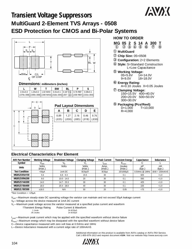
104
Additional information on this product is available from AVX’s catalog or AVX’s FAX Service.Call 1-800-879-1613 and request document #104. Visit our website http://www.avxcorp.com
L W T BW BL P S2.01±0.2 1.25±0.2 1.02 MAX 0.41±0.1 0.18 0.76 REF 0.38±0.1
(.079±.008) (.049±.008) (.040 MAX) (.016±.004) (.007 ) (.030 REF) (.015±.004)
VWM—Maximum steady-state DC operating voltage the varistor can maintain and not exceed 50µA leakage currentVB—Voltage across the device measured at 1mA DC currentVC—Maximum peak voltage across the varistor measured at a specified pulse current and waveform
†Transient Energy Rating Pulse Current & Waveform.1 Joule 2A 8/20µS
.05 Joules 1A 8/20µS
I peak—Maximum peak current which may be applied with the specified waveform without device failureETrans—Maximum energy which may be dissipated with the specified waveform without device failureC—Device capacitance measured with zero volt bias at 0.5Vrms and 1MHzL—Device inductance measured with a current edge rate of 100mA/nS
Transient Voltage SuppressorsMultiGuard 2-Element TVS Arrays - 0508ESD Protection for CMOS and Bi-Polar Systems
AVX Part Number Working Voltage Breakdown Voltage Clamping Voltage Peak Current Transient Energy Capacitance InductanceSymbol VWM VB VC Ipeak Etrans C L
Units Volts Volts Volts Amp. Joules pF nH(max.) (max.) (max.) (max.) (typ.) (typ.)
Test Condition <50µA 1mA DC 8/20µS† 8/20µs 10/1000µS 0.5Vrms @: 1MHz di/dt = 100mA/nS
MG052S05A150 5.6 6.8 - 9.3 15.5 30 0.1 825 <1.0
MG052S09A200 9.0 10.0 - 14.0 20 30 0.1 550 <1.0
MG052S14A300 14.0 14.7 - 20.3 30 30 0.1 425 <1.0
MG052S18A400 18.0 20.4 - 28.0 40 30 0.1 225 <1.0
MG052L18X500 ≤18.0 N/A 50 20 0.05 <75 <1.0
HOW TO ORDERMG 05 2 S 14 A 300 T1 2 3 4 5 6 7 81 MultiGuard2 Chip Size: 05=05083 Configuration: 2=2 Elements4 Style: S=Standard Construction
L=Low Capacitance5 Working Voltage:
05=5.6V 14=14.0V9=9.0V 18=18.0V
6 Energy Rating: A=0.10 Joules X=0.05 Joules
7 Clamping Voltage:150=15.5V 400=40.0V200=20.0V 500=50.0V300=30.0V
8 Packaging (Pcs/Reel):D=1,000 T=10,000 R=4,000
Dimensions: millimeters (inches)
Electrical Characteristics Per Element
*Test Condition = <25µA
A
B
C
D
E
Pad Layout Dimensions
+.010-.003
+0.25-0.08
A B C D E
0.89 1.27 2.16 0.46 0.76(.035) (.050) (.085) (.018) (.030)
BW C/LOF CHIPCL
T
L
PS S
WBL

105
Additional information on this product is available from AVX’s catalog or AVX’s FAX Service.Call 1-800-879-1613 and request document #105. Visit our website http://www.avxcorp.com
Transient Voltage SuppressorsMultiGuard 4-Element TVS Array - 0612
AVX Part Number Working Voltage Breakdown Voltage Clamping Voltage Peak Current Transient Energy Capacitance InductanceSymbol VWM VC VC Ipeak Etrans C IL
Units Volts Volts Volts Amp. Joules pF µ Amp(max.) (max.) (max.) (max.) (typ.) (max.)
Test Condition <50µA 1nA DC 8/20µS† 8/20µs 10/1000µS 0.5Vrms @: 1MHz @VWM
MG064S05A150 5.6 7.6 - 9.3 15.5 30 0.1 825 <1.0
MG064S09A200 9.0 11.0 - 14.0 20 30 0.1 550 <1.0
MG064S14A300 14.0 16.5 - 20.3 30 30 0.1 425 <1.0
MG064S18A400 18.0 22.9 - 28.0 40 30 0.1 220 <1.0
MG064L18X500 ≤18.0* N/A 50 30 0.05 <75 <1.0
HOW TO ORDERMG 06 4 S 14 A 300 T1 2 3 4 5 6 7 81 MultiGuard2 Chip Size: 06=06123 Configuration: 4=4 Elements4 Style: S=Standard Construction
L=Low Capacitance5 Working Voltage:
05=5.6V 14=14.0V09=9.0V 18=18.0V
6 Energy Rating: A=0.10 JoulesX=0.05 Joules
7 Clamping Voltage:150=15.5V 400=40.0V200=20.0V 500=50.0V300=30.0V
8 Packaging (Pcs/Reel):D=1,000R=4,000T=10,000
L W T BW BL P X S3.20±0.2 1.60±0.2 1.22 MAX 0.41±0.1 0.18+0.25 0.76 REF 1.14±0.1 0.38±0.1
(.126±.008) (.063±.008) (.048 MAX) (.016±.004) (.007+.010 ) (.030 REF) (.045±.004) (.015±.004)
Dimensions: millimeters (inches)
-0.08
-.003
VWM—Maximum steady-state DC operating voltage the varistor can maintain and not exceed 50µA leakage currentVB—Voltage across the device measured at 1mA DC currentVC—Maximum peak voltage across the varistor measured at a specified pulse current and waveform
†Transient Energy Rating Pulse Current & Waveform.1 Joule 2A 8/20µS
.05 Joules 1A 8/20µS
I peak—Maximum peak current which may be applied with the specified waveform without device failureETrans—Maximum energy which may be dissipated with the specified waveform without device failureC—Device capacitance measured with zero volt bias at 0.5Vrms and 1MHzL—Device inductance measured with a current edge rate of 100mA/nS
Electrical Characteristics Per Element
*Test Condition = <25µA
WBL
BW C/L OF CHIPCL
T
L
X X
PS S

106
Additional information on this product is available from AVX’s catalog or AVX’s FAX Service.Call 1-800-879-1613 and request document #106. Visit our website http://www.avxcorp.com
TransFeed 0805 Surface Mount ChipAVX-TVS Protection and EMI SuppressionWithin a Single SMT Component
Schematic Diagram Electrical ModelIN OUT IN LS LS
RV C RP
RON
LP
OUT
TransFeed Electrical Specifications
*Vc at 8x20µS @ 1A
Part Vc Ip Cap DCR FeedthruNumber Vwm Vb 8x20µS 8x20µS Il Et 1MHz Ohms Current
@ 2A
V2F105A150Y2E 5.6 7.6 - 9.3 15.5 30 <50 µA 0.1 800 0.200 750 mAV2F109A200Y2E 9.0 11.0 - 14.0 20.0 30 <40 µA 0.1 575 0.200 750 mAV2F114A300Y2E 14.0 16.5 - 20.3 30.0 30 <30 µA 0.1 300 0.200 750 mAV2F118A400Y2E 18.0 22.9 - 28.0 40.0 30 <25 µA 0.1 200 0.200 750 mAV2F118X500Y3D <18.0 N/A <50.0* 20 <10 µA 0.05 <100 0.250 500 mAV2F105C150Y1F 5.6 7.1 - 8.7 15.5 120 <50 µA 0.3 2500 0.150 1 AmpV2F109C200Y1F 9.0 10.5 - 13.5 20.0 120 <40 µA 0.3 1800 0.150 1 AmpV2F114C300Y1F 14.0 15.9 - 19.4 30.0 120 <30 µA 0.3 900 0.150 1 AmpV2F118C400Y1F 18.0 22.5 - 27.5 40.0 120 <25 µA 0.3 500 0.150 1 Amp
HOW TO ORDERV 2 F 1 05 A 150 Y 2 E D1 2 3 4 5 6 7 89 0 s1 Varistor2 Chip Size: 2=08053 Feedthru Capacitor4 Number of Elements5 Voltage: 05=5.6V 14=14V
09=9.0V 18=18V6 Energy Rating: X=0.05J
A=0.1JC=0.3J
7 Varistor Clamping Voltage:150=15.5V 500=50.0V200=20.0V 400=40.0V300=30.0V
8 Capacitance Tolerance:8=+50/-20% Y=+100/-50%
9 DC Resistance:1=.150 Ohms 4=.300 Ohms2=.200 Ohms 6=.600 Ohms3=.250 Ohms
0 Feedthru Current:D=500 mA, E=750 mA, F=1.0 Amp
s Packaging Code (Pcs/Reel):D=1,000R=4,000T=10,000
11
11
BW
T
SX
L
TP
INPUT OUTPUT
LC
P
S W
TP
INPUT OUTPUT
LC
P
S W
CL
EW
WBL
Size L W T BW BL EW X S0805 2.01±0.20 1.25±0.20 0.76±0.08 0.46±0.10 0.18+0.25-0.08 0.25±0.13 1.02±0.10 0.23±0.05
(.079±.008) (.049±.008) (.030±.003) (.018±.004) (.007+.010-.003) (.010±.005) (.040±.004) (.009±.002)
Dimensions: millimeters (inches)
Size T P S W L C0805 3.45 (0.136) 0.51 (0.020) 0.76 (0.030) 1.27 (0.050) 1.02 (0.040) 0.46 (0.018)
Recommended Solder Pad Layout (Typical Dimensions) millimeters (inches)
Note: It is only necessary to ground one centerterminal. However,AVX recommends thatboth side terminals beconnected.
4 Pad Layout 3 Pad Layout
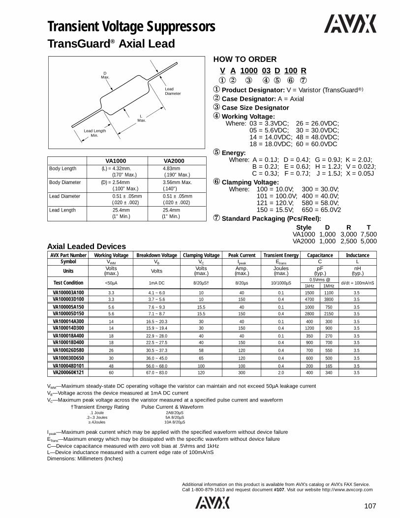
107
Additional information on this product is available from AVX’s catalog or AVX’s FAX Service.Call 1-800-879-1613 and request document #107. Visit our website http://www.avxcorp.com
DMax.
Max.L
Lead LengthMin.
LeadDiameter
Transient Voltage SuppressorsTransGuard® Axial Lead
HOW TO ORDERV A 1000 03 D 100 R1 2 3 4 5 6 71 Product Designator: V = Varistor (TransGuard®)
2 Case Designator: A = Axial3 Case Size Designator4Working Voltage:
Where: 03 = 3.3VDC; 26 = 26.0VDC;05 = 5.6VDC; 30 = 30.0VDC;14 = 14.0VDC; 48 = 48.0VDC;18 = 18.0VDC; 60 = 60.0VDC
5 Energy:Where: A = 0.1J; D = 0.4J; G = 0.9J; K = 2.0J;
B = 0.2J; E = 0.6J; H = 1.2J; V = 0.02J;C = 0.3J; F = 0.7J; J = 1.5J; X = 0.05J
6 Clamping Voltage: Where: 100 = 10.0V; 300 = 30.0V;
101 = 100.0V; 400 = 40.0V;121 = 120.V; 580 = 58.0V;150 = 15.5V; 650 = 65.0V2
7 Standard Packaging (Pcs/Reel):Style D R T
VA1000 1,000 3,000 7,500VA2000 1,000 2,500 5,000
VA1000 VA2000Body Length (L) = 4.32mm. 4.83mm
(170" Max.) (.190" Max.)Body Diameter (D) = 2.54mm 3.56mm Max.
(.100" Max.) (.140")Lead Diameter 0.51 ± .05mm 0.51 ± .05mm
(.020 ± .002) (.020 ± .002)Lead Length 25.4mm 25.4mm
(1" Min.) (1" Min.)
AVX Part Number Working Voltage Breakdown Voltage Clamping Voltage Peak Current Transient Energy Capacitance InductanceSymbol VWM VB VC Ipeak Etrans C L
Units Volts Volts Volts Amp. Joules pF nH(max.) (max.) (max.) (max.) (typ.) (typ.)
Test Condition <50µA 1mA DC 8/20µS† 8/20µs 10/1000µS0.5Vrms @:
di/dt = 100mA/nS1kHz 1MHz
VA100003A100 3.3 4.1 ~ 6.0 10 40 0.1 1500 1100 3.5VA100003D100 3.3 3.7 ~ 5.6 10 150 0.4 4700 3800 3.5
VA100005A150 5.6 7.6 ~ 9.3 15.5 40 0.1 1000 750 3.5VA100005D150 5.6 7.1 ~ 8.7 15.5 150 0.4 2800 2150 3.5
VA100014A300 14 16.5 ~ 20.3 30 40 0.1 400 300 3.5VA100014D300 14 15.9 ~ 19.4 30 150 0.4 1200 900 3.5
VA100018A400 18 22.9 ~ 28.0 40 40 0.1 350 270 3.5VA100018D400 18 22.5 ~ 27.5 40 150 0.4 900 700 3.5
VA100026D580 26 30.5 ~ 37.3 58 120 0.4 700 550 3.5
VA100030D650 30 36.0 ~ 45.0 65 120 0.4 600 500 3.5
VA100048D101 48 56.0 ~ 68.0 100 100 0.4 200 165 3.5VA200060K121 60 67.0 ~ 83.0 120 300 2.0 400 340 3.5
Axial Leaded Devices
VWM—Maximum steady-state DC operating voltage the varistor can maintain and not exceed 50µA leakage currentVB—Voltage across the device measured at 1mA DC currentVC—Maximum peak voltage across the varistor measured at a specified pulse current and waveform
†Transient Energy Rating Pulse Current & Waveform.1 Joule 2A8/20µS
.2–.3 Joules 5A 8/20µS≥.4Joules 10A 8/20µS
I peak—Maximum peak current which may be applied with the specified waveform without device failureETrans—Maximum energy which may be dissipated with the specific waveform without device failureC—Device capacitance measured with zero volt bias at .5Vrms and 1kHzL—Device inductance measured with a current edge rate of 100mA/nSDimensions: Millimeters (Inches)

108
Additional information on this product is available from AVX’s catalog or AVX’s FAX Service.Call 1-800-879-1613 and request document #108. Visit our website http://www.avxcorp.com
E
D t
30 (1
.18)
min
H
Zinc Oxide VaristorsVE/VF Types – General Application (“M” Series)
HOW TO ORDERVE 09 M 0 0251 K DB1 2 3 4 5 6 71 Type Code:
VE = Selection by working voltageVF = Selection by breakdown voltage
2 Size Code:VE Series: 07, 09, 13, 17, 24VF Series: 05, 07, 10, 14, 20
3 Material Code:M = Standard
4 Voltage Marking Code:0 = VE Series1 = VF Series
5 Voltage Code:VE Series: 1st digit: zero. 2nd & 3rd digit: 2significant figures of working voltage. 4th digit:number of significant zeros to be added.Example: 0750 = 75 V, 0301 = 300 VVF Series: 1st, 2nd & 3rd digits: significant fig-ures of breakdown voltage. 4th digit: numberof significant zeros to be added.Example: 2050 = 205 V
6 Tolerance Code:K = ±10% (contact factory for ±5%)
7 Packaging Code:Please refer to fall catalog
* VE13 / VF10: For models with VRMS ≤ 320 Vother version/suffixes available with:E = 5.08 (0.20) Suffix:Ø = 0.6 (.024) Bulk: HBD = 12.5 (.492) max Tape: DA, DB, DC,
DD, DQ, ...
DMaximum ø
Type Type Ceramic coated H +10% Ediameter diameter max. –0.05 (.002) ± 0.8 (.031)
VE07 VF05 5 (.196) 7 (.275) 10 (.394) 0.6 (.024) 5.08 (0.20)VE09 VF07 7 (.275) 9 (.354) 12 (.472) 0.6 (.024) 5.08 (0.20)VE13* VF10* 10 (.393) 13* (.512) 16 (.630) 0.8* (.031) 7.62* (0.30)VE17 VF14 14 (.551) 17 (.669) 20 (.787) 0.8 (.031) 7.62 (0.30)VE24 VF20 20 (.787) 24 (.945) 27 (1.06) 0.8** (.031) 7.62 (0.30)
Dimensions millimeters (inches)
Operating Breakdown Clamping Energy Max. Peak Typical MeanStyle Voltage Voltage Voltage Absorption Current Capacitance Power
Vrms 1mAdc (J) 1p (A) pF@1kHz Dissipation(W)
VE07 14 min. 22 min. 43 min. 0.3 min. 100 min. 40 min. 0.01 min.VF05 to 300 max. to 470 max. to 775 max. to 9.0 max. to 400 max. to 1050 max. to 0.10 max.VE09 14 min. 22 min. 43 min. 0.9 min. 250 min. 80 min. 0.02 min.VF07 to 420 max. to 680 max. to 1720 max. to 25.0 max. to 1200 max. to 1900 max. to 0.20 max.VE13 14 min. 22 min. 43 min. 2.0 min. 500 min. 74 min. 0.05 min.VF10 to 625 max. to 1000 max. to 1650 max. to 68.0 max. to 2500 max. to 4000 max. to 0.40 max.VE17 14 min. 22 min. 43 min. 4.0 min. 1000 min. 165 min. 0.10 min.VF14 to 625 max. to 1000 max. to 1650 max. to 130.0 max. to 4500 max. to 4000 max. to 0.60 max.VE24 75 min. 120 min. 200 min. 40.0 min. 410 min.VF20 to 625 max. to 1000 max. to 1650 max. to 230.0 max.
6500 max.to 4200 max.
0.80 max.
“M” Series Range Capability Dimensions: millimeters (inches)
NB: VE Series - Allows ordering code to be built by specifying operating voltage.VF Series - Allows ordering code to be built by specifying breakdown voltage.

109
Additional information on this product is available fromAVX’s catalog or AVX’s FAX Service. Call 1-800-879-1613and request document #109. Visit our websitehttp://www.avxcorp.com
Type Bulk AMMOPACK REELVE07 - VF05 all 1500 1500 1500
VE09 - VF07 < 230 Vrms 1000 1500 1500
VE09 - VF07 230 V ≤ Vrms ≤ 300 V 1000 1000 1000
VE09 - VF07 > 300 Vrms 750 1000 1000VE13 - VF10 ≤ 230 Vrms 500 750 750
VE13 - VF10 230 V ≤ Vrms ≤ 300 V 500 500 500
VE13 - VF10 > 300 Vrms 500 — —
VE17 - VF14 ≤ 230 Vrms 500 750 750
VE17 - VF14 230 V ≤ Vrms ≤ 300 V 500 500 500
VE17 - VF14 > 300 Vrms 500 — —
VE24 - VF20 250 — —
0.6 (.024)
5.08 (0.2)
0.6 (.024)
5.08 (0.2)
0.6 (.024)
5.08 (0.2)
E
D t
30 (1
.18)
min
H
DMaximum ø
Type Type Ceramic coated H t +10% Ediameter diameter max. max. –0.05 (.002) ± 0.8
VE07 VF05 5 (.196) 7 (.275) 10 (.394) 0.6 (.024) 5.08 (0.20)VE09 VF07 7 (.275) 9 (.354) 12 (.472) see 0.6 (.024) 5.08 (0.20)VE13* VF10* 10 (.393) 13* (.512) 16 (.630) table 0.8* (.031) 7.62* (0.30)VE17 VF14 14 (.551) 17 (.669) 20 (.787) 0.8 (.031) 7.62 (0.30)VE24** VF20** 20 (.787) 24 (.945) 27 (1.06) 0.8** (.031) 7.62 (0.30)
Dimensions millimeters (inches)
Zinc Oxide VaristorsVE/VF Types for Heavy Duty Applications (“P” Series)
HOW TO ORDERVE 09 P 0 0251 K DB1 2 3 4 5 6 71 Type Code:
VE = Selection by working voltageVF = Selection by breakdown voltage
2 Size Code:VE Series: 07, 09, 13, 17, 24VF Series: 05, 07, 10, 14, 20
3 Material Code:P = Power Series
4 Voltage Marking Code:0 = VE Series1 = VF Series
5 Voltage Code:VE Series: 1st digit: zero. 2nd & 3rd digit:2 significant figures of working voltage. 4thdigit: number of significant zeros to be added.Example: 0750 = 75 V, 0301 = 300 VVF Series: 1st, 2nd & 3rd digits: significant figures of breakdown voltage. 4th digit: numberof significant zeros to be added.Example: 2050 = 205 V
6 Tolerance Code:K = ±10% (contact factory for ±5%)
7 Packaging Code:Please refer to fall catalog
* VE13 / VF10: For models with VRMS ≤ 320 Vother version/suffixes available with:E = 5.08 (0.20) Suffix:Ø = 0.6 (.024) Bulk: HBD = 12.5 (.492) max Tape: DA, DB, DC,
DD, DQ, ...**VE24 / VF20: For lead diameter = 1.0 (.039),
please consult us.
Types VE 07/09 - VF 05/07 (VE13 - VF10 320 Vrms upon request)
Leads Straight Kinked (type 1) Kinked (type 2)
Packaging AMMOPACK REEL AMMOPACK REEL AMMOPACK REEL
H/Ho = 16 ± 0.5 DA(*) DB(*) DQ(**) DR(**) D7(**) D5(**)
H/Ho = 18 -0/+2 DC(**) DD(**) DS DT D8 D6
Types VE 13/17 - VF 10/14
Leads Straight Kinked (type 1) Kinked (type 2)
Packaging AMMOPACK REEL AMMOPACK REEL AMMOPACK REEL
H/Ho = 16 ± 0.5 EA(*) EN(*) EC(**) EF(**) EQ(**) ER(**)
H/Ho = 18 -0/+2 EB(**) ED(**) EG EH ES ET
0.8 (.031)
7.62 (0.3)
0.8 (.031)
7.62 (0.3)
0.8 (.031)
7.62 (0.3)
(*) DA, DB, EA, EN suffixes are not available for varistors with VRMS 300V andavailable only upon request. (**) Preferred versions according to IEC 286-2
Operating Breakdown Clamping Energy Max. Peak Typical MeanStyle Voltage Voltage Voltage Absorption Current Capacitance Power
Vrms 1mAdc (J) 1p (A) pF@1kHz Dissipation(W)
VE07 130 min. 205 min. 340 min. 8.5 min. 800 90 min. 0.01VF05 to 230 max. to 360 max. to 595 max. to 16 max. to 55 max.VE09 130 min. 205 min. 340 min. 17.5 min. 250 min. 0.02VF07 to 230 max. to 360 max. to 595 max. to 32 max. 1750 to 140 max.VE13 130 min. 205 min. 340 min. 35 min. 450 min.VF10 to 230 max. to 360 max. to 595 max. to 65 max. 3500 to 250 max. 0.40VE17 130 min. 205 min. 340 min. 70 min. 1000 min.VF14 to 230 max. to 360 max. to 595 max. to 130 max. 6000 to 550 max. 0.60VE24 130 min. 205 min. 340 min. 140 min. 2500 min.VF20 to 230 max. to 360 max. to 595 max. to 250 max. 10,000 to 1500 max. 0.80
“P” Series Range Capability Dimensions: millimeters (inches)
NB: VE Series - Allows ordering code to be built by specifying operating voltage.VF Series - Allows ordering code to be built by specifying breakdown voltage.
Dimensions
Dimensions
Packaging Quantities
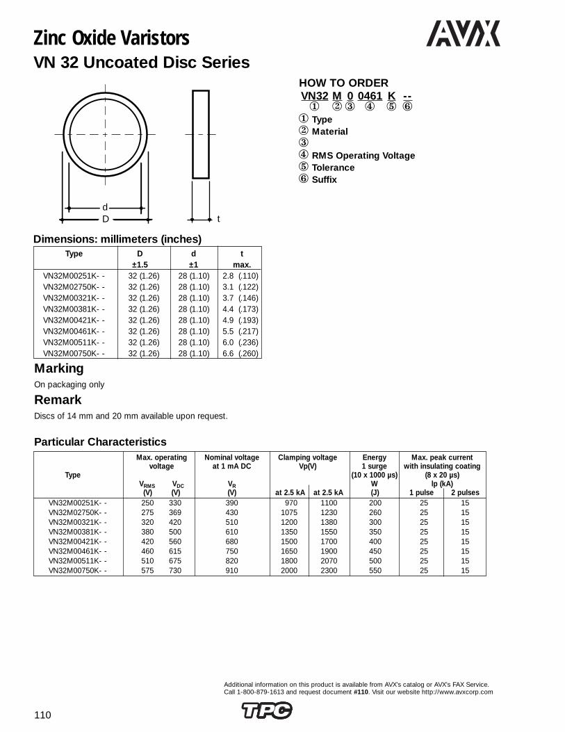
110
Additional information on this product is available from AVX’s catalog or AVX’s FAX Service.Call 1-800-879-1613 and request document #110. Visit our website http://www.avxcorp.com
dD t
Zinc Oxide VaristorsVN 32 Uncoated Disc Series
HOW TO ORDERVN32 M 0 0461 K --1 2 3 4 5 61 Type2 Material34 RMS Operating Voltage5 Tolerance6 Suffix
Max. operating Nominal voltage Clamping voltage Energy Max. peak currentvoltage at 1 mA DC Vp(V) 1 surge with insulating coating
Type (10 x 1000 µs) (8 x 20 µs)VRMS VDC VR W lp (kA)
(V) (V) (V) at 2.5 kA at 2.5 kA (J) 1 pulse 2 pulsesVN32M00251K- - 250 330 390 970 1100 200 25 15VN32M02750K- - 275 369 430 1075 1230 260 25 15VN32M00321K- - 320 420 510 1200 1380 300 25 15VN32M00381K- - 380 500 610 1350 1550 350 25 15VN32M00421K- - 420 560 680 1500 1700 400 25 15VN32M00461K- - 460 615 750 1650 1900 450 25 15VN32M00511K- - 510 675 820 1800 2070 500 25 15VN32M00750K- - 575 730 910 2000 2300 550 25 15
MarkingOn packaging only
RemarkDiscs of 14 mm and 20 mm available upon request.
Particular Characteristics
Type D d t±1.5 ±1 max.
VN32M00251K- - 32 (1.26) 28 (1.10) 2.8 (.110)VN32M02750K- - 32 (1.26) 28 (1.10) 3.1 (.122)VN32M00321K- - 32 (1.26) 28 (1.10) 3.7 (.146)VN32M00381K- - 32 (1.26) 28 (1.10) 4.4 (.173)VN32M00421K- - 32 (1.26) 28 (1.10) 4.9 (.193)VN32M00461K- - 32 (1.26) 28 (1.10) 5.5 (.217)VN32M00511K- - 32 (1.26) 28 (1.10) 6.0 (.236)VN32M00750K- - 32 (1.26) 28 (1.10) 6.6 (.260)
Dimensions: millimeters (inches)

111
Additional information on this product is available from AVX’s catalog or AVX’s FAX Service.Call 1-800-879-1613 and request document #111. Visit our website http://www.avxcorp.com
20 (.787)
~ 40 (1
.57)
o 5.1 (.201)
20 (.787)
44 (1.73)
15...45°
54 (2
.13)
44 (1
.73)
24 (.
945)
5 (.197)
5 (.197)
Zinc Oxide VaristorsVB 32 Blocks
HOW TO ORDERVB32 M 0 0421 K --1 2 3 4 5 61 Type2 Material34 RMS Operating Voltage5 Tolerance6 Suffix
PackagingBulk or three units per box (one for each phase)
MarkingTypeAC nominal voltage (EIA code)Logo
Max. operating Nominal voltage Clamping voltage Energy Max. peak currentvoltage at 1 mA DC at 2.5 kA 1 surge with insulating coating
Type (10 x 1000 µs) (8 x 20 µs)VRMS VDC VR Vp W lp (kA)
(V) (V) (V) (V) (J) 1 pulse 2 pulsesVB32M00251K- - 250 330 390 970 200 25 15VB32M02750K- - 275 369 430 1075 260 25 15VB32M00321K- - 320 420 510 1200 300 25 15VB32M00381K- - 380 500 610 1350 350 25 15VB32M00421K- - 420 560 680 1500 400 25 15VB32M00461K- - 460 615 750 1650 450 25 15VB32M00511K- - 510 675 820 1800 500 25 15VB32M00750K- - 575 730 910 2000 550 25 15
Particular Characteristics
Dimensions millimeters (inches)
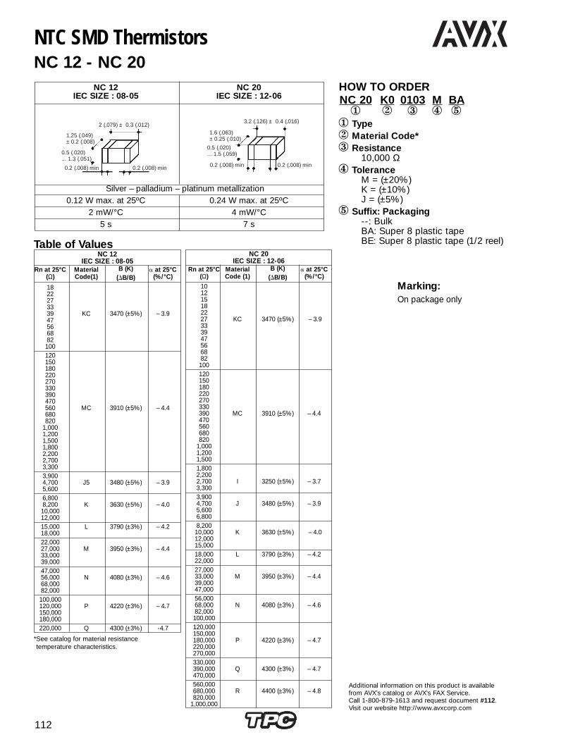
112
Additional information on this product is availablefrom AVX’s catalog or AVX’s FAX Service. Call 1-800-879-1613 and request document #112.Visit our website http://www.avxcorp.com
NTC SMD ThermistorsNC 12 - NC 20
HOW TO ORDERNC 20 K0 0103 M BA1 2 3 4 5
1 Type2 Material Code*3 Resistance
10,000 Ω4 Tolerance
M = (±20%)K = (±10%)J = (±5%)
5 Suffix: Packaging--: BulkBA: Super 8 plastic tapeBE: Super 8 plastic tape (1/2 reel)
NC 12 NC 20IEC SIZE : 08-05 IEC SIZE : 12-06
Silver – palladium – platinum metallization0.12 W max. at 25ºC 0.24 W max. at 25ºC
2 mW/°C 4 mW/°C5 s 7 s
2 (.079) ± 0.3 (.012)
1.25 (.049)± 0.2 (.008)
0.5 (.020)... 1.3 (.051)
0.2 (.008) min 0.2 (.008) min
3.2 (.126) ± 0.4 (.016)
0.2 (.008) min 0.2 (.008) min
1.6 (.063)± 0.25 (.010)
0.5 (.020)... 1.5 (.059)
Marking:On package only
NC 12IEC SIZE : 08-05
Rn at 25°C Material B (K) a at 25°C(Ω) Code(1) (DB/B) (%/°C)
1822273339 KC 3470 (±5%) – 3.947566882100120150180220270330390470560 MC 3910 (±5%) – 4.4680820
1,0001,2001,5001,8002,2002,7003,3003,9004,700 J5 3480 (±5%) – 3.95,6006,8008,200 K 3630 (±5%) – 4.010,00012,00015,000 L 3790 (±3%) – 4.218,00022,00027,000 M 3950 (±3%) – 4.433,00039,00047,00056,000 N 4080 (±3%) – 4.668,00082,000100,000120,000 P 4220 (±3%) – 4.7150,000180,000220,000 Q 4300 (±3%) -4.7
Table of Values
*See catalog for material resistance temperature characteristics.
NC 20IEC SIZE : 12-06
Rn at 25°C Material B (K) a at 25°C(Ω) Code (1) (DB/B) (%/°C)
101215182227 KC 3470 (±5%) – 3.9333947566882100120150180220270330390 MC 3910 (±5%) – 4.4470560680820
1,0001,2001,5001,8002,2002,700 I 3250 (±5%) – 3.73,3003,9004,700 J 3480 (±5%) – 3.95,6006,8008,20010,000 K 3630 (±5%) – 4.012,00015,00018,000 L 3790 (±3%) – 4.222,00027,00033,000 M 3950 (±3%) – 4.439,00047,00056,00068,000 N 4080 (±3%) – 4.682,000100,000120,000150,000180,000 P 4220 (±3%) – 4.7220,000270,000330,000390,000 Q 4300 (±3%) – 4.7470,000560,000680,000 R 4400 (±3%) – 4.8820,000
1,000,000

113
Additional information on this product is available from AVX’s catalog or AVX’s FAX Service.Call 1-800-879-1613 and request document #113. Visit our website http://www.avxcorp.com
NB 21IEC SIZE : 06-03
Rn at 25°C Material B (K) a at 25°C(Ω) Code (1) (DB/B ) (%/°C)
4,700 PC 4200 (1) – 4.7
10,000 J5 3480 (1) – 3.9
15,000 K 3630 (2) – 4.0
22,000 L 3790 (2) – 4.2
47,000 M 3950 (2) – 4.4
100,000 N5 4160 (2) – 4.7
150,000 P 4220 (2) – 4.7
NTC SMD ThermistorsWith Nickel Barrier Termination NB 12 - NB 20 - NB 21
HOW TO ORDERNB 20 K0 0103 M BA1 2 3 4 5
1 Type2 Material Code*3 Resistance
10,000 Ω4 Tolerance
M = (±20%)K = (±10%)J = (±5%)
5 Suffix: Packaging--: BulkBA: Super 8 plastic tapeBE: Super 8 plastic tape (1/2 reel)
NB 21 NB 12 NB 20IEC SIZE : 06-03 IEC SIZE : 08-05 IEC SIZE : 12-06
Nickel Barrier
0.07 W max. at 25ºC 0.12 W max. at 25ºC 0.24 W max. at 25ºC
1 mW/°C 2 mW/°C 4 mW/°C4 s 5 s 7s
1.6 (.063) ± 0.2 (.008)
0.8 (.031)± 0.2 (.008)
0.2 (.008) min 0.2 (.008) min
2 (.079) ± 0.3 (.012)
1.25 (.049)± 0.2 (.008)
0.5 (.020)... 1.3 (.051)
0.2 (.008) min 0.2 (.008) min
3.2 (.126) ± 0.4 (.016)
0.2 (.008) min 0.2 (.008) min
1.6 (.063)± 0.25 (.010)
0.5 (.020)... 1.5 (.059)
NB 20IEC SIZE : 12-06
Rn at 25°C Material B (K) a at 25°C(Ω) Code (1) (DB/B ) (%/°C)
4,700 J 3480 (1) – 3.95,6006,800 3480 (2) – 3.98,200
10,000 K 3630 (1) – 4.012,000
15,00018,000 L 3790 (2) – 4.222,000
27,00033,000 M 3950 (2) – 4.439,00047,000
56,00068,000 N 4080 (2) – 4.682,000
100,000 N5 4160 (2) -4.7
120,000150,000 P 4220 (2) – 4.7180,000220,000
270,000330,000 Q 4300 (2) – 4.7390,000470,000560,000
680,000820,000 R 4400 (2) – 4.8
1,000,000
(1) ± 5%(2) ± 3%
NB 12IEC SIZE : 08-05
Rn at 25°C Material B (K) a at 25°C(Ω) Code (1) (DB/B ) (%/°C)
1822273339 KC 3470 (1) – 3.947566882100
120150180220270330390470560 MC 3910 (1) – 4.4680820
1,0001,2001,5001,8002,2002,7003,300
3,9004,700 J 3480 (1) – 3.95,600
6,8008,200 K 3630 (1) – 4.010,000
12,00015,000 L 3790 (2) – 4.2
18,00022,00027,000 M 3950 (2) – 4.433,000
39,00047,000 N 4080 (2) – 4.656,000
68,00082,000 N5 4160 (2) -4.7
100,000120,000 P 4220 (2) – 4.7150,000180,000
(1) ± 5%(2) ± 3%
Table of Values
(1) ± 5%(2) ± 3%
*See catalog for material resistance temperaturecharacteristics.

114
Additional information on this product is available from AVX’s catalog or AVX’s FAX Service.Call 1-800-879-1613 and request document #114. Visit our website http://www.avxcorp.com
NTC Disc ThermistorsAccurate: NJ 28 - NI 28 - NK 20
HOW TO ORDERNJ28 NA 0103 F --1 2 3 4
1 TypeNJ = Accurate non-insulated leadsNI = Accurate insulated leadsNK = Accurate Chip
2 Material Code*3 Resistance
10 kΩ4 Tolerance
K = 1%(See Table)
ACCURATE
NJ 28 NI 28 NK 20
Coated chip with phenolic Coated chip with epoxy Chipresin + varnish insulated leads
±1%, ±2%, ±3%
0.16 W
3 mW/°C 3 mW/°C 2 mW/°C
8 s 8 s 6 s
< 2 s
ACCURATE
Rn at 25°C (Ω) Material Code B (K) a at 25°C (%/°C)
2,000 KA 3625 ± 1% – 4.1
3,000 MA 3960 ± 0.5% – 4.5
5,000 MA 3960 ± 0.5% – 4.5
10,000 NA 4100 ± 1% – 4.6
20,000 PA 4235 ± 1% – 4.8
50,000 QA 4250 ± 1% – 4.8
100,000 RA 4380 ± 1% – 4.9
2.8 (.110) max 2.8 (.110) max
35 (1
.38)
min
3 (.1
18) m
ax
0.4 (.016) +10 % - 0.06
2.8 (.110) max
.....0.25 (.010)min
2.8 (.110) max
35 (1
.38)
min
3 (.1
18) m
ax
0.4 (.016) +10 % - 0.06
0.75
(.03
0) ±
0.2
5 (.0
10)
1.75 (.069) ± 0.25 (0.10)
1.75
(.06
9)
± 0.2
5 (0
.10)
GENERAL PURPOSERn at Material B (K) a at 25°C
25°C (Ω) Code (∆B/B ) (%/°C)4768
F 2800 (1) – 3.2
100150
G 3030 (1) – 3.4
220 H 3160 (1) – 3.5330470
I 3250 (1) – 3.7
6801,000
J 3480 (1) – 3.9
1,5002,200
K 3630 (1) – 4.0
3,300 L 3790 (2) – 4.24,7006,800
M 3950 (2) – 4.4
10,00015,000
N 4080 (2) – 4.6
22,00033,000
P 4220 (2) – 4.7
47,00068,000
Q 4300 (2) – 4.7
100,000150,000
R 4400 (2) – 4.8
220,000 S 4520 (2) – 5.0330,000
T 4630 (2) – 5.1470,0001,000,000 U 4840 (2) – 5.3
(1) ± 5%(2) ± 3%
Table of Values
*See catalog for material resistance temperature characteristics.

115
Additional information on this product is available from AVX’s catalog or AVX’s FAX Service.Call 1-800-879-1613 and request document #115. Visit our website http://www.avxcorp.com
Rn at 25°C (Ω) Material CodeB (K)
a at 25°C (%/°C)(∆B/B )
4768
F 2800 (1) – 3.2
100150
G 3030 (1) – 3.4
220 H 3160 (1) – 3.5330470
I 3250 (1) – 3.7
6801,000
J 3480 (1) – 3.9
1,5002,200
K 3630 (1) – 4.0
3,300 L 3790 (2) – 4.24,7006,800
M 3950 (2) – 4.4
10,00015,000
N 4080 (2) – 4.6
22,00033,000
P 4220 (2) – 4.7
47,00068,000
Q 4300 (2) – 4.7
100,000150,000
R 4400 (2) – 4.8
220,000 S 4520 (2) – 5.0330,000
T 4630 (2) – 5.1470,0001,000,000 U 4840 (2) – 5.3
NTC Disc ThermistorsGeneral Purpose: ND 03 / ND 06 / ND 09
HOW TO ORDERND 06 P0 0103 K --1 2 3 4
1 TypeND 03 = General PurposeND 06 = General PurposeND 09 = General Purpose
2 Material Code*3 Resistance
10 kΩ4 Tolerance
K = (±10%)
Rn at 25°C (Ω) Material CodeB (K)
a at 25°C (%/°C)(∆B/B )
10 F 2800 (1) – 3.215
22 G 3030 (1) – 3.433
47 H 3160 (1) – 3.568
100 I 3250 (1) – 3.7150220
J 3480 (1) – 3.9
330470
K 3630 (1) – 4.0
680L 3790 (2) – 4.21,000
1,500 M 3950 (2) – 4.42,2003,300
N 4080 (2) – 4.6
4,7006,800 P 4220 (2) – 4.7
10,00015,000
Q 4300 (2) – 4.722,00033,000 R 4400 (2) – 4.847,000
S 4520 (2) – 5.068,000100,000 T 4630 (2) – 5.1150,000
Rn at 25°C (Ω) Material CodeB (K)
a at 25°C (%/°C)(∆B/B )
68 J 3480 (1) – 3.9100
150 K 3630 (1) – 4.0220
330 L 3790 (2) – 4.2470
M 3950 (2) – 4.46801,000
N 4080 (2) – 4.61,5002,2003,300
P 4220 (2) – 4.7
4,700 Q 4300 (2) – 4.76,800
10,000 R 4400 (2) – 4.815,000
22,000 S 4520 (2) – 5.033,000
T 4630 (2) – 5.1 47,00068,000
100,000 U 4840 (2) – 5.3150,000
(1) ± 5%(2) ± 3%
(1) ± 5%(2) ± 3%
(1) ± 5%(2) ± 3%
Table of ValuesND 03 ND 06 ND 09
35 (.
138)
min
( ) ( )
ø 0.6 (.024) +10%-0.05
5.08 (.02)
3 (.1
18) m
ax
D Max T MaxND 03 3.5 (.138) 3.0 (.118)ND 06 6.0 (.236) 4.0 (.157)ND 09 9.5 (.375) 5.0 (.197)
D T
Dimensions: mm (inches)
*See catalog for material resistance temperature characteristics.
GENERAL PURPOSETypes ND 03 ND 06 ND 09
Finish Coated disc with phenolic resin Coated disc with phenolic resin Coated disc with phenolic resinStandards
Marking On package only Nominal resistance Tolerance for ±5%, ±10% Nominal resistance Tolerance for ±5%, ±10%Climatic category – – –Operating temperature -55°C to +150°C -55°C to +150°C-55°C to +150°C -55°C to +150°CTolerance on Rn (25°C) 47Ω to 1MΩ: ±5%, ±10%, ±20% ±5%, ±10%, ±20% ±5%, ±10%, ±20%
1500Ω to 150 kΩ: ±3%Maximum dissipation at 25°C 0.25 W 0.71 W 0.9 WThermal dissipation factor 5 mW/°C 7.1 mW/°C 9 mW/°CThermal time constant 10 s 22 s 30 s

116
Additional information on this product is available from AVX’s catalog or AVX’s FAX Service.Call 1-800-879-1613 and request document #116. Visit our website http://www.avxcorp.com
NTC ThermistorsInsulated Metal Case NM 06
HOW TO ORDERNM 06 P0 0103 M --1 2 3 4
1 Type
2 Material CodeP(See table below)
3 Resistance10 kΩ
4 ToleranceM = (±20%)K = (±10%)
HOW TO ORDERNR55 - - 3002 - 991 2
1 Type
Types NR
Physical data (dim. in mm)
Marking On package only / On parts upon requestOperating temperature -40°C to +200°C
Custom - designed products defined with:Values and tolerances D ± ∆D-R1 ± ∆R1/R1 at T1
E ± ∆E R2 ± ∆R2/R2 at T2, . . .
Type NM 06
Finish Disc thermistor, insulated metalcase for chassis mounting
DIMENSIONS: millimeters (inches)
Marking Nominal resistanceTolerance for ±10%
Operating temperature -55°C to +150°C
Tolerance on Rn (25°C) ±10% ±20%
0.8 W - without heat sink
Maximum dissipation at 25°C 2 W - with heat sinkPart mounted in the center of a brass plate
(dim.: 100 x 100 x 1 mm)
Thermal dissipation factor* 8 mW/°C: without heat sink20 mW/°C: with heat sink
Thermal time constant Depending on cooling system
Test voltage to earth 380 Vrms (50 Hz)
2.5
(.098
) ± 1
(ISO
) ø 4
35 (.138)min
12.6 (.496)max
ø 0.
6 (.0
24) +
10%
- 0.
05
5.5 (.216) ± 0.110 (.394) ± 0.1
*Typical value
Rn at 25°CMaterial Code
B (K)α at 25°C (%/°C)(Ω)
10 F 2800 (1) – 3.2152233
G 3030 (1) – 3.4
4768
H 3160 (1) – 3.5
100 I 3250 (1) – 3.7150220
J 3480 (1) – 3.9
330470
K 3630 (1) – 4.0
6801,000
L 3790 (2) – 4.2
1,500 M 3950 (2) – 4.42,2003,300
N 4080 (2) – 4.6
4,7006,800 P 4220 (2) – 4.7
10,00015,00022,000
Q 4300 (2) – 4.7
33,000 R 4400 (2) – 4.847,00068,000
S 4520 (2) – 5.0
100,000 T 4630 (2) – 5.1150,000220,000 U 4840 (2) – 5.3330,000
∆B/B( )
This type canbe deliveredwith fixing nut,add suffix WCto the reference.
(1) ±5%(2) ±3%
D
Metallization
E
NTC LeadlessDisc Thermistors
Types D E Material B R1 ± DR1 T1 R2 ± DR2 T2 R3 ± DR3 T3Code (k) at T1 (°C) at T2 (°C) at T3 (°C)
NR 55 -- 3002 - 99 5.5 (.217) ± 0.5 (.020) 1.1 (.043) ± 0.4 (.016) N5 4160 1230 Ω ± 7.5% 40 160 Ω ± 5% 96.5 – –NR 67 -- 3068 - 99 6.7 (.264) ± 0.5 (.020) 1.7 (.067) ± 0.3 (.012) N 4080 150 Ω ± 3.3% 100 51 Ω ± 5.3% 140 – –NR 55 -- 3049 - 99 5.5 (.217) ± 0.5 (.020) 1.0 (.040) ± 0.2 (.008) N5 4160 107 Ω ± 2.9% 110 80.6 Ω ± 2.8% 120 – –NR 55 -- 3046 - 99 5.5 (.217) ± 0.5 (.020) 1.3 (.051) ± 0.4 (.016) S 4520 48600 Ω± 7.5% 25 3210 Ω ± 5% 90 – –NR 49 -- 3119 - 99 4.9 (.193) ± 0.3 (.012) 1.5 (.060) ± 0.4 (.016) M 3950 840 Ω ± 10% 37.8 84 Ω ± 5% 104.4 – –NR 55 -- 3114 - 99 5.5 (.217) ± 0.4 (.016) 1.0 (.040) ± 0.2 (.008) P 4220 5000 Ω ± 10% 25 – – – –NR 70 -- 3121 - 99 7.0 (.275) ± 0.3 (.012) 1.2 (.047) ± 0.2 (.008) L 3790 210 Ω ± 10% 40 40 Ω ± 7.5% 90 30 Ω ± 6.7% 100NR 29 -- 3107 - 99 2.9 (.014) ± 0.3 (.012) 1.5 (.060) ± 0.3 (.012) K 3630 2050 Ω ± 6% 25 193 Ω ± 5.4% 96.5 – –NR 55 -- 3122 - 99 5.5 (.217) ± 0.5 (.020) 1.5 (.060) ± 0.4 (.016) J 3480 210 Ω ± 5% 25 – – – –NR 55 -- 3126 - 99 5.5 (.217) ± 0.5 (.020) 1.0 (.040) ± 0.2 (.008) P 4220 3340 Ω ± 10% 25 264 Ω ± 7% 90 107 Ω ± 7% 120NR 47 -- 3116 - 99 4.7 (.185) ± 0.4 (.016) 1.2 (.047) ± 0.2 (.008) R 4400 33000 Ω ± 2% 25 – – – –NR 49 -- 3113 - 99 4.9 (.193) ± 0.3 (.012) 1.2 (.047) ± 0.2 (.008) N 4080 1680 Ω ± 10% 40 382 Ω ± 6.7% 80 176 Ω ± 5% 105NR 47 -- 3101 - 99 4.6 (.181) ± 0.3 (.012) 1.4 (.055) ± 0.3 (.012) J 3480 146 Ω ± 13% 40 22 Ω ± 10% 100 – –NR 55 -- 3071 - 99 5.8 (.228) ± 0.3 (.012) 1.0 (.040) ± 0.2 (.008) L 3790 262 Ω ± 8.7% 40 120 Ω ± 10% 60 35.5 Ω ± 7.8% 100NR 61 -- 3063 - 99 6.1 (.240) ± 0.3 (.012) 1.5 (.060) ± 0.3 (.012) N 4080 760 Ω ± 9.2% 50 130 Ω ± 8.5% 100 56.6 Ω ± 8.5% 130NR 67 -- 3053 - 99 6.7 (.264) ± 0.4 (.016) 1.7 (.067) ± 0.3 (.012) N 4080 540 Ω ± 11% 60 144 Ω ± 7% 100 – –NR 50 -- 3048 - 99 5.0 (.197) ± 0.5 (.020) 1.5 (.060) ± 0.5 (.020) J 3480 233 Ω ± 10% 25 13.3 Ω ± 7% 121 – –NR 60 -- 3021 - 99 6.0 (.236) ± 0.5 (.020) 3.2 (.125) ± 0.3 (.012) P 4220 3640 Ω ± 3% 40 457 Ω ± 3% 96.5 – –NR 55 -- 3016 - 99 5.5 (.217) ± 0.5 (.020) 1.1 (.043) ± 0.4 (.016) Q 4300 5500 Ω ± 9% 40 650 Ω ± 7.7% 96.5 – –
DIMENSIONS: millimeters (inches)

117
Additional information on this product is available from AVX’s catalog or AVX’s FAX Service.Call 1-800-879-1613 and request document #117. Visit our website http://www.avxcorp.com
NTC Inrush Current Limiters ThermistorsNF 08 - 10 - 13 - 15 - 20
HOW TO ORDERNF 13 AA 0509 M --1 2 3 4 5
1 Type2 Inrush Current Limiters3 Resistance
5 kΩ4 Tolerance
M = (±20%)5 Suffix
Bulk, Straight leads (see illustration)Dimensions millimeters (inches)
Type D max e max H max H1 max I min d LSmm mm mm mm mm ±0.02 mm ±0.8 mm
NF08* 9.5 (0.374) 5.0 (0.197) 13.0 (0.512) 16.0 (0.630) 30 (1.181) 0.6 (0.024) 5.08 (0.200)NF08 9.5 (0.374) 5.0 (0.197) 13.0 (0.512) 16.0 (0.630) 30 (1.181) 0.8 (0.031) 7.62 (0.030)NF10* 11.5 (0.453) 5.0 (0.197) 15.0 (0.591) 18.0 (0.709) 30 (1.181) 0.6 (0.024) 5.08 (0.200)NF10 11.5 (0.453) 5.0 (0.197) 15.0 (0.591) 18.0 (0.709) 30 (1.181) 0.8 (0.031) 7.62 (0.300)NF13 15.0 (0.591) 6.0 (0.236) 18.0 (0.709) 22.0 (0.866) 30 (1.181) 0.8 (0.031) 7.62 (0.300)NF15 17.0 (0.669) 6.0 (0.236) 20.0 (0.787) 24.0 (0.945) 30 (1.181) 1.0 (0.039) 7.62 (0.300)NF20 22.0 (0.866) 6.0 (0.236) 25.0 (0.984) 29.0 (1.142) 30 (1.181) 1.0 (0.039) 7.62 (0.300)
General CharacteristicsStandard Maximum Max power Thermal Thermal time Heat Packing
Type tolerance** operating 25°C dissipation constant capacity bulk tape% T°C Watts δth (mW/K) τC (s) H (mJ/K) √ √
NF08* 20 -40 / +200 1.6 8 60 480 √ √NF08 20 -40 / +200 2.2 11 60 660 √ √NF10* 20 -40 / +200 2.0 10 75 750 √ -NF10 20 -40 / +200 2.6 13 75 975 √ √NF13 20 -40 / +200 3.2 16 100 1600 √ √NF15 20 -40 / +200 4.1 20 115 2300 √ -NF20 20 -40 / +200 5.0 25 160 4000 √ -
Outline Drawings millimeters (inches)D e
H
I
3mm max.
d
LS
H1Notes H1
* 0.6 mm copper wire and 5.08 mm leads spacing for those two types.** Other tolerances available: L: ±15, X: ±25%
Notes: In case of adding strength to the lead wire from the side, it may occur crack and fragment at a partof pant leg.* 0.6 mm copper wire and 5.08 mm leads spacing for those two types.
Straight leads(Suffix - - or HB)
Internal kink(Suffix HL or 1N)
Y kink(Suffix HY or 2B)
Ceramic Zero power Max steady ResistanceDisc resistance stade current at max current
ø (mm) R25°C (Ω) Iss max 25°C (A) Riss max (Ω)
08 5.0 2.9 0.208.0 2.3 0.30
10.0 2.1 0.3715.0 1.8 0.5033.0 1.3 0.97
08 5.0 3.4 0.208.0 2.7 0.30
10.0 2.5 0.3715.0 2.1 0.5033.0 1.5 0.97
10 2.5 4.5 0.104.0 3.6 0.165.0 3.3 0.198.0 2.6 0.30
10.0 2.5 0.3416.0 2.0 0.5020.0 1.9 0.5925.0 1.7 0.6950.0 1.4 1.0780.0 1.1 1.60
120.0 1.0 1.9010 2.5 5.2 0.10
4.0 4.1 0.165.0 3.8 0.198.0 3.0 0.30
10.0 2.8 0.3416.0 2.3 0.5020.0 2.1 0.5925.0 2.0 0.6950.0 1.6 1.0780.0 1.3 1.60
120.0 1.2 1.9013 2.5 5.7 0.10
5.0 4.2 0.197.0 3.7 0.248.0 3.6 0.25
10.0 3.3 0.3015.0 2.8 0.4122.0 2.3 0.6133.0 2.2 0.7040.0 2.0 0.8060.0 1.9 0.95
15 1.3 8.9 0.051.5 8.3 0.062.5 6.6 0.093.0 6.1 0.114.0 5.5 0.135.0 4.9 0.176.0 4.7 0.197.0 4.3 0.228.0 4.2 0.24
10.0 3.7 0.3012.0 3.5 0.3316.0 3.0 0.4420.0 3.1 0.4325.0 2.8 0.5333.0 2.5 0.6640.0 2.3 0.8047.0 2.3 0.74
20 1.0 11.4 0.042.5 7.8 0.084.0 6.4 0.135.0 5.9 0.15
10.0 4.3 0.2815.0 4.0 0.3233.0 3.1 0.52
Suffixes for Bulk Packing- - •Straight leads 0.8 or 1 mm wire diameter and 7.62 lead
spacing
HB •Straight leads 0.6 mm wire diameter and 5.08 lead spacing
HL •Internal kink 0.8 mm or 1 mm wire diameter and 7.62 leadspacing
1N •Internal kink 0.6 mm wire diameter and 5.08 lead spacing
HY •Y kink 0.8 or 1 mm wire diameter and 7.62 lead spacing
2B •Y kink 0.6 mm wire diameter and 5.08 lead spacing
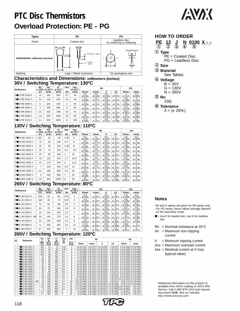
118
Additional information on this product isavailable from AVX’s catalog or AVX’s FAXService. Call 1-800-879-1613 and requestdocument #118. Visit our websitehttp://www.avxcorp.com
PTC Disc ThermistorsOverload Protection: PE - PG
HOW TO ORDERPE 12 J N 0100 X - -1 2 3 4 51 Type
PE = Coated DiscPG = Leadless Disc
2 Size3 Material
See Tables4 Voltage
B = 30VG = 130VN = 265V
5 Rn10Ω
6 ToleranceX = (± 25%)
Types PE PG
Finish Coated disc Leadless disc
for soldering or clamping
DIMENSIONS: millimeters (inches)
Marking Logo / Rated resistance On packaging onlyLS
D
30 m
in
3 m
ax
e
4.5 mm ± 1mm
d + 10 %- 0.05
D e
Metallization
Rn Int* It* Imo IresReference ± 25% at 25°C at 25°C at 25°C PE PG
(Ω) (mA) (mA) (A) (mA) Dmax emax d LS Dmax emax
P04 JN 0151 X - - 150 28 56 0.25 5 5.3 5 0.6 5 4.8 3.5(0.209) (0.197) (0.024) (0.197) (0.189) (0.138)
P04 JN 0101 X - - 100 35 70 0.25 5 5.3 5 0.6 5 4.8 3.5(0.209) (0.197) (0.024) (0.197) (0.189) (0.138)
P06 JN 0700 X - - 70 40 80 0.5 5 7.2 5 0.6 5 6.5 3.5(0.283) (0.197) (0.024) (0.197) (0.256) (0.138)
P08 JN 0250 X - - 25 75 150 0.9 6 9 5 0.6 5 8.2 3.5(0.354) (0.197) (0.024) (0.197) (0.027) (0.138)
P10 JN 0150 X - - 15 110 220 1.5 7 11 5 0.6 5 10.2 3.5(0.433) (0.197) (0.024) (0.197) (0.402) (0.138)
P12 JN 0100 X HB 10 135 270 2.2 8 13 5 0.6 5 12 3.5(0.512) (0.197) (0.024) (0.197) (0.472) (0.138)
P12 JN 0100 X - - 10 150 300 2.2 8 13 5 0.8 7.6 12 3.5(0.512) (0.197) (0.031) (0.299) (0.472) (0.138)
P16 JN 0609 X - - 6 200 400 3.5 12 17.5 6 0.8 7.6 16.5 4(0.689) (0.236) (0.031) (0.299) (0.650) (0.157)
P20 JN 0379 X - - 3.7 300 600 5 16 22 6 0.8 7.6 21 4(0.866) (0.236) (0.031) (0.299) (0.827) (0.157)
Rn Int* It* Imo IresUL Reference ± at at at PE PG
25% 25°C 25°C (A) 25°C Dmax emax d LS Dmax emax(Ω) (mA) (mA) (mA)* P04 NN 0221 X - - 220 35 70 0.25 5 5.6 (0.220) 5 (0.197) 0.6 (0.024) 5 (0.197) 4.8 (0.189) 3.5 (0.059)* P04 NN 0151 X - - 150 45 90 0.25 5 5.6 (0.220) 5 (0.197) 0.6 (0.024) 5 (0.197) 4.8 (0.189) 3.5 (0.059)* P06 NN 0121 X - - 120 52 104 0.5 6 7.2 (0.283) 5 (0.197) 0.6 (0.024) 5 (0.197) 6.5 (0.256) 3.5 (0.059)* P06 NN 0101 X - - 100 58 116 0.5 6 7.2 (0.283) 5 (0.197) 0.6 (0.024) 5 (0.197) 6.5 (0.256) 3.5 (0.059)* P06 NN 0700 X - - 70 65 130 0.5 6 7.2 (0.283) 5 (0.197) 0.6 (0.024) 5 (0.197) 6.5 (0.256) 3.5 (0.059)* P06 NN 0680 X - - 68 65 130 0.5 6 7.2 (0.283) 5 (0.197) 0.6 (0.024) 5 (0.197) 6.5 (0.256) 3.5 (0.059)* P08 NN 0550 X - - 55 80 160 0.9 8 9.0 (0.354) 5 (0.197) 0.6 (0.024) 5 (0.197) 8.2 (0.323) 3.5 (0.059)* P08 NN 0470 X - - 47 85 170 0.9 8 9.0 (0.354) 5 (0.197) 0.6 (0.024) 5 (0.197) 8.2 (0.323) 3.5 (0.059)* P08 NN 0450 X - - 45 85 170 0.9 8 9.0 (0.354) 5 (0.197) 0.6 (0.024) 5 (0.197) 8.2 (0.323) 3.5 (0.059)* P08 NN 0350 X - - 35 90 180 0.9 8 9.0 (0.354) 5 (0.197) 0.6 (0.024) 5 (0.197) 8.2 (0.323) 3.5 (0.059)* P08 NN 0330 X - - 33 90 180 0.9 8 9.0 (0.354) 5 (0.197) 0.6 (0.024) 5 (0.197) 8.2 (0.323) 3.5 (0.059)* P08 NN 0250 X - - 25 100 200 0.9 8 9.0 (0.354) 5 (0.197) 0.6 (0.024) 5 (0.197) 8.2 (0.323) 3.5 (0.059)* P08 NN 0220 X - - 22 105 210 0.9 8 9.0 (0.354) 5 (0.197) 0.6 (0.024) 5 (0.197) 8.2 (0.323) 3.5 (0.059)* P10 NN 0150 X - - 15 135 270 1.5 9 11.5 (0.453) 5 (0.197) 0.6 (0.024) 5 (0.197) 10.2 (0.402) 3.5 (0.059)* P12 NN 0100 X HB 10 180 360 2.2 10 13.5 (0.209) 5 (0.197) 0.6 (0.024) 5 (0.197) 12 (0.472) 3.5 (0.059)* P12 NN 0100 X - - 10 225 450 2.2 12 13.5 (0.209) 5 (0.197) 0.8 (0.031) 7.6 (0.299) 12 (0.472) 3.5 (0.059)* P16 NN 0689 X - - 6.8 300 600 3.5 16 17.5 (0.689) 6 (0.236) 0.8 (0.031) 7.6 (0.299) 16.5 (0.650) 4 (0.157)* P16 NN 0609 X - - 6 310 620 3.5 16 17.5 (0.689) 6 (0.236) 0.8 (0.031) 7.6 (0.299) 16.5 (0.650) 4 (0.157)* P20 NN 0479 X - - 4.7 400 800 5 20 22 (0.866) 6 (0.236) 0.8 (0.031) 7.6 (0.299) 21 (0.827) 4 (0.157)* P20 NN 0379 X - - 3.7 460 920 5 20 22 (0.866) 6 (0.236) 0.8 (0.031) 7.6 (0.299) 21 (0.827) 4 (0.157)
*Int and It values are given for PE series only.For PG series, these values strongly dependon the assembly mode.
= Use E for leaded disc; use G for leadlessdisc
Rn = Nominal resistance at 25°CInt = Maximum non-tripping
current
It = Minimum tripping currentImo = Maximum overload currentIres = Residual current at V max
(typical value)
265V / Switching Temperature: 80ºC
265V / Switching Temperature: 120ºC
Notes
Rn Int* It* Imo IresReference ± 25% at 25°C at 25°C at 25°C PE PG
(Ω) (mA) (mA) (A) (mA) Dmax emax d LS Dmax emax
P03 PB 0130 X - - 13 100 200 0.7 40 4.2 3.5 0.5 5 4 1.5(0.165) (0.138) (0.020) (0.197) (0.157) (0.059)
P04 PB 0130 X - - 13 125 250 1.5 40 5.3 4.5 0.6 5 4.8 3(0.209) (0.177) (0.024) (0.197) (0.189) (0.118)
P06 PB 0609 X - - 6 220 440 2 507.2 4 0.6 5 6.5 2.5
(0.165) (0.157) (0.024) (0.197) (0.256) (0.098)P08 PB 0409 X - - 4 300 600 3 60 9 4 0.6 5 8.2 2.5
(0.283) (0.157) (0.024) (0.197) (0.323) (0.098)P10 PB 0259 X - - 2.5 400 800 4.3 70 11 4 0.6 5 10.2 2.5
(0.433) (0.157) (0.024) (0.197) (0.402) (0.098)P12 PB 0189 X - - 1.8 500 1000 5.5 80 13 4 0.8 7.6 12 2.5
(0.512) (0.157) (0.031) (0.299) (0.472) (0.098)P16 PB 0119 X - - 1.1 800 1600 8 100 17.5 4 0.8 7.6 16.5 2.5
(0.689) (0.157) (0.031) (0.299) (0.650) (0.098)
Rn Int* It* Imo IresReference ± 25% at 25°C at 25°C at 25°C PE PG
(Ω) (mA) (mA) (A) (mA) Dmax emax d LS Dmax emax
P04 MG 0101 X - - 100 45 90 0.35 8 5.3 5 0.6 5 4.8 3.5(0.209) (0.197) (0.024) (0.197) (0.189) (0.059)
P04 MG 0700 X - - 70 50 100 0.4 8 5.3 4.5 0.6 5 4.8 3(0.209) (0.177) (0.024) (0.197) (0.189) (0.118)
P04 MG 0550 X - - 55 60 120 0.45 8 5.3 4.5 0.6 5 4.8 3(0.209) (0.177) (0.024) (0.197) (0.189) (0.118)
P04 MG 0350 X - - 35 75 150 0.5 8.5 5.3 4.5 0.6 5 4.8 3(0.209) (0.177) (0.024) (0.197) (0.189) (0.118)
P06 MG 0250 X - - 25 95 190 1 10 7.2 4.5 0.6 5 6.5 3(0.283) (0.177) (0.024) (0.197) (0.256) (0.118)
P06 MG 0150 X - - 15 125 250 1.3 10.5 7.2 4.5 0.6 5 6.5 3(0.283) (0.177) (0.024) (0.197) (0.256) (0.118)
P08 MG 0100 X - - 10 170 340 2 11.5 9 4.5 0.6 5 8.2 3(0.354) (0.177) (0.024) (0.197) (0.323) (0.118)
P10 MG 0709 X - - 7 210 420 2.8 14 11 4.5 0.6 5 10.2 3(0.433) (0.177) (0.024) (0.197) (0.472) (0.118)
P12 MG 0459 X - - 4.5 280 560 4.5 18 13 5 0.8 7.6 12 3(0.512) (0.197) (0.031) (0.299) (0.472) (0.118)
P16 MG 0309 X - - 3 400 800 7 25 17.5 5 0.8 7.6 16.5 3(0.689) (0.197) (0.031) (0.299) (0.650) (0.118)
P20 MG 0189 X - - 1.8 650 1300 11 30 22 5 0.8 7.6 21 3(0.866) (0.197) (0.031) (0.299) (0.827) (0.118)
130V / Switching Temperature: 110ºC
Characteristics and Dimensions: millimeters (inches)30V / Switching Temperature: 130ºC

119
Additional information on this product is available from AVX’s catalog or AVX’s FAX Service.Call 1-800-879-1613 and request document #119. Visit our website http://www.avxcorp.com
PTC Disc ThermistorsTelecommunications Series: PE - PS
HOW TO ORDERPE 10 - - 0020 - - -1 2
1 Type2 TPC P/N
HOW TO ORDERPE 06 - - 1020 - - -1 2
1 Type2 TPC P/N
Reference Vmax Rn ToleranceRms (Ω) on Rn Dmax emax d LS Finish
PS 06 N - 0005 - - - 130 70+10%
6.4 (0.252) 4 (0.157) 0.6 (0.024) 5 (0.197) Uncoated-15%
PS 06 N - 0015 - - - 245 70+10%
6.4 (0.252) 4 (0.157) 0.6 (0.024) 5 (0.197) Uncoated-15%
PS 10 - - 0019 - - - 245 16 ±25% 11 (0.433) 4.5 (0.177) 0.6 (0.024) 5 (0.197) Coated
PS 10 - - 0020 - - - 245 10 ±20% 11 (0.433) 4.5 (0.177) 0.6 (0.024) 5 (0.197) Coated
PS 08 - - 0021 - - -* 245 25 ±15% 8.3 (0.327) 4 (0.157) 0.6 (0.024) 5 (0.197) Uncoated
PS 08 - - 0022 - - - 245 25 ±25% 9 (0.354) 5 (0.197) 0.6 (0.024) 5 (0.197) Coated
Characteristics and Dimensions: millimeters (inches)
D e
LS
d +10 %- 0.05
*per reel DR = 1 Ω maxIndividual data sheet: upon request
Packaging: on tape and reel.
Quantity: 1500 parts per reel.
Diam. Thick.Type (D) max. (e) max. Vmax R25°C DR25°C Tb Int It Imo Ires tb
mm (inches) mm (inches) (V) (Ohms) (%) (°C) (mA) (mA) (A) (mA) (s)
PE 06 - - 1020 - - - 6.5 (0.256) 3 (0.118) 30 3.0 25 140 400 600 4.5 50 0.260PE 04 - - 1019 - - - 5 (0.197) 3 (0.118) 30 6.0 25 140 270 400 2.5 45 0.230PE 06 - - 1021- - - 8 (0.315) 5 (0.197) 30 8.2 20 115 180PE 08 - - 1031 - - - 9 (0.354) 3.5 (0.138) 80 9.4 25 110 150 300 1.3 20 ≤3PE 04 - - 1032 - - - 6.5 (0.256) 3.5 (0.138) 40 125 25 110 40 80 0.35 8
Overload Protection – Delayed Switching
Diam. Thick.Type (D) max. (e) max. Vmax R25°C DR25°C Tb Int It Imo Ires tb
mm (inches) mm (inches) (V) (Ohms) (%) (°C) (mA) (mA) (A) (mA) (s)
PE 04 JN 0151 X - - 5.3 (0.209) 5 (0.197) 265 150 25 80 28 56 0.25 5PE 04 JN 0101 X - - 5.3 (0.209) 5 (0.197) 265 100 25 80 35 70 0.25 5PE 04 - - 1041 - - - 6.5 (0.256) 5 (0.197) 420 600 25 120 20 40 0.2
Time Delay For Lighting
Diam. Thick.Type (D) max. (e) max. Vmax R25°C DR25°C T1 R1 T2 R2 T3 R3
mm (inches) mm (inches) (V) (Ohms) (%) (°C) (Ohms) (°C) (Ohms) (°C) (Ohms)
PG 08 - - 1008 - - -8.0 + 0.5 1.0 + 0.2 (0.009) 30 8.0 25 105 <2R25°C 115 >2R25°C
(0.315 + 0.020)-.0.1 (0.004)
PG 08 - - 1017 - - - 8.0 + 0.5 1.0 ± 0.1
30 8.0 25 75 <2R25°C 85 >2R25°C(0.315 + 0.020) (0.04 ± 0.004)
PG 08 - - 1015 - - -8.0 + 0.5 1.2+ 0.2 (0.009)
12.5 16 90 <50 110 >1 k 125 >20 k(0.315 + 0.020)-.0.1 (0.004)
PS 06 - - 1005 - - -7 2.5
30 12.5 20 50 <2R25°C 60 >2R25°C 100 >1 k(0.276) (0.098)
PS 04 - - 1009 - - -4.7 ± 0.3 1.05 ± 0.3
80 25.0 25 95 <2R25°C 105 >2R25°C(0.185 ± 0.012) (0.041 ± 0.012)
Heating Elements And Thermostats –Measurement And Control
PE PS PGResin-coated disc Uncoated disc Leadless disc
D eD e
Ø0.6 (.024) +10%
5.08 (0.2)
35(1.38)min.
-0.05 (.02)
(0.04)
(0.047)
Individual data sheet, marking, lead configuration, packaging, ... upon request.
Industrial and Automotive
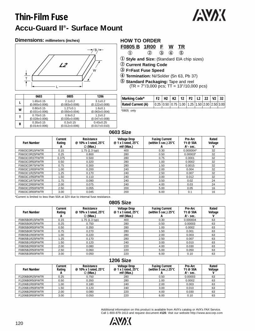
120
Additional information on this product is available from AVX’s catalog or AVX’s FAX Service.Call 1-800-879-1613 and request document #120. Visit our website http://www.avxcorp.com
Thin-Film FuseAccu-Guard II®- Surface Mount
HOW TO ORDERF0805 B 1R00 F W TR1 2 3 4 5
1 Style and Size: (Standard EIA chip sizes)2 Current Rating Code3 F=Fast Fuse Speed4 Termination: Ni/Solder (Sn 63, Pb 37)5 Standard Packaging: Tape and reel
(TR = 7"/3,000 pcs; TT = 13"/10,000 pcs)
L2
B
W
L
T
Current Resistance Voltage Drop Fusing Current Pre-Arc RatedPart Number Rating @ 10% x I rated, 25°C @ 1 x I rated, 25°C (within 5 sec.) 25°C 12t @ 50A Voltage
A Ω (Max.) mV (Max.) A A2 - sec. VF0603C0R15FWTR 0.15 1.75 (1.3 typ) 400 0.30 0.000004* 32F0603C0R25FWTR 0.25 0.800 280 0.50 0.00003* 32F0603C0R37FWTR 0.375 0.500 280 0.75 0.0001 32F0603C0R50FWTR 0.50 0.320 280 1.00 0.0002 32F0603C0R75FWTR 0.75 0.300 280 1.50 0.0015 32F0603C1R00FWTR 1.00 0.200 240 2.00 0.004 32F0603C1R25FWTR 1.25 0.170 240 2.50 0.007 32F0603C1R50FWTR 1.50 0.110 240 3.00 0.012 32F0603C1R75FWTR 1.75 0.090 240 3.50 0.02 24F0603C2R00FWTR 2.00 0.075 240 4.00 0.03 24F0603C2R50FWTR 2.50 0.055 200 5.00 0.05 16F0603C3R00FWTR 3.00 0.045 200 6.00 0.1 16
Dimensions: millimeters (inches)
Marking Code* F2 H2 K2 12 P2 L2 22 V2 32
Rated Current (A) 0.25 0.50 0.75 1.00 1.25 1.50 2.00 2.50 3.00
0603 Size
Current Resistance Voltage Drop Fusing Current Pre-Arc RatedPart Number Rating @ 10% x I rated, 25°C @ 1 x I rated, 25°C (within 5 sec.) 25°C 12t @ 50A Voltage
A Ω (Max.) mV (Max.) A A2 - sec. VF0805B0R15FWTR 0.15 1.75 (1.3 typ) 400 0.30 0.000004 63F0805B0R25FWTR 0.25 0.750 280 0.50 0.00003 63F0805B0R50FWTR 0.50 0.350 280 1.00 0.0002 63F0805B0R75FWTR 0.75 0.270 280 1.50 0.001 63F0805B1R00FWTR 1.00 0.220 280 2.00 0.003 63F0805B1R25FWTR 1.25 0.170 280 2.50 0.007 63F0805B1R50FWTR 1.50 0.120 240 3.00 0.010 63F0805B2R00FWTR 2.00 0.080 220 4.00 0.030 63F0805B2R50FWTR 2.50 0.060 220 5.00 0.050 63F0805B3R00FWTR 3.00 0.050 220 6.00 0.10 63
0805 Size
Current Resistance Voltage Drop Fusing Current Pre-Arc RatedPart Number Rating @ 10% x I rated, 25°C @ 1 x I rated, 25°C (within 5 sec.) 25°C 12t @ 50A Voltage
A Ω (Max.) mV (Max.) A A2 - sec. VF1206B0R25FWTR 0.25 0.750 280 0.50 0.00003 63F1206B0R50FWTR 0.50 0.350 280 1.00 0.0002 63F1206B1R00FWTR 1.00 0.180 240 2.00 0.003 63F1206B1R50FWTR 1.50 0.120 240 3.00 0.010 63F1206B2R00FWTR 2.00 0.080 220 4.00 0.030 63F1206B3R00FWTR 3.00 0.050 220 6.00 0.10 63
1206 Size
0603 0805 1206
L 1.65±0.15 2.1±0.2 3.1±0.2(0.065±0.006) (0.083±0.008) (0.122±0.008)
W 0.80±0.15 1.27±0.1 1.6±0.1(0.031±0.006) (0.050±0.004) (0.063±0.004)
T 0.70±0.15 0.9±0.2 1.2±0.2(0.028±0.006) (0.035±0.008) (0.047±0.008)
B 0.35±0.15 0.3±0.15 0.43±0.25(0.014±0.006) (0.012±0.006) (0.017±0.010)
*Current is limited to less than 50A at 32V due to internal fuse resistance.
*0805 only
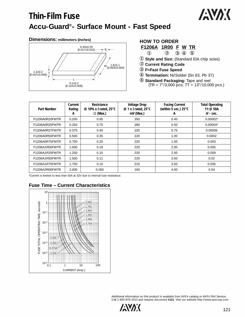
121
Additional information on this product is available from AVX’s catalog or AVX’s FAX Service.Call 1-800-879-1613 and request document #121. Visit our website http://www.avxcorp.com
Thin-Film FuseAccu-Guard®- Surface Mount - Fast Speed
HOW TO ORDERF1206A 1R00 F W TR1 2 3 4 5
1 Style and Size: (Standard EIA chip sizes)2 Current Rating Code3 F=Fast Fuse Speed4 Termination: Ni/Solder (Sn 63, Pb 37)5 Standard Packaging: Tape and reel
(TR = 7"/3,000 pcs; TT = 13"/10,000 pcs.)
B
W
L
T
0.43±0.25(0.017±0.010)
1.6±0.1(0.063±0.004)
3.1±0.2(0.122±0.008)
1.2±0.2(0.047±0.008)
Current Resistance Voltage Drop Fusing Current Total OperatingPart Number Rating @ 10% x I rated, 25°C @ 1 x I rated, 25°C (within 5 sec.) 25°C 12t @ 50A
A Ω (Max.) mV (Max.) A A2 - sec.
F1206A0R20FWTR 0.200 0.95 350 0.40 0.00002*
F1206A0R25FWTR 0.250 0.75 280 0.50 0.00004*
F1206A0R37FWTR 0.375 0.40 220 0.75 0.00006
F1206A0R50FWTR 0.500 0.35 220 1.00 0.0002
F1206A0R75FWTR 0.750 0.25 220 1.50 0.003
F1206A1R00FWTR 1.000 0.18 220 2.00 0.005
F1206A1R25FWTR 1.250 0.15 220 2.50 0.009
F1206A1R50FWTR 1.500 0.11 220 3.00 0.02
F1206A1R75FWTR 1.750 0.10 210 3.50 0.035
F1206A2R00FWTR 2.000 0.065 160 4.00 0.04
*Current is limited to less than 50A at 32V due to internal fuse resistance.
Fuse Time – Current Characteristics
2.00A
1.75A
1.50A
1.25A
1.00A
0.75A
0.20A
0.25A
0.375A
0.50AFUS
E T
OTA
L O
PE
RA
TIN
G T
IME
, sec
ond
s
10
1
10-1
10-2
10-3
10-4
10-5
10-60.1 1 10 100
CURRENT (Amp.)
Dimensions: millimeters (inches)

122
Additional information on this product is available from AVX’s catalog or AVX’s FAX Service.Call 1-800-879-1613 and request document #122. Visit our website http://www.avxcorp.com
Thin-Film Directional CouplersCP0805 Type
HOW TO ORDERCP- 0805 A 0902 - A W1 2 3 4 5 61 Style: Directional Couplers2 Size: 08053 Type: (see below)4 Frequency: MHz5 Sub Type: (see below)6 Termination: Nickel/Solder (Sn/Pb)
Dimensions: millimeters (inches)
0805L 2.03±0.1
(0.080±0.004)
W 1.55±0.1(0.061±0.004)
T 0.98±0.1(0.039±0.004)
A 0.56±0.25(0.022±0.010)
B 0.35±0.15(0.014±0.006)
LAYOUT TYPEType A
Type B
COUP
IN OUT
50 OHM COUP
IN OUT
50 OHM
COUPIN
OUT 50 OHM
COUPIN
OUT 50 OHM
COUPIN
OUT 50 OHM
Sub-Type A Sub-Type B Sub-Type C
Sub-Type A Sub-Type B
COUP
IN
50Ω
OUT
Sub-Type C
COUP
IN
50Ω
OUT
Sub-Type D
COUP
IN
50Ω
OUT
Sub-Type E
Application Part Frequency Coupling L Loss VSWRNumber Band (MHz) (dB) max max
GSM CP0805A0902AW 890 ~ 915 16±1CP0805A0947AW 935 ~ 960 15.5±1 0.25dB 1.2
AMPS CP0805A0836AW 824 ~ 849 16.5±1CP0805A0881AW 869 ~ 894 16±1
Coupler Type : AA
Application Part Frequency Coupling L Loss VSWRNumber Band (MHz) (dB) max max
GSM CP0805A0902BW 890 ~ 915 18±1CP0805A0947BW 935 ~ 960 18±1 0.25dB 1.2
AMPS CP0805A0836BW 824 ~ 849 19±1CP0805A0881BW 869 ~ 894 18.5±1
Coupler Type : AB
Application Part Frequency Coupling L Loss VSWRNumber Band (MHz) (dB) [dB] max max
AMPS CP0805A0836CW 824 ~ 849 14±1CP0805A0881CW 869 ~ 894 13.5±1
GSM CP0805A0902CW 890 ~ 915 13.5±1CP0805A0947CW 935 ~ 960 13±1 0.5 1.4
E-GSM CP0805A0897CW 880 ~ 915 13.5±1CP0805A0942CW 925 ~ 960 13±1
Coupler Type : AC
Coupler Type : ADApplication Part Frequency Coupling L Loss VSWR
Number Band (MHz) (dB) [dB] max maxAMPS CP0805A0836DW 824 ~ 849 13
CP0805A0881DW 869 ~ 894 12.5GSM CP0805A0902DW 890 ~ 915 12.5
CP0805A0947DW 935 ~ 960 12 0.5 1.4E-GSM CP0805A0897DW 880 ~ 915 12.5
CP0805A0942DW 925 ~ 960 12
Application Part Frequency Coupling L Loss VSWRNumber Band (MHz) (dB) max max
PCN CP0805B1747AW 1710 ~ 1785 15.5±1 0.25dBCP0805B1842AW 1805 ~ 1880 15±1 0.3dB
PCS CP0805B1890AW 1850 ~ 1910 15±1CP0805B1950AW 1930 ~ 1990 14.5±1 0.4dB 1.2
PHP CP0805B1907AW 1895 ~ 1920 15±1 0.3dBDECT CP0805B1890AW 1880 ~ 1900 15±1
Wireless LAN CP0805B2442AW 2400 ~ 2484 13±1 0.4dB
Coupler Type : BA
Application Part Frequency Coupling L Loss VSWRNumber Band (MHz) (dB) max max
PCN CP0805B1747BW 1710 ~ 1785 17±1CP0805B1842BW 1805 ~ 1880 16.5±1
PCS CP0805B1890BW 1850 ~ 1910 16±1CP0805B1950BW 1930 ~ 1990 16±1 0.25dB 1.2
PHP CP0805B1907BW 1895 ~ 1920 16±1DECT CP0805B1890BW 1880 ~ 1900 16±1
Wireless LAN CP0805B2442BW 2400 ~ 2484 14±1
Coupler Type : BB
Coupler Type : BCApplication Part Frequency Coupling L Loss VSWR
Number Band (MHz) (dB) max maxPCN CP0805B1747CW 1710 ~ 1785 18.5±1
CP0805B1842CW 1805 ~ 1880 18.5±1PCS CP0805B1890CW 1850 ~ 1910 18±1
CP0805B1950CW 1930 ~ 1990 17.5±1 0.25dB 1.2PHP CP0805B1907CW 1895 ~ 1920 18±1
DECT CP0805B1890CW 1880 ~ 1900 18±1Wireless LAN CP0805B2442CW 2400 ~ 2484 16±1 0.4dB
Coupler Type : AEApplication Part Frequency Coupling L Loss VSWR
Number Band (MHz) (dB) [dB] max maxAMPS CP0805A0836EW 824 ~ 849 11±1
CP0805A0881EW 869 ~ 894 10.5±1GSM CP0805A0902EW 890 ~ 915 10.5±1
CP0805A0947EW 935 ~ 960 10±1 0.85 1.4E-GSM CP0805A0897EW 880 ~ 915 10.5±1
CP0805A0942EW 925 ~ 960 10±1
Note: All coupler types are designed to be used at any frequency within the 800MHz to 2500MHz range. Thepart numbers listed are only examples for typicalapplications.

123
Additional information on this product is available from AVX’s catalog or AVX’s FAX Service.Call 1-800-879-1613 and request document #123. Visit our website http://www.avxcorp.com
Thin-Film Directional CouplersCP0603 Type
Top View
HOW TO ORDERCP 0603 A 0836 A W1 2 3 4 5 61 Style: Directional Couplers2 Size: 06033 Type: (see below)4 Frequency: MHz5 Sub Type: (see below)6 Termination: Nickel/Solder (Sn/Pb)
Dimensions: millimeters (inches)
0603L 1.6±0.1
(0.063±0.004)
W 0.84±0.1(0.033±0.004)
T 0.60±0.1(0.028±0.004)
A 0.35±0.15(0.014±0.006)
B 0.175±0.1(0.007±0.004)
B10.00+0.1/-0.0
(0.000+0.004/-0.0)
OUT
IN
50 OHM
COUPLING
Terminals (Top View)
Coupler Part Number CP0603AxxxxAWApplication Part Frequency Coupling L Loss VSWR
Number Band (MHz) (dB) [dB] max maxAMPS CP0603A0836AW 824 ~ 849 18.5±1
CP0603A0881AW 869 ~ 894 18.5±1 0.25GSM CP0603A0902AW 890 ~ 915 18±1 1.2
CP0603A0947AW 935 ~ 960 17.5±1PDC CP0603A1441AW 1429 ~ 1453 14±1 0.3PCN CP0603A1747AW 1710 ~ 1785 12.5±1
CP0603A1842AW 1805 ~ 1880 12±1PCS CP0603A1880AW 1850 ~ 1910 12±1
CP0603A1960AW 1930 ~ 1990 11.5±1 0.5 1.3PHP CP0603A1907AW 1895 ~ 1920 12±1
DECT CP0603A1890AW 1880 ~ 1900 12±1Wireless LAN CP0603A2442AW 2400 ~ 2484 10±1 0.8 1.3
Coupler Part Number CP0603AxxxxDWApplication Part Frequency Coupling L Loss VSWR
Number Band (MHz) (dB) [dB] max maxAMPS CP0603A0836DW 824 ~ 849 15.5±1
CP0603A0881DW 869 ~ 894 15±1 0.35 1.2GSM CP0603A0902DW 890 ~ 915 14.5±1
CP0603A0947DW 935 ~ 960 14±1PDC CP0603A1441DW 1429 ~ 1453 10.5 0.55 1.3PCN CP0603A1747DW 1710 ~ 1785 9±1
CP0603A1842DW 1805 ~ 1880 8.5±1PCS CP0603A1880DW 1850 ~ 1910 8.5±1
CP0603A1960DW 1930 ~ 1990 8±1 0.9 1.5PHP CP0603A1907DW 1895 ~ 1920 8.5±1
DECT CP0603A1890DW 1880 ~ 1900 8.5±1Wireless LAN CP0603A2442DW 2400 ~ 2484 6.5±1 1.4 1.5
Coupler Part Number CP0603AxxxxBWApplication Part Frequency Coupling L Loss VSWR
Number Band (MHz) (dB) [dB] max maxAMPS CP0603A0836BW 824 ~ 849 16±1
CP0603A0881BW 869 ~ 894 15.5±1 0.25GSM CP0603A0902BW 890 ~ 915 15.5±1
CP0603A0947BW 935 ~ 960 15±1PDC CP0603A1441BW 1429 ~ 1453 11.5±1 0.45PCN CP0603A1747BW 1710 ~ 1785 10±1 1.2
CP0603A1842BW 1805 ~ 1880 9.5±1PCS CP0603A1880BW 1850 ~ 1910 9±1
CP0603A1960BW 1930 ~ 1990 9±1 0.8PHP CP0603A1907BW 1895 ~ 1920 9±1
DECT CP0603A1890BW 1880 ~ 1900 9±1Wireless LAN CP0603A2442BW 2400 ~ 2484 7.5±1 1.1 1.3
Coupler Part Number CP0603AxxxxCWApplication Part Frequency Coupling L Loss VSWR
Number Band (MHz) (dB) [dB] max maxAMPS CP0603A0836CW 824 ~ 849 21±1
CP0603A0881CW 869 ~ 894 20.5±1 0.25 1.2GSM CP0603A0902CW 890 ~ 915 20.5±1
CP0603A0947CW 935 ~ 960 20±1PDC CP0603A1441CW 1429 ~ 1453 16.5±1 0.35PCN CP0603A1747CW 1710 ~ 1785 15±1
CP0603A1842CW 1805 ~ 1880 14.5±1PCS CP0603A1880CW 1850 ~ 1910 14.5±1
CP0603A1960CW 1930 ~ 1990 14±1 0.5 1.3PHP CP0603A1907CW 1895 ~ 1920 14.5±1
DECT CP0603A1890CW 1880 ~ 1900 14.5±1Wireless LAN CP0603A2442CW 2400 ~ 2484 12.5±1
Coupler Part Number CP0603BxxxxAWApplication Part Frequency Coupling L Loss VSWR
Number Band (MHz) (dB) [dB] max maxAMPS CP0603B0836AW 824 ~ 849 24±1
CP0603B0881AW 869 ~ 894 24±1 0.2GSM CP0603B0902AW 890 ~ 915 23.5±1
CP0603B0947AW 935 ~ 960 23.5±1PDC CP0603B1441AW 1429 ~ 1453 20±1PCN CP0603B1747AW 1710 ~ 1785 18±1
CP0603B1842AW 1805 ~ 1880 18±1 0.25 1.2PCS CP0603B1880AW 1850 ~ 1910 17.5±1
CP0603B1960AW 1930 ~ 1990 17.5±1PHP CP0603B1907AW 1895 ~ 1920 17.5±1
DECT CP0603B1890AW 1880 ~ 1900 17.5±1Wireless LAN CP0603B2442AW 2400 ~ 2484 15±1 0.4
L
T
B1 A
Bottom View
WB
Note: All coupler types are designed tobe used at any frequency withinthe 800MHz to 2500MHz range.The part numbers listed are onlyexamples for typical applications.

124
Additional information on this product is available from AVX’s catalog or AVX’s FAX Service.Call 1-800-879-1613 and request document #124. Visit our website http://www.avxcorp.com
High Frequency InductorAccu-L® – Size 0805 – Surface Mount
HOW TO ORDERL 0805 1R8 D EW TR1 2 3 4 5 61 Type2 EIA Chip Size3 Inductance Code: (nH)4 Tolerance:
C = ±0.2nH D = ±0.5 nHG = ±2% J = ±5%
5 Termination: Ni/Solder (Sn 63, Pb 37)6 Standard Packaging: Tape and reel
(7" = 3,000 pcs; 13" = 10,000 pcs.)
B
W
L
T
0.25±0.15(0.010±0.006)
1.5±0.1(0.059±0.004)
2.11±0.1(0.083±0.004)
0.91±0.13(0.036±0.005)
Dimensions:
450 MHz 900 MHz 1700 MHz 2400 MHz
Part NumberTest Freq. Test Freq. Test Freq. Test Freq. SRF min RDC max IDC max
(MHz) (Ω)Inductance L (nH) Q L (nH) Q L (nH) Q L (nH) Q D15°C D70°CTol. Typical Typical Typical Typical (1) (2)
L08051R2hEW ±0.2 ±0.5 nH 1.2 60 1.2 92 1.2 122 1.2 92 10000 0.05 1000 2000
L08051R5hEW ±0.2 ±0.5 nH 1.5 50 1.5 74 1.5 102 1.5 84 10000 0.05 1000 2000
L08051R8hEW ±0.2 ±0.5 nH 1.8 50 1.8 72 1.8 88 1.9 73 10000 0.06 1000 2000
L08052R2hEW ±0.2 ±0.5 nH 2.2 42 2.2 62 2.2 82 2.3 72 10000 0.07 1000 2000
L08052R7hEW ±0.2 ±0.5 nH 2.7 42 2.7 62 2.8 80 2.9 70 10000 0.08 1000 2000
L08053R3hEW ±0.2 ±0.5 nH 3.3 38 3.3 46 3.4 48 3.5 57 10000 0.11 750 1500
L08053R9hEW ±0.2 ±0.5 nH 3.9 27 3.9 36 4.0 38 4.1 42 10000 0.20 750 1500
L08054R7hEW ±0.2 ±0.5 nH 4.7 43 4.8 62 5.3 76 5.8 60 5500 0.10 750 1500
L08055R6hEW ±0.2 ±0.5 nH 5.6 50 5.7 68 6.3 73 7.6 62 4600 0.10 750 1500
L08056R8hEW ±0.2 ±0.5 nH 6.8 43 7.0 62 7.7 71 9.4 50 4500 0.11 750 1500
L08058R2hEW ±0.2 ±0.5 nH 8.2 43 8.5 56 10.0 55 15.2 32 3500 0.12 750 1500
L0805100hEW ±2%, ±5% 10 46 10.6 60 13.4 52 — — 2500 0.13 750 1500
L0805120hEW ±2%, ±5% 12 40 12.9 50 17.3 40 — — 2400 0.20 750 1500
L0805150hEW ±2%, ±5% 15 36 16.7 46 27.0 23 — — 2200 0.20 750 1000
L0805180hEW ±2%, ±5% 18 36 18.8 37 — — — — 1700 0.35 500 1000
L0805220hEW ±2%, ±5% 22 36 23.5 33 — — — — 1400 0.40 500 1000
Inductance vs. Frequency (Typical) Q vs. Frequency (Typical)
h : C = ±0.2nH, D = ±0.5nH, G = ±2%, J = ±5%.(1) IDC measured for 15°C rise at 25°C ambient temperature(2) IDC measured for 70°C rise at 25°C ambient temperature
22nH
15nH10nH
5.6nH
1.8nH
100
10
10.10.01 1 10
Measured on Wiltron 360 Vector Analyzer
Frequency (GHz)
Ind
ucta
nce
(nH
)
1.8nH
5.6nH
10nH
15nH
22nH
100
80
60
40
20
00.1 1 10
Measured on Wiltron 360 Vector Analyzer
Q
Frequency (GHz)

125
Additional information on this product is available from AVX’s catalog or AVX’s FAX Service.Call 1-800-879-1613 and request document #125. Visit our website http://www.avxcorp.com
HOW TO ORDERKBR - 455 Y TR1 2 3 41 Type: (Kyocera Bulk Resonator)2 Oscillation Frequency: 380 to 1050 kHz3 Resonator Type: Y = surface mountable4 Standard Packaging: TR = tape and reel
(13" = 1000 pcs)
SpecificationsFig. A Fig. B Fig. C
Frequency Range 380 to 430kHz 440 to 525kHz 600 to 655kHz 795 to 815kHz 960 to 1050kHz
Frequency Tolerance ±0.5% ±0.5% ±0.5% ±0.5% ±0.5%
Resonant Impedance 20Ω Max. 20Ω Max. 50Ω Max. 70Ω Max. 100Ω Max.
Anti-resonant Impedance 30kΩ Min. 35kΩ Min. 50kΩ Min. 70kΩ Min. 70kΩ Min.
Temperature Characteristics(-20 to +80°C) ±0.3% ±0.3% ±0.3% ±0.3% ±0.3%
C1 100pF 100pF 100pF 100pF 100pF
C2 470pF 100pF 100pF 100pF 100pF
8.5(.335)
3.5(.138)
DateCode
Frequency
9.0(.354)
5.0(.197)
0.7(.028)
0.6 (.024)
0.3(.012)
0.7(.028)
8.0(.315)
3.5(.138)
DateCode
Frequency
9.0(.354)
5.0(.197)
0.7(.028)
0.6 (.024)
0.3(.012)
0.7(.028)
5.0(.197)
2.3(.091)
DateCode
Frequency
6.3(.248)
2.5(.098)
0.6(.024)
0.6 (.024)
0.3(.012)
0.7(.028)
Model Name
2.4(.094)
1.5(.059)
1.5(.059)
6.5(.256)
380 to 430 kHz440 to 525 kHz600 to 655 kHz
Ceramic Element
Outer Terminal
High Temperature Resin Case
2.4(.094)
1.4(.055)
1.4(.055)
3.9(.154)
960 to1020 kHz795 to 815 kHz
7unit: mm (inch)
C2
VDD
C1
fosc
1M
IC : 4069 (HEX INVERTER) (MOTOROLA)
+5VDC
Test Circuit Dimensions: millimeters (inches)
Suggested Land Patterns Structure
Fig. A Fig. B Fig. C
KBR-Y kHz Band SMT Ceramic ResonatorsKBR-Y Series ƒo: 380 to 1050kHz

126
Additional information on this product is available from AVX’s catalog or AVX’s FAX Service.Call 1-800-879-1613 and request document #126. Visit our website http://www.avxcorp.com
kHz Band Leaded Ceramic ResonatorsKBR -B, -BK, -F Series ƒo: 190 to 1050kHz
Dimensions: millimeters (inches)
Fig. A Fig. B Fig. C Fig. D Fig. E Fig. F Fig. G190 to 249kHz (B-Type) 250 to 379kHz (B-Type) 380 to 430kHz (BK-Type) 431 to 439kHz (B-Type) 440 to 525/540 to 655kHz 526 to 539/656 to 795 to 815/960 to
(Types: BK, AK, HK, AHK) 680kHz (B-Type) 1050kHz (F-type)14.2(.559)
3.8(.150)
Model Name Date Code
K
16.5(.650)
8.0(.315)
1.0(.039)
0.8(.031)
0.20(.008)1.6
(.063)
10.0(.394)
11.2(.441)
3.8(.150)
Model Name Date Code
K
13.5(.531)
8.0(.315)
1.0(.039)
0.8(.031)
0.20(.008)1.6
(.063)
7.5(.338)
8.5(.335)
3.5(.138)
Model Name Date Code
9.0(.354)
3.5(.138)
0.8(.031)
0.6(.024)
0.15(.006)1.5
(.059)
5.0(.197)
5.0(.197)
[TS]
8.5(.335)
3.8(.150)
Model NameDate Code
K
8.5(.335)
4.5(.177)
0.8(.031)
0.6(.024)
0.15(.006)1.5
(.059)
5.0(.197)
5.0(.197)
[TS]
8.0(.315)
3.5(.138)
Model Name Date Code
9.0(.354)
3.5(.138)
0.8(.031)
0.6(.024)
0.15(.006)1.5
(.059)
5.0(.197)
5.0(.197)
unit: mm (inch)[TS]
8.0(.315)
3.5 (.138)
Model Name Date Code
8.0(.315)
4.5 (.177)
0.8(.031)
0.6(.024)
0.15(.006)
1.5(.059)
4.2(.165)
5.0(.197)
2.3(.091)
Model Name Date Code
6.3(.248)
3.5 (.138)
0.8(.031)
0.6(.024)
0.2(.008)
2.5(.098)
HOW TO ORDERKBR - 455 BK TS1 2 3 41 Type: (Kyocera Bulk Resonator)2 Oscillation Frequency: 190 to 1020kHz3 Resonator Types: B/BK = 190 to 680kHz
F = 795 to 1050kHz4 Lead Style: Blank u = standard
TS = Single in-lineTL = formed lead
Lead Lead Shape Frequency RangeType B-Type BK-Type F-Type
380 to 430 kHz 795 to 815 kHz
TS 440 to 525 kHz 960 to 1050 kHz540 to 655 kHz Single in-line is
standard for F Series
A* B* A* B* A* B*
190 to 379 kHz 3.0 3.0 380 to 430 kHz 3.5 5.0 795 to 815 kHz 1.9 1.9TL 431 to 439 kHz 4.5 6.0 440 to 525 kHz 3.5 5.0 960 to 1050 kHz 1.9 1.9
526 to 539 kHz 4.5 6.0 540 to 655 kHz 3.5 5.0656 to 680 kHz 4.5 6.0
*Dimensions in mm.
A B
Test Circuit
C2
VDD
C1
+5VDC
1MV
C1, C2 : See SpecificationsIC : 4069 (Hex Inverter) (MOTOROLA)
Parameters TemperatureFrequency Series Frequency Resonant Anti-Resonant C1 C2 Stability Standard Oscillating Case
Fig. Range Tolerance Impedance Impedance (-20 ~ +80°C) Frequency Color
Fig. A 190 ~ 249KHzB
25KΩ min 330pF 200KHzFig. B 250 ~ 379KHz 220pF 300KHzFig. C 380 ~ 430KHz BK
30KΩ min 470pF400KHz
Fig. D 431 ~ 439KHz B 20Ω max -Blue
Fig. E 440 ~ 525KHz BK 455,480,500KHzFig. F 526 ~ 539KHz B ±0.5% 35KΩ min ±0.3% -
540 ~ 599KHzBK
100pF 540,560KHzFig. E600 ~ 655KHz 600,640KHz
Fig. F 656 ~ 680KHz B50Ω max 50KΩ min 100pF
680KHz795 ~ 815KHz
F70Ω max 800KHz
GreenFig. G960 ~ 1050KHz 100Ω max
70KΩ min1000KHz
Specifications
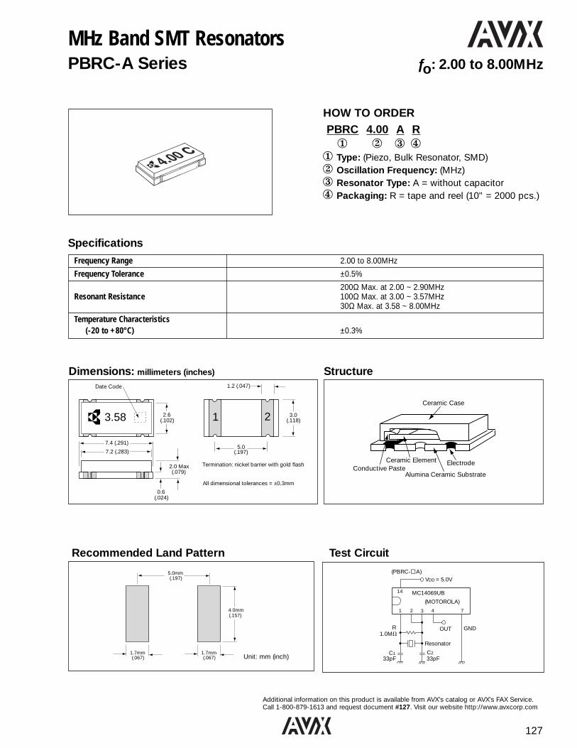
127
Additional information on this product is available from AVX’s catalog or AVX’s FAX Service.Call 1-800-879-1613 and request document #127. Visit our website http://www.avxcorp.com
MHz Band SMT ResonatorsPBRC-A Series ƒo: 2.00 to 8.00MHz
HOW TO ORDERPBRC 4.00 A R1 2 3 4
1 Type: (Piezo, Bulk Resonator, SMD)2 Oscillation Frequency: (MHz) 3 Resonator Type: A = without capacitor4 Packaging: R = tape and reel (10" = 2000 pcs.)
Dimensions: millimeters (inches) StructureDate Code 1.2 (.047)
2.6 (.102)
3.0(.118)
5.0(.197)
7.4 (.291)
7.2 (.283)
2.0 Max(.079)
0.6(.024)
Termination: nickel barrier with gold flash
All dimensional tolerances = ±0.3mm
1 23.58
SpecificationsFrequency Range 2.00 to 8.00MHz
Frequency Tolerance ±0.5%
200Ω Max. at 2.00 ~ 2.90MHzResonant Resistance 100Ω Max. at 3.00 ~ 3.57MHz
30Ω Max. at 3.58 ~ 8.00MHz
Temperature Characteristics(-20 to +80°C) ±0.3%
5.0mm (.197)
4.0mm (.157)
1.7mm(.067)
1.7mm(.067)
14
1 2 3 4 7
VDD = 5.0V
C1 C2
OUT GND
MC14069UB
(MOTOROLA)
Resonator
(PBRC-jA)
1.0MVR
33pF33pF
Recommended Land Pattern Test Circuit
Unit: mm (inch)
Ceramic Case
ElectrodeCeramic Element
Alumina Ceramic SubstrateConductive Paste

128
Additional information on this product is available from AVX’s catalog or AVX’s FAX Service.Call 1-800-879-1613 and request document #128. Visit our website http://www.avxcorp.com
MHz Band SMT Resonators withBuilt-in CapacitorPBRC-B Series ƒo: 2.00 to 36.00MHz
HOW TO ORDERPBRC 3.58 B R1 2 3 4
1 Type: (Piezo, Bulk Resonator, SMD)2 Oscillation Frequency: (MHz) 3 Resonator Type: B = with capacitor4 Packaging: R = tape and reel (10" = 2000 pcs.)
Dimensions: millimeters (inches)
SpecificationsFrequency Range 2.00 to 8.00MHz 8.01 to 36.00MHzLoad Capacitor 33pF (typ.) 10pF (typ)Frequency Tolerance ±0.5% ±0.7%Resonant Resistance 30Ω Max. 150Ω Max.Temperature Characteristics(-20 to +80°C) ±0.3% ±0.1%
Pad Connection
1 3
2
1. Input2. Ground3. Output
Note: Pads 1 and 3 are interchangeable.
Date Code 1.2 (.047)
2.6 (.102)
3.0(.118)
2.5(.098)
2.5(.098)
7.4 (.291)
7.2 (.283)
2.0 Max(.079)
0.6(.024)
Termination: nickel barrier with gold flash
All dimensional tolerances = ±0.3mm
1 2 33.58
Test Circuit
2.00 TO 8.00MHz 8.01 TO 36.00MHz
C2
VDD
C1
R
MC14069UB(MOTOROLA)
1.0MV
OUT GND
Resonator
33pF33pF
14
1 2 3 4 7
= 5.0V(PBRC-hB)
C2
VDD
C1
R
MC74HC04(MOTOROLA)
1.0MV
OUT GND
Resonator
10pF10pF
14
1 2 3 4 7
= 5.0V(PBRC-hB)

129
Additional information on this product is available from AVX’s catalog or AVX’s FAX Service.Call 1-800-879-1613 and request document #129. Visit our website http://www.avxcorp.com
MHz Band Leaded Ceramic ResonatorsKBR, -M, -MS, -MSA, -MSB Series ƒo: 2.00 to 12.00MHz
SpecificationsSeries MS MSA/MSB M
Dimension Fig. A Fig. B Fig. C
Frequency Range 2.00 to 3.50MHz 3.51 to 8.00MHz 8.01 to 12.00MHz
Frequency Tolerance ±0.5% 0.5% ±0.5%
Resonant Resistance 100Ω Max. 30Ω Max. 40Ω Max.
Temperature Characteristics
Fig. A Fig. B Fig. C
KBRMS
Date ofProduction
Frequency
(.472)12.0 Max.
10.0 Max.(.394)
5.0(.197)
1.2 (.047)
0.6 (.024)
5.0(.197)
5.0 Max.(.197)
0.2 (.008)
Date ofProduction
Frequency
5.0(.197)
5.0(.197)
5.0 Max.(.197)
0.3 (.012)
10.0 Max. (.394)
(.394)12.0 Max.
1.2 (.047)
0.5 (.020)
KBRM
Date ofProduction
Frequency
1.2 (.047)
0.6 (.024)
5.0(.197)
5.0(.197)
5.0 Max.(.197)
0.2 (.008)
7 Max.(.276)
(.394)10 Max.
Dimensions: millimeters (inches)
KBR-3.58MSA - 200 Series for Telephone D.T.M.F. ApplicationsTemperature
P/N Frequency Frequency Resonant Stability DimensionsTolerance Resistance(-20 to +80°C)
KBR-3.58MSA-201 +0 -0.25%
KBR-3.58MSA-202 +0.15 -0.10%
KBR-3.58MSA-203 +0.30 -0.05%
KBR-3.58MSA-204 3.5795MHz +0.45 +0.20% 30Ω Max. ±0.3% Fig. B
KBR-3.58MSA-205 +0.60 +0.35%
KBR-3.58MSA-206 -0.30 -0.55%
KBR-3.58MSA-207 -0.15 -0.40%
HOW TO ORDERKBR - 4.00 MSA TR1 2 3 4
1 Type: (Kyocera Bulk Resonator)2 Oscillation Frequency: (MHz)3 Resonator Type: M = 6.01 to 12.00MHz
MS = 2.00 to 3.57MHzMSA = 3.58 to 8.00MHz (Water Resistance)
MSB = 3.58 to 6.00MHz (No Clean)
4 Packaging: TR= tape and reel (14" = 2000 pcs)Blank u = Bulk (2000 pcs)
C2
VDD : 5V (2.0-8MHz) 12V (8.1-12MHz) only M Series
VDD
C1
f osc
R
C1, C2 : 33pFIC : 4069 (HEX INVERTER) (MOTOROLA)
RESONATOR
R : 1MV
Test Circuit

130
Additional information on this product is available from AVX’s catalog or AVX’s FAX Service.Call 1-800-879-1613 and request document #130. Visit our website http://www.avxcorp.com
High Frequency MHz Band Ceramic ResonatorsKBR-MY, -MSA Series ƒo: 12.01 to 36.00MHz
Dimensions: millimeters (inches)
HOW TO ORDERKBR - 16.00 MY TR1 2 3 41 Type: (Kyocera Bulk Resonator)2 Oscillation Frequency: (MHz) 3 Resonator Type: MY = 12.01 to 15.90MHz
MSA = 16.00 to 36.00MHz4 Standard Packaging: Blank u = Bulk (2000 pcs)
TR = tape and reel (14" = 2000 pcs)
R
10.0 Max.(.394)
Date Code
5.0(.197)
1.2(.047)
0.6(.024)
Frequency
5.0 Max.(.197)
0.2 (.008)
10.0 Max.(.394)
5.0(.197)
SpecificationsMY MSA
Frequency Range 12.01 to 15.90MHz 16.00 to 36.00MHzFrequency Tolerance ±0.5% ±0.5%Resonant Resistance 30Ω Max. 30Ω Max.Temperature Characteristics(-20 to +80°C) ±0.3% Max. ±0.3% Max.
Test Circuit
C2
VDD
C1
R
MC74HC04(MOTOROLA)
1.0MV
OUT GND
Resonator
33pF33pF
14
1 2 3 4 7
= 5.0V
KBR-MY KBR-MSA
KBR-MY KBR-MSA
Date ofProduction
Frequency
5.0(.197)
5.0(.197)
5.0 Max.(.197)
0.3 (.012)
10.0 Max. (.394)
(.394)12.0 Max.
1.2 (.047)
0.5 (.020)
C2
VDD
C1
R
MC74HCU04(MOTOROLA)
1.0MV
OUT GND
Resonator
10pF10pF
14
1 2 3 4 7
= 5.0V

131
Additional information on this product is available from AVX’s catalog or AVX’s FAX Service.Call 1-800-879-1613 and request document #131. Visit our website http://www.avxcorp.com
Built-in Capacitor MHz Band Ceramic ResonatorsKBR-MKC/MKD Series ƒo: 3.58 to 36.00MHz
Dimensions: millimeters (inches)
HOW TO ORDERKBR - 4.00 MKC TR1 2 3 41 Type: (Kyocera Bulk Resonator)2 Oscillation Frequency: (MHz) 3 Resonator Type: MKC = built-in capacitor (No Clean)
MKD = built-in capacitor (Water Resistance)
4 Standard Packaging: Blank u = Bulk (2000 pcs)TR = tape and reel (14" = 2000 pcs)
10.0 max.(.394)
6.0 max.(.236)
5.0(.197)
5.0 max.
0.3(.012)0.5
(.020)
2.5(.098)
2.5(.098)
1 2 31,3 Input, Output 2 Ground
(No Polarity)
10.0 max.(.394)
8.0 max.(.315)
5.0(.197)
5.0 Max.
0.3(.012)0.5
(.020)
2.5(.098)
2.5(.098)
1 2 31,3 Input, Output 2 Ground
(No Polarity)
10.0 max.(.394)
9.5 max.(.374)
5.0(.197)
5.0 max.
0.3(.012)0.5
(.020)
2.5(.098)
2.5(.098)
1 2 31,3 Input, Output 2 Ground (No Polarity)
Specifications
MKC/MKD MKDFrequency Range 3.58 to 8.00MHz 16.00 to 36.00MHz
Frequency Tolerance ±0.5% ±0.5%
Resonant Resistance 30Ω 30ΩTemperature Characteristics
(-20 to +80°C) ±0.5% ±0.3%
Test Circuit
C2
VDD
C1
fosc
R
IC : MC14069
C1, C2 : 33pF (Typ.)
R : 1MV
5V
1 3
2
C2
VDD
C1
fosc
R
IC : MC74H404
C1, C2 : 10pF (Typ.)
R : 1MV
5V
1 3
2
3.45~8.0MHz(MKC Type)
3.58~8.0MHz 16.0~36MHz
3.45~8.0MHz(MKD Type) 16.0~36.0MHz(MKD Type)
Pin Connection
1 3
2
1. Input2. Ground3. Output
Note: Pins 1 and 3 are interchangeable.

132
Additional information on this product is available from AVX’s catalog or AVX’s FAX Service.Call 1-800-879-1613 and request document #132. Visit our website http://www.avxcorp.com
SAW ResonatorsPAR Series SMT MHz Band ƒo: 300 to 450MHz
1
34
2
4 – 1.0±0.2v (0.04±0.008)
4 – 1.0±0.2 (0.04±0.008)
4 – 0.6±0.2 (0.024±0.008)
1.9±0.2(0.075
±0.008)
4 – R 0.15 (0.006)
4 – R 0.15 (0.006)
3.8±0.2(0.15±0.008)
2.76±0.2(0.11±0.008)
5.5±0.2(0.22±0.008)
HOW TO ORDERPAR S 433.92 K 04 41 2 3 4 5 61 SMT SAW Resonator2 Type3 Frequency: Please see Electrical Characteristics table 4 Marking Code: See table 5 Frequency Tolerance or Custom Specification:
00 : ±250KHz 04 : ±75KHz01 : ±200KHz 10≥ : Tolerance02 : ±150KHz 11≤ : Custom Spec03 : ±100KHz
6 Package: R : Tape & reel (2K pcs/R)
Specifications (PARS)Part Number Resonant Frequency (MHz) Resonant Loss (dB) Parallel Capacitance (pF)PARS 304,45LXXR 304,45 2.5 max. 4.0 max.PARS 310,00KXXR 310,00 2.5 max. 4.0 max.PARS 314,00KXXR 314,00 2.5 max. 3.2 max.PARS 314,50LXXR 314,50 2.5 max. 3.2 max.PARS 315,00KXXR 315,00 2.5 max. 3.2 max.PARS 320,65KXXR 320,65 2.5 max. 3.2 max.PARS 423,22KXXR 423,22 2.5 max. 3.2 max.PARS 432,92KXXR 432,92 2.5 max. 3.2 max.PARS 432,42LXXR 433,42 2.5 max. 3.2 max.PARS 433,92KXXR 433,92 2.5 max. 3.2 max.
Dimensions: millimeters (inches)
Resonant Frequency Marking CodeMHz
304,45 304 L310,00 310 K314,00 314 K314,50 314 L315,00 315 K320,65 320 K423,22 423 K432,92 432 K433,42 433 L
1.25(0.05)
1.25(0.05)
1.25(0.05)
1.5(0.06)
1.5(0.06)
0.15 (0.006)
0.15 (0.006)
1.0(0.04)
1.0(0.04)
1.25(0.05)
Recommended Land Pattern:millimeters (inches) Marking Code
315K C
Monthly Code
(4 digitsFrequency Marking)
Pin Function➀ Hot➁ NC
➂ Hot
➃ NC

133
Additional information on this product is available from AVX’s catalog or AVX’s FAX Service.Call 1-800-879-1613 and request document #133. Visit our website http://www.avxcorp.com
SAW ResonatorsKAR Series MHz Band ƒo: 46 to 315MHz
HOW TO ORDERKAR - 91 CS1 2 31 Type: (Kyocera Acoustic Resonator)2 Oscillation Frequency: (MHz)3 Resonator Type:
CS, CT = small packagingCB, CD = standard packagingCK = round packaging
Dimensions: millimeters (inches)
Specifications (KAR -u-u)
7.7(.303)
3.2(.126)
9.0(.354)
2.75 (.108)
5.0(.197) 15.6
(.614)
2.5(.098)
4 - [0.65 (.026)
12
34
Ø5.08
Ø9.20
1
2
33.0
3.0Ø0.45
1 2 3
Channel* Resonant Frequency Resonant Loss Parallel Temperature Stability(MHz)** (dB) Capacitance (pF) -10°C to +60°C (ppm/°C) Dimension
2 55.24±0.08 3.8±1KAR-55CD U- 3 61.24±0.08
5.0 MAX3.9±1
±8
5 77.24±0.08 4.5±1KAR-83CB U-6 83.24±0.08
4.0 MAX4.2±1
±7
3 55.24±0.08 4.3±1KAR-55CB W-4 62.24±0.08
5.0 MAX3.7±1
±8 Figure A
3 86.24±0.08 4.2±1KAR-86CB A-4 95.24±0.08
3.0 MAX4.0±1
±5
4 85.24±0.08 4.2±1KAR-85CB O-5 93.24±0.08
3.0 MAX4.0±1
±5
*J: Japan, U: USA, W: Germany, A: Australia, O: East Europe
**Other frequencies available on request.
Fig. A 1. L-ch Fig. B 1. L-ch2. H-ch 2. H-ch4. GND 3. GND3. Common 4. Common
Fig. C 1. Hot2. Hot3. Ground
8(.315)
3.5 (.138)
4 [ 0.65 (.026) 2.0
(.079)
7.2(.283)
12.0(.472)
3 - 2.5 (.098)
12
34
3 61.24±0.08 4.4±1KAR-61CT U- 4 67.24±0.08
5.0 MAX4.2±1
±8
3 77.24±0.08 3.1±1KAR-77CS O-4 83.24±0.08
4.5 MAX2.8±1
±8
1 91.24±0.08 4.0±1KAR-91CS J-2 97.24±0.08
3.0 MAX ±5 Figure B
KAR-211CS U-13 211.24±0.15 2.7 MAX 3.0±1 ±8
KAR-315CS US 315.24±0.25 2.5 MAX 3.2 MAX ±8
KAR-315CK US 315.24±0.25 2.5 MAX 3.2 MAX ±8 Figure C

134
Additional information on this product is available from AVX’s catalog or AVX’s FAX Service.Call 1-800-879-1613 and request document #134. Visit our website http://www.avxcorp.com
SAW ResonatorsKAR Series MHz Band ƒo: 46 to 315MHz
Specifications (KAR -u-u)Part Number Resonant Frequency Resonant Loss Parallel Temperature Stability
(MHz) (dB) Capacitance (pF) (ppm/°C) DimensionKAR-303CS 303.875±0.250
KAR-304CS 304.300±0.250 4.0 max.
KAR-310CS 310.000±0.250
KAR-314CS 314.000±0.250
KAR-314CT 314.500±0.250
KAR-315CS 315.000±0.250
KAR-320CS 320.650±0.250
KAR-345CS 345.000±0.250 2.5 max. ±8 max. Fig. B
KAR-359CS 359.900±0.250 3.2 max.
KAR-417CS 417.500±0.250
KAR-418CS 418.000±0.250
KAR-423CS 423.220±0.250
KAR-432CS 432.920±0.250
KAR-433CS 433.920±0.250
KAR-433CT 433.420±0.250
KAR-479CS 479.500±0.500 2.3 max.
KAR-303CK 303.875±0.250
KAR-304CK 304.300±0.250 4.0 max.
KAR-310CK 310.000±0.250
KAR-314CK 314.000±0.250
KAR-314CL 314.500±0.250
KAR-315CK 315.000±0.250
KAR-320CK 320.650±0.250
KAR-345CK 345.000±0.250 2.5 max. ±8 max. Fig. C
KAR-359CK 359.900±0.250 3.2 max.
KAR-417CK 417.500±0.250
KAR-418CK 418.000±0.250
KAR-423CK 423.220±0.250
KAR-432CK 432.920±0.250
KAR-433CK 433.920±0.250
KAR-433CL 433.420±0.250
KAR-479CK 479.500±0.500 2.3 max.
KAR-303CF 303.875±0.250
KAR-304CF 304.300±0.250 4.0 max.
KAR-310CF 310.000±0.250
KAR-314CF 314.000±0.250
KAR-314CG 314.500±0.250
KAR-315CF 315.000±0.250
KAR-320CF 320.650±0.250
KAR-345CF 345.000±0.250
KAR-359CF 359.900±0.250 2.5 max. ±8 max. Fig. D
KAR-417CF 417.500±0.250 3.2 max.
KAR-418CF 418.000±0.250
KAR-423CF 423.220±0.250
KAR-432CF 432.920±0.250
KAR-433CF 433.920±0.250
KAR-433CG 433.420±0.250
KAR-479CF 479.500±0.500 2.3 max.

135
Additional information on this product is available from AVX’s catalog or AVX’s FAX Service.Call 1-800-879-1613 and request document #135. Visit our website http://www.avxcorp.com
Crystal Clock Oscillators - Miniature SMTK50-HC-CS Series: HCMOS Drive -TTL/CMOS Compatible ƒo: 8 to 68MHz
SpecificationsCLASSIFICATION CODE RATING UNIT REMARKSOutput Frequency f OUT 8~68 MHz ———Frequency Precision Df/f ±100, ±50 ppm Inclusive of Temp, Load, Voltage variation
Aging Rate Df/f ±5 ppm/y ———
Operating Temp. TOPR -10~70 °C ———
Storage Temp. TSTR -55~125 °C ———
Supply Voltage Vcc 5±0.5 V ———
Supply Current I cc 50 max. mA CL=50pF, Temp.=25°C, f=50MHZ
Duty Ratio Sy 45~55 % 0.5Vcc DC Level
Output 0 Level V OL 0.1Vcc max. V IOL=16mA
Output 1 Level V OH 0.9Vcc min. V IOH=-16mA
Rise/Fall Time TR, TF 10 max. nsec 0.1Vcc-0.9Vcc
Load Capacitance CL 50 max. (f≤50MHz), 15 max. (f>50MHz) pF ———
Enable/Disable Time — 100 max. nsec ———
Input Voltage Low VIL 0.8 max. V ———
Input Voltage High VIH 2.2 min. V ———
HOW TO ORDERK50-HC 1 - CS E 40.0000M R
1 2 3 4 5 61 Type: (K50-HC series)2 Stability: 1-100ppm, 0-50ppm3 Output Compatibility: CS = CMOS 45/55 duty cycle @ 50% VDD
4 Tristate Output: E with function5 Frequency: (MHz)6 Standard Packaging: R = tape and reel (1k per reel)
Pad # Function
1 CONTROL
2 CASE GND
3 OUTPUT
4 +VCC
Pin #1 Pin #3
“H” or Open Oscillation
“L” High impedance
A
VVCC
0.1mFNC
4 3
1 2
T.P.
50pF(max.)
CL=50pF (f≤50MHz), CL=15pF (f>50MHz)(Inclusive of test JIG and probe capacitance)
A B
0.1 VCC
0.5 VCC
0.9 VCC
TFTR
Duty Ratio = A
A+Bx 100
32.00001B W01
FrequencyPrecision 1<3
Pin #1 Indication
Output Frequency4 3
21
Model Lot Number
<3
<3
Marking
1) I : ±100ppm, 0 : ±50ppm
Test Circuit
Pin Connection Enable / Disable
Output Waveform Marking Specifications

136
Additional information on this product is available from AVX’s catalog or AVX’s FAX Service.Call 1-800-879-1613 and request document #136. Visit our website http://www.avxcorp.com
Crystal Clock Oscillators - Miniature SMTK50-3C Series: 3.3Volt ƒo: 8 to 68MHz
SpecificationsCLASSIFICATION CODE RATING UNIT REMARKSOutput Frequency f OUT 8~68 MHz ———Frequency Precision Df/f ±100, ±50 ppm Inclusive of Temp, Load, Voltage variation
Aging Rate Df/f ±5 ppm/y ———
Operating Temp. TOPR -10~70 °C ———
Storage Temp. TSTR -55~125 °C ———
Supply Voltage Vcc 3.3±0.3 V ———
Supply Current I cc 25 max. mA CL=15pF, Temp.=25°C, f=68MHZ
Duty Ratio Sy 40~60 % 0.5Vcc DC Level
Output 0 Level V OL 0.1Vcc max. V IOL=8mA
Output 1 Level V OH 0.9Vcc min. V IOH=8mA
Rise/Fall Time TR, TF 10 max. nsec 0.1Vcc-0.9Vcc
Load Capacitance CL 15 max. pF ———
5 msec 8<f≤32MHz
Enable/Disable Time — 150 nsec 32<f≤50MHz
5 msec 50<f≤68MHz
Input Voltage Low VIL 0.5 max. V ———
Input Voltage High VIH 2.0 min. V ———
HOW TO ORDERK50-3C 1 -E 40.0000M R
1 2 3 4 51 Type: (K50-3C series)2 Stability: 1-100ppm, 0-50ppm3 Tristate Output: E with function4 Frequency: (MHz)5 Standard Packaging: R = tape and reel (1k per reel)
Pad # Function
1 CONTROL
2 CASE GND
3 OUTPUT
4 +VCC
Pin #1 Pin #3
“H” or Open Oscillation
“L” High impedanceor Oscillation Stop
A
VVCC
0.1mFNC
4 3
1 2
T.P.
15pF
CL=15pF (Inclusive of test JIG and probe capacitance)
A B
0.1 VCC
0.5 VCC
0.9 VCC
TFTR
Duty Ratio = A
A+Bx 100
32.00001L W01
FrequencyPrecision 1<3
Pin #1 Indication
Output Frequency4 3
21
Model Lot Number
<3
<3
Marking
1) I : ±100ppm, 0 : ±50ppm
Test Circuit
Pin Connection Enable / Disable
Output Waveform Marking Specifications

137
Additional information on this product is available from AVX’s catalog or AVX’s FAX Service.Call 1-800-879-1613 and request document #137. Visit our website http://www.avxcorp.com
Crystal Clock Oscillators - Miniature SMTK50-CS Series: Low Power Consumption ƒo: 8 to 50MHz
SpecificationsCLASSIFICATION CODE RATING UNIT REMARKSOutput Frequency f OUT 8~50 MHz ———Frequency Precision Df/f ±100, ±50 ppm Inclusive of Temp, Load, Voltage variation
Aging Rate Df/f ±5 ppm/y ———
Operating Temp. TOPR -10~70 °C ———
Storage Temp. TSTR -55~125 °C ———
Supply Voltage Vcc 5±0.5 V ———
Supply Current I cc 30 max. mA CL=15pF, Temp.=25°C, f=50MHZ
Duty Ratio Sy 45~55 % 0.5Vcc DC Level
Output 0 Level V OL 0.1Vcc max. V IOL=4mA
Output 1 Level V OH 0.9Vcc min. V IOH=4mA
Rise/Fall Time TR, TF 10 max. nsec 0.1Vcc-0.9Vcc
Load Capacitance CL 15 max. pF ———
Enable/Disable Time — 100 max. nsec ———
Input Voltage Low VIL 0.8 max. V ———
Input Voltage High VIH 2.2 min. V ———
HOW TO ORDERK50-CS 1 - S E 40.0000M R
1 2 3 4 5 61 Type: (K50-CS series)2 Stability: 1-100ppm, 0-50ppm3 Duty Cycle: 45 to 55%4 Tristate Output: E with function5 Frequency: (MHz)6 Standard Packaging: R = tape and reel (1k per reel)
Pad # Function
1 CONTROL
2 CASE GND
3 OUTPUT
4 +VCC
Pin #1 Pin #3
“H” or Open Oscillation
“L” High impedance
A
VVCC
0.1mFNC
4 3
1 2
T.P.
15pF
CL=15pF (Inclusive of test JIG and probe capacitance)
A B
0.1 VCC
0.5 VCC
0.9 VCC
TFTR
Duty Ratio = A
A+Bx 100
32.00001A W01
FrequencyPrecision 1<3
Pin #1 Indication
Output Frequency4 3
21
Model Lot Number
<3
<3
Marking
1) I : ±100ppm, 0 : ±50ppm
Test Circuit
Pin Connection Enable / Disable
Output Waveform Marking Specifications

138
Additional information on this product is available from AVX’s catalog or AVX’s FAX Service.Call 1-800-879-1613 and request document #138. Visit our website http://www.avxcorp.com
KT14
KT14 Series SMT Crystal Clock OscillatorsTemperature Compensated
HOW TO ORDERKT14 - E G R 28 N - 19.200M T1 2 3 4 5 6 7 81 Type2 Frequency Precision:
D=±2ppm, E=±2.5ppm, K=±5ppm3 Lower Temperature Limit:
C=-30°C; E=-20°C, G=-10°C4 Upper Temperature Limit:
V=80°C; T=70°C; R=60°C5 Supply Voltage: 28=2.8V, 30=3.0V; 6 AFC Function: V=with, N=without7 Output Frequency: 12.8M, 13.0M, 14.4M,
14.85M, 16.8M, 19.2M, 19.44M, 19.68M8 Reel Packaging: 2000 pcs per reel
KT14 Recommended Pad Layout
A
VVDD
C1
Osciloscope(~100 MHz)
Oscillator
C1: 10pF Inclusive of test jig and probe capacitance
1 2
4 3PowerSupply
N.C. or Vcon
10KΩ
A
VVDD
10pF
Spectrum Analyzer/Counter
Oscillator1 2
4 3PowerSupply
N.C. or Vcon
10KΩ
FET Probe
1.60
4.6
1.60
1.40 1.403.68
#2 PIN(GND)
#1 PIN(N. C. or Vcont)
#3 PIN(OUTPUT)
#4 PIN(Vcc)
(°C)
300
200
150
100
Over 200°C15 sec. max.
Over 180°C
40 sec. max.
Peak230°C ±5°C
Test Circuit (Amplitude)
Test Circuit (Harmonic Frequency)
5.08 ± 0.15
9.0 ± 0.3
1.2 ± 0.1
1.7 Max
7.0 ± 0.3
1.2 ± 0.1
(4.6)
1.4 0.7
1 2
4 3
#1 Pin Mark Marking
PIN CONNECTION1 Vcont2 GND/CASEGND3 OUTPUT4 +VCC
Units: mm
Recommended Reflow Profile
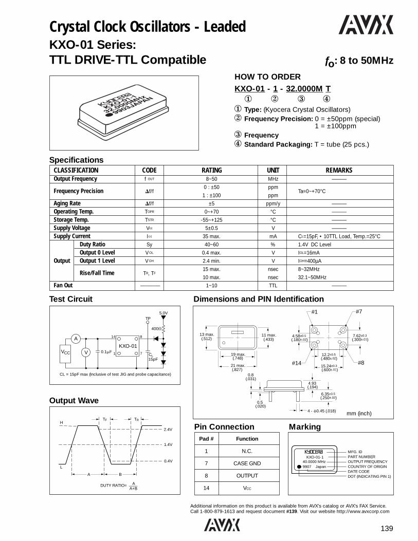
139
Additional information on this product is available from AVX’s catalog or AVX’s FAX Service.Call 1-800-879-1613 and request document #139. Visit our website http://www.avxcorp.com
SpecificationsCLASSIFICATION CODE RATING UNIT REMARKSOutput Frequency f OUT 8~50 MHz ———
0 : ±50 ppmFrequency Precision Df/f
1 : ±100 ppmTa=0~+70°C
Aging Rate Df/f ±5 ppm/y ———
Operating Temp. TOPR 0~+70 °C ———
Storage Temp. TSTR -55~+125 °C ———
Supply Voltage Vcc 5±0.5 V ———
Supply Current I cc 35 max. mA CL=15pF, • 10TTL Load, Temp.=25°C
Duty Ratio Sy 40~60 % 1.4V DC Level
Output 0 Level V OL 0.4 max. V IOL=16mA
Output Output 1 Level V OH 2.4 min. V IOH=400µA
Rise/Fall Time TR, TF15 max. nsec 8~32MHz
10 max. nsec 32.1~50MHz
Fan Out ———— 1~10 TTL ———
Pad # Function
1 N.C.
7 CASE GND
8 OUTPUT
14 VCC
Pin Connection Marking
Crystal Clock Oscillators - LeadedKXO-01 Series:TTL DRIVE-TTL Compatible ƒo: 8 to 50MHz
HOW TO ORDERKXO-01 - 1 - 32.0000M T1 2 3 4
1 Type: (Kyocera Crystal Oscillators)2 Frequency Precision: 0 = ±50ppm (special)
1 = ±100ppm3 Frequency4 Standard Packaging: T = tube (25 pcs.)
Dimensions and PIN Identification#1 #7
#14 #8
13 max.(.512)
11 max.(.433)
19 max.(.748)
21 max.(.827)
0.8(.031)
0.5 (.020)
4.93(.194)
4.58±0.5(.180±.02)
7.62±0.3(.300±.01)
12.2±0.5(.480±.02)
15.24±0.3(.600±.01)
6.35±0.5(.250±.02)
4 - f0.45 (.018) mm (inch)
A
VVCC CL
KXO-010.1mF
400V
TP5.0V
15pF
CL = 15pF max (Inclusive of test JIG and probe capacitance)
14 8
1 7
TF TRH
L
A B
2.4V
1.4V
0.4V
DUTY RATIO= A____A+B
Test Circuit
Output Wave
KXO-01-140.0000 MHz9907 Japan
MFG. IDPART NUMBEROUTPUT FREQUENCYCOUNTRY OF ORIGINDATE CODEDOT (INDICATING PIN 1)

140
Additional information on this product is available from AVX’s catalog or AVX’s FAX Service.Call 1-800-879-1613 and request document #140. Visit our website http://www.avxcorp.com
VCC-0.8V
12a
2.0V
0.8V
12b
t5 14 t3b
t3a
HOW TO ORDER386-HC 1 - C S E - 40.0000M T1 2 3 4 5 6
1 Type: 386 = 14 pin DIP2 Frequency Precision: 1 = ±100ppm3 Output Level/Duty Cycle: CS = CMOS compatible/45 to 55%4 Enable/Disable Function: u = without function, E = with function 5 Frequency6 Packaging: T = tube (25 pcs.)
A
VVDDCL
386-HC0.1mF
T.P.
50pF
CL = 150pF max (Inclusive of test JIG and probe capacitance)
8 5
1 4
Dimensions
386-HC1-CSE32.0000 MHz9907 Japan
MFG. IDPART NUMBEROUTPUT FREQUENCYCOUNTRY OF ORIGINDATE CODEDOT (INDICATING PIN 1)
Markings Pin Connection386 Function
1 N.C. or Control
7 Case GND
8 Output
14 VDD
Clock Time Table (32MHz, 40MHz)Frequency 32MHz 40MHzClock time (ns) Min Max Min MaxClock high time t2a 9 – 8 –Clock high time t2b 5 – 5 –Clock low time t3a 9 – 8 –Clock low time t3b 7 – 6 –Clock tall time t4 – 7.5 – 8Clock rise time t5 – 7.5 – 8
Test Circuit
12a
3.7V
2.0V
0.8V
12b
t5 14 t3b
t3a
Clock Time Table (50MHz)Frequency 50MHzClock time (ns) Min MaxClock high time t2a 7 –Clock high time t2b 4 –Clock low time t3a 7 –Clock low time t3b 5 –Clock tall time t4 – 7Clock rise time t5 – 7
Crystal Clock Oscillators386 Series: HCMOS Drive - CMOS Compatible ƒo: 24, 32, 40, 50MHz
0.8(.031)
4-ø0.45(.018)
7.5 (.28)
6.35 (.25)
PIN 7
PIN 8PIN 14
PIN 1
4.58 (.180)
15.24 (.600)21 (.828)
7.62(.300)
12.2(.408)
13(.512)
Unit: mm (inch)
386-HC1-CSE
32.0000 MHz
9907 Japan
Specifications
CLASSIFICATION CODE RATING UNIT REMARKS
Output Frequency f OUT 25, 32, 40, 50 MHz CL=150pF max. (25, 32, 40MHz)CL=80pF max. (50MHz)
Frequency Precision(Inclusive of Temp. Voltage variation)
Df/f 1: ±100 ppm Ta=0~+70°C
Aging Rate Df/f ±5 ppm/year ———
Operating Temp. TOPR 0~+70 °C ———
Storage Temp. TSTR -55~+125 °C ———
Supply Voltage Vcc 5±0.25 V ———
Supply Current I cc 65 max. mA CL=150pF, Ta=25°C
Duty Ratio Sy 45~55 % 0.5VCC DC Level
Output 0 Level V OL 0.1VCC max. V IOL = 12mAOutput
Output 1 Level V OH 0.9VCC min. V IOH = -1mA
Rise/Fall Time TR, TF See Clock Time Table nsec
Time to Enable/Disable ——— 100 max. nsec ———
Input Current I IH 10 max. µA VCC=5.25VI IL -150 max. µA VCC=5.25V
Input VoltageVIH 2.2 min. VV IL 0.8 max. V
———
Fan Out ——— 7 TTL ———
Loan Capacitance CL150 pF f=25, 32, 40MHz80 pF f=50MHz

141
Additional information on this product is available from AVX’s catalog or AVX’s FAX Service.Call 1-800-879-1613 and request document #141. Visit our website http://www.avxcorp.com
Specifications: TTL CompatibleCLASSIFICATION CODE RATING UNIT REMARKSOutput Frequency f OUT 1~50 50.1~72 MHz ———Frequency Precision 0 : ±50 ppm
(Inclusive of Temp. Voltage variation)Df/f
1 : ±100 ppmTa=0~+70°C
Aging Rate Df/f ±5 ppm/year ———
Operating Temp. TOPR 0~+70 °C ———
Storage Temp. TSTR -55~+125 °C ———
Supply Voltage Vcc 5±0.5 5±0.25 V ———
Supply Current I cc 50 max. 70 max. mA CL=15pF • 10TTL Load, Ta=25°C
Duty Ratio Sy 45~55 % 1.4V DC Level
Output 0 Level V OL 0.4 max. V IOL=16mA
Output Output 1 Level V OH 2.4 min. V IOH=-1mA
Rise/Fall Time TR, TF 5.0 max. 3.5 max. nsec 0.4V~2.4V CL=15pF, • 10TTL Load
Time to Enable/Disable ——— 100 max. nsec ———
Input CurrentI IH 10 max. µA VCC=5.5V
I IL -150 max. µA VCC=5.5V
Input VoltageVIH 2.2 max. V
V IL 0.8 max. V———
Fan Out ——— 10 TTL ———
Load Capacitance CL 15 max. pF ———
Crystal Clock Oscillators - LeadedKXO-HC/KHO-HC Series: HCMOS Drive - ƒo: 1 to 72MHzTTL or CMOS Compatible
HOW TO ORDERKXO-HC 1 -TS E - 32.0000M T1 23 4 5 61 Type: KXO = 14 pin DIP; KHO = 8 pin DIP2 Frequency Precision: S = ±25ppm (special)
0 = ±50ppm1 = ±100ppm
3 Output Level/Duty Cycle: TS = TTL compatible/45 to 55%CS = CMOS compatible/45 to 55%
4 Enable/Disable Function: Blank u = without function E = with function
5 Frequency6 Standard Packaging: T = tube (KXO-HC = 25 pcs.)
(KHO-HC = 40 pcs.)
A
VVDD CL
KXO-HC0.1mF
400V
TP5.0V
15pF
CL = 15pF max (Inclusive of test jig and probe capacitance)
14 8
1 7
TF TRH
L
A B
2.4V
1.4V
0.4V
DUTY RATIO= A____A+B
Test Circuit(KXO-HC-T/KHO-HC-T)
Shape of Output Wave(KXO-HC-T/KHO-HC-T)

142
Additional information on this product is available from AVX’s catalog or AVX’s FAX Service.Call 1-800-879-1613 and request document #142. Visit our website http://www.avxcorp.com
Specifications: CMOS CompatibleCLASSIFICATION CODE RATING UNIT REMARKSOutput Frequency f OUT 1~50 50.1~72 MHz ———
Frequency Precision 0 : ±50 ppm
(Inclusive of Temp. Voltage variation)Df/f
1 : ±100 ppmTa=0~+70°C
Aging Rate Df/f ±5 ppm/year ———
Operating Temp. TOPR 0~+70 °C ———
Storage Temp. TSTR -55~+125 °C ———
Supply Voltage Vcc 5±0.5 5±0.25 V ———
Supply Current I cc 50 max. 80 max. mA CL=50pF, Ta=25°C
Duty Ratio Sy 45~55 % 0.5VCC DC Level
Output 0 Level V OL 0.1VCC max. V IOL = 16mAOutput
Output 1 Level V OH 0.9VCC min. V IOH = 1mA
Rise/Fall Time TR, TF 10 max. 6 max. nsec 0.1CC~0.9CC CL=50pF
Time to Enable/Disable ——— 100 max. nsec ———
Input CurrentI IH 10 max. µA VCC=5.5V
I IL -150 max. µA VCC=5.5V
Input VoltageVIH 2.2 max. V
V IL 0.8 max. V———
Load Capacitance CL 50 max. pF ———
Crystal Clock Oscillators - LeadedKXO-HC/KHO-HC Series HCMOS Drive - ƒo: 1 to 72MHzTTL or CMOS Compatible (Continued)
Dimensions and PIN Identification
#1 #7
#14 #8
13 max.(.512)
11 max.(.433)
19 max.(.748)
21 max.(.827)
0.8(.031)
0.5 (.020)
4.93(.194)
4.58±0.5(.180±.02)
7.62±0.3(.300±.01)
12.2±0.5(.480±.02)
15.24±0.3(.600±.01)
6.35±0.5(.250±.02)
4 - f0.45 (.018)
mm (inch)
#1 #4
#8 #5
12.9(.508)
12.9(.508)
10.8(.425)
10.8(.425)
7.62(.300)
0.8(.031)
5.08(.200)
6.35(.250)
4 - f0.55max.(.022)
mm (inch)
KXO-HC
KHO-HC
Pin ConnectionKXO KHO
1 1 N.C. or Control
7 4 Case/GND
8 5 Output
14 8 +5.0V D.C.
Enable / Disable Function ChartPin 1 Pin 8
High or Open Oscillation
Low High Impedance
A
VVDDCL
KHO-HC0.1mF
T.P.
50pF
CL = 50pF max (Inclusive of test jig and probe capacitance)
8 5
1 4
TF TRH
L
A B
0.9V
0.5V
0.1V
DUTY CYCLE= A____A+B
Test Circuit(KXO-HC-C/KHO-HC-C)
Shape of Output Wave(KXO-HC-C/KHO-HC-C) Markings
KXO-HC
KHO-HC
HCI-TS24.00009907 JPN
MFG. IDPART NUMBEROUTPUT FREQUENCYCOUNTRY OF ORIGINDATE CODEDOT (INDICATING PIN 1)
KXO-HC-TSE42.0000 MHz9907 Japan
MFG. IDPART NUMBEROUTPUT FREQUENCYCOUNTRY OF ORIGINDATE CODEDOT (INDICATING PIN 1)

143
Additional information on this product is available from AVX’s catalog or AVX’s FAX Service.Call 1-800-879-1613 and request document #143. Visit our website http://www.avxcorp.com
MIL-PRF-28861 /1, /4, /5, /12Hermetically SealedEMI Filters (B-level) HOW TO ORDER
MIL-PRF-28861 /2 - 0011 2 3
1 Mil-Spec Number2 Slash Sheet3 Dash Number
.200±.010
.410MAX
.120MIN.140
MIN
.410DIA. MAX
B
A
.115 2 PLACES
.070±.010 DIA.2 PLACES
.250-2B UNF-2A
+.010-.015
.200±.010
L
.145±.045
.145±.045
.410DIA. MAX
A
.070±.010 DIA.2 PLACES.250-2B UNF-2A
.115 2 PLACES
+.010-.015
.200±.010
.793 MAX
.145±.045
.145±.045
.410DIA. MAX
A
.070±.010 DIA.2 PLACES.250-2B UNF-2A
.115 2 PLACES
+.010-.015
GLASS SEAL(EITHER SIDE)
0.020 0.128
0.156A
B REF0.25 ±0.032 Places
0.030±0.002
(See MIL-PRF-22861 for insertion loss and other specification details.)
Dash Cir- Rated Min.number cuit voltage capaci-
DC AC 1/ tancevolts volts (µF)
010, 020 C 200 125 0.15
021, 031 L2 200 125 0.01
022, 032 C 200 125 0.01
023, 033 L2 200 125 0.0027
024, 034 C 200 125 0.0027
025, 035 L2 200 125 0.001
026, 036 C 200 125 0.001
MIL-PRF-28861/1
Dash Cir- Max. Min. Max. Max.number cuit current capaci- voltage DC
(amps) tance drop resist-(µF) (volts) ance
(ohms)010, 028 L1 1.0 0.70 0.14 0.14
011, 029 L2 1.0 0.70 0.14 0.14
012, 030 π 1.0 1.4 0.14 0.14
013, 031 L1 3.0 0.70 0.15 0.05
014, 032 L2 3.0 0.70 0.15 0.05
015, 033 π 3.0 1.4 0.15 0.05
016, 034 L1 5.0 0.70 0.075 0.015
017, 035 L2 5.0 0.70 0.075 0.015
018, 036 π 5.0 1.4 0.075 0.015
MIL-PRF-28861/5
MIL-PRF-28861/12
Dash Cir- Max. Capaci- Max. Max.number cuit current tance voltage DC
(amps) (µF) drop resist-+100% (volts) ance
-0% (ohms)001, 013 L1 0.25 0.15 0.375 1.5
002, 014 L2 0.25 0.15 0.375 1.5
003, 015 π 0.25 0.30 0.375 1.5
004, 016 L1 1.0 0.15 0.250 0.25
005, 017 L2 1.0 0.15 0.250 0.25
006, 018 π 1.0 0.30 0.250 0.25
Dash Cir- Rated Min.number cuit voltage capaci-
DC AC 1/ tancevolts volts (µF)
001, 011 L2 50 - - - 1.2
002, 012 C 50 - - - 1.2
003, 013 L2 70 - - - 0.7
004, 014 C 70 - - - 0.7
005, 015 L2 100 - - - 0.45
006, 016 C 100 - - - 0.45
009, 019 L2 200 125 0.15
Dash Cir- Max. Min. Max. Max.number cuit current capaci- voltage DC
(amps) tance drop resist-(µF) (volts) ance
(ohms)001, 019 L1 0.10 0.70 0.17 1.7
002, 020 L2 0.10 0.70 0.17 1.7
003, 021 π 0.10 1.4 0.17 1.7
004, 022 L1 0.30 0.70 0.23 0.77
005, 023 L2 0.30 0.70 0.23 0.77
006, 024 π 0.30 1.4 0.23 0.77
007, 025 L1 0.50 0.70 0.18 0.36
008, 026 L2 0.50 0.70 0.18 0.36
009, 027 π 0.50 1.4 0.18 0.36
Dash Circuit Max. Rated Capaci-number current voltage tance
(amps) volts (pF)dc -0,
+100%002, 018 C 5.0 50 15,000003, 019 L 5.0 100 2,700004, 020 C 5.0 100 2,700005, 021 L 5.0 100 5,000006, 022 C 5.0 100 5,000008, 024 C 5.0 200 10009, 025 L 5.0 200 25010, 026 C 5.0 200 25012, 028 C 5.0 200 100013, 029 L 5.0 200 500014, 030 C 5.0 200 500034, 036 C 5.0 50 10,000
Dash Cir- Max. Capaci- Max. Max.number cuit current tance voltage DC
(amps) (µF) drop resist-+100% (volts) ance
-0% (ohms)007, 019 L1 3.0 0.15 0.150 0.05
008, 020 L2 3.0 0.15 0.150 0.05
009, 021 π 3.0 0.30 0.150 0.05
010, 022 L1 5.0 0.15 0.075 0.015
011, 023 L2 5.0 0.15 0.075 0.015
012, 024 π 5.0 0.30 0.075 0.015
MIL-PRF-28861/4

144
Additional information on this product is available from AVX’s catalog or AVX’s FAX Service.Call 1-800-879-1613 and request document #144. Visit our website http://www.avxcorp.com
MINIMUM NO LOAD INSERTION LOSSAVX Voltage Min. Current(db) @ 25°C PER MIL-STD-220Part Vdc Cap Idc
10 30 100 300 1 10Number (V) (pF) (A)MHZ MHZ MHZ MHZ GHZ GHZ
ZXS1C3-402 50 4000 1.5 15 20 30 35 45 60ZXS1C3-252 50 2500 1.5 10 15 25 30 40 60
ZXS1A3-152 100 1500 1.5 5 12 22 27 35 55ZXS1A3-102 100 1000 1.5 4 10 20 25 31 55
ZXS1A3-501 100 500 1.5 – – 15 20 30 50ZXS1A3-251 100 250 1.5 – – 9 15 25 40
ZXS1A3-101 100 100 1.5 – – 3 10 20 30ZXS1A3-500 100 50 1.5 – – 1 6 15 25
ZYS1C3-402 50 4000 2.5 15 20 30 35 45 60ZYS1C3-252 50 2500 2.5 10 15 25 30 40 60
ZYS1A3-152 100 1500 2.5 5 12 22 27 35 55ZYS1A3-102 100 1000 2.5 4 10 20 25 31 55
ZYS1A3-501 100 500 2.5 – – 15 20 30 50ZYS1A3-251 100 250 2.5 – – 9 15 25 40
ZYS1A3-101 100 100 2.5 – – 3 10 20 30ZYS1A3-500 100 50 2.5 – – 1 6 15 25
ZZS1C3-103 50 10,000 5 20 26 35 42 48 60ZZS1C3-502 50 5000 5 15 20 30 35 45 60
ZZS1A3-252 100 2500 5 10 15 25 30 40 60ZZS1A3-152 100 1500 5 5 12 22 27 35 55
ZZS1B3-102 200 1000 5 4 10 20 25 31 55ZZS1B3-501 200 500 5 – – 15 20 30 50
ZZS1B3-251 200 250 5 – – 9 15 25 40ZZS1B3-101 200 100 5 – – 3 10 20 30
EMI FiltersMiniature, Subminiature & Microminiature
NOTE: Dimensions in inches (millimeters). Torque limiting tool with custom adapter required for proper installation (see front).
MINIMUM NO LOAD INSERTION LOSSAVX Voltage Min. Current(db) @ 25°C PER MIL-STD-220Part Vdc Cap Idc
10 30 100 300 1 10Number (V) (pF) (A)MHZ MHZ MHZ MHZ GHZ GHZ
SXD1C3-402 50 4000 3 15 20 30 35 45 60SXT1C3-252 50 2500 3 10 15 25 30 40 60
SXT1A3-152 100 1500 3 5 12 22 27 35 55SXT1A3-102 100 1000 3 4 10 20 25 31 55
SXT1A3-501 100 500 3 – – 15 20 30 50SXT1A3-251 100 250 3 – – 9 15 25 40
SXT1A3-101 100 100 3 – – 3 10 20 30SXT1A3-500 100 50 3 – – 1 6 15 25
SYD1C3-402 50 4000 3 15 20 30 35 45 60SYT1C3-252 50 2500 3 10 15 25 30 40 60
SYT1A3-152 100 1500 3 5 12 22 27 35 55SYT1A3-102 100 1000 3 4 10 20 25 31 55
SYT1A3-501 100 500 3 – – 15 20 30 50SYT1A3-251 100 250 3 – – 9 15 25 40
SYT1A3-101 100 100 3 – – 3 10 20 30SYT1A3-500 100 50 3 – – 1 6 15 25
SZD1C3-502 50 5000 5 15 20 30 35 45 60SZT1A3-252 100 2500 5 10 15 25 30 40 60
SZT1A3-152 100 1500 5 5 12 22 27 35 55SZT1A3-102 100 1000 5 4 10 20 25 31 55
SZT1A3-501 100 500 5 – – 15 20 30 50SZT1A3-251 100 250 5 – – 9 15 25 40
SZT1A3-101 100 100 5 – – 3 10 20 30SZT1A3-500 100 50 5 – – 1 6 15 25
Screw-In Style, C Type 1-64 THD. Specifications2-56
SX
SY
SZ
Solder-In Style, C Type Specifications
.080±.005(2.03±0.13)
.018±.002(0.46±0.05)
.021±.001(0.53±0.03)
.073±.003(1.85±0.08)
.020±.003(0.51±0.08)
.180±.020(4.57±0.5)
.090±.005(2.29±0.13)
.190±.020(4.83±0.5)
#1-64UNC-2A THD.
1.5 MAX. IMPERFECT THD.NO UNDERCUT
DASH NO.021±.001
(0.53±0.03) .018±.002(0.46±0.05)
.086±.003(2.18±0.08)
.020±.003(0.51±0.08)
.180±.020(4.57±0.5)
.080±.005(2.03±0.13)
1.5 MAX. IMPERFECT THD.NO UNDERCUT
.190±.020(4.83±0.5)
.090±.005(2.29±0.13)
#2-56UNC-2A THD.
.110±.005(2.79±0.13)
1.5 MAX. IMPERFECT THD.NO UNDERCUT#2-56UNC-2A THD.
.090±.005(2.29±0.13)
.240±.020(6.10±0.5)
.260±.020(6.60±0.5)
.020±.003(0.51±0.08)
.024±.002(0.61±0.05)
.105±.005(2.67±0.13)
.021±.001(.53±0.03)
.073±.002(1.85±0.05)
.093±.005(2.36±0.13)
.100±.020(2.54±0.5)
.275±.020(6.98±0.5)
.016±.002(0.41±0.05)
.075±.005(1.90±0.13)
.008±.003(0.20±0.08)
.030 (0.76)MAX. POTTING
MENISCUS
GLASSSEAL
GLASSSEAL
.105±.002(2.67±0.05)
.020±.002(0.51±0.05)
.030 (0.76)MAX. POTTING
MENISCUS.350±.020(8.89±0.5)
.125±.005(3.18±0.13)
.125±.020(3.18±0.5)
.008±.003(0.20±0.08)
.100±.005(2.54±0.13)
GLASSSEAL
.105±.002(2.67±0.05)
.020±.002(0.51±0.05)
.030 (0.76)MAX. POTTING
MENISCUS.350±.020(8.89±0.5)
.125±.005(3.18±0.13)
.125±.020(3.18±0.5)
.008±.003(0.20±0.08)
.100±.005(2.54±0.13)
ZZS
ZYS
ZXS

145
Additional information on this product is available from AVX’s catalog or AVX’s FAX Service.Call 1-800-879-1613 and request document #145. Visit our website http://www.avxcorp.com
EMI Filters – Solder-in StyleZZ, ZS, YS, XS, & WS Series
HOW TO ORDERZ S 2 C 2 – 103 H1 2 3 4 5 6 71 AVX Style/Case Size2 Glass Seal Orientation:
S = non-flange end (standard)R = flange end (reverse)
3 Circuit (see diagrams to left):1 = capacitor only (“C”)2 = L – circuit (“C” and “L”)
4 Voltage (VDC):A = 100 B = 200 C = 50E = 400 L = 300
5 Lead Material:2 = nickel iron (std)3 = special
6 3 – Digit Capacitance Code (in pF):(e.g. “103” = 10,000 pF)
7 H = Standard High Temperature Design
Case Style OD CD A1* A2** B1* B2** D L F
ZZ 3.56 3.00 2.80 ---- 10.16 ---- 0.76 3.56 0.51(.140") (.118") (.110") ---- (.400") ---- (.030") (.140") (.020")
ZS / ZR 3.96 3.25 2.80 5.08 15.88 18.16 0.76 6.35 0.51(.156") (.128") (.110") (.200") (.625") (.715") (.030") (.250") (.020")
YS / YR 5.08 4.19 3.81 6.35 16.51 19.05 0.81 6.35 0.64(.200") (.165") (.150") (.250") (.650") (.750") (.032") (.250") (.025")
XS / XR 7.37 6.35 3.81 6.35 16.51 19.05 0.81 6.35 0.64(.290") (.250") (.150") (.250") (.650") (.750") (.032") (.250") (.025")
WS / WR 11.43 10.16 5.08 7.62 17.78 20.32 1.27 6.35 0.64(.450") (.400") (.200") (.300") (.700") (.800") (.050") (.250") (.025")
Case Style 50V 100V 200V 300V 400V
ZZ min. 25 25 25 ---- ----
max. 1500 1500 1000 ---- ----
ZS / ZR min. 500 100 10 ---- ----
max. 15,000 15,000 2700 ---- ----
YS / YR min. 1500 1500 1500 ---- ----
max. 100,000 75,000 27,000 ---- ----
XS / XR min. 50,000 50,000 15,000 10,000 ----
max. 250,000 100,000 22,000 10,000 ----
WS / WR min. 150,000 150,000 50,000 ---- 10,000
max. 1,200,000 1,000,000 150,000 ---- 50,000
Mechanical Dimensions: millimeters (inches)
Capacitance Range: picofarads (pF)
Additional information on this and other styles of EMI filter products, including insertion loss curves, is available inAVX’s catalog “AVX EMI Filters”.
CD
OD
F
A L
B
D
ENDVIEW
C
CL
1
2
Circuit Diagrams
(*length for capacitor only; **length for “L-circuit”)

146
Additional information on this product is available from AVX’s catalog or AVX’s FAX Service.Call 1-800-879-1613 and request document #146. Visit our website http://www.avxcorp.com
Bolt Style EMI FiltersSA Series – 4-40 Thread - Epoxy Sealed – Circuits Available – C & L
.030MAX.
.220±.010
.360±.020
.030MAX.
A
A = .120 ±.005
.240±.020
.112-40 UNC-2A(4-40)
.154
.159
.020 ±.002
C
SA1
CIRCUIT DIAGRAMS
STANDARD CONFIGURATION
SA2
THRDEND L2
Insertion Loss2 Per MIL-STD-220, +25°CAVX DC 1 10 100 200 1 10P/N CKT CAP1 Voltage DCR MHz MHz MHz MHz GHz GHz
SA1C1-102 C 1000 50 .02 – 4 20 25 25 55SA1C1-502 C 5000 50 .02 – 15 34 41 42 55SA1C1-103 C .01 50 .02 4 21 35 42 50 70SA1C1-273 C .027 50 .02 10 30 39 43 65 70SA1C1-503 C .05 50 .02 15 35 42 45 70 70SA2C1-102 L2 1000 50 .02 – 4 20 27 30 60SA2C1-502 L2 5000 50 .02 – 15 35 41 45 60SA2C1-103 L2 .01 50 .02 4 21 35 44 50 70SA2C1-273 L2 .027 50 .02 10 30 50 45 65 70SA2C1-503 L2 .05 50 .02 15 37 45 45 70 70SA1A1-102 C 1000 100 .02 – 4 20 25 25 55SA1A1-502 C 5000 100 .02 – 15 35 41 42 55SA1A1-103 C .01 100 .02 4 21 35 42 50 70SA1A1-273 C .027 100 .02 10 30 39 43 65 70SA1A1-453 C .045 100 .02 14 35 42 45 70 70SA2A1-102 L2 1000 100 .02 – 4 20 27 30 60SA2A1-502 L2 5000 100 .02 – 15 35 41 45 60SA2A1-103 L2 .01 100 .02 4 21 35 44 50 70SA2A1-273 L2 .027 100 .02 10 30 50 45 70 70SA2A1-453 L2 .045 100 .02 14 37 45 45 70 70SA1B1-102 C 1000 200 .02 – 4 20 25 25 55SA1B1-502 C 5000 200 .02 – 15 34 41 42 55SA1B1-103 C .01 200 .02 4 21 35 42 50 70SA2B1-102 L2 1000 200 .02 – 4 20 27 30 60SA2B1-502 L2 5000 200 .02 – 15 35 41 45 60SA2B1-103 L2 .01 200 .02 4 21 35 44 50 70
Specifications

147
Additional information on this product is available from AVX’s catalog or AVX’s FAX Service.Call 1-800-879-1613 and request document #147. Visit our website http://www.avxcorp.com
Bolt Style EMI FiltersSB Series – 8-32 Thread - Epoxy Sealed – Circuits Available – C, L, π
.050±.005
.020±.005
.216±.005
.890±.013
.040MAX.
.093±.010
.312±.031
.164-32 UNC-2A(8-32)
.187±.010
.032 ±.002.045±.005
C
SB1
CIRCUIT DIAGRAMS
STANDARD CONFIGURATION
Pi
SB3SB2
THRDEND L2
SpecificationsInsertion Loss2 Per MIL-STD-220, +25°C
AVX DC 1 10 100 200 1 10P/N CKT CAP1 Voltage DCR MHz MHz MHz MHz GHz GHz
SB1C1-102 C 1000 50 .01 – 4 20 25 40 50SB1C1-502 C 5000 50 .01 – 15 34 41 50 55SB1C1-103 C .01 50 .01 4 21 35 40 55 60SB1C1-273 C .027 50 .01 10 30 39 45 65 70SB1C1-503 C .05 50 .01 15 35 42 50 70 70SB2C1-273 L2 .027 50 .01 10 30 50 54 65 70SB2C1-503 L2 .05 50 .01 15 36 54 60 70 70SB3C1-323 π .032 50 .01 12 30 60 70 70 70SB1A1-102 C 1000 100 .01 – 4 20 25 40 50SB1A1-502 C 5000 100 .01 – 15 34 41 50 55SB1A1-103 C .01 100 .01 4 21 35 40 55 60SB1A1-273 C .027 100 .01 10 30 39 45 65 70SB1A1-503 C .05 100 .01 15 35 42 50 70 70SB2A1-103 L2 .01 100 .01 4 21 35 38 65 70SB2A1-273 L2 .027 100 .01 10 30 50 54 70 70SB3A1-152 π 1500 100 .01 – 8 20 45 70 70SB3A1-123 π .012 100 .01 – 12 60 70 70 70SB3A1-153 π .015 100 .01 – 17 37 43 70 70SB1B1-102 C 1000 200 .01 – 4 20 25 40 50SB1B1-502 C 5000 200 .01 – 15 34 41 50 55SB2B1-102 L2 1000 200 .01 – 4 20 27 45 70SB2B1-502 L2 5000 200 .01 – 15 35 41 55 70SB3B1-202 π 2000 200 .01 – 8 42 58 70 70

148
Additional information on this product is available from AVX’s catalog or AVX’s FAX Service.Call 1-800-879-1613 and request document #148. Visit our website http://www.avxcorp.com
Bolt Style EMI FiltersSP Series – 12-32 Thread - Epoxy Sealed – Circuits Available – C, L, π
.250
.311
.921±.020
.040MAX.
.157
.343±.020
.020±.005
.216 UNEF-2A(12-32)
.250±.010
.032 ±.002.045
C
SP1
CIRCUIT DIAGRAMS
STANDARD CONFIGURATION
Pi
SP3SP2
THRDEND L2
Insertion Loss2 Per MIL-STD-220, +25°CAVX DC 1 10 100 200 1 10P/N CKT CAP1 Voltage DCR MHz MHz MHz MHz GHz GHz
SP1C1-204 C .20 50 .01 26 39 52 60 70 70SP2C1-204 L2 .20 50 .01 26 38 65 70 70 70SP3C1-124 π .12 50 .01 20 38 70 70 70 70SP1A1-503 C .05 100 .01 15 35 38 50 70 70SP1A1-104 C .10 100 .01 20 38 48 53 70 70SP2A1-503 L2 .05 100 .01 15 36 54 60 70 70SP3A1-753 π .075 100 .01 18 38 70 70 70 70SP1L1-102 C 1000 200* .01 – 4 20 25 40 50SP1L1-502 C 5000 200* .01 – 15 34 41 50 55SP1L1-103 C .01 200* .01 4 21 35 40 55 60SP1L1-253 C .025 200* .01 8 28 36 44 64 70SP2L1-102 L2 1000 200* .01 – 4 20 27 45 70SP2L1-502 L2 5000 200* .01 – 15 35 41 55 70SP2L1-103 L2 .01 200* .01 4 21 35 38 65 70SP3B1-152 π 1500 200 .01 – 8 20 45 70 70SP3B1-123 π .012 200 .01 – 12 60 70 70 70
Specifications

149
Additional information on this product is available from AVX’s catalog or AVX’s FAX Service.Call 1-800-879-1613 and request document #149. Visit our website http://www.avxcorp.com
Integrated Passive Components (IPC)EMI Noise Filter - KNF
HOW TO ORDERKNF 21 400 -W 31 2 3 4 51 Series:
KNF2 Size:
21 = 0805; 32 = 12063 Cut Off Frequency:
MHz4 Taping Direction:
W (STD)5 Quantity Per Reel:
2 = 2000; 3 = 3000
Recommended Foot Print
SQ W
PC
T
R
U (Via Hole)
Foot Print
Solder ResistArea
KNF 21 KNF 32
T 3.20 (0.126) 4.40 (0.173)
W 1.00 (0.039) 1.40 (0.055)
R 2.30 (0.091) 3.00 (0.118)
C 1.20 (0.047) 2.50 (0.098)
P 0.80 (0.031) 1.20 (0.047)
Q 0.40 (0.016) 0.60 (0.024)
S 0.60 (0.024) 0.60 (0.024)
U 0.30 (0.012) - 0.40 (0.016) 0.50 (0.020)
Dimensions: millimeters (inches)
200MHz
100MHz
50MHz25MHz
10
0
-10
-20
-30
-40
-5010 20 50 100 200 500 1000 2000
Frequency (MHz)
Att
enua
tion
(dB
)
200MHz400MHz
100MHz50MHz
10
0
-10
-20
-30
-40
-5010 20 50 100 200 500 1000 2000
Frequency (MHz)
Att
enua
tion
(dB
)
KNF 32 SERIESKNF 21 SERIES
Dimensions
1.25(0.049)
2.0(0.079)
0.40(0.016)
millimeters (inches)
1.0(0.039)
Max.
IN OUT
GND
Equivalent Circuit
W (STD)
X (Option)
KNF 21 KNF 32
A 2.00 (0.079) 3.20 (0.126)
B 1.25 (0.049) 1.60 (0.063)
C 0.80 (0.031) 1.00 (0.039)
D 0.40 (0.016) 0.60 (0.024)
millimeters (inches)
Part NumberCut off
Capacitance AttenuationRated Rated
Frequency Current Voltage(MHz) (pF) (dB) (A) (V)
KNF21050 50 130 20 (350-850) MHz 0.15 25
KNF21100 100 65 20 (450-950) MHz 0.15 25
KNF21200 200 33 20 (700-1200) MHz 0.15 25
KNF21400 400 17 20 (900-1400) MHz 0.15 25
KNF32025 25 235 20 (200-600) MHz 0.20 25
KNF32050 50 130 20 (350-850) MHz 0.20 25
KNF32100 100 65 20 (450-950) MHz 0.20 25
KNF32200 200 33 20 (600-1100) MHz 0.20 25
Specifications
Taping Direction (W,X)

150
Additional information on this product is available from AVX’s catalog or AVX’s FAX Service.Call 1-800-879-1613 and request document #150. Visit our website http://www.avxcorp.com
Integrated Passive Components (IPC)High Current EMI Noise Filter - KNH
HOW TO ORDERKNH 21 104 -3 AA1 2 3 4 51 Series:
KNH2 Size:
21 = 08053 Capacitance Code4 Taping Quantity:
3 = 30005 Standard
1.25(0.049)
2.0(0.079)
0.40(0.016)
millimeters (inches)
1.0(0.039)
Max.
CapacitanceRated Rated
Part Number Current VoltageValue (A) (VDC)
KNH21104 100nF 2.0 25
KNH21473 47nF 2.0 50
KNH21471 470pF 1.0 50
KNH21221 220pF 1.0 50
KNH21101 100pF 1.0 50
KNH21470 47pF 1.0 50
KNH21220 22pF 1.0 50
Specifications
Electric Characteristics (50Ω System)
IN OUT
GND
Equivalent Circuit
-50
-60
-40
-30
-20
-10
0
10
10521 20 50 100 200 500 1000
Frequency (MHz)
Att
enua
tion
(dB
)
KNH21470KNH21220
KNH21471KNH21221KNH21101
KNH21104KNH21473
Recommended Foot Print
SQ W
PC
T
R
U (Via Hole)
Foot Print
Solder ResistArea
T 3.20 (0.126)
W 1.00 (0.039)
R 2.30 (0.091)
C 1.20 (0.047)
P 0.80 (0.031)
Q 0.40 (0.016)
S 0.60 (0.024)
U 0.30 (0.012) - 0.40 (0.016)
Dimensions: millimeters (inches)

151
Additional information on this product is available from AVX’s catalog or AVX’s FAX Service.Call 1-800-879-1613 and request document #151. Visit our website http://www.avxcorp.com
HOW TO ORDERKNA 32 050 -W 31 2 3 4 51 Series: KNA (Array Signal Line Type)2 Size: 32 = 12063 Cut Off Frequency:
MHz4 Taping Direction:
(W = IN Left/X = IN Right) STD = W5 Quantity (Per Reel = Kpcs):
STD = 3Kpcs
Part Cut off *1 Capaci- ATT Rated RatedNumber Frequency tance Characteristics*2 Current Voltage
(MHz) (pF) (Typical 20dB) (mA = (V = DC)+25/-20% ATT Range = MHz DC)
KNA32050 50 115 350 ~ 850 100 25KNA32100 100 65 450 ~ 950 100 25KNA32200 200 33 700 ~ 1200 100 25
Electrical Characteristics
Integrated Passive Components (IPC)EMI Noise Filter Array - KNA
Equivalent Circuit
OUT
GND GNDIN
OUT
IN
OUT
IN
OUT
IN
Dimensions Taping DirectionW direction is standard specification. However, Xdirection is possible, if specified.
Performance/RequirementA = Insulation Resistance -------- 1000MΩ min.B = Operating Temperature-------- –25 ~ 85°C
Recommended Land Pattern
OUT
IN
GND
R
R L
W G
Input Direction Mark
SP
T
EF
G H
C
Via Hole K
Copper Film PatternResistCopper Film Pattern + Resist
DBMA
IJL
L 3.20 ± 0.20(0.126 ± 0.008)
W 1.60 ± 0.20(0.063 ± 0.008)
T 0.90 max.(0.035 max.)
P 0.80 (0.031)S 0.35 ± 0.15
(0.014 ± 0.006)G 0.60 (0.024)R 0.01 % (.0004)P 0.80 (0.031)
Dimensions: mm (inches)
A 2.20 (0.087)B 1.00 (0.039)C 0.40 (0.016)D 0.60 (0.024)E 2.80 (0.110)F 0.40 (0.016)G 0.40 (0.016)H 0.80 (0.031)I 2.60 (0.102)J 3.80 (0.150)K 0.30 ~ 0.40
(0.012 ~ 0.016)L 5.00 (0.197)M 1.30 (0.051)
Dimensions: mm (inches)
*1 Attenuation of Cut off Frequency 6dB max.*2 Attenuation Characteristics should be standard characteristics of 50Ω.
200MHz
100MHz
50MHz
10
0
-10
-20
-30
-40
-500 100 200 300 400 500 600 700 800 9001000
Frequency (MHz)
Att
enua
tion
(dB
)
W Direction X Direction
Direction of feed

152
Additional information on this product is available from AVX’s catalog or AVX’s FAX Service.Call 1-800-879-1613 and request document #152. Visit our website http://www.avxcorp.com
Thin-Film Low Pass FilterLP0805 Type
HOW TO ORDERLP - 0805 A 0902 - AW1 2 3 4 51 Style: Low Pass2 Size: 08053 Layout Type: (see below)4 Frequency: MHz5 Termination: Nickel/Solder (Sn/Pb)
Dimensions: millimeters (inches)
Application Part Frequency L Loss VSWR Attenuation LayoutNumber Band (MHz) max max (dB) Typical Type
E-GSM LP0805A0897AW 880 ~ 915 A
LP0805A0942AW 925 ~ 960 A
GSM LP0805A0902AW 890 ~ 915 A
LP0805A0947AW 935 ~ 960 A
AMPS LP0805A0836AW 824 ~ 849 A
LP0805A0881AW 869 ~ 894 A
PCN LP0805A1747AW 1710 ~ 1785 0.4dB 1.7 30@2xFo B
LP0805A1842AW 1805 ~ 1880 (0.3dB typ) 20@3xFo B
PCS LP0805A1880AW 1850 ~ 1910 B
LP0805A1960AW 1930 ~ 1990 B
PHP LP0805A1907AW 1895~ 1920 B
DECT LP0805A1890AW 1880 ~ 1900 B
Wireless LAN LP0805A2442AW 2400 ~ 2484 B
Electrical Characteristics
L 2.03±0.1(0.080±0.004)
W 1.55±0.1(0.061±0.004)
T 1.02±0.1(0.040±0.004)
A 0.56±0.25(0.022±0.010)
B 0.35±0.15(0.014±0.006)
Terminals and Layout (top view)
Type A Type B

153
Additional information on this product is available from AVX’s catalog or AVX’s FAX Service.Call 1-800-879-1613 and request document #153. Visit our website http://www.avxcorp.com
Low Pass Filter Array1206 Four Element Integrated Passive Component
100pF-33Ohm
0
0.01 0.1 1 10 100 1000
Frequency (MHz)
Forw
ard
Tra
nsm
issi
on (d
B)
10000 100000
-10
-20
-30
-40
-50
75pF-47Ohm58pF-58Ohm
11 12 13 14
HOW TO ORDERZ 3 F 4 3 Y 330 M 301 K A T 2 A1 2 3 4 5 6 7 8 9 0s ss s1 Style2 Size: 3 = 12063 Filter Array4 Number of Caps5 Voltage: 3 = 25V6 Dielectric: Y = ±500PPM7 Capacitance Code)8 Capacitance Tolerance: M = ±20%9 Resistance Code0 Resist Tolerance: M = ±10%s Failure Rate: A = Not Applicable
s Terminations: T = Plated Ni and Solder
s Packaging Code (Reel Size): 2 = 7" Reel Paper Tape
s
11
12
13
14
L W T BW BL P X S ES3.25±.0.15 1.60±0.2 1.22 MAX 0.41±0.1 0.18+0.25 0.76 REF 1.14±0.1 0.38±0.1 0.41±0.1(.128±.006) (.063±.008) (.048 MAX) (.016±.004) (.007+.010 ) (.030 REF) (.045±.004) (.015±.004) (.016±.004)
Dimensions: millimeters (inches)
-0.08
-.003
ESL
BL W
XS
P
BW Center Line
T
Equivalent Circuits

154
Additional information on this product is available from AVX’s catalog or AVX’s FAX Service.Call 1-800-879-1613 and request document #154. Visit our website http://www.avxcorp.com
PBFS Series
PBFC Series
Ceramic FiltersPBFS and PBFC Series - Surface Mount
HOW TO ORDERPBF S 455 P 15 D R1 2 3 4 5 6 71 Model: PBFS or PBFC2 Type: S = Inline leads
C = Leadless3 Center Frequency:
450 = 450 kHz455 = 455 kHz
4 Number of Ceramic Elements:P = 4-element
5 Passband Width (at 6dB):4-element (30, 25, 20, 15, 12, 9, 6, 4)
6 Group Delay Time:D = Standard Group DelayK = Controlled Group Delay
7 Packaging:R = tape and reel(13" = 1000 pcs. per reel)
Dimensions:
Part No. Center Ripple Bandwidth Stop Band Insertion Input/Output OperatingFrequency (f0) 6dB 40dB Attenuation Loss Impedance Temp. Range
PBF_455P20D
PBF_455P15D
PBF_455P12D
PBF_455P9D
PBF_455P6D
PBF_455P4D
Specification (PBF_455 Series)P (4-element) type - Standard Group Delay
455kHz±1.5kHz
455kHz±1.0kHz
2.0dB max.
25dB min.
35dB min.
6dB max. 1.5kΩ -20°Cto +80°C
±10kHz min. ±20kHz max.
±7.5kHz min. ±15kHz max.
±6.0kHz min. ±12.5kHz max.
±4.5kHz min. ±11.0kHz max.
±3.0kHz min. ±9.0kHz max.
±2.0kHz min. ±7.5kHz max.
Part No. Center Ripple Bandwidth Stop Band Insertion Group Delay Input/Output OperatingFrequency (f0) 6dB 40dB Attenuation Loss Time Impedance Temp. Range
PBF_455P30K
PBF_455P25K
PBF_455P20K
455kHz 1.0dB max. 25dB min.
7dB max.
6dB max.
5dB max.
1.0kΩ±10% -20°Cto +80°C
±15kHz min. ±35kHz max.
±12.5kHz min. ±30kHz max.
±10kHz min. ±25kHz max.
4.0
1.0
0.3±0.1
1.0±0.1 1.0±0.11.0±0.1
2.0 2.06.0
7.38.9
(1) (2) (3)
(1) Input(2) Gnd(3) Output
4.01.0
1.0
7.51.5 1.5
1.0
1.0
1.0
6.0
0.3
(3)
(2)
(1)
(1) Input(2) Gnd(3) Output
15.0µS max (±10.0kHz)
15.0µS max (±8.0kHz)
30.0µS max (±10.0kHz)
PBFS Series PBFC Series
Suggested Solder Pad Layout
2.0 2.0
2.4
1.5 1.5 1.5
2.0 2.0
2.0
1.5
1.5
1.53.9
2.0
P (4-element) type - Controlled Group Delay

155
Additional information on this product is available from AVX’s catalog or AVX’s FAX Service.Call 1-800-879-1613 and request document #155. Visit our website http://www.avxcorp.com
1 Model:2 Center Frequency:
3 Number of Ceramic Elements:
Ceramic FilterKBF-R/P, RS/PS Series - Leaded
KBF-RS Series (6-Element)
KBF-PS Series (4-Element)
PassbandwidthDate Code
0.6(.024)
3.5(.138)
Standard
0.6(.024)
2.2(.087)
Lead Cut
0.4(.016)
0.4(.016)
0.4(.016)
0.6(.024)
1 2
3 4 5
(.035) 0.9
(.035) 0.9
2.9(.114)
2.6(.102)
2.4(.094)
1. Input2. Output3. Ground4. Ground5. Ground
9.5 (.374)
6.4(.252)
6.3(.248)
3.5(.138)
4.3(.168)
PassbandwidthDate Code
0.6(.024)
3.5(.138)
Standard
0.6(.024)
2.2(.087)
Lead Cut
0.4(.016)
0.4(.016)
0.4(.016)
0.6(.024)
1 3
2
(.063) 1.6
(.028) 0.7
1.9
4.3
1. Input2. Ground3. Output4. Ground
6.5 (.256)
6.4(.252)
6.3(.248)
3.5(.138)
4.3(.169)
(.075)
(.169)
4
HOW TO ORDERKBF - 455 R S - 20 A1 2 3 4 5 6
Dimensions: millimeters (inches)
Model No. Center Ripple Bandwidth Stop Band Insertion Input/Output OperatingFrequency (f0) 6dB 50dB Attenuation Loss Impedance Temp. Range
KBF-455RS-20A
KBF-455RS-15A
KBF-455RS-10A
KBF-455RS-9A
KBF-455RS-7A
KBF-455RS-6AS
KBF-455RS-4AS
Electrical CharacteristicsR/RS (6-Element type)
455kHz±1.5kHz
455kHz±1.0kHz
2.0dB max.
37dB min.
35dB min.
4dB max.
6dB max.
1.5kΩ
2.0kΩ
-20°Cto +80°C
±10.0kHz min. ±20.0kHz max.
±7.5kHz min. ±15.0kHz max.
±5.0kHz min. ±12.0kHz max.
±4.5kHz min. ±10.0kHz max.
±3.5kHz min. ±9.0kHz max.
±3.0kHz min. ±9.0kHz max.
±2.0kHz min. ±7.5kHz max.
Model No. Center Ripple Bandwidth Stop Band Insertion Input/Output OperatingFrequency (f0) 6dB 40dB Attenuation Loss Impedance Temp. Range
KBF-455PS-25A
KBF-455PS-20A
KBF-455PS-15A
KBF-455PS-10A
KBF-455PS-7A
KBF-455PS-6AS
KBF-455PS-4AS
455kHz±2.0kHz
455kHz±1.5kHz
455kHz±1.0kHz
2.0dB max.
27dB min.
35dB min.
4dB max.
6dB max.
1.5kΩ
2.0kΩ
-20°Cto +80°C
±12.5kHz min. ±24.0kHz max.
±10.0kHz min. ±20.0kHz max.
±7.5kHz min. ±15.0kHz max.
±5.0kHz min. ±11.0kHz max.
±3.5kHz min. ±9.0kHz max.
±3.0kHz min. ±9.0kHz max.
±2.0kHz min. ±7.5kHz max.
8.0(.315) Marking
7.0(.276)
8.0(.315)
0.8 (.031)
0.6 (.024)
4.0(.157)
(.008)4.3(.169)
0.8 (.031)
7.0(.276)
2.7 (.106)1.2 (.047)
1. INPUT2. OUTPUT3. GROUND
3 1
2
0.2
11.0(.433) Marking
7.0(.276)
8.4(.331)
0.8 (.031)
0.6 (.024)
4.0(.157)
0.2 (.008)4.3(.169)
1.0 (.039)
7.0(.276)
2.7(.106)
1.2 (.047)
1. INPUT2. OUTPUT3. GROUND4. GROUND5. GROUND
5 4 3 1
2
KBF-R Series KBF-P Series(6-Element type) (4-Element type)
450 450KHz455 455KHz
R 6-elementsP 4-elements
4 Blank: Standard, S: Lowprofile
5 Passband Width (at 6dB)
# Elements Total Band Width, kHz
6-Elements 25,20,15,12,10,9,7,6,4
4-Elements 25,20,15,12,10,9,7,6,4
A High selectivity type
AS Ultra high selectivity type6
P/PS (4-Element type)
Standard Packaging: Bulk=200 pcs

156
Additional information on this product is available from AVX’s catalog or AVX’s FAX Service.Call 1-800-879-1613 and request document #156. Visit our website http://www.avxcorp.com
KAF - Cordless Phones Series SAW Filters46 and 49 MHz – Low Insertion Loss SAW Filters
HOW TO ORDERKAF - 46 NR - ME1 2 31 Model (Kyocera Acoustic Filter)
2 Frequency3 Type Number
4.5(.177)
5.0(.197)
5.0(.197)
ø 0.78(.031)
2.5 (.098)
12.0 (.472)
1. OUTPUT2. GROUND3. OUTPUT4. INPUT5. GROUND
Unit: mm (inch)(BOTTOM VIEW)
2
1 35
4
46 49
L1 (µH) 0.47 0.39
L2 (µH) 0 0.33
Part No. Attenuation (46.61 ~ 46.97MHz) Attenuation (49.67 ~ 49.99MHz)
KAF-46NR-ME 6.0 dB max. 30 dB min.
KAF-49NR-MA 30 dB min. 6.0 dB max.
Dimensions:
Specifications
0
10
20
30
40
50
60
70
Att
. (d
B)
KAF-46NR-ME
45.0 46.0 47.0 48.0 49.0 50.0 51.0Frequency (MHz)
0
10
20
30
40
50
60
70
Att
. (d
B)
42.0 44.0 46.0 48.0 50.0 52.0 54.0Frequency (MHz)
0
10
20
30
40
50
60
70
Att
. (d
B)
KAF-49NR-MA
45.0 46.0 47.0 48.0 49.0 50.0 51.0Frequency (MHz)
0
10
20
30
40
50
60
70
Att
. (d
B)
42.0 44.0 46.0 48.0 50.0 52.0 54.0Frequency (MHz)
R.F.V.M.
SG
L1
(BOTTOM VIEW)
L2
50Ω
50Ω
3
51
24
Test Circuit KAF-46NR-ME/KAF-49NR-MA
Characteristics

157
Additional information on this product is available from AVX’s catalog or AVX’s FAX Service.Call 1-800-879-1613 and request document #157. Visit our website http://www.avxcorp.com
Piezoelectric Acoustic Generators
Model Number Sound Pressure Level Static Capacitance
KBS-30DB-1A-20 70dB Min. 1.0~1.5KHz 20Vp-p SQ 30cm 48nF ± 30%
KBT-33SB-2T-2 70dB Min. 1.0~1.5KHz 20Vp-p SQ 30cm 48nF ± 30%
KBT-34SB-1T/1A-0 75dB Min. 1.0~1.5KHz 20Vp-p SQ 30cm 68nF ± 30%
KBT-44SB-1A 75dB Min. 1.0KHz 10Vp-p SQ 30cm 68nF ± 30%
KBS-50DL-05C 120nF Min.
Measured at 120Hz
Telephone Ringers
Specifications
Dimensions Standard LeadsW = Thickness AWG-32 UL-1571L = Length (mm) 50±5, 75±5, 100±10S = Strip (mm) 3±1C = Color red, black
Resonant Resonant Static Dimensions (mm) MetalPart Number Frequency Impedance Capacitance Metal Disc Ceramic Disc Electrode Total Thickness Metal Disc Disc
(kHz) (Ω) (pF) (øA) (øB) (øC) (T) Thickness (t) Material
KBS-13DA-12A 12.0±1.2 700 5,000±30% 13.4±0.1 10.0±0.3 (9.0) 0.36±0.1 0.15±0.03 BrassKBS-15DA-9A-2 10.5±3.0 600 8,000±30% 15.0±0.1 12.0±0.3 (11.0) 0.42±0.1 0.20±0.03 BrassKBS-20DA-7A 6.6±1.0 300 10,000±30% 20.0±0.1 14.2±0.3 (13.0) 0.45±0.1 0.20±0.03 BrassKBS-23DA-4A 4.0±1.0 600 12,000±30% 22.8±0.1 15.0±0.3 (14.0) 0.41±0.1 0.15±0.03 BrassKBS-27DA-5A 4.6±0.5 200 20,000±30% 27.0±0.1 20.2±0.3 (19.0) 0.53±0.1 0.25±0.03 BrassKBS-30DA-1A 1.4±0.5 500 *48,000±30% 30.0±0.1 20.2±0.3 (19.0) 0.23±0.1 0.10±0.03 BrassKBS-35DA-3A 2.9±0.5 200 30,000±30% 35.0±0.1 25.0±0.3 (23.5) 0.53±0.1 0.25±0.03 Brass
External Drive Type -KBS-XXDA
*Measured at 120Hz, all others at 1kHz

158
Additional information on this product is available from AVX’s catalog or AVX’s FAX Service.Call 1-800-879-1613 and request document #158. Visit our website http://www.avxcorp.com
HOW TO ORDERKBS - 27 DB - 4 Y u
1 2 3 4 5 61 Model2 Diameter: (mm) eg. 273 Buzzer With Case4 Resonant Frequency: eg. 3kHz
5 Case Type:
A Lead Type
P Round Terminal Type
6 Disc Material
Blank Brass
HOW TO ORDERKBS - 35 DA - 3 G u - 31 2 3 4 5 6 71 Model2 Diameter: (mm) eg. 353 Element Shape: (Disc-Shaped
Piezoelectric Buzzer)4 Resonant Frequency: eg. 3kHz5 3-Terminal Electrode Type
FC F-Shaped Pattern
G G-Shaped Pattern
GC G-Shaped Pattern With Lead
6 Metal Disc Material
S Stainless Steel
Blank Brass
7 Classification for elements of the sameshape (in case of partial modificationof standard specifications only)
Piezoelectric Acoustic Generators
External Drive-Housing Type - KBS-XXDB
Self-Oscillating Type-KBS-XXDA-XG/FC/GC

159
Additional information on this product is available from AVX’s catalog or AVX’s FAX Service.Call 1-800-879-1613 and request document #159. Visit our website http://www.avxcorp.com
A2 A3 A4 A5 A6 A8 A9Symbols Units Test conditions Class
CL11 CL10 CL9 CL9 CL9 CL8 CLµi 25°C 10000 ± 30% 7500 ± 25% 6000 ± 25% 5000 ± 25% 4000 ± 25% 3500 ± 25 % 2500 ± 25%
25°C 330 330 350 350 410 480 480mT100°C 200 200 250 250 310 370 370
A/m 800 800 800 800 800 1600 160025°C 6.2 6.2 6.4 6.4 12 12 12Hc A/m
100°C 3.1 3.1 4.8 4.8 8 10 10Tc °C > 120 > 120 > 140 > 140 > 160 > 200 > 200fc MHz 25°C 0.3 0.3 0.3 0.5 0.6 1 1.5
tgd /µ x10-6 25°C < 7 < 7 < 9 < 6 < 9 < 8at f kHz 10 10 10 10 10 100r Ω x m 0.3 0.3 0.5 0.5 0.5 2 1
Density g/cm3 4.9 4.9 4.8 4.8 4.7 4.8 4.8
B1 B2 B3 B5 B7 F1 F2 *F4Symbols Units Test conditions Standard IEC 1332
PW1a / PW1b PW3b PW1b PW2a / PW2b PW2b PW3b PW4b PW5bµi 25°C 2500 ± 25% 1900 ± 25% 1900 ± 25% 1800 ± 25% 2000 ± 25% 2300 ± 25% 1900 ± 25% 1100 ± 25%
400 25°C 450 460 470 470 470 450 420 390B at H A/m 100°C 340 360 380 380 380 340 320 310
(nominal mT 1600 25°C 480 490 500 500 500 480 450 420values) A/m 100°C 370 380 400 400 400 370 350 330
Hc A/m25°C 12 16 16 16 16 16 15 15100°C 10 10 10 10 10 10 10 10
Tc °C > 200 > 250 > 250 > 250 > 250 > 230 > 200 > 200
16 kHz - 100°C200 mT < 100 < 80
25 kHz - 100°C200 mT < 180 < 150
32 kHz - 100°C200 mT < 250 < 200 < 140 < 120
60 kHz - 100°C200 mT < 340 < 350 < 330 < 280
PL typ mW/cm3 100 kHz - 100°C100 mT < 150
100 kHz - 100°C200 mT < 700 < 680 < 580
300 kHz - 100°C50 mT < 120 < 100
500 kHz - 100°C50 mT < 230 < 180
1 MHz - 100°C50 mT < 600
1.5 MHz - 100°C50 mT < 1200
r Ω x m 1 6 6 6 6 6 6 6Density g/cm3 4.8 4.8 4.8 4.8 4.8 4.8 4.6 4.6
Power Applications
Filtering Applications
Values measured on [ 35 X [ 12x18 reference toroid.*Values measured on [ 27.1 X [ 13.8x11 reference toroid.
*Specifications mentioned in this publication are subject to change without notice.
Values measured on [ 21 X [ 14x10 reference toroid.
Soft FerritesMaterials
^ ^B at H(Typicalvalues)

160
Additional information on this product is available from AVX’s catalog or AVX’s FAX Service.Call 1-800-879-1613 and request document #160. Visit our website http://www.avxcorp.com
SeeP/N
Od Id hMaterials (AL nH ± 25%)
Fig. mm mm mmA2* A3 A4 A6 A9
non-coated non-coated coated non-coated coated non-coated coated non-coated coated
A T-0400A 4 ± 0.15 2.4 ± 0.15 1.6 ± 0.15 1600 1200 960 840 640 570 400 360A T-0630A 6.3 ± 0.20 3.8 ± 0.15 2.5 ± 0.15 2500 1900 1500 1300 1000 880 560 520A T-1000A 10 ± 0.30 6 ± 0.20 4 ± 0.15 4000 3000 2650 2400 2100 1600 1400 900 840A T-1400A 14 ± 0.40 9 ± 0.40 5 ± 0.30 3300 2900 2400 2100 1770 1500 1250 1100A T-1600A 16 ± 0.50 9.6 ± 0.30 6.3 ± 0.20 4800 4200 3800 3300 2500 2200 1600 1400A T-2000B 20 ± 0.50 10 ± 0.35 7 ± 0.40 7300 6400 5400 5000 3900 3400 2450 2100A T-2500A 25 ± 0.75 15 ± 0.45 10 ± 0.35 7650 6750 6000 5200 4000 3500 2500 2200A T-2800A 27.6 ± 0.85 17.6 ± 0.55 19 ± 0.70 10500 8700 6800 6200 4300 3600A T-3150A 31.5 ± 0.95 19 ± 0.60 12.5 ± 0.45 7550 6600 5000 4400 3200 2650A T-3600A 36 ± 1.10 23 ± 0.70 15 ± 0.55 7700 7200 5350 4700 3350 2950A T-4000A 40 ± 1.20 24 ± 0.70 16 ± 0.50 9600 8400 6300 5500 4000 3850A T-5000A 50 ± 1.50 15 ± 0.45 10 ± 0.35 14500 12500 9650 8500 6000 5300A T-6300A 63 ± 2.00 38 ± 1.20 25 ± 0.80 12500 13500 10000 8800 6300 5600
See P/N a b c d g h i (AL nH ± 25%)Fig. mm mm mm mm mm mm mm A3 A4D ST2805A 28.45 ± 0.55 28.45 ± 0.55 5 ± 0.30 22.65 ± 0.45 5 ± 0.20 22.65 ± 0.45 3600 2900E SQ2005A 14.10 ± 0.25 20.60 ± 0.30 4.6 ± 0.20 16 ± 0.30 4.20 ± 0.20 7.50 ± 0.15 2.40 ± 0.20 2200 1750
Soft FerritesFiltering Application
See P/N a b c d f g h Materials (AL nH ± 25%)Fig. mm mm mm mm mm mm mm A4 A6 A8
B E-1605A 16 ± 0.50 7.15 ± 0.20 4.9 ± 0.20 5.1 ± 0.20 3.8 min 4 ± 0.15 12 ± 0.25 2560 2400 1400B E-1905A 19.15 ± 0.75 7.9 ± 0.25 4.8 ± 0.20 5.6 ± 0.15 4.82 min 4.65 ± 0.15 14.75 ± 0.30 2600 2100 1300B E-2006A 20 ± 0.40 9.95 ± 0.15 5.7 ± 0.20 7.15 ± 0.15 4.1 min 5.75 ± 0.15 14.4 ± 0.30 3000 2500 2000B E-2506A 25.3 ± 0.50 9.5 ± 0.25 6.35 ± 0.25 6.35 ± 0.25 6.1 min 6.32 ± 0.13 19.02 ± 0.38 4000 3500 2500B E-2506C 25.4 ± 0.50 16 ± 0.25 6.35 ± 0.25 12.8 ± 0.25 6.07 min 6.35 ± 0.15 19.04 ± 0.40 2750 2150 1750B E-3007B 30.1 ± 0.70 15 ± 0.20 7.05 ± 0.25 10 ± 0.30 6.15 min 6.95 ± 0.25 19.9 ± 0.40 4660 3800 3200B E-3509A 34.9 ± 0.70 14.4 ± 0.25 9.15 ± 0.25 9.9 ± 0.25 8 min 9.2 ± 0.25 26 ± 0.50 5300 4700 4000C U-1105A 10.5 ± 0.40 7.8 ± 0.20 5 ± 0.15 5.25 ± 0.25 5 min 1600 1300 1100C U-1204A 12 ± 0.55 9.2 ± 0.30 3.95 ± 0.15 5.05 ± 0.15 3.45 min 1850 1600 1250C U-1506A 15.2 ± 0.70 11.2 ± 0.50 6.45 ± 0.25 6.05 ± 0.35 5.2 ± 0.30 3000 2400 2150C U-1606A 15.7 ± 0.50 9.9 ± 0.20 6 ± 0.20 6.2 ± 0.25 6.5 min 2400 2000 1700C U-1706B 17 ± 0.70 16.6 ± 0.20 5.95 ± 0.20 12.2 ± 0.40 7 min 1920 1600 1300C U-2007A 21 ± 0.60 15.3 ± 0.50 7.5 ± 0.30 8.25 ± 0.25 6.3 ± 0.30 4220 3100 2800
Od
h
Od IdId
Fig. A
bd
h a
c
Fig. C Fig. D Fig. E
ah
f
d
b
c
g
Fig. B
Toroids
US Size Toroids
E and U Cores
ST and SQ Cores
SeeP/N
Od Id hMaterials (AL nH ± 25%)
Fig. mm (in) mm (in) mm (in) A2* A3 A4 A5 A6 A9non-coated non-coated coated non-coated coated non-coated coated non-coated coated non-coated coated
A T-0480A 4.84 ± 0.20 2.28 ± 0.10 1.28 ± 0.10 1900 1150 1000 950 850 760 680 475 425(.191 ± .008) (.09 ± .004) (.050 ± .004)
A T-0950A 9.52 ± 0.25 4.75 ± 0.13 3.17 ± 0.25 4400 2650 2300 2100 1800 1750 1550 1050 925(.375 ± .010) (.19 ± .005) (.125 ± .010)
A T-1270A 12.7 ± 0.40 7.14 ± 0.25 4.7 ± 0.20 5400 4050 3550 3100 2800 2700 2400 2150 1900 1350 1200(.500 ± .016) (.28 ± .010) (.185 ± .008)
A T-1270B 12.7 ± 0.40 7.14 ± 0.25 6.35 ± 0.25 7300 5500 4800 4400 3850 3650 3200 2900 2600 1850 1600(.500 ± .016) (.28 ± .010) (.250 ± .010)
A T-1270C 12.7 ± 0.40 7.92 ± 0.25 6.35 ± 0.25 6000 3500 3950 3500 3100 3000 2650 2400 2100 2500 1300(.500 ± .016) (.31 ± .010) (.250 ± .010)
A T-2210A 22.1 ± 0.65 13.72 ± 0.40 12.7 ± 0.45 9100 8000 7200 6400 6050 5300 4800 4200 3000 2500(.870 ± .026) (.54 ± .016) (.500 ± .018)
A T-2210B 22.1 ± 0.65 13.72 ± 0.40 6.35 ± 0.20 4600 4050 3650 3100 3050 2700 2450 2150 1650 1350(.870 ± .026) (.54 ± .016) (.250 ± .008)
A T-2540A 25.4 ± 0.75 15.50 ± 0.45 7.93 ± 0.30 4700 4100 3900 3450 3100 2750 1950 1700(1 ± .030) (.61 ± .018) (.312 ± .012)
A T-3800A 38.1 ± 0.76 19.05 ± 0.38 12.7 ± 0.25 10500 9300 8750 7700 7050 6200 4400 3850(1.5 ± .030) (.75 ± .015) (.500 ± .010)* : AL nH = ± 30%. All mechanical dimensions are given for non-coated toroids.
Coating : Polyamide or epoxy Thickness : < 0.4 mm (to be added on mechanical dimensions) Breakdown voltage > 2000 VDC
a
db
g i
h ch
a
d b
g c

161
Additional information on this product is available from AVX’s catalog or AVX’s FAX Service.Call 1-800-879-1613 and request document #161. Visit our website http://www.avxcorp.com
Materials(AL nH ± 25%)
See Fig. P/N a b c d h j B1 B2mm mm mm mm mm mm
1 U-9316A 93 ± 1.80 76 ± 0.50 16 ± 0.50 48 ± 0.90 34.6 min. 3200 2900IU9316A 93 ± 1.80 16 ± 0.50 27.5 ± 0.50
1 U-9320A 93 ± 1.80 76 ± 0.50 20 ± 0.50 48 ± 0.90 34.6 min. 4000 3600IU9320A 93 ± 1.80 20 ± 0.50 27.5 ± 0.50
1 U-9330A 93 ± 1.80 76 ± 0.50 30 ± 0.60 48 ± 0.90 34.6 min. 6000 5450IU9330A 93 ± 1.80 30 ± 0.60 27.5 ± 0.60
1 U--102A 101.6 ± 2.00 57.1 ± 0.40 25.4 ± 0.80 31.7 ± 0.75 50.8 ± 3.60 5200 4700IU--102A 101.6 ± 2.00 25.4 ± 0.80 25.3 ± 0.50
1 U--126A 126 ± 4.00 91 ± 1.00 20 ± 0.60 63 ± 2.00 70 ± 2.00 3000 2700IU--126A 126 ± 4.00 20 ± 0.60 28 ± 1.00
2 U--141A 141 ± 5.00 78.5 ± 1.00 15 ± 1.00 33.5 ± 1.00 50 min. 45002 U--141B 141 ± 5.00 78.5 ± 1.00 30 ± 1.00 33.5 ± 1.00 51 min. 9000
Materials(AL nH ± 25%)
See Fig. P/N a b c d f g h B1 B2mm mm mm mm mm mm mm
3 E-5521A 55.15 ± 1.05 27.5 ± 0.30 20.7 ± 0.30 18.8 ± 0.30 10.15 min. 16.95 ± 0.25 38.1 ± 0.60 7200 54003 E-5525A 55.15 ± 1.05 27.5 ± 0.30 24.7 ± 0.30 18.8 ± 0.30 10.15 min. 16.95 ± 0.25 38.1 ± 0.60 8600 68803 E-6527A 65.15 ± 1.35 32.5 ± 0.30 27.1 ± 0.30 22.6 ± 0.40 12.1 min. 19.65 ± 0.35 44.95 ± 0.75 10000 77003 E-7032A 70.5 ± 1.00 32.95 ± 0.25 31.6 ± 0.40 22.25 ± 0.35 13 min. 21.65 ± 0.35 48.75 ± 0.75 11500 98003 E-8020A 80 ± 1.80 38.1 ± 0.40 19.8 ± 0.40 28.3 ± 0.40 19.35 min. 19.8 ± 0.40 60.2 ± 1.30 5300 4600
bd
h a
c j c
Fig. 1
h
Od OdId Id
Fig. 4
bd
h a
c
Fig. 2
ah
f
db
c
g
Fig. 3
Soft FerritesPower ApplicationsUPS / High Power
Materials(AL nH ± 25%)
See Fig. P/N Od Id h B1 B2 A6mm mm mm
4 T-5000A 50 ± 1.50 15 ± 0.45 10 ± 0.35 6050 4600 96504 T-5600A 55.4 ± 1.95 32.35 ± 1.15 18 ± 0.75 4850 3700 77004 T-6300A 63 ± 2.00 38 ± 1.20 25 ± 0.80 6300 4750 100004 T-6700A 67 ± 2.00 15 ± 0.50 20 ± 0.60 12500 11500 240004 T-7500A 75 ± 2.00 23 ± 0.50 20 ± 0.70 11000 8950 190004 T-8000A 80 ± 2.80 40 ± 1.40 15 ± 0.60 5000 3950 80004 T--100B 100 ± 3.50 55 ± 1.95 20 ± 0.80 5000 4550 95504 T--100C 100 ± 3.50 67 ± 2.00 20 ± 0.80 3900 2950 62504 T--124A 124.5 ± 3.50 42 ± 1.50 16 ± 1.00 8600 6650 140004 T--152A 152 ± 5.00 68.5 ± 2.00 19 ± 0.50 6600 5750 120004 T--152C 152 ± 5.00 104 ± 3.60 19 ± 0.80 3600 2750 5800
U and I Cores
E Cores
Toroids

162
Additional information on this product is available from AVX’s catalog or AVX’s FAX Service.Call 1-800-879-1613 and request document #162. Visit our website http://www.avxcorp.com
Materials(AL nH ± 25%)
See Fig. P/N a b c d f g h B1 B2 F1 F2 Bobbinmm mm mm mm mm mm mm available
ETD cores5 ET2910A 29.8 ± 0.80 15.8 ± 0.20 9.5 ± 0.30 11 ± 0.30 9.5 ± 0.30 22.7 ± 0.70 2350 1950 2400 2100 •5 ET3411A 34.2 ± 0.80 17.3 ± 0.20 10.8 ± 0.30 12.1 ± 0.30 10.8 ± 0.30 26.3 ± 0.70 2850 2250 2800 2400 •5 ET3913A 39.1 ± 0.90 19.8 ± 0.20 12.5 ± 0.30 14.6 ± 0.40 12.5 ± 0.30 30.1 ± 0.80 3150 2470 3200 2700 •5 ET4415A 44 ± 1.00 22.3 ± 0.20 14.8 ± 0.40 16.5 ± 0.40 14.8 ± 0.40 33.3 ± 0.80 3900 3100 – 3400 •5 ET4916A 48.7 ± 1.10 24.7 ± 0.20 16.3 ± 0.40 18.1 ± 0.40 16.3 ± 0.40 37 ± 0.90 4500 3525 – – •5 ET5419A 54.5 ± 1.30 27.6 ± 0.20 18.9 ± 0.40 20.2 ± 0.40 18.9 ± 0.40 41.2 ± 1.10 5900 4400 – –
See Fig. P/N a b c d f g h B1 B2 F2 F4EFD cores
6 EF1505A 15 ± 0.40 7.5 ± 0.15 4.65 ± 0.15 5.5 ± 0.25 5.3 ± 0.15 11 ± 0.35 – 700 695 435 •6 EF2007A 20 ± 0.55 10 ± 0.15 6.65 ± 0.15 7.7 ± 0.25 8.9 ± 0.20 15.4 ± 0.50 – 1150 1100 670 •6 EF2509A 25 ± 0.65 12.5 ± 0.15 9.1 ± 0.20 9.3 ± 0.25 11.4 ± 0.20 18.7 ± 0.60 – 1800 1850 1100 •6 EF3009A 30 ± 0.80 15 ± 0.15 9.1 ± 0.20 11.2 ± 0.30 14.6 ± 0.25 22.4 ± 0.75 – 1900 1650 1150 •
See Fig. P/N a b c d f g h B1 B2 F1E cores
7 E-1905A 19.15 ± 0.75 7.9 ± 0.25 4.8 ± 0.20 5.6 ± 0.15 4.82 min. 4.65 ± 0.15 14.75 ± 0.30 1140 900 1050 •7 E-2006A 20 ± 0.40 9.95 ± 0.15 5.7 ± 0.20 7.15 ± 0.15 4.1 min. 5.75 ± 0.15 14.4 ± 0.30 1450 1160 1250 •7 E-2506A 25.3 ± 0.50 9.5 ± 0.25 6.35 ± 0.25 6.35 ± 0.25 6.1 min. 6.32 ± 0.125 19.02 ± 0.38 1950 1540 1650 •7 E-2507A 25.4 ± 0.40 12.6 ± 0.20 7.28 ± 0.22 8.9 ± 0.20 4.87 min. 7.5 ± 0.15 17.65 ± 0.25 2200 1760 2050 •7 E-3007B 30.1 ± 0.70 15 ± 0.20 7.05 ± 0.25 10 ± 0.30 6.15 min. 6.95 ± 0.25 19.9 ± 0.40 2000 1600 20007 E-3109B 30.5 ± 0.60 13.4 ± 0.15 9.1 ± 0.30 9.05 ± 0.15 6.20 min. 9.1 ± 0.30 22.2 ± 0.40 2900 2600 26007 E-3509A 34.9 ± 0.70 14.4 ± 0.25 9.15 ± 0.25 9.9 ± 0.25 8 min. 9.2 ± 0.25 26 ± 0.50 3000 2400 2600 •7 E-4112A 40.7 ± 0.80 16.4 ± 0.25 12.45 ± 0.25 10.5 ± 0.25 7.95 min. 12.45 ± 0.25 29.1 ± 0.50 4700 4000 44007 E-4215A 42.15 ± 0.85 21 ± 0.20 14.95 ± 0.25 15.15 ± 0.35 8.65 min. 11.95 ± 0.25 30.1 ± 0.60 5000 3750 – •7 E-4220A 42.15 ± 0.85 21 ± 0.20 19.5 ± 0.50 15.15 ± 0.35 8.65 min. 11.95 ± 0.25 30.1 ± 0.60 6500 4875 – •7 E-4916A 48.85 ± 0.75 20.6 ± 0.20 15.6 ± 0.40 12.11 ± 0.20 7.95 min. 15.6 ± 0.25 32.4 ± 0.65 7000 5600 – •
See Fig. P/N a b c d f g h j B1 B2EI cores
7 EI2206A 22 ± 0.45 15 ± 0.20 5.75 ± 0.25 11 ± 0.25 4.98 min. 5.75 ± 0.25 16.3 ± 0.35 4 ± 0.20 1760 14007 EI2506C 25.4 ± 0.50 16 ± 0.26 6.35 ± 0.25 12.83 ± 0.25 6.07 min. 6.35 ± 0.15 19.04 ± 0.40 3.18 ± 0.20 1900 14507 EI2811A 28 ± 0.55 17 ± 0.20 10.75 ± 0.20 12.5 ± 0.30 5.55 min. 7.25 ± 0.25 18.85 ± 0.25 3.5 ± 0.20 3960 32007 EI3011B 30.25 ± 0.60 21.3 ± 0.20 10.65 ± 0.35 16.3 ± 0.30 4.55 min. 10.65 ± 0.25 20.35 ± 0.35 5.5 ± 0.20 4230 36007 EI3313A 33 ± 0.65 23.3 ± 0.30 12.7 ± 0.30 19.05 ± 0.40 6.59 min. 9.55 ± 0.20 23.5 ± 0.58 5 ± 0.20 4200 31907 EI3510B 34.9 ± 0.70 23.8 ± 0.25 9.52 ± 0.40 19.05 ± 0.40 7.61 min. 9.52 ± 0.20 25.43 ± 0.50 4.75 ± 0.20 3150 25007 EI3512C 35.15 ± 0.65 23.45 ± 0.35 11.7 ± 0.30 18.3 ± 0.30 7.15 min. 10 ± 0.30 24.6 min. 5.5 ± 0.20 3400 34507 EI4012D 40 ± 0.50 27.25 ± 0.25 11.65 ± 0.35 20.25 ± 0.25 8.25 min. 11.65 ± 0.35 29 ± 0.50 7.5 ± 0.30 5000 40007 EI4215B 42.8 ± 0.85 21.1 ± 0.20 15.47 ± 0.25 15.11 ± 0.35 9.11 min. 11.9 ± 0.25 30.97 ± 0.60 5.97 ± 0.20 7100 5150
See Fig. P/N a b c d f g h f B1 B2ER cores
5 ER2811A 28.55 ± 0.55 16.9 ± 0.25 11.4 ± 0.25 12.53 ± 0.28 9.9 ± 0.25 21.6 ± 0.40 2700 24005 ER3411A 34.2 ± 0.80 13 ± 0.20 10.8 ± 0.30 7.8 ± 0.30 10.8 ± 0.30 26.3 ± 0.70 3200 29005 ER3511A 35 ± 0.90 20.3 ± 0.20 11.3 ± 0.40 14.8 ± 0.40 11.3 ± 0.35 26.4 ± 0.90 3200 26005 ER3913D 39.1 ± 0.90 22.2 ± 0.20 12.5 ± 0.30 17 ± 0.35 12.5 ± 0.30 30.1 ± 0.80 3000 25005 ER4013A 40 ± 0.90 22.4 ± 0.20 13.3 ± 0.25 15.45 ± 0.30 13.3 ± 0.25 29.7 ± 0.70 4200 32505 ER4215A 42 ± 0.60 21.6 ± 0.20 14.7 ± 0.30 15.9 ± 0.30 14.7 ± 0.30 31 ± 0.50 4400 3500
db
c
g h a
i
Fig. 6
a
b
e
Fig. 8
db
c
g h a
Fig. 5
ah
f
db
c cj
g
Fig. 7
h2= =
d3 d
= =h1
2
Materials(AL nH ± 25%)
See Fig. P/N a b c h1 h2 d2 d3 h2 B2 F2 Bobbinmm mm mm mm mm mm mm available
8 RM0500B 12.05 ± 0.25 14.3 ± 0.30 10 max. 10.4 ± 0.10 6.5 ± 0.20 10.4 ± 0.20 4.8 ± 0.10 6.5 ± 0.20 1600 1450 •8 RM0600B 14.4 ± 0.30 17.3 ± 0.30 10.75 max. 12.4 ± 0.10 8.2 ± 0.20 12.65 ± 0.25 6.3 ± 0.10 8.2 ± 0.20 2000 2000 •8 RM0800B 19.25 ± 0.45 22.75 ± 0.45 15.7 max. 16.3 ± 0.20 11.2 ± 0.40 17.3 ± 0.30 8.4 ± 0.15 11.2 ± 0.40 3100 2800 •8 RM1000B 24.15 ± 0.55 27.85 ± 0.65 18.6 ± 0.10 12.7 ± 0.30 21.65 ± 0.45 10.7 ± 0.20 12.7 ± 0.30 3800 3800 •8 RM1400B 34.1 ± 0.6 41.5 ± 0.70 28.9 ± 0.10 21.1 ± 0.30 29.6 ± 0.60 14.7 ± 0.30 10.55 ± 0.15 5200 5200 •
E Cores
RM Cores
Soft FerritesPower ApplicationsSwitch Mode Power Supply
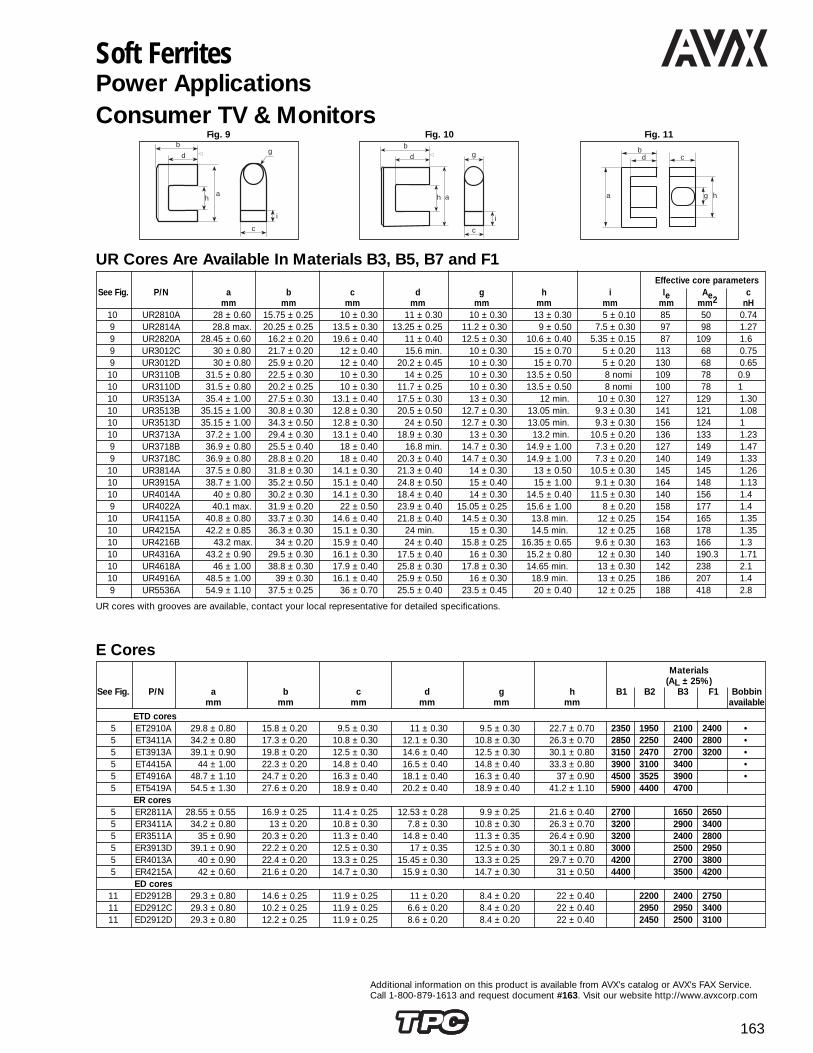
163
Additional information on this product is available from AVX’s catalog or AVX’s FAX Service.Call 1-800-879-1613 and request document #163. Visit our website http://www.avxcorp.com
b
d
ha
i
g
c
Fig. 9
db
c
g ha
Fig. 11b
d
h a
i
c
g
Fig. 10
Soft FerritesPower ApplicationsConsumer TV & Monitors
Effective core parametersSee Fig. P/N a b c d g h i Ie Ae c
mm mm mm mm mm mm mm mm mm2 nH10 UR2810A 28 ± 0.60 15.75 ± 0.25 10 ± 0.30 11 ± 0.30 10 ± 0.30 13 ± 0.30 5 ± 0.10 85 50 0.749 UR2814A 28.8 max. 20.25 ± 0.25 13.5 ± 0.30 13.25 ± 0.25 11.2 ± 0.30 9 ± 0.50 7.5 ± 0.30 97 98 1.279 UR2820A 28.45 ± 0.60 16.2 ± 0.20 19.6 ± 0.40 11 ± 0.40 12.5 ± 0.30 10.6 ± 0.40 5.35 ± 0.15 87 109 1.69 UR3012C 30 ± 0.80 21.7 ± 0.20 12 ± 0.40 15.6 min. 10 ± 0.30 15 ± 0.70 5 ± 0.20 113 68 0.759 UR3012D 30 ± 0.80 25.9 ± 0.20 12 ± 0.40 20.2 ± 0.45 10 ± 0.30 15 ± 0.70 5 ± 0.20 130 68 0.65
10 UR3110B 31.5 ± 0.80 22.5 ± 0.30 10 ± 0.30 14 ± 0.25 10 ± 0.30 13.5 ± 0.50 8 nomi 109 78 0.910 UR3110D 31.5 ± 0.80 20.2 ± 0.25 10 ± 0.30 11.7 ± 0.25 10 ± 0.30 13.5 ± 0.50 8 nomi 100 78 110 UR3513A 35.4 ± 1.00 27.5 ± 0.30 13.1 ± 0.40 17.5 ± 0.30 13 ± 0.30 12 min. 10 ± 0.30 127 129 1.3010 UR3513B 35.15 ± 1.00 30.8 ± 0.30 12.8 ± 0.30 20.5 ± 0.50 12.7 ± 0.30 13.05 min. 9.3 ± 0.30 141 121 1.0810 UR3513D 35.15 ± 1.00 34.3 ± 0.50 12.8 ± 0.30 24 ± 0.50 12.7 ± 0.30 13.05 min. 9.3 ± 0.30 156 124 110 UR3713A 37.2 ± 1.00 29.4 ± 0.30 13.1 ± 0.40 18.9 ± 0.30 13 ± 0.30 13.2 min. 10.5 ± 0.20 136 133 1.239 UR3718B 36.9 ± 0.80 25.5 ± 0.40 18 ± 0.40 16.8 min. 14.7 ± 0.30 14.9 ± 1.00 7.3 ± 0.20 127 149 1.479 UR3718C 36.9 ± 0.80 28.8 ± 0.20 18 ± 0.40 20.3 ± 0.40 14.7 ± 0.30 14.9 ± 1.00 7.3 ± 0.20 140 149 1.33
10 UR3814A 37.5 ± 0.80 31.8 ± 0.30 14.1 ± 0.30 21.3 ± 0.40 14 ± 0.30 13 ± 0.50 10.5 ± 0.30 145 145 1.2610 UR3915A 38.7 ± 1.00 35.2 ± 0.50 15.1 ± 0.40 24.8 ± 0.50 15 ± 0.40 15 ± 1.00 9.1 ± 0.30 164 148 1.1310 UR4014A 40 ± 0.80 30.2 ± 0.30 14.1 ± 0.30 18.4 ± 0.40 14 ± 0.30 14.5 ± 0.40 11.5 ± 0.30 140 156 1.49 UR4022A 40.1 max. 31.9 ± 0.20 22 ± 0.50 23.9 ± 0.40 15.05 ± 0.25 15.6 ± 1.00 8 ± 0.20 158 177 1.4
10 UR4115A 40.8 ± 0.80 33.7 ± 0.30 14.6 ± 0.40 21.8 ± 0.40 14.5 ± 0.30 13.8 min. 12 ± 0.25 154 165 1.3510 UR4215A 42.2 ± 0.85 36.3 ± 0.30 15.1 ± 0.30 24 min. 15 ± 0.30 14.5 min. 12 ± 0.25 168 178 1.3510 UR4216B 43.2 max. 34 ± 0.20 15.9 ± 0.40 24 ± 0.40 15.8 ± 0.25 16.35 ± 0.65 9.6 ± 0.30 163 166 1.310 UR4316A 43.2 ± 0.90 29.5 ± 0.30 16.1 ± 0.30 17.5 ± 0.40 16 ± 0.30 15.2 ± 0.80 12 ± 0.30 140 190.3 1.7110 UR4618A 46 ± 1.00 38.8 ± 0.30 17.9 ± 0.40 25.8 ± 0.30 17.8 ± 0.30 14.65 min. 13 ± 0.30 142 238 2.110 UR4916A 48.5 ± 1.00 39 ± 0.30 16.1 ± 0.40 25.9 ± 0.50 16 ± 0.30 18.9 min. 13 ± 0.25 186 207 1.49 UR5536A 54.9 ± 1.10 37.5 ± 0.25 36 ± 0.70 25.5 ± 0.40 23.5 ± 0.45 20 ± 0.40 12 ± 0.25 188 418 2.8
Materials(AL ± 25%)
See Fig. P/N a b c d g h B1 B2 B3 F1 Bobbinmm mm mm mm mm mm available
ETD cores5 ET2910A 29.8 ± 0.80 15.8 ± 0.20 9.5 ± 0.30 11 ± 0.30 9.5 ± 0.30 22.7 ± 0.70 2350 1950 2100 2400 •5 ET3411A 34.2 ± 0.80 17.3 ± 0.20 10.8 ± 0.30 12.1 ± 0.30 10.8 ± 0.30 26.3 ± 0.70 2850 2250 2400 2800 •5 ET3913A 39.1 ± 0.90 19.8 ± 0.20 12.5 ± 0.30 14.6 ± 0.40 12.5 ± 0.30 30.1 ± 0.80 3150 2470 2700 3200 •5 ET4415A 44 ± 1.00 22.3 ± 0.20 14.8 ± 0.40 16.5 ± 0.40 14.8 ± 0.40 33.3 ± 0.80 3900 3100 3400 •5 ET4916A 48.7 ± 1.10 24.7 ± 0.20 16.3 ± 0.40 18.1 ± 0.40 16.3 ± 0.40 37 ± 0.90 4500 3525 3900 •5 ET5419A 54.5 ± 1.30 27.6 ± 0.20 18.9 ± 0.40 20.2 ± 0.40 18.9 ± 0.40 41.2 ± 1.10 5900 4400 4700
ER cores5 ER2811A 28.55 ± 0.55 16.9 ± 0.25 11.4 ± 0.25 12.53 ± 0.28 9.9 ± 0.25 21.6 ± 0.40 2700 1650 26505 ER3411A 34.2 ± 0.80 13 ± 0.20 10.8 ± 0.30 7.8 ± 0.30 10.8 ± 0.30 26.3 ± 0.70 3200 2900 34005 ER3511A 35 ± 0.90 20.3 ± 0.20 11.3 ± 0.40 14.8 ± 0.40 11.3 ± 0.35 26.4 ± 0.90 3200 2400 28005 ER3913D 39.1 ± 0.90 22.2 ± 0.20 12.5 ± 0.30 17 ± 0.35 12.5 ± 0.30 30.1 ± 0.80 3000 2500 29505 ER4013A 40 ± 0.90 22.4 ± 0.20 13.3 ± 0.25 15.45 ± 0.30 13.3 ± 0.25 29.7 ± 0.70 4200 2700 38005 ER4215A 42 ± 0.60 21.6 ± 0.20 14.7 ± 0.30 15.9 ± 0.30 14.7 ± 0.30 31 ± 0.50 4400 3500 4200
ED cores11 ED2912B 29.3 ± 0.80 14.6 ± 0.25 11.9 ± 0.25 11 ± 0.20 8.4 ± 0.20 22 ± 0.40 2200 2400 275011 ED2912C 29.3 ± 0.80 10.2 ± 0.25 11.9 ± 0.25 6.6 ± 0.20 8.4 ± 0.20 22 ± 0.40 2950 2950 340011 ED2912D 29.3 ± 0.80 12.2 ± 0.25 11.9 ± 0.25 8.6 ± 0.20 8.4 ± 0.20 22 ± 0.40 2450 2500 3100
E Cores
UR Cores Are Available In Materials B3, B5, B7 and F1
UR cores with grooves are available, contact your local representative for detailed specifications.

164
Additional information on this product is available from AVX’s catalog or AVX’s FAX Service.Call 1-800-879-1613 and request document #164. Visit our website http://www.avxcorp.com
Materials(AL ± 25%)
See P/N a b c d f g h B1 B2 F1 BobbinFig. mm mm mm mm min mm mm mm available12 E-1304A 12.8 ± 0.20 6.4 ± 0.10 3.55 ± 0.15 4.65 ± 0.15 2.6 3.55 ± 0.15 9.2 ± 0.30 840 720 125012 E-1306A 13 ± 0.45 6 ± 0.20 6.15 ± 0.20 4.65 ± 0.15 3.64 2.78 ± 0.18 10.48 ± 0.25 1040 850 92012 E-1605A 16 ± 0.50 7.15 ± 0.20 4.9 ± 0.20 5.1 ± 0.20 3.8 4 ± 0.15 12 ± 0.25 1150 1000 100012 E-1605B 16 ± 0.50 12.25 ± 0.20 4.85 ± 0.20 10.25 ± 0.25 3.75 4 ± 0.20 12 ± 0.30 700 64012 E-1605C 16.1 ± 0.60 8.05 ± 0.15 4.5 ± 0.20 5.9 ± 0.20 3.3 4.55 ± 0.15 11.6 ± 0.30 1240 87512 E-1905A 19.15 ± 0.75 7.9 ± 0.25 4.8 ± 0.20 5.6 ± 0.15 4.82 4.65 ± 0.15 14.75 ± 0.30 1140 900 1050 •12 E-1907A 19.15 ± 0.75 7.9 ± 0.25 6.65 ± 0.25 5.6 ± 0.15 4.82 4.65 ± 0.15 14.75 ± 0.30 1600 1300 •12 E-2005B 19.5 ± 0.40 13.55 ± 0.20 5 ± 0.25 11.15 ± 0.20 4.5 4.55 ± 0.15 14 ± 0.30 920 74512 E-2006A 20 ± 0.40 9.95 ± 0.15 5.7 ± 0.20 7.15 ± 0.15 4.1 5.75 ± 0.15 14.4 ± 0.30 1450 1160 1250 •12 E-2206A 22 ± 0.45 15 ± 0.20 5.75 ± 0.25 11 ± 0.25 4.98 5.75 ± 0.25 16.3 ± 0.35 1250 100012 E-2506A 25.3 ± 0.50 9.5 ± 0.25 6.35 ± 0.25 6.35 ± 0.25 6.1 6.32 ± 0.125 19.02 ± 0.38 1950 1540 1650 •12 E-2506B 25.3 ± 0.50 9.9 ± 0.25 6.35 ± 0.25 6.75 ± 0.25 6.1 6.32 ± 0.125 19.02 ± 0.38 2000 160012 E-2506C 25.4 ± 0.50 16 ± 0.25 6.35 ± 0.25 12.83 ± 0.25 6.07 6.35 ± 0.15 19.04 ± 0.40 1350 1150 125012 E-2507A 25.4 ± 0.40 12.6 ± 0.20 7.28 ± 0.22 8.9 ± 0.20 4.87 7.5 ± 0.15 17.65 ± 0.25 2200 1760 2050 •12 E-2507B 25.4 ± 0.50 16 ± 0.26 6.5 ± 0.25 12.83 ± 0.25 6.07 6.35 ± 0.15 19.04 ± 0.40 1300 120012 E-2811A 28 ± 0.55 17 ± 0.20 10.75 ± 0.20 12.5 ± 0.30 5.55 7.25 ± 0.25 18.85 ± 0.25 2700 240012 E-3007B 30.1 ± 0.70 15 ± 0.20 7.05 ± 0.25 10 ± 0.30 6.15 6.95 ± 0.25 19.9 ± 0.4 2000 1600 200012 E-3011A 30 ± 0.60 13.15 ± 0.20 10.7 ± 0.30 8.15 ± 0.15 4.38 10.7 ± 0.25 20 ± 0.30 4700 350012 E-3109B 30.5 ± 0.60 13.4 ± 0.15 9.1 ± 0.30 9.05 ± 0.15 6.2 9.1 ± 0.30 22.2 ± 0.40 2900 2600 260012 E-3213A 31.9 ± 1.00 14 ± 0.40 12.7 ± 0.30 9.65 ± 0.25 6.4 8.9 ± 0.25 22.77 ± 0.77 4000 3200 3750 •12 E-3509A 34.9 ± 0.70 14.4 ± 0.25 9.15 ± 0.25 9.9 ± 0.25 8 9.2 ± 0.25 26 ± 0.50 3000 2400 2600 •12 E-3509B 34.9 ± 0.70 14.4 ± 0.25 9.15 ± 0.25 9.8 ± 0.25 7.9 9.2 ± 0.25 25.75 ± 0.50 3000 250012 E-3510A 34.9 ± 0.70 14.4 ± 0.25 9.7 ± 0.20 9.9 ± 0.25 8.03 9.2 ± 0.25 26 ± 0.50 3000 250012 E-3510B 34.9 ± 0.70 23.8 ± 0.25 9.52 ± 0.40 19.05 ± 0.40 7.61 9.52 ± 0.20 25.43 ± 0.50 2100 175012 E-3512A 34.9 ± 0.70 14.4 ± 0.25 12 ± 0.25 9.8 ± 0.25 7.9 9.2 ± 0.25 25.75 ± 0.50 3750 300012 E-3512B 34.9 ± 0.70 23.8 ± 0.25 12 ± 0.40 19.05 ± 0.40 7.61 9.52 ± 0.20 25.43 ± 0.50 210012 E-4012B 40.5 ± 0.40 27.25 ± 0.25 11.65 ± 0.35 20.25 ± 0.40 7.78 11.65 ± 0.25 28 ± 0.55 3250 255012 E-4012C 39.9 ± 0.80 17.3 ± 0.15 11.87 ± 0.20 10.20 ± 0.20 7.8 11.65 ± 0.25 28.05 ± 0.55 4900 375012 E-4112A 40.7 ± 0.80 16.4 ± 0.25 12.45 ± 0.25 10.5 ± 0.25 7.95 12.45 ± 0.25 29.1 ± 0.50 4700 4000 440012 E-4215A 42.15 ± 0.85 21 ± 0.20 14.95 ± 0.25 15.15 ± 0.35 8.65 11.95 ± 0.25 30.1 ± 0.60 5000 3750 •12 E-4215H 42.3 ± 0.85 21.4 ± 0.20 15 ± 0.25 15.4 ± 0.35 8.75 12 ± 0.25 30.3 ± 0.60 4875 365012 E-4220A 42.15 ± 0.85 21 ± 0.20 19.5 ± 0.50 15.15 ± 0.35 8.65 11.95 ± 0.25 30.1 ± 0.60 6500 4875 •12 E-4220H 42.3 ± 0.85 21.4 ± 0.20 19.6 ± 0.40 15.4 ± 0.35 8.75 12 ± 0.25 30.3 ± 0.60 6475 4875
Fig. 12
h
Od OdId Id
Fig. 13
MaterialsDimensions for uncoated toroids Dimensions for coated toroids (AL nH ± 25%)
See P/N Od Id h Od Id h B2 F1Fig. mm mm mm mm mm mm13 TR1270A 12.7 ± 0.40 7.14 ± 0.25 4.7 ± 0.20 13.9 max. 6.09 min. 5.7 max. 870 110013 TR2000B 20 ± 0.60 10 ± 0.30 7 ± 0.25 21.4 max. 8.9 min. 8.05 max. 1600 195013 TR2000D 20 ± 0.60 10.5 ± 0.35 15 ± 0.55 21.4 max 9 min. 16.35 max. 3100 390013 TR2210A 22.1 ± 0.65 13.72 ± 0.40 12.7 ± 0.45 23.55 max. 12.52 min. 13.95 max. 2000 245013 TR2500A 25 ± 0.75 15 ± 0.45 10 ± 0.35 26.55 max. 13.75 min. 11.15 max. 1750 205013 TR2500B 25 ± 0.75 15 ± 0.45 15 ± 0.55 26.55 max. 13.75 min. 16.35 max. 2550 310013 TR2800B 27.6 ± 0.60 17.6 ± 0.40 15.4 ± 0.30 29 max. 16.4 min. 16.5 max. 2050 275013 TR2800C 27.6 ± 0.60 17.6 ± 0.40 7 ± 0.20 29 max. 16.4 min. 8 max. 1000 130013 TR3150C 31.5 ± 0.95 19 ± 0.60 20 ± 0.70 33.25 max. 17.65 min. 21.5 max. 3400 410013 TR3600A 36 ± 1.10 23 ± 0.70 15 ± 0.55 37.9 max. 21.5 min. 16.35 max. 2200 270013 TR4000A 40 ± 1.20 24 ± 0.70 16 ± 0.50 42 max. 22.45 min. 17.4 max. 2750 3300
ah
f
d
b
c
g
Soft FerritesPower ApplicationsElectronic Ballast
E Cores
Toroids
Coating : Polyamide or Epoxy (contact your local representative) Thickness : < 0.4 mm (to be added on mechanical dimensions) Breakdown voltage > 2000 VDC

ELCOELCO 165
Additional information on this product is available from AVX’s catalog or AVX’s FAX Service.Call 1-800-879-1613 and request document #165. Visit our website http://www.avxcorp.com
2mm Hard Metric ConnectorsSeries 8071 Type A Right Angle Female27 8071 110 011 833 = Type A Right Angle Female with top shield, with pegs
27 8071 110 012 833 = Type A Right Angle Female with top shield, without pegs
Contact Elco for availability of alternate platings
Series 8071 Type B Right Angle Female27 8071 110 010 833 = Type B 110 Pin Right Angle Female with upper shield
Contact Elco for availability of alternate platings
ab
cd
e1111525
TY
P.
2.0
2X4=
8.0
11.4
7.4
3.53.2
3.0
MAX.0.95
TYP.2.0
2X10=20.0
-0.2 049.9
2X10=20.0
2x24=48.0
a bc d fe12.8
12.2
5
6.0
9Z21XX
(20.9)
abcd
fe
(COMPONENT SIDE)RECOMMENDED P.C. BOARD LAYOUT
2.0±0.1 TYP.
2x10=20.0±0.1
2x14=28.0±0.1
2x24=48.0±0.1
2x12=24.0±0.1
2.0±
0.1
TYP.
HOLE2- 2
.0±0
.1
MA
X.
1.5
HOLES135- 0.6±0.05
2x5=
10.0
±0.1
f
f
ab
cd
e122
TY
P.
2.0
2X4=
8.0
11.4
MAX.0.95
TYP.2.0
-0.243.9
42.0
9Z21XX
(20.
9)
TYP.2.0
1.8
3.0 7.
4
2X5=10.01.8
3.2a
bcd
fe
(COMPONENT SIDE)RECOMMENDED P.C. BOARD LAYOUT
2.0±0.1 TYP.
2.0±
0.1
TYP.
MA
X.
1.5
2X (N/5-1) = A±0.1
HOLES132- 0.6±0.05
2 x
5=10
.0±0
.1
f

ELCOELCO166
Additional information on this product is available from AVX’s catalog or AVX’s FAX Service.Call 1-800-879-1613 and request document #166. Visit our website http://www.avxcorp.com
2mm Hard Metric ConnectorsSeries 8071 Type B Right Angle Female27 8071 095 010 833 = Type B 95 Pin Right Angle Female with upper shield
Contact Elco for availability of alternate platings
ab
cd
e119
TY
P.
2.0
2X4=
8.0
11.4
MAX.0.95
TYP.2.0
-0.237.9
36.0
9Z21XX
(20.
9)
abcd
fe
(COMPONENT SIDE)RECOMMENDED P.C. BOARD LAYOUT
2.0±0.1 TYP.
2.0±
0.1
TYP.
MA
X.
1.5
2X (N/5-1) = A±0.1
HOLES114- 0.6±0.05
2 x
5=10
.0±0
.1
f
TYP.2.0
1.8
3.0 7.
4
2X5=10.01.8
3.2
ab
cd
e125
TY
P.
2.0
2X4=
8.0
11.4
MAX.0.95
TYP.2.0
-0.249.9
48.0
9Z21XX
(20.
9)
TYP.2.0
1.8
3.0 7.
4
2X5=10.01.8
3.2a
bcd
fe
(COMPONENT SIDE)RECOMMENDED P.C. BOARD LAYOUT
2.0±0.1 TYP.
2.0±
0.1
TYP.
MA
X.
1.5
48.0 ±0.1
HOLES150- 0.6±0.05
2 x
5=10
.0±0
.1
f
Series 8071 Type B Right Angle Female27 8071 125 010 833 = Type B 125 Pin Right Angle Receptacle with upper shield
Contact Elco for availability of alternate platings

ELCOELCO 167
Additional information on this product is available from AVX’s catalog or AVX’s FAX Service.Call 1-800-879-1613 and request document #167. Visit our website http://www.avxcorp.com
Series 8071 Type C Right Angle Female27 8071 055 011 833 = Type C 55 Pin Right Angle Female with upper shield, with peg
27 8071 055 012 833 = Type C 55 Pin Right Angle Female with upper shield, without peg
Contact Elco for availability of alternate platings
2mm Hard Metric ConnectorsSeries 8071 Type A Right Angle Female with Split Shield27 8071 090 501 833 = Type A Right Angle Female with upper shield, with peg
27 8071 090 502 833 = Type A Right Angle Female with upper shield, without peg
Contact Elco for availability of alternate platings
ab
cd
e1111525
TY
P.
2.0
2X4=
8.0
11.4
MAX.0.95
TYP.2.0
2X10=20.0
-0.2 049.9
2X10=20.0
2X24=48
8N21XX
(20.
9)
TYP.2.0
1.8
3.0
3.5
3.2
2X5=10.0
7.6
12.2
5
abcd
fe
2.0±0.1 TYP.
2X10-20.0±0.1
2X14-28.0±0.1
2X24=48.0±0.1
2X12-24.0±0.1
2.0±
0.1
TYP.
HOLE2- 2
.0±0
.1
MA
X.
1.5
HOLES-0.05 099- 0.6
2X5=
10.0
±0.1
2X7=14.0±0.1
f
f
ab
cd
e111
55P
ELC
O 8
071
TY
P.
2.0
2X4=
8.0
11.4
MAX.0.95
TYP.2.0
2X10=20.0
-0.2 024.95
9Z21XX
(20.
9)
abcd
fe
(COMPONENT SIDE)RECOMMENDED P.C. BOARD LAYOUT
2.0±0.1 TYP.
2X10-20.0±0.1
2.0±
0.1
TYP.
HOLE2- 2
.0±0.1
HOLES66- 0.6±0.05
3.0±0.1MA
X.
1.5
2X5=
10.0
±0.1
TYP.2.0
3.0
3.5
3.2
7.4
1.8 2X5=10.0
011
TYP.2.0
3.0
3.2
7.4
1.8 2X5=10.0
012
f
f
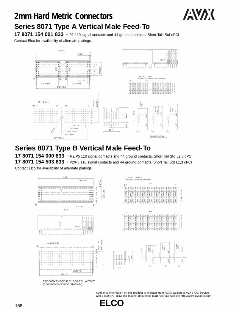
ELCOELCO168
Additional information on this product is available from AVX’s catalog or AVX’s FAX Service.Call 1-800-879-1613 and request document #168. Visit our website http://www.avxcorp.com
Series 8071 Type B Vertical Male Feed-To17 8071 154 000 833 = P2/P5 110 signal contacts and 44 ground contacts, Short Tail Std L2,3 cPCI
17 8071 154 503 833 = P2/P5 110 signal contacts and 44 ground contacts, Short Tail Std L1,3 cPCI
Contact Elco for availability of alternate platings
2mm Hard Metric ConnectorsSeries 8071 Type A Vertical Male Feed-To17 8071 154 001 833 = P1 110 signal contacts and 44 ground contacts, Short Tail, Std cPCI
Contact Elco for availability of alternate platings
9Z21XX
25 1
f
e
dcba
z
1 25
16
10
15 11
-0.2 049.9
MAX.0.95
TY
P.
2.0
2X6=
12.0
TYP.2.0
2X10=20.02X10=20.0
2X24=48.0abcdef
z
25 1
2
2 2 2 2 2 2 2 2 2 2 2 2 2 2 2 2 2 2 2 2 23333 3333 333 33 3 3 33 3 333
3
32
222
32222
32222
32222
32222
32222
32222
32222
32222
32222
32232
32122
32222
32222
32222
32222
32222
32222
32222
32222
32222
32222
1115
CONTACT LAYOUT(CONNECTOR MATING SIDE SHOWN)
P.C
.B.
AR
EA
CO
NTA
CTAR
EA
CO
NTA
CT
AR
EA
CO
NTA
CT
0+0.
211
.3 0+0.
28.
3(3
.5)
(3.5
)
31
(3.5
)
2
0+0.
29.
8
13.4
5
15.4
3.0
4.5
za
f
edcb
1 25 1115
2.0±.1 TYP.
2.0±
0.1
TYP.
2x6-
12.0
±0.1
154- 0.6±0.5
2.0
±0.1
2x24=48.0±0.1
2x14=28.0±0.1
2x12=24.0±0.1
2X10=20.0±0.1
f
f
CONTACT DETAIL
9Z21XX
XX 11
122fed
cb
az
43.9
0.95 Max.
2.0 Typ.
42.0
2.0
Typ
.
2X6=
12.0
(COMPONENT SIDE SHOWN)RECOMMENDED P.C. BOARD LAYOUT
CONTACT LAYOUT(CONNECTOR SIDE SHOWN)
aZ
e
f
dcb
122
2.0 ±0.1 TYP.
42.0 ±0.1
154-ø0.6 ±0.05
2 x
6 =
12.0
±0.
1
2.0
±0.1
TYP
P.C
.B.
1 2 3
AR
EA
CO
NTA
CT
-0+0.
28.
3
abcdef
z
22 1
22222222222222222222222222222222222222222222222222222222222222222222222222222222222222222222222222222222222222
3333333333333333333333
3333333333333333333333
abcdef
z
22 1
1
11111111111111111111113333333333333333333333
3333333333333333333333
111
1111
1111
1111
1111
1111
1111
1111
1111
1111
1111
1111
1111
1111
1111
1111
1111
1111
1111
1111
1111
1111
AR
EA
CO
NTA
CT
0+0.
211
.3
0+0.
29.
8
(3.5
)
(3.5
)
AR
EA
CO
NTA
CT
(3.5
)
000
503
13.4
5
15.4
3.0
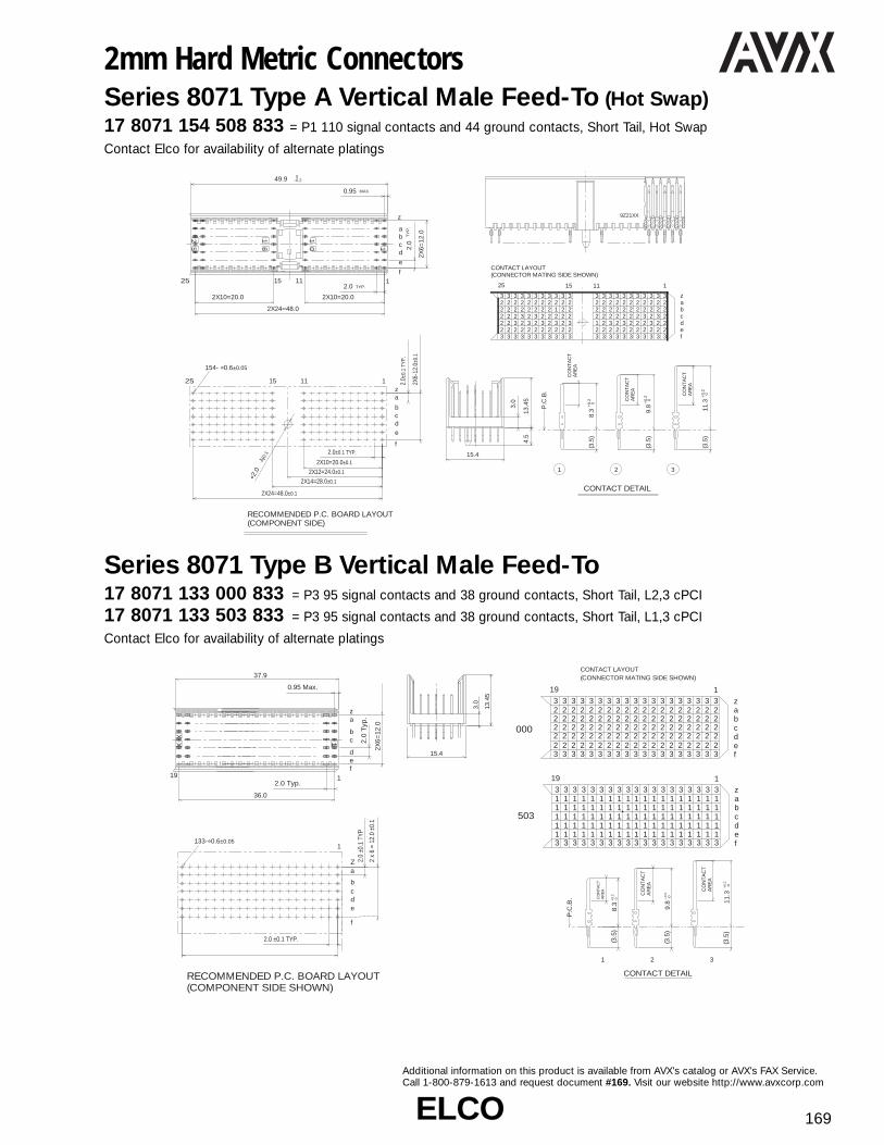
ELCOELCO 169
Additional information on this product is available from AVX’s catalog or AVX’s FAX Service.Call 1-800-879-1613 and request document #169. Visit our website http://www.avxcorp.com
Series 8071 Type B Vertical Male Feed-To17 8071 133 000 833 = P3 95 signal contacts and 38 ground contacts, Short Tail, L2,3 cPCI
17 8071 133 503 833 = P3 95 signal contacts and 38 ground contacts, Short Tail, L1,3 cPCI
Contact Elco for availability of alternate platings
2mm Hard Metric ConnectorsSeries 8071 Type A Vertical Male Feed-To (Hot Swap)17 8071 154 508 833 = P1 110 signal contacts and 44 ground contacts, Short Tail, Hot Swap
Contact Elco for availability of alternate platings
9Z21XX
13.4
5
15.4
3.0
4.5
25 1
f
e
dcba
z
1 25
16
10
15 11
-0.2 049.9
MAX.0.95
TY
P.
2.0
2X6=
12.0
TYP.2.0
2X10=20.02X10=20.0
2X24=48.0
CONTACT DETAIL
P.C
.B.
AR
EA
CO
NTA
CTAR
EA
CO
NTA
CT
AR
EA
CO
NTA
CT
0+0.
211
.3
8.3
(3.5
)
(3.5
)
31
(3.5
)
2
9.8
abcdef
z
25 1
2
2 2 2 2 2 2 2 2 2 2 2 2 2 2 2 2 2 2 2 2 23333 3333 333 33 3 3 33 3 333
3
32
222
32222
32232
32322
32232
32222
32222
32322
32222
32322
32222
32122
32322
32222
32321
32222
32322
32232
32322
32232
32322
32222
1115
(COMPONENT SIDE)RECOMMENDED P.C. BOARD LAYOUT
za
f
edcb
1 25 1115
2.0±0.1 TYP.
2.0±
0.1
TYP.
2X6-
12.0
±0.1
154- f0.6±0.05
Å0.
1
f2.
0
2X24=48.0±0.1
2X14=28.0±0.1
2X12=24.0±0.1
2X10=20.0±0.1
0+0.
2
0+0.
2
CONTACT LAYOUT(CONNECTOR MATING SIDE SHOWN)
abcdef
z
19 1
22222222222222222222222222222222222222222222222222222222222222222222222222222222222222222222222
3333333333333333333
3333333333333333333
abcdef
z
19 1
1
11111111111111111113333333333333333333
3333333333333333333
111
1111
1111
1111
1111
1111
1111
1111
1111
1111
1111
1111
1111
1111
1111
1111
1111
1111
1111
P.C
.B. A
RE
AC
ON
TAC
T
-0+0.
28.
3
CONTACT DETAIL
AR
EA
CO
NTA
CT
AR
EA
CO
NTA
CT
0+0.
211
.3
0+0.
29.
8(3
.5)
(3.5
)
(3.5
)
1 2 3
XX 11
1fed
cb
az
37.9
36.0
0.95 Max.
2.0 Typ.
2.0
Typ
.
2X6=
12.0
(COMPONENT SIDE SHOWN)RECOMMENDED P.C. BOARD LAYOUT
(CONNECTOR MATING SIDE SHOWN)CONTACT LAYOUT
aZ
e
f
dcb
1
2.0 ±0.1 TYP.
2 x
6 =
12.0
±0.
1
2.0
±0.1
TYP
000
503
19
13.4
5
15.4
3.0
133-f0.6±0.05

ELCOELCO170
Additional information on this product is available from AVX’s catalog or AVX’s FAX Service.Call 1-800-879-1613 and request document #170. Visit our website http://www.avxcorp.com
2mm Hard Metric ConnectorsSeries 8071 Type A Vertical Male Feed-To17 8071 100 511 833 = P4 Type A 84 signal contacts and 16 ground contacts, Short Tail (Computer Telephony)
Contact Elco for availability of alternate platings
Series 8071Type B Vertical Male Feed-To17 8071 175 000 833 = 125 signal contacts and 50 ground contacts, Short Tail L2,3 cPCI
17 8071 175 503 833 = 125 signal contacts and 50 ground contacts, Short Tail L1,3 cPCI
Contact Elco for availability of alternate platings
8N21XX
13.4
5
15.4
4.5
3.0
1 25 15 11
25 1
f
e
dcb
az
16
10
-0.2 049.9
MAX.0.95
TY
P.
2.0
TYP.2.0
2X5=
10.0
2X10=20.0 2X10=20.0
2X24=48.0
(COMPONENT SIDE)RECOMMENDED P.C. BOARD LAYOUT
a
f
edc
b
1 25 1115
2.0±0.1 TYP.
2.0±
0.1
TYP.100-f0.6±0.05
f2.
0±0.
1
2X24=48.0±0.1
2X14=28.0±0.1
2X12=24.0±0.1
2X10=20.0±0.1
2X5=
10.0
±0.1
2X7=14.0±0.1
CONTACT DETAIL
P.C
.B.
AR
EA
CO
NTA
CTAR
EA
CO
NTA
CT
AR
EA
CO
NTA
CT
0+0.
211
.3 0+0.
28.
3(3
.5)
(3.5
)
31
(3.5
)
2
0 0+0.
2+
0.2
9.8
9.8
(CONNECTOR MATING SIDE SHOWN) CONTACTS LAYOUT
abcdef
z
25 1
2
2 2 2 2 2 2 2 2 2 2 2 3 2 3 2 2 2
3
2222
32222
32222
32212
32222
33222
2332322
32322
32322
32322
32322
32322
32322
32322
32322
33222
1115
9Z21XX
XX 1
125fed
cb
az
49.9
0.95max.
PITCH 2.0
48.0
PIT
CH
2.0
2X4=
8.0
25
175-ø0.6
2.0
±0.1
Typ
.
2.0 ±0.1 Typ.
48.0 ±0.1
±0.05
2 X
6 =
12.
0 ±0
.1
abcdef
z25 1
222222222222222222222222222222222222222222222222222222222222222222222222222222222222222222222222222222222222222222222222
(COMPONENT SIDE)RECOMMENDED P.C. BOARD LAYOUT
(CONNECTOR SIDE SHOWN)CONTACT LAYOUT
za
f
edcb
1
abcdef
z3 3 3 33 3 3 33 3 33 3333 3333 3 3 3
3
3
3 3 3 3 3 3 3 3 3 3 3 3 3 3 3 3 3 3 3 3 3 3 3
25 1
11 1 1 1 1 1 1 1 1 1 1 1 1 1 1 1 1 1 1 1 1 1 1
11 1 1 1 1 1 1 1 1 1 1 1 1 1 1 1 1 1 1 1 1 1 111 1 1 1 1 1 1 1 1 1 1 1 1 1 1 1 1 1 1 1 1 1 111 1 1 1 1 1 1 1 1 1 1 1 1 1 1 1 1 1 1 1 1 1 111 1 1 1 1 1 1 1 1 1 1
3
3
1
1111 1 1 1 1 1 1 1 1 1 1 1 1
3 3 3 33 3 3 33 3 33 3333 3333 3 3 3
3
3
3 3 3 3 3 3 3 3 3 3 3
22222
3
3 3 3 3 3 3 3 3 3 3 3 3 3
13.4
5
15.4
3.0
CONTACT DETAIL
P.C
.B.
AR
EA
CO
NTA
CTA
RE
AC
ON
TAC
T
0+0.
29.
8 0+0.
28.
3(3
.5)
(3.5
)
AR
EA
CO
NTA
CT
0+0.
211
.3(3
.5)
000
503
1 2 3

ELCOELCO 171
8N21XX13.4
5
15.4
3.0
22 1
122f
e
dcb
az
MAX.0.95
TYP.2.0
-0.2 043.9
2X21=42.0
TY
P.
2.0
2X5=
10.0
(COMPONENT SIDE)RECOMMENDED P.C. BOARD LAYOUT
(CONNECTOR SIDE SHOWN)CONTACT LAYOUT
a
f
edc
b
122
2.0±0.1 TYP.
2.0±
0.1
TYP.
132-f0.6±0.05
2X21=42.0±0.1
2X5=
10.0
±0.1
CONTACT DETAIL
P.C
.B.
M
AR
EA
CO
NTA
CT
AR
EA
CO
NTA
CT
T
PR
ES
S F
IT A
RE
A
AR
EA
CO
NTA
CT
PR
ES
S F
IT A
RE
A
AR
EA
CO
NTA
CT
AR
EA
CO
NTA
CT
AR
EA
CO
NTA
CT
PR
ES
S F
IT A
RE
A
P
11.3
(13.
0)
(16.
0)
9.8
0+0.
28.
3
(14.
5)
MMM
MM
T
MMMMM
MMMMM
MMMMM
MMMMM
MMMMM
MMMMM
MMMMM
MMMMM
MMMMM
MMMMM
MMMMM
MMMMM
MMMMM
MMMMM
MMMMM
MMMMM
MMMMM
PPPPP
PPPPP
PPPPP
PPPPP
122
TTTTTTTTTTTTTTTTTTTTT
z
fedcba
0+0.
2 0+0.
2
Additional information on this product is available from AVX’s catalog or AVX’s FAX Service.Call 1-800-879-1613 and request document #171. Visit our website http://www.avxcorp.com
2mm Hard Metric ConnectorsSeries 8071 Type A Vertical Male Feed-Thru17 8071 154 013 515 = P4 110 signal contacts and 44 ground contacts, Long Tail, L2,3 cPCI
17 8071 154 014 515 = P4 110 signal contacts and 44 ground contacts, Long Tail, L1,3 cPCI
Contact Elco for availability of alternate platings
Series 8071 Type B Vertical Male Feed-Thru17 8071 132 016 515 = P5 110 signal contacts and 22 ground contacts, Long Tail (Computer Telephony)
Contact Elco for availability of alternate platings
9Z21XX
25 1
f
e
dcba
z
1 25
16
10
15 11
-0.2 049.9
MAX.0.95
TY
P.
2.0
2X6=
12.0
TYP.2.0
2X10=20.02X10=20.0
2X24=48.0
(COMPONENT SIDE)RECOMMENDED P.C. BOARD LAYOUT
za
f
edcb
1 25 1115
2.0±0.1 TYP.
2.0±
0.1
TYP.
2X6=
12.0
±0.1
154-f0.6±0.05
f2.
0±0.
1
2X24=48.0±0.1
2X14=28.0±0.1
2X12=24.0±0.1
2X10=20.0±0.1
15 11
PPPPT
PPPPT
PPPPT
PPPPT
PPPPT
PPPPT
PPPPT
PPPPT
PPPPT
PPPPT
PPPPT
PPPPT
PPPPT
PPPPT
PPPPT
PPPPT
PPPPT
PPPPT
PPPPT
PPPPT
PPPPT
PPP
PT
T
TTT T TT T T TT TTT TTTT TTTTP P P P P P P P P P P P P P P P P P P P P
P
125
z
fedcba
AR
EA
CO
NTA
CT
AR
EA
CO
NTA
CT
PR
ES
S F
IT A
RE
A
AR
EA
CO
NTA
CT
PR
ES
S F
IT A
RE
A
AR
EA
CO
NTA
CT
P
0+0.
211
.3
0+0.
29.
8
T
(16.
0)
(14.
5)
W
13.4
5
15.4
3.0
4.5
013
013
014 014
P.C
.B.
AR
EA
CO
NTA
CT
AR
EA
CO
NTA
CT
PR
ES
S F
IT A
RE
A
(16.
0) 0+
0.2
8.3
15 11
WWWWT
WWWWT
WWWWT
WWWWT
WWWWT
WWWWT
WWWWT
WWWWT
WWWWT
WWWWT
WWWWT
WWWWT
WWWWT
WWWWT
WWWWT
WWWWT
WWWWT
WWWWT
WWWWT
WWWWT
WWWWT
WWW
WT
T
TTT T TT T T TT TTT TTTT TTTTW W W W W W W W W W W W W W W W W W W W W
W
125
z
fedcba
13.4
5
15.4
3.0
4.5

ELCOELCO172
Additional information on this product is available from AVX’s catalog or AVX’s FAX Service.Call 1-800-879-1613 and request document #172. Visit our website http://www.avxcorp.com
2mm Hard Metric ConnectorsSeries 8071 Type B Vertical Male Feed-Thru17 8071 133 003 515 = P3 95 signal contacts and 38 ground contacts, Long Tail Std L2,3 cPCI
17 8071 133 004 515 = P3 95 signal contacts and 38 ground contacts, Long Tail Std L1,3 cPCI
17 8071 133 015 515 = P3 95 signal contacts and 38 ground contacts, Long Tail Std L1,3 cPCI
Contact Elco for availability of alternate platings
Variation Code Side View Pin Loading
003
Long Tail, Std.
L2, 3
P3
004
Long Tail, Std.
L1, 3
P3
015
Long Tail, Std.
L1, 3
P3
XX 1
119f
e
dcba
z
MAX.0.95
37.9
TY
P.
2.0
2X6=
12.0
36.0
TYP.2.0
8N21XX
(COMPONENT SIDE)RECOMMENDED P.C. BOARD LAYOUT
za
f
edcb
119
2.0±0.1 TYP.
2.0±
0.1
TYP.
2X6=
12.0
±0.1
36.0±0.1
133-f0.6±0.05
CONTACT DETAIL
AR
EA
CO
NTA
CT
AR
EA
CO
NTA
CT
PR
ES
S F
IT A
RE
A
AR
EA
CO
NTA
CT
PR
ES
S F
IT A
RE
A
AR
EA
CO
NTA
CT
11.3
(16.
0)
9.8
(14.
5)
AR
EA
CO
NTA
CT
AR
EA
CO
NTA
CT
PR
ES
S F
IT A
RE
A
(16.
0)8.
3P.C
.B.
AR
EA
CO
NTA
CT
PR
ES
S F
IT A
RE
A
AR
EA
CO
NTA
CT
(13.
0) 0+
0.2
8.3
0+0.
2 0+0.
2 0+0.
2
M W P T
T T T TT T T TT
T T T T T T T T T
19
PPPPP
PPPPP
PPPPP
PPPPP
PPPPP
PPPPP
PPPPP
PPPPP
PPPPP a
bcdef
zTTT TTTT T T T
T T T T T T T T T T
1
PPPPP
PPPPP
PPPPP
PPPPP
PPPPP
PPPPP
PPPPP
PPPPP
PPPPP
PPPPP
T T T TT T T TT
T T T T T T T T T
19
MMMMM
MMMMM
MMMMM
MMMMM
MMMMM
MMMMM
MMMMM
MMMMM
MMMMM a
bcdef
zTTT TTTT T T T
T T T T T T T T T T
1
MMMMM
MMMMM
MMMMM
MMMMM
MMMMM
MMMMM
MMMMM
MMMMM
MMMMM
MMMMM
T T T TT T T TT
T T T T T T T T T
19
WWWWW
WWWWW
WWWWW
WWWWW
WWWWW
WWWWW
WWWWW
WWWWW
WWWWW a
bcdef
zTTT TTTT T T T
T T T T T T T T T T
1
WWWWW
WWWWW
WWWWW
WWWWW
WWWWW
WWWWW
WWWWW
WWWWW
WWWWW
WWWWW
13.4
5
15.4
3.0
13.4
5
15.4
3.0
13.4
5
15.4
3.0

ELCOELCO 173
Additional information on this product is available from AVX’s catalog or AVX’s FAX Service.Call 1-800-879-1613 and request document #173. Visit our website http://www.avxcorp.com
2mm Hard Metric ConnectorsSeries 8071 Type B Vertical Male Feed-Thru17 8071 154 003 515 = P2/P5 110 signal contacts and 44 ground contacts, Long Tail Std L2,3 cPCI
17 8071 154 004 515 = P2/P5 110 signal contacts and 44 ground contacts, Long Tail Std L1,3 cPCI
17 8071 154 015 515 = P2/P5 110 signal contacts and 44 ground contacts, Long Tail Std L1,3 cPCI
Contact Elco for availability of alternate platings
Variation Code Side View Pin Loading
003
Long Tail, Std.
L2, 3
P2/P5
004
Long Tail, Std.
L1, 3
P2/P5
015
Long Tail, Std.
L1, 3
P2/P5
13.4
5
15.4
3.0
T T T TT T T TT
T T T T T T T T T
22
PPPPP
PPPPP
PPPPP
PPPPP
PPPPP
PPPPP
PPPPP
PPPPP
PPPPP a
bcdef
zTT TTTT TTTT T T T
TT T T T T T T T T T T T
P
1
P
P
PP
PPPPP
PPPPP
PPPPP
PPPPP
PPPPP
PPPPP
PPPPP
PPPPP
PPPPP
PPPPP
PPPPP
PPPPP
13.4
5
15.4
3.0 T T T TT T T TT
T T T T T T T T T
22
MMMMM
MMMMM
MMMMM
MMMMM
MMMMM
MMMMM
MMMMM
MMMMM
MMMMM a
bcdef
zTT TTTT TTTT T T T
TT T T T T T T T T T T T
M
1
M
M
MM
MMMMM
MMMMM
MMMMM
MMMMM
MMMMM
MMMMM
MMMMM
MMMMM
MMMMM
MMMMM
MMMMM
MMMMM
13.4
5
15.4
3.0
T T T TT T T TT
T T T T T T T T T
22
WWWWW
WWWWW
WWWWW
WWWWW
WWWWW
WWWWW
WWWWW
WWWWW
WWWWW a
bcdef
zTT TTTT TTTT T T T
TT T T T T T T T T T T T
W
1
W
W
WW
WWWWW
WWWWW
WWWWW
WWWWW
WWWWW
WWWWW
WWWWW
WWWWW
WWWWW
WWWWW
WWWWW
WWWWW
(COMPONENT SIDE)RECOMMENDED P.C. BOARD LAYOUT
za
f
edcb
122
2.0±0.1 TYP.
2.0±
0.1
TYP.
2X6=
12.0
±0.1
42.0 ±0.1
154-f0.6±0.05
CONTACT DETAIL
AR
EA
CO
NTA
CT
AR
EA
CO
NTA
CT
PR
ES
S F
IT A
RE
A
AR
EA
CO
NTA
CT
PR
ES
S F
IT A
RE
A
AR
EA
CO
NTA
CT
11.3
(16.
0)
9.8
(14.
5)
AR
EA
CO
NTA
CT
AR
EA
CO
NTA
CT
PR
ES
S F
IT A
RE
A
(16.
0)8.
3P.C
.B.
AR
EA
CO
NTA
CT
PR
ES
S F
IT A
RE
A
AR
EA
CO
NTA
CT
(13.
0) 0+
0.2
8.3
0+0.
2 0+0.
2 0+0.
2
M W P T
XX 1
122f
e
dcba
z
MAX.0.95
43.9
TY
P.
2.0
2X6=
12.0
42.0
TYP.2.0
8N21XX

ELCOELCO174
Additional information on this product is available from AVX’s catalog or AVX’s FAX Service.Call 1-800-879-1613 and request document #174. Visit our website http://www.avxcorp.com
2mm Hard Metric ConnectorsSeries 8071 Type B Vertical Male Feed-Thru17 8071 175 003 515 = 125 signal contacts and 50 ground contacts, Long Tail L2,3 cPCI
17 8071 175 015 515 = 125 signal contacts and 50 ground contacts, Long Tail L1,3 cPCI
Contact Elco for availability of alternate platings
Series 8071 Type C Vertical Male Feed-To17 8071 077 509 833 = 55 signal contacts and 22 ground contacts, Short Tail, L1,3
17 8071 077 512 833 = 55 signal contacts and 22 ground contacts, Short Tail, L2,3
Contact Elco for availability of alternate platings
9Z21XX
13.4
5
15.4
3.0
XX 1
125
f
e
dcba
z
MAX.0.95
49.9
TY
P.
2.0
2X6=
12.0
48.0
TYP.2.0
(COMPONENT SIDE)RECOMMENDED P.C. BOARD LAYOUT
(CONNECTOR SIDE SHOWN)CONTACT LAYOUT
za
f
edcb
125
2.0 ±0.1 Typ.
2.0
±0.1
Typ
.
2 x
6 =
12.
0 ±0
.1
2X (N/7-1) = A ±0.1
±0.05175-ø0.6
AR
EA
CO
NTA
CT
AR
EA
CO
NTA
CT
PR
ES
S F
IT A
RE
A
AR
EA
CO
NTA
CT
PR
ES
S F
IT A
RE
A
AR
EA
CO
NTA
CT
0+0.
211
.3(1
6.0)
0+0.
29.
8(1
4.5)
abcdef
zT T T TT T T TT T TT TTTT TTTT T T T
T
T
T T T T T T T T T T T T T T T T T T T T T T T
P
25 003003
015015
1
P
P
PP
PPPPP
PPPPP
PPPPP
PPPPP
PPPPP
PPPPP
PPPPP
PPPPP
PPPPP
PPPPP
PPPPP
PPPPP
PPPPP
PPPPP
PPPPP
PPPPP
PPPPP
PPPPP
PPPPP
PPPPP
PPPPP
PPPPP
PPPPP
13.4
5
15.4
3.0
P.C
.B.
AR
EA
CO
NT
AC
TA
RE
AC
ON
TA
CT
PR
ES
S F
IT A
RE
A
(16.
0) 0+
0.2
8.3
W
1
WWWWW
WWWWW
WWWWW
WWWWW
WWWWW
WWWWW
WWWWW
WWWW
WWWWW
WWWWW
WWWWW
WWWWW
WWWWW
WWWWW
WWWWW
WWWWW
WWWWW
WWWWW
WWWWW
WWWWW
WWWWW
WWWWW
WWWWW
WW
W
W
25
W
TTTTTTTTTTTTTTTTTTTTTTT
T
T
TTTT T T TT T T TT TTT TTTT TTTT z
fedcba
W P T
9Z21XX
1
fe
dcba
zz
1
10
11
77
PE
LC
O 8
07
1
MAX.0.95
2X10=20.0
TYP.2.0
-0.2 024.95
TY
P.
2.0
2X6=
12.0
13.4
5
15.4
4.5
3.0
(CONNECTOR MATING SIDE SHOWN) CONTACT LAYOUT
abcdef
z
1
311111111111111
3
111
3
111
3
111
3
111
3
111
3
111
3
111
3
111
3
111
3
111
11
1 1 1 1 1 1 1 1 1 1 13 3 3 3 3 3 3 3 3 3 3
P.C
.B.
AR
EA
CO
NTA
CT
(3.5
) 0+
0.2
8.3
CONTACT DETAIL
509
AR
EA
CO
NTA
CT
AR
EA
CO
NTA
CT
0+0.
211
.3(3
.5)
3
(3.5
)
1
0+0.
29.
8
2
z
f
dcb
1
a
e
11
(COMPONENT SIDE)RECOMMENDED P.C. BOARD LAYOUT
2.0±0.1 TYP.
77-f0.6±0.05
f2.
0±0.
1
2X10=20.0±0.1
2X10+3=23.0±0.1
2.0±
0.1
TYP.
2X6=
12.0
±0.1
(CONNECTOR MATING SIDE SHOWN) CONTACT LAYOUT
abcdef
z
1
322222222222222
3
222
3
222
3
222
3
222
3
222
3
222
3
222
3
222
3
222
3
222
11
2 2 2 2 2 2 2 2 2 2 23 3 3 3 3 3 3 3 3 3 3
512

ELCOELCO 175
Additional information on this product is available from AVX’s catalog or AVX’s FAX Service.Call 1-800-879-1613 and request document #175. Visit our website http://www.avxcorp.com
2mm Hard Metric ConnectorsSeries 8074 Type L Vertical Male Feed-To61 8074 006 001 007 = Type L 6 position power connector with polarizing key, (housing only)
Power Contact: P/N 71 8074 000 501 ordered separately
POWERCONTACT
71 8074 000 501 863 80 8074 000 001 062
Series 8075 Type M Vertical Male Feed-To17 8075 355 501 833 = Type M 3 position power connector with polarizing key, with 55 signal contacts
Contact Elco for availability of alternate platings
2601
61
02
42
6.257.57.5 7.5
2.0
15.4
3.7 Max.
RECOMMENDED P.C. BOARD LAYOUT(COMPONENT SIDE)
7.56.25
6.257.57.5 7.57.56.25
49.9 0-0.2
10.07.5 7.510.0
5.5
4.5Ø2.0 ±0.1
HO
LE
0.10.1
6 - Ø5.9 +0.2
HOLE-0
Ø2.0 +0.05-0
4
3.0
13.45
7.5 10.0 10.0 7.5
+0.2-0
2601
15
15 11 1
25
25
11111
11111
11111
11111
11111
11111
11111
11111
11111
11111
11111
1015 6 225
ab
cde
za
zabcdef
bc
def
61
62
4.0
2 x 10 = 20.0
2.0 TYP.
2.0 TYP.2 x 4 = 8.0
7.5
2.0
0.95 Max.
15.4
RECOMMENDED P.C. BOARD LAYOUT(COMPONENT SIDE)
CONTACT LAYOUT(CONNECTOR MATING SIDE SHOWN)
7.56.25
3.0
(3.5)13.45
7.57.56.25
2.0 TYP.2 x 4 = 8.0
49.9 0-0.2
9Z21XX
P.C.B.
1
CONTACTAREA
7.510.024.0
2 x 10 = 20.02.0 TYP.
5.5
4.5Ø2.0 ±0.1
HO
LE
55 - Ø0.6 ±0.05 HOLE0.1
0.1
0.1
3 - Ø5.9 +0.2
HOLE-0 8.3 +0.2
-0
5 - Ø2.0 +0.05-0

ELCOELCO176
Additional information on this product is available from AVX’s catalog or AVX’s FAX Service.Call 1-800-879-1613 and request document #176. Visit our website http://www.avxcorp.com
2mm Hard Metric ConnectorsSeries 8483/8485 Style M DIN EuroCard Power Connector59 8483 024 000 025 = Male, Right Angle, 7 Power and 24 Signal Contacts
59 8485 024 000 015 = Female, Vertical, 7 Power and 24 Signal Contacts
Series 8071 Coding Keys: Type A Male Type A Female
Male
101 003 102 006 103 008 104 002Cadmium Yellow Brilliant Blue Pastel Orange Strawberry Red
101 003 102 006 103 008 104 002Cadmium Yellow Brilliant Blue Pastel Orange Strawberry Red
Female
Color Ral CodeNumber No. Key Part Number Plug/Receptacle
Cadmium Yellow 1021 3456 81 8071 000 101003 Plug 3.3V C-PCIBrilliant Blue 5007 1567 81 8071 000 102006 Plug 5.0V C-PCIPastel Orange 2003 3568 81 8071 000 103008 PlugStrawberry Red 3018 1248 81 8071 000 104002 PlugCadmium Yellow 1021 1278 82 8071 000 101003 Receptacle 3.3V C-PCIBrilliant Blue 5007 2348 82 8071 000 102006 Receptacle 5.0V C-PCIPastel Orange 2003 1247 82 8071 000 103008 ReceptacleStrawberry Red 3018 3567 82 8071 000 104002 Receptacle
0.6 x 0.64.5 Max.
10.2 -0.288.9
7.62
2.547 x 2.54= 17.78
3 x 7.62= 22.86
29 x 2.54 = 73.66
94 Max.
2.542.54
5.08
11.1 Max.
3.0 +0.2-0.4
ab
c
ab
c 258111314192022252831
0.6 x 0.6
12.6 Max.
8.5 -0.1
10.6 -0.2
85.0 -0.295.0 Max.
Ø5.8 Max.
4.90 Max.11.6 Max.
5.3 ±0.3
2.54
5.08
90 ±0.17 x 2.54 = 17.78
3 x 7.62 = 22.86
29 x 2.54 = 73.66
2.54
7.62
0.3

ELCOELCO 177
Additional information on this product is available from AVX’s catalog or AVX’s FAX Service.Call 1-800-879-1613 and request document #177. Visit our website http://www.avxcorp.com
2mm Hard Metric ConnectorsSeries 8072 Type A Right Angle Male17 8072 110 001 833 = Type A Right Angle Male
Contact Elco for availability of alternate platings
Series 8072 Type B Right Angle Male17 8072 095 000 833 = Type B Right Angle Male, 5x19 Positions
17 8072 110 000 833 = Type B Right Angle Male, 5x22 Positions
17 8072 125 000 833 = Type B Right Angle Male, 5x25 Positions
Contact Elco for availability of alternate platings
abc
de
2515111
TY
P.
2.0
2X4=
8.0
MAX.0.95
TYP.2.0
-0.2 049.9
15.4
2X10=20.0
2X24=48.0
2X10=20.0
8N21XX
TYP. 2.0
3.0
2X4=8.0
7.4
5.3
1.8
(5.15)
abcde
(COMPONENT SIDE)RECOMMENDED P.C. BOARD LAYOUT
2.0±0.1 TYP.
2X10=20.0±0.1
2X14=28.0±0.1
2X24=48.0±0.1
2.0±
0.1
TYP.
2x4=
8.0±
0.1
MA
X.
1.5
HOLES110-f0.6±0.05
abc
de
N/51
TY
P.
2.0
2X4=
8.0
MAX.0.95
TYP.2.0
-0.2 0B
15.4
2X(N/5-1)=A
P/N
17 8072 125 000 000 833
A B
48.0 49.9
36.017 8072 095 000 000 833 37.9
42.017 8072 110 000 000 833 43.9
TYP.2.0
3.0
2X4=8.0
7.4
5.3
1.8
(5.15)
abcde
(COMPONENT SIDE)RECOMMENDED P.C. BOARD LAYOUT
2.0±0.1 TYP.
2X (N/5-1) = A±0.1
2.0±
0.1
TYP.
2X4=
8.0±
0.1
MA
X.
1.5
HOLESN-f0.6±0.05

ELCOELCO178
Additional information on this product is available from AVX’s catalog or AVX’s FAX Service.Call 1-800-879-1613 and request document #178. Visit our website http://www.avxcorp.com
2mm Hard Metric ConnectorsSeries 8071 RP4 Shroud, Type A & C 61 8071 154 301 007 = RP4 Type A 154 cavities (22 position) L = 3.0, H = 13.45, PCB Thickness: 4.8mm
61 8071 154 311 007 = RP4 Type A 154 cavities (22 position) L = 3.8, H = 14.25, PCB Thickness: 4.0mm
61 8071 154 321 007 = RP4 Type A 154 cavities (22 position) L = 4.6, H = 15.05, PCB Thickness: 3.2mm
61 8071 077 301 007 = Type C 77 cavities (11 position) L = 3.0, H = 13.45, PCB Thickness: 4.8mm
61 8071 077 311 007 = Type C 77 cavities (11 position) L = 3.8, H = 14.25, PCB Thickness: 4.0mm
61 8071 077 321 007 = Type C 77 cavities (11 position) L = 4.6, H = 15.05, PCB Thickness: 3.2mm
Series 8071 RP2, 3, 5 Shroud, Type B 61 8071 133 300 007 = RP3 Type B 133 cavities (19 position) L = 3.0, H = 13.45, PCB Thickness: 4.8mm
61 8071 133 310 007 = RP3 Type B 133 cavities (19 position) L = 3.8, H = 14.25, PCB Thickness: 4.0mm
61 8071 133 320 007 = RP3 Type B 133 cavities (19 position) L = 4.6, H = 15.05, PCB Thickness: 3.2mm
61 8071 154 300 007 = RP2, 5 Type B 154 cavities (22 position) L = 3.0, H = 13.45, PCB Thickness: 4.8mm
61 8071 154 310 007 = RP2, 5 Type B 154 cavities (22 position) L = 3.8, H = 14.25, PCB Thickness: 4.0mm
61 8071 154 320 007 = RP2, 5 Type B 154 cavities (22 position) L = 4.6, H = 15.05, PCB Thickness: 3.2mm
61 8071 175 300 007 = Type B 175 cavities (25 position) L = 3.0, H = 13.45 , PCB Thickness: 4.8mm
61 8071 175 310 007 = Type B 175 cavities (25 position) L = 3.8, H = 14.25, PCB Thickness: 4.0mm
61 8071 175 320 007 = Type B 175 cavities (25 position) L = 4.6, H = 15.05, PCB Thickness: 3.2mm
15.4
HL
25 1
10
16
125 15 11
PITCH 2.0
2x10=20.0
PIT
CH
2.0
2x6=
12.0
-0.2+049.9
0.95max.
2x10=20.0
1
10
111
77
PE
LC
O 8
07
1
PITCH 2.0
2x10=20.0
PIT
CH
2.0
2x6=
12.0
max.0.95
-0.2+024.95
TYPE A TYPE C
P/N A B
61 8071 175 XXX 007
61 8071 133 XXX 007
61 8071 154 XXX 007
48.0 49.9
36.0 37.9
42.0 43.9
# OF POSITIONS
25
19
22
15.4
L H
XX 1
1N/7
PIT
CH
2.0
-0.2+0B
MAX.0.95
PITCH 2.0
2X(N/7-1)=A
2X6=
12.0

ELCO 179
Additional information on this product is available from AVX’s catalog or AVX’s FAX Service.Call 1-800-879-1613 and request document #179. Visit our website http://www.avxcorp.com
2mm Hard Metric ConnectorsSeries 2525 Power Pack Connectors37 2525 0213 01 050 = M 4 thread, with flat tabs, with hardware
37 2525 0213 02 050 = M 4 thread, without tabs, with hardware
37 2525 0213 03 050 = M 4 thread, with 45 degree tabs
67 2525 0213 01 489 = M 4 thread, with flat tabs, without hardware
67 2525 0213 02 489 = M 4 thread, without tabs, without hardware
67 2525 0213 03 489 = M 4 thread, with 45 degree tabs
Series 8073 5 Position Modular Input/Output Cable97 8073 002 050 870 = 5 position cable assembly, double ended, 500mm long
97 8073 002 100 870 = 5 position cable assembly, double ended, 1000mm long
97 8073 002 150 870 = 5 position cable assembly, double ended, 1500mm long
97 8073 002 200 870 = 5 position cable assembly, double ended, 2000mm long
97 8073 002 250 870 = 5 position cable assembly, double ended, 2500mm long
Contact Elco for availability of alternate lengths
A SIDE B SIDEz Row Gnd z Rowa Row Signal 1 a Rowb Row Signal 2 b Rowc Row Gnd c Rowd Row Signal 3 d Rowe Row Signal 4 e Rowf Row Gnd f Row
Wiring Pattern

ELCOELCO180
Additional information on this product is available from AVX’s catalog or AVX’s FAX Service.Call 1-800-879-1613 and request document #180. Visit our website http://www.avxcorp.com
2mm Hard Metric ConnectorsApplication and Installation Tooling
MALE CONNECTORS POSITIONS LENGTH PART #Type A male 22 49.9mm 66 3015 344 000 000Type B male 19 37.9mm 66 3015 347 000 000Type B male 22 43.9mm 66 3015 346 000 000Type B male 25 49.9mm 66 3015 345 000 000Type C male 11 22.3mm 66 3015 348 000 000
FEMALE CONNECTORS (With Upper Shield)Type A female 22 49.9mm Type B female 19 37.9mm Type B female 22 43.9mm Type B female 25 49.9mm Type C female 11
BASE BLOCK All 66 3015 349 000 000
PRESS FIT MACHINE Daughter 36 1004 028 000 000
HAND PRESS 36 1004 030 000 000
PLUG PRESS Backplane 36 1004 029 000 000
RECEPTACLE REPAIR JIG 06 1002 063 000 000
INSTALLATION TOOL FOR CODING KEYS 06 1002 066 000 000

ELCOELCO 181
Additional information on this product is available from AVX’s catalog or AVX’s FAX Service.Call 1-800-879-1613 and request document #181. Visit our website http://www.avxcorp.com
PCI Mezzanine Card Connector SystemSeries 5015 - CMC and PMC Stacking - 1.0mm Pitch - 64 Pin
Technical SpecificationsVoltage Rating 250VCurrent Rating 1.0AInsulation Resistance 1G Ohm min.Operating Temperature -55°C to 85°CInsulation Material LCP GF UL94V-0
Phosphor bronze,Contact Material Gold mating area,
Tin lead tailMating Cycles 100 cycleMating Force 4.0Kg Max
Unmating Force 1.5Kg Max
Height Plug Receptacle8mm 14 5015 064 X00 863 24 5015 064 X00 8639mm 14 5015 064 X01 863 24 5015 064 X00 863
10mm 14 5015 064 X02 863 24 5015 064 X00 86311mm 14 5015 064 X01 863 24 5015 064 X02 86312mm 14 5015 064 X02 863 24 5015 064 X02 86313mm 14 5015 064 X02 863 24 5015 064 X03 86314mm 14 5015 064 X01 863 24 5015 064 X05 86315mm 14 5015 064 X02 863 24 5015 064 X05 863
Ordering Code
8mm, 10mm, 13mm, and 15mm parts are available. Consult the factory for other stack heights.X: 0-Without Boss 1-With Boss
Plugs Receptacles
Top View Top View
Side ViewSide View

ELCOELCO182
Additional information on this product is available from AVX’s catalog or AVX’s FAX Service.Call 1-800-879-1613 and request document #182. Visit our website http://www.avxcorp.com
Elco Quick Reference Guide DIN 41612
No. of rows
Current
Not
es
B B B B C C C C Q Q Q Q R R R R C C R R C C C R D E D E F G F G M M M M M M M M M H H H H H H H H R - -
M F M F M F M F M F M F M F M F M F M F F F F M M M F F F M F F M M F F M M F M/F
M/F
M F M F M F F M F M - - -
8457
8457
8458
8458
8457
8457
8458
8458
8477
8477
8478
8478
8477
8477
8478
8478
8557
8557
8577
8577
8459
8464
8254
8442
8447
8447
8447
8447
8487
8487
8487
8487
8483
8483
8484
8488
8483
8484
8484
8489
8485
8450
8450
8456
8456
8453
8454
8449
8449
9075
9075
8521
8254
8404
2.54
2.54
2.54
2.54
2.54
2.54
2.54
2.54
2.54
2.54
2.54
2.54
2.54
2.54
2.54
2.54
2.54
2.54
2.54
2.54
2.54
2.54
2.54
2.54
5.08
5.08
5.08
5.08
5.08
5.08
5.08
5.08
2.54
2.54
2.54
2.54
2.54
2.54
2.54
N/A
N/A
7.62
7.62
5.08
5.08
5.08
5.08
5.08
5.08
2.54
2.54
- - -
X X X X X X X X X X X X X X X X X X X X X X X X X X X X X X X
X X X X X X X X X X X X X X
X X X X X X X X X X X X X X X X X X X X X X X X
X X X X X X X X X X X X X X X X X X X X X X X X X
X X X X X X X X X
X
X X X X X X X X X X X X
X X X X X X X X X
X X X X X X X X X X X
X X X X X X X X X X X X X X X X X X X X X X X X X X X X X X X X X
X X X X X X X X X X X X X X X X X
32 (1 /2
B),
64 (B
)32
(1 /2 B
), 64
(B)
32 (1 /2
B),
64 (B
)32
(1 /2 B
), 64
(B)
30 (1 /3
C),
48 (1 /2
C),
96 (C
), 12
8, 1
60 (E
xpan
ded
C)
30 (1 /3
C),
48 (1 /2
C),
96 (C
), 12
8, 1
60 (E
xpan
ded
C)
30 (1 /3
C),
48 (1 /2
C),
96 (C
), 12
8, 1
60 (E
xpan
ded
C)
30 (1 /3
C),
48 (1 /2
C),
96 (C
), 12
8, 1
60 (E
xpan
ded
C)
32 (1 /2
Q),
64 (Q
)32
(1 /2 Q
), 64
(Q)
32 (1 /2
Q),
64 (Q
)32
(1 /2 Q
), 64
(Q)
30 (1 /3
R),
48 (1 /2
R),
96 (R
), 15
0, 1
28, 1
60 (E
xpan
ded
R)
48 (1 /2
R),
96 (R
), 12
8, 1
60 (E
xpan
ded
R)
48 (1 /2
R),
96 (R
), 12
8, 1
60 (E
xpan
ded
R)
48 (1 /2
R),
96 (R
)48
(1 /2 C
), 96
(C)
48 (1 /2
C),
96 (C
)48
(1 /2 C
), 96
(R)
48 (1 /2
R),
96 (R
), 12
8 (E
xpan
ded
R)
48 (1 /2
C),
96 (C
)96 96 96
(R),
128
(Exp
ande
d R
)32 48 32 48 48 64 48 64 6,
24,
42,
60,
78
(Sig
nal C
onta
cts)
6, 2
4, 4
2, 6
0, 7
8 (S
igna
l Con
tact
s)6,
24,
42,
60,
78
(Sig
nal C
onta
cts)
6, 2
4, 4
2, 6
0, 7
8 (S
igna
l Con
tact
s)12
, 30
12, 3
0 (1 /2
M)
12, 3
0 (1 /2
M)
N/A
N/A
11 11 15 15 15 15 10+
210
+2
78+
678
+6
- - -
Style
Male / Female
Elco - Series
Pitch (mm)
Dip Solder
Press-fit
Hand Solder
Wire Wrap
Crimp
IDC
Screwed
Coax
High Power
Straight
Right Angled
Term
inat
ion
Sty
le
Max
imum
num
ber
of c
onta
ct p
ositi
ons
Hig
h te
mpe
ratu
re m
ater
ial (
250
- 15
sec
onds
) for
IRre
flow
sol
der
Hig
h te
mpe
ratu
re m
ater
ial (
250
- 15
sec
onds
) for
IRre
flow
sol
der
Hig
h te
mpe
ratu
re m
ater
ial (
250
- 15
sec
onds
) for
IRre
flow
sol
der
Hig
h te
mpe
ratu
re m
ater
ial (
250
- 15
sec
onds
) for
IRre
flow
sol
der
Hig
h te
mpe
ratu
re m
ater
ial (
250
- 15
sec
onds
) for
IRre
flow
sol
der
3 ro
w in
sula
tor,
2 ro
ws
load
ed, 2
x 1
6 /
2 x
32 A
WG
26
/ 28
cabl
e si
ze A
WG
24
- 28
Onl
y ro
w A
and
C c
an b
e lo
aded
with
con
tact
s
Pre
ssfit
for
inte
rnal
bac
kpan
el a
ssem
bly
avai
labl
eP
ress
fit fo
r in
tern
al b
ackp
anel
ass
embl
y av
aila
ble
Pre
ssfit
for
inte
rnal
bac
kpan
el a
ssem
bly
avai
labl
e
No
of c
aviti
es fo
r sp
ecia
l con
tact
s 10
, 8, 6
, 4, 2
No
of c
aviti
es fo
r sp
ecia
l con
tact
s 10
, 8, 6
, 4, 2
No
of c
aviti
es fo
r sp
ecia
l con
tact
s 10
, 8, 6
, 4, 2
No
of c
aviti
es fo
r sp
ecia
l con
tact
s 4,
2N
o of
cav
ities
for
spec
ial c
onta
cts
4, 2
No
of c
aviti
es fo
r sp
ecia
l con
tact
s 4,
2S
peci
al c
onta
cts
Sty
le M
, see
cat
alog
Hig
h po
wer
pre
ss-f
it co
ntac
t S
tyle
M
Inve
rted
pre
ss-f
it H
15 h
eade
r
Sty
le H
10
+ 2
rec
epta
cle
with
2 s
peci
al c
onta
cts
Sty
le H
10
+ 2
rec
epta
cle
with
2 s
peci
al c
onta
cts
Hyb
rid c
onne
ctor
78
sign
al a
nd 6
hig
h po
wer
con
tact
sH
ybrid
con
nect
or 7
8 si
gnal
and
6 h
igh
pow
er c
onta
cts
Eje
ctor
latc
hC
over
ass
embl
y fo
r ID
C a
nd C
rimp
conn
ecto
rC
over
ass
embl
y fo
r ID
C a
nd C
rimp
conn
ecto
r
2 2 2 2 3, 4
, 53,
4, 5
3, 4
, 53,
4, 5
2 2 2 2 3, 4
, 53,
4, 5
3, 4
, 53,
4, 5
3 3 3 3, 4
3 3 3 3, 4
2 3 2 3 3 4 3 4 3 3 3 3 3 3 3 N/A
N/A
1 1 2 2 2 2 2 2 3, 2
3, 2
3 - -
1.5
1.5
1.5
1.5
1.5
1.5
1.5
1.5
1.5
1.5
1.5
1.5
1.5
1.5
1.5
1.5
1.5
1.5
1.5
1.5
3.0
1.5
1.5
- 5.5
5.5
5.5
5.5
5.5
5.5
5.5
5.5
1.5
1.5
1.5
1.5
1.5
1.5
1.5
40 40 20 20 15 15 15 15 15 (4
0)15
(40)
1.5
(5)
1.5
(5)
- - -

ELCOELCO 183
Additional information on this product is available from AVX’s catalog or AVX’s FAX Service.Call 1-800-879-1613 and request document #183. Visit our website http://www.avxcorp.com
Contact Design Number Part Numberand of Loading Performance classes according to DIN 41612Termination Length Positions Description III II I
32 a + b fully loaded 10 8457 032 001 001 10 8457 032 001 025 10 8457 032 001 0493.4 mm (Y) 16 a + b even loading 10 8457 032 001 007 10 8457 032 001 031 10 8457 032 001 055Straight 16 a loading only 10 8457 032 001 003 10 8457 032 001 027 10 8457 032 001 051
32 a + b fully loaded 10 8457 032 002 001 10 8457 032 002 025 10 8457 032 002 04916 a + b even loading 10 8457 032 002 007 10 8457 032 002 031 10 8457 032 002 055
3.0 mm (Y) 16 a loading only 10 8457 032 002 003 10 8457 032 002 027 10 8457 032 002 051Right Angled 30 + 2 fully loaded + ground 10 8457 032 102 001 10 8457 032 102 025 10 8457 032 102 049
32 a + b fully loaded 10 8457 032 003 001 10 8457 032 003 025 10 8457 032 003 04913.0 mm (Y) 16 a + b even loading 10 8457 032 003 007 10 8457 032 003 031 10 8457 032 003 055Straight 16 a loading only 10 8457 032 003 003 10 8457 032 003 027 10 8457 032 003 051
32 a + b fully loaded 10 8457 032 004 001 10 8457 032 004 025 10 8457 032 004 04911.3 mm (Y) 16 a + b even loading 10 8457 032 004 007 10 8457 032 004 031 10 8457 032 004 055Right Angled 16 a loading only 10 8457 032 004 003 10 8457 032 004 027 10 8457 032 004 051
32 a + b fully loaded 10 8457 032 006 001 10 8457 032 006 025 10 8457 032 006 0497.7 mm (Y) 16 a + b even loading 10 8457 032 006 007 10 8457 032 006 031 10 8457 032 006 055Solder Hole 16 a loading only 10 8457 032 006 003 10 8457 032 006 027 10 8457 032 006 051
32 a + b fully loaded 10 8457 032 007 001 10 8457 032 007 025 10 8457 032 007 0496.4 mm (Y) 16 a + b even loading 10 8457 032 007 007 10 8457 032 007 031 10 8457 032 007 055Solder Loop 16 a loading only 10 8457 032 007 003 10 8457 032 007 027 10 8457 032 007 051
32 a + b fully loaded 10 8457 032 008 001 10 8457 032 008 025 10 8457 032 008 04916 a + b even loading 10 8457 032 008 007 10 8457 032 008 031 10 8457 032 008 055
2.3 mm (Y) 16 a loading only 10 8457 032 008 003 10 8457 032 008 027 10 8457 032 008 051Right Angled 30 + 2 fully loaded + ground 10 8457 032 108 001 10 8457 032 108 025 10 8457 032 108 049
DIN 41612 ConnectorsSeries 8457 – Male Style 1⁄2 B - 2 Rows (2 x 16) - .100 Pitch
Dimensions
No. Contact ContactPositions Rows A B C D E
032 2 (2 x 16) 15 1.500 1.754 1.900 2.100(38.10) (44.55) (48.26) (53.34)
Inches (mm)
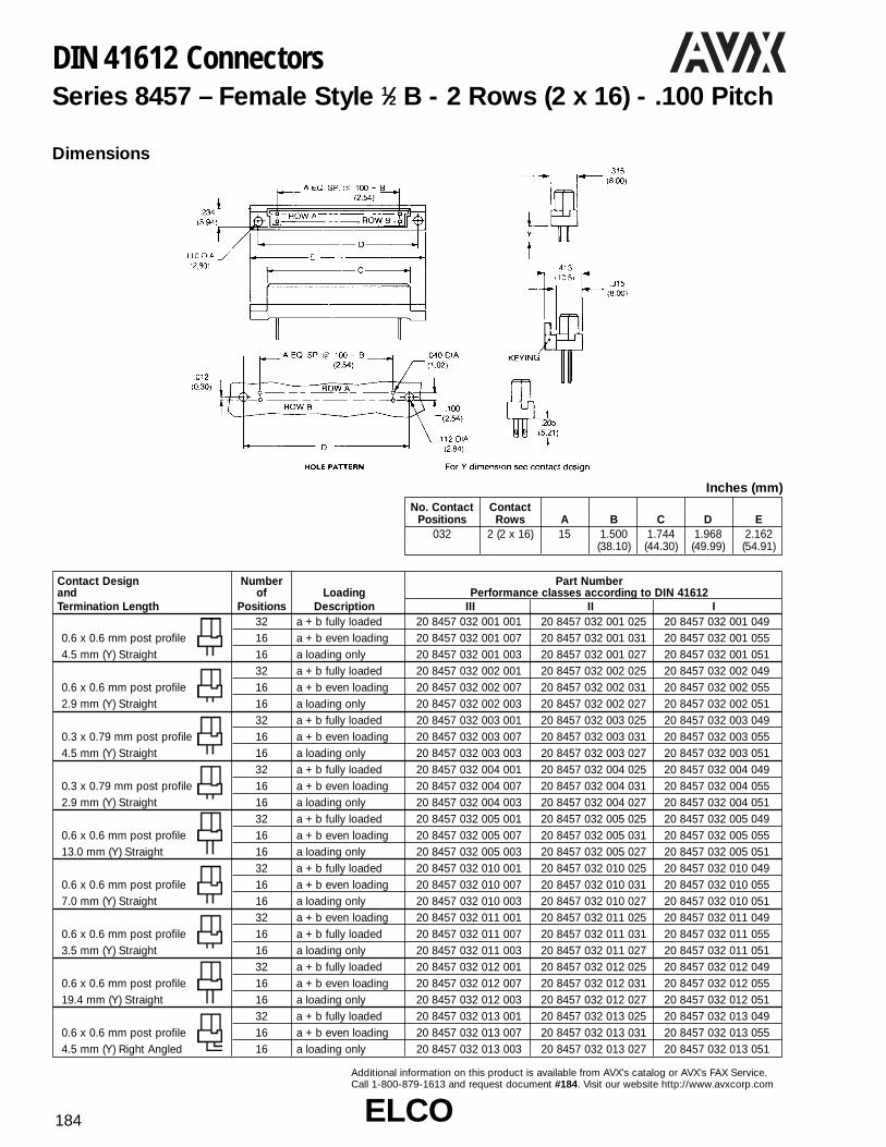
ELCOELCO184
Additional information on this product is available from AVX’s catalog or AVX’s FAX Service.Call 1-800-879-1613 and request document #184. Visit our website http://www.avxcorp.com
DIN 41612 ConnectorsSeries 8457 – Female Style 1⁄2 B - 2 Rows (2 x 16) - .100 Pitch
Contact Design Number Part Numberand of Loading Performance classes according to DIN 41612Termination Length Positions Description III II I
32 a + b fully loaded 20 8457 032 001 001 20 8457 032 001 025 20 8457 032 001 0490.6 x 0.6 mm post profile 16 a + b even loading 20 8457 032 001 007 20 8457 032 001 031 20 8457 032 001 0554.5 mm (Y) Straight 16 a loading only 20 8457 032 001 003 20 8457 032 001 027 20 8457 032 001 051
32 a + b fully loaded 20 8457 032 002 001 20 8457 032 002 025 20 8457 032 002 0490.6 x 0.6 mm post profile 16 a + b even loading 20 8457 032 002 007 20 8457 032 002 031 20 8457 032 002 0552.9 mm (Y) Straight 16 a loading only 20 8457 032 002 003 20 8457 032 002 027 20 8457 032 002 051
32 a + b fully loaded 20 8457 032 003 001 20 8457 032 003 025 20 8457 032 003 0490.3 x 0.79 mm post profile 16 a + b even loading 20 8457 032 003 007 20 8457 032 003 031 20 8457 032 003 0554.5 mm (Y) Straight 16 a loading only 20 8457 032 003 003 20 8457 032 003 027 20 8457 032 003 051
32 a + b fully loaded 20 8457 032 004 001 20 8457 032 004 025 20 8457 032 004 0490.3 x 0.79 mm post profile 16 a + b even loading 20 8457 032 004 007 20 8457 032 004 031 20 8457 032 004 0552.9 mm (Y) Straight 16 a loading only 20 8457 032 004 003 20 8457 032 004 027 20 8457 032 004 051
32 a + b fully loaded 20 8457 032 005 001 20 8457 032 005 025 20 8457 032 005 0490.6 x 0.6 mm post profile 16 a + b even loading 20 8457 032 005 007 20 8457 032 005 031 20 8457 032 005 05513.0 mm (Y) Straight 16 a loading only 20 8457 032 005 003 20 8457 032 005 027 20 8457 032 005 051
32 a + b fully loaded 20 8457 032 010 001 20 8457 032 010 025 20 8457 032 010 0490.6 x 0.6 mm post profile 16 a + b even loading 20 8457 032 010 007 20 8457 032 010 031 20 8457 032 010 0557.0 mm (Y) Straight 16 a loading only 20 8457 032 010 003 20 8457 032 010 027 20 8457 032 010 051
32 a + b even loading 20 8457 032 011 001 20 8457 032 011 025 20 8457 032 011 0490.6 x 0.6 mm post profile 16 a + b fully loaded 20 8457 032 011 007 20 8457 032 011 031 20 8457 032 011 0553.5 mm (Y) Straight 16 a loading only 20 8457 032 011 003 20 8457 032 011 027 20 8457 032 011 051
32 a + b fully loaded 20 8457 032 012 001 20 8457 032 012 025 20 8457 032 012 0490.6 x 0.6 mm post profile 16 a + b even loading 20 8457 032 012 007 20 8457 032 012 031 20 8457 032 012 05519.4 mm (Y) Straight 16 a loading only 20 8457 032 012 003 20 8457 032 012 027 20 8457 032 012 051
32 a + b fully loaded 20 8457 032 013 001 20 8457 032 013 025 20 8457 032 013 0490.6 x 0.6 mm post profile 16 a + b even loading 20 8457 032 013 007 20 8457 032 013 031 20 8457 032 013 0554.5 mm (Y) Right Angled 16 a loading only 20 8457 032 013 003 20 8457 032 013 027 20 8457 032 013 051
Dimensions
No. Contact ContactPositions Rows A B C D E
032 2 (2 x 16) 15 1.500 1.744 1.968 2.162(38.10) (44.30) (49.99) (54.91)
Inches (mm)

ELCOELCO 185
Additional information on this product is available from AVX’s catalog or AVX’s FAX Service.Call 1-800-879-1613 and request document #185. Visit our website http://www.avxcorp.com
DIN 41612 ConnectorsSeries 8457 – Male Style B - 2 Rows (2 x 32) - .100 Pitch
Contact Design Part Numberand Number of Loading Performance classes according to DIN 41612Termination Length Positions Description III II I
64 a + b fully loaded 10 8457 064 001 001 10 8457 064 001 025 10 8457 064 001 0493.4 mm (Y) 32 a + b even loading 10 8457 064 001 007 10 8457 064 001 031 10 8457 064 001 055Straight 32 a loading only 10 8457 064 001 003 10 8457 064 001 027 10 8457 064 001 051
64 a + b fully loaded 10 8457 064 002 001 10 8457 064 002 025 10 8457 064 002 04932 a + b even loading 10 8457 064 002 007 10 8457 064 002 031 10 8457 064 002 055
3.0 mm (Y) 32 a loading only 10 8457 064 002 003 10 8457 064 002 027 10 8457 064 002 051Right Angled 62 + 2 fully loaded + ground 10 8457 064 102 001 10 8457 064 102 025 10 8457 064 102 049
64 a + b fully loaded 10 8457 064 003 001 10 8457 064 003 025 10 8457 064 003 04913.0 mm (Y) 32 a + b even loading 10 8457 064 003 007 10 8457 064 003 031 10 8457 064 003 055Straight 32 a loading only 10 8457 064 003 003 10 8457 064 003 027 10 8457 064 003 051
64 a + b fully loaded 10 8457 064 004 001 10 8457 064 004 025 10 8457 064 004 04911.3 mm (Y) 32 a + b even loading 10 8457 064 004 007 10 8457 064 004 031 10 8457 064 004 055Right Angled 32 a loading only 10 8457 064 004 003 10 8457 064 004 027 10 8457 064 004 051
64 a + b fully loaded 10 8457 064 006 001 10 8457 064 006 025 10 8457 064 006 0497.7 mm (Y) 32 a + b even loading 10 8457 064 006 007 10 8457 064 006 031 10 8457 064 006 055Solder Hole 32 a loading only 10 8457 064 006 003 10 8457 064 006 027 10 8457 064 006 051
64 a + b fully loaded 10 8457 064 007 001 10 8457 064 007 025 10 8457 064 007 0496.4 mm (Y) 32 a + b even loading 10 8457 064 007 007 10 8457 064 007 031 10 8457 064 007 055Solder Loop 32 a loading only 10 8457 064 007 003 10 8457 064 007 027 10 8457 064 007 051
64 a + b fully loaded 10 8457 064 008 001 10 8457 064 008 025 10 8457 064 008 04932 a + b even loading 10 8457 064 008 007 10 8457 064 008 031 10 8457 064 008 055
2.3 mm (Y) 32 a loading only 10 8457 064 008 003 10 8457 064 008 027 10 8457 064 008 051Right Angled 62 + 2 fully loaded + ground 10 8457 064 108 001 10 8457 064 108 025 10 8457 064 108 049
Dimensions
No. Contact ContactPositions Rows A B C D E
064 2 (2 x 32) 31 3.100 3.354 3.500 3.700(78.74) (85.19) (88.90) (93.98)
Inches (mm)

ELCOELCO186
Additional information on this product is available from AVX’s catalog or AVX’s FAX Service.Call 1-800-879-1613 and request document #186. Visit our website http://www.avxcorp.com
DIN 41612 ConnectorsSeries 8457 – Female Style B - 2 Rows (2 x 32) - .100 Pitch
Contact Design Number Part Numberand of Loading Performance classes according to DIN 41612Termination Length Positions Description III II I
64 a + b fully loaded 20 8457 064 001 001 20 8457 064 001 025 20 8457 064 001 0490.6 x 0.6 mm Post Profile 32 a + b even loading 20 8457 064 001 007 20 8457 064 001 031 20 8457 064 001 0554.5 mm (Y) Straight 32 a loading only 20 8457 064 001 003 20 8457 064 001 027 20 8457 064 001 051
64 a + b fully loaded 20 8457 064 002 001 20 8457 064 002 025 20 8457 064 002 0490.6 x 0.6 mm Post Profile 32 a + b even loading 20 8457 064 002 007 20 8457 064 002 031 20 8457 064 002 0552.9 mm (Y) Straight 32 a loading only 20 8457 064 002 003 20 8457 064 002 027 20 8457 064 002 051
64 a + b fully loaded 20 8457 064 003 001 20 8457 064 003 025 20 8457 064 003 0490.3 x 0.79 mm Post Profile 32 a + b even loading 20 8457 064 003 007 20 8457 064 003 031 20 8457 064 003 0554.5 mm (Y) Straight 32 a loading only 20 8457 064 003 003 20 8457 064 003 027 20 8457 064 003 051
64 a + b fully loaded 20 8457 064 004 001 20 8457 064 004 025 20 8457 064 004 0490.3 x 0.79 mm Post Profile 32 a + b even loading 20 8457 064 004 007 20 8457 064 004 031 20 8457 064 004 0552.9 mm (Y) Straight 32 a loading only 20 8457 064 004 003 20 8457 064 004 027 20 8457 064 004 051
64 a + b fully loaded 20 8457 064 005 001 20 8457 064 005 025 20 8457 064 005 0490.6 x 0.6 mm Post Profile 32 a + b even loading 20 8457 064 005 007 20 8457 064 005 031 20 8457 064 005 05513.0 mm (Y) Straight 32 a loading only 20 8457 064 005 003 20 8457 064 005 027 20 8457 064 005 051
64 a + b fully loaded 20 8457 064 010 001 20 8457 064 010 025 20 8457 064 010 0490.6 x 0.6 mm Post Profile 32 a + b even loading 20 8457 064 010 007 20 8457 064 010 031 20 8457 064 010 0557.0 mm (Y) Straight 32 a loading only 20 8457 064 010 003 20 8457 064 010 027 20 8457 064 010 051
64 a + b fully loaded 20 8457 064 011 001 20 8457 064 011 025 20 8457 064 011 0490.6 x 0.6 mm Post Profile 32 a + b even loading 20 8457 064 011 007 20 8457 064 011 031 20 8457 064 011 0553.5 mm (Y) Straight 32 a loading only 20 8457 064 011 003 20 8457 064 011 027 20 8457 064 011 051
64 a + b fully loaded 20 8457 064 012 001 20 8457 064 012 025 20 8457 064 012 0490.6 x 0.6 mm Post Profile 32 a + b even loading 20 8457 064 012 007 20 8457 064 012 031 20 8457 064 012 05519.4 mm (Y) Straight 32 a loading only 20 8457 064 012 003 20 8457 064 012 027 20 8457 064 012 051
64 a + b fully loaded 20 8457 064 013 001 20 8457 064 013 025 20 8457 064 013 0490.6 x 0.6 mm Post Profile 32 a + b even loading 20 8457 064 013 007 20 8457 064 013 031 20 8457 064 013 0554.5 mm (Y) Right Angled 32 a loading only 20 8457 064 013 003 20 8457 064 013 027 20 8457 064 013 051
Dimensions
No. Contact ContactPositions Rows A B C D E
064 2 (2 x 32) 31 3.100 3.343 3.543 3.736(78.74) (84.91) (89.99) (94.89)
Inches (mm)
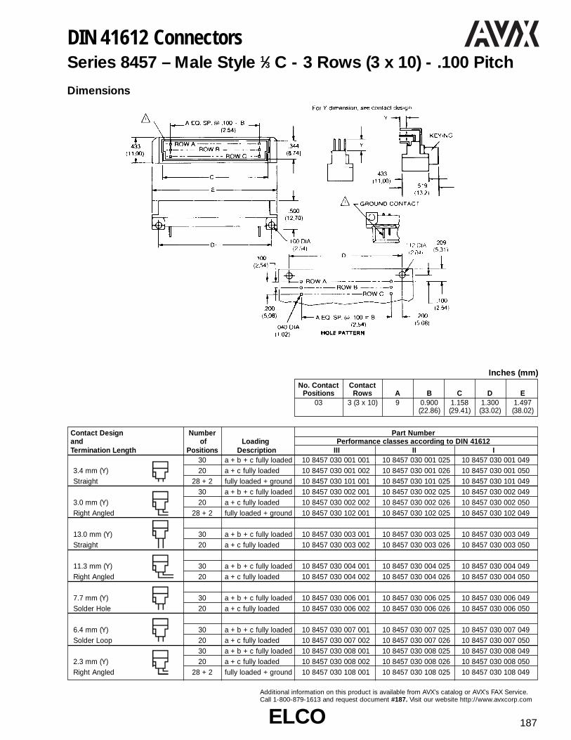
ELCOELCO 187
Additional information on this product is available from AVX’s catalog or AVX’s FAX Service.Call 1-800-879-1613 and request document #187. Visit our website http://www.avxcorp.com
DIN 41612 ConnectorsSeries 8457 – Male Style 1⁄3 C - 3 Rows (3 x 10) - .100 Pitch
Contact Design Number Part Numberand of Loading Performance classes according to DIN 41612Termination Length Positions Description III II I
30 a + b + c fully loaded 10 8457 030 001 001 10 8457 030 001 025 10 8457 030 001 0493.4 mm (Y) 20 a + c fully loaded 10 8457 030 001 002 10 8457 030 001 026 10 8457 030 001 050Straight 28 + 2 fully loaded + ground 10 8457 030 101 001 10 8457 030 101 025 10 8457 030 101 049
30 a + b + c fully loaded 10 8457 030 002 001 10 8457 030 002 025 10 8457 030 002 0493.0 mm (Y) 20 a + c fully loaded 10 8457 030 002 002 10 8457 030 002 026 10 8457 030 002 050Right Angled 28 + 2 fully loaded + ground 10 8457 030 102 001 10 8457 030 102 025 10 8457 030 102 049
13.0 mm (Y) 30 a + b + c fully loaded 10 8457 030 003 001 10 8457 030 003 025 10 8457 030 003 049Straight 20 a + c fully loaded 10 8457 030 003 002 10 8457 030 003 026 10 8457 030 003 050
11.3 mm (Y) 30 a + b + c fully loaded 10 8457 030 004 001 10 8457 030 004 025 10 8457 030 004 049Right Angled 20 a + c fully loaded 10 8457 030 004 002 10 8457 030 004 026 10 8457 030 004 050
7.7 mm (Y) 30 a + b + c fully loaded 10 8457 030 006 001 10 8457 030 006 025 10 8457 030 006 049Solder Hole 20 a + c fully loaded 10 8457 030 006 002 10 8457 030 006 026 10 8457 030 006 050
6.4 mm (Y) 30 a + b + c fully loaded 10 8457 030 007 001 10 8457 030 007 025 10 8457 030 007 049Solder Loop 20 a + c fully loaded 10 8457 030 007 002 10 8457 030 007 026 10 8457 030 007 050
30 a + b + c fully loaded 10 8457 030 008 001 10 8457 030 008 025 10 8457 030 008 0492.3 mm (Y) 20 a + c fully loaded 10 8457 030 008 002 10 8457 030 008 026 10 8457 030 008 050Right Angled 28 + 2 fully loaded + ground 10 8457 030 108 001 10 8457 030 108 025 10 8457 030 108 049
Dimensions
No. Contact ContactPositions Rows A B C D E
03 3 (3 x 10) 9 0.900 1.158 1.300 1.497(22.86) (29.41) (33.02) (38.02)
Inches (mm)

ELCOELCO188
Additional information on this product is available from AVX’s catalog or AVX’s FAX Service.Call 1-800-879-1613 and request document #188. Visit our website http://www.avxcorp.com
DIN 41612 ConnectorsSeries 8457 – Female Style 1⁄3 C - 3 Rows (3 x 10) - .100 Pitch
Contact Design Number Part Numberand of Loading Performance classes according to DIN 41612Termination Length Positions Description III II I
0.6 x 0.6 mm Post Profile 30 a + b + c fully loaded 20 8457 030 001 001 20 8457 030 001 025 20 8457 030 001 0494.5 mm (Y) Straight 20 a + c fully loaded 20 8457 030 001 002 20 8457 030 001 026 20 8457 030 001 050
0.6 x 0.6 mm Post Profile 30 a + b + c fully loaded 20 8457 030 002 001 20 8457 030 002 025 20 8457 030 002 0492.9 mm (Y) Straight 20 a + c fully loaded 20 8457 030 002 002 20 8457 030 002 026 20 8457 030 002 050
0.3 x 0.79 mm Post Profile 30 a + b + c fully loaded 20 8457 030 003 001 20 8457 030 003 025 20 8457 030 003 0494.5 mm (Y) Straight 20 a + c fully loaded 20 8457 030 003 002 20 8457 030 003 026 20 8457 030 003 050
0.3 x 0.79 mm Post Profile 30 a + b + c fully loaded 20 8457 030 004 001 20 8457 030 004 025 20 8457 030 004 0492.9 mm (Y) Straight 20 a + c fully loaded 20 8457 030 004 002 20 8457 030 004 026 20 8457 030 004 050
0.6 x 0.6 mm Post Profile 30 a + b + c fully loaded 20 8457 030 005 001 20 8457 030 005 025 20 8457 030 005 04913.0 mm (Y) Straight 20 a + c fully loaded 20 8457 030 005 002 20 8457 030 005 026 20 8457 030 005 050
0.6 x 0.6 mm Post Profile 30 a + b + c fully loaded 20 8457 030 010 001 20 8457 030 010 025 20 8457 030 010 0497.0 mm (Y) Straight 20 a + c fully loaded 20 8457 030 010 002 20 8457 030 010 026 20 8457 030 010 050
0.6 x 0.6 mm Post Profile 30 a + b + c fully loaded 20 8457 030 011 001 20 8457 030 011 025 20 8457 030 011 0493.5 mm (Y) Straight 20 a + c fully loaded 20 8457 030 011 002 20 8457 030 011 026 20 8457 030 011 050
0.6 x 0.6 mm Post Profile 30 a + b + c fully loaded 20 8457 030 012 001 20 8457 030 012 025 20 8457 030 012 04919.4 mm (Y) Straight 20 a + c fully loaded 20 8457 030 012 002 20 8457 030 012 026 20 8457 030 012 050
0.6 x 0.6 mm Post Profile 30 a + b + c fully loaded 20 8457 030 013 001 20 8457 030 013 025 20 8457 030 013 0494.5 mm (Y) Right Angled 20 a + c fully loaded 20 8457 030 013 002 20 8457 030 013 026 20 8457 030 013 050
Dimensions
No. Contact ContactPositions Rows A B C D E
030 3 (3 x 10) 9 0.900 1.163 1.563 1.144(22.86) (34.75) (39.70) (29.06)
Inches (mm)

ELCOELCO 189
Additional information on this product is available from AVX’s catalog or AVX’s FAX Service.Call 1-800-879-1613 and request document #189. Visit our website http://www.avxcorp.com
DIN 41612 ConnectorsSeries 8457 – Male Style 1⁄2 C - 3 Rows (3 x 16) - .100 Pitch
Contact Design Number Part Numberand of Loading Performance classes according to DIN 41612Termination Length Positions Description III II I
48 a + b + c fully loaded 10 8457 048 001 001 10 8457 048 001 025 10 8457 048 001 04932 a + c fully loaded 10 8457 048 001 002 10 8457 048 001 026 10 8457 048 001 050
3.4 mm (Y) 16 a loading only 10 8457 048 001 003 10 8457 048 001 027 10 8457 048 001 051Straight 46 + 2 fully loaded + ground 10 8457 048 101 001 10 8457 048 101 025 10 8457 048 101 049
48 a + b + c fully loaded 10 8457 048 002 001 10 8457 048 002 025 10 8457 048 002 04932 a + c fully loaded 10 8457 048 002 002 10 8457 048 002 026 10 8457 048 002 050
3.0 mm (Y) 16 a loading only 10 8457 048 002 003 10 8457 048 002 027 10 8457 048 002 051Right Angled 46 + 2 fully loaded + ground 10 8457 048 102 001 10 8457 048 102 025 10 8457 048 102 049
48 a + b + c fully loaded 10 8457 048 003 001 10 8457 048 003 025 10 8457 048 003 04913.0 mm (Y) 32 a + c fully loaded 10 8457 048 003 002 10 8457 048 003 026 10 8457 048 003 050Straight 16 a loading only 10 8457 048 003 003 10 8457 048 003 027 10 8457 048 003 051
48 a + b + c fully loaded 10 8457 048 004 001 10 8457 048 004 025 10 8457 048 004 04911.3 mm (Y) 32 a + c fully loaded 10 8457 048 004 002 10 8457 048 004 026 10 8457 048 004 050Right Angled 16 a loading only 10 8457 048 004 003 10 8457 048 004 027 10 8457 048 004 051
48 a + b + c fully loaded 10 8457 048 006 001 10 8457 048 006 025 10 8457 048 006 0497.7 mm (Y) 32 a + c fully loaded 10 8457 048 006 002 10 8457 048 006 026 10 8457 048 006 050Solder Hole 16 a loading only 10 8457 048 006 003 10 8457 048 006 027 10 8457 048 006 051
48 a + b + c fully loaded 10 8457 048 007 001 10 8457 048 007 025 10 8457 048 007 0496.4 mm (Y) 32 a + c fully loaded 10 8457 048 007 002 10 8457 048 007 026 10 8457 048 007 050Solder Loop 16 a loading only 10 8457 048 007 003 10 8457 048 007 027 10 8457 048 007 051
48 a + b + c fully loaded 10 8457 048 008 001 10 8457 048 008 025 10 8457 048 008 04932 a + c fully loaded 10 8457 048 008 002 10 8457 048 008 026 10 8457 048 008 050
2.3 mm (Y) 16 a loading only 10 8457 048 008 003 10 8457 048 008 027 10 8457 048 008 051Right Angled 46 + 2 fully loaded + ground 10 8457 048 108 001 10 8457 048 108 025 10 8457 048 108 049
Dimensions
No. Contact ContactPositions Rows A B C D E
048 3 (3 x 16) 15 1.500 1.760 1.900 2.122(38.10) (44.70) (48.26) (53.90)
Inches (mm)

ELCOELCO190
Additional information on this product is available from AVX’s catalog or AVX’s FAX Service.Call 1-800-879-1613 and request document #190. Visit our website http://www.avxcorp.com
DIN 41612 ConnectorsSeries 8457 – Female Style 1⁄2 C - 3 Rows (3 x 16) - .100 Pitch
Contact Design Number Part Numberand of Loading Performance classes according to DIN 41612Termination Length Positions Description III II I
48 a + b + c fully loaded 20 8457 048 001 001 20 8457 048 001 025 20 8457 048 001 0490.6 x 0.6 mm Post Profile 32 a + c fully loaded 20 8457 048 001 002 20 8457 048 001 026 20 8457 048 001 0504.5 mm (Y) Straight 16 a loading only 20 8457 048 001 003 20 8457 048 001 027 20 8457 048 001 051
48 a + b + c fully loaded 20 8457 048 002 001 20 8457 048 002 025 20 8457 048 002 0490.6 x 0.6 mm Post Profile 32 a + c fully loaded 20 8457 048 002 002 20 8457 048 002 026 20 8457 048 002 0502.9 mm (Y) Straight 16 a loading only 20 8457 048 002 003 20 8457 048 002 027 20 8457 048 002 051
48 a + b + c fully loaded 20 8457 048 003 001 20 8457 048 003 025 20 8457 048 003 0490.3 x 0.79 mm Post Profile 32 a + c fully loaded 20 8457 048 003 002 20 8457 048 003 026 20 8457 048 003 0504.5 mm (Y) Straight 16 a loading only 20 8457 048 003 003 20 8457 048 003 027 20 8457 048 003 051
48 a + b + c fully loaded 20 8457 048 004 001 20 8457 048 004 025 20 8457 048 004 0490.3 x 0.79 mm Post Profile 32 a + c fully loaded 20 8457 048 004 002 20 8457 048 004 026 20 8457 048 004 0502.9 mm (Y) Straight 16 a loading only 20 8457 048 004 003 20 8457 048 004 027 20 8457 048 004 051
48 a + b + c fully loaded 20 8457 048 005 001 20 8457 048 005 025 20 8457 048 005 0490.6 x 0.6 mm Post Profile 32 a + c fully loaded 20 8457 048 005 002 20 8457 048 005 026 20 8457 048 005 05013.0 mm (Y) Straight 16 a loading only 20 8457 048 005 003 20 8457 048 005 027 20 8457 048 005 051
48 a + b + c fully loaded 20 8457 048 010 001 20 8457 048 010 025 20 8457 048 010 0490.6 x 0.6 mm Post Profile 32 a + c fully loaded 20 8457 048 010 002 20 8457 048 010 026 20 8457 048 010 0507.0 mm (Y) Straight 16 a loading only 20 8457 048 010 003 20 8457 048 010 027 20 8457 048 010 051
48 a + b + c fully loaded 20 8457 048 011 001 20 8457 048 011 025 20 8457 048 011 0490.6 x 0.6 mm Post Profile 32 a + c fully loaded 20 8457 048 011 002 20 8457 048 011 026 20 8457 048 011 0503.5 mm (Y) Straight 16 a loading only 20 8457 048 011 003 20 8457 048 011 027 20 8457 048 011 051
48 a + b + c fully loaded 20 8457 048 012 001 20 8457 048 012 025 20 8457 048 012 0490.6 x 0.6 mm Post Profile 32 a + c fully loaded 20 8457 048 012 002 20 8457 048 012 026 20 8457 048 012 05019.4 mm (Y) Straight 16 a loading only 20 8457 048 012 003 20 8457 048 012 027 20 8457 048 012 051
48 a + b + c fully loaded 20 8457 048 013 001 20 8457 048 013 025 20 8457 048 013 0490.6 x 0.6 mm Post Profile 32 a + c fully loaded 20 8457 048 013 002 20 8457 048 013 026 20 8457 048 013 0504.5 mm (Y) Right Angled 16 a loading only 20 8457 048 013 003 20 8457 048 013 027 20 8457 048 013 051
Dimensions
No. Contact ContactPositions Rows A B C D E
048 3 (3 x 16) 15 1.500 1.969 2.161 1.744(38.10) (50.01) (54.89) (44.30)
Inches (mm)

ELCOELCO 191
Additional information on this product is available from AVX’s catalog or AVX’s FAX Service.Call 1-800-879-1613 and request document #191. Visit our website http://www.avxcorp.com
Contact Design Number Part Numberand of Loading Performance classes according to DIN 41612Termination Length Positions Description III II I
96 a + b + c fully loaded 10 8457 096 001 001 10 8457 096 001 025 10 8457 096 001 04964 a + c fully loaded 10 8457 096 001 002 10 8457 096 001 026 10 8457 096 001 05032 a + c even loading 10 8457 096 001 009 10 8457 096 001 033 10 8457 096 001 057
3.4 mm (Y) 32 a loading only 10 8457 096 001 003 10 8457 096 001 027 10 8457 096 001 051Straight 94 + 2 fully loaded + ground 10 8457 096 101 001 10 8457 096 101 025 10 8457 096 101 049
96 a + b + c fully loaded 10 8457 096 002 001 10 8457 096 002 025 10 8457 096 002 04964 a + c fully loaded 10 8457 096 002 002 10 8457 096 002 026 10 8457 096 002 05032 a + c even loading 10 8457 096 002 009 10 8457 096 002 033 10 8457 096 002 057
3.0 mm (Y) 32 a loading only 10 8457 096 002 003 10 8457 096 002 027 10 8457 096 002 051Right Angled 94 + 2 fully loaded + ground 10 8457 096 102 001 10 8457 096 102 025 10 8457 096 102 049
96 a + b + c fully loaded 10 8457 096 003 001 10 8457 096 003 025 10 8457 096 003 04964 a + c fully loaded 10 8457 096 003 002 10 8457 096 003 026 10 8457 096 003 050
13.0 mm (Y) 32 a + c even loading 10 8457 096 003 009 10 8457 096 003 033 10 8457 096 003 057Straight 32 a loading only 10 8457 096 003 003 10 8457 096 003 027 10 8457 096 003 051
96 a + b + c fully loaded 10 8457 096 004 001 10 8457 096 004 025 10 8457 096 004 04964 a + c fully loaded 10 8457 096 004 002 10 8457 096 004 026 10 8457 096 004 050
11.3mm (Y) 32 a + c even loading 10 8457 096 004 009 10 8457 096 004 033 10 8457 096 004 057Right Angled 32 a loading only 10 8457 096 004 003 10 8457 096 004 027 10 8457 096 004 051
96 a + b + c fully loaded 10 8457 096 006 001 10 8457 096 006 025 10 8457 096 006 04964 a + c fully loaded 10 8457 096 006 002 10 8457 096 006 026 10 8457 096 006 050
7.7 mm (Y) 32 a + c even loading 10 8457 096 006 009 10 8457 096 006 033 10 8457 096 006 057Solder Hole 32 a loading only 10 8457 096 006 003 10 8457 096 006 027 10 8457 096 006 051
96 a + b + c fully loaded 10 8457 096 007 001 10 8457 096 007 025 10 8457 096 007 04964 a + c fully loaded 10 8457 096 007 002 10 8457 096 007 026 10 8457 096 007 050
6.4 mm (Y) 32 a + c even loading 10 8457 096 007 009 10 8457 096 007 033 10 8457 096 007 057Solder Loop 32 a loading only 10 8457 096 007 003 10 8457 096 007 027 10 8457 096 007 051
96 a + b + c fully loaded 10 8457 096 008 001 10 8457 096 008 025 10 8457 096 008 04964 a + c fully loaded 10 8457 096 008 002 10 8457 096 008 026 10 8457 096 008 05032 a + c even loading 10 8457 096 008 009 10 8457 096 008 033 10 8457 096 008 057
2.3 mm (Y) 32 a loading only 10 8457 096 008 003 10 8457 096 008 027 10 8457 096 008 051Right Angled 94 + 2 fully loaded + ground 10 8457 096 108 001 10 8457 096 108 025 10 8457 096 108 04
DIN 41612 ConnectorsSeries 8457 – Male Style C - 3 Rows (3 x 32) - .100 Pitch
Dimensions
No. Contact ContactPositions Rows A B C D E
096 3 (3 x 32) 31 3.100 3.358 3.500 3.697(78.74) (85.29) (88.90) (93.90)
Inches (mm)

ELCOELCO192
Additional information on this product is available from AVX’s catalog or AVX’s FAX Service.Call 1-800-879-1613 and request document #192. Visit our website http://www.avxcorp.com
DIN 41612 ConnectorsSeries 8457 – Female Style C - 3 Rows (3 x 32) - .100 Pitch
Contact Design Number Part Numberand of Loading Performance classes according to DIN 41612Termination Length Positions Description III II I
96 a + b + c fully loaded 20 8457 096 001 001 20 8457 096 001 025 20 8457 096 001 04964 a + c fully loaded 20 8457 096 001 002 20 8457 096 001 026 20 8457 096 001 050
0.6 x 0.6 mm Post Profile 32 a + c even loading 20 8457 096 001 009 20 8457 096 001 033 20 8457 096 001 0574.5 mm (Y) Straight 32 a loading only 20 8457 096 001 003 20 8457 096 001 027 20 8457 096 001 051
96 a + b + c fully loaded 20 8457 096 002 001 20 8457 096 002 025 20 8457 096 002 04964 a + c fully loaded 20 8457 096 002 002 20 8457 096 002 026 20 8457 096 002 050
0.6 x 0.6 mm Post Profile 32 a + c even loading 20 8457 096 002 009 20 8457 096 002 033 20 8457 096 002 0572.9 mm (Y) Straight 32 a loading only 20 8457 096 002 003 20 8457 096 002 027 20 8457 096 002 051
96 a + b + c fully loaded 20 8457 096 003 001 20 8457 096 003 025 20 8457 096 003 04964 a + c fully loaded 20 8457 096 003 002 20 8457 096 003 026 20 8457 096 003 050
0.3 x 0.79 mm Post Profile 32 a + c even loading 20 8457 096 003 009 20 8457 096 003 033 20 8457 096 003 0574.5 mm (Y) Straight 32 a loading only 20 8457 096 003 003 20 8457 096 003 027 20 8457 096 003 051
96 a + b + c fully loaded 20 8457 096 004 001 20 8457 096 004 025 20 8457 096 004 04964 a + c fully loaded 20 8457 096 004 002 20 8457 096 004 026 20 8457 096 004 050
0.3 x 0.79 mm Post Profile 32 a + c even loading 20 8457 096 004 009 20 8457 096 004 033 20 8457 096 004 0572.9 mm (Y) Straight 32 a loading only 20 8457 096 004 003 20 8457 096 004 027 20 8457 096 004 051
96 a + b + c fully loaded 20 8457 096 005 001 20 8457 096 005 025 20 8457 096 005 04964 a + c fully loaded 20 8457 096 005 002 20 8457 096 005 026 20 8457 096 005 050
0.6 x 0.6 mm Post Profile 32 a + c even loading 20 8457 096 005 009 20 8457 096 005 033 20 8457 096 005 05713.0 mm (Y) Straight 32 a loading only 20 8457 096 005 003 20 8457 096 005 027 20 8457 096 005 051
96 a + b + c fully loaded 20 8457 096 010 001 20 8457 096 010 025 20 8457 096 010 04964 a + c fully loaded 20 8457 096 010 002 20 8457 096 010 026 20 8457 096 010 050
0.6 x 0.6 mm Post Profile 32 a + c even loading 20 8457 096 010 009 20 8457 096 010 033 20 8457 096 010 0577.0 mm (Y) Straight 32 a loading only 20 8457 096 010 003 20 8457 096 010 027 20 8457 096 010 051
96 a + b + c fully loaded 20 8457 096 011 001 20 8457 096 011 025 20 8457 096 011 04964 a + c fully loaded 20 8457 096 011 002 20 8457 096 011 026 20 8457 096 011 050
0.6 x 0.6 mm Post Profile 32 a + c all even loading 20 8457 096 011 009 20 8457 096 011 033 20 8457 096 011 0573.5 mm (Y) Straight 32 a loading only 20 8457 096 011 003 20 8457 096 011 027 20 8457 096 011 051
96 a + b + c fully loaded 20 8457 096 012 001 20 8457 096 012 025 20 8457 096 012 04964 a + c fully loaded 20 8457 096 012 002 20 8457 096 012 026 20 8457 096 012 050
0.6 x 0.6 mm Post Profile 32 a + c even loading 20 8457 096 012 009 20 8457 096 012 033 20 8457 096 012 05719.4 mm (Y) Straight 32 a loading only 20 8457 096 012 003 20 8457 096 012 027 20 8457 096 012 051
96 a + b + c fully loaded 20 8457 096 013 001 20 8457 096 013 025 20 8457 096 013 04964 a + c fully loaded 20 8457 096 013 002 20 8457 096 013 026 20 8457 096 013 050
0.6 x 0.6 mm Post Profile 32 a + c even loading 20 8457 096 013 009 20 8457 096 013 033 20 8457 096 013 0574.5 mm (Y) Right Angled 32 a loading only 20 8457 096 013 003 20 8457 096 013 027 20 8457 096 013 051
Dimensions
No. Contact ContactPositions Rows A B C D E
096 3 (3 x 32) 31 3.100 3.543 3.736 3.343(78.74) (89.99) (94.89) (84.91)
Inches (mm)

ELCOELCO 193
Additional information on this product is available from AVX’s catalog or AVX’s FAX Service.Call 1-800-879-1613 and request document #193. Visit our website http://www.avxcorp.com
DIN 41612 ConnectorsSeries 8457 – Male Style C Expanded - 4 Rows (4 x 32) -.100 Pitch
Series 8457 – Male Style C Expanded - 5 Rows (5 x 32) -.100 Pitch
Contact Design Number Part Numberand of Loading Performance classes according to DIN 41612Termination Length Positions Description III II I
3.4 mm (Y) 128 a + b + c + d fully loaded 10 8457 128 001 001 10 8457 128 001 025 10 8457 096 001 049Straight 126 + 2 4 rows fully loaded + ground 10 8457 128 101 001 10 8457 128 101 025 10 8457 096 101 049
3.0 mm (Y) 128 a + b + c + d fully loaded 10 8457 128 002 001 10 8457 128 002 025 10 8457 096 002 049Right Angled 126 + 2 4 rows fully loaded + ground 10 8457 128 102 001 10 8457 128 102 025 10 8457 096 102 049
Dimensions
Contact Design Number Part Numberand of Loading Performance classes according to DIN 41612Termination Length Positions Description III II I
3.4 mm (Y) 160 a + b + c + d + e fully loaded 10 8457 160 001 001 10 8457 160 001 025 10 8457 096 001 049Straight 158 + 2 5 rows fully loaded + ground 10 8457 160 101 001 10 8457 160 101 025 10 8457 096 101 049
3.0 mm (Y) 160 a + b + c + d + e fully loaded 10 8457 160 002 001 10 8457 160 002 025 10 8457 096 002 049Right Angled 158 + 2 5 rows fully loaded + ground 10 8457 160 102 001 10 8457 160 102 025 10 8457 096 102 049

ELCOELCO194
Additional information on this product is available from AVX’s catalog or AVX’s FAX Service.Call 1-800-879-1613 and request document #194. Visit our website http://www.avxcorp.com
DIN 41612 ConnectorsSeries 8447 – Male Style D - 2 Rows (2 x 16) - .100 or .200 Pitch
Series 8447 – Female Style D - 2 Rows (2 x 16) - .200 Pitch
Contact Design Number Part Numberand of Loading Performance classes according to DIN 41612Termination Length Positions Description III II I
3.0 mm (Y) (0.6 x 0.6 mm) 32 a + c fully loaded 10 8447 032 001 001 10 8447 032 001 025 10 8447 032 001 049Right Angled Pitch 5.08 30 + 2 fully loaded + ground 10 8447 032 101 001 10 8447 032 101 025 10 8447 032 101 049
3.0 mm (Y) (0.6 x 0.6 mm) 32 a + c fully loaded 10 8447 032 002 001 10 8447 032 002 025 10 8447 032 002 049Right Angled Pitch 2.54 30 + 2 fully loaded + ground 10 8447 032 102 001 10 8447 032 102 025 10 8447 032 102 049
Dimensions
Dimensions
Contact Design Number Part Numberand of Loading Performance classes according to DIN 41612Termination Length Positions Description III II I
1 x 1 mm Post Profile20.0 mm (Y) Straight 32 a + c fully loaded 20 8447 032 001 001 20 8447 032 001 025 20 8447 032 001 049
1 x 1 mm Post Profile9.0 mm (Y) Straight 32 a + c fully loaded 20 8447 032 002 001 20 8447 032 002 025 20 8447 032 002 049
0.6 x 0.6 mm Post Profile4.0 mm (Y) Straight 32 a + c fully loaded 20 8447 032 003 001 20 8447 032 003 025 20 8447 032 003 049
1 x 1 mm Post Profile12.0 mm (Y) Straight 32 a + c fully loaded 20 8447 032 004 001 20 8447 032 004 025 20 8447 032 004 049
0.6 x 1.28 mm Post Profile4.5 mm (Y) Straight 32 a + c fully loaded 20 8447 032 006 001 20 8447 032 006 025 20 8447 032 006 049
7.5 mm (Y) Solder Hole 32 a + c fully loaded 20 8447 032 007 001 20 8447 032 007 025 20 8447 032 007 049

ELCOELCO 195
Additional information on this product is available from AVX’s catalog or AVX’s FAX Service.Call 1-800-879-1613 and request document #195. Visit our website http://www.avxcorp.com
DIN 41612 ConnectorsSeries 8447 – Male Style E - 3 Rows (3 x 16) - .200 Pitch
Series 8447 – Female Style E - 3 Rows (3 x 16) - .200 Pitch
Contact Design Number Part Numberand of Loading Performance classes according to DIN 41612Termination Length Positions Description III II I
3.0 mm (Y) (0.6 x 0.6 mm) 48 a + c + e fully loaded 10 8447 048 001 001 10 8447 048 001 025 10 8447 048 001 049Right Angled Pitch 5.08 46 + 2 fully loaded + ground 10 8447 048 101 001 10 8447 048 101 025 10 8447 048 101 049
3.0 mm (Y) (0.6 x 0.6 mm) 48 a + c + e fully loaded 10 8447 048 002 001 10 8447 048 002 025 10 8447 048 002 049Right Angled Pitch 2.54 46 + 2 fully loaded + ground 10 8447 048 102 001 10 8447 048 102 025 10 8447 048 102 049
Dimensions
Dimensions
Contact Design Number Part Numberand of Loading Performance classes according to DIN 41612Termination Length Positions Description III II I
1 x 1 mm Post Profile20.0 mm (Y) Straight 48 a + c + e fully loaded 20 8447 048 001 001 20 8447 048 001 025 20 8447 048 001 049
1 x 1 mm Post Profile9.0 mm (Y) Straight 48 a + c + e fully loaded 20 8447 048 002 001 20 8447 048 002 025 20 8447 048 002 049
0.6 x 0.6 mm Post Profile4.0 mm (Y) Straight 48 a + c + e fully loaded 20 8447 048 003 001 20 8447 048 003 025 20 8447 048 003 049
1 x 1 mm Post Profile12.0 mm (Y) Straight 48 a + c + e fully loaded 20 8447 048 004 001 20 8447 048 004 025 20 8447 048 004 049
0.6 x 0.6 mm Post Profile4.5 mm (Y) Straight 48 a + c + e fully loaded 20 8447 048 006 001 20 8447 048 006 025 20 8447 048 006 049
7.5 mm (Y) Solder Hole 48 a + c + e fully loaded 20 8447 048 007 001 20 8447 048 007 025 20 8447 048 007 049

ELCOELCO196
Additional information on this product is available from AVX’s catalog or AVX’s FAX Service.Call 1-800-879-1613 and request document #196. Visit our website http://www.avxcorp.com
DIN 41612 ConnectorsSeries 8487 – Male Style F -3 Rows (3 x 16) - .200 Pitch
Series 8487 – Female Style F -3 Rows (3 x 16) - .200 Pitch
Contact Design Number Part Numberand of Loading Performance classes according to DIN 41612Termination Length Positions Description III II I
32 d + z fully loaded 10 8487 048 001 002 10 8487 048 001 026 10 8487 048 001 05032 b + z fully loaded 10 8487 048 001 005 10 8487 048 001 029 10 8487 048 001 05332 d + z fully, Ground in z2 59 8487 048 000 049 59 8487 048 000 055 59 8487 048 000 06132 d + z fully, Ground in z2 + z32 59 8487 048 000 050 59 8487 048 000 056 59 8487 048 000 06232 b + z fully, Ground in z2 59 8487 048 000 051 59 8487 048 000 057 59 8487 048 000 06332 b + z fully, Ground in z2 + z32 59 8487 048 000 052 59 8487 048 000 058 59 8487 048 000 06348 d + b + z fully loaded 10 8487 048 001 001 10 8487 048 001 025 10 8487 048 001 04948 fully loaded + Ground in z2 59 8487 048 000 047 59 8487 048 000 053 59 8487 048 000 05948 fully, Ground in z2 + z32 59 8487 048 000 048 59 8487 048 000 054 59 8487 048 000 060
3.0 mm (Y) 48 fully loaded + Ground in b2 + b32 59 8487 048 000 067 59 8487 048 000 066 59 8487 048 000 065Right Angled Pitch 5.08 48 fully loaded + Ground in d2 + d32 59 8487 048 000 070 59 8487 048 000 069 59 8487 048 000 068
Dimensions
Dimensions
Contact Design Number Part Numberand of Loading Performance classes according to DIN 41612Termination Length Positions Description III II I
48 d + b + z fully loaded 20 8487 048 001 001 20 8487 048 001 025 20 8487 048 001 0490.6 x 0.6 mm Post Profile 32 d + z fully loaded 20 8487 048 001 002 20 8487 048 001 026 20 8487 048 001 0504.5 mm (X) Straight 32 b + z fully loaded 20 8487 048 001 005 20 8487 048 001 029 20 8487 048 001 053
48 d + b + z fully loaded 20 8487 048 002 001 20 8487 048 002 025 20 8487 048 002 0491 x 1 mm Post Profile 32 d + z fully loaded 20 8487 048 002 002 20 8487 048 002 026 20 8487 048 002 05022.0 mm (X) Straight 32 b + z fully loaded 20 8487 048 002 005 20 8487 048 002 029 20 8487 048 002 053
48 d + b + z fully loaded 20 8487 048 003 001 20 8487 048 003 025 20 8487 048 003 049Soldereyelet 32 d + z fully loaded 20 8487 048 003 002 20 8487 048 003 026 20 8487 048 003 0509.0 mm (X) Straight 32 b + z fully loaded 20 8487 048 003 005 20 8487 048 003 029 20 8487 048 003 053
48 d + b + z fully loaded 20 8487 048 004 001 20 8487 048 004 025 20 8487 048 004 0491 x 1 mm Post Profile 32 d + z fully loaded 20 8487 048 004 002 20 8487 048 004 026 20 8487 048 004 0504.0 mm (X) Straight 32 b + z fully loaded 20 8487 048 004 005 20 8487 048 004 029 20 8487 048 004 053
48 d + b + z fully loaded 20 8487 048 005 001 20 8487 048 005 025 20 8487 048 005 0490.4 x 0.6 mm Post Profile 32 d + z fully loaded 20 8487 048 005 002 20 8487 048 005 026 20 8487 048 005 0503.2 mm (X) Straight 32 b + z fully loaded 20 8487 048 005 005 20 8487 048 005 029 20 8487 048 005 053
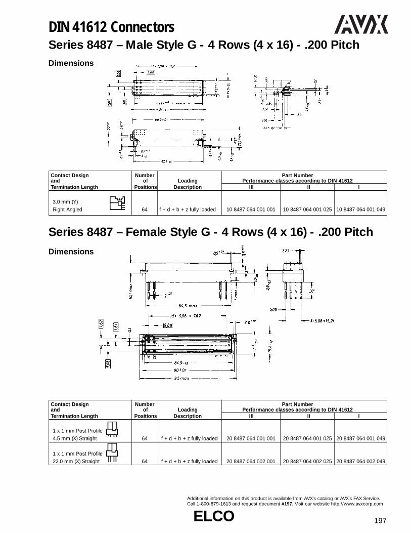
ELCOELCO 197
Additional information on this product is available from AVX’s catalog or AVX’s FAX Service.Call 1-800-879-1613 and request document #197. Visit our website http://www.avxcorp.com
DIN 41612 ConnectorsSeries 8487 – Male Style G - 4 Rows (4 x 16) - .200 Pitch
Series 8487 – Female Style G - 4 Rows (4 x 16) - .200 Pitch
Contact Design Number Part Numberand of Loading Performance classes according to DIN 41612Termination Length Positions Description III II I
3.0 mm (Y)Right Angled 64 f + d + b + z fully loaded 10 8487 064 001 001 10 8487 064 001 025 10 8487 064 001 049
Dimensions
Dimensions
Contact Design Number Part Numberand of Loading Performance classes according to DIN 41612Termination Length Positions Description III II I
1 x 1 mm Post Profile4.5 mm (X) Straight 64 f + d + b + z fully loaded 20 8487 064 001 001 20 8487 064 001 025 20 8487 064 001 049
1 x 1 mm Post Profile22.0 mm (X) Straight 64 f + d + b + z fully loaded 20 8487 064 002 001 20 8487 064 002 025 20 8487 064 002 049

ELCOELCO198
Additional information on this product is available from AVX’s catalog or AVX’s FAX Service.Call 1-800-879-1613 and request document #198. Visit our website http://www.avxcorp.com
Contact Design No. of Cavities No. of Cavities Part Numberand for Single for Special Loading Performance classes according to DIN 41612Termination Length Positions Positions Description III II I
3.0 mm (Y) 12 (3 x 4) 4 a + b + c fully loaded 10 8483 012 001 001 10 8483 012 001 025 10 8483 012 001 049Straight 30 (3 x 10) 2 a + b + c fully loaded 10 8483 030 001 001 10 8483 030 001 025 10 8483 030 001 049
11.4 mm (Y) 12 (3 x 4) 4 a + b + c fully loaded 10 8483 012 002 001 10 8483 012 002 025 10 8483 012 002 049Straight 30 (3 x 10) 2 a + b + c fully loaded 10 8483 030 002 001 10 8483 030 002 025 10 8483 030 002 049
3.0 mm (Y) 12 (3 x 4) 4 a + b + c fully loaded 10 8483 012 003 001 10 8483 012 003 025 10 8483 012 003 049Right Angled 30 (3 x 10) 2 a + b + c fully loaded 10 8483 030 003 001 10 8483 030 003 025 10 8483 030 003 049
11.3mm (Y) 12 (3 x 4) 4 a + b + c fully loaded 10 8483 012 004 001 10 8483 012 004 025 10 8483 012 004 049Right Angled 30 (3 x 10) 2 a + b + c fully loaded 10 8483 030 004 001 10 8483 030 004 025 10 8483 030 004 049Solder eyeletrows a + c 4.8 mm 12 (3 x 4) 4 a + b + c fully loaded 10 8483 012 005 001 10 8483 012 005 025 10 8483 012 005 049row b 7.5 mm 30 (3 x 10) 2 a + b + c fully loaded 10 8483 030 005 001 10 8483 030 005 025 10 8483 030 005 049Solder holerows a + c 6.1 mm 12 (3 x 4) 4 a + b + c fully loaded 10 8483 012 006 001 10 8483 012 006 025 10 8483 012 006 049row b 8.8 mm 30 (3 x 10) 2 a + b + c fully loaded 10 8483 030 006 001 10 8483 030 006 025 10 8483 030 006 049
DIN 41612 ConnectorsSeries 8483 – Male Style 1⁄2 M-3 Rows (3 x 4 or 10) -.100 Pitch
Dimensions

ELCOELCO 199
Additional information on this product is available from AVX’s catalog or AVX’s FAX Service.Call 1-800-879-1613 and request document #199. Visit our website http://www.avxcorp.com
DIN 41612 ConnectorsSeries 8483 – Male Style M - Fully Loaded - 3 Rows (3 x 2, 8, 14, 20 or 28) - .100 Pitch
Contact Design No. of Cavities No. of Cavities Part Numberand for Single for Special Loading Performance classes according to DIN 41612Termination Length Positions Positions Description III II I
6 (3 x 2) 10 a + b + c fully loaded 10 8483 006 001 001 10 8483 006 001 025 10 8483 006 001 04924 (3 x 8) 8 a + b + c fully loaded 10 8483 024 001 001 10 8483 024 001 025 10 8483 024 001 04942 (3 x 14) 6 a + b + c fully loaded 10 8483 042 001 001 10 8483 042 001 025 10 8483 042 001 049
3.0 mm (Y) 60 (3 x 20) 4 a + b + c fully loaded 10 8483 060 001 001 10 8483 060 001 025 10 8483 060 001 049Straight 78 (3 x 28) 2 a + b + c fully loaded 10 8483 078 001 001 10 8483 078 001 025 10 8483 078 001 049
6 (3 x 2) 10 a + b + c fully loaded 10 8483 006 002 001 10 8483 006 002 025 10 8483 006 002 04924 (3 x 8) 8 a + b + c fully loaded 10 8483 024 002 001 10 8483 024 002 025 10 8483 024 002 04942 (3 x 14) 6 a + b + c fully loaded 10 8483 042 002 001 10 8483 042 002 025 10 8483 042 002 049
11.4 mm (Y) 60 (3 x 20) 4 a + b + c fully loaded 10 8483 060 002 001 10 8483 060 002 025 10 8483 060 002 049Straight 78 (3 x 28) 2 a + b + c fully loaded 10 8483 078 002 001 10 8483 078 002 025 10 8483 078 002 049
6 (3 x 2) 10 a + b + c fully loaded 10 8483 006 003 001 10 8483 006 003 025 10 8483 006 003 04924 (3 x 8) 8 a + b + c fully loaded 10 8483 024 003 001 10 8483 024 003 025 10 8483 024 003 04942 (3 x 14) 6 a + b + c fully loaded 10 8483 042 003 001 10 8483 042 003 025 10 8483 042 003 049
3.0 mm (Y) 60 (3 x 20) 4 a + b + c fully loaded 10 8483 060 003 001 10 8483 060 003 025 10 8483 060 003 049Right Angled 78 (3 x 28) 2 a + b + c fully loaded 10 8483 078 003 001 10 8483 078 003 025 10 8483 078 003 049
6 (3 x 2) 10 a + b + c fully loaded 10 8483 006 004 001 10 8483 006 004 025 10 8483 006 004 04924 (3 x 8) 8 a + b + c fully loaded 10 8483 024 004 001 10 8483 024 004 025 10 8483 024 004 04942 (3 x 14) 6 a + b + c fully loaded 10 8483 042 004 001 10 8483 042 004 025 10 8483 042 004 049
11.3mm (Y) 60 (3 x 20) 4 a + b + c fully loaded 10 8483 060 004 001 10 8483 060 004 025 10 8483 060 004 049Right Angled 78 (3 x 28) 2 a + b + c fully loaded 10 8483 078 004 001 10 8483 078 004 025 10 8483 078 004 049
6 (3 x 2) 10 a + b + c fully loaded 10 8483 006 005 001 10 8483 006 005 025 10 8483 006 005 04924 (3 x 8) 8 a + b + c fully loaded 10 8483 024 005 001 10 8483 024 005 025 10 8483 024 005 049
Solder eyelet 42 (3 x 14) 6 a + b + c fully loaded 10 8483 042 005 001 10 8483 042 005 025 10 8483 042 005 049rows a + c 4.8 mm 60 (3 x 20) 4 a + b + c fully loaded 10 8483 060 005 001 10 8483 060 005 025 10 8483 060 005 049row b 7.5 mm 78 (3 x 28) 2 a + b + c fully loaded 10 8483 078 005 001 10 8483 078 005 025 10 8483 078 005 049
6 (3 x 2) 10 a + b + c fully loaded 10 8483 006 006 001 10 8483 006 006 025 10 8483 006 006 04924 (3 x 8) 8 a + b + c fully loaded 10 8483 024 006 001 10 8483 024 006 025 10 8483 024 006 049
Solder hole 42 (3 x 14) 6 a + b + c fully loaded 10 8483 042 006 001 10 8483 042 006 025 10 8483 042 006 049rows a + c 6.1 mm 60 (3 x 20) 4 a + b + c fully loaded 10 8483 060 006 001 10 8483 060 006 025 10 8483 060 006 049row b 8.8 mm 78 (3 x 28) 2 a + b + c fully loaded 10 8483 078 006 001 10 8483 078 006 025 10 8483 078 006 049
Dimensions

ELCOELCO200
Additional information on this product is available from AVX’s catalog or AVX’s FAX Service.Call 1-800-879-1613 and request document #200. Visit our website http://www.avxcorp.com
DIN 41612 ConnectorsSeries 8483 – Female Style M - Fully Loaded - 3 Rows (3 x 2, 8, 14, 20 or 28) - .100 Pitch
Contact Design No. of Cavities No. of Cavities Part Numberand for Single for Special Loading Performance classes according to DIN 41612Termination Length Positions Positions Description III II I
6 (3 x 2) 10 a + b + c fully loaded 20 8483 006 001 001 20 8483 006 001 025 20 8483 006 001 04924 (3 x 8) 8 a + b + c fully loaded 20 8483 024 001 001 20 8483 024 001 025 20 8483 024 001 04942 (3 x 14) 6 a + b + c fully loaded 20 8483 042 001 001 20 8483 042 001 025 20 8483 042 001 049
4.5 mm (Y) 60 (3 x 20) 4 a + b + c fully loaded 20 8483 060 001 001 20 8483 060 001 025 20 8483 060 001 049Straight 78 (2 x 28) 2 a + b + c fully loaded 20 8483 078 001 001 20 8483 078 001 025 20 8483 078 001 049
6 (3 x 2) 10 a + b + c fully loaded 20 8483 006 002 001 20 8483 006 002 025 20 8483 006 002 04924 (3 x 8) 8 a + b + c fully loaded 20 8483 024 002 001 20 8483 024 002 025 20 8483 024 002 04942 (3 x 14) 6 a + b + c fully loaded 20 8483 042 002 001 20 8483 042 002 025 20 8483 042 002 049
2.9 mm (Y) 60 (3 x 20) 4 a + b + c fully loaded 20 8483 060 002 001 20 8483 060 002 025 20 8483 060 002 049Straight 78 (2 x 28) 2 a + b + c fully loaded 20 8483 078 002 001 20 8483 078 002 025 20 8483 078 002 049
6 (3 x 2) 10 a + b + c fully loaded 20 8483 006 003 001 20 8483 006 003 025 20 8483 006 003 04924 (3 x 8) 8 a + b + c fully loaded 20 8483 024 003 001 20 8483 024 003 025 20 8483 024 003 04942 (3 x 14) 6 a + b + c fully loaded 20 8483 042 003 001 20 8483 042 003 025 20 8483 042 003 049
13.0 mm (Y) 60 (3 x 20) 4 a + b + c fully loaded 20 8483 060 003 001 20 8483 060 003 025 20 8483 060 003 049Straight 78 (2 x 28) 2 a + b + c fully loaded 20 8483 078 003 001 20 8483 078 003 025 20 8483 078 003 049
Dimensions

ELCOELCO 201
Additional information on this product is available from AVX’s catalog or AVX’s FAX Service.Call 1-800-879-1613 and request document #201. Visit our website http://www.avxcorp.com
DIN 41612 ConnectorsSeries 8483 – Male Style M - a + c Loaded - 3 Rows (3 x 2, 8, 14, 20 or 28) - .100 Pitch
Dimensions
Contact Design No. of Cavities No. of Cavities Part Numberand for Single for Special Loading Performance classes according to DIN 41612Termination Length Positions Positions Description III II I
6 (3 x 2) 10 a + c fully loaded 10 8483 006 001 002 10 8483 006 001 026 10 8483 006 001 05024 (3 x 8) 8 a + c fully loaded 10 8483 024 001 002 10 8483 024 001 026 10 8483 024 001 05042 (3 x 14) 6 a + c fully loaded 10 8483 042 001 002 10 8483 042 001 026 10 8483 042 001 050
3.0 mm (Y) 60 (3 x 20) 4 a + c fully loaded 10 8483 060 001 002 10 8483 060 001 026 10 8483 060 001 050Straight 78 (3 x 28) 2 a + c fully loaded 10 8483 078 001 002 10 8483 078 001 026 10 8483 078 001 050
6 (3 x 2) 10 a + c fully loaded 10 8483 006 002 002 10 8483 006 002 026 10 8483 006 002 05024 (3 x 8) 8 a + c fully loaded 10 8483 024 002 002 10 8483 024 002 026 10 8483 024 002 05042 (3 x 14) 6 a + c fully loaded 10 8483 042 002 002 10 8483 042 002 026 10 8483 042 002 050
11.4 mm (Y) 60 (3 x 20) 4 a + c fully loaded 10 8483 060 002 002 10 8483 060 002 026 10 8483 060 002 050Straight 78 (3 x 28) 2 a + c fully loaded 10 8483 078 002 002 10 8483 078 002 026 10 8483 078 002 050
6 (3 x 2) 10 a + c fully loaded 10 8483 006 003 002 10 8483 006 003 026 10 8483 006 003 05024 (3 x 8) 8 a + c fully loaded 10 8483 024 003 002 10 8483 024 003 026 10 8483 024 003 05042 (3 x 14) 6 a + c fully loaded 10 8483 042 003 002 10 8483 042 003 026 10 8483 042 003 050
3.0 mm (Y) 60 (3 x 20) 4 a + c fully loaded 10 8483 060 003 002 10 8483 060 003 026 10 8483 060 003 050Right Angled 78 (3 x 28) 2 a + c fully loaded 10 8483 078 003 002 10 8483 078 003 026 10 8483 078 003 050
6 (3 x 2) 10 a + c fully loaded 10 8483 006 004 002 10 8483 006 004 026 10 8483 006 004 05024 (3 x 8) 8 a + c fully loaded 10 8483 024 004 002 10 8483 024 004 026 10 8483 024 004 05042 (3 x 14) 6 a + c fully loaded 10 8483 042 004 002 10 8483 042 004 026 10 8483 042 004 050
11.3mm (Y) 60 (3 x 20) 4 a + c fully loaded 10 8483 060 004 002 10 8483 060 004 026 10 8483 060 004 050Right Angled 78 (3 x 28) 2 a + c fully loaded 10 8483 078 004 002 10 8483 078 004 026 10 8483 078 004 050
6 (3 x 2) 10 a + c fully loaded 10 8483 006 005 002 10 8483 006 005 026 10 8483 006 005 05024 (3 x 8) 8 a + c fully loaded 10 8483 024 005 002 10 8483 024 005 026 10 8483 024 005 050
Solder eyelet 42 (3 x 14) 6 a + c fully loaded 10 8483 042 005 002 10 8483 042 005 026 10 8483 042 005 050rows a + c 4.8 mm 60 (3 x 20) 4 a + c fully loaded 10 8483 060 005 002 10 8483 060 005 026 10 8483 060 005 050row b 7.5 mm 78 (3 x 28) 2 a + c fully loaded 10 8483 078 005 002 10 8483 078 005 026 10 8483 078 005 050
6 (3 x 2) 10 a + c fully loaded 10 8483 006 006 002 10 8483 006 006 026 10 8483 006 006 05024 (3 x 8) 8 a + c fully loaded 10 8483 024 006 002 10 8483 024 006 026 10 8483 024 006 050
Solder hole 42 (3 x 14) 6 a + c fully loaded 10 8483 042 006 002 10 8483 042 006 026 10 8483 042 006 050rows a + c 6.1 mm 60 (3 x 20) 4 a + c fully loaded 10 8483 060 006 002 10 8483 060 006 026 10 8483 060 006 050row b 8.8 mm 78 (3 x 28) 2 a + c fully loaded 10 8483 078 006 002 10 8483 078 006 026 10 8483 078 006 050

ELCOELCO202
Additional information on this product is available from AVX’s catalog or AVX’s FAX Service.Call 1-800-879-1613 and request document #202. Visit our website http://www.avxcorp.com
DIN 41612 ConnectorsSeries 8483 – Female Style M - a + c Loaded - 3 Rows (3 x 2, 8, 14, 20 or 28) - .100 Pitch
Contact Design No. of Cavities No. of Cavities Part Numberand for Single for Special Loading Performance classes according to DIN 41612Termination Length Positions Positions Description III II I
6 (3 x 2) 10 a + c fully loaded 20 8483 006 001 002 20 8483 006 001 026 20 8483 006 001 05024 (3 x 8) 8 a + c fully loaded 20 8483 024 001 002 20 8483 024 001 026 20 8483 024 001 05042 (3 x 14) 6 a + c fully loaded 20 8483 042 001 002 20 8483 042 001 026 20 8483 042 001 050
4.5 mm (Y) 60 (3 x 20) 4 a + c fully loaded 20 8483 060 001 002 20 8483 060 001 026 20 8483 060 001 050Straight 78 (2 x 28) 2 a + c fully loaded 20 8483 078 001 002 20 8483 078 001 026 20 8483 078 001 050
6 (3 x 2) 10 a + c fully loaded 20 8483 006 002 002 20 8483 006 002 026 20 8483 006 002 05024 (3 x 8) 8 a + c fully loaded 20 8483 024 002 002 20 8483 024 002 026 20 8483 024 002 05042 (3 x 14) 6 a + c fully loaded 20 8483 042 002 002 20 8483 042 002 026 20 8483 042 002 050
2.9 mm (Y) 60 (3 x 20) 4 a + c fully loaded 20 8483 060 002 002 20 8483 060 002 026 20 8483 060 002 050Straight 78 (2 x 28) 2 a + c fully loaded 20 8483 078 002 002 20 8483 078 002 026 20 8483 078 002 050
6 (3 x 2) 10 a + c fully loaded 20 8483 006 003 002 20 8483 006 003 026 20 8483 006 003 05024 (3 x 8) 8 a + c fully loaded 20 8483 024 003 002 20 8483 024 003 026 20 8483 024 003 05042 (3 x 14) 6 a + c fully loaded 20 8483 042 003 002 20 8483 042 003 026 20 8483 042 003 050
13.0 mm (Y) 60 (3 x 20) 4 a + c fully loaded 20 8483 060 003 002 20 8483 060 003 026 20 8483 060 003 050Right Angled 78 (2 x 28) 2 a + c fully loaded 20 8483 078 003 002 20 8483 078 003 026 20 8483 078 003 050
Dimensions

ELCOELCO 203
Additional information on this product is available from AVX’s catalog or AVX’s FAX Service.Call 1-800-879-1613 and request document #203. Visit our website http://www.avxcorp.com
DIN 41612 ConnectorsSeries 8489 – Style M Contacts - Special Contacts for Style M Connectors
VariationTermination Dimensions Order Code
Outer InnerConductor Conductor [A [B [C Perf. Class I
CRIMP SOLDER .041/1.05 .067/1.70 .089/2.25 60 8489 020 001 (049)CRIMP SOLDER .067/1.70 .106/2.70 .126/3.20 60 8489 020 002 (049)CRIMP SOLDER .067/1.70 .106/2.70 .141/3.58 60 8489 020 003 (049)
SOLDER SOLDER .051/1.30 .075/1.90 .087/2.20 60 8489 020 004 (049)SOLDER SOLDER .089/2.25 .114/2.90 .126/3.20 60 8489 020 005 (049)
CRIMP SOLDER .041/1.05 .067/1.70 .089/2.25 60 8489 020 006 (049)CRIMP SOLDER .067/1.70 .106/2.70 .126/3.20 60 8489 020 007 (049)CRIMP SOLDER .067/1.70 .106/2.70 .140/3.55 60 8489 020 008 (049)
CRIMP SOLDER .041/1.05 .067/1.70 .089/2.25 60 8489 020 009 (049)CRIMP SOLDER .067/1.70 .106/2.70 .126/3.20 60 8489 020 010 (049)CRIMP SOLDER .067/1.70 .106/2.70 .140/3.55 60 8489 020 011 (049)
P.C. (1) P.C. (1) 60 8489 020 012 (049)
Coax Plug Contact for Receptacle Series 8483/8484 Dimensions: inches/millimeters
Coax Receptacle Contact for Plug Series 8483 Dimensions: inches/millimeters
(1) Not applicable for receptacles with P.C. and Press-fit termination.
VariationTermination Dimensions Order Code
Outer InnerConductor Conductor [A [B [C Perf. Class I
CRIMP SOLDER .067/1.70 .106/2.70 .140/3.55 60 8489 030 001 (049)CRIMP SOLDER .067/1.70 .106/2.70 .126/3.20 60 8489 030 002 (049)CRIMP SOLDER .041/1.05 .067/1.70 .089/2.25 60 8489 030 003 (049)
SOLDER SOLDER .089/2.25 .114/2.90 .126/3.20 60 8489 030 004 (049)SOLDER SOLDER .051/1.30 .075/1.90 .087/2.20 60 8489 030 005 (049)
CRIMP SOLDER .067/1.70 .106/2.70 .126/3.20 60 8489 030 006 (049)CRIMP SOLDER .041/1.05 .067/1.70 .089/2.25 60 8489 030 007 (049)
P.C. P.C. 60 8489 030 008 (049)

ELCOELCO204
Additional information on this product is available from AVX’s catalog or AVX’s FAX Service.Call 1-800-879-1613 and request document #204. Visit our website http://www.avxcorp.com
Variation Termination [A* Performance Ordering CodeSOLDER .189 (4.80) 40 Ampere max. 60 8489 050 001 049SOLDER .138 (3.50) 30 Ampere max. 60 8489 050 002 049SOLDER .110 (2.80) 20 Ampere max. 60 8489 050 003 049SOLDER .067 (1.70) 10 Ampere max. 60 8489 050 004 049CRIMP .189 (4.80) 40 Ampere max. 60 8489 050 005 049CRIMP .138 (3.50) 30 Ampere max. 60 8489 050 006 049CRIMP .110 (2.80) 20 Ampere max. 60 8489 050 007 049CRIMP .067 (1.70) 10 Ampere max. 60 8489 050 008 049
High Power Receptacle Contact for Receptacle Series 8483/8484
DIN 41612 ConnectorsSeries 8489 – Style M Contacts - Special Contacts for Style M Connectors
*[A: inner diameter of contact sleeve.
Variation Termination [A* Performance Ordering CodeSOLDER .189 (4.80) 40 Ampere max. 60 8489 040 001 049SOLDER .138 (3.50) 30 Ampere max. 60 8489 040 002 049SOLDER .110 (2.80) 20 Ampere max. 60 8489 040 003 049SOLDER .067 (1.70) 10 Ampere max. 60 8489 040 004 049CRIMP .189 (4.80) 40 Ampere max. 60 8489 040 005 049CRIMP .138 (3.50) 30 Ampere max. 60 8489 040 006 049CRIMP .110 (2.80) 20 Ampere max. 60 8489 040 007 049CRIMP .067 (1.70) 10 Ampere max. 60 8489 040 008 049
P.C. Contact 40 Ampere max. 60 8489 040 009 049
High Power Plug Contact for Plug Series 8483/8484
Ordering CodeVariation Termination PerformancePerf. Class I
SOLDER CABLE OUTLET STRAIGHTAWG 20 maximum 2.8 KV max 60 8489 060 001 049
SOLDER CABLE OUTLET 90°AWG 20 maximum 2.8 KV max 60 8489 060 002 049
High Voltage Receptacle Contact for Plug Series 8483/8484
Ordering CodeVariation Termination PerformancePerf. Class I
SOLDER CABLE OUTLET STRAIGHTAWG 20 maximum 2.8 KV max 60 8489 070 001 049
SOLDER CABLE OUTLET 90°AWG 20 maximum 2.8 KV max 60 8489 070 002 049
High Voltage Plug Contact for Receptacle Series 8483/8484

ELCOELCO 205
Additional information on this product is available from AVX’s catalog or AVX’s FAX Service.Call 1-800-879-1613 and request document #205. Visit our website http://www.avxcorp.com
DIN 41612 ConnectorsSeries 8477 – Male Style 1⁄2 Q - 2 Rows (2 x 16) Inverted - .100 Pitch
Contact Design Number Part Numberand of Loading Performance classes according to DIN 41612Termination Length Positions Description III II I
32 a + b fully loaded 10 8477 032 001 001 10 8477 032 001 025 10 8477 032 001 04916 a + b even loading 10 8477 032 001 007 10 8477 032 001 031 10 8477 032 001 055
2.9 mm (Y) 16 a loading only 10 8477 032 001 003 10 8477 032 001 027 10 8477 032 001 051Straight 30 + 2 fully loaded + ground 10 9477 032 101 001 10 8477 032 101 025 10 8477 032 101 049
32 a + b fully loaded 10 8477 032 002 001 10 8477 032 002 025 10 8477 032 002 04916 a + b even loading 10 8477 032 002 007 10 8477 032 002 031 10 8477 032 002 055
4.5 mm (Y) 16 a loading only 10 8477 032 002 003 10 8477 032 002 027 10 8477 032 002 051Straight 30 + 2 fully loaded + ground 10 8477 032 102 001 10 8477 032 102 025 10 8477 032 102 049
32 a + b fully loaded 10 8477 032 005 001 10 8477 032 005 025 10 8477 032 005 0499.5 mm (Y) 16 a + b even loading 10 8477 032 005 007 10 8477 032 005 031 10 8477 032 005 055Straight 16 a loading only 10 8477 032 005 003 10 8477 032 005 027 10 8477 032 005 051
32 a + b fully loaded 10 8477 032 006 001 10 8477 032 006 025 10 8477 032 006 04913.0 mm (Y) 16 a + b even loading 10 8477 032 006 007 10 8477 032 006 031 10 8477 032 006 055Straight 16 a loading only 10 8477 032 006 003 10 8477 032 006 027 10 8477 032 006 051
32 a + b fully loaded 10 8477 032 007 001 10 8477 032 007 025 10 8477 032 007 04914.5 mm (Y) 16 a + b even loading 10 8477 032 007 007 10 8477 032 007 031 10 8477 032 007 055Straight 16 a loading only 10 8477 032 007 003 10 8477 032 007 027 10 8477 032 007 051
32 a + b fully loaded 10 8477 032 009 001 10 8477 032 009 025 10 8477 032 009 0498.8, 11.5, 8.8 mm (Y) 16 a + b even loading 10 8477 032 009 007 10 8477 032 009 031 10 8477 032 009 055Solder Hole 16 a loading only 10 8477 032 009 003 10 8477 032 009 027 10 8477 032 009 051
32 a + b fully loaded 10 8477 032 010 001 10 8477 032 010 025 10 8477 032 010 0497.5, 10.2, 7.5 mm (Y) 16 a + b even loading 10 8477 032 010 007 10 8477 032 010 031 10 8477 032 010 055Solder Loop 16 a loading only 10 8477 032 010 003 10 8477 032 010 027 10 8477 032 010 051
Dimensions
No. Contact ContactPositions Rows A B C D E F
032 2 (2 x 16) 15 1.500 1.760 1.862 1.968 2.162(38.10) (44.70) (47.29) (49.99) (54.91)
Inches (mm)

ELCOELCO206
Additional information on this product is available from AVX’s catalog or AVX’s FAX Service.Call 1-800-879-1613 and request document #206. Visit our website http://www.avxcorp.com
DIN 41612 ConnectorsSeries 8477 – Female Style 1⁄2 Q - 2 Rows (2 x 16) Inverted - .100 Pitch
Dimensions
No. Contact ContactPositions Rows A B C D E
032 2 (2 x 16) 15 1.500 2.122 1.900 1.744(38.10) (53.90) (48.26) (44.30)
Inches (mm)
Contact Design Number Part Numberand of Loading Performance classes according to DIN 41612Termination Length Positions Description III II I
32 a + b fully loaded 20 8477 032 002 001 20 8477 032 002 025 20 8477 032 002 0490.6 x 0.6 mm Post Profile 16 a + b all even loading 20 8477 032 002 007 20 8477 032 002 031 20 8477 032 002 0553.0 mm (Y) Right Angled 16 a loading only 20 8477 032 002 003 20 8477 032 002 027 20 8477 032 002 051
32 a + b fully loaded 20 8477 032 006 001 20 8477 032 006 025 20 8477 032 006 0490.3 x 0.79 mm Post Profile 16 a + b all even loading 20 8477 032 006 007 20 8477 032 006 031 20 8477 032 006 0553.0 mm (Y) Right Angled 16 a loading only 20 8477 032 006 003 20 8477 032 006 027 20 8477 032 006 051
32 a + b fully loaded 20 8477 032 008 001 20 8477 032 008 025 20 8477 032 008 0490.6 x 0.6 mm Post Profile 16 a + b all even loading 20 8477 032 008 007 20 8477 032 008 031 20 8477 032 008 05511.43 mm (Y) Right Angled 16 a loading only 20 8477 032 008 003 20 8477 032 008 027 20 8477 032 008 051
32 a + b fully loaded 20 8477 032 009 001 20 8477 032 009 025 20 8477 032 009 0490.3 x 0.79 mm Post Profile 16 a + b all even loading 20 8477 032 009 007 20 8477 032 009 031 20 8477 032 009 0554.5 mm (Y) Right Angled 16 a loading only 20 8477 032 009 003 20 8477 032 009 027 20 8477 032 009 051
32 a + b fully loaded 20 8477 032 012 001 20 8477 032 012 025 20 8477 032 012 0490.6 x 0.6 mm Post Profile 16 a + b all even loading 20 8477 032 012 007 20 8477 032 012 031 20 8477 032 012 0554.5 mm (Y) Right Angled 16 a loading only 20 8477 032 012 003 20 8477 032 012 027 20 8477 032 012 051

ELCOELCO 207
Additional information on this product is available from AVX’s catalog or AVX’s FAX Service.Call 1-800-879-1613 and request document #207. Visit our website http://www.avxcorp.com
DIN 41612 ConnectorsSeries 8477 – Male Style Q - 2 Rows (2 x 32) Inverted - .100 Pitch
Dimensions
No. Contact ContactPositions Rows A B C D E F
064 2 (2 x 32) 31 3.100 3.358 3.461 3.543 3.736(78.74) (85.29) (87.91) (89.99) (94.89)
Inches (mm)
Contact Design Number Part Numberand of Loading Performance classes according to DIN 41612Termination Length Positions Description III II I
64 a + b fully loaded 10 8477 064 001 001 10 8477 064 001 025 10 8477 064 001 04932 a + b even loading 10 8477 064 001 007 10 8477 064 001 031 10 8477 064 001 055
2.9 mm (Y) 32 a loading only 10 8477 064 001 003 10 8477 064 001 027 10 8477 064 001 051Straight 62 + 2 fully loaded + ground 10 9477 064 101 001 10 8477 064 101 025 10 8477 064 101 049
64 a + b fully loaded 10 8477 064 002 001 10 8477 064 002 025 10 8477 064 002 04932 a + b even loading 10 8477 064 002 007 10 8477 064 002 031 10 8477 064 002 055
4.5 mm (Y) 32 a loading only 10 8477 064 002 003 10 8477 064 002 027 10 8477 064 002 051Straight 62 + 2 fully loaded + ground 10 8477 064 102 001 10 8477 064 102 025 10 8477 064 102 049
64 a + b fully loaded 10 8477 064 005 001 10 8477 064 005 025 10 8477 064 005 0499.5 mm (Y) 32 a + b even loading 10 8477 064 005 007 10 8477 064 005 031 10 8477 064 005 055Straight 32 a loading only 10 8477 064 005 003 10 8477 064 005 027 10 8477 064 005 051
64 a + b fully loaded 10 8477 064 006 001 10 8477 064 006 025 10 8477 064 006 04913.0 mm (Y) 32 a + b even loading 10 8477 064 006 007 10 8477 064 006 031 10 8477 064 006 055Straight 32 a loading only 10 8477 064 006 003 10 8477 064 006 027 10 8477 064 006 051
64 a + b fully loaded 10 8477 064 007 001 10 8477 064 007 025 10 8477 064 007 04914.5 mm (Y) 32 a + b even loading 10 8477 064 007 007 10 8477 064 007 031 10 8477 064 007 055Straight 32 a loading only 10 8477 064 007 003 10 8477 064 007 027 10 8477 064 007 051
64 a + b fully loaded 10 8477 064 009 001 10 8477 064 009 025 10 8477 064 009 0498.8, 11.5, 8.8 mm (Y) 32 a + b even loading 10 8477 064 009 007 10 8477 064 009 031 10 8477 064 009 055Solder Hole 32 a loading only 10 8477 064 009 003 10 8477 064 009 027 10 8477 064 009 051
64 a + b fully loaded 10 8477 064 010 001 10 8477 064 010 025 10 8477 064 010 0497.5, 10.2, 7.5 mm (Y) 32 a + b even loading 10 8477 064 010 007 10 8477 064 010 031 10 8477 064 010 055Solder Loop 32 a loading only 10 8477 064 010 003 10 8477 064 010 027 10 8477 064 010 051

ELCOELCO208
Additional information on this product is available from AVX’s catalog or AVX’s FAX Service.Call 1-800-879-1613 and request document #208. Visit our website http://www.avxcorp.com
DIN 41612 ConnectorsSeries 8477 – Male Style 1⁄3 R - 3 Rows (3 x 10) Inverted - .100 Pitch
Contact Design Number Part Numberand of Loading Performance classes according to DIN 41612Termination Length Positions Description III II I
30 a + b + c fully loaded 10 8477 030 001 001 10 8477 030 001 025 10 8477 030 001 04920 a + c fully loaded 10 8477 030 001 002 10 8477 030 001 026 10 8477 030 001 05010 a + c even loading 10 8477 030 001 009 10 8477 030 001 033 10 8477 030 001 057
2.9 mm (Y) 10 a loading only 10 8477 030 001 003 10 8477 030 001 027 10 8477 030 001 051Straight 28 + 2 fully loaded + ground 10 9477 030 101 001 10 8477 030 101 025 10 8477 030 101 049
30 a + b + c fully loaded 10 8477 030 002 001 10 8477 030 002 025 10 8477 030 002 04920 a + c fully loaded 10 8477 030 002 002 10 8477 030 002 026 10 8477 030 002 05010 a + c even loading 10 8477 030 002 009 10 8477 030 002 033 10 8477 030 002 057
4.5 mm (Y) 10 a loading only 10 8477 030 002 003 10 8477 030 002 027 10 8477 030 002 051Straight 28 + 2 fully loaded + ground 10 8477 030 102 001 10 8477 030 102 025 10 8477 030 102 049
30 a + b + c fully loaded 10 8477 030 005 001 10 8477 030 005 025 10 8477 030 005 04920 a + c fully loaded 10 8477 030 005 002 10 8477 030 005 026 10 8477 030 005 050
9.5 mm (Y) 10 a + c even loading 10 8477 030 005 009 10 8477 030 005 033 10 8477 030 005 057Straight 10 a loading only 10 8477 030 005 003 10 8477 030 005 027 10 8477 030 005 051
30 a + b + c fully loaded 10 8477 030 006 001 10 8477 030 006 025 10 8477 030 006 04920 a + c fully loaded 10 8477 030 006 002 10 8477 030 006 026 10 8477 030 006 05010 a + c even loading 10 8477 030 006 009 10 8477 030 006 033 10 8477 030 006 057
13.0 mm (Y) 10 a loading only 10 8477 030 006 003 10 8477 030 006 027 10 8477 030 006 051Straight 28 + 2 fully loaded + ground 10 8477 030 106 001 10 8477 030 106 025 10 8477 030 106 049
96 a + b + c fully loaded 10 8477 030 007 001 10 8477 030 007 025 10 8477 030 007 04964 a + c fully loaded 10 8477 030 007 002 10 8477 030 007 026 10 8477 030 007 050
14.5 mm (Y) 32 a + c even loading 10 8477 030 007 009 10 8477 030 007 033 10 8477 030 007 057Straight 32 a loading only 10 8477 030 007 003 10 8477 030 007 027 10 8477 030 007 051
30 a + b + c fully loaded 10 8477 030 009 001 10 8477 030 009 025 10 8477 030 009 04920 a + c fully loaded 10 8477 030 009 002 10 8477 030 009 026 10 8477 030 009 050
8.8, 11.5, 8.8 mm (Y) 10 a + c even loading 10 8477 030 009 009 10 8477 030 009 033 10 8477 030 009 057Solder Hole 10 a loading only 10 8477 030 009 003 10 8477 030 009 027 10 8477 030 009 051
30 a + b + c fully loaded 10 8477 030 010 001 10 8477 030 010 025 10 8477 030 010 04920 a + c fully loaded 10 8477 030 010 002 10 8477 030 010 026 10 8477 030 010 050
7.5, 10.2, 7.5 mm (Y) 10 a + c even loading 10 8477 030 010 009 10 8477 030 010 033 10 8477 030 010 057Solder Loop 10 a loading only 10 8477 030 010 003 10 8477 030 010 027 10 8477 030 010 051
Dimensions
No. Contact ContactPositions Rows A B C D E F
030 3 (3 x 10) 9 0.900 1.159 1.265 1.368 1.565(22.86) (29.44) (32.12) (34.76) (39.76)
Inches (mm)

ELCOELCO 209
Additional information on this product is available from AVX’s catalog or AVX’s FAX Service.Call 1-800-879-1613 and request document #209. Visit our website http://www.avxcorp.com
DIN 41612 ConnectorsSeries 8477 – Female Style Q - 2 Rows (2 x 32) Inverted - .100 PitchDimensions
No. Contact ContactPositions Rows A B C D E
064 2 (2 x 32) 31 3.100 3.697 3.500 3.343(78.74) (93.90) (88.90) (84.91)
Inches (mm)
Contact Design Number Part Numberand of Loading Performance classes according to DIN 41612Termination Length Positions Description III II I
64 a + b fully loaded 20 8477 064 002 001 20 8477 064 002 025 20 8477 064 002 0490.6 x 0.6 mm Post Profile 32 a + b all even loading 20 8477 064 002 007 20 8477 064 002 031 20 8477 064 002 0553.0 mm (Y) Right Angled 32 a loading only 20 8477 064 002 003 20 8477 064 002 027 20 8477 064 002 051
64 a + b fully loaded 20 8477 064 006 001 20 8477 064 006 025 20 8477 064 006 0490.3 x 0.79 mm Post Profile 32 a + b all even loading 20 8477 064 006 007 20 8477 064 006 031 20 8477 064 006 0553.0 mm (Y) Right Angled 32 a loading only 20 8477 064 006 003 20 8477 064 006 027 20 8477 064 006 051
64 a + b fully loaded 20 8477 064 008 001 20 8477 064 008 025 20 8477 064 008 0490.6 x 0.6 mm Post Profile 32 a + b all even loading 20 8477 064 008 007 20 8477 064 008 031 20 8477 064 008 05511.43 mm (Y) Right Angled 32 a loading only 20 8477 064 008 003 20 8477 064 008 027 20 8477 064 008 051
64 a + b fully loaded 20 8477 064 009 001 20 8477 064 009 025 20 8477 064 009 0490.3 x 0.79 mm Post Profile 32 a + b all even loading 20 8477 064 009 007 20 8477 064 009 031 20 8477 064 009 0554.5 mm (Y) Right Angled 32 a loading only 20 8477 064 009 003 20 8477 064 009 027 20 8477 064 009 051
64 a + b fully loaded 20 8477 064 012 001 20 8477 064 012 025 20 8477 064 012 0490.6 x 0.6 mm Post Profile 32 a + b all even loading 20 8477 064 012 007 20 8477 064 012 031 20 8477 064 012 0554.5 mm (Y) Right Angled 32 a loading only 20 8477 064 012 003 20 8477 064 012 027 20 8477 064 012 051

ELCOELCO210
Additional information on this product is available from AVX’s catalog or AVX’s FAX Service.Call 1-800-879-1613 and request document #210. Visit our website http://www.avxcorp.com
DIN 41612 ConnectorsSeries 8477 – Male Style 1⁄2 R - 3 Rows (3 x 16) Inverted - .100 PitchDimensions
No. Contact ContactPositions Rows A B C D E F
048 3 (3 x 16) 15 1.500 1.760 1.862 1.968 2.162(38.10) (44.70) (47.29) (49.99) (54.91)
Inches (mm)
Contact Design Number Part Numberand of Loading Performance classes according to DIN 41612Termination Length Positions Description III II I
48 a + b + c fully loaded 10 8477 048 001 001 10 8477 048 001 025 10 8477 048 001 04932 a + c fully loaded 10 8477 048 001 002 10 8477 048 001 026 10 8477 048 001 05016 a + c even loading 10 8477 048 001 009 10 8477 048 001 033 10 8477 048 001 057
2.9 mm (Y) 16 a loading only 10 8477 048 001 003 10 8477 048 001 027 10 8477 048 001 051Straight 46 + 2 fully loaded + ground 10 9477 048 101 001 10 8477 048 101 025 10 8477 048 101 049
48 a + b + c fully loaded 10 8477 048 002 001 10 8477 048 002 025 10 8477 048 002 04932 a + c fully loaded 10 8477 048 002 002 10 8477 048 002 026 10 8477 048 002 05016 a + c even loading 10 8477 048 002 009 10 8477 048 002 033 10 8477 048 002 057
4.5 mm (Y) 16 a loading only 10 8477 048 002 003 10 8477 048 002 027 10 8477 048 002 051Straight 46 + 2 fully loaded + ground 10 8477 048 102 001 10 8477 048 102 025 10 8477 048 102 049
48 a + b + c fully loaded 10 8477 048 005 001 10 8477 048 005 025 10 8477 048 005 04932 a + c fully loaded 10 8477 048 005 002 10 8477 048 005 026 10 8477 048 005 050
9.5 mm (Y) 16 a + c even loading 10 8477 048 005 009 10 8477 048 005 033 10 8477 048 005 057Straight 16 a loading only 10 8477 048 005 003 10 8477 048 005 027 10 8477 048 005 051
48 a + b + c fully loaded 10 8477 048 006 001 10 8477 048 006 025 10 8477 048 006 04932 a + c fully loaded 10 8477 048 006 002 10 8477 048 006 026 10 8477 048 006 05016 a + c even loading 10 8477 048 006 009 10 8477 048 006 033 10 8477 048 006 057
13.0 mm (Y) 16 a loading only 10 8477 048 006 003 10 8477 048 006 027 10 8477 048 006 051Straight 46 + 2 fully loaded + ground 10 8477 048 106 001 10 8477 048 106 025 10 8477 048 106 049
48 a + b + c fully loaded 10 8477 048 007 001 10 8477 048 007 025 10 8477 048 007 04932 a + c fully loaded 10 8477 048 007 002 10 8477 048 007 026 10 8477 048 007 050
14.5 mm (Y) 16 a + c even loading 10 8477 048 007 009 10 8477 048 007 033 10 8477 048 007 057Straight 16 a loading only 10 8477 048 007 003 10 8477 048 007 027 10 8477 048 007 051
48 a + b + c fully loaded 10 8477 048 009 001 10 8477 048 009 025 10 8477 048 009 04932 a + c fully loaded 10 8477 048 009 002 10 8477 048 009 026 10 8477 048 009 050
8.8, 11.5, 8.8 mm (Y) 16 a + c even loading 10 8477 048 009 009 10 8477 048 009 033 10 8477 048 009 057Solder Hole 16 a loading only 10 8477 048 009 003 10 8477 048 009 027 10 8477 048 009 051
48 a + b + c fully loaded 10 8477 048 010 001 10 8477 048 010 025 10 8477 048 010 04932 a + c fully loaded 10 8477 048 010 002 10 8477 048 010 026 10 8477 048 010 050
7.5, 10.2, 7.5 mm (Y) 16 a + c even loading 10 8477 048 010 009 10 8477 048 010 033 10 8477 048 010 057Solder Loop 16 a loading only 10 8477 048 010 003 10 8477 048 010 027 10 8477 048 010 051
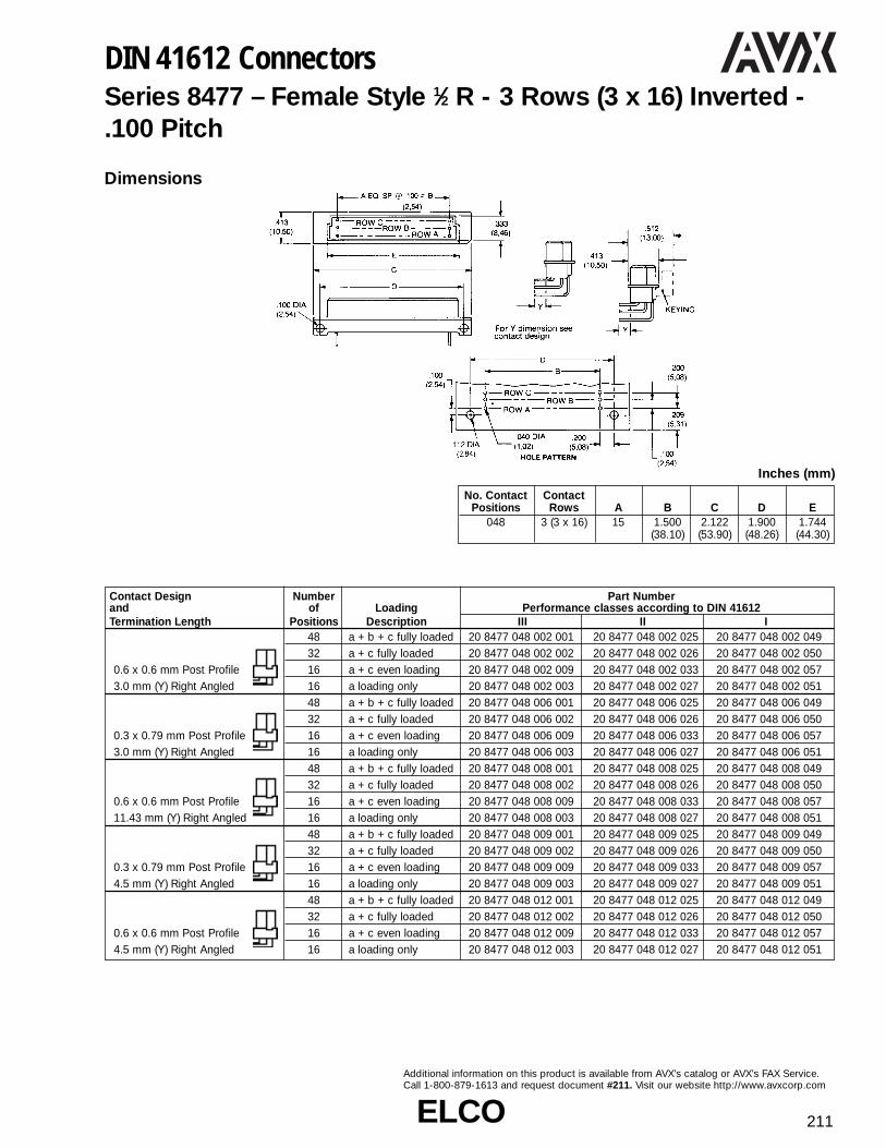
ELCOELCO 211
Additional information on this product is available from AVX’s catalog or AVX’s FAX Service.Call 1-800-879-1613 and request document #211. Visit our website http://www.avxcorp.com
DIN 41612 ConnectorsSeries 8477 – Female Style 1⁄2 R - 3 Rows (3 x 16) Inverted - .100 Pitch
Dimensions
No. Contact ContactPositions Rows A B C D E
048 3 (3 x 16) 15 1.500 2.122 1.900 1.744(38.10) (53.90) (48.26) (44.30)
Inches (mm)
Contact Design Number Part Numberand of Loading Performance classes according to DIN 41612Termination Length Positions Description III II I
48 a + b + c fully loaded 20 8477 048 002 001 20 8477 048 002 025 20 8477 048 002 04932 a + c fully loaded 20 8477 048 002 002 20 8477 048 002 026 20 8477 048 002 050
0.6 x 0.6 mm Post Profile 16 a + c even loading 20 8477 048 002 009 20 8477 048 002 033 20 8477 048 002 0573.0 mm (Y) Right Angled 16 a loading only 20 8477 048 002 003 20 8477 048 002 027 20 8477 048 002 051
48 a + b + c fully loaded 20 8477 048 006 001 20 8477 048 006 025 20 8477 048 006 04932 a + c fully loaded 20 8477 048 006 002 20 8477 048 006 026 20 8477 048 006 050
0.3 x 0.79 mm Post Profile 16 a + c even loading 20 8477 048 006 009 20 8477 048 006 033 20 8477 048 006 0573.0 mm (Y) Right Angled 16 a loading only 20 8477 048 006 003 20 8477 048 006 027 20 8477 048 006 051
48 a + b + c fully loaded 20 8477 048 008 001 20 8477 048 008 025 20 8477 048 008 04932 a + c fully loaded 20 8477 048 008 002 20 8477 048 008 026 20 8477 048 008 050
0.6 x 0.6 mm Post Profile 16 a + c even loading 20 8477 048 008 009 20 8477 048 008 033 20 8477 048 008 05711.43 mm (Y) Right Angled 16 a loading only 20 8477 048 008 003 20 8477 048 008 027 20 8477 048 008 051
48 a + b + c fully loaded 20 8477 048 009 001 20 8477 048 009 025 20 8477 048 009 04932 a + c fully loaded 20 8477 048 009 002 20 8477 048 009 026 20 8477 048 009 050
0.3 x 0.79 mm Post Profile 16 a + c even loading 20 8477 048 009 009 20 8477 048 009 033 20 8477 048 009 0574.5 mm (Y) Right Angled 16 a loading only 20 8477 048 009 003 20 8477 048 009 027 20 8477 048 009 051
48 a + b + c fully loaded 20 8477 048 012 001 20 8477 048 012 025 20 8477 048 012 04932 a + c fully loaded 20 8477 048 012 002 20 8477 048 012 026 20 8477 048 012 050
0.6 x 0.6 mm Post Profile 16 a + c even loading 20 8477 048 012 009 20 8477 048 012 033 20 8477 048 012 0574.5 mm (Y) Right Angled 16 a loading only 20 8477 048 012 003 20 8477 048 012 027 20 8477 048 012 051

ELCOELCO212
Additional information on this product is available from AVX’s catalog or AVX’s FAX Service.Call 1-800-879-1613 and request document #212. Visit our website http://www.avxcorp.com
DIN 41612 ConnectorsSeries 8477 – Male Style R - 3 Rows (3 x 32) Inverted - .100 Pitch
Dimensions
No. Contact ContactPositions Rows A B C D E F
096 3 (3 x 32) 31 3.100 3.358 3.461 3.543 3.736(78.74) (85.29) (87.91) (89.99) (94.89)
Inches (mm)
Contact Design Number Part Numberand of Loading Performance classes according to DIN 41612Termination Length Positions Description III II I
96 a + b + c fully loaded 10 8477 096 001 001 10 8477 096 001 025 10 8477 096 001 04964 a + c fully loaded 10 8477 096 001 002 10 8477 096 001 026 10 8477 096 001 05032 a + c even loading 10 8477 096 001 009 10 8477 096 001 033 10 8477 096 001 057
2.9 mm (Y) 32 a loading only 10 8477 096 001 003 10 8477 096 001 027 10 8477 096 001 051Straight 94 + 2 fully loaded + ground 10 9477 096 101 001 10 8477 096 101 025 10 8477 096 101 049
96 a + b + c fully loaded 10 8477 096 002 001 10 8477 096 002 025 10 8477 096 002 04964 a + c fully loaded 10 8477 096 002 002 10 8477 096 002 026 10 8477 096 002 05032 a + c even loading 10 8477 096 002 009 10 8477 096 002 033 10 8477 096 002 057
4.5 mm (Y) 32 a loading only 10 8477 096 002 003 10 8477 096 002 027 10 8477 096 002 051Straight 94 + 2 fully loaded + ground 10 8477 096 102 001 10 8477 096 102 025 10 8477 096 102 049
96 a + b + c fully loaded 10 8477 096 005 001 10 8477 096 005 025 10 8477 096 005 04964 a + c fully loaded 10 8477 096 005 002 10 8477 096 005 026 10 8477 096 005 050
9.5 mm (Y) 32 a + c even loading 10 8477 096 005 009 10 8477 096 005 033 10 8477 096 005 057Straight 32 a loading only 10 8477 096 005 003 10 8477 096 005 027 10 8477 096 005 051
96 a + b + c fully loaded 10 8477 096 006 001 10 8477 096 006 025 10 8477 096 006 04964 a + c fully loaded 10 8477 096 006 002 10 8477 096 006 026 10 8477 096 006 05032 a + c even loading 10 8477 096 006 009 10 8477 096 006 033 10 8477 096 006 057
13.0 mm (Y) 32 a loading only 10 8477 096 006 003 10 8477 096 006 027 10 8477 096 006 051Straight 94 + 2 fully loaded + ground 10 8477 096 106 001 10 8477 096 106 025 10 8477 096 106 049
96 a + b + c fully loaded 10 8477 096 007 001 10 8477 096 007 025 10 8477 096 007 04964 a + c fully loaded 10 8477 096 007 002 10 8477 096 007 026 10 8477 096 007 050
14.5 mm (Y) 32 a + c even loading 10 8477 096 007 009 10 8477 096 007 033 10 8477 096 007 057Straight 32 a loading only 10 8477 096 007 003 10 8477 096 007 027 10 8477 096 007 051
96 a + b + c fully loaded 10 8477 096 009 001 10 8477 096 009 025 10 8477 096 009 04964 a + c fully loaded 10 8477 096 009 002 10 8477 096 009 026 10 8477 096 009 050
8.8, 11.5, 8.8 mm (Y) 32 a + c even loading 10 8477 096 009 009 10 8477 096 009 033 10 8477 096 009 057Solder Hole 32 a loading only 10 8477 096 009 003 10 8477 096 009 027 10 8477 096 009 051
96 a + b + c fully loaded 10 8477 096 010 001 10 8477 096 010 025 10 8477 096 010 04964 a + c fully loaded 10 8477 096 010 002 10 8477 096 010 026 10 8477 096 010 050
7.5, 10.2, 7.5 mm (Y) 32 a + c even loading 10 8477 096 010 009 10 8477 096 010 033 10 8477 096 010 057Solder Loop 32 a loading only 10 8477 096 010 003 10 8477 096 010 027 10 8477 096 010 051

ELCOELCO 213
Additional information on this product is available from AVX’s catalog or AVX’s FAX Service.Call 1-800-879-1613 and request document #213. Visit our website http://www.avxcorp.com
DIN 41612 ConnectorsSeries 8477 – Female Style R - 3 Rows (3 x 32) Inverted - .100 Pitch
Dimensions
No. Contact ContactPositions Rows A B C D E
096 3 (3 x 32) 31 3.100 3.367 3.500 3.343(78.74) (93.90) (88.90) (84.91)
Inches (mm)
Contact Design Number Part Numberand of Loading Performance classes according to DIN 41612Termination Length Positions Description III II I
96 a + b + c fully loaded 20 8477 096 002 001 20 8477 096 002 025 20 8477 096 002 04964 a + c fully loaded 20 8477 096 002 002 20 8477 096 002 026 20 8477 096 002 050
0.6 x 0.6 mm Post Profile 32 a + c even loading 20 8477 096 002 009 20 8477 096 002 033 20 8477 096 002 0573.0 mm (Y) Right Angled 32 a loading only 20 8477 096 002 003 20 8477 096 002 027 20 8477 096 002 051
96 a + b + c fully loaded 20 8477 096 006 001 20 8477 096 006 025 20 8477 096 006 04964 a + c fully loaded 20 8477 096 006 002 20 8477 096 006 026 20 8477 096 006 050
0.3 x 0.79 mm Post Profile 32 a + c even loading 20 8477 096 006 009 20 8477 096 006 033 20 8477 096 006 0573.0 mm (Y) Right Angled 32 a loading only 20 8477 096 006 003 20 8477 096 006 027 20 8477 096 006 051
96 a + b + c fully loaded 20 8477 096 008 001 20 8477 096 008 025 20 8477 096 008 04964 a + c fully loaded 20 8477 096 008 002 20 8477 096 008 026 20 8477 096 008 050
11.43 mm (Y) 32 a + c even loading 20 8477 096 008 009 20 8477 096 008 033 20 8477 096 008 057Right Angled 32 a loading only 20 8477 096 008 003 20 8477 096 008 027 20 8477 096 008 051
96 a + b + c fully loaded 20 8477 096 009 001 20 8477 096 009 025 20 8477 096 009 04964 a + c fully loaded 20 8477 096 009 002 20 8477 096 009 026 20 8477 096 009 050
4.5 mm (Y) 32 a + c even loading 20 8477 096 009 009 20 8477 096 009 033 20 8477 096 009 057Right Angled 32 a loading only 20 8477 096 009 003 20 8477 096 009 027 20 8477 096 009 051
96 a + b + c fully loaded 20 8477 096 012 001 20 8477 096 012 025 20 8477 096 012 04964 a + c fully loaded 20 8477 096 012 002 20 8477 096 012 026 20 8477 096 012 050
4.5 mm (Y) 32 a + c even loading 20 8477 096 012 009 20 8477 096 012 033 20 8477 096 012 057Right Angled 32 a loading only 20 8477 096 012 003 20 8477 096 012 027 20 8477 096 012 051
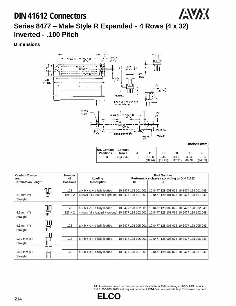
ELCOELCO214
Additional information on this product is available from AVX’s catalog or AVX’s FAX Service.Call 1-800-879-1613 and request document #214. Visit our website http://www.avxcorp.com
DIN 41612 ConnectorsSeries 8477 – Male Style R Expanded - 4 Rows (4 x 32)Inverted - .100 PitchDimensions
No. Contact ContactPositions Rows A B C D E F
128 4 (4 x 32) 31 3.100 3.358 3.461 3.543 3.736(78.74) (85.29) (87.91) (89.99) (94.89)
Inches (mm)
Contact Design Number Part Numberand of Loading Performance classes according to DIN 41612Termination Length Positions Description III II I
128 a + b + c + d fully loaded 10 8477 128 001 001 10 8477 128 001 026 10 8477 128 001 0492.9 mm (Y) 126 + 2 4 rows fully loaded + ground 10 8477 128 101 001 10 8477 128 101 025 10 8477 128 101 049Straight
128 a + b + c + d fully loaded 10 8477 128 002 001 10 8477 128 002 025 10 8477 128 002 0494.5 mm (Y) 126 + 2 4 rows fully loaded + ground 10 8477 128 102 001 10 8477 128 102 025 10 8477 128 102 049Straight
9.5 mm (Y) 128 a + b + c + d fully loaded 10 8477 128 005 001 10 8477 128 005 025 10 8477 128 005 049Straight
13.0 mm (Y) 128 a + b + c + d fully loaded 10 8477 128 006 001 10 8477 128 006 025 10 8477 128 006 049Straight
14.5 mm (Y) 128 a + b + c + d fully loaded 10 8477 128 007 001 10 8477 128 007 025 10 8477 128 007 049Straight

ELCOELCO 215
Additional information on this product is available from AVX’s catalog or AVX’s FAX Service.Call 1-800-879-1613 and request document #215. Visit our website http://www.avxcorp.com
DIN 41612 ConnectorsSeries 8477 – Female Style R Expanded - 4 Rows (4 x 32)Inverted - .100 Pitch
Dimensions
No. Contact ContactPositions Rows A B C D E F G
128 4 (4 x 32) 31 3.100 3.697 3.500 3.343 0.437 0.516(78.74) (93.90) (88.90) (84.90) (11.10) (13.10)
Inches (mm)
Contact Design Number Part Numberand of Loading Performance classes according to DIN 41612Termination Length Positions Description III II I
0.6 x 0.6 mm Post Profile 128 a + b + c + d fully loaded 20 8477 128 002 001 20 8477 128 002 025 20 8477 128 002 0493.0 mm (Y) Right Angled
0.3 x 0.79 mm Post Profile 128 a + b + c + d fully loaded 20 8477 128 006 001 20 8477 128 006 025 20 8477 128 006 0493.0 mm (Y) Right Angled
0.6 x 0.6 mm Post Profile 128 a + b + c + d fully loaded 20 8477 128 008 001 20 8477 128 008 025 20 8477 128 008 04911.43 mm (Y) Right Angled
0.3 x 0.79 mm Post Profile 128 a + b + c + d fully loaded 20 8477 128 009 001 20 8477 128 009 025 20 8477 128 009 0494.5 mm (Y) Right Angled
0.6 x 0.6 mm Post Profile 128 a + b + c + d fully loaded 20 8477 128 012 001 20 8477 128 012 025 20 8477 128 012 0494.5 mm (Y) Right Angled

ELCOELCO216
Additional information on this product is available from AVX’s catalog or AVX’s FAX Service.Call 1-800-879-1613 and request document #216. Visit our website http://www.avxcorp.com
DIN 41612 ConnectorsSeries 8477 – Male Style R Expanded - 5 Rows (5 x 32)Inverted - .100 Pitch
Dimensions
No. Contact ContactPositions Rows A B C D E F
60 5 (5 x 32) 31 3.100 3.358 3.461 3.543 3.736(78.74) (85.29) (87.91) (89.99) (94.89)
Inches (mm)
Contact Design Number Part Numberand of Loading Performance classes according to DIN 41612Termination Length Positions Description III II I
160 a + b + c + d + e fully loaded 10 8477 160 001 001 10 8477 160 001 025 10 8477 160 001 0492.9 mm (Y) 158 + 2 5 rows fully loaded + ground 10 8477 160 101 001 10 8477 160 101 025 10 8477 160 101 049Straight
160 a + b + c + d + e fully loaded 10 8477 160 002 001 10 8477 160 002 025 10 8477 160 002 0494.5 mm (Y) 158 + 2 5 rows fully loaded + ground 10 8477 160 102 001 10 8477 160 102 025 10 8477 160 102 049Straight
9.5 mm (Y) 160 a + b + c + d + e fully loaded 10 8477 160 105 001 10 8477 160 105 025 10 8477 160 105 049Straight
13.0 mm (Y) 160 a + b + c + d + e fully loaded 10 8477 160 106 001 10 8477 160 106 025 10 8477 160 106 049Straight
14.5 mm (Y) 160 a + b + c + d + e fully loaded 10 8477 160 107 001 10 8477 160 107 025 10 8477 160 107 049Straight

ELCOELCO 217
Additional information on this product is available from AVX’s catalog or AVX’s FAX Service.Call 1-800-879-1613 and request document #217. Visit our website http://www.avxcorp.com
DIN 41612 ConnectorsSeries 8477 – Female Style R Expanded - 5 Rows (5 x 32)Inverted - .100 Pitch
Contact Design Number Part Numberand of Loading Performance classes according to DIN 41612Termination Length Positions Description III II I
0.6 x 0.6 mm Post Profile 160 a + b + c + d + e fully loaded 20 8477 160 002 001 20 8477 160 002 025 20 8477 160 002 0493.0 mm (Y) Right Angled
0.6 x 0.6 mm Post Profile 160 a + b + c + d + e fully loaded 20 8477 160 008 001 20 8477 160 008 025 20 8477 160 008 04911.43 mm (Y) Right Angled
0.3 x 0.79 mm Post Profile 160 a + b + c + d + e fully loaded 20 8477 160 009 001 20 8477 160 009 025 20 8477 160 009 0494.5 mm (Y) Right Angled
0.6 x 0.6 mm Post Profile 160 a + b + c + d + e fully loaded 20 8477 160 012 001 20 8477 160 012 025 20 8477 160 012 0494.5 mm (Y) Right Angled
Dimensions
No. Contact ContactPositions Rows A B C D E F G
160 5 (5 x 32) 31 3.100 3.697 3.500 3.343 0.437 0.516(78.74) (93.90) (88.90) (84.90) (11.10) (13.10)
Inches (mm)
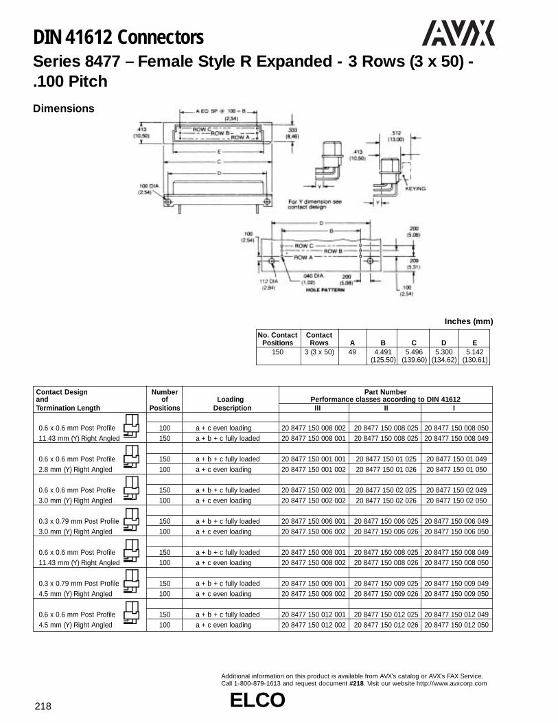
ELCOELCO218
Additional information on this product is available from AVX’s catalog or AVX’s FAX Service.Call 1-800-879-1613 and request document #218. Visit our website http://www.avxcorp.com
DIN 41612 ConnectorsSeries 8477 – Female Style R Expanded - 3 Rows (3 x 50) - .100 Pitch
Contact Design Number Part Numberand of Loading Performance classes according to DIN 41612Termination Length Positions Description III II I
0.6 x 0.6 mm Post Profile 100 a + c even loading 20 8477 150 008 002 20 8477 150 008 025 20 8477 150 008 05011.43 mm (Y) Right Angled 150 a + b + c fully loaded 20 8477 150 008 001 20 8477 150 008 025 20 8477 150 008 049
0.6 x 0.6 mm Post Profile 150 a + b + c fully loaded 20 8477 150 001 001 20 8477 150 01 025 20 8477 150 01 0492.8 mm (Y) Right Angled 100 a + c even loading 20 8477 150 001 002 20 8477 150 01 026 20 8477 150 01 050
0.6 x 0.6 mm Post Profile 150 a + b + c fully loaded 20 8477 150 002 001 20 8477 150 02 025 20 8477 150 02 0493.0 mm (Y) Right Angled 100 a + c even loading 20 8477 150 002 002 20 8477 150 02 026 20 8477 150 02 050
0.3 x 0.79 mm Post Profile 150 a + b + c fully loaded 20 8477 150 006 001 20 8477 150 006 025 20 8477 150 006 0493.0 mm (Y) Right Angled 100 a + c even loading 20 8477 150 006 002 20 8477 150 006 026 20 8477 150 006 050
0.6 x 0.6 mm Post Profile 150 a + b + c fully loaded 20 8477 150 008 001 20 8477 150 008 025 20 8477 150 008 04911.43 mm (Y) Right Angled 100 a + c even loading 20 8477 150 008 002 20 8477 150 008 026 20 8477 150 008 050
0.3 x 0.79 mm Post Profile 150 a + b + c fully loaded 20 8477 150 009 001 20 8477 150 009 025 20 8477 150 009 0494.5 mm (Y) Right Angled 100 a + c even loading 20 8477 150 009 002 20 8477 150 009 026 20 8477 150 009 050
0.6 x 0.6 mm Post Profile 150 a + b + c fully loaded 20 8477 150 012 001 20 8477 150 012 025 20 8477 150 012 0494.5 mm (Y) Right Angled 100 a + c even loading 20 8477 150 012 002 20 8477 150 012 026 20 8477 150 012 050
Dimensions
No. Contact ContactPositions Rows A B C D E
150 3 (3 x 50) 49 4.491 5.496 5.300 5.142(125.50) (139.60) (134.62) (130.61)
Inches (mm)

ELCOELCO 219
Additional information on this product is available from AVX’s catalog or AVX’s FAX Service.Call 1-800-879-1613 and request document #219. Visit our website http://www.avxcorp.com
DIN 41612 ConnectorsSeries 8458 – Male Style 1⁄2 B Press-Fit - 2 Rows (2 x 16) -.100 Pitch
Series 8458 – Male Style B Press-Fit - 2 Rows (2 x 32) - .100 Pitch
Contact Design Number Part Numberand of Loading Performance classes according to DIN 41612Termination Length Positions Description III II Ifor ≥ 2.4 mm PCB’s 32 a + b fully loaded 10 8458 032 001 001 10 8458 032 001 025 10 8458 032 001 0495.3 mm (Y) 16 a loading only 10 8458 032 001 003 10 8458 032 001 027 10 8458 032 001 051Right Angled 30 + 2 fully loaded + ground 10 8458 032 101 001 10 8458 032 101 025 10 8458 032 101 049for 1.6 mm PCB’s 32 a + b fully loaded 10 8458 032 031 001 10 8458 032 031 025 10 8458 032 031 0493.0 mm (Y) 16 a loading only 10 8458 032 031 003 10 8458 032 031 027 10 8458 032 031 051Right Angled 30 + 2 fully loaded + ground 10 8458 032 131 001 10 8458 032 131 025 10 8458 032 131 049
Dimensions
No. Contact ContactPositions Rows A B C D E
032 2 (2 x 16) 15 1.500 1.754 1.900 2.100(38.10) (44.55) (48.26) (53.34)
Inches (mm)
Contact Design Number Part Numberand of Loading Performance classes according to DIN 41612Termination Length Positions Description III II Ifor ≥ 2.4 mm PCB’s 64 a + b fully loaded 10 8458 064 001 001 10 8458 064 001 025 10 8458 064 001 0495.3 mm (Y) 32 a loading only 10 8458 064 001 003 10 8458 064 001 027 10 8458 064 001 051Right Angled 62 + 2 fully loaded + ground 10 8458 064 101 001 10 8458 064 101 025 10 8458 064 101 049for 1.6 mm PCB’s 64 a + b fully loaded 10 8458 064 031 001 10 8458 064 031 025 10 8458 064 031 0493.0 mm (Y) 32 a loading only 10 8458 064 031 003 10 8458 064 031 027 10 8458 064 031 051Right Angled 62 + 2 fully loaded + ground 10 8458 064 131 001 10 8458 064 131 025 10 8458 064 131 049
No. Contact ContactPositions Rows A B C D E
064 2 (2 x 32) 31 3.100 3.354 3.500 3.700(78.74) (85.19) (88.90) (93.98)
Inches (mm)

ELCOELCO220
Additional information on this product is available from AVX’s catalog or AVX’s FAX Service.Call 1-800-879-1613 and request document #220. Visit our website http://www.avxcorp.com
DIN 41612 ConnectorsSeries 8458 – Female Style B Press-Fit - 2 Rows (2 x 32) -.100 Pitch
Dimensions
Contact Design Number Part Numberand of Loading Performance classes according to DIN 41612Termination Length Positions Description III II Ifor ≥ 2.4 mm PCB’s 64 a + b fully loaded 20 8458 064 001 001 20 8458 064 001 025 20 8458 064 001 0490.6 x 0.6 mm Post Profile 32 a + c even loading 20 8458 064 001 003 20 8458 064 001 027 20 8458 064 001 0515.3 mm (Y) Straight 32 a loading only 20 8458 064 001 007 20 8458 064 001 031 20 8458 064 001 055for ≥ 2.4 mm PCB’s 64 a + b fully loaded 20 8458 064 002 001 20 8458 064 002 025 20 8458 064 002 0490.6 x 0.6 mm Post Profile 32 a + c even loading 20 8458 064 002 003 20 8458 064 002 027 20 8458 064 002 0519.3 mm (Y) Straight 32 a loading only 20 8458 064 002 007 20 8458 064 002 031 20 8458 064 002 055for ≥ 2.4 mm PCB’s 64 a + b fully loaded 20 8458 064 003 001 20 8458 064 003 025 20 8458 064 003 0490.6 x 0.6 mm Post Profile 32 a + c even loading 20 8458 064 003 003 20 8458 064 003 027 20 8458 064 003 05116.2 mm (Y) Straight 32 a loading only 20 8458 064 003 007 20 8458 064 003 031 20 8458 064 003 055for ≥ 2.4 mm PCB’s 64 a + b fully loaded 20 8458 064 004 001 20 8458 064 004 025 20 8458 064 004 0490.6 x 0.6 mm Post Profile 32 a + c even loading 20 8458 064 004 003 20 8458 064 004 027 20 8458 064 004 05123.2 mm (Y) Straight 32 a loading only 20 8458 064 004 007 20 8458 064 004 031 20 8458 064 004 055for ≥ 2.4 mm PCB’s 64 a + b fully loaded 20 8458 064 005 001 20 8458 064 005 025 20 8458 064 005 0490.6 x 0.6 mm Post Profile 32 a + c even loading 20 8458 064 005 003 20 8458 064 005 027 20 8458 064 005 05113.2 mm (Y) Straight 32 a loading only 20 8458 064 005 007 20 8458 064 005 031 20 8458 064 005 055for ≥ 2.4 mm PCB’s 64 a + b fully loaded 20 8458 064 009 001 20 8458 064 009 025 20 8458 064 009 0490.6 x 0.6 mm Post Profile 32 a + c even loading 20 8458 064 009 003 20 8458 064 009 027 20 8458 064 009 05112.0 mm (Y) Straight 32 a loading only 20 8458 064 009 007 20 8458 064 009 031 20 8458 064 009 055for ≥ 2.4 mm PCB’s 64 a + b fully loaded 20 8458 064 010 001 20 8458 064 010 025 20 8458 064 010 0490.6 x 0.6 mm Post Profile 32 a + c even loading 20 8458 064 010 003 20 8458 064 010 027 20 8458 064 010 05120.3 mm (Y) Straight 32 a loading only 20 8458 064 010 007 20 8458 064 010 031 20 8458 064 010 055for ≥ 2.4 mm PCB’s 64 a + b fully loaded 20 8458 064 012 001 20 8458 064 012 025 20 8458 064 012 0490.6 x 0.6 mm Post Profile 32 a + c even loading 20 8458 064 012 003 20 8458 064 012 027 20 8458 064 012 05117.0 mm Straight 32 a loading only 20 8458 064 012 007 20 8458 064 012 031 20 8458 064 012 055for 1.6 mm PCB’s 64 a + b fully loaded 20 8458 064 031 001 20 8458 064 031 025 20 8458 064 031 0490.6 x 0.6 mm Post Profile 32 a + c even loading 20 8458 064 031 003 20 8458 064 031 027 20 8458 064 031 0513.0 mm (Y) Straight 32 a loading only 20 8458 064 031 007 20 8458 064 031 031 20 8458 064 031 055

ELCOELCO 221
Additional information on this product is available from AVX’s catalog or AVX’s FAX Service.Call 1-800-879-1613 and request document #221. Visit our website http://www.avxcorp.com
DIN 41612 ConnectorsSeries 8458 – Male Style 1⁄3 C Press-Fit - 3 Rows (3 x 10) -.100 Pitch
Dimensions
No. Contact ContactPositions Rows A B C D E
030 3 (3 x 10) 9 0.900 1.158 1.300 1.497(22.86) (29.41) (33.02) (38.02)
Inches (mm)
Contact Design Number Part Numberand of Loading Performance classes according to DIN 41612Termination Length Positions Description III II Ifor ≥ 2.4 mm PCB’s 30 a + b + c fully loaded 10 8458 030 001 001 10 8458 030 001 025 10 8458 030 001 0495.3 mm (Y) (0.6” x 0.6”) 20 a + c fully loaded 10 8458 030 001 002 10 8458 030 001 026 10 8458 030 001 050Right Angled 28 + 2 fully loaded + ground 10 8458 030 101 001 10 8458 030 101 025 10 8458 030 101 049for 1.6 mm PCB’s 30 a + b + c fully loaded 10 8458 030 031 001 10 8458 030 031 025 10 8458 030 031 0493.0 mm (Y) (0.6” x 0.6”) 20 a + c fully loaded 10 8458 030 031 002 10 8458 030 031 026 10 8458 030 031 050Right Angled 28 + 2 fully loaded + ground 10 8458 030 131 001 10 8458 030 131 025 10 8458 030 131 049

ELCOELCO222
Additional information on this product is available from AVX’s catalog or AVX’s FAX Service.Call 1-800-879-1613 and request document #222. Visit our website http://www.avxcorp.com
DIN 41612 ConnectorsSeries 8458 – Female Style 1⁄3 C Press-Fit - 3 Rows (3 x 10) -.100 PitchDimensions
No. Contact ContactPositions Rows A B C D E
030 3 (3 x 10) 9 0.900 1.563 1.368 1.144(22.86) (39.70) (34.75) (29.06)
Inches (mm)
Contact Design Number Part Numberand of Loading Performance classes according to DIN 41612Termination Length Positions Description III II Ifor ≥ 2.4 mm PCB’s0.6 x 0.6 mm Post Profile 30 a + b + c fully loaded 20 8458 030 001 001 20 8458 030 001 025 20 8458 030 001 0495.3 mm (Y) Straight 20 a + c fully loaded 20 8458 030 001 002 20 8458 030 001 026 20 8458 030 001 050for ≥ 2.4 mm PCB’s0.6 x 0.6 mm Post Profile 30 a + b + c fully loaded 20 8458 030 002 001 20 8458 030 002 025 20 8458 030 002 0499.3 mm (Y) Straight 20 a + c fully loaded 20 8458 030 002 002 20 8458 030 002 026 20 8458 030 002 050for ≥ 2.4 mm PCB’s0.6 x 0.6 mm Post Profile 30 a + b + c fully loaded 20 8458 030 003 001 20 8458 030 003 025 20 8458 030 003 04916.2 mm (Y) Straight 20 a + c fully loaded 20 8458 030 003 002 20 8458 030 003 026 20 8458 030 003 050for ≥ 2.4 mm PCB’s0.6 x 0.6 mm Post Profile 30 a + b + c fully loaded 20 8458 030 004 001 20 8458 030 004 025 20 8458 030 004 04923.2 mm (Y) Straight 20 a + c fully loaded 20 8458 030 004 002 20 8458 030 004 026 20 8458 030 004 050for ≥ 2.4 mm PCB’s0.6 x 0.6 mm Post Profile 30 a + b + c fully loaded 20 8458 030 005 001 20 8458 030 005 025 20 8458 030 005 04913.2 mm (Y) Straight 20 a + c fully loaded 20 8458 030 005 002 20 8458 030 005 026 20 8458 030 005 050for ≥ 2.4 mm PCB’s0.6 x 0.6 mm Post Profile 30 a + b + c fully loaded 20 8458 030 009 001 20 8458 030 009 025 20 8458 030 009 04912.0 mm (Y) Straight 20 a + c fully loaded 20 8458 030 009 002 20 8458 030 009 026 20 8458 030 009 050for ≥ 2.4 mm PCB’s0.6 x 0.6 mm Post Profile 30 a + b + c fully loaded 20 8458 030 010 001 20 8458 030 010 025 20 8458 030 010 04920.3 mm (Y) Straight 20 a + c fully loaded 20 8458 030 010 002 20 8458 030 010 026 20 8458 030 010 050for ≥ 2.4 mm PCB’s0.6 x 0.6 mm Post Profile 30 a + b + c fully loaded 20 8458 030 012 001 20 8458 030 012 025 20 8458 030 012 04917.0 mm (Y) Straight 20 a + c fully loaded 20 8458 030 012 002 20 8458 030 012 026 20 8458 030 012 050for 1.6 mm PCB’s0.6 x 0.6 mm Post Profile 30 a + b + c fully loaded 20 8458 030 031 001 20 8458 030 031 025 20 8458 030 031 0493.0 mm (Y) Straight 20 a + c fully loaded 20 8458 030 031 002 20 8458 030 031 026 20 8458 030 031 050

ELCOELCO 223
Additional information on this product is available from AVX’s catalog or AVX’s FAX Service.Call 1-800-879-1613 and request document #223. Visit our website http://www.avxcorp.com
DIN 41612 ConnectorsSeries 8458 – Male Style 1⁄2 C Press-Fit - 3 Rows (3 x 16) -.100 PitchDimensions
No. Contact ContactPositions Rows A B C D E
048 3 (3 x 16) 15 1.500 1.760 1.900 2.122(38.10) (44.70) (48.26) (53.90)
Inches (mm)
Contact Design Number Part Numberand of Loading Performance classes according to DIN 41612Termination Length Positions Description III II Ifor ≥ 2.4 mm PCB’s 48 a + b + c fully loaded 10 8458 048 001 001 10 8458 048 001 025 10 8458 048 001 049
32 a + c fully loaded 10 8458 048 001 002 10 8458 048 001 026 10 8458 048 001 05016 a + c even loading 10 8458 048 001 009 10 8458 048 001 033 10 8458 048 001 057
0.6 x 0.6 mm Post Profile 16 a loading only 10 8458 048 001 003 10 8458 048 001 027 10 8458 048 001 0515.3 mm (Y) Right Angled 46 + 2 fully loaded + ground 10 8458 048 101 001 10 8458 048 101 025 10 8458 048 101 049for 1.6 mm PCB’s 48 a + b + c fully loaded 10 8458 048 031 001 10 8458 048 031 025 10 8458 048 031 049
32 a + c fully loaded 10 8458 048 031 002 10 8458 048 031 026 10 8458 048 031 05016 a + c even loading 10 8458 048 031 009 10 8458 048 031 033 10 8458 048 031 057
0.6 x 0.6 mm Post Profile 16 a loading only 10 8458 048 031 003 10 8458 048 031 027 10 8458 048 031 0513.0 mm (Y) Right Angled 46 + 2 fully loaded + ground 10 8458 048 131 001 10 8458 048 131 025 10 8458 048 131 049

ELCOELCO224
Additional information on this product is available from AVX’s catalog or AVX’s FAX Service.Call 1-800-879-1613 and request document #224. Visit our website http://www.avxcorp.com
DIN 41612 ConnectorsSeries 8458 – Female Style 1⁄2 C Press-Fit - 3 Rows (3 x 16) -.100 Pitch
Dimensions
No. Contact ContactPositions Rows A B C D E
048 3 (3 x 16) 15 1.500 2.165 1.771 1.748(38.10) (54.99) (44.99) (44.40)
Inches (mm)
Contact Design Number Part Numberand of Loading Performance classes according to DIN 41612Termination Length Positions Description III II Ifor ≥ 2.4 mm PCB’s0.6 x 0.6 mm Post Profile 48 a + b + c fully loaded 20 8458 048 001 001 20 8458 048 001 025 20 8458 048 001 0495.3 mm (Y) Straight 32 a + c fully loaded 20 8458 048 001 002 20 8458 048 001 026 20 8458 048 001 050for ≥ 2.4 mm PCB’s0.6 x 0.6 mm Post Profile 48 a + b + c fully loaded 20 8458 048 002 001 20 8458 048 002 025 20 8458 048 002 0499.3 mm (Y) Straight 32 a + c fully loaded 20 8458 048 002 002 20 8458 048 002 026 20 8458 048 002 050for ≥ 2.4 mm PCB’s0.6 x 0.6 mm Post Profile 48 a + b + c fully loaded 20 8458 048 003 001 20 8458 048 003 025 20 8458 048 003 04916.2 mm (Y) Straight 32 a + c fully loaded 20 8458 048 003 002 20 8458 048 003 026 20 8458 048 003 050for ≥ 2.4 mm PCB’s0.6 x 0.6 mm Post Profile 48 a + b + c fully loaded 20 8458 048 004 001 20 8458 048 004 025 20 8458 048 004 04923.2 mm (Y) Straight 32 a + c fully loaded 20 8458 048 004 002 20 8458 048 004 026 20 8458 048 004 050for ≥ 2.4 mm PCB’s0.6 x 0.6 mm Post Profile 48 a + b + c fully loaded 20 8458 048 005 001 20 8458 048 005 025 20 8458 048 005 04913.2 mm (Y) Straight 32 a + c fully loaded 20 8458 048 005 002 20 8458 048 005 026 20 8458 048 005 050for ≥ 2.4 mm PCB’s0.6 x 0.6 mm Post Profile 48 a + b + c fully loaded 20 8458 048 009 001 20 8458 048 009 025 20 8458 048 009 04912.0 mm (Y) Straight 32 a + c fully loaded 20 8458 048 009 002 20 8458 048 009 026 20 8458 048 009 050for ≥ 2.4 mm PCB’s0.6 x 0.6 mm Post Profile 48 a + b + c fully loaded 20 8458 048 010 001 20 8458 048 010 025 20 8458 048 010 04920.3 mm (Y) Straight 32 a + c fully loaded 20 8458 048 010 002 20 8458 048 010 026 20 8458 048 010 050for ≥ 2.4 mm PCB’s0.6 x 0.6 mm Post Profile 48 a + b + c fully loaded 20 8458 048 012 001 20 8458 048 012 025 20 8458 048 012 04917.0 mm (Y) Straight 32 a + c fully loaded 20 8458 048 012 002 20 8458 048 012 026 20 8458 048 012 050for 1.6 mm PCB’s0.6 x 0.6 mm Post Profile 48 a + b + c fully loaded 20 8458 048 031 001 20 8458 048 031 025 20 8458 048 031 0493.0 mm (Y) Straight 32 a + c fully loaded 20 8458 048 031 002 20 8458 048 031 026 20 8458 048 031 050
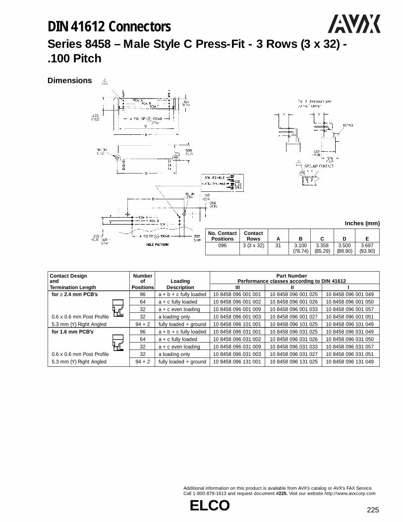
ELCOELCO 225
Additional information on this product is available from AVX’s catalog or AVX’s FAX Service.Call 1-800-879-1613 and request document #225. Visit our website http://www.avxcorp.com
DIN 41612 ConnectorsSeries 8458 – Male Style C Press-Fit - 3 Rows (3 x 32) - .100 Pitch
Dimensions
No. Contact ContactPositions Rows A B C D E
096 3 (3 x 32) 31 3.100 3.358 3.500 3.697(78.74) (85.29) (88.90) (93.90)
Inches (mm)
Contact Design Number Part Numberand of Loading Performance classes according to DIN 41612Termination Length Positions Description III II Ifor ≥ 2.4 mm PCB’s 96 a + b + c fully loaded 10 8458 096 001 001 10 8458 096 001 025 10 8458 096 001 049
64 a + c fully loaded 10 8458 096 001 002 10 8458 096 001 026 10 8458 096 001 05032 a + c even loading 10 8458 096 001 009 10 8458 096 001 033 10 8458 096 001 057
0.6 x 0.6 mm Post Profile 32 a loading only 10 8458 096 001 003 10 8458 096 001 027 10 8458 096 001 0515.3 mm (Y) Right Angled 94 + 2 fully loaded + ground 10 8458 096 101 001 10 8458 096 101 025 10 8458 096 101 049for 1.6 mm PCB’s 96 a + b + c fully loaded 10 8458 096 031 001 10 8458 096 031 025 10 8458 096 031 049
64 a + c fully loaded 10 8458 096 031 002 10 8458 096 031 026 10 8458 096 031 05032 a + c even loading 10 8458 096 031 009 10 8458 096 031 033 10 8458 096 031 057
0.6 x 0.6 mm Post Profile 32 a loading only 10 8458 096 031 003 10 8458 096 031 027 10 8458 096 031 0515.3 mm (Y) Right Angled 94 + 2 fully loaded + ground 10 8458 096 131 001 10 8458 096 131 025 10 8458 096 131 049
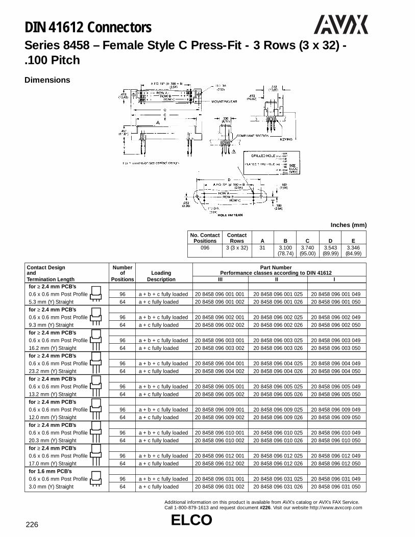
ELCOELCO226
Additional information on this product is available from AVX’s catalog or AVX’s FAX Service.Call 1-800-879-1613 and request document #226. Visit our website http://www.avxcorp.com
DIN 41612 ConnectorsSeries 8458 – Female Style C Press-Fit - 3 Rows (3 x 32) - .100 Pitch
Dimensions
No. Contact ContactPositions Rows A B C D E
096 3 (3 x 32) 31 3.100 3.740 3.543 3.346(78.74) (95.00) (89.99) (84.99)
Inches (mm)
Contact Design Number Part Numberand of Loading Performance classes according to DIN 41612Termination Length Positions Description III II Ifor ≥ 2.4 mm PCB’s0.6 x 0.6 mm Post Profile 96 a + b + c fully loaded 20 8458 096 001 001 20 8458 096 001 025 20 8458 096 001 0495.3 mm (Y) Straight 64 a + c fully loaded 20 8458 096 001 002 20 8458 096 001 026 20 8458 096 001 050for ≥ 2.4 mm PCB’s0.6 x 0.6 mm Post Profile 96 a + b + c fully loaded 20 8458 096 002 001 20 8458 096 002 025 20 8458 096 002 0499.3 mm (Y) Straight 64 a + c fully loaded 20 8458 096 002 002 20 8458 096 002 026 20 8458 096 002 050for ≥ 2.4 mm PCB’s0.6 x 0.6 mm Post Profile 96 a + b + c fully loaded 20 8458 096 003 001 20 8458 096 003 025 20 8458 096 003 04916.2 mm (Y) Straight 64 a + c fully loaded 20 8458 096 003 002 20 8458 096 003 026 20 8458 096 003 050for ≥ 2.4 mm PCB’s0.6 x 0.6 mm Post Profile 96 a + b + c fully loaded 20 8458 096 004 001 20 8458 096 004 025 20 8458 096 004 04923.2 mm (Y) Straight 64 a + c fully loaded 20 8458 096 004 002 20 8458 096 004 026 20 8458 096 004 050for ≥ 2.4 mm PCB’s0.6 x 0.6 mm Post Profile 96 a + b + c fully loaded 20 8458 096 005 001 20 8458 096 005 025 20 8458 096 005 04913.2 mm (Y) Straight 64 a + c fully loaded 20 8458 096 005 002 20 8458 096 005 026 20 8458 096 005 050 for ≥ 2.4 mm PCB’s0.6 x 0.6 mm Post Profile 96 a + b + c fully loaded 20 8458 096 009 001 20 8458 096 009 025 20 8458 096 009 04912.0 mm (Y) Straight 64 a + c fully loaded 20 8458 096 009 002 20 8458 096 009 026 20 8458 096 009 050for ≥ 2.4 mm PCB’s0.6 x 0.6 mm Post Profile 96 a + b + c fully loaded 20 8458 096 010 001 20 8458 096 010 025 20 8458 096 010 04920.3 mm (Y) Straight 64 a + c fully loaded 20 8458 096 010 002 20 8458 096 010 026 20 8458 096 010 050for ≥ 2.4 mm PCB’s0.6 x 0.6 mm Post Profile 96 a + b + c fully loaded 20 8458 096 012 001 20 8458 096 012 025 20 8458 096 012 04917.0 mm (Y) Straight 64 a + c fully loaded 20 8458 096 012 002 20 8458 096 012 026 20 8458 096 012 050for 1.6 mm PCB’s0.6 x 0.6 mm Post Profile 96 a + b + c fully loaded 20 8458 096 031 001 20 8458 096 031 025 20 8458 096 031 0493.0 mm (Y) Straight 64 a + c fully loaded 20 8458 096 031 002 20 8458 096 031 026 20 8458 096 031 050

ELCOELCO 227
Additional information on this product is available from AVX’s catalog or AVX’s FAX Service.Call 1-800-879-1613 and request document #227. Visit our website http://www.avxcorp.com
DIN 41612 ConnectorsSeries 8458 – Female Style C Expanded Press-Fit - 4 Rows (4 x 32) - .100 Pitch
Dimensions
No. Contact ContactPositions Rows A B C D E F G
128 4 (4 x 32) 31 3.100 3.740 3.543 3.346 0.433 0.516(78.74) (95.00) (90.00) (85.00) (11.00) (13.10)
Inches (mm)
Contact Design Number Part Numberand of Loading Performance classes according to DIN 41612Termination Length Positions Description III II Ifor ≥ 2.4 mm PCB’s0.6 x 0.6 mm Post Profile 128 a + b + c + d fully loaded 20 8458 128 001 001 20 8458 128 001 025 20 8458 128 001 0496.3 mm (Y) Straightfor ≥ 2.4 mm PCB’s0.6 x 0.6 mm Post Profile 128 a + b + c + d fully loaded 20 8458 128 002 001 20 8458 128 002 025 20 8458 128 002 0499.3 mm (Y) Straightfor ≥ 2.4 mm PCB’s0.6 x 0.6 mm Post Profile 128 a + b + c + d fully loaded 20 8458 128 003 001 20 8458 128 003 025 20 8458 128 003 04916.2 mm (Y) Straightfor ≥ 2.4 mm PCB’s0.6 x 0.6 mm Post Profile 128 a + b + c + d fully loaded 20 8458 128 004 001 20 8458 128 004 025 20 8458 128 004 04923.2 mm (Y) Straightfor ≥ 2.4 mm PCB’s0.6 x 0.6 mm Post Profile 128 a + b + c + d fully loaded 20 8458 128 005 001 20 8458 128 005 025 20 8458 128 005 04913.2 mm (Y) Straightfor ≥ 2.4 mm PCB’s0.6 x 0.6 mm Post Profile 128 a + b + c + d fully loaded 20 8458 128 009 001 20 8458 128 009 025 20 8458 128 009 04912.0 mm (Y) Straightfor ≥ 2.4 mm PCB’s0.6 x 0.6 mm Post Profile 128 a + b + c + d fully loaded 20 8458 128 010 001 20 8458 128 010 025 20 8458 128 010 04920.3 mm (Y) Straightfor ≥ 2.4 mm PCB’s0.6 x 0.6 mm Post Profile 128 a + b + c + d fully loaded 20 8458 128 012 001 20 8458 128 012 025 20 8458 128 012 04917.0 mm (Y) Straightfor 1.6 mm PCB’s0.6 x 0.6 mm Post Profile 128 a + b + c + d fully loaded 20 8458 128 031 001 20 8458 128 031 025 20 8458 128 031 0493.0 mm (Y) Straight

ELCOELCO228
Additional information on this product is available from AVX’s catalog or AVX’s FAX Service.Call 1-800-879-1613 and request document #228. Visit our website http://www.avxcorp.com
DIN 41612 ConnectorsSeries 8458 – Female Style C Expanded Press-Fit - 5 Rows (5 x 32) - .100 Pitch
Dimensions
No. Contact ContactPositions Rows A B C D E F G
160 5 (5 x 32) 31 3.100 3.740 3.543 3.346 0.433 0.516(78.74) (95.00) (90.00) (85.00) (11.00) (13.10)
Inches (mm)
Contact Design Number Part Numberand of Loading Performance classes according to DIN 41612Termination Length Positions Description III II Ifor ≥ 2.4 mm PCB’s0.6 x 0.6 mm Post Profile 160 a + b + c + d + e fully loaded 20 8458 160 001 002 20 8458 160 001 026 20 8458 160 001 0506.3 mm (Y) Straightfor ≥ 2.4 mm PCB’s0.6 x 0.6 mm Post Profile 160 a + b + c + d + e fully loaded 20 8458 160 002 002 20 8458 160 002 026 20 8458 160 002 0509.3 mm (Y) Straightfor ≥ 2.4 mm PCB’s0.6 x 0.6 mm Post Profile 160 a + b + c + d + e fully loaded 20 8458 160 003 002 20 8458 160 003 026 20 8458 160 003 05016.2 mm (Y) Straightfor ≥ 2.4 mm PCB’s0.6 x 0.6 mm Post Profile 160 a + b + c + d + e fully loaded 20 8458 160 004 002 20 8458 160 004 026 20 8458 160 004 05023.2 mm (Y) Straightfor ≥ 2.4 mm PCB’s0.6 x 0.6 mm Post Profile 160 a + b + c + d + e fully loaded 20 8458 160 005 002 20 8458 160 005 026 20 8458 160 005 05013.2 mm (Y) Straightfor ≥ 2.4 mm PCB’s0.6 x 0.6 mm Post Profile 160 a + b + c + d + e fully loaded 20 8458 160 009 002 20 8458 160 009 026 20 8458 160 009 05012.0 mm (Y) Straightfor ≥ 2.4 mm PCB’s0.6 x 0.6 mm Post Profile 160 a + b + c + d + e fully loaded 20 8458 160 010 002 20 8458 160 010 026 20 8458 160 010 05020.3 mm (Y) Straightfor ≥ 2.4 mm PCB’s0.6 x 0.6 mm Post Profile 160 a + b + c + d + e fully loaded 20 8458 160 012 002 20 8458 160 012 026 20 8458 160 012 05017.0 mm (Y) Straightfor 1.6 mm PCB’s0.6 x 0.6 mm Post Profile 160 a + b + c + d + e fully loaded 20 8458 160 031 001 20 8458 160 031 025 20 8458 160 031 0493.0 mm (Y) Straight

ELCOELCO 229
Additional information on this product is available from AVX’s catalog or AVX’s FAX Service.Call 1-800-879-1613 and request document #229. Visit our website http://www.avxcorp.com
DIN 41612 ConnectorsSeries 8485 – Style M Contacts – Special Contacts for Style M Connectors
High Power Receptacle Contact for Receptacle Series 8484
Variation Termination [A* Performance Ordering Code
Screw f3M .114 (2.90) for 40 Ampere max. 70 8485 02 14 00 343
.118 (3.00)
PCB hole
Press-Fit Note: set 40 Ampere max. 70 8485 03 14 00 343
PCB hole
spec

ELCOELCO230
Additional information on this product is available from AVX’s catalog or AVX’s FAX Service.Call 1-800-879-1613 and request document #230. Visit our website http://www.avxcorp.com
DIN 41612 ConnectorsSeries 8484 – Female Style 1⁄2 M Press-Fit - 3 Rows (3 x 4, 10) - .100 Pitch
Contact Design Number of Number of Part Numberand Cavities for Cavities for Loading Performance classes according to DIN 41612Termination Length Signal Special Description III II I
Positions Positions
5.3 mm (Y) 12 (3 x 4) 4 a + b + c fully loaded 20 8484 012 001 001 20 8484 012 001 025 20 8484 012 001 049Straight 30 (3 x 10) 2 a + b + c fully loaded 20 8484 030 001 001 20 8484 030 001 025 20 8484 030 001 049
9.3 mm (Y) 12 (3 x 4) 4 a + b + c fully loaded 20 8484 012 002 001 20 8484 012 002 025 20 8484 012 002 049Straight 30 (3 x 10) 2 a + b + c fully loaded 20 8484 030 002 001 20 8484 030 002 025 20 8484 030 002 049
16.2 mm (Y) 12 (3 x 4) 4 a + b + c fully loaded 20 8484 012 003 001 20 8484 012 003 025 20 8484 012 003 049Straight 30 (3 x 10) 2 a + b + c fully loaded 20 8484 030 003 001 20 8484 030 003 025 20 8484 030 003 049
23.2 mm (Y) 12 (3 x 4) 4 a + b + c fully loaded 20 8484 012 004 001 20 8484 012 004 025 20 8484 012 004 049Straight 30 (3 x 10) 2 a + b + c fully loaded 20 8484 030 004 001 20 8484 030 004 025 20 8484 030 004 049
13.2 mm (Y) 12 (3 x 4) 4 a + b + c fully loaded 20 8484 012 005 001 20 8484 012 005 025 20 8484 012 005 049Straight 30 (3 x 10) 2 a + b + c fully loaded 20 8484 030 005 001 20 8484 030 005 025 20 8484 030 005 049
18.2 mm (Y) 12 (3 x 4) 4 a + b + c fully loaded 20 8484 012 008 001 20 8484 012 008 025 20 8484 012 008 049Straight 30 (3 x 10) 2 a + b + c fully loaded 20 8484 030 008 001 20 8484 030 008 025 20 8484 030 008 049
12.0 mm (Y) 12 (3 x 4) 4 a + b + c fully loaded 20 8484 012 009 001 20 8484 012 009 025 20 8484 012 009 049Straight 30 (3 x 10) 2 a + b + c fully loaded 20 8484 030 009 001 20 8484 030 009 025 20 8484 030 009 049
20.3 mm (Y) 12 (3 x 4) 4 a + b + c fully loaded 20 8484 012 010 001 20 8484 012 010 025 20 8484 012 010 049Straight 30 (3 x 10) 2 a + b + c fully loaded 20 8484 030 010 001 20 8484 030 010 025 20 8484 030 010 049Special storch leg18.7 mm (Y) 12 (3 x 4) 4 a + b + c fully loaded 20 8484 012 011 001 20 8484 012 011 025 20 8484 012 011 049Straight 30 (3 x 10) 2 a + b + c fully loaded 20 8484 030 011 001 20 8484 030 011 025 20 8484 030 011 049
17.0 mm (Y) 12 (3 x 4) 4 a + b + c fully loaded 20 8484 012 012 001 20 8484 012 012 025 20 8484 012 012 049Straight 30 (3 x 10) 2 a + b + c fully loaded 20 8484 030 012 001 20 8484 030 012 025 20 8484 030 012 049
Dimensions

ELCOELCO 231
Additional information on this product is available from AVX’s catalog or AVX’s FAX Service. Call 1-800-879-1613 and request document #231. Visit our website http://www.avxcorp.com
DIN 41612 ConnectorsSeries 8484 – Female Style M Press-Fit - 3 Rows (3 x 2, 8, 14, 20 or 28) - .100 Pitch
Dimensions
Contact Design Number of Number of Part Numberand Cavities for Cavities for Loading Performance classes according to DIN 41612Termination Length Signal Positions Special Positions Description III II I
6 (3 x 2) 10 a + b + c fully loaded 20 8484 006 001 001 20 8484 006 001 025 20 8484 006 001 04924 ( 3 x 8) 8 a + b + c fully loaded 20 8484 024 001 001 20 8484 024 001 025 20 8484 024 001 04942 (3 x 14) 6 a + b + c fully loaded 20 8484 042 001 001 20 8484 042 001 025 20 8484 042 001 049
5.3 mm (Y) 60 (3 x 20) 4 a + b + c fully loaded 20 8484 060 001 001 20 8484 060 001 025 20 8484 060 001 049Straight 78 (3 x 28) 2 a + b + c fully loaded 20 8484 078 001 001 20 8484 078 001 025 20 8484 078 001 049
6 (3 x 2) 10 a + b + c fully loaded 20 8484 006 002 001 20 8484 006 002 025 20 8484 006 002 04924 ( 3 x 8) 8 a + b + c fully loaded 20 8484 024 002 001 20 8484 024 002 025 20 8484 024 002 04942 (3 x 14) 6 a + b + c fully loaded 20 8484 042 002 001 20 8484 042 002 025 20 8484 042 002 049
9.3 mm (Y) 60 (3 x 20) 4 a + b + c fully loaded 20 8484 060 002 001 20 8484 060 002 025 20 8484 060 002 049Straight 78 (3 x 28) 2 a + b + c fully loaded 20 8484 078 002 001 20 8484 078 002 025 20 8484 078 002 049
6 (3 x 2) 10 a + b + c fully loaded 20 8484 006 003 001 20 8484 006 003 025 20 8484 006 003 04924 ( 3 x 8) 8 a + b + c fully loaded 20 8484 024 003 001 20 8484 024 003 025 20 8484 024 003 04942 (3 x 14) 6 a + b + c fully loaded 20 8484 042 003 001 20 8484 042 003 025 20 8484 042 003 049
16.2 mm (Y) 60 (3 x 20) 4 a + b + c fully loaded 20 8484 060 003 001 20 8484 060 003 025 20 8484 060 003 049Straight 78 (3 x 28) 2 a + b + c fully loaded 20 8484 078 003 001 20 8484 078 003 025 20 8484 078 003 049
6 (3 x 2) 10 a + b + c fully loaded 20 8484 006 004 001 20 8484 006 004 025 20 8484 006 004 04924 ( 3 x 8) 8 a + b + c fully loaded 20 8484 024 004 001 20 8484 024 004 025 20 8484 024 004 04942 (3 x 14) 6 a + b + c fully loaded 20 8484 042 004 001 20 8484 042 004 025 20 8484 042 004 049
23.2 mm (Y) 60 (3 x 20) 4 a + b + c fully loaded 20 8484 060 004 001 20 8484 060 004 025 20 8484 060 004 049Straight 78 (3 x 28) 2 a + b + c fully loaded 20 8484 078 004 001 20 8484 078 004 025 20 8484 078 004 049
6 (3 x 2) 10 a + b + c fully loaded 20 8484 006 005 001 20 8484 006 005 025 20 8484 006 005 04924 ( 3 x 8) 8 a + b + c fully loaded 20 8484 024 005 001 20 8484 024 005 025 20 8484 024 005 04942 (3 x 14) 6 a + b + c fully loaded 20 8484 042 005 001 20 8484 042 005 025 20 8484 042 005 049
13.2 mm (Y) 60 (3 x 20) 4 a + b + c fully loaded 20 8484 060 005 001 20 8484 060 005 025 20 8484 060 005 049Straight 78 (3 x 28) 2 a + b + c fully loaded 20 8484 078 005 001 20 8484 078 005 025 20 8484 078 005 049
6 (3 x 2) 10 a + b + c fully loaded 20 8484 006 008 001 20 8484 006 008 025 20 8484 006 008 04924 ( 3 x 8) 8 a + b + c fully loaded 20 8484 024 008 001 20 8484 024 008 025 20 8484 024 008 04942 (3 x 14) 6 a + b + c fully loaded 20 8484 042 008 001 20 8484 042 008 025 20 8484 042 008 049
18.2 mm (Y) 60 (3 x 20) 4 a + b + c fully loaded 20 8484 060 008 001 20 8484 060 008 025 20 8484 060 008 049Straight 78 (3 x 28) 2 a + b + c fully loaded 20 8484 078 008 001 20 8484 078 008 025 20 8484 078 008 049
6 (3 x 2) 10 a + b + c fully loaded 20 8484 006 009 001 20 8484 006 009 025 20 8484 006 009 04924 ( 3 x 8) 8 a + b + c fully loaded 20 8484 024 009 001 20 8484 024 009 025 20 8484 024 009 04942 (3 x 14) 6 a + b + c fully loaded 20 8484 042 009 001 20 8484 042 009 025 20 8484 042 009 049
12.0 mm (Y) 60 (3 x 20) 4 a + b + c fully loaded 20 8484 060 009 001 20 8484 060 009 025 20 8484 060 009 049Straight 78 (3 x 28) 2 a + b + c fully loaded 20 8484 078 009 001 20 8484 078 009 025 20 8484 078 009 049
6 (3 x 2) 10 a + b + c fully loaded 20 8484 006 010 001 20 8484 006 010 025 20 8484 006 010 04924 ( 3 x 8) 8 a + b + c fully loaded 20 8484 024 010 001 20 8484 024 010 025 20 8484 024 010 04942 (3 x 14) 6 a + b + c fully loaded 20 8484 042 010 001 20 8484 042 010 025 20 8484 042 010 049
20.3 mm (Y) 60 (3 x 20) 4 a + b + c fully loaded 20 8484 060 010 001 20 8484 060 010 025 20 8484 060 010 049Straight 78 (3 x 28) 2 a + b + c fully loaded 20 8484 078 010 001 20 8484 078 010 025 20 8484 078 010 049Special 6 (3 x 2) 10 a + b + c fully loaded 20 8484 006 011 001 20 8484 006 011 025 20 8484 006 011 049storch leg 24 ( 3 x 8) 8 a + b + c fully loaded 20 8484 024 011 001 20 8484 024 011 025 20 8484 024 011 049
42 (3 x 14) 6 a + b + c fully loaded 20 8484 042 011 001 20 8484 042 011 025 20 8484 042 011 04918.7 mm (Y) 60 (3 x 20) 4 a + b + c fully loaded 20 8484 060 011 001 20 8484 060 011 025 20 8484 060 011 049Straight 78 (3 x 28) 2 a + b + c fully loaded 20 8484 078 011 001 20 8484 078 011 025 20 8484 078 011 049
6 (3 x 2) 10 a + b + c fully loaded 20 8484 006 012 001 20 8484 006 012 025 20 8484 006 012 04924 ( 3 x 8) 8 a + b + c fully loaded 20 8484 024 012 001 20 8484 024 012 025 20 8484 024 012 04942 (3 x 14) 6 a + b + c fully loaded 20 8484 042 012 001 20 8484 042 012 025 20 8484 042 012 049
17.0 mm (Y) 60 (3 x 20) 4 a + b + c fully loaded 20 8484 060 012 001 20 8484 060 012 025 20 8484 060 012 049Straight 78 (3 x 28) 2 a + b + c fully loaded 20 8484 078 012 001 20 8484 078 012 025 20 8484 078 012 049

ELCOELCO232
Additional information on this product is available from AVX’s catalog or AVX’s FAX Service.Call 1-800-879-1613 and request document #232. Visit our website http://www.avxcorp.com
DIN 41612 ConnectorsSeries 8478 – Male Style 1⁄2 Q Press-Fit - 2 Rows (2 x 16)Inverted - .100 PitchDimensions
No. Contact Contact A B C D E F
Positions Rows032 2 (2 x 16) 15 1.500 1.760 1.862 1.968 2.162
(38.10) (44.70) (47.29) (49.99) (54.91)
Inches (mm)
Contact Design Number Part Numberand of Loading Performance classes according DIN 41612Termination Length Positions Description III II Ifor ≥ 2.4 mm PCB’s 32 a + b fully loaded 10 8478 032 001 001 10 8478 032 001 025 10 8478 032 001 049
16 a + b even loading 10 8478 032 001 007 10 8478 032 001 031 10 8478 032 001 0550.6 x 0.6 mm Post Profile 16 a loading only 10 8478 032 001 003 10 8478 032 001 027 10 8478 032 001 0515.3 mm (Y) Straight 30 + 2 fully loaded + ground 10 8478 032 101 001 10 8478 032 101 025 10 8478 032 101 049for ≥ 2.4 mm PCB’s 32 a + b fully loaded 10 8478 032 002 001 10 8478 032 002 025 10 8478 032 002 049
16 a + b even loading 10 8478 032 002 007 10 8478 032 002 031 10 8478 032 002 0550.6 x 0.6 mm Post Profile 16 a loading only 10 8478 032 002 003 10 8478 032 002 027 10 8478 032 002 0519.3 mm (Y) Straight 30 + 2 fully loaded + ground 10 8478 032 102 001 10 8478 032 102 025 10 8478 032 102 049for ≥ 2.4 mm PCB’s 32 a + b fully loaded 10 8478 032 003 001 10 8478 032 003 025 10 8478 032 003 049
16 a + b even loading 10 8478 032 003 007 10 8478 032 003 031 10 8478 032 003 0550.6 x 0.6 mm Post Profile 16 a loading only 10 8478 032 003 003 10 8478 032 003 027 10 8478 032 003 05116.2 mm (Y) Straight 30 + 2 fully loaded + ground 10 8478 032 103 001 10 8478 032 103 025 10 8478 032 103 049for ≥ 2.4 mm PCB’s 32 a + b fully loaded 10 8478 032 004 001 10 8478 032 004 025 10 8478 032 004 049
16 a + b even loading 10 8478 032 004 007 10 8478 032 004 031 10 8478 032 004 0550.6 x 0.6 mm Post Profile 16 a loading only 10 8478 032 004 003 10 8478 032 004 027 10 8478 032 004 05118.2 mm (Y) Straight 30 + 2 fully loaded + ground 10 8478 032 104 001 10 8478 032 104 025 10 8478 032 104 049for ≥ 2.4 mm PCB’s 32 a + b fully loaded 10 8478 032 005 001 10 8478 032 005 025 10 8478 032 005 049
16 a + b even loading 10 8478 032 005 007 10 8478 032 005 031 10 8478 032 005 0550.6 x 0.6 mm Post Profile 16 a loading only 10 8478 032 005 003 10 8478 032 005 027 10 8478 032 005 05114.6 mm (Y) Straight 30 + 2 fully loaded + ground 10 8478 032 105 001 10 8478 032 105 025 10 8478 032 105 049for ≥ 2.4 mm PCB’s 32 a + b fully loaded 10 8478 032 006 001 10 8478 032 006 025 10 8478 032 006 049
16 a + b even loading 10 8478 032 006 007 10 8478 032 006 031 10 8478 032 006 0550.6 x 0.6 mm Post Profile 16 a loading only 10 8478 032 006 003 10 8478 032 006 027 10 8478 032 006 05113.2 mm (Y) Straight 30 + 2 fully loaded + ground 10 8478 032 106 001 10 8478 032 106 025 10 8478 032 106 049for ≥ 2.4 mm PCB’s 32 a + b fully loaded 10 8478 032 007 001 10 8478 032 007 025 10 8478 032 007 049
16 a + b even loading 10 8478 032 007 007 10 8478 032 007 031 10 8478 032 007 0550.6 x 0.6 mm Post Profile 16 a loading only 10 8478 032 007 003 10 8478 032 007 027 10 8478 032 007 05123.2 mm (Y) Straight 30 + 2 fully loaded + ground 10 8478 032 107 001 10 8478 032 107 025 10 8478 032 107 049for ≥ 2.4 mm PCB’s 32 a + b fully loaded 10 8478 032 008 001 10 8478 032 008 025 10 8478 032 008 049
16 a + b even loading 10 8478 032 008 007 10 8478 032 008 031 10 8478 032 008 0550.6 x 0.6 mm Post Profile 16 a loading only 10 8478 032 008 003 10 8478 032 008 027 10 8478 032 008 05120.0 mm (Y) Straight 30 + 2 fully loaded + ground 10 8478 032 108 001 10 8478 032 108 025 10 8478 032 108 049for ≥ 2.4 mm PCB’s 32 a + b fully loaded 10 8478 032 009 001 10 8478 032 009 025 10 8478 032 009 049
16 a + b even loading 10 8478 032 009 007 10 8478 032 009 031 10 8478 032 009 0550.6 x 0.6 mm Post Profile 16 a loading only 10 8478 032 009 003 10 8478 032 009 027 10 8478 032 009 0513.9 mm (Y) Straight 30 + 2 fully loaded + ground 10 8478 032 109 001 10 8478 032 109 025 10 8478 032 109 049for 1.6 mm PCB’s 32 a + b fully loaded 10 8478 032 031 001 10 8478 032 031 025 10 8478 032 031 0490.6 x 0.6 mm Post Profile 16 a + b even loading 10 8478 032 031 007 10 8478 032 031 031 10 8478 032 031 0553.0 mm (Y) Straight 16 a loading only 10 8478 032 031 003 10 8478 032 031 027 10 8478 032 031 051

ELCOELCO 233
Additional information on this product is available from AVX’s catalog or AVX’s FAX Service. Call 1-800-879-1613 and request document #233.Visit our website http://www.avxcorp.com
DIN 41612 ConnectorsSeries 8478 – Female Style 1⁄2 Q Press-Fit - 2 Rows (2 x 16)Inverted - .100 Pitch
Series 8478 – Female Style Q Press-Fit - 2 Rows (2 x 32) -Inverted - .100 Pitch
Dimensions
Dimensions
No. Contact ContactPositions Rows A B C D E
064 2 (2 x 32) 31 3.100 3.697 3.500 3.343(78.74) (93.90) (88.90) (84.91)
Inches (mm)
No. Contact ContactPositions Rows A B C D E
064 2 (2 x 32) 31 3.100 3.697 3.500 3.343(78.74) (93.90) (88.90) (84.91)
Inches (mm)
Contact Design Number Part Numberand of Loading Performance classes according to DIN 41612Termination Length Positions Description III II Ifor ≥ 2.4 mm PCB’s 32 a + b fully loaded 20 8478 032 001 001 20 8478 032 001 025 20 8478 032 001 0490.6 x 0.6 mm Post Profile 16 a + b even loading 20 8478 032 001 007 20 8478 032 001 031 20 8478 032 001 0555.3 mm (Y) Right Angled 16 a loading only 20 8478 032 001 003 20 8478 032 001 027 20 8478 032 001 051for 1.6 mm PCB’s 32 a + b fully loaded 20 8478 032 031 001 20 8478 032 031 025 20 8478 032 031 0490.6 x 0.6 mm Post Profile 16 a + b even loading 20 8478 032 031 007 20 8478 032 031 031 20 8478 032 031 055 2.9 mm (Y) Right Angled 16 a loading only 20 8478 032 031 003 20 8478 032 031 027 20 8478 032 031 051
Contact Design Number Part Numberand of Loading Performance classes according to DIN 41612Termination Length Positions Description III II Ifor ≥ 2.4 mm PCB’s 64 a + b fully loaded 20 8478 064 001 001 20 8478 064 001 025 20 8478 064 001 0490.6 x 0.6 mm Post Profile 32 a + b even loading 20 8478 064 001 007 20 8478 064 001 031 20 8478 064 001 0555.3 mm (Y) Right Angled 32 a loading only 20 8478 064 001 003 20 8478 064 001 027 20 8478 064 001 051for 1.6 mm PCB’s 64 a + b fully loaded 20 8478 064 031 001 20 8478 064 031 025 20 8478 064 031 0490.6 x 0.6 mm Post Profile 32 a + b even loading 20 8478 064 031 007 20 8478 064 031 031 20 8478 064 031 0552.9 mm (Y) Right Angled 32 a loading only 20 8478 064 031 003 20 8478 064 031 027 20 8478 064 031 051

ELCOELCO234
Additional information on this product is available from AVX’s catalog or AVX’s FAX Service.Call 1-800-879-1613 and request document #234. Visit our website http://www.avxcorp.com
DIN 41612 ConnectorsSeries 8478 – Male Style Q Press-Fit - 2 Rows (2 x 32)Inverted - .100 Pitch
No. Contact Contact A B C D E F
Positions Rows064 2 (2 x 32) 31 3.100 3.358 3.461 3.543 3.763
(78.74) (85.29) (87.91) (89.99) (94.89)
Inches (mm)
Contact Design Number Part Numberand of Loading Performance classes according DIN 41612Termination Length Positions Description III II Ifor ≥ 2.4 mm PCB’s 64 a + b fully loaded 10 8478 064 001 001 10 8478 064 001 025 10 8478 064 001 049
32 a + b even loading 10 8478 064 001 007 10 8478 064 001 031 10 8478 064 001 0550.6 x 0.6 mm Post Profile 32 a loading only 10 8478 064 001 003 10 8478 064 001 027 10 8478 064 001 0515.3 mm (Y) Straight 62 + 2 fully loaded + ground 10 8478 064 101 001 10 8478 064 101 025 10 8478 064 101 049for ≥ 2.4 mm PCB’s 64 a + b fully loaded 10 8478 064 002 001 10 8478 064 002 025 10 8478 064 002 049
32 a + b even loading 10 8478 064 002 007 10 8478 064 002 031 10 8478 064 002 0550.6 x 0.6 mm Post Profile 32 a loading only 10 8478 064 002 003 10 8478 064 002 027 10 8478 064 002 0519.3 mm (Y) Straight 62 + 2 fully loaded + ground 10 8478 064 102 001 10 8478 064 102 025 10 8478 064 102 049for ≥ 2.4 mm PCB’s 64 a + b fully loaded 10 8478 064 003 001 10 8478 064 003 025 10 8478 064 003 049
32 a + b even loading 10 8478 064 003 007 10 8478 064 003 031 10 8478 064 003 0550.6 x 0.6 mm Post Profile 32 a loading only 10 8478 064 003 003 10 8478 064 003 027 10 8478 064 003 05116.2 mm (Y) Straight 62 + 2 fully loaded + ground 10 8478 064 103 001 10 8478 064 103 025 10 8478 064 103 049for ≥ 2.4 mm PCB’s 64 a + b fully loaded 10 8478 064 004 001 10 8478 064 004 025 10 8478 064 004 049
32 a + b even loading 10 8478 064 004 007 10 8478 064 004 031 10 8478 064 004 0550.6 x 0.6 mm Post Profile 32 a loading only 10 8478 064 004 003 10 8478 064 004 027 10 8478 064 004 05118.2 mm (Y) Straight 62 + 2 fully loaded + ground 10 8478 064 104 001 10 8478 064 104 025 10 8478 064 104 049for ≥ 2.4 mm PCB’s 64 a + b fully loaded 10 8478 064 005 001 10 8478 064 005 025 10 8478 064 005 049
32 a + b even loading 10 8478 064 005 007 10 8478 064 005 031 10 8478 064 005 0550.6 x 0.6 mm Post Profile 32 a loading only 10 8478 064 005 003 10 8478 064 005 027 10 8478 064 005 05114.6 mm (Y) Straight 62 + 2 fully loaded + ground 10 8478 064 105 001 10 8478 064 105 025 10 8478 064 105 049for ≥ 2.4 mm PCB’s 64 a + b fully loaded 10 8478 064 006 001 10 8478 064 006 025 10 8478 064 006 049
32 a + b even loading 10 8478 064 006 007 10 8478 064 006 031 10 8478 064 006 0550.6 x 0.6 mm Post Profile 32 a loading only 10 8478 064 006 003 10 8478 064 006 027 10 8478 064 006 05113.2 mm (Y) Straight 62 + 2 fully loaded + ground 10 8478 064 106 001 10 8478 064 106 025 10 8478 064 106 049for ≥ 2.4 mm PCB’s 64 a + b fully loaded 10 8478 064 007 001 10 8478 064 007 025 10 8478 064 007 049
32 a + b even loading 10 8478 064 007 007 10 8478 064 007 031 10 8478 064 007 0550.6 x 0.6 mm Post Profile 32 a loading only 10 8478 064 007 003 10 8478 064 007 027 10 8478 064 007 05123.2 mm (Y) Straight 62 + 2 fully loaded + ground 10 8478 064 107 001 10 8478 064 107 025 10 8478 064 107 049for ≥ 2.4 mm PCB’s 64 a + b fully loaded 10 8478 064 008 001 10 8478 064 008 025 10 8478 064 008 049
32 a + b even loading 10 8478 064 008 007 10 8478 064 008 031 10 8478 064 008 0550.6 x 0.6 mm Post Profile 32 a loading only 10 8478 064 008 003 10 8478 064 008 027 10 8478 064 008 05120.0 mm (Y) Straight 62 + 2 fully loaded + ground 10 8478 064 108 001 10 8478 064 108 025 10 8478 064 108 049for ≥ 2.4 mm PCB’s 64 a + b fully loaded 10 8478 064 009 001 10 8478 064 009 025 10 8478 064 009 049
32 a + b even loading 10 8478 064 009 007 10 8478 064 009 031 10 8478 064 009 0550.6 x 0.6 mm Post Profile 32 a loading only 10 8478 064 009 003 10 8478 064 009 027 10 8478 064 009 0513.9 mm (Y) Straight 62 + 2 fully loaded + ground 10 8478 064 109 001 10 8478 064 109 025 10 8478 064 109 049for 1.6 mm PCB’s 64 a + b fully loaded 10 8478 064 031 001 10 8478 064 031 025 10 8478 064 031 049
32 a + b even loading 10 8478 064 031 007 10 8478 064 031 031 10 8478 064 031 0550.6 x 0.6 Post Profile 32 a loading only 10 8478 064 031 003 10 8478 064 031 027 10 8478 064 031 0513.0 mm (Y) Straight 30 + 2 fully loaded + ground 10 8478 064 131 001 10 8478 064 131 025 10 8478 064 131 049
Dimensions

ELCOELCO 235
Additional information on this product is available from AVX’s catalog or AVX’s FAX Service.Call 1-800-879-1613 and request document #235. Visit our website http://www.avxcorp.com
DIN 41612 ConnectorsSeries 8478 – Male Style 1⁄3 R Press-Fit - 3 Rows (3 x 10)Inverted - .100 Pitch
No. Contact Contact A B C D E F
Positions Rows030 3 (3 x 10) 9 0.900 1.159 1.265 1.368 1.565
(22.86) (29.44) (32.12) (34.76) (39.76)
Inches (mm)
Dimensions
Contact Design Number Part Numberand of Loading Performance classes according to DIN 41612Termination Length Positions Description III II Ifor ≥ 2.4 mm PCB’s 30 a + b + c fully loaded 10 8478 030 001 001 10 8478 030 001 025 10 8478 030 001 0490.6 x 0.6 mm Post Profile 20 a + c fully loaded 10 8478 030 001 002 10 8478 030 001 026 10 8478 030 001 0505.3 mm (Y) Straight 28 + 2 fully loaded + ground 10 8478 030 101 001 10 8478 030 101 025 10 8478 030 101 049for ≥ 2.4 mm PCB’s 30 a + b + c fully loaded 10 8478 030 002 001 10 8478 030 002 025 10 8478 030 002 0490.6 x 0.6 mm Post Profile 20 a + c fully loaded 10 8478 030 002 002 10 8478 030 002 026 10 8478 030 002 0509.3 mm (Y) Straight 28 + 2 fully loaded + ground 10 8478 030 102 001 10 8478 030 102 025 10 8478 030 102 049for ≥ 2.4 mm PCB’s 30 a + b + c fully loaded 10 8478 030 003 001 10 8478 030 003 025 10 8478 030 003 0490.6 x 0.6 mm Post Profile 20 a + c fully loaded 10 8478 030 003 002 10 8478 030 003 026 10 8478 030 003 05016.2 mm (Y) Straight 28 + 2 fully loaded + ground 10 8478 030 103 001 10 8478 030 103 025 10 8478 030 103 049for ≥ 2.4 mm PCB’s 30 a + b + c fully loaded 10 8478 030 004 001 10 8478 030 004 025 10 8478 030 004 0490.6 x 0.6 mm Post Profile 20 a + c fully loaded 10 8478 030 004 002 10 8478 030 004 026 10 8478 030 004 05018.2 mm (Y) Straight 28 + 2 fully loaded + ground 10 8478 030 104 001 10 8478 030 104 025 10 8478 030 104 049for ≥ 2.4 mm PCB’s 30 a + b + c fully loaded 10 8478 030 005 001 10 8478 030 005 025 10 8478 030 005 0490.6 x 0.6 mm Post Profile 20 a + c fully loaded 10 8478 030 005 002 10 8478 030 005 026 10 8478 030 005 05014.6 mm (Y) Straight 28 + 2 fully loaded + ground 10 8478 030 105 001 10 8478 030 105 025 10 8478 030 105 049for ≥ 2.4 mm PCB’s 30 a + b + c fully loaded 10 8478 030 006 001 10 8478 030 006 025 10 8478 030 006 0490.6 x 0.6 mm Post Profile 20 a + c fully loaded 10 8478 030 006 002 10 8478 030 006 026 10 8478 030 006 05013.2 mm (Y) Straight 28 + 2 fully loaded + ground 10 8478 030 106 001 10 8478 030 106 025 10 8478 030 106 049for ≥ 2.4 mm PCB’s 30 a + b + c fully loaded 10 8478 030 007 001 10 8478 030 007 026 10 8478 030 007 0490.6 x 0.6 mm Post Profile 20 a + c fully loaded 10 8478 030 007 002 10 8478 030 007 026 10 8478 030 007 05023.2 mm (Y) Straight 28 + 2 fully loaded + ground 10 8478 030 107 001 10 8478 030 107 025 10 8478 030 107 049for ≥ 2.4 mm PCB’s 30 a + b + c fully loaded 10 8478 030 008 001 10 8478 030 008 025 10 8478 030 008 0490.6 x 0.6 mm Post Profile 20 a + c fully loaded 10 8478 030 008 002 10 8478 030 008 026 10 8478 030 008 05020.0 mm (Y) Straight 28 + 2 fully loaded + ground 10 8478 030 108 001 10 8478 030 108 025 10 8478 030 108 049for ≥ 2.4 mm PCB’s 30 a + b + c fully loaded 10 8478 030 009 001 10 8478 030 009 025 10 8478 030 009 0490.6 x 0.6 mm Post Profile 20 a + c fully loaded 10 8478 030 009 002 10 8478 030 009 026 10 8478 030 009 0503.9 mm (Y) Straight 28 + 2 fully loaded + ground 10 8478 030 109 001 10 8478 030 109 025 10 8478 030 109 049for 1.6 mm PCB’s0.6 x 0.6 mm Post Profile 30 a + b + c fully loaded 10 8478 030 031 001 10 8478 030 031 025 10 8478 030 031 0493.0 mm (Y) Straight 20 a + c fully loaded 10 8478 030 031 002 10 8478 030 031 026 10 8478 030 031 050
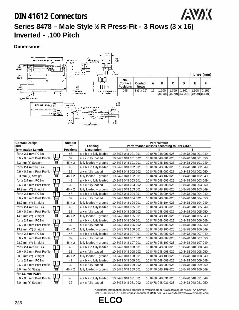
ELCOELCO236
Additional information on this product is available from AVX’s catalog or AVX’s FAX Service.Call 1-800-879-1613 and request document #236. Visit our website http://www.avxcorp.com
DIN 41612 ConnectorsSeries 8478 – Male Style 1⁄2 R Press-Fit - 3 Rows (3 x 16)Inverted - .100 Pitch
No. Contact Contact A B C D E F
Positions Rows048 3 (3 x 16) 15 1.500 1.760 1.862 1.968 2.162
(38.10) (44.70) (47.29) (49.99) (54.91)
Inches (mm)
Dimensions
Contact Design Number Part Numberand of Loading Performance classes according to DIN 41612Termination Length Positions Description III II Ifor ≥ 2.4 mm PCB’s 48 a + b + c fully loaded 10 8478 048 001 001 10 8478 048 001 025 10 8478 048 001 0490.6 x 0.6 mm Post Profile 32 a + c fully loaded 10 8478 048 001 002 10 8478 048 001 026 10 8478 048 001 0505.3 mm (Y) Straight 46 + 2 fully loaded + ground 10 8478 048 101 001 10 8478 048 101 025 10 8478 048 101 049for ≥ 2.4 mm PCB’s 48 a + b + c fully loaded 10 8478 048 002 001 10 8478 048 002 025 10 8478 048 002 0490.6 x 0.6 mm Post Profile 32 a + c fully loaded 10 8478 048 002 002 10 8478 048 002 026 10 8478 048 002 0509.3 mm (Y) Straight 46 + 2 fully loaded + ground 10 8478 048 102 001 10 8478 048 102 025 10 8478 048 102 049for ≥ 2.4 mm PCB’s 48 a + b + c fully loaded 10 8478 048 003 001 10 8478 048 003 025 10 8478 048 003 0490.6 x 0.6 mm Post Profile 32 a + c fully loaded 10 8478 048 003 002 10 8478 048 003 026 10 8478 048 003 05016.2 mm (Y) Straight 46 + 2 fully loaded + ground 10 8478 048 103 001 10 8478 048 103 025 10 8478 048 103 049for ≥ 2.4 mm PCB’s 48 a + b + c fully loaded 10 8478 048 004 001 10 8478 048 004 025 10 8478 048 004 0490.6 x 0.6 mm Post Profile 32 a + c fully loaded 10 8478 048 004 002 10 8478 048 004 026 10 8478 048 004 05018.2 mm (Y) Straight 46 + 2 fully loaded + ground 10 8478 048 104 001 10 8478 048 104 025 10 8478 048 104 049for ≥ 2.4 mm PCB’s 48 a + b + c fully loaded 10 8478 048 005 001 10 8478 048 005 025 10 8478 048 005 0490.6 x 0.6 mm Post Profile 32 a + c fully loaded 10 8478 048 005 002 10 8478 048 005 026 10 8478 048 005 05014.6 mm (Y) Straight 46 + 2 fully loaded + ground 10 8478 048 105 001 10 8478 048 105 025 10 8478 048 105 049for ≥ 2.4 mm PCB’s 48 a + b + c fully loaded 10 8478 048 006 001 10 8478 048 006 025 10 8478 048 006 0490.6 x 0.6 mm Post Profile 32 a + c fully loaded 10 8478 048 006 002 10 8478 048 006 026 10 8478 048 006 05013.2 mm (Y) Straight 46 + 2 fully loaded + ground 10 8478 048 106 001 10 8478 048 106 025 10 8478 048 106 049for ≥ 2.4 mm PCB’s 48 a + b + c fully loaded 10 8478 048 007 001 10 8478 048 007 026 10 8478 048 007 0490.6 x 0.6 mm Post Profile 32 a + c fully loaded 10 8478 048 007 002 10 8478 048 007 026 10 8478 048 007 05023.2 mm (Y) Straight 46 + 2 fully loaded + ground 10 8478 048 107 001 10 8478 048 107 025 10 8478 048 107 049for ≥ 2.4 mm PCB’s 48 a + b + c fully loaded 10 8478 048 008 001 10 8478 048 008 025 10 8478 048 008 0490.6 x 0.6 mm Post Profile 32 a + c fully loaded 10 8478 048 008 002 10 8478 048 008 026 10 8478 048 008 05020.0 mm (Y) Straight 46 + 2 fully loaded + ground 10 8478 048 108 001 10 8478 048 108 025 10 8478 048 108 049for ≥ 2.4 mm PCB’s 48 a + b + c fully loaded 10 8478 048 009 001 10 8478 048 009 025 10 8478 048 009 0490.6 x 0.6 mm Post Profile 32 a + c fully loaded 10 8478 048 009 002 10 8478 048 009 026 10 8478 048 009 0503.9 mm (Y) Straight 46 + 2 fully loaded + ground 10 8478 048 109 001 10 8478 048 109 025 10 8478 048 109 049for 1.6 mm PCB’s0.6 x 0.6 mm Post Profile 48 a + b + c fully loaded 10 8478 048 031 001 10 8478 048 031 025 10 8478 048 031 0493.0 mm (Y) Straight 32 a + c fully loaded 10 8478 048 031 002 10 8478 048 031 026 10 8478 048 031 050

ELCOELCO 237
Additional information on this product is available from AVX’s catalog or AVX’s FAX Service.Call 1-800-879-1613 and request document #237. Visit our website http://www.avxcorp.com
DIN 41612 ConnectorsSeries 8478 – Female Style 1⁄2 R Press-Fit - 3 Rows (3 x 16)Inverted - .100 Pitch
Dimensions
No. Contact ContactPositions Rows A B C D E
048 3 (3 x 16) 31 1.500 2.122 1.900 1.744(38.10) (53.90) (48.26) (44.30)
Inches (mm)
Contact Design Number Part Numberand of Loading Performance classes according to DIN 41612Termination Length Positions Description III II Ifor ≥ 2.4 mm PCB’s0.6 x 0.6 mm Post Profile 48 a + b + c fully loaded 20 8478 048 001 001 20 8478 048 001 025 20 8478 048 001 0495.3 mm (Y) Right Angled 32 a + c fully loaded 20 8478 048 001 002 20 8478 048 001 026 20 8478 048 001 050for 1.6 mm PCB’s0.6 x 0.6 mm Post Profile 48 a + b + c fully loaded 20 8478 048 031 001 20 8478 048 031 025 20 8478 048 031 0492.9 mm (Y) Right Angled 32 a + c fully loaded 20 8478 048 031 002 20 8478 048 031 026 20 8478 048 031 050

ELCOELCO238
Additional information on this product is available from AVX’s catalog or AVX’s FAX Service.Call 1-800-879-1613 and request document #238. Visit our website http://www.avxcorp.com
DIN 41612 ConnectorsSeries 8478 – Male Style R Press-Fit - 3 Rows (3 x 32)Inverted - .100 Pitch
No. Contact Contact A B C D E F
Positions Rows096 3 (3 x 32) 31 3.100 3.358 3.461 3.543 3.736
(78.74) (85.29) (87.91) (89.99) (94.89)
Inches (mm)
Dimensions
Contact Design Number Part Numberand of Loading Performance classes according to DIN 41612Termination Length Positions Description III II Ifor ≥ 2.4 mm PCB’s 96 a + b + c fully loaded 10 8478 096 001 001 10 8478 096 001 025 10 8478 096 001 0490.6 x 0.6 mm Post Profile 64 a + c fully loaded 10 8478 096 001 002 10 8478 096 001 026 10 8478 096 001 0505.3 mm (Y) Straight 94 + 2 fully loaded + ground 10 8478 096 101 001 10 8478 096 101 025 10 8478 096 101 049for ≥ 2.4 mm PCB’s 96 a + b + c fully loaded 10 8478 096 002 001 10 8478 096 002 025 10 8478 096 002 0490.6 x 0.6 mm Post Profile 64 a + c fully loaded 10 8478 096 002 002 10 8478 096 002 026 10 8478 096 002 0509.3 mm (Y) Straight 94 + 2 fully loaded + ground 10 8478 096 102 001 10 8478 096 102 025 10 8478 096 102 049for ≥ 2.4 mm PCB’s 96 a + b + c fully loaded 10 8478 096 003 001 10 8478 096 003 025 10 8478 096 003 0490.6 x 0.6 mm Post Profile 64 a + c fully loaded 10 8478 096 003 002 10 8478 096 003 026 10 8478 096 003 05016.2 mm (Y) Straight 94 + 2 fully loaded + ground 10 8478 096 103 001 10 8478 096 103 025 10 8478 096 103 049for ≥ 2.4 mm PCB’s 96 a + b + c fully loaded 10 8478 096 004 001 10 8478 096 004 025 10 8478 096 004 0490.6 x 0.6 mm Post Profile 64 a + c fully loaded 10 8478 096 004 002 10 8478 096 004 026 10 8478 096 004 05018.2 mm (Y) Straight 94 + 2 fully loaded + ground 10 8478 096 104 001 10 8478 096 104 025 10 8478 096 104 049for ≥ 2.4 mm PCB’s 96 a + b + c fully loaded 10 8478 096 005 001 10 8478 096 005 025 10 8478 096 005 0490.6 x 0.6 mm Post Profile 64 a + c fully loaded 10 8478 096 005 002 10 8478 096 005 026 10 8478 096 005 05014.6 mm (Y) Straight 94 + 2 fully loaded + ground 10 8478 096 105 001 10 8478 096 105 025 10 8478 096 105 049for ≥ 2.4 mm PCB’s 96 a + b + c fully loaded 10 8478 096 006 001 10 8478 096 006 025 10 8478 096 006 0490.6 x 0.6 mm Post Profile 64 a + c fully loaded 10 8478 096 006 002 10 8478 096 006 026 10 8478 096 006 05013.2 mm (Y) Straight 94 + 2 fully loaded + ground 10 8478 096 106 001 10 8478 096 106 025 10 8478 096 106 049for ≥ 2.4 mm PCB’s 96 a + b + c fully loaded 10 8478 096 007 001 10 8478 096 007 026 10 8478 096 007 0490.6 x 0.6 mm Post Profile 64 a + c fully loaded 10 8478 096 007 002 10 8478 096 007 026 10 8478 096 007 05023.2 mm (Y) Straight 94 + 2 fully loaded + ground 10 8478 096 107 001 10 8478 096 107 025 10 8478 096 107 049for ≥ 2.4 mm PCB’s 96 a + b + c fully loaded 10 8478 096 008 001 10 8478 096 008 025 10 8478 096 008 0490.6 x 0.6 mm Post Profile 64 a + c fully loaded 10 8478 096 008 002 10 8478 096 008 026 10 8478 096 008 05020.0 mm (Y) Straight 94 + 2 fully loaded + ground 10 8478 096 108 001 10 8478 096 108 025 10 8478 096 108 049for ≥ 2.4 mm PCB’s 96 a + b + c fully loaded 10 8478 096 009 001 10 8478 096 009 025 10 8478 096 009 0490.6 x 0.6 mm Post Profile 64 a + c fully loaded 10 8478 096 009 002 10 8478 096 009 026 10 8478 096 009 0503.9 mm (Y) Straight 94 + 2 fully loaded + ground 10 8478 096 109 001 10 8478 096 109 025 10 8478 096 109 049for 1.6 mm PCB’s0.6 x 0.6 Post Profile 96 a + b + c fully loaded 10 8478 096 031 001 10 8478 096 031 025 10 8478 096 031 0493.0 mm (Y) Straight 64 a + c fully loaded 10 8478 096 031 002 10 8478 096 031 026 10 8478 096 031 050
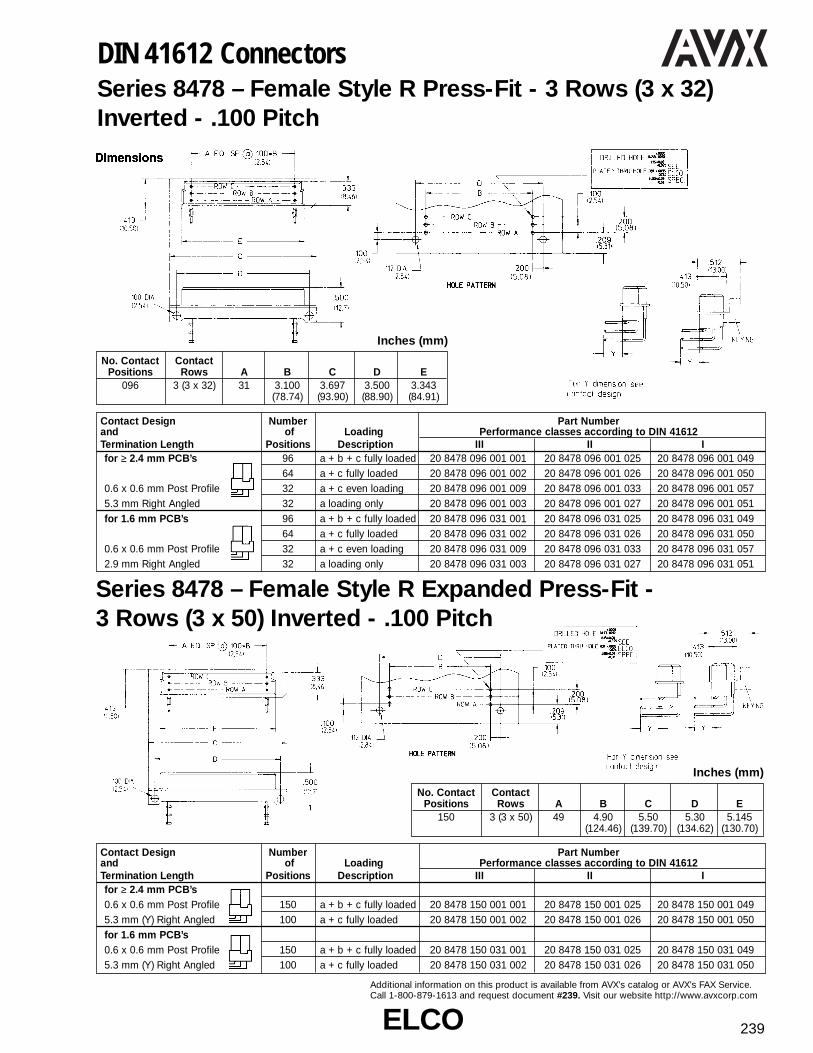
ELCOELCO 239
Additional information on this product is available from AVX’s catalog or AVX’s FAX Service.Call 1-800-879-1613 and request document #239. Visit our website http://www.avxcorp.com
DIN 41612 ConnectorsSeries 8478 – Female Style R Press-Fit - 3 Rows (3 x 32)Inverted - .100 Pitch
Series 8478 – Female Style R Expanded Press-Fit - 3 Rows (3 x 50) Inverted - .100 Pitch
No. Contact ContactPositions Rows A B C D E
150 3 (3 x 50) 49 4.90 5.50 5.30 5.145(124.46) (139.70) (134.62) (130.70)
Inches (mm)
No. Contact ContactPositions Rows A B C D E
096 3 (3 x 32) 31 3.100 3.697 3.500 3.343(78.74) (93.90) (88.90) (84.91)
Inches (mm)
Contact Design Number Part Numberand of Loading Performance classes according to DIN 41612Termination Length Positions Description III II Ifor ≥ 2.4 mm PCB’s0.6 x 0.6 mm Post Profile 150 a + b + c fully loaded 20 8478 150 001 001 20 8478 150 001 025 20 8478 150 001 0495.3 mm (Y) Right Angled 100 a + c fully loaded 20 8478 150 001 002 20 8478 150 001 026 20 8478 150 001 050for 1.6 mm PCB’s0.6 x 0.6 mm Post Profile 150 a + b + c fully loaded 20 8478 150 031 001 20 8478 150 031 025 20 8478 150 031 0495.3 mm (Y) Right Angled 100 a + c fully loaded 20 8478 150 031 002 20 8478 150 031 026 20 8478 150 031 050
Contact Design Number Part Numberand of Loading Performance classes according to DIN 41612Termination Length Positions Description III II Ifor ≥ 2.4 mm PCB’s 96 a + b + c fully loaded 20 8478 096 001 001 20 8478 096 001 025 20 8478 096 001 049
64 a + c fully loaded 20 8478 096 001 002 20 8478 096 001 026 20 8478 096 001 0500.6 x 0.6 mm Post Profile 32 a + c even loading 20 8478 096 001 009 20 8478 096 001 033 20 8478 096 001 0575.3 mm Right Angled 32 a loading only 20 8478 096 001 003 20 8478 096 001 027 20 8478 096 001 051for 1.6 mm PCB’s 96 a + b + c fully loaded 20 8478 096 031 001 20 8478 096 031 025 20 8478 096 031 049
64 a + c fully loaded 20 8478 096 031 002 20 8478 096 031 026 20 8478 096 031 0500.6 x 0.6 mm Post Profile 32 a + c even loading 20 8478 096 031 009 20 8478 096 031 033 20 8478 096 031 0572.9 mm Right Angled 32 a loading only 20 8478 096 031 003 20 8478 096 031 027 20 8478 096 031 051
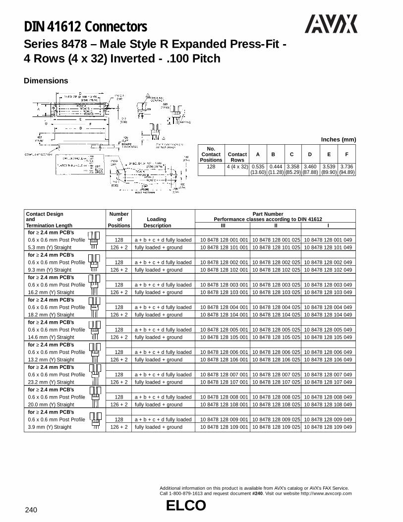
ELCOELCO240
Additional information on this product is available from AVX’s catalog or AVX’s FAX Service.Call 1-800-879-1613 and request document #240. Visit our website http://www.avxcorp.com
DIN 41612 ConnectorsSeries 8478 – Male Style R Expanded Press-Fit - 4 Rows (4 x 32) Inverted - .100 Pitch
Dimensions
No. Contact Contact A B C D E F
Positions Rows128 4 (4 x 32) 0.535 0.444 3.358 3.460 3.539 3.736
(13.60) (11.28) (85.29) (87.88) (89.90) (94.89)
Inches (mm)
Contact Design Number Part Numberand of Loading Performance classes according to DIN 41612Termination Length Positions Description III II Ifor ≥ 2.4 mm PCB’s0.6 x 0.6 mm Post Profile 128 a + b + c + d fully loaded 10 8478 128 001 001 10 8478 128 001 025 10 8478 128 001 0495.3 mm (Y) Straight 126 + 2 fully loaded + ground 10 8478 128 101 001 10 8478 128 101 025 10 8478 128 101 049for ≥ 2.4 mm PCB’s0.6 x 0.6 mm Post Profile 128 a + b + c + d fully loaded 10 8478 128 002 001 10 8478 128 002 025 10 8478 128 002 0499.3 mm (Y) Straight 126 + 2 fully loaded + ground 10 8478 128 102 001 10 8478 128 102 025 10 8478 128 102 049for ≥ 2.4 mm PCB’s0.6 x 0.6 mm Post Profile 128 a + b + c + d fully loaded 10 8478 128 003 001 10 8478 128 003 025 10 8478 128 003 04916.2 mm (Y) Straight 126 + 2 fully loaded + ground 10 8478 128 103 001 10 8478 128 103 025 10 8478 128 103 049for ≥ 2.4 mm PCB’s0.6 x 0.6 mm Post Profile 128 a + b + c + d fully loaded 10 8478 128 004 001 10 8478 128 004 025 10 8478 128 004 04918.2 mm (Y) Straight 126 + 2 fully loaded + ground 10 8478 128 104 001 10 8478 128 104 025 10 8478 128 104 049for ≥ 2.4 mm PCB’s0.6 x 0.6 mm Post Profile 128 a + b + c + d fully loaded 10 8478 128 005 001 10 8478 128 005 025 10 8478 128 005 04914.6 mm (Y) Straight 126 + 2 fully loaded + ground 10 8478 128 105 001 10 8478 128 105 025 10 8478 128 105 049for ≥ 2.4 mm PCB’s0.6 x 0.6 mm Post Profile 128 a + b + c + d fully loaded 10 8478 128 006 001 10 8478 128 006 025 10 8478 128 006 04913.2 mm (Y) Straight 126 + 2 fully loaded + ground 10 8478 128 106 001 10 8478 128 106 025 10 8478 128 106 049for ≥ 2.4 mm PCB’s0.6 x 0.6 mm Post Profile 128 a + b + c + d fully loaded 10 8478 128 007 001 10 8478 128 007 025 10 8478 128 007 04923.2 mm (Y) Straight 126 + 2 fully loaded + ground 10 8478 128 107 001 10 8478 128 107 025 10 8478 128 107 049for ≥ 2.4 mm PCB’s0.6 x 0.6 mm Post Profile 128 a + b + c + d fully loaded 10 8478 128 008 001 10 8478 128 008 025 10 8478 128 008 04920.0 mm (Y) Straight 126 + 2 fully loaded + ground 10 8478 128 108 001 10 8478 128 108 025 10 8478 128 108 049for ≥ 2.4 mm PCB’s0.6 x 0.6 mm Post Profile 128 a + b + c + d fully loaded 10 8478 128 009 001 10 8478 128 009 025 10 8478 128 009 0493.9 mm (Y) Straight 126 + 2 fully loaded + ground 10 8478 128 109 001 10 8478 128 109 025 10 8478 128 109 049

ELCOELCO 241
Additional information on this product is available from AVX’s catalog or AVX’s FAX Service.Call 1-800-879-1613 and request document #241. Visit our website http://www.avxcorp.com
DIN 41612 ConnectorsSeries 8478 – Female Style R Expanded Press-Fit - 4 Rows (4 x 32) Inverted - .100 Pitch
Dimensions
No. Contact ContactPositions Rows A B C D E
128 4 (4 x 32) 31 3.100 3.697 3.500 3.343(78.74) (93.90) (88.90) (84.91)
Inches (mm)
Contact Design Number Part Numberand of Loading Performance classes according to DIN 41612Termination Length Positions Description III II Ifor ≥ 2.4 mm PCB’s0.6 x 0.6 mm Post Profile 128 a + b + c + d fully loaded 20 8478 128 001 001 20 8478 128 001 025 20 8478 128 001 0495.3 mm (Y) Right Angledfor 1.6 mm PCB’s0.6 x 0.6 mm Post Profile 128 a + b + c + d fully loaded 20 8478 128 031 001 20 8478 128 031 025 20 8478 128 031 0495.3 mm (Y) Right Angled

ELCOELCO242
Additional information on this product is available from AVX’s catalog or AVX’s FAX Service.Call 1-800-879-1613 and request document #242. Visit our website http://www.avxcorp.com
DIN 41612 ConnectorsSeries 8478 – Male Style R Expanded Press-Fit - 5 Rows (5 x 32) Inverted - .100 Pitch
Dimensions
No. Contact Contact A B C D E F
Positions Rows160 5 (5 x 32) 0.638 0.543 3.358 3.460 3.539 3.736
(16.20) (13.80) (85.29) (87.88) (89.90) (94.89)
Inches (mm)
Contact Design Number Part Numberand of Loading Performance classes according to DIN 41612Termination Length Positions Description III II Ifor ≥ 2.4 mm PCB’s0.6 x 0.6 mm Post Profile 160 a + b + c + d + e fully loaded 10 8478 160 001 001 10 8478 160 001 025 10 8478 160 001 0495.3 mm (Y) Straight 158 + 2 fully loaded + ground 10 8478 160 101 001 10 8478 160 101 025 10 8478 160 101 049for ≥ 2.4 mm PCB’s0.6 x 0.6 mm Post Profile 160 a + b + c + d + e fully loaded 10 8478 160 002 001 10 8478 160 002 025 10 8478 160 002 0499.3 mm (Y) Straight 158 + 2 fully loaded + ground 10 8478 160 102 001 10 8478 160 102 025 10 8478 160 102 049for ≥ 2.4 mm PCB’s0.6 x 0.6 mm Post Profile 160 a + b + c + d + e fully loaded 10 8478 160 003 001 10 8478 160 003 025 10 8478 160 003 04916.2 mm (Y) Straight 158 + 2 fully loaded + ground 10 8478 160 103 001 10 8478 160 103 025 10 8478 160 103 049for ≥ 2.4 mm PCB’s0.6 x 0.6 mm Post Profile 160 a + b + c + d + e fully loaded 10 8478 160 004 001 10 8478 160 004 025 10 8478 160 004 04918.2 mm (Y) Straight 158 + 2 fully loaded + ground 10 8478 160 104 001 10 8478 160 104 025 10 8478 160 104 049for ≥ 2.4 mm PCB’s0.6 x 0.6 mm Post Profile 160 a + b + c + d + e fully loaded 10 8478 160 005 001 10 8478 160 005 025 10 8478 160 005 04914.6 mm (Y) Straight 158 + 2 fully loaded + ground 10 8478 160 105 001 10 8478 160 105 025 10 8478 160 105 049for ≥ 2.4 mm PCB’s0.6 x 0.6 mm Post Profile 160 a + b + c + d + e fully loaded 10 8478 160 006 001 10 8478 160 006 025 10 8478 160 006 04913.2 mm (Y) Straight 158 + 2 fully loaded + ground 10 8478 160 106 001 10 8478 160 106 025 10 8478 160 106 049for ≥ 2.4 mm PCB’s0.6 x 0.6 mm Post Profile 160 a + b + c + d + e fully loaded 10 8478 160 007 001 10 8478 160 007 025 10 8478 160 007 04923.2 mm (Y) Straight 158 + 2 fully loaded + ground 10 8478 160 107 001 10 8478 160 107 025 10 8478 160 107 049for ≥ 2.4 mm PCB’s0.6 x 0.6 mm Post Profile 160 a + b + c + d + e fully loaded 10 8478 160 008 001 10 8478 160 008 025 10 8478 160 008 04920.0 mm (Y) Straight 158 + 2 fully loaded + ground 10 8478 160 108 001 10 8478 160 108 025 10 8478 160 108 049for ≥ 2.4 mm PCB’s0.6 x 0.6 mm Post Profile 160 a + b + c + d + e fully loaded 10 8478 160 009 001 10 8478 160 009 025 10 8478 160 009 0493.9 mm (Y) Straight 158 + 2 fully loaded + ground 10 8478 160 109 001 10 8478 160 109 025 10 8478 160 109 049

ELCOELCO 243
Additional information on this product is available from AVX’s catalog or AVX’s FAX Service.Call 1-800-879-1613 and request document #243. Visit our website http://www.avxcorp.com
DIN 41612 ConnectorsSeries 8478 – Female Style R Expanded Press-Fit - 5 Rows (5 x 32) Inverted - .100 Pitch
Dimensions
No. Contact ContactPositions Rows A B C D E
160 5 (5 x 32) 31 3.100 3.700 3.500 3.346(78.74) (94.00) (88.90) (85.00)
Inches (mm)
Contact Design Number Part Numberand of Loading Performance classes according to DIN 41612Termination Length Positions Description III II Ifor ≥ 2.4 mm PCB’s0.6 x 0.6 mm Post Profile 160 a + b + c + d + e fully loaded 20 8478 160 001 001 20 8478 160 001 025 20 8478 160 001 0495.3 mm (Y) Right Angledfor 1.6 mm PCB’s0.6 x 0.6 mm Post Profile 160 a + b + c + d + e fully loaded 20 8478 160 031 001 20 8478 160 031 025 20 8478 160 031 0492.9 mm (Y) Right Angled

ELCOELCO244
Additional information on this product is available from AVX’s catalog or AVX’s FAX Service. Call 1-800-879-1613 and request document #244. Visit our website http://www.avxcorp.com
DIN 41612 ConnectorsSeries 8557 – Male Style 1⁄2 C High Temperature - 3 Rows (3 x 16) - .100 Pitch
Series 8557 – Female Style 1⁄2 C High Temperature - 3 Rows (3 x 16) - .100 Pitch
Dimensions
No.Contact Contact A B C D E
Positions Rows048 3 (3 x 16) 15 1.500 1.760 1.900 2.122
(38.10) (44.70) (48.26) (53.90)
Inches (mm)
Contact Design Number Part Numberand of Loading Performance classes according to DIN 41612Termination Length Positions Description III II I
48 a + b + c fully loaded 10 8557 048 001 001 10 8557 048 001 025 10 8557 048 001 0493.4 mm (Y) 32 a + c fully loaded 10 8557 048 001 002 10 8557 048 001 026 10 8557 048 001 050Straight 16 a loading only 10 8557 048 001 003 10 8557 048 001 027 10 8557 048 001 051
48 a + b + c fully loaded 10 8557 048 002 001 10 8557 048 002 025 10 8557 048 002 04932 a + c fully loaded 10 8557 048 002 002 10 8557 048 002 026 10 8557 048 002 050
3.0 mm (Y) 16 a loading only 10 8557 048 002 003 10 8557 048 002 027 10 8557 048 002 051Right Angled 46 + 2 fully loaded + ground 10 8557 048 102 001 10 8557 048 102 025 10 8557 048 102 049
48 a + b + c fully loaded 10 8557 048 008 001 10 8557 048 008 025 10 8557 048 008 0492.3 mm (Y) 32 a + c fully loaded 10 8557 048 008 002 10 8557 048 008 026 10 8557 048 008 050Right Angled 16 a loading only 10 8557 048 008 003 10 8557 048 008 027 10 8557 048 008 051
Dimensions
No.Contact Contact A B C D E
Positions Rows048 3 (3 x 16) 15 1.500 1.969 2.161 1.744
(38.10) (50.01) (54.89) (44.30)
Inches (mm)
Contact Design Number Part Numberand of Loading Performance classes according to DIN 41612Termination Length Positions Description III II I
48 a + b + c fully loaded 20 8557 048 001 001 20 8557 048 001 025 20 8557 048 001 0490.6 x 0.6 mm Post Profile 32 a + c fully loaded 20 8557 048 001 002 20 8557 048 001 026 20 8557 048 001 0504.5 mm (Y) Straight 16 a loading only 20 8557 048 001 003 20 8557 048 001 027 20 8557 048 001 051
48 a + b + c fully loaded 20 8557 048 002 001 20 8557 048 002 025 20 8557 048 002 0490.6 x 0.6 mm Post Profile 32 a + c fully loaded 20 8557 048 002 002 20 8557 048 002 026 20 8557 048 002 0502.9 mm (Y) Straight 16 a loading only 20 8557 048 002 003 20 8557 048 002 027 20 8557 048 002 051

ELCOELCO 245
Additional information on this product is available from AVX’s catalog or AVX’s FAX Service. Call 1-800-879-1613 and request document #245. Visit our website http://www.avxcorp.com
DIN 41612 ConnectorsSeries 8557 – Male Style C High Temperature - 3 Rows (3 x 32) - .100 Pitch
Series 8557 – Female Style C High Temperature - 3 Rows (3 x 32) - .100 Pitch
Dimensions
No.Contact Contact A B C D E
Positions Rows096 3 (3 x 32) 31 3.100 3.358 3.500 3.697
(78.74) (85.29) (88.90) (93.90)
Inches (mm)
Contact Design Number Part Numberand of Loading Performance classes according to DIN 41612Termination Length Positions Description III II I
96 a + b + c fully loaded 10 8557 096 001 001 10 8557 096 001 025 10 8557 096 001 04964 a + c fully loaded 10 8557 096 001 002 10 8557 096 001 026 10 8557 096 001 050
3.4 mm (Y) 32 a + c even loading 10 8557 096 001 009 10 8557 096 001 033 10 8557 096 001 057Straight 32 a loading only 10 8557 096 001 003 10 8557 096 001 027 10 8557 096 001 051
96 a + b + c fully loaded 10 8557 096 002 001 10 8557 096 002 025 10 8557 096 002 04964 a + c fully loaded 10 8557 096 002 002 10 8557 096 002 026 10 8557 096 002 05032 a + c even loading 10 8557 096 002 009 10 8557 096 002 033 10 8557 096 002 057
3.0 mm (Y) 32 a loading only 10 8557 096 002 003 10 8557 096 002 027 10 8557 096 002 051Right Angled 94 + 2 fully loaded + ground 10 8557 096 101 001 10 8557 096 101 025 10 8557 096 101 049
96 a + b + c fully loaded 10 8557 096 008 001 10 8557 096 008 025 10 8557 096 008 04964 a + c fully loaded 10 8557 096 008 002 10 8557 096 008 026 10 8557 096 008 050
2.3 mm (Y) 32 a + c even loading 10 8557 096 008 009 10 8557 096 008 033 10 8557 096 008 057Right Angled 32 a loading only 10 8557 096 008 003 10 8557 096 008 027 10 8557 096 008 051
Dimensions
No.Contact Contact A B C D E
Positions Rows096 3 (3 x 32) 31 3.100 3.543 3.736 3.343
(78.74) (89.99) (94.89) (84.91)
Inches (mm)
Contact Design Number Part Numberand of Loading Performance classes according to DIN 41612Termination Length Positions Description III II I
96 a + b + c fully loaded 20 8557 096 001 001 20 8557 096 001 025 20 8557 096 001 04964 a + c fully loaded 20 8557 096 001 002 20 8557 096 001 026 20 8557 096 001 050
0.3 x 0.79 mm Post Profile 32 a + c even loading 20 8557 096 001 009 20 8557 096 001 033 20 8557 096 001 0574.5 mm (Y) Straight 32 a loading only 20 8557 096 001 003 20 8557 096 001 027 20 8557 096 001 051
96 a + b + c fully loaded 20 8557 096 002 001 20 8557 096 002 025 20 8557 096 002 04964 a + c fully loaded 20 8557 096 002 002 20 8557 096 002 026 20 8557 096 002 050
0.3 x 0.79 mm Post Profile 32 a + c even loading 20 8557 096 002 009 20 8557 096 002 033 20 8557 096 002 0572.9 mm (Y) Straight 32 a loading only 20 8557 096 002 003 20 8557 096 002 027 20 8557 096 002 051

ELCOELCO246
Additional information on this product is available from AVX’s catalog or AVX’s FAX Service. Call 1-800-879-1613 and request document #246. Visit our website http://www.avxcorp.com
DIN 41612 ConnectorsSeries 8577 – Male Style 1⁄2 R High Temperature - 3 Rows (3 x 16) Inverted - .100 Pitch
Series 8577 – Female Style 1⁄2 R High Temperature - 3 Rows (3 x 16) Inverted - .100 Pitch
Dimensions
No. Contact ContactPositions Rows A B C D E F
048 3 (3 x 16) 15 1.500 1.760 1.862 1.968 2.162(38.10) (44.70) (47.29) (49.99) (54.91)
Inches (mm)
Contact Design Number Part Numberand of Loading Performance classes according to DIN 41612Termination Length Positions Description III II I
48 a + b + c fully loaded 10 8577 048 001 001 10 8577 048 001 025 10 8577 048 001 04932 a + c fully loaded 10 8577 048 001 002 10 8577 048 001 026 10 8577 048 001 05016 a + c even loading 10 8577 048 001 009 10 8577 048 001 033 10 8577 048 001 057
2.9 mm (Y) 16 a loading only 10 8577 048 001 003 10 8577 048 001 027 10 8577 048 001 051Straight 46 + 2 fully loaded + ground 10 9577 048 101 001 10 8577 048 101 025 10 8577 048 101 049
48 a + b + c fully loaded 10 8577 048 002 001 10 8577 048 002 025 10 8577 048 002 04932 a + c fully loaded 10 8577 048 002 002 10 8577 048 002 026 10 8577 048 002 05016 a + c even loading 10 8577 048 002 009 10 8577 048 002 033 10 8577 048 002 057
4.5 mm (Y) 16 a loading only 10 8577 048 002 003 10 8577 048 002 027 10 8577 048 002 051Straight 46 + 2 fully loaded + ground 10 8577 048 102 001 10 8577 048 102 025 10 8577 048 102 049
No. Contact ContactPositions Rows A B C D E F G
048 3 (3 x 16) 15 1.500 2.122 1.900 1.744 0.334 0.413(38.10) (53.90) (48.26) (44.30) (8.48) (10.50)
Inches (mm)
Contact Design Number Part Numberand of Loading Performance classes according to DIN 41612Termination Length Positions Description III II I
48 a + b + c fully loaded 20 8577 048 002 001 20 8577 048 002 025 20 8577 048 002 04932 a + c fully loaded 20 8577 048 002 002 20 8577 048 002 026 20 8577 048 002 050
0.6 x 0.6 mm Post Profile 16 a + c even loading 20 8577 048 002 009 20 8577 048 002 033 20 8577 048 002 0573.0 mm (Y) Right Angled 16 a loading only 20 8577 048 002 003 20 8577 048 002 027 20 8577 048 002 051
48 a + b + c fully loaded 20 8577 048 006 001 20 8577 048 006 025 20 8577 048 006 04932 a + c fully loaded 20 8577 048 006 002 20 8577 048 006 026 20 8577 048 006 050
0.3 x 0.79 mm Post Profile 16 a + c even loading 20 8577 048 006 009 20 8577 048 006 033 20 8577 048 006 0573.0 mm (Y) Right Angled 16 a loading only 20 8577 048 006 003 20 8577 048 006 027 20 8577 048 006 051

ELCOELCO 247
Additional information on this product is available from AVX’s catalog or AVX’s FAX Service.Call 1-800-879-1613 and request document #247. Visit our website http://www.avxcorp.com
DIN 41612 ConnectorsSeries 8577 – Male Style R High Temperature - 3 Rows (3 x 32) Inverted - .100 Pitch
Series 8577 – Female Style R High Temperature - 3 Rows (3 x 32) Inverted - .100 Pitch
Dimensions
Dimensions
No. Contact ContactPositions Rows A B C D E F
096 3 (3 x 32) 31 3.100 3.358 3.461 3.543 3.736(78.74) (85.29) (87.91) (89.99) (94.89)
Inches (mm)
Contact Design Number Part Numberand of Loading Performance classes according to DIN 41612Termination Length Positions Description III II I
96 a + b + c fully loaded 10 8577 096 001 001 10 8577 096 001 025 10 8577 096 001 04964 a + c fully loaded 10 8577 096 001 002 10 8577 096 001 026 10 8577 096 001 05032 a + c even loading 10 8577 096 001 009 10 8577 096 001 033 10 8577 096 001 057
2.9 mm (Y) 32 a loading only 10 8577 096 001 003 10 8577 096 001 027 10 8577 096 001 051Straight 46 + 2 fully loaded + ground 10 9577 096 101 001 10 8577 096 101 025 10 8577 096 101 049
48 a + b + c fully loaded 10 8577 096 002 001 10 8577 096 002 025 10 8577 096 002 04932 a + c fully loaded 10 8577 096 002 002 10 8577 096 002 026 10 8577 096 002 05016 a + c even loading 10 8577 096 002 009 10 8577 096 002 033 10 8577 096 002 057
4.5 mm (Y) 16 a loading only 10 8577 096 002 003 10 8577 096 002 027 10 8577 096 002 051Straight 46 + 2 fully loaded + ground 10 8577 096 102 001 10 8577 096 102 025 10 8577 096 102 049
Contact Design Number Part Numberand of Loading Performance classes according to DIN 41612Termination Length Positions Description III II I
96 a + b + c fully loaded 20 8577 096 002 001 20 8577 096 002 025 20 8577 096 002 04964 a + c fully loaded 20 8577 096 002 002 20 8577 096 002 026 20 8577 096 002 050
0.6 x 0.6 mm Post Profile 32 a + c even loading 20 8577 096 002 009 20 8577 096 002 033 20 8577 096 002 0573.0 mm (Y) Right Angled 32 a loading only 20 8577 096 002 003 20 8577 096 002 027 20 8577 096 002 051
96 a + b + c fully loaded 20 8577 096 006 001 20 8577 096 006 025 20 8577 096 006 04964 a + c fully loaded 20 8577 096 006 002 20 8577 096 006 026 20 8577 096 006 050
0.3 x 0.79 mm Post Profile 32 a + c even loading 20 8577 096 006 009 20 8577 096 006 033 20 8577 096 006 0573.0 mm (Y) Right Angled 32 a loading only 20 8577 096 006 003 20 8577 096 006 027 20 8577 096 006 051
No. Contact ContactPositions Rows A B C D E F G
096 3 (3 x 32) 31 3.100 3.697 3.500 3.343 0.334 0.413(78.74) (93.90) (88.90) (84.90) (8.48) (10.50)
Inches (mm)

ELCOELCO248
Additional information on this product is available from AVX’s catalog or AVX’s FAX Service.Call 1-800-879-1613 and request document #248. Visit our website http://www.avxcorp.com
DIN 41612 ConnectorsSeries 8459 – Female Style 1⁄2 IDC - 3 Rows (3 x 16) - .100 Pitch
Series 8549 – Female Style C IDC - 3 Rows (3 x 32) - .100 Pitch
Dimensions
No. Contact ContactPositions Rows A B C D F G H
048 3 (3 x 16) 2.161 1.968 0.591 1.500 2.362 1.220 1.550(54.90) (50.00) (15.00) (38.10) (60.00) (31.00) (39.37)
Inches (mm)
Number of Part NumberContact Loading Performance classes according to DIN 41612
Variation Cavities Description III II IWith strain relief 48 a + c fully loaded 20 8459 048 001 002 20 8459 048 001 026 20 8459 048 001 050
Without strain relief 48 a + c fully loaded 20 8459 048 002 002 20 8459 048 002 026 20 8459 048 002 050
Dimensions
No. Contact ContactPositions Rows A B C D F G H
096 3 (3 x 32) 3.736 3.543 1.220 3.100 3.937 2.480 3.150(94.90) (90.00) (31.00) (78.74) (100.00) (63.00) (80.01)
Inches (mm)
Number of Part NumberContact Loading Performance classes according to DIN 41612
Variation Cavities Description III II I
With strain relief 96 a + c fully loaded 20 8459 096 001 002 20 8459 096 001 026 20 8459 096 001 050
Without strain relief 96 a + c fully loaded 20 8459 096 002 002 20 8459 096 002 026 20 8459 096 002 050

ELCOELCO 249
Additional information on this product is available from AVX’s catalog or AVX’s FAX Service.Call 1-800-879-1613 and request document #249. Visit our website http://www.avxcorp.com
DIN 41612 ConnectorsSeries 8577 – Female Style R Expanded High Temperature -4 Rows (4 x 32) Inverted - .100 Pitch
Series 8577 – Female Style R Expanded High Temperature -3 Rows (3 x 50) Inverted - .100 Pitch
Contact Design Number Part Numberand of Loading Performance classes according to DIN 41612Termination Length Positions Description III II I0.6 x 0.6 mm Post Profile3.0 mm (Y) Right Angled 128 a + b + c + d fully loaded 20 8577 128 002 001 20 8577 128 002 025 20 8577 128 002 049
0.6 x 0.6 mm Post Profile3.0 mm (Y) Right Angled 128 a + b + c + d fully loaded 20 8577 128 006 001 20 8577 128 006 025 20 8577 128 006 049
No. Contact ContactPositions Rows A B C D E F G
128 4 (4 x 32) 31 3.100 3.697 3.500 3.343 0.437 0.516(78.74) (93.90) (88.90) (84.90) (11.10) (13.10)
Contact Design Number Part Numberand of Loading Performance classes according to DIN 41612Termination Length Positions Description III II I
0.6 x 0.6 mm Post Profile 150 a + b + c fully loaded 20 8577 150 001 001 20 8577 150 001 025 20 8577 150 001 0492.8 mm (Y) Right Angled 100 a + c fully loaded 20 8577 150 001 002 20 8577 150 001 026 20 8577 150 001 050
No. Contact ContactPositions Rows A B C D E F
150 3 (3 x 50) 49 4.941 5.154 5.260 5.343 5.536(125.50) (130.90) (133.60) (135.70) (140.60)
Dimensions
Dimensions

ELCOELCO250
Additional information on this product is available from AVX’s catalog or AVX’s FAX Service.Call 1-800-879-1613 and request document #250. Visit our website http://www.avxcorp.com
DIN 41612 ConnectorsSeries 8464 – Female Style C Crimp - 3 Rows (3 x 32) - .100 Pitch
Number of Loading PartContact Design Positions Description NumberCrimp 96 Insulator without keying 20 8464 096 001 000
96 Insulator with keying 22 8464 096 001 000Contacts for 8464 on 10K reel 60 8464 0213 99 742Loose contacts for 8464 60 8464 0213 00 742
Tools Hand tool 06 8464 0101 00 000Crimping machine including applicator 06 7865 5200 00 000Insert for hand crimp tool 06 8464 8201 00 000Extraction tool 06 8464 8101 00 000
Dimensions
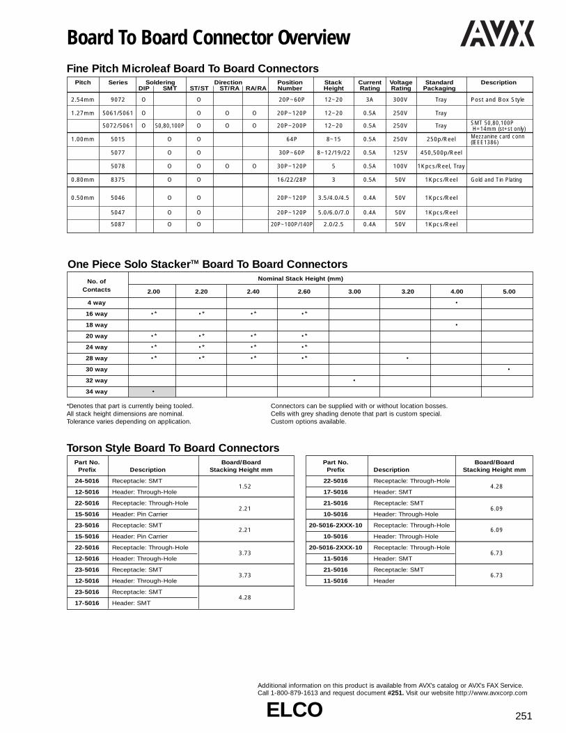
ELCOELCO 251
Additional information on this product is available from AVX’s catalog or AVX’s FAX Service.Call 1-800-879-1613 and request document #251. Visit our website http://www.avxcorp.com
Board To Board Connector OverviewFine Pitch Microleaf Board To Board Connectors
Pitch Series Soldering Direction Position Stack Current Voltage Standard DescriptionDIP SMT ST/ST ST/RA RA/RA Number Height Rating Rating Packaging
2.54mm 9072 O O 20P~60P 12~20 3A 300V Tray Post and Box Style
1.27mm 5061/5061 O O O O 20P~120P 12~20 0.5A 250V Tray
5072/5061 O 50,80,100P O O O 20P~200P 12~20 0.5A 250V Tray SMT 50,80,100PH=14mm (st+st only)
1.00mm 5015 O O 64P 8~15 0.5A 250V 250p/Reel Mezzanine card conn (IEEE1386)
5077 O O 30P~60P 8~12/19/22 0.5A 125V 450,500p/Reel
5078 O O O O 30P~120P 5 0.5A 100V 1Kpcs/Reel, Tray
0.80mm 8375 O O 16/22/28P 3 0.5A 50V 1Kpcs/Reel Gold and Tin Plating
0.50mm 5046 O O 20P~120P 3.5/4.0/4.5 0.4A 50V 1Kpcs/Reel
5047 O O 20P~120P 5.0/6.0/7.0 0.4A 50V 1Kpcs/Reel
5087 O O 20P~100P/140P 2.0/2.5 0.4A 50V 1Kpcs/Reel
*Denotes that part is currently being tooled.All stack height dimensions are nominal. Tolerance varies depending on application.
Connectors can be supplied with or without location bosses.Cells with grey shading denote that part is custom special.Custom options available.
One Piece Solo StackerTM Board To Board ConnectorsNo. of Nominal Stack Height (mm)
Contacts 2.00 2.20 2.40 2.60 3.00 3.20 4.00 5.00
4 way •
16 way •* •* •* •*
18 way •
20 way •* •* •* •*
24 way •* •* •* •*
28 way •* •* •* •* •
30 way •
32 way •
34 way •
Torson Style Board To Board ConnectorsPart No. Board/Board
Prefix Description Stacking Height mm
24-5016 Receptacle: SMT1.52
12-5016 Header: Through-Hole
22-5016 Receptacle: Through-Hole2.21
15-5016 Header: Pin Carrier
23-5016 Receptacle: SMT2.21
15-5016 Header: Pin Carrier
22-5016 Receptacle: Through-Hole3.73
12-5016 Header: Through-Hole
23-5016 Receptacle: SMT3.73
12-5016 Header: Through-Hole
23-5016 Receptacle: SMT4.28
17-5016 Header: SMT
Part No. Board/BoardPrefix Description Stacking Height mm
22-5016 Receptacle: Through-Hole4.28
17-5016 Header: SMT
21-5016 Receptacle: SMT6.09
10-5016 Header: Through-Hole
20-5016-2XXX-10 Receptacle: Through-Hole6.09
10-5016 Header: Through-Hole
20-5016-2XXX-10 Receptacle: Through-Hole6.73
11-5016 Header: SMT
21-5016 Receptacle: SMT6.73
11-5016 Header

ELCOELCO252
Additional information on this product is available from AVX’s catalog or AVX’s FAX Service.Call 1-800-879-1613 and request document #252. Visit our website http://www.avxcorp.com
Board Stacking Connectors 2.54mm PitchSeries 9072 Plug
Series 9072 Receptacle
00 9072 0XX XXX 8XXORDERING CODE
FINISHING CODE(Gold-Mating Area)
883 = Au 0.1µm Min.885 = Au 0.25µm Min.
VARIATION CODE301 = Height Between Boards
“D” 12.0mm (0.472")401 = Height Between Boards
“D” 15.0mm (0.591")501 = Height Between Boards
“D” 18.0mm (0.709")101 = Height Between Boards
“D” 20.0mm (0.787")
NUMBER OFPOSITIONS
20, 30, 40, 50, 60
00 9072 0XX 901 8XXORDERING CODE
FINISHING CODE(Gold-Mating Area)
883 = Au 0.1µm Min.885 = Au 0.25µm Min.NUMBER OF POSITIONS
20, 30, 40, 50, 60
No. ofA B CPositions
20 22.86 33.26 30.4630 35.56 45.96 43.1640 48.26 58.66 55.8650 60.96 71.36 68.5660 73.66 84.06 81.26
No. ofA B CPositions
20 22.86 25.86 30.4630 35.56 38.56 43.1640 48.26 51.26 55.8650 60.96 63.96 68.5660 73.66 76.66 81.26
See Ordering Code about “D”

ELCOELCO 253
Additional information on this product is available from AVX’s catalog or AVX’s FAX Service.Call 1-800-879-1613 and request document #253. Visit our website http://www.avxcorp.com
Microleaf Connectors 1.27mm PitchSeries 5061 Plug Straight (With Flange)
Series 5061 Receptacle Straight (With Flange)
ORDERING CODE10 5061 XXX 002 8XX
FINISH856 = Au 0.1µm861 = Au 0.25µm871 = Au 0.5µm
VARIATION
NO. OF POSITIONSSERIES (20, 30, 40, 50, 60,
PLUG 68, 80, 100, 120)
A = 1.27 (N⁄2 -1)
B = A +4.2
C = A +7.62
D = A +14.0
ORDERING CODE20 5061 XXX 052 8XX
FINISH856 = Au 0.1µm861 = Au 0.25µm871 = Au 0.5µm
VARIATION
NO. OF POSITIONSSERIES (20, 30, 40, 50, 60,
RECEPTACLE 68, 80, 100, 120)

ELCOELCO254
Additional information on this product is available from AVX’s catalog or AVX’s FAX Service.Call 1-800-879-1613 and request document #254. Visit our website http://www.avxcorp.com
Microleaf Connectors 1.27mm PitchSeries 5061 Plug Straight (Without Flange)
Series 5061 Receptacle Straight (Without Flange)
ORDERING CODE10 5061 XXX 000 8XX
FINISH856 = Au 0.1µm861 = Au 0.25µm871 = Au 0.5µm
VARIATION
NO. OF POSITIONSSERIES (20, 30, 40, 50, 60,
PLUG 68, 80, 100, 120)
ORDERING CODE20 5061 XXX 051 8XX
FINISH856 = Au 0.1µm861 = Au 0.25µm871 = Au 0.5µm
VARIATION
NO. OF POSITIONSSERIES (20, 30, 40, 50, 60,
RECEPTACLE 68, 80, 100, 120)
A = 1.27 (N⁄2 -1)
B = A +3.0
C = A +7.0
A = 1.27 (N⁄2 -1)
B = A +4.2
C = A +7.0

ELCOELCO 255
Additional information on this product is available from AVX’s catalog or AVX’s FAX Service.Call 1-800-879-1613 and request document #255. Visit our website http://www.avxcorp.com
Microleaf Connectors 1.27mm PitchSeries 5061 Plug Right Angle (With Flange)
ORDERING CODE10 5061 XX0 103 8XX
FINISH856 = Au 0.1µm861 = Au 0.25µm871 = Au 0.5µm
VARIATION
NO. OF POSITIONSSERIES (20, 30, 40, 50, 60,
PLUG 80, 100, 120)
Series 5061 Receptacle Right Angle (With Flange)ORDERING CODE20 5061 XX0 103 8XX
FINISH856 = Au 0.1µm861 = Au 0.25µm871 = Au 0.5µm
VARIATION
NO. OF POSITIONSSERIES (20, 30, 40, 50, 60,
RECEPTACLE 80, 100, 120)
A = 1.27 (N⁄2 -1)
B = A +3.0
C = A +7.62
D = A +14.0
A = 1.27 (N⁄2 -1)
B = A +4.2
C = A +7.62
D = A +14.0

ELCOELCO256
Additional information on this product is available from AVX’s catalog or AVX’s FAX Service.Call 1-800-879-1613 and request document #256. Visit our website http://www.avxcorp.com
Microleaf Connectors 1.27mm PitchSeries 5061 Plug Right Angle (With Flange) and (With Guide)
Series 5061 Receptacle Right Angle (With Flange) and (With Guide)
ORDERING CODE10 5061 XX0 102 8XX
FINISH856 = Au 0.1µm861 = Au 0.25µm871 = Au 0.5µm
VARIATION
NO. OF POSITIONSSERIES (20, 30, 40, 50, 60,
PLUG 80, 100, 120)
ORDERING CODE20 5061 XXX 102 8XX
FINISH856 = Au 0.1µm861 = Au 0.25µm871 = Au 0.5µm
SERIES VARIATION
RECEPTACLE NO. OF POSITIONS(20, 30, 40, 50, 60, 68,80, 100, 120)
A = 1.27 (N⁄2 -1)
B = A +7.4
C = A +12.7
D = A +18.8
A = 1.27 (N⁄2 -1)
B = A +9.2
C = A +12.7
D = A +18.8

ELCOELCO 257
Additional information on this product is available from AVX’s catalog or AVX’s FAX Service.Call 1-800-879-1613 and request document #257. Visit our website http://www.avxcorp.com
Microleaf Connectors 1.27mm PitchSeries 5061 Plug Right Angle (Without Flange)
ORDERING CODE10 5061 XX0 106 8XX
FINISH856 = Au 0.1µm861 = Au 0.25µm871 = Au 0.5µm
VARIATION
NO. OF POSITIONSSERIES (20, 30, 40, 50, 60,
PLUG 80, 100, 120)
A = 1.27 (N⁄2 -1)
B = A +3.0
C = A +7.0

ELCOELCO258
Additional information on this product is available from AVX’s catalog or AVX’s FAX Service.Call 1-800-879-1613 and request document #258. Visit our website http://www.avxcorp.com
Microleaf Connectors 1.27mm PitchSeries 5072 Plug Straight (With Flange)
Series 5072 Plug Straight Wide Location
ORDERING CODE10 5072 XX0 001 8XX
FINISH856 = Au 0.1µm861 = Au 0.25µm871 = Au 0.5µm
WITH FLANGE WITH KINK
NO. OF POSITIONSSERIES (20, 30, 40, 50,
PLUG 60, 80, 100, 120)
ORDERING CODE10 5072 0X0 002 8XX
FINISH856 = Au 0.1µm861 = Au 0.25µm871 = Au 0.5µm
WIDE LOCATION
NO. OF POSITIONSSERIES (20, 50)
RECEPTACLE
A = 1.27 (N⁄2 -1)
B = A +3.0
C = A +4.2
D = A +14.0
A = 1.27 (N⁄2 -1)
B = A +11.93

ELCOELCO 259
Additional information on this product is available from AVX’s catalog or AVX’s FAX Service.Call 1-800-879-1613 and request document #259. Visit our website http://www.avxcorp.com
Microleaf Connectors 1.27mm PitchSeries 5072 Plug Right Angle (With Flange)
Series 5072 Plug Right Angle (With Flange, With Guide)
ORDERING CODE10 5072 XX0 103 8XX
FINISH856 = Au 0.1µm861 = Au 0.25µm871 = Au 0.5µm
WITH FLANGE
NO. OF POSITIONSSERIES (20, 30, 40, 50, 60,
PLUG 80, 100, 120)
ORDERING CODE10 5072 120 112 8XX
FINISH856 = Au 0.1µm861 = Au 0.25µm871 = Au 0.5µm
WITH FLANGE AND GUIDE
(Short Type)
NO. OF PINSSERIES (120)
PLUG
A = 1.27 (N⁄2 -1)
B = A +4.2
C = A +7.62
D = A +41.0
A = 1.27 (N⁄2 -1)
B = A +3.0
C = A +7.62
D = A +14.0
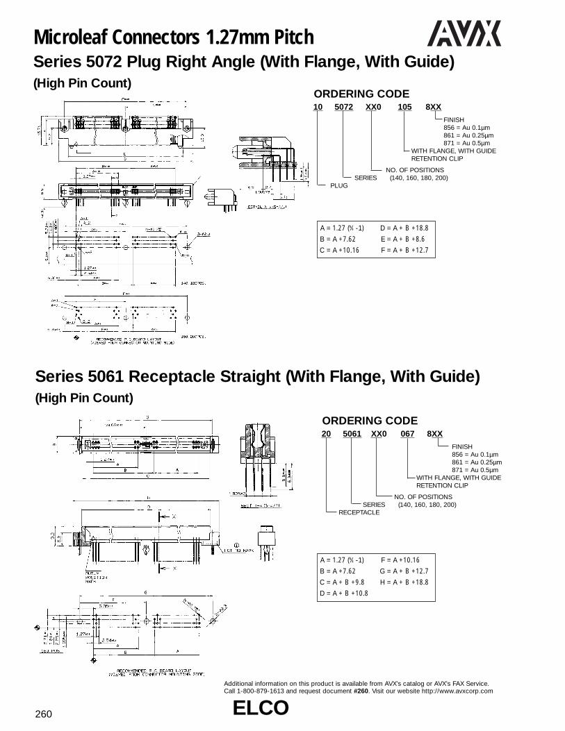
ELCOELCO260
Additional information on this product is available from AVX’s catalog or AVX’s FAX Service.Call 1-800-879-1613 and request document #260. Visit our website http://www.avxcorp.com
Microleaf Connectors 1.27mm PitchSeries 5072 Plug Right Angle (With Flange, With Guide)(High Pin Count)
Series 5061 Receptacle Straight (With Flange, With Guide)(High Pin Count)
ORDERING CODE10 5072 XX0 105 8XX
FINISH856 = Au 0.1µm861 = Au 0.25µm871 = Au 0.5µm
WITH FLANGE, WITH GUIDERETENTION CLIP
NO. OF POSITIONSSERIES (140, 160, 180, 200)
PLUG
ORDERING CODE20 5061 XX0 067 8XX
FINISH856 = Au 0.1µm861 = Au 0.25µm871 = Au 0.5µm
WITH FLANGE, WITH GUIDERETENTION CLIP
NO. OF POSITIONSSERIES (140, 160, 180, 200)
RECEPTACLE
A = 1.27 (N⁄4 -1)
B = A +7.62
C = A +10.16
D = A + B +18.8
E = A + B +8.6
F = A + B +12.7
A = 1.27 (N⁄4 -1)
B = A +7.62
C = A + B +9.8
D = A + B +10.8
F = A +10.16
G = A + B +12.7
H = A + B +18.8

ELCOELCO 261
Additional information on this product is available from AVX’s catalog or AVX’s FAX Service.Call 1-800-879-1613 and request document #261. Visit our website http://www.avxcorp.com
Microleaf SMT Connectors 1.0mm PitchSeries 5078 Plug Straight With Vacuum Pick Up Clip(30~60 Positions)
Series 5078 Receptacle Straight With Vacuum Pick Up Clip(30~60 Positions)
ORDERING CODE14 5078 0X0 100 8XX
FINISH 861 = Ni over
Au Plating833 = Pd/Ni over
Au PlatingVARIATION
NUMBER OF POSITIONSSERIES (30, 40, 50, 60)
TAPE AND REEL14 = Plug
ORDERING CODE24 5078 0X0 100 8XX
FINISH 861 = Ni over
Au Plating833 = Pd/Ni over
Au PlatingVARIATION
NUMBER OF POSITIONSSERIES (30, 40, 50, 60)
TAPE AND REEL24 = Receptacle
A = 1 (N⁄2 -1)
B = 1 (N⁄2 -1)+2
C = 1 (N⁄2 -1)+4
D = 1 (N⁄2 -1)+4.7
E = 1 (N⁄2 -1)+8
F = 1 (N⁄2 -1)+12
G = 1 (N⁄2 -1)+6
A = 1 (N⁄2 -1)
B = 1 (N⁄2 -1)+2.5
C = 1 (N⁄2 -1)+4
D = 1 (N⁄2 -1)+4.5
E = 1 (N⁄2 -1)+8
F = 1 (N⁄2 -1)+12
G = 1 (N⁄2 -1)+6

ELCOELCO262
Additional information on this product is available from AVX’s catalog or AVX’s FAX Service.Call 1-800-879-1613 and request document #262. Visit our website http://www.avxcorp.com
19 5078 XX0 000 8XXFINISH
861 = Au 0.25µm833 = Au Flash
VARIATION
NUMBER OF POSITIONSSERIES (80, 100, 120)
TRAY19 = Plug
Microleaf SMT Connectors 1.0mm PitchSeries 5078 Plug Straight With Vacuum Pick Up Clip(80~120 Positions)
Series 5078 Receptacle Straight With Vacuum Pick Up Clip(80~120 Positions)
ORDERING CODE
ORDERING CODE29 5078 000 000 8XX
FINISH 861 = Au 0.25µm833 = Au Flash
VARIATION
NUMBER OF POSITIONSSERIES (80, 100, 120)
TRAY29 = Receptacle
A = 1 (N⁄4 -1)
B = 1 (N⁄4 -1)+2
C = 1 (N⁄2 -1)+6
D = 1 (N⁄2 -1)+6.7
E = 1 (N⁄2 -1)+10
F = 1 (N⁄2 -1)+14
G = 1 (N⁄2 -1)+8
A = 1 (N⁄4 -1)
B = 1 (N⁄4 -1)+2.45
C = 1 (N⁄2 -1)+6
D = 1 (N⁄2 -1)+6.5
E = 1 (N⁄2 -1)+10
F = 1 (N⁄2 -1)+14
G = 1 (N⁄2 -1)+8

ELCOELCO 263
Additional information on this product is available from AVX’s catalog or AVX’s FAX Service.Call 1-800-879-1613 and request document #263. Visit our website http://www.avxcorp.com
Microleaf SMT Connectors 1.00mm PitchSeries 5078 Standard SMT Plug Right Angle(30~60 Positions)
Series 5078 Standard SMT Receptacle Right Angle(30~60 Positions)
ORDERING CODE14 5078 0X0 510 8XX
FINISH861 = Au 0.25µm833 = Au Flash
VARIATION
NUMBER OF POSITIONSSERIES (30, 40, 50, 60)
TAPE AND REEL14 = Plug
ORDERING CODE24 5078 0X0 510 8XX
FINISH 861 = Au 0.25µm833 = Au Flash
VARIATION
NUMBER OF POSITIONSSERIES (30, 40, 50, 60)
TAPE AND REEL24 = Receptacle
A = 1 (N⁄2 -1)
B = 1 (N⁄2 -1)+0.5
C = 1 (N⁄2 -1)+8
D = 1 (N⁄2 -1)+2
E = 1 (N⁄2 -1)+4.7
F = 1 (N⁄2 -1)+4.0
A = 1 (N⁄2 -1)
B = 1 (N⁄2 -1)+0.5
C = 1 (N⁄2 -1)+8.0
E = 1 (N⁄2 -1)+4.5
F = 1 (N⁄2 -1)+4.0

ELCOELCO264
Additional information on this product is available from AVX’s catalog or AVX’s FAX Service.Call 1-800-879-1613 and request document #264. Visit our website http://www.avxcorp.com
Microleaf SMT Connectors 1.00mm PitchSeries 5078 Lead Reflow Plug Right Angle(30~60 Positions)
Series 5078 Lead Reflow Receptacle Right Angle(30~60 Positions)
ORDERING CODE14 5078 0X0 511 8XX
FINISH 861 = Au 0.25µm833 = Au Flash
VARIATION
NUMBER OF POSITIONSSERIES (30, 40, 50, 60)
TAPE AND REEL14 = Plug
ORDERING CODE24 5078 0X0 511 8XX
FINISH 861 = Au 0.25µm833 = Au Flash
VARIATION
NUMBER OF POSITIONSSERIES (30, 40, 50, 60)
TAPE AND REEL24 = Receptacle
A = 1 (N⁄2 -1)
B = 1 (N⁄2 -1)+0.5
C = 1 (N⁄2 -1)+8
F = 1 (N⁄2 -1)+4.0
H = 1 (N⁄2 -1)+8.5
A = 1 (N⁄2 -1)
B = 1 (N⁄2-1)+0.5
C = 1 (N⁄2 -1)+8
H = 1 (N⁄2 -1)+8.5

ELCOELCO 265
Additional information on this product is available from AVX’s catalog or AVX’s FAX Service.Call 1-800-879-1613 and request document #265. Visit our website http://www.avxcorp.com
29 5078 XX0 520 8XXFINISH
861 = Au 0.25µm833 = Au Flash
VARIATION
NUMBER OF POSITIONSSERIES (80, 100, 120)
TRAY29 = Receptacle
Microleaf SMT Connectors 1.00mm PitchSeries 5078 Standard SMT Plug Right Angle(80~120 Positions)
Series 5078 Standard SMT Receptacle Right Angle(80~120 Positions)
ORDERING CODE19 5078 XX0 520 8XX
FINISH861 = Au 0.25µm833 = Au Flash
VARIATION
NUMBER OF POSITIONSSERIES (80, 100, 120)
TRAY19 = Plug
ORDERING CODE
A = 1 (N⁄4 -1)
B = 1 (N⁄4 -1)+0.5
C = 1 (N⁄2 -1)+10
F = 1 (N⁄2 -1)+6
G = 1 (N⁄2 -1)+8
A = 1 (N⁄4 -1)
B = 1 (N⁄4 -1)+0.5
C = 1 (N⁄2 -1)+10
F = 1 (N⁄2 -1)+6
G = 1 (N⁄2 -1)+8

ELCOELCO266
Additional information on this product is available from AVX’s catalog or AVX’s FAX Service.Call 1-800-879-1613 and request document #266. Visit our website http://www.avxcorp.com
Microleaf SMT Connectors 1.00mm PitchSeries 5078 Lead Reflow Plug Right Angle(80~120 Positions)
Series 5078 Lead Reflow Receptacle Right Angle(80~120 Positions)
ORDERING CODE19 5078 XX0 521 8XX
FINISH861 = Au 0.25µm833 = Au Flash
VARIATION
NUMBER OF POSITIONSSERIES (80, 100, 120)
TRAY19 = Plug
ORDERING CODE29 5078 XX0 521 8XX
FINISH 861 = Au 0.25µm833 = Au Flash
VARIATION
NUMBER OF POSITIONSSERIES (80, 100, 120)
TRAY29 = Receptacle
A = 1 (N⁄4 -1)
B = 1 (N⁄4 -1)+0.5
C = 1 (N⁄2 -1)+10
F = 1 (N⁄2 -1)+6
G = 1 (N⁄2 -1)+10.5
A = 1 (N⁄4 -1)
B = 1 (N⁄4 -1)+0.5
C = 1 (N⁄2 -1)+10
F = 1 (N⁄2 -1)+6
G = 1 (N⁄2 -1)+10.5
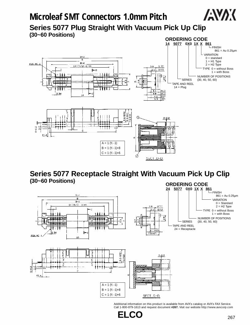
ELCOELCO 267
Additional information on this product is available from AVX’s catalog or AVX’s FAX Service.Call 1-800-879-1613 and request document #267. Visit our website http://www.avxcorp.com
Microleaf SMT Connectors 1.0mm PitchSeries 5077 Plug Straight With Vacuum Pick Up Clip(30~60 Positions)
Series 5077 Receptacle Straight With Vacuum Pick Up Clip(30~60 Positions)
ORDERING CODE14 5077 0X0 1X X 861
FINISH861 = Au 0.25µm
VARIATION 0 = standard1 = H1 Type2 = H2 Type
TYPE 0 = without Boss1 = with Boss
NUMBER OF POSITIONSSERIES (30, 40, 50, 60)
TAPE AND REEL14 = Plug
ORDERING CODE24 5077 0X0 1X X 861
FINISH861 = Au 0.25µm
VARIATION 0 = Standard 2 = H2 Type
TYPE 0 = without Boss1 = with Boss
NUMBER OF POSITIONSSERIES (30, 40, 50, 60)
TAPE AND REEL24 = Receptacle
A = 1 (N⁄2 -1)
B = 1 (N⁄2 -1)+8
C = 1 (N⁄2 -1)+6
A = 1 (N⁄2 -1)
B = 1 (N⁄2 -1)+8
C = 1 (N⁄2 -1)+6

ELCOELCO268
Additional information on this product is available from AVX’s catalog or AVX’s FAX Service.Call 1-800-879-1613 and request document #268. Visit our website http://www.avxcorp.com
Super Micro Connectors 0.8mm PitchSeries 8375 Plug
Series 8375 Receptacle
ORDERING CODE14 8375 0XX X 30 8X8
FINISH808 = Tin Plating 858 = Gold Plating
TYPE 2 = without Boss3 = with Boss
NUMBER OF POSITIONSSERIES (16, 22, 28)
TAPE AND REEL14 = Plug
ORDERING CODE24 8375 0XX X 00 8X8
FINISH808 = Tin Plating 858 = Gold Plating
TYPE 2 = without Boss3 = with Boss
NUMBER OF POSITIONSSERIES (16, 22, 28)
TAPE AND REEL24 = Receptacle
A = 0.8 (N⁄2 -1)
B = 0.8 (N⁄2 -1)+2.7
E = 0.8 (N⁄2 -1)+1.8
F = 0.8 (N⁄2 -1)+1.0
A = 0.8 (N⁄2 -1)
B = 0.8 (N⁄2 -1)+2.7
E = 0.8 (N⁄2 -1)+1.8
F = 0.8 (N⁄2 -1)+1.0

ELCOELCO 269
Additional information on this product is available from AVX’s catalog or AVX’s FAX Service.Call 1-800-879-1613 and request document #269. Visit our website http://www.avxcorp.com
Super Micro Connectors 0.5mm PitchSeries 5087 Plug
ORDERING CODE14 5087 0XX X XX 8XX
FINISH861 = Ni Under Coated
1.25µm min. Gold-Mating AreaAu 0.38µm min.
829 = Ni Under Coated1.25µm min. Gold-Mating AreaAu 0.1µm min.
VARIATION 30 : H = 3.0mm35 : H = 3.5mm40 : H = 4.0mm
TYPE 0 = without Boss withRetention Clip
2 = without Boss,Retention Clip
9 = without Boss,Retention Clip, with Adhesive Tape
NUMBER OF POSITIONSSERIES (20, 30, 32, 36, 40, 50, 60)
TAPE AND REEL14 = Plug
A = 0.5 (N⁄2 -1)
B = 0.5 (N⁄2 -1)+2.7
C = 0.5 (N⁄2 -1)+1.7
D = 0.5 (N⁄2 -1)+1.0
H = 3.0mm Type H = 3.5mm Type H = 4.0mm Type

ELCOELCO270
Additional information on this product is available from AVX’s catalog or AVX’s FAX Service.Call 1-800-879-1613 and request document #270. Visit our website http://www.avxcorp.com
Super Micro Connectors 0.5mm PitchSeries 5087 Receptacle H = 3.0 ~ 4.0mm Type
ORDERING CODE24 5087 0XX X 00 8XX
FINISH861 = Ni Under Coated
1.25µm min. Gold-Mating AreaAu 0.38µm min.
829 = Ni Under Coated1.25µm min. Gold-Mating AreaAu 0.1µm min.
VARIATION H = 3.0 ~ 4.0mm
TYPE 0 = without Boss withRetention Clip
2 = without Boss,Retention Clip
9 = without Boss,Retention Clip, with Adhesive Tape
NUMBER OF POSITIONSSERIES (20, 30, 32, 36, 40, 50, 60)
TAPE AND REEL24 = Receptacle
A = 0.5 (N⁄2 -1)
B = A +2.7
C = A +1.9
D = A +0.9

ELCOELCO 271
Additional information on this product is available from AVX’s catalog or AVX’s FAX Service.Call 1-800-879-1613 and request document #271. Visit our website http://www.avxcorp.com
Super Micro Connectors 0.5mm PitchSeries 5087 Plug
Series 5087 Receptacle H = 2.0 ~ 2.5mm Type
ORDERING CODE14 5087 0XX X XX 8XX
FINISH861 = Ni Under Coated
1.25µm min. Gold-Mating AreaAu 0.38µm min.
829 = Ni Under Coated1.25µm min. Gold-Mating AreaAu 0.1µm min.
VARIATION 20 : H = 2.0mm25 : H = 2.5mm
TYPE 0 = without Boss withRetention Clip
2 = without Boss,Retention Clip
9 = without Boss,Retention Clip, with Adhesive Tape
NUMBER OF POSITIONSSERIES (10*, 20, 30, 40, 50, 60) *2.0mm H only
TAPE AND REEL14 = Plug
ORDERING CODE24 5087 0XX X 01 8XX
FINISH861 = Ni Under Coated
1.25µm min. Gold-Mating AreaAu 0.38µm min.
829 = Ni Under Coated1.25µm min. Gold-Mating AreaAu 0.1µm min.
VARIATION H = 2.0 ~ 2.5mm
TYPE 0 = without Boss withRetention Clip
2 = without Boss,Retention Clip
9 = without Boss,Retention Clip, with Adhesive Tape
NUMBER OF POSITIONSSERIES (10, 20, 30, 40, 50, 60)
TAPE AND REEL24 = Receptacle
A = 0.5 (N⁄2 -1)
B = 0.5 (N⁄2 -1)+4.4
D = 0.5 (N⁄2 -1)+1.5
H = 2.0mm Type
H = 2.5mm Type

ELCOELCO272
Additional information on this product is available from AVX’s catalog or AVX’s FAX Service.Call 1-800-879-1613 and request document #272. Visit our website http://www.avxcorp.com
Stacking Part NumberHeight
4.5mmFemale 24 5046 XXX X00 829Male 14 5046 XXX X45 829
4.0mmFemale 24 5046 XXX X00 829Male 14 5046 XXX X40 829
3.5mmFemale 24 5046 XXX X00 829Male 14 5046 XXX X35 829
3.0mmFemale 24 5046 XXX X00 829Male 14 5046 XXX X30 829
ORDERING CODE
NO. OF POSITIONSVARIATION CODE0 = W/O Metal Tab1 = With Metal Tab5 = W/O Metal Tab / With Kapton Tape6 = With Metal Tab / With Kapton Tape
Board-to-Board Super MicroleafSeries 5046 Plug – 0.5mm Pitch
Series 5046 Receptacle – 0.5mm Pitch
No. ofA B CPositions
20 4.5 10.5 7.730 7.0 13.0 10.240 9.5 15.5 12.750 12.0 18.0 15.260 14.5 20.5 17.770 17.0 23.0 20.280 19.5 25.5 22.790 22.0 28.0 25.2
100 24.5 30.5 27.7110 27.0 33.0 30.2120 29.5 35.5 32.7
No. ofA B CPositions
20 4.5 10.5 7.730 7.0 13.0 10.240 9.5 15.5 12.750 12.0 18.0 15.260 14.5 20.5 17.770 17.0 23.0 20.280 19.5 25.5 22.790 22.0 28.0 25.2
100 24.5 30.5 27.7110 27.0 33.0 30.2120 29.5 35.5 32.7
Plug
Receptacle
A = 0.5 (N⁄2 -1)
B = A +6.0
C = A +3.2

ELCOELCO 273
Additional information on this product is available from AVX’s catalog or AVX’s FAX Service.Call 1-800-879-1613 and request document #273. Visit our website http://www.avxcorp.com
Board-to-Board Super MicroleafSeries 5047 Plug – 0.5mm Pitch
Series 5047 Receptacle – 0.5mm Pitch
No. ofA B CPositions
20 4.5 7.5 0.2530 7.0 10.0 0.540 9.5 12.5 0.2550 12.0 15.0 0.560 14.5 17.5 0.2570 17.0 20.0 0.580 19.5 22.5 0.2590 22.0 25.0 0.5
100 24.5 27.5 0.25110 27.0 30.0 0.5120 29.5 32.5 0.25
Plug
ReceptacleStacking Part NumberHeight
5.0mmFemale 24 5047 XXX 400 XXXMale 14 5047 XXX 450 XXX
7.0mmFemale 24 5047 XXX 400 XXXMale 14 5047 XXX 470 XXX
No. ofA B CPositions
20 4.5 7.5 0.2530 7.0 10.0 0.540 9.5 12.5 0.2550 12.0 15.0 0.560 14.5 17.5 0.2570 17.0 20.0 0.580 19.5 22.5 0.2590 22.0 25.0 0.5
100 24.5 27.5 0.25110 27.0 30.0 0.5120 29.5 32.5 0.25
ORDERING CODE
NO. OF POSITIONSVARIATION CODE
4 = W/O Kapton Tape2 = With Kapton Tape
FINISH CODE
Contact Area856 Au 0.1 µm/MIN861 Au 0.2 µm/MIN
A = 0.5 (N⁄2 -1)
B = A +3.0

ELCOELCO274
Additional information on this product is available from AVX’s catalog or AVX’s FAX Service.Call 1-800-879-1613 and request document #274. Visit our website http://www.avxcorp.com
MOBO One Piece Board To BoardSeries 9158 – Dual Row Solo Stacker™
(28 position example)
ORDERING CODE58 9158 XXX 000 0XX
STACK HEIGHT
NO. OF POSITIONS
SERIESPREFIX
Features• Superior drop test performance• Variable stack height to 0.9mm• Single piece construction
Series 9158 – Solo Stacker™ – Product AvailabilityNo. of Nominal Stack Height (mm)
Positions2.00 2.20 2.40 2.60 3.00 3.20 4.00 5.00
4 way •16 way •* •* •* •18 way •20 way •* •* •* •*24 way •* •* •* •*28 way •* •* •* •* •30 way •32 way •34 way •
*Denotes that part is currently being tooled.All stack height dimensions are nominal. Tolerance varies depending on application.Connectors can be supplied with or without location bosses.Cells with grey shading denote that part is custom special.Custom options available.

ELCOELCO 275
Additional information on this product is available from AVX’s catalog or AVX’s FAX Service.Call 1-800-879-1613 and request document #275. Visit our website http://www.avxcorp.com
Torson Board To Board Connectors.050 Centerline, 2 Row, Vertical, Thru Board
.050 Centerline, 2 Row, SMT, Vertical
ORDERING CODE10 5016 2XXX 10 001
ORDERING CODE11 5016 2XXX 10 001

ELCOELCO276
Additional information on this product is available from AVX’s catalog or AVX’s FAX Service.Call 1-800-879-1613 and request document #276. Visit our website http://www.avxcorp.com
Torson Board To Board Connectors.050 Centerline, 2 Row, Low Profile
.050 Centerline, 2 Row, SMT, Low Profile Vertical
ORDERING CODE12 5016 2XXX 10 001
ORDERING CODE17 5016 2XXX 10 001

ELCOELCO 277
Additional information on this product is available from AVX’s catalog or AVX’s FAX Service.Call 1-800-879-1613 and request document #277. Visit our website http://www.avxcorp.com
Torson Board To Board Connectors.050 Centerline, 2 Row, Right Angle, Thru Board
.050 Centerline, 2 Row, Vertical, Thru Board
ORDERING CODE20 5016 2XXX 20 001
ORDERING CODE20 5016 2XXX 10 001

ELCOELCO278
Additional information on this product is available from AVX’s catalog or AVX’s FAX Service.Call 1-800-879-1613 and request document #278. Visit our website http://www.avxcorp.com
Torson Board To Board Connectors.050 Centerline, 2 Row, Vertical, SMT
.050 Centerline, Low Profile, Thru Board, Top Entry
ORDERING CODE21 5016 2XXX 10 001
ORDERING CODE2 5016 2XXX 10 001

ELCOELCO 279
Additional information on this product is available from AVX’s catalog or AVX’s FAX Service.Call 1-800-879-1613 and request document #279. Visit our website http://www.avxcorp.com
Torson Board To Board Connectors.050 Centerline, Low Profile, Top Entry, SMT
.050 Centerline, Low Profile, Bottom Entry
ORDERING CODE23 5016 2XXX 10 001
ORDERING CODE24 5016 2XXX 10 001
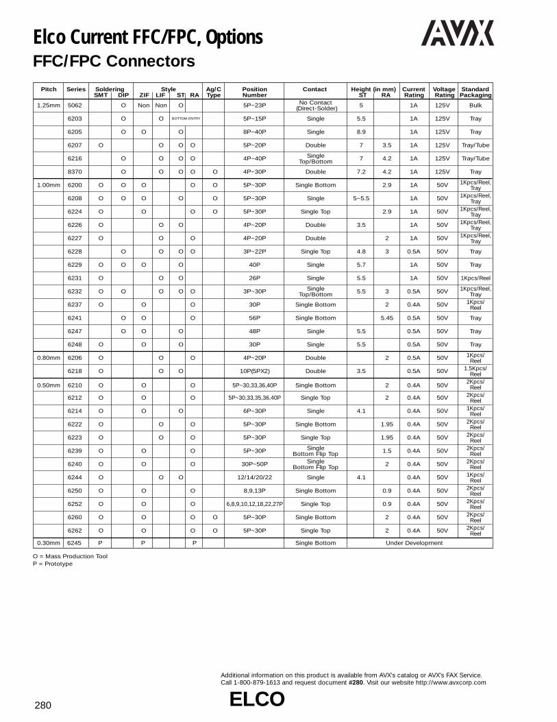
ELCOELCO280
Additional information on this product is available from AVX’s catalog or AVX’s FAX Service.Call 1-800-879-1613 and request document #280. Visit our website http://www.avxcorp.com
Pitch Series Soldering Style Ag/C Position Contact Height (in mm) Current Voltage StandardSMT DIP ZIF LIF ST RA Type Number ST RA Rating Rating Packaging
1.25mm 5062 O Non Non O 5P~23P No Contact 5 1A 125V Bulk(Direct-Solder)
6203 O O BOTTOM ENTRY 5P~15P Single 5.5 1A 125V Tray
6205 O O O 8P~40P Single 8.9 1A 125V Tray
6207 O O O O 5P~20P Double 7 3.5 1A 125V Tray/Tube
6216 O O O O 4P~40P Single 7 4.2 1A 125V Tray/TubeTop/Bottom
8370 O O O O O 4P~30P Double 7.2 4.2 1A 125V Tray
1.00mm 6200 O O O O O 5P~30P Single Bottom 2.9 1A 50V 1Kpcs/Reel,Tray
6208 O O O O O 5P~30P Single 5~5.5 1A 50V 1Kpcs/Reel,Tray
6224 O O O O 5P~30P Single Top 2.9 1A 50V 1Kpcs/Reel,Tray
6226 O O O 4P~20P Double 3.5 1A 50V 1Kpcs/Reel,Tray
6227 O O O 4P~20P Double 2 1A 50V 1Kpcs/Reel,Tray
6228 O O O O 3P~22P Single Top 4.8 3 0.5A 50V Tray
6229 O O O O 40P Single 5.7 1A 50V Tray
6231 O O O 26P Single 5.5 1A 50V 1Kpcs/Reel
6232 O O O O O 3P~30P Single 5.5 3 0.5A 50V 1Kpcs/Reel,Top/Bottom Tray
6237 O O O 30P Single Bottom 2 0.4A 50V 1Kpcs/Reel
6241 O O O 56P Single Bottom 5.45 0.5A 50V Tray
6247 O O O 48P Single 5.5 0.5A 50V Tray
6248 O O O 30P Single 5.5 0.5A 50V Tray
0.80mm 6206 O O O 4P~20P Double 2 0.5A 50V 1Kpcs/Reel
6218 O O O 10P(5PX2) Double 3.5 0.5A 50V 1.5Kpcs/Reel
0.50mm 6210 O O O 5P~30,33,36,40P Single Bottom 2 0.4A 50V2Kpcs/
Reel
6212 O O O 5P~30,33,35,36,40P Single Top 2 0.4A 50V 2Kpcs/Reel
6214 O O O 6P~30P Single 4.1 0.4A 50V 1Kpcs/Reel
6222 O O O 5P~30P Single Bottom 1.95 0.4A 50V 2Kpcs/Reel
6223 O O O 5P~30P Single Top 1.95 0.4A 50V 2Kpcs/Reel
6239 O O O 5P~30P Single 1.5 0.4A 50V 2Kpcs/Bottom Flip Top Reel
6240 O O O 30P~50P Single 2 0.4A 50V 2Kpcs/Bottom Flip Top Reel
6244 O O O 12/14/20/22 Single 4.1 0.4A 50V 1Kpcs/Reel
6250 O O O 8,9,13P Single Bottom 0.9 0.4A 50V 2Kpcs/Reel
6252 O O O 6,8,9,10,12,18,22,27P Single Top 0.9 0.4A 50V 2Kpcs/Reel
6260 O O O O 5P~30P Single Bottom 2 0.4A 50V 2Kpcs/Reel
6262 O O O O 5P~30P Single Top 2 0.4A 50V 2Kpcs/Reel
0.30mm 6245 P P P Single Bottom Under Development
Elco Current FFC/FPC, OptionsFFC/FPC Connectors
O = Mass Production ToolP = Prototype

ELCOELCO 281
Additional information on this product is available from AVX’s catalog or AVX’s FAX Service.Call 1-800-879-1613 and request document #281. Visit our website http://www.avxcorp.com
FFC/FPC Connectors 1.25mm PitchSeries 6207 LIF Straight SMT
A = 1.25 (N -1)B = 1.25 N +1.41C = 1.25 N +5.75D = 1.25 N +1.75
A = 1.25 (N -1)B = 1.25 N +1.41C = 1.25 N +5.75D = 1.25 N +1.75
Specifications• Number of Positions – 5-20• Tube Packaged• Voltage – 125 V• Current Rating – 1.0 amp max.• Dielectric Withstanding Voltage –
500V rms/min.• Operating Temperature – (-20°C - +85°C)• Contact Material – phosphor bronze
(tin-lead plated)• Insulator Material – glass-filled PPS
(UL 94 V-O) brown color• FFC/FPC Thickness –
0.3 ±0.05mm (0.012 ±0.002")• Profile Height – 7.0mm (0.276")
ORDERING CODE
00 6207 34 19 XX 000NUMBER OFPOSITIONS (05-20)
Specifications• Number of Positions – 5-20• Tube Packaged• Voltage – 125 V• Current Rating – 1.0 amp max.• Dielectric Withstanding Voltage –
500V rms/min.• Operating Temperature – (-20°C -
+85°C)• Contact Material – phosphor bronze
(tin-lead plated)• Insulator Material – glass-filled PPS
(UL 94 V-O) brown color• FFC/FPC Thickness –
0.3 ±0.05mm (0.012 ±0.002")• Profile Height – 7.0mm (0.276")
ORDERING CODE
00 6207 33 29 XX 000NUMBER OFPOSITIONS (05-20)
Series 6207 LIF Right Angle SMT

ELCOELCO282
Additional information on this product is available from AVX’s catalog or AVX’s FAX Service.Call 1-800-879-1613 and request document #282. Visit our website http://www.avxcorp.com
Specifications• Number of Positions – 5-23• Vinyl Bag Packaged• Voltage – 125 V• Current Rating – 1.0 amp max.• Dielectric Withstanding Voltage –
500V rms/min.• Operating Temperature – (-40°C - +85°C)• Insulator Material – PBT, natural color
(UL 94 V-O)• FFC/FPC Thickness –
0.3 ±0.05 mm (0.012 ±0.002")• PCB Thickness – 1.6mm (0.633")• Profile Height – 5.0mm (0.197")
ORDERING CODE00 5062 30 10 XX 000
NUMBER OF POSITIONS (05-23)00=BULK PACKAGE
ORDERING CODE00 6203 3010 XX 000
NUMBER OF POSITIONS (05-15)TRAY PACKAGE
FFC/FPC Connectors 1.25mm PitchSeries 5062 Straight
A = 1.25 (N -1)B = 1.25 N +1.73C = 1.25 N +3.75D = 1.25 N +2.5
Specifications• Number of Positions – 5-15• Tray Packaged• Voltage – 125 V• Current Rating – 1.0 amp max.• Dielectric Withstanding Voltage –
500V rms/min.• Operating Temperature – (-40°C - +85°C)• Contact Material – phosphor bronze
(tin-lead plated)• Insulator Material – glass-filled nylon
(UL 94 V-O)• FFC/FPC Thickness –
0.3 ±0.05 mm (0.012 ±0.002")• PCB Thickness – 1.2-1.6mm (0.047-0.063")• Allows insertion of FFC/FPC from bottom
of PC board, at edge or through slit• Profile Height – 5.5mm (0.217")
Series 6203 LIF Right Angle Through-Hole (Bottom Entry)
A = 1.25 (N -1)B = 1.25 N +3.03

ELCOELCO 283
Additional information on this product is available from AVX’s catalog or AVX’s FAX Service.Call 1-800-879-1613 and request document #283. Visit our website http://www.avxcorp.com
ORDERING CODE
FFC/FPC Connectors 1.25mm PitchSeries 6205 ZIF Straight Through-Hole
Series 6216 LIF Right Angle Through-Hole (Bottom Contact)
A = 1.25 N +6.85
A = 1.25 (N -1)B = 1.25 N +1.41C = 1.25 N +2.5
00 6205 XX0 500 825NUMBER OF POSITIONS (08-40)
TRAY PACKAGE
Specifications• Number of Positions – 8-40• Tray Packaged• Voltage – 125 V• Current Rating – 1.0 amp max.• Dielectric Withstanding Voltage –
500V rms/min.• Operating Temperature – (-40°C - +90°C)• Contact Material – phosphor bronze
(tin-lead plated)• Insulator Material – glass-filled PBT,
(UL 94 V-O) black color• Slider Material – glass-filled PBT,
(UL 94 V-O) beige color• FFC/FPC Thickness –
0.3 ±0.05 mm (0.012 ±0.002")• PCB Thickness – 1.6mm (0.063")• Profile Height – 8.9mm (0.350")
ORDERING CODE
Specifications• Number of Positions – 4-40• Tube Packaged or Tray Packaged• Voltage – 200 V• Current Rating – 1.0 amp max.• Dielectric Withstanding Voltage –
500V rms/min.• Operating Temperature – (-20°C - +85°C)• Contact Material – phosphor bronze
(tin-lead plated)• Insulator Material – glass-filled PBT,
(UL 94 V-O) black color• FFC/FPC Thickness – 0.3 ±0.05 mm
(0.012 ±0.002")• PCB Thickness – 1.0-1.6mm (0.039-0.633")• Profile Height – Straight – 7.0mm (0.276")
Right Angle – 4.2mm (0.165")• Reverse footprint for straight type also
available – contact sales office for details
XX 6216 0XX 10X 808NUMBER OF VARIATION CODE
POSITIONS 0:WITH KINKED LEGS(04-30) (EACH TWO PINS AT BOTH ENDS)
1:WITHOUT KINKED LEGS00:TRAY PACKAGE28:TUBE PACKAGE

ELCOELCO284
Additional information on this product is available from AVX’s catalog or AVX’s FAX Service.Call 1-800-879-1613 and request document #284. Visit our website http://www.avxcorp.com
FFC/FPC Connectors 1.25mm PitchSeries 6216 LIF Right Angle Through-Hole (Top Contact)
A = 1.25 (N -1)B = 1.25 N +1.41C = 1.25 N +2.5
A = 1.25 N +3.75B = 1.25 N +1.41C = 1.25 (N -1)
XX 6216 0XX 11X 80800:TRAY
PACKAGE28:TUBE
PACKAGE NUMBER OF POSITIONS (04-30)
Specifications• Number of Positions – 4-40• Tube Packaged or Tray Packaged• Voltage – 200 V• Current Rating – 1.0 amp max.• Dielectric Withstanding Voltage –
500V rms/min.• Operating Temperature – (-20°C - 85°C)• Contact Material – phosphor bronze
(tin-lead plated)• Insulator Material – glass-filled PBT,
(UL 94 V-O) black color• FFC/FPC Thickness – 0.3 ±0.05 mm
(0.012 ±0.002")• PCB Thickness - 1.0-1.6mm (0.039-0.633")• Profile Height – Straight – 7.0mm (0.276")
Right Angle – 4.2mm (0.165")• Reverse footprint for straight type also
available – contact sales office for details
ORDERING CODE
VARIATION CODE0:WITH KINKED LEGS
(EACH TWO PINS ATBOTH ENDS)
1:WITHOUT KINKEDLEGS
Series 6216 LIF Right Angle Through-Hole (High Pin Count)
Specifications• Number of Positions – 4-40• Tube Packaged or Tray Packaged• Voltage – 200 V• Current Rating – 1.0 amp max.• Dielectric Withstanding Voltage –
500V rms/min.• Operating Temperature – (-20°C - +85°C)• Contact Material – phosphor bronze
(tin-lead plated)• Insulator Material – glass-filled PBT,
(UL 94 V-O) black color• FFC/FPC Thickness – 0.3 ±0.05 mm
(0.012 ±0.002")• PCB Thickness – 1.0-1.6mm
(0.039-0.633")• Profile Height – Straight –
7.0mm (0.276")Right Angle – 4.2mm (0.165")
• Reverse footprint for straight type also available – contact sales office for details
00 6216 0XX 12X 808NUMBER VARIATION CODE
OF 0:WITH KINKED LEGSPOSITIONS (31-40) (EACH TWO PINS AT BOTH ENDS)
1:WITHOUT KINKED LEGSTRAY PACKAGE
ORDERING CODE

ELCOELCO 285
Additional information on this product is available from AVX’s catalog or AVX’s FAX Service.Call 1-800-879-1613 and request document #285. Visit our website http://www.avxcorp.com
FFC/FPC Connectors 1.25mm PitchSeries 6216 LIF Straight Through-Hole
Series 6216 LIF Straight Through-Hole (High Pin Count)
A = 1.25 (N -1)B = 1.25 N +1.41C = 1.25 N +2.5
A = 1.25 N +3.75B = 1.25 N +1.41C = 1.25 (N -1)
ORDERING CODE
ORDERING CODE
00 6216 0XX 00X 808NUMBER VARIATION CODE
OF 0:WITH KINKED LEGSPOSITIONS (04-30) (EACH TWO PINS AT BOTH ENDS)
TRAY PACKAGE 1:WITHOUT KINKED LEGS
Specifications• Number of Positions – 4-40• Tube Packaged or Tray Packaged• Voltage – 200 V• Current Rating – 1.0 amp max.• Dielectric Withstanding Voltage –
500V rms/min.• Operating Temperature –
(-20°C - +85°C)• Contact Material – phosphor bronze
(tin-lead plated)• Insulator Material – glass-filled PBT,
(UL 94 V-O) black color• FFC/FPC Thickness – 0.3 ±0.05 mm
(0.012 ±0.002")• PCB Thickness - 1.0-1.6mm
(0.039-0.633")• Profile Height – Straight –
7.0mm (0.276")Right Angle – 4.2mm (0.165")
• Reverse footprint for straight type also available – contact sales office for details
00 6216 1XX 82X 808NUMBER VARIATION CODE
OF 0:WITH KINKED LEGSPOSITIONS (31-40) (EACH TWO PINS AT BOTH ENDS)
1:WITHOUT KINKED LEGSTRAY PACKAGE
Specifications• Number of Positions – 4-40• Tube Packaged or Tray Packaged• Voltage – 200 V• Current Rating – 1.0 amp max.• Dielectric Withstanding Voltage –
500V rms/min.• Operating Temperature – (-20°C - +85°C)• Contact Material – phosphor bronze
(tin-lead plated)• Insulator Material – glass-filled PBT,
(UL 94 V-O) black color• FFC/FPC Thickness – 0.3 ±0.05 mm
(0.012 ±0.002")• PCB Thickness - 1.0-1.6mm (0.039-0.633")• Profile Height – Straight – 7.0mm (0.276")
Right Angle – 4.2mm (0.165")• Reverse footprint for straight type also
available – contact sales office for details
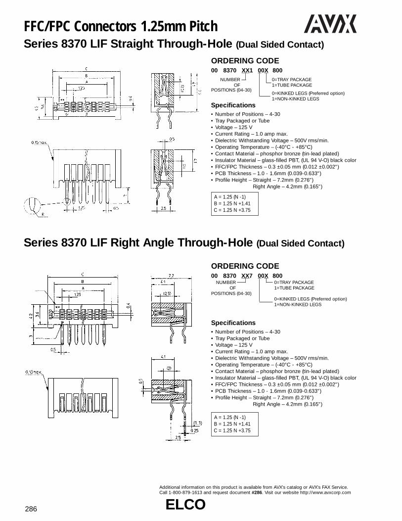
ELCOELCO286
Additional information on this product is available from AVX’s catalog or AVX’s FAX Service.Call 1-800-879-1613 and request document #286. Visit our website http://www.avxcorp.com
FFC/FPC Connectors 1.25mm PitchSeries 8370 LIF Straight Through-Hole (Dual Sided Contact)
Series 8370 LIF Right Angle Through-Hole (Dual Sided Contact)
A = 1.25 (N -1)B = 1.25 N +1.41C = 1.25 N +3.75
A = 1.25 (N -1)B = 1.25 N +1.41C = 1.25 N +3.75
ORDERING CODE
ORDERING CODE
00 8370 XX1 00X 800NUMBER 0=TRAY PACKAGE
OF 1=TUBE PACKAGEPOSITIONS (04-30)
0=KINKED LEGS (Preferred option)1=NON-KINKED LEGS
Specifications• Number of Positions – 4-30• Tray Packaged or Tube• Voltage – 125 V• Current Rating – 1.0 amp max.• Dielectric Withstanding Voltage – 500V rms/min.• Operating Temperature – (-40°C - +85°C)• Contact Material – phosphor bronze (tin-lead plated)• Insulator Material – glass-filled PBT, (UL 94 V-O) black color• FFC/FPC Thickness – 0.3 ±0.05 mm (0.012 ±0.002")• PCB Thickness – 1.0 - 1.6mm (0.039-0.633")• Profile Height – Straight – 7.2mm (0.276")
Right Angle – 4.2mm (0.165")
00 8370 XX7 00X 800NUMBER 0=TRAY PACKAGE
OF 1=TUBE PACKAGEPOSITIONS (04-30)
0=KINKED LEGS (Preferred option)1=NON-KINKED LEGS

ELCOELCO 287
Additional information on this product is available from AVX’s catalog or AVX’s FAX Service.Call 1-800-879-1613 and request document #287. Visit our website http://www.avxcorp.com
FFC/FPC Connectors 1.00mm PitchSeries 6200 ZIF Right Angle SMT (Bottom Contact)
Specifications• Number of Positions – 5-30• Tray Packaged (For Tape & Reel Contact Sales Office)• Voltage – 50 V• Current Rating – 1.0 amp max.• Dielectric Withstanding Voltage – 500V rms/min.• Operating Temperature – (-20°C - +85°C)• Contact Material – phosphor bronze (tin-lead plated)• Insulator & Slider Material – PPS, brown color (UL 94 V-O)• FFC/FPC Thickness – 0.3 ±0.05mm (0.012 ±0.002")• Profile Height – 2.90mm (0.114")
XX 6200 XX7 XXX 800NUMBER VARIATION CODE
OF 052:WITH SOLDER TAB/BOSSPOSITIONS (05-30) 022:WITH ALIGNMENT BOSS
TRAY PACKAGE 032:WITH SOLDER TAB/NO BOSS
FLEX TYPE00=STANDARD05=CARBON PASTE MEMBRANE FLEX
Series 6200 ZIF Right Angle Through-Hole (Bottom Contact)
Specifications• Number of Positions – 5-30• Tray Packaged• Voltage – 50 V• Current Rating – 1.0 amp max.• Dielectric Withstanding Voltage – 500V rms/min.• Operating Temperature – (-20°C - +85°C)• Contact Material – phosphor bronze (tin-lead plated)• Insulator & Slider Material – PPS, brown color
(UL 94 V-O)• FFC/FPC Thickness – 0.3 ±0.05mm (0.012 ±0.002")• Profile Height – 2.90mm (0.114")
XX 6200 XX7 012 800NUMBER
OFPOSITIONS (05-30)
TRAY PACKAGEFLEX TYPE00=STANDARD FFC/FPC05=CARBON PASTE MEMBRANE FLEX
A, F = 1.00 (N-1)B = 1.00N + 1.4
C, D = 1.00N + 7.25E = 1.00N + 7.65
A = 1.00 (N-1)B = 1.00N + 1.4C = 1.00N + 6.45
ORDERING CODE
ORDERING CODE

ELCOELCO288
Additional information on this product is available from AVX’s catalog or AVX’s FAX Service.Call 1-800-879-1613 and request document #288. Visit our website http://www.avxcorp.com
FFC/FPC Connectors 1.00mm PitchSeries 6208 ZIF Straight SMT
A = 1.00 (N-1)B = 1.00N + 1.4C = 1.00N + 6.4
A = 1.00 (N-1)B = 1.00N + 1.4C = 1.00N + 6.4
XX 6208 XXX 0XX XXX00=TRAY FLEX TYPE08=TUBE 000=STANDARD
PACKAGE 009=CARBON PASTE
VARIATION CODE NUMBER *500:SMT WITHOUT BOSS OF520:SMT WITH BOSS (2 Places) POSITIONS (05-30)
Specifications• Number of Positions – 5-30• Tray Packaged, Tube or Tape & Reel -
(Contact Sales Office for Tape & Reel)• Voltage – 50 V• Current Rating – 1.0 amp max.• Dielectric Withstanding Voltage – 500V rms/min.• Operating Temperature – (-30°C - +85°C)• Contact Material – phosphor bronze (tin-lead plated)• Slider Material – PPS (UL 94 V-O)• Insulator Material – glass-filled nylon, PPS• FFC/FPC Thickness – 0.3 ±0.05mm (0.012 ±0.002")• PCB Thickness – 1.2-1.6mm .047 ~ .063"• Profile Height – See “E” dimension
Specifications• Number of Positions – 5-30• Tray Packaged, Tube Packaged• Voltage – 50 V• Current Rating – 1.0 amp max.• Dielectric Withstanding Voltage – 500V rms/min.• Operating Temperature – (-30°C - +85°C)• Contact Material – phosphor bronze (tin-lead plated)• Slider Material – PPS (UL 94 V-O)• Insulator Material – glass-filled nylon, PPS• FFC/FPC Thickness – 0.3 ±0.05mm (0.012 ±0.002")• PCB Thickness – 1.2-1.6mm .047 ~ .063"• Profile Height – See “E” dimension
No. of Positions D E F G5 to 20 3.4 5.0 6.5 0.821 to 25 3.6 5.2 6.7 1.026 to 30 3.9 5.5 7.0 1.3
Series 6208 ZIF Straight Through-Hole
XX 6208 X X 0 1XX 001NUMBER OF POSITIONS (05-30)0:WITHOUT BOSS1:WITH BOSS (1 Place)
0:WITH KINKED LEGS (Preferred option)1:WITHOUT KINKED LEGS08=TUBE PACKAGE
(WITHOUT KINKED LEGS/BOSS)
ORDERING CODE
ORDERING CODE

ELCOELCO 289
Additional information on this product is available from AVX’s catalog or AVX’s FAX Service.Call 1-800-879-1613 and request document #289. Visit our website http://www.avxcorp.com
04 6226 0XX 001 800NUMBER OF POSITIONS (04-20)
TRAY PACKAGE
ORDERING CODE
XX 6224 0XX XXX 800NUMBER FLEX TYPE
OFPOSITIONS (05-30)
FFC/FPC Connectors 1.00mm PitchSeries 6224 ZIF Right Angle SMT (Top Contact)
Specifications• Number of Positions – 5-30• 1000 Connectors per Tape & Reel• Voltage – 50 V• Current Rating – 1.0 amp max.• Dielectric Withstanding Voltage –
500V rms/min.• Operating Temperature – (-20°C - +85°C)• Contact & Metal Tab Material –
phosphor bronze (tin-lead plated)• Slider Material – PPS, black color
(UL 94 V-O)• Insulator Material – PPS, brown color
(UL 94 V-O)• FFC/FPC Thickness –
0.3 ±0.05mm (0.012 ±0.002")• Profile Height – 2.90mm (0.114")
WITHOUT BOSS WITH BOSS
001: STANDARD WITHOUT BOSS002: CARBON PASTE WITHOUT
BOSS003: STANDARD WITH BOSS
(Tray only)004: CARBON PASTE WITH BOSS
(Tray only)08=TAPE AND REEL00=TRAY PACKAGING (only with boss)
Series 6226 LIF Straight SMT (Dual Sided Contact)
Specifications• Number of Positions – 4-20• Tray Packaged• Some sizes available Tape & Reeled• Voltage – 50 V• Current Rating – 1.0 amp max.• Dielectric Withstanding Voltage – 500V rms/min.• Operating Temperature – (-20°C - +85°C)• Contact Material – phosphor bronze(tin-lead plated)• Insulator Material – glass-filled nylon• FFC/FPC Thickness – 0.3 ±0.05mm (0.012 ±0.002")• Profile Height – 3.50mm (0.138")
04 6227 0XX 100 800NUMBER OF POSITIONS (04-20)
TAPE AND REEL
Specifications• Number of Positions – 4-20• 1000 Connectors per Tape & Reel• Voltage – 50 V• Current Rating – 1.0 amp max.• Dielectric Withstanding Voltage – 500V rms/min.• Operating Temperature – (-40°C - +85°C)• Contact & Metal Tab Material – phosphor bronze (tin-lead plated)• Insulator Material – nylon 46, natural color (UL 94 V-O)• FFC/FPC Thickness – 0.3 ±0.05mm (0.012 ±0.002")• Profile Height – 2.00mm (0.079")
Series 6227 LIF Right Angle SMT(Dual Sided Contact)
A = 1.00 (N-1)B = 1.00N + 2.3
A = 1.00 (N-1)B = 1.00N + 3.7
A = 1.00 (N-1)B = 1.00N + 1.2C = 1.00N + 7.2
ORDERING CODE
ORDERING CODE
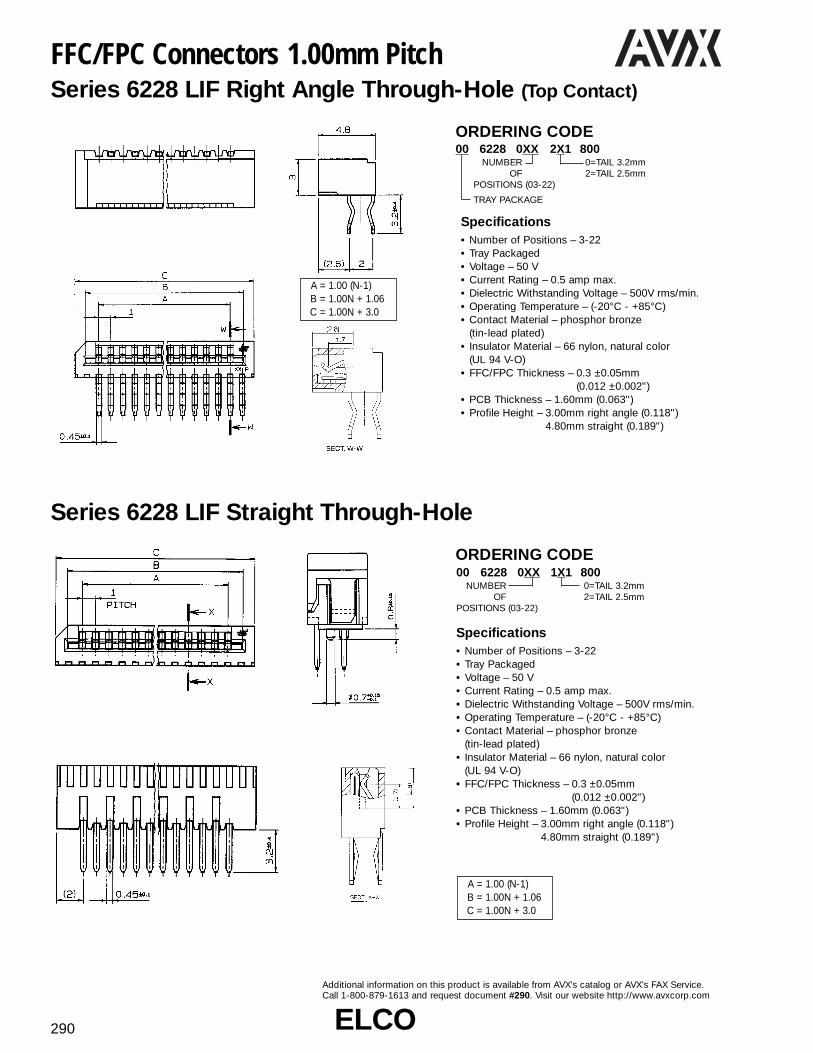
ELCOELCO290
Additional information on this product is available from AVX’s catalog or AVX’s FAX Service.Call 1-800-879-1613 and request document #290. Visit our website http://www.avxcorp.com
FFC/FPC Connectors 1.00mm PitchSeries 6228 LIF Right Angle Through-Hole (Top Contact)
Specifications• Number of Positions – 3-22• Tray Packaged• Voltage – 50 V• Current Rating – 0.5 amp max.• Dielectric Withstanding Voltage – 500V rms/min.• Operating Temperature – (-20°C - +85°C)• Contact Material – phosphor bronze
(tin-lead plated)• Insulator Material – 66 nylon, natural color
(UL 94 V-O)• FFC/FPC Thickness – 0.3 ±0.05mm
(0.012 ±0.002")• PCB Thickness – 1.60mm (0.063")• Profile Height – 3.00mm right angle (0.118")
4.80mm straight (0.189")
00 6228 0XX 2X1 800NUMBER 0=TAIL 3.2mm
OF 2=TAIL 2.5mmPOSITIONS (03-22)
TRAY PACKAGE
A = 1.00 (N-1)B = 1.00N + 1.06C = 1.00N + 3.0
A = 1.00 (N-1)B = 1.00N + 1.06C = 1.00N + 3.0
Series 6228 LIF Straight Through-Hole
00 6228 0XX 1X1 800NUMBER 0=TAIL 3.2mm
OF 2=TAIL 2.5mmPOSITIONS (03-22)
Specifications• Number of Positions – 3-22• Tray Packaged• Voltage – 50 V• Current Rating – 0.5 amp max.• Dielectric Withstanding Voltage – 500V rms/min.• Operating Temperature – (-20°C - +85°C)• Contact Material – phosphor bronze
(tin-lead plated)• Insulator Material – 66 nylon, natural color
(UL 94 V-O)• FFC/FPC Thickness – 0.3 ±0.05mm
(0.012 ±0.002")• PCB Thickness – 1.60mm (0.063")• Profile Height – 3.00mm right angle (0.118")
4.80mm straight (0.189")
ORDERING CODE
ORDERING CODE

ELCOELCO 291
Additional information on this product is available from AVX’s catalog or AVX’s FAX Service.Call 1-800-879-1613 and request document #291. Visit our website http://www.avxcorp.com
FFC/FPC Connectors 1.00mm PitchSeries 6229 ZIF Straight SMT
Series 6229 ZIF Straight Through-Hole
00 6229 040 00X 800NUMBER VARIATION CODE
OF 1:WITHOUT BOSSPOSITIONS (40 position only) 2:WITH BOSS
TRAY PACKAGE (70 per tray)
Specifications• Number of Positions – 40• Tray Packaged• Voltage – 50 V• Current Rating – 1.0 amp max.• Dielectric Withstanding Voltage –
500V rms/min.• Operating Temperature – (-40°C - +85°C)• Contact Material – phosphor bronze
(tin-lead plated)• Slider Material – PPS, natural color
(UL 94 V-O)• Insulator Material – PPS, black color
(UL 94 V-O)• FFC/FPC Thickness –
0.3 ±0.05mm (0.012 ±0.002")• Profile Height – 5.7mm (0.224")
00 6229 640 003 800NUMBER OF POSITIONS(40 position only)
TRAY PACKAGE (70 per tray)
ORDERING CODE
ORDERING CODE

ELCOELCO292
Additional information on this product is available from AVX’s catalog or AVX’s FAX Service.Call 1-800-879-1613 and request document #292. Visit our website http://www.avxcorp.com
FFC/FPC Connectors 1.00mm PitchSeries 6232 LIF Right Angle SMT (Top Contact)
Series 6232 LIF Right Angle SMT (Bottom Contact)
Series 6232 LIF Straight SMT
Specifications• Number of Positions – 3-30• Tray Packaged or SMT Tape and Reel• Voltage – 50 V• Current Rating – 0.50 amp max.• Dielectric Withstanding Voltage – 500V rms/min.• Operating Temperature – (-20°C - +70°C)• Contact Material – phosphor bronze (tin-lead plated)• Insulator Material – glass filled PPS or Nylon• FFC/FPC Thickness – 0.3 ±0.05mm (0.012 ±0.002")• Profile Height – 3.0mm
Specifications• Number of Positions – 3-30• Tray Packaged or SMT Tape and Reel• Voltage – 50 V• Current Rating – 0.50 amp max.• Dielectric Withstanding Voltage – 500V rms/min.• Operating Temperature – (-20°C - +70°C)• Contact Material – phosphor bronze (tin-lead plated)• Insulator Material – glass filled PPS or Nylon• FFC/FPC Thickness – 0.3 ±0.05mm (0.012 ±0.002")• Profile Height – 3.0mm
Specifications• Number of Positions – 3-30• Tray Packaged or SMT Tape and Reel• Voltage – 50 V• Current Rating – 0.50 amp max.• Dielectric Withstanding Voltage – 500V rms/min.• Operating Temperature – (-20°C - +70°C)• Contact Material – phosphor bronze (tin-lead plated)• Insulator Material – glass filled PPS or Nylon• FFC/FPC Thickness – 0.3 ±0.05mm (0.012 ±0.002")• Profile Height – 5.1mm (0.118 – 0.200") (see sketch)
XX 6232 1XX 103 800NUMBER OF POSITIONS (03-30)
00:TRAY PACKAGE04:TAPE AND REEL
XX 6232 1XX 102 800NUMBER OF POSITIONS (03-30)
00:TRAY PACKAGE04:TAPE AND REEL
XX 6232 1XX 0XX 800006:TRAY PACKAGE015:TAPE AND REEL
NUMBER OF POSITIONS(03-30)
00:TRAY PACKAGE04:TAPE AND REEL
A = 1.00 (N-1)B = 1.00N + 1.1C = 1.00N + 3.6
A = 1.00 (N-1)B = 1.00N + 1.1C = 1.00N + 3.6
A = 1.00 (N-1)B = 1.00N + 1.1C = 1.00N + 3.0
ORDERING CODE
ORDERING CODE
ORDERING CODE

ELCOELCO 293
Additional information on this product is available from AVX’s catalog or AVX’s FAX Service.Call 1-800-879-1613 and request document #293. Visit our website http://www.avxcorp.com
FFC/FPC Connectors 1.00mm PitchSeries 6232 LIF Right Angle Through-Hole (Bottom Contact)
Specifications• Number of Positions – 3-30• Tray Packaged• Voltage – 50 V• Current Rating – 0.50 amp max.• Dielectric Withstanding Voltage –
500V rms/min.• Operating Temperature – (-20°C - +70°C)• Contact Material – phosphor bronze
(tin-lead plated)• Insulator Material – glass filled PPS or Nylon• FFC/FPC Thickness –
0.3 ±0.05 mm (0.012 ±0.002")• Profile Height – 3.0mm – (see sketch)
Specifications• Number of Positions – 3-30• Tray Packaged• Voltage – 50 V• Current Rating – 0.50 amp max.• Dielectric Withstanding Voltage –
500V rms/min.• Operating Temperature – (-20°C - +70°C)• Contact Material – phosphor bronze
(tin-lead plated)• Insulator Material – glass filled PPS or Nylon• FFC/FPC Thickness –
0.3 ±0.05 mm (0.012 ±0.002")• Profile Height – 5.5mm (0.217")
00 6232 0XX 104 800TRAY NUMBER OF POSITIONS (03-30)PACKAGE
Series 6232 LIF Straight Through-Hole
00 6232 0XX XXX 800NUMBER VARIATION CODE
OF 006: WITH KINKED LEGSPOSITIONS (03-30) 007: WITHOUT KINKED LEGS
TRAYPACKAGE
A = 1.00 (N-1)B = 1.00N + 1.12C = 1.00N + 3.0
A = 1.00 (N-1)B = 1.00N + 1.12C = 1.00N + 3.0
ORDERING CODE
ORDERING CODE

ELCOELCO294
Additional information on this product is available from AVX’s catalog or AVX’s FAX Service.Call 1-800-879-1613 and request document #294. Visit our website http://www.avxcorp.com
FFC/FPC Connectors 1.00mm PitchSeries 6231 LIF Straight SMT
04 6231 026 000 800NUMBER OF POSITIONS(26 position only)
TAPE AND REEL PACKAGE
Specifications• Number of Positions – 26• 1000 Connectors per Tape & Reel• Voltage – 50 V• Current Rating – 1.0 amp max.• Dielectric Withstanding Voltage – 500V rms/min.• Operating Temperature – (-20°C - +85°C)• Contact Material – phosphor bronze
(tin-lead plated)• Insulator Material – glass-filled PPS
(UL 94 V-O) natural color• FFC/FPC Thickness –
0.3 ±0.05mm (0.012 ±0.002")• Profile Height – 5.5mm (0.217")
Series 6237 ZIF Right Angle SMT (Bottom Contact)
Specifications• Number of Positions – 30• 1000 Connectors per Tape & Reel• Voltage – 50 V• Current Rating – 0.4 amp max.• Dielectric Withstanding Voltage –
200V rms/min.• Operating Temperature – (-40°C - +85°C)• Contact & Metal Tab Material –
phosphor bronze (tin-lead plated)• Slider Material – PPS, natural color
(UL 94 V-O)• Insulator Material – PPS, natural color
(UL 94 V-O)• FFC/FPC Thickness –
0.3 ±0.05mm (0.012 ±0.002")• Profile Height – 2.00mm (0.079")
04 6237 030 000 800NUMBER OF POSITIONS(30 position only)
TAPE AND REEL PACKAGE
A = 35.6B = 29.0
C = 38.2D = 31.2
E = 32.6
ORDERING CODE
ORDERING CODE

ELCOELCO 295
Additional information on this product is available from AVX’s catalog or AVX’s FAX Service.Call 1-800-879-1613 and request document #295. Visit our website http://www.avxcorp.com
FFC/FPC Connectors 0.80mm PitchSeries 6206 LIF Right Angle SMT (Dual Sided Contact)
Specifications• Number of Positions – 4-20• 1000 Connectors per Tape & Reel• Voltage – 50 V• Current Rating – 0.5 amp max.• Dielectric Withstanding Voltage –
200V rms/min.• Operating Temperature –
(-25°C - +85°C)• Contact & Metal Tab Material –
phosphor bronze (tin-lead plated)• Insulator Material – PPS, natural color
(UL 94 V-O)• FFC/FPC Thickness –
0.3 ±0.05mm (0.012 ±0.002")• Profile Height – 2.00mm (0.079")
A = 0.8 (N-1)B = 0.8N + 5.6
04 6206 0XX 000 800NUMBER OF POSITIONS (04-20)
TAPE AND REEL
Series 6218 LIF Straight SMT (Dual Type)
04 6218 010 000 800NUMBER OF POSITIONS (10 position only)
TAPE AND REEL
Specifications• Number of Positions – 10• 1500 Connectors per Tape & Reel• Voltage – 50 V• Current Rating – 0.5 amp max.• Dielectric Withstanding Voltage –
500V rms/min.• Operating Temperature – (-25°C - +85°C)• Contact Material – phosphor bronze
(tin-lead plated)• Insulator Material – nylon 46, natural color
(UL 94 V-O)• FFC/FPC Thickness –
0.3 ±0.05mm (0.012 ±0.002")• Profile Height – 3.5mm (0.138")
ORDERING CODE
ORDERING CODE

ELCOELCO296
Additional information on this product is available from AVX’s catalog or AVX’s FAX Service.Call 1-800-879-1613 and request document #296. Visit our website http://www.avxcorp.com
FFC/FPC Connectors 0.50mm PitchSeries 6210 ZIF Right Angle SMT (Bottom Contact)
Series 6212 ZIF Right Angle SMT (Top Contact)
Specifications• Number of Positions – 5-40• 2000 Connectors per Tape & Reel• Voltage – 50 V• Current Rating – 0.4 amp max.• Dielectric Withstanding Voltage –
200V rms/min.• Operating Temperature – (-40°C - +85°C)• Contact Material – phosphor bronze
(tin-lead plated)• Insulator Material – nylon 46, natural color• Slider Material – PPS, natural color
(UL 94 V-O)• FFC/FPC Thickness –
0.3 ±0.05mm (0.012 ±0.002")• Profile Height – 2.00mm (0.079")
ORDERING CODE08 6210 0XX XXX 800
340 (Small metal tab/strain relief)- Preferred option
010 (Large metal tab/strain relief)NUMBER OF POSITIONS (05-30,33,36,40)
TAPE AND REEL
Specifications• Number of Positions – 5-40• 2000 Connectors per Tape & Reel• Voltage – 50 V• Current Rating – 0.4 amp max.• Dielectric Withstanding Voltage –
200V rms/min.• Operating Temperature –
(-40°C - +85°C)• Contact Material – phosphor bronze
(tin-lead plated)• Insulator Material – nylon 46,
black color• Slider Material – PPS, natural color
(UL 94 V-O)• FFC/FPC Thickness –
0.3 ±0.05mm (0.012 ±0.002")• Profile Height – 2.00mm (0.079")
08 6212 0XX XXX 800340 (Small metal tab/strain relief)
- Preferred option
010 (Large metal tab/strain relief)NUMBER OF POSITIONS(05-30,33,35,36,40)
TAPE AND REEL
A = 0.5N + 4.3B = 0.5 (N-1)C = 0.5N + 6.3D = 0.5N + 0.6
A = 0.5N + 4.3B = 0.5 (N-1)C = 0.5N + 6.3D = 0.5N + 0.6
ORDERING CODE

ELCOELCO 297
Additional information on this product is available from AVX’s catalog or AVX’s FAX Service.Call 1-800-879-1613 and request document #297. Visit our website http://www.avxcorp.com
FFC/FPC Connectors 0.50mm PitchSeries 6214 - ZIF Straight SMT
04 6214 0XX XXX 800NUMBER VARIATION CODE
OF 000: WITH STANDARD SLIDERPOSITIONS (06-30) 010: WITH EXTENDED SLIDER
TAPE AND REEL
Specifications• Number of Positions – 6-30• 1000 Connectors per Tape & Reel• Voltage – 50 V• Current Rating – 0.4 amp max.• Dielectric Withstanding Voltage –
200V rms/min.• Operating Temperature – (-40°C - +85°C)• Contact Material – phosphor bronze
(tin-lead plated)• Insulator Material – nylon 46, natural color
(UL 94 V-O)• Slider Material – PPS, natural color
(UL 94 V-O)• FFC/FPC Thickness –
0.3 ±0.05mm (0.012 ±0.002")• Profile Height – 4.1mm (0.161")
A = 0.5N + 4.5B = 0.5N + 3.9C = 0.5 (N-1)D = 0.5N + 0.6
ORDERING CODE

ELCOELCO298
Additional information on this product is available from AVX’s catalog or AVX’s FAX Service.Call 1-800-879-1613 and request document #298. Visit our website http://www.avxcorp.com
FFC/FPC Connectors 0.50mm PitchSeries 6222 LIF Right Angle SMT (Bottom Contact)
08 6222 0XX 001 800NUMBER OF POSITIONS (05-30)
TAPE AND REEL
Specifications• Number of Positions – 5-30• 2000 Connectors per Tape & Reel• Voltage – 50 V• Current Rating – 0.4 amp max.• Dielectric Withstanding Voltage –
200V rms/min.• Operating Temperature – (-40°C - +85°C)• Contact Material – phosphor bronze
(tin-lead plated)• Insulator Material – PPS, natural color• FFC/FPC Thickness –
0.3 ±0.05mm (0.012 ±0.002")• Profile Height – 1.95mm (0.077")
A = 0.5 (N-1)B = 0.5N + 0.5C = 0.5N + 2.5D = 0.5N + 4.5
A = 0.5 (N-1)B = 0.5N + 0.5C = 0.5N + 2.5D = 0.5N + 4.5
Series 6223 LIF Right Angle SMT (Top Contact)
Specifications• Number of Positions – 5-30• 2000 Connectors per Tape & Reel• Voltage – 50 V• Current Rating – 0.4 amp max.• Dielectric Withstanding Voltage –
200V rms/min.• Operating Temperature – (-40°C - +85°C)• Contact Material – phosphor bronze
(tin-lead plated)• Insulator Material – PPS, black color• FFC/FPC Thickness –
0.3 ±0.05mm (0.012 ±0.002")• Profile Height – 1.95mm (0.077")
08 6223 0XX 001 800NUMBER OF POSITIONS (05-30)
TAPE AND REEL
ORDERING CODE
ORDERING CODE

ELCOELCO 299
Additional information on this product is available from AVX’s catalog or AVX’s FAX Service.Call 1-800-879-1613 and request document #299. Visit our website http://www.avxcorp.com
FFC/FPC Connectors 0.50mm PitchSeries 6239 ZIF Right Angle SMT One-Touch Lock/Flip-Top (Bottom Contact)
Specifications• Number of Positions – 5-30• 2000 Connectors per Tape & Reel• Voltage – 50 V• Current Rating – 0.4 amp max.• Dielectric Withstanding Voltage – 200V rms/min.• Operating Temperature – (-20°C - +85°C)• Contact Material – phosphor bronze (tin-lead plated)• Insulator Material – nylon 46, natural color• Slider Material – PPS, natural color• FFC/FPC Thickness – 0.3 ±0.05mm (0.012 ±0.002")• Profile Height – 1.50mm (0.059")
04 6239 0XX 001 800NUMBER OF POSITIONS (05-30)
TAPE AND REEL
Series 6240 ZIF Right Angle SMT One-Touch Lock/Flip-Top (Bottom Contact)
04 6240 0XX 003 800NUMBER OF POSITIONS (30-50)
TAPE AND REEL
Specifications• Number of Positions – 30-50• 2000 Connectors per Tape & Reel• Voltage – 50 V• Current Rating – 0.4 amp max.• Dielectric Withstanding Voltage – 200V rms/min.• Operating Temperature – (-40°C - +85°C)• Contact Material – phosphor bronze (tin-lead plated)• Insulator Material – PPS, natural color• Slider Material – PPS, natural color• FFC/FPC Thickness – 0.3 ±0.05mm (0.012 ±0.002")• Profile Height – 2.00mm (0.077")
04 6244 0XX 000 800NUMBER OF POSITIONS(12, 14, 20, 22)
TAPE AND REEL
Specifications• Number of Positions – 12, 14, 20, 22• 1000 Connectors per Tape & Reel• Voltage – 50 V• Current Rating – 0.4 amp max.• Dielectric Withstanding Voltage – 200V rms/min.• Operating Temperature – (-40°C - +85°C)• Contact Material – phosphor bronze (tin-lead plated)• Insulator Material – nylon 46, natural color
(UL 94 V-O)• FFC/FPC Thickness –0.3 ±0.05mm (0.012 ±0.002")• Profile Height – 4.1mm (0.161")
Series 6244 LIF Straight SMT
A = 0.5N + 2.1B = 0.5 (N-1)C = 0.5 + 5.8
A = 0.5N + 4.0B = 0.5 (N-1)C = 0.5 + 6.2
A = 0.5N + 2.1B = 0.5 (N-1)C = 0.5N + 0.6
ORDERING CODE
ORDERING CODE
ORDERING CODE

ELCOELCO300
Additional information on this product is available from AVX’s catalog or AVX’s FAX Service.Call 1-800-879-1613 and request document #300. Visit our website http://www.avxcorp.com
Header Low Profile Card 2 Row 4 Row DIL Male IDC DIN Plug &No. of Positions Socket Latched Header Edge Transition Transition Plug Plug 41612 Harness
Series Series Series Series Series Series Series Series Series Series Series8290 8289 8380 8383 6338 8399 8292 8291 8293 8459 8005
SMT2 d
46 s
8 d
910 d d d d d d d d
1214 d d d d d d d
1516 d d d d d d d d d
20 d d d d d d d d
242526 d d d d d d d d
3032 d
34 d d d d d d d d
36 d d
3740 d d d d d d d d
44 d d
50 d d d d d d d d
525660 d d d d d d d d
64 d d d d d d
AccessoriesStrain Relief d d d d d
Coding Key d d d
Polarizing Key d d d
Latch / Eject d d s
ToolingBase Plate d d d d d d d
Hand Tool d d d d d s
Bench Press d d d d d d d
Semi-Automatic d d d
Fully Automatic d s s
OptionsPCB Retention s s s s s
No. of Positions Socket Header
Series Series8284 8284
8 d d
14 d d
16 d d
18 d d
20 d d
24 d d
Compatibility & Approvals• UL
• CSA
• Intermateable and interchangeablewith many other manufacturers
• Compatible with MIL-83503 product
Available d Consult Sales s
IDC for 2.54mm (0.100") Round Conductor Flat Cable
IDC for 1.27mm (0.050") Round Conductor Flat Cable
IDC (Insulation Displacement Connectors) Overview

ELCOELCO 301
Additional information on this product is available from AVX’s catalog or AVX’s FAX Service.Call 1-800-879-1613 and request document #301. Visit our website http://www.avxcorp.com
ORDERING CODE24 8005 X02 100 867
FINISH867 = 15 Micro-
inches Au
VARIATION
STYLE, NO. OF POSITIONSSERIES 002 = Vertical - 2 Position
TAPE AND REEL 502 = Right Angle - 2 Position
2 Position Miniature IDCSeries 8005 Plug Harness (Wire to Board)
L2(STRIP)
L1 (WIRE LENGTH)
1.52
0.25
0.51 MAX.
0.5 MAX.(CUT OFWIRE)
3
1.27
4.83
0.5
0.8MAX.
1.91
1.55MAX.
Series 8005 Receptacle
Wire Color L1 L2 AWG
I
II
Specifications to be supplied by customer. 32 AWG is the preferred option.Wire size must be same as I and II.
VARIATIONContact Sales Office to orderHarness Assembly
1.27
1.21.75
4.83
3.5
2.251.65
4.83
ORDERING CODE97 8005 002 XXX 867
FINISH867 = 15 Micro-inches Au
SERIES
STYLE,
PLUG NO. OF
HARNESS POSITIONS
1.75
2.87
2.27
1.9
0.11.27
4.83
3.34
2.52
1.92
2.0
1.0 0.880.73
0.451.520.3
3.8 ±0.1
Right Angle
Vertical
3 = Wire AWG #32/#30, UL Style 1571
Specifications• Number of Positions – 2• Contact Spacing – 1.27 mm• Current Rating – 1 amp. max.• Voltage Rating – 30V max.• Dielectric Withstanding Voltage – 500V rms/min.• Operating Temperature – -55 to +85°C
II I

ELCOELCO302
Additional information on this product is available from AVX’s catalog or AVX’s FAX Service.Call 1-800-879-1613 and request document #302. Visit our website http://www.avxcorp.com
2 Position Miniature IDCSeries 8015 Plug Harness with Polarization
Series 8015 ReceptacleORDERING CODE24 8015 002 X01 894
FINISH894 = Au Flash over Ni
VARIATIONNO. OF POSITIONS 001 = Color White
SERIES 101 = Color Black
TAPE AND REEL 401 = Color Brown
Wire Color L1 L2
I
II
Specifications to be supplied by customer. Wire size must be same as I and II.
VARIATIONContact Sales Office to orderHarness Assembly
ORDERING CODE97 8015 002 XXX 894
FINISH894 = Au Flash Over Ni
SERIES
NO. OF
PLUG POSITIONS
HARNESS
Vertical
1 = Insulator 61 8015 002 000 00XX = Color Code (Option)
0 = Standard = Natural (White)1 = Black4 = Brown
2 = Contact 71 8015 999 000 8943 = Wire AWG #30, UL Style 1571
Specifications• Number of Positions – 2• Contact Spacing – 1.27 mm• Current Rating – 1 amp. max.• Voltage Rating – 30V max.• Dielectric Withstanding Voltage – 500V rms/min.• Operating Temperature – -55 to +80°C
1.27
0.5
3.7
1.752.8
4.83
3.5
2.251.65
4.2 0.1
0.5 MAX.(CUT OFF)
2.02
0.25
0.51 MAX.
1
2
3
1.27
4.83
0.5
1.91
1.55MAX.
L1
L2
II I
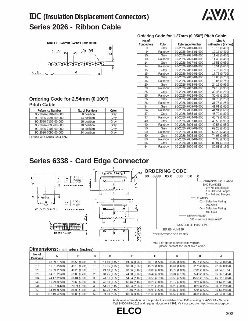
ELCOELCO 303
Additional information on this product is available from AVX’s catalog or AVX’s FAX Service.Call 1-800-879-1613 and request document #303. Visit our website http://www.avxcorp.com
00 6338 0XX 000 0X XVARIATION INSULATOREND FLANGES
0 = No end flanges1 = Half end flanges2 = Full end flanges
ORDERING CODE
PLATING02 = Selective Plating
30µ Gold04 = Selective Plating
10µ GoldSTRAIN RELIEF
000 = Without strain relief*
NUMBER OF POSITIONS
SERIES NUMBER
CONNECTOR CODE PREFIX
*NB: For optional strain relief version,please contact the local sales office.
Ordering Code for 2.54mm (0.100")Pitch Cable
Reference Number No. of Positions Color90-2026-7101-00-000 8 position Grey90-2026-7094-00-000 14 position Grey90-2026-7106-00-000 16 position Grey90-2026-7095-00-000 18 position Grey90-2026-7107-00-000 20 position Grey90-2026-7096-00-000 24 position Grey
For use with Series 8284 only.
No. of Dim. AConductors Color Reference Number millimeters (inches)
9 Grey 90-2026-7049-01-000 10.16 (0.400)9 Rainbow 90-2026-7048-01-000 10.16 (0.400)
10 Grey 90-2026-7021-01-000 11.43 (0.450)10 Rainbow 90-2026-7020-01-000 11.43 (0.450)14 Grey 90-2026-7017-01-000 16.51 (0.650)14 Rainbow 90-2026-7016-01-000 16.51 (0.650)15 Grey 90-2026-7051-01-000 17.78 (0.700)15 Rainbow 90-2026-7050-01-000 17.78 (0.700)16 Grey 90-2026-7015-01-000 19.05 (0.750)16 Rainbow 90-2026-7014-01-000 19.05 (0.750)20 Grey 90-2026-7013-01-000 24.13 (0.950)20 Rainbow 90-2026-7012-01-000 24.13 (0.950)25 Grey 90-2026-7053-01-000 30.48 (1.200)25 Rainbow 90-2026-7052-01-000 30.48 (1.200)26 Grey 90-2026-7011-01-000 31.75 (1.250)26 Rainbow 90-2026-7010-01-000 31.75 (1.250)34 Grey 90-2026-7009-01-000 41.91 (1.650)34 Rainbow 90-2026-7008-01-000 41.91 (1.650)37 Grey 90-2026-7055-01-000 45.72 (1.800)37 Rainbow 90-2026-7054-01-000 45.72 (1.800)40 Grey 90-2026-7007-01-000 49.53 (1.950)40 Rainbow 90-2026-7006-01-000 49.53 (1.950)50 Grey 90-2026-7005-01-000 62.23 (2.450)50 Rainbow 90-2026-7004-01-000 62.23 (2.450)60 Grey 90-2026-7003-01-000 74.93 (2.950)60 Rainbow 90-2026-7002-01-000 74.93 (2.950)64 Grey 90-2026-7001-01-000 80.01 (3.150)64 Rainbow 90-2026-7000-01-000 80.01 (3.150)
Ordering Code for 1.27mm (0.050") Pitch Cable
IDC (Insulation Displacement Connectors)Series 2026 - Ribbon Cable
Series 6338 - Card Edge Connector
No. of A B C D E F G H JPositions
010 43.69 (1.720) 35.56 (1.400) 9 11.43 (0.450) 24.36 (0.960) 38.10 (1.500) 33.02 (1.300) 15.11 (0.595) 15.34 (0.604)016 51.31 (2.020) 43.18 (1.700) 15 19.05 (0.750) 31.98 (1.260) 45.72 (1.800) 40.64 (1.600) 22.73 (0.895) 22.96 (0.904)020 56.39 (2.220) 48.26 (1.900) 19 24.13 (0.950) 37.06 (1.460) 50.80 (2.000) 45.72 (1.800) 27.81 (1.095) 28.04 (1.104026 64.01 (2.520) 55.88 (2.200) 25 31.75 (1.250) 44.68 (1.760) 58.42 (2.300) 53.34 (2.100) 35.43 (1.395) 35.66 (1.404)034 74.17 (2.920) 66.04 (2.600) 33 41.91 (1.650) 54.84 (2.160) 68.58 (2.700) 63.50 (2.500) 45.59 (1.795) 45.82 (1.804)040 81.79 (3.220) 73.66 (2.900) 39 49.53 (1.950) 62.46 (2.460) 76.20 (3.000) 71.12 (2.800) 53.21 (2.095) 53.44 (2.104)044 86.87 (3.420) 78.74 (3.100) 43 54.61 (2.150) 67.54 (2.660) 81.28 (3.200) 76.20 (3.000) 58.29 (2.295) 58.52 (2.304)050 94.49 (3.720) 86.36 (3.400) 49 62.23 (2.450) 75.16 (2.960) 88.90 (3.500) 83.82 (3.300) 65.91 (2.595) 66.14 (2.604)060 107.19 (4.220) 99.06 (3.900) 59 74.93 (2.950) 87.86 (3.460) 101.60 (4.000) 96.52 (3.800) 78.61 (3.095) 78.84 (3.104)
Dimensions: millimeters (inches)
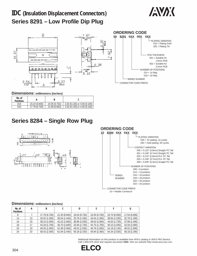
ELCOELCO304
Additional information on this product is available from AVX’s catalog or AVX’s FAX Service.Call 1-800-879-1613 and request document #304. Visit our website http://www.avxcorp.com
00 8291 0XX 00X 0XXORDERING CODE
PLATING VARIATION010 = Plating Gold020 = Plating Tin
PCB THICKNESS001 = Suitable for
1.6mm PCB002 = Suitable for
3.2mm PCBNUMBER OF POSITIONS
014 = 14 Way016 = 16 Way
SERIES NUMBER
CONNECTOR CODE PREFIX
10 8284 0XX 0XX 0XXORDERING CODE
PLATING VARIATION030 = Tin plating, 10 cycles040 = Gold plating, 50 cycles
CONTACT VARIATION000 = 0.110" (2.8mm) Straight PC Tail001 = 0.146" (3.7mm) Straight PC Tail002 = 0.110" (2.8mm) R.A. PC Tail003 = 0.146" (3.7mm) R.A. PC Tail009 = 0.209" (5.3mm) Straight PC Tail
NUMBER OF POSITIONS008 = 8 position014 = 14 position016 = 16 position018 = 18 position020 = 20 position024 = 24 position
SERIESNUMBER
CONNECTOR CODE PREFIX10 = Header Connector
IDC (Insulation Displacement Connectors)Series 8291 – Low Profile Dip Plug
Series 8284 – Single Row Plug
No. of A B CPositions
014 15.24 (0.600) 19.35 (0.762) 3.30 (0.130) or 4.06 (0.160)016 17.78 (0.700) 21.89 (0.862) 3.30 (0.130) or 4.06 (0.160)
Dimensions: millimeters (inches)
Dimensions: millimeters (inches)
No. of A B C D E F GPositions
8 7 17.78 (0.700) 21.30 (0.840) 18.54 (0.730) 19.30 (0.760) 23.70 (0.930) 17.54 (0.690)14 13 33.02 (1.300) 36.54 (1.440) 33.78 (1.330) 34.54 (1.360) 38.94 (1.530) 32.78 (1.290)16 15 38.10 (1.500) 42.22 (1.660) 38.86 (1.530) 39.62 (1.560) 44.02 (1.730) 37.86 (1.490)18 17 43.18 (1.700) 46.70 (1.840) 43.94 (1.730) 44.70 (1.760) 49.10 (1.930) 42.94 (1.690)20 19 48.26 (1.900) 52.38 (2.060) 49.02 (1.930) 49.78 (1.960) 54.18 (2.130) 48.02 (1.890)24 23 58.42 (2.300) 61.94 (2.440) 59.18 (2.330) 59.94 (2.360) 64.34 (2.530) 58.18 (2.290)

ELCOELCO 305
Additional information on this product is available from AVX’s catalog or AVX’s FAX Service.Call 1-800-879-1613 and request document #305. Visit our website http://www.avxcorp.com
Additional information on this product is available from AVX’s catalog or AVX’s FAX Service.Call 1-800-879-1613 and request document #305. Visit our website http://www.avxcorp.com
20 8284 0XX 000 0XXORDERING CODE
PLATING VARIATION030 = Tin Plating,
10 cycles040 = Gold Plating,
50 cycles
CONTACT VARIATION000 = Standard IDC
contact 26/28 AWG
NUMBER OF POSITIONS008 = 8 position014 = 14 position016 = 16 position018 = 18 position020 = 20 position024 = 24 position
SERIESNUMBER
CONNECTORCODE PREFIX
20 = Socket Connector
00 8289 0XX 0XX X X XORDERING CODE
POLARIZATION1 = Type A BS9525 & BT224
Dual Height molding in polarizing key/keys
3 = No Polarizing key/keys - Standard
SERIESNUMBER
CONNECTOR CODE PREFIX
00 = Standard
IDC (Insulation Displacement Connectors)Series 8284 – Single Row Receptacle
Series 8289 – Ejector Style Header
Dimensions: millimeters (inches)
No. of A B C D E FPositions
8 7 17.78 (0.700) 21.30 (0.840) 18.54 (0.720) 19.30 (0.760) 23.70 (0.930)14 13 33.02 (1.180) 36.54 (1.450) 33.78 (1.330) 34.54 (1.360) 38.94 (1.530)16 15 38.10 (1.500) 42.22 (1.660) 38.86 (1.530) 39.62 (1.560) 44.02 (1.730)18 17 43.18 (1.700) 46.70 (1.840) 43.94 (1.730) 44.70 (1.760) 49.10 (1.930)20 19 48.26 (1.900) 52.38 (2.060) 49.02 (1.930) 49.78 (1.960) 54.18 (2.130)24 23 58.42 (2.300) 61.94 (2.440) 59.18 (2.330) 59.94 (2.360) 64.34 (2.530)
No. of A B C DPositions
10 10.16 (0.040) 21.84 (0.860) 27.94 (1.100) 32.11 (1.260)14 15.24 (0.060) 26.92 (1.060) 33.02 (1.300) 37.19 (1.460)16 17.78 (0.070) 29.46 (1.160) 35.56 (1.400) 39.73 (1.560)20 22.86 (0.090) 34.54 (1.360) 40.64 (1.600) 44.81 (1.760)26 30.48 (1.200) 42.16 (1.660) 40.64 (1.900) 52.43 (2.060)34 40.64 (1.600) 52.32 (2.060) 58.42 (2.300) 62.59 (2.460)40 48.26 (1.900) 59.94 (2.360) 66.04 (2.600) 70.21 (2.760)50 60.96 (2.400) 72.64 (2.860) 78.74 (3.100) 82.91 (3.260)60 73.66 (2.900) 85.34 (3.360) 91.44 (3.600) 95.61 (3.760)64 78.74 (3.100) 90.42 (3.560) 96.52 (3.800) 100.69 (3.960)
Dimensions: millimeters (inches)
PLATING1 = Selective Plating 30µ
Gold over Nickel4 = Selective Plating 10µ
Gold over Nickel
LATCH/EJECT LEVER0 = No Latch/Eject Lever1 = Latch/Eject Lever for use with
Series 8290 with strain relief2 = Latch/Eject Lever for use with
Series 8290 without strain relief
CONTACT TERMINATION002 = Straight PC Tail for 2.4mm
PCB - 3.60mm (0.142")004 = Right Angle PC Tail for 2.4mm
PCB - 3.60mm (0.142")006 = Straight PC Tail for 1.6mm
PCB - 2.80mm (0.110")007 = Right Angle PCB Tail for 1.6mm
PCB - 2.80mm (0.110")009 = Press-Fit PC Tail 2.4/3.2mm
PCB - 5.3mm (0.209")
NUMBER OF POSITIONS010 = 10 position014 = 14 position016 = 16 position020 = 20 position026 = 26 position034 = 34 position040 = 40 position050 = 50 position060 = 60 position064 = 64 position
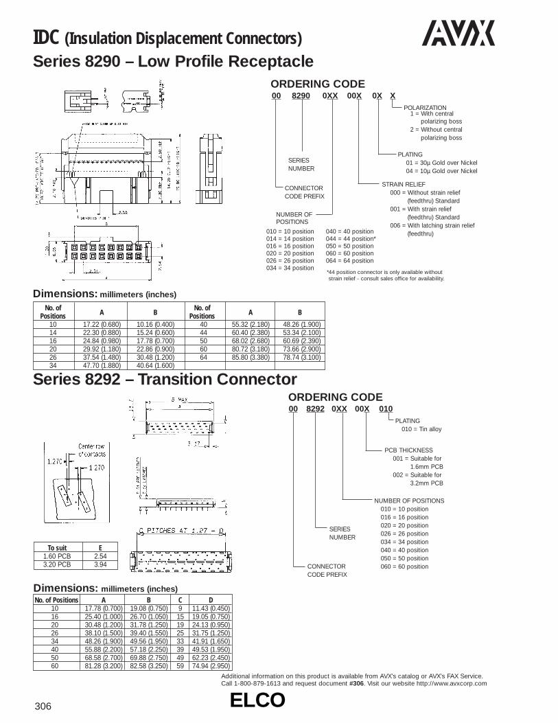
ELCOELCO306
Additional information on this product is available from AVX’s catalog or AVX’s FAX Service.Call 1-800-879-1613 and request document #306. Visit our website http://www.avxcorp.com
IDC (Insulation Displacement Connectors)Series 8290 – Low Profile Receptacle
Series 8292 – Transition Connector
00 8290 0XX 00X 0X XORDERING CODE
POLARIZATION1 = With central
polarizing boss2 = Without central
polarizing boss
SERIESNUMBER
CONNECTOR CODE PREFIX
PLATING01 = 30µ Gold over Nickel04 = 10µ Gold over Nickel
STRAIN RELIEF000 = Without strain relief
(feedthru) Standard001 = With strain relief
(feedthru) Standard006 = With latching strain relief
(feedthru)010 = 10 position014 = 14 position016 = 16 position020 = 20 position026 = 26 position034 = 34 position
040 = 40 position044 = 44 position*050 = 50 position060 = 60 position064 = 64 position
No. of A B
No. of A BPositions Positions
10 17.22 (0.680) 10.16 (0.400) 40 55.32 (2.180) 48.26 (1.900)14 22.30 (0.880) 15.24 (0.600) 44 60.40 (2.380) 53.34 (2.100)16 24.84 (0.980) 17.78 (0.700) 50 68.02 (2.680) 60.69 (2.390)20 29.92 (1.180) 22.86 (0.900) 60 80.72 (3.180) 73.66 (2.900)26 37.54 (1.480) 30.48 (1.200) 64 85.80 (3.380) 78.74 (3.100)34 47.70 (1.880) 40.64 (1.600)
Dimensions: millimeters (inches)
*44 position connector is only available withoutstrain relief - consult sales office for availability.
NUMBER OFPOSITIONS
00 8292 0XX 00X 010ORDERING CODE
PLATING010 = Tin alloy
PCB THICKNESS001 = Suitable for
1.6mm PCB002 = Suitable for
3.2mm PCB
NUMBER OF POSITIONS010 = 10 position016 = 16 position020 = 20 position026 = 26 position034 = 34 position040 = 40 position050 = 50 position060 = 60 position
SERIESNUMBER
CONNECTORCODE PREFIX
No. of Positions A B C D10 17.78 (0.700) 19.08 (0.750) 9 11.43 (0.450)16 25.40 (1.000) 26.70 (1.050) 15 19.05 (0.750)20 30.48 (1.200) 31.78 (1.250) 19 24.13 (0.950)26 38.10 (1.500) 39.40 (1.550) 25 31.75 (1.250)34 48.26 (1.900) 49.56 (1.950) 33 41.91 (1.650)40 55.88 (2.200) 57.18 (2.250) 39 49.53 (1.950)50 68.58 (2.700) 69.88 (2.750) 49 62.23 (2.450)60 81.28 (3.200) 82.58 (3.250) 59 74.94 (2.950)
To suit E1.60 PCB 2.543.20 PCB 3.94
Dimensions: millimeters (inches)

ELCOELCO 307
Additional information on this product is available from AVX’s catalog or AVX’s FAX Service.Call 1-800-879-1613 and request document #307. Visit our website http://www.avxcorp.com
IDC (Insulation Displacement Connectors)Series 8293 – Male Plug Connector
Series 8380 – Low Profile Box Receptacle
XX 8293 0XX 00X 0X XORDERING CODE
POLARIZATION0 = No Polarizing2 = Dual Height Type A
SERIESNUMBER
CONNECTOR CODE PREFIX
10 = StandardConnectorAssembly withmounting flange
11 = StandardConnectorAssembly without mounting flange
PLATING VARIATION01 = Standard 30µ
Gold over Nickel03 = 10µ Gold over Nickel
ASSEMBLY VARIATION000 = Connector
without strain relief001 = Connector
with strain relief
010 = 10 position014 = 14 position016 = 16 position020 = 20 position026 = 26 position
034 = 34 position040 = 40 position050 = 50 position060 = 60 position064 = 64 positionDimensions: millimeters (inches)
NUMBER OF POSITIONS
No. of A B C D EPositions
10 22.89 (0.901) 4 10.16 (0.400) 30.48 (1.200) 38.10 (1.500)14 27.97 (1.101) 6 15.24 (0.600) 35.56 (1.400) 43.18 (1.700)16 30.51 (1.201) 7 17.78 (0.700) 38.10 (1.500) 45.72 (1.800)20 35.59 (1.401) 9 22.86 (0.900) 43.18 (1.700) 50.80 (2.000)26 43.21 (1.701) 12 30.48 (1.200) 50.80 (2.000) 56.59 (2.228)
Dimensions: millimeters (inches)
No. of A B C No. of A B CPositions Positions
10 17.90 (0.705) 4 10.16 (0.400) 34 48.38 (1.905) 16 40.64 (1.600)14 22.98 (0.905) 6 15.24 (0.600) 40 56.00 (2.205) 19 48.26 (1.900)16 25.52 (1.000) 7 17.78 (0.700) 50 68.70 (2.705) 24 60.96 (2.400)20 30.60 (1.200) 9 22.86 (0.900) 60 81.40 (3.205) 29 73.66 (2.900)26 38.22 (1.500) 12 30.48 (1.200) 64 86.48 (3.405) 31 78.74 (3.100)
No. of A B C D EPositions
34 53.37 (2.101) 16 40.64 (1.600) 60.96 (2.400) 68.58 (2.700)40 60.99 (2.401) 19 48.26 (1.900) 68.58 (2.700) 76.20 (3.000)50 73.69 (2.901) 24 60.96 (2.400) 81.28 (3.200) 88.90 (3.500)60 86.39 (3.401) 29 73.66 (2.900) 93.98 (3.700) 101.60 (4.000)64 91.47 (3.601) 31 78.74 (3.100) 98.74 (3.900) 106.68 (4.200)
00 8380 0XX 00X 0X XORDERING CODE
POLARIZATION0 = No Polarizing
Keys Standard2 = Type B -
Dual Height molded in polarizing key(s)SERIES
NUMBER
CONNECTOR CODE PREFIX
00 = StandardConnectorAssembly
PLATING VARIATION01 = 30µ Gold Nickel Solder 04 = 10µ Gold over Nickel
CONTACT VARIATION000 = Solder Tail Straight Contact
for 1.6mm PCB - ContactLength (2.8)
001 = Solder Tail Straight Contactfor 2.4mm PCB - ContactLength (3.6)
002 = Solder Tail Right AngleContact for 1.6mm PCB -Contact Length (2.8)
003 = Solder Tail Right AngleContact for 2.6mm PCB -Contact Length (3.6)
009 = Press-Fit Contact for2.4/3.2 PCB - ContactLength (5.3)
010 = 10 position014 = 14 position016 = 16 position020 = 20 position026 = 26 position034 = 34 position040 = 40 position050 = 50 position060 = 60 position064 = 64 position
NUMBER OFPOSITIONS
NB: Additional plating and tail lengths are available.Consult sales office for availability.

ELCOELCO308
Additional information on this product is available from AVX’s catalog or AVX’s FAX Service.Call 1-800-879-1613 and request document #308. Visit our website http://www.avxcorp.com
IDC (Insulation Displacement Connectors)Series 8383 – Surface Mount Box Header
Series 8399 – Dual-in-Line Transition Connector
00 8383 0XX 00X 0 X 0ORDERING CODE
POLARIZATION0 = No Polarizing
SERIESNUMBER
CONNECTOR CODE PREFIX
00 = StandardConnectorAssembly
PLATING VARIATION
1 = 30µ Gold over Nickel
4 = 10µ Gold over Nickel
CLIP VARIATION0 = No Clip
000 = Solder PC Straight (1.60mm PCB) Length 2.90mm
001 = Solder PC Right Angle(2.40mm PCB) Length 3.70mm
002 = Solder PC Right Angle(1.6mm PCB) Length 2.90mm
003 = Solder PC Straight (2.40mm PCB) Length 3.70mm
009 = Press-Fit Contact for 2.4/3.2mmPCB or contact length 5.3mm
NUMBER OF POSITIONS
010 = 10 position014 = 14 position016 = 16 position020 = 20 position026 = 26 position034 = 34 position040 = 40 position050 = 50 position060 = 60 position064 = 64 position
00 8399 0XX 0X X X 02ORDERING CODE
PLATING02 = Tin Lead
SERIESNUMBER
CONNECTOR CODE PREFIX
00 = Standard
CONTACT2 = 3.6mm tail
phosphorbronze
3 = 2.8mm tail phosphorbronze
CABLE STOP0 = Without cable
stop Standard1 = With cable stop
Special
STRAIN RELIEF00 = Without strain relief01 = With strain relief
NUMBER OF POSITIONS
010 = 10 position014 = 14 position016 = 16 position020 = 20 position026 = 26 position034 = 34 position040 = 40 position050 = 50 position060 = 60 position064 = 64 position
With Strain Relief
Without Strain Relief
No. of Positions A B C10 17.90 (0.705) 4 10.16 (0.400)14 22.98 (0.905) 6 15.24 (0.600)16 25.52 (1.000) 7 17.78 (0.700)20 30.60 (1.200) 9 22.86 (0.900)26 38.22 (1.500) 12 30.48 (1.200)34 48.38 (1.900) 16 40.64 (1.600)40 56.00 (2.200) 19 48.26 (1.900)50 68.70 (2.700) 24 60.96 (2.400)60 81.40 (3.200) 29 73.66 (2.900)64 86.48 (3.200) 31 78.74 (3.100)
Dimensions: millimeters (inches)
No. of Positions A B P C010 18.45 (0.726) 10.16 (.400) 4 20.27 (0.798)014 23.53 (0.926) 15.24 (.600) 6 25.65 (1.01)016 26.07 (1.03) 17.78 (.700) 7 28.19 (1.11)020 31.15 (1.23) 22.86 (.900) 9 33.27 (1.31)026 38.77 (1.53) 30.48 (1.20) 12 40.89 (1.61)034 48.93 (1.93) 40.64 (1.60) 16 51.05 (2.01)040 56.55 (2.23) 48.26 (1.90) 19 58.67 (2.31)050 69.25 (2.73) 60.96 (2.40) 24 71.37 (2.81)060 81.95 (3.23) 73.66 (2.90) 39 84.07 (3.31)064 87.03 (3.42) 78.74 (3.10) 31 89.15 (3.51)
Dimensions: millimeters (inches)
CONTACT VARIATION

ELCOELCO 309
Additional information on this product is available from AVX’s catalog or AVX’s FAX Service.Call 1-800-879-1613 and request document #309. Visit our website http://www.avxcorp.com
IDC (Insulation Displacement Connectors)Series 8459 – IDC DIN Connector
Note: 96 position insulator fitted with 2 rowsof 32 positions, rows A and C.48 position insulator fitted with 2 rowsof 16 positions, rows A and C.
Insulator Size A B C D E F G048 position (3 x 16) 54.90 50.00 15 38.10 60.00 31 39.37
(2.16) (1.97) (1.50) (2.36) (1.55)096 position (3 x 32) 94.90 90.00 31 78.74 100.00 63 80.01
(3.74) (3.54) (3.10) (3.94) (3.15)
Dimensions: millimeters (inches)
Ordering CodeToggle Press Ordering Code 06 8290 7225 00 000Platen Ordering CodeSeries 8290 socket 06 8290 7207 01 000DIL transition connectors 06 8399 7009 00 000Staggered transition connectors 06 8292 7010 00 000Card edge connectors 06 6338 7116 00 000DIL 14/16 connectors 06 8291 7009 00 000
Technical DataTechnical DataForce output max. 15 kN (3300 lbs)Stroke Factory SetAir consumption (per stroke) 0.12scf/in (3.0 litre/cm)Working height adjustable 3.5-8 in (90-210mm)Overhang 3.4 in (86mm)Ram dia 1.57 in (40mm)Ram bore dia with fixation screw M10 5/8 x 2 in (20 H7 x 50mm)Breadth of T-slot 0.394 in (10 H 9mm)Table bore dia 0.787 in (20 H 7mm)Table dimension 6 x 4 in (150 x 110mm)Space requirement 6 x 10 in (155 x 260mm)Air connection thread R 1/4 inWeight 45kg (100 lbs)
Ordering CodePneumatic Press Ordering Code 06 8290 7207 00 000Platen Ordering CodeSeries 8290 socket 06 8290 7207 01 000DIL transition connectors 06 8399 7009 00 000Straggered transition connectors 06 8292 7010 00 000Card edge connectors 06 6338 7116 00 000DIL 14/16 connectors 06 8291 7009 00 000
Non-metric dimensions are for U.S. versions only.
Force output max. 12 kN (2600 lbs)Stroke 45mm (1.8 in)Working height adjustable 120-360mm (5-14 in)Overhang 86mm (3.4 in)Ram bore dia 10 H 7 x 28mm (1/2 x 1 in)Ram dia 32mm (1 1/4 in)Table bore dia 20 H 7mm (0.787 in)Table dimension 185 x 115mm (7 x 4.5 in)Breath of T-slot 10 H 9mm (0.394 in)Weight 30kg (66 lbs)
Non-metric dimensions are for U.S. versions only.
20 8459 0XX 00X 0XXORDERING CODE
PLATING GOLD OVERNICKEL
002 = DIN Class III026 = Class II050 = Class I
VARIATION001 = With strain relief002 = Without strain relief
INSULATOR SIZE048 or 096 (See note)
SERIES NUMBER
CONNECTOR CODE PREFIX
Customer Application ToolingToggle Press Pneumatic

ELCOELCO310
Additional information on this product is available from AVX’s catalog or AVX’s FAX Service.Call 1-800-879-1613 and request document #310. Visit our website http://www.avxcorp.com
Rack and Panel Connectors - Varicon®
Series 8014 – 64 Contact Center-Screw Type Plug
Series 8014 – 64 Contact Center-Screw Type Receptacle
ORDERING CODE10 8014 264 X00 X00
FINISH COLOR000 = without cover,
center-screw, green insulator
100 = with cover,center-screw,green insulator
CONTACT000 = No contact loaded100 = Wire crimp contact
(loose pieces attached)200 = Straight through hole
NUMBER OF POSITIONS264 = 64
SERIESTAPE AND REEL
10 = Plug
ORDERING CODE20 8014 264 XXX X00
FINISH COLOR000 = R/A through hole,
center lock nut, green insulator
100 = ST through hole, center lock nut, green insulator
CONTACT000 = No contact loaded100 = Wire crimp contact
(loose pieces attached)200 = Straight through hole999 = Right angle through hole
NUMBER OF POSITIONS264 = 64
SERIESTAPE AND REEL
20 = Receptacle
4.0mm Pitch
4.0mm Pitch

ELCOELCO 311
Additional information on this product is available from AVX’s catalog or AVX’s FAX Service.Call 1-800-879-1613 and request document #311. Visit our website http://www.avxcorp.com
Rack and Panel Connectors - Varicon®
Series 8014 – 50 Contact Side-Screw Plug
Series 8014 – 50 Contact Side-Screw Receptacle
ORDERING CODE10 8014 350 X00 XXX
FINISH COLOR028 = Side-screw,
gray insulator128 = Side-screw,
gray insulator with cover
(038 = Side-short-screw,gray insulator. . . .special)
CONTACT000 = No contact loaded100 = Wire crimp contact
(loose pieces attached)200 = Straight through hole
NUMBER OF POSITIONS350 = 50
SERIESTAPE AND REEL
10 = Plug
ORDERING CODE20 8014 350 999 028
FINISH COLOR028 = Side-screw,
gray insulatorCONTACT999 = Right angle through hole
NUMBER OF POSITIONS350 = 50
SERIESTAPE AND REEL
20 = Receptacle
4.0mm Pitch
4.0mm Pitch

ELCOELCO312
Additional information on this product is available from AVX’s catalog or AVX’s FAX Service.Call 1-800-879-1613 and request document #312. Visit our website http://www.avxcorp.com
Rack and Panel Connectors - Varicon®
Series 8014 – Crimp Contact
Series 8014 – Cover 64 Contact Center-Screw Aluminum Die Cast
Series 8014 – 50 Contact Side-Screw Plastic (gray) Cover
ORDERING CODE70 8014 000 000 858
FINISH COLOR858 = 10 microinches
gold over nickelplate
ORDERING CODE30 8014 001 000 225
ORDERING CODE30 8014 001 003 008

ELCOELCO 313
Additional information on this product is available from AVX’s catalog or AVX’s FAX Service.Call 1-800-879-1613 and request document #313. Visit our website http://www.avxcorp.com
Rack and Panel Connectors - Varicon®
Series 8016 – Rectangular Connector – 20 Way
Contact Termination
*000 = Contacts not fitted and ordered separately, see page 22 for full list of options
217 = Solder 0.098" x 2.49mm
218 = Wire Wrap –
0.025 x 0.050 x 0.567" / 0.64 x 1.27 x 14.4mm
296 = Wire Wrap –
0.025 x 0.026 x 0.579" / 0.64 x 1.27 x 19.3mm
504 = Solder Tail –
750 = Wire Wrap –
0.025 x 0.050 x 0.760" / 0.64 x 1.27 x 19.3mm
Plug
001/501/601
002/502/602
903/503/603
904/504/604
905/505/605
906/506/606
ORDERING CODE
PlugActuating
Screw
PlugFixed Nut
SocketActuating
Screw
SocketFixedNut
Rec
epta
cle
Connector Plug and ReceptacleCombinations
European Version USA Versions CoverInsulator Grey Polyester Grey Polyester Green Polyester and Actu-
Body Aluminum No No No Cable ating FixedType Cover Cover Cover Cover Cover Cover Entrance Screw Nut
— 001 — 501 601 None Yes No— 002 — 502 602 None No YesMale 903 — 503 603 Top* Yes No(Exposed
904 — 504 604 Side* Yes NoContacts)905 — 505 605 Top* No Yes906 — 506 606 Side* No Yes— 007 507 607 None No Yes— 008 508 608 None Yes NoFemale
909 — 509 — 609 — Top* Yes No(Recessed910 — 510 — 610 — Side* Yes NoContacts)911 — 511 — 611 — Top* No Yes912 — 512 — 612 — Side* No Yes
00
Prefix
8016
SeriesNumber
020
Number ofPositions
XXX 001
SeeVariation
Code
Variation Code
Select variation code combinations marked with square in the table.
*These covers should only be used with crimp contacts.
*Crimp contacts always ordered separately.
Pin Layout20
Way
007/
507/
607
008/
508/
608
909/
509/
609
910/
510/
610
911/
511/
611
912/
512/
612

ELCOELCO314
Additional information on this product is available from AVX’s catalog or AVX’s FAX Service.Call 1-800-879-1613 and request document #314. Visit our website http://www.avxcorp.com
Rack and Panel Connectors - Varicon®
Series 8016 – Rectangular Connector – 20 Way
Clamping and Cover Dimensions RecommendedLayout for FrontChassis Mounting
Standard CoversCover Part Number Number Cable Clamp
European Version USA Version of Positions Entrance Description Size mm (inches)30-8016-9829-20-000 30-8016-9829-00-0000 20 Side Standard 11.53 (0.454) Dia.30-8016-9831-20-000 30-8016-9831-00-0000 20 Top Standard 11.53 (0.454) Dia.
Removable Side Plate Covers millimeters (inches)
Cover Number of Cable ClampPart Number Positions Entrance Description Minimum Size Maximum Size
30-8016-020-000-413 20 Side/Top Standard 5 x 10 (0.197 x 0.394) 10 x 10 (0.394 x 0.394)30-8016-020-000-415 20 45° Standard 5 x 10 (0.197 x 0.394) 10 x 10 (0.394 x 0.394)30-8016-020-000-423 20 Dual 90° Side/Top Special 2 - 5 x 10 (0.197 x 0.394) 2 - 10 x 10 (0.394 x 0.394)30-8016-020-000-425 20 Dual 45° Entry Special 2 - 5 x 10 (0.197 x 0.394) 2 - 10 x 10 (0.394 x 0.394)

ELCOELCO 315
Additional information on this product is available from AVX’s catalog or AVX’s FAX Service.Call 1-800-879-1613 and request document #315. Visit our website http://www.avxcorp.com
Plug
001/501/601002/502/602
903/503/603904/504/604905/505/605906/506/606
919/519/619920/520/620921/521/621922/522/622
931/531/631932/532/632933/533/633934/534/634
007/
507/
607
008/
508/
608
909/
509/
609
910/
510/
610
911/
511/
611
912/
512/
612
923/
523/
623
924/
524/
624
925/
525/
625
926/
526/
626
935/
535/
635
936/
536/
636
937/
537/
637
938/
538/
638
European Version USA ONLY Versions Cover & Actu-Insulator Grey Polyester Grey Polyester Green Polyester Cable ating Fixed
Body Type Aluminum Cover No Cover Aluminum Cover No Cover Aluminum Cover No Cover Entrance Screw NutStd. Large Ex-Large Std. Large Ex-Large Std. Large Ex-Large
Clamp Clamp Clamp Clamp Clamp Clamp Clamp Clamp Clamp— — — 001 — — — 501 — — — 601 None Yes No— — — 002 — — — 502 — — — 602 None No YesMale 903 919 931 — 503 519 531 — 603 619 631 — Top Yes No(Exposed
904 920 932 — 504 520 532 — 604 620 632 — Side Yes NoContacts)905 921 933 — 505 521 533 — 605 621 633 — Top No Yes906 922 934 — 506 522 534 — 606 622 634 — Side No Yes— — 007 — — — 507 — — — 607 None No Yes— — 008 — — — 508 — — — 608 None Yes No
Female 909 923 935 — 509 523 535 — 609 623 635 — Top Yes No(Recessed 910 924 936 — 510 524 536 — 610 624 636 — Side Yes NoContacts) 911 925 937 — 511 525 537 — 611 625 637 — Top No Yes
912 926 938 — 512 526 538 — 612 626 638 — Side No Yes
Rack and Panel Connectors - Varicon®
Series 8016 – Rectangular Connector – 38 Way
00
Prefix
8016
SeriesNumber
038
Number ofPositions
XXX 001
SeeVariation
Code
ORDERING CODE
PlugActuating
Screw
PlugFixed Nut
SocketFixedNut
Rece
ptac
le
Connector Plug and ReceptacleCombinations
Variation Code
Select variation code combinations marked with square in the table.
Contact Termination
*000 = Contacts not fitted and ordered separately, see page 22 for full list of options
217 = Solder 0.098" x 2.49mm
218 = Wire Wrap –
0.025 x 0.050 x 0.567" / 0.64 x 1.27 x 14.4mm
296 = Wire Wrap –
0.025 x 0.026 x 0.579" / 0.64 x 1.27 x 19.3mm
504 = Solder Tail –
750 = Wire Wrap –
0.025 x 0.050 x 0.760" / 0.64 x 1.27 x 19.3mm
*Crimp contacts always ordered separately.
Pin Layout38
Way
SocketActuating
Screw

ELCOELCO316
Additional information on this product is available from AVX’s catalog or AVX’s FAX Service.Call 1-800-879-1613 and request document #316. Visit our website http://www.avxcorp.com
Rack and Panel Connectors - Varicon®
Series 8016 – Rectangular Connector – 38 Way
Clamping and Cover Dimensions Recommended Layout for FrontChassis Mounting
Standard Covers
Removable Side Plate Covers millimeters (inches)Cover Number of Cable Clamp
Part Number Positions Entrance Description Minimum Size Maximum Size30-8016-038-000-413 38 Side/Top Standard 6 x 14 (0.236 x 0.551) 17 x 14 (0.669 x 0.551)30-8016-038-000-415 38 45° Standard 6 x 14 (0.236 x 0.551) 17 x 14 (0.669 x 0.551)30-8016-038-000-423 38 Dual 90° Side/Top Special 2 - 6 x 14 (0.236 x 0.551) 2 - 17 x 14 (0.669 x 0.551)30-8016-038-000-425 38 Dual 45° Entry Special 2 - 6 x 14 (0.236 x 0.551) 2 - 17 x 14 (0.669 x 0.551)
Cover Part Number Number of Cable ClampEuropean Version USA Version Positions Entrance Description Size mm (inches)30-8016-9821-20-000 30-8016-9821-00-0000 38 Side Standard 16.51 X 12.70 (0.650 x 0.500)30-8016-9822-20-000 30-8016-9822-00-0000 38 Top Standard 16.51 X 12.70 (0.650 x 0.500)30-8016-9825-20-000 30-8016-9825-00-0000 38 Side Large 16.51 X 15.44 (0.650 x 0.608)30-8016-9826-20-000 30-8016-9826-00-0000 38 Top Large 16.51 X 15.44 (0.650 x 0.608)30-8016-9838-20-000 30-8016-9838-00-0000 38 Side Extra-Large 20.83 X 15.60 (0.820 x 0.614)30-8016-9839-20-000 30-8016-9839-00-0000 38 Top Extra-Large 20.83 X 15.60 (0.820 x 0.614)
Optional Removable Side Plate Cover
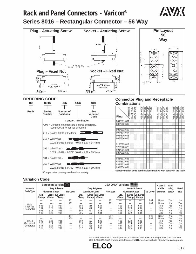
ELCOELCO 317
Additional information on this product is available from AVX’s catalog or AVX’s FAX Service.Call 1-800-879-1613 and request document #317. Visit our website http://www.avxcorp.com
Rack and Panel Connectors - Varicon®
Series 8016 – Rectangular Connector – 56 Way
00
Prefix
8016
SeriesNumber
056
Number ofPositions
XXX 001
SeeVariation
Code
ORDERING CODE
Plug - Actuating Screw
Plug – Fixed Nut
Socket - Actuating Screw
Socket – Fixed Nut
Pin Layout56
Way
Plug
001/501/601002/502/602
903/503/603904/504/604905/505/605906/506/606
919/519/619920/520/620921/521/621922/522/622
931/531/631932/532/632933/533/633934/534/634
007/
507/
607
008/
508/
608
909/
509/
609
910/
510/
610
911/
511/
611
912/
512/
612
923/
523/
623
924/
524/
624
925/
525/
625
926/
526/
626
935/
535/
635
936/
536/
636
937/
537/
637
938/
538/
638
Rece
ptac
le
Connector Plug and ReceptacleCombinations
Select variation code combinations marked with square in the table.
Contact Termination
*000 = Contacts not fitted and ordered separately, see page 22 for full list of options
217 = Solder 0.098" x 2.49mm
218 = Wire Wrap –
0.025 x 0.050 x 0.567" / 0.64 x 1.27 x 14.4mm
296 = Wire Wrap –
0.025 x 0.026 x 0.579" / 0.64 x 1.27 x 19.3mm
504 = Solder Tail –
750 = Wire Wrap –
0.025 x 0.050 x 0.760" / 0.64 x 1.27 x 19.3mm
*Crimp contacts always ordered separately.
European Version USA ONLY Versions Cover & Actu-Insulator Grey Polyester Grey Polyester Green Polyester Cable ating Fixed
Body Type Aluminum Cover No Cover Aluminum Cover No Cover Aluminum Cover No Cover Entrance Screw NutStd. Large Ex-Large Std. Large Ex-Large Std. Large Ex-Large
Clamp Clamp Clamp Clamp Clamp Clamp Clamp Clamp Clamp— — — 001 — — — 501 — — — 601 None Yes No— — — 002 — — — 502 — — — 602 None No YesMale 903 919 931 — 503 519 531 — 603 619 631 — Top Yes No(Exposed
904 920 932 — 504 520 532 — 604 620 632 — Side Yes NoContacts)905 921 933 — 505 521 533 — 605 621 633 — Top No Yes906 922 934 — 506 522 534 — 606 622 634 — Side No Yes— — 007 — — — 507 — — — 607 None No Yes— — 008 — — — 508 — — — 608 None Yes No
Female 909 923 935 — 509 523 535 — 609 623 635 — Top Yes No(Recessed 910 924 936 — 510 524 536 — 610 624 636 — Side Yes NoContacts) 911 925 937 — 511 525 537 — 611 625 637 — Top No Yes
912 926 938 — 512 526 538 — 612 626 638 — Side No Yes
Variation Code
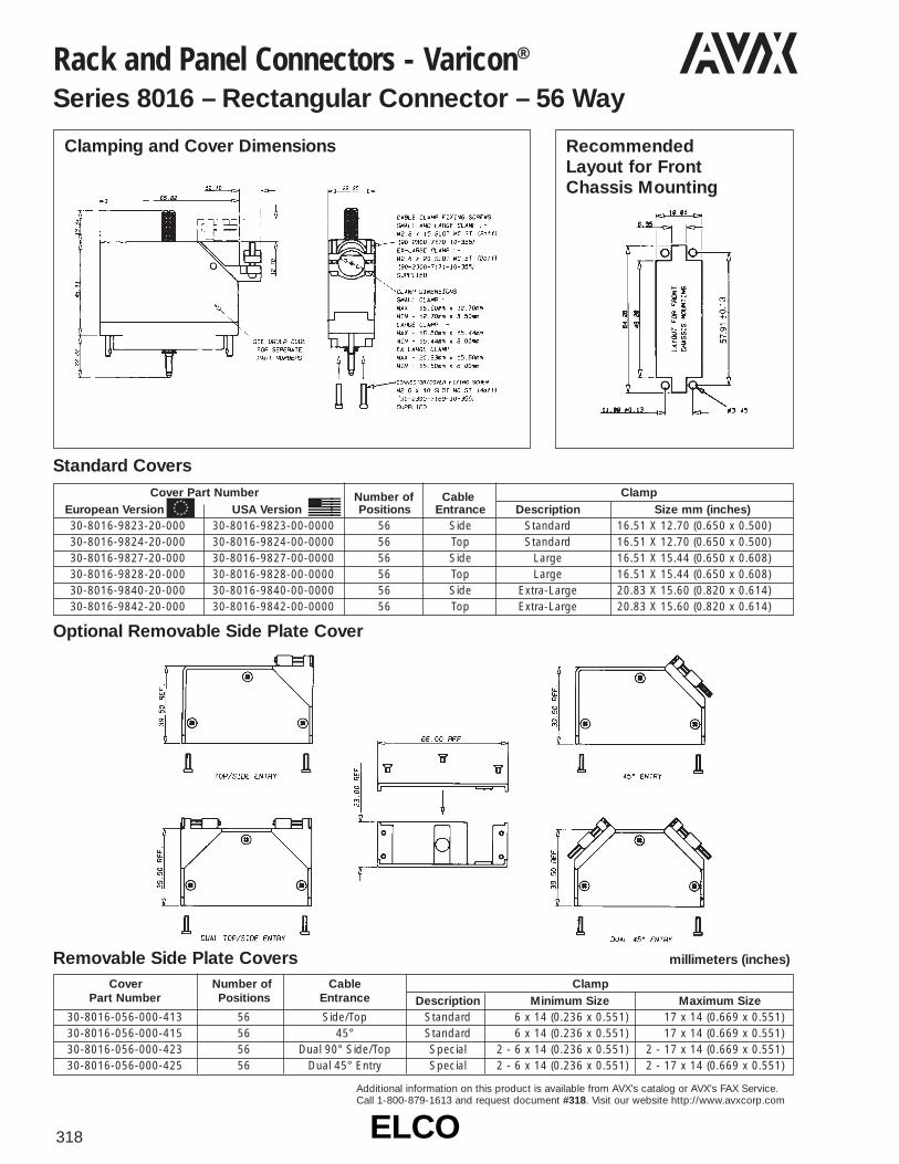
ELCOELCO318
Additional information on this product is available from AVX’s catalog or AVX’s FAX Service.Call 1-800-879-1613 and request document #318. Visit our website http://www.avxcorp.com
Rack and Panel Connectors - Varicon®
Series 8016 – Rectangular Connector – 56 Way
Clamping and Cover Dimensions Recommended Layout for Front Chassis Mounting
Standard Covers
Optional Removable Side Plate Cover
Removable Side Plate Covers millimeters (inches)
Cover Number of Cable ClampPart Number Positions Entrance Description Minimum Size Maximum Size
30-8016-056-000-413 56 Side/Top Standard 6 x 14 (0.236 x 0.551) 17 x 14 (0.669 x 0.551)30-8016-056-000-415 56 45° Standard 6 x 14 (0.236 x 0.551) 17 x 14 (0.669 x 0.551)30-8016-056-000-423 56 Dual 90° Side/Top Special 2 - 6 x 14 (0.236 x 0.551) 2 - 17 x 14 (0.669 x 0.551)30-8016-056-000-425 56 Dual 45° Entry Special 2 - 6 x 14 (0.236 x 0.551) 2 - 17 x 14 (0.669 x 0.551)
Cover Part Number Number of Cable ClampEuropean Version USA Version Positions Entrance Description Size mm (inches)30-8016-9823-20-000 30-8016-9823-00-0000 56 Side Standard 16.51 X 12.70 (0.650 x 0.500)30-8016-9824-20-000 30-8016-9824-00-0000 56 Top Standard 16.51 X 12.70 (0.650 x 0.500)30-8016-9827-20-000 30-8016-9827-00-0000 56 Side Large 16.51 X 15.44 (0.650 x 0.608)30-8016-9828-20-000 30-8016-9828-00-0000 56 Top Large 16.51 X 15.44 (0.650 x 0.608)30-8016-9840-20-000 30-8016-9840-00-0000 56 Side Extra-Large 20.83 X 15.60 (0.820 x 0.614)30-8016-9842-20-000 30-8016-9842-00-0000 56 Top Extra-Large 20.83 X 15.60 (0.820 x 0.614)

ELCOELCO 319
Additional information on this product is available from AVX’s catalog or AVX’s FAX Service.Call 1-800-879-1613 and request document #319. Visit our website http://www.avxcorp.com
European Version USA ONLY Versions Cover & Actu-Insulator Grey Polyester Grey Polyester Green Polyester Cable ating Fixed
Body Type Cover Cover Cover No Cover Cover No Cover Entrance Screw NutLarge Ex-Large Large Ex-Large Large Ex-LargeClamp Clamp Clamp Clamp Clamp Clamp
— — 001 — — 501 — — 601 None Yes No— — 002 — — 502 — — 602 None No YesMale 903 931 — 503 531 — 603 631 — Top Yes No(Exposed
904 932 — 504 532 — 604 632 — Side Yes NoContacts)905 933 — 505 533 — 605 633 — Top No Yes906 934 — 506 534 — 606 634 — Side No Yes
— — 007 — — 507 — — 607 None No Yes— — 008 — — 508 — — 608 None Yes No
Female 909 935 — 509 535 — 609 635 — Top Yes No(Recessed 910 936 — 510 536 — 610 636 — Side Yes NoContacts) 911 937 — 511 537 — 611 637 — Top No Yes
912 938 — 512 538 — 612 638 — Side No Yes
Rack and Panel Connectors - Varicon®
Series 8016 – Rectangular Connector – 90 Way
00
Prefix
8016
SeriesNumber
090
Number ofPositions
XXX 1
SeeVariation
Code
ORDERING CODE
Plug - Actuating Screw
Plug – Fixed Nut
Socket - Actuating Screw
Socket – Fixed Nut
Pin Layout90
Way
Connector Plug and ReceptacleCombinations
Variation Code
Plug
001/501/601002/502/602
903/503/603904/504/604905/505/605906/506/606
931/531/631932/532/632933/533/633934/534/634
007/
507/
607
008/
508/
608
909/
509/
609
910/
510/
610
911/
511/
611
912/
512/
612
935/
535/
635
936/
536/
636
937/
537/
637
938/
538/
638
Rece
ptac
le
Select variation code combinations marked with square in the table.
Contact Termination
*000 = Contacts not fitted and ordered separately, see page 22 for full list of options
217 = Solder 0.098" x 2.49mm
218 = Wire Wrap –
0.025 x 0.050 x 0.567" / 0.64 x 1.27 x 14.4mm
296 = Wire Wrap –
0.025 x 0.026 x 0.579" / 0.64 x 1.27 x 19.3mm
504 = Solder Tail –
750 = Wire Wrap –
0.025 x 0.050 x 0.760" / 0.64 x 1.27 x 19.3mm
*Crimp contacts always ordered separately.

ELCOELCO320
Additional information on this product is available from AVX’s catalog or AVX’s FAX Service.Call 1-800-879-1613 and request document #320. Visit our website http://www.avxcorp.com
Rack and Panel Connectors - Varicon®
Series 8016 – Rectangular Connector – 90 WayClamping and Cover Dimensions Recommended
Layout for Front Chassis Mounting
Standard Covers
Optional Removable Side Plate Cover
Removable Side Plate Covers millimeters (inches)
Cover Number of Cable ClampPart Number Positions Entrance Description Minimum Size Maximum Size
30-8016-090-000-413 90 Side/Top Standard 7 x 21 (0.276) 21 x 21 (0.827 x 0.827)30-8016-090-000-415 90 45° Standard 7 x 21 (0.276) 21 x 21 (0.827 x 0.827)30-8016-090-000-423 90 Dual 90° Side/Top Special 2 - 7 x 21 (0.276) 2 - 21 x 21 (0.827 x 0.827)30-8016-090-000-425 90 Dual 45° Entry Special 2 - 7 x 21 (0.276) 2 - 21 x 21 (0.827 x 0.827)
Cover Part Number Number of Cable ClampEuropean Version USA Version Positions Entrance Description Size mm (inches)30-8016-9832-20-000 30-8016-9832-00-0000 90 Side Large 20.32 (0.800) Dia.30-8016-9833-20-000 30-8016-9833-00-0000 90 Top Large 20.32 (0.800) Dia.30-8016-9843-20-000 30-8016-9843-00-0000 90 Side Extra-Large 25.40 x 20.32 (1.00 x 0.008)30-8016-9844-20-000 30-8016-9844-00-0000 90 Top Extra-Large 25.40 x 20.32 (1.00 x 0.008)

ELCOELCO 321
Additional information on this product is available from AVX’s catalog or AVX’s FAX Service.Call 1-800-879-1613 and request document #321. Visit our website http://www.avxcorp.com
Rack and Panel Connectors - Varicon®
Series 8016 – Rectangular Connector – 120 Way
00
Prefix
8016
SeriesNumber
120
Number ofPositions
XXX 001
SeeVariation
Code
ORDERING CODE
Plug - Actuating Screw
Plug – Fixed Nut
Socket - Actuating Screw
Socket – Fixed Nut
Pin Layout120Way
Connector Plug and ReceptacleCombinations
Plug
001/501/601002/502/602
903/503/603904/504/604905/505/605906/506/606
931/531/631932/532/632933/533/633934/534/634
007/
507/
607
008/
508/
608
909/
509/
609
910/
510/
610
911/
511/
611
912/
512/
612
935/
535/
635
936/
536/
636
937/
537/
637
938/
538/
638
Rece
ptac
le
Select variation code combinations marked with square in the table.
Contact Termination
*000 = Contacts not fitted and ordered separately, see page 22 for full list of options
217 = Solder 0.098" x 2.49mm
218 = Wire Wrap –
0.025 x 0.050 x 0.567" / 0.64 x 1.27 x 14.4mm
296 = Wire Wrap –
0.025 x 0.026 x 0.579" / 0.64 x 1.27 x 19.3mm
504 = Solder Tail –
750 = Wire Wrap –
0.025 x 0.050 x 0.760" / 0.64 x 1.27 x 19.3mm
*Crimp contacts always ordered separately.
European Version USA ONLY Versions Cover & Actu-Insulator Grey Polyester Grey Polyester Green Polyester Cable ating Fixed
Body Type Cover Cover Cover No Cover Cover No Cover Entrance Screw NutLarge Ex-Large Large Ex-Large Large Ex-LargeClamp Clamp Clamp Clamp Clamp Clamp
— — 001 — — 501 — — 601 None Yes No— — 002 — — 502 — — 602 None No YesMale 903 931 — 503 531 — 603 631 — Top Yes No(Exposed
904 932 — 504 532 — 604 632 — Side Yes NoContacts)905 933 — 505 533 — 605 633 — Top No Yes906 934 — 506 534 — 606 634 — Side No Yes
— — 007 — — 507 — — 607 None No Yes— — 008 — — 508 — — 608 None Yes No
Female 909 935 — 509 535 — 609 635 — Top Yes No(Recessed 910 936 — 510 536 — 610 636 — Side Yes NoContacts) 911 937 — 511 537 — 611 637 — Top No Yes
912 938 — 512 538 — 612 638 — Side No Yes
Variation Code

ELCOELCO322
Additional information on this product is available from AVX’s catalog or AVX’s FAX Service.Call 1-800-879-1613 and request document #322. Visit our website http://www.avxcorp.com
Rack and Panel Connectors - Varicon®
Series 8016 – Rectangular Connector – 120 WayClamping and Cover Dimensions Recommended
Layout for FrontChassis Mounting
Standard CoversCover Part Number Number of Cable Clamp
European Version USA Version Positions Entrance Description Size mm (inches)30-8016-9834-20-000 30-8016-9834-00-0000 120 Side Large 20.32 x 27.43 (0.800 x 1.080)30-8016-9835-20-000 30-8016-9835-00-0000 120 Top Large 20.32 x 27.43 (0.800 x 1.080)30-8016-9845-20-000 30-8016-9845-00-0000 120 Side Extra-Large 27.94 x 27.56 (1.100 x 1.085)30-8016-9846-20-000 30-8016-9846-00-0000 120 Top Extra-Large 27.94 x 27.56 (1.100 x 1.085)
NB: There are no removable side plate covers for the 120 Way version.
Contact Style Description Plating Specification Order Code
* Crimp Contact 0.25µM Gold All Over (Standard) 60 8017 0313 00 339Loose 0.25µM Gold Nose & Tail (Optional) 60 8017 0313 00 042
Crimp Contact End Carrier 0.25µM Gold All Over (Standard) 60 8017 0323 99 339(1800 Contacts per reel) 0.25µM Gold Nose & Tail (Optional) 60 8017 0323 99 042
0.25µM Gold All Over (Standard) 60 8017 0323 00 339**0.25µM Gold Nose & Tail (Optional) 60 8017 0323 00 042**
Tail Section – 2.49 x 0.61 (0.098 x 0.024)Solder Tag Contact 0.25µM Gold All Over (Standard) 60 8017 0513 00 339*
Tail Section – 1.27 x 0.63 (0.025 x 0.005)14.4mm Maxiwrap Contact 0.25µM Gold All Over (Standard) 60 8017 0613 00 339
Tail Section – 1.27 x 0.63 (0.025 x 0.005)19.3mm Maxiwrap Contact 0.25µM Gold All Over (Standard) 60 8017 0623 00 339
Tail Section – 0.635 x 0.63 (0.025 x 0.005)14.0 Miniwrap Contact 0.25µM Gold All Over (Standard) 60 8017 0633 00 339
Tail Section – 0.635 x 0.63 (0.025 x 0.005)4.3mm PC Solder Contact 0.25µM Gold All Over (Standard) 60 8017 0663 00 339
* for ø 1.00 mm P.T.H.
* Indicates standard contact / ** Order code to be used when purchasing through a USA source.
Ordered separately
Ordered separately
If fitted type 217
If fitted type 218
If fitted type 750
If fitted type 296
If fitted type 504

ELCO 323
Additional information on this product is available from AVX’s catalog or AVX’s FAX Service.Call 1-800-879-1613 and request document #323. Visit our website http://www.avxcorp.com
Insulator Variation Cover &Body Code Cable Actuating FixedType No. Entrance Screw Screw
001 No Yes No002 No No Yes003 Top Yes No
Plug 004 Side Yes No005 Top No Yes006 Side No Yes
Varicon®
Series 8017
Variation Code
Insulator Variation Cover &Body Code Cable Fixed ActuatingType No. Entrance Nut Nut
007 No Yes No008 No No Yes
Receptacle 009 Top Yes No 010 Side Yes No011 Top No Yes012 Side No Yes
00
Prefix
8017
SeriesNumber
XXX
Number ofPositions
75, 100, 130
XXX 0XX
SeeVariation
Code
ORDERING CODE
Contact Code217 = Solder 0.098" x 2.49mm –
60 8017 0513 00 339
218 = Wire Wrap –
0.025 x 0.050 x 0.567" / 0.64 x 1.27 x 14.4mm
60 8017 0613 00 339
750 = Wire Wrap –
0.025 x 0.050 x 0.760" / 0.64 x 1.27 x 19.3mm
60 8017 0623 00 339
296 = Wire Wrap –
0.025 x 0.026 x 0.579" / 0.64 x 0.66 x 14.7mm
60 8017 0633 00 339
000 = Wire Crimp (Contacts Loose) – Must be ordered separately
60 8017 0313 00 339
000 = Wire Crimp (1800 Contacts on a Reel) –
60 8017 0323 00 339 Must be ordered separately
75/100/130 Contacts
Plug with Plug with Actuating Screw 001 Fixed Screw 002
Receptacle with Receptacle with Fixed Nut 007 Actuating Nut 008
Plug
75 ContactsPlug
Receptacle Receptacle
100 Contacts
Plug
Receptacle
130 Contacts

ELCOELCO324
Additional information on this product is available from AVX’s catalog or AVX’s FAX Service.Call 1-800-879-1613 and request document #324. Visit our website http://www.avxcorp.comAdditional information on this product is available from AVX’s catalog or AVX’s FAX Service. Call 1-800-879-1613 and request document #324.
Visit our website http://www.avxcorp.com
Contact Code000 = Crimp (3000 - contact reel)
Part Number60 8216 0323 00 339
000 = Crimp (loose contact) Accepts #22-30 AWG wirePart Number60 8216 0313 00 339
491 = Wire wrappable removable contact .025" (.635mm) sq. x .564" (14.33mm) tail
Part Number60 8216 0413 00 339
Varicon®
Series 8026 – 0.100" Rectangular ConnectorVariation Codes
Insulator VariationBody Code Actuating Fixed Keying CoverType No. Screw Nut Hardware
701 Yes No Yes No702 Yes No No No
Male 703 No Yes Yes No(Exposed 704 No Yes No NoContacts) 733 No No Yes No
734 No No No No801 No Yes Yes No802 No Yes No No
Female 803 Yes No Yes No (Recessed 804 Yes No No No Contacts) 833 No No Yes No
834 No No No NoTable 2
Male 501 Yes No Yes No (Exposed 502 Yes No No No Contacts) 503 No Yes Yes No
504 No Yes No No601 No Yes Yes No
Female 602 No Yes No No (Recessed 603 Yes No Yes No Contacts) 604 Yes No No No
33 ContactsTable 1
Variation Code No.Insulator Cover Cover Cable Actuating Fixed Keying
Body Without Small Large Entrance Screw Nut HardwareType Cover Clamp Clamp
701 — — No Yes No Yes702 — — No Yes No No703 — — No No Yes Yes704 — — No No Yes No733 — — No No No Yes734 — — No No No No— 705 713 Top Yes No Yes— 706 714 Side Yes No Yes
Male — 707 715 Top Yes No No(Exposed — 708 716 Side Yes No NoContacts) — 709 717 Top No Yes Yes
— 710 718 Side No Yes Yes— 711 719 Top No Yes No— 712 720 Side No Yes No— 735 739 Top No No Yes— 736 740 Side No No Yes— 737 741 Top No No No— 738 742 Side No No No
801 — — No No Yes Yes802 — — No No Yes No803 — — No Yes No Yes804 — — No Yes No No833 — — No No No Yes834 — — No No No No— 805 813 Top No Yes Yes— 806 814 Side No Yes Yes
Female — 807 815 Top No Yes No(Recessed — 808 816 Side No Yes NoContacts) — 809 817 Top Yes No Yes
— 810 818 Side Yes No Yes— 811 819 Top Yes No No— 812 820 Side Yes No No— 835 839 Top No No Yes— 836 840 Side No No Yes— 837 841 Top No No No— 838 842 Side No No No
75, 117 & 165 ContactsTable 3
Table 4
00
Prefix
8026
SeriesNumber
033
Number ofPositions
XXX 803
SeeVariation
Code
ORDERING CODE
Order crimp contacts separately by Part Number.Otherwise specify contact code 491.
Add 050 to order alternative keying (Pin & Socket)
i.e. 701 = Standard hermaphroditic keying
751 = Pin and socketkeying
Complete a 15 digitassembly number foreach mating part, maleand female.
033 = 33 075 = 75
117 = 117165 = 165
Clamp
Cover Cable 8026/.100"Number Entrance Description (2.54mm) sq.
30-8016-9821 Side Small 75 Pin30-8016-9822 Top Small 75 Pin30-8016-9823 Side Small 117 Pin30-8016-9824 Top Small 117 Pin30-8016-9825 Side Large 75 Pin30-8016-9826 Top Large 75 Pin30-8016-9827 Side Large 117 Pin30-8016-9828 Top Large 117 Pin30-8016-9832 Side Large 165 Pin30-8016-9833 Top Large 165 Pin30-8016-9838 Side Ex-Large 75 Pin30-8016-9839 Top Ex-Large 75 Pin30-8016-9840 Side Ex-Large 117 Pin30-8016-9842 Top Ex-Large 117 Pin30-8016-9843 Side Ex-Large 165 Pin30-8016-9844 Top Ex-Large 165 Pin30-8016-9845 Side Ex-Large —30-8016-9846 Top Ex-Large —
COVER CROSS REFERENCE, FORDETAILS SEE 8016 CONNECTOR
Variation Code No.Insulator Cover Cover Cable Actuating Fixed Keying
Body Without Small Large Entrance Nut Screw HardwareType Cover Clamp Clamp
501 — — No Yes No Yes502 — — No Yes No No503 — — No No Yes Yes504 — — No No Yes No— 505 513 Top Yes No Yes— 506 514 Side Yes No Yes
Male — 507 515 Top Yes No No(Exposed — 508 516 Side Yes No NoContacts) — 509 517 Top No Yes Yes
— 510 518 Side No Yes Yes— 511 519 Top No Yes No— 512 520 Side No Yes No
601 — — No No Yes Yes602 — — No No Yes No603 — — No Yes No Yes604 — — No Yes No No— 605 613 Top No Yes Yes— 606 614 Side No Yes Yes
Female — 607 615 Top No Yes No(Recessed — 608 616 Side No Yes NoContacts) — 609 617 Top Yes No Yes
— 610 618 Side Yes No Yes— 611 619 Top Yes No No— 612 620 Side Yes No No

ELCOELCO 325
Additional information on this product is available from AVX’s catalog or AVX’s FAX Service.Call 1-800-879-1613 and request document #325. Visit our website http://www.avxcorp.com
Varicon®
Series 8026 – 0.100" Rectangular Connector
33 CONTACTSFemale Plug (Recessed Contacts) For variation code number
See Table 1 Page 324 See Table 2 Page 324
75 CONTACTSFemale Plug (Recessed Contacts) For variation code number
See Table 3 Page 324 See Table 4 Page 324
117 CONTACTSFemale Plug (Recessed Contacts) For variation code number
See Table 3 Page 324 See Table 4 Page 324
65 CONTACTSFemale Plug (Recessed Contacts) For variation code number
See Table 3 Page 324 See Table 4 Page 324

ELCOELCO326
Additional information on this product is available from AVX’s catalog or AVX’s FAX Service.Call 1-800-879-1613 and request document #326. Visit our website http://www.avxcorp.com
Varicon®
Series 8223 – 0.100" Dual Row Square Grid
Use three digit code number when contacts are to befactory installed. If contacts are to be supplied loose, orcontact tails to be formed, use three zeros (000) in con-tact code section. Note that the wire crimp tail contactscan only be ordered as separate items by part numbers.
Code Profile Description Part No. H BoardFig.Dim. Thk.
Coined Tail Formed 60 8223 0223 .080 1000 90° after installing 60 8223 0213 .062
(Max. 0236 Diag.)
Coined Tail Formed 60 8223 0243.093 1000 90° after installing 60 8223 0253
(Max. 0236 Diag.)
473P.C. Tail Coined
60 8223 0233 .400 2(Max. 0236 Diag.)
519P.C. Tail Coined
60 8223 0213 .279 2(Max. 0236 Diag.)
520P.C. Tail Coined
60 8223 0223 .479 2(Max. 0236 Diag.)
558 P.C. Tail Coined 60 8223 0243 .309 2559 (Max. 0236 Diag.) 60 8223 0253 .509 2
560 P.C. Tail Coined 60 8223 0263 .341 2561 (Max. 0236 Diag.) 60 8223 0273 .541 2
722Wire Hole Tail
60 8200 1613 .162 3(.032 x .050)
721 P.C. Tail .020 Sq. 60 8200 1623 .228 4
736 P.C. Tail .020 Sq. 60 8200 1633 .259 4
737 P.C. Tail .020 Sq. 60 8200 1643 .541 4
753 P.C. Tail .020 Sq. 60 8200 1653 .103 4
771 P.C. Tail .020 Sq. 60 8200 1663 .462 4
Crimp Contact5000 (Reel 3000) 60 8216 0323
22-30 AWG
000Crimp Contact (Loose)
60 8216 0313 522-30 AWG
491Wrappable/Removable
60 8216 0413 .560 6Contact (.025 Sq.)
ORDERING CODE00 8223 XXX XXX
Contact Code
XXX
Variation CodeNumber of Positions024, 048, 072 & 096
AccessoriesGuide Pins Sockets (R) Refer
InsulatorVariation Contact Style Threaded To Board
Type Cover Bracket Keying Locking Lkg. Kyg. Figure Thickness
001 Formed Contact Terminal X 1.080 2.03.062 1.57
PC Terminal X 2002 Wire Hole Terminal X 3
PC Straight Terminal X 4Crimp Contact X 5
Male 003 Wrappable Removable X 6(Exposed 004 Formed Contact Terminal X 1 .093 2.36Contacts) 006 Similar to 001 X 7
007 X 8008 Similar to 002 X 7009 X 8016 Similar to 004 X 7017 X 8018 Similar to 006 X 7019 X 8
901 Formed Contact Terminal X 1.080 2.03.062 1.57
PC Terminal X 2902 Wire Hole Terminal X 3
PC Straight Terminal X 4Crimp Contact X 5
903 Wrappable Removable X 6Female 904 Formed Contact Terminal X 1 .093 2.36
(Exposed 906 Similar to 901 X 15Contacts) 907 X 16
908 Similar to 902 X 15909 X 16916 Similar to 904 X 15917 X 16918 Similar to 905 X 15919 X 16
Male Insulators
Female Insulators
CrimpType
CrimpType

ELCOELCO 327
Additional information on this product is available from AVX’s catalog or AVX’s FAX Service.Call 1-800-879-1613 and request document #327. Visit our website http://www.avxcorp.com
Varilok®
Series 8020 – Cable Connector
Connector Dimensions (mm)
Locking Clip Dimensions (mm)
ORDERING CODEFor complete connectors withNon-Crimp Contacts Fitted
Ordering Code for Housings and Crimp ContactsDescription Part Number Description Part Number2 way connector: Housing only 60-8020-3117-00-000 0.25µM Gold reeled crimp contacts (gold all over) 60-8017-0323-99-3393 way connector: Housing only 60-8020-3317-00-000 0.25µM Gold reeled crimp contacts (selective) 60-8017-0323-99-0420.25µM Gold loose crimp contacts (gold all over) 60-8017-0313-00-339 NB: See page 22 for details of crimp contacts0.25µM Gold loose crimp contacts (selective) 60-8017-0313-00-042 Locking clip 60-8020-3210-00-000
*Contact terminations should be insulatedbecause they may protrude from the insulator
00 8020 0XX 0XX 0XXVARIATION
*CONTACT VARIATION217 = Solder Tag218 = Wire Wrap
(0.61 x 1.27 x 14.4mm)296 = Mini Wire Wrap
(0.61 x 0.66 x 4.73mm)504 = Solder Tail
(0.61 x 0.66 x 4.32mm)
NUMBER OF POSITIONS002 = 2 way003 = 3 way
SERIESNUMBER
PREFIX
Features and Benefits• 2 and 3 position in single row• Uses identical molding for plug and socket• Uses identical contact for plug and socket• Uses standard Varicon 8016 contacts• Uses standard Varicon Crimping Tools, Contact
Extraction Tools and Insertion Tools• Has combined nylon mounting and locking clip
common to both sizes• Contacts for both solder and crimp termination
• Contact – Single row of 2 or 3 Varilok contacts• Configuration – On a 0.200" pitch, 5.08 mm• Contact Rating – 8.5 amperes• Contact Resistance – 6 milliohms (max)• Insulation Resistance – 5,000 megohms (min)• Voltage Proof – 2,500 volts R.M.S. Sea Level
Specifications
2 way connector 3 way connectorhousing housing
Locking clip 2 way assembly 3 way assembly

ELCOELCO328
Additional information on this product is available from AVX’s catalog or AVX’s FAX Service.Call 1-800-879-1613 and request document #328. Visit our website http://www.avxcorp.com
Varilok®
Series 8022 – Cable Connector
• Contact Spacing – 5.08 mm• Contact Rating – 8.5 amperes• Contact Resistance – 6 milliohms (max)• Insulation Resistance – 5K megohms• Voltage Proof – 2.5K volts R.M.S. Sea Level• Operating Temperature – -55°C to 125°C
Technical Specifications
Features• 3 position in single row• Male insulator incorporates two positive
locking arms for up to 1.6 mm thick panel mount
• Uses identical contact for plug and socket• Uses standard Varicon 8016 contacts
(8017 Series)• Uses standard Varicon Crimping Tools,
Contact Extraction Tools and Insertion Tools• Has mounting and locking clip mechanism• Contacts for both solder and crimp
termination
Part NumbersPlug Molding 60 8022 3218 00 000Socket Molding 60 8022 3318 00 000Crimp Contacts (loose) 60 8017 0313 00 339Crimp Contacts (reel) 60 8017 0323 00 339
Panel Cutout
Plug
Socket

ELCOELCO 329
Additional information on this product is available from AVX’s catalog or AVX’s FAX Service.Call 1-800-879-1613 and request document #329. Visit our website http://www.avxcorp.com
Varicon®
Series 8218 – 0.050" Staggered Dual Row
0XX
Variation Code001 = Receptacle002 = Plug-Card005 = Plug-Board
ORDERING CODE
00 8218 100 XXX
Contact Code
Variant 002 right angled contacts
000 = 60 8200 16 33P.C. Tail
000 = 60 8200 16 63P.C. Tail
Variants 001 and 005 722 = 60 8200 16 13
Wire Hole Tail
736 = 60 8200 16 33
P.C. Tail (X = 9/32", Y = 1/4")
753 = 60 8200 16 53
P.C. Tail (X = 1/8", Y = 3/32")
771 = 60 8200 16 63
P.C. Tail (X = 31/64", Y = 29/64")
with keying pins011 = Receptacle012 = Plug-Card/pin
inserted in odd position
013 = Plug-Card/pin inserted ineven position
017 = Plug-Board
with keying holes021 = Receptacle022 = Plug-Card/pin
inserted in odd position
023 = Plug-Card/pin inserted in even position
027 = Plug-Board
Number of Positions002 to 076 for connectors
without center guide
Receptacle Variation 001 Plug Variation 002 Plug Variation 005
Receptacle 001 – Mates with Plugs 002 and 005

ELCOELCO330
Additional information on this product is available from AVX’s catalog or AVX’s FAX Service.Call 1-800-879-1613 and request document #330. Visit our website http://www.avxcorp.com
Varicon®
Series 8219 – 0.050" Staggered Dual Row
001 = ReceptacleWithout
002 = Plug, perpendicular board mountingKeying005 = Plug, parallel board mounting
CodeContact Type
“X”No. Dim.722 Wire hole tail .187721 P. C. solder tail .250736 P. C. solder tail .281737 P. C. solder tail .562753 P. C. solder tail .125771 P. C. solder tail .484
ORDERING CODE00 8219 042
Number of Positions018, 030, 036, 042, 054, 072
722
Contact Code(see below)
001
Variation Code
For Variation = 001
CodeContact TypeNo.
000 P. C. solder tails formed722 Wire hole tail unformed
For Variation = 002
CodeContact Type
“Y”No. Dim.722 Wire hole tail .157721 P. C. solder tail .219736 P. C. solder tail .250737 P. C. solder tail .531753 P. C. solder tail .093771 P. C. solder tail .453
For Variation = 005
NOTE: Connector is supplied with mounting screws or eyelets, as applicable(see drawings).
Contact Factory for Special Variations.
When Keying is ordered with part number, the Key is installed at the factory.
POLARIZING SYSTEM
NumberRef. Ref.
of A B CD
E F GKPositions
18 17 .850 (0.033) 1.150 (0.045) 1.290 (0.051) 1.400 (0.055) 1.540 (0.061) .964 (0.038) 1.300 (0.051)30 29 1.450 (0.057) 1.750 (0.069) 1.890 (0.075) 2.000 (0.079) 2.140 (0.084) 1.564 (0.061) 1.900 (0.075)36 35 1.750 (0.069) 2.050 (0.080) 2.190 (0.086) 2.300 (0.091) 2.440 (0.096) 1.864 (0.073) 2.220 (0.087)42 41 2.050 (0.080) 2.350 (0.093) 2.490 (0.098) 2.600 (0.102) 2.740 (0.108) 2.164 (0.085) 2.500 (0.098)54 53 2.650 (0.104) 2.950 (0.116) 3.090 (0.122) 3.200 (0.126) 3.340 (0.131) 2.764 (0.109) 3.100 (0.122)72 71 3.550 (0.140) 3.850 (0.152) 3.990 (0.157) 4.100 (0.161) 4.240 (0.167) 3.664 (0.144) 4.000 (0.157)
Dimensions: millimeters (inches)
Receptacle 001 - Mates with Plugs 002 and 005

ELCOELCO 331
Additional information on this product is available from AVX’s catalog or AVX’s FAX Service.Call 1-800-879-1613 and request document #331. Visit our website http://www.avxcorp.com
141 = 60 7001 06 33P.C. Termination for 1/8" Card
146 = 60 7001 13 13.078" Base Taper Tab
156 = 60 7001 18 13
Wire wrapping (.026 x .062 x .600")
163 = 60 7001 19 13
.098" Base Taper Tab w/Wire Hole
165 = 60 7001 20 13
Forked Tail Solder Termination for Bus Line Connection
(.056 x .125" Slot)
166 = 60 7001 20 23
Dual Solder Termination for 2 Wires or Bus Line
(.056 x .125" Slot)
189 = 60 7004 02 13
Conventional Solder Termination for 3 Wires
Varicon®
Series 7008 – 0.100" Staggered Dual Row
00 7008 0XX
Number of Positions017, 023, 029, 035, 041
XXX
Contact CodeSee table
001
Variation Code
AvailabilityConnector No. of Positions
Description 17 23 29 35 41With Guides – for 1/16" Card X X X X X
Without Guides – for 1/16" /Card X X X X X
Card Card CodeSlot Guides1/16" Yes 001
No 002
ORDERING CODE

ELCOELCO332
Additional information on this product is available from AVX’s catalog or AVX’s FAX Service.Call 1-800-879-1613 and request document #332. Visit our website http://www.avxcorp.com
Varicon®
Series 7022 – 0.100" Staggered Dual Row
ORDERING CODE
MOUNTING LAYOUT
00 7022 0XX
Number of Positions017, 023, 029, 035, 041
For Series 7008 receptacle
000 00X
Variation Code001 = 1/16" Module Card Thickness002 = 3/32" Module Card Thickness003 = 1/16" Module Card Thickness
60 7001 2913 for 1/16" Card 60 7001 2813 for 1/16" Card60 7001 2923 for 3/32" Card6 560 7001 2823 for 3/32" Card

ELCOELCO 333
Additional information on this product is available from AVX’s catalog or AVX’s FAX Service.Call 1-800-879-1613 and request document #333. Visit our website http://www.avxcorp.com
Varicon®
Series 7023 – 0.100" Staggered Dual Row
Technical Specifications• Current Rating – 10 amperes• Contact Resistance – 6 milliohms, maximum• Contact Material and Plating –
Phosphor Bronze per QQ-B-750, Composition A.Gold, 10 microinches minimum, over nickel, 30 to 100 microinches
• Insulator Material – Diallyl phthalate, glass-filled,flame resistant per MIL-M-14F, Type SDGF.
Variation 001/002/110/111Thermoplastic Polycarbonate Variation 003
• Insulation Resistance – 25,000 megohms, minimum• Dielectric Withstanding Voltage –
Sea Level: 1800 Volts rms3.4" Hg: 675 Volts rms
• Insertion/Withdrawal Force – 2 to 16 ounces per contact
• Conforms to Military Specifications – MIL-C-21097, MIL-E-5400, MIL-E-8189, MIL-T-21200, MIL-E-19600 (Para. 3.5.5), MIL-STD-454.
Numberof B C H
Positions Max.17 2.200 (0.087) 2.470 (0.097) 1.600 (0.063)23 2.800 (0.110) 3.070 (0.121) 2.200 (0.087)29 3.400 (0.134) 3.670 (0.144) 2.800 (0.110)35 4.000 (0.157) 4.270 (0.168) 3.400 (0.134)41 4.600 (0.181) 4.870 (0.192) 4.000 (0.157)47 5.200 (0.205) 5.470 (0.215) 4.600 (0.181)
Contacts used in this connector:
Card Upper Card Lower CardContacts Contacts
1/16" 60 7001 29 13 60 7001 28 13
3/32" 60 7001 29 23 60 7001 28 23
Mounting Layout
00 7023 0XX
Number of Positions017, 023, 029, 035, 041, 047
000 001
Diallyl PhthalateGlass Filled
1/16" Card 3/32" Card 1/16" Card001 002 003110* 111*
*Conforms to MIL-C-21097
Dimensions: millimeters (inches)

ELCOELCO334
Additional information on this product is available from AVX’s catalog or AVX’s FAX Service.Call 1-800-879-1613 and request document #334. Visit our website http://www.avxcorp.com
Varicon®
Series 7024 – 0.100" Staggered Dual Row
ORDERING CODE00 7024 023
Number of Positions017, 023, 029, 035, 041
163
Contact CodeSee table
001
Variation Code001 = 1/16" Thick Card002 = 3/32" Thick Card110* = 1/16" Thick Card111* = 3/32" Thick Card
* For Conformance to MIL-C-21097B
141 = 60 7001 06 33P.C. Termination for 1/8" Card
146 = 60 7001 13 13.078" Base Taper Tab
156 = 60 7001 18 13
Wire wrapping (.026 x .062 x .600")
163 = 60 7001 19 13
.098" Base Taper Tab w/Wire Hole
165 = 60 7001 20 13
Forked Tail Solder Termination for Bus Line Connection
(.056 x .125" Slot)
166 = 60 7001 20 23
Dual Solder Termination for 2 Wires or Bus Line
(.056 x .125" Slot)
189 = 60 7004 02 13
Conventional Solder Termination for 3 Wires
AvailabilityConnector No. of Positions
Description 17 23 29 35 41For 1/16" Card X X X X XFor 3/32" Card X X X X X

ELCOELCO 335
Additional information on this product is available from AVX’s catalog or AVX’s FAX Service.Call 1-800-879-1613 and request document #335. Visit our website http://www.avxcorp.com
217 = 60 8017 05 13Wire Hole
218 = 60 8017 06 13
Solderless Wrap Tail – .025" x .050" x .567"
750 = 60 8017 06 23
Solderless Wrap Tail – .025" x .050" x .760"
296 = 60 8017 06 33
Solderless Wrap Tail – .025" x .025" x .580"
504 = 60 8017 06 63
Solderless Wrap Tail – .025" x .025" x .170"
*000 = 60 8017 03 13
Wire Crimp Tail (Contacts Loose) 18-26 AWG
*000 = 60 8017 03 23
Wire Crimp Tail
(Contacts on a Reel) 18-26 AWG
*Order separately by part number, refer to page 22
Rack and Panel Connectors - Varicon®
Series 7038 – 0.100" Staggered Dual Row, Crimp Contacts
ORDERING CODE00 7038 0XX
Number of Contacts017, 023, 029, 035, 041, 047
XXX
Contact CodeSee table
XXX
Variation Code001 = 1/16" Thick Card002 = 3/32" Thick Card110* = 1/16" Thick Card111* = 3/32" Thick Card
* For Conformance to MIL-C-21097

ELCOELCO336
Additional information on this product is available from AVX’s catalog or AVX’s FAX Service.Call 1-800-879-1613 and request document #336. Visit our website http://www.avxcorp.com
Memory Card Connectors
Series 5027 – Card BUS SMT Connector
PCMCIA Compact Flash MMC Smart Card SO-DIMMSeries Series Series Series
Plug/Ejector 5025 5610 5038 50335027 5620
Receptacles 5069 56119170
Frames/Covers 9170 5612
I/O Plug 9157
Memory Module 6400
31 5027 068 540 833ORDERING CODE

ELCOELCO 337
Additional information on this product is available from AVX’s catalog or AVX’s FAX Service.Call 1-800-879-1613 and request document #337. Visit our website http://www.avxcorp.com
Memory Card ConnectorsSeries 5025 – PCMCIA (Single) Connector/Ejector
Series 5025 – PCMCIA (Dual) Connector/Ejector
Single SMTStand Off Keying Button Connector Ejector
SideHeight = 0 5v. Normal Left 31 5025 068 305 833 30 5025 000 321 000
Right 31 5025 068 305 833 30 5025 000 322 000Height = 0 5v. Reverse Left 31 5025 068 355 833 30 5025 000 321 000
Right 31 5025 068 355 833 30 5025 000 322 000
Dual DIP/DIP
Stand Off Keying Button Connector EjectorSide
Left/Left 31 5025 136 500 833 30 5025 000 621 000
Height = 0 5v. Normal Right/Right 31 5025 136 500 833 30 5025 000 622 000Left/Right 31 5025 136 500 833 30 5025 000 623 000Right/Left 31 5025 136 500 833 30 5025 000 624 000Left/Left 31 5025 136 550 833 30 5025 000 621 000
Height = 0 5v. Reverse Right/Right 31 5025 136 550 833 30 5025 000 622 000Left/Right 31 5025 136 550 833 30 5025 000 623 000Right/Left 31 5025 136 550 833 30 5025 000 624 000
Single DIPStand Off Keying Button Connector Ejector
SideHeight = 0 5v. Normal Left 31 5025 068 100 833 30 5025 000 321 000
Right 31 5025 068 100 833 30 5025 000 322 000Height = 0 5v. Reverse Left 31 5025 068 150 833 30 5025 000 321 000
Right 31 5025 068 150 833 30 5025 000 322 000
Connector Ejector
Connector
Ejector

ELCOELCO338
Additional information on this product is available from AVX’s catalog or AVX’s FAX Service.Call 1-800-879-1613 and request document #338. Visit our website http://www.avxcorp.com
Series 5069 – PCMCIA Receptacle
Series 5069Solder Tail Style Ordering CodeStraddle 20 5069 068 003 833 Semi-Hard TraySingle Side SMT 24 5069 068 901 835 Tape & Reel (72mm)
Stand Off Keying Button Connector EjectorSide
Height = 0 5v. Normal Left Side 31 5027 068 010 833 30 5027 000 001 000Right Side 31 5027 068 010 833 30 5027 000 002 000
Height = 0 5v. Reverse Left Side 31 5027 068 020 833 30 5027 000 001 000Right Side 31 5027 068 020 833 30 5027 000 002 000
Height = 0 3.3v. Normal Left Side 31 5027 068 030 833 30 5027 000 001 000Right Side 31 5027 068 030 833 30 5027 000 002 000
Height = 0 3.3v. Reverse Left Side 31 5027 068 040 833 30 5027 000 001 000Right Side 31 5027 068 040 833 30 5027 000 002 000
Height = 2.2 5v. Normal Left Side 31 5027 068 110 833 30 5027 000 101 000Right Side 31 5027 068 110 833 30 5027 000 102 000
Height = 2.2 5v. Reverse Left Side 31 5027 068 120 833 30 5027 000 101 000Right Side 31 5027 068 120 833 30 5027 000 102 000
Height = 2.2 3.3v. Normal Left Side 31 5027 068 130 833 30 5027 000 101 000Right Side 31 5027 068 130 833 30 5027 000 102 000
Height = 2.2 3.3v. Reverse Left Side 31 5027 068 140 833 30 5027 000 101 000Right Side 31 5027 068 140 833 30 5027 000 102 000
Memory Card ConnectorsSeries 5027 – PCMCIA Connector/Ejector
Connector
Ejector

ELCOELCO 339
Additional information on this product is available from AVX’s catalog or AVX’s FAX Service.Call 1-800-879-1613 and request document #339. Visit our website http://www.avxcorp.com
Memory Card ConnectorsSeries 5069 – PCMCIA Receptacle (Single Side)
Series 5069 – PCMCIA Receptacle (Straddle)
XX 5069 068 901 835
24 = TAPE AND REEL PACKAGE
ORDERING CODE
20 5069 068 003 833ORDERING CODE

ELCOELCO340
Additional information on this product is available from AVX’s catalog or AVX’s FAX Service.Call 1-800-879-1613 and request document #340. Visit our website http://www.avxcorp.com
Memory Card ConnectorsSeries 9170 – Type II Frameless PCMCIA Card Kit
Series 9157 – I/O PCMCIA Card Plug
Selection Guide Frameless Kit Type IIKit Consists Of
Kit Part Number 68 Position Covers I/OTop
Blank I/O 80-9170-4000-00-000 22-9170-000-0Can be supplied with
20-9170-068-001-xxxBottom
special cut-outs 80-9170-4100-00-000Top80-9170-4000-00-000 21-9170-015-001-xxx15 way without co-axial 20-9170-068-001-xxxBottom80-9170-4100-00-000Top80-9170-4000-00-000 21-9170-015-002-xxx15 way with co-axial 20-9170-068-001-xxxBottom80-9170-4100-00-000
Interconnection Assembly (Plug/Covers) Selection Guide
15 Way Plug CoversWithout co-axial 58 9157 015 000 004 58 9157 000 000 00xWith co-axial 58 9157 015 000 003 58 9157 000 000 00x
Grommet Options00x-7 = 5mm Diameter
8 = 3.5mm Diameter
Also Available• The 68 position Cardbus connector can be incorporated
in Elco Frameless Kit Concept• The Cardbus connector will allow engineers to increase
the speed of the actual card.• Dual I/O connectors capabilities for fax/modem applica-
tions.• Combinations of 4, 7 and 15 ways can be mounted.• Your existing I/O connectors can be mounted allowing
you to make full use of your existing cab assemblies.• I/O connectors can also be customized to suit individual
applications thus allow coax, antenna, LED’s etc, to bemounted.
• Extended cards that utilize the frameless kit concept -for WLAN market.
• The plastic bulge element can be customized to suitindividual applications which can be metal coated ifrequired.
• Extended bulge parts can also be mounted on a fullymetalised bottom cover.

ELCOELCO 341
Additional information on this product is available from AVX’s catalog or AVX’s FAX Service.Call 1-800-879-1613 and request document #341. Visit our website http://www.avxcorp.com
Memory Card ConnectorsSeries 5610 – Compact Flash Type I Header (Zero Stand Off)
Connector
Ejector and Connector
Stand Off Keying ConnectorHeight = 0 normal 31 5610 050 500 833
reverse 31 5610 050 550 833Height = 2.2 normal 31 5610 050 210 833
reverse 31 5610 050 260 833
Connector Style Ejector Style Ordering CodeStand Off Keying Button Side Connector EjectorHeight = 0 Normal Straight Left 31 5610 050 500 833 30 5610 000 001 000
Right 31 5610 050 500 833 30 5610 000 002 000Foldable Left 31 5610 050 500 833 30 5610 000 005 000
Right 31 5610 050 500 833 30 5610 000 006 000Height = 0 Reverse Straight Left 31 5610 050 550 833 30 5610 000 001 000
Right 31 5610 050 550 833 30 5610 000 002 000Foldable Left 31 5610 050 550 833 30 5610 000 005 000
Right 31 5610 050 550 833 30 5610 000 006 000Height = 2.2 Normal Straight Left 31 5610 050 210 833 30 5610 000 001 000
Right 31 5610 050 210 833 30 5610 000 002 000Foldable Left 31 5610 050 210 833 30 5610 000 005 000
Right 31 5610 050 210 833 30 5610 000 006 000Height = 2.2 Reverse Straight Left 31 5610 050 260 833 30 5610 000 001 000
Right 31 5610 050 260 833 30 5610 000 002 000Foldable Left 31 5610 050 260 833 30 5610 000 005 000
Right 31 5610 050 260 833 30 5610 000 006 000
Connector
Stand Off
Stand Off
Ejector

ELCOELCO342
Additional information on this product is available from AVX’s catalog or AVX’s FAX Service.Call 1-800-879-1613 and request document #342. Visit our website http://www.avxcorp.com
Receptacle Connector Series 5611 (For Type I)Solder Tail Style Ordering CodeStraddle 20 5611 050 113 833 Semi-Hard TraySingle Side SMT 24 5611 050 114 835 Tape & Reel (56mm)
Card Kit Series 5612 (For Type I)With Insulating Tape 10 5612 100 000 011Without Insulating Tape 10 5612 100 000 012
Type I
Type II
Memory Card ConnectorsSeries 5611/5612 – Compact Flash Connectors/Card Kits
Card Configuration

ELCOELCO 343
Additional information on this product is available from AVX’s catalog or AVX’s FAX Service.Call 1-800-879-1613 and request document #343. Visit our website http://www.avxcorp.com
Memory Card ConnectorsSeries 5620 – Compact Flash Type II Header
Keying A B C D E F G H
Normal 1.4 0.78 #1 #13 #25 #26 #38 #50
31 5620 050 116 833ORDERING CODE
Recommended Printed Circuit Layout

ELCOELCO344
Additional information on this product is available from AVX’s catalog or AVX’s FAX Service.Call 1-800-879-1613 and request document #344. Visit our website http://www.avxcorp.com
Memory Card ConnectorsSeries 5038 – MMC (Multimedia Card)
Series 5033 – (Smart Card)
10 5038 007 052 833ORDERING CODE
97 5033 008 160 001ORDERING CODE
97 5033 008 XXX 001
050 = Harness 50mm160 = Harness 160mm
ORDERING CODE
Connector
Harness
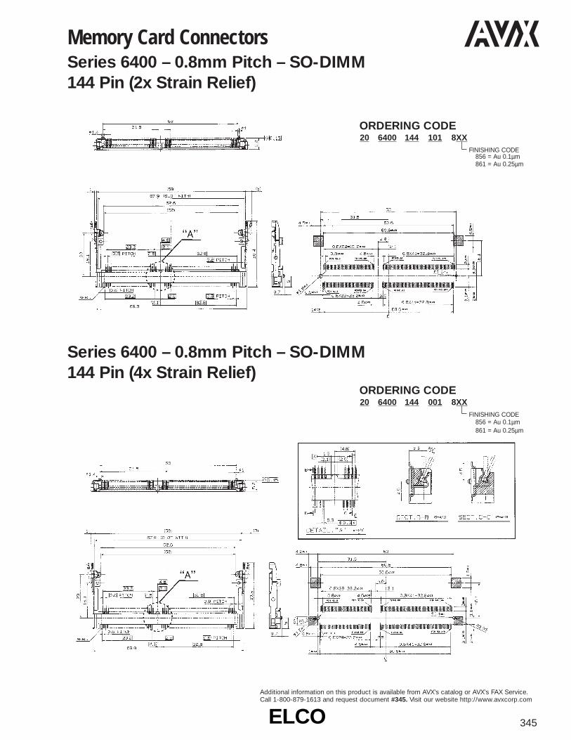
ELCOELCO 345
Additional information on this product is available from AVX’s catalog or AVX’s FAX Service.Call 1-800-879-1613 and request document #345. Visit our website http://www.avxcorp.com
Memory Card ConnectorsSeries 6400 – 0.8mm Pitch – SO-DIMM 144 Pin (2x Strain Relief)
Series 6400 – 0.8mm Pitch – SO-DIMM 144 Pin (4x Strain Relief)
20 6400 144 101 8XXORDERING CODE
FINISHING CODE856 = Au 0.1µm861 = Au 0.25µm
20 6400 144 001 8XXORDERING CODE
FINISHING CODE856 = Au 0.1µm861 = Au 0.25µm

ELCOELCO346
Additional information on this product is available from AVX’s catalog or AVX’s FAX Service.Call 1-800-879-1613 and request document #346. Visit our website http://www.avxcorp.com
RECEPTACLE HOUSING ORDERING CODE62 9515 004 010 001
CAP ORDERING CODE62 9515 004 020 001
HARD SEAL (A) ORDERING CODE92 9515 004 000 003
HARD SEAL (C) ORDERING CODE92 9515 004 XXX XXX
NUMBER OF POSITIONS002 002 = (2P) 003 003 = (3P) 004 004 = (4P)
Automotive Splashproof ConnectorsSeries 9215 – Branch ConnectorsHousing Contact
Plug Receptacle
ORDERING CODE70 9215 999 00X 825
VARIATION CODE (IDC)0 = 0.5sq AVS 0.5 (Crimping side area)1 = 0.85sq2 = 0.3sq
ORDERING CODE60 9215 001 010 00X
VARIATION CODE0 = 0.85sq (white)1 = 0.5sq (black)6 = 0.3sq (blue)
PLUG HOUSING ORDERING CODE61 9515 004 000 001
HARD SEAL (B) ORDERING CODE92 9515 004 XXX XXX
NUMBER OF POSITIONS - Color012 002 = (2P/Blue), 013 003 = (3P/Yellow), 014 004 = (4P/Red)
PLUG CONTACT ORDERING CODE71 9515 999 010 808
RECEPTACLE CONTACT ORDERING CODE72 9515 999 020 808
Series 9515 Connectors
Contact Plug Receptacle
Auto Crimping MachinePress Machine 36 1004 001Applicator 36 1000 044Press Capacity 2 (tons)Dimension W550xH700xD380Weight 85kgPower AC100V 50/60Hz
TOOLING

ELCOELCO 347
Additional information on this product is available from AVX’s catalog or AVX’s FAX Service.Call 1-800-879-1613 and request document #347. Visit our website http://www.avxcorp.com
Plastic Optical Fiber (POF) Connector Series 9710
Series 9711 SP Connector
ORDERING CODEPart No. 61 9710 002 001 001
ORDERING CODEPLUG Part No. 61 9711 002 001 001ADAPTOR Part No. 60 9711 004 101 001
Plug Adaptor

ELCOELCO348
Additional information on this product is available from AVX’s catalog or AVX’s FAX Service.Call 1-800-879-1613 and request document #348. Visit our website http://www.avxcorp.com
CD ROM/HDD ConnectorsSeries 5600 – 0.8mm Pitch 50 Position Plug
Series 5600 – 0.8mm Pitch 50 Position Receptacle
14 5600 050 000 883ORDERING CODE
24 5600 050 100 883ORDERING CODE

ELCOELCO 349
Additional information on this product is available from AVX’s catalog or AVX’s FAX Service.Call 1-800-879-1613 and request document #349. Visit our website http://www.avxcorp.com
Telecom ConnectorsSeries 9156 – POGO Pin Battery Connector
(3 position example)
ORDERING CODE58 9156 00X 000 0XX
CONTACT PITCHPLATING CODE
NO. OF POSITIONS
SERIESPREFIX
Features• Nose heights optional• 2, 3, 4, 5 way available,
custom options available• Contact pitch optional• Current rating typically 3A• Gold and Tin plated contacts
No. of Nose Contact CurrentWays Height mm Pitch mm Rating Amps
2 1.5 4.0 33 2.2 6.5 34 1.5 to 2.6 4.0 3
Examples

ELCOELCO350
Additional information on this product is available from AVX’s catalog or AVX’s FAX Service.Call 1-800-879-1613 and request document #350. Visit our website http://www.avxcorp.com
Features• > 10,000 mating cycles• Optional 50 mohm coax• SMT contacts• Retention brackets
Features• > 10,000 mating cycles• Optional coax• 10/15 contacts
Series 9157 – I/O Plug
Telecom ConnectorsSeries 9157 – I/O Socket

ELCOELCO 351
Additional information on this product is available from AVX’s catalog or AVX’s FAX Service.Call 1-800-879-1613 and request document #351. Visit our website http://www.avxcorp.com
Telecom ConnectorsSeries 9155 – (3, 4 and 5 Position) Battery Connector
ORDERING CODE58 9155 00X 000 0XX
CONTACT PITCHPLATING CODE
NO. OF POSITIONS
SERIESPREFIX
Features• Nose heights between 1.2 and
2.6mm• 3, 4 and 5 way options• 2.5 contact pitch standard• Custom options available• Current rating typically 3A• Gold and Tin plated contacts
No. of Nose Contact CurrentWays Height mm Pitch mm Rating Amps
3 1.2 to 2.6 2.5 34 1.2 to 2.6 2.5/3.0 35 1.2 to 2.6 2.5 3
Example