Insulating, Semiconducting and Metallic 2D Materials for ...
Upload
khangminh22Category
view
0download
0
POROUS CERAMIC AND METALLICMICROREACTORS
Tuning interfaces for multiphase processes

The research presented in this thesis was financially supported by Stichting voor de
Technische Wetenschappen (STW, Project 07569).
Promotion committee
Prof. Dr.ir. R.G.H. Lammertink (promotor) University of Twente
Prof. Dr.-Ing. M. Wessling (co-promotor) University of Twente
Prof. Dr.ir. L. Lefferts University of Twente
Prof. Dr. G. Mul University of Twente
Prof. Dr. J.G.E. Gardeniers University of Twente
Prof. Dr.ir. M.T. Kreutzer Delft University of Technology
Prof. Dr. V. Hessel Eindhoven University of Technology
Prof. Dr. S.R.A. Kersten (chairman) University of Twente
Cover design:
Silhouette of Istanbul, representing a multiphase process.
Photograph by Taner Dortunc, Design by Cenk Aytekin (http://www.cenkaytekin.com/)
Porous Ceramic and Metallic Microreactors: Tuning interfaces for multiphase
processes
ISBN: 978-90-365-3268-6
DOI: 10.3990/1.9789036532686
URL: http://dx.doi.org/10.3990/1.9789036532686
Printed by Gildeprint, Enschede, The Netherlands
c© 2011 Halil Can Aran, Enschede, The Netherlands

POROUS CERAMIC AND METALLICMICROREACTORS
Tuning interfaces for multiphase processes
DISSERTATION
to obtain
the degree of doctor at the University of Twente,
on the authority of the rector magnificus,
Prof. Dr. H. Brinksma,
on account of the decision of the graduation committee,
to be publicly defended on
Friday the 4th of November, 2011 at 16:45
by
Halil Can Aran
born on February 21st, 1982
in Istanbul, Turkey

This thesis has been approved by:
Prof. Dr. ir. R.G.H. Lammertink (promotor)
Prof. Dr.-Ing. M. Wessling (co-promotor)

dedicated to my parents Ahmet and Necla Aran
for all the support, love and encouragement...

i
Contents
1 General Introduction 1
1.1 Microreactors . . . . . . . . . . . . . . . . . . . . . . . . . . . . . . . . 2
1.2 Gas-liquid-solid microreactors . . . . . . . . . . . . . . . . . . . . . . . 5
1.2.1 Dispersed phase microreactors . . . . . . . . . . . . . . . . . . 5
1.2.2 Continuous phase microreactors . . . . . . . . . . . . . . . . . . 6
1.3 Membrane reactors . . . . . . . . . . . . . . . . . . . . . . . . . . . . . 10
1.4 Model gas-liquid-solid reactions . . . . . . . . . . . . . . . . . . . . . . 13
1.4.1 Catalytic hydrogenation of nitrite ions in water . . . . . . . . . 13
1.4.2 Photocatalytic degradation of organic compounds in water . . 14
1.5 Scope of the thesis . . . . . . . . . . . . . . . . . . . . . . . . . . . . . 15
2 Porous Ceramic Mesoreactors:
A new approach for gas-liquid contacting in multiphase microreactor
technology 23
2.1 Introduction . . . . . . . . . . . . . . . . . . . . . . . . . . . . . . . . . 25
2.2 Experimental . . . . . . . . . . . . . . . . . . . . . . . . . . . . . . . . 27
2.2.1 Materials . . . . . . . . . . . . . . . . . . . . . . . . . . . . . . 27
2.2.2 Reactor preparation . . . . . . . . . . . . . . . . . . . . . . . . 27
2.2.3 Reactor characterization . . . . . . . . . . . . . . . . . . . . . . 29
2.2.4 Reactor operation . . . . . . . . . . . . . . . . . . . . . . . . . 31
2.3 Results and Discussion . . . . . . . . . . . . . . . . . . . . . . . . . . . 33
2.3.1 Reactor characterization . . . . . . . . . . . . . . . . . . . . . . 33
2.3.2 Reactor performance . . . . . . . . . . . . . . . . . . . . . . . . 36

2.4 Conclusions . . . . . . . . . . . . . . . . . . . . . . . . . . . . . . . . . 42
2.5 Acknowledgements . . . . . . . . . . . . . . . . . . . . . . . . . . . . . 43
3 Influence of geometrical and operational parameters on the perfor-
mance of porous ceramic meso- and microreactors 47
3.1 Introduction . . . . . . . . . . . . . . . . . . . . . . . . . . . . . . . . . 49
3.2 Influence of geometrical parameters on reactor performance . . . . . . 51
3.2.1 Experimental . . . . . . . . . . . . . . . . . . . . . . . . . . . . 51
3.2.1.1 Materials . . . . . . . . . . . . . . . . . . . . . . . . . 51
3.2.1.2 Reactor preparation . . . . . . . . . . . . . . . . . . . 52
3.2.1.3 Reactor characterization . . . . . . . . . . . . . . . . 53
3.2.1.4 Reactor operation . . . . . . . . . . . . . . . . . . . . 54
3.2.2 Results and Discussion . . . . . . . . . . . . . . . . . . . . . . . 54
3.2.2.1 Reactor characterization . . . . . . . . . . . . . . . . 54
3.2.2.2 Reactor operation . . . . . . . . . . . . . . . . . . . . 56
3.3 Slug flow in porous membrane reactors: An experimental study . . . . 65
3.3.1 Experimental . . . . . . . . . . . . . . . . . . . . . . . . . . . . 66
3.3.1.1 Reactor preparation . . . . . . . . . . . . . . . . . . . 66
3.3.1.2 Reactor operation . . . . . . . . . . . . . . . . . . . . 66
3.3.1.3 Results and Discussion . . . . . . . . . . . . . . . . . 67
3.4 Conclusions . . . . . . . . . . . . . . . . . . . . . . . . . . . . . . . . . 68
3.5 Acknowledgements . . . . . . . . . . . . . . . . . . . . . . . . . . . . . 69
4 Porous metallic microreactors with carbon nanofibers 73
4.1 Introduction . . . . . . . . . . . . . . . . . . . . . . . . . . . . . . . . . 75
4.2 Experimental . . . . . . . . . . . . . . . . . . . . . . . . . . . . . . . . 76
4.2.1 Materials . . . . . . . . . . . . . . . . . . . . . . . . . . . . . . 76
4.2.2 Reactor preparation . . . . . . . . . . . . . . . . . . . . . . . . 77
4.2.3 Reactor operation . . . . . . . . . . . . . . . . . . . . . . . . . 79
4.3 Results and Discussion . . . . . . . . . . . . . . . . . . . . . . . . . . . 80
4.3.1 Reactor characterization . . . . . . . . . . . . . . . . . . . . . . 80

4.3.2 Reactor operation . . . . . . . . . . . . . . . . . . . . . . . . . 82
4.4 Conclusions . . . . . . . . . . . . . . . . . . . . . . . . . . . . . . . . . 88
4.5 Acknowledgements . . . . . . . . . . . . . . . . . . . . . . . . . . . . . 89
5 Porous Photocatalytic Membrane Microreactors (P2M2):
A new reactor concept for photochemistry 93
5.1 Introduction . . . . . . . . . . . . . . . . . . . . . . . . . . . . . . . . . 95
5.2 Experimental . . . . . . . . . . . . . . . . . . . . . . . . . . . . . . . . 97
5.2.1 Materials . . . . . . . . . . . . . . . . . . . . . . . . . . . . . . 97
5.2.2 Reactor preparation . . . . . . . . . . . . . . . . . . . . . . . . 97
5.2.3 Reactor operation . . . . . . . . . . . . . . . . . . . . . . . . . 99
5.3 Results and Discussion . . . . . . . . . . . . . . . . . . . . . . . . . . . 100
5.3.1 Reactor characterization . . . . . . . . . . . . . . . . . . . . . . 100
5.3.2 Reactor operation . . . . . . . . . . . . . . . . . . . . . . . . . 102
5.4 Conclusions . . . . . . . . . . . . . . . . . . . . . . . . . . . . . . . . . 106
5.5 Acknowledgements . . . . . . . . . . . . . . . . . . . . . . . . . . . . . 107
6 Summary and Outlook 111
6.1 Summary . . . . . . . . . . . . . . . . . . . . . . . . . . . . . . . . . . 112
6.2 Outlook . . . . . . . . . . . . . . . . . . . . . . . . . . . . . . . . . . . 114
6.2.1 Fabrication of porous ceramic and metallic microchannels by
replication/templating . . . . . . . . . . . . . . . . . . . . . . . 114
6.2.2 Helical porous microreactors: Improved mass transfer by sec-
ondary flow . . . . . . . . . . . . . . . . . . . . . . . . . . . . . 119
6.2.3 Non-aqueous gas-liquid-solid reactions . . . . . . . . . . . . . . 121
6.2.4 Heat transfer in porous microreactors . . . . . . . . . . . . . . 122
6.3 Epilogue . . . . . . . . . . . . . . . . . . . . . . . . . . . . . . . . . . . 124


1
Chapter 1
General Introduction
The aim of this research is to explore new concepts for multiphase gas-liquid-solid
reactions within microreactors, using membrane technology. This chapter provides
a general view about microreactors and already existing concepts for multiphase
reactions in these devices. Furthermore, an overview of conventional membrane
reactors is presented, followed by some background information on model reactions,
which were performed in this study. Lastly, the scope and outline of this thesis are
given.

Chapter 1
2
1.1 Microreactors
Microreactors are devices with reduced characteristic dimensions for performing
chemical reactions. Their dimensions are much lower than conventional reactors in
process engineering, classically in the sub-millimeter range1–3. Typical examples of
microreactors are shown in Figure 1.1.
Figure 1.1: Examples of microreactors: (left) FRX (Syrris), (center) FlowSyn (FutureChemistry), (right) Micronit Microfluidics.
Microreactors occupy less space and enable much more controlled processes than
conventional macro-scale reactors. Due to their small characteristic length, the
flow inside microreactors is typically laminar, which makes the hydrodynamic
characteristics well defined and controllable. Using these devices, high quality and
accurate experimental information can be gathered very quickly within a small
volume. Reactant costs and waste streams are reduced and safe operation can be
performed thanks to the small volume of these reactors3,4.
The microchannels in these reactors have a large surface to volume ratio (typically
10000 - 50000 m2/m3), which is much higher than in conventional chemical
reactors (100 - 1000 m2/m3)1,3. This ratio leads to excellent heat and mass
transfer properties (Figure 1.2), which make them very suitable for exploring and
performing fast and exothermic reactions5. These properties enable high productivity
General Introduction
3
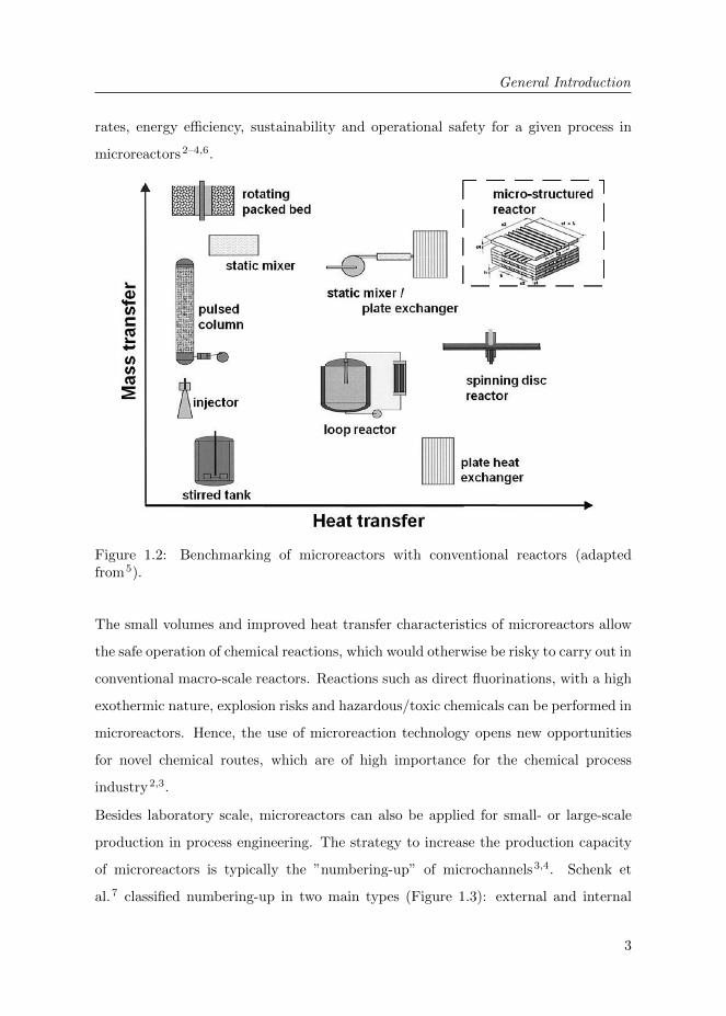
rates, energy efficiency, sustainability and operational safety for a given process in
microreactors2–4,6.
Figure 1.2: Benchmarking of microreactors with conventional reactors (adaptedfrom5).
The small volumes and improved heat transfer characteristics of microreactors allow
the safe operation of chemical reactions, which would otherwise be risky to carry out in
conventional macro-scale reactors. Reactions such as direct fluorinations, with a high
exothermic nature, explosion risks and hazardous/toxic chemicals can be performed in
microreactors. Hence, the use of microreaction technology opens new opportunities
for novel chemical routes, which are of high importance for the chemical process
industry2,3.
Besides laboratory scale, microreactors can also be applied for small- or large-scale
production in process engineering. The strategy to increase the production capacity
of microreactors is typically the ”numbering-up” of microchannels3,4. Schenk et
al.7 classified numbering-up in two main types (Figure 1.3): external and internal
Chapter 1
4
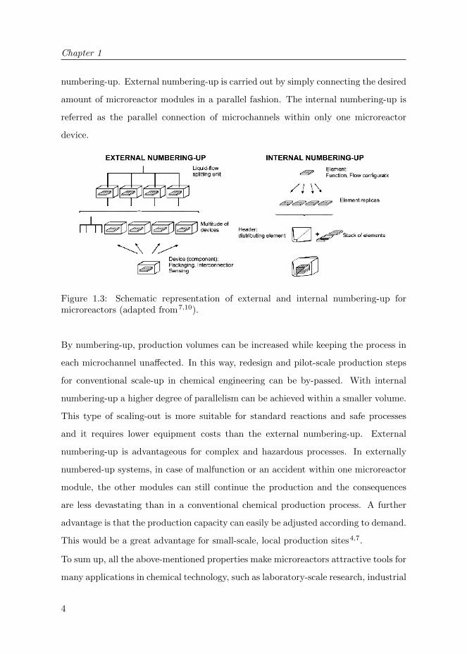
numbering-up. External numbering-up is carried out by simply connecting the desired
amount of microreactor modules in a parallel fashion. The internal numbering-up is
referred as the parallel connection of microchannels within only one microreactor
device.
Figure 1.3: Schematic representation of external and internal numbering-up formicroreactors (adapted from7,10).
By numbering-up, production volumes can be increased while keeping the process in
each microchannel unaffected. In this way, redesign and pilot-scale production steps
for conventional scale-up in chemical engineering can be by-passed. With internal
numbering-up a higher degree of parallelism can be achieved within a smaller volume.
This type of scaling-out is more suitable for standard reactions and safe processes
and it requires lower equipment costs than the external numbering-up. External
numbering-up is advantageous for complex and hazardous processes. In externally
numbered-up systems, in case of malfunction or an accident within one microreactor
module, the other modules can still continue the production and the consequences
are less devastating than in a conventional chemical production process. A further
advantage is that the production capacity can easily be adjusted according to demand.
This would be a great advantage for small-scale, local production sites4,7.
To sum up, all the above-mentioned properties make microreactors attractive tools for
many applications in chemical technology, such as laboratory-scale research, industrial

General Introduction
5
process development and intensification, and on-site production of chemicals in small-
scale2,4.
The aim of the research in this thesis is to explore multiphase processes, such as gas-
liquid-solid reactions, within microreactors. Following, a brief overview of existing
microreactor concepts for these processes is given.
1.2 Gas-liquid-solid microreactors
Multiphase gas-liquid (G-L) and gas-liquid-solid (G-L-S) reactions are of great interest
to the industry; therefore, intensive research is being carried out on these reactions
including microreactors5,8,9. In G-L-S processes, besides the gas and liquid (G-L)
reactants, an additional solid catalyst (S) is required, which catalyzes the reaction
between both reactants.
Hessel et al.9,10 classified multiphase microreactors into two main types: Dispersed
and Continuous Phase microreactors. In the dispersed phase reactors, one phase is
dispersed into the other one, so that both gas and liquid flow in the same microchannel.
In the continuous phase reactors, both phases are separately fed to and withdrawn
from the reactor without being dispersed into each other.
1.2.1 Dispersed phase microreactors
In these devices, gas and liquid are merged inside the same microchannel. Both
streams are fed into the reactor using a dual- or multiple-feed arrangement, in order
to obtain a G-L dispersion in the microchannel. The gas to liquid (G/L) flow ratio
and the inlet conditions of both phases are very critical because they determine the
flow pattern in the microchannel. At low G/L flow ratios, bubbly flow (very small
bubbles) is observed. At intermediate low G/L flow ratios slug flow (segmented-
Taylor flow) and at very large ratios annular flow is predominant11 (Figure 1.4).
The concept of these systems is relatively simple. Slug flow (Figure 1.4 left-(c,d),
Figure 1.4 right) can improve liquid mixing properties inside the microchannel thanks
to the toroidal vortices, which is a great advantage especially in the case of fast

Chapter 1
6
Figure 1.4: (left) Schematic representation of flow patterns in dispersed phasemicroreactors (adapted from11), (right) slug flow and streamlines within the liquidslug (adapted from9).
chemical reactions9,11. Dispersed phase microreactors are applied in various areas
of chemical reaction engineering, such as direct fluorination12, hydrogenation11 and
photocatalytic reactions13–15.
Next to its simplicity and improved mass transfer properties, this principle also has
some drawbacks. Gas and liquid separation is needed at the reactor outlet, since
both streams are inter-mixed. The slugs might coalesce and this situation creates
uncertainty about the actual flow patterns and interfaces in these devices9,10. Another
disadvantage is that the presence of a gas phase in the microchannel decreases the
residence time of the liquid reactant in the reactor.
1.2.2 Continuous phase microreactors
In these microreactors, liquid and gas streams flow separately in their own ports, do
not intermix, but are in contact through the whole reactor length. Some advantages
of these types of reactors are that no phase separation is needed at the outlet of
the reactor, the gas-liquid interface is well-defined and internal numbering-up is
relatively easy. A general drawback is that some additional technical precautions
in reactor design need to be taken to avoid the inter-mixing of the gas and liquid
General Introduction
7
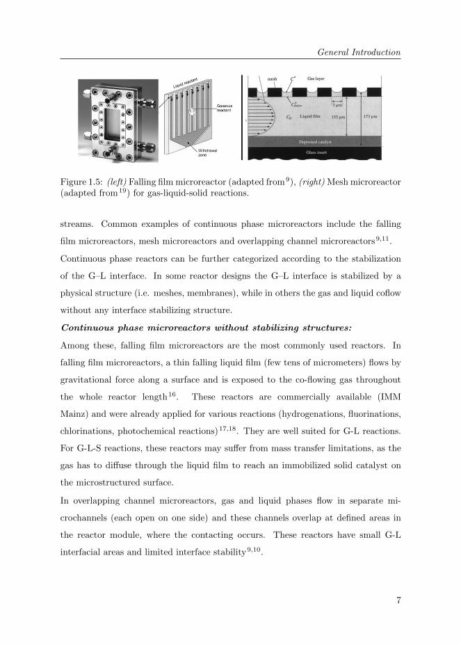
Figure 1.5: (left) Falling film microreactor (adapted from9), (right) Mesh microreactor(adapted from19) for gas-liquid-solid reactions.
streams. Common examples of continuous phase microreactors include the falling
film microreactors, mesh microreactors and overlapping channel microreactors9,11.
Continuous phase reactors can be further categorized according to the stabilization
of the G–L interface. In some reactor designs the G–L interface is stabilized by a
physical structure (i.e. meshes, membranes), while in others the gas and liquid coflow
without any interface stabilizing structure.
Continuous phase microreactors without stabilizing structures:
Among these, falling film microreactors are the most commonly used reactors. In
falling film microreactors, a thin falling liquid film (few tens of micrometers) flows by
gravitational force along a surface and is exposed to the co-flowing gas throughout
the whole reactor length16. These reactors are commercially available (IMM
Mainz) and were already applied for various reactions (hydrogenations, fluorinations,
chlorinations, photochemical reactions)17,18. They are well suited for G-L reactions.
For G-L-S reactions, these reactors may suffer from mass transfer limitations, as the
gas has to diffuse through the liquid film to reach an immobilized solid catalyst on
the microstructured surface.
In overlapping channel microreactors, gas and liquid phases flow in separate mi-
crochannels (each open on one side) and these channels overlap at defined areas in
the reactor module, where the contacting occurs. These reactors have small G-L
interfacial areas and limited interface stability9,10.

Chapter 1
8
Continuous phase microreactors with stabilizing structures:
In these reactors, typically, a physical structure with defined openings (pores) is
placed between the gas and liquid phases in order to stabilize the G-L interface. The
position of the G-L interface is defined by the wetting properties of the liquid phase
on the physical structure. The G-L interface will be in the liquid side, if the pressure
difference over the stabilizing structure is lower than the Laplace pressure (∆p):
∆p = −2 · γL · cos(θ)
rmax(1.1)
where γL is the surface tension of the liquid, θ contact angle of the liquid on the
material of the stabilizing structure and rmax the maximum pore radius of this
structure. When θ is below 90◦, the liquid will wet the stabilizing structure and
no stable interface can be formed under flow conditions. In this case, an additional
gas pressure needs to be applied to stabilize the G-L interface. When θ is above 90◦,
no additional gas pressure is required, but in that case, the pore size of the stabilizing
structure becomes crucial. Structures with large openings will face wetting even at
low-pressure values in the liquid side.
Mesh microreactors are a common example of continuous microreactors with a
stabilizing interface. In these reactors, the gas and the liquid ports are separated
with a planar mesh structure. Both phases are in contact through the openings
(diameter≈5 µm) of the mesh (e.g. nickel)1,19,20. For G-L-S reactions, the solid
catalyst can be immobilized either on the outer side of the liquid port (Figure 1.5) or
directly on the mesh material itself. In the first case, mass transfer limitations might
occur, because the gaseous reactant would have to travel through the liquid film to
reach the solid catalyst.
In these reactors, the meniscus stability at the G-L interface is an important aspect.
Typically, the interface is stabilized by pressure difference between both phases, which
makes the operation technically demanding. The interface can also be stabilized by
hydrophobizing the mesh contactor (for aqueous processes), which can prevent the
leakage of the liquid reactant to the gas port21. However, no high pressures can be

General Introduction
9
applied in the liquid stream due the relatively large pore diameter of the mesh (low
Laplace pressure).
De Jong et al. investigated G-L contacting in microfluidic devices using polymeric
membranes. In their work, porous hydrophobic membranes were used as a stabilizing
interface between the gas and liquid phases22–24. They demonstrated the applicability
of membranes for the local control of liquid composition within a microchannel, by
using various gaseous reactants on the opposite sides of the membrane (Figure 1.6)24.
In addition, they performed catalytic oxidation of glucose as a model reaction, though
very low activity and rapid deactivation was observed. The polymeric membrane itself
was used as catalyst support, which is not well suited for heterogeneously catalyzed
reactions22.
The dual channel microreactor is a new continuous microreactor concept for G-L-S
chemistry that has recently been published by Park et al.25. In these microreactors,
the gas and the liquid are flowing in their own microchannels and they are contacted
Figure 1.6: (top) generation of local concentration gradients by gas-liquid contacting(adapted from24), (bottom) Dual channel microreactor (adapted from25).
Chapter 1
10
with a gas permeable PDMS membrane (Figure 1.6). Continuous contacting between
both phases can be carried out with a stable membrane interface. However, the
membrane does not act as a support for the catalyst. In this concept, the metal
catalyst is suspended inside the liquid phase and needs to be separated from the liquid
product at the reactor outlet. Separation of catalyst particles adds complications to
the process, especially in a continuous operation mode.
De Jong22 and Park et al.25 demonstrated that membranes have a great potential
in microsystems, by providing stable interfaces in multiphase reactions. Even
though there are only very few examples of membrane assisted G-L-S contacting
in microreactor technology, in the past decades intensive research was carried out on
conventional membrane reactors (with higher characteristic dimensions). Membrane
reactors for G-L-S reactions are described in the following section.
1.3 Membrane reactors
Multiphase reactions for gas-liquid (G-L) and heterogeneously catalyzed gas-liquid-
solid (G-L-S) systems are conventionally performed in various types of reactors.
The most widespread types include agitated tanks, slurry reactors, bubble or spray
columns, and trickle-bed reactors. Membrane reactors have also been intensively
investigated due to their various advantages.
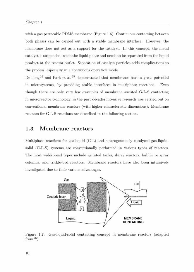
Figure 1.7: Gas-liquid-solid contacting concept in membrane reactors (adaptedfrom26).

General Introduction
11
Membrane reactors offer a stable and controlled G-L interface with a simple reactor
design (Figure 1.7). The gas and liquid phases are added to the reaction zone
from opposite sides of a membrane and meet precisely where the solid (S) catalyst
is located. In these reactors, the gas/liquid flow ratios can be independently
varied26–32. Moreover, the gaseous reactant is distributed homogeneously over to the
catalytic area, along the full reactor length. This makes these reactors advantageous
for processes with low gaseous reactant solubility and/or high gas consumption,
preventing a possible depletion of this reactant in the reactor. Using membrane
reactors, high-pressure operation can be avoided because of the improved three-phase
contacting32,33.
For this concept, porous membranes are preferred over dense membranes because of
their high gas permeability. The porosity of the membrane offers easy access of the
gaseous reactant to the catalytic layer. Typical membrane materials are polymeric or
inorganic membranes. Polymeric membranes are cheap and are available in various
geometries and properties. However, at high temperatures and under chemically harsh
conditions their use is limited. Moreover, the bonding of a metal catalyst particle to
the polymeric surface is weak and the regeneration of the polymer embedded catalyst
is not an easy task. Inorganic materials, such as ceramics, are very favorable to
G-L-S reactions because of their high chemical, thermal and structural stability.
Conventional catalyst immobilization techniques (e.g. wet impregnation, incipient
wetness) with high temperature post-processing can be applied on these materials. In
addition, the regeneration of the catalyst can easily be conducted by calcination and
reduction steps33.
For porous inorganic membrane reactors the G-L interface is typically stabilized by
a pressure difference (trans-membrane pressure), because of the hydrophilic nature
of the membrane materials. An excess pressure (see Equation 1.1) is applied from
the gas side of the reactor and the G-L interface can be positioned on the porous
membrane at the desired location. The stabilization of the interface was intensively
investigated by Vospernik et al.27 and Bercic et al.34 and they demonstrated that the
mass transfer of the gaseous reactant is strongly dependent on the position of the G-L

Chapter 1
12
Figure 1.8: Examples of numbering-up in membrane technology: (left) Hyflux Inocep,(right) GEA membrane modules.
interface in the membrane. Even though accurate interface control can be obtained
by trans-membrane pressure, this method can be considered technically demanding
due to the necessity of additional equipment (e.g. pressure regulators, sensors).
Catalytic membrane reactors were already applied for various chemical reactions
such as hydrogenation27,29 and oxidation28,34 reactions. Large-scale operation with
membrane reactors can be conducted very easily, especially in tubular geometry
(Figure 1.8). Membrane modules with high packing density are already available
on the market; this provides a simple way of channel numbering-up of a developed
reactor.
An important aspect of these reactors is the mass transport in the liquid phase
due to the laminar flow profile. In membrane reactors, the mass transport of the
reactant in the liquid phase from the liquid bulk to the catalytic surface on the wall is
mainly carried out by radial diffusion, which is a relatively slow process. In order to
improve the mass transfer, Vospernik et al.28 and Pashkova et al.35 used static mixers
and glass beads, respectively, inside the membrane channel and observed significant
improvement in the reactor performance. Despite the improved reactor performance,
both methods add operational complications to the process.
A practical way to overcome mass transfer limitations in a process with a wall reaction
is miniaturizing the characteristic length of the reactor channel, as described above
for microreactors. The small characteristic length increases the surface area (catalytic

General Introduction
13
wall) per reactor volume and reduces the diffusion path for the reactant to the reactor
wall. The aim of the present study is to apply the above-mentioned advantages of
membrane reactors for G-L-S reactions in microreactors and merge the advantages
of both reactor designs. In order to test the performances of our microreactors, two
model reactions were performed. These reactions are described below.
1.4 Model gas-liquid-solid reactions
1.4.1 Catalytic hydrogenation of nitrite ions in water
Increasing concentrations of the harmful nitrite (NO2−) and nitrate (NO3
−) ions in
ground waters throughout the world is a critical environmental problem. Therefore,
various processes are being developed to tackle this problem, such as biological
processes, physicochemical techniques and catalytic hydrogenation. Biological
processes are reported to have low conversion rates and to be slow. Physicochemical
techniques (ion exchange, reverse osmosis, electrodialysis) remove these compounds
efficiently, but they require regeneration; since they accumulate these compounds in
secondary streams at high concentrations. The catalytic hydrogenation process is
mentioned as the most promising solution for nitrite removal36–38.
2NO−2 + 3H2Pd→ N2 + 2OH− + 2H2O (1.2)
2NO−2 + 6H2Pd→ 2NH+
4 + 4OH− (1.3)
In this reaction, NO2− ions in aqueous solution (L-reactant) react with hydrogen
(H2; G-reactant) on the solid catalyst (e.g. palladium (Pd); S-catalyst) surface
and form the desired product nitrogen (N2) and the undesired product ammonia
(NH4+). Hydrogenation of nitrite is known to be a very fast reaction inducing mass
transfer limitations, which makes it very suitable to study as a model reaction in
microreactors39.
Chapter 1
14
1.4.2 Photocatalytic degradation of organic compounds in
water
A photochemical reaction is a chemical reaction that takes place in the presence of
light. A photocatalytic reaction is a photochemical reaction, which takes place only
in the presence of a photocatalyst. Photocatalysis is applied in numerous disciplines,
such as water and air treatment, organic synthesis, hydrogen (H2) production from
water and reduction of carbon dioxide (CO2)40,41.
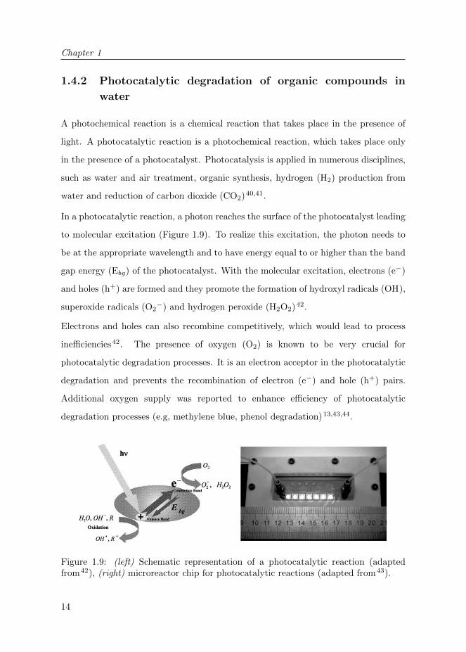
In a photocatalytic reaction, a photon reaches the surface of the photocatalyst leading
to molecular excitation (Figure 1.9). To realize this excitation, the photon needs to
be at the appropriate wavelength and to have energy equal to or higher than the band
gap energy (Ebg) of the photocatalyst. With the molecular excitation, electrons (e−)
and holes (h+) are formed and they promote the formation of hydroxyl radicals (OH),
superoxide radicals (O2−) and hydrogen peroxide (H2O2)42.
Electrons and holes can also recombine competitively, which would lead to process
inefficiencies42. The presence of oxygen (O2) is known to be very crucial for
photocatalytic degradation processes. It is an electron acceptor in the photocatalytic
degradation and prevents the recombination of electron (e−) and hole (h+) pairs.
Additional oxygen supply was reported to enhance efficiency of photocatalytic
degradation processes (e.g, methylene blue, phenol degradation)13,43,44.
Figure 1.9: (left) Schematic representation of a photocatalytic reaction (adaptedfrom42), (right) microreactor chip for photocatalytic reactions (adapted from43).

General Introduction
15
1.5 Scope of the thesis
The aim of this study is to introduce a membrane reactor concept for G-L-S
microreaction technology. In this concept, the contact between gas and liquid for
reaction purposes is achieved using membrane technology and selective wetting of
porous ceramic and metallic membranes.
Figure 1.10: Contacting concept of the porous meso- and microreactors for G-L-Sreaction systems in (left) tubular and (right) planar geometry.
The contact of gas and liquid occurs precisely on the membrane surface, where
the solid catalyst is deposited. For ceramic membrane reactors, the G-L interface
is positioned by controlling the wetting properties of the porous reactor wall, as
opposed to trans-membrane pressure in conventional membrane reactors. For metallic
membrane reactors, a gas-permeable polymeric layer was integrated on the outer
surface to confine the liquid phase.
Fabrication, catalyst deposition, selective surface modification steps and module
preparation were carried out for reactor development. We developed reactors
with tubular (hollow fiber) and planar (chip) geometry and tested them for two
model reactions in water: catalytic hydrogenation of nitrite ions and photocatalytic
degradation of organic compounds. Tubular reactors were applied for the catalytic
hydrogenation in Chapters 2, 3 and 4 and the planar reactor the photocatalytic
reaction in Chapter 5.

Chapter 1
16
Chapter 2 introduces the contacting concept of gas and liquid phases in a membrane
using surface modification techniques. Preparation, characterization and operation of
the reactors are described. In this study, we investigated the influences of the surface
properties and catalyst (palladium) loading on the reactor performance. Furthermore,
we studied the effects of the gas phase composition on the overall productivity of the
reactor. It was observed that reactor performance could be significantly improved by
controlling its surface properties. In addition, even at dilute concentrations of the
gaseous reactant, the reaction rates remained constant, which is of great advantage
for multiphase reactions.
Chapter 3 focuses on improving the understanding of the concept developed in
Chapter 2. Tubular reactors with various thicknesses of catalyst supports and
internal hydraulic diameters were prepared and characterized. The influences of
these geometrical parameters on the reactor performance were tested. Results
indicated increasing internal mass transfer limitations with increasing thickness of
the catalyst support. We also observed that the reactor productivity of the hollow
fibers with smaller internal diameter was considerably improved, indicating external
mass transfer limitations in these reactors. Furthermore, to enhance the mixing in the
membrane channel, slug flow operation (see Figure 1.4) was studied using an inert
gas. With the induced mixing of the inert slug flow, the nitrite conversion values
increased significantly.
Chapter 4 demonstrates the development and application of porous metallic
membrane reactors with carbon nanofibers catalyst supports. We prepared these
reactors by porous stainless steel hollow fiber fabrication, carbon nanofiber growth and
catalyst immobilization steps. Reactors with high mechanical strength and catalytic
surface area were obtained. With the operation of these reactors, we observed high
conversion values for nitrite reduction, even without the presence of hydrogen or
palladium. These results suggest reductive properties of the reactor material itself
and prove their promising potential for chemical reduction processes.
Chapter 5 describes the preparation of porous ceramic microreactors in planar (chip)
geometry and their utilization in photocatalytic processes. Microfabrication, photo-

General Introduction
17
catalyst (titanium dioxide-TiO2) immobilization and selective surface modification
steps for the reactor preparation are explained. The developed reactors showed high
photocatalytic activity in the photocatalytic degradation of phenol and methylene
blue in water. Furthermore, membrane-assisted supply of oxygen improved the reactor
performance.
Chapter 6 summarizes the results obtained in the scope of this work. It gives
recommendations for future research, together with concluding remarks.

Chapter 1
18
Bibliography
[1] L. Kiwi-Minsker and A. Renken. Microstructured reactors for catalytic reactions. Catalysis
Today, 110(1-2):2 – 14, 2005. 2, 8
[2] A. Gavriilidis, P. Angeli, E. Cao, K. K. Yeong, and Y. S. S. Wan. Technology and applications
of microengineered reactors. Chemical Engineering Research and Design, 80(1):3 – 30, 2002.
3, 5
[3] K. Jahnisch, V. Hessel, H. Lowe, and M. Baerns. Chemistry in microstructured reactors.
Angewandte Chemie International Edition, 43(4):406–446, 2004. 2, 3
[4] V. Hessel, S. Hardt, and H. Lowe. Chemical Micro Process Engineering: Fundamentals,
Modelling and Reactions, Sections 1.1-1.5, pages 1–66. Wiley-VCH Verlag GmbH & Co. KGaA,
2005. 2, 3, 4, 5
[5] M. N. Kashid and L. Kiwi-Minsker. Microstructured reactors for multiphase reactions: State
of the art. Industrial & Engineering Chemistry Research, 48(14):6465–6485, 2009. 2, 3, 5
[6] V. Hessel, S. Hardt, and H. Lowe. Chemical Micro Process Engineering: Fundamentals,
Modelling and Reactions, Sections 1.6-1.9, pages 66–124. Wiley-VCH Verlag GmbH & Co.
KGaA, 2005. 3
[7] R. Schenk, V. Hessel, C. Hofmann, J. Kiss, H. Lowe, and A. Ziogas. Numbering-up of micro
devices: a first liquid-flow splitting unit. Chemical Engineering Journal, 101(1-3):421 – 429,
2004. 3, 4
[8] G. Chen, J. Yue, and Q. Yuan. Gas-liquid microreaction technology: Recent developments and
future challenges. Chinese Journal of Chemical Engineering, 16(5):663 – 669, 2008. 5
[9] V. Hessel, P. Angeli, A. Gavriilidis, and H. Lowe. Gas-liquid and gas-liquid-solid
microstructured reactors: Contacting principles and applications. Industrial & Engineering
Chemistry Research, 44(25):9750–9769, 2005. 5, 6, 7
[10] V. Hessel, S. Hardt, and H. Lowe. Chemical Micro Process Engineering: Fundamentals,
Modelling and Reactions, Sections 5.1-5.3, pages 577–619. Wiley-VCH Verlag GmbH & Co.
KGaA, 2005. 4, 5, 6, 7
[11] M. T. Kreutzer, F. Kapteijn, J. A. Moulijn, and J. J. Heiszwolf. Multiphase monolith reactors:
Chemical reaction engineering of segmented flow in microchannels. Chemical Engineering
Science, 60(22):5895 – 5916, 2005. 5, 6, 7
[12] K. Jahnisch, M. Baerns, V. Hessel, W. Ehrfeld, V. Haverkamp, H. Lowe, Ch. Wille, and
A. Guber. Direct fluorination of toluene using elemental fluorine in gas/liquid microreactors.
Journal of Fluorine Chemistry, 105(1):117 – 128, 2000. 6
[13] H. Lindstrom, R. Wootton, and A. Iles. High surface area titania photocatalytic microfluidic
reactors. AIChE Journal, 53(3):695–702, 2007. 6, 14
[14] Y. Matsushita, M. Iwasawa, T. Suzuki, and T. Ichimura. Multiphase photocatalytic oxidation
in a microreactor. Chemistry Letters, 38(8):846–847, 2009.
Bibliography
19
[15] R. Gorges, S. Meyer, and G. Kreisel. Photocatalysis in microreactors. Journal of
Photochemistry and Photobiology A: Chemistry, 167(2-3):95–99, 2004. 6
[16] B. K. Vankayala, P. Lob, V. Hessel, G. Menges, C. Hofmann, D. Metzke, U. Krtschil, and
H. J. Kost. Scale-up of process intensifying falling film microreactors to pilot production scale.
International Journal of Chemical Reactor Engineering, 5:A91, 2007. 7
[17] P. Lob, H. Lowe, and V. Hessel. Fluorinations, chlorinations and brominations of organic
compounds in micro reactors. Journal of Fluorine Chemistry, 125(11):1677–1694, 2004. 7
[18] K. K. Yeong, A. Gavriilidis, R. Zapf, and V. Hessel. Experimental studies of nitrobenzene
hydrogenation in a microstructured falling film reactor. Chemical Engineering Science,
59(16):3491 – 3494, 2004. 7
[19] R. Abdallah, P. Magnico, B. Fumey, and C. de Bellefon. Cfd and kinetic methods for mass
transfer determination in a mesh microreactor. AIChE Journal, 52(6):2230–2237, 2006. 7, 8
[20] C. Amador, D. Wenn, J. Shaw, A. Gavriilidis, and P. Angeli. Design of a mesh microreactor for
even flow distribution and narrow residence time distribution. Chemical Engineering Journal,
135(Supplement 1):S259 – S269, 2008. 8
[21] T. R. Henriksen. Silicon Microreactors for Measurements of Catalytic Activity. PhD thesis,
Lyngby, Technical University of Denmark, April 2010. 8
[22] J. de Jong. Application of membrane technology in microfluidic devices. PhD thesis, Enschede,
University of Twente, April 2008. 9, 10
[23] J. de Jong, B. Ankone, R. G. H. Lammertink, and M. Wessling. New replication technique for
the fabrication of thin polymeric microfluidic devices with tunable porosity. Lab on a Chip,
5:1240–1247, 2005.
[24] J. de Jong, P. W. Verheijden, R. G. H. Lammertink, and M. Wessling. Generation of local
concentration gradients by gas-liquid contacting. Analytical Chemistry, 80(9):3190–3197, 2008.
9
[25] C. P. Park and D.-P. Kim. Dual-channel microreactor for gas-liquid syntheses. Journal of the
American Chemical Society, 132(29):10102–10106, 2010. 9, 10
[26] A. Bottino, G. Capannelli, A. Comite, A. Del Borghi, and R. Di Felice. Catalytic
ceramic membrane in a three-phase reactor for the competitive hydrogenation-isomerisation
of methylenecyclohexane. Separation and Purification Technology, 34(1-3):239 – 246, 2004. 10,
11
[27] M. Vospernik, A. Pintar, G. Bercic, and J. Levec. Experimental verification of ceramic
membrane potentials for supporting three-phase catalytic reactions. Journal of Membrane
Science, 223(1-2):157 – 169, 2003. 11, 12
[28] M. Vospernik, A. Pintar, G. Bercic, J. Batista, and J. Levec. Potentials of ceramic membranes
as catalytic three-phase reactors. Chemical Engineering Research and Design, 82(5):659 – 666,
2004. 12

Chapter 1
20
[29] J. Peureux, M. Torres, H. Mozzanega, A. Giroir-Fendler, and J-A. Dalmon. Nitrobenzene
liquid-phase hydrogenation in a membrane reactor. Catalysis Today, 25(3-4):409 – 415, 1995.
12
[30] R. Dittmeyer, V. Hollein, and K. Daub. Membrane reactors for hydrogenation and
dehydrogenation processes based on supported palladium. Journal of Molecular Catalysis A:
Chemical, 173(1-2):135 – 184, 2001.
[31] R. Dittmeyer, K. Svajda, and M. Reif. A review of catalytic membrane layers for gas/liquid
reactions. Topics in Catalysis, 29:3–27, 2004.
[32] H. C. Aran, J. K. Chinthaginjala, R. Groote, T. Roelofs, L. Lefferts, M. Wessling, and R. G. H.
Lammertink. Porous ceramic mesoreactors: A new approach for gas-liquid contacting in
multiphase microreaction technology. Chemical Engineering Journal, 169(1-3):239 – 246, 2011.
11
[33] G. Centi, R. Dittmeyer, S. Perathoner, and M. Reif. Tubular inorganic catalytic membrane
reactors: advantages and performance in multiphase hydrogenation reactions. Catalysis Today,
79-80:139 – 149, 2003. Catalysis in Multiphase Reactors. 11
[34] G. Bercic, A. Pintar, and J. Levec. Positioning of the reaction zone for gas-liquid reactions in
catalytic membrane reactor by coupling results of mass transport and chemical reaction study.
Catalysis Today, 105(3-4):589 – 597, 2005. 11, 12
[35] A. Pashkova, R. Dittmeyer, N. Kaltenborn, and H. Richter. Experimental study of porous
tubular catalytic membranes for direct synthesis of hydrogen peroxide. Chemical Engineering
Journal, 165(3):924 – 933, 2010. 12
[36] J. K. Chinthaginjala, J. H. Bitter, and L. Lefferts. Thin layer of carbon-nano-fibers (cnfs)
as catalyst support for fast mass transfer in hydrogenation of nitrite. Applied Catalysis A:
General, 383(1-2):24 – 32, 2010. 13
[37] J.K. Chinthaginjala and L. Lefferts. Support effect on selectivity of nitrite reduction in water.
Applied Catalysis B: Environmental, 101(1-2):144 – 149, 2010.
[38] A. Pintar, G. Bercic, and J. Levec. Catalytic liquid-phase nitrite reduction: Kinetics and
catalyst deactivation. AIChE Journal, 44(10):2280–2292, 1998. 13
[39] J. K. Chinthaginjala. Hairy foam : thin layers of carbon nanofibers as catalyst support for
liquid phase reactions. PhD thesis, Enschede, University of Twente, June 2010. 13
[40] O. Carp, C. L. Huisman, and A. Reller. Photoinduced reactivity of titanium dioxide. Progress
in Solid State Chemistry, 32(1-2):33 – 177, 2004. 14
[41] T. van Gerven, G. Mul, J. Moulijn, and A. Stankiewicz. A review of intensification of
photocatalytic processes. Chemical Engineering and Processing, 46(9):781–789, 2007. 14
[42] Serrano B. de Lasa, H. and M. Salaices. Photocatalytic reaction engineering. Springer, 2005.
14

Bibliography
21
[43] Y. Matsushita, N. Ohba, S. Kumada, K. Sakeda, T. Suzuki, and T. Ichimura. Photocatalytic
reactions in microreactors. Chemical Engineering Journal, 135(Supplement 1):S303–S308,
2008. 14
[44] C.-H. Wu and J.-M. Chern. Kinetics of photocatalytic decomposition of methylene blue.
Industrial & Engineering Chemistry Research, 45(19):6450–6457, 2006. 14


23
Chapter 2
Porous Ceramic
Mesoreactors:
A new approach for gas-liquid
contacting in multiphase
microreactor technology
A REVISED VERSION OF THIS CHAPTER HAS BEEN PUBLISHED:
H.C. Aran, J.K. Chinthaginjala, R. Groote, T. Roelofs, L. Lefferts, M. Wessling,
R.G.H. Lammertink, Porous ceramic membrane mesoreactors: A new approach for
gas-liquid contacting in multiphase microreaction technology, Chemical Engineering
Journal, 169(1-3)239–246, 2011 (featured on the journal cover).

Chapter 2
24
ABSTRACT
In this study a concept for gas-liquid-solid (G-L-S) microreactor technology was
developed and optimized which ensures that the gaseous and liquid reactants directly
meet at the solid catalyst surface with a simple contacting approach. Fabrication,
catalyst deposition and surface modification steps were carried out to develop
porous ceramic (alumina-Al2O3) mesoreactors. In order to realize liquid flow
inside the intrinsically hydrophilic porous reactor channel and to obtain a stabilized
gas-liquid-solid interface different surface modification (hydrophobization) strategies
were successfully implemented. Catalytically active reactors with varying surface
properties along the cross-section were obtained and their performance was tested for
nitrite hydrogenation as a G-L-S model reaction. Results showed that the performance
of the reactor could be drastically enhanced by tuning the surface properties. With the
proposed concept, even at dilute concentrations of the gaseous reactant, the reactor
performance remained constant.

Porous Ceramic Mesoreactors
25
2.1 Introduction
The development of miniaturized devices (in micro– and mesoscale) for carrying out
chemical analysis and chemical reactions has shown a rapid improvement in the past
years. A micro– or mesoreactor is a chemical reactor with a reduced dimensional
scale (hydraulic diameter), which results in a very large surface to volume ratio.
This large ratio provides enhanced heat and mass transfer enabling the development
of more efficient processes (process intensification). Micro– and mesofluidic devices
allow new chemical processes that were previously not applied in conventional systems.
In addition, they are sustainable by creating less waste, occupying less space, and
enabling safer operation due to their small volume1–5.
Multiphase reactions for gas–liquid (G–L) and heterogeneously catalyzed gas-liquid-
solid (G–L–S) systems are conventionally performed in various types of reactors.
The most widespread types include agitated tanks, slurry reactors, bubble or spray
columns, and trickle-bed reactors6. Also membrane reactors have been intensively
investigated due to their various advantages including well-defined contact regions
and simple reactor design. In these types of reactors, the G–L interface is generally
stabilized by the use of a pressure difference across the membrane (trans–membrane
pressure)7–14.
With the rapid developments in microreaction technology, some analogues of the
macro-scale reactors became available for G–L and G–L–S reaction systems in the
microscale3,4,6,15,16. Multiphase microreactors for these systems were classified by
Hessel et al.6 in two main types: Continuous and Dispersed Phase microreactors. In
the continuous phase reactors, both phases are separately fed to and withdrawn from
the reactor without being dispersed into each other (e.g. the falling film microreactor).
In the dispersed phase reactors, one phase is dispersed into the other one. Various flow
patterns (e.g. Taylor flow and annular flow) are obtained in these microchannels. In
these microreactors the G/L flow ratios have to be well controlled to create a stable
interface between both phases6. In most of the existing continuous and dispersed

Chapter 2
26
phase reactor designs, the gaseous reactant usually has to diffuse through a liquid
film to reach the solid catalyst that can be immobilized on the microchannel wall.
The aim of the present work is to introduce a membrane reactor concept for G–
L–S microreaction technology. The contact between gas and liquid for reaction
purposes is achieved using membrane technology and selective wetting of porous
ceramic membranes (Figure 2.1).
Figure 2.1: Contacting concept of the porous ceramic mesoreactor for G-L-S reactionsystems.
The contacting between both phases takes place directly at the inner membrane
surface, where the catalyst is immobilized. Using this continuous process concept,
the gas phase composition can be kept constant along the full length of the reactor.
Furthermore, no separation of gas and liquid reactants is necessary at the reactor
outlet. The G–L interface and the positioning of the reaction area are controlled
using surface modification (hydrophobization) techniques, as opposed to controlling
trans–membrane pressure.
The heterogeneously palladium(Pd)–catalyzed hydrogenation of nitrite ions in aque-
ous phase was chosen as G–L–S model reaction system for this study. The removal
of nitrite (NO2−) and nitrate (NO3
−) ions from groundwater is a relevant reaction
from an environmental point of view. It can be carried out via biologic and catalytic
hydrogenation processes. Due to the low reaction rates of the biologic processes, the
catalytic hydrogenation process is mentioned to be more promising for the nitrite

Porous Ceramic Mesoreactors
27
removal. Via the catalytic route the nitrite ions are converted to nitrogen (N2) or the
undesired product ammonia (NH4+)17–21.
2.2 Experimental
2.2.1 Materials
Commercial α–Al2O3 hollow fibers InoCep M800 (Hyflux CEPAration Technologies
(Europe)) with average pore diameter of 800 nm were used as membrane support
in this study. The membrane fibers had an inner diameter of 2.8 mm, an outer
diameter of 3.8 mm and they were prepared with a length of 13.5 cm. γ–Al2O3
(Alfa Aesar, 3 micron APS Powder), MilliQ-water, polyvinyl alcohol (PVA; Sigma-
Aldrich, 99+% hydrolyzed) and acetic acid (Merck, pro analysi) were used for catalyst
support preparation. Palladium(II) 2,4–pentanedione (Pd(acac)2; Alfa Aesar, 34.7%)
in toluene (Merck, ACS) was used as catalyst precursor solution. For the surface
modification steps a perfluorinated octyltrichlorosilane (FOTS; Aldrich, 97%) and n–
hexane as solvent (Merck, ACS) were used as received. An aqueous solution of Phenol
Red sodium salt (Merck, ACS) was used as wetting indicator solution. Sodium nitrite
(NaNO2, Merck, ACS) was used as source for nitrite ions (NO2−).
2.2.2 Reactor preparation
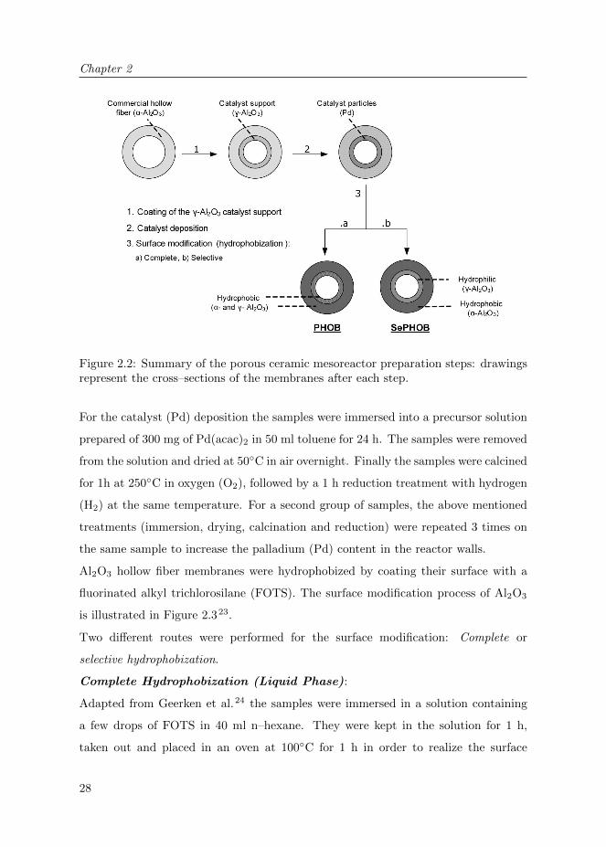
The preparation of the porous ceramic mesoreactor consists of 3 main stages which
are summarized in Figure 2.2.
The inner surface of the commercial α–Al2O3 membrane (BET surface area: ∼0.1
m2/g) was coated with a γ–Al2O3 layer as catalyst support to increase the active
surface area. For the coating procedure a standard recipe for the aqueous 20 wt%
γ–Al2O3 suspension was used22. With the help of a syringe pump the suspension
was fed into the fibers; the excess suspension was removed by flowing air (1 ml/min)
through the fiber for 2 min. The coated samples were then dried in the oven at 50◦C
for 1h and then calcined at 600◦C for 2 h.
Chapter 2
28
Figure 2.2: Summary of the porous ceramic mesoreactor preparation steps: drawingsrepresent the cross–sections of the membranes after each step.
For the catalyst (Pd) deposition the samples were immersed into a precursor solution
prepared of 300 mg of Pd(acac)2 in 50 ml toluene for 24 h. The samples were removed
from the solution and dried at 50◦C in air overnight. Finally the samples were calcined
for 1h at 250◦C in oxygen (O2), followed by a 1 h reduction treatment with hydrogen
(H2) at the same temperature. For a second group of samples, the above mentioned
treatments (immersion, drying, calcination and reduction) were repeated 3 times on
the same sample to increase the palladium (Pd) content in the reactor walls.
Al2O3 hollow fiber membranes were hydrophobized by coating their surface with a
fluorinated alkyl trichlorosilane (FOTS). The surface modification process of Al2O3
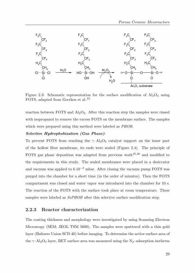
is illustrated in Figure 2.323.
Two different routes were performed for the surface modification: Complete or
selective hydrophobization.
Complete Hydrophobization (Liquid Phase):
Adapted from Geerken et al.24 the samples were immersed in a solution containing
a few drops of FOTS in 40 ml n–hexane. They were kept in the solution for 1 h,
taken out and placed in an oven at 100◦C for 1 h in order to realize the surface
Porous Ceramic Mesoreactors
29
Figure 2.3: Schematic representation for the surface modification of Al2O3 usingFOTS, adapted from Geerken et al.23
reaction between FOTS and Al2O3. After this reaction step the samples were rinsed
with isopropanol to remove the excess FOTS on the membrane surface. The samples
which were prepared using this method were labeled as PHOB.
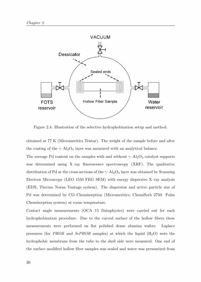
Selective Hydrophobization (Gas Phase):
To prevent FOTS from reaching the γ–Al2O3 catalyst support on the inner part
of the hollow fiber membrane, its ends were sealed (Figure 2.4). The principle of
FOTS gas phase deposition was adapted from previous work25,26 and modified to
the requirements in this study. The sealed membranes were placed in a desiccator
and vacuum was applied to 6·10−2 mbar. After closing the vacuum pump FOTS was
purged into the chamber for a short time (in the order of minutes). Then the FOTS
compartment was closed and water vapor was introduced into the chamber for 10 s.
The reaction of the FOTS with the surface took place at room temperature. These
samples were labeled as SePHOB after this selective surface modification step.
2.2.3 Reactor characterization
The coating thickness and morphology were investigated by using Scanning Electron
Microscopy (SEM; JEOL TSM 5600). The samples were sputtered with a thin gold
layer (Baltzers Union SCD 40) before imaging. To determine the active surface area of
the γ–Al2O3 layer, BET surface area was measured using the N2–adsorption isotherm
Chapter 2
30
Figure 2.4: Illustration of the selective hydrophobization setup and method.
obtained at 77 K (Micromeritics Tristar). The weight of the sample before and after
the coating of the γ–Al2O3 layer was measured with an analytical balance.
The average Pd content on the samples with and without γ–Al2O3 catalyst supports
was determined using X–ray fluorescence spectroscopy (XRF). The qualitative
distribution of Pd at the cross-sections of the γ–Al2O3 layer was obtained by Scanning
Electron Microscopy (LEO 1550 FEG–SEM) with energy dispersive X–ray analysis
(EDX; Thermo Noran Vantage system). The dispersion and active particle size of
Pd was determined by CO–Chemisorption (Micromeritics, ChemiSorb 2750: Pulse
Chemisorption system) at room temperature.
Contact angle measurements (OCA 15 Dataphysics) were carried out for each
hydrophobization procedure. Due to the curved surface of the hollow fibers these
measurements were performed on flat polished dense alumina wafers. Laplace
pressures (for PHOB and SePHOB samples) at which the liquid (H2O) wets the
hydrophobic membrane from the tube to the shell side were measured. One end of
the surface modified hollow fiber samples was sealed and water was pressurized from

Porous Ceramic Mesoreactors
31
inside until water droplets appeared on the outer surface. This pressure difference at
which the wetting occurred (∆p) can be correlated to the Laplace equation:
∆p = −2 · γL · cos(θ)
rmax(2.1)
where γL is the surface tension of the liquid, θ contact angle of the liquid on the
membrane material and rmax the maximum pore radius of the membrane.
An aqueous Phenol Red sodium salt solution (∼300 mg/L) was prepared and pumped
through the surface modified reactors (PHOB and SePHOB) for a minimum time of
15 min, in order to visualize the wetting behavior throughout the sample. Then the
samples were cut and the cross-sections were examined by optical microscopy (Zeiss
Axiovert 40).
2.2.4 Reactor operation
The performance of the reactor was tested for heterogeneously catalyzed hydrogena-
tion of nitrite ions (NO2−) over palladium (Pd) catalyst in aqueous phase.
2NO−2 + 3H2Pd→ N2 + 2OH− + 2H2O (2.2)
2NO−2 + 6H2Pd→ 2NH+
4 + 4OH− (2.3)
The conversion and the reaction rate of the nitrite ions (NO2−) were the main
performance criteria. The production of the undesired product ammonia (NH4+)
was also measured and used to calculate selectivity of the reaction. Selectivity to
nitrogen (N2) follows directly based on the well known fact that no other products
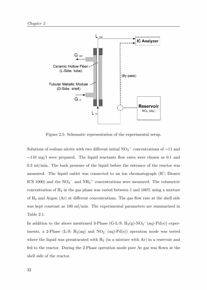
are formed. The porous ceramic mesoreactors were placed into a stainless steel module
with separate in- and outlets for liquid and gas (Figure 2.5). The module was placed
in a vertical position (liquid inlet at the bottom) inside an oven at 298 K. The liquid
reactant (NO2−) was pumped into the tube and the gaseous reactant (hydrogen: H2,
atmospheric pressure) was delivered to the shell side of the porous reactor.
Chapter 2
32
Figure 2.5: Schematic representation of the experimental setup.
Solutions of sodium nitrite with two different initial NO2− concentrations of ∼11 and
∼110 mg/l were prepared. The liquid reactants flow rates were chosen as 0.1 and
0.3 ml/min. The back pressure of the liquid before the entrance of the reactor was
measured. The liquid outlet was connected to an ion chromatograph (IC; Dionex
ICS 1000) and the NO2− and NH4
+ concentrations were measured. The volumetric
concentration of H2 in the gas phase was varied between 1 and 100% using a mixture
of H2 and Argon (Ar) at different concentrations. The gas flow rate at the shell side
was kept constant as 100 ml/min. The experimental parameters are summarized in
Table 2.1.
In addition to the above mentioned 3-Phase (G-L-S: H2(g)-NO2−(aq)-Pd(s)) exper-
iments, a 2-Phase (L-S: H2(aq) and NO2−(aq)-Pd(s)) operation mode was tested
where the liquid was presaturated with H2 (in a mixture with Ar) in a reservoir and
fed to the reactor. During the 2-Phase operation mode pure Ar gas was flown at the
shell side of the reactor.

Porous Ceramic Mesoreactors
33
Table 2.1: Experimental parameters: Reactor types and operation conditions.
Reactor types PHOB - SePHOBCatalyst (Pd) deposition on reactor, times 1 & 3Reaction temperature, K 298Reactor volume, ml 0.83Initial nitrite concentration, mg/l 11 & 110Liquid flow rates, ml/min 0.1 & 0.3Liquid flow back pressures, bar 0.3 & 0.6Gas flow rate, ml/min 100Volumetric H2 concentration in gas phase, % 1 - 100
2.3 Results and Discussion
2.3.1 Reactor characterization
The structures of the γ-Al2O3 coated ceramic hollow fiber used in this study are
displayed in the SEM images in Figure 2.6. The micrographs show that there is a
clear difference in the morphology between the α- and γ-Al2O3 layers. The BET
active surface area of the γ-Al2O3 support was found to be around 73 m2/g, which is
significantly higher compared to the commercial α-Al2O3 support (∼0.1 m2/g). The
weight increase of the sample due to the coated support was ∼5.6 wt%. Thickness of
the support was on average 80 µm.
Figure 2.6: SEM images of the ceramic membrane cross-section after γ-Al2O3 catalystsupport coating: (a), (b) α-Al2O3 / γ-Al2O3 intersection (c) Porous structure of theγ-Al2O3.

Chapter 2
34
Catalyst deposition was performed on samples with- and without γ-Al2O3 support
coating. The overall weight percentage of Pd (measured by XRF) for the sample
consisting of only α-Al2O3 was found to be ∼0.026 wt% and for the sample with
additional γ-Al2O3 coating this value has increased to ∼0.073 wt%. This indicates
that the amount of deposited catalyst could be significantly increased with the γ-
Al2O3 coating due to the high surface area of this layer. For the samples with 3 times
catalyst deposition the corresponding values increased to ∼0.12 and ∼0.26 wt%. It
was observed that the Pd is mainly located in the γ-Al2O3 layer. The EDX results
qualitatively showed a homogeneous distribution of Pd along the cross-section of the
γ-Al2O3 coating. Both samples (containing additional γ-Al2O3 coating) with 1 and
3 times catalyst deposition were used in this work as reactors in order to study the
effect of catalyst loading on the reactor performance. These samples were referred
as Pd loading= 0.073 wt% (1 time deposition) and Pd loading= 0.26 wt% (3 time
deposition).
The Pd dispersion of a sample (measured by CO-Chemisorption) with α- and γ-Al2O3
was ∼7.9% (average particle size≈14 nm) after a single exposure for Pd deposition,
and ∼6.5% (average particle size≈17 nm) after 3 times repetitive Pd deposition.
However, it must be noted that these XRF and CO-Chemisorption results were
obtained for the entire sample (α- and γ-Al2O3) and not specifically for the γ-Al2O3
layer which is relevant for catalytic activity.
Contact angles were measured on dense flat Al2O3 samples after the hydrophobization
step (for both liquid and gas phase hydrophobization methods). For both samples, the
contact angles were around 115◦, which confirms that both methods were successful
in hydrophobizing Al2O3.
The wetting behavior of the porous ceramic fibers modified by the complete (PHOB)
and selective (SePHOB) hydrophobization methods were investigated using an
aqueous Phenol Red solution as wetting indicator. Samples without any surface
modification were completely wetted by the indicator solution within a few seconds.
For the PHOB (completely hydrophobized) sample no considerable coloring in the
cross sections along the length of the fiber was observed indicating that the entire

Porous Ceramic Mesoreactors
35
Figure 2.7: Visualization of the wetting behavior for the selectively hydrophobized(SePHOB) hollow fibers. Optical microscope cross-section images for tracking theliquid flow, indicating where the liquid reaches. (a) partially wetted α-Al2O3 layer,(b) Completely hydrophobic α-Al2O3 and hydrophilic γ-Al2O3 layers.
sample was hydrophobized. For the SePHOB (selectively hydrophobized) samples
wetting was observed only in the γ-Al2O3 layer. This method apparently allows
hydrophobizing only the α-Al2O3 selectively while γ-Al2O3 layer remains hydrophilic.
Apparently, by sealing the ends of the fiber the direct transport of FOTS to the
inner membrane surface and therefore hydrophobization of the γ-Al2O3 layer could
be prevented.
To determine the parameters for the selective hydrophobization (SePHOB) procedure,
the FOTS exposure time was varied and different degrees of wetting were observed
(Figure 2.7). In samples with shorter exposure times wetting was seen also in the α-
Al2O3 layer (Figure 2.7.a) which indicates that some regions also in this layer remained
hydrophilic. But for longer FOTS exposure times it was observed that the α-Al2O3
layer became completely hydrophobic (Figure 2.7.b). Also the wetting behavior was
identical along the length of the fiber. Further increase of the exposure time on the

Chapter 2
36
order of minutes resulted in the same wetting behavior as in Figure 2.7.b; the γ-Al2O3
layer remained still hydrophilic. These results indicate that gas phase modification
of the γ-Al2O3 layer is a slower process compared to modifying the α-Al2O3 layer.
Most likely, this results from the adsorption of FOTS at the γ-Al2O3 layer, combined
with the smaller pore sizes and high surface area of the γ-Al2O3 layer (Figure 2.6).
Probably, the diffusion of FOTS is slower due to the smaller pores and larger amount
of FOTS is needed to cover the high surface area in this layer.
Laplace pressures of the PHOB and SePHOB samples were measured. These
pressures were 1.7 bar for the PHOB samples and 1.1 bar for the SePHOB samples.
For the PHOB sample the liquid has to wet the hydrophobic γ-Al2O3 layer first,
whereas for the SePHOB sample the hydrophilic γ-Al2O3 layer is already wetted,
explaining the higher Laplace pressure for the PHOB sample. The measured Laplace
pressure for the SePHOB sample is comparable to the value predicted from the
Laplace equation for the α-Al2O3, ∼1.5 bar for a maximum pore radius of 800
nm. However, a higher wetting pressure than 1.7 bar should be expected for the
PHOB sample due to the significantly smaller pore sizes in the γ-Al2O3 layer (Figure
2.6). This low value indicates the presence of defects in the γ-Al2O3 layer, such as
macrovoids (large pores), cracks or incomplete hydrophobization.
It must be noted that both of the measured Laplace pressures are higher than the back
pressures (Table 2.1) for each flow rate, which ensures a stable gas-liquid interface
without the liquid reactant leaking to the gas side.
2.3.2 Reactor performance
The catalytic performance of the obtained reactors was investigated using heteroge-
neously Pd catalyzed hydrogenation of nitrite in aqueous phase as a model reaction.
The main performance criteria were the nitrite conversion and the reaction rates which
were determined by measuring the initial and final concentrations of the nitrite ions
before and after the reactor.
In order to determine the influence of the surface properties on the reactor
performance two reactors (Pd loading= 0.073 wt%) with different surface properties

Porous Ceramic Mesoreactors
37
were tested:
• PHOB (hydrophobic α- and γ-Al2O3 layers),
• SePHOB (hydrophobic α-Al2O3 and hydrophilic γ-Al2O3 layers).
Table 2.2 shows the overall conversions of nitrite ions, selectivities to ammonia and
reaction rates as a function of the liquid flow rate for both reactors. It can be seen
that the performance increased drastically by using the SePHOB reactor. These
results clearly show the improvement achieved by altering wall wetting conditions.
This significant increase in the nitrite conversions can be explained by the increased
contact interface between the liquid reactant and the Pd catalyst. While in the
PHOB reactor the liquid reactant was in contact with a hydrophobic γ-Al2O3 catalyst
support preventing efficient contact between the nitrite solution and the active Pd, in
the SePHOB reactor the liquid reactant was able to contact the complete hydrophilic
γ-Al2O3 layer resulting in significantly higher conversion values. The measured
selectivity values to ammonia were found to be approximately 53% for the PHOB
and 40% for the SePHOB reactor.
Table 2.2: Effect of the surface properties on the reactor performance: NO2−
conversions and reaction rates for PHOB and SePHOB reactors (Initial nitriteconcentration≈11 mg/l, H2 concentration=100%, Pd loading=0.073 wt%).
L-Flow rate, Reactor NO2− Reaction rate
ml/min type conversion ·105, mmol/min0.1 PHOB 25% 0.6
SePHOB 71% 1.80.3 PHOB 11% 0.8
SePHOB 39% 2.8
The effect of the H2 concentration in the gas phase of the reactor was investigated for
the PHOB and SePHOB reactors (Pd loading= 0.073 wt%). The flow rate of the gas
phase was kept constant, but the volumetric concentration of gaseous reactant H2 in
the gas flow was varied between 1% and 100% (H2 partial pressures) by using Ar as
diluting agent.

Chapter 2
38
Figure 2.8: The effect of the hydrogen concentration on the reactor performance.Nitrite conversion values for PHOB and SePHOB reactors (Initial nitriteconcentration≈11 mg/l, Pd loading=0.073 wt%).
As can be seen in Figure 2.8, the performance of the reactor remained constant with
decreasing hydrogen concentration. A slight decrease in conversions was observed
when the H2 concentration dropped below 5%. The selectivity to the undesired
product NH4+ decreased very slightly with decreasing H2 concentration. Results show
that even at low values of H2 concentration, the gaseous reactant could easily reach
the reaction area (γ-Al2O3 layer) through the non-wetted pores of the hydrophobic α-
Al2O3. This concept ensures negligible mass transport limitations for the gas reactant.
Even at low H2 concentrations in the gas phase, enough hydrogen is provided to
maintain the reaction with dissolved nitrite (∼0.24 mmol/l).
The initial nitrite concentration in the liquid phase was increased from 11 to 110
mg/l. The experiments were carried out with the SePHOB reactor for different H2
concentrations (5 to 100%) and at two different liquid flow rates (0.1 and 0.3 ml/min).

Porous Ceramic Mesoreactors
39
For increased nitrite concentrations, even though the nitrite conversion values have
decreased compared to the experiments with lower nitrite concentration (Table
2.3), the reaction rates have significantly increased. The selectivity of the reaction
towards ammonia was approximately 24%. In addition, with the variation of the H2
concentration (down to 5%) it was observed that the nitrite conversion performances
again remained constant over the full concentration range. These high nitrite reaction
rates at high initial nitrite concentration (∼2.40 mmol/l) show that the continuous
supply of the gas phase provides enough H2 to the reaction area even though H2
has a low solubility in water (∼0.78 mmol/l at 25◦C27). The apparent order in H2
for this configuration is zero, suggesting that the Pd surface is almost completely
covered with H-atoms. Apparently, this way of introducing H2 is extremely efficient.
The turn-over-frequency (TOF), representing the amount of NO2− ions converted per
surface-Pd-atom, was calculated for the SePHOB reactor (Pd loading= 0.073 wt%,
initial NO2− concentration≈11 mg/L) to be ∼0.5·10−3s−1. This value is relatively
small compared to the TOF obtained in previous work (∼3.4·10−3s−1) for γ-Al2O3
supported Pd catalyst20. However, this is not a surprise when considering the high
level of conversion as reported in Table 2.3, as compared to differential experiments20.
Therefore, the TOF obtained here is an averaged value due to variations in both nitrite
concentration as well as pH along the axis of the reactor.
Table 2.3: Effect initial nitrite concentration on the performance of the SePHOBreactor: NO2
− conversions and reaction rates for PHOB and SePHOB reactors (Initialnitrite concentration≈11 mg/l, H2 concentration=100%, Pd loading= 0.073 wt%).
Initial NO2− L-Flow Rate, NO2
− Reaction RateConcentration ml/min Conversion ·105, mmol/min∼ 11 mg/l 0.1 71% 1.8
0.3 39% 2.8∼ 110 mg/l 0.1 40% 9.9
0.3 18% 13.7
In order to investigate the effect of the amount of catalytically active sites on
the membrane wall, two reactors with two different catalyst loadings were tested.
SePHOB reactors with 0.073 wt% Pd loading and with 0.260 wt% Pd loading were

Chapter 2
40
used and the tests were carried out for initial nitrite concentrations of ∼11 and ∼110
mg/l.
Figure 2.9 illustrates the obtained nitrite conversions for each reactor under the
different process conditions. Higher conversion values were obtained for the reactor
with higher catalyst loading. The increments in conversions and reaction rates for
each flow rate were more evident for higher initial nitrite concentrations (from 9.9
and 13.7·10−5 mmol/min to 15.0 and 22.7·10−5 mmol/min) because of the lower
conversion levels (closer to differential conditions), where the concentration gradients
along the axis are less significant. These results show that the performance can be
improved by increasing the amount of Pd catalyst in the selectively hydrophobized
reactor. However, the extent of the increase is far smaller than the increase in Pd
loading, which is due to the high conversion levels (integral conditions) and hence a
significantly lower concentration in the downstream of the reactor, as well as to the
Figure 2.9: Effect of catalyst loading on the reactor performance. Nitrite conversionvalues for SePHOB reactors with 0.073 wt% and 0.260 wt% Pd loading (Initial nitriteconcentration= ∼11 (low) and ∼110 (high) mg/l, H2 concentration=100%)).

Porous Ceramic Mesoreactors
41
Table 2.4: Comparison of 2-Phase and 3-Phase Systems for a SePHOB reactor (Initialnitrite concentration≈11 mg/l, Pd loading = 0.260 wt%).
Operation L-Flow Rate, Nitrite conversion H2 conversion Selectivity to NH4+
Mode ml/min x(H2),vol x(H2), vol x(H2), vol10% 100% 10% 100% 10% 100%
2-Phase 0.1 11% 72% 51% 47% 5% 36%0.3 14% 53% 72% 40% 4% 60%
3-Phase 0.1 80% 80% - - 37% 40%0.3 46% 46% - - 42% 38%
decreased dispersion of Pd.
The nitrite conversions of the proposed 3-Phase concept were compared with the
performance of a 2-Phase system for the same reaction using the same reactor.
In the 2-Phase system the initial nitrite (NO2−) feed solution was saturated with
the gaseous reactant of H2 or its mixtures with Ar. For this mode, both reactants
(NO2− and H2) are dissolved in water (L) reacting on the catalyst (S) surface and no
reactant (H2) is fed from the gas phase. The solution was fed into the same porous
ceramic mesoreactor. For this comparison, two different liquid flow rates (0.1 and 0.3
ml/min) and two different H2 concentrations (x (H2)) were used. Tests were carried
out in the SePHOB reactor with 0.260 wt% Pd loading. The conversion values of the
presaturated H2 in the liquid phase were calculated for the 2-Phase experiments from
the reaction stochiometry (2, 3) considering the selectivity of the reaction.
The experiments clearly show (Table 2.4) that the performance of the 2-Phase system
is more sensitive to the H2 concentration. For 10% H2 concentration, the conversion
values dropped drastically in the 2-Phase system while for 100% H2 concentration
these values were in the same range for both operation modes. The decrease of
the conversions for low H2 concentrations at 2-Phase operation mode is caused by
depletion (exhaustion) of dissolved hydrogen in the liquid phase along the reactor
axis. Presaturation with 10% H2 (partial pressure= 0.1 bar) results in ∼0.078 mmol/l
dissolved H2 at 25◦C, which is not sufficient to convert the dissolved nitrite (∼0.24
mmol/l) completely. These results demonstrate the key advantage of the proposed
3-Phase contacting system, where a continuous supply of the gaseous reactant along

Chapter 2
42
the full length of the reactor via the membrane prevents depletion of the gaseous
reactant, without dispersing the gas in the liquid phase.
2.4 Conclusions
In this study, a contacting concept for gas-liquid-solid (G-L-S) microreaction tech-
nology was studied. Porous ceramic mesoreactors in tubular geometry with con-
trollable wetting properties and catalytic activity was developed. The reactors
were characterized and the proposed reactor concept was applied for catalytic
hydrogenation of nitrite. The developed reactors showed promising performance for
this environmentally relevant catalytic reaction system.
Main conclusions of this study are as follows:
• The wetting behavior for the liquid reactant on the catalyst surface and the
position of the G-L interface can easily be tuned and a stable G-L-S interface for
heterogeneously catalyzed reaction processes can be obtained applying surface
modification (hydrophobization) techniques.
• Reactors prepared with selective hydrophobization techniques (SePHOB), in
which the membrane support is hydrophobized while the catalyst support
remains hydrophilic, proved to be the most effective configuration for this
reactor approach.
• The performance of the reactor remained constant even when the gaseous
reactant (H2) concentration was decreased. This concept provides very efficient
transfer of H2 by continuous addition through the membrane, allowing operating
at low partial pressures of H2.
Membrane technology shows to have a promising potential to be implemented for
microreactors in G-L-S reaction systems. Despite the above mentioned conclusions
some issues remain to be investigated. Next chapter is focused on different
configurations inside the reactor such as the influence of different thicknesses of the

Porous Ceramic Mesoreactors
43
catalyst support layer, effect of the decreased internal diameters (microscale) and
mixing strategies to increase the performance.
2.5 Acknowledgements
We are grateful to B. Geerdink, K. Altena -Schildkamp and J.A.M. Vrielink for
analysis and technical support. The authors also greatly acknowledge J. Bennink
(Tingle.nl) for the imaging and D. Salamon and J.M. Jani for the fruitful discussions.

Chapter 2
44
Bibliography
[1] A. Gavriilidis, P. Angeli, E. Cao, K. K. Yeong, and Y. S. S. Wan. Technology and applications
of microengineered reactors. Chemical Engineering Research and Design, 80(1):3 – 30, 2002.
25
[2] K. F. Jensen. Microreaction engineering – is small better? Chemical Engineering Science,
56(2):293 – 303, 2001.
[3] M. N. Kashid and L. Kiwi-Minsker. Microstructured reactors for multiphase reactions: State
of the art. Industrial & Engineering Chemistry Research, 48(14):6465–6485, 2009. 25
[4] G. N. Doku, W. Verboom, D. N. Reinhoudt, and A. van den Berg. On-microchip
multiphase chemistry–a review of microreactor design principles and reagent contacting modes.
Tetrahedron, 61(11):2733 – 2742, 2005. 25
[5] P. L. Mills, D. J. Quiram, and J. F. Ryley. Microreactor technology and process miniaturization
for catalytic reactions–a perspective on recent developments and emerging technologies.
Chemical Engineering Science, 62(24):6992 – 7010, 2007. 25
[6] V. Hessel, P. Angeli, A. Gavriilidis, and H. Lowe. Gas-liquid and gas-liquid-solid
microstructured reactors: Contacting principles and applications. Industrial & Engineering
Chemistry Research, 44(25):9750–9769, 2005. 25
[7] J. Coronas and J. Santamaria. Catalytic reactors based on porous ceramic membranes.
Catalysis Today, 51(3-4):377 – 389, 1999. 25
[8] R. Dittmeyer, K. Svajda, and M. Reif. A review of catalytic membrane layers for gas/liquid
reactions. Topics in Catalysis, 29:3–27, 2004.
[9] A. G. Dixon. Recent research in catalytic inorganic membrane reactors. International Journal
of Chemical Reactor Engineering, 1(R6), 2003.
[10] A. Julbe, D. Farrusseng, and C. Guizard. Porous ceramic membranes for catalytic reactors –
overview and new ideas. Journal of Membrane Science, 181(1):3 – 20, 2001.
[11] J. Peureux, M. Torres, H. Mozzanega, A. Giroir-Fendler, and J-A. Dalmon. Nitrobenzene
liquid-phase hydrogenation in a membrane reactor. Catalysis Today, 25(3-4):409 – 415, 1995.
[12] M. Vospernik, A. Pintar, G. Bercic, J. Batista, and J. Levec. Potentials of ceramic membranes
as catalytic three-phase reactors. Chemical Engineering Research and Design, 82(5):659 – 666,
2004.
[13] M. Vospernik, A. Pintar, G. Bercic, and J. Levec. Experimental verification of ceramic
membrane potentials for supporting three-phase catalytic reactions. Journal of Membrane
Science, 223(1-2):157 – 169, 2003.
[14] R. Dittmeyer, V. Hollein, and K. Daub. Membrane reactors for hydrogenation and
dehydrogenation processes based on supported palladium. Journal of Molecular Catalysis A:
Chemical, 173(1-2):135 – 184, 2001. 25

Bibliography
45
[15] G. Chen, J. Yue, and Q. Yuan. Gas-liquid microreaction technology: Recent developments and
future challenges. Chinese Journal of Chemical Engineering, 16(5):663 – 669, 2008. 25
[16] V. Hessel, S. Hardt, and H. Lowe. Chemical Micro Process Engineering: Fundamentals,
Modelling and Reactions, Sections 5.1-5.3, pages 577–619. Wiley-VCH Verlag GmbH & Co.
KGaA, 2005. 25
[17] A. Pintar, G. Bercic, and J. Levec. Catalytic liquid-phase nitrite reduction: Kinetics and
catalyst deactivation. AIChE Journal, 44(10):2280–2292, 1998. 27
[18] K.D. Vorlop and T. Tacke. Erste schritte auf dem weg zur edelmetallkatalysierten nitrat– und
nitrit–entfernung aus trinkwasser. Chemie Ingenieur Technik, 61, 1989.
[19] S. D. Ebbesen, B. L. Mojet, and L. Lefferts. In situ ATR–IR study of nitrite hydrogenation
over Pd/Al2O3. Journal of Catalysis, 256(1):15 – 23, 2008.
[20] J.K. Chinthaginjala and L. Lefferts. Support effect on selectivity of nitrite reduction in water.
Applied Catalysis B: Environmental, 101(1-2):144 – 149, 2010. 39
[21] J. K. Chinthaginjala, J. H. Bitter, and L. Lefferts. Thin layer of carbon-nano-fibers (CNFs)
as catalyst support for fast mass transfer in hydrogenation of nitrite. Applied Catalysis A:
General, 383(1-2):24 – 32, 2010. 27
[22] R. Zapf, C. Becker-Willinger, K. Berresheim, H. Bolz, H. Gnaser, V. Hessel, G. Kolb, P. Lob, A.-
K. Pannwitt, and A. Ziogas. Detailed characterization of various porous alumina–based catalyst
coatings within microchannels and their testing for methanol steam reforming. Chemical
Engineering Research and Design, 81(7):721 – 729, 2003. 27
[23] M.J. Geerken, T.S. van Zanten, R.G.H. Lammertink, Z. Borneman, W. Nijdam, C.J.M. van
Rijn, and M. Wessling. Chemical and thermal stability of alkylsilane based coatings for
membrane emulsification. Advanced Engineering Materials, 6(9):749–754, 2004. 28, 29
[24] M.J. Geerken, R.G.H. Lammertink, and M. Wessling. Tailoring surface properties
for controlling droplet formation at microsieve membranes. Colloids and Surfaces A:
Physicochemical and Engineering Aspects, 292(2-3):224–235, 2007. 28
[25] H. Rathgen. Superhydrophobic surfaces : from fluid mechanics to optics. PhD thesis, Enschede,
University of Twente, December 2008. 29
[26] N. D. Shinn P. J. Clews T. M. Mayer, M. P. de Boer and T. A. Michalske. Chemical vapor
deposition of fluoroalkylsilane monolayer films for adhesion control in microelectromechanical
systems. Journal of Vacuum Science & Technology B, 18, 2000. 29
[27] D.R. Lide and W.M. Haynes (Eds.). CRC Handbook of Chemistry and Physics, 90th ed. CRC
Press/ Taylor and Francis, 2010. 39


47
Chapter 3
Influence of geometrical and
operational parameters on the
performance of porous
ceramic meso- and
microreactors
PARTS OF THIS CHAPTER ARE IN PREPARATION FOR PUBLICATIONS:
H.C. Aran, J.M. Jani, H. Klooster, M. Wessling, L. Lefferts, R.G.H. Lammertink.

Chapter 3
48
ABSTRACT
In this study, porous membrane reactors with various characteristic length (inner
diameter), controllable catalyst support thickness, active catalyst surface area and
tunable wetting properties are described for heterogeneously catalyzed gas-liquid-solid
(G-L-S) reactions. We developed porous ceramic membrane meso- and microreactors
(porous Al2O3) with various geometrical parameters and applied these to a model G-
L-S reaction. Integration of a catalyst support layer (γ–Al2O3), catalyst deposition
(palladium) and surface modification (hydrophobization) steps were carried out to
tailor these tubular porous ceramic reactors. These reactors were tested for catalytic
hydrogenation of nitrite ions (NO2−) in water for different initial concentrations and
flow rates. To improve the external mass transfer in the liquid phase, we integrated
inert slug flow in our porous reactors, merging the advantages of both dispersed
phase and membrane reactor operation. Results showed that the NO2− reaction rate
per catalyst surface area decreased with increasing thickness of the catalyst support
layer, indicating internal mass transfer limitations. Reducing the inner diameter of the
reactor and also the integration of slug flow significantly enhanced the performance
by improving the external mass transfer.

Influence of geometrical and operational parameters on the performance
49
3.1 Introduction
Heterogeneously catalyzed gas-liquid-solid (G-L-S) reactions are of great importance
for the chemical industry, including petrochemical, bulk and fine chemical processes.
A variety of reactor types are used for these multiphase reactions; conventional ones
are slurry phase and trickle/fixed bed reactors1–3. An alternative reactor design for
these reactions is a membrane reactor. This alternative demonstrates a promising
potential for future application due to its many advantages. They offer a stable and
controlled G-L interface with a simple reactor design, in which the gas and liquid
phases can be controlled independently. The phases are added to the reaction zone
from the opposite sides of the membrane and meet precisely where the solid (S)
catalyst is located. The gaseous reactant is distributed homogeneously along the
full reactor length, which makes these reactors advantageous for processes with low
gaseous reactant solubility or high gas consumption, preventing a possible depletion
of this reactant in the reactor4–14. In past years, due to their favorable properties,
these reactors were intensively investigated. A major drawback of these systems
is mass transfer limitations in the liquid phase (reactant diffusion from bulk to the
catalytic wall) due to the laminar flow in the reactor channel. Remarkable efforts were
performed to overcome these limitations. Vospernik et al.9 used a static mixer and
Pashkova et al.13 used glass beads (restructuring the flow) in the a reactor channel,
in order to improve the mass transfer in the liquid phase.
A practical way to overcome mass transfer limitations in a chemical reaction process
is the use of microreactor technology, by miniaturizing the characteristic dimension of
the reactor channels. Microreactors are chemical reactors with reduced characteristic
length and therefore high surface to volume ratio. They offer numerous advantages
for chemical technology with their miniaturized dimensions, such as improved
heat and mass transfer, operational safety, higher degree of control, sustainability,
mobility15,16. Hence, microreactor technology is an attractive platform for G-L-S
reactions.

Chapter 3
50
Falling film microreactors17, mesh microreactors18, catalyst trap microreactors19,
dispersed phase microreactors20 are commonly used reactor designs in this field.
Excellent reviews on G-L-S processes in microreactors are already available21–24.
According to our best knowledge there are only very few examples of membrane
reactors available for G-L-S microreactor technology.14,25.
In Chapter 2, we demonstrated a new method of preparation and application of
porous ceramic mesoreactors for G-L-S reactions. We developed a selective surface
modification (hydrophobization) strategy ensuring a stable gas-liquid-solid interface.
By tuning the surface properties, we were able to define the reaction area and enhance
the performance of the reactor14.
The aim of the present work is to study the influence of geometrical and operational
parameters on the reactor performance for this concept. This chapter consists of
two sections. The effect of catalyst support thickness and the miniaturized channel
dimensions (geometrical parameters) are described in Section 3.2. The integration of
inert slug flow (operational parameter) is given in Section 3.3.
In both sections, Pd-catalyzed hydrogenation of nitrite ions (NO2−) in water is used
as a model reaction to test the reactor performance. In this reaction, NO2− ions in
aqueous solution (L-reactant) react with hydrogen (H2; G-reactant) on the palladium
Figure 3.1: Contacting of gas, liquid and solid phases for the Pd-catalyzedhydrogenation of nitrite in a porous ceramic reactor.

Influence of geometrical and operational parameters on the performance
51
(Pd; S-catalyst) surface and form the desired product nitrogen (N2) and the undesired
by-product ammonia (NH4+)1,26,27. In the present study, the conversion NO2
− is the
main performance criterion. No selectivity studies (N2 or NH4+) were carried out.
2NO−2 + 3H2Pd→ N2 + 2OH− + 2H2O (3.1)
2NO−2 + 6H2Pd→ 2NH+
4 + 4OH− (3.2)
3.2 Influence of geometrical parameters on reactor
performance
In this section, the performance of the porous ceramic (membrane) reactors for
different reactor configurations (catalyst support thickness, characteristic length) is
investigated. Reactors with various properties were prepared and tested for catalytic
hydrogenation of nitrite.
3.2.1 Experimental
3.2.1.1 Materials
As membrane support, commercial porous ceramic (α–Al2O3) hollow fibers (InoCep
M800 -800 nm average pore size-; Hyflux CEPAration Technologies, Europe) with
two different diameters of were used. The used fibers had inner diameters of 0.8 and
2.8 mm. The fibers were cut to a length of 13.5 cm. For catalyst support preparation,
γ–Al2O3 (Alfa Aesar, 3 micron APS Powder), MilliQ-water, polyvinyl alcohol (PVA;
Sigma-Aldrich, 87-89% hydrolyzed) and acetic acid (Merck) were used as received. For
catalyst precursor solution, Palladium(II) 2,4-pentanedione ((Pd(acac)2; Alfa Aesar,
34.7%)) and toluene (Merck) were used. Perfluorinated octyltrichlorosilane (FOTS;
Aldrich, 97%) was used for the surface modification step. For the catalytic model
reaction, sodium nitrite (NaNO2, Merck) was used as reactant.

Chapter 3
52
3.2.1.2 Reactor preparation
The reactor preparation consists of catalyst support coating, catalyst (palladium)
deposition and surface modification steps, which were modified from our Chapter 2
for this study. These preparation steps were carried out identically for the hollow
fibers with 0.8 and 2.8 mm inner diameters.
For the coating of the catalyst support layer, three different aqueous γ–Al2O3
suspensions were prepared. The recipes of the suspensions were adapted from a
standard recipe of Zapf et al.28 and Yeong et al.17. Each suspension consisted of 75
g water, 5 g PVA and 1 g acetic acid and γ–Al2O3 (20 g (Susp. 1), 10 g (Susp. 2), 5
g (Susp. 3)).
The coating procedure is illustrated in Figure 3.2. A glass vessel was filled with the
corresponding γ–Al2O3 suspension and connected to the ceramic (α–Al2O3) hollow
fibers by plastic tubing. With this communicating vessel system (adapted from Luiten
Figure 3.2: Schematic representation of the coating procedure of the γ–Al2O3 layer(catalyst support): Various suspension compositions were used to vary the catalystsupport thickness inside porous α–Al2O3 hollow fibers with inner diameters of 0.8and 2.8 mm.

Influence of geometrical and operational parameters on the performance
53
et al.29) the position and the vertical velocity of the glass vessel were controlled by a
motor driven stage. The filling/emptying speed of the hollow fiber with the suspension
was 0.3 cm/s. After this step, the samples were dried at 50◦C in a vertical position
for ∼1.5 h and calcined at 600◦C for 2 h.
Hollow fibers with an inner diameter (ID) of 2.8 mm were coated with Suspensions
1, 2 and 3 and they were labeled as Sample 1, Sample 2 and Sample 3, respectively.
The hollow fiber with ID of 0.8 mm was coated with Suspension 1 and labeled as
Sample 4 (Table 3.1).
For the catalyst (palladium) deposition (as described in Chapter 2), the γ–Al2O3
coated samples were immersed into a palladium (Pd) precursor solution consisting of
Pd(acac)2 in toluene for 24 h and dried at 50◦C overnight. Following, calcination in
O2 and reduction in H2 atmosphere were carried out at 250◦C.
For the surface modification (hydrophobization) step, we deposited FOTS selectively
on the Pd loaded samples, in order to ensure that only the α–Al2O3 became
hydrophobic and the catalyst support γ–Al2O3 remained hydrophilic. The ends of the
samples were sealed and a gas phase deposition of FOTS was performed, as described
in Chapter 2.
3.2.1.3 Reactor characterization
The thickness of the resulting γ–Al2O3 layer was determined by Scanning Electron
Microscopy (SEM; JEOL TSM 5600). The weight increase of the samples after the
coating with the γ–Al2O3 layer was measured with an analytical balance. The active
Pd surface area in the sample was measured by CO-chemisorption (Micromeritics,
ChemiSorb 2750: Pulse Chemisorption system) at room temperature. For the
visualization of the wetting properties, an aqueous dye solution (Phenol Red or
Methylene Blue) was pumped through the modified hollow fiber and then the cross-
sections of the hollow fibers were examined by optical microscopy (Zeiss Axiovert
40).

Chapter 3
54
Figure 3.3: Schematic representation of the experimental setup and operationalparameters.
3.2.1.4 Reactor operation
The prepared catalytic reactors were tested for the Pd-catalyzed hydrogenation of
nitrite (NO2−). The conversion and reaction rate of NO2
− were the main performance
criteria. The average NO2− reaction rate per active catalytic (Pd) surface area was
calculated for each sample and used as performance criterion.
Three different solutions of NO2− with initial concentrations of 10, 50 and 100 mg/l
were prepared as liquid reactants. The flow rates of liquid reactants were 0.1, 0.2
and 0.3 ml/min. Gaseous hydrogen (H2) was flown in the shell side of the reactor
module with a flow rate of 100 ml/min. The NO2− concentrations at the reactor in-
and outlet were measured by ion chromatography (Dionex ICS 1000).
3.2.2 Results and Discussion
3.2.2.1 Reactor characterization
By applying the above described preparation steps, we obtained reactors with
controllable γ–Al2O3 catalyst support thickness, Pd catalyst surface area and wetting
properties (Figure 3.4). Four samples were prepared for the purpose of this study.
Samples 1, 2 and 3 had an inner diameter (ID) of 2.8 mm and Sample 4 of 0.8 mm.

Influence of geometrical and operational parameters on the performance
55
Figure 3.4: (a) Porous ceramic reactors with 0.8 and 2.8 mm inner diameters, (b)Cross-sectional SEM image of a reactor after γ–Al2O3 layer coating, (c) Wettingproperties after the selective surface modification step: Aqueous dye wetted thehydrophilic γ–Al2O3 layer and not the hydrophobized α–Al2O3 layer.
The results for the γ–Al2O3 layer thickness (δ) and catalyst (Pd) deposition for the
hollow fibers are summarized in Table 3.1.
Table 3.1: Thicknesses and porosity of the resulting catalyst support layer (γ–Al2O3)and active Pd surface area on each sample: Sample 1, 2 and 3 (ID=2.8 mm) wereprepared by the use of different suspensions (1, 2, 3) with varying γ–Al2O3 content.Sample 4 (ID=0.8 mm) was coated with Suspension 1.
Suspension γ-Al2O3 layer CatalystSample γ–Al2O3 content thickness Porosity active Pd-surface
(g/100 g) (µm) (m2/g total sample)1 20 ∼40 ∼66% ∼13E-032 10 ∼20 ∼67% ∼8.4E-033 5 ∼8 ∼64% ∼3.8E-034 20 ∼60 ∼60% ∼4.5E-03
The thickness of the γ-Al2O3 layer (δ) can be controlled by varying the γ-Al2O3
content in the coating suspension. With increasing γ-Al2O3 thickness (volume) the
deposited amount and active surface area of Pd also increase to a similar extend, as

Chapter 3
56
characterized by the CO-Chemisorption results. The porosity of the γ-Al2O3 layer
was estimated with the weight increase of the sample and layer thickness and it is
very similar for all of the samples. The BET surface area of the γ-Al2O3 layer was
found to be around 73 m2/g.
It was observed, that the Pd is mainly located in the γ-Al2O3 layer of the reactor. In
Chapter 2, we used the same Pd deposition method and found by energy dispersive
X-Ray (EDX) analysis, that Pd was homogeneously distributed in the γ-Al2O3 layer.
The selective surface modification step was carried out after the Pd deposition and
characterized by using an aqueous dye solution (Figure 3.4.b). The optical microscope
images showed that the solution wetted only the γ-Al2O3 layer, where most of the
catalyst was deposited. On the other hand, the α-Al2O3 layer remained not wetted,
as we also observed in Chapter 2. This hydrophobization step creates a stable G-L
interface by keeping the liquid flow inside the porous reactor channel. In addition,
the selective nature of this surface modification ensures that the reaction takes place
on the entire γ-Al2O3 layer, where most of the Pd catalyst is deposited.
3.2.2.2 Reactor operation
The reactors were tested for different operational parameters: Liquid flow rates (0.1,
0.2, 0.3 ml/min) and initial NO2− concentrations (10, 50, 100 mg/l). All samples
showed significant activity for the catalytic hydrogenation of NO2− ions. Results for
the reactors with 2.8 mm inner diameter (Samples 1, 2 and 3 ) are displayed in Figure
3.5.
For all the samples, the NO2− conversion decreases with increasing flow rate, due to
decreasing residence time. For higher initial concentrations of NO2−, the conversion
values (in %) decrease compared for the experiments with lower initial concentrations;
however, the absolute amount of converted NO2− is significantly higher.
The comparison of Samples 1, 2 and 3 shows that with increasing δ (thickness of the
γ-Al2O3 layer) the NO2− conversion increases; caused by the increased amount of
the deposited Pd (Table 3.1). Nevertheless, the increment in the conversion is not as
significant as in the amount of the Pd loading. Sample 1 has almost 4 times more Pd

Influence of geometrical and operational parameters on the performance
57
Figure 3.5: Nitrite conversion values for reactors Sample 1 (δ≈40 µm, ID=2.8 mm),Sample 2 (δ≈20 µm, ID=2.8 mm) and Sample 3 (δ≈8 µm, ID=2.8 mm) as a functionof the liquid flow rate for different initial nitrite concentrations (10, 50 and 100 mg/l).The lines between data points are only for guiding purposes.
area than Sample 3 (Table 3.1), but the enhancement in the conversion is only 1.2 to
1.7 times for all concentrations and flow rates. The enhancement is more pronounced
for high initial concentrations and liquid flow rates, which is due to a lower conversion
range and therefore differential conditions for these operational parameters.
In order evaluate the efficiency of the deposited catalyst, the samples were compared
for r′′, the averaged reaction rate of the NO2
− ions (mmol/min) per active Pd surface
area (m2) for each initial concentration.
Another important aspect for a fair comparison between the samples is the level
of NO2− conversion, which influences the concentration profile in the liquid bulk
(differential or integral conditions). We must make sure that each reactor is evaluated
for the same level of NO2− conversion. For that purpose, we manually interpolated
(from Figure 3.5) the conversion values of Sample 1 for the L-Flow rate of 0.3 ml/min

Chapter 3
58
Figure 3.6: Influence of the γ-Al2O3 layer thickness (δ) on the reactor performance:r′′
is NO2− averaged reaction rate per active Pd surface in the reactors for each initial
concentration (10, 50 and 100 mg/l) for identical NO2− conversions (31%, 15% and
10%, respectively), interpolated from Figure 3.5.
for each initial concentration (31% for 10 mg/l, 15% for 50 mg/l and 10% for 100
mg/l). With the interpolation, we obtained the corresponding liquid flow rates for
each sample for these conversion values and calculated average reaction rate per active
Pd surface area (r′′) for the corresponding condition (Figure 3.6).
The r′′
values are displayed in Figure 3.6. As can be seen, Sample 3 with the
thinnest γ-Al2O3 coating has the highest palladium (Pd) turn-over-frequencies for
each concentration.
The catalyst efficiency for each of these reactors can be estimated by calculating the
Thiele moduli and internal effectiveness factors for each γ-Al2O3 layer thickness (δx).
Thiele modulus (φx) is a measure of the ratio of the surface reaction rate to the
reactant diffusion rate through a catalyst pellet30.
φx = δx ·
√k · S′′′c,x
Deff(3.3)

Influence of geometrical and operational parameters on the performance
59
In Equation 3.3, δx represents the thickness of the diffusion path (catalyst support),
k the intrinsic rate constant, S′′′
c,x surface area of catalyst per support volume and
Deff the effective diffusivity of the reactant in the porous catalyst support1,30.
The internal effectiveness factor (ηx) indicates the importance of diffusion and reaction
limitations for a support thickness. It is the ratio of observed overall reaction rate to
the reaction rate that can be achieved by exposing the entire interior catalyst surface
to the external pellet surface conditions30. For a flat geometry (catalyst slab), this
ratio can be estimated from the Thiele modulus (φx) as follows31,32:
ηx =tanh(φx)
φx(3.4)
As shown in Table 3.1, the γ-Al2O3 layers for Samples 1, 2 and 3 exhibit similar
internal characteristics (porosity- see Table 3.1.), therefore we assume that Deff
(Equation 3.3) is the same for each reactor. Since k value is constant (intrinsic)
for nitrite hydrogenation reaction, we can assume that the Thiele modulus for our
samples scales with the layer thickness and the catalytic surface area: φ1/(δ1·√
S′′′
c,1) =
φ2/(δ2 ·√
S′′′
c,2) = φ3/(δ3 ·√
S′′′
c,3). Furthermore, the ratio of the effectiveness
factors can be estimated with observed reaction rates per surface area of catalyst
(r′′) for each sample: η1/r
′′
1 = η2/r′′
2 = η3/r′′
330. By using these ratios of the
Thiele moduli and effectiveness factors together with Equations 3.3 and 3.4, we can
calculate the Thiele modulus for each sample (Equation 3.5- as an example). In
these calculations, r′′
values for the initial nitrite concentration of 100 mg/l and 10%
conversion (interpolated) were used.
η1
η2=
r′′
2
r′′1
=tanh(φ1)/φ1
tanh(φ2)/φ2=
tanh(φ1)/φ1
tanh(φ1·(δ2·
√S′′′c,2)
δ1·√
S′′′c,1
)/(φ1·(δ2·
√S′′′c,2)
δ1·√
S′′′c,1
)
(3.5)
Solving Equation 3.5 for Samples 1, 2 and 3, we find φ1(40 µm)≈2.5±1.0, φ2(20
µm)≈1.4±0.6, φ3(8 µm)≈0.6±0.2. The obtained value for φ2(20 µm) is in good

Chapter 3
60
agreement with values reported by Chinthaginjala et al.26 (1.12 for a 20 µm particle
size γ-Al2O3 pellet). The effectiveness factors, η1, η2 and η3 are 0.4±0.2, 0.6±0.2 and
0.9±0.07, respectively.
From the obtained Thiele moduli (φ), we can have a closer look at the corresponding
concentration profiles (Figure 3.7). These profiles can be obtained by solving the
mass balance for diffusion and reaction in a flat plate catalyst pellet:
∂2c
∂x2− φ2
δ2· c = 0 (3.6)
where c is the reactant concentration, x is the distance into the catalyst layer and
δ the total catalyst layer thickness. Solving this differential equation provides the
concentration profiles inside the catalyst layer for a given value of φ. In Figure
3.7, the normalized concentration profiles along the catalyst support are presented
for the obtained Thiele moduli of Samples 1, 2 and 3. For the thinnest catalyst
Figure 3.7: Normalized reactant concentration profiles (c normalized to surfaceconcentration cs) along the catalyst support (x normalized to support thickness δ)for various Thiele moduli(φ).

Influence of geometrical and operational parameters on the performance
61
layer, the modulus of 0.6 (φ3) results in the highest concentration values throughout
the catalyst support layer and hence the highest efficiency. A higher modulus, such
as 2.5 (φ1) for the thickest catalyst support layer, results in relatively low reactant
concentrations throughout a large portion of that layer. These results show that the
catalytic activity is significantly affected by the γ-Al2O3 support thickness (δ) and
internal mass transfer limitations. This influence is pronounced especially for a γ-
Al2O3 catalyst support because of its small pore size (∼20 nm17) and high tortuosity
(∼433).
In order to study the influence of the inner diameter to the reactor productivity, the
performances of Sample 1 (ID = 2.8 mm, δ≈40 µm) and Sample 4 (ID = 0.8 mm,
δ≈60 µm) are compared. These two samples are chosen for this comparison because
of the comparable catalyst support thickness (δ).
Figure 3.8.a shows that with Sample 4 (ID = 0.8 mm) lower conversion values were
obtained than with Sample 1 (ID = 2.8 mm) for the same liquid flow rates. However,
Sample 1 has a reactor volume of 0.83 ml, while Sample 4 only has 0.07 ml, which
means that for the same flow rates the liquid reactant has 12.3 times higher residence
time in Sample 1.
In order carry out a comparison between the two reactors, the nitrite reaction rate per
active Pd surface area, r′′, was calculated (Figure 3.8.b). We compared the reactors
for the liquid flow rates, for which they show similar conversion levels (Sample 1 : 0.3
ml/min, Sample 4 : 0.1 ml/min) at each initial concentration (indicated by dotted lines
in Figure 3.8.a). In this way, the reactor can be evaluated at similar concentration
conditions (under differential or integral conditions).
Figure 3.8.b shows that higher reaction rates per catalytic surface area were achieved
with the miniaturized dimensions. Sample 4 (ID = 0.8 mm) showed to have higher
efficiency per active Pd surface area than Sample 1 (ID = 2.8 mm) at each initial
concentration.
The kinetics of Pd-catalyzed hydrogenation of nitrite as a surface reaction can be
described by a Langmuir-Hinshelwood mechanism (Equation 3.7). Matatov-Meytal
et al.34 and Pintar et al.35 also suggested similar mechanism for this reaction.

Chapter 3
62
Figure 3.8: Effect of the reactor inner diameter (characteristic length) on theperformance of the ceramic membrane microreactor: (a) NO2
− conversion valuesfor Sample 1 and 4 at various initial concentration and liquid flow rates (dottedlines indicate similar conversion values of the reactors at different flow rates for eachconcentration), (b) Average NO2
− reaction rate per active Pd surface in the reactors(for the indicated operating conditions in Figure 3.8.a.)

Influence of geometrical and operational parameters on the performance
63
r′′′
x =d(cNO−2
)
d(t)=
kapp ·K · cNO−2
1 + K · cNO−2
(3.7)
where r′′′
x is the average rate of NO2− reaction per reactor volume, cNO−2
concentration
of NO2− ions in the water, kapp the apparent reaction rate constant, K the adsorption
coefficient of NO2−. In our case, we did not include the gaseous reactant hydrogen
(H2) term in the reaction mechanism because of its efficient (non-limiting) transport
to the reaction zone. For the identical reactor design, in Chapter 2 we did not observe
any significant influence of the H2 concentration to the reactor performance.
As demonstrated by Gorges et al.36, kapp and K values can be determined with the
linearization of Equation 3.7.
1
r′′′x=
1
kapp+
1
kapp ·K · cNO−2
(3.8)
The observed NO2− reaction rates are shown as a function of nitrite concentrations
in the double-reciprocal plot (Figure 3.9). We used the average value of the initial
and final NO2− concentrations for cNO−2
. From this linear relationship, kapp values
of 0.1 (ID=2.8 mm) and 0.3 mmol/l.min (ID=0.8 mm) and K values of 1.9±0.4 and
2.3±0.5 l/mmol were obtained. The kapp (apparent rate constant) values depend
strongly on the experimental conditions36 and in our case, they considerably differ
for each reactor, since the mass transfer properties do vary due to the different internal
diameters. On the other hand, the K (adsorption coefficient of NO2− on Pd/Al2O3)
values were in good agreement for both reactors. According to our best knowledge,
a Langmuir-Hinshelwood mechanism was previously not applied on a similar system
(NO2− on Pd/Al2O3), therefore these values cannot be directly compared to literature
values.
The higher productivity values and higher reaction rate constants of the miniaturized
reactor (Sample 4 ) can be explained by its higher surface to volume ratio, which
leads to enhanced mass transfer characteristics compared to in Sample 1. Due to

Chapter 3
64
Figure 3.9: Reaction rate (per volume) as a function of the nitrite concentration:Double-reciprocal plot to determine kapp (apparent rate constant) and K (adsorptioncoefficient) from Equations 3.7 and 3.8. cNO−2
is the average value of the initial and
final NO2− concentrations. Error bars indicate the initial and final concentrations for
each experiment.
the laminar flow profile (low flow rates) in our reactor channels, diffusion is the
dominant mechanism for mass transport in the radial direction. The slow nature
of the diffusion process in the liquid phase usually leads to mass transfer limitations
in membrane reactors8. By decreasing the characteristic dimension, the diffusion
path of the reactant in the liquid bulk to the reactor wall is reduced, which results in
improved mass transfer characteristics for Sample 4.
The results in this study indicate some limitations and possible improvement
strategies in our membrane reactor concept. The availability of the solid catalyst
at G-L interface, needs to be improved e.g. (a) by decreasing the catalyst support
thickness (as proven in this work), (b) by integrating catalyst supports with higher
pore volumes and lower tortuosity (e.g. carbon nanofibers26), (c) by applying other
catalyst deposition strategies for higher dispersion of the catalyst. Furthermore,
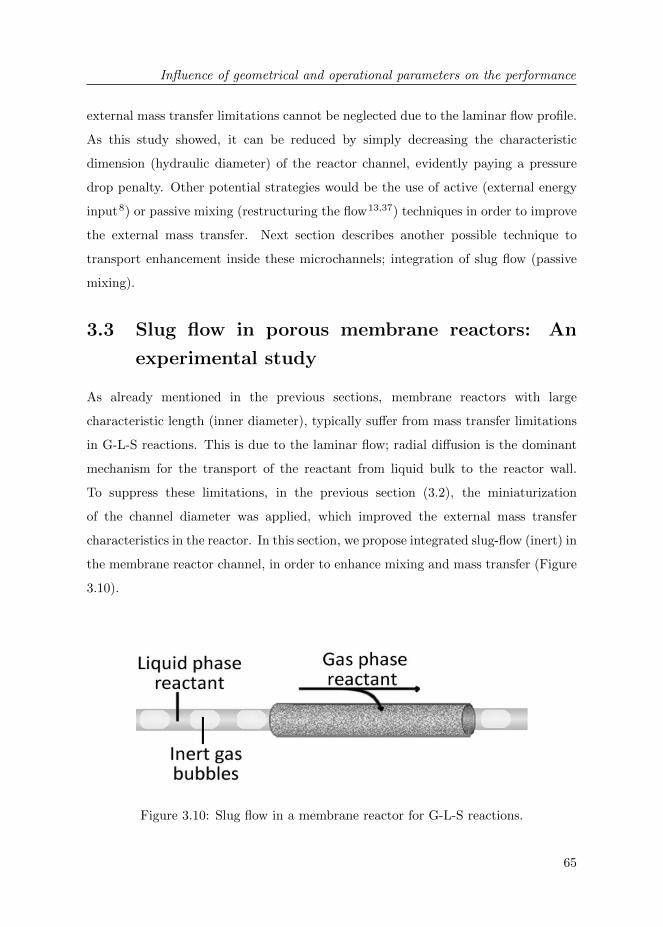
Influence of geometrical and operational parameters on the performance
65
external mass transfer limitations cannot be neglected due to the laminar flow profile.
As this study showed, it can be reduced by simply decreasing the characteristic
dimension (hydraulic diameter) of the reactor channel, evidently paying a pressure
drop penalty. Other potential strategies would be the use of active (external energy
input8) or passive mixing (restructuring the flow13,37) techniques in order to improve
the external mass transfer. Next section describes another possible technique to
transport enhancement inside these microchannels; integration of slug flow (passive
mixing).
3.3 Slug flow in porous membrane reactors: An
experimental study
As already mentioned in the previous sections, membrane reactors with large
characteristic length (inner diameter), typically suffer from mass transfer limitations
in G-L-S reactions. This is due to the laminar flow; radial diffusion is the dominant
mechanism for the transport of the reactant from liquid bulk to the reactor wall.
To suppress these limitations, in the previous section (3.2), the miniaturization
of the channel diameter was applied, which improved the external mass transfer
characteristics in the reactor. In this section, we propose integrated slug-flow (inert) in
the membrane reactor channel, in order to enhance mixing and mass transfer (Figure
3.10).
Figure 3.10: Slug flow in a membrane reactor for G-L-S reactions.

Chapter 3
66
Slug flow (Taylor-flow) is a favorable pattern for microreactors. With this flow
pattern, torroidal vortices are formed in the liquid slugs between the bubbles (see
Figure 1.4), which improves mixing in the microchannel. In microfluidics, slug flow
patterns are used for enhancement of transport, i.e. for biosensors38, but more
commonly in G-L(-S) chemistry it is used as a source for the gaseous reactant (disperse
phase microreactors)20,21,24.
With the present study, we aim to merge the advantages of the dispersed phase
microreactors (slug flow pattern) with the advantages of the membrane reactors.
Taylor-flow is obtained in the reactor channel using inert gas bubbles (air), while
the gaseous reactant is supplied through the porous membrane wall directly to the
reaction zone.
3.3.1 Experimental
3.3.1.1 Reactor preparation
The prepared tubular reactor had an inner diameter of 2.8 mm and a length 13.5
cm. For the reactor preparation, same materials were used and same preparation
methods (γ-Al2O3 catalyst support coating, palladium catalyst deposition and
selective hydrophobization) were carried out as in Section 3.2.
3.3.1.2 Reactor operation
In this experimental study two operation modes were carried out (Figure 3.11):
Continuous Flow and Inert Slug Flow.
In both operation modes, the liquid phase consisted of an aqueous nitrite (NO2−)
solution (50 mg/l). Liquid flow rates were 0.1, 0.2 and 0.3 ml/min. The gaseous
reactant hydrogen (H2) was fed to the shell side of the porous membrane reactor,
as demonstrated in Figure 3.11. In the Continuous Flow operation mode (standard
membrane reactor operation as in Section 3.2), only liquid reactant was flown in the
tube side of the reactor. In the Inert Slug Flow operation mode, an inert gas phase
was dispersed in the liquid phase and the created slug flow was fed to the tube side

Influence of geometrical and operational parameters on the performance
67
Figure 3.11: Reactor operation modes: (top) Continuous Flow, (bottom) Inert SlugFlow.
of the reactor. The same reactor (prepared as decribed in Section 3.2) was used for
both operation modes.
In order to create the slug flow, the liquid phase and the inert gas phase were fed to
a y-mixer by using two separate syringes. The inert gas phase consisted of air at a
gas/liquid flow ratio of 1/1 for all the experiments.
The product at the reactor outlet was collected in a reservoir and injected manually
to an ion chromatograph (Dionex ICS 1000) for analysis.
3.3.1.3 Results and Discussion
Figure 3.12 shows the nitrite (NO2−) conversion values for Continuous and Inert Slug
Flow modes for three different liquid flow rates. We must remark that in the Inert
Slug Flow mode the inert gas/liquid flow rate was 1/1. This means that the residence
time of the NO2− reactant in this operation mode was half the residence time of it in
Continuous mode.
As can be seen from Figure 3.12, the NO2− conversion values are significantly higher
in the Inert Slug Flow mode for each flow rate. The comparable conversion values
for 0.1 ml/min Continuous Flow and 0.2 ml/min Inert Slug Flow show that for these
operation conditions the slug flow induced mixing enhances the reactor performance
by ∼2 times. In addition, since the residence time of the Inert Slug Flow was half
of the Continuous Flow, the conversion enhancement can be considered as ∼4 times
higher for the Inert Slug Flow.
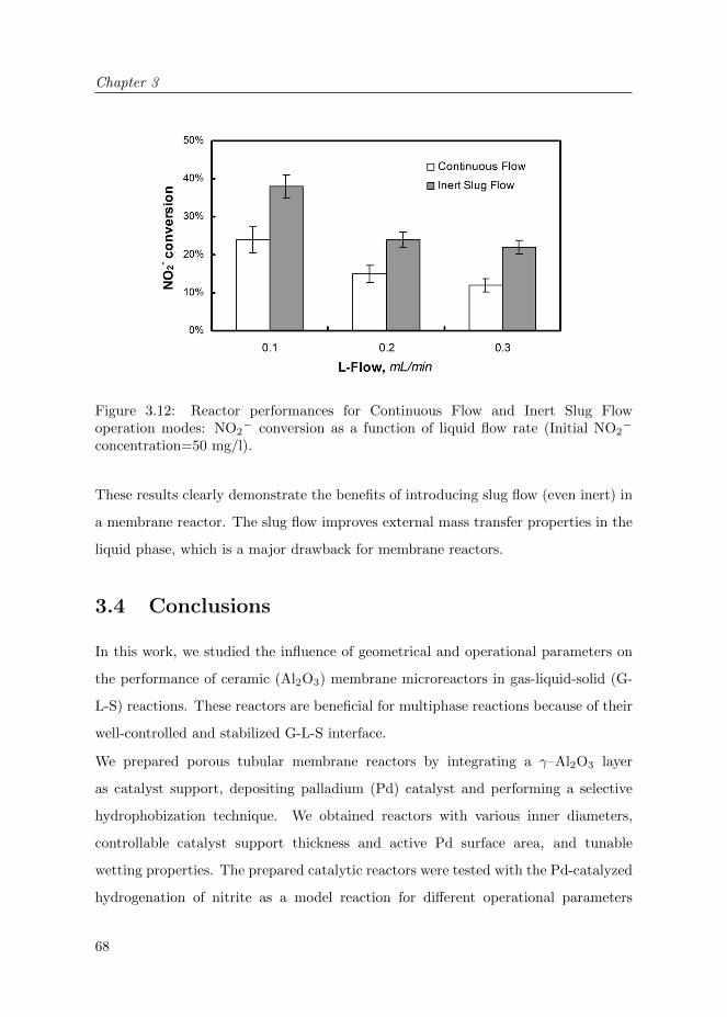
Chapter 3
68
Figure 3.12: Reactor performances for Continuous Flow and Inert Slug Flowoperation modes: NO2
− conversion as a function of liquid flow rate (Initial NO2−
concentration=50 mg/l).
These results clearly demonstrate the benefits of introducing slug flow (even inert) in
a membrane reactor. The slug flow improves external mass transfer properties in the
liquid phase, which is a major drawback for membrane reactors.
3.4 Conclusions
In this work, we studied the influence of geometrical and operational parameters on
the performance of ceramic (Al2O3) membrane microreactors in gas-liquid-solid (G-
L-S) reactions. These reactors are beneficial for multiphase reactions because of their
well-controlled and stabilized G-L-S interface.
We prepared porous tubular membrane reactors by integrating a γ–Al2O3 layer
as catalyst support, depositing palladium (Pd) catalyst and performing a selective
hydrophobization technique. We obtained reactors with various inner diameters,
controllable catalyst support thickness and active Pd surface area, and tunable
wetting properties. The prepared catalytic reactors were tested with the Pd-catalyzed
hydrogenation of nitrite as a model reaction for different operational parameters

Influence of geometrical and operational parameters on the performance
69
(liquid flow rate and initial concentration).
Section 3.2 shows that the NO2− conversion rates per active catalyst surface area
were significantly higher for thinner catalyst support coatings. The results indicated
that with the increasing thickness of the γ–Al2O3 catalyst support the reactors suffer
from internal mass transfer limitations, which is due to the small pore sizes and high
tortuosity of γ–Al2O3. Furthermore, reactors with smaller inner diameter (0.8 mm)
showed higher NO2− conversion rates per active Pd surface than the ones with bigger
inner diameter (2.8 mm). This shows that the miniaturization of the characteristic
length and therefore the diffusion path in the liquid phase enhances the performance
in these reactors thanks to the improved external mass transfer properties.
Section 3.3 describes the integration of slug flow in a membrane reactor for a G-
L-S reaction. This design merges the advantages of dispersed phase concept and a
membrane reactor. The results in this study clearly showed that the performance of a
membrane reactor can be significantly improved by integrating slug flow (Taylor-flow)
in the reactor channel. With the combination of these concepts, the slug flow improves
the mixing in the liquid phase, while the gaseous reactant is very efficiently supplied to
the reaction zone thanks to the porous membrane, thereby avoiding possible depletion.
The combination of membrane and microreactor technology has an interesting
potential for G-L-S reactions. The miniaturization of the membrane reactors is an
easy approach to reduce the mass transfer limitations in these types of reactors, while
microreactors benefit from well-defined G-L-S interface with membrane technology.
3.5 Acknowledgements
We are grateful to K. Altena -Schildkamp, J.A.M. Vrielink, M. Luiten-Olieman, B.
Geerdink and C. Reed for analysis, technical support and fruitful discussions.

Chapter 3
70
Bibliography
[1] J. K. Chinthaginjala. Hairy foam : thin layers of carbon nanofibers as catalyst support for
liquid phase reactions. PhD thesis, Enschede, University of Twente, June 2010. 49, 51, 59
[2] P.A.Ramachandran and R.V. Chaudhari. Three-phase catalytic reactors. Gordon and Breach
Science, 1983.
[3] F. Larachi M.P. Dudukovic and P.L. Mills. Multiphase catalytic reactors: a perspective on
current knowledge and future trends. Catalysis Reviews, 44(1):123–246, 2002. 49
[4] R. Dittmeyer, V. Hollein, and K. Daub. Membrane reactors for hydrogenation and
dehydrogenation processes based on supported palladium. Journal of Molecular Catalysis A:
Chemical, 173(1-2):135 – 184, 2001. 49
[5] R. Dittmeyer, K. Svajda, and M. Reif. A review of catalytic membrane layers for gas/liquid
reactions. Topics in Catalysis, 29:3–27, 2004.
[6] A. G. Dixon. Recent research in catalytic inorganic membrane reactors. International Journal
of Chemical Reactor Engineering, 1(R6), 2003.
[7] J. Coronas and J. Santamaria. Catalytic reactors based on porous ceramic membranes.
Catalysis Today, 51(3-4):377 – 389, 1999.
[8] M. Vospernik, A. Pintar, G. Bercic, and J. Levec. Experimental verification of ceramic
membrane potentials for supporting three-phase catalytic reactions. Journal of Membrane
Science, 223(1-2):157 – 169, 2003. 64, 65
[9] M. Vospernik, A. Pintar, G. Bercic, J. Batista, and J. Levec. Potentials of ceramic membranes
as catalytic three-phase reactors. Chemical Engineering Research and Design, 82(5):659 – 666,
2004. 49
[10] J. Peureux, M. Torres, H. Mozzanega, A. Giroir-Fendler, and J-A. Dalmon. Nitrobenzene
liquid-phase hydrogenation in a membrane reactor. Catalysis Today, 25(3-4):409 – 415, 1995.
[11] W.N. Lau, K.L. Yeung, X.F. Zhang, and R. Martin-Aranda. Zeolite membrane microreactors
and their performance. In J. Chen R. Xu, Z. Gao and W. Yan, editors, From Zeolites to Porous
MOF Materials - The 40th Anniversary of International Zeolite Conference, Proceedings of the
15th International Zeolite Conference, volume 170 of Studies in Surface Science and Catalysis,
pages 1460 – 1465. Elsevier, 2007.
[12] A. Julbe, D. Farrusseng, and C. Guizard. Porous ceramic membranes for catalytic reactors –
overview and new ideas. Journal of Membrane Science, 181(1):3 – 20, 2001.
[13] A. Pashkova, R. Dittmeyer, N. Kaltenborn, and H. Richter. Experimental study of porous
tubular catalytic membranes for direct synthesis of hydrogen peroxide. Chemical Engineering
Journal, 165(3):924 – 933, 2010. 49, 65
[14] H. C. Aran, J. K. Chinthaginjala, R. Groote, T. Roelofs, L. Lefferts, M. Wessling, and R. G. H.
Lammertink. Porous ceramic mesoreactors: A new approach for gas-liquid contacting in
multiphase microreaction technology. Chemical Engineering Journal, 169(1-3):239 – 246, 2011.
49, 50

Bibliography
71
[15] K. Jahnisch, V. Hessel, H. Lowe, and M. Baerns. Chemistry in microstructured reactors.
Angewandte Chemie International Edition, 43(4):406–446, 2004. 49
[16] A. Gavriilidis, P. Angeli, E. Cao, K. K. Yeong, and Y. S. S. Wan. Technology and applications
of microengineered reactors. Chemical Engineering Research and Design, 80(1):3 – 30, 2002.
49
[17] K.K. Yeong, A. Gavriilidis, R. Zapf, and V. Hessel. Catalyst preparation and deactivation
issues for nitrobenzene hydrogenation in a microstructured falling film reactor. Catalysis Today,
81(4):641 – 651, 2003. 50, 52, 61
[18] C. Amador, D. Wenn, J. Shaw, A. Gavriilidis, and P. Angeli. Design of a mesh microreactor for
even flow distribution and narrow residence time distribution. Chemical Engineering Journal,
135(Supplement 1):S259 – S269, 2008. 50
[19] S. McGovern, G. Harish, C.S. Pai, W. Mansfield, J.A. Taylor, S. Pau, and R.S. Besser.
Multiphase flow regimes for hydrogenation in a catalyst-trap microreactor. Chemical
Engineering Journal, 135:S229 – S236, 2008. 50
[20] M. T. Kreutzer, F. Kapteijn, J. A. Moulijn, and J. J. Heiszwolf. Multiphase monolith reactors:
Chemical reaction engineering of segmented flow in microchannels. Chemical Engineering
Science, 60(22):5895 – 5916, 2005. 50, 66
[21] V. Hessel, P. Angeli, A. Gavriilidis, and H. Lowe. Gas-liquid and gas-liquid-solid
microstructured reactors: Contacting principles and applications. Industrial & Engineering
Chemistry Research, 44(25):9750–9769, 2005. 50, 66
[22] M. N. Kashid and L. Kiwi-Minsker. Microstructured reactors for multiphase reactions: State
of the art. Industrial & Engineering Chemistry Research, 48(14):6465–6485, 2009.
[23] G. Chen, J. Yue, and Q. Yuan. Gas-liquid microreaction technology: Recent developments and
future challenges. Chinese Journal of Chemical Engineering, 16(5):663 – 669, 2008.
[24] V. Hessel, S. Hardt, and H. Lowe. Chemical Micro Process Engineering: Fundamentals,
Modelling and Reactions, Sections 5.1-5.3, pages 577–619. Wiley-VCH Verlag GmbH & Co.
KGaA, 2005. 50, 66
[25] C. P. Park and D.-P. Kim. Dual-channel microreactor for gas-liquid syntheses. Journal of the
American Chemical Society, 132(29):10102–10106, 2010. 50
[26] J. K. Chinthaginjala, J. H. Bitter, and L. Lefferts. Thin layer of carbon-nano-fibers (CNFs)
as catalyst support for fast mass transfer in hydrogenation of nitrite. Applied Catalysis A:
General, 383(1-2):24 – 32, 2010. 51, 60, 64
[27] J.K. Chinthaginjala and L. Lefferts. Support effect on selectivity of nitrite reduction in water.
Applied Catalysis B: Environmental, 101(1-2):144 – 149, 2010. 51
[28] R. Zapf, C. Becker-Willinger, K. Berresheim, H. Bolz, H. Gnaser, V. Hessel, G. Kolb, P. Lob, A.-
K. Pannwitt, and A. Ziogas. Detailed characterization of various porous alumina–based catalyst
coatings within microchannels and their testing for methanol steam reforming. Chemical
Engineering Research and Design, 81(7):721 – 729, 2003. 52

Chapter 3
72
[29] M.W.J. Luiten, N.E. Benes, C. Huiskes, H. Kruidhof, and A. Nijmeijer. Robust method for
micro-porous silica membrane fabrication. Journal of Membrane Science, 348(1-2):1–5, 2010.
53
[30] H.S. Fogler. Elements of Chemical Reaction Engineering. Prentice Hall, 1999. 58, 59
[31] R. E. Hayes, B. Liu, R. Moxom, and M. Votsmeier. The effect of washcoat geometry on mass
transfer in monolith reactors. Chemical Engineering Science, 59(15):3169 – 3181, 2004. 59
[32] G.F. Froment and K.B. Bischoff. Chemical Reactor Analysis and Design. Wiley, 1990. 59
[33] K.C. Metaxas and N.G. Papayannakos. Studying the internal mass transfer phenomena inside
a Ni/Al2O3 catalyst for benzene hydrogenation. Chemical Engineering Journal, 140(1-3):352
– 357, 2008. 61
[34] Y. Matatov-Meytal, V. Barelko, I. Yuranov, and M. Sheintuch. Cloth catalysts in water
denitrification: I. Pd on glass fibers. Applied Catalysis B: Environmental, 27(2):127 – 135,
2000. 61
[35] A. Pintar, G. Bercic, and J. Levec. Catalytic liquid-phase nitrite reduction: Kinetics and
catalyst deactivation. AIChE Journal, 44(10):2280–2292, 1998. 61
[36] R. Gorges, S. Meyer, and G. Kreisel. Photocatalysis in microreactors. Journal of
Photochemistry and Photobiology A: Chemistry, 167(2-3):95–99, 2004. 63
[37] J.M. Jani, M. Wessling, and R.G.H. Lammertink. Geometrical influence on mixing in helical
porous membrane microcontactors. Journal of Membrane Science, In Press, Corrected Proof:–,
2011. 65
[38] M. Fumagalli, V. van Steijn, C.R. Kleijn, L.C.P.M. de Smet, E.J.R. Sudholter, and M.T.
Kreutzer. Enhancement of transport in biosensing using flow segmentation. Proceedings of the
1st European conference on Microfluidics, Italy, 2008. 66

73
Chapter 4
Porous metallic microreactors
with carbon nanofibers
A REVISED VERSION OF THIS CHAPTER HAS BEEN PUBLISHED:
H.C. Aran, S. Pacheco Benito, M.W.J. Luiten-Olieman, S. Er, M. Wessling,
L. Lefferts, N.E. Benes, and R.G.H. Lammertink, Carbon nanofibers in catalytic
membrane microreactors, Journal of Membrane Science, 381(1-2), 244–250, 2011.

Chapter 4
74
ABSTRACT
In this study, we report on the fabrication and operation of new hybrid membrane
microreactors for gas-liquid-solid (G-L-S) reactions. The presented reactors consist
of porous stainless steel tubes onto which carbon nanofibers (CNFs) are grown as
catalyst support, all encapsulated by a gas permeable coating. Such reactors benefit
from a controlled G-L-S interface of a membrane reactor and high surface area of
carbon nanofibers as catalyst support. Preparation steps such as porous stainless
steel hollow fiber fabrication, CNF growth on the stainless steel surface, palladium
catalyst immobilization and an outer gas permeable polymeric coating steps are
presented. The fabricated microreactors have high surface area, mechanical strength
and catalytic activity for nitrite reduction in water. Results proved high nitrite
reduction performance of these reactors, even without the presence of palladium
(Pd) or additional hydrogen (H2) supply. Our results suggest intrinsic reductant
properties and catalytic activity of the reactors, which make them very suitable for
hydrogenation reactions.

Porous metallic microreactors with CNFs
75
4.1 Introduction
Microreactors are miniaturized devices for carrying out chemical reactions, which
in recent years have become favorable for chemical technology due to their small
dimensions (characteristic length). The high surface to volume ratio in these devices
provide them improved heat and mass transfer compared to macro-scale reactors1–5.
In this study, we particularly focus on heterogeneously catalyzed gas-liquid-solid (G-
L-S) reactions in microreactors. Typical reactor designs applied for these reaction
systems are the falling film microreactors4,5, dispersed phase microreactors6, catalyst
trap microreactors7 and mesh microreactors8,9.
Recently, we demonstrated an alternative membrane reactor design for these reactions
in microsystems1. In contrast to most of the other designs, in membrane reactors the
gas and liquid phases are contacted precisely where the solid catalyst is located.
These phases can be independently controlled during the process and the gas-liquid
interface is well-defined and stabilized by the membrane10–12. In Chapters 2 and 3,
we performed the contacting of the gas and liquid reactants using a porous ceramic
(Alumina-Al2O3) membrane, which also acts as support for the solid (S) catalyst.
The stabilization of the G-L-S interface in the porous Al2O3 membrane was obtained
by a selective surface modification technique.
The aim of the present work is to utilize porous metallic materials with carbon
nanofibers (CNFs) as catalyst support for a G-L-S reaction process using a membrane
reactor concept: Porous metallic microreactors (Figure 4.1). Carbon nanofibers
(CNFs) are very promising materials as catalyst support, which is due to their
favorable physical and chemical characteristics. CNFs have a high surface area (>100
m2/g) and large pore volumes (>0.5 cm3/g) leading to low tortuosity and efficient
internal mass transfer. Moreover, CNFs are mechanically strong and chemically
inert13–19.
In our concept (Figure 4.1), the liquid flows in the tube side of the hollow fiber and
the contact between the liquid and gas phases takes place on the porous hollow fiber
(in microscale) where the CNF catalyst support is located. The outer surface of the

Chapter 4
76
Figure 4.1: Gas-liquid contacting in porous metallic microreactors for multiphasereactions: Porous stainless steel membrane decorated with carbon nanofibers (CNFs)as catalyst support. Reactor encapsulated with a selective, gas permeable PDMSlayer.
porous hollow fiber is covered with a dense gas permeable polymeric coating in order
to stabilize the G-L-S interface. In this concept, the gas is continuously supplied to
the reaction zone through the membrane along the whole length of the reactor. The
developed reactor is tested for a model multiphase reaction, the catalytic reduction
of nitrite ions in water.
4.2 Experimental
4.2.1 Materials
Stainless steel powder (316L, Epson Atmix Corporation, D50, particle size = 4.17 µm),
polyethersulfone (PES; Ultrason, 6020P) and N-methylpyrrolidone (NMP; 99,5wt%,
Aldrich) were used for the stainless steel suspension preparation. PES and the
stainless steel powder were dried prior to use. The other chemicals were used without
further treatment. Hydrogen, nitrogen (99.999%, Praxair), and ethylene (99.95%,
Praxair) were used for CNFs formation without further purification. Palladium(II)
2,4-pentanedione (Pd(acac)2; Alfa Aesar, 34.7%) and toluene (Merck) were used for
the catalyst precursor solution. For the PDMS coating a General Electric PDMS RTV
615 kit was used (purchased from Permacol B.V.), which consisted of two components;
a vinyl terminated pre-polymer (RTV-A) and a Pt-catalyzed cross-linker (RTV-B).
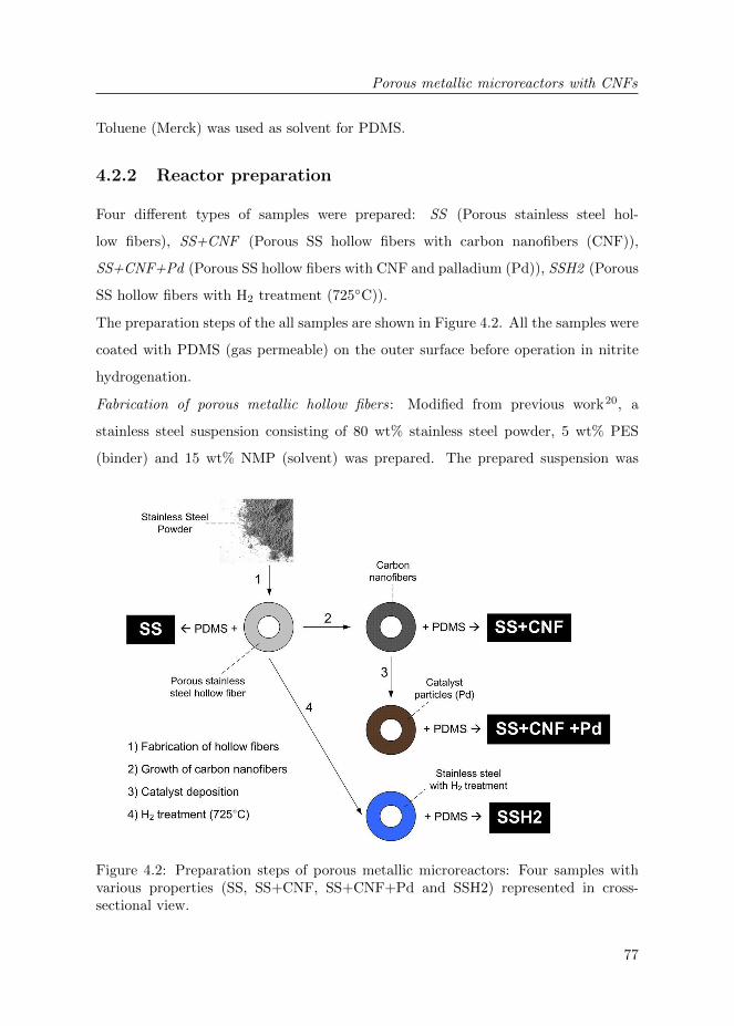
Porous metallic microreactors with CNFs
77
Toluene (Merck) was used as solvent for PDMS.
4.2.2 Reactor preparation
Four different types of samples were prepared: SS (Porous stainless steel hol-
low fibers), SS+CNF (Porous SS hollow fibers with carbon nanofibers (CNF)),
SS+CNF+Pd (Porous SS hollow fibers with CNF and palladium (Pd)), SSH2 (Porous
SS hollow fibers with H2 treatment (725◦C)).
The preparation steps of the all samples are shown in Figure 4.2. All the samples were
coated with PDMS (gas permeable) on the outer surface before operation in nitrite
hydrogenation.
Fabrication of porous metallic hollow fibers: Modified from previous work20, a
stainless steel suspension consisting of 80 wt% stainless steel powder, 5 wt% PES
(binder) and 15 wt% NMP (solvent) was prepared. The prepared suspension was
Figure 4.2: Preparation steps of porous metallic microreactors: Four samples withvarious properties (SS, SS+CNF, SS+CNF+Pd and SSH2) represented in cross-sectional view.

Chapter 4
78
pressurized in a stainless steel vessel using nitrogen (2 bars) and pressed through a
spinneret with an inner diameter of 0.8 mm and an outer diameter of 2.0 mm, followed
by immersion in a coagulating bath. The air gap was 3 cm and de-ionized water was
pressed through the bore of the spinneret (7 ml/min). The fibers were kept in a water
bath for 1 day for removal of the NMP and consequently dried for 1 day. Finally, the
samples were sintered at 1100◦C for 30 min in N2 atmosphere.
Growth of carbon nanofibers: Catalytic chemical vapor deposition method was used
to grow carbon nanofibers (CNFs) on the surfaces of the porous stainless steel hollow
fibers. The hollow fibers were placed in an in-house built 12 mm inner diameter
quartz reactor. Based on previous work17, the samples were heated up to 725◦C
(heating rate = 7.5◦C/min) in diluted air (9% air and balance N2). The total flow
was always kept at 100 ml/min, unless otherwise mentioned. Next, they were treated
with hydrogen (100%) for 2 h and then in diluted air (9% air and balance N2) for 1
h at the same temperature. Then the temperature in the reactor was decreased to
700◦C with N2. For the growth of the CNFs a gas mixture of hydrogen and ethylene
(C2H4) in N2 was fed to the reactor (25% C2H4, 5% H2 and balance N2) for 2 h with
a total flow of 200 ml/min. After the growth step, the samples were cooled down to
room temperature under N2 flow.
Lastly, an aqueous ultrasound treatment was applied to the samples in order to remove
the loose carbon nanofibers from the metal surface, followed by a drying step under
vacuum at 100◦C overnight.
Catalyst deposition: The porous metallic hollow fiber with carbon nanofibers were
immersed in a precursor solution consisting of 300 mg Pd(acac)2 in 50 ml toluene for
24 h. Consequently, the samples were dried overnight at 50◦C, calcined for 1 h and
reduced for 1 h at 250◦C.
SSH2 sample preparation (H2 treatment): Same procedure was followed as for the
growth of carbon nanofibers, where only the final growth step with the carbon source
ethylene (C2H4) was skipped.
PDMS coating : Adapted from Dutczak et al.21, a PDMS/toluene solution was pre-
crosslinked before the coating procedure. RTV-A and RTV-B components (3.75

Porous metallic microreactors with CNFs
79
wt% in total) of the PDMS kit were dissolved in toluene and kept at 80◦C for 2
h. Following that, the cross-linking reaction was continued at 60◦C until the viscosity
of the solution reached approximately 100 mPa·s. The viscosity measurements were
carried out at 25◦C with a Brookfield DV-II+ Pro viscometer using a spindle nr-61.
The pre-crosslinked PDMS/toluene solution was coated at the outer surface of the
hollow fiber using an automated set-up with an immersion/pull up velocity of 0.9
cm/s. The hollow fiber samples were dip-coated in the solution with a contact time
of approximately 30 s, as described in detail elsewhere21. One end of the hollow fiber
was sealed by glue prior to the coating step. Finally, the coated hollow fibers were
placed in an oven at 60◦C for 8 h to finalize the crosslinking reaction.
4.2.3 Reactor operation
The prepared reactors were tested for the catalytic reduction of nitrite (NO2−) ions
in water (Figure 4.3). The conversion of NO2− ions in water and the formation of
the reaction product ammonia (NH4+) were measured. An aqueous NO2
− solution
Figure 4.3: Schematic representation of the experimental setup and operationalparameters.

Chapter 4
80
with initial concentration 50 mg/l was prepared as the liquid reactant and fed to the
microreactor (tube side) with a flow rate of 0.1 ml/min. Hydrogen (H2) or Argon (Ar)
was fed to the shell side of the reactor module (100 ml/min). The NO2− and NH4
+
concentrations at the reactor in- and outlet were measured by an ion chromatograph
(Dionex ICS 1000).
4.3 Results and Discussion
4.3.1 Reactor characterization
Figure 4.4 shows the cross-section of a sintered porous stainless steel hollow fiber.
The hollow fiber has high mechanical strength together with high porosity. The wall
of the hollow fiber (a) contains thin and long macrovoids. This structure is favorable
for the diffusive transport of the NO2− reactant (liquid phase) in the porous structure
during the operation, so that the immobilized catalyst is easily accessible for the liquid
reactant. Furthermore, the outer skin of the hollow fiber (b) does not contain macro
voids and presents a smoother and denser structure. This is beneficial for applying a
thin and defect free PDMS layer in the later stage of reactor preparation. The BET
surface area of the porous stainless steel hollow fibers was ∼0.4 m2/g.
As can be seen in Figure 4.5, carbon nanofibers (CNFs) are successfully grown along
the full cross-section of the porous stainless steel hollow fiber. The CNF deposition on
the hollow fibers can be identified both visually and by SEM analysis (Figure 4.5). A
clear difference in morphology can be seen between samples with and without CNFs.
We also observe metal-nano-particles (iron, nickel) on the tip of the grown nanofibers
(tip-growth17,22), as can be seen in Figure 4.6.a.
The weight increase due to the CNF growth was ∼16%. The BET surface area of the
whole sample after the CNF growth was ∼21.3 m2/g, significantly higher than before
the growth. The surface area of only the carbon on the surface was calculated as
∼151 m2/g, which is in the same range with values reported in the literature14,18,19.
The EDX results (not shown here) qualitatively showed carbon content was highest
near the outer skin of the sample, which is most likely because the packing density

Porous metallic microreactors with CNFs
81
Figure 4.4: Cross-section of the porous stainless steel hollow fiber after the sinteringstep: (a) Wall of the hollow fiber with thin macrovoids, (b) Outer skin of the hollowfiber with a denser structure.
Figure 4.5: Porous stainless steel hollow fibers before (left) and after (right) thegrowth of the carbon nanofibers.
of porous stainless steel was higher at the outer skin compared to the inner wall of
the hollow fiber (see Figure 4.4). This may also be caused by the better access of
the hydrocarbon source (ethylene gas) to the outer surface of the porous hollow fiber
during the CNF growth. The adhesion strength of the carbon nanofibers has been

Chapter 4
82
Figure 4.6: Carbon nanofibers grown on the porous stainless steel surface: (a)Metal- nano-particles (iron, nickel) on the tip of the grown CNFs, (b) Pd particlesimmobilized on the surface of CNFs.
investigated by an aqueous ultrasonic treatment and only a little amount of loose
CNFs was released. No considerable weight loss was measured.
After the catalyst immobilization, the average Pd weight percentage on the sample
was ∼0.1 wt% (measured by XRF). The immobilized Pd particles on the CNFs are
displayed in Figure 4.6.b. Unfortunately, the Pd distribution along the cross-section
of the hollow fiber could not be characterized by the EDX measurements due to the
excessive amount of carbon on the stainless steel surface.
Each sample was coated with a selective PDMS layer before the operation. The
thickness of the PDMS coating was ∼20 µm and was able to keep the liquid inside
the microchannel at our operation conditions.
4.3.2 Reactor operation
Catalytic reduction (hydrogenation) of nitrite (NO2−) is chosen as a model reaction
to test the developed microreactors. Hydrogenation of NO2− is known to be a fast
reaction that induces mass transfer limitations. In addition, NO2− is a harmful
compound for human health and removal of NO2− ions from water is environmentally
relevant due to its increased amount in ground waters. During the catalytic reduction,
NO2− is converted to nitrogen (N2) and the undesired product ammonia (NH4
+). The
Pd-catalyzed hydrogenation of nitrite in the presence of hydrogen gas (H2) typically
takes place as follows1,15,16,23,24.

Porous metallic microreactors with CNFs
83
2NO−2 + 3H2Pd→ N2 + 2OH− + 2H2O (4.1)
2NO−2 + 6H2Pd→ 2NH+
4 + 4OH− (4.2)
In the present study, the conversion of NO2− and the formation of NH4
+ are measured
to characterize the performance of our reactors. Our main performance criterion in
this model reaction is the NO2− conversion. The concentration of NH4
+ is only
measured to confirm the NO2− reduction process.
Figure 4.7 shows an overview of the NO2− conversion results for the prepared reactors
SS (stainless steel), SS+CNF (stainless steel + carbon nanofibers) and SS+CNF+Pd
(stainless steel + carbon nanofibers + palladium) with the supply of H2 as gaseous
reactant or argon (Ar) as inert gas to the shell side of the membrane reactor.
Figure 4.7: Nitrite reduction performances (liquid flow rate= 0.1 ml/min, initialnitrite concentration= 50 mg/l) of the prepared microreactors: SS (stainless steel),SS+CNF (stainless steel with carbon nanofibers), SS+CNF+Pd (stainless steel withcarbon nanofibers and palladium catalyst).
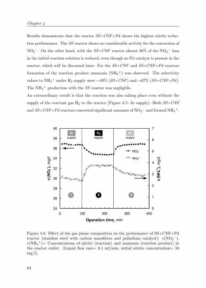
Chapter 4
84
Results demonstrate that the reactor SS+CNF+Pd shows the highest nitrite reduc-
tion performance. The SS reactor shows no considerable activity for the conversion of
NO2−. On the other hand, with the SS+CNF reactor almost 20% of the NO2
− ions
in the initial reaction solution is reduced, even though no Pd catalyst is present in the
reactor, which will be discussed later. For the SS+CNF and SS+CNF+Pd reactors
formation of the reaction product ammonia (NH4+) was observed. The selectivity
values to NH4+ under H2 supply were ∼49% (SS+CNF ) and ∼67% (SS+CNF+Pd).
The NH4+ production with the SS reactor was negligible.
An extraordinary result is that the reaction was also taking place even without the
supply of the reactant gas H2 to the reactor (Figure 4.7- Ar supply). Both SS+CNF
and SS+CNF+Pd reactors converted significant amounts of NO2− and formed NH4
+.
Figure 4.8: Effect of the gas phase composition on the performance of SS+CNF+Pdreactor (stainless steel with carbon nanofibers and palladium catalyst): c(NO2
−),c(NH4
+)= Concentrations of nitrite (reactant) and ammonia (reaction product) atthe reactor outlet. (Liquid flow rate= 0.1 ml/min, initial nitrite concentration= 50mg/l).

Porous metallic microreactors with CNFs
85
Experiments show that for the SS+CNF reactor the conversion of NO2− and the
formation of NH4+ are comparable for the experiments with and without H2 supply.
The only considerable contribution of the H2 supply on the reactor performance
is observed for the reactor SS+CNF+Pd, which is due to the presence of Pd as
hydrogenation catalyst (Figure 4.8).
Figure 4.8 displays the changes in concentration of NO2− and NH4
+ at the reactor
outlet with and without H2 supply during the operation. At the initial stage of
the experiment (1), the reaction proceeds under inert argon (Ar) flow in the gas
side, resulting in a NO2− conversion of ∼25%. When the gas phase composition is
switched to pure H2 (2), the final NO2− concentration decreases indicating a higher
NO2− conversion of ∼30%. Moreover, the concentration of NH4
+ increases. At the
final stage of the experiment (3), when the H2 gas is substituted again with Ar, the
outlet concentrations of NO2− and NH4
+ reach the same values as the initial stage
of the experiment.
In all of our reactors, SS, SS+CNF and SS+CNF+Pd, a decrease in the NO2−
concentration and a simultaneous increase in the NH4+ concentration is observed.
However, the reactors show significantly different NO2− conversion rates (ξ), as ξ(SS )
<< ξ (SS+CNF ) < ξ(SS+CNF+Pd) . Interestingly, the reaction also proceeds
in the absence of external hydrogen supply, as shown in Figure 4.7. Additionally,
in reactor SS+CNF no Pd catalyst is present, but the NO2− conversion still
proceeds drastically, even at lower rates compared to the SS+CNF+Pd reactor. The
remarkable performance of our reactors in the absence of hydrogen gas or Pd catalyst
is discussed in the next paragraphs.
Firstly, during the growth of CNFs the porous stainless steel fibers were exposed to
H2 gas for more than 1 h at elevated temperatures (T≥700◦C). This method of CNF
growth may be responsible for the storage of hydrogen inside the metal bulk of our
microreactors. It is well known that some metals and metal alloys, when exposed
to hydrogen gas, form metal hydrides and store significant amounts of hydrogen.
The formation of the hydrides takes place by adsorption of hydrogen on the metal
surface and formation of a solid hydrogen solution phase in the metal, followed by

Chapter 4
86
the growth of the metal hydride phase25–27. In our case, the stainless steel contains
large amounts of Fe, Ni and Cr. The hydrides of these metal mixtures may form as a
result of the exposure to hydrogen gas at high temperatures. Later, during the NO2−
conversion reaction, these metal hydrides may act as an additional source of hydrogen
and release their stored hydrogen into the reaction medium. Previous studies show
that the metal hydrides act both as a catalyst and as a hydrogen source. Snijder et
al.28, in their cyclohexene hydrogenation reaction, observed that the complex metal
hydride (LaNi5−xAlxHn) acted as an additional source of hydrogen.
To understand whether the metal components of our microreactors can act as a
source of hydrogen, we prepared the SSH2 reactor. The SSH2 reactor, similar to
the SS reactor, does not contain any CNFs but involves a pretreatment step under
hydrogen atmosphere at 725◦C. Using the SSH2 reactor, we performed the NO2−
conversion experiments with and without an external hydrogen gas source. The
observed NO2− conversion values were small: 3 and 2%, respectively for the cases
with and without external hydrogen supply. Additionally, at the outlet of the SSH2
reactor a considerable amount of NH4+ concentration (up to 0.2 mg/l) was observed,
which was notably higher than the SS reactor that was prepared with no hydrogen
pretreatment step. These results support the idea that the storage of atomic hydrogen
inside the metal compartments of our microreactors is possible, however the reactor
performance was significantly lower than that of SS+CNF reactors. Obviously, the
presence of CNFs is crucial for the efficiency of our microreactors.
Secondly, carbon nanofibers (CNFs) and carbon nanotubes (CNTs) are known to store
hydrogen via physisorption. Accordingly, the binding energy of hydrogen to these
materials is low and hydrogen storage takes place only under specific conditions, such
as low temperatures and high hydrogen pressures29–32. Since our experiments were
performed at room temperature and under low or no hydrogen gas pressure, we assume
that the amount of physisorbed hydrogen on the CNFs inside our microreactors is very
limited.
Thirdly, the reductive properties of metal particles on the CNFs with high surface
area may be responsible for the NO2− reduction process. CNFs are known to grow

Porous metallic microreactors with CNFs
87
catalytically on metal surfaces, particularly on iron (Fe), nickel (Ni) and cobalt
(Co)13–15,22. In this study, the preparation of the porous stainless steel hollow fibers
was carried out with 316L powder, consisting of ∼67% Fe and ∼13% Ni (Epson Atmix
Corporation). These metals promote the CNF growth on the porous stainless steel
surface with the help of a carbon source, in our case ethylene. Typically, the growth
of CNFs occurs by deposition of carbon under these metal growth-catalysts (Fe, Ni).
Therefore, the metal particles are squeezed out of the surface and stay at the tip of
the fibers (tip growth)17,22. Accordingly, in our case, the CNFs do not only support
the Pd catalyst, but also contain other metal-nano-particles (Fe, Ni) in an open and
available form on their surfaces (Figure 4.6.a), although part of the particles may be
encapsulated by carbon.
Among these particles, literature studies show that metallic iron (Fe0) particles act as
a reductant of nitrite (NO2−) and nitrate (NO3
−) ions in water, where an additional
supply of hydrogen gas is not present33–37. Similarly, iron particles in their oxidized
state (Fe2+) were reported to act as a reducing agent35,36. According to Hu et al.34,
the NO2− reduction process can occur by the direct reduction on Fe0, or by the
indirect reduction with the hydrogen that is generated from the proton reduction
reaction of Fe0. They showed that the reaction takes place much faster in acidic
conditions, rather than in neutral or alkaline conditions34. In our study, no pH
adjustment was carried out. Similarly, Liang et al.33 used nanoscale Fe0 for the
NO2− reduction, however they did not observe a dependence on pH of the initial
NO2− solutions. They suggested the following reduction mechanism for the nitrite
ions in water:
3Fe0 + NO−2 + 8H+ → 3Fe2+ + NH+4 + 2H2O (4.3)
3Fe0 + 2NO−2 + 8H+ → 3Fe2+ + N2 + 4H2O (4.4)
Fe0 + NO−2 + 6H2O → 3Fe(OH)2 + NH+4 + 2OH− (4.5)
We observe that the conversion values of our SS+CNF microreactor is significantly

Chapter 4
88
higher than that of our SS microreactor, revealing that the presence of the CNFs is
very important in the conversion process. The CNFs do not only increase the surface
area, but also increase the availability of metal particles, particularly Fe. The total
amount of Fe within the reactors is approximately 12 mmol (reactor weight without
CNFs = 1 g), while the calculated reduction rate of nitrite using the SS+CNF reactor
is only 2·10−5 mmol/min. Evidently, not all of iron inside our reactors is available for
reaction. Still, even if 1% of the Fe in the reactor is available for the nitrite reduction,
the reactor can be operated for 100 h until this effect will end.
Accordingly, these metal nanoparticles on the tips of the CNFs shall be responsible
for the reduction of NO2− in our microreactors with H2 supply, noticeably more than
the other factors discussed in here.
4.4 Conclusions
In this study, porous metallic microreactors with carbon nanofibers (CNFs) catalyst
support were developed and applied for catalytic nitrite (NO2−) reduction in water.
Porous stainless steel (SS) hollow fibers with high porosity and mechanical strength
were fabricated and CNFs with high surface area were successfully grown on the
porous SS surface. For particular samples, also palladium (Pd) catalyst was
immobilized on the CNFs as a hydrogenation catalyst. Finally, all the reactors were
encapsulated with a gas permeable polymeric coating. The fabricated microreactors
showed to have a high surface area, mechanical strength and catalytic activity, which
was tested for the catalytic reduction of nitrite (NO2−) reaction.
The presence of the CNF on the SS surface had a significant effect on the reactor
performance. Even without the presence of H2 and Pd, the NO2− ions were
successfully reduced, which was confirmed by the disappearance of NO2− reactant
and formation of ammonia (NH4+). These results indicate the reductive properties of
the reactor material. We proposed that the reductive properties of iron (Fe) particles,
which are located on the tip of the grown CNFs, shall be responsible for the reduction
of NO2− without hydrogen supply.

Porous metallic microreactors with CNFs
89
We also demonstrated that in our Pd-immobilized reactors the NO2− reduction
proceeds by both catalytic reduction (with Pd and H2) and by the reactor material
itself (i.e., by Fe on CNFs). Eventually, the latter effect will exhaust in time and
the reaction will still proceed with the immobilized Pd-catalyst on the CNFs and the
membrane-assisted supply of H2.
In short, we show that the porous metallic microreactors decorated with carbon
nanofibers are suitable materials for the reduction of nitrite and the reactor design is
very promising for the multiphase microreactor technologies.
4.5 Acknowledgements
We are grateful to K. Altena -Schildkamp, J.A.M. Vrielink, M. A. Smithers, B.
Geerdink, J. Bennink (Tingle.nl) and C. Reed for analysis, technical support, images
and fruitful discussions.

Chapter 4
90
Bibliography
[1] H. C. Aran, J. K. Chinthaginjala, R. Groote, T. Roelofs, L. Lefferts, M. Wessling, and R. G. H.
Lammertink. Porous ceramic mesoreactors: A new approach for gas-liquid contacting in
multiphase microreaction technology. Chemical Engineering Journal, 169(1-3):239 – 246, 2011.
75, 82
[2] M. N. Kashid and L. Kiwi-Minsker. Microstructured reactors for multiphase reactions: State
of the art. Industrial & Engineering Chemistry Research, 48(14):6465–6485, 2009.
[3] A. Gavriilidis, P. Angeli, E. Cao, K. K. Yeong, and Y. S. S. Wan. Technology and applications
of microengineered reactors. Chemical Engineering Research and Design, 80(1):3 – 30, 2002.
[4] V. Hessel, P. Angeli, A. Gavriilidis, and H. Lowe. Gas-liquid and gas-liquid-solid
microstructured reactors: Contacting principles and applications. Industrial & Engineering
Chemistry Research, 44(25):9750–9769, 2005. 75
[5] V. Hessel, S. Hardt, and H. Lowe. Chemical Micro Process Engineering: Fundamentals,
Modelling and Reactions, Sections 5.1-5.3, pages 577–619. Wiley-VCH Verlag GmbH & Co.
KGaA, 2005. 75
[6] M. T. Kreutzer, F. Kapteijn, J. A. Moulijn, and J. J. Heiszwolf. Multiphase monolith reactors:
Chemical reaction engineering of segmented flow in microchannels. Chemical Engineering
Science, 60(22):5895 – 5916, 2005. 75
[7] S. McGovern, G. Harish, C.S. Pai, W. Mansfield, J.A. Taylor, S. Pau, and R.S. Besser.
Multiphase flow regimes for hydrogenation in a catalyst-trap microreactor. Chemical
Engineering Journal, 135:S229 – S236, 2008. 75
[8] R. Abdallah, V. Meille, J. Shaw, D. Wenn, and C. de Bellefon. Gas-liquid and gas-liquid-solid
catalysis in a mesh microreactor. Chem. Commun., pages 372–373, 2004. 75
[9] David A. Wenn, John E. A. Shaw, and Bina Mackenzie. A mesh microcontactor for 2-phase
reactions. Lab Chip, 3:180–186, 2003. 75
[10] R. Dittmeyer, K. Svajda, and M. Reif. A review of catalytic membrane layers for gas/liquid
reactions. Topics in Catalysis, 29:3–27, 2004. 75
[11] J. Coronas and J. Santamaria. Catalytic reactors based on porous ceramic membranes.
Catalysis Today, 51(3-4):377 – 389, 1999.
[12] M. Vospernik, A. Pintar, G. Bercic, and J. Levec. Experimental verification of ceramic
membrane potentials for supporting three-phase catalytic reactions. Journal of Membrane
Science, 223(1-2):157 – 169, 2003. 75
[13] J. K. Chinthaginjala, K. Seshan, and L. Lefferts. Preparation and application of carbon-
nanofiber based microstructured materials as catalyst supports. Industrial & Engineering
Chemistry Research, 46(12):3968–3978, 2007. 75, 87
[14] J.K. Chinthaginjala, D.B. Thakur, K. Seshan, and L. Lefferts. How carbon-nano-fibers attach
to Ni foam. Carbon, 46(13):1638 – 1647, 2008. 80

Bibliography
91
[15] J. K. Chinthaginjala, J. H. Bitter, and L. Lefferts. Thin layer of carbon-nano-fibers (CNFs)
as catalyst support for fast mass transfer in hydrogenation of nitrite. Applied Catalysis A:
General, 383(1-2):24 – 32, 2010. 82, 87
[16] J.K. Chinthaginjala and L. Lefferts. Support effect on selectivity of nitrite reduction in water.
Applied Catalysis B: Environmental, 101(1-2):144 – 149, 2010. 82
[17] S. Pacheco-Benito and L. Lefferts. The production of a homogeneous and well-attached layer
of carbon nanofibers on metal foils. Carbon, 48(10):2862 – 2872, 2010. 78, 80, 87
[18] N.M. Rodriguez, M.-S. Kim, and R. Terry K. Baker. Carbon nanofibers: A unique catalyst
support medium. The Journal of Physical Chemistry, 98(50):13108–13111, 1994. 80
[19] N.A. Jarrah, J.G. van Ommen, and L. Lefferts. Mechanistic aspects of the formation of carbon-
nanofibers on the surface of ni foam: A new microstructured catalyst support. Journal of
Catalysis, 239(2):460 – 469, 2006. 75, 80
[20] M.W.J. Luiten-Olieman, L. Winnubst, A. Nijmeijer, M. Wessling, and N.E. Benes. Porous
stainless steel hollow fiber membranes via dry-wet spinning. Journal of Membrane Science,
370(1-2):124 – 130, 2011. 77
[21] S.M. Dutczak, M.W.J. Luiten-Olieman, H.J. Zwijnenberg, L.A.M. Bolhuis-Versteeg,
L. Winnubst, M.A. Hempenius, N.E. Benes, M. Wessling, and D. Stamatialis. Composite
capillary membrane for solvent resistant nanofiltration. Journal of Membrane Science, 372(1-
2): 182–190, 2011. 78, 79
[22] R.T.K. Baker, M.A. Barber, P. S. Harris, F. S. Feates, and R. J. Waite. Nucleation and growth
of carbon deposits from the nickel catalyzed decomposition of acetylene. Journal of Catalysis,
26(1):51 – 62, 1972. 80, 87
[23] A. Pintar, G. Bercic, and J. Levec. Catalytic liquid-phase nitrite reduction: Kinetics and
catalyst deactivation. AIChE Journal, 44(10):2280–2292, 1998. 82
[24] S. D. Ebbesen, B. L. Mojet, and L. Lefferts. In situ ATR–IR study of nitrite hydrogenation
over Pd/Al2O3. Journal of Catalysis, 256(1):15 – 23, 2008. 82
[25] L. Schlapbach and A. Zuttel. Hydrogen-storage materials for mobile applications. Nature,
414(6861):353–358, 2001. 86
[26] S. Er, D. Tiwari, G.A. de Wijs, and G. Brocks. Tunable hydrogen storage in magnesium–
transition metal compounds: First-principles calculations. Phys. Rev. B, 79(2):024105, 2009.
[27] S. Er, D. Tiwari, G.A. de Wijs, and G. Brocks. Tuning the hydrogen storage in magnesium
alloys. The Journal of Physical Chemistry Letters, 1(13):1982–1986, 2010. 86
[28] E.D. Snijder, G.F. Versteeg, and W.P.M. van Swaaij. Hydrogenation of cyclohexene with
LaNi5−xAlxHn metal hydrides suspended in cyclohexane or ethanol. Chemical Engineering
Science, 48(13):2429 – 2441, 1993. 86
[29] S.K. Bhatia and A.L. Myers. Optimum conditions for adsorptive storage. Langmuir,
22(4):1688–1700, 2006. 86
Chapter 4
92
[30] S. Banerjee, S. Murad, and I.K. Puri. Hydrogen storage in carbon nanostructures: Possibilities
and challenges for fundamental molecular simulations. Proceedings of the IEEE, 94(10):1806
–1814, 2006.
[31] S. Er, D. Tiwari, G.A. de Wijs, and G. Brocks. Hydrogen storage by polylithiated molecules
and nanostructures. The Journal of Physical Chemistry C, 113(20):8997–9002, 2009.
[32] S. Er, G.A. de Wijs, and G. Brocks. Dft study of planar boron sheets: A new template for
hydrogen storage. The Journal of Physical Chemistry C, 113(43):18962–18967, 2009. 86
[33] F. Liang, J. Fan, Y. Guo, M. Fan, J. Wang, and H. Yang. Reduction of nitrite by ultrasound-
dispersed nanoscale zero–valent iron particles. Industrial & Engineering Chemistry Research,
47(22):8550–8554, 2008. 87
[34] H.-Y. Hu, N. Goto, and K. Fujie. Effect of ph on the reduction of nitrite in water by metallic
iron. Water Research, 35(11):2789 – 2793, 2001. 87
[35] Y.H. Huang and T.C. Zhang. Nitrite reduction and formation of corrosion coatings in zerovalent
iron systems. Chemosphere, 64(6):937 – 943, 2006. 87
[36] I.F. Cheng, R. Muftikian, Q. Fernando, and N. Korte. Reduction of nitrate to ammonia by
zero-valent iron. Chemosphere, 35(11):2689 – 2695, 1997. 87
[37] A. Shukla, J. Pande, A. Bansiwal, P. Osiceanu, and R. Biniwale. Catalytic hydrogenation of
aqueous phase nitrate over fe/c catalysts. Catalysis Letters, 131:451–457, 2009. 87

93
Chapter 5
Porous Photocatalytic
Membrane Microreactors
(P2M2):
A new reactor concept for
photochemistry
A REVISED VERSION OF THIS CHAPTER HAS BEEN ACCEPTED FOR
PUBLICATION:
H.C. Aran, D. Salamon, T. Rijnaarts, G. Mul, M. Wessling, and R.G.H. Lam-
mertink, Porous Photocatalytic Membrane Microreactors (P2M2): A New Reactor
Concept for Photochemistry, Journal of Photochemistry and Photobiology A: Chem-
istry, in press.

Chapter 5
94
ABSTRACT
In this study, a new membrane microreactor concept for multiphase photocatalytic
reactions is demonstrated. Microfabrication, photocatalyst immobilization and
surface modification steps were performed to develop a Porous Photocatalytic
Membrane Microreactor (P2M2). This concept benefits from a stable gas-liquid-
solid (G-L-S) interface allowing a continuous supply of gaseous reactants and a
reduced light path. A surface modification technique was devised to alter the
wetting conditions of the reactor wall. Through a complete hydrophobization and
a selective hydrophilization step by use of UV-light, we obtained a hydrophobic
porous membrane support with hydrophilic photocatalytic microchannels. The
photocatalytic degradations of methylene blue and phenol were used as model
reactions to test the device, demonstrating significant degradation performance. We
further demonstrated the effect of additional oxygen supply to the performance of the
reactor for both reaction systems.

Porous Photocatalytic Membrane Microreactors (P2M2)
95
5.1 Introduction
Microreactors provide high surface to volume ratio, which leads to enhanced heat and
mass transfer in these devices. Additionally, due to their miniaturized dimensions they
facilitate safer operations, occupy small space and create less waste. These properties
make them superior for many applications (e.g. in heterogeneous catalysis) and open
new routes for chemical technology1–5.
In recent years, microreactors also became attractive for photochemistry and
photocatalytic processes6–9. Their high surface to volume ratio reduces mass
transfer limitations, such that they overcome the setback of the low surface area
of the immobilized macroscale wall reactors for photocatalysis8,10. Moreover, the
miniaturized dimensions in the microreactors provide a reduced path for the light
decreasing photon transfer limitations and lead to high illumination homogeneity
along the reactor6,8.
Many of the already existing concepts from microreaction technology have been
adapted for photochemical and photocatalytic gas-liquid (G-L) and gas-liquid-solid
(G-L-S) reactions. A remarkable reactor design for these purposes is the commercially
available falling film microreactors utilized in G-L reactions6. In these reactors, a
thin falling liquid film flows by gravitational force along a microstructured surface
while it is illuminated by UV light and exposed to the co-flowing gas. Jahnisch et
al.11,12 applied falling film microreactors for photooxidation and photochlorination
reactions, in which the liquid reactant was saturated with the gaseous reactant in this
continuous manner. These reactors are well-suited for G-L photochemical reactions.
However, for photocatalytic G-L-S reactions these reactors can suffer from mass
transfer limitations, as the gas has to diffuse through the liquid film to reach an
immobilized solid catalyst on the microstructured surface.
Another possible microreactor type for the application of photocatalysis is the
dispersed phase microreactors. In these reactors the gaseous reactant is dispersed
in the liquid phase (e.g. slug flow, annular flow) flowing in the microchannel. The
dispersed phase microreactors benefit from enhanced mixing (mass transfer) in the

Chapter 5
96
liquid slugs inside the microchannel13,14. Lindstrom et al.14 integrated slug flow and
Matsushita et al.15,16 investigated annular flow in microreactors for photocatalytic
model reactions and they showed significant improvement in the performance of
their microreactors, compared to single phase operation. For applications in which
long microchannels are required, dispersed phase operation can result in depletion of
gaseous reactants due to its consumption by the reaction17. In addition, the presence
of gas bubbles in microchannels decreases the residence time of the liquid reactant in
the reactor.
The aim of this study is to demonstrate a new concept for multiphase (G-L-
S) photocatalytic reactions inside microreactors: Porous Photocatalytic Membrane
Microreactor (P2M2). In this concept, the contacting of the G-L-S phases is
established using membrane technology. The liquid flows inside microchannels
(fabricated in porous Aluminium oxide: α-Al2O3), where the photocatalyst (Titanium
dioxide: TiO2) is immobilized on the channel wall (Figure 5.1). The gas permeates
through the porous wall of the membrane reaching the liquid that is flowing inside
the microchannel. The microchannels are illuminated from the top by UV-light to
stimulate the photocatalytic reaction.
This reactor design ensures that the liquid (L) - gas (G) interface is located at the
solid (S) photocatalyst surface. We obtain this stable G-L-S interface by selective
Figure 5.1: Contacting concept of Porous Photocatalytic Membrane Microreactor(P2M2).

Porous Photocatalytic Membrane Microreactors (P2M2)
97
surface modification steps (hydrophobization and selective hydrophilization) of the
intrinsically hydrophilic porous reactor materials. Photocatalytic degradations of
methylene blue and phenol on TiO2 catalyst were selected as model reactions in
this work, in order to study the performance of the microreactor and the influence
of oxygen (O2) in these processes. The presence of O2 is known to improve
photocatalytic degradation of organic compounds14–16,18. The reactor concept
presented in this study offers continuous supply of O2 to the entire photocatalytic
microreactor, avoiding its depletion due to consumption.
5.2 Experimental
5.2.1 Materials
Polyvinyl alcohol (PVA; Aldrich, Mowiol 8-88), MilliQ water, aluminum oxide (α-
Al2O3; AKP-30, Sumitomo Chemical), nitric acid (HNO3, Sigma Aldrich, puriss,
65%) were used for the fabrication of the porous α-Al2O3 substrates. For the
preparation of the photocatalyst coating, titanium dioxide (TiO2; Evonik, Aeroxide
P25, 99.5%), PVA (Aldrich, MW=13000-23000 g/mol, 87-89%), acetic acid (Merck),
2-Propanol (Merck) were used. Perfluorinated octyltrichlorosilane (FOTS; Aldrich,
97%) and n-hexane (Merck) were used as received for the surface modification step.
Methylene blue hydrate (MB; Fluka, purum p.a.) and phenol (Sigma Aldrich) were
used as model degradation compounds in this study.
5.2.2 Reactor preparation
The preparation of the Porous Photocatalytic Membrane Reactor (P2M2) consists
of 5 main stages (Figure 5.2): 1) Porous α-Al2O3 substrate fabrication, 2) Micro-
fabrication, 3) Photocatalyst immobilization, 4) Surface modification (a- Complete
Hydrophobization, b- Selective Hydrophilization), 5) Module assembly.
1) Porous α-Al2O3 substrates: These were prepared using an α-Al2O3 (AKP-30)
suspension and colloidal filtration technique, as described elsewhere19, resulting in
circular supports with an average pore diameter of 80 nm and a porosity of 35%.
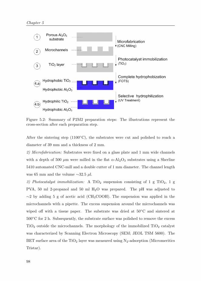
Chapter 5
98
Figure 5.2: Summary of P2M2 preparation steps: The illustrations represent thecross-section after each preparation step.
After the sintering step (1100◦C), the substrates were cut and polished to reach a
diameter of 39 mm and a thickness of 2 mm.
2) Microfabrication: Substrates were fixed on a glass plate and 1 mm wide channels
with a depth of 500 µm were milled in the flat α-Al2O3 substrates using a Sherline
5410 automated CNC-mill and a double cutter of 1 mm diameter. The channel length
was 65 mm and the volume ∼32.5 µl.
3) Photocatalyst immobilization: A TiO2 suspension consisting of 1 g TiO2, 1 g
PVA, 50 ml 2-propanol and 50 ml H2O was prepared. The pH was adjusted to
∼2 by adding 5 g of acetic acid (CH3COOH). The suspension was applied in the
microchannels with a pipette. The excess suspension around the microchannels was
wiped off with a tissue paper. The substrate was dried at 50◦C and sintered at
500◦C for 2 h. Subsequently, the substrate surface was polished to remove the excess
TiO2 outside the microchannels. The morphology of the immobilized TiO2 catalyst
was characterized by Scanning Electron Microscopy (SEM; JEOL TSM 5600). The
BET surface area of the TiO2 layer was measured using N2-adsorption (Micromeritics
Tristar).
Porous Photocatalytic Membrane Microreactors (P2M2)
99
4) Surface modification: For complete hydrophobization (α- Al2O3 and TiO2), the
samples were immersed in a solution containing 0.2 g of FOTS in 50 ml n-hexane. The
substrate was kept in the solution for 1 h, taken out of the solution and then placed
in the oven at 100◦C (adapted from Chpater 2). For selective hydrophilization of the
TiO2 photocatalyst layer, the completely hydrophobized sample was exposed to UV-
light. The exposure time was varied in the order of minutes to determine optimum
modification parameters. The surface properties (hydrophobicity) of the porous α-
Al2O3 and TiO2 were characterized by water contact angle measurements (OCA 15
Dataphysics) on each layer. The measurements were performed after the complete
hydrophobization step and also after each UV-exposure time interval. The samples
were rinsed with 2-propanol and then dried after each surface modification stage.
5) Module assembly: The open microchannels on the substrate were covered with a
UV-transparent foil (Hevel). The foil was softened on the top of the substrate with a
heat treatment in the oven at 120◦C for 30 min. After cooling down, the foil attached
to the surface of the substrate. Following that, the reactor was placed in an in-house
built gas-tight module (PMMA, prepared by CNC Milling), which was connected to
the light-guides of the UV-light source (Figure 5.3).
5.2.3 Reactor operation
Aqueous solutions of methylene blue (∼70 µM) and phenol (∼1 mM) were prepared
as liquid reactants. The liquid reactant solutions were pumped to the microreactor
with flow rates of 10, 30 and 50 µl/min using a syringe pump (Harvard, Picoplus).
Oxygen (O2), air or nitrogen (N2) was fed as gaseous reactant to the gas reservoir of
the module (25 ml/min, atmospheric pressure).
The methylene blue (MB) concentration at the reactor inlet and outlet was determined
by light absorbance measurements using an online UV-Vis Detector (Varian, Prostar
340) with a tungsten lamp (380-800 nm) at a fixed wavelength. The wavelength (λ)
was set to 663 nm (maximum absorption of MB) and calibration was carried out for
different concentrations of MB solution (from 10 to 100 µM).

Chapter 5
100
Figure 5.3: Schematic representation of the fabricated PMMA reactor module (Cross-sectional view).
The photocatalytic degradation of phenol and its products were characterized by
analyzing the UV-VIS Spectrum of the reactor in- and outlet. The reactor outlet
was connected to a micro HPLC flow-through cell (ZEUTEC). The flow-through cell
was attached to a deuterium halogen light source (DT-Mini-2-GS, Mikropack GmbH)
and a high-resolution fiber optic spectrometer (HR4000, Ocean optics Inc.) via two
optical fibers (SR 600 nm, Ocean optics Inc.), as described by Costantini et al.20.
As light source for the photocatalytical reactions, a 120 W UV-lamp (HP-120, Dr.
Grobel UV-elektronik GmbH) was used. The light was focused on the reactor using
four light-guides. The average measured light intensity (at λ=365 nm) on the reactor
surface was approximately 100 mW/cm2.
5.3 Results and Discussion
5.3.1 Reactor characterization
Figure 5.4 shows a fabricated microchannel in porous α-Al2O3 substrate with the
TiO2 layer inside after the surface modification steps. It was observed that the inner

Porous Photocatalytic Membrane Microreactors (P2M2)
101
Figure 5.4: Home-fabricated porous α-Al2O3 microreactor with immobilized TiO2
and modified surface properties. (a) Visualization of the surface properties after theselective hydrophilization step, (b) and (c) SEM images of the ceramic membrane afterphotocatalyst immobilization: immobilized TiO2 in the porous Al2O3 microchannel.
walls of the microchannel were entirely covered with TiO2 (Figure 5.4.b and 5.4.c).
The BET surface area of the TiO2 layer was found to be approximately 45 m2/g.
With the first surface modification step, the complete sample (α-Al2O3 and TiO2)
was successfully hydrophobized. The contact angles for both layers were around 150◦,
measured on porous α-Al2O3 and TiO2 layers. In Chapter 2, we have shown that
a dense α-Al2O3 layer with FOTS coating reaches a contact angle of approximately
115◦. The surface roughness of the porous layers further enhances the hydrophobicity.
This complete hydrophobization step ensures that the liquid does not wet the porous
α-Al2O3 substrate. It also hydrophobizes the TiO2 layer in the microchannel.
The hydrophobicity of the TiO2 layer prevents an intensive contact between this
photocatalyst layer and the liquid reactant, which would limit the reactor perfor-
mance. Therefore, a selective hydrophilization step was carried out by means of UV-

Chapter 5
102
irradiation. After 1 h of UV-irradiation on the sample, the TiO2 became hydrophilic.
The contact angle of the α-Al2O3 layer remained constant. This method ensures
a stable G-L-S interface in the microreactor on the porous α-Al2O3 hydrophobic
membrane, while providing an intensive contact of the liquid reactant with the
hydrophilic TiO2 photocatalyst inside the microchannel (Figure 5.4.a).
The change in the surface properties of TiO2 in the presence of UV-light was
previously observed and investigated in literature21–25. This phenomenon attracted
much attention; however the understanding of it is still under debate. One of the most
widely accepted hypotheses explains it by the photocatalytic properties of the TiO2
layer. With UV-illumination the hydrocarbons on the surface get photocatalytically
decomposed by TiO224,25. Another hypothesis is the structural change of the TiO2
by formation of surface hydroxyl groups under UV-irradiation, which cause the switch
to the hydrophilic state21,23. This hypothesis would be valid for TiO2 films without
an additional hydrocarbon coating. Regardless of the reason for this phenomenon,
the presented method allows us to selectively tune the surface properties in the
microchannel for a porous membrane reactor application in heterogeneous catalysis.
5.3.2 Reactor operation
The photocatalytic properties of P2M2 were tested for the degradations of MB
(C16H18ClN3S) and phenol (C6H5OH) and showed promising degradation properties
with additional O2 supply through the porous membrane. The main performance
criterion was degradation rate for both compounds. The presence of the UV-light,
liquid reactant flow rate and the gas supply through the porous membrane were
studied for these reactions.
Photocatalytic Degradation of Methylene Blue :
Figure 5.5 displays the MB concentration of the outlet flow in time. At the initial stage
of the experiment (1) without the presence of UV-light, MB adsorbs on the surface
of the TiO2 in the microchannel, which leads to a lower MB concentration at the
reactor outlet. After ∼60 min, equilibrium was reached and the UV-light was exposed
to the reactor (2). With the illumination the MB concentration at the reactor outlet

Porous Photocatalytic Membrane Microreactors (P2M2)
103
Figure 5.5: Effect of UV-light on the MB degradation (initial MB concentration=70µM, liquid flow rate= 50 µl/min, without O2 supply): MB concentrations are basedon absorbance measurements of the reactor outlet at λ= 663 nm.
decreases significantly due to the photocatalytic degradation. The decrease in the
concentration indicated a MB degradation of ∼27% (without additional O2 supply).
At the final stage (3), when the UV-light was turned off, the product concentration
reached the initial MB concentration again.
The degradation of MB was studied for different liquid flow rates with O2 supply. As
expected, with increasing flow rate (10, 30 and 50 µl/min), the degradation of MB
decreased (90%, 55% and 35%) due to the decreasing residence time.
In order to determine the influence of O2 in the MB degradation, tests with and
without additional O2 supply were performed. The conversion with air and pure O2
supply were comparable (Figure 5.6). The results showed that the conversion values
with O2 supply were slightly higher than without O2 supply.
O2 is known to act as an electron acceptor in the photocatalytic degradation, forming
superoxide radicals (O2−) as an oxidant. Furthermore, the presence of O2 decreases
recombination of the electron (e−) and hole (h+) pairs, which are generated by
the photocatalyst. This also increases the efficiency of the formation of powerful
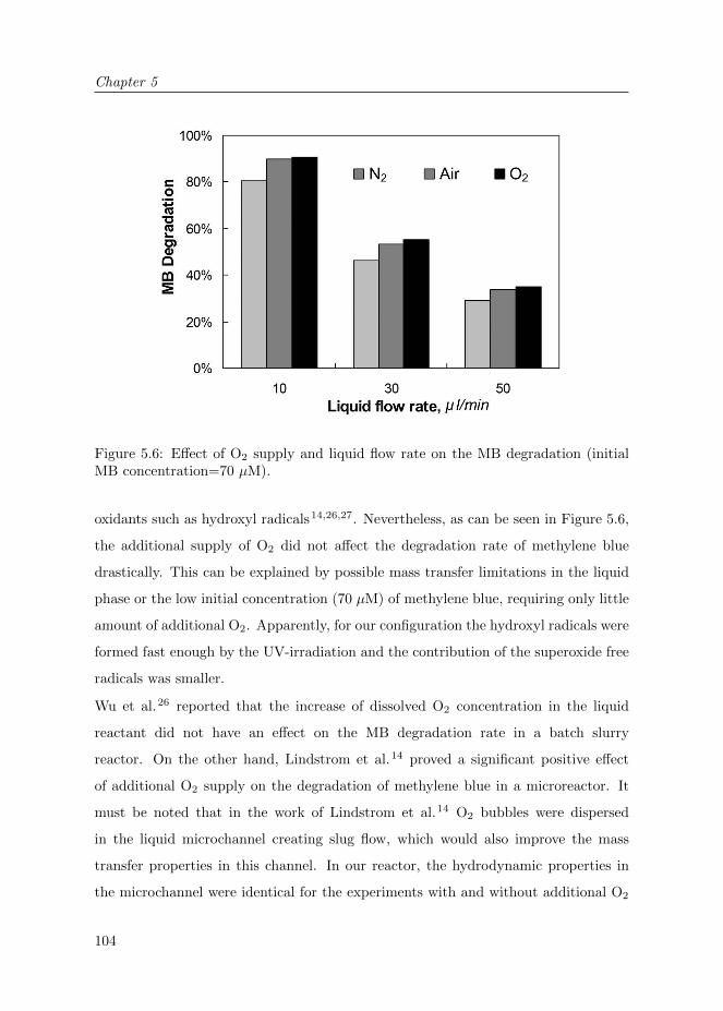
Chapter 5
104
Figure 5.6: Effect of O2 supply and liquid flow rate on the MB degradation (initialMB concentration=70 µM).
oxidants such as hydroxyl radicals14,26,27. Nevertheless, as can be seen in Figure 5.6,
the additional supply of O2 did not affect the degradation rate of methylene blue
drastically. This can be explained by possible mass transfer limitations in the liquid
phase or the low initial concentration (70 µM) of methylene blue, requiring only little
amount of additional O2. Apparently, for our configuration the hydroxyl radicals were
formed fast enough by the UV-irradiation and the contribution of the superoxide free
radicals was smaller.
Wu et al.26 reported that the increase of dissolved O2 concentration in the liquid
reactant did not have an effect on the MB degradation rate in a batch slurry
reactor. On the other hand, Lindstrom et al.14 proved a significant positive effect
of additional O2 supply on the degradation of methylene blue in a microreactor. It
must be noted that in the work of Lindstrom et al.14 O2 bubbles were dispersed
in the liquid microchannel creating slug flow, which would also improve the mass
transfer properties in this channel. In our reactor, the hydrodynamic properties in
the microchannel were identical for the experiments with and without additional O2

Porous Photocatalytic Membrane Microreactors (P2M2)
105
supply, so that merely the impact of O2 in the reaction can be analyzed.
Photocatalytic Degradation of Phenol :
In order to analyze the phenol degradation, the UV-VIS absorbance of the in- and
outlet product were monitored online. The analysis of the absorbance was performed
at wavelengths of 250<λ<400 nm (Figure 5.7).
The photocatalytic degradation of phenol was studied for different gas phase
compositions. The additional O2 supply increased the degradation of phenol
drastically. As can be seen in Figure 5.7 (initial phenol concentration=1 mM, liquid
flow rate= 10 µl/min), with O2 supply (air or pure O2), the absorbance peak of phenol
at 270 nm decreased significantly compared to the values with N2 supply.
The photocatalytic degradation of phenol was intensively studied as a model reaction
in photocatalysis. It is a well-known fact that during phenol degradation, several
aromatic intermediates are formed such as hydroquinone, benzoquinone and catechol.
The formation of these intermediates was also observed in our reaction product, which
Figure 5.7: Effect of O2 supply on the photocatalytic phenol degradation (initialphenol concentration=1 mM, liquid flow rate=10 µl/min). Absorbance spectrum ofthe reactor in- and outlet streams for different gas phase compositions.

Chapter 5
106
is indicated by the increased absorbance at wavelengths higher than 290 nm (Figure
5.7). Moreover, the product had a very light yellow/brown color, which is most likely
due to the formation of reaction intermediates18,28–30.
With increasing flow rate (decreasing residence time) the degradation of phenol
decreased. Unfortunately, the decreasing peak of phenol cannot be related directly
to the conversion value of phenol. The formed intermediate products (e.g. 1, 4-
Benzoquinone, Hydroquinone) also absorb around 270 nm.
Nevertheless, the measurements clearly show that the phenol degradation is improved
with the membrane-assisted O2 supply to the reaction zone. These results prove that
the utilization of membrane technology in photocatalytic processes is an attractive
and promising alternative for multiphase systems.
5.4 Conclusions
A new microreactor concept for photocatalytic gas-liquid-solid (G-L-S) systems was
introduced in this work. In contrast to the existing concepts, Porous Photocatalytic
Membrane Microreactor (P2M2) exploits tuned interfaces to ensure a well-defined
and stable G-L-S interface for the reaction and allows supplying the gaseous
reactant continuously along the length of the microreactor. Microreactors with
controlled surface properties and photocatalytic activity were successfully prepared
by microfabrication, photocatalyst immobilization and selective surface modification
steps.
We showed that the selective surface modification step ensures that the photocatalyst
becomes hydrophilic precisely in photocatalytically active areas. This method can be
applied for membrane reactors especially in heterogeneously catalyzed processes.
We also proved that the availability of the gaseous reactant O2 in photocatalytic
processes can be significantly improved by its continuous distribution to the reaction
zone through a porous membrane. The presented results showed that the membrane-
assisted supply of O2 enhanced the photocatalytic degradation of phenol and
methylene blue.

Porous Photocatalytic Membrane Microreactors (P2M2)
107
5.5 Acknowledgements
We are grateful to J.G.F. Heeks, R. Kooijman and J.A.M. Vrielink for technical
support and analysis. The authors also greatly acknowledge J.M. Jani for the fruitful
discussions and J.Bennink (Tingle.nl) for the illustrations.

Chapter 5
108
Bibliography
[1] M. N. Kashid and L. Kiwi-Minsker. Microstructured reactors for multiphase reactions: State
of the art. Industrial & Engineering Chemistry Research, 48(14):6465–6485, 2009. 95
[2] V. Hessel, P. Angeli, A. Gavriilidis, and H. Lowe. Gas-liquid and gas-liquid-solid
microstructured reactors: Contacting principles and applications. Industrial & Engineering
Chemistry Research, 44(25):9750–9769, 2005.
[3] H. C. Aran, J. K. Chinthaginjala, R. Groote, T. Roelofs, L. Lefferts, M. Wessling, and R. G. H.
Lammertink. Porous ceramic mesoreactors: A new approach for gas-liquid contacting in
multiphase microreaction technology. Chemical Engineering Journal, 169(1-3):239 – 246, 2011.
[4] A. Gavriilidis, P. Angeli, E. Cao, K. K. Yeong, and Y. S. S. Wan. Technology and applications
of microengineered reactors. Chemical Engineering Research and Design, 80(1):3 – 30, 2002.
[5] K. Jahnisch, V. Hessel, H. Lowe, and M. Baerns. Chemistry in microstructured reactors.
Angewandte Chemie International Edition, 43(4):406–446, 2004. 95
[6] E. E. Coyle and M. Oelgemoller. Micro-photochemistry: photochemistry in microstructured
reactors. the new photochemistry of the future? Photochem. Photobiol. Sci., 7:1313–1322,
2008. 95
[7] R. Gorges, S. Meyer, and G. Kreisel. Photocatalysis in microreactors. Journal of
Photochemistry and Photobiology A: Chemistry, 167(2-3):95–99, 2004.
[8] T. van Gerven, G. Mul, J. Moulijn, and A. Stankiewicz. A review of intensification of
photocatalytic processes. Chemical Engineering and Processing, 46(9):781–789, 2007. 95
[9] Y. Matsushita, N. Ohba, S. Kumada, K. Sakeda, T. Suzuki, and T. Ichimura. Photocatalytic
reactions in microreactors. Chemical Engineering Journal, 135(Supplement 1):S303–S308,
2008. 95
[10] R. van Grieken, J. Marugan, C. Sordo, and C. Pablos. Comparison of the photocatalytic
disinfection of e. coli suspensions in slurry, wall and fixed-bed reactors. Catalysis Today, 144(1-
2):48–54, 2009. 95
[11] K. Jahnisch and U. Dingerdissen. Photochemical generation and [4+2]-cycloaddition of singlet
oxygen in a falling-film micro reactor. Chemical Engineering & Technology, 28(4):426–427,
2005. 95
[12] H. Ehrich, D. Linke, K. Morgenschweis, M. Baerns, and K. Jahnisch. Application of
microstructured reactor technology for the photochemical chlorination of alkylaromatics.
CHIMIA International Journal for Chemistry, 56:647–653(7), 2002. 95
[13] M. T. Kreutzer, F. Kapteijn, J. A. Moulijn, and J. J. Heiszwolf. Multiphase monolith reactors:
Chemical reaction engineering of segmented flow in microchannels. Chemical Engineering
Science, 60(22):5895 – 5916, 2005. 96
[14] H. Lindstrom, R. Wootton, and A. Iles. High surface area titania photocatalytic microfluidic
reactors. AIChE Journal, 53(3):695–702, 2007. 96, 97, 104
Bibliography
109
[15] Y. Matsushita, M. Iwasawa, T.Suzuki, and T. Ichimura. Multiphase photocatalytic oxidation
in a microreactor. Chemistry Letters, 38(8):846–847, 2009. 96
[16] Y. Matsushita, M. Iwasawa, N. Ohba, S. Kumada, T. Suzuki, and T. Ichimura. Photocatalytic
oxidation and alkylation processes in microreactors. In Nano/Micro Engineered and Molecular
Systems, 2007. NEMS ’07. 2nd IEEE International Conference on, pages 851 –854, 2007. 96,
97
[17] A. Leclerc, M. Alame, D. Schweich, P. Pouteau, C. Delattre, and C. de Bellefon. Gas-liquid
selective oxidations with oxygen under explosive conditions in a micro-structured reactor. Lab
on a Chip, 8:814–817, 2008. 96
[18] M. Subramanian and A. Kannan. Effect of dissolved oxygen concentration and light intensity on
photocatalytic degradation of phenol. Korean Journal of Chemical Engineering, 25:1300–1308,
2008. 97, 106
[19] A. Nijmeijer, H. Kruidhof, R. Bredesen, and H. Verweij. Preparation and properties of
hydrothermally stable α-alumina membranes. Journal of the American Ceramic Society,
84(1):136–140, 2001. 97
[20] F. Costantini, W. P. Bula, R. Salvio, J. Huskens, H. J. G. E. Gardeniers, D. N. Reinhoudt, and
Willem Verboom. Nanostructure based on polymer brushes for efficient heterogeneous catalysis
in microreactors. Journal of the American Chemical Society, 131(5):1650–1651, 2009. 100
[21] M. Miyauchi, N. Kieda, S. Hishita, T. Mitsuhashi, A. Nakajima, T. Watanabe, and
K. Hashimoto. Reversible wettability control of TiO2 surface by light irradiation. Surface
Science, 511(1-3):401–407, 2002. 102
[22] Y.-H. Tseng, C.-S. Kuo, C.-H. Huang, T. Hirakawa, N. Negishi, and H.-L. Bai. Photoinduced
hydrophilicity of TiO2 film as the effect of H2O2 addition. Micro Nano Letters, IET, 5(2):81
–84, 2010.
[23] M. Fernandez-Rodriguez, V. J. Rico, A. R. Gonzalez-Elipe, and A. Alvarez-Herrero. Uv
irradiation effects on TiO2 thin films. physica status solidi (c), 5(5):1164–1167, 2008. 102
[24] M. Takeuchi, K. Sakamoto, G. Martra, S. Coluccia, and M. Anpo. Mechanism of photoinduced
superhydrophilicity on the TiO2 photocatalyst surface. The Journal of Physical Chemistry B,
109(32):15422–15428, 2005. 102
[25] E. Balaur, J. M. Macak, L. Taveira, and P. Schmuki. Tailoring the wettability of TiO2 nanotube
layers. Electrochemistry Communications, 7(10):1066 – 1070, 2005. 102
[26] C.-H. Wu and J.-M. Chern. Kinetics of photocatalytic decomposition of methylene blue.
Industrial & Engineering Chemistry Research, 45(19):6450–6457, 2006. 104
[27] A. Houas, H. Lachheb, M. Ksibi, E. Elaloui, C. Guillard, and J.-M. Herrmann. Photocatalytic
degradation pathway of methylene blue in water. Applied Catalysis B: Environmental,
31(2):145 – 157, 2001. 104
[28] S. K. Pardeshi and A. B. Patil. A simple route for photocatalytic degradation of phenol in
aqueous zinc oxide suspension using solar energy. Solar Energy, 82(8):700 – 705, 2008. 106

Chapter 5
110
[29] Y.-T. Lin, C. Liang, and J.-H. Chen. Feasibility study of ultraviolet activated persulfate
oxidation of phenol. Chemosphere, 82(8):1168 – 1172, 2011.
[30] B. Roig, C. Gonzalez, and O. Thomas. Monitoring of phenol photodegradation by ultraviolet
spectroscopy. Spectrochimica Acta Part A: Molecular and Biomolecular Spectroscopy, 59:303–
307(5), 2003. 106

111
Chapter 6
Summary and Outlook
The research described in this thesis aimed to explore new concepts for microreactors
in multiphase gas-liquid-solid (G-L-S) reactions by utilizing membrane technology for
contacting these phases. Porous micro- and mesoreactors were developed using various
preparation steps and tested for gas-liquid-solid (G-L-S) model reaction systems.
In this work, we fabricated, modified and characterized porous ceramic (Alumina:
Al2O3) and metallic (stainless steel) reactors in planar and in tubular geometry. These
reactors were applied for catalytic hydrogenation and photocatalytic degradation
reactions of selected compounds in water and showed promising potential for future
applications in microreactor technology.

Chapter 6
112
6.1 Summary
Chapter 1 provides a general view about microreactors and existing concepts for
multiphase reactions in these devices. Furthermore, an overview of conventional
membrane reactors is given, followed by some background information on model
reactions, which were performed in this study. Lastly, the scope and outline of the
thesis are presented.
Chapter 2 demonstrates the preparation of porous ceramic mesoreactors and their
application for catalytic hydrogenation of nitrite ions in water. Tubular reactors
with tailored wetting properties and catalytic activity were developed by utilizing
fabrication, catalyst immobilization and surface modification (hydrophobization)
techniques. With surface modification, the wetting behavior of the liquid reactant
on the catalyst surface and the position of the G-L interface could be easily tuned. A
stable G-L-S interface for heterogeneously catalyzed reaction processes was realized by
applying hydrophobization techniques. Reactors with tunable wetting properties were
obtained, in which the porous support was hydrophobized while the catalyst support
remained hydrophilic. The developed reactors showed high catalytic activities for this
model reaction, reaching nitrite conversion values up to 80%. In addition, the reactor
performance remained constant even at relatively low concentrations of hydrogen
(H2), proving very efficient transfer of the gas phase by continuous addition through
the membrane.
In Chapter 3, we studied the influence of geometrical and operational parameters on
the performance of ceramic (Al2O3) micro- and mesoreactors. We prepared reactors
with various inner diameters, controllable catalyst support thickness (γ-Al2O3 layer)
and active Pd surface area, and tunable wetting properties. In addition, we utilized
inert slug flow in our porous membrane reactor, merging the advantages of both
dispersed phase and continuous phase operation. The prepared reactors were tested
for the catalytic hydrogenation of nitrite. Results showed that with the increasing
catalyst support thickness the performance of the reactor increased, due to the higher
amount of Pd catalyst at the interface. However, the enhancement is not as prominent

Summary and Outlook
113
as the increase in Pd amount at the interface, suggesting further internal mass transfer
limitations with increasing thickness of the γ-Al2O3 layer. Furthermore, reactors
with smaller inner diameter showed higher reactor performance compared with the
ones with larger inner diameter. This shows that lowering of the characteristic
length enhances the performance in these reactors due to improved mass transfer.
In addition, we showed that the integration of slug flow (inert) in a membrane reactor
could further enhance the external mass transfer in the liquid phase.
Chapter 4 describes the utilization of porous stainless steel hollow fibers with
carbon nanofibers (CNFs) as membrane microreactor material. Porous stainless
steel (SS) hollow fibers with high porosity and mechanical strength were obtained
and CNFs with high surface area were successfully grown on the porous SS surface.
The fabricated microreactors displayed a high surface area, mechanical strength and
promising nitrite reduction activity. Results indicated that the presence of CNFs on
the SS surface had a significant effect on the reactor performance. On CNF deposited
reactors, even without the presence of H2 and Pd, the NO2− ions were successfully
reduced. These results indicate the intrinsic reducing properties of the developed
reactor material.
Chapter 5 demonstrates the application of porous microreactors for photocatalytic
gas-liquid-solid (G-L-S) systems in planar chip geometry. Porous Photocatalytic
Membrane Microreactors (P2M2) with controlled surface properties and photo-
catalytic activity were successfully prepared by micromilling (on porous Al2O3),
photocatalyst (TiO2) immobilization and selective surface modification steps. The
reactor was employed in the (UV-light induced) photocatalytic degradation of
methylene blue and phenol in water, where additional O2 was supplied to the
reaction zone. High photocatalytic activity with conversion values up to 90% were
obtained. In addition, results showed that with the membrane-assisted supply of O2
in these photocatalytic processes, the degradation rate in the reactor was significantly
improved, illustrating the advantage of the developed concept.

Chapter 6
114
6.2 Outlook
6.2.1 Fabrication of porous ceramic and metallic microchan-
nels by replication/templating
As described in the previous chapters of this thesis, porous inorganic materials
have a great potential to be applied in microfluidics. However, existing methods
for preparation of these materials are limited by the high characteristic length
(hydraulic diameter) or relatively high wall thickness1,2. Two alternative techniques
are described, which can be applied for the fabrication of novel porous inorganic (e.g.
ceramic, metallic) microfluidic devices.
Porous microchannels in planar geometry via replication:
Chapter 5 demonstrates milling as a simple and cheap approach for microstructuring
of porous ceramic materials in planar geometry. Even with all its advantages,
fabrication of channels with dimensions <100 µm becomes challenging and this
direct microfabrication technique is not applicable on every type of porous substrate.
Moreover, relatively thick substrates have to be used for mechanical strength, which
results in a low channel volume/total reactor volume.
Microfabrication via replication (indirect fabrication) is a promising alternative for
producing microstructured channels3–6. Within the scope of this thesis7, preliminary
studies on this method were carried out for the fabrication of thin porous ceramic
microreactors. This method comprises of precipitation of polymers with dispersed
particles while in contact with a microstructured mold (Figure 6.1). It can be applied
for a wide variety of materials, allows fabrication of very thin microfluidic films (∼100
µm) and microstructures with very small characteristic length (<100 µm).
A polymer-particle suspension, consisting of polymer, solvent and dispersed particles
(e.g. ceramic particles) is cast on a microstructured mold7. Subsequently, the solvent
is removed from the cast suspension (e.g. by evaporation). The remaining polymer-
particle composite (green tape) is released from the microstructured mold and several
green tapes can be stacked together. This is then followed by a final sintering step,
in which the polymer is selectively removed at high temperatures, leaving a porous

Summary and Outlook
115
Figure 6.1: Microfabrication steps of porous ceramic microreactors by replication:Microstructuring of a polymer-particle composite by the use of a mold, followed bystacking and sintering step (adapted from7).
structure behind. According to the final application, surface modification and catalyst
immobilization steps can be carried out before the operation (Figure 6.1).
In preliminary studies, we prepared homogenous ceramic (α-Al2O3) slurries (adapted
from4) and performed accurate micropatterning. We carried out stacking of green
tapes (lamination) and high temperature sintering. For the lamination of green tapes,
we used a commercial adhesive (Pritt-Stick, Henkel) as temporary laminating agent,
which was later eliminated during the sintering step (inspired from8). Figure 6.2 (a,
b) shows the resulting porous ceramic microchannels fabricated via this replication
method with characteristic channel dimensions of ∼25 µm.
With this technique, small and thin porous ceramic microstructured substrates could
be easily fabricated. However, during the fabrication of bigger samples with an area
of larger than ∼2 cm2, we observed that the samples curled, resulting in ”potato-
chips”-like shapes during the sintering step (Figure 6.2.c). To prevent bending, we

Chapter 6
116
Figure 6.2: Porous ceramic microchannels in planar geometry: (a), (b) Microchannelsfabricated by replication, lamination and sintering steps. (c) Bending behavior of thinceramic substrates after sintering.
”sandwiched” the green tapes between two ceramic blocks during the sintering step.
In the case of only one green tape, the bending could be prevented. Nevertheless,
if more than one green tape was stacked on each other, the final ceramic structure
showed cracks on its surface.
This bending problem has to be overcome in order to make these microfluidic devices
feasible for future applications. Possible reasons for bending are density gradients
in the green tape before the sintering and/or temperature gradients in the sample
during the sintering step. These gradients would cause shrinkage mismatches during
the sintering, leading to a curled or cracked final structure. Density gradients can
possibly be avoided by the use of gas permeable (porous or dense) microstructured
molds, in order to make the evaporation of the solvent more homogeneous along the
cross-section. Furthermore, the use of conductive plates at the bottom and/or the top
of the sample could decrease the heat transfer gradients and the shrinkage mismatches
during sintering.
Tubular porous microchannels fabricated by microtemplating:
In Chapters 2 and 3, porous commercial ceramic hollow fibers (from HyFlux
CEPAration) were used as starting materials for tubular meso- or microreactors.
Extrusion and spinning methods are commonly used for fabrication of porous ceramic
and metallic hollow fibers. These methods provide hollow fibers with a well-

Summary and Outlook
117
defined and smooth interface; however, costly equipment is needed for these types
of fabrication.
Within the project, a simple technique was developed for the fabrication of tubular
porous ceramic (or metallic) microchannels (hollow fibers). Salamon et al.1 recently
reported a technique, which comprises of microtemplating polymeric hollow fibers to
fabricate porous ceramic microchannels (Figure 6.3).
In this method, a polymeric hollow fiber is dip-coated in a suspension consisting
of dispersed inorganic particles (ceramic or metallic), a solvent and organic matter
(binder, plasticizer, dispersant). Subsequently, the coated hollow fiber is left for
drying to remove the solvent. After the drying, the composite material is sintered at
a high temperature, so that the initial polymeric hollow fiber template and the organic
matter of the suspension are both removed. Finally, a porous tubular microchannel
is obtained (Figure 6.4).
Figure 6.3: Preparation procedure of tubular porous microchannels by microtem-plating: (a) microtemplate; (b) coating of the microtemplate with a suspensionwith sinterable particles; (c) microtemplate with coated layer; (d) reshaping andnumbering-up and (e) sintering (and removal of the microtemplate)1.

Chapter 6
118
Figure 6.4: Porous ceramic microchannels fabricated by microtemplating: (a) singlemicrochannel, (b) microchannel with multiple layers, (c) multiple microchannels withmultiple layers (adapted from1).
Fabrication of tubular microchannels via templating has several advantages. With
this method, microchannels with small inner diameters can be obtained (Figure 6.4),
which are controlled by the outer diameter of the polymeric hollow fiber template.
Furthermore, multilayered microchannels can be prepared by simply repeating the
coating step with different suspensions (Figure 6.4.b). Multilayered hollow fibers are
very relevant for heterogeneously catalyzed reactions, which require high catalytic
surface area. In addition, internal numbering up can be easily performed by merging
the coated hollow fibers in green state and then sintering them together (Figure 6.4.c).
Within the scope of this thesis, we prepared porous ceramic (α-Al2O3) hollow fibers
and tested them with a few explorative experiments using a model gas-liquid system9.
The adsorption of CO2 in water was chosen as a gas-liquid model reaction system. As
can be seen in Figure 6.5, the water could be saturated with CO2 in a very short time,
thanks to the high surface to volume ratio of the fabricated tubular porous hollow
fiber.
Besides the above-mentioned advantages, we must also remark that surface areas and
interfaces of the fabricated hollow fibers are not as well-defined (see Figure 6.4) as
hollow fibers fabricated by commercial extrusion or spinning methods. However,
we can say that this micro-templating technique is very suitable for small-scale
production and explorative research, thanks to its simplicity. This fabrication method

Summary and Outlook
119
Figure 6.5: Gas-liquid contacting in a tubular porous ceramic microchannelsfabricated by microtemplating (internal diameter≈750 µm): CO2 absorption in watervs. liquid residence time in the porous channel. Solid lines represent results fromnumerical modeling(adapted from R. Groote9).
can be applied for the fabrication of ceramic hollow fibers in locations which do not
have the facilities for spinning and extrusion processes.
6.2.2 Helical porous microreactors: Improved mass transfer
by secondary flow
Due to the small characteristic length of the microchannels, laminar flow is dominant
inside microfluidic devices. Therefore, the radial mass transfer in the liquid phase
proceeds via diffusion. Even though this provides more control on the hydrodynamics
in the microchannel, it can lead to mass transfer limitations in the case of a wall
reaction process (e.g. heterogeneous catalyzed reaction). As an attempt for improving
the liquid mass transfer properties (Chapter 3), we integrated biphasic flow (slug flow
with inert gas bubbles) and observed significant improvement in catalytic reaction
rate. Though it is a simple and efficient alternative, we must also note that in slug
flow operation mode the possible coalescence of the phases creates uncertainty about

Chapter 6
120
Figure 6.6: (left) Experimental setup used for O2 uptake in water, (right) Mixingindex vs. Re comparing helical microchannel with equivalent length of straightchannel15.
the actual flow pattern in the reactor channel. Furthermore, the scaling-up for this
operation mode is less trivial than for single phase operation.
In literature, many mixing strategies for microreactors were intensively investigated.
The micromixers are classified in two main types: active (by external energy input)
or passive (by restructuring the flow) micromixers10. Besides slug flow11, common
examples for passive micromixers include zig-zag mixers12, converging-diverging
channels13, hydrodynamic focusing14 and chaotic advection12.
Among these, chaotic advection can be created by the use of a helical geometry
(inducing Dean vortices), which was already demonstrated for several membrane
applications15. Within our project, Jani et al.15 have recently published on a helical
membrane microcontactor for the absorption of oxygen in water (gas-liquid model
reaction). They reported improved mass transfer properties due to generation of
secondary flow, which provides enhanced mixing in the microchannels and higher gas
uptake in the liquid phase (Figure 6.6).
The application of this geometry would be of great interest for gas-liquid-solid
processes in membrane reactors. As also mentioned in previous sections of this thesis,
membrane reactors usually suffer from mass transfer limitations in the liquid phase.
The formation of Dean vortices (secondary flows) in the liquid stream would improve
the transport of the liquid reactant from the bulk phase to the reactor wall, where
the catalyst is located. Moreover, the operation of this type of reactor is relatively

Summary and Outlook
121
easy; no further precautions have to be taken in addition to a standard membrane
reactor operation.
We must also remark that the generation of secondary flows is known to occur at
relatively high Reynolds (Re) numbers (typically >50) and to obtain these numbers
within microchannels, high liquid velocities are required15. Therefore, long reactor
channels will be needed in order to obtain sufficient residence time for the liquid
reactant. Furthermore, the fabrication of these reactors can be of concern in practice,
depending on the chosen reactor material. The preparation for polymeric hollow
fibers in helical geometry can be relatively easy thanks to the ductile properties of
the material. However, fabrication of porous ceramic or metallic hollow fibers would
be more challenging. Structuring of the hollow fiber would be needed already in
the green state (before sintering) and precautions need to be taken that the helical
structure should sustain during the sintering.
6.2.3 Non-aqueous gas-liquid-solid reactions
As demonstrated in this thesis, the use of porous medium is a promising concept
for multiphase reactions in microreactors. Despite of the advantages of the concept,
additional precautions need to be taken to prevent wetting of the porous structure
by the liquid phase in order to obtain a stable gas-liquid interface. In this thesis,
we applied the reactor concept to aqueous processes and in order to avoid wetting,
we modified the surface properties of porous ceramic materials selectively (by
hydrophobization).
Even though the hydrophobization of the surface is an efficient way for interface
stabilization in aqueous systems, for organic solvents with lower surface tension (e.g.
ethanol: 23·10−3 N/m) than water (72·10−3 N/m) wetting of a porous medium cannot
be prevented easily. Organic solvents are commonly used in microreactor technology,
therefore two potential solutions are addressed, in order to overcome this drawback
in our reactor concept.
Firstly, counterbalancing gas pressure (trans-membrane pressure) can be applied to
avoid wetting and to position the G-L-S interface. With the excess pressure from

Chapter 6
122
the gaseous side, the liquid can be pushed back to the inner side of the porous
medium and the interface can be stabilized. This method is commonly used in
conventional membrane reactors. Vospernik et al.16 and Bercic et al.17 demonstrated
that the interface could accurately be positioned with this method. One drawback
of this method is the requirement of additional equipment during the operation for
the pressure regulation, which makes them technically demanding. Furthermore, the
pressure drop along the channel length may differ for liquid and gas phases, depending
on the length, diameter, flow rates and fluid properties. This could cause inaccuracy
of the G-L-S interface along the reactor axis.
Secondly, the utilization of gas-permeable selective layers can be considered, as also
demonstrated in Chapter 4 (PDMS). The addition of such a selective membrane layer
(e.g. PEBAX, PDMS18) on the porous support would avoid the intermixing of the
gas and liquid phases and stabilize the interface. Even though such membranes can
cause additional mass transfer resistance, the coating layers can be made very thin
to limit this problem for mass transfer from the gas phase.
6.2.4 Heat transfer in porous microreactors
Thanks to their improved heat and mass transfer characteristics, microreactors are
very suitable to explore fast and exothermic reactions. In exothermic G-L and G-L-
S reactions, such as hydrogenations and fluorinations, removal of the heat released
by the reaction is very crucial. In the scope of this thesis, we mainly focused on
the conceptual functionality and mass transfer properties of our microreactors, and
did not investigate the heat transfer. We worked with low liquid phase reactant
concentrations, in which the heat release with the reaction was not of big concern.
Still, for future application of porous microreactors in highly exothermic processes,
some recommendations for heat transfer are addressed below.
Heat transfer in porous microreactors is more complex than in conventional dense
microreactors. In a dense reactor, heat transfer can simply proceed through the
reactor wall. In our porous microreactors the reactor wall is used for the supply of

Summary and Outlook
123
Figure 6.7: Possible ways of heat removal for porous microreactors in exothermicreactions: (a) Integration of a heat exchanging plate for planar geometry, (b)Evaporative cooling for removal of the generated heat in planar and tubular geometry.
the gaseous reactant. Therefore, other strategies need to be applied for heat removal.
The reactor geometry (planar or tubular) is a critical factor in the choice of a strategy.
In planar microreactors, a simple approach can be implemented in which the open
porous microchannels can be covered with a heat exchanging plate (Figure 6.7.a). In
this case, the heat exchange does not directly take place at the reaction interface.
However, the small dimensions of the microchannels should make this strategy
sufficient for the heat removal.
Evaporative cooling (Figure 6.7.b) is a good alternative for heat removal in exothermic
reactions. This method can be applied for both planar and tubular microreactors. It
is very suitable, especially in combination with a porous medium. In this method,
the evaporation of the liquid solvent creates a cooling effect and this can be used for
the removal heat generated with the exothermic reaction. The vapor can be instantly
removed through the porous membrane. As an example, the enthalpy of reaction
for hydrogenation of nitrite can be estimated as ∼450 kJ/mol (from enthalpies of
formation19) and the evaporation enthalpy of water is ∼41 kJ/mol. In our study (low
concentrations), the maximum reaction rate obtained was 22.7·10−8 mol/min for a
flow rate of 0.3 ml/min (∼1.6·10−2 mol/min). This means that with the evaporation
of only 0.015% of the liquid stream the heat generated by the reaction can be removed.
The advantage of this method is that the cooling takes place directly at the reaction
Chapter 6
124
interface, where the heat is generated. Moreover, controlled amounts of evaporative
solvent removal could be of advantage in the case in which the reaction product is
located within the liquid phase, by increasing the concentration of the product in
the solvent. However, accurate control of the process conditions is required to avoid
operational problems for this concept. Excessive evaporation of the liquid solvent
can lead to operational instabilities in the liquid phase and additional mass transfer
limitations of the gas phase.
Other alternatives for heat removal can be the use of membranes with high thermal
conductivities (e.g. palladium membrane20,21) or integration of external mass transfer
concepts (e.g. loop reactors22).
6.3 Epilogue
The utilization of porous media and membrane technology for multiphase (gas-liquid-
solid) contacting in microreactors is of great advantage. The gaseous reactant can
efficiently be supplied to the reaction zone, gas and liquid phases meet directly at the
catalyst surface, and their flow rates can independently be varied during operation.
Porous ceramic and metallic microreactors offer stable interface with their simple
reactor design.

Bibliography
125
Bibliography
[1] D. Salamon, Z. Chlup, L. Lefferts, and M. Wessling. Tailoring of free standing microchannels
structures via microtemplating. Materials Research Bulletin, 46(4):505 – 511, 2011. 114, 117,
118
[2] M. Heule, S. Vuillemin, and L.J. Gauckler. Powder–based ceramic meso– and microscale
fabrication processes. Advanced Materials, 15(15):1237–1245, 2003. 114
[3] J. de Jong, B. Ankone, R. G. H. Lammertink, and M. Wessling. New replication technique for
the fabrication of thin polymeric microfluidic devices with tunable porosity. Lab on a Chip,
5:1240–1247, 2005. 114
[4] T. Rosqvist and S. Johansson. Soft micromolding and lamination of piezoceramic thick films.
Sensors and Actuators A: Physical, 97-98:512 – 519, 2002. 115
[5] M. Bikel. Fundamental aspects of phase separation microfabrication. PhD thesis, Enschede,
University of Twente, December 2009.
[6] L. Vogelaar, R.G. H. Lammertink, J.N. Barsema, W. Nijdam, L.A. M. Bolhuis-Versteeg, C.J.
M. van Rijn, and M. Wessling. Phase separation micromolding: A new generic approach for
microstructuring various materials. Small, 1(6):645–655, 2005. 114
[7] R.G.H. Lammertink. Porous ceramic and metallic microreactors. NWO Vidi Grant, 2006. 114,
115
[8] A. Roosen. Low–temperature/low-pressure lamination of green ceramic tapes. Advanced
Engineering Materials, 2(6):374–376, 2000. 115
[9] R. Groote. Ceramic micro-membrane reactors for gas/liuid contacting in heterogeneously
catalyzed reactions, November 2008. 118, 119
[10] V. Hessel, H. Lowe, and F. Schonfeld. Micromixers–a review on passive and active mixing
principles. Chemical Engineering Science, 60(8-9):2479 – 2501, 2005. 120
[11] M. T. Kreutzer, F. Kapteijn, J. A. Moulijn, and J. J. Heiszwolf. Multiphase monolith reactors:
Chemical reaction engineering of segmented flow in microchannels. Chemical Engineering
Science, 60(22):5895 – 5916, 2005. 120
[12] S. Hardt, K. Drese, V. Hessel, and F. Schonfeld. Passive micro mixers for applications in the
micro reactor and [micro sign]tas field. ASME Conference Proceedings, 2004(41642):45–55,
2004. 120
[13] A. M. Guzman and C. H. Amon. Dynamical flow characterization of transitional and chaotic
regimes in converging-diverging channels. Journal of Fluid Mechanics, 321:25–57, 1996. 120
[14] T.T. Veenstra, T.S.J. Lammerink, M.C. Elwenspoek, and A. Berg van den. Characterization
method for a new diffusion mixer applicable in micro flow analysis systems. Journal of
Micromechanics and Microengineering, 9(2):199–202, 1999. 120
[15] J.M. Jani, M. Wessling, and R.G.H. Lammertink. Geometrical influence on mixing in helical
porous membrane microcontactors. Journal of Membrane Science, In Press, Corrected Proof:–,
2011. 120, 121

Chapter 6
126
[16] M. Vospernik, A. Pintar, G. Bercic, J. Batista, and J. Levec. Potentials of ceramic membranes
as catalytic three-phase reactors. Chemical Engineering Research and Design, 82(5):659 – 666,
2004. 122
[17] G. Bercic, A. Pintar, and J. Levec. Positioning of the reaction zone for gas-liquid reactions in
catalytic membrane reactor by coupling results of mass transport and chemical reaction study.
Catalysis Today, 105(3-4):589 – 597, 2005. 122
[18] J. de Jong. Application of membrane technology in microfluidic devices. PhD thesis, Enschede,
University of Twente, April 2008. 122
[19] D.R. Lide and W.M. Haynes (Eds.). CRC Handbook of Chemistry and Physics, 90th ed. CRC
Press/ Taylor and Francis, 2010. 123
[20] V. M. Gryaznov, M. M. Ermilova, and N. V. Orekhova. Membrane–catalyst systems for
selectivity improvement in dehydrogenation and hydrogenation reactions. Catalysis Today,
67(1-3):185 – 188, 2001. 124
[21] R. Dittmeyer, K. Svajda, and M. Reif. A review of catalytic membrane layers for gas/liquid
reactions. Topics in Catalysis, 29:3–27, 2004. 124
[22] J.C. Middleton and K.J. Carpenter. Loop Reactors. Wiley–VCH Verlag GmbH & Co. KGaA,
2000. 124

Samenvatting
Het doel van het onderzoek in dit proefschrift is om nieuwe concepten te onderzoeken
voor meerfase-microreactoren (gas-vloeistof-vast; afgekort als G-L-S) waarbij gebruik
wordt gemaakt van membraantechnologie voor het met elkaar in contact brengen
van deze fasen. Poreuze micro- en mesoreactoren, zijn ontwikkeld door middel
van verschillende bereidingsstappen en getest voor G-L-S modelreacties. Hiertoe
hebben we keramische (alumina, Al2O3) en metalen (roestvrij stalen) reactoren met
vlakke of cilindrische geometrie ontwikkeld en gekarakteriseerd. Deze reactoren zijn
gebruikt voor katalytische hydrogenering en fotokatalytische degradatie reacties in
water. Uit de resultaten blijkt dat deze reactoren veelbelovend zijn voor toekomstige
toepassingen in microreactortechnologie.
Hoofdstuk 1 geeft aan algemeen overzicht van microreactoren en reeds bestaande
concepten voor het uitvoeren van meerfasereacties in deze reactoren. Daarnaast
wordt een overzicht gepresenteerd van conventionele membraanreactoren, gevolgd
door achtergrondinformatie over de modelreacties die in dit onderzoek zijn gebruikt.
Tot slot worden het doel en de opzet van dit proefschrift gegeven worden.
Hoofdstuk 2 beschrijft de bereiding van poreuze keramische mesoreactoren en
hun toepassing voor de katalytische hydrogenering van nitriet in water. Hi-
ertoe zijn cilindrische reactoren gemaakt met verschillende fabricatietechnieken,
oppervlaktemodificatie (om het oppervlak hydrofoob te maken) en methoden voor
immobilisatie van katalysatoren. De zo verkregen reactoren hebben gecontroleerde
eigenschappen met betrekking tot bevochtiging en katalytische activiteit. Het
bevochtigingsgedrag van de waterige oplossing aan het katalysatoroppervlak en de
positie van het gas-vloeistof (G-L) grensvlak konden worden beinvloed met behulp
van oppervlaktemodificatie. Op deze manier werd een stabiel G-L-S-grensvlak
verkregen voor het uitvoeren van heterogeen gekatalyseerde reacties. Reactoren

met gecontroleerde bevochtigingseigenschappen werden bereid waarbij het membraan
hydrofoob werd gemaakt terwijl het dragermateriaal van de katalysator hydrofiel bleef.
De reactoren die op deze manier verkregen werden, hadden een hoge katalytische
activiteit voor de modelreactie, met nitrietconversies tot wel 80%. Bovendien bleven
de prestaties van de reactoren constant, zelfs bij lage concentraties van de gasvormige
reactant (H2). Dit bewijst dat er een dusdanige goede aanvoer van H2 is door het
membraan dat de stofoverdracht ervan geen beperkende factor wordt.
In hoofdstuk 3 hebben we de invloed van de geometrie en operationele parameters
op de prestaties van de keramische (Al2O3) micro- en mesoreactoren bestudeerd.
Hiertoe hebben we reactoren gemaakt met verschillende interne diameters, een
gecontroleerde laagdikte van het dragermateriaal voor de katalysator (γ-Al2O3) en een
actief oppervlak van Pd met vereiste bevochtigingseigenschappen. Daarnaast hebben
we een inerte slug flow geintegreerd in deze poreuze membraanreactor. Hiermee
konden we de voordelen van het gebruik van een gedispergeerde fase combineren
met die van een continue fase. De zo verkregen reactoren werden getest voor de
katalytische hydrogenering van nitriet onder verschillende operationele parameters.
De resultaten toonden aan dat de prestatie van de reactor verbetert met toenemende
laagdikte van het dragermateriaal voor de katalysator. Dit komt door een toenemende
hoeveelheid Pd-katalysator aan het grensvlak waar de reactie plaatsvindt. Echter,
de prestatie neemt niet evenredig toe met de toename van de hoeveelheid Pd aan
het grensvlak. Dit wijst er op dat bij een toenemende laagdikte van het γ-Al2O3
de stofoverdracht een beperkende factor kan worden. Verder hebben reactoren met
een kleinere interne diameter een betere prestatie vergeleken met reactoren met een
grotere interne diameter. Dit bevestigt dat de prestaties van deze reactoren verbeteren
als gevolg van de verbeterde stofoverdrachtseigenschappen bij miniaturisatie van
de karakteristieke lengteschalen. Bovendien hebben we aangetoond dat de externe
stofoverdracht verder verbeterd kan worden door de integratie van (inerte) slug flow.
Hoofdstuk 4 beschrijft het gebruik van poreuze roestvrij stalen holle vezels met
koolstof nanovezels (carbon nanofibers, CNFs). Sterke en hoog poreuze roestvrij
stalen holle vezels werden verkregen waarbij het mogelijk was om CNFs met een

hoog specifiek oppervlak te laten groeien aan het poreuze roestvrij stalen oppervlak.
Deze microreactoren hadden een hoog specifiek oppervlak, goede mechanische
eigenschappen en lieten een veelbelovende activiteit zien in de reductie van nitriet.
De resultaten toonden aan dat de aanwezigheid van CNFs op het roestvrij stalen
oppervlak de prestaties van de reactor aanzienlijk benvloedden. In reactoren waarop
CNFs waren gegroeid, kon nitriet zelfs worden gereduceerd wanneer er geen H2 en
Pd aanwezig waren. Deze resultaten tonen aan dat het ontwikkelde reactormateriaal
intrinsieke reducerende eigenschappen bezit.
Hoofdstuk 5 beschrijft het gebruik van poreuze microreactoren in fotokatalytische G-
L-S systemen. Vlakke fotokatalytische membraanmicroreactoren met gecontroleerde
oppervlakte-eigenschappen en fotokatalytische activiteit werden succesvol verkregen
met behulp van microfabricagetechnieken (op poreus Al2O3), gevolgd door immo-
bilisatie van de TiO2 fotokatalysator en selectieve oppervlaktemodificatiestappen.
Deze reactoren werden getest voor de (UV-geinduceerde) fotokatalytische degradatie
van methyleenblauw en fenol in water, waarbij extra O2 werd toegediend in de
reactiezone. De reactor had een hoge fotokatalytische activiteit met tot wel 90%
degradatie. Bovendien toonden deze resultaten aan dat de degradatiesnelheid in de
reactor aanzienlijk hoger werd door membraangeassisteerde toevoer van O2 gedurende
het fotokatalytische proces. Deze laatste bevinding laat duidelijk de voordelen van
het ontwikkelde concept zien.
Hoofdstuk 6 vat de resultaten samen die behaald zijn binnen het kader van dit
onderzoek. Verder worden er aanbevelingen voor toekomstig onderzoek gegeven
alsmede enkele afsluitende opmerkingen.
Het gebruik van poreuze media en membraantechnologie voor het in contact brengen
van meerfasesystemen (gas-vloeistof-vast) in microreactoren biedt grote voordelen. In
deze reactoren kan de gasvormige reactant efficient worden toegevoegd aan de reac-
tiezone; de gas- en vloeistoffase ontmoeten elkaar direct aan het katalysatoroppervlak
en gedurende het proces kunnen de verschillende stroomsnelheden onafhankelijk van
elkaar worden gevarieerd. Poreuze keramische en metalen microreactoren combineren

stabiele grensvlakken met een simpel reactorontwerp.
Acknowledgements
It has been a bit more than 4 years and my PhD journey is almost over. This journey made me grow
scientifically, learn many things and hopefully get a Dr. title. However, the thing that I most cared
about it was that I met many people, made a lot of friends for life and had a lot of fun. With this
section, I would like to thank you all for making my stay here so special. I am aware that this is the
most popular section of my thesis, therefore I tried to write very careful and I hope I did not forget
anyone. For those, whom I forgot, please let me know, I owe you a drink.
First, I would like to start with my promotor and supervisor (more a like a superdude) Prof. Dr.
Rob Lammertink. Rob, as we first met 4.5 years ago for the job interview, you gave me very nice
amazing first impression and after all these years, I can honestly say, I am very happy to have made
the right choice and decided to do a PhD with you. You shared my enthusiasm when I could get
good results. You cheered me up when I was down; you put me back on my feet when I was too
much up. You helped, advised and improved me on scientific and personal level. You showed to me
and everybody around you that hierarchy is unnecessary, as long as you know how to communicate.
Of course, I cannot forget the fun factor, our trips to Japan, USA, parties that we had together,
group events, beer motivation that we had, and many other things. I really appreciate it all; I am
very proud and happy to have a supervisor, promoter and most importantly a friend like you. Thank
you for everything. I wish you, Cindy and your children all the best in the future.
I would like to thank my co-promotor Prof Dr.-Ing. Matthias Wessling for his help and guidance
in this project. Matthias, even though you could not be intensively involved in my project at the
final part (due to your departure), you have been an inspiring person to me and most of the people
in our group(s). You ideas, tips and tricks in our meetings were of great value and made me grow
personally and scientifically. Thanks for all and I wish you great success in Aachen.
Another person that I would like to thank is Prof. Dr. Ir. Leon Lefferts. I really appreciated your
contribution to this work. You and the entire CPM group were always open to collaborate, and at
the end, I think we all benefited from that. In addition, your experience in catalysis and your critical
view on the results was of great help. It was a great pleasure to work with you. I also would like
to thank Prof. Dr. Guido Mul, for our great collaboration on photocatalysis (Chapter 5). It was a
nice coincidence that at the time we decided to work on photocatalysis, you moved to Twente. Your
input to the project was of great importance, which lead us to a nice piece of work. Thanks for all
the valuable discussions and our nice chats on the corridor.
Furthermore, I would like to thank my other committee members, for taking part in the committee
and Prof Dr. Han Gardeniers, for your feedbacks in the MCS-SFI seminars, Prof. Dr. Volker Hessel
for the excellent reviews and books on every field of microreactors that made my adaptation to the
microreactor world really fast, Prof. Dr. ir. Michiel Kreutzer for the inspiring lectures on national
conferences, which lead to the work presented in the second part of Chapter 3. Also thanks to my
STW users committee members R. Reintjens, M. Roelands, P.W. Hilberink, R.A. Terpstra, M.
Wiegel, M. Blom, H. Leeuwis, for their positive and also critical feedback to the project.
Greet, our official and unofficial secretary, you are an amazing person and one of the people that I
always envy. Even at your busiest times, you always have a smile on your face, ready to help, coming
up with solutions to everyone on every possible aspect in a very fast way. Your enormous amount of
help during this period is highly appreciated from all of us. Thank you very much!

Next, I would like to thank to my project partners (also co-authors). Every piece of work presented
in this thesis was a result of intensive collaborations with you. Jigar, dear project and destiny
partner, Mr. Euromembrane. As I told you many times, I am very happy to have shared this project
with you. You are a real good friend, a great officemate, we supported each other always in the most
stressful periods of our lives, and we had a lot of fun together, many parties (even in Japan), we will
keep on doing that. I wish you, Falguni and your third almost-member of your family all the best.
David, my half-time project partner, full-time friend. As we met, I was the optimistic and you were
the pessimistic one. With time, we adapted to each other, we even changed roles in between. At the
end, we even managed to get one paper out. Most importantly, I gained very good friend, standing
behind me in the most stressful times of my PhD and also when my car did not start. Best luck to
you with Yujie in Czech. Joost vB, thanks for helping me out, especially at the beginning of the
project, when I had no idea what to do. I really appreciated your help and your company. Good
luck with the final stage of your PhD. My friend Kumar, me meeting you was one the best things
that happened to my project. Thanks to your helpful personality and hairy foams, I jumped in the
catalysis world, which led to three chapters of this thesis. This collaboration made us develop a very
cool friendship for good and bad days. Thanks a lot! Sergio, the Basque carbon nanofiber grower,
after knowing you for 4 years, at the final stage of our PhDs, we realized that we could do something
together and finally we could publish a paper together within couple of months. And we had a lot
of fun, long discussions, exchanging weird e-mails with a humor that nobody else would understand.
Take good care of yourself Basco de Gama. Mieke and Nieck, you guys were helping me out many
times already, even though you had no direct connection to my project. Owing to your ability to
fabricate those hollow fibers, a giant collaboration of 5 different research groups started and we have
a very nice paper. Thanks for all the help! Suleyman, my last minute co-author, thanks for all the
input in to our work to figure out a lot of mysteries in iron. Also, for the nice company, I wish a lot
of luck in USA and also with Besiktas.
I wouldn’t be able to finish my PhD without the technical support of the following people. I wanna
thank Bert, for his helpful personality, designing the holder for my reactor, which worked enough
to have 3 chapters written and his help with IC, Karin, for letting me freely work in the CPM labs
and supporting me when I needed, Louise for all possible analysis techniques, and of course John
Heeks, the rising star, most popular person of our group, for your patience, helpful attitude, for
answering all our questions and being able to build everything. Thanks to you all!
Besides my project partners and technical support, I was also blessed with 4 young victims (my
students) during my PhD. Ramon, for helping me out at the beginning of my PhD, finding
out what cannot work :), writing the Dutch summary of this thesis and being a good friend of
mine, Tobias, the surface modifier, for your great idea on selective hydrophobization, Timon, for
awesomely photocatalyzing with P2M2, Henk for the flowing sluggy and creating the second part
of Chapter 3. Guys, you all significantly contributed to this work, I am very happy to have met all
of you, we are still in contact, let’s keep it that way! Thanks!
Now it is time for my paranymphs: Matias, my half-Turkish, half-Argentinian brother, my first
housemate, boob-de-boules rival, I am very grateful to you, I am very happy that I met you, (in
your words) you formed my home away from being home. You are the person that I like to share my
things with, such as waking you up in the middle of the night telling you that I met the women of
my life. I had happy and sad moments during my stay in Holland, all these years, regarding work,
personal life; you were always there for me standing by my side. I am very happy that you met a
great person like Gert and I wish you both a bright future.
Here comes the other paranymph, my fully Turkish (actually Armenian) brother Erman. A person,
that I met in the first days of university about 11 years ago, in physics class (which later I failed),

a person that taught me math, a very enthusiastic person like myself, a person that is always
supporting me in complicated times, even when he is high (remember Amsterdam), a party dude,
who falls asleep in the parties at 12 pm, but later wakes up and dances, a very important person to
me. 10 numara adamsin kardesim.
Two other special people to me, who are of great meaning to me. Kadir, my brother, who left
home with me 7 years ago to study Aachen in the same airplane, sleeping on the same air mattress
(without air) with me on my first night at Cagri’s house (bele iyi geliyo abi direk yerde yatmak),
eating together uncooked bread from the supermarket, lunches and dinners at Chicken pont, visiting
me 23 times in Netherlands, even though I never visited you in Stuttgart. I am very happy to have
a friend like you! Hakan; you and Tugba’s support from the time I saw you was incredible to me,
taking me to your house like your younger brother, feeding me, giving me money when I needed,
giving advices to me at bad times, finishing those 2 bottles of Raki together. Your departure from
the group and Enschede was and is still heavy to me. Thanks for everything, we still have great
times to come, I wish you both and your new family member a great time.
Further, I would like to thank all the members of our new ”Super Freaking Intelligent” SFI group,
for the great times, that we had. Zeynep and Aytac, for being there for me from the first moment
that I arrived to Enschede and for all the Raki that we drank with long conversations. Elif, being
most original (or crazy) officemate that I ever had, not attacking me even though I tease you a lot,
for our breaks and cooking kofte for my birthday, Ineke, for being my desk neighbor, your relaxing
personality, for your great laughs that we have in the office, Jigar, you already were acknowledged
don’t ask for more, Gor, my goring Armenian friend, for being my first housemate (379), for your
friendship during the most stressful periods of PhD, great dinners in your house and goring to breaks
with me, Sreenath, for your awesome dances in the parties and our jokes on equipment finances
(you still owe me a lot of money for all the borrowed equipment, I hope you will pay them back soon),
Damon for your amazingly thick and dense chest hair, Yali, for joining our group and especially my
new project (we are gonna rock), Martin E. for being a hot! embosser (do not press too much:)),
Lidy and Nienke, for all the support and all the paper work you have done for us. I would like to
thank also my old officemates from ME314 (which now is occupied by Rob forces), Alisia, Srivatsa
and Kishore, for the nice ambiance and friendly talks.
I would like to thank some people, from good old times of MTG. Katja, for being such a caring
friend at good and bad times, Christoph, for being forever 5 and keeping the childhood spirit
together with me, Maik, for maiking it everytime and having an idea on every field of science,
Jens, for introducing to me the red Schnaps and being the funniest Spalter, Ikenna for your weird
humor and calling me Jun (Pshht!), Joao for being the talkative Portuguese b.st.rd, Karina (Ms.
Euromembrane) for being strong in the tough times and staying 18 for many years, Joerg for lending
me you tie, when I most needed it. You guys welcomed me to your group with very warmly and it
made my adaptation very easy.
Current members of MTG, I had enormous fun inside and outside of the office, being for 3 years
your official and 1.5 years unofficial colleague. Thanks for your all the good times. I wanna thank
Antoine for being the best party dude ever, for all your crazy dances, the things that happen to
you on your way back home after a Jagermeister session, Olga for accepting to take me if I am one
day over 150 kg, for sharing HiCOM and ByeCOM enthusiasm with me, Harro for talking a lot and
a lot, for your clean heart, keeping my secrets:), offering always your help, Imre for your help and
great arrangement for the one of the most special days of my life, Didi for all the advises you gave
me during the final part of my PhD and taking over the ”Jun!” responsibility after Ikenna, Enver
for the inappropriate conversations that we have in Turkish on the corridors, for having things to do
every evening and feeding me every lunch time, Nicolas for your super fun, sportive and enthusiastic

character and that night in Amsterdam, Mayur sharing the PhD destiny with me, being 24/7 in the
lab, listening to and solving my problems and our great night life start in Enschede, Harmen, for
your relaxing personality and getting super drunk from the orange juice at our place, Marlon, for
sharing the same musical taste with me (yes, Dio rules!), Jeroen P. for the ’box’es on the corridors,
Joris for the ’box’-’kick’ double combos, Zandrie for funny, but uncomfortable remarks combined
with your laughter, Wojciech for being my table chief, but also my lab slave, Jumeng my Chinese
buddy with a big laughter and great humor, Szymon for his politeness, the 24/7 smile on his face
and for Bata and OSPT partnerships, Anne Corine, for going through hard-times, still being
strong, fighting, for all the happy and sad times we shared, Nieck, for all the fun on the corridors
and parties and our new project on interfacial ballimerization, Marcel(lo) for all the IT support and
being a Catalan lover like myself, John for the funny (or crazy) sounds and remarks on the corridor,
Ana Banana, for the many parties (ending up in me eating flowers) and talking incredibly a lot,
Gerard (Halil Celal Cadafalch Gazquez) for talking even more than Ana and entering my office 45
times per day (on average), Frank for the intensive high and side 5s. I also would like to thank my
other colleagues for all the fun inside and outside of the labs, Jorrit, Sander, Bernke, Geraldine,
Erik (E.R=ik), Erik vdV, Herman, Kitty, Wika, Emiel, Michiel, Marcel, Louis, Weihua,
Martin W., Giri and all others.
Special words of thanks goes to all the members of the Think Tank: Jordi (I love you, too), Joan
(life coaching: more than 3 times means girlfriend, bringing girlfriend to your mothers village means
marriage), Roma (Catalan casanova, my temporary housemate and moving company), Jeroen
Nsync (yo gangster yo, Ajax, yo yo yo). You people have ruled one period of my PhD, we had
incredible amount of fun and we will have a lot more in the future. Our picture is still hanging on
the wall of the student office. (As promised) I would also like to thank to Dio, Lady Gaga and
Katy Perry for the inspiring songs, which made us bond together so strongly.
With this paragraph, I would like thank all the group members of CPM, for all their help during my
PhD period. With their welcoming behavior, I felt like in my own group, could get a lot of work done.
I would like to thank Digvijay for his support and tips for the thesis and the funny conversations
that we had, Chris (the dawg) for his smart ideas, his mediocre reactor and acknowledging the
awesomity of my microreactors, Bert, Karin, Louise, Kumar, Sergio, Ruben, Berta, Arie,
Marijana, Trionfetti, Davide, Cassia, Rao, Arturo for all the help, fun conversations on the
corridors, in the lab and also outside of the university. I also like to thank all the members of the
PCS, inviting me for their borrels, dinners and other activities, especially, Chieh-Chao for their
cheerful and helpful personality, Engin (Hoca!) for being the engine of his group, his incredibly high
amount of scientific ideas and for all the fun in the breaks.
Within these 4 years, besides these groups I also met a lot of other cool people inside and outside
of the university. I also wanna thank them: Anil, don’t forget, we are gonna still gonna shake the
scientific world with our superduper plasma membrane microreactor, Janet, a lot of parties, dancing
and a lot of food, you were really missed here after your departure, Denis, you are a director (Janet’s
stukje) with great talent and humor, I think your value will be understood in 50 years from now,
Can, for being the other Can, making people ask me if it is a common name, for being very close
friend from the first time that we met in the sport center, for the long long breaks and Raki nights,
Burak, cakma fizikci, you were my favorite proposal plans ruiner and military service postponing
company, Jose, best ”la bomba” performer, I ever knew, I expect some performance in my defense
party, Ferran, the geek, but a very useful one, a good friend, thanks for making us keep the catalan
traditions all these years, Michael, Mojito fetishist, New Zealander Gordon Ramsay, Pavlina,
thank for your enthusiasm on drinking the sniper, b52, being the first blonde greek girl I ever met,
introducing the sirtaki to every party and all the nice dinners and BBQs that we had together,

Dimitris, thanks for all your honesty, telling me about my surprise birthday party, introducing me
the Kasteel Rouge, killer jokes (e.g. Sniper=Chinese rapist), Guus (eeeee), el inventor de Women
Correction Device, muchos thankos for being like mios in manios aspectos, eating muchos meatios,
drinking muchios, doing partios, when you are singulos, RBK, thanks for teaching Laura the art
of donaism:) Greg(ory), you were my best last year friend, a lot of dinners, movie nights, biggest
”Naked Gun” fan after me, we were trying hard to get rid of PhD depression, Daphne, you are a
background hero of this thesis, you gave me a lot support, and all your tips made me successfully go
through this period, thanks a lot!
Also I cannot forget the fun that I had with a lot friends from Turkey, my land buddies, special
thanks to Erhan, Arzu, Cem, Berker, Esen, Feridun, Bilge, Hasan, Sertan, Ozlem, Fehmi
(oryantal), Oya and Emre.
Of course I cannot, forget my teammates from my volleyball team Harambee, that I was fighting
together with on the volleyball field. Dimitris, my greek brother. I think I am the only one you did
not threaten with ”I’ll kick your ass!”, we should still play a game to decide who Cyprus belongs to,
Leon, my dear friend who was always there for me for every problem I have, even eating a plastic
flowers with me in parties if needed, Jona, tingler of my research images, exchanging shoes in the H1-
van after parties, starting relationship at the same day as me, Wim, my robot friend (hot action!),
you were my company at the day when I first met Laura in Lunatic, sharing a sleeping bag with
me in Deldenhorst, Jesper, my setter competition and finally my co-coach, Sander, my Casanova
friend with big heart, Tjeerd, knee wining person, competition for number 10, and also (according
to the positions) Wilco, Schoemmie, Tijmen, Tank, van Maanen, Jordi, Alink, Tjibbe,
Brul, Bert, Aart, Hans, Bassie, Luuk, Demmer, Thor, Reinder, Jasper, Matthijs, Julian,
Maxim, Lin, Rob and Sjaak. We had a lot of wins, a lot of defeats, promotions, relegations,
but also incredible parties. You people, were a very important part of my Enschede life. Also, my
physios, trying to fix my old and injured body, Rene, Johan and Nikki.
I also want to thank Werner und Sigi (my German parents), for making my adaptation to Aachen
and Germany very smooth, letting me be the only male student accommodating in your house,
taking very good care of me at my first times living abroad, for the bike tours that we had, amazing
food that Sigi cooks, for all the advices that you gave me during and after my stay in Germany.
Tambien me gustaria darle gracias a toda la familia Garcia Alba, en especial a Angel, Dulce y
Xavi, por darme la bienvenida a su familia con los brazos abiertos. Estoy muy feliz de tener una
segunda familia como vosotros, gracias por abrirme las puertas de vuestra casa, por tratarme como
a un hijo, cuidando de mi, dandome de comer increibles cantidades de comida, por vuestro apoyo en
el dia que le pedi a Laura en matrimonio, por todas las horchata, cenas de Navidad, chorizos, jamon
y longanizas, por hacerme un fan del FC Barcelona y del Nastic! Gracias por todo!
I would like to give special thanks to my family for being there and supporting me all these years.
All my uncles and aunts, my grandparents Halil, Naci, Edibe (I know you are all watching me)
and Nahide and all cousins, for all the support. Special thanks to my uncle Taner for offering
me his beautiful photograph for the cover of my thesis and my cousin Cenk for the cover design. I
would also like to thank my sister Elif and her husband Bugra, my niece Lale, for being here with
me in Netherlands, for the family support away from home and all the happy days we had together.
Especially, I would like to thank to my parents Ahmet and Necla Aran. This thesis is dedicated to
you because of all the support, inspiration and encouragement you have given me from the elementary
school until the end of my PhD, but mentally and scientifically. You are the best parents one can
ever have, sacrificing from yourself to make me feel happier, taking an airplane the same night, when
you hear that I need help. You are the biggest part of who I am today, I am very proud to be your
son. I hope that one day I can pay you back.

Last but by far not the least, comes the women of my life, my future-wife, Ms. Tarragona, a.k.a.
Kleo(patra), the best thing that ever happened to me, Laura Garcia Alba. There are no words
enough to describe my love to you, how much I need your presence, how much fun I have with you
and how safe I feel when I wake up next to you. I love you, for loving me the way I am, for sharing
my happiness, being there for me in my deepest moments when I fall weak, agreeing with the 15 kg
of Bonus Can that I gained after meeting you, for your absolute honesty, sharing with me the head
of your prawns, for forcing me to learn Spanish and not learning 10 words of Turkish, for the way
that you love and take care of your family and my family, for the way you say ”que asco”, for making
me dance salsa, for not letting me grow a moustache and threatening me to grow a moustache for
yourself, for be being a feminist, for sharing over 100 songs together, and ∼2302 other things. Thank
you, for being in Lunatic on that night, for deciding to go upstairs with me in my house, making me
run after you for a month and finally, after 3.5 years agreeing to walk with me to the Mediterranean
balcony and saying YES to me, when I asked you to. After almost 4 years of being you, still when I
am driving alone in the car and listening to music, I am day-dreaming about all the great days we
are gonna have in the future. Thanks for making me feel that way. ∞ x ∞ x ∞ x ∞ x ∞, no es
sufficient com per descriure el meu amor per tu.
Can

The Author
Halil Can Aran was born in Istanbul (Turkey) on the 21st of February
1982. He graduated from St. George’s Austrian High School in 2000.
Afterwards, he started his bachelor study in Chemical Engineering at
Istanbul Technical University and received his B.Sc. degree in 2004.
He continued with a master study at Rheinwestfaelische Technische
Hochschule (RWTH) Aachen in Germany. During his studies he worked on
projects in close collaboration with industry: ”Optimization of the cooling
line of CONTIROD -Continuous casting and rolling plant for copper wire
rod- of SMS Meer” (Mini-Thesis) supervised by Prof.Dr.-Ing. Thomas
Melin and ”Conceptual Process Design for Sustainable Raw Materials in
corporation with Degussa AG” (Master-Thesis) supervised by Prof.Dr.-
Ing Andreas Pfennig. He graduated in 2007 and started his PhD in
the Membrane Technology Group at University of Twente. In 2010, he
moved to the Soft matter, Fluidics and Interfaces group within the same
university. During his PhD research, he worked on ”Porous Ceramic and
Metallic Microreactors”, under supervision of Prof.Dr.ir. Rob Lammertink
and Prof.Dr.-Ing. Matthias Wessling, as described in this thesis.
Copyright © 2022 FDOKUMEN