PCBN PCD Ceramic Inserts - Iscar
80
Machining with ISCAR PCBN PCD Ceramic Inserts www.iscar.com
-
Upload
khangminh22 -
Category
Documents
-
view
0 -
download
0
Transcript of PCBN PCD Ceramic Inserts - Iscar

Machining with ISCAR
PCBN PCD Ceramic Inserts
www. iscar.com

ISCAR2
Table of Contents
A Hard Advantage ...............................................................................................3
Materials for HPT Machining .............................................................................4
Range of Hard Turning Operations ...................................................................5
Grinding Vs. Hard Turning ....................................................................................6
Materials on Hardness Scale ................................................................................7
Hard Part Turning .................................................................................................8
ISCAR PCBN Grades ...........................................................................................9
Choosing the Right Edge Preparation ...................................................................18
PCBN Chip Breakers ............................................................................................23
Wiper Insert ..........................................................................................................26
Key Points for Successful HPT .............................................................................27
Machine, Workpiece and Tool Holder Rigidity and Stability....................................28
Test Reports .........................................................................................................29
PCBN Insert Wear ................................................................................................36
PCBN Designation System ...................................................................................37
Ceramic Inserts ....................................................................................................38
ISCAR Ceramic Grades ........................................................................................40
Ceramic – Edge Preparation .................................................................................46
Test Reports .........................................................................................................47
PCD Inserts ..........................................................................................................50
Materials on Hardness Scales ...............................................................................52
Test Reports .........................................................................................................54
Grade Comparison ...............................................................................................56
Technical Information ............................................................................................58

3
PCBN (Polycrystalline Cubic Boron Nitride) is an excellent choice of material for producing cutting tools, particularly as it can be used at extremely high cutting speeds. Second to only synthetic diamond on a scale of hardness, PCBN is characterized by its innate durability, as well as its thermal shock and chemical resistance.
ISCAR offers a wide range of PCBN and ceramic grades for HPT (Hard Part Turning). HPT refers to the turning of difficult materials such as hardened steels (45 up to 70HRC), super alloys, sintered metals and gray cast iron.
ISCAR PCBN and ceramic inserts are the first choice for HPT at high cutting speeds and are available in a wide range, including:
1.Brazed PCBN - Carbide as a base with brazed CBN tips or top layer for finishing operations.2.Solid PCBN - for more aggressive machining conditions.3.Coated / Uncoated Ceramic inserts - for different kind materials.4.Dimple Ceramic inserts - for high feed machining.
PC
BN
INS
ER
TS
A Hard Advantage

ISCAR4
PCBN
POLYCRYSTALLINE CUBIC BORON NITRIDE
ISCAR materials on a hardness scale:Carbide up to 45Hrc, Ceramic from 45 up to 60Hrc, PCBN from 55 up to 70Hrc
Hardened Materials Ceramic
Hardened Materials
PCBN
Hardened Materials
PCBN
Hardened Materials
PCBN
Hardened Materials Ceramic
Hardened Materials Ceramic
HB HRc
Materials for HPT Machining
There are two main types of materials for HPT (Hard Part Turning): PCBN and Ceramic inserts. In order to machine materials with high hardness level of 65 HRC, inserts with higher level of hardness than a carbide insert are necessary.
Ceramic inserts, which have a higher level of hardness than carbide, offer a good option for HPT machining from 45 to 60 HRC.PCBN inserts are suitable for HPT machining from 50 to 70 HRC.
Boron Nitride is characterized by a very high hardness level - close to synthetic diamond.
Very good thermal conductor - heat removal is critical to achieve the desired outcome and long tool life.
PC
BN
INS
ER
TS
25250
70760
65711
55552
45419
35322

5
Typical Parts – ISO-H
ISCAR PCBN inserts are the best solution for HPT
Shafts Gears Bearings
RollsPump PartsDie & Mold Parts
Hydraulic Components Aerospace ComponentsHSS
The demand for PCBN and ceramic grades is growing exponentially as the use of hardened materials rises throughout industry, particularly in the automotive, bearing, and die & mold industries, among others.
PCBN possesses high thermal conductivity with remarkable chemical stability at high temperatures. These properties enable the machining of hardened materials at high cutting
parameters. PCBN’s strong wear resistance ensures significantly extendedtool life, while maintaining dimensional tolerances and superb surface finish standards.
Range of Hard Turning Operations
Hard part turning (HPT) applications are similar to standard turning applications: continuous machining, light interrupted cut, and a
combination of continuous machining and light interrupted cut applications.
Continuous Cut Continuous & Interrupted Cut Interrupted Cut
PC
BN
INS
ER
TS

ISCAR6
Grinding Vs. Hard Turning
Hard TurningGrinding
• Size tolerance specifications beyond the capability of turning
• Surface finish requirements too tight for hard turning
• Size tolerance specifications beyond the capability of turning
• Complex geometry that makes single-point turning more practical
• Relatively high metal removal rates • Dry machining • Faster machine setup • Faster cycle times • I.D. and O.D. machining on one machine
An important advantage in using PCBN inserts is that they can replace the slow and expensive grinding operations of hardened parts. Turning with PCBN inserts significantly reduces the cost per part when compared to grinding. ISCAR’s global sales figures have shown that customers are changing their finishing processes from grinding to turning with PCBN inserts, particularly in the global automotive industries.
Sur
face
Ra
[μm
]
Feed rate [mm/rev]
Grinding
PCBN
0.1 0.2 0.3
0.5
1
PC
BN
INS
ER
TS

7
Materials on Hardness Scale
4900HV
4500HV
2300HV
2100HV
1800HV
1300HVCarbide
PCBN
Ceramic
In order to machine materials with a high hardness level of 65 HRC, inserts with a higher level of hardness than carbide inserts are needed.
HIGH
HIG
H
Submicron carbide
Carbide
Coated carbide
PCD
PCBN
Ceramic
Cermet
Har
dne
ss C
uttin
g s
pee
d
Feed Toughness
Vickers Hardness
Vickers Hardness
PC
BN
INS
ER
TS

ISCAR8
Hard Part Turning
Why carbide inserts are unsuitable for hard part turning
It is inadvisable to use carbide inserts for hard part turning (HPT) due to low chemical stability between carbide and the hard materials.The high pressure and high temperatures generated during HPT cause rapid wear and short tool life for the carbide insert.
Wear Development
Why use PCBN on hardened materials
• Excellent wear resistance• High toughness• Suitable for highest surface finish demands• Maintains close tolerances• Can replace grinding operations, which
reduces machining cost• Semi finishing - super finishing
(Depth of cut less than 0.8 mm)
Crater wear
Flank wear
CB
N IN
SE
RTS

ISCAR PCBN Grades
9

ISCAR10
Choosing the Right PCBN Grade
ISCAR provides a wide range of PCBN grades. Each grade has been specifically developed for high performance in a wide spectrum of
applications, from continuous cut to heavy interrupted cutting conditions.
ISO
ISO
ISO
ISO
ISO
H01
K01
K01
K01
H010
K010
K010
K010
H20
K20
K20
K20
H30
K30
K30
K30
HARD
TOUGH
Hardened Materials
Gray Cast Iron
Ductile Cast Iron
Unc
oate
d
PC
BN
Unc
oate
d
PC
BN
Unc
oate
d
PC
BN
Unc
oate
d
PC
BN
Unc
oate
d
PC
BN
Coa
ted
P
CB
N
IB90
IB10S
IB90A
IB05S
IB20KD Solid CBN
IB10K
IB10S
IB05SIB10S
IB10HC IB20HCIB25HA IB25HC
IB90IB05H
IB50 IB55 IB25H
IB20HIB10H
S01 S010 S20 S30
Heat Resistant Alloys / Nickel Base
Cintered Materials
IB05S
IB10SCintered Materials
PC
BN
INS
ER
TS

11
Specifications of PCBN Grades for Hardened Steel
GradeCoated/not
CoatedApplication
PCBN content %
Grade InstructionP
CB
N G
rades
for
Hard
ened S
teel
IB05H N 45%
High speed, continuous machining grade. The binding force between particles is improved by using relatively coarse PCBN grains. Excellent wear resistance.
IB10H N 53.3%
Used for finishing operations of hardened steels at medium to high cutting speeds in continuous up to light interrupted cutting conditions. Features very good wear resistance with excellent surface finish results.
IB20H N 65%
Used as a general purpose grade for finishing operations of hardened steels at medium cutting speeds in continuous up to medium interrupted cutting conditions. Features good balance between wear resistance and impact resistance.
IB90 N 90%
Used for finishing operations for medium speeds on hardened steels with heavy interrupted cutting conditions. Features very high toughness and impact resistance.
IB50 N 50%
Used for finishing operations of hardened steels at medium to high cutting speeds in continuous conditions. Features excellent wear resistance with very high surface finish results.
IB55 N 65%
Used for finishing operations of hardened steels at medium cutting speeds in continuous up to medium interrupted cutting conditions. Features very good toughness properties at medium feeds and depths of cut.
IB10HC Y 53%
Coated PCBN grade for hardened steel turning. Excellent crater wear resistance for high speed machining. Newly developed PCBN substrate for high speed cutting.
IB20HC Y 75%Coated PCBN grade for hardened steel turning. High chipping resistance & extremely tough substrate for all-round use.
IB25HC Y 75%
Coated grade for interrupted machining.Medium grained PCBN particles are bound with special binder. The surface is coated with dedicated coating material.
IB25HA Y 75%Coated PCBN grade for hardened steel turning. High chipping resistance & extremely tough substrate for all-round use.
Continuous cut Light interrupted Heavy interrupted
PC
BN
INS
ER
TS

ISCAR12
Recommended Cutting Conditions for Uncoated PCBN Grades
Work Material
Grade Cutting Mode
Cutting Speed M/Min Feed
mm/rev Depth of cut mmContinu-
ous CutLight
interruptedHeavy
interrupted
50-65HRC
IB05HHigh speed continuous hard turning
100-300 - - 0.03-0.18 0.05-0.30
IB10H
Continuous to light interrupted grade
for superior surface finish
80-200 80-150 - 0.03-0.18 0.05-0.30
IB20HContinuous to
ordinarilyinterrupted turning
80-200 80-200 - 0.03-0.25 0.05-0.50
IB25HTough grade for
heavily interrupted turning
- - 80-200 0.03-0.25 0.05-0.50
IB90Toughest grade for heavily interrupted
turning- - 80-120 0.03-0.30 0.05-0.50
IB55HFinishing operations at continuous to light
interrupted cutting80-200 80-200 0.03-0.25 0.05-0.50
IB50Very fine PCBN grain
High speed continuous machining
80-200 80-200 0.03-0.18 0.05-0.3
Cut
ting
sp
eed
Vc
(M/M
in)
Continuous Machining Heavy Interrupted Cut
IB05H
IB25H
IB90IB10H/IB50
IB20H/IB55
50
100
150
250
PC
BN
INS
ER
TS

13
Recommended Cutting Conditions for Hardened Steel with Coated PCBN Grades 50-65HRC
Work Material
Grade Cutting Mode
Cutting Speed M/Min Feed
mm/rev Depth of cut mmContinuous
CutLight
interruptedHeavy
interrupted
50-65HRC
IB10HCCoated grade for high speed
continuous turning150-350 100-300 - 0.05-0.20 0.05-0.30
IB20HCCoated grade for high speed
interrupted turning- 150-250 150-200 0.05-0.25 0.05-0.50
IB25HACoated grade for middle interrupted
turning- 100-220 - 0.05-0.25 0.05-0.50
IB25HCCoated grade for
interrupted turning- - 100-220 0.05-0.25 0.10-0.50
Cut
ting
sp
eed
Vc
(M/M
in)
Continuous Machining Heavy Interrupted Cut
IB10HC
100
150
250
300
IB20HC
IB25HC
IB25
HA
PC
BN
INS
ER
TS

ISCAR14
Specifications of PCBN Grades for Cast Iron
GradeCoated/Not
CoatedApplication
PCBN content %
Grade InstructionP
CB
N G
rades
for
Gra
y C
ast
Iro
n
IB90 N 90%
Used for finishing operations of cast iron at high cutting speeds, and also for medium speeds on hardened steels with heavy interrupted cutting conditions. Features very high toughness and impact resistance.
IB05S N 95%
Uncoated grade that contains 95% PCBN composed of super fine grain size in a special binder. Used for finishing operations with continuous conditions on sintered metals at high cutting speeds. Features high hardness and ensures very good surface finish.
IB10S N 65%
Uncoated grade that contains 95% PCBN composed of fine grain size in a special binder.Used for finishing operations on sintered metals at high cutting speeds and also for valve seats and Titanium alloys at continuous up to light interrupted cutting conditions. Features high hardness and good wear resistance.
IB90A N 90%
Solid uncoated grade that contains 90% PCBN composed of coarse grain size in a special binder. Used for medium to roughing operations of cast iron at high speeds. Excellent for heavy interrupted cutting conditions, and also suitable for hardened steel machining with interrupted conditions. Features toughness and excellent impact resistance.
IB25KD Y 90%
Coated solid grade for high speed continuous or interrupted machining.Medium grained PCBN particles are bound with special binder. The surface is coated with dedicated coating material.
Continuous cut Light interrupted Heavy interrupted
PC
BN
INS
ER
TS
15
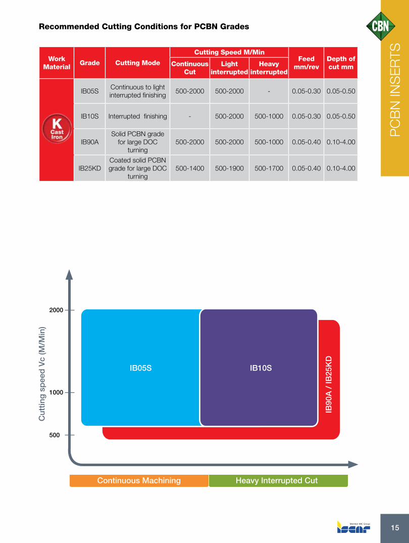
Recommended Cutting Conditions for PCBN Grades
Work Material
Grade Cutting Mode
Cutting Speed M/Min Feed
mm/rev Depth of cut mmContinuous
CutLight
interruptedHeavy
interrupted
IB05SContinuous to light interrupted finishing
500-2000 500-2000 - 0.05-0.30 0.05-0.50
IB10S Interrupted finishing - 500-2000 500-1000 0.05-0.30 0.05-0.50
IB90ASolid PCBN grade
for large DOC turning
500-2000 500-2000 500-1000 0.05-0.40 0.10-4.00
IB25KDCoated solid PCBN grade for large DOC
turning500-1400 500-1900 500-1700 0.05-0.40 0.10-4.00
Cut
ting
sp
eed
Vc
(M/M
in)
Continuous Machining Heavy Interrupted Cut
500
1000
2000
IB05S IB10S
IB90
A /
IB25
KD
PC
BN
INS
ER
TS

ISCAR16
Recommended Cutting Conditions for PCBN Grades
Work Material
Grade Cutting Mode
Cutting Speed M/Min Feed
mm/rev Depth of cut mmContinuous
CutLight
interruptedHeavy
interrupted
IB90For interrupted
machining100-300 80-300 80-200 0.05-0.20 0.10-0.50
IB05SFor high speed
continuous machining
100-400 - - 0.05-0.20 0.10-0.50
Cut
ting
sp
eed
Vc
(M/M
in)
Continuous Machining Heavy Interrupted Cut
100
400
IB05S
IB90
Specifications of PCBN Grades for Super Alloys
GradeCoated/Not
CoatedApplication
PCBN content %
Grade InstructionP
CB
N G
rades
for
S
uper
Allo
ys IB05S N 95%
Super fine grain PCBN grade for machining ferrous sintered metals. The highest content of PCBN in the world as a practical tool material.
IB90 N 90%Suitable for super alloys. High fracture resistance. Good performance in high-speed machining.
Continuous cut Light interrupted Heavy interrupted
PC
BN
INS
ER
TS

17
Specifications of PCBN Grades for Sintered Metals
GradeCoated/Not
CoatedApplication
PCBN content %
Grade Instruction
PC
BN
Gra
des
for
Sin
tere
d M
eta
ls
IB05S N 95%
Super fine grain PCBN grade for machining ferrous sintered metals.The highest content of PCBN in the world as a practical tool material.
IB10S N 95%
Uncoated grade that contains 95% PCBN composed of fine grain size in a special binder.Used for finishing operations on sintered metals at high cutting speeds and also for valve seats and Titanium alloys at continuous up to light interrupted cutting conditions. Features high hardness and good wear resistance.
Continuous cut Light interrupted Heavy interrupted
Recommended Cutting Conditions for PCBN Grades
Work material
Grade Cutting Mode
Cutting speed M/Min Feed
mm/rev Depth of cut mmContinuous
CutLight
interruptedHeavy
interrupted
IB10STougher grade for interrupted turning
- 100-400 100-400 0.05-0.30 0.05-0.50
IB05SHigh wear
resistance grade100-400 100-400 - 0.05-0.30 0.05-0.50
Cut
ting
sp
eed
Vc
(M/M
in)
Continuous Machining Heavy Interrupted Cut
500
1000
2000
IB05S IB10SP
CB
N IN
SE
RTS

Choosing the Right Edge Preparation
ISCAR18

19
Choosing the Right Edge Preparation
Correct PCBN insert edge preparation is essential in hard part turning.
Appropriate edge choice can lengthen tool life dramatically, reduce costs and increase productivity by saving machining time.
GRIP Insert Edge PreparationChoosing the Right Edge Preparation
For Interrupted 0.15mmX30˚
For Continuous 0.2mmX20˚
PC
BN
INS
ER
TS

ISCAR20
PCBN Edge Preparations:
Sharp edges are generally not recommended on PCBN since the sharp edge can chip or break quickly. A sharp edge can be used when cutting forces need to be reduced due to unstable workpiece clamping or machine limitations.
H/E - Honed Edge (honing only) Honing helps strengthen and protecting the edge from chipping and fracturing. Honing can bring benefits (superior surface) in special finishing applications.
R - Land for roughing/interrupted applications (0.13mmX35°+honing).
M - Land for medium/light interrupted applications (0.13mmX25°+honing).
F - Land for finish / continuous applications (0.13mmX15°+honing).
T – Land (chamfer without honing) T-land is a common edge preparation on PCBN/Ceramics (0.14mmX20°).
PCBN Edge PreparationChoosing the Right Edge Preparation
H/E – Honed 0.03-0.04(mm) F – Finishing / continuous: 0.13mmX15°+honing
M – Medium / light interrupted: 0.13mmX25°+honing
T – Medium continuous: 0.14mmX20°
R – Roughing / interrupted: 0.13mmX35°+honing
H/E F
M
T
R
PC
BN
INS
ER
TS

21
H/E Honed 0.03-0.04(mm)
F Finishing / continuous: 0.13mmX15°+honing
M Medium / light interrupted: 0.13mmX25°+honing
R Roughing/ interrupted: 0.13mmX35°+honing
H/E
F
M
R
T Medium continuous: 0.14mmX20°
T
PCBN Edge PreparationChoosing the Right Edge Preparation
PC
BN
INS
ER
TS

ISCAR22
ISCAR PCBN Edge Preparation
PC
BN
edge p
repara
tion fo
r hard
ened s
teel
PCBN Edge Description Edge Prep Type
Edge Prep Honing/ T-Land
Application Edge Instruction
H/E0.03-0.04(mm)
Honing helps strengthen the edge, protecting the edge line from chipping and fracturing. Carefully applied, it can bring benefits when special surface finish or special tolerances is required.
F 0.13mmX15°
Small chamfer that strengthens the cutting edge. Recommended for continuous cut or when lower cutting forces are required. Feed rates must be greater then the hone size to allow actual cutting action and prevent rubbing.
M 0.13mmX25°
Medium chamfer that strengthens the cutting edge. First choice for PCBN inserts. Recommended for continuous cut up to light interrupted cut. Feed rates must be greater then the hone size to allow actual cutting action and prevent rubbing.
T 0.14mmX20°Chamfer without honing. Recommended for continuous and light interrupted cut.
R 0.13mmX35°
Big chamfer that gives very strong cutting edge. Recommended for interrupted cut and unstable machine conditions. Feed rates must be greater then the hone size to allow actual cutting action and prevent rubbing.
Continuous cut Light interrupted Heavy interruptedMedium
PC
BN
INS
ER
TS

PCBN Chip Breakers
23

ISCAR24
PCBN – Chip Breakers
ISCAR presents a new generation of PCBN inserts with the inclusion of efficient chipbreakers that provide improved chip control. When using the standard PCBN flat top inserts (without chipformers), long unbroken and uncontrolled chips are often produced. These chips may harm the workpiece surface and interrupt the machining process.
The new ISCAR PCBN inserts, with HF & HM chipbreakers, provide excellent chip control at various depths of cut. ISCAR’s PCBN inserts with chip breakers solve the problem of long and curled chips.
PC
BN
INS
ER
TS

25
New chip breakers for hardened materialswhen turning hard materials: long and tangled chips are produced.
IB25HA + Chip Breaker
Chip Breaking Area
HF – for high surface finish
The flat surface on the corner allows excellent chip control at small depth of cut
Relatively wide chip breakerallows cutting control at large depth of cut
HM – for medium and rough cutting
HF
HM
Dep
th o
f cu
t [m
m]
Feed rate [mm/rev]
0.5
0.2
1.0
0.1
PC
BN
INS
ER
TS

ISCAR26
Wiper InsertPCBN inserts are mainly for finishing and super finishing on hard part turning. All PCBN inserts are grounded all around for maximum accuracy, better repetition and increased surface quality - an important element of PCBN in the wiper configuration which helps greatly to improve surface finish/quality (similar to grinding). The wiper enables work with a higher feed rate and good surface finish on the work piece.
CBN insert with wiper advantages: • Wiper turning inserts for faster feeds
with better finishes• Can be used on roughing and
finishing operations • Increased tool life• Fits on all standard turning tool holders as
every one of the standard turning inserts• Strong cutting edge produces superior
surface finishes, even at heavier semi-finishing depths of cut
• Improved chip control - under high feed conditions, the chips generated become thicker and are more easily broken, which improves chip control
Cutting condition CNGA 432T-WG-MC IB55 wiper insertSpeed=150m/min Ap=0.2mm Material O1 with 64Hrc
Sur
face
Ra
[μm
]
Feed rate [mm/rev]
No Wiper
Wiper
0.1 0.2 0.3
0.5
1.5
2.5
1
2
3
PC
BN
INS
ER
TS wiper

27
Key Points for Successful HPT
Soft state preparation (before hardening):
Machine close to the final dimensions, leaving only a few tenths for the finishing operation.Make chamfers and radiuses (sharp corners can damage or break the corner - PCBN and ceramic grades don’t work well with sharp corners).
It is better to machine on a smooth area. If needed, use wiper insert to improve surface finish before hard part turning.
Make chamfers and radiuses
Chamfers and radiuses Surface finish using wiper insert
Close to final dimensions & smooth contour
Rounding and chamfering at the ”soft” state
PC
BN
INS
ER
TS
Wiper standard

ISCAR28
Machine, Workpiece and Tool Holder Rigidity and StabilityRigidity and stability are extremely important when working with PCBN.PCBN cannot be operated under vibrations. As long tool overhang and long part overhang can cause vibrations, the tool and the part overhang must be shortened as much as possible to increase rigidity and stability.
Insert Clamping Tool holders with a dimple-clamp mechanism are most recommended for use with PCBN and ceramic inserts. This is due to the stability and rigidity of the insert.
Long tool overhang parts Long overhang
Rigid insert clamping (dimpled)
Short tool overhang parts Short overhang
PC
BN
INS
ER
TS

TEST REPORTS
29
ISCAR30
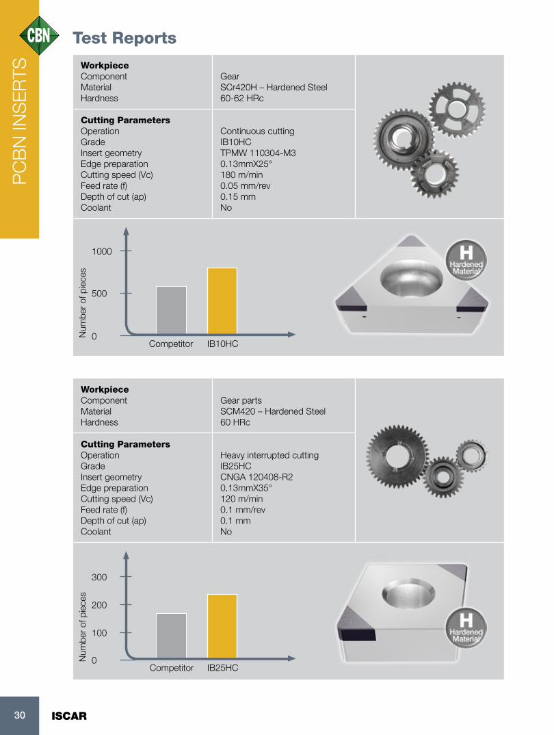
Test Reports
WorkpieceComponent Material Hardness
GearSCr420H – Hardened Steel60-62 HRc
Cutting ParametersOperation Grade Insert geometry Edge preparation Cutting speed (Vc) Feed rate (f) Depth of cut (ap) Coolant
Continuous cuttingIB10HCTPMW 110304-M30.13mmX25°180 m/min0.05 mm/rev0.15 mmNo
WorkpieceComponent Material Hardness
Gear partsSCM420 – Hardened Steel60 HRc
Cutting ParametersOperation Grade Insert geometry Edge preparation Cutting speed (Vc) Feed rate (f) Depth of cut (ap) Coolant
Heavy interrupted cuttingIB25HCCNGA 120408-R2 0.13mmX35° 120 m/min 0.1 mm/rev0.1 mm No
0
0
500
100
1000
200
300
Num
ber
of p
iece
sN
umbe
r of
pie
ces
IB10HC
IB25HC
Competitor
Competitor
PC
BN
INS
ER
TS

31
Component Material Hardness
ShaftHardened Steel56 HRc
Cutting ParametersOperation Grade Insert geometry Edge preparation Cutting speed (Vc) Feed rate (f) Depth of cut (ap) Coolant
Interrupted cuttingIB20H CNGA 120412-M4 0.13mmX25° 160 m/min 0.2 mm/rev 0.2 mm No
Component Material Hardness
Main Shaft Sintered Metal 50 HRc
Cutting ParametersOperation Grade Insert geometry Edge preparation Cutting speed (Vc) Feed rate (f) Depth of cut (ap) Coolant
Continuous cuttingIB05SDCGW 11T308-M2 0.13mmX25° 308 m/min0.1 mm/rev0.4 mm No
0
1000
5000
10000
Num
ber
of p
iece
s
IB05SCompetitor
0
50
100
150
Num
ber
of p
iece
s
IB20HCCompetitor
PC
BN
INS
ER
TS

Part Name Material Hardness
Hardened Coated SleeveHardened Steel65-68 HRc HRC
Cutting ParametersTool Grade Insert geometry Cutting speed (Vc) Feed rate (f) Depth of cut (ap)
CRGNR 2525M-12CEAIB90ARNMN 120400S100202 11 m/min0.4 mm/rev0.5 mm
0
300
600
900
Num
ber
of p
iece
s
IB90ACompetitor
PC
BN
INS
ER
TS
ISCAR32

33
Material
Hardness
High alloyed steel, cast steel and tool steel62 HRC
Cutting ParametersGrade Insert geometry Cutting speed (Vc) Feed rate (f) Depth of cut (ap)
IB50CNGA 120408-2-WGIB50200 m/min0.15 mm/rev0.15 mm
Part Name Material Hardness
Bearing HousingsHardened Steel58-62 HRC
Cutting ParametersTool Grade Insert geometry Cutting speed (Vc) Feed rate (f) Depth of cut (ap)
PDJNL 2525M-15IB50DNMA 150612T188 m/min0.05 mm/rev0.05 mm
0
0
100
100
200
200
300
300
Num
ber
of p
iece
sN
umbe
r of
pie
ces
IB50
IB50
Competitor
Competitor
PC
BN
INS
ER
TS

ISCAR34
Material Hardness
Hardened steel58-62 HRC
Cutting ParametersGrade Insert geometry Cutting speed (Vc) Feed rate (f) Depth of cut (ap)
IB20HCNGA 120408-R2 IB20H100 m/min0.1 mm/rev0.4 mm
0
50
100
Num
ber
of p
iece
s
IB20HCompetitor
Material Hardness
Hardened steel 60 HRC
Cutting Parameters Grade Insert geometry Cutting speed (Vc) Feed rate (f) Depth of cut (ap)
IB10HCCCGW 060204-M2 IB10HC100 m/min0.07 mm/rev0.05 mm
0
600
1200
Num
ber
of p
iece
s
IB10HCCompetitor
PC
BN
INS
ER
TS

35
Part Name Material Hardness
Reverse Gear - DQ200Hardened steel680 HV
Cutting ParametersGrade Insert geometry Cutting speed (Vc) Feed rate (f) Depth of cut (ap)
IB10HCCNGA 120412T-WG-2-138529220 m/min0.1 mm/rev0.15 mm
0
500
1000
Num
ber
of p
iece
s
IB10HCCompetitor
Material Hardness
Pre-Machined 58 HRC
Cutting Parameters ToolGrade Insert geometry Cutting speed (Vc) Feed rate (f) Depth of cut (ap)
JNL 2525M-15IB55DNGA 150608T-MC IB55150 m/min0.12 mm/rev0.17 mm
0
500
1000
Num
ber
of p
iece
s
IB55Competitor
PC
BN
INS
ER
TS

ISCAR36
PC
BN
INS
ER
TS
Crater wear • Reduce cutting speed• Increase feed • Increase/decrease depth of cut
Flank wear
• Increase cutting speed• Increase feed
Chipping • Check stability, eliminate vibration• Do not use coolant• Use a stronger cutting edge:- S-edge geometry- Increase chamfer size (angle and/or width)- Use larger nose radius
Cracking /fracture
• Use uncoated inserts• Check stability, eliminate vibration• Check/replace shim• Make sure tool is aligned to center• Do not use coolant• Decrease feed• Decrease depth of cut• Use a stronger cutting edge:- S-edge geometry- Increase chamfer size (angle and/or width)- Use larger nose radius- Use wiper
Notch wear
• Increase speed• Reduce feed• Reduce/vary depth of cut
Improper use with PCBN inserts can cause premature failure, damage and short tool life. The most common reasons for early failure with PCBN include choosing the wrong grade, using the wrong cutting conditions (speed feed
and D.O.C.), and the wrong choice of edge preparation. HTP machining using unstable tools with high overhang and bed part clamping can cause unstable conditions and vibrations during machining.
PCBN Insert Wear

37
ISCAR is introducing a designation system suited especially for PCBN inserts.The designation system includes indicators for all the important parameters which need to be taken into consideration when choosing a PCBN insert. For example: the number of cutting tips, edge preparation, ISO material family, coating type, etc.
CNMA 120408 R W 2 HF IB X X H C
PCBN Designation System
01-30: application range according to the ISO 513 classification and application of cutting materials
Chipbreaker:HF – finishingHM – medium cutting
ISO Scale:H – Hardened steelS – Exotic materials
Insert size
Wiper
Edge preparation type:R – Roughing / interrupted: 0.13 mmx35°M – Medium / light interrupted: 0.13 mmx25°F – Finishing / continuous: 0.13 mmx15°S – Sharp edgeH/E – Honed (0.03-0.04 mm)T – 0.14 mmx20°
Coating type & solid:C – TiN/Ti (C, N, O) coated tipped insertA – Ti (C, N) coated tipped insert B – Uncoated solidD – TiN coated solid
Number of cutting edges
PC
BN
INS
ER
TS

CERAMIC INSERTS
38 ISCAR

39
Ceramic Inserts – General Information
Hard materials can be machined also by ceramic cutting tools containing Al2O3 or Si3N4.
Ceramic inserts are available as solid ceramic inserts (pressed or grinding) in the following forms:
Solid ceramic insert without hole
Solid ceramic insert with hole
Solid ceramic insert with dimple
Ceramic materials have the following properties for hard turning:
• High hardness level• High wear resistance• Very good stability in high temperatures• Low thermal conductivity
(heat is transferred to chip)• Less sensitivity to thermal cracks due to coolant • Very attractive cost compared to PCBN• Not recommended for interrupted machining
CE
RA
MIC
INS
ER
TS

CERAMIC INSERTS
40 ISCAR

41
ISCAR Ceramic Grades
ISO
ISO
ISO
H01
H01
H01
H10
H10
H10
H20
H20
H20
H30
H30
H30
HARD
TOUGH
Hardened Materials
Cast Iron (Gray Cast Iron / Nodular Cast Iron)
Unc
oat
ed
Cer
amic
Unc
oat
ed
Cer
amic
Unc
oat
ed
Cer
amic
Co
ated
C
eram
icC
oat
ed
Cer
amic
Heat-resistant Alloys / Inconel
IN22 IN23
IN420
IN23IS8
IS6
IN110
IS80
IW7
IS25
IS9IS35
CE
RA
MIC
INS
ER
TS

ISCAR42
Recommended Cutting Conditions for Ceramic Grades
Work Material
Grade Cutting Mode
Cutting Speed M/Min Feed
mm/rev Depth of cut mmContinuous
CutLight
interruptedHeavy
interrupted
40-50HRC
50-65HRC
IN22High speed
machining of hardened steel
180-320 180-320 0.1-0.18 0.1-0.5
50-250 50-250 0.05-0.15 0.1-0.5
IN23Machining
hardened steel for light interrupted
100-280 100-280 0.1-0.2 0.1-0.8
IN420Coated for high
speed machining
100-350 100-3500.05-0.2 0.1-0.6
50-280 50-280
Cut
ting
sp
eed
Vc
(M/M
in)
Continuous Machining Heavy Interrupted Cut
IN420
IN22
IN23
ISCAR Ceramic Grades for Machining Hard Steel
GradeCoated/Not
CoatedApplication Grade Instruction
Cera
mic
Gra
des
for
H
ard
ened S
teel
IN22 N
IN22 – Black ceramic, mainly used for high speed machining of light roughing & finishing of hardened steel. Also suitable for finishing operation of chilled cast iron.
IN420 YIN420 –Coated, used for high speed finishing machining of hardened steel. Improved tool life up to 50% compared to uncoated grade.
IN23 N
N23 – Black ceramic, mostly recommended for machining cast iron at finish to medium conditions. Also suitable for light interrupted cut of hardened steel.
Continuous cut Light interrupted Heavy interrupted
CE
RA
MIC
INS
ER
TS

43
ISCAR Ceramic Grades for Machining Cast Iron
GradeCoated/Not
CoatedApplication Grade Instruction
CB
N G
rades
for
Gra
y C
ast
Iro
n
IN110 NIN110 – White ceramic features high toughness and wear resistance, used for high speed turning of cast iron, especially high speed dry machining of cylinder liner.
IN23 N
IN23 – Black ceramic mostly recommended for machining cast iron at finish to medium conditions. Also suitable for light interrupted cut of hardened steel.
IS6 N
IS6 – (SiAlON), High fracture toughness and thermal shock resistance. Used for very high speedmachining (up to 1200 m/min) roughing to finishing of cast iron, especially for automotive parts.
IS8 NIS8 - High wear resistance with good toughness and thermal shock resistance. Used for high speed machining roughing to finishing of cast iron.
IS80 YIS80 (CVD coated) - High wear resistance with good toughness and thermal shock resistance. Used for high speed machining roughing to finishing of cast iron.
Continuous cut Light interrupted Heavy interrupted
CE
RA
MIC
INS
ER
TS

ISCAR44
Recommended Cutting Conditions for Ceramic Grades
Work Material
Grade Cutting Mode
Cutting Speed M/Min Feed
mm/rev Depth of cut mmContinuous
CutLight
interruptedHeavy
interrupted
IN110High toughness for high speed of cast
iron400-850 0.1-0.3 0.5-2.0
IN23Black ceramic for finish and medium
conditions400-800 0.1-0.4 0.5-2.0
IS6For very high speed machining roughing
to finishing400-700 400-700 400-700 0.2-0.6 0.1-3.5
IS8 High wear resistance for roughing to
finishing of cast iron
400-600 400-600 400-600 0.2-0.6 0.1-4.0
IS80 400-800 400-800 400-800 0.2-0.6 0.1-3.5
Cut
ting
sp
eed
Vc
(M/M
in)
Cut
ting
sp
eed
Vc
(M/M
in)
Continuous Machining Continuous MachiningHeavy Interrupted Cut Heavy Interrupted Cut
IN110
IN23
IS80
IS6
IS8
*Recommended mainly for ductal iron
CE
RA
MIC
INS
ER
TS

45
ISCAR Ceramic Grades for Machining Super Alloys
GradeCoated/Not
CoatedApplication Grade Instruction
CB
N G
rades
fo
r S
uper
Allo
ys
IW7 N
Whisker-reinforced ceramic grade, provides high hardness with excellent toughness for machining Ni based high temperature alloys such as Inconel, Waspaloy etc.
IS25 NReinforced SiAlON composite grade, excellent for machining Ni based high temperature alloys such as Inconel, Waspaloy etc.
IS9 NA very tough grade with high cutting edge stability. Used for roughing to finishing applications on Ni based high temperature alloys and ductile cast iron.
IS35 N
SiAlON ceramic grade, provides high hardness with excellent toughness for machining Ni based high temperature alloys such as Inconel, Waspaloy etc. Suitable for high feed rate and depth of cut.
Continuous cut Light interrupted Heavy interrupted
Recommended Cutting Conditions for Ceramic Grades
Work Material
Grade Cutting Mode
Cutting Speed M/Min Feed
mm/rev Depth of cut mmContinuous
CutLight
interruptedHeavy
interrupted
IW7Excellent toughness for
machining Ni based alloys
200-400 0.1-0.3 0.5-2.5
IS25SiAlON grade
for Ni based alloys200-350 0.1-0.4 1.0-4.0
IS9Tough grade for rough and finish
applications180-230 180-230 0.1-0.3 1.0-3.0
IS35SiAlON grade with
excellent toughness for Ni based alloys
150-250 0.2-0.5 1.0-4.5
Cut
ting
sp
eed
Vc
(M/M
in)
Continuous Machining Heavy Interrupted Cut
IW7
IS25
IS9
IS35
CE
RA
MIC
INS
ER
TS

ISCAR46
Ceramic – Edge Preparation
Edge Preparation – Ceramic Standard Line
Ceramic insert edge preparation is defined by length “L” and angle “Alfa” as in the PCBN line.In addition to the standard range of edge preparations for each grade, different edge preparations can be produced for special inserts if required.
Grades
IN110 IN420 IN22 IN23 IS6 IS80 IS8 IW7 IS9 IS25 IS35
T(mm) 0.2 0.2 0.2 0.2 0.2 0.2 0.2 0.1 0.1 0.1 0.1
20° 25° 25° 25° 25° 25° 25° 20° 25° 20° 20°
Honing only
E E E E
25°
20˚
CE
RA
MIC
INS
ER
TS

TEST REPORTS
47

ISCAR48
Workpiece Material Hardness
Steel and cast steel60 HRC
Cutting Parameters Grade Insert geometry Cutting speed (Vc) Feed rate (f) Depth of cut (ap)
IN22VNGA 160404T IN22135 m/min0.04 mm/rev0.2 mm
0
60
120
Num
ber
of p
iece
s
IN22Competitor
Workpiece Material Hardness
Steel and cast steel58HRC
Cutting Parameters Grade Insert geometry Cutting speed (Vc) Feed rate (f) Depth of cut (ap)
IN23CNGA 431 T366 m/min0.02 mm/rev 0.15 mm
0
600
1200
Num
ber
of p
iece
s
IN23Competitor
Test ReportsC
ER
AM
IC IN
SE
RTS

49
Workpiece Material Hardness
High alloyed steel, cast steel46 HRC
Cutting Parameters Grade Insert geometry Cutting speed (Vc) Feed rate (f) Depth of cut (ap)
IN420CNGA 120412T IN420140 m/min0.1 mm/rev1.5 mm
0
2
4
6
Num
ber
of p
iece
s
IN420Competitor
WorkpieceMaterial Hardness
Super alloys
Cutting Parameters Grade: Insert geometry Cutting speed (Vc) Feed rate (f) Depth of cut (ap)
IS35RNGN 120700220 m/min0.12 mm/rev 2 mm
0
1
2
Num
ber
of p
iece
s
IS35Competitor
CE
RA
MIC
INS
ER
TS

PCD INSERTS
ISCAR50

51
PCD PCD has become a global industry standard for enhanced part quality and significant cost reductions in the overall production cycle.
Non-Ferrous Machining
When it comes to non-ferrous materials processing such as aluminum alloys, titanium, carbon fiber, reinforced plastics, ceramicand other non-metallic materials, PCD (polycrystalline cubic diamond) is an advanced material that significantly reduces machining time and provides excellent surface quality due to excellent abrasion resistance and low coefficient of friction.
PCD has a high thermal conductivity and good heat dissipation from the cutting area. PCD possesses the highest flexural strength of all cutting materials. PCD is very well adapted for aluminum machining with high Si content or other abrasive filler materials.Temperature hardness up to approx. 650 °C.
PCD
POLYCRYSTALLINE CUBIC DIAMOND
High grinding efficiency, low grinding force: Less heat will be generated by the hole in the grinding process. This can decrease or prevent burns and cracks on the surface of the workpiece, and decrease the equipment’s wear and energy consumption.
High wear resistance: Diamond grinding tools’ change in dimension is small. This can lead to good grinding quality and high grinding precision.
Long lifespan, long dressing period: This can greatly increase work efficiency and decrease the product’s labor intensity.Low comprehensive cost: The processing cost of each workpiece is lower.
PC
D IN
SE
RTS

ISCAR52
4900HV
5000HV
6000HV
4500HV
2300HV
2100HV
PCBN
Ceramic
PCD
HIGH
HIG
H
Submicron carbide
Carbide
Coated carbide
PCD
PCBN
Ceramic
Cermet
Har
dne
ss C
uttin
g s
pee
d
Feed Toughness
Vickers Hardness
Materials on Hardness ScalesPCD is characterized by a hardness that is comparable to natural diamond, and it can achieve hardness of 6000HV and more.
PC
D IN
SE
RTS

53
Recommended Cutting Conditions for PCD Grades
Work Material Grade Cutting Speed
(m/min)Feed
(mm/rev)Depth of cut
(mm)
AI alloy (4-9% Si) ID5 800-2500 0.1-0.3
0.05-0.3AI alloy (9-14% Si) ID5, ID6 600-1300 0.1-0.3
AI alloy (14-18% Si) ID5, ID6 300-600 0.1-0.3
Cemented Carbide ID5, ID6 20-40 0.05-0.2 0.02-0.5
Wood ID5, ID4 1000-5000 0.1-0.5 0.2-5.0
Cu alloy ID5 600-1000 0.05-0.2 0.05-3.0
Plastic, FRP ID5, ID4 300-1000 0.05-0.25 0.05-3.0
PC
D IN
SE
RTS
* ID4 and ID6 grades can be offered as special options.

ISCAR54
Workpiece Material Hardness
DIN AIMg1
Cutting parameters Grade Insert geometry Cutting speed (Vc) Feed rate (f) Depth of cut (ap)
ID5VCGW 160408-T2030 ID52,500 m/min0.15 mm/rev0.5 mm
0
500
1000
Num
ber
of p
iece
s
ID5Competitor
Workpiece Material Hardness
Aluminum - cast, alloyed 130 HB
Cutting parameters Grade Insert geometry Cutting speed (Vc) Feed rate (f) Depth of cut (ap)
ID5VCGT 160408-DW2,873 m/min0.45 mm/rev 1 mm
0
5000
10000
Num
ber
of p
iece
s
ID5Competitor
Test ReportsP
CD
INS
ER
TS

55
Workpiece Material Hardness
Copper alloys
Cutting Parameters Grade Insert geometry Cutting speed (Vc) Depth of cut (ap)
ID5CCMT 060204D ID5313 m/min0.15 mm
0
1000
2000
3000
Num
ber
of p
iece
s
ID5Competitor
Workpiece Material Hardness
Aluminum - cast, alloyed100-130 HB
Cutting Parameters Grade Insert geometry Cutting speed (Vc) Feed rate (f) Depth of cut (ap)
ID5GIDA 804-2205 ID5746 m/min0.1 mm/rev 0.2 mm
0
1000
2000
Num
ber
of p
iece
s
ID5Competitor
PC
D IN
SE
RTS

ISCAR56
Grade Comparison
ISOISCAR Tungaloy Mitsubishi Sumitomo Sandvik Kyocera Dijet NTK
Seco Tools
Kenna-metal
TaeguTec Widia Walter CeratizitClassi-fication
Symbol
K
K01 IB10KBX930BX910BX870
MB710MB730MB5015
BN500BNC500
CB7525CB7050CB50
KBN60M - B52 -KB9610KD120KB1630
KB90 WBH10C WCB80TA100
CTL3215
K10IB05SIB10S
BX470BX480BX950
MB710MB730
BN7000BN7500BN500
BNC500
CB7050CB7925CB50
KBN60M JBN795B23B30B52
CBN200CBN300
CBN400CCBN010
KB9640KD120KB1630
KB90A WBK40UWCB80WCB50
TA120TA201
CTL3215
K20IB90AIB90
IB25KD
BXC90BX90S
MB730MBS140
BNS800 CB7050 KBN900 -B23B30B52
CBN300CBN500CBN600CBN010
KB1340KB1345
- WBK45U WCB80 CTL3215
K30IB90A
IB25KDBXC90BX90S
MBS140 BNS800 - KBN900 - B16CBN500CBN600
KB1340KB1345
- - - -
S
S01 IB05S M714B MB730 BN350 - - JBN795 JP2 CBN170 - KB90 - - -
S10IB05SIB90
BX470BX480BX950
MB4020 BN7500 CB7050KBN65BKBN65M
-B23B30
CBN200 KB1630 KB90A WBK45U WCB80 TA201
H
H01IB05H
IB10HCBXM10BX310
BC8110MBC010MB810
BNC100BNC160BNC2010
BNX10BN1000
CB20
KBN510KBN10CKBN05MKBN10M
-B52B5K
CBN10CBN100
CBN160CCBN050C
KB1610KB5610
KB50 WBH10C WCB30 -
H10
IB50IB55
IB10HIB10HCIB20H
IB25HA
BXM10BX330BX530
BC8110MBC020MB8025
BNC160BNC200BNC2020
BN250BN1000
CB7015CB7025CB20CB50
KBN525KBN05MKBN10MKBN25M
JBN245B36B52B6K
CBN150CBN200CBN300
CBN060KCBN050CCBN160CCBN300PCBN400C
KB9610KB1610KB5610
KB50TB650
WBH10CWBH10PWBH10U
WCB30WCB50
CTL3215TA100
H20
IB20HIB20HCIB25HAIB25HC
BXM20BXA20BX360
MBC020BC8120MB8025MB825
BNC200BNC2020
BN250BNX20BNX25BN2000
CB7025CB20
CB7035
KBN525KBN05MKBN10MKBN25M
JBN300JBN330
B22B36B40B6K
CBN150CBN200CBN300
CBN060KCBN160CCBN300PCBN400C
KB5625KB1625
TB650 WBH25PWCB50WCB80
CTL3215TA120
H30IB25HC
IB90BXC50BX380
MB835BNC300BN350BNX25
CB7525KBN35MKBN900
JBN300JBN330
B22B40
CBN500KB1630KB9640
- WBH40C - TA201
*Note: The above table is taken from a publication. We have not obtained approval from each company.
PCBN
GR
AD
E C
OM
PAR
ISO
N

57
ISOISCAR Tungaloy Mitsubishi Sumitomo Sandvik Kyocera Dijet NTK
Seco Tools
Kenna-metal
TaeguTec Widia Walter CeratizitClassi-fication
Symbol
N
N01 ID5DX160DX180
MD205 DA90 CD10 KPD001JDA30JDA735
- -KD1400KD1405KD100
- - WCD10 CTD4125
N10 ID5 DX140MD205MD220
DA150 CD10KPD001KPD010KPD230
JDA715 PD1PCD05PCD10
KD100KD1400KD1425
KP500 WDN25U WCD10CTD4125CTD4110
Grade ComparisonPCD
Ceramic
ISOISCAR Tungaloy Sumitomo Sandvik Kyocera NTK Kennametal TaeguTec Ceramtec Walter Ssang-Yong
Classi-fication
Symbol
K
k01-k10 IN110 - - CC620 KA30HC1HW2
- AW120SN60SN80
-SZ200SZ300
k05-k15 IN23 -NB90SNB90M
CC650 A65HC2HC5HC6
KY1615 AB30 - -ST100SD200TC100
k10-k20 IS6 -SN200KSN2100K
- - SX9KY1310KY3000KY300
AS500
SL506SL508SL606SL608
- -
k15-k25
IS8LX11LX21
SN2000KSN2100K
NS260
CC6090CC6091
KS6000KS6050KS500
SX1SX6SX8
KY1320KY3500KYK10
AS10SL500SL808
Q130WSN10
SN26SN300SN400SN500SN600
IS80 - NS260C CC1690 CS7050SP2SP9
KY3400KYK25
SC10
SL550CSL554CSL654CSL658CSL854CSL858C
- -
S
s01-s15 IW7 WG300 WX2000 CC670 KXW1WA1WA5
KY4300 TC430 - WWS20SW500SW800
s10-s20IS25 IS9
WG300 - - - - KY2100TC3020 AS20
- - -
s20 IS35 - -CC6060CC6065
KS6040SX5SX7SX9
KY1540KYS25KY2100
TC3030 - -SN800SN900
H H01-H10
IN420 - NB100C CC6050A66N
PT600MZC4 ZC7
KY4400 AB2010 - - TC300
IN22LX11 LX21
- - -HC2 HC5HC7
- AB20SH2 SH4
-ST300 ST500 ST700
IIN23LX11 LX21
NB90S NB90M
CC650 A65HC2 HC5 HC6
KY1615 AB30 - -ST100 SD200 TC100
*Note: The above table is taken from a publication. We have not obtained approval from each company.
*Note: The above table is taken from a publication. We have not obtained approval from each company.
GR
AD
E C
OM
PAR
ISO
N

TECHNICAL INFORMATION
58 ISCAR

59
rdi
80°
l
S
95º 95°
95°
Dimensions Tough 1 Hard Recommended Machining Data
Designation l di S r IS8
IS80
IS6 ap
(mm)f
(mm/rev)WNGA 080408T 8.70 12.70 4.76 0.80 • 2.00-4.00 0.20-0.60WNGA 080412T 8.70 12.70 4.76 1.20 • • • 2.00-5.00 0.03-0.95
WNGA-CeramicDouble-Sided Flat Rake Ceramic Inserts for Machining Cast Iron
l Sr
80°
d95º
95º
Dimensions Tough 1 Hard Recommended Machining Data
Designation l di S r IW7
IS35
IS25
IS8
IS80
IN23
IN22
IN42
0
ap (mm)
f (mm/rev)
CNGN 120404T 12.90 12.70 4.76 0.40 • • 1.00-3.00 0.10-0.43CNGN 120408E 12.90 12.70 4.76 0.80 • 1.00-3.00 0.10-0.50CNGN 120408T 12.90 12.70 4.76 0.80 • • • • • 1.00-3.00 0.10-0.50CNGN 120408T0225-WG (1) 12.90 12.70 4.76 0.80 • 1.00-3.00 0.10-0.50CNGN 120412E 12.90 12.70 4.76 1.20 • 1.00-5.00 0.10-0.50CNGN 120412T 12.90 12.70 4.76 1.20 • • • 1.00-4.00 0.10-0.50CNGN 120416T 12.90 12.70 4.76 1.60 • • • 1.00-5.00 0.10-0.50CNGN 120708E 12.90 12.70 7.94 0.80 • 1.00-4.00 0.10-0.50CNGN 120708T 12.90 12.70 7.94 0.80 • • 1.00-4.00 0.10-0.50CNGN 120712E 12.90 12.70 7.94 1.20 • 1.00-5.00 0.10-0.50CNGN 120712T 12.90 12.70 7.94 1.20 • • • 1.00-4.00 0.10-0.50CNGN 120716T 12.90 12.70 7.94 1.60 • • • • 1.00-5.00 0.10-0.50CNGN 160612T 16.12 15.88 6.35 1.20 • 1.00-5.00 0.10-0.50
(1) Wiper edge configuration for finishing operations at high feeds
CNGN-Ceramic80° Rhombic Double-Sided Ceramic Inserts with a T-Land for Machining Cast Iron, Hardened Steel and Nickel Based Alloys
Sr l
di
80°
75°
95º
95º
95º75º
Dimensions Tough 1 Hard Recommended Machining Data
Designation l di S r IS8
IS80
IS6
IN23
IN22
IN42
0
ap (mm)
f (mm/rev)
CNGA 120404T 12.90 12.70 4.76 0.40 • • • 1.00-3.00 0.05-0.20CNGA 120408T 12.90 12.70 4.76 0.80 • • • • • • 1.00-4.00 0.05-0.20CNGA 120412T 12.90 12.70 4.76 1.20 • • • • • 1.00-4.00 0.05-0.20CNGA 120416T 12.90 12.70 4.76 1.60 • • • 1.00-5.00 0.05-0.20
CNGA-Ceramic80° Rhombic Double-Sided Inserts with a T-Land for Machining Cast Iron and Hardened Steel
TEC
HN
ICA
L IN
FOR
MAT
ION

ISCAR60
Slr
di
80° 75°
95º
95º
75º
Dimensions Tough 1 Hard Recommended Machining Data
Designation l di S r IS8
IS80
IS6 ap
(mm)f
(mm/rev)CNGX 120712T 12.90 12.70 7.94 1.20 • • • 1.00-3.00 0.07-0.43CNGX 120716T 12.90 12.70 7.94 1.60 • • • 1.00-3.00 0.07-0.43
CNGX-Ceramic80° Rhombic Double-Sided Dimpled Ceramic Inserts with a T-Land for Machining Cast Iron
Sr
90°
di
75º
45º
45º
45° 75º
Dimensions Tough 1 Hard Recommended Machining Data
Designation di S r IW7
IS8
IS80
IS6
IN23
IN22
IN42
0
IN11
0
ap (mm)
f (mm/rev)
SNGN 120404T 12.70 4.76 0.40 • 0.10-3.50 0.10-0.50SNGN 120408T 12.70 4.76 0.80 • • • • • 0.10-3.50 0.10-0.50SNGN 120412T 12.70 4.76 1.20 • • • • • • • • 0.10-5.00 0.10-0.50SNGN 120416T 12.70 4.76 1.60 • • • • • 0.10-5.00 0.10-0.50SNGN 120708T 12.70 7.94 0.80 • • • 0.10-5.00 0.10-0.50SNGN 120712T 12.70 7.94 1.20 • • • • • 0.10-5.00 0.10-0.50
SNGN 120716T 12.70 7.94 1.60 • • • • • 0.10-5.00 0.10-0.50
SNGN 150712T 15.88 6.35 1.20 • 0.10-5.00 0.10-0.50SNGN 150716T 15.88 6.35 1.60 • • 0.10-5.00 0.10-0.50
SNGN-CeramicSquare Double-Sided Ceramic Inserts with a Flat Rake for Machining Cast Iron, Hardened Steel and Super Alloys
rS
90°
di
75º
45º
45º
45° 75º
Dimensions Tough 1 Hard Recommended Machining Data
Designation di S r IS8
IN23
IN22
IN42
0
ap (mm)
f (mm/rev)
SNGA 120404T 12.70 4.76 0.40 • 0.10-3.00 0.05-0.30SNGA 120408T 12.70 4.76 0.80 • • • • 0.10-3.50 0.05-0.30
SNGA 120412T 12.70 4.76 1.20 • • 0.10-4.00 0.05-0.30
SNGA 120416T 12.70 4.76 1.60 • 0.10-4.50 0.05-0.30
SNGA-CeramicSquare Double-Sided Ceramic Inserts with a Flat Rake for Machining Cast Iron and Hardened Steel
TEC
HN
ICA
L IN
FOR
MAT
ION

61
90°
Slr
di
75º
45º
45º
45°
Dimensions Tough 1 Hard Recommended Machining Data
Designation di S r l IS8
IS80
IS6 ap
(mm)f
(mm/rev)SNGX 120712T 12.70 7.94 1.20 12.70 • • • 0.10-5.00 0.10-0.50SNGX 120716T 12.70 7.94 1.60 12.70 • • • 0.10-5.00 0.10-0.50
SNGX-CeramicSquare Double-Sided Dimpled Ceramic Inserts with a Flat Rake for Machining Cast Iron
55°
Slr
di
62.5º
60°MAX 93º-95º
50ºMAX
93º
27°MAX
Dimensions Tough 1 Hard Recommended Machining Data
Designation l di S r IS8
IN23
IN22
IN42
0
ap (mm)
f (mm/rev)
DNGA 150404T 15.50 12.70 4.76 0.40 • • 0.10-3.00 0.07-0.50DNGA 150408T 15.50 12.70 4.76 0.80 • • • • 0.10-3.50 0.07-0.50DNGA 150412T 15.50 12.70 4.76 1.20 • 0.10-4.00 0.07-0.50DNGA 150604T 15.50 12.70 6.35 0.40 • • 0.10-3.50 0.07-0.50DNGA 150608T 15.50 12.70 6.35 0.80 • • • 0.10-4.00 0.07-0.50DNGA 150612T 15.50 12.70 6.35 1.20 • • 0.10-5.00 0.07-0.50
DNGA-Ceramic55° Rhombic Double-Sided Ceramic Inserts for Machining Cast Iron and Hardened Steel
55°
di
rl S
93º
27°MAX
62.5º
60°MAX
Dimensions Tough 1 Hard Recommended Machining Data
Designation l di S r IS8
IS80
IS6 ap
(mm)f
(mm/rev)DNGX 150712T 12.70 12.70 7.94 1.20 • • • 0.10-4.00 0.10-0.50DNGX 150716T 15.50 12.70 7.94 1.60 • • 0.10-5.00 0.10-0.50
DNGX-Ceramic55° Rhombic Double-Sided Dimpled Ceramic Inserts for Machining Cast Iron
35°
l
di
Sr
93º
30°MAX
91º
50°MAX
72.5º
70°MAX
Dimensions Tough 1 Hard Recommended Machining Data
Designation l di S r IN22
IN42
0
ap (mm)
f (mm/rev)
VNGA 160404T 16.60 9.52 4.76 0.40 • • 0.70-2.50 0.06-0.30VNGA 160408T 16.60 9.52 4.76 0.80 • 0.80-3.00 0.08-0.35
VNGA-Ceramic35° Rhombic Double-Sided Ceramic Inserts with a T-Land for Machining Cast Iron and Hardened Steel
TEC
HN
ICA
L IN
FOR
MAT
ION

ISCAR62
Sdir
l
60°
93°
93º
22°MAX
Dimensions Tough 1 Hard Recommended Machining Data
Designation l di S r IW7
IS8
IS80
IN23
IN22
IN42
0
ap (mm)
f (mm/rev)
TNGN 160408T 16.50 9.52 4.76 0.80 • • • • 1.00-3.50 0.10-0.35TNGN 160412T 16.50 9.52 4.76 1.20 • • • 0.10-4.00 0.10-0.40TNGN 220408T 22.00 12.70 4.76 0.80 • 0.10-5.00 0.10-0.50TNGN 220712T 22.00 12.70 7.94 1.20 • 0.10-5.00 0.10-0.50
TNGN-CeramicTriangular Double-Sided Ceramic Inserts for Machining Cast Iron, Hardened Steel and Nickel Based Alloys
di
60°
Sr
l
91º93º
22°MAX
91º
95º91º
60º
55°MAX
Dimensions Tough 1 Hard Recommended Machining Data
Designation l di S r IN23
IN22
IN42
0
ap (mm)
f (mm/rev)
TNGA 160404T 16.50 9.52 4.76 0.40 • • • 0.10-3.00 0.07-0.50TNGA 160408T 16.50 9.52 4.76 0.80 • • • 0.10-3.50 0.07-0.50TNGA 160412T 16.50 9.52 4.76 1.20 • 0.10-4.00 0.07-0.50TNGA 220408T 22.00 12.70 4.76 0.80 • • • 0.10-5.00 0.07-0.50TNGA 220416T 22.00 12.70 4.76 1.60 • 0.10-5.00 0.07-0.50
TNGA-CeramicTriangular Double-Sided Ceramic Inserts for Machining Super Alloys and Hardened Steel
rdi
l
60°
S11°
91º93º
22°MAX
91º
95º91º
60º
55°MAX
Dimensions Tough 1 Hard Recommended Machining Data
Designation l di S r IN23
IN22
IN42
0
ap (mm)
f (mm/rev)
TPGN 090204T 9.60 5.56 2.38 0.40 • 0.10-1.50 0.07-0.30TPGN 110304T 11.00 6.35 3.18 0.40 • • • 0.10-1.50 0.07-0.30TPGN 110308T 11.00 6.35 3.18 0.80 • • • 0.10-3.00 0.07-0.40TPGN 160304T 16.50 9.52 3.18 0.40 • • • 0.10-4.00 0.07-0.50TPGN 160308T 16.50 9.52 3.18 0.80 • • • 0.10-4.00 0.07-0.50
TPGN-CeramicTriangular Ceramic Inserts with an 11° Positive Flank for Machining Hardened Steel
TEC
HN
ICA
L IN
FOR
MAT
ION

63
diT a°
7°
120°
S
Dimensions Tough 1 Hard Recommended Machining Data
Designation di S IW7
IS35
IS25
IN23 ap
(mm)f
(mm/rev)RCGX 090700E 9.52 7.94 • • • 0.10-3.00 0.07-0.50RCGX 090700T 9.52 7.94 • • • • 0.10-3.00 0.07-0.50RCGX 120700E 12.70 7.94 • • • 0.10-4.00 0.07-0.50RCGX 120700T 12.70 7.94 • • 0.10-4.00 0.07-0.50
RCGX-CeramicRound Ceramic Inserts for Machining Nickel Based Alloys and Hardened Steel
(1) For milling nickel based superalloys; reference recommendations for milling Inconel 718: 0.12 mm/t 900-1000 m/min (2) Insert with a dimple
di
S
CH
RNGN-CeramicRound Double-Sided Ceramic Inserts for Machining Cast Iron, Nickel Based Alloys and Hardened Steel
Dimensions Tough 1 Hard Recommended Machining Data
Designation di S IW7
IS35
IS25
IN23
IN22
IN42
0
ap (mm)
f (mm/rev)
RNGN 090300T 9.52 3.18 • • 0.10-2.00 0.07-0.20RNGN 090400T 9.52 4.76 • 0.10-2.00 0.07-0.20RNGN 120400T 12.70 4.76 • • • 0.10-3.50 0.07-0.50RNGN 120700 S6 (1) 12.70 7.94 • 1.00-2.00 -RNGN 120700E 12.70 7.94 • • • 0.10-2.00 0.07-0.20
RNGN 120700E-CH (2) 12.70 7.94 • • 0.10-2.00 0.07-0.20
RNGN 120700E04 (1) 12.70 7.94 • 1.00-2.00 -RNGN 120700T 12.70 7.94 • • • • • • 0.10-4.50 0.07-0.50
RNGN 120700T-CH (2) 12.70 7.94 • • 0.10-4.50 0.07-0.50
RNGN 120700T02020 12.70 7.94 • 0.10-2.00 0.07-0.20
RNGN 150700T 15.88 7.94 • 0.10-3.00 0.07-0.20
RNGN 190700T 19.05 7.94 • 0.10-3.00 0.07-0.20
80°r It
10°
Sdi
5°95º
95º95º
Dimensions Recommended Machining Data
Designation l di S r lt ID5 ap
(mm)f
(mm/rev)CNMA 120404D 12.90 12.70 4.76 0.40 3.9 • 0.10-3.00 0.05-0.26CNMA 120408D 12.90 12.70 4.76 0.80 3.6 • 0.10-3.00 0.05-0.26
CNMA (PCD)80° Rhombic Inserts with a Single PCD Top Corner Tip and Positive Rake for Finishing Applications
TEC
HN
ICA
L IN
FOR
MAT
ION

ISCAR64
80˚r
di
lt7°
S
d1
7°
95º
95º95º
97°
93°
Dimensions Recommended Machining Data
Designation l di S r lt d1
ID5 ap
(mm)f
(mm/rev)CCMT 060202D 6.30 6.35 2.38 0.20 3.1 2.80 • 0.08-3.00 0.05-0.30CCMT 060204D 6.30 6.35 2.38 0.40 3.0 2.80 • 0.10-3.00 0.05-0.30CCMT 09T304D 9.70 9.52 3.97 0.40 3.9 4.40 • 0.10-3.00 0.05-0.30
CCMT (PCD)Inserts with a Single PCD Top Corner Tip, 7° Clearance and Positive Rake Angle for Finishing Aluminum
55°
di
r
7°
d1
S
7°lt
107.5°93º-95º
50ºMAX 91°
29°MAX
93º
27°MAX
62.5º
60°MAX
Dimensions Recommended Machining Data
Designation l di S r lt d1
ID5 ap
(mm)f
(mm/rev)DCMT 11T302D 11.60 9.52 3.97 0.20 3.7 4.40 • 0.10-3.00 0.05-0.30DCMT 11T304D 11.60 9.52 3.97 0.40 3.6 4.40 • 0.10-3.00 0.05-0.30DCMT 11T308D 11.60 9.52 3.97 0.80 3.3 4.40 • 0.10-3.00 0.05-0.29
DCMT (PCD)55° Rhombic Inserts with a Single PCD Top Corner Tip, 7° Clearance and Positive Rake Angle for Finishing Applications
7°
S
di
35°r
d1
ltl 91°
52°MAX
91º
50°MAX
72.5º
70°MAX
112°
31°MAX
117.5°
95º
48°MAX
107.5º
35°MAX 95º
Dimensions Recommended Machining Data
Designation di S r l d1 IB55 ap
(mm)f
(mm/rev)VCMT 160404T 9.52 4.76 0.40 16.60 4.40 • 0.10-3.00 0.05-0.30VCMT 160408T 9.52 4.76 0.80 16.60 4.40 • 0.10-3.00 0.05-0.30
VCMT (CBN)35° Rhombic Single Brazed Tip Corner Inserts for Finishing Aluminum (PCD) and Cast Iron (CBN)
l
35°
di
r
7°
d1
S
117.5° 107.5º
35°MAX 95º
95º
48°MAX
112°
31°MAX
91°
52°MAX
91º
50°MAX
72.5º
70°MAX
Dimensions Recommended Machining Data
Designation l di S r d1 ID5 ap
(mm)f
(mm/rev)VCGT 160404-DW 16.60 9.52 4.76 0.40 4.40 • 0.10-3.00 0.05-0.30VCGT 160408-DW 16.60 9.52 4.76 0.80 4.40 • 0.10-3.00 0.05-0.30VCGT 160412-DW 16.60 9.52 4.76 1.20 4.40 • 0.10-3.00 0.05-0.30VCGT 220516-DW 22.10 12.70 5.56 1.60 5.50 • 0.10-3.00 0.05-0.30VCGT 220520-DW 22.10 12.70 5.56 2.00 5.50 • 0.10-3.00 0.05-0.30VCGT 220530-DW 22.10 12.70 5.56 3.00 5.50 • 0.10-3.00 0.05-0.30
VCGT-DW (PCD)Inserts with 7° Clearance and a Single PCD Top Corner Tip Chipformer for Machining Aluminum
TEC
HN
ICA
L IN
FOR
MAT
ION

65
7°
di S
d1
7°
lt
60°r
91º 91º
95º91º
Dimensions Recommended Machining Data
Designation l di S r lt d1
ID5 ap
(mm)f
(mm/rev)TCMT 110204D 11.00 6.35 2.38 0.40 3.8 2.80 • 0.10-3.00 0.05-0.30
TCMT (PCD)Inserts with a Single PCD Top Corner Tip, 7° Clearance and Positive Rake Angle for Finishing Aluminum
di
60°
r
S
7°lt
d1
11°91º
Dimensions Recommended Machining Data
Designation l di S r lt d1 ID5 ap
(mm)f
(mm/rev)TPGX 090202 9.52 5.56 2.38 0.20 3.0 2.50 • 0.10-3.00 0.05-0.30TPGX 090204 9.52 5.56 2.38 0.40 3.0 2.50 • 0.10-3.00 0.05-0.30TPGX 110302 11.00 6.35 3.18 0.20 3.4 3.50 • 0.10-3.00 0.05-0.30TPGX 110304 11.00 6.35 3.18 0.40 3.8 3.50 • 0.10-3.00 0.05-0.30
TPGX (PCD)Triangular Inserts with a Single PCD Top Corner Tip, 11° Clearance and Positive Rake Angle for Finishing Aluminum
Typ. x 3
S
80º
dir
lt
l
95º 95°
95°
Dimensions Recommended Machining Data
Designation l di S r lt IB20
H
ap (mm)
f (mm/rev)
WNGA 080408-M3 8.70 12.70 4.76 0.80 2.2 • 0.05-0.50 0.05-0.20
WNGA-M3 (CBN)Multi-Cornered CBN Inserts for Machining Hardened Steel
Typ. x 6
S
80º
lt
di l
r
95º 95°
95°
Dimensions Tough 1 Hard Recommended Machining Data
Designation l di S r lt IB55
IB10
HC
ap (mm)
f (mm/rev)
WNGA 080404T-MC 8.70 12.70 4.76 0.40 3.1 • 0.05-0.50 0.05-0.20WNGA 080408-M6 8.70 12.70 4.76 0.80 2.2 • 0.05-0.50 0.05-0.20WNGA 080408T-MC 8.70 12.70 4.76 0.80 3.1 • 0.05-0.50 0.05-0.20WNGA 080412T-MC 8.70 12.70 4.76 1.20 3.1 • 0.05-0.50 0.05-0.20
WNGA-MC/M6 (CBN)Multi-Cornered CBN Inserts for Machining Hardened Steel
TEC
HN
ICA
L IN
FOR
MAT
ION

ISCAR66
80°lt
di
l
r
S
95º
95º95º
Dimensions Tough 1 Hard Recommended Machining Data
Designation l di S r lt IB90
IB85
IB20
H
IB55
IB50 ap
(mm)f
(mm/rev)CNMA 120404T 12.90 12.70 4.76 0.40 3.2 • • • 0.05-0.50 0.05-0.26CNMA 120408-M1 12.90 12.70 4.76 0.80 3.5 • 0.05-0.50 0.05-0.30CNMA 120408T 12.90 12.70 4.76 0.80 3.4 • • • 0.05-0.50 0.05-0.30CNMA 120408T-WG (1) 12.90 12.70 4.76 0.80 3.5 • • • • 0.05-0.50 0.05-0.30CNMA 120412-M1 12.90 12.70 4.76 1.20 3.5 • 0.05-0.50 0.05-0.30CNMA 120412T 12.90 12.70 4.76 1.20 4.0 • 0.05-0.50 0.05-0.30
CNMA-T/M1/WG (CBN)80° Rhombic Inserts with a Single CBN Top Corner Tip for Machining Cast Iron, Hardened Steel and Super Alloys
Typ. x 2
rS
80º88º
80º
lWiper
lt
di
95º
95º95º
Dimensions Recommended Machining Data
Designation l di S r lt IB25
HC
ap (mm)
f (mm/rev)
CNMA 120408-MW4 12.90 12.70 4.76 0.80 2.2 • 0.05-0.50 0.05-0.40CNMA 120412-MW4 12.90 12.70 4.76 1.20 2.4 • 0.05-0.50 0.05-0.40
CNMA-MW4 (CBN)80° Rhombic Inserts with 4 CBN Wiper Edge Tips for Machining Hardened Steel
Typ. x 2
RE S
LE Ldi
80º88º
Wiper
95º
95º95º
Dimensions Recommended Machining Data
Designation L IC S RE LE IB10
H
ap (mm)
f (mm/rev)
CNMA 120408-MW2 12.90 12.70 4.76 0.80 3.5 • 0.05-0.30 0.03-0.40
CNMA-MW2 (CBN)80° Rhombic Inserts with 2 CBN Wiper Edge Tips for Machining Hardened Steel
TEC
HN
ICA
L IN
FOR
MAT
ION

67
Typ. x 480º
r S
ltdi
l
95º
95º95º
Dimensions Tough 1 Hard Recommended Machining Data
Designation l di S r lt IB25
HC
IB55
IB10
HC
ap (mm)
f (mm/rev)
CNGA 120404T-MC 12.90 12.70 4.76 0.40 3.1 • 0.05-0.50 0.05-0.20CNGA 120408-M4 12.90 12.70 4.76 0.80 2.2 • • 0.05-0.50 0.05-0.20CNGA 120408T-MC 12.90 12.70 4.76 0.80 3.1 • 0.05-0.50 0.05-0.20CNGA 120408T-WG-MC (1) 12.90 12.70 4.76 0.80 3.1 • 0.05-0.50 0.05-0.20CNGA 120412-M4 12.90 12.70 4.76 1.20 2.4 • • 0.05-0.50 0.05-0.20CNGA 120412T-MC 12.90 12.70 4.76 1.20 3.1 • 0.05-0.50 0.05-0.20
(1) Wiper corner configuration
CNGA-4 (CBN)4-Cornered CBN Inserts for Machining Hardened Steel
Typ. x 2l
di
r S
lt 95º
95º95º
Dimensions Tough 1 Hard Recommended Machining Data
Designation l di S r lt IB10
S
IB05
S
IB20
H
IB20
HC
IB10
H
IB10
HC
ap (mm)
f (mm/rev)
CNGA 120404-F2 12.90 12.70 4.76 0.40 2.3 • • 0.05-0.50 0.05-0.20CNGA 120404-M2 12.90 12.70 4.76 0.40 2.3 • • • • 0.05-0.30 0.05-0.20CNGA 120404-R2 12.90 12.70 4.76 0.40 2.2 • 0.05-0.50 0.05-0.20CNGA 120408-F2 12.90 12.70 4.76 0.80 2.2 • • • 0.05-0.30 0.05-0.18CNGA 120408-M2 12.90 12.70 4.76 0.80 2.2 • • • 0.05-0.30 0.05-0.18CNGA 120408-R2 12.90 12.70 4.76 0.80 2.2 • 0.05-0.50 0.05-0.20CNGA 120408-S2 12.90 12.70 4.76 0.80 2.2 • 0.05-0.50 0.05-0.20CNGA 120412-F2 12.90 12.70 4.76 1.20 2.4 • • 0.05-0.50 0.05-0.20CNGA 120412-M2 12.90 12.70 4.76 1.20 2.4 • • • 0.05-0.30 0.05-0.20CNGA 120412-R2 12.90 12.70 4.76 1.20 2.4 • 0.05-0.50 0.05-0.20
CNGA-2 (CBN)80° Rhombic Inserts with 2 CBN Tips for Machining Hardened Steel, Sintered Metals and High Temperature Alloys
Typ. x 280º
l
lt
r S
di
95º
95º95º
Dimensions Recommended Machining Data
Designation l di S r lt IB25
HA
ap (mm)
f (mm/rev)
CNGG 120408-M4HF 12.90 12.70 4.76 0.80 2.2 • 0.20-0.75 0.05-0.20CNGG 120412-M4HM 12.90 12.70 4.76 1.20 2.4 • 0.50-1.00 0.05-0.20
CNGG-M4HF/M4HM (CBN)80° Rhombic Inserts with 4 Chipbreaking CBN Tips for Machining Hardened Steel
TEC
HN
ICA
L IN
FOR
MAT
ION

ISCAR68
80˚r
di
lt
7°
S
d1
95º
95º95º
97°
93°
Dimensions Tough 1 Hard Recommended Machining Data
Designation l di S r lt d1 IB05
H
IB55
IB10
H
ap (mm)
f (mm/rev)
CCGW 03X102T01015-1 3.63 3.57 1.39 0.20 2.0 1.90 • • 0.05-0.50 0.05-0.20CCGW 03X104T01015-1 3.63 3.57 1.39 0.40 2.3 1.90 • • 0.05-0.50 0.05-0.20CCGW 04T102T01015-1 4.44 4.37 1.79 0.20 2.0 2.30 • • 0.05-0.50 0.05-0.20CCGW 04T104T01015-1 4.44 4.37 1.79 0.40 2.3 2.30 • • 0.05-0.50 0.05-0.20CCMT 060202T 6.30 6.35 2.38 0.20 2.6 2.80 • 0.05-0.50 0.05-0.20CCMT 060204T 6.30 6.35 2.38 0.40 2.7 2.80 • 0.05-0.50 0.05-0.20
CCMT 09T304T 9.70 9.52 3.97 0.40 2.9 4.40 • 0.05-0.50 0.05-0.20CCMT 09T308T 9.70 9.52 3.97 0.80 3.6 4.40 • 0.05-0.50 0.05-0.20
CCGW/CCMT (CBN)80° Rhombic Inserts with a Single CBN Top Corner Tip and 7° Clearance for Machining Hardened Steel
80˚lt l
d1
7°
dir S
95º97°
93°
95º
95º
Dimensions Tough 1 Hard Recommended Machining Data
Designation di l S r lt d1
IB05
S
IB20
H
IB20
HC
IB10
H
IB10
HC
ap (mm)
f (mm/rev)
CCGW 060202-F2 6.35 6.30 2.38 0.20 2.3 2.80 • • 0.05-0.50 0.05-0.20CCGW 060204-F2 6.35 6.30 2.38 0.40 2.3 2.80 • • 0.05-0.50 0.05-0.20CCGW 09T304-F2 9.52 9.70 3.97 0.40 2.3 4.40 • • 0.05-0.50 0.05-0.20CCGW 09T308-F2 9.52 9.70 3.97 0.80 2.2 4.40 • • 0.05-0.50 0.05-0.20CCGW 060202-M2 6.35 6.30 2.38 0.20 2.3 2.80 • 0.05-0.50 0.05-0.20CCGW 060204-M2 6.35 6.30 2.38 0.40 2.3 2.80 • • 0.05-0.50 0.05-0.20CCMW 060202-M2 6.35 6.30 2.38 0.20 2.3 2.80 • • 0.05-0.50 0.05-0.20CCMW 060204-M2 6.35 6.30 2.38 0.40 2.3 2.80 • • 0.05-0.50 0.05-0.20CCGW 09T304-M2 9.52 9.70 3.97 0.40 2.3 4.40 • • 0.05-0.50 0.05-0.30CCGW 09T308-M2 9.52 9.70 3.97 0.80 2.2 4.40 • • • 0.05-0.50 0.05-0.30CCMW 09T304-M2 9.52 9.70 3.97 0.40 2.3 4.40 • • 0.05-0.50 0.05-0.15CCMW 09T308-M2 9.52 9.70 3.97 0.80 2.2 4.40 • • 0.05-0.50 0.05-0.30CCGW 060204-R2 6.35 6.30 2.38 0.40 2.3 2.80 • 0.05-0.50 0.05-0.20CCGW 09T304-R2 9.52 9.70 3.97 0.40 2.3 4.40 • 0.05-0.50 0.05-0.20CCGW 09T308-R2 9.52 9.70 3.97 0.80 2.2 4.40 • 0.05-0.50 0.05-0.20
CCGW/CCMW-2 (CBN)80° Positive Rhombic Inserts with 2 CBN Tips for Machining Hardened Steel, Sintered Metals and High Temperature Alloys
S
55°
di
l
r
lt
62.5º
60°MAX 93º-95º
50ºMAX
93º
27°MAX
Dimensions Tough 1 Hard Recommended Machining Data
Designation l di S r lt IB55
IB50 ap
(mm)f
(mm/rev)DNMA 150404T 15.50 12.70 4.76 0.40 2.8 • 0.05-0.50 0.05-0.20DNMA 150408T 15.50 12.70 4.76 0.80 3.2 • • 0.05-0.50 0.05-0.20DNMA 150412T 15.50 12.70 4.76 1.20 3.0 • 0.05-0.50 0.05-0.20DNMA 150604T 15.50 12.70 6.35 0.40 2.8 • 0.05-0.50 0.05-0.20DNMA 150608T 15.50 12.70 6.35 0.80 3.2 • 0.05-0.50 0.05-0.20DNMA 150612T 15.50 12.70 6.35 1.20 3.0 • • 0.05-0.50 0.05-0.20
DNMA (CBN)CBN Inserts with a Flat Rake for Machining Hardened Steel
TEC
HN
ICA
L IN
FOR
MAT
ION

69
di55º
r
lt l
S
Typ. x 462.5º
60°MAX 93º-95º
50ºMAX
93º
27°MAX
Dimensions Tough 1 Hard Recommended Machining Data
Designation l di S r lt IB25
HC
IB55
IB10
HC
ap (mm)
f (mm/rev)
DNGA 150404T-MC 15.50 12.70 4.76 0.40 2.9 • 0.05-0.50 0.05-0.18DNGA 150408-M4 15.50 12.70 4.76 0.80 2.1 • • 0.05-0.50 0.05-0.18DNGA 150408T-MC 15.50 12.70 4.76 0.80 3.0 • 0.05-0.50 0.05-0.18DNGA 150412-M4 15.50 12.70 4.76 1.20 2.0 • • 0.05-0.50 0.05-0.18DNGA 150412T-MC 15.50 12.70 4.76 1.20 3.0 • 0.05-0.50 0.05-0.18DNGA 150604T-MC 15.50 12.70 6.35 0.40 2.9 • 0.05-0.50 0.05-0.18
DNGA 150608T-MC 15.50 12.70 6.35 0.80 3.0 • 0.05-0.50 0.05-0.18DNGA 150612T-MC 15.50 12.70 6.35 1.20 3.0 • 0.05-0.50 0.05-0.18
DNGA-4 (CBN)55° Rhombic 4-Cornered CBN Inserts for Machining Hardened Steel
55º
Typ. x 2lt l
di
r S
62.5º
60°MAX 93º-95º
50ºMAX
93º
27°MAX
Dimensions Tough 1 Hard Recommended Machining Data
Designation l di S r lt IB10
S
IB20
H
IB20
HC
IB10
H
IB10
HC
ap (mm)
f (mm/rev)
DNGA 150404-F2 15.50 12.70 4.76 0.40 2.5 • • 0.10-0.50 0.05-0.30DNGA 150404-M2 15.50 12.70 4.76 0.40 2.5 • • • 0.10-0.50 0.05-0.30DNGA 150408-F2 15.50 12.70 4.76 0.80 2.1 • • 0.10-0.50 0.05-0.30DNGA 150408-M2 15.50 12.70 4.76 0.80 2.1 • • • 0.10-0.50 0.05-0.30DNGA 150408-R2 15.50 12.70 4.76 0.80 2.1 • 0.05-0.50 0.05-0.20DNGA 150412-F2 15.50 12.70 4.76 1.20 2.0 • • 0.10-0.50 0.05-0.30DNGA 150412-M2 15.50 12.70 4.76 1.20 2.0 • • • 0.10-0.50 0.05-0.30DNGA 150412-R2 15.50 12.70 4.76 1.20 2.0 • 0.05-0.50 0.05-0.20
DNGA-2 (CBN)55° Rhombic Inserts with 2 CBN Tips for Machining Hardened Steel, Sintered Metals and High Temperature Alloys
55º
lt lTyp. x 4
r S
di
62.5º
60°MAX
93º
27°MAX
93º-95º
50ºMAX
Dimensions Recommended Machining Data
Designation l di S r lt IB25
HA
ap (mm)
f (mm/rev)
DNGG 150408-M4HF 15.50 12.70 4.76 0.80 2.1 • 0.20-0.75 0.05-0.20DNGG 150412-M4HM 15.50 12.70 4.76 1.20 2.0 • 0.50-1.00 0.05-0.20
DNGG-M4HF/M4HM (CBN)55° Rhombic Inserts with 4 Chipbreaking CBN Tips for Machining Hardened Steel
TEC
HN
ICA
L IN
FOR
MAT
ION

ISCAR70
55°
di
r
7°
d1
S
lt
107.5°93º-95º
50ºMAX 91°
29°MAX
93º
27°MAX
62.5º
60°MAX
Dimensions Recommended Machining Data
Designation l di S r lt d1 IB55 ap
(mm)f
(mm/rev)DCMT 11T304T 11.60 9.52 3.97 0.40 3.4 4.40 • 0.05-0.50 0.05-0.20DCMT 11T308T 11.60 9.52 3.97 0.80 3.1 4.40 • 0.05-0.50 0.05-0.20
DCMT (CBN)55° Rhombic Inserts with a Single CBN Top Corner Tip and 7° Clearance for Machining Hardened Steel
55°
7°lt l
di
r
S
d1
93º-95º
50ºMAX 91°
29°MAX
93º
27°MAX
62.5º
60°MAX
Dimensions Tough 1 Hard Recommended Machining Data
Designation l di S r lt d1
IB05
S
IB20
H
IB20
HC
IB10
H
IB10
HC
ap (mm)
f (mm/rev)
DCGW 070202-F2 7.70 6.35 2.38 0.20 2.5 2.80 • • 0.05-0.50 0.05-0.30DCGW 070204-F2 7.70 6.35 2.38 0.40 2.5 2.80 • • 0.05-0.50 0.05-0.30DCGW 11T302-F2 11.60 9.52 3.97 0.20 2.5 4.40 • • 0.05-0.50 0.05-0.30DCGW 11T304-F2 11.60 9.52 3.97 0.40 2.5 4.40 • • 0.05-0.50 0.05-0.30DCGW 11T308-F2 11.60 9.52 3.97 0.80 2.1 4.40 • • 0.05-0.50 0.05-0.30DCGW 070202-M2 7.70 6.35 2.38 0.20 2.5 2.80 • • 0.05-0.50 0.05-0.30DCGW 070204-M2 7.70 6.35 2.38 0.40 2.5 2.80 • • • 0.05-0.50 0.05-0.30DCGW 070208-M2 7.70 6.35 2.38 0.80 2.5 2.80 • 0.05-0.50 0.05-0.30DCGW 11T302-M2 11.60 9.52 3.97 0.20 2.1 4.40 • • 0.05-0.50 0.05-0.30DCMW 11T304-M2 11.60 9.52 3.97 0.40 2.5 4.40 • • • 0.05-0.50 0.05-0.12DCGW 11T308-M2 11.60 9.52 3.97 0.80 2.1 4.40 • 0.05-0.50 0.05-0.30DCMW 11T308-M2 11.60 9.52 3.97 0.80 2.1 4.40 • • • 0.05-0.50 0.05-0.15DCGW 11T304T01315 11.60 9.52 3.97 0.40 2.5 4.40 • 0.05-0.50 0.05-0.30DCGW 11T304-S2 11.60 9.52 3.97 0.40 2.5 4.40 • 0.05-0.50 0.05-0.30
DCGW/DCMW-2 (CBN)55° Positive Rhombic Inserts with 2 CBN Tips for Machining Hardened Steel, Sintered Metals and High Temperature Alloys
lt
di
l S
35°
r
93º
30°MAX
91º
50°MAX
72.5º
70°MAX
Dimensions Tough 1 Hard Recommended Machining Data
Designation l di S r lt IB10
S
IB20
H
IB20
HC
IB10
H
IB10
HC
ap (mm)
f (mm/rev)
VNGA 160404-F2 16.60 9.52 4.76 0.40 3.1 • • 0.05-0.50 0.05-0.30VNGA 160404-M2 16.60 9.52 4.76 0.40 3.1 • • • 0.05-0.50 0.05-0.30VNGA 160408-F2 16.60 9.52 4.76 0.80 2.2 • • 0.05-0.50 0.05-0.30VNGA 160408-M2 16.60 9.52 4.76 0.80 2.2 • • • 0.05-0.50 0.05-0.30VNGA 160408-R2 16.60 9.52 4.76 0.80 2.2 • 0.05-0.50 0.05-0.30
VNGA-2 (CBN)35° Rhombic Inserts with 2 CBN Tips for Machining Hardened Steel, Sintered Metals and High Temperature Alloys
TEC
HN
ICA
L IN
FOR
MAT
ION

71
lt
di
IS
35°
r93º
30°MAX
91º
50°MAX
72.5º
70°MAX
Dimensions Tough 1 Hard Recommended Machining Data
Designation l di S r lt IB25
HC
IB10
HC
ap (mm)
f (mm/rev)
VNGA 160408-M4 16.60 9.52 4.76 0.80 2.2 • • 0.05-0.30 0.02-0.30
VNGA-4 (CBN)35° Rhombic Inserts with 4 CBN Tips for Machining Hardened Steel
35°
ltl
di
S
r93º
30°MAX
91º
50°MAX
72.5º
70°MAX
Dimensions Recommended Machining Data
Designation l di S r lt IB25
HA
ap (mm)
f (mm/rev)
VNGG 160408-M4HM 16.60 9.52 4.76 0.80 2.2 • 0.50-0.80 0.05-0.20
VNGG-M4HM (CBN)35° Rhombic Insert with 4 Chipbreaking CBN Tips for Machining Hardened Steel
35°
di
lt
r
S
5°
d1
107.5º
35°MAX 95º
95º
48°MAX
112°
31°MAX
91°
52°MAX
91º
50°MAX
72.5º
70°MAX
Dimensions Tough 1 Hard Recommended Machining Data
Designation l di S r lt d1
IB55
IB50 ap
(mm)f
(mm/rev)VBMT 160404T 16.60 9.52 4.76 0.40 4.5 4.40 • • 0.05-0.39 0.05-0.11
VBMT (CBN)Single Corner CBN Tipped Inserts with a Flat Rake for Machining Hardened Steel
r
S
di d1
35°
5°ltl 107.5º
35°MAX 95º
95º
48°MAX
112°
31°MAX
91°
52°MAX
91º
50°MAX
72.5º
70°MAX
Dimensions Tough 1 Hard Recommended Machining Data
Designation l di S r lt d1 IB20
H
IB20
HC
IB10
H
IB10
HC
ap (mm)
f (mm/rev)
VBGW 110304-F2 11.10 6.35 3.18 0.40 3.1 2.80 • • 0.10-0.50 0.05-0.20VBGW 160404-F2 16.60 9.52 4.76 0.40 3.1 4.40 • • 0.10-0.50 0.05-0.20VBGW 160408-F2 16.60 9.52 4.76 0.80 2.2 4.40 • • 0.10-0.50 0.05-0.20VBMW 110304-M2 11.10 6.35 3.18 0.40 3.1 2.80 • • • 0.05-0.50 0.05-0.20VBGW 160404-M2 16.60 9.52 4.76 0.40 3.1 4.40 • 0.05-0.50 0.05-0.20VBMW 160404-M2 16.60 9.52 4.76 0.40 3.1 4.40 • • 0.05-0.50 0.05-0.20
VBGW 160408-M2 16.60 9.52 4.76 0.80 2.2 4.40 • 0.05-0.50 0.05-0.20VBMW 160408-M2 16.60 9.52 4.76 0.80 2.2 4.40 • • 0.05-0.39 0.05-0.11
VBGW/VBMW-2 (CBN)35° Positive Rhombic Inserts with 2 CBN Tips for Machining Hardened Steel
TEC
HN
ICA
L IN
FOR
MAT
ION

ISCAR72
di
lt
60°
rS
91º93º
22°MAX
91º
95º91º
60º
55°MAX
Dimensions Tough 1 Hard Recommended Machining Data
Designation l di S r lt IB90
IB85
IB55
IB50 ap
(mm)f
(mm/rev)TNMA 160404T 16.50 9.52 4.76 0.40 3.9 • • • 0.05-0.50 0.05-0.25TNMA 160408T 16.50 9.52 4.76 0.80 3.5 • • 0.05-0.50 0.05-0.25
TNMA (CBN)Triangular Inserts with a Single Corner CBN Tip for Machining Cast Iron and Hardened Steel
60º
di
r
lt
l
S
Typ. x 691º
93º
22°MAX
91º
95º91º
60º
55°MAX
Dimensions Tough 1 Hard Recommended Machining Data
Designation l di S r lt IB25
HC
IB55
IB10
HC
ap (mm)
f (mm/rev)
TNGA 160404T-MC 16.50 9.52 4.76 0.40 3.2 • 0.05-0.50 0.05-0.20TNGA 160408-M6 16.50 9.52 4.76 0.80 1.9 • • 0.05-0.50 0.05-0.20TNGA 160408T-MC 16.50 9.52 4.76 0.80 1.9 • 0.05-0.50 0.05-0.20
TNGA-MC/M6 (CBN)Triangular Multi-Cornered CBN Inserts for Machining Hardened Steel
60º
ltl
Typ. x 3
S
di
91º93º
22°MAX
91º
95º91º
60º
55°MAX
Dimensions Tough 1 Hard Recommended Machining Data
Designation l di S r lt IB10
S
IB20
H
ap (mm)
f (mm/rev)
TNGA 160404-M3 16.50 9.52 4.76 0.40 2.2 • 0.10-0.50 0.05-0.30TNGA 160408-M3 16.50 9.52 4.76 0.80 1.9 • • 0.05-0.50 0.05-0.30TNGA 160412-M3 16.50 9.52 4.76 1.20 2.4 • 0.10-0.50 0.05-0.30
TNGA-M3 (CBN)Triangular Inserts with 3 CBN Tips for Machining Hardened Steel, Sintered Metals and High Temperature Alloys
di S
d1
7°
lt
60°r
91º 91º
95º91º
Dimensions Tough 1 Hard Recommended Machining Data
Designation l di S r lt d1
IB55
IB50 ap
(mm)f
(mm/rev)TCMT 110204T 11.00 6.35 2.38 0.40 3.5 2.85 • • 0.05-0.50 0.05-0.13
TCMT (CBN)Triangular Positive Inserts with a Single CBN Flat Rake Tip for Machining Hardened Steel
TEC
HN
ICA
L IN
FOR
MAT
ION

73
di
60°r
S
lt
d1
11°
91º
Dimensions Tough 1 Hard Recommended Machining Data
Designation l di S r lt d1 IB90
IB50 ap
(mm)f
(mm/rev)TPGX 090202T 9.52 5.56 2.38 0.20 2.5 2.50 • • 0.05-0.05 0.03-0.20TPGX 090204T 9.52 5.56 2.38 0.40 2.6 2.50 • • 0.05-0.05 0.03-0.20TPGX 110302T 11.00 6.35 3.18 0.20 3.3 3.50 • • 0.05-0.05 0.03-0.20TPGX 110304T 11.00 6.35 3.18 0.40 3.0 3.50 • • 0.05-0.05 0.03-0.20
TPGX (CBN)Triangular Inserts with a Single CBN Top Corner Tip, 11° Clearance for Machining Cast Iron and Hardened Steel
60°
ltr
11°
di S
d1
l
91º
Dimensions Recommended Machining Data
Designation l di S r lt d1 IB05
S
ap (mm)
f (mm/rev)
TPGW 110204-M3 11.00 6.35 2.38 0.40 2.2 2.80 • 0.05-0.50 0.05-0.30TPGW 110208-M3 11.00 6.35 2.38 0.80 2.2 2.80 • 0.05-0.50 0.05-0.30TPGW 110304-M3 11.00 6.35 3.18 0.40 2.2 3.40 • 0.05-0.50 0.05-0.30TPGW 110308-M3 11.00 6.35 3.18 0.80 2.1 3.40 • 0.05-0.50 0.05-0.30
TPGW-M3 (CBN)Triangular Positive Inserts with 3 CBN Tips for Machining Sintered Metals and High Temperature Alloys
90°
di
r S
lt
75º75º
45º
45º
45° 75º
Dimensions Recommended Machining Data
Designation di S r lt IB55 ap
(mm)f
(mm/rev)SNMA 120408T 12.70 4.76 0.80 4.5 • 0.05-0.50 0.05-0.30
SNMA (CBN)Square CBN Tipped Inserts with a Single Flat Rake for Machining Cast Iron and Hardened Steel
S
7°
140°di
Dimensions Recommended Machining Data
Designation di S IB90 ap
(mm)f
(mm/rev)RCGX 060300T 6.35 3.18 • 0.05-0.50 0.05-0.25RCGX 090300T 9.52 3.18 • 0.05-0.50 0.05-0.25RCGX 120400T 12.70 4.76 • 0.05-0.50 0.05-0.25
RCGX (CBN)CBN Round Inserts with a Flat Rake for Machining Cast Iron and Hardened Steel
TEC
HN
ICA
L IN
FOR
MAT
ION

ISCAR74
W M
7°
±0.025
IB50 / IB10HIB20H15 Ref.
R
0.2
20°
0.15
30°
HARD MATERIALS
Dimensions Tough 1 Hard Recommended Machining Data
Designation W±0.02 R±0.05 R±toler M IB20
H
IB50
IB10
H
ap (mm)
f turn (mm/rev)
f groove (mm/rev)
GITM 3.00K-0.20 3.00 0.20 0.050 2.40 • • • 0.00-0.30 0.02-0.07 0.02-0.05GITM 4.00K-0.20 4.00 0.20 0.050 3.20 • • • 0.00-0.40 0.03-0.09 0.02-0.07GITM 5.00K-0.40 5.00 0.40 0.050 4.00 • • • 0.00-0.50 0.05-0.13 0.03-0.10GITM 6.00K-0.40 6.00 0.40 0.050 4.95 • • • 0.00-0.60 0.05-0.15 0.04-0.12GITM 8.00K-0.40 8.00 0.40 0.050 6.00 • 0.00-0.80 0.07-0.20 0.05-0.16
• Dmin for internal machining = 70 mm
GITMCBN Tipped Inserts for Turning and Grooving on Hard Ferrous Materials
7°
R W
M200°
15 Ref.
±0.0250.2
20°
0.15
30°
IB50 / IB10HIB20H
HARD MATERIALS
Dimensions Tough 1 Hard Recommended Machining Data
Designation W±0.02 R±0.05 M D1 min IB20
H
IB50
IB10
Hap
(mm)f turn
(mm/rev)f groove
(mm/rev)GITM 3.00K-1.50 3.00 1.50 2.40 160.0 • • • 0.00-0.30 0.03-0.10 0.02-0.06GITM 4.00K-2.00 4.00 2.00 3.20 160.0 • • • 0.00-0.40 0.04-0.14 0.02-0.09GITM 5.00K-2.50 5.00 2.50 3.90 160.0 • • • 0.00-0.50 0.05-0.18 0.03-0.11GITM 6.00K-3.00 6.00 3.00 5.00 160.0 • • • 0.00-0.60 0.06-0.22 0.04-0.13GITM 8.00K-4.00 8.00 4.00 5.60 160.0 • 0.00-0.80 0.08-0.29 0.05-0.17
• Dmin for internal machining = 70 mm
GITM (full radius)Full Radius CBN Tipped Inserts for Grooving and Turning on Hard Ferrous Materials
TEC
HN
ICA
L IN
FOR
MAT
ION

75
WM
GIPA…D-ID5R
57°
±0.025
15 Ref.
Dimensions Recommended Machining Data
Designation W±0.02 R±0.03 M ID5 ap
(mm)f turn
(mm/rev)f groove
(mm/rev)GIPA 3.00-0.20-D (1) 3.00 0.20 2.40 • 0.25-1.80 0.12-0.25 0.09-0.16
• Dmin for internal machining = 70 mm (1) Single-ended PCD tipped insert
GIPA (PCD)Double-Ended Precision Ground Inserts with a Polished Top Rake for Machining Aluminum
7°
W
±0.025
R M
515 Ref.
Dimensions Recommended Machining Data
Designation W±0.02 R±0.05 M ID5 ap
(mm)f turn
(mm/rev)f groove
(mm/rev)GIPA 3.00-1.50-D (1) 3.00 1.50 2.40 • 0.00-1.50 0.19-0.36 0.09-0.19
GIPA 3.00-1.50YZ-D (2) 3.00 1.50 2.40 • 0.00-1.50 0.19-0.36 0.09-0.19
GIPA 4.00-2.00-D (1) 4.00 2.00 3.20 • 0.00-2.00 0.25-0.53 0.12-0.26GIPA 4.00-2.00YZ-D (2) 4.00 2.00 3.20 • 0.00-2.00 0.25-0.53 0.12-0.26GIPA 5.00-2.50-D (1) 5.00 2.50 3.90 • 0.00-2.50 0.22-0.60 0.11-0.30GIPA 5.00-2.50YZ-D (2) 5.00 2.50 3.90 • 0.00-2.50 0.22-0.60 0.11-0.30GIPA 6.00-3.00-D (1) 6.00 3.00 4.80 • 0.00-3.00 0.26-0.72 0.13-0.36GIPA 6.00-3.00YZ-D (2) 6.00 3.00 4.80 • 0.00-3.00 0.26-0.72 0.13-0.36GIPA 6.00-3.00CB (3) 6.00 3.00 4.80 • 0.00-3.00 0.21-0.58 0.11-0.29
(1) Single-ended PCD tipped insert (2) Single-ended molded PCD chipformer tipped insert (3) Single-ended flat PCD tipped insert with chip deflector
GIPA (full radius PCD)Precision Double-Ended Inserts with Polished Top Rake for Machining Aluminum
TEC
HN
ICA
L IN
FOR
MAT
ION
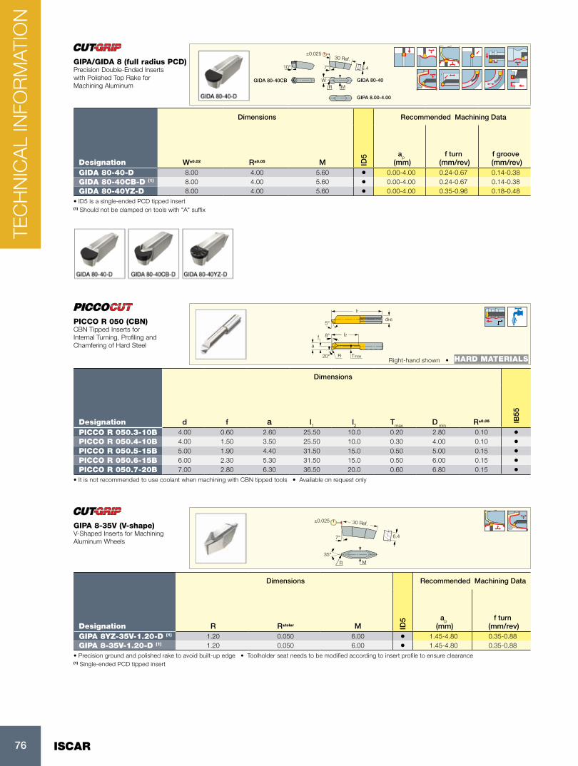
ISCAR76
10° 6.47°
WR M
GIDA 80-40CB
GIPA 8.00-4.00
GIDA 80-40
±0.02530 Ref.
Dimensions Recommended Machining Data
Designation W±0.02 R±0.05 M ID5 ap
(mm)f turn
(mm/rev)f groove
(mm/rev)GIDA 80-40-D 8.00 4.00 5.60 • 0.00-4.00 0.24-0.67 0.14-0.38GIDA 80-40CB-D (1) 8.00 4.00 5.60 • 0.00-4.00 0.24-0.67 0.14-0.38GIDA 80-40YZ-D 8.00 4.00 5.60 • 0.00-4.00 0.35-0.96 0.18-0.48
• ID5 is a single-ended PCD tipped insert (1) Should not be clamped on tools with "A" suffix
GIPA/GIDA 8 (full radius PCD)Precision Double-Ended Inserts with Polished Top Rake for Machining Aluminum
l1
dh6
l2f
20° R
8°
Tmax
a
5°
Right-hand shown • HARD MATERIALS
Dimensions
Designation d f a l1 l2 Tmax D min R±0.05 IB55
PICCO R 050.3-10B 4.00 0.60 2.60 25.50 10.0 0.20 2.80 0.10 •PICCO R 050.4-10B 4.00 1.50 3.50 25.50 10.0 0.30 4.00 0.10 •PICCO R 050.5-15B 5.00 1.90 4.40 31.50 15.0 0.50 5.00 0.15 •PICCO R 050.6-15B 6.00 2.30 5.30 31.50 15.0 0.50 6.00 0.15 •PICCO R 050.7-20B 7.00 2.80 6.30 36.50 20.0 0.60 6.80 0.15 •
• It is not recommended to use coolant when machining with CBN tipped tools • Available on request only
PICCO R 050 (CBN)CBN Tipped Inserts for Internal Turning, Profiling and Chamfering of Hard Steel
30 Ref.
6.47°
±0.025
35°
R M
Dimensions Recommended Machining Data
Designation R R±toler M ID5 ap
(mm)f turn
(mm/rev)GIPA 8YZ-35V-1.20-D (1) 1.20 0.050 6.00 • 1.45-4.80 0.35-0.88GIPA 8-35V-1.20-D (1) 1.20 0.050 6.00 • 1.45-4.80 0.35-0.88
• Precision ground and polished rake to avoid built-up edge • Toolholder seat needs to be modified according to insert profile to ensure clearance(1) Single-ended PCD tipped insert
GIPA 8-35V (V-shape)V-Shaped Inserts for Machining Aluminum Wheels
TEC
HN
ICA
L IN
FOR
MAT
ION

77
h
b
95°
95°f
l1
h
Right-hand shown
95º
95º
Designation h h1 b l1 f Ga° Gr° InsertCCLNR 2020K-12CEA 20.0 20.0 20.0 125.00 25.00 -4 -6 CNGN 1204 S 48 HW 4.0 BCL 6 CLAMP SR M6X1X25ISO7380 SR M5X0.8X10CCLNR/L 2525M-12CEA 25.0 25.0 25.0 150.00 32.00 -4 -6 CNGN 1204 S 48 HW 4.0 BCL 6 CLAMP SR M6X1X25ISO7380 SR M5X0.8X10
CCLNR/LClamp Lock Tools Carrying the Ceramic Negative 80° Rhombic Inserts
h
b
95°
f
l1
h
Right-hand shown
95º
95º
Designation h h1 b l1 f InsertTCLNR/L 2525M-12CH 25.0 25.0 25.0 150.00 32.00 CNGX 1207...T S 48 SR M5X0.8X10 CCL 4 KSP 5 CSC 4 HW 4.0
TCLNR/L-CH95° Lead Angle Tools Carrying the Negative CNGX 80° Rhombic Ceramic Dimpled Inserts
h
b
75°
f
l1
h
Right-hand shown
75º
Designation h h1 b l1 f InsertTCBNR/L 2525M-12CH 25.0 25.0 25.0 150.00 22.00 CNGX 1207...T S 48 SR M5X0.8X10 CCL 4 KSP 5 CSC 4 HW 4.0
TCBNR/L-CH75° Lead Angle Toolholders Using the 100° Corner of CNGX 80° Negative Rhombic Ceramic Dimpled Inserts
h
b75°f
l1
h
Right-hand shown
75°
Designation h h1 b l1 f InsertTCKNR/L 2525M-12CH 25.0 25.0 25.0 150.00 32.00 CNGX 1207...T S 48 SR M5X0.8X10 CCL 4 KSP 5 CSC 4 HW 4.0
TCKNR/L-CH75° Lead Angle Tools Carrying the 100° Corner of CNGX 80° Negative Rhombic Ceramic Dimpled Inserts for Facing
h
b
75°
f
l1
h
Right-hand shown
75º
Designation h h1 b l1 f Ga° Gr° InsertCSRNR/L 2525M-12CEA 25.0 25.0 25.0 150.00 27.00 - - SNGN 1204
Spare Parts
DesignationCSRNR/L S 40 (SEAT) HW 4.0 BCL 6 CLAMP SR M6X1X25ISO7380 SR M5X0.8X10
CSRNR/L75° Lead Angle Tools Carrying the Square Ceramic Inserts
TEC
HN
ICA
L IN
FOR
MAT
ION

ISCAR78
h
b
75°
f
l1
h
Right-hand shown
75º
Designation h h1 b l1 f InsertTSRNR 2525M-12CH 25.0 25.0 25.0 150.00 27.00 SNGX 1207..T S 40 (SEAT) SR M5X0.8X10 CCL 4 KSP 5 CSC 4 HW 4.0
TSRNR/L-CH75° Lead Angle Tools Carrying the Square Ceramic Dimpled Inserts
h
b
45°
f
l1
h45°
Designation h h1 b l1 f InsertCSDNN 2525M-12CEA 25.0 25.0 25.0 150.00 12.50 SNGN 1204
Spare Parts
DesignationCSDNN 2525M-12CEA S 40 (SEAT) SR M5X0.8X10 BCL 6 CLAMP SR M6X1X25ISO7380 HW 4.0 HW 3.0
CSDNN-CE/CEA45° Lead Angle Tools Carrying the Square Ceramic Inserts
h
b
45°
f
l1
h45°
Designation h h1 b l1 fTSDNN 2525M-12CH 25.0 25.0 25.0 150.00 12.50 S 40 (SEAT) SR M5X0.8X10 CCL 4 KSP 5 CSC 4 HW 4.0
TSDNN-CH45° Lead Angle Tools Carrying the Square Ceramic Dimpled Inserts
h
b
45°
f
l1
h
Right-hand shown
45º
45º
Designation h h1 b l1 f Ga° Gr° InsertCSSNR/L 2525M-12CE 25.0 25.0 25.0 150.00 26.00 - - SNGN 1207
Spare Parts
DesignationCSSNR/L-CE S 40 (SEAT) HW 4.0 BCL 6 CLAMP SR M6X1X25ISO7380 SR M5X0.8X10
CSSNR/L-CE45° Lead Angle Tools Carrying the Square Ceramic Inserts for Longitudinal and Face Turning
h
b
45°
f
l1
h
Right-hand shown
45º
45º
Designation h h1 b l1 f InsertTSSNR/L 2525M-12CH 25.0 25.0 25.0 150.00 32.00 SNGX 1207..T S 40 (SEAT) SR M5X0.8X10 CCL 4 KSP 5 CSC 4 HW 4.0
TSSNR/L-CH45° Lead Angle Tools Carrying the Square Ceramic Dimpled Inserts for Longitudinal and Face Turning
TEC
HN
ICA
L IN
FOR
MAT
ION

79
h
b
93°
f
l1
h
Right-hand shown
93°
Designation h h1 b l1 f Ga° Gr° InsertCTJNR 2525M-16CEA 25.0 25.0 25.0 150.00 32.00 -4 -4 TNGN 1604
Spare Parts
DesignationCTJNR/L S 3 HW 4.0 BCL 6 CLAMP SR M6X1X25ISO7380 SR M4X8 ISO7380 SS
CTJNR/L93° Lead Angle Tools Carrying the Triangular Ceramic Inserts for Longitudinal Turning
h
b
93°
f
l1
h
Right-hand shown
93º
27°MAX
Designation h h1 b l1 f InsertTDJNR/L 2525M-15CH 25.0 25.0 25.0 150.00 32.00 DNGX 1507..T SR M5X0.8X10 CCL 4 KSP 5 CSC 4 HW 4.0
TDJNR/L-CH93° Lead Angle Tools Carrying the 55° Rhombic Dimpled Ceramic Inserts
h
b
62.5°
f
l1
h 62.5º
60°MAX
Designation h h1 b l1 f InsertTDNNN 2525M-15CH 25.0 25.0 25.0 150.00 12.50 DNGX 1507..T SR M5X0.8X10 CCL 4 KSP 5 CSC 4 HW 4.0
TDNNN-CH62.5° Lead Angle Tools Carrying the 55° Rhombic Dimpled Ceramic Inserts
h
bf
l1
h
Designation h h1 b l1 f Ga° Gr° InsertCRDNN 2525M-12CE 25.0 25.0 25.0 150.00 12.50 -8.5 0 RNGN 120700 S 43 SR M5X0.8X10 BCL 6 CLAMP SR M6X1X25ISO7380 HW 4.0CRDNN 2525M-12CEA 25.0 25.0 25.0 150.00 12.50 -8.5 0 RNGN 120400 S 43 SR M5X0.8X10 BCL 6 CLAMP SR M6X1X25ISO7380 HW 4.0CRDNN 3225P-12CE 32.0 32.0 25.0 170.00 12.50 -8.5 0 RNGN 120700 S 43 SR M5X0.8X10 BCL 6 CLAMP SR M6X1X25ISO7380 HW 4.0
CRDNNClamp Lock Neutral Tools Carrying Ceramic Round Negative Inserts
h
bf
l1
h
Right-hand shown
Designation h h1 b l1 f Ga° Gr° InsertCRGNR/L 2525M-12CE 25.0 25.0 25.0 150.00 32.00 -6 -6 RNGN 120700 S 43 SR M5X0.8X10 BCL 6 CLAMP SR M6X1X25ISO7380 HW 4.0CRGNR/L 2525M-12CEA 25.0 25.0 25.0 150.00 32.00 -6 -6 RNGN 120400 S 43 SR M5X0.8X10 BCL 6 CLAMP SR M6X1X25ISO7380 HW 4.0CRGNR/L 3225P-12CE 32.0 32.0 25.0 170.00 32.00 -6 -6 RNGN 120700 S 43 SR M5X0.8X10 BCL 6 CLAMP SR M6X1X25ISO7380 HW 4.0
CRGNR/LClamp Lock Tools Carrying the Ceramic Round Negative Inserts
TEC
HN
ICA
L IN
FOR
MAT
ION

3355
494
G
08/2
018
©
ISC
AR
LTD
A
ll rig
hts
rese
rved
www. iscar.com