Multilayer Calendering of Coextruded Sheets
26
104 MULTILAYER CALENDERING OF COEXTRUDED SHEETS Ahmed Hannachi and Evan Mitsoulis* Department of Chemical Engineering University of Ottawa Ottawa, Ontario, Canada KIN 9B4 ABSTRACT: Coextruded multilayer plastic sheets used in the packaging industry are usually calendered between two rolls to reduce the original sheet thickness coming from the die. To meet certain thickness criteria for each layer as well as for the calendered sheet, the operating parameters, such as roll speeds, size, temperatures and minimum gap width, have to be specified. Due to the intractability of the prob- lem by analytical methods, numerical methods have to be used. The Lubrication Ap- proximation Theory (LAT) is employed and the solution is achieved by using a Newton-Raphson iterative scheme which determines both the unknown a priori flow domain and the interface locations for a combination of layers. The analysis provides the pressure distribution, separating force, torque, power consumption and tempera- ture rise. Several cases of 2-, 3- and 9-layer calendering are presented and a design criterion of equal interfacial viscosities is put forward to determine the operating temperatures in the process KEY WORDS: calendering, multilayer flows, sheet finishing, numerical analysis, lubrication approximation theory. INTRODUCTION M ULTILAYER COEXTRUSION IS practiced increasingly today for many commercial plastics products [1]. Up to ll layers can be used in many combinations. Figure 1 shows a nine-layer structure and typical processing temperatures [2]. The outer &dquo;skin&dquo; layers of polyetherimide (PEI) provide high and low temperature impact strength and high heat resistance. The *To whom correspondence should be addressed JOURNAL or PLASTIC FILM & SHEETING, Vo~. 5-APRIL 1989 8756-0879/89/02 O10-I-26 $04 50/0 @ 1989 Technomic Publishing Co, Inc
Transcript of Multilayer Calendering of Coextruded Sheets

104
MULTILAYER CALENDERING OFCOEXTRUDED SHEETS
Ahmed Hannachi and Evan Mitsoulis*
Department of Chemical EngineeringUniversity of OttawaOttawa, Ontario, Canada KIN 9B4
ABSTRACT: Coextruded multilayer plastic sheets used in the packaging industry areusually calendered between two rolls to reduce the original sheet thickness comingfrom the die. To meet certain thickness criteria for each layer as well as for thecalendered sheet, the operating parameters, such as roll speeds, size, temperaturesand minimum gap width, have to be specified. Due to the intractability of the prob-lem by analytical methods, numerical methods have to be used. The Lubrication Ap-proximation Theory (LAT) is employed and the solution is achieved by using aNewton-Raphson iterative scheme which determines both the unknown a priori flowdomain and the interface locations for a combination of layers. The analysis providesthe pressure distribution, separating force, torque, power consumption and tempera-ture rise. Several cases of 2-, 3- and 9-layer calendering are presented and a designcriterion of equal interfacial viscosities is put forward to determine the operatingtemperatures in the process
KEY WORDS: calendering, multilayer flows, sheet finishing, numerical analysis,lubrication approximation theory.
INTRODUCTION
M ULTILAYER COEXTRUSION IS practiced increasingly today for manycommercial plastics products [1]. Up to ll layers can be used in manycombinations. Figure 1 shows a nine-layer structure and typical processingtemperatures [2]. The outer &dquo;skin&dquo; layers of polyetherimide (PEI) providehigh and low temperature impact strength and high heat resistance. The
*To whom correspondence should be addressed
JOURNAL or PLASTIC FILM & SHEETING, Vo~. 5-APRIL 1989
8756-0879/89/02 O10-I-26 $04 50/0@ 1989 Technomic Publishing Co, Inc

105
Figure 1. A nine-layer structure and typical processing temperatures for multilayer sheetcoextrusion (from Reference (2]).
polycarbonate (PC) or poly(ethylene terephthalate) (PET) intermediatelayers would be the volume or &dquo;bulk&dquo; layers. The innermost ethylene vinylalcohol (EVOH) layer provides the &dquo;barrier.&dquo; Also adhesive materials AD1and AD2 (such as ionomers, i.e. polymers in combination with metallic com-plexes) are used as bonding agents or &dquo;tie layers&dquo; to avoid slippage betweenadjacent layers [3-5]. A list of high performance and barrier polymers alongwith typical processing temperatures has been published [2] while Stone-burner [6] gives a list of several tie layers and their appropriate use withpolymer combinations.With the increased interest in coextrusion there has also come the pro-
liferation of equipment. Feedblocks and multimanifold dies have appearedin the literature [7-10] that claim to provide capabilities to coextrudematerials with high viscosity ratios and a variety of combinations with mini-mal changes. While the design of such equipment is usually based on trial-and-error practical experience, progress in theoretical analysis has beenachieved recently as shown by Mitsoulis [11]. In that work, the LubricationApproximation Theory (LAT) (see e.g. the textbooks by Middleman [12] andHan [13]) was used for the analysis and design of some industrial sheet coex-trusion dies. Several design criteria were put forward and met by changes inthe geometry of the die. Mitsoulis’s work showed that the availability of acomputer program based on LAT can provide quickly many importantpieces of information with regard to pressure drop, interface location, etc. fora variety of die geometries, thickness ratios, operating temperatures andmaterial combinations. Such information is essential for design purposes.
Meanwhile it has been common practice in the industry to roll eithermonolayer or multilayer sheets between two cylinders (or calenders) in
order to reduce their thickness and improve mechanical and physical prop-erties [14,15]. The process is called &dquo;calendering&dquo; and it has been extensivelystudied for a single layer [16,17]. A schematic representation of multilayersheet coextrusion and calendering is shown in Figure 2. No work has beendone to date for calendering of multilayer sheets, although experimental evi-dence has quite recently appeared [15], albeit with limited information. It is

106
the purpose of this paper to extend the coextrusion analysis based on LATto the case of multilayer calendering and thus provide a tool for obtainingquantitative results from the process under a variety of operating conditionsand melt combinations.
LUBRICATION APPROXIMATION THEORY
The theory and assumptions for the LAT can be found in standard text-books [12,13]. Referring to Figure 3 we consider the flow in the nip regionbetween two rotating rolls, where N layers pass with (N - 1) interfaceswhich are unknown a priori. The analysis here follows closely the one pre-sented previously by Mitsoulis [11] for multilayer sheet coextrusion. However,an extra complication that arises in calendering is the unknown a prioridomain length for a certain exit thickness requirement. The solution processmust therefore provide both the interface locations and the domain length.
For each layer mass conservation gives the individual flowrate Q, accord-ing to:
where w is the sheet width in the third dimension, vx is the velocity in theflow direction x, and y,, y,+1 are the heights bounding layer i.
The individual flowrates Q, are determined by overall mass conservationfor a given mass production rate m, sheet width w, and individual thick-
Figure 2. Schematic representation of multilayer sheet coextrusion and calenderingbetween two rolls.

107
Figure 3. Notation for multilayer flow analysis in the nip region between two rotating rolls.
nesses h, of the exiting finished sheet. If we take density differences betweenambient and melt conditions into account, we have
where v is the average linear speed of production, Q, the ambient density oflayer i, and h, the ambient (cold) thickness of layer i. The superscript (a)refers to ambient conditions.The linear speed v is then given by
At melt (hot) conditions, the individual flowrates Q, are given by
or, using Equation (3),
108
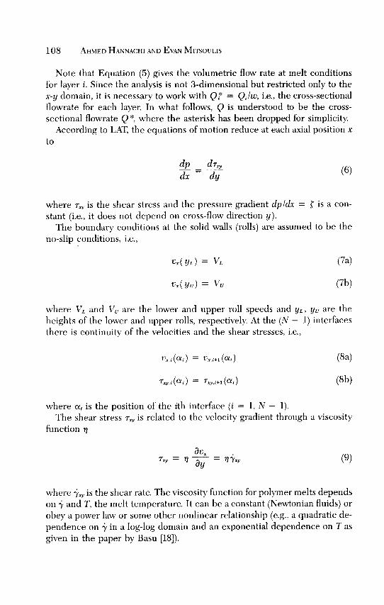
Note that Equation (5) gives the volumetric flow rate at melt conditionsfor layer i. Since the analysis is not 3-dimensional but restricted only to thex-y domain, it is necessary to work with Q * = Q, lw, i.e., the cross-sectionalflowrate for each layer. In what follows, Q is understood to be the cross-sectional flowrate Q *, where the asterisk has been dropped for simplicity.
According to LAT, the equations of motion reduce at each axial position xto
where Txy is the shear stress and the pressure gradient dpldx = ~ is a con-stant (i.e., it does not depend on cross-flow direction y).The boundary conditions at the solid walls (rolls) are assumed to be the
no-slip conditions, i.e.,
where VL and VU are the lower and upper roll speeds and yL, yu are theheights of the lower and upper rolls, respectively. At the (N - 1) interfacesthere is continuity of the velocities and the shear stresses, i.e.,
where a, is the position of the ith interface (i = 1, N - 1).The shear stress Tx,, is related to the velocity gradient through a viscosity
function q
where 1’xy is the shear rate. The viscosity function for polymer melts dependson I and T, the melt temperature. It can be a constant (Newtonian fluids) orobey a power law or some other nonlinear relationship (e.g., a quadratic de-pendence on ’Y in a log-log domain and an exponential dependence on T asgiven in the paper by Basu [18]).

109
Furthermore in calendering (as opposed to die coextrusion) both thepressure and the pressure gradient must be zero at the domain exit to ensuredetachment of the sheet with a flat velocity profile, i.e.,
where X is a dimensionless value of the leave-off distance, x-, where thesheet detaches from the rolls (Figure 3), and is given by
where R is the roll radius (symmetric case) and Ho is half the minimum gap.Note that X is also given by (Middleman [12])
where Hex is the exiting (hot) sheet thickness and also by
where V is the roll speed (symmetric case) and Q the (hot) volumetric flow-rate.
For a nonisothermal analysis due to a temperature-dependent viscosity,LAT is used to reduce the energy equation to (Middleman [12])
A further simplification can be obtained by noting that for polymer melts,conduction is negligible compared with convection and viscous dissipation(high Peclet (Pe) and Nahme number flows [16]). Pe numbers in calenderingare in the order of 102 -103. Thus, as an approxim,ation we can drop the con-duction term ka2Tlc7y2 from Equation (14) and obtain an explicit relation forthe temperature rise at each position (x,y)

110
where 7xy, ixy and vx are the local shear stress, shear rate and axial velocity,respectively. Equation (15) is therefore used to estimate the temperature riselocally and accordingly correct the viscosity function.
METHOD OF SOLUTION
The solution of the equation of motion [Equation (6)] along with the ap-propriate boundary conditions [(7), (8), (10)] must be achieved by somenumerical method since, in the case of N Newtonian layers, analytical solu-tions are either impossible (N > 2) or difficult to obtain (N = 2). The un-knowns consist of:
. yo, an integration constant which corresponds to the position at which themaximum in velocity occurs, i.e., the position of zero shear stress
. r, the pressure gradient which is assumed constant in the thickness direc-tion y
. a,, the (N - 1) interface locations
. xe&dquo;, the domain entrance or attachment position where the entering sheetfirst bites the rolls.
The number of unknowns is then (N + 2) for N layers, and we need(N + 2) knowns to get a unique solution. These are:
. Q, the total flowrate
. vu or VL, the upper or lower roll speed, respectively
. Q.lQ.+1, the (N - 1) flowrate ratios
. X, the dimensionless value of the leave-off distance xt, where the sheetdetaches from the rolls.
Note that either roll speed can be considered as the known since the otheris used as the initial point of calculations (initial-value problem).The iterative technique employed in the present analysis is a full Newton-
Raphson scheme which exhibits a quadratic convergence within three tofour iterations. The method has been described previously by Mitsoulis [11].The extra feature in calendering is the unknown a priori domain length thathas to be solved for. In a preset flow domain with a set exit (X is set), the solu-tion provides all quantities of interest, but it usually does not satisfy Equa-tions (10a-b) of zero pressure and pressure gradient at the exit, so a newentry is found according to Newton-Raphson scheme and the solution pro-cess is repeated until Equations (10a-b) are satisfied. The final solution pro-vides the extent of the flow domain as well as interface location and develop-ment, and also pressure and stress distributions along the domain, velocity,temperature, viscosity, shear rate and shear stress profiles across the domain

111
for each axial position x. These results are used to obtain integrated quanti-ties of engineering interest such as:
-roll-separating force, F
- torque on each roll, T
-power transmitted to the fluid by both rolls, W
- adiabatic temperature rise due to the power input, i1Tad
The results of this work have been obtained by using the programLATROLL [19], which is a modification of LATMULTI originally developedfor multilayer coextrusion of plastics [11]. LATROLL can be used both forcalendering and roll coating and uses as input:~ geometric parameters of calendering unit (roll radii and minimum gap)~ operating requirements (roll speeds, operating temperatures, sheet
width, mass flowrate, and either layer flowrates or thicknesses desired atexit)
~ material properties for each layer (e.g. density, specific heat, and viscositydata)On output the following information is obtained:

112
~ domain length, i.e. location of attachment plane of the entering sheet fora set thickness of the exiting sheet
~ axial distributions of pressure drops and shear stresses for each layer~ velocity, temperature, shear stress, shear rate, and viscosity profiles at any
axial location~ interface development from attachment to detachment plane~ overall roll-separating force, torques on each roll, power consumption and
adiabatic temperature rise of the calendered sheet.
A series of tests have been conducted against either analytical or numeri-cal solutions for a single fluid available in the literature [12,16], and the ac-curacy of the program and the numerical method have thus been well estab-lished.
MATERIAL PROPERTIES
It is generally true that a detailed rheological investigation of the materialsused in multilayer flows is lacking. Due to this lack of thorough measure-ments for viscosity and other material properties, we have taken data fromvarious sources and in some cases where no data could be found we haveassumed reasonable values. Table 1 contains the relevant information for theresins used in the calculations along with their sources.The data for LDPE and HDPE (two compatible resins that need no tie
layers [6]) are taken from Basu [18]. The viscosity function is of the form
with
where g is a Newtonian viscosity and TN a shear stress value below which thematerials behave as Newtonian fluids.The temperature dependence of the viscosity is expressed as
The viscosity data for PC, EVOH and AD2 are taken from Rice [5]. Addi-tional data for PC and EVOH resins given by Collins and Teusch [20] in-dicate that, up to 100 s-’, these resins have approximately a constant vis-

113
<e
G12.sae805.s
!40:s
3CD~
Q.
aIvz
.0-
§
’D
Q)EcnCI’Jca
To

114
cosity and are therefore modelled as Newtonian fluids. However, the
temperature dependence follows an Arrhenius relationship:
where E is the activation energy of the melt, Rg is the ideal gas constant, andT and To are given iu ° K. The values for the other material properties weretaken from the Modern Plastics Encyclopedia [21].
For the adhesive layer ADI we have adopted the values given by Chin etal. [22] for their CXA-3095 resin (an ethylene-based multifunctional polymermade by DuPont). The viscosity data in this work are modeled using onlyEquations (20a) and (22) (Newtonian fluid).
Finally for the polyetherimide (PEI) resin made under the trade nameULTEM and used as a skin layer under very high temperatures, we wereunable to find any other data except for density. We have assumed then aNewtonian behavior with an Arrhenius-type temperature dependence forour calculations. In view of the high processing temperatures and the lowviscosity incurred, such an approximation appears reasonable.
RESULTS AND DISCUSSION
Two-Layer Calendering of Newtonian Fluids
We begin with the analysis of two Newtonian fluids of equal viscosities sothat the results can be checked against the analytical solutions of a singlelayer. The case is symmetric under isothermal conditions. The dimension-less leave-off distance X is taken as 1/3. The data are summarized in Table 2.The solution provides the following results: entrance location xt, en-
trance thickness ratio (H,IH,,),n, maximum pressure P-.,, (located at -X),roll-separating force F, torques on the upper and lower rolls T u and TL, re-spectively, power input W, and adiabatic temperature rise OTad.The results for f,l.&dquo;l~,L = 1 are given in Table 2 and are identical with the
ones obtained from analytical expressions provided by Middleman [12] insingle-layer symmetric calendering of Newtonian fluids.We proceed with calculations of two Newtonian fluids of unequal vis-
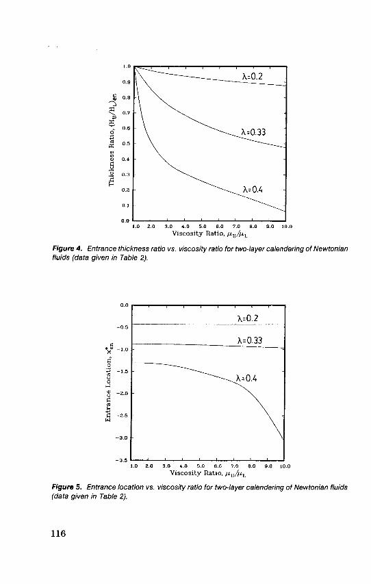
cosities. We keep all other variables unaltered and change only the viscosityratio by decreasing the viscosity JLL of the lower layer to fractions of it,. Westill want an exiting sheet with a 50-50 % thickness. The overall results aregiven in Table 2. Figure 4 plots entrance thickness ratio vs. viscosity ratio fordifferent X values. It is seen that the upper layer gets squeezed at entrancemore than twice when it is tenfold more viscous than the lower layer

115
to
~
I I
i’5cCB11:0’i0)z00)c::
iac-0CB13
ToE!5t0.!2
Lo
E
tCI)~-M
3to-
Na:is
~
~0O>.c~ u
11 gE 3-Q) .E3: ()gO>CI)’-
8 11E a->
~&dquo;<o <uM
II N
3 a.-Ü:::’:!:~ r3 0_0VOII II~~v E .. TUCBI 0r UCI)
II >
J C>°
<II Ob$N&dquo;CZQ) .
r
S- II
’6 ~~ ~ ~ &
E-() ::;,
m &N O
~ II ~ Qll
JII ~
::;,2ex:-5
7iJ Q)E90,SE#()Ct)CBIN Oo II
II d 8
lmO#N0> II
%&dquo;.c Q)
E ::J ro g Ü 0E êi5 .!2>E ’°E :::: LOoCt)
m V IIQ ~ (.~
116
Figure 4. Entrance thickness ratio vs. viscosity ratio for two-layer calendering of Newtonianfluids (data given m Table 2).
Figure 5. Entrance location vs. viscosity ratio for two-layer calendering of Newtonian fluids(data given m Table 2).

117
(X = 1/3). This trend is further increased by increasing X. Symmetry is nolonger maintained and the more viscous the layer the less thickness it has atentry. The domain is also enlarged for the same leave-off distance X (seeFigure 5), so that for the case of X = 1/3 from x h = -0.87452 for ~~l~.L =1, it reaches x tt = -0.96729 for ~.Ul~,L = 10. Again this trend is further in-creased by increasing X. These findings are illustrated in Figure 6, where theinterface development and domain length are clearly shown for the twocases of viscosity ratios. The corresponding pressure distributions are givenin Figure 7. Due to the presence of a less viscous melt at the lower layer in
Figure 6. Interface development and domain length for different viscosity ratios In two-layercalendenng of Newtonian fluids (a) ~,~l~,~ = 1, (b) ,u~l~.~ = 10 (~ = 1/3, data given in
Table 2).

118
Figure 7. Pressure distributions for different viscosity ratios in two-layer calendenng ofNewtoman fluids (X = 1/3, data given in Table 2).
the case of ~.~l~.L ~ 1, the pressure is lower but not proportional to the vis-cosity ratio as might have been expected.
Three-Layer Calendering of ShearThinning Fluids
We proceed with the analysis of a 3-layer sheet produced by a multimani-fold vane die designed by the Cloeren Company. The coextruded sheet iscomprised by HDPE/LDPE/HDPE (1/2/3, where 1 is the upper surface layerand 3 is the lower surface layer), thus having HDPE as the skin layer for itssurface properties. Note that LDPE and HDPE need not have tie layers [6]and that having the less viscous LDPE enclosed by the more viscous HDPEdoes not necessarily cause layer distortion due to the use of the special vanedie [8]. The coextrusion die analysis of this sheet has been carried out byMitsoulis [ll].
Here, we calender the produced sheet to reduce its thickness to a finalcold sheet thickness of h = 0.05 cm. The case is symmetric with regard tooperating conditions but under nonisothermal conditions with data given inTable 3.Two cases are examined: a symmetric arrangement of individual sheet
thicknesses at exit of 10-80-10% (Case I) and an asymmetric arrangement of50-40-10% (Case II). The first numbers correspond to the uppermost layersin each case. The leave-off distance X has been chosen such that the cor-

119
0
1-1.11..
~-0~a!i
0lb
0).r..cdac3~-,TO0eiSPOi
S
0
o0NN
11 I<
~a~
sm90
<DwU7r-~2
11
E
E~U0Cl)
11
~C6
f0
N
I I
’J11
>>90
m
cjI l
J11
(Z
C0
r-(M0
o
11
:evC’sp
120
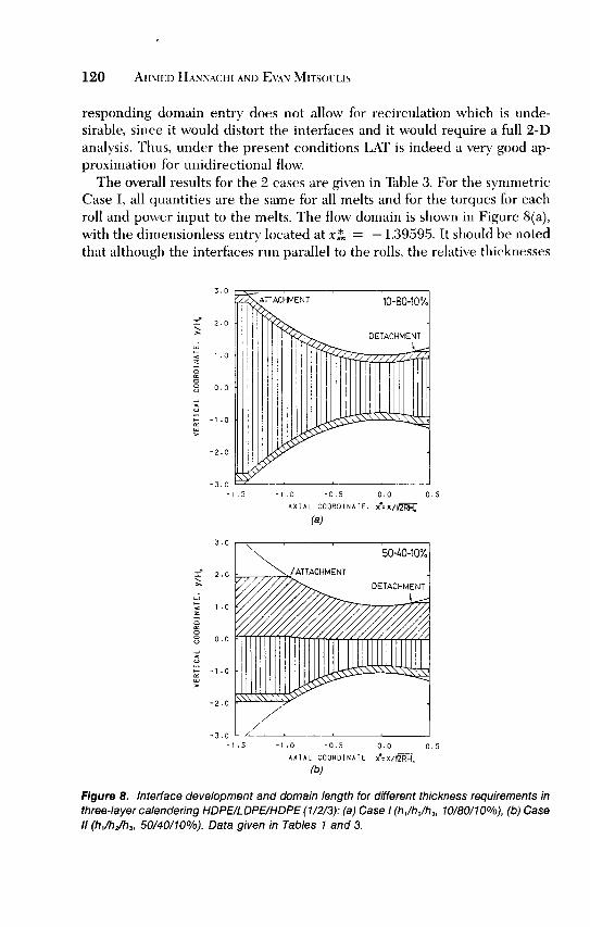
responding domain entry does not allow for recirculation which is unde-sirable, since it would distort the interfaces and it would require a full 2-Danalysis. Thus, under the present conditions LAT is indeed a very good ap-proximation for unidirectional flow.The overall results for the 2 cases are given in Table 3. For the symmetric
Case I, all quantities are the same for all melts and for the torques for eachroll and power input to the melts. The flow domain is shown in Figure 8(a),with the dimensionless entry located at xt = -1.39595. It should be notedthat although the interfaces run parallel to the rolls, the relative thicknesses
Figure 8. Interface development and domain length for different thickness requirements inthree-layer calendenng HOPE/LOPE/HOPE (1/2/3)’ (a) Case I (h,/h/h3, 10/80/10%), (b) Case// (h1/h/h3, 50/40/10%). Data given In Tables 1 and 3.

121
Figure 9. Pressure distributions for the two cases of three-layer calendenng (same data asin Figure 8).
change so at entry we have a sheet entering with a 4-92-4% distribution butat exit we have a 10-80-10% distribution. If we require a thickness distribu-tion at exit of 50-40-10 % (Case II), then the results are changed in a way thatcould not have been predicted a priori. We find a smaller domain length [seeFigure 8(b)] but a higher pressure (see Figure 9) and accordingly the otherquantities are affected. Figure 10 shows the interesting stress distributiondeveloping in calendering and also the effect of changing the thickness re-quirements in the exiting sheet. Also the temperature distribution along andacross the gap is available according to Equation (15). For example, the tem-perature distribution for each layer along the walls and interfaces is pre-sented in Figure 11 for Case I. Because of dropping the conduction term inEquation (14), there is discontinuity of interface temperatures for each layer.However, this inaccuracy is less than 1 ° C. In the particular cases studiedhere, where rather mild conditions prevail, the absolute maximum rise neverexceeds 1 ° C. This is also found when calculating an upper limit for theadiabatic temperature rise due to the power input by using Equation (19). Asshown in Table 3, L1Tad is about 2°C for this case.The above sort of analysis can be used for parametric studies of different
variables in the calendering of multilayer sheets.
Nine-Layer Calendering of Newtonian Fluids
An interesting case of 9 coextruded layers has been given in the literatureby the Cloeren Company [2,7] and analyzed inside the die design by Mitsoulis

122
Figure 10. Shear stress distributions along the calender rolls for the two cases of three-layer calendering (same data as In Figure 8)
Figure 11. Temperature changes at interfaces for Case I (10/80/10%) of three-layercalendering ((same data as in Figure 8(a)J. Wall = temperature of HDPE at interface be-tween HDPE and calender roll; 1,3 = temperature of HDPE at HOPE/LOPE interfaces;2 = temperature of LDPE at HOPE/LOPE interfaces.
123
[ll]. The combination of melts corresponds to the arrangement shown inFigure 1 where an EVOH-barrier layer is sandwiched between two layers ofadhesive (AD2), with PC being the bulk layer. The bulk layers are furtheradhered to the skin layers of PEI through another adhesive material (ADl).The material properties are given in Table 1, and the operating temperaturesare those shown in Figure 1. For lack of other evidence, we have assumedthe temperatures of the adhesive layers as being in between the tempera-tures of the adjacent layers, i.e., To(ADl) = 330°C and To(AD2) = 250°C.
Here, we calender the extruded sheet to reduce its thickness to a finalcold sheet thickness of h = 0.05 cm. The case is symmetric with regard tooperating conditions but under nonisothermal conditions with data given inTable 4. The arrangement of individual sheet thicknesses at exit is symmet-ric with a 8.33/8.33/16.67/8.33/16.67/8.33/16.67/8.33/8.33 % . The first number
corresponds to the uppermost layer.The overall results for this case (Case I) are given in Table 4. Since the
case is symmetric, all quantities are the same for all melts and for the torquesfor each roll and power input to the melts. The flow domain is shown inFigure 12, with the dimensionless entry located at xh = -1.43626. Againno recirculation is found for such an entry as evidenced in Figure 13, wherethe entry velocity profile and interface locations are shown. The wall and in-terface stress distributions along the flow domain are shown in Figure 14 ex-hibiting the maxima and minima associated with this type of flow field.A look at the viscosity distribution across the domain, taken at x = 0
(minimum gap position), shows that there are interfacial viscosity jumps (seeFigure 15). Since the fluids are considered Newtonian with a constant vis-cosity independent of shear rate, these jumps are the same at any axial cut.Such interfacial viscosity mismatches are generally considered undesirable[5], since they may induce slippage between layers and interfacial distortion[13]. It is possible, however, to reduce them or eliminate them by choosingsuitable operating temperatures for each melt, so that the corresponding vis-cosities match. This is apparently the way practiced in the industry to ac-count for proper temperature selection for each melt [5].We have undertaken such a numerical experiment to reduce viscosity
mismatch by an equal amount 0~,. The results are given in Figure 16, wherethe viscosity distribution across the domain is shown together with thenewly found corresponding operating temperatures. By such selection, it
becomes apparent that viscosity mismatches between adjacent layers arehighly reduced (Aju = 13% ~.m~), giving a smoother transition from layer tolayer. The corresponding overall results from this run are also given in Table4 (Case II). The domain is longer now (xh = -1.68403) and the pressureis more than tenfold higher, with the other quantities following suit. Thelayer distribution at entry is also greatly affected as evidenced in Figure 17,

124
4-
~~tI -1tf)11~MN~aQ~6aN0
~0~NQ
~6aQ
6S
10
c’t:
0
cm4)a4)’z~a~
1!
:29
0s-
W~ggCD(0
I I
E
fu
oCO
I I
~
CJÎEu
LOenc5
II ~ ’<m~O~@ .
~ O 00 cDM GO c’~~ NII C’) ~ £2 ~ ~::J~ - g.,¡- ~~’~ ~- M M ~-~ (D 00 o tO ~6~~ae~aeLOC’)enõ&dquo;¡-ÕM O) ~ dp Nc5.%CUgo~ ~ ~ o ~ !$iill$koi(t-J CD en Õ ~ õf~!§! M&dquo; &dquo; CO 0 0~ ~(t::J ~ ~ ae ~ aeurwo QE- CD r-- 0 C’) .,¡-E <o ? ~ co ~<-’ ~ ~ c3 <~ §N M M o N°So~.~-p Cp o °~B. _oII C’) ~E~t~£oq°&dquo;&dquo;~~~ ~ococ &dquo;c&dquo;~ ~ )5 ~~ ~g_ =l18 ~aXm enP ~ 0 8

125
Figure 12. Interface development and domain length for Case I of a nine-layer calendenng(data given in Tables 1 and 4).
Figure 13. Thickness velocity profile at the domain entry (attachment plane) in Case I of anine-layer calendering (same data as m Figure 12).

126
Figure 14. Shear stress distributions along the calender rolls and the mterfaces In Case I ofa nme-layer calendering (same data as m Figure 12). (Tw = shear stress at calendar wall.)
Figure 15. Thickness viscosity profile at the nip region (minimum gap) in Case I of a nine-layer calendering (same data as in Figure 12).

127
Figure 16. Thickness viscosity profile at the nip region (minimum gap) in Case /I of a nine-layer calendering (new operating temperatures, Table 4).
Figure 17. Interface development and domain length for Case /I of a nine-layer calendering(new operating temperatures, Table 4).

128
with the barrier (EVOH) middle layer comprising more than 50% of thetotal thickness for the same exit requirements.
This sort of analysis is very important in deciding operating temperatures,once the viscosities are known as functions of temperature and shear rate. Itis an indispensable tool for multilayer coextrusion and calendering, and theuse of a program like LATROLL can easily (in a matter of minutes) deter-mine the desirable operating parameters for certain production require-ments.
CONCLUSIONS
The present numerical analysis enables the solution of multilayer flows incalendering of thermoplastics and allows the execution of parametric studiesfor design considerations. For a fixed desired thickness and thickness
percentages of the final sheet, and preset operating conditions of roll size,speed and minimum gap, it provides the unknown a priori location of boththe flow domain itself and the interface development as well as operatingvariables of interest, such as pressures, forces, torques, power consumptionand temperature rise. The analysis based on LAT is fast (about 90 CPU secsfor 9 layers in a mainframe computer) and can be used interactively toexamine the effect of several parameters or melt combinations. Thus, it
avoids the use of a fully 2-D analysis, which by using the finite elementmethod would involve a large system of unknowns in the order of 10,000 ormore and would require a supercomputer for its solution.
ACKNOWLEDGEMENTS
Financial assistance from the Natural Sciences and Engineering ResearchCouncil of Canada (NSERC) is gratefully acknowledged. Mr. A. Hannachi isa recipient of a scholarship from the Government of Tunisia.
REFERENCES
1. The Cloeren Company. Mod Plast., 62:41 (August 1985).2. The Cloeren Company. Co-Ex ’85, Tech. Conf., Schot. Bus. Res., Princeton, NJ
(1985)3. Weiss, R. A., P. K. Agarwal and R. D. Lundberg. SPE 42nd ANTEC, Tech. Papers,
30:468 (1984)4. Bentley, D. J. Jr SPE 44th ANTEC, Tech. Papers, 32:781 (1986).5. Rice, C. E. SPE 44th ANTEC, Tech. Papers, 32:835 (1986).6. Stoneburner, L. A. SPE 45th ANTEC, Tech. Papers, 33:837 (1987).

129
7 The Cloeren Company. Mod. Plast., 62:28 (December 1985).8. The Cloeren Company. Mod. Plast , 60:35 (August 1983).9 The Cloeren Company. U.S. Pat. 4,152,387 and 4,197,069 (1986)10 Helmy, H J Plast Film & Sheet., 4:193 (1987).11 Mitsoulis, E Adv Polym Technol., 8:225 (1988).12 Middleman, S. Fundamentals of Polymer Processing, New York, NY:McGraw-Hill
(1977).13 Han, C. D. Multiphase Flow in Polymer Processing, New York, NY:Academic
Press (1981).14 Gaskell, R E. J. Appl Mech., 17.334 (1950).15 Nakayama, K., A. Kaito, M. Kato, S Takahashi, S. Nakayama, Y. Sekiguchi and
Y Oyanagi Proc 4th Ann. Meet. Polym. Proc Soc, Orlando, FL, p. 8.10 (May1988).
16 Mitsoulis, E., J. Vlachopoulos and F. A Mirza Polym. Eng. Sci., 25:6 (1985)17 Vlachopoulos, J. and E. Mitsoulis. "Fluid Flow and Heat Transfer in Calender-
ing," Adv Transp. Proc., Wiley Eastern Ltd. (1989).18. Basu, S Polym. Eng. Sci., 21.1128 (1981).19. Hannachi, A. and E Mitsoulis. "LATROLL—A Software Package for Multilayer
Calendering and Roll Coating of Plastics," Dept. Chem. Eng., Univ. of Ottawa,Ottawa, Ottawa, ON (1989).
20. Collins, P C. and E. O. Teusch SPE 42nd ANTEC, Tech. Papers, 30:915 (1984).21 Modern Plastics Encyclopedia, McGraw-Hill, New York (1988).22. Chin, H. B., Y. J. Kim and C. D. Han. Polym. Eng. Rev., 4:281 (1984).