
From Nonfinite to Finite 1D Arrays of Origami Tiles
9
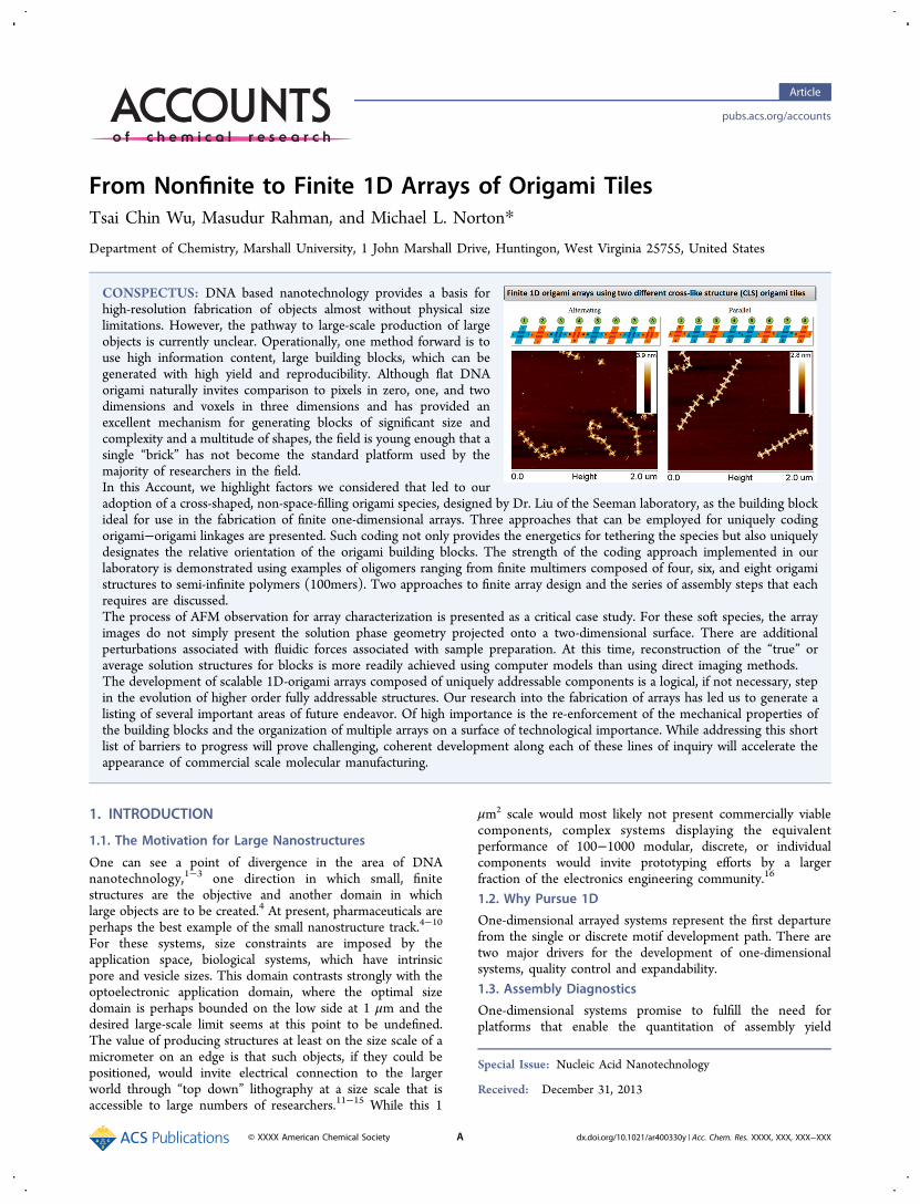
From Nonfinite to Finite 1D Arrays of Origami Tiles Tsai Chin Wu, Masudur Rahman, and Michael L. Norton* Department of Chemistry, Marshall University, 1 John Marshall Drive, Huntingon, West Virginia 25755, United States CONSPECTUS: DNA based nanotechnology provides a basis for high-resolution fabrication of objects almost without physical size limitations. However, the pathway to large-scale production of large objects is currently unclear. Operationally, one method forward is to use high information content, large building blocks, which can be generated with high yield and reproducibility. Although flat DNA origami naturally invites comparison to pixels in zero, one, and two dimensions and voxels in three dimensions and has provided an excellent mechanism for generating blocks of significant size and complexity and a multitude of shapes, the field is young enough that a single “brick” has not become the standard platform used by the majority of researchers in the field. In this Account, we highlight factors we considered that led to our adoption of a cross-shaped, non-space-filling origami species, designed by Dr. Liu of the Seeman laboratory, as the building block ideal for use in the fabrication of finite one-dimensional arrays. Three approaches that can be employed for uniquely coding origami-origami linkages are presented. Such coding not only provides the energetics for tethering the species but also uniquely designates the relative orientation of the origami building blocks. The strength of the coding approach implemented in our laboratory is demonstrated using examples of oligomers ranging from finite multimers composed of four, six, and eight origami structures to semi-infinite polymers (100mers). Two approaches to finite array design and the series of assembly steps that each requires are discussed. The process of AFM observation for array characterization is presented as a critical case study. For these soft species, the array images do not simply present the solution phase geometry projected onto a two-dimensional surface. There are additional perturbations associated with fluidic forces associated with sample preparation. At this time, reconstruction of the “true” or average solution structures for blocks is more readily achieved using computer models than using direct imaging methods. The development of scalable 1D-origami arrays composed of uniquely addressable components is a logical, if not necessary, step in the evolution of higher order fully addressable structures. Our research into the fabrication of arrays has led us to generate a listing of several important areas of future endeavor. Of high importance is the re-enforcement of the mechanical properties of the building blocks and the organization of multiple arrays on a surface of technological importance. While addressing this short list of barriers to progress will prove challenging, coherent development along each of these lines of inquiry will accelerate the appearance of commercial scale molecular manufacturing. 1. INTRODUCTION 1.1. The Motivation for Large Nanostructures One can see a point of divergence in the area of DNA nanotechnology, 1-3 one direction in which small, finite structures are the objective and another domain in which large objects are to be created. 4 At present, pharmaceuticals are perhaps the best example of the small nanostructure track. 4-10 For these systems, size constraints are imposed by the application space, biological systems, which have intrinsic pore and vesicle sizes. This domain contrasts strongly with the optoelectronic application domain, where the optimal size domain is perhaps bounded on the low side at 1 μm and the desired large-scale limit seems at this point to be undefined. The value of producing structures at least on the size scale of a micrometer on an edge is that such objects, if they could be positioned, would invite electrical connection to the larger world through “top down” lithography at a size scale that is accessible to large numbers of researchers. 11-15 While this 1 μm 2 scale would most likely not present commercially viable components, complex systems displaying the equivalent performance of 100-1000 modular, discrete, or individual components would invite prototyping efforts by a larger fraction of the electronics engineering community. 16 1.2. Why Pursue 1D One-dimensional arrayed systems represent the first departure from the single or discrete motif development path. There are two major drivers for the development of one-dimensional systems, quality control and expandability. 1.3. Assembly Diagnostics One-dimensional systems promise to fulfill the need for platforms that enable the quantitation of assembly yield Special Issue: Nucleic Acid Nanotechnology Received: December 31, 2013 Article pubs.acs.org/accounts © XXXX American Chemical Society A dx.doi.org/10.1021/ar400330y | Acc. Chem. Res. XXXX, XXX, XXX-XXX
Transcript of From Nonfinite to Finite 1D Arrays of Origami Tiles
From Nonfinite to Finite 1D Arrays of Origami TilesTsai Chin Wu, Masudur Rahman, and Michael L. Norton*
Department of Chemistry, Marshall University, 1 John Marshall Drive, Huntingon, West Virginia 25755, United States
CONSPECTUS: DNA based nanotechnology provides a basis forhigh-resolution fabrication of objects almost without physical sizelimitations. However, the pathway to large-scale production of largeobjects is currently unclear. Operationally, one method forward is touse high information content, large building blocks, which can begenerated with high yield and reproducibility. Although flat DNAorigami naturally invites comparison to pixels in zero, one, and twodimensions and voxels in three dimensions and has provided anexcellent mechanism for generating blocks of significant size andcomplexity and a multitude of shapes, the field is young enough that asingle “brick” has not become the standard platform used by themajority of researchers in the field.In this Account, we highlight factors we considered that led to ouradoption of a cross-shaped, non-space-filling origami species, designed by Dr. Liu of the Seeman laboratory, as the building blockideal for use in the fabrication of finite one-dimensional arrays. Three approaches that can be employed for uniquely codingorigami−origami linkages are presented. Such coding not only provides the energetics for tethering the species but also uniquelydesignates the relative orientation of the origami building blocks. The strength of the coding approach implemented in ourlaboratory is demonstrated using examples of oligomers ranging from finite multimers composed of four, six, and eight origamistructures to semi-infinite polymers (100mers). Two approaches to finite array design and the series of assembly steps that eachrequires are discussed.The process of AFM observation for array characterization is presented as a critical case study. For these soft species, the arrayimages do not simply present the solution phase geometry projected onto a two-dimensional surface. There are additionalperturbations associated with fluidic forces associated with sample preparation. At this time, reconstruction of the “true” oraverage solution structures for blocks is more readily achieved using computer models than using direct imaging methods.The development of scalable 1D-origami arrays composed of uniquely addressable components is a logical, if not necessary, stepin the evolution of higher order fully addressable structures. Our research into the fabrication of arrays has led us to generate alisting of several important areas of future endeavor. Of high importance is the re-enforcement of the mechanical properties ofthe building blocks and the organization of multiple arrays on a surface of technological importance. While addressing this shortlist of barriers to progress will prove challenging, coherent development along each of these lines of inquiry will accelerate theappearance of commercial scale molecular manufacturing.
1. INTRODUCTION
1.1. The Motivation for Large Nanostructures
One can see a point of divergence in the area of DNAnanotechnology,1−3 one direction in which small, finitestructures are the objective and another domain in whichlarge objects are to be created.4 At present, pharmaceuticals areperhaps the best example of the small nanostructure track.4−10
For these systems, size constraints are imposed by theapplication space, biological systems, which have intrinsicpore and vesicle sizes. This domain contrasts strongly with theoptoelectronic application domain, where the optimal sizedomain is perhaps bounded on the low side at 1 μm and thedesired large-scale limit seems at this point to be undefined.The value of producing structures at least on the size scale of amicrometer on an edge is that such objects, if they could bepositioned, would invite electrical connection to the largerworld through “top down” lithography at a size scale that isaccessible to large numbers of researchers.11−15 While this 1
μm2 scale would most likely not present commercially viablecomponents, complex systems displaying the equivalentperformance of 100−1000 modular, discrete, or individualcomponents would invite prototyping efforts by a largerfraction of the electronics engineering community.16
1.2. Why Pursue 1D
One-dimensional arrayed systems represent the first departurefrom the single or discrete motif development path. There aretwo major drivers for the development of one-dimensionalsystems, quality control and expandability.1.3. Assembly Diagnostics
One-dimensional systems promise to fulfill the need forplatforms that enable the quantitation of assembly yield
Special Issue: Nucleic Acid Nanotechnology
Received: December 31, 2013
Article
pubs.acs.org/accounts
© XXXX American Chemical Society A dx.doi.org/10.1021/ar400330y | Acc. Chem. Res. XXXX, XXX, XXX−XXX

under well-defined conditions.17−20 As the complexity ofconstructs and the density of independent surface boundspecies on these increases, there will be increased pressure todetermine the kinetics of assembly, errors in assembly, andmechanisms for errors in assembly. In contrast to the currentsolution phase assembly approach, which is most amenable topost-assembly characterization, assembly on immobilized 1Darray systems can provide the opportunity for real-time, in situcharacterization of the growth process via high-speed opticaland AFM monitoring systems. Ideally, these systems wouldconsist of a large number of serially arranged “identical”platforms with identical relative orientations and, to the extentcontrollable, present identical assembly or receptor sites to theassembly solution. The value of a system with nearly atomicplacement precision over micrometer distances will only berealized when the ability to characterize the assembly process,and therefore assembly error processes, becomes common-place.
1.4. Expanding Dimensionality
The second driver for the development of 1D systems is thehypothesis that large error rates in finite systems of higherdimensionality can only be avoided through hierarchicalassembly that is sequentially directed, enabled, or gated. In
this approach, rather than generating a design for a 3D systemthat enables one to mix all of the components simultaneouslyand allow self-assembly processes to generate a “bulk” structure,one posits that each step in the assembly process must becontrolled and controllable, such that the step is allowed toproceed to completion before the next step in assembly isenabled.21 While this modular and serial approach is not asintellectually appealing as a one homogeneous reaction solutionapproach, particularly in view of the kinetic burden stepcompletion implies, it may be argued that assembly even in 2Dcan be readily foiled through errors in incorporation of buildingblocks, which then lead to failures in propagation of the growthmotif.22−24 This Account explores the high yield generation offinite 1D systems from a building block motif that is thermallyrobust, highly reproducible, and well suited for incorporationinto higher dimensional finite systems.
2. CROSS-LIKE STRUCTURE (CLS) ORIGAMI AS ASTANDARDIZED BUILDING BLOCK
The four-armed CLS core motif is shown in Figure 1a. Thisstructure was originally designed and used successfully by W.Liu et al. to generate nonfinite 2D arrays of origami.23 As willbe discussed in more detail later, systems can be designed thatwill assemble with no preprogrammed termination, which
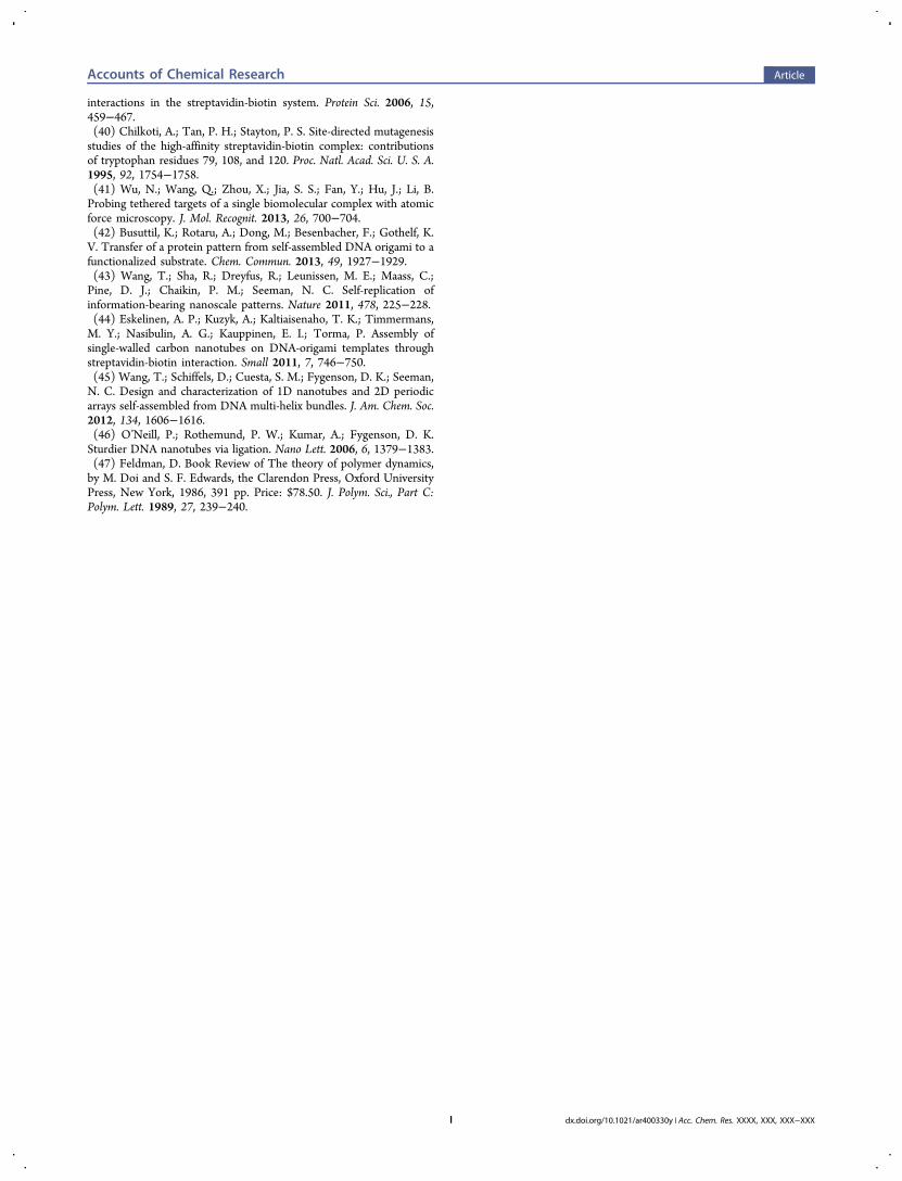
Figure 1. (a) The cross structure with central overlapped region. (b, c) The two kinds of CLSs used in this study are drawn in blue (CLS1) and inorange (CLS2) throughout the manuscript for clarity. (d) An illustration of two kinds of connections used to generate two isomeric forms of 1Darrays from CLS1 tiles. (e) The two kinds of connection used to form 1D origami arrays of finite length from two CLS with different sequences. (f)caDNAno design showing 6 of the 12 helixes connecting the right arm of CLS1 to the left arm of CLS2. Blue lines are the M13 scaffold, and the redlines are the end staples including their sticky ends, which are the three extra bases at the 5′ end that complement the scaffold on the arm of theother cross. (g) Plot of temperature vs time for the first anneals. The CLS anneal program 1 is used to prepare the CLS tiles. (h) The 2nd annealuses program 2 to assemble the 1D array by dropping temperature from 50 to 6 °C over a 1-day or a 3-day-anneal. (i) CanDo 3D prediction of CLStile structure. (j) Side view of CLS tile. The overall structure of CLS bends downward. (k) Inverted CLS, which is the structure of tiles 3, 4, 7, and 8in the alternating design. (l) a close up view drawn using Maya showing the location of the streptavidin on CLS1. The streptavidin is shifted 2.4 nmaway from the middle line.
Accounts of Chemical Research Article
dx.doi.org/10.1021/ar400330y | Acc. Chem. Res. XXXX, XXX, XXX−XXXB

therefore contain an indeterminate number of building blocksand might be termed semi-infinite or nonfinite, as opposed tosystems that contain a programmed number of blocks, whichmay be termed finite. This building block is quite amenable toboth types of structures. The core motif is assembled from the7249 base M13 scaffold and 201 short staple sequences, whichincludes 177 core staple sequences and 24 edge staplesequences. The CLS is composed of an overlay of tworectangular plate like structures, one vertical, with up and downarms, and one horizontal, with arms to the left and right. Eacharm is composed of 12 helixes. The horizontal plate has awindow region in the center. As shown in Figure 1a, a square,central region is double-layered when the two plates areoverlapped, with the exception of the window area. Thiswindow in the center of the double layer has the appearance ofan equal sign when imaged using AFM, which enables one toeasily discern the orientation of the CLS (up and down vs leftand right).There are several unique factors that recommend this four
armed CLS structure for use in 1D and 2D systems andtherefore for use as a standard building block for generation ofmacrostructures, both finite and semi-infinite. One of the mostimportant aspects is that this motif provides an equivalentmechanism for growth in two perpendicular it presents theends of helical domains at the ends of each arm. Thisequivalence of binding interactions along both orthogonaldirections means that association and dissociation kinetics willbe, to a first approximation, isotropic, leading to the possibilityof equal growth rates in two dimensions. Although within thefootprint of the design the system has a very high density ofstaples, and therefore not only high mechanical stability butalso a high density of binding sites for surface modification, thecross motif is most amenable to generation of a non-space-filling tiling. Because the arms bind end to end, square voidsexist along the diagonal direction. This void space may findfuture use as “via” space, providing access to the substrate orproviding channels endowing the system with porosity. Thisconstruct, as with most current origami, does not use the M13plasmid sequence completely, leaving a remainder portion ofthe sequence, a tail, uncomplemented and dangling, usuallyfrom the edge of the structure. For single origami systems, thisdoes not present a problem. However, for systems that aredesigned to pack, this excess material at least can provide akinetic barrier to assembly (sterics) or at worst can interferewith assembly, destroying the coherence of the assembly.However, in the CLS, this tail region is designed to bepositioned in the void space, where it cannot interfere withassembly.While optical methods, particularly FRET (fluorescence
resonant energy transfer) have provided insight into thedynamic structure of particular locations of interest in finiteorigami objects, for example, the closure of an origami box,21
extended distance scales require the application of othermethods. In order to obtain a more direct understanding of theprincipal structural features that may contribute to anyobserved differences in persistence lengths for differentstructures, the program CanDo was used to provide a predicted3D structure for the CLS tile (Figure 1i). CanDo, developed byM. Bathe et al., is an important program for evaluating origamistructures25,26 and is much more accessible than cryo-EM,27 adirect imaging tool. The plot is color-coded using the valuescomputed for root-mean-square thermal fluctuations. Thisprediction reveals that the overall structure of the CLS as
modeled is significantly distorted, with the left and right armsdeparting most from planarity. In addition to this bending,deformation at the end of each of the four arms can also beobserved and may be partially explained by the design using ahelix twist of 33.75°/bp or 10.67bp/turn, as opposed to thestandard B-form DNA, which has a 34.6°/bp or 10.4 bp/turnpitch.28,29 If the twist angle per construct is small, the arrays willflatten on binding to a solid substrate and the AFM images willnot reflect this twisting. If the twist angle is high and the 1Darray length spans greater than a 180° rotation, then one mayanticipate observing folded arrays via AFM.
3. TYPES OF INTERORIGAMI JUNCTIONS
3.1. Geometrical
Shortly after the invention of origami, Rothemund et al.demonstrated the significance of helical stacking in origami−origami interactions.16 While origami do not tend to stack ontop of each other and they do not tend to align alternating tothe directions of the helices, strong interactions between edgesof an origami presenting blunt helical ends can generateunintended multiple origami parallel along the helical direction.This interaction is so powerful that it has been suggested as asole binding force for origami−origami supramolecularconstructs.30−33 In strong contrast to the majority of origamistructures published to date, in the cross origami design, thisstacking energy contribution adds stability to the interorigamiinteractions in two orthogonal directions.
3.2. Sticky End−Sticky End
In the original design by W. Liu et al., the ends of each of thefour arms of the core of the CLS construct were extended usingtwo sets of 5 bp overhangs.23 This resulted in the equivalent oftwo cross constructs, which were entirely different in theirrecognition sequences, even though the cores were exactly thesame. An in-depth study of this approach to the generation of1-D arrays has been recently reported.17 Such use of overhangsequences minimizes the expense and complexity of assemblywhile providing a path to design of systems with a potentiallylarge number of unique tiles.
3.3. Sticky End−ScaffoldWe have taken an alternative approach to generate two differentCLSs used in the majority of our 1D studies. CLS1 and CLS2are represented by the blue cross and orange cross in Figure1b,c. The structure and design of the two crosses are identical.The difference is that each of the folding designs starts at adifferent location on the M13 plasmid, which requires thesequence of every staple to be completely different. Instead ofutilizing the geometrical arrangement of blunt-end stackinginteractions17,30 or pairs of sticky ends,23 the connectionbetween the CLSs is made by base pairing from sequences atthe end of each arm, which have three extra bases that arecomplementary to the m13 plasmid scaffold of the adjacentCLS arm. In other words, a connection is made through 36weak single base interactions per arm. To clarify, a screenshotof a structure map generated using caDNAno of half of onearm, explicitly showing these interorigami bindings, is shown inFigure 1f. caDNAno is an excellent open-source program thatcan be used to design 3D DNA-origami shapes constrained to asquare or honeycomb shaped framework or lattice.34,35 Thisfigure presents the first six helixes connecting the right arm ofCLS1 and the left arm of CLS2. This binding results in thealignment of the “equal signs” and is termed a parallel segment
Accounts of Chemical Research Article
dx.doi.org/10.1021/ar400330y | Acc. Chem. Res. XXXX, XXX, XXX−XXXC

(Figure 1e). Combining a top or down arm with a left or rightarm results in alternating segment (Figure 1e). Unique linkagesbetween any two arms can be programmed through these 36base complementary matches. For arms where binding is notdesired, these three extra bases are replaced with five thymines,a technique previously suggested in the literature.16,17,36 Thesefive thymines prevent nonspecific binding and interfere with ordisrupt the π−π stacking interactions.
4. METHODS AND PROTOCOLS OF ASSEMBLY
Two sources were used for the DNA components necessary toassemble CLS. The single-stranded M13mp18 DNA plasmidscaffold was purchased at a concentration of 1.00 μg/μL fromBayou Biolabs, and all of the staple strands and sticky-endstrand sequences were obtained from Integrated DNATechnologies Inc. at a 25 nmol synthesis scale and in standarddesalted purified form. In a generic preparation, a solutioncomposed of a mixture of staple strands, designed sticky ends,and M13mp18 ssDNA plasmid is brought to a volume of 50 μLusing CLS buffer (1× Tris-acetate-EDTA (TAE) buffer with12.5 mM of MgCl2). The final concentration of ssDNA plasmidin the solution is 10 nM, and the molar ratio of the ssDNAplasmid to each of the other strands is 1:5. To first formindividual CLS blocks, the solution with the designed stickyends appropriate for one construct is first annealed in a slowcooling process, dropping the temperature from 90 to 20 °Cover a 13 h period.This annealing program is shown in Figure 1g. Equal
amounts of blocks are then mixed together and annealed from50 to 6 °C for the formation of the finite arrays. Arrays resultingfrom a 1-day and a 3-day second anneal (Figure 1h) werecompared and are discussed in the following section.Because we frequently observe “failure products”, it is useful
to determine whether the incorporated block is the correct typeby marking one of the two structures. Streptavidin has a longhistory of use as a marker in DNA nanotechnology37 because
the streptavidin−biotin complex has one of the highestnoncovalent binding strengths in nature, with an associatedfree energy of 18 kcal/mol.38−40 In order to make it easier toidentify the blocks, one or two arms of the CLS can bemodified with two closely spaced biotinylated staples duringindividual CLS assembly, then labeled through binding withstreptavidin as a high contrast marker before imaging withAFM.41−44 For example, a single streptavidin marker on onearm enables us to identify the CLS1 components of the arrayand their orientation along all three axes. To break thesymmetry of the CLS, two biotinylated staples were positionedbetween the seventh and the eighth helix of the 12 helixes inthe right arm counting from the “up arm” as shown in Figure 1l.Using streptavidin coding in this manner, we can easily identifywhether an array block or an entire array is facing up or facingdown.
5. GENERATING 1D STRUCTURESThe generation of two broad types of 1D structures is enabledby the CLS origami motif. One is an “infinite” array, which is aconcatenated origami polymer of indeterminate length resultingfrom a single solution reaction. The other is a finite array,composed of distinct origami elements designed to generate apredetermined sequence of elements through self-assembly.5.1. Nonfinite 1D Array
Two different designs, one termed parallel and another namedperpendicular, are represented in Figure 2a,d. The design ofthese 1D arrays both begin by considering edge modificationsof the CLS1 core. In the parallel design, we connect 12 helixesof the right arm of CLS1 via 3 nt long overhanging sticky endson staples of the left arm of the neighboring CLS1 as shown inFigure 1d as R + L. The perpendicular type array was formedby connecting U and D arms between adjacent origami (Figure1d; U + D). AFM imaging indicates that both designs yieldlong 1D arrays of various lengths when annealed using, forexample, CLS anneal program 1 (Figure 1g).
Figure 2. (a) Schematic illustration of one type of 1D array forming pattern made by connecting CLS1 blocks using R and L arms. The landmarkequal (=) sign is then parallel to the long axis of the array. (b) AFM image of a long 1D parallel array. (c) High resolution AFM image. (d)Schematic view of the “perpendicular” type of 1D array formation pattern generated by connecting U and D arms of CLS1 blocks. The equal signsare all perpendicular to the long array direction. (e, f) AFM images of this type of 1D array.
Accounts of Chemical Research Article
dx.doi.org/10.1021/ar400330y | Acc. Chem. Res. XXXX, XXX, XXX−XXXD

5.2. Finite 1D Array
5.2.1. Alternating Design. The first of two designapproaches that we have employed to generate origami arrays
of specific lengths is called the alternating design. In this design,two CLSs, each with a different core sequence, alternate toform the array (shown in Figure 3a,b,c). By rotating the CLS
Figure 3. Illustrations and AFM images of CLS array for the (a) 4mer, (b) 6mer, and (c) 8mer of the alternating design. (d) Formation statistics foreach type of array. (e) Histogram representing the yield. Full-length arrays were counted as products; all other origami assemblies are represented asnonproduct.
Figure 4. Illustrations and AFM images of CLS arrays with the parallel design for the (a) 4mer, (b) 6mer, and (c) 8mer. (d) The statistics forformation of all parallel arrays. (e) Histogram of yields. Full-length arrays were counted as products, and all other origami objects were counted asnonproduct. (f) The parallel form 8mer as designed, with top side facing up. The streptavidin label appears on the right arm of CLS1 shifted slightlybelow the centerline toward the down arm. (g) An upside-down parallel 8mer; streptavidins display mirror symmetry pattern.
Accounts of Chemical Research Article
dx.doi.org/10.1021/ar400330y | Acc. Chem. Res. XXXX, XXX, XXX−XXXE

90° clockwise in each successive insertion into the arraysequence, the four arms of both origamis are combined tocreate seven different CLS-to-CLS connections. Due to the 5′to 3′ direction of the scaffold sequence, this alternating designcan only be achieved by flipping tiles 3, 4, 7, and 8 upside downwhile tiles 1, 2, 5, and 6 remain facing up. The uniqueness ofeach junction design enables us to control the orientation ofeach CLS and the order of the CLS in the array. To provideassistance in process development, one pair of biotins was usedto label the right and left arms of CLS1 in this alternatingdesign.Progressive steps along the self-assembly path of this design
were examined by synthesizing the 4mer, 6mer, and 8merarrays and using AFM to investigate the yield. Equal volumes of10 nM solutions of each building block were mixed andannealed using the 3-day anneal program. A reflection of therobust nature of this building block motif, consistent with thereported observations of Liu,23 the 50 °C annealing temper-ature does not appear to disrupt the staples at the edges, whichare important in selective adhesion. Almost 200 of each type ofarray (4mer, 6mer, and 8mer), were evaluated in order toobtain the histogram shown in Figure 3d. The 4mer, 6mer, and8mer were found to have yields of 70%, 60%, and 47% for thecompletely formed arrays, respectively. The longer the arraywas, the lower the yield, as might be expected since theincreased complexity provides an increasing number of failuremodes. In parallel with the 3-day anneal, a 1-day assembly(termed a second anneal in Figure 1h) was also performed. Theobserved yields were essentially the same, which suggests thatkinetic control rather than equilibrium factors determine theerror product distribution.
5.2.2. Parallel Design. The arrays generated with theparallel pattern (all = signs parallel along the long arraydirection) are much less complex in design, having a 2-foldrotational axis perpendicular to the array plane. Two identicalCLSs bind to each other at the center of the array (Figure4a,b,c), so only four different blocks are required to form the8mer shown in Figure 4c. Experiments with this array designhad as objectives not only achieving high yield of origami arraysof specific lengths but also experimentally determining whetherthere were differences in the binding characteristics of the armsnot readily apparent in the design. This is important becausethe best building block design will be one that produces anorigami array that is naturally resistant to spiral twisting insolution and kinking upon drying. Origami arrays based on thisdesign were assembled, with example images shown in Figure 4.The arrays are generated by mixing together equal volumes
of 10 nM solutions of preannealed building blocks andannealing the resulting solutions from 50 to 6 °C over 24 h.This parallel design produces yields of 86% and 63% for the4mer and 8mer, which are significantly higher than the yieldsobtained with the alternating design. However, the 6mersuffered from a lower yield than expected from this trend. Therelatively high failure rate can be ascribed to the apparentstability of monomer, dimer, and tetramer structures.The two different component blocks used in the design of
the arrays discussed above appear identical in AFM images.However, for identification purposes, in addition to the “equalsign”, we used streptavidin as a high Z and therefore highcontrast marker on the surface. Not only does this enable us todifferentiate CLS1 from CLS2, but this marker also can be usedto determine whether CLS1 is right side up or upside down.
Figure 5. AFM images of 8mer of (a) alternating and (b) parallel origami arrays. (c) The calculated persistence length values of arrays. (d, e) Thedistribution R of alternating and parallel 8mer arrays, respectively.
Accounts of Chemical Research Article
dx.doi.org/10.1021/ar400330y | Acc. Chem. Res. XXXX, XXX, XXX−XXXF

Only one pair of biotins, positioned on only the right arm, wasrequired for labeling in this parallel design (Figure 4f,g).
6. STIFFNESS AND PERSISTENCE LENGTHEven a consideration of the few images provided in Figures 3and 4 seems to indicate that the parallel pattern providesstructures with considerably less bending and kinking of theobserved arrays. This significantly improved linearity of thearrays increases their potential to serve as substrates orstructural components or spacers for organizing other nano-materials for applications. We considered 202 alternating 8merarrays and 217 parallel 8mer arrays to obtain the end-to-enddistance mean values, ⟨R⟩, standard deviations, and meansquare, ⟨R2⟩ for both designs (Figure 5c). The parallel designhas a longer end-to-end distance vector, and the distancedistribution, represented as a histogram plotted with a bin sizeof 50 nm, suggests that the parallel structure has one majormode (closer to a single Gaussian distribution approaching thefull length of the array). According to the ideal chain model, Rshould be normally distributed. A Gaussian curve was thereforeplotted (red line) for comparison in both histogram plots(Figure 5d,e) based on the mean value and standard deviationtabulated in Figure 5c. We used one of the special cases of theideal chain, the worm-like chain (WLC), to model the 8mer.Unlike the ideal chain, which is only flexible between discretesegments, the WLC model considers the segments to becontinuously flexible. The 2D Kratky−Porod model relates themean square end-to-end distance with the persistence lengthvia eq 1:
⟨ ⟩ = − − −R pL p L4 [1 2 (1 e )/ ]L p2 /(2 )(1)
where R is the of end-to-end distance, the angle bracketsdenote the average value, p is the persistence length, and L isthe contour length.45−47 If we assume that a single CLS isapproximately 92 nm from end to end, then the contour lengthof a single 8mer is 736 nm. The persistence length of thealternating arrays is then 130 nm, and p for the parallel 8merarrays is 320 nm. These values are significantly lower than thosefound for origami tubes.43 While qualitative, because the modelis sequence independent, the departures from planarityobserved in the CanDo model (Figure 1i−k) representdepartures from the WLC model in which bond directionsshould be random rather than biased. In the alternating design,which consists of up to 50% blocks with the “perpendicular”orientation, significant departures from linearity are observed inFigure 3a−c coincident with folds located at origami blocks.These folds result in the formation of the small R structuresrepresented in the plot in Figure 5d. Such folds are notfrequently observed for the parallel structures, which do notcontain blocks with the perpendicular orientation. We note thatLiu’s 2D origami crystal design included rotational random-ization at each of the two types of lattice sites, to great effect.23
For the rather short, flat chains studied here, departures fromplanarity and twists in the building block unit can significantlyimpact the observed persistence length. This bias represents thegreatest, but not the only departure of an anisotropic origamidesign from the model.43
7. CONCLUSIONSThis Account reviews efforts directed toward the high yieldfabrication of finite 1D multiorigami arrays. For the longestfinite parallel design arrays considered, the 8mer, the yield was
found to be 63%. From a materials use perspective, on theorder of 77% of all individual origami counted wereincorporated into the 8mer product. While there are certainlymany arrays with errors, more than half of the observed objectsare the fully formed ones. Each linkage in the array is encodedby its unique sequence. These links not only provide a pathtoward product formation, but also can function as multifacetederror nodes, with potential to act as kinetic traps by creatingerror junctions, which can inhibit further growth and productformation. Higher purity materials may be achieved eitherthrough a separation process, assuming no spontaneousbreaking or via yield optimization. Efforts to produce higheryields will require identification of these error generating trapstates and the minimization of their impact via optimization ofmultiple unique linkage sequences. The parallel designdisplayed higher yield and a higher persistence length thanthe alternating design. One factor possibly contributing to thehigher yield is the difference in the number of differentjunctions required. Only four different junctions were requiredto form the 8mer parallel array. In contrast, in the alternatingdesign the scaffold sequences for each arm are used to encodetwo different junctions, one with a “right side up” partner, andone with an upside down partner (Figure 3c). This can lead toerror junctions since there can be competition for scaffold sitesby more than one type of tile. Such competitive binding atjunctions may present important kinetic trap states.Addressing several additional challenges will speed the
adoption of origami as a substrate for more complex molecularmachines or circuits. “Standard elements” with high structuralrigidity, designed for ready integration into large nanosystems,immobilized and aligned on technological substrates such assilicon, must be made available to the engineering community.Such immobilization is a necessary precursor to the generationof electrical, optical, chemical, and mechanical connections toworking nanosystems. The foundations for relatively long finite1D arrays now exist. Motivated by the success of Liu,23 inproducing nonfinite 2D arrays from CLSs, experiments directedtoward solution phase assembly of finite two-dimensionalsystems seeded by these finite 1D arrays are currently ongoingin our laboratories.
■ AUTHOR INFORMATION
Corresponding Author
*Michael Norton. E-mail: [email protected].
Funding
We acknowledge the following grants to support this research:ARO awards W911NF-08-1-0109, W911NF-09-1-0218, andW911NF-11-1-0024 and NSF Cooperative Agreement NumberEPS-1003907.
Notes
The authors declare no competing financial interest.
Biographies
Dr. Tsai-Chin Wu has a background in physics and obtained herPh.D. in Bioengineering from the University of Illinois at Chicago in2012. During her Ph.D. research, she began exploring the potential ofutilizing DNA molecules and nanoparticles to build sensors at thenanometer scale. As a postdoctoral fellow in the Department ofChemistry at Marshall University, she is expanding her knowledge andexperience in microfluidics and self-assembly of DNA structures.
Accounts of Chemical Research Article
dx.doi.org/10.1021/ar400330y | Acc. Chem. Res. XXXX, XXX, XXX−XXXG

Dr. Masudur Rahman received his Ph.D. in Environment & Life-science Engineering from Toyohashi University of Technology(TUT), Japan, in 2007 as a Monbukagakusho Scholar. He developeda quasi-real-time airborne pathogen detection system during hispostdoctoral research at TUT. At Marshall University, his research isfocused on connecting bottom-up methods of patterning with top-down approaches for optoelectronic sensing by developing micro- ornanofabrication systems based on DNA nanostructures and interfer-ence lithography systems for single molecule localization.
Dr. Michael Norton obtained his Ph.D. in Solid State Chemistry fromArizona State University in 1982, working in the area of two-dimensional materials. As a NRC postdoctoral researcher, he workedbriefly in the area of oxide materials at the Naval Weapons Center atChina Lake, California. As an assistant professor at the University ofGeorgia, he developed methods for the electrochemical growth ofsuperconducting oxide superlattices. In his career at MarshallUniversity, his studies have focused on soft matter structures,including DNA based nanostructures, with emphasis on the fabricationand characterization of electro-optical nanoarchitecture for sensingapplications.
■ REFERENCES(1) Seeman, N. C. DNA nanotechnology: Novel DNA constructions.Annu. Rev. Biophys. Biomol. Struct. 1998, 27, 225−248.(2) Seeman, N. C. An overview of structural DNA nanotechnology.Mol. Biotechnol. 2007, 37, 246−257.(3) Zadegan, R. M.; Norton, M. L. Structural DNA nanotechnology:From design to applications. Int. J. Mol. Sci. 2012, 13, 7149−7162.(4) Zhang, G.; Surwade, S. P.; Zhou, F.; Liu, H. DNA nanostructuremeets nanofabrication. Chem. Soc. Rev. 2013, 42, 2488−2496.(5) Zhao, Y. X.; Shaw, A.; Zeng, X.; Benson, E.; Nystrom, A. M.;Hogberg, B. DNA origami delivery system for cancer therapy withtunable release properties. ACS Nano 2012, 6, 8684−8691.(6) Schuller, V. J.; Heidegger, S.; Sandholzer, N.; Nickels, P. C.;Suhartha, N. A.; Endres, S.; Bourquin, C.; Liedl, T. Cellularimmunostimulation by CpG-sequence-coated DNA origami structures.ACS Nano 2011, 5, 9696−9702.(7) Douglas, S. M.; Bachelet, I.; Church, G. M. A logic-gatednanorobot for targeted transport of molecular payloads. Science 2012,335, 831−834.(8) Liu, X.; Xu, Y.; Yu, T.; Clifford, C.; Liu, Y.; Yan, H.; Chang, Y. ADNA nanostructure platform for directed assembly of syntheticvaccines. Nano Lett. 2012, 12, 4254−4259.(9) Arora, H. C.; Jensen, M. P.; Yuan, Y.; Wu, A.; Vogt, S.; Paunesku,T.; Woloschak, G. E. Nanocarriers enhance doxorubicin uptake indrug-resistant ovarian cancer cells. Cancer Res. 2012, 72, 769−778.(10) Endo, M.; Yang, Y.; Sugiyama, H. DNA origami technology forbiomaterials applications. Biomater. Sci. 2013, 1, 347−360.(11) Zheng, M.; Jagota, A.; Semke, E. D.; Diner, B. A.; McLean, R. S.;Lustig, S. R.; Richardson, R. E.; Tassi, N. G. DNA-assisted dispersionand separation of carbon nanotubes. Nat. Mater. 2003, 2, 338−342.(12) Surwade, S. P.; Zhou, F.; Wei, B.; Sun, W.; Powell, A.;O’Donnell, C.; Yin, P.; Liu, H. Nanoscale growth and patterning ofinorganic oxides using DNA nanostructure templates. J. Am. Chem.Soc. 2013, 135, 6778−6781.(13) Surwade, S. P.; Zhao, S.; Liu, H. Molecular lithography throughDNA-mediated etching and masking of SiO2. J. Am. Chem. Soc. 2011,133, 11868−11871.(14) Deng, Z.; Mao, C. Molecular lithography with DNAnanostructures. Angew. Chem., Int. Ed. 2004, 43, 4068−4070.(15) Kershner, R. J.; Bozano, L. D.; Micheel, C. M.; Hung, A. M.;Fornof, A. R.; Cha, J. N.; Rettner, C. T.; Bersani, M.; Frommer, J.;Rothemund, P. W.; Wallraff, G. M. Placement and orientation ofindividual DNA shapes on lithographically patterned surfaces. Nat.Nanotechnol. 2009, 4, 557−561.
(16) Rothemund, P. W. Folding DNA to create nanoscale shapes andpatterns. Nature 2006, 440, 297−302.(17) Kim, K. N.; Sarveswaran, K.; Mark, L.; Lieberman, M.Comparison of methods for orienting and aligning DNA origami.Soft Matter 2011, 7, 4636−4643.(18) Li, Z.; Liu, M.; Wang, L.; Nangreave, J.; Yan, H.; Liu, Y.Molecular behavior of DNA origami in higher-order self-assembly. J.Am. Chem. Soc. 2010, 132, 13545−13552.(19) Mangalum, A.; Rahman, M.; Norton, M. L. Site-specificimmobilization of single-walled carbon nanotubes onto single and one-dimensional DNA origami. J. Am. Chem. Soc. 2013, 135, 2451−2454.(20) Rahman, M.; Neff, D.; Norton, M. L. Rapid, high yield, directedaddition of quantum dots onto surface bound linear DNA origamiarrays. Chem. Commun. 2014, 50, 3413−3416.(21) Andersen, E. S.; Dong, M.; Nielsen, M. M.; Jahn, K.; Subramani,R.; Mamdouh, W.; Golas, M. M.; Sander, B.; Stark, H.; Oliveira, C. L.P.; Pedersen, J. S.; Birkedal, V.; Besenbacher, F.; Gothelf, K. V.; Kjems,J. Self-assembly of a nanoscale DNA box with a controllable lid. Nature2009, 459, 73−76.(22) Yan, H.; Park, S. H.; Finkelstein, G.; Reif, J. H.; LaBean, T. H.DNA-templated self-assembly of protein arrays and highly conductivenanowires. Science 2003, 301, 1882−1884.(23) Liu, W.; Zhong, H.; Wang, R.; Seeman, N. C. Crystalline two-dimensional DNA-origami arrays. Angew. Chem., Int. Ed. 2011, 50,264−267.(24) Liu, Y.; Ke, Y.; Yan, H. Self-assembly of symmetric finite-sizeDNA nanoarrays. J. Am. Chem. Soc. 2005, 127, 17140−17141.(25) Bathe, M. Computer-aided engineering for DNA origami(CanDo). http://cando-dna-origami.org/, 2011.(26) Castro, C. E.; Kilchherr, F.; Kim, D. N.; Shiao, E. L.; Wauer, T.;Wortmann, P.; Bathe, M.; Dietz, H. A primer to scaffolded DNAorigami. Nat. Methods 2011, 8, 221−229.(27) Bai, X. C.; Martin, T. G.; Scheres, S. H.; Dietz, H. Cryo-EMstructure of a 3D DNA-origami object. Proc. Natl. Acad. Sci. U. S. A.2012, 109, 20012−20017.(28) Wang, J. C. Helical repeat of DNA in solution. Proc. Natl. Acad.Sci. U. S. A. 1979, 76, 200−203.(29) Dietz, H.; Douglas, S. M.; Shih, W. M. Folding DNA intotwisted and curved nanoscale shapes. Science 2009, 325, 725−730.(30) Woo, S.; Rothemund, P. W. K. Programmable molecularrecognition based on the geometry of DNA nanostructures. Nat.Chem. 2011, 3, 620−627.(31) Rajendran, A.; Endo, M.; Katsuda, Y.; Hidaka, K.; Sugiyama, H.Programmed two-dimensional self-assembly of multiple DNA origamijigsaw pieces. ACS Nano 2010, 5, 665−671.(32) Endo, M.; Sugita, T.; Rajendran, A.; Katsuda, Y.; Emura, T.;Hidaka, K.; Sugiyama, H. Two-dimensional DNA origami assembliesusing a four-way connector. Chem. Commun. 2011, 47, 3213−3215.(33) Endo, M.; Sugita, T.; Katsuda, Y.; Hidaka, K.; Sugiyama, H.Programmed-assembly system using DNA jigsaw pieces. Chemistry2010, 16, 5362−5368.(34) Douglas, S. M.; Dietz, H.; Liedl, T.; Hogberg, B.; Graf, F.; Shih,W. M. Self-assembly of DNA into nanoscale three-dimensional shapes.Nature 2009, 459, 414−418.(35) Douglas, S. M.; Marblestone, A. H.; Teerapittayanon, S.;Vazquez, A.; Church, G. M.; Shih, W. M. Rapid prototyping of 3DDNA-origami shapes with caDNAno. Nucleic Acids Res. 2009, 37,5001−5006.(36) Ke, Y.; Lindsay, S.; Chang, Y.; Liu, Y.; Yan, H. Self-assembledwater-soluble nucleic acid probe tiles for label-free RNA hybridizationassays. Science 2008, 319, 180−183.(37) Lund, K.; Liu, Y.; Lindsay, S.; Yan, H. Self-assembling amolecular pegboard. J. Am. Chem. Soc. 2005, 127, 17606−17607.(38) Green, N. M. Avidin. 4. Stability at extremes of pH anddissociation into sub-units by guanidine hydrochloride. Biochem. J.1963, 89, 609−620.(39) Hyre, D. E.; Le Trong, I.; Merritt, E. A.; Eccleston, J. F.; Green,N. M.; Stenkamp, R. E.; Stayton, P. S. Cooperative hydrogen bond
Accounts of Chemical Research Article
dx.doi.org/10.1021/ar400330y | Acc. Chem. Res. XXXX, XXX, XXX−XXXH
interactions in the streptavidin-biotin system. Protein Sci. 2006, 15,459−467.(40) Chilkoti, A.; Tan, P. H.; Stayton, P. S. Site-directed mutagenesisstudies of the high-affinity streptavidin-biotin complex: contributionsof tryptophan residues 79, 108, and 120. Proc. Natl. Acad. Sci. U. S. A.1995, 92, 1754−1758.(41) Wu, N.; Wang, Q.; Zhou, X.; Jia, S. S.; Fan, Y.; Hu, J.; Li, B.Probing tethered targets of a single biomolecular complex with atomicforce microscopy. J. Mol. Recognit. 2013, 26, 700−704.(42) Busuttil, K.; Rotaru, A.; Dong, M.; Besenbacher, F.; Gothelf, K.V. Transfer of a protein pattern from self-assembled DNA origami to afunctionalized substrate. Chem. Commun. 2013, 49, 1927−1929.(43) Wang, T.; Sha, R.; Dreyfus, R.; Leunissen, M. E.; Maass, C.;Pine, D. J.; Chaikin, P. M.; Seeman, N. C. Self-replication ofinformation-bearing nanoscale patterns. Nature 2011, 478, 225−228.(44) Eskelinen, A. P.; Kuzyk, A.; Kaltiaisenaho, T. K.; Timmermans,M. Y.; Nasibulin, A. G.; Kauppinen, E. I.; Torma, P. Assembly ofsingle-walled carbon nanotubes on DNA-origami templates throughstreptavidin-biotin interaction. Small 2011, 7, 746−750.(45) Wang, T.; Schiffels, D.; Cuesta, S. M.; Fygenson, D. K.; Seeman,N. C. Design and characterization of 1D nanotubes and 2D periodicarrays self-assembled from DNA multi-helix bundles. J. Am. Chem. Soc.2012, 134, 1606−1616.(46) O’Neill, P.; Rothemund, P. W.; Kumar, A.; Fygenson, D. K.Sturdier DNA nanotubes via ligation. Nano Lett. 2006, 6, 1379−1383.(47) Feldman, D. Book Review of The theory of polymer dynamics,by M. Doi and S. F. Edwards, the Clarendon Press, Oxford UniversityPress, New York, 1986, 391 pp. Price: $78.50. J. Polym. Sci., Part C:Polym. Lett. 1989, 27, 239−240.
Accounts of Chemical Research Article
dx.doi.org/10.1021/ar400330y | Acc. Chem. Res. XXXX, XXX, XXX−XXXI