Buckling and postbuckling of functionally graded multilayer ...
24
Accepted Manuscript Buckling and postbuckling of functionally graded multilayer graphene platelet- reinforced composite beams Jie Yang, Helong Wu, Sritawat Kitipornchai PII: S0263-8223(16)31600-2 DOI: http://dx.doi.org/10.1016/j.compstruct.2016.11.048 Reference: COST 8008 To appear in: Composite Structures Received Date: 19 August 2016 Revised Date: 8 November 2016 Accepted Date: 11 November 2016 Please cite this article as: Yang, J., Wu, H., Kitipornchai, S., Buckling and postbuckling of functionally graded multilayer graphene platelet-reinforced composite beams, Composite Structures (2016), doi: http://dx.doi.org/ 10.1016/j.compstruct.2016.11.048 This is a PDF file of an unedited manuscript that has been accepted for publication. As a service to our customers we are providing this early version of the manuscript. The manuscript will undergo copyediting, typesetting, and review of the resulting proof before it is published in its final form. Please note that during the production process errors may be discovered which could affect the content, and all legal disclaimers that apply to the journal pertain.
-
Upload
khangminh22 -
Category
Documents
-
view
0 -
download
0
Transcript of Buckling and postbuckling of functionally graded multilayer ...
Accepted Manuscript
Buckling and postbuckling of functionally graded multilayer graphene platelet-reinforced composite beams
Jie Yang, Helong Wu, Sritawat Kitipornchai
PII: S0263-8223(16)31600-2DOI: http://dx.doi.org/10.1016/j.compstruct.2016.11.048Reference: COST 8008
To appear in: Composite Structures
Received Date: 19 August 2016Revised Date: 8 November 2016Accepted Date: 11 November 2016
Please cite this article as: Yang, J., Wu, H., Kitipornchai, S., Buckling and postbuckling of functionally gradedmultilayer graphene platelet-reinforced composite beams, Composite Structures (2016), doi: http://dx.doi.org/10.1016/j.compstruct.2016.11.048
This is a PDF file of an unedited manuscript that has been accepted for publication. As a service to our customerswe are providing this early version of the manuscript. The manuscript will undergo copyediting, typesetting, andreview of the resulting proof before it is published in its final form. Please note that during the production processerrors may be discovered which could affect the content, and all legal disclaimers that apply to the journal pertain.

1
Buckling and postbuckling of functionally graded multilayer graphene
platelet-reinforced composite beams
Jie Yang a,*
, Helong Wu b, Sritawat Kitipornchai
b
a School of Engineering, RMIT University, PO Box 71, Bundoora, VIC 3083 Australia
b School of Civil Engineering, The University of Queensland, St Lucia, Brisbane, QLD 4072
Australia
___________________________________________________________________________

2
Abstract
This paper investigates the buckling and postbuckling behaviours of functionally graded mul-
tilayer nanocomposite beams reinforced with a low content of graphene platelets (GPLs) rest-
ing on an elastic foundation. It is assumed that GPLs are randomly oriented and uniformly
dispersed in each individual GPL-reinforced composite (GPLRC) layer with its weight frac-
tion varying layerwise along the thickness direction. The effective material properties of each
layer are estimated by the Halpin-Tsai micromechanics model. The nonlinear governing
equations of the beam on an elastic foundation are derived within the framework of the first-
order shear deformation beam theory then are converted into a nonlinear algebraic system by
using the differential quadrature method. A detailed parametric study is carried out to exam-
ine the effects of the distribution pattern, weight fraction, geometry and size of GPL
nanofillers, foundation stiffness parameters, slenderness ratio and boundary conditions on the
buckling and postbuckling behaviours. The results show that GPLs have a remarkable rein-
forcing effect on the buckling and postbuckling of nanocomposite beams.
Keywords: buckling; postbuckling; functionally graded nanocomposite beam; graphene plate-
let; differential quadrature method
* Corresponding author. Tel.: 61-03-99256169; Fax: 61-03-99256108
E-mail address: [email protected] (J. Yang)
1. Introduction
The material properties of polymer composites are largely dependent, in addition to the filler
properties, on the interface area and intensity of intermolecular interaction between the filler
and matrix. Graphene [1], a two-dimensional single layer of carbon atoms, has attracted con-
siderable attention due to its exceptional mechanical, thermal and electrical properties [2-4].
It has an intrinsic tensile strength of 130 GPa and Young’s modulus of about 1 TPa [2] that
are comparable to carbon nanotubes (CNTs), and a specific surface area of up to 2630 m2 g-1
which is much larger than that of CNTs [5]. These merits, together with nanoscale effects and
interface chemistry, make graphene a novel and promising alternative to conventional fillers,
such as carbon and glass fibres, in polymer composites [6]. As a consequence,
nanocomposites reinforced with graphene and its derivatives have recently become an emerg-
ing area of extensive research efforts in advanced composite materials [7, 8].

3
Numerous studies have demonstrated the significant reinforcing effects of graphene and its
derivatives on the mechanical properties of polymer composites. Among those, Rafiee et al.
[9] measured and compared the mechanical properties of epoxy nanocomposites reinforced
with 0.1± 0.002 wt% graphene platelets (GPLs), single-walled carbon nanotubes (SWCNTs),
and multi-walled carbon nanotubes (MWCNTs), respectively. Their results indicated that the
Young’s modulus, ultimate tensile strength and fracture toughness of the nanocomposites are
significantly greater than those of the pristine epoxy and GPL nanofillers significantly out-
perform carbon nanotubes. Ji et al. [6] investigated the stiffening effect of graphene sheets on
polymer nanocomposites using the Mori-Tanaka micromechanics method. They found that a
low loading of graphene sheets can considerably increase the effective stiffness of the origi-
nal matrix. Zhao et al. [10] reported that a 150% improvement of tensile strength and a nearly
10 times increase of Young’s modulus are achieved for the graphene/PVA composite at a
graphene content of 1.8 vol%. Bortz et al. [11] experimentally examined the fatigue life and
fracture toughness of graphene oxide/epoxy composites. They observed an enhancement of
28~111% in model I fracture toughness and of up to 1580% in uniaxial tensile fatigue life by
adding small amounts (≤ 1 wt%) of graphene oxide in an epoxy system. Yang et al. [12]
demonstrated that MWCNT/multi-graphene platelet (MGP) hybrid nanofillers exhibit higher
solubility and better compatibility than individual MWCNTs and MGPs and consequently
further improve the mechanical properties and thermal conductivity of epoxy composites.
King et al. [13] measured the modulus of graphene nanoplatelet (GNP)/epoxy composites by
using nanoindentation. They results showed that the tensile modulus increased from 2.72 GPa
for the neat epoxy to 3.36 GPa by the addition of 6 wt% GNP, which agrees well with the
prediction by the Halpin-Tsai model. Liu et al. [14] studied the mechanical properties of alu-
mina ceramic composites reinforced with GPLs and suggested that the flexural strength of
composites are considerably higher than that of monolithic ceramic samples. Wu and Drzal
[15] discovered that the coefficient of thermal expansion of the polyetherimide composite can
be reduced by the addition of GNPs. From the material manufacturing perspective, only a low
percentage of nanofillers can be added to the polymer composites as an addition of high con-
tent of nanofillers are prone to agglomerate, which causes a poor dispersion of nanofillers in
the matrix and consequently deteriorates the mechanical properties of nanocomposites [6, 16-
18].
Functionally graded materials (FGMs) are characterized by continuous and smooth varia-
tions in both composition and material properties in one or more direction(s). The material

4
properties of FGMs can be tailored in accordance with the mechanical needs at different re-
gions in various working conditions. In order to effectively make use of a low percentage of
CNTs, Shen [19] applied the concept of FGM to polymer nanocomposites and found that the
resulting mechanical properties can be further improved through a nonuniform distribution of
CNTs in the polymer. Subsequently, the mechanical responses of functionally graded CNT-
reinforced composite (FG-CNTRC) structures have been extensively studied [20-22]. Com-
pared to CNTs, graphene and its derivatives have a wide range of attractive advantages, such
as a larger surface area, abundance in nature, and less expensive when synthesized in large
scale [23]. In addition, graphene nanocomposites exhibit significantly higher modulus and
strength than nanocomposites reinforced with the same amount of CNTs [9]. Owing to the
mechanical advantages of high stiffness, high strength but low mass density, graphene
nanocomposites show great potentials as lightweight and buckling-resistant structural ele-
ments in aeronautical and space industries [24]. Great effort has been directed towards the
mechanical properties and fabrication of graphene nanocomposites. Nonetheless, research
work on the mechanical responses of structures made of such nanocomposites is scarce.
A functionally graded GPL-reinforced composite (GPLRC) structure is ideal in combining
the advantages of both FGMs and GPLs. The fabrication of such functionally graded struc-
tures with a continuous and smooth variation of GPLs across the thickness, however, is ex-
tremely difficult due to the constraint of manufacture technology. A functionally graded GPL
reinforced multilayer nanocomposite structure in which each individual layer is made from a
mixture of uniformly distributed GPL reinforcements and polymer matrix with GPL concen-
tration incrementally varying layer by layer is much easier to fabricate. It is evident that such
a multilayer structure is an excellent approximation to the ideal functionally graded structure
with a continuous and smooth variation of GPLs across the thickness direction when the total
number of layers is sufficiently large.
The buckling and postbuckling of functionally graded multilayer GPLRC beams resting on
an elastic foundation are investigated in this paper. The Halpin-Tsai model is used to estimate
the effective material properties of each individual GPLRC layer. The governing equations
are derived based on the first-order shear deformation beam theory and von Kármán type
nonlinearity. Numerical results are presented for multilayer GPLRC beams with different
GPL distribution patterns to explore which distribution provides the best reinforcing effect on
the buckling and postbuckling performance of nanocomposite beams. The effects of weight
5
fraction, geometry and size of GPLs, foundation stiffness, slenderness ratio and boundary
conditions are also discussed in detail.
2. Functionally graded multilayer GPLRC beam model
The beam under current consideration is composed of perfectly bonded GPLRC layers of the
same thickness that are made from a mixture of an isotropic polymer matrix and GPLs. It is
assumed that the GPLs are uniformly dispersed and randomly oriented in each layer but its
weight fraction varies from layer to layer. Hence, each individual GPLRC layer is isotropic
homogeneous.
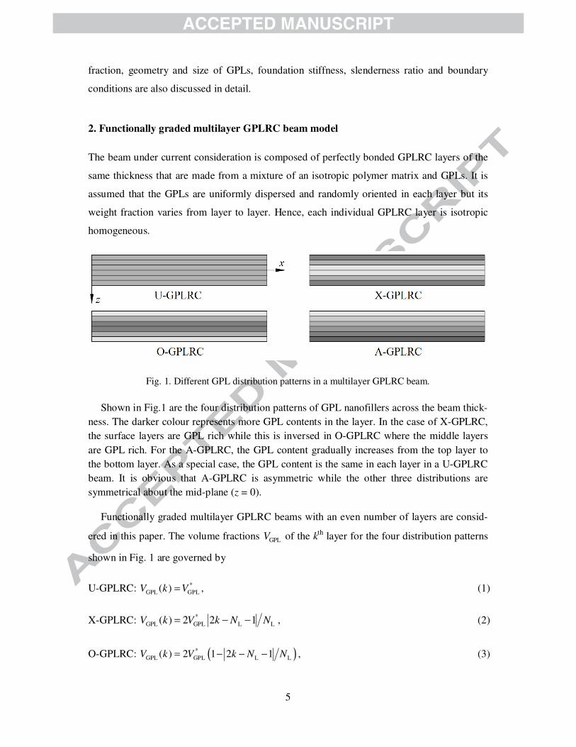
Fig. 1. Different GPL distribution patterns in a multilayer GPLRC beam.
Shown in Fig.1 are the four distribution patterns of GPL nanofillers across the beam thick-
ness. The darker colour represents more GPL contents in the layer. In the case of X-GPLRC,
the surface layers are GPL rich while this is inversed in O-GPLRC where the middle layers
are GPL rich. For the A-GPLRC, the GPL content gradually increases from the top layer to
the bottom layer. As a special case, the GPL content is the same in each layer in a U-GPLRC
beam. It is obvious that A-GPLRC is asymmetric while the other three distributions are
symmetrical about the mid-plane (z = 0).
Functionally graded multilayer GPLRC beams with an even number of layers are consid-
ered in this paper. The volume fractions GPLV of the kth layer for the four distribution patterns
shown in Fig. 1 are governed by
U-GPLRC: *
GPL GPL( )V k V= , (1)
X-GPLRC: *
GPL GPL L L( ) 2 2 1V k V k N N= − − , (2)
O-GPLRC: ( )*
GPL GPL L L( ) 2 1 2 1V k V k N N= − − − , (3)

6
A-GPLRC: ( )*
GPL GPL L( ) 2 1V k V k N= − , (4)
where k = 1, 2, …, NL and NL is the total number of layers of the beam. The total volume
fraction of GPLs, *
GPLV , is determined by
( )( )* GPL
GPL
GPL GPL m GPL1
WV
W Wρ ρ=
+ −, (5)
in which GPLW is GPL weight fraction; GPL
ρ and mρ are the mass densities of GPLs and the
polymer matrix, respectively.
The elastic modulus of composites with randomly oriented fillers can be approximated by
[25, 26]
L T
3 5,
8 8E E E= + (6)
where L
E and T
E are the longitudinal and transverse moduli for a unidirectional lamina and
can be calculated by the Halpin-Tsai model [27]:
L L f T T fL m T m
L f T f
1 1,
1 1
V VE E E E
V V
ξ η ξ η
η η
+ += × = ×
− −, (7)
in which fV is filler volume fraction. Combining Eqs. (6) and (7), the effective elastic modu-
lus of the GPLRC can be obtained as follows
L L GPL T T GPLm m
L GPL T GPL
1 13 5
8 1 8 1
V VE E E
V V
ξ η ξ η
η η
+ += × + ×
− −, (8)
where parameters Lη and Tη take the following forms:
( )( )
( )( )
GPL m GPL m
L T
GPL m L GPL m T
1 1,
E E E E
E E E Eη η
ξ ξ
− −= =
+ +. (9)
In the above equations, GPLE and m
E are Young’s moduli of the GPL and the matrix, respec-
tively. The filler geometry factors L
ξ and T
ξ for GPLs are given by [27]
( ) ( )L GPL GPL T GPL GPL2 , 2a t b tξ ξ= = , (10)
7
in which GPLa , GPL
b and GPLt are the length, width, and thickness of GPLs, respectively. Note
that Lξ can be rewritten as
( ) ( )L GPL GPL GPL GPL2 a b b tξ = × , (11)
where GPL GPLa b and GPL GPLb t denote GPL aspect ratio and width-to-thickness ratio, respec-
tively. According to the rule of mixture, Poisson’s ratio is expressed as [28]
m m GPL GPLV Vν ν ν= + , (12)
in which GPLν and mν are Poisson’s ratios of the GPL and matrix, respectively.
3. Nonlinear governing equations
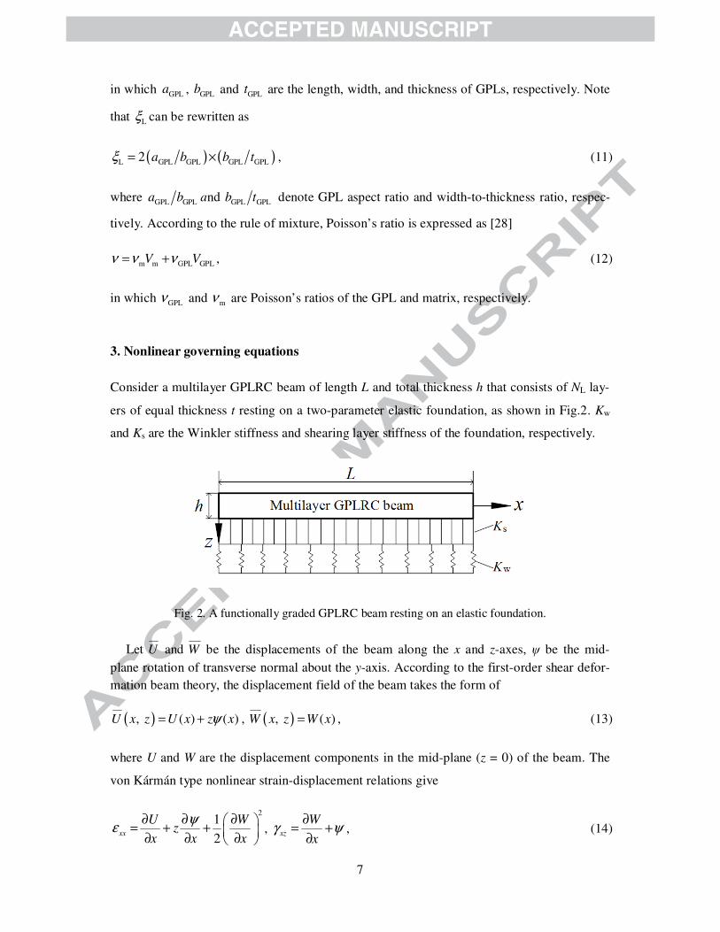
Consider a multilayer GPLRC beam of length L and total thickness h that consists of NL lay-
ers of equal thickness t resting on a two-parameter elastic foundation, as shown in Fig.2. Kw
and Ks are the Winkler stiffness and shearing layer stiffness of the foundation, respectively.
Fig. 2. A functionally graded GPLRC beam resting on an elastic foundation.
Let U and W be the displacements of the beam along the x and z-axes, ψ be the mid-
plane rotation of transverse normal about the y-axis. According to the first-order shear defor-
mation beam theory, the displacement field of the beam takes the form of
( ), ( ) ( )U x z U x z xψ= + , ( ), ( )W x z W x= , (13)
where U and W are the displacement components in the mid-plane (z = 0) of the beam. The
von Kármán type nonlinear strain-displacement relations give
21
2xx
U Wz
x x x
ψε
∂ ∂ ∂ = + +
∂ ∂ ∂ , xz
W
xγ ψ
∂= +
∂, (14)

8
The governing equations can be derived using the principle of virtual displacements:
( )p 0V ϒδ − = , (15)
where the total virtual energy V that is comprised of the strain energy of the beam and the
elastic potential energy of the foundation, and the virtual work p
ϒ done by an applied com-
pressive force P are given by
( )2
/22 2 2
11 55 w s0 /2 0
1 1 d d d
2 2
L h L
xx xzh
WV Q Q z x K W K x
xε γ
−
∂ = + + +
∂ ∫ ∫ ∫ , (16)
2
p0
1 d
2
L WP x
xϒ
∂ =
∂ ∫ , (17)
in which the reduced stiffnesses are given by
( )11 552,
1 2 1
E EQ Q
ν ν= =
− +. (18)
In view of Eq. (14), substituting for V and p
ϒ from Eqs. (16) and (17) into the virtual work
statement in Eq. (15) and integrating through the thickness of the beam, we obtain
( ) ( )
2 2
w s 2 20
s0 0
0
0 dL
x x xx x
L
L L
x x x x
N M QW W WU Q N K W K P W x
x x x x x x x
W W WN U M N Q K P W
x x x
δ δψ δ
δ δψ δ
∂ ∂ ∂∂ ∂ ∂ ∂ = + − + + + − − ∂ ∂ ∂ ∂ ∂ ∂ ∂
∂ ∂ ∂ − + − + + − ∂ ∂ ∂
∫, (19)
where the in-plane force xN , bending moment xM and transverse shear force xQ are calcu-
lated from
2
11 11 11
1
2x
U WN A B A
x x x
ψ∂ ∂ ∂ = + +
∂ ∂ ∂ , (20)
2
11 11 11
1
2x
U WM B D B
x x x
ψ∂ ∂ ∂ = + +
∂ ∂ ∂ , (21)
55x
WQ A
xκ ψ
∂ = +
∂ , (22)
9
in which κ = 5/6 is the shear correction factor. The kth
GPLRC layer is located between the
points z = kz and z = 1k
z + in the thickness direction. The stiffness components are defined as
{ }1/ 2
2 ( ) 2
11 11 11 11 11/2
1
, , {1, , }d {1, , }dL
k
k
Nh z
k
h zk
A B D Q z z z Q z z z+
−=
= =∑∫ ∫ , (23)
1/ 2( )
55 55 55/2
1
d dL
k
k
Nh z
k
h zk
A Q z Q z+
−=
= =∑∫ ∫ . (24)
The governing equations are obtained by setting the coefficients of Uδ , Wδ , and δψ in Eq.
(19) to zero separately:
0xN
x
∂=
∂, (25)
( )2 2
w s 2 20x
x
Q W WK W K N P
x x x
∂ ∂ ∂− + + − =
∂ ∂ ∂, (26)
0xx
MQ
x
∂− =
∂. (27)
In the present analysis, the beam is either clamped or hinged at each end. The associated out-
of-plane boundary conditions are
Clamped (C): U = 0, W = 0, ψ = 0. (28)
Hinged (H): U = 0, W = 0, xM = 0. (29)
Substituting Eqs. (20)-(22) into Eqs. (25)-(29), the governing equations and associated
boundary conditions can be rewritten in terms of displacements:
2 2 2
11 11 112 2 20
U W WA B A
x x x x
ψ∂ ∂ ∂ ∂+ + =
∂ ∂ ∂ ∂, (30)
22 2 2
55 w s 11 11 112 2 2
10
2
W W U W WA K W K A B A P
x x x x x x x
ψ ψκ
∂ ∂ ∂ ∂ ∂ ∂ ∂ + − + + + + − =
∂ ∂ ∂ ∂ ∂ ∂ ∂ , (31)
2 2 2
11 11 11 552 2 20
U W W WB D B A
x x x x x
ψκ ψ
∂ ∂ ∂ ∂ ∂ + + − + =
∂ ∂ ∂ ∂ ∂ ; (32)
Clamped (C): U = 0, W = 0, ψ = 0, (33)
10
Hinged (H): U = 0, W = 0,
2
11 11 11
10
2
U WB D B
x x x
ψ∂ ∂ ∂ + + =
∂ ∂ ∂ . (34)
4. Solution procedure
By introducing the following dimensionless quantities:
2
110 w w 110
2
s s 110 11 55 11 11 11 55 11 11 110
, , ( , ) ( , ) , , , ,
, ( , , , ) ( , , , ) ,
x L h L u w U W h P P A k K L A
k K A a a b d A A B h D h A
ζ η ϕ ψ
κ
= = = = = =
= = (35)
where 110
A is the value of 11
A of a homogeneous beam made from the pure matrix material,
the governing equations (30)-(32) can be transformed into the dimensionless form as
2 2 2
11 11 112 2 20
u w wa b a
ϕη
ζ ζ ζ ζ
∂ ∂ ∂ ∂+ + =
∂ ∂ ∂ ∂, (36)
22 2 22
55 11 11 11 w w2 2 2
1 10
2
w u w w wa a b a P k w k
ϕ ϕη η η
ζ η ζ ζ ζ ζ ζ ζ
∂ ∂ ∂ ∂ ∂ ∂ ∂+ + + + − − + =
∂ ∂ ∂ ∂ ∂ ∂ ∂ , (37)
2 2 2
5511 11 112 2 2
10
au w w wb d b
ϕη ϕ
ζ ζ ζ ζ η ζ η
∂ ∂ ∂ ∂ ∂+ + − + =
∂ ∂ ∂ ∂ ∂ . (38)
The associated boundary conditions can be handled in the same way:
Clamped (C): u = 0, w = 0, φ = 0; (39)
Hinged (H): u = 0, w = 0,
2
11 11 11
10
2
u wb d b
ϕη
ζ ζ ζ
∂ ∂ ∂+ + =
∂ ∂ ∂ . (40)
According to the differential quadrature (DQ) rule [29-31], the displacement components
u, w, φ and their jth partial derivatives with respect to ζ are approximated as the linear
weighting sums of mu , m
w , and mϕ by
{ } { }1
, , ( ) , ,N
m m m m
m
u w l u wϕ ζ ϕ=
=∑ , and { } ( ) { }1
, , , ,im
i
j Nj
m m mjm
u w C u w
ζ ζ
ϕ ϕζ ==
∂=
∂∑ (41)
11
where { }, ,m m m
u w ϕ are the values of { }, ,u w ϕ at ζ = mζ ; lm(ζ) is the Lagrange interpolation
polynomials; ( )im
jC is the weighting coefficient of the j
th derivative and can be calculated using
recursive formula [32, 33]. N is the total number of gird points distributed along the ζ-axis
according to a cosine pattern:
1 ( 1)1 cos
2 1i
i
N
πζ
− = − −
, i = 1, 2, …, N. (42)
By applying relationship (41) to the dimensionless governing equations (36)-(38), one ob-
tains the discretized governing equations:
( ) ( ) ( ) ( )2 2 1 2
11 11 11
1 1 1 1
0im im im im
N N N N
m m m m
m m m m
a C u b C a C w C wϕ η= = = =
+ + =∑ ∑ ∑ ∑ , (43)
( ) ( ) ( ) ( )
( ) ( ) ( )
2
1 1 1 22
11 11 11
1 1 1 1
2 1 2
55 w s
1 1 1
1
2
10
im im im im
im im im
N N N N
m m m m
m m m m
N N N
m m i m
m m m
a C u b C a C w P C w
a C w C k w k C w
η η ϕ η
ϕη
= = = =
= = =
+ + − ×
+ + − + =
∑ ∑ ∑ ∑
∑ ∑ ∑
, (44)
( ) ( ) ( ) ( ) ( )2 2 1 2 15511 11 11
1 1 1 1 1
10
im im im im im
N N N N N
m m m m m i
m m m m m
ab C u d C b C w C w C wϕ η ϕ
η η= = = = =
+ + − + =
∑ ∑ ∑ ∑ ∑ . (45)
The associated boundary conditions (39) and (40) can also be discretized in the same way:
1u = 0, 1w = 0, 1ϕ = 0, (46)
Nu = 0,
Nw = 0,
Nϕ = 0, (47)
for clamped ends at ζ = 0 and 1, respectively, and
1 0u = , 1 0w = , ( ) ( ) ( )1 1 1
2
1 1 1
11 11 11
1 1 1
10
2m m m
N N N
m m m
m m m
b C u d C b C wϕ η= = =
+ + =
∑ ∑ ∑ , (48)
0N
u = , 0N
w = , ( ) ( ) ( )2
1 1 1
11 11 11
1 1 1
10
2Nm Nm Nm
N N N
m m m
m m m
b C u d C b C wϕ η= = =
+ + =
∑ ∑ ∑ , (49)
for hinged ends at ζ = 0, 1.

12
Substitution of the associated boundary conditions (46)-(49) into the discretized governing
equations (43)-(45) leads to a nonlinear algebraic system that governs the buckling and
postbuckling behaviours of the beam resting on an elastic foundation as
[ ]L1 L2 NL1 NL2P− + + =K K K K d 0 , (50)
where d denotes the unknown displacement vector that is composed of mu , mw , mϕ (m = 1,
2, …, N); L1
K and L2
K are constant coefficient matrices, while NL1
K and NL2
K are nonline-
ar matrices, the elements of which are linear and quadratic functions of d, respectively.
By dropping the nonlinear matrices, Eq. (50) reduces to a standard eigenvalue problem
from which the critical buckling load of the functionally graded multilayer GPLRC beam can
be obtained as the lowest positive eigenvalue. After buckling, the postbuckling equilibrium
path of the beam can be determined by solving the nonlinear governing equation (50) with
the iterative scheme detailed by Liew et al. [34].
5. Results and Discussion
Convergence studies are first conducted, and the results with varying numbers of grid points
and layers are compared in Table 1 where the dimensionless critical buckling load Pcr and the
dimensionless postbuckling load PNL at a given dimensionless midspan deflection wm = 1.0
are provided. It is seen that convergent results are obtained when the total numbers of grid
points and individual layers are increased to N = 13 and NL = 22, respectively, implying that a
multilayer GPLRC beam with 22 or more layers is an excellent approximation for an ideal
functionally graded beam structure with a continuous and smooth variation in both material
composition and properties. Considering the ease of fabrication and the manufacturing cost,
NL = 10, as well as N = 13, are used in all the following numerical examples.
Table 1 Buckling and postbuckling results with varying total numbers of grid points and layers for a
C-C functionally graded multilayer X-GPLRC beam (L/h = 10, WGPL = 0.3%).
N (NL = 10) Pcr PNL (wm = 1.0) NL (N = 13) Pcr PNL (wm = 1.0)
7 0.0709 0.0762 4 0.0682 0.1175
9 0.0709 0.1128 6 0.0700 0.1192
11 0.0709 0.1199 10 0.0709 0.1201
13 0.0709 0.1201 16 0.0712 0.1204
13
15 0.0709 0.1201 22 0.0713 0.1205
17 0.0709 0.1201 28 0.0713 0.1205
In order to validate the present formulation and solution procedure, the dimensionless crit-
ical buckling loads of carbon nanotube-reinforced composite (CNTRC) beams with and
without an elastic foundation are calculated and compared in Table 2 with those from the lit-
erature. The material properties used in this example can be found in [35, 36]. As can be ob-
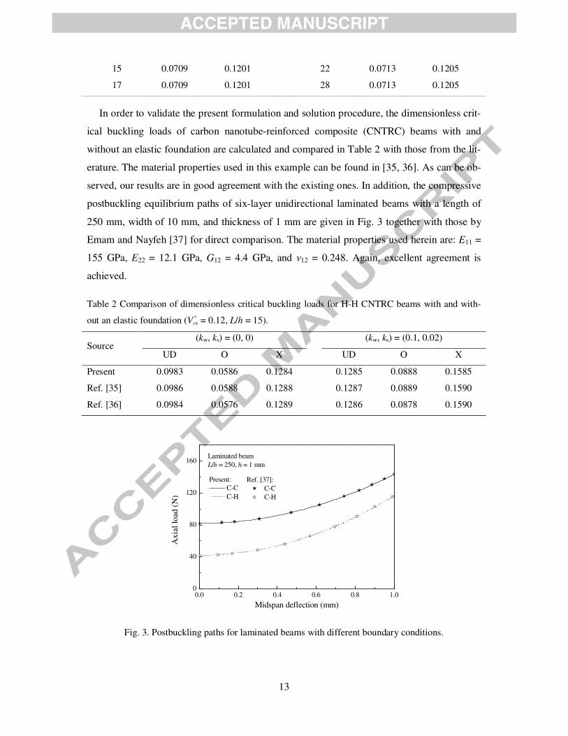
served, our results are in good agreement with the existing ones. In addition, the compressive
postbuckling equilibrium paths of six-layer unidirectional laminated beams with a length of
250 mm, width of 10 mm, and thickness of 1 mm are given in Fig. 3 together with those by
Emam and Nayfeh [37] for direct comparison. The material properties used herein are: E11 =
155 GPa, E22 = 12.1 GPa, G12 = 4.4 GPa, and ν12 = 0.248. Again, excellent agreement is
achieved.
Table 2 Comparison of dimensionless critical buckling loads for H-H CNTRC beams with and with-
out an elastic foundation (V *
cn = 0.12, L/h = 15).
Source (kw, ks) = (0, 0) (kw, ks) = (0.1, 0.02)
UD O X UD O X
Present 0.0983 0.0586 0.1284 0.1285 0.0888 0.1585
Ref. [35] 0.0986 0.0588 0.1288 0.1287 0.0889 0.1590
Ref. [36] 0.0984 0.0576 0.1289 0.1286 0.0878 0.1590
0.0 0.2 0.4 0.6 0.8 1.00
40
80
120
160
Ref. [37]:
C-C
C-H
Present:
C-C
C-H
Ax
ial
load
(N
)
Midspan deflection (mm)
Laminated beam
L/h = 250, h = 1 mm
Fig. 3. Postbuckling paths for laminated beams with different boundary conditions.

14
In what follows, the functionally graded multilayer GPLRC beams with a total thickness h
= 0.01 m and a total number of layers NL = 10 are considered. Each GPLRC layer is made
from a mixture of epoxy and GPLs with a length of GPLa = 2.5 µm, width of GPLb = 1.5 µm,
and thickness of GPL
t = 1.5 nm. The material properties of epoxy matrix are Em = 3.0 GPa, m
ρ
= 1200 kg m-3
, and mν = 0.34 while those of GPLs are EGPL = 1.01 TPa, GPLν = 0.186, and
GPLρ = 1062.5 kg m-3
, as reported in [9, 38].
Table 3 compares the dimensionless critical buckling loads of nanocomposite beams rein-
forced with different nanofillers (GPLs, SWCNTs, and MWCNTs) with the same value of
content Wfiller = 0.3%. The results of the homogeneous pure epoxy beam are also given to
evaluate the reinforcing effects of GPLs, SWCNTs, and MWCNTs. The material properties
and geometry parameters of the SWCNT and MWCNT can be found in [9]. Note that for
CNTs, the filler geometry factors L CNT CNTl dξ = and T
ξ = 2, where CNTl and CNT
d are the
CNT length and diameter, respectively. The critical buckling load is the highest for the beam
with GPL reinforcements. For example, incorporation of 0.3% weight fraction of GPLs uni-
formly dispersed (pattern U) increases the critical buckling load of the beam by 99.3% from
0.0294 to 0.0586, followed by the SWCNTs with a 43.2% increase and MWCNTs with a
10.2% increase. This clearly indicates that GPLs offer much better reinforcement than
SWCNTs and MWCNTs. This can be attributed to GPL’s much higher specific surface area
and two-dimensional geometry that significantly strengthen the interface between the GPLs
and epoxy for effective stress transfer [6, 39]. Among the four distribution patterns in Fig.1,
pattern X yields the highest buckling load, followed by patterns U, A, and O, which indicates
that distribution pattern X is capable of making the most effective use of the reinforcing
nanofillers.
Table 3 Dimensionless critical buckling loads of functionally graded multilayer composite beams re-
inforced with different nanofillers (C-C, L/h = 10, Wfiller = 0.3%).
Filler Pattern U Pattern X Pattern O Pattern A
Pure epoxy 0.0294 0.0294 0.0294 0.0294
GPL 0.0586 0.0709 0.0458 0.0543
SWCNT 0.0421 0.0475 0.0366 0.0410
MWCNT 0.0324 0.0337 0.0311 0.0323
15
Table 4 Dimensionless critical buckling loads of functionally graded multilayer GPLRC beams with
different GPL weight fractions and distribution patterns (C-C , L/h = 10).
(kw, ks) WGPL U-GPLRC X-GPLRC O-GPLRC A-GPLRC
(0.00, 0.00) 0.1% 0.0391 0.0433 0.0349 0.0384
0.3% 0.0586 0.0709 0.0458 0.0543
0.5% 0.0781 0.0984 0.0565 0.0691
(0.10, 0.00) 0.1% 0.0466 0.0507 0.0424 0.0459
0.3% 0.0661 0.0784 0.0533 0.0619
0.5% 0.0857 0.1059 0.0641 0.0767
(0.10, 0.02) 0.1% 0.0666 0.0707 0.0624 0.0659
0.3% 0.0861 0.0984 0.0733 0.0819
0.5% 0.1057 0.1259 0.0841 0.0967
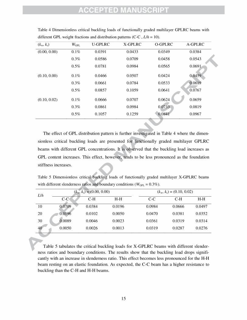
The effect of GPL distribution pattern is further investigated in Table 4 where the dimen-
sionless critical buckling loads are presented for functionally graded multilayer GPLRC
beams with different GPL concentrations. It is observed that the buckling load increases as
GPL content increases. This effect, however, tends to be less pronounced as the foundation
stiffness increases.
Table 5 Dimensionless critical buckling loads of functionally graded multilayer X-GPLRC beams
with different slenderness ratios and boundary conditions (WGPL = 0.3%).
L/h (kw, ks) = (0.00, 0.00) (kw, ks) = (0.10, 0.02)
C-C C-H H-H C-C C-H H-H
10 0.0709 0.0384 0.0196 0.0984 0.0666 0.0497
20 0.0196 0.0102 0.0050 0.0470 0.0381 0.0352
30 0.0089 0.0046 0.0023 0.0361 0.0319 0.0314
40 0.0050 0.0026 0.0013 0.0319 0.0287 0.0276
Table 5 tabulates the critical buckling loads for X-GPLRC beams with different slender-
ness ratios and boundary conditions. The results show that the buckling load drops signifi-
cantly with an increase in slenderness ratio. This effect becomes less pronounced for the H-H
beam resting on an elastic foundation. As expected, the C-C beam has a higher resistance to
buckling than the C-H and H-H beams.
16
100
101
102
103
104
0.02
0.04
0.06
0.08
aGPL
/bGPL
= 1
aGPL
/bGPL
= 4
aGPL
/bGPL
= 10
aGPL
/bGPL
= 20
Pcr
bGPL
/tGPL
X-GPLRC, C-C
WGPL
= 0.3%, L/h = 10
Fig. 4. Effects of GPL geometry and size on the critical buckling load of functionally graded multi-
layer X-GPLRC beams.
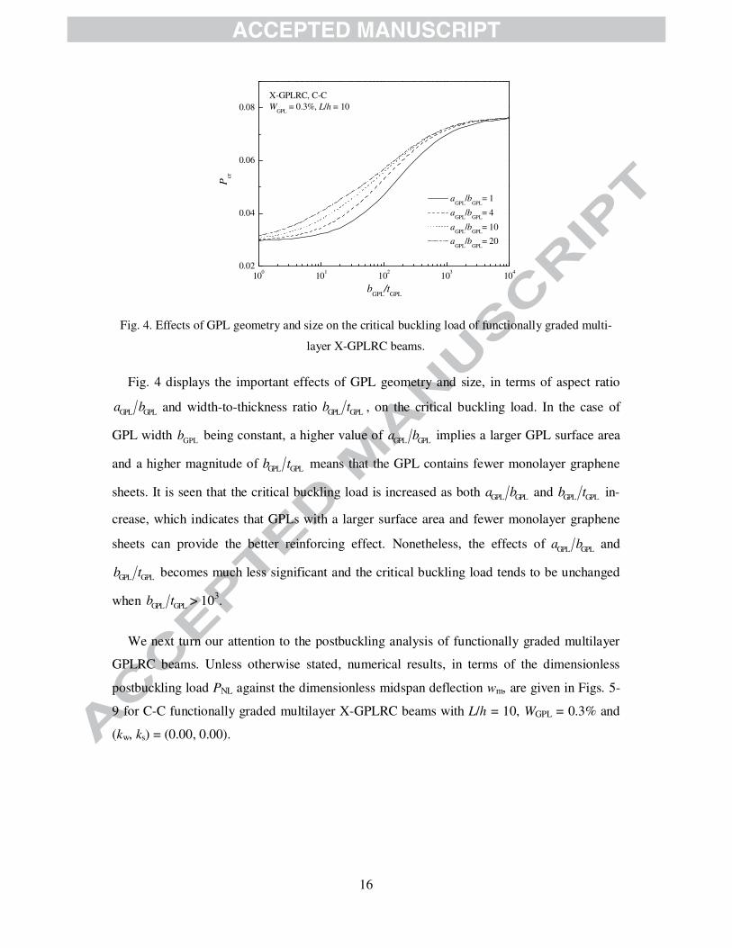
Fig. 4 displays the important effects of GPL geometry and size, in terms of aspect ratio
GPL GPLa b and width-to-thickness ratio GPL GPL
b t , on the critical buckling load. In the case of
GPL width GPL
b being constant, a higher value of GPL GPL
a b implies a larger GPL surface area
and a higher magnitude of GPL GPLb t means that the GPL contains fewer monolayer graphene
sheets. It is seen that the critical buckling load is increased as both GPL GPLa b and GPL GPLb t in-
crease, which indicates that GPLs with a larger surface area and fewer monolayer graphene
sheets can provide the better reinforcing effect. Nonetheless, the effects of GPL GPL
a b and
GPL GPLb t becomes much less significant and the critical buckling load tends to be unchanged
when GPL GPLb t > 10
3.
We next turn our attention to the postbuckling analysis of functionally graded multilayer
GPLRC beams. Unless otherwise stated, numerical results, in terms of the dimensionless
postbuckling load PNL against the dimensionless midspan deflection wm, are given in Figs. 5-
9 for C-C functionally graded multilayer X-GPLRC beams with L/h = 10, WGPL = 0.3% and
(kw, ks) = (0.00, 0.00).

17
0.0 0.2 0.4 0.6 0.8 1.00.00
0.04
0.08
0.12
0.16
Nanofillers:
GPL
SWCNT
MWCNT
Pure Epoxy
PN
L
wm
Multilayer beam, C-C
Wfiller
= 0.3%, L/h = 10
Fig. 5. Postbuckling paths for beams reinforced with different nanofillers.
Fig. 5 compares the postbuckling equilibrium paths for nanocomposite beams reinforced
with GPLs, SWCNTs, and MWCNTs. As observed in buckling analysis, GPL shows the
most significant reinforcing effect on the postbuckling behaviour of the beam, leading to the
highest postbuckling load-carrying capacity, followed by SWCNTs and MWCNT. This is
because, as mentioned before, GPLs are two-dimensional materials while CNTs are one-
dimensional. The lamellar-shaped GPLs can be more perfectly bonded to the epoxy and ef-
fectively transfer the stress at the GPL/epoxy interface [39].
0.0 0.2 0.4 0.6 0.8 1.00.00
0.04
0.08
0.12
0.16
X-GPLRC
U-GPLRC
A-GPLRC
O-GPLRC
Pure Epoxy
PN
L
wm
GPLRC, C-C
Wfiller
= 0.3%, L/h = 10
Fig. 6. Effect of GPL distribution pattern on postbuckling paths of functionally graded multilayer
GPLRC beams.

18
0.0 0.2 0.4 0.6 0.8 1.00.00
0.04
0.08
0.12
0.16
0.20
WGPL
= 0.0% (pure epoxy)
WGPL
= 0.1%
WGPL
= 0.3%
WGPL
= 0.5%
PN
L
wm
X-GPLRC, C-C
L/h = 10
Fig. 7. Effect of GPL weight fraction on postbuckling paths of functionally graded multilayer X-
GPLRC beams.
Figs. 6 and 7 display the postbuckling responses of functionally graded multilayer GPLRC
beams with different GPL distribution patterns and weight fractions, respectively. The results
show that the X-GPLRC beam is capable of carrying higher loads in the postbuckling region
than the beams with other GPL distribution patterns. This is because the X-GPLRC beam
with more GPLs distributed closely to surface layers has the highest beam stiffness. Com-
pared with the pure epoxy beam, all GPLRC beams exhibit considerably higher postbuckling
load-carrying capacity that increases as GPL content grows.
0.0 0.2 0.4 0.6 0.8 1.00.04
0.08
0.12
0.16
aGPL
/bGPL
= 1
aGPL
/bGPL
= 4
aGPL
/bGPL
= 10
aGPL
/bGPL
= 20
PN
L
wm
X-GPLRC, C-C
WGPL
= 0.3%, L/h = 10
bGPL
/tGPL
= 103
(a)

19
0.0 0.2 0.4 0.6 0.8 1.00.00
0.04
0.08
0.12
0.16
bGPL
/tGPL
= 10
bGPL
/tGPL
= 102
bGPL
/tGPL
= 103
bGPL
/tGPL
= 104
PN
L
wm
X-GPLRC, C-C
Wfiller
= 0.3%, L/h = 10
aGPL
/bGPL
= 4
(b)
Fig. 8. Effects of GPL geometry and size on postbuckling paths of functionally graded multilayer X-
GPLRC beams: (a) aspect ratio; (b) width-to-thickness ratio.
The effects of GPL geometry and size on the postbuckling load-deflection curves are in-
vestigated in Fig. 8 for functionally graded multilayer X-GPLRC beams. The GPL width-to-
thickness ratio is taken as GPL GPLb t = 10
3 in Fig. 8a and its aspect ratio is chosen to be GPL GPL
a b
= 4 in Fig. 8b, respectively. The postbuckling resistance increases with an increase in both
GPL GPLa b and GPL GPLb t . This effect, as revealed in buckling analysis, is seen to be much less
significant when GPL GPLa b > 4 and GPL GPLb t > 103. It should also be noted that GPL width-to-
thickness ratio has a much more important influence on the postbuckling behaviour than the
aspect ratio.
Fig. 9 depicts the effect of foundation stiffness on the postbuckling behaviour of function-
ally graded multilayer X-GPLRC beams resting on an elastic foundation. As has been shown
in Table 4, (kw, ks) = (0.10, 0.02) represents the Pasternak elastic foundation; (kw, ks) = (0.10,
0.00) indicates the Winkler elastic foundation and (kw, ks) = (0.00, 0.00) is for the beam with-
out an elastic foundation. The postbuckling curve tends to be higher as the foundation stiff-
ness increases, with the effect of shearing layer stiffness ks being more noticeable than that of
the Winkler foundation stiffness kw.
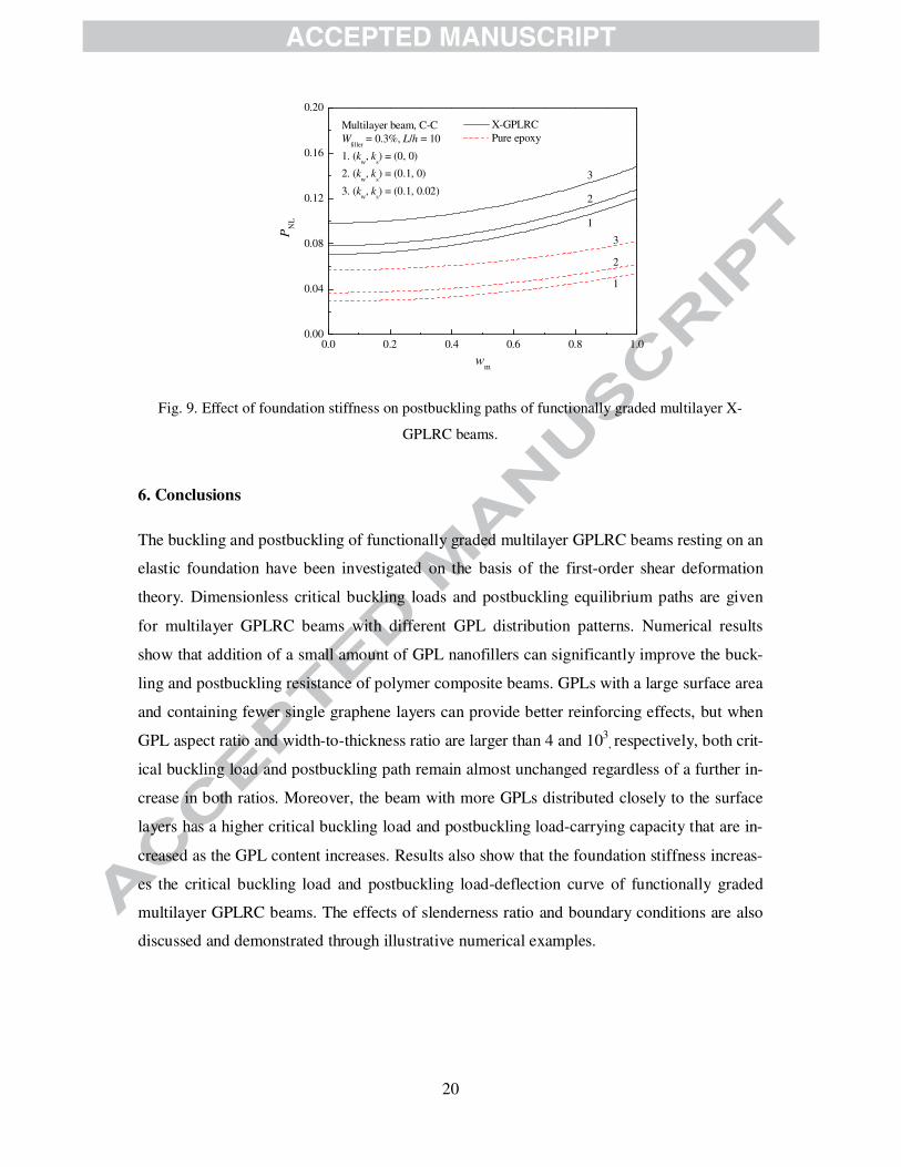
20
0.0 0.2 0.4 0.6 0.8 1.00.00
0.04
0.08
0.12
0.16
0.20
1
3
X-GPLRC
Pure epoxy
PN
L
wm
Multilayer beam, C-C
Wfiller
= 0.3%, L/h = 10
1. (kw, k
s) = (0, 0)
2. (kw, k
s) = (0.1, 0)
3. (kw, k
s) = (0.1, 0.02)
2
3
2
1
Fig. 9. Effect of foundation stiffness on postbuckling paths of functionally graded multilayer X-
GPLRC beams.
6. Conclusions
The buckling and postbuckling of functionally graded multilayer GPLRC beams resting on an
elastic foundation have been investigated on the basis of the first-order shear deformation
theory. Dimensionless critical buckling loads and postbuckling equilibrium paths are given
for multilayer GPLRC beams with different GPL distribution patterns. Numerical results
show that addition of a small amount of GPL nanofillers can significantly improve the buck-
ling and postbuckling resistance of polymer composite beams. GPLs with a large surface area
and containing fewer single graphene layers can provide better reinforcing effects, but when
GPL aspect ratio and width-to-thickness ratio are larger than 4 and 103, respectively, both crit-
ical buckling load and postbuckling path remain almost unchanged regardless of a further in-
crease in both ratios. Moreover, the beam with more GPLs distributed closely to the surface
layers has a higher critical buckling load and postbuckling load-carrying capacity that are in-
creased as the GPL content increases. Results also show that the foundation stiffness increas-
es the critical buckling load and postbuckling load-deflection curve of functionally graded
multilayer GPLRC beams. The effects of slenderness ratio and boundary conditions are also
discussed and demonstrated through illustrative numerical examples.

21
Acknowledgement
The work described in this paper was fully funded by the research grant from the Australian
Research Council under Discovery Project scheme (DP160101978). The authors are grateful
for this financial support.
References
[1] Novoselov KS, Geim AK, Morozov SV, Jiang D, Zhang Y, Dubonos SV, Grigorieva
IV, Firsov AA. Electric field effect in atomically thin carbon films. Science
2004;306(5696):666-669.
[2] Lee C, Wei X, Kysar JW, Hone J. Measurement of the elastic properties and intrinsic
strength of monolayer graphene. Science 2008;321(5887):385-388.
[3] Balandin AA, Ghosh S, Bao W, Calizo I, Teweldebrhan D, Miao F, Lau CN. Superior
thermal conductivity of single-layer graphene. Nano Lett 2008;8(3):902-907.
[4] Du X, Skachko I, Barker A, Andrei EY. Approaching ballistic transport in suspended
graphene. Nat Nanotechnol 2008;3(8):491-495.
[5] Bonaccorso F, Colombo L, Yu G, Stoller M, Tozzini V, Ferrari AC, Ruoff RS,
Pellegrini V. Graphene, related two-dimensional crystals, and hybrid systems for ener-
gy conversion and storage. Science 2015;347(6217):1246501.
[6] Ji X-Y, Cao Y-P, Feng X-Q. Micromechanics prediction of the effective elastic moduli
of graphene sheet-reinforced polymer nanocomposites. Model Simul Mater Sc
2010;18(4):045005.
[7] Young RJ, Kinloch IA, Gong L, Novoselov KS. The mechanics of graphene
nanocomposites: A review. Compos Sci Technol 2012;72(12):1459-1476.
[8] Kim H, Abdala AA, Macosko CW. Graphene/polymer nanocomposites. Macromole-
cules 2010;43(16):6515-6530.
[9] Rafiee MA, Rafiee J, Wang Z, Song H, Yu Z-Z, Koratkar N. Enhanced mechanical
properties of nanocomposites at low graphene content. ACS Nano 2009;3(12):3884-
3890.
[10] Zhao X, Zhang Q, Chen D, Lu P. Enhanced mechanical properties of graphene-based
poly (vinyl alcohol) composites. Macromolecules 2010;43(5):2357-2363.
22
[11] Bortz DR, Heras EG, Martin-Gullon I. Impressive fatigue life and fracture toughness
improvements in graphene oxide/epoxy composites. Macromolecules 2011;45(1):238-
245.
[12] Yang S-Y, Lin W-N, Huang Y-L, Tien H-W, Wang J-Y, Ma C-CM, Li S-M, Wang Y-S.
Synergetic effects of graphene platelets and carbon nanotubes on the mechanical and
thermal properties of epoxy composites. Carbon 2011;49(3):793-803.
[13] King JA, Klimek DR, Miskioglu I, Odegard GM. Mechanical properties of graphene
nanoplatelet/epoxy composites. J Appl Polym Sci 2013;128(6):4217-4223.
[14] Liu J, Yan H, Jiang K. Mechanical properties of graphene platelet-reinforced alumina
ceramic composites. Ceram Int 2013;39(6):6215-6221.
[15] Wu H, Drzal LT. Effect of graphene nanoplatelets on coefficient of thermal expansion
of polyetherimide composite. Mater Chem Phys 2014;146(1):26-36.
[16] Meguid S, Sun Y. On the tensile and shear strength of nano-reinforced composite inter-
faces. Mater Design 2004;25(4):289-296.
[17] Tang L-C, Wan Y-J, Yan D, Pei Y-B, Zhao L, Li Y-B, Wu L-B, Jiang J-X, Lai G-Q.
The effect of graphene dispersion on the mechanical properties of graphene/epoxy
composites. Carbon 2013;60:16-27.
[18] Stankovich S, Dikin DA, Piner RD, Kohlhaas KA, Kleinhammes A, Jia Y, Wu Y, Ngu-
yen ST, Ruoff RS. Synthesis of graphene-based nanosheets via chemical reduction of
exfoliated graphite oxide. Carbon 2007;45(7):1558-1565.
[19] Shen H-S. Nonlinear bending of functionally graded carbon nanotube-reinforced com-
posite plates in thermal environments. Compos Struct 2009;91(1):9-19.
[20] Liew KM, Lei ZX, Zhang LW. Mechanical analysis of functionally graded carbon
nanotube reinforced composites: A review. Compos Struct 2015;120(0):90-97.
[21] Wu HL, Yang J, Kitipornchai S. Nonlinear vibration of functionally graded carbon
nanotube-reinforced composite beams with geometric imperfections. Compos Part B-
Eng 2016;90:86-96.
[22] Wu HL, Yang J, Kitipornchai S. Imperfection sensitivity of postbuckling behaviour of
functionally graded carbon nanotube-reinforced composite beams. Thin Wall Struct
2016;108:225-233.
[23] Tiwari A, Syväjärvi M. Graphene materials: fundamentals and emerging applications:
John Wiley & Sons, 2015.
[24] Rafiee M, Rafiee J, Yu Z-Z, Koratkar N. Buckling resistant graphene nanocomposites.
Appl Phys Lett 2009;95(22):223103.

23
[25] Derek H. An Introduction to Composite Materials: Cambridge University Press, 1981.
[26] Harris B. Engineering Composite Materials: Institute of metals London, 1986.
[27] Halpin J, Kardos J. The Halpin-Tsai equations: a review. Polym Eng Sci
1976;16(5):344-352.
[28] Hejazi SM, Abtahi SM, Safaie F. Investigation of thermal stress distribution in fiber-
reinforced roller compacted concrete pavements. J Ind Text 2016;45(5):896-914.
[29] Shu C. Differential Quadrature and Its Application in Engineering. London: Springer,
2000.
[30] Wu H, Kitipornchai S, Yang J. Thermo-electro-mechanical postbuckling of piezoelec-
tric FG-CNTRC beams with geometric imperfections. Smart Mater Struct
2016;25(9):095022.
[31] Wu H, Kitipornchai S, Yang J. Free vibration and buckling analysis of sandwich beams
with functionally graded carbon nanotube-reinforced composite face sheets. Int J Struct
Stab Dy 2015;15(7):1540011.
[32] Bert CW, Wang X, Striz AG. Differential quadrature for static and free vibration anal-
yses of anisotropic plates. Int J Solids Struct 1993;30(13):1737-1744.
[33] Yang J, Kitipornchai S, Liew K. Non-linear analysis of the thermo-electro-mechanical
behaviour of shear deformable FGM plates with piezoelectric actuators. Int J Numer
Method Eng 2004;59(12):1605-1632.
[34] Liew KM, Yang J, Kitipornchai S. Postbuckling of piezoelectric FGM plates subject to
thermo-electro-mechanical loading. Int J Solids Struct 2003;40(15):3869-3892.
[35] Yas M, Samadi N. Free vibrations and buckling analysis of carbon nanotube-reinforced
composite Timoshenko beams on elastic foundation. Int J Pressure Vessels Pip
2012;98:119-128.
[36] Wattanasakulpong N, Ungbhakorn V. Analytical solutions for bending, buckling and
vibration responses of carbon nanotube-reinforced composite beams resting on elastic
foundation. Comp Mater Sci 2013;71:201-208.
[37] Emam SA, Nayfeh AH. Postbuckling and free vibrations of composite beams. Compos
Struct 2009;88(4):636-642.
[38] Liu F, Ming P, Li J. Ab initio calculation of ideal strength and phonon instability of
graphene under tension. Phys Rev B 2007;76(6):064120.
[39] Fu S-Y, Feng X-Q, Lauke B, Mai Y-W. Effects of particle size, particle/matrix inter-
face adhesion and particle loading on mechanical properties of particulate–polymer
composites. Compos Part B-Eng 2008;39(6):933-961.