640460-1.pdf - Eindhoven University of Technology research ...
Upload
khangminh22Category
view
0download
0
Eindhoven University of Technology
MASTER
Buckling length factors of hollow section members in lattice girders
Boel, H.D.
Award date:2010
Link to publication
DisclaimerThis document contains a student thesis (bachelor's or master's), as authored by a student at Eindhoven University of Technology. Studenttheses are made available in the TU/e repository upon obtaining the required degree. The grade received is not published on the documentas presented in the repository. The required complexity or quality of research of student theses may vary by program, and the requiredminimum study period may vary in duration.
General rightsCopyright and moral rights for the publications made accessible in the public portal are retained by the authors and/or other copyright ownersand it is a condition of accessing publications that users recognise and abide by the legal requirements associated with these rights.
• Users may download and print one copy of any publication from the public portal for the purpose of private study or research. • You may not further distribute the material or use it for any profit-making activity or commercial gain

EINDHOVEN
Buckling L
Section Members in Lattice Girders
Part A: Preliminary Study
Part B: N
HARM BOEL
ID: 0640722
SUPERVISORS:
PROF. IR. H.H. SNIJDER
DR. IR. J.C.D. HOENDERKAMP
IR. R.C. SPOORENBERG
A-2010.6
O-2010.11
INDHOVEN UNIVERSITY OF TECHNOLOGY
Buckling Length Factors of Hollow
embers in Lattice Girders
Part A: Preliminary Study
art B: Numerical Investigation
Appendices
10-11-2010
Hollow
embers in Lattice Girders


Summary The buckling length of an axially loaded member is governed by its boundary conditions. When a hollow
section member in a lattice girder is welded to other members, the end conditions are not known and
influenced by many parameters and by the load case of the girder as well. Thus a buckling length factor cannot
be determined easily. Buckling length factors are given by the old and current Eurocode and by the old Dutch
code. But, the bucking length factors and conditions that must be met to apply these are contradictory. CIDECT
provides formulae to determine the buckling length factor of brace members. But, in the current investigation,
the influence of many variables are unknown and are not taken into account in the given design rules. Most
importantly, a recent numerical study shows that sometimes these design rules provide a too low, and thus a
rather unsafe, buckling length factor.
In Part A “Preliminary study”, it is described what has already been done and thus, what is known about
buckling length factors of hollow section members in lattice girders. A numerical study, recently performed at
the Eindhoven University of Technology, is described, as well as the Finite Element model used to determine
buckling length factors. This model is the basis for the much simpler FE-model, that will be used to execute the
numerical investigations, described in Part B. At the end of the preliminary study, it is concluded that it is
desirable to have more knowledge about the influence of β (ratio of the width/diameter of the brace member
to that of the chord) and γ (ratio of the outer width/diameter to two times the wall thickness of the chord
member) on the buckling length factor.
In Part B “Numerical investigation”, a new and much simpler FE-model of a lattice girder than used in a
previous study, comprising beam-elements rather than shell-elements, is developed to numerically investigate
the buckling length factors. This is done because the previous model required a large number of shell-elements
which made it cumbersome to obtain FE-output, easy to make errors and the previous model required a large
calculation-time. More importantly, this model did not make it possible to investigate the influence of several
parameters separately, such as the influence of the connection stiffness on the buckling length factor. For the
beam-element model, it was necessary to determine the connection stiffnesses by a shell-element model of
the connection. These stiffnesses are represented by rotational springs, connecting the beam-elements
(representing the members) in the FE-model, as shown in Figure 1.
1) Schematization of beam-element model and shell-element model to determine connection stiffness
The FE-model of the connection is composed of two braces and one chord. Several load combinations were
applied to the braces resulting in different stiffness values. The different stiffness values were applied in the
beam-element model. The buckling loads obtained by the beam-element model were compared to the ones
obtained by the full shell-element model (see Figure 2). The stiffness value, providing the most consistency
between the beam- and shell-element model regarding the buckling loads, was determined and used in the
beam-element model to perform the parameter study.


2) Comparison of buckling shapes. Shell-element model (left) and beam-element model (right) (isometric view)
A basic geometry of a lattice girder is used to perform the parameter study. Realistic dimensions have been
selected for the chord and brace members where the chord is varied in section type (square and circular
hollow sections) and in wall thickness. The brace has been varied in section type and dimension. Hereby, the
minimum gap, prescribed by the Eurocode, is applied. Furthermore, the aspect ratio of the lattice girder is
varied and the influence of lateral supports was investigated.
The investigation gave insight into the behavior of the connections between hollow section members and into
the buckling behavior of hollow section members in lattice girders. It appears that both β and γ significantly
influence the stiffness and buckling length factor of members in lattice girders. Also, the buckling length
factors obtained by FE-analysis are compared to the ones given by the Eurocode and CIDECT formulae. It was
found that in general these existing methods are not accurate, as can be seen in Figure 3.
3) In-plane buckling length factors of square section brace members connected to square section chord members
Because the existing methods are not accurate, new formulae were developed, based on existing formulae
and the buckling length factors obtained from FE-analysis. The formulae to determine the buckling length
factor of, for example, brace members are of the form as given below, where A, B, C and D are constants
which depend on the section type combination and in- or out-of plane buckling of the brace.
( ) 1
C
cr
sys
L bK A B D
L Lγ β
= = + +


MASTER THESIS HARM BOEL
3
TABLE OF CONTENTS:
1. INTRODUCTION ..................................................................................................................................... 7
1.1 PROBLEM STATEMENT ................................................................................................................................. 7
1.2 AIM OF RESEARCH ...................................................................................................................................... 8
1.3 PART A: PRELIMINARY STUDY ....................................................................................................................... 8
1.4 PART B: NUMERICAL INVESTIGATION ............................................................................................................. 9
PART A: PRELIMINARY STUDY
2. BUCKLING ........................................................................................................................................... 13
2.1 EULER BUCKLING LOAD/LBA ...................................................................................................................... 13
2.2 FIRST ORDER, SECOND ORDER/GNIA, NTH
ORDER AND GMNIA ........................................................................ 16
2.2.1 First order calculation ..................................................................................................................... 16
2.2.2 2nd
order calculation/GNIA.............................................................................................................. 17
2.2.3 nth
order calculation/GNIA .............................................................................................................. 17
2.2.4 GMNIA ............................................................................................................................................ 18
2.3 BUCKLING LENGTH .................................................................................................................................... 19
2.4 BUCKLING ACCORDING TO THE CODES........................................................................................................... 21
2.4.1 Plasticity and Slenderness ............................................................................................................... 21
2.4.2 Imperfection .................................................................................................................................... 22
2.4.3 Buckling load ................................................................................................................................... 22
2.4.4 Partially fixed ends .......................................................................................................................... 23
2.5 BUCKLING IN THE FINITE ELEMENT METHOD ................................................................................................... 24
2.5.1 The FE methods of solution ............................................................................................................. 24
2.5.2 Example using a full-shell-element model ...................................................................................... 24
3. LATTICE GIRDERS, HOLLOW SECTIONS AND CONNECTIONS ................................................................ 29
3.1 LATTICE GIRDERS ...................................................................................................................................... 29
3.1.1 Buckling of the chord member ........................................................................................................ 30
3.1.2 Buckling of a brace member ........................................................................................................... 32
3.2 HOLLOW SECTION MEMBERS ...................................................................................................................... 33
3.3 CONNECTIONS BETWEEN HSS-MEMBERS ...................................................................................................... 34
4. LITERARY STUDY ................................................................................................................................. 36
4.1 THE CODES (EUROCODE 3 AND NEN6770 (DUTCH CODE)) ............................................................................. 36
4.1.1 Buckling length factors for HSS in lattice girders ............................................................................ 36
4.1.2 Rigidity of connections .................................................................................................................... 37
4.2 WARDENIER ET AL. (1991/1992) CICECT DESIGN GUIDE 1 TO 3. ................................................................... 38
4.2.1 Out of plane buckling of chord members ........................................................................................ 38
4.2.2 Buckling of brace members ............................................................................................................. 38
4.3 MOUTY, J. (1981) CIDECT MONOGRAPH 4: EFFECTIVE LENGTHS OF LATTICE GIRDER MEMBERS ............................. 39
4.3.1 Out-of-plane buckling of laterally unsupported chord members .................................................... 39
4.3.2 Buckling of a brace member ........................................................................................................... 42
4.4 GALAMBOS AND XYKIS .............................................................................................................................. 43
4.5 GALAMBOS, T.V. (1998) GUIDE TO STABILITY DESIGN CRITERIA FOR METAL STRUCTURES (PP 579-586, 787-801) ... 44
4.5.1 Buckling of a chord member ........................................................................................................... 44
4.5.2 Buckling of a laterally unsupported compressive chord ................................................................. 45

MASTER THESIS HARM BOEL
4
4.5.3 Buckling of a brace member ........................................................................................................... 47
4.6 CHEN, W. (1993) SEMI-RIGID CONNECTIONS IN STEEL FRAMES (PAGE 181-184) ................................................ 47
4.7 KOROL, M. AND MIRZA, A. (1982). FINITE ELEMENT ANALYSIS OF RHS T-JOINTS ............................................... 48
4.7.1 Introduction .................................................................................................................................... 49
4.7.2 FE joint model ................................................................................................................................. 49
4.7.3 RHS T-joint results ........................................................................................................................... 50
4.8 HORNUNG, U. AND SAAL, H. (1998/2001). A METHOD OF CALCULATING THE OUT-OF-PLANE BUCKLING LENGTHS OF
DIAGONALS OF TRUSS GIRDERS WITH HOLLOW SECTIONS AND K- OR N-JOINTS ................................................................... 52
4.8.1 Formulas resulted by previous studies ............................................................................................ 52
4.8.2 Methodology ................................................................................................................................... 53
4.8.3 Parameters and combinations ........................................................................................................ 55
4.8.4 Other methods to calculate the buckling length factor in lattice girders: ...................................... 56
4.8.5 Comparison with experimental results ........................................................................................... 57
4.9 FEKETE, F. (2009). THESIS: BUCKLING LENGTHS OF MEMBERS IN HOLLOW SECTION STEEL TRUSSES .......................... 59
4.9.1 The model; global ........................................................................................................................... 59
4.9.2 The model; parameters ................................................................................................................... 59
4.9.3 The model; detailed ........................................................................................................................ 60
4.9.4 Results/discussion ........................................................................................................................... 61
4.9.5 Conclusions ..................................................................................................................................... 65
5. WHAT IS STILL UNKNOWN/TO BE DONE ............................................................................................. 66
5.1 WHAT IS (UN)KNOWN/ ALREADY DONE ........................................................................................................ 66
5.2 FACTORS THAT (POSSIBLY) INFLUENCE THE BUCKLING LOAD .............................................................................. 67
5.2.1 Geometry and supports .................................................................................................................. 67
5.2.2 Sections and connections ................................................................................................................ 68
5.3 TO BE INVESTIGATED ................................................................................................................................. 70
PART B: NUMERICAL INVESTIGATION
6. METHODOLOGY .................................................................................................................................. 73
6.1 CONNECTION STIFFNESS ............................................................................................................................ 74
6.1.1 In-plane rotational stiffness ............................................................................................................ 75
6.1.2 Out-of-plane rotational stiffness..................................................................................................... 79
6.1.3 Torsional stiffness ........................................................................................................................... 83
6.1.4 Axial stiffness .................................................................................................................................. 85
6.1.5 Comparison with results from previous studies .............................................................................. 86
6.2 BEAM-ELEMENT MODEL ............................................................................................................................ 90
6.2.1 Deflection and force distribution .................................................................................................... 91
6.2.2 In-plane stability ............................................................................................................................. 95
6.2.3 Out-of-plane stability .................................................................................................................... 100
6.2.4 Influence connection stiffnesses ................................................................................................... 103
6.2.5 Other geometries .......................................................................................................................... 105
6.2.6 Final Check .................................................................................................................................... 108
6.3 CONCLUSION ......................................................................................................................................... 113
7. PARAMETER STUDY .......................................................................................................................... 115
7.1 CONNECTION STIFFNESS .......................................................................................................................... 115
7.1.1 Parameters ................................................................................................................................... 115
7.1.2 Connection Stiffness Results ......................................................................................................... 121

MASTER THESIS HARM BOEL
5
7.2 BUCKLING LENGTH FACTOR ...................................................................................................................... 127
7.2.1 System Length ............................................................................................................................... 129
7.2.2 Judging Results ............................................................................................................................. 129
7.2.3 Results of buckling analyses .......................................................................................................... 132
7.3 TESTING THEORY ON BUCKLING LENGTH FACTOR ........................................................................................... 147
7.3.1 GNIA .............................................................................................................................................. 147
7.3.2 GMNIA .......................................................................................................................................... 149
7.3.3 Several other cases ....................................................................................................................... 152
7.4 SCALING DIMENSIONS AND CHANGING BRACE WALL THICKNESS ....................................................................... 157
7.4.1 Scaling of the dimensions ............................................................................................................. 157
7.4.2 Wall thickness of the brace ........................................................................................................... 157
7.4.3 Conclusion ..................................................................................................................................... 158
8. NEW FORMULAE ............................................................................................................................... 159
8.1 EXISTING FORMULAE AND FE-RESULTS ....................................................................................................... 159
8.2 DEVELOPING NEW FORMULAE ................................................................................................................... 161
8.2.1 In-plane buckling of brace ............................................................................................................. 161
8.2.2 Out-of-plane buckling of brace ..................................................................................................... 165
8.2.3 In-plane buckling of chord ............................................................................................................ 168
8.2.4 Out-of-plane buckling of chord ..................................................................................................... 171
8.3 SUMMARY ............................................................................................................................................ 174
8.4 ACCURACY OF THE FORMULAE .................................................................................................................. 177
8.4.1 Brace buckling length factor ......................................................................................................... 177
8.4.2 Chord buckling length factor ......................................................................................................... 178
8.4.3 Conclusion regarding the accuracy ............................................................................................... 178
9. DISCUSSION, CONCLUSIONS & RECOMMENDATIONS ....................................................................... 179
9.1 DISCUSSION .......................................................................................................................................... 179
9.1.1 Definition of system length ........................................................................................................... 179
9.1.2 Methodology ................................................................................................................................. 180
9.1.3 Scope of use .................................................................................................................................. 181
9.2 CONCLUSIONS ....................................................................................................................................... 181
9.3 RECOMMENDATIONS .............................................................................................................................. 183
REFERENCE LIST ........................................................................................................................................... 185
BIBLIOGRAPHY ............................................................................................................................................. 186
APPENDICES
I. DERIVATION OF FORMULAE TO CALCULATE OUT-OF-PLANE DEFLECTION .......................................... I-1
I.I CHORD CONNECTED TO ONE BRACE .................................................................................................................. I-1
I.I.I First term: deformation of brace..................................................................................................... I-1
I.I.II Second term: torsion of chord ......................................................................................................... I-2
I.I.III Third term: rotation of chord (about y-axis) ................................................................................... I-2
I.I.IV Fourth term: rotation of connection ............................................................................................... I-2
I.I.V Testing the formula ......................................................................................................................... I-2
I.II LCOUT1 ..................................................................................................................................................... I-3
I.II.III Third term: rotation of chord (about y-axis) ................................................................................... I-3
I.II.IV Fourth term: displacement of chord (in z-direction) ....................................................................... I-4

MASTER THESIS HARM BOEL
6
I.III LCOUT2 ................................................................................................................................................. I-5
I.III.I Third term: rotation of chord (about y-axis) ................................................................................... I-5
I.III.II Fourth term: displacement of chord (in z-direction) ....................................................................... I-6
I.IV LCOUT3 ................................................................................................................................................. I-7
I.IV.I Second term: rotation of chord (about y-axis) ................................................................................ I-7
I.IV.II Third term: displacement of chord (in z-direction) .......................................................................... I-7
I.V PROOF THAT THE FORMULAE ARE CORRECT ........................................................................................................ I-8
II. RESULTS CONNECTION STIFFNESSES ................................................................................................. II-1
II.I CONNECTIONS BETWEEN SHS CHORDS AND SHS BRACES ................................................................................ II-2
II.II CONNECTIONS BETWEEN SHS CHORDS AND CHS BRACES ................................................................................ II-4
II.III CONNECTIONS BETWEEN CHS CHORDS AND CHS BRACES ............................................................................... II-6
III. RESULTS BUCKLING ANALYSES ......................................................................................................... III-1
IV. INPUTFILES ....................................................................................................................................... IV-1
IV.I CONNECTION STIFFNESS ..........................................................................................................................IV-1
IV.I.I Parameters ...................................................................................................................................IV-1
IV.I.II Modeling nodes to apply loads/constraints and volumes of the sections ....................................IV-1
IV.I.III Meshing ....................................................................................................................................IV-2
IV.I.IV Applying loads and constraints.................................................................................................IV-3
IV.II LATTICE GIRDER .....................................................................................................................................IV-5
IV.II.I Parameters ...................................................................................................................................IV-5
IV.II.II Geometry and meshing ............................................................................................................IV-6
IV.II.III Solving ....................................................................................................................................IV-10

MASTER THESIS HARM BOEL
7
1. Introduction This report is made to describe a finite-element investigation on buckling lengths of hollow steel
section members in lattice girders. In practice, an engineer would use the buckling length factor to
determine the first order elastic buckling load of a member. The first order buckling load, material
properties and a buckling curve are then used to determine an elastic-plastic buckling load.
The report consists of two parts; a preliminary study and a report about the numerical investigation.
The first part is made to gain insight into the buckling behavior of members in the lattice girder, with
emphasis on hollow structural members in lattice girders, and to make clear what has already been
done and what is known.
The second part describes the performed numerical study, where the methodology, used
parameters and conclusions are discussed.
1.1 Problem statement
If the members in lattice girders are hinge-connected to each other, it is easy to determine the
buckling load, since the buckling length is equal to the system length of the member. If hollow
sections are used, the members are often welded together which creates a (partially) fixed
connection. A member in a lattice girder, partially fixed to other members, can be schematized as a
beam with rotational springs at the ends (see Figure 1-1). The partial connection with other
members reduces the buckling length and thus increases the buckling load of the member.
Figure 1-1: Schematization of a brace member when (partially) fixed
Even if the connection with the other members is fully rigid, the member to which the brace is
welded is still able to rotate as well. Because of this, the member can generally not be schematized
as a member with fixed ends, but should be modeled as a member with rotational springs at the
ends. Because of many different parameters that could influence the rotational stiffness of the
rotational spring, it is hard to determine the rotational spring stiffness so a buckling load/length
cannot be determined easily.
MASTER THESIS HARM BOEL
8
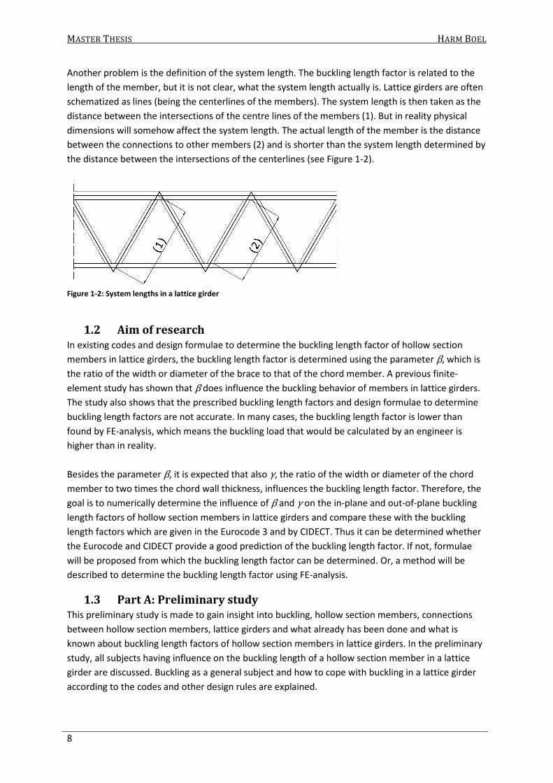
Another problem is the definition of the system length. The buckling length factor is related to the
length of the member, but it is not clear, what the system length actually is. Lattice girders are often
schematized as lines (being the centerlines of the members). The system length is then taken as the
distance between the intersections of the centre lines of the members (1). But in reality physical
dimensions will somehow affect the system length. The actual length of the member is the distance
between the connections to other members (2) and is shorter than the system length determined by
the distance between the intersections of the centerlines (see Figure 1-2).
Figure 1-2: System lengths in a lattice girder
1.2 Aim of research
In existing codes and design formulae to determine the buckling length factor of hollow section
members in lattice girders, the buckling length factor is determined using the parameter β, which is
the ratio of the width or diameter of the brace to that of the chord member. A previous finite-
element study has shown that β does influence the buckling behavior of members in lattice girders.
The study also shows that the prescribed buckling length factors and design formulae to determine
buckling length factors are not accurate. In many cases, the buckling length factor is lower than
found by FE-analysis, which means the buckling load that would be calculated by an engineer is
higher than in reality.
Besides the parameter β, it is expected that also γ, the ratio of the width or diameter of the chord
member to two times the chord wall thickness, influences the buckling length factor. Therefore, the
goal is to numerically determine the influence of β and γ on the in-plane and out-of-plane buckling
length factors of hollow section members in lattice girders and compare these with the buckling
length factors which are given in the Eurocode 3 and by CIDECT. Thus it can be determined whether
the Eurocode and CIDECT provide a good prediction of the buckling length factor. If not, formulae
will be proposed from which the buckling length factor can be determined. Or, a method will be
described to determine the buckling length factor using FE-analysis.
1.3 Part A: Preliminary study
This preliminary study is made to gain insight into buckling, hollow section members, connections
between hollow section members, lattice girders and what already has been done and what is
known about buckling length factors of hollow section members in lattice girders. In the preliminary
study, all subjects having influence on the buckling length of a hollow section member in a lattice
girder are discussed. Buckling as a general subject and how to cope with buckling in a lattice girder
according to the codes and other design rules are explained.
MASTER THESIS HARM BOEL
9
In the subsequent chapter, buckling as a general subject and the buckling length (factor) is
explained. How the code treats buckling is explained as well as the buckling length factors for the
most common cases. How to calculate the buckling length of a beam with semi-rigid ends is made
clear and finally, the calculation of the buckling load by the finite-element program (eigenvalue-
problem) is explained.
The third chapter provides insight in what lattice girders are, which types exist, how they function
and for what purpose they are used. Furthermore, the type of members and connections that are
used in lattice girders are described. The properties of the different types of hollow section
members are explained as well as the rigidity of the connections between the different hollow
sections.
A literary study is presented in Chapter four, where existing information about buckling lengths in
lattice girders is described. Methods to determine the buckling length as well as information about
the connection stiffness are described. Also, a recently performed study concerning the buckling
length of hollow section members in lattice girders is discussed and its conclusions are made clear. It
becomes clear what has already been done and what is still to be investigated. It also becomes clear
which parameters are of influence on the buckling length of members in lattice girders and the
rigidity of the connections.
In the fifth and final chapter of Part A, the literary study described in chapter four is shortly
discussed. It is summarized which parameters have been investigated and what is still unknown. It is
made clear which parameters are most interesting to investigate.
1.4 Part B: Numerical investigation
This part is made to describe the numerical investigation that has been executed. In this part, the
methodology, the investigation and the results about the buckling behavior of hollow steel section
members in lattice girders is made clear. It becomes clear which tools are used to investigate and
what exactly is investigated.
It must be made clear that several FE-models are used. First, to prevent confusion, the models that
are referred to in this report are shortly discussed:
- (Full) shell-element model: a model of an entire lattice girder, comprising entirely of shell-
elements. This model is developed and used in a previous study on buckling length factors
and is described in the preliminary study;
- Shell-element model to determine connection stiffnesses: a model of a small part of a lattice
girder being the connection between a chord and brace member(s). This model comprises
shell elements;
- Beam-element model: a model of an entire lattice girder, comprising of beam-elements. The
connection stiffness determined with the shell-element model is represented by elastic
rotational springs, connecting the braces to the chords. This model is used to perform
buckling analyses (parameter study).
The latter comes in several versions. For buckling analyses, BEAM4-elements (ANSYS) are used. For
Geometric and Material Non-linear Imperfect analyses, BEAM189-elements are used. These models
are referred to as the BEAM4- and the BEAM189-model.

MASTER THESIS HARM BOEL
10
In chapter six, the methodology is described. The procedure to determine the buckling load by FE-
analysis is made clear. The FE-models to determine the connection stiffnesses are described. The
connection stiffnesses obtained by FE-analysis are compared to connection stiffnesses given in
literature, described in the preliminary study. Hereafter, the beam-element model to perform the
buckling analysis is described. This beam-element model is tested by comparing the results obtained
with the beam-element model and the full shell-element model. Here, it is assumed that the full
shell-element model gives accurate results. At the end of this chapter, the way to schematize a
lattice girder by beam-elements and which connection stiffnesses must be used to obtain
trustworthy buckling loads and shapes is known.
In the seventh chapter, the parameter study is described as well as the results. The influence of β
and γ on both the connection stiffness and buckling length factor becomes clear. Also, the influence
of the length of the lattice girder and the presence of lateral supports is shortly investigated and
made clear. At the end, conclusions are made about the validity of the buckling length factors given
by the Eurocode and obtained by the formulae given by CIDECT. It becomes clear that both the
Eurocode and the CIDECT-formulae provide, sometimes very conservative and sometimes very
unsafe buckling length factors, compared to the FE-results.
Because the influence of several parameters has been investigated and a link is found between β , γ
and the buckling length factor, it is tried in chapter eight to develop formulae. First, existing
formulae, given by CIDECT are analyzed. Hereafter, these formulae are adjusted so that a better
approximation of the buckling length factor can be made, based on the results obtained by FE-
analysis.
In the ninth and final chapter, the conclusions made are summarized and the investigation and
results are discussed. Also, recommendations for further research are given.

Part A:
Preliminary Study


MASTER THESIS HARM BOEL
PRELIMINARY STUDY 13
2. Buckling In this chapter, buckling as a general subject is treated. Starting Euler’s method to determine
buckling loads followed by the influence of geometric and material nonlinearity provides insight in
the mechanics of a axially loaded member. The term buckling length is made clear as well. Finally, it
is explained how a FE program copes with buckling.
2.1 Euler Buckling load/LBA
Buckling is a geometric non-linear (GNL) problem. Buckling of an axially loaded column can be
classified as a small strain GNL problem which is associated with large rotations. Buckling analysis in
the FEM is a special case of GNL analysis that deals with equations of the type classified in
mathematics as eigenvalue problems (Becker, 2001).
Buckling of a member occurs when the axial force in the member is so high, that the member cannot
resist this axial force in combination with lateral deflection and thus no stable equilibrium can be
found. The value for which this happens is called a bifurcation point because an intersection
between two equilibrium paths is present. Theoretically, at this point, the member could either stay
in its undeformed (straight) form, or buckle. In Figure 2-1 this is shown in a force-deflection diagram.
The vertical axis represents the axial compressive force in the column (hinged at both ends) and the
horizontal axis shows the lateral deflection in the middle of the column.
Figure 2-1: Euler buckling load / LBA
The load can be determined by a Linear Buckling Analysis (in FEM) or by using Euler’s formula: If
both ends of the column are hinged and the column is axially loaded, it takes on the shape of a half
sinus along its length when buckling occurs. The flexural stiffness of the column resists this
deformation. Figure 2-2 shows an axially loaded member with hinged ends. This is called an Euler
column. Named after Leonhard Paul Euler.
In ANSYS, a LBA can be performed by activating the stress stiffening effects (PSTRES,ON) and by
performing a buckling analysis (ANTYPE,BUCKLE). This is further explained in section 2.5.

MASTER THESIS HARM BOEL
14 PART A
Figure 2-2: Deformation of an Euler column
In a Linear Buckling Analysis, it is assumed that the column is centrically loaded, the material is
homogeneous, isotropic and perfectly elastic and that the deflections are small. A maximum
compressive stress is not taken into account. This way, a buckling load can be found by finding an
equilibrium between the compressive force multiplied with an eccentricity (which is only present if
buckling occurs) and the flexural stiffness of the column where the axial compressive force is called
the disturbing force and the force caused by the flexural stiffness of the column is called the internal
resisting moment. The disturbing force and the internal resisting moment must be in equilibrium for
the column to be stable. Using a differential equation to describe it’s behavior, the first order or
linear buckling load can be found by equation (2.1), which is found by solving the differential
equation.
2
2cr
cr
EIN
L
π= (2.1)
Where:
Ncr is the critical load or buckling load of the column
EI is the flexural stiffness of the column
Lcr is the critical or buckling length of the column (which is equal to the system length if the ends of
the column are hinged), the critical or buckling length is further described in section 2.3.
Buckling Curve:
Equation (2.1) can be adjusted so that a formula for the critical stress crσ is formed:
2
2
cr
cr
NE
A
πσ
λ= = (2.2)
Where:
σcr is the critical stress, the stress whereby the column buckles
λ is the slenderness of the column determined by (2.3)
A is the area of the section
2
cr
cr
L E
i
πλ
σ= = (2.3)
Where:
� is the radius of gyration, determined by (2.4)
MASTER THESIS HARM BOEL
PRELIMINARY STUDY 15
I
iA
= (2.4)
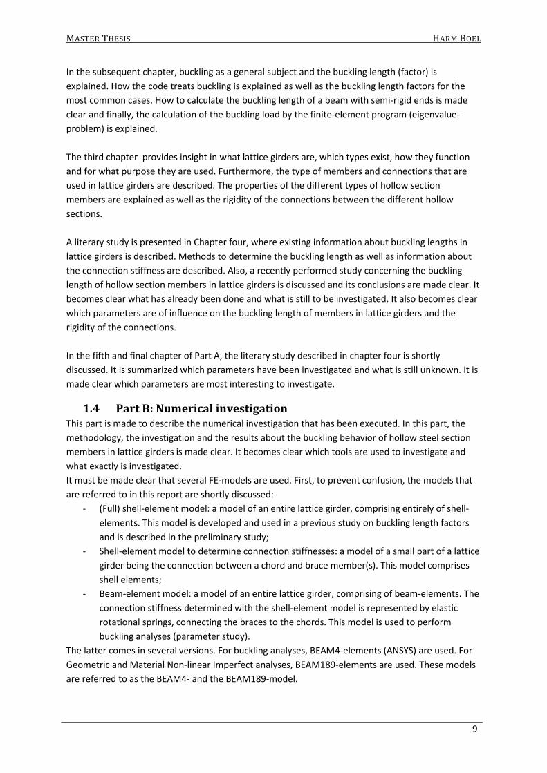
With (2.3) and (2.4) a graph can be plotted with the critical stress on the vertical axis and the
slenderness on the horizontal axis (see Figure 2-3).
Figure 2-3: Euler buckling curve
It can be seen that the critical stress increases when the slenderness decreases. The stress even
exceeds the yielding stress of steel. Of course, this is impossible, but as outlined before, it is
assumed the material is perfectly elastic and a maximum stress is not taken into account.
The critical stress can be determined dimensionless by introducing the relative slenderness. This is
done by (2.5) and shown in Figure 2-4.
2 2
1 cr
E
σχ
λ π= = (2.5)
Figure 2-4: Relative slenderness
Here, χ gives the ratio between the critical or buckling stress and Young’s modulus of the material.
This method is also used by the codes to find the ultimate load for a column and is further explained
in section 2.4.

MASTER THESIS HARM BOEL
16 PART A
2.2 First order, second order/GNIA, nth order and GMNIA
As mentioned before, it is assumed that the column is centrically loaded, the material is
homogeneous, isotropic and perfectly elastic and that the deflections are small. A maximum
compressive stress is not taken into account.
In reality, the material is not perfectly elastic and has a maximum yielding stress. The member will
also not be perfectly straight and centrically loaded. To take these effects into account, a material
and geometric non-linear calculation must be made. The intersection between the material and
geometric non-linear curve is the limit load (e.g. the load for which the column buckles).
In Figure 2-5, geometric and material linear and non-linear curves are shown. These curves are
determined numerically for a circular section member Ø88.9/5 with a length of 3000 mm, loaded by
a force with an eccentricity of 300 mm (which creates a moment, dependent on the force).
Hereafter, the curves and how they are determined are explained.
Figure 2-5: Force deflection diagram
2.2.1 First order calculation
In a first order calculation, the deflection and shortening is calculated by considering the
undeformed shape of the structure. This means that if a small imperfection is present or the load is
not applied centrically (see Figure 2-6), the deflection is linear related to the applied load and in this
case, can be calculated by equation (2.6) (deflection in the middle of the member). The shortening of
the column is found by using Hooke’s law.
Figure 2-6: Member with an imperfection
MASTER THESIS HARM BOEL
PRELIMINARY STUDY 17
² ²
16 16
ML FeLu
EI EI= = (2.6)
Where:
u is the first order deflection at midpoint of the member
M is the moment, calculated by multiplying the force with the imperfection/eccentricity
F is the applied force e is the eccentricity of the applied force
L is the system length
E is young’s modulus of the material
I is the second moment of inertia of the member
2.2.2 2nd order calculation/GNIA
In reality, the bending of the column due to the eccentrically applied force affects the eccentricity of
the load and thus the moment in the column. Thus, the deformation increases the assumed
imperfection and thus the bending moment in the column. This causes a larger deformation, and so
on, which creates a nonlinear relationship between force and displacement. This can be calculated
by a second order calculation or Geometric Nonlinear Imperfect Analysis. In the force-deflection
graph (Figure 2-5), the curve describing the second order buckling of a column has a horizontal
asymptote which is equal to the first order buckling load. For the 2nd order curve in Figure 2-5, no
imperfection in the middle of the member is assumed, but the deflection occurs because of the
bending moment at the right end of the member. The deflection can be calculated by using the ratio
between the 1st order buckling load and the applied load and the deflection caused by the first order
calculation (equation (2.7) and (2.8)).
2 11
nd st
nu u
n=
− (2.7)
Where:
u2nd is the 2nd order deflection
u1st is the 1st order deflection for that particular force determined by (2.6)
� is the ratio between the first order buckling load and the considered force
crN
nF
= (2.8)
In a FE calculation, this behavior can be simulated by calculating the stress stiffness effects. In ANSYS
this is done by inputting: SSTIF,ON. Imperfections can be added by using the eigenvectors that result
from an eigenvalue buckling analysis. The UPGEOM command adds displacements from a previous
analysis and updates the geometry to the deformed configuration.
2.2.3 nth order calculation/GNIA
It is made clear that the second order calculation describes the real structural behavior better,
because it takes the extra forces caused by an increasing deflection into account. But, when the
shortening is checked, the answers are the same. This is almost correct if it is assumed, which is also
done in the first and second order calculation, that the deflections and rotations are small. But, if
deflections become large, the shortening should be calculated with a nth order calculation. In Figure
2-7, the differences between first, second and nth order calculation is made clear. It can be seen, that
the position of the load also changes when the structure deforms. This effect is also taken into
account by the nth order calculation.

MASTER THESIS HARM BOEL
18 PART A
Figure 2-7: Difference between first, second and n
th order calculation
In the nth order calculation, large deformations, rotations and large strains are taken into account. In
ANSYS this is done by issuing NLGEOM,ON, whether large strains are taken into account, depends on
the element type.
2.2.4 GMNIA
The effect of deflection on the geometry has been discussed. It has been assumed that the material
is perfectly elastic. A Geometric and Material Nonlinear Imperfect Analysis also takes plasticity into
account. If one wants to evaluate the experimentally obtained buckling loads, a GMNIA should be
employed.
For a first order plastic calculation, the maximum load is defined by the maximum yield stress
multiplied by the area of the cross section of the member. But because an eccentricity is present, a
moment is created which reduces the capacity of the section to withstand an axial force. Because
the moment increases as the deflection increases (2nd order effect), the capacity to withstand an
axial force decreases. Because an axial force is present, the plastic capacity to withstand a moment
reduces. The reduced plastic moment capacity for a rectangular cross section is calculated by
equation (2.9).
2
; 21p red p
p
FM M Fu
N
= − =
(2.9)
Where:
Mp;red is the reduced plastic moment capacity of the section
Mp is the (ideal) plastic moment capacity of the section
Np is the plastic force capacity of the section
F is the force, determined by (2.10), which causes the reduced plastic moment capacity
( )2 2 2
4
2
p p p p
p
N M N u N uF
M
+ −= (2.10)
The intersection of the 2nd order elastic and 2nd order plastic curve is the ultimate load for which the
member will buckle. In this case, an nth order calculation is not necessary because buckling occurs
when deflections are small.
In Table 2-1 a summary of this section (2.2) is shown where it is made clear which theory takes
geometric and or material nonlinearity into account to calculate the response.

MASTER THESIS HARM BOEL
PRELIMINARY STUDY 19
Table 2-1: Properties of theory’s (X = does not/ V = does take effect into account)
LBA 1st order GNIA
GMNIA 2nd nth
Eccentricity of load / moments X1 V V V V
Geometric nonlinearity
- Equilibrium in deformed state
- Imperfections
- Small rotations, deflections and
strains
- Large rotations, deflections &
strains
V
X
X
X
X
X
X
X
V
V
V
X
V
V
V
V
V
V
V
X / V
Material nonlinearity X X X X V
Output Ncr N Ncr Nu
LBA = Linear Buckling analysis, G(M)NIA = Geometric (and Material) Nonlinear Imperfect Analysis
2.3 Buckling length
The buckling load in (2.1) is valid for a column which is supported by hinges at both ends. In practice,
many other end conditions than hinged are possible. For each situation, a differential equation can
be solved to determine the buckling load. Another way to determine the buckling load, is to define a
buckling length factor. The buckling length is the length of a similar member with hinged ends which
has the same buckling resistance as the given member. For most common cases, the buckling length
factor is determined. For example, for a beam with one fixed and one free end, the buckling length
factor is 2, for a beam with both ends fixed, the buckling length is ½ (see Figure 2-8).
Figure 2-8: Buckling length factors for common cases
This factor must be multiplied with the system length of the member in equation (2.1) to obtain the
first order buckling load of the column.
2
2( )
cr
EIN
KL
π= (2.11)
Where K is the buckling length factor as shown in (2.12).
1 This is valid if the member is schematized by beam-elements. If the member is modeled by shell-elements, an
eccentricity will cause more pressure in one side of the member which can cause lateral/torsional buckling.
MASTER THESIS HARM BOEL
20 PART A
crL
KL
= (2.12)
If the buckling load is known, the buckling length factor can be determined by:
2
2
cr
EIK
N L
π= (2.13)
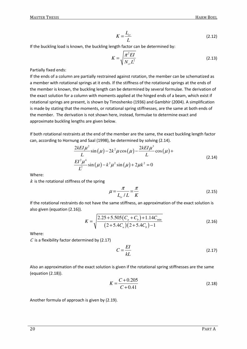
Partially fixed ends:
If the ends of a column are partially restrained against rotation, the member can be schematized as
a member with rotational springs at it ends. If the stiffness of the rotational springs at the ends of
the member is known, the buckling length can be determined by several formulae. The derivation of
the exact solution for a column with moments applied at the hinged ends of a beam, which exist if
rotational springs are present, is shown by Timoshenko (1936) and Gambhir (2004). A simplification
is made by stating that the moments, or rotational spring stiffnesses, are the same at both ends of
the member. The derivation is not shown here, instead, formulae to determine exact and
approximate buckling lengths are given below.
If both rotational restraints at the end of the member are the same, the exact buckling length factor
can, according to Hornung and Saal (1998), be determined by solving (2.14).
( ) ( ) ( )
( ) ( )
2 32
2 42 2 2
2
2 2sin 2 cos cos
sin sin 2 0
kEI kEIk
L L
EIk k
L
µ µµ µ µ µ
µµ µ µ µ
− − +
− + =
(2.14)
Where:
k is the rotational stiffness of the spring
/crL L K
π πµ = = (2.15)
If the rotational restraints do not have the same stiffness, an approximation of the exact solution is
also given (equation (2.16)).
( )
( )( )min
2.25 5.505 1.14
2 5.4 2 5.4 1
a b
a b
C C CK
C C
+ + +=
+ + − (2.16)
Where:
C is a flexibility factor determined by (2.17)
EI
CkL
= (2.17)
Also an approximation of the exact solution is given if the rotational spring stiffnesses are the same
(equation (2.18)).
0.205
0.41
CK
C
+=
+ (2.18)
Another formula of approach is given by (2.19).

MASTER THESIS HARM BOEL
PRELIMINARY STUDY 21
( ) ( )
( ) ( )1 2
1 2
5 5
5 2 5 2K
ρ ρ
ρ ρ
+ +=
+ + (2.19)
Where:
ρ is the fixity factor determined by (2.20).
kL
EIρ = (2.20)
2.4 Buckling according to the codes
The codes use the Euler buckling load as a basis to determine the buckling load. Because the Euler
buckling load assumes a perfectly elastic material behavior, no maximum stress and a perfectly
straight column which is perfectly centrically loaded, the real buckling load will usually be lower than
the Euler buckling load. Therefore, the codes provide buckling curves which do take these effects
into account. Different curves are presented for different section-classes.
2.4.1 Plasticity and Slenderness
To take the maximum stress of the material into account, the slenderness in (2.3) is adjusted by
adding the yield stress of the material, as shown in (2.21) and (2.22).
1
1crL
iλ
λ= (2.21)
Where:
1
y
E
fλ π= (2.22)
So that (2.21) becomes (2.23).
2
1
1
1 1
1
crcr
cr
y y
L E
i E
f f
σπλ
λ σπ
= = = (2.23)
Equation (2.23) can also be written as (2.24), where the Euler buckling load and the yield stress of
the material are used to determine the slenderness:
y
cr
Af
Nλ = (2.24)
Where:
λ is the slenderness
yf is the yield stress of the material
Now, λ is used instead of λ in equation (2.5) so it becomes;
2
1 cr cr
y pl
N
f N
σχ
λ= = = (2.25)

MASTER THESIS HARM BOEL
22 PART A
2.4.2 Imperfection
To take an imperfection into account, imperfection factors are given (see Table 2-2). The type of
section determines which buckling curve/imperfection factor must be chosen.
Table 2-2: Imperfection factors
Buckling curve a0 a b c d
Imperfection factor α 0.13 0.21 0.34 0.49 0.76
2.4.3 Buckling load
With the slenderness and the imperfection factor, a factor can be determined for the yield stress, so
the maximum load can be determined.
( )( )211 0.2
2φ α λ λ= + − + (2.26)
2 2
1χ
φ φ λ=
+ − (2.27)
;u d yN Afχ= (2.28)
Where:
α is the imperfection factor
χ is the reduction factor for the buckling curve, which can never be larger than 1
;u dN is the maximum axial force of the member
According to the codes, an imperfection factor of 0.21 must be used for hot-rolled circular and
rectangular sections with a yield stress of 275 N/mm². The buckling curve for a circular section
Ø88.9/5 is shown in Figure 2-9.
Figure 2-9: Buckling curve according to the Eurocode and Euler

MASTER THESIS HARM BOEL
PRELIMINARY STUDY 23
For both methods, Euler and the Eurocode, the maximum buckling load can only be determined if
the buckling length Lcr is known. To determine the buckling length for members in lattice girders, a
finite element simulation of lattice girders can be used to determine buckling loads. If the buckling
load is known, the buckling length factor can be determined by. How the buckling load is determined
by a finite element program is made clear in section 2.5.
2.4.4 Partially fixed ends
If the stiffness of the rotational springs at the ends of the member is known, the Dutch code
provides a method to determine the buckling length. The stiffness of the rotational springs is used to
determine a flexibility factor. With this flexibility factor, a nomogram (Figure 2-10) can be used to
determine the buckling length factor K. The nomogram is based on equation (2.29).
Figure 2-10: Nomogram to determine the buckling length factor for a braced member
( ) ( ) ( ) ( ) ( )( )2
1 2 1 2 1 2
1 cossin cos 1 sin 2C C C C C C
λλ λ λ λ λ
λ
−= + + − − − (2.29)
Where:
Ci is the flexibility factor of rotational spring i determined by (2.30)
λ is π divided by the buckling length factor (Lcr / L ) and π ≤ λ ≤ 2π
1
i
EIC
kLρ= = (2.30)
Where
ρ is the fixity factor (inverse of flexibility factor)
EI is the flexural stiffness of the member
L is the length of the member
k is the rotational stiffness of the spring

MASTER THESIS HARM BOEL
24 PART A
2.5 Buckling in the finite element method
Using equation (2.13), the buckling length factor can be determined. Before the buckling length can
be determined, the buckling load must be known. A finite element program will be used to
determine buckling loads of members in a lattice girder. Hereafter is explained, how the finite
element program determines the buckling load. An example is given using a shell-element model,
which is used by Fekete (2009) to investigate buckling length factors. This is done to make clear how
a buckling load/length is obtained and also as a check on the results found by Fekete.
2.5.1 The FE methods of solution
In mechanics, buckling is a non-linear problem for which equilibrium is defined in the deformed
state. Mathematically, buckling is a linear problem, which is solved by an eigenvalue calculation.
In a LBA, the eigenvalue is a load factor at which the acting loads, multiplied by the eigenvalue, will
initiate buckling, whereas the eigenvector is the displacement associated with buckling.
This means that a static analysis must be made prior to the buckling analysis. In this static analysis,
the stresses and forces due to the loading on the structure are calculated. After this analysis, the
eigenvalue is calculated. To obtain the buckling load of a certain member, the eigenvalue causing the
considered member to buckle must be multiplied by the load in that member, obtained from the
static analysis. An example is given in section 2.5.2.
2.5.2 Example using a full-shell-element model
As outlined before in section 2.5.1, the buckling load is determined by multiplying the eigenvalue
with the load in the member obtained by a static analysis. Here, an example is described by using a
shell-element model.
In the study of Fekete (2009), a FE-model is used to investigate the effect of the ratio between the
width/diameter of the brace to that of the chord member. This research and the used model is
further described in section 4.9. To clarify the procedure of determining the buckling length of a
member and to check the results found by Fekete, a buckling analysis is made using the same input
as Fekete did. It is chosen to use a circular section chord with a diameter of 200 mm and a wall
thickness of 6.3 mm and a circular section brace with a diameter of 100 mm and a wall thickness of
6.3 mm. This analysis is chosen because, according to Fekete, both in-plane and out-of-plane
buckling occurs in the chord member and several brace members when calculating 20 eigenvalues.
The geometry of the investigated lattice girder can be seen in Figure 2-11. A lateral support is
modeled at the position where the loads are applied and at the end supports, which prevents out-of-
plane buckling of the chord. The members that buckle according to the results of Fekete are the
chord members C2, C3 and C4 and the brace members B2, B4 and B6. The circular sections are
meshed with 12 shell elements circumferentially and around the joint the sections are meshed with
24 shell elements.
Figure 2-11: Geometry of lattice girder

MASTER THESIS HARM BOEL
PRELIMINARY STUDY 25
After performing a static analysis, the axial forces in the members can be determined. Because the
members are modeled with shell elements, the axial force must be determined by multiplying the
average stress by the surface area of the section. As an example, this is done for brace “B4”.
The stresses in the fourth brace (B4), obtained by a static analysis, are as presented in Table 2-3 and
Figure 2-12. Because the stresses differ over the thickness of the element, the average stresses are
calculated and shown in the table.
Table 2-3: Principal compressive stresses in brace B4
Element Average principal stress 3 (N/mm2)
62654 -0.0016827
62655 -0.0016749
62656 -0.0016705
62657 -0.0016707
62658 -0.0016755
62659 -0.0016835
63170 -0.0016927
63171 -0.0017004
63172 -0.0017047
63173 -0.0017045
63174 -0.0016998
63175 -0.0016918
Figure 2-12: Principal compressive stresses in brace B4
The average stress is -0.0016876 N/mm². This must be multiplied by the surface area of the section
to determine the force in the member. The area and the second moment of inertia of the section
must be calculated because the section is modeled as a equilateral dodecagon instead of a
cylindrical tube (see Figure 2-13).

MASTER THESIS HARM BOEL
26 PART A
Figure 2-13: Difference between real (left) and modeled section (right)
The area is:
2
12 12 6.3 24.2513 1833.4A t Elength mm mm mm= × × = × × = (2.31)
Where:
t is the wall thickness
Elength is the length of one element
The second moment of inertia is:
2 4
1925263i i i
i
I I A a mm= + × =∑ (2.32)
Where:
I is the second moment of inertia
( is the distance from the centerline of area � to the centerline of the section
The force in the member is:
1833.4 0.0016876 3.09405N A Nσ= = × − = − (2.33)
Where:
N is the force in the member
σ is the stress in the section
This force represents the first order elastic response of the member and this must be done for every
member that could possibly buckle. After this, a buckling analysis must be made to determine the
eigenvalues. The fourth brace seen from the support (brace B4), for example, buckles out-of-plane
with an eigenvalue of 104258 (third buckling mode) (see Figure 2-14 for the buckling shape of the
lattice girder). This means, that the buckling load is:
104258 3.09405 322579cr
N N Nλ= = ×− = − (2.34)
Where:
λ is the eigenvalue
This mean, using equation (2.13), that the out-of-plane buckling length is:
2
2
210000 19252630.67
322579 5243.09K
π ×= ≈
× (2.35)

MASTER THESIS HARM BOEL
PRELIMINARY STUDY 27
Where the system length is taken as the length between the intersections of the centerline of the
brace with the centerlines of the upper and lower chord member.
Figure 2-14: Buckling shape of lattice girder (view from above (upper) and isometric view (lower))
If this is done for every member that buckles, than the following buckling length factors are found
(see table Table 2-4).
Table 2-4: Calculated buckling length factors
mode λ C2 C3 C4 B2 B4 B6
K In/out K In/out K In/out K In/out K In/out K In/out
1 70818 0.68 out
3 104260 0.93 out 0.67 out
4 104820 0.56 in
8 116380 0.88 in
9 141350 0.58 in
10 148720 0.84 out 0.72 out
12 169940 0.78 in
17 202360 0.86 out
18 207290 0.85 in
If these results are compared to the results found by Fekete (see Table 2-5), it can be seen that,
although the values do not differ much, they differ from each other. If for the brace, instead of the
distance between the intersections of the centre lines, the member length is taken as the system
length, the buckling length factors of the braces in Table 2-4 and Table 2-5 are more in agreement
with each other. The eigenvalues differ somewhat, which could mean a different number of
elements has been used by Fekete.
Since, as can be seen, a lot of calculations must be made to obtain the buckling load/length, an error
is easily made. For example, the axial force in the member can easily be miscalculated, which will
affect the buckling load and thus also the buckling length factor.

MASTER THESIS HARM BOEL
28 PART A
Table 2-5: Buckling length factors by Fekete (2009)
mode λ C2 C3 C4 B2 B4 B6
K In/out K In/out K In/out K In/out K In/out K In/out
1 72607 0.71 out
3 104940 0.96 out 0.69 out
4 106290 0.58 in
8 116840 0.91 in
9 142670 0.60 in
10 149150 0.86 out 0.74 out
12 171520 0.80 in
17 203080 0.88 out
18 209100 0.86 in
19 222330 0.61 in
A remarkable difference is that Fekete found that brace B6 buckles in-plane for buckling mode 19. It
is difficult to say whether this brace has buckled or is just bent due to deformation of the chord
members (see Figure 2-15).
Figure 2-15: Brace B3: buckling or bending?
MASTER THESIS HARM BOEL
PRELIMINARY STUDY 29
3. Lattice girders, Hollow Sections and Connections In this chapter, lattice girders and their properties, purposes and structural behavior are explained.
The influence of the geometry of the lattice girder on the buckling behavior is explained, referring to
outcomes of previous studies (described in chapter 4). After this, hollow steel sections and their
properties are discussed. And finally, because the rigidity of the connections also influences the
buckling load, the connections between hollow steel sections and their properties are discussed.
3.1 Lattice girders
A lattice girder is a girder comprising of multiple members which transfer loads to the supports
mainly by axial forces. Lattice girders are used to accommodate long spans because a high strength
and stiffness can be obtained by using relatively small amounts of steel and commonly used
sections.
A lattice girder comprises of two different types of members: chord members and bracing members.
The chord members are the members which provide the girder of bending resistance. The normal
force in the upper and lower chord member(s) multiplied by the distance between the centerlines of
the members is the moment in the girder and is equal to the moment caused by external loads,
thereby neglecting individual bending of the chords. The bracing members make it possible for the
chord members to cooperate and transfer the shear forces in the girder by axial forces.
Moments can occur in members of a lattice girder and can be divided into moments caused by:
- Rotational stiffnesses of the joints (called secondary moments). These are often neglected in
the calculation of memberforces and strength of the connections;
- Transverse loads. These have to be taken into account. In most cases, the connection with
other members can be schematized as hinged, so the moments are not transferred to other
members, and;
- Eccentricities. When the system lines do not come together in one point, an eccentricity is
present. In chords and braces under tension these moments can be neglected. For the
calculations of the connections, these eccentricities may be neglected if the eccentricity is
within the range of 0.55 times the height of the chord member on the inside and 0.25 times
the height of the chord member on the outside, according to the codes. For chords and
braces under compression, the eccentricities must always be taken into account.
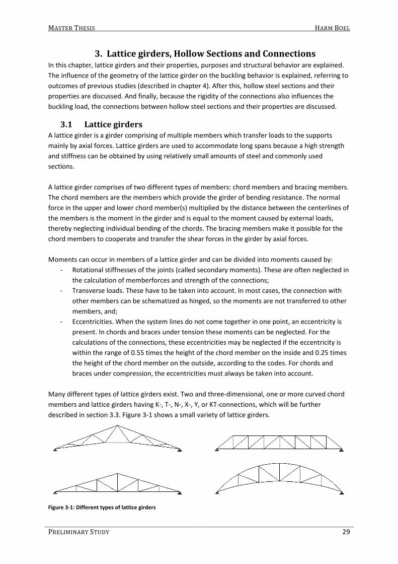
Many different types of lattice girders exist. Two and three-dimensional, one or more curved chord
members and lattice girders having K-, T-, N-, X-, Y, or KT-connections, which will be further
described in section 3.3. Figure 3-1 shows a small variety of lattice girders.
Figure 3-1: Different types of lattice girders

MASTER THESIS HARM BOEL
30 PART A
For this research, the focus is on two-dimensional, straight frames with K-connections. Hereafter,
the structural behavior and the failure modes of lattice girders are discussed.
As outlined before, a lattice girder transfers the loads to the supports mainly by axial forces in the
members. Because the members are mainly axially loaded, a common failure mode is buckling of a
compressed member in the lattice girder. The compressed member that buckles can either be a
chord member or a bracing member, or both. Another failure mode is failure of the joints. But this is
not discussed here because it is not relevant for this subject. Factors that influence the buckling
behavior of members in lattice girders are:
- Axial, flexural and rotational stiffness of the members;
- Geometry of the lattice girder;
- Lateral supports and their flexural and axial stiffness;
- Load cases and;
- Rigidity of the connections.
3.1.1 Buckling of the chord member
The compressed chord is usually the upper chord member. But, the lower chord member can also be
in compression in case the roof is lightweight and the wind creates an upward load. The chord
member can buckle either in-plane or out-of-plane. For both in-plane and out-of-plane buckling of
the chord member, different factors determine the buckling behavior of the member.
3.1.1.1 Out-of-plane buckling
In common cases, the upper chord supports purlins. The purlins carry the loads (weight of the roof,
snow, etc.) and transfer them to the lattice girders which transfer the loads to columns. Besides the
fact that the lattice girder is loaded by the purlins, the purlin also provides lateral support to the
lattice girder. This is necessary because lattice girders are very flexible out-of-plane, in contrast with
in-plane rigidity. Lateral buckling of the supported chord means a horizontal deflection of the chord
member. This horizontal deflection is prevented at the purlin connection because the purlins are
part of a horizontal lattice girder (being the roof) which transfers horizontal loads to the walls.
Figure 3-2: Out-of-plane buckling of chord member (FE model of Fekete)
The model shown in Figure 3-2 has lateral supports at each intersection between a brace and the
upper chord. In this case, horizontal deflection is restricted completely, but rotation is not restricted.

MASTER THESIS HARM BOEL
PRELIMINARY STUDY 31
Rotation is restricted when the purlin is fixed to the chord. Then, the horizontal flexural stiffness of
the purlin would resist out-of-plane buckling of the chord. The laterally supported chord can then be
schematized as a translational and rotational elastic supported member. The axial and flexural
stiffness of the lateral supports determine the stiffness of the elastic supports.
It can also be seen that a rotation in an intersection of the chord with a brace member, causes
rotation of the brace. This means, the rotational stiffness of the brace also prevents the chord from
buckling out-of-plane. Especially buckling of the laterally unsupported chord is resisted by the brace
members, which are connected to the laterally supported chord. In this case, the only direct
restraint for the chord are the brace members.
Buckling length factors as well as formulae to determine the buckling length are given in the codes,
by Galambos and CIDECT. A numerical study, by Fekete (2009), using the finite element method has
been carried out to determine the influence of the ratio between the width of the brace member to
the width or diameter of the chord member (β ). It is shown, that when β increases, a smaller
buckling length factor is found (between 0.91 to 0.96 for β = 0.5, between 0.86 and 0.89 for β = 0.75
and between 0.78 and 0.83 for β = 1). More results of this study can be found in chapter 4.
3.1.1.2 In-plane buckling
In-plane buckling of the chord member does not depend on the lateral supports, but on the stiffness
of the brace members and of the connection with the brace members. If the chord is cut out of the
lattice girder, the chord can be schematized as a member, with elastic rotational springs which
represent the flexural stiffness of the braces. If the purlins are (rotationally) fixed to the chord, the
rotational stiffness of the chord also provides a rotational elastic restraint. Figure 3-3 shows a chord
member in a lattice girder which has buckled in-plane.
Figure 3-3: In-plane buckling of chord member (FE model of Fekete)
Buckling length factors are given in the Eurocode. The numerical study of Fekete shows that β also
influences the in-plane buckling behavior of chord members. For β = 0.5, the buckling length factor

MASTER THESIS HARM BOEL
32 PART A
of 0.91 to 0.92 has been found, for β = 0.75, the buckling length factor was 0.80 to 0.89 and for β =
1.0, the buckling length factor was 0.66 to 0.78.
3.1.2 Buckling of a brace member
When the members are welded together, a (partially) fixed connection is formed. This fixed
connection prevents the end of the brace member to rotate and this way, the buckling length is
decreased and the buckling load of the brace is increased.
3.1.2.1 Out-of-plane buckling
The out-of-plane buckling of the brace, means a rotation at the ends of the braces around the
longitudinal axis of the chord member (see Figure 3-4). This means the chords torsional stiffness and
the stiffness of the lateral supports prevents the brace from buckling out-of-plane which allows the
buckling length to be reduced. Here, the rigidity of the connection between the lateral supports and
the chord member is also of influence since it determines to what extent the lateral supports
prevent buckling of the brace.
Figure 3-4: Out-of-plane buckling of brace members (FE model of Fekete)
Buckling length factors for out of plane buckling are given by the codes and a formula to determine
the buckling length factor is given by CIDECT. The numerical study of Fekete (2009) shows buckling
length factors between 0.60 to 0.62 for β = 0.25, 0.71 to 0.7 for β = 0.5, 0.75 to 0.76 for β = 0.75 and
0.78 for β = 1.0.
3.1.2.2 In-plane buckling
The in-plane buckling is resisted by the chord member. The higher the in-plane flexural stiffness of
the chord, the higher the buckling load of the brace is. The number of braces and distance between
the joints (panel length) may also influence the buckling load because it restrains the chord member
from bending (see Figure 3-5).

MASTER THESIS HARM BOEL
PRELIMINARY STUDY 33
Figure 3-5: In-plane buckling of a brace (FE model of Fekete)
Galambos and the codes provide a buckling length factor, and CIDECT provides formula to determine
the buckling length factor. The numerical study of Fekete (2009) also shows that the factor β is of
influence on the in-plane buckling length of brace members. For β = 0.25, buckling length factors
between 0.53 to 0.65 have been found for in-plane buckling. For β = 0.5, the buckling length factor
was 0.58 to 0.79, for β = 0.75, the buckling length factor was 0.76 to 0.81 and for β = 1.0, the
buckling length factor was 0.74.
3.2 Hollow section members
There are two different hollow structural sections (HSS) member-types. Circular (CHS) and
rectangular (RHS) hollow sections. The second can be divided in rectangular and square hollow
sections (SHS). The main reasons to choose these sections are their torsional stiffness and their
architectural appearance. Hollow sections are also very suitable for axial loading because their
flexural stiffness about the y- and z- axis are the same (not for RHS where h ≠b).
The area, moment of inertia and torsion constant for a CHS can be calculated by (3.1), (3.2) and
(3.3), respectively.
( )( )222
4A d d t
π= − − (3.1)
( ) ( )( )4 412
64I d d tπ= − − (3.2)
( ) ( )( )4 412
32J d d tπ= − − (3.3)
Where:
A is the section area
I is the moment of inertia
* is the torsion constant
d is the diameter of the section
t is the wall thickness of the section
For a RHS, equations (3.4) to (3.6) must be used, assuming the edges of the section are not rounded.
( )( )222A b b t= − − (3.4)
( ) ( )2
3 3 ( )2 2
6 6 2
t b h tI h t t bt
− = − + +
(3.5)
3 21
43
m h
m
tJ t h A
h= + (3.6)

MASTER THESIS HARM BOEL
34 PART A
Where:
b is the outer width of the section
h is the outer height of the section
hm is the mean perimeter
Ah is the area enclosed by the mean perimeter
The warping constant is usually taken as zero.
HSS can be produced in two different ways, hot-rolled and cold-formed. Cold formed HSS are
produced by bending a thin (< 3 mm thick) steel plate and welding the ends together so that a CHS
or RHS is formed. Hot-rolled sections are made by pulling the hot steel over a spine, or by bending a
hot steel plate into the desired form and welding the ends together. Hollow sections in lattice
girders are usually hot-rolled sections.
3.3 Connections between HSS-members
There are many ways to connect a hollow section to another. A hinged connection is obtained by
connecting the members by bolting plates, which are welded to the members, to each other. A fixed
connection is obtained by welding the members directly to each other. Many types of connections
exist and are given in Figure 3-6.
Figure 3-6: Different types of connections (Eurocode 3: 1-8)
In vierendeelgirders, T- connections are used and is often reinforced because the strength and
stiffness of the joints are representative for the total structural behavior of the girder. A few
examples of reinforced connection types are described by Packer (1993) and are given in Figure 3-7.

MASTER THESIS HARM BOEL
PRELIMINARY STUDY 35
Figure 3-7: Connection types (Packer, 1993)
In lattice girders, where bending stiffness of the joint is less important, hollow sections welded
together without reinforcement are very popular because of their architectural appearance. Because
the connection is not reinforced, a semi-rigid connection is formed. Many researchers who have
investigated the behavior of hollow sections welded together concur that full rigidity of an
unstiffened connection can be approached if β = 1 and a low value of b0/t0 is used. But for other
cases, the connection is semi rigid. Both the strength and flexural rigidity of an unstiffened
connection decrease as the chord slenderness ratio (b0/t0) increases and as the bracing to chord
width ratio (β ) decreases. The corresponding investigations are mainly focused on connections
loaded predominantly with moments and shear forces. The strength of the connection is decreased
if large compressive forces are present in the chord.
A connection is considered to be rigid, if the rotation of the joint is zero. The rotation of the joint is
defined as the difference between the angles on the two sides of the connection. This means that
the connection is considered rigid if the rotation on the two sides of the connection is the same. As
mentioned before, a fully rigid connection of an unstiffened connection can be approached if certain
conditions are met (if β = 1 and a low value of b0/t0 is used). But for other cases, the connection is
semi-rigid.
Other factors (besides β and b0/t0) that could influence the rigidity of the connections are:
- Gap between braces;
- Angle between chord and brace;
- Type of joint (K-, N-, Y-, etc.) and;
- The type of member (CHS or RHS).

MASTER THESIS HARM BOEL
36 PART A
4. Literary Study In the past, research has been done to determine buckling length factors for hollow section
members in lattice girders. Several researchers give either a buckling length factor for a certain
situation or a method to determine the buckling length factor. Also the codes provide buckling
length factors for lattice girders comprising of hollow sections.
Starting a study on the information provides by the codes, followed by outcomes of other studies,
this chapter will provide insight in what is already known about buckling lengths in lattice girders. At
the end of this chapter, a comparison between different methods will be made and it will become
clear what is still to be investigated.
4.1 The codes (Eurocode 3 and NEN6770 (Dutch Code))
Codes are internationally used to, among other things, check the limit state of structures and
structural components. The codes provide, beside a procedure to calculate the buckling load as
explained in section 2.4, buckling length factors for hollow sections in lattice girders. Also the
strength and rigidity of connections are discussed although the rigidity of connections between
hollow sections welded to each other are not discussed.
4.1.1 Buckling length factors for HSS in lattice girders
The Eurocode and the Dutch code provide similar buckling length factors for hollow section
members. The factors are given below.
Out-of-plane buckling of chord members
The Eurocode gives a factor of 0.9 times the system length between the lateral supports. The Dutch
code states the buckling length is equal to the system length between the lateral supports, but also
provides equation (4.1) for chords with a changing normal force at a laterally unsupported panel
point.
1
2
0.75 0.25P
KP
= + (4.1)
In-plane buckling of chord members:
The Eurocode provides a buckling length factor of 0.9 times the system length of the chord member
between the joints. The Dutch code states that the buckling length is equal to the system length of
the chord member between the joints.
Out-of-plane buckling of brace members:
The old Eurocode gives a buckling length factor of 0.75 if β ≤ 0.6. The Dutch code also gives a
buckling length factor of 0.75 times the system length between the joints, but only if a RHS chord
and brace is used with β ≥ 0.6, a CHS chord and brace is used with β ≥ 0.5 or if an overlap of the
brace members is made. Otherwise, the Dutch code prescribes a buckling length equal to the system
length between the joints. The new Eurocode gives a buckling length factor of 0.75 times the system
length between the joints, disregarding any value of β.
In-plane buckling of brace members:
The old Eurocode gives a buckling length factor of 0.75 if β ≤ 0.6.
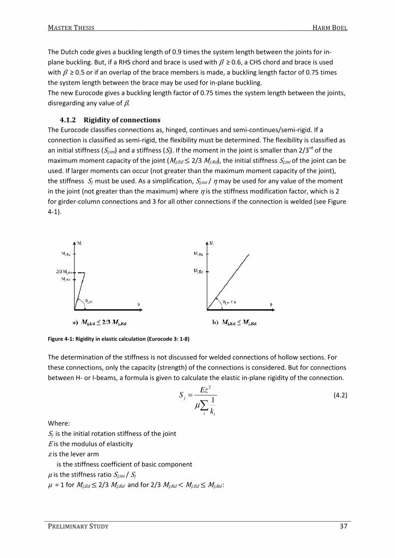
MASTER THESIS
PRELIMINARY STUDY
The Dutch code gives a buckling length of 0.9 times t
plane buckling. But, if a RHS chord and brace is used with
with β ≥ 0.5 or if an overlap of the brace members is made, a buckling length factor of 0.75 times
the system length between the brace may be used for in
The new Eurocode gives a buckling length factor of 0.75 times the system length between the joints,
disregarding any value of β.
4.1.2 Rigidity of connections
The Eurocode classifies connections as, hinge
connection is classified as semi-rigid, the flexibility must be determined. The flexibility is classified as
an initial stiffness (Sj;ini) and a stiffness (
maximum moment capacity of the joint (
used. If larger moments can occur (not greater than the maximum moment capacity of the joint),
the stiffness Sj must be used. As a simplification,
in the joint (not greater than the maximum) where
for girder-column connections and 3 for all other connections if the connection is welded (see
4-1).
Figure 4-1: Rigidity in elastic calculation (Eurocode 3: 1
The determination of the stiffness is not discussed for welded connections of hollow sections. For
these connections, only the capacity (strength) of the c
between H- or I-beams, a formula is given to calculate the elastic in
Where:
Sj is the initial rotation stiffness of the joint
E is the modulus of elasticity
z is the lever arm
is the stiffness coefficient of basic component
μ is the stiffness ratio Sj;ini / Sj
μ = 1 for Mj;Ed ≤ 2/3 Mj;Rd
and for 2/3
The Dutch code gives a buckling length of 0.9 times the system length between the joints for in
plane buckling. But, if a RHS chord and brace is used with β ≥ 0.6, a CHS chord and brace is used
5 or if an overlap of the brace members is made, a buckling length factor of 0.75 times
gth between the brace may be used for in-plane buckling.
The new Eurocode gives a buckling length factor of 0.75 times the system length between the joints,
Rigidity of connections
The Eurocode classifies connections as, hinged, continues and semi-continues/semi
rigid, the flexibility must be determined. The flexibility is classified as
) and a stiffness (Sj). If the moment in the joint is smaller than 2/3
maximum moment capacity of the joint (Mj;Ed ≤ 2/3 Mj;Rd), the initial stiffness Sj;ini
used. If larger moments can occur (not greater than the maximum moment capacity of the joint),
must be used. As a simplification, Sj;ini / η may be used for any value of the
in the joint (not greater than the maximum) where η is the stiffness modification factor, which is 2
column connections and 3 for all other connections if the connection is welded (see
: Rigidity in elastic calculation (Eurocode 3: 1-8)
The determination of the stiffness is not discussed for welded connections of hollow sections. For
these connections, only the capacity (strength) of the connections is considered. But for connections
beams, a formula is given to calculate the elastic in-plane rigidity of the connection. 2
1j
i i
EzS
kµ
=
∑
is the initial rotation stiffness of the joint
is the stiffness coefficient of basic component
and for 2/3 Mj;Rd
< Mj;Ed ≤ Mj;Rd :
HARM BOEL
37
he system length between the joints for in-
a CHS chord and brace is used
5 or if an overlap of the brace members is made, a buckling length factor of 0.75 times
The new Eurocode gives a buckling length factor of 0.75 times the system length between the joints,
continues/semi-rigid. If a
rigid, the flexibility must be determined. The flexibility is classified as
. If the moment in the joint is smaller than 2/3rd of the
j;ini of the joint can be
used. If larger moments can occur (not greater than the maximum moment capacity of the joint),
may be used for any value of the moment
is the stiffness modification factor, which is 2
column connections and 3 for all other connections if the connection is welded (see Figure
The determination of the stiffness is not discussed for welded connections of hollow sections. For
onnections is considered. But for connections
plane rigidity of the connection.
(4.2)

MASTER THESIS HARM BOEL
38 PART A
;
;
1.5j Ed
j Rd
M
M
ψ
µ
=
(4.3)
Where:
ψ is a coefficient, which is 2.7 for welded connections
For a girder, welded to one side of a column, the stiffness coefficients 61, 62 and 63 have to be
determined to determine the rigidity of the section by equation (4.2). The stiffness coefficients are
respectively the shear stiffness of the column, the compressive stiffness of the column and the
tensional stiffness of the column.
4.2 Wardenier et al. (1991/1992) CICECT Design Guide 1 to 3.
CIDECT is an international association of manufacturers of hollow sections whose objective is to
expand knowledge of steel hollow sections and their application in steel construction and
engineering. Activities of the organization is research on structural behavior of hollow steel sections
and the obtained knowledge is made available to engineers, architects and students through
research papers, software and design and architectural publications.
In three publications, which can be of assistance for an engineer to design and calculate hollow
section structures, guidelines and formulae are given to determine the stability behavior of lattice
girders (Design Guides 1, 2 and 3).
4.2.1 Out of plane buckling of chord members
If the chord is not supported laterally, the buckling length factor depends on the loading in the
chord, the torsional rigidity of the truss, the flexural rigidity of the purlins and the purlin to truss
connections. In CIDECT design guide no. 2 (Wardenier et al. 1992a), an example is given for the
buckling length factor of the unsupported lower chord of 0.32 (see Figure 4-2). Reference is given to
Mouty (1981), where two iterative calculation methods are given to determine the buckling length
of compression chords in lattice girders without lateral support.
Figure 4-2: lateral buckling of laterally unsupported chord (Wardenier et al. 1992)
4.2.2 Buckling of brace members
For the buckling of a brace, three formulae are given to calculate the buckling length factor if β ≤
0.6. The formula to be used depends on the combination of the types of sections used. The values of
the buckling length factors are often between 0.5 and 0.75.
1
0
d
dβ = or 1
0
d
bβ = or 1
0
b
bβ =

MASTER THESIS HARM BOEL
PRELIMINARY STUDY 39
For a circular section chord and brace formula (4.4) should be used. For a rectangular section chord
and a circular section brace formula (4.5) should be used and for a rectangular section chord and
brace formula (4.6) should be used.
For a circular section chord and web member:
0.252
1
0
2.20*
crL d
L L d
=
(4.4)
For a rectangular section chord member and a circular section web member:
0.252
1
0
2.35*
crL d
L L b
=
(4.5)
For a rectangular section chord and web member:
0.252
1
0
2.30*
crL b
L L b
=
(4.6)
Where:
Lcr is the buckling length
L is the system length
b1 is the outer width of rectangular web member
d1 is the outer diameter of circular web member
b0 is the outer width of rectangular chord member
d0 is the outer diameter of circular chord member
These formulas can be used for the determination of the buckling length for both out-of-plane and
in-plane buckling of diagonal as well as vertical braces. A few additional recommendations are given:
- If the upper chord differs from the lower chord, it is recommended to calculate the buckling
length at both ends and the higher value for Lcr is to be used.
- If a RHS chord member is used, b0 should be replaced by h0 when the height is smaller than
the width of the chord member (when h0 < b0).
- If a RHS bracing member is used, b1 should be replaced by h1 when h1 > b1.
The cases described above have not been investigated so these conservative recommendations are
given.
4.3 Mouty, J. (1981) CIDECT monograph 4: Effective lengths of lattice
girder members
In this report, several methods to determine buckling lengths of brace and chord members are
described.
4.3.1 Out-of-plane buckling of laterally unsupported chord members
For lattice girders supporting a roof, the lower chord is often not supported laterally. Often, this is
not necessary because the lower chord is in tension. But, if a lightweight roof structure is used and if
the wind creates an upward load, the lower chord becomes a compression chord. In this case, the
buckling length could be taken equal to the laterally unsupported system length. But, if the
connections are welded, and the purlin to upper chord is rigid or semi-rigid, the buckling length can

MASTER THESIS HARM BOEL
40 PART A
be reduced, depending on the loading in the chord, the torsional rigidity of the truss, the bending
rigidity of the purlins and the purlin to truss connections.
In CIDECT Monograph no. 4 (Mouty, 1980), besides the conventional method (buckling length = 0.9
times the system length), two methods are described to calculate the buckling length factor for
laterally unsupported chords. To determine the buckling length, the two methods assume the
compression chord to be laterally stabilized by the presence of local elastic supports at each panel
point. For both methods, formulae are given to determine the buckling length.
4.3.1.1 The first method
The hypothesis for calculation is: The stiffness of the elastic supports are independent, the torsional
rigidity of the web members is neglected, as also is the influence of the axial forces on their bending
stiffness, the bracing members are assumed to be pin jointed to the compression chord and
completely fixed upon the tension chord and the torsional stiffness of the tension chord can be
considered in a conservative manner, for the condition of parallel chords.
First, the stiffness of the elastic support has to be determined by equation (4.7).
2 2
1
1 1
a t j
α
α α α
=
++
(4.7)
Where:
α is the stiffness of the elastic support at the considered point
αa is the stiffness of the web of the girder (bracing members) determined by (4.8)
α2t is the bending stiffness of the cross beams or purlins determined by (4.9)
α2j is the appropriate torsional stiffness of the tension chord determined by (4.10)
3
0
3di
a
di
EI
Lα =∑ (4.8)
Where:
EIdi is the transvers flexural stiffness of brace i
L0di is length between the intersection points of brace i
2
2
1 2
2
1 2
1
1 1
1 1
t
t
ti ei
i i
bh
q q EI k cGJ
c c
α = + +
+
∑ (4.9)
Where:
h is the height of the girder at the considered point
bt is the distance between two girders
q1 factor for the end conditions of the cross beams (2: both ends completely fixed to two identical
and identically loaded girders, 3: one end completely fixed and one end simply supported)
q2 factor for number of laterally supported sides (1: cross beam at one side of the girder, 2: cross
beams at both sides of the girder)
EIti is the flexural stiffness of cross beam or purlin

MASTER THESIS HARM BOEL
PRELIMINARY STUDY 41
kei stiffness of elastic restraint of cross beam index i per unit length of the tension chord
c distance between two elastic supports (panel length)
GJ2 is the torsional stiffness of the tension chord
c1i, c2i is the distance between a fixing point of a cross beam to the next joint (c =c1i+c2i)
2
2 2
0
2 2cosj
GJ c
ch L
πα
= −
(4.10)
Where:
L0 is the length of the lattice girder
Because the calculation is very cumbersome, design charts have been made for some common
cases. In these design charts, the buckling length factor is defined by curves as a function of (4.11).
3
0 i
m
L
EI
α∑ (4.11)
Where:
Im is the flexural moment of inertia of the total number of sections used for the chord determined by
(4.12).
0
i i
m
I cI
L=∑
(4.12)
4.3.1.2 The second method
The hypothesis for calculation is: the bracing members are replaced by a fictitious continuous web
with identical flexural and torsional characteristics, the chords are parallel or slightly convergent
(slope ≤ 10%), the mechanical characteristics of the girder are assumed to be constant between two
lateral bracing points, the applied loads are constant and the compression chord apparent
slenderness (determined by L0/i ) is greater than 150.
The equilibrium of the girder is defined by (4.13).
1
2 2 2 2
2
1 1
1
I R
k n I n k RBµ− =
− − + (4.13)
Where:
6 characterizes the critical buckling load of the compression chord (see equation (4.14))
n is the number of buckling half waves
I1, I2 are the moment of inertia for transverse bending of the chords
μ is the distribution coefficient of the loads (ratio between the axial loads in the chords multiplied by
the ratio between the moments of inertia)
2
2
2
0
cr
EIN k
L
π= (4.14)
R and B are factors which are determined by cumbersome formulae, using flexural and torsional
rigidities of members in the lattice girder and of the cross beams. The formulas are not presented
here. Instead, the used parameters are described below.
The used parameters are: Flexural stiffness of the tension and compressive chord, distance between
the connection to the cross beams and the bending center of the chords, distance between the
bending centres of the chords, flexural stiffness of bracing member, angle between the brace and

MASTER THESIS HARM BOEL
42 PART A
chord member, length of weakest element in bending, stiffness of the end restraint of web member
upon compression and tension chord, torsional stiffness of bracing member, torsional stiffness of
chords and the sectorial second moment of inertia.
Afterwards it has to be ascertained that: the buckling half wave length must be such that the
number of buckling half waves is greater than 2.5 if the supports of the girder are not forks and
diaphragms, the maximum instability is located at the middle of the laterally unbraced part, the
lattice has to be sufficiently compact (s ≤ 0.8Lcr) and the reference length used for calculating the
equivalent web is at the most equal to Lcr .
4.3.2 Buckling of a brace member
For the buckling of a brace, two methods are given; the conventional method and a “new” method.
The conventional method gives a buckling length factor of 0.9 times the system length if, and only if:
- the members are shaped to follow the intersections geometry or the ends of the bracing
members are flattened progressively with a maximum reductions of one third and;
- The smallest transverse dimension of the bracing member must be at least one quarter of
the chord diameter, and its wall thickness must be less than or equal to that of the chord.
For the “new” method (presented in 1981), three formulae are given to calculate the buckling length
factor. These formulae are very similar to the ones described in section 4.2, but not exactly the
same. For a circular section chord and brace formula (4.15) should be used. For a rectangular section
chord and a circular section brace formula (4.16) should be used and for a rectangular section chord
and brace formula (4.17) should be used.
CHS chord and CHS brace:
0.252
1
0
2.42*
crL d
L L d
=
(4.15)
RHS chord and CHS brace:
0.252
1
0
2.12*
crL d
L L b
=
(4.16)
RHS chord and RHS brace:
0.252
1
0
2.25*
crL b
L L b
=
(4.17)
If a rectangular section is used, the longer side of the hollow section should be used as b1.
If unidentical chords are used, the buckling length factor must be calculated at both ends of the
brace. These factors should be transferred on to the vertical axis of the diagram shown in Figure 4-3.
From both points obtained, lines parallel to the orthogonal axes of the diagram are drawn. Through
their intersection points runs a curve giving the required buckling length factor.

MASTER THESIS HARM BOEL
PRELIMINARY STUDY 43
Figure 4-3: Diagram to determine the buckling length factor for a brace connected to two unidentical chords (Mouty,
1981)
4.4 Galambos and Xykis
As mentioned before the upper chord is often supported laterally by purlins because lattice girders
are very flexible out-of-plane compared to in-plane rigidity. Besides the upper (compressed) chord,
the lower chord member can also be laterally supported by horizontal or diagonal bridging between
the lattice girders (see Figure 4-4).
Figure 4-4: cross-section of three lattice girders with horizontal and diagonal bracing (Galambos and Xykis, 1991)
The effect of lateral bracing on the buckling load of chord members has been investigated by
Galambos and Xykis (1991). Analytical studies on three-dimensional rigid space trusses and FE-
analysis on single trusses as well as two and three braced truss systems are reported and compared
to experimental results. The effect of axial and flexural stiffness of the bracing, the brace end-
conditions, the number of trusses in parallel, and the effect of bracing only the top chord was
investigated. The following observations were made:
- The support conditions at the ends of the bridging do not affect the buckling capacity
appreciably;

MASTER THESIS HARM BOEL
44 PART A
- The flexural stiffness of the bridging members has a significant effect on the buckling load;
- The buckling load is only slightly reduced if only the top chord is braced;
- The analysis2 slightly underestimated the experimental buckling load, which was conducted
with a fully rigid brace permitting only vertical movement of the joist at that location;
- The Euler buckling load for the top chord alone is somewhat above that computed by FE
analysis, but somewhat below the test load;
- The two finite element analyses give comparably close results in overlapping cases;
- Based on analytical approach, there is little difference between the two- and the three-joist
systems if horizontal bridging is used, but the difference becomes significant if the bridging is
diagonal and;
- Diagonal bridging is more effective in increasing the buckling load than horizontal bridging.
4.5 Galambos, T.V. (1998) Guide to stability design criteria for metal
structures (pp 579-586, 787-801)
In this book, several buckling length factors and methods to determine buckling length factors are
given for both chord and brace members.
4.5.1 Buckling of a chord member
A buckling length factor of 0.9 is given for in-plane buckling of a chord member that is part of a truss
of constant or nearly constant height and which has the same cross section for the full length of the
truss. In a continuous truss (continuous over three or more supports), the buckling length factor may
be taken 0.85 for the chord connected to the joint where the force in the chord changes from
tension to compression (near the support in the middle).
For out-of-plane buckling, as well as the codes, a formula (4.18) is given when the force in the chord
changes at a panel point that is not laterally supported (see Figure 4-5):
1
2
0.75 0.25P
KP
= + (4.18)
Where:
K is the buckling length factor
P1 is the highest compression force in the chord between the lateral supports
P2 is the lowest compression force in the chord between the lateral supports
Figure 4-5: Different forces in chord between lateral supports (Galambos 1998)
2 It is not clear how the analysis is carried out; which imperfections and material properties are assumed

MASTER THESIS HARM BOEL
PRELIMINARY STUDY 45
4.5.2 Buckling of a laterally unsupported compressive chord
If a chord is laterally unsupported, the buckling length can still often be reduced. But only when the
tension chord is laterally supported. This way, the brace members work as elastic supports for the
compression chord.
Several methods and formulae are available to calculate the out-of-plane buckling load/length of
chord members. For pony trusses with parallel chords, three methods are described to determine
the buckling load/length or the required stiffness of the braces to obtain a certain buckling load of
the chord by Galambos, which are also described by Hayashi (1971).
4.5.2.1 The first method
In the first method it is assumed that the top chord is straight and of uniform cross section, the ends
are fixed against lateral deflection, the torsional rigidities are neglected (the connection of the
braces to the chords are assumed hinged), the axial compression force is constant throughout the
chord length and the equally spaced elastic supports have the same stiffness and can be replaced by
a continuous elastic medium. The half-wave length (buckling length) can be calculated using
equation (4.19).
0.25
/
ch
cr
EIL
k sπ
=
(4.19)
Where:
Lcr > 1.8s and is the buckling length
EIch is the (out-of-plane) flexural rigidity of the chord
6 is the spring constant of the elastic support (or transverse cross frame)
s is the spacing of elastic supports (or transverse cross frame)
The buckling load can be determined by:
2/
chcr
EIN
k s= (4.20)
The required elastic stiffness of the transverse frame can be determined by:
2 2
24
crreq
cr
NC
K L
π= (4.21)
Where:
K ≥ 1.3 and is the buckling length factor
Creq is the required elastic transverse frame stiffness
Ncr is the buckling load of the entire compression chord laterally supported by the transverse frames
(and assumed to be pin-ended) and of the portion of the compression chord between the transverse
frames (with ends restrained consistent with the factor K ).
The assumption that the normal force in the chord is constant throughout its length, makes this
method not applicable for most lattice girders because the normal force in the chord varies for
lattice girders loaded by bending moments.

MASTER THESIS HARM BOEL
46 PART A
4.5.2.2 The second method
If is assumed that the flexural rigidity and the axial force in compression chord vary as a symmetric
second-degree parabola along the chord length and furthermore the same assumptions as by the
first method are made, the required elastic spring stiffness, critical buckling load or buckling length
can be determined by using Figure 4-6. Here, the amount of panels is of influence and for 3 to 8 or
more panels, a graph is drawn from which the buckling load or length can be determined.
Figure 4-6: Effect of variation in compression chord on transverse stiffness requirements (Galambos, 1998)
4.5.2.3 The third method
For the third method, the following assumptions are made: the transverse frames at all panel points
have identical stiffness, the radii of gyration of all top-chord members and posts are identical, the
second moment of inertia of all top-chord members are proportional to the compression forces, the
connections between the top chord and the end posts are pinned, the end posts act as cantilever
springs supporting the ends of the top chord and the load applied is uniformly distributed.
Figure 4-7: Schematization of top chord in a pony truss (Galambos, 1998)
With these assumptions, the effective length factor has been calculated for many cases and given in
a table. In the table, 1/K values can be determined for various values of CL/Ncr and n. The table is
not shown here.
n is the number of panels
C is the elastic transverse frame stiffness
L is the system length of the chord
For the three methods described above, the following parameters are used:
- Number of panels;
- Panel length (or distance between elastic transverse supports);

MASTER THESIS HARM BOEL
PRELIMINARY STUDY 47
- Elastic transverse frame stiffness, i.e.:
o Transverse flexural stiffness of brace members or transverse frame and;
o Length of the brace members.
- Transverse flexural stiffness of the chord;
- Length of the chord.
4.5.3 Buckling of a brace member
Galambos gives a formula to calculate the buckling length factor for braces in a K-braced truss
(seeFigure 4-8) which is the same as equation (4.18). Now, P2 is negative since it is a tensile force.
Figure 4-8: K-braced truss (Galambos 1998)
It is stated that the out-of-plane buckling length factor of braces in a main truss, should be taken as
1, unless detailed knowledge of the make-up of the cross frames is available. For example, K can be
taken 0.8 if the cross frame is as in Figure 4-8.
A buckling length factor of 0.85 is given if the truss is designed for moving live-load systems, for
example, a crane way. This is because the position of live load that produces maximum force in the
web member will result in less than the maximum forces in members framing into it, so that
rotational restraints are developed.
4.6 Chen, W. (1993) Semi-rigid connections in steel frames (page 181-
184)
A connection is considered to be rigid, if the rotation of the joint is zero. The rotation of the joint is
defined as the difference between the angles on the two sides of the connection. This means that
the connection is considered rigid if the rotation on the two sides of the connection is the same. As
mentioned before, a fully rigid connection of an unstiffened connection can be approached if certain
conditions are met (if β = 1 and a low value of b0/t0 is used). But for other cases, the connection is
semi-rigid. In the past, research has been done to determine the rigidity for particular HSS
Vierendeel joints. Hereby, the load-deformation characteristics of the joints have been determined.
It has been shown that the joint-rotation curve is predominantly bilinear as can be seen in Figure
4-9.

MASTER THESIS HARM BOEL
48 PART A
Figure 4-9: Typical moment-rotation characteristic for HSS Vierendeel joints (Chen, W. 1992)
The joint rotational flexibility can thus be characterized by a joint modulus Sj;el and Sj;inel for
respectively the elastic and inelastic portion of the moment-rotation behavior. In Table 4-1, the
results of experiments are presented where My is the intersection between the slopes of the elastic
and inelastic joint modulus.
Table 4-1: Joint rotational stiffness (Chen, W. 1992)
Chord
(SHS)
Branch
(SHS) 0 0/b t β 0yf 3
(N/mm²)
1yf 4
(N/mm²)
My (kNm)
Sj;el
(kNm/rad)
Sj;inel
(kNm/rad)
200/6 125/6 33.3 0.63 392 366 7.65 2280 760
200/9 125/6 22.2 0.63 355 366 17.5 7770 1160
200/12 125/6 16.7 0.63 378 366 5.5 10990 6750
200/6 100/6 33.3 0.50 392 458 13.9 1260 690
200/6 150/6 33.3 0.75 392 439 7.7 8160 4980
150/6 100/6 25.0 0.67 392 415 12.8 2980 480
250/6 175/6 41.7 0.70 383 411 14.2 5180 1150
300/6 200/6 50.0 0.67 457 383 - 4000 2350
In Table 4-1 it can be seen that the ratio b0/t0 has a major influence on both the elastic and inelastic
flexibility and that β is also of significant influence. The inelastic flexibility is also influenced by the
material properties. It has been found that the type of weld has little effect on any aspect of the
joint behavior.
4.7 Korol, M. and Mirza, A. (1982). Finite Element Analysis of RHS T-
joints
This paper describes several methods to determine the behavior of T-joints beyond the elastic
behavior, as well the elastic behavior. The results of other studies are used to compare the results of
this study.
Research on unreinforced and haunch connections is described. Here, mainly the elastic behavior of
the unreinforced connection will be discussed. Behavior of the joint in the elastic-plastic range and
joint failure will not be discussed here because it is not relevant for a linear buckling analysis. Also,
this study focuses on lattice girders with unreinforced connections and thus the results of the
haunch connection will not be discussed here.
3 It is not made clear which stress is meant. It is assumed to be the yield stress of the chord.
4 It is not made clear which stress is meant. It is assumed to be the yield stress of the branch.
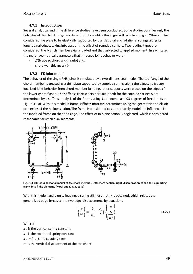
MASTER THESIS HARM BOEL
PRELIMINARY STUDY 49
4.7.1 Introduction
Several analytical and finite difference studies have been conducted. Some studies consider only the
behavior of the chord flange, modeled as a plate which the edges will remain straight. Other studies
considered the plate to be elastically supported by translational and rotational springs along its
longitudinal edges, taking into account the effect of rounded corners. Two loading types are
considered; the branch member axially loaded and that subjected to applied moment. In each case,
the major geometrical parameters that influence joint behavior were:
- β (brace to chord width ratio) and;
- chord wall thickness (t).
4.7.2 FE joint model
The behavior of the single RHS joints is simulated by a two-dimensional model. The top flange of the
chord member is treated as a thin plate supported by coupled springs along the edges. To isolate
localized joint behavior from chord member bending, roller supports were placed on the edges of
the lower chord flange. The stiffness coefficients per unit length for the coupled springs were
determined by a stiffness analysis of the frame, using 31 elements and 93 degrees of freedom (see
Figure 4-10). With this model, a frame stiffness matrix is determined using the geometric and elastic
properties of the hollow section. The frame is considered to appropriately model the influence of
the modeled frame on the top flange. The effect of in-plane action is neglected, which is considered
reasonable for small displacements.
Figure 4-10: Cross-sectional model of the chord member, left: chord section, right: discretization of half the supporting
frame into finite elements (Korol and Mirza, 1982)
With this model, and a unity loading, a spring stiffness matrix is obtained, which relates the
generalized edge forces to the two edge displacements by equation .
v vr
rv r
wk kN
dwk kM
dy
=
i (4.22)
Where:
6ν is the vertical spring constant
6r is the rotational spring constant
6vr = 6rv is the coupling term
B is the vertical displacement of the top chord
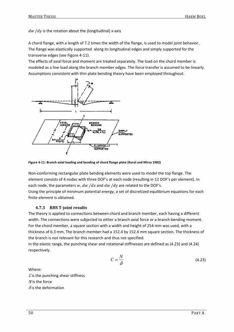
MASTER THESIS HARM BOEL
50 PART A
CB /Cy is the rotation about the (longitudinal) x-axis
A chord flange, with a length of 7.2 times the width of the flange, is used to model joint behavior.
The flange was elastically supported along its longitudinal edges and simply supported for the
transverse edges (see Figure 4-11).
The effects of axial force and moment are treated separately. The load on the chord member is
modeled as a line load along the branch member edges. The force transfer is assumed to be linearly.
Assumptions consistent with thin plate bending theory have been employed throughout.
Figure 4-11: Branch axial loading and bending of chord flange plate (Korol and Mirza 1982)
Non-conforming rectangular plate bending elements were used to model the top flange. The
element consists of 4 nodes with three DOF’s at each node (resulting in 12 DOF’s per element). In
each node, the parameters B, CB /CD and CB /Cy are related to the DOF’s.
Using the principle of minimum potential energy, a set of discretized equilibrium equations for each
finite element is obtained.
4.7.3 RHS T-joint results
The theory is applied to connections between chord and branch member, each having a different
width. The connections were subjected to either a branch axial force or a branch bending moment.
For the chord member, a square section with a width and height of 254 mm was used, with a
thickness of 6.3 mm. The branch member had a 152.4 by 152.4 mm square section. The thickness of
the branch is not relevant for this research and thus not specified.
In the elastic range, the punching shear and rotational stiffnesses are defined as (4.23) and (4.24)
respectively.
N
Cδ
= (4.23)
Where:
C is the punching shear stiffness
N is the force
δ is the deformation

MASTER THESIS HARM BOEL
PRELIMINARY STUDY 51
M
Jϕ
= (4.24)
Where:
J is the rotational stiffness
M is the moment
φ is the rotation
In Table 4-2, the results of other studies are shown for a square section with a width of 152.4 mm
branch connected to a square section with a width of 254 mm and a wall thickness of 9.5 mm.
Hereby, to show its importance, a comparison is made between properly modeled, simply supported
and clamped edges. Young’s modulus E is taken as 2*105 N/mm2.
Table 4-2: axial and rotational stiffnesses for top plate, according to different investigations (Korol and Mirza 1982)
Case C in kN/mm J in kNm/rad
Proper joint 248 244 1333 1062 1390
Simply supported
edges 445 - 2079 - -
Clamped edges 1630 - 5899 - -
The test results of this study (first column of C and J ) show similarities with an experimental study
(second column of C and third column of J ).
The effect of β (brace to chord width ratio) on the joint behavior was investigated. In Figure 4-12 and
Figure 4-13 graphs are shown which show the moment-rotation and force-deflection behavior of the
joint. The non-linear behavior is caused by inputting a tangent modulus ET of 0.025 E. In Table 4-3
and Table 4-4, only the elastic behavior of the joint is shown.
Figure 4-12: Moment – rotation curves for different values of ββββ (in figure: β = λ) (Korol and Mirza 1982)

MASTER THESIS HARM BOEL
52 PART A
Figure 4-13: Force-deflection curves for different values of ββββ (in figure: β = λ) (Korol and Mirza 1982)
Table 4-3: Connection stiffnesses for different values of ββββ
β C in kN/mm J in kNm/rad
0.8 742 3020
0.6 248 1333
0.4 101 790
Table 4-4: Connection stiffnesses for different values of tttt
t in mm C in kN/mm J in kNm/rad
12.7 522 3057
9.5 248 1333
6.3 82 432
4.8 Hornung, U. and Saal, H. (1998/2001). A method of calculating the
out-of-plane buckling lengths of diagonals of truss girders with
hollow sections and K- or N-joints
In this report, a method is presented to calculate the out-of-plane buckling length of the diagonals of
welded truss girders. The results of this method are compared to the Eurocode and to the results of
other numerical as well as experimental studies.
Test results and accompanying numerical calculations sponsored by CIDECT have resulted in
formulas (equations (4.25) to (4.27)) for the out of plane buckling length with a maximum buckling
length factor of 0.75. But, the applicability of these equations is rather limited (only for β – values
smaller than 0.6).
4.8.1 Formulas resulted by previous studies
For a value of β < 0.6, buckling length factors between 0.5 and 0.75 were found by using equations
(4.25) to (4.27). β is the outer width or diameter of the web member divided by the outer width or
diameter of the chord member:
1
0
d
dβ = or 1
0
d
bβ = or 1
0
b
bβ =
For a circular section chord and web member:

MASTER THESIS HARM BOEL
PRELIMINARY STUDY 53
2
1
0
2.20*
crL d
L L d
=
(4.25)
For a rectangular section chord member and a circular section web member:
2
1
0
2.35*
crL d
L L b
=
(4.26)
For a rectangular section chord and web member:
2
1
0
2.30*
crL b
L L b
=
(4.27)
Where:
Lcr is the buckling length
L is the system length
b1 is the outer width of rectangular web member
d1 is the outer diameter of circular web member
b0 is the outer width of rectangular chord member
d0 is the outer diameter of circular chord member
Because lattice girders for scaffolding systems often have a β –value larger than 0.6, it was decided
to investigate the buckling lengths of diagonals in lattice girders with dimensions which are used in
scaffolding systems.
4.8.2 Methodology
To obtain the buckling length factor, a simulation of the connection between the chord member and
the braces was made to determine the rotational stiffness of the connection. For this model, shell
elements have been used. The rotational stiffness was implemented in another numerical model of
the entire lattice girder. This second model consisted of beam elements which were connected by
rotational springs with a rotation stiffness as determined by in the first numerical model. With this
second model, buckling analyses was then performed.
To determine the rotational stiffness of the joint, three load cases were investigated which can be
seen in Figure 4-14. Using different parameters, three formulas (equations (4.28) to (4.30)) are given
to determine the rotational stiffness of the joint for the different load cases.

MASTER THESIS HARM BOEL
54 PART A
Figure 4-14: boundary conditions and unit loads for three different cases (Hornung, U., Saal, H., 2001)
For load case a) the modeled joint is supported by a roll support on the left side and a forked and
hinged support on the right side. A moment parallel to the x-x-axis of the chord member is modeled
at the upper end of the brace.
2 2
; ;
sin cos 1C
T ch b T b
sb
GI EI GIϕ
α αϕ
ϕ ϕ
= + + → = −
(4.28)
For load case b) the model is supported in the same way as load case a) is. A moment perpendicular
to the brace member is modeled at the upper end of the brace.
( )
;
sin cos 1 sinC
T ch b
a s b
GI EIϕ
α α αϕ
ϕ ϕ
+= + → =
− (4.29)
For load case c) the model is supported in the same way as load cases a) and b) except for the fact
that it is also forked on the left side.
( )
( ) ;
sin cos 1 sinC
2 T ch b
a a s b
a s GI EIϕ
α α αϕ
ϕ ϕ
+= + → =
+ − (4.30)
Where:
( is the distance between the support and the intersection between the chord and the brace (see
Figure 4-15)
H is the gap between the braces (see Figure 4-15)
I is the length of the brace (see Figure 4-15)
J is the distance between the intersections of the system lines of the braces with that of the chord
(see Figure 4-15)
K is the angle between the chord and the brace
L is the rotation of the brace in the joint-model caused by load cases a) to c) (see Figure 4-15)
ϕ is the correction for the rotation ϕ because in the beam-model the tubes are represented by the
centerline of the tubes (see Figure 4-15)
GIT;ch is the rotational stiffness of the chord
GIT;b is the rotational stiffness of the brace

MASTER THESIS HARM BOEL
PRELIMINARY STUDY 55
EIb is the flexural stiffness of the brace
1 is the unit load
Cϕ is the rotational stiffness of the connection between the chord and brace member
Figure 4-15: Model to calculate the angle ϕ with explanation of the symbols a , g , b , b and ϕ (Hornung et al. 2001)
Above, the method is explained for K-joints. The same method is used for truss girders with N-joints.
4.8.3 Parameters and combinations
The rotational stiffness of a joint depends on the gap between the intersections of the system lines
of the braces with the system line of the chord, the torsional stiffness of the chord and that of the
brace, the flexural stiffness of the brace, the angle between the chord and the brace and the length
of the brace for the case a). For case b) and c) the rotational stiffness of the joint depends on the
same parameters as for case a) except for the rotational stiffness of the brace. Besides these
parameters, the distance from the intersection between the system line of the brace and that of the
chord to the support of the chord are taken into account.
The different parameters that have been investigated are:
Length5: RHS: L = 3.0, 4.0, 5.0, 5.2 and 6.0 m. CHS: L = 3.1, 4.1, 5.1 6.1 and 7.6 m.
Dimension of the brace: RHS (30x20 mm, t = 2.0 mm) and CHS (Ø = 33.7 mm, t = 2.6 mm).
Angle between chord and
brace:
For RHS braces: 51.5°, 49.1° and 47.0°. For CHS braces: 41.5° (no
variation).
The gap between the
connections:
RHS: g = 10, 12, 18, 33, 45 and 50 mm CHS: g = 60 mm (no variation).
Furthermore, a constant height6 (400 mm) and dimension of the chord member (Ø 48.3/3.2) was
used.
With the spring stiffness from equations (4.28) to (4.30) a beam model with springs at the
connections allowed the buckling length factor to be obtained. Three different load cases (see Figure
4-16) were applied which created three different buckling length factors. The highest value of the
three is chosen as the governing factor.
These buckling length factors were compared to the factors given by the Eurocode. For most cases,
the Eurocode is on the safe side. For two cases, the Eurocode is slightly unsafe according to this
5 It is not clear which length is meant
6 It is not clear which height is meant

MASTER THESIS HARM BOEL
56 PART A
method. The Eurocode is unsafe compared to this method for two cases where the diagonal next to
the support, which had a different angle to that of the other diagonals, initiated the buckling.
Figure 4-16: different load cases on the beam model (Hornung et al. 2001)
4.8.4 Other methods to calculate the buckling length factor in lattice girders:
The outcome of the beam-element-model with rotational springs was compared to formulas to
determine buckling length factors for members elastically restrained at the end. The formulae
described by (4.31) and (4.33) are referred to as the method of Günther and Kupfer, respectively.
Where the first is applicable if two rotational springs with different stiffnesses are present.
( )
( )( )min
2.25 5.505 1.141
2 5.4 2 5.4 1
a b
a b
C C CK
C C
+ + += −
+ + − (4.31)
Where:
Ca and
Cb are the flexibility factors rotations at end a and b of the member determined by (4.32).
EI
CkL
= (4.32)
The second is only applicable if both end conditions are the same.
0.205
0.41
crL C
L C
+=
+ (4.33)
The results according to the formula presented by Günther, Kupfer and that of the beam element
model are compared to the exact solution for a single beam with rotational springs at both ends
(Table 2-1). The exact solution for a single beam with rotational springs (with the same stiffness) at
both ends can, according to Hornung and Saal (1998), be determined by Equation (4.34).
( ) ( ) ( )
( ) ( )
2 32
2 42 2 2
2
2 2sin 2 cos cos
sin sin 2 0
kEI kEIk
L L
EIk k
L
µ µµ µ µ µ
µµ µ µ µ
− − +
− + =
(4.34)

MASTER THESIS HARM BOEL
PRELIMINARY STUDY 57
Where:
/crL L K
π πµ = = (4.35)
Table 4-5: comparison of different methods to determine buckling length factors (Hornung et al. 1998)
Beam-Element-model Günther Kupfer Exact solution for
single beam
0.677 0.633 0.782 0.621
4.8.5 Comparison with experimental results
Because buckling length factors are determined using a numerical simulation, it is interesting to
verify the results of this numerical simulation by experiments. Numerical models have been used to
simulate 16 tests from 1988 and 6 tests from 1992. It is not clear which buckling curve is used to
determine the buckling load from the results of the numerical model to compare these with the
results of the tests by Rondal.
Eight lattice girders consisted of a chord of Ø108/3.6 with a brace of Ø42.4/2.6 and an angle
between the two of 30°. The length of the braces was 1600 mm. Three lattice girders had the same
dimensions for the members only a different angle between them (45 and 60°) and in two cases a
slightly different length of the brace (1622 and 1626 mm).
Seven lattice girders consisted of a chord of Ø70/3 with a brace of Ø26.9/2.35 and an angle of 45°.
Also with a length of the brace of 1600 mm.
Four lattice girders consisted of a chord of Ø108/3.6 with a brace of Ø26.9/2.35 and in two cases an
angle between the two of 30° (length of the brace: 1600 and 1625 mm), one case of 45° (length of
the brace: 1580 mm) and one case 60° (length of the brace: 1605 mm).
One lattice girder consisted of a chord of Ø70/3 with a brace of Ø42.4/2.6 and an angle between the
two of 30°. The length of the brace was 1600 mm.
The gap between the braces is unknown as well as the eccentricity of the system lines of the
members.
When comparing the results of the numerical study, the experimental study and the Eurocode, it
appears that the numerical results are also on the safe side compared to the experimental results
except for one case where it is slightly unsafe (see Table 4-6). In this case a chord of Ø108/3.6 with a
brace of Ø42.4/2.6 was used with an angle between the two of 45°.
The Eurocode is safe compared to the numerical results except for three cases. In two of these cases,
a chord of Ø108/3.6 with a brace of Ø26.9/2.35 is used with an angle between the two of 45 and
60°. In the other case a chord of Ø108/3.6 with a brace of Ø42.4/2.6 and an angle between the two
of 60° was used.

MASTER THESIS HARM BOEL
58 PART A
Table 4-6: Results (experimental, numerical and Eurocode) compared
Test
no.
Ntest
NEURO
Ntest
Nansys
Nansys
NEURO
Test
no.
Ntest
NEURO
Ntest
Nansys
Nansys
NEURO
1 1.3 1.14 1.14 12 1.23 1.21 1.02
2 1.35 1.19 1.13 13 1.34 1.32 1.02
3 1.22 1.06 1.15 14 1.3 1.29 1.01
4 1.24 1.09 1.14 15 1.3 1.28 1.02
5 1.19 1.05 1.13 16 1.3 1.27 1.02
6 1.29 1.13 1.14 17 1.31 1.11 1.18
7 1.2 1.05 1.14 18 1.05 0.97 1.08
8 1.36 1.19 1.14 19 1 1.03 0.97
9 1.41 1.4 1.01 20 1.22 1.47 0.83
10 1.19 1.18 1.01 21 1.39 1.17 1.19
11 1.2 1.18 1.02 22 1.21 1.33 0.91
These results suggest that the Eurocode is limited for a certain ratio between the dimensions of the
brace and the chord member. It also suggests a limit for the angle between the two.
The exact influence of different dimensions of the chord and brace member is not clear, since little
variation has been made in these two parameters. Also the influence of the angle between the two
has not been varied much, so it’s possible influence on the buckling load cannot be determined.

MASTER THESIS HARM BOEL
PRELIMINARY STUDY 59
4.9 Fekete, F. (2009). Thesis: Buckling lengths of members in hollow
section steel trusses
This report describes a numerical study to determine the buckling lengths of hollow section steel
trusses. For the numerical model, shell elements were used.
First the finite element model and the parameters are described. After this, the most important
results are discussed and the conclusions are made clear.
4.9.1 The model; global
A geometry is chosen consisting of two chord members connected only by diagonal braces. The
length of the lattice girder is 48 m with a height of 1.8, 2.6, 3.45, 4.3 or 5.1 m. 16 brace members
were used. The supports are placed at the end of the upper chord and the lower chord is not
supported (see Figure 4-17). Besides the vertical supports, also lateral supports are placed. The
lateral supports are placed in the middle of the upper face of the upper chord, above the
intersection between the two braces. The number of supports was varied.
Figure 4-17: Geometry of the lattice girder
4.9.2 The model; parameters
The dimensions of the chord members and brace members have been varied. For the chord
members, a CHS 200/6.3 and a SHS 200/6.3 were used for which the brace members varied also. The
different combinations of member dimensions are shown in Table 4-7. For each combination, 2, 3, 5,
9 and 17 lateral braces were modeled.
For the brace member we find a deviant dimension: a CHS 199/6.3 is used instead of a CHS 200/6.3.
Why this is done, is not clear, but it is possible that it is done because the connection with a CHS
200/6.3 may give melding errors.
Table 4-7: Parameters
Chord Brace
SHS 200/6.3 SHS 50/6.3
SHS 100/6.3
SHS 150/6.3
SHS 200/6.3
CHS 50/6.3
CHS 100/6.3
CHS 150/6.3
CHS 199/6.3
CHS 200/6.3 CHS 50/6.3
CHS 100/6.3
CHS 150/6.3
CHS 199/6.3
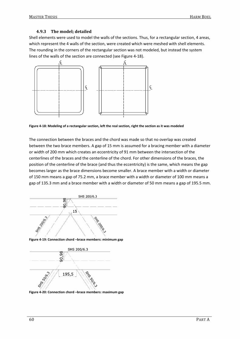
MASTER THESIS HARM BOEL
60 PART A
4.9.3 The model; detailed
Shell elements were used to model the walls of the sections. Thus, for a rectangular section, 4 areas,
which represent the 4 walls of the section, were created which were meshed with shell elements.
The rounding in the corners of the rectangular section was not modeled, but instead the system
lines of the walls of the section are connected (see Figure 4-18).
Figure 4-18: Modeling of a rectangular section, left the real section, right the section as it was modeled
The connection between the braces and the chord was made so that no overlap was created
between the two brace members. A gap of 15 mm is assumed for a bracing member with a diameter
or width of 200 mm which creates an eccentricity of 91 mm between the intersection of the
centerlines of the braces and the centerline of the chord. For other dimensions of the braces, the
position of the centerline of the brace (and thus the eccentricity) is the same, which means the gap
becomes larger as the brace dimensions become smaller. A brace member with a width or diameter
of 150 mm means a gap of 75.2 mm, a brace member with a width or diameter of 100 mm means a
gap of 135.3 mm and a brace member with a width or diameter of 50 mm means a gap of 195.5 mm.
Figure 4-19: Connection chord –brace members: minimum gap
Figure 4-20: Connection chord –brace members: maximum gap
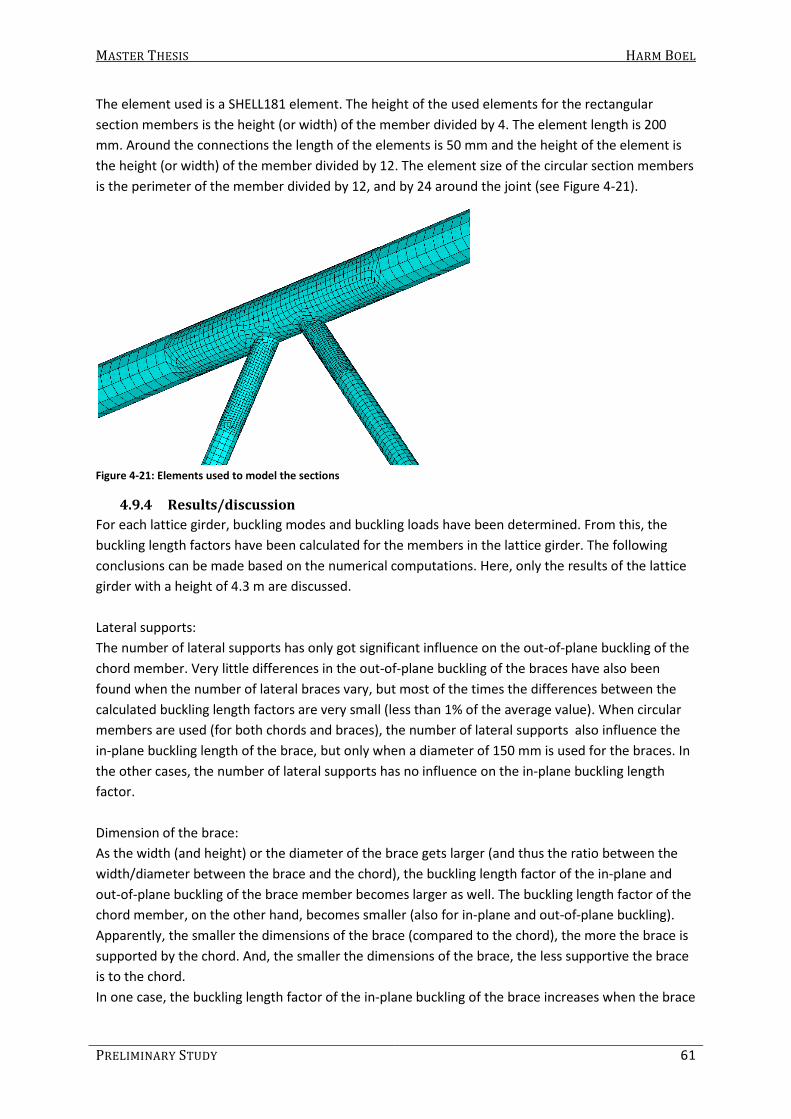
MASTER THESIS HARM BOEL
PRELIMINARY STUDY 61
The element used is a SHELL181 element. The height of the used elements for the rectangular
section members is the height (or width) of the member divided by 4. The element length is 200
mm. Around the connections the length of the elements is 50 mm and the height of the element is
the height (or width) of the member divided by 12. The element size of the circular section members
is the perimeter of the member divided by 12, and by 24 around the joint (see Figure 4-21).
Figure 4-21: Elements used to model the sections
4.9.4 Results/discussion
For each lattice girder, buckling modes and buckling loads have been determined. From this, the
buckling length factors have been calculated for the members in the lattice girder. The following
conclusions can be made based on the numerical computations. Here, only the results of the lattice
girder with a height of 4.3 m are discussed.
Lateral supports:
The number of lateral supports has only got significant influence on the out-of-plane buckling of the
chord member. Very little differences in the out-of-plane buckling of the braces have also been
found when the number of lateral braces vary, but most of the times the differences between the
calculated buckling length factors are very small (less than 1% of the average value). When circular
members are used (for both chords and braces), the number of lateral supports also influence the
in-plane buckling length of the brace, but only when a diameter of 150 mm is used for the braces. In
the other cases, the number of lateral supports has no influence on the in-plane buckling length
factor.
Dimension of the brace:
As the width (and height) or the diameter of the brace gets larger (and thus the ratio between the
width/diameter between the brace and the chord), the buckling length factor of the in-plane and
out-of-plane buckling of the brace member becomes larger as well. The buckling length factor of the
chord member, on the other hand, becomes smaller (also for in-plane and out-of-plane buckling).
Apparently, the smaller the dimensions of the brace (compared to the chord), the more the brace is
supported by the chord. And, the smaller the dimensions of the brace, the less supportive the brace
is to the chord.
In one case, the buckling length factor of the in-plane buckling of the brace increases when the brace
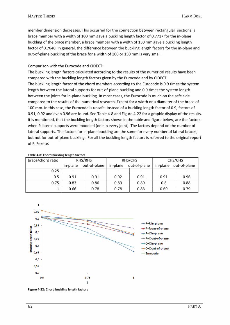
MASTER THESIS HARM BOEL
62 PART A
member dimension decreases. This occurred for the connection between rectangular sections: a
brace member with a width of 100 mm gave a buckling length factor of 0.7717 for the in-plane
buckling of the brace member, a brace member with a width of 150 mm gave a buckling length
factor of 0.7640. In general, the difference between the buckling length factors for the in-plane and
out-of-plane buckling of the brace for a width of 100 or 150 mm is very small.
Comparison with the Eurocode and CIDECT:
The buckling length factors calculated according to the results of the numerical results have been
compared with the buckling length factors given by the Eurocode and by CIDECT.
The buckling length factor of the chord members according to the Eurocode is 0.9 times the system
length between the lateral supports for out-of-plane buckling and 0.9 times the system length
between the joints for in-plane buckling. In most cases, the Eurocode is much on the safe side
compared to the results of the numerical research. Except for a width or a diameter of the brace of
100 mm. In this case, the Eurocode is unsafe. Instead of a buckling length factor of 0.9, factors of
0.91, 0.92 and even 0.96 are found. See Table 4-8 and Figure 4-22 for a graphic display of the results.
It is mentioned, that the buckling length factors shown in the table and figure below, are the factors
when 9 lateral supports were modeled (one in every joint). The factors depend on the number of
lateral supports. The factors for in-plane buckling are the same for every number of lateral braces,
but not for out-of-plane buckling. For all the buckling length factors is referred to the original report
of F. Fekete.
Table 4-8: Chord buckling length factors
brace/chord ratio RHS/RHS
in-plane out-of-plane
RHS/CHS
in-plane out-of-plane
CHS/CHS
in-plane out-of-plane
0.25 - - - - - -
0.5 0.91 0.91 0.92 0.91 0.91 0.96
0.75 0.83 0.86 0.89 0.89 0.8 0.88
1 0.66 0.78 0.78 0.83 0.69 0.79
Figure 4-22: Chord buckling length factors
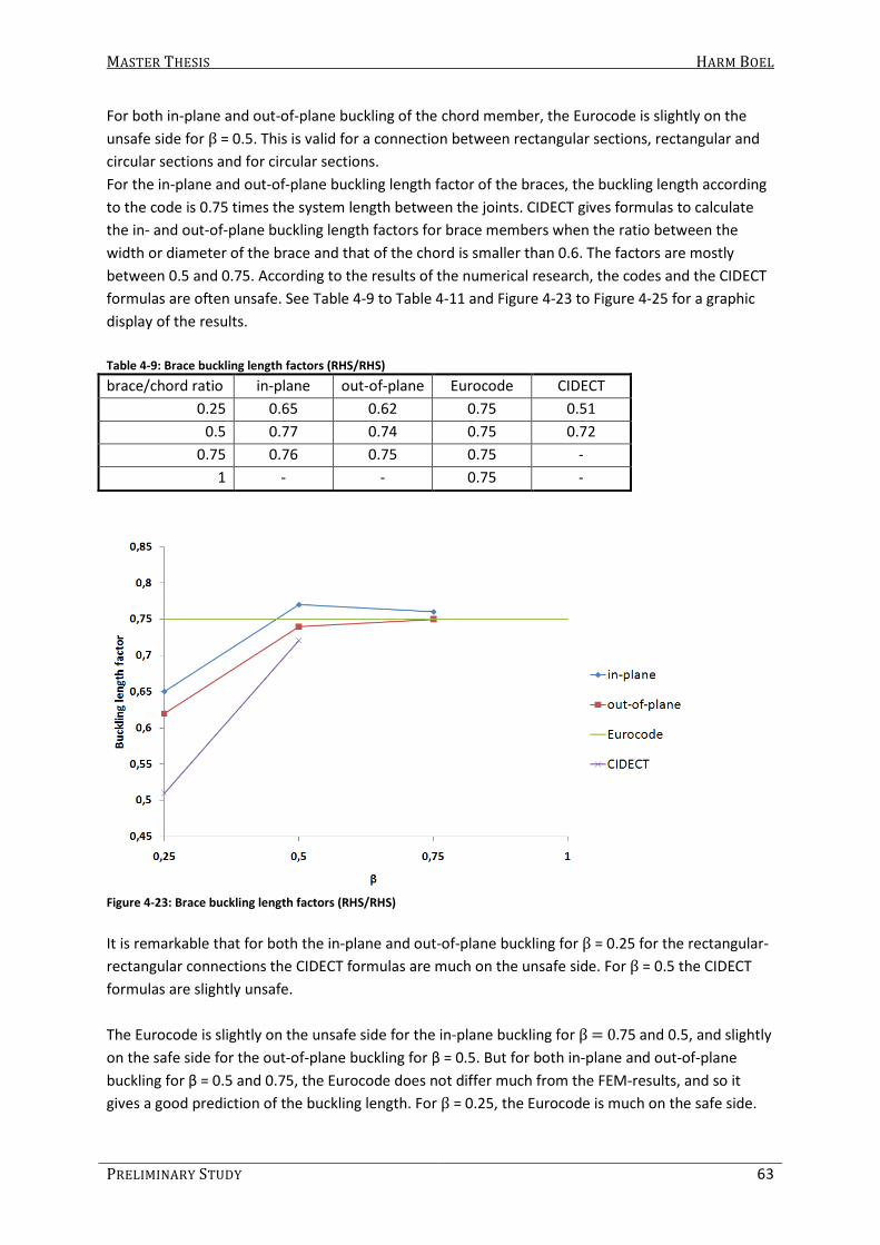
MASTER THESIS HARM BOEL
PRELIMINARY STUDY 63
For both in-plane and out-of-plane buckling of the chord member, the Eurocode is slightly on the
unsafe side for β = 0.5. This is valid for a connection between rectangular sections, rectangular and
circular sections and for circular sections.
For the in-plane and out-of-plane buckling length factor of the braces, the buckling length according
to the code is 0.75 times the system length between the joints. CIDECT gives formulas to calculate
the in- and out-of-plane buckling length factors for brace members when the ratio between the
width or diameter of the brace and that of the chord is smaller than 0.6. The factors are mostly
between 0.5 and 0.75. According to the results of the numerical research, the codes and the CIDECT
formulas are often unsafe. See Table 4-9 to Table 4-11 and Figure 4-23 to Figure 4-25 for a graphic
display of the results.
Table 4-9: Brace buckling length factors (RHS/RHS)
brace/chord ratio in-plane out-of-plane Eurocode CIDECT
0.25 0.65 0.62 0.75 0.51
0.5 0.77 0.74 0.75 0.72
0.75 0.76 0.75 0.75 -
1 - - 0.75 -
Figure 4-23: Brace buckling length factors (RHS/RHS)
It is remarkable that for both the in-plane and out-of-plane buckling for β = 0.25 for the rectangular-
rectangular connections the CIDECT formulas are much on the unsafe side. For β = 0.5 the CIDECT
formulas are slightly unsafe.
The Eurocode is slightly on the unsafe side for the in-plane buckling for β = 0.75 and 0.5, and slightly
on the safe side for the out-of-plane buckling for β = 0.5. But for both in-plane and out-of-plane
buckling for β = 0.5 and 0.75, the Eurocode does not differ much from the FEM-results, and so it
gives a good prediction of the buckling length. For β = 0.25, the Eurocode is much on the safe side.

MASTER THESIS HARM BOEL
64 PART A
Table 4-10 Brace buckling length factors (RHS/CHS)
brace/chord ratio in-plane out-of-plane Eurocode CIDECT
0.25 0.62 0.6 0.75 0.52
0.5 0.79 0.73 0.75 0.74
0.75 0.81 0.75 0.75 -
1 - - 0.75 -
Figure 4-24 Brace buckling length factors (RHS/CHS)
For the rectangular-circular connection, the CIDECT formulas for both in-plane and out-of-plane
buckling are unsafe for β = 0.25. For in-plane buckling, the CIDECT formula is also unsafe for β = 0.5.
The Eurocode is unsafe for the in-plane buckling for β = 0.75 and 0.5, but much on the safe side for β
= 0.25. For the out-of-plane buckling, the Eurocode provides a good prediction of the buckling length
for β = 0.5 and 0.75.
Table 4-11 Brace buckling length factor (CHS/CHS)
brace/chord ratio in-plane out-of-plane Eurocode CIDECT
0.25 0.53 0.61 0.75 0.49
0.5 0.58 0.71 0.75 0.69
0.75 0.67 0.76 0.75 -
1 0.74 0.78 0.75 -

MASTER THESIS HARM BOEL
PRELIMINARY STUDY 65
Figure 4-25 Buckling length factors for brace (CHS/CHS)
For the circular-circular connection, the CIDECT formulas for out-of-plane buckling are unsafe for β =
0.25 and 0.5. For in-plane buckling CIDECT is unsafe for β = 0.25.
The Eurocode for out-of-plane buckling is slightly unsafe for β = 1 and 0.75. For both in-plane and
out-of-plane buckling for β = 0.25 it is much on the safe side and for in-plane buckling it is much on
the safe side for β = 0.5 and 0.75 also, and slightly safe for β = 1.
4.9.5 Conclusions
The buckling length factor for in- and out-of-plane buckling of the chord member can be estimated
by using the Eurocode. In most cases, it gives an upper limit and it is safe to use. For larger values of
β (1), the Eurocode is somewhat uneconomical. For smaller values of β (0.5), it is slightly unsafe.
For in-plane buckling of the brace, the Eurocode is slightly unsafe in most cases, except for lower
values of β (0.25)). But, the Eurocode is much on the safe side for circular section braces when
circular section chords are used.
For out-of-plane buckling of the brace, the Eurocode provides a good prediction of the buckling
length factor, except for lower values of β (0.25). In some cases, when circular section braces and
chords are used, the Eurocode is slightly unsafe for higher values of β (1 or 0.75).
The formulas given by CIDECT are unsafe for both in- and out-of-plane buckling of the brace. Except
for in-plane buckling of a circular section brace when a circular section chord is used for β = 0.5 and
for out-of-plane buckling of a circular section brace when a rectangular section brace is used.

MASTER THESIS HARM BOEL
66 PART A
5. What is still unknown/to be done In chapter 4 it has been shown that several buckling length factors and methods to determine
buckling length factors exist. Most formulas that are given use only a few parameters and thus do
not take every influence into account. In this chapter, the factors that are and are not taken into
account are briefly discussed. Hereafter, it is described what is still to be investigated and a research
proposal is made.
5.1 What is (un)known/ already done
Two methods to determine the out-of-plane buckling length of laterally unsupported chord
members, that are given by Mouty (1981), seem to take every factor into account and need no
further investigation. Galambos describes three somewhat simpler methods to determine the out-
of-plane buckling length factor of laterally unsupported chords in pony trusses.
The research done by Fekete is concentrated on the ratio between the width/diameter of the brace
to that of the chord. Only the used sections have been varied and thus some factors have not been
investigated. Also Galambos, the codes and the CIDECT formulas do not take every factor (described
hereafter) into account. An earlier study has shown, that some of these factors do have influence on
the buckling behavior of a lattice girder.
Research done by F. Fekete:
- Only one geometry was investigated. The effect of vertical braces nor the effect of the angle
of the diagonal braces was investigated;
- Only one load case (force in joint) was studied;
- Only circular and square section members (no rectangular) were investigated. Only one wall
thickness was used in the research;
- The braces had no overlap and the gap between the braces differed dependent on the
dimension of the brace. The eccentricity was the same every time;
- No different heights of the rectangular sections were investigated and;
- The lateral supports were modeled as horizontal supports. Rotation of the supported chords
was not restricted by the lateral support, but the horizontal deflection was restricted
completely.
Galambos, the codes and CIDECT:
Galambos and the codes give standard buckling length factors. Geometry, dimensions and lateral
supports are not taken into account.
CIDECT gives formulas to calculate buckling length factors for brace members. Only the width or
diameter of the brace and the chord member and the length of the brace are needed to calculate
the buckling length factor. The angle of the brace member, the height of the sections, the distance
between joints and the wall thickness of chord and brace member is not taken into account.
Moreover, the formulas that are presented by the CIDECT design guides, Hornung and Saal
(1998/2001) and by Mouty (1981), to which is referred to, differ from each other. The differences
are shown in Table 5-1.

MASTER THESIS HARM BOEL
PRELIMINARY STUDY 67
Table 5-1: Differences between formulas to determine buckling lengths for brace members
Hornung, U. and Saal, H.
(1998 / 2001)
CIDECT design guide
by Wardenier et al.
(1992a)
CIDECT monograph no.4
by Mouty, J. (1981)
CHS chord and CHS brace:
2
1
0
2.20*
d
L d
RHS chord and CHS brace: 2
1
0
2.35*
d
L b
RHS chord and RHS brace:
2
1
0
2.30*
b
L b
CHS chord and CHS brace:
0.252
1
0
2.20*
d
L d
RHS chord and CHS brace: 0.25
2
1
0
2.35*
d
L b
RHS chord and RHS brace:
0.252
1
0
2.30*
b
L b
CHS chord and CHS brace:
0.252
1
0
2.42*
d
L d
RHS chord and CHS brace: 0.25
2
1
0
2.12*
d
L b
RHS chord and RHS brace:
0.252
1
0
2.25*
b
L b
Formulas can be used for the
determination of the buckling
length factor of out-of-plane
buckling of diagonal brace members.
Formulas can be used for the
determination of the
buckling length for both out-
of-plane and in-plane
buckling of diagonal as well
as vertical braces.
In the case of RHS:
b1 is the longer side of the HS
used as the bracing member
Article of 1998
(Journal of
Constructional
Steel Research)
Article of 2001
(tubular
structures IX)
Valid for K-, N- and KT-joints
Valid for K-
joints
Valid for K-
and N-joints
The formulas by Hornung and Saal (1998/2001) are assumed to be incorrect because unrealistic
buckling length factors are obtained when substituting the section dimensions in these formulae.
Fekete (2009) uses the formulas presented by Wardenier et al. (1992a) to compare the results of his
numerical study to. The buckling length factors given by Fekete and by Wardenier et al. differed,
which is also shown in section 4.9.
5.2 Factors that (possibly) influence the buckling load
It has been shown that the buckling length of members in welded hollow section lattice girders
depends on many different factors. In this section it has been tried to make a convenient
arrangement of these factors.
5.2.1 Geometry and supports
Different types of lattice girders can be designed. For example, frames with K-, N- or KT-connections
can be made. Different heights, different types of frames and different ways of supporting the lattice
girder cause a different structural behavior.
- Lateral braces:
The lateral braces support the chord member and prevent it from buckling out-of-plane. If

MASTER THESIS HARM BOEL
68 PART A
the lateral braces are fixed to the chord instead of pinned, the out-of-plane buckling of the
brace is (possibly) also prevented.
Lateral braces are often purlins. The way the purlins are connected to the lattice girder, the
axial and flexural stiffness of the purlin and the distance to the next lattice girder are
parameters which must be taken into account.
- The flexural and torsional stiffness of the chords:
The laterally supported chord will rotate if the unsupported chord buckles. The torsional
stiffness of the chord prevents this rotation.
Because rotation of the ends of the brace are prevented, the buckling length of the brace
decreases as well. The flexural stiffness of the chords prevent in-plane rotation of the ends
of the braces which decreases the in-plane buckling length.
- The panel length (length between two joints):
The unsupported chord is supported by elastic supports which are in fact the brace
members. The distance between the elastic supports is of influence on the buckling load of
the chord. Also the braces can be supported by other braces through the chords.
- Height of the girder and angle between brace and chord (length of brace members):
The brace members can be considered as cantilever beams which prevent the chord from
bending out of plane. The length of the brace members (and thus the height of the girder
and the angle between the braces and the chords) determines the stiffness of the elastic
supports which represents the braces (it also influences the panel length).
- The flexural and torsional stiffness of the brace:
The (transverse) flexural stiffness is determinant for the stiffness of the lateral elastic
supports of the chord. The flexural stiffness (in-plane) prevents the chord from rotation in
plane and is determinant for the in-plane rotational support of the chord.
The rotational stiffness determines the stiffness of the (transverse) rotational support of the
chord.
- Type of frame (using K-,N- or KT-connections):
The number of braces framing into each other and into the chord are of influence on the
elastic (rotational) supports at the ends of the considered chord or brace. Also the sum of
flexural stiffnesses of the braces could be of influence. This means a different structural
behavior for a lattice girder comprising of K- connections than one comprising of KT-
connections.
5.2.2 Sections and connections
Rotational and flexural stiffnesses of members determine the buckling behavior of each other. The
rigidity of connections determine to what extent the members can support each other.
In chapter 4, results are presented of rotational stiffness of connections of hollow sections in
vierendeelgirders. In fact, the connections of hollow sections in lattice girders are not that different.
The main difference is that the members in vierendeelgirders are often connected under an angle of

MASTER THESIS HARM BOEL
PRELIMINARY STUDY 69
90 degrees and only two members are connected to each other. In lattice girders three or more
members are connected to each other and the angle varies from 30 to 90 degrees.
Beneath, the factors that (possibly) influence the stiffness of the connection between two members
and thus the buckling load are described.
- Wall thickness:
If the brace width or diameter is smaller than that of the chord and the end of a brace
rotates, the face of the chord the brace is connected to deforms. The wall thickness is
determinant for the amount of rotation.
- β (ratio between width or diameter of the brace to that of the chord):
As described before, the face of the chord deforms as the brace end rotates. If a small value
of β is used, the rotation will be larger than if a large value of β is used for the same
moment.
- Gap/overlap:
If the end of a brace rotates when two or more braces are connected to a chord, all brace
ends will rotate because they are all connected to the same chord face. This rotation will be
prevented by the other braces. A small gap between brace members could mean that the
brace members support each other or initiate buckling for each other. A large gap would
mean they do not influence each other. An overlap joint has a great stiffness compared to a
gap joint.
- Angle between the members:
If a small angle is used, the length of the connection of the brace section to the chord face is
larger. This could mean a different yield-line pattern which could influence the rotational
stiffness of the joint.
- Type of member:
The brace and chord member sections can either be circular or rectangular. Formulae to
determine the buckling length and previous studies show that the section/combination of
sections is of influence on the buckling length.
- Height of the section (RHS):
The chord member supports the brace member. In formulae described by CIDECT and by the
study by Fekete, the width is taken into account, but not the height. A bigger height means a
larger in-plane flexural stiffness of the chord member which could mean the brace member
is supported more as well. A bigger height of the brace means the connection with the chord
member could be stiffer and/or stronger.
- Type of joint:
There are many different types of joints: K-, T-, Y-, N, KT- and X-joints. In every joint type, the
rotation of the end of one of the brace members is prevented by another member(s) and
possibly in a different way. The angle, the gap and the number of braces joining in that joint
can be of influence.

MASTER THESIS
70
5.3 To be investigated
All factors described in this chapter have or could have influence on the buckling length of a member
in a lattice girder. Many have been investigated. Especially the influence of the factors described in
section 5.2.1 have been investigated in the past and their effect is partially known. The effect can be
determined analytically or, because nowadays the buckling analysis is more accessible, a FE buckling
analysis of the lattice girder can be d
Some factors described in section
β on the flexural stiffness of vierendeel connections between RHS members). But the exact influence
of these factors on the rigidity of the connection cannot yet be determined using formulae and the
other factors have not been investigated thoroughly at all. Because the influence on the buckling
length of the factors in section 5.2.2
investigate the most significant ones numerically using FE analysis. Especially the wall thickness and
β are of significant influence on
Because the codes give (different) bucking length factors dependent on
investigate if and which code is correct.
thickness of the chord (t0 ), because it is found that
stiffness as well as β, especially for small values of
changes, the flexural stiffness of th
where is varied in chord wall thickness and the width of the brace.
Figure 5-1: Different configurations to i
To be investigated
All factors described in this chapter have or could have influence on the buckling length of a member
in a lattice girder. Many have been investigated. Especially the influence of the factors described in
have been investigated in the past and their effect is partially known. The effect can be
determined analytically or, because nowadays the buckling analysis is more accessible, a FE buckling
analysis of the lattice girder can be done using beam elements.
Some factors described in section 5.2.2 have been investigated also (influence of wall thickness and
on the flexural stiffness of vierendeel connections between RHS members). But the exact influence
of these factors on the rigidity of the connection cannot yet be determined using formulae and the
other factors have not been investigated thoroughly at all. Because the influence on the buckling
5.2.2 are not easy to determine analytically, it is interesting to
investigate the most significant ones numerically using FE analysis. Especially the wall thickness and
the rigidity of the connections.
Because the codes give (different) bucking length factors dependent on β, it is interesting to
investigate if and which code is correct. It is also interesting to investigate the influenc
), because it is found that t0 also has a large effect on the connection
, especially for small values of β. Besides the fact that the connection stiffness
changes, the flexural stiffness of the chord also changes. In Figure 5-1 two situations are given,
where is varied in chord wall thickness and the width of the brace.
: Different configurations to investigate
HARM BOEL
PART A
All factors described in this chapter have or could have influence on the buckling length of a member
in a lattice girder. Many have been investigated. Especially the influence of the factors described in
have been investigated in the past and their effect is partially known. The effect can be
determined analytically or, because nowadays the buckling analysis is more accessible, a FE buckling
have been investigated also (influence of wall thickness and
on the flexural stiffness of vierendeel connections between RHS members). But the exact influence
of these factors on the rigidity of the connection cannot yet be determined using formulae and the
other factors have not been investigated thoroughly at all. Because the influence on the buckling
are not easy to determine analytically, it is interesting to
investigate the most significant ones numerically using FE analysis. Especially the wall thickness and
, it is interesting to
It is also interesting to investigate the influence of the wall
also has a large effect on the connection
. Besides the fact that the connection stiffness
two situations are given,

Part B:
Numerical Investigation


MASTER THESIS HARM BOEL
NUMERICAL INVESTIGATION 73
6. Methodology In the preliminary study (part A) it has been concluded that it is desirable to numerically investigate
the influence of β and γ on the buckling length factor of hollow section members in lattice girders.
An existing shell-element model, made by Fekete (2009), can be used. But, it is also mentioned that
it is desirable to have more knowledge about the connection stiffnesses between hollow section
members and the influence of the connection stiffness on the buckling length factor. This is not
possible using the full shell-element model. Besides that, it is expected that large amount of
calculations must be made. The full shell-element model uses a large amount of elements which
causes a large calculation time. Also, results are hard to obtain and errors are easily made.
For these reasons, another methodology is applied. The FE-model is simplified by using beam-
elements for the members. The connection stiffnesses will be represented by elastic rotational and
translational springs. The spring/connection stiffness will be determined by a shell-element model.
This methodology has the disadvantage that several calculations must be made before buckling
analysis can be performed. But, it has the advantage that more information about the connection
stiffness and its influence on the buckling behavior of a lattice girder is obtained. Besides that, the
model is much more simple and it will take much less time to perform a buckling analysis. Also, the
axial forces in the members are easier to obtain (and errors are made less easy) since only one
beam-element is used to model the section, instead of many shell-elements.
In Figure 6-1, the methodology is clarified by comparing the full-shell-element model with the
beam- element model. As can be seen, the elastic rotational and translational springs are positioned
in point C, representing the rotational and translational stiffness of the connection.
Figure 6-1: Shell-element model versus schematization by beam-element model
In the following sections, the FE-models to determine the connection stiffnesses are explained and
connection stiffnesses obtained by FE-analysis are compared to those given by previous studies.
Hereafter, the beam-element model is described and the results obtained by both the beam- and
the full-shell-element model are compared to each other.

MASTER THESIS HARM BOEL
74 PART B
6.1 Connection Stiffness
Six degrees of freedom must be considered when determining the connection stiffness. The degrees
of freedom are: rotation about the x-, y- and z-axis and translation in x-, y- and z-direction. The
translation in x- and z-direction (shear deformation) are not considered. Now, only four degrees of
freedom remain. If the connection of one brace to the chord is cut out of the lattice girder, which is
modeled in the x-y-plane, the connection between the rigid beam and the brace is achieved by
modeling two nodes (i and j) with the same coordinates, rotated about the z-axis so that four elastic
springs can represent the connection properties (see Figure 6-2).
Figure 6-2: Degrees of freedom in connection
Here, the connection properties are described by Cin, Cout, Ctor, and k, which are the in-plane
rotational, out-of-plane rotational, torsional and translational connection stiffness in local y-
direction, respectively. In section 6.1.1 to 6.1.4, the determination of these stiffnesses are
described. Hereby, the connection is modeled using shell-elements (SHELL181). A load (force or
moment) is applied at the end of the brace, which is done by applying the load to a single node,
which is connected to the nodes of the shell-elements by rigid beams (MPC184) (see Figure 6-3).
Figure 6-3: FE-model of connection

MASTER THESIS HARM BOEL
NUMERICAL INVESTIGATION 75
The stiffness is determined by stating that the amount of deflection or rotation of the end of the
brace, based on a superposition of two different deflection modes, is governed by the deflection of
the structure, assuming the connection is fully rigid and the deflection/rotation due to deformation
of the connection. The principle is shown in Figure 6-4, where the deflection of the end of the
cantilever beam is determined by the flexural stiffness of the beam and the rotational stiffness of
the connection.
Figure 6-4: Deflection of cantilever beam with rotational spring
6.1.1 In-plane rotational stiffness
The in-plane rotational stiffness is represented by a rotational spring (Cin ) about the z-axis. The
stiffness is determined by modeling the connection using shell-elements (SHELL181). The rotation of
the connection due to the applied moment is the difference in rotation of the chord and the brace.
The rotation of the chord is kept zero by prohibiting the translation in y- direction and rotation about
the z-axis along the length of the chord, in the middle of the section as shown in Figure 6-5.
Figure 6-5: Schematization of FE-model to determine CCCCinininin
The brace is loaded with a moment at the end of the brace. This moment is applied to a node, which
is connected to the nodes of the shell-elements by rigid beam-elements (MPC184). Due to the
applied moment, the end of the brace will deflect. The deflection due to the rotation of the
connection can be determined by Equation (6.1), the rotation can be calculated by (6.2) and the
stiffness of the connection can be calculated by (6.3).

MASTER THESIS HARM BOEL
76 PART B
2
2
brcon FEM
MLw w
EI= − (6.1)
con
br
w
Lϕ = (6.2)
in
MC
ϕ= (6.3)
Where:
Bcon is the deflection due to rotation of the connection (mm)
BFEM is the deflection obtained by FE-analysis (mm)
M is the applied moment (Nmm)
Lbr is the length of the brace (mm)
E is young’s modulus (N/mm2)
I is the area moment of inertia of the section (mm4)
φ is the rotation of the connection (rad)
Cin is the in-plane rotational stiffness (Nmm/rad)
Because only first order calculations are carried out, Equation (6.4) is assumed (small deflection
theory).
sin( )ϕ ϕ= (6.4)
To determine the influence of the second brace, the connection is modeled with two braces (see
Figure 6-6). Because the upper face of the chord will deform due to the applied moment, the second
brace must also deform. A load in the second brace will then also affect the deformation of the first
brace. Because of this, multiple load cases have been applied and are shown in Figure 6-7.
Figure 6-6: Schematization of chord connected to two braces
Figure 6-7: In-plane load cases
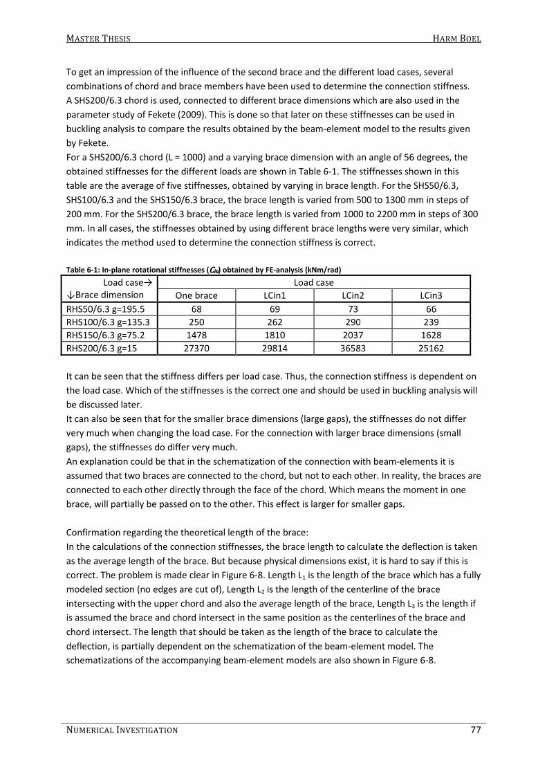
MASTER THESIS HARM BOEL
NUMERICAL INVESTIGATION 77
To get an impression of the influence of the second brace and the different load cases, several
combinations of chord and brace members have been used to determine the connection stiffness.
A SHS200/6.3 chord is used, connected to different brace dimensions which are also used in the
parameter study of Fekete (2009). This is done so that later on these stiffnesses can be used in
buckling analysis to compare the results obtained by the beam-element model to the results given
by Fekete.
For a SHS200/6.3 chord (L = 1000) and a varying brace dimension with an angle of 56 degrees, the
obtained stiffnesses for the different loads are shown in Table 6-1. The stiffnesses shown in this
table are the average of five stiffnesses, obtained by varying in brace length. For the SHS50/6.3,
SHS100/6.3 and the SHS150/6.3 brace, the brace length is varied from 500 to 1300 mm in steps of
200 mm. For the SHS200/6.3 brace, the brace length is varied from 1000 to 2200 mm in steps of 300
mm. In all cases, the stiffnesses obtained by using different brace lengths were very similar, which
indicates the method used to determine the connection stiffness is correct.
Table 6-1: In-plane rotational stiffnesses (CCCCinininin) obtained by FE-analysis (kNm/rad)
Load case→
↓Brace dimension
Load case
One brace LCin1 LCin2 LCin3
RHS50/6.3 g=195.5 68 69 73 66
RHS100/6.3 g=135.3 250 262 290 239
RHS150/6.3 g=75.2 1478 1810 2037 1628
RHS200/6.3 g=15 27370 29814 36583 25162
It can be seen that the stiffness differs per load case. Thus, the connection stiffness is dependent on
the load case. Which of the stiffnesses is the correct one and should be used in buckling analysis will
be discussed later.
It can also be seen that for the smaller brace dimensions (large gaps), the stiffnesses do not differ
very much when changing the load case. For the connection with larger brace dimensions (small
gaps), the stiffnesses do differ very much.
An explanation could be that in the schematization of the connection with beam-elements it is
assumed that two braces are connected to the chord, but not to each other. In reality, the braces are
connected to each other directly through the face of the chord. Which means the moment in one
brace, will partially be passed on to the other. This effect is larger for smaller gaps.
Confirmation regarding the theoretical length of the brace:
In the calculations of the connection stiffnesses, the brace length to calculate the deflection is taken
as the average length of the brace. But because physical dimensions exist, it is hard to say if this is
correct. The problem is made clear in Figure 6-8. Length L1 is the length of the brace which has a fully
modeled section (no edges are cut of), Length L2 is the length of the centerline of the brace
intersecting with the upper chord and also the average length of the brace, Length L3 is the length if
is assumed the brace and chord intersect in the same position as the centerlines of the brace and
chord intersect. The length that should be taken as the length of the brace to calculate the
deflection, is partially dependent on the schematization of the beam-element model. The
schematizations of the accompanying beam-element models are also shown in Figure 6-8.

MASTER THESIS HARM BOEL
78 PART B
Figure 6-8: Different brace lengths
Length L1 is dependent on the angle between the brace and chord and therefore considered not
practical. Length L2 is thought to be the best position of the spring because its rotation then
represents the deformation of the upper face of the chord, which is expected to mainly determine
the connection stiffness and if the brace will buckle, it will rotate in that location. In the case of
Length L3, the brace is taken much longer than the real length.
If the reasons described above are correct, then the stiffness of the connection should be the same
for different brace lengths. The stiffnesses are determined by using Length L1 to L3, and shown in
Table 6-2. These stiffnesses belong to the connection between a SHS200/6.3 chord with a length of
1000 mm and a SHS100/6.3 brace with an angle of 56 degrees.
Table 6-2: In-plane stiffnesses obtained for L1, L2 and L3 (see Figure 6-8)
Brace length
(L2) (mm)
Obtained stiffnesses (kNm/rad)
L1 (kNm/rad) L2 (kNm/rad) L3 (kNm/rad)
500 213.2717 250.2729 323.3985
700 222.0551 250.007 305.1067
900 226.971 249.9126 295.0498
1100 230.0332 249.7826 288.5779
1300 232.2104 249.7582 284.183
Average 224.9082 249.9467 299.2632
The stiffnesses obtained by assuming the brace length is equal to L2 in Figure 6-8 are practically the
same and more robust than the stiffnesses obtained by assuming the brace length is equal to L1 or
L3. This confirms the reasons described before that Length L2 should be taken as the brace length to
calculate the deflection of the brace and the stiffness of the connection.
To check the results obtained by the model described above, a second model of the connection is
made. In this model, the restraints are placed at the ends of the chord (see Figure 6-9). The rotation
of the connection must be determined by Equation (6.5).

MASTER THESIS HARM BOEL
NUMERICAL INVESTIGATION 79
Figure 6-9: Schematization of model; chord restrained at its ends
2
12 2
chord braceFEM brace
chord braceFEM
brace brace
ML MLw L
EI EIw w
L Lϕ
− +
− = = (6.5)
For a SHS200/6.3 chord (L = 2000) and a SHS100/6.3 brace (L = 1000 mm) with an angle of 56
degrees, the deflection of the end of the brace is 4577.9 for a moment of 1000 kNm. This means the
stiffness of the connection is 259 kNm/rad. According to the first method, the stiffness is 250
kNm/rad, which means that the results obtained by this method do not differ significantly from the
results obtained by the first method (difference: 3.6%). It can be assumed that the determined
stiffnesses in Table 6-1 are correct. The first method, the one prohibiting the chord from rotation
and translation, will be used to obtain in-plane rotational stiffnesses.
6.1.2 Out-of-plane rotational stiffness
The out-of-plane rotational stiffness is represented by a rotational spring (Cout ) about the (local) x-
axis. The stiffness is determined by modeling the connection using shell-elements (SHELL181). The
rotation of the connection is the difference in rotation of the chord and the brace. For the in-plane
stiffness, the rotation of the chord is kept zero by restraining translation and rotation of the chord
along its length. For the out-of-plane behavior of the joint, it is questionable how to restrain the
chord from rotation and translation without making the connection too stiff. For this reason, the
chord is restrained at its ends (see Figure 6-10) The torsion, rotation and translation of the chord is
then taken into account to calculate the deflection of the end of the brace.
Figure 6-10: Schematization of FE-model to determine CCCCoutoutoutout

MASTER THESIS HARM BOEL
80 PART B
Because the calculation of out-of-plane deflection is more complex than the calculation of in-plane
deflection, first the out-of-plane deflection is obtained by modeling the connection using 3D-Beam
elements (BEAM4) and checking the deflection obtained by hand calculation. The schematization of
the beam-element model is shown in Figure 6-11.
Figure 6-11: Schematization of chord and brace to calculate out-of-plane deflection
The deflection of point A in Figure 6-11 can be determined by calculating the deflection due to
bending of the brace, torsion of the chord due to the horizontal component of M, rotation (about
the y-axis) of the chord due to the vertical component of M and rotation of the connection
multiplied by the length of the brace. The formula to calculate the deflection is given in (6.6).
( )
( )( )( )22
;
; ;
sin cossin
2 2 12
ch chbrz A br br br
y br ch y ch out
ML MLML Mw L h L L
EI GJ EI C
α αα= + + + + (6.6)
Where:
Bz;A is the deflection in z-direction of point A (mm)
M is the applied moment (Nmm)
Lbr is the length of the brace (mm)
Lch is the length of the chord (mm)
E is young’s modulus (N/mm2)
Iy;br is the area moment of inertia of the brace about its y-axis (mm4)
Iy;ch is the area moment of inertia of the chord about its y-axis (mm4)
G is the shear modulus (N/mm2)
Jch is St. Venants torsion constant of the chord section (mm4)
Cout is the out-of-plane rotational stiffness (Nmm/rad) which is orientated in line with the brace
α is the angle between the brace and the chord
h is the height of the rigid beam, which is half the height of the chord section (mm)
Comparison between several geometries (different brace and chord lengths and angles) and the
obtained deflections show that Equation (6.6) can be used to determine the deflection of point A
and thus to determine the out-of-plane rotational stiffness Cout, which is shown in Appendix I.
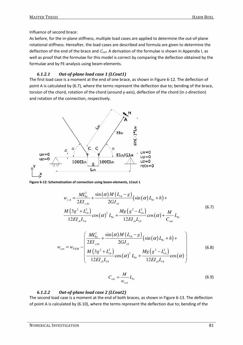
MASTER THESIS HARM BOEL
NUMERICAL INVESTIGATION 81
Influence of second brace:
As before, for the in-plane stiffness, multiple load cases are applied to determine the out-of-plane
rotational stiffness. Hereafter, the load cases are described and formula are given to determine the
deflection of the end of the brace and Cout. A derivation of the formulae is shown in Appendix I, as
well as proof that the formulae for this model is correct by comparing the deflection obtained by the
formulae and by FE-analysis using beam-elements.
6.1.2.1 Out-of-plane load case 1 (LCout1)
The first load case is a moment at the end of one brace, as shown in Figure 6-12. The deflection of
point A is calculated by (6.7), where the terms represent the deflection due to; bending of the brace,
torsion of the chord, rotation of the chord (around y-axis), deflection of the chord (in z-direction)
and rotation of the connection, respectively.
Figure 6-12: Schematization of connection using beam-elements, LCout 1
( ) ( )( )( )
( )( )
( )( )
2
;
;
2 2 2 2
2
sinsin
2 2
3cos cos
12 12
chbr
z A br
y br ch
ch ch
br br
ch ch ch ch out
M L gMLw L h
EI GJ
M g L Mg g L ML L
EI L EI L C
αα
α α
−= + + +
+ −+ +
(6.7)
( ) ( )( )( )
( )( )
( )( )
2
;
2 2 2 2
2
sinsin
2 2
3cos cos
12 12
chbrbr
y br ch
con FEM
ch ch
br
ch ch ch ch
M L gMLL h
EI GJw w
M g L Mg g LL
EI L EI L
αα
α α
− + + +
= −
+ − +
(6.8)
out br
con
MC L
w= (6.9)
6.1.2.2 Out-of-plane load case 2 (LCout2)
The second load case is a moment at the end of both braces, as shown in Figure 6-13. The deflection
of point A is calculated by (6.10), where the terms represent the deflection due to; bending of the
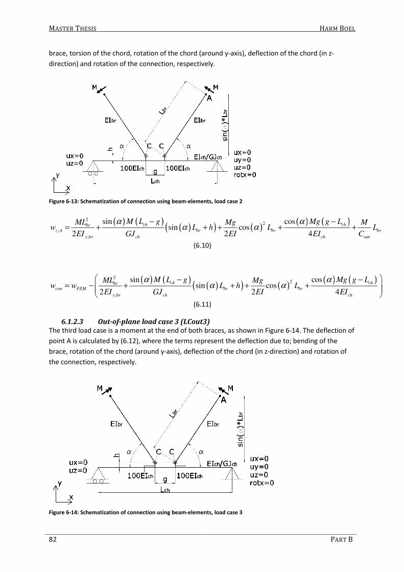
MASTER THESIS HARM BOEL
82 PART B
brace, torsion of the chord, rotation of the chord (around y-axis), deflection of the chord (in z-
direction) and rotation of the connection, respectively.
Figure 6-13: Schematization of connection using beam-elements, load case 2
( ) ( )( )( ) ( )
( ) ( )22
;
;
sin cossin cos
2 2 4
ch chbr
z A br br br
y br ch ch out
M L g Mg g LML Mg Mw L h L L
EI GJ EI EI C
α αα α
− −= + + + + +
(6.10)
( ) ( )( )( ) ( )
( ) ( )22
;
sin cossin cos
2 2 4
ch chbrcon FEM br br
y br ch ch
M L g Mg g LML Mgw w L h L
EI GJ EI EI
α αα α
− −= − + + + +
(6.11)
6.1.2.3 Out-of-plane load case 3 (LCout3)
The third load case is a moment at the end of both braces, as shown in Figure 6-14. The deflection of
point A is calculated by (6.12), where the terms represent the deflection due to; bending of the
brace, rotation of the chord (around y-axis), deflection of the chord (in z-direction) and rotation of
the connection, respectively.
Figure 6-14: Schematization of connection using beam-elements, load case 3

MASTER THESIS HARM BOEL
NUMERICAL INVESTIGATION 83
( )
( )( ) ( )2 2 2 22
2
;
;
3 3 cos 2 3cos
2 6 12
ch ch ch chbrz A br br
y br ch ch ch ch out
M g gL L Mg g gL LML Mw L L
EI EI L EI L C
αα
− + − += + + +
(6.12)
( )
( )( ) ( )2 2 2 22
2
;
3 3 cos 2 3cos
2 6 12
ch ch ch chbrcon FEM br
y br ch ch ch ch
M g gL L Mg g gL LMLw w L
EI EI L EI L
αα
− + − + = − + +
(6.13)
Using a shell-element model to determine the deflection of point A due to a moment M and
calculating its deflection by Equation (6.7) to (6.12), the out-of-plane rotational stiffness Cout can be
determined. This is done for the same combination of sections as has been done for the in-plane
stiffness as shown in Table 6-1. The obtained out-of-plane stiffnesses are shown in Table 6-3.
Table 6-3: Out-of-plane rotational stiffnesses (CCCCoutoutoutout) for different connections and load cases (kNm/rad)
Load case→
↓Brace dimension
Load case
LCout1 LCout2 LCout3
RHS50/6.3 g=195.5 117 106 129
RHS100/6.3 g=135.3 406 319 556
RHS150/6.3 g=75.2 1312 796 3599
RHS200/6.3 g=15 2972 1526 39484
As also has been seen for the in-plane stiffness, the stiffness of the connection does not differ much
for smaller brace dimensions with large gaps, but does differ very much for larger brace dimensions
with small gaps.
6.1.3 Torsional stiffness
The torsional stiffness is represented by a rotational spring (Ctor ) about the (local) y-axis. The same
model is used as described for the determination of the out-of-plane stiffness. Only now, a torsional
moment is applied at the end of the brace (see Figure 6-15) and the rotation of the end of the brace
must be calculated and obtained by FE-analysis, instead of the deflection.
Again, three load cases are used .The same formulas as described before for the lateral displacement
of point A due to LCout1 to LCout3 are modified so they can be used to calculate the rotation of
point A.

MASTER THESIS HARM BOEL
84 PART B
Figure 6-15: Schematization of FE-model to determine CCCCtortortortor
6.1.3.1 Torsion load case 1 (LCtor1)
Figure 6-16: Schematization of connection using beam-elements, load case 1
( ) ( )2 2
;
3
2 12
chchbrx A
br ch ch ch tor
M g LM L gML M
GJ GJ EI L Cϕ
+−= + − + (6.14)
6.1.3.2 Torsion load case 2 (LCtor2)
Figure 6-17: Schematization of connection using beam-elements, load case 2
( )
;2
chbrx A
br ch ch
M L gML Mg M
GJ GJ EI Cϕ
−= + + + (6.15)

MASTER THESIS HARM BOEL
NUMERICAL INVESTIGATION 85
6.1.3.3 Torsion load case 3 (LCtor3)
Figure 6-18: Schematization of connection using beam-elements, load case 3
( )2 2
;
3 3
6
ch chbrz A
br ch ch
M g gL LML Mu
GJ EI L C
− += + + (6.16)
Using a shell-element model to determine the rotation of point A due to a moment M and
calculating its rotation by Equation (6.14) to (6.16), the torsional stiffness Ctor can be determined.
This is done for a SHS200/6.3 chord connected to a SHS100/6.3 brace with an angle of 56°. The
obtained stiffnesses are shown in Table 6-4.
Table 6-4: Torsional stiffnesses for different load cases (kNm/rad)
Load case→ ↓Brace dimension
Load case
LCtor1 LCtor2 LCtor3
RHS100/6.3 g=135.3 986 860 1117
6.1.4 Axial stiffness
The axial stiffness is represented by a translational spring (k ) in line with the (local) y-axis. The
stiffness is determined by modeling the connection using shell-elements (SHELL181). The connection
is restrained by prohibiting the chord from translation in x- and y- direction and rotation about the z-
axis along the length of the chord, in the middle of the section as shown in Figure 6-19.
Figure 6-19: Schematization of FE-model

MASTER THESIS HARM BOEL
86 PART B
The end of the brace is loaded with a force in line with the brace. This force is applied to a node,
which is connected to the nodes of the shell-elements by rigid beam-elements (MPC184). Due to the
force, the end of the brace will deflect. The displacement due to deformation of the connection can
be calculated by (6.17). The axial stiffness of the connection can be calculated by (6.18).
brcon FEM
br
FLu u
EA= − (6.17)
con
Fk
u= (6.18)
Where:
ucon is the displacement due to the deformation of the connection (mm)
uFEM is the displacement of the end of the brace, obtained by FE-analysis (mm)
F is the force (N)
Lbr is the system length of the brace (mm)
E is young’s modulus (N/mm²)
Abr is the section area of the brace (mm²)
k is the connection axial stiffness (N/mm)
For the connection between a SHS200/6.3 chord and a SHS100/6.3 brace with an angle of 56° the
axial stiffness k is 82 248 N/mm.
6.1.5 Comparison with results from previous studies
To check if the stiffnesses obtained by FE-analysis are reliable, the obtained stiffnesses are
compared to experimental and numerical results of previous studies. Because these studies
concerned Vierendeel connections, only one brace is connected to the chord with an angle of 90°.
Torsional stiffnesses have not been found in literature and therefore it is not possible to compare
the torsional stiffnesses obtained by FE-analysis.
6.1.5.1 In-plane rotational stiffnesses (Cin)
Korol and Mirza (1982) also used FE-analysis to determine in-plane rotational stiffnesses of
connections between square hollow sections. The method to determine the in-plane rotational
stiffness, as described in 6.1.1, has been used to determine the in-plane stiffness for the same
dimensions as used by Korol and Mirza. The results are compared in Table 6-5.
Table 6-5: Comparison of in-plane rotational stiffnesses found by FE-analysis
Chord
dimension
Brace
dimension7
Cin in kNm/rad FEM/Korol and
Mirza Korol and Mirza Author
RHS254/12.7 RHS152/5 3057 2352 0.77
RHS254/9.5 RHS101.6/5 790 387 0.49
RHS254/9.5 RHS152/5 1333 1102 0.83
RHS254/9.5 RHS203.2/5 3020 4913 1.63
RHS254/6.3 RHS152/5 432 369 0.85
7 In the FE-analysis performend by Korol and Mirza, the influence of the brace wall thickness is
assumed to be nil and thus it is not specified.

MASTER THESIS HARM BOEL
NUMERICAL INVESTIGATION 87
Chen (1992) presents rotational stiffnesses obtained by experimental results. The connections have
also been modeled and stiffnesses are determined by the method described in section 6.1.1. The
stiffnesses obtained by FE-analysis are compared to the ones obtained by experiments (see Table
6-6).
Table 6-6: Comparison in-plane rotational stiffnesses
Chord
(SHS)
Branch
(SHS)
Experimental:
Chen
(kNm/rad)
FEM:
Author
(kNm/rad)
FEM/
experiments
200/6 125/6 2280 359 0.16
200/9 125/6 7770 1031 0.13
200/12 125/6 10990 2136 0.19
200/6 100/6 1260 173 0.14
200/6 150/6 8160 941 0.12
150/6 100/6 2980 422 0.14
250/6 175/6 5180 663 0.13
300/6 200/6 4000 537 0.13
The stiffnesses obtained by FE-analysis are very different from the stiffnesses given by previous
studies. The stiffnesses given by Chen (1992) are checked by comparing the stiffnesses to the graphs
which display the moment-rotation behavior of the connection. It seems the stiffnesses are not
determined correctly. If the stiffnesses are obtained from the graphs by drawing a linear line in the
graphs, different values for the connection stiffnesses are obtained and are shown in Table 6-7.
Table 6-7: Comparison of in-plane rotational stiffnesses, obtained from moment-rotation curves
Connection
number
Stiffnesses obtained by… (kNm/rad)
Chen Author
1 2280 2960
2 7770 14000
3 10990 26600
4 1260 2400
5 8160 10000
6 2980 3900
7 5180 5200
8 4000 5200
Still, the stiffnesses obtained by FE-analysis and the stiffnesses given by Chen are very different. It is
not clear what causes this difference.
Wardenier (1982) gives a formula (6.19) to calculate the in-plane rotational stiffness.
1.35 1.53
0 0
0
20.43 0.01
2in
d tC E
d
β−
= −
(6.19)
But, only if 0.33 ≤ β ≤ 0.8 and 20 ≤ d0/t0 ≤ 60.
Vegte (1995) gives moment-curvature curves for in-plane stiffnesses. The elastic/initial stiffnesses
are obtained from these graphs by drawing a line with the same gradient. The stiffnesses are also

MASTER THESIS HARM BOEL
88 PART B
calculated by Equation (6.19) and by FE-analysis and are compared to each other and shown in Table
6-8.
In section 6.1.1, it has been shown that the stiffnesses obtained for different brace lengths are the
same. Thus, only one calculation is needed to determine the connection stiffness. But still, as an
extra check, 2 brace lengths have been used to determine the connection stiffness to see if no
significant differences are found between the two stiffnesses. The stiffness obtained by FE-analysis is
the average of these two stiffnesses. For the CHS101.6 brace, a length of 1000 and 2000 mm was
taken. For the CHS193.7 brace, a length of 2000 and 3000 mm was taken. For the CHS298.5 brace, a
length of 3000 and 4000 mm was taken. And for the CHS406.4 brace, a brace length of 4000 and
5000 mm was taken. In all cases, the chord length was 4000 mm.
Table 6-8: In-plane stiffnesses for CHS406.4 chords connected to CHS braces
β t0 Brace
(CHS)
Theory:
Wardenier
(kNm/rad)
Experimental:
Vegte
(kNm/rad)
FEM:
Author
(kNm/rad)
FEM/
Theory
FEM/
Experiments
0.25 8 101.6/8 - 693 664 - 0.96
11 101.6/5.6 - 1309 1144 - 0.87
16 101.6/4 - 2770 2359 - 0.85
0.48 8 193.7/14.2 82080 2934 3110 0.04 1.06
11 193.7/8 106088 4622 5132 0.05 1.11
16 193.7/5.4 140250 8802 9004 0.06 1.02
28 193.7/4 - 23439 21561 - 0.92
0.73 8 298.5/28 308159 10173 9315 0.03 0.92
11 298.5/16 341882 16028 16473 0.05 1.03
16 298.5/11 382779 33910 28463 0.07 0.84
28 298.5/8 - 69232 68449 - 0.99
1 8 406.4/28 - 26381 28189 - 1.07
11 406.4/16 - 43642 48318 - 1.11
16 406.4/11 - 73867 78086 - 1.06
28 406.4/8 - 133070 165460 - 1.24
The stiffnesses found by using the formula given by Wardenier gives very different results than the
ones obtained by FE-analysis or given by Vegte, which are very similar to each other. The stiffnesses
obtained by FE-analysis and given by Vegte for the connection of a CHS406.4/28 chord and a
CHS406.4/8 brace show a difference of 24%. This could be caused by the fact that the FE-model is a
simplification, where not the diameter of the section is modeled, but the so-called ‘effective’
diameter, which is the diameter minus the wall thickness. For this combination of sections, it causes
the brace, which has a larger ‘effective’ diameter, to enclose around the chord. In reality, the
diameters are the same.
Also, it must be mentioned that the stiffnesses of Vegte are obtained by drawing lines in moment-
curvature graphs, which is not very precise.

MASTER THESIS HARM BOEL
NUMERICAL INVESTIGATION 89
6.1.5.2 Out-of-plane rotational stiffness (Cout)
Wardenier (1982) gives a formula to calculate the out-of-plane (6.20) stiffness.
( )2.45 1.63
0 0
0
20.0016 215 135 0.02
2out
d tC E
d
β
β
−
= − −
(6.20)
But, only if 0.33 ≤ β ≤ 0.8 and 20 ≤ d0/t0 ≤ 60.
Vegte (1995) gives moment-curvature curves out-of-plane stiffnesses. The elastic/initial stiffnesses
are obtained from these graphs by drawing a line with the same gradient. The stiffnesses are also
calculated by Equation (6.20) and by FE-analysis and are compared to each other and shown in Table
6-9.
Table 6-9: Out-of-plane stiffnesses for CHS406.4 chords connected to CHS braces
β t0 Brace
(CHS)
Theory:
Wardenier
(kNm/rad)
Experiments:
Vegte
(kNm/rad)
FEM:
Author
(kNm/rad)
FEM/
Theory
FEM/
Experiments
0.25 8 101.6/8 - 215 209 - 0.97
11 101.6/5.6 - 472 449 - 0.95
16 101.6/4 - 1231 1141 - 0.93
0.48 8 193.7/14.2 557 528 583 1.05 1.10
11 193.7/8 1444 1248 1224 0.85 0.98
16 193.7/5.4 3599 3201 2912 0.81 0.91
28 193.7/4 - 11980 10802 - 0.90
0.73 8 298.5/28 2091 1615 1519 0.73 0.94
11 298.5/16 4323 3562 3672 0.85 1.03
16 298.5/11 8670 8477 8533 0.98 1.01
28 298.5/8 - 29671 30190 - 1.02
1 8 406.4/28 - 5771 6814 - 1.18
11 406.4/16 - 10474 16577 - 1.58
16 406.4/11 - 21308 33116 - 1.55
28 406.4/8 - 56555 89380 - 1.58
It can be seen that the out-of-plane stiffnesses obtained by the formula of Wardenier and the
moment-curvature diagrams of Vegte are more similar to each other than the in-plane stiffnesses.
Also the stiffnesses obtained by FE-analysis are very consistent compared to the values obtained
from the graphs given by Vegte.
Again, the stiffnesses of the connection with β = 1 are very different. This is probably due to the fact
that the ‘effective’ diameter is modeled, instead of the actual diameter.
6.1.5.3 Axial stiffness (k)
Korol and Mirza (1982) also used FE-analysis to determine axial stiffnesses of connections between
square hollow sections. The axial stiffness of the same combination of sections is determined by the
method described in section 6.1.4. The axial stiffnesses, given by Korol and Mirza and obtained from
FE-analyses, are compared in Table 6-10.

MASTER THESIS HARM BOEL
90 PART B
Table 6-10: Comparison of axial stiffnesses with numerical results (Korol and Mirza, 1982)
Chord
dimension
Brace
dimension
k in kN/mm FEM/Korol and
Mirza Korol and Mirza FEM
RHS254/12.7 RHS152/5 522 347 0.66
RHS254/9.5 RHS101.6/5 101 64 0.63
RHS254/9.5 RHS152/5 248 163 0.66
RHS254/9.5 RHS203.2/5 742 728 0.98
RHS254/6.3 RHS152/5 82 56 0.68
The stiffnesses obtained by FE-analysis are about 30-40% lower than the stiffnesses given by Korol
and Mirza, except for one case, where the stiffnesses are almost exactly the same. It is not known
what causes the difference.
The goal is to perform buckling analysis using a beam-element model whereby the same results are
obtained as from the full-shell element model. Therefore, the fact stiffnesses obtained by FE-analysis
and from previous studies are the same is less relevant.
Results obtained by the beam- and full-shell-element model are compared in section 6.2.
6.2 Beam-element model
A beam-element model is made to see if the results obtained by the shell-element model can be
obtained by a simpler model as well. The beams are connected to each other by elastic rotational
and translational springs (COMBIN14). First, the force distribution and deflection of the lattice girder
in different FE-models is compared. Hereafter, the in-plane and out-of-plane buckling behavior is
checked by comparing the eigenvalues and buckling shapes obtained by the beam- and the full-shell-
element model.
As an example, a lattice girder with SHS200/6.3 chords and SHS100/6.3 braces is used. After
checking the deflection, force distribution and the in-plane and out-of-plane stability of the lattice
girder, other combinations of chord and brace dimensions are used to perform buckling analysis and
to compare the obtained eigenvalues and buckling shapes to the ones obtained by the full-shell-
element model.
The lattice girder is modeled as shown in Figure 6-20. The area, moment of inertia and torsional
rigidity of the section are calculated by Equation (6.21) to (6.23), respectively.
( )4A b t t= − (6.21)
( )( )
( )2
3 3 ( )2( )
6 6 2
b tt b tI b t t b t t
− − = − + + −
(6.22)
( )( )
( )4
324
44
h
m
b t ttJ A b t t
h b t
−= = = −
− (6.23)
Where:
b is the outer width and height of the section
t is the wall thickness
hm is the mean perimeter
Ah is the area enclosed by the mean perimeter

MASTER THESIS HARM BOEL
NUMERICAL INVESTIGATION 91
Figure 6-20: Modeling of lattice girder connection
The in-plane rotational stiffness, out-of-plane rotational stiffness, torsional stiffness and axial
stiffness presented in section 6.1.1 to 6.1.4, respectively, are used. For the in-plane rotational
stiffness, the lowest value, obtained by LCin3, is used. For the out-of-plane rotational stiffness the
middle value, obtained by LCout1is used. For the Torsional stiffness, the lowest value, obtained by
LCtor2, is used. The applied parameters are presented below:
Chord, RHS200/6.3:
- Ach = 4881 mm2
- Ich = 30531841 mm4
- Jch = 45785652 mm4
Brace, RHS100/6.3:
- Abr = 2361 mm2
- Ibr = 3459064 mm4
- Jbr = 5182739 mm4
Connection:
- k = 82 248 N/mm
- Cin = 239 106 Nmm/rad
- Cout = 406 106 Nmm/rad,
- Ctor = 860 106 Nmm/rad
- Rigid beam: A = 100*Ach, I = 100*Ich, J =100*Jch and grb = 256 mm
6.2.1 Deflection and force distribution
To check if the beam-element model can describe the structural behavior “correctly”, several results
of the beam-element model are compared to the results found by shell-element model.
6.2.1.1 Force distribution
In Table 6-11, the normal forces in the beams are compared for the chord sections C1 to C4 and
braces B2, B4, B6 and B8 (see Figure 6-21).

MASTER THESIS HARM BOEL
92 PART B
Table 6-11: Normal forces in different FE-models
Member shell-element
model(N)
beam-element
model (N) Difference (%)
B2 4.3999 4.3995 -0.01
B4 3.0913 3.1053 0.45
B6 1.8609 1.8649 0.21
B8 0.6123 0.61348 0.19
C1 2.3841 2.3915 0.31
C2 6.6253 6.6197 -0.08
C3 9.3972 9.3956 -0.02
C4 10.7941 10.791 -0.03
Figure 6-21: Geometry of lattice girder
It can be seen that the forces in the members obtained by the two FE-models differ less than 0.5%.
6.2.1.2 In-plane deflection
The in-plane deformation is compared at several positions (see u1 to u4 in Figure 6-21) and are
shown in Table 6-12.
Table 6-12: In-plane vertical deflection of lattice girder (mm)
Position FEM (shell-
elements)
FEM (Beam-
elements) Difference (%)
U1 0.00037989 0.00042993 13.17
U2 0.0011377 0.0012039 5.82
U3 0.0016729 0.001752 4.73
U4 0.0019532 0.0020385 4.37
It can be seen that the deflection differs somewhat. The deflection obtained from the shell-element
model may not be representative for the deflection due to local deformations of the section near
the joint (see Figure 6-22).
Figure 6-22: Local deformations in joint

MASTER THESIS HARM BOEL
NUMERICAL INVESTIGATION 93
Because local deformations in the joint may cause the obtained deflection not to be representative,
the deflections of other positions (see Figure 6-23) have also been obtained and compared and are
shown in Table 6-13.
Figure 6-23: positions for which deflections are compared
Table 6-13: In-plane vertical deflection of lattice girder (mm)
Position FEM (shell-
elements)
FEM (Beam-
elements) Difference (%)
U5 0.000405935 0.00044306 9.15
U6 0.0011509 0.0012246 6.40
U7 0.0016871 0.0017703 4.93
U8 0.0019673 0.0020574 4.58
U9 0.00084263 0.00089145 5.79
U10 0.00142295 0.0015043 5.72
U11 0.0018521 0.0019390 4.69
U12 0.00198865 0.0020798 4.58
It can be seen that the difference between the two FE models is still more than 4% and even more
than 9% near the support. There are several possible causes why the deflections are not similar:
- The deflection is influenced by the axial stiffness (k) and the in-plane rotational stiffness
(Cin). It has been shown that Cin depends on the load case applied to determine Cin:
When changing Cin from 239 to 290 kNm/rad (obtained by LCin3, see Table 6-1), the
deflections are hardly any different.
k is determined by modeling one brace to the chord and thus no extra load cases are
applied to determine the influence of the second brace. When k is given a higher value, the
difference does become significantly smaller. Thus, the determination of k could cause the
difference between the two FE-models.
- The section properties are calculated by Equation (6.21) to (6.23) and are used for the beam-
elements. The stiffness of the sections in the shell-element model may differ somewhat.
- The force distribution is checked on axial forces. But also moments occur. The moment
distribution may be somewhat different. The moment distribution in the shell-element
model is hard to obtain which makes it difficult to compare it with the moment distribution
of the beam-element model.
- The axial, flexural and torsional stiffness of the rigid beams have been modeled as a hundred
times the stiffness of the chord member. When altering the stiffness to a thousand or ten
thousand times the stiffness of the chord member, the deflections obtained by beam-
element model do not differ, which means the stiffness of the rigid beams are not of
significant influence on the deflection of the lattice girder. Also, the stiffness of the rigid
beams seem to be high enough because a much higher stiffness does not influence the
results.

MASTER THESIS HARM BOEL
94 PART B
- The difference between the shell-element model and the Beam-element model are the most
for u1. This may be caused because the stiffness of the connection at that position is not
identical to the stiffnesses of the other connections because of the end-conditions in the
shell-element model. But in the beam-element model, they are assumed the same.
6.2.1.3 Out-of-plane deflection
The shell-element model is loaded with a load perpendicular to the plane on the lower chord as
shown in Figure 6-24. The load is applied by loading every node of the upper and lower face of the
section with a total of 1 N in every loaded joint (see Figure 6-25). The Beam-element model is
subjected to the same load. The deflection of both FE-models is obtained in the positions shown in
Figure 6-23 and are compared in Table 6-14.
Figure 6-24: Out-of-plane loading
Figure 6-25: Out-of-plane forces in detail
Table 6-14: Out-of-plane horizontal deflection of lattice girder (mm)
Position FEM (shell-
elements)
FEM (Beam-
elements) Difference (%)
U5 0.16907 0.16886 -0.12
U6 0.47235 0.47152 -0.18
U7 0.69719 0.69473 -0.35
U8 0.81678 0.81314 -0.45
U9 0.4392 0.43062 -1.95
U10 0.71293 0.7003 -1.77
U11 0.8965 0.88208 -1.61
U12 0.96078 0.94587 -1.55

MASTER THESIS HARM BOEL
NUMERICAL INVESTIGATION 95
The difference in out-of-plane deflection between the two models is less than 1% in the upper chord
and between 1 and 2% in the lower chord. The out-of-plane deflection is better described by the
beam-element model than the in-plane deflection, compared to the results obtained by the shell-
element model.
For the investigation on buckling length factors, the deflection, predicted by the beam-element
model, is less relevant. The axial forces in the members and the buckling modes and eigenvalues are
of greater relevance. Therefore, the eigenvalues and accompanying buckling shapes are compared in
section 6.2.2 and 6.2.3.
6.2.2 In-plane stability
Hereafter, the eigenvalues and buckling shapes (for in-plane buckling) are compared to the ones
obtained by the shell-element model.
1:
Beam-element model: Buckling of B2 (both, asymmetric) Eigenvalue: 103177 (0.53% higher than shell-element solution)
Fekete: Buckling of B2 (one, asymmetric)
The eigenvalue is: 102630
2:
Beam-element model: Buckling of B6 (both, asymmetric) Eigenvalue: 103179 (0.19% lower than shell-element solution)
Fekete: Buckling of B2 (one)
The eigenvalue is: 102980

MASTER THESIS HARM BOEL
96 PART B
3:
Beam-element model: Buckling of B4 (both, asymmetric)
Eigenvalue: 146355 (0.86% higher)
Fekete: Buckling of B4 (one)
The eigenvalue is: 145100
4:
Beam-element model: Buckling of B4 (both, symmetric)
Eigenvalue: 146466 (0.79% higher)
Fekete: Buckling of B4 (one)
The eigenvalue is: 145320
5:
Beam-element model: Buckling of C4 (both, asymmetric)
Eigenvalue: 198932 (2.30% higher)
Fekete: Buckling of C4
The eigenvalue is: 194460
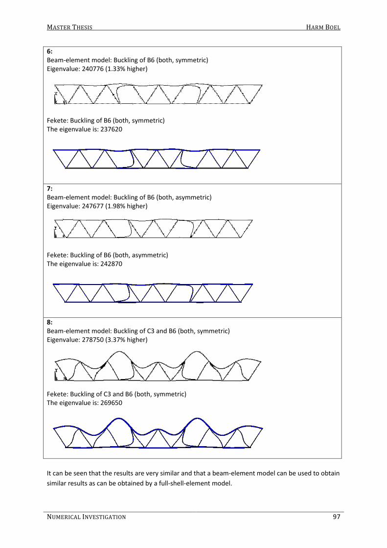
MASTER THESIS HARM BOEL
NUMERICAL INVESTIGATION 97
6:
Beam-element model: Buckling of B6 (both, symmetric)
Eigenvalue: 240776 (1.33% higher)
Fekete: Buckling of B6 (both, symmetric)
The eigenvalue is: 237620
7:
Beam-element model: Buckling of B6 (both, asymmetric)
Eigenvalue: 247677 (1.98% higher)
Fekete: Buckling of B6 (both, asymmetric)
The eigenvalue is: 242870
8:
Beam-element model: Buckling of C3 and B6 (both, symmetric)
Eigenvalue: 278750 (3.37% higher)
Fekete: Buckling of C3 and B6 (both, symmetric) The eigenvalue is: 269650
It can be seen that the results are very similar and that a beam-element model can be used to obtain
similar results as can be obtained by a full-shell-element model.

MASTER THESIS HARM BOEL
98 PART B
The difference is almost 4% in some cases. And although this is not much, different schematizations
of the lattice girder are made to see if results can be obtained which are more consistent with the
results from the shell-element model. For the alternative schematizations, only in-plane stability is
considered by making a 2D-model (using BEAM3-elements). The in-plane buckling loads obtained by
a 2D- and 3D- beam-element model are the same (the in-plane behavior is not influenced by out-of-
plane behavior).
The different models are shown in Figure 6-26. The eigenvalues obtained by these models, for
SHS200/6.3 chords and SHS100/6.3 braces, are compared to the results of shell-element model and
shown in Table 6-15 and Table 6-16. For Variant 3b and 4, another rotational stiffness is used than
for the other models because the rotational spring is in a different location. Length L3, as shown in
Figure 6-8, is used to calculate the rotational stiffness of the spring stiffness. The rotational stiffness
is shown in Table 6-2 and is 299.623 kNm/rad. For Variant 5, the same rotational stiffness is used as
for the other models (Variant 1, 2, 3a and 3c) because a rotational stiffness of the connection
calculated with a different theoretical brace length (stiffness: 351.5 kNm/rad) led to very different
buckling shapes and eigenvalues compared to the results of the shell-element model.
Figure 6-26: Different versions to simulate the structural behavior of the lattice girder
Table 6-15: Eigenvalues obtained by different FE-models; Variant 1 to 3b (SHS200/6.3 chord & SHS100/6.3 brace)
Shell-
elements
Variant 1 Variant 2 Variant 3a Variant 3b
Eigenvalue % Eigenvalue % Eigenvalue % Eigenvalue %
102630 102365 -0.26 102905 0.27 102875 0.24 102923 0.29
102980 102367 -0.60 102908 -0.07 102875 -0.10 102926 -0.05
145100 145629 0.36 146524 0.98 146441 0.92 146593 1.03
145320 145736 0.29 146659 0.92 146571 0.86 146769 1.00
194460 198965 2.32 200776 3.25 199811 2.75 200987 3.36
237620 239646 0.85 241548 1.65 241195 1.50 240825 1.35
242870 246218 1.38 247917 2.08 217809 -10.32 249927 2.91
269650 278888 3.43 284355 5.45 281513 4.40 281872 4.53

MASTER THESIS HARM BOEL
NUMERICAL INVESTIGATION 99
Table 6-16: Eigenvalues obtained by different FE-models; Variant 3c to 5 (SHS200/6.3 chord & SHS100/6.3 brace)
Shell-
elements
Variant 3c Variant 4 Variant 5
Eigenvalue % Eigenvalue % Eigenvalue %
102630 102866 0.23 101589 -1.01 71060 -30.76
102980 102869 -0.11 101592 -1.35 98422 -4.43
145100 146372 0.88 144696 -0.28 100907 -30.46
145320 146492 0.81 144852 -0.32 141146 -2.87
194460 199058 2.36 200538 3.13 201280 3.51
237620 240785 1.33 238085 0.20 236311 -0.55
242870 247619 1.96 246602 1.54 - -
269650 279196 3.54 280927 4.18 278943 3.45
For all the alternative models, the buckling shapes are the same, except for variant 5, where the
seventh buckling shape does not occur. Between the fourth and the fifth eigenvalue, another
buckling shape occurred with an eigenvalue of 166638. Furthermore, it is remarkable that in all
alternative models, always two braces buckle, for example, brace B2 (see Figure 6-21) on both ends
of the lattice girder. For variant 5, often only one brace buckles, which is (sometimes) similar to the
results obtained by Fekete (see buckling shape 1 to 4).
Several models give results that are very similar to the results obtained by the model of Fekete. But,
Variant 3a and 5 sometimes give very different results and are therefore considered not to be useful.
Variant 3b and 4 are also not used because the rotation of the connection mainly takes place due to
deformation of the chord face.
Variant 2 and 3a give very good results, but it is expected that for a (extreme) large gap, the model
will behave to stiff because of the rigid modeling of the chord in the connection. Only Variant 1 and
3c remain. Both models give very good results. Variant 3c will change in modeling for a large chord
dimension and a small gap (see Figure 6-27). For FE-analysis this is not a problem. But, because
formulas to determine the out-of-plane and torsional stiffness have been derived for the first variant
and are not applicable for Variant 3c, Variant 1 is chosen. Also, in reality the brace connects with the
chord on the same position as modeled in Variant 1. In Variant 3c, the brace connects to the chord in
a different location.
Figure 6-27: Variant 3c with large chord dimension and small gap

MASTER THESIS HARM BOEL
100 PART B
6.2.3 Out-of-plane stability
It has been shown that the in-plane structural behavior of lattice girders can be described very well
by a beam-element model, with rotational springs representing the stiffness of the connection
between the members. To see if this also holds for the out-of-plane structural behavior, again the
lattice girder with SHS200/6.3 chords and SHS100/6.3 braces is used to compare the results of the
different FE-models. For the out-of-plane stiffness, the middle value (406 kNm/rad) gave the best
results regarding the buckling shapes and eigenvalues.
Beam-element model: Buckling of B2 (both, symmetrical) Eigenvalue: 107477 (3.12 % lower than shell-element solution)
Fekete: Buckling of B2 (both, symmetric)
The eigenvalue is: 110940
Beam-element model: Buckling of B2 (both, asymmetrical)
Eigenvalue: 108867 (3.46% lower than shell-element solution)
Fekete: Buckling of B2 (one, asymmetric)
The eigenvalue is: 112770
Beam-element model: Buckling of B4 (both, asymmetrical)
Eigenvalue: 158142 (2.96% lower than shell-element solution)
Fekete: Buckling of B4 (one, asymmetric)
The eigenvalue is: 162970

MASTER THESIS HARM BOEL
NUMERICAL INVESTIGATION 101
Beam-element model: Buckling of B4 (both, asymmetrical)
Eigenvalue: 159436 (3.34% lower than shell-element solution)
Fekete: Buckling of B4 (one, asymmetric)
The eigenvalue is: 164950
Beam-element model: Buckling of chord Eigenvalue: 198498 (1.38% higher than shell-element solution)
Fekete: Buckling of chord
The eigenvalue is: 195790
Beam-element model: Buckling of B6 (both, symmetrical)
Eigenvalue: 256016 (0.16% higher than shell-element solution)
Fekete: Buckling of B6 (both, asymmetric)
The eigenvalue is: 255610
Beam-element model: buckling shape not occurred
Fekete: Buckling of ???
Eigenvalue: 267780
This “buckling” shape does not show buckling of a certain member. No buckling length factor can be
found from this shape.

MASTER THESIS HARM BOEL
102 PART B
Beam-element model: Buckling of B6 (both, symmetrical)
Eigenvalue: 271961
Fekete: buckling shape not occurred
Beam-element model: Buckling of B6 (one) Eigenvalue: 280628 (2.54% lower than shell-element solution)
Fekete: Buckling of B2 (one)
The eigenvalue is: 287950
Beam-element model: buckling shape not occurred
Fekete: Buckling of B6 (one) Eigenvalue: 290600
Although some remarkable differences did occur, it can be seen that also the out-of-plane buckling
shapes and eigenvalues are very similar.

MASTER THESIS HARM BOEL
NUMERICAL INVESTIGATION 103
6.2.4 Influence connection stiffnesses
To see which stiffnesses are relevant for the stability behavior of lattice girders, stiffnesses are
varied. The stiffnesses that are of influence on the eigenvalues are varied to determine the amount
of influence on the buckling loads.
6.2.4.1 Axial and rotational stiffness (k and Ctor)
If the axial stiffness is changed, the deflection also changes. But a change in axial stiffness gives only
minor changes for in-plane buckling loads. Even if the axial stiffness is considered fully rigid, the
eigenvalues are hardly any different (see Table 6-17). Also, if the torsional stiffness is changed, only
minor changes occur in the out-of-plane buckling loads. Even if the torsional stiffness is assumed to
be fully rigid, the eigenvalues are more or less the same.
Table 6-17: Influence of axial and torsional connection stiffness (k and Ctor)
In-/out-of-
plane
buckling
Eigenvalues Difference
(%) k ≠ ∞
Ctor ≠ ∞
k = ∞
Ctor = ∞
in 103180 102860 -0.31
in 103180 102860 -0.31
out 107480 107610 0.12
out 108870 108840 -0.03
in 146360 146340 -0.01
in 146470 146450 -0.01
out 158140 158500 0.23
out 159440 159660 0.14
out 198500 198910 0.21
in 198930 199110 0.09
in 240780 240660 -0.05
in 247680 247450 -0.09
out 256020 256440 0.16
out 271690 271700 0.00
in 278750 279280 0.19
out 280630 281100 0.17
Thus, it can be concluded that the axial as well as the torsional stiffness of the connection is of
influence on the structural behavior of the lattice girder, but not relevant for this study, concerning
the buckling length of members in lattice girders. Because of this, all analyses will be performed
assuming the axial (k) and torsional (Ctor) connection stiffnesses are fully rigid.
6.2.4.2 In-plane and out-of-plane rotational stiffnesses (Cin and Cout)
The in-plane and out-of-plane rotational stiffnesses affect the eigenvalues significantly. To
understand the influence of the rotational stiffnesses on the buckling load, the eigenvalues for in-
and out-of-plane buckling of member B2 are obtained for different values of Cin and Cout. Although
the amount of influence probably depends on the flexural stiffnesses of the members used, only one
lattice girder is analyzed. The same geometry and section properties as described before are used. It
has been observed that the in-plane rotational stiffness does not affect the out-of-plane buckling
behavior and vice versa. But still, one connection stiffness is kept constant as the other varied.
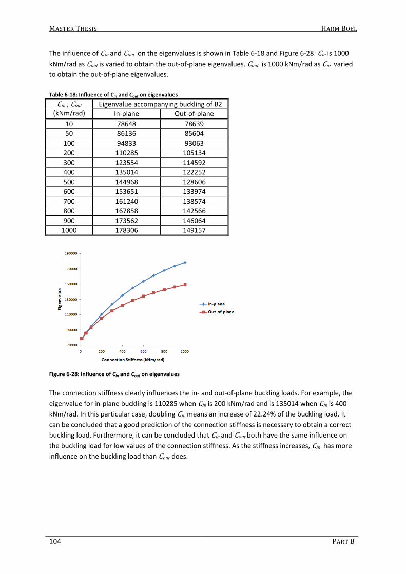
MASTER THESIS HARM BOEL
104 PART B
The influence of Cin and Cout on the eigenvalues is shown in Table 6-18 and Figure 6-28. Cin is 1000
kNm/rad as Cout is varied to obtain the out-of-plane eigenvalues. Cout is 1000 kNm/rad as Cin varied
to obtain the out-of-plane eigenvalues.
Table 6-18: Influence of Cin and Cout on eigenvalues
Cin , Cout
(kNm/rad)
Eigenvalue accompanying buckling of B2
In-plane Out-of-plane
10 78648 78639
50 86136 85604
100 94833 93063
200 110285 105134
300 123554 114592
400 135014 122252
500 144968 128606
600 153651 133974
700 161240 138574
800 167858 142566
900 173562 146064
1000 178306 149157
Figure 6-28: Influence of Cin and Cout on eigenvalues
The connection stiffness clearly influences the in- and out-of-plane buckling loads. For example, the
eigenvalue for in-plane buckling is 110285 when Cin is 200 kNm/rad and is 135014 when Cin is 400
kNm/rad. In this particular case, doubling Cin means an increase of 22.24% of the buckling load. It
can be concluded that a good prediction of the connection stiffness is necessary to obtain a correct
buckling load. Furthermore, it can be concluded that Cin and Cout both have the same influence on
the buckling load for low values of the connection stiffness. As the stiffness increases, Cin has more
influence on the buckling load than Cout does.

MASTER THESIS HARM BOEL
NUMERICAL INVESTIGATION 105
6.2.5 Other geometries
It has been shown that the beam-element model gives very similar results, compared to the shell-
element model for the combination of the sections considered. To see if this is not just a
coincidence, other brace dimensions and gaps are applied. First, the in-plane buckling behavior is
studied.
6.2.5.1 In-plane
The eigenvalues for in-plane buckling shapes are obtained for the combination of SHS200/6.3 chords
connected to SHS50/6.3, SHS150/6.3 and SHS200/6.3 braces. These eigenvalues are compared to
the eigenvalues given by Fekete and shown in Table 6-19. The buckling shapes of both the beam-
and shell-element model are similar in every case. Every time, the lowest in-plane rotational
stiffness, obtained by 3 different load cases (see Table 6-1), is used.
Table 6-19: Eigenvalues obtained by different FE-models (in-plane buckling)
Brace: RHS50/6.3 (g=195.5)
Cin = 66 kNm/rad
Brace: RHS150/6.3 (g=75.2)
Cin = 1478 kNm/rad
Brace: RHS200/6.3 (g=15)
Cin = 25162 kNm/rad
Shell-
elements
Beam-
elements %
Shell-
elements
Beam-
elements %
Shell-
elements
Beam-
elements %
14798 14836 0.26 236960 240275 1.40 372860 386905 3.77
14903 14836 -0.45 307420 313206 1.88 447150 463034 3.55
21058 21118 0.28 377380 387304 2.63 - - -
21059 21118 0.28 401510 415079 3.38 - - -
35071 35125 0.15 419700 433331 3.25 - - -
35244 35132 -0.32 - - - - - -
If the in-plane rotational stiffness obtained by LCin1 is used every time, the results are as presented
in Table 6-20. It can be seen that the results are sometimes much on the unsafe side. This implies
that the lowest obtained stiffness must be used every time.
Table 6-20: Eigenvalues obtained by different FE-models using small gaps (in-plane buckling)
Brace: SHS50/6.3 (g=195.5)
Cin = 69 kNm/rad
Brace: SHS150/6.3 (g=75.2)
Cin = 1810 kNm/rad
Brace: SHS200/6.3 (g=15)
Cin = 29814 kNm/rad
Shell-
elements
Beam-
elements %
Shell-
elements
Beam-
elements %
Shell-
elements
Beam-
elements %
14798 15106 2.08 236960 245668 3.67 372860 389652 4.50
14903 15106 1.36 307420 318630 3.65 447150 465704 4.15
21058 21463 1.92 377380 396042 4.95 - -
21059 21463 1.92 401510 437996 9.09 - -
35071 35719 1.85 419700 456927 8.87 - -
35244 35726 1.37 - - - -
Influence of gap:
It is expected that the stiffness of the connection increases when smaller values for the gap are
used. To see what the influence of the gap is on the stiffness of the connection and to fully
understand the behavior of the in-plane stiffness of a connection between two square hollow
sections, the stiffness for the joint is determined using different gaps. In Table 6-21, a comparison of
the obtained stiffnesses can be found for the connection between a SHS200/6.3 chord and two

MASTER THESIS HARM BOEL
106 PART B
SHS100/6.3 braces. The brace length is varied (two lengths: 500 and 1300 mm) and the chord length
is kept constant (2000 mm).
Table 6-21: Influence of gap on in-plane connection stiffness (kNm/rad) for RHS200/6.3 chord and RHS100/6.3 braces
Gap
(mm)
Load cases (LC)
LCin1 LCin2 LCin3
15 287 434 214
50 285 416 217
100 269 322 231
135.3 262 290 239
150 262 285 243
200 260 270 251
250 259 263 255
∞ 2508 - -
It can be seen that for LCin1, the stiffness does not differ much when a small or large gap is used.
Load case 2 shows a decrease in stiffness for larger gaps and load case 3 shows an increase in
stiffness for larger gaps. In the buckling analysis described before, the lowest value for the stiffness
is used as the stiffness of the in-plane rotational spring. If this would be done again for a gap of 15
mm, the stiffness would be lower (214 instead of 239 kNm/rad) while it is expected that a smaller
gap would give a higher stiffness. The shell-element model is used to determine the buckling shapes
and eigenvalues for a lattice girder with the same dimensions, only now with a gap of 15 mm instead
of 135.3 mm. 4 elements per member width for the members (between the joints) and 6 elements
per member width for the joint area are used. The beam-element model is also used to find the
buckling shapes and eigenvalues and the results are compared (in Table 6-22) to the results found by
the shell-element model.
Table 6-22: Eigenvalues obtained by different FE-models and different connection stiffnesses
Shell-
element
model
Beam-element model
C = 287
kNm/rad
Difference
(%)
C = 434
kNm/rad
Difference
(%)
C = 214
kNm/rad
Difference
(%)
115087 110400 -4.07 125897 9.39 101317 -11.96
115105 110404 -4.08 125910 9.39 101319 -11.98
158570 154035 -2.86 174981 10.35 141412 -10.82
159020 154258 -2.99 175897 10.61 141506 -11.01
199085 200933 0.93 205459 3.20 198439 -0.32
252735 252004 -0.29 270740 7.12 234300 -7.29
268608 262082 -2.43 300371 11.83 239928 -10.68
288149 285600 -0.88 309833 7.53 278251 -3.44
314688 314230 -0.15 330312 4.96 304760 -3.15
316699 315515 -0.37 333084 5.17 305562 -3.52
8 Stiffness is determined by connection between a chord and one brace

MASTER THESIS HARM BOEL
NUMERICAL INVESTIGATION 107
It appears that in this case, the stiffness obtained by LCin1 (287 kNm/rad) must be used to obtain
the most correct results, assuming that Fekete’s model describes the structural behavior correctly.
The eigenvalues obtained by using the beam-element model are all on the safe side, but never more
than 5%. Hereby, it must be mentioned that if more or less elements are used in the shell-element
model, the answer can also differ a few percent. The beam-element model is much more consistent
regarding to the number of elements used.
Now, the problem is that it is unknown which rotational stiffness should be used for buckling
analysis. It is possible that for smaller gaps, the braces influence each other directly, instead of the
assumption of the beam-element model that the brace is only connected to the chord member. This
suggests that the rotational stiffness of the connection should be obtained by loading only one
brace, so that the load in the other brace does not cause an extra load in the brace considered (load
case 1).
But now, it is unknown when the lowest stiffness and when the stiffness obtained by LCin1 should
be used. It is assumed that for smaller gaps, the stiffness obtained by LCin1 should be used, but it is
not clear how to define a small or large gap.
It is most interesting to investigate lattice girders comprising of connections with small gaps because
this is the most common situation. It is assumed that, for the gaps that will be applied, the in-plane
rotational stiffness should be determined by LCin1. This theory is tested later on in this report. First,
out-of-plane buckling shapes and eigenvalues of a lattice girder with varying brace dimensions are
considered.
6.2.5.2 Out-of-plane
The eigenvalues for out-of-plane buckling shapes are obtained for the combination of RHS200/6.3
chords connected to RHS50/6.3, RHS150/6.3 and RHS200/6.3 braces. These eigenvalues are
compared to the ones given by Fekete and shown in Table 6-23. The buckling shapes of both the
beam-element model and the shell-element model are similar in every case. Every time, the out-of-
plane rotational stiffness obtained by LCout1 is used since the stiffnesses obtained by different load
cases differ very much (see Table 6-3) and LCout1 is considered the most ‘neutral’.
Table 6-23: Comparison of eigenvalues for out-of-plane buckling
Brace: RHS50/6.3 (g=195.5)
Cout=117 kNm/rad
Brace: RHS150/6.3 (g=75.2)
Cout=1312 kNm/rad
Brace: RHS200/6.3 (g=15)
Cout=2972 kNm/rad
Shell-
elements
Beam-
elements
% Shell-
elements
Beam-
elements
% Shell-
elements
Beam-
elements
%
16392 15135 -7.67 219270 217570 -0.78 268380 248393 -7.45
16698 16760 0.37 290430 291972 0.53 345590 326008 -5.67
23544 23140 -1.72 358750 355054 -1.03 432140 415407 -3.87
24323 24356 0.14 375700 359650 -4.27 - - -
37489 37101 -1.03 383270 385157 0.49 - - -
38130 37577 -1.45 - - - - - -
39371 38535 -2.12 - - - - - -
40994 41155 0.39 - - - - - -
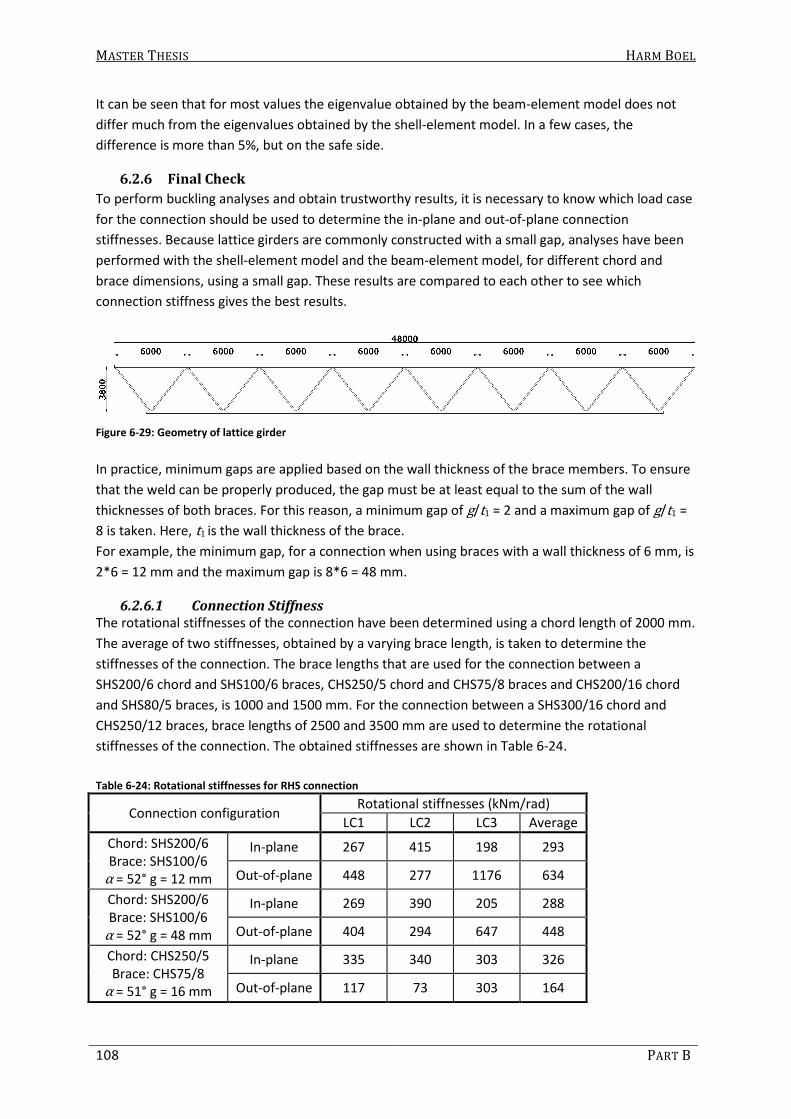
MASTER THESIS HARM BOEL
108 PART B
It can be seen that for most values the eigenvalue obtained by the beam-element model does not
differ much from the eigenvalues obtained by the shell-element model. In a few cases, the
difference is more than 5%, but on the safe side.
6.2.6 Final Check
To perform buckling analyses and obtain trustworthy results, it is necessary to know which load case
for the connection should be used to determine the in-plane and out-of-plane connection
stiffnesses. Because lattice girders are commonly constructed with a small gap, analyses have been
performed with the shell-element model and the beam-element model, for different chord and
brace dimensions, using a small gap. These results are compared to each other to see which
connection stiffness gives the best results.
Figure 6-29: Geometry of lattice girder
In practice, minimum gaps are applied based on the wall thickness of the brace members. To ensure
that the weld can be properly produced, the gap must be at least equal to the sum of the wall
thicknesses of both braces. For this reason, a minimum gap of g/t1 = 2 and a maximum gap of g/t1 =
8 is taken. Here, t1 is the wall thickness of the brace.
For example, the minimum gap, for a connection when using braces with a wall thickness of 6 mm, is
2*6 = 12 mm and the maximum gap is 8*6 = 48 mm.
6.2.6.1 Connection Stiffness
The rotational stiffnesses of the connection have been determined using a chord length of 2000 mm.
The average of two stiffnesses, obtained by a varying brace length, is taken to determine the
stiffnesses of the connection. The brace lengths that are used for the connection between a
SHS200/6 chord and SHS100/6 braces, CHS250/5 chord and CHS75/8 braces and CHS200/16 chord
and SHS80/5 braces, is 1000 and 1500 mm. For the connection between a SHS300/16 chord and
CHS250/12 braces, brace lengths of 2500 and 3500 mm are used to determine the rotational
stiffnesses of the connection. The obtained stiffnesses are shown in Table 6-24.
Table 6-24: Rotational stiffnesses for RHS connection
Connection configuration Rotational stiffnesses (kNm/rad)
LC1 LC2 LC3 Average
Chord: SHS200/6
Brace: SHS100/6 α = 52° g = 12 mm
In-plane 267 415 198 293
Out-of-plane 448 277 1176 634
Chord: SHS200/6
Brace: SHS100/6
α = 52° g = 48 mm
In-plane 269 390 205 288
Out-of-plane 404 294 647 448
Chord: CHS250/5
Brace: CHS75/8 α = 51° g = 16 mm
In-plane 335 340 303 326
Out-of-plane 117 73 303 164
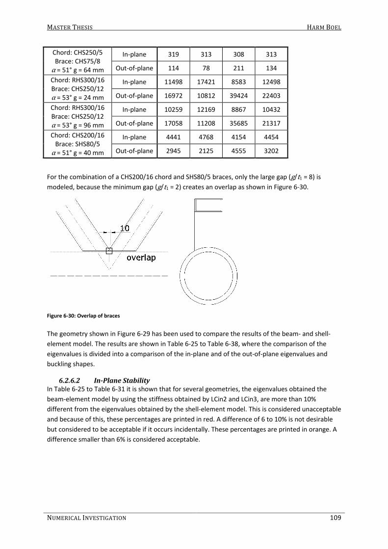
MASTER THESIS HARM BOEL
NUMERICAL INVESTIGATION 109
Chord: CHS250/5
Brace: CHS75/8
α = 51° g = 64 mm
In-plane 319 313 308 313
Out-of-plane 114 78 211 134
Chord: RHS300/16
Brace: CHS250/12
α = 53° g = 24 mm
In-plane 11498 17421 8583 12498
Out-of-plane 16972 10812 39424 22403
Chord: RHS300/16
Brace: CHS250/12
α = 53° g = 96 mm
In-plane 10259 12169 8867 10432
Out-of-plane 17058 11208 35685 21317
Chord: CHS200/16
Brace: SHS80/5
α = 51° g = 40 mm
In-plane 4441 4768 4154 4454
Out-of-plane 2945 2125 4555 3202
For the combination of a CHS200/16 chord and SHS80/5 braces, only the large gap (g/t1 = 8) is
modeled, because the minimum gap (g/t1 = 2) creates an overlap as shown in Figure 6-30.
Figure 6-30: Overlap of braces
The geometry shown in Figure 6-29 has been used to compare the results of the beam- and shell-
element model. The results are shown in Table 6-25 to Table 6-38, where the comparison of the
eigenvalues is divided into a comparison of the in-plane and of the out-of-plane eigenvalues and
buckling shapes.
6.2.6.2 In-Plane Stability
In Table 6-25 to Table 6-31 it is shown that for several geometries, the eigenvalues obtained the
beam-element model by using the stiffness obtained by LCin2 and LCin3, are more than 10%
different from the eigenvalues obtained by the shell-element model. This is considered unacceptable
and because of this, these percentages are printed in red. A difference of 6 to 10% is not desirable
but considered to be acceptable if it occurs incidentally. These percentages are printed in orange. A
difference smaller than 6% is considered acceptable.

MASTER THESIS HARM BOEL
110 PART B
Table 6-25: Comparison of in-plane eigenvalues for RHS200/6 chord and RHS100/6 braces, g = 12 mm
shell-element
model
Beam-element model
Eigen-
value
member LCin1 LCin2 LCin3 Average
Eig.val. % Eig.val. % Eig.val. % Eig.val. %
121886 B2 116101 -4.75 132960 9.09 106840 -12.34 119340 -2.09
122000 B2 116113 -4.83 133010 9.02 106850 -12.42 119360 -2.16
162548 B4 160210 -1.44 184710 13.63 148600 -8.58 163570 0.63
166469 B4 161872 -2.76 189590 13.89 149020 -10.48 166330 -0.08
174282 B4 + C4 173335 -0.54 171140 -1.80 169940 -2.49 175210 0.53
Table 6-26: Comparison of in-plane eigenvalues for RHS200/6 chord and RHS100/6 braces, g = 48 mm
shell-element
model
Beam-element model
Eigen-
value
member LCin1 LCin2 LCin3 Average
Eig.val. % Eig.val. % Eig.val. % Eig.val. %
119221 B2 116121 -2.60 130130 9.15 107610 -9.74 118490 -0.61
120535 B2 116131 -3.65 130160 7.99 107610 -10.72 118500 -1.69
161731 B4 160948 -0.48 170340 5.32 150420 -6.99 163390 1.03
165936 B4 162756 -1.92 181830 9.58 150910 -9.06 166030 0.06
173518 B4 173363 -0.09 186620 7.55 170060 -1.99 174770 0.72
Table 6-27: Comparison of in-plane eigenvalues for CHS250/5 chord and CHS75/8 braces, g = 16 mm
shell-element
model
Beam-element model
Eigen-
value
member LCin1 LCin2 LCin3 Average
Eig.val. % Eig.val. % Eig.val. % Eig.val. %
53551 B2 56596 5.69 56842 6.15 54914 2.55 56142 4.84
53576 B2 56597 5.64 56844 6.10 54915 2.50 56142 4.79
73772 B4 78300 6.14 78644 6.60 75954 2.96 77666 5.28
73912 B4 78330 5.98 78674 6.44 75979 2.80 77694 5.12
Table 6-28: Comparison of in-plane eigenvalues for CHS250/5 chord and CHS75/8 braces, g = 64 mm
shell-element
model
Beam-element model
Eigen-
value
member LCin1 LCin2 LCin3 Average
Eig.val. % Eig.val. % Eig.val. % Eig.val. %
52408 B2 55619 6.13 55301 5.52 55031 5.00 55302 5.52
52581 B2 55621 5.78 55302 5.17 55031 4.66 55302 5.17
72881 B4 77564 6.43 77117 5.81 76737 5.29 77114 5.81
72950 B4 77590 6.36 77139 5.74 76761 5.22 77141 5.75

MASTER THESIS HARM BOEL
NUMERICAL INVESTIGATION 111
Table 6-29: Comparison of in-plane eigenvalues for RHS300/16 chord and CHS250/12 braces, g = 24 mm
shell-element
model
Beam-element model
Eigen-
value
member LCin1 LCin2 LCin3 Average
Eig.val. % Eig.val. % Eig.val. % Eig.val. %
1635600 C4 1662500 1.64 1725800 5.51 1618100 -1.07 1675200 2.42
2110500 C3 2173900 3.00 2240900 6.18 2126800 0.77 2187400 3.64
2538500 B2 2690500 5.99 2797900 - 2571700 1.31 2716100 7.00
2686300 B2 2876700 7.09 3167200 17.90 2657600 -1.07 2938700 9.40
2861900 B2 3009200 5.15 3311600 - 2839400 -0.79 3068100 7.21
Table 6-30: Comparison of in-plane eigenvalues for RHS300/16 chord and CHS250/12 braces, g = 96 mm
shell-element model
Beam-element model
Eigen-value
member LCin1 LCin2 LCin3 Average
Eig.val. % Eig.val. % Eig.val. % Eig.val. %
1591000 C4 1648000 3.58 1674700 5.26 1625600 2.17 1650600 3.75
2065000 C3 2154900 4.35 2183300 5.73 2131000 3.20 2157700 4.49
2475300 B2 2651400 7.11 2709700 9.47 2587800 4.54 2657800 7.37
2561300 B2 2787900 8.85 2917800 13.92 2677300 4.53 2800700 9.35
2734000 B2 2924900 6.98 3040400 11.21 2844100 4.03 2935400 7.37
Table 6-31: Comparison of in-plane eigenvalues for CHS200/16 chord and RHS80/10 braces, g = 40 mm
shell-element
model
Beam-element model
Eigen-
value
member LCin1 LCin2 LCin3 Average
Eig.val. % Eig.val. % Eig.val. % Eig.val. %
111516 B2 113942 2.18 114370 2.56 113510 1.79 113960 2.19
111542 B2 113951 2.16 114380 2.54 113520 1.77 113970 2.18
155876 B4 159404 2.26 159990 2.64 158810 1.88 159430 2.28
156329 B4 159709 2.16 160310 2.55 159110 1.78 159730 2.18
The eigenvalues obtained using the stiffness obtained by LCin1 and the average of LCin1, LCin2 and
LCin3 are acceptable. In general, the best results are obtained when using the average of the
connection stiffnesses. But, the results obtained by using the stiffness obtained by LCin1 are hardly
any different. Also, only one calculation has to be made when applying LCin1 instead of the average
of LCin1 to LCin3. Therefore, it is chosen that LCin1 can be used to obtain the in-plane rotational
stiffness.

MASTER THESIS HARM BOEL
112 PART B
6.2.6.3 Out-Of-Plane Stability
Again, the unacceptable results are printed in red and the acceptable, but not desirable results are
printed in orange. The results can be seen in Table 6-32 to Table 6-38.
Table 6-32: Comparison of out-of-plane eigenvalues for RHS200/6 chord and RHS100/6 braces, g = 12 mm
shell-element model
Beam-element model
Eigen-
value
member LCout1 LCout2 LCout3 Average
Eig.val. % Eig.val. % Eig.val. % Eig.val. %
139128 B2 121652 -12.56 109170 -21.53 148870 7.00 131470 -5.50
143741 B2 122706 -14.63 109950 -23.51 150210 4.50 132680 -7.70
165561 B4 + C4 167647 1.26 169280 2.25 171330 3.48 169450 2.35
Table 6-33: Comparison of out-of-plane eigenvalues for RHS200/6 chord and RHS100/6 braces, g = 48 mm
shell-element
model
Beam-element model
Eigen-
value
member LCout1 LCout2 LCout3 Average
Eig.val. % Eig.val. % Eig.val. % Eig.val. %
132114 B2 118495 -10.31 110340 -16.48 131650 -0.35 121310 -8.18
135453 B2 119499 -11.78 111170 -17.93 132870 -1.91 122370 -9.66
164683 B4 + C4 166689 1.22 169620 3.00 169570 2.97 167760 1.87
187521 B4 171028 -8.80 157970 -15.76 192080 2.43 175560 -6.38
194722 B4 175415 -9.92 158140 -18.79 196260 0.79 179360 -7.89
Table 6-34: Comparison of out-of-plane eigenvalues for CHS250/5 chord and CHS75/8 braces, g = 16 mm
shell-element
model
Beam-element model
Eigen-
value
member LCout1 LCout2 LCout3 Average
Eig.val. % Eig.val. % Eig.val. % Eig.val. %
43090 B2 37149 -13.79 32818 -23.84 47541 10.33 40703 -5.54
43643 B2 38184 -12.51 33414 -23.44 49878 14.29 42156 -3.41
60070 B4 52324 -12.89 45699 -23.92 69435 15.59 57997 -3.45
60503 B4 53359 -11.81 46363 -23.37 71368 17.96 59336 -1.93
100475 B6 87384 -13.03 76406 -23.96 115160 14.62 96720 -3.74
Table 6-35: Comparison of out-of-plane eigenvalues for CHS250/5 chord and CHS75/8 braces, g = 64 mm
shell-element
model
Beam-element model
Eigen-
value
member LCout1 LCout2 LCout3 Average
Eig.val. % Eig.val. % Eig.val. % Eig.val. %
40988 B2 36749 -10.34 33255 -18.87 43328 5.71 38392 -6.33
41484 B2 37760 -8.98 33908 -18.26 45132 8.79 39589 -4.57
57507 B4 52142 -9.33 46747 -18.71 62845 9.28 54750 -4.79
58149 B4 53172 -8.56 47473 -18.36 64456 10.85 55924 -3.83
95903 B6 86900 -9.39 77978 -18.69 104450 8.91 91197 -4.91
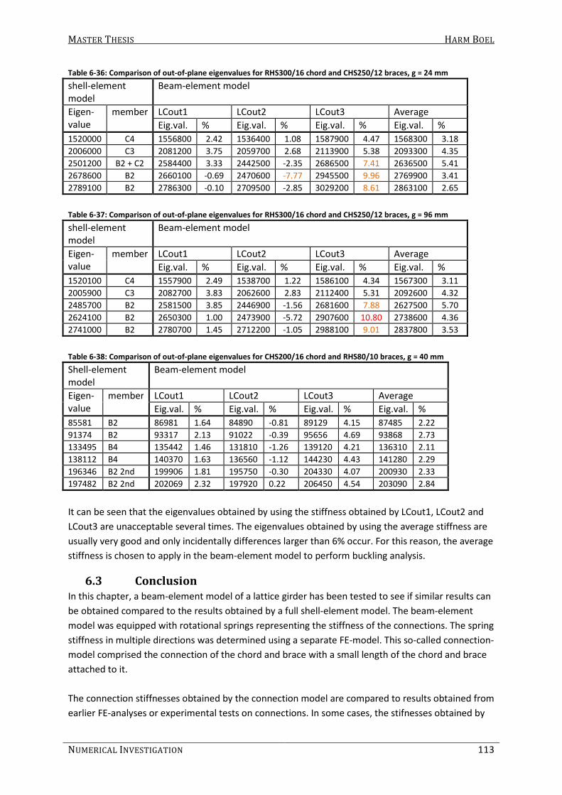
MASTER THESIS HARM BOEL
NUMERICAL INVESTIGATION 113
Table 6-36: Comparison of out-of-plane eigenvalues for RHS300/16 chord and CHS250/12 braces, g = 24 mm
shell-element
model
Beam-element model
Eigen-
value
member LCout1 LCout2 LCout3 Average
Eig.val. % Eig.val. % Eig.val. % Eig.val. %
1520000 C4 1556800 2.42 1536400 1.08 1587900 4.47 1568300 3.18
2006000 C3 2081200 3.75 2059700 2.68 2113900 5.38 2093300 4.35
2501200 B2 + C2 2584400 3.33 2442500 -2.35 2686500 7.41 2636500 5.41
2678600 B2 2660100 -0.69 2470600 -7.77 2945500 9.96 2769900 3.41
2789100 B2 2786300 -0.10 2709500 -2.85 3029200 8.61 2863100 2.65
Table 6-37: Comparison of out-of-plane eigenvalues for RHS300/16 chord and CHS250/12 braces, g = 96 mm
shell-element model
Beam-element model
Eigen-value
member LCout1 LCout2 LCout3 Average
Eig.val. % Eig.val. % Eig.val. % Eig.val. %
1520100 C4 1557900 2.49 1538700 1.22 1586100 4.34 1567300 3.11
2005900 C3 2082700 3.83 2062600 2.83 2112400 5.31 2092600 4.32
2485700 B2 2581500 3.85 2446900 -1.56 2681600 7.88 2627500 5.70
2624100 B2 2650300 1.00 2473900 -5.72 2907600 10.80 2738600 4.36
2741000 B2 2780700 1.45 2712200 -1.05 2988100 9.01 2837800 3.53
Table 6-38: Comparison of out-of-plane eigenvalues for CHS200/16 chord and RHS80/10 braces, g = 40 mm
Shell-element
model
Beam-element model
Eigen-
value
member LCout1 LCout2 LCout3 Average
Eig.val. % Eig.val. % Eig.val. % Eig.val. %
85581 B2 86981 1.64 84890 -0.81 89129 4.15 87485 2.22
91374 B2 93317 2.13 91022 -0.39 95656 4.69 93868 2.73
133495 B4 135442 1.46 131810 -1.26 139120 4.21 136310 2.11
138112 B4 140370 1.63 136560 -1.12 144230 4.43 141280 2.29
196346 B2 2nd 199906 1.81 195750 -0.30 204330 4.07 200930 2.33
197482 B2 2nd 202069 2.32 197920 0.22 206450 4.54 203090 2.84
It can be seen that the eigenvalues obtained by using the stiffness obtained by LCout1, LCout2 and
LCout3 are unacceptable several times. The eigenvalues obtained by using the average stiffness are
usually very good and only incidentally differences larger than 6% occur. For this reason, the average
stiffness is chosen to apply in the beam-element model to perform buckling analysis.
6.3 Conclusion
In this chapter, a beam-element model of a lattice girder has been tested to see if similar results can
be obtained compared to the results obtained by a full shell-element model. The beam-element
model was equipped with rotational springs representing the stiffness of the connections. The spring
stiffness in multiple directions was determined using a separate FE-model. This so-called connection-
model comprised the connection of the chord and brace with a small length of the chord and brace
attached to it.
The connection stiffnesses obtained by the connection model are compared to results obtained from
earlier FE-analyses or experimental tests on connections. In some cases, the stifnesses obtained by

MASTER THESIS HARM BOEL
114 PART B
FE-analysis is very different from the stiffnesses given in literature such as Korol and Mirza (k and
Cin), Chen (Cin) and Wardenier (Cin). In other cases, the stiffnesses were very similar to the ones given
in literature such as Wardenier (Cout) and Vegte (Cin and Cout).
The results obtained by FE-analysis are considered to be trustworthy because the results are
consistent with the results of some previous studies: the results given by Vegte, which is the least
old literature used on connection stiffnesses.
Previous studies using FE-analysis did show very different results (Korol and Mirza) but they may be
less reliable since the use of the FEM back then (1982) was not developed as well as it is today.
Results obtained by experiments (Chen) are also very different. These stiffnesses have been
obtained from a force-deflection diagram which is never a perfect straight line. Also, experimental
results are influenced by section imperfections, material properties and the presence of welds.
It is concluded that the Shell-element model described in this chapter can be used to obtain realistic
connection stiffnesses for as well in-plane as out-of-plane bending. The axial stiffness of the
connection between one chord and a brace with an angle of 90° can also be determined by the
method described in this chapter. The torsional stiffness obtained by FE-analysis is not compared to
results from other studies and thus it is not possible to judge the reliability of the results.
The Beam-element model differs in deflection when compared to the shell-element model. But, the
axial forces in the members and the eigenvalues with accompanying buckling shapes are very
similar. Several variants of beam-element models have been investigated and the one giving the best
results, compared to the results obtained from the shell-element model, is chosen.
The spring stiffness, representing the connection stiffness, is determined by LCin1, LCin2 and LCin3
for in-plane and LCout1, LCout2 and LCout3 for out-of-plane. To determine which connection
stiffness should be used for the rotational springs, 7 lattice girders with different chord and brace
sections and dimensions are analyzed with the shell- and beam-element model.
All determined connection stiffnesses are applied in the beam-element model. Buckling analysis has
been performed and the results (eigenvalues and buckling shapes) are compared to the results
obtained by the shell-element model. The comparison shows that acceptable results can be
obtained when the in-plane rotational stiffness of the connection is determined by using LCin1 and
the out-of-plane rotational stiffness of the connection is determined by the average stiffness
obtained by using LCout1, LCout2 and LCout3.
It can be concluded that buckling length factors can be determined by using a Beam-element model,
where the members are connected by rotational springs, as described in this chapter.

MASTER THESIS HARM BOEL
NUMERICAL INVESTIGATION 115
7. Parameter study The goal of this study is to investigate the influence of β (= b1 /b0) and γ (= b0 /2t0) on the buckling
length factor of hollow sections in lattice girders. To determine the influence of these parameters,
FE-analyses have been performed on lattice girders with varying brace dimensions and chord wall
thicknesses. A realistic lattice girder geometry is chosen and the basic case is shown in Figure 7-1.
Realistic dimensions have been used and are described in section 7.1.1.
Figure 7-1: Basic geometry of lattice girder and load case
Besides β and γ, also other parameters have been varied such as the length of the lattice girder and
the number of horizontal supports. Hereafter, the parameter study and the results are discussed,
starting with the connection stiffness, followed by the buckling length factor.
7.1 Connection Stiffness
Before performing a buckling analysis, the connection stiffness must be determined. The
dimensions, gaps and geometry of the connections to determine the connection stiffnesses and also
the restrictions regarding the dimensions are described first. The results are discussed thereafter.
7.1.1 Parameters
For the chord and brace members, realistic dimensions have been selected:
The chord dimensions are varied in section type, where the diameter of the circular chord is slightly
smaller than the sides of the square section. The wall thickness is varied and is identical for the
square and circular hollow sections:
- SHS200/6.3, 200/10 and 200/16 and;
- CHS193.7/6.3, CHS193.7/10 and CHS193.7/16.
The brace dimensions are also varied in section type and also in width or diameter. The wall
thickness is not varied per section, but only one wall thickness is used for every diameter/width of
the brace where the ratio b1/2t 1 or d1/2t 1 is kept the same as much as possible, depending on the
availability of the sections. Also here, the diameter of the circular sections are slightly different from
the sides of the square sections:
- SHS50/4, 80/5, 100/6.3, 120/7.1, 150/8, 180/10 and 200/12.5 and;
- CHS48.3/4, 76.1/5, 114.3/6.3, 121/7.1, 152.4/8, 177.8/10 and 193.7/12.5.
The Square section chords are combined with square and circular section braces. The circular section
chords are combined with circular section braces.
A geometry-error causes restrictions regarding the combination of some sections. The restrictions
will be explained hereafter.
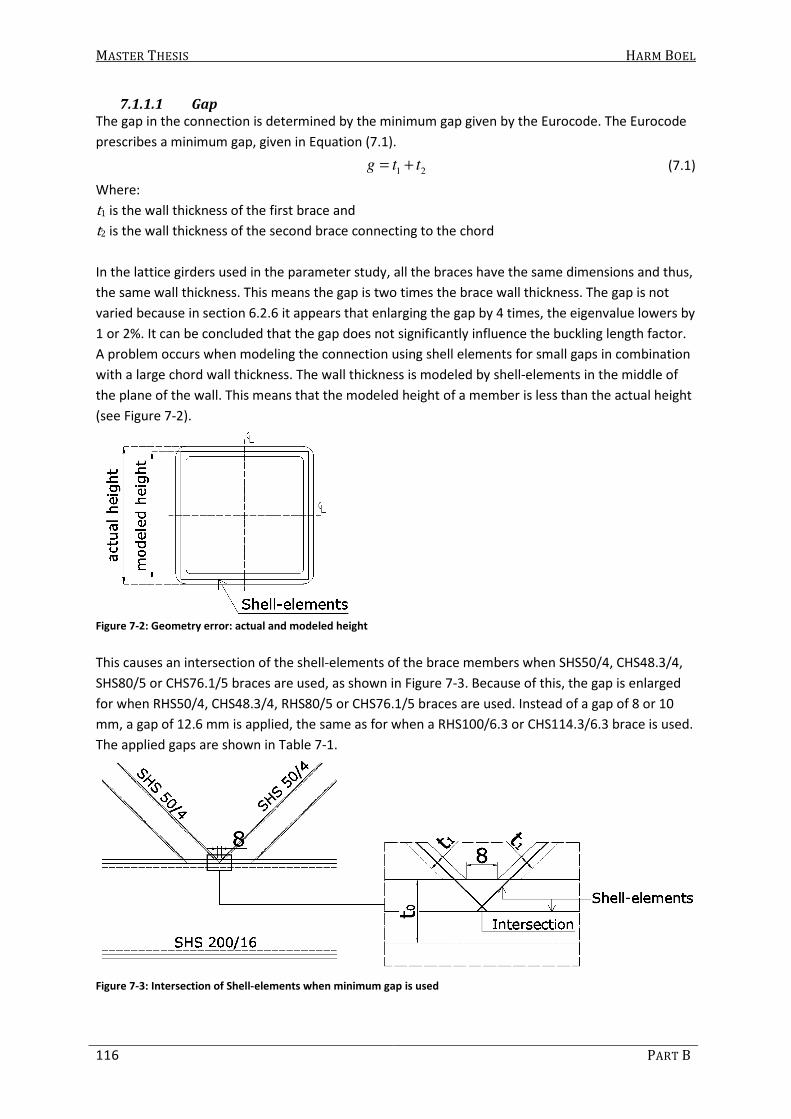
MASTER THESIS HARM BOEL
116 PART B
7.1.1.1 Gap
The gap in the connection is determined by the minimum gap given by the Eurocode. The Eurocode
prescribes a minimum gap, given in Equation (7.1).
1 2g t t= + (7.1)
Where:
t1 is the wall thickness of the first brace and
t2 is the wall thickness of the second brace connecting to the chord
In the lattice girders used in the parameter study, all the braces have the same dimensions and thus,
the same wall thickness. This means the gap is two times the brace wall thickness. The gap is not
varied because in section 6.2.6 it appears that enlarging the gap by 4 times, the eigenvalue lowers by
1 or 2%. It can be concluded that the gap does not significantly influence the buckling length factor.
A problem occurs when modeling the connection using shell elements for small gaps in combination
with a large chord wall thickness. The wall thickness is modeled by shell-elements in the middle of
the plane of the wall. This means that the modeled height of a member is less than the actual height
(see Figure 7-2).
Figure 7-2: Geometry error: actual and modeled height
This causes an intersection of the shell-elements of the brace members when SHS50/4, CHS48.3/4,
SHS80/5 or CHS76.1/5 braces are used, as shown in Figure 7-3. Because of this, the gap is enlarged
for when RHS50/4, CHS48.3/4, RHS80/5 or CHS76.1/5 braces are used. Instead of a gap of 8 or 10
mm, a gap of 12.6 mm is applied, the same as for when a RHS100/6.3 or CHS114.3/6.3 brace is used.
The applied gaps are shown in Table 7-1.
Figure 7-3: Intersection of Shell-elements when minimum gap is used
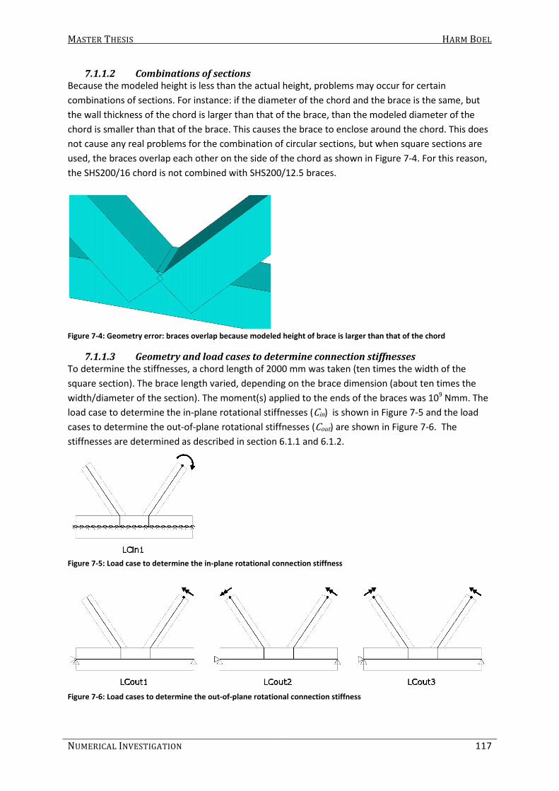
MASTER THESIS HARM BOEL
NUMERICAL INVESTIGATION 117
7.1.1.2 Combinations of sections
Because the modeled height is less than the actual height, problems may occur for certain
combinations of sections. For instance: if the diameter of the chord and the brace is the same, but
the wall thickness of the chord is larger than that of the brace, than the modeled diameter of the
chord is smaller than that of the brace. This causes the brace to enclose around the chord. This does
not cause any real problems for the combination of circular sections, but when square sections are
used, the braces overlap each other on the side of the chord as shown in Figure 7-4. For this reason,
the SHS200/16 chord is not combined with SHS200/12.5 braces.
Figure 7-4: Geometry error: braces overlap because modeled height of brace is larger than that of the chord
7.1.1.3 Geometry and load cases to determine connection stiffnesses
To determine the stiffnesses, a chord length of 2000 mm was taken (ten times the width of the
square section). The brace length varied, depending on the brace dimension (about ten times the
width/diameter of the section). The moment(s) applied to the ends of the braces was 109 Nmm. The
load case to determine the in-plane rotational stiffnesses (Cin) is shown in Figure 7-5 and the load
cases to determine the out-of-plane rotational stiffnesses (Cout) are shown in Figure 7-6. The
stiffnesses are determined as described in section 6.1.1 and 6.1.2.
Figure 7-5: Load case to determine the in-plane rotational connection stiffness
Figure 7-6: Load cases to determine the out-of-plane rotational connection stiffness

MASTER THESIS HARM BOEL
118 PART B
The used section combinations and accompanying gaps, angles and brace lengths are shown in Table
7-1 and Table 7-2. The used symbols are explained below and in Figure 7-7 and Equation (7.2) to
(7.4).
Figures of these connections are shown in Appendix II.
Figure 7-7: Clarification of symbols
1 1 1
0 0 0
b d d
b b dβ = = = (7.2)
0 0
0 02 2
b d
t tγ = = (7.3)
1 1
1 12 2
br
b d
t tγ = = (7.4)
γ is the diameter/width to wall thickness ratio of the chord
γbr is the diameter/width to wall thickness ratio of the brace
β is the diameter/width of the brace to chord ratio
b0 is the chord width
d0 is the chord diameter
t0 is the chord wall thickness
b1 is the brace width
d1 is the brace diameter
t1 is the brace wall thickness
Lbr is the brace length
Lch is the chord length
α is the angle between the chord and the brace
g is the gap
grb is the distance between the rigid beams in the Beam-element model which will be explained
later

MASTER THESIS HARM BOEL
NUMERICAL INVESTIGATION 119
Table 7-1: Section combinations used in parameter study (Square Section Chord)
Chord Section Brace Section β Lbr
(mm) g
(mm) α (°)
grb
(mm)
SHS200/6.3 (γ = 15.87) RHS50/4 (γbr = 6.25) 0.25 500 12.6 44 84.2
RHS80/5(γbr = 8) 0.40 800 12.6 45 126.6
RHS100/6.3(γbr = 7.94) 0.50 1000 12.6 45 154.7
RHS120/7.1 (γbr = 8.45) 0.60 1200 14.2 45 184.2
RHS150/8 (γbr = 9.38) 0.75 1500 16 45 227.5
RHS180/10 (γbr = 9) 0.90 1800 20 45 272.5
RHS200/12.5 (γbr = 8) 1.00 2000 25 46 304.6
CHS48.3/4 (γbr = 6.04) 0.24 500 12.6 44 81.8
CHS76.1/5(γbr = 7.61) 0.38 800 12.6 45 121.4
CHS114.3/6.3(γbr = 9.07) 0.57 1200 12.6 45 174.7
CHS121/7.1 (γbr = 8.52) 0.61 1200 14.2 45 185.6
CHS152.4/8 (γbr = 9.53) 0.76 1500 16 45 230.8
CHS177.8/10 (γbr = 8.89) 0.89 1800 20 45 269.5
CHS193.7/12.5 (γbr = 7.75) 0.97 2000 25 46 296
SHS200/10 (γ = 10) RHS50/4 (γbr = 6.25) 0.25 500 12.6 44 84.2
RHS80/5(γbr = 8) 0.40 800 12.6 45 126.6
RHS100/6.3(γbr = 7.94) 0.50 1000 12.6 45 154.7
RHS120/7.1 (γbr = 8.45) 0.60 1200 14.2 45 184.2
RHS150/8 (γbr = 9.38) 0.75 1500 16 45 227.5
RHS180/10 (γbr = 9) 0.90 1800 20 45 272.5
RHS200/12.5 (γbr = 8) 1.00 2000 25 46 304.6
CHS48.3/4 (γbr = 6.04) 0.24 500 12.6 44 81.8
CHS76.1/5(γbr = 7.61) 0.38 800 12.6 45 121.4
CHS114.3/6.3(γbr = 9.07) 0.57 1200 12.6 45 174.7
CHS121/7.1 (γbr = 8.52) 0.61 1200 14.2 45 185.6
CHS152.4/8 (γbr = 9.53) 0.76 1500 16 45 230.8
CHS177.8/10 (γbr = 8.89) 0.89 1800 20 45 269.5
CHS193.7/12.5 (γbr = 7.75) 0.97 2000 25 46 296
SHS200/16 (γ = 6.25) RHS50/4 (γbr = 6.25) 0.25 500 12.6 44 84.2
RHS80/5(γbr = 8) 0.40 800 12.6 45 126.6
RHS100/6.3(γbr = 7.94) 0.50 1000 12.6 45 154.7
RHS120/7.1 (γbr = 8.45) 0.60 1200 14.2 45 184.2
RHS150/8 (γbr = 9.38) 0.75 1500 16 45 227.5
RHS180/10 (γbr = 9) 0.90 1800 20 45 272.5
CHS48.3/4 (γbr = 6.04) 0.24 500 12.6 44 81.8
CHS76.1/5(γbr = 7.61) 0.38 800 12.6 45 121.4
CHS114.3/6.3(γbr = 9.07) 0.57 1200 12.6 45 174.7
CHS121/7.1 (γbr = 8.52) 0.61 1200 14.2 45 185.6
CHS152.4/8 (γbr = 9.53) 0.76 1500 16 45 230.8
CHS177.8/10 (γbr = 8.89) 0.89 1800 20 45 269.5
CHS193.7/12.5 (γbr = 7.75) 0.97 2000 25 46 296

MASTER THESIS HARM BOEL
120 PART B
Table 7-2: Section combinations used in parameter study (Circular Section Chord)
Chord Section Brace Section β Lbr
(mm) g
(mm) α (°)
grb
(mm)
CHS193.7/6.3 (γ = 15.37)
CHS48.3/4 (γbr = 6.04) 0.25 500 12.6 44 81.7
CHS76.1/5(γbr = 7.61) 0.39 800 12.6 45 121.1
CHS114.3/6.3(γbr = 9.07) 0.59 1200 12.6 45 174.6
CHS121/7.1 (γbr = 8.52) 0.62 1200 14.2 45 185.5
CHS152.4/8 (γbr = 9.53) 0.79 1500 16 45 230.6
CHS177.8/10 (γbr = 8.89) 0.92 1800 20 45 269.3
CHS193.7/12.5 (γbr = 7.75) 1.00 2000 25 46 295.8
CHS193.7/10(γ = 9.69)
CHS48.3/4 (γbr = 6.04) 0.25 500 12.6 44 81.7
CHS76.1/5(γbr = 7.61) 0.39 800 12.6 45 121.1
CHS114.3/6.3(γbr = 9.07) 0.59 1200 12.6 45 174.6
CHS121/7.1 (γbr = 8.52) 0.62 1200 14.2 45 185.5
CHS152.4/8 (γbr = 9.53) 0.79 1500 16 45 230.6
CHS177.8/10 (γbr = 8.89) 0.92 1800 20 45 269.3
CHS193.7/12.5 (γbr = 7.75) 1.00 2000 25 46 295.8
CHS193.7/16(γ = 6.05) CHS48.3/4 (γbr = 6.04) 0.25 500 12.6 44 81.7
CHS76.1/5(γbr = 7.61) 0.39 800 12.6 45 121.1
CHS114.3/6.3(γbr = 9.07) 0.59 1200 12.6 45 174.6
CHS121/7.1 (γbr = 8.52) 0.62 1200 14.2 45 185.5
CHS152.4/8 (γbr = 9.53) 0.79 1500 16 45 230.6
CHS177.8/10 (γbr = 8.89) 0.92 1800 20 45 269.3
CHS193.7/12.5 (γbr = 7.75) 1.00 2000 25 46 295.8
Hereafter, the connection stiffnesses are shortly discussed. Only a few graphs are shown to clarify
the behavior of the joint. The rest of the graphs and tables can be found in Appendix II.
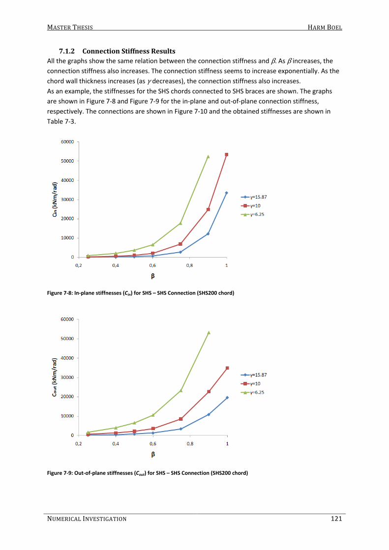
MASTER THESIS HARM BOEL
NUMERICAL INVESTIGATION 121
7.1.2 Connection Stiffness Results
All the graphs show the same relation between the connection stiffness and β. As β increases, the
connection stiffness also increases. The connection stiffness seems to increase exponentially. As the
chord wall thickness increases (as γ decreases), the connection stiffness also increases.
As an example, the stiffnesses for the SHS chords connected to SHS braces are shown. The graphs
are shown in Figure 7-8 and Figure 7-9 for the in-plane and out-of-plane connection stiffness,
respectively. The connections are shown in Figure 7-10 and the obtained stiffnesses are shown in
Table 7-3.
Figure 7-8: In-plane stiffnesses (Cin) for SHS – SHS Connection (SHS200 chord)
Figure 7-9: Out-of-plane stiffnesses (Cout) for SHS – SHS Connection (SHS200 chord)

MASTER THESIS HARM BOEL
122 PART B
Figure 7-10: Connections between RHS chords and RHS braces
Table 7-3: Rotational stiffnesses for SHS – SHS Connections
Chord Brace β α (°)
Cin (kNm/rad)
Cout (kNm/rad) b0 t0 γ b1 t1 γbr
200 6.3 15.87 50 4 6.25 0.25 44 82.35 225.31
80 5 8 0.4 45 188.43 481.85
100 6.3 7.94 0.5 45 355.52 831.2
120 7.1 8.45 0.6 45 711.72 1376.84
150 8 9.38 0.75 45 2766.15 3489.3
180 10 9 0.9 45 12294.51 10837.03
200 12.5 8 1 46 33575.77 19594.12
200 10 10 50 4 6.25 0.25 44 292.07 673.19
80 5 8 0.4 45 627.84 1376.22
100 6.3 7.94 0.5 45 1133.3 2247.05
120 7.1 8.45 0.6 45 2141.5 3605.88
150 8 9.38 0.75 45 6888.31 8584.83
180 10 9 0.9 45 24808.14 22651.62
200 12.5 8 1 46 53409.15 34874.13
200 16 6.25 50 4 6.25 0.25 44 953.48 1726.35
80 5 8 0.4 45 2144.75 4046.51
100 6.3 7.94 0.5 45 3680.7 6643.9
120 7.1 8.45 0.6 45 6547.22 10657.47
150 8 9.38 0.75 45 17717.9 23322.46
180 10 9 0.9 45 52421.85 53125.75

MASTER THESIS HARM BOEL
NUMERICAL INVESTIGATION 123
7.1.2.1 In- and Out-of-plane Stiffness
When SHS braces are connected to a SHS chord, then the out-of-plane stiffness is higher than the in-
plane stiffness for lower values of β. As β increases, the in-plane stiffness exceeds the out-of-plane
stiffness (see Table 7-4 and Figure 7-11).
Table 7-4: Rotational stiffnesses of connections of SHS200/10 (γγγγ =10) chord connected to SHS braces
β Cin
(kNm/rad) Cout
(kNm/rad)
0.25 292.07 673.19
0.4 627.84 1376.22
0.5 1133.3 2247.05
0.6 2141.5 3605.88
0.75 6888.31 8584.83
0.9 24808.14 22651.62
1 53409.15 34874.13
Figure 7-11: Rotational stiffnesses of connections of SHS200/10 (γγγγ =10) chord connected to SHS braces
When CHS braces are connected to a SHS chord, then the out-of-plane stiffness is higher than the in-
plane stiffness for all values of β (see Table 7-5 and Figure 7-12).
Table 7-5: Rotational stiffnesses of connections of SHS200/10 (γγγγ =10) chord connected to CHS braces
β Cin
(kNm/rad) Cout
(kNm/rad)
0.25 210.57 414.81
0.4 399.99 822.18
0.5 908.88 1797.37
0.6 1075.53 2097.5
0.75 2349.3 4573.92
0.9 5128.72 9438.65
1 8875.75 13783.62
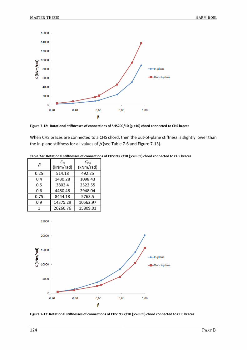
MASTER THESIS HARM BOEL
124 PART B
Figure 7-12: Rotational stiffnesses of connections of SHS200/10 (γγγγ =10) chord connected to CHS braces
When CHS braces are connected to a CHS chord, then the out-of-plane stiffness is slightly lower than
the in-plane stiffness for all values of β (see Table 7-6 and Figure 7-13).
Table 7-6: Rotational stiffnesses of connections of CHS193.7/10 (γγγγ =9.69) chord connected to CHS braces
β Cin
(kNm/rad) Cout
(kNm/rad)
0.25 514.18 492.25
0.4 1430.28 1098.43
0.5 3803.4 2522.55
0.6 4480.48 2948.04
0.75 8444.18 5763.5
0.9 14375.29 10562.97
1 20260.76 15809.01
Figure 7-13: Rotational stiffnesses of connections of CHS193.7/10 (γγγγ =9.69) chord connected to CHS braces

MASTER THESIS HARM BOEL
NUMERICAL INVESTIGATION 125
7.1.2.2 Type of Section (Combination)
In section 7.1.2.1 it can be seen that the section type combination influences the connection
behavior. When comparing the in-plane connection stiffnesses of different section type
combinations in Table 7-7 and Figure 7-14, it can be seen that the connection stiffness of SHS chords
with SHS braces is very high for higher values of β, compared to other section type combinations.
The combination of SHS chords and CHS braces gives the lowest connection stiffness. Hereby, it must
be mentioned that the wall thickness used for the CHS chord is the same as for the SHS chord.
Because the diameter is smaller than the width, γ is slightly lower which has a positive effect on the
connection stiffness.
Table 7-7: In-plane connection stiffnesses of different section type combinations (tttt0000 =10 mm)
SHS - SHS SHS - CHS CHS - CHS
β Cin
(kNm/rad) β
Cin
(kNm/rad) β
Cin
(kNm/rad)
0.25 292.07 0.24 210.57 0.25 514.18
0.4 627.84 0.38 399.99 0.39 1430.28
0.5 1133.3 0.57 908.88 0.59 3803.4
0.6 2141.5 0.61 1075.53 0.62 4480.48
0.75 6888.31 0.76 2349.3 0.79 8444.18
0.9 24808.14 0.89 5128.72 0.92 14375.29
1 53409.15 0.97 8875.75 1.00 20260.76
Figure 7-14: In-plane connection stiffnesses of different section type combinations (tttt0000 =10 mm)
When comparing the out-of-plane connection stiffnesses in Table 7-8 and Figure 7-15, similar
conclusions can be made. Only now, the stiffnesses of CHS braces connected to SHS or CHS chords
show a similar behavior.

MASTER THESIS HARM BOEL
126 PART B
Table 7-8: Out-of-plane connection stiffnesses of different section type combinations (tttt0000 =10 mm)
SHS - SHS SHS - CHS CHS - CHS
β Cin
(kNm/rad) β
Cin
(kNm/rad) β
Cin
(kNm/rad)
0.25 673.19 0.24 414.81 0.25 492.25
0.4 1376.22 0.38 822.18 0.39 1098.43
0.5 2247.05 0.57 1797.37 0.59 2522.55
0.6 3605.88 0.61 2097.5 0.62 2948.04
0.75 8584.83 0.76 4573.92 0.79 5763.5
0.9 22651.62 0.89 9438.65 0.92 10562.97
1 34874.13 0.97 13783.62 1.00 15809.01
Figure 7-15: Out-of-plane connection stiffnesses of different section type combinations (tttt0000 =10 mm)

MASTER THESIS HARM BOEL
NUMERICAL INVESTIGATION 127
7.2 Buckling Length Factor
The connection stiffnesses obtained by FE-analysis (using a shell-element model) described in
section 7.1 are applied in the beam-element models to perform buckling analyses. The outcome of
these analyses are presented in this section. Because there are many results, not all graphs are
shown here. Instead, the results are discussed per parameter. The graphs, containing all buckling
length factors, can be found in Appendix III.
The basic geometry of the lattice girder used to determine buckling length factors is shown in Figure
7-16. The geometry is varied by adding and removing one panel (being two braces (one V-shape)).
These cases will be discussed in section 7.2.3.8.
Figure 7-16: Basic geometry lattice girder
The left end of the lattice girder is restrained from translation in the x- y- and z-direction and from
rotation about the x-axis (forked). The right end of the lattice girder is restrained from translation in
the y- and z-direction and also from rotation about the x-axis. At every joint on the upper chord the
lattice girder is restrained from translation in z-direction. The point load of 1 N is also applied at
these positions.
The connections are modeled as shown in Figure 7-17, where the torsional connection stiffness and
the translational connection stiffnesses are fully rigid. The in- and out-of-plane connection
stiffnesses are represented by rotational springs, as described in section 6.2.
Figure 7-17: Modeling of connections in Beam-element model

MASTER THESIS HARM BOEL
128 PART B
The square section properties are given in Table 7-9 and are obtained from van den Broek et al.
(1998). The sections SHS200/6.3, SHS200/16, SHS120/7.1 are not given. Therefore, these sections
are drawn in a CAD-program wherefrom the area and moment of inertia are obtained by listing the
mass properties. The St. Venant torsion constant is calculated by (3.6). For these sections, the
rounding in the edges is assumed to have an inner radius equal to- and an outer radius of 1.5 times
the wall thickness. The circular section properties are determined by (3.1) to (3.3).
Table 7-9: Section properties used in Beam-element model
Section A (mm2) Iy = Iz (mm
4) J (mm
4)
SHS200/6.3 4838 30111515 46530094
SHS200/10 7493 44700000 71490000
SHS200/16 11502 63935375 103397674
SHS50/4 718.8 249400 414600
SHS80/5 1473 1365000 2219000
SHS100/6.3 2319 3354000 5454000
SHS120/7.1 3152 6628903 10514338
SHS150/8 4475 14900000 23930000
SHS180/10 6693 31920000 51420000
SHS200/12.5 9207 53330000 86680000
CHS193.7/6.3 3709 16300456 32600912
CHS193.7/10 5771 24415882 48831764
CHS193.7/16 8932 35542570 71085140
CHS48.3/4 557 137676 275352
CHS76.1/5 1117 709220 1418440
CHS114.3/6.3 2138 3127138 6254276
CHS121.0/7.1 2541 4135935 8271870
CHS152.4/8 3629 9488169 18976338
CHS177.8/10 5272 18619818 37239636
CHS193.7/12.5 7116 29343122 58686244
3 21
43
m h
m
tJ t h A
h= + (7.5)
( )( )222
4A d d t
π= − − (7.6)
( ) ( )( )4 412
64I d d tπ= − − (7.7)
( ) ( )( )4 412
32J d d tπ= − − (7.8)
Where:
hm is the mean perimeter
Ah is the area enclosed by the mean perimeter
A is the section area
I is the moment of inertia
* is the torsion constant
d is the diameter of the section
t is the wall thickness of the section

MASTER THESIS HARM BOEL
NUMERICAL INVESTIGATION 129
7.2.1 System Length
The buckling length factor is a factor that is multiplied by the system length of the member to find its
buckling length. Therefore it is important to define the assumed system length. Here, the system
length is defined as the distance between the intersections of the centerline of the brace member
with the face of the chord, and is shown in Figure 7-18. This applies to in-plane as well as out-of-
plane.
Figure 7-18: System Length of Chord and Brace member
7.2.2 Judging Results
When attributing an eigenvalue to a buckling shape, problems may occur. There are many cases of
doubt where, for example, a brace member seems to have buckled, but at the same time, the brace
could also have bent due to buckling of the chord member to which it is connected. An example of
such a case can be seen below for a SHS150/8 brace connected to a SHS200/6.3 chord. In Figure 7-19
it can be seen in the view from above that the top chord has buckled out-of-plane. In the end view, it
can be seen that two brace members (B2) have bent significantly more than the other brace
members, which indicates buckling of the brace also occurred. But on the other hand, in the view
from above it can be seen that the chord member buckles at its ends, which means that the angle
rotation near the connection with the end braces is larger (marked by a red square). This might
cause that particular brace to bend more than other braces.
Figure 7-19: Out-of-plane buckling or bending of brace? (left: end view, right: view from above)

MASTER THESIS HARM BOEL
130 PART B
In Figure 7-20, a higher buckling shape is shown where also buckling of the chord occurred. But here,
there seems to be no doubt that also the brace has buckled. Now the problem is which eigenvalue to
attribute to the out-of-plane buckling of the brace, the eigenvalue accompanying Figure 7-19 or
Figure 7-20?
Figure 7-20: Out-of-plane buckling of chord and brace member (left: end view, right: view from above)
In this particular case, it is taken that the brace buckles as shown in Figure 7-19. If this is not correct
than it gives a too high, and thus a safe, buckling length factor. In general, this is done for every case
of doubt, which means that some buckling length factors may be too large and thus conservative.
If the buckling length factor is presented in a graph against β, there seems to be a relation. But there
are erratic samples. Usually these erratic samples occur for higher values of β, probably because
buckling of brace and chord members occur at the same time. In many cases these buckling length
factors are coming from a case of doubt. In the case described above, the graph for out-of-plane
buckling of the brace member is shown in Figure 7-21.
Figure 7-21: Out-of-plane buckling length factors for SHS braces connected to a SHS200/6.3 chord (γγγγ = 15.87)
If for the case of doubt described above (for β = 0.75) the other eigenvalue is attributed to buckling
of the brace (accompanying Figure 7-20), the graph would look like Figure 7-22 (the buckling length
factor is now 0.85 instead of 0.94).
X
Y
Z
XY
Z

MASTER THESIS HARM BOEL
NUMERICAL INVESTIGATION 131
Figure 7-22: Adjusted out-of-plane buckling length factors for SHS braces connected to a SHS200/6.3 chord (γγγγ = 15.87)
In this particular case, the buckling length factor accompanying β = 0.9 is also a case of doubt. The
buckling length factor is now determined on 0.96, but could also be 0.91, 0.88 or 0.74 because in
several buckling shapes it seems that the brace buckles. This means the graph could also look like
Figure 7-23 if the buckling length factor for β = 0.9 is 0.74.
Figure 7-23: Readjusted out-of-plane buckling length factors for SHS braces connected to a SHS200/6.3 chord (γγγγ = 15.87)
As described above, it can be very hard to obtain the right buckling length factor. The lowest
eigenvalue is chosen in a case of doubt. Because if it is wrong, it will be a safe approximation of the
buckling length factor. Furthermore, it is concluded that sometimes the obtained buckling length
factor is very dependent on the interpretation of the person judging the results.

MASTER THESIS HARM BOEL
132 PART B
7.2.3 Results of buckling analyses
In general it can be said that both β and γ influence the buckling length factor. A high value for β
means a lower buckling length factor for the chord member and a higher buckling length factor for
the brace member. A high value for γ (lower value for t0) means a lower buckling length factor for
the chord member and a higher buckling length factor for the brace members. Hereby it must be
mentioned that the buckling length factor of the chord member is less influenced by γ than the
buckling length factor of the brace.
The in- and out-of-plane buckling length factors for chord and brace members are given for the
combination of SHS chords and SHS braces. The buckling length factor provided by the Eurocode and
CIDECT-formulae are also presented in these graphs (the CIDECT formulas are for β ≤ 0.6, the graph
is dotted for larger values of β ). According to CIDECT, for SHS braces connected to SHS chords,
Equation (7.9) must be used to calculate the buckling length factor. For CHS braces connected to SHS
chords, Equation (7.10) must be used. For CHS braces connected to CHS chords, Equation (7.11)
must be used.
0.252
1
0
2.3cr
br
L bK
L L b
= =
(7.9)
0.252
1
0
2.35cr
br
L dK
L L b
= =
(7.10)
0.252
1
0
2.2cr
br
L dK
L L d
= =
(7.11)
7.2.3.1 In-plane buckling of Chord member
In Figure 7-24 and Table 7-10 it can be seen that the buckling length factor decreases as β increases.
For β ≤ 0.6 the buckling length factors are almost the same. For larger values of β , the buckling
length factor seems to decrease linearly. It can also be seen that a larger chord wall thickness means
an increase in buckling length factor of the chord, although it appears that the influence of the chord
wall thickness does not have a large influence. Furthermore, it can be said that, looking at the by the
Eurocode prescribed buckling length factor, the Eurocode gives a safe approximation of the in-plane
buckling length factor for chord members.
Table 7-10: In-plane buckling length factors of chord member (SHS200 chord and SHS braces)
Brace:
SHS… β
Chord: SHS200
γ = 15.87 γ = 10 γ = 6.25
50/4 0.25 - - -
80/5 0.4 0.86 0.87 0.90
100/6.3 0.5 0.86 0.86 0.88
120/7.1 0.6 0.83 0.84 0.86
150/8 0.75 0.74 0.75 0.77
180/10 0.9 0.63 0.66 0.69
200/12.5 1 0.58 0.61 -

MASTER THESIS HARM BOEL
NUMERICAL INVESTIGATION 133
Figure 7-24: In-plane buckling length factors of chord member (SHS200 chord and SHS braces)
7.2.3.2 Out-of-plane buckling of Chord member
For the out-of-plane buckling length factors of the chord, the same conclusions can be made as has
been done for in-plane buckling length factors of the chord (see Figure 7-25 and Table 7-11).
Table 7-11: Out-of-plane buckling length factors of chord member (SHS200 chord and SHS braces)
Brace:
SHS… β
Chord: SHS200
γ = 15.87 γ = 10 γ = 6.25
50/4 0.25 - - -
80/5 0.4 0.86 0.88 0.92
100/6.3 0.5 0.86 0.88 0.91
120/7.1 0.6 0.84 0.86 0.86
150/8 0.75 0.79 0.81 0.83
180/10 0.9 0.72 0.75 0.77
200/12.5 1 0.67 0.70 -
Figure 7-25: Out-of-plane buckling length factors of the chord member (SHS200 chord and SHS braces)

MASTER THESIS HARM BOEL
134 PART B
The Eurocode gives a safe approximation of the out-of-plane buckling length factor for chord
members. Only for small values of β the buckling length factor, determined by FE-analysis,
incidentally and slightly exceeds the value of 0.9. For example, for the combination of a SHS200/16
chord (γ = 6.25) and a SHS80/5 brace, the out-of-plane buckling length factor is 0.92 for the chord
member. Hereby it must be mentioned that for small values of β, buckling of the brace members
occurred before buckling of the chord member. Although the order in which members buckle also
depends on the load case, most lattice girders are loaded in a similar way as the ones investigated.
7.2.3.3 In-plane buckling of Brace member
In Figure 7-26 and Table 7-12 it can be seen that an increase in β means an increase of the in-plane
buckling length factor. An increase in the chord wall thickness means a decrease in the buckling
length factor. The influence of the chord wall thickness is much larger on the buckling length factor
of braces than on that of the chords.
When comparing the FE-results to the buckling length factor provided by the Eurocode, it can be
seen that the Eurocode gives a safe approximation for most buckling length factors, but sometimes
an unsafe approximation for large values of β. Especially when a large value of γ is used (small chord
wall thickness).
The CIDECT formula seems to give a good prediction of the buckling length factor, except for the
chord wall thickness of 6.3 mm. For other section combinations (SHS – CHS and CHS – CHS), the
formulae also seem to give a good prediction, even for the small chord wall thickness and especially
for the combination of circular chords and braces.
According to CIDECT, the formulae are valid for β ≤ 0.6. For larger values of β, the formulae are a bit
conservative, but a better and safer approximation than the buckling length factor provided by the
Eurocode.
It is remarkable that for β = 0.25, the CIDECT-formulae give a buckling length factor smaller than 0.5
(see Table 7-13). This is an unsafe approximation compared to the FE-results and more importantly,
not possible because the buckling length factor of a beam with fully rigid end supports has a buckling
length factor of 0.5.
Table 7-12: In-plane buckling length factors of brace member (SHS200 chord and SHS braces)
Brace:
SHS… β
Chord: SHS200
γ = 15.87 γ = 10 γ = 6.25
50/4 0.25 0.59 0.53 0.51
80/5 0.4 0.68 0.57 0.53
100/6.3 0.5 0.73 0.61 0.54
120/7.1 0.6 0.74 0.68 0.59
150/8 0.75 0.81 0.68 0.66
180/10 0.9 0.66 0.77 0.67
200/12.5 1 - - -

MASTER THESIS HARM BOEL
NUMERICAL INVESTIGATION 135
Table 7-13: Buckling length factors determined by Equation (7.9) (bbbb0000 = 200)
Figure 7-26: In-plane buckling length factors of brace member (SHS200 chord and SHS braces)
7.2.3.4 Out-of-plane buckling of Brace member
In Figure 7-27 and Table 7-14, it can be seen that the out-of-plane buckling length factors of the
braces are very similar compared to the in-plane buckling length factors. An increase of both β and
γ means an increase of the buckling length factor.
Table 7-14: Out-of-plane buckling length factors of brace member (SHS200 chord and SHS braces)
Brace:
SHS… β
Chord: SHS200
γ = 15.87 γ = 10 γ = 6.25
50/4 0.25 0.60 0.58 0.57
80/5 0.4 0.66 0.61 0.58
100/6.3 0.5 0.70 0.64 0.60
120/7.1 0.6 0.74 0.70 0.63
150/8 0.75 0.85 0.81 0.71
180/10 0.9 0.75 0.98 0.84
200/12.5 1 0.81 0.74 -
b1
(mm) β
Lbr
(mm) K
50 0.25 6588 0.48
80 0.4 6557 0.61
100 0.5 6537 0.68
120 0.6 6517 0.75
150 0.75 6486 0.83
180 0.9 6454 0.92
200 1.0 6432 0.97

MASTER THESIS HARM BOEL
136 PART B
Figure 7-27: Out-of-plane buckling length factors of brace member (SHS200 chord and SHS braces)
For larger values of β, especially when a large value of γ is used, the Eurocode frequently gives an
unsafe approximation of the buckling length factor. The old Eurocode prescribed a buckling length
factor of 0.75 if β ≤ 0.6. This seems to be a better approximation than the current Eurocode, where
a buckling length factor of 0.75 is given, disregarding any value of β .
The CIDECT formula seems to give an even better approximation for the out-of-plane buckling length
factors than in-plane. Even for β > 0.6. But, for a chord wall thickness of 6.3 mm, the formulae are
somewhat unsafe, compared to the FE-results.
7.2.3.5 Discussion Results
It can clearly be seen that for buckling of the brace member, an increase in β means an increase in
buckling length factor. A decrease of the chord-wall thickness also causes the buckling length factor
to increase.
The latter is very easy to explain. An increase of the chord wall thickness means an increase of the
flexural stiffness of the chord as well as an increase of the connection stiffnesses. This means the
brace is supported more (restrained more against rotation) at its ends and thus the buckling
resistance is higher, which means a lower buckling length factor.
But the first is very questionable. An increase in β means an (exponential) increase in connection
stiffness, so one might expect the buckling length factor to decrease, because more support is
present because of the increased connection stiffness.
But, the flexural stiffness of the brace also increases and the flexural stiffness of the chord remains
the same. Thus, the flexural stiffness of the chord compared to the flexural stiffness of the brace is
relatively smaller when β increases.
This is shown in a hand calculation of a column supported by two members, as shown in Figure 7-28.
The buckling length of the column is calculated as follows:
- First, the spring stiffnesses must be calculated;
- Second, the spring stiffness is transferred into a fixity-factor and;
- the buckling length factor is calculated by Equation (2.19) (N.M. Newmark).
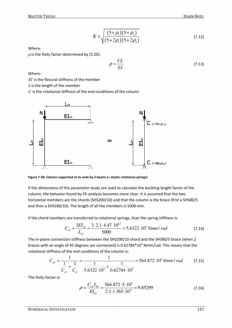
MASTER THESIS HARM BOEL
NUMERICAL INVESTIGATION 137
( ) ( )
( ) ( )1 2
1 2
5 5
5 2 5 2K
ρ ρ
ρ ρ
+ +=
+ + (7.12)
Where:
ρ is the fixity factor determined by (2.20).
CL
EIρ = (7.13)
Where:
EI is the flexural stiffness of the member
L is the length of the member
C is the rotational stiffness of the end conditions of the column
Figure 7-28: Column supported at its ends by 2 beams (= elastic rotational springs)
If the dimensions of this parameter study are used to calculate the buckling length factor of the
column, the behavior found by FE-analysis becomes more clear. It is assumed that the two
horizontal members are the chords (SHS200/10) and that the column is the brace (first a SHS80/5
and then a SHS180/10). The length of all the members is 5000 mm.
If the chord members are transferred to rotational springs, than the spring stiffness is:
12
93 3 2.1 4.47 105.6322 10 /
5000
chch
ch
EIC Nmm rad
L
⋅ ⋅ ⋅= = = ⋅ (7.14)
The in-plane connection stiffness between the SHS200/10 chord and the SHS80/5 brace (when 2
braces with an angle of 45 degrees are connected) is 0.62784*109 Nmm/rad. This means that the
rotational stiffness of the end conditions of the column is:
6
9 9
1 1564.872 10 /
1 1 1 1
5.6322 10 0.62784 10
tot
ch in
C Nmm rad
C C
= = = ⋅
+ +⋅ ⋅
(7.15)
The fixity-factor is:
9
11
564.872 5 109.85299
2.1 1.365 10
tot br
br
C L
EIρ
⋅ ⋅= = =
⋅ ⋅ (7.16)

MASTER THESIS HARM BOEL
138 PART B
This means, the buckling length factor is 0.60 (see Equation (7.17)).
( )
( )
( )
( )
2 2
2 2
5 5 9.852990.601
5 2 5 2 9.85299K
ρ
ρ
+ += = =
+ + ⋅ (7.17)
If a SHS180/10 is chosen for the column (brace), the ratio between the flexural stiffnesses as well as
the connection stiffnesses will change as calculated below.
The spring stiffness representing the chords flexural stiffness does not change and is 5.6322*109
Nmm/rad. The connection stiffness between the SHS200/10 chord and the SHS180/10 braces is
24.80814*109 Nmm/rad. This means the total rotational stiffness becomes:
6
9 9
1 14590.11 10 /
1 1 1 1
5.6322 10 24.80814 10
tot
ch in
C k Nmm rad
C C
= = = = ⋅
+ +⋅ ⋅
(7.18)
This rotational stiffness is 8.12 times higher than the stiffness for the combination with a SHS80/5
brace, while the connection stiffness is increased by a factor 39.51.
Besides the change in connection stiffness, the flexural stiffness of the column itself is also increased
by a factor 23.38, which means the flexibility-factor becomes:
9
11
4590.11 5 103.42383
2.1 31.92 10
tot br
br
C L
EIρ
⋅ ⋅= = =
⋅ ⋅ (7.19)
Now, the buckling length factor is:
( )
( )
( )
( )
2 2
2 2
5 5 3.423830.711
5 2 5 2 3.42383K
ρ
ρ
+ += = =
+ + ⋅ (7.20)
It can be seen that an increase of β causes an increase of the connection stiffness. But the increase
of the connection stiffness does not mean a proportional increment in the total rotational stiffness
of the end conditions. Besides that, the flexural stiffness of the column also increases when a larger
value for β is used. Because of these changes in stiffnesses, the fixity factor decreases when β
increases which means an increase in buckling length factor.
Now, it has been made clear that both the buckling resistance of the brace as well as the braces
flexural stiffness increase when β increases. Both values are used in the formula to determine the
buckling length, namely Equation (7.21).
2
cr
cr
EIL
N
π= (7.21)

MASTER THESIS HARM BOEL
NUMERICAL INVESTIGATION 139
Here, it can be seen that a larger buckling load means a smaller buckling length and that a larger
flexural stiffness means a larger buckling length. If the flexural stiffness increases more than the
buckling load when increasing β, than the buckling length increases, which also increases the
buckling length factor.
7.2.3.6 Comparison In- and Out-of-plane buckling
In general, out-of-plane buckling occurred before in-plane buckling, which means the out-of-plane
buckling length factors are slightly higher than the in-plane buckling length factors. In some cases,
mainly for small values of β, in-plane buckling occurred before out-of-plane buckling did.
In Table 7-15 and Figure 7-29 a comparison is made between the in- and out-of-plane buckling
length factors of chord members.
Table 7-15: Buckling length factors for a RHS200/10 chord (γγγγ = 10) connected to SHS braces
Chord: β
K
SHS… in out
50/4 0.25 - -
80/5 0.4 0.87 0.88
100/6.3 0.5 0.86 0.88
120/7.1 0.6 0.84 0.86
150/8 0.75 0.75 0.81
180/10 0.9 0.66 0.75
200/12.5 1 0.61 0.70
Figure 7-29: Buckling length factors for a RHS200/10 chord (γγγγ = 10) connected to SHS braces
In Table 7-16 and Figure 7-30 a comparison is made between the in- and out-of-plane buckling
length factors of brace members.
Table 7-16: Buckling length factors for CHS braces connected to a RHS200/16 chord (γγγγ = 6.25)
Chord: β
K
SHS… in out
50/4 0.25 - -
80/5 0.4 0.87 0.88
100/6.3 0.5 0.86 0.88
120/7.1 0.6 0.84 0.86
150/8 0.75 0.75 0.81
180/10 0.9 0.66 0.75
200/12.5 1 0.61 0.70

MASTER THESIS HARM BOEL
140 PART B
Figure 7-30: In- and out-of-plane buckling length factors for CHS braces connected to a RHS200/16 chord (γγγγ = 6.25)
7.2.3.7 Comparison different Section Type Combinations
Because the Dutch code (NEN6771) makes a distinction in section type combination when reducing
the buckling length, the influence of this parameter is investigated (according to the Dutch code, K =
0.75 for in- and out-of-plane buckling of the brace if a RHS chord and brace is used with β ≥ 0.6, or a
CHS chord and brace is used with β ≥ 0.5).
Results obtained by FE-analyses are compared to see if the combination of different section types
influences the buckling length factor. Hereby, it must be mentioned that the CHS chord has a slightly
different value for γ compared to the SHS chord.
For in- and out-of-plane buckling of the chord member, the buckling length factors for the
combination of SHS chords to SHS braces and of CHS chords connected to CHS braces are very
similar. The buckling length factors for the combination of SHS chords and CHS braces are slightly
higher (see Figure 7-31 and Table 7-17).
Table 7-17: In-plane buckling length factors of chord members with a wall thickness of 10 mm
Brace: β
SHS - SHS Brace: β
SHS - CHS Brace: β
CHS - CHS
SHS… K CHS… K CHS… K
50/4 0.25 - 48.3/4 0.24 - 48.3/4 0.25 -
80/5 0.4 0.87 76.1/5 0.38 - 76.1/5 0.39 0.86
100/6.3 0.5 0.86 114.3/6.3 0.57 0.88 114.3/6.3 0.59 0.83
120/7.1 0.6 0.84 121/7.1 0.61 0.85 121/7.1 0.62 0.80
150/8 0.75 0.75 152.4/8 0.76 0.81 152.4/8 0.79 0.72
180/10 0.9 0.66 177.8/10 0.89 0.75 177.8/10 0.92 0.65
200/12.5 1 0.61 193.7/12.5 0.97 0.69 193.7/12.5 1 0.61

MASTER THESIS HARM BOEL
NUMERICAL INVESTIGATION 141
Figure 7-31: In-plane buckling length factors of chord members with a wall thickness of 10 mm
For in and out-of-plane buckling of brace members, the buckling length factors of all section type
combinations are very similar (see Figure 7-32 and Table 7-18). It seems that the distinction made by
the Dutch code is not correct, when considering the FE-results. For in-plane buckling of braces
connected to chords with a wall thickness of 6.3 mm, CHS braces connected to CHS chords show
lower buckling length factors for a small value of β than other section type combinations.
Table 7-18: Out-of-plane buckling length factors of braces connected to chords with a wall thickness of 16 mm
Brace: β
SHS - SHS Brace: β
SHS - CHS Brace: β
CHS - CHS
SHS… K CHS… K CHS… K
50/4 0.25 0.57 48.3/4 0.24 0.56 48.3/4 0.25 0.56
80/5 0.4 0.58 76.1/5 0.38 0.57 76.1/5 0.39 0.58
100/6.3 0.5 0.60 114.3/6.3 0.57 0.60 114.3/6.3 0.59 0.61
120/7.1 0.6 0.63 121/7.1 0.61 0.61 121/7.1 0.62 0.63
150/8 0.75 0.71 152.4/8 0.76 0.69 152.4/8 0.79 0.74
180/10 0.9 0.84 177.8/10 0.89 0.77 177.8/10 0.92 0.85
200/12.5 1 - 193.7/12.5 0.97 0.81 193.7/12.5 1 0.76
Figure 7-32: Out-of-plane buckling length factors for braces connected to chords with a wall thickness of 16 mm

MASTER THESIS HARM BOEL
142 PART B
7.2.3.8 Influence of Length of Lattice Girder
As mentioned before, the basic geometry is varied by adding and removing one panel. In Figure
7-33, Lattice Girder 1 to 3 (LG1 to LG3) are shown. LG2 is the basic case. Characteristics of these
lattice girders are summarized in Table 7-19.
Figure 7-33: Different lengths of lattice girders
Table 7-19: Characteristics of Lattice Girders
Characteristic LG1 LG2 LG3
Number of panels 4 5 6
Span (mm) 38400 48000 57600
Height/Span 1/8 1/10 1/12
In the graphs it can be seen that the length of the lattice girder, the number of panels and/or the
slenderness of the lattice girder has no significant influence on the buckling length factor for in-plane
and out-of-plane buckling of both chord and brace members. See for example Figure 7-34 and Figure
7-35, accompanied by Table 7-20 and Table 7-21, respectively.
In some cases, especially for larger values of β and γ, there is a large difference. But since there’s no
clear pattern found, it cannot be said that the length, number of panels or slenderness of the girder
is of significant influence on the buckling length factors of chords and braces.

MASTER THESIS HARM BOEL
NUMERICAL INVESTIGATION 143
Table 7-20: In-plane buckling length factors for a CHS193.7/6.3 chord (γγγγ = 15.37)
Brace: β
K
CHS… LG1 LG2 LG3
48.3/4 0.25 - - -
76.1/5 0.39 0.89 0.81 0.85
114.3/6.3 0.59 0.83 0.80 0.82
121/7.1 0.62 0.80 0.77 0.79
152.4/8 0.79 0.71 0.69 0.71
177.8/10 0.92 0.64 0.63 0.64
193.7/12.5 1 0.60 0.59 0.60
Figure 7-34: In-plane buckling length factors for a CHS193.7/6.3 chord (γγγγ = 15.37) connected to CHS braces
Table 7-21: Out-of-plane buckling length factors for SHS braces connected to a SHS200/10 chord (γγγγ = 10)
Brace: β
K
RHS… LG1 LG2 LG3
50/4 0.25 0.58 0.58 0.57
80/5 0.4 0.62 0.61 0.60
100/6.3 0.5 0.64 0.64 0.63
120/7.1 0.6 0.67 0.70 0.67
150/8 0.75 0.75 0.81 0.79
180/10 0.9 0.81 0.98 0.87
200/12.5 1 0.74 0.74 -
Figure 7-35: Out-of-plane buckling length factors for SHS braces connected to a SHS200/10 chord (γγγγ = 10)

MASTER THESIS HARM BOEL
144 PART B
7.2.3.9 Influence of horizontal supports
Up till now, all results that are discussed were related to members in lattice girders which were
supported out-of-plane in every joint on the upper chord. To see if the number of lateral supports
influences the buckling length factor, FE-analyses have been done on the basic geometry (LG2)
without lateral supports (except for the end supports).
In chapter 6 it is already mentioned that the out-of-plane stiffness does not influence the in-plane
buckling behavior. For this reason, only out-of-plane buckling length factors are compared.
The buckling length factors for the brace members can be determined the same way as done before.
But, because the axial force in the chord member is not constant over the unsupported length, a
buckling length factor cannot be determined as easy as done before. This will be discussed later.
First, buckling of the brace members is considered.
Out-of-plane buckling of the brace:
In general, there is no significant difference between the buckling length factors for laterally
supported or unsupported lattice girders. Except for when β = 0.25. The buckling length factor of the
braces in laterally unsupported lattice girders is significantly higher than for braces in laterally
supported lattice girders. This is probably because chord and brace buckle simultaneously.
Furthermore, large differences are present incidentally, but there’s no clear pattern. See for example
Figure 7-36 and Table 7-22
Table 7-22: Out-of-plane buckling length factors for laterally supported and unsupported SHS braces connected to a
SHS200/10 chord (γγγγ = 10)
Brace: β
… lateral supports
RHS… With Without
50/4 0.25 0.58 0.70
80/5 0.4 0.61 0.60
100/6.3 0.5 0.64 0.64
120/7.1 0.6 0.70 0.69
150/8 0.75 0.81 0.80
180/10 0.9 0.98 0.83
200/12.5 1 0.74 -
Figure 7-36: Out-of-plane buckling length factors of laterally supported and unsupported SHS braces connected to a
SHS200/10 chord

MASTER THESIS HARM BOEL
NUMERICAL INVESTIGATION 145
Out-of-plane buckling of the chord:
As mentioned before, the buckling length factors of the chord member cannot be determined as
done before because the axial force is not constant over its length as shown in Figure 7-37.
Figure 7-37: Axial forces in upper chord when loaded with unity load
To see to what extend the buckling resistance is enhanced by the presence of braces, the buckling
resistance of a chord, loaded as shown in Figure 7-37, must be known. Therefore, the shown
situation is modeled and a buckling load is obtained. It appears that for this particular case, the
buckling load can be determined by (7.22), which is the load in the middle of the chord. Hereby, the
buckling length factor is 1, because in this case the chord is simply supported.
( )
2 2
222.01856 2.01856
cr
EI EIN
L KL
π π= = (7.22)
Now, the buckling loads obtained by FE-analysis can be used to determine an out-of-plane buckling
length factor for the chord by (7.23).
2
22.01856
cr
EIK
N L
π= (7.23)
In Table 7-23 and Figure 7-38 it can be seen that an increase in β means a decrease in buckling
length factor. This can be explained by knowing that a larger β means a higher flexural stiffness of
the brace and a higher connection stiffness. It can also be seen that γ has little influence on the
buckling length factor. For a very large value of β, the buckling length factor is often near 0.5 and is
even lower than that in one case.
Table 7-23: Out-of-plane buckling length factors of laterally unsupported chord (SHS200 chord and SHS braces)
Brace:
SHS… β
Chord: SHS200/…
6.3 10 16
50/4 0.25 1.14 1.24 1.37
80/5 0.4 0.82 0.85 0.90
100/6.3 0.5 0.73 0.75 0.77
120/7.1 0.6 0.68 0.69 0.71
150/8 0.75 0.61 0.62 0.64
180/10 0.9 0.53 0.56 0.58
200/12.5 1 0.48 0.51 -

MASTER THESIS HARM BOEL
146 PART B
Figure 7-38: Out-of-plane buckling length factors of laterally unsupported chord (SHS200 chord and SHS braces)
It is really remarkable that the buckling resistance of the chord connected to very small braces, is
less than when no braces are connected (single beam). This could be explained by the fact that
buckling of the brace member also occurs and initiates buckling of the chord member, as shown in
Figure 7-39. For almost each case that β = 0.25, the brace buckled which probably causes the chord
to bend/buckle. This can also be seen when considering the buckling length factor of the braces. The
buckling length factors are relatively high for when β = 0.25. For higher values of β, the buckling
resistance of the chord is significantly enlarged by the presence of braces. Hereby, the chord buckled
without buckling of a brace occurred.
Figure 7-39: Buckling of brace initiating buckling/bending of chord (SHS200/16 chord, SHS50/4 brace)

MASTER THESIS HARM BOEL
NUMERICAL INVESTIGATION 147
7.3 Testing theory on buckling length factor
In section 4.2, a buckling length factor is assigned to a member in a lattice girder when that
particular member seemed to buckle. The buckling length factor is determined by an eigenvalue
calculation. It is desirable to verify the found eigenvalue. Besides that, it is desirable to know if the
procedure proposed in this report is correct, where the buckling length factor can be used for the
calculation for the limit load of that particular member according to the Eurocode.
To verify the found eigenvalues, a GNIA (Geometric Non-linear Imperfect Analysis) is performed.
To test if the limit load of a member in a lattice girder can be calculated by using the found buckling
length factor and the calculation method of the Eurocode, a GMNIA (Geometric and Material Non-
linear Imperfect Analysis) is performed.
The first (GNIA) can be performed, using the same model as used for the LBA. But for the second
(GMNIA), the exact section shape must be known and non-linear material behavior must be entered.
This is not possible for the elements used for the LBA and thus the model is adjusted, using other
beam-elements.
First, the GNIA is explained. This analysis can check the buckling shape found and the accompanying
eigenvalue. Also, the GNIA is a good leg up to the GMNIA.
An example of a GNIA is given for out-of-plane buckling of a chord member, which occurred as the
first mode shape for, among others, a combination of SHS200/10 chords and SHS150/8 braces (basic
geometry). Hereafter, the GMNIA is explained using the same example. After this, several GNIA’s
and GMNIA’s are performed for, respectively, out-of-plane buckling of the brace, in-plane buckling
of the brace and combined out-of-plane buckling of brace and chord.
It must be mentioned that the geometry of the connection is not modeled. Thus, the rotational
stiffness of the connection does not change when the rotation is increased. In reality, yielding of the
joint will cause a non-linear behavior. But, because only buckling behavior is of interest here, failing
of the joint is not relevant. Change in geometry of the joint due to large deformations also may
cause a non-linear connection behavior. But, it is expected that very large rotations of the joint are
needed for the stiffness to change and that this is not of significant influence on the connection
stiffness for the investigated range of deformation.
7.3.1 GNIA
The mode shape accompanying the first eigenvalue is used as an imperfection of the geometry
(ANSYS command: UPGEOM). The magnitude of the imperfection is calculated by using the
equations given by the Dutch code (NEN6771):
( )*
0
u
u
Me
Nα λ λ= − (7.24)
Where:
λ is the slenderness determined by (7.25)
α and λ0 are the factors for the buckling curve given by the code (0.21 and 0.2 for buckling curve a)
Mu is the maximum capacity to withstand bending moment determined by (7.26)

MASTER THESIS HARM BOEL
148 PART B
Nu is the maximum axial force of the member determined by (7.27)
y
cr
Af
Nλ = (7.25)
u pl yM W f= (7.26)
u yN Af= (7.27)
Equation (7.24) is determined by using experimental results where the buckling behavior was
influenced by all sorts of imperfections such as an initially bent member, inhomogeneity and residual
stresses. Thus, e* is an imperfection, taking all these effects into account.
The unity load multiplied by the eigenvalue is used to determine the (first order elastic) buckling
load on the lattice girder. The load is gradually increased where after the load-displacement diagram
of the member that buckles is considered. The assumption that buckling occurs for the found
eigenvalue is correct if the graph shows a horizontal asymptote at the first buckling load.
The load is gradually increased by a fifth of the maximum load in 6 load steps, starting with a fifth of
the maximum load. The FE-program defines up to 40 sub-steps for each load step and uses the
Newton-Raphson method until the convergence criteria are satisfied (0.5% for both forces and
displacements) with a maximum of 10 iterations.
The maximum load, obtained by a LBA, is overrun by 20%. This is done because large translation and
rotation effects are taken into account which may cause the force deflection diagram to overrun the
found eigenvalue. Also, if the eigenvalue found is not correct for any reason (too low for instance),
the force deflection diagram will show this immediately.
Out-of-plane buckling of the chord member (between connections) is the first mode shape for,
among others, a combination of SHS200/10 chords and SHS150/8 braces (basic geometry, laterally
supported). The imperfection is calculated by (7.24) and is 13.87 mm. Other variables which are
determinant for the imperfection can be seen in Table 7-24.
Table 7-24: Properties of the SHS200/10 chord
Variable Value Unity Variable Value Unity
E 210000 N/mm² A 7600 mm²
fy 275 N/mm² I 4585 ·104 mm4
Lsys 9373 mm Ncr 1649 kN
K 0.81 - Npl 2090 kN
Lcr 7592 mm Wpl 542 ·103 mm3
λ 1.13 - Mpl 149 kNm
e* 13.87 mm
In Figure 7-40, a force deflection diagram is shown. On the horizontal axis, the out-of-plane
deflection of the middle of the chord member is shown and on the vertical axis the total load on the
lattice girder. It can clearly be seen that the critical load, determined by a LBA, is overrun. A moment

MASTER THESIS HARM BOEL
NUMERICAL INVESTIGATION 149
later, no stable equilibrium can be found by the FE-program and the calculation is aborted at a load
7.1% higher than obtained by eigenvalue extraction.
Figure 7-40: Load – deflection diagram for out-of-plane deflection of middle of chord
To see if no discretization error is made, the number of elements per member is doubled. No
significant differences were found (maximum load was 0.56% lower). It can be concluded that the
number of elements used are also enough for a GNIA (10 elements per member).
7.3.2 GMNIA
To correctly calculate physical non-linear behavior, the exact section shape must be known. The
beam-elements used (BEAM4) are not capable of doing so. Besides that, non-linear material
behavior must be entered which is also not possible with these elements. Because of this, it is
chosen to use BEAM189 elements. With BEAM189 elements, the section shape and dimensions
must be defined, where after the FE-program calculates the section area, moment of inertia, etc.
Now it is possible to correctly model rectangular and circular hollow sections and input non-linear
material behavior. It must be mentioned that the rounding in the edges of the rectangular sections
cannot be modeled. For the rigid beams, BEAM4-elements are used, which have, like in the BEAM4-
model, an area, moment of inertia and torsion constant of 100 times that of the chord member.
A bi-linear stress-strain diagram is inputted where the yield stress is 275 N/mm².
For the combination of SHS200/10 chord and SHS150/8 braces a GMNIA is performed. But because
other elements were needed to describe the material non-linearity, first a LBA and a GNIA is
performed and compared to the results obtained by the BEAM4-model. The eigenvalues in Table
7-25 and the load – deflection diagram in Figure 7-41 show that the BEAM189 model gives similar
results compared to the BEAM4-model.
Table 7-25: Comparison of eigenvalues given by different beam-element models
mode shape BEAM4 BEAM189 difference
1 269480 274168 1.74%
2 310830 316186 1.72%
3 391080 396058 1.27%
4 438380 445318 1.58%
5 481560 483060 0.31%
6 550790 552154 0.25%
7 557450 565003 1.35%

MASTER THESIS HARM BOEL
150 PART B
8 631140 636189 0.80%
9 685270 692447 1.05%
10 750730 757443 0.89%
11 806310 813126 0.85%
12 881960 888512 0.74%
13 944130 949097 0.53%
14 1031800 1039492 0.75%
15 1088700 1096407 0.71%
16 1123000 1129826 0.61%
17 1167700 1174516 0.58%
18 1250600 1263047 1.00%
19 1282200 1286702 0.35%
20 1321800 1329492 0.58%
Figure 7-41: Comparison of load – deflection diagram obtained by different beam-element models
Now, a GMNIA can be performed. The results obtained by the GNIA and the GMNIA, both by the
BEAM189 model, are shown in the load –deflection diagram in Figure 7-42.
Figure 7-42: Out-of-plane deflection of middle of chord
The FE-program finds a maximum load of 77.0 % of the load obtained by eigenvalue extraction. The
ultimate load in the chord member is 1264.96 kN. The force – deflection diagram of the chord
member is shown in Figure 7-43.

MASTER THESIS HARM BOEL
NUMERICAL INVESTIGATION 151
Figure 7-43: Force – deflection diagram for middle of upper chord
The ultimate load of the chord according to the Eurocode is calculated below. The section properties
used in the GMNIA are used to calculate the limit load because they differ somewhat compared to
the section properties used for the parameter study (obtained from tables) (see Table 7-24).
The ultimate load is calculated by using (7.28) to (7.32).
2
2( )
cr
EIN
KL
π= (7.28)
y
cr
Af
Nλ = (7.29)
( )( )211 0.2
2φ α λ λ= + − + (7.30)
2 2
1χ
φ φ λ=
+ − (7.31)
;u d yN Afχ= (7.32)
Where:
K is the buckling length factor
λ is the slenderness
α is the imperfection factor (0.21 for buckling curve a)
χ is the reduction factor for the buckling curve, which can never be larger than 1
Nu;d is the maximum axial force of the member
Table 7-26: Comparison Eurocode and FE-results
FE-output Hand-calculation (Eurocode) Difference (%)
Ncr (N) 1 642 430 1 648 836 0.39%
Nultimate (N) 1 264 960 1 209 751 - 4.36%
Nultimate / Ncr 0.77 0.73 - 5.19%

MASTER THESIS HARM BOEL
152 PART B
The ultimate load obtained from FE-analysis in the chord is almost 5% higher than calculated by the
method given by the Eurocode which means the Eurocode is slightly safe compared to the FE-
results.
7.3.3 Several other cases
The procedure of the GNIA and the GMNIA has been explained and it has been shown that the found
eigenvalue is correct and that the calculation of the ultimate load according to the Eurocode is
consistent with the ultimate load found by FE-analysis. Hereafter, a GNIA and GMNIA has been
performed for several other cases. And because it has been shown that the BEAM189-model gives
similar results compared to the BEAM4-model, the BEAM189-model is also used for the GNIA,
instead of only for the GMNIA.
7.3.3.1 Out-of-plane buckling of the brace member
Out-of-plane buckling of the brace member is the first mode shape for, among others, a combination
of CHS193.7/6.3 chords and CHS76.1/5 braces (basic geometry). The imperfection is 7.91 mm. Other
variables which are determinant for the imperfection and the calculation of the ultimate load can be
seen in Table 7-27.
Table 7-27: Variables of the CHS76.1/5 brace
Variable Value Unity Variable Value Unity
E 210000 N/mm² A 1117 mm²
fy 275 N/mm² I 71 ·104 mm4
Lsys 6566 mm Ncr 89 kN
K 0.62 - Npl 307 kN
Lcr 4071 mm Wpl 25 ·103 mm3
λ 1.86 - Mpl 7 kNm
e* 7.91 mm
Figure 7-44 shows the load (total load on lattice girder) – deflection (z-deflection in middle of brace)
diagram. The highest load is 9.36% higher than the eigenvalue. The force – deflection diagram of the
brace member is shown in Figure 7-45 and a comparison between the Eurocode and the FE-results
can be found in Table 7-28.
Figure 7-44: Load – deflection diagram for out-of-plane deflection of middle of brace

MASTER THESIS HARM BOEL
NUMERICAL INVESTIGATION 153
Figure 7-45: Force – deflection diagram for middle of brace (B2)
Table 7-28: Comparison Eurocode and FE-results
FE-output Hand-calculation (Eurocode) Difference (%)
Ncr (N) 87 585 88 695 1.27%
Nultimate (N) 78 206 78 139 - 0.09%
Nultimate / Ncr 0.89 0.88 - 1.12%
It can be seen that for this case, the difference between the limit load, obtained by FE-analysis and
hand-calculation, is negligible.
7.3.3.2 In-plane buckling of the brace member
In-plane buckling of the brace member is the first mode shape for, among others, a combination of
SHS200/6.3 chords and CHS121/7.1 braces (basic geometry). The imperfection is 9.25 mm. Other
variables which are determinant for the imperfection and the calculation of the ultimate load can be
seen in Table 7-29.
Table 7-29: Variables of the CHS76.1/5 brace
Variable Value Unity Variable Value Unity
E 210000 N/mm² A 2541 mm²
fy 275 N/mm² I 414 ·104 mm4
Lsys 6516 mm Ncr 350 kN
K 0.76 - Npl 698.658 kN
Lcr 4952 mm Wpl 92 ·103 mm3
λ 1.41 - Mpl 25 kNm
e* 9.25 mm
Figure 7-46 shows the load (total load on lattice girder) – deflection (z-deflection in middle of brace)
diagram. The highest load is 15.90% higher than the eigenvalue. The force – deflection diagram of
the brace member is shown in Figure 7-47 and a comparison between the Eurocode and the FE-
results can be found in Table 7-30.

MASTER THESIS HARM BOEL
154 PART B
Figure 7-46: Load – deflection diagram for in-plane deflection of middle of brace (deflection in x-direction)
Figure 7-47: Force – deflection diagram for middle of brace (B2)
Table 7-30: Comparison Eurocode and FE-results
FE-output Hand-calculation (Eurocode) Difference (%)
Ncr (N) 349 938 349 568 - 0.11%
Nultimate (N) 282 634 287 329 1.66%
Nultimate / Ncr 0.81 0.82 1.24%
7.3.3.3 Combined buckling of chord and brace (out-of-plane)
Simultaneous buckling of the chord and brace member occurred for a combination of SHS200/10
chords and SHS120/7.1 braces. The imperfection is different for the two members but only one
imperfection can be inputted. According to a GNIA, with an assumed imperfection of 9.42 mm (one
thousandth of the chord system length), it appears that the deflection of the middle of the chord is
the largest and is 1.29 times the displacement of the middle of the brace. Thus, the imperfection
inputted is the imperfection of the chord member and the brace member will have an imperfection
1.29 times smaller than that. Variables to determine the imperfection for the chord and the brace
can be seen in Table 7-31 and Table 7-32, respectively.
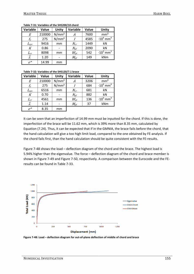
MASTER THESIS HARM BOEL
NUMERICAL INVESTIGATION 155
Table 7-31: Variables of the SHS200/10 chord
Variable Value Unity Variable Value Unity
E 210000 N/mm² A 7600 mm²
fy 275 N/mm² I 4585 ·104 mm4
Lsys 9416 mm Ncr 1449 kN
K 0.86 - Npl 2090 kN
Lcr 8098 mm Wpl 542 ·103 mm3
λ 1.20 - Mpl 149 kNm
e* 14.99 mm
Table 7-32: Variables of the SHS120/7.1 brace
Variable Value Unity Variable Value Unity
E 210000 N/mm² A 3206 mm²
fy 275 N/mm² I 684 ·104 mm4
Lsys 6516 mm Ncr 681 kN
K 0.70 - Npl 882 kN
Lcr 4561 mm Wpl 136 ·103 mm3
λ 1.14 - Mpl 37 kNm
e* 8.35 mm
It can be seen that an imperfection of 14.99 mm must be inputted for the chord. If this is done, the
imperfection of the brace will be 11.62 mm, which is 39% more than 8.35 mm, calculated by
Equation (7.24). Thus, it can be expected that if in the GMNIA, the brace fails before the chord, that
the hand calculation will give a too high limit load, compared to the one obtained by FE-analysis. If
the chord fails first, than the hand calculation should be quite consistent with the FE-results.
Figure 7-48 shows the load – deflection diagram of the chord and the brace. The highest load is
5.94% higher than the eigenvalue. The force – deflection diagram of the chord and brace member is
shown in Figure 7-49 and Figure 7-50, respectively. A comparison between the Eurocode and the FE-
results can be found in Table 7-33.
Figure 7-48: Load – deflection diagram for out-of-plane deflection of middle of chord and brace

MASTER THESIS HARM BOEL
156 PART B
Figure 7-49: Force – deflection diagram of the Chord
Figure 7-50: Force – deflection diagram of the brace
Table 7-33: Comparison Eurocode (hand calculation) and FE-results
FE-output Hand-calculation Difference (%)
Nultimate Brace (N) 1 057 390 1 106 556 4.65%
Nultimate Chord (N) 497 472 503 066 1.12%
According to the Eurocode, the maximum load of the brace is 503066 N and on the chord is 1106556
N. The load in the brace and the chord after performing a static analysis is 2.81629 and 5.99191 N,
respectively. If a linear relationship is assumed for the load and the force in the members, then the
brace and the chord would fail at a load-multiplication factor of 178627 and 184675, respectively.
Thus, the brace will fail first.
FE-analysis gave a maximum multiplication factor of 176647. The maximum load in the brace and
the chord was 1057390 and 497472 N, respectively. Both are very close to the hand-calculated limit
load. It is not clear which member has failed. It is possible that, just like first order buckling, failing of
the brace and chord member occurred simultaneously.

MASTER THESIS HARM BOEL
NUMERICAL INVESTIGATION 157
7.4 Scaling dimensions and changing brace wall thickness
In this investigation, the relationship between β and the buckling length factor is shown. This
suggests that the dimensions do not matter, as long as β is the same.
But, in the calculations in section 7.2.3.5 it is made clear that the buckling length factor is dependent
on the flexural stiffness of the member itself and the rotational stiffness of the end conditions of
that member. To see what happens to the buckling length factor when other dimensions are used,
but with the same value for β, two calculations are made.
7.4.1 Scaling of the dimensions
If the chord and brace member dimensions are scaled by a factor 2, than β will still be the same.
But, the slenderness of the members will change because the length is not changed. Also, the
flexural stiffnesses are changed. It is possible that this might influence the buckling length factor.
To test this, the combination of SHS200/10 chords and SHS100/6.3 braces is scaled by a factor 2. The
chord dimension is now SHS400/20 and the braces are a SHS200/12.6 (gap = 25.2 mm). Now, the
same values are used for β and γ. The same basic geometry is used to perform the buckling analysis.
The connection stiffnesses are shown in Table 7-34 and compared to the connection stiffnesses
between the SHS200/10 chord and the SHS100/6.3 braces. The buckling length factors are compared
in Table 7-35.
Table 7-34: Comparison connection stiffnesses for different dimensions
SHS200/10 – SHS100/6.3 SHS400/20 – SHS200/12.6 Difference (%)
Cin (kNm/rad) 1133.3 9306.68 721.2
Cout (kNm/rad) 2247.05 18553.04 725.7
Table 7-35: Comparison buckling length factors for different dimensions used
K SHS200/10 – SHS100/6.3 SHS400/20 – SHS200/12.6 Difference (%)
Chord in-plane 0.86 0.89 3.49
Chord out-of-plane 0.88 0.89 1.14
Brace in-plane 0.61 0.67 9.84
Brace out-of-plane 0.64 0.68 6.25
It can be seen that the connection stiffnesses are more than 8 times higher than before. Also, the
buckling length factors are higher. The buckling length factors for the chord are not influenced
much, but the buckling length factors of the brace increased significantly.
Apparently, β and γ are not enough to determine the connection stiffnesses. Also the buckling
length factor is dependent on more variables. Maybe a flexural stiffness to length ratio of the
members should be determined, or the length of the member should be taken into account like
done in the formulae given by CIDECT.
7.4.2 Wall thickness of the brace
If the wall thickness of the brace is changed, then β and γ are still the same. Also, it is expected that
the connection stiffness does not differ much. But, the flexural stiffness of the brace does change.
And if the end-conditions then do not change, the buckling length factor is probably also different.

MASTER THESIS HARM BOEL
158 PART B
To test this, SHS100/12.5 instead of SHS100/6.3 braces are used, in combination with SHS200/10
chords (gap = 25 mm). The connection stiffnesses are shown in Table 7-36 and compared to the
connection stiffnesses between the SHS200/10 chord and the SHS100/6.3 braces. The buckling
length factors are compared in Table 7-37.
Table 7-36: Comparison connection stiffnesses for different dimensions
SHS200/10 – SHS100/6.3 SHS200/10 – SHS100/12.5 Difference (%)
Cin (kNm/rad) 1133.3 1121.36 -1.05
Cout (kNm/rad) 2247.05 2065.74 -8.07
Table 7-37: Comparison buckling length factors for different dimensions used
K SHS200/10 – SHS100/6.3 SHS200/10 – SHS100/12.5 Difference (%)
Chord in-plane 0.86 0.82 -4.65
Chord out-of-plane 0.88 0.85 -3.41
Brace in-plane 0.61 0.67 9.84
Brace out-of-plane 0.64 0.69 7.81
It can be seen that, as expected, the connection stiffnesses do not change significantly. The buckling
length factors of the chord have decreased and the buckling length factors of the brace have
increased.
Apparently, the increase in flexural stiffness of the brace provides the chord of more support. The
brace is then supported less by the chord because it is stiffer itself.
7.4.3 Conclusion
In this section, it has been shown that it is possible for buckling length factors of members to differ,
even when the same value for β and γ are used. This means simple formulae to accurately calculate
the buckling length of a member in a lattice girder can never exist, unless they are somewhat
conservative, giving the engineer a safe approximation of the buckling length factor.
In the next chapter, it is tried to develop such formulae, partially based on the existing CIDECT-
formulae.
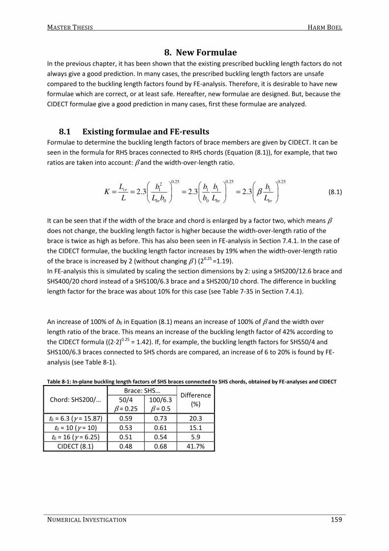
MASTER THESIS HARM BOEL
NUMERICAL INVESTIGATION 159
8. New Formulae In the previous chapter, it has been shown that the existing prescribed buckling length factors do not
always give a good prediction. In many cases, the prescribed buckling length factors are unsafe
compared to the buckling length factors found by FE-analysis. Therefore, it is desirable to have new
formulae which are correct, or at least safe. Hereafter, new formulae are designed. But, because the
CIDECT formulae give a good prediction in many cases, first these formulae are analyzed.
8.1 Existing formulae and FE-results
Formulae to determine the buckling length factors of brace members are given by CIDECT. It can be
seen in the formula for RHS braces connected to RHS chords (Equation (8.1)), for example, that two
ratios are taken into account: β and the width-over-length ratio.
0.25 0.25 0.252
1 1 1 1
0 0
2.3 2.3 2.3cr
br br br
L b b b bK
L L b b L Lβ
= = = =
(8.1)
It can be seen that if the width of the brace and chord is enlarged by a factor two, which means β
does not change, the buckling length factor is higher because the width-over-length ratio of the
brace is twice as high as before. This has also been seen in FE-analysis in Section 7.4.1. In the case of
the CIDECT formulae, the buckling length factor increases by 19% when the width-over-length ratio
of the brace is increased by 2 (without changing β ) (20.25 =1.19).
In FE-analysis this is simulated by scaling the section dimensions by 2: using a SHS200/12.6 brace and
SHS400/20 chord instead of a SHS100/6.3 brace and a SHS200/10 chord. The difference in buckling
length factor for the brace was about 10% for this case (see Table 7-35 in Section 7.4.1).
An increase of 100% of b0 in Equation (8.1) means an increase of 100% of β and the width over
length ratio of the brace. This means an increase of the buckling length factor of 42% according to
the CIDECT formula ((2·2)0.25 = 1.42). If, for example, the buckling length factors for SHS50/4 and
SHS100/6.3 braces connected to SHS chords are compared, an increase of 6 to 20% is found by FE-
analysis (see Table 8-1).
Table 8-1: In-plane buckling length factors of SHS braces connected to SHS chords, obtained by FE-analyses and CIDECT
Chord: SHS200/…
Brace: SHS… Difference
(%) 50/4
β = 0.25
100/6.3
β = 0.5
t0 = 6.3 (γ = 15.87) 0.59 0.73 20.3
t0 = 10 (γ = 10) 0.53 0.61 15.1
t0 = 16 (γ = 6.25) 0.51 0.54 5.9
CIDECT (8.1) 0.48 0.68 41.7%

MASTER THESIS HARM BOEL
160 PART B
It can also be seen that if the wall thickness of the chord changes, the buckling length factor does
not change according to the CIDECT formula. In FE-analysis it has been found that an increase of the
chord wall thickness from 6.3 to 10 mm, the buckling length factor decreases by 8 to 16% (see Table
8-2).
Table 8-2: In-plane buckling length factors of SHS braces connected to SHS chords obtained by FE-analyses
Brace:
SHS… β
t0 = 6.3
(γ = 15.87)
t0 = 10
(γ = 10)
Difference
(%)
50/4 0.25 0.59 0.53 -10.2
80/5 0.4 0.68 0.57 -16.2
100/6.3 0.5 0.73 0.61 -16.4
120/7.1 0.6 0.74 0.68 -8.1
150/8 0.75 0.81 0.68 -16.0
180/10 0.9 0.66 0.77 16.7

MASTER THESIS HARM BOEL
NUMERICAL INVESTIGATION 161
8.2 Developing new formulae
Although the CIDECT formulae do not take every factor into account (correctly) when calculating the
buckling length factor, these formulae are a good prediction for many cases, even outside the range
of applicability. But, for very low values of β and for large values of γ (small values of t0), the
formulae can be unsafe. Therefore, it is tried to adjust these formulae so that a better
approximation of the buckling length factor can be obtained.
8.2.1 In-plane buckling of brace
In this section, new formulae to determine the in-plane buckling length factors for brace members
are developed. This is done per section type combination. First, SHS braces connected to SHS chords
are considered. Hereafter, the developed formula is adjusted for other section type combinations.
8.2.1.1 SHS braces connected to SHS chords
First, the influence of change in β and width-to-length ratio is adjusted. According to FE-analysis, the
buckling length factor would increase by approximately 10% when either β or the width-to-length
ratio is increased by 100%. This can be achieved when altering the power 0.25 to 0.14 in Equation
(8.1). Secondly, the buckling length factor can never be smaller than 0.5. It is assumed that the
buckling length factor should be approximately 0.6 for β = 0.25 because the highest buckling length
factor in Table 8-2 is 0.59. This can be achieved by altering the CIDECT formula for SHS braces
connected to SHS chords into Equation (8.2).
0.14
11.5cr
br
L bK
L Lβ
= =
(8.2)
When comparing the outcome of this equation to the FE-results, it can be seen that this formula
gives a safe approximation of the buckling length factor (see Table 8-3 and Figure 8-1).
Table 8-3: In-plane buckling length factors (SHS braces connected to SHS chords)
Brace:
SHS… β
t0 = 6.3
(γ = 15.87)
t0 = 10
(γ = 10)
t0 = 16
(γ = 6.25)
Equation
(8.2)
50/4 0.25 0.59 0.53 0.51 0.62
80/5 0.4 0.68 0.57 0.53 0.71
100/6.3 0.5 0.73 0.61 0.54 0.76
120/7.1 0.6 0.74 0.68 0.59 0.80
150/8 0.75 0.81 0.68 0.66 0.85
180/10 0.9 0.66 0.77 0.67 0.90
200/12.5 1.0 - - - 0.92
Figure 8-1: In-plane buckling length factors of SHS braces (connected to SHS chords)

MASTER THESIS HARM BOEL
162 PART B
It can be seen that although the formula is safe compared to the FE-results, it is also very
conservative for smaller values of γ. And because it is desirable to be able to take the influence of γ
into account, Equation (8.2) is changed into Equation (8.3). Hereby, it is tried to give an accurate, but
safe prediction of the buckling length factor. The outcome of this formula is compared to the FE-
results in Table 8-4 and Figure 8-2 (in the tables and figures, Equation (8.3) and other formulae given
in this chapter are referred to as the formulae given by the Author). It can be seen that the formula
gives a good prediction of the buckling length factors. The accuracy of the formulae presented by the
Author is shown in section 8.4.
( )0.14
11.05 0.025 0.5cr
br
L bK
L Lγ β
= = + ≥
(8.3)
Where:
1
0
b
bβ = (8.4)
Table 8-4: In-plane buckling length factors of brace: SHS chords – SHS braces
Lbr (mm)
Brace:
SHS… β
γ = 15.87 γ = 10 γ = 6.25
FE-results Author
(8.3) FE-results
Author
(8.3) FE-results
Author
(8.3)
6588 50/4 0.25 0.59 0.60 0.53 0.54 0.51 0.50
6557 80/5 0.4 0.68 0.69 0.57 0.62 0.53 0.57
6537 100/6.3 0.5 0.73 0.73 0.61 0.66 0.54 0.61
6517 120/7.1 0.6 0.74 0.77 0.68 0.69 0.59 0.64
6486 150/8 0.75 0.81 0.82 0.68 0.74 0.66 0.68
6454 180/10 0.9 0.66 0.86 0.77 0.78 0.67 0.72
6432 200/12.5 1 - 0.89 - 0.80 - 0.74
Figure 8-2: In-plane buckling length factors of brace: SHS chords – SHS braces

MASTER THESIS HARM BOEL
NUMERICAL INVESTIGATION 163
8.2.1.2 CHS braces connected to SHS chords
When CHS braces are connected to SHS chords, Equation (8.3) gives a somewhat conservative
prediction of the buckling length factor for lower values of γ. Therefore, the formula is adjusted into
Equation (8.5). The outcome of this formula and the results obtained by FE-analysis are compared in
Table 8-5 and Figure 8-3.
( )0.14
10.95 0.03 0.5cr
br
L dK
L Lγ β
= = + ≥
(8.5)
Where:
1
0
d
bβ = (8.6)
Table 8-5: In-plane buckling length factors of brace: SHS chords – CHS braces
Lbr (mm)
Brace:
CHS… β
γ = 15.87 γ = 10 γ = 6.25
FE-
results Author
(8.5) FE-
results Author
(8.5) FE-
results Author (8.5)
6589 48.3/4 0.24 0.57 0.59 0.52 0.51 0.51 0.47 � 0.50
6561 76.1/5 0.38 0.66 0.67 0.56 0.59 0.52 0.53
6523 114.3/6.3 0.57 0.74 0.75 0.62 0.66 0.55 0.60
6516 121/7.1 0.61 0.76 0.76 0.63 0.67 0.56 0.61
6484 152.4/8 0.76 0.81 0.81 0.68 0.71 0.59 0.65
6456 177.8/10 0.89 0.78 0.85 0.75 0.74 0.65 0.68
6438 193.7/12.5 0.97 0.80 0.87 0.77 0.76 0.66 0.69
Figure 8-3: In-plane buckling length factors of brace: SHS chords – CHS braces

MASTER THESIS HARM BOEL
164 PART B
8.2.1.3 CHS braces connected to CHS chords
When CHS braces are connected to CHS chords, the buckling length factor seems to increase
exponentially when β increases linearly. To achieve this, the power 0.14 in the previous formula is
removed. Furthermore, the formula is adjusted to fit the results found by FE-analysis. Although for
larger values of β the buckling length factors are somewhat higher than obtained by FE-analysis,
Equation (8.7) seems to give a good prediction of the in-plane buckling length factor (see Table 8-6
and Figure 8-4).
( ) 12.5 0.50 1cr
br
L dK
L Lγ β
= = + + ≤
(8.7)
Where:
1
0
d
dβ = (8.8)
Table 8-6: In-plane buckling length factors of brace: CHS chords – CHS braces
Lbr (mm)
Brace:
CHS… β
γ = 15.37 γ = 9.69 γ = 6.05
FE-
results
Author
(8.7)
FE-
results
Author
(8.7)
FE-
results
Author
(8.7)
6594 48.3/4 0.25 0.52 0.53 0.51 0.52 0.51 0.52
6566 76.1/5 0.39 0.54 0.58 0.52 0.56 0.51 0.54
6528 114.3/6.3 0.59 0.63 0.68 0.57 0.63 0.55 0.59
6520 121/7.1 0.62 0.69 0.71 0.60 0.64 0.55 0.60
6488 152.4/8 0.79 0.85 0.83 0.71 0.73 0.62 0.66
6461 177.8/10 0.92 0.87 0.95 0.79 0.81 0.68 0.72
6443 193.7/12.5 1 - 1.04 � 1 0.65 0.87 0.59 0.76
Figure 8-4: In-plane buckling length factors of brace: CHS chords – CHS braces
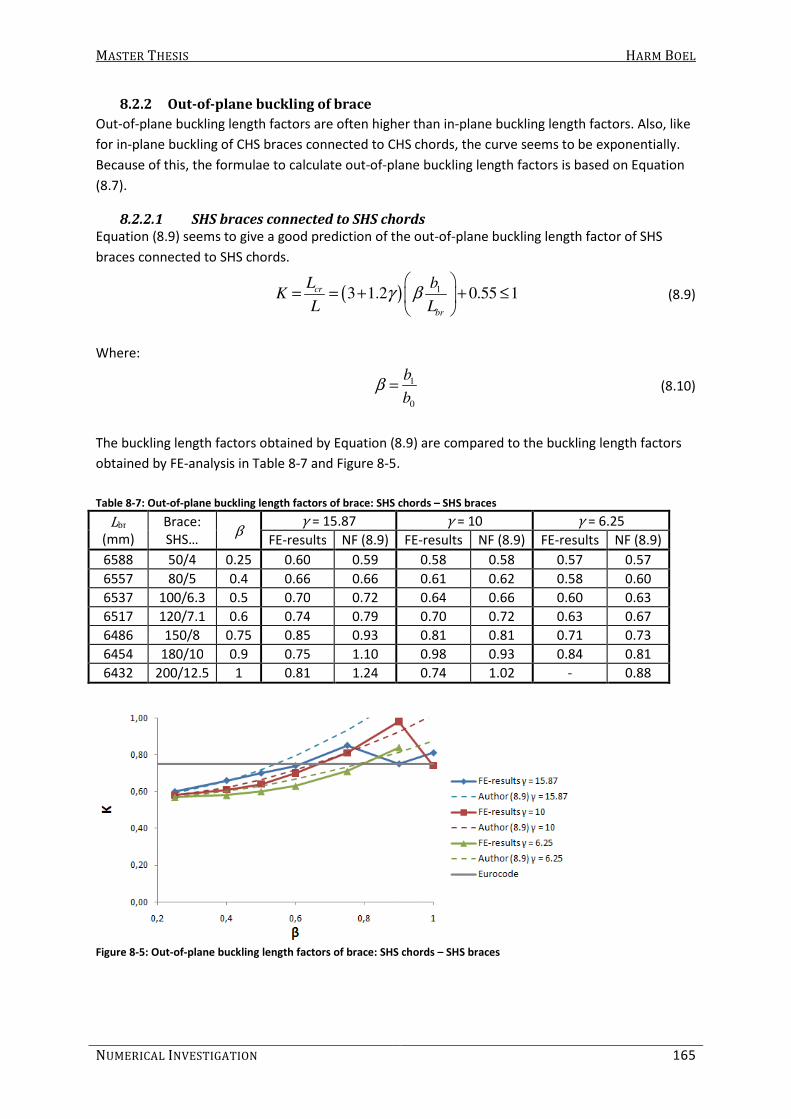
MASTER THESIS HARM BOEL
NUMERICAL INVESTIGATION 165
8.2.2 Out-of-plane buckling of brace
Out-of-plane buckling length factors are often higher than in-plane buckling length factors. Also, like
for in-plane buckling of CHS braces connected to CHS chords, the curve seems to be exponentially.
Because of this, the formulae to calculate out-of-plane buckling length factors is based on Equation
(8.7).
8.2.2.1 SHS braces connected to SHS chords
Equation (8.9) seems to give a good prediction of the out-of-plane buckling length factor of SHS
braces connected to SHS chords.
( ) 13 1.2 0.55 1cr
br
L bK
L Lγ β
= = + + ≤
(8.9)
Where:
1
0
b
bβ = (8.10)
The buckling length factors obtained by Equation (8.9) are compared to the buckling length factors
obtained by FE-analysis in Table 8-7 and Figure 8-5.
Table 8-7: Out-of-plane buckling length factors of brace: SHS chords – SHS braces
Lbr (mm)
Brace:
SHS… β
γ = 15.87 γ = 10 γ = 6.25
FE-results NF (8.9) FE-results NF (8.9) FE-results NF (8.9)
6588 50/4 0.25 0.60 0.59 0.58 0.58 0.57 0.57
6557 80/5 0.4 0.66 0.66 0.61 0.62 0.58 0.60
6537 100/6.3 0.5 0.70 0.72 0.64 0.66 0.60 0.63
6517 120/7.1 0.6 0.74 0.79 0.70 0.72 0.63 0.67
6486 150/8 0.75 0.85 0.93 0.81 0.81 0.71 0.73
6454 180/10 0.9 0.75 1.10 0.98 0.93 0.84 0.81
6432 200/12.5 1 0.81 1.24 0.74 1.02 - 0.88
Figure 8-5: Out-of-plane buckling length factors of brace: SHS chords – SHS braces

MASTER THESIS HARM BOEL
166 PART B
8.2.2.2 CHS braces connected to SHS chords
Equation (8.9) is adjusted to fit the results obtained for the out-of-plane buckling of CHS braces
connected to SHS chords. Equation (8.11) gives a good prediction of the buckling length factor,
except for larger values of β. But, the formula is considered to be accurate enough, because buckling
of the brace is determinate for smaller values of β and for these situations the Equation (8.11) does
give a good prediction. In Table 8-8 and Figure 8-6, the buckling length factors obtained by FE-
analysis and by Equation (8.11) are compared.
( ) 13 1.2 0.55 1cr
br
L dK
L Lγ β
= = + + ≤
(8.11)
Where:
1
0
d
bβ = (8.12)
Table 8-8: Out-of-plane buckling length factors of brace: SHS chords – CHS braces
Lbr (mm)
Brace:
CHS… β
γ = 15.87 γ = 10 γ = 6.25
FE-results Author
(8.11) FE-results
Author
(8.11) FE-results
Author
(8.11)
6589 48.3/4 0.24 0.59 0.58 0.57 0.57 0.56 0.56
6561 76.1/5 0.38 0.64 0.63 0.59 0.60 0.57 0.58
6523 114.3/6.3 0.57 0.71 0.74 0.64 0.67 0.60 0.63
6516 121/7.1 0.61 0.73 0.76 0.65 0.68 0.61 0.63
6484 152.4/8 0.76 0.81 0.89 0.70 0.76 0.69 0.68
6456 177.8/10 0.89 0.93 1.02 0.79 0.84 0.77 0.73
6438 193.7/12.5 0.97 0.95 1.10 0.95 0.90 0.81 0.77
Figure 8-6: Out-of-plane buckling length factors of brace: SHS chords – CHS braces

MASTER THESIS HARM BOEL
NUMERICAL INVESTIGATION 167
8.2.2.3 CHS braces connected to CHS chords
For CHS braces connected to CHS chords, Equation (8.13) gives a good approximation of the results.
The results obtained by this formula and by FE-analysis are compared in Table 8-9 and Figure 8-7.
( ) 15 0.55 1cr
br
L dK
L Lγ β
= = + + ≤
(8.13)
Where:
1
0
d
dβ = (8.14)
Table 8-9: Out-of-plane buckling length factors of brace: CHS chords – CHS braces
Lbr (mm)
Brace: CHS…
β
γ = 15.37 γ = 9.69 γ = 6.05
FE-results Author
(8.13) FE-results
Author
(8.13) FE-results
Author
(8.13)
6594 48.3/4 0.25 0.58 0.59 0.57 0.58 0.56 0.57
6566 76.1/5 0.39 0.62 0.64 0.59 0.61 0.58 0.60
6528 114.3/6.3 0.59 0.69 0.75 0.66 0.70 0.61 0.66
6520 121/7.1 0.62 0.74 0.78 0.66 0.71 0.63 0.67
6488 152.4/8 0.79 0.90 0.91 0.76 0.81 0.74 0.75
6461 177.8/10 0.92 0.95 1.05 0.85 0.91 0.77 0.82
6443 193.7/12.5 1 0.81 1.14 0.74 0.98 0.76 0.87
Figure 8-7: Out-of-plane buckling length factors of brace: CHS chords – CHS braces
Although the formulae described in section 8.2.1 and 8.2.2 sometimes give large differences
compared to the FE-results, they are a clear improvement of the existing formulae: The slope of the
diagram is given much better and the chord wall thickness is taken into account. The buckling length
can be reduced more than prescribed by the codes, but is not unsafe for larger values of β. This
makes these formulae a better tool than the rules provided by the Eurocode.

MASTER THESIS HARM BOEL
168 PART B
8.2.3 In-plane buckling of chord
CIDECT does not provide simple formulae to determine the buckling length factor of the chord. The
Eurocode gives a buckling length factor of 0.9. This seems to be a good prediction of the buckling
length factor. But, for larger values of β, a factor of 0.9 is somewhat conservative. Therefore, simple
formulae to obtain a more accurate chord buckling length factor are designed.
It has been shown that the buckling length factor of the chord is not influenced much by the chord
wall thickness. For this reason, the chord wall thickness (or γ) is not taken into account. It has also
been shown in section 7.2.3.7 that the buckling length factors for the combination of SHS chords
connected to SHS braces and CHS chords connected to CHS braces are very similar. For this reason,
the formulae for these combinations will be the same, and other formulae will be given for the
combination of SHS chords connected to CHS braces.
8.2.3.1 SHS – SHS and CHS – CHS
In Section 7.2.3.7, it has been shown that the buckling length factors are very similar for SHS chords
connected to SHS braces and CHS chords connected to CHS braces. The buckling length factors for
in-plane buckling were not more than 0.9. For larger values of β, an even lower buckling length
factor can be applied.
For β < 0.6, the buckling length factor can be assumed 0.9. For β = 1, the buckling length factor is
between 0.58 and 0.64. If a formula is designed to give a buckling length factor of about 0.9 for β =
0.6 and 0.65 for β = 1, the formula becomes as shown in Equation (8.15). This formula gives a safe,
but still a good approximation of the buckling length factors.
In Table 8-10 and Figure 8-8, the formula is compared to the buckling length factors of SHS chords
connected to SHS braces. In Table 8-11 and Figure 8-9, the formula is compared to the buckling
length factors of CHS chords connected to CHS braces.
1.25 0.6crL
KL
β= = − (8.15)
Where for SHS chords connected to SHS braces:
1
0
b
bβ = (8.16)
And for CHS chords connected to CHS braces:
1
0
d
dβ = (8.17)
Table 8-10: In-plane buckling length factors of Chord: SHS chords – SHS braces
Lbr (mm)
Brace:
SHS… β
FE-results Author
(8.15) γ = 15.87 γ = 10 γ = 6.25
6588 50/4 0.25 - - - 0.90
6557 80/5 0.4 0.86 0.87 0.90 0.90
6537 100/6.3 0.5 0.86 0.86 0.88 0.90
6517 120/7.1 0.6 0.83 0.84 0.86 0.89
6486 150/8 0.75 0.74 0.75 0.77 0.80
6454 180/10 0.9 0.63 0.66 0.69 0.71
6432 200/12.5 1 0.58 0.61 - 0.65

MASTER THESIS HARM BOEL
NUMERICAL INVESTIGATION 169
Figure 8-8: In-plane buckling length factors of Chord: SHS chords – SHS braces
Table 8-11: In-plane buckling length factors of Chord: CHS chords – CHS braces
Lbr (mm)
Brace:
SHS… β
FE-results Author
(8.15) γ = 15.37 γ = 9.69 γ = 6.05
6594 48.3/4 0.25 - - - 0.90
6566 76.1/5 0.39 0.81 0.86 0.90 0.90
6528 114.3/6.3 0.59 0.80 0.83 0.82 0.90
6520 121/7.1 0.62 0.77 0.80 0.84 0.88
6488 152.4/8 0.79 0.69 0.72 0.76 0.78
6461 177.8/10 0.92 0.63 0.65 0.69 0.70
6443 193.7/12.5 1 0.59 0.61 0.64 0.65
Figure 8-9: In-plane buckling length factors of Chord: CHS chords – CHS braces

MASTER THESIS HARM BOEL
170 PART B
8.2.3.2 SHS braces connected to CHS chords
In Section 7.2.3.7, it has been shown that the buckling length factors for SHS chords connected to
CHS braces are somewhat higher than for other section type combinations. For this reason, the
formulae to calculate the buckling length factor for SHS chords connected to CHS braces differ.
Furthermore, the same behavior is observed. The buckling length factor seems to decrease linearly
as β increases. Buckling of the chord for β ≤ 0.6 is not observed, but it is expected that a similar
behavior can be assumed, which means the buckling length factor for chords is fairly constant.
Equation (8.18) seems to give a good prediction of the buckling length factor. The buckling length
factors obtained by FE-analysis and by this formula are compared in Table 8-12 and Figure 8-10.
1.17 0.45 0.9crL
KL
β= = − ≤ (8.18)
Where:
1
0
d
bβ = (8.19)
Table 8-12: In-plane buckling length factors of Chord: SHS chords – CHS braces
Lbr (mm)
Brace:
CHS… β
FE-results Author
(8.18) γ = 15.87 γ = 10 γ = 6.25
6589 48.3/4 0.24 - - - 0.90
6561 76.1/5 0.38 - - - 0.90
6523 114.3/6.3 0.57 0.87 0.88 0.90 0.90
6516 121/7.1 0.61 0.85 0.85 0.87 0.90
6484 152.4/8 0.76 0.81 0.81 0.83 0.83
6456 177.8/10 0.89 0.74 0.75 0.76 0.77
6438 193.7/12.5 0.97 0.69 0.69 0.71 0.73
Figure 8-10: In-plane buckling length factors of Chord: SHS chords – CHS braces
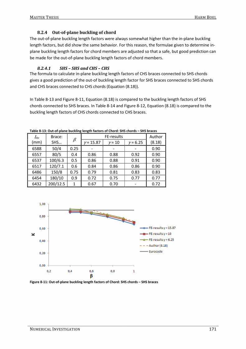
MASTER THESIS HARM BOEL
NUMERICAL INVESTIGATION 171
8.2.4 Out-of-plane buckling of chord
The out-of-plane buckling length factors were always somewhat higher than the in-plane buckling
length factors, but did show the same behavior. For this reason, the formulae given to determine in-
plane buckling length factors for chord members are adjusted so that a safe, but good prediction can
be made for the out-of-plane buckling length factors of chord members.
8.2.4.1 SHS – SHS and CHS – CHS
The formula to calculate in-plane buckling length factors of CHS braces connected to SHS chords
gives a good prediction of the out-of buckling length factor for SHS braces connected to SHS chords
and CHS braces connected to CHS chords (Equation (8.18)).
In Table 8-13 and Figure 8-11, Equation (8.18) is compared to the buckling length factors of SHS
chords connected to SHS braces. In Table 8-14 and Figure 8-12, Equation (8.18) is compared to the
buckling length factors of CHS chords connected to CHS braces.
Table 8-13: Out-of-plane buckling length factors of Chord: SHS chords – SHS braces
Lbr (mm)
Brace:
SHS… β
FE-results Author
(8.18) γ = 15.87 γ = 10 γ = 6.25
6588 50/4 0.25 - - - 0.90
6557 80/5 0.4 0.86 0.88 0.92 0.90
6537 100/6.3 0.5 0.86 0.88 0.91 0.90
6517 120/7.1 0.6 0.84 0.86 0.86 0.90
6486 150/8 0.75 0.79 0.81 0.83 0.83
6454 180/10 0.9 0.72 0.75 0.77 0.77
6432 200/12.5 1 0.67 0.70 - 0.72
Figure 8-11: Out-of-plane buckling length factors of Chord: SHS chords – SHS braces

MASTER THESIS HARM BOEL
172 PART B
Table 8-14: Out-of-plane buckling length factors of Chord: CHS chords – CHS braces
Lbr (mm)
Brace:
SHS… β
FE-results Author
(8.18) γ =
15.37
γ =
9.69
γ =
6.05
6594 48.3/4 0.25 - - - 0.90
6566 76.1/5 0.39 0.86 0.88 0.93 0.90
6528 114.3/6.3 0.59 0.84 0.87 0.86 0.90
6520 121/7.1 0.62 0.83 0.84 0.88 0.89
6488 152.4/8 0.79 0.77 0.79 0.81 0.82
6461 177.8/10 0.92 0.71 0.74 0.77 0.76
6443 193.7/12.5 1 0.67 0.70 0.73 0.72
Figure 8-12: Out-of-plane buckling length factors of Chord: CHS chords – CHS braces

MASTER THESIS HARM BOEL
NUMERICAL INVESTIGATION 173
8.2.4.2 CHS braces connected to SHS chords
To determine the out-of-plane buckling length factors for SHS chords connected to CHS braces,
Equation (8.20) is developed. In Table 8-15 and Figure 8-13, Equation (8.20) is compared to the
buckling length factors of SHS chords connected to CHS braces, obtained by FE-analysis.
1.05 0.25 0.9crL
KL
β= = − ≤ (8.20)
Table 8-15: Out-of-plane buckling length factors of Chord: SHS chords – CHS braces
Lbr (mm)
Brace:
CHS… β
FE-results Author
(8.20) γ = 15.87 γ = 10 γ = 6.25
6589 48.3/4 0.24 - - - 0.90
6561 76.1/5 0.38 - - - 0.90
6523 114.3/6.3 0.57 0.87 0.88 0.92 0.90
6516 121/7.1 0.61 0.85 0.87 0.88 0.90
6484 152.4/8 0.76 0.82 0.84 0.86 0.86
6456 177.8/10 0.89 0.77 0.79 0.80 0.83
6438 193.7/12.5 0.97 0.73 0.76 0.78 0.81
Figure 8-13: Out-of-plane buckling length factors of Chord: SHS chords – CHS braces

MASTER THESIS HARM BOEL
174 PART B
8.3 Summary
In this chapter, existing formulae are analyzed and the influence of different variables in the
formulae have been compared to the FE-results. After this, new formulae are developed. It must be
mentioned that these formula are only valid for the investigated geometry, with lateral supports in
each joint on the upper chord and loaded as shown in Figure 8-14.
Figure 8-14: Geometry of lattice girder for which the formulae are valid
The formulae to determine the buckling length factor of braces are based on the existing formulae
from CIDECT where the slope of the diagram (Buckling length factor - β) is made more consistent
with the slope obtained by FE-analysis. Furthermore, the influence of the chord wall thickness is
taken into account and added in the formulae. The new formulae can be found in Equations (8.21) to
(8.26) for in-plane and out-of-plane buckling, respectively.
In-plane buckling of SHS braces connected to SHS chords:
( )0.14
11.05 0.025cr
br
L bK
L Lγ β
= = +
(8.21)
In-plane buckling of CHS braces connected to SHS chords:
( )0.14
10.95 0.03 0.5cr
br
L dK
L Lγ β
= = + ≥
(8.22)
In-plane buckling of CHS braces connected to CHS chords:
( ) 12.5 0.5 1.00cr
br
L dK
L Lγ β
= = + + ≤
(8.23)
Out-of-plane buckling of SHS braces connected to SHS chords:
( ) 13 1.2 0.55 1.00cr
br
L bK
L Lγ β
= = + + ≤
(8.24)
Out-of-plane buckling of CHS braces connected to SHS chords:
11.2 0.55 1.00cr
br
L dK
L Lγ β
= = + ≤
(8.25)
Out-of-plane buckling of CHS braces connected to CHS chords:
( ) 15 0.55 1.00cr
br
L dK
L Lγ β
= = + + ≤
(8.26)

MASTER THESIS HARM BOEL
NUMERICAL INVESTIGATION 175
It can be seen that Equations (8.21) to (8.26) are all of the form as shown in Equation (8.27). Here,
the variables A, B, C and D are constants which depend on the section type combination and in- or
out-of-plane buckling of the brace, as shown in Table 8-16. It is mentioned that the buckling length
factor is restricted to the range 0.5 ≤ K ≤ 1.0.
( ) 1
C
cr
br
L dK A B D
L Lγ β
= = + +
(8.27)
Table 8-16: Constants to determine brace buckling length factors
Chords Brace In- or out-of-
plane buckling A B C D
SHS SHS In-plane 1.05 0.025 0.14 0
SHS SHS Out-of-plane 3 1.2 1 0.55
SHS CHS In-plane 0.95 0.03 0.14 0
SHS CHS Out-of-plane 0 1.2 1 0.55
CHS CHS In-plane 2.5 1 1 0.5
CHS CHS Out-of-plane 5 1 1 0.55
CIDECT does not provide formulae to determine the buckling length factor of chord members. From
the FE-results it can be found that the chord buckling length factor is not influenced by γ or scaling
of the dimensions as much as the brace buckling length factor. Because of this, simple and
somewhat safe formulae are given and can be found in (8.28) to (8.30).
In-plane buckling of SHS chords connected to SHS braces and CHS chords connected to CHS braces:
1.25 0.6 0.90K β= − ≤ (8.28)
Out-of-plane buckling for SHS chords connected to SHS braces and CHS chords connected to CHS
braces. In-plane buckling for SHS chords connected to CHS braces:
1.17 0.45 0.9K β= − ≤ (8.29)
Out-of-plane buckling of SHS chords connected to CHS braces:
1.105 0.25 0.9K β= − ≤ (8.30)
It can be seen that Equations (8.28) to (8.30) are all of the form as shown in Equation (8.31). Here,
the variables E, and F are constants which depend on the section type combination and in- or out-
of-plane buckling of the chord, as shown in Table 8-17 (K ≤ 0.9).
crL
K E FL
β= = + (8.31)

MASTER THESIS HARM BOEL
176 PART B
Table 8-17: Constants to determine chord buckling length factors
Chord Braces In- or out-of-
plane buckling E F
SHS SHS In-plane 1.25 -0.6
SHS SHS Out-of-plane 1.17 -0.45
SHS CHS In-plane 1.17 -0.45
SHS CHS Out-of-plane 1.105 -0.25
CHS CHS In-plane 1.25 -0.6
CHS CHS Out-of-plane 1.17 -0.45
Although the buckling length factors obtained by Equation (8.21) to (8.26) and (8.28) to (8.30) are
sometimes different from the buckling length factors obtained from FE-results, in general the
formulae give a good and safe prediction of the buckling length factor. Incidentally, the formulae
give a somewhat unsafe prediction. The engineer is able to reduce the buckling length more than
when the Eurocode is used.

MASTER THESIS HARM BOEL
NUMERICAL INVESTIGATION 177
8.4 Accuracy of the formulae
As explained before, it is tried to develop new formulae to determine buckling length factors for
hollow section members in lattice girders, whereby the formulae provide a safe, but accurate
approximation of the buckling length factor. This is done by altering existing formulae and curve-
fitting over results found by FE-analysis. To show the accuracy of the new formulae, but also that of
the formulae given by CIDECT and the buckling length factor given by the Eurocode, the outcome of
the different formulae are compared to the buckling length factors obtained by FE-analysis.
8.4.1 Brace buckling length factor
In Figure 8-15 results obtained by FE-analyses (horizontal axis) are compared to the buckling length
factors obtained by the Author’s formulae, buckling length factors given by the Eurocode and
obtained by the formulae given by CIDECT (vertical axis). It is mentioned that only the buckling
length factors obtained by FE-analyses of the basic geometry are shown.
Figure 8-15: Comparison brace buckling length factors: predicted and FE-results
It can be seen that the Eurocode is sometimes accurate, but in all the other cases the Eurocode
provides a very conservative or un-conservative buckling length factor. The buckling length factors
obtained by the formulae given by CIDECT are usually conservative, and in some cases more than 5%
un-conservative.
The buckling length factors obtained by the Author’s formulae are usually between 5% un-
conservative and 7% conservative, which is a clear improvement compared to the rules and design
formulae given by the Eurocode and CIDECT, respectively.

MASTER THESIS HARM BOEL
178 PART B
8.4.2 Chord buckling length factor
In Figure 8-16, the results obtained by FE-analyses are compared to the buckling length factors
obtained by the new formulae and the buckling length factor given by the Eurocode. Again, it is
mentioned that only the buckling length factors obtained by FE-analyses of the basic geometry are
shown.
Figure 8-16: Comparison chord buckling length factors: predicted and FE-results
It can be seen that the Eurocode is often conservative. The buckling length factors obtained by the
Author’s formulae are sometimes un-conservative, but always less than 5%. In most cases, the
buckling length factor is somewhat conservative, but often less than 5%.
8.4.3 Conclusion regarding the accuracy
It can be said that the formulae presented in this chapter allow the engineer to approximate the
buckling length factor very well. Also, these formulae are more accurate compared to the formulae
given by CIDECT and the rules given by the Eurocode. Again, it is mentioned that these formula are
based on results obtained by FE-analysis as described in this report. Therefore, these formulae
should only be used for similar situations. If one doubts which buckling length factor to apply and a
FE-program is at hand, a buckling analysis can be performed fairly easy, as described in chapter 6.

MASTER THESIS HARM BOEL
NUMERICAL INVESTIGATION 179
9. Discussion, Conclusions & Recommendations In this chapter, a short discussion is made about the investigation and the obtained results.
Hereafter, the conclusions made in this report are summed up. Finally, recommendations are given
for further research.
To investigate buckling length factors, a beam-element model is used. The connections of the beams
are represented by rotational springs with stiffnesses determined using a model of the connection
comprising shell-elements. The results that are obtained by the beam-model are considered to be
accurate because the results are compared with the results obtained by a shell-element model of
the entire lattice girder and close agreement was observed. It has been shown that the in-plane and
out-of-plane rotational connection stiffness must be modeled to obtain accurate first order buckling
loads. The other connection stiffnesses considered in this report, the axial and torsional stiffness, do
influence the structural behavior, but do not affect the buckling behavior significantly.
9.1 Discussion
The buckling length factors given in this report are relative to the system length. The system length
can be interpreted in different ways. In the methodology used to execute the parameter study,
certain assumptions have been made. Also, the conclusions drawn here are only valid when certain
conditions are met. These subjects are discussed hereafter.
9.1.1 Definition of system length
The buckling length factor, is relative to the system length. In this report, the system length of the
members is defined as the distance between the intersections of the centerline of the brace with the
face of the chord member. The measured distance is parallel to the member considered. See, for
example, the system length of a brace in Figure 9-1 (Lsys;Author).
Figure 9-1: System Length by Author (left) and in practice (right)
In practice, usually another definition of the system length is used. The system length is then often
assumed as Lsys;practice, shown in Figure 9-1. This means that in practice, the buckling length of a
member in a lattice girder, determined by a buckling length factor given in this report, differs from
the buckling length found by FE-analysis. For example, the out-of-plane buckling length for a
SHS100/6.3 brace connected to SHS200/10 chords was 4172 mm (basic geometry). According to the

MASTER THESIS HARM BOEL
180 PART B
definition of the system length in this report, the buckling length factor is 0.638 (Lsys;Author = 6537
mm). If this buckling length factor is used to determine the buckling length, assuming the system
length is 6755 mm (in agreement with Lsys;practice), the buckling length would be 4310 mm, which is
1.0% higher than obtained from FE-analysis. It can be seen that the buckling length factor
determined in this report gives a larger buckling length in practice and thus a lower buckling load
than obtained from FE-analysis. Thus, the suggested equations given to determine buckling length
factors give an underestimate of the first order buckling load. The difference in buckling length
would be larger if a larger width to length ratio would be used for the members.
9.1.2 Methodology
To determine buckling length factors for members in a lattice girder, the entire lattice girder is
modeled. Buckling of the entire lattice girder (global behavior) is interpreted as buckling of a single
member is that particular lattice girder (local behavior). This philosophy is tested: the buckling length
factor obtained by eigenvalue extraction is used to determine the ultimate load of that particular
member by using the calculation method given by the Eurocode.
The ultimate load of the lattice girder (and the maximum load in the considered member) is also
determined by performing a geometric and material non-linear imperfect analysis (GMNIA). The
ultimate load obtained by both methods are compared and the difference was within 5%. Therefore,
it is concluded that the methodology is correct and that the buckling length factors obtained can be
used to determine the ultimate load of a single member in a lattice girder and hence determine the
capacity of the lattice girder itself.
A beam-element model is used to perform buckling analyses. The connection stiffnesses between
the different members are determined by modeling the connection with shell-elements. Because the
connection stiffness is load depending on the force exerted on the braces, different load cases were
applied to determine the stiffness of the elastic rotational springs in the beam-element model,
representing the connection stiffness. Thus, the obtained connection stiffness is an approximation,
since the load distribution in the connection at time of buckling is not known.
The validity of the eigenvalues found by the beam-element model is tested: a shell-element model
of the entire lattice girder (used in a previous study) is used to obtain eigenvalues as well as the
beam-element model. This is done for several cases (different chord and brace dimensions, wall
thicknesses and gaps). The difference between the beam-element model (with the chosen
connection stiffnesses) and the full shell-element model was usually less than 6%. Incidentally, the
difference was between 6 to 10%, but never more than 10%. Therefore, is concluded that the beam-
element model can be used to obtain accurate first order buckling loads.
In some cases, it is hard to say whether a member has buckled or bent due to buckling of an
adjacent member. In such cases, the buckling length factor obtained is dependent on the
interpretation of the person judging the results. In this investigation, in a case of doubt it is assumed
that buckling has occurred.

MASTER THESIS HARM BOEL
NUMERICAL INVESTIGATION 181
9.1.3 Scope of use
New formulae have been developed. These formulae are partially based on the existing CIDECT
formulae and the FE-results. The formulae have been shown to give a better approximation of the
buckling length factors when compared to the existing formulae and rules, presented by CIDECT and
the Eurocode, respectively.
If these formulae are to be used in practice, the engineer must make sure that the following
conditions are met:
- The lattice girder must be symmetric, consisting of one upper and lower chord, having
identical dimensions. The chords must be connected to each other by diagonals which all
have identical dimensions and the girder must be identical loaded as done in this numerical
study;
- The lattice girder is laterally supported in every joint in the compressed chord. Both ends of
the lattice girder are forked and restrained from vertical and lateral translation. One end is
restrained from in-plane horizontal translation;
- Commonly square or circular hollow section members must be used, the slenderness must
be such that the beam-theory applies and;
- The angle between the chord and the braces must be within 40 and 50 degrees and the gap
applied is not much larger than the minimum gap prescribed by the Eurocode;
- the aspect ratio of the lattice girder is about 10.
If these conditions are not met and a FE-program is at hand, the same methodology as described in
chapter 6 can be used to perform buckling analyses. Hereby, it is recommended that a maximum
width over length ratio of 1/20 is used for the members.
This is recommended because in Section 6.2.6, a maximum width over length ratio of 1/20 was used
to test the beam-element model by comparing the obtained eigenvalues with those obtained by the
shell-element model. The maximum width over height ratio used in the parameter study was about
1/30.
9.2 Conclusions
The goal of this investigation was to determine the influence of β and γ on the buckling length factor
of hollow section members in lattice girders. β is defined as the ratio of the width or diameter of the
brace to that of the chord member. γ is defined as the width or diameter of the chord to twice the
wall thickness of the chord member. Besides β and γ, also other parameters have been varied. The
influence of β and γ on the connection stiffness is also determined.
First, the influence of β and γ on the buckling length factor of hollow section members in lattice
girders is given.
- An increase of β (keeping γ constant) means a decrease of the in- and out-of-plane buckling
length factors of chord members. This is due to the fact that both the flexural stiffness of the
brace as the connection stiffness increases as β increases;
- An increase of β means an increase of the in- and out-of-plane buckling length factors of
brace members. One might expect otherwise since the connection stiffness increases
exponentially as β increases. It is important to understand that when β increases, the
flexural stiffness of the brace also increases relative to that of the chord, which means the

MASTER THESIS HARM BOEL
182 PART B
ends of the braces are restrained less, relative to their flexural stiffness, increasing the
buckling length factor;
- For β ≤ 0.6 the in- and out-of-plane buckling length factors of chord members are fairly
constant and about 0.9;
- For β > 0.6 the in- and out-of-plane buckling length factors of chord members decrease
linearly;
- An increase of γ (decrease of the chord wall thickness) means a slight decrease in buckling
length factor of the chord members;
- An increase of γ means a significant increase in buckling length factor of the brace
members.
Furthermore, the following conclusions can be made:
- In general, the out-of-plane buckling length factors are higher than the in-plane buckling
length factors for both chord and brace members;
- The combination of CHS braces and SHS chords gives a higher buckling length factor for the
chord member, for both in- as well as out-of-plane buckling. The other combinations (SHS –
SHS and CHS – CHS) give similar results;
- The in-plane behavior does not affect the out-of-plane buckling behavior and vice versa;
- The first buckling mode of the lattice girder when β < 0.6 comprised buckling of the brace
member. When β > 0.6, the chord member buckled first. Around β = 0.6, the brace and the
chord buckled almost simultaneously.
Besides the influence of β and γ on the buckling length factor, the aspect ratio of the lattice girder is
varied. It is found that this does affect the buckling length factor, but in general the difference was
not more than 5 to 10 % for brace members and 2% for chord members. Incidentally, the differences
were larger.
Also the lateral supports of the upper chord were removed to determine its influence. It is found
that the buckling length factor of the braces in laterally unsupported lattice girders is sometimes
higher than for braces in laterally supported lattice girders. When β = 0.25, the buckling length factor
for braces in laterally unsupported lattice girders is always higher, because buckling of the chord
occurred simultaneously. Furthermore, it can be said that when no lateral supports are present, an
increase in β means a decrease of the out-of-plane buckling length factor of the chord. When β is
very small, the buckling resistance of the chord is less than that of a single beam, probably due to
simultaneously buckling of the brace member.
The by FE-analysis obtained buckling length factors are also compared to the factors given by the
Eurocode and the formulae given by CIDECT:
- The Eurocode prescribes a buckling length factor of 0.9 for chord members. According to this
parameter study, this is a good prediction of the buckling length for values of β ≤ 0.6. For
larger values of β, the Eurocode is conservative.
- The Eurocode gives a buckling length factor of 0.75 for brace members. This is a good
approximation when β is around 0.6 (0.55 ≤ β ≤ 0.65). When β is smaller than 0.6, the
Eurocode is conservative. When β is larger, the Eurocode is un-conservative compared to
the FE-results.

MASTER THESIS HARM BOEL
NUMERICAL INVESTIGATION 183
- The old Eurocode also provided a buckling length factor of 0.75, but only for β ≤ 0.6. This is
conservative for low values of beta. For higher values of beta, the old Eurocode provided a
buckling length factor of 1.0, which is also conservative.
- The CIDECT formulae give quite a good approximation of the buckling length factor, even for
β > 0.6. But in some cases, when a small chord wall thickness is used, the formulae are
somewhat un-conservative. For very low values of β, CIDECT gives a buckling length factor
lower than 0.5, which violates the criterion that the buckling length factor cannot be smaller
than 0.5 which represents a clamped – clamped column.
Because the buckling length factors provided by the Eurocode and CIDECT are not always accurate,
new formulae are presented. It is concluded that with these formulae, an engineer is able to fairly
accurately predict the buckling length factor of chord and brace members. Hereby, it is mentioned
that certain conditions must be met which are described in section 9.1.3.
Because connection stiffnesses had to be determined to perform buckling analyses with a beam-
element model, the influence of β and γ on the connection stiffness can also be determined:
- The connection stiffness increases exponentially as β increases linearly;
- An increase of γ (a decrease of the wall thickness) means a decrease of the connection
stiffness.
The connection stiffness is dependent on the section type combinations. The conclusions that can be
made are:
- For SHS braces connected to SHS chords, the in-plane connection stiffness is higher than the
out-of-plane stiffnesses for high values of β. For lower values of β the in-plane stiffness is
somewhat lower, but not significantly;
- For CHS braces connected to SHS chords, the in-plane connection stiffness is higher than the
out-of-plane stiffness, except for the lowest value for β investigated (β = 0.25);
- For CHS braces connected to CHS chords, the in-plane stiffness is lower than the out-of-
plane stiffness;
- For in-plane stiffnesses, the combination of CHS braces and CHS chords give higher
stiffnesses than CHS braces connected to SHS chords. SHS braces connected to SHS chords
are relatively low for lower values of β, but are significantly higher for high values of β;
- Out-of-plane stiffnesses of CHS braces connected to CHS or SHS chords are very similar. SHS
braces connected to SHS chords give the highest stiffnesses, although for low values of β
there is no significant difference.
9.3 Recommendations
It has been mentioned that the conclusions made herein are only valid for the geometry, load case
and used section types investigated. Because many other lattice girder geometries and conditions
are possible, it is interesting to investigate several other situations, such as:
- Different geometries, with N-connections for example, or asymmetric girders;
- Different load cases, for example an upward load representing wind suction on a roof
structure or built up columns;
- Other prescribed constraints, such as a continuous lattice girder;
- Using rectangular sections instead of square ones;
- Using different dimensions for the brace members, depending on the load in the brace.

MASTER THESIS HARM BOEL
184 PART B
It has been shown in section 7.4.1 that the connection stiffnesses can differ very much when the
same values for β and γ are used (scaling of the sections). Also, little information about connection
stiffnesses is found in literature, especially for connections in lattice girders. It is desirable to have
more knowledge about the stiffness of connections in lattice girders comprising hollow section
members.
Furthermore, it is desirable to be able to analytically determine the buckling length factor, for
example, as has been done for a column supported by beams as described in section 7.2.3.5.
It is proposed to cut out a part of the lattice girder and to determine rotational stiffnesses
representing (a part of) the rest of the lattice girder. However, it is expected that certain
simplifications must be made so that an exact solution can never be found. It is expected that the
difficulty lies in taking the effect of the load in other members into account. Also, simultaneous
buckling of brace and chord members is probably hard to capture through analytical methods.
If the analytical approach is successful, it might give a better approximation of the buckling length
factors than formulae based on FE-analyses because flexural stiffnesses of the members and
connection stiffnesses are taken into account, instead of ratios like β and γ. Also, it would save time
to investigate numerous lattice girder geometries and load cases since the method can be applied
for any given situation.

MASTER THESIS HARM BOEL
185
Reference List
BECKER, A.A. 2001. Understanding non-linear finite element analysis through illustrative
benchmarks. NAFEMS.
BROEK, T.J. et al. 1998. Staalprofielen – deel 5 (Over) spannend staal. Rotterdam: Kennisoverdracht
SG
CHEN, W. 1993. Semi-rigid connections in steel frames. London: McGraw-Hill.
GALAMBOS, T.V. 1998. Guide to stability design criteria for metal structures. 5th edn. Chichester:
Wiley-Interscience
GALAMBOS, T.V. and XYKIS, C. 1991. The Effect of Lateral Bracing on the Stability of Steel Trusses.
Journal of Constructional Steel Research. 20 (4), pp. 251-258
FEKETE, F. 2009. Buckling lengths of members in hollow section steel trusses. Unpublished Master
thesis. Eindhoven: Eindhoven University of Technology
HORNUNG, U. and SAAL, H. 1998. A method for calculating the out-of-plane buckling length of
diagonals of truss girders with hollow sections and K-joints. Journal of constructional Steel Research.
46 (1-3) pp. 489-501
HORNUNG, U. and SAAL, H. 2001. A method for calculating the out-of-plane buckling length of
diagonals of truss girders with hollow sections and K-joints or N-joints. In: PUTHLI, R.S. and HERION,
S. Tubular Structures IX. Lisse: Swets & Zeitlinger B.V. pp. 323-330
KOROL, M. and MIRZA, A. (1982). Finite element Analysis of RHS T-joints. Journal of the Structural
Division. 108 (9) pp. 2081-2098
PACKER, J.A. 1993. Moment Connections between Rectangular Hollow Sections. Journal of
constructional Steel Research. 25 (1-2) pp. 63-81
TIMOSHENKO, S. 1936. Theory of elastic stability. S.l.: McGraw-Hill
GAMBHIR, M.L. 2004. Stability Analysis and Design of Structures. Berlin: Springer
VEGTE, G.J. 1995. The Static Strength of Uniplanar and Multiplanar Tubular T- and X-joints. PhD
Thesis. Delft: Delft University of Technology.
WARDENIER, J., KORUBANE, Y., PACKER, J.A., DUTTA, D. and YEOMANS, N. 1991. Design Guide for
circular hollow section (CHS) joints under predominantly static loading. Köln: Verlag TÜV Rheinland
GmbH.

MASTER THESIS HARM BOEL
186
WARDENIER, J., KORUBANE, Y., PACKER, J.A., DUTTA, D. and YEOMANS, N. 1992a. Structural stability
of hollow sections. Köln: Verlag TÜV Rheinland GmbH.
WARDENIER, J., KORUBANE, Y., PACKER, J.A., DUTTA, D. and YEOMANS, N. 1992b. Design Guide for
rectangular hollow section (RHS) joints under predominantly static loading. Köln: Verlag TÜV
Rheinland GmbH.
WARDENIER, J. 1982 Hollow Section Joints. Phd Thesis. Delft: Delft University of Technology.
Bibliography
CHAN, S.L. and CHUI, P.P.T. 2000. Non-linear static and cyclic analysis of steel frames with semi-rigid
connections. Amsterdam: Elsevier Science.
FUNG, T.C., SOH, C.K. and GHO, W.M. 2001. Ultimate capacity of completely overlapped tubular
joints. 2: Behavioral study. Journal of Constructional Steel Research. 57 (8) pp. 881-906
HAYASHI, T. 1971. Handbook of structural stability. S.I.: Corona
YOUNG, W.C. and BUDYNAS, R.G. 2002. Roark’s formulas for stress and strain. London: McGraw-Hill

Appendices


MASTER THESIS HARM BOEL
I-1
I. Derivation of formulae to calculate out-of-plane deflection The formulae to calculate the out-of-plane deflection of the end of a brace connected to a chord
may seem complex. However, the formulae can easily be determined by combining different simple
and well known equations. Hereafter, the equations to calculate the deflection of the end of the
brace is are explained for the connection between a chord and one brace in the middle of the chord,
LCout1, LCout2 and LCout3, respectively. For the connection of one brace to the chord and for
LCout1, the general equations and structural behavior is explained and for LCout2 and LCout3, only
the differences are made clear.
I.I Chord connected to one brace
If one brace is connected to the middle of the chord and a moment is applied at the end of the brace
(see Figure I-1), then the deflection is caused by bending of the brace, torsion of the chord, rotation
of the chord and rotation of the out-of-plane rotational spring. The deflection can be calculated by
(1.1).
Figure I-1: Schematization of chord and brace
( )
( )( )( )22
;
; ;
sin cossin
2 2 12
ch chbrz A br br br
y br ch y ch out
ML MLML Mu L h L L
EI GJ EI C
α αα= + + + + (1.1)
I.I.I First term: deformation of brace
The first term of the equation to calculate the deflection of point A is the formula to calculate the
deflection of a cantilever beam. In this case, the cantilever is the brace (see (1.2)). This term is the
same for LCout1, LCout2 and LCout3.
2
;
;2
br
z A
y br
MLu
EI= (1.2)

MASTER THESIS HARM BOEL
I-2
I.I.II Second term: torsion of chord
The second term is the displacement of the end of the brace due to torsion of the chord. The chord
section rotates around it’s longitudinal axis. This gives a deflection when multiplied with the height
of the brace. The torsion of the chord is caused by the horizontal component of the applied moment
and is calculated by multiplying the moment by the sine of the angle. The formula is given in (1.3).
The length of the chord that rotates is a ½ times the length of the chord( ½ Lch). The height of the
brace is the sine of the angle multiplied with the length of the brace, plus the height of the rigid
beam.
( )
( )( );
sinsin
2
ch
z A br
ch
MLu L h
GJ
αα= + (1.3)
I.I.III Third term: rotation of chord (about y-axis)
The third term is the displacement due to rotation (about the y-axis) of the chord. This is caused by
the vertical component of the moment which is the cosine of the angle multiplied by the applied
moment. This rotation must be multiplied by the distance in x-direction of the point to the middle of
the chord (cosine of the angle multiplied by the brace length) to calculate the displacement. In this
particular case, the moment is applied in the middle of the chord which means the connection
between the brace and the chord will not deflect in z-direction. This makes it possible to schematize
the chord as a simply supported beam with half the length and half the moment applied at one end
of the beam. This way, the well known formula to calculate the deflection at the end of a beam can
easily be transferred into the third term (1.4) by multiplying it by ¼.
( )2
;
;
cos
12
ch
z A br
y ch
MLu L
EI
α= (1.4)
I.I.IV Fourth term: rotation of connection
The fourth and last term to calculate the out-of-plane deflection of the end of the brace is to
calculate the rotation of the connection, multiplied by the length of the brace as shown in (1.5).
;z A br
out
Mu L
C= (1.5)
I.I.V Testing the formula
The fTo test if Equation (1.1) is correct, a FE-model comprising of beam-elements (BEAM4) and a
rotational spring is modeled and loaded as shown in Figure I-1. The deflection of the end of the
brace is compared to the deflection obtained by hand calculation. For example, a CHS200/6.3 chord
is used with an area, moment of inertia, torsional stiffness and length of 3834 mm², 17999004 mm4,
35998008 mm4 and 1200, respectively. A CHS100/6.3 brace is used with an area, moment of inertia,
torsional stiffness and length of 1855 mm², 2044457 mm4, 4088915 mm4 and 700, respectively. The
angle between the chord and the brace is 56°, a moment of 109 Nmm is applied and the out-of-plane
rotational stiffness is 235.98 kNm/rad. The deflection of the end of the brace is calculated by (1.6).
( )( )( )
( )
66 2
; 5
2 6 6
5
sin 56 10 120010 700sin 56 700 100
2 2.1 10 2044457 2 80769 35998008
cos 56 10 700 10700 700 3.65677
12 2.1 10 17999004 235980000
z Au = + + +
⋅ ⋅ ⋅ ⋅
+ =⋅ ⋅ ⋅
(1.6)

MASTER THESIS HARM BOEL
I-3
The FE-solution is 3.6594 mm, which is 0.072% higher than obtained by hand calculation. The
difference is probably caused by rounding of the numbers (like shear modulus, area, moment of
inertia and torsional stiffness).
To obtain rotational stiffnesses of vierendeel-connections which have an angle 90°, the formula can
be simplified to (1.7).
( )2
;
;2 2
br ch
z A br br
y br ch out
ML ML Mu L h L
EI GJ C= + + + (1.7)
I.II LCout1
The first load case is very similar to the one described before (see Figure I-2). Only now, the brace is
not attached to the chord in the middle of the chord. This means the chord will also deflect in z-
direction in that posisition. Now, the moment causes the brace to bend, the chord to rotate around
its longitudinal axis, the chord to rotate around the y-axis, the chord to deflect along the z-axis and
the out-of-plane rotational spring to rotate. The deflection of the end of the brace can be calculated
by (1.8).
Figure I-2: Schematization of connection using beam-elements, load case 1
( ) ( )( )( )
( )( )
( ) ( )
2
;
;
2 2 2 2
2
sinsin
2 2
3 coscos
12 12
chbrz A br
y br ch
ch ch
br br
ch ch ch ch out
M L gMLw L h
EI GJ
M g L Mg g L ML L
EI L EI L C
αα
αα
−= + + +
+ −+ +
(1.8)
As mentioned before, the first term is to calculate the deflection due to bending of the brace. This
term is the same as for all the other load cases. The second term is slightly different, because the
length of the chord that rotates is now half the chord length minus half the gap ( ½ (Lch -g )).
I.II.III Third term: rotation of chord (about y-axis)
The vertical component of the moment (see Figure I-3) causes a rotation about the y-axis of the
chord. Because this moment is not applied in the middle of the chord, it is not easy to determine the
rotation. Also, the chord will deflect. But this will be described in section I.II.IV.

MASTER THESIS HARM BOEL
I-4
Figure I-3: Y-component of applied moment out of middle on chord
The rotation about the y-axis can be calculated by (1.9) and (1.10).
For 0 ≤ x ≤ a:
( ) ( )2
2 22 6 3
2 6
Mx Mx L aL a
EIL EILϕ = + − + (1.9)
For a ≤ x ≤ L:
( )( )
( ) ( )( )2
222 6 3
2 6
M L x Mx L L a L L a
EIL EILϕ
−= + − − + − (1.10)
Knowing that (1.11) and that the moment is the cosine of angle multiplied by the applied moment,
Equation (1.9) becomes (1.12).
( )1
2chx a L g= = + (1.11)
( ) ( ) ( )
( ) ( )2
22
;
cos cos 32 3
8 6 4
ch
y ch ch ch
M L g ML L g L L g
EIL EIL
α αϕ
+ = + − + + +
(1.12)
Simplifying this formula, (1.12) becomes (1.13).
( ) ( )2 2
;
cos 3
12
ch
y ch
ch ch
M g L
EI L
αϕ
+= (1.13)
The third term can then be obtained by multiplying the rotation with the distance in x-direction from
the considered point to the end of the brace (cosine of the angle multiplied by the length of the
brace).
I.II.IV Fourth term: displacement of chord (in z-direction)
The vertical component of the moment (see Figure I-3) causes a displacement in z-direction of the
chord. The displacement in z-direction is calculated by (1.14) and (1.15).
For 0 ≤ x ≤ a:
( ) ( )3
2 22 6 3
6 6
Mx My x L aL a x
EIL EIL= + − + (1.14)
For a ≤ x ≤ L:
( )( )
( ) ( )( )( )3
222 6 3
6 6
M L x My x L L a L L a L x
EIL EIL
−= + − − + − − (1.15)

MASTER THESIS HARM BOEL
I-5
Knowing that (1.11) and that the moment is the cosine of the applied moment, Equation (1.14)
becomes (1.16).
( ) ( ) ( )
( ) ( ) ( )3
22
;
cos cos 32 3
48 12 4
ch
z ch ch ch ch
M L g Mu L L g L L g L g
EIL EIL
α α+ = + − + + + +
(1.16)
Simplifying (1.16), the fourth term becomes (1.17).
( ) ( )2 2
;
cos
12
ch
z ch
ch ch
Mg g Lu
EI L
α −= (1.17)
I.III LCout2
Besides the moment applied in point A, also a moment is applied at the end of the other brace, as
shown in Figure I-4. Now, the deflection of point A can be calculated by (1.18), where the terms
represent the deflection of the end of the brace due to bending of the brace, torsion of the chord,
rotation of the chord displacement of the chord and rotation of the out-of-plane rotational spring.
Figure I-4: Schematization of connection using beam-elements, load case LCout2
( ) ( )( )( )
( )( ) ( )
2
;
;
2
sinsin
2
coscos
2 4
chbrz A br
y br ch
ch
br br
ch out
M L gMLu L h
EI GJ
Mg g LMg ML L
EI EI C
αα
αα
−= + + +
−+ +
(1.18)
The first and the fifth term are exactly the same as for LCout1. The second term is same except that
the moment is doubled and thus the whole term is multiplied by 2.
I.III.I Third term: rotation of chord (about y-axis)
For LCout2, two moments are applied which makes it necessary to use both (1.9) and (1.10).
Knowing that (1.11) and that the moment is the cosine of the applied moment, Equation (1.9) and
(1.10) become (1.19).

MASTER THESIS HARM BOEL
I-6
( ) ( ) ( )( ) ( )
( ) ( ) ( )( ) ( )
2
22
;
2
2
2
cos cos 32 3
8 6 4
1cos
cos 1 122 6 3
2 6 2 2
ch
y ch ch ch
ch ch
ch ch ch ch
M L g ML L g L L g
EIL EIL
M L L gM
L L L g L L L gEIL EIL
α αϕ
αα
+ = + − + + + −
− + + − − − + − −
(1.19)
Simplifying (1.19), the third term becomes (1.20).
( )
;
cos
2y ch
Mg
EI
αϕ = (1.20)
I.III.II Fourth term: displacement of chord (in z-direction)
For the fourth term is also determined by a much longer formula, whereby (1.14) and (1.15) become
(1.21).
( ) ( ) ( )( ) ( ) ( )
( ) ( )
( )( ) ( ) ( )
3
22
;
3
2
2
cos cos 32 3
48 12 4
1cos
2
6
cos 1 1 12 6 3
6 2 2 2
ch
z ch ch ch ch
ch ch
ch ch ch ch ch
M L g Mu L L g L L g L g
EIL EIL
M L L g
EIL
ML L L g L L L g L L g
EIL
α α
α
α
+ = + − + + + + +
− +
+
− − − + − − − +
(1.21)
Simplifying (1.21), the fourth term becomes (1.22).
( ) ( )
;
cos
4
ch
z ch
ch
Mg g Lu
EI
α −= (1.22)

MASTER THESIS HARM BOEL
I-7
I.IV LCout3
Now, the moment applied at the other brace is in the opposite direction as shown in Figure I-5. The
deflection of point A can be calculated by (1.23).
Figure I-5: Schematization of connection using beam-elements, load case 1
( )
( )( ) ( )2 2 2 22
2
;
;
3 3 cos 2 3cos
2 6 12
ch ch ch chbr
z A br br
y br ch ch ch ch out
M g gL L Mg g gL LML Mu L L
EI EI L EI L C
αα
− + − += + + +
(1.23)
As can be seen, only four terms are used. This is because the torsion of the first moment is
neutralized by the second moment so no torsional deformation is present in the position of the
connection between the right brace and the chord.
I.IV.I Second term: rotation of chord (about y-axis)
The calculation of the rotation of the chord is very similar as presented for LCout2 (Equation (1.19)).
Only now, the last term becomes positive instead of negative. Simplifying this equation, the second
term becomes (1.24).
( )
( )2 2
;
3 3cos
6
ch ch
y ch
ch ch
M g gL L
EI Lϕ α
− += (1.24)
I.IV.II Third term: displacement of chord (in z-direction)
The same counts for the out-of-plane displacement of the chord where the last two terms become
negative instead of positive, so the third term becomes (1.25).
( ) ( )2 2
;
cos 2 3
12
ch ch
z ch
ch ch
Mg g gL Lu
EI L
α − += (1.25)

MASTER THESIS HARM BOEL
I-8
I.V Proof that the formulae are correct
The parameters given in Table I-1 are used to calculate the deflection of the end of the brace due to
bending of the brace, torsion of the chord, rotation of the chord, deflection of the chord and
rotation of the connection. FE-analysis is also used to calculate the deflection of the end of the
brace. The results of both calculations are compared to each other in Table I-2. It can be seen that
the hand calculations are correct for the assumed models.
Table I-1: parameters used to test formulae
E 210000 N/mm2
v 0.3 -
G 80769 N/mm²
M 109 Nmm
α
56
(0.9773844)
degrees
(radian)
g 256 mm
Cout 500*106
Nmm/rad
Chord: RHS200/6.3 Brace: RHS50/6.3
Lch 2000 mm Lbr 500 mm
Ach 4881 mm2 Abr 1101 mm2
Ich 30531841 mm4 Ibr 352326 mm4
Jch 45785653 mm4 Jbr 525757 mm4
Table I-2: Results obtained by hand calculation and FE-analysis
Deflection due to: Hand calculation FE-analysis
LCout1
Bending of brace (mm) 1689.454195
torsion of chord (mm) 100.5811453
(y-)rotation of chord (mm) 4.263911512
Deflection of chord (mm) -3.66019029 3.6602
rotation of connection (mm) 1000
Total 2790.639062 -2790.6
torsion of chord (rad) 0.195485856 -0.19549
(y-)rotation of chord (rad) 0.015250235 0.01525
LCout2
Bending of brace (mm) 1689.454195
torsion of chord (mm) 201.1622906
(y-)rotation of chord (mm) 3.121267501
Deflection of chord (mm) -9.73454865 9.7345
rotation of connection (mm) 1000
Total 2884.003205 -2884.0
torsion of chord (rad) 0.390971712 -0.39097
(y-)rotation of chord (rad) 0.011163473 0.011163
LCout2
Bending of brace (mm) 1689.454195
(y-)rotation of chord (mm) 5.406555523
Deflection of chord (mm) 2.414168064 -2.4142
rotation of connection (mm) 1000
Total 2697.274919 -2697.2
(y-)rotation of chord (rad) 0.019336996 0.019337

MASTER THESIS HARM BOEL
II-1
II. Results Connection stiffnesses Here, the connection stiffnesses are presented. Also figures of the connections with measurements
are shown. Besides the gap, also the space between the intersection of the centre lines of the braces
with the upper face of the chord are shown. This is the distance between the rigid beams in the
beam-element model.
Also the distance between the intersection of the centerlines of the braces to the centerline of the
chord is shown. This is the eccentricity according to the codes and is shown because moments which
are caused by these eccentricities may be ignored for certain cases. The effects of the eccentricity
may be ignored for calculating the connections when the eccentricity on the, in the figures, upper
side is smaller than 0.55 times the height or diameter of the chord or smaller than 0.25 times the
height or diameter of the chord on the lower side of the centerline of the chord (see Figure II-1).
Most connections meet these conditions, but some don’t. This does not have to be a problem, but in
practice, these situations are usually avoided.
• −0,55 d0 ≤ e ≤ 0,25 d0
• −0,55 h0 ≤ e ≤ 0,25 h0
Figure II-1: Limits for eccentricity (Eurocode 3)

MASTER THESIS HARM BOEL
II-2
II.I Connections between SHS chords and SHS braces
Figure II-2: Connections between RHS chords and RHS braces
Table II-1: Rotational stiffnesses for SHS – SHS Connections
Chord Brace β α (°)
Cin (kNm/rad)
Cout (kNm/rad) b0 t0 γ b1 t1 γ
200 6.3 15.87 50 4 6.25 0.25 44 82.35 225.31
80 5 8 0.4 45 188.43 481.85
100 6.3 7.94 0.5 45 355.52 831.2
120 7.1 8.45 0.6 45 711.72 1376.84
150 8 9.38 0.75 45 2766.15 3489.3
180 10 9 0.9 45 12294.51 10837.03
200 12.5 8 1 46 33575.77 19594.12
200 10 10 50 4 6.25 0.25 44 292.07 673.19
80 5 8 0.4 45 627.84 1376.22
100 6.3 7.94 0.5 45 1133.3 2247.05
120 7.1 8.45 0.6 45 2141.5 3605.88
150 8 9.38 0.75 45 6888.31 8584.83
180 10 9 0.9 45 24808.14 22651.62
200 12.5 8 1 46 53409.15 34874.13
200 16 6.25 50 4 6.25 0.25 44 953.48 1726.35
80 5 8 0.4 45 2144.75 4046.51
100 6.3 7.94 0.5 45 3680.7 6643.9
120 7.1 8.45 0.6 45 6547.22 10657.47
150 8 9.38 0.75 45 17717.9 23322.46
180 10 9 0.9 45 52421.85 53125.75

MASTER THESIS HARM BOEL
II-3
Figure II-3: In-plane stiffnesses (Cin) for SHS – SHS Connection (SHS200 chord)
Figure II-4: Out-of-plane stiffnesses (Cout) for SHS – SHS Connection (SHS200 chord)

MASTER THESIS HARM BOEL
II-4
II.II Connections between SHS chords and CHS braces
Figure II-5: Connections between RHS chords and CHS braces
Table II-2: Rotational stiffnesses for SHS – CHS Connections
Chord Brace β α (°)
Cin (kNm/rad)
Cout (kNm/rad) b0 t0 γ d1 t1 γ
200 6.3 15.87 48.3 4 6.04 0.24 44 61.26 137.06
76.1 5 7.61 0.38 45 116.04 258.27
114.3 6.3 9.07 0.57 45 282.05 600.47
121 7.1 8.52 0.61 45 340.2 715.7
152.4 8 9.53 0.76 45 809.07 1715.72
177.8 10 8.89 0.89 45 2045.23 4349.34
193.7 12.5 7.75 0.97 46 3772.35 7043.39
200 10 10 48.3 4 6.04 0.24 44 210.57 414.81
76.1 5 7.61 0.38 45 399.99 822.18
114.3 6.3 9.07 0.57 45 908.88 1797.37
121 7.1 8.52 0.61 45 1075.53 2097.5
152.4 8 9.53 0.76 45 2349.3 4573.92
177.8 10 8.89 0.89 45 5128.72 9438.65
193.7 12.5 7.75 0.97 46 8875.75 13783.62
200 16 6.25 48.3 4 6.04 0.24 44 600.66 927.37
76.1 5 7.61 0.38 45 1344.24 2355.23
114.3 6.3 9.07 0.57 45 3020.33 5456.12
121 7.1 8.52 0.61 45 3507.45 6319.44
152.4 8 9.53 0.76 45 7033.1 12767.31
177.8 10 8.89 0.89 45 13176.69 22117.52
193.7 12.5 7.75 0.97 46 19957.49 28844.32
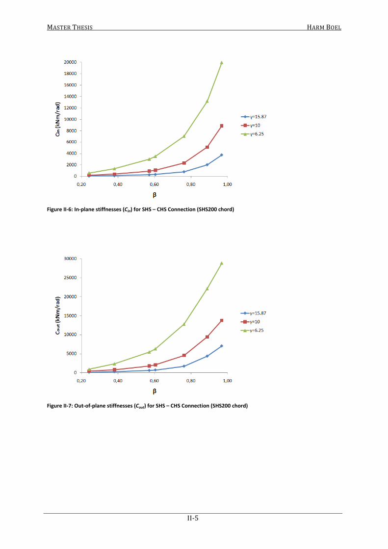
MASTER THESIS HARM BOEL
II-5
Figure II-6: In-plane stiffnesses (Cin) for SHS – CHS Connection (SHS200 chord)
Figure II-7: Out-of-plane stiffnesses (Cout) for SHS – CHS Connection (SHS200 chord)

MASTER THESIS HARM BOEL
II-6
II.III Connections between CHS chords and CHS braces
Figure II-8: Connections between CHS chords and CHS braces
Table II-3: Rotational stiffnesses for CHS – CHS Connections
Chord Brace β α (°)
Cin (kNm/rad)
Cout (kNm/rad) d0 t0 γ d1 t1 γ
193.7 6.3 15.37 48.3 4 6.04 0.25 44 253.05 199.54
76.1 5 7.61 0.39 45 711.35 436.63
114.3 6.3 9.07 0.59 45 1915.38 1086.34
121 7.1 8.52 0.62 45 2263.17 1276.56
152.4 8 9.53 0.79 45 4266.25 2626.36
177.8 10 8.89 0.92 45 7297.05 4955.74
193.7 12.5 7.75 1.00 46 10648.32 7510.43
193.7 10 9.69 48.3 4 6.04 0.25 44 514.18 492.25
76.1 5 7.61 0.39 45 1430.28 1098.43
114.3 6.3 9.07 0.59 45 3803.4 2522.55
121 7.1 8.52 0.62 45 4480.48 2948.04
152.4 8 9.53 0.79 45 8444.18 5763.5
177.8 10 8.89 0.92 45 14375.29 10562.97
193.7 12.5 7.75 1.00 46 20260.76 15809.01
193.7 16 6.05 48.3 4 6.04 0.25 44 873.18 918.8
76.1 5 7.61 0.39 45 2701.52 2492.41
114.3 6.3 9.07 0.59 45 7556.34 5883.91
121 7.1 8.52 0.62 45 8940.64 6878.91
152.4 8 9.53 0.79 45 17017.01 13075.14
177.8 10 8.89 0.92 45 28273.04 23021.16
193.7 12.5 7.75 1.00 46 37655.57 32541.07

MASTER THESIS HARM BOEL
II-7
Figure II-9: In-plane stiffnesses (Cin) for CHS – CHS Connection (CHS193.7 chord)
Figure II-10: Out-of-plane stiffnesses (Cout) for CHS – CHS Connection (CHS193.7 chord)


MASTER THESIS HARM BOEL
III. Results Buckling Analyses
LG1
LG2
LG3
Comparison In- and Out-of-plane Buckling LG2
Comparison Section Type Combination LG2
Comparison LG1, LG2 and LG3
With/Without Lateral Supports


MASTER THESIS HARM BOEL
In-plane
Brace:
SHS γ=15.87 γ=10 γ=6.25
50/4 0.25 - - -
80/5 0.4 0.87 0.84 0.88
100/6.3 0.5 0.87 0.88 0.92
120/7.1 0.6 0.88 0.90 0.82
150/8 0.75 0.75 0.77 0.80
180/10 0.9 0.65 0.67 0.71
200/12.5 1 0.59 0.62 -
Out-of-plane
SHS Chord - SHS Braces
βChord: SHS200
Buckling of Chord (C2)
0,00
0,20
0,40
0,60
0,80
1,00
0,2 0,4 0,6 0,8 1
K
β
γ = 15.87
γ = 10
γ = 6.25
Eurocode
___________________________________________________________________________________________________________________________
III-1
Out-of-plane
Brace:
SHS γ=15.87 γ=10 γ=6.25
50/4 0.25 - - -
80/5 0.4 0.92 0.89 0.89
100/6.3 0.5 0.87 0.88 0.94
120/7.1 0.6 0.88 0.83 0.86
150/8 0.75 0.81 0.83 0.85
180/10 0.9 0.73 0.76 0.79
200/12.5 1 0.69 0.72 -
βChord: SHS200
0,00
0,20
0,40
0,60
0,80
1,00
0,2 0,4 0,6 0,8 1
K
β
γ = 15.87
γ = 10
γ = 6.25
Eurocode
0,00
0,20
0,40
0,60
0,80
1,00
0,2 0,4 0,6 0,8 1
K
β
γ = 15.87
γ = 10
γ = 6.25
Eurocode
___________________________________________________________________________________________________________________________
III-1

MASTER THESIS HARM BOEL
In-plane
Brace:
SHS γ=15.87 γ=10 γ=6.25
50/4 0.25 0.59 0.53 0.51
80/5 0.4 0.68 0.57 0.53
100/6.3 0.5 0.73 0.61 0.54
120/7.1 0.6 0.76 0.65 0.57
150/8 0.75 0.82 0.69 0.61
180/10 0.9 0.65 0.74 0.65
200/12.5 1 0.74 0.65 -
Out-of-plane
SHS Chord - SHS Braces
βChord: SHS200
Buckling of Brace (B2)
0,00
0,20
0,40
0,60
0,80
1,00
0,2 0,4 0,6 0,8 1
K
β
γ = 15.87
γ = 10
γ = 6.25
Eurocode
___________________________________________________________________________________________________________________________
III-2
Out-of-plane
Brace:
SHS γ=15.87 γ=10 γ=6.25
50/4 0.25 0.61 0.58 0.58
80/5 0.4 0.66 0.62 0.59
100/6.3 0.5 0.70 0.64 0.61
120/7.1 0.6 0.77 0.67 0.63
150/8 0.75 0.86 0.75 0.68
180/10 0.9 0.75 0.81 0.86
200/12.5 1 0.81 0.74 -
βChord: SHS200
0,00
0,20
0,40
0,60
0,80
1,00
0,2 0,4 0,6 0,8 1
K
β
γ = 15.87
γ = 10
γ = 6.25
Eurocode
0,00
0,20
0,40
0,60
0,80
1,00
0,2 0,4 0,6 0,8 1
K
β
γ = 15.87
γ = 10
γ = 6.25
Eurocode
___________________________________________________________________________________________________________________________
III-2

MASTER THESIS HARM BOEL
Buckling of Chord (C2)
In-plane
Brace:
CHS γ=15.87 γ=10 γ=6.25
48.3/4 0.24 - - -
76.1/5 0.38 0.90 - -
114.3/6.3 0.57 0.88 0.89 0.94
121/7.1 0.61 0.86 0.86 0.89
152.4/8 0.76 0.84 0.84 0.87
177.8/10 0.89 0.76 0.76 0.78
193.7/12.5 0.97 0.70 0.71 0.73
Out-of-plane
SHS Chord - CHS Braces
βChord: SHS200
0,00
0,20
0,40
0,60
0,80
1,00
0,2 0,4 0,6 0,8 1
K
β
γ = 15.87
γ = 10
γ = 6.25
Eurocode
___________________________________________________________________________________________________________________________
III-3
Out-of-plane
Brace:
CHS γ=15.87 γ=10 γ=6.25
48.3/4 0.24 - - -
76.1/5 0.38 0.89 - -
114.3/6.3 0.57 0.87 0.89 0.88
121/7.1 0.61 0.86 0.87 0.90
152.4/8 0.76 0.84 0.87 0.91
177.8/10 0.89 0.79 0.81 0.83
193.7/12.5 0.97 0.75 0.77 0.80
βChord: SHS200
0,00
0,20
0,40
0,60
0,80
1,00
0,2 0,4 0,6 0,8 1
K
β
γ = 15.87
γ = 10
γ = 6.25
Eurocode
0,00
0,20
0,40
0,60
0,80
1,00
0,2 0,4 0,6 0,8 1
K
β
γ = 15.87
γ = 10
γ = 6.25
Eurocode
___________________________________________________________________________________________________________________________
III-3

MASTER THESIS HARM BOEL
Buckling of Brace (B2)
In-plane
Brace:
CHS γ=15.87 γ=10 γ=6.25
48.3/4 0.24 0.57 0.52 0.51
76.1/5 0.38 0.66 0.56 0.52
114.3/6.3 0.57 0.74 0.62 0.55
121/7.1 0.61 0.76 0.63 0.56
152.4/8 0.76 0.77 0.66 0.62
177.8/10 0.89 0.77 0.76 0.66
193.7/12.5 0.97 0.81 0.74 0.77
Out-of-plane
SHS Chord - CHS Braces
βChord: SHS200
0,00
0,20
0,40
0,60
0,80
1,00
0,2 0,4 0,6 0,8 1
K
β
γ = 15.87
γ = 10
γ = 6.25
Eurocode
___________________________________________________________________________________________________________________________
III-4
Out-of-plane
Brace:
CHS γ=15.87 γ=10 γ=6.25
48.3/4 0.24 0.60 0.58 0.57
76.1/5 0.38 0.65 0.60 0.58
114.3/6.3 0.57 0.71 0.64 0.61
121/7.1 0.61 0.73 0.66 0.61
152.4/8 0.76 0.77 0.74 0.65
177.8/10 0.89 0.94 0.80 0.71
193.7/12.5 0.97 0.86 0.80 0.83
βChord: SHS200
0,00
0,20
0,40
0,60
0,80
1,00
0,2 0,4 0,6 0,8 1
K
β
γ = 15.87
γ = 10
γ = 6.25
Eurocode
0,00
0,20
0,40
0,60
0,80
1,00
0,2 0,4 0,6 0,8 1
K
β
γ = 15.87
γ = 10
γ = 6.25
Eurocode
___________________________________________________________________________________________________________________________
III-4

MASTER THESIS HARM BOEL
Buckling of Chord (C2)
In-plane
Brace:
CHS γ=15.37 γ=9.69 γ=6.05
48.3/4 0.25 - - -
76.1/5 0.39 0.89 0.87 0.89
114.3/6.3 0.59 0.83 0.89 0.84
121/7.1 0.62 0.80 0.84 0.79
152.4/8 0.79 0.71 0.74 0.78
177.8/10 0.92 0.64 0.67 0.70
193.7/12.5 1 0.60 0.62 0.65
Out-of-plane
CHS Chord - CHS Braces
βChord: CHS193.7
0,00
0,20
0,40
0,60
0,80
1,00
0,2 0,4 0,6 0,8 1
K
β
γ = 15.37
γ = 9.69
γ = 6.05
Eurocode
___________________________________________________________________________________________________________________________
III-5
Out-of-plane
Brace:
CHS γ=15.37 γ=9.69 γ=6.05
48.3/4 0.25 - - -
76.1/5 0.39 0.90 0.89 0.89
114.3/6.3 0.59 0.88 0.84 0.87
121/7.1 0.62 0.85 0.89 0.85
152.4/8 0.79 0.78 0.81 0.84
177.8/10 0.92 0.73 0.75 0.78
193.7/12.5 1 0.68 0.71 0.74
βChord: CHS193.7
0,00
0,20
0,40
0,60
0,80
1,00
0,2 0,4 0,6 0,8 1
K
β
γ = 15.37
γ = 9.69
γ = 6.05
Eurocode
0,00
0,20
0,40
0,60
0,80
1,00
0,2 0,4 0,6 0,8 1
K
β
γ = 15.37
γ = 9.69
γ = 6.05
Eurocode
___________________________________________________________________________________________________________________________
III-5
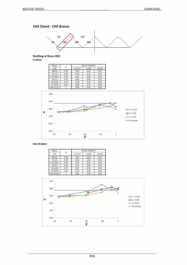
MASTER THESIS HARM BOEL
Buckling of Brace (B2)
In-plane
Brace:
CHS γ=15.37 γ=9.69 γ=6.05
48.3/4 0.25 0.52 0.51 0.51
76.1/5 0.39 0.54 0.52 0.51
114.3/6.3 0.59 0.67 0.59 0.54
121/7.1 0.62 0.64 0.58 0.57
152.4/8 0.79 0.70 0.72 0.63
177.8/10 0.92 0.66 0.76 0.66
193.7/12.5 1 0.76 0.65 0.59
Out-of-plane
CHS Chord - CHS Braces
βChord: CHS193.7
0,00
0,20
0,40
0,60
0,80
1,00
0,2 0,4 0,6 0,8 1
K
β
γ = 15.37
γ = 9.69
γ = 6.05
Eurocode
___________________________________________________________________________________________________________________________
III-6
Out-of-plane
Brace:
CHS γ=15.37 γ=9.69 γ=6.05
48.3/4 0.25 0.59 0.58 0.57
76.1/5 0.39 0.63 0.60 0.58
114.3/6.3 0.59 0.72 0.61 0.62
121/7.1 0.62 0.72 0.68 0.63
152.4/8 0.79 0.91 0.78 0.69
177.8/10 0.92 0.76 0.83 0.87
193.7/12.5 1 0.81 0.78 0.69
βChord: CHS193.7
0,00
0,20
0,40
0,60
0,80
1,00
0,2 0,4 0,6 0,8 1
K
β
γ = 15.37
γ = 9.69
γ = 6.05
Eurocode
0,00
0,20
0,40
0,60
0,80
1,00
0,2 0,4 0,6 0,8 1
K
β
γ = 15.37
γ = 9.69
γ = 6.05
Eurocode
___________________________________________________________________________________________________________________________
III-6

MASTER THESIS HARM BOEL
Buckling of Chord (C3)
In-plane
Brace:
SHS γ=15.87 γ=10 γ=6.25
50/4 0.25 - - -
80/5 0.4 0.86 0.87 0.90
100/6.3 0.5 0.86 0.86 0.88
120/7.1 0.6 0.83 0.84 0.86
150/8 0.75 0.74 0.75 0.77
180/10 0.9 0.63 0.66 0.69
200/12.5 1 0.58 0.61 -
Out-of-plane
SHS Chord - SHS Braces
Chord: SHS200β
0,00
0,20
0,40
0,60
0,80
1,00
0,2 0,4 0,6 0,8 1
K
β
γ = 15.87
γ = 10
γ = 6.25
Eurocode
___________________________________________________________________________________________________________________________
III-7
Out-of-plane
Brace:
SHS γ=15.87 γ=10 γ=6.25
50/4 0.25 - - -
80/5 0.4 0.86 0.88 0.92
100/6.3 0.5 0.86 0.88 0.91
120/7.1 0.6 0.84 0.86 0.86
150/8 0.75 0.79 0.81 0.83
180/10 0.9 0.72 0.75 0.77
200/12.5 1 0.67 0.70 -
βChord: SHS200
0,00
0,20
0,40
0,60
0,80
1,00
0,2 0,4 0,6 0,8 1
K
β
γ = 15.87
γ = 10
γ = 6.25
Eurocode
0,00
0,20
0,40
0,60
0,80
1,00
0,2 0,4 0,6 0,8 1
K
β
γ = 15.87
γ = 10
γ = 6.25
Eurocode
___________________________________________________________________________________________________________________________
III-7
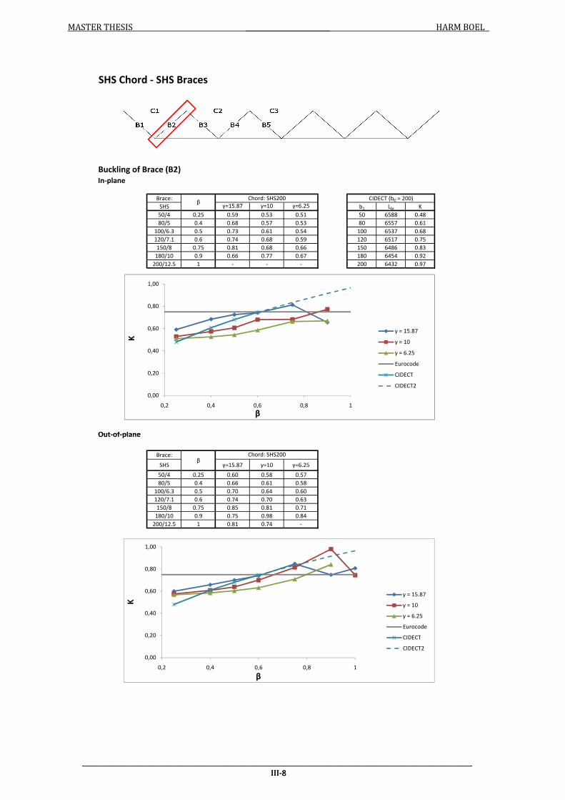
MASTER THESIS HARM BOEL
Buckling of Brace (B2)
In-plane
Brace:
SHS γ=15.87 γ=10 γ=6.25 b1 Lbr K
50/4 0.25 0.59 0.53 0.51 50 6588 0.48
80/5 0.4 0.68 0.57 0.53 80 6557 0.61
100/6.3 0.5 0.73 0.61 0.54 100 6537 0.68
120/7.1 0.6 0.74 0.68 0.59 120 6517 0.75
150/8 0.75 0.81 0.68 0.66 150 6486 0.83
180/10 0.9 0.66 0.77 0.67 180 6454 0.92
200/12.5 1 - - - 200 6432 0.97
Out-of-plane
CIDECT (b0 = 200)
SHS Chord - SHS Braces
βChord: SHS200
0,00
0,20
0,40
0,60
0,80
1,00
0,2 0,4 0,6 0,8 1
K
β
γ = 15.87
γ = 10
γ = 6.25
Eurocode
CIDECT
CIDECT2
___________________________________________________________________________________________________________________________
III-8
Out-of-plane
Brace:
SHS γ=15.87 γ=10 γ=6.25
50/4 0.25 0.60 0.58 0.57
80/5 0.4 0.66 0.61 0.58
100/6.3 0.5 0.70 0.64 0.60
120/7.1 0.6 0.74 0.70 0.63
150/8 0.75 0.85 0.81 0.71
180/10 0.9 0.75 0.98 0.84
200/12.5 1 0.81 0.74 -
βChord: SHS200
0,00
0,20
0,40
0,60
0,80
1,00
0,2 0,4 0,6 0,8 1
K
β
γ = 15.87
γ = 10
γ = 6.25
Eurocode
CIDECT
CIDECT2
0,00
0,20
0,40
0,60
0,80
1,00
0,2 0,4 0,6 0,8 1
K
β
γ = 15.87
γ = 10
γ = 6.25
Eurocode
CIDECT
CIDECT2
___________________________________________________________________________________________________________________________
III-8

MASTER THESIS HARM BOEL
Buckling of Chord (C3)
In-plane
Brace:
CHS γ=15.87 γ=10 γ=6.25
48.3/4 0.24 - - -
76.1/5 0.38 - - -
114.3/6.3 0.57 0.87 0.88 0.90
121/7.1 0.61 0.85 0.85 0.87
152.4/8 0.76 0.81 0.81 0.83
177.8/10 0.89 0.74 0.75 0.76
193.7/12.5 0.97 0.69 0.69 0.71
Out-of-plane
SHS Chord - CHS Braces
βChord: SHS200
0,00
0,20
0,40
0,60
0,80
1,00
0,2 0,4 0,6 0,8 1
K
β
γ = 15.87
γ = 10
γ = 6.25
Eurocode
___________________________________________________________________________________________________________________________
III-9
Out-of-plane
Brace:
CHS γ=15.87 γ=10 γ=6.25
48.3/4 0.24 - - -
76.1/5 0.38 - - -
114.3/6.3 0.57 0.87 0.88 0.92
121/7.1 0.61 0.85 0.87 0.88
152.4/8 0.76 0.82 0.84 0.86
177.8/10 0.89 0.77 0.79 0.80
193.7/12.5 0.97 0.73 0.76 0.78
βChord: SHS200
0,00
0,20
0,40
0,60
0,80
1,00
0,2 0,4 0,6 0,8 1
K
β
γ = 15.87
γ = 10
γ = 6.25
Eurocode
0,00
0,20
0,40
0,60
0,80
1,00
0,2 0,4 0,6 0,8 1
K
β
γ = 15.87
γ = 10
γ = 6.25
Eurocode
___________________________________________________________________________________________________________________________
III-9

MASTER THESIS HARM BOEL
Buckling of Brace (B2)
In-plane
Brace:
CHS γ=15.87 γ=10 γ=6.25 d1 Lbr K
48.3/4 0.24 0.57 0.52 0.51 48.3 6589 0.48
76.1/5 0.38 0.66 0.56 0.52 76.1 6561 0.61
114.3/6.3 0.57 0.74 0.62 0.55 114.3 6523 0.74
121/7.1 0.61 0.76 0.63 0.56 121 6516 0.77
152.4/8 0.76 0.81 0.68 0.59 152.4 6484 0.86
177.8/10 0.89 0.78 0.75 0.65 177.8 6456 0.93
193.7/12.5 0.97 0.80 0.77 0.66 193.7 6438 0.97
Out-of-plane
CIDECT (b0 = 200)
SHS Chord - CHS Braces
βChord: SHS200
0,00
0,20
0,40
0,60
0,80
1,00
0,2 0,4 0,6 0,8 1
K
β
γ = 15.87
γ = 10
γ = 6.25
Eurocode
CIDECT
CIDECT2
___________________________________________________________________________________________________________________________
III-10
Out-of-plane
Brace:
CHS γ=15.87 γ=10 γ=6.25
48.3/4 0.24 0.59 0.57 0.56
76.1/5 0.38 0.64 0.59 0.57
114.3/6.3 0.57 0.71 0.64 0.60
121/7.1 0.61 0.73 0.65 0.61
152.4/8 0.76 0.81 0.70 0.69
177.8/10 0.89 0.93 0.79 0.77
193.7/12.5 0.97 0.95 0.95 0.81
βChord: SHS200
0,00
0,20
0,40
0,60
0,80
1,00
0,2 0,4 0,6 0,8 1
K
β
γ = 15.87
γ = 10
γ = 6.25
Eurocode
CIDECT
CIDECT2
0,00
0,20
0,40
0,60
0,80
1,00
0,2 0,4 0,6 0,8 1
K
β
γ = 15.87
γ = 10
γ = 6.25
Eurocode
CIDECT
CIDECT2
___________________________________________________________________________________________________________________________
III-10

MASTER THESIS HARM BOEL
Buckling of Chord (C3)
In-plane
Brace:
CHS γ=15.37 γ=9.69 γ=6.05
48.3/4 0.25 - - -
76.1/5 0.39 0.81 0.86 0.90
114.3/6.3 0.59 0.80 0.83 0.82
121/7.1 0.62 0.77 0.80 0.84
152.4/8 0.79 0.69 0.72 0.76
177.8/10 0.92 0.63 0.65 0.69
193.7/12.5 1 0.59 0.61 0.64
Out-of-plane
CHS Chord - CHS Braces
βChord: CHS193.7
0,00
0,20
0,40
0,60
0,80
1,00
0,2 0,4 0,6 0,8 1
K
β
γ = 15.37
γ = 9.69
γ = 6.05
Eurocode
___________________________________________________________________________________________________________________________
III-11
Out-of-plane
Brace:
CHS γ=15.37 γ=9.69 γ=6.05
48.3/4 0.25 - - -
76.1/5 0.39 0.86 0.88 0.93
114.3/6.3 0.59 0.84 0.87 0.86
121/7.1 0.62 0.83 0.84 0.88
152.4/8 0.79 0.77 0.79 0.81
177.8/10 0.92 0.71 0.74 0.77
193.7/12.5 1 0.67 0.70 0.73
βChord: CHS193.7
0,00
0,20
0,40
0,60
0,80
1,00
0,2 0,4 0,6 0,8 1
K
β
γ = 15.37
γ = 9.69
γ = 6.05
Eurocode
0,00
0,20
0,40
0,60
0,80
1,00
0,2 0,4 0,6 0,8 1
K
β
γ = 15.37
γ = 9.69
γ = 6.05
Eurocode
___________________________________________________________________________________________________________________________
III-11

MASTER THESIS HARM BOEL
Buckling of Brace (B2)
In-plane
Brace:
CHS γ=15.37 γ=9.69 γ=6.05 d1 Lbr K
48.3/4 0.25 0.52 0.51 0.51 48.3 6594 0.45
76.1/5 0.39 0.54 0.52 0.51 76.1 6566 0.57
114.3/6.3 0.59 0.63 0.57 0.55 114.3 6528 0.70
121/7.1 0.62 0.69 0.60 0.55 121 6520 0.72
152.4/8 0.79 0.85 0.71 0.62 152.4 6488 0.81
177.8/10 0.92 0.87 0.79 0.68 177.8 6461 0.88
193.7/12.5 1 - 0.65 0.59 193.7 6443 0.92
Out-of-plane
CIDECT (d0 = 193.7)
CHS Chord - CHS Braces
βChord: CHS193.7
0,00
0,20
0,40
0,60
0,80
1,00
0,2 0,4 0,6 0,8 1
K
β
γ = 15.37
γ = 9.69
γ = 6.05
Eurocode
CIDECT
CIDECT2
___________________________________________________________________________________________________________________________
III-12
Out-of-plane
Brace:
CHS γ=15.37 γ=9.69 γ=6.05
48.3/4 0.25 0.58 0.57 0.56
76.1/5 0.39 0.62 0.59 0.58
114.3/6.3 0.59 0.69 0.66 0.61
121/7.1 0.62 0.74 0.66 0.63
152.4/8 0.79 0.90 0.76 0.74
177.8/10 0.92 0.95 0.85 0.85
193.7/12.5 1 0.81 0.74 0.76
βChord: CHS193.7
0,00
0,20
0,40
0,60
0,80
1,00
0,2 0,4 0,6 0,8 1
K
β
γ = 15.37
γ = 9.69
γ = 6.05
Eurocode
CIDECT
CIDECT2
0,00
0,20
0,40
0,60
0,80
1,00
0,2 0,4 0,6 0,8 1
K
β
γ = 15.37
γ = 9.69
γ = 6.05
Eurocode
CIDECT
CIDECT2
___________________________________________________________________________________________________________________________
III-12

MASTER THESIS HARM BOEL
Buckling of Chord (C3)
In-plane
Brace:
SHS γ=15.87 γ=10 γ=6.25
50/4 0.25 - - -
80/5 0.4 0.89 0.90 0.92
100/6.3 0.5 0.88 0.88 0.90
120/7.1 0.6 0.85 0.85 0.87
150/8 0.75 0.76 0.77 0.79
180/10 0.9 0.65 0.68 0.71
200/12.5 1 0.59 0.62 -
Out-of-plane
SHS Chord - SHS Braces
βChord: SHS200
0,00
0,20
0,40
0,60
0,80
1,00
0,2 0,4 0,6 0,8 1
K
β
γ = 15.87
γ = 10
γ = 6.25
Eurocode
___________________________________________________________________________________________________________________________
III-13
Out-of-plane
Brace:
SHS γ=15.87 γ=10 γ=6.25
50/4 0.25 - - -
80/5 0.4 0.90 0.90 0.92
100/6.3 0.5 0.88 0.90 0.91
120/7.1 0.6 0.86 0.88 0.89
150/8 0.75 0.81 0.83 0.85
180/10 0.9 0.74 0.77 0.80
200/12.5 1 0.69 0.72 -
βChord: SHS200
0,00
0,20
0,40
0,60
0,80
1,00
0,2 0,4 0,6 0,8 1
K
β
γ = 15.87
γ = 10
γ = 6.25
Eurocode
0,00
0,20
0,40
0,60
0,80
1,00
0,2 0,4 0,6 0,8 1
K
β
γ = 15.87
γ = 10
γ = 6.25
Eurocode
___________________________________________________________________________________________________________________________
III-13
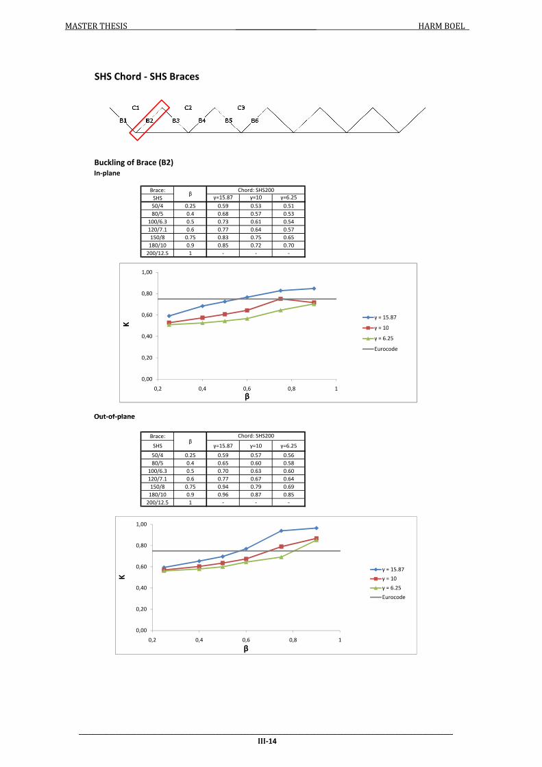
MASTER THESIS HARM BOEL
Buckling of Brace (B2)
In-plane
Brace:
SHS γ=15.87 γ=10 γ=6.25
50/4 0.25 0.59 0.53 0.51
80/5 0.4 0.68 0.57 0.53
100/6.3 0.5 0.73 0.61 0.54
120/7.1 0.6 0.77 0.64 0.57
150/8 0.75 0.83 0.75 0.65
180/10 0.9 0.85 0.72 0.70
200/12.5 1 - - -
Out-of-plane
SHS Chord - SHS Braces
βChord: SHS200
0,00
0,20
0,40
0,60
0,80
1,00
0,2 0,4 0,6 0,8 1
K
β
γ = 15.87
γ = 10
γ = 6.25
Eurocode
___________________________________________________________________________________________________________________________
III-14
Out-of-plane
Brace:
SHS γ=15.87 γ=10 γ=6.25
50/4 0.25 0.59 0.57 0.56
80/5 0.4 0.65 0.60 0.58
100/6.3 0.5 0.70 0.63 0.60
120/7.1 0.6 0.77 0.67 0.64
150/8 0.75 0.94 0.79 0.69
180/10 0.9 0.96 0.87 0.85
200/12.5 1 - - -
βChord: SHS200
0,00
0,20
0,40
0,60
0,80
1,00
0,2 0,4 0,6 0,8 1
K
β
γ = 15.87
γ = 10
γ = 6.25
Eurocode
0,00
0,20
0,40
0,60
0,80
1,00
0,2 0,4 0,6 0,8 1
K
β
γ = 15.87
γ = 10
γ = 6.25
Eurocode
___________________________________________________________________________________________________________________________
III-14

MASTER THESIS HARM BOEL
Buckling of Chord (C3)
In-plane
Brace:
CHS γ=15.87 γ=10 γ=6.25
48.3/4 0.24 - - -
76.1/5 0.38 - - -
114.3/6.3 0.57 0.89 0.90 0.91
121/7.1 0.61 0.88 0.87 0.89
152.4/8 0.76 0.84 0.83 0.84
177.8/10 0.89 0.76 0.77 0.78
193.7/12.5 0.97 0.71 0.71 0.73
Out-of-plane
SHS Chord - CHS Braces
βChord: SHS200
0,00
0,20
0,40
0,60
0,80
1,00
0,2 0,4 0,6 0,8 1
K
β
γ = 15.87
γ = 10
γ = 6.25
Eurocode
___________________________________________________________________________________________________________________________
III-15
Out-of-plane
Brace:
CHS γ=15.87 γ=10 γ=6.25
48.3/4 0.24 - - -
76.1/5 0.38 - - -
114.3/6.3 0.57 0.89 0.90 0.92
121/7.1 0.61 0.89 0.89 0.90
152.4/8 0.76 0.85 0.86 0.87
177.8/10 0.89 0.80 0.82 0.84
193.7/12.5 0.97 0.75 0.78 0.80
βChord: SHS200
0,00
0,20
0,40
0,60
0,80
1,00
0,2 0,4 0,6 0,8 1
K
β
γ = 15.87
γ = 10
γ = 6.25
Eurocode
0,00
0,20
0,40
0,60
0,80
1,00
0,2 0,4 0,6 0,8 1
K
β
γ = 15.87
γ = 10
γ = 6.25
Eurocode
___________________________________________________________________________________________________________________________
III-15
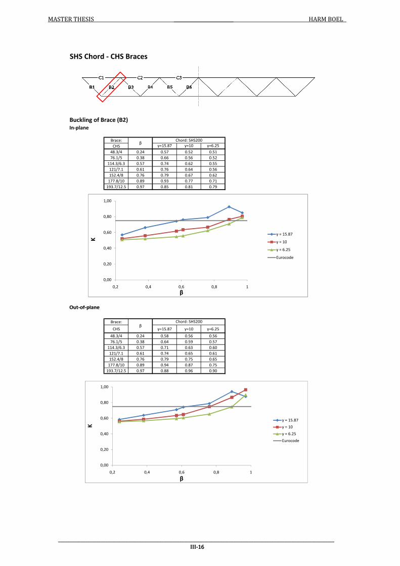
MASTER THESIS HARM BOEL
Buckling of Brace (B2)
In-plane
Brace:
CHS γ=15.87 γ=10 γ=6.25
48.3/4 0.24 0.57 0.52 0.51
76.1/5 0.38 0.66 0.56 0.52
114.3/6.3 0.57 0.74 0.62 0.55
121/7.1 0.61 0.76 0.64 0.56
152.4/8 0.76 0.79 0.67 0.62
177.8/10 0.89 0.93 0.77 0.71
193.7/12.5 0.97 0.85 0.81 0.79
Out-of-plane
SHS Chord - CHS Braces
βChord: SHS200
0,00
0,20
0,40
0,60
0,80
1,00
0,2 0,4 0,6 0,8 1
K
β
γ = 15.87
γ = 10
γ = 6.25
Eurocode
___________________________________________________________________________________________________________________________
III-16
Out-of-plane
Brace:
CHS γ=15.87 γ=10 γ=6.25
48.3/4 0.24 0.58 0.56 0.56
76.1/5 0.38 0.64 0.59 0.57
114.3/6.3 0.57 0.71 0.63 0.60
121/7.1 0.61 0.74 0.65 0.61
152.4/8 0.76 0.79 0.75 0.65
177.8/10 0.89 0.94 0.87 0.75
193.7/12.5 0.97 0.88 0.96 0.90
βChord: SHS200
0,00
0,20
0,40
0,60
0,80
1,00
0,2 0,4 0,6 0,8 1
K
β
γ = 15.87
γ = 10
γ = 6.25
Eurocode
0,00
0,20
0,40
0,60
0,80
1,00
0,2 0,4 0,6 0,8 1
K
β
γ = 15.87
γ = 10
γ = 6.25
Eurocode
___________________________________________________________________________________________________________________________
III-16

MASTER THESIS HARM BOEL
Buckling of Chord (C3)
In-plane
Brace:
CHS γ=15.37 γ=9.69 γ=6.05
48.3/4 0.25 - - -
76.1/5 0.39 0.85 0.89 0.92
114.3/6.3 0.59 0.82 0.84 0.87
121/7.1 0.62 0.79 0.82 0.85
152.4/8 0.79 0.71 0.74 0.78
177.8/10 0.92 0.64 0.67 0.70
193.7/12.5 1 0.60 0.63 0.66
Out-of-plane
CHS Chord - CHS Braces
βChord: CHS193.7
0,00
0,20
0,40
0,60
0,80
1,00
0,2 0,4 0,6 0,8 1
K
β
γ = 15.37
γ = 9.69
γ = 6.05
Eurocode
___________________________________________________________________________________________________________________________
III-17
Out-of-plane
Brace:
CHS γ=15.37 γ=9.69 γ=6.05
48.3/4 0.25 - - -
76.1/5 0.39 0.89 0.90 0.93
114.3/6.3 0.59 0.86 0.88 0.91
121/7.1 0.62 0.85 0.86 0.88
152.4/8 0.79 0.79 0.81 0.84
177.8/10 0.92 0.73 0.76 0.79
193.7/12.5 1 0.69 0.72 0.75
βChord: CHS193.7
0,00
0,20
0,40
0,60
0,80
1,00
0,2 0,4 0,6 0,8 1
K
β
γ = 15.37
γ = 9.69
γ = 6.05
Eurocode
0,00
0,20
0,40
0,60
0,80
1,00
0,2 0,4 0,6 0,8 1
K
β
γ = 15.37
γ = 9.69
γ = 6.05
Eurocode
___________________________________________________________________________________________________________________________
III-17

MASTER THESIS HARM BOEL
Buckling of Brace (B2)
In-plane
Brace:
CHS γ=15.37 γ=9.69 γ=6.05
48.3/4 0.25 0.52 0.51 0.51
76.1/5 0.39 0.54 0.52 0.51
114.3/6.3 0.59 0.62 0.59 0.58
121/7.1 0.62 0.67 0.65 0.57
152.4/8 0.79 0.76 0.79 0.68
177.8/10 0.92 0.87 0.73 0.72
193.7/12.5 1 - - 0.75
Out-of-plane
CHS Chord - CHS Braces
βChord: CHS193.7
0,00
0,20
0,40
0,60
0,80
1,00
0,2 0,4 0,6 0,8 1
K
β
γ = 15.37
γ = 9.69
γ = 6.05
Eurocode
___________________________________________________________________________________________________________________________
III-18
Out-of-plane
Brace:
CHS γ=15.37 γ=9.69 γ=6.05
48.3/4 0.25 0.58 0.56 0.56
76.1/5 0.39 0.62 0.59 0.57
114.3/6.3 0.59 0.72 0.64 0.61
121/7.1 0.62 0.81 0.68 0.62
152.4/8 0.79 0.91 0.84 0.72
177.8/10 0.92 0.99 0.89 0.87
193.7/12.5 1 - - 0.86
βChord: CHS193.7
0,00
0,20
0,40
0,60
0,80
1,00
0,2 0,4 0,6 0,8 1
K
β
γ = 15.37
γ = 9.69
γ = 6.05
Eurocode
0,00
0,20
0,40
0,60
0,80
1,00
0,2 0,4 0,6 0,8 1
K
β
γ = 15.37
γ = 9.69
γ = 6.05
Eurocode
___________________________________________________________________________________________________________________________
III-18

MASTER THESIS HARM BOEL
Buckling of Chord (C3)
Chord: SHS200/6.3 (γ = 15.87)
Brace:
SHS in out
50/4 0.25 - -
80/5 0.4 0.86 0.86
100/6.3 0.5 0.86 0.86
120/7.1 0.6 0.83 0.84
150/8 0.75 0.74 0.79
180/10 0.9 0.63 0.72
200/12.5 1 0.58 0.67
Chord: SHS200/10 (γ = 10)
Brace:
SHS in out
50/4 0.25 - -
80/5 0.4 0.87 0.88
100/6.3 0.5 0.86 0.88
120/7.1 0.6 0.84 0.86
150/8 0.75 0.75 0.81
180/10 0.9 0.66 0.75
200/12.5 1 0.61 0.70
K
K
In- and out-of-plane buckling: SHS Chord - SHS Braces
β
β
0,00
0,20
0,40
0,60
0,80
1,00
0,2 0,4 0,6 0,8 1
K
β
In-plane
Out-of-plane
Eurocode
0,40
0,60
0,80
1,00
K In-plane
Out-of-plane
___________________________________________________________________________________________________________________________
III-19
200/12.5 1 0.61 0.70
Chord: SHS200/16 (γ = 6.25)
Brace:
SHS in out
50/4 0.25 - -
80/5 0.4 0.90 0.92
100/6.3 0.5 0.88 0.91
120/7.1 0.6 0.86 0.86
150/8 0.75 0.77 0.83
180/10 0.9 0.69 0.77
200/12.5 1 - -
Kβ
0,00
0,20
0,40
0,60
0,80
1,00
0,2 0,4 0,6 0,8 1
K
β
In-plane
Out-of-plane
Eurocode
0,00
0,20
0,40
0,60
0,80
1,00
0,2 0,4 0,6 0,8 1
K
β
In-plane
Out-of-plane
Eurocode
0,00
0,20
0,40
0,60
0,80
1,00
0,2 0,4 0,6 0,8 1
K
β
In-plane
Out-of-plane
Eurocode
___________________________________________________________________________________________________________________________
III-19

MASTER THESIS HARM BOEL
Buckling of Brace (B2)
Chord: SHS200/6.3 (γ = 15.87)
Brace:
SHS in out
50/4 0.25 0.59 0.60
80/5 0.4 0.68 0.66
100/6.3 0.5 0.73 0.70
120/7.1 0.6 0.74 0.74
150/8 0.75 0.81 0.85
180/10 0.9 0.66 0.75
200/12.5 1 - 0.81
Chord: SHS200/10 (γ = 10)
Brace:
SHS in out
50/4 0.25 0.53 0.58
80/5 0.4 0.57 0.61
100/6.3 0.5 0.61 0.64
120/7.1 0.6 0.68 0.70
150/8 0.75 0.68 0.81
180/10 0.9 0.77 0.98
200/12.5 1 - 0.74
β
In- and out-of-plane buckling: SHS Chord - SHS Braces
βK
K
0,00
0,20
0,40
0,60
0,80
1,00
0,2 0,4 0,6 0,8 1
K
β
In-plane
Out-of-plane
Eurocode
0,40
0,60
0,80
1,00
K
In-plane
Out-of-plane
Eurocode
___________________________________________________________________________________________________________________________
III-20
200/12.5 1 - 0.74
Chord: SHS200/16 (γ = 6.25)
Brace:
SHS in out
50/4 0.25 0.51 0.57
80/5 0.4 0.53 0.58
100/6.3 0.5 0.54 0.60
120/7.1 0.6 0.59 0.63
150/8 0.75 0.66 0.71
180/10 0.9 0.67 0.84
200/12.5 1 - -
βK
0,00
0,20
0,40
0,60
0,80
1,00
0,2 0,4 0,6 0,8 1
K
β
In-plane
Out-of-plane
Eurocode
0,00
0,20
0,40
0,60
0,80
1,00
0,2 0,4 0,6 0,8 1
K
β
In-plane
Out-of-plane
Eurocode
0,00
0,20
0,40
0,60
0,80
1,00
0,2 0,4 0,6 0,8 1
K
β
In-plane
Out-of-plane
Eurocode
___________________________________________________________________________________________________________________________
III-20

MASTER THESIS HARM BOEL
Buckling of Chord (C3)
Chord: SHS200/6.3 (γ = 15.87)
Brace:
CHS in out
48.3/4 0.24 - -
76.1/5 0.38 - -
114.3/6.3 0.57 0.87 0.87
121/7.1 0.61 0.85 0.85
152.4/8 0.76 0.81 0.82
177.8/10 0.89 0.74 0.77
193.7/12.5 0.97 0.69 0.73
Chord: SHS200/10 (γ = 10)
Brace:
CHS in out
48.3/4 0.24 - -
76.1/5 0.38 - -
114.3/6.3 0.57 0.88 0.88
121/7.1 0.61 0.85 0.87
152.4/8 0.76 0.81 0.84
177.8/10 0.89 0.75 0.79
193.7/12.5 0.97 0.69 0.76
βK
βK
In- and out-of-plane buckling: SHS Chord - CHS Braces
0,00
0,20
0,40
0,60
0,80
1,00
0,2 0,4 0,6 0,8 1
K
β
In-plane
Out-of-plane
Eurocode
0,40
0,60
0,80
1,00
K In-plane
Out-of-plane
___________________________________________________________________________________________________________________________
III-21
193.7/12.5 0.97 0.69 0.76
Chord: SHS200/16 (γ = 6.25)
Brace:
CHS in out
48.3/4 0.24 - -
76.1/5 0.38 - -
114.3/6.3 0.57 0.90 0.92
121/7.1 0.61 0.87 0.88
152.4/8 0.76 0.83 0.86
177.8/10 0.89 0.76 0.80
193.7/12.5 0.97 0.71 0.78
βK
0,00
0,20
0,40
0,60
0,80
1,00
0,2 0,4 0,6 0,8 1
K
β
In-plane
Out-of-plane
Eurocode
0,00
0,20
0,40
0,60
0,80
1,00
0,2 0,4 0,6 0,8 1
K
β
In-plane
Out-of-plane
Eurocode
0,00
0,20
0,40
0,60
0,80
1,00
0,2 0,4 0,6 0,8 1
K
β
In-plane
Out-of-plane
Eurocode
___________________________________________________________________________________________________________________________
III-21

MASTER THESIS HARM BOEL
Buckling of Brace (B2)
Chord: SHS200/6.3 (γ = 15.87)
Brace:
CHS in out
48.3/4 0.24 0.57 0.59
76.1/5 0.38 0.66 0.64
114.3/6.3 0.57 0.74 0.71
121/7.1 0.61 0.76 0.73
152.4/8 0.76 0.81 0.81
177.8/10 0.89 0.78 0.93
193.7/12.5 0.97 0.80 0.95
Chord: SHS200/10 (γ = 10)
Brace:
CHS in out
48.3/4 0.24 0.52 0.57
76.1/5 0.38 0.56 0.59
114.3/6.3 0.57 0.62 0.64
121/7.1 0.61 0.63 0.65
152.4/8 0.76 0.68 0.70
177.8/10 0.89 0.75 0.79
193.7/12.5 0.97 0.77 0.95
βK
In- and out-of-plane buckling: SHS Chord - CHS Braces
βK
0,00
0,20
0,40
0,60
0,80
1,00
0,2 0,4 0,6 0,8 1
K
β
In-plane
Out-of-plane
Eurocode
0,40
0,60
0,80
1,00
K
In-plane
Out-of-plane
Eurocode
___________________________________________________________________________________________________________________________
III-22
193.7/12.5 0.97 0.77 0.95
Chord: SHS200/16 (γ = 6.25)
Brace:
CHS in out
48.3/4 0.24 0.51 0.56
76.1/5 0.38 0.52 0.57
114.3/6.3 0.57 0.55 0.60
121/7.1 0.61 0.56 0.61
152.4/8 0.76 0.59 0.69
177.8/10 0.89 0.65 0.77
193.7/12.5 0.97 0.66 0.81
βK
0,00
0,20
0,40
0,60
0,80
1,00
0,2 0,4 0,6 0,8 1
K
β
In-plane
Out-of-plane
Eurocode
0,00
0,20
0,40
0,60
0,80
1,00
0,2 0,4 0,6 0,8 1
K
β
In-plane
Out-of-plane
Eurocode
0,00
0,20
0,40
0,60
0,80
1,00
0,2 0,4 0,6 0,8 1
K
β
In-plane
Out-of-plane
Eurocode
___________________________________________________________________________________________________________________________
III-22

MASTER THESIS HARM BOEL
Buckling of Chord (C3)
Chord: CHS193.7/6.3 (γ = 15.37)
Brace:
CHS in out
48.3/4 0.25 - -
76.1/5 0.39 0.81 0.86
114.3/6.3 0.59 0.80 0.84
121/7.1 0.62 0.77 0.83
152.4/8 0.79 0.69 0.77
177.8/10 0.92 0.63 0.71
193.7/12.5 1 0.59 0.67
Chord: CHS193.7/10 (γ = 9.69)
Brace:
CHS in out
48.3/4 0.25 - -
76.1/5 0.39 0.86 0.88
114.3/6.3 0.59 0.83 0.87
121/7.1 0.62 0.80 0.84
152.4/8 0.79 0.72 0.79
177.8/10 0.92 0.65 0.74
193.7/12.5 1 0.61 0.70
βK
βK
In- and out-of-plane buckling: CHS Chord - CHS Braces
0,00
0,20
0,40
0,60
0,80
1,00
0,2 0,4 0,6 0,8 1
K
β
In-plane
Out-of-plane
Eurocode
0,40
0,60
0,80
1,00
K In-plane
Out-of-plane
___________________________________________________________________________________________________________________________
III-23
193.7/12.5 1 0.61 0.70
Chord: CHS193.7/16 (γ = 6.05)
Brace:
CHS in out
48.3/4 0.25 - -
76.1/5 0.39 0.90 0.93
114.3/6.3 0.59 0.82 0.86
121/7.1 0.62 0.84 0.88
152.4/8 0.79 0.76 0.81
177.8/10 0.92 0.69 0.77
193.7/12.5 1 0.64 0.73
βK
0,00
0,20
0,40
0,60
0,80
1,00
0,2 0,4 0,6 0,8 1
K
β
In-plane
Out-of-plane
Eurocode
0,00
0,20
0,40
0,60
0,80
1,00
0,2 0,4 0,6 0,8 1
K
β
In-plane
Out-of-plane
Eurocode
0,00
0,20
0,40
0,60
0,80
1,00
0,2 0,4 0,6 0,8 1
K
β
In-plane
Out-of-plane
Eurocode
___________________________________________________________________________________________________________________________
III-23

MASTER THESIS HARM BOEL
Buckling of Brace (B2)
Chord: CHS193.7/6.3 (γ = 15.37)
Brace:
CHS in out
48.3/4 0.25 0.52 0.58
76.1/5 0.39 0.54 0.62
114.3/6.3 0.59 0.63 0.69
121/7.1 0.62 0.69 0.74
152.4/8 0.79 0.85 0.90
177.8/10 0.92 0.87 0.95
193.7/12.5 1 - 0.81
Chord: CHS193.7/10 (γ = 9.69)
Brace:
CHS in out
48.3/4 0.25 0.51 0.57
76.1/5 0.39 0.52 0.59
114.3/6.3 0.59 0.57 0.66
121/7.1 0.62 0.60 0.66
152.4/8 0.79 0.71 0.76
177.8/10 0.92 0.79 0.85
193.7/12.5 1 0.65 0.74
βK
βK
In- and out-of-plane buckling: CHS Chord - CHS Braces
0,00
0,20
0,40
0,60
0,80
1,00
0,2 0,4 0,6 0,8 1
K
β
In-plane
Out-of-plane
Eurocode
0,40
0,60
0,80
1,00
K
In-plane
Out-of-plane
Eurocode
___________________________________________________________________________________________________________________________
III-24
193.7/12.5 1 0.65 0.74
Chord: CHS193.7/16 (γ = 6.05)
Brace:
CHS in out
48.3/4 0.25 0.51 0.56
76.1/5 0.39 0.51 0.58
114.3/6.3 0.59 0.55 0.61
121/7.1 0.62 0.55 0.63
152.4/8 0.79 0.62 0.74
177.8/10 0.92 0.68 0.85
193.7/12.5 1 0.59 0.76
βK
0,00
0,20
0,40
0,60
0,80
1,00
0,2 0,4 0,6 0,8 1
K
β
In-plane
Out-of-plane
Eurocode
0,00
0,20
0,40
0,60
0,80
1,00
0,2 0,4 0,6 0,8 1
K
β
In-plane
Out-of-plane
Eurocode
0,00
0,20
0,40
0,60
0,80
1,00
0,2 0,4 0,6 0,8 1
K
β
In-plane
Out-of-plane
Eurocode
___________________________________________________________________________________________________________________________
III-24

MASTER THESIS HARM BOEL
Buckling of Chord (C3)
In-plane buckling; wall thickness chord: 6.3
Brace: SHS - SHS Brace: SHS - CHS Brace: CHS - CHS
SHS K CHS K CHS K
50/4 0.25 - 48.3/4 0.24 - 48.3/4 0.25 -
80/5 0.4 0.86 76.1/5 0.38 - 76.1/5 0.39 0.81
100/6.3 0.5 0.86 114.3/6.3 0.57 0.87 114.3/6.3 0.59 0.80
120/7.1 0.6 0.83 121/7.1 0.61 0.85 121/7.1 0.62 0.77
150/8 0.75 0.74 152.4/8 0.76 0.81 152.4/8 0.79 0.69
180/10 0.9 0.63 177.8/10 0.89 0.74 177.8/10 0.92 0.63
200/12.5 1 0.58 193.7/12.5 0.97 0.69 193.7/12.5 1 0.59
Out-of-plane buckling; wall thickness chord: 6.3
Section type combination
β ββ
0,00
0,20
0,40
0,60
0,80
1,00
0,2 0,4 0,6 0,8 1
K
β
SHS - SHS
SHS - CHS
CHS - CHS
Eurocode
___________________________________________________________________________________________________________________________
III-25
Out-of-plane buckling; wall thickness chord: 6.3
Brace: SHS - SHS Brace: SHS - CHS Brace: CHS - CHS
SHS K CHS K CHS K
50/4 0.25 - 48.3/4 0.24 - 48.3/4 0.25 -
80/5 0.4 0.86 76.1/5 0.38 - 76.1/5 0.39 0.86
100/6.3 0.5 0.86 114.3/6.3 0.57 0.87 114.3/6.3 0.59 0.84
120/7.1 0.6 0.84 121/7.1 0.61 0.85 121/7.1 0.62 0.83
150/8 0.75 0.79 152.4/8 0.76 0.82 152.4/8 0.79 0.77
180/10 0.9 0.72 177.8/10 0.89 0.77 177.8/10 0.92 0.71
200/12.5 1 0.67 193.7/12.5 0.97 0.73 193.7/12.5 1 0.67
β β β
0,00
0,20
0,40
0,60
0,80
1,00
0,2 0,4 0,6 0,8 1
K
β
SHS - SHS
SHS - CHS
CHS - CHS
Eurocode
0,00
0,20
0,40
0,60
0,80
1,00
0,2 0,4 0,6 0,8 1
K
β
SHS - SHS
SHS - CHS
CHS - CHS
Eurocode
___________________________________________________________________________________________________________________________
III-25

MASTER THESIS HARM BOEL
Buckling of Chord (C3)
In-plane buckling; wall thickness chord: 10
Brace: SHS - SHS Brace: SHS - CHS Brace: CHS - CHS
SHS K CHS K CHS K
50/4 0.25 - 48.3/4 0.24 - 48.3/4 0.25 -
80/5 0.4 0.87 76.1/5 0.38 - 76.1/5 0.39 0.86
100/6.3 0.5 0.86 114.3/6.3 0.57 0.88 114.3/6.3 0.59 0.83
120/7.1 0.6 0.84 121/7.1 0.61 0.85 121/7.1 0.62 0.80
150/8 0.75 0.75 152.4/8 0.76 0.81 152.4/8 0.79 0.72
180/10 0.9 0.66 177.8/10 0.89 0.75 177.8/10 0.92 0.65
200/12.5 1 0.61 193.7/12.5 0.97 0.69 193.7/12.5 1 0.61
Out-of-plane buckling; wall thickness chord: 10
Section type combination
β ββ
0,00
0,20
0,40
0,60
0,80
1,00
0,2 0,4 0,6 0,8 1
K
β
SHS - SHS
SHS - CHS
CHS - CHS
Eurocode
___________________________________________________________________________________________________________________________
III-26
Out-of-plane buckling; wall thickness chord: 10
Brace: SHS - SHS Brace: SHS - CHS Brace: CHS - CHS
SHS K CHS K CHS K
50/4 0.25 - 48.3/4 0.24 - 48.3/4 0.25 -
80/5 0.4 0.88 76.1/5 0.38 - 76.1/5 0.39 0.88
100/6.3 0.5 0.88 114.3/6.3 0.57 0.88 114.3/6.3 0.59 0.87
120/7.1 0.6 0.86 121/7.1 0.61 0.87 121/7.1 0.62 0.84
150/8 0.75 0.81 152.4/8 0.76 0.84 152.4/8 0.79 0.79
180/10 0.9 0.75 177.8/10 0.89 0.79 177.8/10 0.92 0.74
200/12.5 1 0.70 193.7/12.5 0.97 0.76 193.7/12.5 1 0.70
β β β
0,00
0,20
0,40
0,60
0,80
1,00
0,2 0,4 0,6 0,8 1
K
β
SHS - SHS
SHS - CHS
CHS - CHS
Eurocode
0,00
0,20
0,40
0,60
0,80
1,00
0,2 0,4 0,6 0,8 1
K
β
SHS - SHS
SHS - CHS
CHS - CHS
Eurocode
___________________________________________________________________________________________________________________________
III-26

MASTER THESIS HARM BOEL
Buckling of Chord (C3)
In-plane buckling; wall thickness chord: 16
Brace: SHS - SHS Brace: SHS - CHS Brace: CHS - CHS
SHS K CHS K CHS K
50/4 0.25 - 48.3/4 0.24 - 48.3/4 0.25 -
80/5 0.4 0.90 76.1/5 0.38 - 76.1/5 0.39 0.90
100/6.3 0.5 0.88 114.3/6.3 0.57 0.90 114.3/6.3 0.59 0.82
120/7.1 0.6 0.86 121/7.1 0.61 0.87 121/7.1 0.62 0.84
150/8 0.75 0.77 152.4/8 0.76 0.83 152.4/8 0.79 0.76
180/10 0.9 0.69 177.8/10 0.89 0.76 177.8/10 0.92 0.69
200/12.5 1 0.00 193.7/12.5 0.97 0.71 193.7/12.5 1 0.64
Out-of-plane buckling; wall thickness chord: 16
β β
Section type combination
β
0,00
0,20
0,40
0,60
0,80
1,00
0,2 0,4 0,6 0,8 1
K
β
SHS - SHS
SHS - CHS
CHS - CHS
Eurocode
___________________________________________________________________________________________________________________________
III-27
Out-of-plane buckling; wall thickness chord: 16
Brace: SHS - SHS Brace: SHS - CHS Brace: CHS - CHS
SHS K CHS K CHS K
50/4 0.25 - 48.3/4 0.24 - 48.3/4 0.25 -
80/5 0.4 0.92 76.1/5 0.38 - 76.1/5 0.39 0.93
100/6.3 0.5 0.91 114.3/6.3 0.57 0.92 114.3/6.3 0.59 0.86
120/7.1 0.6 0.86 121/7.1 0.61 0.88 121/7.1 0.62 0.88
150/8 0.75 0.83 152.4/8 0.76 0.86 152.4/8 0.79 0.81
180/10 0.9 0.77 177.8/10 0.89 0.80 177.8/10 0.92 0.77
200/12.5 1 0.00 193.7/12.5 0.97 0.78 193.7/12.5 1 0.73
β β β
0,00
0,20
0,40
0,60
0,80
1,00
0,2 0,4 0,6 0,8 1
K
β
SHS - SHS
SHS - CHS
CHS - CHS
Eurocode
0,00
0,20
0,40
0,60
0,80
1,00
0,2 0,4 0,6 0,8 1
K
β
SHS - SHS
SHS - CHS
CHS - CHS
Eurocode
___________________________________________________________________________________________________________________________
III-27

MASTER THESIS HARM BOEL
Buckling of Brace (B2)
In-plane buckling; wall thickness chord: 6.3
Brace: SHS - SHS Brace: SHS - CHS Brace: CHS - CHS
SHS K CHS K CHS K
50/4 0.25 0.59 48.3/4 0.24 0.57 48.3/4 0.25 0.52
80/5 0.4 0.68 76.1/5 0.38 0.66 76.1/5 0.39 0.54
100/6.3 0.5 0.73 114.3/6.3 0.57 0.74 114.3/6.3 0.59 0.63
120/7.1 0.6 0.74 121/7.1 0.61 0.76 121/7.1 0.62 0.69
150/8 0.75 0.81 152.4/8 0.76 0.81 152.4/8 0.79 0.85
180/10 0.9 0.66 177.8/10 0.89 0.78 177.8/10 0.92 0.87
200/12.5 1 - 193.7/12.5 0.97 0.80 193.7/12.5 1 -
Out-of-plane buckling; wall thickness chord: 6.3
Section type combination
β β β
0,00
0,20
0,40
0,60
0,80
1,00
0,2 0,4 0,6 0,8 1
K
β
SHS - SHS
SHS - CHS
CHS - CHS
Eurocode
___________________________________________________________________________________________________________________________
III-28
Out-of-plane buckling; wall thickness chord: 6.3
Brace: SHS - SHS Brace: SHS - CHS Brace: CHS - CHS
SHS K CHS K CHS K
50/4 0.25 0.60 48.3/4 0.24 0.59 48.3/4 0.25 0.58
80/5 0.4 0.66 76.1/5 0.38 0.64 76.1/5 0.39 0.62
100/6.3 0.5 0.70 114.3/6.3 0.57 0.71 114.3/6.3 0.59 0.69
120/7.1 0.6 0.74 121/7.1 0.61 0.73 121/7.1 0.62 0.74
150/8 0.75 0.85 152.4/8 0.76 0.81 152.4/8 0.79 0.90
180/10 0.9 0.75 177.8/10 0.89 0.93 177.8/10 0.92 0.95
200/12.5 1 0.81 193.7/12.5 0.97 0.95 193.7/12.5 1 0.81
β β β
0,00
0,20
0,40
0,60
0,80
1,00
0,2 0,4 0,6 0,8 1
K
β
SHS - SHS
SHS - CHS
CHS - CHS
Eurocode
0,00
0,20
0,40
0,60
0,80
1,00
0,2 0,4 0,6 0,8 1
K
β
SHS - SHS
SHS - CHS
CHS - CHS
Eurocode
___________________________________________________________________________________________________________________________
III-28

MASTER THESIS HARM BOEL
Buckling of Brace (B2)
In-plane buckling; wall thickness chord: 10
Brace: SHS - SHS Brace: SHS - CHS Brace: CHS - CHS
SHS K CHS K CHS K
50/4 0.25 0.53 48.3/4 0.24 0.52 48.3/4 0.25 0.51
80/5 0.4 0.57 76.1/5 0.38 0.56 76.1/5 0.39 0.52
100/6.3 0.5 0.61 114.3/6.3 0.57 0.62 114.3/6.3 0.59 0.57
120/7.1 0.6 0.68 121/7.1 0.61 0.63 121/7.1 0.62 0.60
150/8 0.75 0.68 152.4/8 0.76 0.68 152.4/8 0.79 0.71
180/10 0.9 0.77 177.8/10 0.89 0.75 177.8/10 0.92 0.79
200/12.5 1 - 193.7/12.5 0.97 0.77 193.7/12.5 1 0.65
Out-of-plane buckling; wall thickness chord: 10
Section type combination
β ββ
0,00
0,20
0,40
0,60
0,80
1,00
0,2 0,4 0,6 0,8 1
K
β
SHS - SHS
SHS - CHS
CHS - CHS
Eurocode
___________________________________________________________________________________________________________________________
III-29
Out-of-plane buckling; wall thickness chord: 10
Brace: SHS - SHS Brace: SHS - CHS Brace: CHS - CHS
SHS K CHS K CHS K
50/4 0.25 0.58 48.3/4 0.24 0.57 48.3/4 0.25 0.57
80/5 0.4 0.61 76.1/5 0.38 0.59 76.1/5 0.39 0.59
100/6.3 0.5 0.64 114.3/6.3 0.57 0.64 114.3/6.3 0.59 0.66
120/7.1 0.6 0.70 121/7.1 0.61 0.65 121/7.1 0.62 0.66
150/8 0.75 0.81 152.4/8 0.76 0.70 152.4/8 0.79 0.76
180/10 0.9 0.98 177.8/10 0.89 0.79 177.8/10 0.92 0.85
200/12.5 1 0.74 193.7/12.5 0.97 0.95 193.7/12.5 1 0.74
β β β
0,00
0,20
0,40
0,60
0,80
1,00
0,2 0,4 0,6 0,8 1
K
β
SHS - SHS
SHS - CHS
CHS - CHS
Eurocode
0,00
0,20
0,40
0,60
0,80
1,00
0,2 0,4 0,6 0,8 1
K
β
SHS - SHS
SHS - CHS
CHS - CHS
Eurocode
___________________________________________________________________________________________________________________________
III-29

MASTER THESIS HARM BOEL
Buckling of Brace (B2)
In-plane buckling; wall thickness chord: 16
Brace: SHS - SHS Brace: SHS - CHS Brace: CHS - CHS
SHS K CHS K CHS K
50/4 0.25 0.51 48.3/4 0.24 0.51 48.3/4 0.25 0.51
80/5 0.4 0.53 76.1/5 0.38 0.52 76.1/5 0.39 0.51
100/6.3 0.5 0.54 114.3/6.3 0.57 0.55 114.3/6.3 0.59 0.55
120/7.1 0.6 0.59 121/7.1 0.61 0.56 121/7.1 0.62 0.55
150/8 0.75 0.66 152.4/8 0.76 0.59 152.4/8 0.79 0.62
180/10 0.9 0.67 177.8/10 0.89 0.65 177.8/10 0.92 0.68
200/12.5 1 0.00 193.7/12.5 0.97 0.66 193.7/12.5 1 0.59
Out-of-plane buckling; wall thickness chord: 16
β β
Section type combination
β
0,00
0,20
0,40
0,60
0,80
1,00
0,2 0,4 0,6 0,8 1
K
β
SHS - SHS
SHS - CHS
CHS - CHS
Eurocode
___________________________________________________________________________________________________________________________
III-30
Out-of-plane buckling; wall thickness chord: 16
Brace: SHS - SHS Brace: SHS - CHS Brace: CHS - CHS
SHS K CHS K CHS K
50/4 0.25 0.57 48.3/4 0.24 0.56 48.3/4 0.25 0.56
80/5 0.4 0.58 76.1/5 0.38 0.57 76.1/5 0.39 0.58
100/6.3 0.5 0.60 114.3/6.3 0.57 0.60 114.3/6.3 0.59 0.61
120/7.1 0.6 0.63 121/7.1 0.61 0.61 121/7.1 0.62 0.63
150/8 0.75 0.71 152.4/8 0.76 0.69 152.4/8 0.79 0.74
180/10 0.9 0.84 177.8/10 0.89 0.77 177.8/10 0.92 0.85
200/12.5 1 0.00 193.7/12.5 0.97 0.81 193.7/12.5 1 0.76
β β β
0,00
0,20
0,40
0,60
0,80
1,00
0,2 0,4 0,6 0,8 1
K
β
SHS - SHS
SHS - CHS
CHS - CHS
Eurocode
0,00
0,20
0,40
0,60
0,80
1,00
0,2 0,4 0,6 0,8 1
K
β
SHS - SHS
SHS - CHS
CHS - CHS
Eurocode
___________________________________________________________________________________________________________________________
III-30

MASTER THESIS HARM BOEL
Buckling of Chord (C2 / C3) Brace:
SHS LG1 LG2 LG3
50/4 0.25 - - -
80/5 0.4 0.87 0.86 0.89
100/6.3 0.5 0.87 0.86 0.88
120/7.1 0.6 0.88 0.83 0.85
150/8 0.75 0.75 0.74 0.76
180/10 0.9 0.65 0.63 0.65
200/12.5 1 0.59 0.58 0.59
Comparison LG1, LG2 & LG3: SHS - SHS
βK
In-plane buckling; t1: 6.3 mm
0,00
0,20
0,40
0,60
0,80
1,00
0,2 0,4 0,6 0,8 1
K
β
LG1
LG2
LG3
Eurocode
___________________________________________________________________________________________________________________________
III-31
Brace:
SHS LG1 LG2 LG3
50/4 0.25 - - -
80/5 0.4 0.92 0.86 0.90
100/6.3 0.5 0.87 0.86 0.88
120/7.1 0.6 0.88 0.84 0.86
150/8 0.75 0.81 0.79 0.81
180/10 0.9 0.73 0.72 0.74
200/12.5 1 0.69 0.67 0.69
βKOut-of-plane buckling; t1: 6.3 mm
0,00
0,20
0,40
0,60
0,80
1,00
0,2 0,4 0,6 0,8 1
K
β
LG1
LG2
LG3
Eurocode
0,00
0,20
0,40
0,60
0,80
1,00
0,2 0,4 0,6 0,8 1
K
β
LG1
LG2
LG3
Eurocode
___________________________________________________________________________________________________________________________
III-31

MASTER THESIS HARM BOEL
Buckling of Chord (C2 / C3) Brace:
SHS LG1 LG2 LG3
50/4 0.25 - - -
80/5 0.4 0.84 0.87 0.90
100/6.3 0.5 0.88 0.86 0.88
120/7.1 0.6 0.90 0.84 0.85
150/8 0.75 0.77 0.75 0.77
180/10 0.9 0.67 0.66 0.68
200/12.5 1 0.62 0.61 0.62
βK
Comparison LG1, LG2 & LG3: SHS - SHS
In-plane buckling; t1: 10 mm
0,00
0,20
0,40
0,60
0,80
1,00
0,2 0,4 0,6 0,8 1
K
β
LG1
LG2
LG3
Eurocode
___________________________________________________________________________________________________________________________
III-32
Brace:
SHS LG1 LG2 LG3
50/4 0.25 - - -
80/5 0.4 0.89 0.88 0.90
100/6.3 0.5 0.88 0.88 0.90
120/7.1 0.6 0.83 0.86 0.88
150/8 0.75 0.83 0.81 0.83
180/10 0.9 0.76 0.75 0.77
200/12.5 1 0.72 0.70 0.72
βKOut-of-plane buckling; t1: 10 mm
0,00
0,20
0,40
0,60
0,80
1,00
0,2 0,4 0,6 0,8 1
K
β
LG1
LG2
LG3
Eurocode
0,00
0,20
0,40
0,60
0,80
1,00
0,2 0,4 0,6 0,8 1
K
β
LG1
LG2
LG3
Eurocode
___________________________________________________________________________________________________________________________
III-32

MASTER THESIS HARM BOEL
Buckling of Chord (C2 / C3) Brace:
SHS LG1 LG2 LG3
50/4 0.25 - - -
80/5 0.4 0.88 0.90 0.92
100/6.3 0.5 0.92 0.88 0.90
120/7.1 0.6 0.82 0.86 0.87
150/8 0.75 0.80 0.77 0.79
180/10 0.9 0.71 0.69 0.71
Comparison LG1, LG2 & LG3: SHS - SHS
βK
In-plane buckling; t1: 16 mm
0,00
0,20
0,40
0,60
0,80
1,00
0,2 0,4 0,6 0,8 1
K
β
LG1
LG2
LG3
Eurocode
___________________________________________________________________________________________________________________________
III-33
Brace:
SHS LG1 LG2 LG3
50/4 0.25 - - -
80/5 0.4 0.89 0.92 0.92
100/6.3 0.5 0.94 0.91 0.91
120/7.1 0.6 0.86 0.86 0.89
150/8 0.75 0.85 0.83 0.85
180/10 0.9 0.79 0.77 0.80
βKOut-of-plane buckling; t1: 16 mm
0,00
0,20
0,40
0,60
0,80
1,00
0,2 0,4 0,6 0,8 1
K
β
LG1
LG2
LG3
Eurocode
0,00
0,20
0,40
0,60
0,80
1,00
0,2 0,4 0,6 0,8 1
K
β
LG1
LG2
LG3
Eurocode
___________________________________________________________________________________________________________________________
III-33

MASTER THESIS HARM BOEL
Buckling of Brace (B2) Brace:
SHS LG1 LG2 LG3
50/4 0.25 0.59 0.59 0.59
80/5 0.4 0.68 0.68 0.68
100/6.3 0.5 0.73 0.73 0.73
120/7.1 0.6 0.76 0.74 0.77
150/8 0.75 0.82 0.81 0.83
180/10 0.9 0.65 0.66 0.85
200/12.5 1 0.74 - -
Comparison LG1, LG2 & LG3: SHS - SHS
βK
In-plane buckling; t1: 6.3 mm
0,00
0,20
0,40
0,60
0,80
1,00
0,2 0,4 0,6 0,8 1
K
β
LG1
LG2
LG3
Eurocode
___________________________________________________________________________________________________________________________
III-34
Brace:
SHS LG1 LG2 LG3
50/4 0.25 0.61 0.60 0.59
80/5 0.4 0.66 0.66 0.65
100/6.3 0.5 0.70 0.70 0.70
120/7.1 0.6 0.77 0.74 0.77
150/8 0.75 0.86 0.85 0.94
180/10 0.9 0.75 0.75 0.96
200/12.5 1 0.81 0.81 -
βKOut-of-plane buckling; t1: 6.3 mm
0,00
0,20
0,40
0,60
0,80
1,00
0,2 0,4 0,6 0,8 1
K
β
LG1
LG2
LG3
Eurocode
0,00
0,20
0,40
0,60
0,80
1,00
0,2 0,4 0,6 0,8 1
K
β
LG1
LG2
LG3
Eurocode
___________________________________________________________________________________________________________________________
III-34

MASTER THESIS HARM BOEL
Buckling of Brace (B2) Brace:
SHS LG1 LG2 LG3
50/4 0.25 0.53 0.53 0.53
80/5 0.4 0.57 0.57 0.57
100/6.3 0.5 0.61 0.61 0.61
120/7.1 0.6 0.65 0.68 0.64
150/8 0.75 0.69 0.68 0.75
180/10 0.9 0.74 0.77 0.72
200/12.5 1 0.65 - -
Comparison LG1, LG2 & LG3: SHS - SHS
βK
In-plane buckling; t1: 10 mm
0,00
0,20
0,40
0,60
0,80
1,00
0,2 0,4 0,6 0,8 1
K
β
LG1
LG2
LG3
Eurocode
___________________________________________________________________________________________________________________________
III-35
Brace:
SHS LG1 LG2 LG3
50/4 0.25 0.58 0.58 0.57
80/5 0.4 0.62 0.61 0.60
100/6.3 0.5 0.64 0.64 0.63
120/7.1 0.6 0.67 0.70 0.67
150/8 0.75 0.75 0.81 0.79
180/10 0.9 0.81 0.98 0.87
200/12.5 1 0.74 0.74 -
βKOut-of-plane buckling; t1: 10 mm
0,00
0,20
0,40
0,60
0,80
1,00
0,2 0,4 0,6 0,8 1
K
β
LG1
LG2
LG3
Eurocode
0,00
0,20
0,40
0,60
0,80
1,00
0,2 0,4 0,6 0,8 1
K
β
LG1
LG2
LG3
Eurocode
___________________________________________________________________________________________________________________________
III-35

MASTER THESIS HARM BOEL
Buckling of Brace (B2) Brace:
SHS LG1 LG2 LG3
50/4 0.25 0.51 0.51 0.51
80/5 0.4 0.53 0.53 0.53
100/6.3 0.5 0.54 0.54 0.54
120/7.1 0.6 0.57 0.59 0.57
150/8 0.75 0.61 0.66 0.65
180/10 0.9 0.65 0.67 0.70
Comparison LG1, LG2 & LG3: SHS - SHS
In-plane buckling; t1: 16 mmK
β
0,00
0,20
0,40
0,60
0,80
1,00
0,2 0,4 0,6 0,8 1
K
β
LG1
LG2
LG3
Eurocode
___________________________________________________________________________________________________________________________
III-36
Brace:
SHS LG1 LG2 LG3
50/4 0.25 0.58 0.57 0.56
80/5 0.4 0.59 0.58 0.58
100/6.3 0.5 0.61 0.60 0.60
120/7.1 0.6 0.63 0.63 0.64
150/8 0.75 0.68 0.71 0.69
180/10 0.9 0.86 0.84 0.85
Out-of-plane buckling; t1: 16 mmβ
K
0,00
0,20
0,40
0,60
0,80
1,00
0,2 0,4 0,6 0,8 1
K
β
LG1
LG2
LG3
Eurocode
0,00
0,20
0,40
0,60
0,80
1,00
0,2 0,4 0,6 0,8 1
K
β
LG1
LG2
LG3
Eurocode
___________________________________________________________________________________________________________________________
III-36

MASTER THESIS HARM BOEL
Buckling of Chord (C2 / C3) Brace:
CHS LG1 LG2 LG3
48.3/4 0.24 - - -
76.1/5 0.38 0.90 - -
114.3/6.3 0.57 0.88 0.87 0.89
121/7.1 0.61 0.86 0.85 0.88
152.4/8 0.76 0.84 0.81 0.84
177.8/10 0.89 0.76 0.74 0.76
193.7/12.5 0.97 0.70 0.69 0.71
Comparison LG1, LG2 & LG3: SHS - CHS
βK
In-plane buckling; t1: 6.3 mm
0,00
0,20
0,40
0,60
0,80
1,00
0,2 0,4 0,6 0,8 1
K
β
LG1
LG2
LG3
Eurocode
___________________________________________________________________________________________________________________________
III-37
Brace:
CHS LG1 LG2 LG3
48.3/4 0.24 - - -
76.1/5 0.38 0.89 - -
114.3/6.3 0.57 0.87 0.87 0.89
121/7.1 0.61 0.86 0.85 0.89
152.4/8 0.76 0.84 0.82 0.85
177.8/10 0.89 0.79 0.77 0.80
193.7/12.5 0.97 0.75 0.73 0.75
βKOut-of-plane buckling; t1: 6.3 mm
0,00
0,20
0,40
0,60
0,80
1,00
0,2 0,4 0,6 0,8 1
K
β
LG1
LG2
LG3
Eurocode
0,00
0,20
0,40
0,60
0,80
1,00
0,2 0,4 0,6 0,8 1
K
β
LG1
LG2
LG3
Eurocode
___________________________________________________________________________________________________________________________
III-37

MASTER THESIS HARM BOEL
Buckling of Chord (C2 / C3) Brace:
CHS LG1 LG2 LG3
48.3/4 0.24 - - -
76.1/5 0.38 - - -
114.3/6.3 0.57 0.89 0.88 0.90
121/7.1 0.61 0.86 0.85 0.87
152.4/8 0.76 0.84 0.81 0.83
177.8/10 0.89 0.76 0.75 0.77
193.7/12.5 0.97 0.71 0.69 0.71
Comparison LG1, LG2 & LG3: SHS - CHS
βK
In-plane buckling; t1: 10 mm
0,00
0,20
0,40
0,60
0,80
1,00
0,2 0,4 0,6 0,8 1
K
β
LG1
LG2
LG3
Eurocode
___________________________________________________________________________________________________________________________
III-38
Brace:
CHS LG1 LG2 LG3
48.3/4 0.24 - - -
76.1/5 0.38 - - -
114.3/6.3 0.57 0.89 0.88 0.90
121/7.1 0.61 0.87 0.87 0.89
152.4/8 0.76 0.87 0.84 0.86
177.8/10 0.89 0.81 0.79 0.82
193.7/12.5 0.97 0.77 0.76 0.78
βKOut-of-plane buckling; t1: 10 mm
0,00
0,20
0,40
0,60
0,80
1,00
0,2 0,4 0,6 0,8 1
K
β
LG1
LG2
LG3
Eurocode
0,00
0,20
0,40
0,60
0,80
1,00
0,2 0,4 0,6 0,8 1
K
β
LG1
LG2
LG3
Eurocode
___________________________________________________________________________________________________________________________
III-38

MASTER THESIS HARM BOEL
Buckling of Chord (C2 / C3) Brace:
CHS LG1 LG2 LG3
48.3/4 0.24 - - -
76.1/5 0.38 - - -
114.3/6.3 0.57 0.94 0.90 0.91
121/7.1 0.61 0.89 0.87 0.89
152.4/8 0.76 0.87 0.83 0.84
177.8/10 0.89 0.78 0.76 0.78
193.7/12.5 0.97 0.73 0.71 0.73
βK
In-plane buckling; t1: 16 mm
Comparison LG1, LG2 & LG3: SHS - CHS
0,00
0,20
0,40
0,60
0,80
1,00
0,2 0,4 0,6 0,8 1
K
β
LG1
LG2
LG3
Eurocode
___________________________________________________________________________________________________________________________
III-39
Brace:
CHS LG1 LG2 LG3
48.3/4 0.24 - - -
76.1/5 0.38 - - -
114.3/6.3 0.57 0.88 0.92 0.92
121/7.1 0.61 0.90 0.88 0.90
152.4/8 0.76 0.91 0.86 0.87
177.8/10 0.89 0.83 0.80 0.84
193.7/12.5 0.97 0.80 0.78 0.80
βKOut-of-plane buckling; t1: 16 mm
0,00
0,20
0,40
0,60
0,80
1,00
0,2 0,4 0,6 0,8 1
K
β
LG1
LG2
LG3
Eurocode
0,00
0,20
0,40
0,60
0,80
1,00
0,2 0,4 0,6 0,8 1
K
β
LG1
LG2
LG3
Eurocode
___________________________________________________________________________________________________________________________
III-39

MASTER THESIS HARM BOEL
Buckling of Brace (B2) Brace:
CHS LG1 LG2 LG3
48.3/4 0.24 0.57 0.57 0.57
76.1/5 0.38 0.66 0.66 0.66
114.3/6.3 0.57 0.74 0.74 0.74
121/7.1 0.61 0.76 0.76 0.76
152.4/8 0.76 0.77 0.81 0.79
177.8/10 0.89 0.77 0.78 0.93
193.7/12.5 0.97 0.81 0.80 0.85
Comparison LG1, LG2 & LG3: SHS - CHS
βK
In-plane buckling; t1: 6.3 mm
0,00
0,20
0,40
0,60
0,80
1,00
0,2 0,4 0,6 0,8 1
K
β
LG1
LG2
LG3
Eurocode
___________________________________________________________________________________________________________________________
III-40
Brace:
CHS LG1 LG2 LG3
48.3/4 0.24 0.60 0.59 0.58
76.1/5 0.38 0.65 0.64 0.64
114.3/6.3 0.57 0.71 0.71 0.71
121/7.1 0.61 0.73 0.73 0.74
152.4/8 0.76 0.77 0.81 0.79
177.8/10 0.89 0.94 0.93 0.94
193.7/12.5 0.97 0.86 0.95 0.88
βKOut-of-plane buckling; t1: 6.3 mm
0,00
0,20
0,40
0,60
0,80
1,00
0,2 0,4 0,6 0,8 1
K
β
LG1
LG2
LG3
Eurocode
0,00
0,20
0,40
0,60
0,80
1,00
0,2 0,4 0,6 0,8 1
K
β
LG1
LG2
LG3
Eurocode
___________________________________________________________________________________________________________________________
III-40

MASTER THESIS HARM BOEL
Buckling of Brace (B2) Brace:
CHS LG1 LG2 LG3
48.3/4 0.24 0.52 0.52 0.52
76.1/5 0.38 0.56 0.56 0.56
114.3/6.3 0.57 0.62 0.62 0.62
121/7.1 0.61 0.63 0.63 0.64
152.4/8 0.76 0.66 0.68 0.67
177.8/10 0.89 0.76 0.75 0.77
193.7/12.5 0.97 0.74 0.77 0.81
KβIn-plane buckling; t1: 10 mm
Comparison LG1, LG2 & LG3: SHS - CHS
0,00
0,20
0,40
0,60
0,80
1,00
0,2 0,4 0,6 0,8 1
K
β
LG1
LG2
LG3
Eurocode
___________________________________________________________________________________________________________________________
III-41
Brace:
CHS LG1 LG2 LG3
48.3/4 0.24 0.58 0.57 0.56
76.1/5 0.38 0.60 0.59 0.59
114.3/6.3 0.57 0.64 0.64 0.63
121/7.1 0.61 0.66 0.65 0.65
152.4/8 0.76 0.74 0.70 0.75
177.8/10 0.89 0.80 0.79 0.87
193.7/12.5 0.97 0.80 0.95 0.96
βKOut-of-plane buckling; t1: 10 mm
0,00
0,20
0,40
0,60
0,80
1,00
0,2 0,4 0,6 0,8 1
K
β
LG1
LG2
LG3
Eurocode
0,00
0,20
0,40
0,60
0,80
1,00
0,2 0,4 0,6 0,8 1
K
β
LG1
LG2
LG3
Eurocode
___________________________________________________________________________________________________________________________
III-41

MASTER THESIS HARM BOEL
Buckling of Brace (B2) Brace:
CHS LG1 LG2 LG3
48.3/4 0.24 0.51 0.51 0.51
76.1/5 0.38 0.52 0.52 0.52
114.3/6.3 0.57 0.55 0.55 0.55
121/7.1 0.61 0.56 0.56 0.56
152.4/8 0.76 0.62 0.59 0.62
177.8/10 0.89 0.66 0.65 0.71
193.7/12.5 0.97 0.77 0.66 0.79
K
Comparison LG1, LG2 & LG3: SHS - CHS
βIn-plane buckling; t1: 16 mm
0,00
0,20
0,40
0,60
0,80
1,00
0,2 0,4 0,6 0,8 1
K
β
LG1
LG2
LG3
Eurocode
___________________________________________________________________________________________________________________________
III-42
Brace:
CHS LG1 LG2 LG3
48.3/4 0.24 0.57 0.56 0.56
76.1/5 0.38 0.58 0.57 0.57
114.3/6.3 0.57 0.61 0.60 0.60
121/7.1 0.61 0.61 0.61 0.61
152.4/8 0.76 0.65 0.69 0.65
177.8/10 0.89 0.71 0.77 0.75
193.7/12.5 0.97 0.83 0.81 0.90
Out-of-plane buckling; t1: 16 mmβ
K
0,00
0,20
0,40
0,60
0,80
1,00
0,2 0,4 0,6 0,8 1
K
β
LG1
LG2
LG3
Eurocode
0,00
0,20
0,40
0,60
0,80
1,00
0,2 0,4 0,6 0,8 1
K
β
LG1
LG2
LG3
Eurocode
___________________________________________________________________________________________________________________________
III-42
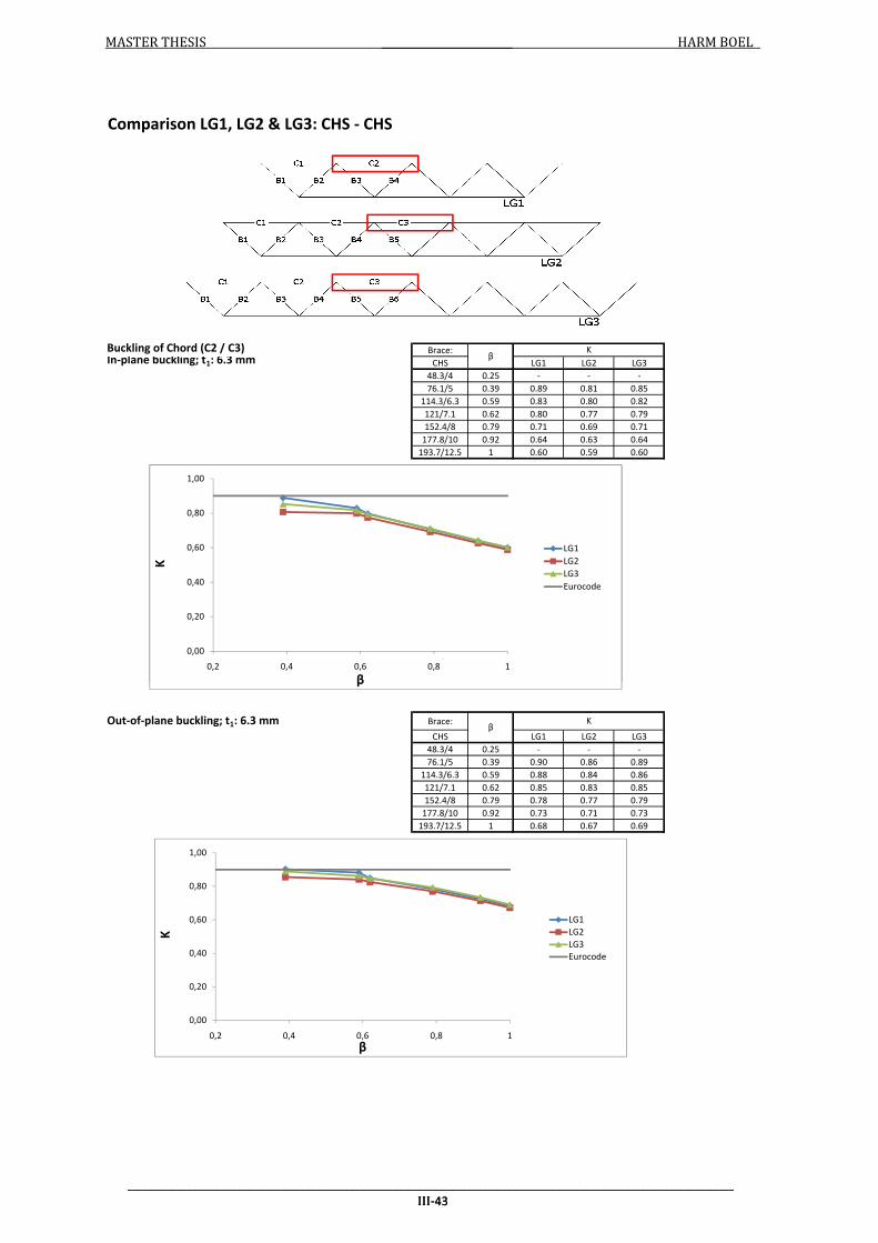
MASTER THESIS HARM BOEL
Buckling of Chord (C2 / C3) Brace:
CHS LG1 LG2 LG3
48.3/4 0.25 - - -
76.1/5 0.39 0.89 0.81 0.85
114.3/6.3 0.59 0.83 0.80 0.82
121/7.1 0.62 0.80 0.77 0.79
152.4/8 0.79 0.71 0.69 0.71
177.8/10 0.92 0.64 0.63 0.64
193.7/12.5 1 0.60 0.59 0.60
Comparison LG1, LG2 & LG3: CHS - CHS
βK
In-plane buckling; t1: 6.3 mm
0,00
0,20
0,40
0,60
0,80
1,00
0,2 0,4 0,6 0,8 1
K
β
LG1
LG2
LG3
Eurocode
___________________________________________________________________________________________________________________________
III-43
Brace:
CHS LG1 LG2 LG3
48.3/4 0.25 - - -
76.1/5 0.39 0.90 0.86 0.89
114.3/6.3 0.59 0.88 0.84 0.86
121/7.1 0.62 0.85 0.83 0.85
152.4/8 0.79 0.78 0.77 0.79
177.8/10 0.92 0.73 0.71 0.73
193.7/12.5 1 0.68 0.67 0.69
βKOut-of-plane buckling; t1: 6.3 mm
0,00
0,20
0,40
0,60
0,80
1,00
0,2 0,4 0,6 0,8 1
K
β
LG1
LG2
LG3
Eurocode
0,00
0,20
0,40
0,60
0,80
1,00
0,2 0,4 0,6 0,8 1
K
β
LG1
LG2
LG3
Eurocode
___________________________________________________________________________________________________________________________
III-43

MASTER THESIS HARM BOEL
Buckling of Chord (C2 / C3) Brace:
CHS LG1 LG2 LG3
48.3/4 0.25 - - -
76.1/5 0.39 0.87 0.86 0.89
114.3/6.3 0.59 0.89 0.83 0.84
121/7.1 0.62 0.84 0.80 0.82
152.4/8 0.79 0.74 0.72 0.74
177.8/10 0.92 0.67 0.65 0.67
193.7/12.5 1 0.62 0.61 0.63
Comparison LG1, LG2 & LG3: CHS - CHS
βK
In-plane buckling; t1: 10 mm
0,00
0,20
0,40
0,60
0,80
1,00
0,2 0,4 0,6 0,8 1
K
β
LG1
LG2
LG3
Eurocode
___________________________________________________________________________________________________________________________
III-44
Brace:
CHS LG1 LG2 LG3
48.3/4 0.25 - - -
76.1/5 0.39 0.89 0.88 0.90
114.3/6.3 0.59 0.84 0.87 0.88
121/7.1 0.62 0.89 0.84 0.86
152.4/8 0.79 0.81 0.79 0.81
177.8/10 0.92 0.75 0.74 0.76
193.7/12.5 1 0.71 0.70 0.72
Out-of-plane buckling; t1: 10 mmβ
K
0,00
0,20
0,40
0,60
0,80
1,00
0,2 0,4 0,6 0,8 1
K
β
LG1
LG2
LG3
Eurocode
0,00
0,20
0,40
0,60
0,80
1,00
0,2 0,4 0,6 0,8 1
K
β
LG1
LG2
LG3
Eurocode
___________________________________________________________________________________________________________________________
III-44

MASTER THESIS HARM BOEL
Buckling of Chord (C2 / C3) Brace:
CHS LG1 LG2 LG3
48.3/4 0.25 - - -
76.1/5 0.39 0.89 0.90 0.92
114.3/6.3 0.59 0.84 0.82 0.87
121/7.1 0.62 0.79 0.84 0.85
152.4/8 0.79 0.78 0.76 0.78
177.8/10 0.92 0.70 0.69 0.70
193.7/12.5 1 0.65 0.64 0.66
βK
In-plane buckling; t1: 16 mm
Comparison LG1, LG2 & LG3: CHS - CHS
0,00
0,20
0,40
0,60
0,80
1,00
0,2 0,4 0,6 0,8 1
K
β
LG1
LG2
LG3
Eurocode
___________________________________________________________________________________________________________________________
III-45
Brace:
CHS LG1 LG2 LG3
48.3/4 0.25 - - -
76.1/5 0.39 0.89 0.93 0.93
114.3/6.3 0.59 0.87 0.86 0.91
121/7.1 0.62 0.85 0.88 0.88
152.4/8 0.79 0.84 0.81 0.84
177.8/10 0.92 0.78 0.77 0.79
193.7/12.5 1 0.74 0.73 0.75
βKOut-of-plane buckling; t1: 16 mm
0,00
0,20
0,40
0,60
0,80
1,00
0,2 0,4 0,6 0,8 1
K
β
LG1
LG2
LG3
Eurocode
0,00
0,20
0,40
0,60
0,80
1,00
0,2 0,4 0,6 0,8 1
K
β
LG1
LG2
LG3
Eurocode
___________________________________________________________________________________________________________________________
III-45

MASTER THESIS HARM BOEL
Buckling of Brace (B2) Brace:
CHS LG1 LG2 LG3
48.3/4 0.25 0.52 0.52 0.52
76.1/5 0.39 0.54 0.54 0.54
114.3/6.3 0.59 0.67 0.63 0.62
121/7.1 0.62 0.64 0.69 0.67
152.4/8 0.79 0.70 0.85 0.76
177.8/10 0.92 0.66 0.87 0.87
193.7/12.5 1 0.76 - -
Comparison LG1, LG2 & LG3: CHS - CHS
βK
In-plane buckling; t1: 6.3 mm
0,00
0,20
0,40
0,60
0,80
1,00
0,2 0,4 0,6 0,8 1
K
β
LG1
LG2
LG3
Eurocode
___________________________________________________________________________________________________________________________
III-46
Brace:
CHS LG1 LG2 LG3
48.3/4 0.25 0.59 0.58 0.58
76.1/5 0.39 0.63 0.62 0.62
114.3/6.3 0.59 0.72 0.69 0.72
121/7.1 0.62 0.72 0.74 0.81
152.4/8 0.79 0.91 0.90 0.91
177.8/10 0.92 0.76 0.95 0.99
193.7/12.5 1 0.81 0.81 -
Out-of-plane buckling; t1: 6.3 mmβ
K
0,00
0,20
0,40
0,60
0,80
1,00
0,2 0,4 0,6 0,8 1
K
β
LG1
LG2
LG3
Eurocode
0,00
0,20
0,40
0,60
0,80
1,00
0,2 0,4 0,6 0,8 1
K
β
LG1
LG2
LG3
Eurocode
___________________________________________________________________________________________________________________________
III-46

MASTER THESIS HARM BOEL
Buckling of Brace (B2) Brace:
CHS LG1 LG2 LG3
48.3/4 0.25 0.51 0.51 0.51
76.1/5 0.39 0.52 0.52 0.52
114.3/6.3 0.59 0.59 0.57 0.59
121/7.1 0.62 0.58 0.60 0.65
152.4/8 0.79 0.72 0.71 0.79
177.8/10 0.92 0.76 0.79 0.73
193.7/12.5 1 0.65 0.65 -
KβIn-plane buckling; t1: 10 mm
Comparison LG1, LG2 & LG3: CHS - CHS
0,00
0,20
0,40
0,60
0,80
1,00
0,2 0,4 0,6 0,8 1
K
β
LG1
LG2
LG3
Eurocode
___________________________________________________________________________________________________________________________
III-47
Brace:
CHS LG1 LG2 LG3
48.3/4 0.25 0.58 0.57 0.56
76.1/5 0.39 0.60 0.59 0.59
114.3/6.3 0.59 0.61 0.66 0.64
121/7.1 0.62 0.68 0.66 0.68
152.4/8 0.79 0.78 0.76 0.84
177.8/10 0.92 0.83 0.85 0.89
193.7/12.5 1 0.78 0.74 -
βKOut-of-plane buckling; t1: 10 mm
0,00
0,20
0,40
0,60
0,80
1,00
0,2 0,4 0,6 0,8 1
K
β
LG1
LG2
LG3
Eurocode
0,00
0,20
0,40
0,60
0,80
1,00
0,2 0,4 0,6 0,8 1
K
β
LG1
LG2
LG3
Eurocode
___________________________________________________________________________________________________________________________
III-47

MASTER THESIS HARM BOEL
Buckling of Brace (B2) Brace:
CHS LG1 LG2 LG3
48.3/4 0.25 0.51 0.51 0.51
76.1/5 0.39 0.51 0.51 0.51
114.3/6.3 0.59 0.54 0.55 0.58
121/7.1 0.62 0.57 0.55 0.57
152.4/8 0.79 0.63 0.62 0.68
177.8/10 0.92 0.66 0.68 0.72
193.7/12.5 1 0.59 0.59 0.75
K
Comparison LG1, LG2 & LG3: CHS - CHS
βIn-plane buckling; t1: 16 mm
0,00
0,20
0,40
0,60
0,80
1,00
0,2 0,4 0,6 0,8 1
K
β
LG1
LG2
LG3
Eurocode
___________________________________________________________________________________________________________________________
III-48
Brace:
CHS LG1 LG2 LG3
48.3/4 0.25 0.57 0.56 0.56
76.1/5 0.39 0.58 0.58 0.57
114.3/6.3 0.59 0.62 0.61 0.61
121/7.1 0.62 0.63 0.63 0.62
152.4/8 0.79 0.69 0.74 0.72
177.8/10 0.92 0.87 0.85 0.87
193.7/12.5 1 0.69 0.76 0.86
βKOut-of-plane buckling; t1: 16 mm
0,00
0,20
0,40
0,60
0,80
1,00
0,2 0,4 0,6 0,8 1
K
β
LG1
LG2
LG3
Eurocode
0,00
0,20
0,40
0,60
0,80
1,00
0,2 0,4 0,6 0,8 1
K
β
LG1
LG2
LG3
Eurocode
___________________________________________________________________________________________________________________________
III-48

MASTER THESIS HARM BOEL
Buckling of Brace (B2)
Chord: SHS200/6.3 (γ = 15.87)
Brace:
with without
50/4 0.25 0.60 0.57
80/5 0.4 0.66 0.67
100/6.3 0.5 0.70 0.75
120/7.1 0.6 0.74 0.81
150/8 0.75 0.85 0.84
180/10 0.9 0.75 0.75
200/12.5 1 0.81 -
Chord: SHS200/10 (γ = 10)
Brace:
with without
50/4 0.25 0.58 0.70
80/5 0.4 0.61 0.60
100/6.3 0.5 0.64 0.64
120/7.1 0.6 0.70 0.69
150/8 0.75 0.81 0.80
With/without lateral supports: SHS Chord - SHS Braces
SHS
K
β Lateral supports
β
K
Lateral supports
SHS
0,00
0,20
0,40
0,60
0,80
1,00
0,2 0,4 0,6 0,8 1
K
β
With Lat. Sup.
Without Lat. Sup.
Eurocode
0,60
0,80
1,00
K
With Lat. Sup.
Without Lat. Sup.
___________________________________________________________________________________________________________________________
III-49
150/8 0.75 0.81 0.80
180/10 0.9 0.98 0.83
200/12.5 1 0.74 -
Chord: SHS200/16 (γ = 6.25)
Brace:
with without
50/4 0.25 0.57 0.65
80/5 0.4 0.58 0.57
100/6.3 0.5 0.60 0.59
120/7.1 0.6 0.63 0.71
150/8 0.75 0.71 0.81
180/10 0.9 0.84 0.93
200/12.5 1 0.00 -
K
βSHS
Lateral supports
0,00
0,20
0,40
0,60
0,80
1,00
0,2 0,4 0,6 0,8 1
K
β
With Lat. Sup.
Without Lat. Sup.
Eurocode
0,00
0,20
0,40
0,60
0,80
1,00
0,2 0,4 0,6 0,8 1
K
β
With Lat. Sup.
Without Lat. Sup.
Eurocode
0,00
0,20
0,40
0,60
0,80
1,00
0,2 0,4 0,6 0,8 1
K
β
With Lat. Sup.
Without Lat. Sup.
Eurocode
___________________________________________________________________________________________________________________________
III-49

MASTER THESIS HARM BOEL
Buckling of Brace (B2)
Chord: SHS200/6.3 (γ = 15.87)
Brace:
with without
48.3/4 0.24 0.59 0.68
76.1/5 0.38 0.64 0.63
114.3/6.3 0.57 0.71 0.74
121/7.1 0.61 0.73 0.83
152.4/8 0.76 0.81 0.80
177.8/10 0.89 0.93 0.92
193.7/12.5 0.97 0.95 0.82
Chord: SHS200/10 (γ = 10)
Brace:
with without
48.3/4 0.24 0.57 0.62
76.1/5 0.38 0.59 0.58
114.3/6.3 0.57 0.64 0.64
121/7.1 0.61 0.65 0.69
152.4/8 0.76 0.70 0.78
With/without lateral supports: SHS Chord - CHS Braces
β
K
CHSLateral supports
β
K
CHSLateral supports
0,00
0,20
0,40
0,60
0,80
1,00
0,2 0,4 0,6 0,8 1
K
β
With Lat. Sup.
Without Lat. Sup.
Eurocode
0,60
0,80
1,00
K
With Lat. Sup.
Without Lat. Sup.
___________________________________________________________________________________________________________________________
III-50
152.4/8 0.76 0.70 0.78
177.8/10 0.89 0.79 0.87
193.7/12.5 0.97 0.95 0.94
Chord: SHS200/16 (γ = 6.25)
Brace:
with without
48.3/4 0.24 0.56 0.59
76.1/5 0.38 0.57 0.55
114.3/6.3 0.57 0.60 0.65
121/7.1 0.61 0.61 0.61
152.4/8 0.76 0.69 0.68
177.8/10 0.89 0.77 0.88
193.7/12.5 0.97 0.81 0.90
β
K
CHSLateral supports
0,00
0,20
0,40
0,60
0,80
1,00
0,2 0,4 0,6 0,8 1
K
β
With Lat. Sup.
Without Lat. Sup.
Eurocode
0,00
0,20
0,40
0,60
0,80
1,00
0,2 0,4 0,6 0,8 1
K
β
With Lat. Sup.
Without Lat. Sup.
Eurocode
0,00
0,20
0,40
0,60
0,80
1,00
0,2 0,4 0,6 0,8 1
K
β
With Lat. Sup.
Without Lat. Sup.
Eurocode
___________________________________________________________________________________________________________________________
III-50
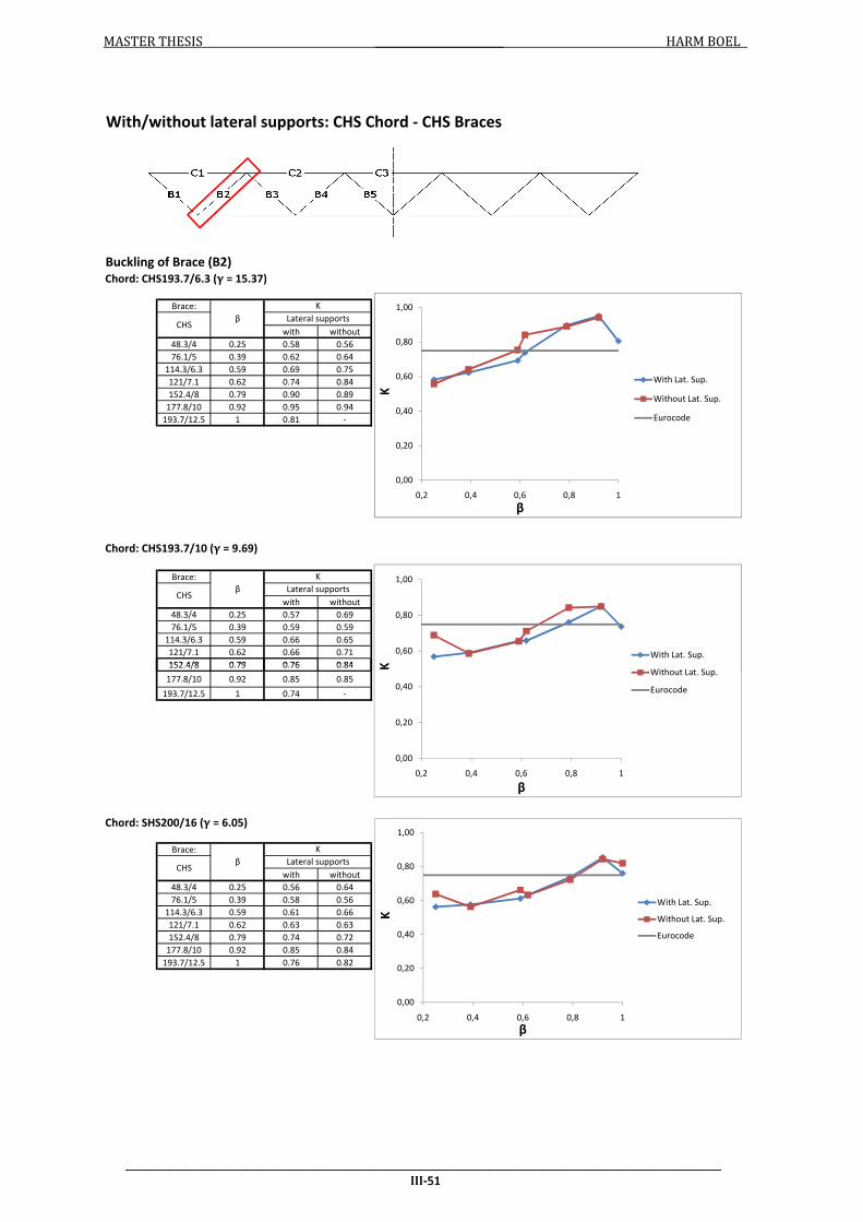
MASTER THESIS HARM BOEL
Buckling of Brace (B2)
Chord: CHS193.7/6.3 (γ = 15.37)
Brace:
with without
48.3/4 0.25 0.58 0.56
76.1/5 0.39 0.62 0.64
114.3/6.3 0.59 0.69 0.75
121/7.1 0.62 0.74 0.84
152.4/8 0.79 0.90 0.89
177.8/10 0.92 0.95 0.94
193.7/12.5 1 0.81 -
Chord: CHS193.7/10 (γ = 9.69)
Brace:
with without
48.3/4 0.25 0.57 0.69
76.1/5 0.39 0.59 0.59
114.3/6.3 0.59 0.66 0.65
121/7.1 0.62 0.66 0.71
152.4/8 0.79 0.76 0.84
With/without lateral supports: CHS Chord - CHS Braces
β
K
CHSLateral supports
β
K
CHSLateral supports
0,00
0,20
0,40
0,60
0,80
1,00
0,2 0,4 0,6 0,8 1
K
β
With Lat. Sup.
Without Lat. Sup.
Eurocode
0,60
0,80
1,00
K
With Lat. Sup.
Without Lat. Sup.
___________________________________________________________________________________________________________________________
III-51
152.4/8 0.79 0.76 0.84
177.8/10 0.92 0.85 0.85
193.7/12.5 1 0.74 -
Chord: SHS200/16 (γ = 6.05)
Brace:
with without
48.3/4 0.25 0.56 0.64
76.1/5 0.39 0.58 0.56
114.3/6.3 0.59 0.61 0.66
121/7.1 0.62 0.63 0.63
152.4/8 0.79 0.74 0.72
177.8/10 0.92 0.85 0.84
193.7/12.5 1 0.76 0.82
β
K
CHSLateral supports
0,00
0,20
0,40
0,60
0,80
1,00
0,2 0,4 0,6 0,8 1
K
β
With Lat. Sup.
Without Lat. Sup.
Eurocode
0,00
0,20
0,40
0,60
0,80
1,00
0,2 0,4 0,6 0,8 1
K
β
With Lat. Sup.
Without Lat. Sup.
Eurocode
0,00
0,20
0,40
0,60
0,80
1,00
0,2 0,4 0,6 0,8 1
K
β
With Lat. Sup.
Without Lat. Sup.
Eurocode
___________________________________________________________________________________________________________________________
III-51

MASTER THESIS HARM BOEL
Chord: SHS200/…
Brace:
γ=15.87 γ=10 γ=6.25
50/4 0.25 1.14 1.24 1.37
80/5 0.4 0.82 0.85 0.90
100/6.3 0.5 0.73 0.75 0.77
120/7.1 0.6 0.68 0.69 0.71
150/8 0.75 0.61 0.62 0.64
180/10 0.9 0.53 0.56 0.58
200/12.5 1 0.48 0.51 -
Chord: SHS200/…
Brace:
γ=15.87 γ=10 γ=6.25
48.3/4 0.24 1.33 1.48 1.69
76.1/5 0.38 0.92 0.96 1.02
114.3/6.3 0.57 0.75 0.75 0.78
121/7.1 0.61 0.72 0.73 0.75
152.4/8 0.76 0.65 0.66 0.68
Without Lateral Supports: buckling of chord
SHSβ
K
Chord: SHS200
β
K
CHSChord: SHS200
0,00
0,20
0,40
0,60
0,80
1,00
1,20
1,40
0,2 0,4 0,6 0,8 1
K
β
γ = 15.87
γ = 10
γ = 6.25
Single beam
0,80
1,00
1,20
1,40
1,60
1,80
K γ = 15.87
γ = 10
___________________________________________________________________________________________________________________________
III-52
152.4/8 0.76 0.65 0.66 0.68
177.8/10 0.89 0.58 0.60 0.63
193.7/12.5 0.97 0.54 0.57 0.59
Chord: CHS193.7/…
Brace:
γ=15.37 γ=9.69 γ=6.05
48.3/4 0.25 1.10 1.22 1.36
76.1/5 0.39 0.79 0.83 0.89
114.3/6.3 0.59 0.65 0.67 0.70
121/7.1 0.62 0.63 0.65 0.67
152.4/8 0.79 0.57 0.59 0.61
177.8/10 0.92 0.51 0.54 0.56
193.7/12.5 1 0.47 0.50 0.52
β
K
Chord: CHS193.7CHS
0,00
0,20
0,40
0,60
0,80
1,00
1,20
1,40
0,2 0,4 0,6 0,8 1
K
β
γ = 15.87
γ = 10
γ = 6.25
Single beam
0,00
0,20
0,40
0,60
0,80
1,00
1,20
1,40
1,60
1,80
0,2 0,4 0,6 0,8 1
K
β
γ = 15.87
γ = 10
γ = 6.25
Single beam
0,00
0,20
0,40
0,60
0,80
1,00
1,20
1,40
0,2 0,4 0,6 0,8 1
K
β
γ = 15.37
γ = 9.69
γ = 6.05
Single beam
___________________________________________________________________________________________________________________________
III-52

MASTER THESIS HARM BOEL
IV-1
IV. Inputfiles Here, the ANSYS input files are presented. First, the input files to model the connections are
presented, followed by the input files for the lattice girders.
IV.I Connection stiffness
Several input files are made to determine the axial, rotational and torsional stiffnesses and for
different load cases and section type combinations. A large part of the input file is the same. Only
small differences are present in, for example, the part where constraints and loads are applied.
Because of this, the input file is presented in parts.
IV.I.I Parameters
The first part of the file is the same for every load case and section type combination.
FINISH /CLEAR ! Fill in parameters h_ch=200 !height/diameter chord t_ch=10 !wall thickness chord h_br=100 !height/diameter brace t_br=6.3 !wall thickness brace g=12.6 !gap between braces l_ch=2000 !length chord l_br=1000 !length brace ang_dg=45 !angle in degrees between chord and brace heff_ch=h_ch-t_ch !distance between centreplanes of elements of chord heff_br=h_br-t_br !distance between centreplanes of elements of brace PI=3.141592654 ang=ang_dg/180*PI !angle in radian between chord and brace n_el_ch=12 !number of elements for the chord n_el_br=32 !number of elements for the brace ! Choosing element types and real constants /PREP7 ET,1,SHELL181 !shell elements R,1,t_ch,t_ch,t_ch,t_ch R,2,t_br,t_br,t_br,t_br, MP,EX,1,210000 MP,PRXY,1,0.3 ET,2,MPC184,1 !rigid beams
IV.I.II Modeling nodes to apply loads/constraints and volumes of the sections
The second part of the model differs, depending on the load case and section type combination.
! Modeling nodes to apply loads/constraints ! End of right brace N,1,0.5*l_ch+0.5*g+0.5*h_br/sin(ang)+cos(ang)*l_br,0.5*h_ch+sin(ang)*l_br,0 ! End of left brace N,2,0.5*l_ch-0.5*g-0.5*h_br/sin(ang)-cos(ang)*l_br,0.5*h_ch+sin(ang)*l_br,0
! Only for out-of-plane rotational and torsional stiffness N,3,0,0,0 !left side of chord N,4,l_ch,0,0 !right side of chord
! Defining volumes of the members ! Chord WPLANE,2, 0,0,0, 0,0,1, 0,1,0
!square section chord BLC5,0,0,heff_ch,heff_ch,-l_ch
!circular section chord

MASTER THESIS HARM BOEL
IV-2
CYL4,0,0,0.5*heff_ch,,,,-l_ch !Brace (right) WPLANE,3, (0.5*l_ch)+0.5*g+0.5*h_br/sin(ang)-(0.5*h_ch/tan(ang)),0,0, (0.5*l_ch)+0.5*g+0.5*h_br/sin(ang)-(0.5*h_ch/tan(ang)),0,100, 0.5*l_ch+0.5*g+0.5*h_br/sin(ang)-((0.5*h_ch/tan(ang))+(tan(ang)*0.5*h_ch)),0.5*h_ch,0
!square section brace BLC5,0,0,heff_br,heff_br,-(l_br+0.5*h_ch/sin(ang))
!circular section brace CYL4,0,0,0.5*heff_br,,,,-(l_br+0.5*h_ch/sin(ang))
!Brace (left) WPLANE,4, (0.5*l_ch)-0.5*g-0.5*h_br/sin(ang)+(0.5*h_ch/tan(ang)),0,0, (0.5*l_ch)-0.5*g-0.5*h_br/sin(ang)+(0.5*h_ch/tan(ang)),0,-100, 0.5*l_ch-0.5*g-0.5*h_br/sin(ang)+((0.5*h_ch/tan(ang))+(tan(ang)*0.5*h_ch)),0.5*h_ch,0
!square section brace BLC5,0,0,heff_br,heff_br,-(l_br+0.5*h_ch/sin(ang))
!circular section brace CYL4,0,0,0.5*heff_br,,,,-(l_br+0.5*h_ch/sin(ang))
!Cut brace end to chord surface WPLANE,1, 0,0,0, 1,0,0, 0,1,0 SELTOL,1 VSEL,S,LOC,Y,0.5*heff_ch,0.5*heff_ch+sin(ang)*l_br+cos(ang)*0.5*heff_br *GET,br_vol,VOLU,0,NUM,MIN VSEL,S,LOC,Y,-0.5*heff_ch,0.5*heff_ch *GET,ch_vol,VOLU,0,NUM,MIN VSEL,ALL VSBV,br_vol,ch_vol,SEPO,DELETE,KEEP SELTOL,1 VSEL,S,LOC,Y,0.5*heff_ch,0.5*heff_ch+sin(ang)*l_br+cos(ang)*0.5*heff_br VSEL,U,LOC,x,0.5*l_ch,0.5*l_ch+10000 *GET,br_vol,VOLU,0,NUM,MIN VSEL,S,LOC,Y,-0.5*heff_ch,0.5*heff_ch *GET,ch_vol,VOLU,0,NUM,MIN VSEL,ALL VSBV,br_vol,ch_vol,SEPO,DELETE,KEEP !!Glueing the volumes VGLUE,ALL
IV.I.III Meshing
The third part also differs per section type and load case.
! Meshing the model ! Members TYPE,1 MAT,1 ! Chord REAL,1 ASEL,S,LOC,Y,-0.5*heff_ch,0.5*heff_ch ASEL,U,AREA,,1 ASEL,U,AREA,,2 AESIZE,ALL,heff_ch/n_el_ch AMESH,ALL ! Braces REAL,2 ASEL,S,LOC,Y,0.5*heff_ch,0.5*heff_ch+sin(ang)*l_br+cos(ang)*0.5*heff_br

MASTER THESIS HARM BOEL
IV-3
ASEL,U,AREA,,8 !Area numbers dependent on used section type combination
ASEL,U,AREA,,20 !For SHS chord with SHS braces: 8 and 20
!For SHS chord with CHS braces: 8 and 16
!For CHS chord with SHS braces: 6 and 18
!For CHS chord with CHS braces: 6 and 14
AESIZE,ALL,PI*heff_br/n_el_br AMESH,ALL !Attaching node 1 and 2 to section using MPC-elements TYPE,2 LOCAL,11,0,0.5*l_ch+0.5*g+0.5*h_br/sin(ang)+cos(ang)*l_br,0.5*h_ch+sin(ang)*l_br,0,ang_dg,0,0 SELTOL,1 NSEL,S,LOC,y,-0.5*heff_br,0.5*heff_br NSEL,R,LOC,x,0 NSEL,U,NODE,,1 *GET,nu,NODE,0,COUNT *DO,i,1,nu *GET,minn,NODE,0,NUM,MIN E,1,minn NSEL,U,NODE,,minn *ENDDO LOCAL,12,0,0.5*l_ch-0.5*g-0.5*h_br/sin(ang)-cos(ang)*l_br,0.5*h_ch+sin(ang)*l_br,0,-ang_dg,0,0 SELTOL,1 NSEL,S,LOC,y,-0.5*heff_br,0.5*heff_br NSEL,R,LOC,x,0 NSEL,U,NODE,,2 *GET,nu,NODE,0,COUNT *DO,i,1,nu *GET,minn,NODE,0,NUM,MIN E,2,minn NSEL,U,NODE,,minn *ENDDO CSYS,0
! The next part only for out-of-plane and torsional load cases SELTOL,1 NSEL,S,LOC,y,-0.5*heff_ch,0.5*heff_ch NSEL,R,LOC,x,0 NSEL,U,NODE,,3 *GET,nu,NODE,0,COUNT *DO,i,1,nu *GET,minn,NODE,0,NUM,MIN E,3,minn NSEL,U,NODE,,minn *ENDDO
SELTOL,1 NSEL,S,LOC,y,-0.5*heff_ch,0.5*heff_ch NSEL,R,LOC,x,l_ch NSEL,U,NODE,,4 *GET,nu,NODE,0,COUNT *DO,i,1,nu *GET,minn,NODE,0,NUM,MIN E,4,minn NSEL,U,NODE,,minn *ENDDO
IV.I.IV Applying loads and constraints
The last part models the constraints and applies the loads. These are different for every load case.
IV.I.IV.I Axial and in-plane rotational stiffness /SOLU ANTYPE,STATIC

MASTER THESIS HARM BOEL
IV-4
! Modeling constraints and loads ! Constraints for in-plane rotational spring stiffnesses SELTOL,1 NSEL,S,LOC,y,0 D,ALL,ROTZ D,ALL,UY
! Only for axial stiffness D,ALL,UX
NSEL,U,LOC,x,2,l_ch
!only for in-plane rotational stiffness D,ALL,UX
D,ALL,UZ ! Apply load NSEL,ALL
! Axial stiffness F,1,fx,-1000000
! In-plane rotational stiffness F,1,mz,1000000000
! For LCin2 F,2,mz,1000000000
! For Lin3 F,2,mz,-1000000000
SOLVE FINISH
IV.I.IV.II Out-of-plane rotational and torsional stiffness /SOLU ANTYPE,STATIC ! Modeling constraints and loads ! Constraints NSEL,ALL D,3,UY D,3,UZ D,4,UX D,4,UY D,4,UZ D,4,ROTX ! Apply load NSEL,ALL
! Out-of-plane rotational stiffness F,1,my,1000000000
! LCout2 F,2,my,-1000000000 !(-/+ for LCout2/LCout3)
! LCout3 F,2,my,1000000000
! Torsional stiffness F,1,mx,1000000000
! LCtor2 F,2,mx,1000000000
! LCtor3 F,2,mx,-1000000000

MASTER THESIS HARM BOEL
IV-5
SOLVE FINISH
IV.II Lattice girder Also for the lattice girder, several input files are made. The differences are made clear per part of the input file.
IV.II.I Parameters
The first part of the file differs for the different beam-elements used.
IV.II.I.I BEAM4 element model FINISH /CLEAR
! For GNIA /FILNAME,FRAME_LBA
/TITLE,FRAME_LBA ! Lattice girder h=4800 !distance between centerlines of chords l_p=9600 !length of one panel (v-shape) pnumb=5 !number of panels g=81.7 !distance between rigid beams ang_dg=44 !angle between brace and chord n_eigval=20 !number of eigenvalues to calculate !chord h_ch=193.7 !height/diameter of section A_ch=3709 !section area I_ch=16300456 !moment of inertia Ixx_ch=32600912 !torsional stiffness ne_ch=10 !number of elements per member ne_cn=2 !number of elements in the connection/gap !brace h_br=48.3 !height/diameter of section A_br=557 !section area I_br=137676 !moment of inertia Ixx_br=275352 !torsional stiffness ne_br=10 !number of elements per member !spring stiffnesses kNm/rad C_in=253.05 !in-plane rotational stiffness (kNm/rad) C_out=199.54 !out-of-plane rotational stiffness (kNm/rad) /PREP7 ! Define element-types and real constants ET,1,BEAM4 MP,EX,1,210000 MP,PRXY,1,0.3 R,1,A_ch,I_ch,I_ch,h_ch,h_ch, !real constants of chord RMORE,,Ixx_ch R,2,A_br,I_br,I_br,h_br,h_br, !real constants of brace RMORE,,Ixx_br R,3,100*A_ch,100*I_ch,100*I_ch,h_ch,h_ch, !real constant of "rigid beam" RMORE,,100*Ixx_ch ET,2,COMBIN14,,6 !In-plane rotational spring R,4,1000000*C_in ET,3,COMBIN14,,4 !Out-of-plane rotational spring R,5,1000000*C_out
IV.II.I.II BEAM189 element model FINISH /CLEAR
! For G(M)NIA /FILNAME,FRAME_LBA /TITLE,FRAME_LBA
! Lattice girder

MASTER THESIS HARM BOEL
IV-6
h=4800 !distance between centerlines of chords l_p=9600 !length of one panel (v-shape) pnumb=5 !number of panels g=185.6 !gap between brace center lines (mm) ang_dg=45 !angle between chord and brace (degrees) ! Chord HSS_ch=2 !sectiontype (1=CHS or anything else=SHS) h_ch=200 !height/diameter t_ch=6.3 !wall thickness ne_ch=10 !number of elements per member ne_cn=2 !number of elements in the connection/gap ! Brace HSS_br=1 h_br=121 !heigth of the brace t_br=7.1 !wall thickness of brace ne_br=10 !number of elements per member ! Connection C_in=340.2 !in-plane rotational stiffness (kNm/rad) C_out=715.7 !out-of-plane rotational stiffness (kNm/rad) /PREP7 ! Define element-types and real constants ET,1,BEAM189 *IF,HSS_ch,EQ,1,THEN !determine chord section SECTYPE,1,BEAM,CTUBE SECDATA,0.5*h_ch-t_ch,0.5*h_ch,16 *ELSE SECTYPE,1,BEAM,HREC SECDATA,h_ch,h_ch,t_ch,t_ch,t_ch,t_ch *ENDIF SECPLOT,1 *GET,A_ch,SECP,1,PROP,AREA *GET,I_ch,SECP,1,PROP,IYY *GET,Ixx_ch,SECP,1,PROP,TORS *IF,HSS_br,EQ,1,THEN !determine brace section SECTYPE,2,BEAM,CTUBE SECDATA,0.5*h_br-t_br,0.5*h_br,16 *ELSE SECTYPE,2,BEAM,HREC SECDATA,h_br,h_br,t_br,t_br,t_br,t_br *ENDIF SECPLOT,2 MP,EX,1,210000 MP,PRXY,1,0.3 ET,2,COMBIN14,,6 !In-plane rotational spring R,4,1000000*C_in ET,3,COMBIN14,,4 !Out-of-plane rotational spring R,5,1000000*C_out ET,4,BEAM4 !"rigid beam" R,6,100*A_ch,100*I_ch,100*I_ch,h_ch,h_ch, RMORE,,100*Ixx_ch
IV.II.II Geometry and meshing
The second part is almost the same for all beam-element models. Little differences are present and are
clarified below.
! Input geometry and meshing ! Define lines for braces *DO,i,1,pnumb K,0,(i-1)*l_p+0.5*g,h-0.5*h_ch K,0,i*l_p-0.5*l_p-0.5*g,0.5*h_ch *GET,minn,KP,,NUM,MIN L,minn,minn+1 KSEL,none

MASTER THESIS HARM BOEL
IV-7
K,0,i*l_p-0.5*l_p+0.5*g,0.5*h_ch K,0,i*l_p-0.5*g,h-0.5*h_ch *GET,minn,KP,,NUM,MIN L,minn,minn+1 KSEL,none *ENDDO
!!meshing braces TYPE,1 REAL,2 !For the BEAM189-model: SECNUM,2 *GET,br_le,LINE,1,LENG LESIZE,ALL,br_le/ne_br LMESH,ALL KDELE,ALL
! Define lines for upper chord ! Members (between connections) *DO,i,1,pnumb K,,(i-1)*l_p+0.5*g,h K,,i*l_p-0.5*g,h *GET,minn,KP,,NUM,MIN L,minn,minn+1 KSEL,NONE *ENDDO
!!meshing upper chord SELTOL,1 LSEL,S,LOC,y,h
TYPE,1 REAL,1 !For the BEAM189-model: SECNUM,1 *GET,minn,LINE,,NUM,MIN *GET,ch_le,LINE,minn,LENG LESIZE,ALL,ch_le/ne_ch LMESH,ALL KSEL,NONE LSEL,NONE
! Between chord members (gap) ! Start of truss K,,0,h SELTOL,1 KSEL,S,LOC,y,h KSEL,U,LOC,x,0.5*g+2,l_p*pnumb *GET,minn,KP,,NUM,MIN *GET,maxx,KP,,NUM,MAX L,minn,maxx ! End of truss K,,pnumb*l_p,h SELTOL,1 KSEL,S,LOC,y,h KSEL,U,LOC,x,0,l_p*pnumb-0.5*g-2 *GET,minn,KP,,NUM,MIN *GET,maxx,KP,,NUM,MAX L,minn,maxx
TYPE,1 REAL,3 !For the BEAM189-model: TYPE,4 REAL,6 *GET,minn,LINE,,NUM,MIN *GET,ch_le,LINE,minn,LENG LESIZE,ALL,0.5*g LMESH,ALL KSEL,NONE LSEL,NONE
! Between members (connection) SELTOL,1 *DO,i,1,pnumb-1 KSEL,S,LOC,x,i*l_p-0.5*g,i*l_p+0.5*g KSEL,U,LOC,y,0,h-2 *GET,minn,KP,,NUM,MIN *GET,maxx,KP,,NUM,MAX L,minn,maxx *ENDDO

MASTER THESIS HARM BOEL
IV-8
TYPE,1 REAL,1 !For the BEAM189-model: SECNUM,1 LESIZE,ALL,g/ne_cn LMESH,ALL KSEL,NONE
! Define lines for lower chord ! Members (between connections) *DO,i,1,pnumb-1 K,,i*l_p-0.5*l_p+0.5*g,0 K,,(i+1)*l_p-0.5*l_p-0.5*g,0 *GET,minn,KP,,NUM,MIN L,minn,minn+1 KSEL,NONE *ENDDO KSEL,ALL ! Start of truss K,,0.5*l_p-0.5*g,0 SELTOL,1 KSEL,S,LOC,y,0 KSEL,U,LOC,x,0.5*l_p+0.5*g+2,l_p*pnumb *GET,minn,KP,,NUM,MIN *GET,maxx,KP,,NUM,MAX L,minn,maxx ! End of truss K,,pnumb*l_p-0.5*l_p+0.5*g,0 SELTOL,1 KSEL,S,LOC,y,0 KSEL,U,LOC,x,0,l_p*pnumb-0.5*l_p-0.5*g-2 *GET,minn,KP,,NUM,MIN *GET,maxx,KP,,NUM,MAX L,minn,maxx KSEL,ALL LSEL,ALL
! Meshing lower chord TYPE,1 REAL,1 !For the BEAM189-model: SECNUM,1 SELTOL,1 LSEL,S,LOC,y,0 *GET,minn,LINE,,NUM,MIN *GET,ch_le,LINE,minn,LENG LESIZE,ALL,ch_le/ne_ch LMESH,ALL KSEL,NONE LSEL,NONE
! Between members (connection) SELTOL,1 *DO,i,1,pnumb-2 KSEL,S,LOC,x,i*l_p+0.5*l_p-0.5*g,i*l_p+0.5*l_p+0.5*g KSEL,U,LOC,y,0+2,h *GET,minn,KP,,NUM,MIN *GET,maxx,KP,,NUM,MAX L,minn,maxx *ENDDO
TYPE,1 REAL,1 !For the BEAM189-model: SECNUM,1
LESIZE,ALL,g/ne_cn LMESH,ALL KSEL,NONE
! Modeling connections ! Upper chord *DO,i,1,pnumb N,,(i-1)*l_p+0.5*g,h-0.5*h_ch SELTOL,1 NSEL,S,LOC,x,(i-1)*l_p+0.5*g NSEL,U,LOC,y,0,h-0.5*h_ch-2 *GET,minn,NODE,,NUM,MIN

MASTER THESIS HARM BOEL
IV-9
*GET,maxx,NODE,,NUM,MAX
TYPE,2 !modeling in-plane rotational spring REAL,4 E,minn,maxx
TYPE,3 !modeling out-of-plane rotational spring REAL,5 E,minn,maxx
! Constraining DOF’s of node i and j (translation in x-, y- and z-direction and rotation ! about the local y-axis)
CP,NEXT,ux,minn,maxx CP,NEXT,uy,minn,maxx CP,NEXT,uz,minn,maxx CP,NEXT,roty,minn,maxx
! Rotate nodes so that the y-axis is in line with the braces
NMODIF,minn,,,,90-ang_dg NMODIF,maxx,,,,90-ang_dg
! Rigid beams NSEL,U,NODE,,minn *GET,cn,NODE,,NUM,MIN
TYPE,1 ! BEAM189-model: TYPE,4 REAL,6 REAL,3
E,cn,maxx
*ENDDO *DO,i,1,pnumb N,,i*l_p-0.5*g,h-0.5*h_ch SELTOL,1 NSEL,S,LOC,x,i*l_p-0.5*g NSEL,U,LOC,y,0,h-0.5*h_ch-2 *GET,minn,NODE,,NUM,MIN *GET,maxx,NODE,,NUM,MAX
TYPE,2 REAL,4 E,minn,maxx
TYPE,3 REAL,5 E,minn,maxx
CP,NEXT,ux,minn,maxx CP,NEXT,uy,minn,maxx CP,NEXT,uz,minn,maxx CP,NEXT,roty,minn,maxx
NMODIF,minn,,,,-(90-ang_dg) NMODIF,maxx,,,,-(90-ang_dg)
! Rigid beams NSEL,U,NODE,,minn *GET,cn,NODE,,NUM,MIN
TYPE,1 ! BEAM189-model: TYPE,4 REAL,6 REAL,3
E,cn,maxx
*ENDDO ! Lower chord *DO,i,1,pnumb N,,i*l_p-0.5*l_p-0.5*g,0.5*h_ch SELTOL,1 NSEL,S,LOC,x,i*l_p-0.5*l_p-0.5*g NSEL,U,LOC,y,0.5*h_ch+2,h *GET,minn,NODE,,NUM,MIN *GET,maxx,NODE,,NUM,MAX
TYPE,2

MASTER THESIS HARM BOEL
IV-10
REAL,4 E,minn,maxx
TYPE,3 REAL,5 E,minn,maxx
CP,NEXT,ux,minn,maxx CP,NEXT,uy,minn,maxx CP,NEXT,uz,minn,maxx CP,NEXT,roty,minn,maxx
NMODIF,minn,,,,90-ang_dg NMODIF,maxx,,,,90-ang_dg
! Rigid beams NSEL,U,NODE,,minn *GET,cn,NODE,,NUM,MIN
TYPE,1 ! BEAM189-model: TYPE,4 REAL,6 REAL,3
E,cn,maxx
*ENDDO *DO,i,1,pnumb N,,i*l_p-0.5*l_p+0.5*g,0.5*h_ch SELTOL,1 NSEL,S,LOC,x,i*l_p-0.5*l_p+0.5*g NSEL,U,LOC,y,0.5*h_ch+2,h *GET,minn,NODE,,NUM,MIN *GET,maxx,NODE,,NUM,MAX
TYPE,2 REAL,4 E,minn,maxx
TYPE,3 REAL,5 E,minn,maxx
CP,NEXT,ux,minn,maxx CP,NEXT,uy,minn,maxx CP,NEXT,uz,minn,maxx CP,NEXT,roty,minn,maxx
NMODIF,minn,,,,-(90-ang_dg) NMODIF,maxx,,,,-(90-ang_dg)
! Rigid beams NSEL,U,NODE,,minn *GET,cn,NODE,,NUM,MIN
TYPE,1 ! BEAM189-model: TYPE,4 REAL,6 REAL,3
E,cn,maxx
*ENDDO
IV.II.III Solving
The last part is very different for the different types of analysis. Beneath, the last part of the
different files is shown.
IV.II.III.I Static and Buckling Analysis /SOLU ANTYPE,STATIC PSTRES,ON ! Define supports SELTOL,1 ! Left

MASTER THESIS HARM BOEL
IV-11
NSEL,S,LOC,x,0 D,ALL,ux D,ALL,uy D,ALL,uz D,ALL,rotx ! Right NSEL,ALL NSEL,S,LOC,x,pnumb*l_p D,ALL,uy D,ALL,uz D,ALL,rotx ! Defining load and horizontal supports *DO,i,1,pnumb-1 NSEL,ALL SELTOL,1 NSEL,S,LOC,x,i*l_p NSEL,U,LOC,y,0,h-2 F,ALL,FY,-1 D,ALL,uz *ENDDO NSEL,ALL ESEL,ALL SOLVE FINISH
!!Retrieving axial forces in members (for BEAM4-model) /POST1 ETABLE,MFORXI,SMISC,1 ETABLE,MFORXJ,SMISC,7 !element number is dependent of number of panels and elements used ESEL,S,ELEM,,15 !B2 ESEL,A,ELEM,,35 !B4 ESEL,A,ELEM,,105 !C1 ESEL,A,ELEM,,115 !C2 ESEL,A,ELEM,,125 !C3
/OUTPUT,NFOR,txt,, PRETAB,MFORXI,MFORXJ /OUTPUT,,,,
NSEL,ALL ESEL,ALL ! Performing buckling analysis /SOLU ANTYPE,BUCKLE BUCOPT,LANB,n_eigval ! For G(M)NIA, n_eigval = 1 SOLVE FINISH /SOLU EXPASS,ON MXPAND,n_eigval ! For G(M)NIA, n_eigval = 1 SOLVE FINISH
! Plot buckling shapes and list eigenvalues /POST1 ! Enter post-processor PARSAV,ALL,parameters,txt /OUTPUT,eigenvalues,txt ! Redirects text output into this file SET,LIST /OUTPUT,,,, *Do,i,1,n_eigval SET,1,i ! Set the mode PLDISP,0 ! Plot the deflected shape *GET,frequency,ACTIVE,0,SET,FREQ ! Get the frequency

MASTER THESIS HARM BOEL
IV-12
/TLABEL,-1,-1,mode: %i%, freq: %frequency% ! Create label (mode, freq) /VIEW,1,,,1 ! Front wiev /UI,COPY,SAVE,WMF,GRAPH,Color,REVERSE,LANDSCAPE,NO ! Generate a wmf /VIEW,1,-1 ! Left side wiev /UI,COPY,SAVE,WMF,GRAPH,Color,REVERSE,LANDSCAPE,NO ! Generate a wmf /VIEW,1,,1 ! Top wiev /UI,COPY,SAVE,WMF,GRAPH,Color,REVERSE,LANDSCAPE,NO ! Generate a wmf /VIEW,1,-1,0.5,1 ! Isometric wiev /UI,COPY,SAVE,WMF,GRAPH,Color,REVERSE,LANDSCAPE,NO ! Generate a wmf *ENDDO FINISH
IV.II.III.I G(M)NIA /POST1 SET,LIST SET,FIRST PLDISP *GET,PCR_FRAME,ACTIVE,0,SET,FREQ FINISH /FILNAME,FRAME_G(M)NIA /TITLE,FRAME_G(M)NIA /PREP7 TB,BKIN,1,1 !Only for GMNIA TBDATA,1,275,0 !Only for GMNIA UPGEOM,Imp,,,'FRAME_LBA' FINISH
/SOLU ANTYPE,STATIC
NLGEOM,ON OUTRES,ALL,ALL OUTPR,ALL,ALL SSTIFF,ON
NEQIT,10 NSUBST,40
CNVTOL,F,,0.005,,1 CNVTOL,U,,0.005,,1
*DO,A,0.2,1.2,0.2 *DO,i,1,pnumb-1 NSEL,ALL SELTOL,1 NSEL,S,LOC,x,i*l_p NSEL,U,LOC,y,0,h-2 F,ALL,FY,-1*A*PCR_FRAME D,ALL,uz NSEL,ALL ESEL,ALL *ENDDO SOLVE *ENDDO
/POST 26 NUMVAR,200
Copyright © 2022 FDOKUMEN