Elastic shear buckling characteristics of LiteSteel Beams
39
QUT Digital Repository: http://eprints.qut.edu.au/ This is the accepted version of this article. To be published as: Poologanathan, Keerthan and Mahendran, Mahen (2010) Elastic shear buckling characteristics of LiteSteel Beams. Journal of Constructional Steel Research, 66(11). pp. 1309-1319. © Copyright 2010 Elsevier Ltd All rights reserved.
-
Upload
khangminh22 -
Category
Documents
-
view
2 -
download
0
Transcript of Elastic shear buckling characteristics of LiteSteel Beams

QUT Digital Repository: http://eprints.qut.edu.au/
This is the accepted version of this article. To be published as: Poologanathan, Keerthan and Mahendran, Mahen (2010) Elastic shear buckling characteristics of LiteSteel Beams. Journal of Constructional Steel Research, 66(11). pp. 1309-1319.
© Copyright 2010 Elsevier Ltd All rights reserved.

1
Elastic Shear Buckling Characteristics of LiteSteel Beams
Poologanathan Keerthan and Mahen Mahendran
Faculty of Built Environment and Engineering
Queensland University of Technology, Brisbane, QLD 4000, Australia
Abstract: LiteSteel beam (LSB) is a new cold-formed steel hollow flange channel beam. The
unique LSB section is produced by a patented manufacturing process involving simultaneous
cold-forming and dual electric resistance welding. To date, limited research has been
undertaken on the shear buckling behaviour of LSBs with torsionally rigid, rectangular
hollow flanges. For the shear design of LSB web panels, their elastic shear buckling strength
must be determined accurately including the potential post-buckling strength. Currently the
elastic shear buckling coefficients of web panels are determined by assuming conservatively
that the web panels are simply supported at the junction between the flange and web elements.
Therefore finite element analyses were carried out to investigate the elastic shear buckling
behaviour of LSB sections including the effect of true support conditions at the junction
between their flange and web elements. An improved equation for the higher elastic shear
buckling coefficient of LSBs was developed and included in the shear capacity equations of
Australian cold-formed steel codes. Predicted ultimate shear capacity results were compared
with available experimental results, both of which showed considerable improvement to the
shear capacities of LSBs. A study on the shear flow distribution of LSBs was also undertaken
prior to the elastic buckling analysis study. This paper presents the details of this investigation
and the results including the shear flow distribution of LSBs.
Keywords: LiteSteel beam, Elastic shear buckling, Shear flow, Cold-formed steel structures,
Slender web, Hollow flanges.
Corresponding author’s email address: [email protected]

2
1. Introduction
In recent times cold-formed and thin-walled steel sections have been used extensively in
residential, industrial and commercial buildings as primary load bearing members. LiteSteel
Beam (LSB) is a new cold-formed steel hollow flange channel beam produced by OneSteel
Australian Tube Mills (see Figure 1). It has a unique shape including two rectangular hollow
flanges, and is manufactured using dual electric resistance welding and automated continuous
roll-forming technologies. It has the beneficial characteristics of including torsionally rigid
closed rectangular flanges combined with economical fabrication processes from a single strip
of high strength steel. The cross-sectional shape of LSB has been designed such that it
provides higher structural performance compared to other cold-formed steel beams produced
to date. Its integral benefits of lightweight, strength, and ease of constructability offer a new
alternative for structural engineers. The LiteSteel beam has a wide range of applications in
residential, commercial and industrial buildings (Figure 1), and is considered to be on average
40% lighter than traditional hot-rolled structural sections of equivalent bending strength [1].
Table 1 provides the currently available LSB sections and their dimensions.
In the building systems, LSB sections are commonly used as flexural members, for example,
floor joists and bearers. For LSBs to be used as flexural members, their flexural and shear
capacities must be known. Recently Anapayan and Mahendran [2] have investigated the
flexural behaviour and strengths of LSBs by using experimental and numerical studies.
However, the shear behaviour of LSBs has not been investigated yet. Past research on the
shear behaviour of beams [3,4] has been restricted to plate girders. Therefore in this research
the elastic shear buckling behaviour of LSB sections was investigated using finite element
analyses including the effect of true support conditions at the junction between their flange
and web elements. The results were then used to develop an equation for their elastic shear
buckling coefficients and assess the ultimate shear capacity improvement based on the current
shear design rules. Predicted ultimate shear capacity results were compared with available
experimental results [5]. A detailed study into the shear flow distribution of LSBs was also
undertaken prior to the elastic buckling analysis study. This paper presents the details of this
research into the elastic shear buckling and shear flow characteristics of LSBs and the results.

3
2. Shear Flow Distribution in LiteSteel Beams
The shear flow (q) in a given cross section can be determined by the well known shear flow
equation. Since the shear flow distribution in LSB is different to that in other conventional
open cold-formed steel members, theoretical analyses were undertaken to investigate the
shear flow distribution in LSBs. The shear flow variation of open sections is determined by
starting from a free edge where shear flow (q) is equal to zero. In LSBs, however, there is no
free edge. Consequently, the shear flow analysis for LSBs is more complicated than that for
the open cold-formed steel sections. To commence the analysis, the shear flow is assumed to
be zero at an arbitrary point. This implies that the section has been "cut" longitudinally at that
point, thus creating a free edge. The general shear flow equation is then used to find the
"preliminary" shear flow (qp) distribution along each wall. Preliminary shear flow is based on
the assumption that shear flow is zero at the selected point. Since this is a bending problem,
the shear flow should give a zero angle of twist. If the preliminary shear flow (qp) were to be
solved for the angle of twist, it would not result in zero twist. Therefore the shear flow qp is
not the true shear flow. To satisfy the zero twist requirement, a constant shear flow of
unknown magnitude q0 can be found using the angle of twist equation. Having determined qo,
the shear flow at any point within the LSB hollow flange can be found by simply adding qo to
the shear flow distribution qp found previously [6]. The shear flow at other points on the LSB
web element can be found using the general shear flow equation. Figure 2 shows the shear
flow pattern of one of the LSB sections, 125x45x2.0 LSB, while Figure 3 shows the shear
flow distribution along its full depth. The shear flows calculated at four points (P1 to P4) on
the web element are shown in Figure 2. Shear flow calculations for 125x45x2.0 LSB are
shown in Appendix A. The calculated shear flow distribution of 125x45x2.0 LSB agreed well
with THIN-WALL analysis results with a deviation of only 0.9% [7].
In order to compare the shear flows in LSBs with other sections, shear flow analysis of lipped
and unlipped channel sections were also carried out [7]. Some of the shear flow results are
compared in Figure 4. In the shear capacity calculations of cold-formed steel members
including the case of shear yielding, AS/NZS 4600 [8] recommends the use of the depth of
flat portion of web measured along the plane of the web (d1). It was found that the shear
stresses are concentrated within the web element of LSB, lipped and unlipped channel
sections (see Figure 4). Hence the clear height of web (d1) should be used instead of the full
depth (d) to find the shear capacity of LSB. For LSBs, the use of d1 is recommended as the

4
clear height of web instead of the depth of the flat portion of web measured along the plane of
the web recommended for cold-formed channel sections. The reasons for this are as follows.
LSB has two rectangular hollow flanges, which are likely to increase the shear yielding
capacity by framing action.
Outside of the corners are filled with weld material unlike in cold-formed channel
sections.
Shear buckling occurs within the clear height of web.
Although the use of d1 as the depth of the flat portion of web is conservative in estimating
the shear yield capacity, it is not safe in the case of elastic buckling.
Shear behaviour of LSBs and plate girders are very similar (web-flange boundary
condition and welding process), and for plate girders, clear web height is used in the shear
capacity calculations.
3. Elastic Shear Buckling Analysis of LiteSteel Beams
This section describes the development of ideal finite element models to investigate the
elastic shear buckling characteristics of LiteSteel beams (LSBs). For this purpose, a general
purpose finite element program ABAQUS [9], which has the capability of undertaking elastic
buckling analyses of three dimensional structures was used.
3.1 Model Description
Ideal finite element models of LSBs were developed using ABAQUS Version 6.2 [9].
Idealized simply supported boundary conditions were implemented in LSBs under a three–
point loading arrangement. Figure 5 shows the schematic diagram of loading set-up used in
this study. The developed ideal finite element models were then used to undertake the elastic
shear buckling analyses of LSBs and determine their elastic shear buckling capacities.
ABAQUS has several element types to simulate the shear behaviour of beams. But among
those, shell element was selected for the ideal model as it has the capability to simulate the
shear buckling behaviour of thin steel beams (LSB). The shell element in ABAQUS called
S4R5 was used to model the shear behaviour of LSBs. This element is thin, shear flexible,
isometric quadrilateral shell with four nodes and five degree of freedom per node, utilizing
reduced integration and bilinear interpolation scheme. Other element types, S9R5, S8R5, S4R

5
and S4, were also used in order to compare the accuracy of element type S4R5. It was found
that the elastic shear buckling capacity of 200x45x1.6 LSB (aspect ratio = 1.0) was 53.1 kN
when S9R5, S8R5 and S4R5 elements were used while it was 53.2 kN and 53.3 kN,
respectively, when S4R and S4 elements were used. This shows the negligible difference in
the elastic shear buckling capacities of LSBs when different element types are used. Since
S4R5 shell element is computationally more economical, it was used in all the elastic
buckling analyses of LSBs in this study.
The ideal model of LSBs was developed using their centreline dimensions based on the
nominal external dimensions given in Table 1. Some researchers modelled the corners
between various plate elements in their finite element analyses [10]. In order to investigate the
effect of corners on the shear buckling behaviour of LSBs, some LSBs were modelled with
and without corners. The corners between the hollow flange and web plate elements were
included in these models. It was found that the effect of corners on the shear buckling
behaviour and capacity of LSBs is negligible. For example, the elastic shear buckling
capacities of 200x45x1.6 LSB and 250x60x2.0 LSB with and without corners were 53.7 and
53.2 kN and 86.6 and 85.9 kN, respectively (less than 1% difference). Hence the corners were
not included in the analyses of LSBs. The finite element modelling was carried out using MD
PATRAN R 2.1 pre-processing facilities using which the model was created and then
submitted to ABAQUS for the analysis. The results were also viewed using MD PATRAN R
2.1 post-processing facilities.
3.2 Convergence Study
In finite element analyses, selection of a suitable mesh size and layout is critical. It is
desirable to use as many elements as possible in the analysis to improve the accuracy of
results. However, such an analysis will require excessive computer time and resources. In
order to assess the requirement of a suitable mesh size, a convergence study was first carried
out for a plate girder subjected to shear as used by Lee et al. [4]. This plate girder is similar to
125x45x2.0 LSB in terms of its dimensions and these dimensions are: clear web height d1 =
125 mm, web thickness tw = 2 mm, flange width = 50 mm and flange thickness tf = 4 mm.
Three different mesh sizes (10mm x 10mm, 10mm x 5mm, 5mm x 5mm) were used to model
this plate girder. An aspect ratio (a/d1) of one was considered. Idealized simply supported
boundary conditions were implemented in these plate girder models under a three–point

6
loading arrangement as shown in Figure 5. They were provided along the support and loading
points.
Figure 6 shows the finite element model of plate girder used in this research. Table 2
compares the shear buckling coefficient results with those obtained by Lee et al. [4] while
Figure 7 shows the shear buckling mode of the plate girder. Table 2 results show that the plate
girder models with a 5mm x 5mm mesh produce results that are closer to Lee et al.’s [4]
results, i.e., only 0.6% difference. Therefore it was decided that the use of a 5mm x 5mm
mesh will give sufficiently accurate results for the present study on LSBs in shear.
A convergence study was also undertaken for LSBs to further confirm the adequacy of the
chosen finite element mesh. It showed that an element size of 5mm x 5 mm gave an accurate
representation of shear buckling deformations and provided suitable accuracy for all the LSB
sections. The geometry and finite element mesh of a typical ideal LSB model is shown in
Figure 8.
3.3 Material Model and Properties
For the elastic buckling analyses undertaken in this study the elastic modulus E and Poisson’s
ratio ν were taken as 200,000 MPa and 0.3, respectively.
3.4 Loads and Boundary Conditions
Simply supported boundary conditions were implemented in the LSB models used in this
research. They were used at the support to provide the following requirements:
Simply supported in-plane - Both ends fixed against in-plane vertical deflection but
unrestrained against in-plane rotation, and one end fixed against longitudinal
horizontal displacement.
Simply supported out-of-plane - Both ends fixed against out-of-plane horizontal
deflection and twist rotation, but unrestrained against minor axis rotation.
In order to provide simply supported conditions for the shear panel, following boundary
conditions were applied at the supports and the loading point. The vertical translation was not
restrained at the loading point. Table 3 shows the boundary conditions used along the edges of
the model.

7
Applied loading was based on the shear flows and forces in LSBs to eliminate any torsional
loading effects. These shear force values were calculated based on the shear flow principles
given in Section 2 and were assumed to be uniformly distributed throughout the web and
flange elements. Since the zero shear flow point is located very close to the right hand corner
of LSB (2.26 mm for 125x45x2.0 LSB as shown in Figure 2) it is simply assumed to be at the
right hand corner in the shear force calculations for all the LSB sections. Shear force
calculations for 125x45x2.0 LSB are shown next.
Since the finite element model of 125x45x2.0 LSB consists of 31 nodes in the web element, a
load of 3100 N was applied to its web element, ie. 100 N on each node. Since the zero shear
flow point is assumed to be at the right hand corner of LSB, shear forces in the flange
elements are calculated using Appendix A results for V = 3100 N. They are as follows: Top
flange (a-b) = 231.57 N (0.0747V), Inside flange (d-c) = 307.83 N (0.0993V), and Right hand
side vertical flange (a-d) = 20.39 N (0.00658V). The shear force in the right hand side vertical
element of flange is about 0.7% of the total shear force (V) and hence this small force was
neglected. However, moments about the shear centre must be balanced in order to get
accurate results. Hence small changes are made to the flange element shear forces in order to
balance the moments about the shear centre. Since the moment about the shear centre in this
case is equal to -1302.62 Nmm (=3100x18.4-231.57x123-307.83x97) based on 125x45x2.0
LSB dimensions, shear forces in the top and inside flanges were slightly modified as follows.
Shear force in the top flange (a-b) = 231.57 - 1302.62x231.57
(231.57 307.83)x123=227.02N
Shear force in the inside flange (d-c) = 307.83 - 1302.62x307.83
(231.57 307.83)x97=300.16N
Figure 9 shows the shear flow pattern loading used in the finite element model of 125x45x2.0
LSB. Here constant shear forces were applied throughout the web as well as the top and
bottom flanges. Preliminary finite element analyses showed that the effect of using
approximate shear forces had minimal effect on the elastic buckling analysis results.
Therefore similar calculations were used for all other LSB sections in their analyses. Figure
10 shows a typical finite element model of LSB.

8
3.5 Elastic Shear Buckling
3.5.1 General
For a web element with a large depth to thickness ratio, its shear capacity is governed by
elastic shear buckling. The elastic critical shear buckling stress can be computed using
Equation 1 if the relevant elastic shear buckling coefficient kv is known [11].
2
12
2
112
d
tEk wvcr
(1)
where
d1, tw = Clear height and thickness of web
kv = Shear buckling coefficient (5.34)
Equation 2 gives the elastic shear buckling capacity of cold-formed steel beams, assuming
that E = 200,000 MPa and ν = 0.30.
3v w
v cr 1 w1
0 .9 0 5 E k tV d t
d for
wy
v
t
d
f
Ek 1415.1 (2)
Real boundary condition at the juncture of the web and flange elements of steel beams being
somewhere between simple and fixed condition has been recognized from early days. Usually
it has been assumed as simply supported or fixed due to lack of means to evaluate it in a
rational manner. For example, in the case of plate girders, Basler [12] and Porter et al. [3]
assumed that the web panel was simply supported at the juncture while Chern and Ostapenko
[13] obtained the ultimate strength by assuming that the juncture behaved like a fixed support.
However, Sharp and Clark [14] assumed intuitively that the flange to web boundary condition
to be half way between the simply supported and fixed conditions for plate girders.
Recent research by Lee et al. [4] has shown that the boundary condition at the flange-web
juncture in practical designs is much closer to fixity for plate girders. They showed that the
assumption that the web panel is simply supported at the juncture leads to a considerable
underestimation of the ultimate shear strength because of the underestimation of the elastic
shear buckling strength of plate girders. Based on a detailed numerical study of plate girders,

9
Lee et al. [4] proposed the following simple equations for the determination of shear buckling
coefficients (kv) of plate girder web panels in terms of the shear buckling coefficients of web
plates with simple-simple (kss) and simple-fixed (ksf) boundary conditions. The latter case
refers to web panels that have fixed conditions at the web-flange juncture and simply
supported along the other two edges. Equations 3a and 3b show that the shear buckling
coefficient of plate girders (kv) is closer to ksf .
)]2(3
21)[(
5
4
w
fsssfssv t
tkkkk for 2
2
1
w
f
t
t (3a)
)(5
4sssfssv kkkk for 2
w
f
t
t (3b)
21
34.54
dakss for 1
1
d
a (4a)
21
434.5
dakss for 1
1
d
a (4b)
11
21
39.844.331.234.5
dadada
ksf for 11
d
a (5a)
sf 2 3
1 1
5.61 1.99k 8.98
a d a d for 1
1
d
a (5b)
where tw, tf = Thicknesses of plate girder web and flange elements;
a = Shear span of web panel and a/d1 = Aspect ratio
3.5.2 Elastic Buckling Analysis In order to obtain the shear buckling coefficient of LSBs, elastic buckling analyses were
carried out based on the ideal model of LSB developed using ABAQUS with an aspect ratio
(a/d1) of 1.0 (see Figure 10). It was provided with idealized simply supported boundary
conditions given in Table 3. S4R5 shell elements were used with a suitable mesh size of 5mm
x 5mm for the entire cross-section and length of LSB sections. The shear flow based loading
was applied to prevent any torsional effects. ABAQUS uses the subspace iteration
Eigenslover in its buckling analyses. Eigenvalues, also known as load multipliers, are
extracted from this analysis and the lowest values are most important. In the buckling
analyses of LSBs, 10 buckling mode shapes were considered. The first buckling mode was
normally an anti-symmetric buckling shape whereas the second buckling mode was normally

10
symmetric. The first buckling mode provided the lowest load multiplier and was thus used in
all the analyses of LSBs.
Figure 11 (a) shows the typical shear buckling mode of LiteSteel beams. As stated earlier,
some LSBs were also analysed with corners, which showed negligible differences in their
shear buckling behaviour and capacities. Figure 11 (b) shows the shear buckling mode of
200x45x1.6 LSB with corners. Table 4 compares the shear buckling coefficients (kLSB)
determined from the elastic buckling analyses of LSBs for an aspect ratio of 1.0. kss and ksf
were determined by using Equations 4 and 5, respectively. Table 4 indicates that kLSB is very
close to ksf. Therefore the realistic support condition of LSB at the web-flange juncture is
considered to be closer to a fixed condition.
Figure 12 (b) shows a typical deformed cross section of buckled LSB. Deformed cross-section
of web panels resemble the buckling mode shape of Eulerian column fixed at both ends. This
can be compared with the deformation shapes of plates with simply supported and fixed edges
as shown in Figures 12 (a) and (c), respectively. This observation implies that the boundary
condition at the flange-web juncture of LSBs is very close to a fixed support condition.
3.6 Shear Buckling Coefficient
Based on the elastic buckling analysis results in Table 4, the following simple equation (Eq.6)
was developed for the determination of the shear buckling coefficients of LSBs. For this
purpose the minimum shear buckling coefficient of LSBs of 12.19 from Table 4 was used.
The values of kss and ksf for a given aspect ratio were determined from Equations 4 and 5,
respectively. Further elastic buckling analyses were also performed for other non-standard
LSB sections with varying hollow flange sizes. However, it was found that the minimum
shear buckling coefficient was 12.19 when the hollow flange sizes are larger than the smallest
hollow flange (45x15x1.6 mm) used in the currently available LSBs (see Table 1).
)(87.0 sssfssLSB kkkk
(6) This equation is similar to that proposed by Lee at al. [4] for the shear buckling coefficient of
plate girders (Equation 3). Therefore it can be stated that the boundary condition at the flange-
web juncture of LSBs is almost the same as that for plate girders (0.87 versus 0.80 in
Equations 6 and 3). The proposed shear buckling coefficient equation for LSBs (Equation 6)

11
shows that the boundary condition at the flange-web juncture of LSBs is equivalent to 87%
fixed condition. Since the level of fixity at the web-flange juncture of LSBs is the same for
the available LSBs, Equation 6 is applicable for all the aspect ratios ( 11
d
a and 11
d
a ). In
order to confirm this, further elastic buckling analyses were undertaken for LSBs with an
aspect ratio of 1.5. Shear buckling coefficients calculated from these elastic buckling analysis
results also confirmed that flange-web juncture of LSBs is equivalent to 87% fixed condition.
4. Proposed Design Formulae for the Shear Strength of LiteSteel Beams
New shear strength formulae were proposed for LSBs based on the current design capacity
equations in AS/NZS 4600 [8]. They are presented in terms of shear strength (τv) instead of
shear capacity (Vv) in AS/NZS 4600. The increased shear buckling coefficient given by
Equation 6 (kLSB) was included to allow for the additional fixity in the web-flange juncture
instead of kv assumed as 5.34 in AS/NZS 4600. Equations 7 to 9 present the relevant design
equations when post-buckling strength is not included, where fyw is the web yield stress and
d1/tw is the ratio of clear height of web to web thickness.
ywv f64.0 for yw
LSB
w f
Ek
t
d1 (Shear yielding) (7)
for yw
LSB
wyw
LSB
f
Ek
t
d
f
Ek415.11 (Inelastic shear buckling) (8)
for yw
LSB
w f
Ek
t
d415.11 (Elastic shear buckling) (9)
Figure 13 shows the new design curves of shear strength (τv) versus d1/tw based on the
proposed equations for LSBs with different aspect ratios (1, 2, 3, 4 and infinity). It
demonstrates the significant shear strength improvement for LSBs with an aspect ratio of 1.0.
2
1
905.0
w
LSBv
t
d
Ek
w
ywLSB
v
t
d
fEk
1
64.0
12
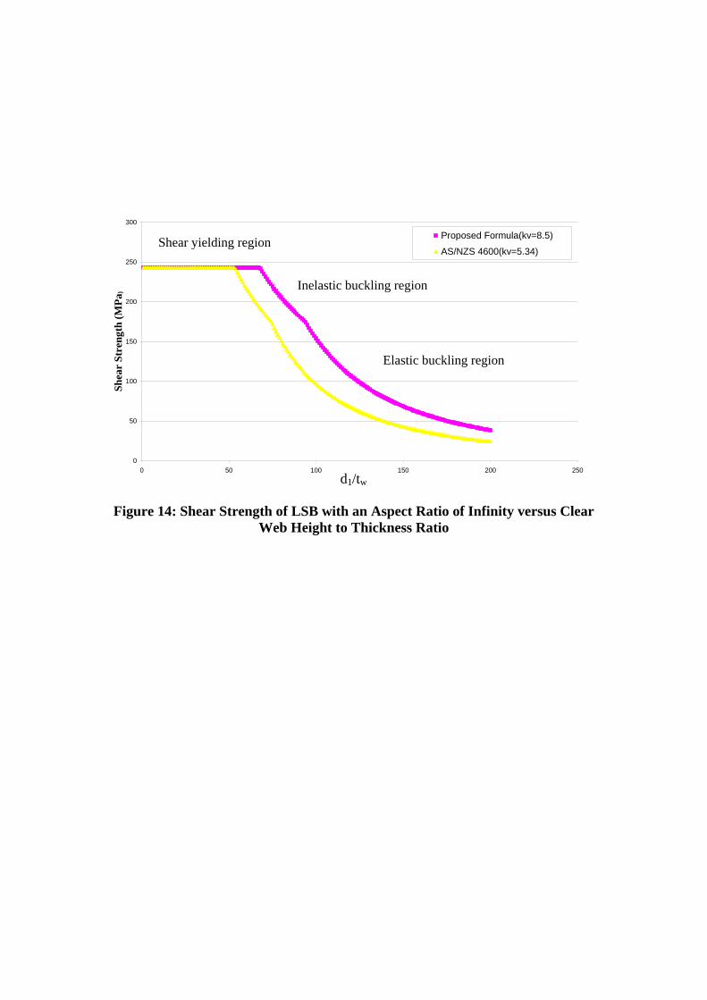
Long span LSBs are being used in practical applications and do not have transverse stiffeners.
In order to simulate this practical application, the infinity aspect ratio was also considered.
Figure 14 presents the new design curves based on the proposed equations (Eqs. 7 to 9) for
the aspect ratio of infinity based on an increased buckling coefficient of 8.5, and compares
them with the AS/NZS 4600 design equations. Figure 14 shows that the shear capacities
predicted by the current design rules in AS/NZS 4600 are conservative because AS/NZS 4600
[8] assumes that the web panel is simply supported at the juncture between the flange and web
elements and uses a smaller shear buckling coefficient (kv) of 5.34. However in this study it
was found that the realistic support condition at the web-flange juncture of LSB is closer to a
fixed support condition. Therefore the assumption considered by Clause 3.3.4 of AS/NZS
4600 may result in an overly conservative shear design for LiteSteel beams.
In order to assess the accuracy of the proposed shear strength formulae above, their
predictions were compared with Keerthan and Mahendran’s [5] experimental results given in
Table 5. Experimental shear capacities were obtained based on testing of LSBs using a three
point loading arrangement as used in the finite element models (see Figure 5). In Table 5 the
ultimate shear strengths were calculated by dividing the ultimate failure load by the web area
d1tw. Figures 15 (a) and (b) show the new design curves based on the proposed shear strength
equations (Eqs. 7 to 9) for the aspect ratios of 1.0 and 1.5, respectively, and compare them
with the experimental capacities and AS/NZS 4600 design equations. They show that the
shear capacities predicted by the current design rules in AS/NZS 4600 are very conservative.
The proposed design formulae have improved this situation as they include a higher shear
buckling coefficient kLSB to allow for the additional fixity at the web-flange juncture.
However, they are also conservative as the potential post-buckling strength has not been
included.
Plates with a large width to thickness ratio when subjected to direct compression or shear
undergo elastic buckling at a critical stress value. Analytical studies show that thin plates do
not collapse when buckling stress is reached, but has considerable post-buckling strength.
This has been experimentally verified for plates under axial compression and appropriate
strength formulae have also been developed and included in various codes. However, this is
not the case for shear loading. Presumably because of lack of experimental evidence on the
shear capacity of plates without stiffeners, design codes do not include the post-buckling
strength in shear, and the design shear stress in webs is therefore limited by the elastic

13
buckling capacity [15]. This research has shown that significant reserve strength beyond
elastic buckling is present and that post-buckling shear strength in LSB can be included in
their design (see Figures 15 (a) and (b)).
5. Effect of Hollow Flange on the Elastic Shear Buckling Capacity of Beams
The LiteSteel beams provide many structural advantages. There are no free edges and the
sections have a low width to thickness (b/t) compared with other cold-formed sections, which
combine to reduce the tendency of the section to buckle locally. The hollow flanges also
provide a higher torsional stiffness. Since the LSBs have two rigid rectangular hollow flanges,
the boundary condition at the web-flange juncture is also much close to a fixed condition than
in the conventional open cold-formed steel members and hot-rolled and welded I-sections.
The shear buckling coefficient of LSBs is likely to be higher than that of other cold-formed
steel and I-section beams. In order to demonstrate this, the ideal finite element model
developed in the earlier sections of this paper was used to analyse the shear buckling
behaviour of other steel sections of similar sizes (125 mm depth, 45 mm width and 2 mm
thickness) such as lipped channel section, I-section and plates. Table 6 shows the elastic shear
buckling coefficients of different beam sections with an aspect ratio of 1.0.
When a section starts to buckle, it can no longer effectively carry load. In traditional cold-
formed steel sections the flanges are free and are more prone to buckling, and therefore do not
contribute much to shear capacity. The flanges of LSBs do not buckle locally and hence can
more readily provide higher fixity at the web-flange juncture. Figure 16 shows the different
beam sections and their shear buckling coefficient while demonstrating the effect of varying
fixity level at the web-flange juncture.
When we consider the same height beam sections, LSBs have a lower clear height and a
higher shear buckling coefficient than other conventional cold-formed steel beams and hot-
rolled I-section beams. Therefore their elastic shear buckling strengths are higher than those
of other conventional cold-formed and hot-rolled steel beams.
6. Conclusions This paper has presented the details of an investigation into the elastic shear buckling
characteristics of a recently developed, cold-formed steel hollow flange beam known as

14
LiteSteel Beam (LSB). Currently the elastic shear buckling coefficients and strengths of web
panels are determined by assuming conservatively that the web panels are simply supported at
the junction between the flange and web elements. However, it was found that the web-flange
juncture in LSBs is closer to a fixed support. Numerical analyses based on three-dimensional
finite element modelling were carried out to investigate the shear buckling behaviour of 13
different LSB sections. The results were then evaluated to determine the effects of important
geometric parameters on the resulting support condition at the junction between the flange
and web elements. Effects of this improved support condition on the shear capacity of LSBs
has been demonstrated by modifying the current AS/NZS 4600 design equations through the
inclusion of a higher elastic shear buckling coefficient. A comparison of shear capacities of
LSBs predicted by the current and modified design rules in AS/NZS 4600 with experimental
capacities showed that the current shear design rules are very conservative. The modified
shear design rules have improved this situation. However, they are also conservative as the
potential post-buckling strength has not been included. Nonlinear finite element analyses are
being undertaken to investigate the post-buckling behaviour of LSBs in shear and to improve
the proposed design equations further.
A detailed study into the shear flow distribution of LSBs was also undertaken prior to the
elastic buckling analysis study, and this paper has presented the calculation methods used and
the results of shear flow distribution for LSBs and lipped channel beam sections.
7. Acknowledgements
The authors would like to thank Australian Research Council and OneSteel Australian Tube
Mills for their financial support and the Queensland University of Technology for providing
the necessary research facilities and support to conduct this research project. They would also
like to thank Mr Ross Dempsey, Manager - Research and Testing, OneSteel Australian Tube
Mills for his technical contributions, and his overall support to the many different phases of
this research project.

15
8. References
[1] OneSteel Australian Tube Mills, (OATM), LiteSteel Beam Publication, Brisbane,
Australia, 2008.
[2] Anapayan, T. and Mahendran, M., Parametric Studies and Development of Design Rules
for LiteSteel Beams subject to Lateral Buckling, Research Report, Queensland University
of Technology, Brisbane, Australia, 2009.
[3] Porter, D.M., Rockey K.C. and Evans H.R., The Collapse Behaviour of Plate Girders
Loaded in Shear, Journal of Structural Engineering, 1975, Vol. 53, pp. 313–325.
[4] Lee, S.C., Davidson, J.S. and Yoo, C., Shear Buckling Coefficients of Plate Girder Web
Panels, Journal of Computers and Structures, 1995, Vol. 59, pp. 789-795.
[5] Keerthan, P. and Mahendran, M., Experimental Studies on the Shear Behaviour of
LiteSteel Beams, Research Report, Queensland University of Technology, Brisbane,
Australia. 2009.
[6] Kollbrunner, C.F. and Basler, K., Torsion in Structures, Springer – Verlag, Berlin
Heidelberg, New York, USA, 1969.
[7] Keerthan, P. and Mahendran, M., Shear Flow Distribution and Shear Buckling Coefficient
of LiteSteel Beams, Research Report, Queensland University of Technology, Brisbane,
Australia, 2009.
[8] Standards Australia/Standards New Zealand (SA), Australian/New Zealand Standard
AS/NZS4600 Cold-formed Steel Structures, Sydney, Australia, 2005.
[9] Hibbitt, Karlsson and Sorensen (HKS), ABAQUS User’s Manual, Hibbitt, Karlsson and
Sorensen Inc., New York, USA, 2007.
[10] Del Coz Díaz, J.J., García Nieto, P.J., Fernández Rico, M. and Suárez Sierra, J.L., Non-
linear Analysis of the Tubular 'Heart' Joint by FEM and Experimental Validation. Journal
of Constructional Steel Research, 2007, Vol. 63, Issue 8, pp. 1077-1090.
[11] Hancock, G.J., Design of Cold-formed Steel Structures, 3rd Edition, Australian Institute
of Steel Construction, Sydney, Australia, 2005.
[12] Basler, K., Strength of Plate Girders in Shear, Trans. ASCE 1963, Vol.128, pp. 683–
719.

16
[13] Chern, C. and Ostapenko, A., Ultimate Strength of Plate Girders under Shear, Fritz
Engineering Laboratory Report. No. 328.7, Bethlehem (Pa), Lehigh University, USA,
1969.
[14] Sharp, M.L and Clark, J.W, Thin Aluminium Shear Webs, J. Struct.Div., ASCE 1971,
Vol.97, ST4, pp. 1021-1038.
[15] Suter, G.T. and Humar, J.L., Post-Buckling Shear Strength of a Cold-formed Steel Joist,
Proc. of the 5th International Specialty Conference on Cold-formed Steel Structures, St.
Louis, Missouri, USA, 1986, pp. 225-237.

17
Appendix A: Shear Flow Calculations This section presents the shear flow calculations for 125x45x2.0 LSB. In these calculations V
is the shear force and x is the distance from one corner for each plate element. Shear flows are
calculated assuming a zero shear flow point at the right hand corner of LSB (a) (see Fig.A1).
A1: Shear Flow in LiteSteel Beams
Shear flow in the top flange element (a to b)
56
VQ V (2x) 61.5q 8.076 10 Vx
I 1.523 10
Shear flow at point ‘b’, x 43q 0.00347V
Shear force in (a-b) VVxdxqdx 0747.010076.843
0
543
0
Shear flow in the left hand side vertical flange element (b to c)
610523.1
)2/5.61()2(00347.0
xxV
Vq
Shear flow at point ‘c’, x 13q 0.00441V
Shear force in (b-c) = VdxxxV
Vqdx 0517.010523.1
)2/5.61()2(00347.0
6
13
0
13
0
Shear flow in the right hand side vertical flange element (a to d)
610523.1
)2/5.61()2(
xxV
q
Shear flow at point ‘d’, x 13q 0.000939V
Shear force in (a-d) = VdxxxV
qdx 00658.010523.1
)2/5.61()2(6
13
0
13
0
Shear flow in the inside flange element (d to c)
ab
c d
= +q qp q0

18
610523.1
5.48)2(000939.0
xV
Vq
Shear flow at point ‘c’, x 43q 0.00368V
Shear force in (d-c) VdxxV
Vqdx 0993.010523.1
5.48)2(000939.0 6
43
0
43
0
Since the resultant shear flow passes through the shear centre, the section will not twist. The
constant shear flow q0 is obtained using the following angle of twist equation as A, G and t
are constants.
qds 112q0 +0.00658V + 0.0993V – 0.0747V- 0.0517V = 0
q0 = 0.000183V
The zero shear flow point in the hollow flange (see Figure 2) is determined using the
following equation.
0000183.010076.8 5 VVxq x = 2.26 mm
The shear flows are calculated by adding q0 and qp values calculated above. These values at
four points (P1 to P4) on the web element are as follows for V = 1 N: Point P1 = 0.0033
N/mm, Point P2 = 0.00424 N/mm, Point P3 = 0.0081 N/mm and Point P4 = 0.00964 N/mm
(see Figure 3).
The shear force in each element of LSB can be found now using the final shear flows
calculated above. These shear forces can then be used to determine the location of its shear
centre using the basic principles as shown in Keerthan and Mahendran [7]. These calculations
gave the shear centre location at 17.86 mm from the web element for 125x45x2.0 LSB. This
agrees well with 17.85 mm as determined from THIN-WALL.

Figure 1: LiteSteel Beams and their Applications [1]

Figure 2: Shear Flow of 125x45x2.0 LSB
Figure 3: Shear Flow along the Depth in 125x45x2.0 LSB
0
20
40
60
80
100
120
0.003 0.004 0.005 0.006 0.007 0.008 0.009 0.01
Shear Flow N/mm
Dis
tan
ce(m
m)
P1
P2 P3
P4
Web
Dep
th (
mm
)
2.26mm Zero shear flow
P1
P2
P3
P4

Figure 4: Shear Flow Distribution in 125x45x2.0 LSB and Lipped Channel
Section along the Depth
0
20
40
60
80
100
120
0.003 0.004 0.005 0.006 0.007 0.008 0.009 0.01
Shear Flow N/mm
Dis
tan
ce(m
m)

Figure 5: Schematic Diagram of Loading Set-up
a a
d1
Load
LSB

Figure 6: Finite Element Model of the Plate Girder Used in this Study

Figure 7: Shear Buckling Mode of the Plate Girder Used in this Study
(tw= 2mm, tf = 4mm, d1 = 125mm, a = 125mm, Aspect Ratio a/d1 = 1)

Figure 8: Geometry and Finite Element Mesh of a Typical LSB
Hollow flange
Web

Figure 9: Shear Flow Pattern Loading (125x45x2.0 LSB)
227.02 N
300.16 N
3100N
227.02 N
300.16 N

Figure 10: Ideal Finite Element Model of 200x45x1.6 LSB
Shear flow based loading
Simply supported

Figure 11: Shear Buckling Mode of 200x45x1.6 LSB (Aspect Ratio = 1.0)
(a) LSB without Corners (b) LSB with Corners
Corners

Figure 12: Shear Buckling Deformed Shape
(a) Top and bottom edges are simply supported
(b) 200x45x1.6 LSB (c) Top and bottom edges are fixed

Figure 13: Shear Strength of LSB versus Clear Web Height to Thickness Ratio
Inelastic buckling region
Elastic buckling region
Shear yielding region
0
50
100
150
200
250
0 50 100 150 200
d1/tw
Sh
ear
Str
engt
h (
MP
a)
Aspect Ratio = 1, kv=12.19
Aspect Ratio = Infinity, kv=8.5
Aspect Ratio = 2, kv=9.64
Aspect Ratio = 3, kv=9.0
Aspect Ratio = 4, kv=8.81
kv = 5.34
0
50
100
150
200
250
300
0 50 100 150 200 250d1/tw
Sh
ear
Str
engt
h (
MP
a )
Proposed Formula(kv=8.5)
AS/NZS 4600(kv=5.34)
Figure 14: Shear Strength of LSB with an Aspect Ratio of Infinity versus Clear Web Height to Thickness Ratio
Inelastic buckling region
Elastic buckling region
Shear yielding region
d1/tw

(a) Aspect Ratio = 1.0
(b) Aspect Ratio = 1.5 Figure 15: Shear Strength versus Clear Web Height to Thickness Ratio for LSBs
with fyw = 430 MPa
0
50
100
150
200
250
300
350
0 50 100 150 200 250
d1/tw
Sh
ear
Str
engt
h (
N/m
m2)
Proposed Design Formula
Experimental Results
AS/NZS 4600
Sh
ear
Str
engt
h (
MP
a)
d1/tw
0
50
100
150
200
250
300
350
0 50 100 150 200 250
d1/tw
Sh
ear
Str
engt
h (M
pa)
Proposed Design Formula
Experimental Results
AS/NZS 4600
Sh
ear
Str
engt
h (
MP
a)
d1/tw

Figure 16: Effect of Varying Fixity Level at the Web-Flange Juncture of
Different Beam Sections (Aspect Ratio = 1.0)
Top and bottom edges are simply supported
kv = 9.34
125x45x2.0 LSB kv = 12.59
Top and bottom edges are fixed kv = 12.60
125x45x2.0 Lipped Channel Beam kv = 10.81
125x50 Plate Girder Beam tw = 1mm, tf = 2mm
kv = 12.15
Web-Flange Juncture

Table 1: Nominal Dimensions of LSB Sections
LSB Section
(External Dimensions)
Depth Flange Width
Flange Depth
Thick-ness
Corner Radius
d bf df t ro riw
mm mm mm mm mm mm 300x75x3.0LSB 300 75 25.0 3.00 4.50 3.00 300x75x2.5LSB 300 75 25.0 2.50 3.75 3.00 300x60x2.0LSB 300 60 20.0 2.00 3.00 3.00 250x75x3.0LSB 250 75 25.0 3.00 4.50 3.00 250x75x2.5LSB 250 75 25.0 2.50 3.75 3.00 250x60x2.0LSB 250 60 20.0 2.00 3.00 3.00 200x60x2.5LSB 200 60 20.0 2.50 3.75 3.00 200x60x2.0LSB 200 60 20.0 2.00 3.00 3.00 200x45x1.6LSB 200 45 15.0 1.60 2.40 3.00 150x45x2.0LSB 150 45 15.0 2.00 3.00 3.00 150x45x1.6LSB 150 45 15.0 1.60 2.40 3.00 125x45x2.0LSB 125 45 15.0 2.00 3.00 3.00 125x45x1.6LSB 125 45 15.0 1.60 2.40 3.00
* d, bf, df = External dimensions

Table 2: Comparison of Shear Buckling Coefficient of the Plate Girder used by
Lee et al. (1995)
Table 3: Boundary Conditions Used in the Finite Element Model
Note: u, v and w are translations while θx, θy and θz are rotations in the x, y and z
directions, respectively. 0 denotes free and 1 denotes restrained.
Mesh Size (mm)
This Research Lee et al. (1995) Difference
(%) 10 x 10 12.59 11.95 5.4 10 x 5 12.14 11.95 1.6 5 x 5 12.02 11.95 0.6
Edges u v w θx θy θz
Left and Right (Support)
0 1 1 1 0 0
Middle (Loading Point) 1 0 1 1 0 0

Table 4: Comparison of Shear Buckling Coefficients of LiteSteel Beams
(Aspect Ratio = 1.0)
LSB Section kss ksf kLSB 125x45x1.6 9.34 12.60 12.58 125x45x2.0 9.34 12.60 12.59 150x45x1.6 9.34 12.60 12.57 150x45x2.0 9.34 12.60 12.58 200x45x1.6 9.34 12.60 12.19 200x60x2.0 9.34 12.60 12.57 200x60x2.5 9.34 12.60 12.58 250x60x2.0 9.34 12.60 12. 45 250x75x2.5 9.34 12.60 12.58 250x75x3.0 9.34 12.60 12.59 300x60x2.0 9.34 12.60 12.41 300x75x2.5 9.34 12.60 12.43 300x75x3.0 9.34 12.60 12.45

Table 5: Ultimate Shear Strengths from Keerthan and Mahendran’s [5]
Experimental Study
LSB Section
Aspect Ratio
d1/tw Ultimate
Shear Capacity (kN)
Ultimate Shear Strength
(MPa) 150x45x2.0 1.0 60.9 68.5 289.8 200x45x1.6 1.0 105.3 63.6 232.9 200x60x2.0 1.0 81.2 88.2 279.8 200x60x2.5 1.0 64.4 119.3 296.4 250x60x2.0 1.0 106.9 90.1 219.4 250x75x2.5 1.0 80.1 139.6 276.7 300x60x2.0 1.0 133.2 93.0 180.0 300x75x2.5 1.0 99.6 143.7 229.1 125x45x2.0 1.5 49.1 56.9 308.1 150x45x1.6 1.5 75.9 45.8 241.6 150x45x1.6 1.5 75.9 47.0 247.9 150x45x1.6 1.5 75.9 47.1 248.4 150x45x2.0 1.5 60.9 58.8 248.7 150x45x2.0 1.5 60.9 59.5 251.7 150x45x2.0 1.5 60.9 61.1 258.4 200x45x1.6 1.5 105.3 54.2 198.5 200x45x1.6 1.5 105.3 56.8 208.0 200x60x2.0 1.5 81.2 74.0 234.7 200x60x2.5 1.5 64.4 110.0 273.3 250x60x2.0 1.5 106.9 >75.0 >182.5 250x75x2.5 1.5 80.1 118.9 235.7 300x60x2.0 1.5 133.2 >75.0 >145.2 300x75x2.5 1.5 99.6 125.1 199.4 200x60x2.0 1.6 81.2 79.4 251.9 200x60x2.5 1.6 64.4 107.9 268.1

Table 6: Shear Buckling Coefficients of Different Beam Sections with an Aspect
Ratio of 1.0
Beam Sections Shear Buckling Coefficient (kv )
Plate with simply supported edges
9.34
Lipped Channel Section (125x45x2.0)
10.81
I-Section (125x50) 12.15
LSB (125x45x2.0) 12.59
Plate with fixed edges 12.60