Elastic Buckling Simplified Methods for Cold-Formed Columns ...
12
Proceedings of the Annual Stability Conference Structural Stability Research Council Pittsburgh, Pennsylvania, May 10-14, 2011 Elastic Buckling Simplified Methods for Cold-Formed Columns and Beams with Edge-Stiffened Holes Grey, C.N. 1 , Moen, C.D. 2 Abstract This paper presents a suite of prediction methods for approximating the elastic buckling properties of cold-formed steel columns and beams with edge-stiffened holes. The simplified methods supplement recently developed elastic buckling prediction procedures supporting the extension of the American Iron and Steel Institute’s Direct Strength Method to members with holes. Weighted average section properties are used with classical column stability equations to predict flexural and flexural-torsional buckling loads and beam lateral-torsional buckling moments including the influence of edge-stiffened holes. Cross-sectional instability of lipped C- sections including stiffened holes is evaluated with eigen-buckling analysis and the finite strip method. Critical elastic distortional buckling is shown to be minimally affected by the presence of stiffened holes when edge stiffener dimensions around web holes are sized to replace bending stiffness lost by the removal of web material at a hole. Finite strip analysis of the net section at a stiffened hole is performed to evaluate local buckling. The simplified methods are validated with thin shell finite element eigen-buckling parameter studies where the edge-stiffened holes are explicitly modeled. 1 Graduate Research Assistant, Virginia Tech ([email protected]) 2 Assistant Professor, Virginia Tech ([email protected])
-
Upload
khangminh22 -
Category
Documents
-
view
1 -
download
0
Transcript of Elastic Buckling Simplified Methods for Cold-Formed Columns ...

Proceedings of the Annual Stability Conference
Structural Stability Research Council Pittsburgh, Pennsylvania, May 10-14, 2011
Elastic Buckling Simplified Methods for Cold-Formed Columns and Beams with Edge-Stiffened Holes
Grey, C.N.1, Moen, C.D.2
Abstract This paper presents a suite of prediction methods for approximating the elastic buckling properties of cold-formed steel columns and beams with edge-stiffened holes. The simplified methods supplement recently developed elastic buckling prediction procedures supporting the extension of the American Iron and Steel Institute’s Direct Strength Method to members with holes. Weighted average section properties are used with classical column stability equations to predict flexural and flexural-torsional buckling loads and beam lateral-torsional buckling moments including the influence of edge-stiffened holes. Cross-sectional instability of lipped C-sections including stiffened holes is evaluated with eigen-buckling analysis and the finite strip method. Critical elastic distortional buckling is shown to be minimally affected by the presence of stiffened holes when edge stiffener dimensions around web holes are sized to replace bending stiffness lost by the removal of web material at a hole. Finite strip analysis of the net section at a stiffened hole is performed to evaluate local buckling. The simplified methods are validated with thin shell finite element eigen-buckling parameter studies where the edge-stiffened holes are explicitly modeled.
1 Graduate Research Assistant, Virginia Tech ([email protected]) 2 Assistant Professor, Virginia Tech ([email protected])

1. Introduction Elastic buckling and load-deformation response are intimately related for thin-walled cold-formed steel structural members with or without holes. For members with unstiffened holes, local buckling half-waves can form at a hole or between holes (Moen and Schafer 2009a; Moen and Schafer 2009b). Experiments have demonstrated that distortional buckling deformations in columns and joists increase with the presence of unstiffened web holes (Moen and Schafer 2008; Schudlich et al. 2011). Nonlinear finite element modeling results provide evidence that cold-formed steel column global buckling capacity decreases when large holes are present and that the controlling global buckling mode can switch from weak axis flexure to flexural-torsional buckling (Moen 2008; Moen and Schafer 2011). Edge stiffeners may prevent unstiffened strip local buckling in the compressed regions above or below a hole (Yu 2007) and can cause distortional buckling to occur between holes (Moen and Yu 2010) as shown in Fig. 1c.
Figure 1 : Lipped C-section column elastic buckling with stiffened holes - (a) local buckling between holes, (b)
distortional buckling at a hole, (c) distortional buckling between holes, and (d) global (flexural-torsional) buckling Currently, cold-formed steel members without holes can be designed with the American Iron and Steel Institute’s Direct Strength Method (DSM) (AISI-S100 2007), which utilizes the local, distortional, and global (Euler) elastic buckling properties to predict ultimate strength. The elastic buckling properties for members without holes can be determined from an elastic buckling curve generated with the semi-analytical finite strip method. However, discontinuities caused by holes cannot be explicitly modeled with the finite strip method, and therefore, simplified methods for use in design are needed. This paper presents procedures for approximating the change in the elastic buckling load (or moment) of cold-formed steel columns and beams due to the presence of edge-stiffened holes. Similar procedures were recently validated for cold-formed steel members with unstiffened holes (Moen and Schafer 2009a). The stiffened hole simplified methods for predicting global buckling, distortional buckling, and local buckling are evaluated with finite element eigen-buckling parameter studies on industry standard Structural Stud Manufacturers Association (SSMA) cold-formed steel members (Table 1, Fig. 2). The selected cross-sections were part of an experimental program evaluating the flexural capacity of cold-formed steel joists with edge-stiffened holes sponsored by the National Association of Home Builders (Elhajj 1999).
Table 1: SSMA structural stud and stiffened hole dimensions
(a)
(b) (d)
(c)
Thickness Web Size Flange Width
Stud Length
Hole Depth
Hole Length
Hole Spacing
Inside Corner Radius
Hole Stiffener Length
Hole Radius
(in.) (in.) (in.) (in.) (in.) (in.) (in.) (in.) (in.) (in.)t H B L hhole Lhole S R Q Rhole
800S162-43 0.0451 8 1.625 144 4.25 7 24 0.0712 0.688 2.21800S162-54 0.0566 8 1.625 144 4.25 7 24 0.0849 0.688 2.21
1000S162-54 0.0566 10 1.625 240 6.25 9 24 0.0849 0.688 3.211200S162-54 0.0566 12 1.625 240 6.25 9 24 0.0849 0.688 3.211200S162-68 0.0713 12 1.625 240 6.25 9 24 0.1069 0.688 3.21
SSMA Designation
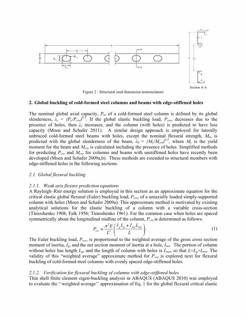
Figure 2 : Structural stud dimension nomenclature
2. Global buckling of cold-formed steel columns and beams with edge-stiffened holes The nominal global axial capacity, Pn, of a cold-formed steel column is defined by its global slenderness, λc = (Py/Pcre)0.5. If the global elastic buckling load, Pcre, decreases due to the presence of holes, then λc increases, and the column (with holes) is predicted to have less capacity (Moen and Schafer 2011). A similar design approach is employed for laterally unbraced cold-formed steel beams with holes, except the nominal flexural strength, Mn, is predicted with the global slenderness of the beam, λb = (My/Mcre)0.5, where My is the yield moment for the beam and Mcre is calculated including the presence of holes. Simplified methods for predicting Pcre and Mcre for columns and beams with unstiffened holes have recently been developed (Moen and Schafer 2009a,b). These methods are extended to structural members with edge-stiffened holes in the following sections. 2.1. Global flexural buckling 2.1.1. Weak axis flexure prediction equations A Rayleigh–Ritz energy solution is employed in this section as an approximate equation for the critical elastic global flexural (Euler) buckling load, Pcre, of a uniaxially loaded simply-supported column with holes (Moen and Schafer 2009a). This approximate method is motivated by existing analytical solutions for the elastic buckling of a column with a variable cross-section (Timoshenko 1908; Falk 1956; Timoshenko 1961). For the common case when holes are spaced symmetrically about the longitudinal midline of the column, Pcre is determined as follows:
⎟⎟⎠
⎞⎜⎜⎝
⎛ +=
LLILI
LEP netnetgg
cre 2
2π . (1)
The Euler buckling load, Pcre, is proportional to the weighted average of the gross cross section moment of inertia, Ig, and the net section moment of inertia at a hole, Inet. The portion of column without holes has length Lg, and the length of column with holes is Lnet, so that L=Lg+Lnet. The validity of this “weighted average” approximate method for Pcre is explored next for flexural buckling of cold-formed steel columns with evenly spaced edge-stiffened holes. 2.1.2. Verification for flexural buckling of columns with edge-stiffened holes Thin shell finite element eigen-buckling analysis in ABAQUS (ABAQUS 2010) was employed to evaluate the ‘‘weighted average’’ approximation of Eq. 1 for the global flexural critical elastic
H hhole
B
Q
t
L
S
hholeH
A
A
Lhole
Rhole
D
Section A-A
R
R
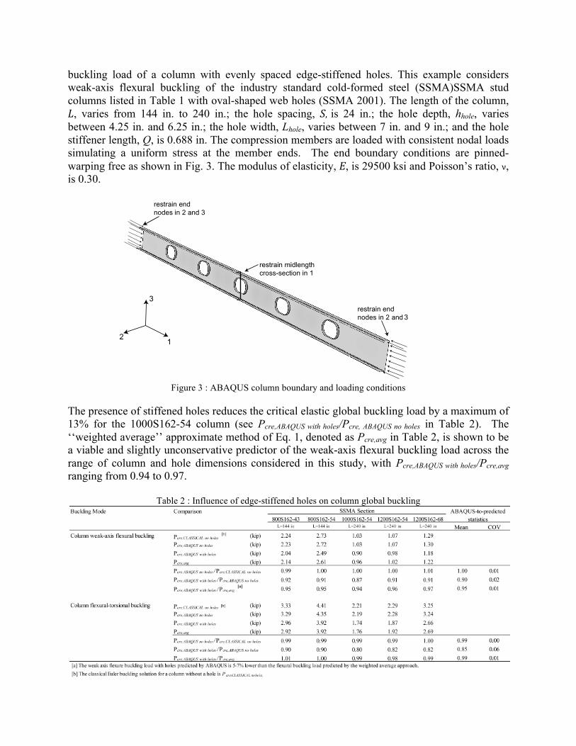
buckling load of a column with evenly spaced edge-stiffened holes. This example considers weak-axis flexural buckling of the industry standard cold-formed steel (SSMA)SSMA stud columns listed in Table 1 with oval-shaped web holes (SSMA 2001). The length of the column, L, varies from 144 in. to 240 in.; the hole spacing, S, is 24 in.; the hole depth, hhole, varies between 4.25 in. and 6.25 in.; the hole width, Lhole, varies between 7 in. and 9 in.; and the hole stiffener length, Q, is 0.688 in. The compression members are loaded with consistent nodal loads simulating a uniform stress at the member ends. The end boundary conditions are pinned-warping free as shown in Fig. 3. The modulus of elasticity, E, is 29500 ksi and Poisson’s ratio, ν, is 0.30.
Figure 3 : ABAQUS column boundary and loading conditions
The presence of stiffened holes reduces the critical elastic global buckling load by a maximum of 13% for the 1000S162-54 column (see Pcre,ABAQUS with holes/Pcre, ABAQUS no holes in Table 2). The ‘‘weighted average’’ approximate method of Eq. 1, denoted as Pcre,avg in Table 2, is shown to be a viable and slightly unconservative predictor of the weak-axis flexural buckling load across the range of column and hole dimensions considered in this study, with Pcre,ABAQUS with holes/Pcre,avg ranging from 0.94 to 0.97.
Table 2 : Influence of edge-stiffened holes on column global buckling
3

2.2. Global flexural-torsional buckling 2.2.1. Flexural-torsional prediction equations For singly-symmetric sections subjected to flexural-torsional buckling, the elastic flexural-torsional buckling load, Pcre, including the influence of holes, can be calculated with the “weighted average” approach and the following equation provided in AISI-S100-07:
( ) ( ) ⎥⎦⎤
⎢⎣⎡ −+−+= textextex
gcre
AP σβσσσσσ
β4
22 , (2)
where
! =1!xo,avgro,avg
"
#$$
%
&''
2
, " ex =# 2EIx,avgAg KxLx( )2
, " t =1
Agro,avg2 GJavg +
# 2ECw,net
KtLt( )2(
)**
+
,--. (3)
The radius of gyration about the shear center is defined as ro,avg=(rx,avg
2 + ry,avg2 + xo,avg
2)0.5, where the “weighted average” x distance from the shear center to the centroid of the cross-section is xo,avg
xo,avg =
xo,gLg + xo,netLnetL
. (4)
The column buckling load, Pcre, is also a function of the radii of gyration of a cross section about the centroidal axes, i.e., rx,avg = (Ix,avg /Aavg)0.5 and ry,avg = (Iy,avg/Aavg)0.5, where Ix,avg, Iy,avg, and Aavg are calculated using a similar form of Eq. 4. (Note that the gross cross-sectional area, Ag, in Eq. 3 and Eq. 4 converts the uniform compressive stress at the ends of the column to a force and should not be confused with Aavg). The St. Venant torsional constant, Javg, including the influence of holes, can be calculated with weighted average approach with a similar form of Eq. 4. However, the warping torsion constant, Cw, does not follow the weighted average approximation, as the presence of holes prevents warping resistance from developing (Moen and Schafer 2009a). A viable approximation for warping stiffness at the net section is Cw,net (see Eq. 3). Note that all net section properties, e.g., Ix,net, Iy,net, Anet, xo,net, yo,net, Jnet, and Cw,net, can readily be calculated with the built-in section property calculations in the freely available open source program CUFSM (Schafer and Ádàny 2006) by setting the element thicknesses to zero at the hole (Moen and Schafer 2010a). The validity of the weighted average approach for flexural-torsional buckling is evaluated in the following sections. 2.2.2. Evaluation of torsional property approximations A procedure for calculating torsional properties of a thin-walled structural member with holes is described in Moen and Schafer (2009b). An imposed torsional rotation (twist) is applied at the member end in a finite element model with either warping free or warping fixed boundary conditions. The torsion created by the imposed twist is read from the finite element model and input into the classical differential equation for nonuniform torsion to obtain J and Cw for the member, including the influence of holes. The torsional properties for the SSMA member dimensions in Table 1 are calculated with this procedure (JABAQUS with holes and Cw, ABAQUS with holes in Table 3) to evaluate the viability of the weighted average Javg and net section Cw,net approximations in Eq. 4.

The results in Table 3 demonstrate that the weighted average approach is a viable, conservative predictor of the St. Venant torsional constant for the SSMA members with stiffened holes considered in this study, with the weighted average predicting a maximum of 13% lower than that predicted by the semi-analytical approach (compare JABAQUS with holes to Javg in Table 3). It is hypothesized that Javg underpredicts the actual torsional resistance because the weighted average approach assumes the stiffened holes are rectangular, whereas the actual holes are oval and taper to the gross cross-section. The net section warping torsion constant, Cw,net, is consistent with that predicted by the semi-analytical approach (compare Cw ABAQUS with holes to Cw,net in Table 3). The addition of edge-stiffened holes has a minimal effect on J and Cw for the members evaluated in this study (compare J,ABAQUS with holes to J,ABAQUS no holes and C,w ABAQUS with holes to C,w ABAQUS no holes in Table 3).
Table 3: Influence of edge-stiffened holes on torsion properties
2.2.3. Verification for flexural-torsional buckling of a column with edge-stiffened holes The second elastic global mode of all SSMA columns analyzed is flexural-torsional buckling. Table 2 shows that the flexural-torsional mode is more sensitive to hole size than the weak-axis flexural mode (compare Pcre,ABAQUS with holes /Pcre,ABAQUS no holes in Table 2). The flexure-torsional buckling loads of the SSMA columns with edge-stiffened holes from ABAQUS are within 2% of the flexural buckling loads predicted by the weighted average approach (compare Pcre,ABAQUS with
holes /Pcre,avg in Table 2). 2.3. Lateral-torsional buckling 2.3.1. Lateral-torsional buckling prediction equation The “weighted average” method developed for columns with holes is extended to beams with edge-stiffened holes in this section. The classical lateral-torsional stability equation for a simply-supported beam with holes loaded with a constant moment along its length can be represented as:
Mcre =!L
EIy,avg GJavg +ECw,net! 2
L2!
"#
$
%& . (5)
Buckling Mode Comparison800S162-43 800S162-54 1000S162-54 1200S162-54 1200S162-68
L=144 in L=144 in L=240 in L=240 in L=240 in Mean COVSt Venant's torsion constant, J J,g
[a] (in.4) 0.000364 0.000715 0.000836 0.000957 0.001899J,ABAQUS no holes (in.4) 0.000364 0.000714 0.000835 0.000957 0.001896J,ABAQUS with holes (in.4) 0.000367 0.000730 0.000831 0.000942 0.001878J,avg (in.4) 0.000342 0.000670 0.000733 0.000854 0.001692J,ABAQUS no holes /J,g 1.00 1.00 1.00 1.00 1.00 1.00 0.00J,ABAQUS with holes /J,g 1.01 1.02 0.99 0.98 0.99 1.00 0.02J,ABAQUS with holes /J,avg 1.08 1.09 1.13 1.10 1.11 1.10 0.02
Warping torsion constant, Cw Cw ,g [a] (in.6) 1.99 2.41 4.00 6.05 7.24
Cw ,ABAQUS no holes (in.6) 1.99 2.41 4.00 6.05 7.24Cw ,ABAQUS with holes (in.6) 2.01 2.47 3.98 5.95 7.17Cw,net (in.6) 1.91 2.30 3.67 5.77 6.88Cw ,ABAQUS no holes /Cw ,g 1.00 1.00 1.00 1.00 1.00 1.00 0.00Cw ,ABAQUS with holes /Cw ,g 1.01 1.02 1.00 0.98 0.99 1.00 0.02Cw ,ABAQUS with holes /Cw ,net 1.06 1.07 1.09 1.03 1.04 1.06 0.02
[a] J,g, and Cw,g are calculated for the gross cross-section with the CUFSM section property calculator
SSMA Section ABAQUS-to-predicted statistics

The approximate method for beams with edge-stiffened holes is implemented by replacing Iy and J with Iy,avg and Javg (see form of Eq. 4) and by calculating Cw,net assuming the cross-section thickness is zero over the hole as discussed in Section 2.2.1.
2.3.2. Verification for lateral-torsional bucking of a beam with edge-stiffened holes The cold-formed steel SSMA members evaluated in the previous sections as columns are now evaluated as beams with uniform moments. The beam ends are modeled as pinned warping-free and the cross-section at the longitudinal midline is warping-fixed as shown in Fig. 3. The critial elastic lateral-torsional buckling moment, Mcre, decreases with the presence of edge-stiffened holes by a maximum of 8% as shown in Table 4. The “weighted average” prediction method is demonstrated to be an accurate predictor of Mcre when compared to the ABAQUS eigen-buckling results (see Mcre,ABAQUS with holes /Mcre,avg in Table 4).
Table 4 : Influence of edge-stiffened holes on beam global buckling
3. Distortional buckling of cold-formed steel columns and beams with edge-stiffened holes Distortional buckling is recognized as a design limit state for cold-formed steel columns and beams with open cross-sections separate from that of global or local-global buckling interaction (Lau and Hancock 1987; AISI-S100 2007). Rotational restraint of the web to the flange is interrupted in open-cross sections when unstiffened holes are present, reducing the critical elastic distortional buckling load (Moen and Schafer 2009a). A recent study demonstrated that the addition of edge stiffeners to holes may compensate for the loss in web bending stiffness at a web hole, causing distortional buckling to occur between holes (Moen and Yu 2010) in the same way that local buckling can occur at a hole or between holes (Moen and Schafer 2009b). This idea is implemented in the next section with a simplified approach for predicting the distortional buckling load including the effect of stiffened holes. 3.1. Distortional buckling prediction for columns with holes The distortional critical elastic buckling load, Pcrd, is calculated for a cold-formed steel column with holes as: Pcrd =min(Pcrdnh,Pcrdh ) , (6) where Pcrdnh is the distortional buckling load for a buckled half-wave without a hole, which may be calculated by finite strip or hand methods (AISI-S100 2007). The buckling load for a distortional buckling half-wave including a hole, Pcrdh, can be calculated for unstiffened holes by simulating the effect of the hole with a reduced web thickness in a finite strip analysis, as
Buckling Mode Comparison800S162-43 800S162-54 1000S162-54 1200S162-54 1200S162-68
L=144 in L=144 in L=240 in L=240 in L=240 in Mean COVBeam lateral-torsional buckling
Mcre,CLASSICAL no holes [a] (kip-in.)
8.48 10.72 5.54 6.66 8.65Mcre,ABAQUS no holes (kip-in.) 8.52 10.77 5.58 6.69 8.74Mcre,ABAQUS with holes (kip -in.) 8.09 10.23 5.11 6.33 8.27Mcre,avg (kip -in.) 8.22 10.36 5.17 6.36 8.20Mcre,ABAQUS no holes/Mcre,CLASSICAL no holes
[a] 1.00 1.01 1.01 1.00 1.01 1.01 0.00Mcre,ABAQUS with holes/Mcre,ABAQUS no holes 0.95 0.95 0.92 0.95 0.95 0.94 0.01Mcre,ABAQUS with holes/Mcre,avg 0.98 0.99 0.99 1.00 1.01 0.99 0.01
[a] The critical lateral-torsional buckling moment for a beam without holes is denoted as Mcre,CLASSICAL no holes
SSMA Section ABAQUS-to-predicted statistics

detailed in Moen and Schafer (2010a). A similar finite strip approach for calculating Pcrdh of cold-formed steel columns with edge-stiffened holes is derived in the next section. 3.2. Effective web stiffness considering edge-stiffened holes A web with an edge-stiffened hole will have a reduction in bending stiffness from the removal of hole material and an increase in web bending stiffness from the presence of the edge stiffeners around the hole. The reduced transverse rotational stiffness of a web with an unstiffened hole over a distortional buckling half-wavelength, Lcrd, is approximated in Moen and Schafer (2009a) as:
K! ,hole = 1! LholeLcrd
"
#$
%
&'K! ,
(7)
where Kθ is the cumulative web stiffness without a hole over Lcrd for a column with an open cross-section (Schafer 2002):
crdLH
EtK ⎟⎟⎠
⎞⎜⎜⎝
⎛
−=
)1(6 2
3
νθ . (8)
For a stiffened hole, the two parallel transverse hole edge stiffeners can be thought of as beams spanning hhole, each adding rotational restraint Kθ,stiffener to the web over Lcrd, i.e.,
K! ,stiffener =2EIstiffenerhhole
hholeH
!
"#
$
%&n LholeLcrd
!
"#
$
%&
m
, Istiffener =112tQ3 . (9)
The rotational restraint Kθ,stiffener is formulated assuming concentrated moments at each end. The (hhole/H)n multiplier in Eq. 9 is included because a stiffener will be less effective at restraining the flanges when hhole is small relative to the web width H. The (Lhole/ Lcrd)m multiplier expresses the influence of the two parallel stiffeners along the length of the hole on web rotational restraint. When Lhole is small relative to the distortional half-wavelength Lcrd, the stiffeners along hhole are assumed to be less effective at restraining the compressed flanges. (It should be noted that Eq. 9 is a mechanics-based “educated guess” that produces a simple equation conducive to design. A preliminary validation of Eq. 9 is provided in the next section, with further validation planned in the near future for other cross-sections and hole dimensions.) An equivalent cumulative web rotational stiffness, Kθ,r, can be written including the loss of web material and the presence of edge stiffeners as
stiffenerholecrdr
r KKLHEtK ,2
3
, 2)1(6 θθθ ν
+=⎟⎟⎠
⎞⎜⎜⎝
⎛
−= . (10)
Substituting Eq. 7 and Eq. 9 into Eq. 10 and solving for the effective web thickness, tr, results in
tr = 1! Lhole
Lcrd
"
#$
%
&'t3 +
2tQ3Hhhole
1!! 2
Lcrd
"
#$
%
&'hholeH
"
#$
%
&'n LholeLcrd
"
#$
%
&'
m(
)**
+
,--
1/3
. (11)
The exponents n=1 and m=3 produce the most accurate predictions for Pcrdh considering the columns in this study (see the following validation section). Therefore, the effect of a stiffened hole on the critical elastic distortional buckling load can be approximated by changing the cross-section web thickness to tr in a finite strip analysis. The procedure for calculating Pcrdh is the same as that outlined in Moen and Schafer (2010a). First, the distortional buckling half-

wavelength, Lcrd, is obtained from a finite strip analysis of the gross cross-section. The effective thickness, tr, is then implemented in a second finite strip analysis performed just at Lcrd, which produces Pcrdh. 3.3. Distortional buckling prediction for beams with holes The distortional critical elastic buckling moment, Mcrd, is calculated for a cold-formed steel beam with holes as: Mcrd =min(Mcrdnh,Mcrdh ) , (12) where Mcrdnh is the distortional buckling load of a half-wave without a hole, which may be calculated by finite strip or hand methods (AISI-S100 2007). The buckling load for a distortional buckling half-wave including a hole, Mcrdh, can be calculated for unstiffened holes by simulating the effect of the hole by reducing the web thickness in a finite strip analysis, as detailed in Moen and Schafer (2010b). The exponents n=1 and m=1 are recommended in Eq. 11, and the same finite strip analysis discussed in Section 3.2 is used to approximate Mcrdh for cold-formed beams with edge-stiffened holes. The viability of this approach is confirmed in the next section with thin shell finite element eigen-buckling parameter studies. 3.4. Verification for distortional bucking of members with edge-stiffened holes The critical elastic distortional buckling loads (moments) for the cold-formed steel SSMA member dimensions in Table 2 at a stiffened hole and away from a stiffened holes are approximated with finite strip methods in this section i.e., Pcrdnh,simp, Pcrdh,simp for columns and Mcrdnh,simp, Mcrdh,simp for beams. The same distortional buckling modes (at a hole and between holes) were identified in thin shell finite element eigen-buckling analyses (Pcrdnh,ABAQUS, Pcrdh,ABAQUS for columns and Mcrdnh,ABAQUS, Mcrdh,ABAQUS) for comparison (Fig. 1). The modeled FE boundary conditions are described in Fig. 3. Note that Pcrdnh,simp and Mcrdnh,simp were calculated with the gross cross-section in CUFSM, and Pcrdh,simp and Mcrdh,simp were calculated with a reduced web thickness (Eq. 11) in CUFSM. For both columns and beams with stiffened holes considered in this study, the simplified method is on average an accurate predictor of Pcrd (ABAQUS-to-predicted mean of 1.01 for columns in Table 5, 1.07 for beams in Table 6), however the coefficient of variation (COV) of the ABAQUS-to-predicted buckling loads is high, especially for columns (0.14 for columns, 0.09 for beams). In some cases the finite strip distortional buckling prediction is lower than the ABAQUS results (Pcrd, ABAQUS/Pcrd,simp=0.86 for the 1000S162-54 column in Table 5). Both the ABAQUS results and the simplified method predict that distortional buckling occurs between stiffened holes (Pcrdnh, Mcrdnh) in all cases. In other words, the hole stiffeners with Q=0.688 in. provide enough rotational restraint to the compressed flanges to compensate for the loss in web material at the hole, resulting in distortional buckling between holes. Unfortunately this prediction trend cannot be confirmed based on the NAHB tests conducted for these members because the experimental report does not describe specimen failure modes in detail. The finite strip simplified method for predicting Pcrdh and Mcrdh using the modified web thickness in Eq. 11 and n=1, m=3 for columns, n=1, m=1 for beams, is on average an accurate predictor when compared to the ABAQUS results (ABAQUS-to-predicted mean is 1.06 for columns in Table 5, 1.07 for beams for Table 6). The ABAQUS-to-prediction COV is high however, and in

some cases the prediction is unconservative (Pcrdh,ABAQUS/Pcrdh,simp=0.91 for the 800S162-54 column in Table 5, Mcrdh,ABAQUS/Mcrdh,simp=0.93 for the 800S162-43 beam in Table 6).
Table 5 : Influence of edge-stiffened holes on column distortional buckling
Table 6 : Influence of edge-stiffened holes on beam distortional buckling
4. (AISI-S100)Local buckling of cold-formed steel columns and beams with edge-stiffened
holes 4.1. Local buckling prediction equations The local critical elastic buckling load, Pcr, is calculated for a cold-formed steel column with holes as: ),min(, hcrnhcrsimplifiedcr PPP = , (13) where Pcrnh is the local buckling load of the gross section, ignoring the hole, which may be calculated by finite strip or hand methods (AISI-S100). The buckling load including the hole, Pcrh, may be calculated by a finite strip analysis of the net cross-section (e.g., in CUFSM) as shown in Fig. 4 and examining only those buckling half-wavelengths shorter than the length of the hole. (It should be noted that in previous publications by the second author it was recommended to restrain the cross-section corners in a finite strip analysis of the net section. Recent experiments by Schudlich et al. (2011) have determined that an Euler type buckling failure of the unstiffened strip and compressed flange is a possible local buckling failure mode when hole depth is large relative to web height. This local buckling mode can be readily identified with a net section finite strip model if the corners are unrestrained in CUFSM.)
Figure 4 : Local buckling at a stiffened hole in CUFSM
800S162-43 4.44 19.43 0.053 5.31 4.44 3.90 26.00 6.73 25.00 3.90 1.27 0.88800S162-54 7.16 16.07 0.062 9.20 7.16 7.42 25.25 8.35 24.00 7.42 0.91 1.04
1000S162-54 4.98 20.12 0.061 6.17 4.98 4.29 24.75 5.31 24.50 4.29 0.86 0.861200S162-54 3.39 20.03 0.059 4.26 3.39 3.66 24.75 4.77 26.00 3.66 1.12 1.081200S162-68 5.85 16.58 0.069 8.08 5.85 6.96 24.75 9.26 26.25 6.96 1.15 1.19
Mean 1.06 1.01COV 0.16 0.14
SSMA Section Pcrdnh,simp (kip)
Lcrd (in.)
t r (in.)
Pcrdh,simp (kip)
Pcrd,simp (kip)
Pcrd,ABAQUS/Pcrd,simp
ABAQUS-to-predicted statistics
Pcrdnh,ABAQUS (kip)
Lcrdnh,ABAQUS (in.)
Pcrdh,ABAQUS (kip)
Lcrdh,ABAQUS (in.)
Pcrd,ABAQUS (kip)
Pcrdh,ABAQUS/Pcrdh,simp
800S162-43 43.88 15.72 0.055 55.69 43.88 43.51 15.75 52.03 23.75 43.51 0.93 0.99800S162-54 71.82 12.94 0.063 85.30 71.82 72.15 12.90 83.44 19.75 72.15 0.98 1.00
1000S162-54 68.40 16.67 0.062 76.41 68.40 73.90 15.60 99.14 27.50 73.90 1.30 1.081200S162-54 59.36 16.60 0.060 66.59 59.36 70.48 18.25 75.34 24.75 70.48 1.13 1.191200S162-68 97.82 11.11 0.068 111.25 97.82 107.65 12.20 111.14 21.50 107.65 1.00 1.10
Mean 1.07 1.07COV 0.14 0.07ABAQUS-to-predicted statistics
SSMA Section Mcrdnh,simp
(kip-in.)Lcrd
(in.)t r
(in.)
Mcrdh,simp
(kip-in.)Mcrd,simp
(kip-in.)Mcrdnh,ABAQUS
(kip-in.)Lcrdnh,ABAQUS
(in.)Mcrdh,ABAQUS
(kip-in.)Lcrdh,ABAQUS
(in.)Mcrd,ABAQUS
(kip-in.)Mcrdh,ABAQUS/Mcrdh,simp Mcrd,ABAQUS/Mcrd,simp

Once the net cross section is input into CUFSM, an eigen-buckling analysis is performed (zero thickness line can remain or it may be removed), and an elastic buckling curve is generated (Moen and Schafer 2009b). The half-wavelength corresponding to the minimum buckling load is Lcrh. When Lhole< Lcrh, Pcrh is equal to the buckling load at the length of the hole. If Lhole≥ Lcrh , Pcrh is the minimum on the buckling curve. Use of the net cross-section for buckling half-wavelengths greater than Lhole is conservative and fails to reflect the stiffness contributions of the gross section in a finite strip analysis. 4.2. Verification for local bucking of members with edge-stiffened holes The elastic local buckling properties of the SSMA members summarized in Table 2 are predicted with the finite strip approach discussed in the previous section and compared to ABAQUS thin shell finite element eigen-buckling analysis. The finite element model boundary conditions are summarized in Fig. 3, and both a uniaxially loaded column and a beam with a constant moment are considered. For both columns and beams, local buckling is predicted to occur between holes, i.e., Pcrh >> Pcrnh and Mcrh >> Mcrnh (Table 6, Table 7).
Table 7 : Influence of edge-stiffened holes on column local buckling
Table 8 : Influence of edge-stiffened holes on beam local buckling
5. Conclusions Recently developed elastic buckling simplified prediction methods for thin-walled cold-formed steel members with holes are also viable for members with edge-stiffened holes. Global buckling loads (moments) of lipped C-section columns and beams with edge-stiffened holes were accurately predicted by inputting weighted average cross section properties into classically derived engineering expressions for flexural and torsional buckling. An effective web thickness equation was derived and validated for distortional buckling of C-section members with edge-stiffened holes. A finite strip analysis can be performed to simulate the removal of web material and the increase in flange rotational restraint provided by edge stiffeners in the web over a distortional buckling half-wave. For local buckling, finite strip based simplified methods, including a local buckling analysis of the net cross-section, accurately predicted that the edge stiffeners minimized buckling at a hole, causing buckled half-waves to form between the holes.
800S162-43 2.68 6.14 32.3 1.70 2.68 2.70 1.01800S162-54 5.24 6.10 63.4 1.70 5.24 5.26 1.01
1000S162-54 3.88 7.68 63.4 1.70 3.88 3.90 1.001200S162-54 3.00 11.18 37.2 2.30 3.00 3.05 1.011200S162-68 5.62 13.41 74.4 2.30 5.62 5.74 1.02
Mean 1.01COV 0.01
ABAQUS-to-predicted statistics
Pcr! ,ABAQUS (kip)
Pcr! ,ABAQUS/Pcr!,simpSSMA Section Pcr!nh,simp (kip)
Lcr!nh (in.)
Pcr!h,simp (kip)
Lcr!h (in.)
Pcr! ,simp (kip)
800S162-43 32.0 4.22 140.0 1.60 32.0 32.1 1.00800S162-54 62.4 4.19 274.1 1.60 62.4 62.6 1.00
1000S162-54 55.9 5.28 333.8 1.60 55.9 56.2 1.001200S162-54 51.1 6.36 212.7 2.20 51.1 51.3 1.001200S162-68 96.7 6.48 424.6 2.20 96.7 96.9 1.00
Mean 1.00COV 0.00
SSMA Section Mcr!nh,simp
(kip)Lcr!nh (in.)
Mcr!h,simp
(kip)Lcr!h (in.)
Mcr! ,simp
(kip)Mcr! ,ABAQUS
(kip)Mcr! ,ABAQUS/Mcr! ,simp
ABAQUS-to-predicted statistics

Acknowledgements The authors wish to thank Tom Trestain for his willingness over the past year to thoughtfully discuss and critique the topics and ideas presented in this paper. References ABAQUS (2010). ABAQUS/Standard Version 6.9-2. Providence (RI), Dessault Systèmes: ABAQUS V.6.9-2 Finite
Element Program. AISI-S100 (2007). North American Specification for the Design of Cold-Formed Steel Structural Members.
Washington, D.C., American Iron and Steel Institute. Elhajj, P. E. (1999). “Innovative Residential Floor Construction: Structural Evaluation of Steel Joists with Pre-
Formed Web Openings.” Upper Marlboro, MD, NAHB Research Center, Inc. Falk, S. (1956). "Die Knickformeln fuer den Stab mit n Teilstuecken konstanter Biegesteifigkeit (Buckling formulas
for members with n segments of constant bending resistance)." Ingenieur—Archiv, 24(2), 85-91. Lau, S. C. W. and G. J. Hancock (1987). "Distortional buckling formulas for channel columns." ASCE Journal of
Structural Engineering, 113(5), 1063-1078. Moen, C.D. (2008). "Direct Strength Design for Cold-Formed Steel Members with Perforations," Ph.D. Thesis,
Johns Hopkins University, Baltimore. Moen, C.D., and Schafer, B.W. (2008). "Experiments on cold-formed steel columns with holes." Thin-Walled
Structures, 46, 1164-1182. Moen, C. D. and B. W. Schafer (2009a). "Elastic buckling of cold-formed steel columns and beams with holes."
Engineering Structures, 31(12), 2812-2824. Moen, C.D., and Schafer, B.W. (2009b). "Elastic buckling of thin plates with holes in compression or bending."
Thin-Walled Structures, 47(12), 1597-1607. Moen, C. D. and B. W. Schafer (2010a). “Extending Direct Strength Design to Cold-Formed Steel Columns with
Holes.” Twentieth International Specialty Conference on Cold-Formed Steel Structures, St. Louis, Missouri, USA.
Moen, C.D., and Schafer, B.W. (2010b). "Extending Direct Strength Design to Cold-formed Beams with Holes." 20th International Specialty Conference on Cold-Formed Steel Structures, St. Louis, MO.
Moen, C.D., and Schafer, B.W. (2011). "Direct Strength Method for the Design of Cold-Formed Steel Columns with Holes." ASCE Journal of Structural Engineering (accepted).
Moen, C.D., and Yu, C. (2010). "Elastic buckling of thin-walled structural components with stiffened holes." 51th AIAA/ASME/ASCE/AHS/ASC Structures, Structural Dynamics and Materials Conference, April 12, 2005 - April 15, 2010, Orlando, FL.
Schafer, B. W. (2002). "Local, distortional, and Euler buckling of thin-walled columns." Journal of Structural Engineering, 128(3), 289-299.
Schafer, B. W. and S. Ádàny (2006). “Buckling analysis of cold-formed steel members using CUFSM: conventional and constrained finite strip methods.” Eighteenth International Specialty Conference on Cold-Formed Steel Structures, Orlando, FL.
Schudlich, A., von der Heyden, A., and Moen, C.D. (2011). "Distortional buckling of cold-formed steel joists with unstiffened holes." Sixth International Conference on Thin-Walled Structures, Timisoara, Romania.
SSMA (2001). Product Technical Information, ICBO ER-4943P, Steel Stud Manufacturers Association. Timoshenko, S. P. (1908). Buckling of Bars with Variable Cross-Section. Kiev, Bull. Polytech. Inst. Timoshenko, S. P., Gere, J. M. (1961). Theory of Elastic Stability. New York, McGraw-Hill. Yu, C. "Behavior and design of cold-formed steel joists with edge stiffened perforations." 2007 Annual Stability
Conference, April 18, 2007 - April 21, 2007. Structural Stability Research Council, New Orleans, LA, United states, 2007, 239-258.