MATH: Simplified Steel Design
38
S T R U C T U R A L S T E E L D E S I G N 4-8 1.4 Steel Section Steel Section are usually designated by shapes of their cross sections. The common types are W Section (wide flange), S-beam (American Standard Beam), American Standard Channel, Tee sections and Angular Sections. W Shapes American wide-flange I or H-shaped steel beams are referred to as W shapes and are designated by the letter W followed by their nominal depth in millimeters, with their mass in kg/m as the last designation. Example W 410x 85 means that this W shape is 410 mm deep and has a mass of 85 kg/m. this shape consists of two rectangular-shaped flanges connected by a rectangular plate and symmetrical about both the x and y axes. Typical W shape d= deep of beam b f = width of flange
Transcript of MATH: Simplified Steel Design

S T R U C T U R A L S T E E L DE S I G N 4-8
1.4 Steel Section
Steel Section are usually designated by shapes of their cross sections. The common types are W Section (wide flange), S-beam (American Standard Beam), American Standard Channel, Tee sections and Angular Sections.
W Shapes
American wide-flange I or H-shaped steel beams are referred to as W shapes and are designated by the letter W followed by their nominal depth in millimeters, with their mass in kg/m as the last designation.
Example W 410x 85 means that this W shape is 410 mm deep and has a mass of 85 kg/m. this shape consists of two rectangular-shaped flanges connected by a rectangular plate and symmetricalabout both the x and y axes.
Typical W shaped= deep of beambf= width of flange

tf= thickness of flangetw= thickness of web
Designation
Theoreticalmass(kg/m)
Area(mm2)
Depth(mm)
FLANGE Webthickness(mm)
Width(mm)
Thickness(mm)
W 410x 85
85 10800
417 181 18.2 10.9
S T R U C T U R A L S T E E L DE S I G N 4-8
S Shapes
These shapes were formerly called I-beams and American Standard beams. The difference between W and S-shapes are.
1. The flange width of the S-shape is narrower than the W-shape.2. The inner face of the flange of the
S-shape has a slope of about 16.7°
Example: S 610 x 134Deep of beam= 610 mmTheoretical mass= 134 kg/m
Designation
Theoretical
mass(kg/m)
Area(mm2)
Depth(mm)
FLANGE Webthickness
(mm)
Width(mm)
Thickness(mm)
S 610x 134
134.4 17100
610 181 22.1 15.9

M Shapes (also called HP Shapes)
These are doubly symmetrical shapes which are not classified as W or S-shapes. They are symmetrical both x and y-axes.
Example: M 356 x 25.6Deep of beam= 356 mmTheoretical mass= 25.6 kg/m
Designation
Area (mm2
)
Depth(mm)
FLANGE Webthickness(mm)
Width(mm)
Thickness(mm)
M 356 x25.6
3258
356 101.6
6.9 5.33
S T R U C T U R A L S T E E L DE S I G N 4-8
C Shapes
These are channel shapes formerly called American Standard Channels. The inner face of the flange has the same slope as S-shapes.
Example: C 380 x 74
Designation
Theoreticalmass(kg/m)
Area(mm2)
Depth(mm)
FLANGE Webthickness(mm)
Width(mm)
Thickness(mm)

C 380x 74
74.4 9480 381 94 16.5 18.2
MC Shapes
These were formerly called ship building or Miscellaneous Channels andare not classified as C shapes.
Example: MC 458 x 86
Designation
Area(mm2)
Depth(mm)
FLANGE Webthickness(mm)
Width(mm)
Thickness(mm)
MC 458x 86
11032
457.2
106.68
15.88 17.78
L Shapes
These are either equal of unequal leg angles. All angles have parallelflange faces.
Example: Equal angle section L 200 x 30.
Size andThicknes
s
Theoretica
lmass(kg/m
)
Area (mm2)
200 x 87.1 11100

200 x 30
S T R U C T U R A L S T E E L DE S I G N 4-8
Example: Unequal angle L- 200 x 150 x 25
SizeandThickness
Theoreticalmass(kg/m)
Area (mm2)
200x150x25
63.8 8120
Structural Tee or Split Tee WT 300 x 119.3
Structural Tee are obtained by splitting W, S or M shapes such that each split section has one half the area of the original shape. Nominal depth is 300 mm and a mass of 119.3 kg/m obtained by splitting W600 x 238.6 shapes.
Example: WT 300 x 119.3

Designation
Area(mm2)
Depth(mm)
FLANGE Stemthickness(mm)
Width(mm)
Thickness(mm)
W 300 x119.3
15226 313.94
357.91
28.829
16.662
S T R U C T U R A L S T E E L DE S I G N 44-48
CHAPTER THREEBOLTED CONNECTIONS FOR TENSION MEMBERS
3.1 Types of Bolts
Bolting and welding have been the methods used for making structural steel connections for the past few decades and riveting is almost obsolete because they no longer provide the most economical connections. Rivets are still occasionally used for fasteners, but their use has declined to such a degree that most steel fabricators have discontinued riveting altogether.
Types of bolts for connecting members
1. Unfinished bolts = sometimes called ordinary or common bolts. They are classified by the ASTM as A302 bolts and are made from carbon

steels with stress-strain characteristics similar to those of A-36 steel.
2. High strength bolts = they are made from medium-carbon heat treated steel and from alloy steel and have tensile strengths greater than those of ordinary bolts. They are designated as A 325 and A 490 bolts.
S T R U C T U R A L S T E E L DE S I G N 44-48
3.2 Types of bolted connection
1. Slip-critical or Friction type connection = bolted connections where high slipresistance is desired. When high-strength bolts are fully tensioned, they clamp parts being connected tightly together, this results on a considerable resistance to slipping on the surface equal to the clamping force times the coefficient of
frictional resistance, the members will slip on each other and will tend to shear off the bolts. In this type of connection, thespecification assumes the bolts are in shear and no bearing.
2. Bearing type connection = bolting connections where high slip resistance is not necessary.
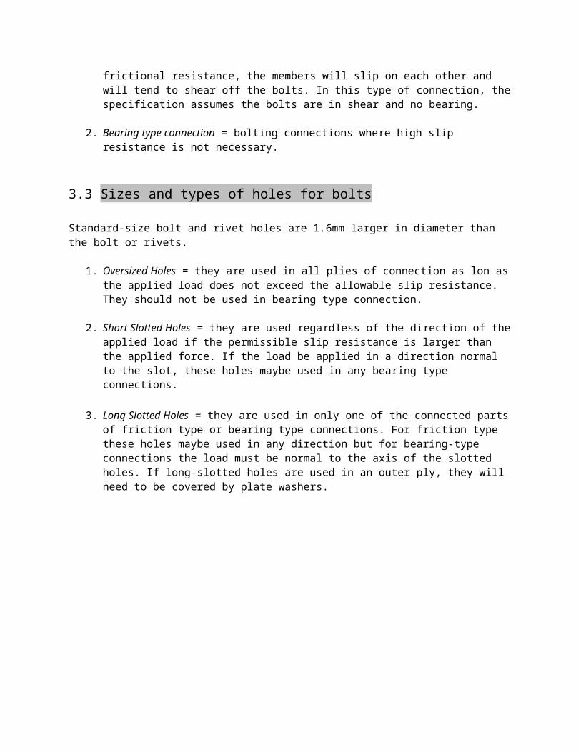
3.3 Sizes and types of holes for bolts
Standard-size bolt and rivet holes are 1.6mm larger in diameter than the bolt or rivets.
1. Oversized Holes = they are used in all plies of connection as lon asthe applied load does not exceed the allowable slip resistance. They should not be used in bearing type connection.
2. Short Slotted Holes = they are used regardless of the direction of theapplied load if the permissible slip resistance is larger than the applied force. If the load be applied in a direction normal to the slot, these holes maybe used in any bearing type connections.
3. Long Slotted Holes = they are used in only one of the connected partsof friction type or bearing type connections. For friction type these holes maybe used in any direction but for bearing-type connections the load must be normal to the axis of the slotted holes. If long-slotted holes are used in an outer ply, they will need to be covered by plate washers.

S T R U C T U R A L S T E E L DE S I G N 44-48
3.4 Types of Bolted Connections
1. Lap Joint
2. Butt Joint
3. Double Plane Connection
4. Bolts in Multiple Shear
5. Triple Riveted-Butt Joint
6. Quadruple-Riveted Butt Joint

S T R U C T U R A L S T E E L DE S I G N 44-48
3.5 Failure of Bolted Joints
1. Shear Failure of Bolt:
2. Tension Failure of Plate
3. Bearing Failure of Plate
4. Shear Failure of Plate Behind Bolt
5. Double shear Failure of a Butt Joint
3.6 Minimum Spacing of Bolts(Section 510.4.8)

Distance between centers of standard, oversized or slotted fastener
holes shall not be less than 223 times the nominal diameter of the
fastener nor less than the required by the following paragraph, if applicable.
S T R U C T U R A L S T E E L DE S I G N 44-48
Along a line of transmitted forces, the distance between centers of holes “S” shall be less than 3d when:
Fp = 1.2 Fu for standard or short-slotted holes with two or more bolts in line of force.Fp = 1.0 Fu for long-slotted holes with the axis of the slot perpendicular to the direction of load and with two or more bolts in the line of force. Otherwise, the distance between centers of holes shall not be less than the following:
S ≥ 2PFut
+ d2
Equation 3.6-a
Where: P = force transmitted by one fastener to the critical connected part.
Fu = specified min. tensile strength of the critical; connected part.
t = thickness of critical connected partd = nominal diameter of fastener

3.7 Minimum Edge Distance
Min. Le = 2PFut
but not less than 1.5d
Equation 3.7-a
3.8 Maximum Edge Distance and Spacing
Max. Le = 12t but not exceed 150 mmt = thickness of the connected part under considered
For unpainted built up members which is exposed to atmospheric corrosion:
Max. Le = 8t but not to exceed 125 mmSpacing of fasteners = 14t but to exceed 175 mmWhere t = thickness of thinnest part
S T R U C T U R A L S T E E L DE S I G N 164-167
4.15 Problem
A C 375 x 50.5 (channel) is used as purlins of a roof truss having a pitch of ¼. There are 9 purlins on each of the top chord spaced at 2.15 m. on centers. The spacing between trusses are subjected to the following loads:

Tile Roof = 860 kPa of roof surfaceWind load = 1.20 kPa normal to roof surface
Use A 36 steel:Fy= 248 MPaFu= 400 MPa
1. Determine the diameter of the sag rods for thw purlins of the truss if they are placed at the mid span.
2. Determine the diameter of the sag rods for the purlins of the truss if they are placed at the third points.
3. Determine the diameter of the tie rods at the ridge if the sag rods are placed at the third points.
SOLUTION:1. Diam. Of sag rods at midspan of the
purlins.Load on each purlins.
Roof covering = 2.15 (0.86)Roof covering = 1.849 kN/m
Weight of purlins = 50.5(9.81)1000
Weight of purlins = 0.495 kN/m
Tan θ = 12θ = 26.57°

Tangential component of theloads:Wt = (1,849 + 0.495) Sin26.57°Wt = 1.048 kN/m
Using 3 moment equation:
MB = -WL232
MB = -1.048(6.75)2
32Mb = - 1.492 kN/m
MB = 3.375 R1 - 1.048(3.375) (3.375)
2-1.492 = 3.375 R1 - 5.969
R1 = 1.327 kNR2 = 1.327 kN
R1+R2+R=1.048 (6.75 ) 1.327 + 1.327 R = 1.048 (6.75)R = 4.42 kN (reaction at sag rods at mid point)
Total load on the critical sag rods: (It will support the 8 lowerpurlins)T = 8(4.42)T = 35.36 kN
A= T
0.33Fu
A= 353600.33(400)
A= 267.88 mm2

πd2
4 = 267.88
d = 18.47 mm
Use d= 20 mm ø
2. Diameter of sag rods atmiddle thirds:Using 3 moment equation.
MB= MC
MB= -WL290
MB= -1.048(6.75)2
90MB= 0.53 kN.m
MB= R1 (2.25) – 1.048(2.25) (2.25)
2
-0.53 = 2.25 R1- 2.652R1= 0.943 =R2
R1+R2+2R=¿ 1.048(6.75)R=¿ 0.2594 kN (reaction at sag rods at middle thirds)
T= 2.594(8) (total reaction of critical sag rods)T= 20.752 kN
A= T
0.33Fu
A= 207520.33(400)
A= 157.21 mm2πd2
4 = 157.21
d=14.14

Use d= 16 mm ø (min. diam.)
3. Dia. Of tie bar at ridge purlins: Th= Cos θ= 20752
Th= 20752
cos26.57°Th= 23202 N (tension of tie bar)
A= Th
0.33Fu
A= 23202
0.33(400)A= 175.77 mm2πd2
4 = 175.77
d= 14.95 mm
use d= 16 mm (min.diam.)
S T R U C T U R A L S T E E L DE S I G N 188-188A
5.12 Standard Bolted Beam Connections
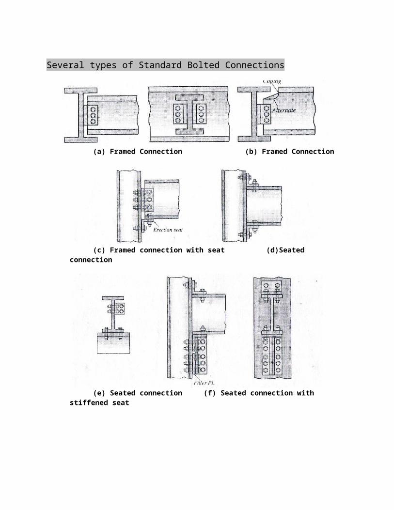
Several types of Standard Bolted Connections
(a) Framed Connection (b) Framed Connection
(c) Framed connection with seat (d)Seated connection
(e) Seated connection (f) Seated connection with stiffened seat

FRAMED CONNECTIONThese types of connections consist of a pair of flexible web angles usually shop-connected to the web of the supported beam and field-connected to the supporting beam or column. When two beams are being connected, it is usually necessary to keep their flanges at the same elevation, the top flange of one of the beam will have to cut back, this is called coping. This type of connection must be check for blockshear capacity.
FRAME CONNECTION WITH SEATThis type of framed connection consists of two web angles connected tothe beam web in the shop after which bolts are placed through the angles and column in the field. An angular section called erection seat, supports the beam during erection.
SEATED CONNECTIONThis type of connection consists of an erection set which is shop connected to the column and another angle at the top of the beam whichis field-connected to the beam and column. The top angle keeps the topflange of the beam from being accidentally twisted out of place duringconstruction.
SEATED CONNECTION WITH STIFFENED SEATThis connection is used for heavier loads by placing stiffened seats in addition to the top angle.

S T R U C T U R A L S T E E L DE S I G N 238-251
BENDING STRESSES
7.1 Types of Beams
Beams are structural members that support transverse loads, horizontal, sloping or vertical loads, depending upon their end connections. Simple beams have end connections which are considered not to have any end moments with its end free to rotate. A beam is considered continuous beams if it extend continuously across three or more supports and it is considered fixed beams if its ends are rigidlyattached to other members so that a moment can be transmitted across the connection.
1. Joist = these are closely spaced beams supporting the floors and roofs of buildings
2. Lintels = are beams over openings in masonry walls such as windows and doors.
3. Spandrel beams = these beams supports the exterior walls of the building.
4. Floor beams = these are larger beams found in many bridges perpendicular to the roadway of the bridge and they are used to transfer the floor loads from stringers to the roadways.

5. Stringers = these are beams in the floor of bridges which are running parallel to the roadways.
6. Girder = these are large beams into which smaller beams are framed.
7.2 Bending Stresses
If a beam in subjected to a bending moment, the stress maybe computed
using the flexural formulafb=MCI . When the stresses are within the
limit of the material, the procedure is called elastic design or allowable stress design (ASD).
fb=MCI Equation
7.2.1
Where:fb= extreme fiber stressM= bending moment at the section under consideration.I= moment of inertia of the cross section with respect to the neutral axis.c= distance from the neutral axis to the extreme fiber.Ic= is known as the section modulus.
fb= allowable bending stress.
fb=MCI
fb=MS <
fb
It should be remembered that this formula is limited to stress situations below the elastic limit because it is based on the usual elastic assumptions, that a plane section before bending remains a plane section after bending, and the stress is proportional to the strain.
S T R U C T U R A L S T E E L DE S I G N 238-251
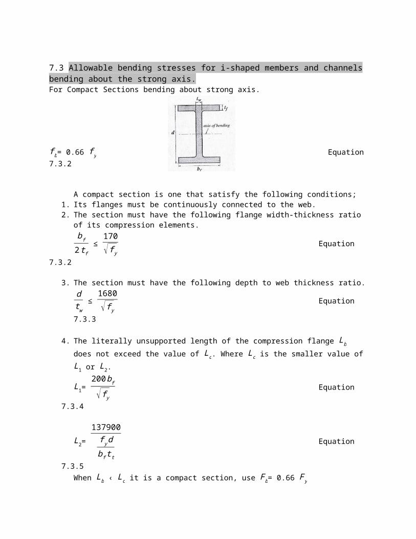
7.3 Allowable bending stresses for i-shaped members and channels bending about the strong axis.For Compact Sections bending about strong axis.
fb= 0.66 fy Equation7.3.2
A compact section is one that satisfy the following conditions;1. Its flanges must be continuously connected to the web.2. The section must have the following flange width-thickness ratio
of its compression elements.bf
2tf ≤
170√fy
Equation
7.3.2
3. The section must have the following depth to web thickness ratio.dtw ≤
1680√fy
Equation
7.3.3
4. The literally unsupported length of the compression flange Lb does not exceed the value of Lc. Where Lc is the smaller value ofL1 or L2.
L1= 200bf√fy
Equation
7.3.4
L2= 137900fydbftt
Equation
7.3.5When Lb ‹ Lc it is a compact section, use Fb= 0.66 Fy

Note: For beams having full lateral supports Lb= 0
7.4 For members with compact sections as defined by section2.1 (NSCP) (excluding hybrid beams and members with yieldpoints greater than 448 MPa) symmetrical about and loaded inthe plane of their minor axis, theallowable stress is Fb= 0.66Fy.
bf
2tf ≤ 170√fy
dtw ‹
1680√fy
S T R U C T U R A L S T E E L DE S I G N 238-251
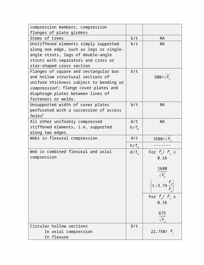
Table 7.4.1Limiting Width-Thickness Ratios For Compression Members With Compact
Sections
Description of element
WidthThicknessRatio
LimitingWidth-
ThicknessRatios
(Compact)Flanges of I-shaped rolled beams and channels in flexurea
b/t 170/√FyFlanges of I-shaped welded beams in flexure
b/t 170/√FyOutstanding legs of pairs of angles in continuous contact; angles or plates projecting from rolled beams or columns; stiffeners on plate girders.
b/t NA
Angles or plates projecting from girders, built-up columns or other
b/t NA
compression members; compression flanges of plate girdersStems of trees b/t NAUnstiffened elements simply supported along one edge, such as legs or single-angle struts, legs of double-angle struts with separators and cross or star-shaped cross section
b/t NA
Flanges of square and rectangular box and hollow structural sections of uniform thickness subject to bending orcompressiond; flange cover plates and diaphragm plates between lines of fasteners or welds.
b/t500/√Fy
Unsupported width of cover plates perforated with a succession of accessholesb
b/t NA
All other uniformly compressed stiffened elements, i.e, supported along two edges.
b/th/tw
NA
Webs in flexural compression d/t 1680/√Fyh/tw -------
Web in combined flexural and axial compression
d/tw For fa/ Fy ≤0.16
1680√Fy
(1–3.74 fa
fy )For fa/ Fy ≤
0.16
675√Fy
Circular hollow sections In axial compression In flexure
D/t22,750/ Fy
22,750/ Fy
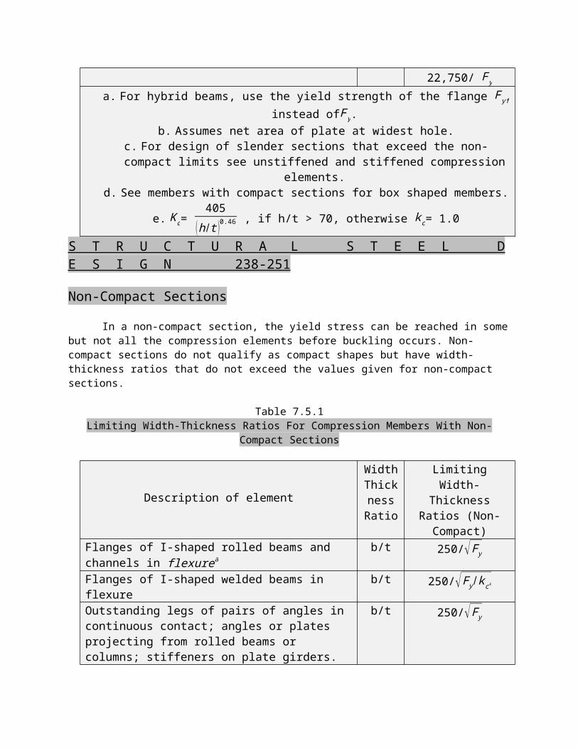
a. For hybrid beams, use the yield strength of the flange Fyf
instead ofFy.b. Assumes net area of plate at widest hole.
c. For design of slender sections that exceed the non-compact limits see unstiffened and stiffened compression
elements.d. See members with compact sections for box shaped members.
e. Kc= 405
(h /t )0.46 , if h/t > 70, otherwise kc= 1.0
S T R U C T U R A L S T E E L DE S I G N 238-251
Non-Compact Sections
In a non-compact section, the yield stress can be reached in somebut not all the compression elements before buckling occurs. Non-compact sections do not qualify as compact shapes but have width-thickness ratios that do not exceed the values given for non-compact sections.
Table 7.5.1Limiting Width-Thickness Ratios For Compression Members With Non-
Compact Sections
Description of element
WidthThicknessRatio
LimitingWidth-
ThicknessRatios (Non-Compact)
Flanges of I-shaped rolled beams and channels in flexurea
b/t 250/√FyFlanges of I-shaped welded beams in flexure
b/t 250/√Fy/kce
Outstanding legs of pairs of angles in continuous contact; angles or plates projecting from rolled beams or columns; stiffeners on plate girders.
b/t 250/√Fy

Angles or plates projecting from girders, built-up columns or other compression members; compression flanges of plate girders
b/t 250/√Fy/kc
Stems of trees b/t 333/√FyUnstiffened elements simply supported along one edge, such as legs or single-angle struts, legs of double-angle struts with separators and cross or star-shaped cross section
b/t 200/√Fy
Flanges of square and rectangular box and hollow structural sections of uniform thickness subject to bending orcompressiond; flange cover plates and diaphragm plates between lines of fasteners or welds.
b/t 625/√Fy
Unsupported width of cover plates perforated with a succession of accessholesb
b/t 832/√Fy
All other uniformly compressed stiffened elements, i.e, supported along two edges.
b/th/tw
664/√Fy
Webs in flexural compression d/t --------h/tw 1995/√Fy
Web in combined flexural and axial compression
d/tw 1995/√FyCircular hollow sections In axial compression In flexure
D/t----------------
S T R U C T U R A L S T E E L DE S I G N 238-251

7.6 Partially compact bending about strong axis
For members meeting the requirements of compact sections bending about the strong axis except that their flanges are non-compact (excluding built-up members with yield points greater than 448 MPa) the allowable stress is:
Fb=Fy[0.79−0.000762bf
2tf√Fy]
Equation 7.6.1
170√Fy
< bf
2tf <
250√Fy
(partially compact.)
The section is partially compact.
7.7 For built up members meeting the requirements of compact sections bending about the strong axis except that their flanges are non-compact and their webs are compact or non-compact (excluding hybrid girders and members with yield points greater than 448 MPa) the allowable stress is.
Fb=Fy[0.79−0.000762( bf2tf )√Fy
Kc ]Equation 7.7.1
Where:

Kc = 4.05
( htw )0.46 if
htw > 70, otherwise Kc= 1.0
Equation 7.7.2
S T R U C T U R A L S T E E L DE S I G N 238-251
7.8 For members with a non-compact section bending about the strong axis, but not included in equation 7.6.1 and equation 7.7.2 and loaded through the shear center and braced laterally in the region of compression stress at interval of not exceeding: S=200Bf√Fy
The allowable bending stree is Fb= 0.60 Fy

7.9 Allowable Bending stress for I-shaped members, solid bars and rectangular plates which is bending about its weak axis.
7.10 Members with Compact Sections, bending about its weak axis.
For doubly symmetrical I and H-shape members with compact flanges, continuously connected to the web and bent about their weak axis (except members with yield points greater than 448 Ma) solid round andsquare bars, and solid rectangular sections bent about their weaker axis, the allowable stress is:
Fb = 0.75 Fy Equation 7.10.1
bf
2tf =
170√Fy
(compact section)
S T R U C T U R A L S T E E L DE S I G N 238-251
7.11 Members with non-compact sections, bending about its weak axis.
For members not meeting the requirements for compact section and not covered for box-type and tubular flexural members, bent about their minor axis, the allowable stress is.

Fb = 0.60 Fy Equation 7.11.1
7.12 Partially compact, bending about its weak axis.
For Doubly symmetrical I and H-shaped members bent about their weak axes (except members with yield points greater than 448 MPa) withnon-compact flanges continuously connected to the web maybe designed on the basis of an allowable stress of:
Fb = Fy [1.075−0.0019bf
2tf√Fy] Equation
7.12.1
170√Fy
< bf
2tf <
250√Fy
(partially compact)
7.13 Members with compact or non-compact sections with unbraced length greater than Lc : (Lb>Lc )
Allowable bending stress is Fb= 0.60 Fy
Where Lc is the smaller value of L1 or L2
L1= 200√Fy
Lu= the bigger value of L1 and L2
L2= 137900Fydbftf
Lb= unbraced length

S T R U C T U R A L S T E E L DE S I G N 238-251
7.14 For flexural memers with compact or non-compact sections, and with unbraced lengths Lb greater than Lc and unbraced lengthLb less than Lu , the allowable bending stress is Fb= 0.60 Fy
When Lb > LcLb < Lu
7.15 For such members with an axis of symmetry and loaded in the plane or their web, the allowable bending stress in and loaded inthe plane or their web, the allowable bending stress in compression is the larger value of equation 7.15.1 and or equation 7.16.1 and equation 7.15.2 except that equation 7.15.2 is applicable only to sections with a compression flange that is solid and approximately rectangular in cross section and that hasan area not less than the tension flange.
When Lb > Lc and Lb < Lu Use the following relation.
Case 1 √703270Cb
Fy < √3516330CbFy
Allowable bending stress is the larger of equation 7.15.1 and equation7.15.2 but < 0.60 Fy.
Fb= Fy [23−Fy (L /rt)
2
10.55x10²Cb ] Equation
7.15.1

Fb= CbLdbftf
Equation
7.15.2
7.16 For such members with an axis of symmetry in and loaded in the plane or their web, the allowable bending stress in compression is the larger value of equation 7.15.1 and or equation 7.16.1 and equation 7.15.2 except that equation 7.15.2 is applicable only to sections with a compression flange that is solid and approximately rectangular in cross section and that hasan area not less than tension flange. When Lb > Lc and Lb > Lu Use the following relation.
Case 2Lrt > √3516330CbFy
Allowable bending stress is the larger value of equation 7.16.1 and equation 7.15.2 but < 0.60 Fy.
Fb=
1172100Cb
( Lrt )2 Equation
7.16.1
Fb= 82740Cb
Ldbftf
Equation
7.15.2
S T R U C T U R A L S T E E L DE S I G N 238-251
Note: Equation 7.15.2 shall not apply to hybrid girders.

Where:L= distance between cross section braced against twist or lateral displacements of the compression flange, in mm. For cantilevers bracedagainst twist only at the support, L may conservatively be taken as the actual length.
rt= radius of gyration of a section comprising the compression flange plus 1/3 of the compression web area, taken about an axis in the planeof the web, in mm.
bf= width compression flange in mm.
tf= thickness of compression flange in mm.
Cb= 1.75 + 1.05 M1M2 + 0.3 (M1M2 )
2
but not more than 2.3
Equation 7.16.2
M1= smaller bending moment at the ends of the unbraced length taken about the strong axis of the beam.
M2= larger bending moment at the ends of the unbraced lengths taken about the strong axis of the beam.
M1M2 = ratio of end moments.
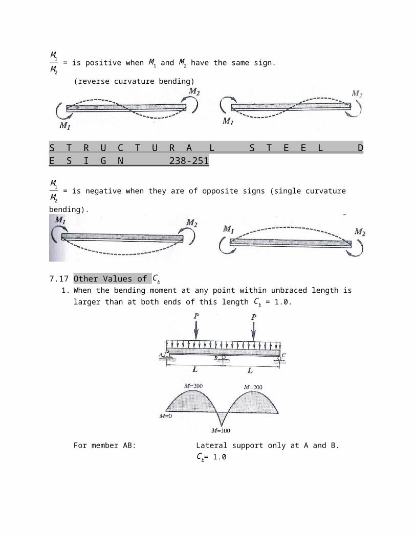
M1M2 = is positive when M1 and M2 have the same sign.
(reverse curvature bending)
S T R U C T U R A L S T E E L DE S I G N 238-251
M1M2 = is negative when they are of opposite signs (single curvature
bending).
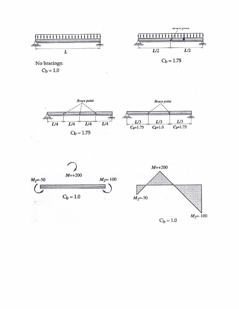
7.17 Other Values of Cb1. When the bending moment at any point within unbraced length is
larger than at both ends of this length Cb = 1.0.
For member AB: Lateral support only at A and B.Cb= 1.0
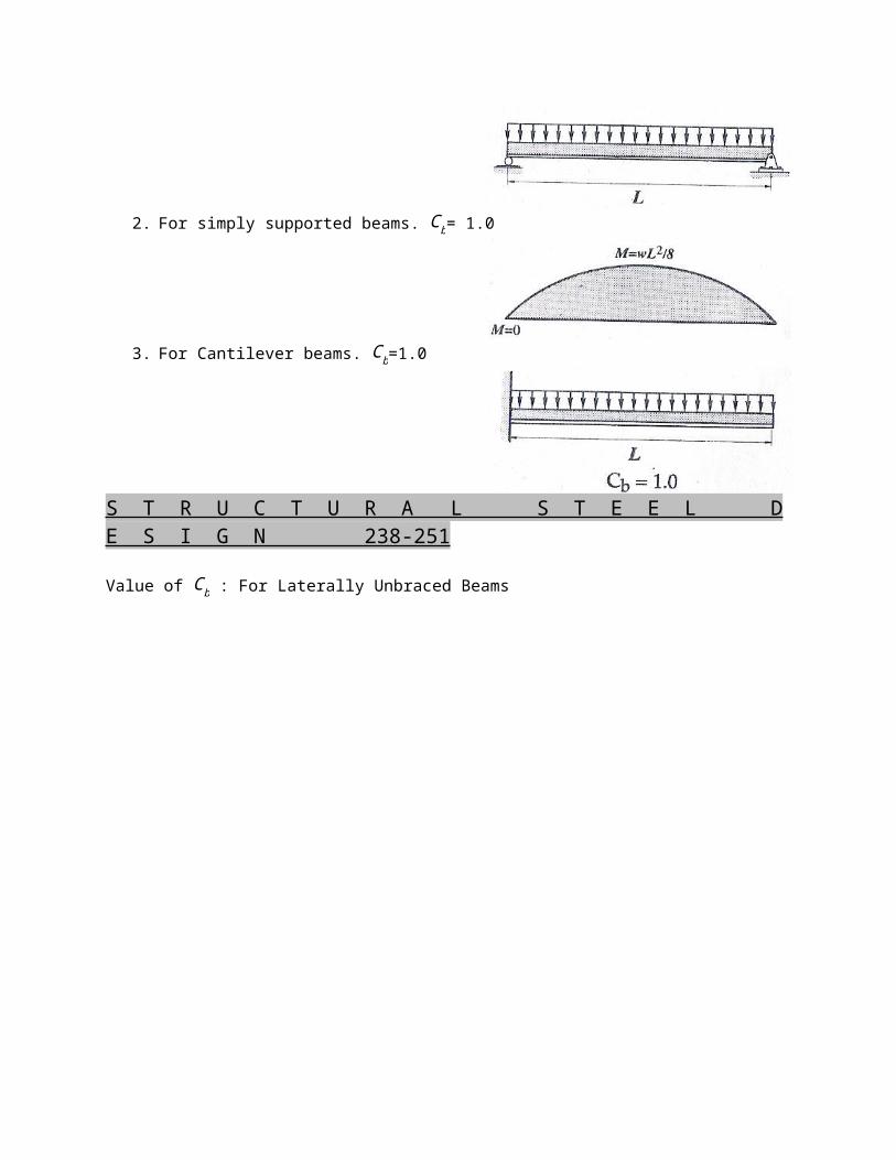
2. For simply supported beams. Cb= 1.0
3. For Cantilever beams. Cb=1.0
S T R U C T U R A L S T E E L DE S I G N 238-251
Value of Cb : For Laterally Unbraced Beams

S T R U C T U R A L S T E E L DE S I G N 238-251
Summary
Allowable bending stress for laterally unbraced beams
1. When unbraced length Lb < LcFb= 0.66 Fy
2. When unbraced length Lb < Lc
But Lb < LuFb= 0.60 Fy
3. When unbraced length Lb < Lc
Lb < LuFb is less than 0.60 Fy
Check whether:
A. √703270Cb
Fy < L
rt < √3516330CbFy
Use bigger value of Fb from (a) or (b) but < 0.60 Fy
(a) Fb= Fy [23−Fy (L /rt)
2
10.55x10⁶Cb ](b) Fb=
82740Cb
Ldbftf
B. √703270Cb
Fy < L
rt < √3516330CbFy

Use bigger value of “Fb” from (a) or (b) but < 0.60Fy
(a) Fb= 1172100Cb
(L/rt )2
(b) Fb= 82740Cb
Ldbftf
S T R U C T U R A L S T E E L DE S I G N 238-251
7.18 Computation of radius of gyration rt
Properties of W 12 x 14d = 302.514 mmbf = 100.787 mmtf= 5.69 mmtw = 5.029 mm
x = 13 (145.567)
x = 48.522
Area of shaded portion:
A = 100.787(5.69) + 48.522(5.029)A = 817.50

I = 5.69(100.787 )3
12 + 48.522 (5.029 )3
12
I = 485964.4
rt = √ IArt = √485964.4817.50
rt = 24.38