Free vibration and buckling analyses of functionally graded beams with edge cracks
13
Free vibration and buckling analyses of functionally graded beams with edge cracks J. Yang a, * , Y. Chen a,b a Department of Building and Construction, City University of Hong Kong, Tat Chee Avenue, Kowloon, Hong Kong b School of Civil Engineering, Beijing Jiaotong University, 100044 Beijing, PR China Available online 21 March 2007 Abstract This paper presents a theoretical investigation in free vibration and elastic buckling of beams made of functionally graded materials (FGMs) containing open edge cracks by using Bernoulli–Euler beam theory and the rotational spring model. It is assumed that the mate- rial properties vary along the beam thickness only according to exponential distributions. Analytical solutions of the natural frequencies, critical buckling load, and the corresponding mode shapes are obtained for cracked FGM beams with clamped–free, hinged–hinged, and clamped–clamped end supports. A detailed parametric study is conducted to show the influences of the location and total number of cracks, material properties, slenderness ratio, and end supports on the flexural vibration and buckling characteristics of cracked FGM beams. Ó 2007 Elsevier Ltd. All rights reserved. Keywords: Functionally graded materials; Beam; Open edge crack; Vibration; Buckling 1. Introduction Cracks in a structural element in the form of initial defects within the material or caused by fatigue or stress concentration can reduce the natural frequencies and change the vibration mode shapes due to the local flexibil- ity introduced by the crack. Understanding the dynamic characteristics of cracked structures is of prime importance in structural health monitoring and non-destructive dam- age evaluation because the predicted vibration data can be used to detect, locate, and quantify the extent of the cracks or damages in a structure. A large number of inves- tigations in the free vibration of cracked beams are avail- able in open literature, see, for example, those by Dimarogonas [1], Gounaris et al. [2], Chondros et al. [3], Shifrin and Ruotolo [4], Binici [5]. Basically, the theoretical modeling techniques can be grouped into ‘‘continuous’’ models and ‘‘lumped flexibility’’ models. The first category uses a continuous, one-dimensional cracked beam model through variational principles. The finite element method, Galerkin method, and Rayleigh–Ritz method are the com- monly used numerical approaches in this category. The sec- ond category represents the presence of a crack and the reduction in the beam bending stiffness by means of a line spring, and the equivalent lumped stiffness is determined through fracture mechanics analysis, starting from the knowledge of stress intensity factor (SIF). Among those in this category, Yokoyama and Chen [6] obtained the vibration characteristics of a Bernoulli–Euler beam with a single edge crack based on a modified line-spring model. Zheng and Fan [7] computed the natural frequencies of a Timoshenko beam with an arbitrary number of transverse open cracks. A modified Fourier series solution technique was developed. By using the differential quadrature method and the spring model, Hsu [8] studied the flexural vibration and dynamic response of edge-cracked Bernoulli–Euler beams resting on an elastic foundation and subjected to an axial loading and lateral excitation force. El Bikri et al. [9] investigated the geometrically non-linear free 0263-8223/$ - see front matter Ó 2007 Elsevier Ltd. All rights reserved. doi:10.1016/j.compstruct.2007.03.006 * Corresponding author. Tel.: +852 2194 2895; fax: +852 2788 7612. E-mail address: [email protected] (J. Yang). www.elsevier.com/locate/compstruct Available online at www.sciencedirect.com Composite Structures 83 (2008) 48–60
-
Upload
independent -
Category
Documents
-
view
1 -
download
0
Transcript of Free vibration and buckling analyses of functionally graded beams with edge cracks

Available online at www.sciencedirect.com
www.elsevier.com/locate/compstruct
Composite Structures 83 (2008) 48–60
Free vibration and buckling analyses of functionally gradedbeams with edge cracks
J. Yang a,*, Y. Chen a,b
a Department of Building and Construction, City University of Hong Kong, Tat Chee Avenue, Kowloon, Hong Kongb School of Civil Engineering, Beijing Jiaotong University, 100044 Beijing, PR China
Available online 21 March 2007
Abstract
This paper presents a theoretical investigation in free vibration and elastic buckling of beams made of functionally graded materials(FGMs) containing open edge cracks by using Bernoulli–Euler beam theory and the rotational spring model. It is assumed that the mate-rial properties vary along the beam thickness only according to exponential distributions. Analytical solutions of the natural frequencies,critical buckling load, and the corresponding mode shapes are obtained for cracked FGM beams with clamped–free, hinged–hinged, andclamped–clamped end supports. A detailed parametric study is conducted to show the influences of the location and total number ofcracks, material properties, slenderness ratio, and end supports on the flexural vibration and buckling characteristics of crackedFGM beams.� 2007 Elsevier Ltd. All rights reserved.
Keywords: Functionally graded materials; Beam; Open edge crack; Vibration; Buckling
1. Introduction
Cracks in a structural element in the form of initialdefects within the material or caused by fatigue or stressconcentration can reduce the natural frequencies andchange the vibration mode shapes due to the local flexibil-ity introduced by the crack. Understanding the dynamiccharacteristics of cracked structures is of prime importancein structural health monitoring and non-destructive dam-age evaluation because the predicted vibration data canbe used to detect, locate, and quantify the extent of thecracks or damages in a structure. A large number of inves-tigations in the free vibration of cracked beams are avail-able in open literature, see, for example, those byDimarogonas [1], Gounaris et al. [2], Chondros et al. [3],Shifrin and Ruotolo [4], Binici [5]. Basically, the theoreticalmodeling techniques can be grouped into ‘‘continuous’’models and ‘‘lumped flexibility’’ models. The first category
0263-8223/$ - see front matter � 2007 Elsevier Ltd. All rights reserved.
doi:10.1016/j.compstruct.2007.03.006
* Corresponding author. Tel.: +852 2194 2895; fax: +852 2788 7612.E-mail address: [email protected] (J. Yang).
uses a continuous, one-dimensional cracked beam modelthrough variational principles. The finite element method,Galerkin method, and Rayleigh–Ritz method are the com-monly used numerical approaches in this category. The sec-ond category represents the presence of a crack and thereduction in the beam bending stiffness by means of a linespring, and the equivalent lumped stiffness is determinedthrough fracture mechanics analysis, starting from theknowledge of stress intensity factor (SIF). Among thosein this category, Yokoyama and Chen [6] obtained thevibration characteristics of a Bernoulli–Euler beam with asingle edge crack based on a modified line-spring model.Zheng and Fan [7] computed the natural frequencies of aTimoshenko beam with an arbitrary number of transverseopen cracks. A modified Fourier series solution techniquewas developed. By using the differential quadrature methodand the spring model, Hsu [8] studied the flexural vibrationand dynamic response of edge-cracked Bernoulli–Eulerbeams resting on an elastic foundation and subjected toan axial loading and lateral excitation force. El Bikriet al. [9] investigated the geometrically non-linear free

hxo
z
L
L1
a
2 2 2( , , )E ν ρ
1 1 1( , , )E ν ρ
Fig. 1. An FGM beam with an open edge crack.
Table 1Fundamental frequency ratio x1/x10 of an isotropic homogenousclamped–free beam
L1=L ¼ 0:2 L1=L ¼ 0:4 L1=L ¼ 0:6
Present 0.97833 0.99107 0.99776Yokoyama and Chen [6] 0.94101 0.96667 0.99583
J. Yang, Y. Chen / Composite Structures 83 (2008) 48–60 49
vibrations of a clamped–clamped beam containing an opencrack. A semi-analytical model based on an extension ofthe Rayleigh–Ritz method was used in their study.
Another important issue deserving special attention in acracked structure is the weakened buckling capacity due tothe existence of cracks. Wang [10] gave a comprehensivestudy on the stability of a cracked beam subjected to a fol-lower compressive load. Zhou and Huang [11] presented aclosed form solution of the maximum deflection forcracked columns with rectangular cross-sections and stud-ied the elastic buckling problem analytically. A repair tech-nique using a piezoelectric patch that produce a localmoment to counteract the loss of bending stiffness torestore the buckling load-carry capacity of a cracked col-umn has also been proposed recently [12].
Functionally graded materials (FGMs), a novel class ofmacroscopically inhomogeneous composites with spatiallycontinuous material properties, have attracted considerableresearch efforts over the past few years due to their increas-ing applications in many engineering sectors. Numerousstudies have been conducted on FGM beams, plates andshell structures, dealing with a variety of subjects such asthermal elasticity [13–16], fracture analysis [17–20], staticbending [21–24], free vibration and dynamic response[25–29], buckling and postbuckling [30–33], piezo-thermo-elastic behavior [34–36], and so on. Literature review showsthat although there are quite a few papers presenting crackand fracture analyses of FGM structures, no previous workinvestigating the vibration and buckling behavior ofcracked FGM structures has been reported.
The objective of this paper is to study the free vibrationand elastic buckling of slender FGM beams with open edgecracks to gain an insight into the effects of material propertydistribution, the total number and location of cracks, theslenderness ratio and boundary condition on the vibra-tional and buckling characteristics of edge-cracked FGMbeams. The classical Bernoulli–Euler beam theory and therotational spring model are used in the present study. Com-prehensive numerical results are obtained analytically forbeams with clamped–free, hinged–hinged, and clamped–clamped boundary conditions.
2. The rotational spring model
Consider an FGM beam of length L and thickness h,containing an edge crack of depth a located at a distanceL1 from the left end as shown in Fig. 1. The shear modulusm, Young’s modulus E, and mass density q of the beamvary in the thickness direction only and follow the expo-nential distributions below
mðzÞ ¼ m0ebz; EðzÞ ¼ E0ebz; qðzÞ ¼ q0ebz ð1Þwhere m0, E0, and q0 are the values of the shear modulus,Young’s modulus, and mass density at the midplane(z ¼ 0) of the beam. b is a constant defining the materialproperty variation along the thickness direction, andb ¼ 0 corresponds to an isotropic homogeneous beam.
Poisson’s ratio l is taken as a constant since its influenceon the stress intensity factors (SIF) is quite limited [18].
It is assumed that the crack is perpendicular to the beamsurface and always remains open. Based on the well-accepted rotational-spring model, the cracked beam canbe treated as two sub-beams connected by an elastic rota-tional spring at the cracked section which has no massand no length. The bending stiffness of the cracked sectionkT is related to the flexibility G by
kT ¼1
Gð2Þ
From Broek’s approximation [37], the flexibility of thebeam G due to the presence of the crack can be derived as
1� l2
EðzÞ KI ¼M2
I
2
dGda
ð3Þ
where MI is the bending moment at the cracked section, KI
is the stress intensity factor (SIF) under mode I loading andis a function of the geometry, the loading, and the materialproperties as well. For an FGM strip with an open edgecrack under bending, the expression of SIF was derivedby Erdogan and Wu [18] as
KI ¼ �4ffiffiffiap
mðzÞ1þ �l
X1n¼0
anT n2z� a
a
� �ð4Þ
where �l ¼ ð3� 4lÞ for plane strain problem, Tn is theChebyshev polynomial of the first kind. The constants an
are determined by evaluating the boundary integrals usingGaussian quadrature and then solving the resulting func-tional equation by collocation method. The detailed solu-tion process can be found in Erdogan and Wu’s paper [18].
3. Free vibration analysis
Based on the Kirchhoff–Love hypothesis, the displace-ments parallel to the x- and z-axes of an arbitrary point
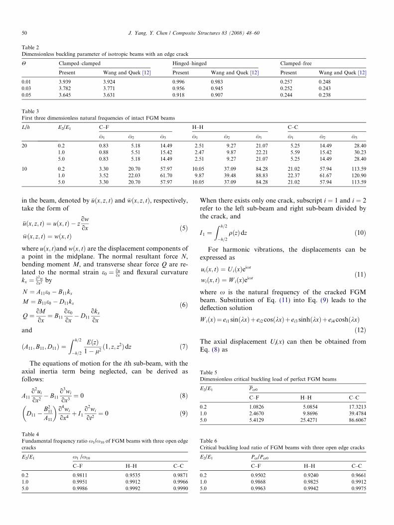
Table 2Dimensionless buckling parameter of isotropic beams with an edge crack
H Clamped–clamped Hinged–hinged Clamped–free
Present Wang and Quek [12] Present Wang and Quek [12] Present Wang and Quek [12]
0.01 3.939 3.924 0.996 0.983 0.257 0.2480.03 3.782 3.771 0.956 0.945 0.252 0.2430.05 3.645 3.631 0.918 0.907 0.244 0.238
Table 3First three dimensionless natural frequencies of intact FGM beams
L/h E2/E1 C–F H–H C–C
�x1 �x2 �x3 �x1 �x2 �x3 �x1 �x2 �x3
20 0.2 0.83 5.18 14.49 2.51 9.27 21.07 5.25 14.49 28.401.0 0.88 5.51 15.42 2.47 9.87 22.21 5.59 15.42 30.235.0 0.83 5.18 14.49 2.51 9.27 21.07 5.25 14.49 28.40
10 0.2 3.30 20.70 57.97 10.05 37.09 84.28 21.02 57.94 113.591.0 3.52 22.03 61.70 9.87 39.48 88.83 22.37 61.67 120.905.0 3.30 20.70 57.97 10.05 37.09 84.28 21.02 57.94 113.59
Table 5Dimensionless critical buckling load of perfect FGM beams
E2/E1 P cr0
C–F H–H C–C
0.2 1.0826 5.0854 17.32131.0 2.4670 9.8696 39.47845.0 5.4129 25.4271 86.6067
50 J. Yang, Y. Chen / Composite Structures 83 (2008) 48–60
in the beam, denoted by �uðx; z; tÞ and �wðx; z; tÞ, respectively,take the form of
�uðx; z; tÞ ¼ uðx; tÞ � zowox
�wðx; z; tÞ ¼ wðx; tÞð5Þ
where uðx; tÞand wðx; tÞ are the displacement components ofa point in the midplane. The normal resultant force N,bending moment M, and transverse shear force Q are re-lated to the normal strain e0 ¼ ou
ox and flexural curvaturekx ¼ o2w
ox2 by
N ¼ A11e0 � B11kx
M ¼ B11e0 � D11kx
Q ¼ oMox¼ B11
oe0
ox� D11
okx
ox
ð6Þ
and
ðA11;B11;D11Þ ¼Z h=2
�h=2
EðzÞ1� l2
ð1; z; z2Þdz ð7Þ
The equations of motion for the ith sub-beam, with theaxial inertia term being neglected, can be derived asfollows:
A11
o2ui
ox2� B11
o3wi
ox3¼ 0 ð8Þ
D11 �B2
11
A11
� �o4wi
ox4þ I1
o2wi
ot2¼ 0 ð9Þ
Table 4Fundamental frequency ratio x1/x10 of FGM beams with three open edgecracks
E2/E1 x1 /x10
C–F H–H C–C
0.2 0.9811 0.9535 0.98711.0 0.9951 0.9912 0.99665.0 0.9986 0.9992 0.9990
When there exists only one crack, subscript i ¼ 1 and i ¼ 2refer to the left sub-beam and right sub-beam divided bythe crack, and
I1 ¼Z h=2
�h=2
qðzÞdz ð10Þ
For harmonic vibrations, the displacements can beexpressed as
uiðx; tÞ ¼ UiðxÞeixt
wiðx; tÞ ¼ W iðxÞeixtð11Þ
where x is the natural frequency of the cracked FGMbeam. Substitution of Eq. (11) into Eq. (9) leads to thedeflection solution
W iðxÞ¼ ei1 sinðkxÞþ ei2 cosðkxÞþ ei3 sinhðkxÞþ ei4 coshðkxÞð12Þ
The axial displacement Ui(x) can then be obtained fromEq. (8) as
Table 6Critical buckling load ratio of FGM beams with three open edge cracks
E2/E1 Pcr/Pcr0
C–F H–H C–C
0.2 0.9502 0.9240 0.96611.0 0.9868 0.9825 0.99125.0 0.9963 0.9942 0.9975

J. Yang, Y. Chen / Composite Structures 83 (2008) 48–60 51
U iðxÞ ¼ kB11
A11
½ei1 cosðkxÞ � ei2 sinðkxÞ þ ei3 coshðkxÞ
þ ei4 sinhðkxÞ� þ gixþ gi0 ð13Þ
where k4 ¼ x2I1=d, d ¼ D11 � B211=A11, unknown constants
eij; gi, gi0ði ¼ 1; 2; j ¼ 1; . . . ; 4Þ are to be determined fromboundary conditions and the compatibility condition atthe cracked section.
The present study considers FGM beams with threedifferent end supports, i.e., a beam with left endclamped and the other end free (clamped–free), a beamhinged at both ends (hinged–hinged), and a beamclamped at both ends (clamped–clamped). The associ-ated boundary conditions, for FGM beams with a singlecrack, require that
0.0 0.2 0.4 0.6 0.8 1.00.93
0.94
0.95
0.96
0.97
0.98
0.99
1.00
ω 1/ω10
ω 1/ω10
L1/L
L/h = 10:E2/E1 = 0.2E2/E1 = 1.0E2/E1 = 5.0
L/h = 20:E2/E1 = 0.2E2/E1 = 1.0 E2/E1 = 5.0
0.0 0.2 0.0.93
0.94
0.95
0.96
0.97
0.98
0.99
1.00
L/h = 20:E2/E1E2/E1E2/E1
a
c
Fig. 2. Fundamental frequency ratio of FGM beams with an edge crack atclamped.
U 1 ¼ 0; W 1 ¼ 0;dW 1
dx¼ 0 at x ¼ 0 ð14aÞ
N 2 ¼ 0; M2 ¼ 0; Q2 ¼ 0 at x ¼ L ð14bÞ
for a clamped–free beam,
U 1 ¼ 0; W 1 ¼ 0; M1 ¼ 0 at x ¼ 0 ð15aÞU 2 ¼ 0; W 2 ¼ 0; M2 ¼ 0 at x ¼ L ð15bÞ
for a hinged–hinged beam, and
U 1 ¼ 0; W 1 ¼ 0;dW 1
dx¼ 0 at x ¼ 0 ð16aÞ
U 2 ¼ 0; W 2 ¼ 0;dW 2
dx¼ 0 at x ¼ L ð16bÞ
for a clamped–clamped beam.
0.0 0.2 0.4 0.6 0.8 1.00.95
0.96
0.97
0.98
0.99
1.00
L/h = 10:E2/E1 = 0.2E2/E1 = 1.0E2/E1 = 5.0
L/h = 20:E2/E1 = 0.2E2/E1 = 1.0 E2/E1 = 5.0
ω 1/ω10
L1/L
L1/L
4 0.6 0.8 1.0
L/h= 10:E2/E1 = 0.2E2/E1 = 1.0E2/E1 = 5.0
= 0.2 = 1.0 = 5.0
b
varying locations: (a) clamped–free; (b) hinged–hinged and (c) clamped–
0.0 0.5 1.0 1.5 2.0
-1.0
-0.5
0.0
0.5
1.0
cracked beam C-F H-H C-C
vibr
atio
n m
ode
shap
es
x
perfect beam C-F H-H C-C
L/h=20E
2/E
1=0.2
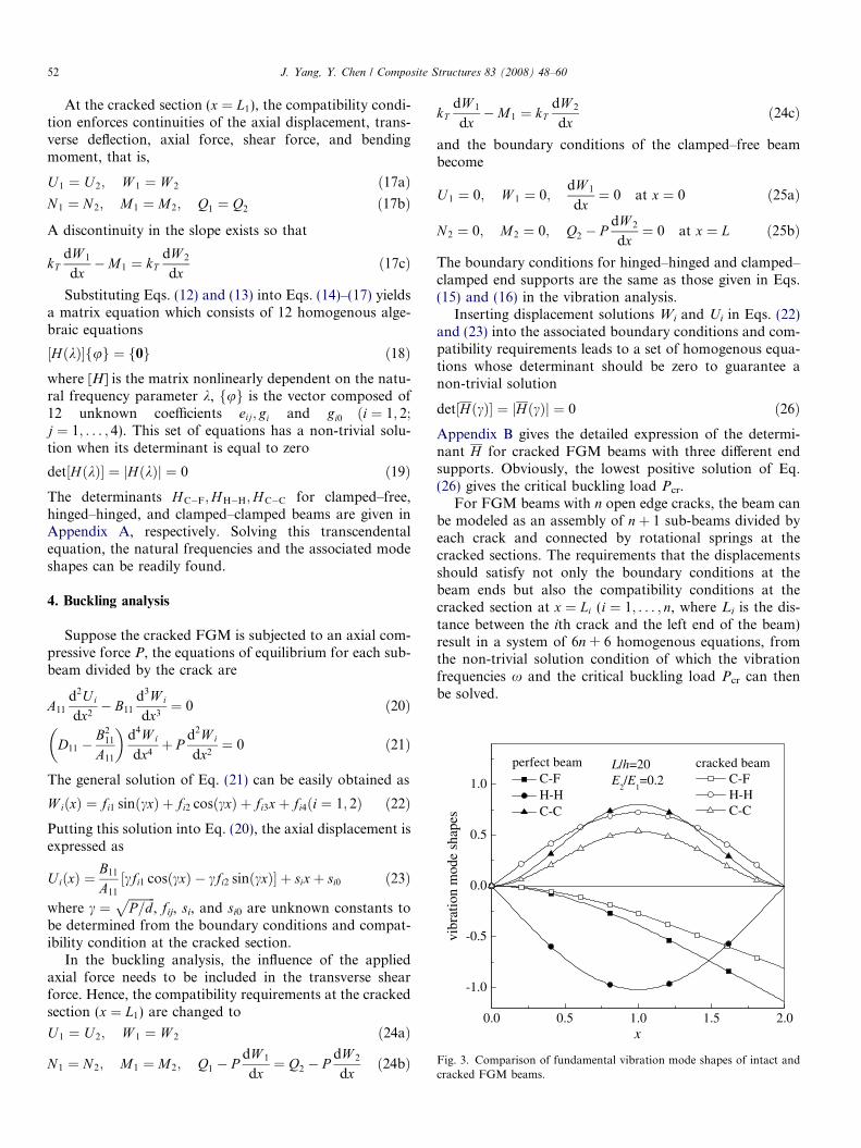
Fig. 3. Comparison of fundamental vibration mode shapes of intact andcracked FGM beams.
52 J. Yang, Y. Chen / Composite Structures 83 (2008) 48–60
At the cracked section (x ¼ L1), the compatibility condi-tion enforces continuities of the axial displacement, trans-verse deflection, axial force, shear force, and bendingmoment, that is,
U 1 ¼ U 2; W 1 ¼ W 2 ð17aÞN 1 ¼ N 2; M1 ¼ M2; Q1 ¼ Q2 ð17bÞ
A discontinuity in the slope exists so that
kTdW 1
dx�M1 ¼ kT
dW 2
dxð17cÞ
Substituting Eqs. (12) and (13) into Eqs. (14)–(17) yieldsa matrix equation which consists of 12 homogenous alge-braic equations
½HðkÞ�fug ¼ f0g ð18Þwhere [H] is the matrix nonlinearly dependent on the natu-ral frequency parameter k, fug is the vector composed of12 unknown coefficients eij; gi and gi0 ði ¼ 1; 2;j ¼ 1; . . . ; 4). This set of equations has a non-trivial solu-tion when its determinant is equal to zero
det½HðkÞ� ¼ jHðkÞj ¼ 0 ð19ÞThe determinants H C�F;H H�H;H C�C for clamped–free,hinged–hinged, and clamped–clamped beams are given inAppendix A, respectively. Solving this transcendentalequation, the natural frequencies and the associated modeshapes can be readily found.
4. Buckling analysis
Suppose the cracked FGM is subjected to an axial com-pressive force P, the equations of equilibrium for each sub-beam divided by the crack are
A11
d2Ui
dx2� B11
d3W i
dx3¼ 0 ð20Þ
D11 �B2
11
A11
� �d4W i
dx4þ P
d2W i
dx2¼ 0 ð21Þ
The general solution of Eq. (21) can be easily obtained as
W iðxÞ ¼ fi1 sinðcxÞ þ fi2 cosðcxÞ þ fi3xþ fi4ði ¼ 1; 2Þ ð22ÞPutting this solution into Eq. (20), the axial displacement isexpressed as
UiðxÞ ¼B11
A11
½cfi1 cosðcxÞ � cfi2 sinðcxÞ� þ sixþ si0 ð23Þ
where c ¼ffiffiffiffiffiffiffiffiffiP=d
p, fij, si, and si0 are unknown constants to
be determined from the boundary conditions and compat-ibility condition at the cracked section.
In the buckling analysis, the influence of the appliedaxial force needs to be included in the transverse shearforce. Hence, the compatibility requirements at the crackedsection (x ¼ L1) are changed to
U 1 ¼ U 2; W 1 ¼ W 2 ð24aÞ
N 1 ¼ N 2; M1 ¼ M2; Q1 � PdW 1
dx¼ Q2 � P
dW 2
dxð24bÞ
kTdW 1
dx�M1 ¼ kT
dW 2
dxð24cÞ
and the boundary conditions of the clamped–free beambecome
U 1 ¼ 0; W 1 ¼ 0;dW 1
dx¼ 0 at x ¼ 0 ð25aÞ
N 2 ¼ 0; M2 ¼ 0; Q2 � PdW 2
dx¼ 0 at x ¼ L ð25bÞ
The boundary conditions for hinged–hinged and clamped–clamped end supports are the same as those given in Eqs.(15) and (16) in the vibration analysis.
Inserting displacement solutions Wi and Ui in Eqs. (22)and (23) into the associated boundary conditions and com-patibility requirements leads to a set of homogenous equa-tions whose determinant should be zero to guarantee anon-trivial solution
det½HðcÞ� ¼ jHðcÞj ¼ 0 ð26ÞAppendix B gives the detailed expression of the determi-nant H for cracked FGM beams with three different endsupports. Obviously, the lowest positive solution of Eq.(26) gives the critical buckling load Pcr.
For FGM beams with n open edge cracks, the beam canbe modeled as an assembly of nþ 1 sub-beams divided byeach crack and connected by rotational springs at thecracked sections. The requirements that the displacementsshould satisfy not only the boundary conditions at thebeam ends but also the compatibility conditions at thecracked section at x ¼ Li (i ¼ 1; . . . ; n, where Li is the dis-tance between the ith crack and the left end of the beam)result in a system of 6n + 6 homogenous equations, fromthe non-trivial solution condition of which the vibrationfrequencies x and the critical buckling load Pcr can thenbe solved.

J. Yang, Y. Chen / Composite Structures 83 (2008) 48–60 53
5. Numerical results and discussion
Table 1 gives the fundamental frequency ratio x1=x10 ofa clamped–free isotropic beam (L=h ¼ 4:0, l ¼ 0:3) with anopen edge crack of depth a=h ¼ 0:2 at different locationsðL1=L ¼ 0:2; 0:4; 0:6Þ. This example was previously ana-lyzed by Yokoyama and Chen [6] using the finite elementmethod and Bernoulli–Euler beam theory. Our analyticalsolutions are in good agreement with the finite elementresults.
Table 2 lists the dimensionless buckling parameterPL2=p2EI of isotropic beams with an edge crack at the mid-point (L1=L ¼ 0:5) under hinged–hinged, clamped–free,and clamped–clamped boundary conditions. The valueH ¼ kT=EI is a function of the crack depth and EI is the
0.0 0.2 0.4 0.6 0.8 1.00.96
0.97
0.98
0.99
1.00
ω1
ω2
ω3
L/h = 20E2/E1 = 0.2
ω n/ωn0
ω n/ωn0
L1/L
0.0 0.2 0.4
0.97
0.98
0.99
1.00
L/h = 20E2/E1 = 0
a
c
Fig. 4. The first three frequency ratios of FGM beams with an edge crack atclamped.
beam bending rigidity. The present results agree very wellwith those given by Wang and Quek [12].
Tables 3–6 and Figs. 2–8 present analytical solutions forthe free vibration and elastic buckling of clamped–free,hinged–hinged, and clamped–clamped functionally gradedbeams containing a single or multiple open edge cracks.
The frequency ratios xn/xn0 of cracked functionallygraded beams are given in Tables 3, 4, and Figs. 2–5 whilethe critical buckling load ratios Pcr/Pcr0 are given in Tables5, 6, and Figs. 6–8, where xn0 and Pcr0 represent the nthnatural frequency and the critical buckling load of theintact counterparts. Unless otherwise stated, it is assumedin the following examples that the beam thicknessh ¼ 0:1 m; the crack depth ratio a=h ¼ 0:2; the slendernessratio L=h ¼ 10 and 20; the Young’s modulus ratio
0.0 0.2 0.4 0.6 0.8 1.00.97
0.98
0.99
1.00
ω1
ω2
ω3
L/h = 20E2/E1 = 0.2
ω n/ωn0
L1/L
L1/L
0.6 0.8 1.0
ω1
ω2
ω3
.2
b
varying locations: (a) clamped–free; (b) hinged–hinged and (c) clamped–
0.2 0.4 0.6 0.8 1.00.97
0.98
0.99
1.00
E2/E1 = 0.2E2 /E1 = 1.0 E2 /E1 = 5.0
0.2 0.4 0.6 0.8 1.0
0.97
0.98
0.99
1.00
E2/E1 = 0.2E2/E1 = 1.0E2/E1 = 5.0
ω 1/ω10
ω 1/ω10
ω 1/ω10
L2 /L L1 /L
L1 /L
0.2 0.4 0.6 0.8 1.0
0.97
0.98
0.99
1.00
E2 /E1 = 0.2E2 /E1 = 1.0 E2 /E1 = 5.0
a b
c
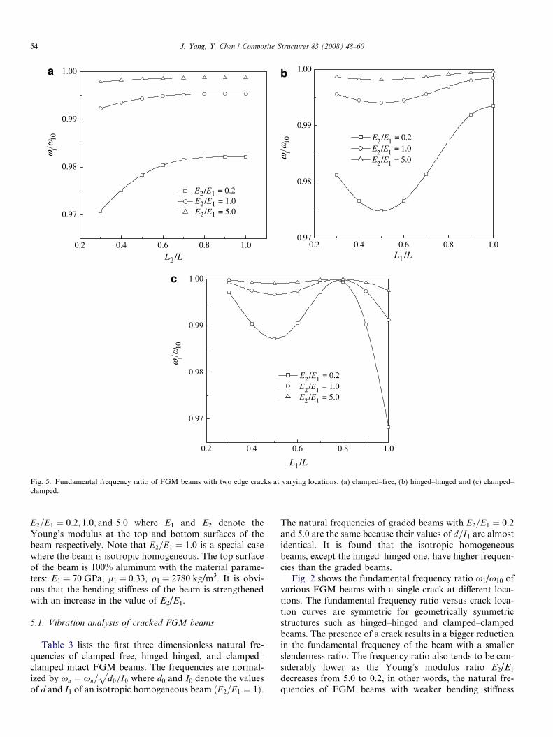
Fig. 5. Fundamental frequency ratio of FGM beams with two edge cracks at varying locations: (a) clamped–free; (b) hinged–hinged and (c) clamped–clamped.
54 J. Yang, Y. Chen / Composite Structures 83 (2008) 48–60
E2=E1 ¼ 0:2; 1:0; and 5:0 where E1 and E2 denote theYoung’s modulus at the top and bottom surfaces of thebeam respectively. Note that E2=E1 ¼ 1:0 is a special casewhere the beam is isotropic homogeneous. The top surfaceof the beam is 100% aluminum with the material parame-ters: E1 = 70 GPa, l1 = 0.33, q1 = 2780 kg/m3. It is obvi-ous that the bending stiffness of the beam is strengthenedwith an increase in the value of E2/E1.
5.1. Vibration analysis of cracked FGM beams
Table 3 lists the first three dimensionless natural fre-quencies of clamped–free, hinged–hinged, and clamped–clamped intact FGM beams. The frequencies are normal-ized by �xn ¼ xn=
ffiffiffiffiffiffiffiffiffiffiffid0=I0
pwhere d0 and I0 denote the values
of d and I1 of an isotropic homogeneous beam ðE2=E1 ¼ 1Þ.
The natural frequencies of graded beams with E2=E1 ¼ 0:2and 5.0 are the same because their values of d=I1 are almostidentical. It is found that the isotropic homogeneousbeams, except the hinged–hinged one, have higher frequen-cies than the graded beams.
Fig. 2 shows the fundamental frequency ratio x1/x10 ofvarious FGM beams with a single crack at different loca-tions. The fundamental frequency ratio versus crack loca-tion curves are symmetric for geometrically symmetricstructures such as hinged–hinged and clamped–clampedbeams. The presence of a crack results in a bigger reductionin the fundamental frequency of the beam with a smallerslenderness ratio. The frequency ratio also tends to be con-siderably lower as the Young’s modulus ratio E2/E1
decreases from 5.0 to 0.2, in other words, the natural fre-quencies of FGM beams with weaker bending stiffness

0.0 0.2 0.4 0.6 0.8 1.00.89
0.90
0.91
0.92
0.93
0.94
0.95
0.96
0.97
0.98
0.99
1.00
L/h = 20E2/E1 = 0.2E2/E1 = 1.0 E2/E1 = 5.0
L/h = 10E2/E1 = 0.2E2/E1 = 1.0E2/E1 = 5.0
0.0 0.2 0.4 0.6 0.8 1.00.91
0.92
0.93
0.94
0.95
0.96
0.97
0.98
0.99
1.00P
cr/P
cr0
Pcr
/Pcr
0
Pcr
/Pcr
0
L1/L
L1/L
L1/L
L/h = 20E2/E1 = 0.2E2/E1 = 1.0 E2/E1 = 5.0
L/h = 10E2/E1 = 0.2E2/E1 = 1.0E2/E1 = 5.0
0.0 0.2 0.4 0.6 0.8 1.00.91
0.92
0.93
0.94
0.95
0.96
0.97
0.98
0.99
1.00
L/h = 20E2/E1 = 0.2E2/E1 = 1.0 E2/E1 = 5.0
L/h = 10E2/E1 = 0.2E2/E1 = 1.0E2/E1 = 5.0
a b
c
Fig. 6. Critical buckling load ratio of FGM beams with an edge crack at varying locations: (a) clamped–free; (b) hinged-hinged and (c) clamped–clamped.
J. Yang, Y. Chen / Composite Structures 83 (2008) 48–60 55
are more sensitive to the crack. The crack location affectsthe fundamental frequency in a different way for FGMbeams with different end supports. The frequency ratio isthe minimum when the crack is located at the fixed end,the midpoint, and the beam ends for the clamped–freebeam, the hinged–hinged beam, and the clamped–clampedbeam, respectively, i.e., where the maximum bendingmoment under a uniformly distributed load is achieved.
Fig. 3 demonstrates the change of the fundamentalvibration mode shape of FGM beams (E2=E1 ¼ 0:2,L=h ¼ 20) due to a crack. The mode shape of the hinged–hinged cracked beam is shown to be opposite to that ofits intact counterpart while the intact and crackedclamped–free and clamped–clamped beams have similarmode shapes which differ in the vibration amplitudes only.
Fig. 4 compares the frequency ratio versus crack loca-tion curves for the first three frequencies of FGM beams
(E2=E1 ¼ 0:2, L=h ¼ 20) with a single crack. The resultsfor the 2nd and 3rd frequencies seem to be much morecomplicated than those for the fundamental frequency.The lowest frequency ratio for the first three frequenciesof the clamped–clamped and clamped–free beams arefound to be at the same locations. The hinged–hingedbeam, however, has the lowest ratio at L1=L ¼ 0:50 forthe fundamental frequency, L1=L ¼ 0:25, 0.75 for the 2ndfrequency, and L1=L ¼ 0:20; 0:80 for the 3rd frequency. Itshould be noted that the lowest fundamental frequencyratio is smaller than the lowest 2nd and 3rd frequencyratios.
The results for FGM beams (L=h ¼ 20) with two edgecracks are displayed in Fig. 5 where the first crack isassumed to be located at L1=L ¼ 0:2. Compared withFGM beams with a single edge crack, the beam with twocracks has an even lower fundamental frequency. When
L1/L0.2 0.4 0.6 0.8 1.0
0.91
0.92
0.93
0.94
0.95
0.96
0.97
0.98
0.99
1.00
Pcr
/Pcr
0
Pcr
/Pcr
0
E2/E1 = 0.2E2/E1 = 1.0 E2/E1 = 5.0
0.2 0.40.95
0.96
0.97
0.98
0.99
1.00
a
c
Fig. 8. Critical buckling load ratio of FGM beams with two edge cracks atclamped.
0.0 0.5 1.0 1.5 2.0-2.0
-1.5
-1.0
-0.5
0.0
0.5
1.0
L/h=20E
2/E
1=0.2
cracked beam C-F H-H C-C
bulc
king
mod
e sh
pes
x
perfect beam C-F H-H C-C
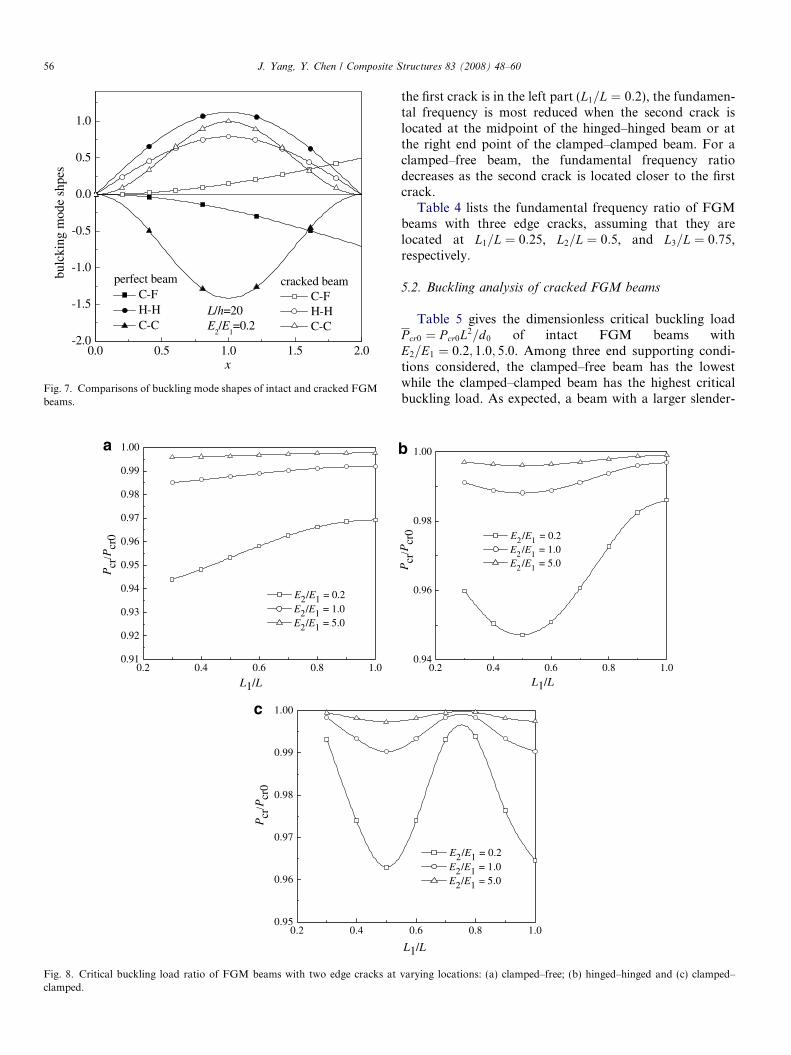
Fig. 7. Comparisons of buckling mode shapes of intact and cracked FGMbeams.
56 J. Yang, Y. Chen / Composite Structures 83 (2008) 48–60
the first crack is in the left part (L1=L ¼ 0:2), the fundamen-tal frequency is most reduced when the second crack islocated at the midpoint of the hinged–hinged beam or atthe right end point of the clamped–clamped beam. For aclamped–free beam, the fundamental frequency ratiodecreases as the second crack is located closer to the firstcrack.
Table 4 lists the fundamental frequency ratio of FGMbeams with three edge cracks, assuming that they arelocated at L1=L ¼ 0:25, L2=L ¼ 0:5, and L3=L ¼ 0:75,respectively.
5.2. Buckling analysis of cracked FGM beams
Table 5 gives the dimensionless critical buckling loadP cr0 ¼ P cr0L2=d0 of intact FGM beams withE2=E1 ¼ 0:2; 1:0; 5:0. Among three end supporting condi-tions considered, the clamped–free beam has the lowestwhile the clamped–clamped beam has the highest criticalbuckling load. As expected, a beam with a larger slender-
0.2 0.4 0.6 0.8 1.00.94
0.96
0.98
1.00
Pcr
/Pcr
0
L1/L
L1/L
E2 /E1 = 0.2E2 /E1 = 1.0 E2 /E1 = 5.0
0.6 0.8 1.0
E2/E1 = 0.2E2/E1 = 1.0 E2/E1 = 5.0
b
varying locations: (a) clamped–free; (b) hinged–hinged and (c) clamped–

J. Yang, Y. Chen / Composite Structures 83 (2008) 48–60 57
ness ratio and a lower Young’s modulus ratio E2/E1 has asmaller critical buckling load.
Fig. 6 exhibits the critical buckling load ratios Pcr/Pcr0
of FGM beams ðE2=E1 ¼ 0:2; 1:0; 5:0; L=h ¼ 10; 20Þ withone edge crack at different crack locations. The bucklingmode shape change due to the crack is shown in Fig. 7for beams with E2=E1 ¼ 0:2 and L=h ¼ 20. Fig. 8 givesthe results for FGM beams ðE2=E1 ¼ 0:2; 1:0;5:0; L=h ¼ 20Þ containing two edge cracks with the firstone located at L1=L ¼ 0:20. The variation of Pcr/Pcr0 isquite similar to what was observed in the vibration analy-sis. The critical buckling load ratio is significantlydecreased when the slenderness ratio L/h is changed from20 to 10 and the Young’s modulus ratio E2/E1 is decreasedfrom 5 to 0.2. The geometrically symmetrical structure, i.e.,the hinged–hinged beam and the clamped–clamped beam,has symmetric critical buckling load ratio versus cracklocation curves. The minimum critical buckling load ratioof beams with two edge cracks is apparently lower thanthat of the beams with a single edge crack. The bucklingdeflections of both clamped–free and clamped–clampedcracked beams are opposite to the deflections of their per-fect counterparts.
Table 6 presents the critical buckling load ratios forFGM beams with three edge cracks located atL1=L ¼ 0:25, L2=L ¼ 0:5, and L3=L ¼ 0:75, respectively.The numerical results in both Tables 3 and 5 indicate thatin the presence of three cracks, the hinged–hinged beamsuffers the greatest loss in both the fundamental frequencyand the critical buckling load.
6. Concluding marks
Free vibration and buckling behavior of functionallygraded beams with open edge cracks are theoreticallyinvestigated in this paper by using the analytical approach
H C�F ¼
0 0 0 0
0 1 0 1
1 0 1 0
0 0 0 0
0 0 0 0
0 0 0 0B11
A11J 21 � B11
A11J 11
B11
A11J 41
B11
A11J 31
J 11 J 21 J 31 J 41
0 0 0 1
�J 11 �J 21 J 31 J 41
�J 21 J 11 J 41 J 31
J 21 � dkkT
J 11 �J 11 � dkkT
J 21 J 41 þ dkkT
J 31 J 31 þ dkkT
J 41
������������������������������
based on the rotational-spring model. A parametric studyhas been conducted to discuss the effects of the materialcomposition, crack location, total number of cracks,boundary conditions, and the slenderness ratio on boththe natural frequencies and critical buckling load ofcracked FGM beams. Our numerical results indicate thatthe edge crack affects the natural frequencies and thebuckling load in a quite similar way. The vibration andbuckling behavior of an FGM beam with a smaller slen-derness ratio and a lower Young’s modulus ratio E2/E1
are more sensitive to the presence of cracks. Moreover,the frequency ratio and the buckling load ratio becomemuch lower as the crack is located near where the maxi-mum bending moment due to a uniform distributed loadoccurs. Compared with clamped–free and clamped–clamped beams, the frequency and buckling load of thehinged–hinged beam are more adversely affected by theedge crack.
Acknowledgements
The work described in this paper was fully funded by agrant from City University of Hong Kong (Project No.7001958). The authors are grateful for this financialsupport.
Appendix A.
Let
J 10 ¼ sinðkLÞ; J 11 ¼ sinðkL1Þ; J 20 ¼ cosðkLÞ; J 21
¼ cosðkL1Þ; J 30 ¼ sinhðkLÞ; J 31 ¼ sinhðkL1Þ; J 40
¼ coshðkLÞ; J 41 ¼ coshðkL1Þ
The determinant in vibration analysis of FGM beams withan open edge crack is given as follows:
0 1 0 0 0 0 0 0
0 0 0 0 0 0 0 0
0 0 0 0 0 0 0 0
0 0 0 0 0 0 1 0
0 0 J 10 J 20 �J 30 �J 40B11
dk2 0
0 0 �J 20 J 10 J 40 J 30 0 0
L1 1 � B11
A11J 21
B11
A11J 11 � B11
A11J 41 � B11
A11J 31 �L1 �1
0 0 �J 11 �J 21 �J 31 �J 41 0 0
0 0 0 0 0 0 �1 0
� B11
dk2 0 J 11 J 21 �J 31 �J 41B11
dk2 0
0 0 J 21 �J 11 �J 41 �J 31 0 0
� B11
kT k 0 �J 21 J 11 �J 41 �J 31 0 0
������������������������������
0 1 0 0 0 0 0 0
0 0 0 0 0 0 0 0B11
dk2 0 0 0 0 0 0 0
0 0 B11kA J 20 � B11k
A11J 10
B11kA11
J 40B11kA11
J 30 L 1
0 0 J 10 J 20 J 30 J 40 0 0
0 0 J 10 J 20 �J 30 �J 40B11
dk2 0
L1 1 � B11
A11J 21
B11
A11J 11 � B11
A11J 41 � B11
A11J 31 �L1 �1
0 0 �J 11 �J 21 �J 31 �J 41 0 0
0 0 0 0 0 0 �1 0
� B11
dk2 0 J 11 J 21 �J 31 �J 41B11
dk2 0
0 0 J 21 �J 11 �J 41 �J 31 0 0
� B11
kT k 0 �J 21 J 11 �J 41 �J 31 0 0
�������������������������������0 1 0 0 0 0 0 0
0 0 0 0 0 0 0 0
0 0 0 0 0 0 0 0
0 0 0 0 0 0 L 1
0 0 J 10 J 20 J 30 J 40 0 0
0 0 J 20 �J 10 J 40 J 30 0 0
L1 1 � B11
A11J 21
B11
A11J 11 � B11
A11J 41 � B11
A11J 31 �L1 �1
0 0 �J 11 �J 21 �J 31 �J 41 0 0
0 0 0 0 0 0 �1 0
� B11
dk2 0 J 11 J 21 �J 31 �J 41B11
dk2 0
0 0 J 21 �J 11 �J 41 �J 31 0 0
1B11
kT k 0 �J 21 J 11 �J 41 �J 31 0 0
������������������������������
0 0 0 0 0
0 0 0 0 0
0 0 0 0 0
0 0 0 0 1
J 20 0 0 B11
dk2 0
0 0 1 0 01c
11J 21 � B11c
A11J 11 0 � B11
A11�L1 �1
1 �J 21 �L1 �1 0 0
0 0 0 �1 0
1 �J 21 0 0 � B11
dc2 0
0 �1 0 0 0
1 J 11 � 1c 0 0 0
������������������������������
58 J. Yang, Y. Chen / Composite Structures 83 (2008) 48–60
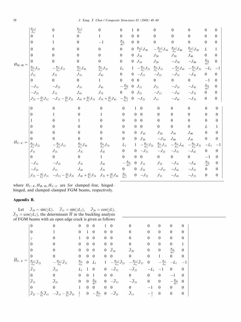
H H�H ¼
B11kA11
0 B11kA11
0
0 1 0 1
0 1 0 �1
0 0 0 0
0 0 0 0
0 0 0 0B11
A11J 21 � B11
A11J 11
B11
A11J 41
B11
A11J 31
J 11 J 21 J 31 J 41
0 0 0 1
�J 11 �J 21 J 31 J 41
�J 21 J 11 J 41 J 31
J 21 � dkkT
J 11 �J 11 � dkkT
J 21 J 41 þ dkkT
J 31 J 31 þ dkkT
J 41
�������������������������������
H C�C ¼
0 0 0 0
0 1 0 1
1 0 1 0
0 0 0 0
0 0 0 0
0 0 0 0B11
A11J 21 � B11
A11J 11
B11
A11J 41
B11
A11J 31
J 11 J 21 J 31 J 41
0 0 0 1
�J 11 �J 21 J 31 J 41
�J 21 J 11 J 41 J 31
J 21 � dkkT
J 11 �J 11 � dkkT
J 21 J 41 þ dkkT
J 31 J 31 þ dkkT
J 4
������������������������������where H C�F;H H�H;H C�C are for clamped–free, hinged–hinged, and clamped–clamped FGM beams, respectively.
Appendix B.
Let J 10 ¼ sinðcLÞ, J 11 ¼ sinðcL1Þ, J 20 ¼ cosðcLÞ,J 21 ¼ cosðcL1Þ, the determinant H in the buckling analysisof FGM beams with an open edge crack is given as follows
H C�F ¼
0 0 0 0 0 1 0
0 1 0 1 0 0 0
c 0 1 0 0 0 0
0 0 0 0 0 0 0
0 0 0 0 0 0 J 10
0 0 0 0 0 0 0B11cA11
J 21 � B11cA11
J 11B11
A110 L1 1 � B1
A
J 11 J 21 L1 1 0 0 �J 1
0 0 0 0 1 0 0
J 11 J 21 0 0 B11
dc2 0 �J 1
0 0 1 0 0 0 0
J 21 � dckT
J 11 �J 11 � dckT
J 211c 0 � B11
kT c 0 �J 2
������������������������������

0 0 0 0 0
0 0 0 0 0
0 0 0 0 0
J 20 � B11cA11
J 10B11
A110 L 1
J 20 0 0 B11
dk2 0
0 0 1 0 011c
11J 21 � B11c
A11J 11 0 � B11
A11�L1 �1
11 �J 21 �L1 �1 0 0
0 0 0 �1 0
11 �J 21 0 0 � B11
dc2 0
0 �1 0 0 0
21 J 11 � 1c 0 0 0
�������������������������������0 0 0 0 0
0 0 0 0 0
0 0 0 0 0
0 0 0 1 1
J 20 L 1 0 0
�J 10 1 0 0 011c
11J 21 � B11c
A11J 11 0 � B11
A11�L1 �1
1 �J 21 �L1 �1 0 0
0 0 0 �1 0
1 �J 21 0 0 � B11
dc2 0
0 �1 0 0 0
1 J 11 � 1c 0 0 0
������������������������������
J. Yang, Y. Chen / Composite Structures 83 (2008) 48–60 59
H H�H ¼
B11cA11
0 B11
A110 0 1 0
0 1 0 1 0 0 0
0 1 0 0 B11
dk2 0 0
0 0 0 0 0 0 B11cA11
0 0 0 0 0 0 J 10
0 0 0 0 0 0 0B11cA11
J 21 � B11cA11
J 11B11
A110 L1 1 � B
A
J 11 J 21 L1 1 0 0 �J
0 0 0 0 1 0 0
J 11 J 21 0 0 B11
dc2 0 �J
0 0 1 0 0 0 0
J 21 � dckT
J 11 �J 11 � dckT
J 211c 0 � B
kT c 0 �J
�������������������������������
H C�C ¼
0 0 0 0 0 1 0
0 1 0 1 0 0 0
c 0 1 0 0 0 0
0 0 0 0 0 0 0
0 0 0 0 0 0 J 10
0 0 0 0 0 0 J 20
B11cA11
J 21 � B11cA11
J 11B11
A110 L1 1 � B
A
J 11 J 21 L1 1 0 0 �J 1
0 0 0 0 1 0 0
J 11 J 21 0 0 B11
dc2 0 �J 1
0 0 1 0 0 0 0
J 21 � dckT
J 11 �J 11 � dckT
J 211c 0 � B11
kT c 0 �J 2
������������������������������
where H C�F;H H�H;H C�C are for clamped–free, hinged–hinged, and clamped–clamped FGM beams, respectively.
References
[1] Dimarogonas AD. Vibration of cracked structures: a state of the artreview. Eng Fract Mech 1996;55(5):831–57.
[2] Gounaris GD, Papadopoulos CA, Dimarogonas AD. Crack identi-fication in beams by coupled response measurement. Comput Struct1996;58(2):299–305.
[3] Chondros TG, Dimarogonas AD, Yao J. A continuous cracked beamvibration theory. J Sound Vib 1998;215(1):17–34.
[4] Shifrin EI, Ruotolo R. Natural frequencies of a beam with anarbitrary number of cracks. J Sound Vib 1999;222(3):409–23.
[5] Binici B. Vibration of beams with multiple open cracks subjected toaxial force. J Sound Vib 2005;287(1-2):277–95.
[6] Yokoyama T, Chen MC. Vibration analysis of edge-cracked beamsusing a line-spring model. Eng Fract Mech 1998;59(3):403–9.
[7] Zheng DY, Fan SC. Natural frequency changes of a crackedtimoshenko beam by modified Fourier series. J Sound Vib2001;246(2):297–317.
[8] Hsu MH. Vibration analysis of edge-cracked beam on elasticfoundation with axial loading using the differential quadraturemethod. Comput Methods Appl Mech Eng 2005;194(1):1–17.
[9] El Bikri K, Benamar R, Bennouna MM. Geometrically non-linearfree vibrations of clamped–clamped beams with an edge crack.Comput Struct 2006;84(7):485–502.
[10] Wang Q. A comprehensive stability analysis of a cracked beamsubjected to follower compression. Int J Solids Struct 2004;41(18-19):4875–88.
[11] Zhou L, Huang Y. Crack effect on the elastic buckling behavior ofaxially and eccentrically loaded columns. Struct Eng Mech2006;22(2):169–84.
[12] Wang Q, Quek ST. Repair of cracked column under axiallycompressive load via piezoelectric patch. Comput Struct2005;83(15–16):1355–63.
[13] Noda N. Thermal stresses in functionally graded materials. J ThermalStresses 1999;22(4–5):477–512.
[14] Liew KM, Kitipornchai S, Zhang XZ, Lim CW. Analysis of thethermal stress behavior of functionally graded hollow circularcylinders. Int J Solids Struct 2003;40(10):2355–80.
[15] Qian LF, Batra RC. Transient thermoelastic deformations of a thickfunctionally graded plate. J Thermal Stresses 2004;27(8):705–40.
[16] Ootao Y, Tanigawa Y. Transient thermoelastic problem of function-ally graded thick strip due to nonuniform heat supply. Compos Struct2004;63(2):139–46.
[17] Jin ZH, Batra RC. Some basic fracture mechanics concepts infunctionally graded materials. J Mech Phy Solids 1996;44(8):1221–35.
[18] Erdogan F, Wu BH. The surface crack problem for a plate withfunctionally graded properties. J Appl Mech ASME 1997;64(3):448–56.
[19] Wang BL, Noda N. Thermally induced fracture of a smart functionallygraded composite structure. Theor Appl Fract Mech 2001;35(2):93–109.
[20] Guo LC, Wu LZ, Zeng T, Ma L. The dynamic fracture behavior of afunctionally graded coating-substrate system. Compos Struct2004;64(3-4):433–41.
60 J. Yang, Y. Chen / Composite Structures 83 (2008) 48–60
[21] Yang J, Shen HS. Nonlinear bending analysis of shear deformablefunctionally graded plates subjected to thermo-mechanical loads undervarious boundary conditions. Compos Part B 2003;34(2):103–15.
[22] Ma LS, Wang TJ. Nonlinear bending and post-buckling of afunctionally graded circular plate under mechanical and thermalloadings. Int J Solids Struct 2003;40(13–14):3311–30.
[23] Yang J, Kitipornchai S, Liew KM. Non-linear analysis of the thermo-electro-mechanical behaviour of shear deformable FGM plates withpiezoelectric actuators. Int J Numer Methods Eng 2004;59(12):1605–32.
[24] Ferreira AJM, Batra RC, Roque CMC, Qian LF, Martins PALS.Static analysis of functionally graded plates using third-order sheardeformation theory and a meshless method. Compos Struct2005;69(4):449–57.
[25] Praveen GN, Reddy JN. Nonlinear transient thermoelastic analysis offunctionally graded ceramic-metal plates. Int J Solids Struct1998;35(33):4457–76.
[26] Reddy JN. Analysis of functionally graded plates. Int J NumerMethods Eng 2000;47(1–3):663–84.
[27] Vel SS, Batra RC. Three-dimensional exact solution for the vibration offunctionally graded rectangular plates. J Sound Vib 2004;272(3–5):703–30.
[28] Kitipornchai S, Yang J, Liew KM. Random vibration of functionallygraded laminates in thermal environments. Comput Methods ApplMech Eng 2005;195(9–12):1075–95.
[29] Yang J, Shen HS. Dynamic response of initially stressed functionallygraded rectangular thin plates. Compos Struct 2001;54(4):497–508.
[30] Liew KM, Yang J, Kitipornchai S. Postbuckling of piezoelectricFGM plates subject to thermo-electro-mechanical loading. Int JSolids Struct 2003;40:3869–92.
[31] Yang J, Liew KM, Kitipornchai S. Second-order statistics of theelastic buckling of functionally graded rectangular plates. Compos SciTechnol 2005;65(7–8):1165–75.
[32] Shen HS. Postbuckling of axially loaded FGM hybrid cylindricalshells in thermal environments. Compos Sci Technol 2005;65(11–12):1675–90.
[33] Na KS, Kim JH. Three-dimensional thermomechanical bucklinganalysis for functionally graded composite plates. Compos Struct2006;73(4):413–22.
[34] Ootao Y, Tanigawa Y. Three-dimensional transient piezothermo-elasticity in functionally graded rectangular plate bonded to apiezoelectric plate. Int J Solids Struct 2000;37(32):4377–401.
[35] Reddy JN, Chen ZQ. Three-dimensional solutions of smart func-tionally graded plates. J Appl Mech ASME 2000;68(2):234–41.
[36] Kapuria S, Bhattacharyya M, Kumar AN. Assessment of coupled IDmodels for hybrid piezoelectric layered functionally graded beams.Compos Struct 2006;72(4):455–68.
[37] Broek D. Elementary Engineering Fracture Mechanics. MartinusNijhoff; 1986.