Generic Overlapping Cracks in Polymers: Modeling of Interaction
11
Int J Fract (2006) 142:277–287 DOI 10.1007/s10704-006-9043-4 ORIGINAL PAPER Generic Overlapping Cracks in Polymers: Modeling of Interaction Ramaswamy Sankar · Alan J. Lesser Received: 29 October 2003 / Accepted: 16 November 2006 / Published online: 18 January 2007 © Springer Science+Business Media B.V. 2007 Abstract This paper deals with modeling of the interaction in overlapping cracks that the authors have earlier identified to be generic to a wide range of polymeric systems (Ramasamy and Lesser, J Polym Sci B Phys, 2003). A complex stress func- tion method is used for evaluating stress inten- sity factors for interacting cracks. The interaction between two parallel overlapping cracks is consid- ered first. It is shown for this case that the stress intensity factor can fall below the threshold value when there is sufficient overlap, leading to arrest of crack growth at the overlapping tip. Then the inter- action in a doubly periodic infinite array of cracks is considered. The interaction in the array is found to be non-linear. However, at a given stress level, the highest density of stable cracks is related to the threshold value for crack propagation K th though a simple set of equations. It is also shown that in an infinite array of cracks, the energy release rate cri- terion for crack growth is different from the stress intensity factor criterion due to a reduced stiffness of the material. Keywords Crack interaction · Shielding · Modeling · Rubber modified polymers R. Sankar (B ) · A. J. Lesser University of Massachusetts, 120 Governor’s drive, Coute building, Amherst, MA, USA, 01003 e-mail: [email protected] 1 Introduction The subject of this paper arises from observations of crack patterns that the authors have earlier identified to be generic over a range of polymeric materials (Ramaswamy and Lesser 2003). In the previous study, different polymeric systems were subjected to a range of biaxial stress states to the point of irreversible microscopic damage. The samples were then analyzed using microscopy tech- niques, the results of which are shown in Figs. 1–3. It can be seen that the initial damage is in the form of an array of cracks oriented perpendicu- lar to the direction of the higher principal stress. Further, as indicated by the arrows, the arrays con- sist of repeating units of a two crack overlapping sub-pattern, schematically shown in Fig. 4a. The overlapping or cascading pattern can also be seen in other polymers such as blends of polystyrene and poly phenylene oxide (Wilfong et al. 1986) and high-impact polystyrene (Donald and Kramer 1982). Thus, the cascading pattern is generic to a range of polymeric systems that are varied in their microstructure and morphology. It is interesting to note that, while these polymers have varied levels of fracture toughness at the macroscopic scale, the formation of damage at some microscopic scale is generic. Although the pattern can occur at differ- ent length scales, the size and number density of cracks will be dependent on material properties and stress level.
Transcript of Generic Overlapping Cracks in Polymers: Modeling of Interaction

Int J Fract (2006) 142:277–287DOI 10.1007/s10704-006-9043-4
ORIGINAL PAPER
Generic Overlapping Cracks in Polymers: Modelingof Interaction
Ramaswamy Sankar · Alan J. Lesser
Received: 29 October 2003 / Accepted: 16 November 2006 / Published online: 18 January 2007© Springer Science+Business Media B.V. 2007
Abstract This paper deals with modeling of theinteraction in overlapping cracks that the authorshave earlier identified to be generic to a wide rangeof polymeric systems (Ramasamy and Lesser, JPolym Sci B Phys, 2003). A complex stress func-tion method is used for evaluating stress inten-sity factors for interacting cracks. The interactionbetween two parallel overlapping cracks is consid-ered first. It is shown for this case that the stressintensity factor can fall below the threshold valuewhen there is sufficient overlap, leading to arrest ofcrack growth at the overlapping tip. Then the inter-action in a doubly periodic infinite array of cracksis considered. The interaction in the array is foundto be non-linear. However, at a given stress level,the highest density of stable cracks is related to thethreshold value for crack propagation Kth thougha simple set of equations. It is also shown that in aninfinite array of cracks, the energy release rate cri-terion for crack growth is different from the stressintensity factor criterion due to a reduced stiffnessof the material.
Keywords Crack interaction · Shielding ·Modeling · Rubber modified polymers
R. Sankar (B) · A. J. LesserUniversity of Massachusetts, 120 Governor’s drive,Coute building, Amherst, MA, USA, 01003e-mail: [email protected]
1 Introduction
The subject of this paper arises from observationsof crack patterns that the authors have earlieridentified to be generic over a range of polymericmaterials (Ramaswamy and Lesser 2003). In theprevious study, different polymeric systems weresubjected to a range of biaxial stress states to thepoint of irreversible microscopic damage. Thesamples were then analyzed using microscopy tech-niques, the results of which are shown in Figs. 1–3.It can be seen that the initial damage is in theform of an array of cracks oriented perpendicu-lar to the direction of the higher principal stress.Further, as indicated by the arrows, the arrays con-sist of repeating units of a two crack overlappingsub-pattern, schematically shown in Fig. 4a. Theoverlapping or cascading pattern can also be seenin other polymers such as blends of polystyreneand poly phenylene oxide (Wilfong et al. 1986)and high-impact polystyrene (Donald and Kramer1982). Thus, the cascading pattern is generic to arange of polymeric systems that are varied in theirmicrostructure and morphology. It is interesting tonote that, while these polymers have varied levelsof fracture toughness at the macroscopic scale, theformation of damage at some microscopic scale isgeneric. Although the pattern can occur at differ-ent length scales, the size and number density ofcracks will be dependent on material propertiesand stress level.
278 R. Sankar, A. J. Lesser
Fig. 1 Cascading crackpatterns in ABS. a Low-magnification image. bHigh-magnification image
Fig. 2 Cascading crackpatterns in aPVC-10%MBS—confocalmicroscope image; bKraton D 1401P. Stressstate is uniaxial tension
Fig. 3 Cascading crack patterns in KratonD—co-continu-ous system
Useful insight into the nature of damage may beobtained from the evolution of a cascading crackpattern itself. Figure 5 shows the in situ growthof two cracks in a loaded polycarbonate film thatis exposed to a stress-cracking agent (oleic acid)(Raman et al. 2003). Upon exposure to oleic acid,two crazes nucleate in random locations as shownin Fig. 5-1. At a fixed stress level, the cracks growtoward one another in a direction perpendicular tothe higher principal stress (Figs. 5-2) and eventuallyoverlap (Figs. 5-3, 5-4) until they stabilize under the
2a
2d
2d1
d1d1
2d22
Fig. 4 a Two crack overlapping or cascading pattern. bDoubly periodic infinite array of cracks
applied load (Figs. 5-5, 5-6). Also note that as over-lapping occurs, the crack tip opening displacementdecreases. This could be due to favorable interac-tion between the two cracks leading to reducedstress levels, which can be quantified using stressintensity factors.
Analytical solutions for stress intensity factorsin multiple crack problems do not exist exceptin special cases like parallel cracks and collinearcracks (Kachanov 1993). However, several numer-ical techniques have been developed to study inter-actions in multiple crack problems. These typicallyinvolve the use of a Green’s function or, the super-position principle followed by polynomial expan-sion of the tractions and satisfying the boundaryconditions on all the crack surfaces (Datsyshin

Generic Overlapping Cracks in Polymers 279
Fig. 5 Evolution of thecascadingpattern—growth of cracksin a polycarbonate film ata fixed stress level. Thecracks stop growing whena cascading pattern isreached (image 6).Growth at the other endsof the cracks is not shown
and Savruk 1973; Chudnovsky and Kachanov 1983;Chen 1984; Horrii and Nemat-Nasser 1985). Theseapproaches have focused on the accuracy and com-putational effort of the numerical method(Kachanov 1993). The intent of this work however,is to study the nature of interaction in cascading ar-rays of cracks using one of the numerical methods.
In this study, a complex stress function methodproposed by Wang and Feng (2001) is used. Thismethod assumes linear elasticity and has been cho-sen for its high degree of accuracy even for generalconfigurations of cracks including infinite arrays.The interaction between two cascading cracks isconsidered first, followed by the interaction in aninfinite array of cascading cracks. The goal is alsoto quantitatively relate the interaction, which de-pends on the size and number density of cracks, tointrinsic material properties.
1.1 Numerical formulation for evaluationof stress intensity factors
Consider an isotropic infinite plate of thickness Bcontaining N cracks as shown in Fig. 6. The plate is
loaded in the far field by a uniform uniaxial stressσ . By principle of superposition, the problem canbe subdivided into N+1 sub problems. One of themis a plate without any cracks subjected to a uniformfar field stress σ . Each of the N sub problems is aninfinite plate containing a single crack with local-ized normal pseudo-traction pn(xn), shear tractionqn(xn) and associated crack opening displacement(COD) 2δn(xn), where xn is measured along theaxis of the nth crack. The normal and shear trac-tions arise from the interaction between the cracks.Assuming that the tractions are continuously dis-tributed, they can be expanded into a polynomialseries as follows:
pn(s) =N∑
n=0
AnUn(ξ), (1a)
qn(s) =N∑
n=0
BnUn(ξ), (1b)
where ξ = s/a is a dimensionless coordinate onthe crack surface, Un(ξ) is the Chebyshev polyno-mial of second kind and, An and Bn are unknownreal coefficients. This expansion enables analyti-cal integration of the Cauchy integral allowing for

280 R. Sankar, A. J. Lesser
Fig. 6 Infinite plate withmultiple cracks—the plateis loaded with a constantstress
pn(xn)
qn(xn) vn(xn), un(xn)
N
n=1
= +
N cracks
σ
σ σ
σ
Σ
evaluating the Westergaard stress functions ZI andZII, for modes I and II as shown below.
ZI(z) = 1
π√
z2 − a2
a∫
−a
√a2 − s2
z − sp(s)ds, (2a)
ZII(z) = 1
π√
z2 − a2
a∫
−a
√a2 − s2
z − sq(s)ds. (2b)
Here z is a complex variable (z = x + iy). Thestress field is each sub-problem is directly relatedto the Westergaard stress function as (subscript nhas been dropped for convenience).
σx(z) = ReZI(z) − yImZ′I(z) + 2ImZII(z)
+yReZ′II(z), (3a)
σy(z) = ReZI(z) + yImZ′I(z) − yReZ′
II(z), (3b)
τxy(z) = −yReZ′I(z) + ReZII(z) − yImZ′
II(z).
(3c)
Here the prime represents derivatives with respectto z and the origin is at the center of the crack.
The stress fields in each sub problem are super-imposed, accounting for transformations, to getthe stress field in the original problem. The unk-nown coefficients are then evaluated by applyingthe boundary condition of traction free crack sur-faces. This is done by a method of collocation withunequal segmental averaging. Here the collocationpoints are chosen as:
ξj = xjn
an= cos
[j − (Nn + 1)
Nn + 1π
]
(j = 0, 1, . . . , Nn + 1). (4)
By doing this, the segments closer to the crack tipare made shorter in length resulting in better accu-racy, since stress variations are stronger near thecrack tip. The stress intensity factors are directlyrelated to the coefficients An and Bn.
KnI,±an
= σ√
πan
Nn∑
k=0
(±1)k Ak, (5a)
KnII,±an
= σ√
πan
Nn∑
k=0
(±1)k Bk. (5b)
Further details of this numerical method can befound in Wang and Feng (2001). Wang et al. haveshown that the technique is very accurate even forclose crack spacings. The above formulation is usedto study crack growth in the two configurations ofinterest shown schematically in Fig. 4.
2 Results and Discussion
2.1 Two interacting cracks in an infinite plate
Consider an infinite plate containing two parallelequal sized cracks as in Fig. 7. The plate is loadedin the far field by a constant stress σ in Mode 1.The crack configuration is described by the cen-ter-to-center distance ‘d1’, half crack length ‘a’ andvertical separation ‘2d2’. Kin and Kout denote themode I stress intensity factors at the inner andouter tips, respectively. The crack configurationis altered in the following manner: d1 and d2 areheld constant (d1 = 2.5 μm; d2 = 0.25 μm) while thecrack length is incremented equally on both sides.Figure 8 schematically shows the variation of crack

Generic Overlapping Cracks in Polymers 281
Inner tip Outer tip
d1
2a
2d2
σ
σ
Fig. 7 Infinite plate with two parallel cracks—the plate isloaded with a constant stress in the far field
CA B
Fig. 8 The crack configuration varies from a (two smallcracks far apart) to c (overlapping or cascading configura-tion)
configuration. The mode I stress intensity factorsKin and Kout are evaluated as a function of cracklength. The normalized stress intensity factors areplotted versus crack length in Fig. 9.
In the initial configuration A, the cracks aresmall in length and are located far apart that theydo not feel one another. So Kin and Kout arealmost equal. The stress level however is chosenhigh enough that the both the crack tips can prop-agate in this configuration (K > Kth). As the cracklength increases, interaction starts to occur and Kinincreases faster than Kout. After the cracks over-lap (Fig. 8b), Kin starts to decrease but Kout con-tinues to increase. When there is sufficient overlap(Fig. 8c), Kin falls below a threshold Kth of thematerial and therefore stabilizes these tips. At thisstage, the overlapping inner tips cannot propagateat that stress level. Hence crack growth at the innertips is arrested because of crack interaction.
In Fig. 10, two different vertical spacings areconsidered (d2 = 0.25 and 0.5 μm, d1 = 2.5 μm).It is found that Kin and Kout for both cases followa similar trend, i.e., Kin falls below the thresholdvalue for crack propagation when there is suffi-cient overlapping between the cracks (as indicated
Fig. 9 Two interacting cracks—variation of stress inten-sity factor versus crack length. The stress intensity factorsare normalized by the fracture toughness Kth of the mate-rial. ‘d1’ and ‘d2’ are held constant; d1 = 2.5 μm and d2 =0.25 μm. Kth = 1 unit
Fig. 10 Two interacting cracks—variation of stress inten-sity factor versus crack length for two different values of‘d2’. d1 = 2.5 μm; Kth = 1 unit
by d and e on Fig. 10). However, when the ver-tical separation is increased, longer cracks with agreater extent of overlap are required before Kinfalls below the threshold value. If the stress levelis increased above the chosen value, the configu-ration in which stabilization occurs at the inner tipwill change. Note that favorable interaction (i.e.,decrease of stress intensity factor at the inner tip)occurs only after the cracks start overlapping andis stronger when the ratio d2/a is smaller.
It should also be noted that even when the farfield loading is pure mode I, the interaction

282 R. Sankar, A. J. Lesser
between the cracks leads to a mode II effect. Thishowever is insignificant and its effects have beenneglected in the above analysis.
2.2 Infinite doubly periodic array of cracks
For optimizing the design of a material, it wouldbe useful to know quantitatively how the damagepattern varies from one material to another. In thissection, the overall damage is modeled as a doublyperiodic staggered array of cracks, schematicallyshown in Fig. 11a. As in the two-crack problem, aninfinite 2D plate loaded in the far field by a con-stant stress σ (Mode 1) is considered. The crackconfiguration is described by the horizontal spac-ing period ‘2d1,’ vertical period ‘2d2’ and the cracklength ‘2a.’ The number density in the horizontaldirection is denoted by n1 = a/2d1 and the num-ber density in the vertical direction by n2 = a/2d2.Then the overall crack density ρ is defined by:
ρ = n1 ∗ n2 = a2
4d1d2. (6)
Note that the denominator in (6) the area of arepeating unit or representative element in thearray of cracks (Fig. 11b). So the above equationreduces to:
ρ = na2, (7)
where n = 1/4d1d2 is the number of cracks per unitarea. So ρ is equivalent to the 2D damage param-eter or crack density parameter that is commonlyused in literature (Kachanov 1993).
As inferred from the two-crack problem, thecracks need to be overlapping for favorable inter-action (i.e., arrest of crack growth). This impliesthat n1 should be greater than 0.25 (Fig. 12a). More-over, overlapping crack configurations would makea better representation of the observed damagepattern than configurations where the cracks arenot overlapping (Fig. 12b). Also, n1 should be lessthan 0.5 in order to avoid overlapping of adjacentcollinear cracks. Hence configurations correspond-ing to 0.25 < n1 < 0.5 are considered. The crackconfiguration is varied by incrementing the cracklength equally on both ends while keeping d2 andd1 constant. The stress intensity factors are normal-ized by the value for an isolated crack in an infinite
σ
σ
A
B
D
C
d1
2d2
2a
B C
2d22a
A 2d1 D
A
B
Fig. 11 a Doubly periodic infinite array of cracks. b Repeat-ing unit of the array is the region within the dotted linesjoining the centers of cracks ABCD. The lines that repre-sent cracks in 1 are shown as open surfaces in 2
2d22d2
1 2
1
2
A
B
Fig. 12 a Schematic representation of crack configurationfor (1) n1 = 0.25—crack tips are aligned vertically; (2) n1 =0.4—cracks are overlapping here. Note that 2 has a higheroverall density than 1. b Overlapping crack pattern 1 is abetter representation of the observed damage than non-overlapping pattern 2
plate and plotted as a function of overall crackdensity ρ in Fig. 13 at different values of verticaldensity. Note that at constant n2, the extent of over-lap increases with increasing horizontal density n1or equivalently, the overall crack density (shown
Generic Overlapping Cracks in Polymers 283
0.0 0.2 0.4 0.6 0.8 1.0
ρ1.2 1.4 1.6
0
1
2
3
4
5
6
7
8
0.3750.751.251.752.53.0
n2
n2
Kmin
a
KI
Crack density
σ p
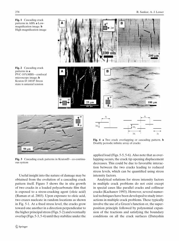
Fig. 13 Normalized stress intensity factor as a function ofn1 and n2 for the doubly periodic array. Only overlappingconfigurations are considered (0.25 < n1 < 0.5). Overlap-ping increases with increasing density at constant n2
in Fig. 12a). Since the far field stress is mode 1 onlyand the crack configuration is symmetric, there isno mode 2 effect due to interaction.
Several observations can be made from theresults plotted in Fig. 13. It can be seen that forany value of vertical density n2, the stress intensityfactor diverges at a certain overall crack density.This corresponds to n1 = 0.5 (ρ = 0.5n2), the singu-lar case of two collinear crack tips touching eachother. Second, the non-linear curves at constantn2 go through a minimum value of stress intensityfactor for all n2 > 0.375. The lower bound arises be-cause the vertical density represents the extent offavorable ‘shielding’ type interaction between thecracks and hence if n2 is not large enough, the stressintensity factor will not decrease before diverging.
Consider next a material with a threshold valueKth. All the overlapping configurations with K <
Kth are stable at the chosen stress level (linearelasticity assumption). Further, at Kth, the high-est density of stable cracks would correspond tothe minimum value for a certain value of n2. Forexample if Kth
σ√
πa= 2, the maximum density of sta-
ble cracks would be about 0.5, the minimum valueon n2 = 1.25 curve (Fig. 13). For crack densitiesgreater than 0.5, the stress intensity factor valuesremain above the chosen threshold value of 2 andso those would be unstable conditions where thecrack tips can grow. The minimum values of stressintensity factors are plotted versus n2 and overalldensity ρ in Fig. 14a and b respectively, and thefollowing simple correlations are obtained.
Kth
σ√
πa= 1.628n1 ∗ n2 + 1.152, (8)
Kth
σ√
πa= 0.833n2 + 0.958. (9)
Note that the stress level and crack length arebuilt into the left hand side of the above equa-tions. Equations (8) and (9) provide the solutionfor the vertical and horizontal densities that cor-respond to the highest overall density of stableoverlapping cracks (0.25 < n1 < 0.5, n2 > 0.375) ina material with threshold value Kth and at a stresslevel σ . The interaction in the array of cracks isnon-linear as seen in Fig. 13, but the solution forthe highest density of cracks stable for a given Kthis surprisingly linear as in (8) and (9). If the verticaland horizontal densities are known at a particularstress level, the threshold stress intensity factor forthe material can be evaluated. Solving for n2 fromequation (9), we get
n2 = 10.833
∗(
Kth
σ√
πa− 0.958
)
= 1.2 ∗(
Kth
σ√
πa− 0.958
). (10a)
Substituting this in (8),
Kth
σ√
πa= 1.628n1 ∗ 1.2 ∗
(Kth
σ√
πa− 0.958
)
+ 1.152 (10b)
orKth
σ√
πa− 1.152 = 1.954n1
∗(
Kth
σ√
πa− 0.958
)(10c)
or n1 =0.511 ∗
(Kth
σ√
πa− 1.152
)
(Kth
σ√
πa− 0.958
) . (10d)
Equations (10a) and (10d) form the solution forthe highest density of stable cracks for fixed valuesof Kth and stress level σ . Equating the right handsides of (8) and (9), we get
1.628n1 ∗ n2 + 1.152 = 0.833n2 + 0.958. (11a)
Simplifying (11a), we have
n2 = 14.29 − 8.39n1
. (11b)

284 R. Sankar, A. J. Lesser
0.0 0.2 0.4 0.6 0.8 1.0 1.2 1.4 1.61.0
1.5
2.0
2.5
3.0
3.5
4.0
Crack density ρ
0.0 0.5 1.0 1.5 2.0 2.5 3.0 3.51.0
1.5
2.0
2.5
3.0
3.5
4.0
Kth
/2d2Vertical density n2 = a
s pa
Kth
s pa
A
B
Fig. 14 The stress intensity factors corresponding to thehighest density of stable cracks are plotted as a function ofvertical density n2 in a and overall crack density ρ in b
It can be seen from (11b) that in the limiting caseof two crack tips touching each other (n1 = 0.5),a very high value of vertical density (n2 = 10.53)is obtained. For this case, an infinite vertical den-sity would be required to stabilize the cracks. Thedifference between this expected value and thevalue predicted by (11b) is attributed to approx-imations in the numerical procedure and in (8)and (9). Besides, this is a singular case for which anumerical method cannot give accurate results.
Equations (8) and (9) are valid only under thefollowing bounds for n1 and n2 as discussed inearlier paragraphs. Recall that these bounds rep-resent the criteria for favorable ‘shielding’ typeinteraction.
0.25 < n1 < 0.5, (12a)
0.375 < n2. (12b)
Let us now apply these bounds to (10a) and (10d).Equation (10a) can be rewritten as:
n2 = 10.833
∗[
Kth
σ√
πa− 0.958
]. (13a)
Using(12b) in (13a), we have
n2 = 10.833
∗[
Kth
σ√
πa− 0.958
]> 0.375 (13b)
orKth
σ√
πa> 0.375 ∗ 0.833 + 0.958 = 1.27.
(13c)
Squaring both sides and rewriting, we get an upperbound for the crack length as:
a < 0.197(
Kth
σ
)2
. (13d)
Using the lower bound for n1 in (10d), we get
n1 =0.511 ∗
(Kth
σ√
πa− 1.152
)
(Kth
σ√
πa− 0.958
) > 0.25 (14a)
or 2.044 ∗(
Kth
σ√
πa− 1.152
)
>
(Kth
σ√
πa− 0.958
)(14b)
or 1.044 ∗ Kth
σ√
πa> 1.397. (14c)
Squaring both sides and rewriting, we get
a < 0.178(
Kth
σ
)2
. (14d)
Comparing (13d) and (14d), we find that the latteris limiting.
Therefore, (14d) gives an upper bound for thecrack length corresponding to the highest densitiesof stable overlapping cracks in the chosen doublyperiodic array. This upper bound depends on thestress level as well the threshold value for crackpropagation, which is material dependent.
Summarizing, at a given threshold value Kth, anumber of stable overlapping configurations withvarying crack densities exist. The configuration cor-responding to the highest density of stable cascad-ing cracks for a give threshold stress intensity factoris given by:
n1 =0.511 ∗
(Kth
σ√
πa− 1.152
)
(Kth
σ√
πa− 0.958
) . (15a)

Generic Overlapping Cracks in Polymers 285
and n2 = 1.2 ∗(
Kth
σ√
πa− 0.958
). (15b)
Further, at this highest density the crack length isbounded by:
a < 0.178(
Kth
σ
)2
. (15c)
This implies that the largest crack length amax isgiven by:
amax = 0.178(
Kth
σ
)2
. (15d)
Also, at a given level of stress, ranges of cracklengths (a < amax) are permissible in the samematerial. This explains the initial observation thatthe cascading crack patterns were repetitive at diff-erent length scales.
Also, a stress intensity factor criterion has beenused here to describe crack growth. In this two-crack problem, it is equivalent to an energy releaserate (G) criterion. The two quantities are relatedas G = K2
I /E0, where E0 is the Young’s modulusof the virgin material. In the infinite array con-figuration (Fig. 4b), the two criteria need not beequivalent.
3 Infinite doubly periodic array of cracks: effectof reduced stiffness on energy release rates
Consider the doubly periodic staggered array ofcracks as shown in Fig. 11a. The presence of thecracks softens the material leading to a lower effec-tive modulus E′ and hence a higher energy releaserate G′ given by, G′ = K2
I /E′. Here G′ is the energyrelease rate associated with an isolated crack that issurrounded by a material of lower modulus E′. Thecrack configuration affects both the stress inten-sity factor as well as the effective stiffness of theplate. In this section, a formulation for calculatingthe effective stiffness of the cracked array is pre-sented.
In order to calculate the effective modulus, con-sider the smallest repeating unit of the array, whichis the region within the dotted lines in Fig. 11b. Thisunit consists of one quarter each of cracks A, B, C,and D. The average vertical extension ‘δ2’ of thisrepeating unit is given by
δ2 = σ
E0∗ 2d2 + δ̂2 ∗ 2a
2d1, (16)
where δ̂2 is the crack opening displacement aver-aged over the crack length. The first term in (16)is the vertical extension of the element if it con-tained no crack. The second term represents thecontribution of the crack opening displacements(which exists over the crack length ‘2a’) to the over-all extension of the element over its length ‘2d1’.
The average strain ‘ε2’ of the element is then
ε2 = δ2
2d2= σ
E0+ δ̂2 ∗ 2a
2d1 ∗ 2d2. (17)
Then the effective modulus E′ can be written as
E′ = σ
ε2= E0
1 + 2∗a∗δ̂22d1∗2d2
∗ E0σ
. (18)
In (18), the crack opening displacement andhence its average δ̂2 will be related to crack lengthas:
δ̂2 ∝ aσ
E0. (19)
Hence the expression for effective modulus E′ canbe rewritten as
E′ = E0
1 + ρβ(20)
where ρ is the crack density (ρ = a2/4d1d2) and theparameter β takes the effect of crack configurationand hence crack interaction. The above expressionis commonly seen in formulations for the effectivemodulus of a cracked body (Kachanov 1993).
Once the effective modulus is known, the effec-tive energy release rate can be calculated as G′ =K2
I /E′. Equation (18) is equivalent to the expres-sion for the effective modulus as reported inKarihaloo et al. (1996). The crack opening dis-placements are directly related to the Westergaardstress functions (Anderson), which are evaluatedusing the numerical procedure described in the ear-lier section.
δ1(x) = (1 − 2ν)
2μRe(Z̄I) + (1 − ν)
μIm
(Z̄II
), (21a)
δ2(x) = (1 − ν)
μIm(Z̄I) − (1 − 2ν)
2μRe(Z̄II). (21b)
286 R. Sankar, A. J. Lesser
Crack Density ρ 0.0 0.1 0.2 0.3 0.4 0.5
E'/E
0
0.1
0.2
0.3
0.4
0.5
0.6
0.7
0.8
Fig. 15 Effective stiffness as a function of crack density forcase 1—d2 = 1; d1 = 2; d2/d1 = 0.5
Here δ1 is the crack sliding displacement; δ2 is thecrack opening displacement; μ is the shear modu-lus of the un-cracked material and ν is the Pois-son’s ratio. ZI and ZII are the integrals of theWestergaard’s stress functions ZI and ZII, respec-tively. Hence the values for modulus have the samedegree of accuracy as the stress intensity factors,since both are obtained from the stress functions.
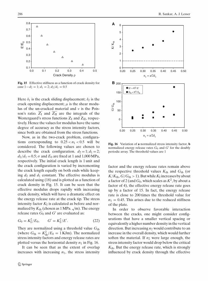
Now, as in the two-crack problem, configura-tions corresponding to 0.25 < n1 < 0.5 will beconsidered. The following values are chosen todescribe the crack configuration. d2 = 1; d1 = 2;d2/d1 = 0.5; σ and E0 are fixed at 1 and 1,000 MPa,respectively. The initial crack length is 1 unit andthe crack configuration is varied by incrementingthe crack length equally on both ends while keep-ing d2 and d1 constant. The effective modulus iscalculated using (18) and is plotted as a function ofcrack density in Fig. 15. It can be seen that theeffective modulus drops rapidly with increasingcrack density, which will have a dramatic effect onthe energy release rate at the crack tip. The stressintensity factor KI is calculated as before and nor-malized by Kth (chosen as 1 MPa.
√m). The energy
release rates G0 and G′ are evaluated as:
G0 = K2I /E0, G′ = K2
I /E′. (22)
They are normalized using a threshold value Gth(where Gth = K2
th/E0 = 1 KJm). The normalizedstress intensity factors and energy release rates areplotted versus the horizontal density n1 in Fig. 16.
It can be seen that as the extent of overlapincreases with increasing n1, the stress intensity
0.20 0.25 0.30 0.35 0.40 0.45 0.50
0
50
100
150
200
G′ = K2/ E′
G0 = K2/ E0
0.20 0.25 0.30 0.35 0.40 0.45 0.500
1
2
3
4
5
6
G/ G
th
B
A
K/ K
th
n1 = a/2d1
n1 = a/2d1
Fig. 16 Variation of a normalized stress intensity factor, bnormalized energy release rates G0 and G′ for the doublyperiodic array. The threshold values are 1
factor and the energy release rates remain abovethe respective threshold values Kth and Gth (orK/Kth, G/Gth > 1). But while KI increases by abouta factor of 2 (and G0, which scales as K2, by about afactor of 4), the effective energy release rate goesup by a factor of 15. In fact, the energy releaserate is close to 200 times the threshold value forn1 = 0.45. This arises due to the reduced stiffnessof the plate.
In order to observe favorable interactionbetween the cracks, one might consider config-urations that have a smaller vertical spacing orequivalently a higher number density in the verticaldirection. But increasing n2 would contribute to anincrease in the overall density, which would furthersoften the material. If n2 were large enough, thestress intensity factor would drop below the criticalKth. But the energy release rate, which is stronglyinfluenced by crack density through the effective

Generic Overlapping Cracks in Polymers 287
stiffness, would remain above Gth, as observed inthe previous illustration.
The above discussion raises the question as towhich parameter, the stress intensity factor or theeffective energy release rate, governs crack growth.As shown earlier, these two parameters are notequivalent for a plate with an array of cracks. �
4 Summary
Microscopic crack patterns that are generic todifferent polymeric materials are observed. Thegeneric feature is the overlapping of adjacent cracksthat is found to be repetitive at different lengthscales in the materials. In order to explain thisobservation, the damage pattern is modeled as adoubly periodic infinite array of cracks containedin a 2D plate. Linear elasticity is assumed. First, theinteraction between two parallel cracks present inan infinite plate is analyzed using a complex stressfunction method. It is shown that crack growthcan be stabilized in overlapping or cascading crackconfigurations, where the stress intensity factor atthe overlapping crack tip drops below the thresh-old value. In this case, the stress intensity factoris equivalent to an energy release rate criteria forcrack growth.
For the doubly periodic array, correlations areobtained for the highest density of stable cracksfor given values of threshold stress intensity factorand stress level.
Kth
σ√
πa= 1.628n1 � n2 + 1.152, (23)
Kth
σ√
πa= 0.833n2 + 0.958. (24)
It is shown that at this highest density, crack length
is bounded by: a < 0.178(
Kthσ
)2. This means that
at fixed Kth and σ , a range of configurations withdifferent crack lengths and densities can be stable.This also explains the self-similarity of interactionin the array at different length scales. The abovelinear solution applies only to the highest densityof stable cracks for a chosen Kth and K < Kth as thecondition for stability. The interaction is non-linearin general as seen in Fig. 13.
It is also shown that the stiffness of the platedrops dramatically due to the presence of thecracks. The crack configuration affects the stressintensity factor in a different way as compared tothe modulus of the material. So the stress inten-sity factor criterion becomes different from theenergy release rate criterion for crack growth. Thisraises the question as to which parameter, the stressintensity factor or the effective energy release rate,governs crack growth.
Finally, it should be noted that in this analysis,cracks have been prescribed in space. In reality,new cracks evolve in different parts of the materialas the existing cracks grow. Also, an elastic analy-sis is not representative of crack growth in manymaterials. The physics behind mechanisms of dam-age initiation have to be tied with the crack growthprocess in order to obtain a better understandingof damage evolution and growth in materials.
References
Anderson TL (2004) Fracture mechanics; Fundamentalsand applications. Int CRC, NY
Chudnovsky A, Kachanov M (1983) Interaction of a crackwith a field of microcracks. J Eng Sci 21(8):1009–1018
Chen YZ (1984) General case of multiple crack problemsin an infinite plate. Eng Fract Mech 20(4):591–597
Datsyshin A, Savruk MP (1973) A system of arbitrarilyoriented cracks in elastic solids. J Appl Math Mech37(2):326–332
Donald AM, Kramer EJ (1982) Internal structure ofrubber particles and craze break-down in high-impactpolystyrene (HIPS). J Mater Sci 17(8):2351–2358
Horrii H, Nemat-Nasser S (1985) Elastic fields of interactingin homogeneities. Int J Solids Struct 21:731–745
Kachanov M (1993) Elastic solids with many cracks andrelated problems. In: Hutchinson J, Wu T (eds) Advancesin applied mechanics. Academic, New York, p 259
Karihaloo BL, Wang J, Grzybowski M (1996) Doubly peri-odic arrays of bridged cracks and short-fibre reinforcedcementitious materials. J Mech Phys Solids 44(10):1565–1586
Ramaswamy S, Lesser AJ (2003) Genetic crack patterns inrubber-modified polymers under biaxial stress states. JPolym Sci Part B Phys 41(19): 2248–2256
Raman A, Farris RJ, Lesser AJ (2003) What is RSS? J ApplPolym Sci 88(2):550–564
Wilfong DL, Hiltner A, Baer E (1986) Advances in chem-istry series. In: Paul DR, Sperling LH (eds) AmericanChemical Society
Wang GS, Feng XT (2001) The interaction of multiple rowsof periodical cracks. Intl J Fracture 110(1):73–100