Wave dynamics of cracks and multiple contact surface interaction
8
Wave dynamics of cracks and multiple contact surface interaction Y.P. Stefanov * Institute of Strength Physics and Materials Science, Siberian Branch of Russian Academy of Sciences, pr. Akademicheskii 2/1, Tomsk 634021, Russian Federation Abstract This work considers the numerical simulation of crack behavior involving contact surfaces. A surface-slipping al- gorithm is developed to obtain the deformation of solids containing one or several cracks under dynamic loading. A shear-loading-induced crack is also considered. Ó 2000 Elsevier Science Ltd. All rights reserved. 1. Introduction The deformation process involving contact and creation of new surfaces such as cracking can be complicated. Contact and slip of crack surfaces aect the stress–strain state such that it changes as a function of time. As the solid damages, it is necessary to account for the evolution process. While the formation of contact conditions may be easy, the numerical evaluation can be tedious and involved. A technique for calculating the slip motion of grids has been developed to simulate the interaction of surface discontinuity in accordance with some preassumed friction law. A technique reported in [1,2] uses adjustment of grid–node ve- locities to calculate the slip motion of deformation grids. A similar technique and a node-splitting procedure have been used here. Both dynamic and quasi-static loading problems are considered. 2. Basic approach The basic equations of continuum mechanics involve the equations of motion, continuity, ener- gy and the constitutive relations. The hypoelastic and elastic-perfectly plastic models could be used [3]. The system of equations was solved by a finite- dierence method for plane strain [4]. Use was made of a uniform grid with the cell size Dx Dy 0:01 cm. To stabilize the grid compu- tation, the quadratic (volumetric), tensor (linear), and angular artificial viscosities were employed. The set of equations is solved for a given set of initial and boundary conditions. In what follows, the crack is assumed to prop- agate along the boundaries of the computational- grid cells. The growth is simulated by splitting the nodes and specifying the free-surface conditions on newly formed boundaries [5,6]. Splitting of the nodes takes place over pairs of adjacent cells oc- cupying the surface area. Each time step involves the following sequence of operations: • Calculate the motion for a would-be contact free surface under specified conditions at all other boundaries. www.elsevier.com/locate/tafmec Theoretical and Applied Fracture Mechanics 34 (2000) 101–108 * Tel.: +7-3822-259092; fax: +7-3822-259576. E-mail address: [email protected] (Y.P. Stefanov). 0167-8442/00/$ - see front matter Ó 2000 Elsevier Science Ltd. All rights reserved. PII: S 0 1 6 7 - 8 4 4 2 ( 0 0 ) 0 0 0 2 8 - 8
-
Upload
independent -
Category
Documents
-
view
1 -
download
0
Transcript of Wave dynamics of cracks and multiple contact surface interaction

Wave dynamics of cracks and multiple contact surfaceinteraction
Y.P. Stefanov *
Institute of Strength Physics and Materials Science, Siberian Branch of Russian Academy of Sciences, pr. Akademicheskii 2/1,
Tomsk 634021, Russian Federation
Abstract
This work considers the numerical simulation of crack behavior involving contact surfaces. A surface-slipping al-
gorithm is developed to obtain the deformation of solids containing one or several cracks under dynamic loading. A
shear-loading-induced crack is also considered. Ó 2000 Elsevier Science Ltd. All rights reserved.
1. Introduction
The deformation process involving contact andcreation of new surfaces such as cracking can becomplicated. Contact and slip of crack surfacesa�ect the stress±strain state such that it changes asa function of time. As the solid damages, it isnecessary to account for the evolution process.
While the formation of contact conditions maybe easy, the numerical evaluation can be tediousand involved. A technique for calculating the slipmotion of grids has been developed to simulate theinteraction of surface discontinuity in accordancewith some preassumed friction law. A techniquereported in [1,2] uses adjustment of grid±node ve-locities to calculate the slip motion of deformationgrids. A similar technique and a node-splittingprocedure have been used here. Both dynamic andquasi-static loading problems are considered.
2. Basic approach
The basic equations of continuum mechanicsinvolve the equations of motion, continuity, ener-gy and the constitutive relations. The hypoelasticand elastic-perfectly plastic models could be used[3]. The system of equations was solved by a ®nite-di�erence method for plane strain [4]. Use wasmade of a uniform grid with the cell sizeDx � Dy � 0:01 cm. To stabilize the grid compu-tation, the quadratic (volumetric), tensor (linear),and angular arti®cial viscosities were employed.The set of equations is solved for a given set ofinitial and boundary conditions.
In what follows, the crack is assumed to prop-agate along the boundaries of the computational-grid cells. The growth is simulated by splitting thenodes and specifying the free-surface conditionson newly formed boundaries [5,6]. Splitting of thenodes takes place over pairs of adjacent cells oc-cupying the surface area. Each time step involvesthe following sequence of operations:· Calculate the motion for a would-be contact free
surface under speci®ed conditions at all otherboundaries.
www.elsevier.com/locate/tafmec
Theoretical and Applied Fracture Mechanics 34 (2000) 101±108
* Tel.: +7-3822-259092; fax: +7-3822-259576.
E-mail address: [email protected] (Y.P. Stefanov).
0167-8442/00/$ - see front matter Ó 2000 Elsevier Science Ltd. All rights reserved.
PII: S 0 1 6 7 - 8 4 4 2 ( 0 0 ) 0 0 0 2 8 - 8

· Determine the time and place of contact.· Calculate interaction and motion correction
from the previous time setup.· Calculate the stress±strain state.· Determine new surfaces and regions of would-
be contact.The process of new surface generation by
splitting nodes was used in [7] where interaction ofelastic-plastic solid with rigid solid was considered.The computer program allows simulation ofelastoplastic deformation and fracture of solidsunder various loading conditions. The motion andstress±strain state for continuous, homogeneoussolids under small deformation can be made. Theproblems of contact interaction and fracture in-volving steps 2, 3, and 5 are more complicated.
3. Solutions to examples
In order to show the types of solutions that thenumerical procedure could handle, considerationwill be given to incidence waves impinging onsurface of discontinuities. Normal incident waveimpinging on a crack has been considered. Thecase of zero incidence angle has been described in[8]. In what follows, both compressive and shearwaves will be considered. The loading rate will bein the range of 100 m/s and the correspondingelastic material properties are given in Table 1.
3.1. Staggered parallel cracks
Let two parallel cracks, 1 and 2 be o�set asshown in Fig. 1. Impact shear and compressiveloads are applied. Initially the body unstressed.The loading conditions are
ux � fx�t� � f �t�; uy � fy�t� � f �t�: �1�
The compressional waves would travel through thecrack without distorting. The presence of the crack
is only by the shear wave such that the cracksurfaces would experience relative motion. Thiscan be seen in Fig. 2. Note the di�erence in thevelocities for the x-component of velocity.
Outside the crack region, the waves are undis-turbed while those in the vicinity of the crack arere¯ected. The crack tip becomes a source for thefront bending and emission of waves di�ering inmode. Displacement (shear) of the crack surfacesgives rise to tension and compression regions thatare non-symmetrically located. Fig. 3 shows acomputational deformation grid pattern near oneof the tips. At a later time the e�ect of stressconcentration occurs. Figs. 4(a)±(c) show the dis-tribution patterns for rx, ry and sxy .
Note that the surface displacement of the crackII and stress concentration at the tip nearest to
Table 1
Mechanical properties of material
Bulk modulus,
K (GPa)
Shear modulus,
l (GPa)
Material density,
q0 (g/cm3)
75 25 2.7
Fig. 1. Specimen geometry and loading scheme.
Fig. 2. Velocity of particles lying on the opposite crack surfaces
with normal incidence of compressive and shear waves.
102 Y.P. Stefanov / Theoretical and Applied Fracture Mechanics 34 (2000) 101±108
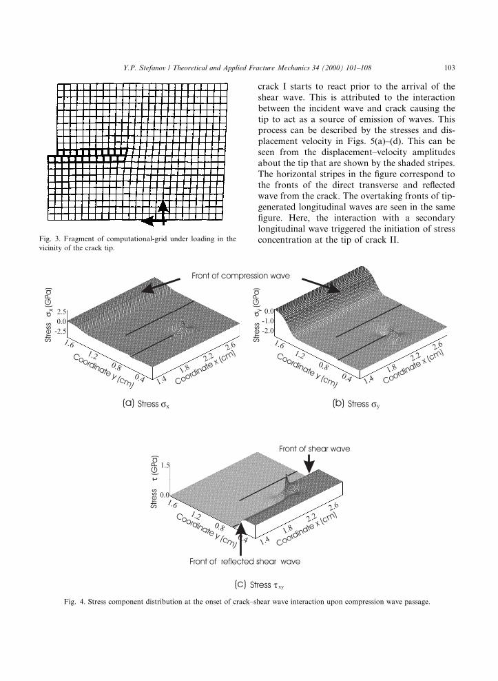
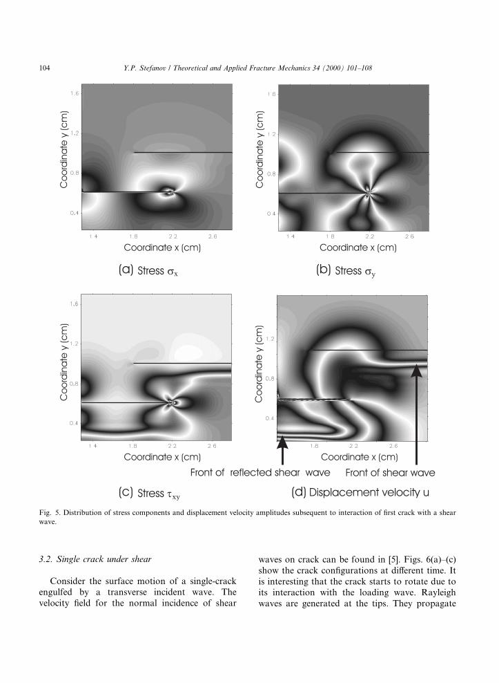
crack I starts to react prior to the arrival of theshear wave. This is attributed to the interactionbetween the incident wave and crack causing thetip to act as a source of emission of waves. Thisprocess can be described by the stresses and dis-placement velocity in Figs. 5(a)±(d). This can beseen from the displacement±velocity amplitudesabout the tip that are shown by the shaded stripes.The horizontal stripes in the ®gure correspond tothe fronts of the direct transverse and re¯ectedwave from the crack. The overtaking fronts of tip-generated longitudinal waves are seen in the same®gure. Here, the interaction with a secondarylongitudinal wave triggered the initiation of stressconcentration at the tip of crack II.
Fig. 4. Stress component distribution at the onset of crack±shear wave interaction upon compression wave passage.
Fig. 3. Fragment of computational-grid under loading in the
vicinity of the crack tip.
Y.P. Stefanov / Theoretical and Applied Fracture Mechanics 34 (2000) 101±108 103
3.2. Single crack under shear
Consider the surface motion of a single-crackengulfed by a transverse incident wave. Thevelocity ®eld for the normal incidence of shear
waves on crack can be found in [5]. Figs. 6(a)±(c)show the crack con®gurations at di�erent time. Itis interesting that the crack starts to rotate due toits interaction with the loading wave. Rayleighwaves are generated at the tips. They propagate
Fig. 5. Distribution of stress components and displacement velocity amplitudes subsequent to interaction of ®rst crack with a shear
wave.
104 Y.P. Stefanov / Theoretical and Applied Fracture Mechanics 34 (2000) 101±108

along the crack and tend to bend the cracksurfaces. As a result, the crack becomes inclinedrelative to the shear direction. Its surfaces tend toopen as the generated waves run from tip to tip.The rotated angle of the crack axis in Fig. 6 isabout 0:45°. Crack surfaces come in contact andthe e�ect of interaction is accounted for. The crackshapes presented in Fig. 7 have the same time se-quence as those in Fig. 6. Without taking surfaceinteraction into account, interpenetration of cracksurfaces occur.
3.3. Inclined crack engulfed by compressive wave
With inclined incidence of the compressivewave, the crack surfaces interact and slip as the
wave front arrives. The intersection point of thefront and the crack becomes a moving emitter. Theapparent velocity (the emitter velocity) will exceedthat of the wave
VI � VP= cos�a�; �2�
where a is the incidence angle. The emitter motiongives rise to the formation of conical waves of thelongitudinal and transverse types. At such a ve-locity, the front of the longitudinal wave makes anangle 45° with the crack surface, while the front ofconical transverse wave forms an acute angle(�36°) with the crack surface due to its lowerpropagation velocity. The x- and y-stress compo-nent distributions are shown in Fig. 8(a) and
Fig. 7. Time sequence of crack surfaces without consideration for surface interaction. (a) Time t1; (b) time t2 > t1; (c) time t3 > t2.
Fig. 6. Time sequence of crack surfaces with consideration for surface interaction.
Y.P. Stefanov / Theoretical and Applied Fracture Mechanics 34 (2000) 101±108 105
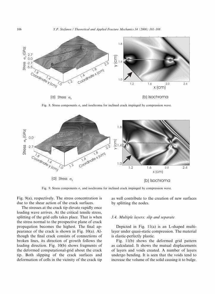
Fig. 9(a), respectively. The stress concentration isdue to the shear action of the crack surfaces.
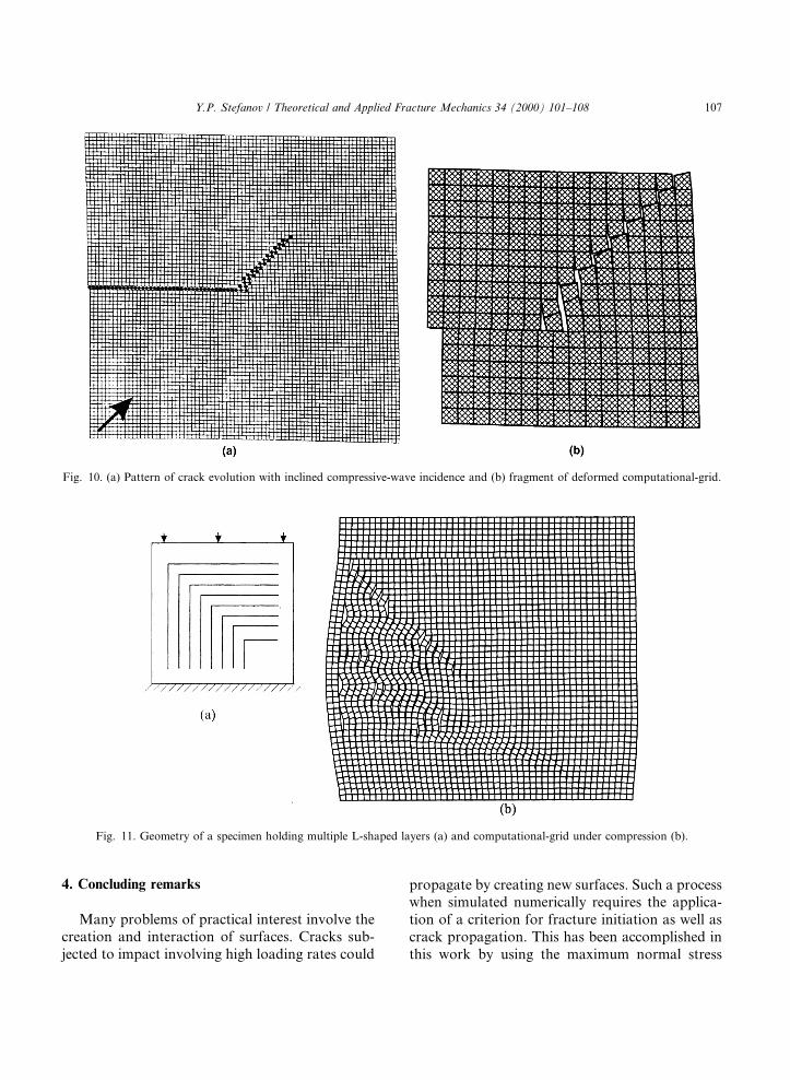
The stresses at the crack tip elevate rapidly onceloading wave arrives. At the critical tensile stress,splitting of the grid cells takes place. That is whenthe stress normal to the prospective plane of crackpropagation becomes the highest. The ®nal ap-pearance of the crack is shown in Fig. 10(a). Al-though the ®nal crack consists of connections ofbroken lines, its direction of growth follows theloading direction. Fig. 10(b) shows fragments ofthe deformed computational-grid about the cracktip. Both slipping of the crack surfaces anddeformation of cells in the vicinity of the crack tip
as well contribute to the creation of new surfacesby splitting the nodes.
3.4. Multiple layers: slip and separate
Depicted in Fig. 11(a) is an L-shaped multi-layer under quasi-static compression. The materialis elastic-perfectly plastic.
Fig. 11(b) shows the deformed grid patternas calculated. It shows the mutual displacementsof layers and voids created. A number of layersundergo bending. It is seen that the voids tend toincrease the volume of the solid causing it to bulge.
Fig. 9. Stress components ry and isochroma for inclined crack impinged by compression wave.
Fig. 8. Stress components rx and isochroma for inclined crack impinged by compression wave.
106 Y.P. Stefanov / Theoretical and Applied Fracture Mechanics 34 (2000) 101±108
4. Concluding remarks
Many problems of practical interest involve thecreation and interaction of surfaces. Cracks sub-jected to impact involving high loading rates could
propagate by creating new surfaces. Such a processwhen simulated numerically requires the applica-tion of a criterion for fracture initiation as well ascrack propagation. This has been accomplished inthis work by using the maximum normal stress
Fig. 10. (a) Pattern of crack evolution with inclined compressive-wave incidence and (b) fragment of deformed computational-grid.
Fig. 11. Geometry of a specimen holding multiple L-shaped layers (a) and computational-grid under compression (b).
Y.P. Stefanov / Theoretical and Applied Fracture Mechanics 34 (2000) 101±108 107

criterion and the splitting of grid±nodes in thenumerical analysis. Capability of the present ap-proach has been demonstrated by presenting thesolutions to several non-trivial problems. Amongthem are compressive waves impinging on an in-clined crack and failure of an L-shaped multi-layersystem under compression
References
[1] C. Descombes, A. Fanget, A.Y. LeRoux, An augmented
Lagrangian formulation for dynamics contact/impact prob-
lems is an explicit Lagrangian ®nite element code, in:
International Workshop on New Models and Numerical
Codes for Wave Processes in Condensed Media, AWE
Hunting ± Brae, Great Britain, 1997, pp. 762±772.
[2] A.I. Gulidov, I.I. Shabalin, Calculation of contact bound-
aries with considering friction for dynamic interaction of
deformed solid, in: IX Conference on Numerical Techniques
for Solution of Problems of Elasticity and Plasticity
Theories, Novosibirsk, Russia, 1988, pp. 70±75 (in Russian).
[3] W.K. Nowacki, Wave Problems of Plasticity Theory, Mir,
Moscow, 1978 (in Russian).
[4] M.L. Wilkins, Calculations of Elastic±Plastic Flow, Meth-
ods in Computational Physics, vol. 3, Academic Press, New
York, 1964, pp. 211±263.
[5] M.M. Nemirovich-Danchenko, A model for the brittle
hypoelastic medium: application to computation of defor-
mation and failure in rock, Physical Mesomech. 2 (1998)
101±108.
[6] Yu.P. Stefanov, Numerical research into behaviour of
elastic-perfectly plastic solids with stationary and propagat-
ing cracks under quasi-static and dynamic tensile loading,
Physical Mesomech. 2 (1998) 77±88.
[7] Yu.P. Stefanov, P.V. Makarov, P.V. Burkov, V.S. Matveev,
Dynamic simulation of chip generation and formation in
metal cutting, J. Theoret. Appl. Fracture Mech. 28 (2)
(1994) 117±124.
[8] M.M. Nemirovich-Danchenko, Y.P. Stefanov, Application
of the ®nite-di�erence method in Lagrange variables to
calculation of wave ®elds in complexly structured media,
Russian Geol. Geophys. 36 (11) (1995) 97±108.
108 Y.P. Stefanov / Theoretical and Applied Fracture Mechanics 34 (2000) 101±108