
Rethinking Contact Arc Suppression
51
1
-
Upload
independent -
Category
Documents
-
view
3 -
download
0
Transcript of Rethinking Contact Arc Suppression

1

2
Thank you very much for allowing me to share my area of expertise with you.

“Sometimes we have to close our eyes in order to see more clearly!” -rh
3

Some sources of unintentional but predictable contact current arcing.
4

Some not so well known basic relay, contactor and switch contact information…
5

This slide shows T9A style relay contact electrodes in comparison under a 20x inspection microscope magnification:
6

This slide outlines a general example of five primary industry classifications for electromechanical switching
applications, along with some representative examples from each class:
Consumer applications are those that typically operate at lower power, and under relatively benign operating
temperature conditions of 0ºC to 70ºC.
These include, but are not limited to home and office applications.
Commercial applications are those that operate at higher power and under operating temperature conditions of -40ºC to
85ºC.
These include, but are not limited to commercial appliances and HVAC, as well as various manufacturing equipment.
Industrial applications are those that typically use high power and operate under the even more operating temperature
conditions of -40ºC to 100ºC.
Automotive applications are typically associated with vehicles. These applications my be relatively low power through
higher power, operating under a wide range of operating temperature conditions from -40ºC to 125ºC. These
applications include consumer vehicles and industrial vehicles such as agricultural, mining, and construction equipment.
Military applications include those, regardless of power, operating under the most arduous of operating temperature
conditions of -55ºC to 150ºC.
7

This slide shows a few examples of significant contact arc suppression patents of the past:
Thomas Edison, George Westinghouse and Nikola Tesla who were some of the pioneers who started to commercialize
electrical power had to put up with contact arcing but I am sure they wished they could have gotten rid of it.
To date, the author has reviewed over 340 US and International, granted and pending patents in the contact arc
suppression space some dating back to the days of Nikola Tesla.
For example: US Patent 1,368,325 filed August 13, 1916 and granted February 15, 1921 by Chrichton, assigned to
Westinghouse, teaches the reduction to practice of an “Arc Extinguishing Device”.
Another more modern example: US Patent 7,782,578 filed March 5, 2007 and granted August 24, 2010 by Tao, assigned
to Delta Electronics, Inc., teaches the reduction to practice of a “Relay Protection Circuit and Controlling Method thereof
Having Relatively Better Effectiveness for Suppressing DC Arc”.
8

This slide indicates the significance of the continuous needs and attempts by the industry to come up with better
contact arc suppression solutions.
9

This slide presents a general example of a Power Classification:
Sources for AC power include generators, alternators, transformers, etc.
AC power is typically sinusoidal, however, it may also be non-sinusoidal, or phase controlled.
Applications for AC power include the power grid (utility power, power stations, transmission lines, etc.) as well as off the
grid uses such as rail power.
Sources for DC power include various types of battery-like storage, such as batteries, solar cells, fuel cells, capacitor
banks and thermopiles, as well as dynamos, power supplies.
DC power types include direct, pulsating, variable, and alternating (which includes superimposed AC, full wave
rectification and half wave rectification).
DC power is mostly associated with self-propelled applications, i.e., anything that drives, flies, swims, crawls, dives,
tunnels, digs, cuts, slices, heats, cools, lifts, moves, etc.
10
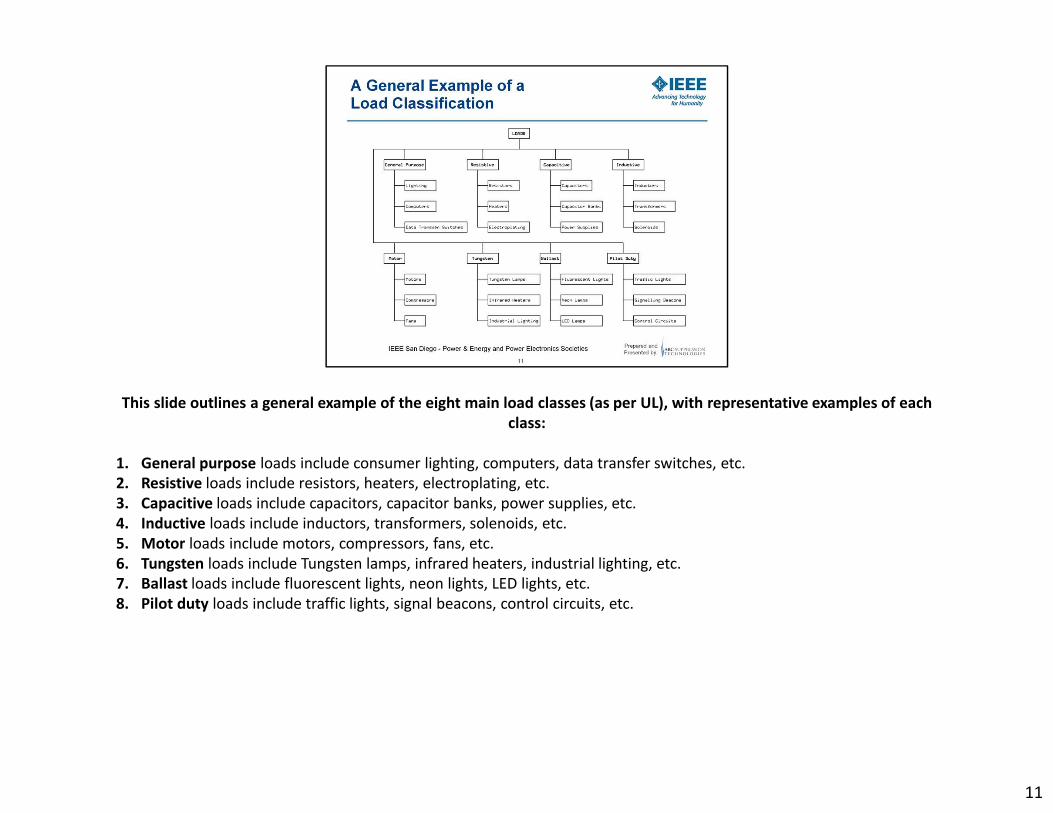
This slide outlines a general example of the eight main load classes (as per UL), with representative examples of each
class:
1. General purpose loads include consumer lighting, computers, data transfer switches, etc.
2. Resistive loads include resistors, heaters, electroplating, etc.
3. Capacitive loads include capacitors, capacitor banks, power supplies, etc.
4. Inductive loads include inductors, transformers, solenoids, etc.
5. Motor loads include motors, compressors, fans, etc.
6. Tungsten loads include Tungsten lamps, infrared heaters, industrial lighting, etc.
7. Ballast loads include fluorescent lights, neon lights, LED lights, etc.
8. Pilot duty loads include traffic lights, signal beacons, control circuits, etc.
11

This slide shows the contact cycle of a relay or contactor and the contact cycle of a switch (respectively):
A contact cycles through four distinct states: OPEN, MAKE, CLOSED and BREAK. The make and break states are generally
transitional and are of generally short duration. The open and closed states are generally non-transitional and are of
generally longer duration. A general switch cycle may start with the OPEN state. As part of the MAKE state, the contact
may bounce multiple times until it achieves the CLOSED state. A general switch cycle may remain a certain amount of
time in the CLOSED state. As part of the BREAK state, the contact may bounce multiple times until it re-enters the OPEN
state.
12

This slide outlines a general example of a Spark Classification:
Atmospheric sparks include electrostatic discharge and lightning.
Non-atmospheric sparks include electric discharge, spark generators, turbo blades, and both magnetic and piezoelectric
igniters.
The various classes of sparks are powered by an electrostatic charge.
13

This slide outlines a general example of an Arc Classification:
Unpredictable arcs include arc flash, chafing, plasma chambers, sputtering processes, etc., and are typically both
dangerous and undesired.
Predictable and desired arcs include both desired and undesired arcing. Arc lamps, arc welders, and arc chambers are
examples of desired, predictable arcing.
Predictable but undesired arcs include arcing in connectors and the contact current arcing that occurs within switches,
relays and contactors.
The various classes of electrical arcs are powered by a continuous power source.
14
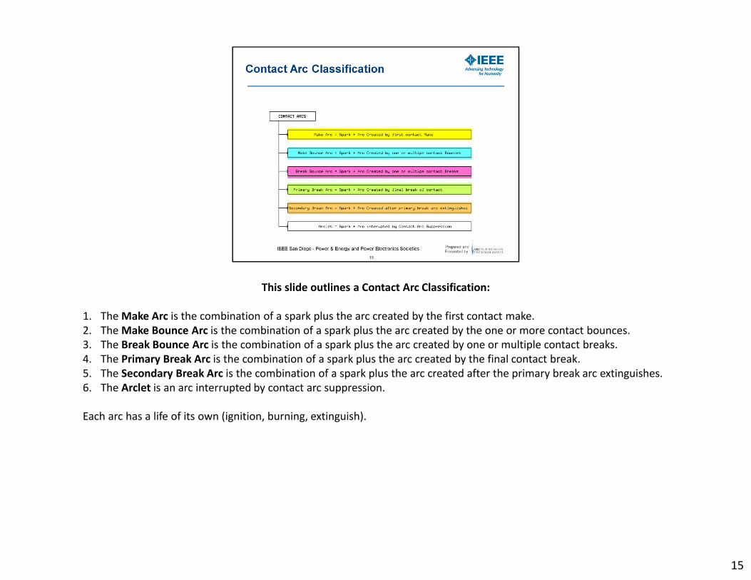
This slide outlines a Contact Arc Classification:
1. The Make Arc is the combination of a spark plus the arc created by the first contact make.
2. The Make Bounce Arc is the combination of a spark plus the arc created by the one or more contact bounces.
3. The Break Bounce Arc is the combination of a spark plus the arc created by one or multiple contact breaks.
4. The Primary Break Arc is the combination of a spark plus the arc created by the final contact break.
5. The Secondary Break Arc is the combination of a spark plus the arc created after the primary break arc extinguishes.
6. The Arclet is an arc interrupted by contact arc suppression.
Each arc has a life of its own (ignition, burning, extinguish).
15
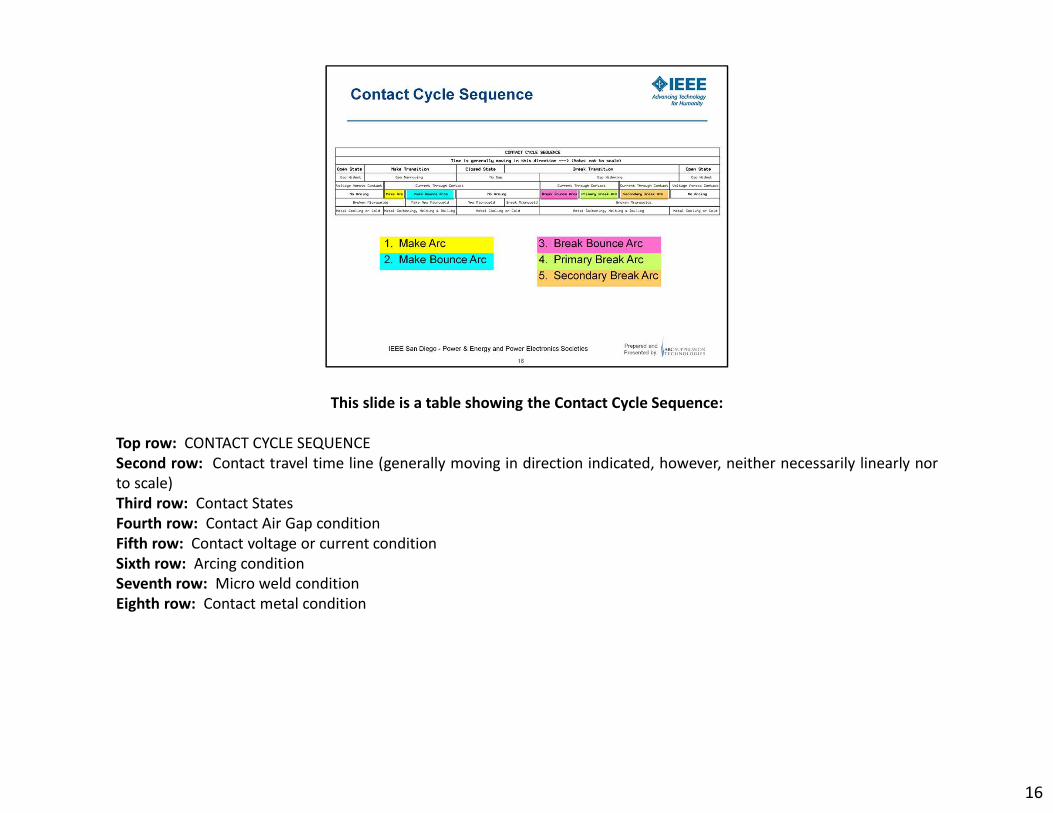
This slide is a table showing the Contact Cycle Sequence:
Top row: CONTACT CYCLE SEQUENCE
Second row: Contact travel time line (generally moving in direction indicated, however, neither necessarily linearly nor
to scale)
Third row: Contact States
Fourth row: Contact Air Gap condition
Fifth row: Contact voltage or current condition
Sixth row: Arcing condition
Seventh row: Micro weld condition
Eighth row: Contact metal condition
16

This slide is a chart illustrating an example of a contact arc cycle at greater than a 1A load current without arc
suppression:
It is assumed that the contact of a switch, relay or contactor is working within specified operating limits. A contact cycles
through four distinct states: Open, make, closed and break. The make and break states are generally transitional and are
of generally short duration. The open and closed states are generally non-transitional and are of generally longer
duration. Each state generally has specific phases associated with them that the contact has to travel through. A general
switch cycle may start with the:
1. OPEN state. After entering the make state the contact cycles through phase
2. First Make Arc, followed generally by phase
3. Multiple make bounce arcs, followed generally by phase
4. Make Micro Weld and coming to rest at the generally non-transitional state
5. CLOSED. A general switch cycle may remain a certain amount of time in the state CLOSED state. After entering the
break state the contact cycles through phase
6. Break Micro Weld, followed by phase
7. Contact Breaks Open, followed by phase
17

8. None or more break bounce arcs, followed by phase
9. Primary Break Arc Ignites, followed by phase
10. Primary Break Arc Burns, followed by phase
11. Primary Break Arc Extinguishes, followed by phase
12. Possible Secondary Break Arc Ignites, followed by phase
13. Possible Secondary Break Arc Burns, followed by
14. Possible Secondary Break Arc Extinguishes, and coming to rest at the generally non-transitional state
15. OPEN
Phases 9 through 14 are the direct cause of the noted deleterious effects of contact surface deterioration, including metal
sputtering, particle deposition, material migration and surface destruction.
17

This slide represents examples of a contact breaking event without contact arc suppression. Showing in the following
sequence:
Current flowing, current constricting and contact heating, metal melting and pooling, molten wire bridge forming, wire
bridge ripping followed by a first dielectric (low voltage) breakdown (spark), ignition of the primary break arc between 9
and 15V, primary break arc burning, primary break arc lengthening, primary break arc extinguishing followed by a
secondary (high voltage) dielectric breakdown (spark), ignition of the secondary break arc via a high voltage spike,
secondary break arc burning, secondary break arc extinguishing, contact travels to its open position.
18

This slide represents examples of a contact making event without contact arc suppression. Showing in the following
sequence:
Contact open, contact closing and gap small enough for the first dielectric breakdown (spark) to occur, make arc igniting,
current constricting, contact metal heating possibly melting, contact closing for the first time and current flowing for the
first time, contact bouncing, current constricting and contact heating, metal melting and pooling, molten wire bridge
forming, wire bridge ripping followed by a dielectric (low voltage) breakdown (spark), ignition of the bounce arc between
9 and 15V, bounce arc burning, bounce arc lengthening, bounce arc shortening, contact closing, bounce arc
extinguishing, possibly followed by another contact bounce, with bounce arc and metal melting, making for a good
quality micro weld, providing low contact resistance.
19

This slide outlines an example of a general classification contact arc suppression as currently available to industry:
These contact arc suppression classes fall into three broad classes of devices, contact design, and discrete components.
Contact devices are generally understood to be hybrid power devices, using both solid state and electromechanical
components. Four-port devices typically use input outside of the contacts, including but not limited to optical, coil
power, coil back EMF, coil signal timing, zero crossing, or magnetic amplifiers. Contact design includes both the contact
construction and adjacent, environment conditions in which the contacts operate. Mechanical means include elements
such as baffles and pressurized gas. Magnetic means include both permanent and electromagnets. Contact construction
includes contact speed, contact material, contact arrangement, and gap environment. The gap environment may be gas,
vacuum, liquid or solid state. Discrete components are broadly classified as current limiters, voltage limiters, and rise-
time limiters. Current limiters include linear and non-linear resistors. Non-linear resistors are comprised of voltage
dependent resistors (VDR’s), positive temperature coefficient (PTC) Thermistors, and negative temperature coefficient
(NTC) Thermistors. Voltage limiters are either unipolar or bipolar. Unipolar voltage limiters include transient voltage
suppressors (TVS’s), diodes, and zener diodes. Bipolar voltage limiters include metal oxide varistors (MOV’s), TVS’s, and
back-to-back zeners. Risetime limiters are generally known as snubbers, and are either linear or non-linear. Non-linear
snubbers are comprised of a combination of components such as resistors R, capacitors C, inductors L and diodes D but
not limited to and thus including possible circuit configuration permutations such as RC, RCD, RLC, RLCD, RL, RLD, CDRCD
20

This slide shows the schematic symbols for the discrete components noted in the discrete class of the Contact Arc
Suppression Classification slide:
Top row: The symbol for a resistor, the symbols for a VDR, a PTC, and an NTC, the symbols for a TVS, a diode, and a zener
diode
Bottom row: The symbols for an MOV, a TVS, and back-to-back zener diodes, the symbols for an RC, an RCD, an RLC, an
RLCD, an RL, an RLD, and a CDRCD Snubber.
21

This slide shows example schematic diagrams for contact arc suppression noted in the contact design class of the
Contact Arc Suppression Classification slide:
Top row: A diagram for contact arc suppression by means of baffles, a diagram for contact arc suppression by means of
pressurized gas, a diagram of contact arc suppression by means of permanent magnet, a diagram of contact arc
suppression by means of electromagnet.
Middle row: A diagram for contact arc suppression by means of contact speed, a diagram of contact arc suppression by
means of contact material, a diagram of contact arc suppression by means of contact arrangement, a diagram of contact
arc suppression by means of contact operating in a vacuum.
Bottom row: A diagram of contact arc suppression by means of contact operating in a gas, a diagram of contact arc
suppression by means of contact operating in a liquid, a diagram of contact arc suppression by means of a solid state
device as part of the contact construction.
22

This slide illustrates an example of an academic teaching of four-port network elements:
At the top: General (Symmetrical) four-port network element configuration (balanced input and balanced output)
In the middle: Special (Asymmetrical) four-port network element configuration (unbalanced input and unbalanced
output)
At the bottom: Two-port network element configuration (with input and output sharing the same connection leads)
Each variant displays the associated input, output, sensing and suppression aspects of the design.
23

This slide shows four example schematics of four-port contact arc suppression:
Top left: Shows the input being derived from sensing the change in contact current and timing the suppression means
from this input.
Top right: Shows the input being derived from sensing coil power back EMF and timing the suppression means from this
input.
Bottom left: Shows the input being derived from the coil, which is used to attempt to synchronize the contact activation
with AC zero-crossing to provide suppression.
Bottom right: Shows the input being derived from an optical sensor detecting the arc visually and timing the
suppression means from this input.
24

This slide shows four example connections of two-port contact arc suppression:
Top left: Shows the contact arc suppression means connected across the power source.
Top right: Shows the contact arc suppression means connected across the contact.
Bottom left: Shows the contact arc suppression means connected across the load.
Bottom right: Shows the arc contact suppression means connected across the coil connection.
25

This slide illustrates a contact arcing measurement test set-up:
The results obtained using this test set-up allow for determining the effectiveness of a contact arc suppression on either
an electromechanical relay or a contactor. This is achieved by simultaneously measuring the current through the contact
and the voltage across the contact during either the MAKE or BREAK transitions. This test requires both a high-speed
current probe and a high-voltage differential voltage probe, as well as a two-channel, externally and delay triggered
oscilloscope. The current probe must be connected to measure the current through the contact, with its output signal
fed into the oscilloscope’s channel 1. The voltage probe must be connected across the contacts, with its output signal fed
into the oscilloscope’s channel 2. The relay driver’s signal should be fed into the oscilloscope’s external trigger input, and
a delayed trigger employed to bring the instant of contact transition into view on the scope. Triggering on the rising edge
will display the MAKE transition, while triggering on the falling edge will display the BREAK transition.
26
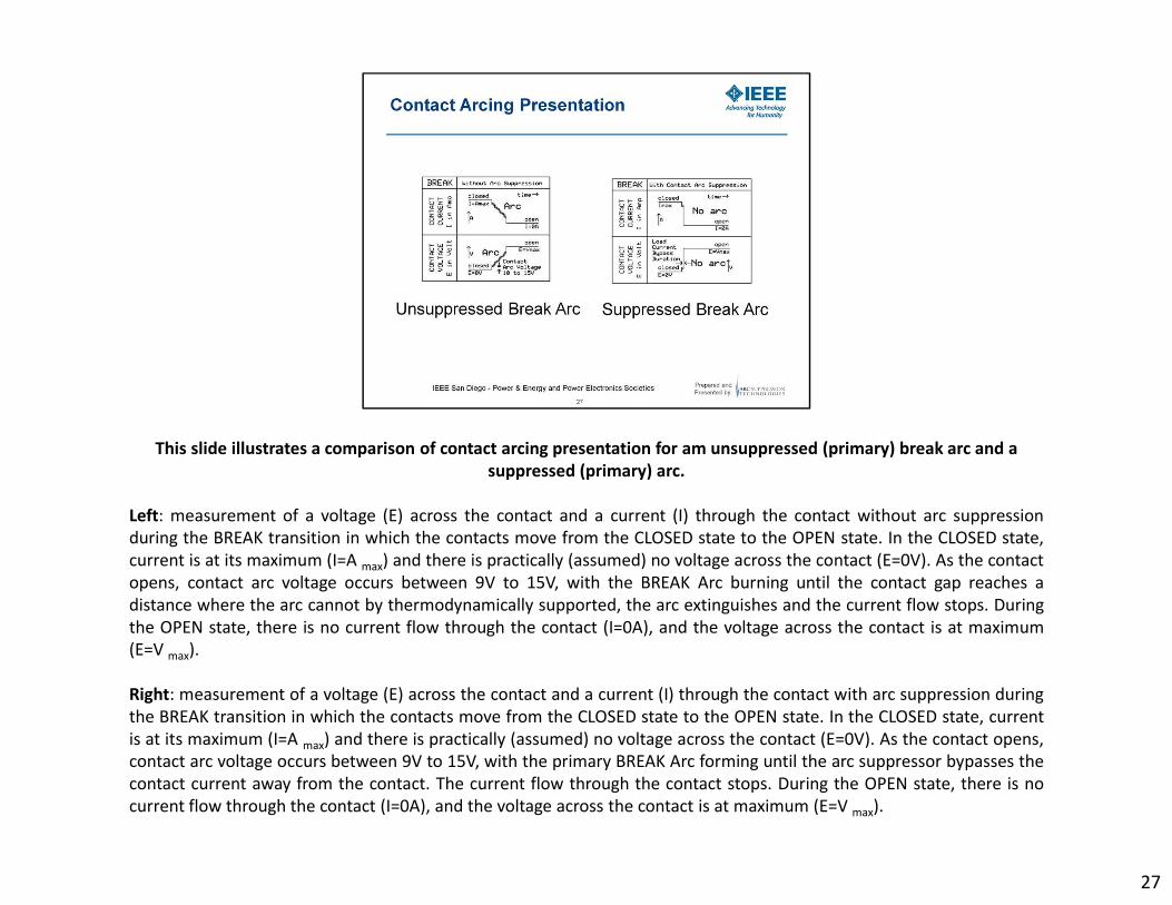
This slide illustrates a comparison of contact arcing presentation for am unsuppressed (primary) break arc and a
suppressed (primary) arc.
Left: measurement of a voltage (E) across the contact and a current (I) through the contact without arc suppression
during the BREAK transition in which the contacts move from the CLOSED state to the OPEN state. In the CLOSED state,
current is at its maximum (I=A max) and there is practically (assumed) no voltage across the contact (E=0V). As the contact
opens, contact arc voltage occurs between 9V to 15V, with the BREAK Arc burning until the contact gap reaches a
distance where the arc cannot by thermodynamically supported, the arc extinguishes and the current flow stops. During
the OPEN state, there is no current flow through the contact (I=0A), and the voltage across the contact is at maximum
(E=V max).
Right: measurement of a voltage (E) across the contact and a current (I) through the contact with arc suppression during
the BREAK transition in which the contacts move from the CLOSED state to the OPEN state. In the CLOSED state, current
is at its maximum (I=A max) and there is practically (assumed) no voltage across the contact (E=0V). As the contact opens,
contact arc voltage occurs between 9V to 15V, with the primary BREAK Arc forming until the arc suppressor bypasses the
contact current away from the contact. The current flow through the contact stops. During the OPEN state, there is no
current flow through the contact (I=0A), and the voltage across the contact is at maximum (E=V max).
27

This slide introduces the contact arc suppression factor calculation:
The contact arc suppression factor is a figure of merit allowing for a device to device and application to application
comparison of efficacy. For example the ASF for a typical 0.1uF capacitor in series with a 100Ω RC Snubber is slightly
greater than one (1) and the AST for a two-port contact arc suppressor in a low power applications is in the hundreds
(100’s) and in high power applications in the tens of thousands (10k’s).
28

This slide shows examples of AC & DC contact arc measurements:
These measurements were obtained via the contact arcing measurement test set-up of the previous slide.
Left Graph Discussion:
AC Contact Arc Measurement of a T9A style relay normally open contact.
Voltage is 240Vac, current is 12.5Arms (17.7Apk), resistive load rated at 3kW.
Y-axis: CH1, Current through the contact shown by the blue trace (sinusoidal wave), 13.5A/div
Y-axis: CH2, Voltage across the contact shown by the red trace (sinusoidal wave), 10V/div
The instant of momentary contact separation where for a very short moment in time an air gap exists as a very fast rising
edge transitioning from 0V to about 12V. The risetime of the contact separation event is extremely fast and can reach
speeds of around 8kV/us. At a voltage of about 12V (this “arc voltage” is dependent on the specific contact metal alloy)
the arc ignites. Once established the arc continues to burn in this graph for about the next seven milliseconds. The arc
extinguishes at the moment in the vicinity of the zero crossing where the current is not sufficiently large enough and the
air gap is sufficiently wide enough to thermodynamically support the arc. Note that the current continues to flow almost
as if the contact has not yet opened while the arc is burning between the two contact electrodes. Another fact to note is
29

that the dynamic arc impedance negative and thus has a voltage regulating effect on the burning ac arc. In this case the arc
voltage levels out at an average of about 25V.
Right Graph Discussion:
DC Contact Arc Measurement of a T9A style relay normally open contact.
Voltage is 33Vdc, current is 6.75A, inductive load 1.6H + 4.9Ω
Y-axis: CH1, Current through the contact shown by the yellow trace, 6.75A/div
Y-axis: CH2, Voltage across the contact shown by the cyan trace, 36V/div
The instant of momentary contact separation where for a very short moment in time an air gap exists as a very fast rising edge
transitioning from 0V to about 12V. The risetime of the contact separation event is extremely fast and can reach speeds of around
8kV/us. At a voltage of about 12V (this “arc voltage” is dependent on the specific contact metal alloy) the arc ignites. Once
established the arc continues to burn in this graph for about the next eleven milliseconds. The arc extinguishes at the moment
where the current is not sufficiently large enough to thermodynamically support the arc through the widening air gap. The
moment the arc extinguishes and the air gap opens, current stops flowing through the inductor, its magnetic field collapses and
the inductor responds with a counter electro-motoric force (CEMF) aka back EMF in form of a high voltage spike. Contrary to
popular belief, this voltage spike is NOT the arc. If this voltage spike is high enough and if there is still sufficient residual ionization
in the air-gap, a secondary break arc may ignite. The secondary break arc will be of a much shorter duration then the primary
break arc and thus be less energetic. This voltage spike may be reduced and or clipped by connecting a voltage limiter across the
contact. Please note that the clamping voltage of this voltage limiter must be greater than the maximum operating voltage across
the open contact. Also note that in this case the current continues to drop towards zero as soon as the contact electrodes
separate. A further fact to notice is that this primary break dc arc burns for almost as long as the contact travels to its open state
end point. This of course is a fire hazard and this condition must be recognized and avoided.
29

This slide shows examples of AC contact arc measurements:
These measurements were obtained via the contact arcing measurement test set-up of the previous slide.
Common Conditions:
AC Contact Arc Measurements of a T9A style relay normally open contact.
Voltage is 240Vac, current is 12.5Arms (17.7Apk), resistive load rated at 3kW.
Y-axis: CH1, Current through the contact shown by the blue trace (sinusoidal wave), 13.5A/div
Y-axis: CH2, Voltage across the contact shown by the red trace (sinusoidal wave), 10V/div
Left Top Graph Discussion: AC Contact arc measurement. The instant of momentary contact separation where for a very
short moment in time an air gap exists as a very fast rising edge transitioning from 0V to about 12V. The risetime of the
contact separation event is extremely fast and can reach speeds of around 8kV/us. At a voltage of about 12V (this “arc
voltage” is dependent on the specific contact metal alloy) the arc ignites. Once established the arc continues to burn in
this graph for about the next seven milliseconds. The arc extinguishes at the moment in the vicinity of the zero crossing
where the current is not sufficiently large enough and the air gap is sufficiently wide enough to thermodynamically
support the arc. Note that the current continues to flow almost as if the contact has not yet opened while the arc is
30

burning between the two contact electrodes. Another fact to note is that the dynamic arc impedance negative and thus has a
voltage regulating effect on the burning ac arc. In this case the arc voltage levels out at an average of about 25V.
Arc Suppression Factor Calculation:
Warc0 ≈ Iarc * Varc * Tarc
Iarc0 ≈ 13.0A (average)
Varc0 ≈ 25V (average)
Tarc0 ≈ 7ms
Warc0 ≈ 1.05J
The energy contained in this unsuppressed primary contact break arc is 1.05Joules.
Right Top Graph Discussion: AC Arc with Snubber measurement. Same conditions and comments as for the left top graph
discussion except that in this case, the arc burns between the two contact electrodes with a little bit less pronounced voltage
excursions. The snubber appears to have removed some high speed transients while the arc was burning and in effect reduced the
electromagnetic emissions originating from the burning arc.
Unsuppressed Arc Energy Calculation:
Iarc1 ≈ 13.0A (average)
Varc1 ≈ 25V (average)
Tarc1 ≈ 7ms
Warc1 ≈ 1.05J
The energy contained in this snubber suppressed primary contact break arc is 1.05Joules.
Left Bottom Graph Discussion: Suppressed AC Arc Measurement at 1ms/div time base. Same conditions as for the left top graph
discussion except that in this case, as soon as the contact separates and the arc ignites, it is extinguished within about 5us by the
half ac cycle crowbar type current bypass occurring within the two-port contact arc suppressor that is connected across this
contact.
Energy Dissipated within Crowbar Arc Suppressor Calculation:
Iarc2 ≈ 13.0A (average)
30

Varc2 ≈ 2V (average)
Tarc2 ≈ 7ms
Warc2 ≈ 182mJ
The energy dissipated inside the crowbar type two-port contact arc suppressor in this case is 182mJ.
Right Bottom Graph Discussion: Suppressed AC Arc Measurement at 5us/div time base. Same conditions as for the left bottom
graph discussion except that in this case, the time scale has been reduced from 1ms/div to 5us/div to zoom in on the residual arc
(arclet) of the suppressed AC arc.
Suppressed Arc Energy Calculation:
Iarc3 ≈ 17.0A (average)
Varc3 ≈ 12V (average)
Tarc3 ≈ 5us
Warc3 ≈ 1.02mJ
The energy contained in this suppressed primary contact break arclet is 1.02milliJoules.
Arc Suppression Factor Calculation:
Warc ≈ Iarc * Varc * Tarc
ASF = Warc0/Warc3 = 1.05J/1.02mJ = 1,029
The arc suppression factor in this case is about 1.029. In other words, this figure of merit constitutes a reduction in arc energy of
slightly over 1000 fold.
30

This slide shows examples of DC contact arc measurements:
These measurements were obtained via the contact arcing measurement test set-up of the previous slide.
Common Conditions:
DC Contact Arc Measurement of a T9A style relay normally open contact.
Voltage is 33Vdc, current is 6.75A, inductive load 1.6H + 4.9Ω
Y-axis: CH1, Current through the contact shown by the yellow trace, 6.75A/div
Y-axis: CH2, Voltage across the contact shown by the cyan trace, 36V/div
Left Graph Discussion: Unsuppressed DC Arc Measurement. The instant of momentary contact separation where for a
very short moment in time an air gap exists as a very fast rising edge transitioning from 0V to about 12V. The risetime of
the contact separation event is extremely fast and can reach speeds of around 8kV/us. At a voltage of about 12V (this
“arc voltage” is dependent on the specific contact metal alloy) the arc ignites. Once established the arc continues to burn
in this graph for about the next eleven milliseconds. The arc extinguishes at the moment where the current is not
sufficiently large enough to thermodynamically support the arc through the widening air gap. The moment the arc
extinguishes and the air gap opens, current stops flowing through the inductor, its magnetic field collapses and the
31
inductor responds with a counter electro-motoric force (CEMF) aka back EMF in form of a high voltage spike. Contrary to popular
belief, this voltage spike is NOT the arc. If this voltage spike is high enough and if there is still sufficient residual ionization in the
air-gap, a secondary break arc may ignite. The secondary break arc will be of a much shorter duration then the primary break arc
and thus be less energetic. This voltage spike may be reduced and or clipped by connecting a voltage limiter across the contact.
Please note that the clamping voltage of this voltage limiter must be greater than the maximum operating voltage across the open
contact. Also note that in this case the current continues to drop towards zero as soon as the contact electrodes separate. A
further fact to notice is that this primary break dc arc burns for almost as long as the contact travels to its open state end point.
This of course is a fire hazard and this condition must be recognized and avoided.
Right Graph Discussion: Suppressed DC Arc Measurement. Same conditions as for the left graph discussion except that in this
case, as soon as the contact separates and the arc ignites, it is extinguished within about 5us by the pulse type current bypass
occurring within the two-port contact arc suppressor that is connected across this contact. The DC arclet is the tiny overshoot at
the instant of contact separation where the voltage across the contact reaches about 12V. The DC arc suppression pulse duration
is about 500us during which the current bypass occurring within the two-port contact arc suppressor temporarily carries the full
contact current. The moment the arc suppression pulse ends, current stops flowing through the inductor, its magnetic field
collapses and the inductor responds with a counter electro-motoric force (CEMF) aka back EMF in form of a high voltage spike.
Note that this voltage spike is now much closer to the contact separation point and that the current through the contact drops to
zero as soon as the arc suppression bypass pulse duration is over.
31

This slide shows T9A style relay contact electrodes in comparison under a 20x inspection microscope magnification:
Left:
Brand new (fresh-out-of-the-box),
Normally open Contacts from a
T9A style,
a most popular relay,
Sealed case was destroyed for photo shoot
Right:
Very used,
Same type of relay as above
240Vac,
resistive load,
20A (half its rated current),
4 second cycle time,
50% duty cycle,
32

100k cycles,
operating Non-vented at 22⁰C ambient,
Continuous operation for 4.63 Days,
without contact arc suppression,
and at its End-of-Life (EOL)
32
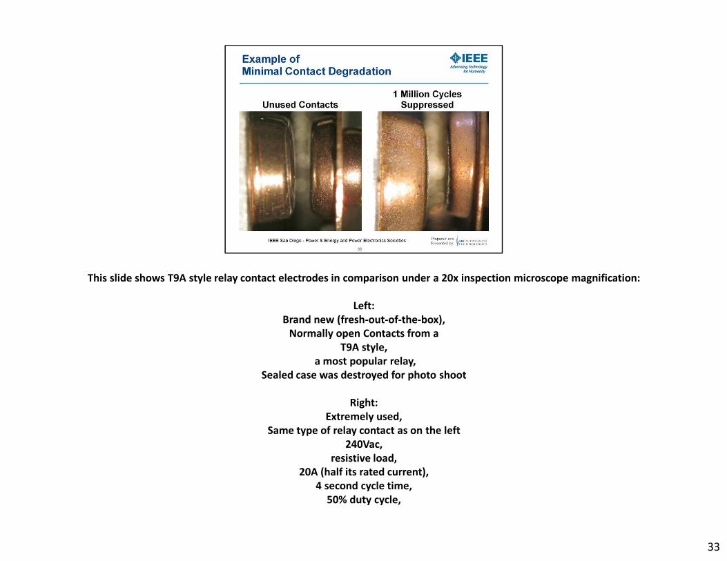
This slide shows T9A style relay contact electrodes in comparison under a 20x inspection microscope magnification:
Left:
Brand new (fresh-out-of-the-box),
Normally open Contacts from a
T9A style,
a most popular relay,
Sealed case was destroyed for photo shoot
Right:
Extremely used,
Same type of relay contact as on the left
240Vac,
resistive load,
20A (half its rated current),
4 second cycle time,
50% duty cycle,
33

1M cycles,
46.3 Days or about 1.5 Months of continuous operation,
at 22⁰C ambient,
with contact arc suppression,
and still looking as if in its operational infancy
33

This slide shows T9A style relay contact electrodes in comparison under a 20x inspection microscope magnification:
Left:
Very used,
Same type of relay as above
240Vac,
resistive load,
20A (half its rated current),
4 second cycle time,
50% duty cycle,
100k cycles,
operating Non-vented
at 22⁰C ambient,
Continuous operation for 4.63 Days,
without contact arc suppression,
and at its End-of-Life (EOL)
34
Right:
Extremely used,
Same type of relay contact as on the left
240Vac,
resistive load,
20A (half its rated current),
4 second cycle time,
50% duty cycle,
1M cycles,
46.3 Days or about 1.5 Months of continuous operation,
at 22⁰C ambient,
with contact arc suppression,
and still looking as if in its operational infancy
QUESTION: How long can we run the contact on the right until it matches the look of the contact on the left?
34

This slide shows What We Have Learned:
Off script: Arc suppressed contacts live a very long and healthy life.
35

This slide shows What We Have Learned: Five Arcs
At power source voltages of less then 15V there is typically very little arcing going on. The current automotive battery
standard of 12Vdc is one method to significantly reduce arcing in relays and switches in cars. The move to the new
proposed automotive battery standard of 42Vdc is going to create unprecedented contact deterioration due to contact
arcing in relays and switches in future cars. Just take a look at the hardest working contact in your car, the car starter
solenoid, if you open it up even after tens of thousands of miles, you will see the bright red contact copper without
significant contact discoloration from carbon deposits. At 42Vdc contact arcing and contact deterioration occurs every
time the contact switches a load over 1Amp.
36

This slide shows What We Have Learned: Discrete Components
Neither snubbers nor diodes nor MOV’s extend contact life in any significant way.
37

This slide shows What We Have Learned: Contact Designs
Mechanical baffles, pressurized gases, magnets and unique contact construction are typically employed when contact
currents and especially interrupt currents are measured in many kilo amperes.
38

This slide shows What We Have Learned: Hybrid Power Switching Devices
39

40

41
“You can achieve the impossible, for the impossible is only in other people’s heads!” –rh
42
Thank you very much for the opportunity to share with you what I have learned!

43