OnanCCK_Generator_Manual.pdf - Rethinking the Dream
48
-
Upload
khangminh22 -
Category
Documents
-
view
5 -
download
0
Transcript of OnanCCK_Generator_Manual.pdf - Rethinking the Dream

-
.,,
•
• I
GENERAL INFORMATION
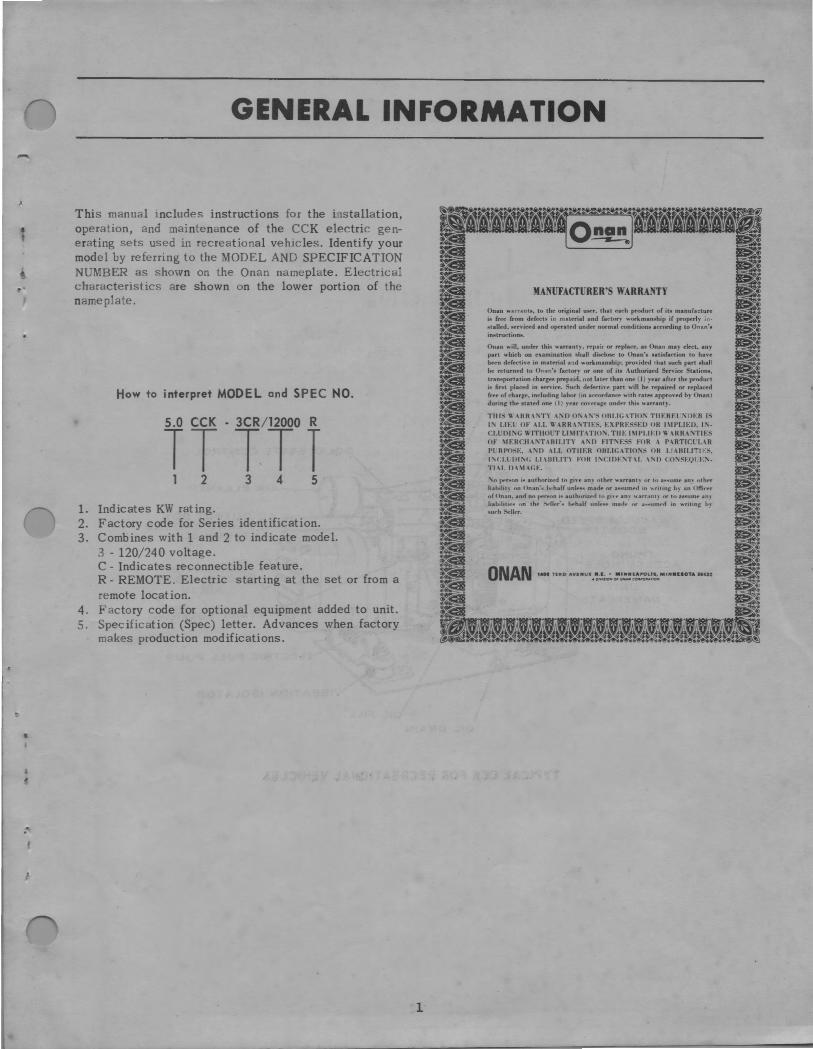
This manual includes instructions for the installation, operation, and maintenance of the CCK electric generating sets used in recreational vehicles. Identify your model by referring to the MODEL AND SPECIFICATION NUMBER as shown on the Onan nameplate. Electrical characteristics are shown on the lower portion of the nameplate.
How to interpret MODEL and SPEC NO.
2 3 4 5
1. Indicates KW rating. 2. Factory code for Series identification. 3. Combines with 1 and 2 to indicate model.
3 - 120/240 voltage. C - Indicates reconnectible feature. R - REMOTE. Electric starting at the set or from a remote location.
4. Factory code for optional equipment added to unit. S. Specification (Spec) letter. Advances when factory
makes production modifications .
1
MANUFACTURER'S WARRANTY
Onan v.arnnt@I. to tht' oririnal uM-r. that t>uh produc-1 of its manufacture is free from d.-fect~ in matrrial and factor, '>orkman~hip if pro~rly in-11talled, 11ervi«d and o~rated undt'r normal oond1tion1 urordin~ to Onan', in11tru('tions.
Onan will. under this warrant). repair or replatt, as Onan may elrct . any part v.·hieh on t>umination 11hall dil5Cloee to Onan·a aatidaC'tion to havtbf-t'n ddtttive in matf'rial and "'orkmanahip: pro,ided that auch part shall he returnNt to Onan'a factory or one of ita 4.uthorized Service Stations, tran<1porta1ion charg" prepaid, not latf'r than one (I) year after the produ<'I i11 fir11,t placed in service. Surh df'fttti,,. part ""ill hf' rf'pai~d or replacNI frtt or char,:,.. includint1: labor / in arC'ordanN" "'ith rates approvNf h) Onan) Jurin~ thf" 1tateil one ( I ) ~·t-ar ro,f"uf?:e unrl,.r thi11, "'arrant~.
TIIIS U .\HR\'\T"I \'\00'\.\'\'~0HI.IG\TIO'\ TIIERF.l~DER IS I:\ LIEL OF .\LL U -\RR \'\TIE~. EXPRE~SEU OH l\ll'LIED. J'\. CLLOJ",G IHTHOLT LIMITHIO"\, TUE I\IPI.IEll I\ o\RRAr>TIES ot l!ERCll-1,TABILITY -1,n FIT"\F.SS FOR \ P-IRTICLLIR l'L Rl'<N .. ,,n -ILL OTIIF.R 0111.JGHIO"\S OH I.I IHILITIES. l'\Cl.l IH J'\f; I.I \IIILIT) FOR l'\C:JIH'\T\I. \'\ll C:O'\SEQl F'\. TJ\I. l>\\l.\(;E.
'\n 1wr-.on i<. authorizl:"d tn ,:i,e an, ntht-r 1otarnnt, or to ai, .. umt- an, olhf"r lialtilih nn Onan·,. ht·halr uni.-... -. mulr or a<1, .. umf'II in •.-ritinf?: h~ an Offir,.r o(Onan. an<f no pf'r~on i"' author11:1"111o ,:iH· an, "'arr.mt~ nr to a&1111m.- an~ liabihtif'" nn thf' :-wn,.r·,. ilf'halC uole.._.., ma,1.- or .-,~umr<f m writin,:: I,, ~urh Stllrr. ·
ONAN ,uo 7HD Ava•u• .. '!!~:!!~~:.=:!. ••••••OTA 11412
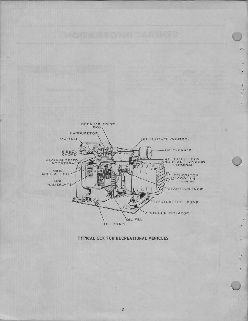
TIMING ACCESS HOLE·
UNIT NAMEPLATE
BREAKER POINT BOX
FILL
OIL DRAIN
OLID STATE CONTROL
---AIR CLEANER
OUTPUT BOX PLANT GROUND TERMINAL
COOLING AIR IN
TART SOLENOID
ELECTRIC FUEL PUMP
VIBRATION ISOLATOR
TYPICAL CCK FOR RECREATIONAL VEHICLES
2
"
•
..
•
-' •
•
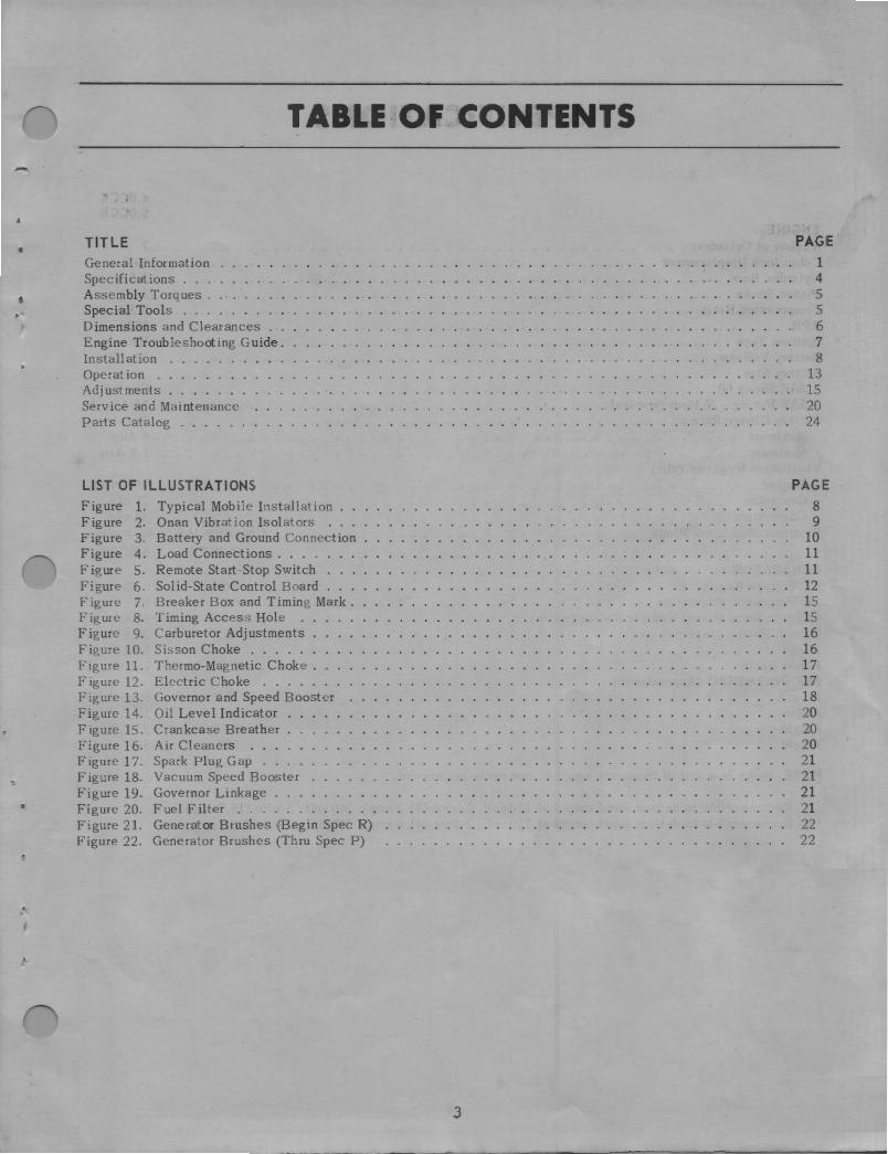
TABLE OF CONTENTS
TITLE General Information Specifications . . . Assembly Torques . Special Tools . . . Dimensions and Clearances Engine Troubleshooting Guide. Install at ion Operation ....... . Adjustments ...... . Service and Maintenance Parts Catalog . . . . . .
LIST OF ILLUSTRATIONS Figure 1. Typical Mobile Installation Figure 2. Onan Vibration Isolators . Figure 3. Battery and Ground Connection Figure 4. Load Connections . . . . Figure 5. Remote Start-Stop Switch .. . Figure 6. Solid-State Control Board .. . Figure 7. Breaker Box and Timing Mark . Figure 8. Timing Access Hole Figure 9. Carburetor Adjustments . Figure 10. Sisson Choke ..... . Figure 11. Thermo-Magnetic Choke . Figure 12. Electric Choke ..... Figure 13. Governor and Speed Booster Figure 14. Oil Level Indicator Figure 15. Crankcase Breather Figure 16. Air Cleaners Figure 17. Spark Plug Gap .. Figure 18. Vacuum Speed Booster Figure 19. Governor Linkage ... Figure 20. Fuel Filter . . . . . . Figure 21. Generator Brushes (Begin Spec R) Figure 22. Generator Brushes (Thru Spec P)
3
PAGE 1 4 5 5 6 7 8
13 15 20 24
PAGE 8 9
10 11 11 12 15 15 16 16 17 17 18 20 20 20 21 21 21 21 22 22

ENGINE Number of Cylinders . Cubic Inch Displacement Cylinder Bore ... Piston Stroke . . . Compression Ratio RPM ..... Ignition Type . Battery Voltage Battery Size
SAE Group 60 SAE Rating - 20 Hour (nominal) .
Battery Charge Rate . Maximum ....... . Minimum ... .. .. .
Ventilation Required (cfm) Engine .. Generator ....... . Combustion ...... .
SPECI Fl CATIONS
4.0CCK 5.0CCK
2 49.8 3-1/4 3 5.5:l 1800 Battery 12 volt
One 74 Amp/Hr. Two-Step 6 Amp. 1.5 Amp.
750 cfm 75 cfm 32 cfm
Recommended Spark Plugs Champion H-8 or equivalent
GENERATOR AC Voltage Regulation . . . . . . . . . . . . AC Frequency Regulation . . . . . . . . . . . 60 Hertz Recreational Vehicle Rating (watts) Current Rating (amperes) Phase ............. . Power Factor ......... . SET DIMENSIONS (Approximate) Length Width Height Weight
NOTE: Hertz is a unit of frequency equal to one cycle per second.
4.0CCK
±4% 5% 4000 16.7* Single 1.0
29-3 / 4 19-1/ 2 22-7/ 16 339
* - Reconnectible to deliver rated output at 120volt, 2-wire (33.3 amp); 240 volt, 2-wire (16. 7 amp). ** - Reconnectible to deliver rated output at 120volt, 2-wire (41.6amp); 240volt, 2-wire (20.8amp).
4
5.0CCK
±4% 5% 5000 20.8** Single 1.0
32-1/ 8 19-1/ 2 22-7 / 16 397
• •

-
•
t
.•
..
Blower Housing Screws Connecting Rod Bolts . Cylinder Head Screws . Exhaust Manifold Screws Flywheel Mounting Screws Fuel Pump Mounting Screws . Generator Adapter Screws Intake Manifold Screws . . Oil Base Screws . . . . . . Oil Pump Mounting Screws Rear Bearing Plate Capscrews Spark Plugs . . . . . . . Timing Gear Cover Screws
ASSEMBLY TORQUES
SPECIAL TOOLS
Bearing Ci.earance Guide (Plasti-Gage) .002,, to .006" ...... . .004,, to .009" ...... .
Combination Bearing Remover -Main & Carn ....... .
C ornb ination Bearing Driver -Main & Carn ..... .
Crankshaft Gear Puller . Gear Puller Ring. . . . . Flywheel Puller ..... Carburetor Adjustment Wrench Continuity Tester ..... Series Circuit Tester Torque Wrench - l/2"Drive
0 to 100 Ft-Lb Spray Can Paint - Green . .
420P256 420P257
420A325
420B324 420872 420A248 420Al00 4208169 420B290 420A288
420P222 525Pl37
5
Valve Seat Driver Valve Guide Driver .... Valve Spring -Compressor Valve Lock Replacer . . Tappet Lock Wrench . . Valve Guide Honing Set Ridge Reamer . . . . . . Cylinder Hone ..... . Cylinder Wall Micro-Finishing Brush Ring Compressor .. . Ring Spreader .... . Piston Groove Cleaner Oil Seat Guide & Driver
Bearing Plate Gear Cover ..... .
FT .-LB. 10-15 24-26 29-31 15-20 35-40
5-6 20-25 15-20 43-48
7-9 20-25 25-30 15-20
. 420A71 420A3 420Pll 420P10 420A18 420P30 420P26 420P3 420P32 420P21 420P14 420P33
420818 420831

DIMENSIONS AND CLEARANCES
CYLINDER & PISTONS Piston to Pin ..... Piston to Connecting Rod . . Piston Ring Gap in Cylinder Piston Clearance in Cylinder (Measured Below Oil Control Ring 90 ° From Pin) Cylinder Bore - Honed ............................. .
CRANKSHAFT & CAMSHAFT Crankshaft Main Bearing - Journal to Bearing Clearance Crankshaft End Play . . . . . . . . . . Camshaft Bearing to Camshaft Clearance Camshaft End Play . . . . . . . . . . . Connecting Rod End Play ....... . Crankshaft Rod Journal to Rod Bearing Clearance Timing Gear Backlash Oil Pump Gear Backlash ............ .
TAP PETS & VALVES Valve Tappet Clearance -
Intake .... . Exhaust ...... .
Valve Seat Width . . . . Valve Stem to Guide -
Intake .... . Exhaust ... .
Valve Face Angle Valve Seat Angle
IGNITION Spark Plug Gap .............. . Ignition Breaker Point Gap (Full Separation) Ignition Timing . . . . . . . . . . . . . . .
6
Minimum Maximum
Thumb Push Fit .0002 .0007 .010 .023 .0015 .0035 3.249 3.250
.0025
.006
.0015
.003
.002
.0020
.002
.002
.006
.015 1/ 32
.001
.0025 44 ° 45 °
.0038
.012
.0030
.016
.0033
.003
.005
.008
.017 3/ 64
.0025
.0040
.025
.020 19 ° BTC
-
•.
>
.. •
TROUBLE - ~ ~ - ..., - ~ - , - -KEY NUMBER I 2 3 4 5 6 7 8 9 10 11 12 13 14 15 ~-- -
I I I I 140 Backfire at Carburetor I 3 19 25
Bearin2 Wear 10 11 12 13 15 16 18 19 I I I I 140
Black Exhaust I 3 7 8 19 21 5 31 I 136 I I I I 40
Blue Exhaust 6 8 10 20 34
Burned Valves 3 9 25 33 '-I Bushin2 Wear 10 11 I' l"l 18
Connecting Rod Wear 10 11 12 13 18
Cranks Slowly 14 18 I I 1221 I I I 1211 I I I I I I I I I 138
Cylinder Wear 3 10 II 12 13
Engine Stops I 7 8 I I I I I I I I I I 251 I I 129 I I I I I I 1361371 I I 40, Failure to Start I 3 4 5 6 7 8 19 23 24 25 33 34 I 36 I 13s 139 I 40 Governor Hunts 2 7 21 30 31 32 I 361 I 139
Governor Insensitive
High Oil Pressure 14 15 16 17 20
Low Engine Power 2 3 4 5 6 7 8 9 19 21 25 28 33 34 1361 I 1391401 41 Low Oil Pressure 10 11 12 13 15 16 17 18 34 Low Speed 29 1361 I 139 Mechanical Knocks 3 9 10 11 12 13 15 18 25 33 34 136 I I I Misfiring I 2 3 4 s 7 8 9 19 25 J36J l J39l40l 41
No Governor Control 31 32
Overheating 10 11 12 26 I I 136 I I 1391 I 41 Piston Wear 3 10 11 12 13 15 Poor Compression 8 9 I I I I I I I I I I I I 1201 I I I I I 341
Ring Wear 3 6 10 11 12 13 15 I Sticking Valves 9 291 I I I 33
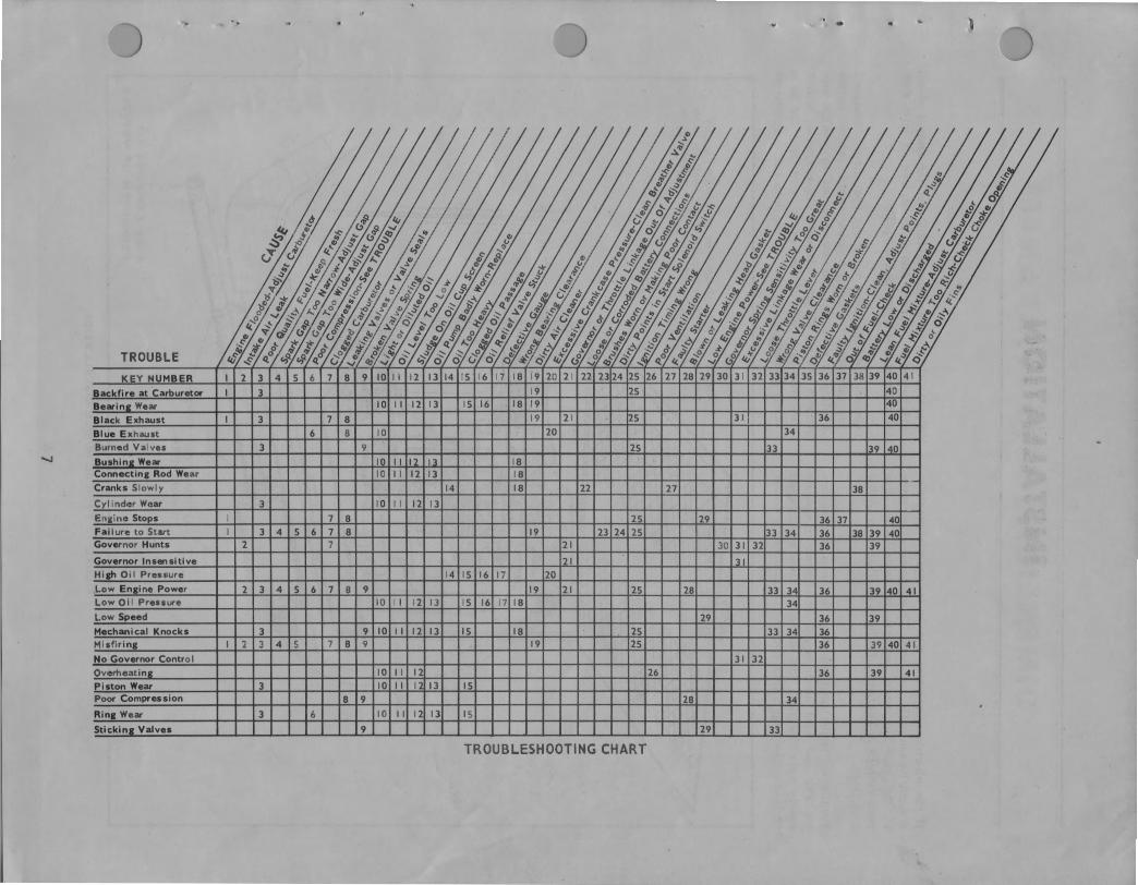
TROUBLESHOOTING CHART
INSTALLATION
If the electric generating set is to operate properly, it must be correctly installed. This manual gives some of the more important aspects of installation. For more details, a Technical Bulletin (T-012) is available from Onan.
Ventilation is the most important factor to be considered. The unit must have enough cooling air to operate safely and efficiently. The heated air must be disposed of to keep the engine from overheating and losing power.
I I
I I I I I I I I I '
FUEL LINE
t I I \ ' \ \ \'
AUTOMOTIVE HANGERS
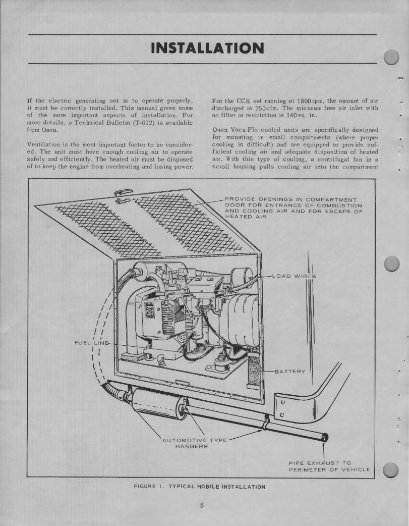
For the CCK set running at 1800 rpm, the amount of air discharged is 750cfm. The minimum free air inlet with no filter or restriction is 140 sq. in .
Onan Vacu-Flo cooled units are specifically designed for mounting in small compartments (where proper cooling is difficult) and are equipped to provide sufficient cooling air and adequate disposition of heated air. With this type of cooling, a centrifugal fan in a scroll housing pulls cooling air into the compartment
PROVIDE OPENINGS IN COMPARTMENT DOOR FOR ENTRANCE OF COMBUSTION AND COOLING AIR AND FOR ESCAPE OF HEATED AIR
1, I WIRES
f PIPE EXHAUST TO PERIMETER OF VEHICLE
FIGURE I. TYPICAL MOBILE INSTALLATION
8
:
and over the cooling fins and surfaces of the engine. Heated air is expelled through a single discharge and away from the unit and installation area.
LOCATION The compartment itself should be of vapor tight design and completely independent of living quarters. The interior lining should be fireproof. A sheet metal covered compartment may be readily sealed and lends itself easily to treatment. The set may have to be removed for service, so make the door large enough to facilitate removal of the unit.
The compartment location is determined by physical size, access opening and most important, best mounting sup port. Allow 2 ,, clearance on all sizes of the unit for rocking on mounts.
POSITIONING The following should be considered for accessibility when mounting the unit in a compartment. (Position so operating instructions and nameplate are visible and/or install an accessible nameplate, data decal or sticker.)
1. Make air discharge duct as short as possible. Position so exhaust heated air is not drawn into cool air inlet.
2. Air cleaner should be easy to remove and service. 3. Battery or batteries must be accessible for service. 4. Oil fill tube cap should be easy to reach. S. The control box switch should be visible. 6. Provide space for muffler. 7. Oil drain should be readily accessible. 8. Cylinder head should be readily accessible for
service. 9. Rope start sheave should be accessible.
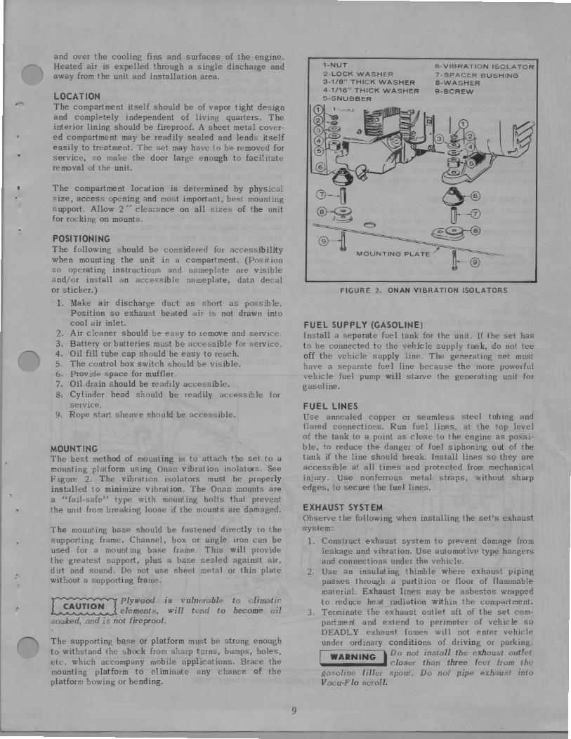
MOUNTING The best method of mounting is to attach the set to a mounting platform using Onan vibration isolators. See Figure 2. The vibration isolators must be properly installed to minimize vibration. The Onan mounts are a "fail-safe" type with mounting bolts that prevent the unit from breaking loose if the mounts are damaged.
The mounting base should be fastened directly to the supporting frame. Channel, box or angle iron can be used for a mounting base frame. This will provide the greatest support, plus a base sealed against air, dirt and sound. Do not use sheet metal or thin plate without a supporting frame.
~ Plywood is vulnerable ~ elements, will tend to soaked, and is not fireproof.
to climatic become oil
The supporting base or platform must be strong enough to withstand the shock from sharp turns, bumps, holes, etc. which accompany mobile applications. Brace the mounting platform to eliminate any chance of the platform bowing or bending.
9
1-NUT
2-LOCK WASHER 3-1/8" THICK WASHER 4-1/16" THICK WASHER 5-SNUBBER
6-VIBRATION ISOLATOR 7-SPACER BUSHING 8-WASHER 9-SCREW
FIGURE 2. ONAN VIBRATION ISOLATORS
FUEL SUPPLY (GASOLINE) Install a separate fuel tank for the unit. If the set has to be connected to the vehicle supply tank, do not tee off the vehicle supply line. The generating set must have a separate fue 1 line because the more powerful vehicle fuel pump will starve the generating unit for gasoline.
FUEL LINES Use annealed copper or seamless steel tubing and flared connections. Run fuel lines, at the top level of the tank to a point as close to the engine as possible, to reduce the danger of fuel siphoning out of the tank if the line should break. Install lines so they are accessible at all times and protected from mechanical injury. Use nonferrous metal straps, without sharp edges, to secure the fuel lines.
EXHAUST SYSTEM Observe the following when installing the set's exhaust system:
1. Construct exhaust system to prevent damage from leakage and vibration. Use automotive type hangers and connections under the vehicle.
2. Use an insulating thimble where exhaust piping passes through a partition or floor of flammable material. Exhaust lines may be asbestos wrapped to reduce heat radiation within the compartment.
3. Terminate the exhaust outlet aft of the set compartment and extend to perimeter of vehicle so DEADLY exhaust fumes will not enter vehicle under ordinary conditions of driving or parking.
WARNING • Do not install the exhaust outlet ._ _____ _.! closer than three feet from the gasoline filler spout. Do not pipe exhaust into Vacu-F lo scroll.
When installing mufflers, other than those supplied with the unit or if the exhaust system is excessively complicated, the exhaust back pressure should be checked. Exhaust back pressure at rated load, measured at the exhaust manifold, should not exceed 2 in. Hg. (Mercury column). Where a tapped hole is not provided, the manifold and/or a pipe coupling may be drilled and tapped. After measurement is made, plug the hole with an ordinary pipe plug.
WARNING ~ Do not use discharged Vacu-Flo air -------•- for heating since it may contain carbon monoxide or other poisonous gases.
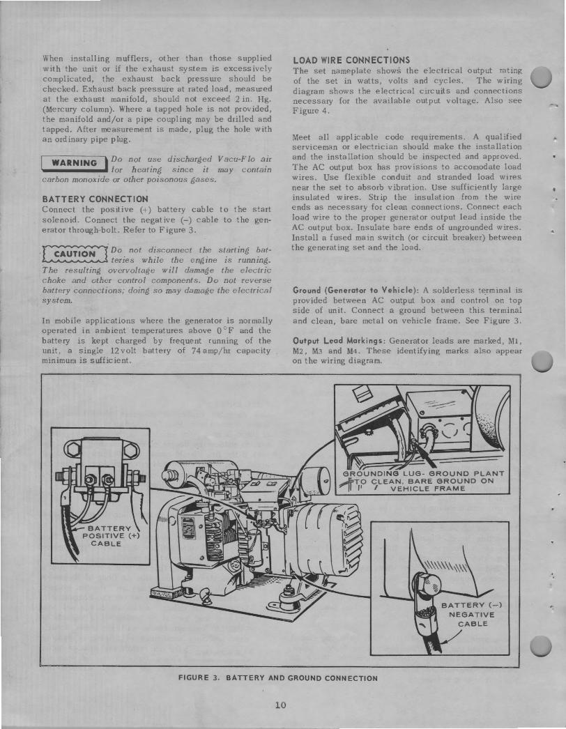
BATTERY CONNECTION Connect the positive (+) battery cable to the start solenoid. Connect the negative (-) cable to the generator through-bolt. Refer to Figure 3.
-[~Do. not d~sconnect th_e st~rting ~at--~ terzes while the engine zs running.
The resulting overvoltage will damage the electric choke and other control components. Do not reverse battery connections; doing so may damage the electrical system.
In mobile applications where the generator is normally operated in ambient temperatures above O °F and the battery is kept charged by frequent running of the unit, a single 12 volt battery of 74 amp/hr capacity minimum is sufficient.
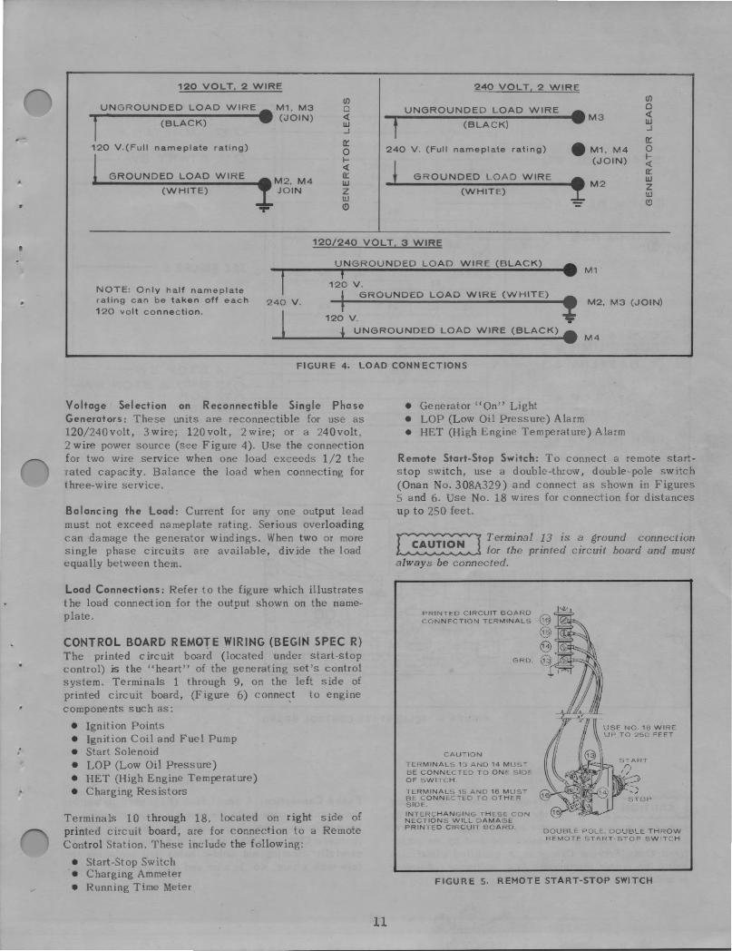
LOAD WIRE CONNECTIONS The set nameplate shows the electrical output rating of the set in watts, volts and cycles. The wiring diagram shows the electrical circuits and connections necessary for the available output voltage. Also see Figure 4.
Meet all applicable code requirements. A qualified serviceman or electrician should make the installation and the installation should be inspected and approved. The AC output box has provisions to accomodate load wires. Use flexible conduit and stranded load wires near the set to absorb vibration. Use sufficiently large insulated wires. Strip the insulation from the wire ends as necessary for clean connections. Connect each load wire to the proper generator output lead inside the AC output box. Insulate bare ends of ungrounded wires. Install a fused main switch (or circuit breaker) between the generating set and the load.
Ground (Generator to Vehicle): A solderless terminal is provided between AC output box and control on top side of unit. Connect a ground between this terminal and clean, bare metal on vehicle frame. See Figure 3.
Output Lead Markings: Generator leads are marked, Ml, M2, M3 and M4. These identifying marks also appear on the wiring diagram.
FIGURE 3. BATTERY AND GROUND CONNECTION
10
t
:
120 VOLT, 2 WIRE
UNGROUNDED LOAD WIRE. M1, M3 t (BLACK) (JOIN)
120 V.(Full nameplate rating)
.__G_R_o_u_N_D_E_D_L_o_A_D_w_IR_E __ M2, M4
(WHITE) JOIN
(/) 0 <{ w ...J
(l::
0 I<{ (l:: w z w (!)
240 VOLT, 2 WIRE
UNGROUNDED LOAD WIRE .M3 7 (BLACK)
240 V . (Full nameplate rating) • M1, M4 (JOIN)
GROUNDED LOAD WIRE M2
(WHITE)
-
(/) 0 <{ w ...J
(l::
0 I-<{ (l:: w z w (!)
120/240 VOLT. 3 WIRE
UNGROUNDED LOAD WIRE (BLACK) • -.,r------.,----------------- M1 120 v.
NOTE: Only half nameplate rating can be taken off each
120 volt connection.
i GROUNDED LOAD WIRE (WHITE) 240 V. f
' M2, M3 (JOIN)
120 V. l l UNGROUNDED LOAD WIRE (BLACK) • M 4
FIGURE 4. LOAD CONNECTIONS
Voltage Selection on Reconnectible Single Phase Generators: These units are reconnectible for use as 120/240volt, 3wire; 120volt, 2wire; or a 240volt, 2 wire power source (see Figure 4). Use the connection for two wire service when one load exceeds 1/2 the rated capacity. Balance the load when connecting for three-wire service.
Balancing the Load: Current for any one output lead must not exceed nameplate rating. Serious overloading can damage the generator windings. When two or more single phase circuits are available, divide the load equally between them.
Load Connections: Refer to the figure which illustrates the load connection for the output shown on the nameplate.
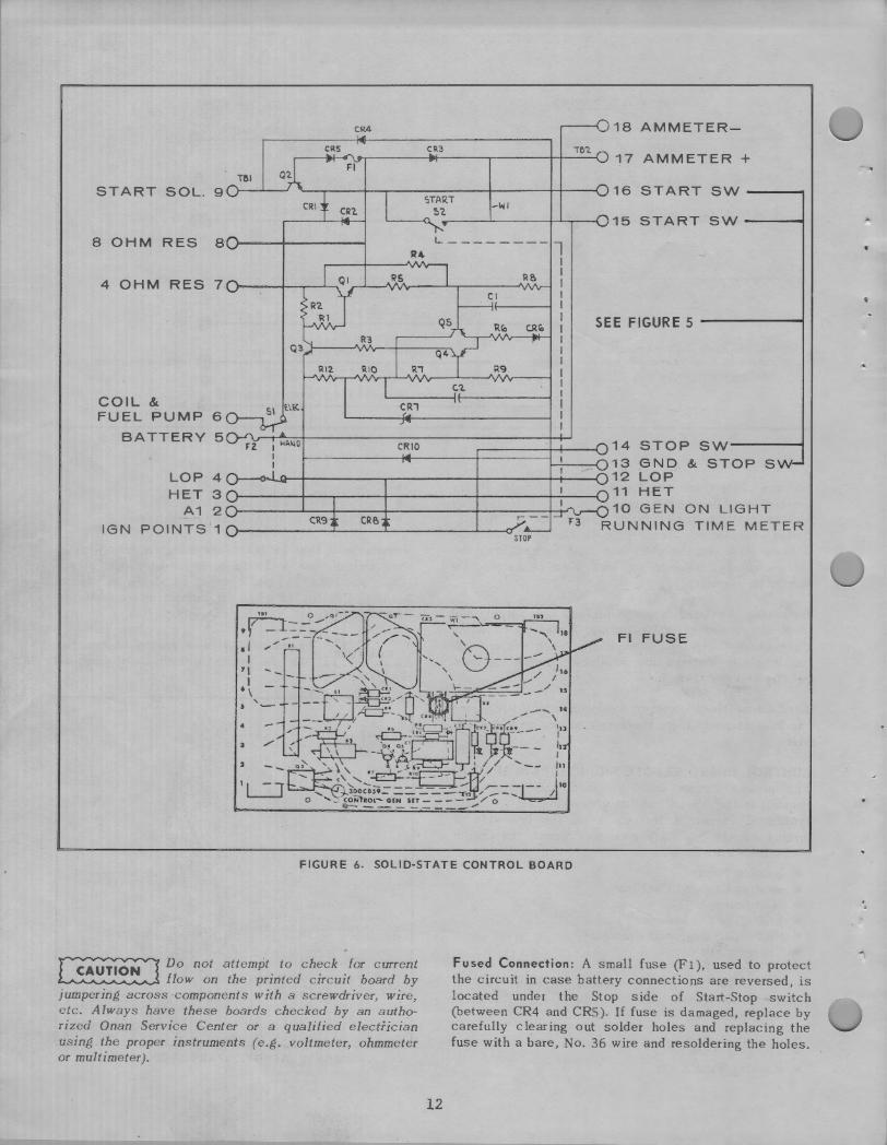
CONTROL BOARD REMOTE WIRING (BEGIN SPEC R) The printed circuit board (located under start-stop control) i:s the "heart" of the generating set's control system. Terminals 1 through 9, on the left side of printed circuit board, (Figure 6) connect to engine components such as:
• Ignition Points • Ignition Coil and Fuel Pump • Start Solenoid • LOP (Low Oil Pressure) • HET (High Engine Temperature) • Charging Resistors
Terminals 10 through 18, located on right side of printed circuit board, are for connection to a Remote Control Station. These include the following:
• Start-Stop Switch • Charging Ammeter • Running Time Meter
11
• Generator "On" Light • LOP (Low Oil Pressure) Alarm • HET (High Engine Temperature) Alarm
Remote Start-Stop Switch: To connect a remote startstop switch, use a double-throw, double-pole switch (Onan No. 308A329) and connect as shown in Figures 5 and 6. Use No. 18 wires for connection for distances up to 250 feet.
~ Terminal ~3 is -=! gr_ound connection ~ for the printed circuit board and must always be connected.
PRINTED CIRCUIT BOARD CONNECTION TERMINALS
GRD
CAUTION
TERMINALS 13 AND 14 MUST BE CONNECTED TO ONE SIDE OF SWITCH
TERMINALS 15 AND 16 MUST BE CONNECTED TO OTHER SIDE
INTERCHANGING THESE CON NECTIONS WILL DAMAGE PRINTED CIRCUIT BOARD
DOUBLE POLE. DOUBLE THROW REMOTE START-STOP SWITCH
FIGURE s. REMOTE START-STOP SWITCH
CR4
CRS
T&I START SOL. 9
CRI START
~7. -WI
18 AMMETER-
16 START SW ---
'----o.. ..--~~---;--......,.--1..115 ST ART SW ----i 8 OHM RES 8 · l..-------- 7
R4 I .....---+----vVv---, I
4 OHM RES 7c >---1--...--........._
COIL & FUEL PUMP 6
CR1
Cl
RB I I I I I I I I I I I I I I
SEE FIGURE 5 ----""""""'
BATTERY 5 14 STOP sw-----i 13 GND & STOP SW
LOP 4 12 LOP
CRIO
H ET 3 1 1-------.......---+-----------+--,----l 1 11 HE T A1 2 10 GEN ON LIGHT
IGN POINTS 1 CR9 RUNNING TIME METER STOP
Fl FUSE
FIGURE 6. SOLID-STATE CONTROL BOARD
~ Do not attempt. to ch~ck . for current ~ flow on the printed circuit board by jumpering across ·components with a screwdriver, wire, etc. Always have these boards checked by an authorized Onan Service Center or a qualified electrician using the proper instruments (e.g. voltmeter, ohmmeter or multimeter).
12
Fused Connection: A small fuse (Fl), used to protect the circuit in case battery connections are reversed, is located under the Stop side of Start-Stop switch (between CR4 and CRS ). If fuse is damaged, replace by carefully clearing out solder holes and replacing the fuse with a bare, No. 36 wire and resoldering the holes.
,
. .
OPERATION
BEFORE STARTING Crankcase Oi I: Be sure the crankcase has been filled with oil to the "FULL" mark on. the oil level indicator. Refer to the Maintenance Section for the recommended oil changes and complete lubricating oil recommendations.
Recommended Fuel: Use clean, fresh, regular grade, automotive gasoline. Do not use highly leaded premium types.
For new engines, the most satisfactory results are obtained by using nonleaded gasoline. For older engines that have previously used leaded gasoline, heads must be taken off and all lead deposits removed from engine before switching to nonleaded gasoline.
~ If ]~ad deposits _are _not removed from ~ engme before swztchmg from leaded to non leaded gasoline, preignition could occur causing severe damage to the engine.
ELECTRIC STARTING Push the Start-Stop switch to its "START" position. Release the switch as soon as the engine starts.
If the engine fails to start at first try, inhibitor oil used at the factory may have fouled the spark plugs. Remove the plugs, clean in a suitable solvent, dry thoroughly and install. Heavy exhaust smoke when the engine is first started is normal and is caused by the inhibitor oil.
OPTIONAL MANUAL STARTING (Begin Spec R) If the battery charge condition is too low to crank the engine, some engines equipped with a rope sheave, can be started manually. Move "Rope Start" button to "Hold" position. Pull the rope with a fast, steady pull to crank the engine. Do not jerk. After starting, release "Hold" switch .
NOTE: Units not equipped with rope sheave cannot be started manually.
MANUAL ST ART ING {Through Spec P) Set the control box switch to its manual start position. Pull the rope with fast, steady pull to crank the engine. Do not jerk. ·ter starting, return the control b.ox switch to the electric start position to avoid discharging the battery.
APPLYING LOAD If practical, allow set to warm up before connecting a heavy load. Continuous generator over10 ding may
13
ca·use high operating temperatures that can damage the windings. Keep the load within nameplate rating.
STOPPING 1. Push Start-Stop switch to "STOP" position. 2. Release switch when unit stops.
BREAK-IN PROCEDURE Controlled break-in with the proper oil and a conscientiously applied maintenance program will help to assure satisfactory service from your Onan electric generating set.
When operating engine for the first time, use the following sequence using SE or SE/ CC oil (former designation was MS or MS/DG):
1. One half hour at 1/2 load. 2. One half hour at 3/4 load. 3. Full load. 4. Change crankcase oil after the first SO hours of
operation.
BATTERY CHARGING (Begin Spec R) The battery charge rate is automatically controlled by a solid-state voltage regulator. The high charge rate was set at the factory for average operating conditions.
INFREQUENT SERVICE If the set is used infrequently, extended shutdown periods can result in difficult starting. Run unit at least 30 minutes every week to eliminate hard starting.
HIGH TEMPERATURES 1. See that nothing obstructs air flow to and from
the set. 2. Keep CDoling fins clean. Air housing should be
properly installed and undamaged. 3. Keep ignition timing properly adjusted.
LOW TEMPERATURES 1. Use correct SAE No. oil for temperature conditions.
Change oil only when engine is warm. If an unexpected temperature drop causes an emergency, move the vehicle to a warm location.
2. Use fresh gasoline. Protect against moisture condensation. Below 0 ° F adjust carburetor main jet for a slightly richer fuel mixture.
3. Keep ignition system clean, properly adjusted and batteries in a: well charged condition.
4. Partially restrict cool air flow, but use care to avoid overheating.
OUT-OF-SERVICE PROTECTION Protect a set that will be out-of-service for more than 30 days as follows:
1. Run the set until thoroughly warm. 2. Turn off fuel supply and run until engine stops. 3. Drain oil from oil base while still warm. Refill
and attach a warning tag stating oil viscosity used.
4. Remove each spark plug. Pour 1 oz. (two tablespoons) of rust inhibitor (or SAE #50 oil) into each cylinder. Crank engine slowly (by hand) several times. Install spark plugs.
S. Service air cleaner. 6. Clean governor linkage and protect by wrapping
with a clean cloth. 7. Plug exhaust outlet to prevent entrance of moisture,
dirt, bugs, etc. 8. Wipe generator brushes, slip rings, etc. Do not
apply lubricant or preservative. 9. Wipe entire unit. Coat rustable parts with a light
film of grease or oil. 1 O. If battery is used, disconnect and follow standard
battery storage procedure.
DUST AND DI RT 1. Keep set clean. Keep cooling surfaces clean. 2. Service air cleaner as frequently as necessary. 3. Change crankcase oil every SO operating hours
or sooner. 4. Keep oil and gasoline in dust-tight containers. S. Keep governor linkage clean. 6. Clean generator brushes, slip rings and commutator.
Do not remove normal (dark brown) film. Do not polish.
HIGH ALTITUDE For operation at altitudes of 2500 feet above sea level, close carburetor main jet adjustment slightly to maintain proper air-to-fuel ratio (refer to the Adjustment Section). Maximum power will be reduced approximately 4% for each 1000 feet above sea level, after the first 1000 feet.
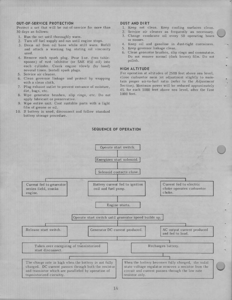
SEQUENCE OF OPERATION
I Operate start switch. I I
I Energizes start solenoid. l I
I Solenoid contacts close. l I
I I I
Current fed to generator Battery current fed to ignition Current fed to electric series field, cranks coil and fuel pump. choke operates carburetor engine. choke.
I I Engine starts. I
I I Operate start switch until generator speed builds up. I
I I I I
Release start switch. Generator DC current produced. AC output current produced and fed to load.
I I I
Takes over energizing of tr~nsistorized I I Recharges battery. start disconnect.
I I I
The charge rate is high when the battery is not fully When the battery becomes fully charged, the solid charged. DC current passes through both the resistor state voltage regulator removes a resistor from the and transistor which are paralleled by operation of circuit and current passes through the low rate tra,nsistorized circuitry. resistor only.
14
ADJUSTMENTS
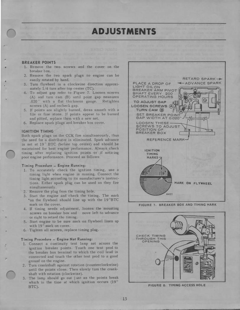
BREAKER POINTS , 1. Remove the two screws and the cover on the
,
:
breaker box. 2. Remove the two spark plugs so engine can be
easily rotated by hand. 3. Turn flywheel in a clockwise direction approxi
mately 1/ 4 turn after top center (TC). 4. To adjust gap refer to Figure 7. Loosen screws
(A) and turn cam (B) until point gap measures .020 " with a flat thickness gauge. Retighten screws (A) and recheck gap.
5. If points are slightly burned, dress smooth with a file or fine stone. If points appear to be burned and pitted, replace them with a new set.
6. Replace spark plugs and breaker box cover.
IGNITION TIMING Both spark plugs on the CCK fire simultaneously, thus the need for a distributor is eliminated. Spark advance is set at 19 ° BTC (before top center) and should be maintained for best engine performance. Always check timing after replacing ignition points or if noticing poor engine performance. Proceed as follows :
Timing Procedure - Engine Running: 1. To accurately check the ignition timing, use a
timing light when e ngine is running. Connect the timing light according to its manufacturer's instructions. Either spark plug can be used as they fire simultaneously.
2. Remove the plug from the timing hole. 3. Start the engine and check the timing. The mark
~on the flywheel should line up with the 19° BTC mark on the cover.
4. If timing needs adjustment, loosen the mounting screws on breaker box and move left to advance or right to retard the timing.
S. Start engine to be sure mark on flywheel lines up with 19 ° mark on cover.
6. Tighten all screws, replace timing plug.
Timing Procedure - Engine Not Running: 1. Connect a continuity test lamp set across the
ignition breaker points. Touch one test prod to the breaker box terminal to which the coil lead is connected and touch the other test prod to a good ground on the engine.
2. Turn crankshaft against rotation (counterclockwise) until the points close. Then slowly turn the crankshaft with rotation (clockwise).
3. The lamp should go out just as the points break which is the time at which ignition occurs (19 ° BTC).
15
PLACE A DROP OF LIGHT OILON BREAKER ARM PIVOT SHAFT EVERY 200 OPERATING HOURS
TO ADJUST GAP
RETARD SPARK-+~ADVANCE SPARK
LOOSEN SCREWS @ TURN CAM@ A SET BREAKER POINT ~"f===:iiiiiir;;_iiiiiiiir=if GAP WIDTH AT 0.020"
LOOSEN THESE ~ SCREWS TO ADJUST POSITION OF ···~ BREAKER BOX I I
REFERENCE MARK
IGNITION TIMING MARKS
MARK ON FLYWHEEL
FIGURE 7. BREAKER BOX AND TIMING MARK
CHECK TIMING THROUGH THIS
OPENING
0
F IGURE 8. TIMI NG ACCESS HOLE
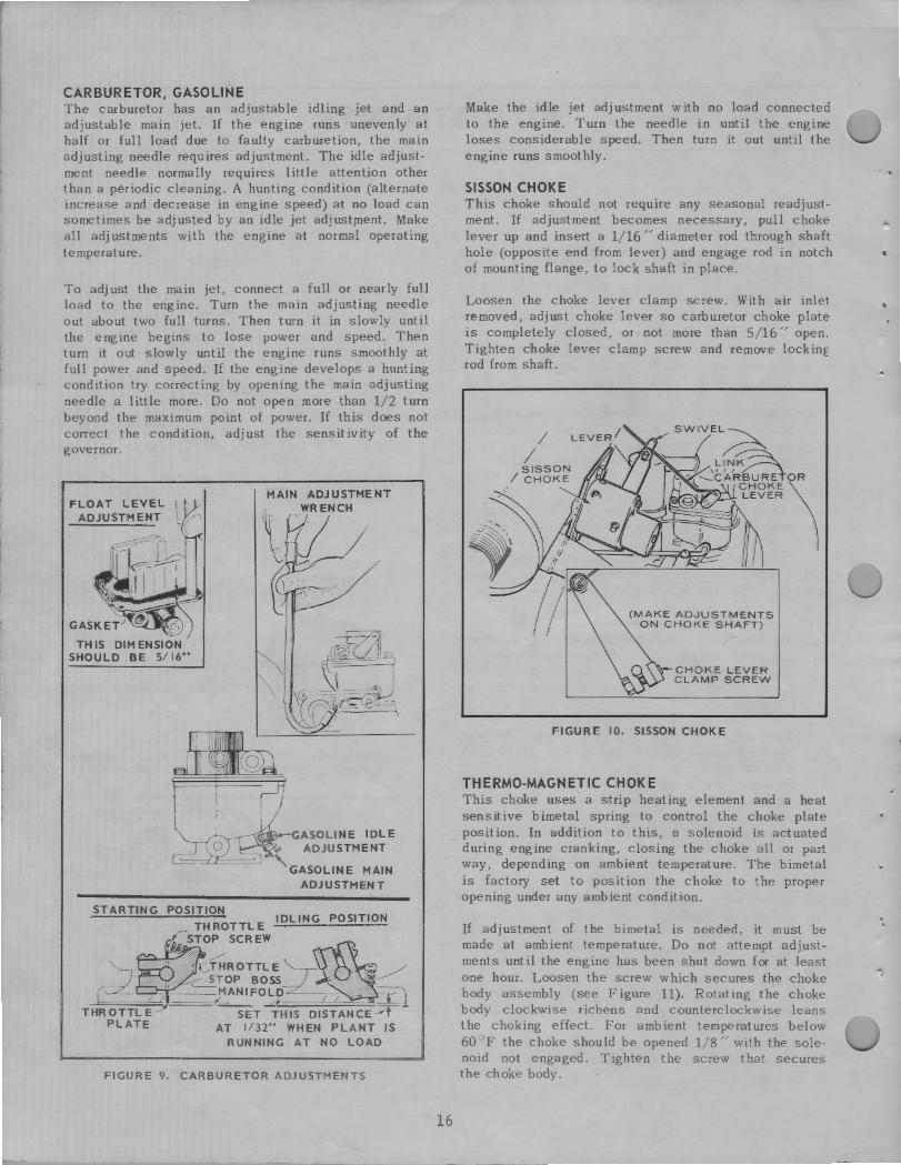
CARBURETOR, GASOLINE The carburetor has an adjustable idling jet and an adjustable main jet. If the engine runs unevenly at half or full load due to faulty carburetion, the main adjusting needle requires adjustment. The idle adjustment needle normally requires little attention other than a periodic cleaning . A hunting condition (alternate increase and decrease in engine speed) at no load can sometimes be adjusted by an idle jet adjust)llent. Make all adjustments with the engine at normal operating temperature.
To adjust the main jet, connect a full or nearly full load to the engine. Turn the main adjusting needle out about two full turns. Then turn it in slowly until the engine begins to lose power and speed. Then turn it out slowly until the engine runs smoothly at full power and speed. If the engine develops a hunting condition try correcting by opening the main adjusting needle a little more. Do not open more than 1/ 2 turn beyond the maximum point of power. If this does not correct the condition, adjust the sensitivity of the governor.
FLOAT LEVEL \ ADJUSTMENT L ('
TH IS DIMENSION SHOULD BE 5/ 16"
MAIN ADJUSTMENT
\ , WRENCH
~-~.-r.ASOLINE IDLE ADJUSTMENT
GASOLINE MAIN ADJUSTMENT
STARTING POSITION TH ROT TL E IDLING POSITION
1 STOP SCREW
'fHROTTLE d ~ STOP BOSS
"--,.-~ANIFO_:P 1 1 r l THROTTLE SET THIS DISTANCE~
PLATE AT 1/32" WHEN PLANT IS RUNNING AT NO LOAD
F IGURE 9. CARBURETOR ADJUSTM ENTS
16
Make the idle jet adjustment with no load connected to the engine. Turn the needle in until the engine loses considerable speed. Then turn it out until the engine runs smoothly.
SISSON CHOKE This choke should not require any seasonal readjustment. If adjustment becomes necessary , pull choke lever up and insert a 1/ 16" diameter rod through shaft hole (opposite end from lever) and engage rod in notch of mounting flange, to lock shaft in place.
Loosen the choke lever clamp screw. With air inlet removed, adjust choke lever so carburetor choke plate is completely closed, or not more than 5 / 16 " open. Tighten choke lever clamp screw and remove locking rod from shaft.
CHOKE LEVER CLAMP SCREW
FIGURE 10. SISSON CHOKE
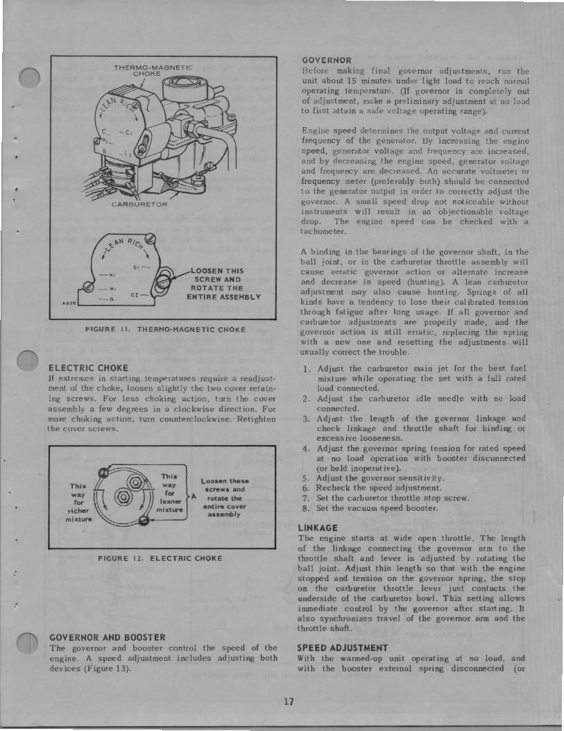
THERMO-MAGNETIC CHOKE This choke uses a strip heating element and a heat sensitive bimetal spring to control the choke plate position. In addition to this, a solenoid is actuated during engine cranking, closing the choke all or part way, depending on ambient temperature. The bi metal is factory set to position the choke to the proper opening under any ambient condition.
If adjustment of the bimetal is needed, it must be made at ambient temperature. Do not attempt adjustments until the engine has been shut down for at least one hour. Loosen the screw which secures the choke body assembly (see Figure 11). Rotating the choke body clockwise richens and counterclockwise leans the choking effect. For ambient temperatures below 60 ° F the choke should be opened 1/ 8 " with the solenoid not engaged. Tighten the screw that secures the choke body.
. .
:-
CARBURETOR
LOOSEN THIS SCREW AND
ROTATE THE ENTIRE ASSEMBLY
FIGURE 11. THERMO-MAGNETIC CHOKE
ELECTRIC CHOKE If extremes in starting temperatures require a readjustment of the choke, loosen slightly the two cover retaining screws. For less choking action, turn the cover assembly a few degrees in a clockwise direction. For more choking action, turn counterclockwise. Retighten the cover screws.
Loosen these screws and
A rotate the entire cover
assembly
FIGURE 12. ELECTRIC CHOKE
GOVERNOR AND BOOSTER The governor and booster control the speed of the engine. A speed adjustment includes adjusting both devices (Figure 13).
17
GOVERNOR Before making final governor adjustments, run the unit about 15 minutes under light load to reach normal operating temperature. (If governor is completely out of adjustment, make a preliminary adjustment at no load to first attain a safe voltage operating range).
Engine speed determines the output voltage and current frequency of the generator. By increasing the engine speed, generator voltage and frequency are increased, and by decreasing the engine speed, generator voltage and frequency are decreased. An accurate voltmeter or frequency meter (preferably both) should be connected to the generator output in order to correctly adjust the governor. A small speed drop not noticeable without instruments will result in an objectionable voltage drop. The engine speed can be checked with a tachometer.
A binding in the bearings of the governor shaft, in the ball joint, or in the carburetor throttle assembly will cause erratic governor action or alternate increase and decrease in speed (hunting). A lean carburetor adjustment may also cause hunting. Springs of all kinds have a tendency to lose their calibrated tension through fatigue after long usage. If all governor and carburetor adjustments are properly made, and the governor action is still erratic, replacing the spring with a new one and resetting the adjustments will usually correct the trouble.
1. Adjust the carburetor main jet for the best fuel mixture while operating the set with a full rated load connected.
2. Adjust the carburetor idle needle with no load connected.
3. Adjust the length of the governor linkage and check linkage and throttle shaft for binding or excessive looseness.
4. Adjust the governor spring tension for rated speed at no load operation with booster disconnected (or held inoperative).
S. Adjust the governor sensitivity. 6. Recheck the speed adjustment. 7. Set the carburetor throttle stop screw. 8. Set the vacuum speed booster.
LINKAGE The engine starts at wide open throttle. The length of the linkage connecting the governor arm to the throttle shaft and lever is adjusted by rotating the ball joint. Adjust this length so that with the engine stopped and tension on the governor spring, the stop on the carburetor throttle lever just contacts the underside of the carburetor bowl. This setting allows immediate control by the governor after starting. It also synchronizes travel of the governor arm and the throttle shaft.
SPEED ADJUSTMENT With the warmed-up unit operating at no load, and with the booster external spring disconnected (or

otherwise held inactive), adjust the tension ot the governor spring. Refer to Voltage Chart and the Speed Chart and select the column which corresponds to the nameplate of the unit in question. Turn the speed adj us ting nut to obtain a voltage and speed reading within the limits shown.
VOLTAGE CHART FOR CHECKING GOVERNOR REGULATION
120VOLT 120/240 VOLT AC GEN .ERATING SETS I PHASE I PHASE
2WIRE 3WIRE
Maximum No Load Volts 126 126/252
Minimum Ful I Load Volts I 10 110/220 Without Booster
NOTE: Output rating is at UNITY power factor load.
SPEED CHART FOR CHECKING GOVERNOR REGULATION
Maximum No Load Speed RPM Hertz (Current Frequency)
Minimum Full Load Speed Without Booster RPM Hertz
1890 63
1770
59
CARBURETOR THROTTLE PLATE
THROTTLE STOP SCREW -
SENSITIVITY ADJUSTMENT Refer to the Governor Adjustment illustration, and to the Voltage and Speed Charts. Check the voltage and speed, first with no load connected and again with a full load. Adjust the sensitivity to give the closest regulation (least speed and voltage difference between no load and full load) without causing a hunting condition.
To increase sensitivity (closer regulation), shift the adjusting clip toward the governor shaft.
An adjustment for too much sen sit iv ity will cause alternate increase and decrease of engine speed (hunting).
To decrease sensitivity, shift the adjusting clip toward the outer end of the governor arm. Too little sensitivity will result in too much difference in speed between no load and full load conditions.
Any change in the sensitivity adjustment usually requires a compensating speed (spring tension) adjustment.
SPEED BOOSTER After satisfactory performance under various loads has been attained by governor adjustments without the booster, the booster can be connected. Connect the booster external spring to the bracket on the governor link (rod). With the unit operating at no load, slide the bracket on the governor link just to the position where there is no tension on the external spring (Figure 13).
- GOVERNOR CONTROL
THIS DISTANCE : ~ DETERMINES SENSITIVITY (0 ~
GOVERNOR ARM AND SHAFT
LINKAGE
CUP
FIGURE 13. GOVERNOR AND SPEED BOOSTER
18
. .
Apply a full rated electrical load to the generator. The output voltage should stabilize at nearly the same reading for full load as for no load operation. The speed may remain about the same or increase when the load is applied, resulting in a frequency 1 or 2 hertz higher than the no load frequency (1 hertz is equal to 30 rpm for a 4 pole generator). If the rise in frequency is more than 2 hertz, lessen the internal spring tension. If there is a drop in the frequency, increase the booster internal spring tension. To increase the tension, pull out on the spring bracket and move the pin to a different hole.
With the booster disconnected, a maximum drop of 3 hertz from no load to full load is normal. With the booster in operation, a maximum increase of 2 hertz from no load to full load is normal. A drop of 1 hertz at 1/4 load is permissible, giving an overall spread of 3 hertz maximum.
The effect of the booster is limited by the general condition of the engine. The booster cannot compensate for a loss in engine vacuum caused by leaky valves, worn piston rings, etc .
19
SERVICE AND MAINTENANCE
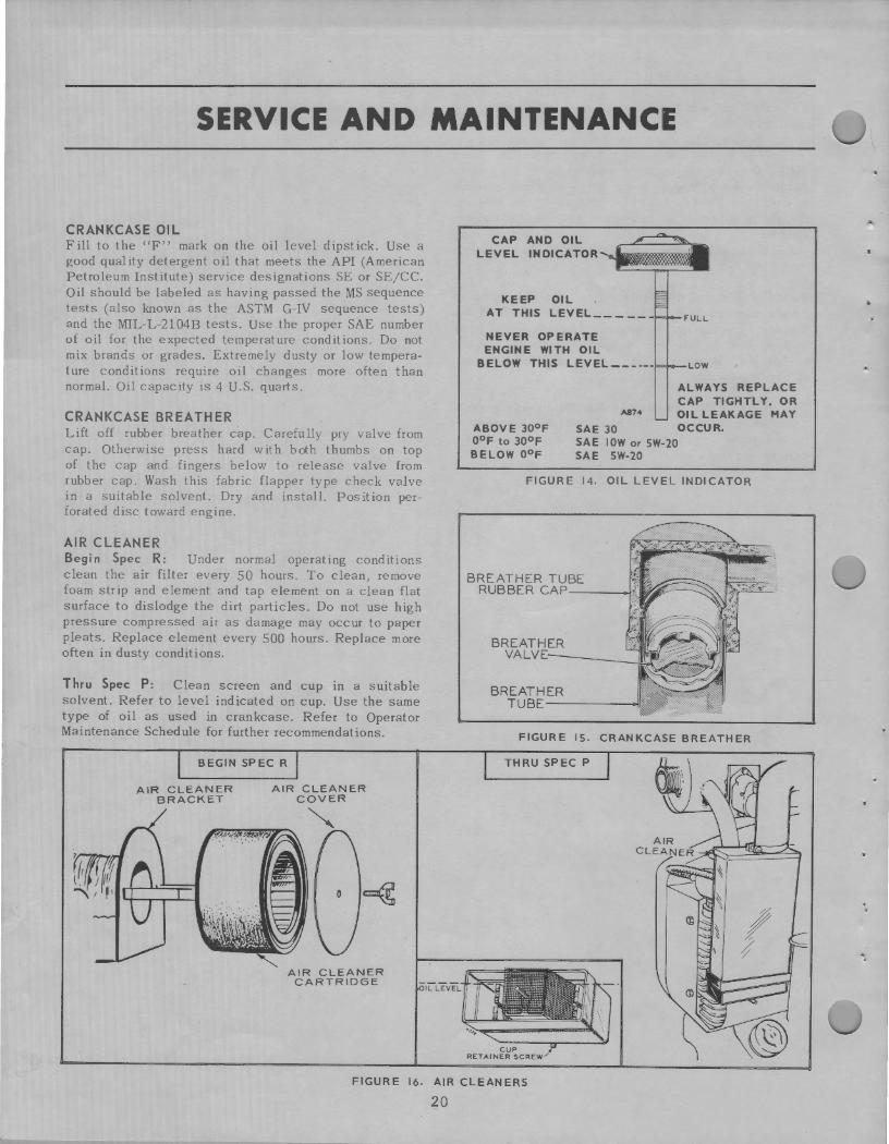
CRANKCASE OIL Fill to the "F" mark on the oil level dipstick. Use a good quality detergent oil that meets the API (American Petroleum Institute) service designations SE or SE/CC. Oil should be labeled as having passed the MS sequence tests (also known as the ASTM G-IV sequence tests) and the MIL-L-2104B tests. Use the proper SAE number of oil for the expected temperature conditions. Do not mix brands or grades. Extremely dusty or low temperature conditions require oil changes more often than normal. Oil capacity is 4 U.S. quarts.
CRANKCASE BREATHER Lift off rubber breather cap. Carefully pry valve from cap. Otherwise press hard with both thumbs on top of the cap and fingers below to release valve from rubber cap. Wash this fabric flapper type check valve in a suitable solvent. Dry and install. Position perforated disc toward engine.
AIR CLEANER Begin Spec R: Under normal operating conditions clean the air filter every SO hours. To clean, remove foam strip and element and tap element on a clean flat surface to dislodge the dirt particles. Do not use high pressure compressed air as damage may occur to paper pleats. Replace element every 500 hours. Replace more often in dusty conditions.
Thru Spec P: Clean screen and cup in a suitable solvent. Refer to level indicated on cup. Use the same type of oil as used in crankcase. Refer to Operator Maintenance Schedule for further recommendations.
BEGIN SPEC R
AIR CLEANER BRACKET
AIR CLEANER COVER
""
AIR CLEANER CARTRIDGE
CAP AND OIL LEVEL INDICATOR
KEEP OIL AT THIS LEVEL ____ _
NEVER OPERATE ENGINE WITH OIL
BELOW THIS LEVEL------
F"ULL
LOW
ALWAYS REPLACE CAP TIGHTLY, OR
ASH OIL LEAKAGE HAY ABOVE 30°F 0°F to 30°F BELOW 0°F
SAE 30 OCCUR. SAE IOW or SW-20 SAE SW-20
FIGURE 14. OIL LEVEL INDICATOR
BREATHER VALVE.-----
BREATHER TUBE-----.
FIGURE IS. CRANKCASE BREATHER
THRU SPEC P
FIGURE 16. AIR CLEANERS
20
:
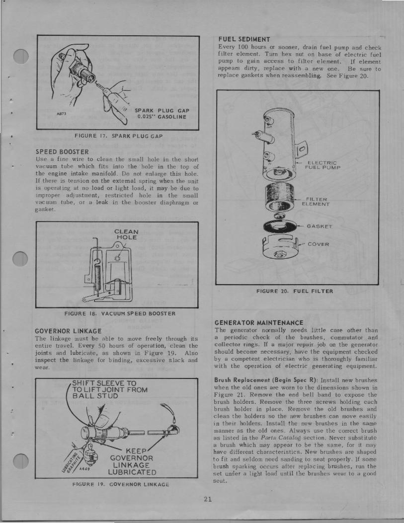
SPARK PLUG GAP 0.025" GASOLINE
FIGURE 17. SPARK PLUG GAP
SPEED BOOSTER Use a fine wire to clean the small hole in the short vacuum tube which fits into the hole in the top of the engine intake manifold. Do not enlarge this hole. If there is tension on the external spring when the unit is operating at no load or light load, it may be due to improper adjustment, restricted hole in the small vacuum tube, or a leak in the booster diaphragm or gasket.
CLEAN HOLE
FIGURE 18. VACUUM SPEED BOOSTER
GOVERNOR LINKAGE The linkage must be able to move freely through its entire travel. Every SO hours of operation, clean the joints and lubricate, as shown in Figure 19. Also inspect the linkage for binding, excessive slack and wear.
SH I FT SLEEVE TO TO LI FT JOI NT FROM BALL STUD
FIGURE 19. GOVERNOR LINKAGt:
21
FUEL SEDIMENT Every 100 hours or sooner, drain fuel pump and check filter element. Turn hex nut on base of electric fuel pump to gain access to filter element. If element appears dirty, replace with a new one. Be sure to replace gaskets when reassembling. See Figure 20.
ELECTRIC FUECPUMP
FILTER ELEMENT
FIGURE 20. FUEL FILTER
GENERATOR MAINTENANCE The generator normally needs little care other than a periodic check of the brushes, commutator and collector rings. If a major repair job on the generator should become necessary, have the equipment checked by a competent electrician who is thoroughly familiar with the operation of electric generating equipment.
Brush Replacement (Begin Spec R): Install new brushes when the old ones are worn to the dimensions shown in Figure 21. Remove the end bell band to expose the brush holders. Remove the three screws holding each brush holder in place. Remove the old brushes and clean the holders so the new brushes can move easily in their holders. Install the new brushes in the same manner as the old ones. Always use the correct brush as listed in the Parts Catalog section. Never substitute a brush which may appear to be the same, for it may have different characteristics. New brushes are shaped to fit and seldom need sanding to seat properly. If some brush sparking occurs after replacing brushes, run the set under a light load until the brushes wear to a good seat.
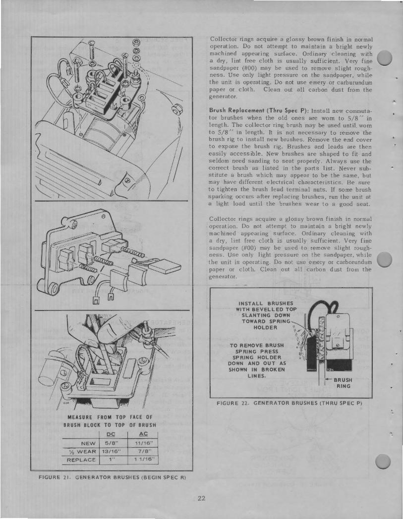
MEASURE FROM TOP FACE OF BRUSH BLOCK TO TOP OF BRUSH
DC AC
NEW 5/8" 11/16"
½ WEAR 13/16" 7/8"
REPLACE 1" 1 1 /16"
FIGURE 21. GENERATOR BRUSHES (BEGIN SPEC R)
22
Collector rings acquire a glossy brown finish in normal operation. Do not attempt to maintain a bright newly machined appearing surface. Ordinary cleaning with a dry, lint free cloth is usually sufficient. Very fine sandpaper (#00) may be used to remove slight roughness. Use only light pressure on the sandpaper, while the unit is operating. Do not use emery or carburundum paper or cloth. Clean out all carbon dust from the generator.
Brush Replacement (Thru Spec P): Install new commutator brushes when the old ones are worn to 5/8" in length. The collector ring brush may be used until. worn to 5/8" in length. It is not necessary to remove the brush rig to install new brushes. Remove the end cover to expose the brush rig. Brushes and leads are then easily accessible. New brushes are shaped to fit and seldom need sanding to seat properly. Always use the correct brush as listed in the parts list. Never substitute a brush which may appear to be the same, but may have different electrical characteristics. Be sure to tighten the brush lead terminal nuts. If some brush sparking occurs after replacing brushes, run the unit at a light load until the brushes wear to a go_od seat.
Collector rings acquire a glossy brown finish in normal operation. Do not attempt to maintain a bright newly machined appearing surface. Ordinary cleaning with a dry, lint free cloth is usually sufficient. Very fine sandpaper (#00) may be used to remove slight roughness. Use only light pressure on the sandpaper, while the unit is operating. Do not use emery or carborundum paper or cloth. Clean out all carbon dust from the generator.
INSTALL BRUSHES WITH BEVELLED TOP
SLANTING DOWN TOWARD SPRING
HOLDER
TO REMOVE BRUSH SPRING PRESS
SPRING HOLDER DOWN AND OUT AS SHOWN IN BROKEN
LINES. I BRUSH RING
FIGURE 22. GENERATOR BRUSHES (THRU SPEC P)
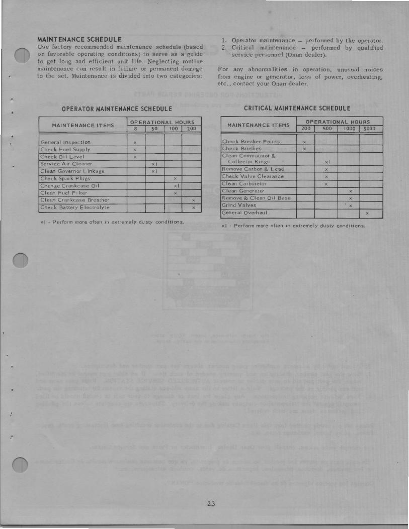
. .
MAINTENANCE SCHEDULE Use factory recommended maintenance schedule (based on favorable operating conditions) to serve as a guide to get long and efficient unit life. Neglecting routine maintenance can result in failure or permanent damage to the set. Maintenartce is divided into two categories:
OPERATOR MAINTENANCE SCHEDULE
MAINTENANCE ITEMS OPERATIONAL HOURS
8 so 100 I 200
General Inspection X
Check Fuel Supply X
Check Oi I Level X
Service Air Cleaner XI
Clean Governor Linkage XI
Check Spark Plugs X
Change Crankcase Oi I xi Clean Fuel Filter X
Clean Crankcase Breather X
Check Battery Electrolyte X
xi - Perform more often in extremely dusty conditions.
23
1. Operator maintenance - performed by the operator. 2. Critical maintenance - performed by qualified
service personnel (Onan dealer).
For any abnormalities in operation, unusual noises from engine or generator, loss of power, overheating, etc., contact your Onan dealer.
CRITICAL MAINTENANCE SCHEDULE
MAINTENANCE ITEMS OPERATIONAL HOURS
200 500 1000 5000
Check Breaker Points X
Check Brushes X
Clean Commutator & Collector Rings xi
Remove Carbon & Lead X
Check Valve Clearance X
Clean Carburetor X
Clean Generator X
Remove & Clean Oi I Base X
Grind Valves X
General Overhaul X
xi - Perform more often in extremely dusty conditions .

PARTS CATALOG
INSTRUCTIONS FOR ORDERING REPAIR PARTS
For parts or service, contact the dealer from whom you purchased this equipment or refer to your Nearest Authorized Onan Parts and Service Center.
To avoid errors or delay in filling your parts order, please furnish all information requested.
Always refer to the nameplate on your unit: 1. Always give the MODEL and SPEC NO. and SERIAL NO.
For handy reference, insert YOUR plant nameplate information in the spaces above.
2. Do not order by reference number or group number, always use part number and description. 3. Give the part number, description and quantity needed of each item. If an older part cannot be identified,
return the part prepaid to your dealer or nearest AUTHORIZED SERVICE STATION. Print your name and address plainly on the package. Write a letter to the same address stating the reason for returning the parL
4. State definite shipping instructions. Any claim for loss or damage to your unit in transit should be filed promptly against the transportation company making the delivery. Shipments are complete unless the packing list indicates items are back ordered.
Prices are purposely omitted from this Parts Catalog due to the confusion resulting from fluctuating costs, import duties, sales taxes, exchange rates, etc.
For current parts prices, consult your Onan Dealer, Distributor or Parts and Service Center.
''En esta lista de partes los precios se omiten de proposito, ya que bastante confusion resulto de fluctuaciones de los precios, derechos aduanales, impuestos de venta, cambios extranjeros, etc."
Consiga los precios vigentes de su distribui.dor de productos "ONAN".
24
. .
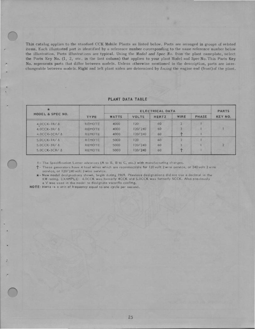
This catalog applies to the standard CCK Mobile Plants as listed below. Parts are arranged in groups of related items. Each illustrated part is identified by a reference number corresponding to the same reference number below the illustration. Parts illustrations are typical. Using the Model and Spec No. from the plant nameplate, select the Parts Key No. (1, 2, etc. in the last column) that applies to your plant Model and Spec No. This Parts Key No. represents parts that differ between models. Unless otherwise mentioned in the description, parts are interchangeable between models. Right and left plant sides are determined by facing the engine end (front) of the plant.
PLANT DATA TABLE
* ELECTRICAL DATA MODEL & SPEC NO.
TYPE WATTS VOLTS HERTZ WIRE PHASE
4.0CCK-1 R/ .t. REMOTE 4000 120 60 2 I
4.0CCK-3R/ i REMOTE 4000 120/240 60 3 I
4.0CCK-3CR/ .t. REMOTE 4000 120/240 60 t I
5.0CCK-1 R/ .t. REMOTE 5000 120 60 2 I
5.0CCK-3R/ .t. REMOTE 5000 120/ 240 60 3 I
5.0CCK-3CR/ i REMOTE 5000 120/ 240 60 t I
.t.- The Specification Letter advances (A to B, B to C, etc.) with manufacturing changes.
t- These generators have 4 load wires which are reconnectible for 120volt 2wire service, or 240volt 2wire service, or 120/ 240volt 3wire service.
•- New model designations shown, begin during 1969. Previous designations did not use a decimal in the KW rating. EXAMPLE: 4.0CCK was formerly 4CCK and 5.0CCK was formerly 5CCK. Also previously a V was used in the model to d~signate vacu-flo cooling.
NOTE: Hertz is a unit of frequency equal to one cycle per second .
25
PARTS
KEY NO.
I
2
~ 33
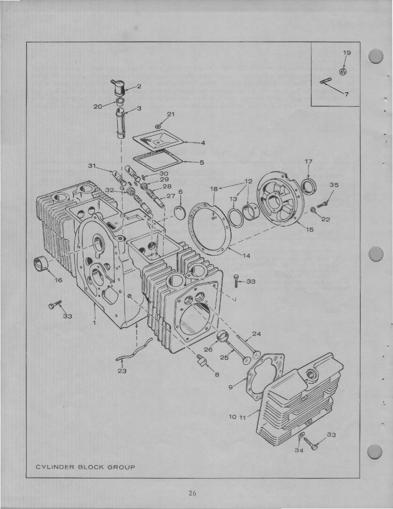
CYLINDER BLOCK GROUP
26
f 33 34v
•
' '
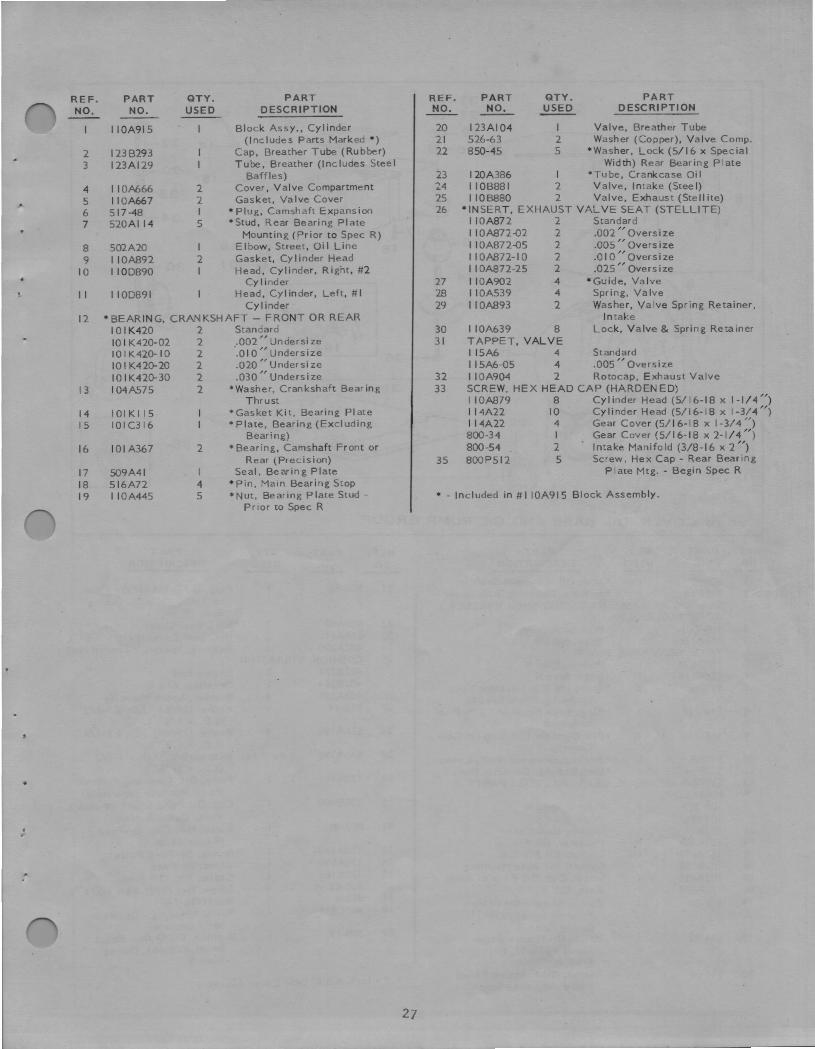
REF. NO.
2 3
4 5 6 7
8 9
10
11
12
13
14 15
16
17 18 19
PART QTY. PART NO. USED DESCRIPTION
I IOA915 Block Assy., Cylinder (Includes Parts Marked•)
123B293 Cap, Breather Tube (Rubber) 123Al29 Tube, Breather (Includes Steel
Baffles) I IOA666 2 Cover, Valve Compartment I IOA667 2 Gasket, Va Ive Cover 517-48 I • Plug, Camshaft Expansion 520AI 14 5 •Stud, Rear Bearing Plate
Mounting (Prior to Spec R) 502A20 I Elbow, Street, Qi I Line I IOA892 2 Gasket, Cylinder Head 1100890 I Head, Cylinder, Right, #2
Cy I ind er 1100891 Head, Cylinder, Left, # I
Cylinder • BEARING, CRANKSHAFT - FRONT OR REAR
IOIK420 2 Standard 10 I K420-02 2 .002" Undersi ze IOIK420-IO 2 .QI O,, Under size 10 I K420-20 2 .020,, U ndersi ze IOIK420-30 2 .030,, Unders i ze I04A575 2 •washer, Crankshaft Bearing
Thrust I 01 Kl 15 •Gasket Kit, Bearing Plate IOIC316 •Plate, Bearing (Excluding
Bearing) IOI A367 2 • Bearing, Camshaft Front or
Rear (Precision) 509A41 Seal, Bearing Plate 516A72 4 •Pin, Main Bearing Stop I IOA445 5 •Nut, Bearing Plate Stud -
Prior to Spec R
27
REF. PART QTY. PART NO. NO. USED DESCRIPTION
20 I 23AI04 I Valve, Breather Tube 21 526-63 2 Washer (Copper), Valve Comp. 22 850-45 5 •washer, Lock (5/16 x Special
Width) Rear Bearing Plate 23 I 20A386 I •Tu be, Crankcase Qi I 24 I IOB88I 2 Valve, Intake (Steel) 25 110B880 2 Valve, Exhaust (Ste I I ite) 26 • INSERT, EXHAUST VAL VE SEAT (STELLITE)
I IOA872 2 Standard I IOA872-02 2 .002,, Oversize I IOA872-05 2 .005,, Oversize I IOA872-IO 2 .O IO,, Oversize I IOA872-25 2 .025,, Oversize
27 I IOA902 4 •Guide, Valve 28 I IOA539 4 Spring, Va Ive 29 I IOA893 2 Washer, Valve Spring Retainer,
Intake 30 I IOA639 8 Lock, Valve & Spring Retainer 31 TAPPET, VALVE
I15A6 4 Standard I I 5A6-05 4 .005" Oversize
32 I IOA904 2 Rotocap, Exhaust Valve 33 SCREW, HEX HEAD CAP (HARDEN ED)
I IOA879 8 Cylinder Head (5/16-18 x 1-1/4") 1I4A22 10 Cylinder Head (5/16-18 x 1-3/4") 114A22 4 Gear Cover (5/ 16-18 x 1-3/ 4 ") 800-34 I Gear Cover (5/16-18 x 2-1/4 ") 800-54 2 Intake Manifold (3/8-16 x 2")
35 800P512 5 Screw, Hex Cap - Rear Bearing Plate Mtg. - Begin Spec R
• - Included in # I IOA915 Block Assembly.

3
13
37-@ 27--@>
4 ------- 29--@ \. . ~ 26--.®
. I --~-.
\ 7
,2
22
_A17-£ 25 y 18
24-{] 2s-<::)
L36 .!/4R, . 19A 39
/-,4 32-t ~1~ 20--@
33~
34~
35ii] GEAR COVER, BASE AND OIL PUMP GROUP
REF. PART QTY. PART REF. PART QTY. PART
NO. NO. USED DESCRIPTION NO. NO. USED DESCRIPTION
I 509P8 *Seal, Oil -Governor Shaft 2 510Pl3 I *Bearing, Governor Shaft Upper
21 505-56 Plug, Oi I Drain ( I /2) - Prior
*SHAFT & ARM ASSEMBLY, GOVERNOR (INCLUDES to Serial #355651, During
ADJUSTABLE CLIP) Spec R
3 150-710 I Prior to Spec N 22 509A40 I *Seal, Gear Cover
4 I 50AI 286 I Begin Spec N 23 5I6AI I 2 Pin, Gear Cover (5/16 x 1/8")
•YOKE, GOVERNOR SHAFT 24 402A290 4 Bushing, Spacer, Vibration Mour
5 150A620 I Prior to Spec N 25 CUSHION, VIBRATION
6 150BI 187 I Begin Spec N 402B283 2 Engine End
7 815-46 2 *Screw (#8-32) - Governor Yoke 402B284 2 Generator End
Mounting- Begin Spec N 26 402A282 4 Snubber, Shock Mounting
8 518-129 *Ring, Yoke Retainer "E" - Prior 27 526-14 4 Washer (29/64" I.D. x 1-1/2"
to Spec N 28
O.D. x 1/8")
9 516-130 *Pin, Governor Cup Stop (In Gear 526Al95 4 Washer (29/64" I.D. x 3-1/4"
Cover) 29 526Al98
O.D. X 1 /8 ")
10 5I0A8 * Bearing, Governor Sh aft, Lower As Req. Washer (5/8" I.D. x 1-1/2"
11 510Pl4 I * Bal I, Bearing, Governor Shaft O.D. x I /16")
12 COVER ASSEMBLY, GEAR (INCLUDES PARTS 30 I20A49l Pump; Oi I, Complete (Internal
MARKED*) Parts Not Sold Separately)
I 03-207 Prior to Spec N 31 I 20B400 Cup, Oi I Pump Intake (Includes
103A357 Begin Spec N Pipe, Cup & Screen)
13 103BI I Gasket, Gear Cover 32 801-48 Screw, Hex Cap, By-Pass
14 I 23A489 Indicator, Oil Fill (Replaces Stud)
15 I23Al9I Gasket, Oil Fill Cap 33 I20Al40 Spring, By-Pass Valve
16 102B 158 Gasket, Oi I Base Mounting 34 I20A398 Valve, By-Pass
17 I02A455 4 Screw, Cap, Oil Base to Block 35 I20Kl6 I Gasket Kit, Oil Pump 18 I 02A579 I Base, Oi I 36 800-82 4 Screw, Hex (7/16-14 x 3-3/4")
19 505-50 I Elbow, Street - Oi I Drain -37 862-4 4 Nut (7/16-14)
Prior to Serial #355651, 38 403C933 I Plate, Mounting - Generator
During Spec R 39 505-19 Set - Optional
19A 504-92 Valve, Oi I Drain - Begin Bushing, Oi I Drain - Begin
Serial #355651, During Serial #355651, During
Spec R Spec R
20 526-66 Washer, Oil Pressure Relief Valve Adjusting Screw * - Included in Gear Cover Assembly.
28

6
1
j @
a-13 \,>11 , I
17
5 23
26
Ti 4
22
CRANKSHAFT, FLYWHEEL, CAMSHAFT AND PISTON GROUP
REF. PART QTY. PART REF. PART QTY. PART
NO. NO. USED DESCRIPTION NO. NO. USED DESCRIPTION
I I S0A78 I Ring, Camshaft Center Pin 14 ROD, CONNECTING
2 CUP, GOVERNOR I I4C98 2 Standard
I50A6I2 I Prior to Spec N I I4C98-I0 2 .0Io"undersize
I50BI 116 I Begin Spec N I I 4C98-20 2 .020,, Under size
3 5I0P 15 10 Ba 11, Governor Fly II4C98-30 2 .030,, Undersize
4 I 34A9I I I Plate, Blower Wheel - Prior to 15 RING SET, PISTON
Spec N I I3Al52 2 Standard
5 I34B565 Wheel, Blower I I3Al52-I0 2 .0 IO,, Oversize
6 I 05-353 Gear Set, Timing (Includes I I3Al52-20 2 .020,, Oversize
Camshaft & Crankshaft Gears) I I 3AI 52-30 2 .030,, Oversize
7 I05A4 Washer, Camshaft Gear Thrust I I3A 152-40 2 .040 ,, Oversize
8 515-1 Key, Camshaft Gear Mounting 16 I I0A284 4 Screw, Connecting Rod Cap
• 9 105-140 Camshaft (Includes Center Pin) 17 I I4A59 4 Washer, Connecting Rod Cap r 10 ISOA75 I Pin, Camshaft Center Screw Lock
11 PISTON & PIN (Includes Retainer Rings) 18 I92A83 Rope, Manual Starting
I I2A7I 2 Standard 19 526Al7 Washer, Whee I Mounting
I I2A7 I-I0 1 .0 IO,, Oversize 20 515-2 Key, Wheel Mounting
I I2A7I-20 2 .020,, Oversize 21 I04Al70 Screw, Whee I Mounting
I I 2A7 l-30 2 .030,, Oversize 22 I92B272 Sheave, Rope
I I2A7I-40 2 .040,, Oversize 23 I04D499 Flywheel
12 PIN, PISTON 24 518-14 Lock, Crankshaft Gear Washer
I I2A69 2 Standard 25 104A43 Washer, Crankshaft Gear Ret.
I I 2A69-02 2 .002,, Oversize 26 I04D578 Crankshaft
13 I I2A3 4 Ring, Piston Pin Retainer 27 515-1 Key, Crankshaft Gear Mounting
29
1-34
1i"40 32 31
1
43 42
~QtOt 41
w ... 2 /4 - " • .A
13 .• 11 ! .'.;··.·.•.·· 3 '-,:
I ,· I I
,.._._23
c:Qs,• 21
®-22 26
! ,~.:c4.J .... ;l.)
27
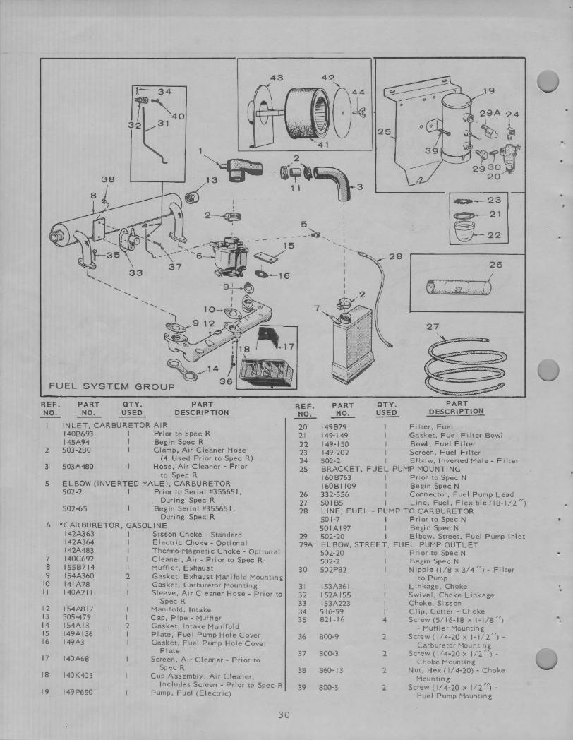
FUEL SYSTEM
REF. NO.
I
2
3
5
PART NO.
QTY. USED
PART DESCRIPTION
INLET, CARBURETOR AIR 140B693 I Prior to Spec R I 45A94 I Begin Spec R 503-280 I Clamp, Air Cleaner Hose
503A480 (4 Used Prior to Spec R)
Hose, Air Cleaner - Prior to Spec R
ELBOW (INVERTED MALE), CARBURETOR 502-2 I PriortoSerial#355651,
502-65 During Spec R
Begin Serial #35565 I, During Spec R
6 *CARBURETOR, GASOLINE
7 8 9
10 II
12 13 14 15 16
17
18
19
142A363 I Sisson Choke - Standard I 42A364 I Electric Choke - Option al 142A483 I Thermo-Magnetic Choke - Option al 140C692 I Cleaner, Air - Prior to Spec R 155B714 I Muffler, Exhaust 154A360 2 Gasket, Exhaust Manifold Mounting 141A78 I Gasket, Carburetor Mounting 140A21 I I Sleeve, Air Cleaner Hose - Prior to
154A817 I 505-479 I 154Al3 2 149AI 36 I 149A3 I
140A68
140K403
149P650
Spec R Manifold, Intake Cap, Pipe - Muffler Gasket, Intake Manifold Plate, Fuel Pump Hole Cover Gasket, Fuel Pump Hole Cover
Pl ate Screen, Air Cleaner - Prior to
Spec R Cup Assembly, Air Cleaner,
Includes Screen - Prior to Spec R Pump, Fuel (Electric)
30
REF.
~ 20 21 22 23 24 25
26 27 28
29 29A
30
31 32 33 34 35
36
37
38
39
PART
~ QTY.
~ PART
DESCRIPTION
149B79 Filter, Fuel 149-149 Gasket, Fue! Filter Bowl 149-150 Bowl, Fuel Filter 149-202 Screen, Fuel Filter 502-2 I Elbow, Inverted Male- Filter BRACKET, FUEL PUMP MOUNTING 160B763 I Prior to Spec N 160BI 109 I Begin Spec N 332-556 I Connector, Fuel Pump Lead 501B5 I Line, Fuel,Flexible(l8-l / 2") LINE, FUEL - PUMP TO CARBURETOR 501-7 I P ri ortoSpecN 501Al97 I Begin Spec N 502-20 I Elbow, Street, Fuel Pump Inlet ELBOW, STREET, FUEL PUMP OUTLET 502-20 I Prior to Spec N 502-2 Begin Spec N 502P82 Nipple (I / 8 x 3/4 ") - Filter
153A361 152A 155 153A223 516-59 821-16
800-9
800-3
860-13
800-3
I I I I 4
2
2
2
2
to Pump Linkage, Choke Swivel, Choke Linkage Choke, Sisson Clip, Cotter - Choke Screw (5/ 16- 18 x 1-1 / 8 ")
- Muffler Mounting Screw(l/4-20 x 1-1 / 2'') -
Carburetor Mounting Screw ( 1/4-20 x 1/ 2 ") -
Choke Mounting Nut, Hex (1/4-20) - Choke
Mounting Screw ( I/ 4-20 x 1/2 ") -
Fuel Pump Mount ing
4
.
REF. NO.
PART NO.
40 Bl 5-104 41 I40B495
42 140A 1153
QTY. USED
PART DESCRIPTION
Screw, Set (B-32 x 5/ 16 ") Cartridge, Air Cleaner - Begin
Spec R Cover, Air Cleaner - Begin
Spec R
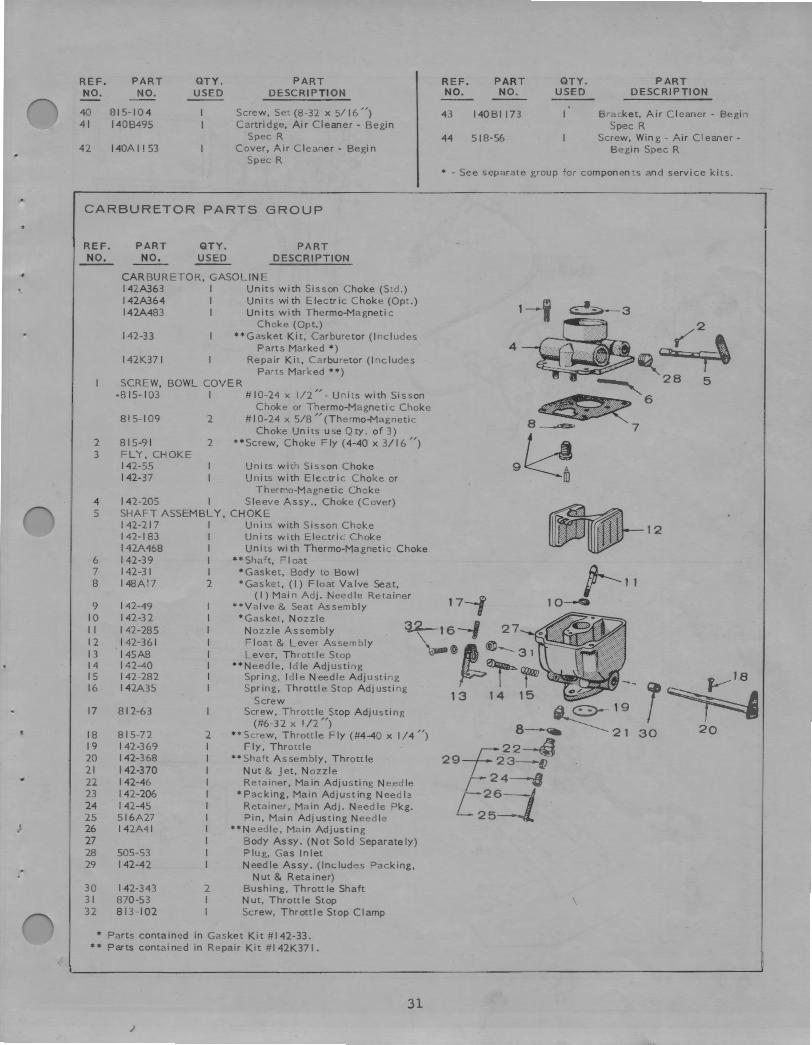
CARBURETOR PARTS GROUP
REF. NO.
2 3
4 5
6 7 8
9 10 II 12 13 14 15 16
17
18 19 20 21 22 23 24 25 26 27 28 29
30 31 32
PART NO,
QTY. USED
PART DESCRIPTION
CARBURETOR, GASOLINE 142A363 I Units with Sisson Choke (Std.) 142A364 I Units with Electric Choke (Opt.) 142A483 I Units with Thermo-Magnetic
Choke (Opt.) 142-33 **Gasket Kit, Carburetor (Includes
Parts Marked *) 142K37 I Repair Kit, Carburetor (Includes
Parts Marked • *) SCREW, BOWL COVER
•B 15-103 I #10-24 x 1/2" - Units with Sisson Choke or Thermo-Magnetic Choke
Bl 5-109 2 # I 0-24 x 5/8 ,, (Thermo-Magnetic Choke Units use Qty. of 3)
815-91 2 **Screw, Choke Fly (4-40 x 3/16 ") FLY, CHOKE 142-55 Units with Sisson Choke 142-37 Units with Electric Choke or
Thermo-Magnetic Choke 142-205 I Sleeve Assy., Choke (Cover) SHAFT ASSEMBLY, CHOKE 142-217 I Units with Sisson Choke 142-183 I Units with Electric Choke I42A468 I Un its with T'hermo-Magnetic Choke 142-39 I ••Shaft, FI oat 142-31 I • Gasket, Body to Bowl 148Al7 2 *Gasket, (I) Float Valve Seat,
(I) Main Adj. Needle Retainer 142-49 **Valve & Seat Assembly 142-32 *Gasket, Nozzle 142-285 Nozzle Assembly 142-361 Float & Lever Assembly I45A8 Lever, Throttle Stop 142-40 **Needle, Idle Adjusting 142-282 Spring, Idle Needle Adjusting 142A35 Spring, Throttle Stop Adjusting
Screw 812-63 Screw, Throttle Stop Adjusting
(#6-32 x I /2 ") 815-72 2 **Screw, Throttle Fly (#4--40 x 1/4 ") 142-369 I Fly , Throttle 142-368 I **Shaft Assembly, Throttle 142-370 I Nut & Jet, Nozzle 142-46 I Retainer, Main Adjusting Needle 142-206 I *Packing, Main Adjusting Needle 142--45 I Retainer, Main Adj. Needle Pkg. 516A27 I Pin, Main Adjusting Needle 142A41 I **Needle, Main Adjusting
I Body Assy. (Not Sold Separately) 505-53 I Plug, Gas Inlet 142-42 I Needle Assy. (Includes Packing,
Nut & Retainer) 142-343 2 Bushing, Throttle Shaft 870 -53 I Nut, Throttle Stop 813 - 102 I Screw, Throttle Stop Clamp
• Parts contained in Gasket Kit # 142-33. •• Parts contained in Repair Kit # I 42K371.
31
)
REF. NO.
PART NO.
43 140BI 173
44 518-56
QTY. USED
PART DESCRIPTION
Bracket, Air Cleaner - Begin Spec R
Screw, Wing - Air Cleaner -Begin Spec R
• - See separate group for components and service kits.
4
1-j ~2
~- ~~ ~ 28 5
~6 8--..a:s, 7 gk! ~ 12 ~v-
t----11 10-0
f--'18 r~ 30 20
IGNITION GROUP 22 6
15~
32 30
~7----16
9 12 5
.•
~31
~281? / 29
14~ 24 ~ '.
32

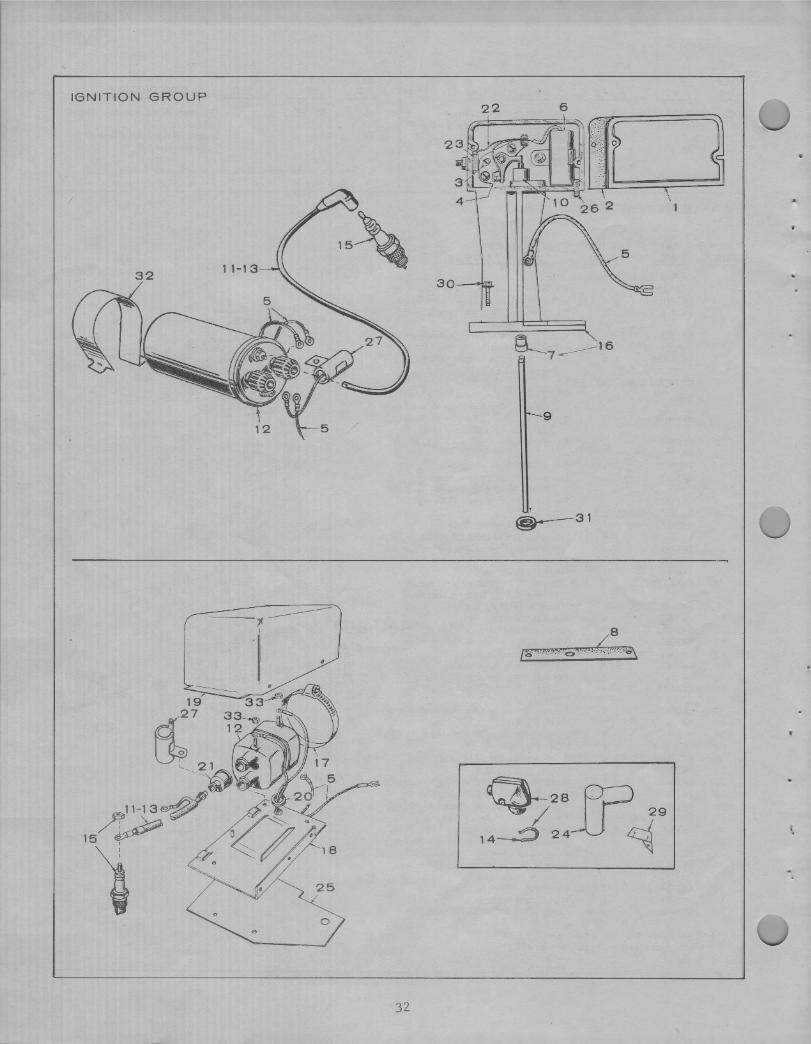
REF. PART QTY. PART REF. PART QTY. PART NO. NO. USED DESCRIPTION ~ NO. USED DFSCRIPTION
I 160A930 Cover, Breaker Box 17 503P514 I Clamp, Ignition Coil - Prior to
2 160AIS0 Gasket, Breaker Box Cover Spec R
3 160A75 Pi vet , Break er Arm 18 I66B383 Bracket, Ignition Coil - Prior
4 160A2 Point Set, Breaker to Spec R
5 334-28 Lead (4ft. Piece of Bulk Wire) 19 I66C385 Cover, Ignition Coil - Prior to
6 312A69 I Condenser, Breaker Box (.3 Mfd.) Spec R
7 BUSHING, BREAKER BOX 20 508P I 14 Grommet, Ignition Coil Mounting . 160A929 I Prior to Spec R Bracket - Prior to Spec R
160A1041 I Begin Spec R 21 160A558 2 Nipple, Ignition Coi I Rubber 8 160A43 I Gasket, Breaker Box Mounting - - Pr ior to Spec R
Prior to Spec R 22 160A428 Strap, Point Set to Breaker Box 9 160A723 I Plunger, Breaker Terminal Block
10 DIAPHRAGM, PLUNGER 23 160A349 I Block & Terminal, Breaker Box
• 160A263 I Prior to Spec R 24 166P250 2 Cover, Spark Plug {Optional) -160AI 143 I Begin Spec R Prior to Spec R
II CABLE, SPARK PLUG LEFT 25 166A466 Bracket, Coi I Mounting Adapter I67A1467 I Prior to Spec R (13 ") - Prior to Spec R 167Al520 I Begin Spec R (7-1 /2 ") 26 160A261 I Wick, Breaker Box
12 COIL, IGNITION 27 CONDENSER, IGNITION 166C346 I Prior to Spec R 312Al62 I Prior to Spec R 166B535 I Begin Spec R 312A27 I Begin Spec R
13 CABLE, SPARK PLUG RIGHT 28 167A67 2 Shie Id, Spark Plug ( Includes I67AI468 I Prior to Spec R (21-1/2 ") Clamp & Shield) - Prior to 167AISS7 I Begin Spec R (14-1/2") Spec R
14 L67A64 2 Clamp, Spark Plug Shield - 29 166BS 19 I Bracket, Timing - Begin Spec N Prior to Spec R 30 8 ISP357 2 Screw, and Shakei:>roof Washer
15 167-24 I 2 Plug, Spark Breaker Box Mounting
16 BOX ASSEMBLY, IGNITION BREAKER (COMPLETE) 31 160AI040 Gasket, Breaker Box Mounting -
160A963 I Prior to Spec R Begin Spec R
160AI 135 I Begin Spec R 32 166B588 I Clamp, Coi I - Begin Spec R 33 870-53 2 Nut, Hex ( I 0-32)
33
18
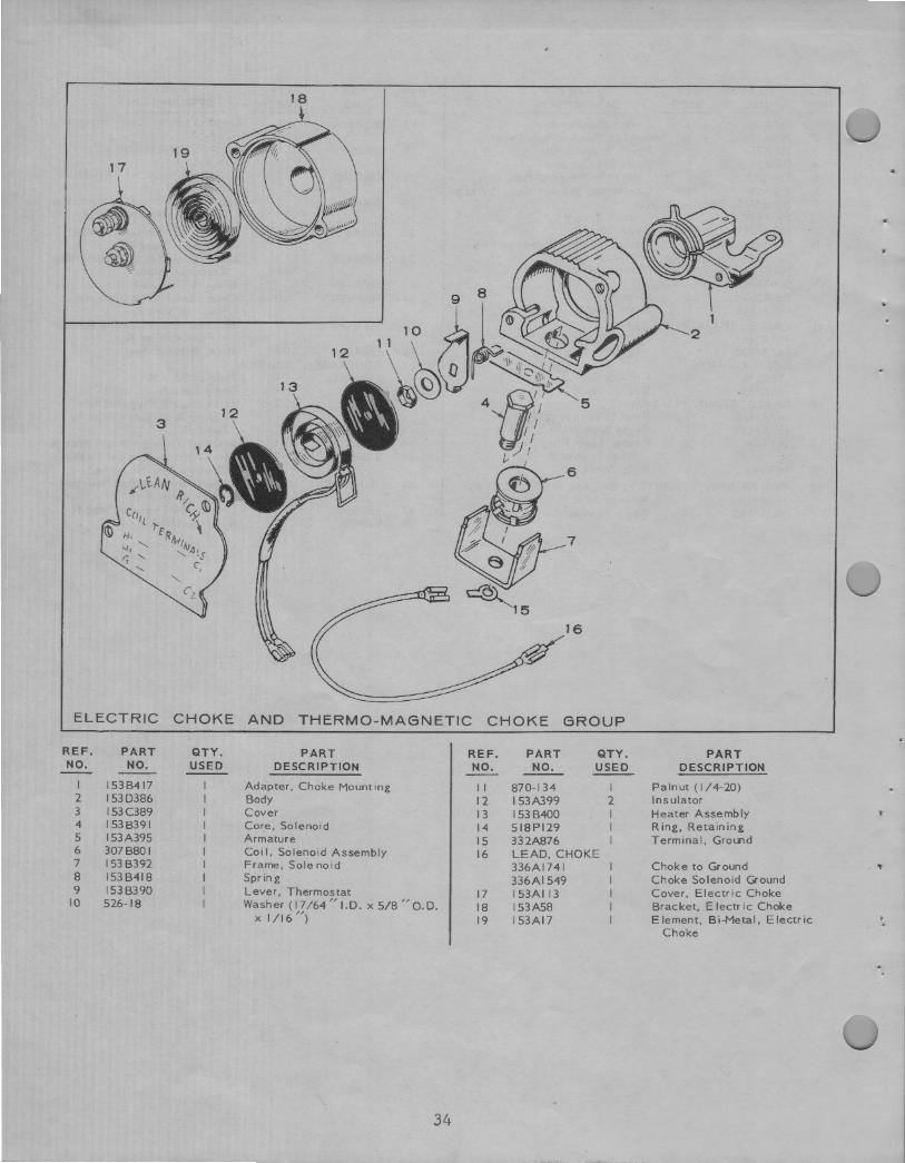
ELECTRIC CHOKE AND THERMO-MAGNETIC CHOKE GROUP
REF. PART QTY. PART REF. PART QTY. PART NO. NO. USED DESCRIPTION NO. NO. USED DESCRIPTION
I 153B417 Adapter, Choke Mounting 11 870-134 I Palnut (1/4-20) 2 1530386 Body 12 I 53A399 2 Insulator 3 153C389 Cover 13 153B400 I Heater Assembly 4 153B391 Core, Solenoid 14 518Pl29 I Ring, Retaining 5 I 53A395 Armature 15 332A876 I Terminal, Ground 6 307B801 Coi I, Solenoid Assembly 16 LEAD.CHOKE 7 I 53 B392 Frame, Solenoid 336Al741 Choke to Ground 1
8 153B418 Spring 336AI 549 Choke Solenoid Ground 9 153B390 Lever, Thermostat 17 153AI 13 Cover, Electric Choke
10 526-18 Washer(l7/64"1.D. xS/8"0.D. 18 I 53A58 Bracket, Electric Choke X 1/16") 19 153Al7 Element, Bi-Metal, Electric
Choke
34
1 1
13
t'J 12
10
/ 24
ama~
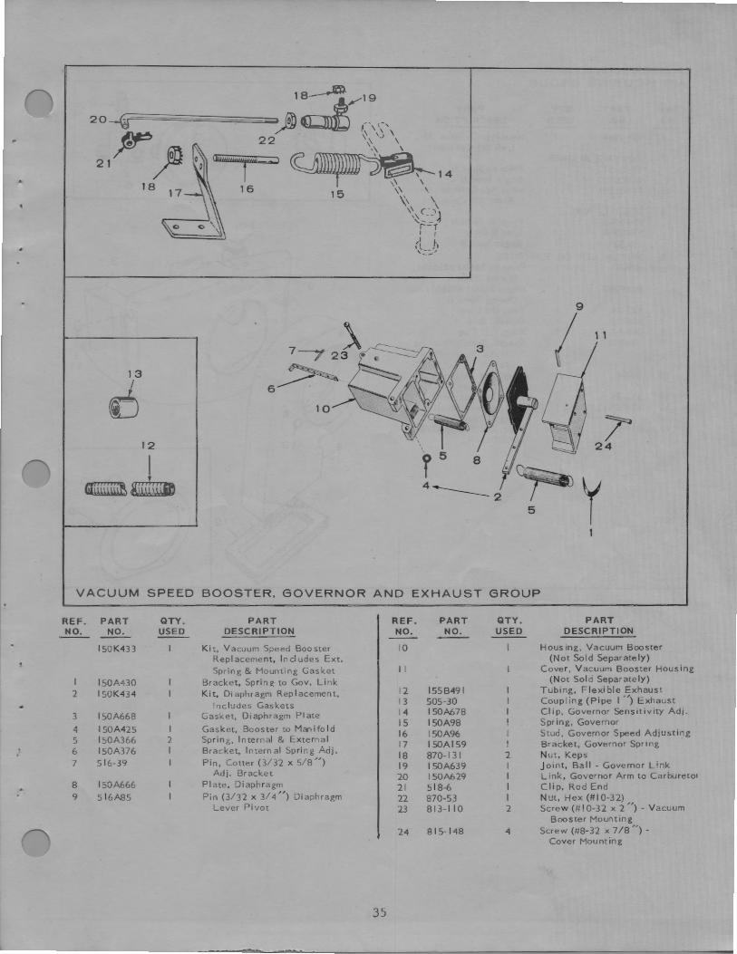
VACUUM SPEED BOOSTER, GOVERNOR AND EXHAUST GROUP
REF. PART QTY. PART REF. PART QTY. PART NO. NO. USED DESCRIPTION NO. NO. USED DESCRIPTION
150K433 Kit, Vacuum Speed Booster 10 Housing, Vacuum Booster Replacement, Includes Ext. (Not Sold Separately)
Spring & Mounting Gasket 11 Cover, Vacuum Booster Housing
I l50A430 Bracket, Spring to Gov. Link (Not Sold Separately)
2 I 50K434 Kit, Diaphragm Replacement, 12 l55B491 I Tubing, Flexible Exhaust
Includes Gaskets 13 505-30 I Coupling (Pipe I " ) Exhaust .. 14 150A678 I Clip, Governor Sensitivity Adj.
3 150A668 Gasket, Diaphragm Plate 15 150A98 I Spring, Governor
4 150A425 I Gasket, Booster to Manifold 16 150A96 I Stud, Governor Speed Adjusting 5 l50A366 2 Spring, Internal & External
17 I SOAl59 I Bracket, Governor Spring 6 150A376 I Bracket, Internal Spring Adj.
18 870-131 2 Nut, Keps 7 516-39 Pin, Cotter (3/ 32 x 5/ 8 ") 19 I 50A639 I Joint, Bal I - Governor Link
Adj. Bracket 20 150A629 I Link, Governor Arm to Carbureto1 8 150A666 Plate, Diaphragm 21 518-6 I Clip, Rod End 9 516A85 Pin (3/ 32 x 3/ 4") Diaphragm 22 870-5~ I Nut, Hex (# 10-32)
L ever Pivot 23 813-110 2 Screw (# I 0-3 2 x 2 ") - Vacuum Booster Mounting
24 815- 148 4 Screw (#8-32 x 7 /8 ") -Cover Mounting
35
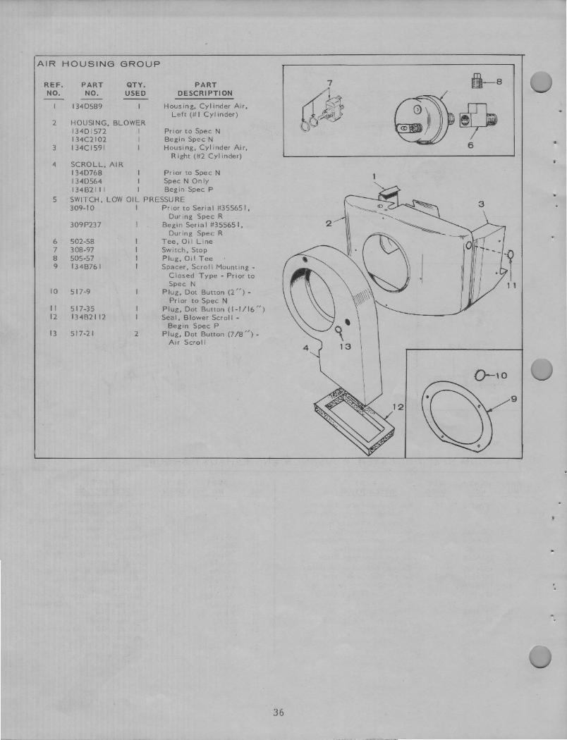
AIR HOUSING GROUP
REF. NO.
2
3
4
5
6 7 8 9
10
11 12
13
PART NO.
134D589
QTY. USED
HOUSING, BLOWER I34D 1572 I 134C2I02 I 134Cl59I I
SCROLL, AIR
PART DESCRl PTI ON
Housing, Cylinder Air, Left (# I Cylinder)
Prior to Spec N Begin Spec N Housing, Cylinder Air,
Right (#2 Cylinder)
I 34D768 Prior to Spec N I 34DS64 Spec N Only 134 B2I I I I Beg in Spec P
SWITCH, LOW OIL PRESSURE 309-10 I PriortoSerial#35S651,
309P237
502-58 308-97 505-57 I 34B761
S 17-9
517-3S 134B2112
517-21 2
During Spec R Begin Serial #355651,
During Spec R Tee, Oil Line Switch, Stop Plug, Oil Tee Spacer, Scroll Mounting -
Closed Type - Prior to Spec N
Plug, Dot Button (2") -Prior to Spec N
Plug, Dot Button (1-1/16") Seal, Blower Scroll -
Begin Spec P Plug, Dot Button (7 /8 ") -
Air Scroll
i-s
@~ 6
3
Q-10
·o 0
9
36
0
D
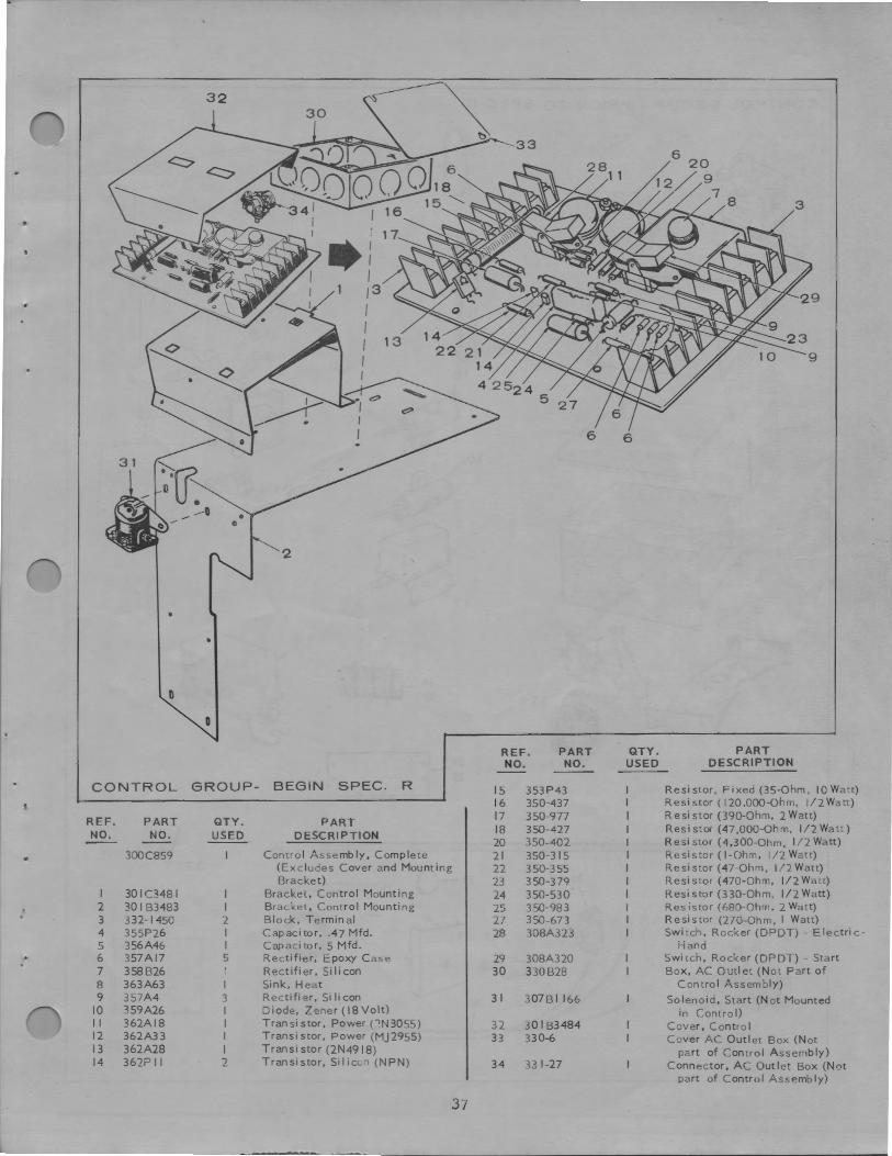
REF. PART QTY. PART NO. NO. USED DESCRIPTION
CONTROL GROUP- BEGIN SPEC. R 15 353P43 Resistor, Fixed (35-Ohm, IO Watt) 16 350-437 Resistor ( I20,000-0hm, l/2Watt)
REF. PART QTY. PART 17 350-977 R esi star (390-Ohm, 2 Watt)
NO. NO. USED DESCRIPTION 18 350-427 Resistor (47,000-Ohm, l/2Watt) 20 350-402 Resi star (4,300-Ohm, 1/2 Watt)
300C859 Control Assembly, Complete 21 350-315 Resistor ( I-Ohm, 1/2 Watt) (Excludes Cover and Mounting 22 350-355 Resistor (47-Ohm, l/2Watt) Bracket) 23 350-379 Resi star (470-Ohm, 1/2 Watt)
I 301C3481 I Bracket, Control Mounting 24 350-530 Resi star (330-Ohm, 1 /2 Watt) . 2 30 I B3483 I Bracket, Control Mounting 25 350-983 Res is tor (680-Ohm. 2 Watt) . 3 332-1450 2 Block, Term in al 27 350-673 Resistor (270-Ohm, I Watt) 4 355P26 I Capacitor, .47 Mfd. 28 308A323 Switch, Rocker (DPDT) - Electric -5 356A46 I Capacitor, 5 Mfd. Hand 6 357A17 5 Rectifier, Epoxy Case 29 308A320 Switch, Rocker (DPDT) - Start 7 358B26 Rectifier, Silicon 30 330B28 Box, AC Outlet (Not Part of 8 363A63 I Sink, Heat Control Assembly) 9 357A4 3 Rectifier, Si Ii con 31 307BI 166 Solenoid, Start (Not Mounted
10 359A26 I Diode, Zener (18Volt) in Control) 11 362A18 I Transistor, Power (,N3055) 32 30 I B3484 Cover, Control 12 362A33 I Transi star, Power (MJ2955) 33 330-6 Cover AC Outlet Box (Not 13 362A28 I Transi star (2N49I8) part of Control Assembly) 14 362P 11 2 Transistor, Sil i c<..7 (NPN) 34 33 1-27 Connector, AC Out let Box (Not
part of Control Assembly)
37

CONTROL G ROUP
2
9
5
19 28
' ~ ~
12
0
- PRIOR TO SPEC R
14
22
_-::;;,·:.,. ., 0
21--~ .. , 0
Oe, '
.•,•,·.·.·-·-:-:-·f :· . . . :.,.,'. -.-.-.·.·-·-·--:-.-:-.-;-:-f --.-.
26_.., '!•
27 ··~ . 6
-·-·-···;_.:. :.\._.;.·.·-·. ........... ····· ': .. J .·::1· ;.;.;( ~
35 / 31-0
~ ,,M ~ •L:JJ
~32-0 36
38
37~
0
0
...... ......... Mz o
o,.
23
...
REF. PART QTY. PART REF. PART QTY. PART NO. NO. USED DESCRIPTION NO. NO. USED DESCRIPTION
307B64:.t. Relay. Choke - Prior to Spec N 19 332AS37 Block, Terminal - Remote Control 2 30 I B2722 Relay & Terminal Block - Prior 20 SOLENOID, START
to Spec N 30781046 I Prior to Spec N BRACKET, CONTROL MOUNTING 307B845 I Begin Spec N
3 301BI 198 I Prior to Spec N 21 332-142 As Req. Terminal, Solderless 4 30 I 83227 I Begin Spec N STRIP, MARKER (LOAD TERMINAL) - PRIOR
COVER, CONTROL BOX TO SPEC N 5 301Cl244 I Prior to Spec N 22 332AS40 120V 6 30 I B3102 Begin Spec N 23 332A539 120/ 240 V (Non-Reconnectible)
BOX, CONTROL 24 332A435 I I 2Q/240 V ( Reconnecti ble) 7 30 I B2723 I Prior to Spec N 25 STRIP, MARKER (REMOTE) 8 30 I D3228 Begin Spec N 332A763 I 120/240 V ( Re conn ecti bl e) -
• 9 30181271 Plate, Control Box End - Prior to Spec N Prior to Spec N 332A566 Al I - Begin Spec N
10 308P I 54 Switch, Start-Stop 26 332A609 Block, Terminal (2 Place) -11 302AS8 Ammeter, Charge - Pri or to Prior to Spec N
Spec N 27 332A23 I Block, Terminal (Load) -12 3078253 Relay, Stop 120/ 240 V (Non-Reconnecti bl e) 13 RESISTOR, FIXED - Prior to Spec N
304A25 I I 30-Ohm, 5 Watt 28 332A254 Block, Terminal (Load) -304A344 I-Ohm, 24 Watt (3/ 4 x 2 ") 120/ 240 V (Reconn ectible) -304A60 1.72-Ohm, 25 Watt (9/ I 6 x 2 ") Prior to Spec N
- (Ignition) 29 416A77 2 Cable, Battery (28 ") 14 304Al75 Resistor, Adjustable (I-Ohm) 30 416A4 Cab le, Battery Jumper
- (3/ 4 X 4°) 31 517-19 Plug, Dot Button ( 1/ 2 ") -IS CONDENSER (0.1 Mfd.), LOAD TERMINAL Prior to Spec N
SUPPRESSION - PRIOR TO SPEC N 32 508-1 3 Grommet, Rubber - Begin Spec N 3 I 2A58 I 120V 33 3058235 I Rectifier - Begin Spec N 312AS8 2 120/ 240 V (Non-Reconnectible) 34 305A254 Sink, Heat (Rectifier Mounting 3 I 2A58 3 120/ 240 V ( Reconn ecti ble) Bracket) - Begin Spec N
16 3 I 2A57 I Condenser ( I Mfd.) Start 35 308P2 Switch, Toggle (Manual-Electric Solenoid Suppression Start) - Begin Spec N
17 REGULATOR, VOLTAGE (CHARGE CIRCUIT) 36 338B526 Harness, Wiring - Begin Spec N 305AI I Prior to Spec N 37 332A439 2 Jumper, Load Terminal Block -305B383 Begin Spec N I 20/ 240 V ( Reconnecti b I e) -
18 307B180 Relay, Reverse Current - Prior Prior to Spec N to Spec N
t
39
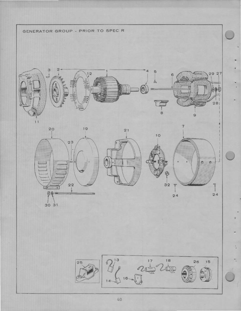
GENERATOR GROUP - PRIOR TO SPEC R
1 1
19
i
30 31
4 5
) l ~ c:i;;.=~~~·.::=1
~ 8
9
7
10
32 l
I
I I I I I I I
J
24 24
0)3 17 18 26 15
[}j/ ~~ ~~ 14--0 16-0 w~
40
..
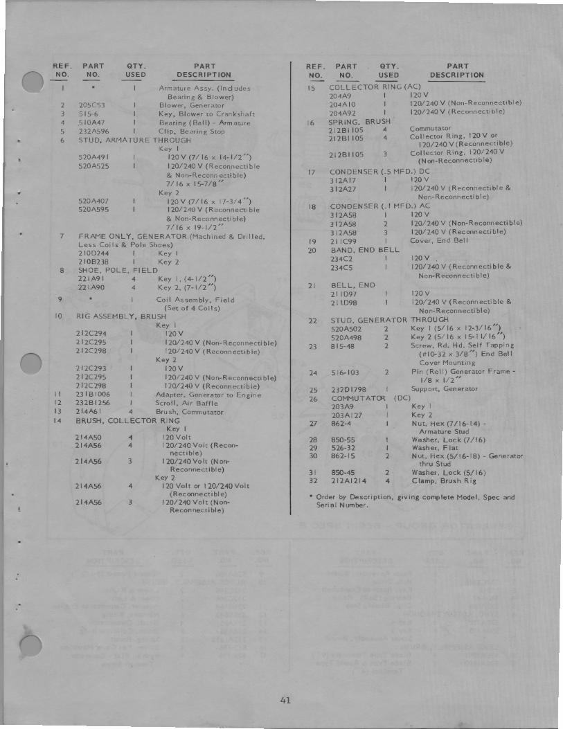
REF. PART QTY. PART REF. PART QTY. PART NO. NO. USED DESCRIPTION NO. NO. USED DESCRIPTION
• Armature Assy. (Includes 15 COLLECTOR RING (AC)
Bearing & Blower) 204A9 I 120V
2 205C53 Blower, Generator 204AI0 120/240 V (Non-Reconnectibl e)
3 515-6 Key, Blower to Cranl<shaft 204A92 120/ 240V (Reconnectible)
4 .5 I0A47 Bearing (Ball) - Armature 16 SPRING, BRUSH 5 232A596 I Clip, Bearing Stop 2I2BI 105 4 Commutator
• 6 STUD, ARMATURE THROUGH 2I2BI 105 4 Collector Ring, 120V or
Key I 120/240 V (Reconnectible)
520A49 I 120 V (7/ 16 x 14- 1/2") 212BI 105 3 Collector Ring, 120/240 V
520A525 I201240V (Reconnectible (N on-Reconnecti b le)
& Non-Reconn ecti ble) 17 CONDENSER (.5 MFD.) DC
7/ 16 X 15-7/ 8,, 3I2Al7 I I20V
.. Key 2 3 I 2A27 I 120/240 V (Reconnectible &
520A407 120V (7 / 16 x 17-.3/ 4") Non-Reconnecti ble)
520A595 I20/ 240V (Reconnectible 18 CONDENSER(. I MFD.) AC
& Non-Reconn ecti ble) 312A58 I 120V
7 / 16 X 19-1 /2,, 312A58 2 120/ 240 V (Non-Reconnectible)
7 FRAME ONLY, GENERATOR (Machined & Drilled, 312A58 3 120/ 240 V (Reconnectible)
Less Coils & Pole Shoes) 19 21 IC99 I Cover, End Bell
2 I0D244 I Key I 20 BAND, END BELL
2 IOB238 I Key 2 234C2 I I20V
8 SHOE, POLE, Fl ELD 234C5 I 120/ 240 V (Reconnectible &
22 IA9 I 4 Key I, (4-1/2") Non-Reconn ecti ble)
221.A90 4 Key 2, (7-1 / 2 ") 21 BELL, END
9 • Coil Assembly, Field 21 ID97 120V
(Set of 4 Coi Is) 21 ID98 120/ 240 V (Reconnectible &
10 RIG ASSEMBLY, BRUSH Non-Reconnecti ble)
Key I 22 STUD, GENERATOR THROUGH
212C29_4 120V 520A502 2 Key I (5/ 16 x 12-.3/ 16")
212C295 120/240 V (Non-Reconnectible) 520A498 2 Key 2 ( 5/ 16 x I 5- I I/ 16 ")
212C298 120/240 V ( Reconn ecti b le) 23 815-48 2 Screw, Rd. Hd. Self Tapping
Key 2 (#10-32 x 3/ 8") End Bell
2 I 2C293 I20V Cover Mounting
2 I 2C295 120/240 V (Non-Reconnecti bl e) 24 516-103 2 Pin (Roll) Generator Frame -
212C298 120/240 V (Reconnectible) i / 8 X 1/2"
11 231 B 1006 Adapter, Generator to Engine 25 232D 1798 Support, Generator
12 232Bl256 Scroll, Air Baffle 26 COMMUTATOR (DC)
13 2l.4A6I 4 Brush, Commutator 203A9 I Key I
14 BRUSH, COLLECTOR RING 203Al27 I Key 2
Key I 27 862-4 I Nut, Hex (7/16-14) -
Armature Stud 214A50 4 120Volt 214A56 4 120/240Volt (Recon-
28 850-55 I Washer, Lock (7/16)
nectible) 29 526-32 I Washer, Flat
214A56 3 120/240 Vo It (Non-30 862-15 2 Nut, Hex (5/16-18) - Generator
thru Stud Reconnectible)
Key 2 31 850-45 2 Washer, Lock (5/ 16)
214A56 4 120 Volt or I 20/240Volt 32 212A1214 4 Clamp, Brush Rig
214A56 (Reconnectible) • Order by Description, giving complete Model Spec and
3 120/240 Volt (Non-• Reconnectible)
Serial Number. '
41
~ ~ 8
~ 811
@---a:i~!).....___9
12
16 30 ~~--
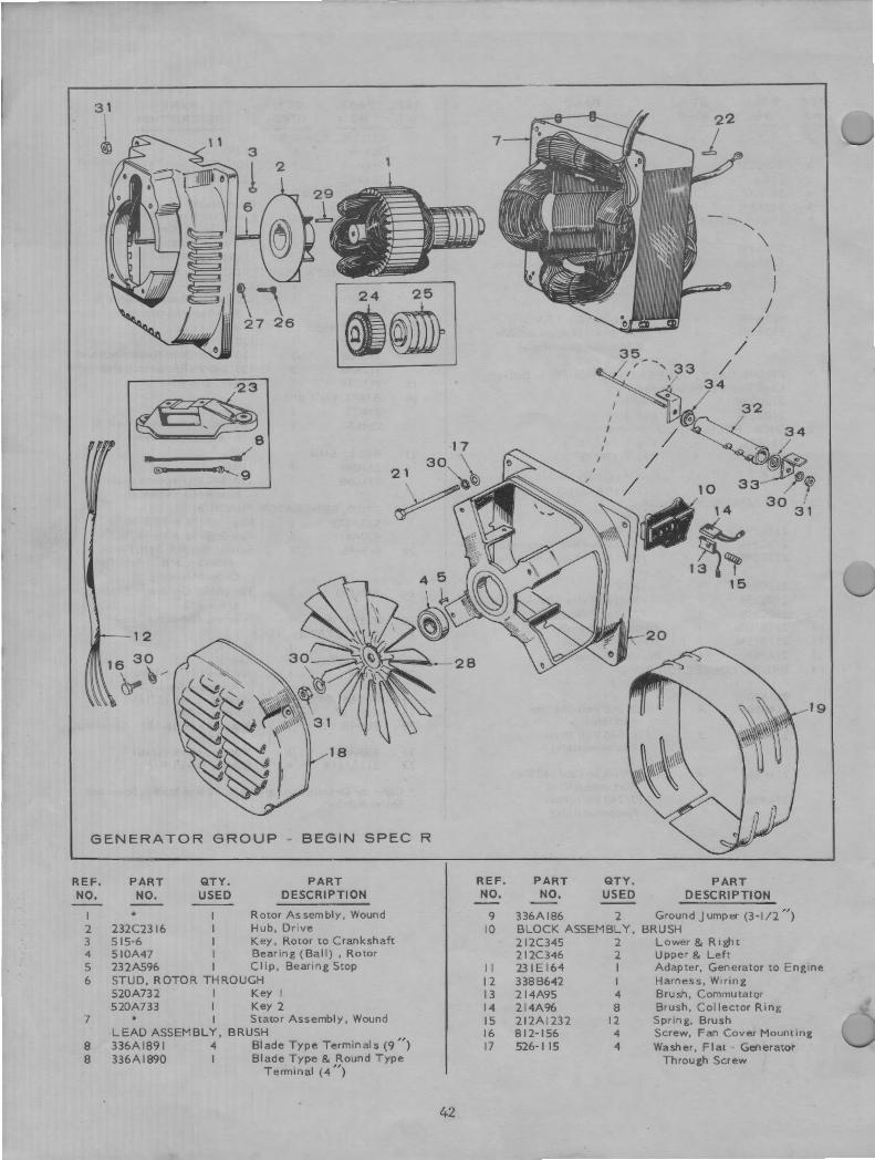
GENERATOR GROUP - BEGIN SPEC R
REF. NO,
PART NO.
QTY. USED
PART DESCRIPTION
I * Rotor Assembly, Wound 2 232C2316 Hub, Drive 3 515-6 Key, Rotor to Crankshaft 4 510A47 Bearing (Ball), Rotor 5 232A596 I Clip, Bearing Stop 6 STUD, ROTOR THROUGH
520A732 I Key I 520A733 I Key 2
7 * I StatorAssembly,Wound LEAD ASS EMBLY, BRUSH
8 336Al891 4 BladeTypeTerminals(9 " ) 8 336Al890 I Blade Type & Round Type
Terminal (4 ")
42
REF. NO.
PART NO,
QTY. USED
PART DESCRIPTION
9 336Al86 2 GroundJumper(3-l / 2 " ) 10 BLOCK ASSEMBLY, BRUSH
2l2C345 2 Lower & Right 2 I 2C346 2 Upper & Left
19
11 23 IE 164 I Adapter, Generator t o Engine 12 3388642 I Harness, Wiring 13 2 I 4A95 4 Brush, Commutator 14 214A96 8 Brush, CollectorR i ng 15 212Al232 12 Spring, Brush 16 812-156 4 Screw, Fan Cover Mounting 17 526-115 4 Washer, Flat - Generator
Through Screw
REF. NO.
18 19 20 21
22
23
• 24 25 26
•
i
..
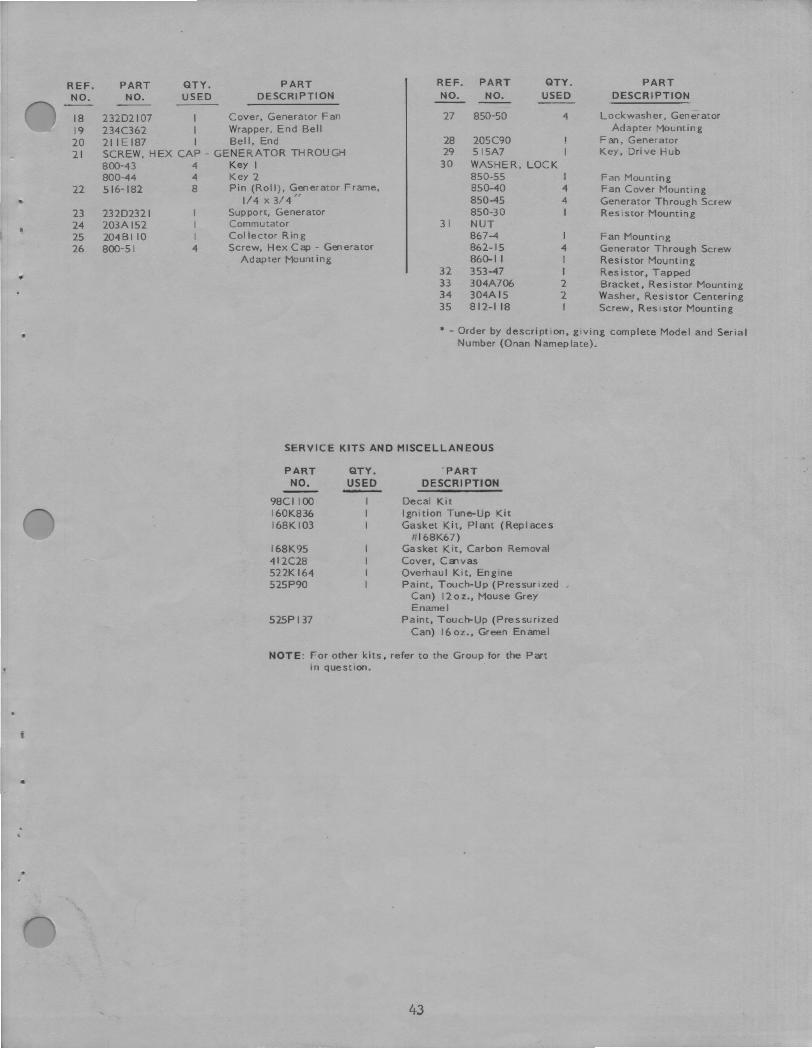
PART QTY. PART REF. PART QTY. PART NO. USED DESCRIPTION NO. NO. USED DESCRIPTION
232D2107 Cover, Generator Fan 27 850-50 4 Lockwasher, Generator
234C362 Wrapper, End Bell Adapter Mounting
21 IE 187 I Bell, End 28 205C90 Fan, Generator SCREW, HEX CAP - GENERATOR THROUGH 29 515A7 Key, Drive Hub
800-43 4 Key I 30 WASHER, LOCK 800-44 4 Key 2 850-55 I Fan Mounting 516-182 8 Pin (Roll), Generator Frame, 850-40 4 Fan Cover Mounting
1/ 4 X 3/ 4,, 850-45 4 Generator Through Screw 232D2321 Support, Generator 850-30 I Resistor Mounting 203Al52 Commutator 31 NUT 204BI 10 I Collector Ring 867-4 I Fan Mounting 800-5 I 4 Screw, Hex Cap - Generator 862-15 4 Generator Through Screw
Adapter Mounting 860-11 I Resistor Mounting 32 353-47 I Resistor, Tapped 33 304A706 2 Bracket, Resistor Mounting 34 304Al5 2 Washer, Resistor Centering 35 812-118 I Screw, Resistor Mounting
• - Order by description, giving complete Model and Serial Number (Onan Nameplate).
SERVICE KITS AND MISCELLANEOUS
PART NO.
98CI 100 160K836 168K 103
l68K95 412C28 522K164 525P90
525P 137
QTY. USED -
PART DESCRIPTION
Decal Kit Ignition Tune-Up Kit Gasket Kit, Plant (Replaces
#168K67) Gasket Kit, Carbon Removal Cover, Canvas Overhaul Kit, Engine Paint, Touch-Up (Pressurized
Can) 12oz., Mouse Grey Enamel
Paint, Touc~Up (Pressurized Can) 16 oz., Green Enamel
NOTE: For other kits, refer to the Group for the Part in question.
43
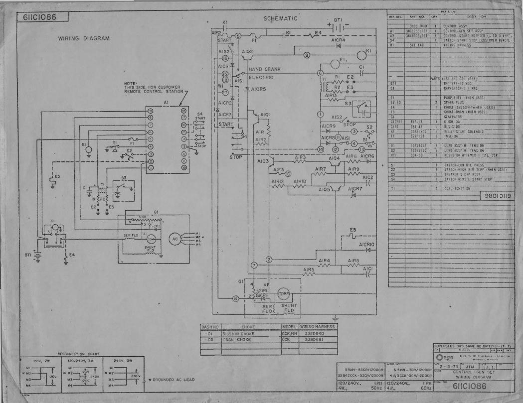
6IIC1086
WIRING DIAGRAM
NOTE• THIS SIDE FOR CUSTOMER
"""' co"'"",'."'"~ ..---------t-<~ © I !® @, S~A~T
r----•-•-1 --
~E~ S3
~ . - :l ~ :~R l_! __ J :. l3
Cl
i(I
BTI .=-. -.
PfC"'<NfCT•ON CHA~T
I20V, 2W
.:~~ ::~
I201240V, lW
'" .. M2~ U)=.1-1 24'ov M4 1:11ov 1
240V. 3\W
.. :;~ Ml 240\,
•I U-4
tr._>---,, -,~
GI ---~
.J I
~ --o-l-=-_ .Jsrtp
l<I l<Z • .. , 1<4
DASH NO
-01
-02
.,. GROUNDED AC LEAD
Kl BTI SCHEMATIC ~II ic;.-. --
1 I~'- - -./\r=- - AICR4 .J
PA.ti \ l'~t
l{f. DfS.' ,.u1 1-jO- -l ~ i------c,r~I. ~-°"--------!
JOOC 1000 i , -t-ccsrHOl ,s,,----cii, r~OL:C[s srris,.,s,...,-------1
CC'1R0l-S1'?l AQ!Pl[R·~:--,-0 ~J••:::; SW:T~H STllH S!OP (CUSICV.[R R£'1·:l'l ,
-IIRING Hl'~( ~S .:..=- --···
___!!_I____ _ I • BllffRY-11 voe -------AICRS
~I ilRTSI l.iST!WC .. G[N < frfJ _ .
Cl I flPACITCR_O.!._MFO _______ _
s"roP
J > AIR!,>
AIR2
--- __=----------([1) ~ ,-AIQ3t.;----~~----AI04.J AIR6 AICRG
ES , --11.r.-- -I AICRIO
2>---------- AIR4 AIRS
El E2. EJ £4-TI
1··· ,~IT-~
I I
I
·Puiiii -ruTi:"71Hc"N usiii '-' -----, SPARf. PLUG - -
('tlQII,( ·.S.l SSON (wHEN_-:u~~[O) . CHO~( ONA~ 1111[ ~ Ul[O) GE~IRll0R - -- ·-OIOJ[ JA -· -- -
R(" '. ICI R[LAY lllRT SOLF>,CI0--·-----7 fUI(_ 9~_-_· ____ : ______ -1
- . l[AO. lSSY.-HI Yr111ioN-l[ lO l\lf HI l!s,,o. --- ----i ~[SISTO? Hll(St.O I Jlif:_::_11!__
SIi TCK-LOJ Oil PRESS ·s111c• HICK liR lf!~1'i"11£~ UlfOI
~' i ~ J BR["[R L ClP a·.s, - -~ ---~ ·!·"~K-R[Y1~[_:_~r-~rcP·----
_!_1____ ___.! _ COll-lCN! !_l_~N--~------<
9801~119
7 ' AICI AIRS
----7
-=-CHOKE MODEL WIRING HARNESS
SISSION CHOKE CCK,NH 33SD640
ONAN CHOKE CCK 338D691
SUPfRSEOS O-~-.i1£NO OAff.('l ti- 11 71
On~ --,----2-1~-n • Jn.t_r . .1 1-1 t
s.5NH-53cn112000RI 6.s~,H-3CR11wooR --~ CONTH"L -c.ui :.~r :i58,,42CCK. - ~:5CR/12000R 4 6.~CCK'..3CR/12000R w,n,,.~G £'1:~r,N~U
120/240V. , 4W.,
I PH I 120/240V., 50Hz 4\V.,
I PH 6('Hz 6IICI086