Schwarzian derivatives and a linearly invariant family in ℂ n
Upload
independentCategory
view
3download
0
Available online at www.sciencedirect.com
Mechanics Research Communications 35 (2008) 361–371
www.elsevier.com/locate/mechrescom
MECHANICSRESEARCH COMMUNICATIONS
Elastic buckling of rectangular plates under linearly varyingin-plane normal load with a circular cutout
M. Aydin Komur, Mustafa Sonmez *
Department of Civil Engineering, School of Engineering, Aksaray University, 68100 Aksaray, Turkey
Received 27 January 2007; received in revised form 12 January 2008Available online 26 January 2008
Abstract
The elastic buckling behavior of rectangular perforated plates was studied by using the finite element method in thisstudy. Circular cutout was chosen at different locations along the principal x-axis of plates subjected to linearly varyingloading in order to evaluate the effect of cutout location on the buckling behavior of plates. The results show that the cen-ter of a circular hole should not be placed at the end half of the outer panel for all loading patterns. Furthermore, thepresence of a circular hole always causes a decrease in the elastic buckling load of plates subjected to bending, even ifthe circular hole is not in the outer panel.� 2008 Elsevier Ltd. All rights reserved.
Keywords: Buckling; Perforated plates; Linearly varying in-plane load; Cutouts; Rectangular plates
1. Introduction
The buckling behavior of plates has been studied by many researchers in structural mechanics for over acentury (Brush and Almroth, 1975; Chajes, 1974; Timoshenko and Gere, 1961). Steel plates are often usedas the main components of steel structures such as ship decks and hulls, platforms on oil rigs, and plateand box girders. Openings in such steel plates may be required to provide access for inspection, maintenance,or simply to reduce weight. However, the presence of such openings in plate elements leads to change in stressdistribution within the member and variations in buckling characteristics of the plate element (Shanmugamet al., 1999). The effects of the shape, size, location and types of applied load on the performance and bucklingbehavior of such perforated plates have been investigated by several researchers over the past two decades.
Shanmugam et al. (1999) presented most of the previous works on the elastic buckling of perforatedplates. They analyzed several uniaxially and biaxially loaded perforated square plates with different bound-ary conditions by using the finite element method (FEM). They proposed a design formula for predictingthe ultimate load capacity of elasto-plastic plates with a rectangular and a circular cutout. They showed that
0093-6413/$ - see front matter � 2008 Elsevier Ltd. All rights reserved.
doi:10.1016/j.mechrescom.2008.01.005
* Corresponding author. Tel.: +90 382 2150953; fax: +90 382 215 0592.E-mail address: [email protected] (M. Sonmez).

362 M. Aydin Komur, M. Sonmez / Mechanics Research Communications 35 (2008) 361–371
an increase in the hole size and slenderness ratio causes a significant loss in the ultimate strength of perforatedplates.
Brown and Yettram (1986, 1987), Brown (1990), Shakerley and Brown (1996) used the conjugate load/dis-placement method (CLDM) to investigate the parameters affecting the stability of perforated plates subjectedto different types of loading. Their results showed that the elastic buckling load of rectangular plates havingrectangular holes decreases under shear loading as the hole size increases. On the other hand, the elastic buck-ling load capacity of plates under uniaxial and/or biaxial compressions may increase as the hole size beyond acertain limit increases (Brown et al., 1987). They also investigated the effects of eccentricity of a rectangularhole on the buckling of a square plate under in-plane uniaxial loading and shear loading. They advised thatsmall square holes be located away from the center of the plate and large square holes be placed at the centerof the plate to minimize the reduction in the elastic bucking load under uniaxial loading. However, they alsostated that the orientation of the perforation to the loading axis has a significant effect on the buckling loadand concluded that the plate buckling load when the major dimension of the rectangular hole running perpen-dicular to the loading axis is larger than that of running parallel to loading axis (Shakerley and Brown, 1996).
Recently, El-Sawy and Nazmy (2001) used the FEM to investigate the effect of plate aspect ratio and holelocation on the elastic buckling load of rectangular plates subjected to uniaxial end compression in their lon-gitudinal direction. They concluded that a perforated square panel that is a part of a rectangular plate can notbe treated as a separate square plate having the perforation. They recommended that a perforation not beplaced in a critical zone defined by the end half of the outer square panel and it must be located in an interiorpanel of the plate.
In the literature a great deal of attention has been focused on studying the elastic buckling of perforatedplates subjected to uniaxial, biaxial and shear loadings, but no work appears related to the effect of the plateaspect ratio and the hole location on the buckling of rectangular plates subjected to linearly varying in-planeloading. The main objective of this paper is, therefore, to investigate the aforementioned effects on rectangularplates containing a circular hole.
2. Problem definition
A rectangular plate containing a circular hole in a Cartesian coordinate system is given in Fig. 1. The platehas length a, width b, thickness t and a circular hole with the diameter d. The plate is subjected to linearlyvarying in-plane loading in the longitudinal direction and all its edges are simply supported in the out-of-planedirection. In other words, there is no lateral edge displacement perpendicular to the plate plane on all fouredges. Three points on the edge at y = �b/2, are restrained from in-plane translation to prevent the plate fromexhibiting rigid body motion. Two of the three points are restrained from translating in the y-direction and thethird restraint is used to prevent the x-direction translation. The location of the third restrain is chosen at theintersection point of the plate longitudinal edge and the section of the hole center (El-Sawy and Nazmy, 2001).
Fig. 1. Geometry and typical mesh of a plate with a circular hole.

-N0
α=0.5 α=1.0 α=1.5 α=2.0-N0
α=0.0
-N0
-N0 -N0
0.5N0-0.5N0
-N0
N0
Fig. 2. Example of in-plane loading Nx along the edge x = 0.
M. Aydin Komur, M. Sonmez / Mechanics Research Communications 35 (2008) 361–371 363
In this study, plate aspect ratios (a/b) are selected to have integer values, i.e. 1, 2, 3 and 4 in order to investigatethe effects of the aspect ratio on the buckling load.
A linearly varying force is subjected to two opposite edges (x = 0 and x = a) as follows:
Nx ¼ �N 0 1� ab
y þ b2
� �� �ð1Þ
where N0 and a are the intensity of the compressive force per unit length and a numerical factor, respectively.Negative sign in Eq. (1) represents compression. By changing a in Eq. (1), different particular cases may beobtained. For instance, if a is set to zero, the uniformly distributed compressive force is obtained. By takinga = 1, the compressive force varies linearly from �N0 at y = �b/2 to zero at y = b/2. For a = 2, pure in-planebending is obtained. The other cases (a = 0.5 and a = 1.5) give a combination of bending and compression. Allloading cases are shown in Fig. 2. For simplicity, hereafter the loading cases of a = 0.0, 0.5 and 1.0 are called‘‘compression”, and a = 1.5 and 2.0 are called ‘‘bending”. The case of a < 0 or a > 2 are not considered be-cause such cases are identical with the cases of 0 6 a 6 2 as far as the edge conditions are the same (Kangand Leissa, 2005; Leissa and Kang, 2002).
3. Finite element analysis procedure
The commercial multipurpose finite element software program ANSYS (2005) was employed in thisresearch. The general-purpose Elastic Shell63 element is used to model the perforated plate because it showssatisfactory performance in verification work previously described by El-Sawy and Nazmy (2001) and El-Sawyet al. (2004). The Elastic Shell63 element has four nodes possessing six degrees of freedom per node.
An irregular discretisation in finite element modeling is employed as shown in Fig. 1 in this study. The meshdensity of the plate was chosen based on the size of a circular hole. The default shell element size was selectedb/20. The shell element size along the hole perimeter was set to the smaller of b/50 or pd/40. The mesh patternwas set-up on the basis of the results achieved in previous numerical studies (El-Sawy and Nazmy, 2001). Thecenter of the circular holes was moved along the x-axis from the plate outer edge xedge = 0.05b + d/2 towardthe center of the plate (xedge = a/2). The material of the plates was assumed to be homogeneous, isotropic andelastic. The material properties for Young’s modulus E = 210 GPa and Poision’s ratio m = 0.3 were selected.
4. Linear buckling analysis
In linear elastic analysis, the load distribution is obtained after it is applied to the model structure, but theload magnitude which the structure can sustain is unknown. In order to determine the maximum load carryingcapacity of the structure, nonlinear analysis or buckling analysis must be employed. In nonlinear analysis,externally applied load is divided into smaller load steps, then these smaller loads are incrementally appliedat each increment and an equilibrium state is searched through iteration. Hence, the maximum load carryingcapacity or instability point(s) of the structure is determined. The second method is the buckling analysis bywhich one may obtain only the critical loads and the corresponding deformation shapes of the modeled

364 M. Aydin Komur, M. Sonmez / Mechanics Research Communications 35 (2008) 361–371
structure. There are two types of buckling analyses: linear and nonlinear. The linear buckling analysis (oreigenvalue analysis) is performed in two steps. The first step is an elastic linear analysis which is performedto determine the internal reactions (initial stresses) in the structure due to externally applied loads. The secondstep is to determine eigenvalues based on the geometric stiffness matrix obtained from the linear analysis. Thelinear buckling analysis will not be suitable if the deformations are not small or if the material shows nonlinearbehavior near collapse. In such cases, the nonlinear buckling analysis, which is a combination of both linearand nonlinear buckling analysis, must be performed. In the present study, the material behavior is assumed tobe linear elastic and deformations compared with the overall dimensions of plate are assumed to be small.Based on the assumptions, the linear buckling analysis is used to determine the critical buckling load of per-forated plates.
ANSYS uses the first and second order terms of strain to generate the stiffness matrixes in the bucklinganalysis. The first term of strain yields the conventional stiffness matrix, K0, and the second term of strainfor the initial stress stiffness matrix, Kr. The initial stress stiffness matrix, Kr, accounting for the effects of exist-ing initial stress, is proportional to the stress level in the plate. The matrix equilibrium equation can beexpressed as
fF g ¼ ð½K0� þ ½Krðkr0Þ�ÞfDg ¼ ð½K0� þ k½Kr�ÞfDg ð2Þ
Initial stress r0 is unknown at the beginning of the analysis. By applying a unit load to the plate, the initialstress reaches to the level of kr0, where k is a scalar multiplier. {F} and {D} are the external load and the cor-responding nodal displacement vector, respectively. At the buckling, the plate displacements increase with noincrease in the external load. Mathematically, this can be defined by
ð½K0� þ k½Krðr0Þ�ÞfdDg ¼ 0 ð3Þ
where {dD} is the incremental nodal displacement vector. The incremental displacement vector {dD} cannotbe zero (Cook et al., 1989); therefore, a non-trivial solution of Eq. (3) is
detð½K0� þ k½Krðr0Þ�Þ ¼ 0 ð4Þ
Calculating the determinant of Eq. (4) gives n-different eigenvalues ki, where n is the dimension of stiffnessmatrix. The lowest eigenvalue k1 corresponds to the critical load level N0 = k1 � r0 � t, where buckling occurs.The associated eigenvectors represent the characteristic mode shapes of the buckled plate.
5. Discussion of results
This section presents the results on the effect of size and location of a circular cutout on the buckling load ofrectangular plates subjected to linearly varying loading. All the results are presented in a normalized form. Forinstance, the elastic buckling load ratio defined in Eq. (5) is used instead of the elastic buckling load
N � ¼ N 0
N cr
ð5Þ
where N0 and Ncr is the elastic critical load of the plate with and without a cutout, respectively. In order toestablish the accuracy of the presented study, the results obtained by ANSYS is compared to those from Kangand Leissa (2005), who obtained these results by using an exact solution procedure based on the infinite powerseries. The non-dimensional buckling load, N �cr obtained by ANSYS along with the corresponding valuesobtained from Kang and Leissa (2005) are listed in Table 1. The non-dimensional buckling load is given as
N �cr ¼ N crb2=D ð6Þ
where D in Eq. (6) is the flexural rigidity of the plate defined by
D ¼ Et3
12ð1� m2Þ ð7Þ

Table 1Non-dimensional buckling load N �cr for different loading cases and aspect ratios
a/b a N�cr
This study Kang and Leissa Ratio
1 0.00 39.42 39.48 0.9981 0.50 52.42 52.49 0.9991 1.00 76.99 77.08 0.9991 1.50 133.15 132.00 1.0091 2.00 250.79 253.00 0.9912 0.00 39.43 39.48 0.9992 0.50 52.43 52.82 0.9932 1.00 77.00 77.21 0.9972 1.50 133.18 132.63 1.0042 2.00 235.16 235.70 0.9983 0.00 39.42 39.48 0.9993 0.50 52.42 52.35 1.0013 1.00 76.99 76.77 1.0033 1.50 133.17 132.34 1.0063 2.00 237.26 237.67 0.998
M. Aydin Komur, M. Sonmez / Mechanics Research Communications 35 (2008) 361–371 365
As mentioned before, default plate thickness t = b/20, Young’s modulus E = 210 GPa and Poision’s ratiom = 0.3 are used in all analyses. There is a good agreement between the two sets of results. The maximum devi-ation was less than 1% and within an acceptable level.
A number of plates with different loading cases (a ranging from 0 to 2), different normalized hole sizes (d/bratios ranging from 0.1 to 0.7), and aspect ratio (a/b ranging from 1 to 4) were analyzed by using finite elementpackage, ANSYS. The results obtained are plotted as shown in Figs. 3–6 for plate aspect ratios of 1,2, 3 and 4,respectively. In all these figures, the variations of the buckling load ratios N* are plotted against the ratio ofthe distance between the plate outer edge and the center of the hole to the plate width (xedge/b). In each of the
0 0.1 0.2 0.3 0.40.4
0.6
0.8
1
(a) Case of α=0
xedge
/b
N*
d/b=0.1d/b=0.2d/b=0.3d/b=0.4d/b=0.5d/b=0.6d/b=0.7
0 0.1 0.2 0.3 0.40.4
0.6
0.8
1
(b) Case of α=0.5
xedge
/b
N*
0 0.1 0.2 0.3 0.40.4
0.6
0.8
1
(c) Case of α=1
xedge
/b
N*
0 0.1 0.2 0.3 0.40.4
0.6
0.8
1
(d) Case of α=1.5
xedge
/b
N*
0 0.1 0.2 0.3 0.40.4
0.6
0.8
1
(e) Case of α=2.0
xedge
/b
N*
Fig. 3. Buckling load ratios N* for a square plate subjected to linearly varying loading (a) a = 0, (b) a = 0.5, (c) a = 1, (d) a = 1.5, (e)a = 2.
0 0.5 1
0.5
1
1.5(a) Case of α=0
xedge
/b
N*
d/b=0.1d/b=0.2d/b=0.3d/b=0.4d/b=0.5d/b=0.6d/b=0.7
0 0.5 1
0.5
1
1.5(b) Case of α=0.5
xedge
/b
N*
0 0.5 1
0.5
1
1.5(c) Case of α=1
xedge
/b
N*
0 0.5 10.4
0.6
0.8
1
1.2(d) Case of α=1.5
xedge
/b
N*
0 0.5 10.4
0.6
0.8
1
1.2(e) Case of α=2.0
xedge
/b
N*
Fig. 4. Buckling load ratios N* for a rectangular plate with aspect ratio of 2 and subjected to linearly varying loading (a) a = 0, (b) a = 0.5,(c) a = 1, (d) a = 1.5, (e) a = 2.
Fig. 5. Critical buckling mode shapes of rectangular plate for d/b = 0.5, a = 0.0 and a/b = 2.
366 M. Aydin Komur, M. Sonmez / Mechanics Research Communications 35 (2008) 361–371
figures, a number of curves are plotted for different values of the normalized hole size (d/b) and each subplot isdevoted to the different loading cases.
Fig. 3 presents the variation of the elastic buckling load ratio of a square plate. It can be seen from thisfigure that increasing normalized hole size (d/b) causes a decrease in the buckling load ratios with the excep-tion of d/b = 0.7 for a = 2.0 (see Fig. 3e). Moving the circular hole along the x-axis affects the buckling loadratios of the square plate in two different ways. The buckling load ratios N* decrease while the small circularholes (i.e. d/b = 0.1–0.3) come close to the center of the square plate. The bending stiffness of the middle por-tion of the plate provides the larger resistance to buckling. As a result, the presence of a circular hole in thatpart of the square plate causes a reduction on the buckling load ratio of the plate. On the other hand, thebuckling load ratios of the plate increase as the large holes (i.e. d/b = 0.5–0.7) are moved toward the centerof the square plate. This is because punching a large hole in the most outer edge of the plate causes a decrease
0 0.5 1 1.5
0.6
0.8
1
(a) Case of α=0.0
xedge
/b
N*
d/b=0.1d/b=0.2d/b=0.3d/b=0.4d/b=0.5d/b=0.6d/b=0.7
0 0.5 1 1.50.4
0.6
0.8
1
(b) Case of α=0.5
xedge
/b
N*
0 0.5 1 1.50.4
0.6
0.8
1
(c) Case of α=1.0
xedge
/b
N*
0 0.5 1 1.50.4
0.6
0.8
1
1.2(d) Case of α=1.5
xedge
/b
N*
0 0.5 1 1.50.4
0.6
0.8
1
1.2(e) Case of α=2
xedge
/b
N*
Fig. 6. Buckling load ratios N* for a rectangular plate with aspect ratio of 3 and subjected to linearly varying loading (a) a = 0, (b) a = 0.5,(c) a = 1, (d) a = 1.5, (e) a = 2.
0 0.5 1 1.5 20.4
0.6
0.8
1
(a) Case of α=0.0
xedge
/b
N*
d/b=0.1d/b=0.2d/b=0.3d/b=0.4d/b=0.5d/b=0.6d/b=0.7
0 0.5 1 1.5 20.4
0.6
0.8
1
(b) Case of α=0.5
xedge
/b
N*
0 0.5 1 1.5 20.4
0.6
0.8
1
(c) Case of α=1.0
xedge
/b
N*
0 0.5 1 1.5 20.4
0.6
0.8
1
1.2(d) Case of α=1.5
xedge
/b
N*
0 0.5 1 1.5 20.4
0.6
0.8
1
1.2(e) Case of α=2
xedge
/b
N*
Fig. 7. Buckling load ratios N* for a rectangular plate with aspect ratio of 4 and subjected to linearly varying loading (a) a = 0, (b) a = 0.5,(c) a = 1, (d) a = 1.5, (e) a = 2.
M. Aydin Komur, M. Sonmez / Mechanics Research Communications 35 (2008) 361–371 367
on the edge stiffness of the plate. Moving the large hole toward the center of plate causes an increase on theedge stiffness. This increases the buckling load ratio. The buckling load ratios N* of square plates with thenormalized hole size of 0.4, 0.3 and 0.1 are almost constant while the holes is moved along the x-axis forthe compression loading cases, a = 1.5 and a = 2.0, respectively.

368 M. Aydin Komur, M. Sonmez / Mechanics Research Communications 35 (2008) 361–371
The buckling load ratios N* of a rectangular plate with the aspect ratio of 2 are given in Fig. 4a–e. Closeobservation of this figure shows clearly that the presence of a small hole (i.e. d/b = 0.1 and 0.2) has no con-siderable effect on the buckling load ratio of the rectangular plate. However, moving the holes with large diam-eter (d/b = 0.5–0.7) along the x-axis causes a significant variation on buckling load ratios N*, this effect is evenmore significant for the compression loading cases. For example the plate having a circular hole, whose centeris at the middle of the plate, can buckle at loads higher than the buckling load for corresponding plates with-out a cutout. Even though this behavior is somewhat counterintuitive at first glance, this has been studied formany years and experimentally verified for isotropic plates (Nemeth, 1996; El-Sawy and Nazmy, 2001). Thebuckled mode shape of the plate may be used to explain such behavior. A solid plate subjected to compressionbuckles in a double half waves, but the presence of large hole at the middle of the plate changes from doublehalf waves to three half waves. Counter plots (lines of constant displacement) of the critical buckling modeshapes are displayed in Fig. 5 for plates having a/b = 2, and d/b = 0.5 and under pure compression. As shownin the figure, the presence of large hole changes the buckling mode shape of the plate having a/b = 2. Thismakes the buckled loads of the rectangular plates with aspect ratio of 2 larger than Ncr for the compressionloading cases. All the buckling load ratios are less than one for the bending loading cases, because there is nochange in the mode shapes while the hole is moved along the x-axis.
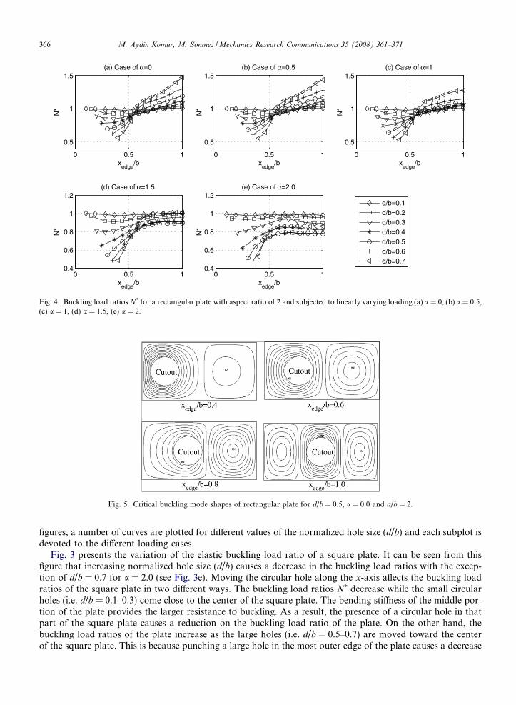
The buckling load ratio N* of rectangular plates with the aspect ratio of 3 and 4 versus xedge/b for all fiveloading cases are depicted in Figs. 6 and 7, respectively. These figures illustrate that for compression loading
0 0.1 0.2 0.3 0.4 0.5 0.60.7
0.8
0.9
1
1.1
1.2
1.3
1.4
1.5
d/b
N*
(a) Case of a/b=2 and xedge
/b=1
α=0.0
α=0.5
α=1.0
α=1.5
α=2.0
0 0.1 0.2 0.3 0.4 0.5 0.60.7
0.75
0.8
0.85
0.9
0.95
1
1.05
1.1
(b) Case of a/b=3 and xedge
/b=1
d/b
N*
0 0.1 0.2 0.3 0.4 0.5 0.60.7
0.75
0.8
0.85
0.9
0.95
1
1.05
1.1
(c) Case of a/b=4 and xedge
/b=1
d/b
N*
0 0.1 0.2 0.3 0.4 0.5 0.60.7
0.75
0.8
0.85
0.9
0.95
1
1.05
1.1
(d) Case of a/b=4 and xedge
/b=2
d/b
N*
xedgexedge
xedge xedge
Fig. 8. Buckling load ratios N* of plates with a cutout lying at a nodal cross line.

M. Aydin Komur, M. Sonmez / Mechanics Research Communications 35 (2008) 361–371 369
cases the location of circular cutouts does not have a considerable effect on the buckling load ratio of rectan-gular plates while xedge/b is larger than around 0.6. For bending loading cases, comparison between the curvesin Figs. 6 and 7d and e and the corresponding ones in Fig. 4d and e show that the buckling behavior of rect-angular plates with aspect ratio of 2, 3 and 4 follow the same trend and explanation is similar to that of pro-vided earlier. Overall, all the buckling load ratios N* in Figs. 3–7 always decrease significantly at the end halfof outer panel for all loading cases. Perforations which lies on xedge/b > �0.6 do not causes the reduction onthe buckling load of rectangular plates subjected to compression while perforations cause a decrease in thebuckling load up to 20% for bending loading cases.
The buckling load ratio of a square plate having a perforation is almost equal to the buckling load of arectangular plate having perforation on the outer panel. It may be interesting to determine the buckling loadratios of rectangular plates having a hole on the middle or edge of the panels. Rectangular plates are consid-ered to consist of square plates, i.e. a rectangular plate having a/b = 3, consists of three square plates. Edgesbetween two neighbor panels are called as nodal cross lines. Fig. 8 shows that the variation in the bucklingload ratios N* as the normalized hole size (d/b) when the center of hole lies on the plate major x-axis at a nodal
0 0.1 0.2 0.3 0.4 0.5 0.60.5
0.6
0.7
0.8
0.9
1
d/b
N*
(a) Case of a/b=1 and xedge
/b=0.5
α=0.0
α=0.5
α=1.0
α=1.5
α=2.0
0 0.1 0.2 0.3 0.4 0.5 0.60.5
0.6
0.7
0.8
0.9
1
(b) Case of a/b=2 and xedge
/b=0.5
d/b
N*
0 0.1 0.2 0.3 0.4 0.5 0.60.5
0.6
0.7
0.8
0.9
1
(c) Case of a/b=3 and xedge
/b=0.5
d/b
N*
0 0.1 0.2 0.3 0.4 0.5 0.60.5
0.6
0.7
0.8
0.9
1
(d) Case of a/b=4 and xedge
/b=0.5
d/b
N*
0 0.1 0.2 0.3 0.4 0.5 0.6
0.6
0.8
1
(e) Case of a/b=3 and xedge
/b=1.5
d/b
N*
0 0.1 0.2 0.3 0.4 0.5 0.6
0.6
0.8
1
(f) Case of a/b=4 and xedge
/b=1.5
d/b
N*
xedgexedge
xedge xedge
xedge xedge
Fig. 9. Buckling load ratios N* of plates with a cutout lying between nodal cross lines.

370 M. Aydin Komur, M. Sonmez / Mechanics Research Communications 35 (2008) 361–371
cross line. It could be seen from these figures that increasing the normalized hole sizes (d/b) increases the buck-ling load ratios N* of plates having a/b = 2 subjected to compression loading. However, size of a hole in thenodal cross line does not cause the reduction of the buckling load ratio of plates having a/b = 3 and a/b = 4.The buckled configuration of simple supported intact plates with aspect ratios of 2, 3 or 4 has two, three orfour half sine waves, respectively under compression loading. The nodal cross lines act as if they are imaginarysupports in the lateral direction. On the other hand, the presence of a hole at the cross line change the bucklingshape of the plate as in Fig. 5. When the loading is bending, the behavior of the perforated plate is somewhatdifferent from that of described above. For bending cases the buckling load ratios decrease as the normalizedhole size increases up to d/b = 0.6. It should be noticed that the plates subjected to bending (a = 1.5 and 2.0)show the worst stability when the normalized hole sizes (d/b) are 0.5 and 0.6, respectively.
Fig. 9 shows the buckling load ratio N* plotted against the normalized hole size (d/b) for various loadingconditions when the center of hole lies on the plate major axis at a point between nodal cross lines. Comparingthe set of curves in Fig. 8 with those in Fig. 9 shows that the buckling load ratios are identical to each otherunder bending. Conversely, as the normalized hole sizes increase, a decrease in the buckling load is observedfor compression loading cases when a cutout is at the outer panel. This means that irrespective of loadingcases, the presence of a hole at the middle of the outer panel always causes a reduction in the elastic bucklingload of the plate based on the hole size.
6. Conclusions and recommendations
The buckling behavior of perforated rectangular plates subjected to linearly varying loading has been stud-ied by the finite element method. Effects of hole size and location on the buckling load of rectangular plateswith aspect ratios of 1 through 4 have been investigated. Based on the findings, the following conclusions andrecommendations have been reached:
� The elastic buckling loads Ncr of a plate having a circular cutout in the end half of the square panel alwaysdecrease significantly for all loading cases; therefore, it is recommended to have no hole in this zone. If ahole in the critical zone is inevitable, the normalized hole size (d/b) should be less than 0.3 in order to havethe buckling load larger than 0.8Ncr.� Small holes (d/b = 0.1) on the plate x-axis have no considerable effect on the buckling load ratio. Hence, the
designers may neglect their presence.� A hole which lies in the outer panel reduces the stability of the plate for all loading cases but it is more
serious for compression cases compared to bending cases. It is, therefore, suggested to locate the centerof the hole in any interior panels for compression loading cases.� For compression loading cases, the location of a hole at any interior panel of a rectangular plate has no con-
siderable effect on the buckling load. For bending cases, the presence of the circular hole with d/b = 0.5 and0.6 causes a reduction on the buckling load up to 20%. Therefore, an extra measure must be taken to avoidthe elastic buckling of plates with hole sizes of 0.5 and 0.6 for bending cases.
Acknowledgements
The authors would like to express their thanks to Karadeniz Technical University for access to the ANSYSsoftware.
References
ANSYS, 2005. User Manual, Version 10.0, Ansys, Inc.Brown, C.J., 1990. Elastic buckling of perforated plates subjected to concentrated loads. Computers and Structures 36 (6), 1103–1109.Brown, C.J., Yettram, A.L., 1986. The elastic stability of square perforated plates under combination of bending, shear and direct load.
Thin-Walled Structures 4 (3), 239–246.Brown, C.J., Yettram, A.L., Burnett, M., 1987. Stability of plates with rectangular holes. Journal of Structural Engineering, ASCE 113 (5),
1111–1116.

M. Aydin Komur, M. Sonmez / Mechanics Research Communications 35 (2008) 361–371 371
Brush, D.O., Almroth, B.O., 1975. Buckling of Bars, Plates and Shells. McGraw-Hill Book Company, New York.Chajes, A., 1974. Principle of Structural Stability Theory. Prentice-Hall, Inc., New Jersey.Cook, M.E., Malkus, D.S., Plesha, M.E., 1989. Concepts and Applications of Finite Element Analysis, third ed. John Wiley & Sons, USA,
441–444.El-Sawy, K.M., Nazmy, A.S., 2001. Effect of aspect ratio on the elastic buckling of uniaxially loaded plates with eccentric holes. Thin-
Walled Structures 39, 983–998.El-Sawy, K.M., Nazmy, A.S., Martini, M.I., 2004. Elasto-plastic buckling of perforated plates under uniaxial compression. Thin-Walled
Structures 42, 1083–1101.Kang, J.H., Leissa, A.W., 2005. Exact solutions for the buckling rectangular plates having linearly varying in-plane loading on two
opposite simply supported edges. International Journal of Solids and Structures 42, 4220–4238.Leissa, A.W., Kang, J.H., 2002. Exact solutions for vibration and buckling of an SS-C-SS-C rectangular plate loaded by linearly varying
in-plane stresses. International Journal of Mechanical Sciences 44, 1925–1945.Nemeth, M., 1996. Buckling and postbuckling behavior of laminated composite plates with a cutout. NASA Technical Paper 3587.
National Aeronautics and Space Administration, Langley Center, Virginia.Shakerley, T.M., Brown, C.J., 1996. Elastic buckling of plates with eccentrically positioned rectangular perforations. International Journal
of Mechanical Sciences 38 (8–9), 825–838.Shanmugam, N.E., Thevendran, V., Tan, Y.H., 1999. Design formula for axially compressed perforated plates. Thin-Walled Structures 34
(1), 1–20.Timoshenko, S.P., Gere, J.M., 1961. Theory of Elastic Stability, second ed. McGraw-Hill, New York.
Copyright © 2022 FDOKUMEN