Unit 2: Lecture 1 Rectangular Waveguides
29
Unit 2: Lecture 1 Rectangular Waveguides
-
Upload
khangminh22 -
Category
Documents
-
view
5 -
download
0
Transcript of Unit 2: Lecture 1 Rectangular Waveguides
Unit 2: Lecture 1
Rectangular Waveguides

➢Wave guides
➢Basic features
➢Rectangular Wave guide
➢Circular Wave guide
➢Advantages
➢Disadvantages
➢Key points about waveguides
CONTENTS
➢ At frequencies higher than 3 GHz, transmission of electromagnetic
energy along the transmission lines and cables becomes difficult.
➢ This is due to the losses that occur both in the solid dielectric needed
to support the conductor and in the conductors themselves.
➢ A metallic tube can be used to transmit electromagnetic wave at the
above frequencies.
BASICS ON WAVEGUIDES

DEFINING A WAVEGUIDE
➢ A Hollow metallic tube of uniform cross section for transmitting
electromagnetic waves by successive reflections from the inner walls
of the tube is called waveguide.

BASIC FEATURES OF A
WAVEGUIDE
➢ Waveguides may be used to carry energy between pieces of
equipment or over longer distances to carry transmitter power to an
antenna or microwave signals from an antenna to a receiver.
➢ Waveguides are made from copper, aluminum. These metals are
extruded into long rectangular or circular pipes.
➢ An electromagnetic energy to be carried by a waveguide is injected
into one end of the waveguide.
➢ The electric and magnetic fields associated with the signal bounce
off the inside walls back and forth as it progresses down the
waveguide.

EM FIELD CONFIGURATION WITHIN THE
WAVEGUIDE
➢ In order to determine the EM field configuration within the
waveguide, Maxwell’s equations should be solved subject to
appropriate boundary conditions at the walls of the guide.
➢ Such solutions give rise to a number of field configurations. Each
configuration is known as a mode. The following are the different
modes possible in a waveguide system.

COMPONENTS OF ELECTRIC AND MAGNETIC
FIELD INTENSITIES IN AN EM WAVE
POSSIBLE TYPES OF MODES
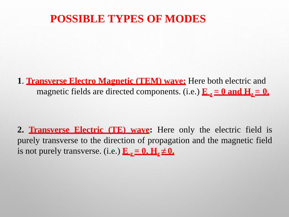
1. Transverse Electro Magnetic (TEM) wave: Here both electric and
magnetic fields are directed components. (i.e.) E z = 0 and Hz = 0.
2. Transverse Electric (TE) wave: Here only the electric field is
purely transverse to the direction of propagation and the magnetic field
is not purely transverse. (i.e.) E z = 0, Hz ≠ 0.
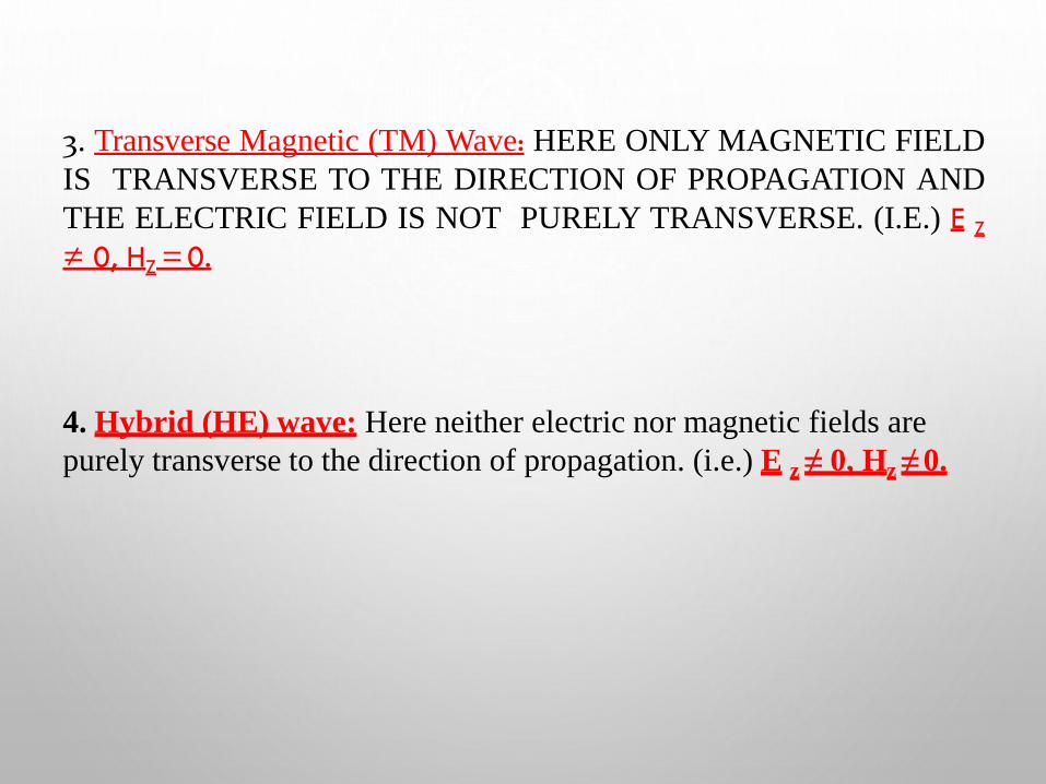
3. Transverse Magnetic (TM) Wave: HERE ONLY MAGNETIC FIELD
IS TRANSVERSE TO THE DIRECTION OF PROPAGATION AND
THE ELECTRIC FIELD IS NOT PURELY TRANSVERSE. (I.E.) E Z≠ 0, HZ=0.
4. Hybrid (HE) wave: Here neither electric nor magnetic fields are
purely transverse to the direction of propagation. (i.e.) E z ≠ 0, Hz ≠ 0.


RECTANGULAR WAVEGUIDES
➢ Any shape of cross section of a waveguide can support
electromagnetic waves of which rectangular and circular waveguides
have become more common.
➢ A waveguide having rectangular cross section is known as
Rectangular waveguide.
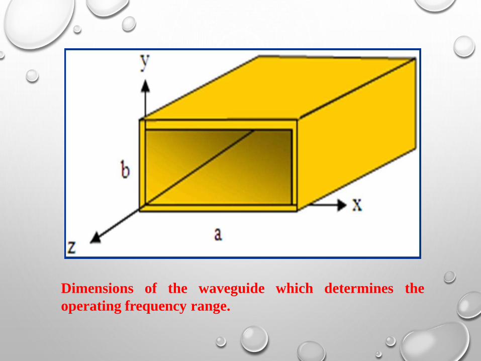
Dimensions of the waveguide which determines the
operating frequency range.
DIMENSIONS OF THE WAVEGUIDE WHICH DETERMINES THE
OPERATING FREQUENCY RANGE:
1. The size of the waveguide determines its operating frequency range.
2. The frequency of operation is determined by the dimension ‘a’.
3.This dimension is usually made equal to one – half the wavelength at
the lowest frequency of operation, this frequency is known as the
waveguide cutoff frequency.
4.At the cutoff frequency and below, the waveguide will not transmit
energy. At frequencies above the cutoff frequency, the waveguide will
propagate energy.

WAVE PATHS IN A WAVEGUIDE AT VARIOUS
FREQUENCIES
( a ) At high
frequency
( b) At medium
frequency
( c ) At low
frequency
(d) At cutoff
frequency
WAVE PROPAGATION
➢ When a probe launches energy into the waveguide, the
electromagnetic fields bounce off the side walls of the waveguide as
shown in the above diagram.
➢ The angles of incidence and reflection depend upon the operating
frequency. At high frequencies, the angles are large and therefore, the
path between the opposite walls is relatively long as shown in Fig.

➢ At lower frequency, the angles decrease and the path between the
sides shortens.
➢ When the operating frequency is reaches the cutoff frequency of the
waveguide, the signal simply bounces back and forth directly
between the side walls of the waveguide and has no forward motion.
➢ At cut off frequency and below, no energy will propagate.

CUT OFF FREQUENCY
is selected based on the desired➢ The exact size of the wave guide
operating frequency.
➢ The size of the waveguide is chosen so that its rectangular width is
greater than one – half the wavelength but less than the one
wavelength at the operating frequency.
➢ This gives a cutoff frequency that is below the operating frequency,
thereby ensuring that the signal will be propagated down the line.

REPRESENTATION OF MODES
➢ The general symbol of representation will be TE m, n or TM m, n where
the subscript m indicates the number of half wave variations of the
electric field intensity along the b ( wide) dimension of the
waveguide.
➢ The second subscript n indicates the number of half wave variations
of the electric field in the a (narrow) dimension of the guide.
➢ The TE 1, 0 mode has the longest operating wavelength and is
designated as the dominant mode. It is the mode for the lowest
frequency that can be propagated in a waveguide.

EXPRESSION FOR CUT OFF WAVELENGTH
➢ For a standard rectangular waveguide, the cutoff wavelength is given
by,
2
+ n
2
a b
m 2
c =
Where a and b are measured in centimeters
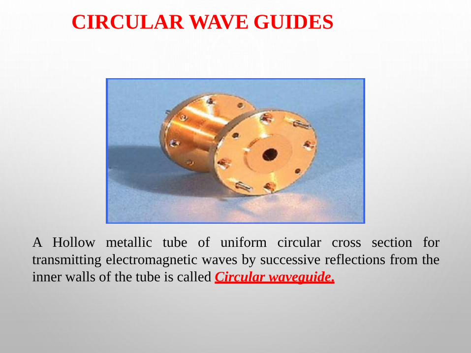
CIRCULAR WAVE GUIDES
A Hollow metallic tube of uniform circular cross section for
transmitting electromagnetic waves by successive reflections from the
inner walls of the tube is called Circular waveguide.
➢ The circular waveguide is used in many special applications in
microwave techniques.
➢ It has the advantage of greater power – handling capacity and lower
attenuation for a given cutoff wavelength. However, the
disadvantage of somewhat greater size and weight.
➢ The polarization of the transmitted wave can be altered due to the
minor irregularities of the wall surface of the circular guide, whereas
the rectangular wave guide the polarization is fixed.
CIRCULAR WAVE GUIDES (contd.)

➢ The first subscript m indicates the number of full – wave variations
of the radial component of the electric field around the
circumference of the waveguide.
➢ The second subscript n indicates the number of half – wave
variations across the diameter.
DESCRIPTION OF CIRCULAR
WAVEGUIDES

ADVANTAGES
➢ Waveguides have several advantages over two-wire and coaxial
transmission lines.
➢ Skin effect tends to increase the effective resistance of the conductor.
Although energy transfer in coaxial cable is caused by
electromagnetic field motion, the magnitude of the field is limited by
the size of the current-carrying area of the inner conductor.
➢ The small size of the center conductor is even further reduced by
skin effect and energy transmission by coaxial cable becomes less
efficient than by waveguides.

➢ Dielectric losses are also lower in waveguides than in two-wire andcoaxial transmission lines.
➢ The dielectric in waveguides is air, which has a much lowerdielectric loss than conventional insulating materials. However,waveguides are also subject to dielectric breakdown caused bystanding waves.
➢ Power-handling capability is another advantage of waveguides.Waveguides can handle more power than coaxial lines of the samesize because power-handling capability is directly related to thedistance between conductors.
ADVANTAGES

➢ Physical size is the primary lower-frequency limitation of
waveguides. The width of a waveguide must be approximately a half
wavelength at the frequency of the wave to be transported.
➢ Waveguides are difficult to install because of their rigid, hollow-pipe
shape. Special couplings at the joints are required to assure proper
operation.
➢ Costs are more and decrease the practicality of waveguide systems at
any other than microwave frequencies.
DISADVANTAGES
KEY POINTS ABOUT WAVEGUIDES
➢ Electromagnetic waves can be guided along a desired route not only
by transmission lines but also by hollow pipes, dielectric coated
surfaces, or dielectric rods.
➢ It is typical of all these hollow waveguides that (1) they cannot
support the TEM wave type, but support the TE and TM wave types
and (2) they cannot transmit energy below a certain frequency,
known as the Cut-off frequency.
➢ Waves of frequencies above the cut-off frequency propagate without
attenuation (except due to losses in materials).

➢ Waves of frequencies lower than the cut-off frequency, known as
evanescent modes, are exponentially attenuated and do not propagate
at all.
➢ Among hollow metallic waveguides, the most important are those of
rectangular cross section. There are an infinite number of both TEmn
and TMmn modes that can propagate along such waveguides.
➢ The higher-order modes (with larger m and n values) for
the same waveguide must be of increasingly higher
frequencies. So there is a frequency range in which only
one mode, the TE10 mode, can propagate. This mode is
therefore termed the Dominant mode.
KEY POINTS ABOUT WAVEGUIDES

➢ Commonly used printed micro strip lines support a hybrid mode,
consisting of both TE and TM wave types. However, because the
longitudinal components of the electric and magnetic field vectors
are small, we can approximately treat the wave as a “quasi-TEM”
wave, similar to that in a transmission line.
➢ The quality factor of waveguide resonators may be by two orders of
magnitude greater than that of lumped-element resonant circuits.
KEY POINTS ABOUT WAVEGUIDES

End of Lecture 1