Packed Absorbers for Deep CO2 Removal - Optimized Gas ...
11
1 Packed Absorbers for Deep CO2 Removal † Ralph H. Weiland 1 and Nathan A. Hatcher 2 Optimized Gas Treating, Inc. 1 Clarita, Oklahoma, USA 2 Buda, Texas, USA When an ideal stage calculation method is used to design or assess performance of an absorber in a CO2 removal unit, the only way for packing size (and type) to be brought into play is through calculation of the stage count (or the number of transfer units) and then applying a stage efficiency or a value for the height equivalent to theoretical plate (HETP). Unfortunately, there is no way to compute such values unless one has direct experience in a nearly identical, or a very similar, column under the same operating conditions. In other words, to reliably design such a column and predict its performance, one must already know the answers. Such an ap- proach can hardly be construed as prediction, and it is certainly not capable of allowing the ef- fect of packing type and size on absorber performance to be assessed. In contrast, this article demonstrates how packing size, even within the same packing series, directly affects overall absorber performance. To see this behavior requires a modern simulation tool capable of modeling the mass transfer and heat transfer as rate-based pro- cesses. In this work, the ProTreat® mass and heat transfer rate-based simulator is used to show just how performance of packing varies in two deep CO2 removal applications. Tempera- ture profiles can be significantly impacted by changing packing size, even when all the operating conditions are kept the same. With the changing temperature profiles come changes in CO2 re- moval performance and corrosion implications. Normal temperature profiles in absorbers for deep CO2 removal at high pressure typi- cally exhibit a pronounced bulge or maximum somewhere within the column. Not only can the position of the temperature bulge be packing-size dependent, but so can the value of the bulge temperature. The bulge temperature itself can be higher when large packing sizes are used and how much it can vary depends on the particulars of the gas being treated and the solvent composition. For example, in the absorber of a syngas unit using MDEA lightly spiked with pi- perazine it is shown that the magnitude of the bulge does not vary greatly with packing size, alt- hough its width does. In an LNG plant, on the other hand, both the temperature at the bulge, and the shape of the temperature profile can depend greatly on packing size. Packing size de- pendence of the temperature bulge is somewhat counterintuitive, but it can be readily explained and understood by thinking about absorption as a mass transfer rate process. There can be enormous variations in temperatures, flows and compositions within a col- umn that are not manifested in the product stream temperatures and compositions but that can have a huge effect on such critical parameters as solvent degradation, corrosion rates, and even on hydraulic performance measures. Locating where flooding is likely to initiate in a col- umn requires accurate assessment of flows and properties of the phases throughout the tower. Such predictions are well suited to ProTreat® simulation but are challenging for an ideal stage simulator. There are two different scenarios in which selecting the right packing size and being fully appre- ciative of the consequences of good and bad choices can be critical to success, namely: (a) de- sign of a new column, and (b) revamp of an existing column. In the first scenario, one is free to choose the column diameter to achieve a specified flood condition. Large packings have lower † Nitrogen + Syngas, January–February, 2018
-
Upload
khangminh22 -
Category
Documents
-
view
5 -
download
0
Transcript of Packed Absorbers for Deep CO2 Removal - Optimized Gas ...
1
Packed Absorbers for Deep CO2 Removal†
Ralph H. Weiland1 and Nathan A. Hatcher2 Optimized Gas Treating, Inc.
1 Clarita, Oklahoma, USA 2 Buda, Texas, USA
When an ideal stage calculation method is used to design or assess performance of an absorber in a CO2 removal unit, the only way for packing size (and type) to be brought into play is through calculation of the stage count (or the number of transfer units) and then applying a stage efficiency or a value for the height equivalent to theoretical plate (HETP). Unfortunately, there is no way to compute such values unless one has direct experience in a nearly identical, or a very similar, column under the same operating conditions. In other words, to reliably design such a column and predict its performance, one must already know the answers. Such an ap-proach can hardly be construed as prediction, and it is certainly not capable of allowing the ef-fect of packing type and size on absorber performance to be assessed.
In contrast, this article demonstrates how packing size, even within the same packing series, directly affects overall absorber performance. To see this behavior requires a modern simulation tool capable of modeling the mass transfer and heat transfer as rate-based pro-cesses. In this work, the ProTreat® mass and heat transfer rate-based simulator is used to show just how performance of packing varies in two deep CO2 removal applications. Tempera-ture profiles can be significantly impacted by changing packing size, even when all the operating conditions are kept the same. With the changing temperature profiles come changes in CO2 re-moval performance and corrosion implications.
Normal temperature profiles in absorbers for deep CO2 removal at high pressure typi-cally exhibit a pronounced bulge or maximum somewhere within the column. Not only can the position of the temperature bulge be packing-size dependent, but so can the value of the bulge temperature. The bulge temperature itself can be higher when large packing sizes are used and how much it can vary depends on the particulars of the gas being treated and the solvent composition. For example, in the absorber of a syngas unit using MDEA lightly spiked with pi-perazine it is shown that the magnitude of the bulge does not vary greatly with packing size, alt-hough its width does. In an LNG plant, on the other hand, both the temperature at the bulge, and the shape of the temperature profile can depend greatly on packing size. Packing size de-pendence of the temperature bulge is somewhat counterintuitive, but it can be readily explained and understood by thinking about absorption as a mass transfer rate process.
There can be enormous variations in temperatures, flows and compositions within a col-umn that are not manifested in the product stream temperatures and compositions but that can have a huge effect on such critical parameters as solvent degradation, corrosion rates, and even on hydraulic performance measures. Locating where flooding is likely to initiate in a col-umn requires accurate assessment of flows and properties of the phases throughout the tower. Such predictions are well suited to ProTreat® simulation but are challenging for an ideal stage simulator.
There are two different scenarios in which selecting the right packing size and being fully appre-ciative of the consequences of good and bad choices can be critical to success, namely: (a) de-sign of a new column, and (b) revamp of an existing column. In the first scenario, one is free to choose the column diameter to achieve a specified flood condition. Large packings have lower
† Nitrogen + Syngas, January–February, 2018

2
pressure drop and flood later than small packings do; they have higher hydraulic capacity. In this case column diameter and the maximum vapor and liquid velocities through the column de-pend on packing size. At the same time, one might expect somewhat different separations per-formance because mass transfer coefficients depend on phase velocities and on the wetted area of the packing. In the revamp scenario, the column diameter is fixed regardless of packing size, so the vapor and liquid velocities are determined by the packing’s hydraulic capacity, i.e., the packing’s size, and it cannot be adjusted by specifying a larger or smaller column diameter. Choosing a large diameter packing to achieve higher capacity may be contraindicated by the inability of the limited surface area of large packing to achieve anything even close to the speci-fied separation. This is one of the dangers in any tower revamp that focuses primarily on ca-pacity. These situations are discussed in the context of two case studies, one in LNG produc-tion and the other in an ammonia syngas unit.
The packing series selected for the study is Intalox Metal Tower Packing (IMTP®) be-cause it is available in six commercial sizes from #15 to #70. This makes it easier to discern and discuss the effect of packing size without confusing the issue by bringing into play the effect of different packing types.
Case 1: Low CO2 Gases Require Low L/G Ratios — LNG from Pipeline Gas
Revamp Scenario
To isolate the effect of packing size from all other parameters, it is simplest to start with the revamp case. The tower to be revamped with new packing is 10-ft (3-m) diameter with suffi-cient height to hold a 40-ft (12-m) deep bed of random packing. Solvent and gas flow rates are constant at 1,000 USgpm (227 m3/h) and 250 MMSCFD (280,000 Nm3/h), respectively. Inlet gas is at 850 psig (59 barg) containing 2% CO2. The solvent is 32 wt% MDEA promoted with 8 wt% piperazine. This pressure and solvent composition might be typical of an LNG absorber where very low residual levels of CO2 in the treated gas are necessary. The optimal composi-tion depends of course on the CO2 content of the raw gas, the gas pressure, and sundry other factors. Diglycolamine (DGA®) and ADEG® are also used commercially in LNG applications. Which type of solvent is actually selected depends as much on licensing terms and the availabil-ity of process guarantees as on purely technical considerations.
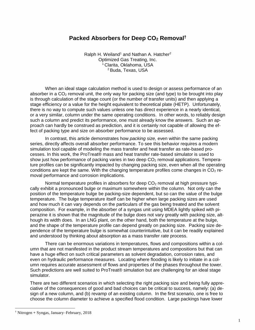
Figure 1 shows temperature profiles for these packings as predicted by ProTreat simu-lation. There are two striking observations:
Small packings have a small, sharp temperature bulge very close to the bottom of the absorber, and the bulge becomes ever broader as larger packings are used, and
Much higher bulge temperatures are predicted to occur with large packings — the larger the packing, the higher the temperature
Why do the profiles broaden, and why is the bulge temperature so much hotter with very large packings when there is almost complete absorption of CO2 (> 99.9%) and the total heat of ab-sorption that is released is virtually identical in all cases?
3
Figure 1 Revamped Absorber Temperature Profiles and Packing Size Dependence — LNG
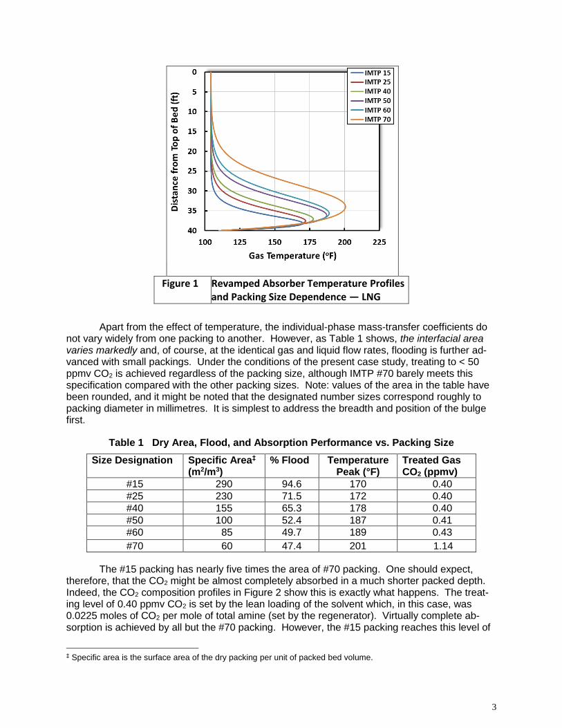
Apart from the effect of temperature, the individual-phase mass-transfer coefficients do not vary widely from one packing to another. However, as Table 1 shows, the interfacial area varies markedly and, of course, at the identical gas and liquid flow rates, flooding is further ad-vanced with small packings. Under the conditions of the present case study, treating to < 50 ppmv CO2 is achieved regardless of the packing size, although IMTP #70 barely meets this specification compared with the other packing sizes. Note: values of the area in the table have been rounded, and it might be noted that the designated number sizes correspond roughly to packing diameter in millimetres. It is simplest to address the breadth and position of the bulge first.
Table 1 Dry Area, Flood, and Absorption Performance vs. Packing Size
Size Designation Specific Area‡ (m2/m3)
% Flood Temperature Peak (°F)
Treated Gas CO2 (ppmv)
#15 290 94.6 170 0.40
#25 230 71.5 172 0.40
#40 155 65.3 178 0.40
#50 100 52.4 187 0.41
#60 85 49.7 189 0.43
#70 60 47.4 201 1.14
The #15 packing has nearly five times the area of #70 packing. One should expect, therefore, that the CO2 might be almost completely absorbed in a much shorter packed depth. Indeed, the CO2 composition profiles in Figure 2 show this is exactly what happens. The treat-ing level of 0.40 ppmv CO2 is set by the lean loading of the solvent which, in this case, was 0.0225 moles of CO2 per mole of total amine (set by the regenerator). Virtually complete ab-sorption is achieved by all but the #70 packing. However, the #15 packing reaches this level of
‡ Specific area is the surface area of the dry packing per unit of packed bed volume.

4
treating after the gas flows through less than the bottom 15 feet of packing. With #60 packing most of the bed is used, and with #70 packing, even using the entire bed depth leaves an unab-sorbed residual CO2 level in the treated gas greater than the lowest achievable level. The width of the temperature bulge shows a rough correspondence with the most actively absorbing re-gion of the bed.
Figure 2 Revamped Absorber CO2 Concentration Profiles and Packing Size Dependence — LNG
The lesson is that because larger packings have smaller surface areas, they need a greater proportion of the packed bed to reach the target level of absorption, and the temperature bulge is therefore broader. Of course, at the extreme ends of the absorber, phase temperatures return closer to the temperatures of the entering liquid and gas streams. The temperatures of the entering streams drive the temperatures of the hot exiting streams down at the ends of the beds. The remaining question is why larger packings produce hotter bulge temperatures.
Packings with small dry area necessarily have smaller wetted area, and they also have smaller total liquid holdup volume. In the case considered here, there is the same total extent of absorption regardless of the packing size. Thus, there is the same heat released, but now into a smaller liquid volume rather than into a large one. Consequently, the smaller liquid volume associated with a larger packing must become hotter simply in order to absorb the heat re-leased.
Interestingly, this effect is not discernable in the outlet gas and liquid streams. The rela-tive coldness of the feed gas and feed liquid streams dominate the top and bottom temperatures and confine the high temperatures to the column interior, away from the ends. However, keep-ing tower interior temperatures below a critical value can be paramount in controlling what could become runaway corrosion. If one is unaware of how hot the temperature bulge can really be-come, it’s impossible to account for it in the revamp, so the final revamp recommendations

5
could easily result in a tower that experiences both unexpected and excessive corrosion in ac-tual operation. Ideal stage simulators, even with efficiencies and other embellishments are inca-
pable of predicting this aspect of packing behavior. Only the ProTreat simulator’s mass trans-fer rate basis allows accurate assessment.
New Design
New column design for a specified flood rating can present an even greater sensitivity to pack-ing size. Figures 3 and 4 show temperature and composition profiles for a design case using identical gas and liquid flows, compositions and inlet temperatures to the revamp case. Again, the absorber contains 40-ft of packing, but its diameter is now adjusted from one size packing to another so as to achieve 70% flood in all cases.
Figure 3 Temperature Profiles in New Absorber Designed for 70% Flood — LNG

6
Figure 4 New Absorber CO2 Concentration Profiles and Packing Size Dependence — LNG
Now there are very high, broad temperature bulges with large diameter packings, and absorption of CO2 to design requirements needs more packed bed depth than is necessary when the packings are of smaller size. Large packing can accommodate higher liquid flow rates before flooding. Thus, when design is to a specified percentage flood, the same degree of flooding is reached in a smaller diameter tower when it contains large packing. In other words, the hydraulic load§ at a given percentage of flood is higher with large packings.
A new tower with fixed height but operating at the same percent of flood with large pack-ing necessarily contains a lower total packing surface area. The absorption rate is slower which spreads the bulge over more of the column. However, the value of temperature at the bulge is higher in the new-design, large-packing case because the entire tower now has less total holdup volume to contain the released heat of absorption. Note: liquid holdup volume is fairly sensitive to the liquid and vapor loads (per unit tower cross-section). Perhaps the effect of hy-draulic load might be more easily understood if hydraulic load were measured on the basis of the unit wetted area of packing as a more fundamentally meaningful parameter rather than on the tower cross-sectional area which pertains to gross hydraulics. In any event, the interaction amongst operating parameters in the design case is somewhat more complex because, unlike in the revamp case, now gross hydraulics is a function of packing size, too.
§ Hydraulic load is measured in terms of mass or volume flow rate per unit of tower cross-section and small diameter towers have higher hydraulic load, all other conditions remaining the same

7
Case 2: High CO2 Gases Need High L/G Ratios — Absorber in Ammonia Syngas Treating
Revamp
The tower to be revamped from trays to packing is 15-ft (4.6-m) diameter with sufficient height to hold a 40-ft (12-m) deep bed of random packing. Solvent and gas flow rates are constant at 4,500 USgpm (1,022 m3/h) and 250 MMSCFD (280,000 Nm3/h), respectively. The crude syn-gas is at 350 psig (24.3 barg) containing 18% CO2. The solvent is 40 wt% MDEA promoted with 3 wt% piperazine. MDEA promoted with moderate levels of piperazine is commonly used in syngas purification because extremely low CO2 levels are not required in the treated gas. The tower pressures here tend to be lower than in LNG plants and the CO2 level in the feed gas is usually quite high, 18 mole% being common. Primary amines such as MEA and amine-pro-moted hot potassium carbonate are also used commercially in ammonia applications. Again, there are often many non-technical factors that determine solvent selection.
Figure 5 shows temperature profiles for these packings as predicted by ProTreat simu-lation. There are two striking observations that contrast with Case 1:
Small packings now have only a slightly lower albeit sharp temperature bulge very close to the bottom of the absorber, and the bulge becomes only moderately broader as larger packings are used, and
Only slightly higher bulge temperatures are predicted to occur with large packings ver-sus the much higher bulge temperatures seen in Case 1.
The reason for the broadening of the temperature bulge in this case is identical with Case 1—larger packings lack the surface area of small sizes and this slows down absorption rates and spreads absorption across much more of the tower.
Figure 5 Revamped Absorber Temperature Profiles and Packing Size Dependence
Obviously in a column of fixed dimensions, flooding is further advanced with small pack-ings. As Figure 6 shows, under the conditions of the present case study, treating to below
8
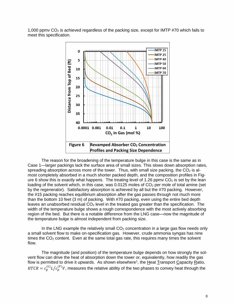
1,000 ppmv CO2 is achieved regardless of the packing size, except for IMTP #70 which fails to meet this specification.
Figure 6 Revamped Absorber CO2 Concentration Profiles and Packing Size Dependence
The reason for the broadening of the temperature bulge in this case is the same as in Case 1—larger packings lack the surface area of small sizes. This slows down absorption rates, spreading absorption across more of the tower. Thus, with small size packing, the CO2 is al-most completely absorbed in a much shorter packed depth, and the composition profiles in Fig-ure 6 show this is exactly what happens. The treating level of 1.26 ppmv CO2 is set by the lean loading of the solvent which, in this case, was 0.0125 moles of CO2 per mole of total amine (set by the regenerator). Satisfactory absorption is achieved by all but the #70 packing. However, the #15 packing reaches equilibrium absorption after the gas passes through not much more than the bottom 10 feet (3 m) of packing. With #70 packing, even using the entire bed depth leaves an unabsorbed residual CO2 level in the treated gas greater than the specification. The width of the temperature bulge shows a rough correspondence with the most actively absorbing region of the bed. But there is a notable difference from the LNG case—now the magnitude of the temperature bulge is almost independent from packing size.
In the LNG example the relatively small CO2 concentration in a large gas flow needs only a small solvent flow to make on-specification gas. However, crude ammonia syngas has nine times the CO2 content. Even at the same total gas rate, this requires many times the solvent flow.
The magnitude (and position) of the temperature bulge depends on how strongly the sol-vent flow can drive the heat of absorption down the tower or, equivalently, how readily the gas flow is permitted to drive it upwards. As shown elsewhere1, the Heat Transport Capacity Ratio,
𝐻𝑇𝐶𝑅 = 𝑐𝑝(𝐿)𝐿 𝑐𝑝
(𝑉)𝑉⁄ , measures the relative ability of the two phases to convey heat through the
9
column (cp is heat capacity and L and V are mass flow rates of the liquid and vapor phases, re-spectively). The value of the HTCR relative to unity is the major factor determining the position of the temperature bulge. In the LNG example, the HTCR is about 1.4 while in the syngas case it is 12. The much larger heat carrying capacity of the solvent in the syngas case drives most of the released heat out the bottom of the column. In the LNG case, neither phase is dominant, and this allows the temperature bulge to spread more responsively to packing size and to de-velop a higher bulge temperature.
Design: New Syngas Absorber
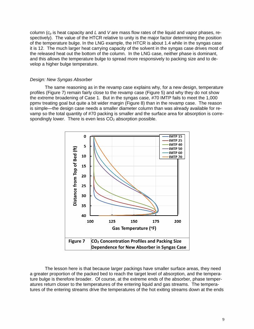
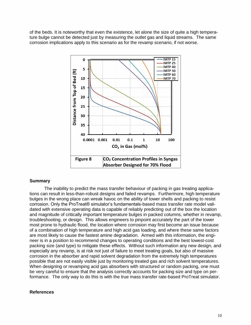
The same reasoning as in the revamp case explains why, for a new design, temperature profiles (Figure 7) remain fairly close to the revamp case (Figure 5) and why they do not show the extreme broadening of Case 1. But in the syngas case, #70 IMTP fails to meet the 1,000 ppmv treating goal but quite a bit wider margin (Figure 8) than in the revamp case. The reason is simple—the design case needs a smaller diameter column than was already available for re-vamp so the total quantity of #70 packing is smaller and the surface area for absorption is corre-spondingly lower. There is even less CO2 absorption possible.
Figure 7 CO2 Concentration Profiles and Packing Size Dependence for New Absorber in Syngas Case
The lesson here is that because larger packings have smaller surface areas, they need a greater proportion of the packed bed to reach the target level of absorption, and the tempera-ture bulge is therefore broader. Of course, at the extreme ends of the absorber, phase temper-atures return closer to the temperatures of the entering liquid and gas streams. The tempera-tures of the entering streams drive the temperatures of the hot exiting streams down at the ends
10
of the beds. It is noteworthy that even the existence, let alone the size of quite a high tempera-ture bulge cannot be detected just by measuring the outlet gas and liquid streams. The same corrosion implications apply to this scenario as for the revamp scenario, if not worse.
Figure 8 CO2 Concentration Profiles in Syngas Absorber Designed for 70% Flood
Summary
The inability to predict the mass transfer behaviour of packing in gas treating applica-tions can result in less-than-robust designs and failed revamps. Furthermore, high temperature bulges in the wrong place can wreak havoc on the ability of tower shells and packing to resist corrosion. Only the ProTreat® simulator’s fundamentals-based mass transfer rate model vali-dated with extensive operating data is capable of reliably predicting out of the box the location and magnitude of critically important temperature bulges in packed columns, whether in revamp, troubleshooting, or design. This allows engineers to pinpoint accurately the part of the tower most prone to hydraulic flood, the location where corrosion may first become an issue because of a combination of high temperature and high acid gas loading, and where these same factors are most likely to cause the fastest amine degradation. Armed with this information, the engi-neer is in a position to recommend changes to operating conditions and the best lowest-cost packing size (and type) to mitigate these effects. Without such information any new design, and especially any revamp, is at risk not just of failure to meet treating goals, but also of massive corrosion in the absorber and rapid solvent degradation from the extremely high temperatures possible that are not easily visible just by monitoring treated gas and rich solvent temperatures. When designing or revamping acid gas absorbers with structured or random packing, one must be very careful to ensure that the analysis correctly accounts for packing size and type on per-formance. The only way to do this is with the true mass transfer rate-based ProTreat simulator.
References

11
1. https://www.protreat.com/files/publications/176/Contactor%20Vol_10%20No_7%20(Sen-sible%20Temperature%20Profiles).pdf
ProTreat is a registered trademark of Optimized Gas Treating, Inc.
Other trademarks are the property of their owners