Optimized Lossless Embedded Compression for Mobile ...
16
electronics Article Optimized Lossless Embedded Compression for Mobile Multimedia Applications Sungchul Yoon 1,2 , Sungho Jun 1 , Yongkwon Cho 1 , Kilwhan Lee 1 , Hyukjae Jang 1 and Tae Hee Han 2,3, * 1 System LSI Division, Samsung Electronics Co. Ltd, Hwaseong 18448, Korea; [email protected] (S.Y.); [email protected] (S.J.); [email protected] (Y.C.); [email protected] (K.L.); [email protected] (H.J.) 2 Department of Semiconductor and Display Engineering, Sungkyunkwan University, Suwon 16419, Korea 3 Department of Artificial Intelligence, Sungkyunkwan University, Suwon 16419, Korea * Correspondence: [email protected]; Tel.: +82-31-299-4587 Received: 15 April 2020; Accepted: 20 May 2020; Published: 23 May 2020 Abstract: Power consumption is a critical design factor in modern mobile chip design, in which the memory system with dynamic random-access memory (DRAM) consumes more than half of the entire system’s power. Without DRAM bandwidth compression, extreme multimedia operations such as 8K high dynamic range (HDR) recording and 8K video conference calling are not possible without sacrificing image quality or trimming because of thermal limitations or battery time sustainability constraints. Since heterogeneous processors are substantially involved in managing various types of fallbacks or software solutions, complicated compression algorithms for high-compression ratios are not actually adaptable owing to timing closure problems or high throughput requirements. In this paper, we propose evaluation metrics to assess lossless embedded compression (LEC) algorithms to reflect realistic design considerations for mobile multimedia scenarios. Furthermore, we introduce an optimized LEC implementation for contemporary multimedia applications in mobile devices based on the proposed metrics. The proposed LEC implementation enhances the compression ratio of LEC algorithms in other commercial application processors for contemporary premium smartphones by up to 9.2% on average, while maintaining the same timing closure condition. Keywords: lossless embedded compression (LEC); prediction; entropy encoding; residual transform; memory bandwidth compression 1. Introduction As computing power has increased dramatically and the degree of integration has improved significantly owing to the development of nanoscale semiconductor processes in recent decades, the requirements in mobile devices are constantly evolving to satisfy the user experience. For example, a mobile chip that can acquire an image frame from 200 million pixels, perform 8K high dynamic range (HDR) recording, and display previews at 144 fps while maximizing the image quality for whole paths has emerged [1]. However, the bandwidth and capacity of cutting-edge dynamic random-access memory (DRAM) have not made much progress in terms of thermal design power (TDP) to meet the aggressive market demands [2,3]. Therefore, it is essential to minimize power consumption by significantly reducing the DRAM bandwidth in high-end multimedia applications by introducing a method to resolve thermal problems and extend battery life. Consequently, several proprietary power reduction features such as ARM (Advanced RISC Machine) frame buffer compression (AFBC), adaptive scalable texture compression (ASTC), and transaction elimination (TE) have been introduced [4]. Electronics 2020, 9, 868; doi:10.3390/electronics9050868 www.mdpi.com/journal/electronics
-
Upload
khangminh22 -
Category
Documents
-
view
4 -
download
0
Transcript of Optimized Lossless Embedded Compression for Mobile ...

electronics
Article
Optimized Lossless Embedded Compression forMobile Multimedia Applications
Sungchul Yoon 1,2, Sungho Jun 1, Yongkwon Cho 1, Kilwhan Lee 1, Hyukjae Jang 1 andTae Hee Han 2,3,*
1 System LSI Division, Samsung Electronics Co. Ltd, Hwaseong 18448, Korea; [email protected] (S.Y.);[email protected] (S.J.); [email protected] (Y.C.); [email protected] (K.L.);[email protected] (H.J.)
2 Department of Semiconductor and Display Engineering, Sungkyunkwan University, Suwon 16419, Korea3 Department of Artificial Intelligence, Sungkyunkwan University, Suwon 16419, Korea* Correspondence: [email protected]; Tel.: +82-31-299-4587
Received: 15 April 2020; Accepted: 20 May 2020; Published: 23 May 2020�����������������
Abstract: Power consumption is a critical design factor in modern mobile chip design, in which thememory system with dynamic random-access memory (DRAM) consumes more than half of theentire system’s power. Without DRAM bandwidth compression, extreme multimedia operations suchas 8K high dynamic range (HDR) recording and 8K video conference calling are not possible withoutsacrificing image quality or trimming because of thermal limitations or battery time sustainabilityconstraints. Since heterogeneous processors are substantially involved in managing various types offallbacks or software solutions, complicated compression algorithms for high-compression ratios arenot actually adaptable owing to timing closure problems or high throughput requirements. In thispaper, we propose evaluation metrics to assess lossless embedded compression (LEC) algorithms toreflect realistic design considerations for mobile multimedia scenarios. Furthermore, we introduce anoptimized LEC implementation for contemporary multimedia applications in mobile devices basedon the proposed metrics. The proposed LEC implementation enhances the compression ratio of LECalgorithms in other commercial application processors for contemporary premium smartphones byup to 9.2% on average, while maintaining the same timing closure condition.
Keywords: lossless embedded compression (LEC); prediction; entropy encoding; residual transform;memory bandwidth compression
1. Introduction
As computing power has increased dramatically and the degree of integration has improvedsignificantly owing to the development of nanoscale semiconductor processes in recent decades,the requirements in mobile devices are constantly evolving to satisfy the user experience. For example,a mobile chip that can acquire an image frame from 200 million pixels, perform 8K high dynamicrange (HDR) recording, and display previews at 144 fps while maximizing the image quality for wholepaths has emerged [1]. However, the bandwidth and capacity of cutting-edge dynamic random-accessmemory (DRAM) have not made much progress in terms of thermal design power (TDP) to meetthe aggressive market demands [2,3]. Therefore, it is essential to minimize power consumption bysignificantly reducing the DRAM bandwidth in high-end multimedia applications by introducing amethod to resolve thermal problems and extend battery life. Consequently, several proprietary powerreduction features such as ARM (Advanced RISC Machine) frame buffer compression (AFBC), adaptivescalable texture compression (ASTC), and transaction elimination (TE) have been introduced [4].
Electronics 2020, 9, 868; doi:10.3390/electronics9050868 www.mdpi.com/journal/electronics

Electronics 2020, 9, 868 2 of 16
Among these techniques, lossless embedded compression (LEC) has become essential such that itloses its competitiveness in the mobile chipset market if it is not actually used. In this regard, severalrelated studies on LEC have surveyed the cache and memory compression methods, compressionalgorithms for various types of data, and interactions with other approaches.
Although lossy compression guarantees constant bandwidth gain, the image quality is inevitablydeteriorated, which can be fatal in multimedia cases. For example, image details obtained throughseveral painful tuning operations may vanish due to lossy compression, and it is more probablethat image quality would be more deteriorated after repeated memory operations. Therefore,lossy compression is adaptable in minimal cases where quality is not a high priority.
In high-end mobile devices, the camera and display subsystems, as well as video codecs, are usuallyintegrated into the same die and compete to occupy more memory bandwidth. However, they alloperate in association with other subsystems even in extreme cases of 8K HDR recordings and 8Kvideo conference calls via LTE (Long-Term Evolution) or 5G networks, and a given application taskwill be distributed in a heterogeneous computing environment to achieve minimum execution time.
In this situation, it is essential to use a unified bandwidth compression that all the necessary systemcomponents, including processors, can decompress. For example, in camera encoding, the neuralprocessing unit (NPU) can be engaged to manage specific recognitions such as face detection and lanedetection. However, the image data cannot be compressed when acquired from an image sensor if theprocessor cannot decompress. As another example, the graphics processing unit (GPU) fallback occurswhenever the display controller cannot perform even one of the input frames. In this case, if the GPUcannot decompress, the LEC algorithm is completely ineffective for display paths. As a final example,a digital signal processor (DSP) can enhance image quality when a movie is decoded via the videocodec standard. Likewise, if a DSP does not know how to decompress the frame, the codec shouldwrite the decoded video frame in a raw format.
The contemporary memory system in mobile chips uses more ranks and banks to maximize thetotal bandwidth, with a minimum access size to mitigate the utilization loss of hardware resourcessuch as bus, cache, and main memory [5,6]. Thus, the achievable compression ratio (CR) is inevitablyquantized in real multimedia applications by burst lengths for a single access. For example, if the blocksize is 256 bytes and the bus width of a system is 16 bytes, the actual CR is quantized to 6.25% for eachblock. As another example, if the block size is the same and the minimum burst length of a systemfor high memory utilization is 64 bytes, the actual CR is quantized to 25% for each block. Therefore,the best CR of an LEC algorithm does not entirely guarantee the maximum bandwidth gain, and anefficient LEC algorithm can be affected by other parameters in the mobile chip design.
An optimized and unified LEC for mobile chips should satisfy not only high CR but also manyother metrics, which is a trade-off with CR. In this paper, we suggest some metrics to assess LECperformance to consider the realistic factors in this dark silicon era [7,8] and propose an optimizedLEC algorithm for mobile multimedia scenarios based on the metrics. With the proposed LECimplementation, we achieved up to 9.2% enhanced CR on average while satisfying the target frequencyup to 1.4 GHz. The contributions of this paper are summarized as follows:
1. We propose realistic metrics to assess LEC performance that help to evaluate what is needed inthe design of cutting-edge high-performance mobile devices.
2. We develop an efficient encoding method, according to the realistic characteristics of theresidual distribution.
3. We present an efficient metadata structure to minimize the access overhead optionally.4. We implement an optimized LEC for high-end mobile multimedia based on the metrics, which is
used not only for video codec, but for the entire multimedia scenario in modern mobile devices.

Electronics 2020, 9, 868 3 of 16
2. Related Works
2.1. Data Compression for Cache and Memory Systems
Several data compression techniques were introduced to accomplish the aims of differentapproaches [9–11]. Particularly, Mittal et al. [11] summarized the current data compression techniquesfor memory systems, including cache. The authors classified the techniques based on the processorcomponent in which compression is applied using the compression algorithm and the objective.In addition, the authors explained factors and trade-offs in compression, to which we referred to makeour performance metrics. Although Mittal et al. mentioned that smartphones are used for data-intensiveapplications such as multimedia, they did not focus on multimedia data compression itself.
However, in mobile chipsets, memory bandwidth for multimedia applications such as camera,video codec, and display accounts for most of the total bandwidth. For example, a 200-megapixelcamera and UHD (Ultra High-Definition) (3840 × 2160) 144 Hz display require a few tens of gigabytesper second, which generally accounts for most of the total memory bandwidth in a mobile system,and seamless operation is not possible without an efficient data compression algorithm.
In modern computing systems, if hardware accelerators cannot perform some multimedia jobs,then a GPU or central processing unit (CPU) should be engaged to process them, which is known asGPU fallback or CPU fallback [12,13]. In a similar vein, if there is no hardware accelerator for somespecific functions, then the associated software task should process them using a DSP or NPU. In caseswhere the processors cannot manage compressed data in memory, the data compression for memorybandwidth is applicable to minimal cases in which the GPU is never involved. In other words, an LECalgorithm for mobile multimedia should be interpreted by processors such as CPU, DSP, and GPU forsoftware solutions.
2.2. Lossy Compression for Bandwidth and Footprint Reduction
Lossy compression can be a very efficient way to save bandwidth and memory footprint. Efficientlossy compression algorithms and implementations are proposed previous studies [14–16]. Data losscan cause significant image quality issues in multimedia applications, thus they are not appropriateapproaches in general. Since the tolerance for image quality loss due to data compression is notallowed in most cases, this study does not deal with lossy compression. However, as future work,we plan to develop an optimized lossy compression only for specific cases, which tolerate some imagequality loss to prioritize the sustainable battery time.
2.3. Lossless Compression for Bandwidth Reduction in Multimedia Environments
The LEC algorithms for the video codec system were previously proposed [17–21]. However,the algorithms mainly enhance CR in video codec applications and use a much more complexaddressing mode, which is not applicable to general multimedia scenarios, including camera, display,and associated software tasks in processors. The authors proposed efficient LEC algorithms thatcan save not only memory bandwidth but also memory footprint by using partition group andused finer-grained prediction and dynamic k-order unary exponential Golomb (EG) code as entropyencoding or improved variable length coding (VLC). However, because only the video codec system istargeted, the LEC algorithms are too complex to obtain frequency higher than 1 GHz and throughputhigher than 16 bytes/clock or 32 bytes/clock; therefore, other architectural alternatives need to beconsidered for high-performance mobile devices.
This study is different from previous studies on LEC algorithms and implementations in that weconcentrate on searching for an LEC algorithm supported by all processors with high throughputand frequency as well as multimedia hardware accelerators. To accomplish the goal, we analyzethe trade-off between algorithm complexity and hardware cost and search for an optimal point withevaluation metrics to assess an LEC.

Electronics 2020, 9, 868 4 of 16
3. Metrics for LEC Evaluation
In leading-edge mobile application processors, various hardware accelerators for multimediaapplications, and heterogeneous processors such as CPU, GPU, DSP, and NPU share unified systemmemory, as shown in Figure 1. It is totally different from high-performance computing systems inwhich the GPU has a dedicated high-bandwidth memory. In addition, GPU, NPU, and DSP playcritical roles in mobile multimedia scenarios as various artificial intelligence (AI)-based applicationshave emerged. Therefore, bandwidth compression for system memory can provide an appropriategain only when the compression algorithm is feasible for the processors. However, according to oursurvey, researchers have not realized that the processors should understand the compression algorithmto obtain the maximum gain from expensive investment in compression and decompression.
Electronics 2020, 9, x FOR PEER REVIEW 4 of 16
3. Metrics for LEC Evaluation
In leading-edge mobile application processors, various hardware accelerators for multimedia applications, and heterogeneous processors such as CPU, GPU, DSP, and NPU share unified system memory, as shown in Figure 1. It is totally different from high-performance computing systems in which the GPU has a dedicated high-bandwidth memory. In addition, GPU, NPU, and DSP play critical roles in mobile multimedia scenarios as various artificial intelligence (AI)-based applications have emerged. Therefore, bandwidth compression for system memory can provide an appropriate gain only when the compression algorithm is feasible for the processors. However, according to our survey, researchers have not realized that the processors should understand the compression algorithm to obtain the maximum gain from expensive investment in compression and decompression.
As mentioned above, previous studies on LEC for multimedia concentrated on achieving the highest CR by improving their prediction and entropy encoding methods. However, because functions that require random access, such as motion estimation and geometric distortion compensation, are more often needed in modern mobile chips, the requirement for random access is mandatory with minimum overhead. In addition, because modern memory systems support a group of banks and have a minimum burst to increase DRAM utilization, the final CR is inevitably quantized at a minimum burst without a huge temporal buffer. This implies that a certain amount of compression gain can be sacrificed to increase the maximum throughput or random accessibility.
The complexity of a compression algorithm generally increases the hardware cost by increasing the area or reducing the feasibility of parallelism. Furthermore, random accessibility is crucial in some multimedia scenarios; however, it affects the actual CR because of metadata information and redundant access. Likewise, hardware area and performance such as throughput and maximum frequency, are the main factors to consider. In this section, we define four main metrics used to evaluate the performance of an LEC. Table 1 shows the list of concerns to consider in an LEC algorithm.
Main
CSI
CSI
GPU
DRAMController
MP w/ L1
L2
CODEC
DSI
Image Signal Processor
Mobile Application Processor
LPD
DR
4/LP
DD
R5
Display Controller
Rear Front
Cover
DSP/NPU
DMA
HW accelerators
CPUBig/Mid/Little w/ L1 and L2
L3
CSI : Camera Serial InterfaceDSI : Display Serial Interface
Figure 1. System configuration in the mobile application processor. Abbreviations: CPU, central processing unit; GPU, graphics processing unit; DSP, digital signal processor; NPU, neural processing unit; DMA (Direct Memory Access); DRAM (dynamic random-access memory); HW (HardWare); LPDDR (Low-Power Double Data Rate).
Figure 1. System configuration in the mobile application processor. Abbreviations: CPU, centralprocessing unit; GPU, graphics processing unit; DSP, digital signal processor; NPU, neural processingunit; DMA (Direct Memory Access); DRAM (dynamic random-access memory); HW (HardWare);LPDDR (Low-Power Double Data Rate).
As mentioned above, previous studies on LEC for multimedia concentrated on achieving thehighest CR by improving their prediction and entropy encoding methods. However, because functionsthat require random access, such as motion estimation and geometric distortion compensation, are moreoften needed in modern mobile chips, the requirement for random access is mandatory with minimumoverhead. In addition, because modern memory systems support a group of banks and have aminimum burst to increase DRAM utilization, the final CR is inevitably quantized at a minimumburst without a huge temporal buffer. This implies that a certain amount of compression gain can besacrificed to increase the maximum throughput or random accessibility.
The complexity of a compression algorithm generally increases the hardware cost by increasingthe area or reducing the feasibility of parallelism. Furthermore, random accessibility is crucial in somemultimedia scenarios; however, it affects the actual CR because of metadata information and redundant

Electronics 2020, 9, 868 5 of 16
access. Likewise, hardware area and performance such as throughput and maximum frequency, are themain factors to consider. In this section, we define four main metrics used to evaluate the performanceof an LEC. Table 1 shows the list of concerns to consider in an LEC algorithm.
Table 1. Concerns to consider when developing lossless embedded compression (LEC).
Category Concerns
CR Is the compression ratio (CR) of the LEC sufficiently high?Software Can processors compress and decompress the LEC to engage software?
Cost Is the implementation cost acceptable?Overhead Is bandwidth overhead for header access reasonable?
Throughput Is the throughput of the LEC achievable in the design budget?
3.1. Compression Ratio (CR)
The CR is the most crucial metric for the LEC algorithm, since a higher CR provides a greaterchance to reduce memory bandwidth and power. The bigger the block size, the more complicatedthe prediction algorithm, and more adaptive entropy encoding generally helps to achieve high CR.In addition, efficient entropy encoding with residual values is one of the key factors for high CR.
A square block such as 16 × 16 generally shows the best CR due to high spatial locality, but higherblocks cost more area for line memories in real-time subsystems such as camera and display. In addition,a loop filter in video codec such as high efficiency video codec (HEVC) requires a read-and-writeoperation for the below four lines by re-reading the compression result of the above block. In thiscase, a 16 × 16 block shape is inefficient for the read-modify operation, thus twice accessing thewhole compressed region. Therefore, in the case of multimedia operations involving camera, display,and codec, selecting a long horizontal block shape, such as 64 × 4, is a better choice when consideringthe overall system.
Numerous prediction algorithms for image compression have been reported [22–24]. As a moresophisticated prediction algorithm refers to more neighborhood pixels, it becomes difficult to reachthe maximum target frequency and process it in parallel. Meanwhile, a simple prediction algorithmcannot guarantee that it can satisfy the target CR because it refers to very few pixels. In this study,CR is defined as the equation below; a low number implies better performance from the compressionperspective. In addition, to conduct experiments with various types of real images, we purchased testimages from NHK (Nippon Hikikomori Kyokai) [25] and categorized them into five groups accordingto their characteristics, as shown in Table 2.
Compression Ratio =Compressed size
Uncompressed(Original) size× 100(%)
Table 2. Description of test image groups [25].
Test Image Class Characteristics
A Outdoor bright images with complex textures such as leaves and grassB Outdoor bright images with simple textures such as sky and skinC Outdoor bright images with mid-range textures between class A and BD Dark indoor images with complex textures such as some light sourcesE Dark indoor images with simple textures

Electronics 2020, 9, 868 6 of 16
3.2. Metadata Overhead (MO)
Compressed data can be divided into payloads for encoded data and metadata for compressioninformation. Metadata provides information to efficiently access compressed data, which is essential forrandom access. However, if the metadata is too large, even if the compression rate is large, the overallCR may drop due to the metadata overhead. Therefore, metadata should contain concise and essentialinformation. The metadata overhead is defined as follows:
Header Overhead =Metadata size f or a blockUncompressed block size
× 100(%)
For example, if the size of metadata is 16 bytes for each 16× 16 block with an 8-bit pixel component,the overall CR is likely to increase; however, the metadata overhead accounts for 6.25%. The reasonwhy large metadata size can cause higher CR is that it contains as much information as possible tocompress the data, for example, uniform color in graphic user interface (GUI) images. Meanwhile,if the metadata is only 1 byte, then the overhead is only 0.4%. This study proposes a method to increaserandom accessibility with only 0.4% of metadata overhead.
3.3. Achievable Frequency (AF)
A modern mobile CPU operates at almost 3 GHz, and a GPU operates at 1.4 GHz; NPU andDSP usually require a frequency higher than 1 GHz. For such processors to be able to compress anddecompress the same algorithm to other multimedia accelerators, the algorithm should be as simple aspossible to meet the maximum frequency of the processors. Alternatively, other architectural designs,such as a parallel operation for multiple blocks should also be considered, but this is not alwayspossible for the processors. Therefore, the achievable frequency should be 1 if the LEC algorithm is tobe applied to a specific system. In other words, if the AF metric is 0, it means that the compressionalgorithm is not appropriate for the system.
3.4. Area Overhead (AO)
The total area overhead (AO) is an important metric to assess an LEC algorithm. In general,larger block size and complexity of the algorithm provide a better CR, but this has a high cost interms of huge area overhead due to register slices, temporal buffers, number of reference pixels, etc.Therefore, the unit area of an encoder and decoder engine affects the total area overhead of an LECimplementation. In addition, the height of the block is tightly coupled to area overhead in real-timeoperations such as camera and display subsystems. As the resolution increases, the number of linememories due to the height of the LEC block significantly affects the chip area. The area overhead canbe calculated as the percentage of the total area increased by LEC support.
4. Proposed LEC
The aim of the proposed design is that all hardware accelerators are related to entire multimediascenarios, and general processors such as GPU and DSP support the proposed LEC algorithm.Alternatively, very restricted paths can be used for compression, because the software cannot distinguishwhether the frame buffer is compressed or not and hence cannot reach the total memory bandwidthrequirement. The maximum target frequency is 1.4 GHz at nominal voltage, and the maximumthroughput is 64 bytes/cycle for compression and 32 bytes/cycle for decompression. Figure 2 shows thecompression and decompression flows in the proposed LEC.

Electronics 2020, 9, 868 7 of 16
Electronics 2020, 9, x FOR PEER REVIEW 7 of 16
Input Block
Pixel Unpacking
Prediction(MED)
Entropy Encoding(EG)
Packing
Header and Payload
(a) Compression flow
Payload Fetch
Payload Decoding
Data Re-ordering
Output Block
(b) Decompression flow
Header Prefetch
Figure 2. (a) Compression and (b) decompression flow in proposed LEC. Abbreviations: MED, median edge detection; EG, exponential Golomb.
4.1. Prediction
Gradient adaptive prediction (GAP) [22] tends to show higher performance than delta modulation and median edge detection (MED) prediction [23], but its maximum frequency is limited to a certain extent because of the number of reference neighborhood pixels, as shown in Figure 3. According to our evaluation result, MED with LOCO-I (Low Complexity Lossless Compression for Images) algorithm shows a similar CR as GAP and provides a better chance to enhance the critical path by removing dependencies of neighborhood pixels. In addition, the max frequency of GAP is under 1 GHz (actually around 800 MHz) according to our implementation. The MED algorithm refers to four neighborhood pixels, but the prediction stage can be pipelined by grouping input pixels and changing the order of reference pixels. With the parallelization, we can enhance the critical path and total throughput. Therefore, we adapted the parallelized MED with LOCO-I algorithm as a prediction method.
Given a value X in MED prediction, and its left, upper, and upper-left neighbors A, B, and C, respectively, the prediction value is determined based on the following equation:
1. If C is greater than the maximum value out of A and B, the prediction value for X is the minimum value out of A and B.
2. If C is smaller than or equal to the minimum value out of A and B, the prediction value for X is the maximum value out of A and B.
3. Otherwise, the prediction value for X is A + B – C. For boundary pixels that do not have a neighbor, MED prediction is the same as delta
modulation.
Figure 2. (a) Compression and (b) decompression flow in proposed LEC. Abbreviations: MED, medianedge detection; EG, exponential Golomb.
4.1. Prediction
Gradient adaptive prediction (GAP) [22] tends to show higher performance than delta modulationand median edge detection (MED) prediction [23], but its maximum frequency is limited to a certainextent because of the number of reference neighborhood pixels, as shown in Figure 3. According to ourevaluation result, MED with LOCO-I (Low Complexity Lossless Compression for Images) algorithmshows a similar CR as GAP and provides a better chance to enhance the critical path by removingdependencies of neighborhood pixels. In addition, the max frequency of GAP is under 1 GHz (actuallyaround 800 MHz) according to our implementation. The MED algorithm refers to four neighborhoodpixels, but the prediction stage can be pipelined by grouping input pixels and changing the orderof reference pixels. With the parallelization, we can enhance the critical path and total throughput.Therefore, we adapted the parallelized MED with LOCO-I algorithm as a prediction method.
Given a value X in MED prediction, and its left, upper, and upper-left neighbors A, B, and C,respectively, the prediction value is determined based on the following equation:
1. If C is greater than the maximum value out of A and B, the prediction value for X is the minimumvalue out of A and B.
2. If C is smaller than or equal to the minimum value out of A and B, the prediction value for X isthe maximum value out of A and B.
3. Otherwise, the prediction value for X is A + B – C.
For boundary pixels that do not have a neighbor, MED prediction is the same as delta modulation.Table 3 shows the CR comparison of four prediction algorithms with the same entropy encoding
and data packing; that is, the MED and GAP with test image classes shown in Table 2.

Electronics 2020, 9, 868 8 of 16
Electronics 2020, 9, x FOR PEER REVIEW 8 of 16
C
A
B
X
C
A
B D
XA X
(b) MED prediction (c) GAP prediction(a) DM prediction
X The current pixel
Reference pixel(s)
Figure 3. Reference pixels for each prediction algorithm. Abbreviations: DM, delta modulation; MED, median edge detection; GAP, gradient adaptive prediction. (a) Delta modulation prediction uses one neighborhood pixel; (b) MED prediction uses three neighborhood pixels; (c) GAP prediction uses four neighborhood pixels.
Table 3 shows the CR comparison of four prediction algorithms with the same entropy encoding and data packing; that is, the MED and GAP with test image classes shown in Table 2.
Table 3. CR comparison according to the prediction algorithm.
Test Image Class CR with MED (%) CR with GAP (%) A 65.34 64.85
B 47.91 48.06
C 51.89 50.75
D 54.39 53.9
E 52.23 51.6
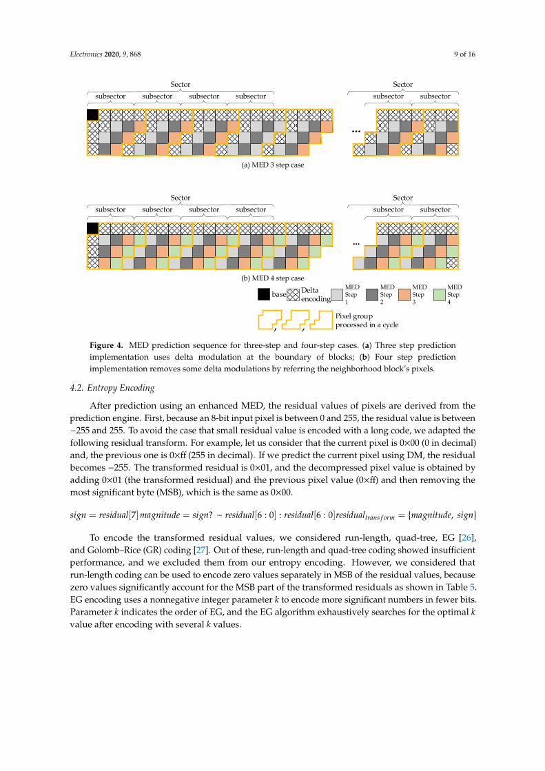
To increase the throughput of MED processing, we propose a per-sector decompression method that requires three or four independent MED decompressions in a cycle, as shown in Figure 4. Due to the shape of the block, some pixels need to be processed through delta modulation instead of MED. By grouping up to 16 pixels and changing the order of pixels, we can achieve the desirable throughput for MED processing. With the synthesis results shown in Table 4, we decided to use the three-step MED because implementation of the four-step MED cannot satisfy the AF metric, even though it might show slightly higher prediction performance because of the minimum delta modulation (DM) predictions.
Table 4. Synthesis result of MED implementations to check achievable frequency.
Number of Steps Max Frequency (GHz)
at 5 nm Process 1 1.4 2 1.4 3 1.4 4 1.36 5 1.03
Figure 3. Reference pixels for each prediction algorithm. Abbreviations: DM, delta modulation; MED,median edge detection; GAP, gradient adaptive prediction. (a) Delta modulation prediction uses oneneighborhood pixel; (b) MED prediction uses three neighborhood pixels; (c) GAP prediction uses fourneighborhood pixels.
Table 3. CR comparison according to the prediction algorithm.
Test Image Class CR with MED (%) CR with GAP (%)
A 65.34 64.85B 47.91 48.06C 51.89 50.75D 54.39 53.9E 52.23 51.6
To increase the throughput of MED processing, we propose a per-sector decompression methodthat requires three or four independent MED decompressions in a cycle, as shown in Figure 4. Due tothe shape of the block, some pixels need to be processed through delta modulation instead of MED.By grouping up to 16 pixels and changing the order of pixels, we can achieve the desirable throughputfor MED processing. With the synthesis results shown in Table 4, we decided to use the three-step MEDbecause implementation of the four-step MED cannot satisfy the AF metric, even though it might showslightly higher prediction performance because of the minimum delta modulation (DM) predictions.
Table 4. Synthesis result of MED implementations to check achievable frequency.
Number of Steps Max Frequency (GHz)at 5 nm Process
1 1.42 1.43 1.44 1.365 1.03
Electronics 2020, 9, 868 9 of 16
Electronics 2020, 9, x FOR PEER REVIEW 9 of 16
(a) MED 3 step case
subsectorSector
subsector subsector subsector
...
subsectorsubsectorSector
base Deltaencoding
MED Step 4
MED Step 1
MED Step 2
MED Step 3
Pixel group processed in a cycle
(b) MED 4 step case
subsectorSector
subsector subsector subsector
...
subsectorsubsectorSector
, , Figure 4. MED prediction sequence for three-step and four-step cases. (a) Three step prediction implementation uses delta modulation at the boundary of blocks; (b) Four step prediction implementation removes some delta modulations by referring the neighborhood block’s pixels.
4.2. Entropy Encoding
After prediction using an enhanced MED, the residual values of pixels are derived from the prediction engine. First, because an 8-bit input pixel is between 0 and 255, the residual value is between −255 and 255. To avoid the case that small residual value is encoded with a long code, we adapted the following residual transform. For example, let us consider that the current pixel is 0x00 (0 in decimal) and, the previous one is 0xff (255 in decimal). If we predict the current pixel using DM, the residual becomes −255. The transformed residual is 0x01, and the decompressed pixel value is obtained by adding 0x01 (the transformed residual) and the previous pixel value (0xff) and then removing the most significant byte (MSB), which is the same as 0x00.
To encode the transformed residual values, we considered run-length, quad-tree, EG [26], and
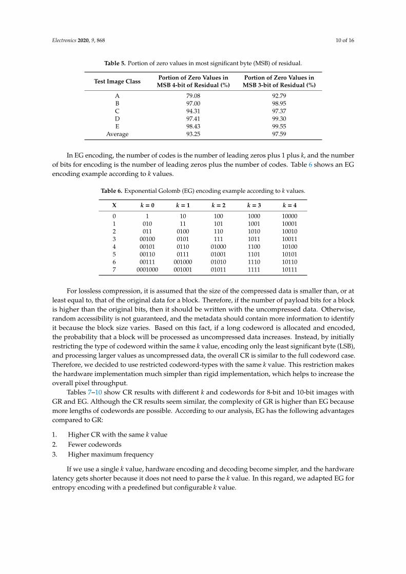
Golomb–Rice (GR) coding [27]. Out of these, run-length and quad-tree coding showed insufficient performance, and we excluded them from our entropy encoding. However, we considered that run-length coding can be used to encode zero values separately in MSB of the residual values, because zero values significantly account for the MSB part of the transformed residuals as shown in Table 5. EG encoding uses a nonnegative integer parameter k to encode more significant numbers in fewer bits. Parameter k indicates the order of EG, and the EG algorithm exhaustively searches for the optimal k value after encoding with several k values.
Table 5. Portion of zero values in most significant byte (MSB) of residual.
𝑠𝑖𝑔𝑛 = 𝑟𝑒𝑠𝑖𝑑𝑢𝑎𝑙 7 𝑚𝑎𝑔𝑛𝑖𝑡𝑢𝑑𝑒 = 𝑠𝑖𝑔𝑛? ~𝑟𝑒𝑠𝑖𝑑𝑢𝑎𝑙 6: 0 : 𝑟𝑒𝑠𝑖𝑑𝑢𝑎𝑙 6: 0 𝑟𝑒𝑠𝑖𝑑𝑢𝑎𝑙 = {𝑚𝑎𝑔𝑛𝑖𝑡𝑢𝑑𝑒, 𝑠𝑖𝑔𝑛}
Figure 4. MED prediction sequence for three-step and four-step cases. (a) Three step predictionimplementation uses delta modulation at the boundary of blocks; (b) Four step predictionimplementation removes some delta modulations by referring the neighborhood block’s pixels.
4.2. Entropy Encoding
After prediction using an enhanced MED, the residual values of pixels are derived from theprediction engine. First, because an 8-bit input pixel is between 0 and 255, the residual value is between−255 and 255. To avoid the case that small residual value is encoded with a long code, we adapted thefollowing residual transform. For example, let us consider that the current pixel is 0×00 (0 in decimal)and, the previous one is 0×ff (255 in decimal). If we predict the current pixel using DM, the residualbecomes −255. The transformed residual is 0×01, and the decompressed pixel value is obtained byadding 0×01 (the transformed residual) and the previous pixel value (0×ff) and then removing themost significant byte (MSB), which is the same as 0×00.
sign = residual[7]magnitude = sign? ∼ residual[6 : 0] : residual[6 : 0]residualtrans f orm ={magnitude, sign
}To encode the transformed residual values, we considered run-length, quad-tree, EG [26],
and Golomb–Rice (GR) coding [27]. Out of these, run-length and quad-tree coding showed insufficientperformance, and we excluded them from our entropy encoding. However, we considered thatrun-length coding can be used to encode zero values separately in MSB of the residual values, becausezero values significantly account for the MSB part of the transformed residuals as shown in Table 5.EG encoding uses a nonnegative integer parameter k to encode more significant numbers in fewer bits.Parameter k indicates the order of EG, and the EG algorithm exhaustively searches for the optimal kvalue after encoding with several k values.
Electronics 2020, 9, 868 10 of 16
Table 5. Portion of zero values in most significant byte (MSB) of residual.
Test Image Class Portion of Zero Values inMSB 4-bit of Residual (%)
Portion of Zero Values inMSB 3-bit of Residual (%)
A 79.08 92.79B 97.00 98.95C 94.31 97.37D 97.41 99.30E 98.43 99.55
Average 93.25 97.59
In EG encoding, the number of codes is the number of leading zeros plus 1 plus k, and the numberof bits for encoding is the number of leading zeros plus the number of codes. Table 6 shows an EGencoding example according to k values.
Table 6. Exponential Golomb (EG) encoding example according to k values.
X k = 0 k = 1 k = 2 k = 3 k = 4
0 1 10 100 1000 100001 010 11 101 1001 100012 011 0100 110 1010 100103 00100 0101 111 1011 100114 00101 0110 01000 1100 101005 00110 0111 01001 1101 101016 00111 001000 01010 1110 101107 0001000 001001 01011 1111 10111
For lossless compression, it is assumed that the size of the compressed data is smaller than, or atleast equal to, that of the original data for a block. Therefore, if the number of payload bits for a blockis higher than the original bits, then it should be written with the uncompressed data. Otherwise,random accessibility is not guaranteed, and the metadata should contain more information to identifyit because the block size varies. Based on this fact, if a long codeword is allocated and encoded,the probability that a block will be processed as uncompressed data increases. Instead, by initiallyrestricting the type of codeword within the same k value, encoding only the least significant byte (LSB),and processing larger values as uncompressed data, the overall CR is similar to the full codeword case.Therefore, we decided to use restricted codeword-types with the same k value. This restriction makesthe hardware implementation much simpler than rigid implementation, which helps to increase theoverall pixel throughput.
Tables 7–10 show CR results with different k and codewords for 8-bit and 10-bit images withGR and EG. Although the CR results seem similar, the complexity of GR is higher than EG becausemore lengths of codewords are possible. According to our analysis, EG has the following advantagescompared to GR:
1. Higher CR with the same k value2. Fewer codewords3. Higher maximum frequency
If we use a single k value, hardware encoding and decoding become simpler, and the hardwarelatency gets shorter because it does not need to parse the k value. In this regard, we adapted EG forentropy encoding with a predefined but configurable k value.

Electronics 2020, 9, 868 11 of 16
Table 7. CR comparison with Golomb–Rice (GR) coding with different codewords for 8-bit images.
Test Image Class(8-Bit)
CR (%) with GR(k = 2 and 64 Codes)
CR (%) with GR(k = 2 and 32 Codes)
CR (%) with GR(k = 2 and 24 Codes)
CR (%) with GR(k = 2 and 16 Codes)
A 71.92 72.41 72.9 74.97B 54.04 54.37 54.67 55.59C 56.67 57.44 58.17 60.09D 54.17 54.91 55.64 57.76E 51.76 52.03 52.4 53.28
Average 57.71 58.23 58.76 60.34
Table 8. CR comparison with EG with different codewords for 8-bit images.
Test Image Class(8-Bit)
CR (%) with EG(k = 1 and 8 Codes)
CR (%) with EG(k = 2 and 7 Codes)
CR (%) with EG(k = 3 and 6 Codes)
CR (%) with EG(k = 4 and 5 Codes)
A 73.71 70.71 71.64 78.12B 54.53 54.42 63.8 75.6C 55.42 56.29 64.86 75.99D 55.98 55.84 63.53 75.4E 52.64 52.67 63.15 75.43
Average 58.46 57.99 65.4 76.11
Table 9. CR comparison with GR with different codewords for 10-bit images.
Test Image Class(10-Bit)
CR (%) with GR(k = 2 and 64 Codes)
CR (%) with GR(k = 3 and 32 Codes)
CR (%) with GR(k = 4 and 16 Codes)
CR (%) with GR(k = 5 and 8 Codes)
A 90.93 82.74 77.24 76.03B 66.96 59.25 62.86 70.95C 70.62 64.21 64.89 71.72D 73.73 63.78 63.1 70.57E 67.29 59.64 61.31 70.49
Average 73.91 65.92 65.88 71.95
Table 10. CR comparison with EG with different codewords for 10-bit images.
Test Image Class(10-Bit)
CR (%) with EG(k = 2 and 7 Codes)
CR (%) with EG(k = 3 and 6 Codes)
CR (%) with EG(k = 4 and 5 Codes)
CR (%) with EG(k = 5 and 4 Codes)
A 82.85 79.21 76.9 77.75B 64.44 63.4 63.6 71.2C 64.84 64.07 65.14 72.04D 66.88 64.55 64.66 70.87E 64.04 61.96 62.11 70.55
Average 68.61 66.64 66.48 72.48
4.3. Metadata/Payload Structure
To minimize the metadata overhead, we propose 1-byte metadata that contains only the amount ofdata for the compressed block. The metadata indicates how many bytes the compressed data occupies.For example, if metadata is 1, then the compressed data is 32 bytes after compression when the basicunit is 32 bytes. If metadata is 0, then the block is not compressed.
For random access, a block size of 64 × 4 is too large to reduce the access overhead. Therefore,we define a partial encoding to minimize the access overhead during random access, as shown inFigure 5b. In partial mode, the superblock is 64 × 4 in size, whereas the subblock is 32 × 4 and thewhole superblock is composed of two subblocks. The LSB 4-bit and MSB 4-bit metadata identify thesizes of subblock0 and superblock, respectively. The size of subblock1 can be calculated by subtractingLSB 4-bit from MSB 4-bit.

Electronics 2020, 9, 868 12 of 16
Electronics 2020, 9, x FOR PEER REVIEW 12 of 16
sizes of subblock0 and superblock, respectively. The size of subblock1 can be calculated by subtracting LSB 4-bit from MSB 4-bit.
Sub-block 0 Sub-block1
64
4
64
4
(a) 64 × 4 encoding case
(b) 32 × 4 partial encoding case
1 byte
4-bit 4-bit
The size of sub-block0 The size of super-block
Figure 5. Metadata structure: (a) 64 × 4 encoding case; (b) 32 × 4 encoding case
Figure 6 illustrates the payload structure. It contains a k value and EG encoded data. As mentioned above, if the encoded data exceeds the original size, it is marked as an uncompressed block, and the original data is written as is. In addition, if a partial update is necessary, some specific blocks can be written in uncompressed data, which is very useful for boundary processing.
Entropy k
2-bit
Pixel 0
Variable
Pixel 1 Pixel N-1 Zero padding
Variable
Figure 6. Payload structure.
Figure 7 shows the metadata and payload layout of the proposed LEC algorithm. Since the positions of the metadata and payload are deterministic, the metadata can be pre-fetched into a buffer and the payload can also be pre-fetched when the metadata is not available, but the IP (Intellectual Property) is sensitive to latency immunity. However, the payload should generally be fetched according to the metadata information to reduce memory bandwidth.
128 pixels
32 lines
464
64x4
After compression,Y Plane Payload buffer
Y plane of YUV 128x32 uncompressed image
YYYY...
CR
50%
100%
25%
50%
8'h26 8'h0 …...
Metadata
64x4
64x4
64x4
Total payload size(4'h2 = 128bytes)
Sub-block0 payload size(4'h5 = 40byte)
compression
After compression,Y Plane Header buffer
8'h14 8'h25 Metadata
Figure 7. Metadata and payload layout of proposed LEC.
Figure 5. Metadata structure: (a) 64 × 4 encoding case; (b) 32 × 4 encoding case.
Figure 6 illustrates the payload structure. It contains a k value and EG encoded data. As mentionedabove, if the encoded data exceeds the original size, it is marked as an uncompressed block, and theoriginal data is written as is. In addition, if a partial update is necessary, some specific blocks can bewritten in uncompressed data, which is very useful for boundary processing.
Electronics 2020, 9, x FOR PEER REVIEW 12 of 16
sizes of subblock0 and superblock, respectively. The size of subblock1 can be calculated by subtracting LSB 4-bit from MSB 4-bit.
Sub-block 0 Sub-block1
64
4
64
4
(a) 64 × 4 encoding case
(b) 32 × 4 partial encoding case
1 byte
4-bit 4-bit
The size of sub-block0 The size of super-block
Figure 5. Metadata structure: (a) 64 × 4 encoding case; (b) 32 × 4 encoding case
Figure 6 illustrates the payload structure. It contains a k value and EG encoded data. As mentioned above, if the encoded data exceeds the original size, it is marked as an uncompressed block, and the original data is written as is. In addition, if a partial update is necessary, some specific blocks can be written in uncompressed data, which is very useful for boundary processing.
Entropy k
2-bit
Pixel 0
Variable
Pixel 1 Pixel N-1 Zero padding
Variable
Figure 6. Payload structure.
Figure 7 shows the metadata and payload layout of the proposed LEC algorithm. Since the positions of the metadata and payload are deterministic, the metadata can be pre-fetched into a buffer and the payload can also be pre-fetched when the metadata is not available, but the IP (Intellectual Property) is sensitive to latency immunity. However, the payload should generally be fetched according to the metadata information to reduce memory bandwidth.
128 pixels
32 lines
464
64x4
After compression,Y Plane Payload buffer
Y plane of YUV 128x32 uncompressed image
YYYY...
CR
50%
100%
25%
50%
8'h26 8'h0 …...
Metadata
64x4
64x4
64x4
Total payload size(4'h2 = 128bytes)
Sub-block0 payload size(4'h5 = 40byte)
compression
After compression,Y Plane Header buffer
8'h14 8'h25 Metadata
Figure 7. Metadata and payload layout of proposed LEC.
Figure 6. Payload structure.
Figure 7 shows the metadata and payload layout of the proposed LEC algorithm. Since thepositions of the metadata and payload are deterministic, the metadata can be pre-fetched into a bufferand the payload can also be pre-fetched when the metadata is not available, but the IP (IntellectualProperty) is sensitive to latency immunity. However, the payload should generally be fetched accordingto the metadata information to reduce memory bandwidth.
Electronics 2020, 9, x FOR PEER REVIEW 12 of 16
sizes of subblock0 and superblock, respectively. The size of subblock1 can be calculated by subtracting LSB 4-bit from MSB 4-bit.
Sub-block 0 Sub-block1
64
4
64
4
(a) 64 × 4 encoding case
(b) 32 × 4 partial encoding case
1 byte
4-bit 4-bit
The size of sub-block0 The size of super-block
Figure 5. Metadata structure: (a) 64 × 4 encoding case; (b) 32 × 4 encoding case
Figure 6 illustrates the payload structure. It contains a k value and EG encoded data. As mentioned above, if the encoded data exceeds the original size, it is marked as an uncompressed block, and the original data is written as is. In addition, if a partial update is necessary, some specific blocks can be written in uncompressed data, which is very useful for boundary processing.
Entropy k
2-bit
Pixel 0
Variable
Pixel 1 Pixel N-1 Zero padding
Variable
Figure 6. Payload structure.
Figure 7 shows the metadata and payload layout of the proposed LEC algorithm. Since the positions of the metadata and payload are deterministic, the metadata can be pre-fetched into a buffer and the payload can also be pre-fetched when the metadata is not available, but the IP (Intellectual Property) is sensitive to latency immunity. However, the payload should generally be fetched according to the metadata information to reduce memory bandwidth.
128 pixels
32 lines
464
64x4
After compression,Y Plane Payload buffer
Y plane of YUV 128x32 uncompressed image
YYYY...
CR
50%
100%
25%
50%
8'h26 8'h0 …...
Metadata
64x4
64x4
64x4
Total payload size(4'h2 = 128bytes)
Sub-block0 payload size(4'h5 = 40byte)
compression
After compression,Y Plane Header buffer
8'h14 8'h25 Metadata
Figure 7. Metadata and payload layout of proposed LEC. Figure 7. Metadata and payload layout of proposed LEC.

Electronics 2020, 9, 868 13 of 16
5. Performance Evaluation and Implementation
5.1. Performance Evaluation with the Proposed Metrics
For the performance evaluation, we compared three LEC algorithms in commercial AP productswith the performance metrics shown in Section 3. Due to confidentiality issues, we cannot exposeexactly. The first commercial LEC algorithm shows the best performance in area overhead; however,it cannot reach the achievable frequency metric and shows the worst CR. The second commercialLEC algorithm satisfies AF, but CR and AO are not competent. The proposed LEC algorithm showsbetter performance in every metric, except area overhead. The pipelined MED algorithm and twoencoding methods according to MSB and LSB partitioning, enhance overall CR, keeping hardwarereasonably simple. Moreover, the efficient metadata information shows the lower metadata overhead.As the minimum access unit is 32 bytes or 64 bytes in modern mobile chips due to multi-rank memorysystems with high bandwidth, we calculated CR in the 64-byte minimum access case.
As shown in Table 11, the proposed LEC algorithm has the best performance in CR and metadataoverhead. In addition, it meets the achievable frequency that targets 1.4 GHz. Even though the areaoverhead is worse than algorithm 1, algorithm 1 is not feasible for the target system, because theachievable frequency metric is not satisfied.
Table 11. Performance comparison according to the proposed metrics.
Metrics Commercial LECAlgorithm 1
Commercial LECAlgorithm 2
Proposed LECAlgorithm
CR average (%) 71.8 71.2 62.0CR min (%) 64.5 62.4 56.3CR max (%) 81.9 83.4 73.8
Metadata overhead (MO) (%) 6.25 0.4 0.4Achievable frequency (AF) 0 1 1
Area overhead (AO) (%) 2.03 8.21 4.05
5.2. Implementation Results
Figures 8 and 9 show the proposed LEC compression and decompression engines. Each hardwareaccelerator uses them in its way. For example, as the scan order is fixed in the display panel side,a display controller and a camera interface, which are representative real-time IPs, need four-linememories to decompress and a huge metadata buffer to pre-fetch metadata. As another example,codec utilizes random access to perform motion estimation and is very sensitive to memory latency;therefore, it should sometimes pre-fetch the payload data even when the metadata is not ready. It hashuge metadata and payload caches to reuse them.
Electronics 2020, 9, x FOR PEER REVIEW 13 of 16
5. Performance Evaluation and Implementation
5.1. Performance Evaluation with the Proposed Metrics
For the performance evaluation, we compared three LEC algorithms in commercial AP products with the performance metrics shown in Section 3. Due to confidentiality issues, we cannot expose exactly. The first commercial LEC algorithm shows the best performance in area overhead; however, it cannot reach the achievable frequency metric and shows the worst CR. The second commercial LEC algorithm satisfies AF, but CR and AO are not competent. The proposed LEC algorithm shows better performance in every metric, except area overhead. The pipelined MED algorithm and two encoding methods according to MSB and LSB partitioning, enhance overall CR, keeping hardware reasonably simple. Moreover, the efficient metadata information shows the lower metadata overhead. As the minimum access unit is 32 bytes or 64 bytes in modern mobile chips due to multi-rank memory systems with high bandwidth, we calculated CR in the 64-byte minimum access case.
As shown in Table 11, the proposed LEC algorithm has the best performance in CR and metadata overhead. In addition, it meets the achievable frequency that targets 1.4 GHz. Even though the area overhead is worse than algorithm I, algorithm I is not feasible for the target system, because the achievable frequency metric is not satisfied.
Table 11. Performance comparison according to the proposed metrics.
Metrics Commercial LEC Algorithm I
Commercial LEC Algorithm II
Proposed LEC Agorithm
CR average (%) 71.8 71.2 62.0 CR min (%) 64.5 62.4 56.3 CR max (%) 81.9 83.4 73.8
Metadata overhead (MO) (%) 6.25 0.4
0.4
Achievable frequency (AF)
0 1 1
Area overhead (AO) (%) 2.03 8.21 4.05
5.2. Implementation Results
Figures 8 and 9 show the proposed LEC compression and decompression engines. Each hardware accelerator uses them in its way. For example, as the scan order is fixed in the display panel side, a display controller and a camera interface, which are representative real-time IPs, need four-line memories to decompress and a huge metadata buffer to pre-fetch metadata. As another example, codec utilizes random access to perform motion estimation and is very sensitive to memory latency; therefore, it should sometimes pre-fetch the payload data even when the metadata is not ready. It has huge metadata and payload caches to reuse them.
ENCODER
IP Req I/F
LowPixelReg
IP Pixel I/F
UpperPixelReg
InputBuffer
BufferCtrl
MED_TOP BitCounterEst.
Residual
K_V
ALU
E
EG_ENCODER
PAYLOADPACKING
BestK
MetadataGenBitCount
Payload I/FM
etadata Out I/F
Block1 Block0
ForceUncompress
Info
MED
Residual
P2
Reg
P0 P1
Figure 8. Proposed LEC compression engine. Figure 8. Proposed LEC compression engine.

Electronics 2020, 9, 868 14 of 16
Electronics 2020, 9, x FOR PEER REVIEW 14 of 16
For the decompression side, each hardware accelerator can have metadata and payload access patterns as well as memory structure for the dedicated efficient storage to pre-fetch them. After pre-fetching the metadata, the hardware decides how many bursts it should request according to the metadata value. Furthermore, it reads the exact amount of payload data from memory and feeds the payload to the decompression engine.
DECODER
EG_DECODER
Payload I/F
OutputBuffer
Block1 Block0
IP Pixel I/F
.
Figure 9. Proposed LEC decompression engine.
Table 12 shows the implementation result of the compression and decompression engines. The pipelined MED prediction (Figure 4) and a simplified encoding method achieve the target frequency of 1.4 GHz. The compression and decompression engines are integrated with each hardware accelerator and processor, so that the total area overhead is about 4.05%, as shown in Table 12.
Table 12. Implementation results.
Condition Compression Engine Decompression Engine Area (mm2) at 5 nm process 0.0047 0.0037
Max frequency at nominal voltage 1.4 GHz 1.4 GHz
6. Conclusion
We present essential metrics to assess the LEC algorithm, show efficient encoding for metadata and payload, and propose an optimized LEC implementation for the most recent mobile multimedia scenarios. For GPU and DSP to support the same LEC algorithm in software IP, the algorithm should reach the target frequency and throughput. In addition, since the latest memory systems usually have a minimum burst length due to multiple bank structures to maximize utilization, the CR value is inevitably quantized to the minimum burst length. In this regard, the adequately simplified LEC algorithm can show improved performance over the complicated algorithm only for the best CR in the realistic metrics presented in this paper. The proposed algorithm enhances the actual CR of the LEC algorithm in a commercial chip up to 9.2% on average, while being able to keep the complexity to meet the timing closure condition.
For future work, a centralized LEC implementation is an exciting topic of research. After the memory management unit, since the address exists in the physical address space and the block data should be gathered to a certain point, the centralized LEC implementation does not seem to be beneficial. However, from an area perspective, the centralized LEC can give a better option than the distributed LEC implementation if the above-mentioned issues are resolved.
7. Patents
Jun, S.H. and Lim, Y.H., Samsung Electronics Co. Ltd. 2019. Image processing device and method for operating image processing device. U.S. Patent Application 16/205,900.
Jun, S.H., Park, C.S., Song, M.K., Lee, K.K., Lee, K.W., Jang, H.J., and Jeong, K.A., Samsung Electronics Co. Ltd. 2019. Image processing device. U.S. Patent Application 16/252,806.
Jun, S.H. and Lim, Y.H., Samsung Electronics Co. Ltd. 2019. Image processing device. U.S. Patent Application 16/252,796.
Figure 9. Proposed LEC decompression engine.
For the decompression side, each hardware accelerator can have metadata and payload accesspatterns as well as memory structure for the dedicated efficient storage to pre-fetch them. Afterpre-fetching the metadata, the hardware decides how many bursts it should request according to themetadata value. Furthermore, it reads the exact amount of payload data from memory and feeds thepayload to the decompression engine.
Table 12 shows the implementation result of the compression and decompression engines.The pipelined MED prediction (Figure 4) and a simplified encoding method achieve the targetfrequency of 1.4 GHz. The compression and decompression engines are integrated with each hardwareaccelerator and processor, so that the total area overhead is about 4.05%, as shown in Table 12.
Table 12. Implementation results.
Condition Compression Engine Decompression Engine
Area (mm2) at 5 nm process 0.0047 0.0037Max frequency at nominal voltage 1.4 GHz 1.4 GHz
6. Conclusions
We present essential metrics to assess the LEC algorithm, show efficient encoding for metadataand payload, and propose an optimized LEC implementation for the most recent mobile multimediascenarios. For GPU and DSP to support the same LEC algorithm in software IP, the algorithm shouldreach the target frequency and throughput. In addition, since the latest memory systems usuallyhave a minimum burst length due to multiple bank structures to maximize utilization, the CR valueis inevitably quantized to the minimum burst length. In this regard, the adequately simplified LECalgorithm can show improved performance over the complicated algorithm only for the best CR in therealistic metrics presented in this paper. The proposed algorithm enhances the actual CR of the LECalgorithm in a commercial chip up to 9.2% on average, while being able to keep the complexity to meetthe timing closure condition.
For future work, a centralized LEC implementation is an exciting topic of research. After thememory management unit, since the address exists in the physical address space and the blockdata should be gathered to a certain point, the centralized LEC implementation does not seem to bebeneficial. However, from an area perspective, the centralized LEC can give a better option than thedistributed LEC implementation if the above-mentioned issues are resolved.
7. Patents
Jun, S.H. and Lim, Y.H., Samsung Electronics Co. Ltd. 2019. Image processing device and methodfor operating image processing device. U.S. Patent Application 16/205,900.
Jun, S.H., Park, C.S., Song, M.K., Lee, K.K., Lee, K.W., Jang, H.J., and Jeong, K.A., SamsungElectronics Co. Ltd. 2019. Image processing device. U.S. Patent Application 16/252,806.
Jun, S.H. and Lim, Y.H., Samsung Electronics Co. Ltd. 2019. Image processing device. U.S. PatentApplication 16/252,796.

Electronics 2020, 9, 868 15 of 16
Author Contributions: Conceptualization, S.J. and H.J.; software, S.J. and H.J.; investigation, S.Y., Y.C., and K.L.;writing—original draft preparation, S.Y.; writing—review and editing, T.H.H. All authors have read and agreed tothe published version of the manuscript.
Funding: This work was supported by Samsung Electronics.
Acknowledgments: This work was partly supported by Institute of Information & Communications TechnologyPlanning & Evaluation (IITP) grant funded by the Korea government (MSIT) (No. 2019-0-00421, AI GraduateSchool Support Program (Sungkyunkwan University)) and the KSRC (Korea Semiconductor Research Consortium)grant funded by the Ministry of Trade, Industry & Energy (MOTIE, Korea) (No. 10080594, The development of thefuture semiconductor device).
Conflicts of Interest: The authors declare no conflicts of interest.
References
1. Snapdragon 865 Features Detailed. Available online: https://wccftech.com/qualcomm-snapdragon-865-features-200mp-cameras-144hz-displays-8k-video-support/ (accessed on 2 February 2020).
2. Furtunato, A.F.; Georgiou, K.; Eder, K.; Xavier-de-Souza, S. When parallel speedups hit the memory wall.arXiv 2019, arXiv:1905.01234.
3. Sun, X.H.; Liu, Y.H. Utilizing Concurrency: A New Theory for Memory Wall. In International Workshop onLanguages and Compilers for Parallel Computing; Springer: Cham, Switzerland, 2016; pp. 18–23.
4. Bratt, I. The arm mali-t880 mobile gpu. In Proceedings of the 2015 IEEE Hot Chips 27 Symposium (HCS),Cupertino, CA, USA, 22–25 August 2015; pp. 1–27.
5. Seongil, O.; Son, Y.H.; Kim, N.S.; Ahn, J. Row-buffer decoupling: A case for low-latency DRAMmicroarchitecture. In Proceedings of the 2014 ACM/IEEE 41st International Symposium on ComputerArchitecture (ISCA), Minneapolis, MN, USA, 14–18 June 2014; pp. 337–348.
6. Asghari-Moghaddam, H.; Son, Y.H.; Ahn, J.H.; Kim, N.S. Chameleon: Versatile and practical near-DRAMacceleration architecture for large memory systems. In Proceedings of the 2016 49th Annual IEEE/ACMInternational Symposium on Microarchitecture (MICRO), Taipei, Taiwan, 15–19 October 2016; pp. 1–13.
7. Pedram, A.; Richardson, S.; Horowitz, M.; Galal, S.; Kvatinsky, S. Dark memory and accelerator-rich systemoptimization in the dark silicon era. IEEE Des. Test 2016, 34, 39–50. [CrossRef]
8. Kanduri, A.; Rahmani, A.M.; Liljeberg, P.; Hemani, A.; Jantsch, A.; Tenhunen, H. A perspective on darksilicon. In The Dark Side of Silicon; Springer: Cham, Switzerland, 2017; pp. 3–20.
9. Tang, S.; Tan, H.; Li, L. A novel memory compression technique for embedded system. In Proceedings ofthe 2012 Second International Conference on Digital Information and Communication Technology and it’sApplications (DICTAP), Bangkok, Thailand, 16–18 May 2012; pp. 287–292.
10. Pekhimenko, G.; Mowry, T.C.; Mutlu, O. Linearly compressed pages: A main memory compressionframework with low complexity and low latency. In Proceedings of the 2013 21st International Conferenceon Parallel Architectures and Compilation Techniques (PACT), Davis, CA, USA, 7–11 December 2013; p. 489.
11. Mittal, S.; Vetter, J.S. A survey of architectural approaches for data compression in cache and main memorysystems. IEEE Trans. Parallel Distrib. Syst. 2015, 27, 1524–1536. [CrossRef]
12. Klimovic, A.; Anderson, J.H. Bitwidth-optimized hardware accelerators with software fallback. In Proceedingsof the 2013 International Conference on Field-Programmable Technology (FPT), Kyoto, Japan, 9–11 December2013; pp. 136–143.
13. Renderscript | Android Open Source Project. Available online: https://source.android.com/devices/architecture/
vndk/renderscript (accessed on 22 March 2020).14. Zhou, X.; Lian, X.; Zhou, W.; Liu, Z.; Zhang, X. A low power lossy frame memory recompression algorithm.
In Proceedings of the 2016 Asia-Pacific Signal and Information Processing Association Annual Summit andConference (APSIPA), Jeju, Korea, 13–16 December 2016; pp. 1–4.
15. Guo, L.; Zhou, D.; Zhou, J.; Kimura, S. Embedded frame compression for energy-efficient computer visionsystems. In Proceedings of the 2018 IEEE International Symposium on Circuits and Systems (ISCAS),Florence, Italy, 27–30 May 2018; pp. 1–5.
16. Guo, L.; Zhou, D.; Zhou, J.; Kimura, S.; Goto, S. Lossy compression for embedded computer vision systems.IEEE Access 2018, 6, 39385–39397. [CrossRef]
17. Lian, X.; Liu, Z.; Zhou, W.; Duan, Z. Lossless frame memory compression using pixel-grain prediction anddynamic order entropy coding. IEEE Trans. Circuits Syst. Video Technol. 2015, 26, 223–235. [CrossRef]
https://wccftech.com/qualcomm-snapdragon-865-features-200mp-cameras-144hz-displays-8k-video-support/

Electronics 2020, 9, 868 16 of 16
18. Wang, Z.; Hou, Z.; Hu, R.; Xiao, J. A lossless recompression approach for video streaming transmission.IEEE Access 2019, 7, 35162–35172. [CrossRef]
19. Li, S.; Yin, H.; Fang, X.; Lu, H. Lossless image compression algorithm and hardware architecture forbandwidth reduction of external memory. IET Image Proc. 2017, 11, 379–388. [CrossRef]
20. Kanakagiri, R.; Panda, B.; Mutyam, M. MBZip: Multiblock data compression. ACM Trans. Archit. Code Optim.2017, 14, 1–29. [CrossRef]
21. Lal, S.; Lucas, J.; Juurlink, B. E2MC: Entropy Encoding Based Memory Compression for GPUs. In Proceedingsof the IEEE International Parallel and Distributed Processing Symposium (IPDPS), Orlando, FL, USA, 29May–2 June 2017; pp. 1119–1128.
22. Wu, X.; Memon, N. Context-based, adaptive, lossless image coding. IEEE Trans. Commun. 1997, 45, 437–444.[CrossRef]
23. Weinberger, M.J.; Seroussi, G.; Sapiro, G. The LOCO-I lossless image compression algorithm: Principles andstandardization into JPEG-LS. IEEE Trans. Image Process. 2000, 9, 1309–1324. [CrossRef] [PubMed]
24. Li, X.; Orchard, M.T. Edge-directed prediction for lossless compression of natural images. IEEE Tran.Image Process. 2001, 10, 813–817.
25. ITE/ARIB HDTV Test Materials—Second Edition B-Series. Available online: http://www.nes.or.jp/en/wwd/
distribution.html (accessed on 2 February 2020).26. Exponential-Golomb Coding. Available online: https://en.wikipedia.org/wiki/Exponential-Golomb_coding
(accessed on 2 February 2020).27. Golomb Coding. Available online: https://en.wikipedia.org/wiki/Golomb_coding (accessed on 2 February 2020).
© 2020 by the authors. Licensee MDPI, Basel, Switzerland. This article is an open accessarticle distributed under the terms and conditions of the Creative Commons Attribution(CC BY) license (http://creativecommons.org/licenses/by/4.0/).