Terminal Boxes
27
EN EN EN EN EN EN EN EN EN EN EN EN EN EN EN EN EN EN EN EN EN EN EN EN EN Operating instructions Additional languages www.stahl-ex.com EN Terminal Boxes Series 8146/1, Series 8146/2 – Save for future use! –
-
Upload
khangminh22 -
Category
Documents
-
view
2 -
download
0
Transcript of Terminal Boxes

ENENENENENENENENENENENENENENENENEN
Operating instructions Additional languages www.stahl-ex.com
EN
ENENENENENENENEN
Terminal Boxes
Series 8146/1, Series 8146/2
– Save for future use! –

ENENENENENENENENENENENENENENENENENENENENENENENENEN
Contents1 General Information ............................................................................................31.1 Manufacturer .......................................................................................................31.2 About these Operating Instructions .....................................................................31.3 Further Documents .............................................................................................31.4 Conformity with Standards and Regulations .......................................................32 Explanation of the Symbols ................................................................................42.1 Symbols in these Operating Instructions ............................................................42.2 Symbols on the Device .......................................................................................43 Safety ..................................................................................................................53.1 Intended Use .......................................................................................................53.2 Personnel Qualification .......................................................................................53.3 Residual Risks ....................................................................................................64 Transport and Storage ........................................................................................85 Product Selection, Project Engineering and Modification ...................................85.1 Additional Through Holes in Flange Plates .........................................................95.2 Additional Through Holes in the Enclosure with
an internal Brass or Flange Plate ......................................................................105.3 External Attached Components
(Cable Entries, Stopping Plugs, Breathers) ......................................................135.4 Internal Built-In Components
(Conductors, Terminals, Fuses) ........................................................................146 Mounting and Installation ..................................................................................176.1 Mounting / Dismounting, Operating Position .....................................................176.2 Installation .........................................................................................................187 Commissioning .................................................................................................218 Maintenance and Repair ...................................................................................218.1 Maintenance .....................................................................................................218.2 Maintenance .....................................................................................................218.3 Repair ...............................................................................................................219 Returning the Device ........................................................................................2110 Cleaning ............................................................................................................2211 Disposal ............................................................................................................2212 Accessories and Spare Parts ...........................................................................2213 Annex A ............................................................................................................2313.1 Technical Data ..................................................................................................2314 Annex B ............................................................................................................2614.1 Dimensions / Fastening Dimensions .................................................................26
2 Terminal BoxesSeries 8146/1, Series 8146/2

General Information ENENENENENENENENENENENENENENENENENENENENENENENENEN
1 General Information
1.1 ManufacturerR. STAHL Schaltgeräte GmbHAm Bahnhof 3074638 Waldenburg Germany
Phone: +49 7942 943-0Fax: +49 7942 943-4333Internet: www.stahl-ex.comE-Mail: [email protected]
1.2 About these Operating Instructions Read these operating instructions, especially the safety notes, carefully before use. Observe all other applicable documents (see also section 1.3). Keep the operating instructions throughout the service life of the device. Make the operating instructions accessible to operating and maintenance personnel at all
times. Pass the operating instructions on to each subsequent owner or user of the device. Update the operating instructions every time you receive an amendment to them from
R. STAHL.
ID-No.: 137189 / 8146619300Publication Code: 2016-11-10·BA00·III·en·06
The original instructions are the German edition.They are legally binding in all legal affairs.
1.3 Further Documents• Data sheet• EU Type Examination CertificateFor documents in additional languages, see www.stahl-ex.com.
1.4 Conformity with Standards and Regulations• Certificates and EU Declaration of Conformity: www.stahl-ex.com.• The device has IECEx approval. See IECEx homepage: http://iecex.iec.ch/
137189 / 81466193002016-11-10·BA00·III·en·06
3Terminal BoxesSeries 8146/1, Series 8146/2
Explanation of the SymbolsENENENENENENENENENENENENENENENENENENENENENENENENEN
137189 / 8146619300Terminal Boxes
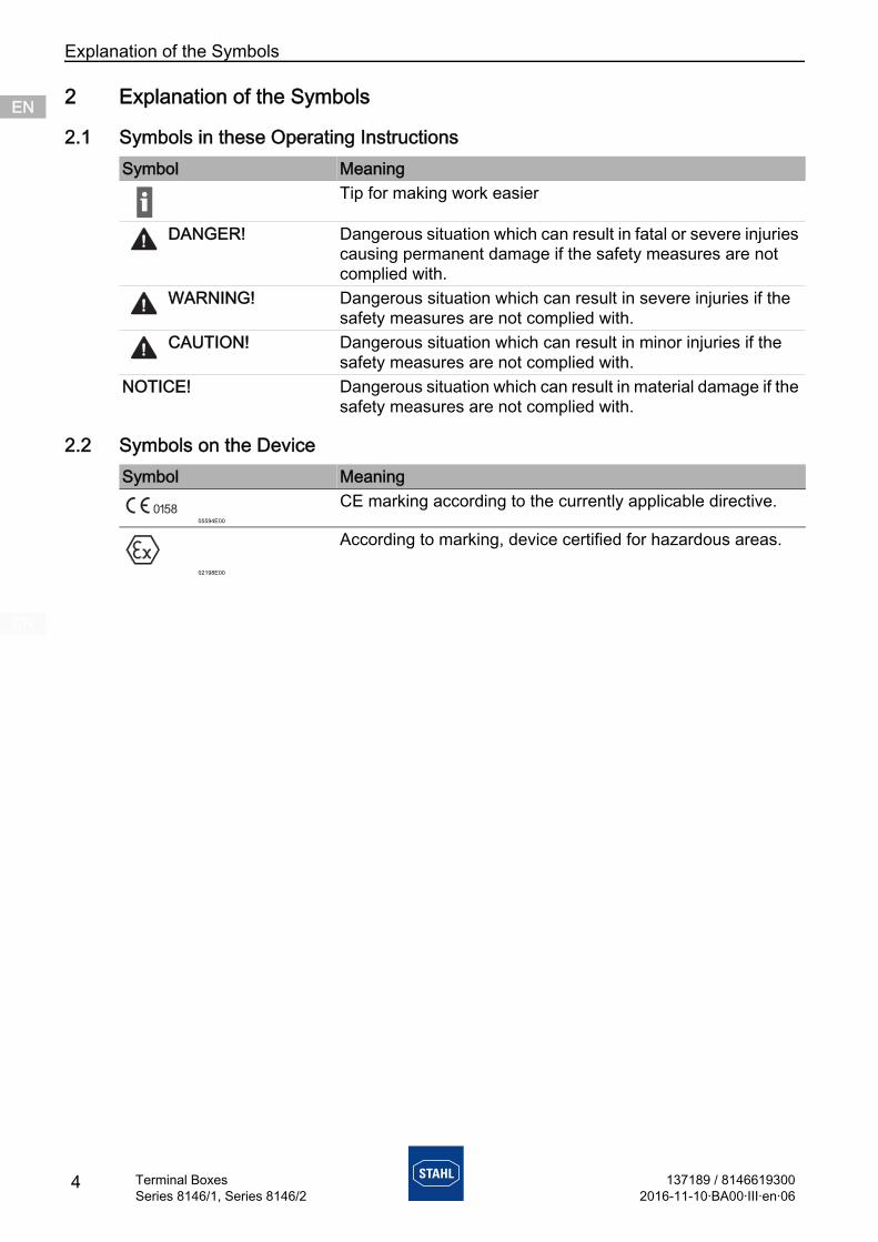
2 Explanation of the Symbols
2.1 Symbols in these Operating Instructions
2.2 Symbols on the Device
Symbol MeaningTip for making work easier
DANGER! Dangerous situation which can result in fatal or severe injuries causing permanent damage if the safety measures are not complied with.
WARNING! Dangerous situation which can result in severe injuries if the safety measures are not complied with.
CAUTION! Dangerous situation which can result in minor injuries if the safety measures are not complied with.
NOTICE! Dangerous situation which can result in material damage if the safety measures are not complied with.
Symbol Meaning
05594E00
CE marking according to the currently applicable directive.
02198E00
According to marking, device certified for hazardous areas.
42016-11-10·BA00·III·en·06Series 8146/1, Series 8146/2

SafetyENENENENENENENENENENENENENENENENENENENENENENENENEN
3 SafetyThe device has been manufactured to the state of the art while observing recognised safety-related rules. When using the device, it is nevertheless possible for hazards to occur to life and limb of the user or third parties or for the device, environment or material assets to be compromised.
Use the device only- if it is not damaged- as intended, while remaining aware of safety and dangers- in accordance with these operating instructions.
3.1 Intended UseThe terminal boxes 8146/1 and /2 are used to distribute electric energy and / or electric signals in hazardous areas. They are explosion-protected equipment certified for use in hazardous areas of Zones 1, 2, 21 and 22.The terminal boxes are manufactured in various sizes and can be combined to create larger distribution units. They must be installed so they are stationary.Intended use includes observing these operating instructions and the other applicable documents, e.g. the data sheet. Any other use of the terminal boxes is not intended.
3.2 Personnel QualificationQualified specialist personnel are required to perform the activities described in these operating instructions. This primarily applies to work in the following areas:• Product selection, project engineering and modification• Mounting/dismounting the device• Installation• Commissioning• Maintenance, repair, cleaning
Specialists who perform these tasks must have a level of knowledge that meets applicable national standards and regulations.
Additional knowledge is required for tasks in hazardous areas! R. STAHL recommends having a level of knowledge equal to that described in the following standards:• IEC/EN 60079-14 (Electrical installations design, selection and erection)• IEC/EN 60079-17 (Inspection and maintenance of electrical installations)• IEC/EN 60079-19 (Equipment repair, overhaul and reclamation)
137189 / 81466193002016-11-10·BA00·III·en·06
5Terminal BoxesSeries 8146/1, Series 8146/2

SafetyENENENENENENENENENENENENENENENENENENENENENENENENEN
3.3 Residual Risks
3.3.1 Explosion HazardAn explosion hazard cannot be entirely ruled out in hazardous areas despite the device having a state-of-the-art design.
Perform all work steps in hazardous areas with the utmost care at all times!
Possible moments of danger (residual risks) can be categorised according to the following causes:
Mechanical damageThe device can be pressed or scratched during transport, mounting or commissioning, causing it to no longer be leak-tight. Such damage can, for example, render the device's explosion protection partially or fully ineffective. This can result in explosions causing fatal or severe injuries to persons. Observe the weight and the maximum load-bearing capacity of the device;
see specifications on the packaging. Transport the device only in the original packaging or in equivalent packaging. Use transporting or lifting equipment which is suitable for the size and weight of the device
and can reliably carry the weight of the device. Check the packaging and the device for damage. Report any damage to R. STAHL
immediately. Store the device in the original packaging in a dry (no condensation) and stable position
which is safe from vibrations. Do not damage the enclosure, built-in components or seals during mounting.
Excessive heating or electrostatic chargeSubsequently modifying the device, operating it outside of permitted conditions or failing to clean it properly can cause it to heat up excessively or to become electrostatically charged, causing it to produce sparks. This can result in explosions causing fatal or severe injuries to persons. Operate the device only within the prescribed operating conditions
(see the type plate and the "Technical data" chapter). Only allow the manufacturer to paint the device and have this company coat it with special,
conductive paint. Equip devices used outdoors in the elements with a protective roof or wall.
Regularly inspect the device for a material change (plastic). If any changes are identified, test or replace the device.
Do not paint the device. Have all repairs performed by the manufacturer. Comply with the area specification of EN IEC 60079-0 when fitting additional plastic
adhesive labels. Clean the device only with a damp cloth.
6 137189 / 81466193002016-11-10·BA00·III·en·06
Terminal BoxesSeries 8146/1, Series 8146/2

SafetyENENENENENENENENENENENENENENENENENENENENENENENENEN
Impairment of IP protectionWhen installed properly and completely, the device will have the required IP degree of protection. Making structural changes to the device or mounting it improperly can impair its IP protection. This can result in explosions causing fatal or severe injuries to persons. Only apply labels (on the outside) without drilling any additional holes. Only drill holes for cable glands exactly according to the instructions in the
"Product selection, project engineering and modification" and "Mounting" chapters of these operating instructions. Consult with R: STAHL first if there are any discrepancies or uncertainties.
Mount the device only in the prescribed mounting position. More detailed explanations of this can be found in the "Mounting" chapter.
Improper installation, commissioning, maintenance or cleaningBasic work such as installation, commissioning, maintenance or cleaning of the device must be performed only in accordance with the valid national regulations of the country of use and only by qualified persons. Otherwise the explosion protection can be rendered ineffective. This can result in explosions causing fatal or severe injuries to persons. Have mounting, installation, commissioning and maintenance performed only by qualified
and authorised persons (see section 3.2). Only make changes to the device in accordance with the instructions in these operating
instructions. Have R. STAHL or a test body (3rd party inspection) carry out acceptance. Perform maintenance and repairs on the device only using original spare parts and after
consultation with R. STAHL. Gently clean the device only with a damp cloth and without scratching, abrasive or
aggressive cleaning agents or solutions. Never clean the device with a strong water jet, e.g. using a high-pressure washer!
3.3.2 Risk of Injury
Falling devices or componentsThe heavy device or components can fall during transport and mounting, causing severe injury to persons in the form of bruises and contusions. Use transporting and lifting equipment suitable for the size and weight of the device when
transporting and mounting it. Observe the weight and the maximum load-bearing capacity of the device;
see specifications on the packaging. Use suitable mounting hardware for mounting.
Electric shockDuring electric installation, operation and maintenance, there will at times be high voltages present at the device. Persons coming into contact with electric lines carrying excessively high voltage can suffer severe electric shocks and consequently injuries. Operate the device only on equipment with the internal voltage specified in the
"Technical data" chapter. Connect electric circuits only to suitable terminals.
137189 / 81466193002016-11-10·BA00·III·en·06
7Terminal BoxesSeries 8146/1, Series 8146/2

Transport and StorageENENENENENENENENENENENENENENENENENENENENENENENENEN
4 Transport and Storage Transport and store the device carefully and in accordance with the safety notes
(see "Safety" section).
5 Product Selection, Project Engineering and Modification
When complying with the installation conditions and specifications on the type plate: Check whether enough cable entries are provided. Drill additional holes if necessary;
see sections 5.1 to 5.2. Equip terminals and, if necessary, mount built-in components; see section 5.4.
The methods mainly considered for modification are subsequently machining or equipping the terminal box. In this case, the following possibilities are available:• Additional through holes on the flange plate, either by R. STAHL or by the customer
(section 5.1)• Additional through holes in the enclosure, either by R. STAHL or by the customer
(section 5.2)• External attached components either by R. STAHL or by the customer (section 5.3)• Internal built-in components either by R. STAHL or by the customer (section 5.4)
DANGER! Explosion due to subsequent, complete painting of the device!Non-compliance results in fatal or severe injuries. Do not paint the device. Have all repairs performed by the manufacturer.
DANGER! Explosion due to defective sealing of the device!Non-compliance results in fatal or severe injuries. Only apply labels (on the outside) without drilling any additional holes. Only create additional drilled holes specifically in accordance with the instructions
in the "Mounting" chapter. Consult R. STAHL in the event of deviations or uncertainties.
Equip the enclosure only with equipment (e.g. cable entries, stopping plugs, drain and breather valves) that is verifiably approved for use in hazardous areas. Examples: EU Type Examination Certificate or IECEx Certificate of Conformity
Seal any unused cable entries with the stopping plugs approved for the type of protection.
Seal all open drilled holes by means of suitable equipment.
Acceptance of work performed in-house must be carried out in accordance with national regulations. Otherwise, you must have R. STAHL or a test body (3rd party inspection) (section 3.3.1) carry out acceptance. On request, R. STAHL can carry out this work if offered appropriate remuneration. If the work is carried out by R. STAHL, no additional acceptance is necessary.
8 137189 / 81466193002016-11-10·BA00·III·en·06
Terminal BoxesSeries 8146/1, Series 8146/2

Product Selection, Project Engineering and Modification ENENENENENENENENENENENENENENENENENENENENENENENENEN
5.1 Additional Through Holes in Flange Plates
5.1.1 Creation of Additional Drilled Holes and Through Holes by R. STAHL Forward the following information to R. STAHL:
- Type- Data sheet- Quantity, manufacturers and approvals of the components that are to be installed.
R. STAHL• will check whether the components, drilled hole diameters, quantity and position
correspond with the approval• will create the drilled holes and through holes• will mount the components• will update the order documentation• will carry out a routine test• will, if necessary, fit a new type plate if the technical data has changed,
e.g. due to the components that are to be additionally installed.
5.1.2 Ascertaining the usable Area for Cable Entries in Flange PlatesAll dimensions in mm [inches]
18495E00
Collision frame and earth connection of flange plate
Select a space/area for the cable entry on the flange plate anywhere inside the collision frame (see thin line in figure). Ensure that screw connections made later do not go beyond this collision frame.
Observe the following conditions when doing so: Leave enough distance to the circumferential seal (min. 3 mm)
(see detail in figure).
3 12[0, ]
3 12[0, ]
137189 / 81466193002016-11-10·BA00·III·en·06
9Terminal BoxesSeries 8146/1, Series 8146/2

Product Selection, Project Engineering and ModificationENENENENENENENENENENENENENENENENENENENENENENENENEN
5.1.3 Creation of Additional Drilled Holes and Through Holes by the Customer Modify the device carefully and only in accordance with the safety notes
(see "Safety" section). Calculate the usable area, see section 5.1.2. Create additional through holes by lasing or punching (drilling, hole cutting). When punching and cutting, make sure that the outer surfaces of the enclosure remain flat
and undamaged (without cracks). Determine the core hole diameter for threads. Do not use an NPT thread! When determining the through holes, observe the mounting distances. Adjust the hole diameters to the dimensions of the built-in parts or their seals. ONLY use built-in components with flat seal (gasket). Observe section 5.3 when subsequently equipping components!
5.2 Additional Through Holes in the Enclosure with an internal Brass or Flange Plate
5.2.1 Creation of Additional Drilled Holes and Through Holes by R. STAHL Give the following information to R. STAHL:
- Enclosure side- Type- Data sheet- Quantity, manufacturers and approvals of the components that are to be installed.
R. STAHL• will check whether the components, drilled hole diameters, quantity and position
correspond with the approval• will create the drilled holes and through holes• will mount the components• will update the order documentation• will carry out a routine test• will, if necessary, fit a new type plate if the technical data has changed,
e.g. due to the components that are to be additionally installed.
Terminal boxes which the customer wants delivered without drilled holes are generally marked as empty enclosures with the corresponding type plate (marking in accordance with EN IEC 60079-7 and EN IEC 60079-0, as incomplete equipment "U" inside the enclosure).
10 137189 / 81466193002016-11-10·BA00·III·en·06
Terminal BoxesSeries 8146/1, Series 8146/2

Product Selection, Project Engineering and Modification ENENENENENENENENENENENENENENENENENENENENENENENENEN
5.2.2 Creation of Additional Drilled Holes and Through Holes by the Customer Modify the device carefully and only in accordance with the safety notes
(see "Safety" section). Calculate the usable area for built-in components, see sections 5.1.2 and 5.2.2. Create additional through holes by lasing or punching (drilling, hole cutting).
When doing so, maintain a distance of min. 10 mm to the rim of the enclosure (see figure). All dimensions in mm [inches]
18478E00
When punching and cutting, make sure that the outer surfaces of the enclosure remain flat and undamaged (without cracks).
When determining the through holes, observe the mounting distances. Adjust the hole diameters to the dimensions of the built-in parts or their seals. ONLY use built-in components with flat seal (gasket). Observe section 5.3 when subsequently equipping components!
5.2.3 Creation of Additional Drilled Holes and Through Holes in the Enclosure with Flange Plate by R. STAHL Give the following information to R. STAHL:
- Enclosure side- Type- Data sheet- Quantity, manufacturers and approvals of the components that are to be installed.
R. STAHL• will check whether the components, drilled hole diameters, quantity and position
correspond with the approval• will create the drilled holes and through holes• will mount the components• will update the order documentation• will carry out a routine test• will, if necessary, fit a new type plate if the technical data has changed,
e.g. due to the components that are to be additionally installed.
10 [0,39]
10
[0
,39
]10 [0,39]
10
[0
,39
]
137189 / 81466193002016-11-10·BA00·III·en·06
11Terminal BoxesSeries 8146/1, Series 8146/2

Product Selection, Project Engineering and ModificationENENENENENENENENENENENENENENENENENENENENENENENENEN
5.2.4 Creation of Additional Drilled Holes and Through Holes in the Enclosure with Flange Plate by the Customer Modify the device carefully and only in accordance with the safety notes
(see "Safety" section). Calculate the usable area for built-in components, see sections 5.1.2 and 5.2.2. Select a space/area for the cable entry on the flange plate anywhere inside the collision
frame (see thin line in figure). Ensure that screw connections made later do not go beyond this collision frame. Leave enough distance (min. 15 mm) to the circumferential frame (see the figure for the "Collision frame" section). All dimensions in mm [inches]
18479E00
When punching and cutting, make sure that the outer surfaces of the enclosure remain flat and undamaged (without cracks).
When determining the through holes, observe the mounting distances. Adjust the hole diameters to the dimensions of the built-in parts or their seals. ONLY use built-in components with flat seal (gasket). Observe section 5.3 when subsequently equipping components!
1 [0, 9]5 5
1[0
,9
]5
5
1 [0, 9]5 5
1[0
,9
]5
5
12 137189 / 81466193002016-11-10·BA00·III·en·06
Terminal BoxesSeries 8146/1, Series 8146/2
Product Selection, Project Engineering and Modification ENENENENENENENENENENENENENENENENENENENENENENENENEN
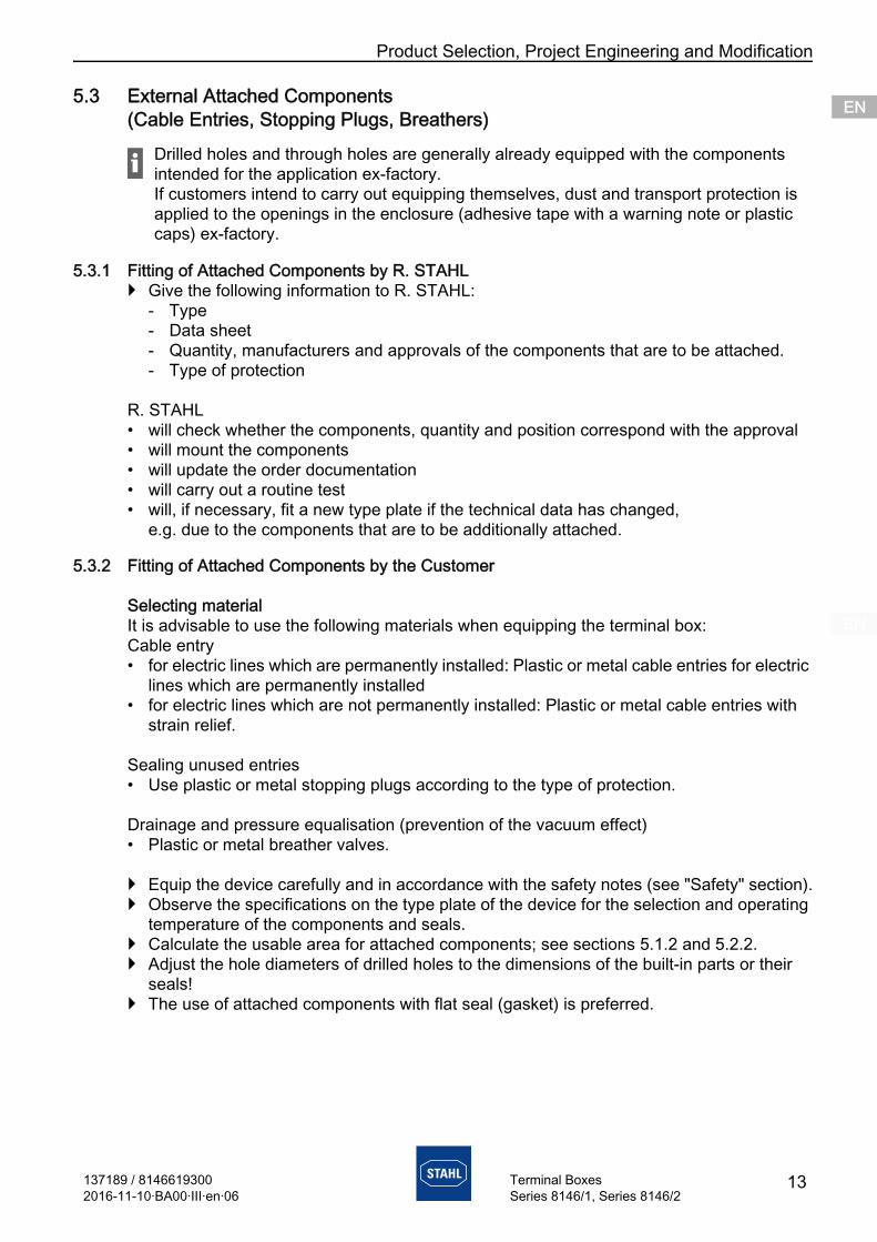
5.3 External Attached Components (Cable Entries, Stopping Plugs, Breathers)
5.3.1 Fitting of Attached Components by R. STAHL Give the following information to R. STAHL:
- Type- Data sheet- Quantity, manufacturers and approvals of the components that are to be attached.- Type of protection
R. STAHL• will check whether the components, quantity and position correspond with the approval• will mount the components• will update the order documentation• will carry out a routine test• will, if necessary, fit a new type plate if the technical data has changed,
e.g. due to the components that are to be additionally attached.
5.3.2 Fitting of Attached Components by the Customer
Selecting materialIt is advisable to use the following materials when equipping the terminal box:Cable entry• for electric lines which are permanently installed: Plastic or metal cable entries for electric
lines which are permanently installed• for electric lines which are not permanently installed: Plastic or metal cable entries with
strain relief.
Sealing unused entries• Use plastic or metal stopping plugs according to the type of protection.
Drainage and pressure equalisation (prevention of the vacuum effect)• Plastic or metal breather valves.
Equip the device carefully and in accordance with the safety notes (see "Safety" section). Observe the specifications on the type plate of the device for the selection and operating
temperature of the components and seals. Calculate the usable area for attached components; see sections 5.1.2 and 5.2.2. Adjust the hole diameters of drilled holes to the dimensions of the built-in parts or their
seals! The use of attached components with flat seal (gasket) is preferred.
Drilled holes and through holes are generally already equipped with the components intended for the application ex-factory.If customers intend to carry out equipping themselves, dust and transport protection is applied to the openings in the enclosure (adhesive tape with a warning note or plastic caps) ex-factory.
137189 / 81466193002016-11-10·BA00·III·en·06
13Terminal BoxesSeries 8146/1, Series 8146/2

Product Selection, Project Engineering and ModificationENENENENENENENENENENENENENENENENENENENENENENENENEN
14 137189 / 8146619300Terminal Boxes
5.4 Internal Built-In Components (Conductors, Terminals, Fuses)
Ascertaining the maximum number of conductors
5.4.1 Ascertain the Number of Conductors using the Table from the EU Type Examination Certificate Refer to the specifications in the EU Type Examination Certificate for the maximum
permitted number of conductors in relation to the current load and conductor cross-section.
Taking enclosure 8146/1061 as an example: The maximum permitted number of conductors can be ascertained using the following table.
06219E00
*) Current, **) conductor cross-section
Explanations of the table:Each inserted conductor and each internal connection conductor must be counted. Jumpers and protective conductors are not considered conductors.
Non-critical area (light area of the table)The light area is non-critical in terms of heating up the enclosure. Circuits classified as being in this area can be incorporated in the enclosure in any number.
Heat develops in every terminal box due to contact resistance at the terminals and the cables installed in the enclosure. In order to ensure that the maximum permissible temperatures of a terminal box are not exceeded, care should be taken that the current load of the circuits installed in the terminal box does not exceed certain values!
2016-11-10·BA00·III·en·06Series 8146/1, Series 8146/2

Product Selection, Project Engineering and Modification ENENENENENENENENENENENENENENENENENENENENENENENENEN
Critical (inscribed area of the table)The part of the table shows the maximum permissible number of conductors considering the cross-sections of the conductors and the continuous current loading. When using this table, simultaneous factors and load factors may be accounted for. Mixed arrangements with circuits of different cross-sections and currents are possible; in this case the proportion of the loading from the individual circuits should be taken into account. If a terminal box is fully loaded according to the criteria in the dark part of the table, then any number of circuits from the non-critical (light part of the table) may be added.
Dangerous (dark area of the table)Terminal boxes which are designed according to this area require an additional temperature-rise test.
Example calculation (general):
Ensure that operating temperatures of the terminal box and the selected electric lines (in particular low temperatures) match.
5.4.2 Additional Terminals
Fitting of additional terminals by R. STAHL Forward the following information to R. STAHL:
- Type- Manufacturer- Data sheet- Quantity- Enclosure size
R. STAHL• will check whether the terminal type, quantity, cross-section and current load correspond
with the approval• will check whether the enclosure size, drilled holes and through holes are sufficient• will install the terminals• will, if necessary, create required drilled holes and fit required cable entries• will update the order documentation• will carry out a routine test• will, if necessary, fit a new type plate if the technical data, such as current or conductor
cross-section, has changed.
Cross-section [mm2] Current [A] Number of conductors Proportion2.5 20 8 (of 20) = 40 %4 25 6 (of 22) = 27 %6 35 4 (of 17) = 24 %
= 91 % < 100 %
137189 / 81466193002016-11-10·BA00·III·en·06
15Terminal BoxesSeries 8146/1, Series 8146/2

Product Selection, Project Engineering and ModificationENENENENENENENENENENENENENENENENENENENENENENENENEN
137189 / 8146619300Terminal Boxes
Fitting of additional terminals by the customer Modify the device carefully and only in accordance with the safety notes
(see "Safety" section). Ascertain additional terminal points, terminal type, quantity, cross-section and current
load. Check whether type plate data is changed as a result of subsequently equipping
(cross-section, voltage, current, etc.). Check whether enough space and fastening options are available for equipping.
5.4.3 Fuses
When fitting fuses, the ambient temperature values for the following temperature classes apply:
When fitting fuses, the ambient temperature values for areas with dust explosion hazard for the following max. permissible surface temperatures apply:
Subsequent equipping is not permitted if the installation conditions are not complied with!
Installing, modifying or retrofitting fuses is only permitted to be performed by R. STAHL!
Fuse current value Temperature class( 4 A T6> 4 A to ( 5 A T5> 5 A to ( 6.3 A T4
Fuse current value Ambient temperature (Ta)
Max. permissible surface temperature
( 4 A ( 40 °C T80°C( 4 A ( 56 °C T95°C( 5 A ( 46 °C T95°C( 6.3 A ( 70 °C T130°C
162016-11-10·BA00·III·en·06Series 8146/1, Series 8146/2

Mounting and Installation ENENENENENENENENENENENENENENENENENENENENENENENENEN
6 Mounting and Installation
6.1 Mounting / Dismounting, Operating Position Mount the device carefully and only in accordance with the safety notes
(see "Safety" section). Read through the following installation conditions and assembly instructions carefully and
follow them precisely.
6.1.1 Operating Position
Mount the device using the mounting straps. Refer to the dimensional drawing for the dimensions of the mounting holes.
16523E00
Alignment of enclosure depending on mounting type:• For vertical mounting: any alignment• For horizontal mounting: cover on top• Hanging position/overhanging cover is not permitted!
6.1.2 Environmental Installation Conditions Provide a protective roof or wall if the explosion-protected device is exposed to weather. Equip explosion-protected electric equipment with a breather and drain valve in order to
prevent the vacuum effect. Observe the correct mounting orientation (bottom) when doing so. See also section 6.1.1
Do not create any cold bridges (risk of condensation). If necessary, mount the enclosure with a clearance to reduce condensation in the enclosure to a minimum.
DANGER! Explosion due to incorrect mounting position!Non-compliance results in fatal or severe injuries. Mount the device only on the floor or wall, not overhead or in a free-standing
position. Mount the device torsion-free only on a level surface.
≦ 90°
137189 / 81466193002016-11-10·BA00·III·en·06
17Terminal BoxesSeries 8146/1, Series 8146/2

Mounting and InstallationENENENENENENENENENENENENENENENENENENENENENENENENEN
6.2 Installation
6.2.1 Conductor Connection Select suitable conductors that do not exceed the permitted heating temperature within the
enclosure. Ensure that conductors have the specified cross-sections. Guide the conductor insulation so that it reaches the terminals. Do not damage the conductor when stripping the insulation (e.g. by denting it). Attach the core end sleeves properly. If the system is equipped with all possible terminals and live conductors, and and the
maximum current load has been reached, ensure that the length of a conductor from the screw connection to the terminal point does not exceed the diagonal planes of the enclosure.
Operation under difficult conditions, such as on ships or in strong sunlight, requires additional measures to be taken for correct installation, depending on the place of use. Further information and instructions on this can be obtained from your regional sales contact on request.
DANGER! Explosion due to excess heating inside the enclosure!Non-compliance results in fatal or severe injuries. Ensure that distances between Ex e electric circuits and Ex i electric circuits comply
with standards (EN IEC 60079-11). Select suitable conductors that do not exceed the permitted heating temperature
within the enclosure. Pay attention to the specified cross-sections. Attach the core end sleeves properly.
DANGER! Explosion due to improper installation!Non-compliance results in fatal or severe injuries. Install the device carefully and only in accordance with the safety notes
("Safety" section). The installation steps stated below must be carried out very precisely.
The necessary technical details/data on electric installation can be found in the following documents: "Technical data" chapter in these operating instructions Documentation and data sheets provided by the terminal manufacturers Documentation and data sheets of the installed devices (e.g. for specifications on
equipotential bonding, earthing and intrinsically safe circuits)
18 137189 / 81466193002016-11-10·BA00·III·en·06
Terminal BoxesSeries 8146/1, Series 8146/2

Mounting and Installation ENENENENENENENENENENENENENENENENENENENENENENENENEN
6.2.2 Installation Conditions
Installation conditions for creepage distances and clearances
Distances, creepage distances and clearances When installing components, the creepage distances and clearances between the
individual components, as well as between the components and the enclosure walls, must be sufficiently dimensioned. Observe the values from the EN IEC 60079-7 standard (table) when doing so.
Check the creepage distances of the components and comply with them in accordance with the specifications in the respective operating instructions.
The clearance distances, depending on the rated operational voltage of the fitted terminals, must be complied with.
Observe the distance between the enclosure cover and connection screws of the built-in components (with the conductor connected): at least the value of the required clearances.
18591E00
I = Minimum distance from the enclosure in accordance with EN IEC 60079-7 standard (table)
y = ClearanceX = Factor in accordance with
EN IEC 60079-7 depending on conductor cross-section
18590E00
X * I = Minimum distance
18592E00
18593E00
m = 50 mm distance between Ex e and Ex i terminal blocks
c = 8 mm distance between Ex e and Ex i cable lines
II II
X I*
y
I
I
m
c
137189 / 81466193002016-11-10·BA00·III·en·06
19Terminal BoxesSeries 8146/1, Series 8146/2

Mounting and InstallationENENENENENENENENENENENENENENENENENENENENENENENENEN
Distance between the connecting units for intrinsically safe and non-intrinsically safe circuits Mount partitions used to separate connection terminals at least 1.5 mm from the enclosure
walls, or alternatively ensure a minimum distance of 50 mm between the uncoated conducting parts of the connection terminals (when measured in any direction around the partition)
Make sure that metallic partitions• are at least 0.45 mm thick• are earthed• are sufficiently strong and rigid• have sufficient current carrying capacity.
Make sure that non-metallic, insulating partitions• are at least 0.9 mm thick• have an appropriate comparative tracking index (CTI)• are reinforced to prevent deformation.
When using fuses > 4 A, implement additional design measures to prevent impermissible heat-up at the terminals of the intrinsically safe circuits.
Covers for combinations of non-intrinsically safe and intrinsically safe circuits Equip all live parts which are not acc. to "Ex i" protection with an inner cover which meets
at least the degree of protection IP30 when the equipment is open.
Intrinsically safe circuits In intrinsically safe circuits, use only insulated cables and conductors with a test voltage
of at least 500 V AC and a minimum quality of H05. Calculate the insulation test voltage for the insulation and separation of terminals and
conductors from the sum of the rated operational voltages of intrinsically safe and non-intrinsically safe circuits.• In case of "intrinsically safe to earth", there is a minimum rated insulation voltage value
of 500 V (otherwise, double the value of the rated operational voltage of intrinsically safe circuits).
• In the case of "intrinsically safe to non-intrinsically safe", there is a minimum rated insulation voltage value of 1500 V (otherwise, double the rated operational voltage plus 1000 V).
Clearance and creepage distances of intrinsically safe components Make sure that the creepage distances and clearances between the uncoated,
conductive parts of connection terminals of separated, intrinsically safe circuits to earthed or potential-free, conductive parts is equal or greater than the values of EN IEC 60079-11, Table 5.
For separated, intrinsically safe electric circuits, set up a safe distance between the uncoated, conductive parts of external connections, which meets the following requirements:• minimum 6 mm between the separated, intrinsically safe circuits• minimum 3 mm to earthed parts if possible connection to earth has not been considered
in the safety analysis.
20 137189 / 81466193002016-11-10·BA00·III·en·06
Terminal BoxesSeries 8146/1, Series 8146/2

CommissioningENENENENENENENENENENENENENENENENENENENENENENENENEN
7 CommissioningBefore commissioning, carry out the following checks: Check the enclosure for damage. Check that mounting and installation have been performed correctly. When doing so,
check whether all covers and partitions for live parts have been installed and fastened. Make sure that all openings/drilled holes in the enclosure are sealed with permissible
components. Dust and transport protection (adhesive tape or plastic caps) fitted at the factory must be replaced with certified components.
Make sure that seals and sealing systems are clean and undamaged. If necessary, remove foreign bodies. If necessary, clean the connection chamber. Check whether all prescribed tightening torques have been observed.
8 Maintenance and Repair Observe the relevant national regulations in the country of use, e.g. EN IEC 60079-14,
EN IEC 60079-17, EN IEC 60079-19.
8.1 MaintenanceCheck the following points in addition to the national regulations:• whether the clamping screws holding the cables are securely seated,• whether the device enclosure and/or protective enclosure have cracks or other visible
signs of damage• compliance with the permitted temperatures,• the screws and nuts are securely fastened.
8.2 Maintenance Perform maintenance on the device according to the applicable national regulations and
the safety notes in these operating instructions ("Safety" section).
8.3 Repair Perform repairs to the device only using original spare parts and after consulting with
R. STAHL.
9 Returning the Device Only return or package the devices after consulting R. STAHL!
Contact the responsible representative at R. STAHL for this.
R. STAHL's customer service is available to handle returns if repair or service is required.
Only return or package the devices after contacting and consulting R. STAHL!
137189 / 81466193002016-11-10·BA00·III·en·06
21Terminal BoxesSeries 8146/1, Series 8146/2

CleaningENENENENENENENENENENENENENENENENENENENENENENENENEN
Contact customer service personally.
or
Go to the www.stahl.com website. Select "Downloads" > Customer service > "RMA Request". Fill out the form.
Wait for confirmation. R. STAHL's customer service will contact you. You will receive an RMA slip after speaking with customer service.
Send the device along with the RMA slip in the packaging to R. STAHL Schaltgeräte GmbH (refer to Section 1.1 for the address).
10 Cleaning Check the device for damage before and after cleaning it. Take damaged devices out of
operation immediately. To avoid electrostatic charging, the devices located in hazardous areas may only be
cleaned using a damp cloth. When cleaning with a damp cloth, use water or mild, non-abrasive, non-scratching
cleaning agents. Do not use aggressive detergents or solvents. Never clean the device with a strong water jet, e.g. using a high-pressure washer!
11 Disposal Observe national and local regulations and statutory regulations regarding disposal. Separate materials when sending them for recycling. Ensure environmentally friendly disposal of all components according to the statutory
regulations.
12 Accessories and Spare Parts NOTICE! Malfunction or damage to the device due to the use of non-original components.Non-compliance can result in material damage. Use only original accessories and spare parts from R. STAHL Schaltgeräte GmbH
(see data sheet).
22 137189 / 81466193002016-11-10·BA00·III·en·06
Terminal BoxesSeries 8146/1, Series 8146/2

Annex A ENENENENENENENENENENENENENENENENENENENENENENENENEN
13 Annex A
13.1 Technical Data
Explosion ProtectionGlobal (IECEx)
Gas and dust IECEx PTB 06.0046Ex d e ia/ib [ia Ga] mb IIA, IIB, IIC T6, T5, T4 GbEx tb IIIA, IIIB, IIIC, T80°C, T95°C, T130°C Db IP66
Europe (ATEX)Gas and dust PTB 01 ATEX 1016
E II 2 G Ex d e ia/ib [ia Ga] mb IIA, IIB, IIC T6, T5, T4 GbE II 2 D Ex tb IIIA, IIIB, IIIC T80°C, T95°C, T130°C Db IP66
Certifications and certificatesCertificates IECEx, ATEX, China (China-Ex), Brazil (INMETRO), Canada (CSA),
Kazakhstan (TR), Korea (KCs), Russia (TR), Taiwan (ITRI), Ukraine (TR), Belarus (TR), USA (UL)
Ship approval GL, RS
Technical DataElectrical data
Rated operational voltage
max. 1100 V AC / DC (depending on the terminal type and the Ex components used)
Rated operational current
max. 500 A (depending on the terminal type and the Ex components used)
Ambient conditionsAmbient temperature -60 to +100 °C
(depending on the Ex components used)Mechanical data
Degree of protection IP66 acc. to IEC/EN 60529Material
Enclosure Polyester resin, glass-fibre-reinforced, dark grey, similar to RAL 7024 Impact resistance ) 7 J Surface resistance ( 109 O Flame-resistant according to IEC/EN 60695, UL 94, ASTM D635
Seal Standard: foamed siliconeSpecial: PU, foamed (-20 to +80 °C)
FlangesStandard In the standard design, the enclosures are supplied without flanges.Option Depending on order, the enclosures can be fitted on one or more sides with
flanges; flange material: polyester resin, glass-fibre-reinforcedCover lock with captive M6 stainless steel combo head screws according to the specific
ations of the terminal block manufacturers
137189 / 81466193002016-11-10·BA00·III·en·06
23Terminal BoxesSeries 8146/1, Series 8146/2

Annex AENENENENENENENENENENENENENENENENENENENENENENENENEN
Connection cross-section
Terminals Rated cross section that can be used, max. 300 mm2. The maximum number of terminals for the respective enclosure size is indicated in the EU Type Examination Certificate.
Mounting / InstallationConnection According to the order directly to the fitted components or to the terminal
blocks.The rated operational voltage, the rated operational current and the rated cross section depend on the terminal type used and the explosion protected components.
Explosion ProtectionVersion as cable end box
Version 8146/1000-C923 8146/1093-C924 8146/1000-C958Global (IECEx)
Gas and dust IECEx PTB 06.0046 IECEx PTB 06.0046 IECEx PTB 06.0046Ex d e ia/ib [ia Ga] mb IIA, IIB, IIC T6, T5, T4 Gb
Ex d e ia/ib [ia Ga] mb IIA, IIB, IIC T6, T5, T4 Gb
Ex d e ia/ib [ia Ga] mb IIA, IIB, IIC T6, T5, T4 Gb
Ex tb IIIA, IIIB, IIIC, T80°C, T95°C, T130°C Db IP66
Ex tb IIIA, IIIB, IIIC, T80°C, T95°C, T130°C Db IP66
Ex tb IIIA, IIIB, IIIC, T80°C, T95°C, T130°C Db IP66
Europe (ATEX)Gas and dust PTB 01 ATEX 1016 PTB 01 ATEX 1016 PTB 01 ATEX 1016
E II 2 G Ex d e ia/ib [ia Ga] mb IIA, IIB, IIC T6, T5, T4 Gb
E II 2 G Ex d e ia/ib [ia Ga] mb IIA, IIB, IIC T6, T5, T4 Gb
E II 2 G Ex d e ia/ib [ia Ga] mb IIA, IIB, IIC T6, T5, T4 Gb
E II 2 D Ex tb IIIA, IIIB, IIIC T80°C, T95°C, T130°C Db IP66
E II 2 D Ex tb IIIA, IIIB, IIIC T80°C, T95°C, T130°C Db IP66
E II 2 D Ex tb IIIA, IIIB, IIIC T80°C, T95°C, T130°C Db IP66
Certifications and certificates Certificates IECEx, ATEX, China (China-Ex), Brazil (INMETRO), Canada (CSA),
Kazakhstan (TR), Korea (KCs), Russia (TR), Taiwan (ITRI), Ukraine (TR), Belarus (TR), USA (UL)
Ship approval GL, RS
Technical Data
24 137189 / 81466193002016-11-10·BA00·III·en·06
Terminal BoxesSeries 8146/1, Series 8146/2

Annex A ENENENENENENENENENENENENENENENENENENENENENENENENEN
For further technical data, see www.stahl-ex.com.Technical DataVersion as cable end box
Version 8146/1000-C923 8146/1093-C924 8146/1000-C958Electrical data
Rated operational voltage
max. 690 V AC max. 690 V AC max. 690 V AC
Rated current depending on the temperature class
400 A / T5315 A / T6
355 A / T5315 A / T6
160 A / T5 125 A / T6
Ambient conditionsAmbient temperature -30 to +50 °C (T6 315 A)
-30 to +65 °C (T5 315 A)-30 to +50 °C (T5 400 A)
-30 to +40 °C (T6 315 A)-30 to +55 °C (T5 315 A)-30 to +45 °C (T5 355 A)
-30 to +55 °C (T6 125 A)-30 to +40 °C (T5 125 A)-30 to +45 °C (T5 160 A)
Mechanical dataDegree of protection IP66 IP66 IP66Terminals 12 stud terminals M12
185 mm2;4 PE stud terminals 185 mm2
6 stud terminals M12 185 mm2;2 PE stud terminals 185 mm2
8 line-up terminals 70 mm2
Internal wiring Copper bar 20 x 10 mm (Cu-ETP R300)
Copper bar 20 x 10 mm (Cu-ETP R300)
Cable NSGAFöu 70; 70 mm2
Cable entry brass plate with 2 x M75
brass plate with 2 x M75
brass plate with 2 x M75
Mounting / InstallationCable entries Standard: In polyamide,
Series 8161Special: In metal
Standard: In polyamide, Series 8161Special: In metal
Standard: In polyamide, Series 8161Special: In metal
137189 / 81466193002016-11-10·BA00·III·en·06
25Terminal BoxesSeries 8146/1, Series 8146/2

Annex BENENENENENENENENENENENENENENENENENENENENENENENENEN
14 Annex B
14.1 Dimensions / Fastening Dimensions
Dimensional drawings (all dimensions in mm [inches]) – Subject to modifications
04180E0003179E00
04303E00
8146/.03. 8146/.04. 8146/.05.
04304E00
04305E00
8146/.06. 8146/.07.
04306E00
04307E00
8146/.S7. 8146/.08.
26 137189 / 81466193002016-11-10·BA00·III·en·06
Terminal BoxesSeries 8146/1, Series 8146/2

Annex B ENENENENENENENENENENENENENENENENENENENENENENENENEN
Version as cable end box04308E00
8146/.09.
04309E00
Additional dimension for flange mounting
Dimensional drawings (all dimensions in mm [inches]) – Subject to modifications
04175E00
04178E00 04179E00
8146/1000-C958 8146/1093-C924 8146/1000-C923
Dimensional drawings (all dimensions in mm [inches]) – Subject to modifications
Enclosure height hEnclosure 8146/...1
91 mm8146/...2131 mm
8146/...3150 mm
8146/...5190 mm
8146/...6230 mm
8146/.03. X – – – –8146/.04. X – – – –8146/.05. X X – – –8146/.06. X X – – –8146/.07. X X X X –8146/.S7. X – X – –8146/.08. X X X X X8146/.09. X X X X –X ... available version
Flange thickness[mm]
Di- mension a[mm]
2.8 75.8 10
137189 / 81466193002016-11-10·BA00·III·en·06
27Terminal BoxesSeries 8146/1, Series 8146/2