APPLICATION NOTE V850ES/JG3-L Continuous Positive Airway Pressure Machine Reference Design
Upload
khangminh22Category
view
2download
0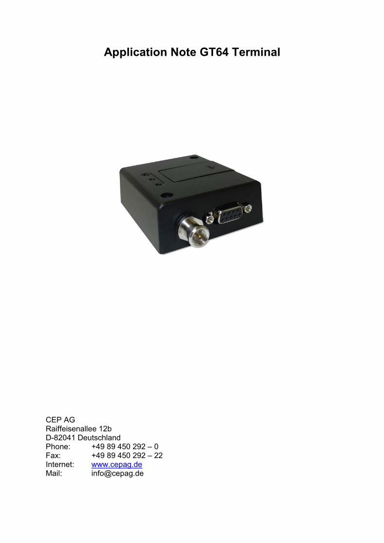
Application Note GT64 Terminal
CEP AG Raiffeisenallee 12b D-82041 Deutschland Phone: +49 89 450 292 – 0 Fax: +49 89 450 292 – 22 Internet: www.cepag.de Mail: [email protected]

The following table shows the differences between the standard GS64 Terminal and the GT64 Terminal regarding the interfaces and the inputs and outputs. Basically, the GT64 has 5 inputs and 1 output. GS64 Terminal GT64 Terminal
SUB D9 RS232 (with RX, TX, RTS, CTS, GND, DCD, DSR, RI, DTR with +/-8V levels) for AT-C modem functionality
RS232 (with RX, TX, RTS, CTS, GND, DCD, DSR, RI, DTR with +/-8V levels) for AT-C modem functionality or under control of
embedded application
USB USB 2.0 full speed for AT-C modem functionality
4 x input (max. voltage VIN is 30V; low level: 0...1V; high level: 4...30V) ESD-protected
under full control of embedded appl.
Mini Western 5V-36V power supply voltage
5V-36V power supply voltage and 1 x input (max. voltage VIN is 30V; low level: 0...1V; high level: 4...30V) and 1x output (switch
voltage is VIN; high side switch; max. Output 400mA; short circuit protected) both ESD-
protected under full control of embedded appl.
internal GS64
module without embedded
application with embedded application
Mini USB connector At the mini USB connector are 4 inputs, with the following technical description:
• max. voltage VIN is 30V • low level: 0...1V • high level: 4...30V • ESD protected • under full control of embedded application
Pinning of the USB connector for the variant GS64T I/O:
GS64 GPIO GS64 PIN Mini USB Mini USB PIN GPIO 6 48 IN1 1 GPIO 7 49 IN2 3 GPIO 8 50 IN3 2 GPIO 9 51 IN4 4
- - GND 5 All inputs are under control of an embedded application script or at-commands!

The following commands have to be used to initialise and to configure the GPIOs to control the the inputs: Configure GPIO 6 – 9 as an input: at*e2io=2,“IO6“,0 at*e2io=2,“IO7“,0 at*e2io=2,“IO8“,0 at*e2io=2,“IO9“,0 Read the GPIO status: at*e2io=0,“IO6“ at*e2io=0,“IO7“ at*e2io=0,“IO8“ at*e2io=0,“IO9“ For example GPIO 6: *E2IO: 0,“IO6”,0 Input is low *E2IO: 0,“IO6”,1 Input is high GPIO7, GPIO8, GPIO9 have the same behaviour! Mini Western connector At the mini Western connector is 1 input and 1 output, with the following technical description: Pinning of the RJ11 connector:
PIN: 1 VCC 2 Digital Input (GPIO4 GS64 module) 3 HR_IN 4 TO_IN 5 Digital Output (GPIO5 GS64 module) 6 GND
PIN: 6 5 4 3 2 1

• 1 x input • max. voltage VIN is 30V • low level: 0...1V; high level: 4...30V • 1x output • switch voltage is VIN; high side switch • max. Output 400mA • short circuit protected • both are ESC protected • and both are under full control of embedded application
Configure GPIO 4 as an input:
at*e2io=2,“IO4“,0
Read the GPIO status:
at*e2io=0,“IO4“
For example GPIO 4:
*E2IO: 0,“IO4”,0 Input is low
*E2IO: 0,“IO4”,1 Input is high
Configure GPIO 5 as an output:
at*e2io=2,”IO4”,1
Set output to “high-level”
at*e2io=1,"IO5",1
Set output to “low-level”
at*e2io=1,"IO5",0
CEP AG Version 1.1 _________________________________________________________________________________
__________________________________________________________________________________________ page 1 of 23
GS64 Terminal Technical Description
CEP AG Raiffeisenallee 12b 82041 Oberhaching Germany Phone: +49 89 450 292 – 0 Fax: +49 89 450 292 – 22 Internet: www.cepag.de Mail: [email protected] Version 1.1 Note: Specification is preliminary and subject to change without prior notice

CEP AG Version 1.1 _________________________________________________________________________________
__________________________________________________________________________________________ page 2 of 23
Important information This technical description contains important information for start up and use of the GS64 Terminal. Read it carefully before you start working with the GS64 Terminal. The warranty will be void should damage occur due to non-compliance with these instructions for use. We cannot accept any responsibility for consequential loss. We cannot be held responsible for material loss or personal injury that is due to incompetent use or non-compliance with the safety instructions. The warranty will be void in such circumstances. The GS64 Terminal contains highly integrated components which can be damaged by electrostatic discharge if the user would open the housing.
Therefore only touch the GS64 Terminal on the housing or connectors and avoid to touch the components on the board.
Safety Instructions
When using products which are exposed to electric voltage the valid regulations have to be observed.
Before opening of a device always pull the mains adapter or make sure that the device is disconnected from the power supply. You should only use tools on components, modules or devices if they are disconnected from the power supply and the electric charge, which may still be stored in some components, inside the device has been discharged. All cables and wires which are energized and connected to the device, the module or components have to be checked regularly for any damage of the isolation shield or fractures of the cables. If the supply cables are visibly damaged the device has to be taken out of operation immediately until the faulty cable has been exchanged. When using components or modules it is necessary to strictly observe the specification given in the corresponding description of these components. If a description for a private end-customer not clearly states which electric data is valid for a component or a module, how to wire the device, which external components or additional devices can be connected or which parameters these components are allowed to have, a specialist must be contacted. Before putting a device into operation, it has to be clarified, whether this device or module is meant for the field of application. In case of doubt ask specialists or the manufacturer of the device. Please note that we are not responsible for any errors in usage or connection. Therefore we cannot accept any responsibility for consequential loss. Devices which operate with >35 Volt have to be connected by a specialist. Before putting the device into operation it should be checked that there is no current leakage on the housing. In case that measurements with the opened housing are necessary, an isolating-transformer has to be integrated for safety reasons. Alternatively the voltage can be supplied by an appropriate power supply which complies with the safety regulations. All wiring work has to be done in a voltage free state only.

CEP AG Version 1.1 _________________________________________________________________________________
__________________________________________________________________________________________ page 3 of 23
Contents 1 Mechanical Description ....................................................................................... 4
1.1 Overview ...................................................................................................... 4 1.2 Physical Dimensions .................................................................................... 5
2 Electrical Description ........................................................................................... 6 2.1 Power Connector.......................................................................................... 6 2.2 Mini USB Connector..................................................................................... 7 2.3 Antenna Connector ...................................................................................... 7 2.4 SIM card reader............................................................................................ 8 2.5 RS232 Serial Port......................................................................................... 8
2.5.1 Serial Data ............................................................................................ 9 2.5.2 Serial Data Signals................................................................................ 9 2.5.3 Control Signals – RTS, CTS, DTR, DSR, DCD, RI ............................. 10
3 Operation........................................................................................................... 11 3.1 Switching on the modem ............................................................................ 11 3.2 Switching off the modem ............................................................................ 11 3.3 Resetting the modem ................................................................................. 11 3.4 Operating states / LEDs ............................................................................. 12
3.4.1 Power up LED (green LED in the middle) ........................................... 12 3.4.2 Status LEDs (one yellow, one red)...................................................... 12
4 Safety and Product Care ................................................................................... 13 4.1 Safety instructions ...................................................................................... 13 4.2 General precautions ................................................................................... 13 4.3 SIM card precautions ................................................................................. 14 4.4 Antenna precautions .................................................................................. 14
5 Installation of the modem .................................................................................. 14 5.1 Where to install the modem........................................................................ 15
5.1.1 Environmental conditions .................................................................... 15 5.1.2 Signal strenght .................................................................................... 15 5.1.3 Connections of components to GS64 Terminal................................... 15 5.1.4 Network and Subscription ................................................................... 15
5.2 How to install the modem ........................................................................... 16 5.2.1 Power supply....................................................................................... 16 5.2.2 Securing the modem ........................................................................... 16
5.3 Antenna...................................................................................................... 16 5.3.1 General ............................................................................................... 16 5.3.2 Antenna type ....................................................................................... 17 5.3.3 Antenna placement ............................................................................. 17 5.3.4 The antenna cable .............................................................................. 17 5.3.5 Possible communications disturbances .............................................. 17
5.4 Accessories................................................................................................ 18 6 Technical Data .................................................................................................. 19 7 Abbreviations..................................................................................................... 21 8 Declaration of Conformity .................................................................................. 22 9 Service and Support .......................................................................................... 23

CEP AG Version 1.1 _________________________________________________________________________________
__________________________________________________________________________________________ page 4 of 23
1 Mechanical Description
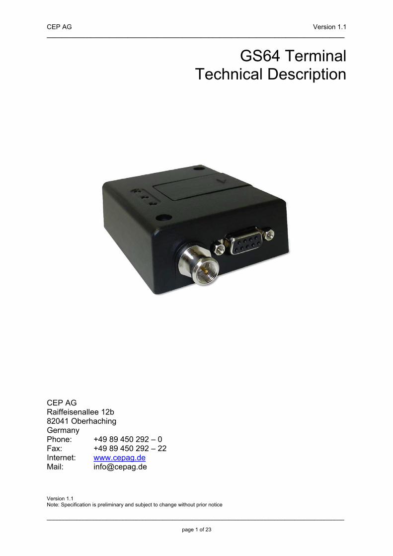
1.1 Overview The pictures below shows the mechanical design of the GS64 Terminal along with the positions of the different connectors and mounting holes. The GS64 Terminal case is made of durable PC/ABS plastic.
Mini USB connector
Power connector
mounting holes Access to
SIM card holder
3 status LEDs
antenna connector
RS232 connector

CEP AG Version 1.1 _________________________________________________________________________________
__________________________________________________________________________________________ page 5 of 23
Please note the following:
• Mounting holes positioned at two of the corners make it possible to securely bolt the modem into your application.
• Keypad, display, microphone, speaker and battery are not part of the modem.
• The SIM card is mounted in the modem. • The pins and electrical characteristics or the modem’s various
connectors are described in “2. Electrical Description” • Information about the antenna connector is found in
“2.3 Antenna Connector”
1.2 Physical Dimensions Overall dimensions: 77 x 67 x 26 mm
CEP AG Version 1.1 _________________________________________________________________________________
__________________________________________________________________________________________ page 6 of 23
2 Electrical Description The modem uses the following industry standard connectors:
• RJ11 6-way (power connector) • Mini USB (USB connector) • SIM card reader • FME male coaxial jack (antenna connector) • Sub-D socket, 9 pin (RS232 serial port)
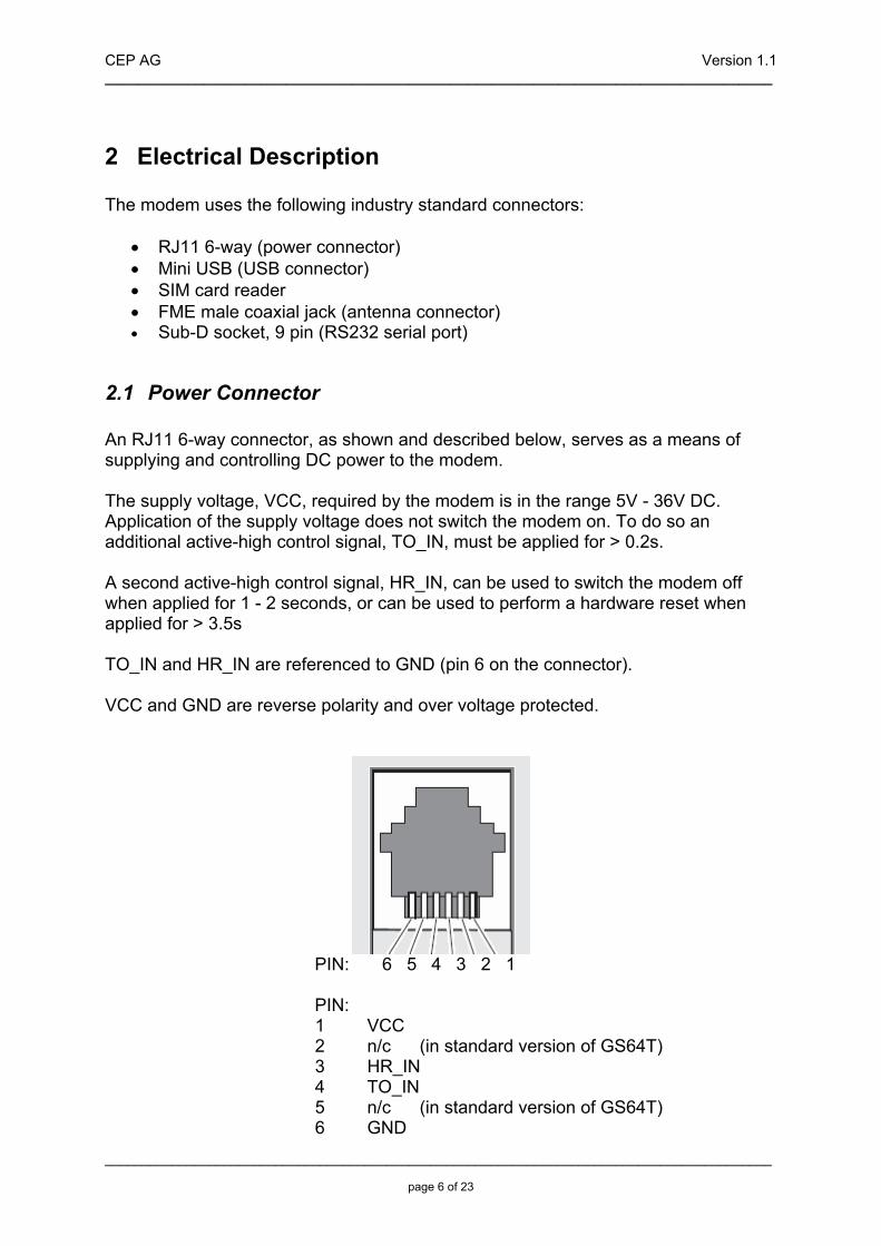
2.1 Power Connector An RJ11 6-way connector, as shown and described below, serves as a means of supplying and controlling DC power to the modem. The supply voltage, VCC, required by the modem is in the range 5V - 36V DC. Application of the supply voltage does not switch the modem on. To do so an additional active-high control signal, TO_IN, must be applied for > 0.2s. A second active-high control signal, HR_IN, can be used to switch the modem off when applied for 1 - 2 seconds, or can be used to perform a hardware reset when applied for > 3.5s TO_IN and HR_IN are referenced to GND (pin 6 on the connector). VCC and GND are reverse polarity and over voltage protected.
PIN: 6 5 4 3 2 1 PIN:
1 VCC 2 n/c (in standard version of GS64T) 3 HR_IN 4 TO_IN 5 n/c (in standard version of GS64T) 6 GND

CEP AG Version 1.1 _________________________________________________________________________________
__________________________________________________________________________________________ page 7 of 23
Signals of Power Connector
PIN Signal Direction Limits Description
1 VCC Input 5 – 36V Positiv power input
2 - - - No connection in standard version
3 HR_IN Input 5 – 36V
Active high control line used to switch off or reset the modem VIH > 5V, VIL < 2V Power off: 1s < t < 2s Hard reset: t > 3.5s
4 TO_IN Input 5 – 36V
Active high control line used to switch on the modem VIH > 5V, VIL < 2V Power on: t > 0.2s
5 - - - No connection in standard version
6 GND Input -
Negative power (ground) input and return path for TO_IN and HR_IN
2.2 Mini USB Connector The USB 2.0 interface allows the connectivity to all relevant PCs and control boards in office and industrial environments. The USB interface is a USB 2.0 full speed interface for AT-C modem functionality between the GS64 Terminal and e.g. a PC.
2.3 Antenna Connector The antenna connector allows transmission of radio frequency (RF) signals between the modem and an external customer-supplied antenna. The modem is fitted with a 50Ω, FME male coaxial jack.

CEP AG Version 1.1 _________________________________________________________________________________
__________________________________________________________________________________________ page 8 of 23
Describtion of antenna connector parameters
Parameter Limit Description
Nominal impedance
50Ω (SWR better than 2.5:1)
Output Power
Watt peak (Class 4) 1 Watt peak (Class 1)
Extended GSM900 GSM1800
Static Sensitivity
Better than –102dBm Better than –102dBm
Extended GSM900 GSM1800
2.4 SIM card reader The GS64 Terminal is fitted with a SIM card reader designed for 1.8V and 3V SIM cards. It is the flip-up type which is lockable in the horizontal position and is accessed through a removable panel as shown below.
2.5 RS232 Serial Port The modem supports a standard RS232 serial interface (EIA/TIA 574) via its 9 pin Sub-D connector, shown below. In line with serial communication terminology the GS64 Terminal should be considered as the data circuit-terminating equipment (DCE) and the external application or computer as the data terminating equipment (DTE).

CEP AG Version 1.1 _________________________________________________________________________________
__________________________________________________________________________________________ page 9 of 23
The electrical characteristics of the serial port signals are shown below:
PIN Signal Direction Voltage levels Description
1 DCD Output > + 4V <- 4 V Data carrier detect
2 RD Output > + 4V <- 4 V Received data
3 TD Input > + 2V < 0.8 V Transmitted data
4 DTR Input > + 2V < 0.8 V Data terminal ready
5 GND - 0 V Ground connection
6 DSR Output > + 4V < - 4 V Data set ready
7 RTS Input > + 2V < 0.8 V Request to send
8 CTS Output > + 4V < - 4 V Clear to send
9 RI Output > + 4V < - 4 V Ring indicator
2.5.1 Serial Data The modem supports the standard data character format of
• 1 start bit, 7 or 8 data bits, 1 optional parity bit, 1 or 2 stop bits • Programmable baud rate • Auto-configuration mode with auto-baud and auto-format operation
2.5.2 Serial Data Signals The default baud rate is 9.6kbps, however higher bit rates up to 460kbps are supported. At start-up the GS64 Terminal transmits and receives data at the default rate of 9.6kbps in either standard AT mode or binary mode (the first received data - AT or binary format - determines the operating mode). When reprogramming, the transmission rate is automatically negotiated by the programming application. Speeds up to 460kbps are supported. Serial Data From Modem (RD) RD is an output signal that the modem uses to send data to the application. Serial Data To Modem (TD) TD is an input signal, used by the application to send data to the modem.

CEP AG Version 1.1 _________________________________________________________________________________
__________________________________________________________________________________________ page 10 of 23
2.5.3 Control Signals – RTS, CTS, DTR, DSR, DCD, RI RTS and CTS are capable of transmitting at 1/10th of the data transmission speed for data rates up to 460kbps (byte-oriented flow control mechanism). Request to Send (RTS) Used to condition the DCE for data transmission. The default level is high by internal pull up. The exact behaviour of RTS is defined by an AT command. Software or hardware control can be selected. Hardware flow is the default control. The application must pull RTS low to communicate with the modem. The modem will respond by asserting CTS low, indicating it is ready for communication. Clear To Send (CTS) CTS indicates that the DCE is ready to transmit data. The default level is high. You can define the exact behaviour of CTS through an AT command, and can select software or hardware flow control. Data Terminal Ready (DTR) DTR indicates that the DTE is ready to transmit and receive data. It also acts as a hardware ‘hang-up’, terminating calls when switched high. The signal is active low. You can define the exact behaviour of DTR with an AT command. The DTR line can also be used to switch on the modem when activated for 0.2 seconds. The DTR line must be deactivated prior to switching off the modem to ensure it switches off (powers down) correctly. Data Set Ready (DSR) An active DSR signal is sent from the modem to the application (DTE) to confirm that a communications path has been established. DSR has two modes of operation, settable using the AT command AT&S. Data Carrier Detect (DCD) DCD indicates that the DCE is receiving a valid carrier (data signal) when low. You can define the exact behaviour of DCD with an AT command. Ring Indicator (RI) RI indicates that a ringing signal is being received by the DCE when low. You can define the exact behaviour or RI with an AT command.

CEP AG Version 1.1 _________________________________________________________________________________
__________________________________________________________________________________________ page 11 of 23
3 Operation
3.1 Switching on the modem There are two ways to switch on the modem, once power is applied. • either assert TO_IN high for > 0.2s; • or activate the RS232 control line DTR, high for > 0.2s. The modem is fully operational after 4 seconds. Logging onto a network may take longer than this and is outside the control of the modem. The modem can be configured to start up at the time power is applied by permanently tying power connector signals TO_IN (pin 4) and VCC (pin 1) together. In this case DTR must be used to switch the modem on again after it has been switched off or reset, while power is still applied. Note! DTR must be cycled from low to high.
3.2 Switching off the modem There are three ways to switch off (power down) the modem as described below: • either use the AT+CFUN command; • or assert HR_IN high for 1 - 2 seconds. A delay of up to 10s is experienced as the modem logs off the network • or assert TO_IN low to high for 1 - 2 seconds. Note! The DTR line must be deactivated prior to switching off the modem to ensure the unit switches off correctly.
3.3 Resetting the modem A full system reset, independent of the status of the software, may be applied to the modem as follows: • assert HR_IN high for > 3.5s.
CEP AG Version 1.1 _________________________________________________________________________________
__________________________________________________________________________________________ page 12 of 23
3.4 Operating states / LEDs
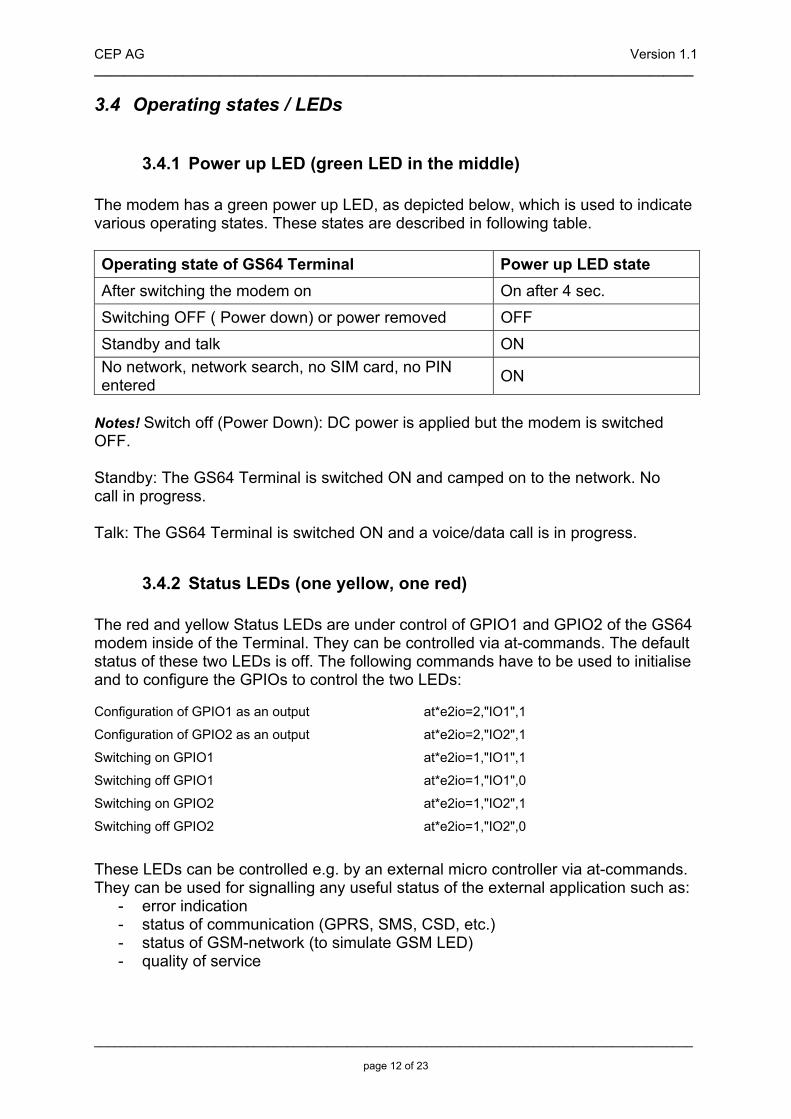
3.4.1 Power up LED (green LED in the middle) The modem has a green power up LED, as depicted below, which is used to indicate various operating states. These states are described in following table. Operating state of GS64 Terminal Power up LED state After switching the modem on On after 4 sec.
Switching OFF ( Power down) or power removed OFF
Standby and talk ON No network, network search, no SIM card, no PIN entered ON
Notes! Switch off (Power Down): DC power is applied but the modem is switched OFF. Standby: The GS64 Terminal is switched ON and camped on to the network. No call in progress. Talk: The GS64 Terminal is switched ON and a voice/data call is in progress.
3.4.2 Status LEDs (one yellow, one red) The red and yellow Status LEDs are under control of GPIO1 and GPIO2 of the GS64 modem inside of the Terminal. They can be controlled via at-commands. The default status of these two LEDs is off. The following commands have to be used to initialise and to configure the GPIOs to control the two LEDs: Configuration of GPIO1 as an output at*e2io=2,"IO1",1
Configuration of GPIO2 as an output at*e2io=2,"IO2",1
Switching on GPIO1 at*e2io=1,"IO1",1
Switching off GPIO1 at*e2io=1,"IO1",0
Switching on GPIO2 at*e2io=1,"IO2",1
Switching off GPIO2 at*e2io=1,"IO2",0 These LEDs can be controlled e.g. by an external micro controller via at-commands. They can be used for signalling any useful status of the external application such as:
- error indication - status of communication (GPRS, SMS, CSD, etc.) - status of GSM-network (to simulate GSM LED) - quality of service

CEP AG Version 1.1 _________________________________________________________________________________
__________________________________________________________________________________________ page 13 of 23
4 Safety and Product Care Please read the information in this section and the information in “Installation of the Modem”, before starting your integration work!
4.1 Safety instructions PLEASE READ THESE SAFETY INSTRUCTIONS AND KEEP A COPY OF THEM.
• Always ensure that use of the modem is permitted. The modem may present a hazard if used in proximity to personal medical electronic devices. As a rule, the modem must not be used in hospitals, airports or planes.
• Never use the modem at a gas station, refuelling point, blasting area or in any other environment where explosives may be present.
• Operating the modem close to other electronic devices, such as antennas, television sets, and radios may cause electromagnetic interference.
• This product is intended to be used with the antenna or other radiating element at least 20cm away from any part of the human body. In applications where this rule cannot be applied, the application designer is responsible for providing the SAR measurement test report and declaration.
• You are responsible for observing your country's safety standards, and where applicable, the relevant wiring rules.
4.2 General precautions The GS64 Terminal as a stand alone item is designed for indoor use only. To use outside it must be integrated into a weatherproof enclosure. Do not exceed the environmental and electrical limits as specified in “Technical Data”.
• Avoid exposing the modem to lighted cigarettes, naked flames or to extreme hot or cold temperature.
• Never try to dismantle the modem yourself. There are no components inside the modem that can be serviced by the user. If you attempt to dismantle the modem, you may invalidate the warranty.
• The GS64 Terminal must not be installed or located where the surface temperature of the plastic case may exceed 85°C.
• All cables connected to the GS64 Terminal must be secured or clamped, immediately adjacent to the modem's connectors, to provide strain relief and to avoid transmitting excessive vibration to the modem in the installation.
• Ensure the d.c. cable, supplying power to the GS64 Terminal, does not exceed 3 metres.
• To protect power supply cables and meet the fire safety requirements when the unit is powered from a battery or a high current supply, connect a fast 1.25A fuse in line with the positive supply.
• Do not connect any incompatible component or product to the GS64 Terminal.
CEP AG Version 1.1 _________________________________________________________________________________
__________________________________________________________________________________________ page 14 of 23
Note! CEP AG may refuse warranty claims where evidence of product misuse is found.
4.3 SIM card precautions Before handling the SIM card in your application, ensure that you are not charged with static electricity. Use proper precautions to avoid electrostatic discharges. • When the SIM card hatch is opened, the SIM card connectors lie exposed under the SIM card holder. Caution! Do not touch these connectors! If you do, you may release an electrical discharge that could damage the modem or the SIM card. • When designing your application, the SIM card’s accessibility should be taken into account. We always recommend that you have the SIM card protected by a PIN code. This will ensure that the SIM card cannot be used by an unauthorized person.
4.4 Antenna precautions If the antenna is to be mounted outside, consider the risk of lightning. Follow the instructions provided by the antenna manufacturer.
• Never connect more than one modem to a single antenna. The modem can be damaged by radio frequency energy from the transmitter of another modem.
• Like any mobile station, the antenna of the modem emits radio frequency energy. To avoid EMI (electromagnetic interference), you must determine whether the application itself, or equipment in the application’s proximity, needs further protection against radio emission and the disturbances it might cause. Protection is secured either by shielding the surrounding electronics or by moving the antenna away from the electronics and the external signals cable.
• The modem and antenna may be damaged if either come into contact with ground potentials other than the one in your application. Beware, ground potential are not always what they appear to be.
5 Installation of the modem This chapter gives you advice and helpful hints on how to integrate the GS64 Terminal into your application from a hardware perspective. Please read the information given in “Safety and Product Care”, page 10 and then read the information in this section before starting your integration work.
CEP AG Version 1.1 _________________________________________________________________________________
__________________________________________________________________________________________ page 15 of 23
5.1 Where to install the modem There are several conditions which need to be taken into consideration when designing your application as they might affect the modem and its function. They are:
5.1.1 Environmental conditions The modem must be installed so that the environmental conditions stated in the Technical Data chapter, such as temperature, humidity and vibration are satisfied. Additionally, the electrical specifications in the Technical Data section must not be exceeded.
5.1.2 Signal strenght The modem has to be placed in a way that ensures sufficient signal strength. To improve signal strength, the antenna can be moved to another position. Signal strength may depend on how close the modem is to a radio base station. You must ensure that the location at which you intend to use the modem, is within the network coverage area. Degradation in signal strength can be the result of a disturbance from another source, for example an electronic device in the immediate vicinity. More information about possible communication disturbances can be found in section 5.3.5. When an application is completed, you can verify signal strength by issuing the AT command AT+CSQ. See “AT+CSQ Signal Strength”. Tip! Before installing the modem, use an ordinary mobile telephone to check a possible location for it. In determining the location for the modem and antenna, you should consider signal strength as well as cable length
5.1.3 Connections of components to GS64 Terminal The integrator is responsible for the final integrated system. Incorrectly designed or installed, external components may cause radiation limits to be exceeded. For instance, improperly made connections or improperly installed antennas can disturb the network and lead to malfunctions in the modem or equipment.
5.1.4 Network and Subscription Before your application is used, you must ensure that your chosen network provides the necessary telecommunication services. Contact your service provider to obtain the necessary information.
• If you intend to use SMS in the application, ensure this is included in your (voice) subscription.
• Consider the choice of the supplementary services

CEP AG Version 1.1 _________________________________________________________________________________
__________________________________________________________________________________________ page 16 of 23
5.2 How to install the modem
5.2.1 Power supply
• Use a high-quality power supply cable with low resistance. This ensures that the voltages at the connector pins are within the allowed range, even during the maximum peak current.
• When the unit is powered from a battery or a high current supply, connect a fast 1.25A fuse in line with the positive supply. This protects the power cabling and modem.
5.2.2 Securing the modem Before securing the modem take into account the amount of additional space required for the mating connectors and cables that will be used in the application.
• Where access is restricted, it may be easier to connect all the cables to the modem prior to securing it in the application.
• Securely attach the GS64 Terminal modem to the host application using two 3mm diameter pan-head screws
5.3 Antenna
5.3.1 General The antenna is the component in your system that maintains the radio link between the network and the modem. Since the antenna transmits and receives electromagnetic energy, its efficient function will depend on: • the type of antenna (for example, circular or directional); • the placement of the antenna; • communication disturbances in the vicinity in which the antenna operates. In the sections below, issues concerning antenna type, antenna placement, antenna cable, and possible communication disturbances are addressed. In any event, you should contact your local antenna manufacturer for additional information concerning antenna type, cables, connectors, antenna placement, and the surrounding area. You should also determine whether the antenna needs to be grounded or not. Your local antenna manufacturer might be able to design a special antenna suitable for your the application.

CEP AG Version 1.1 _________________________________________________________________________________
__________________________________________________________________________________________ page 17 of 23
5.3.2 Antenna type Make sure that you choose the right type of antenna for the modem. Consider the following requirements:
• the antenna must be designed for the one of the frequency bands in use; please ask your network provider for more informations:
o GSM 850/900 MHz o GSM 1800/1900 MHz;
• the impedance of the antenna and antenna cable must be 50Ω; • the antenna output-power handling must be a minimum of 2W; • the VSWR value should be less than 3:1 to avoid damage to the modem.
5.3.3 Antenna placement The antenna should be placed away from electronic devices or other antennas. The recommended minimum distance between adjacent antennas, operating in a similar radio frequency band, is at least 50cm. If signal strength is weak, it is useful to face a directional antenna at the closest radio base station. This can increase the strength of the signal received by the modem. The modem’s peak output power can reach 2W. RF field strength varies with antenna type and distance. At 10cm from the antenna the field strength may be up to 70V/m and at 1m it will have reduced to 7V/m. In general, CE-marked products for residential and commercial areas, and light industry can withstand a minimum of 3V/m.
5.3.4 The antenna cable Use 50Ω impedance low-loss cable and high-quality 50Ω impedance connectors (frequency range up to 2GHz) to avoid RF losses. Ensure that the antenna cable is as short as possible. The Voltage Standing-Wave Ratio (VSWR) may depend on the effectiveness of the antenna, cable and connectors. In addition, if you use an adapter between the antenna cable and the antenna connector, it is crucial that the antenna cable is a high-quality, low-loss cable. Minimize the use of extension cables, connectors and adapters. Each additional cable, connector or adapter causes a loss of signal power.
5.3.5 Possible communications disturbances Possible communication disturbances include the following:
• Noise can be caused by electronic devices and radio transmitters. • Path-loss occurs as the strength of the received signal steadily decreases in
proportion to the distance from the transmitter.
CEP AG Version 1.1 _________________________________________________________________________________
__________________________________________________________________________________________ page 18 of 23
• Shadowing is a form of environmental attenuation of radio signals caused by hills, buildings, trees or even vehicles. This can be a particular problem inside buildings, especially if the walls are thick and reinforced.
• Multi-path fading is a sudden decrease or increase in the signal strength. This is the result of interference caused when direct and reflected signals reach the antenna simultaneously. Surfaces such as buildings, streets, vehicles, etc., can reflect signals.
• Hand-over occurs as you move from one cell to another in the GSM network. Your mobile application call is transferred from one cell to the next. Hand-over can briefly interfere with communication and may cause a delay, or at worst, a disruption.
5.4 Accessories Please contact CEP AG for availability or check CEP’s webpage www.cepag.de.
CEP AG Version 1.1 _________________________________________________________________________________
__________________________________________________________________________________________ page 19 of 23
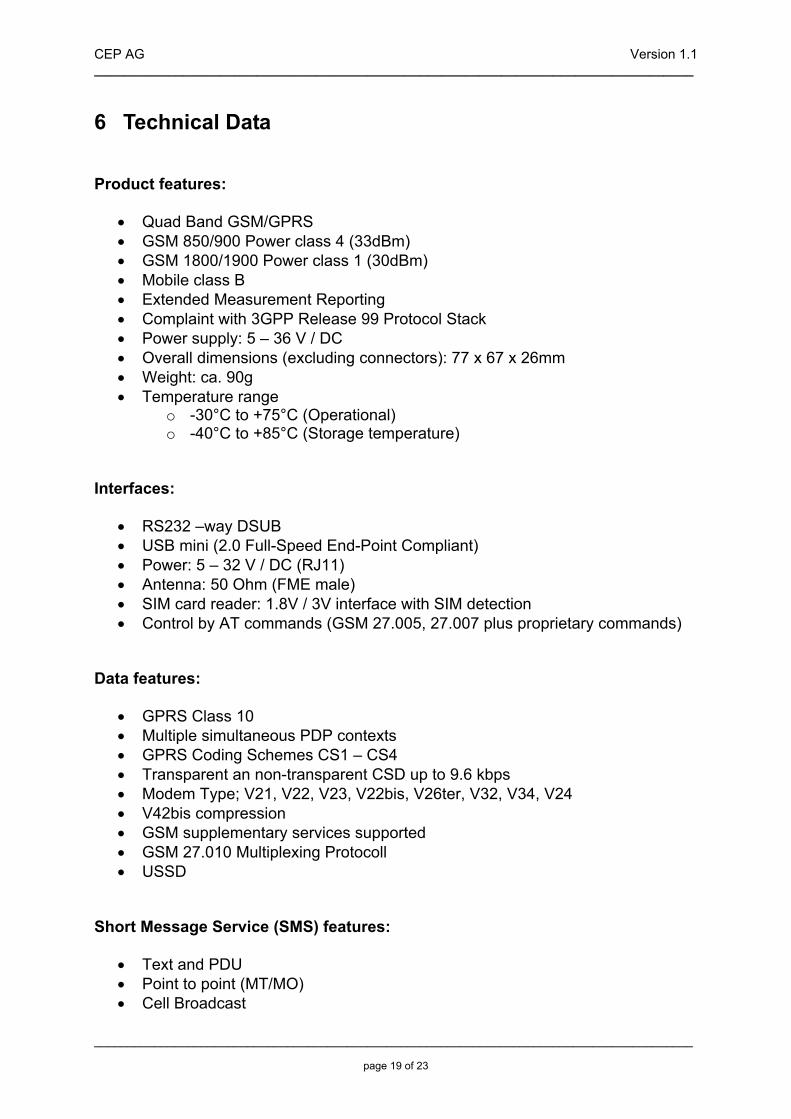
6 Technical Data Product features:
• Quad Band GSM/GPRS • GSM 850/900 Power class 4 (33dBm) • GSM 1800/1900 Power class 1 (30dBm) • Mobile class B • Extended Measurement Reporting • Complaint with 3GPP Release 99 Protocol Stack • Power supply: 5 – 36 V / DC • Overall dimensions (excluding connectors): 77 x 67 x 26mm • Weight: ca. 90g • Temperature range
o -30°C to +75°C (Operational) o -40°C to +85°C (Storage temperature)
Interfaces:
• RS232 –way DSUB • USB mini (2.0 Full-Speed End-Point Compliant) • Power: 5 – 32 V / DC (RJ11) • Antenna: 50 Ohm (FME male) • SIM card reader: 1.8V / 3V interface with SIM detection • Control by AT commands (GSM 27.005, 27.007 plus proprietary commands)
Data features:
• GPRS Class 10 • Multiple simultaneous PDP contexts • GPRS Coding Schemes CS1 – CS4 • Transparent an non-transparent CSD up to 9.6 kbps • Modem Type; V21, V22, V23, V22bis, V26ter, V32, V34, V24 • V42bis compression • GSM supplementary services supported • GSM 27.010 Multiplexing Protocoll • USSD
Short Message Service (SMS) features:
• Text and PDU • Point to point (MT/MO) • Cell Broadcast

CEP AG Version 1.1 _________________________________________________________________________________
__________________________________________________________________________________________ page 20 of 23
Internet Protocol:
• TCP/IP protocol stack • Extensive AT command access to TCP/IP stack • Multiple sockets with listening/server capability • IPv4 protocol • Dynamic & Static IP address allocation • PPP protocol (PAP) • UDP protocol • FTP client – File Transfer Protocol (file transfers)
Other features:
• SIM Application Toolkit Class 2 • 3x LED for status indication • Power Supply voltage measurement via at-command • Same mounting holes as Sony Ericsson GM29 • Same connector positions as Sony Ericsson GM29

CEP AG Version 1.1 _________________________________________________________________________________
__________________________________________________________________________________________ page 21 of 23
7 Abbreviations
Abbreviation Explanations CBM Cell Broadcast Message CBS Cell Broadcast Service CSD Circuit Switched Data DCE Data Circuit Terminating Equipment DTE Data Terminal Equipment DTMF Dual Tone Multi Frequency EFR Enhanced Full Rate EMC Electro-Magnetic Compatibility ETSI European Telecommunication Standards Institute FR Full Rate GPRS General Packet Radio Service GSM Global System for Mobile Communication HR Half Rate HSCSD High Speed Circuit Switched Data ITU-T International Telecommunication Union - Telecommunications Standardisation Sector ME Mobile Equipment MO Mobile Originated MS Mobile Station MT Mobile Terminated PDU Protocol Data Unit RLP Radio Link Protocol RF Radio Frequency RTC Real Time Clock SIM Subscriber Identity Module SMS Short Message Service TA Terminal Adapter TE Terminal Equipment TS Telecom Services
CEP AG Version 1.1 _________________________________________________________________________________
__________________________________________________________________________________________ page 22 of 23
8 Declaration of Conformity The GS64 Terminal will carry the following certificates: CE FCC E-Mark

CEP AG Version 1.1 _________________________________________________________________________________
__________________________________________________________________________________________ page 23 of 23
9 Service and Support To contact customer support please use the contact details below:
Customer Support CEP AG Raiffeisenallee 12b 82041 Oberhaching
Germany
E-mail: [email protected]
or
Tel. +49-89-450 292 – 11
Information about CEP AG, products and accessories is available on the following web site:
http://www.cepag.de
Copyright © 2022 FDOKUMEN