Application Note - AN-TDA16888-0-010323
20
Power Management & Supply Version 1.1 , March 2001 Application Note AN-TDA16888-0-010323 TDA 16888: Multioutput Single Transistor Forward Converter 150W / 100kHz Author: Michael Herfurth Published by Infineon Technologies AG http://www.infineon.com Never stop thinking
-
Upload
khangminh22 -
Category
Documents
-
view
3 -
download
0
Transcript of Application Note - AN-TDA16888-0-010323

Power Management & Supply
Version 1.1 , March 2001
Application Note
AN-TDA16888-0-010323
TDA 16888: Multioutput Single TransistorForward Converter 150W / 100kHz
Author: Michael Herfurth
Published by Infineon Technologies AGhttp://www.infineon.com
N e v e r s t o p t h i n k i n g

TDA 16888: Multioutput Single TransistorForward Converter 150W / 100kHz
2 of 20 AN-TDA16888-0-010323V1.1
150W Output: 5V/18A; 12V/4A; -12V/1A; Standby: 5V/100mA
Operating Frequency: 100kHz
Contents:
1.Circuit description................................................................... 32. Circuit diagram....................................................................... 63. Test results............................................................................. 74. Bill of materials...................................................................... 85. Control PCB layout................................................................ 116. Power PCB layout.................................................................. 127. Transformer design............................................................... 138. Smoothing choke design...................................................... 149. Boost inductor design........................................................... 1510. RFI choke design................................................................. 1611. Picture of testboard............................................................. 17

TDA 16888: Multioutput Single TransistorForward Converter 150W / 100kHz
3 of 20 AN-TDA16888-0-010323V1.1
Circuit description
Multioutput single transistor forward converter with boost PFC preconverter
The power supply for a PC using up to 150 W of power must, for example, provide the followingvoltages: 5V/18A; 12V/4A; -12V/0.7A; -5V/0,3A; and Standby 5V/0.1A. If any of the mains systemsin use around the world may be used as a power source, then an input voltage range of 90V to 270VAC is required, taking into account the relevant tolerances.
The application circuit using the TDA 16888 is able to cover universal input voltage range mentionedabove (if required). In this circuit a boost converter (Q1, L2, D5, C3) works as an active harmonic filterto provide power factor correction, intermediate circuit voltage stabilization and to supply the primaryand secondary side control logic in normal and standby operation. In addition, the bridging time fordips in the mains voltage is not dependent on the mains voltage level. How the IC works in a typicalapplication circuit is described below.
Start up
When the mains voltage is switched on, the smoothing capacitor C3 is charged by a current pulse, thecurrent being limited by the winding resistances of the chokes and NTC resistor R36. Start-upcapacitor C11A is charged by a low current (<1mA) through resistors R2 and R43. Once the switch-onthreshold (14V) is reached at pin 19, the TDA 16888 changes from the passive to the active state. Inthe passive state the IC draws a maximum current of 100µA while monitoring the switching thresholdsand actively maintaining the driver outputs at the L-level. In the active state the chip first checkswhether the intermediate circuit voltage at pin 19 lies between 20% and 120% of its nominal value(e.g. between 80V and 480V for a nominal value of 400V). If this is the case, the chip concludes thatmonitoring for the intermediate circuit voltage is connected (FMEA) and there is no risk to operationfrom an overvoltage.
If the intermediate circuit voltage is found to be satisfactory, and no excess current is detected at pin6, then the PFC converter starts working at half the rated frequency to cut the IC current consumption.During this process the TDA 16888 is initially powered from the start-up capacitor C11A until the boostconverter starts to supply it, or, should the IC switch-off threshold (11V) be reached first, it switchesinto the passive state and a new start-up attempt is initiated. As soon as the intermediate circuitvoltage has reached 80% of its nominal value, the PWM also starts running, with both convertersections now operating at the rated frequency. A soft-start procedure is used for the PMW converter,the rise time being set using C14 at pin 13.
If the voltage at pin 13 is less than 0.4V, the chip interprets this condition as standby mode, and shutsoff the PWM section. In standby mode the PFC converter again works at half the rated frequency toreduce current consumption.
While the MOSFET Q1is switching, a modulated AC voltage appears at the secondary windings ofchoke L2. The voltage across the main winding of choke L2 varies during rated operation from 400Vwhen Q1 is cut off and the AC input voltage passes through zero, to 400V when Q1 is conducting andthe maximum input voltage is at its peak value. The lowest voltage across the main winding (±200V)arises when the input voltage is exactly half as large as the intermediate circuit voltage. This is whythe standby and IC supply voltages are derived from bridge rectification of the auxiliary windings onL2, in order to use both the cut-off and conduction phase of the inductance. The voltage regulators IC5and Q3/D11 are required because of the variation by a factor of 2 in the dc voltage obtained.
When the PFC converter is run up, the intermediate circuit voltage overshoots. Under low load it takesa considerable time to return to its nominal level, because of the slow discharge of the smoothingcapacitor C3. During this period the voltage regulator would cut off the MOSFET Q1(up to more than100ms), which would prevent the control logic being supplied from the boost converter choke. This iswhy the TDA 16888 has a further control loop, using input pin 20, in addition to the two control loopsfor the intermediate circuit voltage and the input current. A second output path from the boostconverter (D6, C4, R2) is taken via potential divider R1, R27 to detect whether Q1 is operating.

TDA 16888: Multioutput Single TransistorForward Converter 150W / 100kHz
4 of 20 AN-TDA16888-0-010323V1.1
This works by the voltage at C4 being set using voltage divider R1, R27 to the nominal value of theintermediate circuit voltage, or a few percent below. The short time constant of the second output pathfrom the boost converter (C4≈10nF, R2≈500kΩ) means that any drop in the voltage at C4 is rapidlydetected, and the MOSFET Q1 switched on via the PFC current regulator. If necessary this is donewith such short pulses that the voltage at the main output from the boost converter does not rise, evenwith no load at all. The limited controllability of the boost converter during no-load conditions meansthat the power available at the standby output is limited. For example 5V/100mA is provided with aquite good efficiency.
Normal operation
The oscillator frequency is set by just one external resistor R24. The ramp voltages for the oscillatorand the pulse width modulation (PWM) of the PFC section are generated across integrated capacitors.The duty cycle of the PFC section varies from 0 to over 90%, and for the PWM section from 0 to 50%maximum. During one switching period, the PFC MOSFET Q1 switches on first. The PWM MOSFETQ2 switches on half a period later. For greater reliability, flip-flops are used to control this timingsequence. The oscillator therefore runs at twice the rate of the external operating frequency. Byintegrating the capacitors, external circuitry is not required, and so the current consumption is reducedbecause of the smaller capacitances.
The waveform of the rectified, unsmoothed mains voltage is detected across resistors R4A, R4B, andapplied to the first input of an integrated multiplier. The output voltage from the PFC voltage controlamplifier is taken to at the second input to the multiplier. The current at the output of the multiplier, pin4, is a reference value having the waveform of the rectified mains voltage and an amplitude controlledby the voltage regulator. The PFC current regulator controls the rectified mains current such that thevoltage drop across shunt R6 assumes exactly the same value as the voltage drop across R5produced by the output current from the multiplier. The output current from the PFC current regulator(pin 3) sets up the duty cycle for the MOSFET Q1 by comparison with an internally generated rampvoltage.
The intermediate circuit voltage is regulated by the PFC voltage regulator (pin 17, pin 18) at a levelthat is greater than or equal to the peak value of the maximum input voltage (270V⋅√2= 382V). Anintermediate circuit voltage of 380V is often chosen, because one must expect a maximum voltage ofthis magnitude even without a PFC converter. A 450V type smoothing capacitor (C3) is used,however, to ensure that even under transient conditions, the voltage remains below the permittedcapacitor voltage. In this case it is worth increasing the intermediate circuit voltage to 410V, and todesign the onset threshold for overvoltage limiting to be 430V (R11, R12 to give 5.5V at pin 19). Theintermediate circuit voltage still remains below 450V during transient conditions, and the benefit lies inthe 40% higher hold time, which can be bridged if the mains drops out.
The PWM converter is designed to work as a single-ended forward converter. The turn-on time isdetermined by the oscillator, as soon as the voltage at the soft start input pin 13 and the control inputpin 14 exceeds 0.4V. After the soft start phase, the voltage at control input pin 14 together with theramp voltage at pin 15 controls the turn-off time. An improved current ramp control technique (currentmode control) is used here, where the ramp voltage has an amplitude 5 times higher than thosetraditionally used. The current in the Q2 source path is also measured across shunt resistor R15, anddetected at pin 11. At a voltage of 1V at pin 11, the integrated overcurrent comparator switches offMOSFET Q2. The signal at pin 11 is also amplified by a factor of 5 by a linear amplifier, and taken viaan internal 10k resistor to pin 15. A base ramp voltage with an amplitude of 1.5V is produced acrosscapacitor C13 connected to this pin, even when there is no transistor current (slope compensation).This voltage can rise to over 6V when the maximum current flows through Q2. This allows pulse widthmodulation at higher signal levels, enabling stable operation right up to no-load conditions.
The transformer Tr1 in the forward converter works at the pre-regulated intermediate circuit voltage.This means that a higher transformer ratio can be selected, reducing the current load for theMOSFET. Furthermore, a larger duty cycle can be set during normal operation because there is asmaller variation range for the input voltage. The magnetization energy can be fed back into thesmoothing capacitor using a demagnetization winding and demagnetization diode D7.
TDA 16888: Multioutput Single TransistorForward Converter 150W / 100kHz
5 of 20 AN-TDA16888-0-010323V1.1
In forward converters with universal input voltage range this is not possible without pre-regulation, orcauses significant losses in the required demagnetization network. In our application circuit,overvoltage peaks across MOSFET Q2 and diode D7 are efficiently limited using diodes D22 and D27and network C31, R40. On the secondary side there is one rectifying and one freewheeling diode (D8,D9; D20, D21) for each output voltage. A damping network (e.g. R41, C29; R42, C30) is connected inparallel with every diode, to attenuate commutation-induced overvoltage spikes and transients.Another RC element (R47, C34) damps the voltage decay in intermittent dc flow, to avoid irregularpremagnetization of the smoothing choke. The output voltages are taken via separate windings on acommon smoothing choke L3 to convert the switched voltages into a flow of current. The smoothingcapacitors (e.g. C15, C28) reduce the ripple on the output voltage and serve as a storage device whenthe load changes rapidly. For high output currents it is advisable to divide up the smoothingcapacitance with small inductances (L5, L6), to compensate for the equivalent series resistance (ESR)of the capacitors.
The output voltage with the highest stability specification is controlled directly by regulating amplifierIC2 and optocoupler IC3. The other output voltages are stabilized indirectly by the choice of windingratio for transformer Tr1 and choke L3 according to the ratio of the output voltages. An extracomparator IC6 and optocoupler IC4 monitor the standby output voltage. When the standby switch isclosed, the PWM converter is only started once the PFC converter has produced at least 90% of thenominal voltage at the standby output. Standby operation can be initiated by opening the switch.Transistor Q4 with low-pass filter at its base, prevents noise spikes and leakage currents from theoptocoupler from discharging the soft-start capacitor during normal operation.
Protective features
When a short circuit occurs on the output side, the primary current is limited by measuring the dropacross shunt R15. In applications with several output voltages, this only works as a short-termprotective measure, because the output rectifier, for example, cannot withstand the overload. Extraprotection can be provided by monitoring the output voltages for a minimum value, with a delayedswitch into standby mode.
To deal with overshoots in the intermediate circuit voltage, a switch-off threshold can be set asrequired (e.g. 5% above the nominal value) using potential divider R11, R12. If this is exceeded thanthe PFC converter cuts off the power to the intermediate circuit.
When transient mains surges occur which charge the smoothing capacitor C3 to 10% above the PFCswitch-off threshold, the PWM MOSFEET Q2 is also cut-off to protect the power supply unit. If themains voltage rises still further, then varistor R30 can limit it. Using these protective devices, theapplication circuit can withstand transient mains surges of 600V and more.
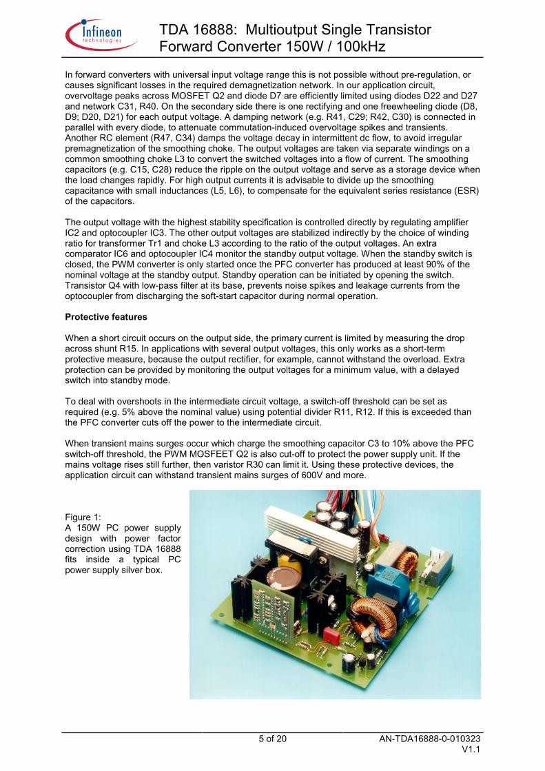
Figure 1:A 150W PC power supplydesign with power factorcorrection using TDA 16888fits inside a typical PCpower supply silver box.

TDA 16888: Multioutput Single TransistorForward Converter 150W / 100kHz
6 of 20 AN-TDA16888-0-010323V1.1
SIPM
OS
600V
SIPM
OS
1000
V
V BUS
= 4
10V
AUX
1
L2
D5 D6
Tr.1
R18
R4A
R4B
Q1
R10C
4C
3
IC3
R23
C14
C13
R24
C12
C11
D10
R27R1
R2
R3
C8R
7R
8R
11R12
R9
R1 3
R14 C
6
C5
R15
R16
C7
R5
mea
ns tw
o re
sist
ors
in s
erie
s
C2
D12
...D
15
Q3
C18
C21
R26
C23
C11
AC
22R35
R20
C16
C17
R21
R19
IC2
R17
C19
C20
D16
...D
19
IC1
R34
Q4
R37 R38
R39
OFF
=ST
ANDB
Y
-12V
0,7A
1819
20
48
Volta
ge E
A
+
STAN
DBY
EA
152
176
37
1110
169
14
5
1312
C39
C42
90V-
270V
AC
RFI
Fuse
L1
C1
D1.
..D4
L4R36
A
R22
C41
Q2
R32
+
+
R33
C27
R25
IC4
IC6
C31
Cur
rent
EA
R28
==
C10
R6
1C
urre
nt-
limita
tion
Star
tup
UVL
OVR
EF
PW
MO
ver-
volta
ge=
=
-+ -
+O
SC
Sof
t-st
art
PWM
-
=
R31
+C
29R
41
D8
D9
C30
C34
C15
C28
5V 18A
+R
42R
47
+C
35C
36C
37+
R46
C32
R44
D21
R45
C33
D20
D24
D23
L3C
38R
48
12V
4A
R40
5V 0,1A
D11
R30
C25
C26
R29
C3A
L3L5L6
L3
+
R62
C9A
IC5
R43
D22
D27
==
R35A
C22A
D7
IC6
+ C38
A
-5V/
0,3A
C24 R
36
Circ
uit
Dia
gram
of s
ingl
e tra
nsis
tor m
ultio
utpu
t for
war
d co
nver
ter w
ith P
FC

TDA 16888: Multioutput Single TransistorForward Converter 150W / 100kHz
7 of 20 AN-TDA16888-0-010323V1.1
V in
I in
P in
PFTH
DV
BUS
V ou
t1I o
ut1
V ou
t2I o
ut2
V ou
t3I o
ut3
V ou
t4I o
ut4
VStb
yIS
tby
P ou
tEf
ficie
ncy
V A
CA
rms
W%
%V
DC
V D
CA
V D
CA
V D
CA
V D
CA
VA
W%
90
2,45
220,
099
,84,
638
0,00
5,00
18,1
012
,60
4,00
-12,
700,
70-5
,00
0,30
5,00
0,10
151,
869
,090
1,62
146,
099
,93,
538
0,00
5,00
18,0
013
,10
1,00
-13,
400,
10-5
,00
0,00
5,00
0,10
104,
971
,990
0,60
54,0
99,8
2,8
380,
005,
005,
0012
,20
1,00
-12,
300,
10-5
,00
0,00
5,00
0,10
38,9
72,1
904,
838
0,00
5,00
0,00
12,1
00,
00-1
1,90
0,00
-5,0
00,
005,
000,
100,
590
2,7
380,
000,
000,
000,
000,
005,
000,
100,
5
120
1,70
205,
099
,93,
438
0,00
5,00
18,1
012
,60
4,00
-12,
700,
70-5
,00
0,30
5,00
0,10
151,
874
,012
01,
1714
0,0
99,9
2,8
380,
005,
0018
,00
13,1
01,
00-1
3,40
0,10
-5,0
00,
005,
000,
1010
4,9
75,0
120
0,44
53,0
99,4
6,0
380,
005,
005,
0012
,20
1,00
-12,
300,
10-5
,00
0,00
5,00
0,10
38,9
73,5
120
4,7
380,
005,
000,
0012
,10
0,00
-11,
900,
00-5
,00
0,00
5,00
0,10
0,5
120
2,7
380,
000,
000,
000,
000,
005,
000,
100,
5
180
1,10
198,
099
,73,
638
0,00
5,00
18,1
012
,60
4,00
-12,
700,
70-5
,00
0,00
5,00
0,10
150,
375
,918
00,
7613
6,0
99,5
1,5
380,
005,
0018
,00
13,1
01,
00-1
3,40
0,10
-5,0
00,
005,
000,
1010
4,9
77,2
180
0,29
51,0
97,0
12,5
380,
005,
005,
0012
,20
1,00
-12,
300,
10-5
,00
0,00
5,00
0,10
38,9
76,3
180
4,5
380,
005,
000,
0012
,10
0,00
-11,
900,
00-5
,00
0,00
5,00
0,10
0,5
180
2,6
380,
000,
000,
000,
000,
005,
000,
100,
5
230
0,85
196,
099
,44,
038
0,00
5,00
18,1
012
,60
4,00
-12,
700,
70-5
,00
0,00
5,00
0,10
150,
376
,723
00,
5913
5,0
98,9
4,5
380,
005,
0018
,00
13,1
01,
00-1
3,40
0,10
-5,0
00,
005,
000,
1010
4,9
77,7
230
0,24
51,0
94,0
14,0
380,
005,
005,
0012
,20
1,00
-12,
300,
10-5
,00
0,00
5,00
0,10
38,9
76,3
230
4,6
380,
005,
000,
0012
,10
0,00
-11,
900,
00-5
,00
0,00
5,00
0,10
0,5
230
2,5
380,
000,
000,
000,
000,
005,
000,
100,
5
270
0,73
196,
098
,94,
438
0,00
5,00
18,1
012
,60
4,00
-12,
700,
70-5
,00
0,00
5,00
0,10
150,
376
,727
00,
5113
4,0
98,3
5,1
380,
005,
0018
,00
13,1
01,
00-1
3,40
0,10
-5,0
00,
005,
000,
1010
4,9
78,3
270
0,21
51,0
90,4
16,0
380,
005,
005,
0012
,20
1,00
-12,
300,
10-5
,00
0,00
5,00
0,10
38,9
76,3
270
4,4
380,
005,
000,
0012
,10
0,00
-11,
900,
00-5
,00
0,00
5,00
0,10
0,5
270
2,5
380,
000,
000,
000,
000,
000,
5
Test
Res
ults
of s
ingl
e tra
nsis
tor m
ultio
utpu
t for
war
d co
nver
ter w
ith P
FC

TDA 16888: Multioutput Single TransistorForward Converter 150W / 100kHz
8 of 20 AN-TDA16888-0-010323V1.1
Bill of Materials
Component Value Order-Nr. Manufacturer
IC 1 * TDA 16888 Q67000-A9284 InfineonIC 2 TL 431 C TIIC 3 CNY 17 F-3 Q62703-N50 InfineonIC 4 CNY 17-3 Q62703-N88 InfineonIC 5 TLE 4264 G Q67006-A-9139 InfineonIC 6 TL 431 C TI
Q 1 BUZ 91 (600V/ 0,8 Ω) Q67078-S1342-A2 InfineonQ 2 BUZ 51 (1000V/ 4Ω) Q67078-S1344-A2 InfineonQ 3 BSS 129 (240V/ 20Ω, Depletion) Q67000-S116 InfineonQ 4 * BC 338 (30V/ 800mA, NPN) Q62702-C314 Infineon
D 1...D 4 GR B250 C5000/3300D 5 STTA506D (600V; 5A; 20ns) STD 6 MUR 160 (600V; 1A; 75ns) MotorolaD 7 BYT 11-1000 (1000V; 1A; 100ns) STD 8, D 9 MBR 2535 CTL (Schottky 35V; 2x 12,5A) MotorolaD 10 1N4148D 11 BZX 83 C13D 12...D 15 UF 4003 (100V; 1A; 50ns) GID 16...D 19 UF 4003 (100V; 1A; 50ns) GID 20, D 21 BYV 32-100 (100V; 2x 10A; 25ns) Eupec, PhilipsD 22 BYT 11-1000 (1000V; 1A; 100ns) STD 23, D 24 MUR 120 (200V; 1A; 50ns) MotorolaD 27 BYT 11-1000 (1000V; 1A; 100ns) STL 1 2x 6,8mH/ 2A B82724-J2202-N1 EPCOSL 2 1mH E36/11; N27; GAP 2mm
100turns, 0,6mm ∅AUX 1: 8turns 0,33mm ∅AUX 2: 5turns 0,33mm ∅
B66389-G1000-X127 EPCOS
L 3 8µH (W3) E36/11, N27, GAP 2mmW3: 9turns 2x 2x0,9mm ∅W1: 21turns 0,7mm ∅W2: 21turns 0,3mm ∅
B66389-G1000-X127 EPCOS
L 4 500µH EF25, N27, GAP 2mm90turns, 0,45mm ∅
B66317-G1000-X127 EPCOS
L 5 1µH 9turns 2mm ∅ airchokeL 6 1µH 10turns 1,2mm ∅ airchokeFuse 2,5A MT
Component Value Order-Nr. Manufacturer
T 1 E36/11, N27, without GAPPrimary: 68 turns 0,40mm ∅Demagn.: 68 turns 0,22mm ∅Sec.1: 3 turns 4x 0,8mm ∅Sec.2: 7 turns 2x 0,8mm ∅Sec.3: 7 turns 0,4mm ∅
B66389-G-X127 EPCOS

TDA 16888: Multioutput Single TransistorForward Converter 150W / 100kHz
9 of 20 AN-TDA16888-0-010323V1.1
Component Value Order-Nr. Manufacturer
C 1 0,33µF 275V AC, X2 B81133-D1334-M EPCOSC 2 not assembledC 3 150µF/ 450V Elko B43501-J5157-M EPCOSC 3A 0,15µF/ 630V MKP B32652-A6154-K EPCOSC 4 10nF/ 1000V MKP B32652-A103-K EPCOSC 5 * 47nF/63V MKT B32529-C473-K EPCOSC 6 * 100nF/63V MKT B32529-C104-K EPCOSC 7 * 1nF/63V MKT B32529-C102-K EPCOSC 8 * 10nF/63V MKT B32529-C103-K EPCOSC 9 * not assembledC 9A * 6,8nF/63V MKT B32529-C682-K EPCOSC 10 * 10pF/100V CG B37979-G1100-J51 EPCOSC 11 * 0,47µF/63V MKT B32529-C474-K EPCOSC 11A * 100µF/25V Elko B41283-C5107-T90 EPCOSC 11B * 47nF/50V X7R B37981-F5473-K51 EPCOSC 12 * 0,15µF/63V MKT B32529-C154-K EPCOSC 13 * 100pF/50V CG B37979-G5101-J51 EPCOSC 14 * 100nF/63V MKT B32529-C104-K EPCOSC 15 2200µF/10V Elko B41822-A3228-M EPCOSC 16 68nF/63V MKT B32529-C683-K EPCOSC 17 2,2nF/63V MKT B32529-C222-K EPCOSC 18 100µF/63V Elko B41822-A8107-M EPCOSC 19 470µF/35V Elko B41822-A7477-M EPCOSC 20 100µF/25V Elko B41822-A1107-M EPCOSC 21 * 220pF/50V CG B37979-G5221-J51 EPCOSC 22 * 4,7nF/63V MKT B32529-C472-K EPCOSC 22A * 10nF MKT B32529-C103-K EPCOSC 23 * not assembledC 24 0,33µF 275V AC, X2 B81133-D1334-M EPCOSC 25, C 26 3,3nF 250V AC, Y2, lead spacing 15mm B81121-C-B142 EPCOSC 25, C 26 3,3nF 250V AC, Y2, lead spacing 10mm B81122-C1332-M EPCOSC 27 4,7nF/63V MKT B32529-C472-K EPCOSC 28 2200µF/10V Elko B41822-A3228-M EPCOSC 29 1nF/63V MKT B32529-C102-K EPCOSC 30 1nF/63V MKT B32529-C102-K EPCOSC 31 1nF/630V Position R 40C 32 2,2nF/63V MKT B32529-C222-K EPCOSC 33 2,2nF/63V MKT B32529-C222-K EPCOS
C 34 insert wire bridgeC 35 insert wire bridgeC 36 1000µF/16V B41822-A4108-M EPCOSC 37 1000µF/16V B41822-A4108-M EPCOSC 38 470µF/16V B41822-A4477-M EPCOSC 39 3,3nF 250V AC, Y1 B81123-C1332-M EPCOSC 41 * 220pF/50V CG B37979-G5221-J51 EPCOSC 40 not assembledC 42 insert wire bridgeC 1,5nF/630V assembled between Heatsink of
Q2 and BUS Voltage* = located on control board

TDA 16888: Multioutput Single TransistorForward Converter 150W / 100kHz
10 of 20 AN-TDA16888-0-010323V1.1
Component Value Order-Nr. ManufacturerR 1 * 3825K 2x 1,91M metalR 2 220KR 2A 220KR 3 * 22KR 4A * 390K metalR 4B * 390K metalR 5 * 2,2KR 6 0,22 1 + 2x 0,56 parallelR 7 * 2,2KR 8 * 7,5KR 9 3,3R 10 18KR 11 * 51K metalR 12 * 3825K 2x 1,91M metalR 13 * 3825K 2x 1,91M metalR 14 * 51K metalR 15 0,50 2x 1 parallelR 16 * 390KR 17 18KR 18 3,3R 19 5,1K metalR 20 5,1K metalR 21 10KR 22 680R 23 * 33KR 24 * 51 K metalR 25 * 10KR 26 * 68KR 27 * 51K metalR 28 4,7KR 29 1R 30 SIOV-S14K250G5 Q69x4603 EPCOSR 31 insert wire bridgeR 32 * 1,1KR 33 470R 34 * 56KR 35 * 1,1KR 35A * 680R 36A 56 4WR 37 3,9K metalR 38 5,1K metalR 39 1K1R 40 220K 2WR 41 33R 42 33R 43 not assembledR 43 A 330K 2W between VBUS and VCCR 44 56R 45 56R 46 470R 47 100R 48 470R 49 not assembled• = located on control boardWarning: Heatsink of D5 is connected to 380V BUS Voltage !

TDA 16888: Multioutput Single TransistorForward Converter 150W / 100kHz
11 of 20 AN-TDA16888-0-010323V1.1
Printed Circuit Board of control circuit

TDA 16888: Multioutput Single TransistorForward Converter 150W / 100kHz
12 of 20 AN-TDA16888-0-010323V1.1
Prin
ted
Circ
uit B
oard
of p
ower
circ
uit

TDA 16888: Multioutput Single TransistorForward Converter 150W / 100kHz
13 of 20 AN-TDA16888-0-010323V1.1
Pin 8 • • Pin 9Pin 7 • • Pin 10
Pin 5 • • Pin 12Pin 4 • • Pin 13
Pin 2 • • Pin 15Pin 1 • • Pin 16
Top
• • Pin 11
• • Pin 14
Single ended feed forward Transformer
150W / 100kHz; Output voltage: 5V/18A; 12V/4A; -12V/1ACore E36/18/11; N27; without gap; ALMIN = 2330nH; coil former vertical
Primary winding 68 turns 0,40 mm ∅ transformer wireDemagnetization 68 turns 0,22 mm ∅ transformer wireSecondary winding1 3 turns 4 x 0,8 mm ∅ transformer wireSecondary winding2 7 turns 2 x 0,8 mm ∅ transformer wireSecondary winding3 7 turns 0,4 mm ∅ transformer wire
Pin 11+12Pin 9+10
center
Pin 1Pin 434 turns 0,22 mm Ø MAG
Pin 7
Pin 2Pin 534 turns 0,40 mm Ø PRIM
3 turns 4 x 0,8mm Ø SEC
means one layer Makrofol
34 turns 0,40 mm Ø PRIM
34 turns 0,22 mm Ø MAG
Pin 2
Pin 1Pin 5
Pin 16Pin 13
7 turns 0,4mm Ø SEC
Pin 15Pin 14
7 turns 2 x 0,8mm Ø SEC
5
SEC
PRI
MAG
PRI
MAG
41
1
22
7
5
11, 12
9, 10
SEC
SEC
1516
1314

TDA 16888: Multioutput Single TransistorForward Converter 150W / 100kHz
14 of 20 AN-TDA16888-0-010323V1.1
Top
Smoothing Choke of single ended forward converter
Pin 8 • • Pin 9Pin 7 • • Pin 10Pin 6 • • Pin 11Pin 5 • • Pin 12Pin 4 • • Pin 13Pin 3 • • Pin 14Pin 2 • • Pin 15Pin 1 • • Pin 16
Winding 1: 9 turns 2 x 2 x 0,95 mm ∅ transformer wireWinding 2: 21 turns 0,7 mm ∅ transformer wireWinding 2: 21 turns 0,3 mm ∅ transformer wire
Core E36/18/11; N27; total gap = 2mm; AL = 100nH; coil former horizontal;L = 8µH; @5V output
center
9 turns 2x 0,95mm Ø w1 Pin 14
21 turns 0,7mm Ø w2
Pin 6
Pin 7
Pin 15
21 turns 0,3mm Ø w3
9 turns 2x 0,95mm Ø w1Pin 2
Pin 3
Pin 13
Pin 10

TDA 16888: Multioutput Single TransistorForward Converter 150W / 100kHz
15 of 20 AN-TDA16888-0-010323V1.1
Core E36/18/11; N27; total gap = 2mm; AL = 100 nH; L = 1 mH; IPEAK = 3,5 A; coil former vertical
W1 : 100 turns 30 x 0,1stranded wire w/ silkW2 : 8 turns 0,30 transformer wireW3 : 5 turns 0,30 transformer wire
1 layer
W2: 8 turns 0,30 mm Ø
W3: 5 turns 0,30 mm Ø
W1: 25 turns 30x 0,1 mm Ø
center
Pin 11
Pin 14Pin 1Pin 2Pin 7Pin 5Pin 14
Pin 13
Pin 8 • • Pin 9Pin 7 • • Pin 10
Pin 5 • • Pin 12Pin 4 • • Pin 13
Pin 2 • • Pin 15Pin 1 • • Pin 16
Top
• • Pin 11
• • Pin 14
W1: 25 turns 30x 0,1 mm Ø
W1: 25 turns 30x 0,1 mm Ø
W1: 25 turns 30x 0,1 mm Ø
Boost converter choke for PFC

TDA 16888: Multioutput Single TransistorForward Converter 150W / 100kHz
16 of 20 AN-TDA16888-0-010323V1.1
means one layer of Makrofol
RFI Choke L= 470µH, IPEAK= 3,5A
Core E 25/13/7 (EF25), N27, total gap= 2mm, AL=54 nH,coil former vertical
88,5 turns transformer wire 0,55 mm Ø
Pin 1
Pin 6
Pin 10
Pin 5
Top•••••
•••••
22 turns 0,55 mm Ø
22 turns 0,55 mm Ø
22 turns 0,55 mm Ø
Pin 9
Pin 422,5 turns 0,55 mm Ø

TDA 16888: Multioutput Single TransistorForward Converter 150W / 100kHz
17 of 20 AN-TDA16888-0-010323V1.1

TDA 16888: Multioutput Single TransistorForward Converter 150W / 100kHz
18 of 20 AN-TDA16888-0-010323V1.1
References:
[1] nnn
Revision HistoryApplication Note AN-TDA16888-0-010323Actual Release: V1.1 Date:2001-03-23 Previous Release: V0.1Page ofactualRelease
Page ofprev.Release
Subjects changed since last release

TDA 16888: Multioutput Single TransistorForward Converter 150W / 100kHz
19 of 20 AN-TDA16888-0-010323V1.1
For questions on technology, delivery and prices please contact the InfineonTechnologies Offices in Germany or the Infineon Technologies Companies andRepresentatives worldwide: see the address list on the last page or our webpage at
http://www.infineon.com
CoolMOS and CoolSET are trademarks of Infineon Technologies AG.
Edition 2000-03--03Published by Infineon Technologies AG,St.-Martin-Strasse 53,D-81541 München
© Infineon Technologies AG 2000.All Rights Reserved.
Attention please!The information herein is given to describe certain components and shall not be considered as warranted characteristics.Terms of delivery and rights to technical change reserved.We hereby disclaim any and all warranties, including but not limited to warranties of non-infringement, regarding circuits, descriptions and chartsstated herein.Infineon Technologies is an approved CECC manufacturer.
InformationFor further information on technology, delivery terms and conditions and prices please contact your nearest Infineon Technologies Office inGermany or our Infineon Technologies Representatives worldwide (see address list).
WarningsDue to technical requirements components may contain dangerous substances. For information on the types in question please contact yournearest Infineon Technologies Office.Infineon Technologies Components may only be used in life-support devices or systems with the express written approval of InfineonTechnologies, if a failure of such components can reasonably be expected to cause the failure of that life-support device or system, or to affect thesafety or effectiveness of that device or system. Life support devices or systems are intended to be implanted in the human body, or to supportand/or maintain and sustain and/or protect human life. If they fail, it is reasonable to assume that the health of the user or other persons may beendangered.

TDA 16888: Multioutput Single TransistorForward Converter 150W / 100kHz
20 of 20 AN-TDA16888-0-010323V1.1
Infineon Technologies AG sales offices worldwide –partly represented by Siemens AGASiemens AG ÖsterreichErdberger Lände 26A-1031 WienT (+43)1-17 07-3 56 11Fax (+43)1-17 07-5 59 73AUSSiemens Ltd.885 Mountain HighwayBayswater,Victoria 3153T (+61)3-97 21 21 11Fax (+61)3-97 21 72 75BSiemens Electronic ComponentsBeneluxCharleroisesteenweg 116/Chaussée de Charleroi 116B-1060 Brussel/BruxellesT (+32)2-5 36 69 05Fax (+32)2-5 36 28 57Email:[email protected] Ltda.SemiconductoresAvenida Mutinga,3800-Pirituba05110-901 São Paulo-SPT (+55)11-39 08 25 64Fax (+55)11-39 08 27 28CDNInfineon Technologies Corporation320 March Road,Suite 604Canada,Ontario K2K 2E2T (+1)6 13-5 91 63 86Fax (+1)6 13-5 91 63 89CHSiemens Schweiz AGBauelementeFreilagerstrasse 40CH-8047 ZürichT (+41)1-4 953065Fax (+41)1-4 955050DInfineon Technologies AGVölklinger Str.2D-40219 DüsseldorfT (+49)2 11-3 99 29 30Fax (+49)2 11-3 99 14 81Infineon Technologies AGWerner-von-Siemens-Platz 1D-30880 Laatzen (Hannover)T (+49)5 11-8 77 22 22Fax (+49)5 11-8 77 15 20Infineon Technologies AGVon-der-Tann-Straße 30D-90439 NürnbergT (+49)9 11-6 54 76 99Fax (+49)9 11-6 54 76 24Infineon Technologies AGWeissacher Straße 11D-70499 StuttgartT (+49)7 11-1 37 33 14Fax (+49)7 11-1 37 24 48DInfineon Technologies AGHalbleiter DistributionRichard-Strauss-Straße 76D-81679 MünchenT (+49)89-92 21 40 86Fax (+49)89-92 21 20 71DKSiemens A/SBorupvang 3DK-2750 BallerupT (+45)44 77-44 77Fax (+45)44 77-40 17ESiemens S.A.Dpto.ComponentesRonda de Europa,5E-28760 Tres Cantos-MadridT (+34)91-5 14 71 51Fax (+34)91-5 14 70 13
FInfineon Technologies France,39/47,Bd.OrnanoF-93527 Saint-Denis CEDEX2T (+33)1-49 22 31 00Fax (+33)1-49 22 28 01FINSiemens ComponentsScandinaviaP.O .Bo x 6 0FIN-02601 Espoo (Helsinki)T (+3 58)10-5 11 51 51Fax (+3 58)10-5 11 24 95Email:[email protected] TechnologiesSiemens HouseOldburyGB-Bracknell,BerkshireRG12 8FZT (+44)13 44-39 66 18Fax (+44)13 44-39 66 32HSimacomp Kft.Lajos u.103H-1036 BudapestT (+36)1-4 57 16 90Fax (+36)1-4 57 16 92HKInfineon TechnologiesHong Kong Ltd.Suite 302,Level 3,Festival Walk,80 Tat Chee Avenue,Yam Yat Tsuen,Kowloon TongHong KongT (+8 52)28 32 05 00Fax (+8 52)28 27 97 62ISiemens S..A.Semiconductor SalesVia Piero e Alberto Pirelli,10I-20126 MilanoT (+39)02-66 76 -1Fax (+39)02-66 76 43 95INDSiemens Ltd.Components DivisionNo.84 Keonics Electronic CityHosur RoadBangalore 561 229T (+91)80-8 52 11 22Fax (+91)80-8 52 11 80Siemens Ltd.CMP Div,5th Floor4A Ring Road,IP EstateNew Delhi 110 002T (+91)11-3 31 99 12Fax (+91)11-3 31 96 04Siemens Ltd.CMP Div,4th Floor130,Pandurang Budhkar Marg,WorliMumbai 400 018T (+91)22-4 96 21 99Fax (+91)22-4 96 22 01IRLSiemens Ltd.Electronic Components Division8,Raglan RoadIRL-Dublin 4T (+3 53)1-2 16 23 42Fax (+3 53)1-2 16 23 49ILNisko Ltd.2A,Habarzel St.P.O.Box 5815161580 Tel Aviv –IsrealT (+9 72)3 -7 65 73 00Fax (+9 72)3 -7 65 73 33
JSiemens Components K.K.Talanawa Park Tower 12F &17F3-20-14,Higashi-Gotanda,Shinagawa-kuTokyoT (+81)3-54 49 64 11Fax (+81)3 -54 49 64 01MALInfineon Technologies AGSdn BhdBayan Lepas Free Industrial Zone111900 PenangT (+60)4 -6 44 99 75Fax (+60)4 -6 41 48 72NSiemens ComponentsScandinaviaØstre Aker vei 24Postboks 10,VeitvetN-0518 OsloT (+47)22-63 30 00Fax (+47)22-68 49 13Email:[email protected] Electronic ComponentsBeneluxPostbus 16068NL-2500 BB Den HaagT (+31)70-3 33 20 65Fax (+31)70-3 33 28 15Email:[email protected] Auckland300 Great South RoadGreenlandAucklandT (+64)9-5 20 30 33Fax (+64)9-5 20 15 56PSiemens S.A.an Componentes ElectronicosR.Irmaos Siemens,1AlfragideP-2720-093 AmadoraT (+351)1-4 17 85 90Fax (+351)1-4 17 80 83PKSiemens Pakistan EngineeringCo.Ltd.PO Box 1129,Islamabad 4400023 West Jinnah AveIslamabadT (+92)51-21 22 00Fax (+92)51-21 16 10PLSiemens SP.z.o.o.ul.Zupnicza 11PL-03-821 WarszawaT (+48)22-8 70 91 50Fax (+48)22-8 70 91 59ROKSiemens Ltd.Asia Tower,10th Floor726 Yeoksam-dong,Kang-nam KuCPO Box 3001Seoul 135-080T (+82)2-5 27 77 00Fax (+82)2-5 27 77 79RUSINTECH electronicsul.Smolnaya,24/1203RUS-125 445 MoskvaT (+7)0 95 -4 51 97 37Fax (+7)0 95 -4 51 86 08SSiemens Components ScandinaviaÖsterögatan 1,Box 46S-164 93 KistaT (+46)8-7 03 35 00Fax (+46)8-7 03 35 01Email:[email protected]
RCInfineon TechnologiesAsia Pacific Pte.Ltd.Taiwan Branch10F,No.136 Nan King East RoadSection 23,TaipeiT (+8 86)2-27 73 66 06Fax (+8 86)2-27 71 20 76SGPInfineon Technologies AsiaPacific,Pte.Ltd.168 Kallang WaySingapore 349 253T (+65)8 40 06 10Fax (+65)7 42 62 39USAInfineon Technologies Corporation1730 North First StreetSan Jose,CA 95112T (+1)4 08-5 01 60 00Fax (+1)4 08-5 01 24 24Siemens Components,Inc.Optoelectronics Division19000 Homestead RoadCupertino,CA 95014T (+1)4 08-2 57 79 10Fax (+1)4 08-7 25 34 39Siemens Components,Inc.Special Products Division186 Wood Avenue SouthIselin,NJ 08830-2770T (+1)7 32-9 06 43 00Fax (+1)7 32-6 32 28 30VRCInfineon TechnologiesHong Kong Ltd.Beijing OfficeRoom 2106,Building AVantone New World PlazaNo.2 Fu Cheng Men Wai Da JieJie100037 BeijingT (+86)10 -68 57 90 -06,-07Fax (+86)10 -68 57 90 08Infineon TechnologiesHong Kong Ltd.Chengdu OfficeRoom14J1,Jinyang Mansion58 Tidu StreetChengdu,Sichuan Province 610 016T (+86)28-6 61 54 46 /79 51Fax (+86)28 -6 61 01 59Infineon TechnologiesHong Kong Ltd.Shanghai OfficeRoom1101,Lucky Target SquareNo.500 Chengdu Road NorthShanghai 200003T (+86)21-63 6126 18 /19Fax (+86)21-63 61 11 67Infineon TechnologiesHong Kong Ltd.Shenzhen OfficeRoom 1502,Block ATian An International BuildingRenim South RoadShenzhen 518 005T (+86)7 55 -2 28 91 04Fax (+86)7 55-2 28 02 17ZASiemens Ltd.Components DivisionP.O.B.3438Halfway House 1685T (+27)11-6 52 -27 02Fax (+27)11-6 52 20 42