APPLICATION NOTE AN163
124
1 Copyright Cirrus Logic, Inc. 2001 (All Rights Reserved) P.O. Box 17847, Austin, Texas 78760 (512) 445 7222 FAX: (512) 445 7581 http://www.cirrus.com APPLICATION NOTE AVR/OUTBOARD DECODER SYSTEMS: APPLICATION CODE USER’S GUIDE FOR THE CS4932X FAMILY Contents l Dolby Digital ™ (AC-3 ™ ) Description l DTS Digital Surround ™ Description l MPEG-1, Audio Layer 3 (MP3) Description l MPEG Multichannel Description l AAC Description l Crystal Original Surround Description l Software Naming Convention l Document Strategy l Understanding Application Messaging l Hardware Configurations Supported by the CS4932X and AC-3, DTS, MP3, MPEG Multichannel, AAC and Crystal Original Surround l How to Control Common Application Modules such as: — Audio Manager — Generalized Bass Manager — Pro Logic Module — Tone Control l How to Control Specific Application Modules such as: — AC-3: AC-3 Manager, PCM Processor — DTS: DTS Manager — MP3: MP3 Manager — MPEG Multichannel: MPEG Multichannel Manager — AAC: AAC Manager — Crystal Original Surround: C.O.S. Effects Manager C.O.S. PCM Processor ® ® ® 5 Discrete Channels Autodetect (AC-3, DTS, MP3, MPEG- MC, AAC and PCM) AC-3, DTS, MP3, MPEG-MC, AAC or PCM Enable Autodetect Enable LFE Enable 2 Channels (Lt & Rt) 0.1 (Sub) CMPDAT/ DAI Pro Logic Decode Up to 5 Discrete Channels Up to 5.1 Discrete Channels Dualzone Downmixed 2 Channel Output (Formatted as either Digital Audio or S/PDIF) AC-3, DTS, MP3, MPEG- MC, and AAC Decode / PCM Processing 5.1 Discrete Channels Tone Control (L, C, R) Tone Control Parameters Specific to AC-3, DTS, MPEG-MC and C.O.S. Code Bass Manager Bass Parameter Output Mode Downmix ProLogic Enable & Stereo OR Dolby Surround Encoded Input 5 Channels (Ls=Rs) Specific to AC-3, DTS, MPEG-MC and AAC Code 5 Discrete Channels Output Mode Control Audio Manager Up to 5.1 Discrete Channels Downmixed 2 Channel Output (Formatted as either Digital Audio or S/PDIF) Volume/Mute Channel Remap Delay AN163 JUN ‘01 AN163REV3 DIGITAL SOUND PROCESSING CRYSTAL ® ™ 查询an163供应商
-
Upload
khangminh22 -
Category
Documents
-
view
0 -
download
0
Transcript of APPLICATION NOTE AN163
1
Copyright Cirrus Logic, Inc. 2001(All Rights Reserved)P.O. Box 17847, Austin, Texas 78760
(512) 445 7222 FAX: (512) 445 7581http://www.cirrus.com
APPLICATION NOTEAVR/OUTBOARD DECODER SYSTEMS: APPLICATION
CODE USER’S GUIDE FOR THE CS4932X FAMILYContents� Dolby Digital™ (AC-3™) Description� DTS Digital Surround™ Description� MPEG-1, Audio Layer 3 (MP3) Description� MPEG Multichannel Description� AAC Description� Crystal Original Surround Description� Software Naming Convention� Document Strategy� Understanding Application Messaging� Hardware Configurations Supported by the
CS4932X and AC-3, DTS, MP3, MPEG Multichannel, AAC and Crystal Original Surround
� How to Control Common Application Modules such as:— Audio Manager— Generalized Bass Manager— Pro Logic Module— Tone Control
� How to Control Specific Application Modules such as:— AC-3: AC-3 Manager, PCM Processor— DTS: DTS Manager— MP3: MP3 Manager— MPEG Multichannel: MPEG Multichannel
Manager— AAC: AAC Manager— Crystal Original Surround:
C.O.S. Effects ManagerC.O.S. PCM Processor
®
®
®
5 DiscreteChannels
Autodetect(AC-3, DTS,MP3, MPEG-MC, AAC and
PCM)
AC-3, DTS, MP3,MPEG-MC, AAC or
PCM Enable
AutodetectEnable
LFE Enable
2 Channels(Lt & Rt)
0.1 (Sub)
CMPDAT/DAI
Pro LogicDecode
Up to 5DiscreteChannels
Up to 5.1Discrete
Channels
Dualzone
Downmixed2 Channel
Output(Formatted
as eitherDigital Audio
orS/PDIF)
AC-3, DTS,MP3, MPEG-MC, and AACDecode / PCM
Processing
5.1 DiscreteChannels
ToneControl(L, C, R)
Tone ControlParameters
Specific to AC-3,DTS, MPEG-MC
andC.O.S. Code
BassManager
Bass ParameterOutput Mode
Downmix
ProLogic Enable& Stereo OR
Dolby SurroundEncoded Input
5 Channels(Ls=Rs)
Specific toAC-3, DTS,MPEG-MC
andAAC Code
5 DiscreteChannels
Output ModeControl
AudioManager
Up to 5.1DiscreteChannels
Downmixed2 Channel
Output(Formattedas either
Digital Audioor
S/PDIF)
Volume/MuteChannel Remap
Delay
AN163
JUN ‘01AN163REV3
DIGITAL SOUND
PROCES SING
C R Y S T A L ®
™
查询an163供应商

AN163
2 AN163REV3
TABLE OF CONTENTS 1. OVERVIEW................................................................................................................................ 7
1.1 Document Strategy............................................................................................................. 71.1.1 Hardware Documentation ...................................................................................... 71.1.2 CS493XX Application Code User’s Guides ........................................................... 8
1.2 Using the CS4932X .......................................................................................................... 141.3 Software Naming Convention........................................................................................... 151.4 Understanding the Differences between IBA Application Codes and Full Download
Application Codes............................................................................................................ 151.5 Understanding the Feature Set of a Device vs. the Application Code.............................. 171.6 Dolby Digital Description .................................................................................................. 181.7 DTS Digital Surround Description..................................................................................... 201.8 MP3 Description ............................................................................................................... 211.9 MPEG Multichannel Description....................................................................................... 221.10 AAC Description ............................................................................................................. 231.11 Crystal Original Surround Description ............................................................................ 24
2. HARDWARE CONFIGURATION ............................................................................................ 252.1 Supported Input/Output Modes ........................................................................................ 25
2.1.1 DCLK = 86MHz.................................................................................................... 262.1.2 Configuring the XMT958/AUDAT3 Data Format.................................................. 262.1.3 S/PDIF (AES/EBU) Channel Status Block Control .............................................. 262.1.4 S/PDIF (AES/EBU) Validity Bit Control ................................................................ 27
Contacting Cirrus Logic SupportFor a complete listing of Direct Sales, Distributor, and Sales Representative contacts, visit the Cirrus Logic web site at:http://www.cirrus.com/corporate/contacts
Dolby Digital, AC-3, Dolby Pro Logic, Dolby Pro Logic II, Dolby Surround, Surround EX, Virtual Dolby Digital and the “AAC” logo are trademarks and the “DolbyDigital” logo, “Dolby Digital with Pro Logic II” logo, “Dolby” and the double-”D” symbol are registered trademarks of Dolby Laboratories Licensing Corporation. DTS,DTS Digital Surround, DTS-ES Extended Surround, DTS Neo:6, and DTS Virtual 5.1 are trademarks and the “DTS”, “DTS-ES”, “DTS Virtual 5.1” logos are registeredtrademarks of the Digital Theater Systems Corporation. The “MPEG Logo” is a registered trademark of Philips Electronics N. V. Home THX Cinema and THX areregistered trademarks of Lucasfilm Ltd. Surround EX is a jointly developed technology of THX and Dolby Labs, Inc. AAC (Advanced Audio Coding) is an “MPEG-2-standard-based” digital audio compression algorithm (offering up 5.1 discrete decoded channels for this implementation) collaboratively developed by AT&T, theFraunhofer Institute, Dolby Laboratories, and the Sony Corporation. In regards to the MP3 capable functionality of the CS49300 Family DSP (via downloading ofmp3_493xxx_vv.ld and mp3e_493xxx_vv.ld application codes) the following statements are applicable: “Supply of this product conveys a license for personal, privateand non-commercial use. MPEG Layer-3 audio decoding technology licensed from Fraunhofer IIS and THOMSON Multimedia.” MLP and Meridian Lossless Packingare registered trademarks of Meridian Audio Ltd. Harman VMAx is a registered trademark of Harman International. The Logic 7 logo and Logic 7 are registeredtrademarks of Lexicon. SRS CircleSurround, and SRS TruSurround are trademarks of SRS Labs, Inc. The HDCD logo, HDCD, High Definition Compatible Digitaland Pacific Microsonics are either registered trademarks or trademarks of Pacific Microsonics, Inc. in the United States and/or other countries. HDCD technologyprovided under license from Pacific Microsonics, Inc. This product’s software is covered by one or more of the following in the United States: 5,479,168; 5,638,074;5,640,161; 5,872,531; 5,808,574; 5,838,274; 5,854,600; 5,864,311; and in Australia: 669114; with other patents pending. Intel is a registered trademark of IntelCorporation. Motorola is a registered trademark of Motorola, Inc. I2C is a registered trademark of Philips Semiconductor. Purchase of I2C Components of CirrusLogic, Inc., or one of its sublicensed Associated Companies conveys a license under the Philips I2C Patent Rights to use those components in a standard I2C system.The “Crystal Logo” and the “Crystal Digital Sound Processing Logo” are registered trademarks of Cirrus Logic, Inc. All other names are trademarks, registeredtrademarks, or service marks of their respective companies.
Preliminary product information describes products which are in production, but for which full characterization data is not yet available. Advance product informationdescribes products which are in development and subject to development changes. Cirrus Logic, Inc. has made best efforts to ensure that the information containedin this document is accurate and reliable. However, the information is subject to change without notice and is provided “AS IS” without warranty of any kind (expressor implied). No responsibility is assumed by Cirrus Logic, Inc. for the use of this information, nor for infringements of patents or other rights of third parties. Thisdocument is the property of Cirrus Logic, Inc. and implies no license under patents, copyrights, trademarks, or trade secrets. No part of this publication may becopied, reproduced, stored in a retrieval system, or transmitted, in any form or by any means (electronic, mechanical, photographic, or otherwise) without the priorwritten consent of Cirrus Logic, Inc. Items from any Cirrus Logic website or disk may be printed for use by the user. However, no part of the printout or electronicfiles may be copied, reproduced, stored in a retrieval system, or transmitted, in any form or by any means (electronic, mechanical, photographic, or otherwise) withoutthe prior written consent of Cirrus Logic, Inc.Furthermore, no part of this publication may be used as a basis for manufacture or sale of any items without the priorwritten consent of Cirrus Logic, Inc. The names of products of Cirrus Logic, Inc. or other vendors and suppliers appearing in this document may be trademarks orservice marks of their respective owners which may be registered in some jurisdictions. A list of Cirrus Logic, Inc. trademarks and service marks can be found athttp://www.cirrus.com.
AN163
AN163REV3 3
3. APPLICATION MESSAGING.................................................................................................. 293.1 Indexed Module Communication Protocol ........................................................................ 29
3.1.1 Write Session....................................................................................................... 293.1.2 Solicited Read Message Format.......................................................................... 303.1.3 Unsolicited Read Message Format...................................................................... 31
4. COMMON APPLICATION MODULES.................................................................................... 324.1 Audio Manager for Dolby Digital, DTS, MP3, MPEG Multichannel, AAC
and Crystal Original Surround.......................................................................................... 334.1.1 Audio_Control: (Index 0x00) ................................................................................ 374.1.2 Noise_Control (Index 0x01): (Applicable to AC-3 Code Only) ............................. 384.1.3 Sampling Frequency Code (Index 0x14) ............................................................. 39
4.2 Generalized Bass Manager for Dolby Digital, DTS, MP3, MPEG Multichannel,AAC, and Crystal Original Surround ................................................................................ 40
4.2.1 Bass Manager Block Diagrams............................................................................ 444.2.2 Dolby Digital Bass Management Configurations.................................................. 46
4.3 Unsolicited Messages (Read-Only) .................................................................................. 544.3.1 Autodetect Operation ........................................................................................... 554.3.2 Special Considerations for Autodetection ............................................................ 58
4.4 Generalized Pro Logic Manager for Dolby Digital, DTS, MPEG Multichannel and AAC .. 594.4.1 Using Pro Logic in Normal, Wide and Phantom Modes....................................... 60
4.4.1.1 Normal Mode ....................................................................................... 604.4.1.2 Wide Mode........................................................................................... 614.4.1.3 Phantom Mode..................................................................................... 61
4.4.2 Pro Logic decode of 48 kHz input PCM (Using AC-3 Application Code) ............. 614.5 Generalized Tone Control Manager for Dolby Digital, DTS, MPEG Multichannel
and C.O.S. ....................................................................................................................... 634.6 Controlling the Level for Treble and Bass Boost/Cut........................................................ 65
4.6.1 Level Settings for +12 dB to -12 dB Tone Control ............................................... 654.6.2 Tone Control Look-Up Tables (LUT0, LUT1, LUT2) ............................................ 66
4.7 Controlling the Corner Frequencies of the LPF/HPF for Bass and Treble Control ........... 695. AC-3 SPECIFIC MODULES AND OPERATIONS................................................................... 71
5.1 AC-3 Manager .................................................................................................................. 715.1.1 OUTPUT_MODE_CONTROL.............................................................................. 755.1.2 Downmix Equation for Lt, Rt ................................................................................ 755.1.3 AC-3 Stream Information ..................................................................................... 755.1.4 Special Considerations For AC-3......................................................................... 765.1.5 AC-3 decode with Autodetect .............................................................................. 765.1.6 AC-3 with Pro Logic Decode and Autodetect....................................................... 77
5.2 PCM Manager (for AC-3 Application Code) ..................................................................... 785.2.1 PCM_CONTROL ................................................................................................. 805.2.2 Karaoke Capable Function: ................................................................................. 805.2.3 Special Considerations For PCM......................................................................... 815.2.4 Special Considerations For Pink/White Noise ..................................................... 815.2.5 PCM Pass-through (Using AC-3 Application Code)............................................. 815.2.6 Pink/White Noise Generation............................................................................... 82
6. DTS MANAGER AND OPERATIONS..................................................................................... 836.1 DTS Manager ................................................................................................................... 83
6.1.1 DTS_CONTROL .................................................................................................. 866.1.2 Downmix Equation for Lt, Rt ................................................................................ 866.1.3 DTS Stream Information ...................................................................................... 866.1.4 DTS Decode with Autodetect............................................................................... 866.1.5 Special Considerations For DTS CDs and Autodetection.................................... 88
AN163
4 AN163REV3
7. MP3 MANAGER AND OPERATIONS..................................................................................... 897.1 MP3 Manager ................................................................................................................... 89
7.1.1 MP3_CONTROL .................................................................................................. 907.2 MP3 Decode with Autodetect............................................................................................ 90
7.2.1 Special Considerations MP3 Autodetect.............................................................. 917.2.2 For System Designers: When to Download MP3 Application code... .................. 93
8. MPEG MULTICHANNEL MANAGER AND OPERATIONS .................................................... 958.1 MPEG Multichannel Manager ........................................................................................... 95
8.1.1 MPEG_CONTROL ............................................................................................... 988.1.2 Downmix Equation for Lt, Rt ................................................................................ 988.1.3 MPEG Stream Information ................................................................................... 98
8.2 MPEG Multichannel Decode with Autodetect ................................................................... 999. AAC MANAGER AND OPERATIONS .................................................................................. 100
9.1 AAC Manager ................................................................................................................. 1009.1.1 AAC_CONTROL ................................................................................................ 1029.1.2 Downmix Equation for Lt, Rt .............................................................................. 1029.1.3 AAC Stream Information .................................................................................... 102
9.2 AAC Decode with Autodetect.......................................................................................... 1039.2.1 Implicit Speaker Mapping................................................................................... 104
10. CRYSTAL ORIGINAL SURROUND (C.O.S.) SPECIFIC MODULES AND OPERATIONS 10510.1 C.O.S. Effects Manager ................................................................................................ 105
10.1.1 EFFECTS_MGR_CONTROL........................................................................... 10710.1.2 Basic Crystal Surround Effects Explanation..................................................... 108
10.2 C.O.S. PCM Processor ................................................................................................. 11210.2.1 PCM_CONTROL.............................................................................................. 11310.2.2 Creating Custom Effects Using Advanced Settings ......................................... 114
10.2.2.1 FIR Section: Early Reflections.......................................................... 11410.2.2.2 Comb Filter Section: After-reflections............................................... 11410.2.2.3 All-Pass Filter Section: More After-reflections and Decorrelation .... 114
10.2.3 Crystal Original Surround Effects Modes ......................................................... 11610.2.4 Non - Reverberative Effects ............................................................................. 116
10.2.4.1 Passthru ........................................................................................... 11710.2.4.2 Mono ................................................................................................ 11710.2.4.3 Classical ........................................................................................... 11710.2.4.4 Panorama......................................................................................... 11710.2.4.5 Movie 1-4.......................................................................................... 11710.2.4.6 Music 1-4.......................................................................................... 117
10.2.5 Reverberative Effects....................................................................................... 11710.2.5.1 t1r1a1i1.cfg - Room 1....................................................................... 11910.2.5.2 t2r3a1i2.cfg - Room 2....................................................................... 11910.2.5.3 t1r1a2i1.cfg - Theater 1 .................................................................... 11910.2.5.4 t2r3a2i2.cfg -- Theater 2................................................................... 11910.2.5.5 t1r1a3i1.cfg -- Hall 1 ......................................................................... 11910.2.5.6 t2r3a3i2.cfg -- Hall 2 ......................................................................... 11910.2.5.7 t2r3a4i2.cfg -- Stadium..................................................................... 119
10.3 Effects Configuration Files ............................................................................................ 11910.3.1 COEFMAKR.EXE and EFFECTS.EXE ............................................................ 12010.3.2 Command Line Options for COEFMAKR.EXE................................................. 121

AN163
AN163REV3 5
LIST OF FIGURESFigure 1. Dolby Digital Block Diagram, Configured for PCM Pass-Through/Pink Noise Generation19Figure 2. Dolby Digital Block Diagram, Configured for AC-3 Decoding ........................................ 19Figure 3. DTS Block Diagram ....................................................................................................... 20Figure 4. MP3 Block Diagram ....................................................................................................... 21Figure 5. MPEG Multichannel Block Diagram............................................................................... 22Figure 6. AAC Block Diagram ....................................................................................................... 23Figure 7. Crystal Original Surround Block Diagram ...................................................................... 24Figure 8. Filter Topology ............................................................................................................... 44Figure 9. Subwoofer Summing Module......................................................................................... 45Figure 10. Bass Manager Processing Unit.................................................................................... 45Figure 11. Generic Autodetect Flow Chart................................................................................... 57Figure 12. Typical Download Sequence ....................................................................................... 58Figure 13. Normal Mode ............................................................................................................... 60Figure 14. Wide Mode................................................................................................................... 61Figure 15. Phantom Mode............................................................................................................. 61Figure 16. Composite Graph of a Frequency Sweep with Bass and Treble ................................. 69Figure 17. Composite Graph of a Frequency Sweep with Bass ................................................... 70Figure 18. Composite Graph of a Frequency Sweep with Treble ................................................. 70Figure 19. AC-3 Decode with Autodetect...................................................................................... 76Figure 20. DTS decode with Autodetect ....................................................................................... 87Figure 21. DTS Specific Autodetection Flowchart......................................................................... 88Figure 22. MP3 Decode with Autodetect....................................................................................... 92Figure 23. When to Download MP3 Code..................................................................................... 94Figure 24. MPEG Multichannel decode with Autodetect............................................................... 99Figure 25. AAC decode with Autodetect ..................................................................................... 103Figure 26. Illustrated Basic Reverb Theory................................................................................. 110Figure 27. Block Diagram of Effects Code.................................................................................. 110Figure 28. Block Diagram of Effects Channel Mixer ................................................................... 111Figure 29. Block Diagram of Effects Reverberator Module......................................................... 115

AN163
6 AN163REV3
LIST OF TABLESTable 1. Hardware Configurations Supported By: AC-3, DTS, MP3, MPEG Multichannel,
and AAC........................................................................................................................ 25Table 2. Hardware Configurations Supported By: PCM Pass-Through (AC-3 Code)
and Crystal Original Surround....................................................................................... 25Table 3. Professional Channel Status bytes 0, 1, and 3 ............................................................... 28Table 5. Write Message Format .................................................................................................... 29Table 6. Read Command Message Format .................................................................................. 30Table 7. Read Response Message Format................................................................................... 30Table 8. Unsolicited Read Message Format ................................................................................. 31Table 9. Audio Manager ................................................................................................................ 33Table 10. Bass Manager ............................................................................................................... 40Table 11. Dolby Configuration 0.................................................................................................... 46Table 12. Dolby Configuration 1.................................................................................................... 47Table 13. Dolby Configuration 2.................................................................................................... 48Table 14. Dolby Alternative Configuration 2.................................................................................. 49Table 15. Dolby Configuration 3 (Normal - No Sub Out)............................................................... 50Table 16. Dolby Configuration 3 (Sub Out) ................................................................................... 51Table 17. Dolby DVD Configuration (Bass to L/R) ........................................................................ 52Table 18. Dolby DVD Configuration (Bass to Subwoofer)............................................................. 53Table 19. Unsolicited Messages ................................................................................................... 54Table 20. Generalized Pro Logic Manager.................................................................................... 59Table 21. Enabling Pro Logic decode of 48 kHz PCM .................................................................. 62Table 22. Tone Control.................................................................................................................. 63Table 23. Look-Up Table 0; “LUT0”............................................................................................... 67Table 24. Look-Up Table 1; “LUT1”............................................................................................... 67Table 25. Look-Up Table 2; “LUT2”............................................................................................... 68Table 26. AC-3 Manager ............................................................................................................... 71Table 27. Enabling AC-3 Decode with Autodetect ........................................................................ 76Table 28. Enabling AC-3 with Pro Logic Decode with Autodetect................................................. 77Table 29. PCM Processor ............................................................................................................. 78Table 30. Enabling PCM Pass-through of 44.1 kHz PCM............................................................. 81Table 31. Enabling Pink/White Noise Generation ......................................................................... 82Table 32. Pink/White Noise Generation for All 5.1 Channel.......................................................... 82Table 33. DTS Manager ................................................................................................................ 83Table 34. Enabling DTS Decode with Autodetect ......................................................................... 87Table 35. MP3 Manager................................................................................................................ 89Table 36. Enabling MP3 Decode with Autodetect ......................................................................... 91Table 37. MPEG Manager............................................................................................................. 95Table 38. Enabling MPEG Decode with Autodetect...................................................................... 99Table 39. AAC Manager.............................................................................................................. 100Table 40. Enabling AAC Decode with Autodetect ....................................................................... 103Table 41. Implicit Speaker Mapping ............................................................................................ 104Table 42. C.O.S. Effects Manager .............................................................................................. 105Table 43. C.O.S. PCM Processor ............................................................................................... 112
AN163
AN163REV3 7
1. OVERVIEW
The CS4932X is a sub-family of the CS49300Family DSPs which are system-on-a-chip solutionsfor Multichannel audio decompression and digitalsignal processing. Since the part is RAM-based, adownload of application software is required eachtime the CS4932X is powered up.
The CS49300 Family is generally targeted at threedifferent market segments. The broadcast market,where audio/video (A/V) synchronization isalways required, the DVD Player market whereaudio/video (A/V) synchronization is sometimesrequired, and the outboard decoder markets whereaudio/video synchronization is not required.Another important differentiation between theseapplications is the format in which the data will bereceived by the CS49300 Family. In systems whereA/V synchronization is required from theCS4931X, the incoming data is typically PESencoded. In an outboard decoder application, thedata typically comes in the IEC61937 format (asspecified by the DVD consortium). In DVDplayers, where A/V synchronization is notrequired, data is typically delivered in anelementary stream format. An important point toremember is that the CS49300 Family can supportall three environments, but different devicenumbers and downloads are required depending onthe input data type.
Broadcast applications include (but are not limitedto) digital cable and satellite set-top boxapplications and digital TVs. Data input can be ESor PES in format, while data delivery is either serialor parallel and is typically bursty in nature.
DVD-Audio Players are unique in that they mayhave the additional requirement of MLP®
(Meridian Lossless Packing) Technology and othercompressed audio decoding algorithms that are notneeded in the Broadcast market, yet may or maynot require A/V synchronization. Data delivery canbe ES, PES, or IEC61937 depending on theimplementation. Often times, a system may be ahybrid between an outboard decoder and abroadcast system depending on its functionality.
Outboard decoder applications include stand-alonedecoders and audio/video receivers. Where data isdelivered by way of a S/PDIF cable where the datais formatted IEC61937 (for compressed data) orIEC60958 (for PCM data).
This User’s Guide covers application code thatprovides decoding of compressed data streamssuch as:
� Dolby Digital (AC-3), delivered via an IEC61937 stream
� DTS and DTS-ES, delivered via an IEC61937 stream; DTS Format-16 and DTS Format-14 (via IEC60958)
� MPEG-1, Layer 3 (MP3) delivered via an IEC61937 stream
� MPEG-2, Audio Layer 2 Stereo and Multichannel (with and without extension), delivered via an IEC61937 stream
� MPEG-2, AAC (Advanced Audio Coding) delivered via an IEC61937 stream.
This guide also covers application code thatprovides effects processing of Linear PCMdelivered in an IEC60958 stream, called CrystalOriginal Surround.
1.1 Document Strategy
Multiple documents are needed to fully define,understand and implement the functionality of theCS4932X. They can be split up into two basicgroups: hardware and application codedocumentation. Please note that hardware andapplication code are co-dependent and one can notsuccessfully use the part without an understandingof both. The “ANXXX” notation denotes theapplication note number under which therespective user’s guide was released.
1.1.1 Hardware Documentation
CS49300 Family Data Sheet This document describes the electricalcharacteristics of the device from timing to basefunctionality. This is the hardware designers tool tolearn the part’s electrical and systemsrequirements.
AN163
8 AN163REV3
1.1.2 CS493XX Application Code User’s Guides
The following application notes describe theapplication codes used with the CS493XX.Whenever an application code user’s guide isreferred to, it should be assumed that one or moreof the below documents are being referenced. Thislist will grow with each new application released.For the most current list of released user’s guidesand application codes please refer to theCS4931x/CS49330 Part Matrix vs. Code Matrixand the CS4932x/CS49330 Part Matrix vs. CodeMatrix available from the CS49300 Page. Allappendices covering proprietary algorithms suchas: DTS-ES™, DTS Neo:6, Dolby Digital withDolby Pro Logic II, Virtual Dolby Digital™,VMAx, SRS CircleSurround™, HDCD®, Logic7™, SRS TruSurround™, and THX®/THX®
Surround EX™, in addition to the correspondingdevice-specific codes are available from CirrusLogic. All application codes are only available fora 90 day evaluation period upon signing of aCrystal Ware Software Evaluation Agreement(CWSEA) after the proper IP rights have beenconfirmed (i.e. - the end-customer has a DolbyDigital License, DTS License, etc.). A Crystal WareLicensing Agreement (CWLA) must be signedbefore these application codes may be used in aproduction-level design.
AN161 DVD Audio/Video Systems:Application Code User’s Guide for the CS4930X
This guide describes all application code (e.g.Dolby Digital; DTS; MPEG-1, Layer 3 (MP3);MPEG-2, Layer 3 (a.k.a. MP3); MPEG-2, Layer 2Multichannel.) intended specifically for DVDPlayers. This guide also describes the additionalapplication codes designed for DVD Audio Playerssuch as: Meridian Lossless Packing (with bothelementary and DVD Audio Pack support), allsupported LPCM formats, in addition to adiscussion of audio/video synchronizationconsiderations. All application codes referred to inAN161 are only available for a 90 day evaluationperiod upon signing of a Crystal Ware Software
Evaluation Agreement (CWSEA) after the properIP rights have been confirmed (i.e. - the end-customer has a MLP License, Dolby DigitalLicense, DTS License, and/or AAC License). ACrystal Ware Licensing Agreement (CWLA) mustbe signed before these application codes may beused in a production-level design.
AN162 Broadcast Systems: Application CodeUser’s Guide for the CS4931X
This guide describes all application code (e.g.Dolby Digital; Stereo MPEG-1, Layers 1 and 2,Stereo MPEG-2, Layer 2; and MPEG-2, AAC)designed for broadcast systems such as HDTV andset-top box receivers. This document also providesa discussion of broadcast system considerationsand dependencies, such as bursty data delivery, andaudio/video synchronization. All application codesreferred to in AN162 are only available for a 90day evaluation period upon signing of a CrystalWare Software Evaluation Agreement (CWSEA)after the proper IP rights have been confirmed (i.e.- the end-customer has a Dolby Digital License,and/or AAC License). A Crystal Ware LicensingAgreement (CWLA) must be signed before theseapplication codes may be used in a production-level design.
AN162A Appendix A to Application Note162: PCMP (SMPTE 302M) User’s Guide for theCS4931X Family and CS49330
The PCMP application code is a SMPTE 302Mdecoder designed for broadcast applications wherePCM is delivered in an MPEG-2 transport streamPES packet. It provides support for AVsynchronization, channel change, bitstreamparameter reporting and PLL control, among otherfeatures offered in other broadcast-basedapplication codes discussed in AN162. In addition,a mutually exclusive PCM pass-throughapplication mode is available with the PCMPrelease. This feature is similar to the AVR-basedAC-3 code that is capable of passing PCM via I2Sdata delivery. PCMP application code andAN162A are available for a 90 day evaluationperiod upon signing of a Crystal Ware SoftwareEvaluation Agreement (CWSEA). A Crystal Ware

AN163
AN163REV3 9
Licensing Agreement (CWLA) must be signedbefore these application codes may be used in aproduction-level design.
AN162B Appendix B to Application Note162: AC-3 + PCM Mixer (AC3N) User’s Guidefor the CS4931X
AC3N - Dolby Digital decoder supporting PESparsing and AV Sync for data that is deliveredaccording to the “PES over I2S” Cirrus Logicproprietary packing technique. Additionally, anIEC60958 Lt, Rt output or IEC61937 compressedoutput is supported from the AUDAT3/XMT958pin. AC3N application code and AN162B areavailable for a 90 day evaluation period uponsigning of a Crystal Ware Software EvaluationAgreement (CWSEA). A Crystal Ware LicensingAgreement (CWLA) must be signed before theseapplication codes may be used in a production-level design.
AN162C Appendix C to Application Note162: Interfacing the TeraLogic TL8XX DigitalTV ICs to the CS4931X Audio Decoder ICs usingAACT or AAST
AN162C includes a brief description of hardwareconfigurations and software feature set supportedby the Cougar DTV Development Platform incombination with the CS4931X when using twoseparate AAC application codes developedexclusively for TeraLogic. These two codes areAACT and AAST. The AACT code offers up to 5.1Channel decoded outputs for an 5.1 Channel AACDigital Audio Source (Low Complexity, ADTS,Elementary Stream Data packed according to theIEC61937 specification) delivered via an I 2 S (orLJ) output from the TL85X. The AACT code isalso capable of simultaneously mixing PCM via theDAI port on the CS4931X. The AAST code offersup to 2.0 Channel (Lt, Rt downmix) decodedoutputs for a 5.1 Channel AAC Digital AudioSource (Low Complexity, ADTS, ElementaryStream Data packed according to the IEC61937specification) delivered via an I 2 S (or LJ) outputfrom the TL85x. AACT and AAST applicationcodes and AN162C are available for a 90 day
evaluation period upon signing of a Crystal WareSoftware Evaluation Agreement (CWSEA). ACrystal Ware Licensing Agreement (CWLA) mustbe signed before these application codes may beused in a production-level design.
AN163 AVR/Outboard Decoder Systems:Application Code User’s Guide for the CS4932XFamily
This guide describes all application code (e.g.Dolby Digital; DTS; MPEG-1, Layer 3 (MP3);MPEG-2, Layer 3 (a.k.a. MP3); MPEG-2, Layer 2Multichannel; MPEG-2, AAC; and CrystalOriginal Surround) designed for outboard decoderand A/V Receiver systems. All application codesreferred to in AN163 are only available for a 90day evaluation period upon signing of a CrystalWare Software Evaluation Agreement (CWSEA)after the proper IP rights have been confirmed (i.e.- the end-customer has a Dolby Digital License,DTS License, and/or AAC License). A CrystalWare Licensing Agreement (CWLA) must be signedbefore these application codes may be used in aproduction-level design.
AN163A Appendix A to Application Note163: Virtual Dolby Digital™ User’s Guide for theCS4932X Family
This appendix offers how to control the software-specific features displayed in the Virtual DolbyDigital Manager. Release of this document andcode requires confirmation of an approved VirtualDolby Digital license. Please contact DolbyLaboratories Licensing Corporation for licensinginformation. Virtual Dolby Digital applicationcode and AN163A are available for a 90 dayevaluation period upon signing of a Crystal WareSoftware Evaluation Agreement (CWSEA) afterCirrus Logic has confirmed that the end-user has aVirtual Dolby Digital License and is in goodstanding with Dolby Laboratories. A Crystal WareLicensing Agreement (CWLA) must be signedbefore this application code may be used in aproduction-level design.
AN163
10 AN163REV3
AN163B Appendix B to Application Note163: VMAx VirtualTheater™ User’s Guide forthe CS4932X Family
This appendix offers how to control the software-specific features displayed in the VMAxVirtualTheater Manager. Please contact HarmanInternational and Dolby Laboratories LicensingCorporation for licensing information. VMAxVirtualTheater application code and AN163B areavailable for a 90 day evaluation period uponsigning of a Crystal Ware Software EvaluationAgreement (CWSEA) after Cirrus Logic hasconfirmed that the end-user has a VMAx License aswell as a Virtual Dolby Digital License and is ingood standing with both Harman International andDolby Laboratories Licensing Corporation. ACrystal Ware Licensing Agreement (CWLA) mustbe signed before this application code may be usedin a production-level design.
AN163C Appendix C to Application Note163: SRS CircleSurround™ User’s Guide for theCS4932X Family and CS49330
This appendix offers how to control the software-specific features displayed in the SRSCircleSurround Manager. Release of this documentand code is currently only authorized to licenseesof SRS CircleSurround technology. Please contactSRS Labs for licensing information. SRSCircleSurround application code and AN163C areavailable for a 90 day evaluation period uponsigning of a Crystal Ware Software EvaluationAgreement (CWSEA) after Cirrus Logic hasconfirmed that the end-user has a SRSCircleSurround License, and is in good standingwith SRS Labs. A Crystal Ware LicensingAgreement (CWLA) must be signed before theseapplication codes may be used in a production-level design.
AN163D Appendix D to Application Note163: Pacific Microsonics™ HDCD® User’s Guidefor the CS4932X Family and CS49330
This appendix offers how to control the software-specific features displayed in the HDCD Manager.Release of this document and code is currently only
authorized to licensees of HDCD technology.Please contact Pacific Microsonics for licensinginformation. HDCD application code and AN163Dare available for a 90 day evaluation period uponsigning of a Crystal Ware Software EvaluationAgreement (CWSEA) after Cirrus Logic hasconfirmed that the end-user has an HDCD Licenseand is in good standing with Pacific Microsonics.A Crystal Ware Licensing Agreement (CWLA)must be signed before this application code may beused in a production-level design.
AN163E Appendix E to Application Note163: Logic 5™ 5.1 Channel PCM EnhancementUser’s Guide for the CS4932X Family
This appendix offers how to control the software-specific features displayed in the Logic 5 Manager.Release of this document and code is currently onlyauthorized to licensees of Logic 5 technology.Please contact Lexicon, Inc. for licensinginformation. Logic 5 application code and AN163Eare available for a 90 day evaluation period uponsigning of a Crystal Ware Software EvaluationAgreement (CWSEA) after Cirrus Logic hasconfirmed that the end-user has a Logic 5 Licenseand is in good standing with Lexicon, Inc. ACrystal Ware Licensing Agreement (CWLA) mustbe signed before this application code may be usedin a production-level design.
AN163F Appendix F to Application Note163: SRS TruSurround™ User’s Guide for theCS4932X Family
This appendix offers how to control the software-specific features displayed in the SRS TruSurroundManager. Release of this document and coderequires confirmation of an approved SRSTruSurround license. Please contact SRS Labs forlicensing information. Furthermore, if the versionof code that is to be released is based on VirtualDolby Digital technology, a Virtual Dolby DigitalLicense will be required. Please contact DolbyLaboratories Licensing Corporation for licensinginformation. If the version of this code is based onDTS technology, a DTS license will be required.Please contact Digital Theater Systems forlicensing information. If the version of this code is
AN163
AN163REV3 11
based on MPEG-2, Layer 2 Multichanneltechnology, no additional licensing is requiredother than the SRS TruSurround license. All SRSTruSurround application codes and AN163F areavailable for a 90 day evaluation period uponsigning of a Crystal Ware Software EvaluationAgreement (CWSEA) after Cirrus Logic hasconfirmed that the end-user has a SRSTruSurround License, Virtual Dolby DigitalLicense and DTS Virtual 5.1 License and is in goodstanding with SRS Labs, Dolby LaboratoriesLicensing Corporation, and DTS Corporation. ACrystal Ware Licensing Agreement (CWLA) mustbe signed before these application codes may beused in a production-level design.
AN163G Appendix G to Application Note163: Crystal 5.1 Channel Digital Post-ProcessorUser’s Guide for the CS49330
This appendix offers how to control the software-specific features for a non-license basedmultichannel PCM digital post-processing code.This code offers the following features:Multichannel PCM input, LR2LsRs copy, TestNoise and Impulse Generator, PCM Mixing,Downmixing, Tone Control and 3-band ParametricEQ control of up to 5 full-bandwidth inputchannels, Bass Manager and Delay. Crystal 5.1Channel Digital Post-Processor application codeand AN163G are available for a 90 day evaluationperiod upon signing of a Crystal Ware SoftwareEvaluation Agreement (CWSEA). A Crystal WareLicensing Agreement (CWLA) must be signedbefore this application code may be used in aproduction-level design.
AN163H Appendix H to Application Note163: THX®/THX® Surround EX™ 5.1 ChannelPost-Processor User’s Guide for the CS49330
This appendix offers how to control the software-specific features for THX and THX Surround EXapplication codes. Release of this document andcode(s) requires confirmation of an approved THXlicense status. Please contact the Mr. MarkPaddack at the THX Division of Lucasfilm, Ltd. forlicensing information. Both Home THX Cinema
and/or THX Surround EX 5.1 Channel Post-Processing application codes and AN163H areavailable for a 90 day evaluation period uponsigning of a Crystal Ware Software EvaluationAgreement (CWSEA) after Cirrus Logic hasconfirmed that the end-user has a Home THXCinema and/or THX Surround EX License and is ingood standing with the THX Division of Lucasfilm,Ltd. A Crystal Ware Licensing Agreement (CWLA)must be signed before these application codes maybe used in a production-level design.
AN163I Appendix I to Application Note 163:Crystal P.D.F. User’s Guide for the CS4932X
This appendix offers how to control the software-specific features for Crystal P.D.F. (Pro LogicDouble-Frequency) application code. This codeallows for stereo or Pro Logic encoded PCM Stereostreams with sampling rates up to 96kHz. This codealso allows for 1:2 upsampling for all inputsampling frequencies up to 48kHz. Digitaldeemphasis for all input sampling frequencies isalso available with dual-precision bassmanagement. A Dolby Pro Logic License isrequired. Crystal P.D.F. application code andAN163I are available for a 90 day evaluationperiod upon signing of a Crystal Ware SoftwareEvaluation Agreement (CWSEA) after CirrusLogic has confirmed that the end-user has a DolbyPro Logic License and is in good standing withDolby Laboratories Licensing Corporation. ACrystal Ware Licensing Agreement (CWLA) mustbe signed before this application code may be usedin a production-level design.
AN163J Appendix J to Application Note 163:Digital/Multimedia Speaker User’s Guide for theCS4932X Family
This appendix describes the Digital/MultimediaSpeaker (D.M.S.) licensed software that canprocess up to two PCM stereo streams, as well asperform an AC-3 decode or DTS (depending on theversion of code requested). It also controlsindependent 5-channel tone control and 3-bandparametric EQ on all full-bandwidth channels.With the appropriate Dolby licenses, codes for

AN163
12 AN163REV3
various virtualization modules are available thatsupport Virtualization of Dolby Digital or DolbyPro Logic decoded output down to two channels. ADual-Precision Bass Manager is also available withthis code. A Dolby Digital, DTS or additionalvirtualizer technology license may be required,depending on which application code is required.All Digital/Multimedia application codes andAN163J are available for a 90 day evaluationperiod upon signing of a Crystal Ware SoftwareEvaluation Agreement (CWSEA) after CirrusLogic has confirmed that the end-user has theproper IP owner’s licenses and is in good standingwith all respective companies. A Crystal WareLicensing Agreement (CWLA) must be signedbefore these application codes may be used in aproduction-level design.
AN163K Appendix K to Application Note163: 5-Channel, 5-Band Graphic EqualizerUser’s Guide For the CS4932X Family
This appendix describes how to control thelicensed application code that runs on theCS4932X Family DSP and offers the designer a 5-channel, 5- band graphic equalizer. This graphicequalizer features 24-bits of precision at thebackend of an AC-3 decoder (which offersadditional Pass-Through). The application codealso offers a DTS decoder or an MPEGMultichannel decoder, instead of a Dolby Digitaldecoder. All application codes with a 5-Band, 5Channel Graphic EQ and AN163K are availablefor a 90 day evaluation period upon signing of aCrystal Ware Software Evaluation Agreement(CWSEA) after Cirrus Logic has confirmed that theend-user has a Dolby Digital License and DTSDigital Surround License and is in good standingwith Dolby Laboratories Licensing Corporation,and the DTS Corporation. A Crystal WareLicensing Agreement (CWLA) must be signedbefore these application codes may be used in aproduction-level design.
AN163L Appendix L to Application Note163: DTS-ES Discrete 6.1 and Matrix 6.1 User’sGuide for the CS4932X Family
This appendix describes the licensed softwaredesigned to run on: the CS49326 and CS49329which provides DTS Digital Surround 5.1 channeldecoding in addition to DTS-ES Discrete 6.1 andDTS-ES Matrix 6.1 decoding. Descriptions forsoftware configuration and in-depth descriptions ofapplication control modules are also included inthis document. DTS-ES Discrete 6.1 and Matrix 6.1application code and AN163L are available for a90 day evaluation period upon signing of a CrystalWare Software Evaluation Agreement (CWSEA)after Cirrus Logic has confirmed that the end-userhas a DTS-ES License, and is in good standing withthe DTS Corporation. A Crystal Ware LicensingAgreement (CWLA) must be signed before theseapplication codes may be used in a production-level design.
AN163M Appendix M to Application Note163: Dolby Pro Logic II ™ PCM EnhancementUser’s Guide for the CS4932X Family
This appendix describes how to control thelicensed software designed to run on: the CS4932XFamily, which provides Dolby Pro Logic IIdecoding of 2 channel PCM material and AC-3DTS, MPEG. To find out about the licensingrequirements for using these Dolby features,contact Dolby Laboratories Licensing Corporationfor licensing information. All application codesthat contain Dolby Pro Logic II decodingtechnology and AN163M are available for a 90 dayevaluation period upon signing of a Crystal WareSoftware Evaluation Agreement (CWSEA) afterCirrus Logic has confirmed that the end-user has aDolby Pro Logic II License in addition to a DolbyDigital License and DTS Digital Surround Licenseand is in good standing with Dolby LaboratoriesLicensing Corporation, and the DTS Corporation.A Crystal Ware Licensing Agreement (CWLA) mustbe signed before these application codes may beused in a production-level design.
AN163N Appendix N to Application Note163: DTS Neo:6 PCM Enhancement User’sGuide for the CS4932X Family
AN163
AN163REV3 13
This appendix describes the licensed softwaredesigned to run on: the CS49326 and CS49329which provides DTS NEO:6 decoding for 2-channel PCM. This appendix documents how toenable the DTS NEO:6 functionality. DTS Neo:6and AN163N are available for a 90 day evaluationperiod upon signing of a Crystal Ware SoftwareEvaluation Agreement (CWSEA) after CirrusLogic has confirmed that the end-user has a DTSNeo:6 License and is in good standing with theDTS Corporation. A Crystal Ware LicensingAgreement (CWLA) must be signed before theseapplication codes may be used in a production-level design.
AN163O Appendix H to Application Note163: THX®/THX® Surround EX™ 7.1 ChannelPost-Processor User’s Guide for the CS49330
This appendix offers how to control the software-specific features for Home THX Cinema and THXSurround EX 7.1 Channel Post-Processorapplication codes. This application code is capableof post-processing DTS-ES Discrete 6.1 channelstreams. Release of this document and code(s)requires confirmation of an approved THX licensestatus. Please contact Mr. Mark Paddack at theTHX Division of Lucasfilm, Ltd. for licensinginformation. Both Home THX Cinema and/or THXSurround EX 7.1 Channel Post-Processingapplication codes and AN163O are available for a90 day evaluation period upon signing of a CrystalWare Software Evaluation Agreement (CWSEA)after Cirrus Logic has confirmed that the end-userhas a Home THX Cinema and/or THX SurroundEX License and is in good standing with the THXDivision of Lucasfilm, Ltd. A Crystal WareLicensing Agreement (CWLA) must be signedbefore these application codes may be used in aproduction-level design.
AN163P Appendix P to Application Note163: Crystal PL2_2FS User’s Guide for theCS4932X
This appendix offers how to control the software-specific features for Crystal PL2_2FS (Pro Logic IIDouble-Frequency) application code. This code
allows for stereo or Pro Logic encoded PCM Stereostreams with sampling rates up to 96kHz. This codealso allows for 1:2 upsampling for all inputsampling frequencies up to 48kHz. Digitaldeemphasis for all input sampling frequencies isalso available with dual-precision bassmanagement. A Dolby Pro Logic II License isrequired. Crystal PL2_2FS application code andAN163P are available for a 90 day evaluationperiod upon signing of a Crystal Ware SoftwareEvaluation Agreement (CWSEA) after CirrusLogic has confirmed that the end-user has a DolbyPro Logic II License and is in good standing withDolby Laboratories Licensing Corporation. ACrystal Ware Licensing Agreement (CWLA) mustbe signed before this application code may be usedin a production-level design.
AN163Q Appendix Q to Application Note163: Crystal 7.1 Channel Digital Post-ProcessorUser’s Guide for the CS49330
This appendix offers how to control the software-specific features for a non-license basedmultichannel PCM digital post-processing code.This code offers the following features:Multichannel PCM input, LR2LsRs copy, TestNoise and Impulse Generator, PCM Mixing,Downmixing, Tone Control and 3-band ParametricEQ control of up to 7 full-bandwidth inputchannels, Bass Manager and Delay. Crystal 7.1Channel Digital Post-Processor application codeand AN163Q are available for a 90 day evaluationperiod upon signing of a Crystal Ware SoftwareEvaluation Agreement (CWSEA). A Crystal WareLicensing Agreement (CWLA) must be signedbefore this application code may be used in aproduction-level design.
AN163R Appendix R to Application Note163: Crystal Extra Surround 6.1/7.1 ChannelDecoder Enhancement User’s Guide for theCS4932X
This appendix offers how to control all applicationcodes which offer the Crystal Extra Surround6.1/7.1 Channel Decoder Enhancement. CrystalExtra Surround (CES) algorithm processes the
AN163
14 AN163REV3
surround channels (Ls and Rs) to produce the extrasurround channel (BsC) or channels (BsL, BsR)using proprietary matrix techniques developed byCirrus Logic. The Crystal Extra Surround modulecan operate in "Matrix Encoded Mode" (e.g. -Surround EX™ encoded Dolby Digital™ streams orDTS-ES™ Extended Surround streams) or "Non-Matrix Encoded Mode" (e.g. - normal DolbyDigital, DTS Digital Surround™, or MPEGMultichannel streams) which is user controlled.These two different matrix processing modes areavailable to help provide optimum surroundchannel steering performance depending onwhether the input surround channels (Ls and Rs)are matrix encoded or not. All Crystal ExtraSurround enabled application codes and AN163Rare available for a 90 day evaluation period uponsigning of a Crystal Ware Software EvaluationAgreement (CWSEA). A Crystal Ware LicensingAgreement (CWLA) must be signed before theseapplication codes may be used in a production-level design.
AN163S Appendix S to Application Note 163:Logic 7™ 7.1 Channel PCM Enhancement User’sGuide for the CS4932X Family
This appendix offers how to control the software-specific features displayed in the Logic 7 Manager.Release of this document and code is currently onlyauthorized to licensees of Logic 7 technology.Please contact Lexicon, Inc. for licensinginformation. Logic 7 application code and AN163Sare available for a 90 day evaluation period uponsigning of a Crystal Ware Software EvaluationAgreement (CWSEA) after Cirrus Logic hasconfirmed that the end-user has a Logic 7 Licenseand is in good standing with Lexicon, Inc. ACrystal Ware Licensing Agreement (CWLA) mustbe signed before this application code may be usedin a production-level design.
AN163T Appendix T to Application Note163: SRS CircleSurround II™ User’s Guide forthe CS4932X Family and CS49330
This appendix offers how to control the software-specific features displayed in the SRS
CircleSurround II Manager. Release of thisdocument and code is currently only authorized tolicensees of SRS CircleSurround II technology.Please contact SRS Labs for licensing information.SRS CircleSurround II application code andAN163T are available for a 90 day evaluationperiod upon signing of a Crystal Ware SoftwareEvaluation Agreement (CWSEA) after CirrusLogic has confirmed that the end-user has a SRSCircleSurround II License, and is in good standingwith SRS Labs. A Crystal Ware LicensingAgreement (CWLA) must be signed before thisapplication code may be used in a production-leveldesign.
AN163U Appendix U to Application Note163: Crystal DVD Audio Bass ManagementUser’s Guide for the CS4932X Family andCS49330
This appendix offers how to control the software-specific features of the Crystal DVD Audio BassManager application code in addition to to showinga system block diagram of how to deliver 6channels of 96kHz, 24-bit audio or 2 channels of192kHz, 24-bit audio into the DSP from 3 stereo,high-performance A/Ds. Crystal DVD Audio BassManagement application code and AN163U areavailable for a 90 day evaluation period uponsigning of a Crystal Ware Software EvaluationAgreement (CWSEA). A Crystal Ware LicensingAgreement (CWLA) must be signed before thisapplication code may be used in a production-leveldesign.
1.2 Using the CS4932X
No matter what application is being used on thechip, the following four steps are always followedto use the CS4932X in system. Please refer to theassociated documents (seen below in parentheses).
1) Reset and/or Download Code. (CS49300Family Datasheet)
2) Hardware Configuration. (CS49300 FamilyDatasheet)
3) Application Configuration. (AN163)
AN163
AN163REV3 15
4) Kickstart - This is the “Go” command to theCS4932X once the system is properlyconfigured. (AN163)
1.3 Software Naming Convention
To keep up with the different applications, parts,hardware revisions and software revisions thefollowing naming convention has been adopted forthe CS4932X software:
ANAME_CCCCCC_VV.LD
where:
ANAME = Application Name = 2...12 chars(can include “_”s)
CCCCCC = Chip Number = 6 chars NOTE: This is exactly what is marked on thechip except “x” wherever wildcard applies
VV = Version Number = 2 digits
This document uses the terms Dolby Digital andAC-3 interchangeably. For the AC-3 Section,CS49325, 326, and 329 has been replaced withCS4932X. For the DTS Section, CS49326 and 329have been replaced with CS4932X. For the MPEGMultichannel Section, CS49325, 326, 329 and 330have been replaced with CS493XX. For the MP3Section, CS49325, 326, 329, and 330 have beenreplaced with CS493XX. For the AAC Section,CS49329 is the only device applicable. For theC.O.S. Section, CS49325, 326, 329, and 330 havebeen replaced with CS493XX. Unless otherwisespecified, CS4932X should be interpreted asapplying to the CS49325, 326, 328 and 329. Pleaserefer to Figure 1 and Figure 2 for more detailedinformation.
It should be noted that some AC-3 codes (whichalso handle PCM Pass-Through), DTS codes andC.O.S. codes have an “I” after the first threecharacters, such as ac3i_493263_05.LD,dtsi_493263_05.LD, and effi_4932xx_04.ld. This“I” stands for IBA or Internal Boot Assist. This isdue to the fact that the code for Dolby Digital,and/or DTS (along with DTS Tables), and CrystalOriginal Surround Effects code are already locatedin the ROM of the CS49325 (AC-3 and COS only),
CS49326, and CS49328 (DTS and COS only). TheIBA code must be downloaded just like any otherfull download code following the instructions inthe CS49300 Family Datasheet to initiate therespective application. Please see Section 1.4“Understanding the Differences between IBAApplication Codes and Full Download ApplicationCodes” on page 15.
1.4 Understanding the Differences between IBA Application Codes and Full DownloadApplication Codes
The Internal Boot Assist (IBA) code simply loadsthe internal code from ROM into active memory,whereas the Full Download downloads directly toactive memory. The typical size of an IBA code isaround 300 bytes, where a Full Download code canbe as large as 32 Kbytes. IBA codes are only forapplications that accept IEC60958 or IEC61937streams. The system designer should be aware thatwhile both codes may be downloaded from the hostmicrocontroller or autobooted from externalmemory, there are some fundamental feature setdifferences between the two types of applicationcodes for AC-3, DTS and C.O.S.
Please see below for all major feature differencesbetween AC3_4932XX_VV.LD vs.AC3I_4932XX_VV.LD:
AC3_4932XX_VV.LD has:
1) Fs-dependent digital deemphasis for PCMinput. This means that the deemphasiscoefficients are embedded inside the code (for48 kHz, 44.1 kHz and 32 kHz), so that the userneed only select the appropriate Fs, and whendigital deemphasis is enabled, the response willbe correct. For PCM streams with pre-emphasisand an Fs higher than 48 kHz, additional stepsmust be taken to enable deemphasis. Once thehost determines that the incoming PCM streamhas changed to 96 kHz, 99.2 kHz, or 64 kHzfrom the S/PDIF receiver and pre-emphasiswas applied earlier on in the mastering process,the host must either reset the DSP (due to the Fs
AN163
16 AN163REV3
change on the DIR) and re-download theac3_4932xx_vv.ld code with appropriate Fsdigital deemphasis coefficient set OR performan Application Restart, and then download theappropriate Fs digital deemphasis coefficientset.
Note: This extra message patch download is only necessary if the host wants to enable digital deemphasis.
2) Tone Control.
3) Audio_Change_Config_Notification for theDolby Digital stream-specific variable oftimecod2 (also know as dsurmodex). Thismeans that if a stream changes from just aDolby Digital stream to one that is DolbyDigital Surround EX encoded, the DSP willperform an unsolicited message.
AC3I_4932XX_VV.LD has:
1) There exists a message patch for 96 kHz,88.2 kHz, 64 kHz, 48 kHz, 44.1 kHz, and32 kHz Fs digital deemphasis coefficients. Thismeans that once the host determines that theincoming PCM stream has changed to 96 kHz,99.2 kHz, 64 kHz, 48 kHz, 44.1 kHz, or32 kHz from the S/PDIF receiver and pre-emphasis was applied earlier on in themastering process, the host must either: (a)Reset the DSP (due to the Fs change on theDIR), and re-download the AC3I32XX.LDcode with appropriate Fs digital deemphasiscoefficient set. (b) Or, perform an ApplicationRestart, and then download the appropriate Fsdigital deemphasis coefficient set.
Note: This extra message patch download is only necessary if the host wants to enable digital deemphasis.
Please see below for all major feature differencesbetween DTS_32XX.LD vs. DTSI32XX.LD:
DTS_32XX.LD has:
1) Tone Control.
2) Pro Logic decoding support for AMODE = 2, 3,
or 4 type DTS streams.
3) Audio_Change_Config_Notification for theDTS stream-specific variable of pcmr. Thismeans that if a stream changes from just a DTS5.1 stream to one that is DTS-ES Discrete 6.1or DTS-ES Matrix 6.1 encoded, the DSP willperform an unsolicited message.
DTSI32XX.LD does not incorporate the features ofDTS_32XX.LD.
Please see below for all major feature differencesbetween EFF_32XX.LD vs. EFFI32XX.LD:
EFF_32XX.LD has:
1) Tone Control.
2) Fs-dependent digital deemphasis for PCMinput. This means that the deemphasiscoefficients are embedded inside the code (for48 kHz, 44.1 kHz, and 32 kHz), so that the userneed only select the appropriate Fs, and whendigital deemphasis is enabled, the response willbe correct. For PCM streams with pre-emphasisand an Fs higher than 48 kHz, additional stepsmust be taken to enable deemphasis. Once thehost determines that the incoming PCM streamhas changed to 96 kHz, 99.2 kHz, or 64 kHzfrom the S/PDIF receiver and pre-emphasiswas applied earlier on in the mastering process,the host must either: (a) Reset the DSP (due tothe Fs change on the DIR), and re-download theEFF_32XX.LD code with appropriate Fsdigital deemphasis coefficient set. (b) Or,perform an Application Restart, and thendownload the appropriate Fs digitaldeemphasis coefficient set.
Note: This extra message patch download is only necessary if the host wants to enable digital deemphasis.
EFFI32XX.LD has:
1) There exists a message patch for 96 kHz,88.2 kHz, 64 kHz, 48 kHz, 44.1 kHz, and32 kHz Fs digital deemphasis coefficients. Thismeans that once the host determines that the
AN163
AN163REV3 17
incoming PCM stream has changed to 96 kHz,99.2 kHz, 64 kHz, 48 kHz, 44.1 kHz or 32 kHzfrom the S/PDIF receiver and pre-emphasiswas applied earlier on in the mastering process,the host must either: (a) Reset the DSP (due tothe Fs change on the DIR), and re-download theEFFI32XX.LD code with appropriate Fs digitaldeemphasis coefficient set. (b) Or, perform anApplication Restart, and then download theappropriate Fs digital deemphasis coefficient
set.
Note: This extra message patch download is only necessary if the host wants to enable digital deemphasis.
1.5 Understanding the Feature Set of a Device vs. the Application Code
Please refer to CS4932X/CS49330 Part Matrix vs.Code Matrix PDF available from the CS49300Page.
AN163
18 AN163REV3
1.6 Dolby Digital Description
Dolby Digital, also known as AC-3, is a digitalaudio compression algorithm developed by DolbyLaboratories for up to 5.1 channels of audio. ThisUser’s Guide covers the software that decodesDolby Digital, and is designed to run on theCS49325, CS49326, CS49328, and CS49329devices. This User’s Guide covers all code that isnamed with AAAA == AC3_, AC3D, AC3X,AC3R and CCC == 325, 326 and 329 in addition toAAAA == AC3I and CCC == 325 and 326, asdescribed in the previous section.
Along with Dolby Digital, this document describeshow to use the code for Dolby Pro Logic decode,tone control, pink/white noise generation, and bassmanagement, as well as other features. It isassumed that the reader is familiar with therequirements and features of Dolby Digital asspecified in:
• Dolby AC-3 Specification: Digital AudioCompression Standard (AC-3), AdvancedTelevision Systems Committee, Dec. 20, 1995
• Licensee Information Manual: Dolby DigitalMultichannel Digital Audio Decoding for
Consumer Products, Licensee InformationManual, Version 2.0, April, 1997
Special versions of the Dolby Digital decoder existwith different features, such as Virtual DolbyDigital™, VMAx VirtualTheater™, and SRSTruSurround™. Dolby Digital and/or Pro Logicdecoding must be enabled in order for properoperation. For each such version of Dolby Digitaldecode, a separate appendix covers the incrementalchanges with respect to this application note. Forcommands specific to Virtual Dolby Digitalsoftware, please refer to AN163A. For commandsspecific to VMAx VirtualTheater software, pleaserefer to AN163B. For commands specific to SRSTruSurround software, please refer to AN163F.
Figure 1 displays a functional block diagram of theDolby Digital application code when configuredfor PCM pass-through or Pink/White NoiseGeneration. It gives an idea of the interactionbetween the various application modules whenPCM is enabled. Figure 2 displays a functionalblock diagram when the part is configured fordecoding AC-3.
AC-3 and PCM should be considered as separateapplications when using this code.

AN163
AN163REV3 19
5 DiscreteChannels
(C, Ls, Rs = 0during PCM
Pass-Through
Autodetect(PCM)
PCM EnableAutodetect
Enable
LFE Enable
2 Channels(Lt & Rt)
0.1 (Sub)(LFE = 0)DuringPCMPass-
Through
CMPDAT/DAI
Pro LogicDecode
Up to 5Discrete
Channels
Up to 5.1DiscreteChannels
Dualzone
2 ChannelOutput
(Formattedas either
Digital Audioor
S/PDIF)
PCM Pass-Through
5 Channels(C, Ls, Rs,LFE = 0)
during PCMPass-
ThroughTone
Control(L, C, R)
Tone ControlParameters
BassManager
Bass ParameterOutput Mode
Dolby SurroundEncoded Input
5 Channels(Ls=Rs)
2 DiscreteChannels
Output ModeControl
AudioManager
Up to 5.1DiscreteChannels
2 ChannelOutput
(Formattedas either
Digital Audioor
S/PDIF)
Volume/MuteChannel Remap
Delay
Pink/WhiteNoise
Generation
Pink NoiseControl
(Autodetectshould bedisabled
when usingpink noise)
Downmix
5 DiscreteChannels
Autodetect(AC-3)
AC-3 EnableAutodetect
Enable
LFE Enable
2 Channels(Lt & Rt)
0.1 (Sub)
CMPDAT/DAI
Pro LogicDecode
Up to 5DiscreteChannels
Up to 5.1DiscreteChannels
Dualzone
Downmixed2 Channel
Output(Formattedas either
Digital Audioor
S/PDIF)
AC-3 Decode
5.1 DiscreteChannels
ToneControl(L, C, R)
Tone ControlParameters
BassManager
Bass ParameterOutput Mode
Downmix
ProLogic Enable& Stereo OR
Dolby SurroundEncoded Input
5 Channels(Ls=Rs)
5 DiscreteChannels
Output ModeControl
AudioManager
Up to 5.1Discrete
Channels
Downmixed2 Channel
Output(Formatted
as eitherDigital Audio
orS/PDIF)
Volume/MuteChannel Remap
Delay
Figure 1. Dolby Digital Block Diagram, Configured for PCM Pass-Through/Pink Noise Generation
Figure 2. Dolby Digital Block Diagram, Configured for AC-3 Decoding
AN163
20 AN163REV3
1.7 DTS Digital Surround Description
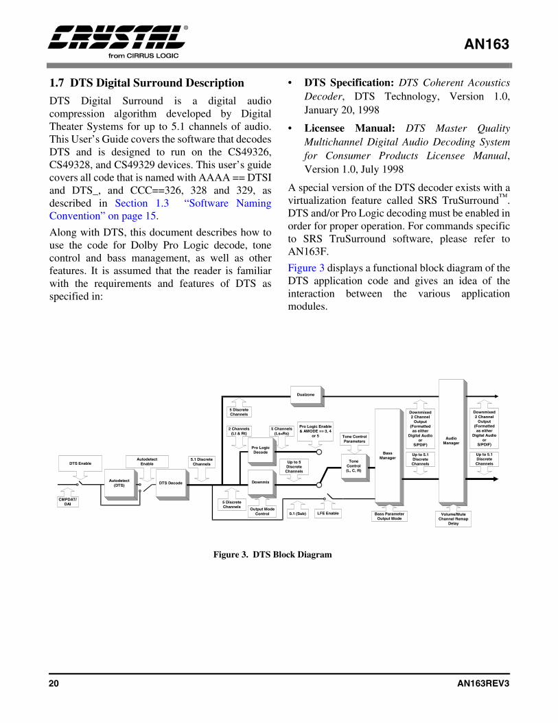
DTS Digital Surround is a digital audiocompression algorithm developed by DigitalTheater Systems for up to 5.1 channels of audio.This User’s Guide covers the software that decodesDTS and is designed to run on the CS49326,CS49328, and CS49329 devices. This user’s guidecovers all code that is named with AAAA == DTSIand DTS_, and CCC==326, 328 and 329, asdescribed in Section 1.3 “Software NamingConvention” on page 15.
Along with DTS, this document describes how touse the code for Dolby Pro Logic decode, tonecontrol and bass management, as well as otherfeatures. It is assumed that the reader is familiarwith the requirements and features of DTS asspecified in:
• DTS Specification: DTS Coherent AcousticsDecoder, DTS Technology, Version 1.0,January 20, 1998
• Licensee Manual: DTS Master QualityMultichannel Digital Audio Decoding Systemfor Consumer Products Licensee Manual,Version 1.0, July 1998
A special version of the DTS decoder exists with avirtualization feature called SRS TruSurround™.DTS and/or Pro Logic decoding must be enabled inorder for proper operation. For commands specificto SRS TruSurround software, please refer toAN163F.
Figure 3 displays a functional block diagram of theDTS application code and gives an idea of theinteraction between the various applicationmodules.
Figure 3. DTS Block Diagram
5 DiscreteChannels
Autodetect(DTS)
DTS EnableAutodetect
Enable
LFE Enable
2 Channels(Lt & Rt)
0.1 (Sub)
CMPDAT/DAI
Pro LogicDecode
Up to 5DiscreteChannels
Up to 5.1DiscreteChannels
Dualzone
Downmixed2 Channel
Output(Formattedas either
Digital Audioor
S/PDIF)
DTS Decode
5.1 DiscreteChannels
ToneControl(L, C, R)
Tone ControlParameters
BassManager
Bass ParameterOutput Mode
Downmix
Pro Logic Enable& AMODE == 3, 4
or 5
5 Channels(Ls=Rs)
5 DiscreteChannels
Output ModeControl
AudioManager
Up to 5.1DiscreteChannels
Downmixed2 Channel
Output(Formattedas either
Digital Audioor
S/PDIF)
Volume/MuteChannel Remap
Delay

AN163
AN163REV3 21
1.8 MP3 Description
MPEG-1, Audio Layer 3 (also known as MP3) is adigital audio compression algorithm developed bythe Moving Pictures Experts Group for up to 2discrete decoded channels of audio. This User’sGuide covers the software that decodes MPEG-1,Audio Layer 3 and is designed to run on theCS49325, CS49326, CS49328, and CS49329devices. This User’s Guide covers all code that isnamed with AAAA == MP3_ and CCC==325, 326,328 and 329, as described in the previous Section1.3 “Software Naming Convention” on page 15.
Along with MP3, this document describes how touse the code for bass management, as well as otherfeatures. It is assumed that the reader is familiarwith the features of MP3 as specified in:
ISO/IEC 11172-3, Information technology -Coding of moving pictures and associatedaudio for digital storage media at up to about1.5 Mbit/s - Part 3: Audio
Figure 4 displays a functional block diagram of theMP3 application code and gives you an idea of theinteraction between the various applicationmodules.
2 DiscreteChannels
MP3 Decoding
MP3 EnableAutodetect
Enable
CMPDAT/DAI
2.1 Channels
Dualzone
Autodetect(MP3)
2.1 Channels
2 DecodedChannels
(PCM)
BassManager
AudioManager
Volume/MuteChannel Remap
Delay
Bass ParameterOutput Mode
Figure 4. MP3 Block Diagram

AN163
22 AN163REV3
1.9 MPEG Multichannel Description
MPEG Multichannel is a digital audio compressionalgorithm developed by the Moving PicturesExperts Group for multiple discrete encodedchannels of audio. This User’s Guide covers thesoftware that decodes MPEG-1, Audio Layer 2 aswell as MPEG-2, Audio Layer 2 (with and withoutextension) Stereo and Multichannel streams with adecoded output of up to 5.1 discrete channels and isdesigned to run on the CS49325, CS49326,CS49328, and CS49329. This User’s Guide coversall code that is named with AAAA == MPG_ andCCC==325, 326, 328 and 329, as described inSection 1.3.
Along with MPEG Multichannel this documentdescribes how to use the code for Dolby Pro Logic
decode, tone control and bass management, as wellas other features. It is assumed that the reader isfamiliar with the features of MPEG Multichannelas specified in:
ISO/IEC 13818-3, MPEG Audio Coding Standard
A special version of the MPEG Multichanneldecoder exists with a virtualization feature, calledSRS TruSurround™. MPEG Multichannel and/orPro Logic decoding must be enabled in order forproper operation. For commands specific to SRSTruSurround software, please refer to AN163F.
Figure 5 displays a functional block diagram of theMPEG Multichannel application code and gives anidea of the interaction between the variousapplication modules.
5 DiscreteChannels
Autodetect(MPEG-MC)
MPEG-MC EnableAutodetect
Enable
LFE Enable
2 Channels(Lt & Rt)
0.1 (Sub)
CMPDAT/DAI
Pro LogicDecode
Up to 5DiscreteChannels
Up to 5.1DiscreteChannels
Dualzone
Downmixed2 Channel
Output(Formattedas either
Digital Audioor
S/PDIF)
MPEG-MCDecode
5.1 DiscreteChannels
ToneControl(L, C, R)
Tone ControlParameters
BassManager
Bass ParameterOutput Mode
Downmix
Pro Logic Enable& Audio_Config
== 9
5 Channels(Ls=Rs)
5 DiscreteChannels
Output ModeControl
AudioManager
Up to 5.1Discrete
Channels
Downmixed2 Channel
Output(Formatted
as eitherDigital Audio
orS/PDIF)
Volume/MuteChannel Remap
Delay
Figure 5. MPEG Multichannel Block Diagram
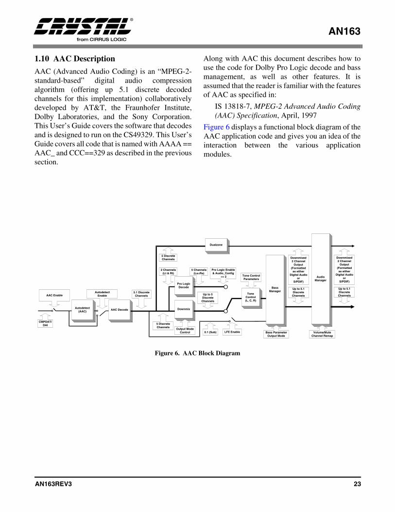
AN163
AN163REV3 23
1.10 AAC Description
AAC (Advanced Audio Coding) is an “MPEG-2-standard-based” digital audio compressionalgorithm (offering up 5.1 discrete decodedchannels for this implementation) collaborativelydeveloped by AT&T, the Fraunhofer Institute,Dolby Laboratories, and the Sony Corporation.This User’s Guide covers the software that decodesand is designed to run on the CS49329. This User’sGuide covers all code that is named with AAAA ==AAC_ and CCC==329 as described in the previoussection.
Along with AAC this document describes how touse the code for Dolby Pro Logic decode and bassmanagement, as well as other features. It isassumed that the reader is familiar with the featuresof AAC as specified in:
IS 13818-7, MPEG-2 Advanced Audio Coding(AAC) Specification, April, 1997
Figure 6 displays a functional block diagram of theAAC application code and gives you an idea of theinteraction between the various applicationmodules.
5 DiscreteChannels
Autodetect(AAC)
AAC EnableAutodetect
Enable
LFE Enable
2 Channels(Lt & Rt)
0.1 (Sub)
CMPDAT/DAI
Pro LogicDecode
Up to 5DiscreteChannels
Up to 5.1DiscreteChannels
Dualzone
Downmixed2 Channel
Output(Formattedas either
Digital Audioor
S/PDIF)
AAC Decode
5.1 DiscreteChannels
ToneControl(L, C, R)
Tone ControlParameters
BassManager
Bass ParameterOutput Mode
Downmix
Pro Logic Enable& Audio_Config
== 2
5 Channels(Ls=Rs)
5 DiscreteChannels
Output ModeControl
AudioManager
Up to 5.1Discrete
Channels
Downmixed2 Channel
Output(Formatted
as eitherDigital Audio
orS/PDIF)
Volume/MuteChannel Remap
Figure 6. AAC Block Diagram

AN163
24 AN163REV3
1.11 Crystal Original Surround Description
Crystal Original Surround is an application codedesigned to take process PCM data and convert atwo-channel source into 5.1 channels with effectsprocessing. This User’s Guide covers the softwarethat processes PCM using the C.O.S. ApplicationCode designed to run on the CS49325, CS49326,CS49328, CS49329, and CS49330. This User’sGuide covers all code that is named with AAAA ==EFF_, and CCC==325, 326, 328, 329, and 330, asdescribed in the previous section.
It is assumed that the reader is familiar with effectsprocessing, however a brief description of reverb,echo, and other filtering techniques are covered.
Along with Crystal Original Surround, thisdocument describes how to use the code for tonecontrol and bass management, as well as otherfeatures. Figure 7 displays a functional blockdiagram of the Crystal Original Surroundapplication code and gives you an idea of theinteraction between the various applicationmodules.
Other Stereo PCM processing application codes areavailable and are discussed in separate appendicesto AN163. They are: SRS Circle Surround(AN163C), Pacific Microsonics HDCD (AN163D)and Logic 7 (AN163E).
Crystal OriginalSurround Effects
Enable
AutodetectEnable
CMPDAT/DAI
Dualzone
Autodetect(PCM)
EQParameters
2 DiscreteChannels
5 Discrete Channels(Reverb Out)
1 Channel(FIR Out)
TestImpulse
Test Impulse Enable
2 DiscreteChannels
(L, R)3-Band
ParametricEqualizer
Stereo PCM toMultichannel
PCM Processing
2 Channels(Ls, Rs)
3.1 Channels(L, C, R, LFE)
Channel Mixer
Divider FIR
FIR Enable
2 DiscreteChannels
5.1 Channels
5.1 Channels
2 Channels(Pass-Through)
ToneControl(L, C, R)
BassManager
AudioManager
Volume/MuteChannel Remap
Delay
Bass ParameterOutput Mode
ToneControl
Parameters
Figure 7. Crystal Original Surround Block Diagram
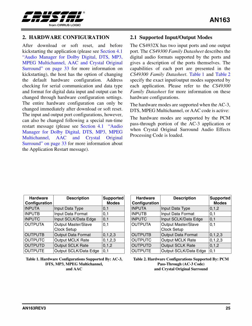
AN163
AN163REV3 25
2. HARDWARE CONFIGURATION
After download or soft reset, and beforekickstarting the application (please see Section 4.1“Audio Manager for Dolby Digital, DTS, MP3,MPEG Multichannel, AAC and Crystal OriginalSurround” on page 33 for more information onkickstarting), the host has the option of changingthe default hardware configuration. Addresschecking for serial communication and data typeand format for digital data input and output can bechanged through hardware configuration settings.The entire hardware configuration can only bechanged immediately after download or soft reset.The input and output port configurations, however,can also be changed following a special run-timerestart message (please see Section 4.1 “AudioManager for Dolby Digital, DTS, MP3, MPEGMultichannel, AAC and Crystal OriginalSurround” on page 33 for more information aboutthe Application Restart message).
2.1 Supported Input/Output Modes
The CS4932X has two input ports and one outputport. The CS49300 Family Datasheet describes thedigital audio formats supported by the ports andgives a description of the ports themselves. Thecapabilities of each port are presented in theCS49300 Family Datasheet. Table 1 and Table 2specify the exact input/output modes supported byeach application. Please refer to the CS49300Family Datasheet for more information on thesehardware configurations.
The hardware modes are supported when the AC-3,DTS, MPEG Multichannel, or AAC code is active:
The hardware modes are supported by the PCMpass-through portion of the AC-3 application orwhen Crystal Original Surround Audio EffectsProcessing Code is loaded.
Hardware Configuration
Description Supported Modes
INPUTA Input Data Type 0,1INPUTB Input Data Format 0,1INPUTC Input SCLK/Data Edge 0,1OUTPUTA Output Master/Slave
Clock Setup0,1
OUTPUTB Output Data Format 0,1,2,3OUTPUTC Output MCLK Rate 0,1,2,3OUTPUTD Output SCLK Rate 0,1,2OUTPUTE Output SCLK/Data Edge 0,1
Table 1. Hardware Configurations Supported By: AC-3, DTS, MP3, MPEG Multichannel,
and AAC
Hardware Configuration
Description Supported Modes
INPUTA Input Data Type 0,1,2INPUTB Input Data Format 0,1INPUTC Input SCLK/Data Edge 0,1OUTPUTA Output Master/Slave
Clock Setup0,1
OUTPUTB Output Data Format 0,1,2,3OUTPUTC Output MCLK Rate 0,1,2,3OUTPUTD Output SCLK Rate 0,1,2OUTPUTE Output SCLK/Data Edge 0,1
Table 2. Hardware Configurations Supported By: PCM Pass-Through (AC-3 Code)
and Crystal Original Surround

AN163
26 AN163REV3
2.1.1 DCLK = 86MHz
The switching characteristics of the Motorola andIntel parallel communication modes, discussed inthe CS49300 Data Sheet, have notes that state “Itshould be noted that DCLK for the internal clockmode is application specific. The application codeuser’s guide should be checked to confirm DCLKfor the particular application.” For all theapplication codes discussed in this application codeuser’s guide, DCLK is equal to 86 MHz.
2.1.2 Configuring the XMT958/AUDAT3 Data Format
The following commands must be sent to configurethe data present on the XMT958/AUDAT3 pin toS/PDIF (IEC60958) format that is driven from thesupplied MCLK at 256 Fs:
0x8002710xf7ffff0x8001710x021000
The following commands must be sent to configurethe data present on the XMT958/AUDAT3 pin toS/PDIF (IEC60958) format that is driven from thesupplied MCLK at 512 Fs:
0x8002710xf7ffff0x8001710x061000
The following commands must be sent to configurethe data present on the XMT958/AUDAT3 pin toI2S 24-bit format that is driven from the suppliedMCLK (256Fs/512Fs/128Fs/384Fs) set by theOUTPUT C Parameter in the CS49300 Data Sheet:
0x8002710xF80FFF0x8002700xF01701
The following commands must be sent to configurethe data present on the XMT958/AUDAT3 pin toI2S 20-bit format that is driven from the suppliedMCLK (256Fs/512Fs/128Fs/384Fs) set by theOUTPUT C Parameter in the CS49300 Data Sheet:
0x8002710xF80FFF0x8002700xF01301
The following commands must be sent to configurethe data present on the XMT958/AUDAT3 pin toLeft Justified 24-bit format that is driven from thesupplied MCLK (256Fs/512Fs/128Fs/384Fs) setby the OUTPUT C Parameter in the CS49300 DataSheet:
0x8002710xF80FFF0x8002700xF01700
The following commands must be sent to configurethe data present on the XMT958/AUDAT3 pin toLeft Justified 20-bit format that is driven from thesupplied MCLK (256Fs/512Fs/128Fs/384Fs) setby the OUTPUT C Parameter in the CS49300 DataSheet:
0x8002710xF80FFF0x8002700xF01300
One of the configurations listed above must be sentbefore kickstart.
2.1.3 S/PDIF (AES/EBU) Channel Status Block Control
The CS4932X, in combination with all of the codesmentioned in this document, offers the “minimum”professional implementation of control over theIEC60958 channel status bits. According to theIEC60958 Specification, the host has control overthe setting of the “PRO” bit in the channel statusword (Channel Status Byte 0, Bit 0).
“Professional use of the channel status block” willbe implemented if the host sets the PRO bit to astate of logic 1. These additional channel status bitsmay also be set by the host: Channel Status Byte 0,Bits 1-5; Channel Status Byte 1, Bits 0-7; andChannel Status Byte 3, Bits 0 and 1. Please refer toTable 3 for the IEC60958 definition for the settingof each bit or set of bits.
AN163
AN163REV3 27
“Consumer use of the channel status block” will beimplemented if the host sets the PRO bit to logicstate 0. These additional channel status bits mayalso be set by the host: Channel Status Byte 0, Bits1-5; Channel Status Byte 1, Bits 0-7; and ChannelStatus Byte 3, Bits 0 and 1. Please refer to Table 4for the IEC6096 definition for the setting of eachbit or set of bits.
The channel status bits map to the DSP Write DataWord in the following manner (please refer toTable 5):
• Channel Status Byte 0, Bit 0 = maps to bit 8 inthe DSP Write Data Word.
• Channel Status Byte 0, Bits 1:5 = map to bits9:13 in the DSP Write Data Word.
• Channel Status Byte 1, Bits 0:7 = map to bits14:21 in the DSP Write Data Word.
• Channel Status Byte 3, Bits 0 and 1 = map tobits 22 and 23 in the DSP Write Data Word.
Please refer to the IEC60958 Specification formore a more detailed explanation of the channelstatus block definitions.
For example, the following command sets theChannel Status Block of the Left Subframe(Channel A) for: Consumer Mode (Byte 0, Bit0 =0); 48kHz Fs (Byte 3, Bit 0 and 1 = 01); CategoryCode = General (Byte 1, Bits 0:7 = 000000000); 2Audio Channels without Pre-Emphasis and CopyProhibited (Byte 0, Bits 1:5 = 00000):
0x8002720x0000FF0x8001720x800000
For example the following command sets theChannel Status Block of the Right Subframe(Channel B) for: Consumer Mode (Byte 0, Bit 0 =0), 32kHz Fs (Byte 3, Bits 0 and 1 = 11); CategoryCode = General (Byte 1, Bits 0:7 = 000000000); 2Audio Channels without Pre-Emphasis and CopyProhibited (Byte 0, Bits 1:5 = 00000):
0x8002730x0000FF0x8001730xC00000
The first word performs a logical “AND” of theregister with the second word, which acts as amask. The values located in the bit locations“AND’ed” with a one are preserved, while thelocations “AND’ed” with a zero are cleared. Thethird word performs a logical “OR” of the sameregister with the fourth word, which contains thenecessary CSW bits that the user wants to set.
2.1.4 S/PDIF (AES/EBU) Validity Bit Control
In addition to the Channel Status Block Control,the Validity bit in the IEC60958 stream may alsobe set by the host to indicate if the according audiosample is fit for conversion to analog.
The following command must be sent to CLEARthe IEC60958 Validity bit:
0x8002710xFFBFFF
The following command must be sent to SET theIEC60958 Validity bit:
0x8001710x004000
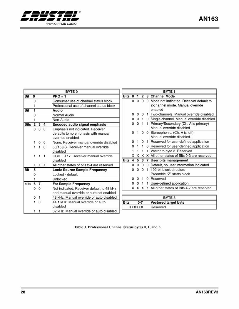
AN163
28 AN163REV3
B
BYTE 0Bit 0 PRO = 1
0 Consumer use of channel status block1 Professional use of channel status block
Bit 1 Audio0 Normal Audio1 Non-Audio
Bits 2 3 4 Encoded audio signal emphasis0 0 0 Emphasis not indicated. Receiver
defaults to no emphasis with manual override enabled
1 0 0 None. Receiver manual override disabled1 1 0 50/15 µS. Receiver manual override
disabled1 1 1 CCITT J.17. Receiver manual override
disabledX X X All other states of bits 2-4 are reserved
Bit 5 Lock: Source Sample Frequency0 Locked - default1 Unlocked
bits 6 7 Fs: Sample Frequency0 0 Not indicated. Receiver default to 48 kHz
and manual override or auto set enabled0 1 48 kHz. Manual override or auto disabled1 0 44.1 kHz. Manual override or auto
disabled1 1 32 kHz. Manual override or auto disabled
BYTE 1
Bits 0 1 2 3 Channel Mode0 0 0 0 Mode not indicated. Receiver default to
2-channel mode. Manual override enabled
0 0 0 1 Two-channels. Manual override disabled0 0 1 0 Single channel. Manual override disabled0 0 1 1 Primary/Secondary (Ch. A is primary)
Manual override disabled0 1 0 0 Stereophonic. (Ch. A is left)
Manual override disabled.0 1 0 1 Reserved for user-defined application0 1 1 0 Reserved for user-defined application1 1 1 1 Vector to byte 3. ReservedX X X X All other states of Bits 0-3 are reserved.
Bits 4 5 6 7 User bits management 0 0 0 0 Default, no user information indicated0 0 0 1 192-bit block structure
Preamble “Z” starts block0 0 1 0 Reserved0 0 1 1 User-defined applicationX X X X All other states of Bits 4-7 are reserved.
BYTE 3Bits 0-7 Vectored target byte
XXXXXX Reserved
Table 3. Professional Channel Status bytes 0, 1, and 3
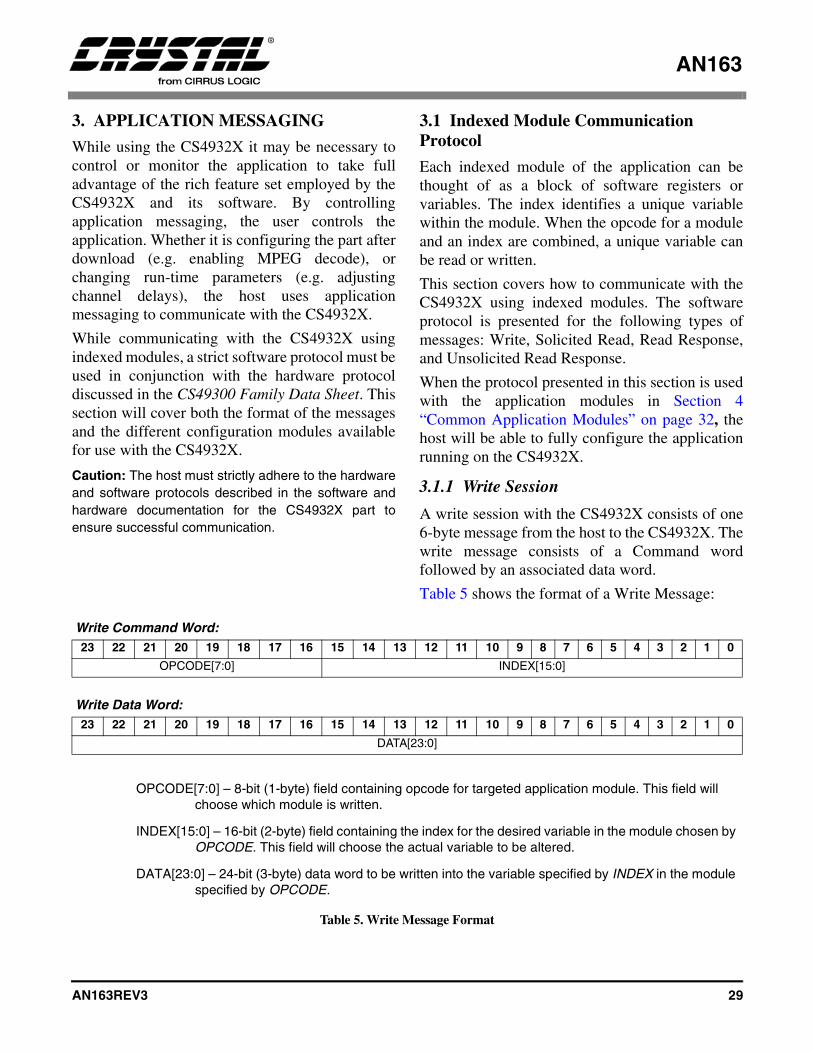
AN163
AN163REV3 29
3. APPLICATION MESSAGING
While using the CS4932X it may be necessary tocontrol or monitor the application to take fulladvantage of the rich feature set employed by theCS4932X and its software. By controllingapplication messaging, the user controls theapplication. Whether it is configuring the part afterdownload (e.g. enabling MPEG decode), orchanging run-time parameters (e.g. adjustingchannel delays), the host uses applicationmessaging to communicate with the CS4932X.
While communicating with the CS4932X usingindexed modules, a strict software protocol must beused in conjunction with the hardware protocoldiscussed in the CS49300 Family Data Sheet. Thissection will cover both the format of the messagesand the different configuration modules availablefor use with the CS4932X.
Caution: The host must strictly adhere to the hardwareand software protocols described in the software andhardware documentation for the CS4932X part toensure successful communication.
3.1 Indexed Module Communication Protocol
Each indexed module of the application can bethought of as a block of software registers orvariables. The index identifies a unique variablewithin the module. When the opcode for a moduleand an index are combined, a unique variable canbe read or written.
This section covers how to communicate with theCS4932X using indexed modules. The softwareprotocol is presented for the following types ofmessages: Write, Solicited Read, Read Response,and Unsolicited Read Response.
When the protocol presented in this section is usedwith the application modules in Section 4“Common Application Modules” on page 32, thehost will be able to fully configure the applicationrunning on the CS4932X.
3.1.1 Write Session
A write session with the CS4932X consists of one6-byte message from the host to the CS4932X. Thewrite message consists of a Command wordfollowed by an associated data word.
Table 5 shows the format of a Write Message:
Write Command Word:23 22 21 20 19 18 17 16 15 14 13 12 11 10 9 8 7 6 5 4 3 2 1 0
OPCODE[7:0] INDEX[15:0]
Write Data Word:23 22 21 20 19 18 17 16 15 14 13 12 11 10 9 8 7 6 5 4 3 2 1 0
DATA[23:0]
OPCODE[7:0] – 8-bit (1-byte) field containing opcode for targeted application module. This field will choose which module is written.
INDEX[15:0] – 16-bit (2-byte) field containing the index for the desired variable in the module chosen by OPCODE. This field will choose the actual variable to be altered.
DATA[23:0] – 24-bit (3-byte) data word to be written into the variable specified by INDEX in the module specified by OPCODE.
Table 5. Write Message Format
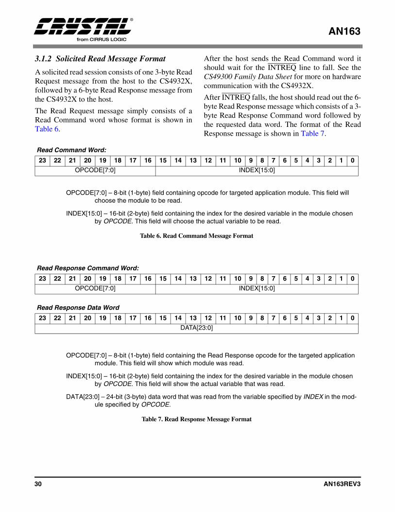
AN163
30 AN163REV3
3.1.2 Solicited Read Message Format
A solicited read session consists of one 3-byte ReadRequest message from the host to the CS4932X,followed by a 6-byte Read Response message fromthe CS4932X to the host.
The Read Request message simply consists of aRead Command word whose format is shown inTable 6.
After the host sends the Read Command word itshould wait for the INTREQ line to fall. See theCS49300 Family Data Sheet for more on hardwarecommunication with the CS4932X.
After INTREQ falls, the host should read out the 6-byte Read Response message which consists of a 3-byte Read Response Command word followed bythe requested data word. The format of the ReadResponse message is shown in Table 7.
Read Command Word:
23 22 21 20 19 18 17 16 15 14 13 12 11 10 9 8 7 6 5 4 3 2 1 0
OPCODE[7:0] INDEX[15:0]
OPCODE[7:0] – 8-bit (1-byte) field containing opcode for targeted application module. This field will choose the module to be read.
INDEX[15:0] – 16-bit (2-byte) field containing the index for the desired variable in the module chosen by OPCODE. This field will choose the actual variable to be read.
Table 6. Read Command Message Format
Read Response Command Word:
23 22 21 20 19 18 17 16 15 14 13 12 11 10 9 8 7 6 5 4 3 2 1 0
OPCODE[7:0] INDEX[15:0]
Read Response Data Word
23 22 21 20 19 18 17 16 15 14 13 12 11 10 9 8 7 6 5 4 3 2 1 0
DATA[23:0]
OPCODE[7:0] – 8-bit (1-byte) field containing the Read Response opcode for the targeted application module. This field will show which module was read.
INDEX[15:0] – 16-bit (2-byte) field containing the index for the desired variable in the module chosen by OPCODE. This field will show the actual variable that was read.
DATA[23:0] – 24-bit (3-byte) data word that was read from the variable specified by INDEX in the mod-ule specified by OPCODE.
Table 7. Read Response Message Format
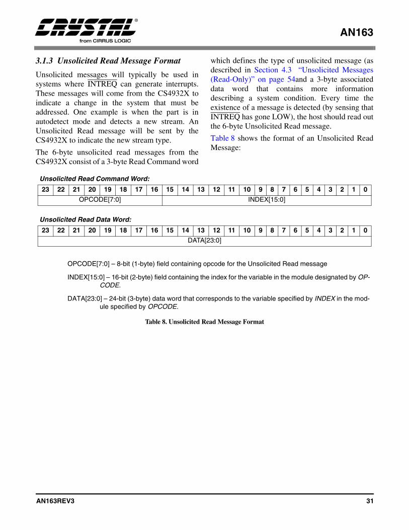
AN163
AN163REV3 31
3.1.3 Unsolicited Read Message Format
Unsolicited messages will typically be used insystems where INTREQ can generate interrupts.These messages will come from the CS4932X toindicate a change in the system that must beaddressed. One example is when the part is inautodetect mode and detects a new stream. AnUnsolicited Read message will be sent by theCS4932X to indicate the new stream type.
The 6-byte unsolicited read messages from theCS4932X consist of a 3-byte Read Command word
which defines the type of unsolicited message (asdescribed in Section 4.3 “Unsolicited Messages(Read-Only)” on page 54and a 3-byte associateddata word that contains more informationdescribing a system condition. Every time theexistence of a message is detected (by sensing thatINTREQ has gone LOW), the host should read outthe 6-byte Unsolicited Read message.
Table 8 shows the format of an Unsolicited ReadMessage:
Unsolicited Read Command Word:
23 22 21 20 19 18 17 16 15 14 13 12 11 10 9 8 7 6 5 4 3 2 1 0
OPCODE[7:0] INDEX[15:0]
Unsolicited Read Data Word:
23 22 21 20 19 18 17 16 15 14 13 12 11 10 9 8 7 6 5 4 3 2 1 0
DATA[23:0]
OPCODE[7:0] – 8-bit (1-byte) field containing opcode for the Unsolicited Read message
INDEX[15:0] – 16-bit (2-byte) field containing the index for the variable in the module designated by OP-CODE.
DATA[23:0] – 24-bit (3-byte) data word that corresponds to the variable specified by INDEX in the mod-ule specified by OPCODE.
Table 8. Unsolicited Read Message Format

AN163
32 AN163REV3
4. COMMON APPLICATION MODULES
Both the Generalized Audio Manager andGeneralized Bass Manager are generic in their useand apply to Dolby Digital, DTS, MP3, MPEGMultichannel, AAC, and Crystal Original Surroundcode, in addition to the codes covered in AN163appendices.
The Generalized Pro Logic Manager is applicableto all codes with the exception of MP3 and C.O.S.codes in addition to all IBA-Based codes.
The Generalized Tone Control Manager isapplicable to all codes with the exception of MP3and AAC. The block diagram on the cover page ofthis document portrays the interaction between thevarious application modules and the AC-3, DTS,MP3, MPEG Multichannel, AAC and CrystalOriginal Surround code.
The following should be noted about all values inthe application modules:
• Variables marked by “Default*” will only beinitialized after download. These variables willretain their values after a soft reset (orApplication Restart, where applicable).
• Variables marked by ‘Default’ will be re-initialized to the values shown in thisapplication note after download, soft reset (orApplication Restart, where applicable).
• Variables marked by ‘†’ can be modifiedduring runtime of any application code.Variables NOT marked by ‘†’ can NOT bemodified during runtime of any applicationcode.
• Only those values which are presented as validor which fall within the specified range shouldbe written to the application module variables.If a value which falls outside the stated range iswritten to a variable, functionality of theapplication is not guaranteed and erroneousoutput could result.
• All bits that are not defined should beconsidered reserved and written with 0’s unless
specified otherwise.
• For variables such as volume and scalingfactors, the real number range of 0.0-1.0 iswritten as 0x000000-0x7FFFFF. This range islinear, i.e. 1/4 volume, or -12 dB, is representedas 0x1FFFFF and is equivalent to a value of0.25.
• The formula for converting variable settingsfrom a hexadecimal number into dB is asfollows:
20 * log (variable setting/max value for variable)
e.g. 20 * log (0x1FFFFF/0x7FFFFF) == -12 dB
Numbers preceded by 0x should be interpretedas hex, and numbers followed by ‘b’ should beinterpreted as binary. All values sent to theCS4932X should be converted to hexadecimal.Likewise all values read from the part are inhexadecimal.

AN163
AN163REV3 33
4.1 Audio Manager for Dolby Digital, DTS, MP3, MPEG Multichannel, AACand Crystal Original Surround
Write Opcode = 0x88; Read Opcode = 0x09; Read Response Opcode = 0x89
Write Message = 0x8800HH 0xhhhhhh
Read Request Message = 0x0900HH;
Read Response Message = 0x8900HH 0xhhhhhh
0xHH = index, 0xhhhhhh = data value
Index Variable Dataword Content0x00 AUDIO_MGR_CONTROL Bit 15 = Audio_Config_Change_Notification_Enable = 0/1= Disable/Enable
unsolicited message notification of any change in audio configuration of any input bitstream.
Note: This bit is applicable only for the following algorithms: AAC, AC-3, MPEG and DTS. The exact fields are specified for each application separately. Please refer to Section 4.1.1 “Audio_Control: (Index 0x00)” on page 37 for more detail.
Bit 14 = Startup_Autodetect_Bypass_Enable= 0/1= Disable/Enable bypassing of autodetection at start-up, i.e. for the first time after download/reset. (Valid only with Autodetect_Enable==1).
Note: If the above mode is enabled, during readback this bit is reserved and may read 0 or 1. Setting of this bit is not recommended with DTS code.
Bit 13 = Null_Pause_Report_Enable = 0/1= Disable/Enable reporting of Null and Pause IEC61937 data types (Valid only with Autodetect_Enable==1).
Note: Care should be taken when enabling this bit as it could cause multiple interrupts to be taken by the host. Using this bit is not suggested unless IEC61937 streams and null/pause reporting are understood in the context of how it will affect the host microcontroller and interrupts. Use of null/pause reporting is not required for a working system.
Bit 12 = Autodetect_Enable = 0/1= Disable/Enable autodetect functionality.Bit 9 = Delay_Granularity 0/1 = ms/16 sample.
Note: Not applicable to AAC code.
Bit 8 = Application_Restart_Enable = 0/1= Disable/Enable restart of software application.
Note: This setting is ONLY applicable for AC-3 and C.O.S. application codes. This bit should be set to 0 for all other application codes.
Bit 4 = PLL_Enable = 0/1 = Disable/Enable Phase Locked Loop generation of DSP clock. It is mandatory that the PLL be enabled for the CS4932X.
Bit 0 = Kickstart_Enable = 0/1 = Disable/Enable Kickstart of application.Default = 0x000000
Table 9. Audio Manager
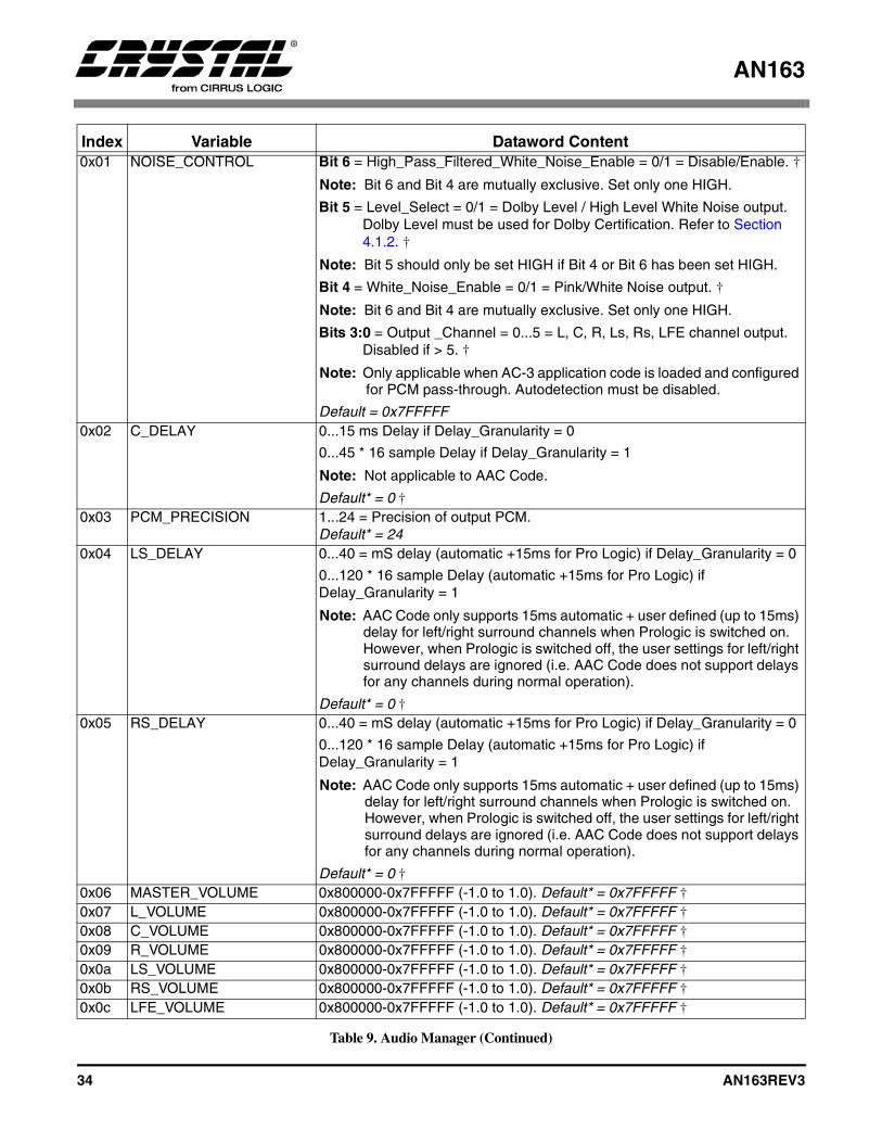
AN163
34 AN163REV3
0x01 NOISE_CONTROL Bit 6 = High_Pass_Filtered_White_Noise_Enable = 0/1 = Disable/Enable. †
Note: Bit 6 and Bit 4 are mutually exclusive. Set only one HIGH.
Bit 5 = Level_Select = 0/1 = Dolby Level / High Level White Noise output. Dolby Level must be used for Dolby Certification. Refer to Section 4.1.2. †
Note: Bit 5 should only be set HIGH if Bit 4 or Bit 6 has been set HIGH.
Bit 4 = White_Noise_Enable = 0/1 = Pink/White Noise output. †
Note: Bit 6 and Bit 4 are mutually exclusive. Set only one HIGH.
Bits 3:0 = Output _Channel = 0...5 = L, C, R, Ls, Rs, LFE channel output. Disabled if > 5. †
Note: Only applicable when AC-3 application code is loaded and configured for PCM pass-through. Autodetection must be disabled.
Default = 0x7FFFFF0x02 C_DELAY 0...15 ms Delay if Delay_Granularity = 0
0...45 * 16 sample Delay if Delay_Granularity = 1
Note: Not applicable to AAC Code.
Default* = 0 †0x03 PCM_PRECISION 1...24 = Precision of output PCM.
Default* = 240x04 LS_DELAY 0...40 = mS delay (automatic +15ms for Pro Logic) if Delay_Granularity = 0
0...120 * 16 sample Delay (automatic +15ms for Pro Logic) if Delay_Granularity = 1
Note: AAC Code only supports 15ms automatic + user defined (up to 15ms) delay for left/right surround channels when Prologic is switched on. However, when Prologic is switched off, the user settings for left/right surround delays are ignored (i.e. AAC Code does not support delays for any channels during normal operation).
Default* = 0 †0x05 RS_DELAY 0...40 = mS delay (automatic +15ms for Pro Logic) if Delay_Granularity = 0
0...120 * 16 sample Delay (automatic +15ms for Pro Logic) if Delay_Granularity = 1
Note: AAC Code only supports 15ms automatic + user defined (up to 15ms) delay for left/right surround channels when Prologic is switched on. However, when Prologic is switched off, the user settings for left/right surround delays are ignored (i.e. AAC Code does not support delays for any channels during normal operation).
Default* = 0 †0x06 MASTER_VOLUME 0x800000-0x7FFFFF (-1.0 to 1.0). Default* = 0x7FFFFF †0x07 L_VOLUME 0x800000-0x7FFFFF (-1.0 to 1.0). Default* = 0x7FFFFF †0x08 C_VOLUME 0x800000-0x7FFFFF (-1.0 to 1.0). Default* = 0x7FFFFF †0x09 R_VOLUME 0x800000-0x7FFFFF (-1.0 to 1.0). Default* = 0x7FFFFF †0x0a LS_VOLUME 0x800000-0x7FFFFF (-1.0 to 1.0). Default* = 0x7FFFFF †0x0b RS_VOLUME 0x800000-0x7FFFFF (-1.0 to 1.0). Default* = 0x7FFFFF †0x0c LFE_VOLUME 0x800000-0x7FFFFF (-1.0 to 1.0). Default* = 0x7FFFFF †
Index Variable Dataword Content
Table 9. Audio Manager (Continued)
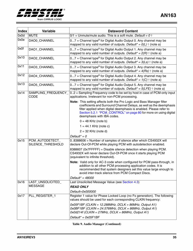
AN163
AN163REV3 35
0x0d MUTE 0/1 = Unmute/mute audio. This is a soft mute. Default = 0 †0x0e DAO0_CHANNEL 0...7 = Channel typea for Digital Audio Output 0. Any channel may be
mapped to any valid number of outputs. Default* = 0(L) † (note a)0x0f DAO1_CHANNEL 0...7 = Channel typea for Digital Audio Output 1. Any channel may be
mapped to any valid number of outputs. Default* = 2(R) † (note a)0x10 DAO2_CHANNEL 0...7 = Channel typea for Digital Audio Output 2. Any channel may be
mapped to any valid number of outputs. Default* = 3(Ls) † (note a)0x11 DAO3_CHANNEL 0...7 = Channel typea for Digital Audio Output 3. Any channel may be
mapped to any valid number of outputs. Default* = 4(Rs) † (note a)0x12 DAO4_CHANNEL 0...7 = Channel typea for Digital Audio Output 4. Any channel may be
mapped to any valid number of outputs. Default* = 1(C) † (note a)0x13 DAO5_CHANNEL 0...7 = Channel typea for Digital Audio Output 5. Any channel may be
mapped to any valid number of outputs. Default* = 5(LFE) † (note a)0x14 SAMPLING_FREQUENCY_
CODE0..2 = Sampling Frequency code to be set by host in case of PCM-only input applications. Irrelevant for non-PCM processing.
Note: This setting affects both the Pro Logic and Bass Manager filter coefficients and Surround Channel Delays, as well as the deemphasis filter applied when digital deemphasis is enabled. Please refer to Section 5.2.1 “PCM_CONTROL” on page 80 for more on using digital deemphasis with IBA codes.
0 = 48 KHz (note b)
1 = 44.1 KHz (note c)
2 = 32 KHz (note d)
Default* = 00x15 PCM_AUTODETECT_
SILENCE_THRESHOLD0..8388606 = Number of samples of silence after which CS4932X will declare Out-Of-PCM while playing PCM with autodetection enabled.
8388607 (0x7FFFFF) = Disable silence detection when playing PCM. CS4932X will never declare Out-Of-PCM once it starts playing PCM (equivalent to infinite threshold).
Note: Valid only for AC-3 code when configured for PCM pass-through, in addition to all other PCM processing application codes. It is recommended that system designers set this value large enough to avoid inter-track silence from PCM Compact Discs.
Default* = 480000x16 LAST_UNSOLICITED_
MESSAGELast Unsolicited Message Value (see Section 4.3)
READ ONLY
Default=0x0000000x17 PLL_REGISTER_1 Register 1 value for Phase Locked Loop (no Fs generation). The following
values should be used for each corresponding CLKIN frequency:
0x05F1BF (CLKIN = 12.288MHz, DCLK = 86MHz, Output A1)0x0BF1BF (CLKIN = 24.576MHz, DCLK = 86MHz, Output A1)0x0d214f (CLKIN = 27MHz, DCLK = 86MHz, Output A1)
Default* = 0x05F1BF
Index Variable Dataword Content
Table 9. Audio Manager (Continued)

AN163
36 AN163REV3
Notes: a. Channel type 0...7 corresponds to Channels L, C, R, Ls, Rs, LFE, Lz, and Rz respectively. Lz and Rz refer dual-zone outputs. If the source made available to the decoder is a 5.1 Channel AC-3 stream, these outputs will be Pro Logic encoded and should be considered to be Lt and Rt. However, for a 2.0 Channel AC-3 stream, these outputs will be simply L and R.
b. Pre-loaded coefficients will provide a 80 Hz Crossover if input Fs is 48 kHz. A different set of coefficients must be downloaded for 96 kHz or 192 kHz Fs support.
c. Pre-loaded coefficients will provide a 80 Hz Crossover if input Fs is 44.1 kHz. A different set of coefficients must be downloaded for 88.2 kHz or 176.4 kHz Fs support.
d. Pre-loaded coefficients will provide a 80 Hz Crossover if input Fs is 32 kHz. A different set of coefficients must be downloaded for 64 kHz or 128 kHz Fs support.
† See definition on page 32.
“Default” vs. “Default*” See definition page 32.
0x18 PLL_REGISTER_2 Register 2 value for Phase Locked Loop (no Fs generation). The following values should be used for each corresponding CLKIN frequency:
0x002F7D (CLKIN = 12.288MHz, DCLK = 86MHz, Output A1)0x002F7D (CLKIN = 24.576MHz, DCLK = 86MHz, Output A1)0x00237D (CLKIN = 27MHz, DCLK = 86MHz, Output A1)
Default* = 0x002F7D0x19 L_DELAY 0...15 ms Delay if Delay_Granularity = 0
0...45 * 16 sample Delay if Delay_Granularity = 1
Note: Not applicable to AAC Code.
Default* = 0 †0x1a R_DELAY 0...15 ms Delay if Delay_Granularity = 0
0...45 * 16 sample Delay if Delay_Granularity = 1
Note: Not applicable to AAC Code.
Default* = 0 †0x1b LFE_DELAY 0...10 ms Delay if Delay_Granularity = 0
0...30 * 16 sample Delay if Delay_Granularity = 1
Note: Not applicable to AAC Code.
Default* = 0 †0x1c LZ_VOLUME 0x800000-0x7FFFFF (-1.0 to 1.0). Default* = 0x7FFFFF †0x1d RZ_VOLUME 0x800000-0x7FFFFF (-1.0 to 1.0). Default* = 0x7FFFFF †0x1e DAO6_CHANNEL 0...7 = Channel typea for Digital Audio Output 6. Any channel may be
mapped to any valid number of outputs. Default* = 6(Lz) † (note a)0x1f DAO7_CHANNEL 0...7 = Channel typea for Digital Audio Output 7. Any channel may be
mapped to any valid number of outputs. Default* = 7(Rz) † (note a)0x20 DUALZONE_
ATTENUATION0x800000-0x7FFFFF (-1.0 to 1.0). Default* = 0x7FFFFF †
Index Variable Dataword Content
Table 9. Audio Manager (Continued)
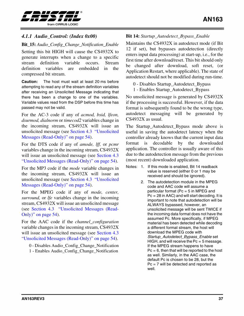
AN163
AN163REV3 37
4.1.1 Audio_Control: (Index 0x00)
Bit_15: Audio_Config_Change_Notification_Enable
Setting this bit HIGH will cause the CS4932X togenerate interrupts when a change to a specificstream definition variable occurs. Streamdefinition variables are embedded in thecompressed bit stream.
Caution: The host must wait at least 20 ms beforeattempting to read any of the stream definition variablesafter receiving an Unsolicited Message indicating thatthere has been a change to one of the variables.Variable values read from the DSP before this time haspassed may not be valid.
For the AC-3 code if any of acmod, bsid, lfeon,dsurmod, dialnorm or timecod2 variables change inthe incoming stream, CS4932X will issue anunsolicited message (see Section 4.3 “UnsolicitedMessages (Read-Only)” on page 54).
For the DTS code if any of amode, lff, or pcmrvariables change in the incoming stream, CS4932Xwill issue an unsolicited message (see Section 4.3“Unsolicited Messages (Read-Only)” on page 54).
For the MP3 code if the mode variable changes inthe incoming stream, CS4932X will issue anunsolicited message (see Section 4.3 “UnsolicitedMessages (Read-Only)” on page 54).
For the MPEG code if any of mode, center,surround, or lfe variables change in the incomingstream, CS4932X will issue an unsolicited message(see Section 4.3 “Unsolicited Messages (Read-Only)” on page 54).
For the AAC code if the channel_configurationvariable changes in the incoming stream, CS4932Xwill issue an unsolicited message (see Section 4.3“Unsolicited Messages (Read-Only)” on page 54).
0 - Disables Audio_Config_Change_Notification1 - Enables Audio_Config_Change_Notification
Bit 14: Startup_Autodetect_Bypass_Enable
Maintains the CS4932X in autodetect mode (if Bit12 if set), but bypasses autodetection (directlyenters input data processing) at start-up, i.e., for thefirst time after download/reset. This bit should onlybe changed after download, soft reset, (orApplication Restart, where applicable). The state ofautodetect should not be modified during run-time.
0 - Disables Startup_Autodetect_Bypass1 - Enables Startup_Autodetect_Bypass
No unsolicited message is generated by CS4932Xif the processing is successful. However, if the dataformat is subsequently found to be the wrong type,autodetect messaging will be generated byCS4932X as usual.
The Startup_Autodetect_Bypass mode above isuseful in saving the autodetect latency when thecontroller already knows that the current input dataformat is decodable by the downloadedapplication. The controller is usually aware of thisdue to the autodetection message from the previous(most recent) downloaded application. Notes: 1. If this mode is enabled, Bit 14 readback
value is reserved (either 0 or 1 may be received and should be ignored).
2. The autodetection module in the MPEG code and AAC code will assume a particular format (Pc = 5 in MPEG and Pc = 28 in AAC) and will start decoding. It is important to note that autodetection will be ALWAYS bypassed, however, an unsolicited message will be sent TWICE if the incoming data format does not have the assumed Pc. More specifically, if MPEG material has been detected while decoding a different format stream, the host will download the MPEG code with Startup_Autodetect_Bypass_Enable set HIGH, and will receive the Pc = 5 message. If the MPEG stream happens to have Pc = 6, then that will be reported to the host as well. Similarly, in the AAC case, the default Pc is chosen to be 28, but the Pc = 7 will be detected and reported as well.
AN163
38 AN163REV3
Bit 12: Autodetect_Enable
Places the CS4932X into autodetect mode (seeSection 4.3 “Unsolicited Messages (Read-Only)”on page 54). This bit should only be changed afterdownload, soft reset, (or Application Restart,where applicable). The state of autodetect shouldnot be modified during run-time.
0 - Disables Autodetect1 - Enables Autodetect
Bit 9: Delay Granularity
Delay Granularity should be setup at kickstart (notafter). This setting is used to choose the delaygranularity as mS or in 16-sample units.
0 - The delay indices are interpreted as mS
1 - The delay indices are interpreted as thenumber of 16-sample-units to delay. In otherwords, the individual channel delay setting ismultiplied by 16 to determine the amount ofdelay in samples.
Bit 8: Application_Restart_Enable
Used along with Kickstart_Enable in only the AC-3 and C.O.S. application codes, restarts thedownloaded software application.
0 - Disables Application_Restart1 - Enables Application_Restart
When enabled, this action allows input unit settingsto be changed on the fly without resetting theoutput unit (which may cause clicks on the DAC ifin master mode). This action also allows changes ofprocessing parameters (such as filter coefficients)without resetting the output unit. ApplicationRestart effectively places the CS4932X in a start-up state as if it had been issued a hardware resetplus a soft reset, except that the preset output andcontrol port configuration is maintained. Except forissuing output and host initialization messages,after an Application_Restart, the host should treatthe CS4932X as it would at start-up, i.e., issueinput unit initialization, setup applicationparameters, and then kickstart.
After sending an Application Restart, the hostshould wait a certain amount of time after sending
Application Restart before sending any furthercommands to the CS4932X.
For example, here are several delay sequences thatshould be followed: If the AC-3 Application Codewas processing an AC-3 Stream, the host must wait35 ms. If the C.O.S. application code or AC-3application code was processing PCM, the hostmust wait 12 ms.Note: Just as with Soft Reset, all Default* settings are
untouched by Application Restart.
Bit 4: PLL_Enable
Enables the use of the Phase Locked Loop (PLL) togenerate internal DSPCLK from the desiredexternal CLKIN.
0 - Disables PLL1 - Enables PLL
The register values in PLL_Register_1 (0x17) andPLL_Register_2 (0x18) define the desired DSPclock and reference CLKIN used. The defaultvalues at download, set up a 86 MHz DSPCLKfrom a 12.288 MHz external CLKIN. Theseregister values should be downloaded prior toKickstart with PLL_Enable. Use the correspondingPLL values located in Table 9 for 24.576 MHzexternal CLKIN or 27 MHz external CLKIN.
For other system requirements, please contact thefactory for appropriate register values.
Bit 0: Kickstart Enable
Puts CS4932X into run-time mode. Indicates thatall hardware and software configuration activitieshave been completed and CS4932X can start theapplication.
0 - Application continues waiting for kickstart1 - Application is kickstarted
4.1.2 Noise_Control (Index 0x01): (Applicable to AC-3 Code Only)
Switches ON Pink/White Noise in Channels L, C,R, Ls, Rs and LFE. Pink/White noise will not beenabled unless the AC-3 application code isconfigured for PCM pass-through and theOutput_Channel is set to a value in the range
AN163
AN163REV3 39
0x0 - 0x5. Autodetect should not be enabled whenusing Pink/White Noise.
Bit 5: Level_Select
Level_Select sets up output level.
0 - Default level (Dolby-compatible)1 - 10.5 dB boosted with respect to default level.
Bit 4: White_Noise_Enable
White_Noise_Enable enables White noise if set(otherwise output is Pink noise).
0 - Pink Noise1 - White Noise
Bits 3:0: Output Channel
Output Channel selects channel for noise output
0x0 - Left0x1 -Center0x2 -Right0x3 -Left Surround (This value controls
both Ls and Rs in Pro Logic Mode)0x4 -Right Surround (This value has no effect
in Pro Logic mode)0x5 -LFE0x6 -Lz0x7 -Rz 0x8-0xf - Disabled
4.1.3 Sampling Frequency Code (Index 0x14)
This parameter controls the sampling frequency forPCM applications. This must be set by the hostduring while a PCM application is loaded, but notduring runtime. Note: For PCM input, the DSP does NOT know the
sampling frequency setting. If the system expects to receive PCM from a S/PDIF receiver, it is up to the host to inquire about the sampling frequency information from the receiver, and then inform the DSP.
For Pro Logic processing of PCM streams or whendigital deemphasis is enabled (refer to Section 5.2“PCM Manager (for AC-3 Application Code)” onpage 78), the correct sampling frequency must alsobe given to the Pro Logic Manager for properoperation of filters. For compressed inputs, such asAC-3, DTS, MPEG, or AAC, the decoderapplication will set up sampling frequencyinformation based on the information parsed fromthe bitstream; consequently, this field does notneed to be set.
Bits 2:0: Sampling_Frequency_Code
0x0 - 48kHz0x1 - 44.1kHz0x2 - 32kHz
For 192 kHz or 96 kHz Stereo PCM support, thehost should set the Fs to 48 kHz and download thecorrect 192 kHz or 96 kHz coefficients in theGeneralized Bass Manager in the place of the48 kHz coefficients.
For 176.4 kHz or 88.2 kHz Stereo PCM support,the host should set the Fs to 44.1 kHz anddownload the correct 176.4 kHz or 88.2 kHzcoefficients in the Generalized Bass Manager in theplace of the 44.1 kHz coefficients.
For 128 kHz or 64 kHz Stereo PCM support, thehost should set the Fs to 32 kHz and download thecorrect 128 kHz or 64 kHz coefficients in theGeneralized Bass Manager in the place of the32 kHz coefficients.
Please contact your FAE for the appropriate192 kHz, 176.4 kHz, 128 kHz, 96 kHz, 88.2 kHzor 64 kHz coefficient files, along with the desiredcrossover frequencies you need. These coefficientsonly effect the Generic Bass Manager module anddo not effect the generic Pro Logic module.Currently, the Pro Logic module only supportssampling frequencies up to 48 kHz for the standardapplication code releases of AC-3, DTS, MPEGMultichannel, and AAC.
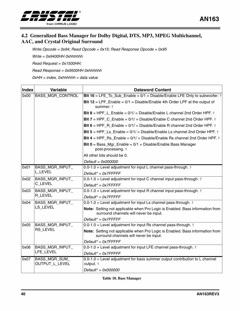
AN163
40 AN163REV3
4.2 Generalized Bass Manager for Dolby Digital, DTS, MP3, MPEG Multichannel,AAC, and Crystal Original Surround
Write Opcode = 0x94; Read Opcode = 0x15; Read Response Opcode = 0x95
Write = 0x9400HH 0xhhhhhh
Read Request = 0x1500HH;
Read Response = 0x9500HH 0xhhhhhh
0xHH = index, 0xhhhhhh = data value
Index Variable Dataword Content0x00 BASS_MGR_CONTROL Bit 16 = LFE_To_Sub_Enable = 0/1 = Disable/Enable LFE Only to subwoofer. †
Bit 12 = LPF_Enable = 0/1 = Disable/Enable 4th Order LPF at the output of summer. †
Bit 8 = HPF_L_Enable = 0/1/ = Disable/Enable L channel 2nd Order HPF. †
Bit 7 = HPF_C_Enable = 0/1/ = Disable/Enable C channel 2nd Order HPF. †
Bit 6 = HPF_R_Enable = 0/1/ = Disable/Enable R channel 2nd Order HPF. †
Bit 5 = HPF_Ls_Enable = 0/1/ = Disable/Enable Ls channel 2nd Order HPF. †
Bit 4 = HPF_Rs_Enable = 0/1/ = Disable/Enable Rs channel 2nd Order HPF. †
Bit 0 = Bass_Mgr_Enable = 0/1 = Disable/Enable Bass Managerpost-processing. †
All other bits should be 0.
Default = 0x0000000x01 BASS_MGR_INPUT_
L_LEVEL0.0-1.0 = Level adjustment for input L channel pass-through. †
Default* = 0x7FFFFF0x02 BASS_MGR_INPUT_
C_LEVEL0.0-1.0 = Level adjustment for input C channel input pass-through. †
Default* = 0x7FFFFF0x03 BASS_MGR_INPUT_
R_LEVEL0.0-1.0 = Level adjustment for input R channel input pass-through. †
Default* = 0x7FFFFF0x04 BASS_MGR_INPUT_
LS_LEVEL0.0-1.0 = Level adjustment for input Ls channel pass-through. †
Note: Setting not applicable when Pro Logic is Enabled. Bass information from surround channels will never be input.
Default* = 0x7FFFFF0x05 BASS_MGR_INPUT_
RS_LEVEL0.0-1.0 = Level adjustment for input Rs channel pass-through. †
Note: Setting not applicable when Pro Logic is Enabled. Bass information from surround channels will never be input.
Default* = 0x7FFFFF0x06 BASS_MGR_INPUT_
LFE_LEVEL0.0-1.0 = Level adjustment for input LFE channel pass-through. †
Default* = 0x7FFFFF0x07 BASS_MGR_SUM_
OUTPUT_L_LEVEL0.0-1.0 = Level adjustment for bass summer output contribution to L channel output. †
Default* = 0x000000
Table 10. Bass Manager

AN163
AN163REV3 41
0x08 BASS_MGR_SUM_OUTPUT_C_LEVEL
0.0-1.0 = Level adjustment for bass summer output contribution to C channel output. †
Default* = 0x0000000x09 BASS_MGR_SUM_
OUTPUT_R_LEVEL0.0-1.0 = Level adjustment for bass summer output contribution to R channel output. †
Default* = 0x0000000x0a BASS_MGR_SUM_
OUTPUT_LS_LEVEL0.0-1.0 = Level adjustment for bass summer output contribution to Ls channel output. †
Default* = 0x0000000x0b BASS_MGR_SUM_
OUTPUT_RS_LEVEL0.0-1.0 = Level adjustment for bass summer output contribution to Rs channel output. †
Default* = 0x0000000x0c BASS_MGR_LFE_
L_LEVEL0.0-1.0 = Level adjustment for input LFE contribution to L channel output. †
Default* = 0x0000000x0d BASS_MGR_LFE
_C_LEVEL0.0-1.0 = Level adjustment for input LFE contribution to C channel output. †
Default* = 0x0000000x0e BASS_MGR_LFE_
R_LEVEL0.0-1.0 = Level adjustment for input LFE contribution to R channel output. †
Default* = 0x0000000x0f BASS_MGR_LFE_
LS_LEVEL0.0-1.0 = Level adjustment for input LFE contribution to Ls channel output. †
Default* = 0x0000000x10 BASS_MGR_LFE_
RS_LEVEL0.0-1.0 = Level adjustment for input LFE contribution to Rs channel output. †
Default* = 0x0000000x11 BASS_MGR_SUM_
INPUT_L_LEVEL0.0-1.0 = Level adjustment for input L channel contribution to bass summer input. †
Default* = 0x16c3110x12 BASS_MGR_SUM_
INPUT_C_LEVEL0.0-1.0 = Level adjustment for input C channel contribution to bass summer input. †
Default* = 0x16c3110x13 BASS_MGR_SUM_
INPUT_R_LEVEL0.0-1.0 = Level adjustment for input R channel contribution to bass summer input. †
Default* = 0x16c3110x14 BASS_MGR_SUM_
INPUT_LS_LEVEL0.0-1.0 = Level adjustment for input Ls channel contribution to bass summer input. †
Default* = 0x16c3110x15 BASS_MGR_SUM_
INPUT_RS_LEVEL0.0-1.0 = Level adjustment for input Rs channel contribution to bass summer input. †
Default* = 0x16c3110x16 BASS_MGR_SUM_
INPUT_LFE_LEVEL0.0-1.0 = Level adjustment for input LFE channel contribution to bass summer.†
Default* = 0x47facd0x17 BASS_MGR_LPF_48_B0 0.0-1.0 = b0 coefficient for Low Pass Filter, Fs = 48 kHz. † (Note a)
Default* = 0x000072
Index Variable Dataword Content
Table 10. Bass Manager (Continued)
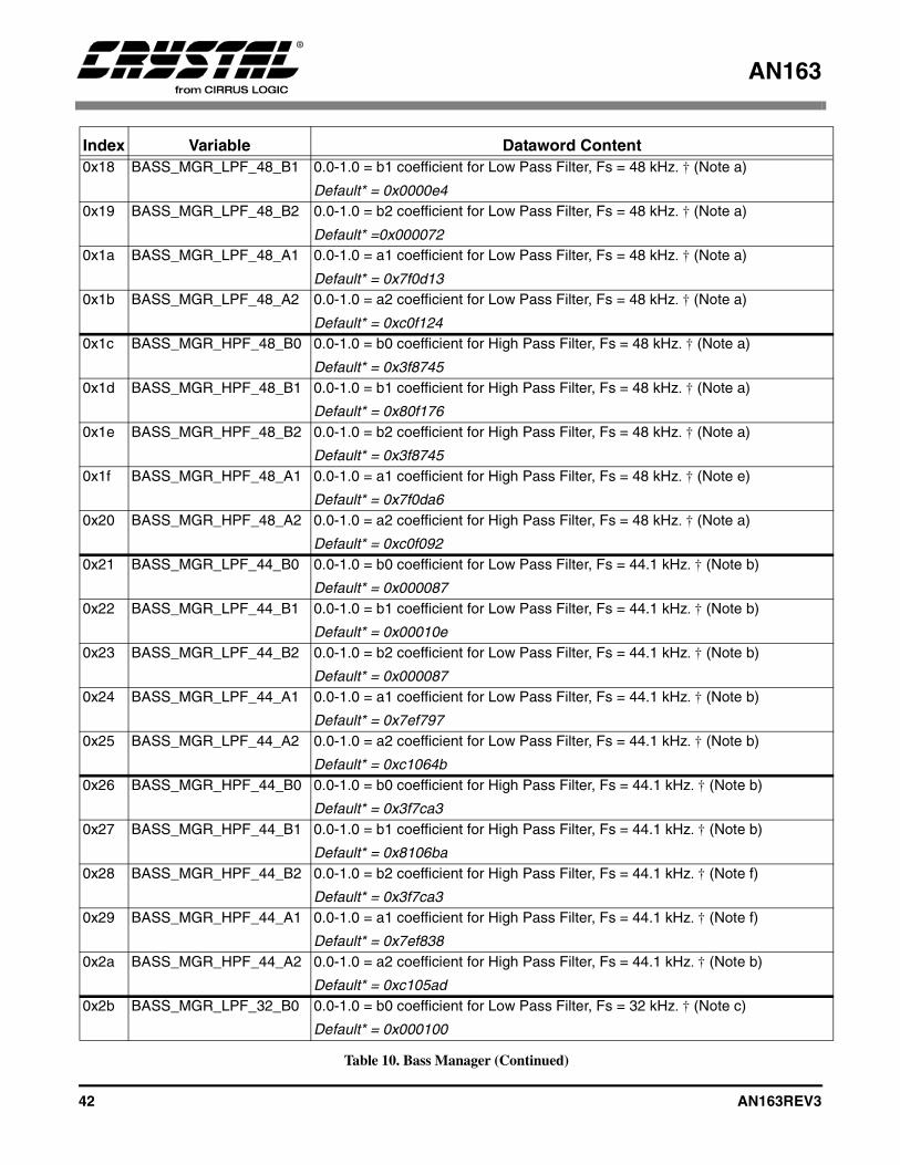
AN163
42 AN163REV3
0x18 BASS_MGR_LPF_48_B1 0.0-1.0 = b1 coefficient for Low Pass Filter, Fs = 48 kHz. † (Note a)
Default* = 0x0000e40x19 BASS_MGR_LPF_48_B2 0.0-1.0 = b2 coefficient for Low Pass Filter, Fs = 48 kHz. † (Note a)
Default* =0x0000720x1a BASS_MGR_LPF_48_A1 0.0-1.0 = a1 coefficient for Low Pass Filter, Fs = 48 kHz. † (Note a)
Default* = 0x7f0d130x1b BASS_MGR_LPF_48_A2 0.0-1.0 = a2 coefficient for Low Pass Filter, Fs = 48 kHz. † (Note a)
Default* = 0xc0f1240x1c BASS_MGR_HPF_48_B0 0.0-1.0 = b0 coefficient for High Pass Filter, Fs = 48 kHz. † (Note a)
Default* = 0x3f87450x1d BASS_MGR_HPF_48_B1 0.0-1.0 = b1 coefficient for High Pass Filter, Fs = 48 kHz. † (Note a)
Default* = 0x80f1760x1e BASS_MGR_HPF_48_B2 0.0-1.0 = b2 coefficient for High Pass Filter, Fs = 48 kHz. † (Note a)
Default* = 0x3f87450x1f BASS_MGR_HPF_48_A1 0.0-1.0 = a1 coefficient for High Pass Filter, Fs = 48 kHz. † (Note e)
Default* = 0x7f0da60x20 BASS_MGR_HPF_48_A2 0.0-1.0 = a2 coefficient for High Pass Filter, Fs = 48 kHz. † (Note a)
Default* = 0xc0f0920x21 BASS_MGR_LPF_44_B0 0.0-1.0 = b0 coefficient for Low Pass Filter, Fs = 44.1 kHz. † (Note b)
Default* = 0x0000870x22 BASS_MGR_LPF_44_B1 0.0-1.0 = b1 coefficient for Low Pass Filter, Fs = 44.1 kHz. † (Note b)
Default* = 0x00010e0x23 BASS_MGR_LPF_44_B2 0.0-1.0 = b2 coefficient for Low Pass Filter, Fs = 44.1 kHz. † (Note b)
Default* = 0x0000870x24 BASS_MGR_LPF_44_A1 0.0-1.0 = a1 coefficient for Low Pass Filter, Fs = 44.1 kHz. † (Note b)
Default* = 0x7ef7970x25 BASS_MGR_LPF_44_A2 0.0-1.0 = a2 coefficient for Low Pass Filter, Fs = 44.1 kHz. † (Note b)
Default* = 0xc1064b0x26 BASS_MGR_HPF_44_B0 0.0-1.0 = b0 coefficient for High Pass Filter, Fs = 44.1 kHz. † (Note b)
Default* = 0x3f7ca30x27 BASS_MGR_HPF_44_B1 0.0-1.0 = b1 coefficient for High Pass Filter, Fs = 44.1 kHz. † (Note b)
Default* = 0x8106ba0x28 BASS_MGR_HPF_44_B2 0.0-1.0 = b2 coefficient for High Pass Filter, Fs = 44.1 kHz. † (Note f)
Default* = 0x3f7ca30x29 BASS_MGR_HPF_44_A1 0.0-1.0 = a1 coefficient for High Pass Filter, Fs = 44.1 kHz. † (Note f)
Default* = 0x7ef8380x2a BASS_MGR_HPF_44_A2 0.0-1.0 = a2 coefficient for High Pass Filter, Fs = 44.1 kHz. † (Note b)
Default* = 0xc105ad0x2b BASS_MGR_LPF_32_B0 0.0-1.0 = b0 coefficient for Low Pass Filter, Fs = 32 kHz. † (Note c)
Default* = 0x000100
Index Variable Dataword Content
Table 10. Bass Manager (Continued)
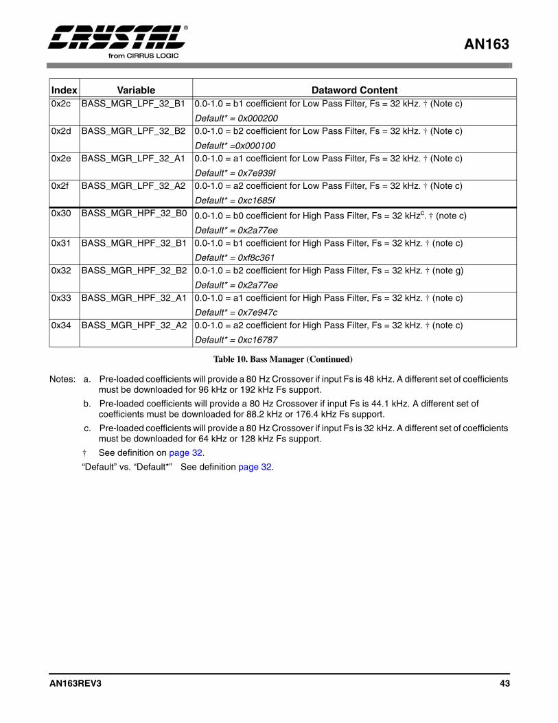
AN163
AN163REV3 43
Notes: a. Pre-loaded coefficients will provide a 80 Hz Crossover if input Fs is 48 kHz. A different set of coefficients must be downloaded for 96 kHz or 192 kHz Fs support.
b. Pre-loaded coefficients will provide a 80 Hz Crossover if input Fs is 44.1 kHz. A different set of coefficients must be downloaded for 88.2 kHz or 176.4 kHz Fs support.
c. Pre-loaded coefficients will provide a 80 Hz Crossover if input Fs is 32 kHz. A different set of coefficients must be downloaded for 64 kHz or 128 kHz Fs support.
† See definition on page 32.
“Default” vs. “Default*” See definition page 32.
0x2c BASS_MGR_LPF_32_B1 0.0-1.0 = b1 coefficient for Low Pass Filter, Fs = 32 kHz. † (Note c)
Default* = 0x0002000x2d BASS_MGR_LPF_32_B2 0.0-1.0 = b2 coefficient for Low Pass Filter, Fs = 32 kHz. † (Note c)
Default* =0x0001000x2e BASS_MGR_LPF_32_A1 0.0-1.0 = a1 coefficient for Low Pass Filter, Fs = 32 kHz. † (Note c)
Default* = 0x7e939f0x2f BASS_MGR_LPF_32_A2 0.0-1.0 = a2 coefficient for Low Pass Filter, Fs = 32 kHz. † (Note c)
Default* = 0xc1685f0x30 BASS_MGR_HPF_32_B0 0.0-1.0 = b0 coefficient for High Pass Filter, Fs = 32 kHzc. † (note c)
Default* = 0x2a77ee0x31 BASS_MGR_HPF_32_B1 0.0-1.0 = b1 coefficient for High Pass Filter, Fs = 32 kHz. † (note c)
Default* = 0xf8c3610x32 BASS_MGR_HPF_32_B2 0.0-1.0 = b2 coefficient for High Pass Filter, Fs = 32 kHz. † (note g)
Default* = 0x2a77ee0x33 BASS_MGR_HPF_32_A1 0.0-1.0 = a1 coefficient for High Pass Filter, Fs = 32 kHz. † (note c)
Default* = 0x7e947c0x34 BASS_MGR_HPF_32_A2 0.0-1.0 = a2 coefficient for High Pass Filter, Fs = 32 kHz. † (note c)
Default* = 0xc16787
Index Variable Dataword Content
Table 10. Bass Manager (Continued)
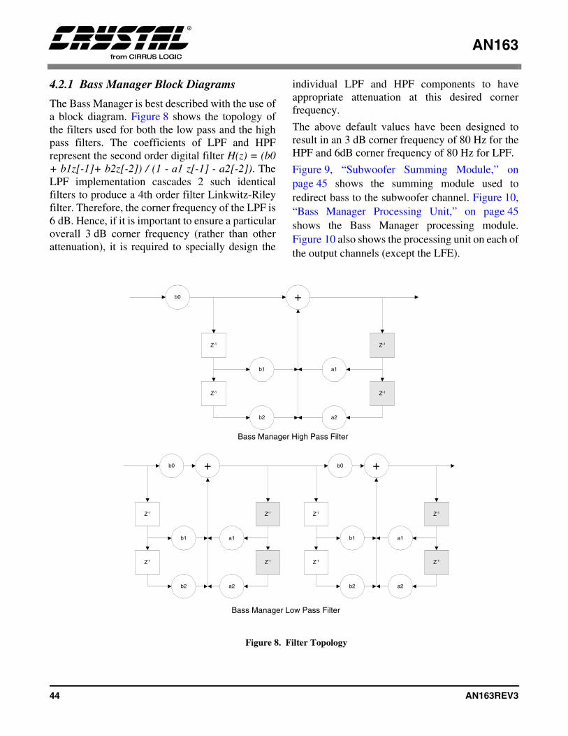
AN163
44 AN163REV3
4.2.1 Bass Manager Block Diagrams
The Bass Manager is best described with the use ofa block diagram. Figure 8 shows the topology ofthe filters used for both the low pass and the highpass filters. The coefficients of LPF and HPFrepresent the second order digital filter H(z) = (b0+ b1z[-1]+ b2z[-2]) / (1 - a1 z[-1] - a2[-2]). TheLPF implementation cascades 2 such identicalfilters to produce a 4th order filter Linkwitz-Rileyfilter. Therefore, the corner frequency of the LPF is6 dB. Hence, if it is important to ensure a particularoverall 3 dB corner frequency (rather than otherattenuation), it is required to specially design the
individual LPF and HPF components to haveappropriate attenuation at this desired cornerfrequency.
The above default values have been designed toresult in an 3 dB corner frequency of 80 Hz for theHPF and 6dB corner frequency of 80 Hz for LPF.
Figure 9, “Subwoofer Summing Module,” onpage 45 shows the summing module used toredirect bass to the subwoofer channel. Figure 10,“Bass Manager Processing Unit,” on page 45shows the Bass Manager processing module.Figure 10 also shows the processing unit on each ofthe output channels (except the LFE).
b0
b2
a1b1
b0+
a2
Z-1
Z-1Z-1
+
Z-1Z-1
Z-1Z-1
b0
a2
a1
b2
b1
Bass Manager High Pass Filter
Bass Manager Low Pass Filter
+
b1
b2 a2
a1
Z-1
Z-1
Z-1 Z-1
Z-1
Figure 8. Filter Topology
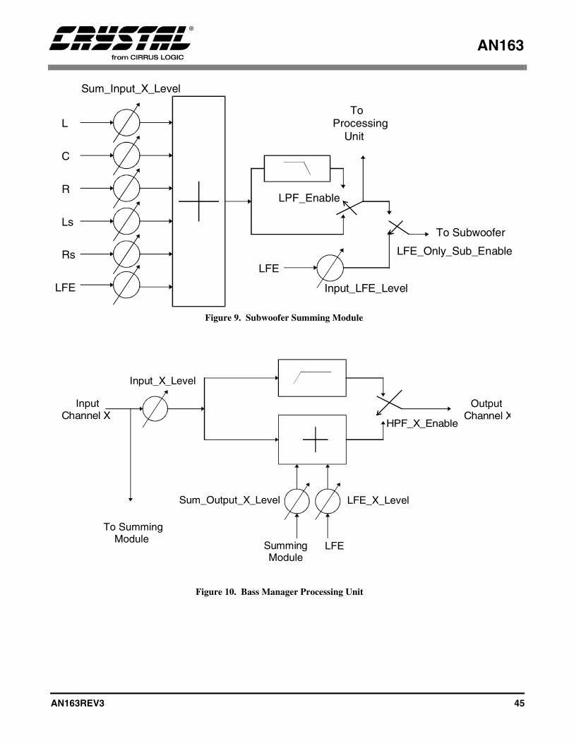
AN163
AN163REV3 45
L
C
R
Ls
Rs
LFE
To Subwoofer
Sum_Input_X_Level
ToProcessing
Unit
LFE_Only_Sub_Enable
LFE
LPF_Enable
Input_LFE_Level
Figure 9. Subwoofer Summing Module
To SummingModule
InputChannel X
OutputChannel X
HPF_X_Enable
Input_X_Level
SummingModule
LFE
Sum_Output_X_Level LFE_X_Level
Figure 10. Bass Manager Processing Unit
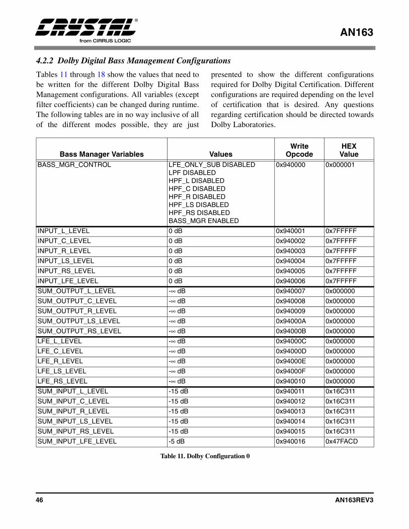
AN163
46 AN163REV3
4.2.2 Dolby Digital Bass Management Configurations
Tables 11 through 18 show the values that need tobe written for the different Dolby Digital BassManagement configurations. All variables (exceptfilter coefficients) can be changed during runtime.The following tables are in no way inclusive of allof the different modes possible, they are just
presented to show the different configurationsrequired for Dolby Digital Certification. Differentconfigurations are required depending on the levelof certification that is desired. Any questionsregarding certification should be directed towardsDolby Laboratories.
Bass Manager Variables ValuesWrite
OpcodeHEX
ValueBASS_MGR_CONTROL LFE_ONLY_SUB DISABLED
LPF DISABLEDHPF_L DISABLEDHPF_C DISABLEDHPF_R DISABLEDHPF_LS DISABLEDHPF_RS DISABLEDBASS_MGR ENABLED
0x940000 0x000001
INPUT_L_LEVEL 0 dB 0x940001 0x7FFFFF
INPUT_C_LEVEL 0 dB 0x940002 0x7FFFFF
INPUT_R_LEVEL 0 dB 0x940003 0x7FFFFF
INPUT_LS_LEVEL 0 dB 0x940004 0x7FFFFF
INPUT_RS_LEVEL 0 dB 0x940005 0x7FFFFF
INPUT_LFE_LEVEL 0 dB 0x940006 0x7FFFFF
SUM_OUTPUT_L_LEVEL -∞ dB 0x940007 0x000000
SUM_OUTPUT_C_LEVEL -∞ dB 0x940008 0x000000
SUM_OUTPUT_R_LEVEL -∞ dB 0x940009 0x000000
SUM_OUTPUT_LS_LEVEL -∞ dB 0x94000A 0x000000
SUM_OUTPUT_RS_LEVEL -∞ dB 0x94000B 0x000000
LFE_L_LEVEL -∞ dB 0x94000C 0x000000
LFE_C_LEVEL -∞ dB 0x94000D 0x000000
LFE_R_LEVEL -∞ dB 0x94000E 0x000000
LFE_LS_LEVEL -∞ dB 0x94000F 0x000000
LFE_RS_LEVEL -∞ dB 0x940010 0x000000
SUM_INPUT_L_LEVEL -15 dB 0x940011 0x16C311
SUM_INPUT_C_LEVEL -15 dB 0x940012 0x16C311
SUM_INPUT_R_LEVEL -15 dB 0x940013 0x16C311
SUM_INPUT_LS_LEVEL -15 dB 0x940014 0x16C311
SUM_INPUT_RS_LEVEL -15 dB 0x940015 0x16C311
SUM_INPUT_LFE_LEVEL -5 dB 0x940016 0x47FACD
Table 11. Dolby Configuration 0
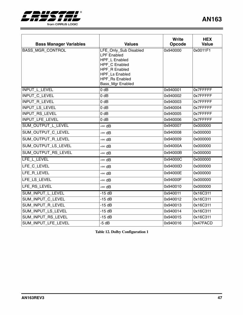
AN163
AN163REV3 47
Bass Manager Variables ValuesWrite
OpcodeHEX
ValueBASS_MGR_CONTROL LFE_Only_Sub Disabled
LPF EnabledHPF_L EnabledHPF_C EnabledHPF_R EnabledHPF_Ls EnabledHPF_Rs EnabledBass_Mgr Enabled
0x940000 0x0011F1
INPUT_L_LEVEL 0 dB 0x940001 0x7FFFFF
INPUT_C_LEVEL 0 dB 0x940002 0x7FFFFF
INPUT_R_LEVEL 0 dB 0x940003 0x7FFFFF
INPUT_LS_LEVEL 0 dB 0x940004 0x7FFFFF
INPUT_RS_LEVEL 0 dB 0x940005 0x7FFFFF
INPUT_LFE_LEVEL 0 dB 0x940006 0x7FFFFF
SUM_OUTPUT_L_LEVEL -∞ dB 0x940007 0x000000
SUM_OUTPUT_C_LEVEL -∞ dB 0x940008 0x000000
SUM_OUTPUT_R_LEVEL -∞ dB 0x940009 0x000000
SUM_OUTPUT_LS_LEVEL -∞ dB 0x94000A 0x000000
SUM_OUTPUT_RS_LEVEL -∞ dB 0x94000B 0x000000
LFE_L_LEVEL -∞ dB 0x94000C 0x000000
LFE_C_LEVEL -∞ dB 0x94000D 0x000000
LFE_R_LEVEL -∞ dB 0x94000E 0x000000
LFE_LS_LEVEL -∞ dB 0x94000F 0x000000
LFE_RS_LEVEL -∞ dB 0x940010 0x000000
SUM_INPUT_L_LEVEL -15 dB 0x940011 0x16C311
SUM_INPUT_C_LEVEL -15 dB 0x940012 0x16C311
SUM_INPUT_R_LEVEL -15 dB 0x940013 0x16C311
SUM_INPUT_LS_LEVEL -15 dB 0x940014 0x16C311
SUM_INPUT_RS_LEVEL -15 dB 0x940015 0x16C311
SUM_INPUT_LFE_LEVEL -5 dB 0x940016 0x47FACD
Table 12. Dolby Configuration 1

AN163
48 AN163REV3
Bass Manager Variables ValuesWrite
OpcodeHEX
ValueBASS_MGR_CONTROL LFE_Only_Sub Disabled
LPF EnabledHPF_L DisabledHPF_C EnabledHPF_R DisabledHPF_Ls EnabledHPF_Rs EnabledBass_Mgr Enabled
0x940000 0x0010B1
INPUT_L_LEVEL -12 dB 0x940001 0x2026F2
INPUT_C_LEVEL ADJ, default = 0 dB 0x940002 0x7FFFFF
INPUT_R_LEVEL -12 dB 0x940003 0x2026F2
INPUT_LS_LEVEL ADJ, default = 0 dB 0x940004 0x7FFFFF
INPUT_RS_LEVEL ADJ, default = 0 dB 0x940005 0x7FFFFF
INPUT_LFE_LEVEL 0 dB 0x940006 0x7FFFFF
SUM_OUTPUT_L_LEVEL -1.5 dB 0x940007 0x6BB2D5
SUM_OUTPUT_C_LEVEL -∞ dB 0x940008 0x000000
SUM_OUTPUT_R_LEVEL -1.5 dB 0x940009 0x6BB2D5
SUM_OUTPUT_LS_LEVEL -∞ dB 0x94000A 0x000000
SUM_OUTPUT_RS_LEVEL -∞ dB 0x94000B 0x000000
LFE_L_LEVEL -∞ dB 0x94000C 0x000000
LFE_C_LEVEL -∞ dB 0x94000D 0x000000
LFE_R_LEVEL -∞ dB 0x94000E 0x000000
LFE_LS_LEVEL -∞ dB 0x94000F 0x000000
LFE_RS_LEVEL -∞ dB 0x940010 0x000000
SUM_INPUT_L_LEVEL -∞ dB 0x940011 0x000000
SUM_INPUT_C_LEVEL -15 dB 0x940012 0x16C311
SUM_INPUT_R_LEVEL -∞ dB 0x940013 0x000000
SUM_INPUT_LS_LEVEL -15 dB 0x940014 0x16C311
SUM_INPUT_RS_LEVEL -15 dB 0x940015 0x16C311
SUM_INPUT_LFE_LEVEL -5 dB 0x940016 0x47FACD
Table 13. Dolby Configuration 2

AN163
AN163REV3 49
Bass Manager Variables ValuesWrite
OpcodeHEX
ValueBASS_MGR_CONTROL LFE_Only_Sub Disabled
LPF EnabledHPF_L DisabledHPF_C EnabledHPF_R DisabledHPF_Ls EnabledHPF_Rs EnabledBass_Mgr Enabled
0x940000 0x0010B1
INPUT_L_LEVEL 0 dB 0x940001 0x7FFFFF
INPUT_C_LEVEL 0 dB 0x940002 0x7FFFFF
INPUT_R_LEVEL 0 dB 0x940003 0x7FFFFF
INPUT_LS_LEVEL 0 dB 0x940004 0x7FFFFF
INPUT_RS_LEVEL 0 dB 0x940005 0x7FFFFF
INPUT_LFE_LEVEL 0 dB 0x940006 0x7FFFFF
SUM_OUTPUT_L_LEVEL -∞ dB 0x940007 0x000000
SUM_OUTPUT_C_LEVEL -∞ dB 0x940008 0x000000
SUM_OUTPUT_R_LEVEL -∞ dB 0x940009 0x000000
SUM_OUTPUT_LS_LEVEL -∞ dB 0x94000A 0x000000
SUM_OUTPUT_RS_LEVEL -∞ dB 0x94000B 0x000000
LFE_L_LEVEL -∞ dB 0x94000C 0x000000
LFE_C_LEVEL -∞ dB 0x94000D 0x000000
LFE_R_LEVEL -∞ dB 0x94000E 0x000000
LFE_LS_LEVEL -∞ dB 0x94000F 0x000000
LFE_RS_LEVEL -∞ dB 0x940010 0x000000
SUM_INPUT_L_LEVEL -∞ dB 0x940011 0x000000
SUM_INPUT_C_LEVEL -15 dB 0x940012 0x16C311
SUM_INPUT_R_LEVEL -∞ dB 0x940013 0x000000
SUM_INPUT_LS_LEVEL -15 dB 0x940014 0x16C311
SUM_INPUT_RS_LEVEL -15 dB 0x940015 0x16C311
SUM_INPUT_LFE_LEVEL -5 dB 0x940016 0x47FACD
Table 14. Dolby Alternative Configuration 2

AN163
50 AN163REV3
Bass Manager Variables ValuesWrite
OpcodeHEX
ValueBASS_MGR_CONTROL LFE_Only_Sub Disabled
LPF EnabledHPF_L DisabledHPF_C EnabledHPF_R DisabledHPF_Ls DisabledHPF_Rs DisabledBass_Mgr Enabled
0x940000 0x001081
INPUT_L_LEVEL -8 dB 0x940001 0x32F52C
INPUT_C_LEVEL -8 dB 0x940002 0x32F52C
INPUT_R_LEVEL -8 dB 0x940003 0x32F52C
INPUT_LS_LEVEL -8 dB 0x940004 0x32F52C
INPUT_RS_LEVEL -8 dB 0x940005 0x32F52C
INPUT_LFE_LEVEL -8 dB 0x940006 0x32F52C
SUM_OUTPUT_L_LEVEL -4.5 dB 0x940007 0x4C3EA7
SUM_OUTPUT_C_LEVEL -∞ dB 0x940008 0x000000
SUM_OUTPUT_R_LEVEL -4.5 dB 0x940009 0x4C3EA7
SUM_OUTPUT_LS_LEVEL -∞ dB 0x94000A 0x000000
SUM_OUTPUT_RS_LEVEL -∞ dB 0x94000B 0x000000
LFE_L_LEVEL -8 dB 0x94000C 0x32F52C
LFE_C_LEVEL -∞ dB 0x94000D 0x000000
LFE_R_LEVEL -8 dB 0x94000E 0x32F52C
LFE_LS_LEVEL -8 dB 0x94000F 0x32F52C
LFE_RS_LEVEL -8 dB 0x940010 0x32F52C
SUM_INPUT_L_LEVEL -∞ dB 0x940011 0x000000
SUM_INPUT_C_LEVEL -8 dB 0x940012 0x32F52C
SUM_INPUT_R_LEVEL -∞ dB 0x940013 0x000000
SUM_INPUT_LS_LEVEL -∞ dB 0x940014 0x000000
SUM_INPUT_RS_LEVEL -∞ dB 0x940015 0x000000
SUM_INPUT_LFE_LEVEL -∞ dB 0x940016 0x000000
Table 15. Dolby Configuration 3 (Normal - No Sub Out)

AN163
AN163REV3 51
Bass Manager Variables ValuesWrite
OpcodeHEX
ValueBASS_MGR_CONTROL LFE_Only_Sub Disabled
LPF EnabledHPF_L DisabledHPF_C EnabledHPF_R DisabledHPF_Ls DisabledHPF_Rs DisabledBass_Mgr Enabled
0x940000 0x011081
INPUT_L_LEVEL -4 dB 0x940001 0x50C335
INPUT_C_LEVEL -4 dB 0x940002 0x50C335
INPUT_R_LEVEL -4 dB 0x940003 0x50C335
INPUT_LS_LEVEL -4 dB 0x940004 0x50C335
INPUT_RS_LEVEL -4 dB 0x940005 0x50C335
INPUT_LFE_LEVEL -4 dB 0x940006 0x50C335
SUM_OUTPUT_L_LEVEL -4.5 dB 0x940007 0x4C3EA7
SUM_OUTPUT_C_LEVEL -∞ dB 0x940008 0x000000
SUM_OUTPUT_R_LEVEL -4.5 dB 0x940009 0x4C3EA7
SUM_OUTPUT_LS_LEVEL -∞ dB 0x94000A 0x000000
SUM_OUTPUT_RS_LEVEL -∞ dB 0x94000B 0x000000
LFE_L_LEVEL -∞ dB 0x94000C 0x000000
LFE_C_LEVEL -∞ dB 0x94000D 0x000000
LFE_R_LEVEL -∞ dB 0x94000E 0x000000
LFE_LS_LEVEL -∞ dB 0x94000F 0x000000
LFE_RS_LEVEL -∞ dB 0x940010 0x000000
SUM_INPUT_L_LEVEL -∞ dB 0x940011 0x000000
SUM_INPUT_C_LEVEL -4 dB 0x940012 0x50C335
SUM_INPUT_R_LEVEL -∞ dB 0x940013 0x000000
SUM_INPUT_LS_LEVEL -∞ dB 0x940014 0x000000
SUM_INPUT_RS_LEVEL -∞ dB 0x940015 0x000000
SUM_INPUT_LFE_LEVEL -∞ dB 0x940016 0x000000
Table 16. Dolby Configuration 3 (Sub Out)
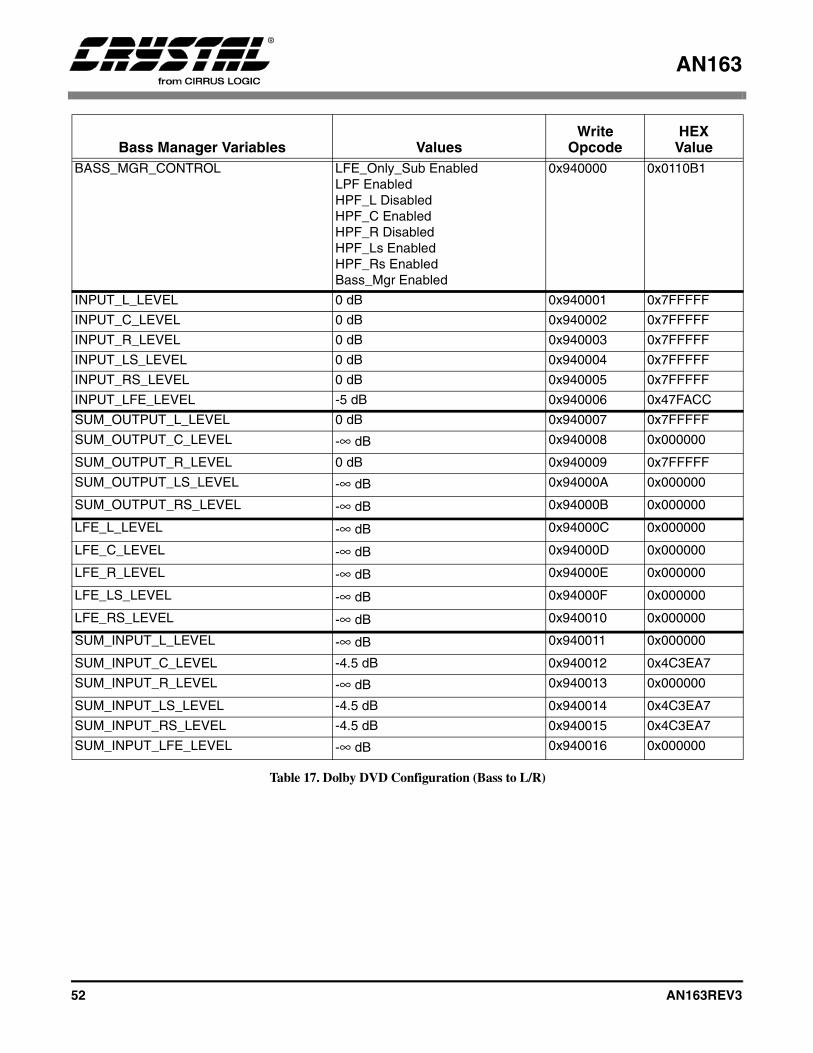
AN163
52 AN163REV3
Bass Manager Variables ValuesWrite
OpcodeHEX
ValueBASS_MGR_CONTROL LFE_Only_Sub Enabled
LPF EnabledHPF_L DisabledHPF_C EnabledHPF_R DisabledHPF_Ls EnabledHPF_Rs EnabledBass_Mgr Enabled
0x940000 0x0110B1
INPUT_L_LEVEL 0 dB 0x940001 0x7FFFFF
INPUT_C_LEVEL 0 dB 0x940002 0x7FFFFF
INPUT_R_LEVEL 0 dB 0x940003 0x7FFFFF
INPUT_LS_LEVEL 0 dB 0x940004 0x7FFFFF
INPUT_RS_LEVEL 0 dB 0x940005 0x7FFFFF
INPUT_LFE_LEVEL -5 dB 0x940006 0x47FACC
SUM_OUTPUT_L_LEVEL 0 dB 0x940007 0x7FFFFF
SUM_OUTPUT_C_LEVEL -∞ dB 0x940008 0x000000
SUM_OUTPUT_R_LEVEL 0 dB 0x940009 0x7FFFFF
SUM_OUTPUT_LS_LEVEL -∞ dB 0x94000A 0x000000
SUM_OUTPUT_RS_LEVEL -∞ dB 0x94000B 0x000000
LFE_L_LEVEL -∞ dB 0x94000C 0x000000
LFE_C_LEVEL -∞ dB 0x94000D 0x000000
LFE_R_LEVEL -∞ dB 0x94000E 0x000000
LFE_LS_LEVEL -∞ dB 0x94000F 0x000000
LFE_RS_LEVEL -∞ dB 0x940010 0x000000
SUM_INPUT_L_LEVEL -∞ dB 0x940011 0x000000
SUM_INPUT_C_LEVEL -4.5 dB 0x940012 0x4C3EA7
SUM_INPUT_R_LEVEL -∞ dB 0x940013 0x000000
SUM_INPUT_LS_LEVEL -4.5 dB 0x940014 0x4C3EA7
SUM_INPUT_RS_LEVEL -4.5 dB 0x940015 0x4C3EA7
SUM_INPUT_LFE_LEVEL -∞ dB 0x940016 0x000000
Table 17. Dolby DVD Configuration (Bass to L/R)
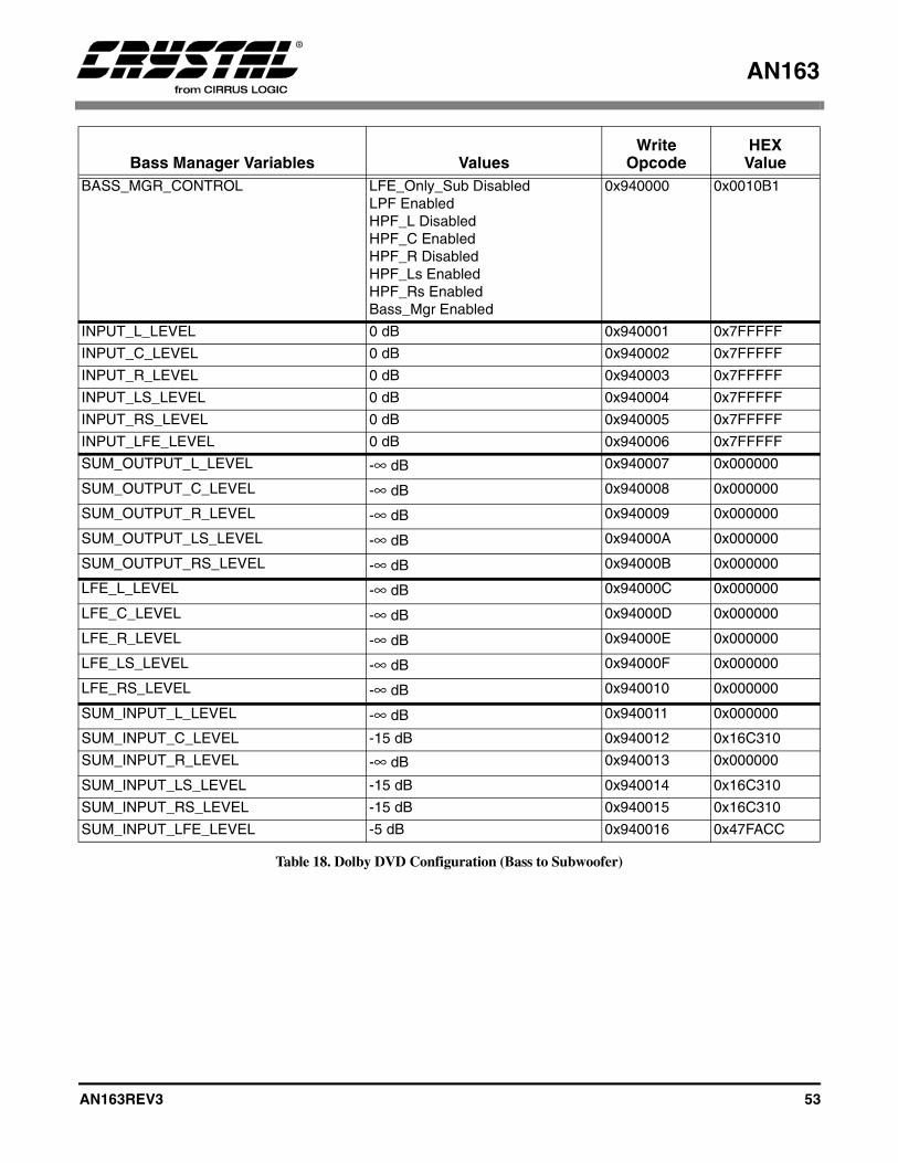
AN163
AN163REV3 53
Bass Manager Variables ValuesWrite
OpcodeHEX
ValueBASS_MGR_CONTROL LFE_Only_Sub Disabled
LPF EnabledHPF_L DisabledHPF_C EnabledHPF_R DisabledHPF_Ls EnabledHPF_Rs EnabledBass_Mgr Enabled
0x940000 0x0010B1
INPUT_L_LEVEL 0 dB 0x940001 0x7FFFFF
INPUT_C_LEVEL 0 dB 0x940002 0x7FFFFF
INPUT_R_LEVEL 0 dB 0x940003 0x7FFFFF
INPUT_LS_LEVEL 0 dB 0x940004 0x7FFFFF
INPUT_RS_LEVEL 0 dB 0x940005 0x7FFFFF
INPUT_LFE_LEVEL 0 dB 0x940006 0x7FFFFF
SUM_OUTPUT_L_LEVEL -∞ dB 0x940007 0x000000
SUM_OUTPUT_C_LEVEL -∞ dB 0x940008 0x000000
SUM_OUTPUT_R_LEVEL -∞ dB 0x940009 0x000000
SUM_OUTPUT_LS_LEVEL -∞ dB 0x94000A 0x000000
SUM_OUTPUT_RS_LEVEL -∞ dB 0x94000B 0x000000
LFE_L_LEVEL -∞ dB 0x94000C 0x000000
LFE_C_LEVEL -∞ dB 0x94000D 0x000000
LFE_R_LEVEL -∞ dB 0x94000E 0x000000
LFE_LS_LEVEL -∞ dB 0x94000F 0x000000
LFE_RS_LEVEL -∞ dB 0x940010 0x000000
SUM_INPUT_L_LEVEL -∞ dB 0x940011 0x000000
SUM_INPUT_C_LEVEL -15 dB 0x940012 0x16C310
SUM_INPUT_R_LEVEL -∞ dB 0x940013 0x000000
SUM_INPUT_LS_LEVEL -15 dB 0x940014 0x16C310
SUM_INPUT_RS_LEVEL -15 dB 0x940015 0x16C310
SUM_INPUT_LFE_LEVEL -5 dB 0x940016 0x47FACC
Table 18. Dolby DVD Configuration (Bass to Subwoofer)

AN163
54 AN163REV3
4.3 Unsolicited Messages (Read-Only)
No Write Message. No Read Request.
Unsolicited Read Response = 0x8700HH 0xhhhhhh
0xHH = index, 0xhhhhhh = data value
Index Variable Dataword Content0x00 AUTODETECT_
RESPONSEBit 23 = Decodable_Stream_Flag= 0/1 = This stream is not/is decodable by
the application (no need for new download if 1).Bits 22:6 = Reserved.Bit 5 Non_IEC61937_Stream_Flag= 1/0 = This stream is not/is IEC61937
compressed data.If Non_IEC61937_Stream_Flag=1Bits 4:0 = Non_IEC61937 Stream Descriptor.
0x00 = Silent Input Data (Out of Application Sync).0x01 = DTS Format-16 elementary stream.0x02 = DTS Format-14 elementary stream.0x03 = Linear PCM stream.0x04 = HDCD PCM stream (only available in HDCD application).0x05-0x1F = Reserved.
If Non_IEC61937_Stream_Flag=0Bits 4:0 = IEC61937 Stream Descriptor = Identical to bits [4:0] of the Pc burst
data type descriptor in IEC61937 specification. Description of the data-type field of Pc reproduced below from IEC61937 Specification (current as of 11/97):0x00 = Never Reported. (Null data is ignored by CS4932X, unless Bit 13 in Audio_Mgr_Control is set, see Section 4.1).0x01 = AC-3 data.0x02 = Reserved.0x03 = Never Reported. (Pause is ignored by CS4932X, unless Bit 13 in Audio_Mgr_Control is set, see Section 4.1).0x04 = MPEG-1 Layer 1 data.0x05 = MPEG-1 Layer 2 or 3 data or MPEG-2 without extension.0x06 = MPEG-2 data with extension.0x07 = Reserved.0x08 = MPEG-2 Layer 1 Low sampling frequency.0x09 = MPEG-2 Layer 2 or 3 Low sampling frequency.0x0A = Reserved.0x0B = DTS-1 data (512-sample bursts).0x0C = DTS-2 data (1024-sample bursts).0x0D = DTS-3 data (2048-sample bursts).0x0E - 0x1B = Reserved.0x1C = MPEG-2 AAC ADTS data.0x1D - 0x1F = Reserved.
0x03 AUDIO_CONFIGURATION_ CHANGE
Bits 23:0 = Reserved.Please see Section 4.1.1 “Audio_Control: (Index 0x00)” on page 37 bit 15 for more information.
0x10 PLL_OUT_OF_LOCK Bit 23 = 1.Bits 22:0 = Reserved.
Table 19. Unsolicited Messages
AN163
AN163REV3 55
4.3.1 Autodetect Operation
The sequence of events involving autodetection aredescribed below from the host’s perspective:Note: This example assumes CS49326, CS49328, or
CS49329 is being used since only these devices can play DTS. In the case of DTS being detected on CS49325 or AC-3 detected on CS49326, the host should display an appropriate user message to the front panel stating that the detected stream (DTS or AC-3) cannot be played on this receiver.
1) Host downloads CS4932X with a tentativeapplication code, for this example we will useAC3I32X7.LD.
2) Host then configures the CS4932X hardwareappropriately and sets up applicationparameters as desired, including enabling thedesired application. For this example we willsay the code is configured for AC-3 decode.
3) Host then kickstarts CS4932X with Autodetectenabled (see Section 4.1 “Audio Manager forDolby Digital, DTS, MP3, MPEGMultichannel, AAC and Crystal OriginalSurround” on page 33 for details).
4) The Autodetect module of the enabledapplication of the CS4932X analyzes the inputfor a maximum of 100 ms of non-silent/non-pause data and determines the content of theinput bitstream.
5a) If the enabled application can play the detectedinput (i.e., if AC-3 was detected in this case),then the CS4932X issues an UnsolicitedMessage to the host indicating the data typewith Decodable_Bitstream_Flag=1. In ourexample of the IEC61937 AC-3 stream, themessage would be 0x870000 0x800001. TheCS4932X then goes ahead and processes itaccording to the application parameters assetup in Step 2 above.
5b) If the enabled application cannot play thedetected input (say Non-IEC61937 LD DTSwas detected), then the CS4932X soft mutes the
outputs, and issues an Unsolicited Message tothe host indicating the data type withDecodable_Bitstream_Flag=0. In our example,the message would be 0x870000 0x000021.
On receiving this message, host repeats Steps 1onwards but this time downloads the DTS codeto the CS4932X (along with correct hardwareconfiguration and application configuration forDTS with Autodetect enabled). Subsequently,DTS will be detected within 100 mS andsuccessfully played by the new DTS code, aftersending the corresponding unsolicited message(0x870000 0x800021).
If the host desires, it can reduce the latency ofthis second autodetection, by enablingStartup_Autodetect_Bypass in the Kickstart.This will allow the DTS decoder to directlystart decoding the input data (which is known tobe DTS), while still retaining subsequentautodetect functionality.
6) After the steps above have taken place andwhile CS4932X is successfully playing theinput bitstream (still AC-3 in our example), ifthe host receives external information that theinput has been changed (e.g., the user selects anew source using the front panel buttons), thenbefore switching the input data to theCS4932X, the host should send a Soft Reset (oran Application Restart, for AC-3 or C.O.S.code) message. (See Section 4.1 “AudioManager for Dolby Digital, DTS, MP3, MPEGMultichannel, AAC and Crystal OriginalSurround” on page 33.)
If Application Restart is used, this effectivelyputs CS4932X in Step 2, without changing theoutput hardware configuration (i.e., outputclocks are not interrupted). The inputconfiguration would need to be changed if it isdifferent than the default. If Soft Reset isissued, then the entire hardware configurationneeds to be resent.
AN163
56 AN163REV3
The host should then repeat Steps 2, 3, 4, 5a/bas described above after delivering the newinput stream to the CS4932X.
If the new input content is detected asunchanged (still AC-3 in our example), theCS4932X responds and continues processing itas in Step 5a. This situation will happen if thenew stream selected by the user is also AC-3.
If the input content is detected as different(non-AC-3 in our example), the CS4932Xresponds as in Step 5b and continuesmonitoring the input stream for change incontent.
7) During runtime, while successfully playing theinput bitstream, the CS4932X alsosimultaneously monitors the input.
Note: The CS4932X has only one active input. The “input” is defined as the pin receiving data for which the application is configured (e.g. If the application is configured for PCM, the pin receiving PCM data is the input. If the application is configured for compressed data, the pin receiving compressed data is the input). As soon as the CS4932X detects a change in the bitstream (no longer AC-3, in our original example), then the CS4932X automatically reverts to Step 4., i.e., analyzes the input to determine the content. This is an automatic version of Step 6 above, but is intended to cover only the cases where the host is not aware of any possible upstream content changes. Whenever possible, the host should convey information about a possible change in input as in Step 6.
If the input content is detected as different(non-AC-3 in our example), the CS4932Xreverts to Step 5b.
For compressed data streams the code will alsoreport the Unsolicited Message 0x8700000x800020 to indicate an out-of-sync conditionwhen the decoder loses sync with the incomingstream due to silent input data. This is aninformative message and no action is needed bythe host.
If the input content is detected as unchanged(still AC-3 in our example), the CS4932Xcontinues processing it like in Step 5a, withoutrequiring any further action from the host. Thissituation could arise due to a pause or trackchange upstream in the source (such as a DVDplayer).
In the case of compressed data being playedcurrently (like AC-3 in our example), the hostcould see an out-of-sync Unsolicited Messagefollowed by an Unsolicited Message indicatingMPEG data. The presence of out-of-syncmessages due to “special” functions like pauseor track change is completely dependent uponthe audio source (such as the DVD player).
In the case of a PCM application that iscurrently active, if the silence is less thanPCM_Autodetect_Silence_Threshold (default48000 samples, i.e. 1 Second at 48 KHz) beforetransitioning to new PCM, the CS4932Xcontinues to process the input data as if nochange had occurred. In case this threshold isset to 8388607 = 0x7fffff, then silence iscompletely ignored (threshold is effectivelyinfinite).
However, during PCM processing, if thesilence is more thanPCM_Autodetect_Silence_Threshold, theCS4932X jumps to a Silent Input Data state,and the output is muted (transparent due tosilent input anyway). Transition to this SilentInput Data state is reported via an UnsolicitedMessage (0x870000 0x800020). This messageis informative only, and no action should betaken by the host. CS4932X is effectively inStep 4 above now, waiting to autodetect theinput once non-silent data appears. Once inputdata is detected, a corresponding UnsolicitedMessage is issued to the host and the processcontinues as above. Please see Figure 11, for anoverview of the previously described flow.
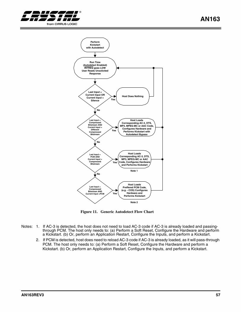
AN163
AN163REV3 57
Notes: 1. If AC-3 is detected, the host does not need to load AC-3 code if AC-3 is already loaded and passing-through PCM. The host only needs to: (a) Perform a Soft Reset, Configure the Hardware and perform a Kickstart. (b) Or, perform an Application Restart, Configure the Inputs, and perform a Kickstart.
2. If PCM is detected, host does need to reload AC-3 code if AC-3 is already loaded, as it will pass-through PCM. The host only needs to: (a) Perform a Soft Reset, Configure the Hardware and perform a Kickstart. (b) Or, perform an Application Restart, Configure the Inputs, and perform a Kickstart.
PerformKickstart
with Autodetect
Run Time(Autodetect Enabled)INTREQ goes LOW
User Reads UnsolicitedResponse
Last Input =Current Input ORCurrent Input =
Silence
Host Does NothingYes
Last Input =Compressed
Bitstream ANDCurrent Input =
DifferentCompressed
Bitstream
Yes
No
Yes
No
Host LoadsCorresponding AC-3, DTS,
MP3, MPEG-MC or AAC Code,Configures Hardware andPerforms Kickstart with
Autodetect Bypass
Host LoadsCorresponding AC-3, DTS,
MP3, MPEG-MC or AACCode, Configures Hardware
and Performs Kickstart
Host LoadsPreffered PCM Code,
(e.g. - COS) ConfiguresHardware and
Performs Kickstart
Last Input =PCM AND
Current Input =Compressed
Bitstream
Yes
No
Last Input =Compressed
Bitstream ANDCurrent Input =PCM
Note 1
Note 2
Figure 11. Generic Autodetect Flow Chart
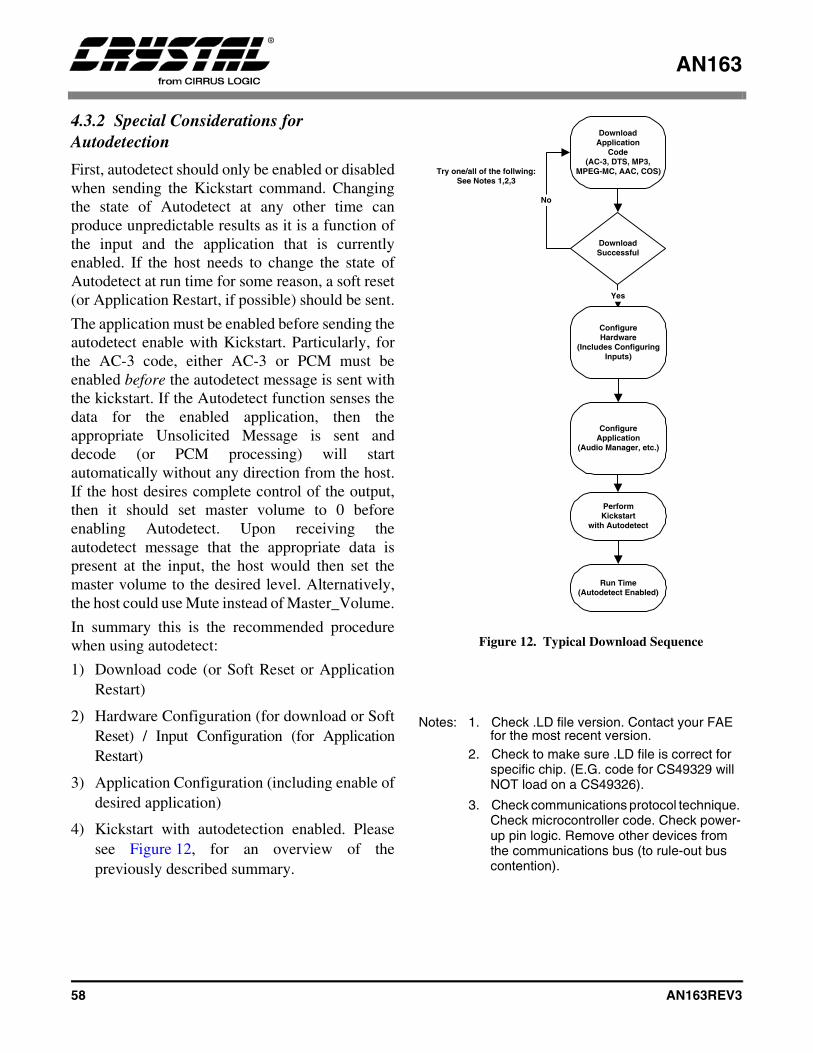
AN163
58 AN163REV3
4.3.2 Special Considerations for Autodetection
First, autodetect should only be enabled or disabledwhen sending the Kickstart command. Changingthe state of Autodetect at any other time canproduce unpredictable results as it is a function ofthe input and the application that is currentlyenabled. If the host needs to change the state ofAutodetect at run time for some reason, a soft reset(or Application Restart, if possible) should be sent.
The application must be enabled before sending theautodetect enable with Kickstart. Particularly, forthe AC-3 code, either AC-3 or PCM must beenabled before the autodetect message is sent withthe kickstart. If the Autodetect function senses thedata for the enabled application, then theappropriate Unsolicited Message is sent anddecode (or PCM processing) will startautomatically without any direction from the host.If the host desires complete control of the output,then it should set master volume to 0 beforeenabling Autodetect. Upon receiving theautodetect message that the appropriate data ispresent at the input, the host would then set themaster volume to the desired level. Alternatively,the host could use Mute instead of Master_Volume.
In summary this is the recommended procedurewhen using autodetect:
1) Download code (or Soft Reset or ApplicationRestart)
2) Hardware Configuration (for download or SoftReset) / Input Configuration (for ApplicationRestart)
3) Application Configuration (including enable ofdesired application)
4) Kickstart with autodetection enabled. Pleasesee Figure 12, for an overview of thepreviously described summary.
Notes: 1. Check .LD file version. Contact your FAE for the most recent version.
2. Check to make sure .LD file is correct for specific chip. (E.G. code for CS49329 will NOT load on a CS49326).
3. Check communications protocol technique. Check microcontroller code. Check power-up pin logic. Remove other devices from the communications bus (to rule-out bus contention).
DownloadApplication
Code(AC-3, DTS, MP3,
MPEG-MC, AAC, COS)
DownloadSuccessful
Yes
No
Try one/all of the follwing:See Notes 1,2,3
ConfigureApplication
(Audio Manager, etc.)
PerformKickstart
with Autodetect
Run Time(Autodetect Enabled)
ConfigureHardware
(Includes ConfiguringInputs)
Figure 12. Typical Download Sequence

AN163
AN163REV3 59
4.4 Generalized Pro Logic Manager for Dolby Digital, DTS, MPEG Multichannel and AAC
Write Opcode = 0x8E; Read Opcode = 0x0F; Read Response Opcode = 0x8F
Write = 0x8E00HH 0xhhhhhh
Read Request = 0x0F00HH;
Read Response = 0x8F00HH 0xhhhhhh
0xHH = index, 0xhhhhhh = data value
For AC-3, the code will not automatically enablePro Logic if the stream is 2/0 Dolby Surroundencoded. This task is the responsibility of the host.The end-user may choose to override the hostcontroller’s default setting when a Dolby Surroundencoded 2/0 AC-3 stream is detected. This abilityto disable or enable Pro Logic decoding iscontrolled via commands from this generalized ProLogic Manager. If the input is NOT DolbySurround encoded or is more or less than 2channels, it is not recommended that Pro Logicdecoding occur. For PCM input, the AC-3 moduleis still used, but is configured for PCM Pass-Through and AC-3 decoding is disabled. Pleaserefer to Section 4.4.2 “Pro Logic decode of 48 kHzinput PCM (Using AC-3 Application Code)” onpage 61 for an example of how to configure theAC-3 code for PCM Pass-Through and Pro Logicdecoding.
For DTS, when the input stream is 2/0 Stereo orDolby Surround encoded material, this modulegives the additional flexibility to perform a ProLogic decode. If the input is NOT Dolby Surroundencoded or is more or less than 2 channels, it is notrecommended that Pro Logic decoding occur.
For MPEG, when the input stream is 2/0 Stereo orDolby Surround encoded material, this modulegives the additional flexibility to perform a ProLogic decode. If the input is NOT Dolby Surroundencoded, two independent mono channels, or ismore or less than 2 channels, it is not recommendedthat Pro Logic decoding occur.
For AAC, when the input stream is 2/0 Stereo orDolby Surround encoded material, this modulegives the additional flexibility to perform a ProLogic decode. If the input is NOT Dolby Surroundencoded, two independent mono channels, or ismore or less than 2 channels, it is not recommendedthat Pro Logic decoding occur.
Index Variable Dataword Content0x00 PRO_LOGIC_CONTROL Bit 8 = Autobalance_Enable = 0/1= Disable/Enable Autobalance. †
Bit 4 = Btype_NR_Enable = 0/1= Disable/Enable B-Type Noise Reduction. †
Bit 0 = ProLogic_Enable = 0/1 = Disable/Enable Pro Logic decoding. †
Default = 0x000000
Table 20. Generalized Pro Logic Manager
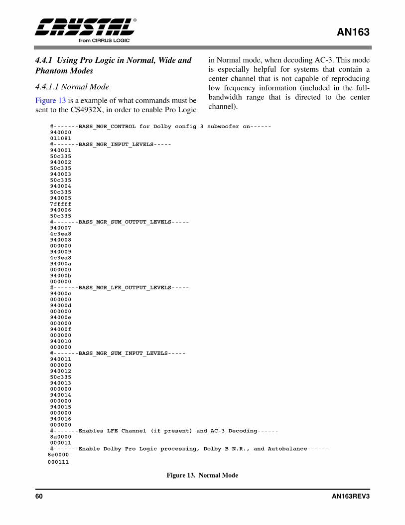
AN163
60 AN163REV3
4.4.1 Using Pro Logic in Normal, Wide and Phantom Modes
4.4.1.1 Normal Mode
Figure 13 is a example of what commands must besent to the CS4932X, in order to enable Pro Logic
in Normal mode, when decoding AC-3. This modeis especially helpful for systems that contain acenter channel that is not capable of reproducinglow frequency information (included in the full-bandwidth range that is directed to the centerchannel).
Figure 13. Normal Mode
#-------BASS_MGR_CONTROL for Dolby config 3 subwoofer on------940000011081#-------BASS_MGR_INPUT_LEVELS-----94000150c33594000250c33594000350c33594000450c3359400057fffff94000650c335#-------BASS_MGR_SUM_OUTPUT_LEVELS-----9400074c3ea89400080000009400094c3ea894000a00000094000b000000#-------BASS_MGR_LFE_OUTPUT_LEVELS-----94000c00000094000d00000094000e00000094000f000000940010000000#-------BASS_MGR_SUM_INPUT_LEVELS-----94001100000094001250c335940013000000940014000000940015000000940016000000#-------Enables LFE Channel (if present) and AC-3 Decoding------8a0000000011#-------Enable Dolby Pro Logic processing, Dolby B N.R., and Autobalance------8e0000000111
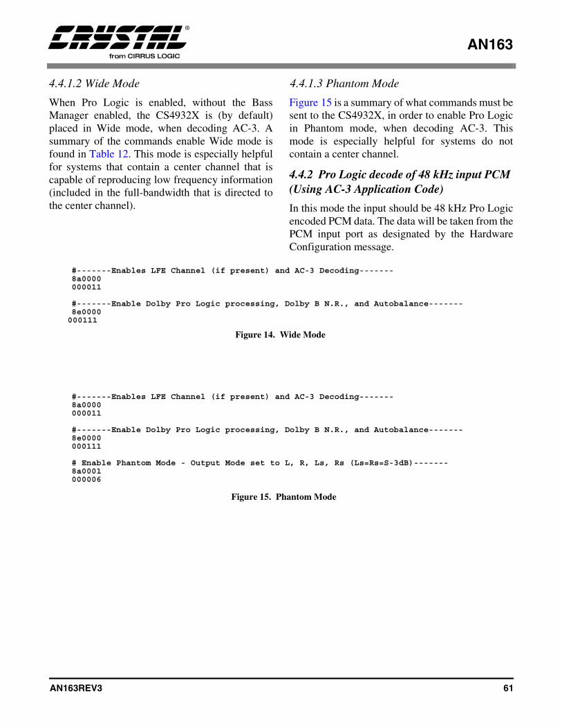
AN163
AN163REV3 61
4.4.1.2 Wide Mode
When Pro Logic is enabled, without the BassManager enabled, the CS4932X is (by default)placed in Wide mode, when decoding AC-3. Asummary of the commands enable Wide mode isfound in Table 12. This mode is especially helpfulfor systems that contain a center channel that iscapable of reproducing low frequency information(included in the full-bandwidth that is directed tothe center channel).
4.4.1.3 Phantom Mode
Figure 15 is a summary of what commands must besent to the CS4932X, in order to enable Pro Logicin Phantom mode, when decoding AC-3. Thismode is especially helpful for systems do notcontain a center channel.
4.4.2 Pro Logic decode of 48 kHz input PCM (Using AC-3 Application Code)
In this mode the input should be 48 kHz Pro Logicencoded PCM data. The data will be taken from thePCM input port as designated by the HardwareConfiguration message.
#-------Enables LFE Channel (if present) and AC-3 Decoding-------8a0000000011
#-------Enable Dolby Pro Logic processing, Dolby B N.R., and Autobalance-------8e0000000111
Figure 14. Wide Mode
#-------Enables LFE Channel (if present) and AC-3 Decoding-------8a0000000011
#-------Enable Dolby Pro Logic processing, Dolby B N.R., and Autobalance-------8e0000000111
# Enable Phantom Mode - Output Mode set to L, R, Ls, Rs (Ls=Rs=S-3dB)-------8a0001000006
Figure 15. Phantom Mode
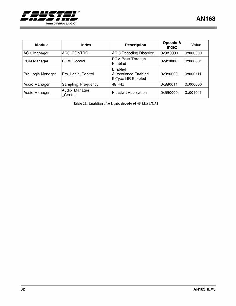
AN163
62 AN163REV3
Module Index DescriptionOpcode &
IndexValue
AC-3 Manager AC3_CONTROL AC-3 Decoding Disabled 0x8A0000 0x000000
PCM Manager PCM_ControlPCM Pass-Through Enabled
0x9c0000 0x000001
Pro Logic Manager Pro_Logic_ControlEnabledAutobalance EnabledB-Type NR Enabled
0x8e0000 0x000111
Audio Manager Sampling_Frequency 48 kHz 0x880014 0x000000
Audio ManagerAudio_Manager_Control
Kickstart Application 0x880000 0x001011
Table 21. Enabling Pro Logic decode of 48 kHz PCM
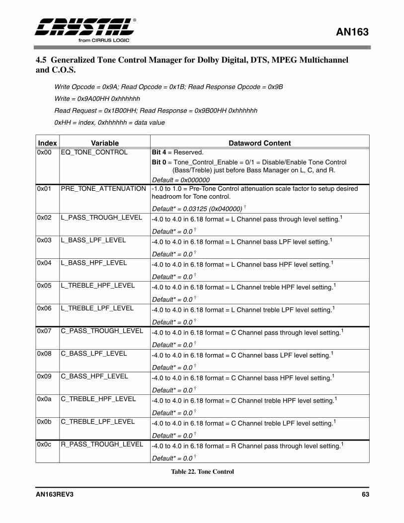
AN163
AN163REV3 63
4.5 Generalized Tone Control Manager for Dolby Digital, DTS, MPEG Multichanneland C.O.S.
Write Opcode = 0x9A; Read Opcode = 0x1B; Read Response Opcode = 0x9B
Write = 0x9A00HH 0xhhhhhh
Read Request = 0x1B00HH; Read Response = 0x9B00HH 0xhhhhhh
0xHH = index, 0xhhhhhh = data value
Index Variable Dataword Content0x00 EQ_TONE_CONTROL Bit 4 = Reserved.
Bit 0 = Tone_Control_Enable = 0/1 = Disable/Enable Tone Control (Bass/Treble) just before Bass Manager on L, C, and R.
Default = 0x0000000x01 PRE_TONE_ATTENUATION -1.0 to 1.0 = Pre-Tone Control attenuation scale factor to setup desired
headroom for Tone control.
Default* = 0.03125 (0x040000) †
0x02 L_PASS_TROUGH_LEVEL -4.0 to 4.0 in 6.18 format = L Channel pass through level setting.1
Default* = 0.0 †
0x03 L_BASS_LPF_LEVEL -4.0 to 4.0 in 6.18 format = L Channel bass LPF level setting.1
Default* = 0.0 †
0x04 L_BASS_HPF_LEVEL -4.0 to 4.0 in 6.18 format = L Channel bass HPF level setting.1
Default* = 0.0 †
0x05 L_TREBLE_HPF_LEVEL -4.0 to 4.0 in 6.18 format = L Channel treble HPF level setting.1
Default* = 0.0 †
0x06 L_TREBLE_LPF_LEVEL -4.0 to 4.0 in 6.18 format = L Channel treble LPF level setting.1
Default* = 0.0 †
0x07 C_PASS_TROUGH_LEVEL -4.0 to 4.0 in 6.18 format = C Channel pass through level setting.1
Default* = 0.0 †
0x08 C_BASS_LPF_LEVEL -4.0 to 4.0 in 6.18 format = C Channel bass LPF level setting.1
Default* = 0.0 †
0x09 C_BASS_HPF_LEVEL -4.0 to 4.0 in 6.18 format = C Channel bass HPF level setting.1
Default* = 0.0 †
0x0a C_TREBLE_HPF_LEVEL -4.0 to 4.0 in 6.18 format = C Channel treble HPF level setting.1
Default* = 0.0 †
0x0b C_TREBLE_LPF_LEVEL -4.0 to 4.0 in 6.18 format = C Channel treble LPF level setting.1
Default* = 0.0 †
0x0c R_PASS_TROUGH_LEVEL -4.0 to 4.0 in 6.18 format = R Channel pass through level setting.1
Default* = 0.0 †
Table 22. Tone Control
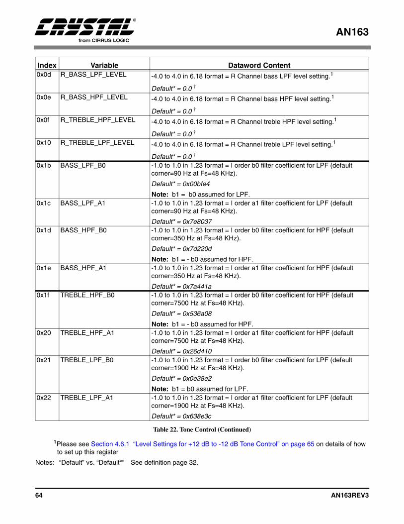
AN163
64 AN163REV3
1Please see Section 4.6.1 “Level Settings for +12 dB to -12 dB Tone Control” on page 65 on details of how to set up this register
Notes: “Default” vs. “Default*” See definition page 32.
0x0d R_BASS_LPF_LEVEL -4.0 to 4.0 in 6.18 format = R Channel bass LPF level setting.1
Default* = 0.0 †
0x0e R_BASS_HPF_LEVEL -4.0 to 4.0 in 6.18 format = R Channel bass HPF level setting.1
Default* = 0.0 †
0x0f R_TREBLE_HPF_LEVEL -4.0 to 4.0 in 6.18 format = R Channel treble HPF level setting.1
Default* = 0.0 †
0x10 R_TREBLE_LPF_LEVEL -4.0 to 4.0 in 6.18 format = R Channel treble LPF level setting.1
Default* = 0.0 †
0x1b BASS_LPF_B0 -1.0 to 1.0 in 1.23 format = I order b0 filter coefficient for LPF (default corner=90 Hz at Fs=48 KHz).
Default* = 0x00bfe4
Note: b1 = b0 assumed for LPF.0x1c BASS_LPF_A1 -1.0 to 1.0 in 1.23 format = I order a1 filter coefficient for LPF (default
corner=90 Hz at Fs=48 KHz).
Default* = 0x7e80370x1d BASS_HPF_B0 -1.0 to 1.0 in 1.23 format = I order b0 filter coefficient for HPF (default
corner=350 Hz at Fs=48 KHz).
Default* = 0x7d220d
Note: b1 = - b0 assumed for HPF.0x1e BASS_HPF_A1 -1.0 to 1.0 in 1.23 format = I order a1 filter coefficient for HPF (default
corner=350 Hz at Fs=48 KHz).
Default* = 0x7a441a0x1f TREBLE_HPF_B0 -1.0 to 1.0 in 1.23 format = I order b0 filter coefficient for HPF (default
corner=7500 Hz at Fs=48 KHz).
Default* = 0x536a08
Note: b1 = - b0 assumed for HPF.0x20 TREBLE_HPF_A1 -1.0 to 1.0 in 1.23 format = I order a1 filter coefficient for HPF (default
corner=7500 Hz at Fs=48 KHz).
Default* = 0x26d4100x21 TREBLE_LPF_B0 -1.0 to 1.0 in 1.23 format = I order b0 filter coefficient for LPF (default
corner=1900 Hz at Fs=48 KHz).
Default* = 0x0e38e2
Note: b1 = b0 assumed for LPF.0x22 TREBLE_LPF_A1 -1.0 to 1.0 in 1.23 format = I order a1 filter coefficient for LPF (default
corner=1900 Hz at Fs=48 KHz).
Default* = 0x638e3c
Index Variable Dataword Content
Table 22. Tone Control (Continued)
AN163
AN163REV3 65
The tone control application code enhancementallows the host to send commands to the DSP thatallows a parametric boost of up to +12 dB to trebleand/or bass frequencies in addition to a parametriccut of up to -12 dB to treble and/or bass frequencieson the front three channels (L, C, R). The onlyapplication codes covered by AN163 that haveTone Control ability are: ac3_32x8.ld, dts_32x8.ld,mpg_32x8.ld, and eff_32x7.ld (or later releases).Other application codes not covered specifically inAN163, such as SRS Circle Surround(cs__3xx3.ld), also support tone control. Pleaserefer to the appropriate AN163 appendix for moreinformation.
Note: For system certification purposes (such as Dolby Laboratories), tone control should be disabled during certification testing.
4.6 Controlling the Level for Treble and Bass Boost/Cut
When tone control is enabled, the pre-BassManager channel PCM is attenuated by thePre_Tone_Attenuation scale factor and passedthrough tone control shelving filters for bass andtreble.Note: Pre_Tone_Attenuation affects only channels
which have tone control (L, C, and R) and leaves the other channels (Ls, Rs, LFE) untouched at the full level. Thus, in order to equalize all the levels coming out of the CS4932X, the controller should set the volumes of the other channels (Ls, Rs, LFE) to be the same as Pre_Tone_Attenuation. Pre_Tone_Attenuation and the above matching volume setting will result in reduced level which has to be compensated by analog gain after the digital-to-analog conversion in the analog chain
The controller has the knowledge of thisattenuation setting at all times and can thusadjust the post-DAC analog gain accordingly.However, this increased digital headroom willresult in smaller dynamic range numbers andthus it is recommended that a passthrough (noTone Control) mode be implemented for testingpurposes.
For each channel (L, C, R), the tone control moduleaccepts 5 independent parametersPass_Through_Level, Bass_LPF_Level,Bass_HPF_Level, Treble_LPF_Level, andTreble_HPF_Level to adjust the amount ofcut/boost in the low and high frequency bands forthat channel. The following section describes theprocedure by which appropriate values for theseparameters can be arrived at for a desired tonecontrol setting.
4.6.1 Level Settings for +12 dB to -12 dB Tone Control
The desired bass and treble values are mapped tofive values which are plugged into a particularchannel’s X_Pass_Through_Level,X_Bass_LPF_Level, X_Bass_HPF_Level,X_Treble_HPF_Leve,l and X_Treble_LPF_Levelregisters, where X denotes L, C, R, Ls, or Rs.
The procedure for mapping the desired bass andtreble values is given below. These variables can bechanged on the fly without audible artifacts, if thestep is smaller than 1 dB. Obviously, a one-stepchange from -12 dB to +12 dB would result in anaudible artifact. Please note that the procedureassumes integer values for the tone levels. Also, theabbreviation LUT is used to denote a “Look-UpTable”. Table 23, Table 24 and Table 25 are thethree Look-Up Tables used in the mapping schemeand are labeled LUT0, LUT1, and LUT2. Themapping is sensitive to the “polarity” of the tonelevels. The four possible cases are handleddifferently as follows:
• Bass Level > = 0 and Treble > = 0:
X_Pass_Through_Level = 0x03FFFF;X_Bass_LPF_Level = LUT1(Bass_Level);X_Bass_HPF_Level = 0;X_Treble_HPF_Level = LUT1(Treble_Level);X_Treble_LPF_Level = 0;
• Bass Level > = 0 and Treble < 0:
X_Pass_Through_Level = LUT0( abs (Treble_Level) );X_Bass_LPF_Level = LUT1( (Bass_Level) );
AN163
66 AN163REV3
X_Bass_HPF_Level = 0;X_Treble_HPF_Level = 0;X_Treble_LPF_Level = LUT2(abs (Treble_Level) );
• Bass Level < 0 and Treble > = 0:
X_Pass_Through_Level = LUT0(abs (Bass_Level) );
X_Bass_LPF_Level = 0;
X_Bass_HPF_Level = LUT2(abs (Bass_Level) );
X_Treble_HPF_Level = LUT1(Treble_Level);
X_Treble_LPF_Level = 0;
• Bass Level < 0 and Treble < 0:
X_Pass_Through_Level = LUT0(abs (Bass_Level) ) - LUT2(abs (Treble_Level) ) + CF;
X_Bass_LPF_Level = -CF;
X_Bass_HPF_Level = LUT2(abs (Bass_Level) );
X_Treble_HPF_Level = -CF;
X_Treble_LPF_Level = LUT2(abs (Treble_Level) );
4.6.2 Tone Control Look-Up Tables (LUT0, LUT1, LUT2)
The LUT0, LUT1, and LUT2 look-up tables havethe following characteristics: The bass and treblesetting values range from -12 to +12 dB. In order toaccommodate this range in 24-bit signed, fixed-point binary format, the Hex values are allrepresented in 6.18 format. The tables can be storedin the microcontroller and used with the algorithmdescribed in the previous section to generate thevarious filter settings for a given user setting.
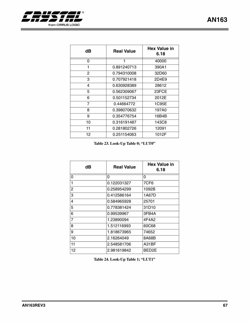
AN163
AN163REV3 67
dB Real Value Hex Value in 6.18
0 1 40000
1 0.891240713 390A1
2 0.794310008 32D60
3 0.707921418 2D4E9
4 0.630928389 28612
5 0.562309067 23FCE
6 0.501152734 2012E
7 0.44664772 1C95E
8 0.398070632 197A0
9 0.354776754 16B4B
10 0.316191487 143C8
11 0.281802726 12091
12 0.251154063 1012F
Table 23. Look-Up Table 0; “LUT0”
dB Real ValueHex Value in
6.18
0 0 0
1 0.122031327 7CF6
2 0.258954299 1092B
3 0.412586164 1A67D
4 0.584965928 25701
5 0.778381424 31D10
6 0.99539967 3FB4A
7 1.23890094 4F4A2
8 1.512116993 60C68
9 1.818673965 74652
10 2.16264049 8A68B
11 2.548581706 A31BF
12 2.981619842 BED2E
Table 24. Look-Up Table 1; “LUT1”
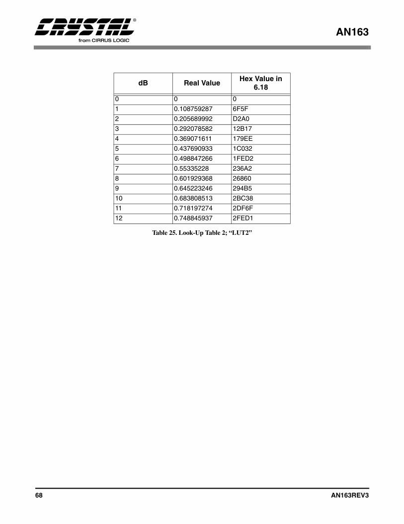
AN163
68 AN163REV3
dB Real Value Hex Value in 6.18
0 0 0
1 0.108759287 6F5F
2 0.205689992 D2A0
3 0.292078582 12B17
4 0.369071611 179EE
5 0.437690933 1C032
6 0.498847266 1FED2
7 0.55335228 236A2
8 0.601929368 26860
9 0.645223246 294B5
10 0.683808513 2BC38
11 0.718197274 2DF6F
12 0.748845937 2FED1
Table 25. Look-Up Table 2; “LUT2”
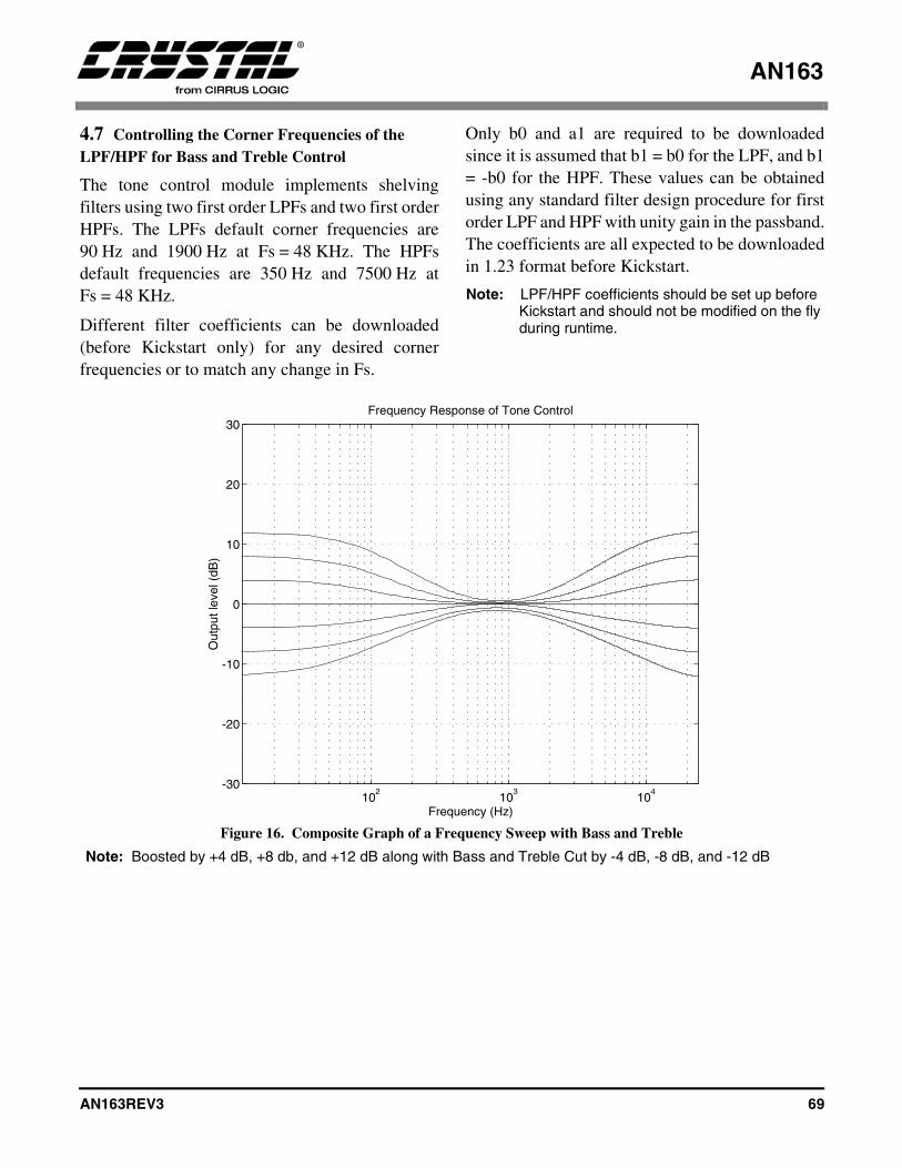
AN163
AN163REV3 69
4.7 Controlling the Corner Frequencies of the LPF/HPF for Bass and Treble Control
The tone control module implements shelvingfilters using two first order LPFs and two first orderHPFs. The LPFs default corner frequencies are90 Hz and 1900 Hz at Fs = 48 KHz. The HPFsdefault frequencies are 350 Hz and 7500 Hz atFs = 48 KHz.
Different filter coefficients can be downloaded(before Kickstart only) for any desired cornerfrequencies or to match any change in Fs.
Only b0 and a1 are required to be downloadedsince it is assumed that b1 = b0 for the LPF, and b1= -b0 for the HPF. These values can be obtainedusing any standard filter design procedure for firstorder LPF and HPF with unity gain in the passband.The coefficients are all expected to be downloadedin 1.23 format before Kickstart.
Note: LPF/HPF coefficients should be set up before Kickstart and should not be modified on the fly during runtime.
Figure 16. Composite Graph of a Frequency Sweep with Bass and Treble
Note: Boosted by +4 dB, +8 db, and +12 dB along with Bass and Treble Cut by -4 dB, -8 dB, and -12 dB
102
103
104
-30
-20
-10
0
10
20
30
Frequency (Hz)
Out
put l
evel
(dB
)
Frequency Response of Tone Control

AN163
70 AN163REV3
102
103
104
-30
-20
-10
0
10
20
30
Frequency (Hz)
Out
put l
evel
(dB
)
Frequency Response of Tone Control
Figure 17. Composite Graph of a Frequency Sweep with Bass
Note: Boosted by +4 dB, +8 db, and +12 dB along with Bass Cut by -4 dB, -8 dB, and -12 dB
102
103
104
-30
-20
-10
0
10
20
30
Frequency (Hz)
Out
put l
evel
(dB
)
Frequency Response of Tone Control
Figure 18. Composite Graph of a Frequency Sweep with Treble
Note: Boosted by +4 dB, +8 db, and +12 dB along with Treble Cut by -4 dB, -8 dB, and -12 dB
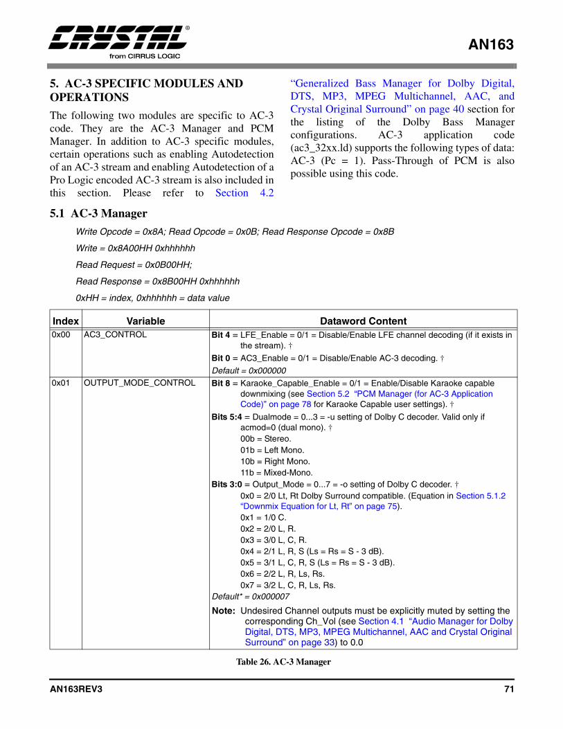
AN163
AN163REV3 71
5. AC-3 SPECIFIC MODULES AND OPERATIONS
The following two modules are specific to AC-3code. They are the AC-3 Manager and PCMManager. In addition to AC-3 specific modules,certain operations such as enabling Autodetectionof an AC-3 stream and enabling Autodetection of aPro Logic encoded AC-3 stream is also included inthis section. Please refer to Section 4.2
“Generalized Bass Manager for Dolby Digital,DTS, MP3, MPEG Multichannel, AAC, andCrystal Original Surround” on page 40 section forthe listing of the Dolby Bass Managerconfigurations. AC-3 application code(ac3_32xx.ld) supports the following types of data:AC-3 (Pc = 1). Pass-Through of PCM is alsopossible using this code.
5.1 AC-3 Manager
Write Opcode = 0x8A; Read Opcode = 0x0B; Read Response Opcode = 0x8B
Write = 0x8A00HH 0xhhhhhh
Read Request = 0x0B00HH;
Read Response = 0x8B00HH 0xhhhhhh
0xHH = index, 0xhhhhhh = data value
Index Variable Dataword Content0x00 AC3_CONTROL Bit 4 = LFE_Enable = 0/1 = Disable/Enable LFE channel decoding (if it exists in
the stream). †
Bit 0 = AC3_Enable = 0/1 = Disable/Enable AC-3 decoding. †
Default = 0x0000000x01 OUTPUT_MODE_CONTROL Bit 8 = Karaoke_Capable_Enable = 0/1 = Enable/Disable Karaoke capable
downmixing (see Section 5.2 “PCM Manager (for AC-3 Application Code)” on page 78 for Karaoke Capable user settings). †
Bits 5:4 = Dualmode = 0...3 = -u setting of Dolby C decoder. Valid only if acmod=0 (dual mono). †00b = Stereo.01b = Left Mono.10b = Right Mono.11b = Mixed-Mono.
Bits 3:0 = Output_Mode = 0...7 = -o setting of Dolby C decoder. †0x0 = 2/0 Lt, Rt Dolby Surround compatible. (Equation in Section 5.1.2 “Downmix Equation for Lt, Rt” on page 75).0x1 = 1/0 C.0x2 = 2/0 L, R.0x3 = 3/0 L, C, R.0x4 = 2/1 L, R, S (Ls = Rs = S - 3 dB).0x5 = 3/1 L, C, R, S (Ls = Rs = S - 3 dB).0x6 = 2/2 L, R, Ls, Rs.0x7 = 3/2 L, C, R, Ls, Rs.
Default* = 0x000007
Note: Undesired Channel outputs must be explicitly muted by setting the corresponding Ch_Vol (see Section 4.1 “Audio Manager for Dolby Digital, DTS, MP3, MPEG Multichannel, AAC and Crystal Original Surround” on page 33) to 0.0
Table 26. AC-3 Manager
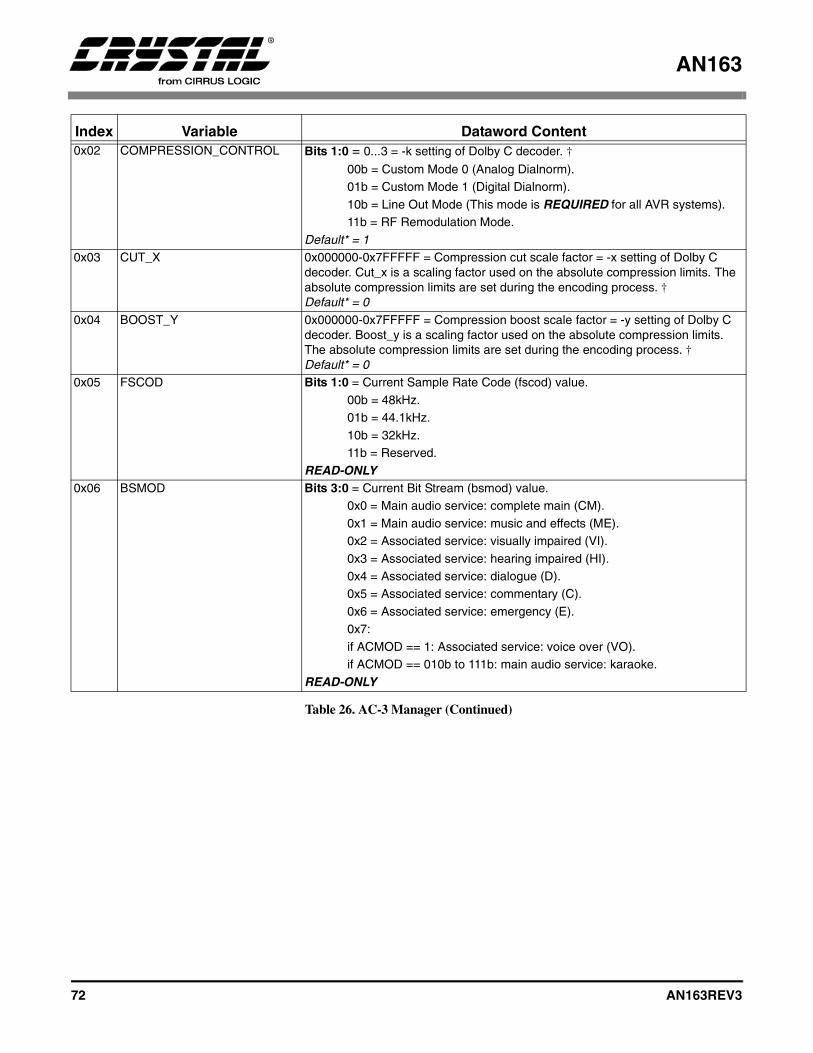
AN163
72 AN163REV3
0x02 COMPRESSION_CONTROL Bits 1:0 = 0...3 = -k setting of Dolby C decoder. †
00b = Custom Mode 0 (Analog Dialnorm).01b = Custom Mode 1 (Digital Dialnorm).10b = Line Out Mode (This mode is REQUIRED for all AVR systems).11b = RF Remodulation Mode.
Default* = 10x03 CUT_X 0x000000-0x7FFFFF = Compression cut scale factor = -x setting of Dolby C
decoder. Cut_x is a scaling factor used on the absolute compression limits. The absolute compression limits are set during the encoding process. †Default* = 0
0x04 BOOST_Y 0x000000-0x7FFFFF = Compression boost scale factor = -y setting of Dolby C decoder. Boost_y is a scaling factor used on the absolute compression limits. The absolute compression limits are set during the encoding process. †Default* = 0
0x05 FSCOD Bits 1:0 = Current Sample Rate Code (fscod) value.00b = 48kHz.01b = 44.1kHz.10b = 32kHz.11b = Reserved.
READ-ONLY0x06 BSMOD Bits 3:0 = Current Bit Stream (bsmod) value.
0x0 = Main audio service: complete main (CM).0x1 = Main audio service: music and effects (ME).0x2 = Associated service: visually impaired (VI).0x3 = Associated service: hearing impaired (HI).0x4 = Associated service: dialogue (D).0x5 = Associated service: commentary (C).0x6 = Associated service: emergency (E).0x7: if ACMOD == 1: Associated service: voice over (VO).if ACMOD == 010b to 111b: main audio service: karaoke.
READ-ONLY
Index Variable Dataword Content
Table 26. AC-3 Manager (Continued)

AN163
AN163REV3 73
0x07 ACMOD Bits 3:0 = Current Audio Coding Mode (acmod) value
0x0 = 1+1 Ch1, Ch2.
0x1 = 1/0 C.
0x2 = 2/0 L, R.
0x3 = 3/0 L, C, R.
0x4 = 2/1 L, R, S.
0x5 = 3/1 L, C, R, S.
0x6 = 2/2 L, R, Ls, Rs.
0x7 = 3/2 L, C, R, Ls, Rs.
Note: Changes in this stream variable will result in an Unsolicited Message from the DSP if Audio_Config_Change_Notification has been enabled in the Audio Manager. Please refer to Section 4.1.1 “Audio_Control: (Index 0x00)” on page 37 for more information.
READ-ONLY0x08 DSURMOD Bits 1:0 = Current Dolby Surround Mode (dsurmod value) valid only when
(acmod=2).
00b = Not indicated.
01b = NOT Dolby Surround encoded.
10b = Dolby Surround Encoded.
11b = Reserved.
Note: Changes in this stream variable will result in an Unsolicited Message from the DSP if Audio_Config_Change_Notification has been enabled in the Audio Manager. Please refer to Section 4.1.1 “Audio_Control: (Index 0x00)” on page 37 for more information.
READ-ONLY0x09 CLEV 0x000000-0x7FFFFF = Current center mixing level (interpreted stream
value as 1.23 fractional integer). Valid only if 3 front channels exist.
READ-ONLY0x0a SLEV 0x000000-0x7FFFFF = Current surround mixing level (interpreted stream
value as 1.23 fractional integer). Valid only if a surround channel exists. READ-ONLY
0x0b LFEON Bit 0 = Current lfeon value.
0 = LFE channel is off.
1 = LFE channel is on.
Notes: Changes in this stream variable will result in an Unsolicited Message from the DSP if Audio_Config_Change_Notification has been enabled in the Audio Manager. Please refer to Section 4.1.1 “Audio_Control: (Index 0x00)” on page 37 for more information.
READ-ONLY
Index Variable Dataword Content
Table 26. AC-3 Manager (Continued)
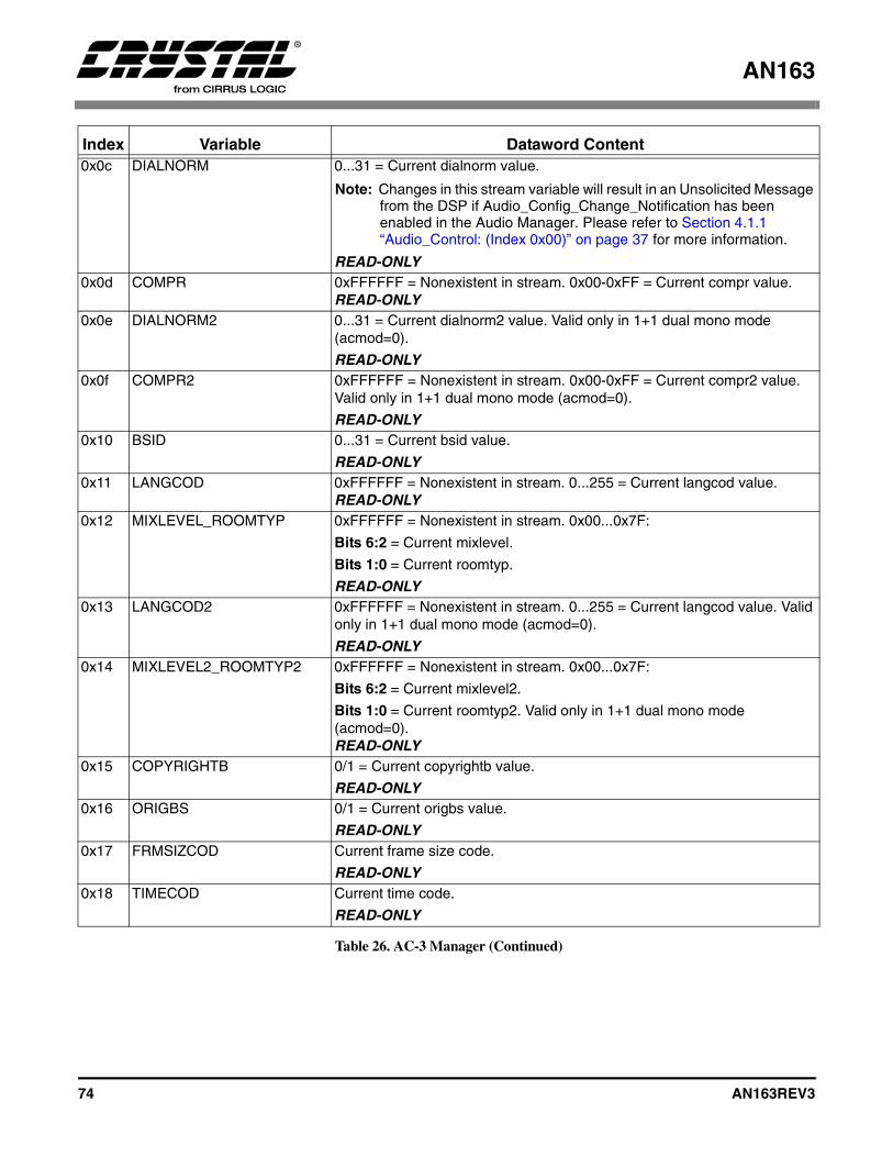
AN163
74 AN163REV3
0x0c DIALNORM 0...31 = Current dialnorm value.
Note: Changes in this stream variable will result in an Unsolicited Message from the DSP if Audio_Config_Change_Notification has been enabled in the Audio Manager. Please refer to Section 4.1.1 “Audio_Control: (Index 0x00)” on page 37 for more information.
READ-ONLY0x0d COMPR 0xFFFFFF = Nonexistent in stream. 0x00-0xFF = Current compr value.
READ-ONLY0x0e DIALNORM2 0...31 = Current dialnorm2 value. Valid only in 1+1 dual mono mode
(acmod=0).
READ-ONLY0x0f COMPR2 0xFFFFFF = Nonexistent in stream. 0x00-0xFF = Current compr2 value.
Valid only in 1+1 dual mono mode (acmod=0).
READ-ONLY 0x10 BSID 0...31 = Current bsid value.
READ-ONLY0x11 LANGCOD 0xFFFFFF = Nonexistent in stream. 0...255 = Current langcod value.
READ-ONLY0x12 MIXLEVEL_ROOMTYP 0xFFFFFF = Nonexistent in stream. 0x00...0x7F:
Bits 6:2 = Current mixlevel.
Bits 1:0 = Current roomtyp.
READ-ONLY0x13 LANGCOD2 0xFFFFFF = Nonexistent in stream. 0...255 = Current langcod value. Valid
only in 1+1 dual mono mode (acmod=0).
READ-ONLY0x14 MIXLEVEL2_ROOMTYP2 0xFFFFFF = Nonexistent in stream. 0x00...0x7F:
Bits 6:2 = Current mixlevel2.
Bits 1:0 = Current roomtyp2. Valid only in 1+1 dual mono mode (acmod=0). READ-ONLY
0x15 COPYRIGHTB 0/1 = Current copyrightb value.
READ-ONLY0x16 ORIGBS 0/1 = Current origbs value.
READ-ONLY0x17 FRMSIZCOD Current frame size code.
READ-ONLY0x18 TIMECOD Current time code.
READ-ONLY
Index Variable Dataword Content
Table 26. AC-3 Manager (Continued)
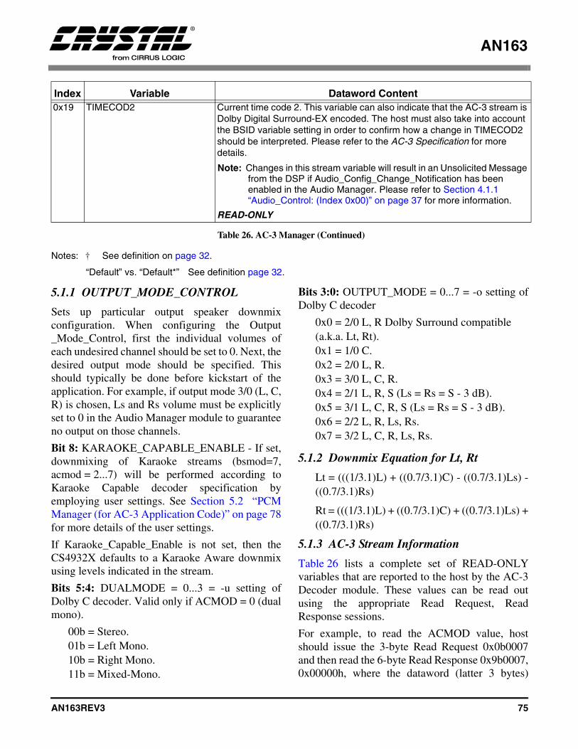
AN163
AN163REV3 75
Notes: † See definition on page 32.
“Default” vs. “Default*” See definition page 32.
5.1.1 OUTPUT_MODE_CONTROL
Sets up particular output speaker downmixconfiguration. When configuring the Output_Mode_Control, first the individual volumes ofeach undesired channel should be set to 0. Next, thedesired output mode should be specified. Thisshould typically be done before kickstart of theapplication. For example, if output mode 3/0 (L, C,R) is chosen, Ls and Rs volume must be explicitlyset to 0 in the Audio Manager module to guaranteeno output on those channels.
Bit 8: KARAOKE_CAPABLE_ENABLE - If set,downmixing of Karaoke streams (bsmod=7,acmod = 2...7) will be performed according toKaraoke Capable decoder specification byemploying user settings. See Section 5.2 “PCMManager (for AC-3 Application Code)” on page 78for more details of the user settings.
If Karaoke_Capable_Enable is not set, then theCS4932X defaults to a Karaoke Aware downmixusing levels indicated in the stream.
Bits 5:4: DUALMODE = 0...3 = -u setting ofDolby C decoder. Valid only if ACMOD = 0 (dualmono).
00b = Stereo.01b = Left Mono.10b = Right Mono.11b = Mixed-Mono.
Bits 3:0: OUTPUT_MODE = 0...7 = -o setting ofDolby C decoder
0x0 = 2/0 L, R Dolby Surround compatible(a.k.a. Lt, Rt).0x1 = 1/0 C.0x2 = 2/0 L, R.0x3 = 3/0 L, C, R.0x4 = 2/1 L, R, S (Ls = Rs = S - 3 dB).0x5 = 3/1 L, C, R, S (Ls = Rs = S - 3 dB).0x6 = 2/2 L, R, Ls, Rs.0x7 = 3/2 L, C, R, Ls, Rs.
5.1.2 Downmix Equation for Lt, Rt
Lt = (((1/3.1)L) + ((0.7/3.1)C) - ((0.7/3.1)Ls) -((0.7/3.1)Rs)
Rt = (((1/3.1)L) + ((0.7/3.1)C) + ((0.7/3.1)Ls) +((0.7/3.1)Rs)
5.1.3 AC-3 Stream Information
Table 26 lists a complete set of READ-ONLYvariables that are reported to the host by the AC-3Decoder module. These values can be read outusing the appropriate Read Request, ReadResponse sessions.
For example, to read the ACMOD value, hostshould issue the 3-byte Read Request 0x0b0007and then read the 6-byte Read Response 0x9b0007,0x00000h, where the dataword (latter 3 bytes)
0x19 TIMECOD2 Current time code 2. This variable can also indicate that the AC-3 stream is Dolby Digital Surround-EX encoded. The host must also take into account the BSID variable setting in order to confirm how a change in TIMECOD2 should be interpreted. Please refer to the AC-3 Specification for more details.
Note: Changes in this stream variable will result in an Unsolicited Message from the DSP if Audio_Config_Change_Notification has been enabled in the Audio Manager. Please refer to Section 4.1.1 “Audio_Control: (Index 0x00)” on page 37 for more information.
READ-ONLY
Index Variable Dataword Content
Table 26. AC-3 Manager (Continued)
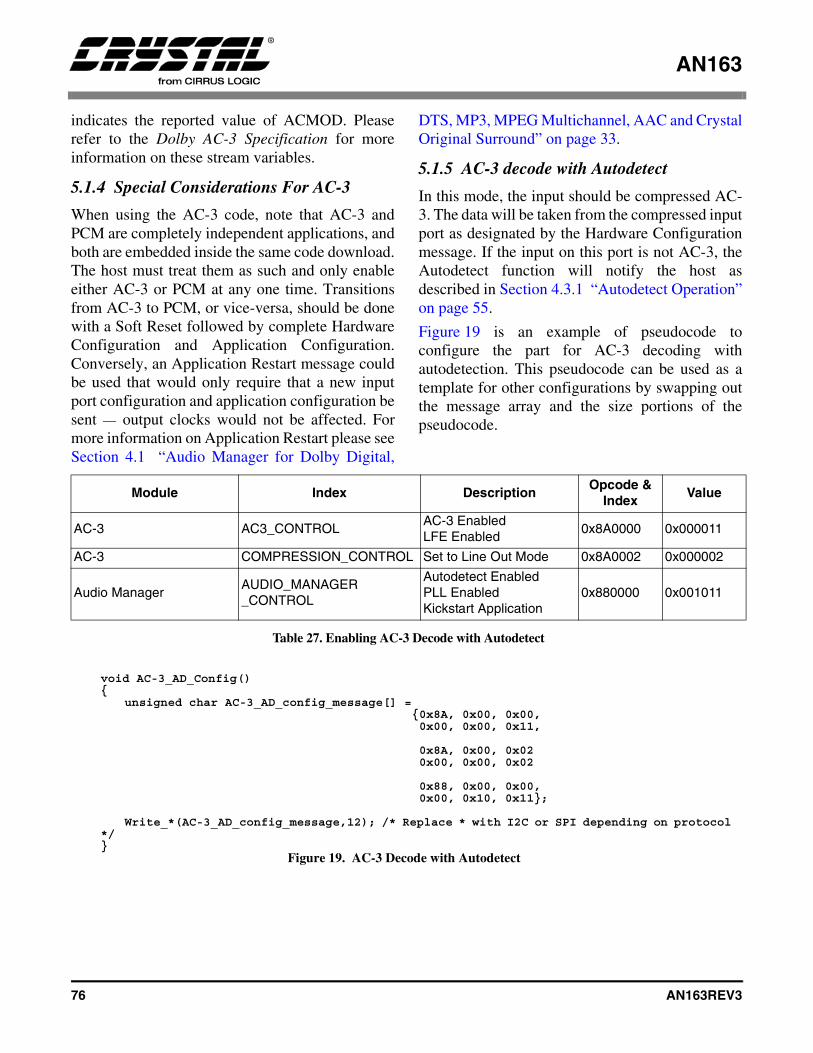
AN163
76 AN163REV3
indicates the reported value of ACMOD. Pleaserefer to the Dolby AC-3 Specification for moreinformation on these stream variables.
5.1.4 Special Considerations For AC-3
When using the AC-3 code, note that AC-3 andPCM are completely independent applications, andboth are embedded inside the same code download.The host must treat them as such and only enableeither AC-3 or PCM at any one time. Transitionsfrom AC-3 to PCM, or vice-versa, should be donewith a Soft Reset followed by complete HardwareConfiguration and Application Configuration.Conversely, an Application Restart message couldbe used that would only require that a new inputport configuration and application configuration besent — output clocks would not be affected. Formore information on Application Restart please seeSection 4.1 “Audio Manager for Dolby Digital,
DTS, MP3, MPEG Multichannel, AAC and CrystalOriginal Surround” on page 33.
5.1.5 AC-3 decode with Autodetect
In this mode, the input should be compressed AC-3. The data will be taken from the compressed inputport as designated by the Hardware Configurationmessage. If the input on this port is not AC-3, theAutodetect function will notify the host asdescribed in Section 4.3.1 “Autodetect Operation”on page 55.
Figure 19 is an example of pseudocode toconfigure the part for AC-3 decoding withautodetection. This pseudocode can be used as atemplate for other configurations by swapping outthe message array and the size portions of thepseudocode.
Module Index DescriptionOpcode &
IndexValue
AC-3 AC3_CONTROLAC-3 EnabledLFE Enabled
0x8A0000 0x000011
AC-3 COMPRESSION_CONTROL Set to Line Out Mode 0x8A0002 0x000002
Audio ManagerAUDIO_MANAGER_CONTROL
Autodetect Enabled PLL EnabledKickstart Application
0x880000 0x001011
Table 27. Enabling AC-3 Decode with Autodetect
void AC-3_AD_Config(){
unsigned char AC-3_AD_config_message[] = {0x8A, 0x00, 0x00, 0x00, 0x00, 0x11,
0x8A, 0x00, 0x02 0x00, 0x00, 0x02
0x88, 0x00, 0x00, 0x00, 0x10, 0x11};
Write_*(AC-3_AD_config_message,12); /* Replace * with I2C or SPI depending on protocol */}
Figure 19. AC-3 Decode with Autodetect
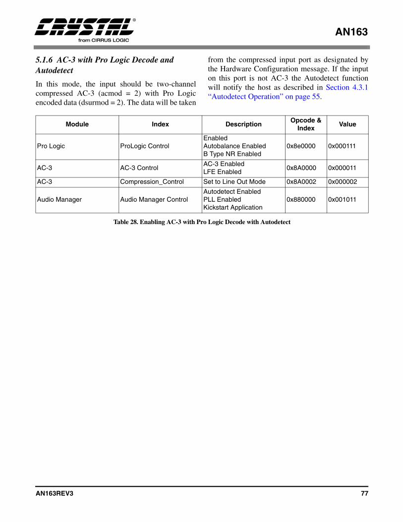
AN163
AN163REV3 77
5.1.6 AC-3 with Pro Logic Decode and Autodetect
In this mode, the input should be two-channelcompressed AC-3 (acmod = 2) with Pro Logicencoded data (dsurmod = 2). The data will be taken
from the compressed input port as designated bythe Hardware Configuration message. If the inputon this port is not AC-3 the Autodetect functionwill notify the host as described in Section 4.3.1“Autodetect Operation” on page 55.
Module Index DescriptionOpcode &
IndexValue
Pro Logic ProLogic ControlEnabledAutobalance EnabledB Type NR Enabled
0x8e0000 0x000111
AC-3 AC-3 ControlAC-3 EnabledLFE Enabled
0x8A0000 0x000011
AC-3 Compression_Control Set to Line Out Mode 0x8A0002 0x000002
Audio Manager Audio Manager ControlAutodetect EnabledPLL EnabledKickstart Application
0x880000 0x001011
Table 28. Enabling AC-3 with Pro Logic Decode with Autodetect
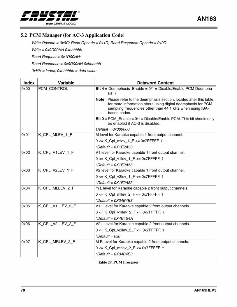
AN163
78 AN163REV3
5.2 PCM Manager (for AC-3 Application Code)
Write Opcode = 0x9C; Read Opcode = 0x1D; Read Response Opcode = 0x9D
Write = 0x9C00HH 0xhhhhhh
Read Request = 0x1D00HH;
Read Response = 0x9D00HH 0xhhhhhh
0xHH = index, 0xhhhhhh = data value
Index Variable Dataword Content0x00 PCM_CONTROL Bit 4 = Deemphasis_Enable = 0/1 = Disable/Enable PCM Deempha-
sis. †
Note: Please refer to the deemphasis section, located after this table, for more information about using digital deemphasis for PCM sampling frequencies other than 44.1 kHz when using IBA-based codes.
Bit 0 = PCM_Enable = 0/1 = Disable/Enable PCM. This bit should only be enabled if AC-3 is disabled.
Default = 0x0000000x01 K_CPL_MLEV_1_F M level for Karaoke capable 1 front output channel.
0 <= K_Cpl_mlev_1_F <= 0x7FFFFF. †
*Default = 0X1E2A530x02 K_CPL_V1LEV_1_F V1 level for Karaoke capable 1 front output channel.
0 <= K_Cpl_v1lev_1_F <= 0x7FFFFF. †
*Default = 0X1E2A530x03 K_CPL_V2LEV_1_F V2 level for Karaoke capable 1 front output channel.
0 <= K_Cpl_v2lev_1_F <= 0x7FFFFF. †
*Default = 0X1E2A530x04 K_CPL_MLLEV_2_F m L level for Karaoke capable 2 front output channels.
0 <= K_Cpl_mllev_2_F <= 0x7FFFFF. †
*Default = 0X34B4B30x05 K_CPL_V1LLEV_2_F V1 L level for Karaoke capable 2 front output channels.
0 <= K_Cpl_v1llev_2_F <= 0x7FFFFF. †
*Default = 0X4B4B4A0x06 K_CPL_V2LLEV_2_F V2 L level for Karaoke capable 2 front output channels.
0 <= K_Cpl_v2llev_2_F <= 0x7FFFFF. †
*Default = 0x00x07 K_CPL_MRLEV_2_F M R level for Karaoke capable 2 front output channels.
0 <= K_Cpl_mrlev_2_F <= 0x7FFFFF. †
*Default = 0X34B4B3
Table 29. PCM Processor
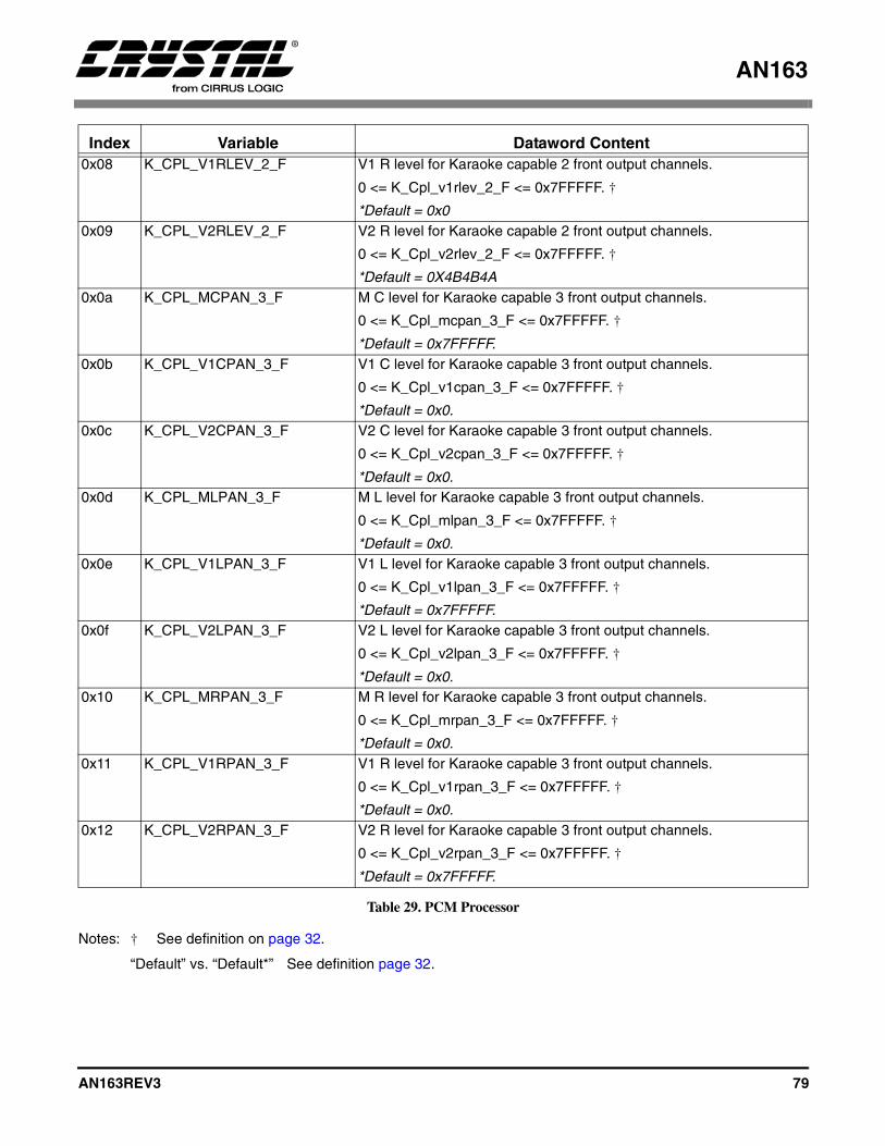
AN163
AN163REV3 79
Notes: † See definition on page 32.
“Default” vs. “Default*” See definition page 32.
0x08 K_CPL_V1RLEV_2_F V1 R level for Karaoke capable 2 front output channels.
0 <= K_Cpl_v1rlev_2_F <= 0x7FFFFF. †
*Default = 0x00x09 K_CPL_V2RLEV_2_F V2 R level for Karaoke capable 2 front output channels.
0 <= K_Cpl_v2rlev_2_F <= 0x7FFFFF. †
*Default = 0X4B4B4A0x0a K_CPL_MCPAN_3_F M C level for Karaoke capable 3 front output channels.
0 <= K_Cpl_mcpan_3_F <= 0x7FFFFF. †
*Default = 0x7FFFFF.0x0b K_CPL_V1CPAN_3_F V1 C level for Karaoke capable 3 front output channels.
0 <= K_Cpl_v1cpan_3_F <= 0x7FFFFF. †
*Default = 0x0.0x0c K_CPL_V2CPAN_3_F V2 C level for Karaoke capable 3 front output channels.
0 <= K_Cpl_v2cpan_3_F <= 0x7FFFFF. †
*Default = 0x0.0x0d K_CPL_MLPAN_3_F M L level for Karaoke capable 3 front output channels.
0 <= K_Cpl_mlpan_3_F <= 0x7FFFFF. †
*Default = 0x0.0x0e K_CPL_V1LPAN_3_F V1 L level for Karaoke capable 3 front output channels.
0 <= K_Cpl_v1lpan_3_F <= 0x7FFFFF. †
*Default = 0x7FFFFF.0x0f K_CPL_V2LPAN_3_F V2 L level for Karaoke capable 3 front output channels.
0 <= K_Cpl_v2lpan_3_F <= 0x7FFFFF. †
*Default = 0x0.0x10 K_CPL_MRPAN_3_F M R level for Karaoke capable 3 front output channels.
0 <= K_Cpl_mrpan_3_F <= 0x7FFFFF. †
*Default = 0x0.0x11 K_CPL_V1RPAN_3_F V1 R level for Karaoke capable 3 front output channels.
0 <= K_Cpl_v1rpan_3_F <= 0x7FFFFF. †
*Default = 0x0.0x12 K_CPL_V2RPAN_3_F V2 R level for Karaoke capable 3 front output channels.
0 <= K_Cpl_v2rpan_3_F <= 0x7FFFFF. †
*Default = 0x7FFFFF.
Index Variable Dataword Content
Table 29. PCM Processor
AN163
80 AN163REV3
5.2.1 PCM_CONTROL
Bit 4: DEEMPHASIS_ENABLE
Disable/Enable PCM Deemphasis. The filter usedis identical to CS4334 (50/15 uS).
1 - Enables Deemphasis0 - Disables Deemphasis
For systems that plan on using a “Non-IBA-Based”PCM Processing application code such asac3_3265.ld (that has been configured for PCMPass-Through) and want to support digitaldeemphasis for the sampling frequencies of 32 kHzand 48 kHz, as well as 44.1 kHz, PCM, the hostonly needs to inform the DSP the setting for thecurrent PCM sampling frequency, which is set viathe Audio Manager (0x14) before Kickstart.Note: For systems that plan on using an “IBA-Based”
PCM Processing application code such as ac3i326x.ld (that has been configured for PCM Pass-Through) and want to support digital de-emphasis for the sampling frequencies of 32 kHz and 48 kHz, as well as 44.1 kHz, PCM, the host, in addition to communicating the setting for the current PCM sampling frequency, which is set via the Audio Manager (0x14), must also download the following commands before Kickstart:
For 32 kHz support:
848ff9bb82fa848ffe42aef3848ffff8d406
For 44.1 kHz support:
848ff8aeacda848ffc3b6543848ffdf34797
For 48 kHz support:
848ff7ab9ed7848ffa39be36848ffbf1e0a1
For 64 kHz support:
848ff9a25a7b848ffe34f310848fffed676b
For 88.2 kHz support:
848ff899f80b848ffc30eb8a848ffde90c82
For 96 kHz support:
848ff7981257848ffa300d08848ffbe8054f
Digital de-emphasis support does not exist forsampling frequencies other than 96 kHz, 88.2 kHz,64 kHz, 48 kHz, 44.1 kHz, or 32 kHz regardless ofwhat code is being downloaded.
Bit 1: PCM_ENABLE
Disable/Enable PCM. This bit should only beenabled if AC-3 is disabled.
1 - Enables PCM Pass-Through0 - Disables PCM Pass-Through
5.2.2 Karaoke Capable Function:
Karaoke Capable functionality is enabled whenBit 8 of Output_Mode_Control in AC-3_Manageris set to 1.
If Karaoke_Capable_Enable is not set, thenCS4932X defaults to a Karaoke Aware downmix,using levels indicated in the stream.
Karaoke Capable functionality is enabled whenBit 8 of Output_Mode_Control in AC-3_Manageris set to 1.
In a karaoke bit stream (bsmod=7, acmod=2...7), 3special channels have to be downmixed accordingto user specification. They are M (guide melody),and V1, V2 (vocal tracks one and two).
In Karaoke Aware mode (default mode whereKaraoke_Capable_Enable=0), the CS4932X

AN163
AN163REV3 81
downmixes these channels according to theclev/slev values indicated in the bitstream. ThisKaraoke Aware downmix reproduces all theprogram content in the front speakers according tothe programmed levels and audio configuration ofthe bitstream.
In Karaoke Capable mode, the downmixcoefficients are set up by the user according to thenumber of output front channels: 1, 2, or 3.Independent settings are available for each of these3 cases as indicated in Table 29 on page 78. Thefollowing equations define the downmixingperformed for each of the 3 cases:
• 1 front channel:
Ck = mlev * M + v1lev * V1 + v2lev * V2.
Co = 0.707 * L + Ck + 0.707 * R.
• 2 front channels:
Lk = mllev * M + v1llev * V1 +v2llev * V2.
Rk = mrlev * M + v1rlev * V1 + v2rlev * V2.
Lo = L + Lk
Ro = R + Rk
• 3 front channels:
Ck = mcpan * M + v1cpan * V1 + v2cpan * V2.
Lk = mlpan * M + v1lpan * V1 + v2lpan * V2.
Rk = mrpan * M + v1rpan * V1 + v2rpan * V2.
Lo = L + Lk
Co = Ck
Ro = R + Rk
5.2.3 Special Considerations For PCM
When using the AC-3 code, it should be noted thatAC-3 and PCM are completely independent
applications. The host must treat them as such andonly enable either AC-3 or PCM at any one time.Transitions from AC-3 to PCM or vice-versashould be done with a soft reset followed bycomplete Hardware Configuration and ApplicationConfiguration. Conversely, an Application Restartmessage could be used, which would only requirethat a new input port configuration and applicationconfiguration be sent — output clocks would not beaffected.
5.2.4 Special Considerations For Pink/White Noise
Pink/White Noise is controlled by threeparameters. These parameters are the currentlyconfigured application (i.e. PCM), the channelselected by the Noise_Control variable:, and thestate of the Autodetect Enable. In order to usePink/White Noise, the code should be configuredstrictly for PCM before Kickstart. If Pro Logic isenabled, the host loses independent control ofPink/White Noise on the Ls and Rs channels — thesurround channels operate in unison.
White noise can be generated by additionallysetting Bit 4 of Noise_Control in the messagesabove. In the same message, if Bit 5 is set, a10.5 dB boosted noise is received.
5.2.5 PCM Pass-through (Using AC-3 Application Code)
In this mode, the input should be 44.1 kHz PCMdata. The data will be taken from the PCM inputport, as designated by the Hardware Configurationmessage. (See Table 30.)
Module Index DescriptionOpcode
and IndexValue
PCM PCM Control Enabled 0x9c0000 0x000001
Audio Manager Sampling Frequency 44.1 kHz 0x880014 0x000001
Audio Manager Audio Manager Control Kickstart Application 0x880000 0x001011
Table 30. Enabling PCM Pass-through of 44.1 kHz PCM

AN163
82 AN163REV3
5.2.6 Pink/White Noise Generation
To cycle through the channels (after sending theabove messages), the host would send thefollowing sequence of commands, pausing
between each command to hold the pink noise on aparticular channel (See Table 32).
Module Index DescriptionOpcode
and IndexValue
PCM PCM Control Enabled 0x9c0000 0x000001
Audio Manager Noise Control Pink Noise On Left Channel 0x880001 0x000000
Audio Manager Audio Manager Control Kickstart ApplicationAutodetect Disabled
0x880000 0x000011
Table 31. Enabling Pink/White Noise Generation
Module Index DescriptionOpcode
and IndexValue
Audio Manager Noise Control Pink Noise On Left Channel 0x880001 0x000000
Audio Manager Noise Control Pink Noise On Center Channel 0x880001 0x000001
Audio Manager Noise Control Pink Noise On Right Channel 0x880001 0x000002
Audio Manager Noise Control Pink Noise On Left Surround Channel
0x880001 0x000003
Audio Manager Noise Control Pink Noise On Right Surround Channel
0x880001 0x000004
Audio Manager Noise Control Pink Noise On LFE Channel 0x880001 0x000005
Table 32. Pink/White Noise Generation for All 5.1 Channel
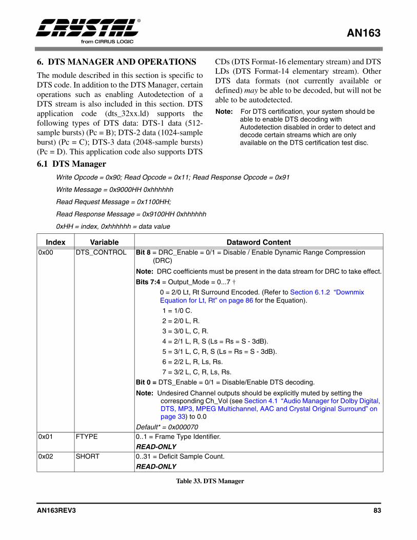
AN163
AN163REV3 83
6. DTS MANAGER AND OPERATIONS
The module described in this section is specific toDTS code. In addition to the DTS Manager, certainoperations such as enabling Autodetection of aDTS stream is also included in this section. DTSapplication code (dts_32xx.ld) supports thefollowing types of DTS data: DTS-1 data (512-sample bursts) (Pc = B); DTS-2 data (1024-sampleburst) (Pc = C); DTS-3 data (2048-sample bursts)(Pc = D). This application code also supports DTS
CDs (DTS Format-16 elementary stream) and DTSLDs (DTS Format-14 elementary stream). OtherDTS data formats (not currently available ordefined) may be able to be decoded, but will not beable to be autodetected. Note: For DTS certification, your system should be
able to enable DTS decoding with Autodetection disabled in order to detect and decode certain streams which are only available on the DTS certification test disc.
6.1 DTS Manager
Write Opcode = 0x90; Read Opcode = 0x11; Read Response Opcode = 0x91
Write Message = 0x9000HH 0xhhhhhh
Read Request Message = 0x1100HH;
Read Response Message = 0x9100HH 0xhhhhhh
0xHH = index, 0xhhhhhh = data value
Index Variable Dataword Content0x00 DTS_CONTROL Bit 8 = DRC_Enable = 0/1 = Disable / Enable Dynamic Range Compression
(DRC)
Note: DRC coefficients must be present in the data stream for DRC to take effect.
Bits 7:4 = Output_Mode = 0...7 †
0 = 2/0 Lt, Rt Surround Encoded. (Refer to Section 6.1.2 “Downmix Equation for Lt, Rt” on page 86 for the Equation).
1 = 1/0 C.
2 = 2/0 L, R.
3 = 3/0 L, C, R.
4 = 2/1 L, R, S (Ls = Rs = S - 3dB).
5 = 3/1 L, C, R, S (Ls = Rs = S - 3dB).
6 = 2/2 L, R, Ls, Rs.
7 = 3/2 L, C, R, Ls, Rs.
Bit 0 = DTS_Enable = 0/1 = Disable/Enable DTS decoding.
Note: Undesired Channel outputs should be explicitly muted by setting the corresponding Ch_Vol (see Section 4.1 “Audio Manager for Dolby Digital, DTS, MP3, MPEG Multichannel, AAC and Crystal Original Surround” on page 33) to 0.0
Default* = 0x0000700x01 FTYPE 0..1 = Frame Type Identifier.
READ-ONLY0x02 SHORT 0..31 = Deficit Sample Count.
READ-ONLY
Table 33. DTS Manager
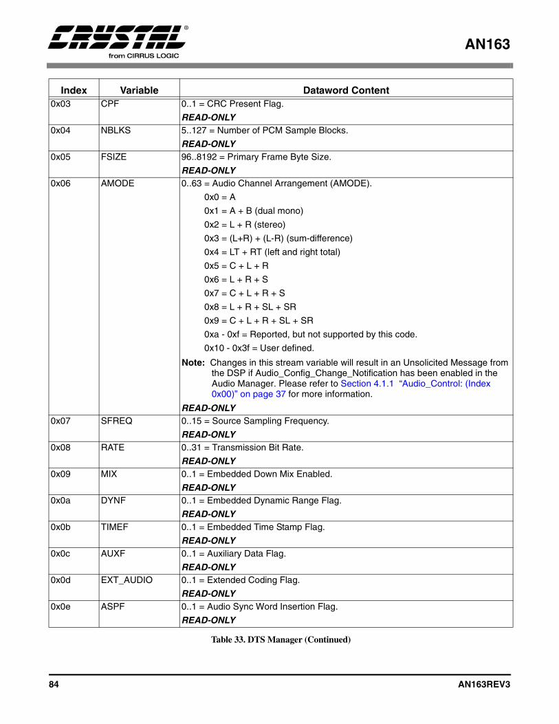
AN163
84 AN163REV3
0x03 CPF 0..1 = CRC Present Flag.
READ-ONLY0x04 NBLKS 5..127 = Number of PCM Sample Blocks.
READ-ONLY0x05 FSIZE 96..8192 = Primary Frame Byte Size.
READ-ONLY0x06 AMODE 0..63 = Audio Channel Arrangement (AMODE).
0x0 = A
0x1 = A + B (dual mono)
0x2 = L + R (stereo)
0x3 = (L+R) + (L-R) (sum-difference)
0x4 = LT + RT (left and right total)
0x5 = C + L + R
0x6 = L + R + S
0x7 = C + L + R + S
0x8 = L + R + SL + SR
0x9 = C + L + R + SL + SR
0xa - 0xf = Reported, but not supported by this code.
0x10 - 0x3f = User defined.
Note: Changes in this stream variable will result in an Unsolicited Message from the DSP if Audio_Config_Change_Notification has been enabled in the Audio Manager. Please refer to Section 4.1.1 “Audio_Control: (Index 0x00)” on page 37 for more information.
READ-ONLY0x07 SFREQ 0..15 = Source Sampling Frequency.
READ-ONLY0x08 RATE 0..31 = Transmission Bit Rate.
READ-ONLY0x09 MIX 0..1 = Embedded Down Mix Enabled.
READ-ONLY0x0a DYNF 0..1 = Embedded Dynamic Range Flag.
READ-ONLY0x0b TIMEF 0..1 = Embedded Time Stamp Flag.
READ-ONLY0x0c AUXF 0..1 = Auxiliary Data Flag.
READ-ONLY0x0d EXT_AUDIO 0..1 = Extended Coding Flag.
READ-ONLY0x0e ASPF 0..1 = Audio Sync Word Insertion Flag.
READ-ONLY
Index Variable Dataword Content
Table 33. DTS Manager (Continued)
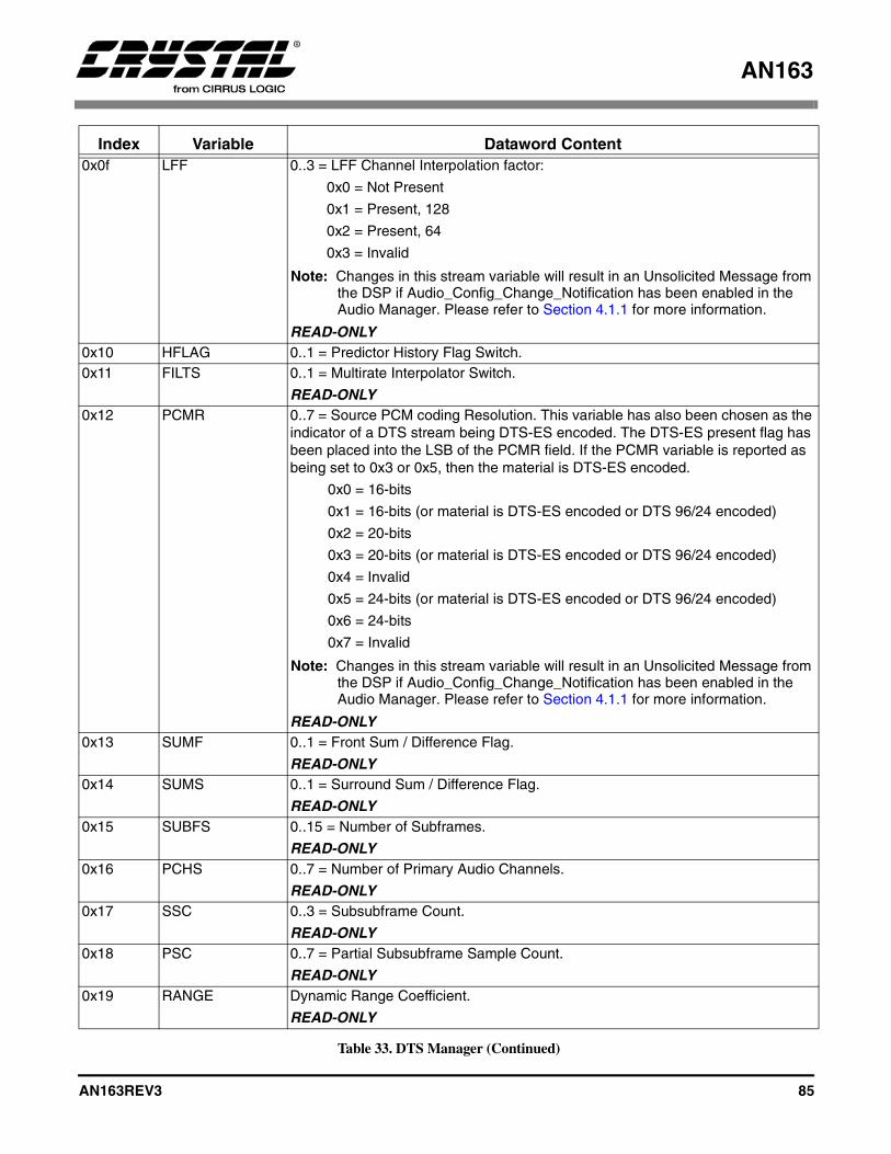
AN163
AN163REV3 85
0x0f LFF 0..3 = LFF Channel Interpolation factor:
0x0 = Not Present
0x1 = Present, 128
0x2 = Present, 64
0x3 = Invalid
Note: Changes in this stream variable will result in an Unsolicited Message from the DSP if Audio_Config_Change_Notification has been enabled in the Audio Manager. Please refer to Section 4.1.1 for more information.
READ-ONLY0x10 HFLAG 0..1 = Predictor History Flag Switch.0x11 FILTS 0..1 = Multirate Interpolator Switch.
READ-ONLY0x12 PCMR 0..7 = Source PCM coding Resolution. This variable has also been chosen as the
indicator of a DTS stream being DTS-ES encoded. The DTS-ES present flag has been placed into the LSB of the PCMR field. If the PCMR variable is reported as being set to 0x3 or 0x5, then the material is DTS-ES encoded.
0x0 = 16-bits
0x1 = 16-bits (or material is DTS-ES encoded or DTS 96/24 encoded)
0x2 = 20-bits
0x3 = 20-bits (or material is DTS-ES encoded or DTS 96/24 encoded)
0x4 = Invalid
0x5 = 24-bits (or material is DTS-ES encoded or DTS 96/24 encoded)
0x6 = 24-bits
0x7 = Invalid
Note: Changes in this stream variable will result in an Unsolicited Message from the DSP if Audio_Config_Change_Notification has been enabled in the Audio Manager. Please refer to Section 4.1.1 for more information.
READ-ONLY0x13 SUMF 0..1 = Front Sum / Difference Flag.
READ-ONLY0x14 SUMS 0..1 = Surround Sum / Difference Flag.
READ-ONLY0x15 SUBFS 0..15 = Number of Subframes.
READ-ONLY0x16 PCHS 0..7 = Number of Primary Audio Channels.
READ-ONLY0x17 SSC 0..3 = Subsubframe Count.
READ-ONLY0x18 PSC 0..7 = Partial Subsubframe Sample Count.
READ-ONLY0x19 RANGE Dynamic Range Coefficient.
READ-ONLY
Index Variable Dataword Content
Table 33. DTS Manager (Continued)
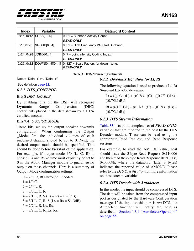
AN163
86 AN163REV3
Notes: “Default” vs. “Default*”
See definition page 32.
6.1.1 DTS_CONTROL
Bits 8 DRC_ENABLE
By enabling this bit the DSP will recognizeDynamic Range Compression (DRC)coefficients placed in the data stream by a DTS-certified encoder.
Bits 7:4: OUTPUT_MODE
These bits set up the output speaker downmixconfiguration. When configuring the Output_Mode, first the individual volumes of eachundesired channel should be set to 0. Next, thedesired output mode should be specified. Thisshould be done before kickstart of the application.For example, if output mode 3/0 (L, C, R) ischosen, Ls and Rs volume must explicitly be set to0 in the Audio Manager module to guarantee nooutput on those channels. Here is a summary ofOutput_Mode configuration settings.
0 = 2/0 Lt, Rt Surround Encoded.1 = 1/0 C.2 = 2/0 L, R.3 = 3/0 L, C, R.4 = 2/1 L, R, S (Ls = Rs = S - 3dB).5 = 3/1 L, C, R, S (Ls = Rs = S - 3dB).6 = 2/2 L, R, Ls, Rs.7 = 3/2 L, C, R, Ls, Rs.
6.1.2 Downmix Equation for Lt, Rt
The following equation is used to produce a Lt, RtSurround Encoded downmix.
Lt = (((1/3.1)L) + ((0.7/3.1)C) - ((0.7/3.1)Ls) -((0.7/3.1)Rs)
Rt = (((1/3.1)L) + ((0.7/3.1)C) + ((0.7/3.1)Ls) +((0.7/3.1)Rs)
6.1.3 DTS Stream Information
Table 33 lists out a complete set of READ-ONLYvariables that are reported to the host by the DTSDecoder module. These can be read using theappropriate Read Request, and Read Responsesessions.
For example, to read the AMODE value, hostshould issue the 3-byte Read Request 0x110006and then read the 6-byte Read Response 0x910006,0x00009h, where the dataword (latter 3 bytes)indicates the reported value of AMODE. Pleaserefer to the DTS Specification for more informationon these stream variables.
6.1.4 DTS Decode with Autodetect
In this mode, the input should be compressed DTS.The data will be taken from the compressed inputport as designated by the Hardware Configurationmessage. If the input on this port is not DTS, theAutodetect function will notify the host asdescribed in Section 4.3.1 “Autodetect Operation”on page 55.
0x1a..0x1e SUBS[0...4] 0..31 = Subband Activity Count.
READ-ONLY0x1f..0x23 VQSUB[0...4] 0..31 = High Frequency VQ Start Subband.
READ-ONLY0x24..0x28 JOINX[0...4] 0..7 = Joint Intensity Coding Index.
READ-ONLY0x29..0x32 DOWN[0...4][0...1] 0..127 = Scale Factors for downmixing.
READ-ONLY
Index Variable Dataword Content
Table 33. DTS Manager (Continued)

AN163
AN163REV3 87
Figure 20 is an example of pseudocode toconfigure the part DTS decode with autodetect.This pseudocode can be used as a template for
other configurations by swapping out the values inthe message array and the size.
Module Index DescriptionOpcode &
IndexValue
DTS Manager DTS Control DTS Enabled (Assumes all 5.1 channels are available.)
0x900000 0x000071
Audio Manager Audio Manager Control Autodetect Enabled PLL EnabledKickstart Application
0x880000 0x001011
Table 34. Enabling DTS Decode with Autodetect
void DTS_AD_Config(){
unsigned char DTS_AD_config_message[] = {0x90, 0x00, 0x00, 0x00, 0x00, 0x71,
0x88, 0x00, 0x00, 0x00, 0x10, 0x11};
Write_*(DTS_AD_config_message,12); /* Replace * with I2C or SPI depending on protocol */}
Figure 20. DTS decode with Autodetect

AN163
88 AN163REV3
6.1.5 Special Considerations For DTS CDs and Autodetection
A DTS CD is treated like a linear PCM CD by allCD/DVD players. During FF/REW ("trick"modes), the CD/DVD player drops audio samplesto create an effect audible to the listener. DroppingDTS data, however, causes corruption of thebitstream which makes the data indistinguishablefrom linear PCM. As a result, the DTS decoder willgenerate an autodetect message indicating PCMwas detected.
However, if a user actually changed the CD (eitherby hand or by CD changer), this would cause theDSP to report silence; also known as “Silent InputData (Out of Application Sync).” If this is the case,the host must then respond to whatever the DSPreports after this detection of silence. If the disc isswitched to PCM, then the host must load thecorresponding PCM code. If the disc is switched toDTS, then the host must load the DTS code.
An abrupt transition from DTS to PCM shouldindicate to the system controller that a “trick” modeis being used, hence the PCM code should not beloaded. If the host does nothing, the DTS code willthen automute during this FF/REW period andthere will be no problems. Please refer to Figure 21to see a flow chart depicting the DTS autodetectionprocess.
However, the recommendation described abovedoes not take into account a sudden change fromDTS to PCM due to a source change. It is thereforesuggested that if the user selects a source change(e.g. could change input from a DTS CD playing toa DAT playing 44.1 kHz PCM), the host will beaware of this input change and should subsequentlyperform a Soft Reset, Configure the Hardware, and
perform a kickstart. This will ensure protectionfrom such a scenario.
PerformKickstart
with Autodetect
Run Time(Autodetect Enabled)INTREQ goes LOW
User Reads UnsolicitedResponse
Last Input =Current Input OR
Last Input = SilenceHost Does Nothing
Yes
Last Input =Compressed
Bitstream ANDCurrent Input =
DifferentCompressed
Bitstream
Yes
Yes
No
Host Loads CorrespondingAC-3 or MPEG Code,Configures Hardware
and Performs Kickstartwith Autodetect Bypass
Host Loads DTS Code,Configures Hardware
and Performs Kickstart
Host performs soft muteand waits for stream to
change back to DTS,unless host is aware ofsource input change.
Last Input =PCM
Bitstream ANDCurrent Input =
DTS
Yes
No
Last Input =DTS
Bitstream ANDCurrent Input =
PCMBitstream
No
Figure 21. DTS Specific Autodetection Flowchart
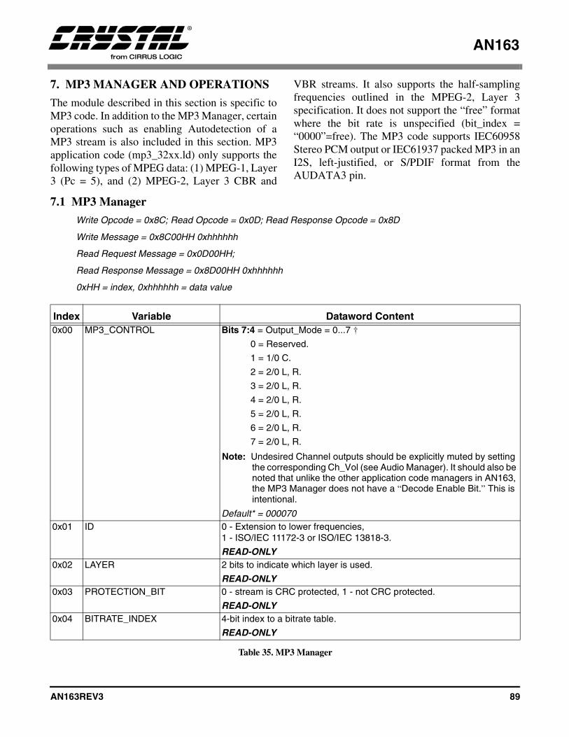
AN163
AN163REV3 89
7. MP3 MANAGER AND OPERATIONS
The module described in this section is specific toMP3 code. In addition to the MP3 Manager, certainoperations such as enabling Autodetection of aMP3 stream is also included in this section. MP3application code (mp3_32xx.ld) only supports thefollowing types of MPEG data: (1) MPEG-1, Layer3 (Pc = 5), and (2) MPEG-2, Layer 3 CBR and
VBR streams. It also supports the half-samplingfrequencies outlined in the MPEG-2, Layer 3specification. It does not support the “free” formatwhere the bit rate is unspecified (bit_index =“0000”=free). The MP3 code supports IEC60958Stereo PCM output or IEC61937 packed MP3 in anI2S, left-justified, or S/PDIF format from theAUDATA3 pin.
7.1 MP3 Manager
Write Opcode = 0x8C; Read Opcode = 0x0D; Read Response Opcode = 0x8D
Write Message = 0x8C00HH 0xhhhhhh
Read Request Message = 0x0D00HH;
Read Response Message = 0x8D00HH 0xhhhhhh
0xHH = index, 0xhhhhhh = data value
Index Variable Dataword Content0x00 MP3_CONTROL Bits 7:4 = Output_Mode = 0...7 †
0 = Reserved.
1 = 1/0 C.
2 = 2/0 L, R.
3 = 2/0 L, R.
4 = 2/0 L, R.
5 = 2/0 L, R.
6 = 2/0 L, R.
7 = 2/0 L, R.
Note: Undesired Channel outputs should be explicitly muted by setting the corresponding Ch_Vol (see Audio Manager). It should also be noted that unlike the other application code managers in AN163, the MP3 Manager does not have a “Decode Enable Bit.” This is intentional.
Default* = 0000700x01 ID 0 - Extension to lower frequencies,
1 - ISO/IEC 11172-3 or ISO/IEC 13818-3.
READ-ONLY0x02 LAYER 2 bits to indicate which layer is used.
READ-ONLY0x03 PROTECTION_BIT 0 - stream is CRC protected, 1 - not CRC protected.
READ-ONLY0x04 BITRATE_INDEX 4-bit index to a bitrate table.
READ-ONLY
Table 35. MP3 Manager
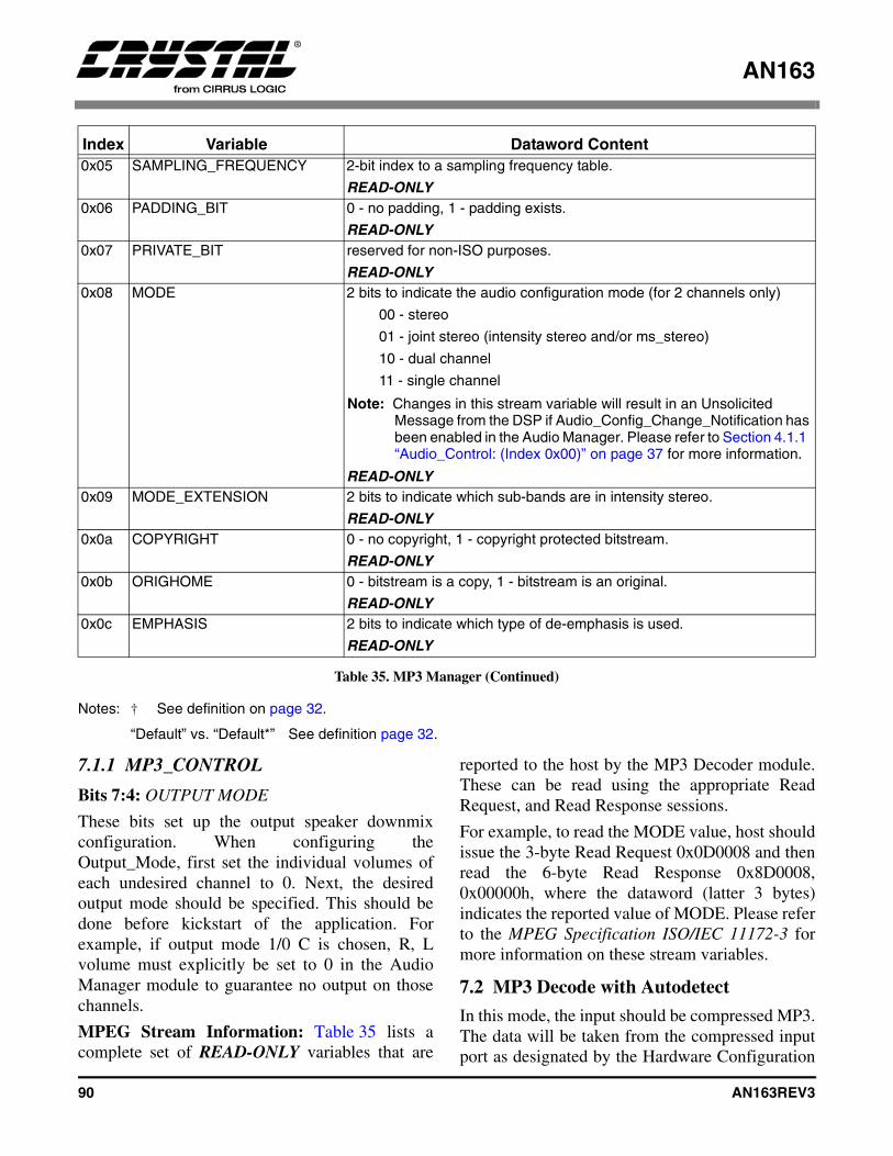
AN163
90 AN163REV3
Notes: † See definition on page 32.
“Default” vs. “Default*” See definition page 32.
7.1.1 MP3_CONTROL
Bits 7:4: OUTPUT MODE
These bits set up the output speaker downmixconfiguration. When configuring theOutput_Mode, first set the individual volumes ofeach undesired channel to 0. Next, the desiredoutput mode should be specified. This should bedone before kickstart of the application. Forexample, if output mode 1/0 C is chosen, R, Lvolume must explicitly be set to 0 in the AudioManager module to guarantee no output on thosechannels.
MPEG Stream Information: Table 35 lists acomplete set of READ-ONLY variables that are
reported to the host by the MP3 Decoder module.These can be read using the appropriate ReadRequest, and Read Response sessions.
For example, to read the MODE value, host shouldissue the 3-byte Read Request 0x0D0008 and thenread the 6-byte Read Response 0x8D0008,0x00000h, where the dataword (latter 3 bytes)indicates the reported value of MODE. Please referto the MPEG Specification ISO/IEC 11172-3 formore information on these stream variables.
7.2 MP3 Decode with Autodetect
In this mode, the input should be compressed MP3.The data will be taken from the compressed inputport as designated by the Hardware Configuration
0x05 SAMPLING_FREQUENCY 2-bit index to a sampling frequency table.
READ-ONLY0x06 PADDING_BIT 0 - no padding, 1 - padding exists.
READ-ONLY0x07 PRIVATE_BIT reserved for non-ISO purposes.
READ-ONLY0x08 MODE 2 bits to indicate the audio configuration mode (for 2 channels only)
00 - stereo
01 - joint stereo (intensity stereo and/or ms_stereo)
10 - dual channel
11 - single channel
Note: Changes in this stream variable will result in an Unsolicited Message from the DSP if Audio_Config_Change_Notification has been enabled in the Audio Manager. Please refer to Section 4.1.1 “Audio_Control: (Index 0x00)” on page 37 for more information.
READ-ONLY0x09 MODE_EXTENSION 2 bits to indicate which sub-bands are in intensity stereo.
READ-ONLY0x0a COPYRIGHT 0 - no copyright, 1 - copyright protected bitstream.
READ-ONLY0x0b ORIGHOME 0 - bitstream is a copy, 1 - bitstream is an original.
READ-ONLY0x0c EMPHASIS 2 bits to indicate which type of de-emphasis is used.
READ-ONLY
Index Variable Dataword Content
Table 35. MP3 Manager (Continued)
AN163
AN163REV3 91
message. If the input on this port is not MP3, theAutodetect function will notify the host asdescribed in Section 4.3.1 “Autodetect Operation”on page 55.
Figure 22 is an example of pseudocode toconfigure the part MP3 decode with autodetect.This pseudocode can be used as a template forother configurations by swapping out the values forthe message array and the size in the pseudocode.
7.2.1 Special Considerations MP3 Autodetect
In general, if the Autodetect function senses AC-3,DTS, PCM, or MPEG data, the appropriateUnsolicited Message is sent indicating that thecorresponding stream was detected. The hostwould then need to download the appropriate code.However, if the autodetect function senses a validIEC61937-packed MP3 stream, it will send the hostan Unsolicited Message of 0x000005 (provided thecurrent application code was not MP3). The hostmust then download the MP3 application code, inorder to determine if the stream is MPEG-1, AudioLayer 3 or is another type of MPEG with a reportedPc value of 5.
Note: This same Unsolicited Message of 0x000005 could also indicate that the stream was IEC61937-packed MPEG-1, Audio Layer 2 or IEC61937-packed MPEG-2 without extension. However, the only way to determine that the stream is MP3 is to download the MP3 application code.
After downloading the MP3 application code,configuring the hardware and performing akickstart, the DSP will then generate an UnsolicitedMessage indicating that the stream has a Pc valueof 5 (0x000005). This first Unsolicited Messagedoes not indicate the MPEG stream type. If theinput stream is MPEG-1, Audio Layer 3, the DSPwill send the host an Unsolicited Message of0x800005 and begin decoding the audio stream. Note: This second Unsolicited Message may not
occur for up to 26ms after the first Unsolicited Message.
However if the host has not seen a secondUnsolicited Message of 0x80005 after 26ms fromthe first Unsolicited Message of 0x000005, the hostthen knows that the input stream is MPEG-1, Layer2 or MPEG-2 without extension. The host mustthen download the MPEG-2 application code(mpg_2xxx.ld), Configure the Hardware andperform a kickstart.
Module Index Description Opcode & Index
Value
MP3 Manager MP3 Control MP3 Enabled (Assumes 2.0 channels are available.)
0x8C0000 0x000020
Audio Manager Audio Manager Control Autodetect Enabled PLL EnabledKickstart Application
0x880000 0x001011
Table 36. Enabling MP3 Decode with Autodetect

AN163
92 AN163REV3
void MP3_AD_Config(){
unsigned char MP3_AD_config_message[] = {0x8C, 0x00, 0x00, 0x00, 0x00, 0x20,
0x88, 0x00, 0x00, 0x00, 0x10, 0x11};
Write_*(MP3_AD_config_message,12); /* Replace * with I2 C or SPI depending on protocol */}
Figure 22. MP3 Decode with Autodetect
AN163
AN163REV3 93
7.2.2 For System Designers: When to Download MP3 Application code...
The worst-case autodetection scenario is if MPEGMultichannel application code is already loadedinto the DSP and the input data stream changesseemlessly (on the frame, and with no frames ofsilence) from an MPEG-1, Layer 2 IEC61937-packed data stream or an MPEG-2 withoutextension IEC61937-packed data stream to anMPEG-1, Layer 3 IEC61937-packed data stream.Detection of both stream types by the MPEG codewill always report 0x000005, however if the streamis actually MPEG-1, Layer 3, the DSP will not beable to decode the stream, hence no audio will beheard.
However, we will assume that an MPEG-1, Layer2 or MPEG-2 without extension stream will beseparated by some detectable amount of silence(approximate 500ms) before being followed by anMPEG-1, Audio Layer 3 stream. With thisassumption in mind, the two data streams will beseparated with an entirely different type of stream,silence. If the current application code is MPEGand it detects silence, it will send an UnsolicitedMessage of 0x000010. The host must thendownload the MP3 application code, configure thehardware and perform a kickstart. Again, if theDSP detects anything other than silence, it willgenerate the appropriate unsolicited message
which the host will interpret and then download theappropriate application code.
The inverse of the above scenario however does notpresent a problem though if the MP3 applicationcode was already loaded. The host would havereceived an Unsolicited Message of 0x800005when MPEG-1, Layer 3 was detected. Even if theinput data stream changed seemlessly (on theframe, and with no frames of silence) from anMPEG-1, Layer 3, IEC61937-packed data streamto an MPEG-1, Layer 2, IEC61937-packed datastream or an MPEG-2 without extensionIEC61937-packed data stream, the host would stillreport an Unsolicited Message of 0x00005. Thehost need only wait 26 ms and then load theMPEG-2 application code, and audio could then beheard.
Again, if another type of application code is loaded,like AC-3, and the DSP sends the host anUnsolicited Message of 0x000005, the host mustdownload the MP3 to determine if the reported Pcvalue of 5 indicates that the stream is either MPEG-1, Layer 2 or MPEG-1, Layer 3 or MPEG-2without extension. Please see Section 23 “When toDownload MP3 Code...” on page 94, for anoverview of the previously described summary ofwhen to download MP3 versus MPEGMultichannel application code.
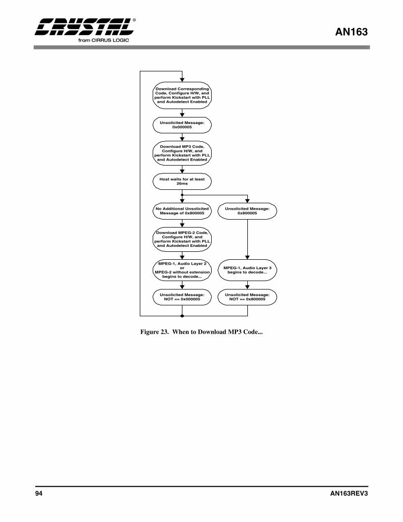
AN163
94 AN163REV3
Figure 23. When to Download MP3 Code...
Unsolicited Message:0x000005
Download MP3 Code,Configure H/W, and
perform Kickstart with PLLand Autodetect Enabled
Download CorrespondingCode, Configure H/W, andperform Kickstart with PLL
and Autodetect Enabled
MPEG-1, Audio Layer 3begins to decode...
Download MPEG-2 Code,Configure H/W, and
perform Kickstart with PLLand Autodetect Enabled
No Additional UnsolicitedMessage of 0x800005
Unsolicited Message:0x800005
MPEG-1, Audio Layer 2or
MPEG-2 without extensionbegins to decode...
Unsolicited Message:NOT == 0x000005
Unsolicited Message:NOT == 0x800005
Host waits for at least26ms

AN163
AN163REV3 95
8. MPEG MULTICHANNEL MANAGER AND OPERATIONS
The module described in this section is specific toMPEG code. In addition to the MPEG Manager,certain operations such as enabling Autodetectionof an MPEG stream are also included in thissection. MPEG-2 Multichannel application code(mpg_32xx.ld) supports the following types of
MPEG data: MPEG-1, Layer 2 (Pc = 5); MPEG-2without extension (Pc = 5); MPEG-2 withextension (Pc = 6). Please refer to MP3 applicationcode for support of MPEG-1, Audio Layer 3. Note: MPEG-2 Multichannel application code
(mpg_32xx.ld) does NOT support the following types of MPEG data: MPEG-1, Audio Layer 1 (Pc = 4); or MPEG-2, Audio Layer 1, Low Sampling Frequency (Pc = 8); MPEG-2, Audio Layer 2 or 3, Low Sampling Frequency (Pc = 9).
8.1 MPEG Multichannel Manager
Write Opcode = 0x8C; Read Opcode = 0x0D; Read Response Opcode = 0x8D
Write Message = 0x8C00HH 0xhhhhhh
Read Request Message = 0x0D00HH;
Read Response Message = 0x8D00HH 0xhhhhhh
0xHH = index, 0xhhhhhh = data value
Index Variable Dataword Content0x00 MPEG_CONTROL Bits 7:4 = Output_Mode = 0...7 †
0 = 2/0 Lt, Rt Surround Encoded. (Refer to Section 8.1.2 “Down-mix Equation for Lt, Rt” on page 98 for Equation).
1 = 1/0 C.
2 = 2/0 L, R.
3 = 3/0 L, C, R.
4 = 2/1 L, R, S (Ls = Rs = S - 3dB).
5 = 3/1 L, C, R, S (Ls = Rs = S - 3dB).
6 = 2/2 L, R, Ls, Rs.
7 = 3/2 L, C, R, Ls, Rs.
Bit 0 = MPEG_Enable = 0/1 = Disable/Enable MPEG decoding.
Default = 0x000070
Note: Undesired Channel outputs should be explicitly muted by setting the corresponding Ch_Vol (see Section 4.1 “Audio Manager for Dolby Digital, DTS, MP3, MPEG Multichannel, AAC and Crystal Original Surround” on page 33) to 0.0
0x01 ID 0 - Extension to lower frequencies, 1 - ISO/IEC 11172-3 or ISO/IEC 13818-3.
READ-ONLY0x02 LAYER 2 bits to indicate which layer is used.
READ-ONLY0x03 PROTECTION_BIT 0 - stream is CRC protected, 1 - not CRC protected.
READ-ONLY
Table 37. MPEG Manager
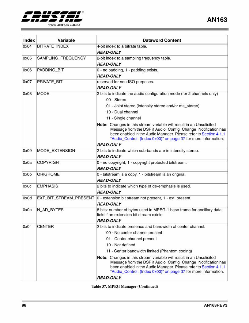
AN163
96 AN163REV3
0x04 BITRATE_INDEX 4-bit index to a bitrate table.
READ-ONLY0x05 SAMPLING_FREQUENCY 2-bit index to a sampling frequency table.
READ-ONLY0x06 PADDING_BIT 0 - no padding, 1 - padding exists.
READ-ONLY0x07 PRIVATE_BIT reserved for non-ISO purposes.
READ-ONLY0x08 MODE 2 bits to indicate the audio configuration mode (for 2 channels only)
00 - Stereo
01 - Joint stereo (intensity stereo and/or ms_stereo)
10 - Dual channel
11 - Single channel
Note: Changes in this stream variable will result in an Unsolicited Message from the DSP if Audio_Config_Change_Notification has been enabled in the Audio Manager. Please refer to Section 4.1.1 “Audio_Control: (Index 0x00)” on page 37 for more information.
READ-ONLY0x09 MODE_EXTENSION 2 bits to indicate which sub-bands are in intensity stereo.
READ-ONLY0x0a COPYRIGHT 0 - no copyright, 1 - copyright protected bitstream.
READ-ONLY0x0b ORIGHOME 0 - bitstream is a copy, 1 - bitstream is an original.
READ-ONLY0x0c EMPHASIS 2 bits to indicate which type of de-emphasis is used.
READ-ONLY0x0d EXT_BIT_STREAM_PRESENT 0 - extension bit stream not present, 1 - ext. present.
READ-ONLY0x0e N_AD_BYTES 8 bits: number of bytes used in MPEG-1 base frame for ancillary data
field if an extension bit stream exists.
READ-ONLY0x0f CENTER 2 bits to indicate presence and bandwidth of center channel.
00 - No center channel present
01 - Center channel present
10 - Not defined
11 - Center bandwidth limited (Phantom coding)
Note: Changes in this stream variable will result in an Unsolicited Message from the DSP if Audio_Config_Change_Notification has been enabled in the Audio Manager. Please refer to Section 4.1.1 “Audio_Control: (Index 0x00)” on page 37 for more information.
READ-ONLY
Index Variable Dataword Content
Table 37. MPEG Manager (Continued)
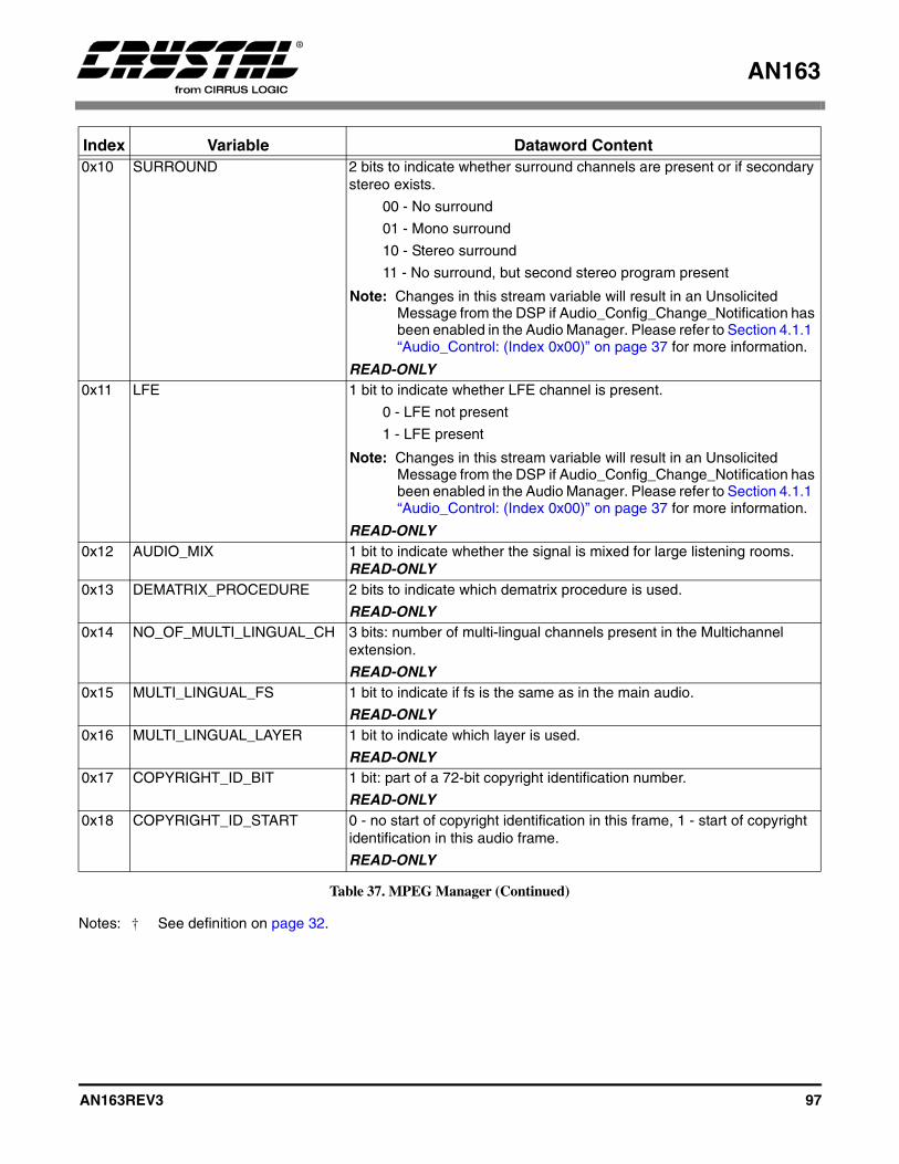
AN163
AN163REV3 97
Notes: † See definition on page 32.
0x10 SURROUND 2 bits to indicate whether surround channels are present or if secondary stereo exists.
00 - No surround
01 - Mono surround
10 - Stereo surround
11 - No surround, but second stereo program present
Note: Changes in this stream variable will result in an Unsolicited Message from the DSP if Audio_Config_Change_Notification has been enabled in the Audio Manager. Please refer to Section 4.1.1 “Audio_Control: (Index 0x00)” on page 37 for more information.
READ-ONLY0x11 LFE 1 bit to indicate whether LFE channel is present.
0 - LFE not present
1 - LFE present
Note: Changes in this stream variable will result in an Unsolicited Message from the DSP if Audio_Config_Change_Notification has been enabled in the Audio Manager. Please refer to Section 4.1.1 “Audio_Control: (Index 0x00)” on page 37 for more information.
READ-ONLY0x12 AUDIO_MIX 1 bit to indicate whether the signal is mixed for large listening rooms.
READ-ONLY0x13 DEMATRIX_PROCEDURE 2 bits to indicate which dematrix procedure is used.
READ-ONLY0x14 NO_OF_MULTI_LINGUAL_CH 3 bits: number of multi-lingual channels present in the Multichannel
extension.
READ-ONLY0x15 MULTI_LINGUAL_FS 1 bit to indicate if fs is the same as in the main audio.
READ-ONLY0x16 MULTI_LINGUAL_LAYER 1 bit to indicate which layer is used.
READ-ONLY0x17 COPYRIGHT_ID_BIT 1 bit: part of a 72-bit copyright identification number.
READ-ONLY0x18 COPYRIGHT_ID_START 0 - no start of copyright identification in this frame, 1 - start of copyright
identification in this audio frame.
READ-ONLY
Index Variable Dataword Content
Table 37. MPEG Manager (Continued)

AN163
98 AN163REV3
8.1.1 MPEG_CONTROL
Bits 7:4: OUTPUT_MODE
These bits set up the output speaker downmixconfiguration. When configuring the OUTPUT_MODE, first the individual volumes of eachundesired channel should be set to 0. Next, thedesired output mode should be specified. Thisshould be done before kickstart of the application.For example, if output mode 3/0 (L, C, R) ischosen, Ls and Rs volume must explicitly be set to0 in the Audio Manager module to guarantee nooutput on those channels.
0 = 2/0 Lt, Rt Surround Encoded.1 = 1/0 C.2 = 2/0 L, R.3 = 3/0 L, C, R.4 = 2/1 L, R, S (Ls = Rs = S - 3dB).5 = 3/1 L, C, R, S (Ls = Rs = S - 3dB).6 = 2/2 L, R, Ls, Rs.7 = 3/2 L, C, R, Ls, Rs.
8.1.2 Downmix Equation for Lt, Rt
The following equation is used to produce a Lt, RtSurround Encoded downmix.
Lt = (((1/3.1)L) + ((0.7/3.1)C) - ((0.7/3.1)Ls) -((0.7/3.1)Rs)
Rt = (((1/3.1)L) + ((0.7/3.1)C) + ((0.7/3.1)Ls) +((0.7/3.1)Rs)
8.1.3 MPEG Stream Information
Table 37 on page 95 lists a complete set of READ-ONLY variables that are reported to the host by theMPEG Decoder module. These can be read usingthe appropriate Read Request, and Read Responsesessions.
For example, to read the MODE value, host shouldissue the 3-byte Read Request 0x0D0008 and thenread the 6-byte Read Response 0x8D0008,0x00000h, where the dataword (latter 3 bytes)indicates the reported value of MODE. Please referto the MPEG Specification (ISO/IEC 11172-3 andISO/IEC 13818-3) for more information on thesestream variables.
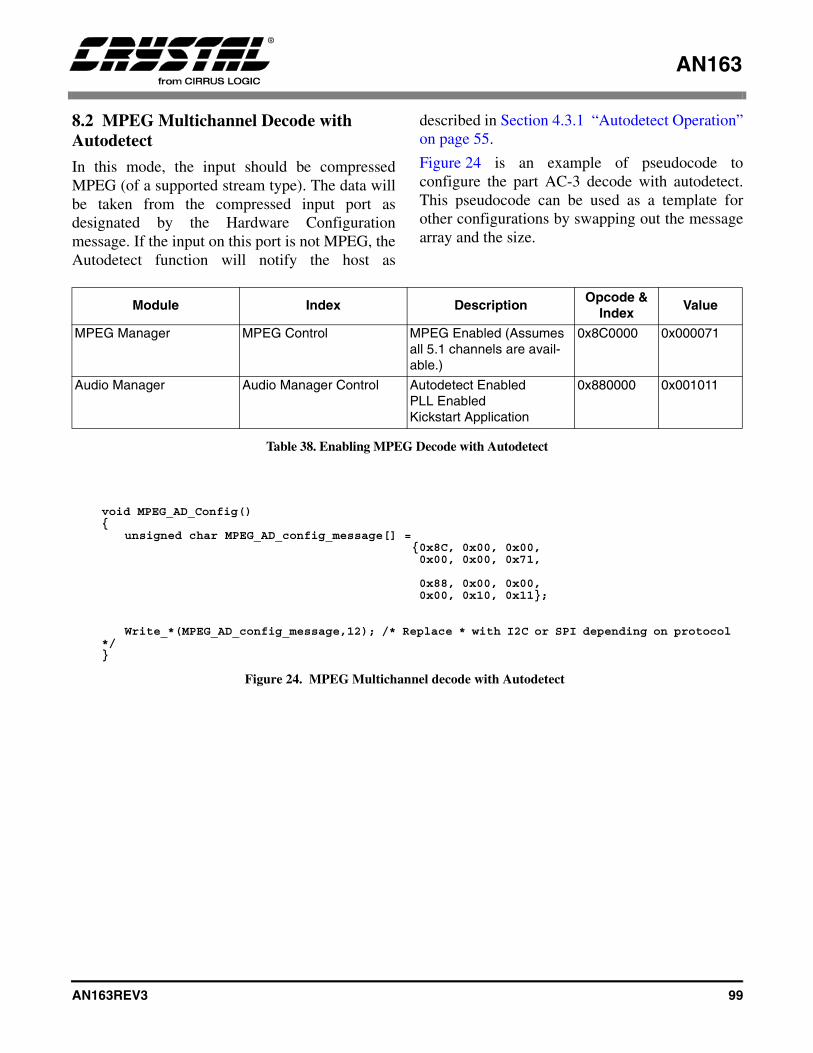
AN163
AN163REV3 99
8.2 MPEG Multichannel Decode with Autodetect
In this mode, the input should be compressedMPEG (of a supported stream type). The data willbe taken from the compressed input port asdesignated by the Hardware Configurationmessage. If the input on this port is not MPEG, theAutodetect function will notify the host as
described in Section 4.3.1 “Autodetect Operation”on page 55.
Figure 24 is an example of pseudocode toconfigure the part AC-3 decode with autodetect.This pseudocode can be used as a template forother configurations by swapping out the messagearray and the size.
Module Index DescriptionOpcode &
IndexValue
MPEG Manager MPEG Control MPEG Enabled (Assumes all 5.1 channels are avail-able.)
0x8C0000 0x000071
Audio Manager Audio Manager Control Autodetect Enabled PLL EnabledKickstart Application
0x880000 0x001011
Table 38. Enabling MPEG Decode with Autodetect
void MPEG_AD_Config(){
unsigned char MPEG_AD_config_message[] = {0x8C, 0x00, 0x00, 0x00, 0x00, 0x71,
0x88, 0x00, 0x00, 0x00, 0x10, 0x11};
Write_*(MPEG_AD_config_message,12); /* Replace * with I2C or SPI depending on protocol */}
Figure 24. MPEG Multichannel decode with Autodetect
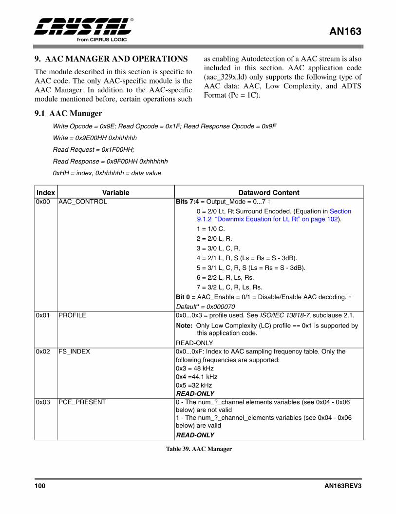
AN163
100 AN163REV3
9. AAC MANAGER AND OPERATIONS
The module described in this section is specific toAAC code. The only AAC-specific module is theAAC Manager. In addition to the AAC-specificmodule mentioned before, certain operations such
as enabling Autodetection of a AAC stream is alsoincluded in this section. AAC application code(aac_329x.ld) only supports the following type ofAAC data: AAC, Low Complexity, and ADTSFormat (Pc = 1C).
9.1 AAC Manager
Write Opcode = 0x9E; Read Opcode = 0x1F; Read Response Opcode = 0x9F
Write = 0x9E00HH 0xhhhhhh
Read Request = 0x1F00HH;
Read Response = 0x9F00HH 0xhhhhhh
0xHH = index, 0xhhhhhh = data value
Index Variable Dataword Content0x00 AAC_CONTROL Bits 7:4 = Output_Mode = 0...7 †
0 = 2/0 Lt, Rt Surround Encoded. (Equation in Section 9.1.2 “Downmix Equation for Lt, Rt” on page 102).
1 = 1/0 C.
2 = 2/0 L, R.
3 = 3/0 L, C, R.
4 = 2/1 L, R, S (Ls = Rs = S - 3dB).
5 = 3/1 L, C, R, S (Ls = Rs = S - 3dB).
6 = 2/2 L, R, Ls, Rs.
7 = 3/2 L, C, R, Ls, Rs.
Bit 0 = AAC_Enable = 0/1 = Disable/Enable AAC decoding. †
Default* = 0x0000700x01 PROFILE 0x0...0x3 = profile used. See ISO/IEC 13818-7, subclause 2.1.
Note: Only Low Complexity (LC) profile == 0x1 is supported by this application code.
READ-ONLY0x02 FS_INDEX 0x0...0xF: Index to AAC sampling frequency table. Only the
following frequencies are supported:0x3 = 48 kHz0x4 =44.1 kHz0x5 =32 kHz READ-ONLY
0x03 PCE_PRESENT 0 - The num_?_channel elements variables (see 0x04 - 0x06 below) are not valid1 - The num_?_channel_elements variables (see 0x04 - 0x06 below) are valid
READ-ONLY
Table 39. AAC Manager
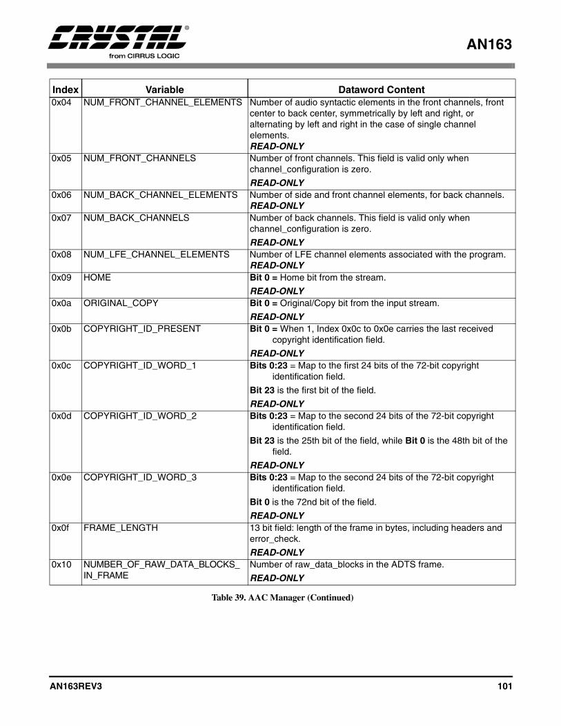
AN163
AN163REV3 101
0x04 NUM_FRONT_CHANNEL_ELEMENTS Number of audio syntactic elements in the front channels, front center to back center, symmetrically by left and right, or alternating by left and right in the case of single channel elements. READ-ONLY
0x05 NUM_FRONT_CHANNELS Number of front channels. This field is valid only when channel_configuration is zero.
READ-ONLY0x06 NUM_BACK_CHANNEL_ELEMENTS Number of side and front channel elements, for back channels.
READ-ONLY0x07 NUM_BACK_CHANNELS Number of back channels. This field is valid only when
channel_configuration is zero.
READ-ONLY0x08 NUM_LFE_CHANNEL_ELEMENTS Number of LFE channel elements associated with the program.
READ-ONLY0x09 HOME Bit 0 = Home bit from the stream.
READ-ONLY0x0a ORIGINAL_COPY Bit 0 = Original/Copy bit from the input stream.
READ-ONLY0x0b COPYRIGHT_ID_PRESENT Bit 0 = When 1, Index 0x0c to 0x0e carries the last received
copyright identification field.
READ-ONLY0x0c COPYRIGHT_ID_WORD_1 Bits 0:23 = Map to the first 24 bits of the 72-bit copyright
identification field.
Bit 23 is the first bit of the field.
READ-ONLY0x0d COPYRIGHT_ID_WORD_2 Bits 0:23 = Map to the second 24 bits of the 72-bit copyright
identification field.
Bit 23 is the 25th bit of the field, while Bit 0 is the 48th bit of the field.
READ-ONLY0x0e COPYRIGHT_ID_WORD_3 Bits 0:23 = Map to the second 24 bits of the 72-bit copyright
identification field.
Bit 0 is the 72nd bit of the field.
READ-ONLY0x0f FRAME_LENGTH 13 bit field: length of the frame in bytes, including headers and
error_check.
READ-ONLY0x10 NUMBER_OF_RAW_DATA_BLOCKS_
IN_FRAMENumber of raw_data_blocks in the ADTS frame.
READ-ONLY
Index Variable Dataword Content
Table 39. AAC Manager (Continued)

AN163
102 AN163REV3
Notes: † See definition on page 32.
“Default” vs. “Default*” See definition page 32.
9.1.1 AAC_CONTROL
Bits 7:4: OUTPUT_MODE
These bits set up the output speaker downmixconfiguration. When configuring the OUTPUT_MODE, first set the individual volumes of eachundesired channel to 0. Next, the desired outputmode should be specified. This should be donebefore kickstart of the application. For example, ifoutput mode 3/0 (L, C, R) is chosen, Ls and Rsvolume must explicitly be set to 0 in the AudioManager module to guarantee no output on thosechannels.
0 = 2/0 Lt, Rt Surround Encoded.1 = 1/0 C.2 = 2/0 L, R.3 = 3/0 L, C, R.4 = 2/1 L, R, S (Ls = Rs = S - 3dB).5 = 3/1 L, C, R, S (Ls = Rs = S - 3dB).6 = 2/2 L, R, Ls, Rs.7 = 3/2 L, C, R, Ls, Rs.
9.1.2 Downmix Equation for Lt, Rt
The following equation is used to produce a Lt, RtSurround Encoded downmix.
Lt = (((1/3.1)L) + ((0.7/3.1)C) - ((0.7/3.1)Ls) -((0.7/3.1)Rs)
Rt = (((1/3.1)L) + ((0.7/3.1)C) + ((0.7/3.1)Ls) +((0.7/3.1)Rs)
9.1.3 AAC Stream Information
Table 39 lists a complete set of READ-ONLYvariables that are reported to the host by the AACDecoder module. These can be read using theappropriate Read Request, Read Responsesessions.For example, to read the PROFILE value, hostshould issue the 3-byte Read Request 0x1f0001and then read the 6-byte Read Response 0x9f0001,0x00001h, where the dataword (latter 3 bytes)indicates the reported value of PROFILE. Pleaserefer to the MPEG-2 AAC Specification (ISO/IEC13818-7) for more information on these streamvariables.
0x11 CHANNEL_CONFIGURATION 0x0...0x7 = channel configuration used. If channel_configuration is greater than 0, the channel configuration is given by the default bitstream index number in Table 41, Implicit Speaker Mapping. If channel_configuration equals 0, the channel configuration is not specified in the header and must be given by a program_config_element following as first bitstream element in the first raw_data_block after the header, or by the implicit configuration (See ISO/IEC 13818-7, subclause 3.5) or must be known in the application.
Note: Changes in this stream variable will result in an Unsolicited Message from the DSP if Audio_Config_Change_Notification has been enabled in the Audio Manager. Please refer to Section 4.1.1 “Audio_Control: (Index 0x00)” on page 37 for more information.
READ-ONLY0x12 PROTECTION_ABSENT 0 - stream is CRC protected, 1 - stream is not CRC protected.
READ-ONLY
Index Variable Dataword Content
Table 39. AAC Manager (Continued)
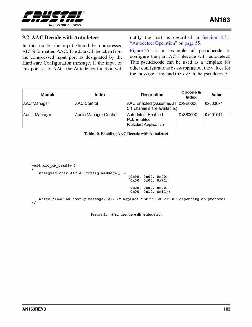
AN163
AN163REV3 103
9.2 AAC Decode with Autodetect
In this mode, the input should be compressedADTS formatted AAC. The data will be taken fromthe compressed input port as designated by theHardware Configuration message. If the input onthis port is not AAC, the Autodetect function will
notify the host as described in Section 4.3.1“Autodetect Operation” on page 55.
Figure 25 is an example of pseudocode toconfigure the part AC-3 decode with autodetect.This pseudocode can be used as a template forother configurations by swapping out the values forthe message array and the size in the pseudocode.
Module Index DescriptionOpcode &
IndexValue
AAC Manager AAC Control AAC Enabled (Assumes all 5.1 channels are available.)
0x9E0000 0x000071
Audio Manager Audio Manager Control Autodetect Enabled PLL EnabledKickstart Application
0x880000 0x001011
Table 40. Enabling AAC Decode with Autodetect
void AAC_AD_Config(){
unsigned char AAC_AD_config_message[] = {0x9E, 0x00, 0x00, 0x00, 0x00, 0x71,
0x88, 0x00, 0x00, 0x00, 0x10, 0x11};
Write_*(AAC_AD_config_message,12); /* Replace * with I2C or SPI depending on protocol */}
Figure 25. AAC decode with Autodetect
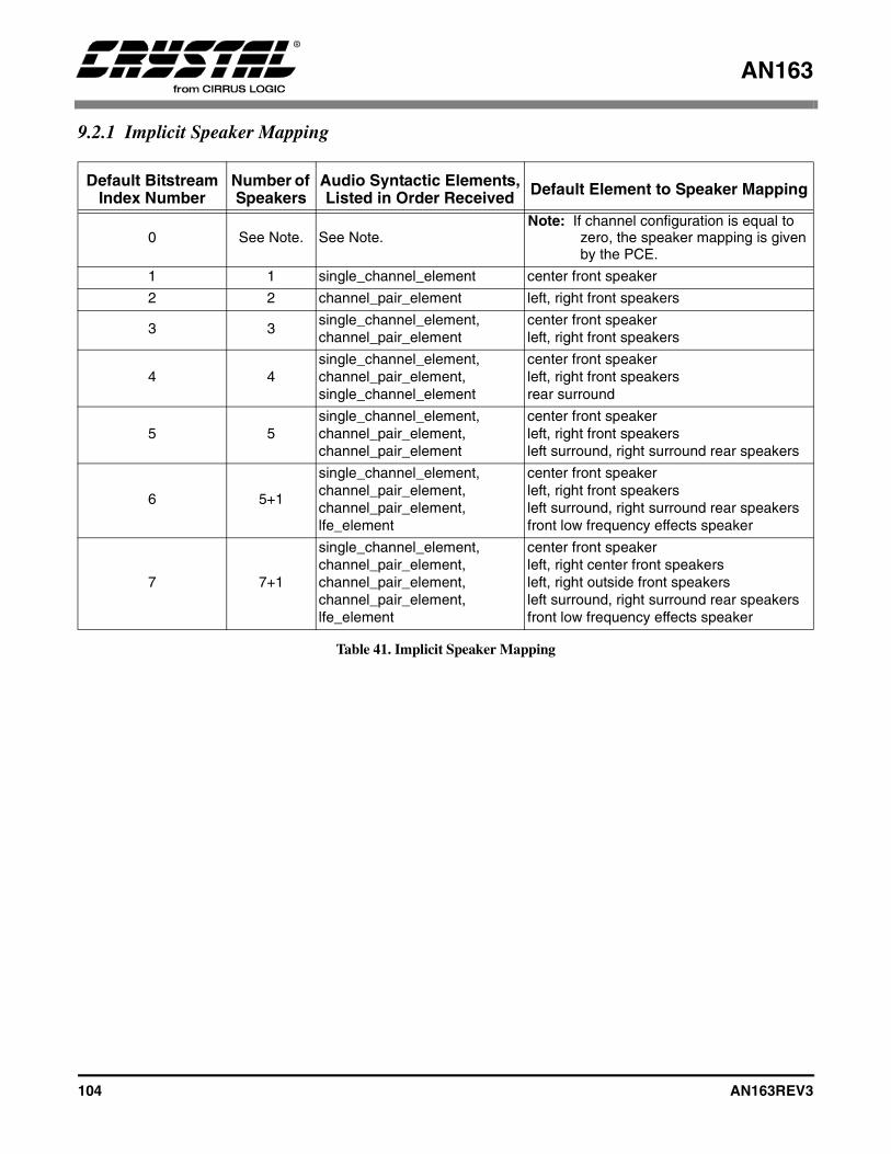
AN163
104 AN163REV3
9.2.1 Implicit Speaker Mapping
Default Bitstream Index Number
Number of Speakers
Audio Syntactic Elements,Listed in Order Received Default Element to Speaker Mapping
0 See Note. See Note.Note: If channel configuration is equal to
zero, the speaker mapping is given by the PCE.
1 1 single_channel_element center front speaker
2 2 channel_pair_element left, right front speakers
3 3single_channel_element, channel_pair_element
center front speakerleft, right front speakers
4 4single_channel_element, channel_pair_element,single_channel_element
center front speakerleft, right front speakersrear surround
5 5single_channel_element, channel_pair_element,channel_pair_element
center front speakerleft, right front speakersleft surround, right surround rear speakers
6 5+1
single_channel_element, channel_pair_element,channel_pair_element,lfe_element
center front speakerleft, right front speakersleft surround, right surround rear speakersfront low frequency effects speaker
7 7+1
single_channel_element, channel_pair_element,channel_pair_element,channel_pair_element,lfe_element
center front speakerleft, right center front speakersleft, right outside front speakersleft surround, right surround rear speakersfront low frequency effects speaker
Table 41. Implicit Speaker Mapping
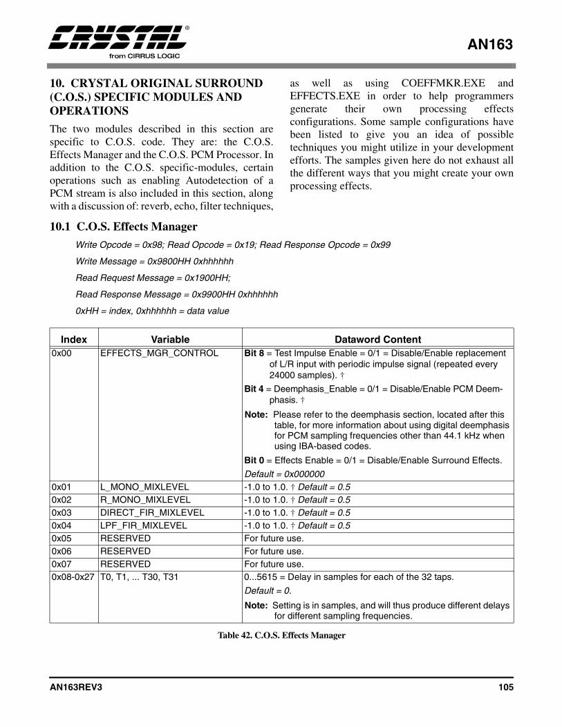
AN163
AN163REV3 105
10. CRYSTAL ORIGINAL SURROUND (C.O.S.) SPECIFIC MODULES AND OPERATIONS
The two modules described in this section arespecific to C.O.S. code. They are: the C.O.S.Effects Manager and the C.O.S. PCM Processor. Inaddition to the C.O.S. specific-modules, certainoperations such as enabling Autodetection of aPCM stream is also included in this section, alongwith a discussion of: reverb, echo, filter techniques,
as well as using COEFFMKR.EXE andEFFECTS.EXE in order to help programmersgenerate their own processing effectsconfigurations. Some sample configurations havebeen listed to give you an idea of possibletechniques you might utilize in your developmentefforts. The samples given here do not exhaust allthe different ways that you might create your ownprocessing effects.
10.1 C.O.S. Effects Manager
Write Opcode = 0x98; Read Opcode = 0x19; Read Response Opcode = 0x99
Write Message = 0x9800HH 0xhhhhhh
Read Request Message = 0x1900HH;
Read Response Message = 0x9900HH 0xhhhhhh
0xHH = index, 0xhhhhhh = data value
Index Variable Dataword Content0x00 EFFECTS_MGR_CONTROL Bit 8 = Test Impulse Enable = 0/1 = Disable/Enable replacement
of L/R input with periodic impulse signal (repeated every 24000 samples). †
Bit 4 = Deemphasis_Enable = 0/1 = Disable/Enable PCM Deem-phasis. †
Note: Please refer to the deemphasis section, located after this table, for more information about using digital deemphasis for PCM sampling frequencies other than 44.1 kHz when using IBA-based codes.
Bit 0 = Effects Enable = 0/1 = Disable/Enable Surround Effects.
Default = 0x0000000x01 L_MONO_MIXLEVEL -1.0 to 1.0. † Default = 0.50x02 R_MONO_MIXLEVEL -1.0 to 1.0. † Default = 0.50x03 DIRECT_FIR_MIXLEVEL -1.0 to 1.0. † Default = 0.50x04 LPF_FIR_MIXLEVEL -1.0 to 1.0. † Default = 0.50x05 RESERVED For future use.0x06 RESERVED For future use.0x07 RESERVED For future use.0x08-0x27 T0, T1, ... T30, T31 0...5615 = Delay in samples for each of the 32 taps.
Default = 0.
Note: Setting is in samples, and will thus produce different delays for different sampling frequencies.
Table 42. C.O.S. Effects Manager

AN163
106 AN163REV3
0x28-0x47 C0, C1,... C31 -1.0 to 1.0 = Coefficients for each of the 32 taps.
Default = 0.00x48 DIRECT_REVERB_MIXLEVEL -1.0 to 1.0. † Default = 0.8750x49 FIR_REVERB_MIXLEVEL -1.0 to 1.0. † Default = 0.1250x4a REVERB_TIME (COMB_G) 0.0 to 1.0 = Reverberation time: unitless constant (minimum 0.0 to
maximum 1.0). Default = 0.50x4b REVERB_LIVENESS (COMB_H) 0.0 to 1.0 = High-frequency attenuation in reverberator: unitless
constant. Default = 0.2 0x4c L_L_OUT_MIXLEVEL -1.0 to 1.0. † Default = 1.00x4d R_L_OUT_MIXLEVEL -1.0 to 1.0. † Default = 0.00x4e L_C_OUT_MIXLEVEL -1.0 to 1.0. † Default = 0.50x4f R_C_OUT_MIXLEVEL -1.0 to 1.0. † Default = 0.50x50 L_R_OUT_MIXLEVEL -1.0 to 1.0. † Default = 0.00x51 R_R_OUT_MIXLEVEL -1.0 to 1.0. † Default = 1.00x52 L_LS_OUT_MIXLEVEL -1.0 to 1.0. † Default = 0.50x53 R_LS_OUT_MIXLEVEL -1.0 to 1.0. † Default = 0.50x54 L_RS_OUT_MIXLEVEL -1.0 to 1.0. † Default = 0.50x55 R_RS_OUT_MIXLEVEL -1.0 to 1.0. † Default = 0.50x56 L_LFE_OUT_MIXLEVEL -1.0 to 1.0. † Default = 0.50x57 R_LFE_OUT_MIXLEVEL -1.0 to 1.0. † Default = 0.50x58 FIR_L_OUT_MIXLEVEL -1.0 to 1.0. † Default = 0.00x59 REVERB_L_OUT_MIXLEVEL -1.0 to 1.0. † Default = 0.00x5a FIR_C_OUT_MIXLEVEL -1.0 to 1.0. † Default = 0.00x5b REVERB_C_OUT_MIXLEVEL -1.0 to 1.0. † Default = 0.00x5c FIR_R_OUT_MIXLEVEL -1.0 to 1.0. † Default = 0.00x5d REVERB_R_OUT_MIXLEVEL -1.0 to 1.0. † Default = 0.00x5e FIR_LS_OUT_MIXLEVEL -1.0 to 1.0. † Default = 0.00x5f REVERB_LS_OUT_MIXLEVEL -1.0 to 1.0. † Default = 0.00x60 FIR_RS_OUT_MIXLEVEL -1.0 to 1.0. † Default = 0.00x61 REVERB_RS_OUT_MIXLEVEL -1.0 to 1.0. † Default = 0.0ADVANCED SETTINGS0x62 COMB_0_DELAY_SIZE 1...1103 samples. Default=8870x63 COMB_1_DELAY_SIZE 1...1213 samples. Default=9470x64 COMB_2_DELAY_SIZE 1...1321 samples. Default=10690x65 COMB_3_DELAY_SIZE 1...1433 samples. Default=12970x66 COMB_4_DELAY_SIZE 1...1543 samples. Default=14390x67 COMB_5_DELAY_SIZE 1...1657 samples. Default=15710x68 COMB_0_G1 0.0 to 1.0. Default=0.460x69 COMB_1_G1 0.0 to 1.0. Default=0.480x6a COMB_2_G1 0.0 to 1.0. Default=0.500x6b COMB_3_G1 0.0 to 1.0. Default=0.520x6c COMB_4_G1 0.0 to 1.0. Default=0.530x6d COMB_5_G1 0.0 to 1.0. Default=0.55
Index Variable Dataword Content
Table 42. C.O.S. Effects Manager (Continued)

AN163
AN163REV3 107
Notes: † See definition on page 32.
10.1.1 EFFECTS_MGR_CONTROL
Bit 8: Test Impulse Enable
Disable/Enable replaces L/R input with periodicimpulse signal (every 24K samples). In this mode,disabling of autodetection causes pulse generationto be independent of the input. If autodetect is leftenabled, a pulse will only be generated if PCM ispresented at the active PCM input.
1 - Enables Test Impulse0 - Disables Test Impulse
Bit 4: Deemphasis_Enable
Disable/Enable PCM Deemphasis. The filter usedis identical to CS4334 (50/15 uS).
1 - Enables Deemphasis0 - Disables Deemphasis
For systems that plan on using a “Non-IBA-Based”PCM Processing application code such aseff_32x6.ld and want to support digital deemphasisfor the sampling frequencies of 32 kHz and48 kHz, as well as 44.1 kHz, PCM, the host onlyneeds to inform the DSP the setting for the currentPCM sampling frequency, which comes via theAudio Manager (0x14) before kickstart.Note: For systems that plan on using an “IBA-Based”
PCM Processing application code such as effi32xx.ld and want to support digital deemphasis for the sampling frequencies of 32 kHz and 48 kHz, as well as 44.1 kHz, PCM, the host must, in addition to communicating the
current PCM sampling frequency setting via the Audio Manager (0x14), also download the following commands before kickstart:
For 32 kHz support:
848fffbb82fa848fe842aef3848fe9f8d406
For 44.1 kHz support:
848ffeaeacda848fe63b6543848fe7f34797
For 48 kHz support:
848ffdab9ed7848fe439be36848fe5f1e0a1
For 64 kHz support:
848fffa25a7b848fe834f310848fe9ed676b
0x6e COMB_0_MIXLEVEL 0.0 to 1.0. Default=0.90x6f COMB_1_MIXLEVEL 0.0 to 1.0. Default=0.90x70 COMB_2_MIXLEVEL 0.0 to 1.0. Default=0.90x71 Comb_3_Mixlevel 0.0 to 1.0. Default=0.90x72 Comb_4_Mixlevel 0.0 to 1.0. Default=0.90x73 Comb_5_Mixlevel 0.0 to 1.0. Default=0.90x74 Allpass_g1 0.0 to 1.0. Default=0.70x75 Allpass_g2 0.0 to 1.0. Default=0.51
Index Variable Dataword Content
Table 42. C.O.S. Effects Manager (Continued)
AN163
108 AN163REV3
For 88.2 kHz support:
848ffe99f80b848fe630eb8a848fe7e90c82
For 96 kHz support:
848ffd981257848fe4300d08848fe5e8054f
Digital deemphasis support does not exist forsampling frequencies other than 96 kHz, 88.2 kHz,64 kHz, 48 kHz, 44.1 kHz, or 32 kHz, regardless ofwhat code is being downloaded.
Bit 0: Effects Enable
Disable/Enable Surround Effects.
1 - Enables Effects0 - Disables Effects
Note: Surround Effects parameters (listed without the † symbol) are sampled by the CS4932X only once just after kickstart (after a download/Soft Reset or Application Restart). These parameters cannot be varied at run-time. Therefore, to change modes, one has to issue a Soft Reset or Application Restart, reconfigure hardware settings, issue the new Effects messages and then kickstart.
10.1.2 Basic Crystal Surround Effects Explanation
Crystal Original Surround Effects is based onpublic-domain research on acoustic reverberation.For a more detailed discussion of the properties ofthe Cirrus Logic implementation, see “About ThisReverberation Business”, James A. Moorer,Computer Music Journal 3(2): 13-28, 1979.
Figure 26 is an illustration of basic reverb theory.In this figure, E-R should be interpreted as EarlyReflections, while A-R should be interpreted as
After Reflections. Figure 27 illustrates the variousmodules of the Crystal Original Surround Effectsand the corresponding control parameters availableto the user. This forms the Surround EffectsProcessor whose outputs (square nodes with boldlegend) are available to the Output Channel Mixer.The Output Channel Mixer also receives the LRstereo pair input.
If Deemphasis is enabled, the LR stereo input isfirst de-emphasized (50/15 uS). This stage is notshown in Figure 27 and is required only if the inputLR PCM input has been pre-emphasized at thesource.
The next stage allows for Equalization of the inputLR stereo pair. When EQ is enabled, stereo PCMinput to the Effects Module (after de-emphasis ifenabled) is first attenuated by thePre_EQ_Attenuation scale factor (specified inusual 1.23 format), and then processed by thecascade of three EQ biquads specified by the{EQ0...2: b2, b1, b0, a2, a1} coefficients. Theoutput of the last EQ biquad is then scaled by thePost_EQ_Gain scale factor (specified in 6.18format to allow for up to 30 dB of gain, i.e., scalefactor of 32). The EQ-ed stereo pair output thenforms the LR input for all further effectsprocessing.
The Equalization module affects the signal at theinput, while Tone Control (refer to Section 4.5“Generalized Tone Control Manager for DolbyDigital, DTS, MPEG Multichannel and C.O.S.” onpage 63) is designed to only boost the bass or treblejust before the Bass Manager.
The mono input for the surround processing isderived by mixing the input LR stereo pair withuser parameters L_Mono_Mixlevel andR_Mono_Mixlevel. No internal protection orchecking is applied to prevent overflow. This isalso true for all other summing stages in theapplication. Therefore, the user settings shouldensure that the sum of the magnitudes of summingmix levels does not exceed unity.

AN163
AN163REV3 109
In addition, an impulse generator (not shown inFigure 27) is also provided for testing purposes. Inthis mode, the input L/R stereo pair is zeroed out,and a unit amplitude impulse is inserted in bothinput channels every 24000 samples (half a secondat Fs = 48 KHz).
The LPF at the input of the FIR delay structure is afirst-order filter with a corner frequency of Fs/6,i.e., 8 KHz for Fs = 48 KHz and 7.35 KHz forFs = 44.1 KHz. The variable mix levels,Direct_FIR_Mixlevel and LPF_FIR_Mixlevelallow one to select the amount of high frequenciesto be passed into the FIR stage of the surroundprocessor. This can be used to vary the amount of“brightness” of the surround effect.
The Delay Buffer can hold up to 5616 sampleswhich corresponds to 117 mS at Fs = 48 KHz, and127.35 mS at Fs = 44 KHz. Thirty two user-specifiable taps T0-T31 are available from thisdelay buffer. The settings T0-T31 specify theabsolute number of samples of delay (0... 5615).The tap delays need not be in monotonic or anyspecific ordering, and can be arbitrarily sequenced.For example, T0=4000 samples, T1 = 300 samples,T31 = 0 samples are valid settings.
An FIR filter can be constructed using these delaybuffer taps with coefficients C0-C31corresponding to the taps T0-T31. This FIR filtercan be used to model the Early Reflections of aparticular room. The FIR output is available to theOutput Channel Mixer directly. Tap 31 is availableas an input to the reverberator for further surroundeffects processing.
The mono input to the Reverberator Module isderived by mixing the output of Tap 31 of the delay
buffer and the FIR output using user-specifiedparameters, Direct_Reverb_Mixlevel andFIR_Reverb_Mixlevel respectively. Note that Tap31 defaults to a delay of 0, i.e., the direct output ofVariable LPF structure. Tap 31 can be adjusted toalign the impulse response of the ReverberatorModule (After Reflections) with the end of theEarly Reflections produced by the FIR filter.
The Reverberator Module accepts user settings forReverb_Time and Reverb_Liveness, which are bothunitless constants. A larger value of Reverb_Timeincreases the duration of the reverberation effect,i.e., the period of sustained echo. A larger value ofReverb_Liveness decreases the high frequencycontent (increased high-frequency attenuation) inthe reverberation. The Reverberator Moduleproduces 5 outputs to the Output Channel Mixer,one for each output full-bandwidth channel. Amore detailed treatment of the advanced settingspossible in the reverberator, as well as informationon creating custom effects modes is presented inSection 10.2.2. Figure 28 illustrates the OutputChannel Mixer Note: “Mix level” abbreviated as “Mlv.’” due to lack of
space.
Each of the five full-bandwidth output channels (L,C, R, Ls, and Rs) is derived as a user-specifiablemix of the input L/R stereo pair, the FIR output,and the corresponding output channel of theReverberator Module. The Low Frequency Effects(LFE) channel output carries no surroundprocessing, and is only a user-specifiable mix ofthe input L/R stereo pair.
Disabling the surround effects can be used forsimple PCM pass through.
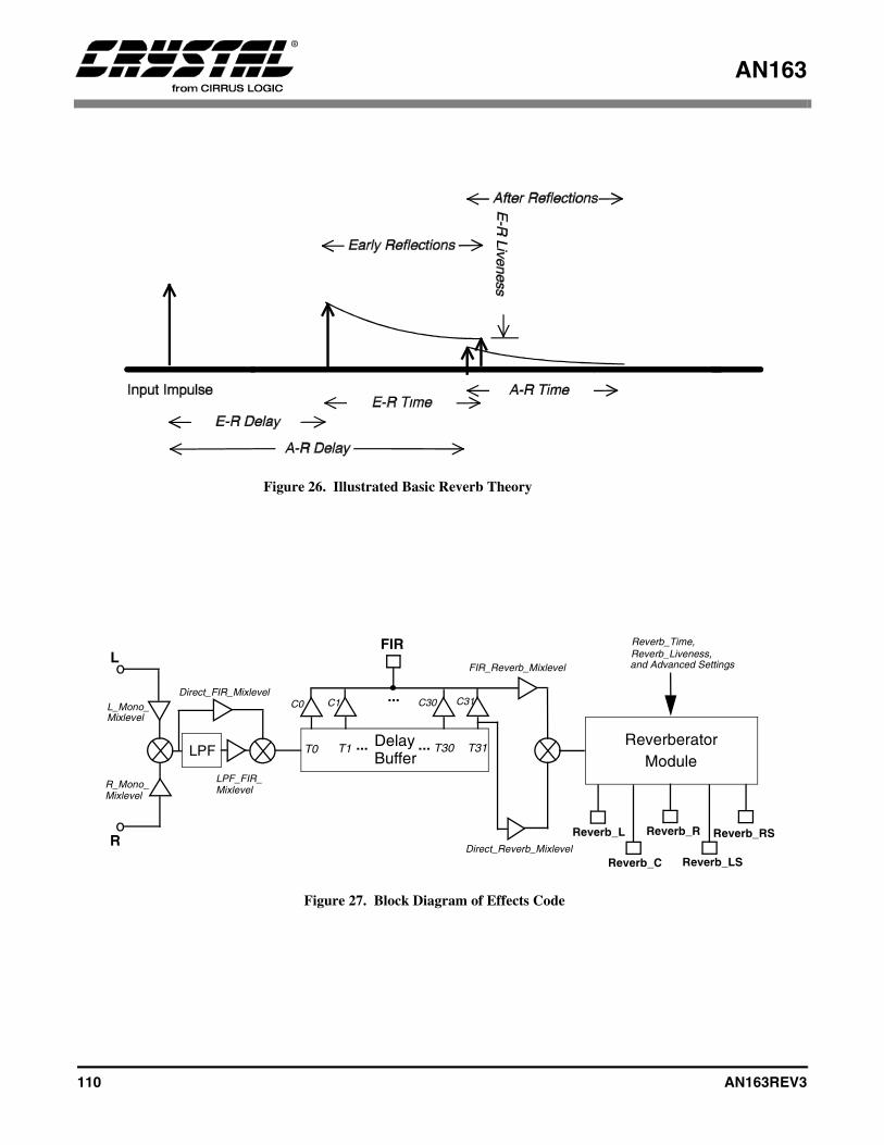
AN163
110 AN163REV3
Figure 26. Illustrated Basic Reverb Theory
Delay
L
Ro
o
FIR
L_Mono_
R_Mono_
C0
T0 T1 T30 T31Buffer
... ...
C1 C30 C31...
ReverberatorModule
FIR_Reverb_MixlevelReverb_Liveness,and Advanced Settings
Reverb_Time,
Direct_Reverb_Mixlevel
Reverb_L
Reverb_C
Reverb_R
Reverb_LS
Reverb_RS
Mixlevel
Mixlevel
LPF
Direct_FIR_Mixlevel
LPF_FIR_Mixlevel
Figure 27. Block Diagram of Effects Code

AN163
AN163REV3 111
L
R
o
FIR
L_Rs_Out_Mlv.
o
Reverb_Rs
Rs_OutR_Rs_Out_Mlv.
FIR_Rs_Out_Mlv.
Reverb_Rs_Out_Mlv.
L
R
o
FIR
L_L_Out_Mlv.
o
Reverb_L
L_OutR_L_Out_Mlv.
FIR_L_Out_Mlv.
Reverb_L_Out_Mlv.
L
Ro
L_LFE_Out_Mlv.
o LFE_Out
R_LFE_Out_Mlv.
L
R
o
FIR
L_C_Out_Mlv.
o
Reverb_C
C_OutR_C_Out_Mlv.
FIR_C_Out_Mlv.
Reverb_C_Out_Mlv.
L
R
o
FIR
L_R_Out_Mlv.
o
Reverb_R
R_OutR_R_Out_Mlv.
FIR_R_Out_Mlv.
Reverb_R_Out_Mlv.
L
R
o
FIR
L_Ls_Out_Mlv.
o
Reverb_Ls
Ls_OutR_Ls_Out_Mlv.
FIR_Ls_Out_Mlv.
Reverb_Ls_Out_Mlv.
Figure 28. Block Diagram of Effects Channel Mixer

AN163
112 AN163REV3
10.2 C.O.S. PCM Processor
Write Opcode = 0x9C; Read Opcode = 0x1D; Read Response Opcode = 0x9D
Write = 0x9C00HH 0xhhhhhh
Read Request = 0x1D00HH;
Read Response = 0x9D00HHh 0xhhhhhh
0xHH = index
0xhhhhhh = data value
Index Variable Dataword Content0x00 PCM_CONTROL Bit 4 = PCM_Input_EQ_Enable = 0/1 = Disable/Enable 3-band EQ filters
on input PCM.
Bit 0 = PCM_Divider_FIR_Enable = 0/1 = Disable/Enable FIR filter on PCM output of Ls/Rs channels.
Default = 0x0000000x01-0x10
DIV_C0, DIV_C1, DIV_C15 -1.0 to 1.0 = Coefficients for each of the 16 taps of the FIR filter.
Default* DIV_C0 = 1.0
Default* DIV_C1-15 = 0.00x11 PRE_EQ_ATTENUATION -1.0 to 1.0 = Pre-EQ attenuation scale factor to setup desired headroom
for EQ filtering. †
Default* = 1.00x12 EQ0_B2 -4.0 to 4.0 in 3.21 format = Biquad coefficient for EQ Filter 0.
Default* = 1.0 (0x200000)0x13 EQ0_B1 -4.0 to 4.0 in 3.21 format = Biquad coefficient for EQ Filter 0.
Default* = 0.00x14 EQ0_B0 -4.0 to 4.0 in 3.21 format = Biquad coefficient for EQ Filter 0.
Default* = 0.00x15 EQ0_A2 -4.0 to 4.0 in 3.21 format = Biquad coefficient for EQ Filter 0.
Default* = 0.00x16 EQ0_A1 -4.0 to 4.0 in 3.21 format = Biquad coefficient for EQ Filter 0.
Default* = 0.00x17 EQ1_B2 -4.0 to 4.0 in 3.21 format = Biquad coefficient for EQ Filter 1.
Default* = 1.0 (0x200000)0x18 EQ1_B1 -4.0 to 4.0 in 3.21 format = Biquad coefficient for EQ Filter 1.
Default* = 0.00x19 EQ1_B0 -4.0 to 4.0 in 3.21 format = Biquad coefficient for EQ Filter 1.
Default* = 0.00x1a EQ1_A2 -4.0 to 4.0 in 3.21 format = Biquad coefficient for EQ Filter 1.
Default* = 0.00x1b EQ1_A1 -4.0 to 4.0 in 3.21 format = Biquad coefficient for EQ Filter 1.
Default* = 0.0
Table 43. C.O.S. PCM Processor
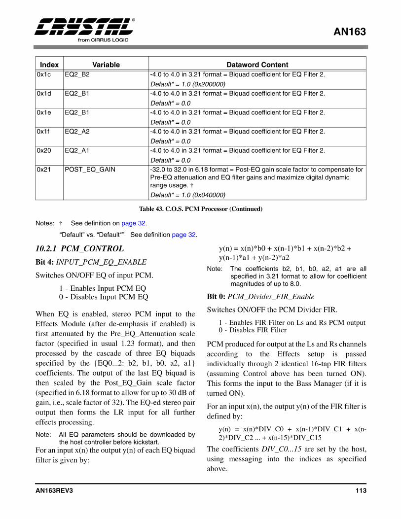
AN163
AN163REV3 113
Notes: † See definition on page 32.
“Default” vs. “Default*” See definition page 32.
10.2.1 PCM_CONTROL
Bit 4: INPUT_PCM_EQ_ENABLE
Switches ON/OFF EQ of input PCM.
1 - Enables Input PCM EQ0 - Disables Input PCM EQ
When EQ is enabled, stereo PCM input to theEffects Module (after de-emphasis if enabled) isfirst attenuated by the Pre_EQ_Attenuation scalefactor (specified in usual 1.23 format), and thenprocessed by the cascade of three EQ biquadsspecified by the {EQ0...2: b2, b1, b0, a2, a1}coefficients. The output of the last EQ biquad isthen scaled by the Post_EQ_Gain scale factor(specified in 6.18 format to allow for up to 30 dB ofgain, i.e., scale factor of 32). The EQ-ed stereo pairoutput then forms the LR input for all furthereffects processing.
Note: All EQ parameters should be downloaded bythe host controller before kickstart.
For an input x(n) the output y(n) of each EQ biquadfilter is given by:
y(n) = x(n)*b0 + x(n-1)*b1 + x(n-2)*b2 + y(n-1)*a1 + y(n-2)*a2
Note: The coefficients b2, b1, b0, a2, a1 are allspecified in 3.21 format to allow for coefficientmagnitudes of up to 8.0.
Bit 0: PCM_Divider_FIR_Enable
Switches ON/OFF the PCM Divider FIR.
1 - Enables FIR Filter on Ls and Rs PCM output0 - Disables FIR Filter
PCM produced for output at the Ls and Rs channelsaccording to the Effects setup is passedindividually through 2 identical 16-tap FIR filters(assuming Control above has been turned ON).This forms the input to the Bass Manager (if it isturned ON).
For an input x(n), the output y(n) of the FIR filter isdefined by:
y(n) = x(n)*DIV_C0 + x(n-1)*DIV_C1 + x(n-2)*DIV_C2 ... + x(n-15)*DIV_C15
The coefficients DIV_C0...15 are set by the host,using messaging into the indices as specifiedabove.
0x1c EQ2_B2 -4.0 to 4.0 in 3.21 format = Biquad coefficient for EQ Filter 2.
Default* = 1.0 (0x200000)0x1d EQ2_B1 -4.0 to 4.0 in 3.21 format = Biquad coefficient for EQ Filter 2.
Default* = 0.00x1e EQ2_B1 -4.0 to 4.0 in 3.21 format = Biquad coefficient for EQ Filter 2.
Default* = 0.00x1f EQ2_A2 -4.0 to 4.0 in 3.21 format = Biquad coefficient for EQ Filter 2.
Default* = 0.00x20 EQ2_A1 -4.0 to 4.0 in 3.21 format = Biquad coefficient for EQ Filter 2.
Default* = 0.00x21 POST_EQ_GAIN -32.0 to 32.0 in 6.18 format = Post-EQ gain scale factor to compensate for
Pre-EQ attenuation and EQ filter gains and maximize digital dynamic range usage. †
Default* = 1.0 (0x040000)
Index Variable Dataword Content
Table 43. C.O.S. PCM Processor (Continued)
AN163
114 AN163REV3
10.2.2 Creating Custom Effects Using Advanced Settings
This section describes the Reverberator module.Figure 29 shows a block diagram of the internalimplementation of the reverberator module.
10.2.2.1 FIR Section: Early Reflections
The FIR filter shown in Figure 29 allows one tosimulate Early Reflections and model specificroom acoustics. Given a particular set of FIR filtertaps and coefficients (generated by actual roommeasurements and/or listening experiments),various sizes of rooms can be derived by simplyscaling the tap locations (not the coefficients).Other effects can be generated by moving back allof the taps to simulate a delay in the EarlyReflections. The amplitude of the coefficients canbe scaled according to the desired liveness of theroom. If the amplitude of the coefficients does notfall off quickly, then the room will appear more live(that is, later Early Reflections will be more presentin the output).
10.2.2.2 Comb Filter Section: After-reflections
Following the Early Reflections simulated by theFIR, comb filters are used to simulate the denseAfter Reflections that are caused by walls andtransitions thereof. Each comb filter reproduces theinput signal with periodic delay and decayingamplitude. Furthermore, a first order low pass filteris included in the feedback to simulate theabsorption of high frequencies by air. Thisproduces a more realistic or ‘live’ reverberationthat sounds less ‘tinny’.
Six combs are used in parallel to produce denseAfter Reflections. The delay sizes of the combs arechosen to be mutually prime to avoid coincidingechoes from different combs. It is recommended toset the delays of each comb as roughly 10% morethan the previous one. However comb sizes witharrangements that are too regular can cause a buzzyoutput.
The coefficients G1 and G2 for a comb shouldsatisfy G1+G2<1 for stability. The scheme forcontrolling the parameters in the CS493XXguarantees this. The individual default Comb_[0-5]_g1 can be changed. G1 and G2 are derived foreach comb automatically as shown in Figure 29using Comb_g and Comb_h as well as Comb_[0-5]_g1.
Increasing (or decreasing) the Reverb_Time(Comb_g) parameter increases (or decreases) thelength of the after-reflection tail since it scales up(or down) the feedback in the comb.
Increasing (or decreasing) the Reverb_Liveness(Comb_h) parameter increases (or decreases) theamount of LPF action in the feedback, thus makingthe sound more (or less) dampened. This isparticularly important to reduce the clicking effectwhen reverberating short impulsive sounds.
While experimenting, it may be found that aparticular comb’s reverberation (among the six) isaudibly predominant (buzzing sound). Toovercome this, the corresponding Comb_[0-5]_Mixlevel for that comb can be reduced toequalize its audible effect with the other combs.These can also be used to overcome overflowissues that may happen with different choices ofg1, g, and h.
10.2.2.3 All-Pass Filter Section: More After-reflections and Decorrelation
All-Pass filters are another means of simulatingAfter Reflections. In addition, they are used here todecorrelate the different channel outputs from eachother.
In the CS493XX implementation, the delay sizesare fixed (as specified in Figure 29) and all of theAll-Pass filters share the same values of G1 andG2. For stability, G2 < = 1 - G1 ^ 2 should beguaranteed by the host if these values are changed.
Increasing (or decreasing) the G2 parameterincreases (or decreases) the reverberation time(length of after-reflection tail) by scaling up (ordown) the reverberated contribution to the output.

AN163
AN163REV3 115
o
Reverb_L
Reverb_C
Reverb_R
Reverb_LS
Reverb_RS
FIR + Direct Mono Mix
Comb_0
Comb_1
Comb_2
Comb_3
Comb_4
Comb_5
Comb_[0-5]_Mixlevel
Reverb_Time (Comb_g), Reverb_Liveness (Comb_h), Comb_[0-5]_g1,Comb_[0-5]_Delay_Size
AP_Main
AP_RAP_L
AP_C AP_Ls
AP_Rs
AllPass_g1, AllPass_g2
z^(-Delay_Size)
z^-(1)
x(n)o
G2
G1
y(n)o
+
+
+
+
Comb Filter Module
G1 = Comb_h * Comb_g1G2 = Comb_g * (1 - G1)Delay_Size = Comb_Delay_Size
z^(-Delay_Size)x(n)
o
G1
G2
y(n)o
+
+
-
+
AllPass (AP) Filter Module
G1 = AllPass_g1; G2 = AllPass_g2Delay_Size = 293, 127, 139, 151, 163, 173
+
G1
for Main, L, C, R, Ls, Rs, respectively.
AllPass Filters
Figure 29. Block Diagram of Effects Reverberator Module
AN163
116 AN163REV3
10.2.3 Crystal Original Surround Effects Modes
This section describes some standard effects modesthat are provided along with the applicationmicrocode. Each mode is setup by issuing anApplication Restart message or Soft Reset(assuming the microcode is already downloaded),sending any required hardware configurationmessages, and finally sending the correspondingconfiguration message set for each surround effectsmode. For each mode described, the configurationsettings are given. Although one can assume thedefault values as listed in Table 42, the providedmessage sets explicitly set up all the parameters inmost cases. Thus they can serve as templates forany future custom development by the user.Note: Surround Effects parameters are sampled by
the CS4932X only once just after kickstart (aftera download/soft reset or Application Restart).These parameters cannot be varied at run-time.Therefore, to change modes, one has to issuea Soft Reset or Application Restart, reconfigurehardware settings, issue the new Effectsmessages and then kickstart.
The included effects modes were all derived fromone of two basic filter structures:
A basic 7-point FIR filter with taps at: T0-6 = 0,955, 1699, 1867, 1987, 3355, 3821 samples. Thecorresponding coefficients are C0-6 = 0.9804, 1.0,0.802, 0.6225, 0.7049, 0.2618, and 0.2373.
A 19-point FIR filter with taps at: T0-18 = 0, 206,1032, 1080, 1286, 1296, 1430, 2198, 2328, 2746,2818, 2856, 2938, 3394, 3398, 3485, 3557, 3614,and 3826 samples. The corresponding coefficientsare C0-18 = 1.0, 0.841, 0.504, 0.491, 0.379, 0.380,0.346, 0.289, 0.272, 0.192, 0.193, 0.217, 0.181,0.180, 0.181, 0.176, 0.142, 0.167, and 0.134.
By scaling these taps and coefficients, differenteffects can be created. By decreasing (or
increasing) the coefficients, the liveness of theroom can be increased (or decreased). Scaling thetap locations will increase/decrease the length ofEarly Reflections. Delaying the taps (offsetting alltaps by the same amount of time) causes a delay inthe Early Reflections.
A brief description of each surround effect mode isprovided below. Note that the modes have beendesigned for Fs=48 KHz. When used for Fs=44.1KHz, the change is largely inaudible andacceptable in most cases. If necessary, the user mayscale the delay and reverb time parameters (if used)appropriately.
The effects can be broken into two categories,reverberative and non-reverberative. Reverberativeeffects have both late and early reflections, whilenon-reverberative effects are composed entirely ofearly reflections. The next two sections list thedifferent configuration examples sent with thecode. The examples are categorized by whether theeffect is reverberative or not. Non-reverberativeeffects are much more subtle, while reverberativeeffects are more extreme and can sometimesinterfere with the actual source material. Thenaming of each mode is very subjective and is onlyintended as a suggestion.
Section 10.3.1 “COEFMAKR.EXE andEFFECTS.EXE” on page 120 describes a programthat can create effects configuration files for theuser.
10.2.4 Non - Reverberative Effects
Non-reverberative effects provide a subtle effectthrough remapping and/or redirecting the stereoinput. In this way, the end user can fill all of thespeakers in a surround system without significantlyaltering the content of the source. Delays are usedin some modes to simulate a larger listening area.
AN163
AN163REV3 117
10.2.4.1 Passthru
This mode does not engage the Effects Managerand thus has no reverberation or Early Reflections.The default setup of Output Channel Mixer is used,i.e.,
L_Out = L
R_Out = R
C_Out = Ls_Out = Rs_Out = LFE_Out = 0.5 L + 0.5 R
10.2.4.2 Mono
This mode has no reverberation or EarlyReflections and only uses the Output ChannelMixer. The Output Channel Mixer is setup for:
L_Out = R_Out = C_Out = Ls_Out = Rs_Out =0.5 L + 0.5 R
LFE_Out = 0
10.2.4.3 Classical
This mode has no reverberation and only uses FIRand the Output Channel Mixer. The mono mix isset up as (L+R)/2 with no LPF contribution andfeeds FIR, a 5-tap filter.
The Output Channel Mixer is setup for:
L_Out = L
R_Out = R
C_Out = Ls_Out = Rs_Out = FIR
LFE_Out = 0
10.2.4.4 Panorama
This mode has no reverberation and only uses FIRand the Output Channel Mixer. The mono mix isset up as (L-R)/2 with no LPF contribution andfeeds FIR, the same 5-tap filter as in Classicalmode.
The Output Channel Mixer is setup for:
L_Out = L - 0.31623 R
R_Out = R - 0.31623 L
C_Out = 0.5 L + 0.5 R
Ls_Out = Rs_Out = FIR
LFE_Out = 0
10.2.4.5 Movie 1-4
These modes have no reverberation and only useFIR and the Output Channel Mixer. Each mode hasa different FIR delay tap/coefficient setting, but allhave the following generic setup. The mono mix isset up as (L+R)/2 with no LPF contribution andfeeds FIR, a 4 or 5-tap filter depending on themode.
The Output Channel Mixer is setup for:
L_Out = L
R_Out = R
C_Out = Ls_Out = Rs_Out = FIR
LFE_Out = 0
10.2.4.6 Music 1-4
These modes are identical to Movie1-4 modesabove, except that the Output Channel Mixer is setup for C_Out = 0.
10.2.5 Reverberative Effects
Reverberative effects combine the different filtersdiscussed in sections Section 10.1.2 “Basic CrystalSurround Effects Explanation” on page 108, and inSection 10.2.2 “Creating Custom Effects UsingAdvanced Settings” on page 114 to create a moreobvious effect. These effects can be used to fill outthe incoming source if so desired. Care should betaken as some reverberative effects can be so strongthat they can interfere with the original stereosource signal. The effects listed below start withthe subtle effects (Room) and graduate to the veryobvious (Stadium).
To simplify the use of the following configurationfiles, the following naming convention has beenused:
tErGaKiN.cfg
E - This number represents the FIR filter type usedfor Early Reflections. Type 1 is a 7-Tap, and Type2 is a 19-Tap, per the discussion in the previous
AN163
118 AN163REV3
section. The 19-Tap filter will make the EarlyReflections sound much thicker. This is usefulwhen trying to create an echo pattern that soundsthick.
G - This represents the amount of Initial Delay andEarly Reflection time. A shorter Early Reflectiontime will make the room size sound smaller, and alonger time will make the room sound larger. InitialDelay until Early Reflections will cause the roomto sound as if the source is further from the walls.
G == 1: Early Reflections last for 40 ms, and the Initial Delay until Early Reflections is 20 ms.
G == 2: Early Reflections last for 80 ms (default), and the Initial Delay until Early Reflections is 10 ms.
G == 3: Early Reflections last for 115 ms, and there is no Initial Delay until Early Reflections (0 ms).
K - This represents the amount of time for AfterReflections. The After Reflections produced byReverb Module will produce a dense tail to theeffect, and this parameter will influence the lengthof that tail.
K == 1: Reverb time is set to 0.25 ms.
K == 2: Reverb time is set to 0.5 ms(default).
K == 3: Reverb time is set to 0.8 ms.
K == 4: Reverb time is set to 0.98 ms. This will produce a reverb time that is very large.
Note: Only one example with K=4 is presented here (Stadium).
N - This represents the After Reflection (Reverb)Liveness. To absorb more of the high frequencycontent of the After Reflections (to sound lessbright), the number should be higher. To increasethe high frequency content (to sound more bright),the number should be lower.
For N == 1:Reverb Liveness (After Reflection Liveness) is set to 0.2
For N == 2:Reverb Liveness (After Reflection Liveness) is set to 0.8
To simplify the use of the filters, a description ofsome of the filters follows. Note that configurationfiles are supplied for many more variations of theparameters specified above. The suppliedconfiguration files are intended to span a range ofeffects that can be created using the coefmakr.exeprogram. To create intermediate sounding effects,one could simply interpolate the parametersspecified to the coefmakr.exe program and use thecorresponding configuration files. Section 10.3.1“COEFMAKR.EXE and EFFECTS.EXE” on page120 has more details.
For all Reverberative Modes, the followingmixlevels (default in coefmakr.exe) are used:
L_Mono_Mixlevel = 0.5
R_Mono_Mixlevel = 0.5
Direct_FIR_Mixlevel = 0.875
LPF_FIR_Mixlevel = 0.125
Reverb_Direct_Mixlevel = 1
Reverb_FIR_Mixlevel = 0
L_to_L_Out = 0.875
R_to_L_Out = 0
L_to_C_Out = 0.4375
R_to_C_Out = 0.4375
L_to_R_Out = 0
R_to_R_Out = 0.875
L_to_Ls_Out = 0.125
R_to_Ls_Out = 0.125
L_to_Rs_Out = 0.125
R_to_Rs_Out = 0.125
L_to_LFE_Out = 0.5
R_to_LFE_Out = 0.5
AN163
AN163REV3 119
FIR_to_L_Out = 0.0833
Reverb_to_L_Out = 0.0417
FIR_to_C_Out = 0.0417
Reverb_to_C_Out = 0.0213
FIR_to_R_Out = 0.0833
Reverb_to_R_Out = 0.0417
FIR_to_Ls_Out = 0.5
Reverb_to_Ls_Out = 0.25
FIR_to_Rs_Out = 0.5
Reverb_to_Rs_Out = 0.25
10.2.5.1 t1r1a1i1.cfg - Room 1
This effect mode simulates the reflections from asmall room. The room is not live, and has smallEarly and Late Reflection Times. The type 1 filteris used, providing a very mild effect.
10.2.5.2 t2r3a1i2.cfg - Room 2
This effect mode simulates the reflections from asmall room, but uses a larger FIR filter spread outover a larger time to thicken the sound of the EarlyReflections.
10.2.5.3 t1r1a2i1.cfg - Theater 1
This effect mode simulates the reflections as in amedium size theater. The Early Reflections will beshort, but very present. The Late Reflections arebright, but are present for medium amount of time.
10.2.5.4 t2r3a2i2.cfg -- Theater 2
The Early Reflections in this effect are dominantand long, allowing for a very thick sounding EarlyReflection. This effect mode has a short ReverbTime but large Reverb Liveness, making the soundless bright.
10.2.5.5 t1r1a3i1.cfg -- Hall 1
This effect has a lot of Early and Late Reflections,with a large Reverb Time, but a small ReverbLiveness. This effect will have a very large sound,
and the high frequencies will be present in the AfterReflections.
10.2.5.6 t2r3a3i2.cfg -- Hall 2
This effect, similar to Hall1, has the same amountof Early and Late Reflections. In this effect mode,the higher frequencies are less present, resulting ina less bright sound in the reflections.
10.2.5.7 t2r3a4i2.cfg -- Stadium
This effect, utilizing a maximum of Early and LateReflections, has a long decay time. The sound ishighly decorrelate, making the echoes soundmuddy. The long decay time provides for an effectof the sound bouncing off many hard walls, and avery bright tone is used. This effect is presentedmerely to demonstrate the extreme capability of theCrystal scheme, and may require modificationbefore use in a real system that you develop.
10.3 Effects Configuration Files
COEFMAKR.EXE is a program written to assistdevelopment of unique effects configurations. It isdocumented in Section 10.3.1“COEFMAKR.EXE and EFFECTS.EXE” on page120. This program can be used to createconfiguration files for the effects modes presentedin the previous sections. The configuration fileshave been omitted from this document to conservespace. The COEFMAKR.EXE program along withthe configuration files are in a zip file available atwww.cirrus.com under the CS49300 page. Theconfiguration file contains paired 3-byte wordswhich are the actual commands to be sent to theCS49300. These messages correlate with theparameters in Table 42. In addition comment linesmarked by a # symbol are included to help explainthe configuration messages. When porting themessages to code for a host microcontroller, thecomment lines should be omitted and care shouldbe taken to keep the paired 3- byte words togetherin the correct order. The configuration files alsocontain a “Kickstart” as the last command (seeSection 4.1 “Audio Manager for Dolby Digital,DTS, MP3, MPEG Multichannel, AAC and Crystal
AN163
120 AN163REV3
Original Surround” on page 33 for moreinformation).
10.3.1 COEFMAKR.EXE and EFFECTS.EXE
COEFMAKR.EXE (Coefficient Maker) is asimple, easy-to-use program for generatingconfiguration files used in conjunction with CrystalEffects code for the CS49300 series of SurroundSound DSP's. The program takes all of theconfiguration options on the command line, and allof these options can be displayed with the -?command line switch. Note that since there are 56command line options (a minimum of 1 must bespecified), to display Mix Level options, the -x?switch must be used. For all Advanced Options, the-o? switch must be used.
EFFECTS.EXE is a GUI version ofCOEFMAKR.EXE which allows the user to editeffects configuration files and try them on one ofthe CRD49300/CDB49300 application boards inreal time. The program mirrors the block diagramsshown in Figure 27, Figure 28, and Figure 29 andallows the user control over the parametersdiscussed in section.
Here is a short description of the files and theircontents:
• COEFMAKR.EXE: This file is the mainprogram for the coefficient maker.
• FIR.CFG: This file contains the templates for 2basic FIR (Early Reflection) filters, which arescaled by COEFMAKR.EXE into the FIRsection of the effects code. Additional filterscan be added to this file, or the file can bereplaced by one of the same structure.However, if a different file is used, it must bespecified in the command line (-c option). ForCOEFMAKR.EXE to run correctly, this filemust reside in the same directory.
• MAKETEST.BAT: This batch file will generateall of the default configuration files shown insection (with reverb) using COEFMAKR.EXE.
• EFFECTS.EXE: GUI version ofCOEFMAKR.EXE
More files may need to be present. Please read theREADME.TXT file in the zip file from which theprograms were extracted for more information onthese programs.

AN163
AN163REV3 121
10.3.2 Command Line Options for COEFMAKR.EXE
Basic Options Settings:
----------
Usage: coefmakr [-qfile.out -cfilter.cfg -fx -dy -tz -rw -lb -mu -v -xelevel]
-qfile.out : file.out = Config file to be generated(default=file.out)
-cfilter.cfg : filter.cfg = Filter parameter file(default=fir.cfg)
-fb : b = Sampling Rate (32, 44, 48* KHz)
-du : u = Initial Delay of Early Reflections (0*,1,...,115ms)
-te : e = FIR Filter Type (1* or 2)
-rg : g = Early Reflection Time (0,1,...,80*,... ms)
-lh : h = Liveness of Early Reflection (0,...,1*)
-mj : j = Delay Until After Reflections (0,1,...,100*,...ms)
-ak : k = After Reflection Time (0,...,0.5*,...,1)
-in : n = After Reflection Liveness (0,...,1*)
-xp : p = Mix Level(s) to Change (? for options)
-os : s = Advanced Options (? for options)
-v = Run in non-verbose mode
-x Options:
-----------
Settings for Mix level:
a = L_Mono_Mixlevel(-1..0.5*..1)
b = R_Mono_Mixlevel(-1..0.5*..1)
c = Direct_FIR_Mixlevel(-1..0.875*..1)
d = LPF_FIR_Mixlevel(-1..0.125*..1)
e = Reverb_Direct_Mixlevel(-1..0.875*..1)
f = Reverb_FIR_Mixlevel(-1..0*..1)
g = L_to_L_Out(-1..0.875*..1)
h = R_to_L_Out(-1..0*..1)
i = L_to_C_Out(-1..0.4375*..1)
j = R_to_C_Out(-1..0.4375*..1)
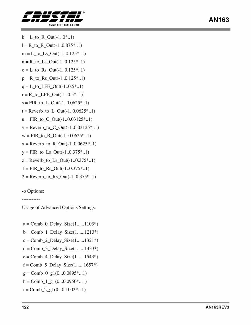
AN163
122 AN163REV3
k = L_to_R_Out(-1..0*..1)
l = R_to_R_Out(-1..0.875*..1)
m = L_to_Ls_Out(-1..0.125*..1)
n = R_to_Ls_Out(-1..0.125*..1)
o = L_to_Rs_Out(-1..0.125*..1)
p = R_to_Rs_Out(-1..0.125*..1)
q = L_to_LFE_Out(-1..0.5*..1)
r = R_to_LFE_Out(-1..0.5*..1)
s = FIR_to_L_Out(-1..0.0625*..1)
t = Reverb_to_L_Out(-1..0.0625*..1)
u = FIR_to_C_Out(-1..0.03125*..1)
v = Reverb_to_C_Out(-1..0.03125*..1)
w = FIR_to_R_Out(-1..0.0625*..1)
x = Reverb_to_R_Out(-1..0.0625*..1)
y = FIR_to_Ls_Out(-1..0.375*..1)
z = Reverb_to_Ls_Out(-1..0.375*..1)
1 = FIR_to_Rs_Out(-1..0.375*..1)
2 = Reverb_to_Rs_Out(-1..0.375*..1)
-o Options:
-----------
Usage of Advanced Options Settings:
a = Comb_0_Delay_Size(1......1103*)
b = Comb_1_Delay_Size(1......1213*)
c = Comb_2_Delay_Size(1......1321*)
d = Comb_3_Delay_Size(1......1433*)
e = Comb_4_Delay_Size(1......1543*)
f = Comb_5_Delay_Size(1......1657*)
g = Comb_0_g1(0...0.0895*...1)
h = Comb_1_g1(0...0.0950*...1)
i = Comb_2_g1(0...0.1002*...1)
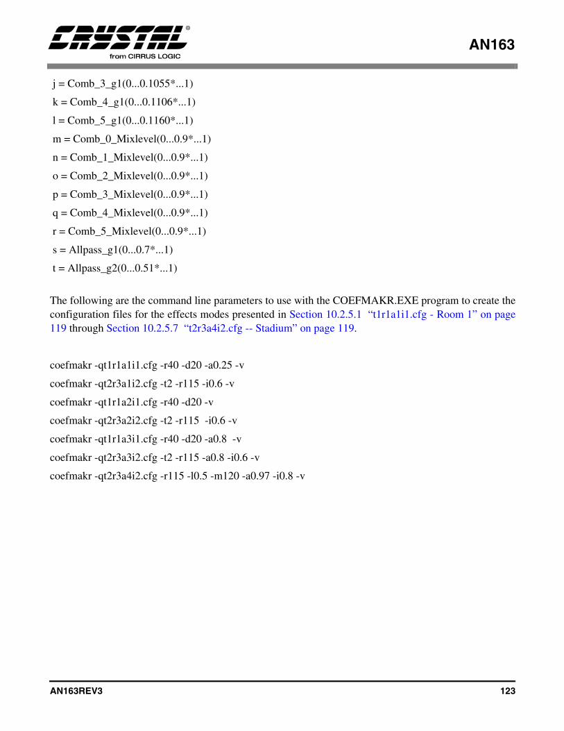
AN163
AN163REV3 123
j = Comb_3_g1(0...0.1055*...1)
k = Comb_4_g1(0...0.1106*...1)
l = Comb_5_g1(0...0.1160*...1)
m = Comb_0_Mixlevel(0...0.9*...1)
n = Comb_1_Mixlevel(0...0.9*...1)
o = Comb_2_Mixlevel(0...0.9*...1)
p = Comb_3_Mixlevel(0...0.9*...1)
q = Comb_4_Mixlevel(0...0.9*...1)
r = Comb_5_Mixlevel(0...0.9*...1)
s = Allpass_g1(0...0.7*...1)
t = Allpass_g2(0...0.51*...1)
The following are the command line parameters to use with the COEFMAKR.EXE program to create theconfiguration files for the effects modes presented in Section 10.2.5.1 “t1r1a1i1.cfg - Room 1” on page119 through Section 10.2.5.7 “t2r3a4i2.cfg -- Stadium” on page 119.
coefmakr -qt1r1a1i1.cfg -r40 -d20 -a0.25 -v
coefmakr -qt2r3a1i2.cfg -t2 -r115 -i0.6 -v
coefmakr -qt1r1a2i1.cfg -r40 -d20 -v
coefmakr -qt2r3a2i2.cfg -t2 -r115 -i0.6 -v
coefmakr -qt1r1a3i1.cfg -r40 -d20 -a0.8 -v
coefmakr -qt2r3a3i2.cfg -t2 -r115 -a0.8 -i0.6 -v
coefmakr -qt2r3a4i2.cfg -r115 -l0.5 -m120 -a0.97 -i0.8 -v