APPLICATION NOTE V850ES/JG3-L Continuous Positive Airway Pressure Machine Reference Design
21
APPLICATION NOTE R01AN0714EU0100 Rev.1.00 Page 1 of 18 November 15, 2011 V850ES/JG3-L Continuous Positive Airway Pressure Machine Reference Design Introduction The sleep apnea syndrome is a disease which occurs in millions of people and is common after the age of 65. It is characterized by disturbed sleep with frequent periods of apnea or ineffective breathing terminated usually by arousal from the sleep. The intermittent hypoxia that occurs during apneas is a risk factor for cardiovascular diseases such as hypertension and heart attacks. The apneas that occur are of two kinds. First one is the central apneas in which breathing movements cease and the second is obstructed apneas in which breathing movements are present but airflow in to lungs is prevented by blockage of the upper airways. Obstructive apneas can be treated with devices that apply a continuous positive pressure to the airways during sleep. Apnea is defined as an absence of respiratory movements for a period of time. These respiratory movements may be categorized as central (no respiratory effort), obstructive (respiratory effort with absent airflow) or mixed (central pause greater than 2 seconds with obstructed respiratory efforts). Sleep Apnea is treated by using a Continuous Positive Airway Pressure (CPAP) machine. The advantages of CPAP are that if tolerated it provides a relatively risk free route symptomatic relief to a serious disorder. CPAP machines have incorporated technology as it has become available to improve the comfort and self- regulating capability to deliver therapy as needed. Contents 1. CPAP Machine: ................................................................................................................................. 3 2. Sleep Apnea Device Requirements .................................................................................................. 6 3. Renesas V850ES/JG3-L Device Architecture Overview................................................................... 8 4. Reference Design Architecture ....................................................................................................... 12 5. Software Flowcharts ........................................................................................................................ 14 Appendix A - References ........................................................................................................................ 17 R01AN0714EU0100 Rev.1.00 November 15, 2011
Transcript of APPLICATION NOTE V850ES/JG3-L Continuous Positive Airway Pressure Machine Reference Design

APPLICATION NOTE
R01AN0714EU0100 Rev.1.00 Page 1 of 18 November 15, 2011
V850ES/JG3-L Continuous Positive Airway Pressure Machine Reference Design
Introduction The sleep apnea syndrome is a disease which occurs in millions of people and is common after the age of 65. It is characterized by disturbed sleep with frequent periods of apnea or ineffective breathing terminated usually by arousal from the sleep. The intermittent hypoxia that occurs during apneas is a risk factor for cardiovascular diseases such as hypertension and heart attacks.
The apneas that occur are of two kinds. First one is the central apneas in which breathing movements cease and the second is obstructed apneas in which breathing movements are present but airflow in to lungs is prevented by blockage of the upper airways. Obstructive apneas can be treated with devices that apply a continuous positive pressure to the airways during sleep.
Apnea is defined as an absence of respiratory movements for a period of time. These respiratory movements may be categorized as central (no respiratory effort), obstructive (respiratory effort with absent airflow) or mixed (central pause greater than 2 seconds with obstructed respiratory efforts). Sleep Apnea is treated by using a Continuous Positive Airway Pressure (CPAP) machine. The advantages of CPAP are that if tolerated it provides a relatively risk free route symptomatic relief to a serious disorder. CPAP machines have incorporated technology as it has become available to improve the comfort and self- regulating capability to deliver therapy as needed.
Contents
1. CPAP Machine: ................................................................................................................................. 3
2. Sleep Apnea Device Requirements .................................................................................................. 6
3. Renesas V850ES/JG3-L Device Architecture Overview................................................................... 8
4. Reference Design Architecture ....................................................................................................... 12
5. Software Flowcharts........................................................................................................................ 14
Appendix A - References ........................................................................................................................ 17
R01AN0714EU0100Rev.1.00
November 15, 2011

V850ES/JG3-L Continuous Positive Airway Pressure Machine Reference Design
R01AN0714EU0100 Rev.1.00 Page 2 of 18 November 15, 2011
List of Figures Figure 1 Example of a CPAP Machine and Mask...................................................................................................... 3
Figure 2 CPAP machine Signal Flow Diagram........................................................................................................... 4
Figure 3 Block diagram of Sleep Apnea Device......................................................................................................... 5
Figure 4 Device Architecture diagram ......................................................................................................................... 9
Figure 5 Hardware Implementation Diagram............................................................................................................ 12
Figure 6 Software Architecture ................................................................................................................................... 13
Figure 7 CPAP Initialization......................................................................................................................................... 14
Figure 8 CPAP Blower control .................................................................................................................................... 15
Figure 9 CPAP Apnea event record........................................................................................................................... 15
Figure 10 CPAP Data Archival.................................................................................................................................... 16
Figure 11 CPAP Data Retrieval .................................................................................................................................. 16

V850ES/JG3-L Continuous Positive Airway Pressure Machine Reference Design
R01AN0714EU0100 Rev.1.00 Page 3 of 18 November 15, 2011
1. CPAP Machine:
Figure 1 Example of a CPAP Machine and Mask
1.1 Theory of Operation CPAP is currently the first line of treatment and is indicated for reversal of sleep induced abnormal upper airway behavior, provided it is severe and results in disruption of sleep with negative day time consequences. The machine consists of a comfortable, lightweight, flexible good nasal mask during sleep, through the headband fixed on the patient's nose (excluding mouth), then a soft nasal mask airway connected to a blower to produce high-speed airflow through the hose into the upper respiratory tract, in throat partially to form a positive pressure.
The clinical prescription of CPAP is usually given as a single therapeutic pressure value. The following are the normal control strategies followed by most manufacturers to control the pressure [1].
1. The controller sets a constant pressure at the machine (constant blower speed). This pressure is slightly higher than the patient’s need to account for the maximum leak condition.
2. The controller is driven by active feedback from the pressure measured at the mask. This feedback will cause the blower to continuously vary pressure (at the blower) so as to maintain it constant at the mask. Either blower speed or valve opening may be varied to achieve the constant pressure at the mask.
3. Control of pressure as exerted at the machine is based on assumptions about how the pressure will change as it travels along the tubing that connects the blower to the mask. Blower speed can be used to calculate a predicted drop in pressure between patient and machine, creating a deliberately variable higher pressure than prescribed to deliver constant therapeutic target.
The latest CPAP machines or APAP machines modify the pressure they deliver within individual breaths as a function of the instantaneous flow. This will improve pressure induced discomfort, by limiting unnecessary rises in pressure above the prescribed value during expiration The simplest way to accomplish this is to vary the blower speed in response to fluctuations detected in the measured pressure. A constant trade-off exists between the need to optimally set CPAP for a stable physiologic state and the need to respond with a rapid change in CPAP to state changes affecting the airway. The algorithms vary with manufacturer and are proprietary in nature [1].
Temp
Sticky Note
cpap اولین روش درمان و پیچیده برای خواب بازگشتی که شامل رفتار راه هوایی بالاتر غیر عادی میباشد، تامین میکند آن هست شدید و نتایج در قطع خواب با نتایج زمانی منفی. ماشین شامل یک راحتی، وزن کم، انعطاف پذیری خوب ماسک خواب، پیشانی بند ثابت روی بینی بیمار (به استثنای دهان)، از یک ماسک نرم راه هوایی متصل به یک دمنده برای تولید یک جریان هوای پر سرعت درون شلنگ به اندازهی بالاترین میزان تنفسی درون گلو به صورت یک فشار مثبت. نوع بالینی cpap معمولا یک مقدار فشار درمانی را میدهد در ادامه نحوه کنترل عادی توسط سازندهها برای کنترل فشار آورده شده است. 1. کنترل کننده یک فشار ثابت را در ماشین تنظیم میکند (سرعت ثابت دمنده) این فشار به طور نرمی بالاتر از فشار مورد نیاز بیمار برای داشتن بیشترین میزان نشتی. 2. کنترل کننده توسط فیدبک فعال از فشار اندازهگیری شده در ماسک راهاندازی میشود. این فیدبک دلیل این است که دمنده به صورت پیوسته فشارهای متنوعی را در ماسک ثابت نگه میدارد. هم سرعت دمنده و هم باز شدن شیر ممکن است فشار های متفاوت ثابتی را در ماسک دهد. 3. کنترل فشار که براساس مفروضاتی دربارهی فشار تغییر میکند در ارسال در راستای تیوب متصل به دمندهی ماسک. سرعت دمنده میتواند در افت پیشبینی شده فشار بین بیمار و ماشین مورد استفاده قرار گیرد. ساخت یک فشار بالای متغیر که صورت عمدی از دستگاه به هدف درمانی ثابت. آخرین ماشینهای cpap یاماشینهای apap اصلاح میکند فشاری را که آنها در تنفس اشخاص انتقال میدهند به صورت یک عملکرد جریان همزمان. این بهبود میاید فشار را که شامل میشود ناراحتی، توسط محدود کردن غیر ضروری که افزایش میدهد فشار بالای مقدرا تجویزشده در طول بازدم. شاده ترین راه برای اینکه چندین سرعت دنده در در پاسخ به نوسانات شناسایی شده در فشار اندازهگیری شده. یک تعادل ثابت برای تنظیم بهینه وجود دارد. برای یک حالت فیزیولوژیکی پایدار و نیاز به پاسخ با تغییرات سریع در cpap برای حالتی که تغییر میدهد تاثیر بر راه هوایی را. الگوریتمهایی با سازنده متفاوت و به طور خاص در طبیعت.

V850ES/JG3-L Continuous Positive Airway Pressure Machine Reference Design
R01AN0714EU0100 Rev.1.00 Page 4 of 18 November 15, 2011
Manufacturers have constantly been improving the comfort and self-regulating capability of the machines to deliver therapy as needed, to match the changing conditions that occur during a night of sleep and over time. To accomplish this, device should include capabilities to tailor the pressure of the therapy to the patient’s needs [1].These advanced machines have improved control algorithms, usability features to give good performance and provide compliance records [1].
Presently, the blower driven by a DC brushless (BLDC) motor has been widely used for generating the air source and controlling the airway pressure and air flow rate nearby the nasal mask by directly adjusting the speed of the motor. In addition, this kind of motor and blower can be made small-size, inexpensive and easy-to-use [3]. A two degree-of-freedom control method for achieving bi-level positive airway pressure (Bi-PAP) of an obstructive sleep apnea (OSA) treatment system is presented in [3]. In this approach, a mathematical model of the overall open-loop system is established based on the input-output data and its system parameters are sequentially determined using the recursive least-squares (RLS) approach. A two degree-of-freedom (DOF) controller, including a nonlinear feed forward controller and a feedback proportional-integral-derivative controller (PID controller) with gain scheduling, is proposed to maintain and follow the desired bi-level pressure set points [3].
1.2 Signal Processing
Figure 2 CPAP machine Signal Flow Diagram
The signal flow diagram shown in Figure 2 represents a typical CPAP machine. The air blower motor speed is controlled by the microcontroller using a motor driver circuit. The pressure at the mask is measured by the sensor and related analog and digital processing. The motor speed is varied to maintain the prescribed pressure at the face mask by using a proprietary algorithm. The temperature and humidity are measured and heater/humidifier is controlled to maintain comfortable levels for the user.
The signals from the sensors are processed using both analog and digital elements to derive the average values to be used for the computations in the control loop. The control algorithms are very sophisticated and proprietary. Some of the algorithms use mathematical models to achieve the objective.
As pointed out earlier, BLDC is used to control the blower to maintain the pressure at the face mask. The control algorithm differs from manufacturer to manufacturer and proprietary in nature. An extensive treatment of motor control required is covered in [2].
Temp
Sticky Note
سازندهها به طور ثابت بهبود در راحتی و خود تنظیمی ماشین را برای درمان مورد نیاز دارند. برای یکسان کردن شرایط تغییر که اتفاق میافتد در طول خواب شب. برای انجام این موضوع وسیله باید شامل ظرفیتها برای مناسب کردن فشار مورد نیاز درمان بیمار. این ماشین پیشرفته الگوریتم بهبود یافتهای دارد ویژگیهای قابل استفاده که قابلیت اجرای خوبی می دهد و ثبت را بهبود میدهد. فعلا این دمنده توسط یک موتور dc brshless راهاندازی مشود. که برای تولید منبع هوا و کنترل فشار راههای هوایی و و نرخ فشار هوای نزدیک به روزنه بینی توسط تنظیم مستقیم سرعت موتور. بعلاوه این نوع موتور و دمنده که میتواند در اندازهی کوچکی ساخته شود، ارزان بودن و استفاده راحت. روش کنترل دو درجه آزادی برای یافتن فشار راه هوایی مثبت bi-pap یک آپنه خواب انسدادی. سیستم درمان در [3] نمایش داده شده در این پنجره یک مدل ریاضی بازگشتی سیستم حلقهباز براساس اطالاعات ورودی _خروجی طراحی شده است. پارامترهای این سیستم به طور متوالی با استفاده از پنجره حداقل مستطیلهای بازگشتی تعیین میشود. کنترلر با دو درجه آزادی شامل یک کنترلر feedforward غیر خطی و یک کنترلر فیدبک دار متناسب اتگرال_مشتق با گین زمانبندی شده که به طور اصلی مطرح شده و بدنبال نقاط تنظیم شده مطلوب bi_level. دیاگرام نشان داده شده در شکل 2 یک ماشین معمولی cpap نشان میدهد. سرعت موتور دمنده هست کنترل شده توسط میکروکنترلر با استفاده از مدار راهانداز موتور. سرعت موتور متفاوت شده برای نگه داشتن فشار تجویز شده و گرم کننده یا مرطوب کننده که منترل شده با نگه داشتن سطوح برای کاربر. سیگنالهاش خروجی سنسورها با استفاده از المانهای آنالوگ و دیجیتال پردازش میشود. برای راهاندازی مقدار میانگین استفاده شده برای محاسبه در حلقه کنترل. الگوریتمهای کنترل پیچیده و خاص میباشد. تعدادی از الگوریتمها از مدلهای ریاضی برای رسیدن به هدف استفاده میکند. نقطه خروجی اولیه BLCD استفده شده برای کنترلدمنده برای نگه داشتن فشار ماسک صورت. الگوریتم کنترل متفاوت میکند از سازنده به سازنده و به نسبی در طبیعت. یک درمان گسترده کنترل موتور نیاز دارد به پشش در شکل [2].
Temp
Highlight
Temp
Highlight
Temp
Highlight

V850ES/JG3-L Continuous Positive Airway Pressure Machine Reference Design
R01AN0714EU0100 Rev.1.00 Page 5 of 18 November 15, 2011
1.3 Block Diagram of Sleep Apnea Device A typical CPAP machine using a microcontroller is shown in Figure 3. CPAP machine is a complex device implementing many proprietary algorithms to achieve its main objective of providing comfortable pressure at the face mask to assist the user to get a good night sleep.
Figure 3 Block diagram of Sleep Apnea Device
Temp
Sticky Note
ماشین cpap معمولی با استفاده از میکروکنترلر نشان داده شده در شکل 3. ماشین cpap هست یک وسیله پیچیده که الگوریتمهای اختصاصی بسیاری برای رسیدن به هدف اصلی فشار راحت بهبودیافته ماسک صورت برای کمک به کاربر برای داشتن یک خواب شب راحت.

V850ES/JG3-L Continuous Positive Airway Pressure Machine Reference Design
R01AN0714EU0100 Rev.1.00 Page 6 of 18 November 15, 2011
2. Sleep Apnea Device Requirements
2.1 Sensor Requirements The main sensors used in the CPAP machine are pressure, temperature and relative humidity. Analog amplification and filtering is required before interfacing these sensors to the ADC.
2.2 Signal Processing Requirements The main objective of the CPAP machine is maintaining the prescribed pressure at the face mask. In order to achieve this, the blower motor speed is varied depending on the pressure measured at the face mask. In some designs, there is no measurement of the pressure. Instead the speed is varied depending on the back pressure. Some of the advanced CPAP machines provide temperature and humidity adjustment. Sensors are placed in the path way to measure these parameters and adjust correspondingly. All these sensors need filtering and amplification before digitization. Digital filtering may be required to implement control algorithms.
2.3 Blower and BLDC motor control requirements According to the design guidelines and rules from American Thoracic Society and the ISO-17510, there are many regulations for treating the OSA patients; one of them is that the OSA treatment machine or equipment must offer required pressure ranging from 4 cmH20 to 20 cm H20, and the required amount of air flow rate up to 120 liters per minute (LPM). The BLDC motor must have low inertia and fast acceleration in order to quickly change its speed and then alter the pressure to meet the patient's requirement. Furthermore, the motor driver must have a good ability to deal with the speed feedback loop control [3]. The main goals of motor control required for CPAP are reliability, quiet operation, dynamic and efficient operation [2].
2.4 Processing Requirements The processing requirements include some support for digital signal processing. The processor can be a low power 8/16/32 bit device with support for 12 bit ADC. Digital signal processing capabilities are required to do signal processing and implement motor control algorithms.
2.5 Storage Requirements Information on breathing, pressure levels delivered, apneas, etc. is required to be stored for later retrieval to help determine the effectiveness of CPAP therapy. The CPAP Host Software also allows the user and the Physician to analyze recorded data for any night view the data on an hour by hour basis. This feature needs a local flash storage. Some advanced machines support data storage on the removable flash cards.
2.6 Display Requirements Machines that display advanced tracking through the on machine display allow for fast review of therapy metrics. Many people like to use on screen display to check every morning what their AHI and leak rate were through the previous night, to see if adjustments need to be made just as readjusting their mask. The information provided on the on machine screen is usually average values over different time frames, such as 1 day (last night), 7 night, 30 nights, etc. These requirements need a large, easy-to-read custom LCD display with backlight to display values and error indicators. Graphical LCD support is required for advanced CPAP machines.
2.7 Power Requirements CPAP machines are normally operated using the mains power supply. However portable machines used for travel purpose may use rechargeable batteries. These machines have a blower whose motor speed is controlled to keep the pressure stable. The design should use motor with low consumption to get a good battery cycle life. The power supply should be designed to use AC power to charge the battery and operate the machine.
2.8 Connectivity Requirements CPAP machines record important data for the user and their Physicians. This data need to be accessed by the Physician for therapy and compliance purpose. These machines should have minimum USB connectivity to interface to a computer. User should be able to retrieve the secure data and send it to the Physician. However with wireless connectivity and internet, Physicians can access the data without user intervention. Low end machines should have USB and High end machines can support internet connectivity using Wi-Fi / Bluetooth.
Temp
Sticky Note
2.1 سنسورهای مورد نیاز سنسورهای استفاده شده در ماشین cpap عبارتنداز : سنسور فشار، دما، رطوبت نسبی. تقویت کنندگی آنالوگ و فیلترینگ که به خاطر تداخلات ایجاد شده در این سنسورها هنگام ADC (آنالوگ به دیجیتال) نیاز است. هدف اصلی ماشین cpap نگه داشتن فشار تجویز شده به ماسک صورت است. بترتیب برای رسیدن به این سرعت موتور دمنده وابستگی مختلفی به فشار پشتی ایجاد شده است. برخی از ماشینهای cpap دما را بهبود میدهد و فشار را تنظیم میکند. سنسورهایی که در مسیر هوایی برای برای اندازهگیری پارامترها و تنظیم نسبی. همه این سنسورها نیاز به فیلترینگ و تقویت کنندگی قبل از دیجیتال سازی دارد. فیلترینگ دیجیتال ممکن است به الگوریتمهای کنترل نیاز داشته باشد. دمنده و نیازمندیهای کنترل موتور BLCD با توجه به طراحی راهنماهای خطی و نقش انجمن بیماریهای ریوی آمریکا و ISO-17510 تنظیمات زیادی وجود دارد برای درمان بیماران OSA، یکی از آنها ماشین درمان osa یا تجهیزاتی که باید فشار مورد نیاز در بازه 4_20 سانتیمتر آب را پیشنهاد دهد و نرخ جریان هوای مورد نیاز بیش از 20لیتر در دقیقه. موتور BLCD باید رکود کمتر و شتاب بیشتری برای تطبیق در تغییرات سریع داشته باشد برای تنظیم سرعت و فشار مورد نیاز بیمار را داشته باشد. بنابراین راهانداز موتور باید قابلیت خوبی مقدار اختیاری، پویای و عمل قابل قبول داشته باشد. پردازش مورد نیاز تجهیزات پردازشی که شامل پردازش سیگنال دیجیتالی میباشد. پردازشگر میتواند یک توان پایین برای ADC 12 بیتی باشد. قابلیت پردازش سیگنال دیجیتالی نیاز دارد به پردازش دیجیتال و الگوریتمهای کنترل موتور میباشد. نیازمندیهای ذخیرهسازی اطلاعات اطلاعات تنفس، سطوح فشار انتقال یافته، آپنه، و ... . نیازمند برای بازیابی اخیر برای کمک به تعیین تاثیر درمان CPAP. نرمافزار اصلی CPAP اجازه میدهد تا کاربر و پزشک اطلااعات ثبت شده رابرای هر شب که نشان میدهد اطلاعات را ساعت به ساعت آنالیز کند. این ویژگیها نیاز دارد به یک ذخیرهی محلی. برخی از دستگاهاهی پیشرفته اطلاعات ذخیره شده را با یک کارت حافظه قابل نوشتن دوباره پشتیبانی میکند. نمایش منبع تغذیه ماشین CPAP به طور عادی راهاندازی میشود با استفاده ازمنبع تغذیه اصلی. به هر حال ماشین قابل حمل استفاده شده برای انتقال هدف که ممکن است باتریهای قابل شارژ باشد. این ماشینها یک دمنده که سرعت موتور آن کنترل شده فشار پایدار را نگه میدارد. طراحی باید استفاده کند از موتور با مصرف یک باتری با چرخه بازیابی ولتاژ خوب. منبع تغذیه باید به گونه ای طراحی شود که با برق ac شارژ شده و مورد استفاده قرار گیرد. اتصال ماشین CPAP اطلاعات مهم را ثبت میکند برای کاربر و پزشک. این اطالاعات نیاز دارد به رسیدن توسط پزشک برای درمان و هدف قابل قبول. این ماشین باید اتصال USB کوچکی برای اتصال با کامپیوتر داشته باشد. کاربر باید توانایی بازیابی امن اطلاعات و فرستادن آنها به پزشک داشته باشد. به هرحال این اتصال بدون سیم واینترنتی، پزشک میتواند بدون دخالت به اطلاعات دسترسی پیدا کند. ماشین پایانه پایین باید USB داشته باشد و ماشین پایانه بالا میتواند با ارسال اطلاعات با اینترنت بدون سیم باشد.

V850ES/JG3-L Continuous Positive Airway Pressure Machine Reference Design
R01AN0714EU0100 Rev.1.00 Page 7 of 18 November 15, 2011
2.9 User interface requirements User interface is required to manage the storage of values as well as displaying the archived values on user prompt. Displaying status while conducting the measurement will be helpful for the user. The user interaction is provided by a keypad and LCD display.
2.10 Other requirements The CPAP treatment should be comfortable to the user and to achieve this lot of manufacturers spend lot time and effort in designing the face mask and the control algorithms. The machine should operate very quietly as not to disturb the sleep of the user. These machines should be able to operate with batteries to make them portable and can be used while travelling.
2.11 Future Trends The future for CPAP machines is leading to auto adjusting machines. These systems are also intended for long term treatment. Their goal is to improve effectiveness and/or reduce side effects by ensuring that the instantaneous pressure is always close to optimal [4]. Most of the future advances will take place in the control algorithms in order to provide a comfortable pressure and in the connectivity solutions for the retrieval of the data to be used for personalizing therapy and for compliance purposes.
Other areas for future advances are the battery operation and quiet blower operation as not to disturb the sleep of the user.

V850ES/JG3-L Continuous Positive Airway Pressure Machine Reference Design
R01AN0714EU0100 Rev.1.00 Page 8 of 18 November 15, 2011
3. Renesas V850ES/JG3-L Device Architecture Overview The V850ES/JG3-L is a 32-bit single-chip microcontroller that includes the V850ES CPU core and peripheral functions such as ROM/RAM, timer/counters, serial interfaces, an A/D converter, a D/A converter, USB function controller. In addition to high real-time response characteristics and 1-clock-pitch basic instructions, the V850ES/JG3-L features multiply instructions, saturated operation instructions, bit manipulation instructions, etc., realized by a hardware multiplier, as optimum instructions for digital servo control applications.
Features
Minimum instruction execution time: 50 ns (operating on main clock (fXX) of 20 MHz: VDD = 2.7 to 3.6 V) (In PLL mode: ×4 : 5 MHz) 62.5 ns (operating on main clock (fXX) of 16 MHz: VDD = 3.0 to 3.6 V) (In PLL mode: ×8, 1/3 : 6 MHz) 200 ns (operating on main clock (fXX) of 5 MHz: VDD = 2.2 to 3.6 V) (In clock-through mode) 400 ns (operating on main clock (fXX) of 2.5 MHz: VDD = 2.0 to 3.6 V) (In clock-through mode) 30.5 μs (operating on sub clock (fXT) of 32.768 kHz: VDD = 2.0 to 3.6 V) General-purpose registers:
• 32 bits × 32 registers CPU features:
• Signed multiplication (16 × 16 → 32): 1 to 2 clocks • Signed multiplication (32 × 32 → 64): 1 to 5 clocks • Saturated operations (overflow and underflow detection functions included) • Most instructions can be executed in 1 clock cycle by using 32-bit RISC-based 5-stage pipeline architecture • Instruction fetching from internal ROM and accessing internal RAM for data can beexecuted separately, by
using Harvard architecture • High code efficiency achieved by using variable length instructions • 32-bit shift instruction: 1 clock cycle • Bit manipulation instructions • Load/store instructions with long/short format
Memory space: • 64 MB of linear address space (for programs and data) • External expansion: Up to 16 MB (including 1 MB used as internal ROM/RAM) • Internal memory: RAM: 40 KB • Flash memory: 256/384/512 KB
External bus interface: • Separate bus/multiplexed bus output selectable • 8/16 bit data bus sizing function • Wait function
• Programmable wait function • External wait function
• Idle state function • Bus hold function
Interrupts and exceptions: • Internal external: • maskable / Nonmaskable • Software exceptions: 32 sources • Exception trap: 2 sources
Ports: • I/O ports: 80
Timer function: • 16-bit interval timer M (TMM): 1 channel • 16-bit timer/event counter P (TMP): 6 channels • 16-bit timer/event counter Q (TMQ): 1 channel • Watch timer: 1 channel
V850ES/JG3-L Continuous Positive Airway Pressure Machine Reference Design
R01AN0714EU0100 Rev.1.00 Page 9 of 18 November 15, 2011
Figure 4 Device Architecture diagram
Processor The V850ES/JG3-L is a 32-bit single-chip microcontroller that includes the V850ES CPU core and peripheral functions such as ROM/RAM, timer/counters, serial interfaces, an A/D converter, a D/A converter, USB function controller. In addition to high real-time response characteristics and 1-clock-pitch basic instructions, the V850ES/JG3-L features multiply instructions, saturated operation instructions, bit manipulation instructions, etc., realized by a hardware multiplier, as optimum instructions for digital servo control applications.

V850ES/JG3-L Continuous Positive Airway Pressure Machine Reference Design
R01AN0714EU0100 Rev.1.00 Page 10 of 18 November 15, 2011
Memory For instruction addressing, up to a combined total of 16 MB of external memory area and internal ROM area, plus an internal RAM area, are supported in a linear address space (program space) of up to 64 MB. For operand addressing (data access), up to 4 GB of a linear address space (data space) is supported. The 4 GB address space, however, is viewed as 64 images of a 64 MB physical address space. This means that the same 64 MB physical address space is accessed regardless of the value of bits 31 to 26. A user accessible 40KB internal RAM is provided in V850ES/JG3-L devices. Flash memory The internal flash memory of the V850ES/JG3-L can be rewritten by using the rewrite function of the dedicated flash memory programmer, regardless of whether the V850ES/JG3-L has already been mounted on the target system or not (off-board/on-board programming). A security function that prohibits rewriting the user program written to the internal flash memory is also supported, so that the program cannot be changed by an unauthorized person. The rewrite function using the user program (self-programming) is ideal for an application where it is assumed that the program will be changed after production/shipment of the target system. A boot swap function that rewrites the entire flash memory area safely is also supported. In addition, interrupt servicing can be executed during self- programming, so that the flash memory can be rewritten under various conditions, such as while communicating with an external device.
Bus Controller The external bus interface function is used to connect external devices to areas other than the internal ROM, RAM, or on-chip I/O registers. These ports control address/data I/O, the read/write strobe signal, waits, the clock output, bus hold, and the address strobe signal. This can be used to interface external memories such as ROM and RAM, and external I/O devices.
Timers The V850ES/JG3-L has seven timer/event counter channels which support the following modes.
1. Interval timer TMPn generates an interrupt at a preset interval and can output a square wave.
2. External event counter TMPn counts the number of externally input signal pulses.
3. External trigger pulse output TMPn starts counting and outputs a pulse when the specified external signal is input.
4. One-shot pulse output TMPn outputs a one-shot pulse with an output width that can be freely specified.
5. PWM output TMPn outputs a pulse with a constant cycle whose active width can be changed. The pulse duty can also be changed freely even while the timer is operating.
6. Free-running timer TMPn counts from 0000H to FFFFH and then resets.
7. Pulse width measurement TMPn can be used to measure the pulses of a signal input externally.
Apart from the above, it also supports a 16-bit interval timer and a watchdog timer.
RTC The V850ES/JG3-L provides real-time counter (RTC) which has the following features. 1. Counting up to 99 years using year, month, day-of-week, day, hour, minute, and second sub-counters
provided 2. Year, month, day-of-week, day, hour, minute, and second counter display using BCD codes 3. Alarm interrupt function 4. Constant-period interrupt function (period: 1 month to 0.5 second) 5. Interval interrupt function (period: 1.95 ms to 125 ms) 6. Pin output function of 1 Hz 7. Pin output function of 32.768 kHz 8. Pin output function of 512 Hz or 16.384 kHz 9. Watch error correction function 10. Sub clock operation or main clock operation

V850ES/JG3-L Continuous Positive Airway Pressure Machine Reference Design
R01AN0714EU0100 Rev.1.00 Page 11 of 18 November 15, 2011
ADC The Successive approximation A/D converter converts analog input signals into digital values with a resolution of 10 bits, and can handle 12 analog input signal channels.
DAC V850ES/JG3-L, provides two eight bit R-2R ladder type D/A converter channels with a maximum conversion time of 3 micro second.
Ports The V850ES/JG3-L has a total of 80 I/O port pins to provide port functions. Some of these pins support 5V input tolerable and some provide selectable N-channel open-drain output. The input/output is specifiable in 1 bit units.
USB The V850ES/JG3-L supports an internal USB function controller (USBF) conforming to the Universal Serial Bus Specification. Data communication using the polling method is performed between the USB function controller and external host device by using a token-based protocol. It supports 12 Mbps (full-speed) transfer. Bulk and interrupt transfer endpoints are supported.

V850ES/JG3-L Continuous Positive Airway Pressure Machine Reference Design
R01AN0714EU0100 Rev.1.00 Page 12 of 18 November 15, 2011
4. Reference Design Architecture Table 1 Requirements Table
CPAP Machine Requirements
Relevance Renesas Device V850ES/JG3-L
External Hardware
Amplifier High None External Required Analog Filter High None External Required 12 bit ADC High 10 bit ADC External ADC
Signal Processing High Multiplier Motor Control High SW Available External Driver
DAC Medium 8 bit ,3uS R-2R LCD Controller High None Data Storage High Small On Chip Flash External Required Connectivity High USB wireless
4.1 Hardware Architecture A typical implementation of CPAP using Renesas V850ES/JG3-L device is shown in Figure 5. A motor driver circuit is required to drive the BLDC motor which runs the blower. Pressure at the mask is monitored by a sensor whose output is amplified and filtered before digitization by internal ADC. An external circuit is required to control the heater and humidifier. This interface in turn can be controlled by PWM signals from V850ES/JG3-L. The built in 8 bit DAC is used to generate audio alarm signals. An external LCD controller is used to drive the custom made LCD display. User input can be given using the external keypad interfaced to V850ES/JG3-L device. The power to all components is provided by the onboard power supply. This power supply can be driven by AC mains or by a rechargeable battery pack. The charger circuit is built in to the power supply.
Figure 5 Hardware Implementation Diagram
4.2 Software Architecture

V850ES/JG3-L Continuous Positive Airway Pressure Machine Reference Design
R01AN0714EU0100 Rev.1.00 Page 13 of 18 November 15, 2011
The low level software includes drivers for blower motor, heater and humidifier control. The middle ware consists of control algorithms for blower, heater/ humidifier and signal processing for sensors like pressure, temperature and humidity. Data archiving and recall is to be implemented in the middleware which controls the onboard flash driver. The display driver controls the custom LCD including backlight to provide user display functionality. Power management is critical software which optimizes the resources to prolong the battery life. The USB driver along with Continua USB stack provides the connectivity need of the device. The main CPAP application implements the final user application which provides the user interface.
Figure 6 Software Architecture

V850ES/JG3-L Continuous Positive Airway Pressure Machine Reference Design
R01AN0714EU0100 Rev.1.00 Page 14 of 18 November 15, 2011
5. Software Flowcharts The following flow charts show high level software implementation.
Initialize Hardware
CheckThe presenceOf sensor
Start
CheckData
signature
Initialize storage pointer to begining
Initialize storage pointer
Initialize timer, Interrupts
Display Message
CheckFor user Input
B
Call appropiate routine
To process user Input
Bad
Good
No Sensor
No Input
Figure 7 CPAP Initialization

V850ES/JG3-L Continuous Positive Airway Pressure Machine Reference Design
R01AN0714EU0100 Rev.1.00 Page 15 of 18 November 15, 2011
Figure 8 CPAP Blower control
Figure 9 CPAP Apnea event record
V850ES/JG3-L Continuous Positive Airway Pressure Machine Reference Design
R01AN0714EU0100 Rev.1.00 Page 16 of 18 November 15, 2011
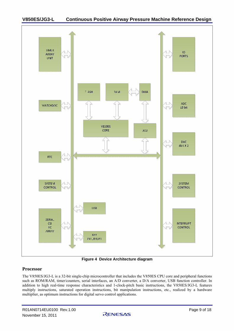
Figure 10 CPAP Data Archival
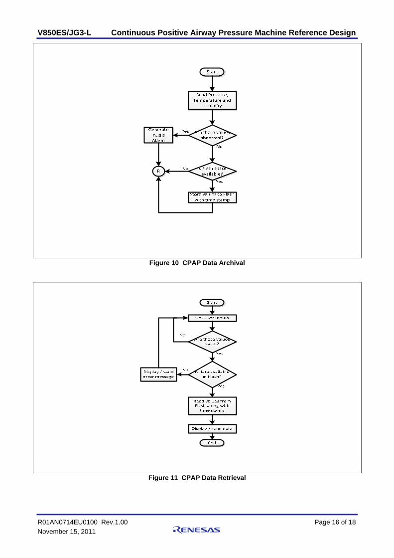
Figure 11 CPAP Data Retrieval

V850ES/JG3-L Continuous Positive Airway Pressure Machine Reference Design
R01AN0714EU0100 Rev.1.00 Page 17 of 18 November 15, 2011
Appendix A - References [1] David M. Rapoport, Ron S. Leder , " Continuous positive Airway Pressure ", in Encyclopedia of Medical Devices and Instrumentation, Second edition, Vol. 2, Wiley-Interscience, 2006, pp. 329-336.
[2] Renesas, Implementing PAP Machine for treating Apnea using RX62N, Renesas Electronics Application Note, January, 2011
[3] Ching-Chih Tsai, Zen-Chung Wang, Chih-Sung Chen, Two Degree-of-freedom Control for Bi-level Positive Air way Pressure of an Obstructive Sleep Apnea, The 33rd Annual Conference of the IEEE Industrial Electronics Society (IECON), Nov. 5-8, 2007, Taipei, Taiwan
[4] Daniela Boisteanu, Raluca Vasiluta, Andrei Cernomaz, Corina Mucenica, Home monitoring of sleep apnea treatment: benefits of intelligent CPAP devices, Advanced Technologies for Enhanced Quality of Life, 2009

V850ES/JG3-L Continuous Positive Airway Pressure Machine Reference Design
R01AN0714EU0100 Rev.1.00 Page 18 of 18 November 15, 2011
Website and Support Renesas Electronics Website
http://www.renesas.com/ Inquiries
http://www.renesas.com/inquiry All trademarks and registered trademarks are the property of their respective owners.

A-1
Revision Record Description
Rev. Date Page Summary 1.00 November 15, 2011 — First edition issued

General Precautions in the Handling of MPU/MCU Products The following usage notes are applicable to all MPU/MCU products from Renesas. For detailed usage notes on the products covered by this manual, refer to the relevant sections of the manual. If the descriptions under General Precautions in the Handling of MPU/MCU Products and in the body of the manual differ from each other, the description in the body of the manual takes precedence.
1. Handling of Unused Pins Handle unused pins in accord with the directions given under Handling of Unused Pins in the manual. ⎯ The input pins of CMOS products are generally in the high-impedance state. In operation with an
unused pin in the open-circuit state, extra electromagnetic noise is induced in the vicinity of LSI, an associated shoot-through current flows internally, and malfunctions occur due to the false recognition of the pin state as an input signal become possible. Unused pins should be handled as described under Handling of Unused Pins in the manual.
2. Processing at Power-on The state of the product is undefined at the moment when power is supplied. ⎯ The states of internal circuits in the LSI are indeterminate and the states of register settings and
pins are undefined at the moment when power is supplied. In a finished product where the reset signal is applied to the external reset pin, the states of pins are not guaranteed from the moment when power is supplied until the reset process is completed. In a similar way, the states of pins in a product that is reset by an on-chip power-on reset function are not guaranteed from the moment when power is supplied until the power reaches the level at which resetting has been specified.
3. Prohibition of Access to Reserved Addresses Access to reserved addresses is prohibited. ⎯ The reserved addresses are provided for the possible future expansion of functions. Do not access
these addresses; the correct operation of LSI is not guaranteed if they are accessed. 4. Clock Signals
After applying a reset, only release the reset line after the operating clock signal has become stable. When switching the clock signal during program execution, wait until the target clock signal has stabilized. ⎯ When the clock signal is generated with an external resonator (or from an external oscillator)
during a reset, ensure that the reset line is only released after full stabilization of the clock signal. Moreover, when switching to a clock signal produced with an external resonator (or by an external oscillator) while program execution is in progress, wait until the target clock signal is stable.
5. Differences between Products Before changing from one product to another, i.e. to one with a different type number, confirm that the change will not lead to problems. ⎯ The characteristics of MPU/MCU in the same group but having different type numbers may differ
because of the differences in internal memory capacity and layout pattern. When changing to products of different type numbers, implement a system-evaluation test for each of the products.

Notice1. All information included in this document is current as of the date this document is issued. Such information, however, is subject to change without any prior notice. Before purchasing or using any Renesas
Electronics products listed herein, please confirm the latest product information with a Renesas Electronics sales office. Also, please pay regular and careful attention to additional and different information to
be disclosed by Renesas Electronics such as that disclosed through our website.
2. Renesas Electronics does not assume any liability for infringement of patents, copyrights, or other intellectual property rights of third parties by or arising from the use of Renesas Electronics products or
technical information described in this document. No license, express, implied or otherwise, is granted hereby under any patents, copyrights or other intellectual property rights of Renesas Electronics or
others.
3. You should not alter, modify, copy, or otherwise misappropriate any Renesas Electronics product, whether in whole or in part.
4. Descriptions of circuits, software and other related information in this document are provided only to illustrate the operation of semiconductor products and application examples. You are fully responsible for
the incorporation of these circuits, software, and information in the design of your equipment. Renesas Electronics assumes no responsibility for any losses incurred by you or third parties arising from the
use of these circuits, software, or information.
5. When exporting the products or technology described in this document, you should comply with the applicable export control laws and regulations and follow the procedures required by such laws and
regulations. You should not use Renesas Electronics products or the technology described in this document for any purpose relating to military applications or use by the military, including but not limited to
the development of weapons of mass destruction. Renesas Electronics products and technology may not be used for or incorporated into any products or systems whose manufacture, use, or sale is
prohibited under any applicable domestic or foreign laws or regulations.
6. Renesas Electronics has used reasonable care in preparing the information included in this document, but Renesas Electronics does not warrant that such information is error free. Renesas Electronics
assumes no liability whatsoever for any damages incurred by you resulting from errors in or omissions from the information included herein.
7. Renesas Electronics products are classified according to the following three quality grades: "Standard", "High Quality", and "Specific". The recommended applications for each Renesas Electronics product
depends on the product's quality grade, as indicated below. You must check the quality grade of each Renesas Electronics product before using it in a particular application. You may not use any Renesas
Electronics product for any application categorized as "Specific" without the prior written consent of Renesas Electronics. Further, you may not use any Renesas Electronics product for any application for
which it is not intended without the prior written consent of Renesas Electronics. Renesas Electronics shall not be in any way liable for any damages or losses incurred by you or third parties arising from the
use of any Renesas Electronics product for an application categorized as "Specific" or for which the product is not intended where you have failed to obtain the prior written consent of Renesas Electronics.
The quality grade of each Renesas Electronics product is "Standard" unless otherwise expressly specified in a Renesas Electronics data sheets or data books, etc.
"Standard": Computers; office equipment; communications equipment; test and measurement equipment; audio and visual equipment; home electronic appliances; machine tools;
personal electronic equipment; and industrial robots.
"High Quality": Transportation equipment (automobiles, trains, ships, etc.); traffic control systems; anti-disaster systems; anti-crime systems; safety equipment; and medical equipment not specifically
designed for life support.
"Specific": Aircraft; aerospace equipment; submersible repeaters; nuclear reactor control systems; medical equipment or systems for life support (e.g. artificial life support devices or systems), surgical
implantations, or healthcare intervention (e.g. excision, etc.), and any other applications or purposes that pose a direct threat to human life.
8. You should use the Renesas Electronics products described in this document within the range specified by Renesas Electronics, especially with respect to the maximum rating, operating supply voltage
range, movement power voltage range, heat radiation characteristics, installation and other product characteristics. Renesas Electronics shall have no liability for malfunctions or damages arising out of the
use of Renesas Electronics products beyond such specified ranges.
9. Although Renesas Electronics endeavors to improve the quality and reliability of its products, semiconductor products have specific characteristics such as the occurrence of failure at a certain rate and
malfunctions under certain use conditions. Further, Renesas Electronics products are not subject to radiation resistance design. Please be sure to implement safety measures to guard them against the
possibility of physical injury, and injury or damage caused by fire in the event of the failure of a Renesas Electronics product, such as safety design for hardware and software including but not limited to
redundancy, fire control and malfunction prevention, appropriate treatment for aging degradation or any other appropriate measures. Because the evaluation of microcomputer software alone is very difficult,
please evaluate the safety of the final products or system manufactured by you.
10. Please contact a Renesas Electronics sales office for details as to environmental matters such as the environmental compatibility of each Renesas Electronics product. Please use Renesas Electronics
products in compliance with all applicable laws and regulations that regulate the inclusion or use of controlled substances, including without limitation, the EU RoHS Directive. Renesas Electronics assumes
no liability for damages or losses occurring as a result of your noncompliance with applicable laws and regulations.
11. This document may not be reproduced or duplicated, in any form, in whole or in part, without prior written consent of Renesas Electronics.
12. Please contact a Renesas Electronics sales office if you have any questions regarding the information contained in this document or Renesas Electronics products, or if you have any other inquiries.
(Note 1) "Renesas Electronics" as used in this document means Renesas Electronics Corporation and also includes its majority-owned subsidiaries.
(Note 2) "Renesas Electronics product(s)" means any product developed or manufactured by or for Renesas Electronics.
http://www.renesas.com
Refer to "http://www.renesas.com/" for the latest and detailed information.
Renesas Electronics America Inc. 2880 Scott Boulevard Santa Clara, CA 95050-2554, U.S.A.Tel: +1-408-588-6000, Fax: +1-408-588-6130
Renesas Electronics Canada Limited1101 Nicholson Road, Newmarket, Ontario L3Y 9C3, CanadaTel: +1-905-898-5441, Fax: +1-905-898-3220
Renesas Electronics Europe LimitedDukes Meadow, Millboard Road, Bourne End, Buckinghamshire, SL8 5FH, U.KTel: +44-1628-585-100, Fax: +44-1628-585-900
Renesas Electronics Europe GmbH
Arcadiastrasse 10, 40472 Düsseldorf, Germany Tel: +49-211-65030, Fax: +49-211-6503-1327
Renesas Electronics (China) Co., Ltd.7th Floor, Quantum Plaza, No.27 ZhiChunLu Haidian District, Beijing 100083, P.R.China Tel: +86-10-8235-1155, Fax: +86-10-8235-7679
Renesas Electronics (Shanghai) Co., Ltd.Unit 204, 205, AZIA Center, No.1233 Lujiazui Ring Rd., Pudong District, Shanghai 200120, China Tel: +86-21-5877-1818, Fax: +86-21-6887-7858 / -7898
Renesas Electronics Hong Kong LimitedUnit 1601-1613, 16/F., Tower 2, Grand Century Place, 193 Prince Edward Road West, Mongkok, Kowloon, Hong KongTel: +852-2886-9318, Fax: +852 2886-9022/9044
Renesas Electronics Taiwan Co., Ltd.13F, No. 363, Fu Shing North Road, Taipei, TaiwanTel: +886-2-8175-9600, Fax: +886 2-8175-9670
Renesas Electronics Singapore Pte. Ltd. 1 harbourFront Avenue, #06-10, keppel Bay Tower, Singapore 098632Tel: +65-6213-0200, Fax: +65-6278-8001
Renesas Electronics Malaysia Sdn.Bhd. Unit 906, Block B, Menara Amcorp, Amcorp Trade Centre, No. 18, Jln Persiaran Barat, 46050 Petaling Jaya, Selangor Darul Ehsan, MalaysiaTel: +60-3-7955-9390, Fax: +60-3-7955-9510
Renesas Electronics Korea Co., Ltd.11F., Samik Lavied' or Bldg., 720-2 Yeoksam-Dong, Kangnam-Ku, Seoul 135-080, KoreaTel: +82-2-558-3737, Fax: +82-2-558-5141
SALES OFFICES
© 2011 Renesas Electronics Corporation. All rights reserved.
Colophon 1.1