PE-5000 - Terminal Elektronika Sekawan
7
Electrical Machine/Power Electronics PE-5000 Power Electronics Training System Features u List of Experiments } 1-1: Three-Phase source voltage measurement 1-2: Digital storage oscilloscope and differential amplifier 1-3: SCR characteristic and measurement 1-4: TRIAC characteristic and measurement 2-0: Trigger pulse measurement 2-1: Single-Phase Half-Wave uncontrolled rectifier 2-2: Single-Phase Full-Wave uncontrolled rectifier 2-3: Single-Phase Half-Wave controlled rectifier 2-4: Single-Phase Full-Wave controlled rectifier 2-5:Symmetrical Single-Phase Full-Wave Semi-Controlled rectifier 2-6: Asymmetrical Single-Phase Full-Wave Semi-Controlled rectifier 2-7: Single-Phase Semi-Controlled AC voltage controller 2-8: Single-Phase Full-Controlled AC voltage controller Basic Measurement and Characteristic of SCR and TRIAC Single-Phase Rectifiers and AC Voltage Controller (AC DC AC AC) → 、 → 3-1: Three-Phase Half-Wave uncontrolled rectifier 3-2: Three-Phase Full-Wave uncontrolled rectifier 3-3: Three-Phase Half-Wave controlled rectifier 3-4: Three-Phase Full-Wave Semi-Controlled rectifier 3-5: Three-Phase Full-Wave Full-Controlled rectifier 3-6: Three-Phase Full-Wave Semi-Controlled AC voltage controller 3-7: Three-Phase Full-Wave Full-Controlled AC voltage controller Three-Phase Rectifiers and AC Voltage Controller (AC DC AC AC) → 、 → 4-0: IGBT characteristic measurement 4-1: DC PWM controller 4-2: Single-Quadrant DC chopper 4-3: Two-Quadrant DC chopper 4-4: Four-Quadrant DC chopper 4-5: SCR DC chopper 5-1: Single-Phase PWM controller 5-2: Single-Phase inverter 5-3: Three-Phase PWM controller 5-4: Three-Phase inverter DC Choppers (DC DC) → Inverters (AC DC AC) → → 6-0: Power MOSFET characteristic measurement 6-1: Buck switching power supply 6-2: Boost switching power supply 6-3: Buck-Boost switching power supply 6-4: Flyback switching power supply 6-5: Electronic ballast Applications of Power Electronics Electrical Machine / Power Electronics Chapter 1 : Chapter 2 : Chapter 3 : Chapter 4 : Chapter 5 : Chapter 6 : The PE-5000 Power Electronics Training System consists of 28 experimental modules, a three-phase squirrel cage motor, load, control and measuring devices. It inculdes single-phase rectifiers, three-phase rectifiers, DC choppers, inverters and application experiments. The PE-5000 is the combination of power, electronics, and control. It has wide applications of solid-state electronics to the control and conversion of electric power. Popular circuits of power electronics contain rectifiers, choppers and inverters. The experimental modules of PE-5000 include converter, power supply, load, control and testing modules. These experimental modules and instruments are introduced and demonstrated in the subsequent experiments. Notebook is excluded *
-
Upload
khangminh22 -
Category
Documents
-
view
0 -
download
0
Transcript of PE-5000 - Terminal Elektronika Sekawan
Electrical Machine/Power Electronics
PE-5000
Power Electronics Training System
Features�
List of Experiments�
1-1: Three-Phase source voltage measurement
1-2: Digital storage oscilloscope and differential amplifier
1-3: SCR characteristic and measurement
1-4: TRIAC characteristic and measurement
2-0: Trigger pulse measurement
2-1: Single-Phase Half-Wave uncontrolled rectifier
2-2: Single-Phase Full-Wave uncontrolled rectifier
2-3: Single-Phase Half-Wave controlled rectifier
2-4: Single-Phase Full-Wave controlled rectifier
2-5:Symmetrical Single-Phase Full-Wave Semi-Controlled rectifier
2-6: Asymmetrical Single-Phase Full-Wave Semi-Controlled rectifier
2-7: Single-Phase Semi-Controlled AC voltage controller
2-8: Single-Phase Full-Controlled AC voltage controller
Basic Measurement and Characteristic of SCR and TRIAC
Single-Phase Rectifiers andAC Voltage Controller (AC DC AC AC)→ 、 →
3-1: Three-Phase Half-Wave uncontrolled rectifier
3-2: Three-Phase Full-Wave uncontrolled rectifier
3-3: Three-Phase Half-Wave controlled rectifier
3-4: Three-Phase Full-Wave Semi-Controlled rectifier
3-5: Three-Phase Full-Wave Full-Controlled rectifier
3-6: Three-Phase Full-Wave Semi-Controlled AC voltage controller
3-7: Three-Phase Full-Wave Full-Controlled AC voltage controller
Three-Phase Rectifiers andAC Voltage Controller (AC DC AC AC)→ 、 →
4-0: IGBT characteristic measurement
4-1: DC PWM controller
4-2: Single-Quadrant DC chopper
4-3: Two-Quadrant DC chopper
4-4: Four-Quadrant DC chopper
4-5: SCR DC chopper
5-1: Single-Phase PWM controller
5-2: Single-Phase inverter
5-3: Three-Phase PWM controller
5-4: Three-Phase inverter
DC Choppers (DC DC)→
Inverters (AC DC AC)→ →
6-0: Power MOSFET characteristic measurement
6-1: Buck switching power supply
6-2: Boost switching power supply
6-3: Buck-Boost switching power supply
6-4: Flyback switching power supply
6-5: Electronic ballast
Applications of Power Electronics
Electrical Machine / Power Electronics
Chapter 1 :
Chapter 2 :
Chapter 3 :
Chapter 4 :
Chapter 5 :
Chapter 6 :
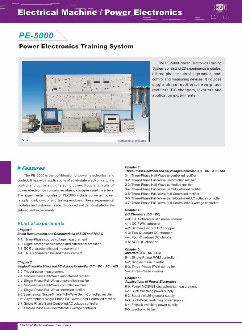
The PE-5000 Power Electronics Training
System consists of 28 experimental modules,
a three-phase squirrel cage motor, load,
control and measuring devices. It inculdes
single-phase rect i f iers, three-phase
rectifiers, DC choppers, inverters and
application experiments.
The PE-5000 is the combination of power, electronics, and
control. It has wide applications of solid-state electronics to the
control and conversion of electric power. Popular circuits of
power electronics contain rectifiers, choppers and inverters.
The experimental modules of PE-5000 include converter, power
supply, load, control and testing modules. These experimental
modules and instruments are introduced and demonstrated in the
subsequent experiments.
Notebook is excluded*

PE-5000
Electrical Machine/Power Electronics
DC Power Supply ( 0-40V/6A)
(1) Input voltage : 220VAC, 50/60Hz
(2) 2 output voltage : 0~20V, 0~40VDC
(3) Rated current : 0~20V/6A, 0~40V/6A
(4) Overload protection
Reference Variable Generator
(1) Vc range : 0V~ +10V, -10V~+10V
(2) Linear scale : 0~100%
(3) 7-segment display for displaying the value
of output control voltage Vc
(4) Operation power supply : ±15V
Differential Amplifier
(1) 4 Channels output and input
(2) Measuring voltage (Max.) : 700Vp
(3) Output voltage (Max.) : 10Vp
(4) Measuring frequency (Max.) : 200KHz
(5) Input voltage range : 500V, 100V, 10V
(6) Output voltage range : 10V
(7) Output terminal : common ground, 3 types
a. 2 BNC sockets for oscilloscope, switching
switch to selected measuring channel
(A/B, C/D)
b. 4mm terminal for module connection
(8) Operation power supply :
AC220V, 50/60Hz
Current Transducer
(1) Hall current sensor
(2) Measuring frequency (Max.) : 200KHz
(3) Current measuring :
a. Input : 20Ap, output 10V
b. Input : 5Ap, output 10V
c. Input : 1Ap, output 10V
(4) Overcurrent indicator
(5) Operation power supply :
AC220V, 50/60Hz
Three Phase Angle Controller
(1) Pulse output : Electric isolation, directly drives
up to 6 thyristors
(2) Trigger angle : 0~180
(3) Control input signal : 0~10VDC
(4) Rectification angle : 0~90 adjustable
(5) Convert angle : 0~180 adjustable
(6) Mode select :Single pulse & continuous pulse
(7) Operation power supply : ±15V
R.M.S. Meter
(1) Measuring range :
a. Current : 0.1/0.3/1/3/10/30 A
b. Voltage : 3/10/30/100/300/1000V
(2) 3 Measuring types :
a. RMS AC+DC : Total RMS value
b. RMS AC : Ripple RMS value
c. AV AC+DC : Arithmetic mean value
(3) Overload protection
(4) ± Value indicator : LED
(5) Accuracy : 2%. Full scale
(6) Operation power supply :
AC220V, 50/60Hz
Power Meter (0.3W-30KW)(1) Measuring range : 0.3W~30KW
a. Current : 0.1/0.3/1/3/10/30 A rmsb. Voltage : 3/10/30/100/300/1000V rms
(2) Frequency range : 0~20KHz(3) Overload protection(4) Overcurrent & overvoltage
LED indicator(5) Reactive power ± value indicator
(QL & QC)(6) Accuracy : 2% full scale(7) Output terminal :
Measuring full scale 100%=1V(8) Operation power supply :
AC220V, 50/60Hz
Resistor Load Unit
(1) Bench top type
(2) 3 load resistors, each one 100
(3) Rated current : 2.5A
(4) Rated power : 625W
Ω
DC Power Supply ( 15V/2A)
(1) Short circuit & over temperature protection
(2) Overcurrent indicator : LED
(3) Over temperature indicator : LED
(4) Rated output : ±15V/2A
(5) Power indicator : LED
(6) Operation power supply :
AC220V, 50/60Hz
Specifications�
1. PE-5310-1A
2. PE-5310-1B
3. PE-5310-2A
4. PE-5310-2B
5. PE-5310-2C
6. PE-5310-2D
7. PE-5310-3A
8. PE-5310-3B
9. PE-5310-3C

PE-5000
Electrical Machine/Power Electronics
Flyback Switching Power Supply
(1) Test point :
a. Switching control IC output signal
b. Current feedback signal
c. Voltage feedback signal
d. Switching power component terminal
(2) Switching frequency up to 40KHz
(3) Converter control : Isolation feedback converter
(4) Input voltage : 95~250V AC
(5) Output : 45W, up to 80% efficiency
(6) Output voltage ripple : ≤ 5%
(7) Output voltage regulation : ≤ 5%
(8) Output voltage : DC 12V ~ 15V,
adjustable by R18
(9) Rated current : 2A Max.
overload & short circuit protection
Switching power component : MOSFET
Boost Switching Power Supply
(1) Test point :
a. Switching control IC output signal
b. Current feedback signal
c. Voltage feedback signal
d. Switching power component terminal
(2) Switching frequency : ≥ 40KHz
(3) Input voltage : DC 10 ~ 16V
(4) Output : 60W, up to 85% efficiency
(5) Output voltage ripple : ≤ 5%
(6) Output voltage regulation : ≤ 5%
(7) Output voltage : DC 18V ~ 30V,
adjustable
(8) Rated current : 2A Max.
overload & short circuit protection(9) Switching power component : MOSFET
Buck Switching Power Supply
(1) Test point :
a.Switching control IC output signal
b.Current feedback signal
c.Voltage feedback signal
d.Switching power component terminal
(2) Switching frequency : ≥40KHz
(3) Input voltage : DC 17~ 30V
(4) Output : 45W, up to 85% efficiency
(5) Output voltage ripple : ≤5%
(6) Output voltage regulation : ≤5%
(7) Output voltage : DC 10V ~ 15V,
adjustable
(8) Rated current : 2A Max.
overload & short circuit protection
(9) Switching power component :MOSFET
Buck-Boost Switching Power Supply Unit
(1) Test point :
a. Switching control IC output signal
b. Current feedback signal
c. Voltage feedback signal
d. Switching power component terminal
(2) Switching frequency : ≥40KHz
(3) Input voltage : DC 20 ~ 30V
(4) Output : 60W, up to 85% efficiency
(5) Output voltage ripple : ≤5%
(6) Output voltage regulation : ≤5%
(7) Output voltage : DC 25V ~ 30V,
adjustable
(8) Rated current : 2A Max.
overload & short circuit protection
(9) Switching power component :MOSFET
Electronic Ballast Fluorescent Lamp(1) Switching frequency : 10KHz(2) Input voltage range : 220V AC(3) Type of lamp : 35cm long tube 10W(4) Control mode : half-bridge
self-excitation feedback multivibrator(5) Output current : 2A max. with overflow
and short circuit protection(6) Switching power component : BJT
IGBT Drive Set(1) Input voltage : DC 20~300V(2) Output voltage : 20~300Vp(3) Drive circuit :
Photo couple and drive circuit(4) Output device : IGBT, 800V/60A(5) Current protector
Resistor Load
(1) 2 resistors load :
a. 5~50Ω/120W
b.10~100 /120W
(2) Overcurrent protection
Ω
(1) Bench top type
(2) Load indicator : 50mH x 2/200mH
(3) Rated current : 5A
Inductive Load Unit
10. PE-5310-3D
11. PE-5310-3E
12. PE-5310-4A
(10)
13. PE-5310-4B
14. PE-5310-4C
15. PE-5310-4D
16. PE-5310-4E
17. PE-5310-4F

PE-5000
Electrical Machine/Power Electronics
Three Phase PWM Controller
(1) Triangular wave( carrier) generator :
a. Amplitude : -10V~+10V
b. Frequency : 5K, 10K, 20KHz
(2) Sine wave signal generator
(3) Multiplex
(4) PWM Signal generator : 6 x TTL level
(5) Square wave signal generator
(6) IP input : DC -10V~+10V
(7) Operation power supply : DC±15V
Three Phase Rectifier & Filter(1) Power input : 1Ø or 3Ø, 20~220VAC(2) With Inductor & capacitor filter circuit(3) Surge protection in voltage circuit(4) Output voltage :
28~310VDC (max.)/10A(max.)
Universal Inverter 3x230V(1) 6 x TTL level signal input : > 2.5μS, for interlock
& dead time control(2) Power input : 1Ø or 3Ø AC 20~220V(3) With photo-couple, isolation and main circuit(4) Output power component : IGBT 800V/50A(5) With adjustable overcurrent protection circuit(6) Output capacity : 220V/ 1.5KV(7) Operation power supply :
AC220V, 50/60Hz
Power Diode Set
(1) Rated voltage : 1200V
(2) Rated current : 40A
Fuse Set
(1) Module design
(2) 3 x D-Type fuses, 500V/6A
Thyristor (800V/10A)
(1) Rated voltage : 800V
(2) Rated current : 10A
(3) With RC surge buffer protection circuit
SCR/TRIAC Set(1) SCR : 800V/16A(2) TRIAC : 600V/12A(3) Load lamp : 2 x 24V/10W (with switch)(4) Load inductor : 1 x 50m H/1A( with switch)(5) With current/voltage transfer measurement(6) With trigger control adjustable(7) Operation power supply :
AC220V, 50/60Hz
MOSFET/ IGBT Set
(1) IGBT : 800V/50A
(2) MOSFET : 100V/48A
(3) Load lamp : 2 x 24V/10W (with switch)
(4) Load inductor : 1 x 50mH/1A( with switch)
(5) With current/voltage transfer measurement
(6) With trigger control adjustable
(7) With external signal input
(8) Operation power supply : DC+15V
DC PWM Generator(1) Triangular wave( carrier) generator :
a. Amplitude : 0~10V or -10V~+10Vb. Frequency : 1K, 10K, 15KHz
(2) PWM signal generator :2 x PWM control signal
(3) IP input : DC -10V~+10V(4) Operation power supply : DC±15V
Single Phase PWM Controller(1) Triangular wave( carrier) generator :
a. Amplitude : -10V~+10Vb. Frequency : 1K, 5K, 15KHz
(2) Sine wave signal generator(3) Multiplex(4) PWM Signal generator : 2 x TTL level(5) Square wave signal generator(6) IP input : DC 0V~+10V(7) Operation power supply :DC±15V
18. PE-5310-4G
19. PE-5310-4H
20. PE-5310-4I
21. PE-5310-4J
22. PE-5310-4K
23. PE-5310-5A
24. PE-5310-5B
25. PE-5310-5C
26. PE-5310-5D
27. PE-5310-5E
PE-5000
Electrical Machine/Power Electronics
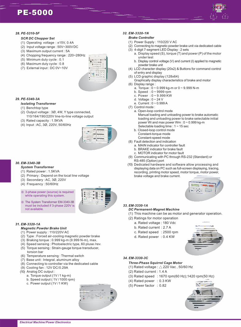
System Transformer
(1) Rated power : 1.5KVA
(2) Primary : Depend on the local line voltage
(3) Secondary : AC, 3Ø, 220V
(4) Frequency : 50/60Hz
Magnetic Powder Brake Unit
(1) Power supply : 110/220V AC
(2) Type : Forced air-cooling magnetic powder brake
(3) Braking torque : 0.999 kg-m (9.999 N-m), max.
(4) Speed sensing : Photoelectric type, 60 pluse /rev.
(5) Torque sensing : Strain-gauge torque transducer,
torsion bar
(6) Temperature sensing : Thermal switch
(7) Base unit : Integral, aluminum alloy
(8) Connecting to controller via the dedicated cable
(9) Cooling fan : 12V DC/0.29A
Analog DC output :
a. Torque output (1V /1 kg-m)
b. Speed output ( 1V /1000 rpm)
c. Power output (1V /1 KW)
Three-Phase Squirrel Cage Motor
(1) Rated voltage : 220 Vac , 50/60 Hz
(2) Rated current : 1.4 A
(3) Rated speed : 1670 rpm(60 Hz);1420 rpm(50 Hz)
(4) Rated power : 0.3 KW
(5) Power factor : 0.82
△
DC Permanent-Magnet Machine
(1) This machine can be as motor and generator operation.
(2) Ratings for motor operation
a. Rated voltage : 180 Vdc
b. Rated current : 2.7 A
c. Rated speed : 2500 rpm
d. Rated power : 0.4 KW
Brake Controller
(1) Power Supply : 110/220 V AC(2) Connecting to magnetic powder brake unit via dedicated cable(3) 4-digit 7-segment LED Display : 2 sets
(4) LCD character display (20x2) & Buttons for command controlof entry and display
(5) LCD graphic display (128x64)Graphically display characteristics of brake and motor
(6) Display range :
e. Current : 0 ~ 0.999 A(7) Control mode :
Manual loading and unloading power to brake automaticloading and unloading power to brake selectable initialpower Wi and max power Wm : 0 ~ 0.999 kg-mSelectable loading time : 1 ~ 15 sec
b. Closed-loop control modeConstant-torque modeConstant-speed mode
(8) Fault detection and indicationa. MAIN indicator for controller fault
(9) Communicating with PC through RS-232 (Standard) orRS-485 (Option) portDedicated hardware and software allow processing anddisplaying data on PC such as full-screen displaying, tracing,recording, printing motor speed, motor torque, motor power,brake voltage and brake current.
a. Display speed (S), torque (T) and power (P) of the motorunder test
b. Display control voltage (V) and current (I) applied to magneticpowder brake unit
a. Torque : 0 ~ 0.999 kg-m or 0 ~ 9.999 N-mb. Speed : 0 ~ 9999 rpmc. Power : 0 ~ 9.999 KWd. Voltage : 0 ~ 24 V
a. Open-loop control mode
b. BRAKE indicator for brake faultc. MOTOR indicator for motor fault
SCR DC Chopper Set
(1) Operating voltage : ±15V, 0.4A
(2) Input voltage range : 50V~300VDC
(3) Maximum output current : 5A
(4) Chopping frequency range : 220~280Hz
(5) Minimum duty cycle : 0.1
(6) Maximum duty cycle : 0.8
(7) External input : DC 0V~10V
28. PE-5310-5F
29. PE-5340-3A
30. EM-3340-3B
31. EM-3320-1A
(10)
32. EM-3320-1N
(10)
33. EM-3330-1A
34. EM-3330-3C
Isolating Transformer
(1) Benchtop type
(2) Output voltage : 3Ø, 4W, Y type connected,
110/164/190/220V line-to-line voltage output
(3) Rated capacity : 1.5KVA
(4) Input : AC, 3Ø, 220V, 50/60Hz
※ 3-phase power (source) is requiredwhile operating this system.
EM-3340-3Bmust be included if 3-phase 220V isnot available.
※ The System Transformer
PE-5000
Electrical Machine/Power Electronics
Shaft End Guard
(1) Material : Plate coating
(2) A guard attachable to avoid contact with
electrical machines rotating parts
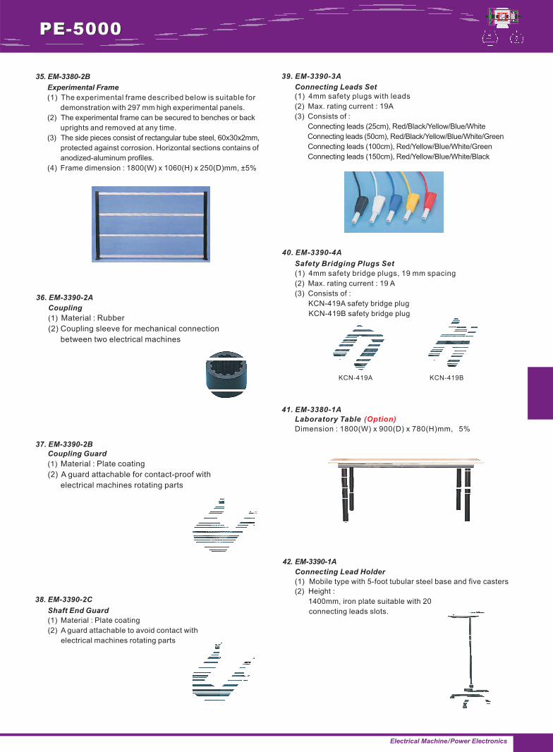
(1) 4mm safety plugs with leads
(2) Max. rating current : 19A
(3) Consists of :
Connecting leads (25cm), Red/Black/Yellow/Blue/White
Connecting leads (50cm), Red/Black/Yellow/Blue/White/Green
Connecting leads (100cm), Red/Yellow/Blue/White/Green
Connecting leads (150cm), Red/Yellow/Blue/White/Black
Connecting Leads Set
Safety Bridging Plugs Set
(1) 4mm safety bridge plugs, 19 mm spacing
(2) Max. rating current : 19 A
(3) Consists of :
KCN-419A safety bridge plug
KCN-419B safety bridge plug
Laboratory Table
Dimension : 1800(W) x 900(D) x 780(H)mm, 5%
(Option)
Connecting Lead Holder
(1) Mobile type with 5-foot tubular steel base and five casters
(2) Height :
1400mm, iron plate suitable with 20
connecting leads slots.
KCN-419A KCN-419B
Experimental Frame
(1) The experimental frame described below is suitable for
demonstration with 297 mm high experimental panels.
(2) The experimental frame can be secured to benches or back
uprights and removed at any time.
(3) The side pieces consist of rectangular tube steel, 60x30x2mm,
protected against corrosion. Horizontal sections contains of
anodized-aluminum profiles.
(4) Frame dimension : 1800(W) x 1060(H) x 250(D)mm, ±5%
Coupling
(1) Material : Rubber
(2) Coupling sleeve for mechanical connection
between two electrical machines
Coupling Guard
(1) Material : Plate coating
(2) A guard attachable for contact-proof with
electrical machines rotating parts
35. EM-3380-2B
36. EM-3390-2A
37. EM-3390-2B
38. EM-3390-2C
39. EM-3390-3A
40. EM-3390-4A
41. EM-3380-1A
42. EM-3390-1A
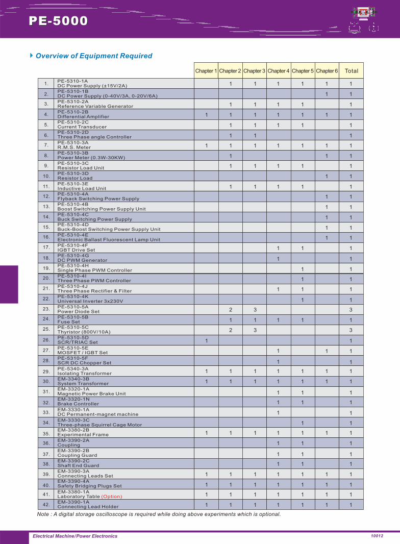
Overview of Equipment Required
PE-5310-1ADC Power Supply (±15V/2A)
Chapter 1 Total
PE-5310-1BDC Power Supply (0-40V/3A, 0-20V/6A)
Note : A digital storage oscilloscope is required while doing above experiments which is optional.
PE-5310-2AReference Variable Generator
PE-5310-2BDifferential Amplifier
PE-5310-2CCurrent Transducer
PE-5310-2DThree Phase angle Controller
PE-5310-3AR.M.S. Meter
PE-5310-3BPower Meter (0.3W-30KW)
PE-5310-3CResistor Load Unit
PE-5310-3DResistor Load
PE-5310-3EInductive Load Unit
PE-5310-4AFlyback Switching Power Supply
PE-5310-4BBoost Switching Power Supply Unit
PE-5310-4CBuck Switching Power Supply
PE-5310-4DBuck-Boost Switching Power Supply Unit
PE-5310-4EElectronic Ballast Fluorescent Lamp Unit
PE-5310-4FIGBT Drive Set
PE-5310-4GDC PWM Generator
PE-5310-4HSingle Phase PWM Controller
PE-5310-4IThree Phase PWM Controller
PE-5310-4JThree Phase Rectifier & Filter
PE-5310-4KUniversal Inverter 3x230V
PE-5310-5APower Diode Set
PE-5310-5BFuse Set
PE-5310-5CThyristor (800V/10A)
PE-5310-5DSCR/TRIAC Set
PE-5310-5EMOSFET / IGBT Set
PE-5310-5FSCR DC Chopper Set
EM-3320-1AMagnetic Power Brake Unit
EM-3320-1NBrake Controller
EM-3330-1ADC Permanent-magnet machine
EM-3330-3CThree-phase Squirrel Cage Motor
PE-5340-3AIsolating Transformer
EM-3380-2BExperimental Frame
EM-3390-2ACoupling
EM-3390-2BCoupling Guard
EM-3390-2CShaft End Guard
EM-3390-3AConnecting Leads Set
EM-3390-4ASafety Bridging Plugs Set
EM-3340-3BSystem Transformer
EM-3380-1ALaboratory Table (Option)
EM-3390-1AConnecting Lead Holder
1 1 1 1 1 1
1 1
1 1 1 1 1
1 1 1 1 11 1
1 1 1 1 1
1 1 1
1 1 1 1 11 1
1 11
1 1 1 1 1
11
1 1 1 1 1
11
11
11
11
11
1 1 1
1 1
1 1
1 1
1 1 1
1 1
2 3 3
1 1 1 1 1
2 3 3
11
111
11
1 1 1
1 1 1
11
1 1
1 1 1 1 11 1
1 1 1 1 11 1
1 1 1
1 1 1
1 1 1
1 1 1 1 11 1
1 1 1 1 11 1
1 1 1 1 11 1
1 1 1 1 11 1
1 1 1 1 11 1
�
1.
2.
3.
4.
5.
6.
7.
8.
9.
10.
11.
12.
13.
14.
15.
16.
17.
18.
19.
20.
21.
22.
23.
24.
25.
26.
27.
28.
29.
30.
31.
32.
33.
34.
35.
36.
37.
38.
39.
40.
41.
42.
PE-5000
Electrical Machine/Power Electronics
Chapter 2 Chapter 3 Chapter 4 Chapter 5 Chapter 6
10012