Navi-Trainer 5000 (v. 5.35). Instructor Manual
507
NAVI-TRAINER PROFESSIONAL 5000 (VERSION 5.35) INSTRUCTOR MANUAL Issue date: October, 2014
-
Upload
khangminh22 -
Category
Documents
-
view
0 -
download
0
Transcript of Navi-Trainer 5000 (v. 5.35). Instructor Manual
NAVI-TRAINER PROFESSIONAL 5000(VERSION 5.35)
INSTRUCTOR MANUAL
Issue date: October, 2014
Copyright © 1993–2014 Transas MIP Ltd. All rights reserved.
The information contained herein is proprietary to Transas MIP Ltd. and shall not be duplicated inwhole or in part. The technical details contained in this manual are the best that are available at thedate of issue but are subject to change without notice.
Transas MIP Ltd. pursues the policy of continuous development. This may lead to the productdescribed in this manual being different from the product delivered after its publication.
The names of actual companies and products mentioned herein may be the trademarks of theirrespective owners.
NVIDIA ® and PhysX ® are registered trademarks of NVIDIA Corporation and are used under license.
3
CONTENTS
Introduction 11Annotation 13Printing House Conventions 14General 15
Chapter 1. Arrangement of Instructor Workplace 17Starting Navi-Trainer Instructor 19Description of MainWindow 20Menu Bar 21Toolbars 21CustomisingMenu Bar and Toolbars 22Chart Window 29Status Bar 31
InstructorWorkplace Configuration 32SavingWorkplace Configuration 32Loading Configuration 33Default Configuration 33Autosaving Configuration 33
Chapter 2. Creating and Editing Exercise 35Selection of Training Area 39Information on Training Area 40Chart Setup 41Chart Centering 41Zooming Chart Fragment 41Changing Chart Scale 42Canceling Operations with Charts 42Loading and Unloading Area Charts 43Information on Chart 43Measuring Bearing and Range 44Setting Reference Point 44ChangingWindow Orientation 44Display of Auxiliary Elements (Overlays) 45Depth Section 47Changing Color Palette 48SelectingMotion Display Modes 48
Operations with Objects 49Object Categories 49Adding New Object to Exercise 54Selecting Object on Chart 56Opening Object’s Context Menu 56
Navi-Trainer Professional 5000 (Version 5.35) • Instructor Manual
4
Moving Object 56Rotating Object 56RenamingObject 57Setting Ship Tactical Image 57Opening Object’s Properties Panel 58Deleting Object 59Objects Panel 59Readonly Mode 61
Selection of Measurement Units 62General Exercise Settings 63Displaying Ship Track as Series of Dots 64Displaying Ship Track as Series of Ship Contours 65Displaying Speed Vectors 66Enabling/Disabling Automatic Sound Signals 68Miscellaneous Settings 69
Setting Environmental Sailing Conditions 71Environment Settings 72Creating Environment Conditions Template 81Overall Environmental Conditions 83Local Environmental Conditions 91Importing Tides and Currents 99Creating Vector Field of Current 103Setting of Clouds 106Setting Atmosphere Fronts 107EditingWave Spectrums 109
Ship Setup 112Own Ship Setup 112Ship-Target Setup 114
Data on Ships 116Setting Ship Properties 117General Ship Properties 119Setting Ship Position 119Autopilot Settings 120Navigational Equipment Initial Settings 121UAIS Initial Settings 125Setting of Navigational Signals 126Setting Options 128Contours Settings 130Fenders Settings 131
Route Planning 132Plotting Route on Chart 132Assigning Object to Route 133General Route Settings 134Editing Route on Chart 135Setting Route Properties 136Route Tabular Form 139Conditions for Following on Route 141Route Export and Import 141
Setting Procedural Alarms 143Creating Procedural Alarms 143
Contents
5
Template of Procedural Alarms 145Switching On/Off Procedural Alarms 146
Setting Synchronization with External GPS Source 147Magnetic Deviation 148SettingMagnetic Deviation 148Magnetic Deviation Template 148
Ship Equipment Fault Scenarios 150Creating Fault Scenarios 150Editing Fault Scenarios 153List of Device Faults 155
Aid-to-Navigation Objects (Buoys) 158LandObjects 159Setting LandObjects 159Tidal Stream Signal Station 159Traffic Control Signal Station 160
Floating Objects 161Setting Floating Objects 161Designation Floating Objects on Chart 162
AIS AtoN 164Setup of Exchange Recording 167Setup of Video Log File Recording 168Using Templates 169Template of Single Object 169Template of Group of Objects 170
Creating Comments on Exercise 173Adding User Information to Chart 174Pre-playing of Exercise 176Saving and Loading Exercise 177Saving Exercise 177Loading Exercise 178Loading of NT 3000 Exercises 179
Chapter 3. Simulator Session 181Opening Simulator Session 183Types of Training Scenario 183Distribution of Tasks 183Starting Exercise 186Pausing Exercise 186Session Overloading 186
Possible Operations During Simulator Session 188Control of Ships 189Control of Own Ships and Target Ships (AdvancedModels) 189Control of Targets Ships (SimplifiedModels) 189
Giving Sound Signals 191Giving Sound Signals by Target Ships 191Giving Siren Signals 192
Control of Autopilot 193Motion Data Display 195Fire Detection Alarm 196Control of Navigation Signals 197Selecting Signals Preset Combination 197
Navi-Trainer Professional 5000 (Version 5.35) • Instructor Manual
6
Setting Lights 198Setting Shapes 199Change of Lights and Shapes 200
Flashing Light Signaling 201SettingMalfunctions on Ship's Properties Panel 202Setting Radar Faults 202Setting Loran-С Faults 203Setting Propulsion Plant Faults 204Setting Steering System Faults 206
UAIS Message Exchange 208Message Reply 208Monitoring of UAIS Messages 209
Setting Options During Simulator Session 210Using Virtual Force 211Setting Virtual Force 211Changing Virtual Force 212Setting Virtual Force Properties 212
Ship Information Panel 213Events Panel 214Monitoring of Dangerous Targets 217CPA/TCPA Monitoring Panel 217General CPA/TCPA Settings 217Graphic Presentation of СРА/ТСРА Data 218
Diagrams of ShipMotion Parameters 220Ship DiagramWindow 220SelectingMonitored Parameters 223Setting Parameter Properties 225Diagram Settings Template 226Export Diagram Data to CSV-Format 227Diagram Printout 227
Instructor Visualization 229Setting Camera 229Instructor Visualization Control Panel 232
Creating Visualization Screenshots 236Loading Visual Profile on Bridge 237Visual Settings 238Setting Radar 240Loading ECDIS Data 241Transmitting NAVTEX Messages 242VHF Playback 245Control of Auxiliary Machinery 247Control of Remote Sensors 249Creation of Log Scripts 251LogScript Panel 251Saving Current Log Script 251Recording Log Script 252Editing Log Script 254
Closing Simulator Session 256Saving Current State of Exercise 256Stop Exercise 256
Contents
7
Chapter 4. Debriefing 257General 259Loading Log File 260Log Playback 261Log Script Playback 262Main ExerciseWindow Printout 264Playback of Audio Log Files 266Playback of Video Log Files 267Report Generation 268Report GeneratorWizard 270
Chapter 5. Special Exercises 275Mooring Operations 277MooringWalls 277Characteristics of Mechanical and Hydrodynamic Interaction 280Points on Ship Contour 281Operations with Tow/Mooring Lines 282Control of MooringWinches 285SettingMooring Objects 287Work with BalloonMooring Fenders 295
Operations with Anchors 297Setting Anchor Parameters 297Selecting Seabed Type 299On-Chart Control of Anchors 300Control of AnchorWinches during Exercise 302
TowingOperations 304Setting Bridle 304Creating Barge Tow 306Operations with Tow Winches 307
Operations with Automatic Tugs 314Automatic Tugs General Settings 315Reserving and Releasing of Tug 315Basic Operations 316Automatic Tug Control Page 323
Navigation in Ice Conditions 324Work with Ice Zone 324Setting Ship Ice Class 329Setting Ice Repulsion 330Setting Ice Accretion 331Operations with Icebergs 331Operations with Ice Breaker 334Monitoring Trainee Performance 337
Fishing Operations 338Shoal Objects 338Selecting Vertical Sonic Speed Distribution 341Pinnacle Objects 342Fishing Buoys 343Setting Bottom and Pelagic Trawl 344Setting Purse Seine 347Setting Long Line 350Watching Trainee Performance 352
Navi-Trainer Professional 5000 (Version 5.35) • Instructor Manual
8
Search and RescueOperations 354SAR Objects 354Signaling in Accordance with ICS 365Giving Distress Signals 369Use of Rescue Boat 370
Operations with Helicopters and Aircrafts 374Operations with Helicopter Objects 374Operations with Aircraft Objects 376Deck Helicopters 377
Underway Replenishment Operations 382Setting Underway Replenishment Criteria 382Underway Replenishment Control Panel 383P&D Line and SpanWire Rendering/Heaving 384
Joint ShipManeuvering in Formations 387Creating Fleet Formation 387Control of Fleet Formation 390
Passing of Locks 392Setting Lock Initial Properties 392Control of Lock 393Monitoring Fulfilment of Exercise with Locks 397
Control of Semaphores 398Ro-RoOperations 400ECDIS Training 404Ordering Charts, Chart Update andWeather Forecasts 404Order Processing 407
Operations with Submarine 409Pirates Attacks Control 411Control of Motion Platform 412
Chapter 6. Ship Communication Aids 415Intercom 417Telephone Communication with Subscribers 417Playback of Radiotelephone Communications 419
VHF Communication 420Radio Traffic Monitoring 420Keeping of ListeningWatch 421Playback of Radiotelephone Communications 424
Chapter 7. Joint Operation of NTPRO with Other Simulators 425Joint Exercises on NTPRO and VTMS Simulator 427Creating NTPROExercise 427Creating VTMS Configuration 431
Joint Exercises on NTPRO and ERS/TechSim Simulators 447Preparation of Joint Exercises 447Establishing Connection with ERS/TechSim Simulator 450Running Joint Exercises 451
Joint Exercises on NTPRO and TGS Simulators 453Establishing Connection with TGS Simulator 453Running Joint Exercises 454
Chapter 8. Transas Evaluation and Assessment System 455General 457System Overview 457
Contents
9
Principles of InstructorWork with TEAS 458Rule Editor 459Competency Assessment Scenario 459Description of Operations, Parameters, and Constants 460Rule Editor's Toolbar Buttons 470Rule Editor's Context Menu 471Formation of Assessment Rules 472
Grading Panel 482Training Report 483Trainee Registration 483Log Playback and Data Export to Training Report 484
Proficiency Growth Assessment 485Annex 1 487Navi-Trainer Instructor Menu Description 489
Annex 2 497Parameters Monitored for Detecting Violations 499


11
INTRODUCTION
Annotation 13Printing House Conventions 14General 15

Introduction • Annotation
13
ANNOTATIONThis Manual is intended for use by the Instructor of the navigational simulator Navi-TrainerProfessional 5000 (NTPRO 5000).
TheManual consists of eight chapters and two annexes. Each of the chapters has its own list of contents.
For work with theManual youmay need the following additional documentation:
l Navi-Trainer 5000 Professional (v. 5.35). Technical Description and Installation Manual;
l Navi-Trainer Professional 5000 (v. 5.35). Navigational Bridge.
Information in this document is subject to change in order to improve simulator reliability, design, orfunction without prior notification.
Navi-Trainer Professional 5000 (Version 5.35) • Instructor Manual
14
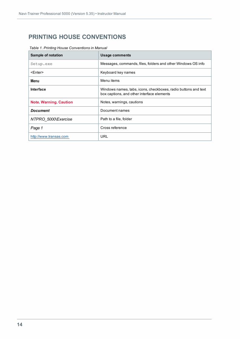
PRINTING HOUSE CONVENTIONS
Sample of notation Usage comments
Setup.exe Messages, commands, files, folders and other Windows OS info
<Enter> Keyboard key names
Menu Menu items
Interface Windows names, tabs, icons, checkboxes, radio buttons and textbox captions, and other interface elements
Note,Warning,Caution Notes, warnings, cautions
Document Document names
NTPRO_5000\Exercise Path to a file, folder
Page 1 Cross reference
http://www.transas.com URL
Table 1. Printing House Conventions in Manual
Introduction • General
15
GENERALThe instructor workplace in NTPRO 5000 navigation simulator is based on Navi-Trainer Instructorapplication intended for:
l Creation and editing of exercise scenarios;
l Starting and conducting simulator session;
l Debriefing.
An “exercise scenario” or an “exercise” is understood as a description of location andmotion of objectswithin the scene space.
An “exercise scene” or a “scene” is understood as amodel or actual geographic area.
The scene is an aggregate of:
l The terrain spatial model (submerged and surface part);
l Spatial models of coastal structures (buildings, bridges, berths, etc.);
l Spatial models of aids to navigation (lighthouses, buoys, etc.).
Scenes of different geographic areas of the earth are supplied togetherwith the simulator.
Exercise objects include:
l Ships (own and targets);
l Tugboats (own and targets);
l Barges (targets);
l Helicopters (targets, “deck helicopters”);
l Aircrafts (targets);
l Mooring objects (CALM, SALM, bollard, etc.);
l Fishing objects (shoal, pinnacle, buoys);
l Objects of search and rescue operations (SART, man over board, damaged tanker, oil slick, etc.);
l Environment objects (composite condition zone, ice, cloud, current field, etc.);
l Land objects (tidal stream signal station, traffic control signal station, watch tower, etc.);
l Floating objects (buoys, containers, trunk, etc.);
l Scene objects (visual camera, routes, AtoN station, ERBL, etc.);
l VTS radar towers;
l Acoustic transponder;
l Creature and transport animated objects;
l User objects (ellipse, line, text, zone);
l TEAS objects.
Navi-Trainer Professional 5000 (Version 5.35) • Instructor Manual
16
The exercise scenario creation procedure implies:
l Selection of a geographic area;
l Setting environment sailing conditions;
l Setting of the initial object positions;
l Setting of the objects’ speed and routes;
l Setting of characteristics and faults of the navigational equipment.
The simulator session procedure includes the followingmain stages:
l Exercise assignment to bridge and starting;
l Exercisemonitoring and control.
Exercise debriefing implies:
l Log playback;
l Report generation.
17
CHAPTER 1.ARRANGEMENT OF INSTRUCTOR
WORKPLACE
This chapter contains:
Starting Navi-Trainer Instructor 19Description of Main Window 20Menu Bar 21Toolbars 21CustomisingMenu Bar and Toolbars 22Chart Window 29Status Bar 31
Instructor Workplace Configuration 32SavingWorkplace Configuration 32Loading Configuration 33Default Configuration 33Autosaving Configuration 33

Chapter 1. Arrangement of Instructor Workplace • Starting Navi-Trainer Instructor
19
STARTING NAVI-TRAINER INSTRUCTORUsually, “Navi-Trainer instructor” application is added to simulator configuration and started automaticallyafter simulator start.
However, application (nti.exe) can be started from command line:
nti.exe – SERVER: name – LANG: language,
where:
l name – Trainer Server name;
l language – language code (9 – English, 25 – Russian).
In this case, the application can only be used for creating an exercise and debriefing on the instructorworkplace.
Navi-Trainer Professional 5000 (Version 5.35) • Instructor Manual
20
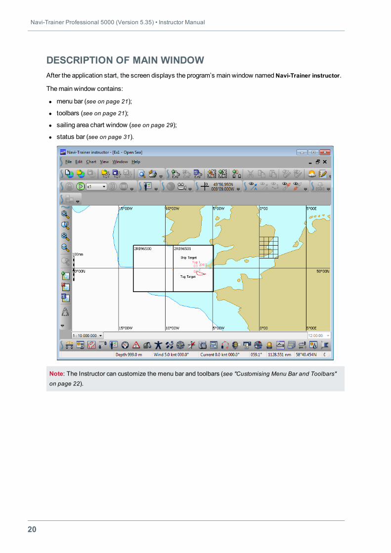
DESCRIPTION OF MAIN WINDOWAfter the application start, the screen displays the program’s main window namedNavi-Trainer instructor.
Themain window contains:
l menu bar (see on page 21);
l toolbars (see on page 21);
l sailing area chart window (see on page 29);
l status bar (see on page 31).
Note: The Instructor can customize the menu bar and toolbars (see "Customising Menu Bar and Toolbars"on page 22).
Chapter 1. Arrangement of Instructor Workplace • Description of Main Window
21
Menu BarMenu bar contains the followingmenu commands:
l File – handling exercise files;
l Edit – creating and editing exercises;
l Chart – handling charts;
l View – setting the instructor station elements for the display;
l Window – handling windows;
l Help – calling context help and obtaining additional information.
Note: For more information, see "Navi-Trainer Instructor Menu Description " on page 489.
To change the arrangement of themenu bar, left-click the sign in the left-hand part of themenu bar,holding themouse button drag themenu bar to the desired position on the tool ribbon. When a menu bar isdragged beyond the tool ribbon, themenu bar assumes the form of a window.
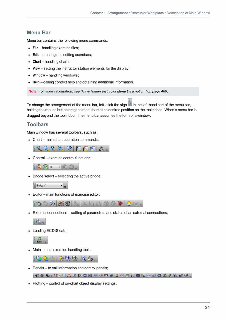
ToolbarsMain window has several toolbars, such as:
l Chart –main chart operation commands;
l Control – exercise control functions;
l Bridge select – selecting the active bridge;
l Editor –main functions of exercise editor:
l External connections – setting of parameters and status of an external connections;
l Loading ECDIS data;
l Main –main exercise handling tools;
l Panels – to call information and control panels;
l Plotting – control of on-chart object display settings;
Navi-Trainer Professional 5000 (Version 5.35) • Instructor Manual
22
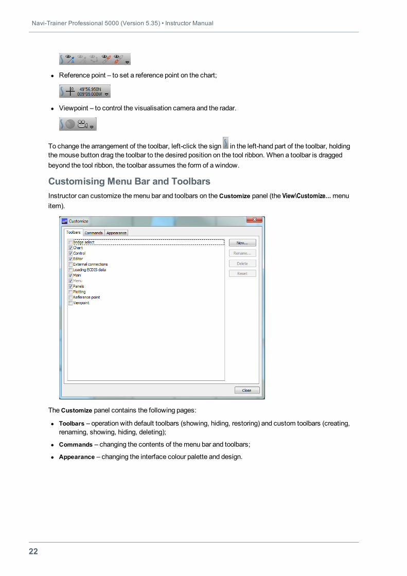
l Reference point – to set a reference point on the chart;
l Viewpoint – to control the visualisation camera and the radar.
To change the arrangement of the toolbar, left-click the sign in the left-hand part of the toolbar, holdingthemouse button drag the toolbar to the desired position on the tool ribbon. When a toolbar is draggedbeyond the tool ribbon, the toolbar assumes the form of a window.
Customising Menu Bar and ToolbarsInstructor can customize themenu bar and toolbars on theCustomize panel (the View\Customize…menuitem).
TheCustomize panel contains the following pages:
l Toolbars – operation with default toolbars (showing, hiding, restoring) and custom toolbars (creating,renaming, showing, hiding, deleting);
l Commands – changing the contents of themenu bar and toolbars;
l Appearance – changing the interface colour palette and design.
Chapter 1. Arrangement of Instructor Workplace • Description of Main Window
23
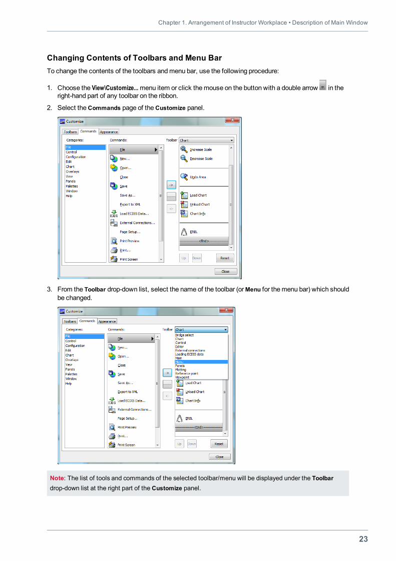
Changing Contents of Toolbars and Menu BarTo change the contents of the toolbars andmenu bar, use the following procedure:
1. Choose the View\Customize...menu item or click themouse on the button with a double arrow in theright-hand part of any toolbar on the ribbon.
2. Select theCommands page of theCustomize panel.
3. From the Toolbar drop-down list, select the name of the toolbar (orMenu for the menu bar) which shouldbe changed.
Note: The list of tools and commands of the selected toolbar/menu will be displayed under the Toolbardrop-down list at the right part of the Customize panel.
Navi-Trainer Professional 5000 (Version 5.35) • Instructor Manual
24
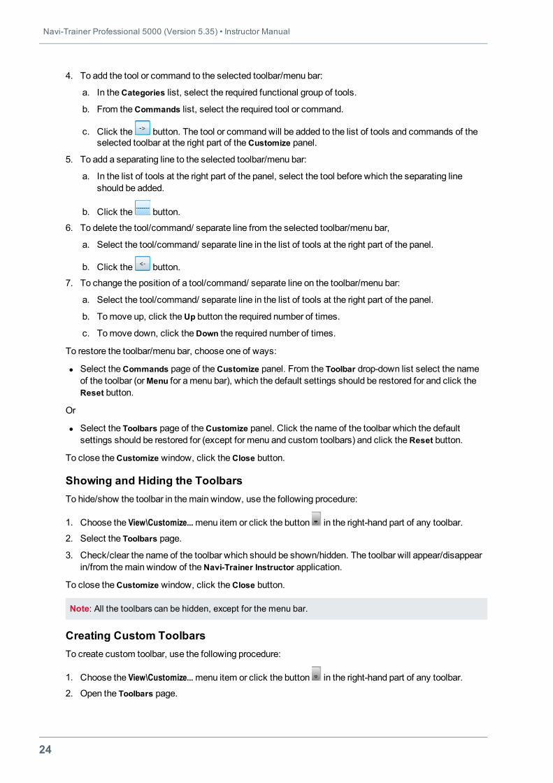
4. To add the tool or command to the selected toolbar/menu bar:
a. In theCategories list, select the required functional group of tools.
b. From theCommands list, select the required tool or command.
c. Click the button. The tool or commandwill be added to the list of tools and commands of theselected toolbar at the right part of theCustomize panel.
5. To add a separating line to the selected toolbar/menu bar:
a. In the list of tools at the right part of the panel, select the tool before which the separating lineshould be added.
b. Click the button.
6. To delete the tool/command/ separate line from the selected toolbar/menu bar,
a. Select the tool/command/ separate line in the list of tools at the right part of the panel.
b. Click the button.
7. To change the position of a tool/command/ separate line on the toolbar/menu bar:
a. Select the tool/command/ separate line in the list of tools at the right part of the panel.
b. Tomove up, click theUp button the required number of times.
c. Tomove down, click theDown the required number of times.
To restore the toolbar/menu bar, choose one of ways:
l Select theCommands page of theCustomize panel. From the Toolbar drop-down list select the nameof the toolbar (orMenu for amenu bar), which the default settings should be restored for and click theReset button.
Or
l Select the Toolbars page of theCustomize panel. Click the name of the toolbar which the defaultsettings should be restored for (except for menu and custom toolbars) and click theReset button.
To close theCustomize window, click theClose button.
Showing and Hiding the ToolbarsTo hide/show the toolbar in themain window, use the following procedure:
1. Choose the View\Customize...menu item or click the button in the right-hand part of any toolbar.
2. Select the Toolbars page.
3. Check/clear the name of the toolbar which should be shown/hidden. The toolbar will appear/disappearin/from themain window of theNavi-Trainer Instructor application.
To close theCustomize window, click theClose button.
Note: All the toolbars can be hidden, except for the menu bar.
Creating Custom ToolbarsTo create custom toolbar, use the following procedure:
1. Choose the View\Customize...menu item or click the button in the right-hand part of any toolbar.
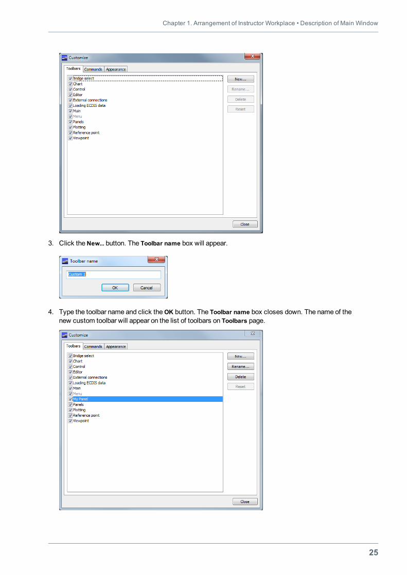
2. Open the Toolbars page.
Chapter 1. Arrangement of Instructor Workplace • Description of Main Window
25
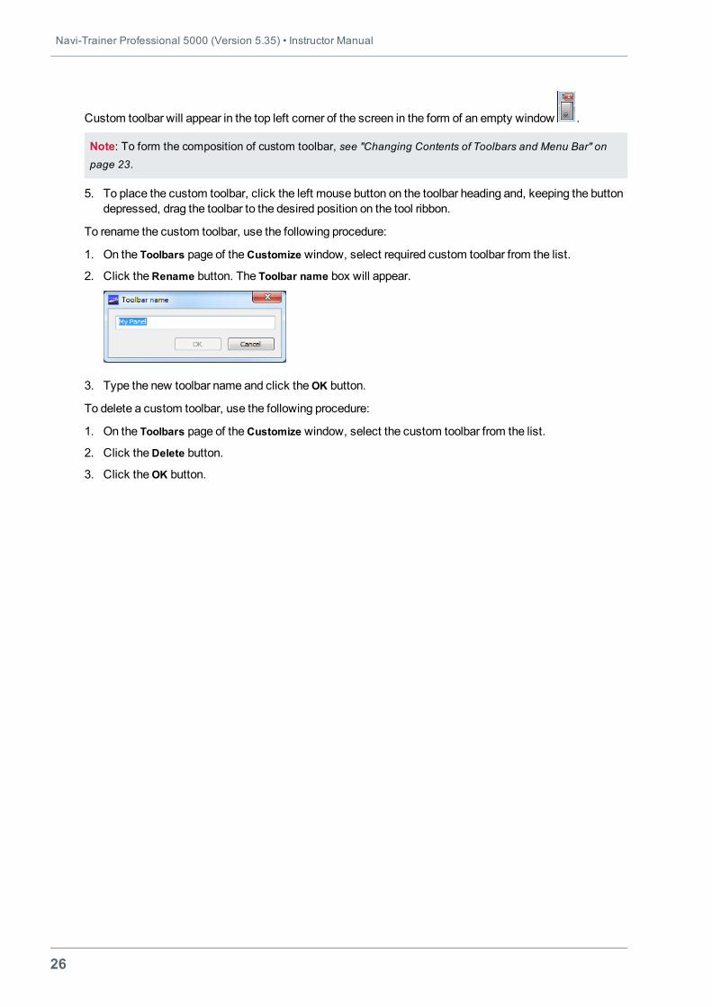
3. Click theNew... button. The Toolbar name box will appear.
4. Type the toolbar name and click theОK button. The Toolbar name box closes down. The name of thenew custom toolbar will appear on the list of toolbars on Toolbars page.
Navi-Trainer Professional 5000 (Version 5.35) • Instructor Manual
26
Custom toolbar will appear in the top left corner of the screen in the form of an empty window .
Note: To form the composition of custom toolbar, see "Changing Contents of Toolbars and Menu Bar" onpage 23.
5. To place the custom toolbar, click the left mouse button on the toolbar heading and, keeping the buttondepressed, drag the toolbar to the desired position on the tool ribbon.
To rename the custom toolbar, use the following procedure:
1. On the Toolbars page of theCustomize window, select required custom toolbar from the list.
2. Click theRename button. The Toolbar name box will appear.
3. Type the new toolbar name and click theОK button.
To delete a custom toolbar, use the following procedure:
1. On the Toolbars page of theCustomize window, select the custom toolbar from the list.
2. Click theDelete button.
3. Click theОK button.
Chapter 1. Arrangement of Instructor Workplace • Description of Main Window
27
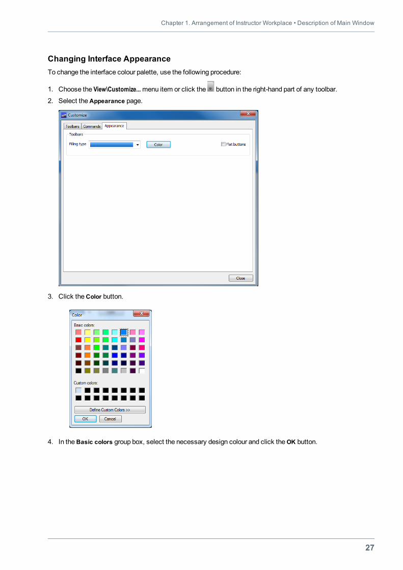
Changing Interface AppearanceTo change the interface colour palette, use the following procedure:
1. Choose the View\Customize...menu item or click the button in the right-hand part of any toolbar.
2. Select theAppearance page.
3. Click theСolor button.
4. In theBasic colors group box, select the necessary design colour and click theОK button.
Navi-Trainer Professional 5000 (Version 5.35) • Instructor Manual
28
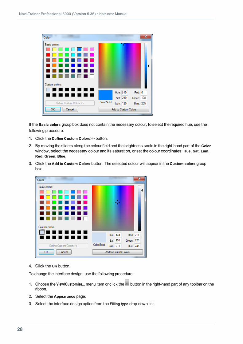
If theBasic colors group box does not contain the necessary colour, to select the required hue, use thefollowing procedure:
1. Click theDefine Custom Colors>> button.
2. By moving the sliders along the colour field and the brightness scale in the right-hand part of theColorwindow, select the necessary colour and its saturation, or set the colour coordinates: Hue, Sat, Lum,Red, Green, Blue.
3. Click theAdd to Custom Colors button. The selected colour will appear in theCustom colors groupbox.
4. Click theОK button.
To change the interface design, use the following procedure:
1. Choose the View\Customize...menu item or click the button in the right-hand part of any toolbar on theribbon.
2. Select theAppearance page.
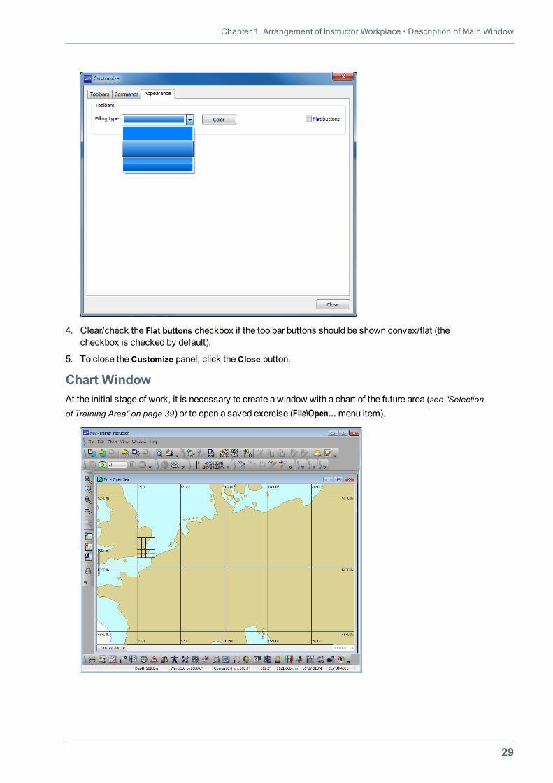
3. Select the interface design option from the Filling type drop-down list.
Chapter 1. Arrangement of Instructor Workplace • Description of Main Window
29
4. Clear/check the Flat buttons checkbox if the toolbar buttons should be shown convex/flat (thecheckbox is checked by default).
5. To close theCustomize panel, click theClose button.
Chart WindowAt the initial stage of work, it is necessary to create a window with a chart of the future area (see "Selectionof Training Area" on page 39) or to open a saved exercise (File\Open…menu item).
Navi-Trainer Professional 5000 (Version 5.35) • Instructor Manual
30
The chart window can be expanded to the width of themain window , returned to the initial state ,collapsed or closed .
It is possible to open several windows for each exercise:
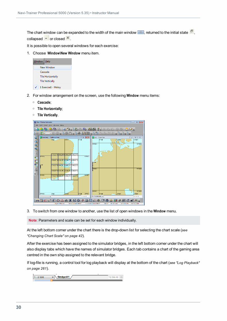
1. Choose Window\New Window menu item.
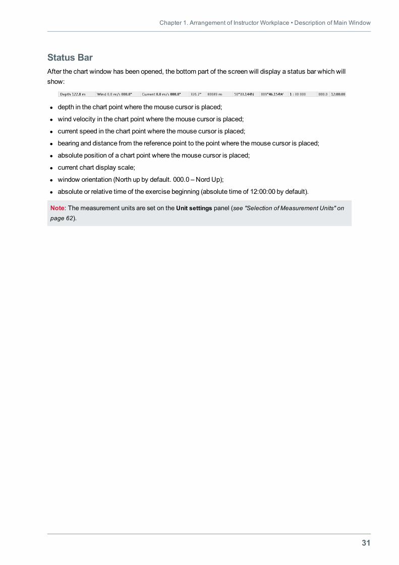
2. For window arrangement on the screen, use the followingWindow menu items:o Cascade;o Tile Horizontally;o Tile Vertically.
3. To switch from one window to another, use the list of open windows in theWindow menu.
Note: Parameters and scale can be set for each window individually.
At the left bottom corner under the chart there is the drop-down list for selecting the chart scale (see"Changing Chart Scale" on page 42).
After the exercise has been assigned to the simulator bridges, in the left bottom corner under the chart willalso display tabs which have the names of simulator bridges. Each tab contains a chart of the gaming areacentred in the own ship assigned to the relevant bridge.
If log-file is running, a control tool for log playback will display at the bottom of the chart (see "Log Playback"on page 261).
Chapter 1. Arrangement of Instructor Workplace • Description of Main Window
31
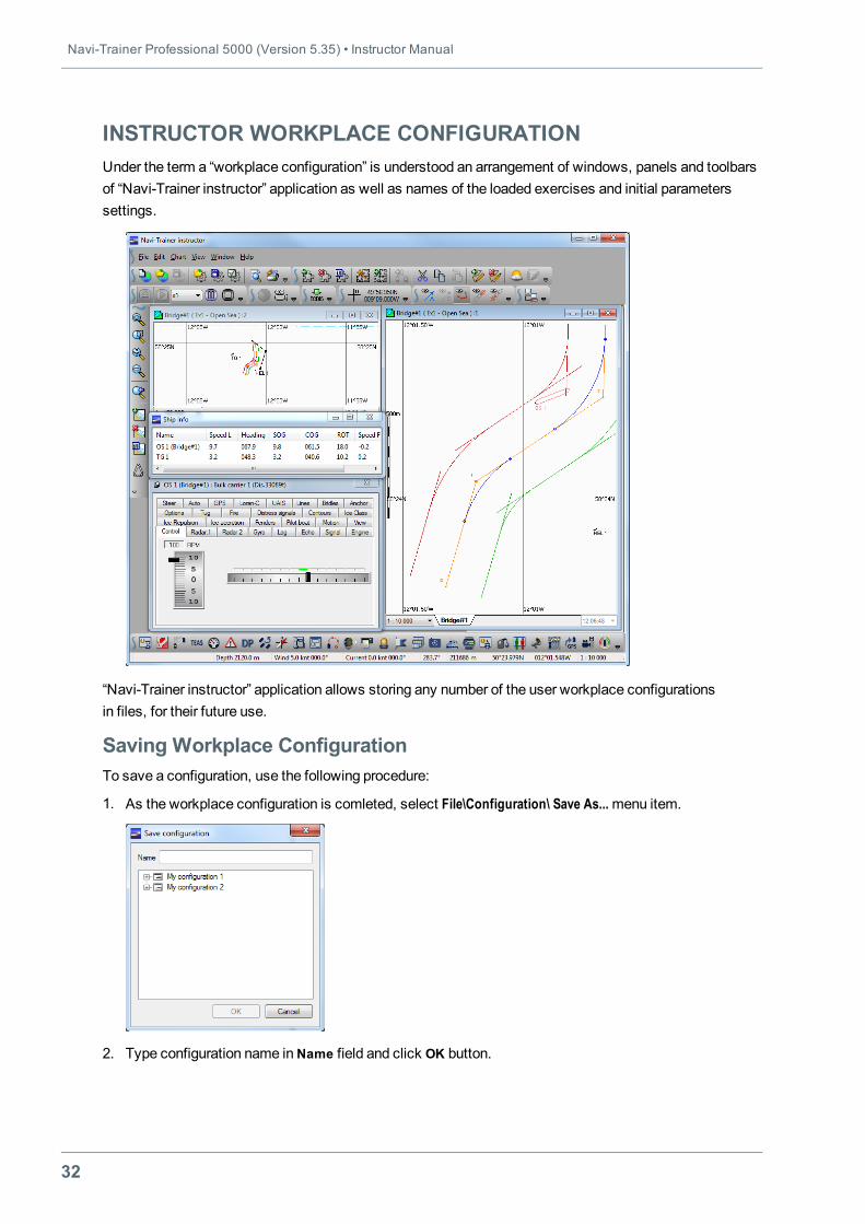
Status BarAfter the chart window has been opened, the bottom part of the screen will display a status bar which willshow:
l depth in the chart point where themouse cursor is placed;
l wind velocity in the chart point where themouse cursor is placed;
l current speed in the chart point where themouse cursor is placed;
l bearing and distance from the reference point to the point where themouse cursor is placed;
l absolute position of a chart point where themouse cursor is placed;
l current chart display scale;
l window orientation (North up by default. 000.0 – Nord Up);
l absolute or relative time of the exercise beginning (absolute time of 12:00:00 by default).
Note: The measurement units are set on the Unit settings panel (see "Selection of Measurement Units" onpage 62).
Navi-Trainer Professional 5000 (Version 5.35) • Instructor Manual
32
INSTRUCTOR WORKPLACE CONFIGURATIONUnder the term a “workplace configuration” is understood an arrangement of windows, panels and toolbarsof “Navi-Trainer instructor” application as well as names of the loaded exercises and initial parameterssettings.
“Navi-Trainer instructor” application allows storing any number of the user workplace configurationsin files, for their future use.
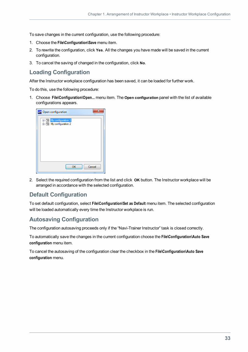
Saving Workplace ConfigurationTo save a configuration, use the following procedure:
1. As the workplace configuration is comleted, select File\Configuration\ Save As...menu item.
2. Type configuration name inName field and click OK button.
Chapter 1. Arrangement of Instructor Workplace • Instructor Workplace Configuration
33
To save changes in the current configuration, use the following procedure:
1. Choose the File\Configuration\Savemenu item.
2. To rewrite the configuration, click Yes. All the changes you havemade will be saved in the currentconfiguration.
3. To cancel the saving of changed in the configuration, click No.
Loading ConfigurationAfter the Instructor workplace configuration has been saved, it can be loaded for further work.
To do this, use the following procedure:
1. Choose File\Configuration\Open...menu item. TheOpen configuration panel with the list of availableconfigurations appears.
2. Select the required configuration from the list and click OK button. The Instructor workplace will bearranged in accordance with the selected configuration.
Default ConfigurationTo set default configuration, select File\Configuration\Set as Default menu item. The selected configurationwill be loaded automatically every time the Instructor workplace is run.
Autosaving ConfigurationThe configuration autosaving proceeds only if the “Navi-Trainer Instructor” task is closed correctly.
To automatically save the changes in the current configuration choose the File\Configuration\Auto Saveconfiguration menu item.
To cancel the autosaving of the configuration clear the checkbox in the File\Configuration\Auto Saveconfiguration menu.

35
CHAPTER 2.CREATING AND EDITING EXERCISE
This chapter contains:
Selection of Training Area 39Information on Training Area 40Chart Setup 41Chart Centering 41Zooming Chart Fragment 41Changing Chart Scale 42Canceling Operations with Charts 42Loading and Unloading Area Charts 43Information on Chart 43Measuring Bearing and Range 44Setting Reference Point 44ChangingWindow Orientation 44Display of Auxiliary Elements (Overlays) 45Depth Section 47Changing Color Palette 48SelectingMotion Display Modes 48
Operations with Objects 49Object Categories 49Adding New Object to Exercise 54Selecting Object on Chart 56Opening Object’s Context Menu 56Moving Object 56Rotating Object 56RenamingObject 57Setting Ship Tactical Image 57Opening Object’s Properties Panel 58Deleting Object 59Objects Panel 59
Navi-Trainer Professional 5000 (Version 5.35) • Instructor Manual
36
Readonly Mode 61Selection of Measurement Units 62General Exercise Settings 63Displaying Ship Track as Series of Dots 64Displaying Ship Track as Series of Ship Contours 65Displaying Speed Vectors 66Enabling/Disabling Automatic Sound Signals 68Miscellaneous Settings 69
Setting Environmental Sailing Conditions 71Environment Settings 72Creating Environment Conditions Template 81Overall Environmental Conditions 83Local Environmental Conditions 91Importing Tides and Currents 99Creating Vector Field of Current 103Setting of Clouds 106Setting Atmosphere Fronts 107EditingWave Spectrums 109
Ship Setup 112OwnShip Setup 112Ship-Target Setup 114
Data on Ships 116Setting Ship Properties 117General Ship Properties 119Setting Ship Position 119Autopilot Settings 120Navigational Equipment Initial Settings 121UAIS Initial Settings 125Setting of Navigational Signals 126Setting Options 128Contours Settings 130Fenders Settings 131
Route Planning 132Plotting Route on Chart 132Assigning Object to Route 133General Route Settings 134Editing Route on Chart 135Setting Route Properties 136Route Tabular Form 139Conditions for Following on Route 141Route Export and Import 141
Setting Procedural Alarms 143
Chapter 2. Creating and Editing Exercise •
37
Creating Procedural Alarms 143Template of Procedural Alarms 145Switching On/Off Procedural Alarms 146
Setting Synchronization with External GPS Source 147Magnetic Deviation 148SettingMagnetic Deviation 148Magnetic Deviation Template 148
Ship Equipment Fault Scenarios 150Creating Fault Scenarios 150Editing Fault Scenarios 153List of Device Faults 155
Aid-to-Navigation Objects (Buoys) 158Land Objects 159Setting LandObjects 159Tidal Stream Signal Station 159Traffic Control Signal Station 160
Floating Objects 161Setting Floating Objects 161Designation Floating Objects on Chart 162
AIS AtoN 164Setup of Exchange Recording 167Setup of Video Log File Recording 168Using Templates 169Template of Single Object 169Template of Group of Objects 170
Creating Comments on Exercise 173Adding User Information to Chart 174Pre-playing of Exercise 176Saving and Loading Exercise 177Saving Exercise 177Loading Exercise 178Loading of NT 3000 Exercises 179

Chapter 2. Creating and Editing Exercise • Selection of Training Area
39
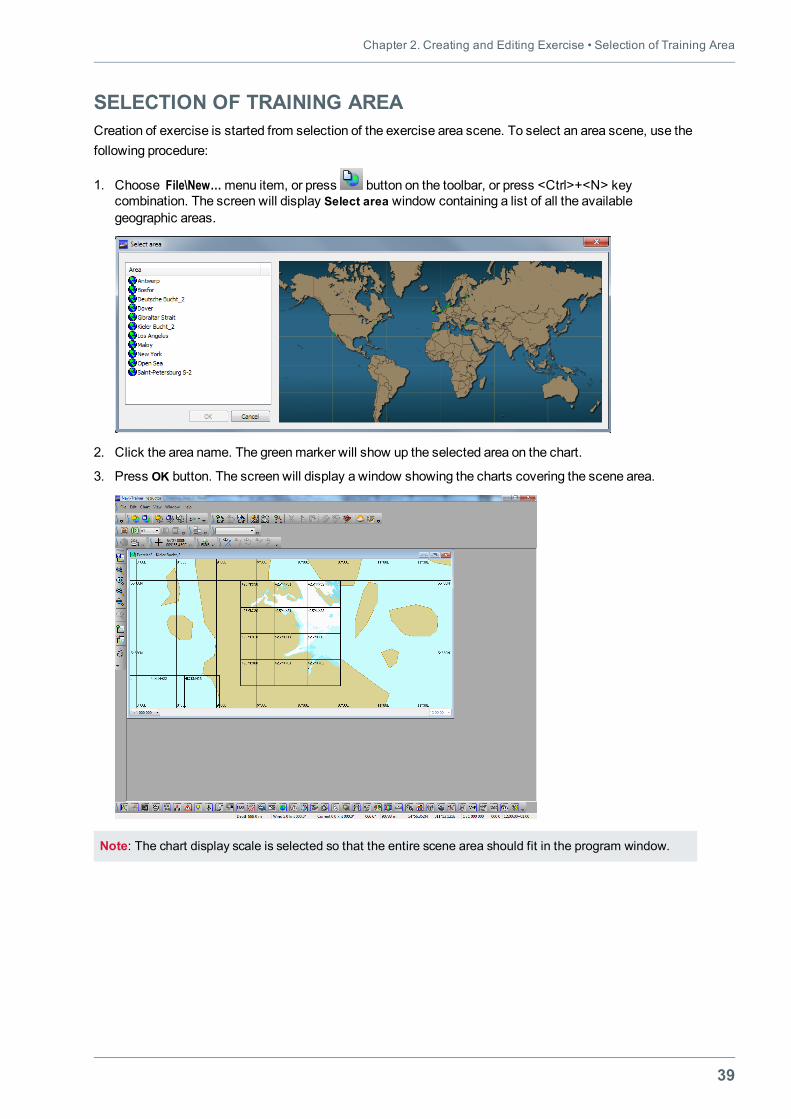
SELECTION OF TRAINING AREACreation of exercise is started from selection of the exercise area scene. To select an area scene, use thefollowing procedure:
1. Choose File\New…menu item, or press button on the toolbar, or press <Ctrl>+<N> keycombination. The screen will display Select area window containing a list of all the availablegeographic areas.
2. Click the area name. The greenmarker will show up the selected area on the chart.
3. Press OK button. The screen will display a window showing the charts covering the scene area.
Note: The chart display scale is selected so that the entire scene area should fit in the program window.
Navi-Trainer Professional 5000 (Version 5.35) • Instructor Manual
40
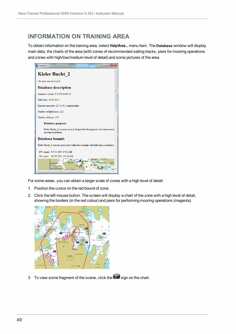
INFORMATION ON TRAINING AREATo obtain information on the training area, select Help\Area...menu item. TheDatabase window will displaymain data, the charts of the area (with zones of recommended sailing tracks, piers for mooring operationsand zones with high/low/medium level of detail) and some pictures of the area.
For some areas, you can obtain a larger scale of zones with a high level of detail:
1. Position the cursor on the red bound of zone.
2. Click the left mouse button. The screen will display a chart of the zone with a high level of detail,showing the borders (in the red colour) and piers for performingmooring operations (magenta).
3. To view some fragment of the scene, click the sign on the chart.
Chapter 2. Creating and Editing Exercise • Chart Setup
41
CHART SETUPChart CenteringFor chart centering with respect to the selected point, use the following procedure:
1. Choose Chart\Centremenu item, or press button on the toolbar, or press <Ctrl>+<Alt>+<C> key
combination. The cursor will be switched to the chart centeringmode .
2. Position the cursor on the required place on the chart and click the left mouse button, or press one ofthe following key combinations:o move to the left – <Shift>+<←>;o move to the right – <Shift>+<→>;o move up – <Shift>+<↑>;o move down – <Shift>+<↓>.
Note: The selected point will be displayed in the centre of the window. The screen centre shifts to adistance equal to 1/1000 of the current display scale.
3. To return to the default cursor mode, click the right mouse button.
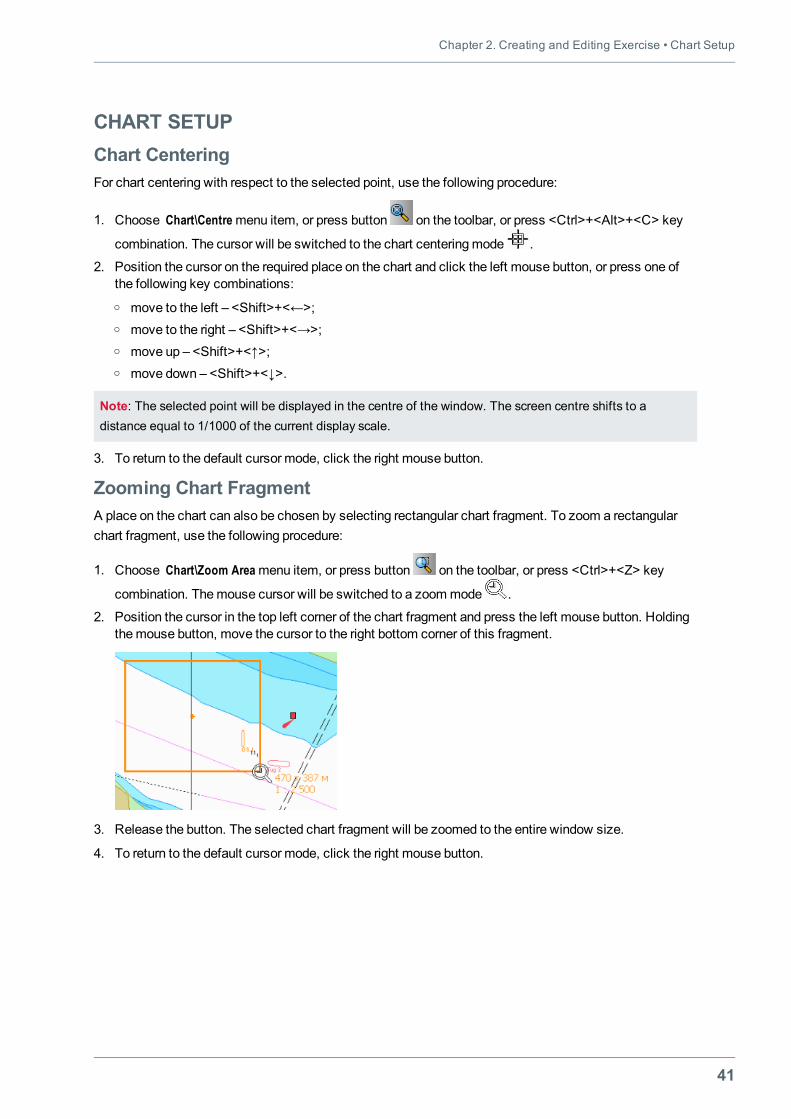
Zooming Chart FragmentA place on the chart can also be chosen by selecting rectangular chart fragment. To zoom a rectangularchart fragment, use the following procedure:
1. Choose Chart\Zoom Areamenu item, or press button on the toolbar, or press <Ctrl>+<Z> key
combination. Themouse cursor will be switched to a zoommode .
2. Position the cursor in the top left corner of the chart fragment and press the left mouse button. Holdingthemouse button, move the cursor to the right bottom corner of this fragment.
3. Release the button. The selected chart fragment will be zoomed to the entire window size.
4. To return to the default cursor mode, click the right mouse button.
Navi-Trainer Professional 5000 (Version 5.35) • Instructor Manual
42
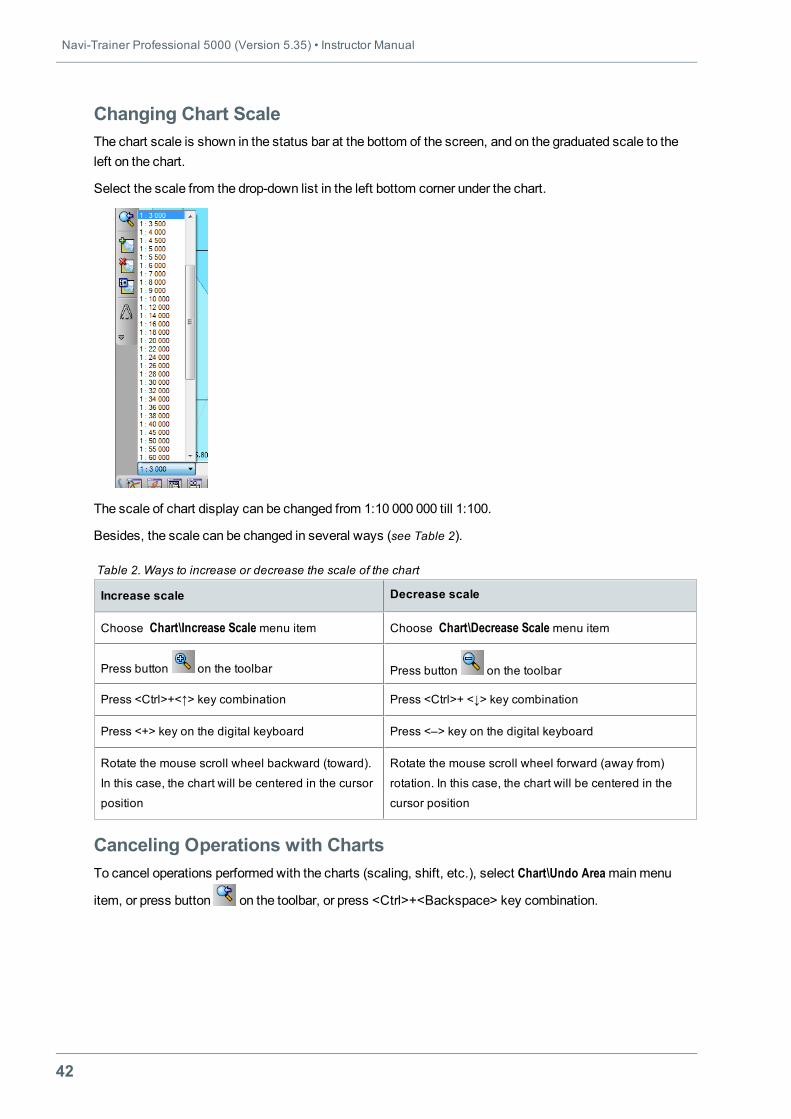
Changing Chart ScaleThe chart scale is shown in the status bar at the bottom of the screen, and on the graduated scale to theleft on the chart.
Select the scale from the drop-down list in the left bottom corner under the chart.
The scale of chart display can be changed from 1:10 000 000 till 1:100.
Besides, the scale can be changed in several ways (see Table 2).
Increase scale Decrease scale
Choose Chart\Increase Scalemenu item Choose Chart\Decrease Scalemenu item
Press button on the toolbar Press button on the toolbar
Press <Ctrl>+<↑> key combination Press <Ctrl>+ <↓> key combination
Press <+> key on the digital keyboard Press <–> key on the digital keyboard
Rotate the mouse scroll wheel backward (toward).
In this case, the chart will be centered in the cursor
position
Rotate the mouse scroll wheel forward (away from)
rotation. In this case, the chart will be centered in the
cursor position
Table 2. Ways to increase or decrease the scale of the chart
Canceling Operations with ChartsTo cancel operations performed with the charts (scaling, shift, etc.), select Chart\Undo Areamainmenu
item, or press button on the toolbar, or press <Ctrl>+<Backspace> key combination.
Chapter 2. Creating and Editing Exercise • Chart Setup
43
Loading and Unloading Area ChartsUsually, all the Area charts are displayed on the screen. Any chart can be removed from display asrequired. To do this, use the following procedure:
1. Choose Chart\Unload Chart menu item, or press button on the toolbar, or press<Ctrl>+<Shift>+<L> key combination. Themouse cursor will be switched to the chart unloadingmode
.
2. Point the cursor on the boundary of the chart required to be unloaded, and click the left mouse button.The chart will disappear, and its boundary will be shown as a thin line.
3. To return to the default cursor mode, click the right mouse button.
To return the excluded chart or to display a loaded chart on top of other charts, use the following procedure:
1. Choose Chart\Load Chart menu item, or press button on the toolbar, or press <Ctrl>+<L> key
combination. Themouse cursor will be switched to the chart loadingmode .
2. Position the cursor on the boundary of the chart which should be loaded or shown on top of other, andclick the left mouse button.The selected chart will appear or will be displayed on top of the other charts.The chart boundary will be shown in the bold line.
3. To return to the default cursor mode, click the right mouse button.
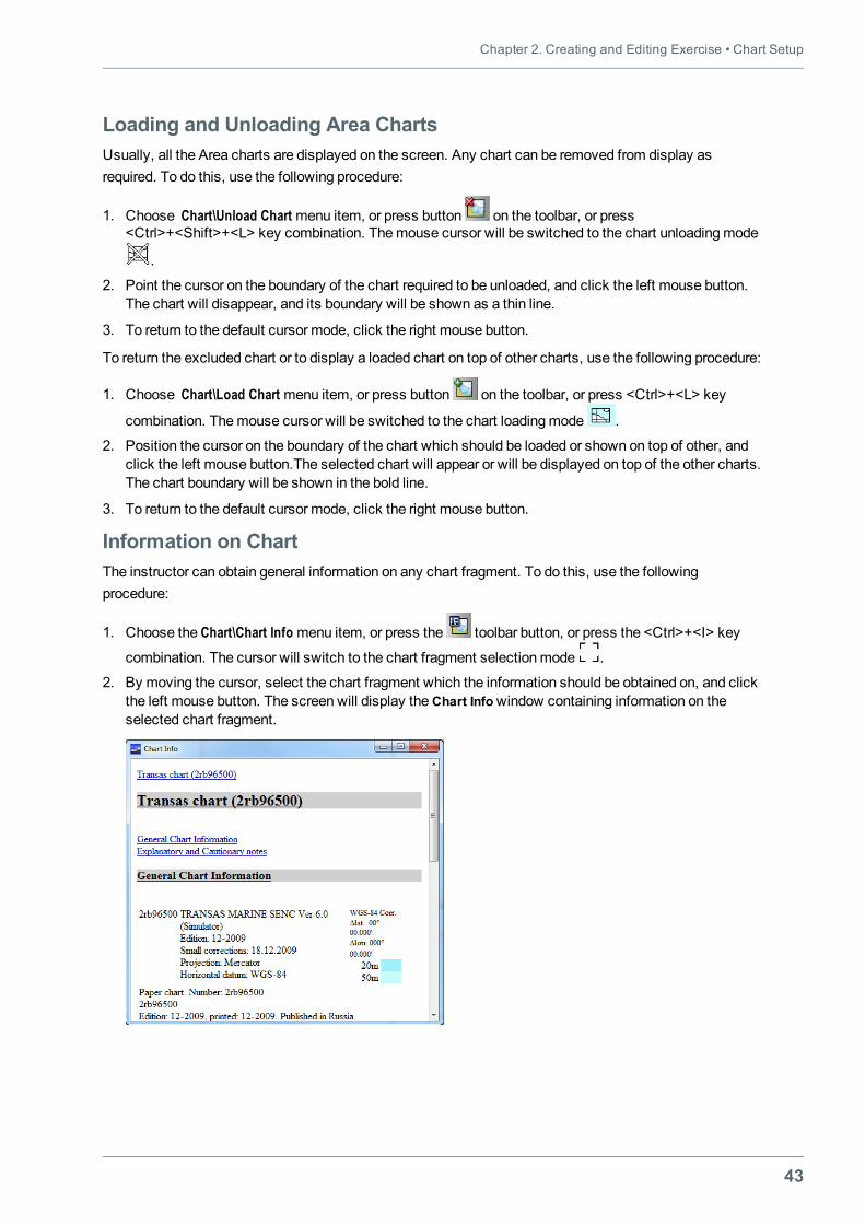
Information on ChartThe instructor can obtain general information on any chart fragment. To do this, use the followingprocedure:
1. Choose the Chart\Chart Info menu item, or press the toolbar button, or press the <Ctrl>+<I> key
combination. The cursor will switch to the chart fragment selectionmode .
2. By moving the cursor, select the chart fragment which the information should be obtained on, and clickthe left mouse button. The screen will display theChart Infowindow containing information on theselected chart fragment.
Navi-Trainer Professional 5000 (Version 5.35) • Instructor Manual
44
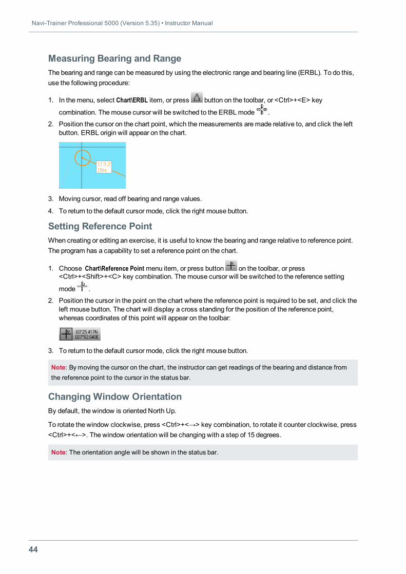
Measuring Bearing and RangeThe bearing and range can bemeasured by using the electronic range and bearing line (ERBL). To do this,use the following procedure:
1. In themenu, select Chart\ERBL item, or press button on the toolbar, or <Ctrl>+<E> key
combination. Themouse cursor will be switched to the ERBLmode .
2. Position the cursor on the chart point, which themeasurements aremade relative to, and click the leftbutton. ERBL origin will appear on the chart.
3. Moving cursor, read off bearing and range values.
4. To return to the default cursor mode, click the right mouse button.
Setting Reference PointWhen creating or editing an exercise, it is useful to know the bearing and range relative to reference point.The program has a capability to set a reference point on the chart.
1. Choose Chart\Reference Point menu item, or press button on the toolbar, or press<Ctrl>+<Shift>+<C> key combination. Themouse cursor will be switched to the reference setting
mode .
2. Position the cursor in the point on the chart where the reference point is required to be set, and click theleft mouse button. The chart will display a cross standing for the position of the reference point,whereas coordinates of this point will appear on the toolbar:
3. To return to the default cursor mode, click the right mouse button.
Note: By moving the cursor on the chart, the instructor can get readings of the bearing and distance fromthe reference point to the cursor in the status bar.
Changing Window OrientationBy default, the window is oriented North Up.
To rotate the window clockwise, press <Ctrl>+<→> key combination, to rotate it counter clockwise, press<Ctrl>+<←>. The window orientation will be changing with a step of 15 degrees.
Note: The orientation angle will be shown in the status bar.
Chapter 2. Creating and Editing Exercise • Chart Setup
45
Display of Auxiliary Elements (Overlays)It is possible to show and hide on the chart the following auxiliary elements:
l chart borders, grid and range rings;
l TХ–97 chart elements;
l DCW converted chart elements;
l depth contours on the S-57 charts;
l user information (line, zone, text, ellipsis).
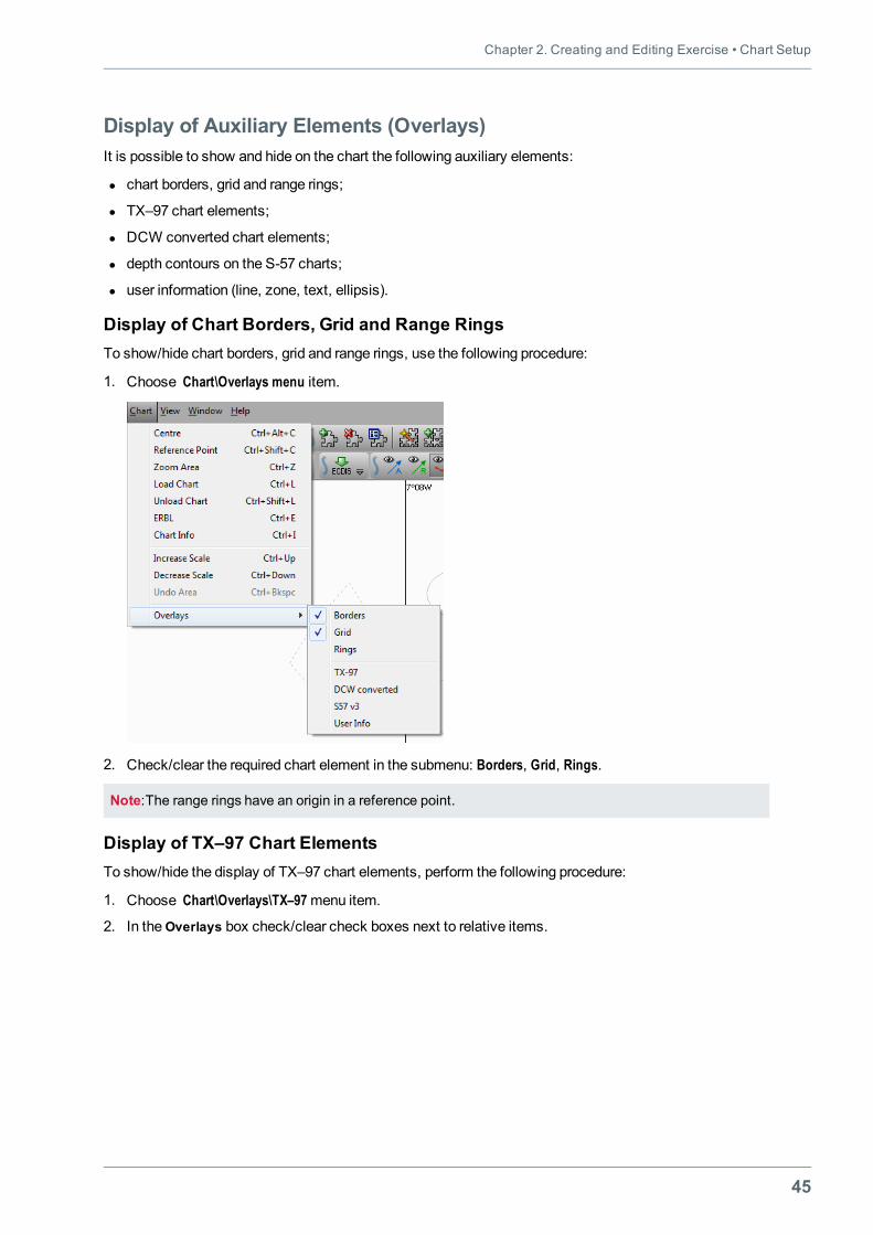
Display of Chart Borders, Grid and Range RingsTo show/hide chart borders, grid and range rings, use the following procedure:
1. Choose Chart\Overlays menu item.
2. Check/clear the required chart element in the submenu: Borders, Grid, Rings.
Note:The range rings have an origin in a reference point.
Display of TХ–97 Chart ElementsTo show/hide the display of TХ–97 chart elements, perform the following procedure:
1. Choose Chart\Overlays\TХ–97menu item.
2. In theOverlays box check/clear check boxes next to relative items.
Navi-Trainer Professional 5000 (Version 5.35) • Instructor Manual
46
3. Press theOK button.
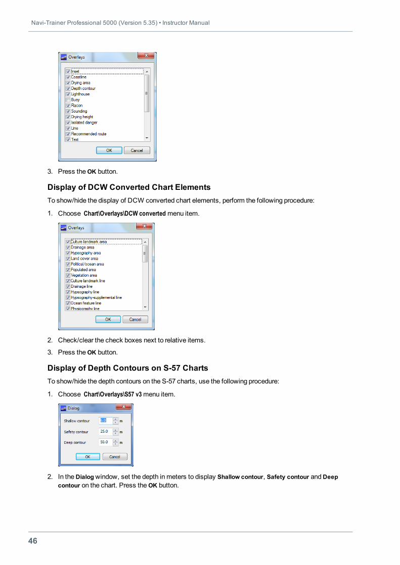
Display of DCW Converted Chart ElementsTo show/hide the display of DCW converted chart elements, perform the following procedure:
1. Choose Chart\Overlays\DCW converted menu item.
2. Check/clear the check boxes next to relative items.
3. Press theOK button.
Display of Depth Contours on S-57 ChartsTo show/hide the depth contours on the S-57 charts, use the following procedure:
1. Choose Chart\Overlays\S57 v3menu item.
2. In theDialogwindow, set the depth in meters to display Shallow contour, Safety contour andDeepcontour on the chart. Press theOK button.
Chapter 2. Creating and Editing Exercise • Chart Setup
47
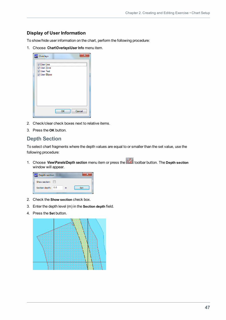
Display of User InformationTo show/hide user information on the chart, perform the following procedure:
1. Choose Chart\Overlays\User Info menu item.
2. Check/clear check boxes next to relative items.
3. Press theOK button.
Depth SectionTo select chart fragments where the depth values are equal to or smaller than the set value, use thefollowing procedure:
1. Choose View\Panels\Depth section menu item or press the toolbar button. TheDepth sectionwindow will appear.
2. Check the Show section check box.
3. Enter the depth level (m) in the Section depth field.
4. Press the Set button.
Navi-Trainer Professional 5000 (Version 5.35) • Instructor Manual
48
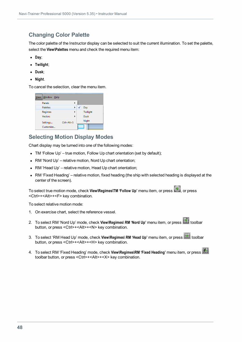
Changing Color PaletteThe color palette of the Instructor display can be selected to suit the current illumination. To set the palette,select the View\Palettesmenu and check the requiredmenu item:
l Day;
l Twilight;
l Dusk;
l Night.
To cancel the selection, clear themenu item.
Selecting Motion Display ModesChart display may be turned into one of the followingmodes:
l TM ‘Follow Up’ – truemotion, Follow Up chart orientation (set by default);
l RM ‘Nord Up’ – relativemotion, Nord Up chart orientation;
l RM ‘Head Up’ – relativemotion, Head Up chart orientation;
l RM ‘Fixed Heading’ – relativemotion, fixed heading (the ship with selected heading is displayed at thecenter of the screen).
To select truemotionmode, check View\Regimes\TM ‘Follow Up’menu item, or press , or press<Ctrl>+<Alt>+<F> key combination.
To select relativemotionmode:
1. On exercise chart, select the reference vessel.
2. To select RM ‘Nord Up’ mode, check View\Regimes\ RM ‘Nord Up’menu item, or press toolbarbutton, or press <Ctrl>+<Alt>+<N> key combination.
3. To select ‘RM Head Up’ mode, check View\Regimes\ RM ‘Head Up’menu item, or press toolbarbutton, or press <Ctrl>+<Alt>+<H> key combination.
4. To select RM ‘Fixed Heading’ mode, check View\Regimes\RM ‘Fixed Heading’menu item, or presstoolbar button, or press <Ctrl>+<Alt>+<X> key combination.
Chapter 2. Creating and Editing Exercise • Operations with Objects
49
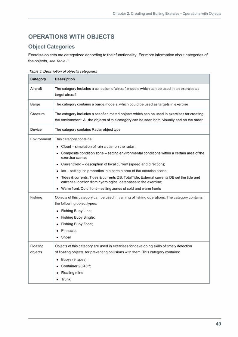
OPERATIONS WITH OBJECTSObject CategoriesExercise objects are categorized according to their functionality. For more information about categories ofthe objects, see Table 3.
Category Description
Aircraft The category includes a collection of aircraft models which can be used in an exercise as
target aircraft
Barge The category contains a barge models, which could be used as targets in exercise
Creature The category includes a set of animated objects which can be used in exercises for creating
the environment. All the objects of this category can be seen both, visually and on the radar
Device The category contains Radar object type
Environment This category contains:
l Cloud – simulation of rain clutter on the radar;
l Composite condition zone – setting environmental conditions within a certain area of theexercise scene;
l Current field – description of local current (speed and direction);
l Ice – setting ice properties in a certain area of the exercise scene;
l Tides & currents, Tides & currents DB, TotalTide, External currents DB set the tide andcurrent allocation from hydrological databases to the exercise;
l Warm front, Cold front – setting zones of cold and warm fronts
Fishing Objects of this category can be used in training of fishing operations. The category contains
the following object types:
l Fishing Buoy Line;
l Fishing Buoy Single;
l Fishing Buoy Zone;
l Pinnacle;
l Shoal
Floating
objects
Objects of this category are used in exercises for developing skills of timely detection
of floating objects, for preventing collisions with them. This category contains:
l Buoys (9 types);
l Container 20/40 ft;
l Floating mine;
l Trunk
Table 3. Description of object's categories
Navi-Trainer Professional 5000 (Version 5.35) • Instructor Manual
50
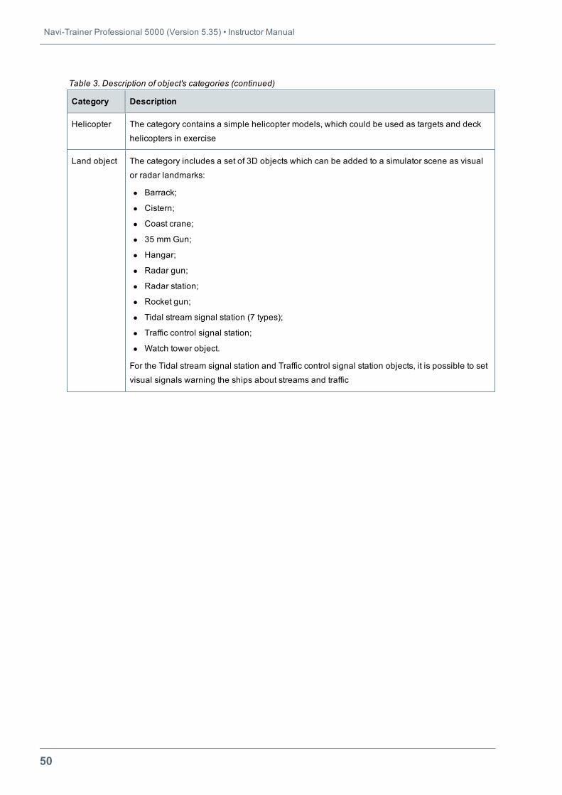
Category Description
Helicopter The category contains a simple helicopter models, which could be used as targets and deck
helicopters in exercise
Land object The category includes a set of 3D objects which can be added to a simulator scene as visual
or radar landmarks:
l Barrack;
l Cistern;
l Coast crane;
l 35 mm Gun;
l Hangar;
l Radar gun;
l Radar station;
l Rocket gun;
l Tidal stream signal station (7 types);
l Traffic control signal station;
l Watch tower object.
For the Tidal stream signal station and Traffic control signal station objects, it is possible to set
visual signals warning the ships about streams and traffic
Table 3. Description of object's categories (continued)
Chapter 2. Creating and Editing Exercise • Operations with Objects
51
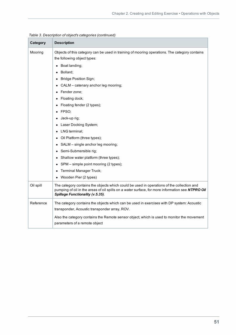
Category Description
Mooring Objects of this category can be used in training of mooring operations. The category contains
the following object types:
l Boat landing;
l Bollard;
l Bridge Position Sign;
l CALM – catenary anchor leg mooring;
l Fender zone;
l Floating dock;
l Floating fender (2 types);
l FPSO;
l Jack-up rig;
l Laser Docking System;
l LNG terminal;
l Oil Platform (three types);
l SALM – single anchor leg mooring;
l Semi-Submersible rig;
l Shallow water platform (three types);
l SPM – simple point mooring (2 types);
l Terminal Manager Truck;
l Wooden Pier (2 types)
Oil spill The category contains the objects which could be used in operations of the collection andpumping of oil in the areas of oil spills on a water surface, for more information see NTPROOilSpillage Functionality (v.5.35).
Reference The category contains the objects which can be used in exercises with DP system: Acoustic
transponder, Acoustic transponder array, ROV.
Also the category contains the Remote sensor object, which is used to monitor the movement
parameters of a remote object
Table 3. Description of object's categories (continued)
Navi-Trainer Professional 5000 (Version 5.35) • Instructor Manual
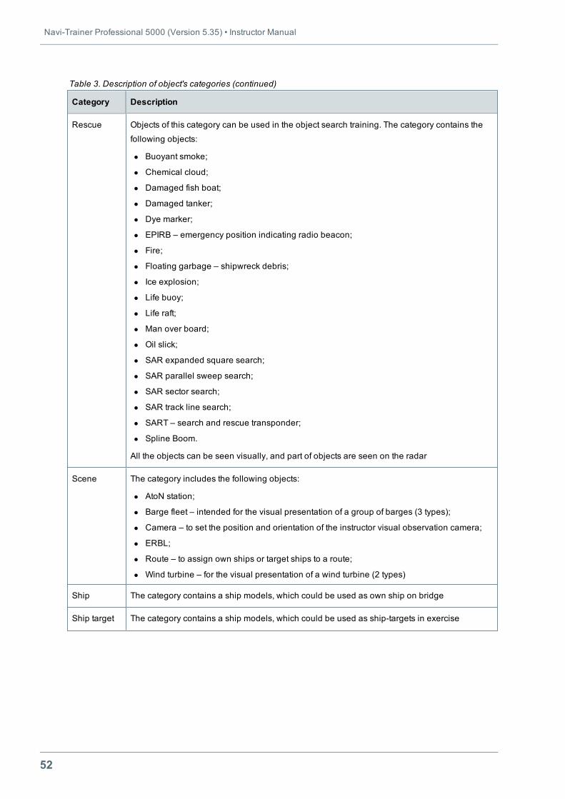
52
Category Description
Rescue Objects of this category can be used in the object search training. The category contains the
following objects:
l Buoyant smoke;
l Chemical cloud;
l Damaged fish boat;
l Damaged tanker;
l Dye marker;
l EPIRB – emergency position indicating radio beacon;
l Fire;
l Floating garbage – shipwreck debris;
l Ice explosion;
l Life buoy;
l Life raft;
l Man over board;
l Oil slick;
l SAR expanded square search;
l SAR parallel sweep search;
l SAR sector search;
l SAR track line search;
l SART – search and rescue transponder;
l Spline Boom.
All the objects can be seen visually, and part of objects are seen on the radar
Scene The category includes the following objects:
l AtoN station;
l Barge fleet – intended for the visual presentation of a group of barges (3 types);
l Camera – to set the position and orientation of the instructor visual observation camera;
l ERBL;
l Route – to assign own ships or target ships to a route;
l Wind turbine – for the visual presentation of a wind turbine (2 types)
Ship The category contains a ship models, which could be used as own ship on bridge
Ship target The category contains a ship models, which could be used as ship-targets in exercise
Table 3. Description of object's categories (continued)
Chapter 2. Creating and Editing Exercise • Operations with Objects
53
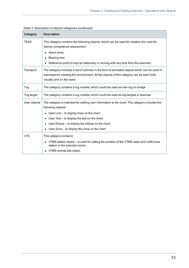
Category Description
TEAS This category contains the following objects, which can be used for creation the rules for
trainee competence assessment:
l Alarm zone;
l Bearing line;
l Reference point (it may be stationary or moving with any ship from the exercise)
Transport The category includes a set of vehicles in the form of animated objects which can be used in
exercises for creating the environment. All the objects of this category can be seen both,
visually and on the radar
Tug The category contains a tug models, which could be used as own tug on bridge
Tug target The category contains a tug models, which could be used as tug-targets in exercise
User objects The category is intended for adding user information to the chart. This category includes the
following objects:
l User Line – to display lines on the chart;
l User Text – to display the text on the chart;
l User Ellipse – to display the ellipse on the chart;
l User Zone – to display the zone on the chart
VTS This category contains:
l VTMS station object – is used for setting the position of the VTMS radar and UAIS basestation in the exercise scene;
l VTMS remote site object
Table 3. Description of object's categories (continued)
Navi-Trainer Professional 5000 (Version 5.35) • Instructor Manual
54
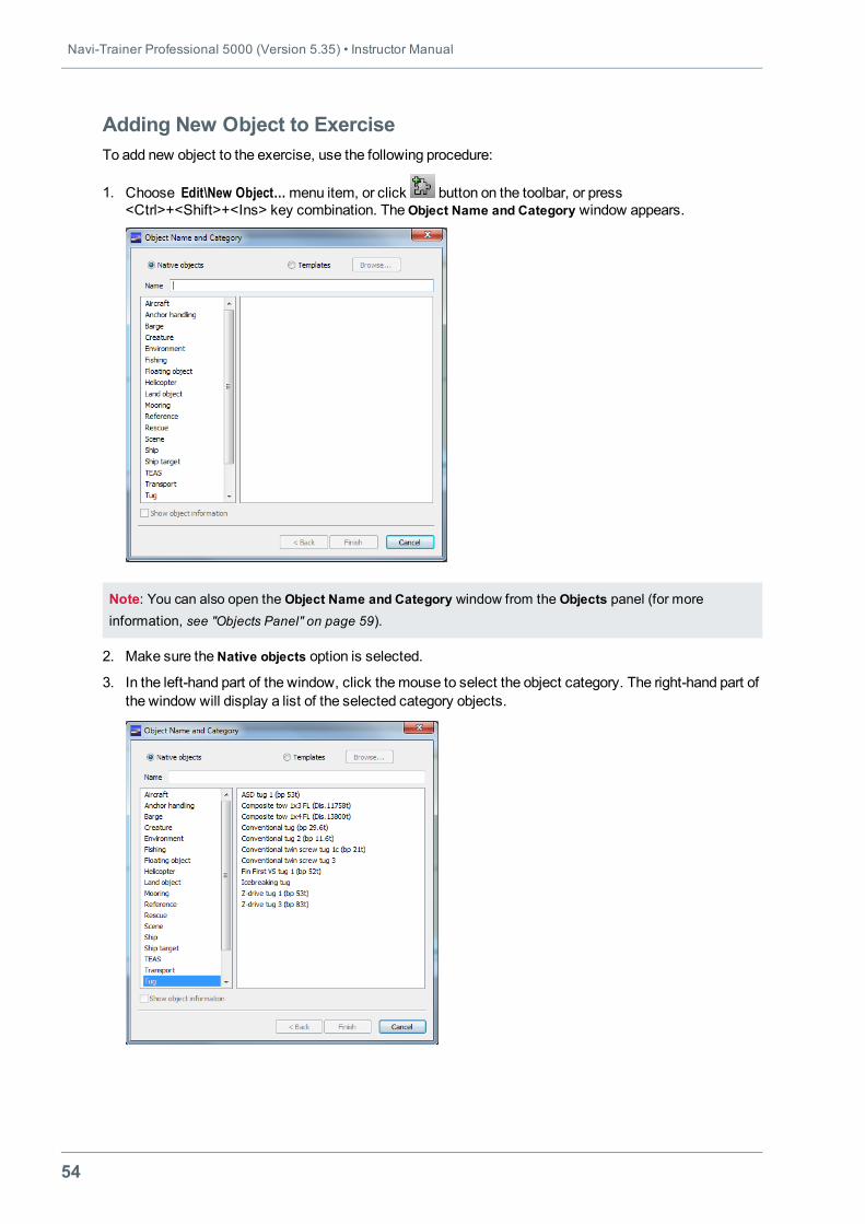
Adding New Object to ExerciseTo add new object to the exercise, use the following procedure:
1. Choose Edit\New Object…menu item, or click button on the toolbar, or press<Ctrl>+<Shift>+<Ins> key combination. TheObject Name and Category window appears.
Note: You can also open the Object Name and Category window from the Objects panel (for moreinformation, see "Objects Panel" on page 59).
2. Make sure theNative objects option is selected.
3. In the left-hand part of the window, click themouse to select the object category. The right-hand part ofthe window will display a list of the selected category objects.
Chapter 2. Creating and Editing Exercise • Operations with Objects
55
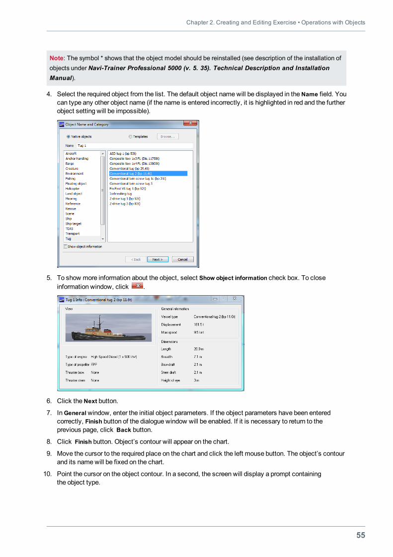
Note: The symbol * shows that the object model should be reinstalled (see description of the installation ofobjects under Navi-Trainer Professional 5000 (v. 5. 35). Technical Description and InstallationManual).
4. Select the required object from the list. The default object namewill be displayed in theName field. Youcan type any other object name (if the name is entered incorrectly, it is highlighted in red and the furtherobject setting will be impossible).
5. To show more information about the object, select Show object information check box. To closeinformation window, click .
6. Click theNext button.
7. InGeneralwindow, enter the initial object parameters. If the object parameters have been enteredcorrectly, Finish button of the dialogue window will be enabled. If it is necessary to return to theprevious page, click Back button.
8. Click Finish button. Object’s contour will appear on the chart.
9. Move the cursor to the required place on the chart and click the left mouse button. The object’s contourand its namewill be fixed on the chart.
10. Point the cursor on the object contour. In a second, the screen will display a prompt containingthe object type.
Navi-Trainer Professional 5000 (Version 5.35) • Instructor Manual
56
Selecting Object on ChartTo perform any operations with the object (move, rotate, rename, delete, set the properties, etc.), it shouldbemade active, i.e. selected on the chart.
To do this, point the cursor on the object contour and click the left mouse button. The object contour will beshown in the orange color.
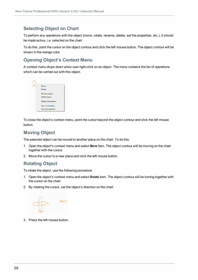
Opening Object’s Context MenuA context menu drops downwhen user right-click on an object. Themenu contains the list of operationswhich can be carried out with this object.
To close the object’s context menu, point the cursor beyond the object contour and click the left mousebutton.
Moving ObjectThe selected object can bemoved to another place on the chart. To do this:
1. Open the object's context menu and select Move item. The object contour will bemoving on the charttogether with the cursor.
2. Move the cursor to a new place and click the left mouse button.
Rotating ObjectTo rotate the object, use the following procedure:
1. Open the object’s context menu and select Rotate item. The object contour will be turning together withthe cursor on the chart.
2. By rotating the cursor, set the object’s direction on the chart.
3. Press the left mouse button.
Chapter 2. Creating and Editing Exercise • Operations with Objects
57
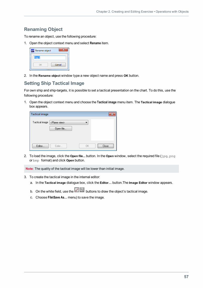
Renaming ObjectTo rename an object, use the following procedure:
1. Open the object context menu and select Rename item.
2. In theRename object window type a new object name and press OK button.
Setting Ship Tactical ImageFor own ship and ship-targets, it is possible to set a tactical presentation on the chart. To do this, use thefollowing procedure:
1. Open the object context menu and choose the Tactical imagemenu item. The Tactical image dialoguebox appears.
2. To load the image, click theOpen file... button. In theOpenwindow, select the required file (jpg, pngor bmp format) and click Open button.
Note: The quality of the tactical image will be lower than initial image.
3. To create the tactical image in the internal editor:a. In the Tactical image dialogue box, click the Editor… button.The Image Editor window appears.
b. On the white field, use the buttons to draw the object’s tactical image.
c. Choose File\Save As…menu) to save the image.
Navi-Trainer Professional 5000 (Version 5.35) • Instructor Manual
58
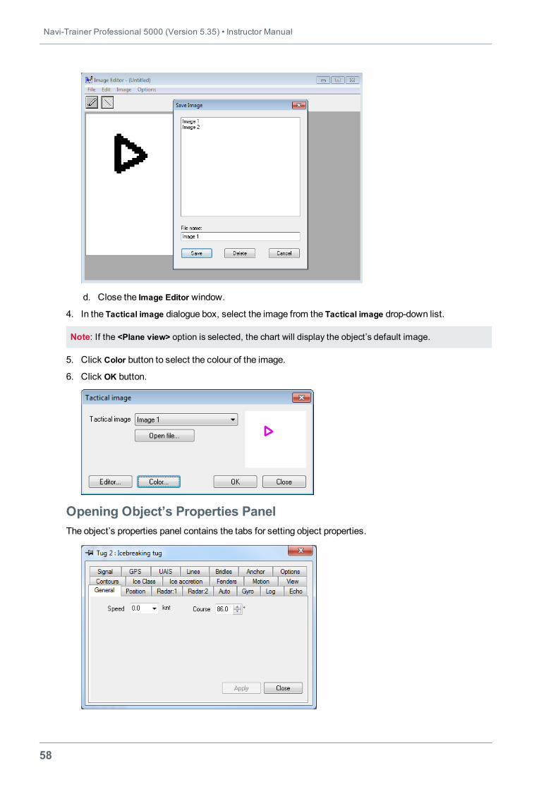
d. Close the Image Editor window.
4. In the Tactical image dialogue box, select the image from the Tactical image drop-down list.
Note: If the <Plane view> option is selected, the chart will display the object’s default image.
5. Click Color button to select the colour of the image.
6. Click OK button.
Opening Object’s Properties PanelThe object’s properties panel contains the tabs for setting object properties.
Chapter 2. Creating and Editing Exercise • Operations with Objects
59
To open the object’s properties panel, use the following procedure:
1. Select the object on the exercise chart.
2. Use one of the following ways:o Open the object’s context menu and choose General propertiesmenu item.
Note: The properties panel of route waypoints, segments, and line fastening points is opened by choosingthe Propertiesmenu item of the object context menu.
o Choose Edit\Object properties…menu item.
o Press the toolbar button.o Use theObjects panel (for more information, see "Objects Panel" on page 59).
Note: The view of the object properties panel at the exercise creation stage may be different from that afterthe start of the simulator session (for more information about the ship properties, see "Setting ShipProperties" on page 117).
Deleting ObjectTo delete the object, use the following procedure:
1. Select the object on the exercise chart.
2. Use one of the following ways:o Open the object’s context menu and choose the Delete Object item.
o Press button on the toolbar.o Choose Edit\Delete Object menu item.o Press <Ctrl>+<Shift>+<Del> key combination.o Use theObjects panel (for more information, see "Objects Panel" on page 59).
3. To confirm the object deletion, press theOK button.
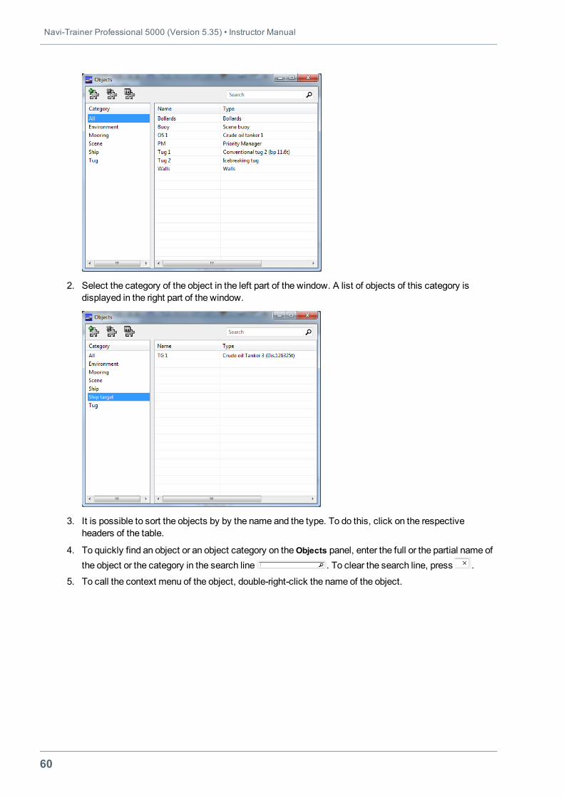
Objects PanelTheObjects panel contains a list of all objects of the exercise.
To use the panel, perform the following operations:
1. Choose View\Panels\Objects…menu item, or press the toolbar button. TheObjects panel appears onthe screen. The panel displays the categories, names and types of objects added to the chart.
Navi-Trainer Professional 5000 (Version 5.35) • Instructor Manual
60
2. Select the category of the object in the left part of the window. A list of objects of this category isdisplayed in the right part of the window.
3. It is possible to sort the objects by by the name and the type. To do this, click on the respectiveheaders of the table.
4. To quickly find an object or an object category on theObjects panel, enter the full or the partial name ofthe object or the category in the search line . To clear the search line, press .
5. To call the context menu of the object, double-right-click the name of the object.
Chapter 2. Creating and Editing Exercise • Operations with Objects
61
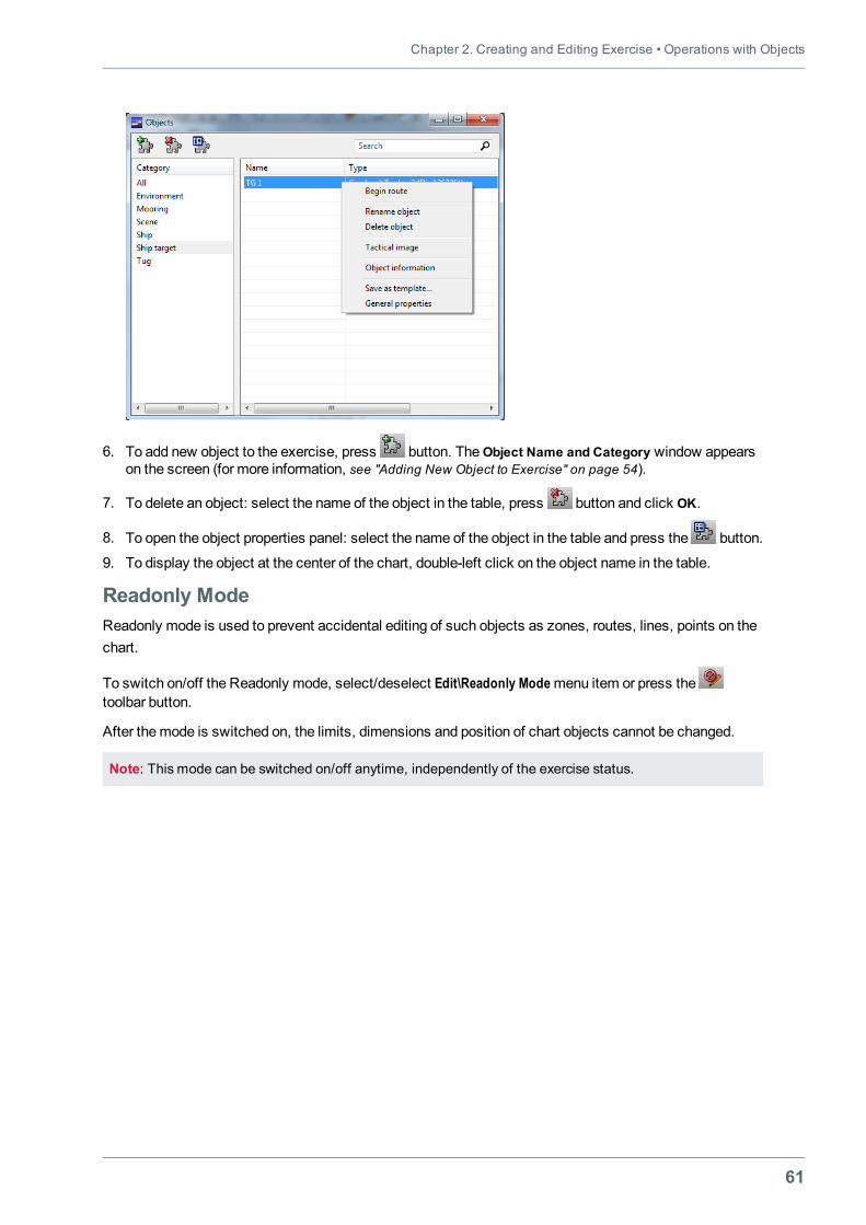
6. To add new object to the exercise, press button. TheObject Name and Category window appearson the screen (for more information, see "Adding New Object to Exercise" on page 54).
7. To delete an object: select the name of the object in the table, press button and click OK.
8. To open the object properties panel: select the name of the object in the table and press the button.
9. To display the object at the center of the chart, double-left click on the object name in the table.
Readonly ModeReadonly mode is used to prevent accidental editing of such objects as zones, routes, lines, points on thechart.
To switch on/off the Readonly mode, select/deselect Edit\Readonly Modemenu item or press thetoolbar button.
After themode is switched on, the limits, dimensions and position of chart objects cannot be changed.
Note: This mode can be switched on/off anytime, independently of the exercise status.
Navi-Trainer Professional 5000 (Version 5.35) • Instructor Manual
62
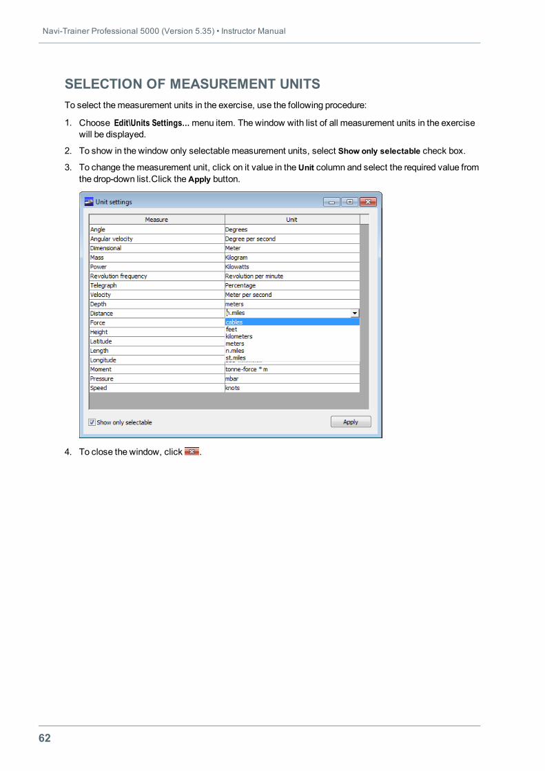
SELECTION OF MEASUREMENT UNITSTo select themeasurement units in the exercise, use the following procedure:
1. Choose Edit\Units Settings…menu item. The window with list of all measurement units in the exercisewill be displayed.
2. To show in the window only selectable measurement units, select Show only selectable check box.
3. To change themeasurement unit, click on it value in theUnit column and select the required value fromthe drop-down list.Click theApply button.
4. To close the window, click .
Chapter 2. Creating and Editing Exercise • General Exercise Settings
63
GENERAL EXERCISE SETTINGSThe Settings panel is used for adjusting the general exercise settings, such as:
l Plotting – displaying ship track as a series of dots on the chart (see "Displaying Ship Track as Series ofDots" on page 64);
l Contours – displaying ship track as a series of ship contours on the chart (see "Displaying Ship Track asSeries of Ship Contours" on page 65);
l Vectors – displaying speed vectors on the chart (see "Displaying Speed Vectors" on page 66);
l Routes – routes settings (see "General Route Settings" on page 134);
l Auto sounds – enabling/disabling automatic sound signals (see "Enabling/Disabling Automatic SoundSignals" on page 68);
l CPA/TCPA – CPA/TCPA settings (see "General CPA/TCPA Settings" on page 217);
l UNREP Criteria – underwater replenishment criteria (see "Setting Underway Replenishment Criteria" onpage 382);
l Current Field – current field settings (see "Current Field General Settings" on page 103);
l Autotugs – auto tugs settings (see "Automatic Tugs General Settings" on page 315);
l Misc –miscellaneous settings (see "Miscellaneous Settings" on page 69).
Navi-Trainer Professional 5000 (Version 5.35) • Instructor Manual
64
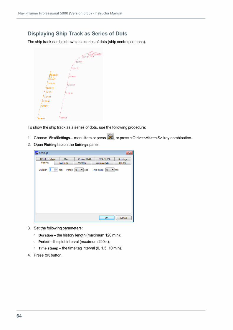
Displaying Ship Track as Series of DotsThe ship track can be shown as a series of dots (ship centre positions).
To show the ship track as a series of dots, use the following procedure:
1. Choose View\Settings…menu item or press , or press <Ctrl>+<Alt>+<S> key combination.
2. Open Plotting tab on the Settings panel.
3. Set the following parameters:o Duration – the history length (maximum 120min);o Period – the plot interval (maximum 240 s);o Time stamp – the time tag interval (0, 1.5, 10min).
4. Press OK button.
Chapter 2. Creating and Editing Exercise • General Exercise Settings
65
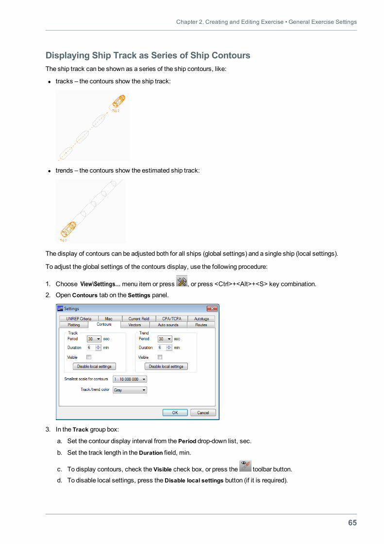
Displaying Ship Track as Series of Ship ContoursThe ship track can be shown as a series of the ship contours, like:
l tracks – the contours show the ship track:
l trends – the contours show the estimated ship track:
The display of contours can be adjusted both for all ships (global settings) and a single ship (local settings).
To adjust the global settings of the contours display, use the following procedure:
1. Choose View\Settings…menu item or press , or press <Ctrl>+<Alt>+<S> key combination.
2. OpenContours tab on the Settings panel.
3. In the Track group box:
a. Set the contour display interval from the Period drop-down list, sec.
b. Set the track length in theDuration field, min.
c. To display contours, check the Visible check box, or press the toolbar button.
d. To disable local settings, press theDisable local settings button (if it is required).
Navi-Trainer Professional 5000 (Version 5.35) • Instructor Manual
66
4. In the Trend group box:
a. Set the contour display interval from the Period drop-down list, sec.
b. Set the track length in theDuration field, min.
c. To display contours, check the Visible check box, or press the toolbar button.
d. To disable local settings, press theDisable local settings button (if it is required).
5. Select theminimum contour display scale from the Smallest scale for contours drop-down list. If thescale is less, than set value, the ship contours assume the form of a dot.
6. Select color of the contours from the Track/trend color drop-down list (Grey – as default).
7. Press theOK button.
Note: Formore informationabout local settingsof the contoursdisplay, see "ContoursSettings"on page 130.
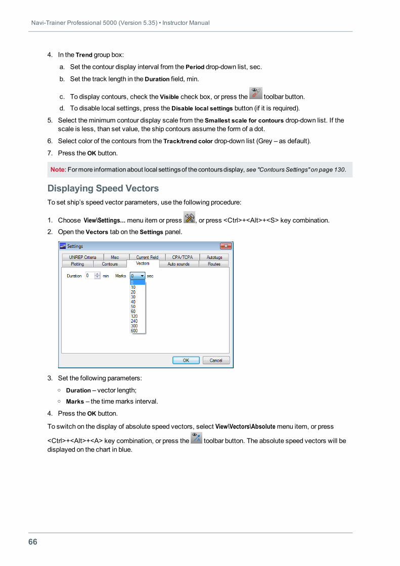
Displaying Speed VectorsTo set ship’s speed vector parameters, use the following procedure:
1. Choose View\Settings…menu item or press , or press <Ctrl>+<Alt>+<S> key combination.
2. Open the Vectors tab on the Settings panel.
3. Set the following parameters:o Duration – vector length;o Marks – the timemarks interval.
4. Press theOK button.
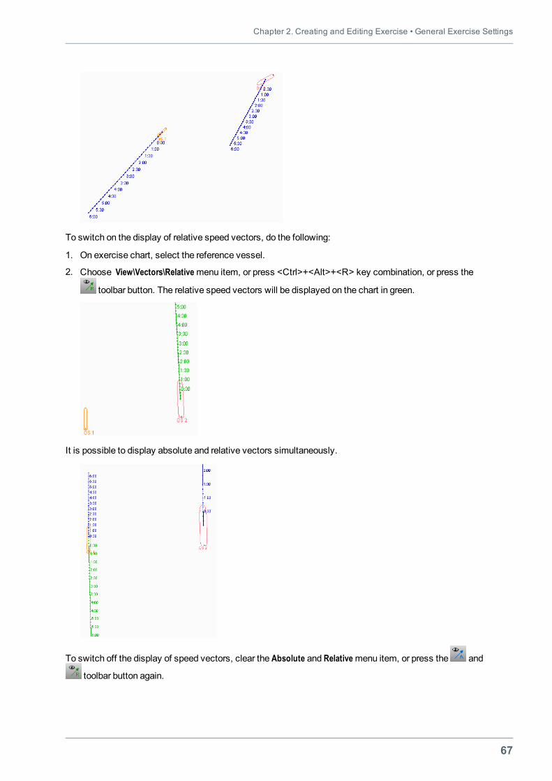
To switch on the display of absolute speed vectors, select View\Vectors\Absolutemenu item, or press
<Ctrl>+<Alt>+<A> key combination, or press the toolbar button. The absolute speed vectors will bedisplayed on the chart in blue.
Chapter 2. Creating and Editing Exercise • General Exercise Settings
67
To switch on the display of relative speed vectors, do the following:
1. On exercise chart, select the reference vessel.
2. Choose View\Vectors\Relativemenu item, or press <Ctrl>+<Alt>+<R> key combination, or press the
toolbar button. The relative speed vectors will be displayed on the chart in green.
It is possible to display absolute and relative vectors simultaneously.
To switch off the display of speed vectors, clear the Absolute and Relativemenu item, or press the and
toolbar button again.
Navi-Trainer Professional 5000 (Version 5.35) • Instructor Manual
68
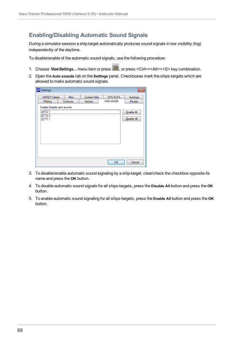
Enabling/Disabling Automatic Sound SignalsDuring a simulator session a ship-target automatically produces sound signals in low visibility (fog)independently of the daytime.
To disable/enable of the automatic sound signals, use the following procedure:
1. Choose View\Settings…menu item or press , or press <Ctrl>+<Alt>+<S> key combination.
2. Open theAuto sounds tab on the Settings panel. Checkboxes mark the ships-targets which areallowed tomake automatic sound signals.
3. To disable/enable automatic sound signaling by a ship-target, clear/check the checkbox opposite itsname and press theOK button.
4. To disable automatic sound signals for all ships-targets, press theDisable All button and press theOKbutton.
5. To enable automatic sound signaling for all ships-targets, press the Enable All button and press theOKbutton.
Chapter 2. Creating and Editing Exercise • General Exercise Settings
69
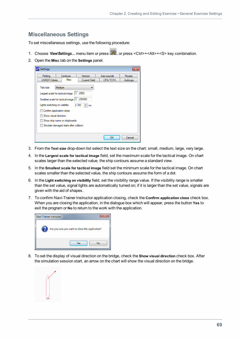
Miscellaneous SettingsTo set miscellaneous settings, use the following procedure:
1. Choose View\Settings…menu item or press , or press <Ctrl>+<Alt>+<S> key combination.
2. Open theMisc tab on the Settings panel.
3. From the Text size drop-down list select the text size on the chart: small, medium, large, very large.
4. In the Largest scale for tactical image field, set themaximum scale for the tactical image. On chartscales larger than the selected value, the ship contours assume a standard view.
5. In the Smallest scale for tactical image field set theminimum scale for the tactical image. On chartscales smaller than the selected value, the ship contours assume the form of a dot.
6. In the Light switching on visibility field, set the visibility range value. If the visibility range is smallerthan the set value, signal lights are automatically turned on; if it is larger than the set value, signals aregiven with the aid of shapes.
7. To confirm Navi-Trainer Instructor application closing, check theConfirm application close check box.When you are closing the application, in the dialogue box which will appear, press the button Yes toexit the program orNo to return to the work with the application.
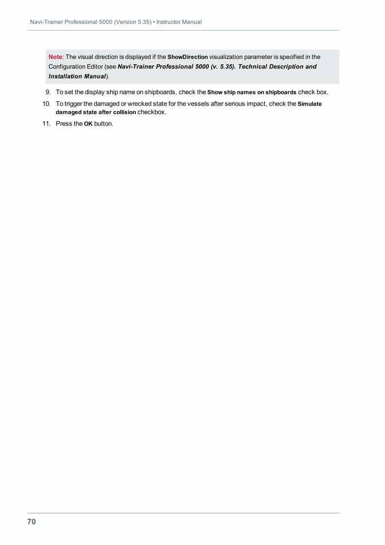
8. To set the display of visual direction on the bridge, check the Show visual direction check box. Afterthe simulation session start, an arrow on the chart will show the visual direction on the bridge.
Navi-Trainer Professional 5000 (Version 5.35) • Instructor Manual
70
Note: The visual direction is displayed if the ShowDirection visualization parameter is specified in theConfiguration Editor (see Navi-Trainer Professional 5000 (v. 5.35). Technical Description andInstallation Manual).
9. To set the display ship name on shipboards, check the Show ship names on shipboards check box.
10. To trigger the damaged or wrecked state for the vessels after serious impact, check the Simulatedamaged state after collision checkbox.
11. Press theOK button.
Chapter 2. Creating and Editing Exercise • Setting Environmental Sailing Conditions
71
SETTING ENVIRONMENTAL SAILING CONDITIONSEnvironmental sailing conditions can be set for the entire exercise scene or within a certain zone on theexercise chart.
Instructor can set the following environmental conditions:
l Environment settings: date and time, weather type, colour of water, season, etc. (see "EnvironmentSettings" on page 72).
l Environment conditions template (see "Creating Environment Conditions Template" on page 81).
l Overall environmental conditions: current, wind, wave, visibility, sky, tide, etc. (see "OverallEnvironmental Conditions" on page 83).
l Local environmental conditions which are set in the composite condition zone, such as: current, depth,fog, muddy strata, sky, tide, wind, etc. (see "Local Environmental Conditions" on page 91).
l Tides and currents from the common databases (see "Importing Tides and Currents" on page 99).
l Vector field of currents (see "Creating Vector Field of Current" on page 103).
l Clouds (see "Setting of Clouds" on page 106).
l Atmosphere fronts (see "Setting Atmosphere Fronts" on page 107).
l Wave spectrums (see "Editing Wave Spectrums" on page 109).
l Ice zones (see "Creation of Ice Zone" on page 324).
Navi-Trainer Professional 5000 (Version 5.35) • Instructor Manual
72
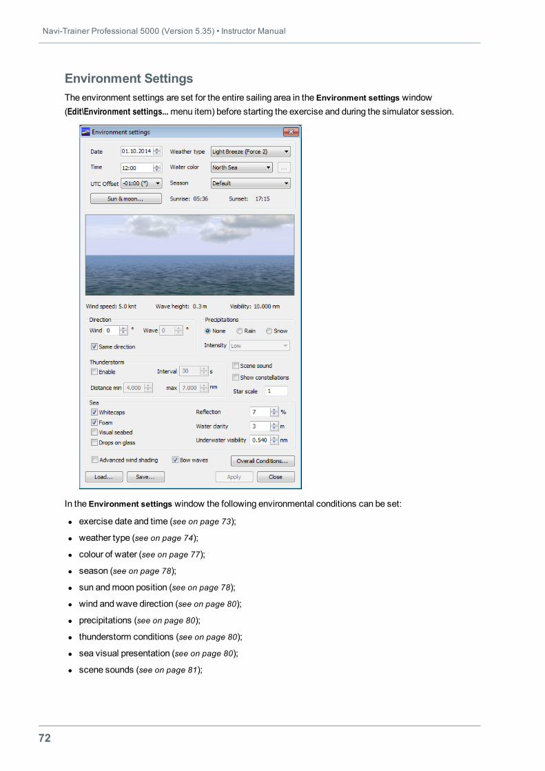
Environment SettingsThe environment settings are set for the entire sailing area in the Environment settings window(Edit\Environment settings...menu item) before starting the exercise and during the simulator session.
In the Environment settings window the following environmental conditions can be set:
l exercise date and time (see on page 73);
l weather type (see on page 74);
l colour of water (see on page 77);
l season (see on page 78);
l sun andmoon position (see on page 78);
l wind and wave direction (see on page 80);
l precipitations (see on page 80);
l thunderstorm conditions (see on page 80);
l sea visual presentation (see on page 80);
l scene sounds (see on page 81);
Chapter 2. Creating and Editing Exercise • Setting Environmental Sailing Conditions
73
l constellation display (see on page 81);
l additional visual effects: advanced wind shading and bow waves (see on page 81).
Note: To view information about setting overall conditions, see "Overall Environmental Conditions" on page83. To view information about saving the environment conditions template, see "Creating EnvironmentConditions Template" on page 81
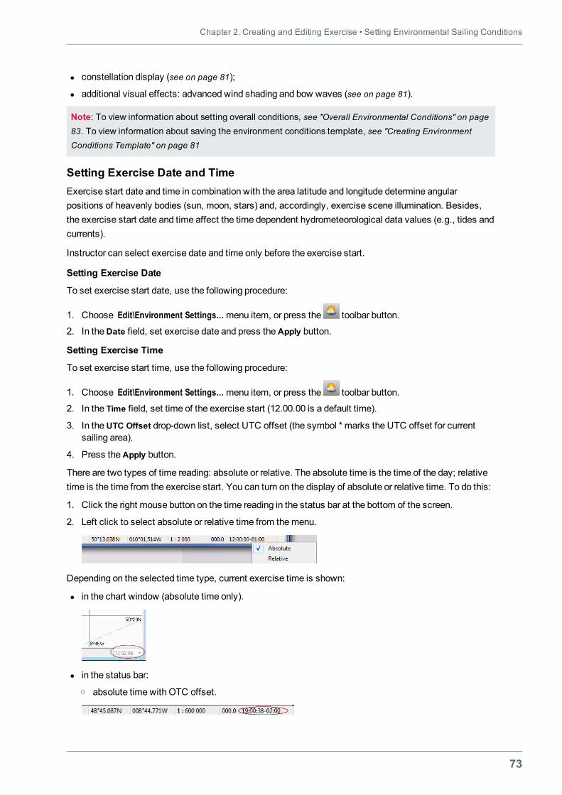
Setting Exercise Date and TimeExercise start date and time in combination with the area latitude and longitude determine angularpositions of heavenly bodies (sun, moon, stars) and, accordingly, exercise scene illumination. Besides,the exercise start date and time affect the time dependent hydrometeorological data values (e.g., tides andcurrents).
Instructor can select exercise date and time only before the exercise start.
Setting Exercise Date
To set exercise start date, use the following procedure:
1. Choose Edit\Environment Settings…menu item, or press the toolbar button.
2. In theDate field, set exercise date and press theApply button.
Setting Exercise Time
To set exercise start time, use the following procedure:
1. Choose Edit\Environment Settings…menu item, or press the toolbar button.
2. In the Time field, set time of the exercise start (12.00.00 is a default time).
3. In theUTC Offset drop-down list, select UTC offset (the symbol * marks the UTC offset for currentsailing area).
4. Press theApply button.
There are two types of time reading: absolute or relative. The absolute time is the time of the day; relativetime is the time from the exercise start. You can turn on the display of absolute or relative time. To do this:
1. Click the right mouse button on the time reading in the status bar at the bottom of the screen.
2. Left click to select absolute or relative time from themenu.
Depending on the selected time type, current exercise time is shown:
l in the chart window (absolute time only).
l in the status bar:o absolute time with OTC offset.
Navi-Trainer Professional 5000 (Version 5.35) • Instructor Manual
74
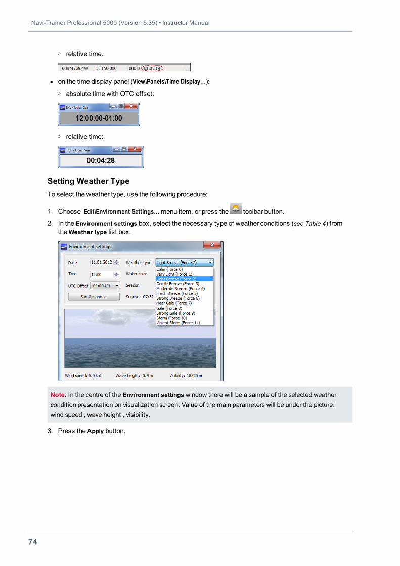
o relative time.
l on the time display panel (View\Panels\Time Display…):o absolute time with OTC offset:
o relative time:
Setting Weather TypeTo select the weather type, use the following procedure:
1. Choose Edit\Environment Settings…menu item, or press the toolbar button.
2. In the Environment settings box, select the necessary type of weather conditions (see Table 4) fromthe Weather type list box.
Note: In the centre of the Environment settings window there will be a sample of the selected weathercondition presentation on visualization screen. Value of the main parameters will be under the picture:wind speed , wave height , visibility.
3. Press theApply button.
Chapter 2. Creating and Editing Exercise • Setting Environmental Sailing Conditions
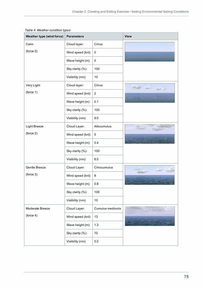
75
Weather type (wind force) Parameters View
Calm
(force 0)
Cloud layer: Cirrus
Wind speed (knt): 0
Wave height (m): 0
Sky clarity (%): 100
Visibility (nm): 10
Very Light
(force 1)
Cloud layer: Cirrus
Wind speed (knt): 2
Wave height (m) : 0.1
Sky clarity (%): 100
Visibility (nm): 9.0
Light Breeze
(force 2)
Cloud Layer: Altocumulus
Wind speed (knt): 5
Wave height (m): 0.4
Sky clarity (%): 100
Visibility (nm): 8.0
Gentle Breeze
(force 3)
Cloud Layer: Cirrocumulus
Wind speed (knt): 8
Wave height (m): 0.8
Sky clarity (%): 100
Visibility (nm): 10
Moderate Breeze
(force 4)
Cloud Layer: Cumulus mediocris
Wind speed (knt): 13
Wave height (m): 1.3
Sky clarity (%): 70
Visibility (nm): 5.0
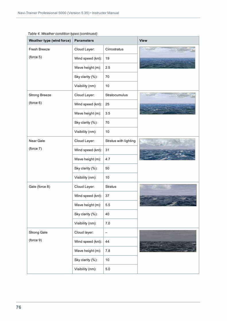
Table 4. Weather condition types
Navi-Trainer Professional 5000 (Version 5.35) • Instructor Manual
76
Weather type (wind force) Parameters View
Fresh Breeze
(force 5)
Cloud Layer: Cirrostratus
Wind speed (knt): 19
Wave height (m): 2.5
Sky clarity (%): 70
Visibility (nm): 10
Strong Breeze
(force 6)
Cloud Layer: Stratocumulus
Wind speed (knt): 25
Wave height (m): 3.5
Sky clarity (%): 70
Visibility (nm): 10
Near Gale
(force 7)
Cloud Layer: Stratus with lighting
Wind speed (knt): 31
Wave height (m): 4.7
Sky clarity (%): 50
Visibility (nm): 10
Gale (force 8) Cloud Layer: Stratus
Wind speed (knt): 37
Wave height (m): 5.5
Sky clarity (%): 40
Visibility (nm): 7.0
Strong Gale
(force 9)
Cloud layer: –
Wind speed (knt): 44
Wave height (m): 7.8
Sky clarity (%): 10
Visibility (nm): 5.0
Table 4. Weather condition types (continued)
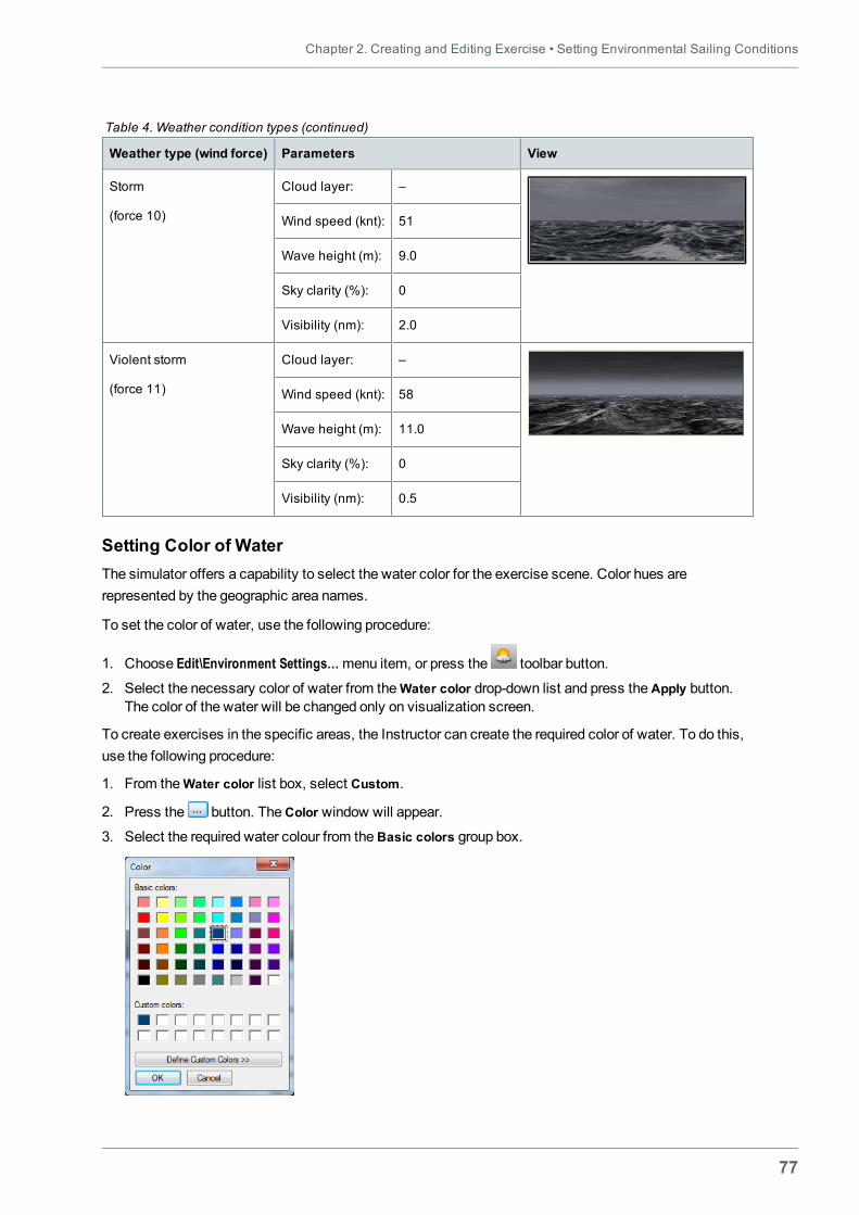
Chapter 2. Creating and Editing Exercise • Setting Environmental Sailing Conditions
77
Weather type (wind force) Parameters View
Storm
(force 10)
Cloud layer: –
Wind speed (knt): 51
Wave height (m): 9.0
Sky clarity (%): 0
Visibility (nm): 2.0
Violent storm
(force 11)
Cloud layer: –
Wind speed (knt): 58
Wave height (m): 11.0
Sky clarity (%): 0
Visibility (nm): 0.5
Table 4. Weather condition types (continued)
Setting Color of WaterThe simulator offers a capability to select the water color for the exercise scene. Color hues arerepresented by the geographic area names.
To set the color of water, use the following procedure:
1. Choose Edit\Environment Settings…menu item, or press the toolbar button.
2. Select the necessary color of water from the Water color drop-down list and press theApply button.The color of the water will be changed only on visualization screen.
To create exercises in the specific areas, the Instructor can create the required color of water. To do this,use the following procedure:
1. From theWater color list box, select Custom.
2. Press the button. TheColor window will appear.
3. Select the required water colour from theBasic colors group box.
Navi-Trainer Professional 5000 (Version 5.35) • Instructor Manual
78
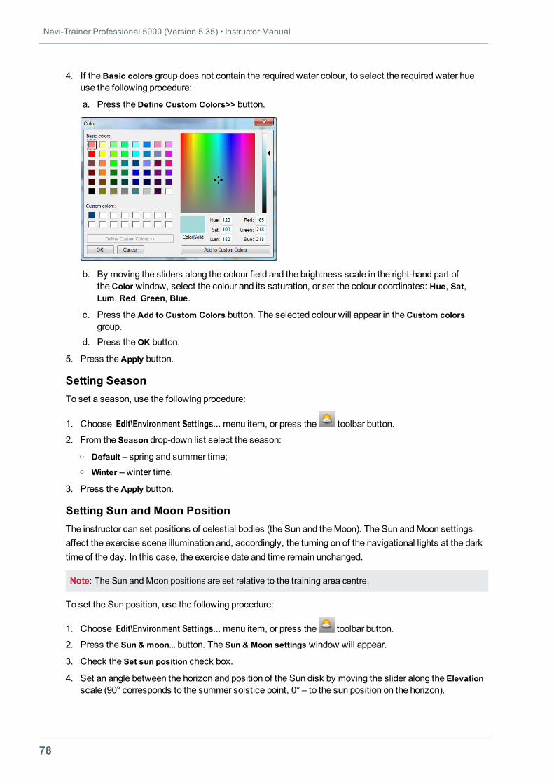
4. If theBasic colors group does not contain the required water colour, to select the required water hueuse the following procedure:
a. Press theDefine Custom Colors>> button.
b. By moving the sliders along the colour field and the brightness scale in the right-hand part ofthe Color window, select the colour and its saturation, or set the colour coordinates: Hue, Sat,Lum, Red, Green, Blue.
c. Press theAdd to Custom Colors button. The selected colour will appear in theCustom colorsgroup.
d. Press theОK button.
5. Press theApply button.
Setting SeasonTo set a season, use the following procedure:
1. Choose Edit\Environment Settings…menu item, or press the toolbar button.
2. From the Season drop-down list select the season:o Default – spring and summer time;o Winter – winter time.
3. Press theApply button.
Setting Sun and Moon PositionThe instructor can set positions of celestial bodies (the Sun and theMoon). The Sun andMoon settingsaffect the exercise scene illumination and, accordingly, the turning on of the navigational lights at the darktime of the day. In this case, the exercise date and time remain unchanged.
Note: The Sun and Moon positions are set relative to the training area centre.
To set the Sun position, use the following procedure:
1. Choose Edit\Environment Settings…menu item, or press the toolbar button.
2. Press the Sun & moon... button. The Sun & Moon settings window will appear.
3. Check the Set sun position check box.
4. Set an angle between the horizon and position of the Sun disk by moving the slider along the Elevationscale (90° corresponds to the summer solstice point, 0° – to the sun position on the horizon).
Chapter 2. Creating and Editing Exercise • Setting Environmental Sailing Conditions
79
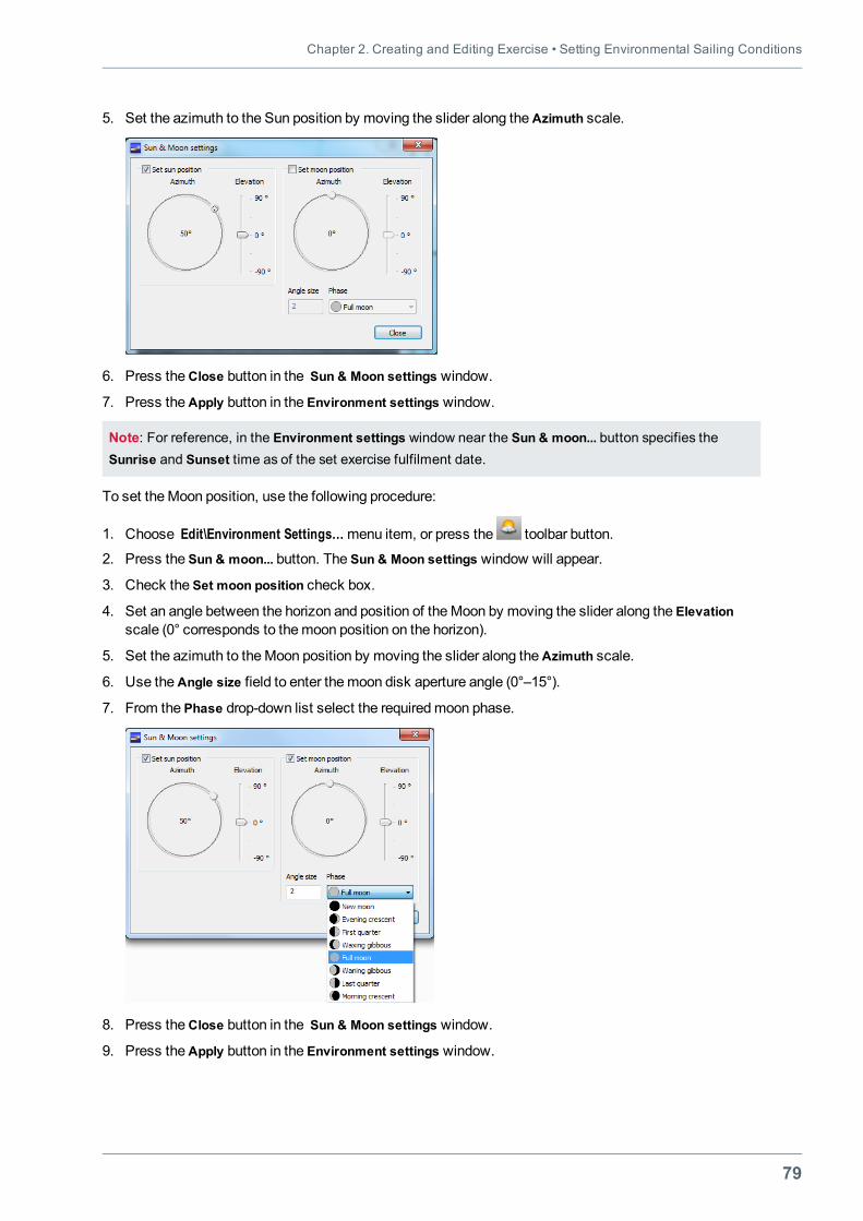
5. Set the azimuth to the Sun position by moving the slider along theAzimuth scale.
6. Press theClose button in the Sun & Moon settings window.
7. Press theApply button in the Environment settings window.
Note: For reference, in the Environment settings window near the Sun & moon... button specifies theSunrise and Sunset time as of the set exercise fulfilment date.
To set theMoon position, use the following procedure:
1. Choose Edit\Environment Settings…menu item, or press the toolbar button.
2. Press the Sun & moon... button. The Sun & Moon settings window will appear.
3. Check the Set moon position check box.
4. Set an angle between the horizon and position of theMoon by moving the slider along the Elevationscale (0° corresponds to themoon position on the horizon).
5. Set the azimuth to theMoon position by moving the slider along theAzimuth scale.
6. Use theAngle size field to enter themoon disk aperture angle (0°–15°).
7. From the Phase drop-down list select the requiredmoon phase.
8. Press theClose button in the Sun & Moon settings window.
9. Press theApply button in the Environment settings window.
Navi-Trainer Professional 5000 (Version 5.35) • Instructor Manual
80
Setting Wind and Wave DirectionTo set wind and wave direction, use the following procedure:
1. Choose Edit\Environment Settings…menu item, or press the toolbar button.
2. In theWind field, set the wind direction.
3. In theWave field, set the wave direction, or check Same direction check box to set the wave directionidentical to that of the wind.
4. Press theApply button.
Setting PrecipitationsTo set the precipitations, use the following procedure:
1. Choose Edit\Environment Settings…menu item, or press the toolbar button.
2. Check Rain or Snow check box.
3. Select precipitation intensity from the list (low, medium, high).
4. Press theApply button.
Setting Thunderstorm ConditionsTo set the thunderstorm conditions, use the following procedure:
1. Choose Edit\Environment Settings…menu item, or press the toolbar button.
2. Check Enable check box.
3. Enter thunderstorm time interval (s).
4. Enter minimal andmaximal distance from the ship to lightning displaying (nm).
5. Press theApply button.
Setting Sea Visual PresentationTo set the sea visual presentation, use the following procedure:
1. Choose Edit\Environment Settings…menu item, or press the toolbar button.
2. In the Sea group box check the parameters which should be displayed on the visualizationmonitor:o Witecaps – appearance of whitecaps on sea surface;o Foam – appearance of foam on sea surface;o Visual seabed – detailed seabed;o Drops on glass – drops on cabin glass.
3. Set the values of parameters:o Reflection – reflection of the ship (clouds etc.) in the water surface;o Water clarity – range of visibility under water;o Underwater visibility – water translucency.
4. Press theApply button.
Chapter 2. Creating and Editing Exercise • Setting Environmental Sailing Conditions
81
Scene Sound Switch On/OffThe scene sounds can be switched on/off for some areas. To do this, use the following procedure:
1. Choose Edit\Environment Settings…menu item, or press the toolbar button.
2. Check/clear the Scene sound checkbox.
3. Press theApply button.
Setting Constellation DisplayTo display constellation on the visualization screen, use the following procedure:
1. Choose Edit\Environment Settings…menu item, or press the toolbar button.
2. Check Show constellations check box.
3. Enter star scale (1–5).
4. Press theApply button.
Setting Additional Visual EffectsTo set additional visual effects, use the following procedure:
1. Choose the Edit\Environment Settings…menu item, or press the toolbar button.
2. To set the advanced wind shading effect, select theAdvanced wind shading check box.
Note: The wind shading enables considering of correct wind shadow, created by both exercise and sceneobjects. The wind shading can be used only if the Seagull6000/Wind Shading support option is selected inthe process of installation of simulator areas and objects.
3. To set simulation of the bow waves, select Bowwaves check box.
4. Click theApply button.
Creating Environment Conditions TemplateThe Instructor can save and load in any exercise the environment conditions templatemade in advance.To create an environment conditions template:
1. Choose the Edit\Environment Settings...menu item.
2. In the Environment settings window, set the required parameters and press theApply button (for moreinformation see "Environment Settings" on page 72).
3. Press theOverall Conditions button and set overall conditions parameters in theOverall ConditionManager window. Press theApply andClose buttons (for more information see "Overall EnvironmentalConditions" on page 83).
4. In the Environment settings window, press the Save… button.
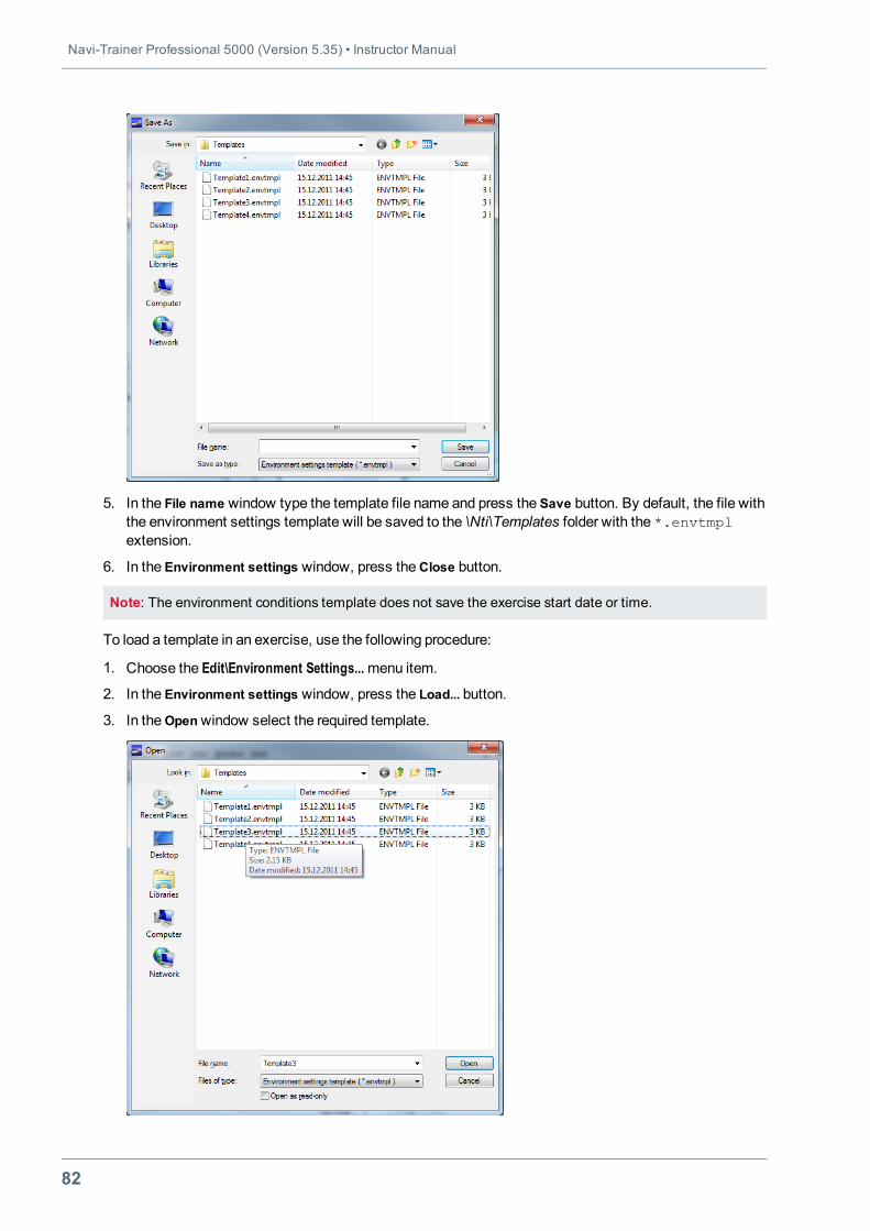
Navi-Trainer Professional 5000 (Version 5.35) • Instructor Manual
82
5. In the File name window type the template file name and press the Save button. By default, the file withthe environment settings template will be saved to the \Nti\Templates folder with the *.envtmplextension.
6. In the Environment settings window, press theClose button.
Note: The environment conditions template does not save the exercise start date or time.
To load a template in an exercise, use the following procedure:
1. Choose the Edit\Environment Settings...menu item.
2. In the Environment settings window, press the Load... button.
3. In theOpenwindow select the required template.
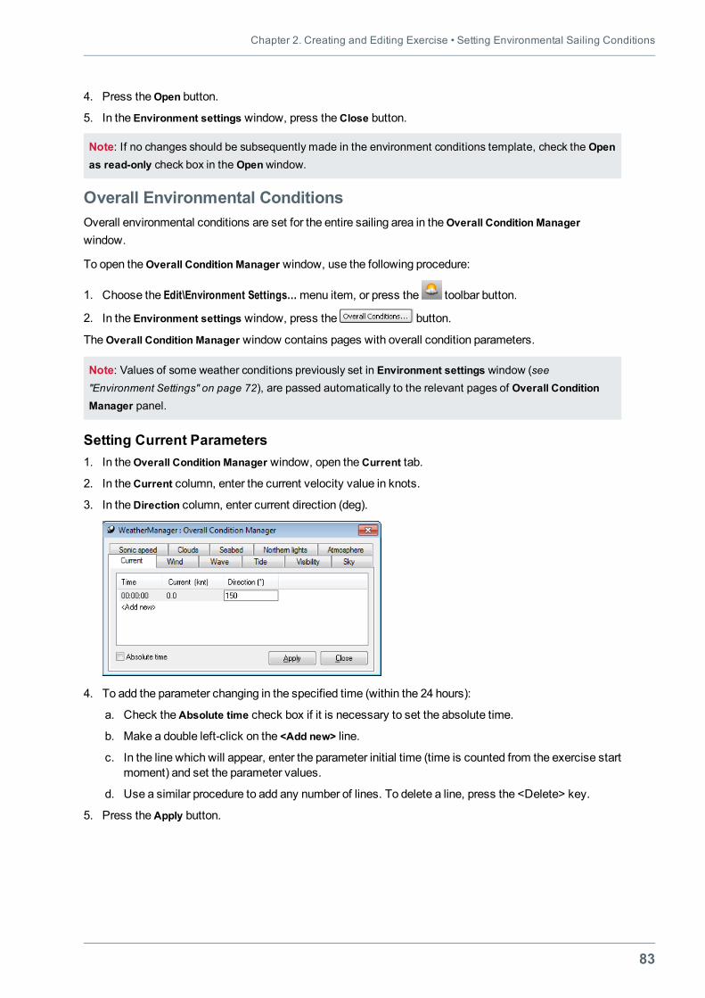
Chapter 2. Creating and Editing Exercise • Setting Environmental Sailing Conditions
83
4. Press theOpen button.
5. In the Environment settings window, press theClose button.
Note: If no changes should be subsequently made in the environment conditions template, check the Openas read-only check box in the Openwindow.
Overall Environmental ConditionsOverall environmental conditions are set for the entire sailing area in theOverall Condition Managerwindow.
To open theOverall Condition Manager window, use the following procedure:
1. Choose the Edit\Environment Settings…menu item, or press the toolbar button.
2. In the Environment settings window, press the button.
TheOverall Condition Manager window contains pages with overall condition parameters.
Note: Values of some weather conditions previously set in Environment settings window (see"Environment Settings" on page 72), are passed automatically to the relevant pages of Overall ConditionManager panel.
Setting Current Parameters1. In theOverall Condition Manager window, open theCurrent tab.
2. In theCurrent column, enter the current velocity value in knots.
3. In theDirection column, enter current direction (deg).
4. To add the parameter changing in the specified time (within the 24 hours):
a. Check theAbsolute time check box if it is necessary to set the absolute time.
b. Make a double left-click on the <Add new> line.
c. In the line which will appear, enter the parameter initial time (time is counted from the exercise startmoment) and set the parameter values.
d. Use a similar procedure to add any number of lines. To delete a line, press the <Delete> key.
5. Press theApply button.
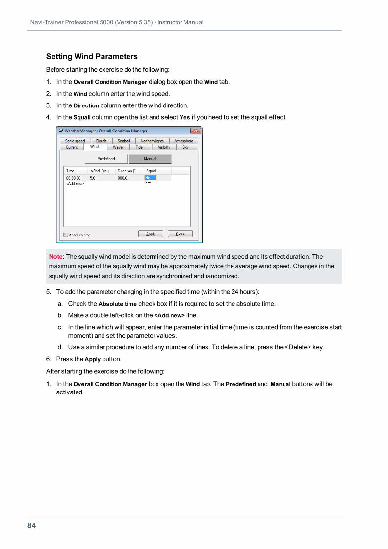
Navi-Trainer Professional 5000 (Version 5.35) • Instructor Manual
84
Setting Wind ParametersBefore starting the exercise do the following:
1. In theOverall Condition Manager dialog box open theWind tab.
2. In theWind column enter the wind speed.
3. In theDirection column enter the wind direction.
4. In the Squall column open the list and select Yes if you need to set the squall effect.
Note: The squally wind model is determined by the maximum wind speed and its effect duration. Themaximum speed of the squally wind may be approximately twice the average wind speed. Changes in thesqually wind speed and its direction are synchronized and randomized.
5. To add the parameter changing in the specified time (within the 24 hours):
a. Check theAbsolute time check box if it is required to set the absolute time.
b. Make a double left-click on the <Add new> line.
c. In the line which will appear, enter the parameter initial time (time is counted from the exercise startmoment) and set the parameter values.
d. Use a similar procedure to add any number of lines. To delete a line, press the <Delete> key.
6. Press theApply button.
After starting the exercise do the following:
1. In theOverall Condition Manager box open theWind tab. The Predefined and Manual buttons will beactivated.
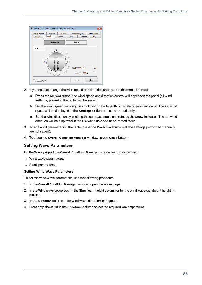
Chapter 2. Creating and Editing Exercise • Setting Environmental Sailing Conditions
85
2. If you need to change the wind speed and direction shortly, use themanual control:
a. Press theManual button: the wind speed and direction control will appear on the panel (all windsettings, pre-set in the table, will be saved).
b. Set the wind speed, moving the scroll box on the logarithmic scale of arrow indicator. The set windspeed will be displayed in theWind speed field and used immediately.
c. Set the wind direction by clicking the compass scale and rotating the arrow indicator. The set winddirection will be displayed in theDirection field and used immediately.
3. To edit wind parameters in the table, press the Predefined button (all the settings performedmanuallyare not saved).
4. To close theOverall Condition Manager window, press Close button.
Setting Wave ParametersOn theWave page of theOverall Condition Manager window instructor can set:
l Wind wave parameters;
l Swell parameters.
Setting Wind Wave Parameters
To set the wind wave parameters, use the following procedure:
1. In theOverall Condition Manager window, open theWave page.
2. In theWind wave group box, in the Significant height column enter the wind wave significant height inmeters.
3. In theDirection column enter wind wave direction in degrees.
4. From drop-down list in the Spectrum column select the required wave spectrum.
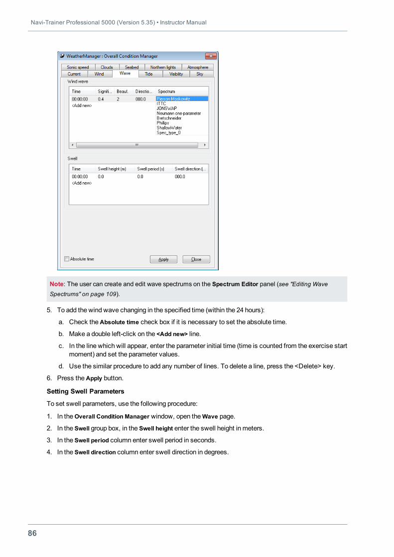
Navi-Trainer Professional 5000 (Version 5.35) • Instructor Manual
86
Note: The user can create and edit wave spectrums on the Spectrum Editor panel (see "Editing Wave
Spectrums" on page 109).
5. To add the wind wave changing in the specified time (within the 24 hours):
a. Check theAbsolute time check box if it is necessary to set the absolute time.
b. Make a double left-click on the <Add new> line.
c. In the line which will appear, enter the parameter initial time (time is counted from the exercise startmoment) and set the parameter values.
d. Use the similar procedure to add any number of lines. To delete a line, press the <Delete> key.
6. Press theApply button.
Setting Swell Parameters
To set swell parameters, use the following procedure:
1. In theOverall Condition Manager window, open the Wave page.
2. In the Swell group box, in the Swell height enter the swell height in meters.
3. In the Swell period column enter swell period in seconds.
4. In the Swell direction column enter swell direction in degrees.
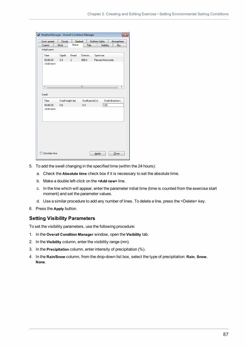
Chapter 2. Creating and Editing Exercise • Setting Environmental Sailing Conditions
87
5. To add the swell changing in the specified time (within the 24 hours):
a. Check theAbsolute time check box if it is necessary to set the absolute time.
b. Make a double left-click on the <Add new> line.
c. In the line which will appear, enter the parameter initial time (time is counted from the exercise startmoment) and set the parameter values.
d. Use a similar procedure to add any number of lines. To delete a line, press the <Delete> key.
6. Press theApply button.
Setting Visibility ParametersTo set the visibility parameters, use the following procedure:
1. In theOverall Condition Manager window, open the Visibility tab.
2. In the Visibility column, enter the visibility range (nm).
3. In the Precipitation column, enter intensity of precipitation (%).
4. In theRain/Snow column, from the drop-down list box, select the type of precipitation: Rain, Snow,None.
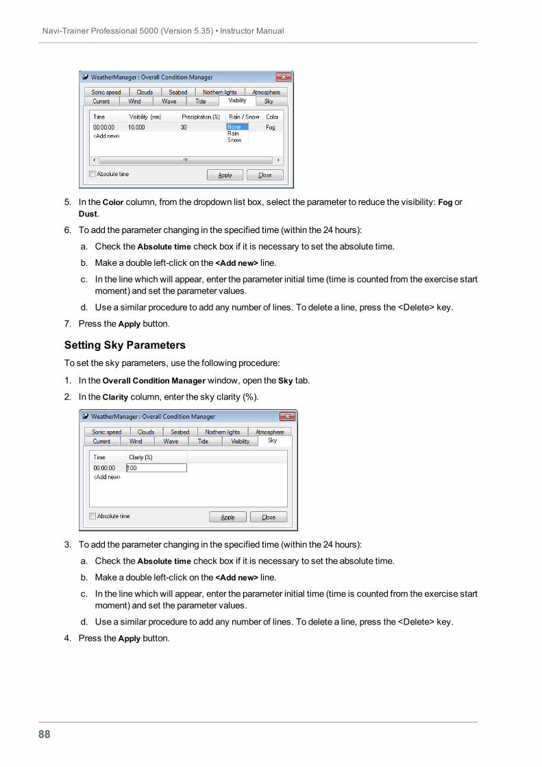
Navi-Trainer Professional 5000 (Version 5.35) • Instructor Manual
88
5. In theColor column, from the dropdown list box, select the parameter to reduce the visibility: Fog orDust.
6. To add the parameter changing in the specified time (within the 24 hours):
a. Check theAbsolute time check box if it is necessary to set the absolute time.
b. Make a double left-click on the <Add new> line.
c. In the line which will appear, enter the parameter initial time (time is counted from the exercise startmoment) and set the parameter values.
d. Use a similar procedure to add any number of lines. To delete a line, press the <Delete> key.
7. Press theApply button.
Setting Sky ParametersTo set the sky parameters, use the following procedure:
1. In theOverall Condition Manager window, open the Sky tab.
2. In theClarity column, enter the sky clarity (%).
3. To add the parameter changing in the specified time (within the 24 hours):
a. Check theAbsolute time check box if it is necessary to set the absolute time.
b. Make a double left-click on the <Add new> line.
c. In the line which will appear, enter the parameter initial time (time is counted from the exercise startmoment) and set the parameter values.
d. Use a similar procedure to add any number of lines. To delete a line, press the <Delete> key.
4. Press theApply button.
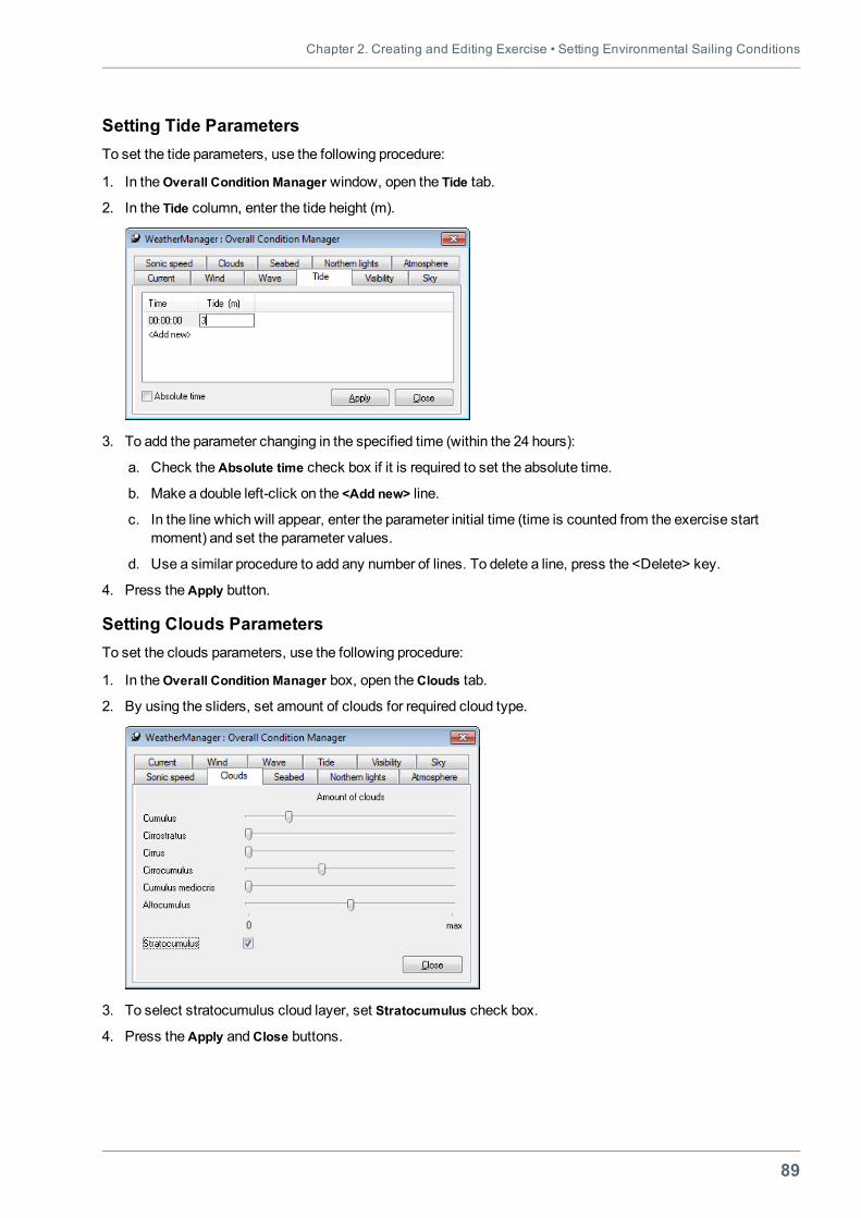
Chapter 2. Creating and Editing Exercise • Setting Environmental Sailing Conditions
89
Setting Tide ParametersTo set the tide parameters, use the following procedure:
1. In theOverall Condition Manager window, open the Tide tab.
2. In the Tide column, enter the tide height (m).
3. To add the parameter changing in the specified time (within the 24 hours):
a. Check theAbsolute time check box if it is required to set the absolute time.
b. Make a double left-click on the <Add new> line.
c. In the line which will appear, enter the parameter initial time (time is counted from the exercise startmoment) and set the parameter values.
d. Use a similar procedure to add any number of lines. To delete a line, press the <Delete> key.
4. Press theApply button.
Setting Clouds ParametersTo set the clouds parameters, use the following procedure:
1. In theOverall Condition Manager box, open theClouds tab.
2. By using the sliders, set amount of clouds for required cloud type.
3. To select stratocumulus cloud layer, set Stratocumulus check box.
4. Press theApply andClose buttons.
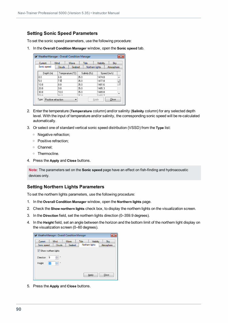
Navi-Trainer Professional 5000 (Version 5.35) • Instructor Manual
90
Setting Sonic Speed ParametersTo set the sonic speed parameters, use the following procedure:
1. In theOverall Condition Manager window, open the Sonic speed tab.
2. Enter the temperature (Temperature column) and/or salinity (Salinity column) for any selected depthlevel. With the input of temperature and/or salinity, the corresponding sonic speed will be re-calculatedautomatically.
3. Or select one of standard vertical sonic speed distribution (VSSD) from the Type list:o Negative refraction;o Positive refraction;o Channel;o Thermocline.
4. Press theApply andClose buttons.
Note: The parameters set on the Sonic speed page have an effect on fish-finding and hydroacousticdevices only.
Setting Northern Lights ParametersTo set the northern lights parameters, use the following procedure:
1. In theOverall Condition Manager window, open theNorthern lights page.
2. Check the Show northern lights check box, to display the northern lights on the visualization screen.
3. In theDirection field, set the northern lights direction (0–359.9 degrees).
4. In theHeight field, set an angle between the horizon and the bottom limit of the northern light display onthe visualization screen (0–60 degrees).
5. Press theApply andClose buttons.
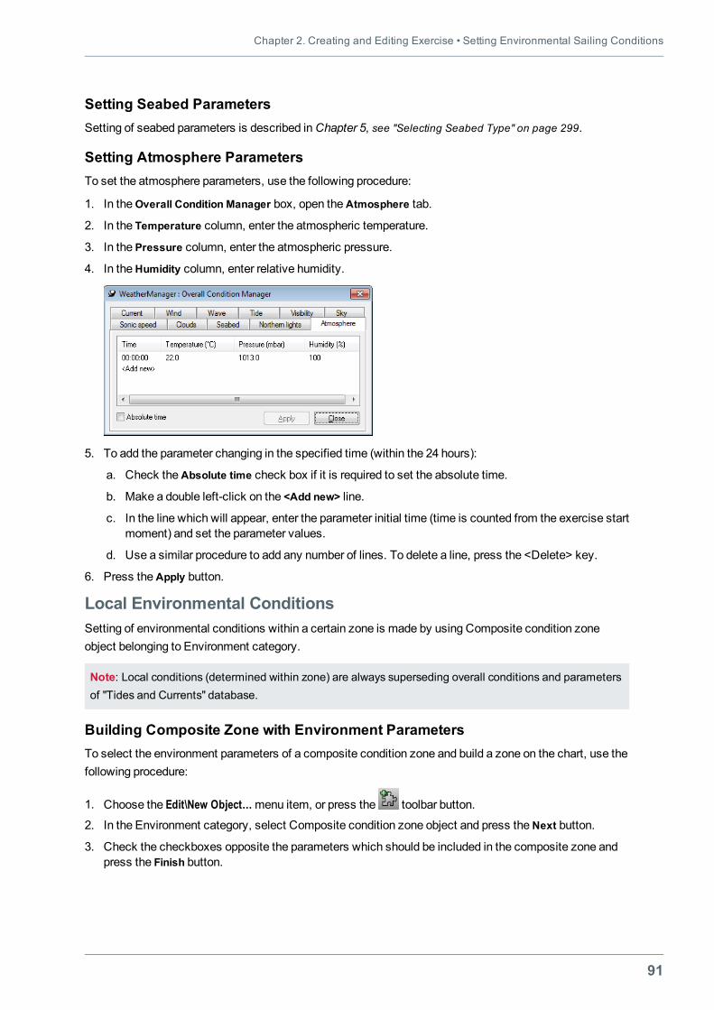
Chapter 2. Creating and Editing Exercise • Setting Environmental Sailing Conditions
91
Setting Seabed ParametersSetting of seabed parameters is described inChapter 5, see "Selecting Seabed Type" on page 299.
Setting Atmosphere ParametersTo set the atmosphere parameters, use the following procedure:
1. In theOverall Condition Manager box, open theAtmosphere tab.
2. In the Temperature column, enter the atmospheric temperature.
3. In the Pressure column, enter the atmospheric pressure.
4. In theHumidity column, enter relative humidity.
5. To add the parameter changing in the specified time (within the 24 hours):
a. Check theAbsolute time check box if it is required to set the absolute time.
b. Make a double left-click on the <Add new> line.
c. In the line which will appear, enter the parameter initial time (time is counted from the exercise startmoment) and set the parameter values.
d. Use a similar procedure to add any number of lines. To delete a line, press the <Delete> key.
6. Press theApply button.
Local Environmental ConditionsSetting of environmental conditions within a certain zone is made by using Composite condition zoneobject belonging to Environment category.
Note: Local conditions (determined within zone) are always superseding overall conditions and parametersof "Tides and Currents" database.
Building Composite Zone with Environment ParametersTo select the environment parameters of a composite condition zone and build a zone on the chart, use thefollowing procedure:
1. Choose the Edit\New Object…menu item, or press the toolbar button.
2. In the Environment category, select Composite condition zone object and press theNext button.
3. Check the checkboxes opposite the parameters which should be included in the composite zone andpress the Finish button.
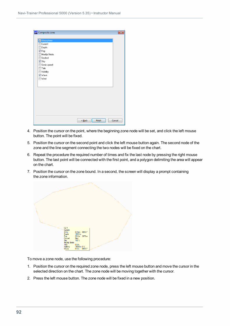
Navi-Trainer Professional 5000 (Version 5.35) • Instructor Manual
92
4. Position the cursor on the point, where the beginning zone node will be set, and click the left mousebutton. The point will be fixed.
5. Position the cursor on the second point and click the left mouse button again. The second node of thezone and the line segment connecting the two nodes will be fixed on the chart.
6. Repeat the procedure the required number of times and fix the last node by pressing the right mousebutton. The last point will be connected with the first point, and a polygon delimiting the area will appearon the chart.
7. Position the cursor on the zone bound. In a second, the screen will display a prompt containingthe zone information.
Tomove a zone node, use the following procedure:
1. Position the cursor on the required zone node, press the left mouse button andmove the cursor in theselected direction on the chart. The zone node will bemoving together with the cursor.
2. Press the left mouse button. The zone node will be fixed in a new position.
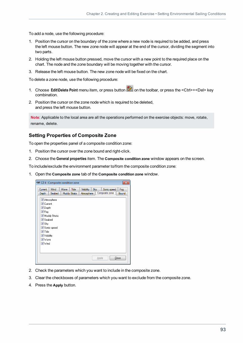
Chapter 2. Creating and Editing Exercise • Setting Environmental Sailing Conditions
93
To add a node, use the following procedure:
1. Position the cursor on the boundary of the zone where a new node is required to be added, and pressthe left mouse button. The new zone node will appear at the end of the cursor, dividing the segment intotwo parts.
2. Holding the left mouse button pressed, move the cursor with a new point to the required place on thechart. The node and the zone boundary will bemoving together with the cursor.
3. Release the left mouse button. The new zone node will be fixed on the chart.
To delete a zone node, use the following procedure:
1. Choose Edit\Delete Point menu item, or press button on the toolbar, or press the <Ctrl>+<Del> keycombination.
2. Position the cursor on the zone node which is required to be deleted,and press the left mouse button.
Note: Applicable to the local area are all the operations performed on the exercise objects: move, rotate,rename, delete.
Setting Properties of Composite ZoneTo open the properties panel of a composite condition zone:
1. Position the cursor over the zone bound and right-click.
2. Choose the General properties item. TheComposite condition zone window appears on the screen.
To include/exclude the environment parameter to/from the composite condition zone:
1. Open theComposite zone tab of theComposite condition zone window.
2. Check the parameters which you want to include in the composite zone.
3. Clear the checkboxes of parameters which you want to exclude from the composite zone.
4. Press theApply button.
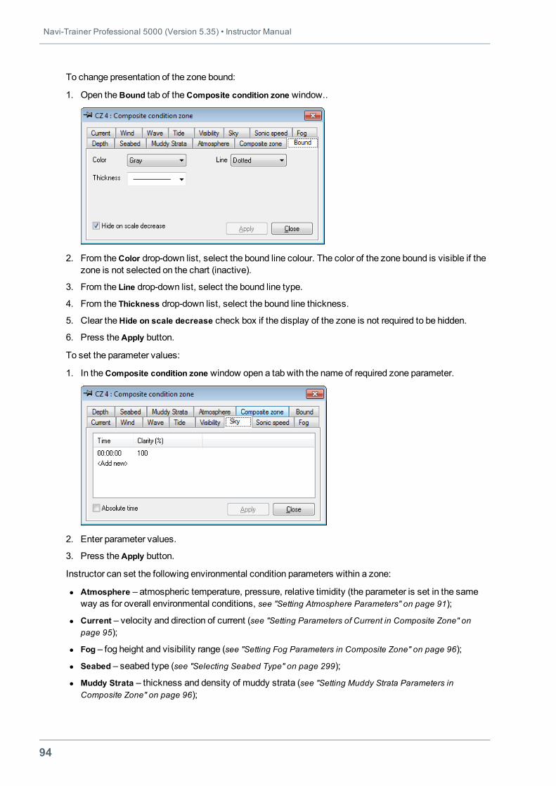
Navi-Trainer Professional 5000 (Version 5.35) • Instructor Manual
94
To change presentation of the zone bound:
1. Open theBound tab of theComposite condition zone window..
2. From theColor drop-down list, select the bound line colour. The color of the zone bound is visible if thezone is not selected on the chart (inactive).
3. From the Line drop-down list, select the bound line type.
4. From the Thickness drop-down list, select the bound line thickness.
5. Clear theHide on scale decrease check box if the display of the zone is not required to be hidden.
6. Press theApply button.
To set the parameter values:
1. In theComposite condition zone window open a tab with the name of required zone parameter.
2. Enter parameter values.
3. Press theApply button.
Instructor can set the following environmental condition parameters within a zone:
l Atmosphere – atmospheric temperature, pressure, relative timidity (the parameter is set in the sameway as for overall environmental conditions, see "Setting Atmosphere Parameters" on page 91);
l Current – velocity and direction of current (see "Setting Parameters of Current in Composite Zone" onpage 95);
l Fog – fog height and visibility range (see "Setting Fog Parameters in Composite Zone" on page 96);
l Seabed – seabed type (see "Selecting Seabed Type" on page 299);
l Muddy Strata – thickness and density of muddy strata (see "Setting Muddy Strata Parameters inComposite Zone" on page 96);
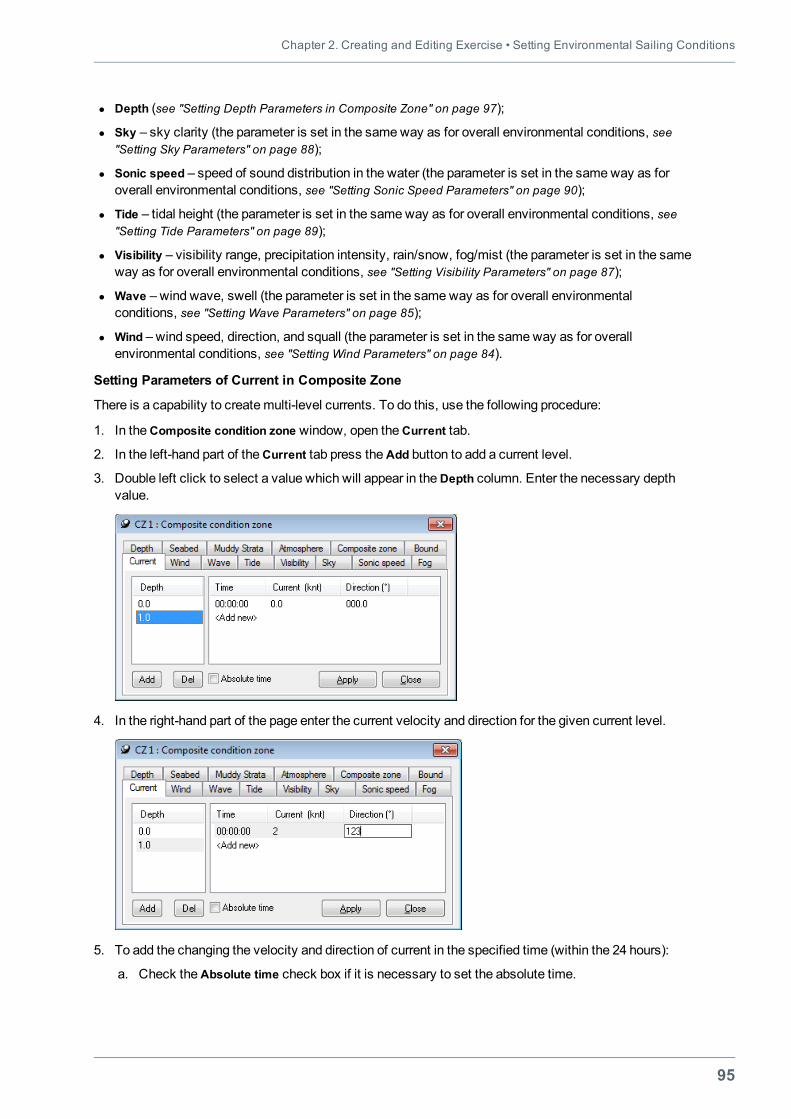
Chapter 2. Creating and Editing Exercise • Setting Environmental Sailing Conditions
95
l Depth (see "Setting Depth Parameters in Composite Zone" on page 97);
l Sky – sky clarity (the parameter is set in the sameway as for overall environmental conditions, see"Setting Sky Parameters" on page 88);
l Sonic speed – speed of sound distribution in the water (the parameter is set in the sameway as foroverall environmental conditions, see "Setting Sonic Speed Parameters" on page 90);
l Tide – tidal height (the parameter is set in the sameway as for overall environmental conditions, see"Setting Tide Parameters" on page 89);
l Visibility – visibility range, precipitation intensity, rain/snow, fog/mist (the parameter is set in the sameway as for overall environmental conditions, see "Setting Visibility Parameters" on page 87);
l Wave – wind wave, swell (the parameter is set in the sameway as for overall environmentalconditions, see "Setting Wave Parameters" on page 85);
l Wind – wind speed, direction, and squall (the parameter is set in the sameway as for overallenvironmental conditions, see "Setting Wind Parameters" on page 84).
Setting Parameters of Current in Composite Zone
There is a capability to createmulti-level currents. To do this, use the following procedure:
1. In theComposite condition zone window, open theCurrent tab.
2. In the left-hand part of theCurrent tab press theAdd button to add a current level.
3. Double left click to select a value which will appear in theDepth column. Enter the necessary depthvalue.
4. In the right-hand part of the page enter the current velocity and direction for the given current level.
5. To add the changing the velocity and direction of current in the specified time (within the 24 hours):
a. Check theAbsolute time check box if it is necessary to set the absolute time.
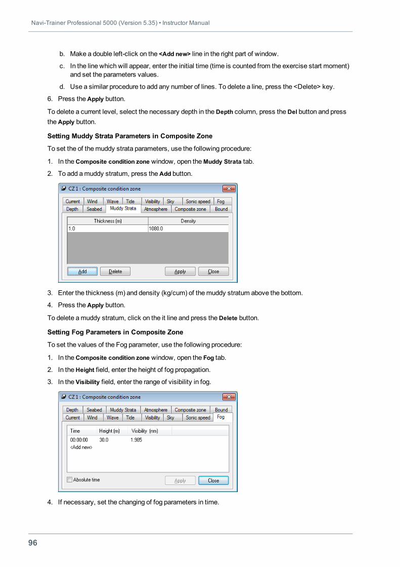
Navi-Trainer Professional 5000 (Version 5.35) • Instructor Manual
96
b. Make a double left-click on the <Add new> line in the right part of window.
c. In the line which will appear, enter the initial time (time is counted from the exercise start moment)and set the parameters values.
d. Use a similar procedure to add any number of lines. To delete a line, press the <Delete> key.
6. Press theApply button.
To delete a current level, select the necessary depth in theDepth column, press theDel button and presstheApply button.
Setting Muddy Strata Parameters in Composite Zone
To set the of themuddy strata parameters, use the following procedure:
1. In theComposite condition zone window, open theMuddy Strata tab.
2. To add amuddy stratum, press theAdd button.
3. Enter the thickness (m) and density (kg/cum) of themuddy stratum above the bottom.
4. Press theApply button.
To delete amuddy stratum, click on the it line and press theDelete button.
Setting Fog Parameters in Composite Zone
To set the values of the Fog parameter, use the following procedure:
1. In theComposite condition zone window, open the Fog tab.
2. In theHeight field, enter the height of fog propagation.
3. In the Visibility field, enter the range of visibility in fog.
4. If necessary, set the changing of fog parameters in time.
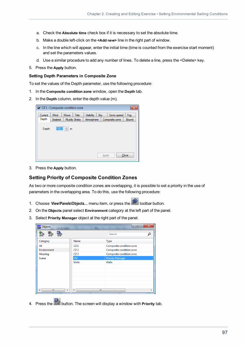
Chapter 2. Creating and Editing Exercise • Setting Environmental Sailing Conditions
97
a. Check theAbsolute time check box if it is necessary to set the absolute time.
b. Make a double left-click on the <Add new> line in the right part of window.
c. In the line which will appear, enter the initial time (time is counted from the exercise start moment)and set the parameters values.
d. Use a similar procedure to add any number of lines. To delete a line, press the <Delete> key.
5. Press theApply button.
Setting Depth Parameters in Composite Zone
To set the values of the Depth parameter, use the following procedure:
1. In theComposite condition zone window, open theDepth tab.
2. In theDepth column, enter the depth value (m).
3. Press theApply button.
Setting Priority of Composite Condition ZonesAs two or more composite condition zones are overlapping, it is possible to set a priority in the use ofparameters in the overlapping area. To do this, use the following procedure:
1. Choose View\Panels\Objects…menu item, or press the toolbar button.
2. On theObjects panel select Environment category at the left part of the panel.
3. Select Priority Manager object at the right part of the panel.
4. Press the button. The screen will display a window with Priority tab.
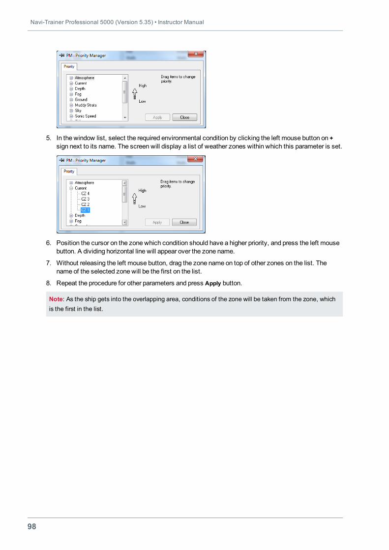
Navi-Trainer Professional 5000 (Version 5.35) • Instructor Manual
98
5. In the window list, select the required environmental condition by clicking the left mouse button on +sign next to its name. The screen will display a list of weather zones within which this parameter is set.
6. Position the cursor on the zone which condition should have a higher priority, and press the left mousebutton. A dividing horizontal line will appear over the zone name.
7. Without releasing the left mouse button, drag the zone name on top of other zones on the list. Thename of the selected zone will be the first on the list.
8. Repeat the procedure for other parameters and press Apply button.
Note: As the ship gets into the overlapping area, conditions of the zone will be taken from the zone, whichis the first in the list.
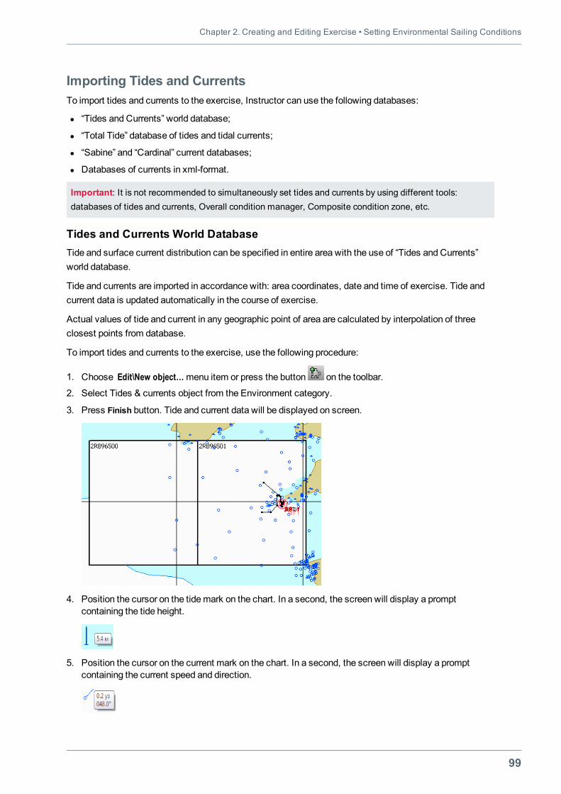
Chapter 2. Creating and Editing Exercise • Setting Environmental Sailing Conditions
99
Importing Tides and CurrentsTo import tides and currents to the exercise, Instructor can use the following databases:
l “Tides and Currents” world database;
l “Total Tide” database of tides and tidal currents;
l “Sabine” and “Cardinal” current databases;
l Databases of currents in xml-format.
Important: It is not recommended to simultaneously set tides and currents by using different tools:databases of tides and currents, Overall condition manager, Composite condition zone, etc.
Tides and Currents World DatabaseTide and surface current distribution can be specified in entire area with the use of “Tides and Currents”world database.
Tide and currents are imported in accordance with: area coordinates, date and time of exercise. Tide andcurrent data is updated automatically in the course of exercise.
Actual values of tide and current in any geographic point of area are calculated by interpolation of threeclosest points from database.
To import tides and currents to the exercise, use the following procedure:
1. Choose Edit\New object…menu item or press the button on the toolbar.
2. Select Tides & currents object from the Environment category.
3. Press Finish button. Tide and current data will be displayed on screen.
4. Position the cursor on the tidemark on the chart. In a second, the screen will display a promptcontaining the tide height.
5. Position the cursor on the current mark on the chart. In a second, the screen will display a promptcontaining the current speed and direction.
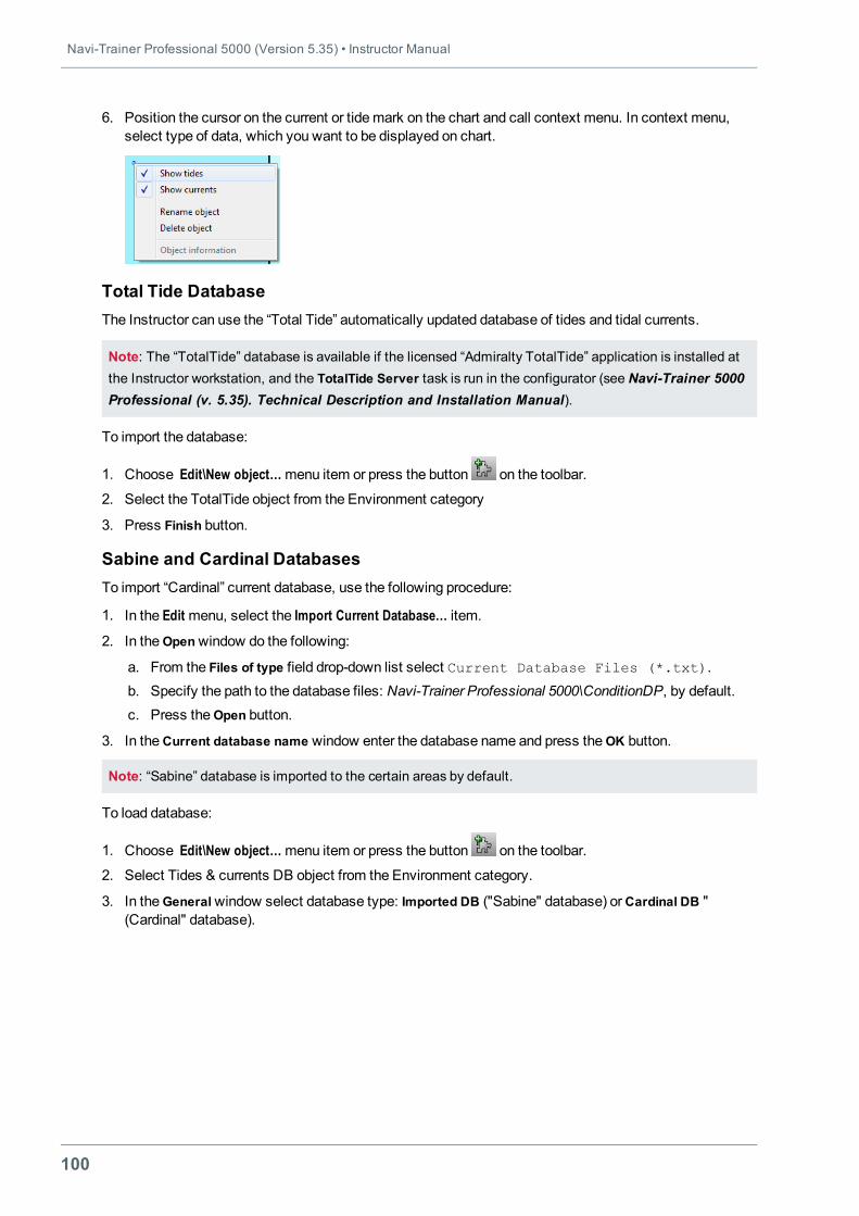
Navi-Trainer Professional 5000 (Version 5.35) • Instructor Manual
100
6. Position the cursor on the current or tidemark on the chart and call context menu. In context menu,select type of data, which you want to be displayed on chart.
Total Tide DatabaseThe Instructor can use the “Total Tide” automatically updated database of tides and tidal currents.
Note: The “TotalTide” database is available if the licensed “Admiralty TotalTide” application is installed atthe Instructor workstation, and the TotalTide Server task is run in the configurator (see Navi-Trainer 5000Professional (v. 5.35). Technical Description and Installation Manual).
To import the database:
1. Choose Edit\New object…menu item or press the button on the toolbar.
2. Select the TotalTide object from the Environment category
3. Press Finish button.
Sabine and Cardinal DatabasesTo import “Cardinal” current database, use the following procedure:
1. In the Edit menu, select the Import Current Database… item.
2. In theOpenwindow do the following:
a. From the Files of type field drop-down list select Current Database Files (*.txt).b. Specify the path to the database files: Navi-Trainer Professional 5000\ConditionDP, by default.c. Press the Open button.
3. In theCurrent database name window enter the database name and press theOK button.
Note: “Sabine” database is imported to the certain areas by default.
To load database:
1. Choose Edit\New object…menu item or press the button on the toolbar.
2. Select Tides & currents DB object from the Environment category.
3. In theGeneralwindow select database type: Imported DB ("Sabine" database) orCardinal DB "(Cardinal" database).
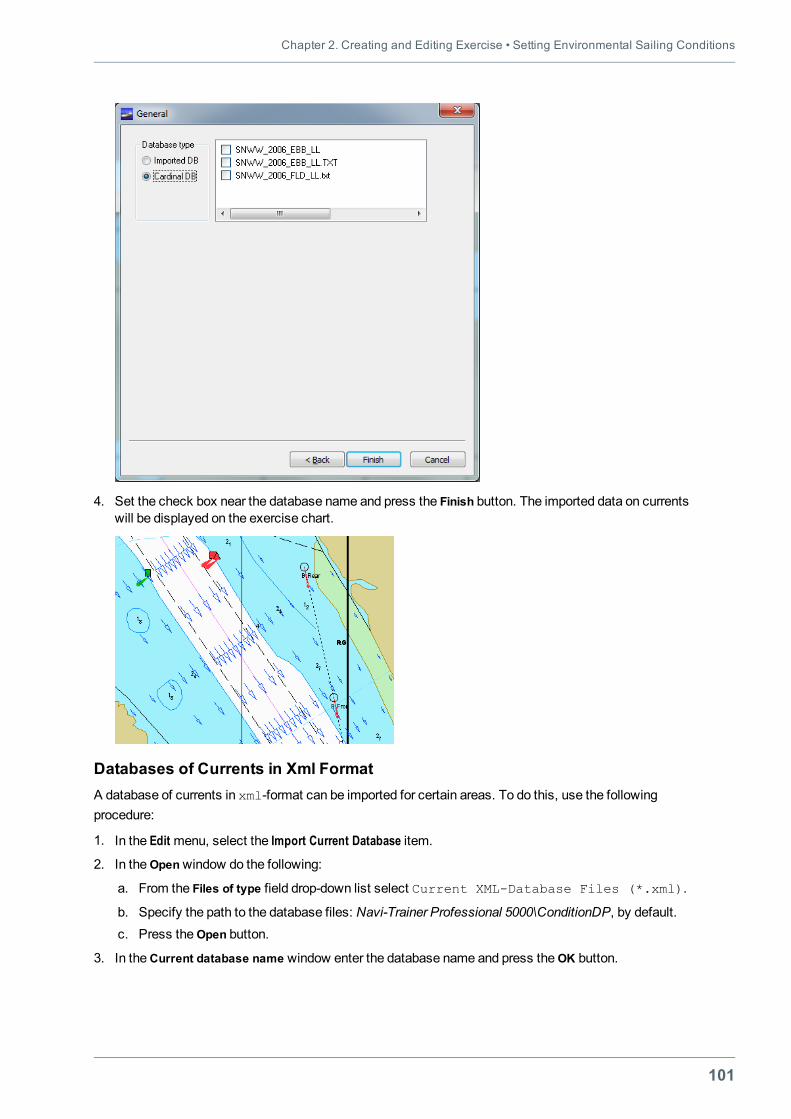
Chapter 2. Creating and Editing Exercise • Setting Environmental Sailing Conditions
101
4. Set the check box near the database name and press the Finish button. The imported data on currentswill be displayed on the exercise chart.
Databases of Currents in Xml FormatA database of currents in xml-format can be imported for certain areas. To do this, use the followingprocedure:
1. In the Edit menu, select the Import Current Database item.
2. In theOpenwindow do the following:
a. From the Files of type field drop-down list select Current XML-Database Files (*.xml).
b. Specify the path to the database files: Navi-Trainer Professional 5000\ConditionDP, by default.c. Press the Open button.
3. In theCurrent database name window enter the database name and press theOK button.
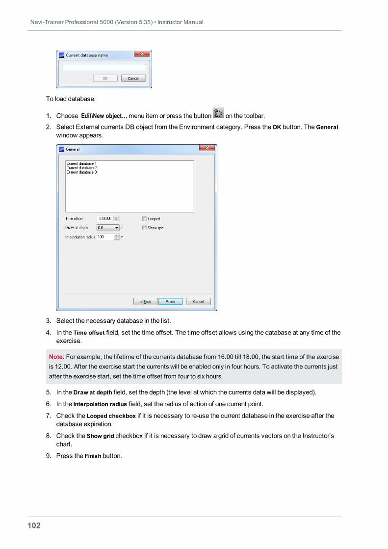
Navi-Trainer Professional 5000 (Version 5.35) • Instructor Manual
102
To load database:
1. Choose Edit\New object…menu item or press the button on the toolbar.
2. Select External currents DB object from the Environment category. Press theOK button. TheGeneralwindow appears.
3. Select the necessary database in the list.
4. In the Time offset field, set the time offset. The time offset allows using the database at any time of theexercise.
Note: For example, the lifetime of the currents database from 16:00 till 18:00, the start time of the exerciseis 12.00. After the exercise start the currents will be enabled only in four hours. To activate the currents justafter the exercise start, set the time offset from four to six hours.
5. In theDraw at depth field, set the depth (the level at which the currents data will be displayed).
6. In the Interpolation radius field, set the radius of action of one current point.
7. Check the Looped checkbox if it is necessary to re-use the current database in the exercise after thedatabase expiration.
8. Check the Show grid checkbox if it is necessary to draw a grid of currents vectors on the Instructor’schart.
9. Press the Finish button.
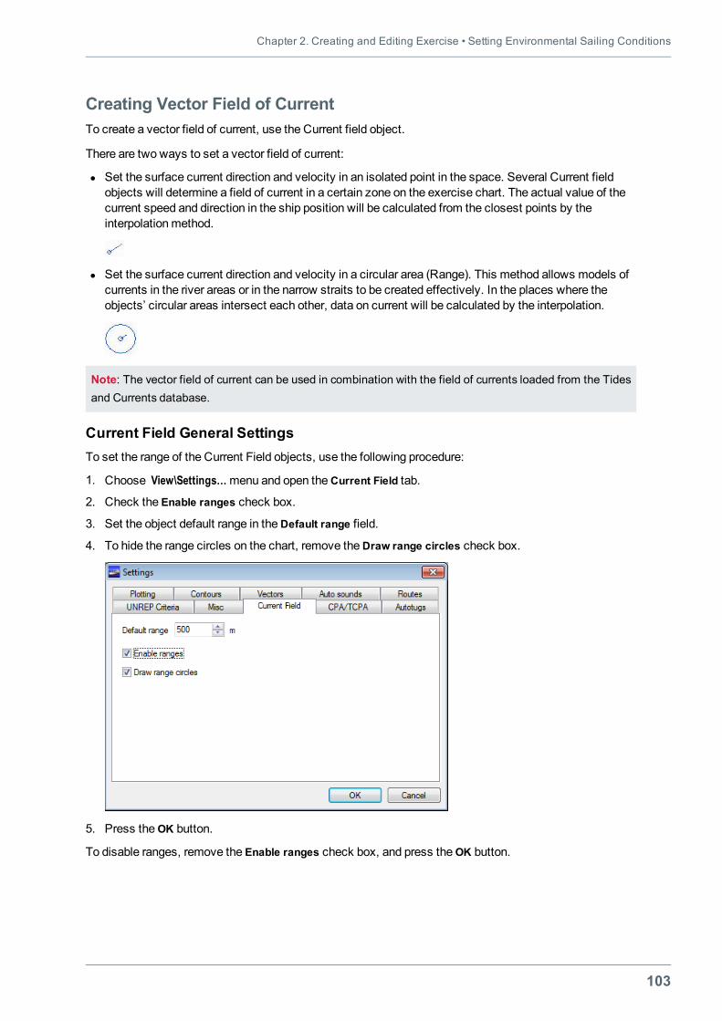
Chapter 2. Creating and Editing Exercise • Setting Environmental Sailing Conditions
103
Creating Vector Field of CurrentTo create a vector field of current, use the Current field object.
There are two ways to set a vector field of current:
l Set the surface current direction and velocity in an isolated point in the space. Several Current fieldobjects will determine a field of current in a certain zone on the exercise chart. The actual value of thecurrent speed and direction in the ship position will be calculated from the closest points by theinterpolationmethod.
l Set the surface current direction and velocity in a circular area (Range). This method allows models ofcurrents in the river areas or in the narrow straits to be created effectively. In the places where theobjects’ circular areas intersect each other, data on current will be calculated by the interpolation.
Note: The vector field of current can be used in combination with the field of currents loaded from the Tidesand Currents database.
Current Field General SettingsTo set the range of the Current Field objects, use the following procedure:
1. Choose View\Settings…menu and open theCurrent Field tab.
2. Check the Enable ranges check box.
3. Set the object default range in theDefault range field.
4. To hide the range circles on the chart, remove theDraw range circles check box.
5. Press theOK button.
To disable ranges, remove the Enable ranges check box, and press theOK button.
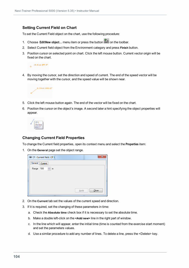
Navi-Trainer Professional 5000 (Version 5.35) • Instructor Manual
104
Setting Current Field on ChartTo set the Current Field object on the chart, use the following procedure:
1. Choose Edit\New object…menu item or press the button on the toolbar.
2. Select Current field object from the Environment category and press Finish button.
3. Position cursor on selected point on chart. Click the left mouse button. Current vector origin will befixed on the chart.
4. By moving the cursor, set the direction and speed of current. The end of the speed vector will bemoving together with the cursor, and the speed value will be shown near.
5. Click the left mouse button again. The end of the vector will be fixed on the chart.
6. Position the cursor on the object’s image. A second later a hint specifying the object properties willappear.
Changing Current Field PropertiesTo change the Current field properties, open its context menu and select the Properties item:
1. On theGeneral page set the object range.
2. On theCurrent tab set the values of the current speed and direction.
3. If it is required, set the changing of these parameters in time:
a. Check theAbsolute time check box if it is necessary to set the absolute time.
b. Make a double left-click on the <Add new> line in the right part of window.
c. In the line which will appear, enter the initial time (time is counted from the exercise start moment)and set the parameters values.
d. Use a similar procedure to add any number of lines. To delete a line, press the <Delete> key.
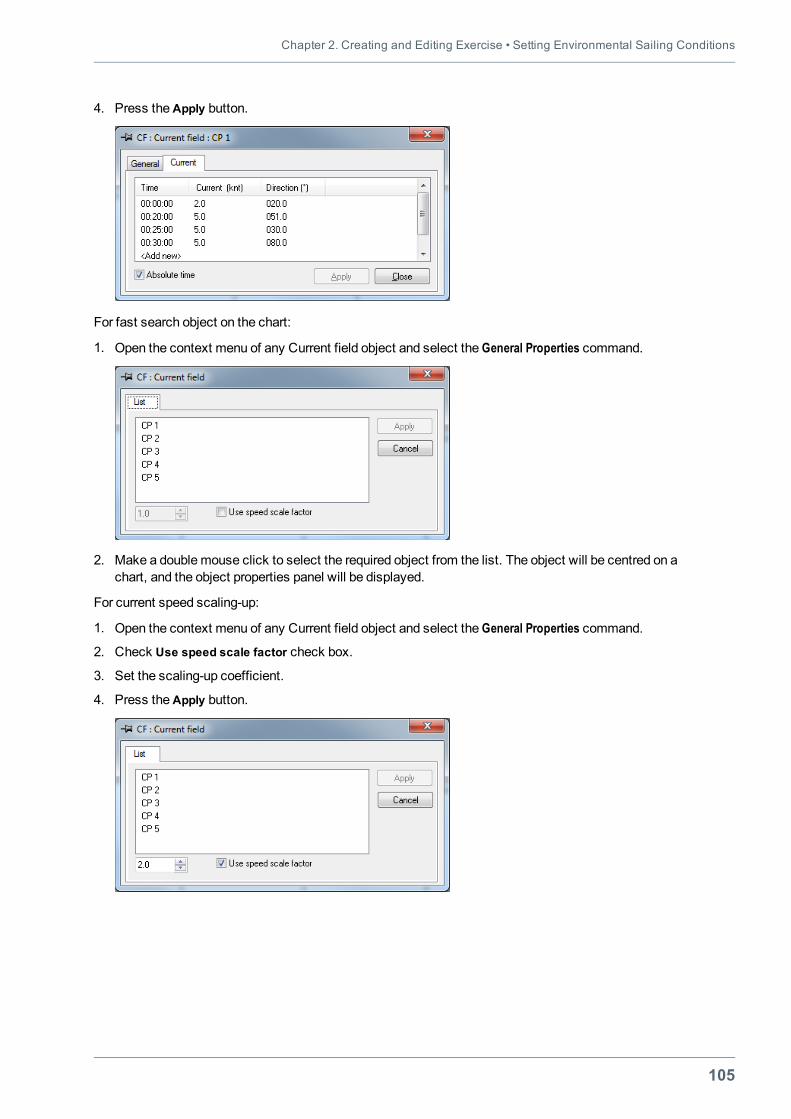
Chapter 2. Creating and Editing Exercise • Setting Environmental Sailing Conditions
105
4. Press theApply button.
For fast search object on the chart:
1. Open the context menu of any Current field object and select the General Properties command.
2. Make a doublemouse click to select the required object from the list. The object will be centred on achart, and the object properties panel will be displayed.
For current speed scaling-up:
1. Open the context menu of any Current field object and select the General Properties command.
2. Check Use speed scale factor check box.
3. Set the scaling-up coefficient.
4. Press theApply button.
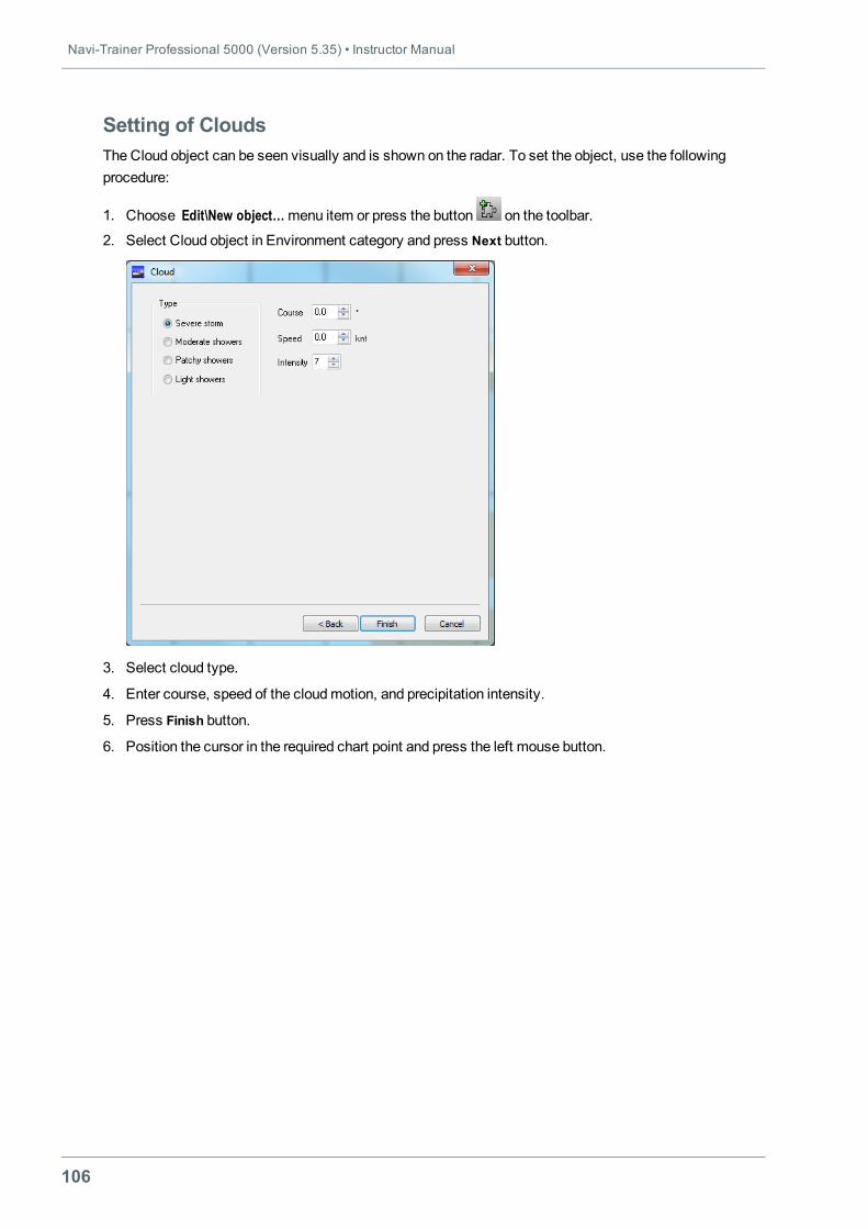
Navi-Trainer Professional 5000 (Version 5.35) • Instructor Manual
106
Setting of CloudsThe Cloud object can be seen visually and is shown on the radar. To set the object, use the followingprocedure:
1. Choose Edit\New object…menu item or press the button on the toolbar.
2. Select Cloud object in Environment category and press Next button.
3. Select cloud type.
4. Enter course, speed of the cloudmotion, and precipitation intensity.
5. Press Finish button.
6. Position the cursor in the required chart point and press the left mouse button.
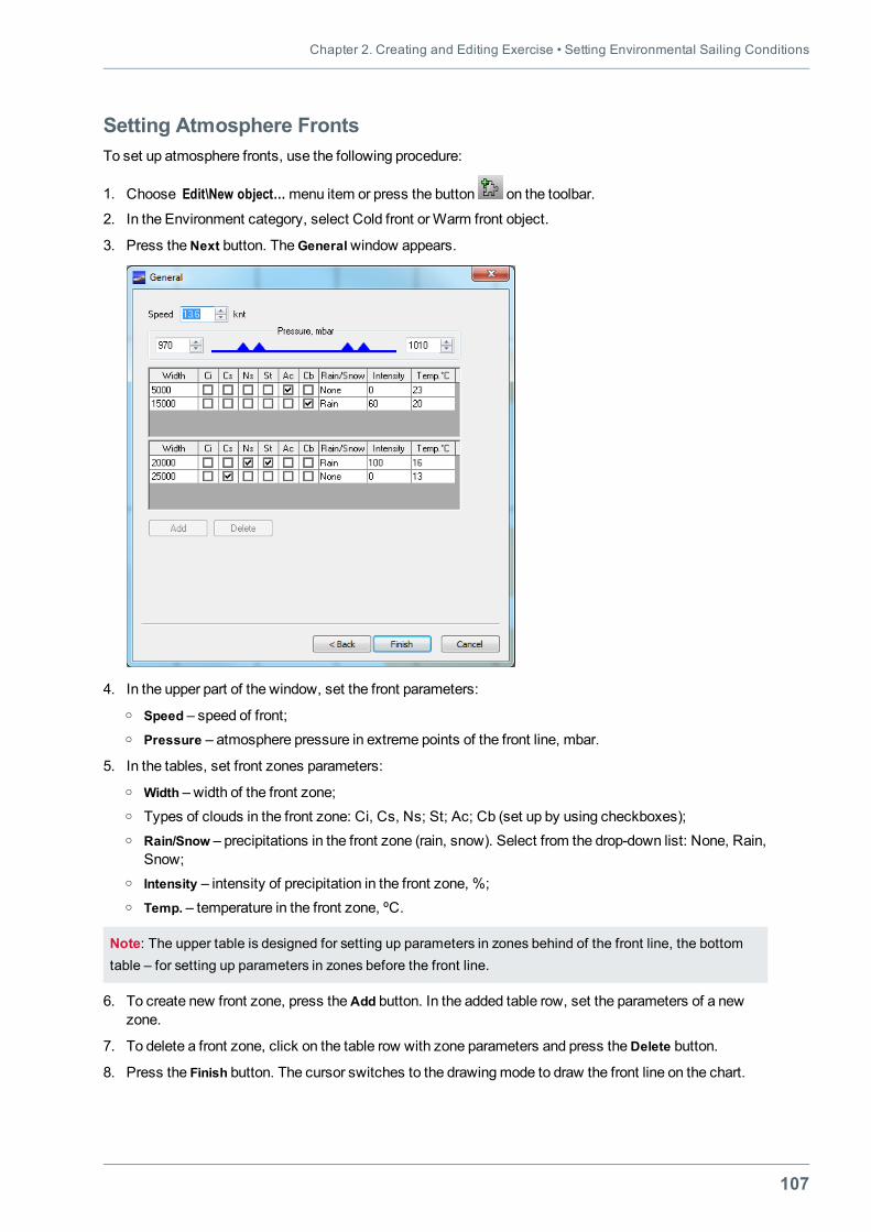
Chapter 2. Creating and Editing Exercise • Setting Environmental Sailing Conditions
107
Setting Atmosphere FrontsTo set up atmosphere fronts, use the following procedure:
1. Choose Edit\New object…menu item or press the button on the toolbar.
2. In the Environment category, select Cold front orWarm front object.
3. Press theNext button. TheGeneralwindow appears.
4. In the upper part of the window, set the front parameters:o Speed – speed of front;o Pressure – atmosphere pressure in extreme points of the front line, mbar.
5. In the tables, set front zones parameters:o Width – width of the front zone;o Types of clouds in the front zone: Ci, Cs, Ns; St; Ac; Cb (set up by using checkboxes);o Rain/Snow – precipitations in the front zone (rain, snow). Select from the drop-down list: None, Rain,
Snow;o Intensity – intensity of precipitation in the front zone, %;o Temp. – temperature in the front zone, ºС.
Note: The upper table is designed for setting up parameters in zones behind of the front line, the bottomtable – for setting up parameters in zones before the front line.
6. To create new front zone, press theAdd button. In the added table row, set the parameters of a newzone.
7. To delete a front zone, click on the table row with zone parameters and press theDelete button.
8. Press the Finish button. The cursor switches to the drawingmode to draw the front line on the chart.
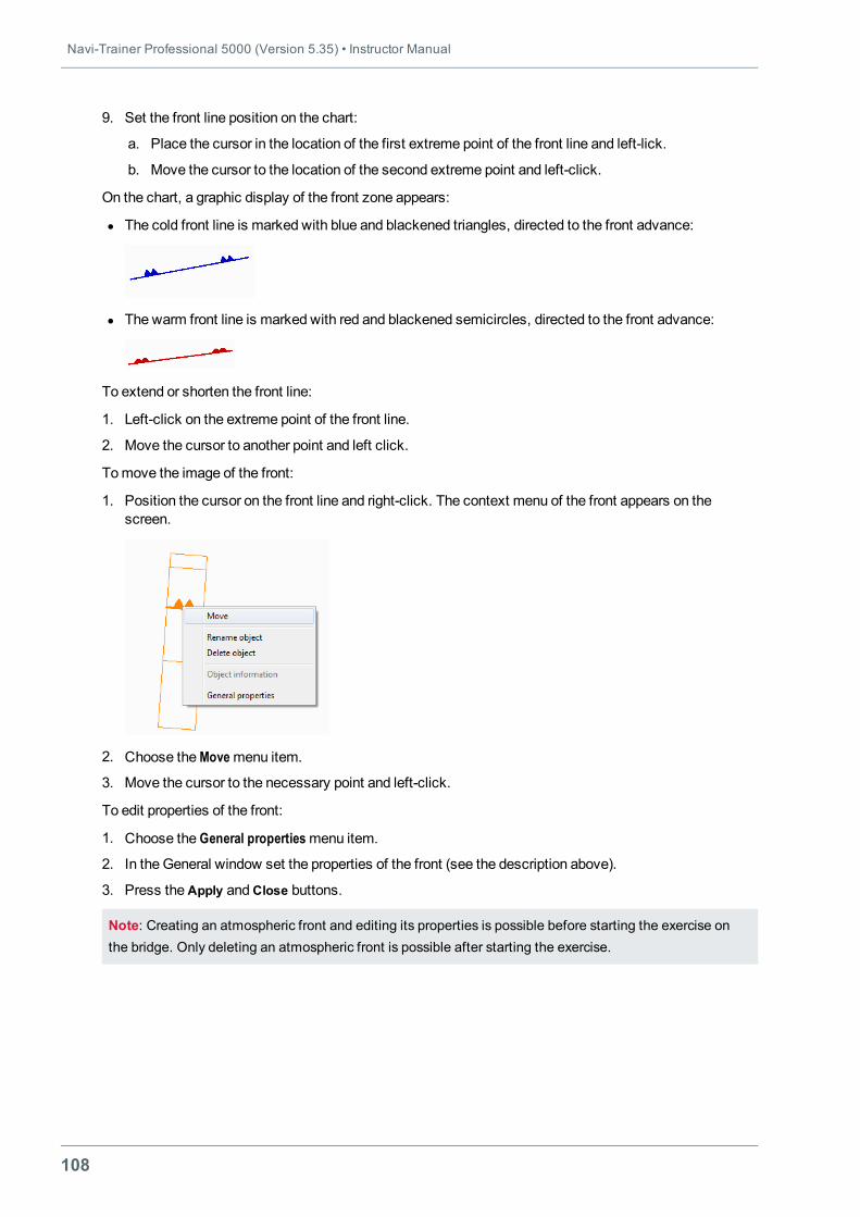
Navi-Trainer Professional 5000 (Version 5.35) • Instructor Manual
108
9. Set the front line position on the chart:
a. Place the cursor in the location of the first extreme point of the front line and left-lick.
b. Move the cursor to the location of the second extreme point and left-click.
On the chart, a graphic display of the front zone appears:
l The cold front line is marked with blue and blackened triangles, directed to the front advance:
l The warm front line is marked with red and blackened semicircles, directed to the front advance:
To extend or shorten the front line:
1. Left-click on the extreme point of the front line.
2. Move the cursor to another point and left click.
Tomove the image of the front:
1. Position the cursor on the front line and right-click. The context menu of the front appears on thescreen.
2. Choose theMovemenu item.
3. Move the cursor to the necessary point and left-click.
To edit properties of the front:
1. Choose the General propertiesmenu item.
2. In the General window set the properties of the front (see the description above).
3. Press theApply andClose buttons.
Note: Creating an atmospheric front and editing its properties is possible before starting the exercise onthe bridge. Only deleting an atmospheric front is possible after starting the exercise.
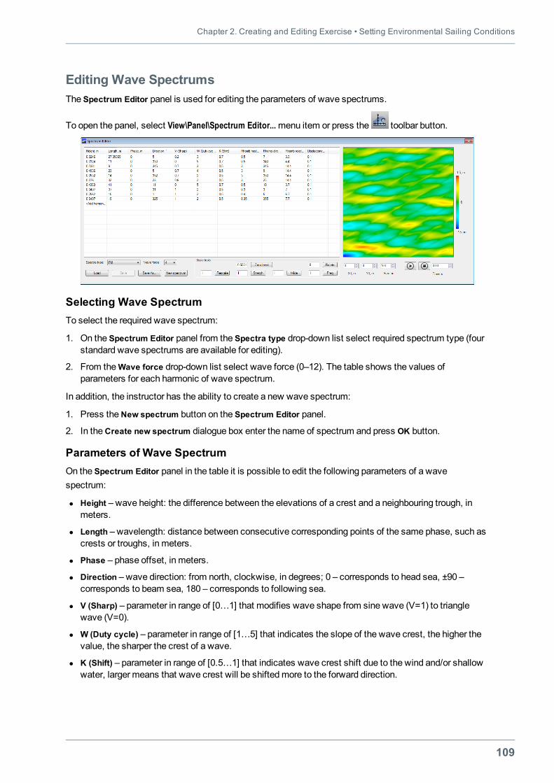
Chapter 2. Creating and Editing Exercise • Setting Environmental Sailing Conditions
109
Editing Wave SpectrumsThe Spectrum Editor panel is used for editing the parameters of wave spectrums.
To open the panel, select View\Panel\Spectrum Editor...menu item or press the toolbar button.
Selecting Wave SpectrumTo select the required wave spectrum:
1. On the Spectrum Editor panel from the Spectra type drop-down list select required spectrum type (fourstandard wave spectrums are available for editing).
2. From theWave force drop-down list select wave force (0–12). The table shows the values ofparameters for each harmonic of wave spectrum.
In addition, the instructor has the ability to create a new wave spectrum:
1. Press theNew spectrum button on the Spectrum Editor panel.
2. In theCreate new spectrum dialogue box enter the name of spectrum and press OK button.
Parameters of Wave SpectrumOn the Spectrum Editor panel in the table it is possible to edit the following parameters of a wavespectrum:
l Height – wave height: the difference between the elevations of a crest and a neighbouring trough, inmeters.
l Length – wavelength: distance between consecutive corresponding points of the same phase, such ascrests or troughs, in meters.
l Phase – phase offset, in meters.
l Direction – wave direction: from north, clockwise, in degrees; 0 – corresponds to head sea, ±90 –corresponds to beam sea, 180 – corresponds to following sea.
l V (Sharp) – parameter in range of [0…1] that modifies wave shape from sine wave (V=1) to trianglewave (V=0).
l W (Duty cycle) – parameter in range of [1…5] that indicates the slope of the wave crest, the higher thevalue, the sharper the crest of a wave.
l K (Shift) – parameter in range of [0.5…1] that indicates wave crest shift due to the wind and/or shallowwater, larger means that wave crest will be shiftedmore to the forward direction.
Navi-Trainer Professional 5000 (Version 5.35) • Instructor Manual
110
l Rhombmodulation – parameter in range of [0…1000] that indicates the wave packet factor. “1000”means that there is no packet factor and “0” means that every N-th wave will have largest amplitude.
l Rhomb direction– direction from which wave packets are coming. In general, it should coincide withwave direction or be very close to it..
l Rhomb relative length – parameter indicates, how many wave crests make a wave packet. In general,this should be between 5 and 15.
l Displacement – parameter in range of [0…1], does not affect wave shape. It indicates that visualizationshould draw wave crests sharper andmove texture in wave trough faster. In general, it should be closeto 0.1.
Setting Spectrum ValuesTo change the value of the parameter on the Spectrum Editor panel, double left-click on the table cell andenter the new value.
To add a new harmonic of wave spectrum, double left-click on the <Add harmonic> row of the table. Thenew harmonic will contain default parameter's values. Enter new parameter's values, if it is required.
Note: If the values of the parameters are set incorrectly, they will be marked in red. When you hover cursorover these values, the pop-up message appears.
To delete the harmonic from the table, right-click on the required row and select Deletemenu item.
Saving and Loading of Wave SpectrumThe specified values of the wave spectrum can be saved in a file in xml-format. To do this:
1. On the Spectrum Editor panel press Save As button, if it is required to save the file under a new name.
Note: All standard spectra can be saved only under a new name if edited .
2. In the Save As window select a folder, enter the file name and press the Save button.
In the future, to save the changes, you can use the Save button.
To load wave spectrum:
1. Press the Load button on the Spectrum Editor panel.
2. In theOpenwindow select the required file and press theOpen button.
Scaling Wave SpectrumIn the Scale Tools group box of the Spectrum Editor panel it is possible to set the scaling for all harmonicsof the wave spectrum at the same time.
For scaling the following tools are used:
l Zero level – shift zero level, in metres;
l Rescale –multiplier of wave height;
l Stretch –multiplier of wavelength;
l Wide –multiplier of range of a wave direction;
l Rotate – rotation the spectrum by specified angle;
l Freq – frequency range.
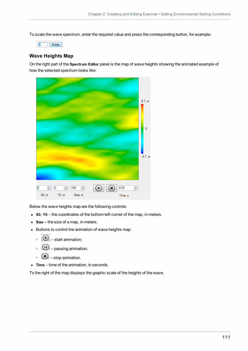
Chapter 2. Creating and Editing Exercise • Setting Environmental Sailing Conditions
111
To scale the wave spectrum, enter the required value and press the corresponding button, for example:
Wave Heights MapOn the right part of the Spectrum Editor panel is themap of wave heights showing the animated example ofhow the selected spectrum looks like:
Below the wave heights map are the following controls:
l X0, Y0 – the coordinates of the bottom-left corner of themap, in meters.
l Size – the size of amap, in meters.
l Buttons to control the animation of wave heights map:
o – start animation;
o – pausing animation;
o – stop animation.
l Time – time of the animation, in seconds.
To the right of themap displays the graphic scale of the heights of the wave.
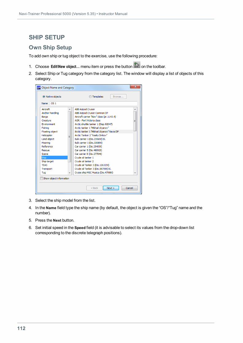
Navi-Trainer Professional 5000 (Version 5.35) • Instructor Manual
112
SHIP SETUPOwn Ship SetupTo add own ship or tug object to the exercise, use the following procedure:
1. Choose Edit\New object…menu item or press the button on the toolbar.
2. Select Ship or Tug category from the category list. The window will display a list of objects of thiscategory.
3. Select the shipmodel from the list.
4. In theName field type the ship name (by default, the object is given the “OS”/“Tug” name and thenumber).
5. Press theNext button.
6. Set initial speed in the Speed field (it is advisable to select its values from the drop-down listcorresponding to the discrete telegraph positions).
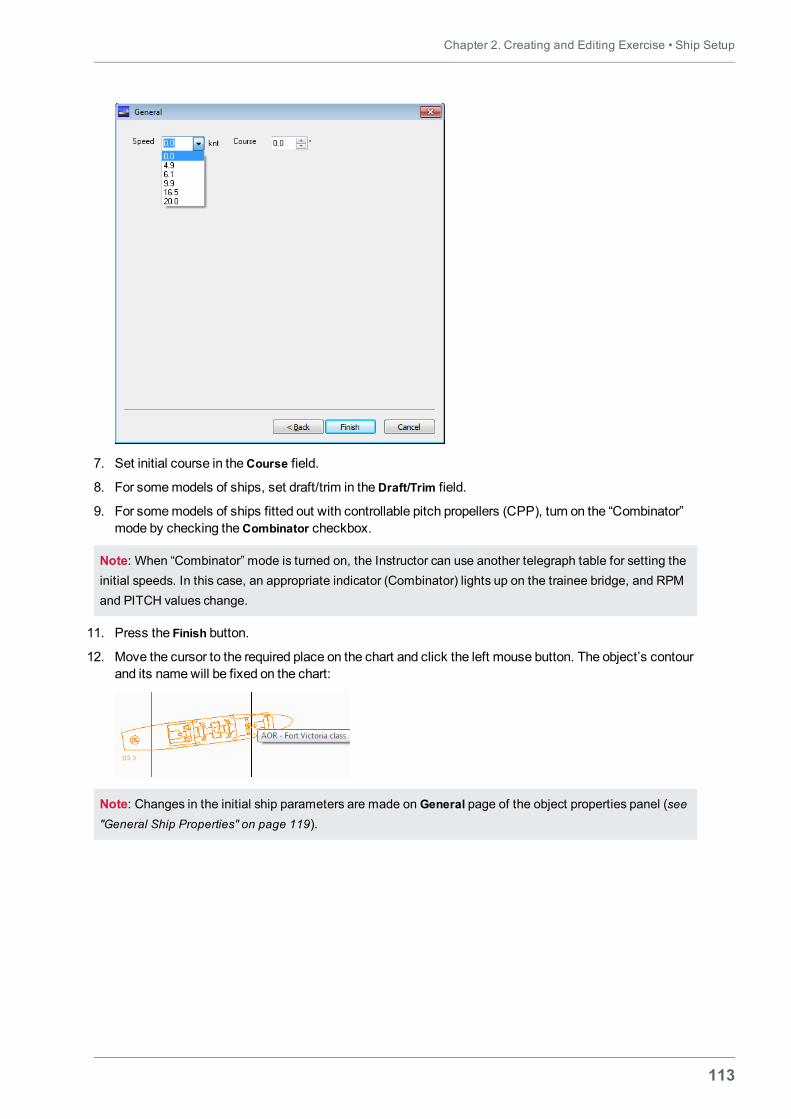
Chapter 2. Creating and Editing Exercise • Ship Setup
113
7. Set initial course in theCourse field.
8. For somemodels of ships, set draft/trim in theDraft/Trim field.
9. For somemodels of ships fitted out with controllable pitch propellers (CPP), turn on the “Combinator”mode by checking theCombinator checkbox.
Note: When “Combinator” mode is turned on, the Instructor can use another telegraph table for setting theinitial speeds. In this case, an appropriate indicator (Combinator) lights up on the trainee bridge, and RPMand PITCH values change.
11. Press the Finish button.
12. Move the cursor to the required place on the chart and click the left mouse button. The object’s contourand its namewill be fixed on the chart:
Note: Changes in the initial ship parameters are made on General page of the object properties panel (see"General Ship Properties" on page 119).
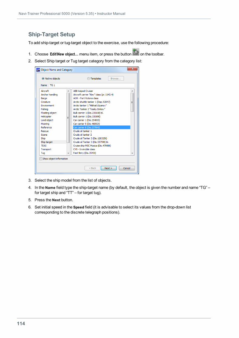
Navi-Trainer Professional 5000 (Version 5.35) • Instructor Manual
114
Ship-Target SetupTo add ship-target or tug-target object to the exercise, use the following procedure:
1. Choose Edit\New object…menu item, or press the button on the toolbar.
2. Select Ship target or Tug target category from the category list:
3. Select the shipmodel from the list of objects.
4. In theName field type the ship-target name (by default, the object is given the number and name “TG” –for target ship and “TT” – for target tug).
5. Press theNext button.
6. Set initial speed in the Speed field (it is advisable to select its values from the drop-down listcorresponding to the discrete telegraph positions).
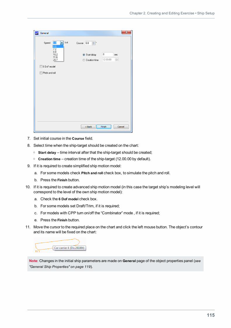
Chapter 2. Creating and Editing Exercise • Ship Setup
115
7. Set initial course in theCourse field.
8. Select time when the ship-target should be created on the chart:o Start delay – time interval after that the ship-target should be created;o Creation time – creation time of the ship-target (12.00.00 by default).
9. If it is required to create simplified shipmotionmodel:
a. For somemodels check Pitch and roll check box, to simulate the pitch and roll.
b. Press the Finish button.
10. If it is required to create advanced shipmotionmodel (in this case the target ship’s modeling level willcorrespond to the level of the own shipmotionmodel):
a. Check the 6 Dof model check box.
b. For somemodels set Draft/Trim, if it is required;
c. For models with CPP turn on/off the “Combinator” mode , if it is required;
e. Press the Finish button.
11. Move the cursor to the required place on the chart and click the left mouse button. The object’s contourand its namewill be fixed on the chart:
Note: Changes in the initial ship parameters are made on General page of the object properties panel (see"General Ship Properties" on page 119).
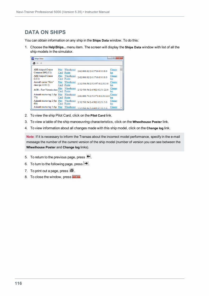
Navi-Trainer Professional 5000 (Version 5.35) • Instructor Manual
116
DATA ON SHIPSYou can obtain information on any ship in the Ships Data window. To do this:
1. Choose the Help\Ships...menu item. The screen will display the Ships Data window with list of all theshipmodels in the simulator.
2. To view the ship Pilot Card, click on the Pilot Card link.
3. To view a table of the shipmanoeuvring characteristics, click on theWheelhouse Poster link.
4. To view information about all changes made with this ship model, click on theChange log link.
Note: If it is necessary to inform the Transas about the incorrect model performance, specify in the e-mailmessage the number of the current version of the ship model (number of version you can see between theWheelhouse Poster and Change log links).
5. To return to the previous page, press .
6. To turn to the following page, press .
7. To print out a page, press .
8. To close the window, press .
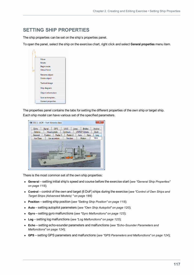
Chapter 2. Creating and Editing Exercise • Setting Ship Properties
117
SETTING SHIP PROPERTIESThe ship properties can be set on the ship’s properties panel.
To open the panel, select the ship on the exercise chart, right click and select General propertiesmenu item.
The properties panel contains the tabs for setting the different properties of the own ship or target ship.Each shipmodel can have various set of the specified parameters.
There is themost common set of the own ship properties:
l General – setting initial ship's speed and course before the exercise start (see "General Ship Properties"on page 119);
l Control – control of the own and target (6 DoF) ships during the exercise (see "Control of Own Ships andTarget Ships (Advanced Models) " on page 189)
l Position – setting ship position (see "Setting Ship Position" on page 119);
l Auto – setting autopilot parameters (see "Own Ship Autopilot" on page 120);
l Gyro – setting gyromalfunctions (see "Gyro Malfunctions" on page 123);
l Log – setting logmalfunctions (see "Log Malfunctions" on page 123);
l Echo – setting echo-sounder parameters andmalfunctions (see "Echo-Sounder Parameters andMalfunctions" on page 124);
l GPS – setting GPS parameters andmalfunctions (see "GPS Parameters and Malfunctions" on page 124);
Navi-Trainer Professional 5000 (Version 5.35) • Instructor Manual
118
l Radar – setting radar parameters andmalfunctions before the exercise start (see "Radar Parametersand Malfunctions" on page 122) and during the exercise (see "Setting Radar Faults" on page 202);
l UAIS – setting UAIS parameters (see "UAIS Initial Settings" on page 125);
l Signal – setting navigational signals (see "Setting of Navigational Signals" on page 126);
l Options – setting options: before the exercise start (see "Setting Options" on page 128) and during theexercise (see "Setting Options During Simulator Session" on page 210);
l Motion – displaying current ship data (see "Motion Data Display" on page 195);
l Lines – setting initial state of the winch before the exercise start and control themooring winchesduring the exercise (see "Control of Mooring Winches" on page 285);
l Engine – setting propulsion plant faults during the exercise (see "Setting Propulsion Plant Faults" on page204);
l Steer – setting steering system faults during the exercise(see "Setting Steering System Faults" on page206);
l Bridles – displaying bridle parameters (see "Setting Bridle" on page 304);
l Anchor – setting anchor properties (see "Setting Anchor Parameters" on page 297);
l Contours – setting display of the ship contours (tracks and trends), display of wind and currentdiagrams, display of rotation centre and pivot point (see "Contours Settings" on page 130);
l Fenders – setting fenders parameters (see "Fenders Settings" on page 131);
l Ice Class – setting ship ice class (see "Setting Ship Ice Class" on page 329);
l Ice accretion – setting ice accretion parameters (see "Setting Ice Accretion" on page 331);
l UREP Criteria – setting underway replenishment criteria (see "Setting Underway Replenishment Criteria"on page 382);
l Fire – control fire detection alarm system during the exercise (see "Fire Detection Alarm" on page 196);
l Distress signals – giving distress signals (see "Giving Distress Signals" on page 369);
l Davit – setting davit parameters (see "Use of Rescue Boat" on page 370);
l Visual Scripts – selecting ship visual script;
l View – ship view.
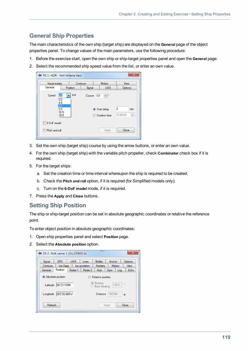
Chapter 2. Creating and Editing Exercise • Setting Ship Properties
119
General Ship PropertiesThemain characteristics of the own ship (target ship) are displayed on theGeneral page of the objectproperties panel. To change values of themain parameters, use the following procedure:
1. Before the exercise start, open the own ship or ship-target properties panel and open theGeneral page.
2. Select the recommended ship speed value from the list, or enter an own value.
3. Set the own ship (target ship) course by using the arrow buttons, or enter an own value.
4. For the own ship (target ship) with the variable pitch propeller, check Combinator check box if it isrequired.
5. For the target ships:
a. Set the creation time or time interval whereupon the ship is required to be created;
b. Check the Pitch and roll option, if it is required (for Simplifiedmodels only);
c. Turn on the 6-DoFmodelmode, if it is required.
7. Press theApply andClose buttons.
Setting Ship PositionThe ship or ship-target position can be set in absolute geographic coordinates or relative the referencepoint.
To enter object position in absolute geographic coordinates:
1. Open ship properties panel and select Position page.
2. Select theAbsolute position option.
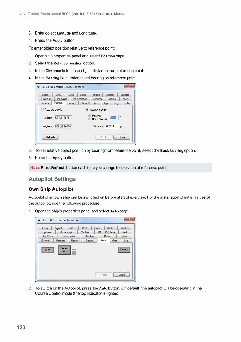
Navi-Trainer Professional 5000 (Version 5.35) • Instructor Manual
120
3. Enter object Latitude and Longitude.
4. Press theApply button.
To enter object position relative to reference point:
1. Open ship properties panel and select Position page.
2. Select theRelative position option.
3. In theDistance field, enter object distance from reference point.
4. In theBearing field, enter object bearing on reference point.
5. To set relative object position by bearing from reference point, select theBack bearing option.
6. Press theApply button.
Note: Press Refresh button each time you change the position of reference point.
Autopilot Settings
Own Ship AutopilotAutopilot of an own ship can be switched on before start of exercise. For the installation of initial values ofthe autopilot, use the following procedure:
1. Open the ship’s properties panel and select Auto page.
2. To switch on the Autopilot, press theAuto button. On default, the autopilot will be operating in theCourse Control mode (the top indicator is lighted).
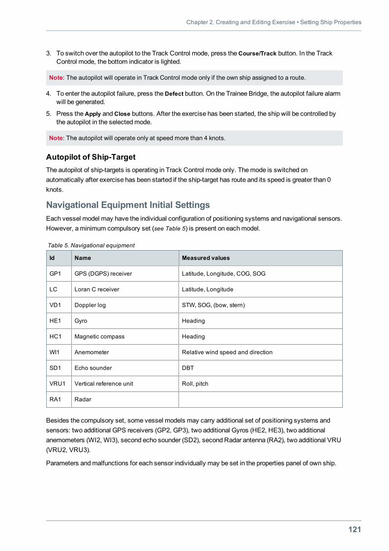
Chapter 2. Creating and Editing Exercise • Setting Ship Properties
121
3. To switch over the autopilot to the Track Control mode, press the Course/Track button. In the TrackControl mode, the bottom indicator is lighted.
Note: The autopilot will operate in Track Control mode only if the own ship assigned to a route.
4. To enter the autopilot failure, press theDefect button. On the Trainee Bridge, the autopilot failure alarmwill be generated.
5. Press theApply andClose buttons. After the exercise has been started, the ship will be controlled bythe autopilot in the selectedmode.
Note: The autopilot will operate only at speed more than 4 knots.
Autopilot of Ship-TargetThe autopilot of ship-targets is operating in Track Control mode only. Themode is switched onautomatically after exercise has been started if the ship-target has route and its speed is greater than 0knots.
Navigational Equipment Initial SettingsEach vessel model may have the individual configuration of positioning systems and navigational sensors.However, a minimum compulsory set (see Table 5) is present on eachmodel.
Id Name Measured values
GP1 GPS (DGPS) receiver Latitude, Longitude, COG, SOG
LC Loran C receiver Latitude, Longitude
VD1 Doppler log STW, SOG, (bow, stern)
HE1 Gyro Heading
HC1 Magnetic compass Heading
WI1 Anemometer Relative wind speed and direction
SD1 Echo sounder DBT
VRU1 Vertical reference unit Roll, pitch
RA1 Radar
Table 5. Navigational equipment
Besides the compulsory set, some vessel models may carry additional set of positioning systems andsensors: two additional GPS receivers (GP2, GP3), two additional Gyros (HE2, HE3), two additionalanemometers (WI2, WI3), second echo sounder (SD2), second Radar antenna (RA2), two additional VRU(VRU2, VRU3).
Parameters andmalfunctions for each sensor individually may be set in the properties panel of own ship.
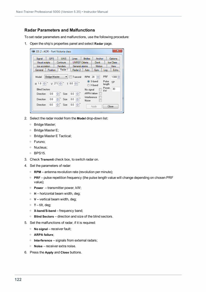
Navi-Trainer Professional 5000 (Version 5.35) • Instructor Manual
122
Radar Parameters and MalfunctionsTo set radar parameters andmalfunctions, use the following procedure:
1. Open the ship’s properties panel and select Radar page.
2. Select the radar model from theModel drop-down list:o BridgeMaster;o BridgeMaster E;o BridgeMaster E Tactical;o Furuno;o Nucleus;o BPS15.
3. Check Transmit check box, to switch radar on.
4. Set the parameters of radar:o RPM – antenna revolution rate (revolution per minute);o PRF – pulse repetition frequency (the pulse length value will change depending on chosen PRF
value);o Power – transmitter power, kW;o H – horizontal beam width, deg;o V – vertical beam width, deg;o T – tilt, deg;o X-band/S-band – frequency band;o Blind Sectors – direction and size of the blind sectors.
5. Set themalfunctions of radar, if it is required:o No signal – receiver fault;o ARPA failure;o Interference – signals from external radars;o Noise – receiver extra noise.
6. Press theApply andClose buttons.
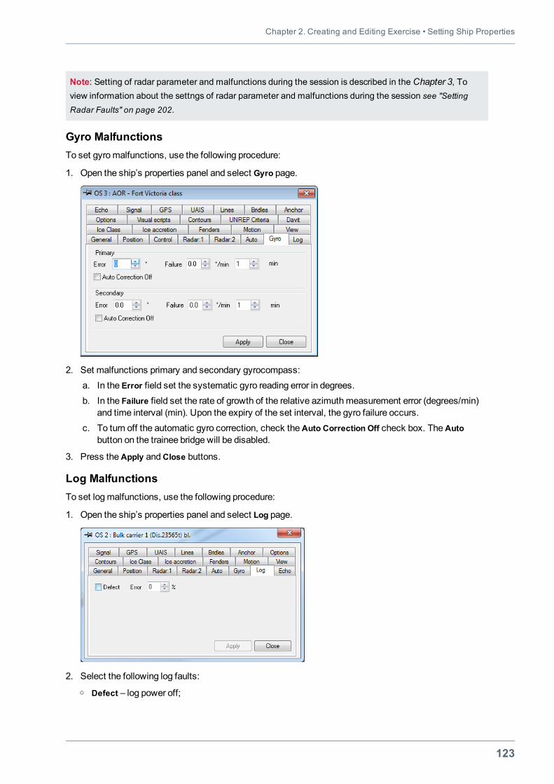
Chapter 2. Creating and Editing Exercise • Setting Ship Properties
123
Note: Setting of radar parameter and malfunctions during the session is described in the Chapter 3, Toview information about the settngs of radar parameter and malfunctions during the session see "SettingRadar Faults" on page 202.
Gyro MalfunctionsTo set gyromalfunctions, use the following procedure:
1. Open the ship’s properties panel and select Gyro page.
2. Set malfunctions primary and secondary gyrocompass:a. In the Error field set the systematic gyro reading error in degrees.b. In the Failure field set the rate of growth of the relative azimuthmeasurement error (degrees/min)
and time interval (min). Upon the expiry of the set interval, the gyro failure occurs.c. To turn off the automatic gyro correction, check theAuto Correction Off check box. TheAuto
button on the trainee bridge will be disabled.
3. Press theApply andClose buttons.
Log MalfunctionsTo set logmalfunctions, use the following procedure:
1. Open the ship’s properties panel and select Log page.
2. Select the following log faults:o Defect – log power off;
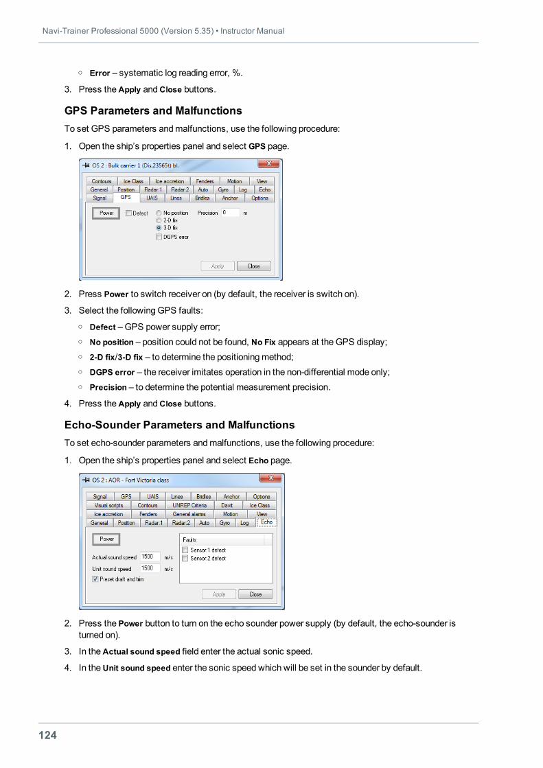
Navi-Trainer Professional 5000 (Version 5.35) • Instructor Manual
124
o Error – systematic log reading error, %.
3. Press theApply andClose buttons.
GPS Parameters and MalfunctionsTo set GPS parameters andmalfunctions, use the following procedure:
1. Open the ship’s properties panel and select GPS page.
2. Press Power to switch receiver on (by default, the receiver is switch on).
3. Select the following GPS faults:o Defect –GPS power supply error;o No position – position could not be found, No Fix appears at the GPS display;o 2-D fix/3-D fix – to determine the positioningmethod;o DGPS error – the receiver imitates operation in the non-differential mode only;o Precision – to determine the potential measurement precision.
4. Press theApply andClose buttons.
Echo-Sounder Parameters and MalfunctionsTo set echo-sounder parameters andmalfunctions, use the following procedure:
1. Open the ship’s properties panel and select Echo page.
2. Press the Power button to turn on the echo sounder power supply (by default, the echo-sounder isturned on).
3. In theActual sound speed field enter the actual sonic speed.
4. In theUnit sound speed enter the sonic speed which will be set in the sounder by default.
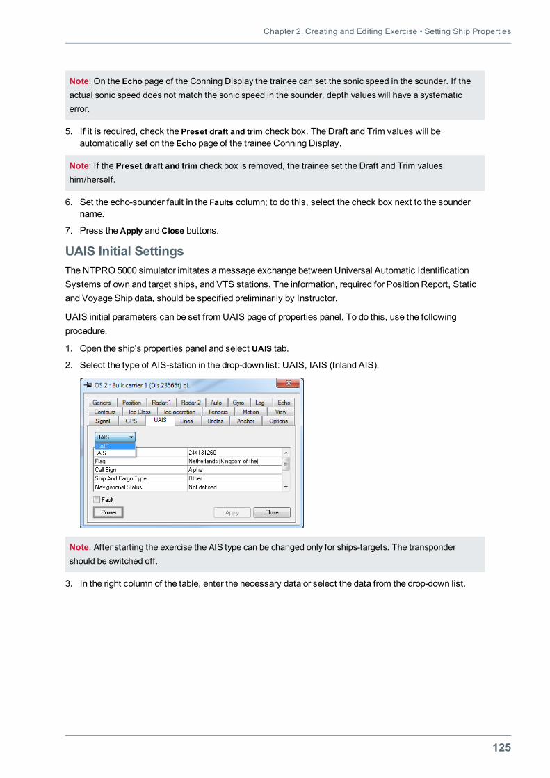
Chapter 2. Creating and Editing Exercise • Setting Ship Properties
125
Note: On the Echo page of the Conning Display the trainee can set the sonic speed in the sounder. If theactual sonic speed does not match the sonic speed in the sounder, depth values will have a systematicerror.
5. If it is required, check the Preset draft and trim check box. The Draft and Trim values will beautomatically set on the Echo page of the trainee Conning Display.
Note: If the Preset draft and trim check box is removed, the trainee set the Draft and Trim valueshim/herself.
6. Set the echo-sounder fault in the Faults column; to do this, select the check box next to the soundername.
7. Press theApply andClose buttons.
UAIS Initial SettingsThe NTPRO 5000 simulator imitates amessage exchange between Universal Automatic IdentificationSystems of own and target ships, and VTS stations. The information, required for Position Report, Staticand Voyage Ship data, should be specified preliminarily by Instructor.
UAIS initial parameters can be set from UAIS page of properties panel. To do this, use the followingprocedure.
1. Open the ship’s properties panel and select UAIS tab.
2. Select the type of AIS-station in the drop-down list: UAIS, IAIS (Inland AIS).
Note: After starting the exercise the AIS type can be changed only for ships-targets. The transpondershould be switched off.
3. In the right column of the table, enter the necessary data or select the data from the drop-down list.
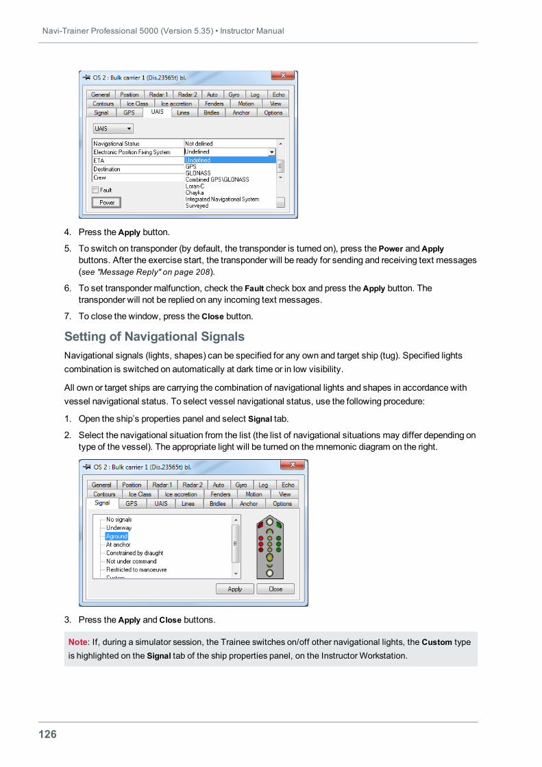
Navi-Trainer Professional 5000 (Version 5.35) • Instructor Manual
126
4. Press theApply button.
5. To switch on transponder (by default, the transponder is turned on), press the Power andApplybuttons. After the exercise start, the transponder will be ready for sending and receiving text messages(see "Message Reply" on page 208).
6. To set transponder malfunction, check the Fault check box and press theApply button. Thetransponder will not be replied on any incoming text messages.
7. To close the window, press theClose button.
Setting of Navigational SignalsNavigational signals (lights, shapes) can be specified for any own and target ship (tug). Specified lightscombination is switched on automatically at dark time or in low visibility.
All own or target ships are carrying the combination of navigational lights and shapes in accordance withvessel navigational status. To select vessel navigational status, use the following procedure:
1. Open the ship’s properties panel and select Signal tab.
2. Select the navigational situation from the list (the list of navigational situations may differ depending ontype of the vessel). The appropriate light will be turned on themnemonic diagram on the right.
3. Press theApply andClose buttons.
Note: If, during a simulator session, the Trainee switches on/off other navigational lights, the Custom typeis highlighted on the Signal tab of the ship properties panel, on the Instructor Workstation.
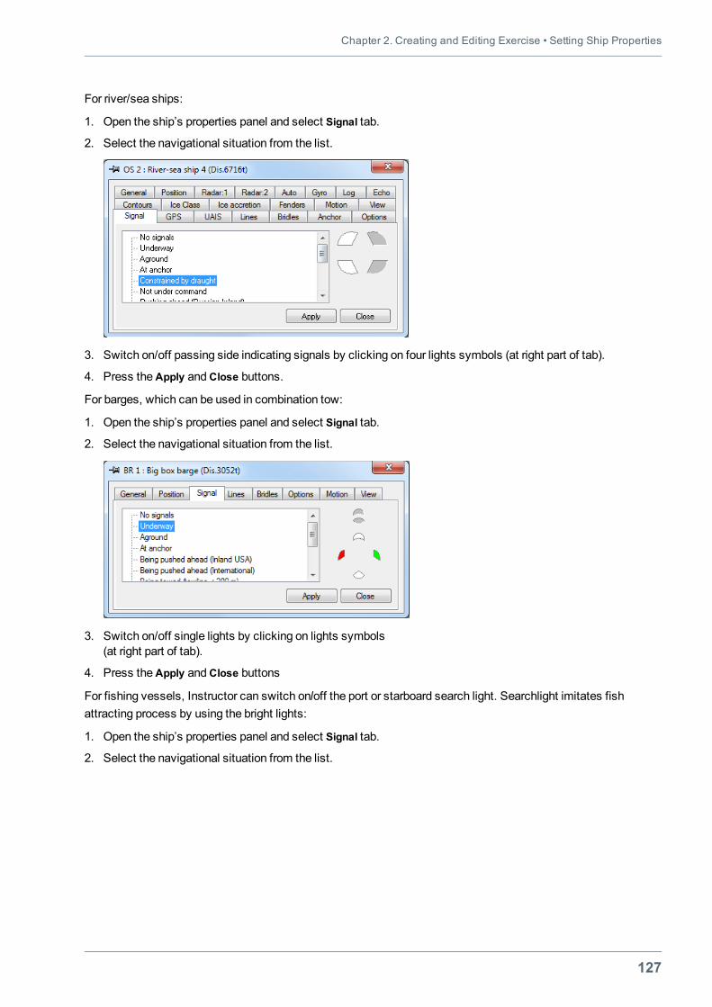
Chapter 2. Creating and Editing Exercise • Setting Ship Properties
127
For river/sea ships:
1. Open the ship’s properties panel and select Signal tab.
2. Select the navigational situation from the list.
3. Switch on/off passing side indicating signals by clicking on four lights symbols (at right part of tab).
4. Press theApply andClose buttons.
For barges, which can be used in combination tow:
1. Open the ship’s properties panel and select Signal tab.
2. Select the navigational situation from the list.
3. Switch on/off single lights by clicking on lights symbols(at right part of tab).
4. Press theApply andClose buttons
For fishing vessels, Instructor can switch on/off the port or starboard search light. Searchlight imitates fishattracting process by using the bright lights:
1. Open the ship’s properties panel and select Signal tab.
2. Select the navigational situation from the list.
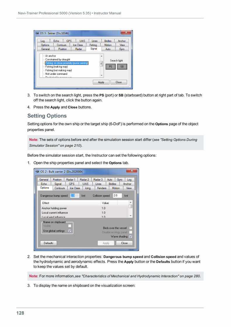
Navi-Trainer Professional 5000 (Version 5.35) • Instructor Manual
128
3. To switch on the search light, press the PS (port) or SB (starboard) button at right part of tab. To switchoff the search light, click the button again.
4. Press theApply andClose buttons.
Setting OptionsSetting options for the own ship or the target ship (6-DoF) is performed on the Options page of the objectproperties panel.
Note: The sets of options before and after the simulation session start differ (see "Setting Options DuringSimulator Session" on page 210).
Before the simulator session start, the Instructor can set the following options:
1. Open the ship properties panel and select theOptions tab.
2. Set themechanical interaction properties: Dangerous bump speed andCollision speed and values ofthe hydrodynamic and aerodynamic effects. Press theApply button or theDefaults button if you wantto keep the values set by default.
Note: For more information,see "Characteristics of Mechanical and Hydrodynamic Interaction" on page 280.
3. To display the name on shipboard on the visualization screen:
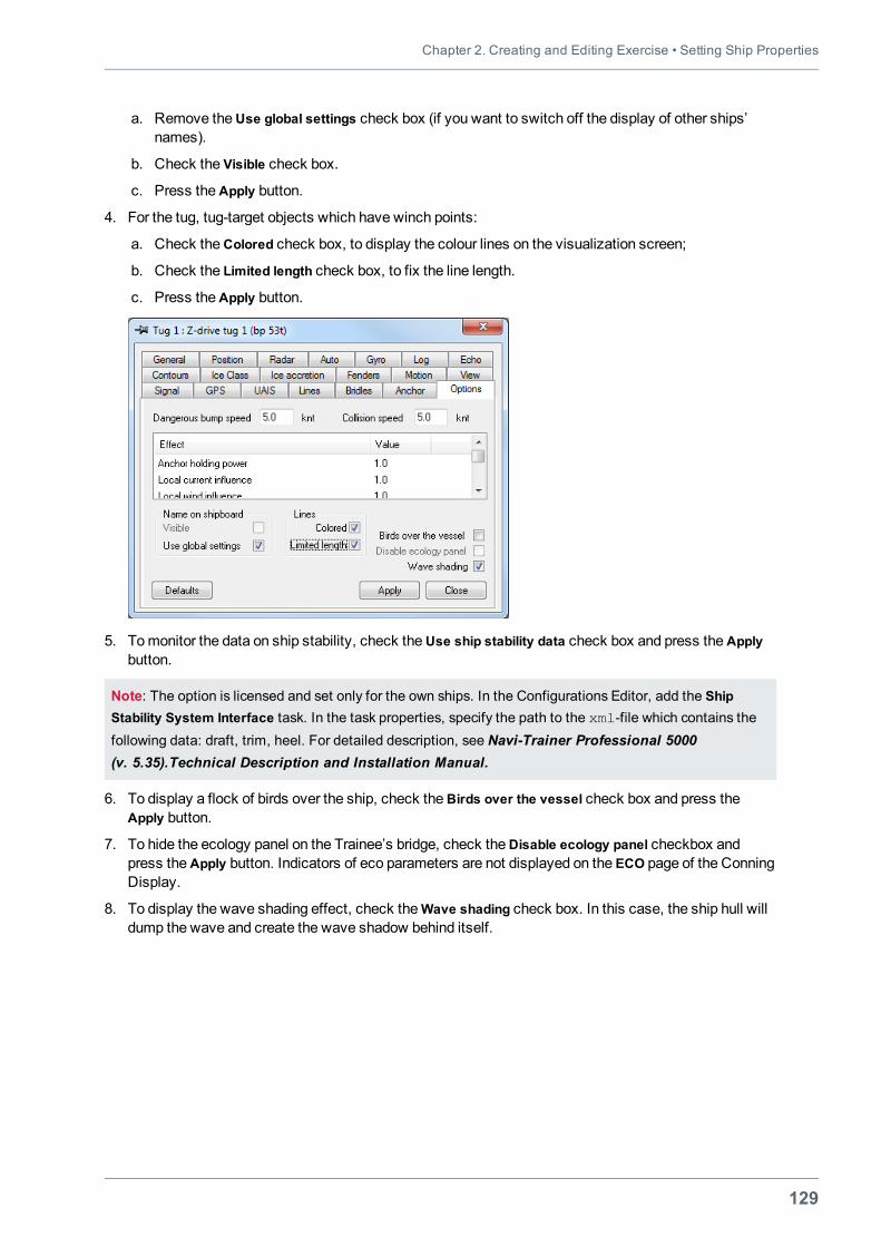
Chapter 2. Creating and Editing Exercise • Setting Ship Properties
129
a. Remove theUse global settings check box (if you want to switch off the display of other ships’names).
b. Check the Visible check box.
c. Press theApply button.
4. For the tug, tug-target objects which have winch points:
a. Check theColored check box, to display the colour lines on the visualization screen;
b. Check the Limited length check box, to fix the line length.
c. Press theApply button.
5. Tomonitor the data on ship stability, check theUse ship stability data check box and press theApplybutton.
Note: The option is licensed and set only for the own ships. In the Configurations Editor, add the ShipStability System Interface task. In the task properties, specify the path to the xml-file which contains thefollowing data: draft, trim, heel. For detailed description, see Navi-Trainer Professional 5000(v. 5.35).Technical Description and Installation Manual.
6. To display a flock of birds over the ship, check theBirds over the vessel check box and press theApply button.
7. To hide the ecology panel on the Trainee’s bridge, check theDisable ecology panel checkbox andpress theApply button. Indicators of eco parameters are not displayed on the ECO page of the ConningDisplay.
8. To display the wave shading effect, check theWave shading check box. In this case, the ship hull willdump the wave and create the wave shadow behind itself.
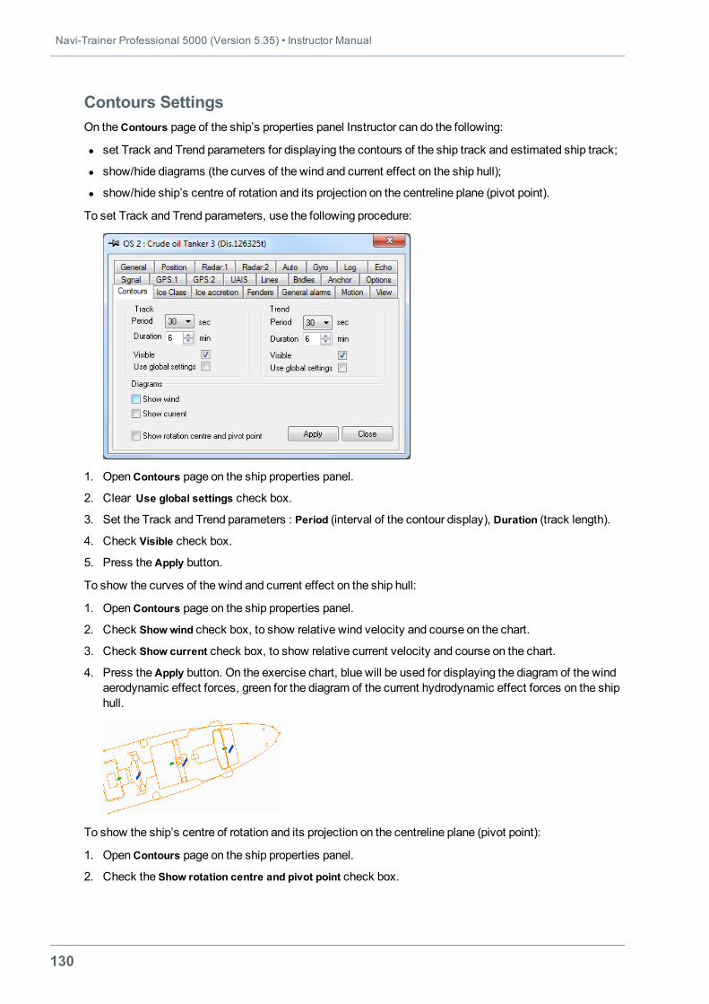
Navi-Trainer Professional 5000 (Version 5.35) • Instructor Manual
130
Contours SettingsOn theContours page of the ship’s properties panel Instructor can do the following:
l set Track and Trend parameters for displaying the contours of the ship track and estimated ship track;
l show/hide diagrams (the curves of the wind and current effect on the ship hull);
l show/hide ship’s centre of rotation and its projection on the centreline plane (pivot point).
To set Track and Trend parameters, use the following procedure:
1. OpenContours page on the ship properties panel.
2. Clear Use global settings check box.
3. Set the Track and Trend parameters : Period (interval of the contour display), Duration (track length).
4. Check Visible check box.
5. Press theApply button.
To show the curves of the wind and current effect on the ship hull:
1. OpenContours page on the ship properties panel.
2. Check Show wind check box, to show relative wind velocity and course on the chart.
3. Check Show current check box, to show relative current velocity and course on the chart.
4. Press theApply button. On the exercise chart, blue will be used for displaying the diagram of the windaerodynamic effect forces, green for the diagram of the current hydrodynamic effect forces on the shiphull.
To show the ship’s centre of rotation and its projection on the centreline plane (pivot point):
1. OpenContours page on the ship properties panel.
2. Check the Show rotation centre and pivot point check box.
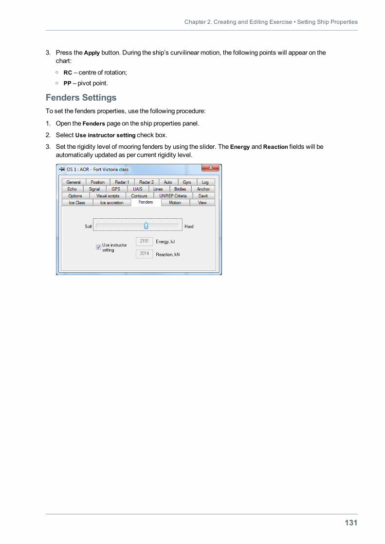
Chapter 2. Creating and Editing Exercise • Setting Ship Properties
131
3. Press theApply button. During the ship’s curvilinear motion, the following points will appear on thechart:o RC – centre of rotation;o PP – pivot point.
Fenders SettingsTo set the fenders properties, use the following procedure:
1. Open the Fenders page on the ship properties panel.
2. Select Use instructor setting check box.
3. Set the rigidity level of mooring fenders by using the slider. The Energy andReaction fields will beautomatically updated as per current rigidity level.
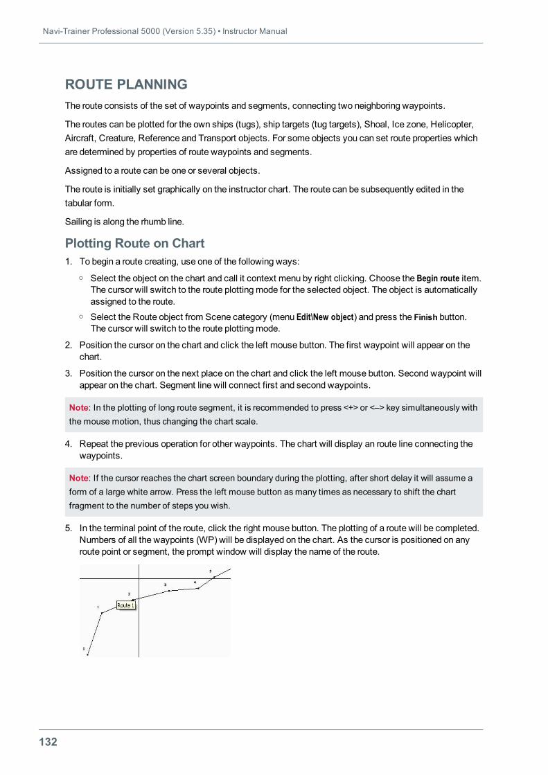
Navi-Trainer Professional 5000 (Version 5.35) • Instructor Manual
132
ROUTE PLANNINGThe route consists of the set of waypoints and segments, connecting two neighboring waypoints.
The routes can be plotted for the own ships (tugs), ship targets (tug targets), Shoal, Ice zone, Helicopter,Aircraft, Creature, Reference and Transport objects. For some objects you can set route properties whichare determined by properties of route waypoints and segments.
Assigned to a route can be one or several objects.
The route is initially set graphically on the instructor chart. The route can be subsequently edited in thetabular form.
Sailing is along the rhumb line.
Plotting Route on Chart1. To begin a route creating, use one of the following ways:
o Select the object on the chart and call it context menu by right clicking. Choose the Begin route item.The cursor will switch to the route plottingmode for the selected object. The object is automaticallyassigned to the route.
o Select the Route object from Scene category (menu Edit\New object) and press the Finish button.The cursor will switch to the route plottingmode.
2. Position the cursor on the chart and click the left mouse button. The first waypoint will appear on thechart.
3. Position the cursor on the next place on the chart and click the left mouse button. Second waypoint willappear on the chart. Segment line will connect first and second waypoints.
Note: In the plotting of long route segment, it is recommended to press <+> or <–> key simultaneously withthe mouse motion, thus changing the chart scale.
4. Repeat the previous operation for other waypoints. The chart will display an route line connecting thewaypoints.
Note: If the cursor reaches the chart screen boundary during the plotting, after short delay it will assume aform of a large white arrow. Press the left mouse button as many times as necessary to shift the chartfragment to the number of steps you wish.
5. In the terminal point of the route, click the right mouse button. The plotting of a route will be completed.Numbers of all the waypoints (WP) will be displayed on the chart. As the cursor is positioned on anyroute point or segment, the prompt window will display the name of the route.
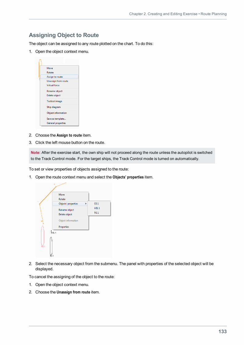
Chapter 2. Creating and Editing Exercise • Route Planning
133
Assigning Object to RouteThe object can be assigned to any route plotted on the chart. To do this:
1. Open the object context menu.
2. Choose the Assign to route item.
3. Click the left mouse button on the route.
Note: After the exercise start, the own ship will not proceed along the route unless the autopilot is switchedto the Track Control mode. For the target ships, the Track Control mode is turned on automatically.
To set or view properties of objects assigned to the route:
1. Open the route context menu and select the Objects’ properties item.
2. Select the necessary object from the submenu. The panel with properties of the selected object will bedisplayed.
To cancel the assigning of the object to the route:
1. Open the object context menu.
2. Choose the Unassign from route item.
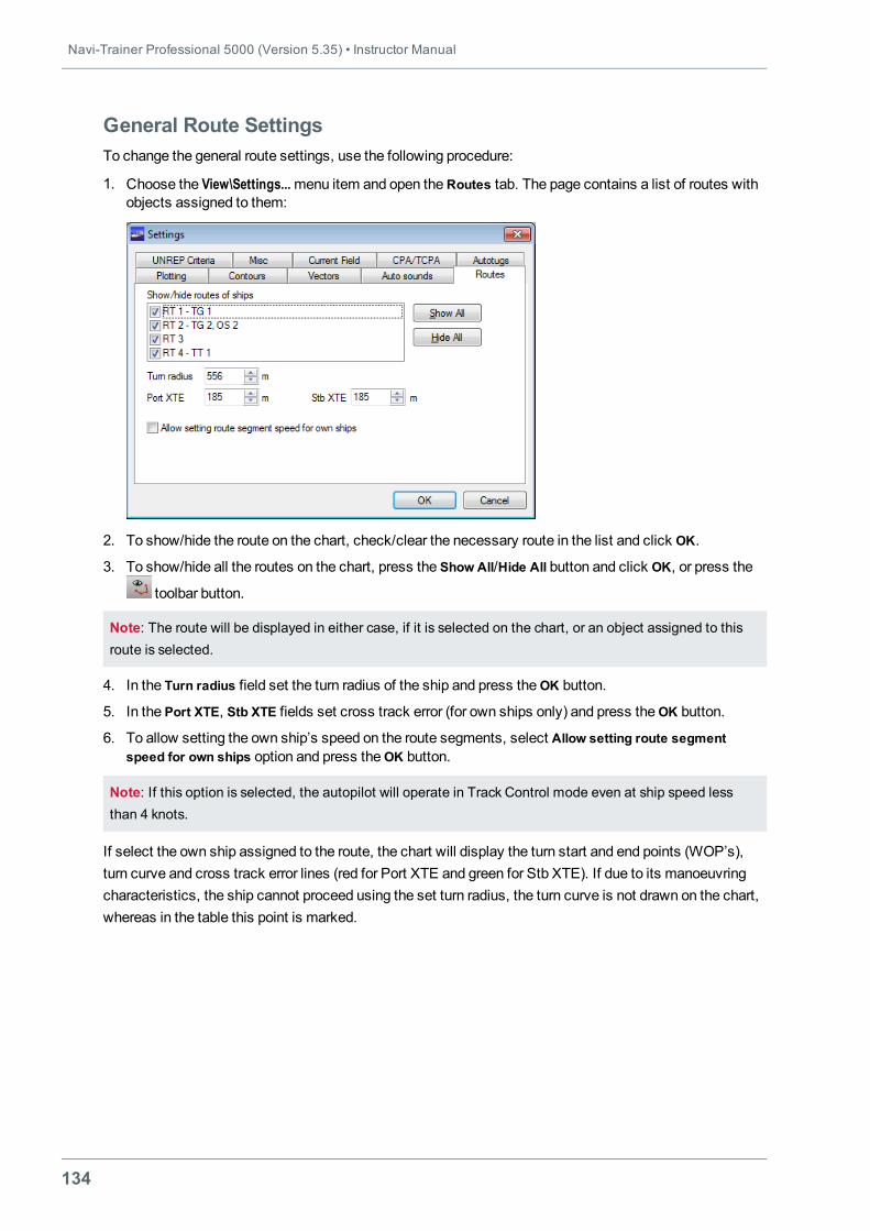
Navi-Trainer Professional 5000 (Version 5.35) • Instructor Manual
134
General Route SettingsTo change the general route settings, use the following procedure:
1. Choose the View\Settings...menu item and open theRoutes tab. The page contains a list of routes withobjects assigned to them:
2. To show/hide the route on the chart, check/clear the necessary route in the list and click OK.
3. To show/hide all the routes on the chart, press the Show All/Hide All button and click OK, or press the
toolbar button.
Note: The route will be displayed in either case, if it is selected on the chart, or an object assigned to thisroute is selected.
4. In the Turn radius field set the turn radius of the ship and press theOK button.
5. In the Port XTE, Stb XTE fields set cross track error (for own ships only) and press theOK button.
6. To allow setting the own ship’s speed on the route segments, select Allow setting route segmentspeed for own ships option and press theOK button.
Note: If this option is selected, the autopilot will operate in Track Control mode even at ship speed lessthan 4 knots.
If select the own ship assigned to the route, the chart will display the turn start and end points (WOP’s),turn curve and cross track error lines (red for Port XTE and green for Stb XTE). If due to its manoeuvringcharacteristics, the ship cannot proceed using the set turn radius, the turn curve is not drawn on the chart,whereas in the table this point is marked.
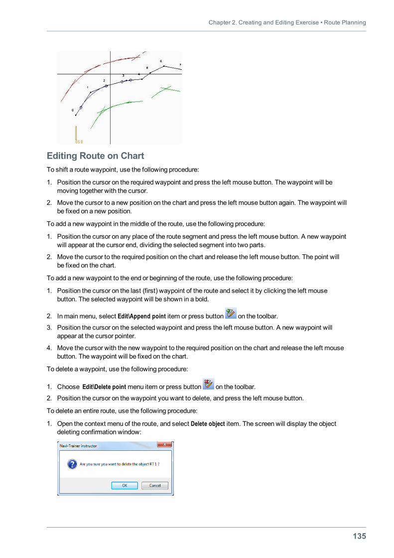
Chapter 2. Creating and Editing Exercise • Route Planning
135
Editing Route on ChartTo shift a route waypoint, use the following procedure:
1. Position the cursor on the required waypoint and press the left mouse button. The waypoint will bemoving together with the cursor.
2. Move the cursor to a new position on the chart and press the left mouse button again. The waypoint willbe fixed on a new position.
To add a new waypoint in themiddle of the route, use the following procedure:
1. Position the cursor on any place of the route segment and press the left mouse button. A new waypointwill appear at the cursor end, dividing the selected segment into two parts.
2. Move the cursor to the required position on the chart and release the left mouse button. The point willbe fixed on the chart.
To add a new waypoint to the end or beginning of the route, use the following procedure:
1. Position the cursor on the last (first) waypoint of the route and select it by clicking the left mousebutton. The selected waypoint will be shown in a bold.
2. In mainmenu, select Edit\Append point item or press button on the toolbar.
3. Position the cursor on the selected waypoint and press the left mouse button. A new waypoint willappear at the cursor pointer.
4. Move the cursor with the new waypoint to the required position on the chart and release the left mousebutton. The waypoint will be fixed on the chart.
To delete a waypoint, use the following procedure:
1. Choose Edit\Delete point menu item or press button on the toolbar.
2. Position the cursor on the waypoint you want to delete, and press the left mouse button.
To delete an entire route, use the following procedure:
1. Open the context menu of the route, and select Delete object item. The screen will display the objectdeleting confirmation window:
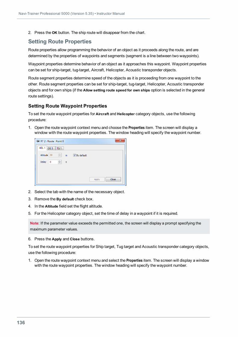
Navi-Trainer Professional 5000 (Version 5.35) • Instructor Manual
136
2. Press theOK button. The ship route will disappear from the chart.
Setting Route PropertiesRoute properties allow programming the behavior of an object as it proceeds along the route, and aredetermined by the properties of waypoints and segments (segment is a line between two waypoints).
Waypoint properties determine behavior of an object as it approaches this waypoint. Waypoint propertiescan be set for ship-target, tug-target, Aircraft, Helicopter, Acoustic transponder objects.
Route segment properties determine speed of the objects as it is proceeding from one waypoint to theother. Route segment properties can be set for ship-target, tug-target, Helicopter, Acoustic transponderobjects and for own ships (if theAllow setting route speed for own ships option is selected in the generalroute settings).
Setting Route Waypoint PropertiesTo set the route waypoint properties forAircraft andHelicopter category objects, use the followingprocedure:
1. Open the route waypoint context menu and choose the Properties item. The screen will display awindow with the route waypoint properties. The window heading will specify the waypoint number.
2. Select the tab with the name of the necessary object.
3. Remove theBy default check box.
4. In theAltitude field set the flight altitude.
5. For the Helicopter category object, set the time of delay in a waypoint if it is required.
Note: If the parameter value exceeds the permitted one, the screen will display a prompt specifying themaximum parameter values.
6. Press theApply andClose buttons.
To set the route waypoint properties for Ship target, Tug target and Acoustic transponder category objects,use the following procedure:
1. Open the route waypoint context menu and select the Properties item. The screen will display a windowwith the route waypoint properties. The window heading will specify the waypoint number.
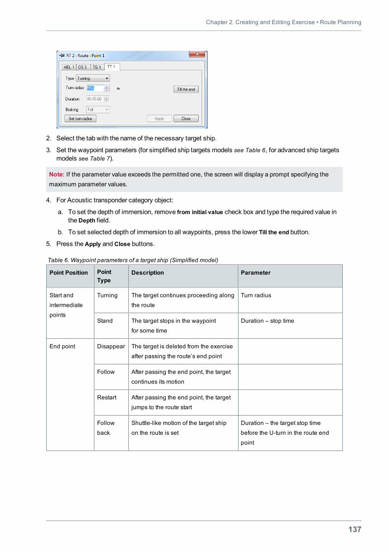
Chapter 2. Creating and Editing Exercise • Route Planning
137
2. Select the tab with the name of the necessary target ship.
3. Set the waypoint parameters (for simplified ship targets models see Table 6, for advanced ship targetsmodels see Table 7).
Note: If the parameter value exceeds the permitted one, the screen will display a prompt specifying themaximum parameter values.
4. For Acoustic transponder category object:
a. To set the depth of immersion, remove from initial value check box and type the required value intheDepth field.
b. To set selected depth of immersion to all waypoints, press the lower Till the end button.
5. Press theApply andClose buttons.
Point Position PointType
Description Parameter
Start and
intermediate
points
Turning The target continues proceeding along
the route
Turn radius
Stand The target stops in the waypoint
for some time
Duration – stop time
End point Disappear The target is deleted from the exercise
after passing the route’s end point
Follow After passing the end point, the target
continues its motion
Restart After passing the end point, the target
jumps to the route start
Follow
back
Shuttle-like motion of the target ship
on the route is set
Duration – the target stop time
before the U-turn in the route end
point
Table 6. Waypoint parameters of a target ship (Simplified model)
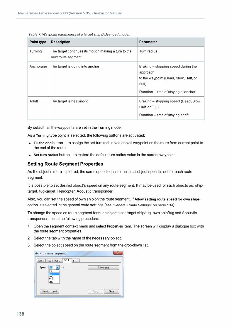
Navi-Trainer Professional 5000 (Version 5.35) • Instructor Manual
138
Point type Description Parameter
Turning The target continues its motion making a turn to the
next route segment
Turn radius
Anchorage The target is going into anchor Braking – stopping speed during the
approach
to the waypoint (Dead, Slow, Half, or
Full).
Duration – time of staying at anchor
Adrift The target is heaving-to Braking – stopping speed (Dead, Slow,
Half, or Full).
Duration – time of staying adrift
Table 7. Waypoint parameters of a target ship (Advanced model)
By default, all the waypoints are set in the Turningmode.
As a Turning type point is selected, the following buttons are activated:
l Till the end button – to assign the set turn radius value to all waypoint on the route from current point tothe end of the route;
l Set turn radius button – to restore the default turn radius value in the current waypoint.
Setting Route Segment PropertiesAs the object’s route is plotted, the same speed equal to the initial object speed is set for each routesegment.
It is possible to set desired object’s speed on any route segment. It may be used for such objects as: ship-target, tug-target, Helicopter, Acoustic transponder.
Also, you can set the speed of own ship on the route segment, if Allow setting route speed for own shipsoption is selected in the general route settings (see "General Route Settings" on page 134).
To change the speed on route segment for such objects as: target ship/tug, own ship/tug and Acoustictransponder, – use the following procedure:
1. Open the segment context menu and select Properties item. The screen will display a dialogue box withthe route segment properties.
2. Select the tab with the name of the necessary object.
3. Select the object speed on the route segment from the drop-down list.
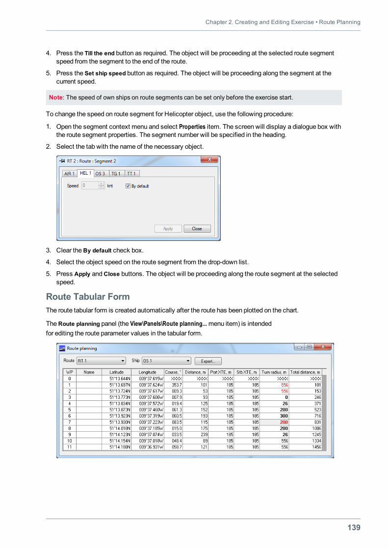
Chapter 2. Creating and Editing Exercise • Route Planning
139
4. Press the Till the end button as required. The object will be proceeding at the selected route segmentspeed from the segment to the end of the route.
5. Press the Set ship speed button as required. The object will be proceeding along the segment at thecurrent speed.
Note: The speed of own ships on route segments can be set only before the exercise start.
To change the speed on route segment for Helicopter object, use the following procedure:
1. Open the segment context menu and select Properties item. The screen will display a dialogue box withthe route segment properties. The segment number will be specified in the heading.
2. Select the tab with the name of the necessary object.
3. Clear theBy default check box.
4. Select the object speed on the route segment from the drop-down list.
5. Press Apply andClose buttons. The object will be proceeding along the route segment at the selectedspeed.
Route Tabular FormThe route tabular form is created automatically after the route has been plotted on the chart.
TheRoute planning panel (the View\Panels\Route planning...menu item) is intendedfor editing the route parameter values in the tabular form.
Navi-Trainer Professional 5000 (Version 5.35) • Instructor Manual
140
The panel consists of:
l TheRoute drop-down list for selecting the route plotted on the chart;
l The Ship drop-down list which contains all the ships assigned to this route;
l Route parameter table.
The route parameter table contains the following information on each route segment:
l WP – waypoint number;
l Name – waypoint name (optional);
l Latitude and Longitude – waypoint coordinates;
l Speed – ship speed on the given route segment (used for target ships and own ships if Allow settingroute speed for own ships option is selected in the general route settings);
l Course – direction to the given point;
l Distance – distance between the previous and current waypoint(current route segment);
l Port XTE and Stb XTE – cross track error value on the given route segment (used for own ships only);
l Turn radius – turn radius in the waypoint;
l Stay type – stay type (optional parameter used for target ships only);
l Stay time – stay time (optional parameter, set for target ships only in selecting the stay type:Anchorage, Adrift, Stand, Follow back;
l ETA – estimated time of arrival in the given point (used for target ships only);
l Total time – summary estimated time of arrival in the given point(used for target ships only);
l Total distance – summary distance of route segments to the given point;
l Altitude – altitude applies only toAircraft andHelicopter category objects;
l Depth – depth applies only toAcoustic transponder category objects.
Fields available for editing: Name, Latitude, Longitude, Distance, Course, Port XTE, Stb XTE, Turn radius,Stay type, Stay time, Speed, Altitude, Depth.
Fields filled in automatically: Total distance, ETA, and Total time.
In the case of automatic re-calculation of the route segment, the following conditions are fulfilled:
l with the change of coordinates, the distance and direction are re-calculated;
l with the change of distance, point coordinates are re-calculated;
l with the change of direction, point coordinates are re-calculated.
To set and edit parameters in the tabular form, use the following procedure:
1. Choose the View\Panels\Route planning...menu item, or press the toolbar button.
2. From theRoutedrop-down list select the necessary route.
3. From the Ship drop-down list, select the necessary ship (target ship) assigned to the route.
4. Make a doublemouse click in theWP field, to select the waypoint number.
5. Click themouse to select a field for editing.
6. Enter a new value.
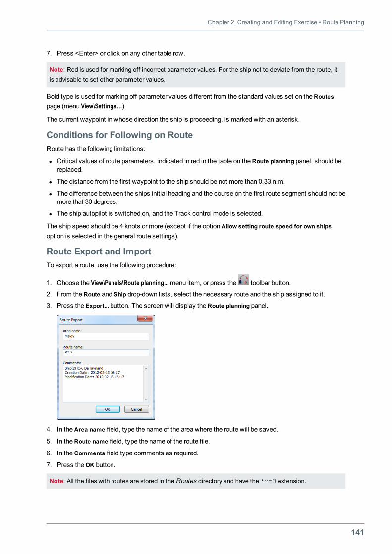
Chapter 2. Creating and Editing Exercise • Route Planning
141
7. Press <Enter> or click on any other table row.
Note: Red is used for marking off incorrect parameter values. For the ship not to deviate from the route, itis advisable to set other parameter values.
Bold type is used for marking off parameter values different from the standard values set on theRoutespage (menu View\Settings…).
The current waypoint in whose direction the ship is proceeding, is marked with an asterisk.
Conditions for Following on RouteRoute has the following limitations:
l Critical values of route parameters, indicated in red in the table on theRoute planning panel, should bereplaced.
l The distance from the first waypoint to the ship should be not more than 0,33 n.m.
l The difference between the ships initial heading and the course on the first route segment should not bemore that 30 degrees.
l The ship autopilot is switched on, and the Track control mode is selected.
The ship speed should be 4 knots or more (except if the optionAllow setting route speed for own shipsoption is selected in the general route settings).
Route Export and ImportTo export a route, use the following procedure:
1. Choose the View\Panels\Route planning...menu item, or press the toolbar button.
2. From theRoute and Ship drop-down lists, select the necessary route and the ship assigned to it.
3. Press the Export... button. The screen will display theRoute planning panel.
4. In theArea name field, type the name of the area where the route will be saved.
5. In theRoute name field, type the name of the route file.
6. In theComments field type comments as required.
7. Press theOK button.
Note: All the files with routes are stored in the Routes directory and have the *rt3 extension.
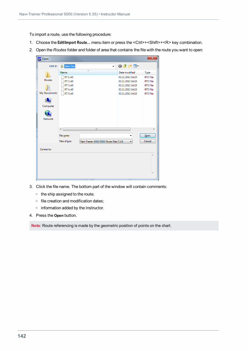
Navi-Trainer Professional 5000 (Version 5.35) • Instructor Manual
142
To import a route, use the following procedure:
1. Choose the Edit\Import Route…menu item or press the <Ctrl>+<Shift>+<R> key combination.
2. Open theRoutes folder and folder of area that contains the file with the route you want to open:
3. Click the file name. The bottom part of the window will contain comments:o the ship assigned to the route;o file creation andmodification dates;o information added by the Instructor.
4. Press theOpen button.
Note: Route referencing is made by the geometric position of points on the chart.
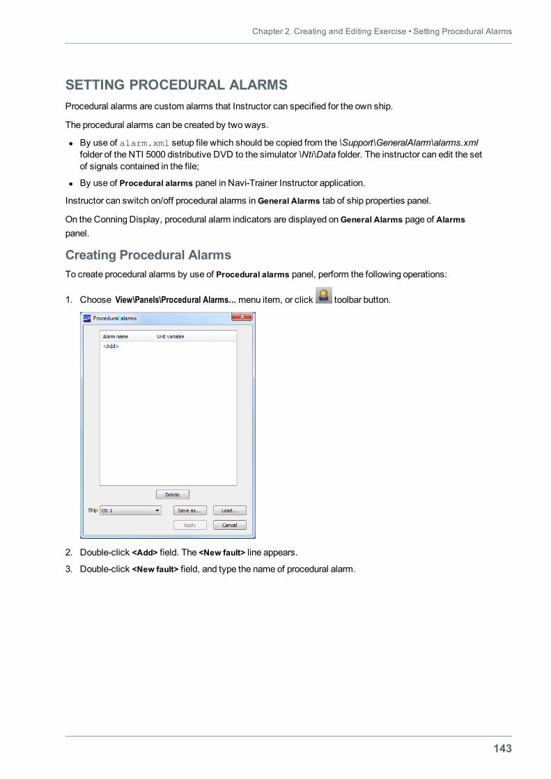
Chapter 2. Creating and Editing Exercise • Setting Procedural Alarms
143
SETTING PROCEDURAL ALARMSProcedural alarms are custom alarms that Instructor can specified for the own ship.
The procedural alarms can be created by two ways.
l By use of alarm.xml setup file which should be copied from the \Support\GeneralAlarm\alarms.xmlfolder of the NTI 5000 distributive DVD to the simulator \Nti\Data folder. The instructor can edit the setof signals contained in the file;
l By use of Procedural alarms panel in Navi-Trainer Instructor application.
Instructor can switch on/off procedural alarms inGeneral Alarms tab of ship properties panel.
On the Conning Display, procedural alarm indicators are displayed onGeneral Alarms page of Alarmspanel.
Creating Procedural AlarmsTo create procedural alarms by use of Procedural alarms panel, perform the following operations:
1. Choose View\Panels\Procedural Alarms…menu item, or click toolbar button.
2. Double-click <Add> field. The <New fault> line appears.
3. Double-click <New fault> field, and type the name of procedural alarm.
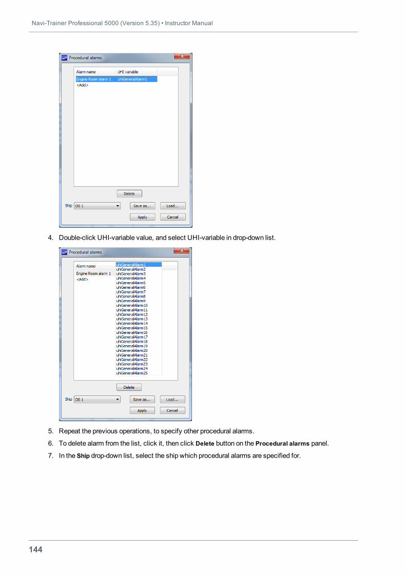
Navi-Trainer Professional 5000 (Version 5.35) • Instructor Manual
144
4. Double-click UHI-variable value, and select UHI-variable in drop-down list.
5. Repeat the previous operations, to specify other procedural alarms.
6. To delete alarm from the list, click it, then click Delete button on the Procedural alarms panel.
7. In the Ship drop-down list, select the ship which procedural alarms are specified for.
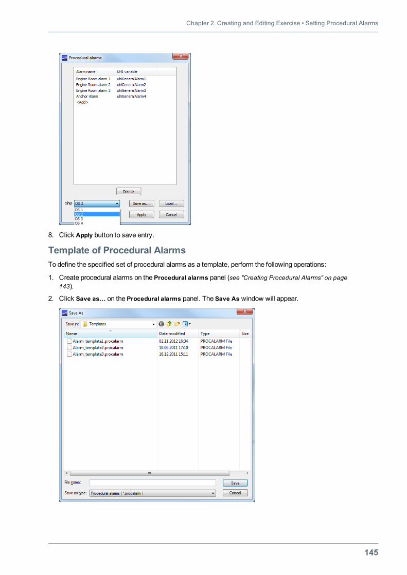
Chapter 2. Creating and Editing Exercise • Setting Procedural Alarms
145
8. Click Apply button to save entry.
Template of Procedural AlarmsTo define the specified set of procedural alarms as a template, perform the following operations:
1. Create procedural alarms on the Procedural alarms panel (see "Creating Procedural Alarms" on page143).
2. Click Save as… on the Procedural alarms panel. The Save As window will appear.
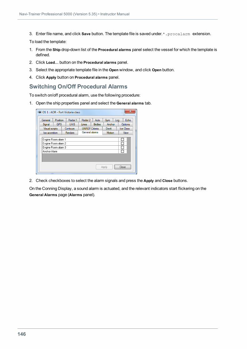
Navi-Trainer Professional 5000 (Version 5.35) • Instructor Manual
146
3. Enter file name, and click Save button. The template file is saved under.*.procalarm extension.
To load the template:
1. From the Ship drop-down list of the Procedural alarms panel select the vessel for which the template isdefined.
2. Click Load… button on the Procedural alarms panel.
3. Select the appropriate template file in theOpenwindow, and click Open button.
4. Click Apply button on Procedural alarms panel.
Switching On/Off Procedural AlarmsTo switch on/off procedural alarm, use the following procedure:
1. Open the ship properties panel and select theGeneral alarms tab.
2. Check checkboxes to select the alarm signals and press theApply andClose buttons.
On the Conning Display, a sound alarm is actuated, and the relevant indicators start flickering on theGeneral Alarms page (Alarms panel).
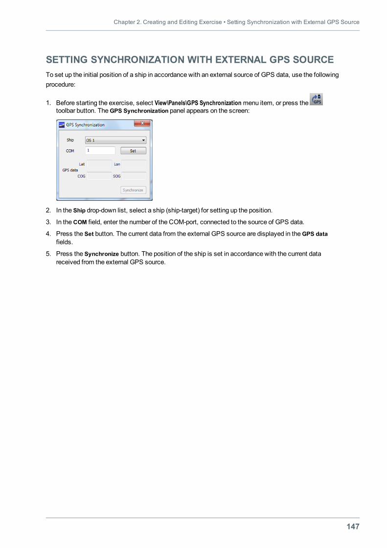
Chapter 2. Creating and Editing Exercise • Setting Synchronization with External GPS Source
147
SETTING SYNCHRONIZATION WITH EXTERNAL GPS SOURCETo set up the initial position of a ship in accordance with an external source of GPS data, use the followingprocedure:
1. Before starting the exercise, select View\Panels\GPS Synchronization menu item, or press thetoolbar button. TheGPS Synchronization panel appears on the screen:
2. In the Ship drop-down list, select a ship (ship-target) for setting up the position.
3. In theCOM field, enter the number of the COM-port, connected to the source of GPS data.
4. Press the Set button. The current data from the external GPS source are displayed in theGPS datafields.
5. Press the Synchronize button. The position of the ship is set in accordance with the current datareceived from the external GPS source.
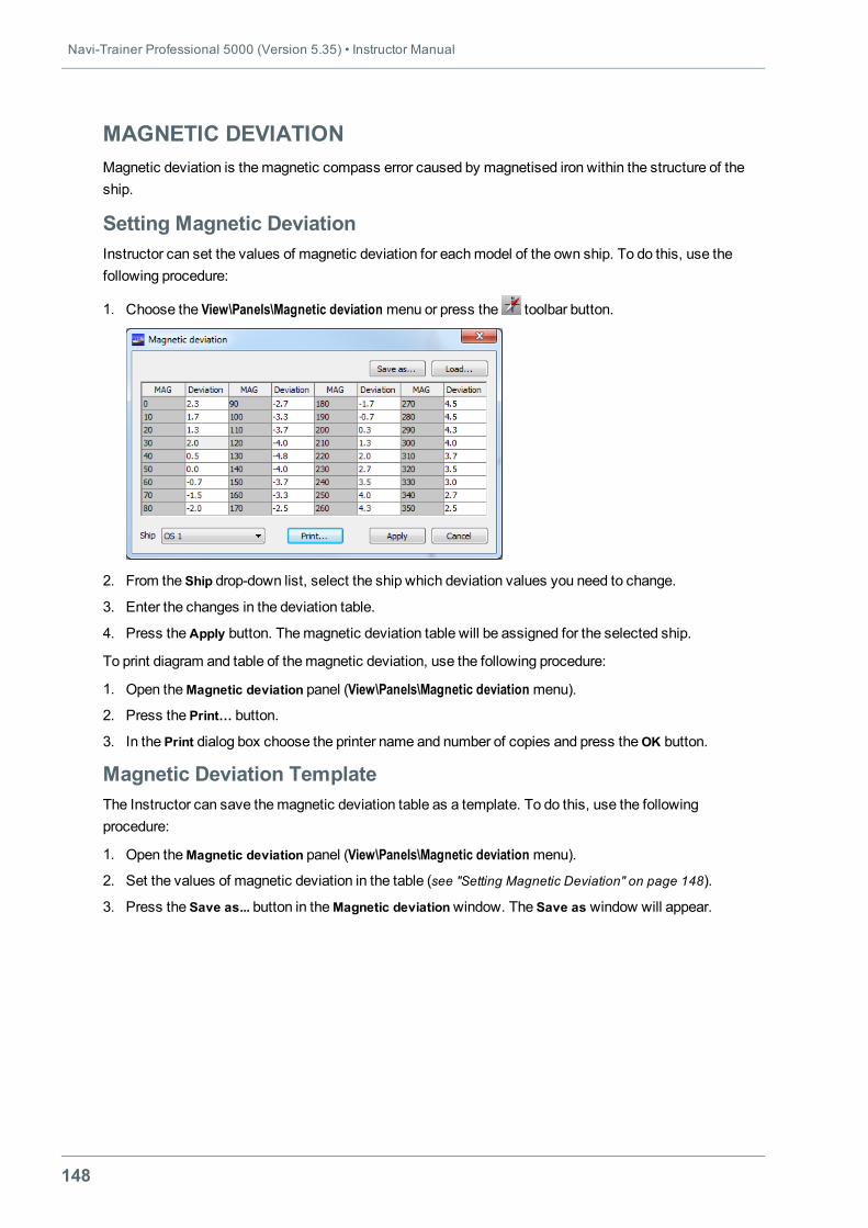
Navi-Trainer Professional 5000 (Version 5.35) • Instructor Manual
148
MAGNETIC DEVIATIONMagnetic deviation is themagnetic compass error caused by magnetised iron within the structure of theship.
Setting Magnetic DeviationInstructor can set the values of magnetic deviation for eachmodel of the own ship. To do this, use thefollowing procedure:
1. Choose the View\Panels\Magnetic deviation menu or press the toolbar button.
2. From the Ship drop-down list, select the ship which deviation values you need to change.
3. Enter the changes in the deviation table.
4. Press theApply button. Themagnetic deviation table will be assigned for the selected ship.
To print diagram and table of themagnetic deviation, use the following procedure:
1. Open theMagnetic deviation panel (View\Panels\Magnetic deviation menu).
2. Press the Print… button.
3. In the Print dialog box choose the printer name and number of copies and press theOK button.
Magnetic Deviation TemplateThe Instructor can save themagnetic deviation table as a template. To do this, use the followingprocedure:
1. Open theMagnetic deviation panel (View\Panels\Magnetic deviation menu).
2. Set the values of magnetic deviation in the table (see "Setting Magnetic Deviation" on page 148).
3. Press the Save as... button in theMagnetic deviationwindow. The Save as window will appear.
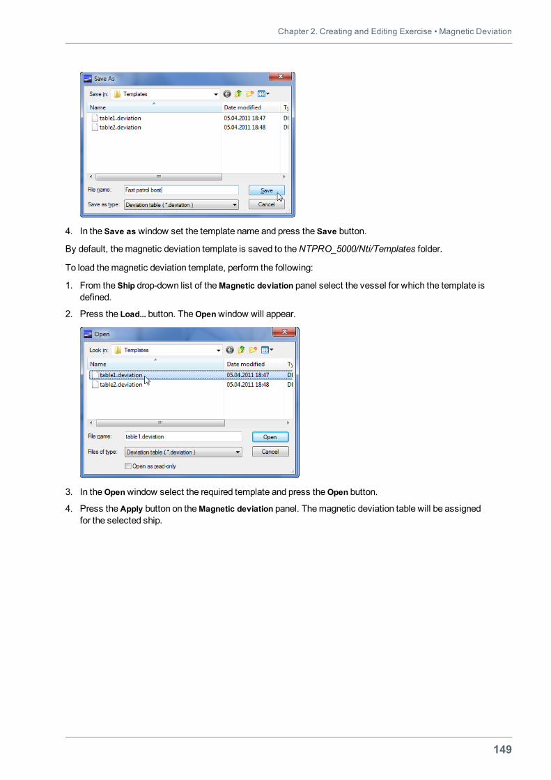
Chapter 2. Creating and Editing Exercise • Magnetic Deviation
149
4. In the Save as window set the template name and press the Save button.
By default, themagnetic deviation template is saved to theNTPRO_5000/Nti/Templates folder.
To load themagnetic deviation template, perform the following:
1. From the Ship drop-down list of theMagnetic deviation panel select the vessel for which the template isdefined.
2. Press the Load... button. TheOpenwindow will appear.
3. In theOpenwindow select the required template and press theOpen button.
4. Press theApply button on theMagnetic deviation panel. Themagnetic deviation table will be assignedfor the selected ship.
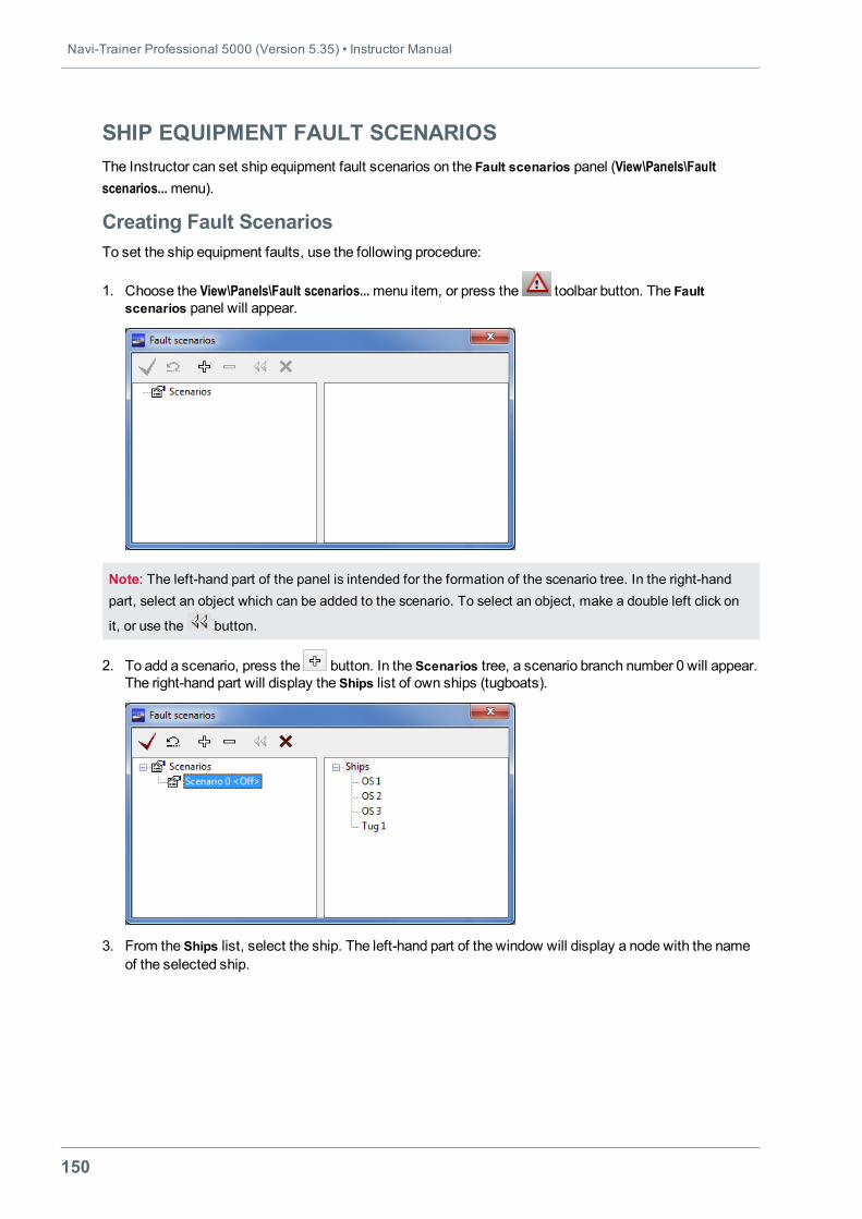
Navi-Trainer Professional 5000 (Version 5.35) • Instructor Manual
150
SHIP EQUIPMENT FAULT SCENARIOSThe Instructor can set ship equipment fault scenarios on the Fault scenarios panel (View\Panels\Faultscenarios...menu).
Creating Fault ScenariosTo set the ship equipment faults, use the following procedure:
1. Choose the View\Panels\Fault scenarios...menu item, or press the toolbar button. The Faultscenarios panel will appear.
Note: The left-hand part of the panel is intended for the formation of the scenario tree. In the right-handpart, select an object which can be added to the scenario. To select an object, make a double left click on
it, or use the button.
2. To add a scenario, press the button. In the Scenarios tree, a scenario branch number 0 will appear.The right-hand part will display the Ships list of own ships (tugboats).
3. From the Ships list, select the ship. The left-hand part of the window will display a node with the nameof the selected ship.
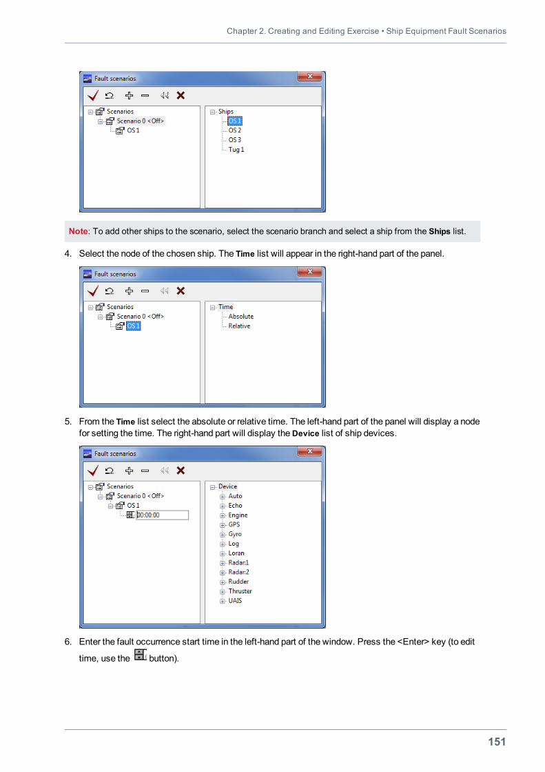
Chapter 2. Creating and Editing Exercise • Ship Equipment Fault Scenarios
151
Note: To add other ships to the scenario, select the scenario branch and select a ship from the Ships list.
4. Select the node of the chosen ship. The Time list will appear in the right-hand part of the panel.
5. From the Time list select the absolute or relative time. The left-hand part of the panel will display a nodefor setting the time. The right-hand part will display theDevice list of ship devices.
6. Enter the fault occurrence start time in the left-hand part of the window. Press the <Enter> key (to edit
time, use the button).
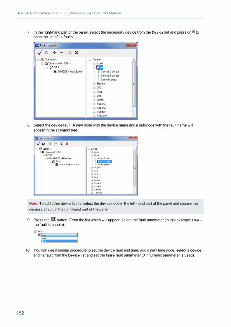
Navi-Trainer Professional 5000 (Version 5.35) • Instructor Manual
152
7. In the right-hand part of the panel, select the necessary device from theDevice list and press on toopen the list of its faults.
8. Select the device fault. A new node with the device name and a sub-node with the fault namewillappear in the scenario tree.
Note: To add other device faults, select the device node in the left-hand part of the panel and choose thenecessary fault in the right-hand part of the panel.
9. Press the button. From the list which will appear, select the fault parameter (in this example True –the fault is enable).
10. You can use a similar procedure to set the device fault end time: add a new time node, select a deviceand its fault from theDevice list and set the False fault parameter (0 if numeric parameter is used).
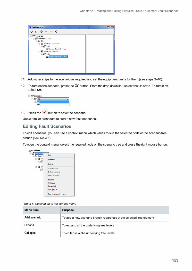
Chapter 2. Creating and Editing Exercise • Ship Equipment Fault Scenarios
153
11. Add other ships to the scenario as required and set the equipment faults for them (see steps 3–10).
12. To turn on the scenario, press the button. From the drop-down list, select theOn state. To turn it off,select Off.
13. Press the button to save the scenario.
Use a similar procedure to create new fault scenarios.
Editing Fault ScenariosTo edit scenarios, you can use a context menu which varies to suit the selected node or the scenario treebranch (see Table 8).
To open the context menu, select the required node on the scenario tree and press the right mouse button:
Menu item Purpose
Add scenario To add a new scenario branch regardless of the selected tree element
Expand To expand all the underlying tree levels
Collapse To collapse al the underlying tree levels
Table 8. Description of the context menu
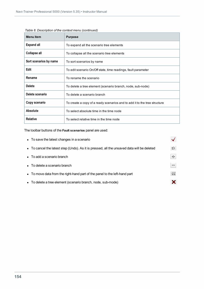
Navi-Trainer Professional 5000 (Version 5.35) • Instructor Manual
154
Menu item Purpose
Expand all To expand all the scenario tree elements
Collapse all To collapse all the scenario tree elements
Sort scenarios by name To sort scenarios by name
Edit To edit scenario On/Off state, time readings, fault parameter
Rename To rename the scenario
Delete To delete a tree element (scenario branch, node, sub-node)
Delete scenario To delete a scenario branch
Copy scenario To create a copy of a ready scenarios and to add it to the tree structure
Absolute To select absolute time in the time node
Relative To select relative time in the time node
Table 8. Description of the context menu (continued)
The toolbar buttons of the Fault scenarios panel are used:
l To save the latest changes in a scenario
l To cancel the latest step (Undo). As it is pressed, all the unsaved data will be deleted
l To add a scenario branch
l To delete a scenario branch
l Tomove data from the right-hand part of the panel to the left-hand part
l To delete a tree element (scenario branch, node, sub-mode)
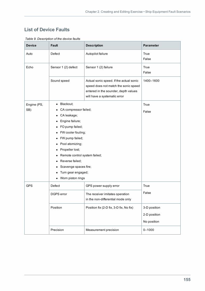
Chapter 2. Creating and Editing Exercise • Ship Equipment Fault Scenarios
155
List of Device Faults
Device Fault Description Parameter
Auto Defect Autopilot failure True
False
Echo Sensor 1 (2) defect Sensor 1 (2) failure True
False
Sound speed Actual sonic speed. If the actual sonic
speed does not match the sonic speed
entered in the sounder, depth values
will have a systematic error
1400–1600
Engine (PS,
SB)
l Blackout;
l CA compressor failed;
l CA leakage;
l Engine failure;
l FO pump failed;
l FW cooler fouling;
l FW pump failed;
l Pool atomizing;
l Propeller lost;
l Remote control system failed;
l Reverse failed;
l Scavenge spaces fire;
l Turn gear engaged;
l Worn piston rings
True
False
GPS Defect GPS power supply error True
FalseDGPS error The receiver imitates operation
in the non-differential mode only
Position Position fix (2-D fix, 3-D fix, No fix) 3-D position
2-D position
No position
Precision Measurement precision 0–1000
Table 9. Description of the device faults
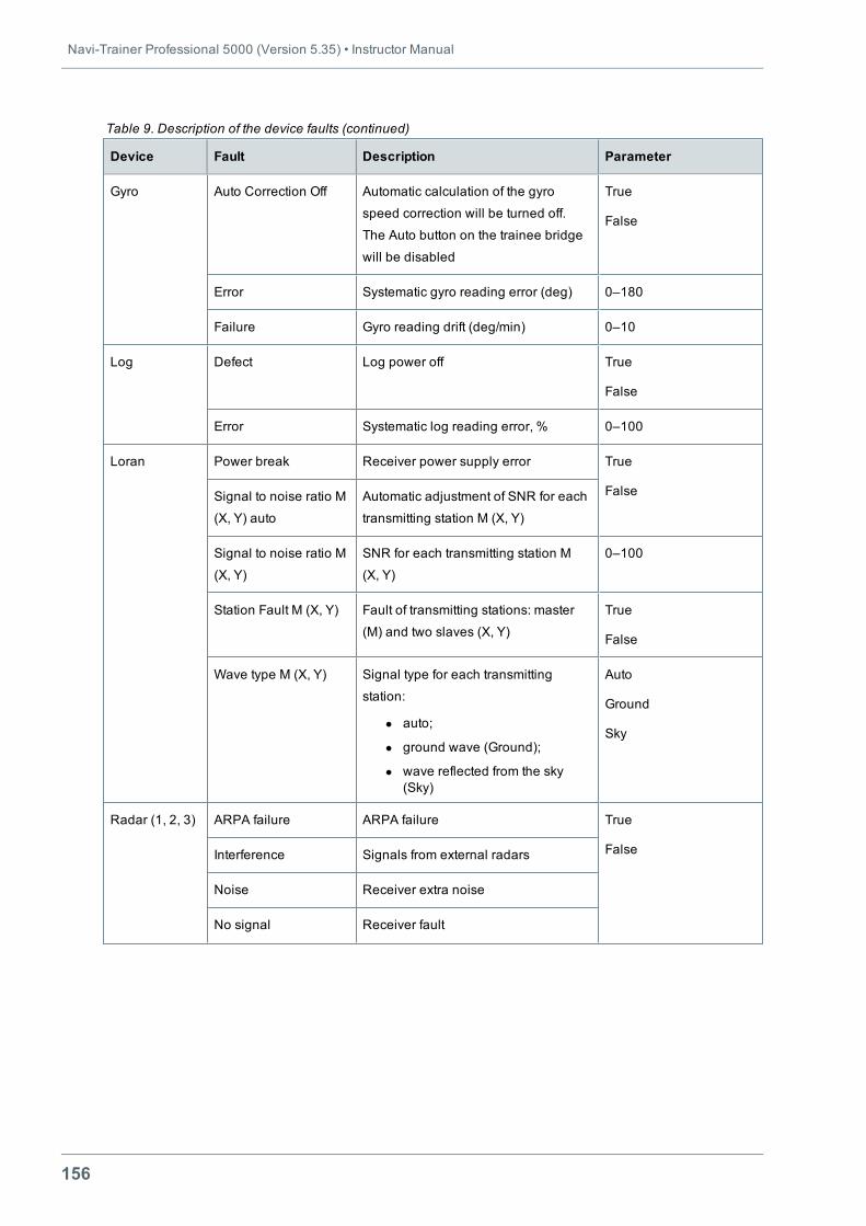
Navi-Trainer Professional 5000 (Version 5.35) • Instructor Manual
156
Device Fault Description Parameter
Gyro Auto Correction Off Automatic calculation of the gyro
speed correction will be turned off.
The Auto button on the trainee bridge
will be disabled
True
False
Error Systematic gyro reading error (deg) 0–180
Failure Gyro reading drift (deg/min) 0–10
Log Defect Log power off True
False
Error Systematic log reading error, % 0–100
Loran Power break Receiver power supply error True
FalseSignal to noise ratio М
(X, Y) auto
Automatic adjustment of SNR for each
transmitting station М (X, Y)
Signal to noise ratio М
(X, Y)
SNR for each transmitting station М
(X, Y)
0–100
Station Fault M (X, Y) Fault of transmitting stations: master
(M) and two slaves (X, Y)
True
False
Wave type M (X, Y) Signal type for each transmitting
station:
l auto;
l ground wave (Ground);
l wave reflected from the sky(Sky)
Auto
Ground
Sky
Radar (1, 2, 3) ARPA failure ARPA failure True
FalseInterference Signals from external radars
Noise Receiver extra noise
No signal Receiver fault
Table 9. Description of the device faults (continued)
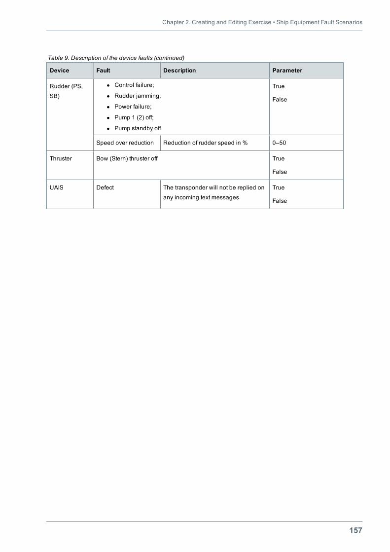
Chapter 2. Creating and Editing Exercise • Ship Equipment Fault Scenarios
157
Device Fault Description Parameter
Rudder (PS,
SB)
l Control failure;
l Rudder jamming;
l Power failure;
l Pump 1 (2) off;
l Pump standby off
True
False
Speed over reduction Reduction of rudder speed in % 0–50
Thruster Bow (Stern) thruster off True
False
UAIS Defect The transponder will not be replied on
any incoming text messages
True
False
Table 9. Description of the device faults (continued)
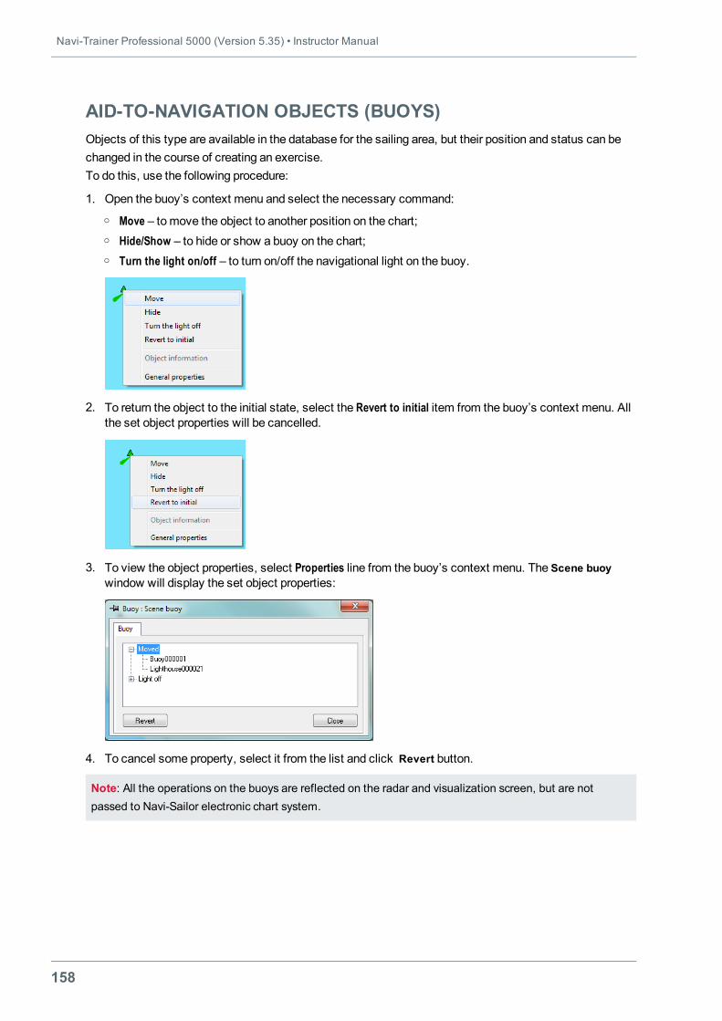
Navi-Trainer Professional 5000 (Version 5.35) • Instructor Manual
158
AID-TO-NAVIGATION OBJECTS (BUOYS)Objects of this type are available in the database for the sailing area, but their position and status can bechanged in the course of creating an exercise.To do this, use the following procedure:
1. Open the buoy’s context menu and select the necessary command:o Move – tomove the object to another position on the chart;o Hide/Show – to hide or show a buoy on the chart;o Turn the light on/off – to turn on/off the navigational light on the buoy.
2. To return the object to the initial state, select the Revert to initial item from the buoy’s context menu. Allthe set object properties will be cancelled.
3. To view the object properties, select Properties line from the buoy’s context menu. The Scene buoywindow will display the set object properties:
4. To cancel some property, select it from the list and click Revert button.
Note: All the operations on the buoys are reflected on the radar and visualization screen, but are notpassed to Navi-Sailor electronic chart system.
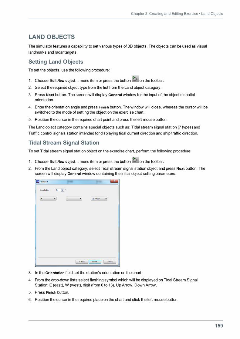
Chapter 2. Creating and Editing Exercise • Land Objects
159
LAND OBJECTSThe simulator features a capability to set various types of 3D objects. The objects can be used as visuallandmarks and radar targets.
Setting Land ObjectsTo set the objects, use the following procedure:
1. Choose Edit\New object…menu item or press the button on the toolbar.
2. Select the required object type from the list from the Land object category.
3. Press Next button. The screen will display Generalwindow for the input of the object’s spatialorientation.
4. Enter the orientation angle and press Finish button. The window will close, whereas the cursor will beswitched to themode of setting the object on the exercise chart.
5. Position the cursor in the required chart point and press the left mouse button.
The Land object category contains special objects such as: Tidal stream signal station (7 types) andTraffic control signals station intended for displaying tidal current direction and ship traffic direction.
Tidal Stream Signal StationTo set Tidal stream signal station object on the exercise chart, perform the following procedure:
1. Choose Edit\New object…menu item or press the button on the toolbar.
2. From the Land object category, select Tidal stream signal station object and press Next button. Thescreen will display Generalwindow containing the initial object setting parameters.
3. In theOrientation field set the station’s orientation on the chart.
4. From the drop-down lists select flashing symbol which will be displayed on Tidal Stream SignalStation: E (east), W (west), digit (from 0 to 13), Up Arrow, Down Arrow.
5. Press Finish button.
6. Position the cursor in the required place on the chart and click the left mouse button.
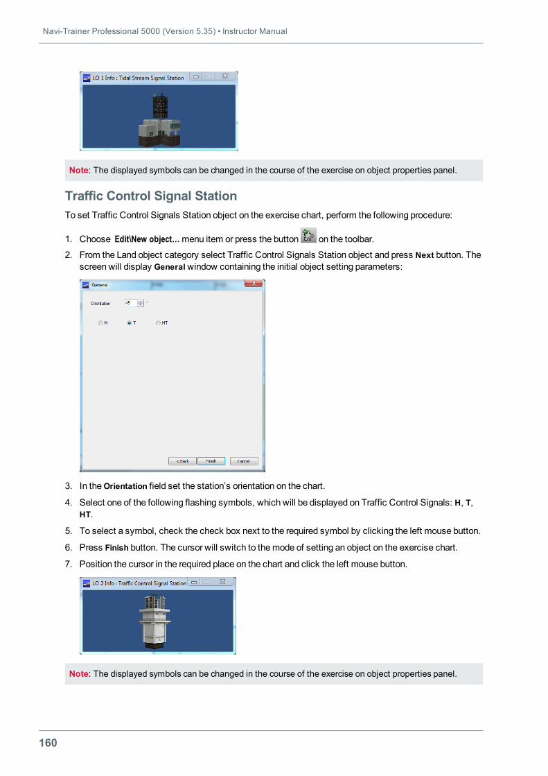
Navi-Trainer Professional 5000 (Version 5.35) • Instructor Manual
160
Note: The displayed symbols can be changed in the course of the exercise on object properties panel.
Traffic Control Signal StationTo set Traffic Control Signals Station object on the exercise chart, perform the following procedure:
1. Choose Edit\New object…menu item or press the button on the toolbar.
2. From the Land object category select Traffic Control Signals Station object and press Next button. Thescreen will display Generalwindow containing the initial object setting parameters:
3. In theOrientation field set the station’s orientation on the chart.
4. Select one of the following flashing symbols, which will be displayed on Traffic Control Signals: H, T,HT.
5. To select a symbol, check the check box next to the required symbol by clicking the left mouse button.
6. Press Finish button. The cursor will switch to themode of setting an object on the exercise chart.
7. Position the cursor in the required place on the chart and click the left mouse button.
Note: The displayed symbols can be changed in the course of the exercise on object properties panel.
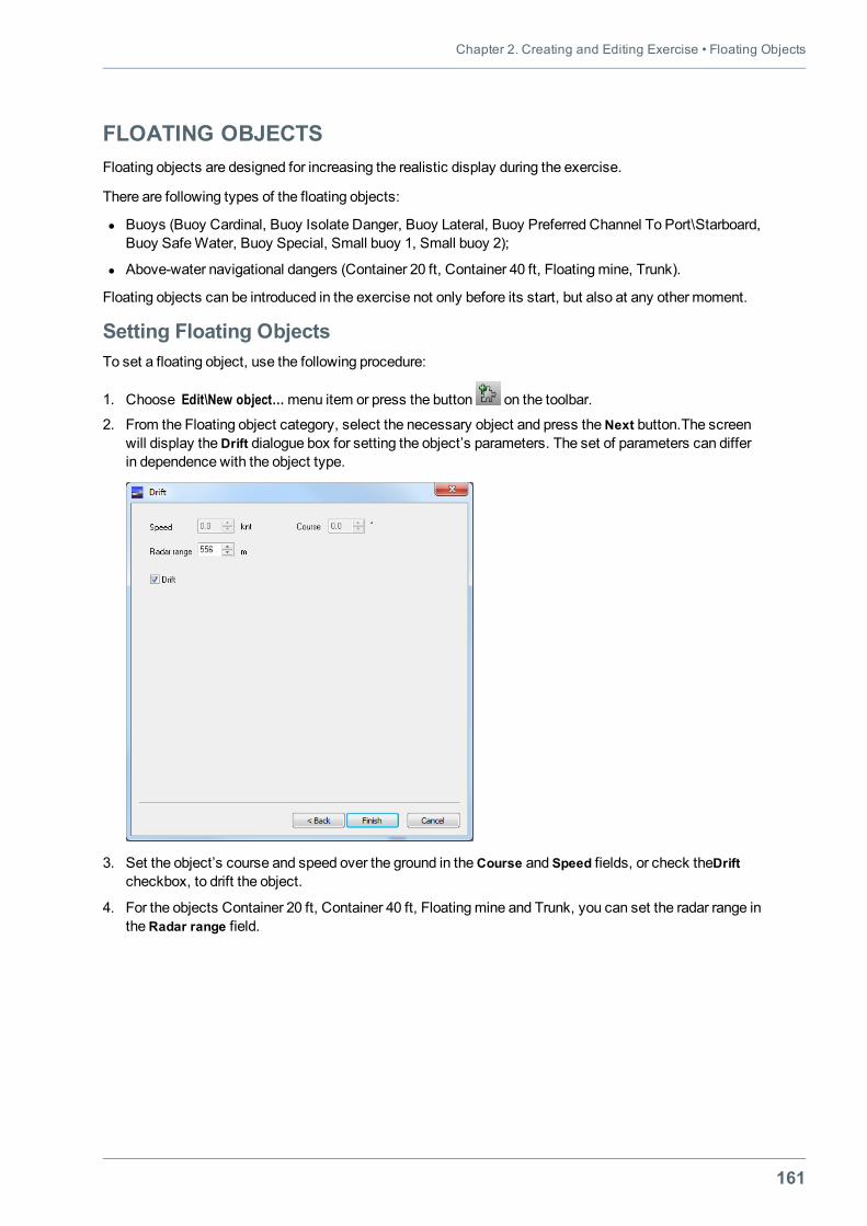
Chapter 2. Creating and Editing Exercise • Floating Objects
161
FLOATING OBJECTSFloating objects are designed for increasing the realistic display during the exercise.
There are following types of the floating objects:
l Buoys (Buoy Cardinal, Buoy Isolate Danger, Buoy Lateral, Buoy Preferred Channel To Port\Starboard,Buoy SafeWater, Buoy Special, Small buoy 1, Small buoy 2);
l Above-water navigational dangers (Container 20 ft, Container 40 ft, Floatingmine, Trunk).
Floating objects can be introduced in the exercise not only before its start, but also at any other moment.
Setting Floating ObjectsTo set a floating object, use the following procedure:
1. Choose Edit\New object…menu item or press the button on the toolbar.
2. From the Floating object category, select the necessary object and press theNext button.The screenwill display theDrift dialogue box for setting the object’s parameters. The set of parameters can differin dependence with the object type.
3. Set the object’s course and speed over the ground in theCourse and Speed fields, or check theDriftcheckbox, to drift the object.
4. For the objects Container 20 ft, Container 40 ft, Floatingmine and Trunk, you can set the radar range intheRadar range field.
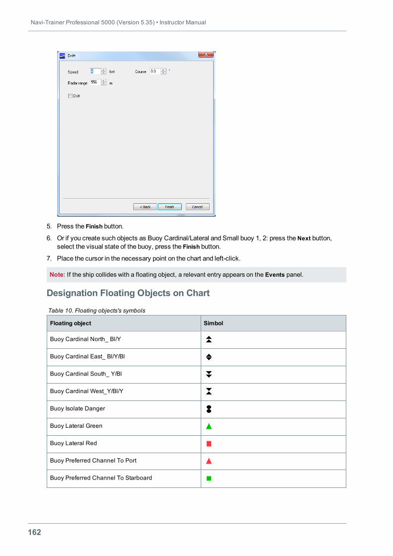
Navi-Trainer Professional 5000 (Version 5.35) • Instructor Manual
162
5. Press the Finish button.
6. Or if you create such objects as Buoy Cardinal/Lateral and Small buoy 1, 2: press theNext button,select the visual state of the buoy, press the Finish button.
7. Place the cursor in the necessary point on the chart and left-click.
Note: If the ship collides with a floating object, a relevant entry appears on the Events panel.
Designation Floating Objects on Chart
Floating object Simbol
Buoy Cardinal North_ Bl/Y
Buoy Cardinal East_ Bl/Y/Bl
Buoy Cardinal South_ Y/Bl
Buoy Cardinal West_Y/Bl/Y
Buoy Isolate Danger
Buoy Lateral Green
Buoy Lateral Red
Buoy Preferred Channel To Port
Buoy Preferred Channel To Starboard
Table 10. Floating objects's symbols
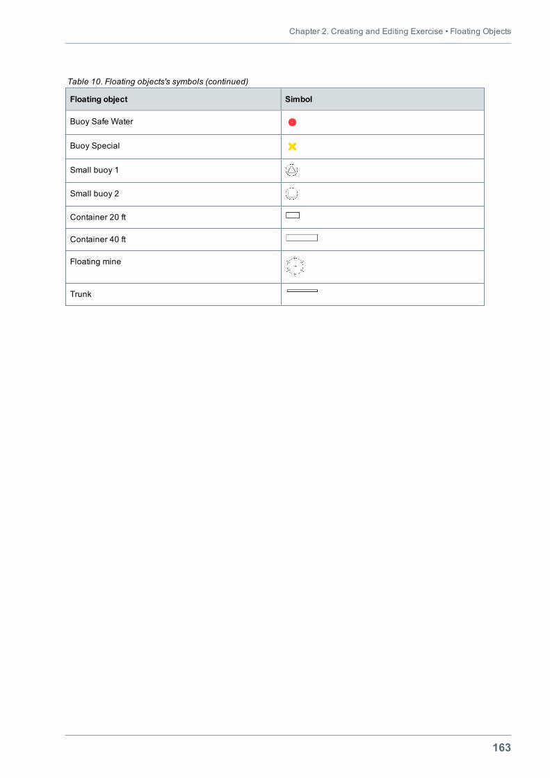
Chapter 2. Creating and Editing Exercise • Floating Objects
163
Floating object Simbol
Buoy Safe Water
Buoy Special
Small buoy 1
Small buoy 2
Container 20 ft
Container 40 ft
Floating mine
Trunk
Table 10. Floating objects's symbols (continued)
Navi-Trainer Professional 5000 (Version 5.35) • Instructor Manual
164
AIS ATONAIS AtoN – a device or system that is designed and operated to enhance the safe and efficient navigationof vessels and/or vessel traffic.
There are three types of AIS AtoN:
l Real – an AIS station located on a real AtoN (Aids to Navigation);
l Synthetic – an AIS station distantly located from a real AtoN and transmittingmessages (message 21)about the location and status of AtoN;
l Virtual – an AIS station transmittingmessages (message 21) about the location and status of a non-existing (virtual) AtoN.
An AIS AtoN, independently of the selected type, can be placed in any point on the chart or connected tothe following objects of the exercise:
l Small buoy 1, 2 (category Floating objects);
l Oil platform, Oil platform 1, 2 (category Mooring).
After running a simulator session, all data about the AtoN are displayed on themonitor of theMKD imitatorof the Conning Display and are also displayed on themonitor of the radar. On deleting an AtoN Stationobject from the exercise, the respective data disappear from themonitors of theMKD imitator and theradar on 400 sec.
To set the object, use the following procedure:
1. Choose Edit\New object…menu item or press the button on the toolbar.
2. From the Scene category, select the AtoN Station object.
3. In theName field, type the name of the object (if necessary).
4. Press theNext button. TheAtoN window appears on the screen:
5. In theAtoN AIS station group box, select the type of the object:o Real;o Synthetic;o Virtual.
6. If theReal type is selected, set the dimensions of the AtoN Station in theBow, Stern, Port and Stbdfields of theDimensions group box.
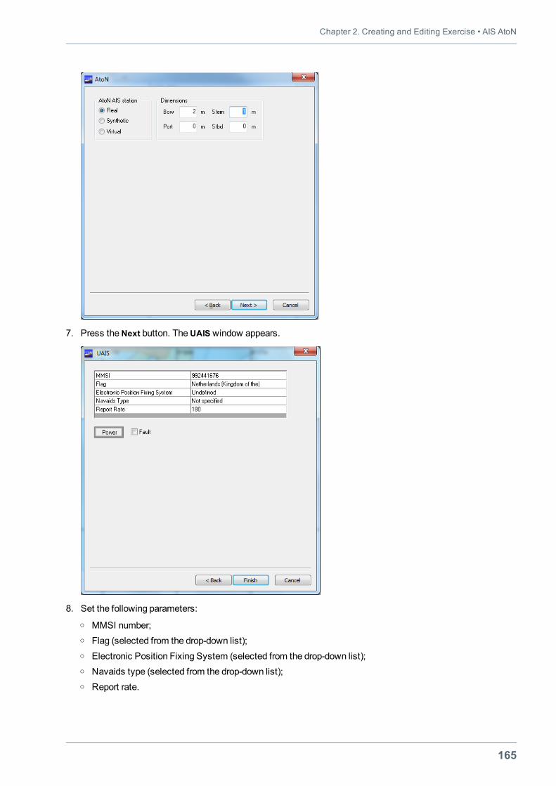
Chapter 2. Creating and Editing Exercise • AIS AtoN
165
7. Press theNext button. TheUAIS window appears.
8. Set the following parameters:o MMSI number;o Flag (selected from the drop-down list);o Electronic Position Fixing System (selected from the drop-down list);o Navaids type (selected from the drop-down list);o Report rate.
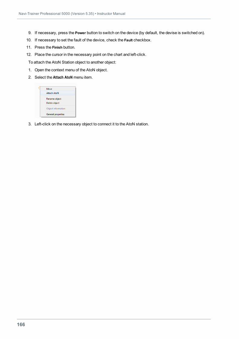
Navi-Trainer Professional 5000 (Version 5.35) • Instructor Manual
166
9. If necessary, press the Power button to switch on the device (by default, the devise is switched on).
10. If necessary to set the fault of the device, check the Fault checkbox.
11. Press the Finish button.
12. Place the cursor in the necessary point on the chart and left-click.
To attach the AtoN Station object to another object:
1. Open the context menu of the AtoN object.
2. Select the Attach AtoNmenu item.
3. Left-click on the necessary object to connect it to the AtoN station.
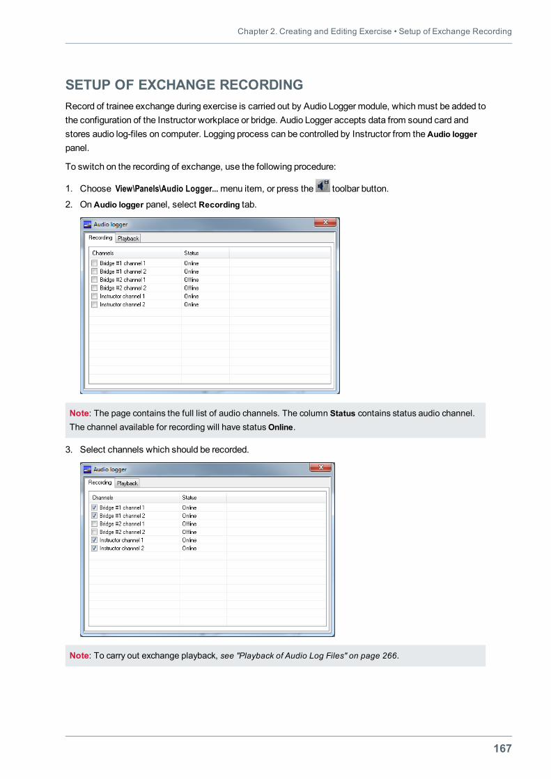
Chapter 2. Creating and Editing Exercise • Setup of Exchange Recording
167
SETUP OF EXCHANGE RECORDINGRecord of trainee exchange during exercise is carried out by Audio Logger module, whichmust be added tothe configuration of the Instructor workplace or bridge. Audio Logger accepts data from sound card andstores audio log-files on computer. Logging process can be controlled by Instructor from theAudio loggerpanel.
To switch on the recording of exchange, use the following procedure:
1. Choose View\Panels\Audio Logger...menu item, or press the toolbar button.
2. OnAudio logger panel, select Recording tab.
Note: The page contains the full list of audio channels. The column Status contains status audio channel.The channel available for recording will have statusOnline.
3. Select channels which should be recorded.
Note: To carry out exchange playback, see "Playback of Audio Log Files" on page 266.
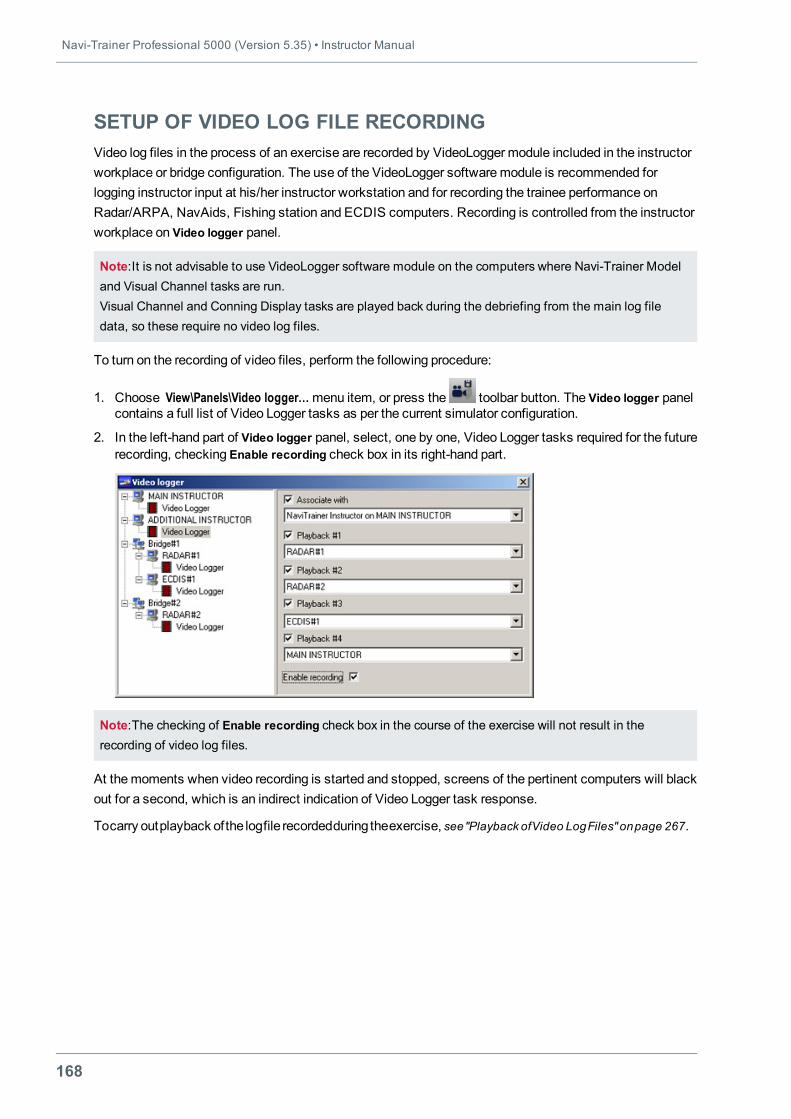
Navi-Trainer Professional 5000 (Version 5.35) • Instructor Manual
168
SETUP OF VIDEO LOG FILE RECORDINGVideo log files in the process of an exercise are recorded by VideoLogger module included in the instructorworkplace or bridge configuration. The use of the VideoLogger softwaremodule is recommended forlogging instructor input at his/her instructor workstation and for recording the trainee performance onRadar/ARPA, NavAids, Fishing station and ECDIS computers. Recording is controlled from the instructorworkplace on Video logger panel.
Note:It is not advisable to use VideoLogger software module on the computers where Navi-Trainer Modeland Visual Channel tasks are run.Visual Channel and Conning Display tasks are played back during the debriefing from the main log filedata, so these require no video log files.
To turn on the recording of video files, perform the following procedure:
1. Choose View\Panels\Video logger…menu item, or press the toolbar button. The Video logger panelcontains a full list of Video Logger tasks as per the current simulator configuration.
2. In the left-hand part of Video logger panel, select, one by one, Video Logger tasks required for the futurerecording, checking Enable recording check box in its right-hand part.
Note:The checking of Enable recording check box in the course of the exercise will not result in therecording of video log files.
At themoments when video recording is started and stopped, screens of the pertinent computers will blackout for a second, which is an indirect indication of Video Logger task response.
Tocarry outplayback ofthe logfile recordedduring theexercise, see"Playback ofVideo LogFiles" onpage 267.
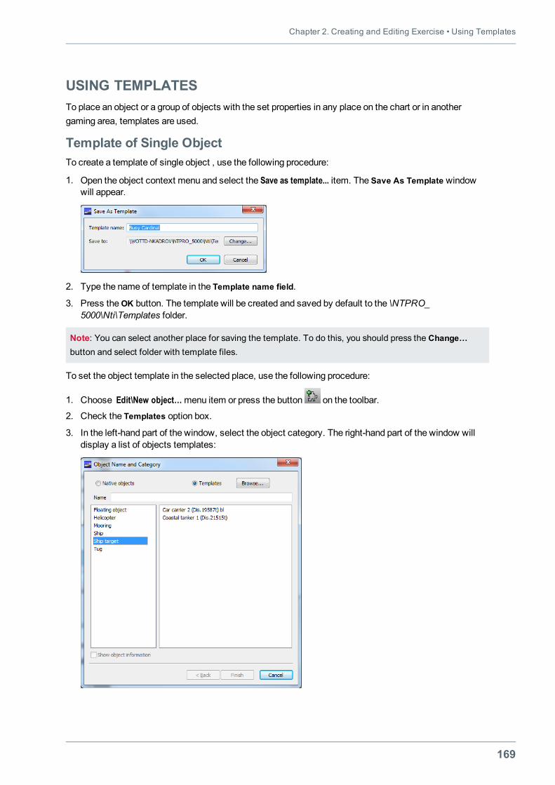
Chapter 2. Creating and Editing Exercise • Using Templates
169
USING TEMPLATESTo place an object or a group of objects with the set properties in any place on the chart or in anothergaming area, templates are used.
Template of Single ObjectTo create a template of single object , use the following procedure:
1. Open the object context menu and select the Save as template... item. The Save As Template windowwill appear.
2. Type the name of template in the Template name field.
3. Press theOK button. The template will be created and saved by default to the \NTPRO_5000\Nti\Templates folder.
Note: You can select another place for saving the template. To do this, you should press the Change…button and select folder with template files.
To set the object template in the selected place, use the following procedure:
1. Choose Edit\New object…menu item or press the button on the toolbar.
2. Check the Templates option box.
3. In the left-hand part of the window, select the object category. The right-hand part of the window willdisplay a list of objects templates:
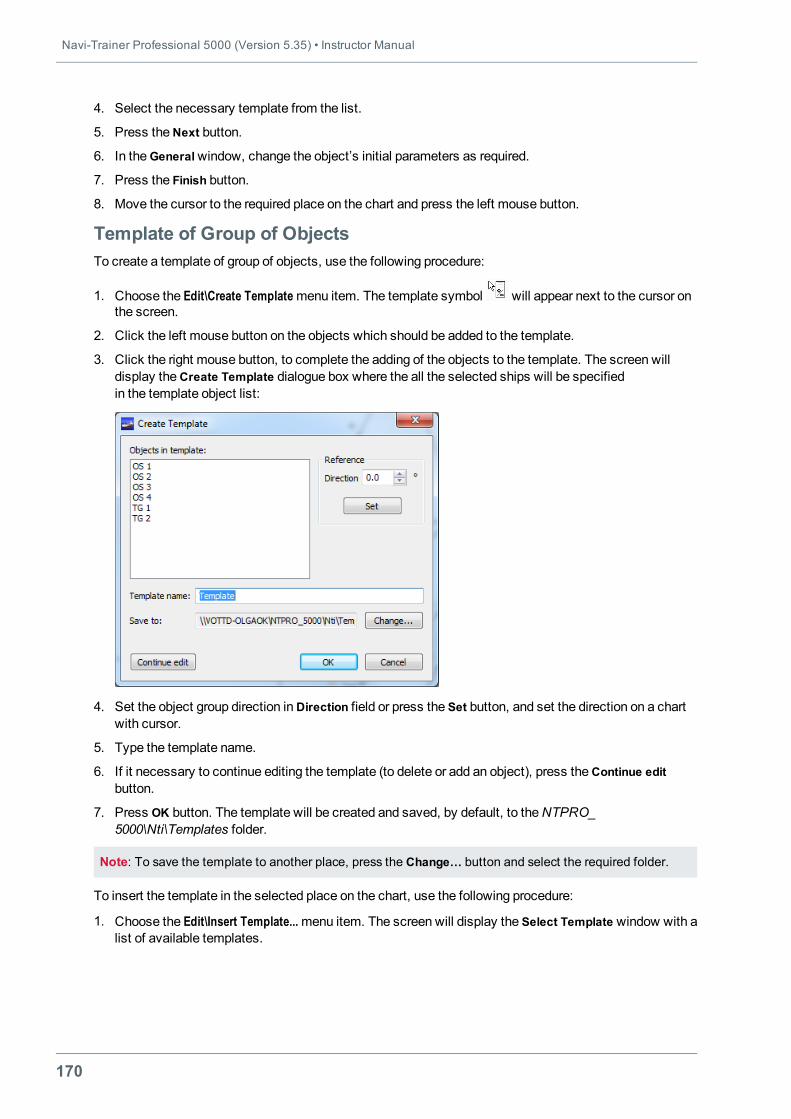
Navi-Trainer Professional 5000 (Version 5.35) • Instructor Manual
170
4. Select the necessary template from the list.
5. Press theNext button.
6. In theGeneralwindow, change the object’s initial parameters as required.
7. Press the Finish button.
8. Move the cursor to the required place on the chart and press the left mouse button.
Template of Group of ObjectsTo create a template of group of objects, use the following procedure:
1. Choose the Edit\Create Templatemenu item. The template symbol will appear next to the cursor onthe screen.
2. Click the left mouse button on the objects which should be added to the template.
3. Click the right mouse button, to complete the adding of the objects to the template. The screen willdisplay theCreate Template dialogue box where the all the selected ships will be specifiedin the template object list:
4. Set the object group direction inDirection field or press the Set button, and set the direction on a chartwith cursor.
5. Type the template name.
6. If it necessary to continue editing the template (to delete or add an object), press theContinue editbutton.
7. Press OK button. The template will be created and saved, by default, to theNTPRO_5000\Nti\Templates folder.
Note: To save the template to another place, press the Change… button and select the required folder.
To insert the template in the selected place on the chart, use the following procedure:
1. Choose the Edit\Insert Template...menu item. The screen will display the Select Template window with alist of available templates.
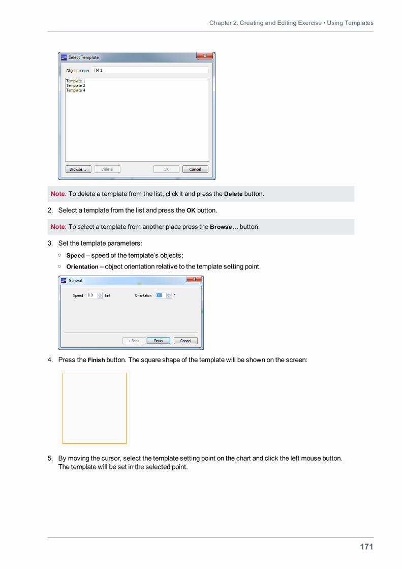
Chapter 2. Creating and Editing Exercise • Using Templates
171
Note: To delete a template from the list, click it and press the Delete button.
2. Select a template from the list and press theОK button.
Note: To select a template from another place press the Browse… button.
3. Set the template parameters:o Speed – speed of the template’s objects;o Orientation – object orientation relative to the template setting point.
4. Press the Finish button. The square shape of the template will be shown on the screen:
5. By moving the cursor, select the template setting point on the chart and click the left mouse button.The template will be set in the selected point.
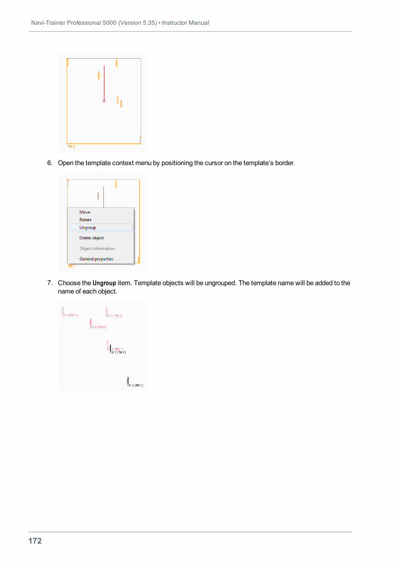
Navi-Trainer Professional 5000 (Version 5.35) • Instructor Manual
172
6. Open the template context menu by positioning the cursor on the template’s border.
7. Choose the Ungroup item. Template objects will be ungrouped. The template namewill be added to thename of each object.
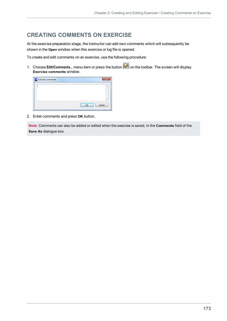
Chapter 2. Creating and Editing Exercise • Creating Comments on Exercise
173
CREATING COMMENTS ON EXERCISEAt the exercise preparation stage, the Instructor can add own comments which will subsequently beshown in theOpenwindow when this exercise or log file is opened.
To create and edit comments on an exercise, use the following procedure:
1. Choose Edit/Comments...menu item or press the button on the toolbar. The screen will displayExercise comments window.
2. Enter comments and press OK button.
Note: Comments can also be added or edited when the exercise is saved, in the Comments field of theSave As dialogue box.
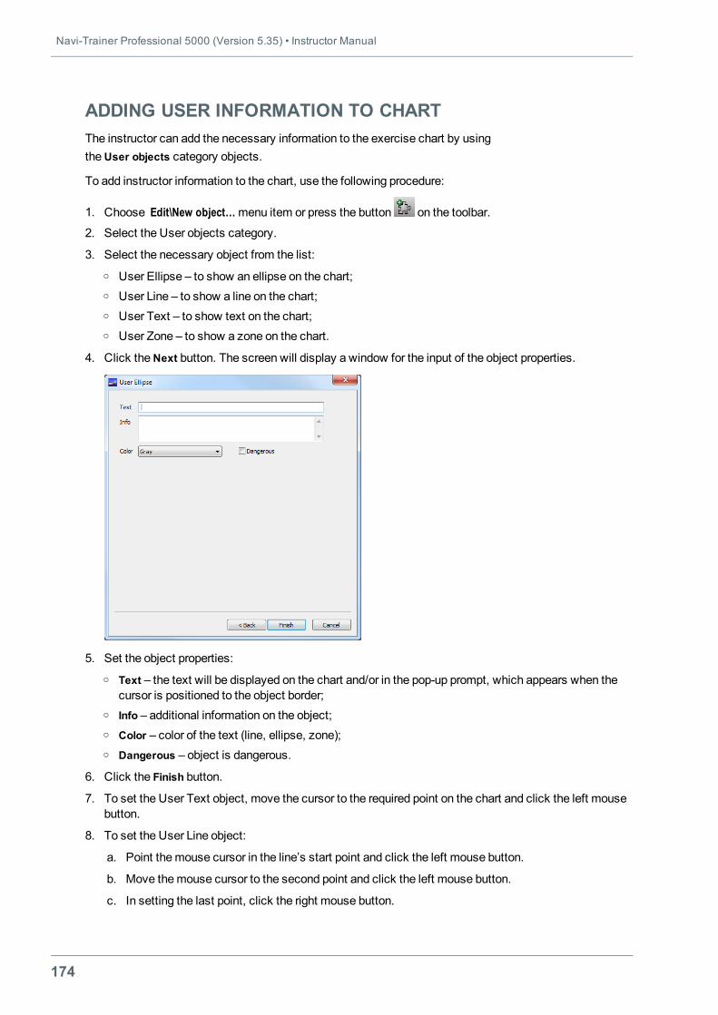
Navi-Trainer Professional 5000 (Version 5.35) • Instructor Manual
174
ADDING USER INFORMATION TO CHARTThe instructor can add the necessary information to the exercise chart by usingtheUser objects category objects.
To add instructor information to the chart, use the following procedure:
1. Choose Edit\New object…menu item or press the button on the toolbar.
2. Select the User objects category.
3. Select the necessary object from the list:o User Ellipse – to show an ellipse on the chart;o User Line – to show a line on the chart;o User Text – to show text on the chart;o User Zone – to show a zone on the chart.
4. Click theNext button. The screen will display a window for the input of the object properties.
5. Set the object properties:o Text – the text will be displayed on the chart and/or in the pop-up prompt, which appears when the
cursor is positioned to the object border;o Info – additional information on the object;o Color – color of the text (line, ellipse, zone);o Dangerous – object is dangerous.
6. Click the Finish button.
7. To set the User Text object, move the cursor to the required point on the chart and click the left mousebutton.
8. To set the User Line object:
a. Point themouse cursor in the line’s start point and click the left mouse button.
b. Move themouse cursor to the second point and click the left mouse button.
c. In setting the last point, click the right mouse button.
Chapter 2. Creating and Editing Exercise • Adding User Information to Chart
175
9. To set an User Ellipse object:
a. Place the cursor to the object’s position.
b. By moving the cursor, set the object dimensions and click the left mouse button.
10. To set a User Zone object:
a. Place the cursor to the zone’s first node position and click the left mouse button.
b. Move the cursor to the position of the zone’s second node and click the left mouse button.
c. In setting the last node, click the right mouse button.
After the userobjects havebeen set on thechart, theirparameters will be shownin the Information onChart
windowwhich canbe openedby pressing the toolbar button(see "Information on Chart" on page 43).
To turn on/off the display of user text and line, select Chart\Overlays\User Info item and check/clearUser Text, User Line, User Ellipse and User Zone check boxes.
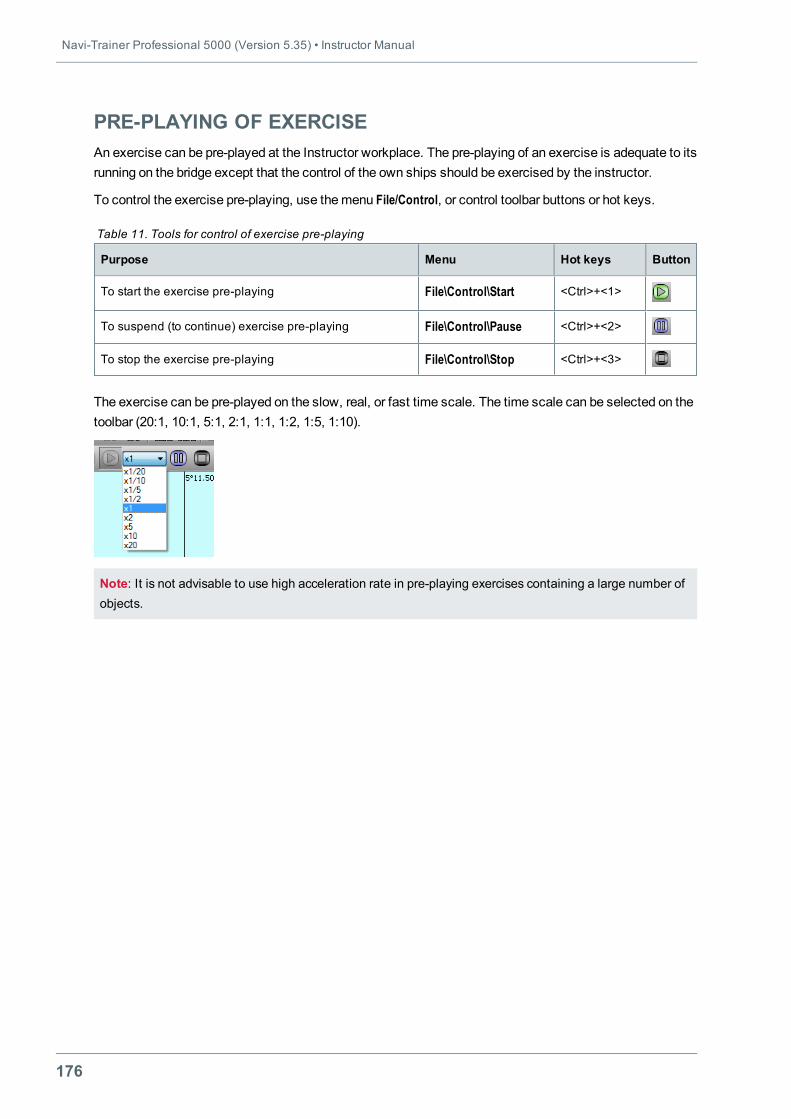
Navi-Trainer Professional 5000 (Version 5.35) • Instructor Manual
176
PRE-PLAYING OF EXERCISEAn exercise can be pre-played at the Instructor workplace. The pre-playing of an exercise is adequate to itsrunning on the bridge except that the control of the own ships should be exercised by the instructor.
To control the exercise pre-playing, use themenu File/Control, or control toolbar buttons or hot keys.
Purpose Menu Hot keys Button
To start the exercise pre-playing File\Control\Start <Ctrl>+<1>
To suspend (to continue) exercise pre-playing File\Control\Pause <Ctrl>+<2>
To stop the exercise pre-playing File\Control\Stop <Ctrl>+<3>
Table 11. Tools for control of exercise pre-playing
The exercise can be pre-played on the slow, real, or fast time scale. The time scale can be selected on thetoolbar (20:1, 10:1, 5:1, 2:1, 1:1, 1:2, 1:5, 1:10).
Note: It is not advisable to use high acceleration rate in pre-playing exercises containing a large number ofobjects.
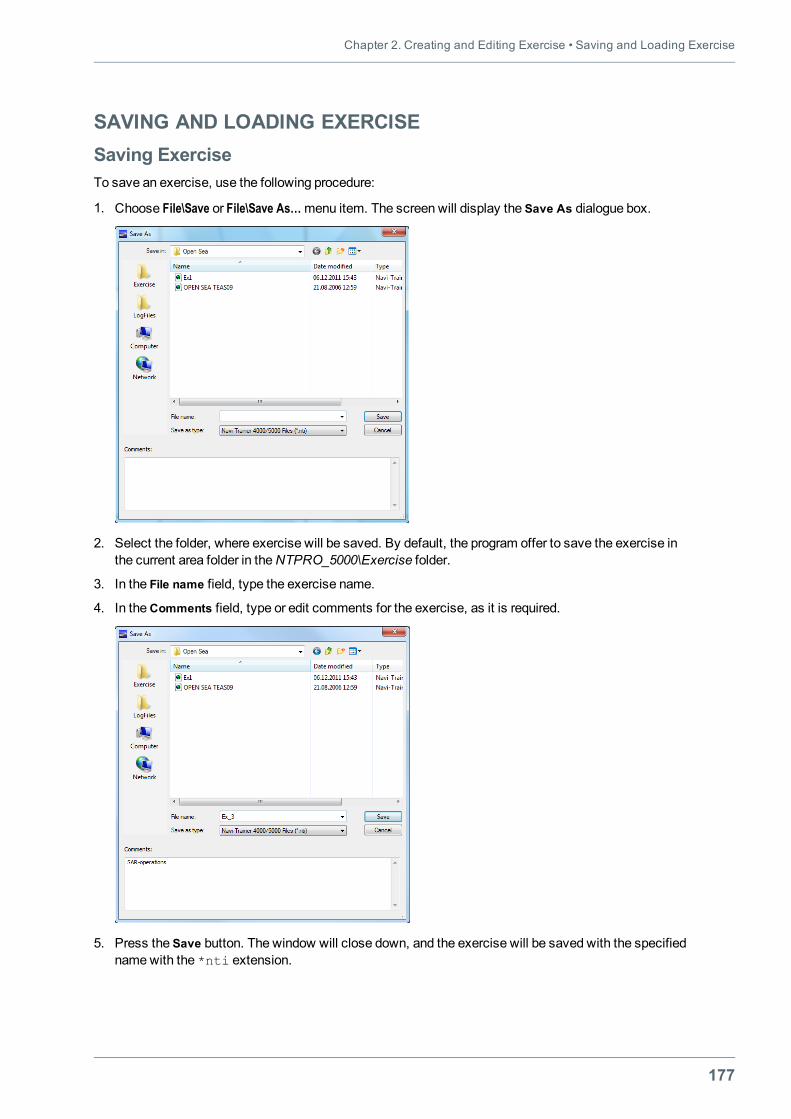
Chapter 2. Creating and Editing Exercise • Saving and Loading Exercise
177
SAVING AND LOADING EXERCISESaving ExerciseTo save an exercise, use the following procedure:
1. Choose File\Save or File\Save As…menu item. The screen will display the Save As dialogue box.
2. Select the folder, where exercise will be saved. By default, the program offer to save the exercise inthe current area folder in theNTPRO_5000\Exercise folder.
3. In the File name field, type the exercise name.
4. In theComments field, type or edit comments for the exercise, as it is required.
5. Press the Save button. The window will close down, and the exercise will be saved with the specifiednamewith the *nti extension.
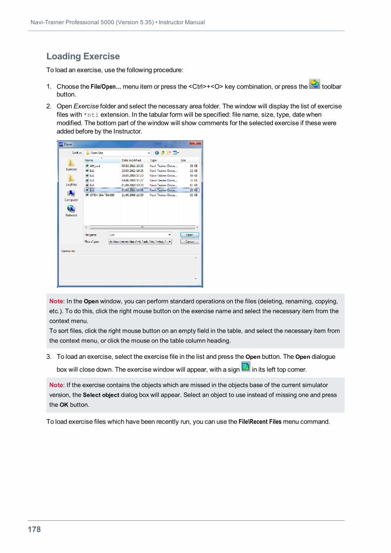
Navi-Trainer Professional 5000 (Version 5.35) • Instructor Manual
178
Loading ExerciseTo load an exercise, use the following procedure:
1. Choose the File/Open…menu item or press the <Сtrl>+<O> key combination, or press the toolbarbutton.
2. OpenExercise folder and select the necessary area folder. The window will display the list of exercisefiles with *nti extension. In the tabular form will be specified: file name, size, type, date whenmodified. The bottom part of the window will show comments for the selected exercise if these wereadded before by the Instructor.
Note: In the Openwindow, you can perform standard operations on the files (deleting, renaming, copying,etc.). To do this, click the right mouse button on the exercise name and select the necessary item from thecontext menu.To sort files, click the right mouse button on an empty field in the table, and select the necessary item fromthe context menu, or click the mouse on the table column heading.
3. To load an exercise, select the exercise file in the list and press theOpen button. TheOpen dialogue
box will close down. The exercise window will appear, with a sign in its left top corner.
Note: If the exercise contains the objects which are missed in the objects base of the current simulatorversion, the Select object dialog box will appear. Select an object to use instead of missing one and pressthe OK button.
To load exercise files which have been recently run, you can use the File\Recent Filesmenu command.
Chapter 2. Creating and Editing Exercise • Saving and Loading Exercise
179
Loading of NT 3000 ExercisesNTPRO 5000 inherits exercises created by Exercise Editor of NTPRO 3000.
To load an exercise created in Navi-Trainer 3000 simulator, use the following procedure:
1. Choose File\Open…menu item. The screen will display Open dialogue window.
2. In the Look in tree of directories, select the folder where Navi-Trainer 3000 exercises are stored. Setthe file extension filter (*.edt). The screen will display a list of available exercises in Navi-Trainer3000 format.
3. Double click on the name of the required exercise or press theOpen button.
Note: An exercise in Navi-Trainer 3000 format will not be loaded unless the same area is installed in Navi-Trainer 5000 simulator.The Navi-Trainer 3000 exercise can be saved in Navi-Trainer 5000 format only.The exercise is saved in the exercise folder for the same area.

181
CHAPTER 3.SIMULATOR SESSION
This chapter contains:
Opening Simulator Session 183Types of Training Scenario 183Distribution of Tasks 183Starting Exercise 186Pausing Exercise 186Session Overloading 186
Possible Operations During Simulator Session 188Control of Ships 189Control of Own Ships and Target Ships (AdvancedModels) 189Control of Targets Ships (SimplifiedModels) 189
Giving Sound Signals 191Giving Sound Signals by Target Ships 191Giving Siren Signals 192
Control of Autopilot 193Motion Data Display 195Fire Detection Alarm 196Control of Navigation Signals 197Selecting Signals Preset Combination 197Setting Lights 198Setting Shapes 199Change of Lights and Shapes 200
Flashing Light Signaling 201Setting Malfunctions on Ship's Properties Panel 202Setting Radar Faults 202Setting Loran-С Faults 203Setting Propulsion Plant Faults 204Setting Steering System Faults 206
UAIS Message Exchange 208
Navi-Trainer Professional 5000 (Version 5.35) • Instructor Manual
182
Message Reply 208Monitoring of UAIS Messages 209
Setting Options During Simulator Session 210Using Virtual Force 211Setting Virtual Force 211Changing Virtual Force 212Setting Virtual Force Properties 212
Ship Information Panel 213Events Panel 214Monitoring of Dangerous Targets 217CPA/TCPA Monitoring Panel 217General CPA/TCPA Settings 217Graphic Presentation of СРА/ТСРА Data 218
Diagrams of Ship Motion Parameters 220Ship DiagramWindow 220SelectingMonitored Parameters 223Setting Parameter Properties 225Diagram Settings Template 226Export Diagram Data to CSV-Format 227Diagram Printout 227
Instructor Visualization 229Setting Camera 229Instructor Visualization Control Panel 232
Creating Visualization Screenshots 236Loading Visual Profile on Bridge 237Visual Settings 238Setting Radar 240Loading ECDIS Data 241Transmitting NAVTEX Messages 242VHF Playback 245Control of Auxiliary Machinery 247Control of Remote Sensors 249Creation of Log Scripts 251LogScript Panel 251Saving Current Log Script 251Recording Log Script 252Editing Log Script 254
Closing Simulator Session 256Saving Current State of Exercise 256Stop Exercise 256
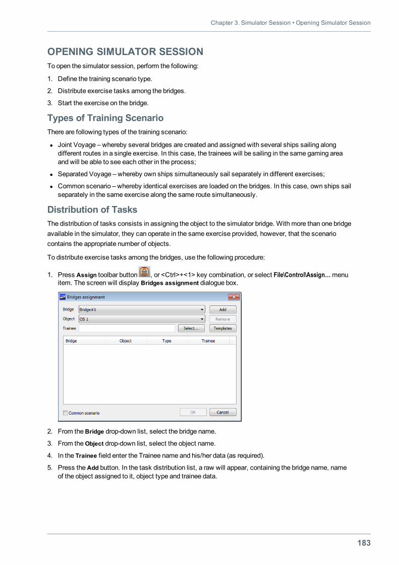
Chapter 3. Simulator Session • Opening Simulator Session
183
OPENING SIMULATOR SESSIONTo open the simulator session, perform the following:
1. Define the training scenario type.
2. Distribute exercise tasks among the bridges.
3. Start the exercise on the bridge.
Types of Training ScenarioThere are following types of the training scenario:
l Joint Voyage – whereby several bridges are created and assigned with several ships sailing alongdifferent routes in a single exercise. In this case, the trainees will be sailing in the same gaming areaand will be able to see each other in the process;
l Separated Voyage – whereby own ships simultaneously sail separately in different exercises;
l Common scenario – whereby identical exercises are loaded on the bridges. In this case, own ships sailseparately in the same exercise along the same route simultaneously.
Distribution of TasksThe distribution of tasks consists in assigning the object to the simulator bridge. With more than one bridgeavailable in the simulator, they can operate in the same exercise provided, however, that the scenariocontains the appropriate number of objects.
To distribute exercise tasks among the bridges, use the following procedure:
1. Press Assign toolbar button , or <Ctrl>+<1> key combination, or select File\Control\Assign…menuitem. The screen will display Bridges assignment dialogue box.
2. From theBridge drop-down list, select the bridge name.
3. From theObject drop-down list, select the object name.
4. In the Trainee field enter the Trainee name and his/her data (as required).
5. Press theAdd button. In the task distribution list, a raw will appear, containing the bridge name, nameof the object assigned to it, object type and trainee data.
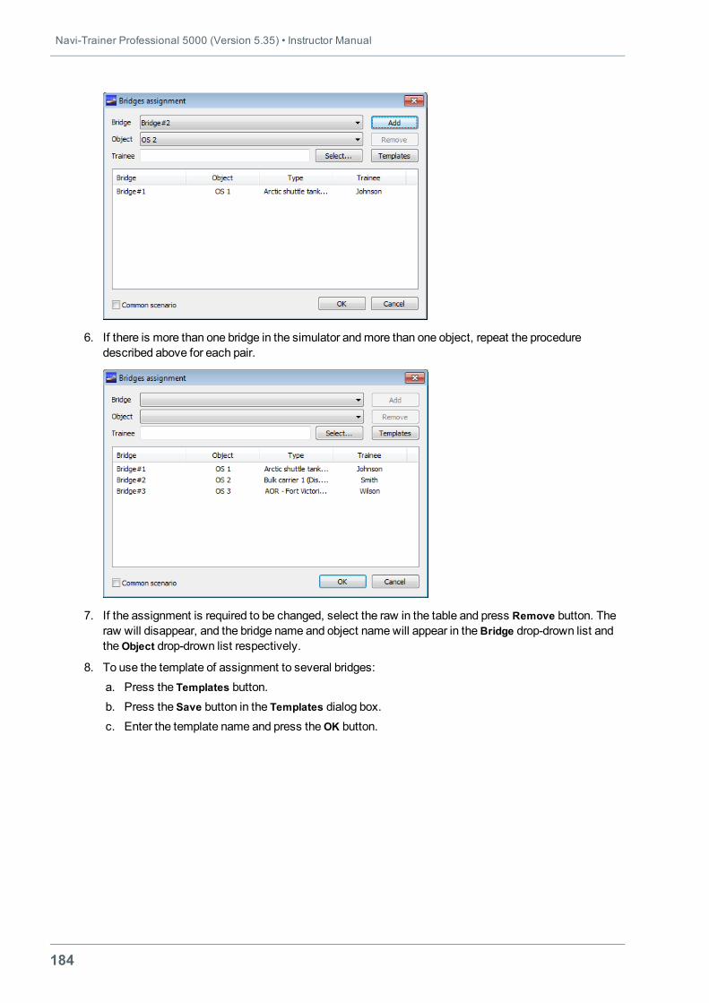
Navi-Trainer Professional 5000 (Version 5.35) • Instructor Manual
184
6. If there is more than one bridge in the simulator andmore than one object, repeat the proceduredescribed above for each pair.
7. If the assignment is required to be changed, select the raw in the table and press Remove button. Theraw will disappear, and the bridge name and object namewill appear in theBridge drop-drown list andtheObject drop-drown list respectively.
8. To use the template of assignment to several bridges:a. Press the Templates button.b. Press the Save button in the Templates dialog box.c. Enter the template name and press theOK button.
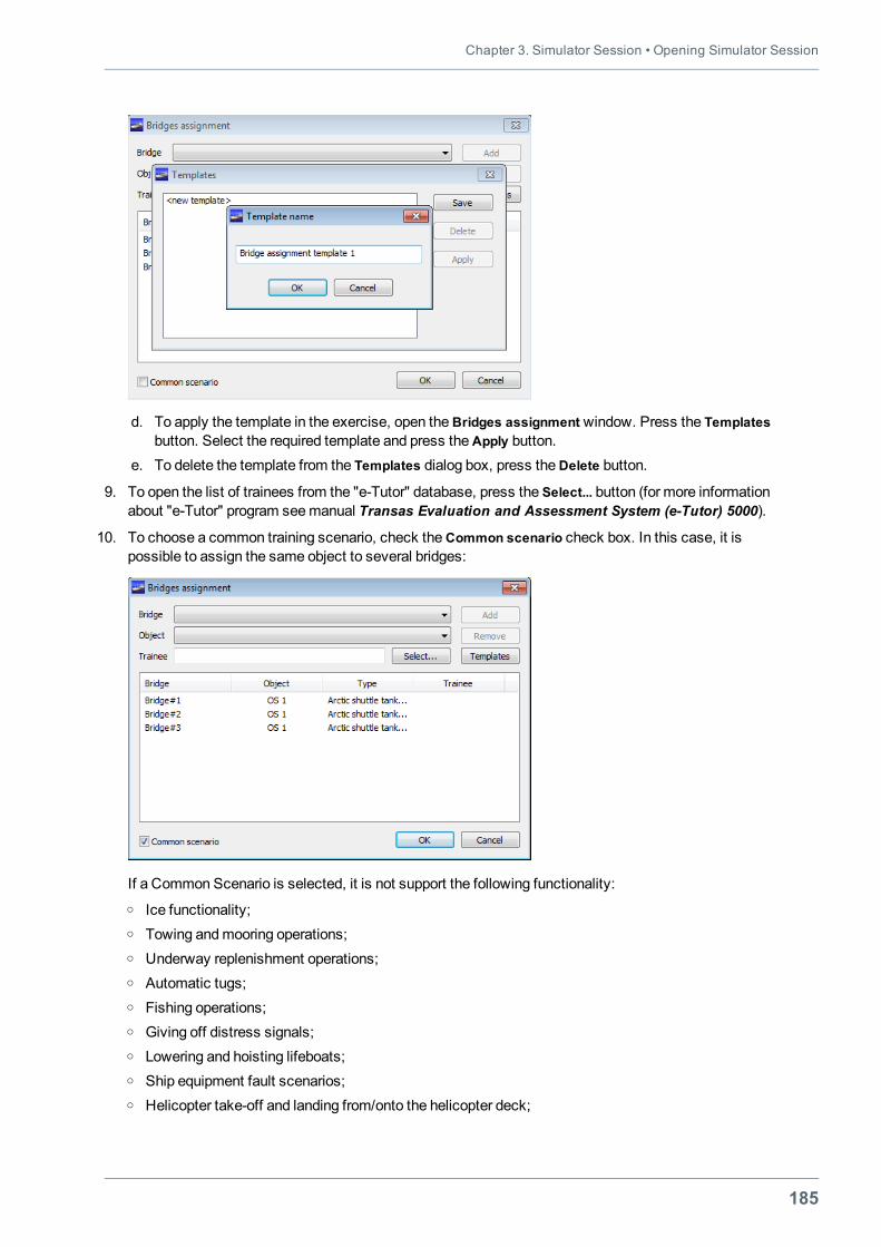
Chapter 3. Simulator Session • Opening Simulator Session
185
d. To apply the template in the exercise, open theBridges assignment window. Press the Templatesbutton. Select the required template and press theApply button.
e. To delete the template from the Templates dialog box, press theDelete button.
9. To open the list of trainees from the "e-Tutor" database, press the Select... button (for more informationabout "e-Tutor" program seemanual Transas Evaluation and Assessment System (e-Tutor) 5000).
10. To choose a common training scenario, check theCommon scenario check box. In this case, it ispossible to assign the same object to several bridges:
If a Common Scenario is selected, it is not support the following functionality:o Ice functionality;o Towing andmooring operations;o Underway replenishment operations;o Automatic tugs;o Fishing operations;o Giving off distress signals;o Lowering and hoisting lifeboats;o Ship equipment fault scenarios;o Helicopter take-off and landing from/onto the helicopter deck;
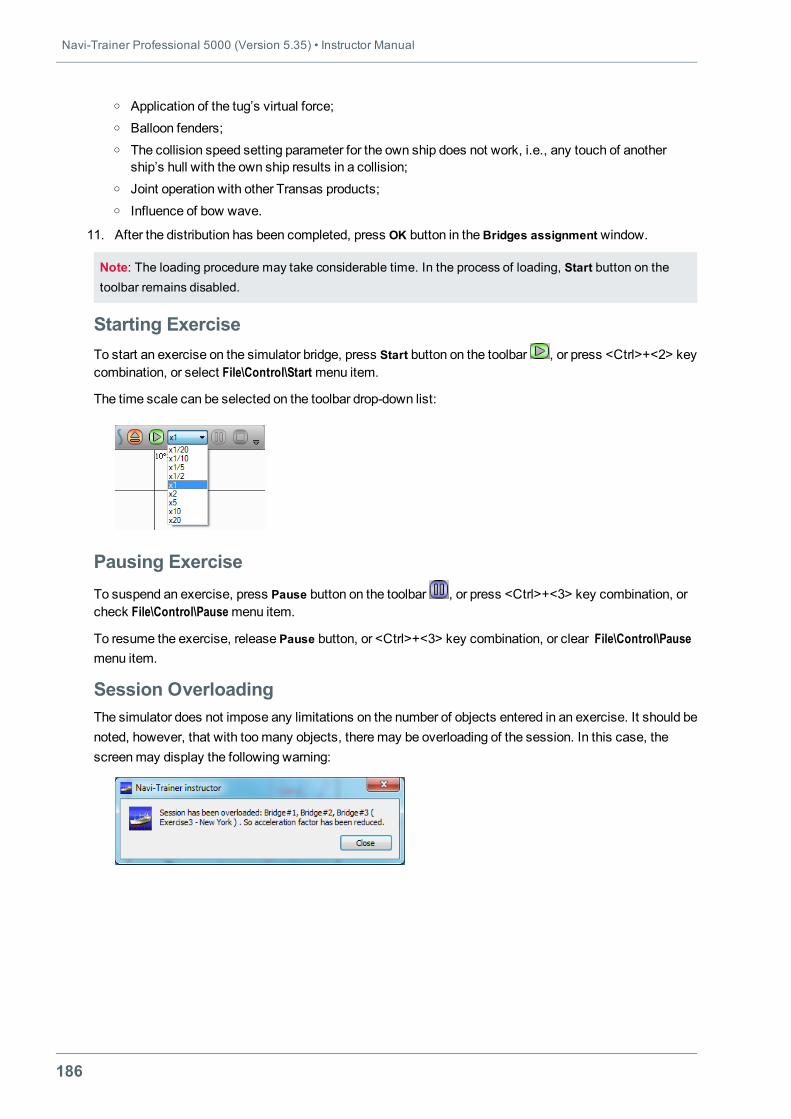
Navi-Trainer Professional 5000 (Version 5.35) • Instructor Manual
186
o Application of the tug’s virtual force;o Balloon fenders;o The collision speed setting parameter for the own ship does not work, i.e., any touch of another
ship’s hull with the own ship results in a collision;o Joint operation with other Transas products;o Influence of bow wave.
11. After the distribution has been completed, press OK button in theBridges assignment window.
Note: The loading procedure may take considerable time. In the process of loading, Start button on thetoolbar remains disabled.
Starting ExerciseTo start an exercise on the simulator bridge, press Start button on the toolbar , or press <Ctrl>+<2> keycombination, or select File\Control\Start menu item.
The time scale can be selected on the toolbar drop-down list:
Pausing ExerciseTo suspend an exercise, press Pause button on the toolbar , or press <Ctrl>+<3> key combination, orcheck File\Control\Pausemenu item.
To resume the exercise, release Pause button, or <Ctrl>+<3> key combination, or clear File\Control\Pausemenu item.
Session OverloadingThe simulator does not impose any limitations on the number of objects entered in an exercise. It should benoted, however, that with toomany objects, theremay be overloading of the session. In this case, thescreenmay display the following warning:
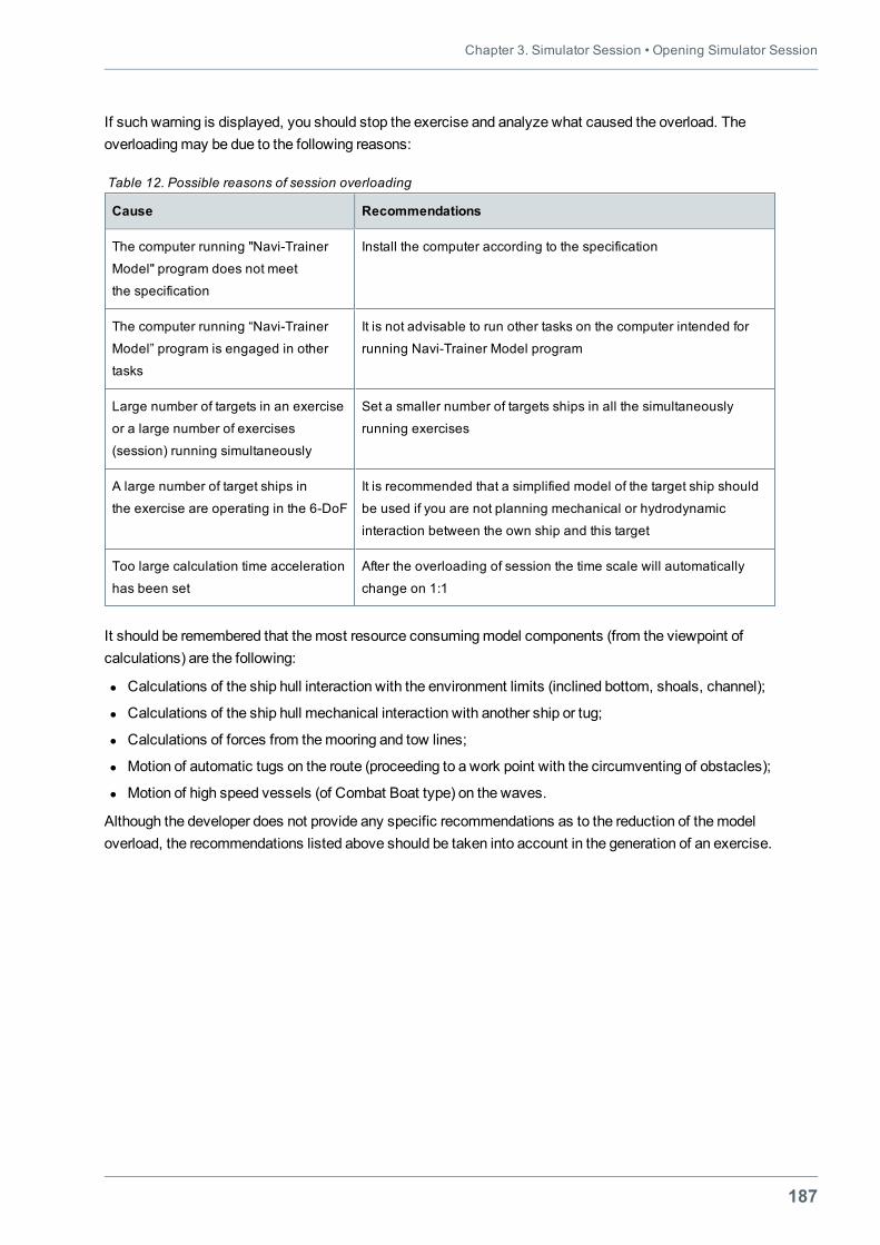
Chapter 3. Simulator Session • Opening Simulator Session
187
If such warning is displayed, you should stop the exercise and analyze what caused the overload. Theoverloadingmay be due to the following reasons:
Cause Recommendations
The computer running "Navi-Trainer
Model" program does not meet
the specification
Install the computer according to the specification
The computer running “Navi-Trainer
Model” program is engaged in other
tasks
It is not advisable to run other tasks on the computer intended for
running Navi-Trainer Model program
Large number of targets in an exercise
or a large number of exercises
(session) running simultaneously
Set a smaller number of targets ships in all the simultaneously
running exercises
A large number of target ships in
the exercise are operating in the 6-DoF
It is recommended that a simplified model of the target ship should
be used if you are not planning mechanical or hydrodynamic
interaction between the own ship and this target
Too large calculation time acceleration
has been set
After the overloading of session the time scale will automatically
change on 1:1
Table 12. Possible reasons of session overloading
It should be remembered that themost resource consumingmodel components (from the viewpoint ofcalculations) are the following:
l Calculations of the ship hull interaction with the environment limits (inclined bottom, shoals, channel);
l Calculations of the ship hull mechanical interaction with another ship or tug;
l Calculations of forces from themooring and tow lines;
l Motion of automatic tugs on the route (proceeding to a work point with the circumventing of obstacles);
l Motion of high speed vessels (of Combat Boat type) on the waves.
Although the developer does not provide any specific recommendations as to the reduction of themodeloverload, the recommendations listed above should be taken into account in the generation of an exercise.
Navi-Trainer Professional 5000 (Version 5.35) • Instructor Manual
188
POSSIBLE OPERATIONS DURING SIMULATOR SESSIONAfter the simulator session start, the Instructor can do the following:
l Add new objects (except for objects of Ship, Tug and VTS categories, and such objects as: Pinnacle –Fishing category ,Ice class, Tides and currents – Environment category, Laser docking system –Mooring category).
l Move objects (except for the Current field, VTS objects whose position can only be changed before thesimulator session start).
l Delete objects (except for objects of Ship, Tug and VTS categories and also tide and currentdatabase);
l Add and change some object properties. After the assignment of ships to the bridges, the shipproperties panel will contain some additional tabs.
l Control the objects from properties panel.
l Control mooring winches and anchor winches.
l Exchange UAIS message, give a sound signals, set equipment malfunctions and other.
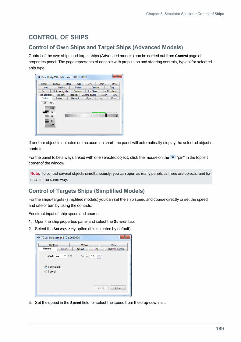
Chapter 3. Simulator Session • Control of Ships
189
CONTROL OF SHIPSControl of Own Ships and Target Ships (Advanced Models)Control of the own ships and target ships (Advancedmodels) can be carried out from Control page ofproperties panel. The page represents of console with propulsion and steering controls, typical for selectedship type:
If another object is selected on the exercise chart, the panel will automatically display the selected object’scontrols.
For the panel to be always linked with one selected object, click themouse on the "pin" in the top leftcorner of the window.
Note: To control several objects simultaneously, you can open as many panels as there are objects, and fixeach in the same way.
Control of Targets Ships (Simplified Models)For the ships-targets (simplifiedmodels) you can set the ship speed and course directly or set the speedand rate of turn by using the controls.
For direct input of ship speed and course:
1. Open the ship properties panel and select theGeneral tab.
2. Select the Set explicitly option (it is selected by default):
3. Set the speed in the Speed field, or select the speed from the drop-down list.
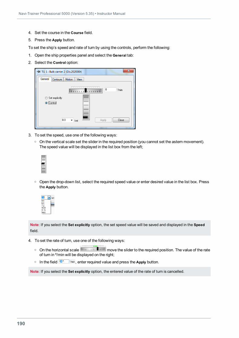
Navi-Trainer Professional 5000 (Version 5.35) • Instructor Manual
190
4. Set the course in theCourse field.
5. Press theApply button.
To set the ship’s speed and rate of turn by using the controls, perform the following:
1. Open the ship properties panel and select theGeneral tab:
2. Select theControl option:
3. To set the speed, use one of the following ways:o On the vertical scale set the slider in the required position (you cannot set the asternmovement).
The speed value will be displayed in the list box from the left;
o Open the drop-down list, select the required speed value or enter desired value in the list box. PresstheApply button.
Note: If you select the Set explicitly option, the set speed value will be saved and displayed in the Speedfield.
4. To set the rate of turn, use one of the following ways:
o On the horizontal scale move the slider to the required position. The value of the rateof turn in º/min will be displayed on the right;
o In the field , enter required value and press theApply button.
Note: If you select the Set explicitly option, the entered value of the rate of turn is cancelled.
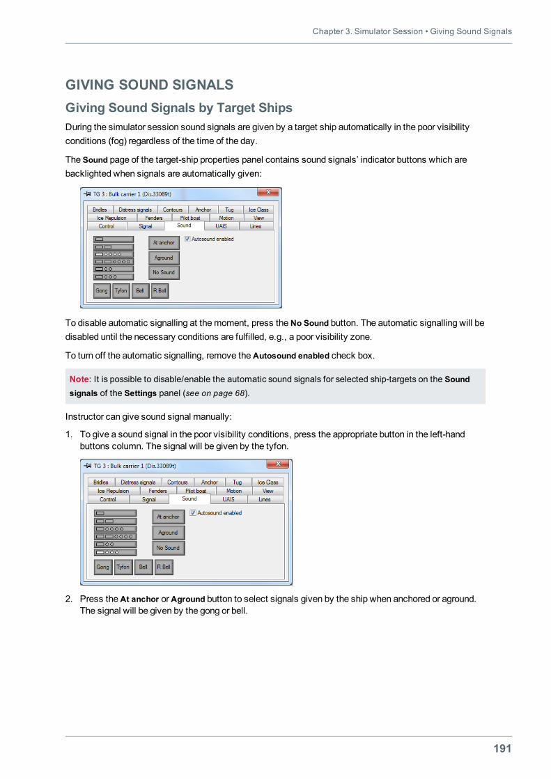
Chapter 3. Simulator Session • Giving Sound Signals
191
GIVING SOUND SIGNALSGiving Sound Signals by Target ShipsDuring the simulator session sound signals are given by a target ship automatically in the poor visibilityconditions (fog) regardless of the time of the day.
The Sound page of the target-ship properties panel contains sound signals’ indicator buttons which arebacklighted when signals are automatically given:
To disable automatic signalling at themoment, press theNo Sound button. The automatic signalling will bedisabled until the necessary conditions are fulfilled, e.g., a poor visibility zone.
To turn off the automatic signalling, remove theAutosound enabled check box.
Note: It is possible to disable/enable the automatic sound signals for selected ship-targets on the Soundsignals of the Settings panel (see on page 68).
Instructor can give sound signal manually:
1. To give a sound signal in the poor visibility conditions, press the appropriate button in the left-handbuttons column. The signal will be given by the tyfon.
2. Press theAt anchor orAground button to select signals given by the ship when anchored or aground.The signal will be given by the gong or bell.
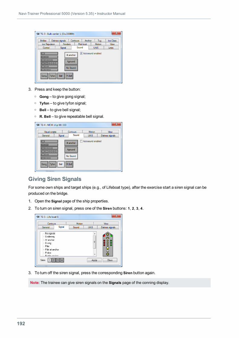
Navi-Trainer Professional 5000 (Version 5.35) • Instructor Manual
192
3. Press and keep the button:o Gong – to give gong signal;o Tyfon – to give tyfon signal;o Bell – to give bell signal;o R. Bell – to give repeatable bell signal.
Giving Siren SignalsFor some own ships and target ships (e.g., of Lifeboat type), after the exercise start a siren signal can beproduced on the bridge.
1. Open the Signal page of the ship properties.
2. To turn on siren signal, press one of the Siren buttons: 1, 2, 3, 4.
3. To turn off the siren signal, press the corresponding Siren button again.
Note: The trainee can give siren signals on the Signals page of the conning display.
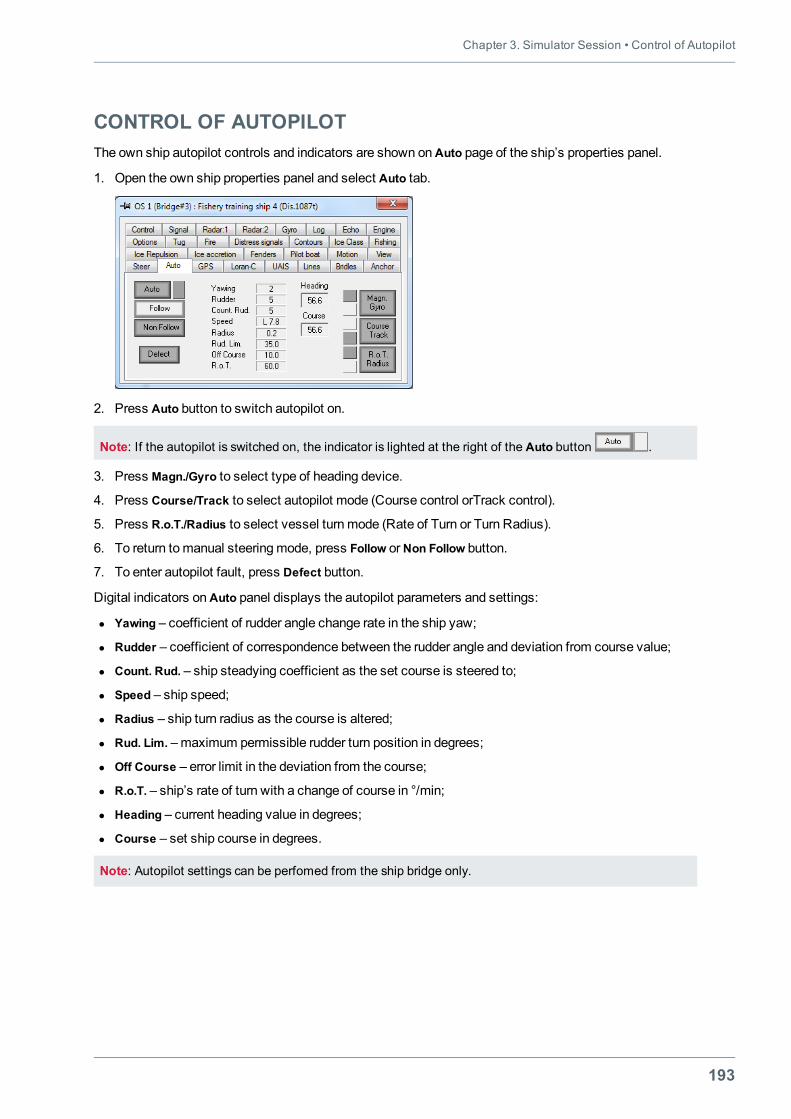
Chapter 3. Simulator Session • Control of Autopilot
193
CONTROL OF AUTOPILOTThe own ship autopilot controls and indicators are shown onAuto page of the ship’s properties panel.
1. Open the own ship properties panel and select Auto tab.
2. Press Auto button to switch autopilot on.
Note: If the autopilot is switched on, the indicator is lighted at the right of the Auto button .
3. Press Magn./Gyro to select type of heading device.
4. Press Course/Track to select autopilot mode (Course control orTrack control).
5. Press R.o.T./Radius to select vessel turnmode (Rate of Turn or Turn Radius).
6. To return tomanual steeringmode, press Follow orNon Follow button.
7. To enter autopilot fault, press Defect button.
Digital indicators onAuto panel displays the autopilot parameters and settings:
l Yawing – coefficient of rudder angle change rate in the ship yaw;
l Rudder – coefficient of correspondence between the rudder angle and deviation from course value;
l Count. Rud. – ship steadying coefficient as the set course is steered to;
l Speed – ship speed;
l Radius – ship turn radius as the course is altered;
l Rud. Lim. –maximum permissible rudder turn position in degrees;
l Off Course – error limit in the deviation from the course;
l R.o.T. – ship’s rate of turn with a change of course in °/min;
l Heading – current heading value in degrees;
l Course – set ship course in degrees.
Note: Autopilot settings can be perfomed from the ship bridge only.
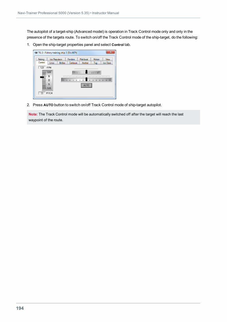
Navi-Trainer Professional 5000 (Version 5.35) • Instructor Manual
194
The autopilot of a target-ship (Advancedmodel) is operation in Track Control mode only and only in thepresence of the targets route. To switch on/off the Track Control mode of the ship-target, do the following:
1. Open the ship-target properties panel and select Control tab.
2. Press AUTO button to switch on/off Track Control mode of ship-target autopilot.
Note: The Track Control mode will be automatically switched off after the target will reach the lastwaypoint of the route.
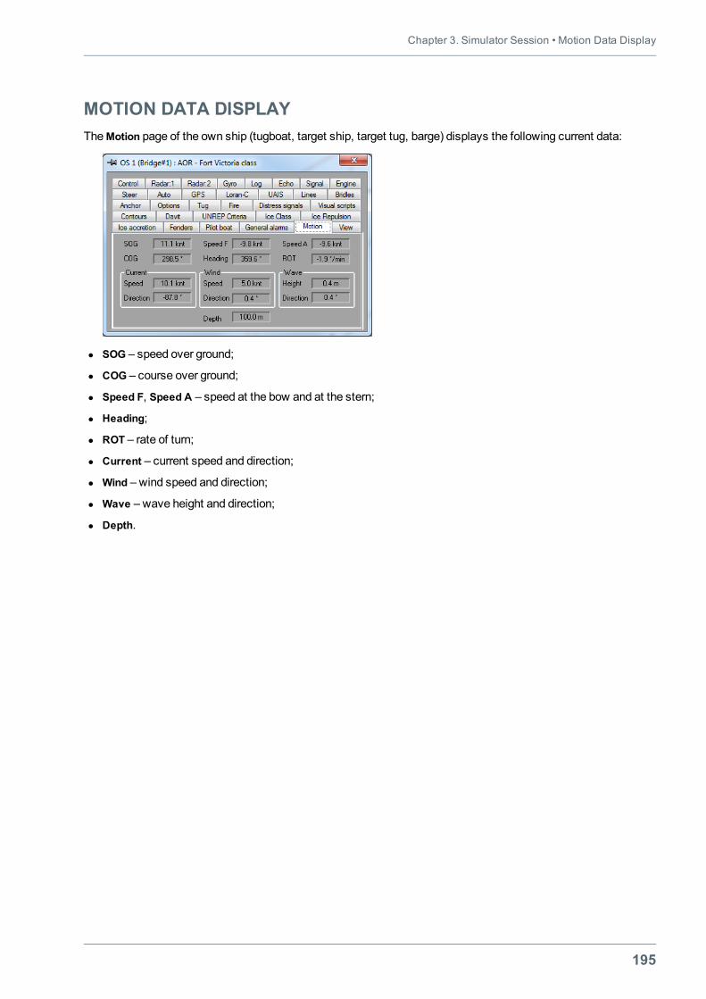
Chapter 3. Simulator Session • Motion Data Display
195
MOTION DATA DISPLAYTheMotion page of the own ship (tugboat, target ship, target tug, barge) displays the following current data:
l SOG – speed over ground;
l COG – course over ground;
l Speed F, Speed A – speed at the bow and at the stern;
l Heading;
l ROT – rate of turn;
l Current – current speed and direction;
l Wind – wind speed and direction;
l Wave – wave height and direction;
l Depth.
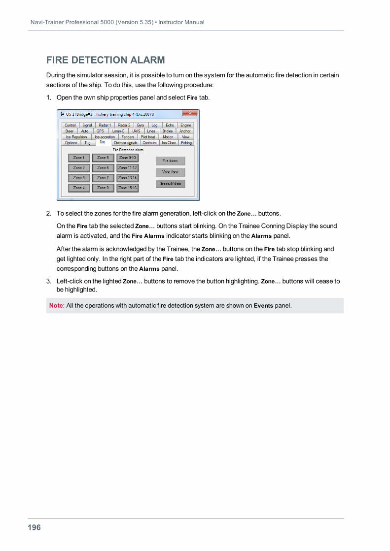
Navi-Trainer Professional 5000 (Version 5.35) • Instructor Manual
196
FIRE DETECTION ALARMDuring the simulator session, it is possible to turn on the system for the automatic fire detection in certainsections of the ship. To do this, use the following procedure:
1. Open the own ship properties panel and select Fire tab.
2. To select the zones for the fire alarm generation, left-click on the Zone… buttons.
On the Fire tab the selected Zone… buttons start blinking. On the Trainee Conning Display the soundalarm is activated, and the Fire Alarms indicator starts blinking on theAlarms panel.
After the alarm is acknowledged by the Trainee, the Zone… buttons on the Fire tab stop blinking andget lighted only. In the right part of the Fire tab the indicators are lighted, if the Trainee presses thecorresponding buttons on theAlarms panel.
3. Left-click on the lighted Zone… buttons to remove the button highlighting. Zone… buttons will cease tobe highlighted.
Note: All the operations with automatic fire detection system are shown on Events panel.
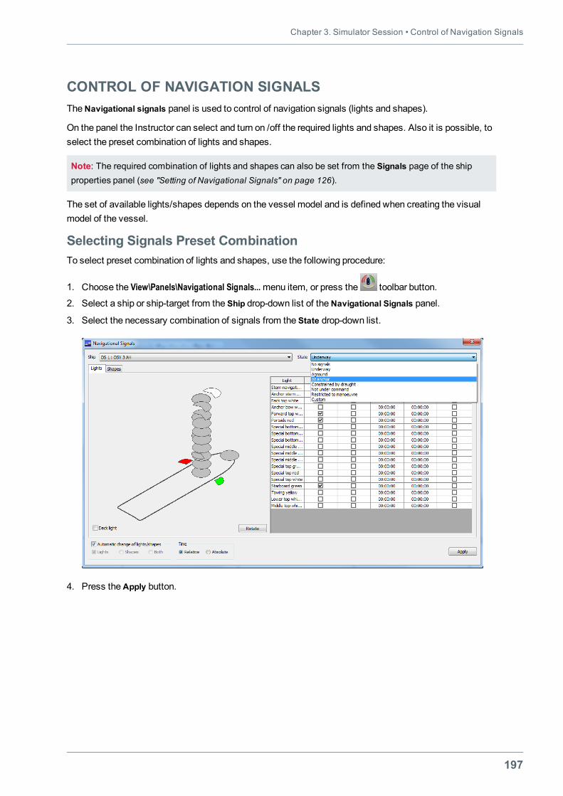
Chapter 3. Simulator Session • Control of Navigation Signals
197
CONTROL OF NAVIGATION SIGNALSTheNavigational signals panel is used to control of navigation signals (lights and shapes).
On the panel the Instructor can select and turn on /off the required lights and shapes. Also it is possible, toselect the preset combination of lights and shapes.
Note: The required combination of lights and shapes can also be set from the Signals page of the shipproperties panel (see "Setting of Navigational Signals" on page 126).
The set of available lights/shapes depends on the vessel model and is defined when creating the visualmodel of the vessel.
Selecting Signals Preset CombinationTo select preset combination of lights and shapes, use the following procedure:
1. Choose the View\Panels\Navigational Signals...menu item, or press the toolbar button.
2. Select a ship or ship-target from the Ship drop-down list of theNavigational Signals panel.
3. Select the necessary combination of signals from the State drop-down list.
4. Press theApply button.
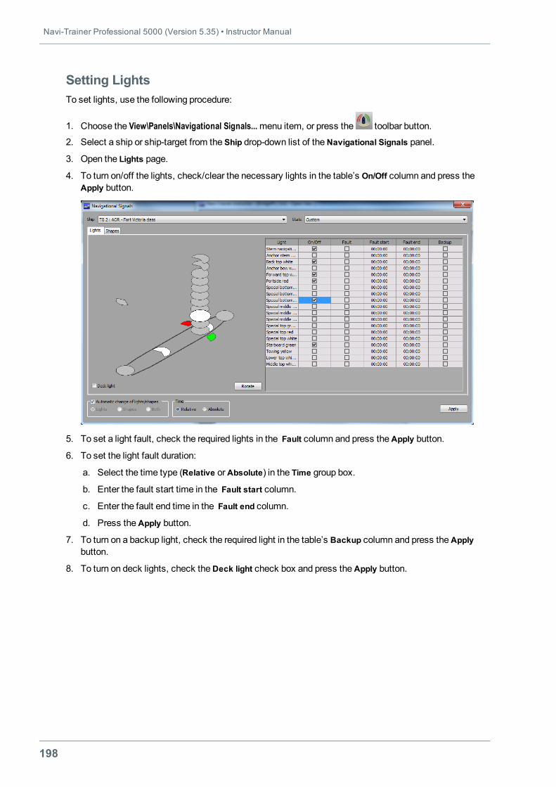
Navi-Trainer Professional 5000 (Version 5.35) • Instructor Manual
198
Setting LightsTo set lights, use the following procedure:
1. Choose the View\Panels\Navigational Signals...menu item, or press the toolbar button.
2. Select a ship or ship-target from the Ship drop-down list of theNavigational Signals panel.
3. Open the Lights page.
4. To turn on/off the lights, check/clear the necessary lights in the table’s On/Off column and press theApply button.
5. To set a light fault, check the required lights in the Fault column and press theApply button.
6. To set the light fault duration:
a. Select the time type (Relative orAbsolute) in the Time group box.
b. Enter the fault start time in the Fault start column.
c. Enter the fault end time in the Fault end column.
d. Press theApply button.
7. To turn on a backup light, check the required light in the table’s Backup column and press theApplybutton.
8. To turn on deck lights, check theDeck light check box and press theApply button.
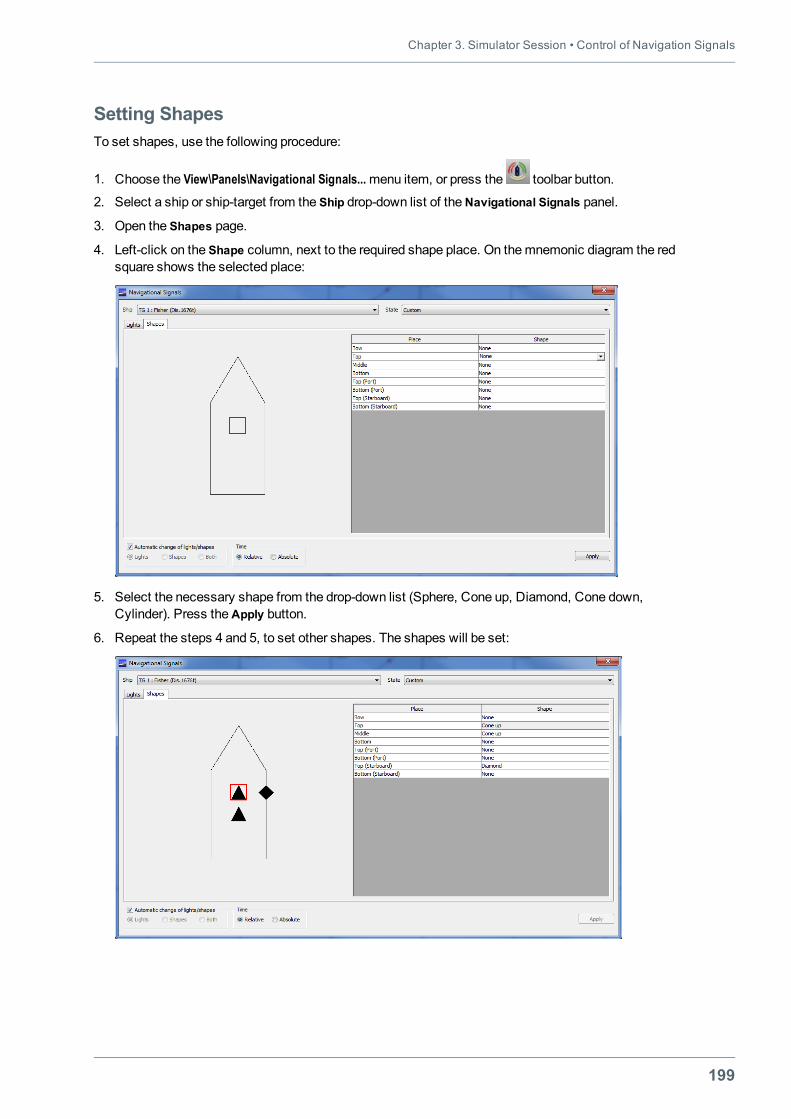
Chapter 3. Simulator Session • Control of Navigation Signals
199
Setting ShapesTo set shapes, use the following procedure:
1. Choose the View\Panels\Navigational Signals...menu item, or press the toolbar button.
2. Select a ship or ship-target from the Ship drop-down list of theNavigational Signals panel.
3. Open the Shapes page.
4. Left-click on the Shape column, next to the required shape place. On themnemonic diagram the redsquare shows the selected place:
5. Select the necessary shape from the drop-down list (Sphere, Cone up, Diamond, Cone down,Cylinder). Press theApply button.
6. Repeat the steps 4 and 5, to set other shapes. The shapes will be set:

Navi-Trainer Professional 5000 (Version 5.35) • Instructor Manual
200
Change of Lights and ShapesBy default, the navigational shapes are automatically replaced with navigational lights at night or in lowvisibility (fog).
The instructor can disable the automatic change of navigation signals and specify which navigation signalwill be displayed regardless of day time and visibility conditions. To do this, use the following procedure:
1. Choose the View\Panels\Navigational Signals...menu item, or press the toolbar button.
2. Clear theAutomatic change of lights/shapes check box.
3. Select the required type of the navigational signal: Lights/Shapes/Both.
4. Press theApply button.
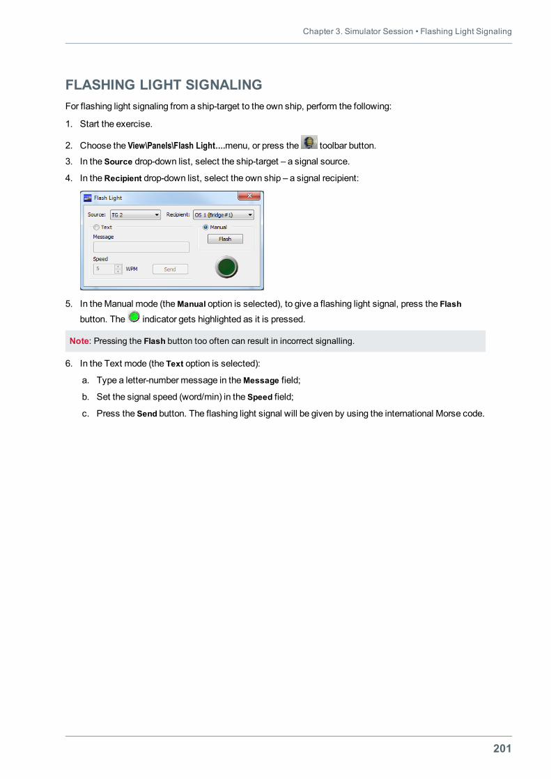
Chapter 3. Simulator Session • Flashing Light Signaling
201
FLASHING LIGHT SIGNALINGFor flashing light signaling from a ship-target to the own ship, perform the following:
1. Start the exercise.
2. Choose the View\Panels\Flash Light….menu, or press the toolbar button.
3. In the Source drop-down list, select the ship-target – a signal source.
4. In theRecipient drop-down list, select the own ship – a signal recipient:
5. In theManual mode (theManual option is selected), to give a flashing light signal, press the Flash
button. The indicator gets highlighted as it is pressed.
Note: Pressing the Flash button too often can result in incorrect signalling.
6. In the Text mode (the Text option is selected):
a. Type a letter-numbermessage in theMessage field;
b. Set the signal speed (word/min) in the Speed field;
c. Press the Send button. The flashing light signal will be given by using the international Morse code.
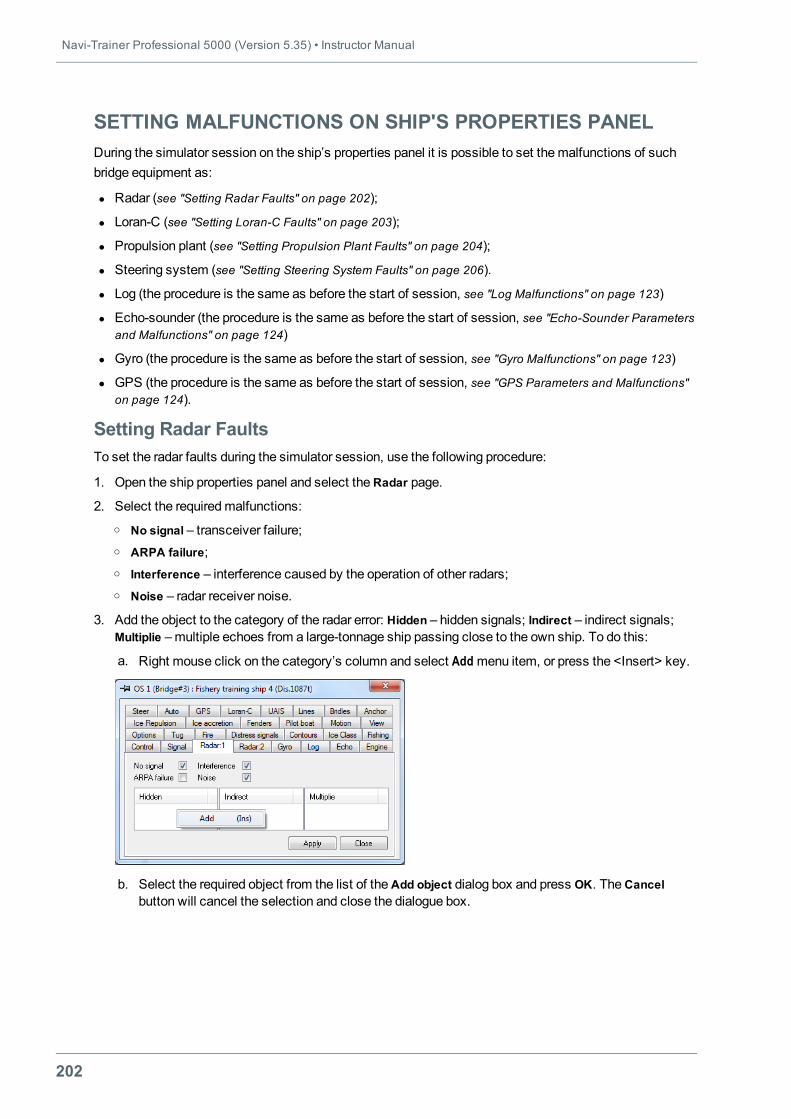
Navi-Trainer Professional 5000 (Version 5.35) • Instructor Manual
202
SETTING MALFUNCTIONS ON SHIP'S PROPERTIES PANELDuring the simulator session on the ship’s properties panel it is possible to set themalfunctions of suchbridge equipment as:
l Radar (see "Setting Radar Faults" on page 202);
l Loran-C (see "Setting Loran-С Faults" on page 203);
l Propulsion plant (see "Setting Propulsion Plant Faults" on page 204);
l Steering system (see "Setting Steering System Faults" on page 206).
l Log (the procedure is the same as before the start of session, see "Log Malfunctions" on page 123)
l Echo-sounder (the procedure is the same as before the start of session, see "Echo-Sounder Parametersand Malfunctions" on page 124)
l Gyro (the procedure is the same as before the start of session, see "Gyro Malfunctions" on page 123)
l GPS (the procedure is the same as before the start of session, see "GPS Parameters and Malfunctions"on page 124).
Setting Radar FaultsTo set the radar faults during the simulator session, use the following procedure:
1. Open the ship properties panel and select theRadar page.
2. Select the requiredmalfunctions:o No signal – transceiver failure;o ARPA failure;o Interference – interference caused by the operation of other radars;o Noise – radar receiver noise.
3. Add the object to the category of the radar error: Hidden – hidden signals; Indirect – indirect signals;Multiplie –multiple echoes from a large-tonnage ship passing close to the own ship. To do this:
a. Right mouse click on the category’s column and select Add menu item, or press the <Insert> key.
b. Select the required object from the list of theAdd object dialog box and press OK. TheCancelbutton will cancel the selection and close the dialogue box.
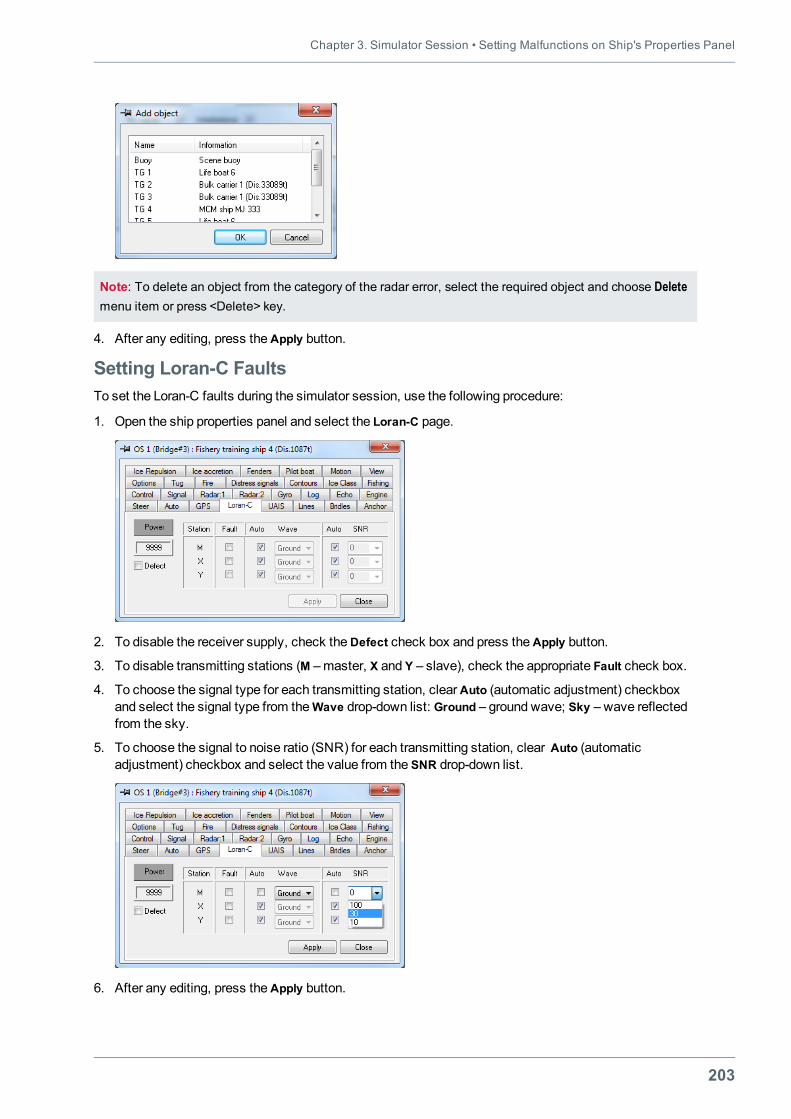
Chapter 3. Simulator Session • Setting Malfunctions on Ship's Properties Panel
203
Note: To delete an object from the category of the radar error, select the required object and choose Deletemenu item or press <Delete> key.
4. After any editing, press theApply button.
Setting Loran-С FaultsTo set the Loran-С faults during the simulator session, use the following procedure:
1. Open the ship properties panel and select the Loran-C page.
2. To disable the receiver supply, check theDefect check box and press the Apply button.
3. To disable transmitting stations (M –master, X and Y – slave), check the appropriate Fault check box.
4. To choose the signal type for each transmitting station, clearAuto (automatic adjustment) checkboxand select the signal type from theWave drop-down list: Ground – ground wave; Sky – wave reflectedfrom the sky.
5. To choose the signal to noise ratio (SNR) for each transmitting station, clear Auto (automaticadjustment) checkbox and select the value from the SNR drop-down list.
6. After any editing, press theApply button.
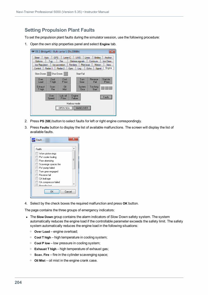
Navi-Trainer Professional 5000 (Version 5.35) • Instructor Manual
204
Setting Propulsion Plant FaultsTo set the propulsion plant faults during the simulator session, use the following procedure:
1. Open the own ship properties panel and select Engine tab.
2. Press PS (SB) button to select faults for left or right engine correspondingly.
3. Press Faults button to display the list of available malfunctions. The screen will display the list ofavailable faults.
4. Select by the check boxes the requiredmalfunction and press OK button.
The page contains the three groups of emergency indicators:
l The Slow Down group contains the alarm indicators of Slow Down safety system. The systemautomatically reduces the engine load if the controllable parameter exceeds the safety limit. The safetysystem automatically reduces the engine load in the following situations:o Over Load – engine overload;o Cool T high – high temperature in cooling system;o Cool P low – low pressure in cooling system;o Exhaust T high – high temperature of exhaust gas;o Scav. Fire – fire in the cylinder scavenging space;o Oil Mist – oil mist in the engine crank case.
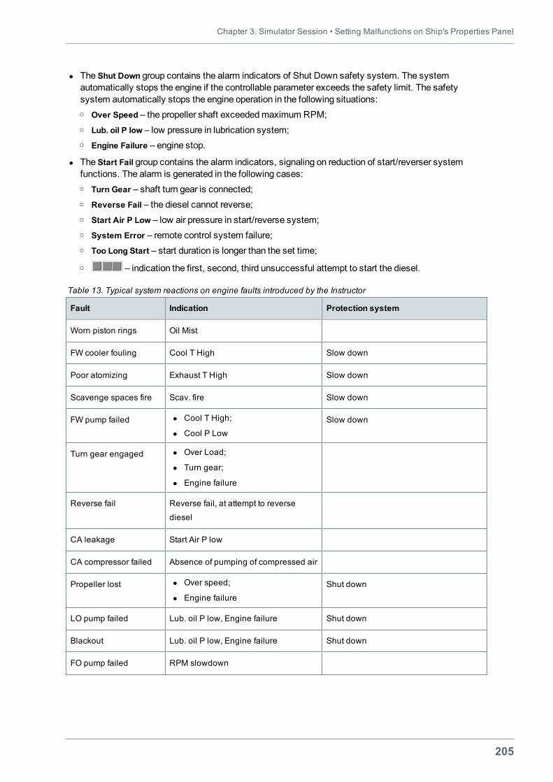
Chapter 3. Simulator Session • Setting Malfunctions on Ship's Properties Panel
205
l The Shut Down group contains the alarm indicators of Shut Down safety system. The systemautomatically stops the engine if the controllable parameter exceeds the safety limit. The safetysystem automatically stops the engine operation in the following situations:o Over Speed – the propeller shaft exceededmaximum RPM;o Lub. oil P low – low pressure in lubrication system;o Engine Failure – engine stop.
l The Start Fail group contains the alarm indicators, signaling on reduction of start/reverser systemfunctions. The alarm is generated in the following cases:o Turn Gear – shaft turn gear is connected;o Reverse Fail – the diesel cannot reverse;o Start Air P Low – low air pressure in start/reverse system;o System Error – remote control system failure;o Too Long Start – start duration is longer than the set time;
o – indication the first, second, third unsuccessful attempt to start the diesel.
Fault Indication Protection system
Worn piston rings Oil Mist
FW cooler fouling Cool T High Slow down
Poor atomizing Exhaust T High Slow down
Scavenge spaces fire Scav. fire Slow down
FW pump failed l Cool T High;
l Cool P LowSlow down
Turn gear engaged l Over Load;
l Turn gear;
l Engine failure
Reverse fail Reverse fail, at attempt to reverse
diesel
CA leakage Start Air P low
CA compressor failed Absence of pumping of compressed air
Propeller lost l Over speed;
l Engine failureShut down
LO pump failed Lub. oil P low, Engine failure Shut down
Blackout Lub. oil P low, Engine failure Shut down
FO pump failed RPM slowdown
Table 13. Typical system reactions on engine faults introduced by the Instructor
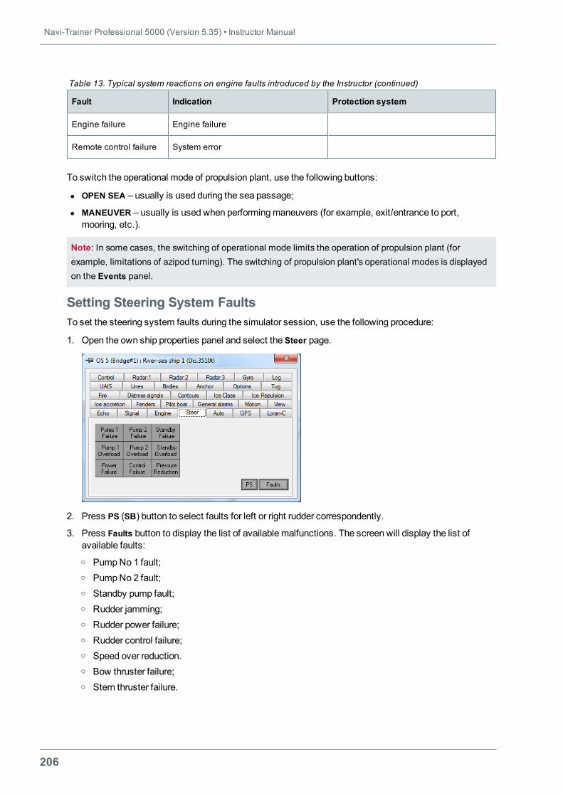
Navi-Trainer Professional 5000 (Version 5.35) • Instructor Manual
206
Fault Indication Protection system
Engine failure Engine failure
Remote control failure System error
Table 13. Typical system reactions on engine faults introduced by the Instructor (continued)
To switch the operational mode of propulsion plant, use the following buttons:
l OPEN SEA – usually is used during the sea passage;
l MANEUVER – usually is used when performingmaneuvers (for example, exit/entrance to port,mooring, etc.).
Note: In some cases, the switching of operational mode limits the operation of propulsion plant (forexample, limitations of azipod turning). The switching of propulsion plant's operational modes is displayedon the Events panel.
Setting Steering System FaultsTo set the steering system faults during the simulator session, use the following procedure:
1. Open the own ship properties panel and select the Steer page.
2. Press PS (SB) button to select faults for left or right rudder correspondently.
3. Press Faults button to display the list of available malfunctions. The screen will display the list ofavailable faults:o PumpNo 1 fault;o PumpNo 2 fault;o Standby pump fault;o Rudder jamming;o Rudder power failure;o Rudder control failure;o Speed over reduction.o Bow thruster failure;o Stern thruster failure.
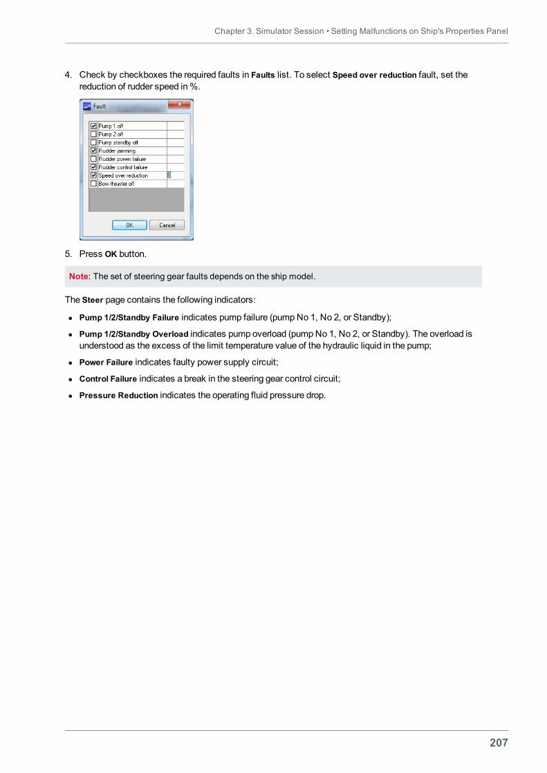
Chapter 3. Simulator Session • Setting Malfunctions on Ship's Properties Panel
207
4. Check by checkboxes the required faults in Faults list. To select Speed over reduction fault, set thereduction of rudder speed in%.
5. Press OK button.
Note: The set of steering gear faults depends on the ship model.
The Steer page contains the following indicators:
l Pump 1/2/Standby Failure indicates pump failure (pumpNo 1, No 2, or Standby);
l Pump 1/2/Standby Overload indicates pump overload (pumpNo 1, No 2, or Standby). The overload isunderstood as the excess of the limit temperature value of the hydraulic liquid in the pump;
l Power Failure indicates faulty power supply circuit;
l Control Failure indicates a break in the steering gear control circuit;
l Pressure Reduction indicates the operating fluid pressure drop.
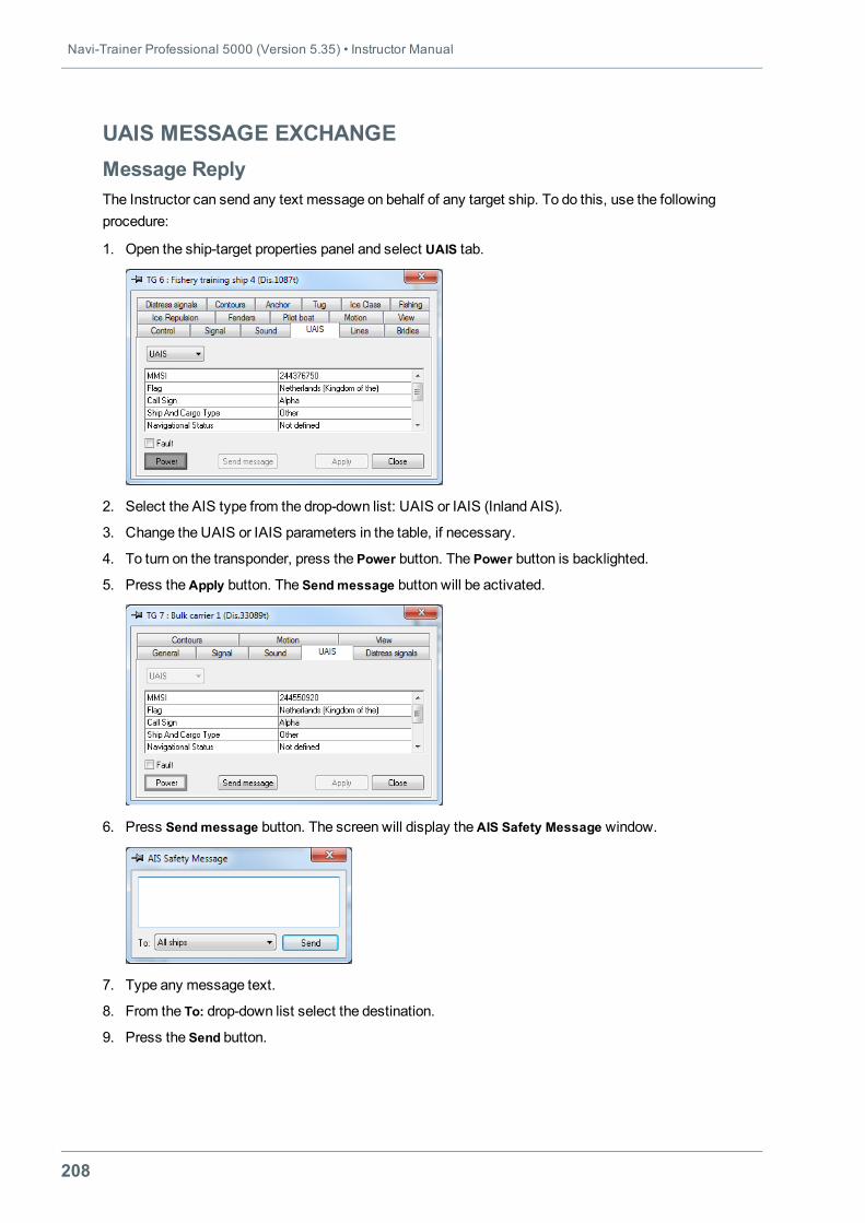
Navi-Trainer Professional 5000 (Version 5.35) • Instructor Manual
208
UAIS MESSAGE EXCHANGEMessage ReplyThe Instructor can send any text message on behalf of any target ship. To do this, use the followingprocedure:
1. Open the ship-target properties panel and select UAIS tab.
2. Select the AIS type from the drop-down list: UAIS or IAIS (Inland AIS).
3. Change the UAIS or IAIS parameters in the table, if necessary.
4. To turn on the transponder, press the Power button. The Power button is backlighted.
5. Press theApply button. The Sendmessage button will be activated.
6. Press Sendmessage button. The screen will display theAIS Safety Message window.
7. Type any message text.
8. From the To: drop-down list select the destination.
9. Press the Send button.
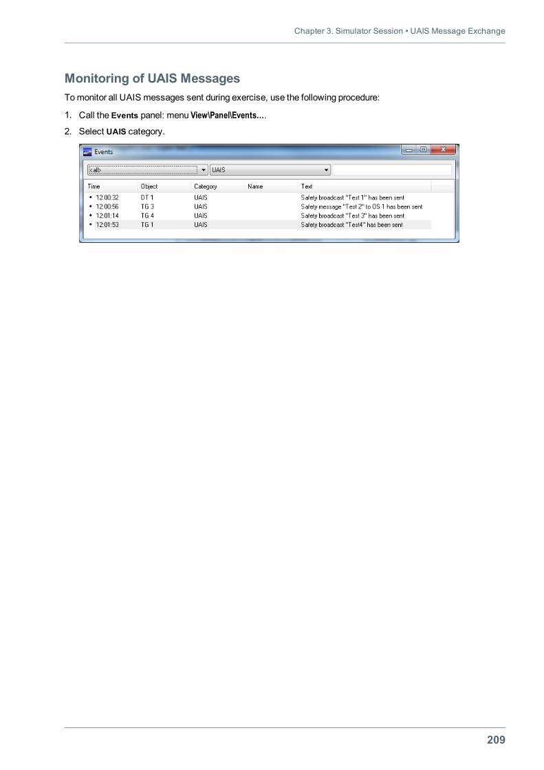
Chapter 3. Simulator Session • UAIS Message Exchange
209
Monitoring of UAIS MessagesTomonitor all UAIS messages sent during exercise, use the following procedure:
1. Call the Events panel: menu View\Panel\Events….
2. Select UAIS category.
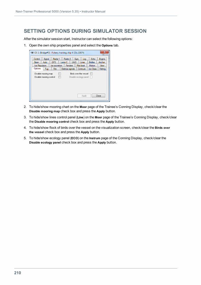
Navi-Trainer Professional 5000 (Version 5.35) • Instructor Manual
210
SETTING OPTIONS DURING SIMULATOR SESSIONAfter the simulator session start, Instructor can select the following options:
1. Open the own ship properties panel and select theOptions tab.
2. To hide/show mooring chart on theMoor page of the Trainee’s Conning Display, check/clear theDisable mooring map check box and press theApply button.
3. To hide/show lines control panel (Line) on theMoor page of the Trainee’s Conning Display, check/cleartheDisable mooring control check box and press the Apply button.
4. To hide/show flock of birds over the vessel on the visualization screen, check/clear theBirds overthe vessel check box and press the Apply button.
5. To hide/show ecology panel (ECO) on the Instrum page of the Conning Display, check/clear theDisable ecology panel check box and press theApply button.
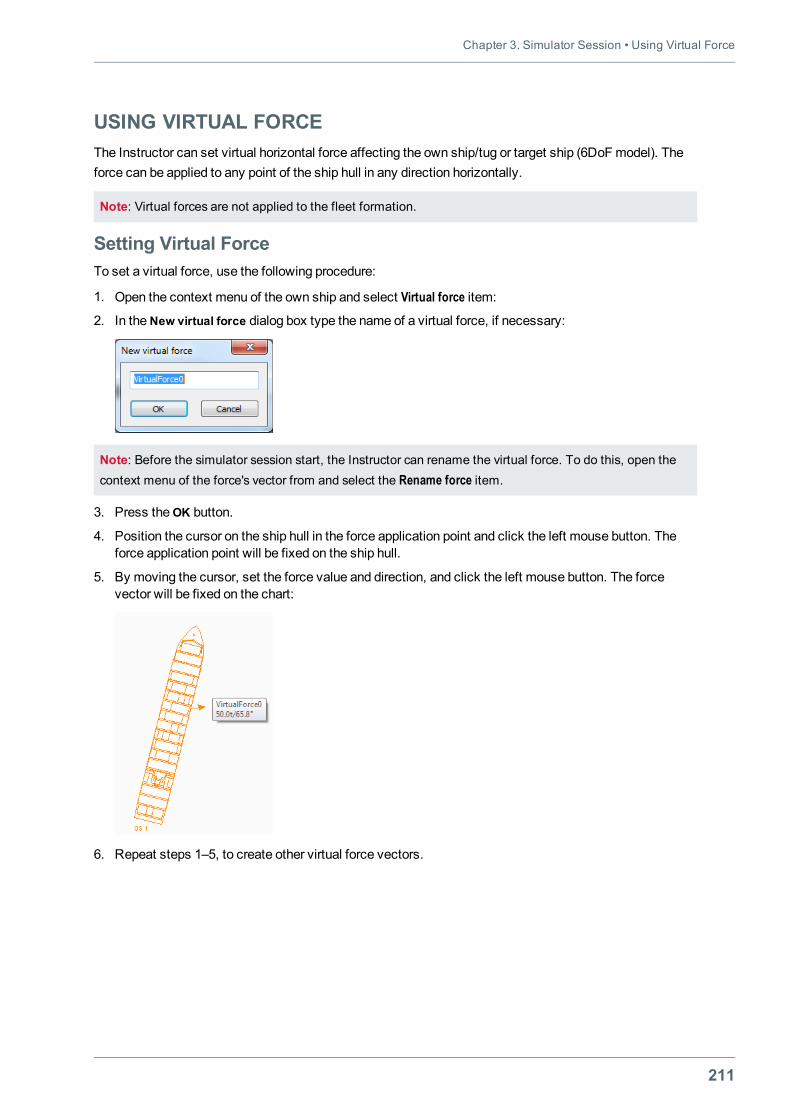
Chapter 3. Simulator Session • Using Virtual Force
211
USING VIRTUAL FORCEThe Instructor can set virtual horizontal force affecting the own ship/tug or target ship (6DoF model). Theforce can be applied to any point of the ship hull in any direction horizontally.
Note: Virtual forces are not applied to the fleet formation.
Setting Virtual ForceTo set a virtual force, use the following procedure:
1. Open the context menu of the own ship and select Virtual force item:
2. In theNew virtual force dialog box type the name of a virtual force, if necessary:
Note: Before the simulator session start, the Instructor can rename the virtual force. To do this, open thecontext menu of the force's vector from and select the Rename force item.
3. Press theOK button.
4. Position the cursor on the ship hull in the force application point and click the left mouse button. Theforce application point will be fixed on the ship hull.
5. By moving the cursor, set the force value and direction, and click the left mouse button. The forcevector will be fixed on the chart:
6. Repeat steps 1–5, to create other virtual force vectors.
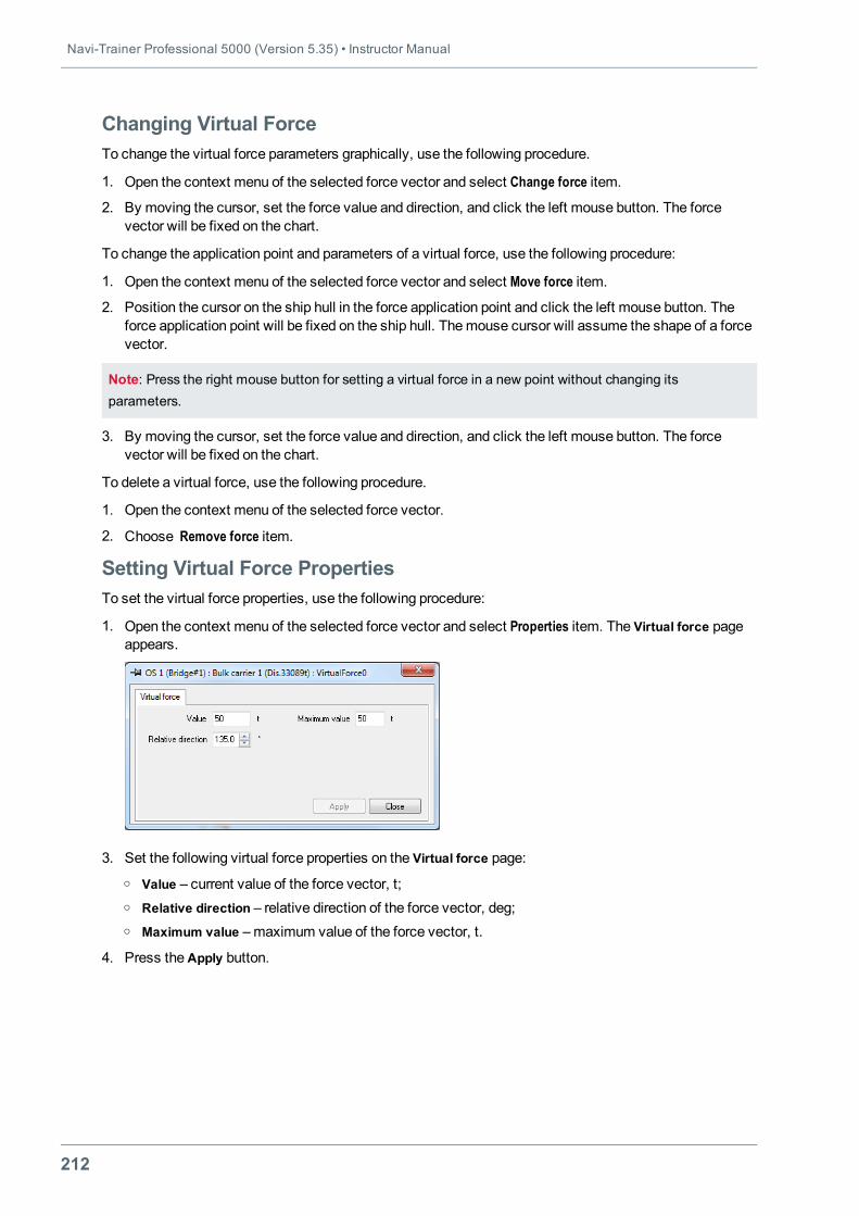
Navi-Trainer Professional 5000 (Version 5.35) • Instructor Manual
212
Changing Virtual ForceTo change the virtual force parameters graphically, use the following procedure.
1. Open the context menu of the selected force vector and select Change force item.
2. By moving the cursor, set the force value and direction, and click the left mouse button. The forcevector will be fixed on the chart.
To change the application point and parameters of a virtual force, use the following procedure:
1. Open the context menu of the selected force vector and select Move force item.
2. Position the cursor on the ship hull in the force application point and click the left mouse button. Theforce application point will be fixed on the ship hull. Themouse cursor will assume the shape of a forcevector.
Note: Press the right mouse button for setting a virtual force in a new point without changing itsparameters.
3. By moving the cursor, set the force value and direction, and click the left mouse button. The forcevector will be fixed on the chart.
To delete a virtual force, use the following procedure.
1. Open the context menu of the selected force vector.
2. Choose Remove force item.
Setting Virtual Force PropertiesTo set the virtual force properties, use the following procedure:
1. Open the context menu of the selected force vector and select Properties item. The Virtual force pageappears.
3. Set the following virtual force properties on the Virtual force page:o Value – current value of the force vector, t;o Relative direction – relative direction of the force vector, deg;o Maximum value –maximum value of the force vector, t.
4. Press theApply button.
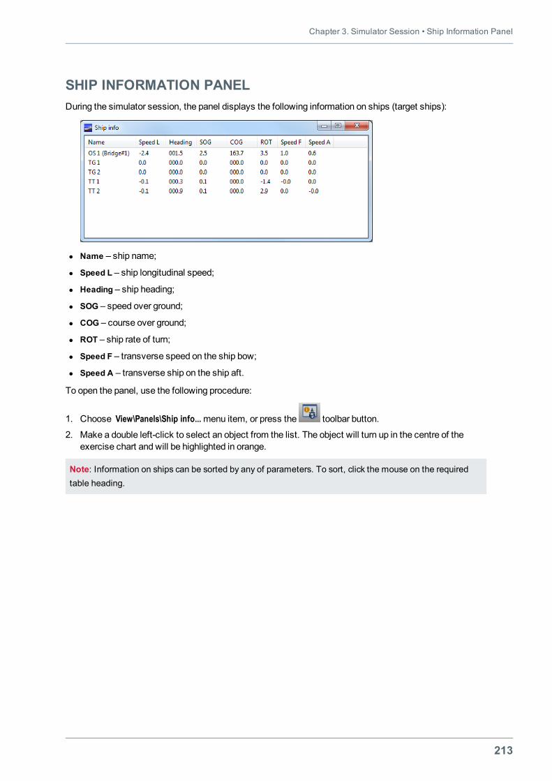
Chapter 3. Simulator Session • Ship Information Panel
213
SHIP INFORMATION PANELDuring the simulator session, the panel displays the following information on ships (target ships):
l Name – ship name;
l Speed L – ship longitudinal speed;
l Heading – ship heading;
l SOG – speed over ground;
l COG – course over ground;
l ROT – ship rate of turn;
l Speed F – transverse speed on the ship bow;
l Speed A – transverse ship on the ship aft.
To open the panel, use the following procedure:
1. Choose View\Panels\Ship info...menu item, or press the toolbar button.
2. Make a double left-click to select an object from the list. The object will turn up in the centre of theexercise chart and will be highlighted in orange.
Note: Information on ships can be sorted by any of parameters. To sort, click the mouse on the requiredtable heading.

Navi-Trainer Professional 5000 (Version 5.35) • Instructor Manual
214
EVENTS PANELThe Events panel displays the list of events, which take place during the simulator session.
To show the Events panel, choose the View\Panels\Events…menu item, or press the toolbar button.
The table of Events panel contains:
l Time – event time;
l Object – exercise object, with which the event is associated;
l Category – event type;
l Name – event name;
l Text – tag text.
The events in table may be sorted by object type (Object), event type (Category), or comment (Text). Tosort the events in table, use the following procedure:
1. Select the ship name from the left drop-down list, to sort events by object.
2. Select event category from themiddle drop-down list, to sort events by category.
3. Type the "key word" in the right text box, to sort events by text comment.
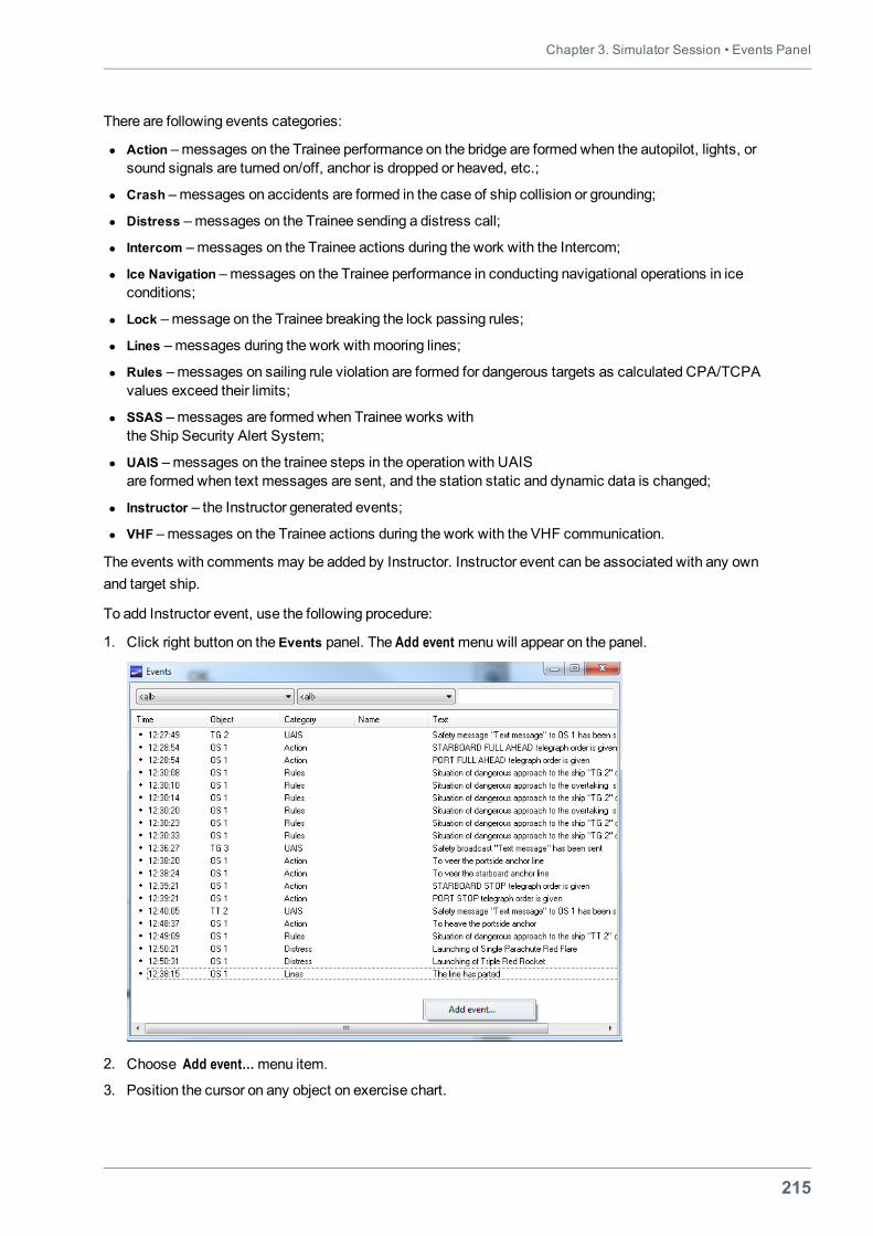
Chapter 3. Simulator Session • Events Panel
215
There are following events categories:
l Action –messages on the Trainee performance on the bridge are formed when the autopilot, lights, orsound signals are turned on/off, anchor is dropped or heaved, etc.;
l Crash –messages on accidents are formed in the case of ship collision or grounding;
l Distress –messages on the Trainee sending a distress call;
l Intercom –messages on the Trainee actions during the work with the Intercom;
l Ice Navigation –messages on the Trainee performance in conducting navigational operations in iceconditions;
l Lock –message on the Trainee breaking the lock passing rules;
l Lines –messages during the work with mooring lines;
l Rules –messages on sailing rule violation are formed for dangerous targets as calculated CPA/TCPAvalues exceed their limits;
l SSAS –messages are formed when Trainee works withthe Ship Security Alert System;
l UAIS –messages on the trainee steps in the operation with UAISare formed when text messages are sent, and the station static and dynamic data is changed;
l Instructor – the Instructor generated events;
l VHF –messages on the Trainee actions during the work with the VHF communication.
The events with comments may be added by Instructor. Instructor event can be associated with any ownand target ship.
To add Instructor event, use the following procedure:
1. Click right button on the Events panel. The Add event menuwill appear on the panel.
2. Choose Add event…menu item.
3. Position the cursor on any object on exercise chart.
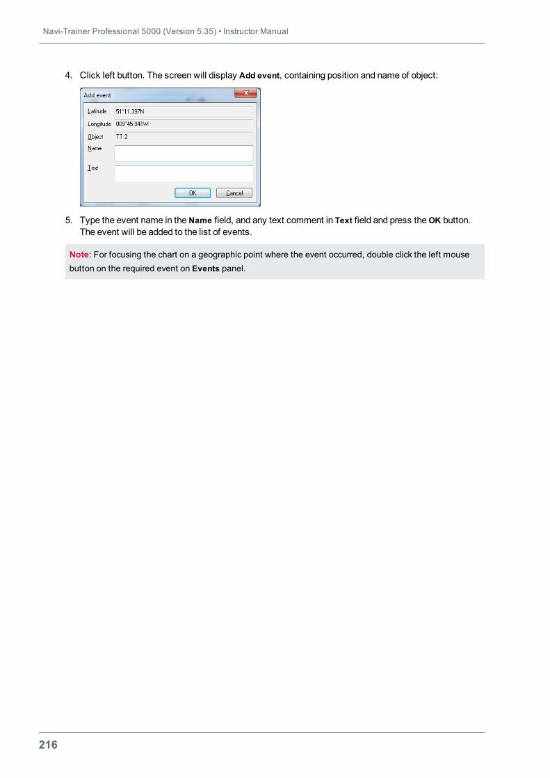
Navi-Trainer Professional 5000 (Version 5.35) • Instructor Manual
216
4. Click left button. The screen will display Add event, containing position and name of object:
5. Type the event name in theName field, and any text comment in Text field and press theOK button.The event will be added to the list of events.
Note: For focusing the chart on a geographic point where the event occurred, double click the left mousebutton on the required event on Events panel.
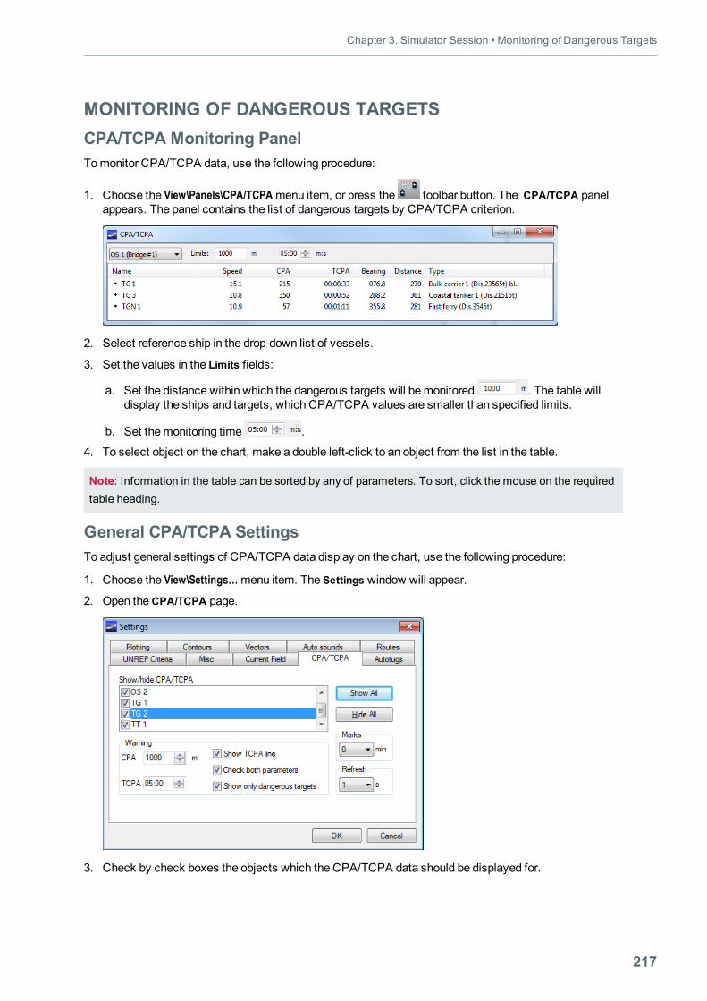
Chapter 3. Simulator Session • Monitoring of Dangerous Targets
217
MONITORING OF DANGEROUS TARGETSCPA/TCPA Monitoring PanelTomonitor CPA/TCPA data, use the following procedure:
1. Choose the View\Panels\CPA/TCPAmenu item, or press the toolbar button. The CPA/TCPA panelappears. The panel contains the list of dangerous targets by CPA/TCPA criterion.
2. Select reference ship in the drop-down list of vessels.
3. Set the values in the Limits fields:
a. Set the distance within which the dangerous targets will bemonitored . The table willdisplay the ships and targets, which CPA/TCPA values are smaller than specified limits.
b. Set themonitoring time .
4. To select object on the chart, make a double left-click to an object from the list in the table.
Note: Information in the table can be sorted by any of parameters. To sort, click the mouse on the requiredtable heading.
General CPA/TCPA SettingsTo adjust general settings of CPA/TCPA data display on the chart, use the following procedure:
1. Choose the View\Settings…menu item. The Settings window will appear.
2. Open theCPA/TCPA page.
3. Check by check boxes the objects which the CPA/TCPA data should be displayed for.
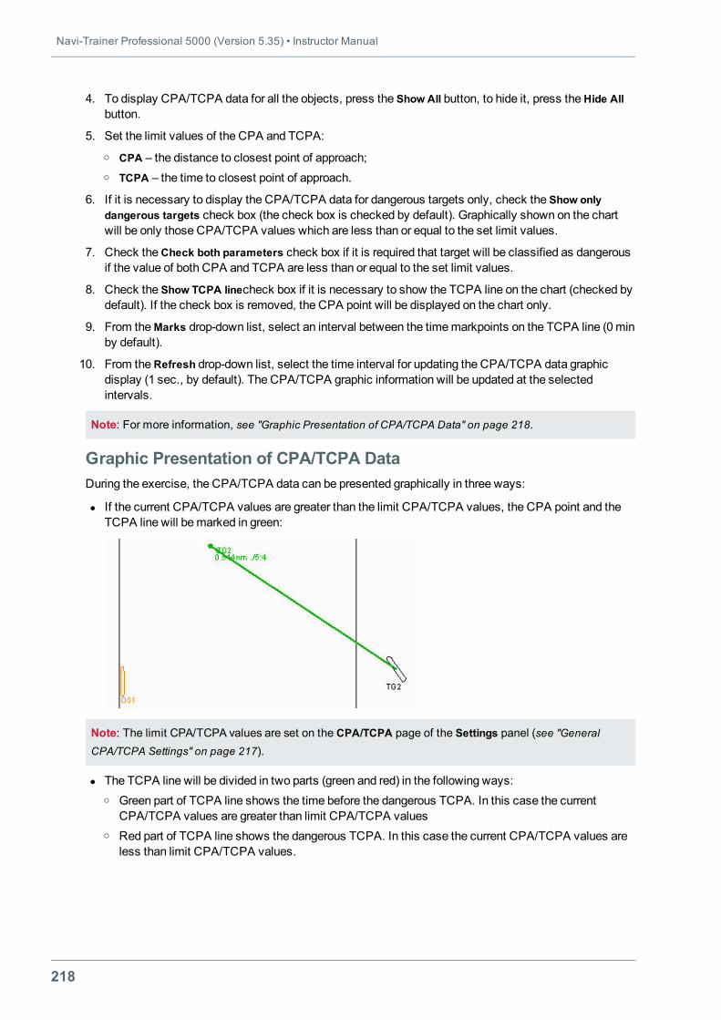
Navi-Trainer Professional 5000 (Version 5.35) • Instructor Manual
218
4. To display CPA/TCPA data for all the objects, press the Show All button, to hide it, press theHide Allbutton.
5. Set the limit values of the CPA and TCPA:o CPA – the distance to closest point of approach;o TCPA – the time to closest point of approach.
6. If it is necessary to display the СРА/ТСРА data for dangerous targets only, check the Show onlydangerous targets check box (the check box is checked by default). Graphically shown on the chartwill be only those CPA/TCPA values which are less than or equal to the set limit values.
7. Check theCheck both parameters check box if it is required that target will be classified as dangerousif the value of both СРА and ТСРА are less than or equal to the set limit values.
8. Check the Show TCPA linecheck box if it is necessary to show the ТСРА line on the chart (checked bydefault). If the check box is removed, the CPA point will be displayed on the chart only.
9. From theMarks drop-down list, select an interval between the timemarkpoints on the ТСРА line (0minby default).
10. From theRefresh drop-down list, select the time interval for updating the СРА/ТСРА data graphicdisplay (1 sec., by default). The СРА/ТСРА graphic information will be updated at the selectedintervals.
Note: For more information, see "Graphic Presentation of СРА/ТСРА Data" on page 218.
Graphic Presentation of СРА/ТСРА DataDuring the exercise, the СРА/ТСРА data can be presented graphically in three ways:
l If the current СРА/ТСРА values are greater than the limit СРА/ТСРА values, the СРА point and theТСРА line will bemarked in green:
Note: The limit CPA/TCPA values are set on the CPA/TCPA page of the Settings panel (see "GeneralCPA/TCPA Settings" on page 217).
l The ТСРА line will be divided in two parts (green and red) in the following ways:o Green part of ТСРА line shows the time before the dangerous ТСРА. In this case the current
СРА/ТСРА values are greater than limit СРА/ТСРА valueso Red part of ТСРА line shows the dangerous ТСРА. In this case the current СРА/ТСРА values are
less than limit СРА/ТСРА values.
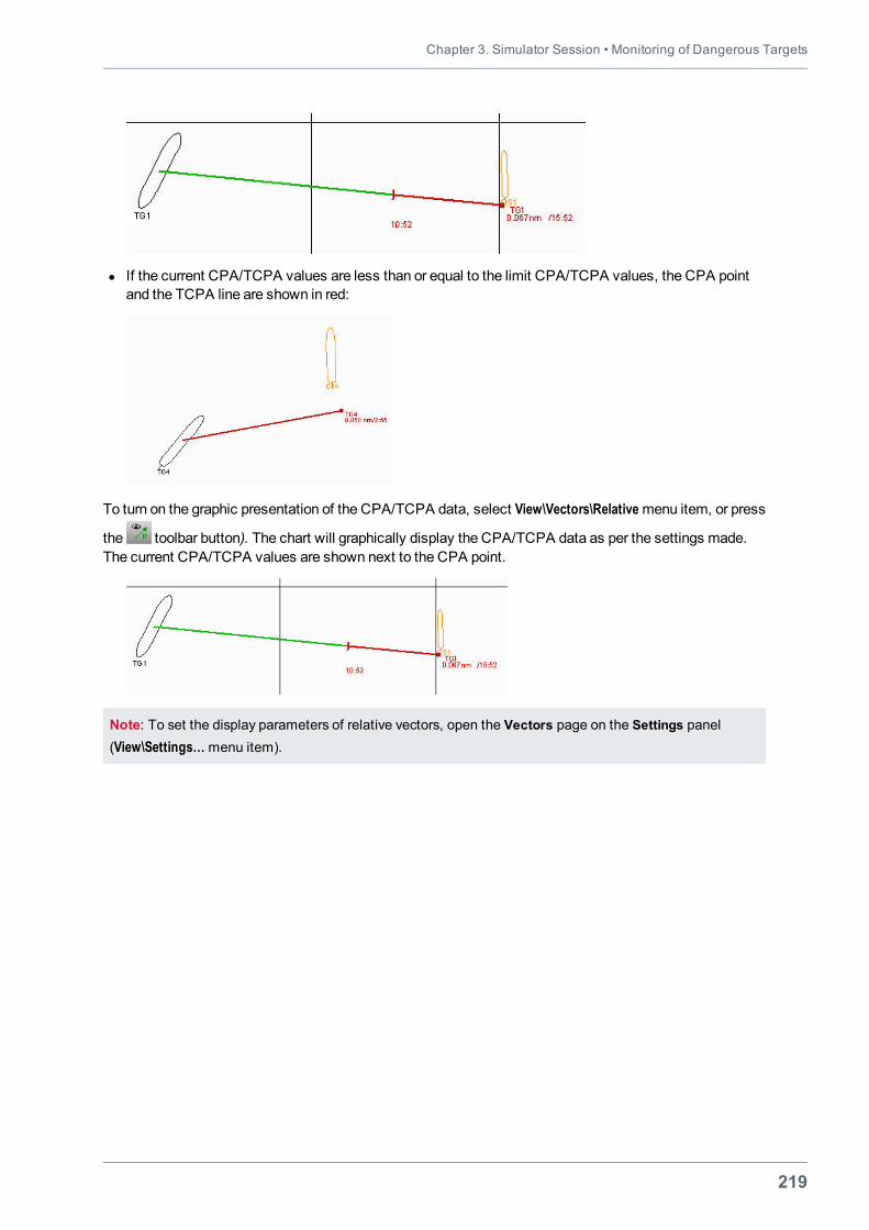
Chapter 3. Simulator Session • Monitoring of Dangerous Targets
219
l If the current СРА/ТСРА values are less than or equal to the limit СРА/ТСРА values, the CРА pointand the ТСРА line are shown in red:
To turn on the graphic presentation of the СРА/ТСРА data, select View\Vectors\Relativemenu item, or press
the toolbar button). The chart will graphically display the СРА/ТСРА data as per the settings made.The current CPA/TCPA values are shown next to the СРА point.
Note: To set the display parameters of relative vectors, open the Vectors page on the Settings panel(View\Settings…menu item).
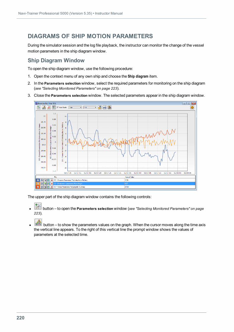
Navi-Trainer Professional 5000 (Version 5.35) • Instructor Manual
220
DIAGRAMS OF SHIP MOTION PARAMETERSDuring the simulator session and the log file playback, the instructor canmonitor the change of the vesselmotion parameters in the ship diagram window.
Ship Diagram WindowTo open the ship diagram window, use the following procedure:
1. Open the context menu of any own ship and choose the Ship diagram item.
2. In the Parameters selectionwindow, select the required parameters for monitoring on the ship diagram(see "Selecting Monitored Parameters" on page 223).
3. Close the Parameters selectionwindow. The selected parameters appear in the ship diagram window.
The upper part of the ship diagram window contains the following controls:
l button – to open the Parameters selectionwindow (see "Selecting Monitored Parameters" on page223).
l button – to show the parameters values on the graph. When the cursor moves along the time axisthe vertical line appears. To the right of this vertical line the prompt window shows the values ofparameters at the selected time.
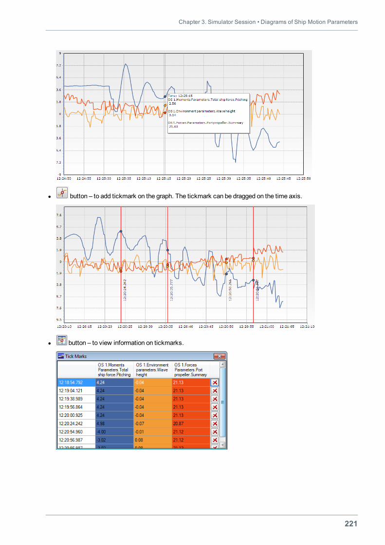
Chapter 3. Simulator Session • Diagrams of Ship Motion Parameters
221
l button – to add tickmark on the graph. The tickmark can be dragged on the time axis.
l button – to view information on tickmarks.
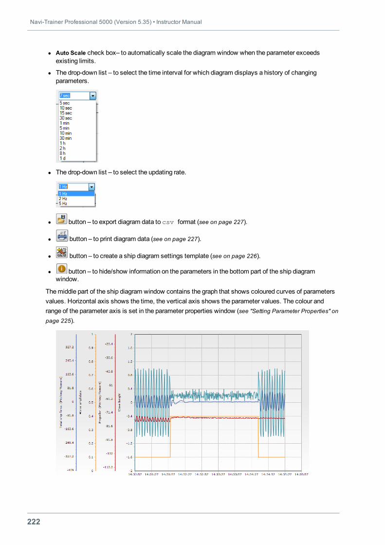
Navi-Trainer Professional 5000 (Version 5.35) • Instructor Manual
222
l Auto Scale check box– to automatically scale the diagram window when the parameter exceedsexisting limits.
l The drop-down list – to select the time interval for which diagram displays a history of changingparameters.
l The drop-down list – to select the updating rate.
l button – to export diagram data to csv format (see on page 227).
l button – to print diagram data (see on page 227).
l button – to create a ship diagram settings template (see on page 226).
l button – to hide/show information on the parameters in the bottom part of the ship diagramwindow.
Themiddle part of the ship diagram window contains the graph that shows coloured curves of parametersvalues. Horizontal axis shows the time, the vertical axis shows the parameter values. The colour andrange of the parameter axis is set in the parameter properties window (see "Setting Parameter Properties" onpage 225).
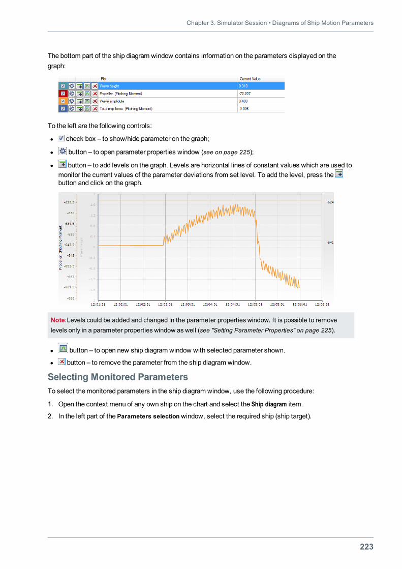
Chapter 3. Simulator Session • Diagrams of Ship Motion Parameters
223
The bottom part of the ship diagram window contains information on the parameters displayed on thegraph:
To the left are the following controls:
l check box – to show/hide parameter on the graph;
l button – to open parameter properties window (see on page 225);
l button – to add levels on the graph. Levels are horizontal lines of constant values which are used tomonitor the current values of the parameter deviations from set level. To add the level, press thebutton and click on the graph.
Note:Levels could be added and changed in the parameter properties window. It is possible to removelevels only in a parameter properties window as well (see "Setting Parameter Properties" on page 225).
l button – to open new ship diagram window with selected parameter shown.
l button – to remove the parameter from the ship diagram window.
Selecting Monitored ParametersTo select themonitored parameters in the ship diagram window, use the following procedure:
1. Open the context menu of any own ship on the chart and select the Ship diagram item.
2. In the left part of the Parameters selectionwindow, select the required ship (ship target).
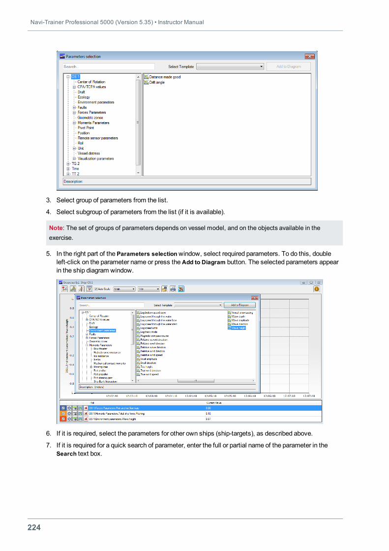
Navi-Trainer Professional 5000 (Version 5.35) • Instructor Manual
224
3. Select group of parameters from the list.
4. Select subgroup of parameters from the list (if it is available).
Note: The set of groups of parameters depends on vessel model, and on the objects available in theexercise.
5. In the right part of the Parameters selectionwindow, select required parameters. To do this, doubleleft-click on the parameter name or press theAdd to Diagram button. The selected parameters appearin the ship diagram window.
6. If it is required, select the parameters for other own ships (ship-targets), as described above.
7. If it is required for a quick search of parameter, enter the full or partial name of the parameter in theSearch text box.
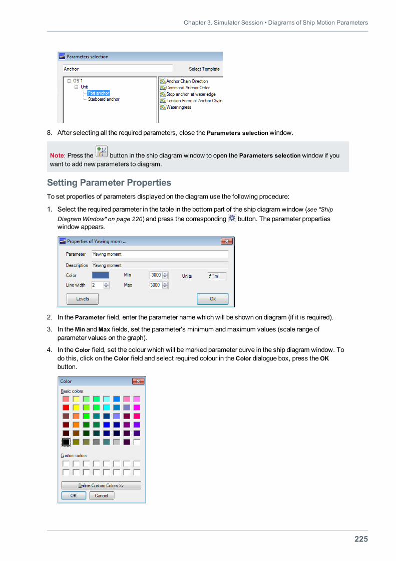
Chapter 3. Simulator Session • Diagrams of Ship Motion Parameters
225
8. After selecting all the required parameters, close the Parameters selectionwindow.
Note: Press the button in the ship diagram window to open the Parameters selectionwindow if youwant to add new parameters to diagram.
Setting Parameter PropertiesTo set properties of parameters displayed on the diagram use the following procedure:
1. Select the required parameter in the table in the bottom part of the ship diagram window (see "ShipDiagram Window" on page 220) and press the corresponding button. The parameter propertieswindow appears.
2. In the Parameter field, enter the parameter namewhich will be shown on diagram (if it is required).
3. In theMin andMax fields, set the parameter's minimum andmaximum values (scale range ofparameter values on the graph).
4. In theColor field, set the colour which will bemarked parameter curve in the ship diagram window. Todo this, click on theColor field and select required colour in theColor dialogue box, press theOKbutton.
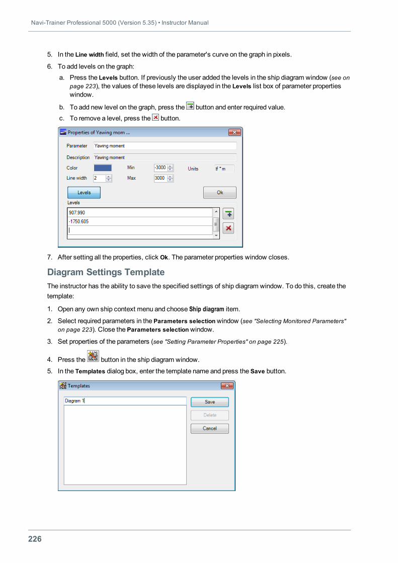
Navi-Trainer Professional 5000 (Version 5.35) • Instructor Manual
226
5. In the Line width field, set the width of the parameter's curve on the graph in pixels.
6. To add levels on the graph:a. Press the Levels button. If previously the user added the levels in the ship diagram window (see on
page 223), the values of these levels are displayed in the Levels list box of parameter propertieswindow.
b. To add new level on the graph, press the button and enter required value.c. To remove a level, press the button.
7. After setting all the properties, click Ok. The parameter properties window closes.
Diagram Settings TemplateThe instructor has the ability to save the specified settings of ship diagram window. To do this, create thetemplate:
1. Open any own ship context menu and choose Ship diagram item.
2. Select required parameters in the Parameters selectionwindow (see "Selecting Monitored Parameters"on page 223). Close the Parameters selectionwindow.
3. Set properties of the parameters (see "Setting Parameter Properties" on page 225).
4. Press the button in the ship diagram window.
5. In the Templates dialog box, enter the template name and press the Save button.
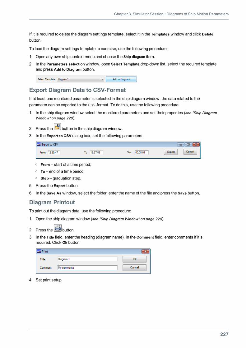
Chapter 3. Simulator Session • Diagrams of Ship Motion Parameters
227
If it is required to delete the diagram settings template, select it in the Templates window and click Deletebutton.
To load the diagram settings template to exercise, use the following procedure:
1. Open any own ship context menu and choose the Ship diagram item.
2. In the Parameters selectionwindow, open Select Template drop-down list, select the required templateand press Add to Diagram button.
Export Diagram Data to CSV-FormatIf at least onemonitored parameter is selected in the ship diagram window, the data related to theparameter can be exported to the CSV-format. To do this, use the following procedure:
1. In the ship diagram window select themonitored parameters and set their properties (see "Ship DiagramWindow" on page 220).
2. Press the button in the ship diagram window.
3. In the Export to CSV dialog box, set the following parameters:
o From – start of a time period;o To – end of a time period;o Step – graduation step.
5. Press the Export button.
6. In the Save As window, select the folder, enter the name of the file and press the Save button.
Diagram PrintoutTo print out the diagram data, use the following procedure:
1. Open the ship diagram window (see "Ship Diagram Window" on page 220).
2. Press the button.
3. In the Title field, enter the heading (diagram name). In theComment field, enter comments if it'srequired. Click Ok button.
4. Set print setup.
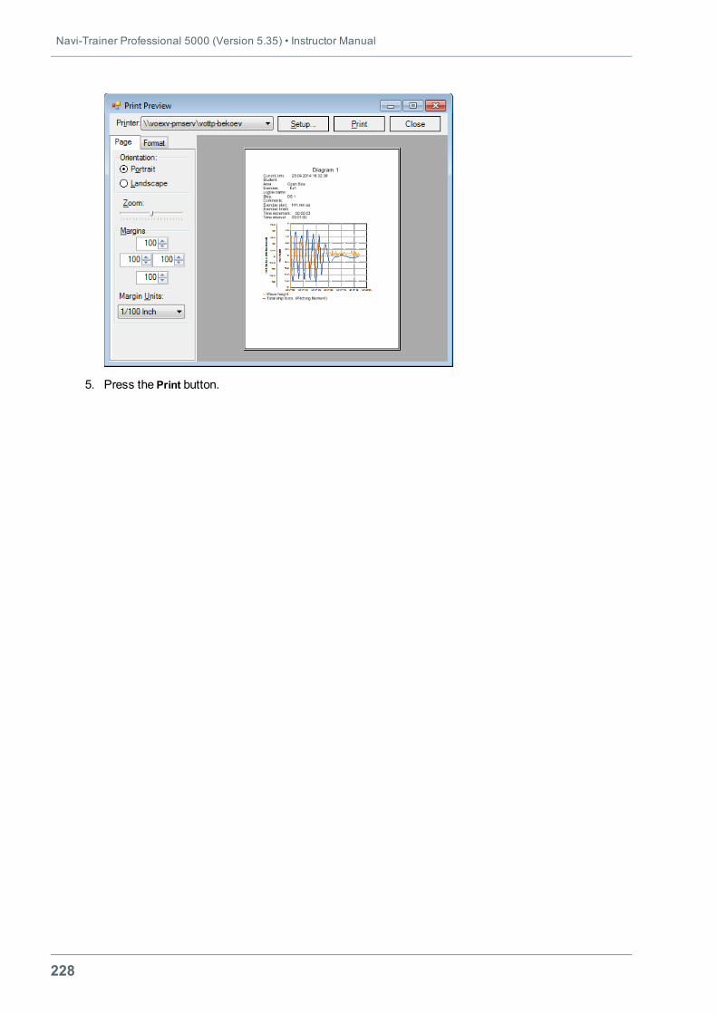
Navi-Trainer Professional 5000 (Version 5.35) • Instructor Manual
228
5. Press the Print button.
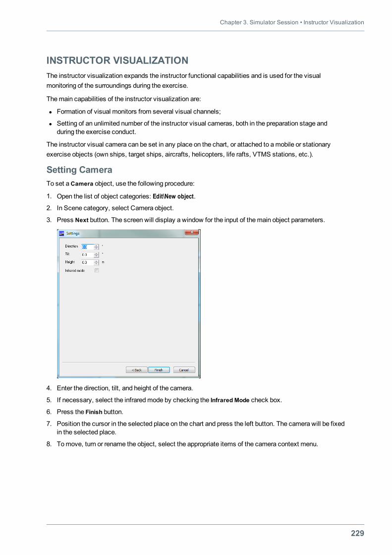
Chapter 3. Simulator Session • Instructor Visualization
229
INSTRUCTOR VISUALIZATIONThe instructor visualization expands the instructor functional capabilities and is used for the visualmonitoring of the surroundings during the exercise.
Themain capabilities of the instructor visualization are:
l Formation of visual monitors from several visual channels;
l Setting of an unlimited number of the instructor visual cameras, both in the preparation stage andduring the exercise conduct.
The instructor visual camera can be set in any place on the chart, or attached to a mobile or stationaryexercise objects (own ships, target ships, aircrafts, helicopters, life rafts, VTMS stations, etc.).
Setting CameraTo set aCamera object, use the following procedure:
1. Open the list of object categories: Edit\New object.
2. In Scene category, select Camera object.
3. Press Next button. The screen will display a window for the input of themain object parameters.
4. Enter the direction, tilt, and height of the camera.
5. If necessary, select the infraredmode by checking the Infrared Mode check box.
6. Press the Finish button.
7. Position the cursor in the selected place on the chart and press the left button. The camera will be fixedin the selected place.
8. Tomove, turn or rename the object, select the appropriate items of the camera context menu.
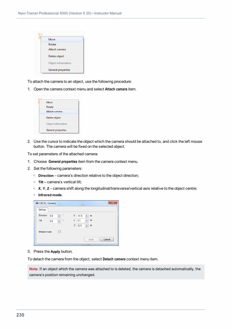
Navi-Trainer Professional 5000 (Version 5.35) • Instructor Manual
230
To attach the camera to an object, use the following procedure:
1. Open the camera context menu and select Attach camera item.
2. Use the cursor to indicate the object which the camera should be attached to, and click the left mousebutton. The camera will be fixed on the selected object.
To set parameters of the attached camera:
1. Choose General properties item from the camera context menu.
2. Set the following parameters:o Direction – camera’s direction relative to the object direction;o Tilt – camera’s vertical tilt;o X, Y, Z – camera shift along the longitudinal/transverse/vertical axis relative to the object centre;o Infrared mode.
3. Press theApply button.
To detach the camera from the object, select Detach camera context menu item.
Note: If an object which the camera was attached to is deleted, the camera is detached automatically, thecamera’s position remaining unchanged.
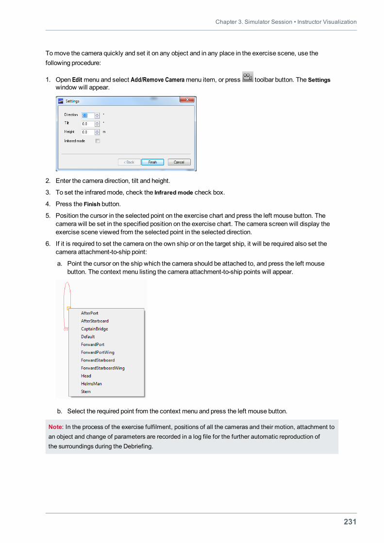
Chapter 3. Simulator Session • Instructor Visualization
231
Tomove the camera quickly and set it on any object and in any place in the exercise scene, use thefollowing procedure:
1. Open Edit menu and select Add/Remove Cameramenu item, or press toolbar button. The Settingswindow will appear.
2. Enter the camera direction, tilt and height.
3. To set the infraredmode, check the Infrared mode check box.
4. Press the Finish button.
5. Position the cursor in the selected point on the exercise chart and press the left mouse button. Thecamera will be set in the specified position on the exercise chart. The camera screen will display theexercise scene viewed from the selected point in the selected direction.
6. If it is required to set the camera on the own ship or on the target ship, it will be required also set thecamera attachment-to-ship point:
a. Point the cursor on the ship which the camera should be attached to, and press the left mousebutton. The context menu listing the camera attachment-to-ship points will appear.
b. Select the required point from the context menu and press the left mouse button.
Note: In the process of the exercise fulfilment, positions of all the cameras and their motion, attachment toan object and change of parameters are recorded in a log file for the further automatic reproduction ofthe surroundings during the Debriefing.
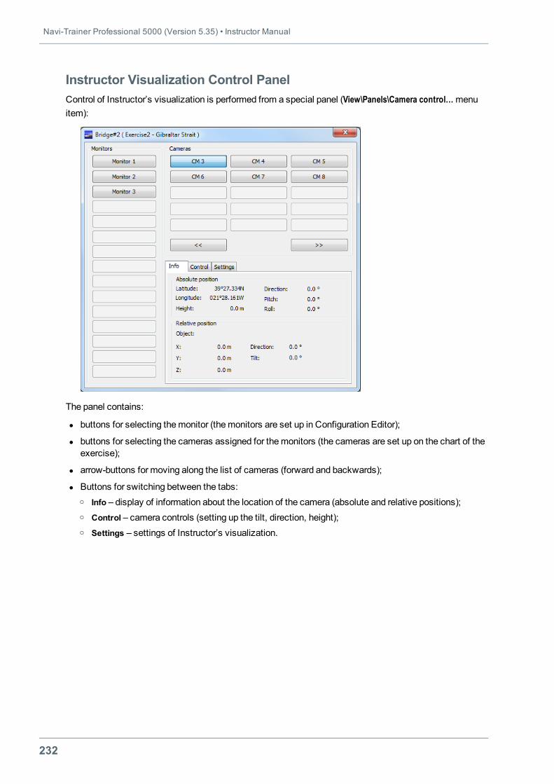
Navi-Trainer Professional 5000 (Version 5.35) • Instructor Manual
232
Instructor Visualization Control PanelControl of Instructor’s visualization is performed from a special panel (View\Panels\Camera control…menuitem):
The panel contains:
l buttons for selecting themonitor (themonitors are set up in Configuration Editor);
l buttons for selecting the cameras assigned for themonitors (the cameras are set up on the chart of theexercise);
l arrow-buttons for moving along the list of cameras (forward and backwards);
l Buttons for switching between the tabs:o Info – display of information about the location of the camera (absolute and relative positions);o Control – camera controls (setting up the tilt, direction, height);o Settings – settings of Instructor’s visualization.
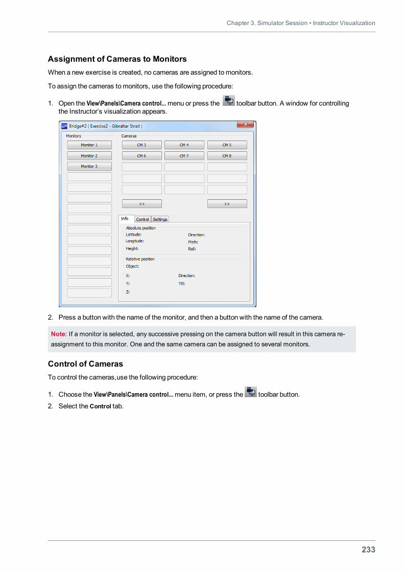
Chapter 3. Simulator Session • Instructor Visualization
233
Assignment of Cameras to MonitorsWhen a new exercise is created, no cameras are assigned tomonitors.
To assign the cameras tomonitors, use the following procedure:
1. Open the View\Panels\Camera control...menu or press the toolbar button. A window for controllingthe Instructor’s visualization appears.
2. Press a button with the name of the monitor, and then a button with the name of the camera.
Note: If a monitor is selected, any successive pressing on the camera button will result in this camera re-assignment to this monitor. One and the same camera can be assigned to several monitors.
Control of CamerasTo control the cameras,use the following procedure:
1. Choose the View\Panels\Camera control...menu item, or press the toolbar button.
2. Select theControl tab.
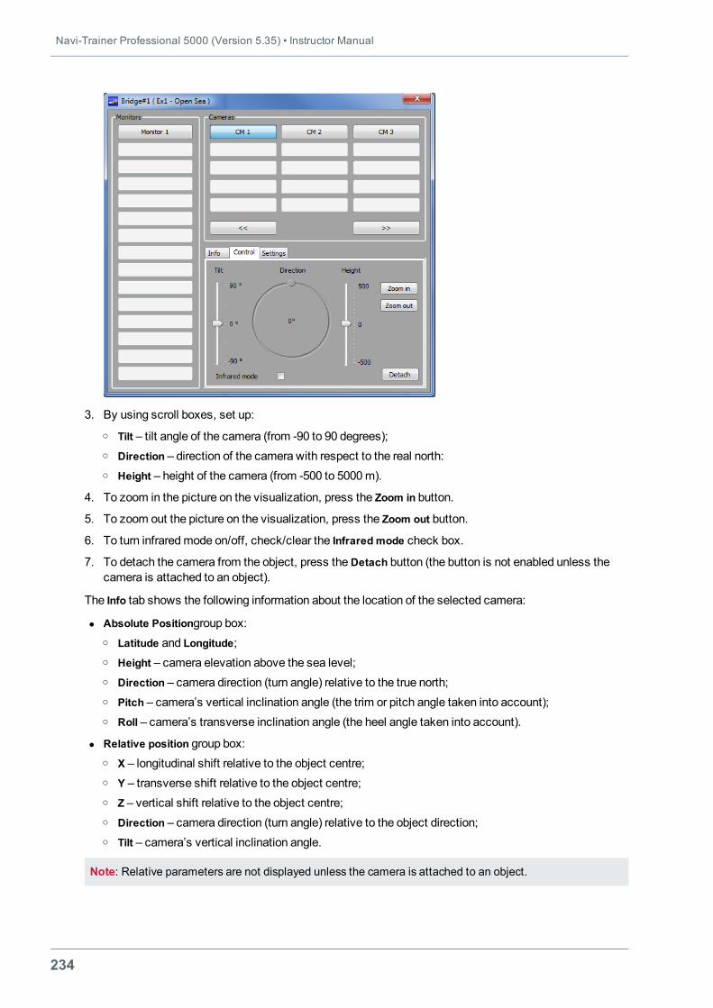
Navi-Trainer Professional 5000 (Version 5.35) • Instructor Manual
234
3. By using scroll boxes, set up:o Tilt – tilt angle of the camera (from -90 to 90 degrees);o Direction – direction of the camera with respect to the real north:o Height – height of the camera (from -500 to 5000m).
4. To zoom in the picture on the visualization, press the Zoom in button.
5. To zoom out the picture on the visualization, press the Zoom out button.
6. To turn infraredmode on/off, check/clear the Infrared mode check box.
7. To detach the camera from the object, press theDetach button (the button is not enabled unless thecamera is attached to an object).
The Info tab shows the following information about the location of the selected camera:
l Absolute Positiongroup box:o Latitude and Longitude;o Height – camera elevation above the sea level;o Direction – camera direction (turn angle) relative to the true north;o Pitch – camera’s vertical inclination angle (the trim or pitch angle taken into account);o Roll – camera’s transverse inclination angle (the heel angle taken into account).
l Relative position group box:o X – longitudinal shift relative to the object centre;o Y – transverse shift relative to the object centre;o Z – vertical shift relative to the object centre;o Direction – camera direction (turn angle) relative to the object direction;o Tilt – camera’s vertical inclination angle.
Note: Relative parameters are not displayed unless the camera is attached to an object.
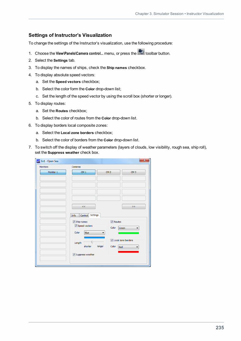
Chapter 3. Simulator Session • Instructor Visualization
235
Settings of Instructor’s VisualizationTo change the settings of the Instructor’s visualization, use the following procedure:
1. Choose the View\Panels\Camera control...menu, or press the toolbar button.
2. Select the Settings tab.
3. To display the names of ships, check the Ship names checkbox.
4. To display absolute speed vectors:a. Set the Speed vectors checkbox;
b. Select the color form theColor drop-down list;
c. Set the length of the speed vector by using the scroll box (shorter or longer).
5. To display routes:
a. Set theRoutes checkbox;
b. Select the color of routes from theColor drop-down list.
6. To display borders local composite zones:
a. Select the Local zone borders checkbox;
b. Select the color of borders from theColor drop-down list.
7. To switch off the display of weather parameters (layers of clouds, low visibility, rough sea, ship roll),set the Suppress weather check box.
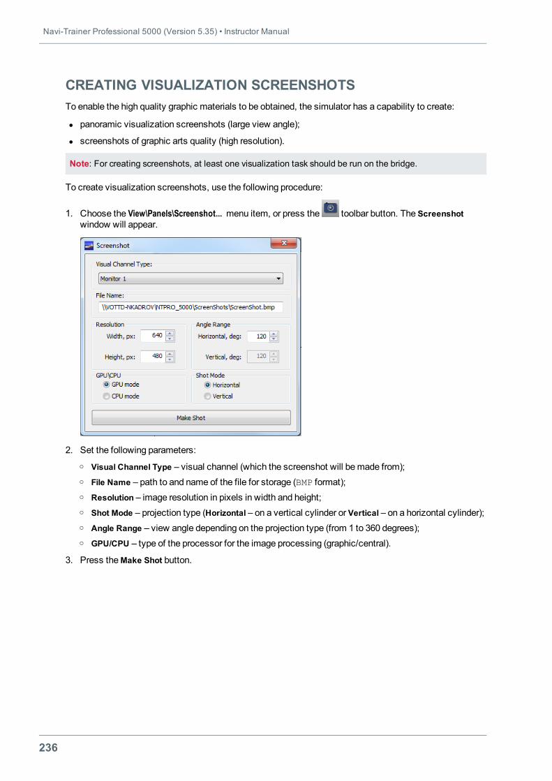
Navi-Trainer Professional 5000 (Version 5.35) • Instructor Manual
236
CREATING VISUALIZATION SCREENSHOTSTo enable the high quality graphic materials to be obtained, the simulator has a capability to create:
l panoramic visualization screenshots (large view angle);
l screenshots of graphic arts quality (high resolution).
Note: For creating screenshots, at least one visualization task should be run on the bridge.
To create visualization screenshots, use the following procedure:
1. Choose the View\Panels\Screenshot... menu item, or press the toolbar button. The Screenshotwindow will appear.
2. Set the following parameters:o Visual Channel Type – visual channel (which the screenshot will bemade from);o File Name – path to and name of the file for storage (BMP format);o Resolution – image resolution in pixels in width and height;o Shot Mode – projection type (Horizontal – on a vertical cylinder or Vertical – on a horizontal cylinder);o Angle Range – view angle depending on the projection type (from 1 to 360 degrees);o GPU/CPU – type of the processor for the image processing (graphic/central).
3. Press theMake Shot button.

Chapter 3. Simulator Session • Loading Visual Profile on Bridge
237
LOADING VISUAL PROFILE ON BRIDGE
The Visual Profile panel (View\Panels\Visual Profiles...menu, or toolbar button) allows the Visual Profilefile to be selected and loaded on the bridge.
The Visual Profile is created and edited with the aid of the Visual System Tuning program (seeNavi-Trainer Professional 5000 (v. 5.35). Technical Description and Installation Manual).
The Visual Profile contains information on a set of visual tasks for a group of channels, on the channelpositions relative to each other, visual settings of each channel, information on the geometry adjustment,blends adjustment and colour adjustment.
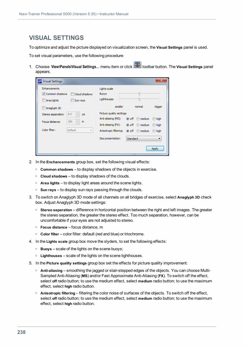
Navi-Trainer Professional 5000 (Version 5.35) • Instructor Manual
238
VISUAL SETTINGSTo optimize and adjust the picture displayed on visualization screen, the Visual Settings panel is used.
To set visual parameters, use the following procedure:
1. Choose View\Panels\Visual Settings…menu item or click toolbar button. The Visual Settings panelappears.
2. In the Enchancements group box, set the following visual effects:o Common shadows – to display shadows of the objects in exercise.o Cloud shadows – to display shadows of the clouds.o Area lights – to display light areas around the scene lights.o Sun rays – to display sun rays passing through the clouds.
3. To switch on Anaglyph 3D mode of all channels on all bridges of exercise, select Anaglyph 3D checkbox. Adjust Anaglyph 3D mode settings:o Stereo separation – difference in horizontal position between the right and left images. The greater
the stereo separation, the greater the stereo effect. Toomuch separation, however, can beuncomfortable if your eyes are not adjusted to stereo.
o Focus distance – focus distance, mo Color filter – color filter: default (red and blue) or triochrome.
4. In the Lights scale group box move the slyders, to set the following effects:o Buoys – scale of the lights on the scene buoys;o Lighthouses – scale of the lights on the scene lighthouses.
5. In the Picture quality settings group box set the effects for picture quality improvement:o Anti-aliasing – smoothing the jagged or stair-stepped edges of the objects. You can chooseMulti-
Sampled Anti-Aliasing (MS) and/or Fast Approximate Anti-Aliasing (FX). To switch off the effect,select off radio button; to use themedium effect, select medium radio button; to use themaximumeffect, select high radio button.
o Anisotropic filtering – filtering the color noise of surfaces of the objects. To switch off the effect,select off radio button; to use themedium effect, select medium radio button; to use themaximumeffect, select high radio button.
Chapter 3. Simulator Session • Visual Settings
239
o Sea presentation – quality of the sea presentation: Standard – standard quality; Simplified –simplified quality (it does not require high processing power of graphics card); As inConfigurationEditor – the quality set in the Configuration Editor.
Note: Application of visualization optimizing effects requires considerable processing power of graphicscard. The improvement of visualization by means of described effects is efficient for widescreen picturesproduced by projectors. As for visualization applied for displays, these settings may not take such ameaningful effect.
6. To apply all settings, press theApply button.
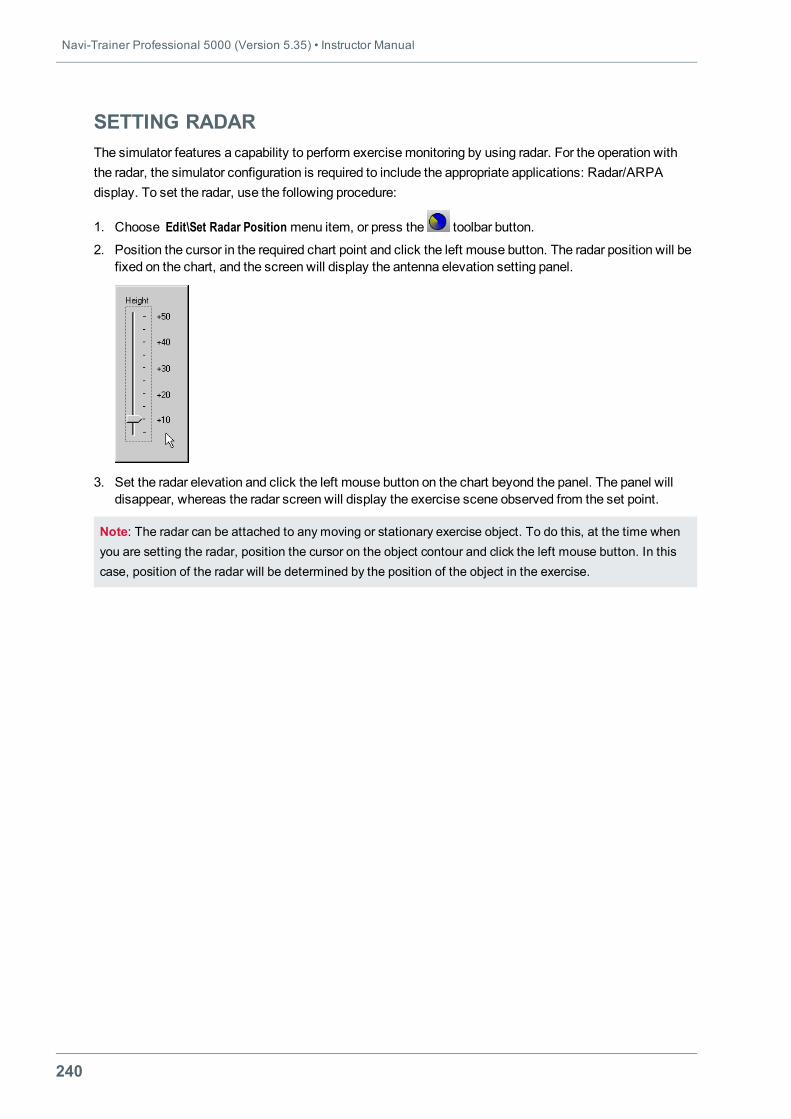
Navi-Trainer Professional 5000 (Version 5.35) • Instructor Manual
240
SETTING RADARThe simulator features a capability to perform exercisemonitoring by using radar. For the operation withthe radar, the simulator configuration is required to include the appropriate applications: Radar/ARPAdisplay. To set the radar, use the following procedure:
1. Choose Edit\Set Radar Position menu item, or press the toolbar button.
2. Position the cursor in the required chart point and click the left mouse button. The radar position will befixed on the chart, and the screen will display the antenna elevation setting panel.
3. Set the radar elevation and click the left mouse button on the chart beyond the panel. The panel willdisappear, whereas the radar screen will display the exercise scene observed from the set point.
Note: The radar can be attached to any moving or stationary exercise object. To do this, at the time whenyou are setting the radar, position the cursor on the object contour and click the left mouse button. In thiscase, position of the radar will be determined by the position of the object in the exercise.
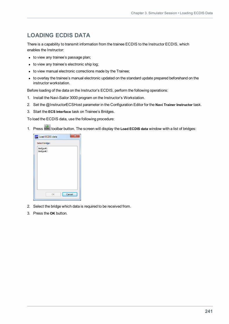
Chapter 3. Simulator Session • Loading ECDIS Data
241
LOADING ECDIS DATAThere is a capability to transmit information from the trainee ECDIS to the Instructor ECDIS, whichenables the Instructor:
l to view any trainee’s passage plan;
l to view any trainee’s electronic ship log;
l to view manual electronic corrections made by the Trainee;
l to overlay the trainee’s manual electronic updated on the standard update prepared beforehand on theinstructor workstation.
Before loading of the data on the Instructor’s ECDIS, perform the following operations:
1. Install the Navi-Sailor 3000 program on the Instructor’s Workstation.
2. Set the@InstructorECSHost parameter in the Configuration Editor for theNavi Trainer Instructor task.
3. Start the ECS Interface task on Trainee’s Bridges.
To load the ECDIS data, use the following procedure:
1. Press toolbar button. The screen will display the Load ECDIS data window with a list of bridges:
2. Select the bridge which data is required to be received from.
3. Press theОK button.
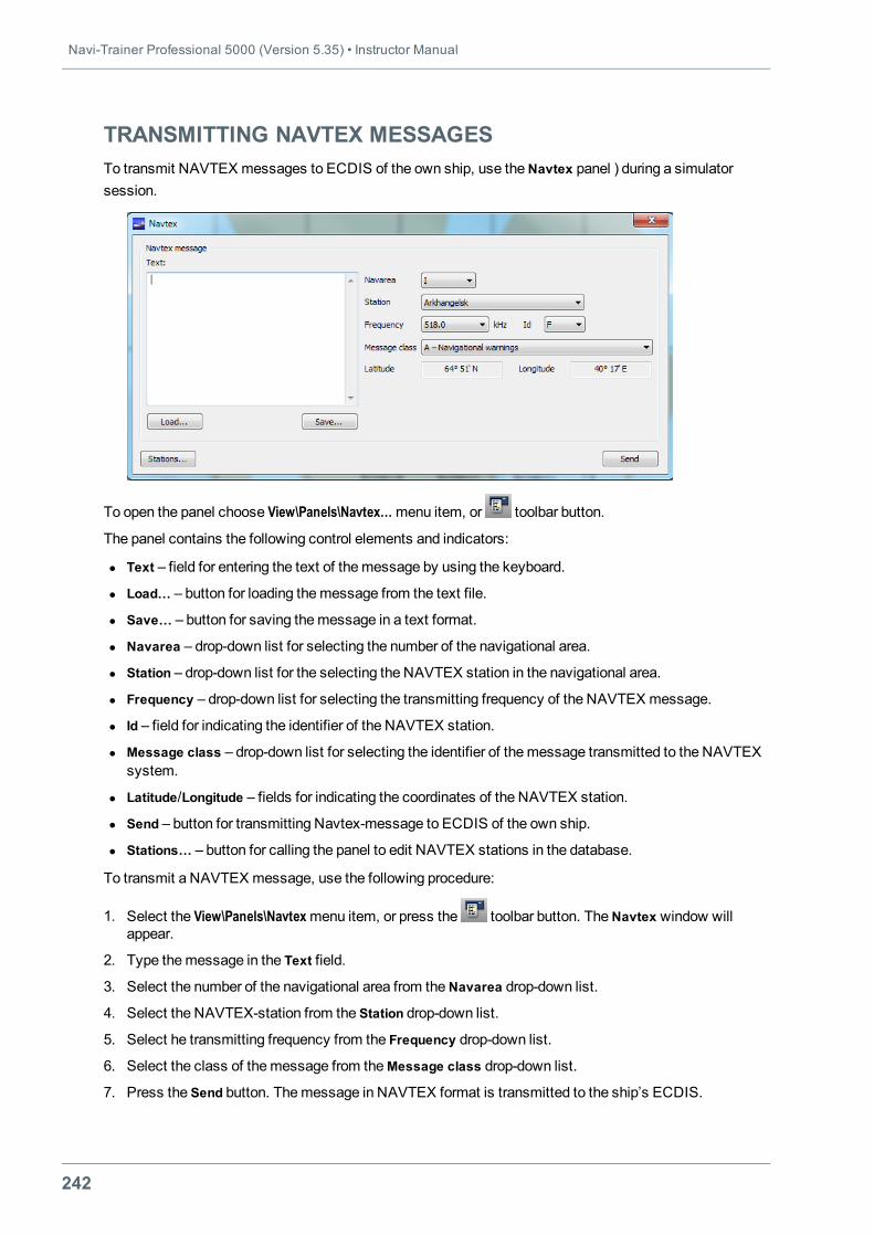
Navi-Trainer Professional 5000 (Version 5.35) • Instructor Manual
242
TRANSMITTING NAVTEX MESSAGESTo transmit NAVTEX messages to ECDIS of the own ship, use theNavtex panel ) during a simulatorsession.
To open the panel choose View\Panels\Navtex…menu item, or toolbar button.
The panel contains the following control elements and indicators:
l Text – field for entering the text of themessage by using the keyboard.
l Load… – button for loading themessage from the text file.
l Save… – button for saving themessage in a text format.
l Navarea – drop-down list for selecting the number of the navigational area.
l Station – drop-down list for the selecting the NAVTEX station in the navigational area.
l Frequency – drop-down list for selecting the transmitting frequency of the NAVTEX message.
l Id – field for indicating the identifier of the NAVTEX station.
l Message class – drop-down list for selecting the identifier of themessage transmitted to the NAVTEXsystem.
l Latitude/Longitude – fields for indicating the coordinates of the NAVTEX station.
l Send – button for transmitting Navtex-message to ECDIS of the own ship.
l Stations… – button for calling the panel to edit NAVTEX stations in the database.
To transmit a NAVTEX message, use the following procedure:
1. Select the View\Panels\Navtexmenu item, or press the toolbar button. TheNavtex window willappear.
2. Type themessage in the Text field.
3. Select the number of the navigational area from theNavarea drop-down list.
4. Select the NAVTEX-station from the Station drop-down list.
5. Select he transmitting frequency from the Frequency drop-down list.
6. Select the class of themessage from theMessage class drop-down list.
7. Press the Send button. Themessage in NAVTEX format is transmitted to the ship’s ECDIS.
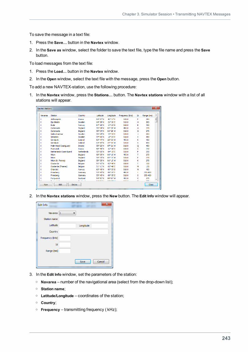
Chapter 3. Simulator Session • Transmitting NAVTEX Messages
243
To save themessage in a text file:
1. Press the Save… button in theNavtex window.
2. In the Save as window, select the folder to save the text file, type the file name and press the Savebutton.
To loadmessages from the text file:
1. Press the Load… button in theNavtex window.
2. In theOpenwindow, select the text file with themessage, press theOpen button.
To add a new NAVTEX-station, use the following procedure:
1. In theNavtex window, press the Stations… button. TheNavtex stations window with a list of allstations will appear.
2. In theNavtex stations window, press theNew button. The Edit Infowindow will appear.
3. In the Edit Infowindow, set the parameters of the station:o Navarea – number of the navigational area (select from the drop-down list);o Station name;o Latitude/Longitude – coordinates of the station;o Country;o Frequency – transmitting frequency ( kHz);
Navi-Trainer Professional 5000 (Version 5.35) • Instructor Manual
244
o Id – alphabetical identifier of the station;o Range – broadcasting range (nm).
4. Press the Save button. After saving the parameters, the new station is added to the list of stations.
To edit parameters of the station:
1. In theNavtex stations window, select the required information in the list.
2. Press the Edit button.
3. Set new values of parameters of the station.
4. Press the Save button.
To delete a station from the list:
1. In theNavtex stations window, select the required station in the list.
2. Press Delete button.
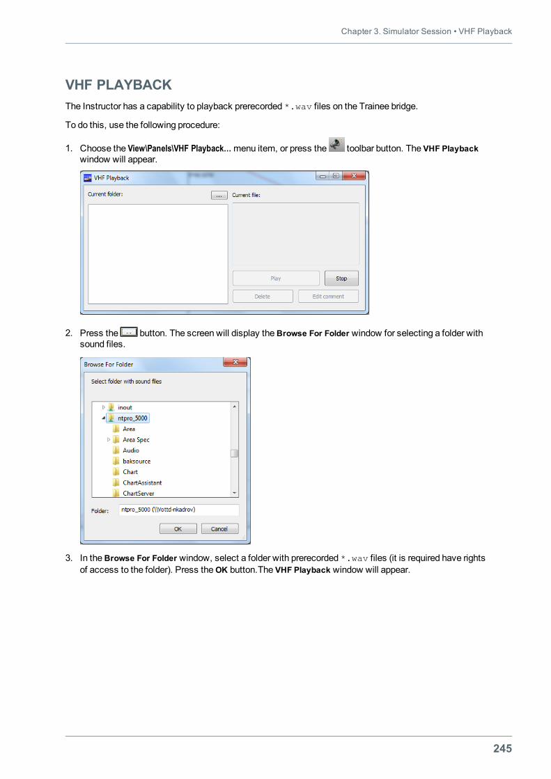
Chapter 3. Simulator Session • VHF Playback
245
VHF PLAYBACKThe Instructor has a capability to playback prerecorded *.wav files on the Trainee bridge.
To do this, use the following procedure:
1. Choose the View\Panels\VHF Playback…menu item, or press the toolbar button. The VHF Playbackwindow will appear.
2. Press the button. The screen will display theBrowse For Folder window for selecting a folder withsound files.
3. In theBrowse For Folder window, select a folder with prerecorded *.wav files (it is required have rightsof access to the folder). Press theOK button.The VHF Playback window will appear.
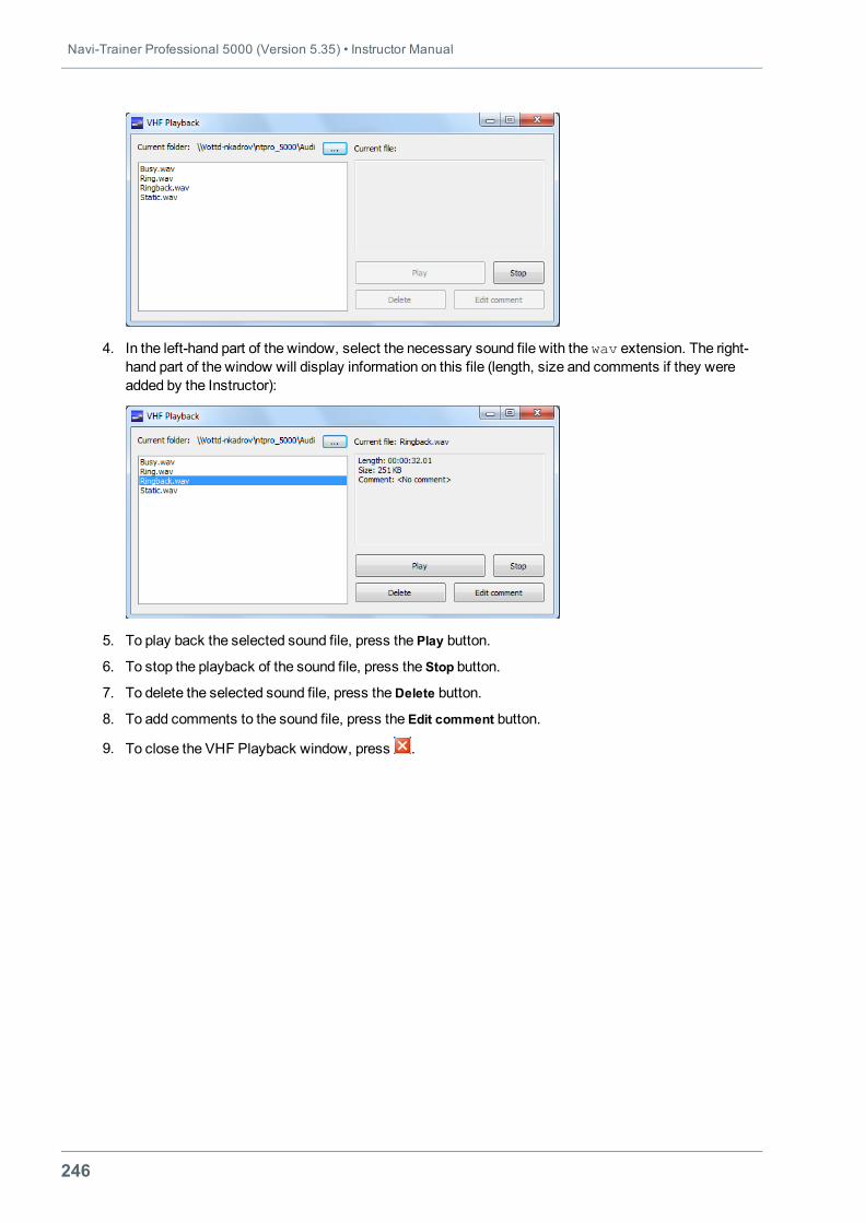
Navi-Trainer Professional 5000 (Version 5.35) • Instructor Manual
246
4. In the left-hand part of the window, select the necessary sound file with the wav extension. The right-hand part of the window will display information on this file (length, size and comments if they wereadded by the Instructor):
5. To play back the selected sound file, press the Play button.
6. To stop the playback of the sound file, press the Stop button.
7. To delete the selected sound file, press theDelete button.
8. To add comments to the sound file, press the Edit comment button.
9. To close the VHF Playback window, press .
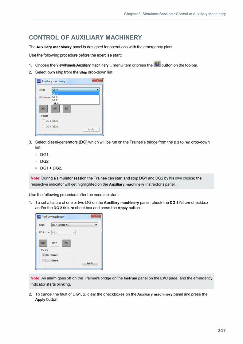
Chapter 3. Simulator Session • Control of Auxiliary Machinery
247
CONTROL OF AUXILIARY MACHINERYTheAuxiliary machinery panel is designed for operations with the emergency plant.
Use the following procedure before the exercise start:
1. Choose the View\Panels\Auxiliary machinery…menu item or press the button on the toolbar.
2. Select own ship from the Ship drop-down list.
3. Select diesel-generators (DG) which will be run on the Trainee’s bridge from theDG to run drop-downlist:o DG1;o DG2;o DG1 + DG2.
Note: During a simulator session the Trainee can start and stop DG1 and DG2 by his own choice; therespective indicator will get highlighted on the Auxiliary machinery Instructor’s panel.
Use the following procedure after the exercise start:
1. To set a failure of one or two DG on theAuxiliary machinery panel, check theDG 1 failure checkboxand/or theDG 2 failure checkbox and press theApply button.
Note: An alarm goes off on the Trainee's bridge on the Instrum panel on the EPC page, and the emergencyindicator starts blinking.
2. To cancel the fault of DG1, 2, clear the checkboxes on theAuxiliary machinery panel and press theApply button.
Navi-Trainer Professional 5000 (Version 5.35) • Instructor Manual
248
The highlighted indicators on theAuxiliary machinery panel shows:
l DG1 – DG 1 is running;
l DG2 – DG 2 is running;
l EG – emergency DG is running. The indicator gets highlighted if the Instructor has set the failure of twogenerators, or if in case of failure of one of the diesel-generators the Trainee has not started the otherdiesel-generator in time.
On the Events panel (the View\Panels\Events…menu) displays the following Trainee’s actions:
l start of diesel-generator DG1, 2;
l stop of diesel-generator DG1, 2;
l automatic stop of diesel-generator DG 1, 2;
l automatic start of emergency diesel-generator EG.
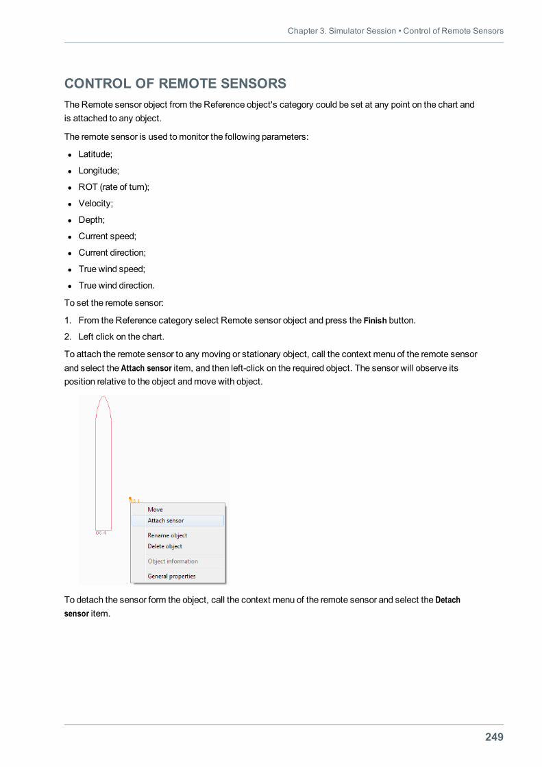
Chapter 3. Simulator Session • Control of Remote Sensors
249
CONTROL OF REMOTE SENSORSThe Remote sensor object from the Reference object's category could be set at any point on the chart andis attached to any object.
The remote sensor is used tomonitor the following parameters:
l Latitude;
l Longitude;
l ROT (rate of turn);
l Velocity;
l Depth;
l Current speed;
l Current direction;
l True wind speed;
l True wind direction.
To set the remote sensor:
1. From the Reference category select Remote sensor object and press the Finish button.
2. Left click on the chart.
To attach the remote sensor to any moving or stationary object, call the context menu of the remote sensorand select the Attach sensor item, and then left-click on the required object. The sensor will observe itsposition relative to the object andmove with object.
To detach the sensor form the object, call the context menu of the remote sensor and select the Detachsensor item.
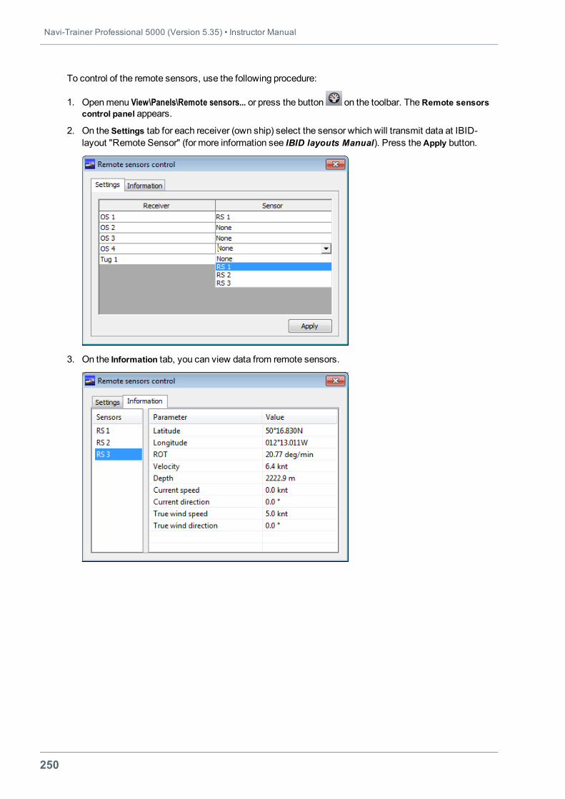
Navi-Trainer Professional 5000 (Version 5.35) • Instructor Manual
250
To control of the remote sensors, use the following procedure:
1. Openmenu View\Panels\Remote sensors... or press the button on the toolbar. TheRemote sensorscontrol panel appears.
2. On the Settings tab for each receiver (own ship) select the sensor which will transmit data at IBID-layout "Remote Sensor" (for more information see IBID layouts Manual). Press theApply button.
3. On the Information tab, you can view data from remote sensors.
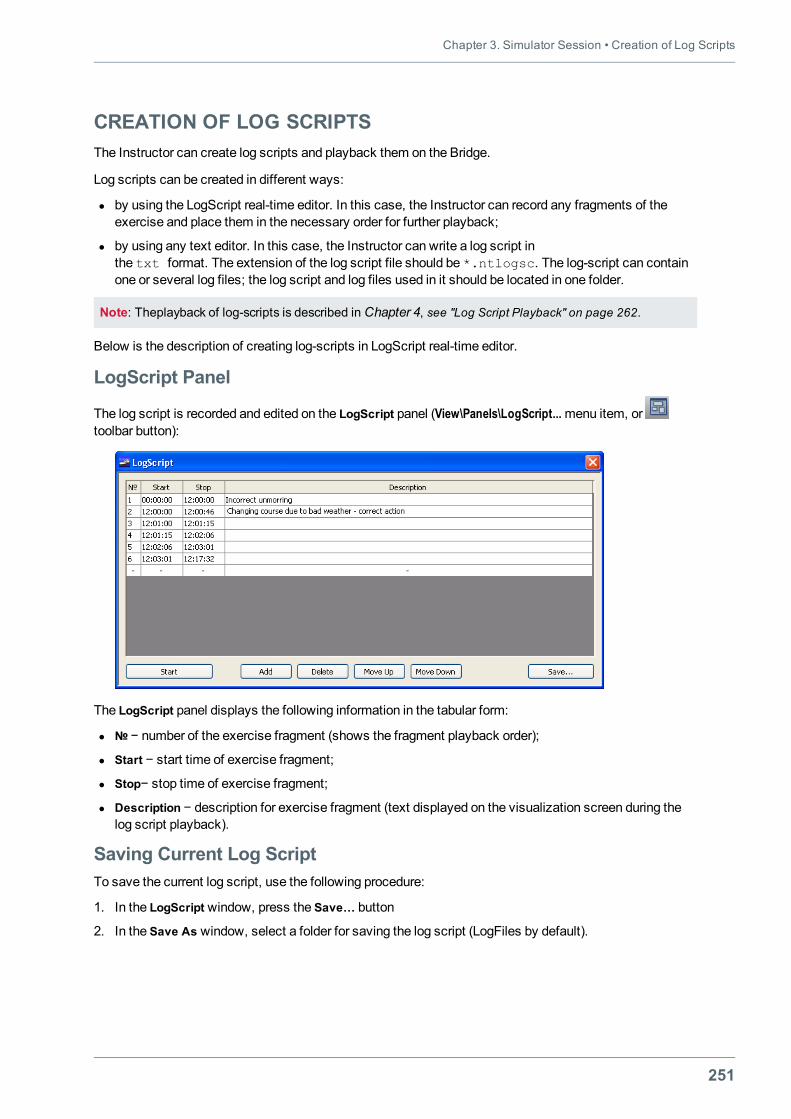
Chapter 3. Simulator Session • Creation of Log Scripts
251
CREATION OF LOG SCRIPTSThe Instructor can create log scripts and playback them on the Bridge.
Log scripts can be created in different ways:
l by using the LogScript real-time editor. In this case, the Instructor can record any fragments of theexercise and place them in the necessary order for further playback;
l by using any text editor. In this case, the Instructor can write a log script inthe txt format. The extension of the log script file should be *.ntlogsc. The log-script can containone or several log files; the log script and log files used in it should be located in one folder.
Note: Theplayback of log-scripts is described in Chapter 4, see "Log Script Playback" on page 262.
Below is the description of creating log-scripts in LogScript real-time editor.
LogScript Panel
The log script is recorded and edited on the LogScript panel (View\Panels\LogScript...menu item, ortoolbar button):
The LogScript panel displays the following information in the tabular form:
l № − number of the exercise fragment (shows the fragment playback order);
l Start − start time of exercise fragment;
l Stop− stop time of exercise fragment;
l Description − description for exercise fragment (text displayed on the visualization screen during thelog script playback).
Saving Current Log ScriptTo save the current log script, use the following procedure:
1. In the LogScript window, press the Save… button
2. In the Save As window, select a folder for saving the log script (LogFiles by default).
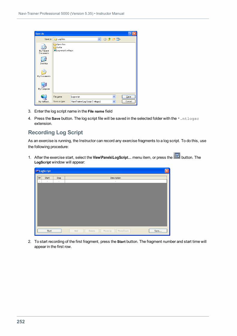
Navi-Trainer Professional 5000 (Version 5.35) • Instructor Manual
252
3. Enter the log script name in the File name field
4. Press the Save button. The log script file will be saved in the selected folder with the *.ntlogscextension.
Recording Log ScriptAs an exercise is running, the Instructor can record any exercise fragments to a log script. To do this, usethe following procedure:
1. After the exercise start, select the View\Panels\LogScript…menu item, or press the button. TheLogScript window will appear:
2. To start recording of the first fragment, press the Start button. The fragment number and start time willappear in the first row.
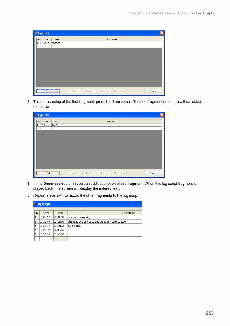
Chapter 3. Simulator Session • Creation of Log Scripts
253
3. To end recording of the first fragment, press the Stop button. The first fragment stop time will be addedto the row.
4. In theDescription column you can add description of this fragment. When this log script fragment isplayed back, the screen will display the entered text.
5. Repeat steps 2–4, to record the other fragments to the log script.
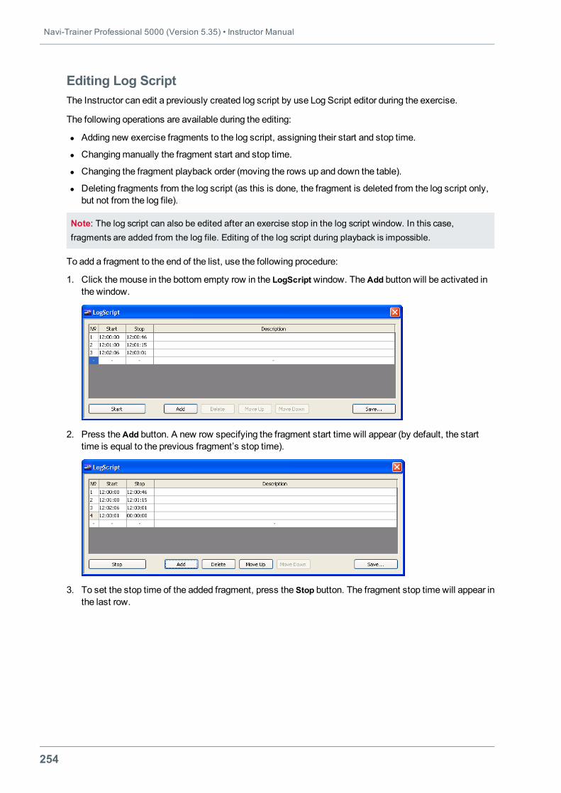
Navi-Trainer Professional 5000 (Version 5.35) • Instructor Manual
254
Editing Log ScriptThe Instructor can edit a previously created log script by use Log Script editor during the exercise.
The following operations are available during the editing:
l Adding new exercise fragments to the log script, assigning their start and stop time.
l Changingmanually the fragment start and stop time.
l Changing the fragment playback order (moving the rows up and down the table).
l Deleting fragments from the log script (as this is done, the fragment is deleted from the log script only,but not from the log file).
Note: The log script can also be edited after an exercise stop in the log script window. In this case,fragments are added from the log file. Editing of the log script during playback is impossible.
To add a fragment to the end of the list, use the following procedure:
1. Click themouse in the bottom empty row in the LogScript window. TheAdd button will be activated inthe window.
2. Press theAdd button. A new row specifying the fragment start time will appear (by default, the starttime is equal to the previous fragment’s stop time).
3. To set the stop time of the added fragment, press the Stop button. The fragment stop time will appear inthe last row.
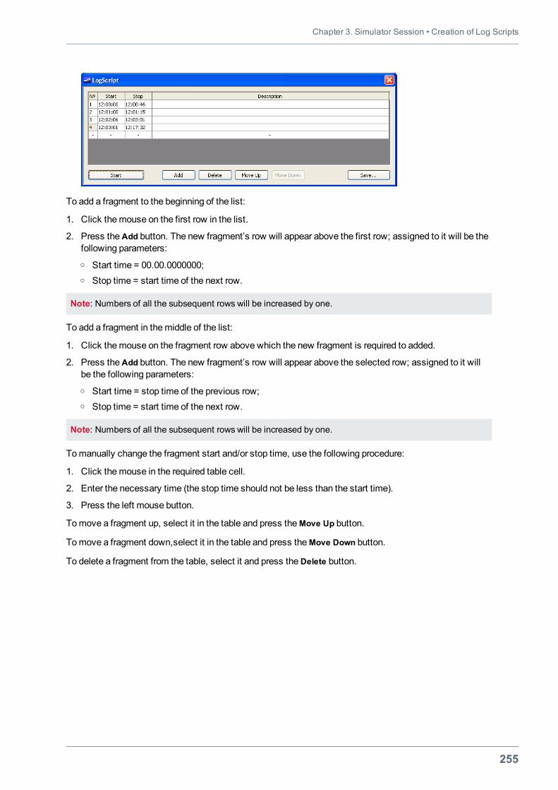
Chapter 3. Simulator Session • Creation of Log Scripts
255
To add a fragment to the beginning of the list:
1. Click themouse on the first row in the list.
2. Press theAdd button. The new fragment’s row will appear above the first row; assigned to it will be thefollowing parameters:o Start time = 00.00.0000000;o Stop time = start time of the next row.
Note: Numbers of all the subsequent rows will be increased by one.
To add a fragment in themiddle of the list:
1. Click themouse on the fragment row above which the new fragment is required to added.
2. Press theAdd button. The new fragment’s row will appear above the selected row; assigned to it willbe the following parameters:o Start time = stop time of the previous row;o Stop time = start time of the next row.
Note: Numbers of all the subsequent rows will be increased by one.
Tomanually change the fragment start and/or stop time, use the following procedure:
1. Click themouse in the required table cell.
2. Enter the necessary time (the stop time should not be less than the start time).
3. Press the left mouse button.
Tomove a fragment up, select it in the table and press theMove Up button.
Tomove a fragment down,select it in the table and press theMove Down button.
To delete a fragment from the table, select it and press theDelete button.
Navi-Trainer Professional 5000 (Version 5.35) • Instructor Manual
256
CLOSING SIMULATOR SESSIONSaving Current State of ExerciseIn course the exercise, the current state of exercise can be saved as initial stateof new exercise. To do this, select File\Save As...menu item. In the Save As dialog box, enter file name andpress the Save button.
Stop Exercise
To terminate the exercise, press Stop button on the toolbar , or select File\Control\Stop menu item.
257
CHAPTER 4.DEBRIEFING
This chapter contains:
General 259Loading Log File 260Log Playback 261Log Script Playback 262Main Exercise Window Printout 264Playback of Audio Log Files 266Playback of Video Log Files 267Report Generation 268Report Generator Wizard 270


Chapter 4. Debriefing • General
259
GENERALDebriefing presumes the playback of an exercise record (log) and generation of different reports, based onlog data. The exercise log represents a data file formed in the course of an exercise. The exercise report isformed in accordance with the selected template on the basis of exercise log. The report can be printed outor saved to a file in the Excel (*.csv) format.
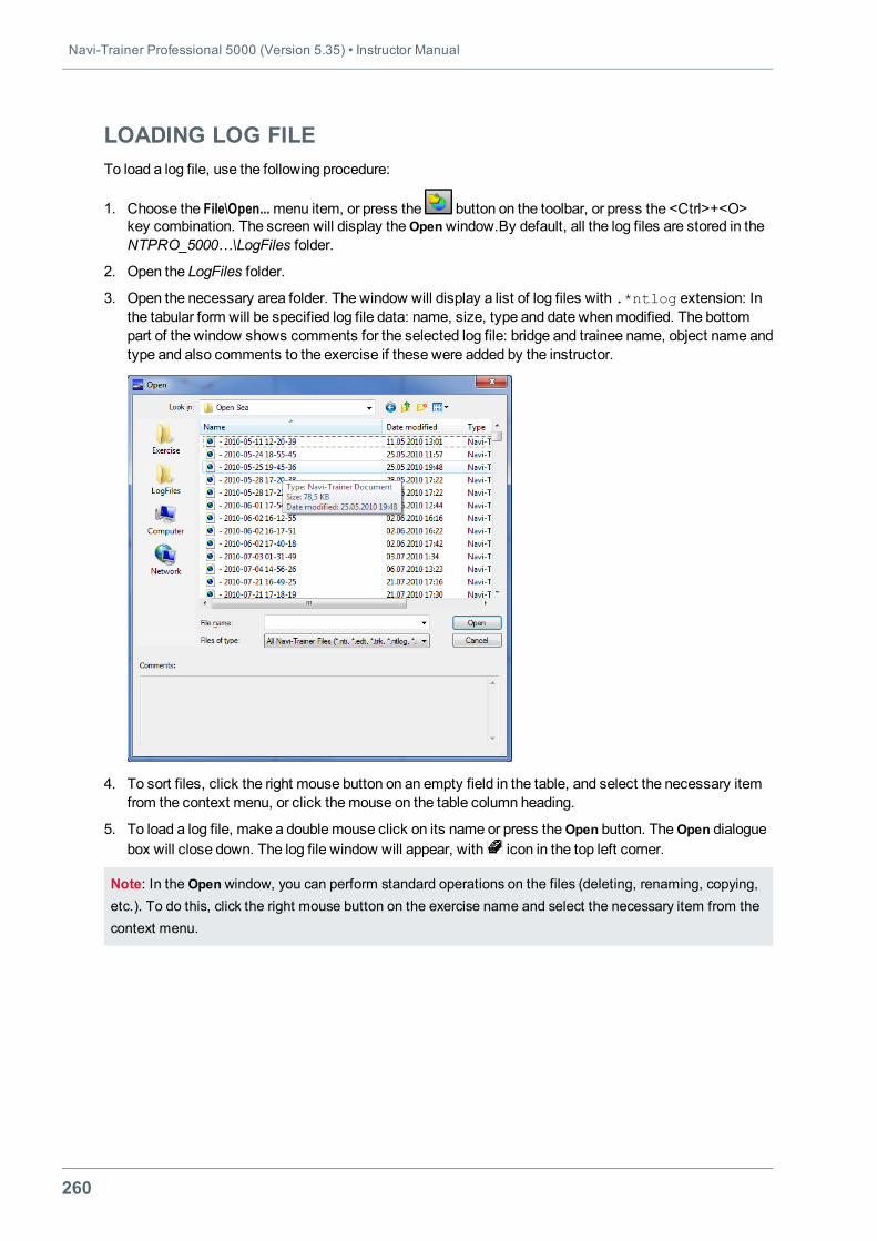
Navi-Trainer Professional 5000 (Version 5.35) • Instructor Manual
260
LOADING LOG FILETo load a log file, use the following procedure:
1. Choose the File\Open...menu item, or press the button on the toolbar, or press the <Сtrl>+<O>key combination. The screen will display theOpenwindow.By default, all the log files are stored in theNTPRO_5000…\LogFiles folder.
2. Open the LogFiles folder.
3. Open the necessary area folder. The window will display a list of log files with .*ntlog extension: Inthe tabular form will be specified log file data: name, size, type and date whenmodified. The bottompart of the window shows comments for the selected log file: bridge and trainee name, object name andtype and also comments to the exercise if these were added by the instructor.
4. To sort files, click the right mouse button on an empty field in the table, and select the necessary itemfrom the context menu, or click themouse on the table column heading.
5. To load a log file, make a doublemouse click on its name or press theOpen button. TheOpen dialoguebox will close down. The log file window will appear, with icon in the top left corner.
Note: In the Openwindow, you can perform standard operations on the files (deleting, renaming, copying,etc.). To do this, click the right mouse button on the exercise name and select the necessary item from thecontext menu.
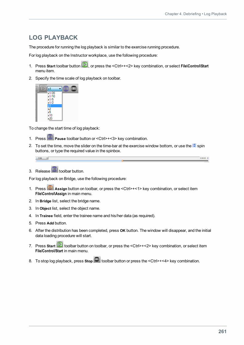
Chapter 4. Debriefing • Log Playback
261
LOG PLAYBACKThe procedure for running the log playback is similar to the exercise running procedure.
For log playback on the Instructor workplace, use the following procedure:
1. Press Start toolbar button , or press the <Ctrl>+<2> key combination, or select File\Control\Startmenu item.
2. Specify the time scale of log playback on toolbar.
To change the start time of log playback:
1. Press Pause toolbar button or <Ctrl>+<3> key combination.
2. To set the time, move the slider on the time-bar at the exercise window bottom, or use the spinbuttons, or type the required value in the spinbox.
3. Release toolbar button.
For log playback on Bridge, use the following procedure:
1. Press Assign button on toolbar, or press the <Ctrl>+<1> key combination, or select itemFile\Control\Assign in mainmenu.
2. InBridge list, select the bridge name.
3. InObject list, select the object name.
4. In Trainee field, enter the trainee name and his/her data (as required).
5. Press Add button.
6. After the distribution has been completed, press OK button. The window will disappear, and the initialdata loading procedure will start.
7. Press Start toolbar button on toolbar, or press the <Ctrl>+<2> key combination, or select itemFile/Control/Start in mainmenu.
8. To stop log playback, press Stop toolbar button or press the <Ctrl>+<4> key combination.
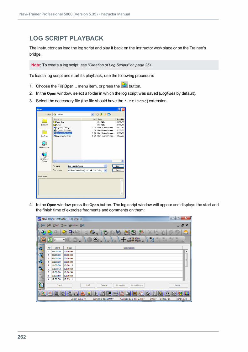
Navi-Trainer Professional 5000 (Version 5.35) • Instructor Manual
262
LOG SCRIPT PLAYBACKThe Instructor can load the log script and play it back on the Instructor workplace or on the Trainee'sbridge.
Note: To create a log script, see "Creation of Log Scripts" on page 251.
To load a log script and start its playback, use the following procedure:
1. Choose the File\Open…menu item, or press the button.
2. In theOpenwindow, select a folder in which the log script was saved (LogFiles by default).
3. Select the necessary file (the file should have the *.ntlogsc) extension.
4. In theOpenwindow press theOpen button. The log script window will appear and displays the start andthe finish time of exercise fragments and comments on them:
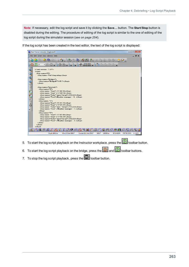
Chapter 4. Debriefing • Log Script Playback
263
Note: If necessary, edit the log script and save it by clicking the Save… button. The Start/Stop button isdisabled during the editing. The procedure of editing of the log script is similar to the one of editing of thelog script during the simulator session (see on page 254).
If the log script has been created in the text editor, the text of the log script is displayed:
5. To start the log script playback on the Instructor workplace, press the toolbar button.
6. To start the log script playback on the bridge, press the and toolbar buttons.
7. To stop the log script playback, press the toolbar button.
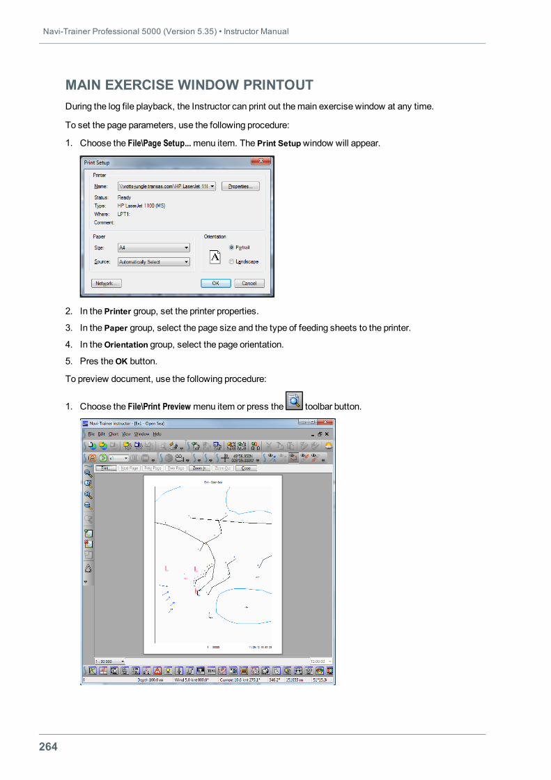
Navi-Trainer Professional 5000 (Version 5.35) • Instructor Manual
264
MAIN EXERCISE WINDOW PRINTOUTDuring the log file playback, the Instructor can print out themain exercise window at any time.
To set the page parameters, use the following procedure:
1. Choose the File\Page Setup...menu item. The Print Setupwindow will appear.
2. In the Printer group, set the printer properties.
3. In the Paper group, select the page size and the type of feeding sheets to the printer.
4. In theOrientation group, select the page orientation.
5. Pres theОK button.
To preview document, use the following procedure:
1. Choose the File\Print Preview menu item or press the toolbar button.
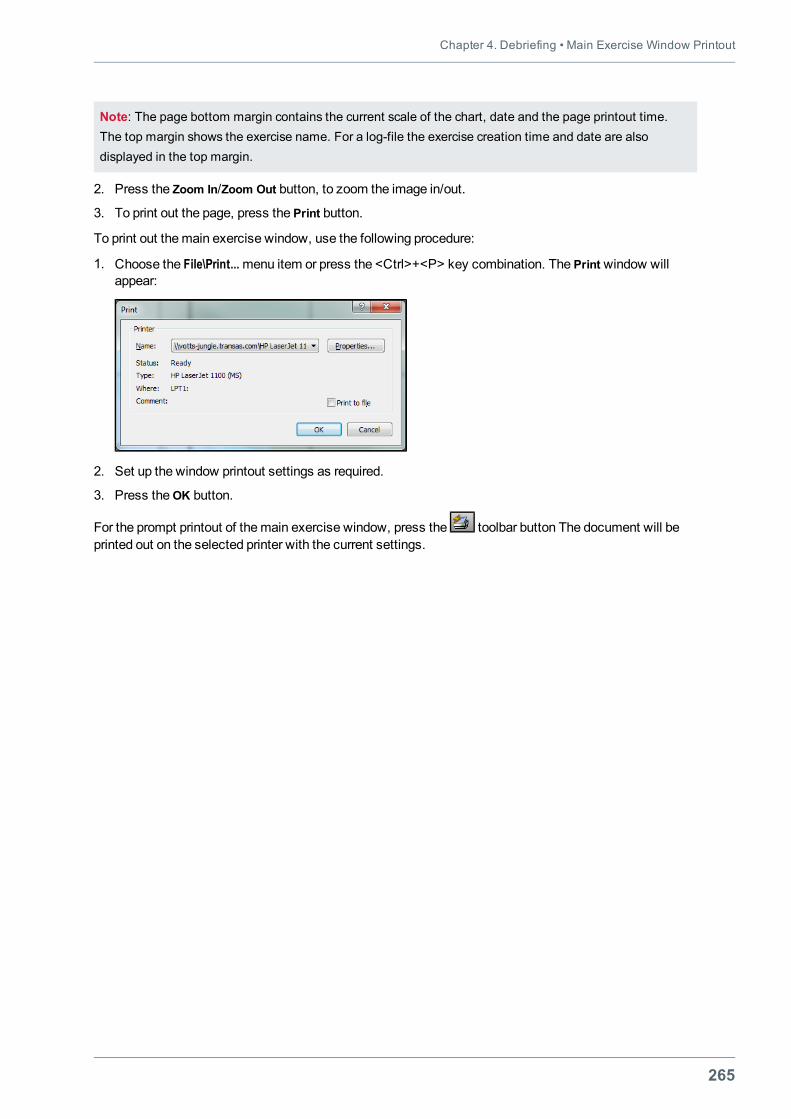
Chapter 4. Debriefing • Main Exercise Window Printout
265
Note: The page bottom margin contains the current scale of the chart, date and the page printout time.The top margin shows the exercise name. For a log-file the exercise creation time and date are alsodisplayed in the top margin.
2. Press the Zoom In/Zoom Out button, to zoom the image in/out.
3. To print out the page, press the Print button.
To print out themain exercise window, use the following procedure:
1. Choose the File\Print...menu item or press the <Ctrl>+<Р> key combination. The Print window willappear:
2. Set up the window printout settings as required.
3. Press theОK button.
For the prompt printout of themain exercise window, press the toolbar button The document will beprinted out on the selected printer with the current settings.
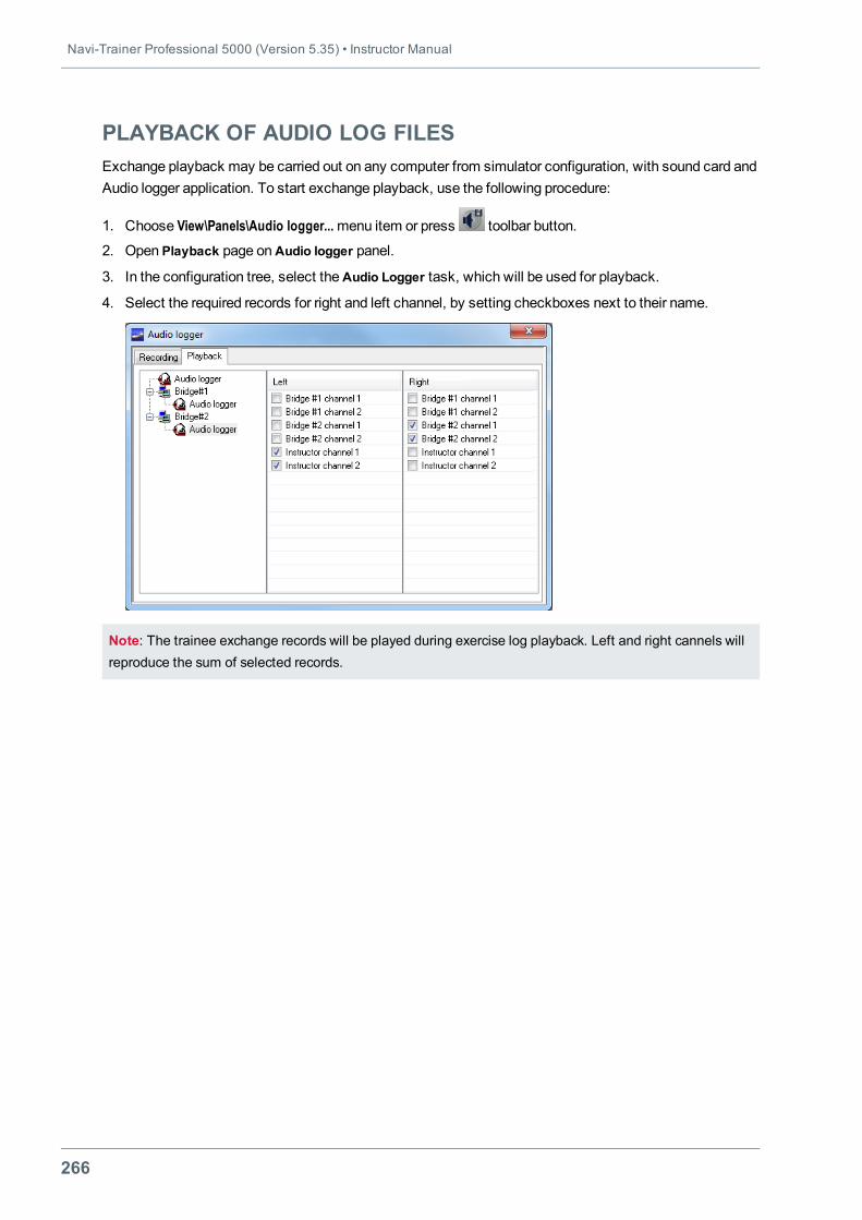
Navi-Trainer Professional 5000 (Version 5.35) • Instructor Manual
266
PLAYBACK OF AUDIO LOG FILESExchange playback may be carried out on any computer from simulator configuration, with sound card andAudio logger application. To start exchange playback, use the following procedure:
1. Choose View\Panels\Audio logger...menu item or press toolbar button.
2. Open Playback page onAudio logger panel.
3. In the configuration tree, select theAudio Logger task, which will be used for playback.
4. Select the required records for right and left channel, by setting checkboxes next to their name.
Note: The trainee exchange records will be played during exercise log playback. Left and right cannels willreproduce the sum of selected records.
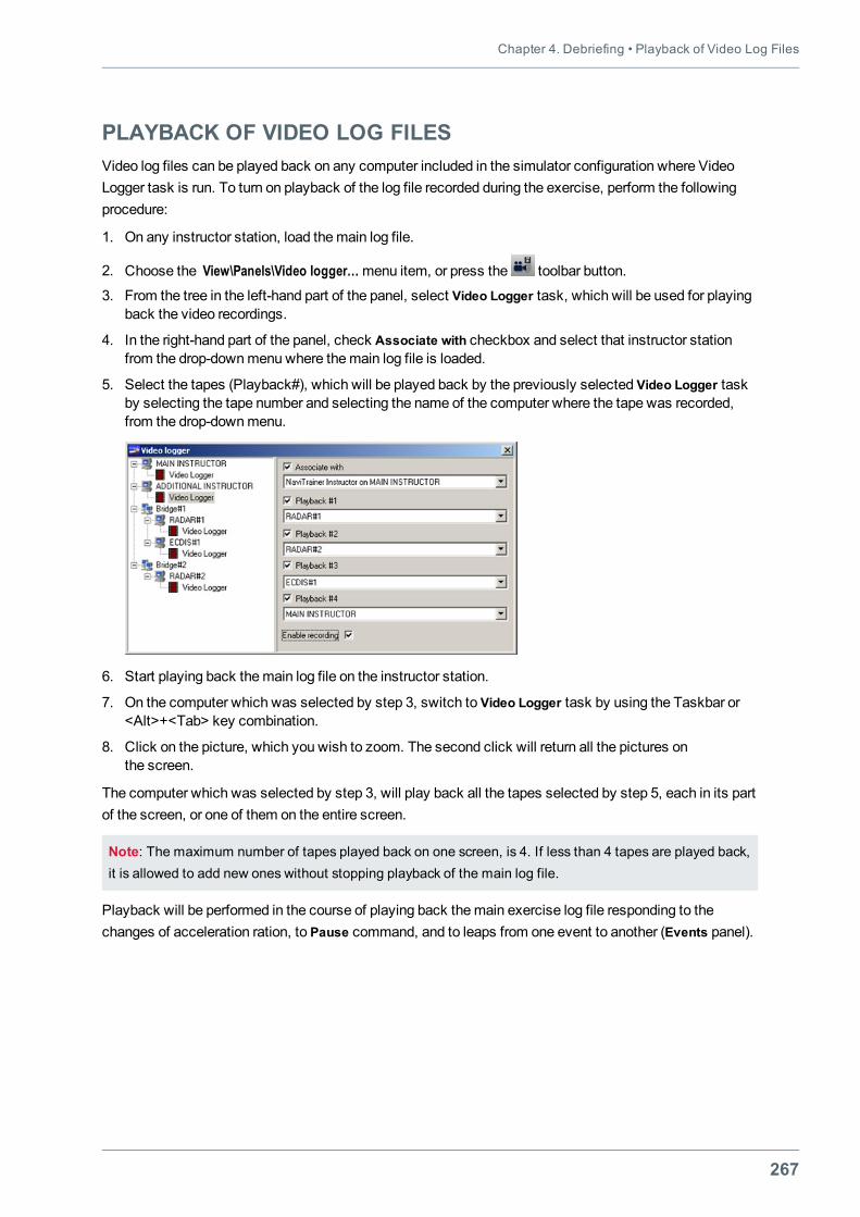
Chapter 4. Debriefing • Playback of Video Log Files
267
PLAYBACK OF VIDEO LOG FILESVideo log files can be played back on any computer included in the simulator configuration where VideoLogger task is run. To turn on playback of the log file recorded during the exercise, perform the followingprocedure:
1. On any instructor station, load themain log file.
2. Choose the View\Panels\Video logger…menu item, or press the toolbar button.
3. From the tree in the left-hand part of the panel, select Video Logger task, which will be used for playingback the video recordings.
4. In the right-hand part of the panel, check Associate with checkbox and select that instructor stationfrom the drop-downmenu where themain log file is loaded.
5. Select the tapes (Playback#), which will be played back by the previously selected Video Logger taskby selecting the tape number and selecting the name of the computer where the tape was recorded,from the drop-downmenu.
6. Start playing back themain log file on the instructor station.
7. On the computer which was selected by step 3, switch to Video Logger task by using the Taskbar or<Alt>+<Tab> key combination.
8. Click on the picture, which you wish to zoom. The second click will return all the pictures onthe screen.
The computer which was selected by step 3, will play back all the tapes selected by step 5, each in its partof the screen, or one of them on the entire screen.
Note: The maximum number of tapes played back on one screen, is 4. If less than 4 tapes are played back,it is allowed to add new ones without stopping playback of the main log file.
Playback will be performed in the course of playing back themain exercise log file responding to thechanges of acceleration ration, to Pause command, and to leaps from one event to another (Events panel).
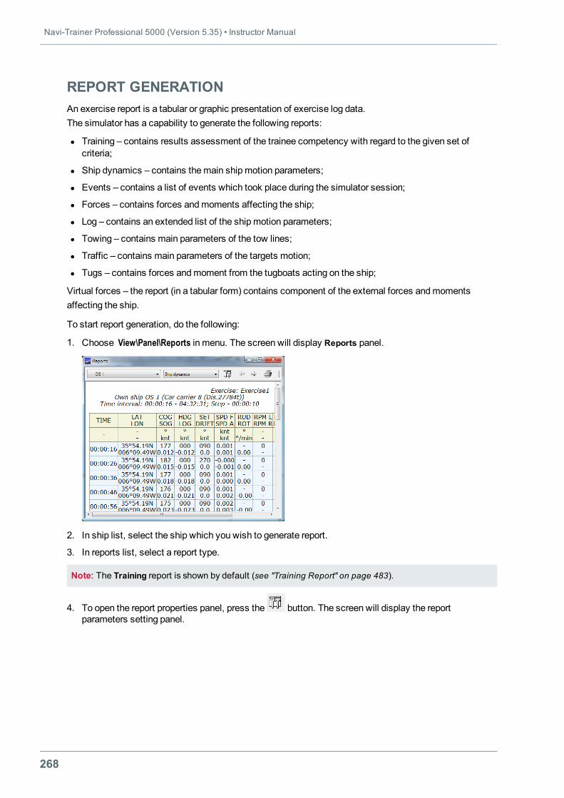
Navi-Trainer Professional 5000 (Version 5.35) • Instructor Manual
268
REPORT GENERATIONAn exercise report is a tabular or graphic presentation of exercise log data.The simulator has a capability to generate the following reports:
l Training – contains results assessment of the trainee competency with regard to the given set ofcriteria;
l Ship dynamics – contains themain shipmotion parameters;
l Events – contains a list of events which took place during the simulator session;
l Forces – contains forces andmoments affecting the ship;
l Log – contains an extended list of the shipmotion parameters;
l Towing – contains main parameters of the tow lines;
l Traffic – contains main parameters of the targets motion;
l Tugs – contains forces andmoment from the tugboats acting on the ship;
Virtual forces – the report (in a tabular form) contains component of the external forces andmomentsaffecting the ship.
To start report generation, do the following:
1. Choose View\Panel\Reports in menu. The screen will display Reports panel.
2. In ship list, select the ship which you wish to generate report.
3. In reports list, select a report type.
Note: The Training report is shown by default (see "Training Report" on page 483).
4. To open the report properties panel, press the button. The screen will display the reportparameters setting panel.
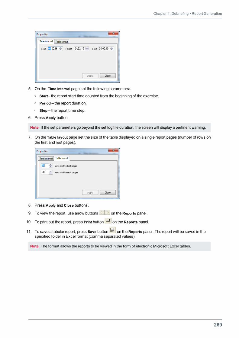
Chapter 4. Debriefing • Report Generation
269
5. On the Time interval page set the following parameters:.o Start– the report start time counted from the beginning of the exercise.o Period – the report duration.o Step – the report time step.
6. Press Apply button.
Note: If the set parameters go beyond the set log file duration, the screen will display a pertinent warning.
7. On the Table layout page set the size of the table displayed on a single report pages (number of rows onthe first and rest pages).
8. Press Apply andClose buttons.
9. To view the report, use arrow buttons on theReports panel.
10. To print out the report, press Print button on theReports panel.
11. To save a tabular report, press Save button on theReports panel. The report will be saved in thespecified folder in Excel format (comma separated values).
Note: The format allows the reports to be viewed in the form of electronic Microsoft Excel tables.
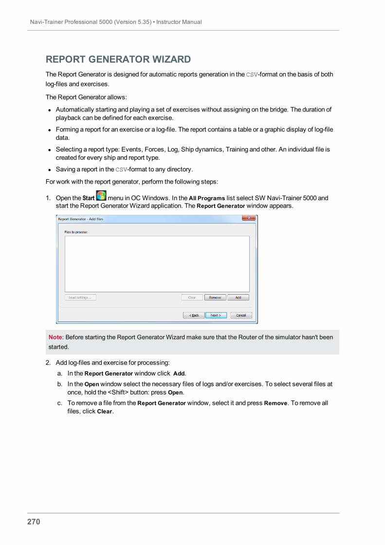
Navi-Trainer Professional 5000 (Version 5.35) • Instructor Manual
270
REPORT GENERATOR WIZARDThe Report Generator is designed for automatic reports generation in the CSV-format on the basis of bothlog-files and exercises.
The Report Generator allows:
l Automatically starting and playing a set of exercises without assigning on the bridge. The duration ofplayback can be defined for each exercise.
l Forming a report for an exercise or a log-file. The report contains a table or a graphic display of log-filedata.
l Selecting a report type: Events, Forces, Log, Ship dynamics, Training and other. An individual file iscreated for every ship and report type.
l Saving a report in the CSV-format to any directory.
For work with the report generator, perform the following steps:
1. Open the Start menu in OC Windows. In theAll Programs list select SW Navi-Trainer 5000 andstart the Report GeneratorWizard application. TheReport Generator window appears.
Note: Before starting the Report Generator Wizard make sure that the Router of the simulator hasn't beenstarted.
2. Add log-files and exercise for processing:a. In theReport Generator window click Add.b. In theOpenwindow select the necessary files of logs and/or exercises. To select several files at
once, hold the <Shift> button: press Open.c. To remove a file from theReport Generator window, select it and press Remove. To remove all
files, click Clear.
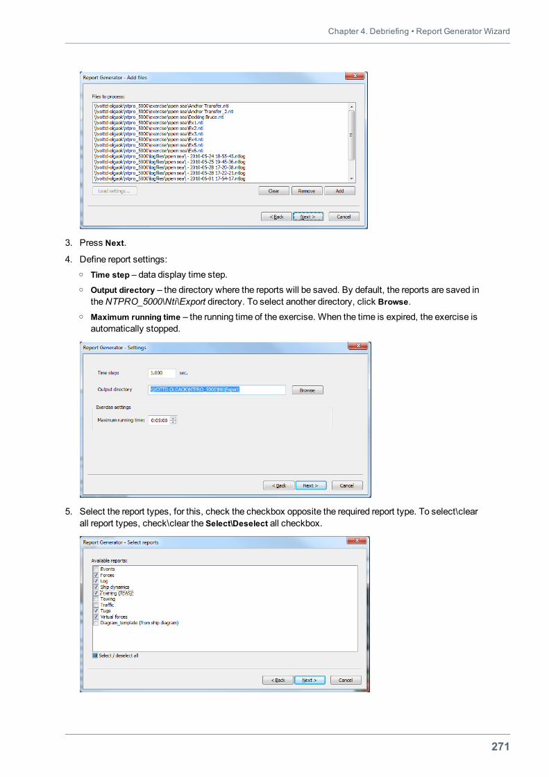
Chapter 4. Debriefing • Report Generator Wizard
271
3. Press Next.
4. Define report settings:o Time step – data display time step.o Output directory – the directory where the reports will be saved. By default, the reports are saved in
theNTPRO_5000\Nti\Export directory. To select another directory, click Browse.o Maximum running time – the running time of the exercise. When the time is expired, the exercise is
automatically stopped.
5. Select the report types, for this, check the checkbox opposite the required report type. To select\clearall report types, check\clear the Select\Deselect all checkbox.
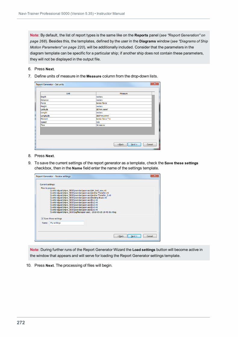
Navi-Trainer Professional 5000 (Version 5.35) • Instructor Manual
272
Note: By default, the list of report types is the same like on the Reports panel (see "Report Generation" onpage 268). Besides this, the templates, defined by the user in the Diagrams window (see "Diagrams of ShipMotion Parameters" on page 220), will be additionally included. Consider that the parameters in thediagram template can be specific for a particular ship; if another ship does not contain these parameters,they will not be displayed in the output file.
6. Press Next.
7. Define units of measure in theMeasure column from the drop-down lists.
8. Press Next.
9. To save the current settings of the report generator as a template, check the Save these settingscheckbox, then in theName field enter the name of the settings template.
Note: During further runs of the Report Generator Wizard the Load settings button will become active inthe window that appears and will serve for loading the Report Generator settings template.
10. Press Next. The processing of files will begin.
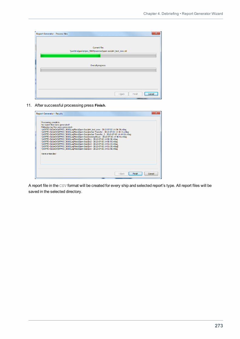
Chapter 4. Debriefing • Report Generator Wizard
273
11. After successful processing press Finish.
A report file in the CSV format will be created for every ship and selected report’s type. All report files will besaved in the selected directory.

275
CHAPTER 5.SPECIAL EXERCISES
This chapter contains:
Mooring Operations 277MooringWalls 277Characteristics of Mechanical and Hydrodynamic Interaction 280Points on Ship Contour 281Operations with Tow/Mooring Lines 282Control of MooringWinches 285SettingMooring Objects 287Work with BalloonMooring Fenders 295
Operations with Anchors 297Setting Anchor Parameters 297Selecting Seabed Type 299On-Chart Control of Anchors 300Control of AnchorWinches during Exercise 302
Towing Operations 304Setting Bridle 304Creating Barge Tow 306Operations with Tow Winches 307
Operations with Automatic Tugs 314Automatic Tugs General Settings 315Reserving and Releasing of Tug 315Basic Operations 316Automatic Tug Control Page 323
Navigation in Ice Conditions 324Work with Ice Zone 324Setting Ship Ice Class 329Setting Ice Repulsion 330Setting Ice Accretion 331Operations with Icebergs 331
Navi-Trainer Professional 5000 (Version 5.35) • Instructor Manual
276
Operations with Ice Breaker 334Monitoring Trainee Performance 337
Fishing Operations 338Shoal Objects 338Selecting Vertical Sonic Speed Distribution 341Pinnacle Objects 342Fishing Buoys 343Setting Bottom and Pelagic Trawl 344Setting Purse Seine 347Setting Long Line 350Watching Trainee Performance 352
Search and Rescue Operations 354SAR Objects 354Signaling in Accordance with ICS 365Giving Distress Signals 369Use of Rescue Boat 370
Operations with Helicopters and Aircrafts 374Operations with Helicopter Objects 374Operations with Aircraft Objects 376Deck Helicopters 377
Underway Replenishment Operations 382Setting Underway Replenishment Criteria 382Underway Replenishment Control Panel 383P&D Line and SpanWire Rendering/Heaving 384
Joint Ship Maneuvering in Formations 387Creating Fleet Formation 387Control of Fleet Formation 390
Passing of Locks 392Setting Lock Initial Properties 392Control of Lock 393Monitoring Fulfilment of Exercise with Locks 397
Control of Semaphores 398Ro-Ro Operations 400ECDIS Training 404Ordering Charts, Chart Update andWeather Forecasts 404Order Processing 407
Operations with Submarine 409Pirates Attacks Control 411Control of Motion Platform 412
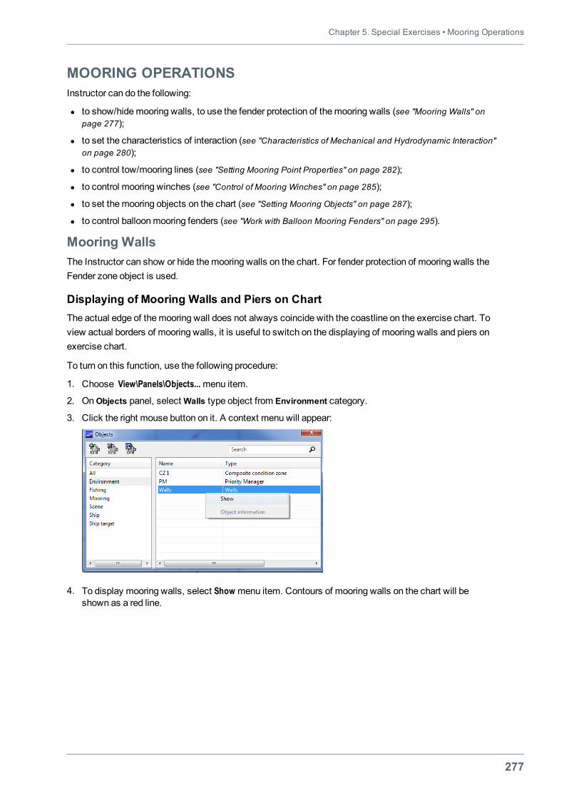
Chapter 5. Special Exercises • Mooring Operations
277
MOORING OPERATIONSInstructor can do the following:
l to show/hidemooring walls, to use the fender protection of themooring walls (see "Mooring Walls" onpage 277);
l to set the characteristics of interaction (see "Characteristics of Mechanical and Hydrodynamic Interaction"on page 280);
l to control tow/mooring lines (see "Setting Mooring Point Properties" on page 282);
l to control mooring winches (see "Control of Mooring Winches" on page 285);
l to set themooring objects on the chart (see "Setting Mooring Objects" on page 287);
l to control balloonmooring fenders (see "Work with Balloon Mooring Fenders" on page 295).
Mooring WallsThe Instructor can show or hide themooring walls on the chart. For fender protection of mooring walls theFender zone object is used.
Displaying of Mooring Walls and Piers on ChartThe actual edge of themooring wall does not always coincide with the coastline on the exercise chart. Toview actual borders of mooring walls, it is useful to switch on the displaying of mooring walls and piers onexercise chart.
To turn on this function, use the following procedure:
1. Choose View\Panels\Objects...menu item.
2. OnObjects panel, selectWalls type object from Environment category.
3. Click the right mouse button on it. A context menu will appear:
4. To display mooring walls, select Show menu item. Contours of mooring walls on the chart will beshown as a red line.
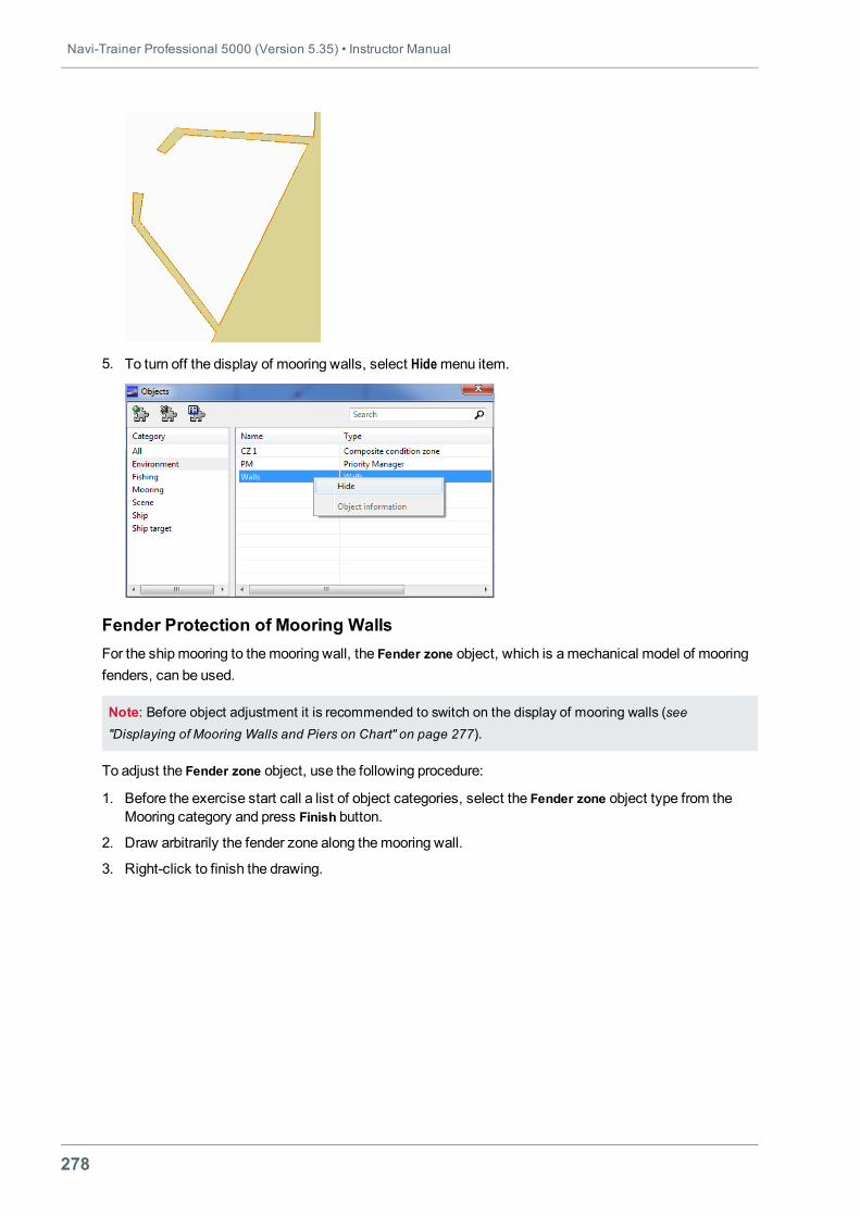
Navi-Trainer Professional 5000 (Version 5.35) • Instructor Manual
278
5. To turn off the display of mooring walls, select Hidemenu item.
Fender Protection of Mooring WallsFor the shipmooring to themooring wall, the Fender zone object, which is amechanical model of mooringfenders, can be used.
Note: Before object adjustment it is recommended to switch on the display of mooring walls (see"Displaying of Mooring Walls and Piers on Chart" on page 277).
To adjust the Fender zone object, use the following procedure:
1. Before the exercise start call a list of object categories, select the Fender zone object type from theMooring category and press Finish button.
2. Draw arbitrarily the fender zone along themooring wall.
3. Right-click to finish the drawing.
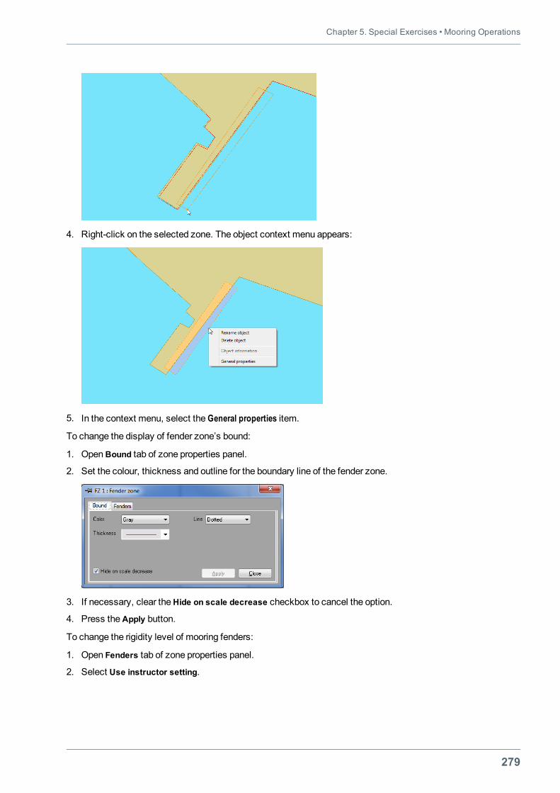
Chapter 5. Special Exercises • Mooring Operations
279
4. Right-click on the selected zone. The object context menu appears:
5. In the context menu, select the General properties item.
To change the display of fender zone’s bound:
1. OpenBound tab of zone properties panel.
2. Set the colour, thickness and outline for the boundary line of the fender zone.
3. If necessary, clear theHide on scale decrease checkbox to cancel the option.
4. Press theApply button.
To change the rigidity level of mooring fenders:
1. Open Fenders tab of zone properties panel.
2. Select Use instructor setting.
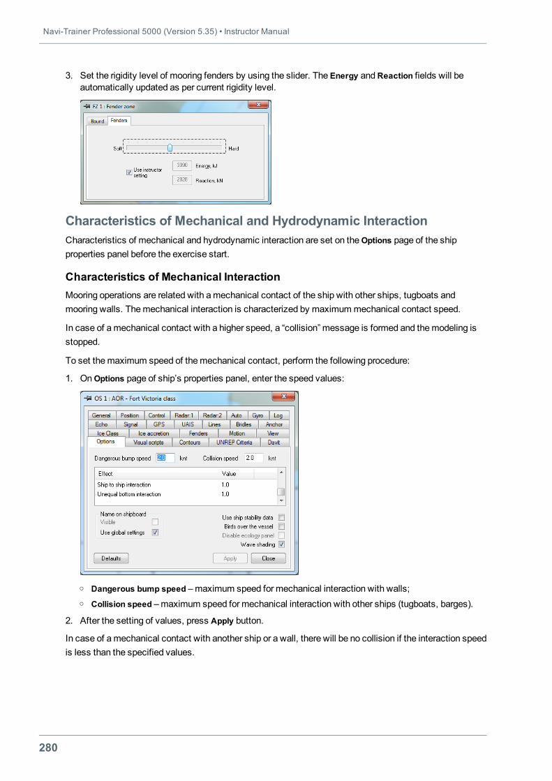
Navi-Trainer Professional 5000 (Version 5.35) • Instructor Manual
280
3. Set the rigidity level of mooring fenders by using the slider. The Energy andReaction fields will beautomatically updated as per current rigidity level.
Characteristics of Mechanical and Hydrodynamic InteractionCharacteristics of mechanical and hydrodynamic interaction are set on theOptions page of the shipproperties panel before the exercise start.
Characteristics of Mechanical InteractionMooring operations are related with amechanical contact of the ship with other ships, tugboats andmooring walls. Themechanical interaction is characterized by maximummechanical contact speed.
In case of amechanical contact with a higher speed, a “collision” message is formed and themodeling isstopped.
To set themaximum speed of themechanical contact, perform the following procedure:
1. OnOptions page of ship’s properties panel, enter the speed values:
o Dangerous bump speed –maximum speed for mechanical interaction with walls;o Collision speed –maximum speed for mechanical interaction with other ships (tugboats, barges).
2. After the setting of values, press Apply button.
In case of amechanical contact with another ship or a wall, there will be no collision if the interaction speedis less than the specified values.
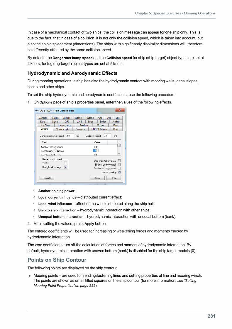
Chapter 5. Special Exercises • Mooring Operations
281
In case of amechanical contact of two ships, the collisionmessage can appear for one ship only. This isdue to the fact, that in case of a collision, it is not only the collision speed, which is taken into account, butalso the ship displacement (dimensions). The ships with significantly dissimilar dimensions will, therefore,be differently affected by the same collision speed.
By default, theDangerous bump speed and theCollision speed for ship (ship-target) object types are set at2 knots, for tug (tug-target) object types are set at 5 knots.
Hydrodynamic and Aerodynamic EffectsDuringmooring operations, a ship has also the hydrodynamic contact with mooring walls, canal slopes,banks and other ships.
To set the ship hydrodynamic and aerodynamic coefficients, use the following procedure:
1. OnOptions page of ship’s properties panel, enter the values of the following effects.
o Anchor holding power;o Local current influence – distributed current effect;o Local wind influence – effect of the wind distributed along the ship hull;o Ship to ship interaction – hydrodynamic interaction with other ships;o Unequal bottom interaction – hydrodynamic interaction with unequal bottom (bank).
2. After setting the values, press Apply button.
The entered coefficients will be used for increasing or weakening forces andmoments caused byhydrodynamic interaction.
The zero coefficients turn off the calculation of forces andmoment of hydrodynamic interaction. Bydefault, hydrodynamic interaction with uneven bottom (bank) is disabled for the ship target models (0).
Points on Ship ContourThe following points are displayed on the ship contour:
l Mooring points – are used for sending\fastening lines and setting properties of line andmooring winch.The points are shown as small filled squares on the ship contour (for more information, see "SettingMooring Point Properties" on page 282).
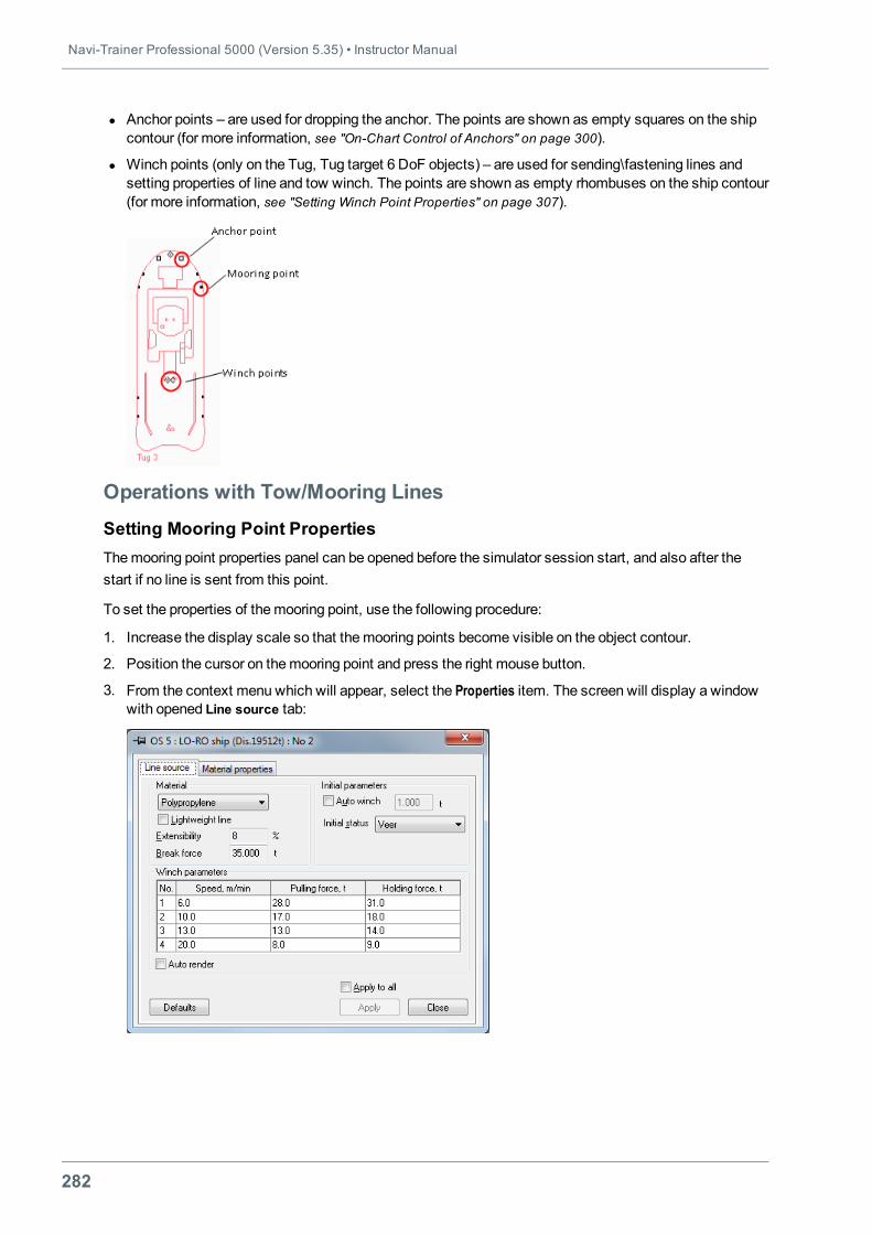
Navi-Trainer Professional 5000 (Version 5.35) • Instructor Manual
282
l Anchor points – are used for dropping the anchor. The points are shown as empty squares on the shipcontour (for more information, see "On-Chart Control of Anchors" on page 300).
l Winch points (only on the Tug, Tug target 6 DoF objects) – are used for sending\fastening lines andsetting properties of line and tow winch. The points are shown as empty rhombuses on the ship contour(for more information, see "Setting Winch Point Properties" on page 307).
Operations with Tow/Mooring Lines
Setting Mooring Point PropertiesThemooring point properties panel can be opened before the simulator session start, and also after thestart if no line is sent from this point.
To set the properties of themooring point, use the following procedure:
1. Increase the display scale so that the mooring points become visible on the object contour.
2. Position the cursor on themooring point and press the right mouse button.
3. From the context menu which will appear, select the Properties item. The screen will display a windowwith opened Line source tab:
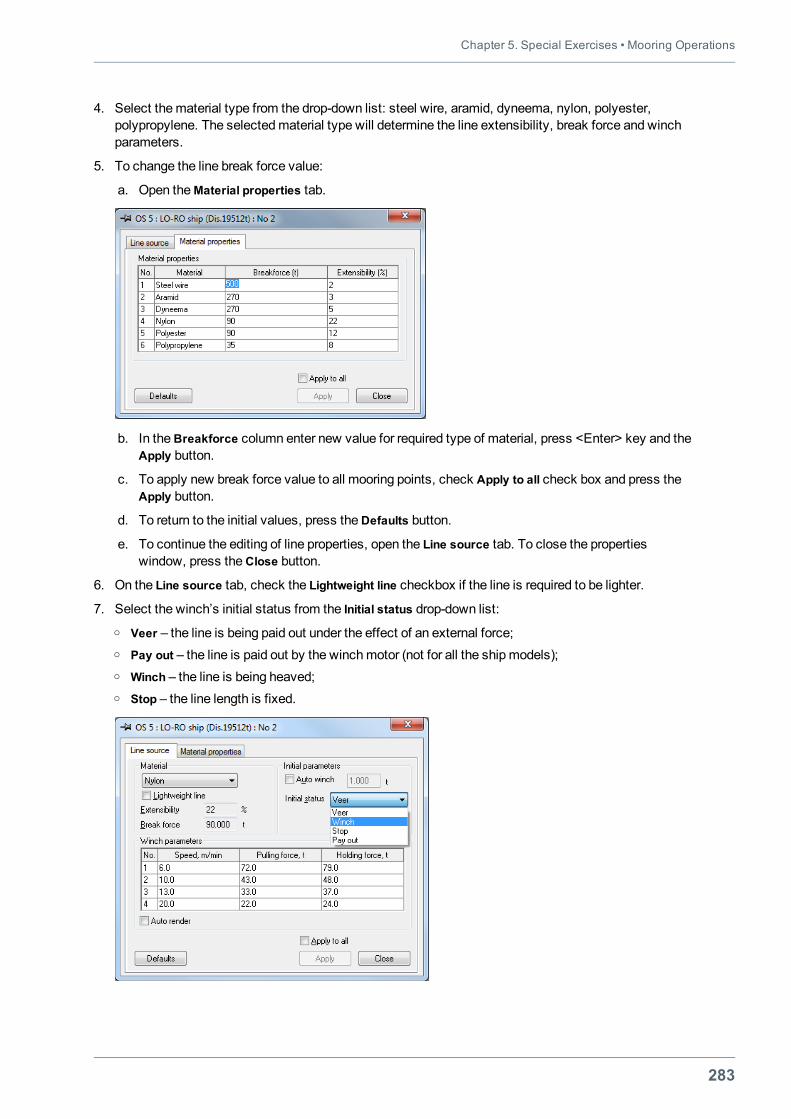
Chapter 5. Special Exercises • Mooring Operations
283
4. Select thematerial type from the drop-down list: steel wire, aramid, dyneema, nylon, polyester,polypropylene. The selectedmaterial type will determine the line extensibility, break force and winchparameters.
5. To change the line break force value:
a. Open theMaterial properties tab.
b. In theBreakforce column enter new value for required type of material, press <Enter> key and theApply button.
c. To apply new break force value to all mooring points, check Apply to all check box and press theApply button.
d. To return to the initial values, press theDefaults button.
e. To continue the editing of line properties, open the Line source tab. To close the propertieswindow, press theClose button.
6. On the Line source tab, check the Lightweight line checkbox if the line is required to be lighter.
7. Select the winch’s initial status from the Initial status drop-down list:o Veer – the line is being paid out under the effect of an external force;o Pay out – the line is paid out by the winchmotor (not for all the shipmodels);o Winch – the line is being heaved;o Stop – the line length is fixed.
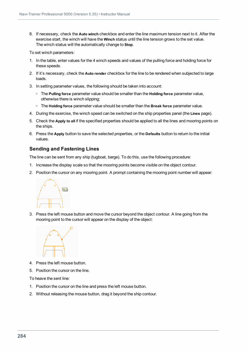
Navi-Trainer Professional 5000 (Version 5.35) • Instructor Manual
284
8. If necessary, check theAuto winch checkbox and enter the linemaximum tension next to it. After theexercise start, the winch will have theWinch status until the line tension grows to the set value.The winch status will the automatically change to Stop.
To set winch parameters:
1. In the table, enter values for the 4 winch speeds and values of the pulling force and holding force forthese speeds.
2. If it’s necessary, check theAuto render checkbox for the line to be rendered when subjected to largeloads.
3. In setting parameter values, the following should be taken into account:o The Pulling force parameter value should be smaller than theHolding force parameter value,
otherwise there is winch slipping;o TheHolding force parameter value should be smaller than theBreak force parameter value.
4. During the exercise, the winch speed can be switched on the ship properties panel (the Lines page).
5. Check theApply to all if the specified properties should be applied to all the lines andmooring points onthe ships.
6. Press theApply button to save the selected properties, or theDefaults button to return to the initialvalues.
Sending and Fastening LinesThe line can be sent from any ship (tugboat, barge). To do this, use the following procedure:
1. Increase the display scale so that the mooring points become visible on the object contour.
2. Position the cursor on any mooring point. A prompt containing themooring point number will appear:
3. Press the left mouse button andmove the cursor beyond the object contour. A line going from themooring point to the cursor will appear on the display of the object:
4. Press the left mouse button.
5. Position the cursor on the line.
To heave the sent line:
1. Position the cursor on the line and press the left mouse button.
2. Without releasing themouse button, drag it beyond the ship contour.
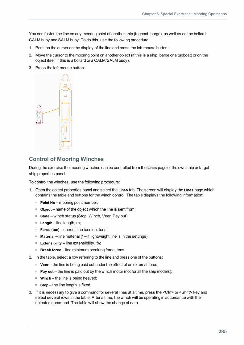
Chapter 5. Special Exercises • Mooring Operations
285
You can fasten the line on any mooring point of another ship (tugboat, barge), as well as on the bollard,CALM buoy and SALM buoy. To do this, use the following procedure:
1. Position the cursor on the display of the line and press the left mouse button.
2. Move the cursor to themooring point on another object (if this is a ship, barge or a tugboat) or on theobject itself if this is a bollard or a CALM/SALM buoy).
3. Press the left mouse button.
Control of Mooring WinchesDuring the exercise themooring winches can be controlled from the Lines page of the own ship or targetship properties panel.
To control the winches, use the following procedure:
1. Open the object properties panel and select the Lines tab. The screen will display the Lines page whichcontains the table and buttons for the winch control. The table displays the following information:o Point No –mooring point number;o Object – name of the object which the line is sent from;o State – winch status (Stop, Winch, Veer, Pay out);o Length – line length, m;o Force (ton) – current line tension, tons;o Material – linematerial (* – if lightweight line is in the settings);o Extensibility – line extensibility, %;o Break force – lineminimum breaking force, tons.
2. In the table, select a row referring to the line and press one of the buttons:o Veer – the line is being paid out under the effect of an external force;o Pay out – the line is paid out by the winchmotor (not for all the shipmodels);o Winch – the line is being heaved;o Stop – the line length is fixed.
3. If it is necessary to give a command for several lines at a time, press the <Ctrl> or <Shift> key andselect several rows in the table. After a time, the winch will be operating in accordance with theselected command. The table will show the change of data.
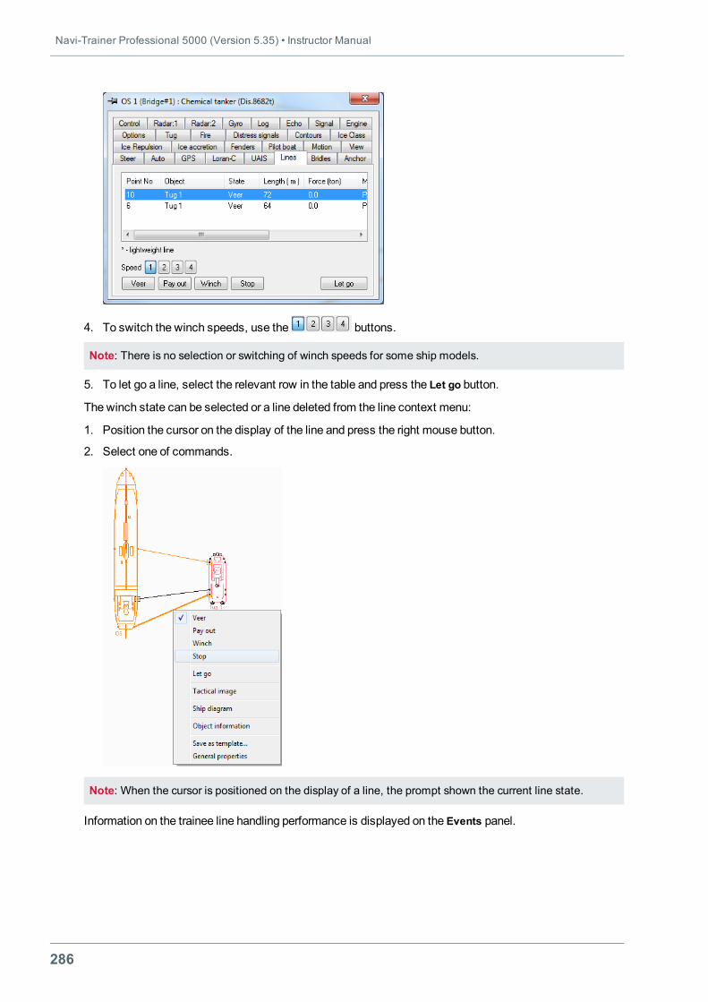
Navi-Trainer Professional 5000 (Version 5.35) • Instructor Manual
286
4. To switch the winch speeds, use the buttons.
Note: There is no selection or switching of winch speeds for some ship models.
5. To let go a line, select the relevant row in the table and press the Let go button.
The winch state can be selected or a line deleted from the line context menu:
1. Position the cursor on the display of the line and press the right mouse button.
2. Select one of commands.
Note: When the cursor is positioned on the display of a line, the prompt shown the current line state.
Information on the trainee line handling performance is displayed on the Events panel.
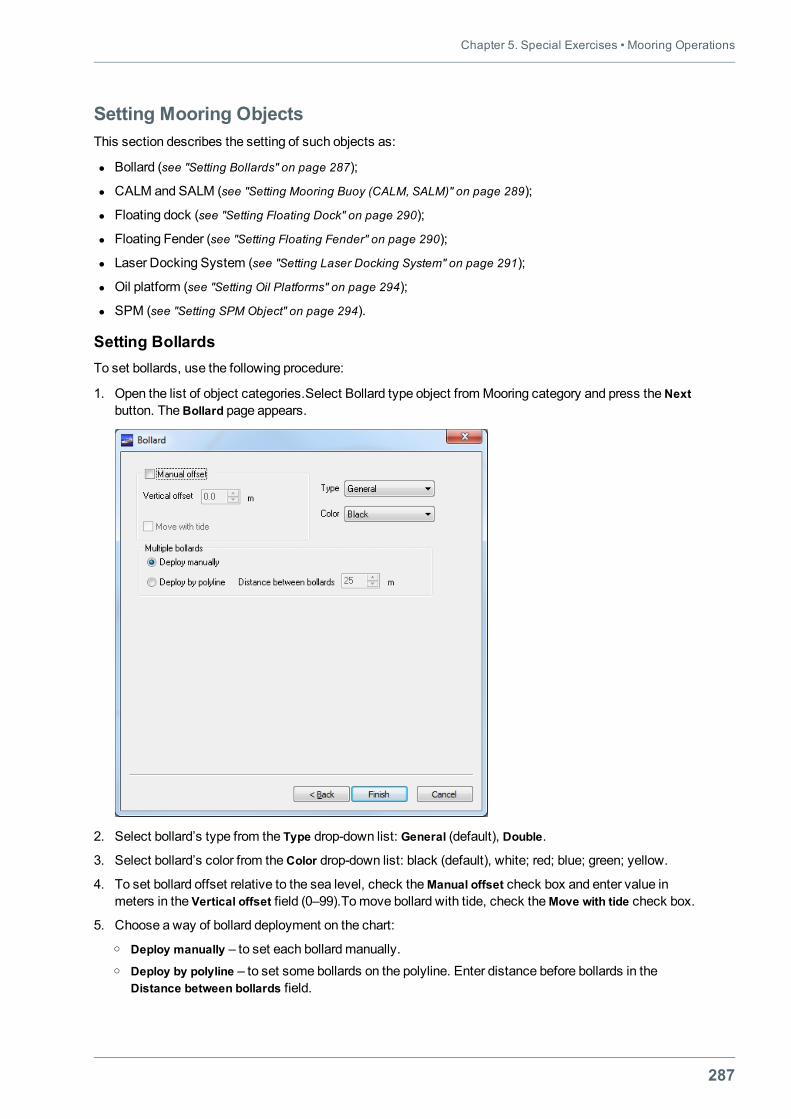
Chapter 5. Special Exercises • Mooring Operations
287
Setting Mooring ObjectsThis section describes the setting of such objects as:
l Bollard (see "Setting Bollards" on page 287);
l CALM and SALM (see "Setting Mooring Buoy (CALM, SALM)" on page 289);
l Floating dock (see "Setting Floating Dock" on page 290);
l Floating Fender (see "Setting Floating Fender" on page 290);
l Laser Docking System (see "Setting Laser Docking System" on page 291);
l Oil platform (see "Setting Oil Platforms" on page 294);
l SPM (see "Setting SPM Object" on page 294).
Setting BollardsTo set bollards, use the following procedure:
1. Open the list of object categories.Select Bollard type object from Mooring category and press theNextbutton. TheBollard page appears.
2. Select bollard’s type from the Type drop-down list: General (default), Double.
3. Select bollard’s color from theColor drop-down list: black (default), white; red; blue; green; yellow.
4. To set bollard offset relative to the sea level, check theManual offset check box and enter value inmeters in the Vertical offset field (0–99).Tomove bollard with tide, check theMove with tide check box.
5. Choose a way of bollard deployment on the chart:o Deploy manually – to set each bollardmanually.o Deploy by polyline – to set some bollards on the polyline. Enter distance before bollards in the
Distance between bollards field.
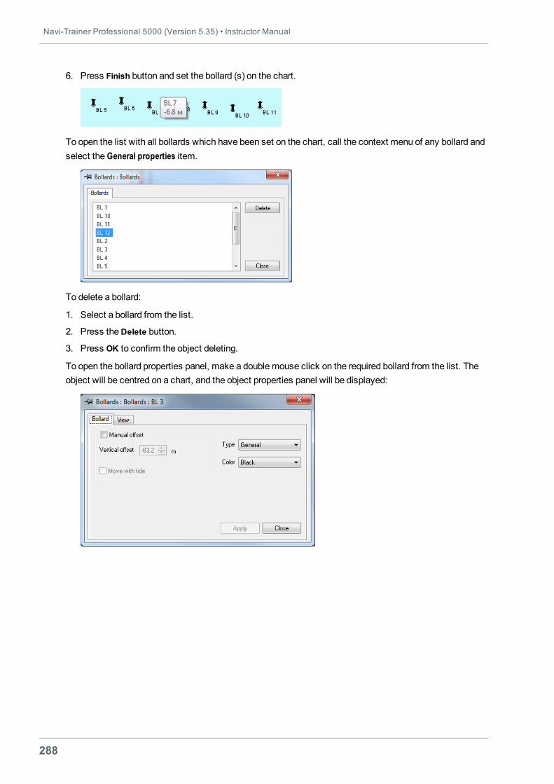
Navi-Trainer Professional 5000 (Version 5.35) • Instructor Manual
288
6. Press Finish button and set the bollard (s) on the chart.
To open the list with all bollards which have been set on the chart, call the context menu of any bollard andselect the General properties item.
To delete a bollard:
1. Select a bollard from the list.
2. Press theDelete button.
3. Press OK to confirm the object deleting.
To open the bollard properties panel, make a doublemouse click on the required bollard from the list. Theobject will be centred on a chart, and the object properties panel will be displayed:
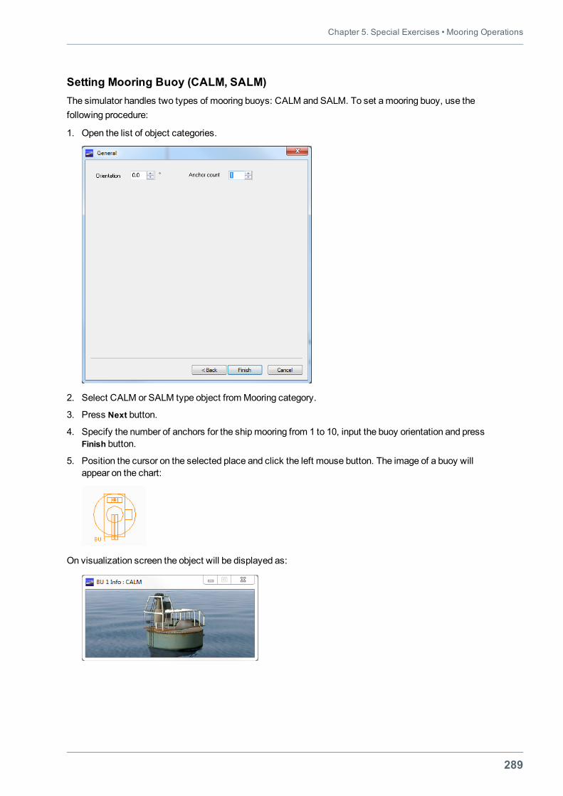
Chapter 5. Special Exercises • Mooring Operations
289
Setting Mooring Buoy (CALM, SALM)The simulator handles two types of mooring buoys: CALM and SALM. To set a mooring buoy, use thefollowing procedure:
1. Open the list of object categories.
2. Select CALM or SALM type object fromMooring category.
3. Press Next button.
4. Specify the number of anchors for the shipmooring from 1 to 10, input the buoy orientation and pressFinish button.
5. Position the cursor on the selected place and click the left mouse button. The image of a buoy willappear on the chart:
On visualization screen the object will be displayed as:
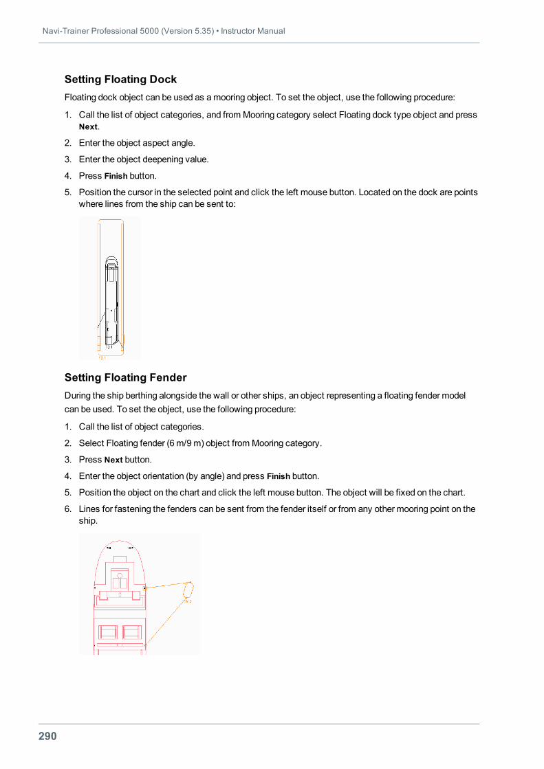
Navi-Trainer Professional 5000 (Version 5.35) • Instructor Manual
290
Setting Floating DockFloating dock object can be used as amooring object. To set the object, use the following procedure:
1. Call the list of object categories, and fromMooring category select Floating dock type object and pressNext.
2. Enter the object aspect angle.
3. Enter the object deepening value.
4. Press Finish button.
5. Position the cursor in the selected point and click the left mouse button. Located on the dock are pointswhere lines from the ship can be sent to:
Setting Floating FenderDuring the ship berthing alongside the wall or other ships, an object representing a floating fender modelcan be used. To set the object, use the following procedure:
1. Call the list of object categories.
2. Select Floating fender (6m/9m) object fromMooring category.
3. Press Next button.
4. Enter the object orientation (by angle) and press Finish button.
5. Position the object on the chart and click the left mouse button. The object will be fixed on the chart.
6. Lines for fastening the fenders can be sent from the fender itself or from any other mooring point on theship.
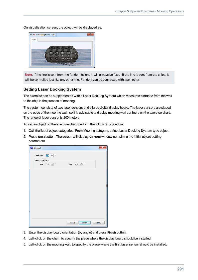
Chapter 5. Special Exercises • Mooring Operations
291
On visualization screen, the object will be displayed as:
Note: If the line is sent from the fender, its length will always be fixed. If the line is sent from the ships, itwill be controlled just like any other line. Fenders can be connected with each other.
Setting Laser Docking SystemThe exercise can be supplemented with a Laser Docking System whichmeasures distance from the wallto the ship in the process of mooring.
The system consists of two laser sensors and a large digital display board. The laser sensors are placedon the edge of themooring wall, so it is advisable to display mooring wall contours on the exercise chart.The range of laser sensor is 200meters.
To set an object on the exercise chart, perform the following procedure:
1. Call the list of object categories. From Mooring category, select Laser Docking System type object.
2. Press Next button. The screen will display Generalwindow containing the initial object settingparameters.
3. Enter the display board orientation (by angle) and press Finish button.
4. Left-click on the chart, to specify the place where the display board should be installed.
5. Left-click on themooring wall, to specify the place where the first laser sensor should be installed.
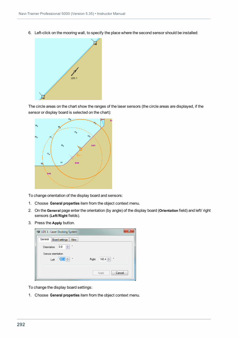
Navi-Trainer Professional 5000 (Version 5.35) • Instructor Manual
292
6. Left-click on themooring wall, to specify the place where the second sensor should be installed:
The circle areas on the chart show the ranges of the laser sensors (the circle areas are displayed, if thesensor or display board is selected on the chart):
To change orientation of the display board and sensors:
1. Choose General properties item from the object context menu.
2. On theGeneral page enter the orientation (by angle) of the display board (Orientation field) and left/ rightsensors (Left/Right fields).
3. Press theApply button.
To change the display board settings:
1. Choose General properties item from the object context menu.
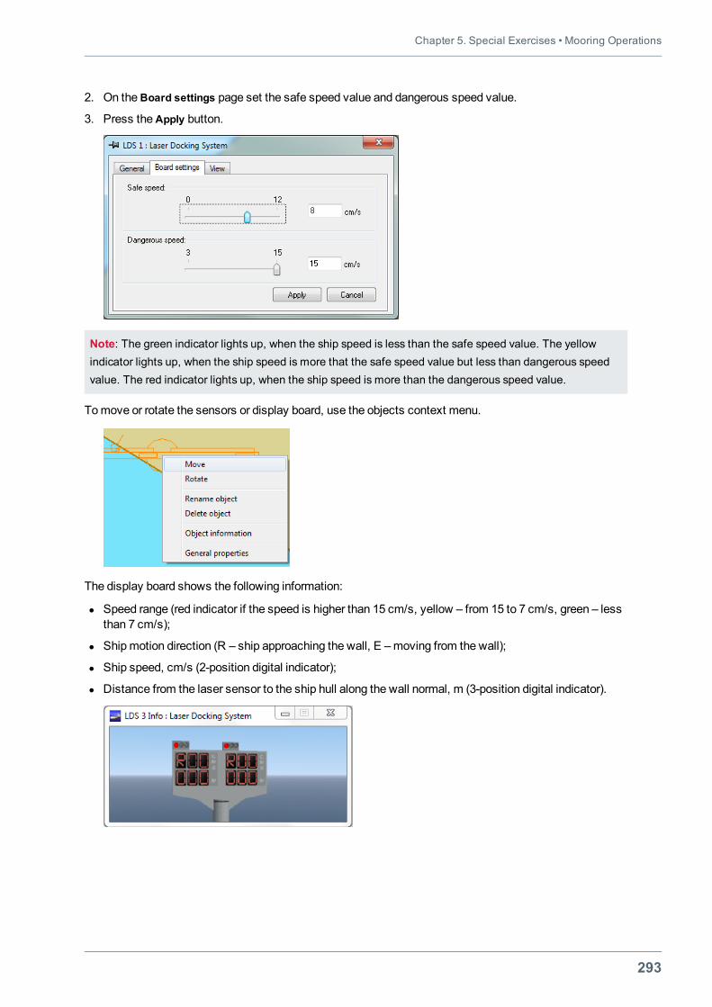
Chapter 5. Special Exercises • Mooring Operations
293
2. On theBoard settings page set the safe speed value and dangerous speed value.
3. Press theApply button.
Note: The green indicator lights up, when the ship speed is less than the safe speed value. The yellowindicator lights up, when the ship speed is more that the safe speed value but less than dangerous speedvalue. The red indicator lights up, when the ship speed is more than the dangerous speed value.
Tomove or rotate the sensors or display board, use the objects context menu.
The display board shows the following information:
l Speed range (red indicator if the speed is higher than 15 cm/s, yellow – from 15 to 7 cm/s, green – lessthan 7 cm/s);
l Shipmotion direction (R – ship approaching the wall, E –moving from the wall);
l Ship speed, cm/s (2-position digital indicator);
l Distance from the laser sensor to the ship hull along the wall normal, m (3-position digital indicator).
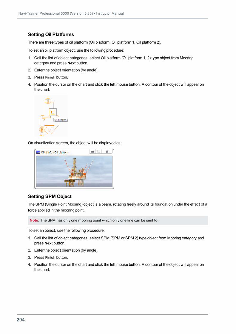
Navi-Trainer Professional 5000 (Version 5.35) • Instructor Manual
294
Setting Oil PlatformsThere are three types of oil platform (Oil platform, Oil platform 1, Oil platform 2).
To set an oil platform object, use the following procedure:
1. Call the list of object categories, select Oil platform (Oil platform 1, 2) type object fromMooringcategory and press Next button.
2. Enter the object orientation (by angle).
3. Press Finish button.
4. Position the cursor on the chart and click the left mouse button. A contour of the object will appear onthe chart.
On visualization screen, the object will be displayed as:
Setting SPM ObjectThe SPM (Single Point Mooring) object is a beam, rotating freely around its foundation under the effect of aforce applied in themooring point.
Note: The SPM has only one mooring point which only one line can be sent to.
To set an object, use the following procedure:
1. Call the list of object categories, select SPM (SPM or SPM 2) type object fromMooring category andpress Next button.
2. Enter the object orientation (by angle).
3. Press Finish button.
4. Position the cursor on the chart and click the left mouse button. A contour of the object will appear onthe chart.
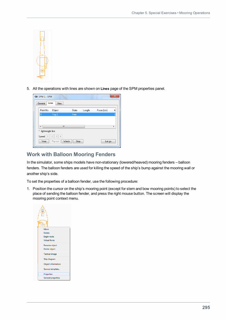
Chapter 5. Special Exercises • Mooring Operations
295
5. All the operations with lines are shown on Lines page of the SPM properties panel.
Work with Balloon Mooring FendersIn the simulator, some ships models have non-stationary (lowered/heaved) mooring fenders – balloonfenders. The balloon fenders are used for killing the speed of the ship’s bump against themooring wall oranother ship’s side.
To set the properties of a balloon fender, use the following procedure:
1. Position the cursor on the ship’s mooring point (except for stern and bow mooring points) to select theplace of sending the balloon fender, and press the right mouse button. The screen will display themooring point context menu.
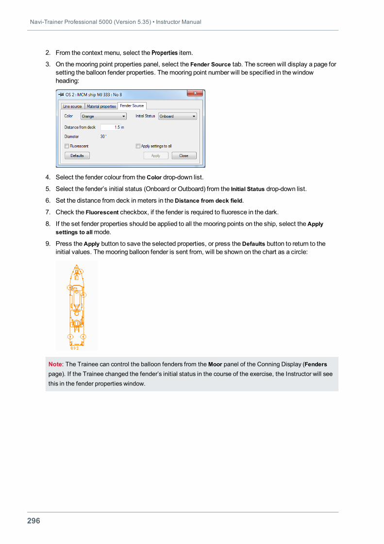
Navi-Trainer Professional 5000 (Version 5.35) • Instructor Manual
296
2. From the context menu, select the Properties item.
3. On themooring point properties panel, select the Fender Source tab. The screen will display a page forsetting the balloon fender properties. Themooring point number will be specified in the windowheading:
4. Select the fender colour from theColor drop-down list.
5. Select the fender’s initial status (Onboard or Outboard) from the Initial Status drop-down list.
6. Set the distance from deck inmeters in theDistance from deck field.
7. Check the Fluorescent checkbox, if the fender is required to fluoresce in the dark.
8. If the set fender properties should be applied to all themooring points on the ship, select theApplysettings to allmode.
9. Press theApply button to save the selected properties, or press theDefaults button to return to theinitial values. Themooring balloon fender is sent from, will be shown on the chart as a circle:
Note: The Trainee can control the balloon fenders from theMoor panel of the Conning Display (Fenderspage). If the Trainee changed the fender’s initial status in the course of the exercise, the Instructor will seethis in the fender properties window.
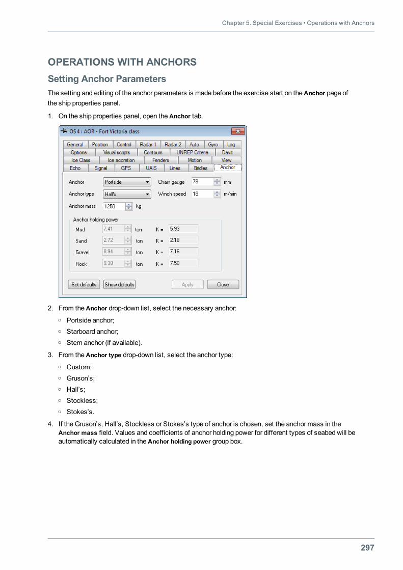
Chapter 5. Special Exercises • Operations with Anchors
297
OPERATIONS WITH ANCHORSSetting Anchor ParametersThe setting and editing of the anchor parameters is made before the exercise start on theAnchor page ofthe ship properties panel.
1. On the ship properties panel, open theAnchor tab.
2. From theAnchor drop-down list, select the necessary anchor:o Portside anchor;o Starboard anchor;o Stern anchor (if available).
3. From theAnchor type drop-down list, select the anchor type:o Custom;o Gruson’s;o Hall’s;o Stockless;o Stokes’s.
4. If the Gruson’s, Hall’s, Stockless or Stokes’s type of anchor is chosen, set the anchor mass in theAnchor mass field. Values and coefficients of anchor holding power for different types of seabed will beautomatically calculated in theAnchor holding power group box.
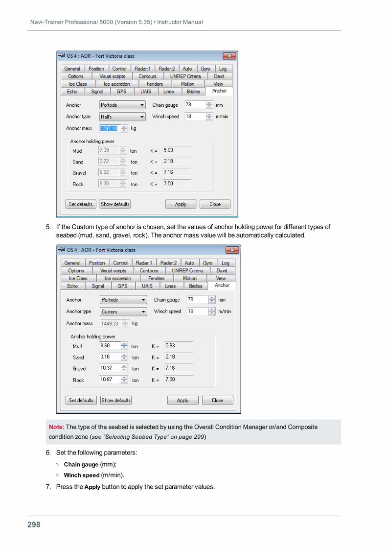
Navi-Trainer Professional 5000 (Version 5.35) • Instructor Manual
298
5. If the Custom type of anchor is chosen, set the values of anchor holding power for different types ofseabed (mud, sand, gravel, rock). The anchor mass value will be automatically calculated.
Note: The type of the seabed is selected by using the Overall Condition Manager or/and Compositecondition zone (see "Selecting Seabed Type" on page 299)
6. Set the following parameters:o Chain gauge (mm);o Winch speed (m/min).
7. Press theApply button to apply the set parameter values.
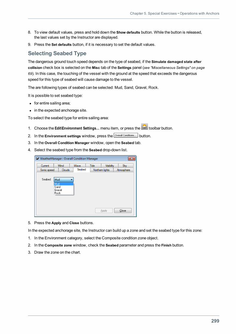
Chapter 5. Special Exercises • Operations with Anchors
299
8. To view default values, press and hold down the Show defaults button. While the button is released,the last values set by the Instructor are displayed.
9. Press the Set defaults button, if it is necessary to set the default values.
Selecting Seabed TypeThe dangerous ground touch speed depends on the type of seabed, if the Simulate damaged state aftercollision check box is selected on theMisc tab of the Settings panel (see "Miscellaneous Settings" on page69). In this case, the touching of the vessel with the ground at the speed that exceeds the dangerousspeed for this type of seabed will cause damage to the vessel.
The are following types of seabed can be selected: Mud, Sand, Gravel, Rock.
It is possible to set seabed type:
l for entire sailing area;
l in the expected anchorage site.
To select the seabed type for entire sailing area:
1. Choose the Edit\Environment Settings…menu item, or press the toolbar button.
2. In the Environment settings window, press the button.
3. In theOverall Condition Manager window, open the Seabed tab.
4. Select the seabed type from the Seabed drop-down list.
5. Press theApply andClose buttons.
In the expected anchorage site, the Instructor can build up a zone and set the seabed type for this zone:
1. In the Environment category, select the Composite condition zone object.
2. In theComposite zone window, check the Seabed parameter and press the Finish button.
3. Draw the zone on the chart.
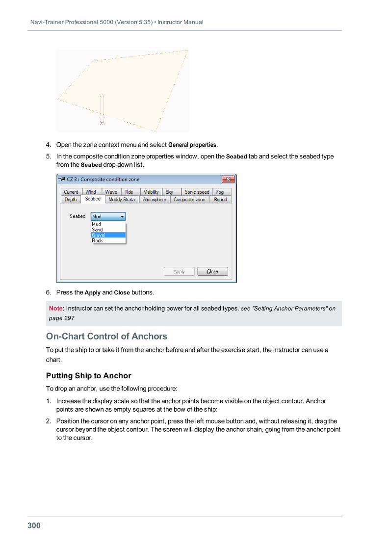
Navi-Trainer Professional 5000 (Version 5.35) • Instructor Manual
300
4. Open the zone context menu and select General properties.
5. In the composite condition zone properties window, open the Seabed tab and select the seabed typefrom the Seabed drop-down list.
6. Press theApply andClose buttons.
Note: Instructor can set the anchor holding power for all seabed types, see "Setting Anchor Parameters" onpage 297
On-Chart Control of AnchorsTo put the ship to or take it from the anchor before and after the exercise start, the Instructor can use achart.
Putting Ship to AnchorTo drop an anchor, use the following procedure:
1. Increase the display scale so that the anchor points become visible on the object contour. Anchorpoints are shown as empty squares at the bow of the ship:
2. Position the cursor on any anchor point, press the left mouse button and, without releasing it, drag thecursor beyond the object contour. The screen will display the anchor chain, going from the anchor pointto the cursor.
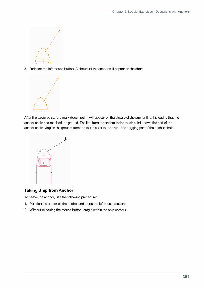
Chapter 5. Special Exercises • Operations with Anchors
301
3. Release the left mouse button. A picture of the anchor will appear on the chart.
After the exercise start, a mark (touch point) will appear on the picture of the anchor line, indicating that theanchor chain has reached the ground. The line from the anchor to the touch point shows the part of theanchor chain lying on the ground; from the touch point to the ship – the sagging part of the anchor chain.
Taking Ship from AnchorTo heave the anchor, use the following procedure:
1. Position the cursor on the anchor and press the left mouse button.
2. Without releasing themouse button, drag it within the ship contour.
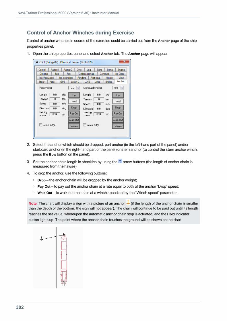
Navi-Trainer Professional 5000 (Version 5.35) • Instructor Manual
302
Control of Anchor Winches during ExerciseControl of anchor winches in course of the exercise could be carried out from theAnchor page of the shipproperties panel.
1. Open the ship properties panel and select Anchor tab. TheAnchor page will appear:
2. Select the anchor which should be dropped: port anchor (in the left-hand part of the panel) and/orstarboard anchor (in the right-hand part of the panel) or stern anchor (to control the stern anchor winch,press theBow button on the panel).
3. Set the anchor chain length in shackles by using the arrow buttons (the length of anchor chain ismeasured from the hawse).
4. To drop the anchor, use the following buttons:o Drop – the anchor chain will be dropped by the anchor weight;o Pay Out – to pay out the anchor chain at a rate equal to 50% of the anchor “Drop” speed;o Walk Out – to walk out the chain at a winch speed set by the “Winch speed” parameter.
Note: The chart will display a sign with a picture of an anchor (if the length of the anchor chain is smallerthan the depth of the bottom, the sign will not appear). The chain will continue to be paid out until its lengthreaches the set value, whereupon the automatic anchor chain stop is actuated, and the Hold indicatorbutton lights up. The point where the anchor chain touches the ground will be shown on the chart.
Chapter 5. Special Exercises • Operations with Anchors
303
5. To view information about the state of the anchor chain, use the following digital displays:o Length – length of the paid out anchor chain;o Tension – anchor chain tension, in tons;o Speed – winch speed, m/s;o Direction – anchor chain direction relative to the ship centreline plane, degrees;o Holding Power – anchor’s holding power, tons.
6. To stop the anchor chainmotionmanually, press theHold button.
7. To heave the anchor chain, press theUp button. At themoment when the anchor breaks away from theground, the anchor mark will disappear from the chart.The anchor chain will be heaved until its lengthbecomes equal to 0 (the anchor is in the hawse).
8. For the emergency let-go of the anchor chain inner end, press the Release button.
9. Check theWater edge checkbox to stop the winch when the anchor reaches the water surface.
Note: The Trainee can control the anchor winches from the conning displayMoor panel (the Anchorspage).
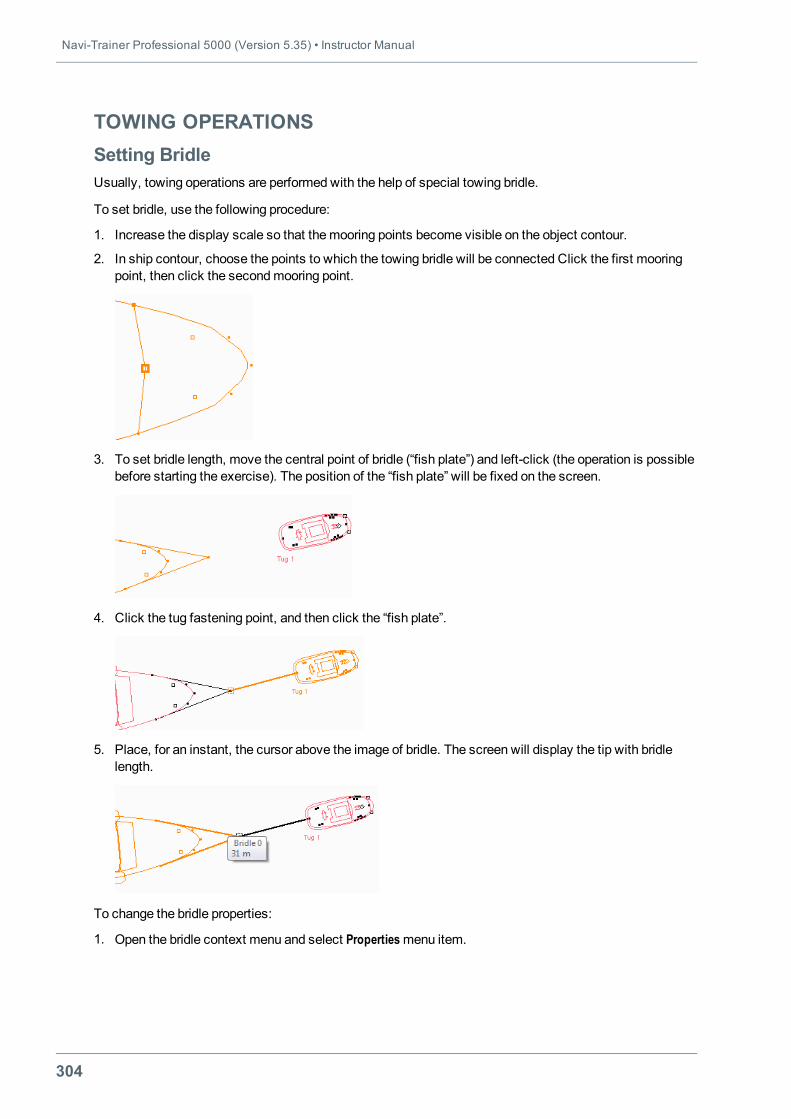
Navi-Trainer Professional 5000 (Version 5.35) • Instructor Manual
304
TOWING OPERATIONSSetting BridleUsually, towing operations are performed with the help of special towing bridle.
To set bridle, use the following procedure:
1. Increase the display scale so that themooring points become visible on the object contour.
2. In ship contour, choose the points to which the towing bridle will be connected Click the first mooringpoint, then click the secondmooring point.
3. To set bridle length, move the central point of bridle (“fish plate”) and left-click (the operation is possiblebefore starting the exercise). The position of the “fish plate” will be fixed on the screen.
4. Click the tug fastening point, and then click the “fish plate”.
5. Place, for an instant, the cursor above the image of bridle. The screen will display the tip with bridlelength.
To change the bridle properties:
1. Open the bridle context menu and select Propertiesmenu item.
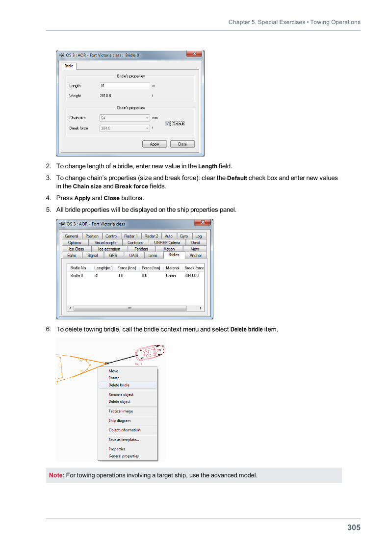
Chapter 5. Special Exercises • Towing Operations
305
2. To change length of a bridle, enter new value in the Length field.
3. To change chain’s properties (size and break force): clear theDefault check box and enter new valuesin theChain size andBreak force fields.
4. Press Apply andClose buttons.
5. All bridle properties will be displayed on the ship properties panel.
6. To delete towing bridle, call the bridle context menu and select Delete bridle item.
Note: For towing operations involving a target ship, use the advanced model.
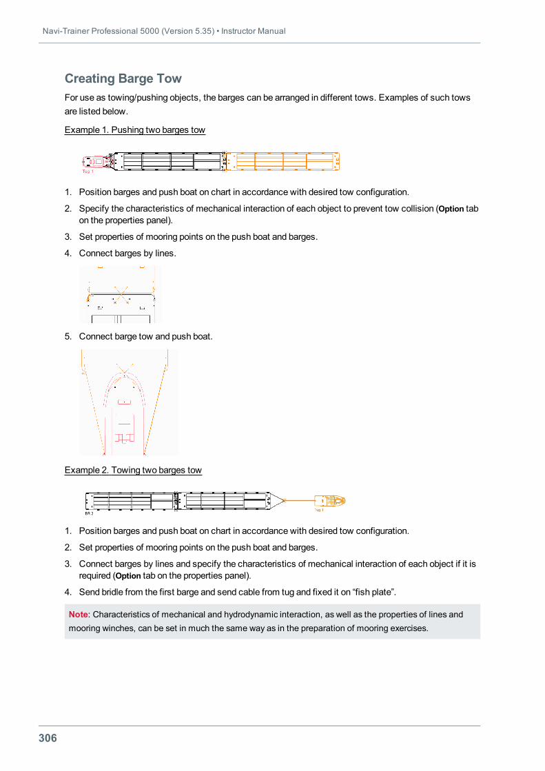
Navi-Trainer Professional 5000 (Version 5.35) • Instructor Manual
306
Creating Barge TowFor use as towing/pushing objects, the barges can be arranged in different tows. Examples of such towsare listed below.
Example 1. Pushing two barges tow
1. Position barges and push boat on chart in accordance with desired tow configuration.
2. Specify the characteristics of mechanical interaction of each object to prevent tow collision (Option tabon the properties panel).
3. Set properties of mooring points on the push boat and barges.
4. Connect barges by lines.
5. Connect barge tow and push boat.
Example 2. Towing two barges tow
1. Position barges and push boat on chart in accordance with desired tow configuration.
2. Set properties of mooring points on the push boat and barges.
3. Connect barges by lines and specify the characteristics of mechanical interaction of each object if it isrequired (Option tab on the properties panel).
4. Send bridle from the first barge and send cable from tug and fixed it on “fish plate”.
Note: Characteristics of mechanical and hydrodynamic interaction, as well as the properties of lines andmooring winches, can be set in much the same way as in the preparation of mooring exercises.
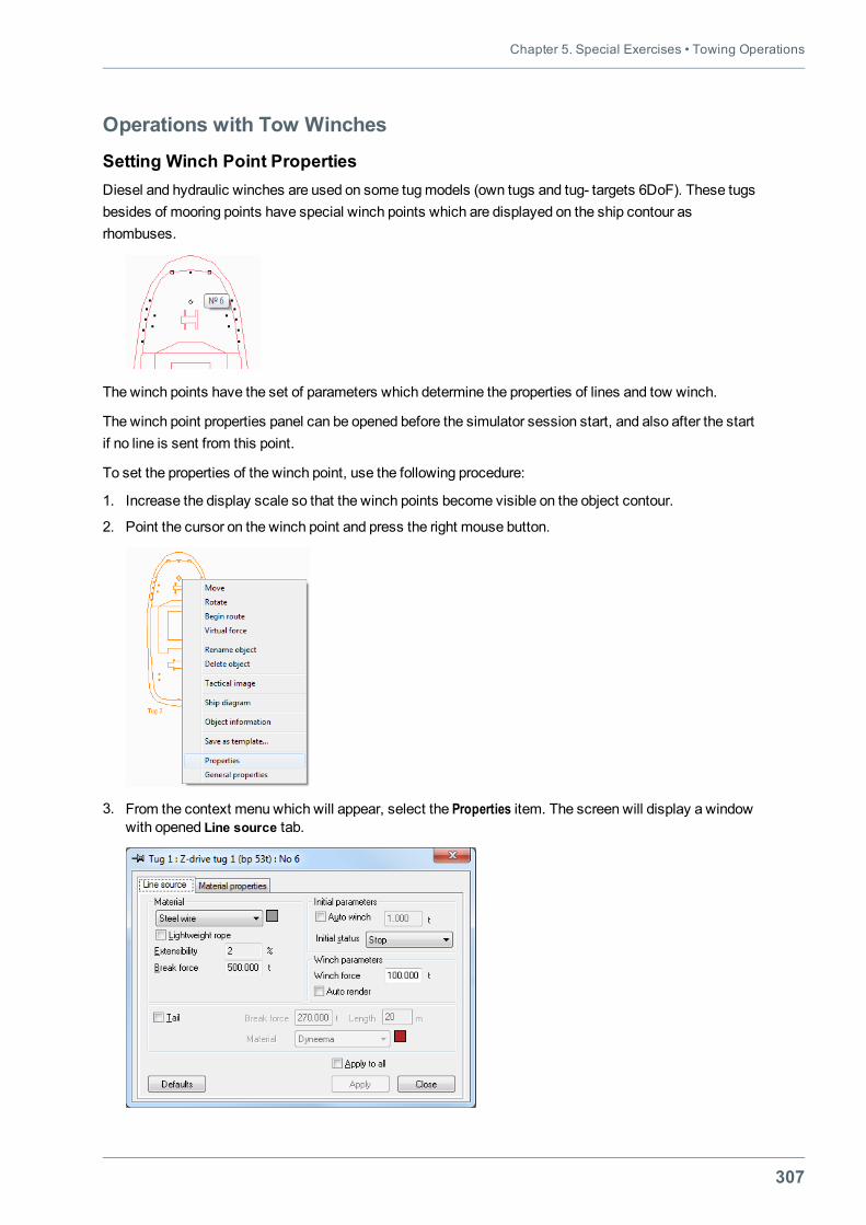
Chapter 5. Special Exercises • Towing Operations
307
Operations with Tow Winches
Setting Winch Point PropertiesDiesel and hydraulic winches are used on some tugmodels (own tugs and tug- targets 6DoF). These tugsbesides of mooring points have special winch points which are displayed on the ship contour asrhombuses.
The winch points have the set of parameters which determine the properties of lines and tow winch.
The winch point properties panel can be opened before the simulator session start, and also after the startif no line is sent from this point.
To set the properties of the winch point, use the following procedure:
1. Increase the display scale so that the winch points become visible on the object contour.
2. Point the cursor on the winch point and press the right mouse button.
3. From the context menu which will appear, select the Properties item. The screen will display a windowwith opened Line source tab.
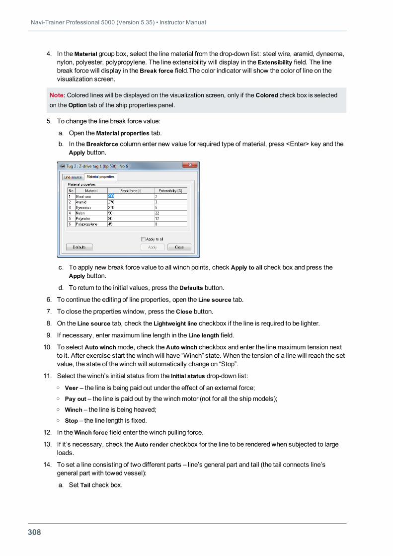
Navi-Trainer Professional 5000 (Version 5.35) • Instructor Manual
308
4. In theMaterial group box, select the linematerial from the drop-down list: steel wire, aramid, dyneema,nylon, polyester, polypropylene. The line extensibility will display in the Extensibility field. The linebreak force will display in theBreak force field.The color indicator will show the color of line on thevisualization screen.
Note: Colored lines will be displayed on the visualization screen, only if the Colored check box is selectedon the Option tab of the ship properties panel.
5. To change the line break force value:
a. Open theMaterial properties tab.b. In theBreakforce column enter new value for required type of material, press <Enter> key and the
Apply button.
c. To apply new break force value to all winch points, check Apply to all check box and press theApply button.
d. To return to the initial values, press theDefaults button.
6. To continue the editing of line properties, open the Line source tab.
7. To close the properties window, press theClose button.
8. On the Line source tab, check the Lightweight line checkbox if the line is required to be lighter.
9. If necessary, enter maximum line length in the Line length field.
10. To select Auto winchmode, check theAuto winch checkbox and enter the linemaximum tension nextto it. After exercise start the winch will have “Winch” state. When the tension of a line will reach the setvalue, the state of the winch will automatically change on “Stop”.
11. Select the winch’s initial status from the Initial status drop-down list:o Veer – the line is being paid out under the effect of an external force;o Pay out – the line is paid out by the winchmotor (not for all the shipmodels);o Winch – the line is being heaved;o Stop – the line length is fixed.
12. In theWinch force field enter the winch pulling force.
13. If it’s necessary, check theAuto render checkbox for the line to be rendered when subjected to largeloads.
14. To set a line consisting of two different parts – line’s general part and tail (the tail connects line’sgeneral part with towed vessel):
a. Set Tail check box.
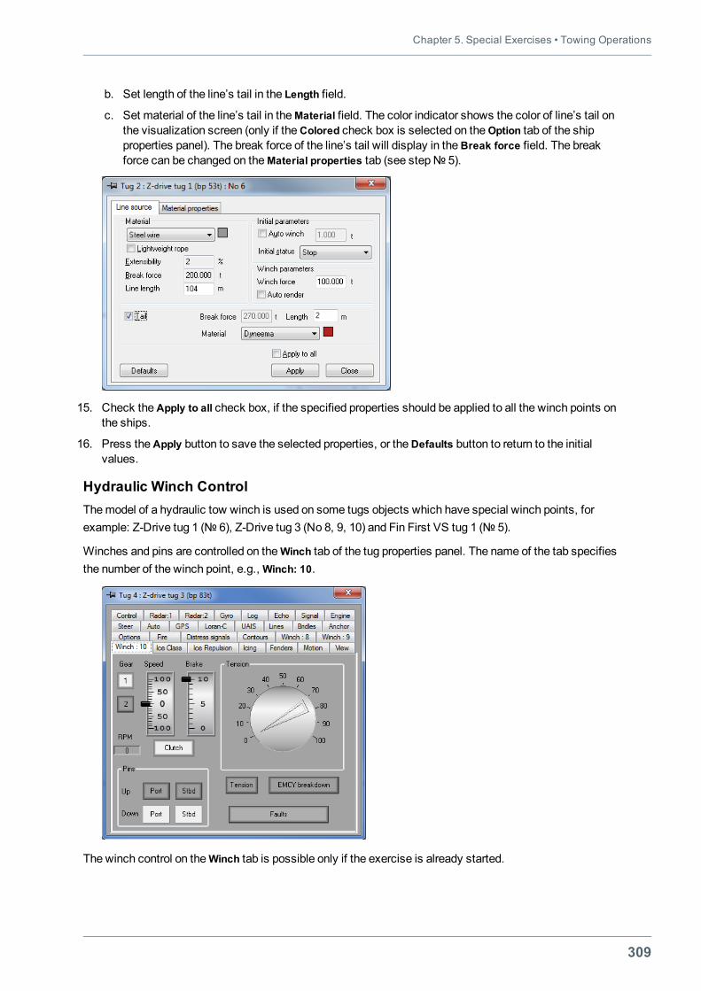
Chapter 5. Special Exercises • Towing Operations
309
b. Set length of the line’s tail in the Length field.
c. Set material of the line’s tail in theMaterial field. The color indicator shows the color of line’s tail onthe visualization screen (only if theColored check box is selected on theOption tab of the shipproperties panel). The break force of the line’s tail will display in theBreak force field. The breakforce can be changed on theMaterial properties tab (see step№ 5).
15. Check theApply to all check box, if the specified properties should be applied to all the winch points onthe ships.
16. Press theApply button to save the selected properties, or theDefaults button to return to the initialvalues.
Hydraulic Winch ControlThemodel of a hydraulic tow winch is used on some tugs objects which have special winch points, forexample: Z-Drive tug 1 (№ 6), Z-Drive tug 3 (No 8, 9, 10) and Fin First VS tug 1 (№ 5).
Winches and pins are controlled on theWinch tab of the tug properties panel. The name of the tab specifiesthe number of the winch point, e.g.,Winch: 10.
The winch control on theWinch tab is possible only if the exercise is already started.
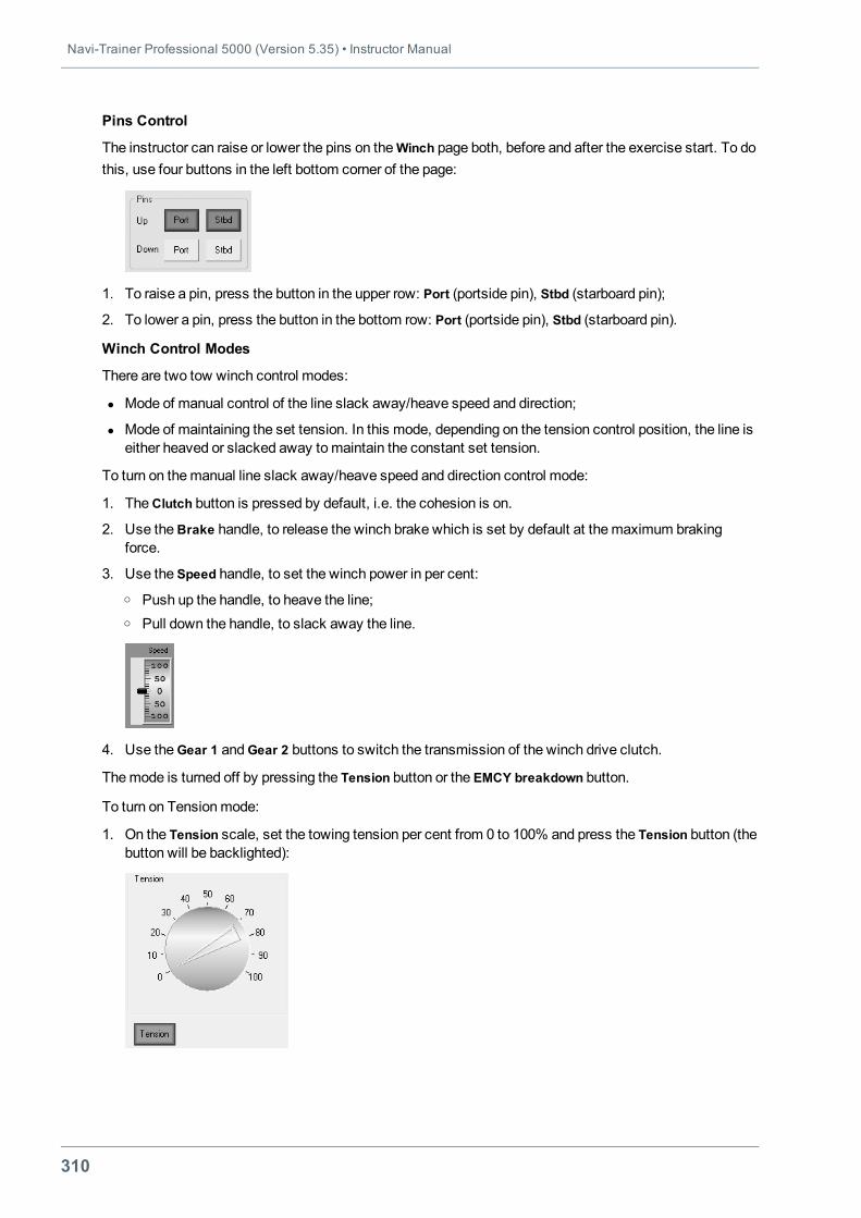
Navi-Trainer Professional 5000 (Version 5.35) • Instructor Manual
310
Pins Control
The instructor can raise or lower the pins on theWinch page both, before and after the exercise start. To dothis, use four buttons in the left bottom corner of the page:
1. To raise a pin, press the button in the upper row: Port (portside pin), Stbd (starboard pin);
2. To lower a pin, press the button in the bottom row: Port (portside pin), Stbd (starboard pin).
Winch Control Modes
There are two tow winch control modes:
l Mode of manual control of the line slack away/heave speed and direction;
l Mode of maintaining the set tension. In this mode, depending on the tension control position, the line iseither heaved or slacked away tomaintain the constant set tension.
To turn on themanual line slack away/heave speed and direction control mode:
1. TheClutch button is pressed by default, i.e. the cohesion is on.
2. Use theBrake handle, to release the winch brake which is set by default at themaximum brakingforce.
3. Use the Speed handle, to set the winch power in per cent:o Push up the handle, to heave the line;o Pull down the handle, to slack away the line.
4. Use theGear 1 andGear 2 buttons to switch the transmission of the winch drive clutch.
Themode is turned off by pressing the Tension button or the EMCY breakdown button.
To turn on Tensionmode:
1. On the Tension scale, set the towing tension per cent from 0 to 100% and press the Tension button (thebutton will be backlighted):
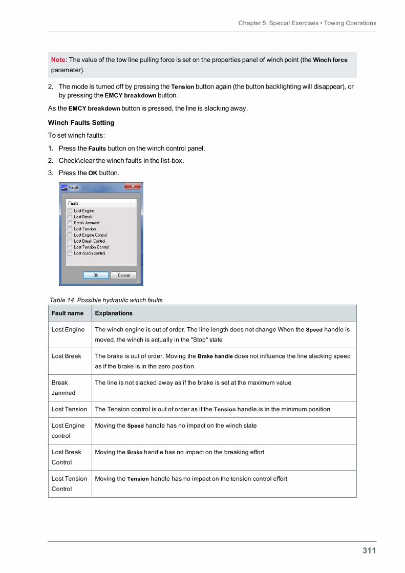
Chapter 5. Special Exercises • Towing Operations
311
Note: The value of the tow line pulling force is set on the properties panel of winch point (theWinch forceparameter).
2. Themode is turned off by pressing the Tension button again (the button backlighting will disappear), orby pressing the EMCY breakdown button.
As the EMCY breakdown button is pressed, the line is slacking away.
Winch Faults Setting
To set winch faults:
1. Press the Faults button on the winch control panel.
2. Check\clear the winch faults in the list-box.
3. Press theOK button.
Fault name Explanations
Lost Engine The winch engine is out of order. The line length does not change When the Speed handle is
moved, the winch is actually in the "Stop" state
Lost Break The brake is out of order. Moving the Brake handle does not influence the line slacking speed
as if the brake is in the zero position
Break
Jammed
The line is not slacked away as if the brake is set at the maximum value
Lost Tension The Tension control is out of order as if the Tension handle is in the minimum position
Lost Engine
control
Moving the Speed handle has no impact on the winch state
Lost Break
Control
Moving the Brake handle has no impact on the breaking effort
Lost Tension
Control
Moving the Tension handle has no impact on the tension control effort
Table 14. Possible hydraulic winch faults
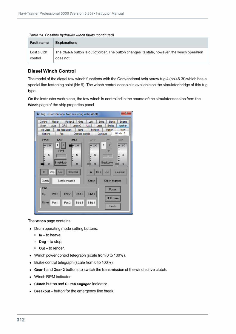
Navi-Trainer Professional 5000 (Version 5.35) • Instructor Manual
312
Fault name Explanations
Lost clutch
control
The Clutch button is out of order. The button changes its state, however, the winch operation
does not
Table 14. Possible hydraulic winch faults (continued)
Diesel Winch ControlThemodel of the diesel tow winch functions with the Conventional twin screw tug 4 (bp 46.3t) which has aspecial line fastening point (No 9). The winch control console is available on the simulator bridge of this tugtype.
On the instructor workplace, the tow winch is controlled in the course of the simulator session from theWinch page of the ship properties panel.
TheWinch page contains:
l Drum operatingmode setting buttons:o In – to heave;o Dog – to stop;o Out – to render.
l Winch power control telegraph (scale from 0 to 100%).
l Brake control telegraph (scale from 0 to 100%).
l Gear 1 andGear 2 buttons to switch the transmission of the winch drive clutch.
l Winch RPM indicator.
l Clutch button andClutch engaged indicator.
l Breakout – button for the emergency line break.
Chapter 5. Special Exercises • Towing Operations
313
l Breakdown – button for the emergency winch brake release. After pressing the button, the line isslacking away.
l Four pairs of control buttons for the stern pins directing the tow line (two on the starboard – Stbd 1, Stbd2 and two on the portside – Port 1, Port 2), where:o top row Up buttons are used for lifting the pins;o bottom row Down buttons are used for lowering the pins.
l Power button for turning on the pin power supply.
l Hold down button for turning on holding down of the line’s vertical motion. This is necessary to preventthe line sliding down from the pins.
l Faults button for winch faults setting.
To switch from one drum operatingmode to another, the line is required to have no speed, and the Powertelegraph handle should be on the zero.
In render mode with the gear engaged, the winch is controlled with the Power telegraph. With the geardisengaged, the line is rendered by the force of the line itself.
Note: Control of the starboard drum winch drive is currently not implemented.
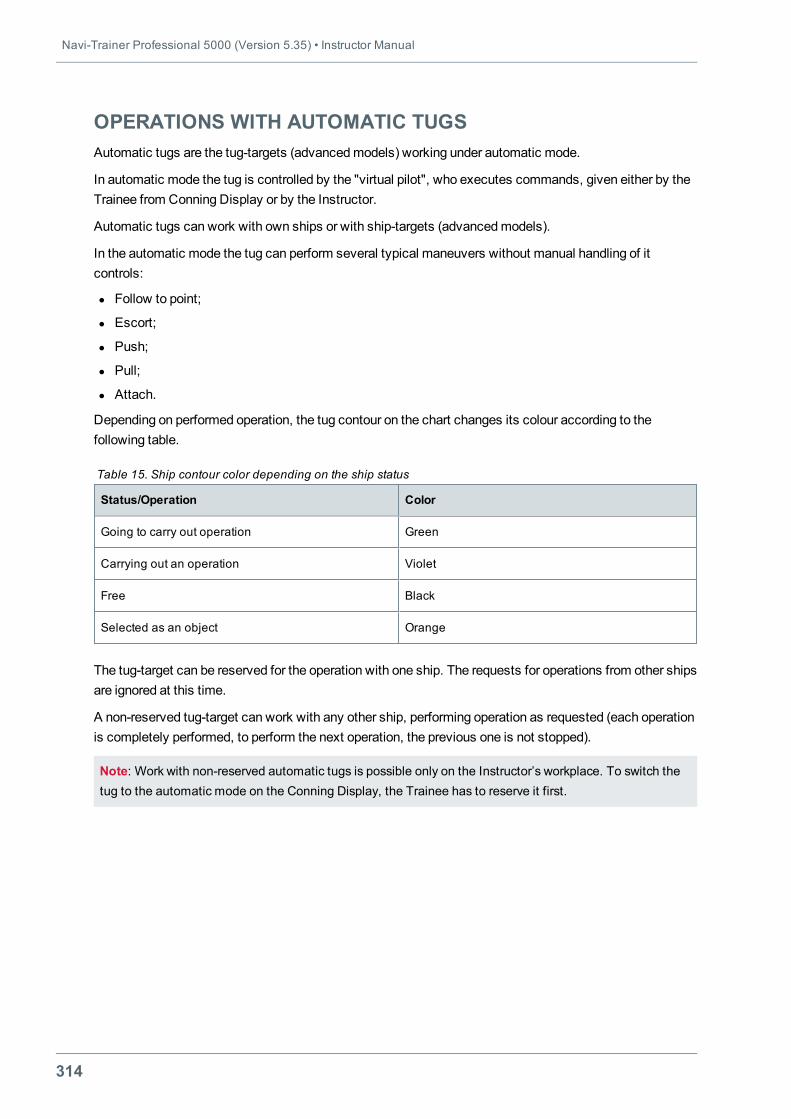
Navi-Trainer Professional 5000 (Version 5.35) • Instructor Manual
314
OPERATIONS WITH AUTOMATIC TUGSAutomatic tugs are the tug-targets (advancedmodels) working under automatic mode.
In automatic mode the tug is controlled by the "virtual pilot", who executes commands, given either by theTrainee from Conning Display or by the Instructor.
Automatic tugs can work with own ships or with ship-targets (advancedmodels).
In the automatic mode the tug can perform several typical maneuvers without manual handling of itcontrols:
l Follow to point;
l Escort;
l Push;
l Pull;
l Attach.
Depending on performed operation, the tug contour on the chart changes its colour according to thefollowing table.
Status/Operation Color
Going to carry out operation Green
Carrying out an operation Violet
Free Black
Selected as an object Orange
Table 15. Ship contour color depending on the ship status
The tug-target can be reserved for the operation with one ship. The requests for operations from other shipsare ignored at this time.
A non-reserved tug-target can work with any other ship, performing operation as requested (each operationis completely performed, to perform the next operation, the previous one is not stopped).
Note: Work with non-reserved automatic tugs is possible only on the Instructor’s workplace. To switch thetug to the automatic mode on the Conning Display, the Trainee has to reserve it first.
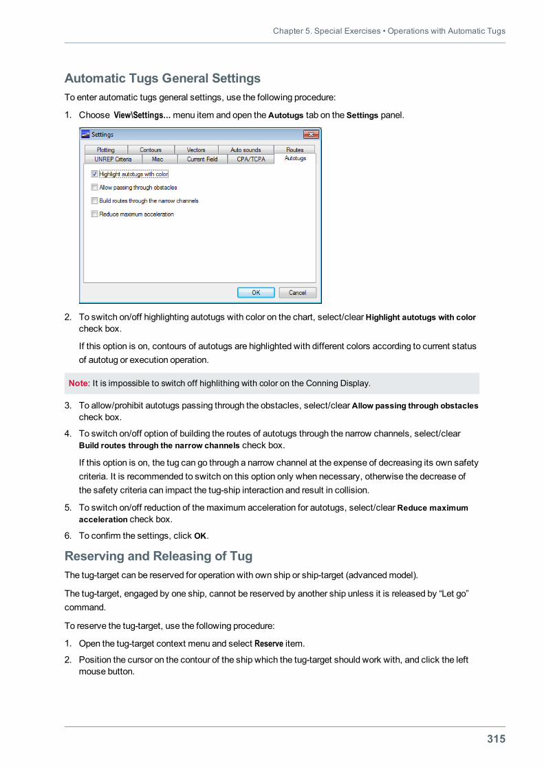
Chapter 5. Special Exercises • Operations with Automatic Tugs
315
Automatic Tugs General SettingsTo enter automatic tugs general settings, use the following procedure:
1. Choose View\Settings…menu item and open theAutotugs tab on the Settings panel.
2. To switch on/off highlighting autotugs with color on the chart, select/clearHighlight autotugs with colorcheck box.
If this option is on, contours of autotugs are highlighted with different colors according to current statusof autotug or execution operation.
Note: It is impossible to switch off highlithing with color on the Conning Display.
3. To allow/prohibit autotugs passing through the obstacles, select/clearAllow passing through obstaclescheck box.
4. To switch on/off option of building the routes of autotugs through the narrow channels, select/clearBuild routes through the narrow channels check box.
If this option is on, the tug can go through a narrow channel at the expense of decreasing its own safetycriteria. It is recommended to switch on this option only when necessary, otherwise the decrease ofthe safety criteria can impact the tug-ship interaction and result in collision.
5. To switch on/off reduction of themaximum acceleration for autotugs, select/clearReduce maximumacceleration check box.
6. To confirm the settings, click OK.
Reserving and Releasing of TugThe tug-target can be reserved for operation with own ship or ship-target (advancedmodel).
The tug-target, engaged by one ship, cannot be reserved by another ship unless it is released by “Let go”command.
To reserve the tug-target, use the following procedure:
1. Open the tug-target context menu and select Reserve item.
2. Position the cursor on the contour of the ship which the tug-target should work with, and click the leftmouse button.
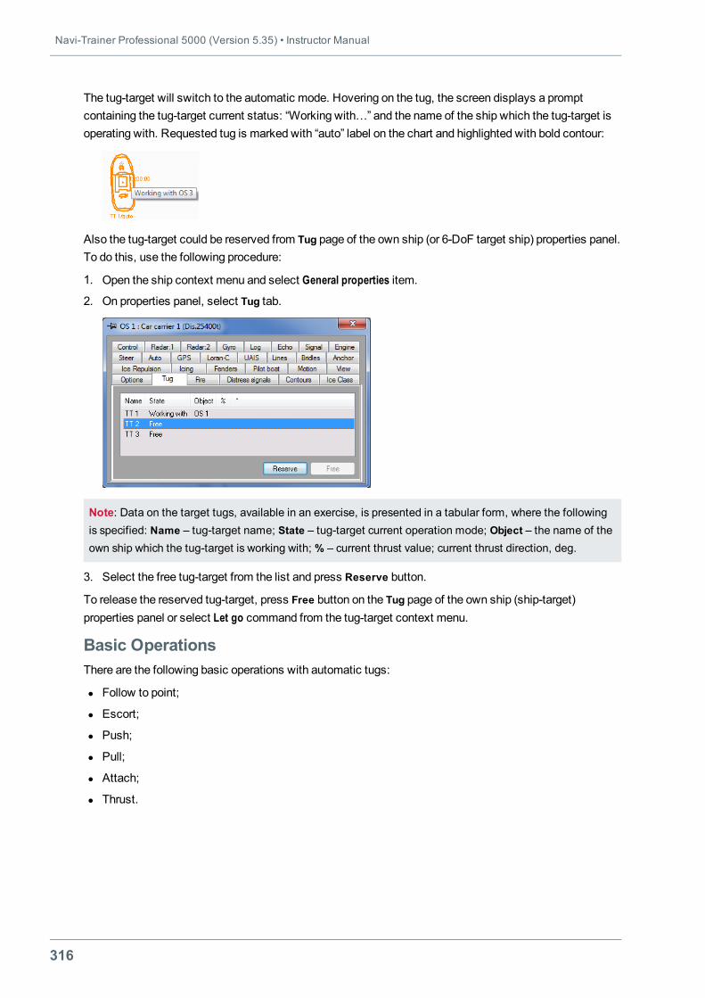
Navi-Trainer Professional 5000 (Version 5.35) • Instructor Manual
316
The tug-target will switch to the automatic mode. Hovering on the tug, the screen displays a promptcontaining the tug-target current status: “Working with…” and the name of the ship which the tug-target isoperating with. Requested tug is marked with “auto” label on the chart and highlighted with bold contour:
Also the tug-target could be reserved from Tug page of the own ship (or 6-DoF target ship) properties panel.To do this, use the following procedure:
1. Open the ship context menu and select General properties item.
2. On properties panel, select Tug tab.
Note: Data on the target tugs, available in an exercise, is presented in a tabular form, where the followingis specified: Name – tug-target name; State – tug-target current operation mode; Object – the name of theown ship which the tug-target is working with; % – current thrust value; current thrust direction, deg.
3. Select the free tug-target from the list and press Reserve button.
To release the reserved tug-target, press Free button on the Tug page of the own ship (ship-target)properties panel or select Let go command from the tug-target context menu.
Basic OperationsThere are the following basic operations with automatic tugs:
l Follow to point;
l Escort;
l Push;
l Pull;
l Attach;
l Thrust.
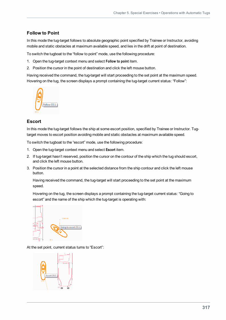
Chapter 5. Special Exercises • Operations with Automatic Tugs
317
Follow to PointIn this mode the tug-target follows to absolute geographic point specified by Trainee or Instructor, avoidingmobile and static obstacles at maximum available speed, and lies in the drift at point of destination.
To switch the tugboat to the “follow to point” mode, use the following procedure:
1. Open the tug-target context menu and select Follow to point item.
2. Position the cursor in the point of destination and click the left mouse button.
Having received the command, the tug-target will start proceeding to the set point at themaximum speed.Hovering on the tug, the screen displays a prompt containing the tug-target current status: “Follow”:
EscortIn this mode the tug-target follows the ship at some escort position, specified by Trainee or Instructor. Tug-target moves to escort position avoidingmobile and static obstacles at maximum available speed.
To switch the tugboat to the “escort” mode, use the following procedure:
1. Open the tug-target context menu and select Escort item.
2. If tug-target hasn’t reserved, position the cursor on the contour of the ship which the tug should escort,and click the left mouse button.
3. Position the cursor in a point at the selected distance from the ship contour and click the left mousebutton.
Having received the command, the tug-target will start proceeding to the set point at themaximumspeed.
Hovering on the tug, the screen displays a prompt containing the tug-target current status: “Going toescort” and the name of the ship which the tug-target is operating with:
At the set point, current status turns to “Escort”:
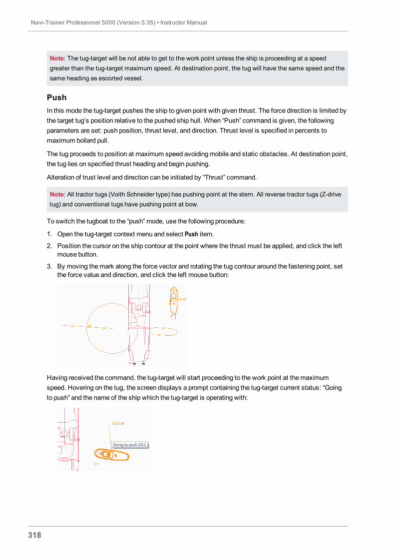
Navi-Trainer Professional 5000 (Version 5.35) • Instructor Manual
318
Note: The tug-target will be not able to get to the work point unless the ship is proceeding at a speedgreater than the tug-target maximum speed. At destination point, the tug will have the same speed and thesame heading as escorted vessel.
PushIn this mode the tug-target pushes the ship to given point with given thrust. The force direction is limited bythe target tug’s position relative to the pushed ship hull. When “Push” command is given, the followingparameters are set: push position, thrust level, and direction. Thrust level is specified in percents tomaximum bollard pull.
The tug proceeds to position at maximum speed avoidingmobile and static obstacles. At destination point,the tug lies on specified thrust heading and begin pushing.
Alteration of trust level and direction can be initiated by “Thrust” command.
Note: All tractor tugs (Voith Schneider type) has pushing point at the stern. All reverse tractor tugs (Z-drivetug) and conventional tugs have pushing point at bow.
To switch the tugboat to the “push” mode, use the following procedure:
1. Open the tug-target context menu and select Push item.
2. Position the cursor on the ship contour at the point where the thrust must be applied, and click the leftmouse button.
3. By moving themark along the force vector and rotating the tug contour around the fastening point, setthe force value and direction, and click the left mouse button:
Having received the command, the tug-target will start proceeding to the work point at themaximumspeed. Hovering on the tug, the screen displays a prompt containing the tug-target current status: “Goingto push” and the name of the ship which the tug-target is operating with:
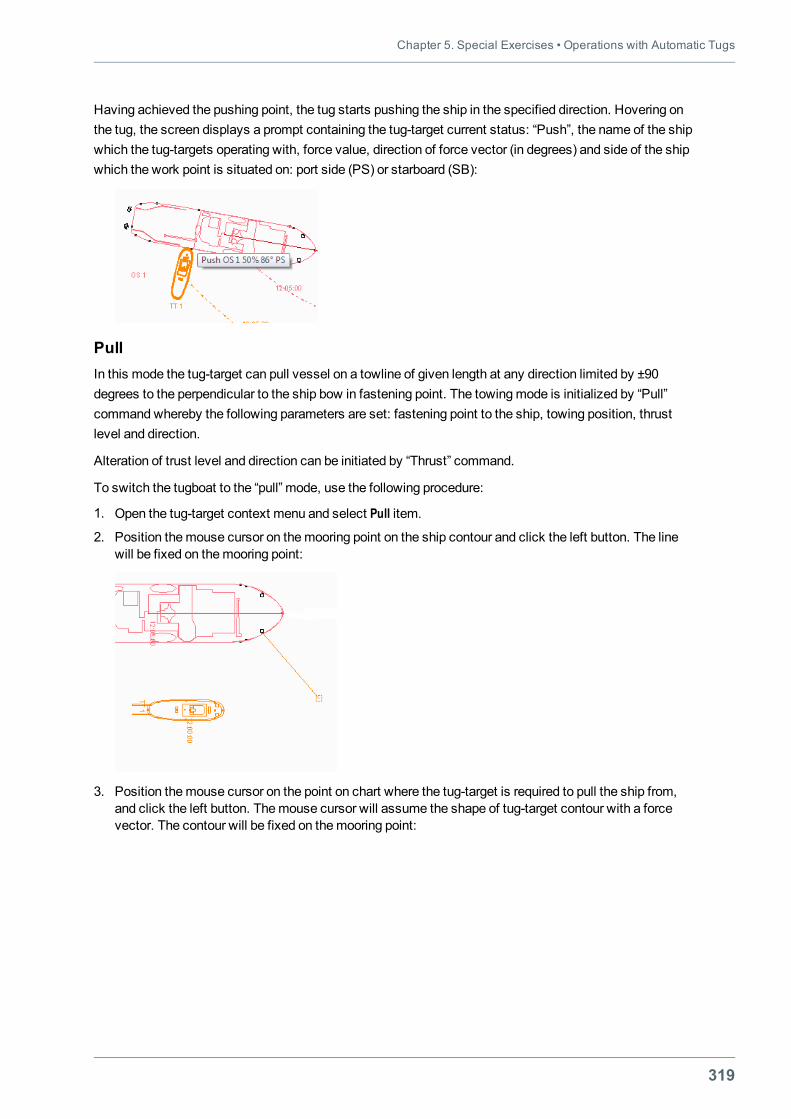
Chapter 5. Special Exercises • Operations with Automatic Tugs
319
Having achieved the pushing point, the tug starts pushing the ship in the specified direction. Hovering onthe tug, the screen displays a prompt containing the tug-target current status: “Push”, the name of the shipwhich the tug-targets operating with, force value, direction of force vector (in degrees) and side of the shipwhich the work point is situated on: port side (PS) or starboard (SB):
PullIn this mode the tug-target can pull vessel on a towline of given length at any direction limited by ±90degrees to the perpendicular to the ship bow in fastening point. The towingmode is initialized by “Pull”commandwhereby the following parameters are set: fastening point to the ship, towing position, thrustlevel and direction.
Alteration of trust level and direction can be initiated by “Thrust” command.
To switch the tugboat to the “pull” mode, use the following procedure:
1. Open the tug-target context menu and select Pull item.
2. Position themouse cursor on themooring point on the ship contour and click the left button. The linewill be fixed on themooring point:
3. Position themouse cursor on the point on chart where the tug-target is required to pull the ship from,and click the left button. Themouse cursor will assume the shape of tug-target contour with a forcevector. The contour will be fixed on themooring point:
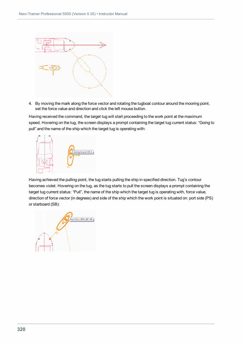
Navi-Trainer Professional 5000 (Version 5.35) • Instructor Manual
320
4. By moving themark along the force vector and rotating the tugboat contour around themooring point,set the force value and direction and click the left mouse button.
Having received the command, the target tug will start proceeding to the work point at themaximumspeed. Hovering on the tug, the screen displays a prompt containing the target tug current status: “Going topull” and the name of the ship which the target tug is operating with:
Having achieved the pulling point, the tug starts pulling the ship in specified direction. Tug’s contourbecomes violet. Hovering on the tug, as the tug starts to pull the screen displays a prompt containing thetarget tug current status: “Pull”, the name of the ship which the target tug is operating with, force value,direction of force vector (in degrees) and side of the ship which the work point is situated on: port side (PS)or starboard (SB):
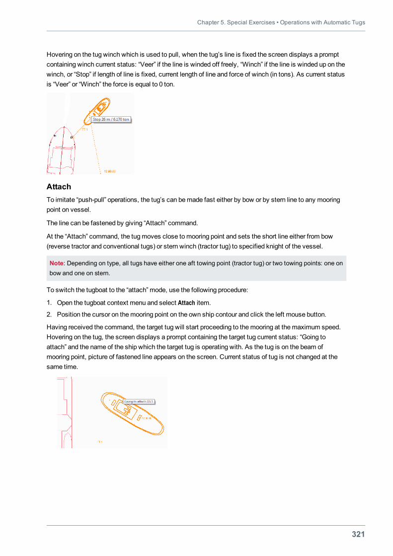
Chapter 5. Special Exercises • Operations with Automatic Tugs
321
Hovering on the tug winch which is used to pull, when the tug’s line is fixed the screen displays a promptcontaining winch current status: “Veer” if the line is winded off freely, “Winch” if the line is winded up on thewinch, or “Stop” if length of line is fixed, current length of line and force of winch (in tons). As current statusis “Veer” or “Winch” the force is equal to 0 ton.
AttachTo imitate “push-pull” operations, the tug’s can bemade fast either by bow or by stern line to any mooringpoint on vessel.
The line can be fastened by giving “Attach” command.
At the “Attach” command, the tugmoves close tomooring point and sets the short line either from bow(reverse tractor and conventional tugs) or stern winch (tractor tug) to specified knight of the vessel.
Note: Depending on type, all tugs have either one aft towing point (tractor tug) or two towing points: one onbow and one on stern.
To switch the tugboat to the “attach” mode, use the following procedure:
1. Open the tugboat context menu and select Attach item.
2. Position the cursor on themooring point on the own ship contour and click the left mouse button.
Having received the command, the target tug will start proceeding to themooring at themaximum speed.Hovering on the tug, the screen displays a prompt containing the target tug current status: “Going toattach” and the name of the ship which the target tug is operating with. As the tug is on the beam ofmooring point, picture of fastened line appears on the screen. Current status of tug is not changed at thesame time.
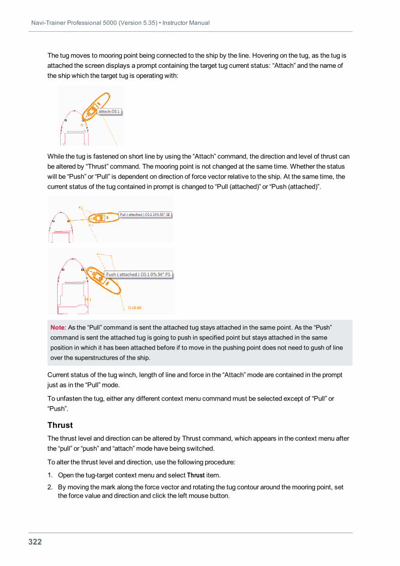
Navi-Trainer Professional 5000 (Version 5.35) • Instructor Manual
322
The tugmoves tomooring point being connected to the ship by the line. Hovering on the tug, as the tug isattached the screen displays a prompt containing the target tug current status: “Attach” and the name ofthe ship which the target tug is operating with:
While the tug is fastened on short line by using the “Attach” command, the direction and level of thrust canbe altered by “Thrust” command. Themooring point is not changed at the same time. Whether the statuswill be “Push” or “Pull” is dependent on direction of force vector relative to the ship. At the same time, thecurrent status of the tug contained in prompt is changed to “Pull (attached)” or “Push (attached)”.
Note: As the “Pull” command is sent the attached tug stays attached in the same point. As the “Push”command is sent the attached tug is going to push in specified point but stays attached in the sameposition in which it has been attached before if to move in the pushing point does not need to gush of lineover the superstructures of the ship.
Current status of the tug winch, length of line and force in the “Attach” mode are contained in the promptjust as in the “Pull” mode.
To unfasten the tug, either any different context menu commandmust be selected except of “Pull” or“Push”.
ThrustThe thrust level and direction can be altered by Thrust command, which appears in the context menu afterthe “pull” or “push” and “attach” mode have being switched.
To alter the thrust level and direction, use the following procedure:
1. Open the tug-target context menu and select Thrust item.
2. By moving themark along the force vector and rotating the tug contour around themooring point, setthe force value and direction and click the left mouse button.
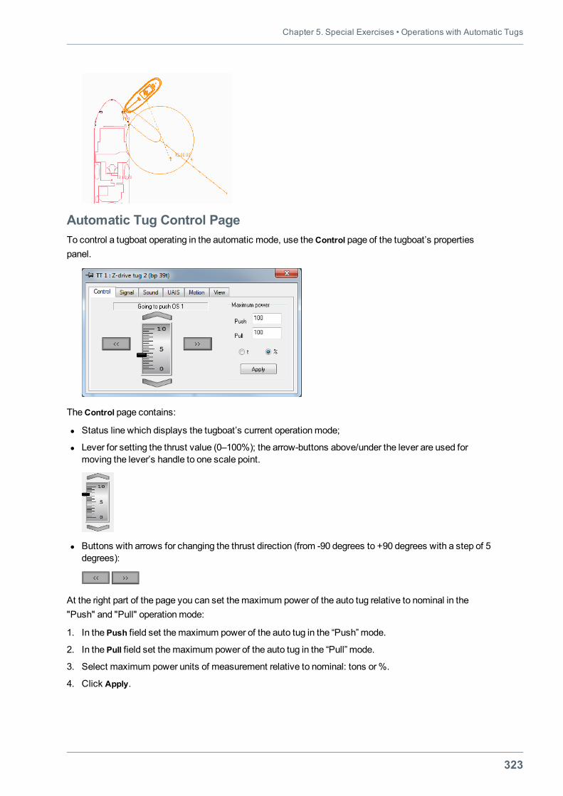
Chapter 5. Special Exercises • Operations with Automatic Tugs
323
Automatic Tug Control PageTo control a tugboat operating in the automatic mode, use theControl page of the tugboat’s propertiespanel.
TheControl page contains:
l Status line which displays the tugboat’s current operationmode;
l Lever for setting the thrust value (0–100%); the arrow-buttons above/under the lever are used formoving the lever’s handle to one scale point.
l Buttons with arrows for changing the thrust direction (from -90 degrees to +90 degrees with a step of 5degrees):
At the right part of the page you can set themaximum power of the auto tug relative to nominal in the"Push" and "Pull" operationmode:
1. In the Push field set themaximum power of the auto tug in the “Push” mode.
2. In the Pull field set themaximum power of the auto tug in the “Pull” mode.
3. Select maximum power units of measurement relative to nominal: tons or%.
4. Click Apply.
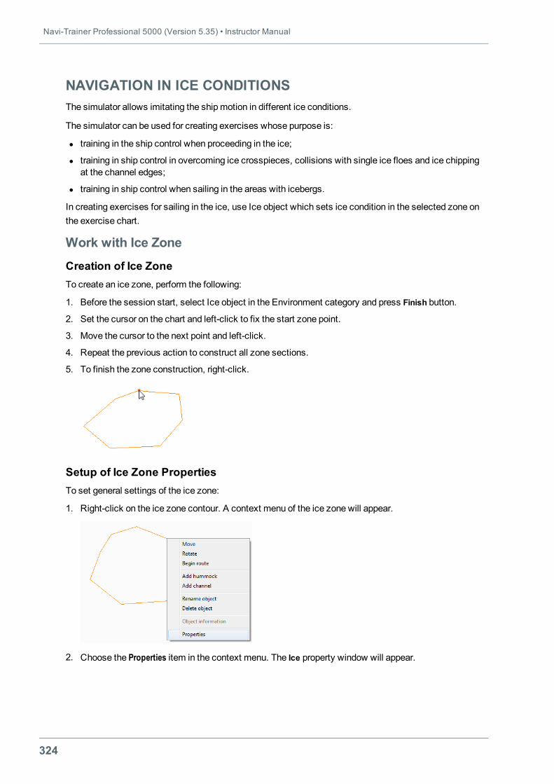
Navi-Trainer Professional 5000 (Version 5.35) • Instructor Manual
324
NAVIGATION IN ICE CONDITIONSThe simulator allows imitating the shipmotion in different ice conditions.
The simulator can be used for creating exercises whose purpose is:
l training in the ship control when proceeding in the ice;
l training in ship control in overcoming ice crosspieces, collisions with single ice floes and ice chippingat the channel edges;
l training in ship control when sailing in the areas with icebergs.
In creating exercises for sailing in the ice, use Ice object which sets ice condition in the selected zone onthe exercise chart.
Work with Ice Zone
Creation of Ice ZoneTo create an ice zone, perform the following:
1. Before the session start, select Ice object in the Environment category and press Finish button.
2. Set the cursor on the chart and left-click to fix the start zone point.
3. Move the cursor to the next point and left-click.
4. Repeat the previous action to construct all zone sections.
5. To finish the zone construction, right-click.
Setup of Ice Zone PropertiesTo set general settings of the ice zone:
1. Right-click on the ice zone contour. A context menu of the ice zone will appear.
2. Choose the Properties item in the context menu. The Ice property window will appear.
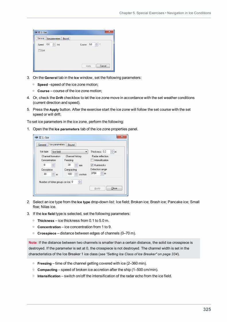
Chapter 5. Special Exercises • Navigation in Ice Conditions
325
3. On theGeneral tab in the Ice window, set the following parameters:o Speed –speed of the ice zonemotion;o Course – course of the ice zonemotion;
4. Or, check theDrift checkbox to let the ice zonemove in accordance with the set weather conditions(current direction and speed).
5. Press theApply button. After the exercise start the ice zone will follow the set course with the setspeed or will drift.
To set ice parameters in the ice zone, perform the following:
1. Open the the Ice parameters tab of the ice zone properties panel.
2. Select an ice type from the Ice type drop-down list: Ice field; Broken ice; Brash ice; Pancake ice; Smallfloe; Nilas ice.
3. If the Ice field type is selected, set the following parameters:o Thickness – ice thickness from 0.1 to 5.0m.o Concentration – ice concentration from 1 to 9.o Crosspiece – distance between edges of channels (0–70m).
Note: If the distance between two channels is smaller than a certain distance, the solid ice crosspiece isdestroyed. If the parameter is set at 0, the crosspiece is not destroyed. The channel width is set in thecharacteristics of the Ice Breaker 1 ice class (see "Setting Ice Class of Ice Breaker" on page 334).
o Freezing – time of the channel getting covered with ice (2–360min).o Compacting – speed of broken ice accretion after the ship (1–500 cm/min).o Intensification – switch on/off the intensification of the radar echo from the ice field.
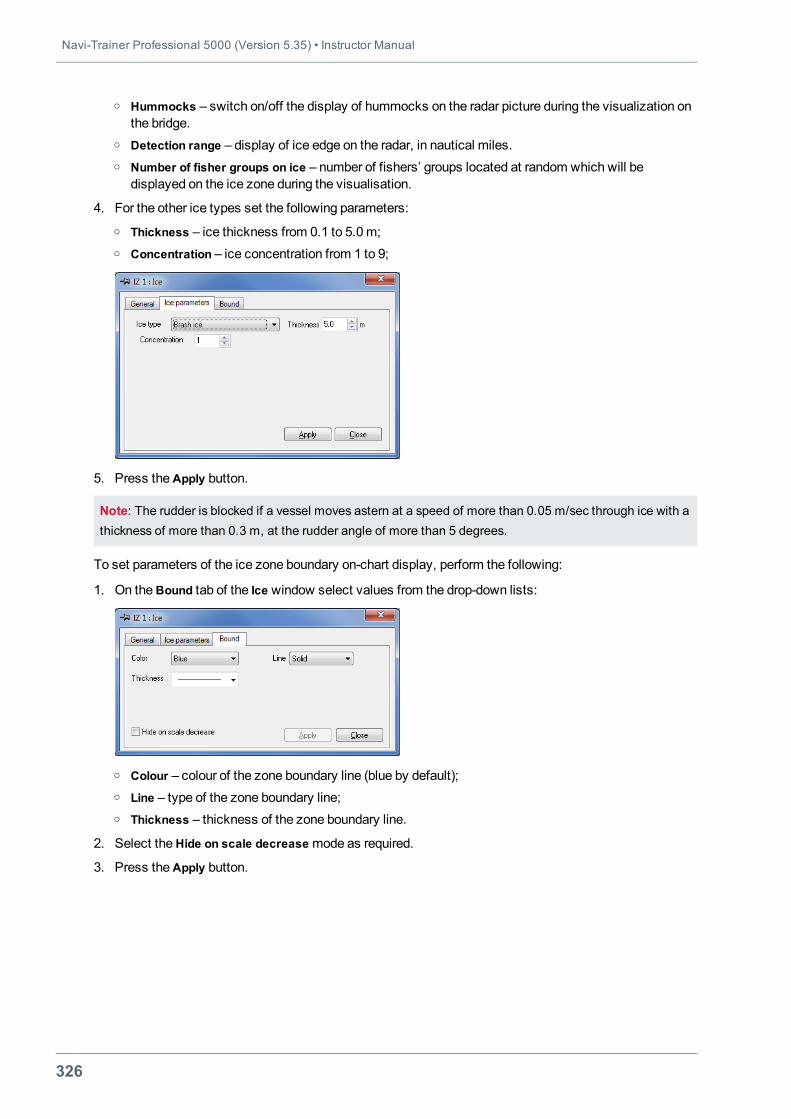
Navi-Trainer Professional 5000 (Version 5.35) • Instructor Manual
326
o Hummocks – switch on/off the display of hummocks on the radar picture during the visualization onthe bridge.
o Detection range – display of ice edge on the radar, in nautical miles.o Number of fisher groups on ice – number of fishers’ groups located at random which will be
displayed on the ice zone during the visualisation.
4. For the other ice types set the following parameters:o Thickness – ice thickness from 0.1 to 5.0m;o Concentration – ice concentration from 1 to 9;
5. Press theApply button.
Note: The rudder is blocked if a vessel moves astern at a speed of more than 0.05 m/sec through ice with athickness of more than 0.3 m, at the rudder angle of more than 5 degrees.
To set parameters of the ice zone boundary on-chart display, perform the following:
1. On theBound tab of the Ice window select values from the drop-down lists:
o Colour – colour of the zone boundary line (blue by default);o Line – type of the zone boundary line;o Thickness – thickness of the zone boundary line.
2. Select theHide on scale decreasemode as required.
3. Press theApply button.
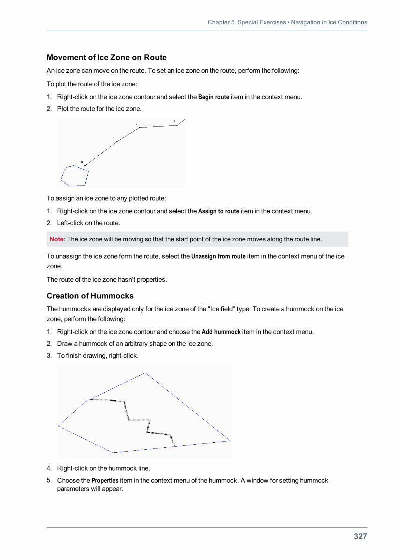
Chapter 5. Special Exercises • Navigation in Ice Conditions
327
Movement of Ice Zone on RouteAn ice zone canmove on the route. To set an ice zone on the route, perform the following:
To plot the route of the ice zone:
1. Right-click on the ice zone contour and select the Begin route item in the context menu.
2. Plot the route for the ice zone.
To assign an ice zone to any plotted route:
1. Right-click on the ice zone contour and select the Assign to route item in the context menu.
2. Left-click on the route.
Note: The ice zone will be moving so that the start point of the ice zone moves along the route line.
To unassign the ice zone form the route, select the Unassign from route item in the context menu of the icezone.
The route of the ice zone hasn’t properties.
Creation of HummocksThe hummocks are displayed only for the ice zone of the "Ice field" type. To create a hummock on the icezone, perform the following:
1. Right-click on the ice zone contour and choose the Add hummock item in the context menu.
2. Draw a hummock of an arbitrary shape on the ice zone.
3. To finish drawing, right-click.
4. Right-click on the hummock line.
5. Choose the Properties item in the context menu of the hummock. A window for setting hummockparameters will appear.
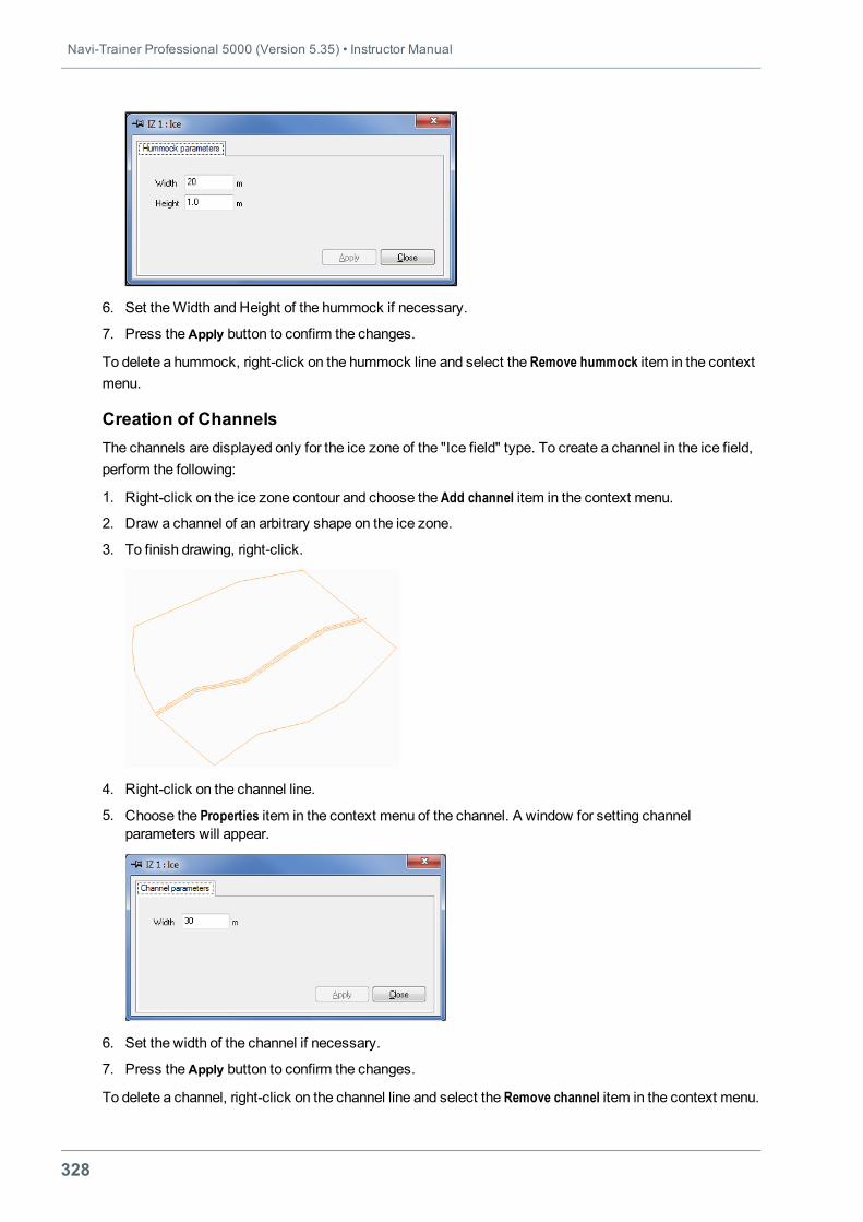
Navi-Trainer Professional 5000 (Version 5.35) • Instructor Manual
328
6. Set theWidth and Height of the hummock if necessary.
7. Press theApply button to confirm the changes.
To delete a hummock, right-click on the hummock line and select the Remove hummock item in the contextmenu.
Creation of ChannelsThe channels are displayed only for the ice zone of the "Ice field" type. To create a channel in the ice field,perform the following:
1. Right-click on the ice zone contour and choose the Add channel item in the context menu.
2. Draw a channel of an arbitrary shape on the ice zone.
3. To finish drawing, right-click.
4. Right-click on the channel line.
5. Choose the Properties item in the context menu of the channel. A window for setting channelparameters will appear.
6. Set the width of the channel if necessary.
7. Press theApply button to confirm the changes.
To delete a channel, right-click on the channel line and select the Remove channel item in the context menu.
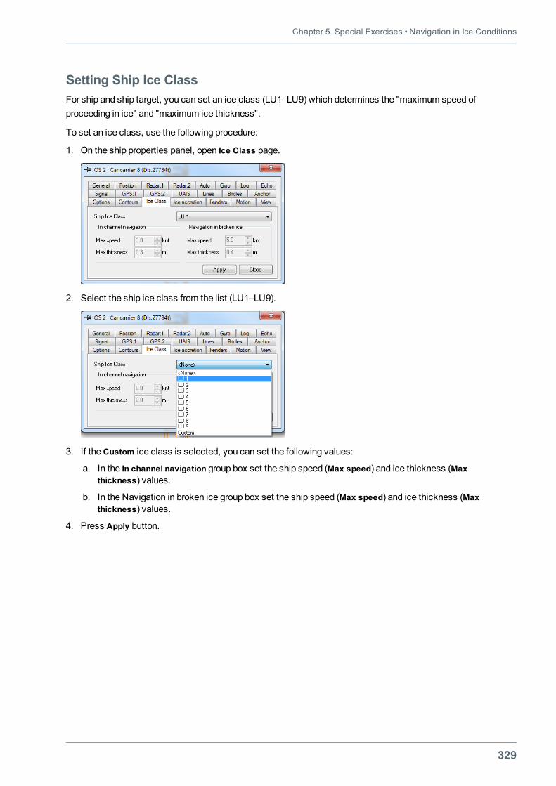
Chapter 5. Special Exercises • Navigation in Ice Conditions
329
Setting Ship Ice ClassFor ship and ship target, you can set an ice class (LU1–LU9) which determines the "maximum speed ofproceeding in ice" and "maximum ice thickness".
To set an ice class, use the following procedure:
1. On the ship properties panel, open Ice Class page.
2. Select the ship ice class from the list (LU1–LU9).
3. If theCustom ice class is selected, you can set the following values:
a. In the In channel navigation group box set the ship speed (Max speed) and ice thickness (Maxthickness) values.
b. In the Navigation in broken ice group box set the ship speed (Max speed) and ice thickness (Maxthickness) values.
4. Press Apply button.
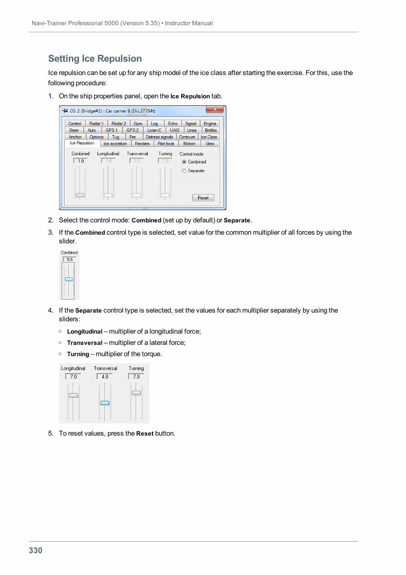
Navi-Trainer Professional 5000 (Version 5.35) • Instructor Manual
330
Setting Ice RepulsionIce repulsion can be set up for any shipmodel of the ice class after starting the exercise. For this, use thefollowing procedure:
1. On the ship properties panel, open the Ice Repulsion tab.
2. Select the control mode: Combined (set up by default) or Separate.
3. If theCombined control type is selected, set value for the commonmultiplier of all forces by using theslider.
4. If the Separate control type is selected, set the values for eachmultiplier separately by using thesliders:o Longitudinal –multiplier of a longitudinal force;o Transversal –multiplier of a lateral force;o Turning –multiplier of the torque.
5. To reset values, press theReset button.
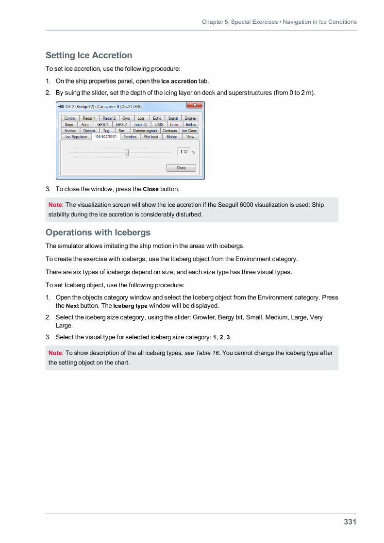
Chapter 5. Special Exercises • Navigation in Ice Conditions
331
Setting Ice AccretionTo set ice accretion, use the following procedure:
1. On the ship properties panel, open the Ice accretion tab.
2. By suing the slider, set the depth of the icing layer on deck and superstructures (from 0 to 2m).
3. To close the window, press theClose button.
Note: The visualization screen will show the ice accretion if the Seagull 6000 visualization is used. Shipstability during the ice accretion is considerably disturbed.
Operations with IcebergsThe simulator allows imitating the shipmotion in the areas with icebergs.
To create the exercise with icebergs, use the Iceberg object from the Environment category.
There are six types of icebergs depend on size, and each size type has three visual types.
To set Iceberg object, use the following procedure:
1. Open the objects category window and select the Iceberg object from the Environment category. PresstheNext button. The Iceberg type window will be displayed.
2. Select the iceberg size category, using the slider: Growler, Bergy bit, Small, Medium, Large, VeryLarge.
3. Select the visual type for selected iceberg size category: 1, 2, 3.
Note: To show description of the all iceberg types, see Table 16. You cannot change the iceberg type afterthe setting object on the chart.
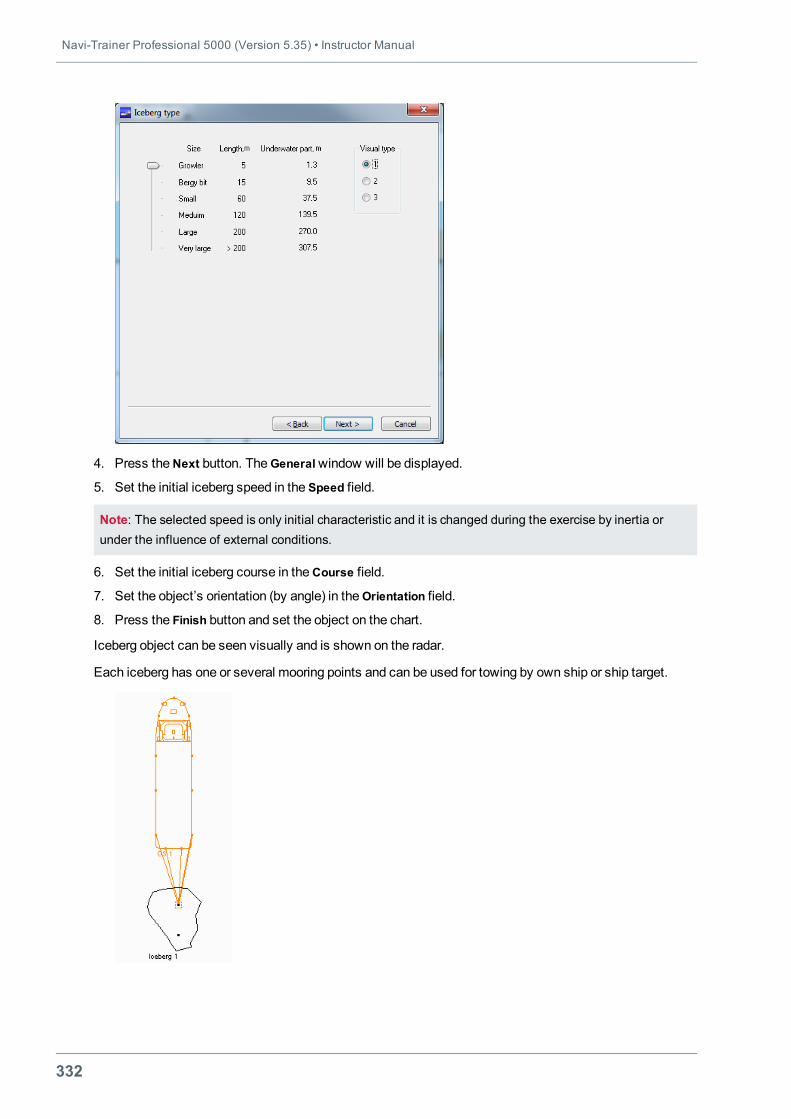
Navi-Trainer Professional 5000 (Version 5.35) • Instructor Manual
332
4. Press theNext button. TheGeneralwindow will be displayed.
5. Set the initial iceberg speed in the Speed field.
Note: The selected speed is only initial characteristic and it is changed during the exercise by inertia orunder the influence of external conditions.
6. Set the initial iceberg course in theCourse field.
7. Set the object’s orientation (by angle) in theOrientation field.
8. Press the Finish button and set the object on the chart.
Iceberg object can be seen visually and is shown on the radar.
Each iceberg has one or several mooring points and can be used for towing by own ship or ship target.
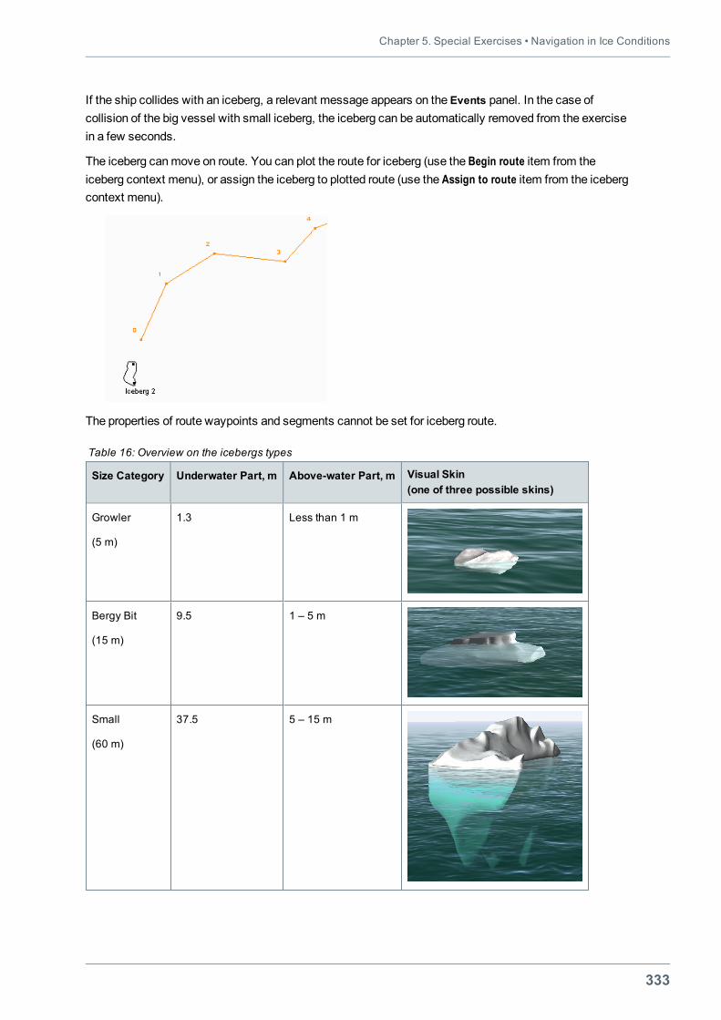
Chapter 5. Special Exercises • Navigation in Ice Conditions
333
If the ship collides with an iceberg, a relevant message appears on the Events panel. In the case ofcollision of the big vessel with small iceberg, the iceberg can be automatically removed from the exercisein a few seconds.
The iceberg canmove on route. You can plot the route for iceberg (use the Begin route item from theiceberg context menu), or assign the iceberg to plotted route (use the Assign to route item from the icebergcontext menu).
The properties of route waypoints and segments cannot be set for iceberg route.
Size Category Underwater Part, m Above-water Part, m Visual Skin(one of three possible skins)
Growler
(5 m)
1.3 Less than 1 m
Bergy Bit
(15 m)
9.5 1 – 5 m
Small
(60 m)
37.5 5 – 15 m
Table 16: Overview on the icebergs types
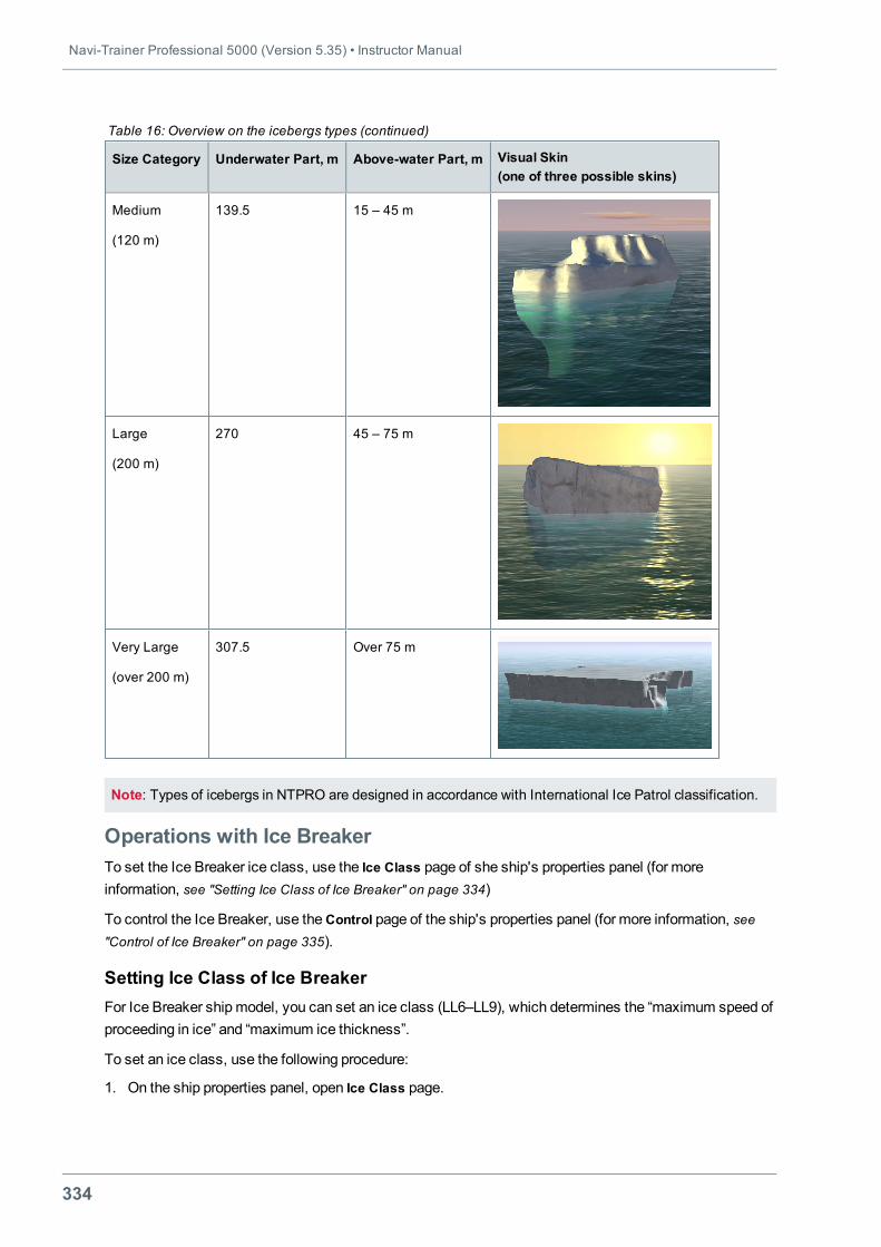
Navi-Trainer Professional 5000 (Version 5.35) • Instructor Manual
334
Size Category Underwater Part, m Above-water Part, m Visual Skin(one of three possible skins)
Medium
(120 m)
139.5 15 – 45 m
Large
(200 m)
270 45 – 75 m
Very Large
(over 200 m)
307.5 Over 75 m
Table 16: Overview on the icebergs types (continued)
Note: Types of icebergs in NTPRO are designed in accordance with International Ice Patrol classification.
Operations with Ice BreakerTo set the Ice Breaker ice class, use the Ice Class page of she ship's properties panel (for moreinformation, see "Setting Ice Class of Ice Breaker" on page 334)
To control the Ice Breaker, use theControl page of the ship's properties panel (for more information, see"Control of Ice Breaker" on page 335).
Setting Ice Class of Ice BreakerFor Ice Breaker ship model, you can set an ice class (LL6–LL9), which determines the “maximum speed ofproceeding in ice” and “maximum ice thickness”.
To set an ice class, use the following procedure:
1. On the ship properties panel, open Ice Class page.
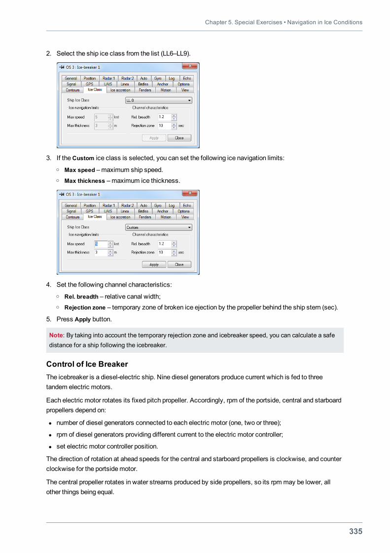
Chapter 5. Special Exercises • Navigation in Ice Conditions
335
2. Select the ship ice class from the list (LL6–LL9).
3. If theCustom ice class is selected, you can set the following ice navigation limits:o Max speed –maximum ship speed.o Max thickness –maximum ice thickness.
4. Set the following channel characteristics:o Rel. breadth – relative canal width;o Rejection zone – temporary zone of broken ice ejection by the propeller behind the ship stern (sec).
5. Press Apply button.
Note: By taking into account the temporary rejection zone and icebreaker speed, you can calculate a safedistance for a ship following the icebreaker.
Control of Ice BreakerThe icebreaker is a diesel-electric ship. Nine diesel generators produce current which is fed to threetandem electric motors.
Each electric motor rotates its fixed pitch propeller. Accordingly, rpm of the portside, central and starboardpropellers depend on:
l number of diesel generators connected to each electric motor (one, two or three);
l rpm of diesel generators providing different current to the electric motor controller;
l set electric motor controller position.
The direction of rotation at ahead speeds for the central and starboard propellers is clockwise, and counterclockwise for the portsidemotor.
The central propeller rotates in water streams produced by side propellers, so its rpmmay be lower, allother things being equal.
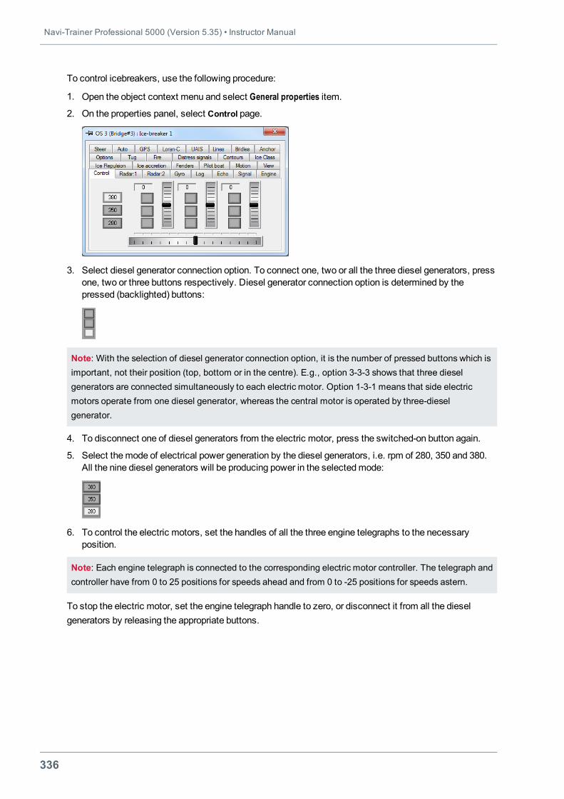
Navi-Trainer Professional 5000 (Version 5.35) • Instructor Manual
336
To control icebreakers, use the following procedure:
1. Open the object context menu and select General properties item.
2. On the properties panel, select Control page.
3. Select diesel generator connection option. To connect one, two or all the three diesel generators, pressone, two or three buttons respectively. Diesel generator connection option is determined by thepressed (backlighted) buttons:
Note: With the selection of diesel generator connection option, it is the number of pressed buttons which isimportant, not their position (top, bottom or in the centre). E.g., option 3-3-3 shows that three dieselgenerators are connected simultaneously to each electric motor. Option 1-3-1 means that side electricmotors operate from one diesel generator, whereas the central motor is operated by three-dieselgenerator.
4. To disconnect one of diesel generators from the electric motor, press the switched-on button again.
5. Select themode of electrical power generation by the diesel generators, i.e. rpm of 280, 350 and 380.All the nine diesel generators will be producing power in the selectedmode:
6. To control the electric motors, set the handles of all the three engine telegraphs to the necessaryposition.
Note: Each engine telegraph is connected to the corresponding electric motor controller. The telegraph andcontroller have from 0 to 25 positions for speeds ahead and from 0 to -25 positions for speeds astern.
To stop the electric motor, set the engine telegraph handle to zero, or disconnect it from all the dieselgenerators by releasing the appropriate buttons.
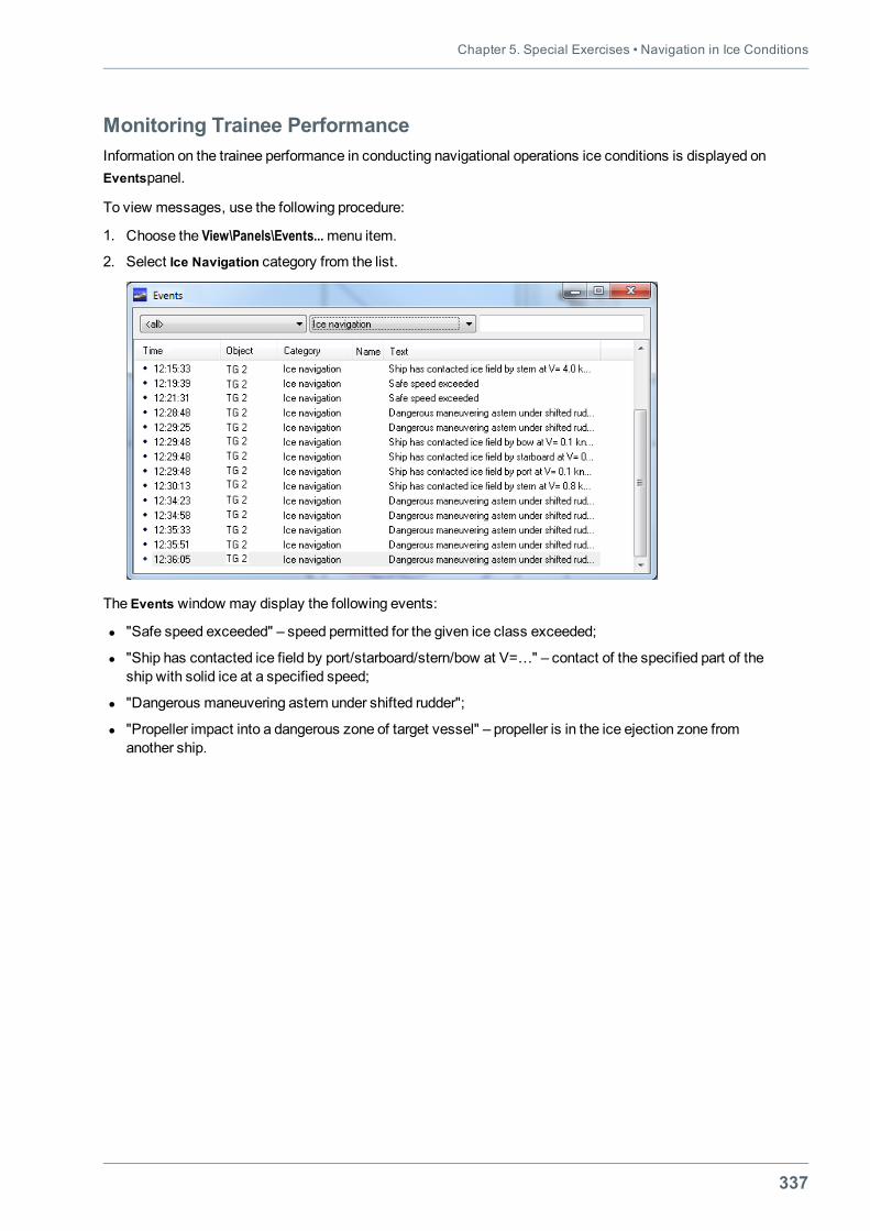
Chapter 5. Special Exercises • Navigation in Ice Conditions
337
Monitoring Trainee PerformanceInformation on the trainee performance in conducting navigational operations ice conditions is displayed onEventspanel.
To view messages, use the following procedure:
1. Choose the View\Panels\Events...menu item.
2. Select Ice Navigation category from the list.
The Events window may display the following events:
l "Safe speed exceeded" – speed permitted for the given ice class exceeded;
l "Ship has contacted ice field by port/starboard/stern/bow at V=…" – contact of the specified part of theship with solid ice at a specified speed;
l "Dangerous maneuvering astern under shifted rudder";
l "Propeller impact into a dangerous zone of target vessel" – propeller is in the ice ejection zone fromanother ship.
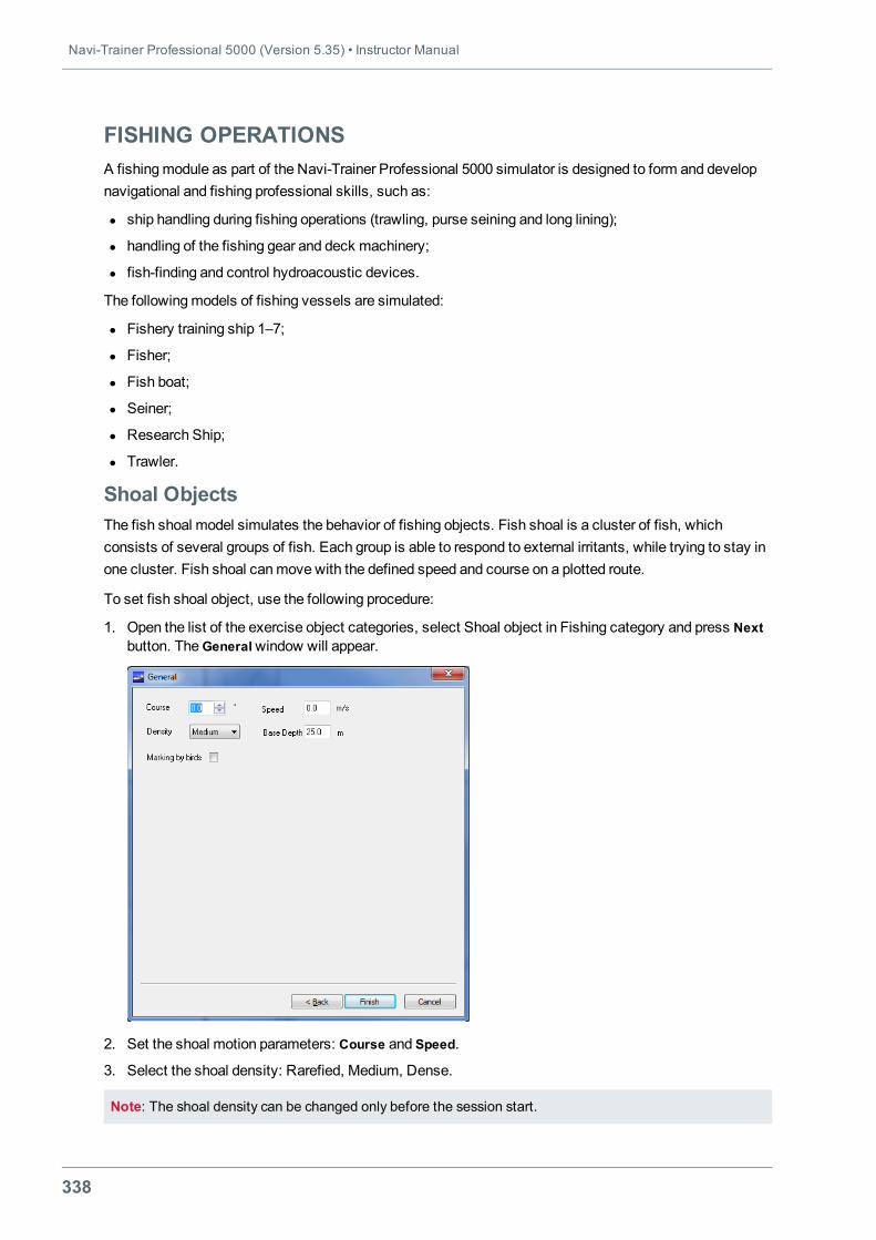
Navi-Trainer Professional 5000 (Version 5.35) • Instructor Manual
338
FISHING OPERATIONSA fishingmodule as part of the Navi-Trainer Professional 5000 simulator is designed to form and developnavigational and fishing professional skills, such as:
l ship handling during fishing operations (trawling, purse seining and long lining);
l handling of the fishing gear and deck machinery;
l fish-finding and control hydroacoustic devices.
The followingmodels of fishing vessels are simulated:
l Fishery training ship 1–7;
l Fisher;
l Fish boat;
l Seiner;
l Research Ship;
l Trawler.
Shoal ObjectsThe fish shoal model simulates the behavior of fishing objects. Fish shoal is a cluster of fish, whichconsists of several groups of fish. Each group is able to respond to external irritants, while trying to stay inone cluster. Fish shoal canmove with the defined speed and course on a plotted route.
To set fish shoal object, use the following procedure:
1. Open the list of the exercise object categories, select Shoal object in Fishing category and press Nextbutton. TheGeneralwindow will appear.
2. Set the shoal motion parameters: Course and Speed.
3. Select the shoal density: Rarefied, Medium, Dense.
Note: The shoal density can be changed only before the session start.
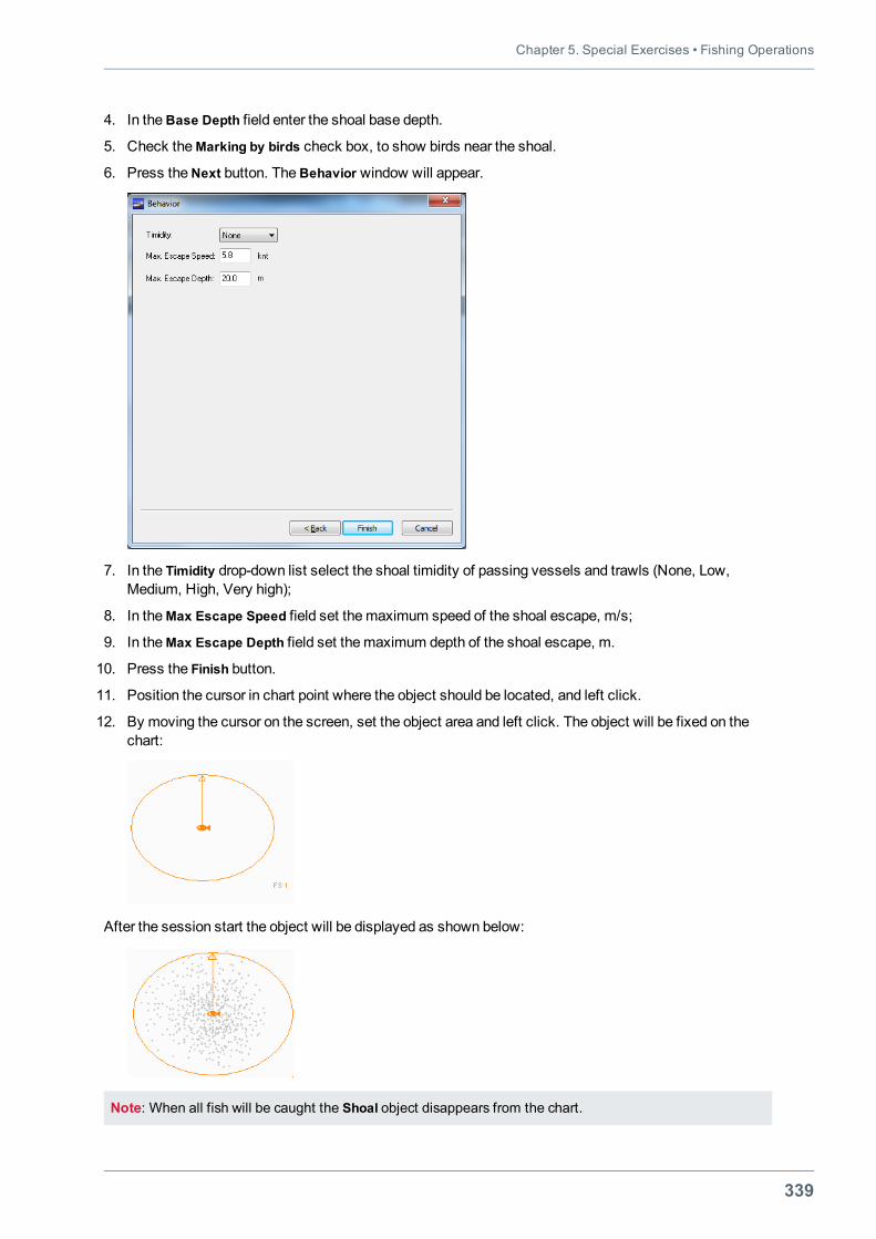
Chapter 5. Special Exercises • Fishing Operations
339
4. In theBase Depth field enter the shoal base depth.
5. Check theMarking by birds check box, to show birds near the shoal.
6. Press theNext button. TheBehavior window will appear.
7. In the Timidity drop-down list select the shoal timidity of passing vessels and trawls (None, Low,Medium, High, Very high);
8. In theMax Escape Speed field set themaximum speed of the shoal escape, m/s;
9. In theMax Escape Depth field set themaximum depth of the shoal escape, m.
10. Press the Finish button.
11. Position the cursor in chart point where the object should be located, and left click.
12. By moving the cursor on the screen, set the object area and left click. The object will be fixed on thechart:
After the session start the object will be displayed as shown below:
Note: When all fish will be caught the Shoal object disappears from the chart.
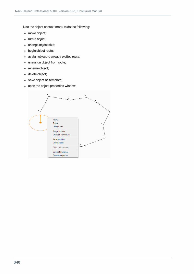
Navi-Trainer Professional 5000 (Version 5.35) • Instructor Manual
340
Use the object context menu to do the following:
l move object;
l rotate object;
l change object size;
l begin object route;
l assign object to already plotted route;
l unassign object from route;
l rename object;
l delete object;
l save object as template;
l open the object properties window.
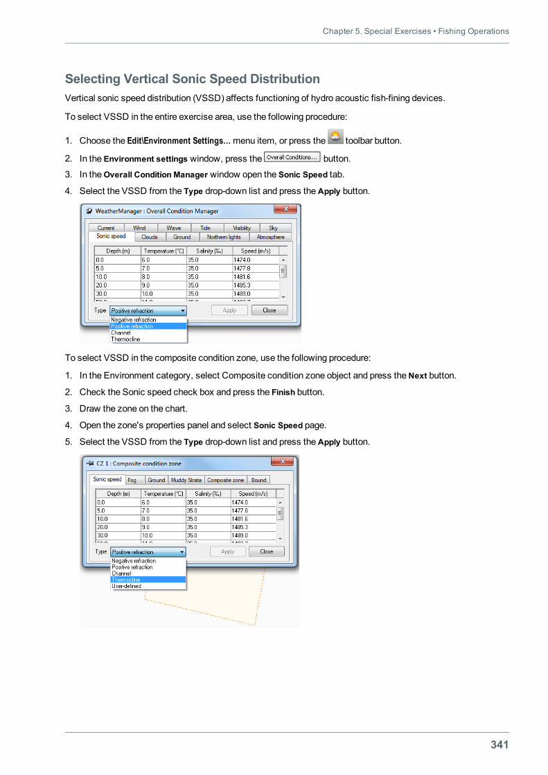
Chapter 5. Special Exercises • Fishing Operations
341
Selecting Vertical Sonic Speed DistributionVertical sonic speed distribution (VSSD) affects functioning of hydro acoustic fish-fining devices.
To select VSSD in the entire exercise area, use the following procedure:
1. Choose the Edit\Environment Settings…menu item, or press the toolbar button.
2. In the Environment settings window, press the button.
3. In theOverall Condition Manager window open the Sonic Speed tab.
4. Select the VSSD from the Type drop-down list and press theApply button.
To select VSSD in the composite condition zone, use the following procedure:
1. In the Environment category, select Composite condition zone object and press theNext button.
2. Check the Sonic speed check box and press the Finish button.
3. Draw the zone on the chart.
4. Open the zone's properties panel and select Sonic Speed page.
5. Select the VSSD from the Type drop-down list and press theApply button.
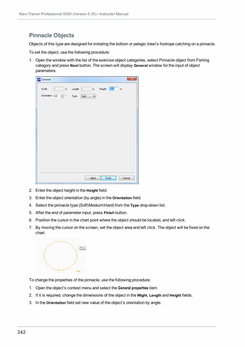
Navi-Trainer Professional 5000 (Version 5.35) • Instructor Manual
342
Pinnacle ObjectsObjects of this type are designed for imitating the bottom or pelagic trawl’s footrope catching on a pinnacle.
To set the object, use the following procedure:
1. Open the window with the list of the exercise object categories, select Pinnacle object from Fishingcategory and press Next button. The screen will display Generalwindow for the input of objectparameters.
2. Enter the object height in theHeight field.
3. Enter the object orientation (by angle) in theOrientation field.
4. Select the pinnacle type (Soft\Medium\Hard) from the Type drop-down list.
5. After the end of parameter input, press Finish button.
6. Position the cursor in the chart point where the object should be located, and left click.
7. By moving the cursor on the screen, set the object area and left click. The object will be fixed on thechart.
To change the properties of the pinnacle, use the following procedure:
1. Open the object’s context menu and select the General properties item.
2. If it is required, change the dimensions of the object in theWight, Length andHeight fields.
3. In theOrientation field set new value of the object’s orientation by angle.
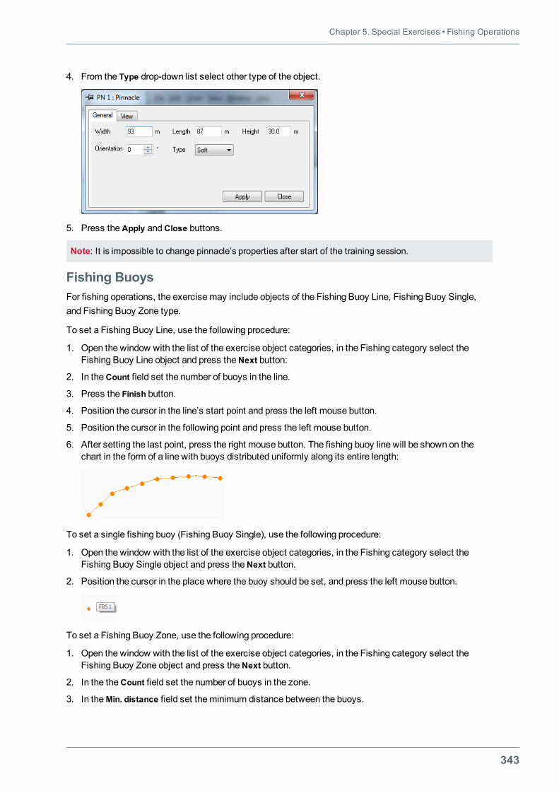
Chapter 5. Special Exercises • Fishing Operations
343
4. From the Type drop-down list select other type of the object.
5. Press theApply andClose buttons.
Note: It is impossible to change pinnacle’s properties after start of the training session.
Fishing BuoysFor fishing operations, the exercisemay include objects of the Fishing Buoy Line, Fishing Buoy Single,and Fishing Buoy Zone type.
To set a Fishing Buoy Line, use the following procedure:
1. Open the window with the list of the exercise object categories, in the Fishing category select theFishing Buoy Line object and press theNext button:
2. In theCоunt field set the number of buoys in the line.
3. Press the Finish button.
4. Position the cursor in the line’s start point and press the left mouse button.
5. Position the cursor in the following point and press the left mouse button.
6. After setting the last point, press the right mouse button. The fishing buoy line will be shown on thechart in the form of a line with buoys distributed uniformly along its entire length:
To set a single fishing buoy (Fishing Buoy Single), use the following procedure:
1. Open the window with the list of the exercise object categories, in the Fishing category select theFishing Buoy Single object and press theNext button.
2. Position the cursor in the place where the buoy should be set, and press the left mouse button.
To set a Fishing Buoy Zone, use the following procedure:
1. Open the window with the list of the exercise object categories, in the Fishing category select theFishing Buoy Zone object and press theNext button.
2. In the theCоunt field set the number of buoys in the zone.
3. In theMin. distance field set theminimum distance between the buoys.
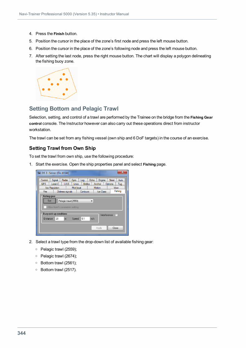
Navi-Trainer Professional 5000 (Version 5.35) • Instructor Manual
344
4. Press the Finish button.
5. Position the cursor in the place of the zone’s first node and press the left mouse button.
6. Position the cursor in the place of the zone’s following node and press the left mouse button.
7. After setting the last node, press the right mouse button. The chart will display a polygon delineatingthe fishing buoy zone.
Setting Bottom and Pelagic TrawlSelection, setting, and control of a trawl are performed by the Trainee on the bridge from the Fishing Gearcontrol console. The Instructor however can also carry out these operations direct from instructorworkstation.
The trawl can be set from any fishing vessel (own ship and 6 DoF targets) in the course of an exercise.
Setting Trawl from Own ShipTo set the trawl from own ship, use the following procedure:
1. Start the exercise. Open the ship properties panel and select Fishing page.
2. Select a trawl type from the drop-down list of available fishing gear:o Pelagic trawl (2559);o Pelagic trawl (2674);o Bottom trawl (2561);o Bottom trawl (2517).
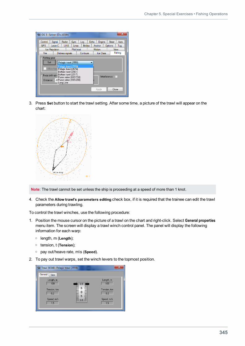
Chapter 5. Special Exercises • Fishing Operations
345
3. Press Set button to start the trawl setting. After some time, a picture of the trawl will appear on thechart:
Note: The trawl cannot be set unless the ship is proceeding at a speed of more than 1 knot.
4. Check theAllow trawl’s parameters editing check box, if it is required that the trainee can edit the trawlparameters during trawling.
To control the trawl winches, use the following procedure:
1. Position themouse cursor on the picture of a trawl on the chart and right-click. Select General propertiesmenu item. The screen will display a trawl winch control panel. The panel will display the followinginformation for each warp:o length, m (Length);o tension, t (Tension);o pay out/heave rate, m\s (Speed).
2. To pay out trawl warps, set the winch levers to the topmost position.
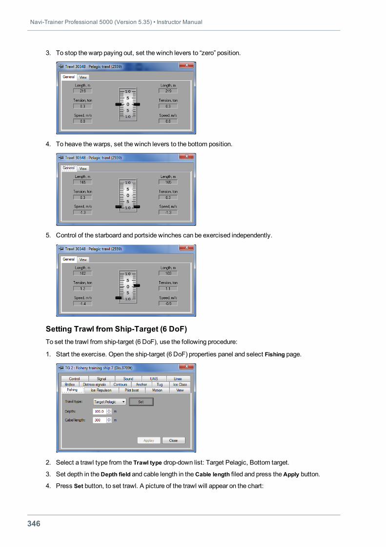
Navi-Trainer Professional 5000 (Version 5.35) • Instructor Manual
346
3. To stop the warp paying out, set the winch levers to “zero” position.
4. To heave the warps, set the winch levers to the bottom position.
5. Control of the starboard and portside winches can be exercised independently.
Setting Trawl from Ship-Target (6 DoF)To set the trawl from ship-target (6 DoF), use the following procedure:
1. Start the exercise. Open the ship-target (6 DoF) properties panel and select Fishing page.
2. Select a trawl type from the Trawl type drop-down list: Target Pelagic, Bottom target.
3. Set depth in theDepth field and cable length in theCable length filed and press theApply button.
4. Press Set button, to set trawl. A picture of the trawl will appear on the chart:
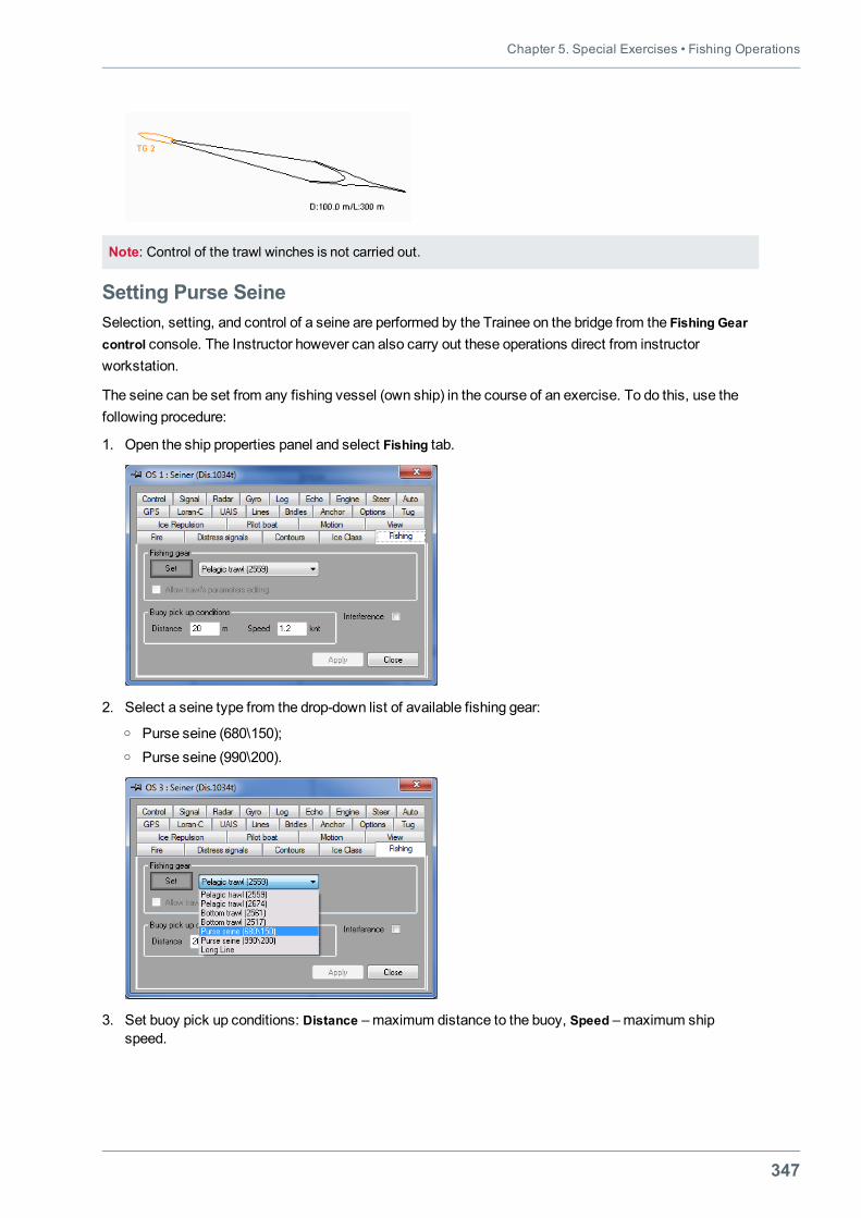
Chapter 5. Special Exercises • Fishing Operations
347
Note: Control of the trawl winches is not carried out.
Setting Purse SeineSelection, setting, and control of a seine are performed by the Trainee on the bridge from the Fishing Gearcontrol console. The Instructor however can also carry out these operations direct from instructorworkstation.
The seine can be set from any fishing vessel (own ship) in the course of an exercise. To do this, use thefollowing procedure:
1. Open the ship properties panel and select Fishing tab.
2. Select a seine type from the drop-down list of available fishing gear:o Purse seine (680\150);o Purse seine (990\200).
3. Set buoy pick up conditions: Distance –maximum distance to the buoy, Speed –maximum shipspeed.
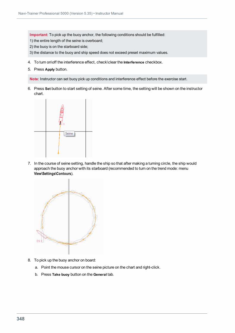
Navi-Trainer Professional 5000 (Version 5.35) • Instructor Manual
348
Important: To pick up the buoy anchor, the following conditions should be fulfilled:1) the entire length of the seine is overboard;2) the buoy is on the starboard side;3) the distance to the buoy and ship speed does not exceed preset maximum values.
4. To turn on\off the interference effect, check\clear the Interference checkbox.
5. Press Apply button.
Note: Instructor can set buoy pick up conditions and interference effect before the exercise start.
6. Press Set button to start setting of seine. After some time, the setting will be shown on the instructorchart.
7. In the course of seine setting, handle the ship so that after making a turning circle, the ship wouldapproach the buoy anchor with its starboard (recommended to turn on the trendmode: menuView\Settings\Contours).
8. To pick up the buoy anchor on board:
a. Point themouse cursor on the seine picture on the chart and right-click.
b. Press Take buoy button on theGeneral tab.
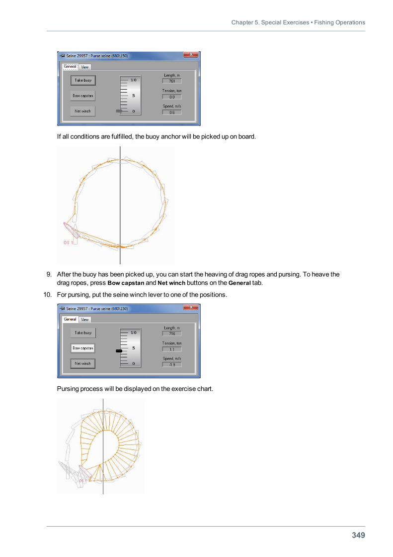
Chapter 5. Special Exercises • Fishing Operations
349
If all conditions are fulfilled, the buoy anchor will be picked up on board.
9. After the buoy has been picked up, you can start the heaving of drag ropes and pursing. To heave thedrag ropes, press Bow capstan and Net winch buttons on theGeneral tab.
10. For pursing, put the seine winch lever to one of the positions.
Pursing process will be displayed on the exercise chart.
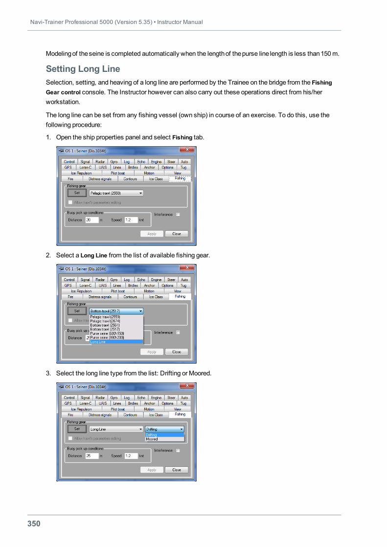
Navi-Trainer Professional 5000 (Version 5.35) • Instructor Manual
350
Modelingof theseine is completed automatically when the lengthof thepurse line length is less than150m.
Setting Long LineSelection, setting, and heaving of a long line are performed by the Trainee on the bridge from the FishingGear control console. The Instructor however can also carry out these operations direct from his/herworkstation.
The long line can be set from any fishing vessel (own ship) in course of an exercise. To do this, use thefollowing procedure:
1. Open the ship properties panel and select Fishing tab.
2. Select a Long Line from the list of available fishing gear.
3. Select the long line type from the list: Drifting or Moored.
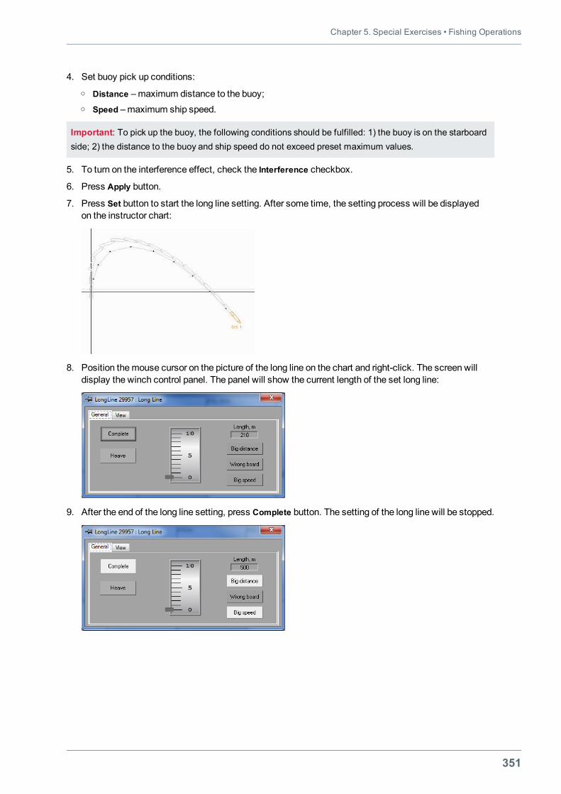
Chapter 5. Special Exercises • Fishing Operations
351
4. Set buoy pick up conditions:o Distance –maximum distance to the buoy;o Speed –maximum ship speed.
Important: To pick up the buoy, the following conditions should be fulfilled: 1) the buoy is on the starboardside; 2) the distance to the buoy and ship speed do not exceed preset maximum values.
5. To turn on the interference effect, check the Interference checkbox.
6. Press Apply button.
7. Press Set button to start the long line setting. After some time, the setting process will be displayedon the instructor chart:
8. Position themouse cursor on the picture of the long line on the chart and right-click. The screen willdisplay the winch control panel. The panel will show the current length of the set long line:
9. After the end of the long line setting, press Complete button. The setting of the long line will be stopped.
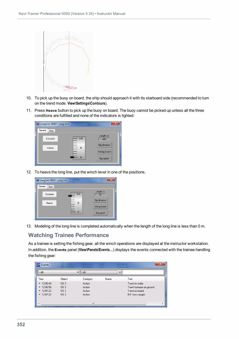
Navi-Trainer Professional 5000 (Version 5.35) • Instructor Manual
352
10. To pick up the buoy on board, the ship should approach it with its starboard side (recommended to turnon the trendmode: View\Settings\Contours).
11. Press Heave button to pick up the buoy on board. The buoy cannot be picked up unless all the threeconditions are fulfilled and none of the indicators is lighted:
12. To heave the long line, put the winch lever in one of the positions.
13. Modeling of the long line is completed automatically when the length of the long line is less than 0m.
Watching Trainee PerformanceAs a trainee is setting the fishing gear, all the winch operations are displayed at the instructor workstation.In addition, the Events panel (View\Panels\Events…) displays the events connected with the trainee handlingthe fishing gear:
Chapter 5. Special Exercises • Fishing Operations
353
In the case of operation with a trawl, the following events are shown:
l "Trawl on water" – end of trawl setting;
l "Trawl footrope on ground" – footrope touching the bottom;
l "Trawl otter doors on ground" – trawl doors touching the bottom;
l "Trawl lost" – alarm signifying an error which resulted in the loss of a trawl;
l "N.N tons caught" – catch calculations result.
In the case of operation with a seine, the following events are shown:
l "Seine setting" – command to set the seine is given;
l "Seine completing the set" – end of setting the net and dragrope;
l "Seine pursing" – pursing start indication;
l "Seine on board" – pursing end indication;
l "Seine lost" – alarm signifying an error which resulted in the loss of a seine;
l "N.N tons caught" – catch calculations result.
In the case of operation with a long line, the following events are shown:
l "Long Line setting" – command to set the long line is given;
l "Long Line fishing" – end of long line setting;
l "Long Line heave" – long line heaving start indication;
l "Long Line on board" – long line heaving end indication;
l "N.N tons caught" – catch calculations result.
Navi-Trainer Professional 5000 (Version 5.35) • Instructor Manual
354
SEARCH AND RESCUE OPERATIONSTo ensure simulator training in the search and rescue (SAR) operations as per the requirements ofInternational MERSAR and IAMSAR Conventions, the simulator has a number of objects for practisingsearch and rescue operations, and the following functionality is implemented:
l Giving signals in compliance with the International Code of Signals (ICS-69) by using flags, flashinglight (with appropriate visual effects) and sound signals;
l Giving distress signals associated with appropriate visual effects;
l UAIS functionality;
l Integration with Transas GMDSS Simulator TGS 5000 (transmission of ship position coordinates,speed, local time, SART and radar operation, reception and transmission of messages to NavtexManager utility (NS 3000 ECDIS-I) for their further processing).
SAR ObjectsThe objects from the Rescue category can take part in SAR operations.
Rescue category objects are added to the exercise by using standard procedures. All these objects can beused by the Instructor both at the exercise preparation stage and during the exercise, adding them, at thenecessary time, in the required place of the scenario. Besides, SART and Life buoy objects can be thrownoverboard by the Trainees themselves: the former by using the GMDSS work station, the latter by usingthe Conning Display.
Note: Also helicopters from Helicopter category can take part in SAR operations (see "Operations withHelicopter Objects" on page 374).
This section describes the specific features of such Rescue objects as: Damaged Tanker, Damaged fishboat, Fire objects, EPIRB, AIS SART and SAR routes.
Damaged Tanker ObjectThe Damaged tanker object has several visual scripts:
l Code flags – tanker with a distress signals as per the International Code of Signals (November,Charlie);
l Damaged ship – tanker with fire in the stern part;
l Distress flag – tanker with a distress flag;
l Flames on vessel – tanker with a burning barrel on the stern;
l Hand flare – tanker with a person holding a hand flare on the stern;
l Safe – tanker which does not move relative to the water;
l Sinking ship – tanker with a starboard list and slight forward trim;
l Square flag and ball – tanker with a distress signal which is a square flag with a ball under it.
l Wave arms – tanker with a person waving arms on the stern.
To set visual script of the object, use the following procedure:
1. Open the object properties panel.
2. Select Visual scripts tab.
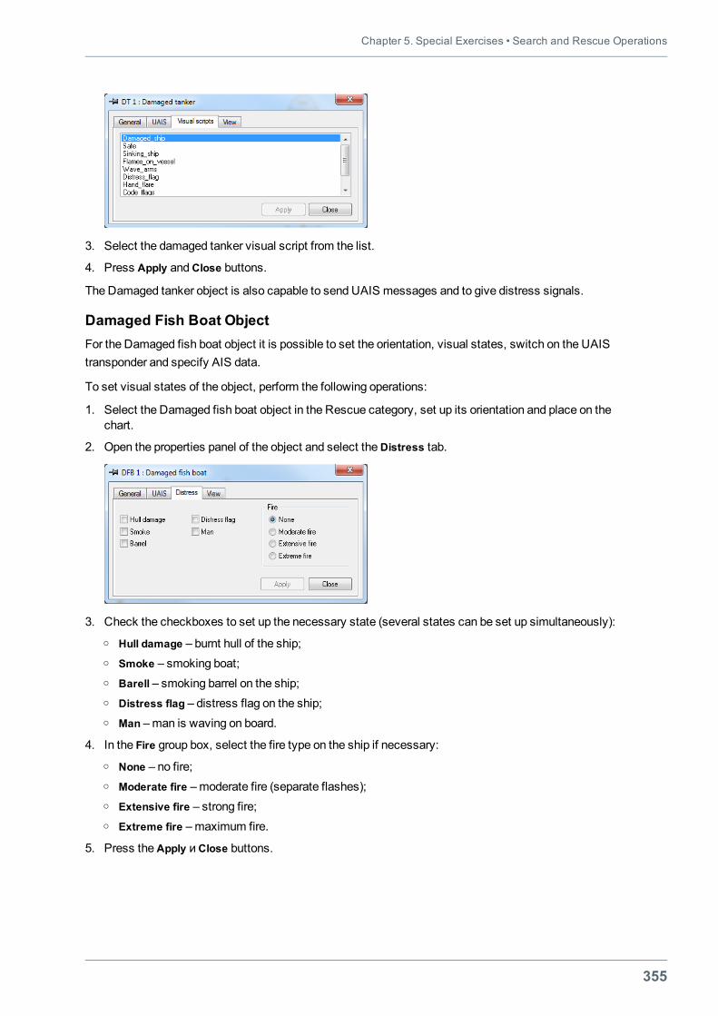
Chapter 5. Special Exercises • Search and Rescue Operations
355
3. Select the damaged tanker visual script from the list.
4. Press Apply andClose buttons.
The Damaged tanker object is also capable to send UAIS messages and to give distress signals.
Damaged Fish Boat ObjectFor the Damaged fish boat object it is possible to set the orientation, visual states, switch on the UAIStransponder and specify AIS data.
To set visual states of the object, perform the following operations:
1. Select the Damaged fish boat object in the Rescue category, set up its orientation and place on thechart.
2. Open the properties panel of the object and select theDistress tab.
3. Check the checkboxes to set up the necessary state (several states can be set up simultaneously):o Hull damage – burnt hull of the ship;o Smoke – smoking boat;o Barell – smoking barrel on the ship;o Distress flag – distress flag on the ship;o Man –man is waving on board.
4. In the Fire group box, select the fire type on the ship if necessary:o None – no fire;o Moderate fire –moderate fire (separate flashes);o Extensive fire – strong fire;o Extreme fire –maximum fire.
5. Press theApply иClose buttons.
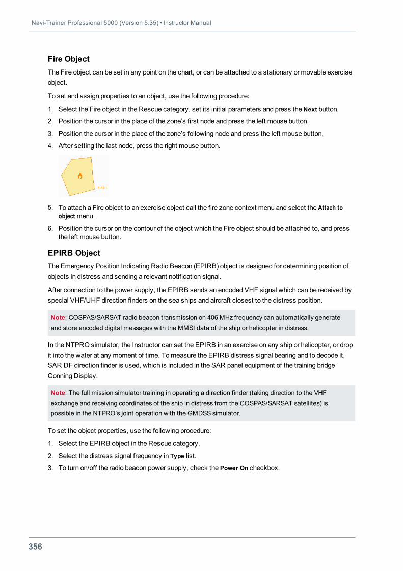
Navi-Trainer Professional 5000 (Version 5.35) • Instructor Manual
356
Fire ObjectThe Fire object can be set in any point on the chart, or can be attached to a stationary or movable exerciseobject.
To set and assign properties to an object, use the following procedure:
1. Select the Fire object in the Rescue category, set its initial parameters and press theNext button.
2. Position the cursor in the place of the zone’s first node and press the left mouse button.
3. Position the cursor in the place of the zone’s following node and press the left mouse button.
4. After setting the last node, press the right mouse button.
5. To attach a Fire object to an exercise object call the fire zone context menu and select the Attach toobject menu.
6. Position the cursor on the contour of the object which the Fire object should be attached to, and pressthe left mouse button.
EPIRB ObjectThe Emergency Position Indicating Radio Beacon (EPIRB) object is designed for determining position ofobjects in distress and sending a relevant notification signal.
After connection to the power supply, the EPIRB sends an encoded VHF signal which can be received byspecial VHF/UHF direction finders on the sea ships and aircraft closest to the distress position.
Note: COSPAS/SARSAT radio beacon transmission on 406 MHz frequency can automatically generateand store encoded digital messages with the MMSI data of the ship or helicopter in distress.
In the NTPRO simulator, the Instructor can set the EPIRB in an exercise on any ship or helicopter, or dropit into the water at any moment of time. Tomeasure the EPIRB distress signal bearing and to decode it,SAR DF direction finder is used, which is included in the SAR panel equipment of the training bridgeConning Display.
Note: The full mission simulator training in operating a direction finder (taking direction to the VHFexchange and receiving coordinates of the ship in distress from the COSPAS/SARSAT satellites) ispossible in the NTPRO’s joint operation with the GMDSS simulator.
To set the object properties, use the following procedure:
1. Select the EPIRB object in the Rescue category.
2. Select the distress signal frequency in Type list.
3. To turn on/off the radio beacon power supply, check the Power On checkbox.
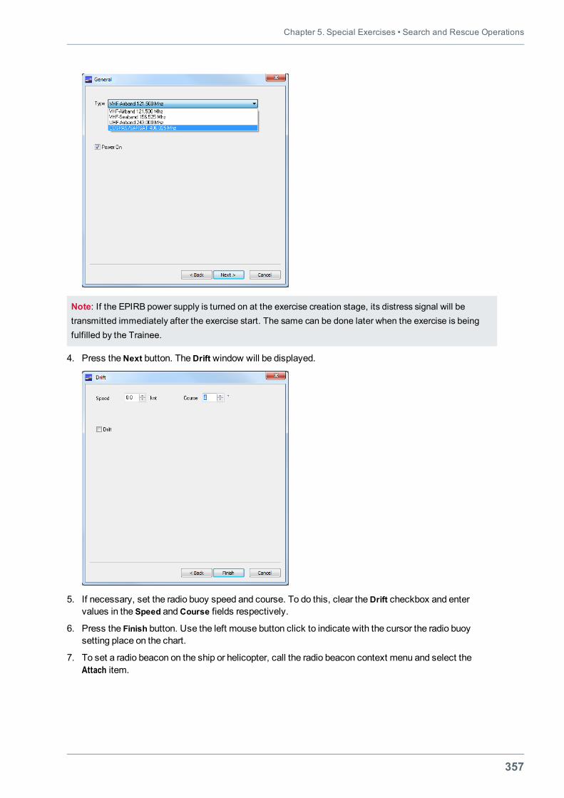
Chapter 5. Special Exercises • Search and Rescue Operations
357
Note: If the EPIRB power supply is turned on at the exercise creation stage, its distress signal will betransmitted immediately after the exercise start. The same can be done later when the exercise is beingfulfilled by the Trainee.
4. Press theNext button. TheDrift window will be displayed.
5. If necessary, set the radio buoy speed and course. To do this, clear theDrift checkbox and entervalues in the Speed andCourse fields respectively.
6. Press the Finish button. Use the left mouse button click to indicate with the cursor the radio buoysetting place on the chart.
7. To set a radio beacon on the ship or helicopter, call the radio beacon context menu and select theAttach item.
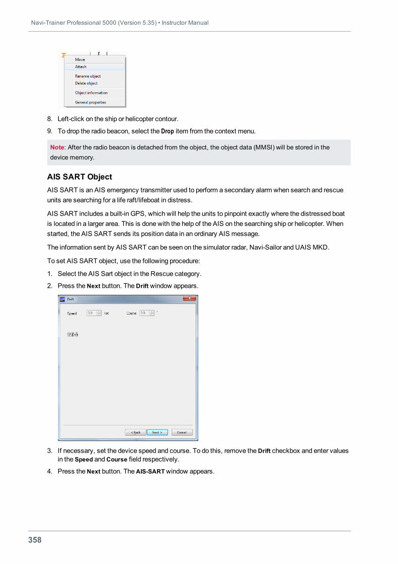
Navi-Trainer Professional 5000 (Version 5.35) • Instructor Manual
358
8. Left-click on the ship or helicopter contour.
9. To drop the radio beacon, select the Drop item from the context menu.
Note: After the radio beacon is detached from the object, the object data (MMSI) will be stored in thedevice memory.
AIS SART ObjectAIS SART is an AIS emergency transmitter used to perform a secondary alarm when search and rescueunits are searching for a life raft/lifeboat in distress.
AIS SART includes a built-in GPS, which will help the units to pinpoint exactly where the distressed boatis located in a larger area. This is done with the help of the AIS on the searching ship or helicopter. Whenstarted, the AIS SART sends its position data in an ordinary AIS message.
The information sent by AIS SART can be seen on the simulator radar, Navi-Sailor and UAIS MKD.
To set AIS SART object, use the following procedure:
1. Select the AIS Sart object in the Rescue category.
2. Press theNext button. TheDrift window appears.
3. If necessary, set the device speed and course. To do this, remove theDrift checkbox and enter valuesin the Speed andCourse field respectively.
4. Press theNext button. TheAIS-SARTwindow appears.
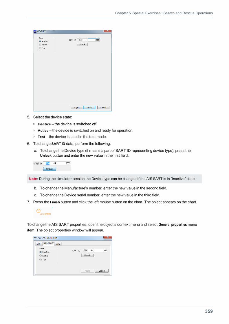
Chapter 5. Special Exercises • Search and Rescue Operations
359
5. Select the device state:o Inactive – the device is switched off.o Active – the device is switched on and ready for operation.o Test – the device is used in the test mode.
6. To change SART ID data, perform the following:
a. To change the Device type (it means a part of SART ID representing device type), press theUnlock button and enter the new value in the first field.
Note: During the simulator session the Device type can be changed if the AIS SART is in "Inactive" state.
b. To change theManufacture’s number, enter the new value in the second field.
c. To change the Device serial number, enter the new value in the third field.
7. Press the Finish button and click the left mouse button on the chart. The object appears on the chart.
To change the AIS SART properties, open the object’s context menu and select General propertiesmenuitem. The object properties window will appear.
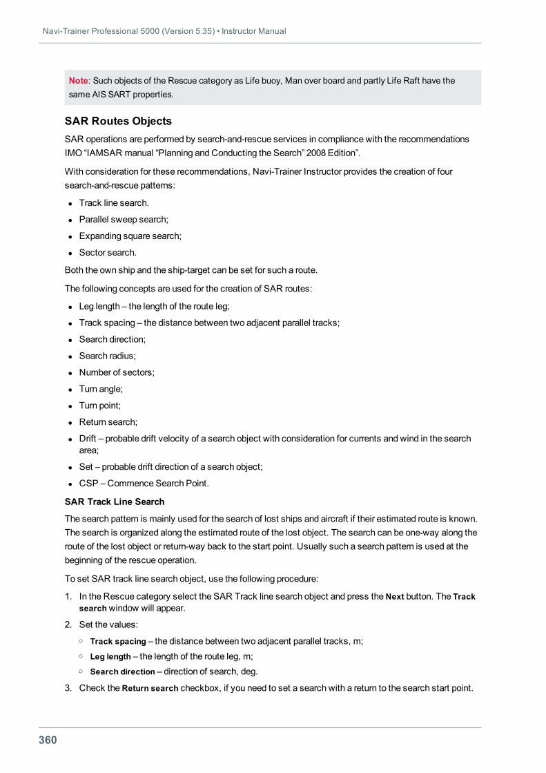
Navi-Trainer Professional 5000 (Version 5.35) • Instructor Manual
360
Note: Such objects of the Rescue category as Life buoy, Man over board and partly Life Raft have thesame AIS SART properties.
SAR Routes ObjectsSAR operations are performed by search-and-rescue services in compliance with the recommendationsIMO “IAMSAR manual “Planning and Conducting the Search” 2008 Edition”.
With consideration for these recommendations, Navi-Trainer Instructor provides the creation of foursearch-and-rescue patterns:
l Track line search.
l Parallel sweep search;
l Expanding square search;
l Sector search.
Both the own ship and the ship-target can be set for such a route.
The following concepts are used for the creation of SAR routes:
l Leg length – the length of the route leg;
l Track spacing – the distance between two adjacent parallel tracks;
l Search direction;
l Search radius;
l Number of sectors;
l Turn angle;
l Turn point;
l Return search;
l Drift – probable drift velocity of a search object with consideration for currents and wind in the searcharea;
l Set – probable drift direction of a search object;
l CSP –Commence Search Point.
SAR Track Line Search
The search pattern is mainly used for the search of lost ships and aircraft if their estimated route is known.The search is organized along the estimated route of the lost object. The search can be one-way along theroute of the lost object or return-way back to the start point. Usually such a search pattern is used at thebeginning of the rescue operation.
To set SAR track line search object, use the following procedure:
1. In the Rescue category select the SAR Track line search object and press theNext button. The Tracksearchwindow will appear.
2. Set the values:o Track spacing – the distance between two adjacent parallel tracks, m;o Leg length – the length of the route leg, m;o Search direction – direction of search, deg.
3. Check theReturn search checkbox, if you need to set a search with a return to the search start point.
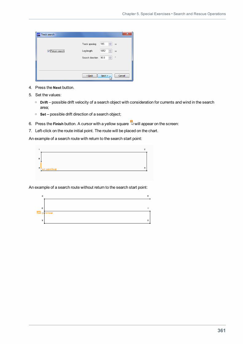
Chapter 5. Special Exercises • Search and Rescue Operations
361
4. Press theNext button.
5. Set the values:o Drift – possible drift velocity of a search object with consideration for currents and wind in the search
area;o Set – possible drift direction of a search object;
6. Press the Finish button. A cursor with a yellow square will appear on the screen:
7. Left-click on the route initial point. The route will be placed on the chart.
An example of a search route with return to the search start point:
An example of a search route without return to the search start point:
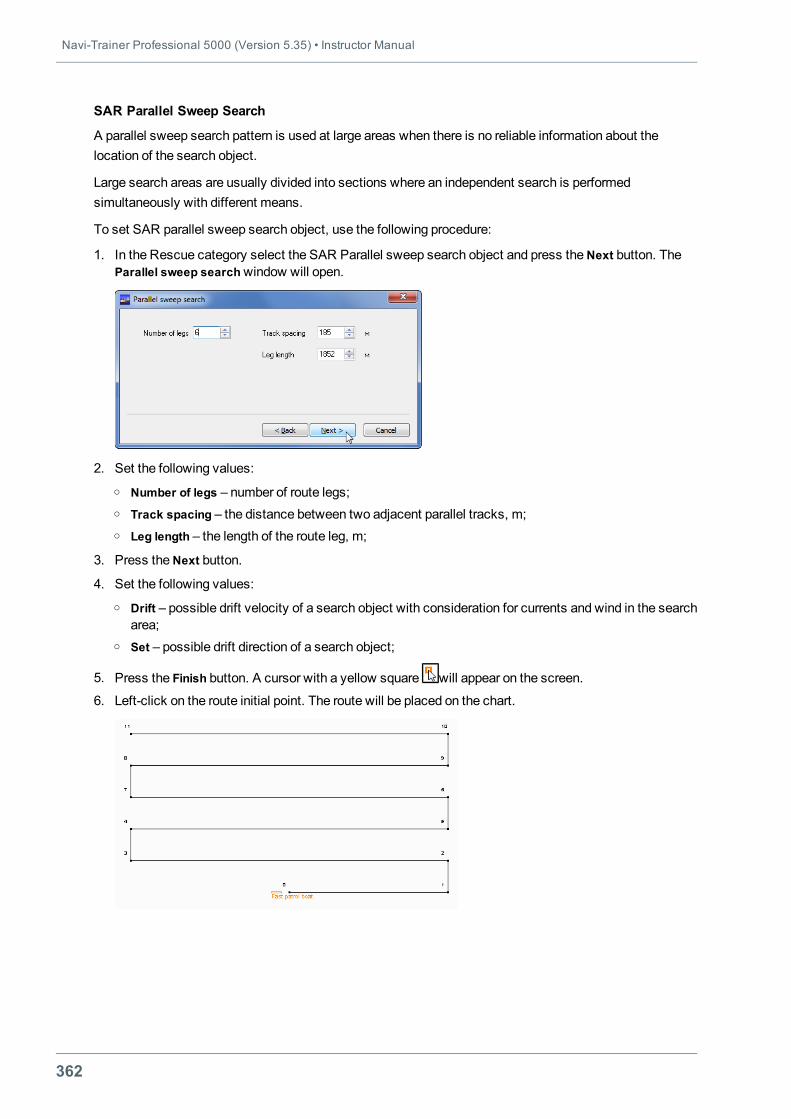
Navi-Trainer Professional 5000 (Version 5.35) • Instructor Manual
362
SAR Parallel Sweep Search
A parallel sweep search pattern is used at large areas when there is no reliable information about thelocation of the search object.
Large search areas are usually divided into sections where an independent search is performedsimultaneously with different means.
To set SAR parallel sweep search object, use the following procedure:
1. In the Rescue category select the SAR Parallel sweep search object and press theNext button. TheParallel sweep searchwindow will open.
2. Set the following values:o Number of legs – number of route legs;o Track spacing – the distance between two adjacent parallel tracks, m;o Leg length – the length of the route leg, m;
3. Press theNext button.
4. Set the following values:o Drift – possible drift velocity of a search object with consideration for currents and wind in the search
area;o Set – possible drift direction of a search object;
5. Press the Finish button. A cursor with a yellow square will appear on the screen.
6. Left-click on the route initial point. The route will be placed on the chart.
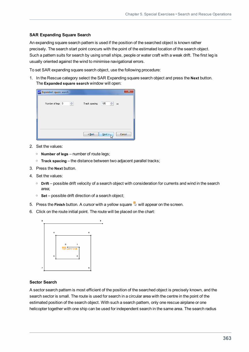
Chapter 5. Special Exercises • Search and Rescue Operations
363
SAR Expanding Square Search
An expanding square search pattern is used if the position of the searched object is known ratherprecisely. The search start point concurs with the point of the estimated location of the search object.Such a pattern suits for search by using small ships, people or water craft with a weak drift. The first leg isusually oriented against the wind tominimise navigational errors.
To set SAR expanding square search object, use the following procedure:
1. In the Rescue category select the SAR Expanding square search object and press theNext button.The Expanded square searchwindow will open:
2. Set the values:o Number of legs – number of route legs;o Track spacing – the distance between two adjacent parallel tracks;
3. Press theNext button.
4. Set the values:o Drift – possible drift velocity of a search object with consideration for currents and wind in the search
area;o Set – possible drift direction of a search object;
5. Press the Finish button. A cursor with a yellow square will appear on the screen.
6. Click on the route initial point. The route will be placed on the chart:
Sector Search
A sector search pattern is most efficient of the position of the searched object is precisely known, and thesearch sector is small. The route is used for search in a circular area with the centre in the point of theestimated position of the search object. With such a search pattern, only one rescue airplane or onehelicopter together with one ship can be used for independent search in the same area. The search radius
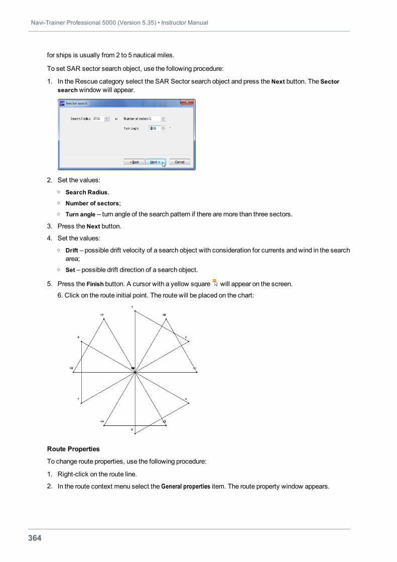
Navi-Trainer Professional 5000 (Version 5.35) • Instructor Manual
364
for ships is usually from 2 to 5 nautical miles.
To set SAR sector search object, use the following procedure:
1. In the Rescue category select the SAR Sector search object and press theNext button. The Sectorsearchwindow will appear.
2. Set the values:o Search Radius.o Number of sectors;o Turn angle – turn angle of the search pattern if there aremore than three sectors.
3. Press theNext button.
4. Set the values:o Drift – possible drift velocity of a search object with consideration for currents and wind in the search
area;o Set – possible drift direction of a search object.
5. Press the Finish button. A cursor with a yellow square will appear on the screen.
6. Click on the route initial point. The route will be placed on the chart:
Route Properties
To change route properties, use the following procedure:
1. Right-click on the route line.
2. In the route context menu select the General properties item. The route property window appears.
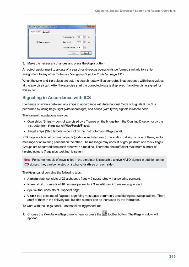
Chapter 5. Special Exercises • Search and Rescue Operations
365
3. Make the necessary changes and press theApply button.
An object assignment to a route of a search-and-rescue operation is performed similarly to a shipassignment to any other route (see "Assigning Object to Route" on page 133).
When theDrift and Set values are set, the search route will be corrected in accordance with these valuesat the exercise start. After the exercise start the corrected route is displayed if an object is assigned forthis route.
Signaling in Accordance with ICSExchange of signals between any ships in accordance with International Code of Signals ICS-69 isperformed by using flags, light (with searchlight) and sound (with tyfon) signals in Morse code.
The transmitting stations may be:
l Own ships (Ships) – control exercised by a Trainee on the bridge from the Conning Display, or by theInstructor from Flags panel (View\Panels\Flags);
l Target ships (Ship targets) – control by the Instructor from Flags panel.
ICS flags are hoisted on two halyards (portside and starboard): the station callsign on one of them, and amessage or answering pennant on the other. Themessagemay consist of groups (from one to six flags).Groups are separated from each other with a tackline. Therefore, the sufficient maximum number ofhoisted objects (flags plus tackline) is seven.
Note: For some models of naval ships in the simulator it is possible to give NATO signals in addition to theICS signals; they can be hoisted on six halyards (three on each side).
The Flags panel contains the following tabs:
l Alphabet tab: consists of 26 alphabetic flags + 3 substitutes + 1 answering pennant;
l Numeral tab: consists of 10 numeral pennants + 3 substitutes + 1 answering pennant;
l Special tab: consists of 9 special flags;
l Codes tab: consists of flag sets signifyingmessages commonly used during rescue operations. Thereare 6 of them in the delivery set, but this number can be increased by the Instructor.
To work with the Flags panel, use the following procedure:
1. Choose the View\Panels\Flags...menu item, or press the toolbar button. The Flags window willappear.
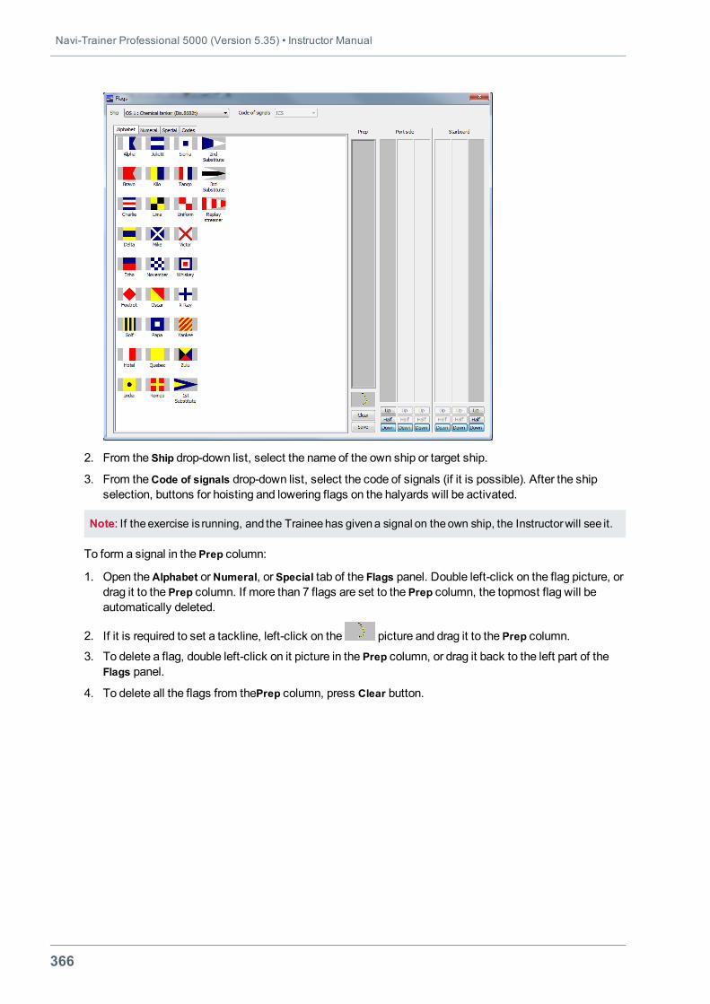
Navi-Trainer Professional 5000 (Version 5.35) • Instructor Manual
366
2. From the Ship drop-down list, select the name of the own ship or target ship.
3. From theCode of signals drop-down list, select the code of signals (if it is possible). After the shipselection, buttons for hoisting and lowering flags on the halyards will be activated.
Note: If theexercise is running, and the Traineehas givena signal on theown ship, the Instructorwill see it.
To form a signal in the Prep column:
1. Open theAlphabet orNumeral, or Special tab of the Flags panel. Double left-click on the flag picture, ordrag it to the Prep column. If more than 7 flags are set to the Prep column, the topmost flag will beautomatically deleted.
2. If it is required to set a tackline, left-click on the picture and drag it to the Prep column.
3. To delete a flag, double left-click on it picture in the Prep column, or drag it back to the left part of theFlags panel.
4. To delete all the flags from thePrep column, press Clear button.
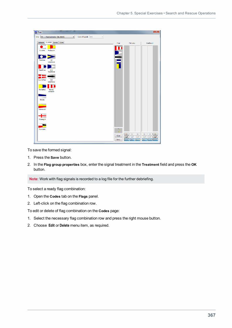
Chapter 5. Special Exercises • Search and Rescue Operations
367
To save the formed signal:
1. Press the Save button.
2. In the Flag group properties box, enter the signal treatment in the Treatment field and press theOKbutton.
Note: Work with flag signals is recorded to a log file for the further debriefing.
To select a ready flag combination:
1. Open theCodes tab on the Flags panel.
2. Left-click on the flag combination row.
To edit or delete of flag combination on theCodes page:
1. Select the necessary flag combination row and press the right mouse button.
2. Choose Edit or Deletemenu item, as required.
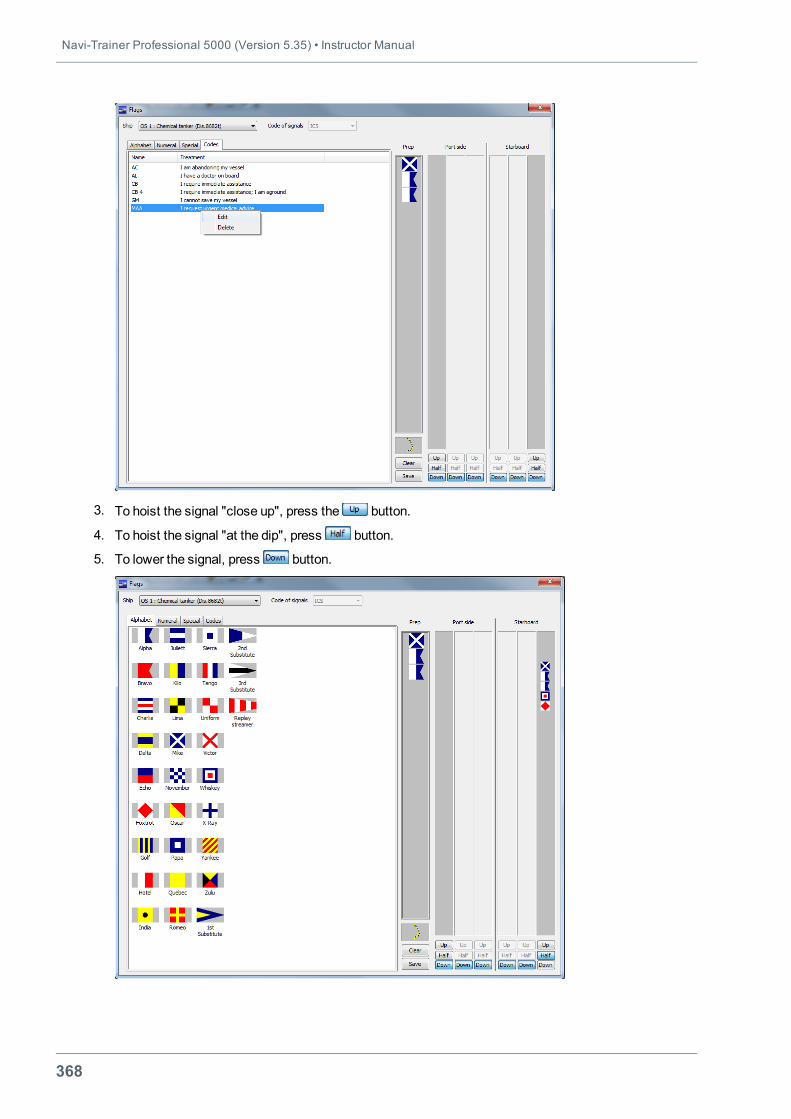
Navi-Trainer Professional 5000 (Version 5.35) • Instructor Manual
368
3. To hoist the signal "close up", press the button.
4. To hoist the signal "at the dip", press button.
5. To lower the signal, press button.
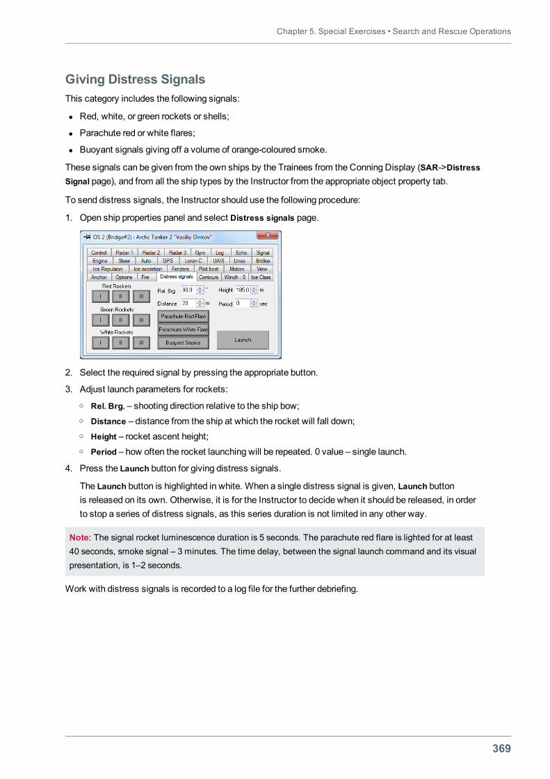
Chapter 5. Special Exercises • Search and Rescue Operations
369
Giving Distress SignalsThis category includes the following signals:
l Red, white, or green rockets or shells;
l Parachute red or white flares;
l Buoyant signals giving off a volume of orange-coloured smoke.
These signals can be given from the own ships by the Trainees from the Conning Display (SAR->DistressSignal page), and from all the ship types by the Instructor from the appropriate object property tab.
To send distress signals, the Instructor should use the following procedure:
1. Open ship properties panel and select Distress signals page.
2. Select the required signal by pressing the appropriate button.
3. Adjust launch parameters for rockets:o Rel. Brg. – shooting direction relative to the ship bow;o Distance – distance from the ship at which the rocket will fall down;o Height – rocket ascent height;o Period – how often the rocket launching will be repeated. 0 value – single launch.
4. Press the Launch button for giving distress signals.
The Launch button is highlighted in white. When a single distress signal is given, Launch buttonis released on its own. Otherwise, it is for the Instructor to decide when it should be released, in orderto stop a series of distress signals, as this series duration is not limited in any other way.
Note: The signal rocket luminescence duration is 5 seconds. The parachute red flare is lighted for at least40 seconds, smoke signal – 3 minutes. The time delay, between the signal launch command and its visualpresentation, is 1–2 seconds.
Work with distress signals is recorded to a log file for the further debriefing.
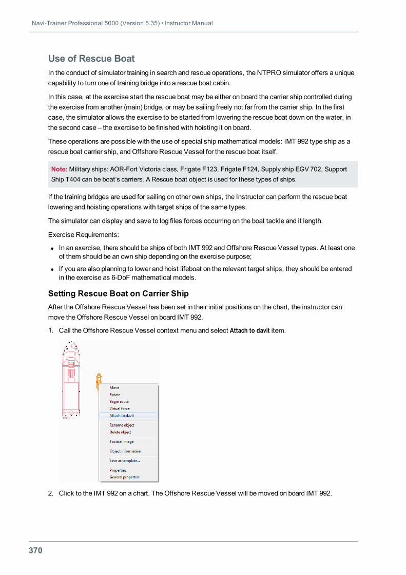
Navi-Trainer Professional 5000 (Version 5.35) • Instructor Manual
370
Use of Rescue BoatIn the conduct of simulator training in search and rescue operations, the NTPRO simulator offers a uniquecapability to turn one of training bridge into a rescue boat cabin.
In this case, at the exercise start the rescue boat may be either on board the carrier ship controlled duringthe exercise from another (main) bridge, or may be sailing freely not far from the carrier ship. In the firstcase, the simulator allows the exercise to be started from lowering the rescue boat down on the water, inthe second case – the exercise to be finished with hoisting it on board.
These operations are possible with the use of special ship mathematical models: IMT 992 type ship as arescue boat carrier ship, andOffshore Rescue Vessel for the rescue boat itself.
Note: Military ships: AOR-Fort Victoria class, Frigate F123, Frigate F124, Supply ship EGV 702, SupportShip T404 can be boat’s carriers. A Rescue boat object is used for these types of ships.
If the training bridges are used for sailing on other own ships, the Instructor can perform the rescue boatlowering and hoisting operations with target ships of the same types.
The simulator can display and save to log files forces occurring on the boat tackle and it length.
Exercise Requirements:
l In an exercise, there should be ships of both IMT 992 andOffshore Rescue Vessel types. At least oneof them should be an own ship depending on the exercise purpose;
l If you are also planning to lower and hoist lifeboat on the relevant target ships, they should be enteredin the exercise as 6-DoF mathematical models.
Setting Rescue Boat on Carrier ShipAfter the Offshore Rescue Vessel has been set in their initial positions on the chart, the instructor canmove theOffshore Rescue Vessel on board IMT 992.
1. Call the Offshore Rescue Vessel context menu and select Attach to davit item.
2. Click to the IMT 992 on a chart. TheOffshore Rescue Vessel will bemoved on board IMT 992.

Chapter 5. Special Exercises • Search and Rescue Operations
371
3. If it is necessary to return to the autonomous sailing, use Release from davit command from theOffshore Rescue Vessel context menu.
Instructor on theDavit page can adjust break force value for ropes andmaximum force of boat collisionwith a board of IMT 992 ship as well.
For both ships, their own routes can be plotted regardless of whether the Offshore Rescue Vessel is onboard IMT 992 or on the water.
Note: The rescue boat can currently be lowered and hoisted on the IMT 992 portside only.
Loading and Running Exercise on BridgesThe instructor procedures for loading and running the exercise on the bridges are in no way different fromthe standard procedures.
Own IMT 992 ship is loaded on themain bridge, whereas the Offshore Rescue Vessel – on the rescue boatbridge in accordance with the joint sailing scenario.
If the exercise conditions are that the rescue boat is on board the carrier ship, the trainees on the rescueboat bridge will see themselves in the rescue boat, but on deck of IMT 992 carrier ship.
Main recommendations for organising this type of simulator training:
l If the rescue boat is on board the carrier ship in the exercise, after the exercise start, the crew of theOffshore Rescue Vessel should be engaged in the VHF exchange with the crew on IMT 992 bridge,awaiting lowering on the water;
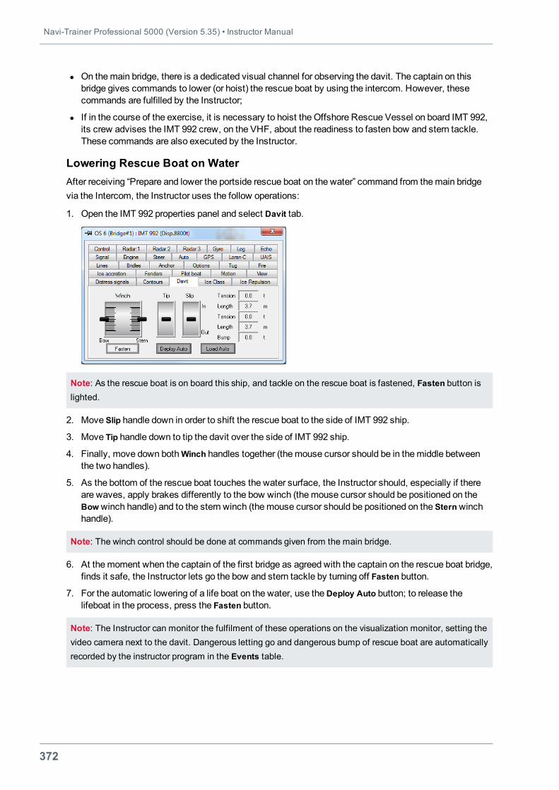
Navi-Trainer Professional 5000 (Version 5.35) • Instructor Manual
372
l On themain bridge, there is a dedicated visual channel for observing the davit. The captain on thisbridge gives commands to lower (or hoist) the rescue boat by using the intercom. However, thesecommands are fulfilled by the Instructor;
l If in the course of the exercise, it is necessary to hoist the Offshore Rescue Vessel on board IMT 992,its crew advises the IMT 992 crew, on the VHF, about the readiness to fasten bow and stern tackle.These commands are also executed by the Instructor.
Lowering Rescue Boat on WaterAfter receiving “Prepare and lower the portside rescue boat on the water” command from themain bridgevia the Intercom, the Instructor uses the follow operations:
1. Open the IMT 992 properties panel and select Davit tab.
Note: As the rescue boat is on board this ship, and tackle on the rescue boat is fastened, Fasten button islighted.
2. Move Slip handle down in order to shift the rescue boat to the side of IMT 992 ship.
3. Move Tip handle down to tip the davit over the side of IMT 992 ship.
4. Finally, move down bothWinch handles together (themouse cursor should be in themiddle betweenthe two handles).
5. As the bottom of the rescue boat touches the water surface, the Instructor should, especially if thereare waves, apply brakes differently to the bow winch (themouse cursor should be positioned on theBowwinch handle) and to the stern winch (themouse cursor should be positioned on the Sternwinchhandle).
Note: The winch control should be done at commands given from the main bridge.
6. At themoment when the captain of the first bridge as agreed with the captain on the rescue boat bridge,finds it safe, the Instructor lets go the bow and stern tackle by turning off Fasten button.
7. For the automatic lowering of a life boat on the water, use theDeploy Auto button; to release thelifeboat in the process, press the Fasten button.
Note: The Instructor can monitor the fulfilment of these operations on the visualization monitor, setting thevideo camera next to the davit. Dangerous letting go and dangerous bump of rescue boat are automaticallyrecorded by the instructor program in the Events table.
Chapter 5. Special Exercises • Search and Rescue Operations
373
Hoisting Rescue Boat on Carrier ShipBefore the rescue boat approaches the side of IMT 992, the davit should be tipped and bow tackle shouldbe lowered so as to be half a meter above the water surface if this was not done before.
The simulator automatically checks the distance of the rescue boat bow and stern approach to the tackle,and will not allow the Fasten button to be activated if the distance is large (more than 1metre). As thecommand to fasten the tackle is given from themain bridge (after an appropriate VHF request from therescue boat bridge), the ill-timed Fasten command is recorded by the instructor program in the Eventstable.
If the tackle fastening is successful, the Instructor will be able to use other davit controls:
l Winch handles aremoved up. The tackle is heaved and the rescue boat is hoisted. As the tackle isheaved to its proper position, the winch handles will automatically take themiddle position;
l Tip handle is moved up. The davit is topped to the stowed position. As this position is reached, Tiphandle automatically returns to themiddle position;
l Slip handle is moved up. The davit is shifted to the stowed position. As this position is reached, Sliphandles automatically returns to themiddle position.
To hoist the rescue boat automatically on the carrier ship:
1. Press theDeploy Auto button to lower the davit.
2. Press the Fasten button.
3. Press the Load Auto button.
After the end of all the operations, the simulator session can be stopped by the Instructor with the exercisestop button.
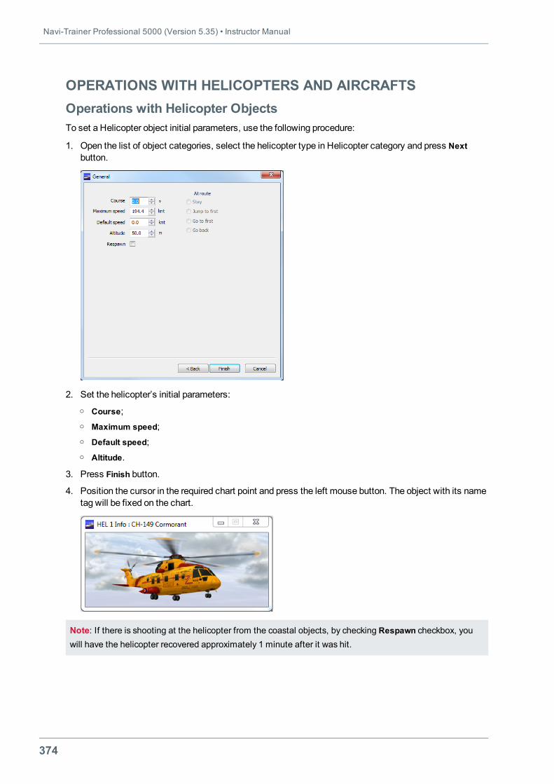
Navi-Trainer Professional 5000 (Version 5.35) • Instructor Manual
374
OPERATIONS WITH HELICOPTERS AND AIRCRAFTSOperations with Helicopter ObjectsTo set a Helicopter object initial parameters, use the following procedure:
1. Open the list of object categories, select the helicopter type in Helicopter category and press Nextbutton.
2. Set the helicopter’s initial parameters:o Course;o Maximum speed;o Default speed;o Altitude.
3. Press Finish button.
4. Position the cursor in the required chart point and press the left mouse button. The object with its nametag will be fixed on the chart.
Note: If there is shooting at the helicopter from the coastal objects, by checking Respawn checkbox, youwill have the helicopter recovered approximately 1 minute after it was hit.
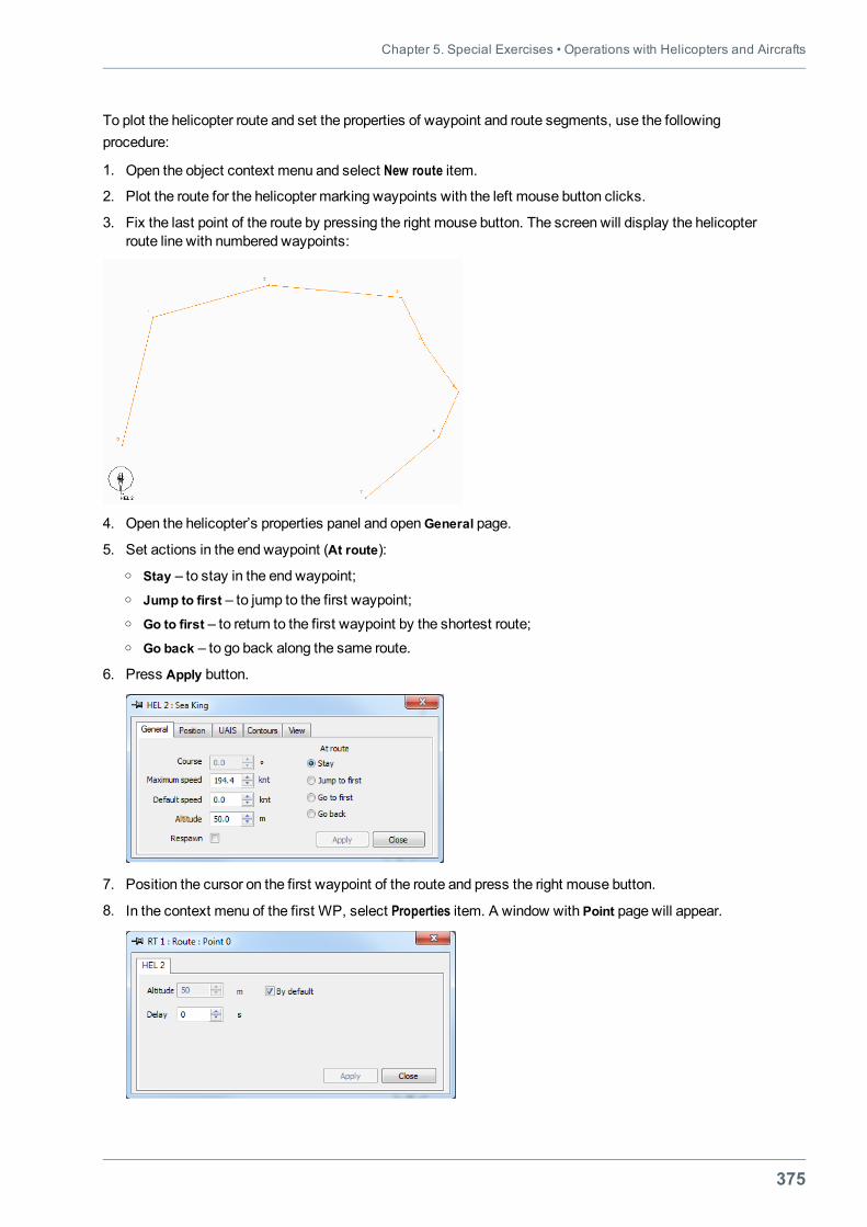
Chapter 5. Special Exercises • Operations with Helicopters and Aircrafts
375
To plot the helicopter route and set the properties of waypoint and route segments, use the followingprocedure:
1. Open the object context menu and select New route item.
2. Plot the route for the helicopter marking waypoints with the left mouse button clicks.
3. Fix the last point of the route by pressing the right mouse button. The screen will display the helicopterroute line with numbered waypoints:
4. Open the helicopter’s properties panel and openGeneral page.
5. Set actions in the end waypoint (At route):o Stay – to stay in the end waypoint;o Jump to first – to jump to the first waypoint;o Go to first – to return to the first waypoint by the shortest route;o Go back – to go back along the same route.
6. Press Apply button.
7. Position the cursor on the first waypoint of the route and press the right mouse button.
8. In the context menu of the first WP, select Properties item. A window with Point page will appear.
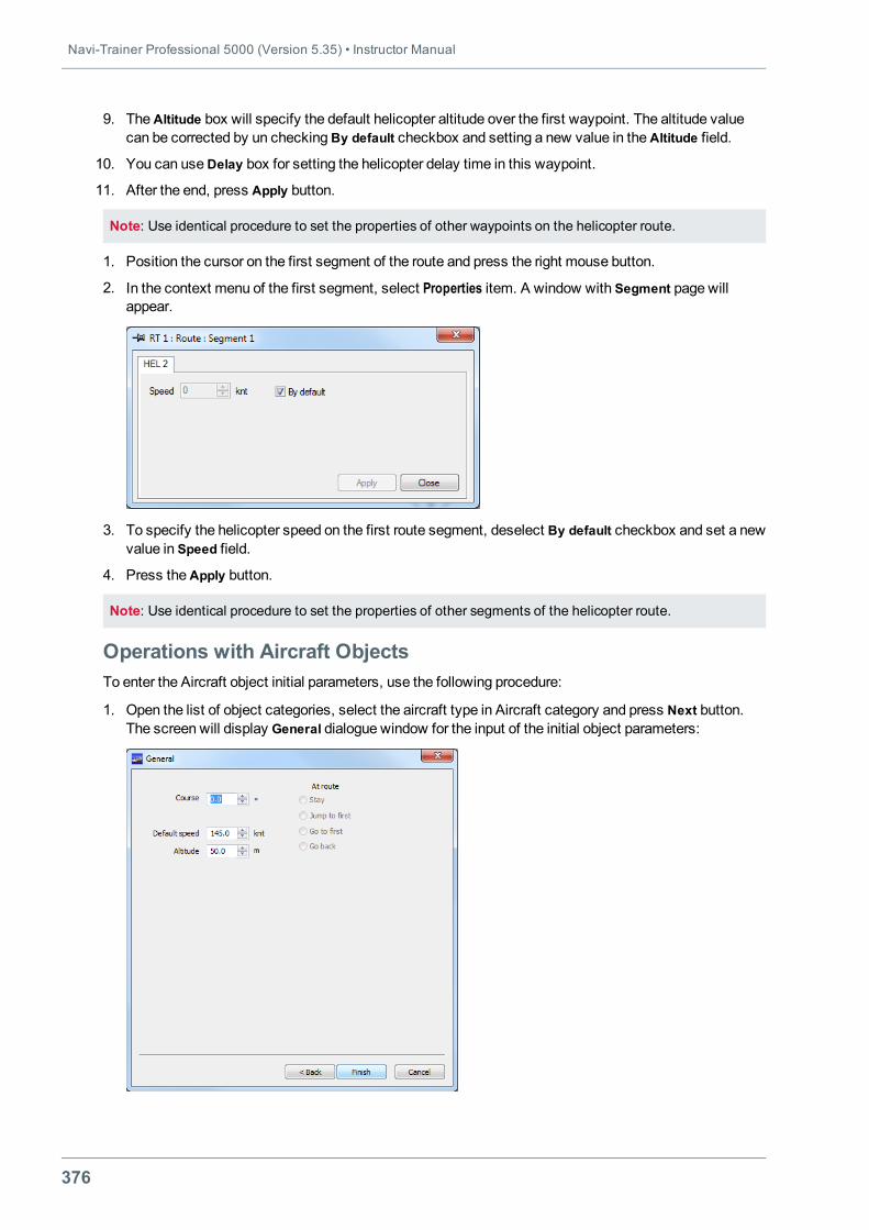
Navi-Trainer Professional 5000 (Version 5.35) • Instructor Manual
376
9. TheAltitude box will specify the default helicopter altitude over the first waypoint. The altitude valuecan be corrected by un checking By default checkbox and setting a new value in theAltitude field.
10. You can useDelay box for setting the helicopter delay time in this waypoint.
11. After the end, press Apply button.
Note: Use identical procedure to set the properties of other waypoints on the helicopter route.
1. Position the cursor on the first segment of the route and press the right mouse button.
2. In the context menu of the first segment, select Properties item. A window with Segment page willappear.
3. To specify the helicopter speed on the first route segment, deselect By default checkbox and set a newvalue in Speed field.
4. Press theApply button.
Note: Use identical procedure to set the properties of other segments of the helicopter route.
Operations with Aircraft ObjectsTo enter the Aircraft object initial parameters, use the following procedure:
1. Open the list of object categories, select the aircraft type in Aircraft category and press Next button.The screen will display General dialogue window for the input of the initial object parameters:
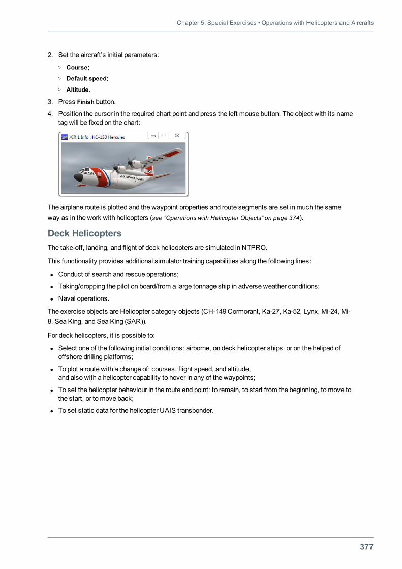
Chapter 5. Special Exercises • Operations with Helicopters and Aircrafts
377
2. Set the aircraft’s initial parameters:o Course;o Default speed;o Altitude.
3. Press Finish button.
4. Position the cursor in the required chart point and press the left mouse button. The object with its nametag will be fixed on the chart:
The airplane route is plotted and the waypoint properties and route segments are set in much the sameway as in the work with helicopters (see "Operations with Helicopter Objects" on page 374).
Deck HelicoptersThe take-off, landing, and flight of deck helicopters are simulated in NTPRO.
This functionality provides additional simulator training capabilities along the following lines:
l Conduct of search and rescue operations;
l Taking/dropping the pilot on board/from a large tonnage ship in adverse weather conditions;
l Naval operations.
The exercise objects are Helicopter category objects (CH-149 Cormorant, Ka-27, Ka-52, Lynx, Mi-24, Mi-8, Sea King, and Sea King (SAR)).
For deck helicopters, it is possible to:
l Select one of the following initial conditions: airborne, on deck helicopter ships, or on the helipad ofoffshore drilling platforms;
l To plot a route with a change of: courses, flight speed, and altitude,and also with a helicopter capability to hover in any of the waypoints;
l To set the helicopter behaviour in the route end point: to remain, to start from the beginning, to move tothe start, or to move back;
l To set static data for the helicopter UAIS transponder.
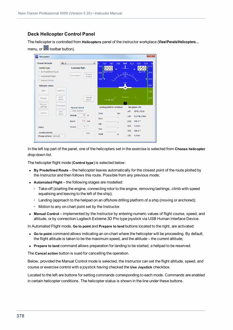
Navi-Trainer Professional 5000 (Version 5.35) • Instructor Manual
378
Deck Helicopter Control PanelThe helicopter is controlled from Helicopters panel of the instructor workplace (View\Panels\Helicopters…
menu, or toolbar button).
In the left top part of the panel, one of the helicopters set in the exercise is selected from Choose helicopterdrop-down list.
The helicopter flight mode (Control type) is selected below:
l By Predefined Route – the helicopter leaves automatically for the closest point of the route plotted bythe Instructor and then follows this route. Possible from any previous mode;
l Automated Flight – the following stages aremodelled:o Take-off (starting the engine, connecting rotor to the engine, removing lashings, climb with speed
equalising and leaving to the left of the ship);o Landing (approach to the helipad on an offshore drilling platform of a ship (moving or anchored);o Motion to any on-chart point set by the Instructor.
l Manual Control – implemented by the Instructor by entering numeric values of flight course, speed, andaltitude, or by connection Logitech Extreme 3D Pro type joystick via USB Human Interface Device.
In Automated Flight mode, Go to point and Prepare to land buttons located to the right, are activated:
l Go to point command allows indicating an on-chart where the helicopter will be proceeding. By default,the flight altitude is taken to be themaximum speed, and the altitude – the current altitude;
l Prepare to land command allows preparation for landing to be started, a helipad to be reserved.
TheCancel action button is sued for cancelling the operation.
Below, provided theManual Control mode is selected, the Instructor can set the flight altitude, speed, andcourse or exercise control with a joystick having checked theUse Joystick checkbox.
Located to the left are buttons for setting commands corresponding to eachmode. Commands are enabledin certain helicopter conditions. The helicopter status is shown in the line under these buttons.
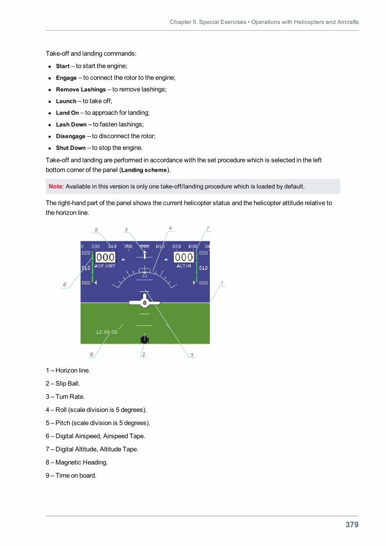
Chapter 5. Special Exercises • Operations with Helicopters and Aircrafts
379
Take-off and landing commands:
l Start – to start the engine;
l Engage – to connect the rotor to the engine;
l Remove Lashings – to remove lashings;
l Launch – to take off;
l Land On – to approach for landing;
l Lash Down – to fasten lashings;
l Disengage – to disconnect the rotor;
l Shut Down – to stop the engine.
Take-off and landing are performed in accordance with the set procedure which is selected in the leftbottom corner of the panel (Landing scheme).
Note: Available in this version is only one take-off/landing procedure which is loaded by default.
The right-hand part of the panel shows the current helicopter status and the helicopter attitude relative tothe horizon line.
1 – Horizon line.
2 – Slip Ball.
3 – Turn Rate.
4 – Roll (scale division is 5 degrees).
5 – Pitch (scale division is 5 degrees).
6 – Digital Airspeed, Airspeed Tape.
7 – Digital Altitude, Altitude Tape.
8 –Magnetic Heading.
9 – Time on board.
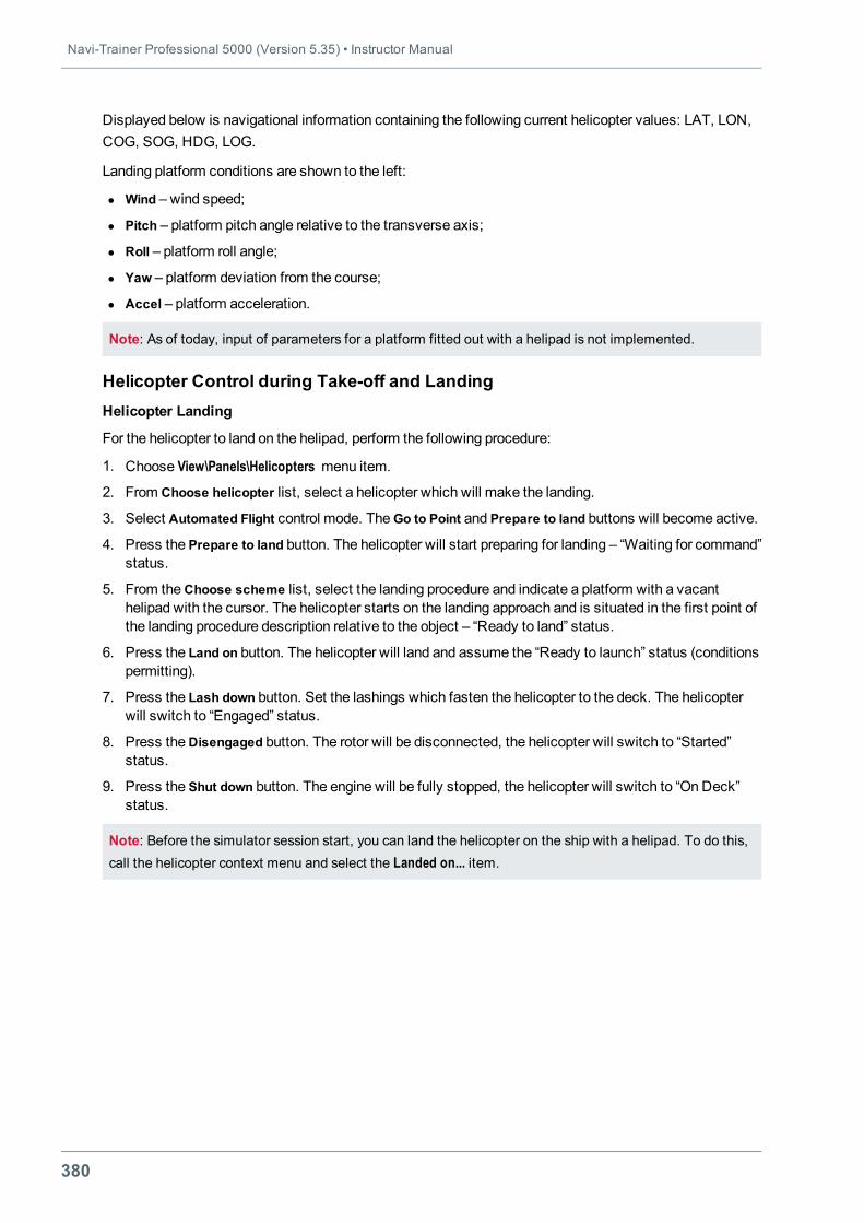
Navi-Trainer Professional 5000 (Version 5.35) • Instructor Manual
380
Displayed below is navigational information containing the following current helicopter values: LAT, LON,COG, SOG, HDG, LOG.
Landing platform conditions are shown to the left:
l Wind – wind speed;
l Pitch – platform pitch angle relative to the transverse axis;
l Roll – platform roll angle;
l Yaw – platform deviation from the course;
l Accel – platform acceleration.
Note: As of today, input of parameters for a platform fitted out with a helipad is not implemented.
Helicopter Control during Take-off and LandingHelicopter Landing
For the helicopter to land on the helipad, perform the following procedure:
1. Choose View\Panels\Helicopters menu item.
2. From Choose helicopter list, select a helicopter which will make the landing.
3. Select Automated Flight control mode. TheGo to Point and Prepare to land buttons will become active.
4. Press the Prepare to land button. The helicopter will start preparing for landing – “Waiting for command”status.
5. From theChoose scheme list, select the landing procedure and indicate a platform with a vacanthelipad with the cursor. The helicopter starts on the landing approach and is situated in the first point ofthe landing procedure description relative to the object – “Ready to land” status.
6. Press the Land on button. The helicopter will land and assume the “Ready to launch” status (conditionspermitting).
7. Press the Lash down button. Set the lashings which fasten the helicopter to the deck. The helicopterwill switch to “Engaged” status.
8. Press theDisengaged button. The rotor will be disconnected, the helicopter will switch to “Started”status.
9. Press the Shut down button. The engine will be fully stopped, the helicopter will switch to “On Deck”status.
Note: Before the simulator session start, you can land the helicopter on the ship with a helipad. To do this,call the helicopter context menu and select the Landed on... item.
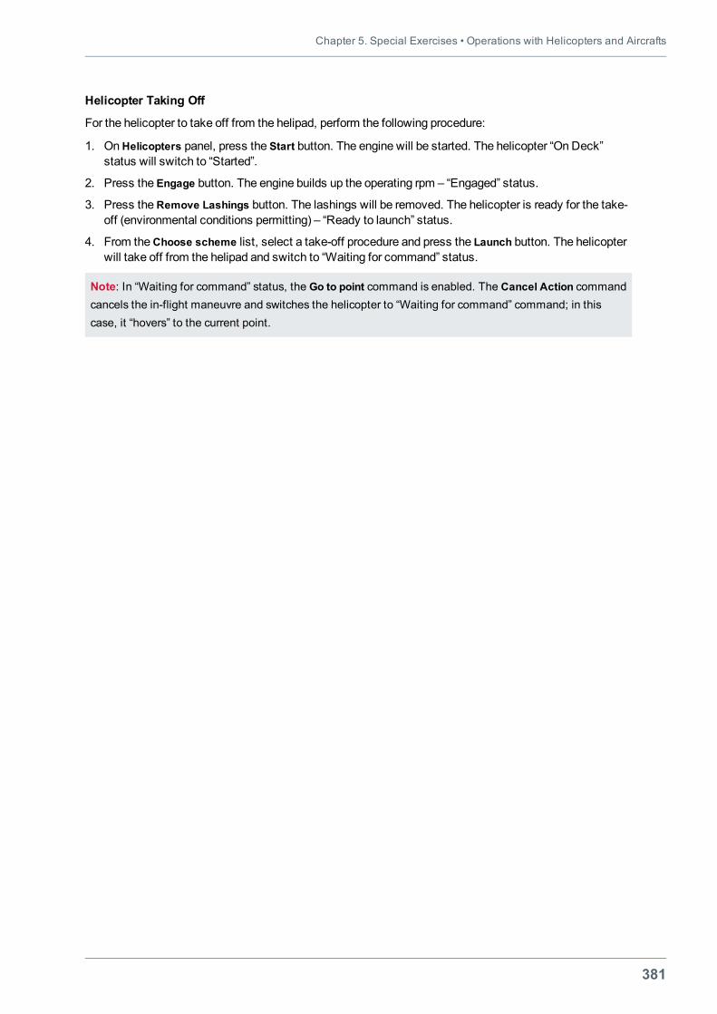
Chapter 5. Special Exercises • Operations with Helicopters and Aircrafts
381
Helicopter Taking Off
For the helicopter to take off from the helipad, perform the following procedure:
1. OnHelicopters panel, press the Start button. The engine will be started. The helicopter “On Deck”status will switch to “Started”.
2. Press the Engage button. The engine builds up the operating rpm – “Engaged” status.
3. Press theRemove Lashings button. The lashings will be removed. The helicopter is ready for the take-off (environmental conditions permitting) – “Ready to launch” status.
4. From theChoose scheme list, select a take-off procedure and press the Launch button. The helicopterwill take off from the helipad and switch to “Waiting for command” status.
Note: In “Waiting for command” status, the Go to point command is enabled. The Cancel Action commandcancels the in-flight maneuvre and switches the helicopter to “Waiting for command” command; in thiscase, it “hovers” to the current point.
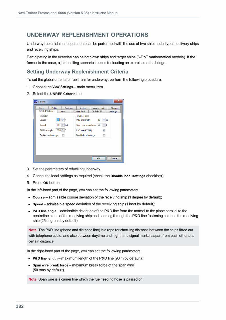
Navi-Trainer Professional 5000 (Version 5.35) • Instructor Manual
382
UNDERWAY REPLENISHMENT OPERATIONSUnderway replenishment operations can be performed with the use of two shipmodel types: delivery shipsand receiving ships.
Participating in the exercise can be both own ships and target ships (6-DoF mathematical models). If theformer is the case, a joint sailing scenario is used for loading an exercise on the bridge.
Setting Underway Replenishment CriteriaTo set the global criteria for fuel transfer underway, perform the following procedure:
1. Choose the View\Settings…mainmenu item.
2. Select theUNREP Criteria tab.
3. Set the parameters of refuelling underway.
4. Cancel the local settings as required (check theDisable local settings checkbox).
5. Press OK button.
In the left-hand part of the page, you can set the following parameters:
l Course – admissible course deviation of the receiving ship (1 degree by default);
l Speed – admissible speed deviation of the receiving ship (1 knot by default);
l P&D line angle – admissible deviation of the P&D line from the normal to the plane parallel to thecentreline plane of the receiving ship and passing through the P&D line fastening point on the receivingship (25 degrees by default).
Note: The P&D line (phone and distance line) is a rope for checking distance between the ships fitted outwith telephone cable, and also between daytime and night time signal markers apart from each other at acertain distance.
In the right-hand part of the page, you can set the following parameters:
l P&D line length –maximum length of the P&D line (90m by default);
l Span wire break force –maximum break force of the span wire(50 tons by default).
Note: Span wire is a carrier line which the fuel feeding hose is passed on.
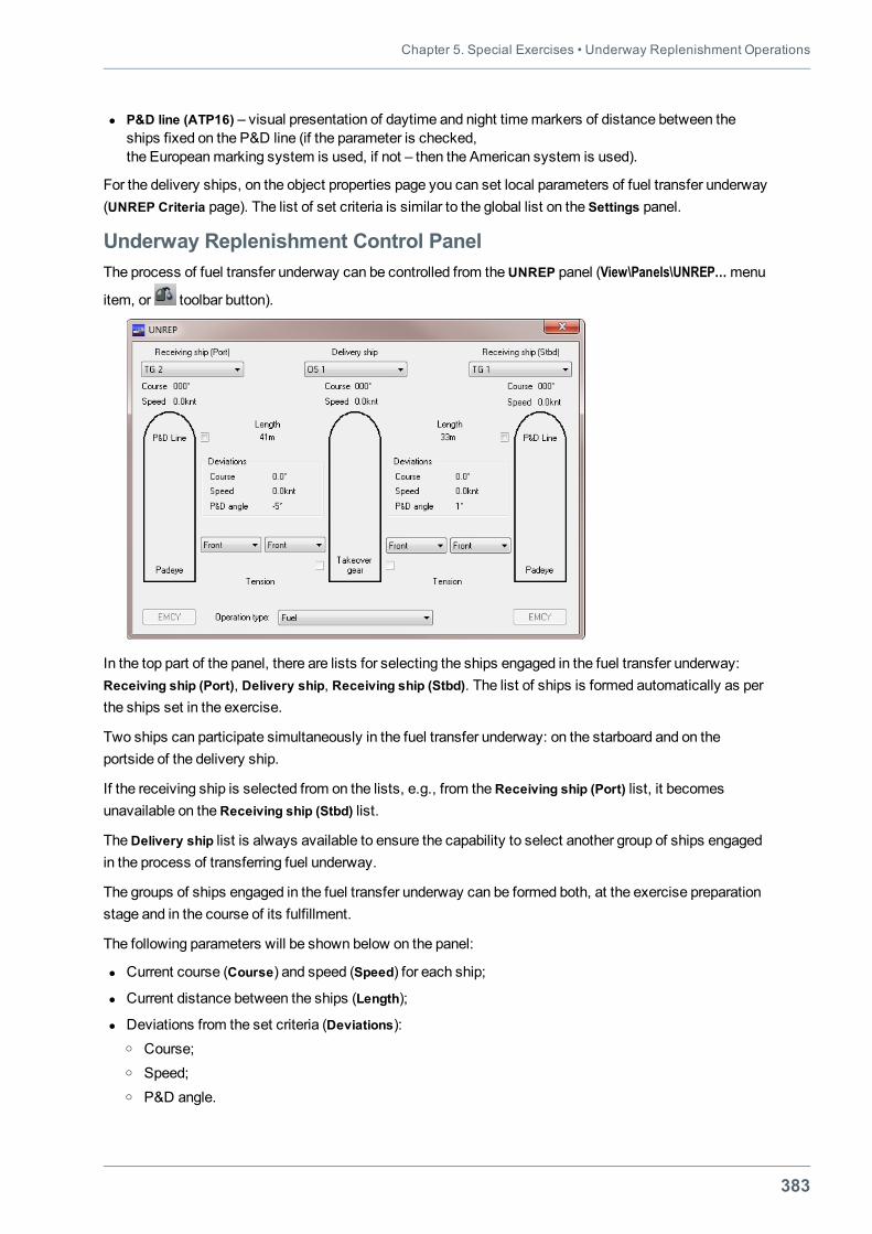
Chapter 5. Special Exercises • Underway Replenishment Operations
383
l P&D line (ATP16) – visual presentation of daytime and night timemarkers of distance between theships fixed on the P&D line (if the parameter is checked,the Europeanmarking system is used, if not – then the American system is used).
For the delivery ships, on the object properties page you can set local parameters of fuel transfer underway(UNREP Criteria page). The list of set criteria is similar to the global list on the Settings panel.
Underway Replenishment Control PanelThe process of fuel transfer underway can be controlled from theUNREP panel (View\Panels\UNREP…menu
item, or toolbar button).
In the top part of the panel, there are lists for selecting the ships engaged in the fuel transfer underway:Receiving ship (Port), Delivery ship, Receiving ship (Stbd). The list of ships is formed automatically as perthe ships set in the exercise.
Two ships can participate simultaneously in the fuel transfer underway: on the starboard and on theportside of the delivery ship.
If the receiving ship is selected from on the lists, e.g., from theReceiving ship (Port) list, it becomesunavailable on theReceiving ship (Stbd) list.
TheDelivery ship list is always available to ensure the capability to select another group of ships engagedin the process of transferring fuel underway.
The groups of ships engaged in the fuel transfer underway can be formed both, at the exercise preparationstage and in the course of its fulfillment.
The following parameters will be shown below on the panel:
l Current course (Course) and speed (Speed) for each ship;
l Current distance between the ships (Length);
l Deviations from the set criteria (Deviations):o Course;o Speed;o P&D angle.
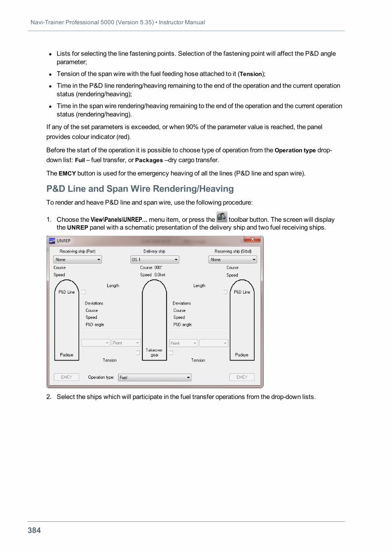
Navi-Trainer Professional 5000 (Version 5.35) • Instructor Manual
384
l Lists for selecting the line fastening points. Selection of the fastening point will affect the P&D angleparameter;
l Tension of the span wire with the fuel feeding hose attached to it (Tension);
l Time in the P&D line rendering/heaving remaining to the end of the operation and the current operationstatus (rendering/heaving);
l Time in the span wire rendering/heaving remaining to the end of the operation and the current operationstatus (rendering/heaving).
If any of the set parameters is exceeded, or when 90% of the parameter value is reached, the panelprovides colour indicator (red).
Before the start of the operation it is possible to choose type of operation from theOperation type drop-down list: Fuil – fuel transfer, or Packages –dry cargo transfer.
The EMCY button is used for the emergency heaving of all the lines (P&D line and span wire).
P&D Line and Span Wire Rendering/HeavingTo render and heave P&D line and span wire, use the following procedure:
1. Choose the View\Panels\UNREP…menu item, or press the toolbar button. The screen will displaytheUNREP panel with a schematic presentation of the delivery ship and two fuel receiving ships.
2. Select the ships which will participate in the fuel transfer operations from the drop-down lists.
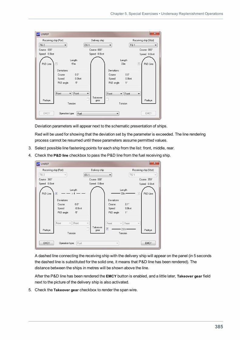
Chapter 5. Special Exercises • Underway Replenishment Operations
385
Deviation parameters will appear next to the schematic presentation of ships.
Red will be used for showing that the deviation set by the parameter is exceeded. The line renderingprocess cannot be resumed until these parameters assume permitted values.
3. Select possible line fastening points for each ship from the list: front, middle, rear.
4. Check the P&D line checkbox to pass the P&D line from the fuel receiving ship.
A dashed line connecting the receiving ship with the delivery ship will appear on the panel (in 5 secondsthe dashed line is substituted for the solid one, it means that P&D line has been rendered). Thedistance between the ships in metres will be shown above the line.
After the P&D line has been rendered the EMCY button is enabled, and a little later, Takeover gear fieldnext to the picture of the delivery ship is also activated.
5. Check the Takeover gear checkbox to render the span wire.
Navi-Trainer Professional 5000 (Version 5.35) • Instructor Manual
386
Notes:1. If the distance between the ships is larger than the set value, it is impossible to render the P&D line orspan wire;2. If the distance between the ships is smaller than or equal to the set value, the P&D line can be rendered,but the span wire cannot be rendered until the P&D line is put out;3. When the set P&D line angle parameter is exceeded, the P&D line breaks.
6. To heave the lines, use the reverse process: first clear the Takeover gear checkbox, and after the spanwire has been removed, clear P&D Line checkbox.
Notes:1. All the P&D line and span wire handling operations are recorded to a log file;2. Rendering/heaving of the P&D line and span wire, emergency heaving of all the lines, cases ofexceeding the set maximum parameters are recorded on Events panel.
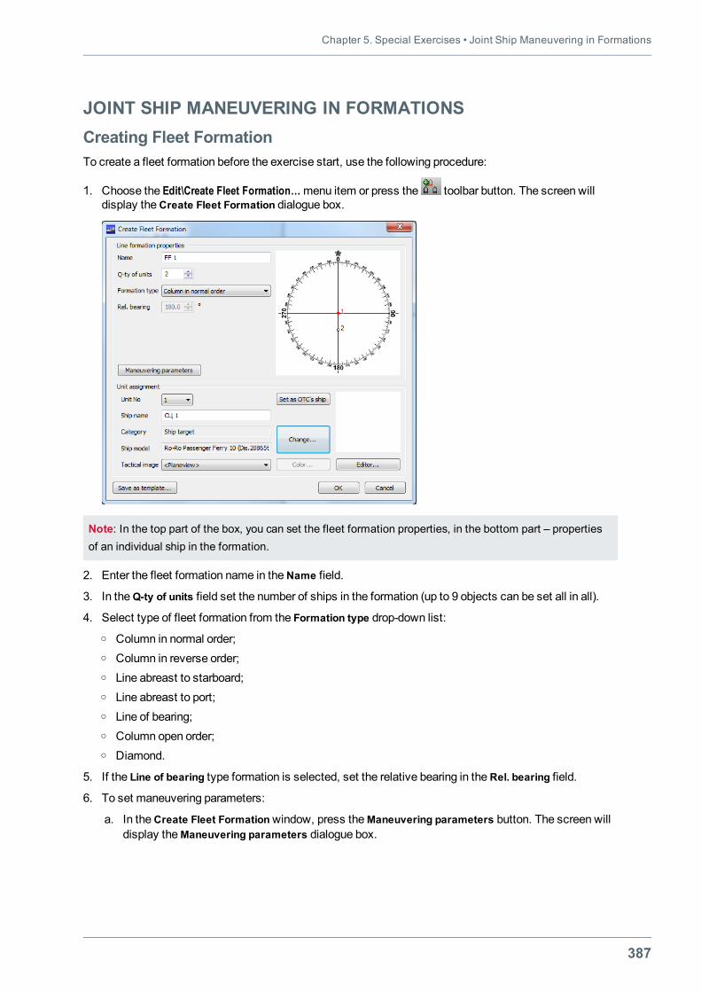
Chapter 5. Special Exercises • Joint Ship Maneuvering in Formations
387
JOINT SHIP MANEUVERING IN FORMATIONSCreating Fleet FormationTo create a fleet formation before the exercise start, use the following procedure:
1. Choose the Edit\Create Fleet Formation…menu item or press the toolbar button. The screen willdisplay theCreate Fleet Formation dialogue box.
Note: In the top part of the box, you can set the fleet formation properties, in the bottom part – propertiesof an individual ship in the formation.
2. Enter the fleet formation name in theName field.
3. In theQ-ty of units field set the number of ships in the formation (up to 9 objects can be set all in all).
4. Select type of fleet formation from the Formation type drop-down list:o Column in normal order;o Column in reverse order;o Line abreast to starboard;o Line abreast to port;o Line of bearing;o Column open order;o Diamond.
5. If the Line of bearing type formation is selected, set the relative bearing in theRel. bearing field.
6. To set maneuvering parameters:
a. In theCreate Fleet Formationwindow, press theManeuvering parameters button. The screen willdisplay theManeuvering parameters dialogue box.
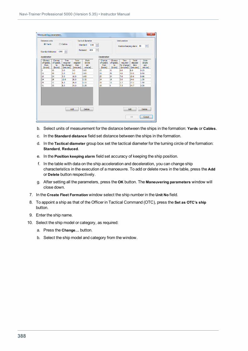
Navi-Trainer Professional 5000 (Version 5.35) • Instructor Manual
388
b. Select units of measurement for the distance between the ships in the formation: Yards orCables.
c. In the Standard distance field set distance between the ships in the formation.
d. In the Tactical diameter group box set the tactical diameter for the turning circle of the formation:Standard, Reduced.
e. In the Position keeping alarm field set accuracy of keeping the ship position.
f. In the table with data on the ship acceleration and deceleration, you can change shipcharacteristics in the execution of amanoeuvre. To add or delete rows in the table, press theAddorDelete button respectively.
g. After setting all the parameters, press theOK button. TheManeuvering parameters window willclose down.
7. In theCreate Fleet Formationwindow select the ship number in theUnit No field.
8. To appoint a ship as that of the Officer in Tactical Command (OTC), press the Set as OTC’s shipbutton.
9. Enter the ship name.
10. Select the shipmodel or category, as required:
a. Press theChange… button.
b. Select the shipmodel and category from the window.
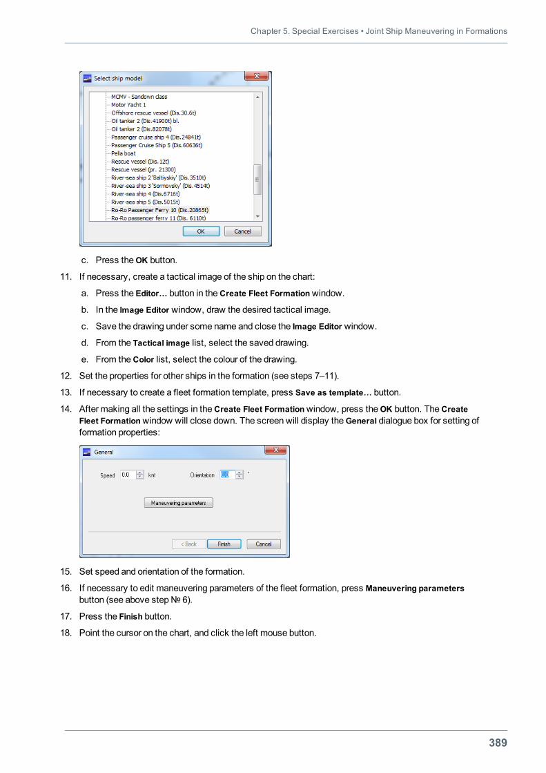
Chapter 5. Special Exercises • Joint Ship Maneuvering in Formations
389
c. Press theOK button.
11. If necessary, create a tactical image of the ship on the chart:
a. Press the Editor… button in theCreate Fleet Formationwindow.
b. In the Image Editor window, draw the desired tactical image.
c. Save the drawing under some name and close the Image Editor window.
d. From the Tactical image list, select the saved drawing.
e. From theColor list, select the colour of the drawing.
12. Set the properties for other ships in the formation (see steps 7–11).
13. If necessary to create a fleet formation template, press Save as template… button.
14. After making all the settings in theCreate Fleet Formationwindow, press theOK button. TheCreateFleet Formationwindow will close down. The screen will display theGeneral dialogue box for setting offormation properties:
15. Set speed and orientation of the formation.
16. If necessary to edit maneuvering parameters of the fleet formation, press Maneuvering parametersbutton (see above step№ 6).
17. Press the Finish button.
18. Point the cursor on the chart, and click the left mouse button.
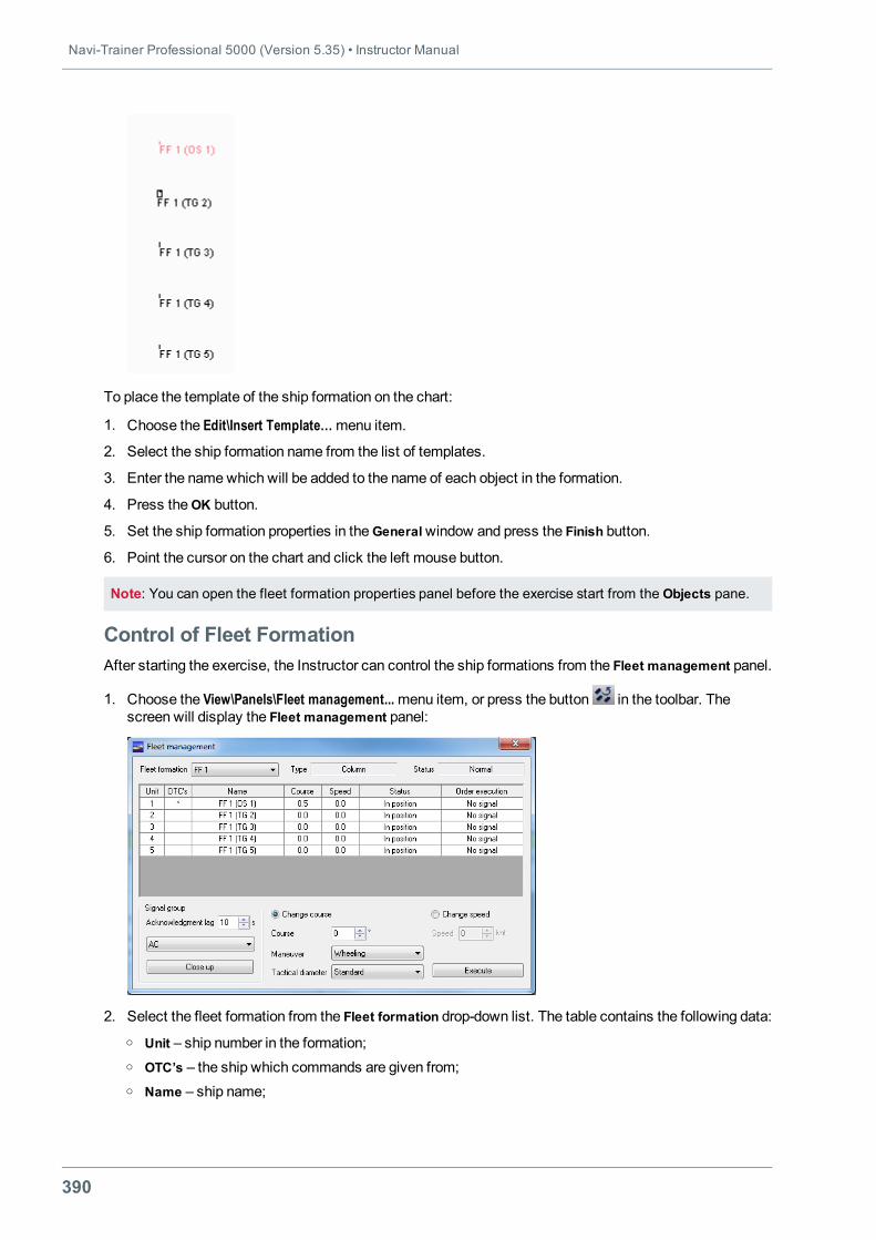
Navi-Trainer Professional 5000 (Version 5.35) • Instructor Manual
390
To place the template of the ship formation on the chart:
1. Choose the Edit\Insert Template…menu item.
2. Select the ship formation name from the list of templates.
3. Enter the namewhich will be added to the name of each object in the formation.
4. Press theOK button.
5. Set the ship formation properties in theGeneralwindow and press the Finish button.
6. Point the cursor on the chart and click the left mouse button.
Note: You can open the fleet formation properties panel before the exercise start from the Objects pane.
Control of Fleet FormationAfter starting the exercise, the Instructor can control the ship formations from the Fleet management panel.
1. Choose the View\Panels\Fleet management...menu item, or press the button in the toolbar. Thescreen will display the Fleet management panel:
2. Select the fleet formation from the Fleet formation drop-down list. The table contains the following data:o Unit – ship number in the formation;o OTC’s – the ship which commands are given from;o Name – ship name;
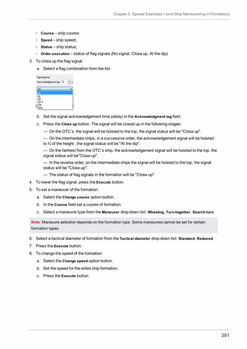
Chapter 5. Special Exercises • Joint Ship Maneuvering in Formations
391
o Course – ship course;o Speed – ship speed;o Status – ship status;o Order execution – status of flag signals (No signal, Close up, At the dip).
3. To close up the flag signal:
a. Select a flag combination from the list.
b. Set the signal acknowledgement time (delay) in theAcknowledgment lag field.
c. Press theClose up button. The signal will be closed up in the following stages:
— On theOTC’s, the signal will be hoisted to the top, the signal status will be "Close up".— On the intermediate ships, in a successive order, the acknowledgement signal will be hoistedto¾ of the height , the signal status will be "At the dip".— On the farthest from theOTC’s ship, the acknowledgement signal will be hoisted to the top, thesignal status will be"Close up".— In the reverse order, on the intermediate ships the signal will be hoisted to the top, the signalstatus will be "Close up".— The status of flag signals in the formation will be "Close up".
4. To lower the flag signal, press the Execute button.
5. To set amaneuver of the formation:
a. Select theChange course option button.
b. In theCourse field set a course of formation.
c. Select amaneuvre type from theManeuver drop-down list:Wheeling, Turn-together, Search turn.
Note: Maneuvre selection depends on the formation type. Some maneuvres cannot be set for certainformation types.
6. Select a tactical diameter of formation from the Tactical diameter drop-down list: Standard, Reduced.
7. Press the Execute button.
8. To change the speed of the formation:
a. Select theChange speed option button.
b. Set the speed for the entire ship formation.
c. Press the Execute button.
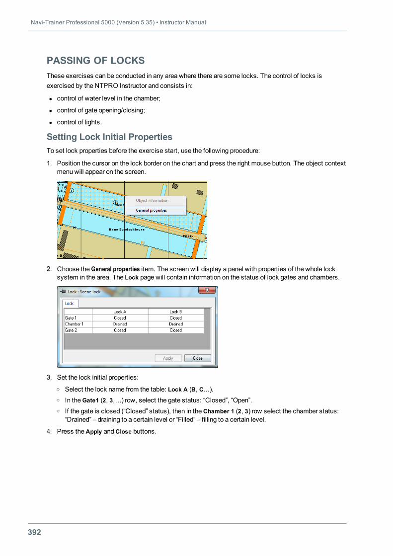
Navi-Trainer Professional 5000 (Version 5.35) • Instructor Manual
392
PASSING OF LOCKSThese exercises can be conducted in any area where there are some locks. The control of locks isexercised by the NTPRO Instructor and consists in:
l control of water level in the chamber;
l control of gate opening/closing;
l control of lights.
Setting Lock Initial PropertiesTo set lock properties before the exercise start, use the following procedure:
1. Position the cursor on the lock border on the chart and press the right mouse button. The object contextmenu will appear on the screen.
2. Choose the General properties item. The screen will display a panel with properties of the whole locksystem in the area. The Lock page will contain information on the status of lock gates and chambers.
3. Set the lock initial properties:o Select the lock name from the table: Lock A (B, С...).o In theGate1 (2, 3,…) row, select the gate status: “Closed”, “Open”.o If the gate is closed (“Closed” status), then in theChamber 1 (2, 3) row select the chamber status:
“Drained” – draining to a certain level or “Filled” – filling to a certain level.
4. Press theApply andClose buttons.
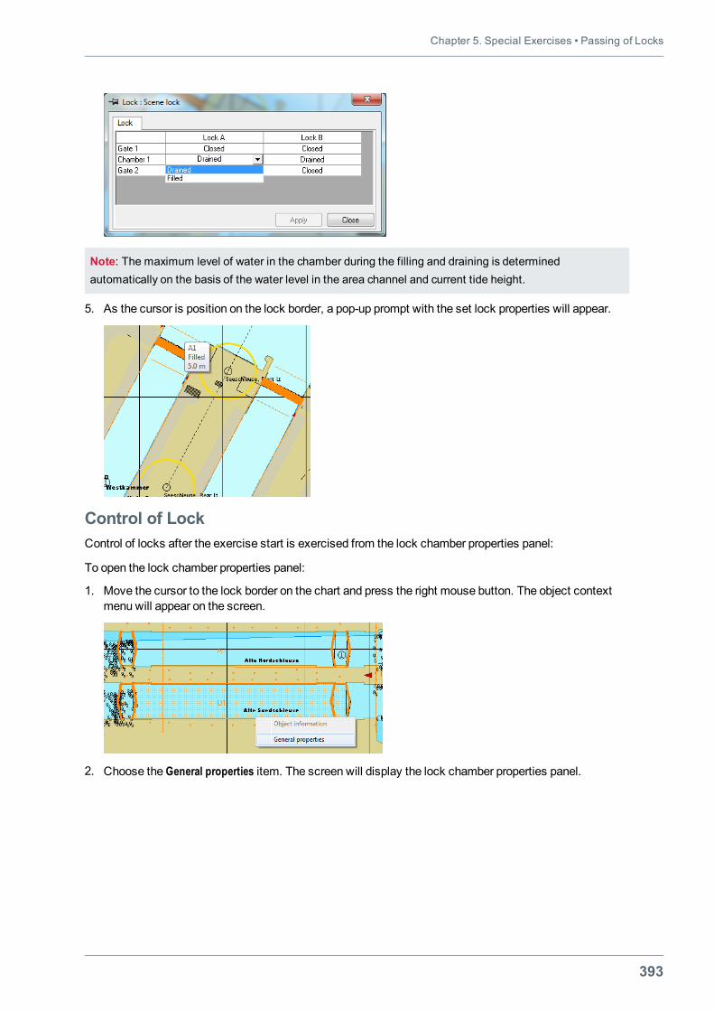
Chapter 5. Special Exercises • Passing of Locks
393
Note: The maximum level of water in the chamber during the filling and draining is determinedautomatically on the basis of the water level in the area channel and current tide height.
5. As the cursor is position on the lock border, a pop-up prompt with the set lock properties will appear.
Control of LockControl of locks after the exercise start is exercised from the lock chamber properties panel:
To open the lock chamber properties panel:
1. Move the cursor to the lock border on the chart and press the right mouse button. The object contextmenu will appear on the screen.
2. Choose the General properties item. The screen will display the lock chamber properties panel.
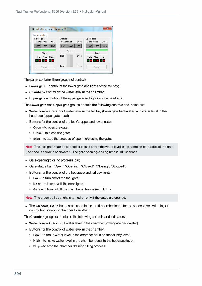
Navi-Trainer Professional 5000 (Version 5.35) • Instructor Manual
394
The panel contains three groups of controls:
l Lower gate – control of the lower gate and lights of the tail bay;
l Chamber – control of the water level in the chamber;
l Upper gate – control of the upper gate and lights on the headrace.
The Lower gate andUpper gate groups contain the following controls and indicators:
l Water level – indicator of water level in the tail bay (lower gate backwater) and water level in theheadrace (upper gate head);
l Buttons for the control of the lock’s upper and lower gates:o Open – to open the gate;o Close – to close the gate;o Stop – to stop the process of opening/closing the gate.
Note: The lock gates can be opened or closed only if the water level is the same on both sides of the gate(the head is equal to backwater). The gate opening/closing time is 100 seconds.
l Gate opening/closing progress bar;
l Gate status bar: “Open”, “Opening”, “Closed”; “Closing”, “Stopped”;
l Buttons for the control of the headrace and tail bay lights:o Far – to turn on/off the far lights;o Near – to turn on/off the near lights;o Gate – to turn on/off the chamber entrance (exit) lights.
Note: The green trail bay light is turned on only if the gates are opened.
l TheGo down, Go up buttons are used in themulti-chamber locks for the successive switching ofcontrol from one lock chamber to another.
TheChamber group box contains the following controls and indicators:
l Water level – indicator of water level in the chamber (lower gate backwater);
l Buttons for the control of water level in the chamber:o Low – tomake water level in the chamber equal to the tail bay level;o High – tomake water level in the chamber equal to the headrace level;o Stop – to stop the chamber draining/filling process.
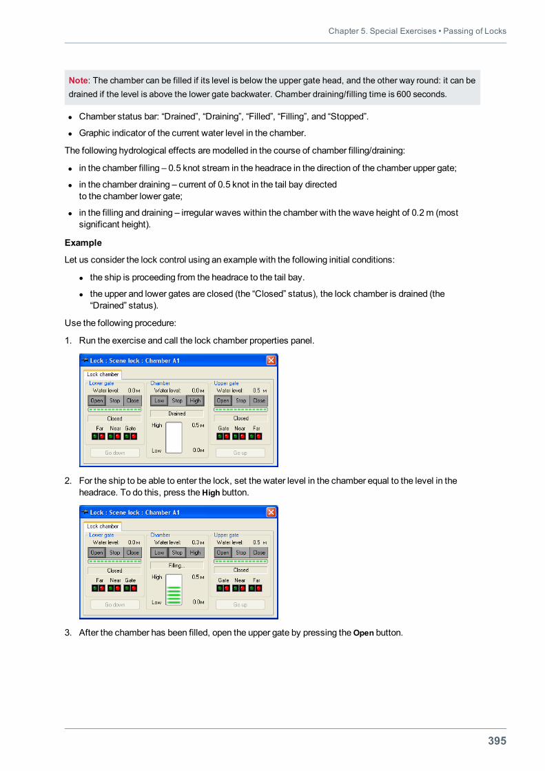
Chapter 5. Special Exercises • Passing of Locks
395
Note: The chamber can be filled if its level is below the upper gate head, and the other way round: it can bedrained if the level is above the lower gate backwater. Chamber draining/filling time is 600 seconds.
l Chamber status bar: “Drained”, “Draining”, “Filled”, “Filling”, and “Stopped”.
l Graphic indicator of the current water level in the chamber.
The following hydrological effects aremodelled in the course of chamber filling/draining:
l in the chamber filling – 0.5 knot stream in the headrace in the direction of the chamber upper gate;
l in the chamber draining – current of 0.5 knot in the tail bay directedto the chamber lower gate;
l in the filling and draining – irregular waves within the chamber with the wave height of 0.2m (mostsignificant height).
Example
Let us consider the lock control using an example with the following initial conditions:
l the ship is proceeding from the headrace to the tail bay.
l the upper and lower gates are closed (the “Closed” status), the lock chamber is drained (the“Drained” status).
Use the following procedure:
1. Run the exercise and call the lock chamber properties panel.
2. For the ship to be able to enter the lock, set the water level in the chamber equal to the level in theheadrace. To do this, press the High button.
3. After the chamber has been filled, open the upper gate by pressing the Open button.
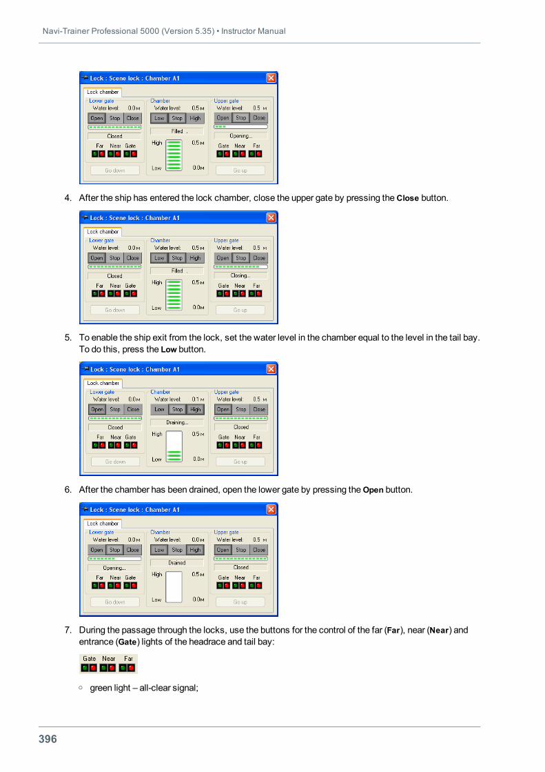
Navi-Trainer Professional 5000 (Version 5.35) • Instructor Manual
396
4. After the ship has entered the lock chamber, close the upper gate by pressing theClose button.
5. To enable the ship exit from the lock, set the water level in the chamber equal to the level in the tail bay.To do this, press the Low button.
6. After the chamber has been drained, open the lower gate by pressing the Open button.
7. During the passage through the locks, use the buttons for the control of the far (Far), near (Near) andentrance (Gate) lights of the headrace and tail bay:
o green light – all-clear signal;
Chapter 5. Special Exercises • Passing of Locks
397
o red light– restrictive signal.
Note: Green light of the chamber's entrance lights cannot be switched on unless the gate is open.
Monitoring Fulfilment of Exercise with LocksThe following violations of lock passing rules are recorded automatically to enablemonitoring andassessment of the exercise fulfilment:
l crossing of the far lights line with the restrictive signal on;
l crossing of the near lights line with the restrictive signal on;
l crossing of the stop sign line in the tail bay or headrace with the restrictive signal of intermediate lightson;
l crossing of the stop sign line in the lock chamber with the restrictive signal of exit lights on;
l ship touching the gate.
Information on violations is displayed on the Events panel.
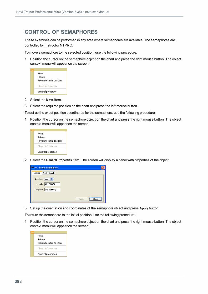
Navi-Trainer Professional 5000 (Version 5.35) • Instructor Manual
398
CONTROL OF SEMAPHORESThese exercises can be performed in any area where semaphores are available. The semaphores arecontrolled by Instructor NTPRO.
Tomove a semaphore to the selected position, use the following procedure:
1. Position the cursor on the semaphore object on the chart and press the right mouse button. The objectcontext menu will appear on the screen:
2. Select theMove item.
3. Select the required position on the chart and press the left mouse button.
To set up the exact position coordinates for the semaphore, use the following procedure:
1. Position the cursor on the semaphore object on the chart and press the right mouse button. The objectcontext menu will appear on the screen:
2. Select the General Properties item. The screen will display a panel with properties of the object:
3. Set up the orientation and coordinates of the semaphore object and press Apply button.
To return the semaphore to the initial position, use the following procedure:
1. Position the cursor on the semaphore object on the chart and press the right mouse button. The objectcontext menu will appear on the screen:
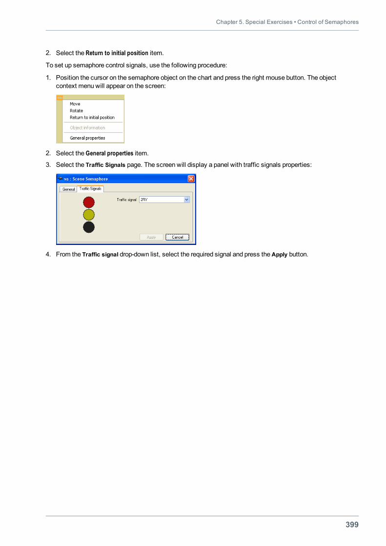
Chapter 5. Special Exercises • Control of Semaphores
399
2. Select the Return to initial position item.
To set up semaphore control signals, use the following procedure:
1. Position the cursor on the semaphore object on the chart and press the right mouse button. The objectcontext menu will appear on the screen:
2. Select the General properties item.
3. Select the Traffic Signals page. The screen will display a panel with traffic signals properties:
4. From the Traffic signal drop-down list, select the required signal and press theApply button.
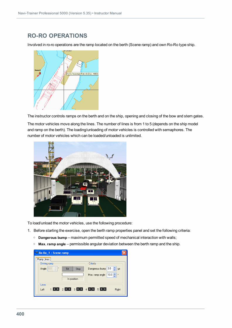
Navi-Trainer Professional 5000 (Version 5.35) • Instructor Manual
400
RO-RO OPERATIONSInvolved in ro-ro operations are the ramp located on the berth (Scene ramp) and ownRo-Ro type ship.
The instructor controls ramps on the berth and on the ship, opening and closing of the bow and stern gates.
Themotor vehicles move along the lines. The number of lines is from 1 to 5 (depends on the shipmodeland ramp on the berth). The loading/unloading of motor vehicles is controlled with semaphores. Thenumber of motor vehicles which can be loaded/unloaded is unlimited.
To load/unload themotor vehicles, use the following procedure:
1. Before starting the exercise, open the berth ramp properties panel and set the following criteria:o Dangerous bump –maximum permitted speed of mechanical interaction with walls;o Max. ramp angle – permissible angular deviation between the berth ramp and the ship.
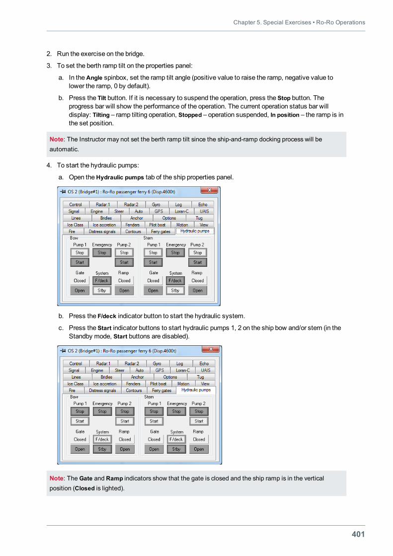
Chapter 5. Special Exercises • Ro-Ro Operations
401
2. Run the exercise on the bridge.
3. To set the berth ramp tilt on the properties panel:
a. In theAngle spinbox, set the ramp tilt angle (positive value to raise the ramp, negative value tolower the ramp, 0 by default).
b. Press the Tilt button. If it is necessary to suspend the operation, press the Stop button. Theprogress bar will show the performance of the operation. The current operation status bar willdisplay: Tilting – ramp tilting operation, Stopped – operation suspended, In position – the ramp is inthe set position.
Note: The Instructor may not set the berth ramp tilt since the ship-and-ramp docking process will beautomatic.
4. To start the hydraulic pumps:
a. Open theHydraulic pumps tab of the ship properties panel.
b. Press the F/deck indicator button to start the hydraulic system.
c. Press the Start indicator buttons to start hydraulic pumps 1, 2 on the ship bow and/or stern (in theStandby mode, Start buttons are disabled).
Note: The Gate and Ramp indicators show that the gate is closed and the ship ramp is in the verticalposition (Closed is lighted).
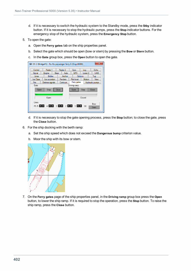
Navi-Trainer Professional 5000 (Version 5.35) • Instructor Manual
402
d. If it is necessary to switch the hydraulic system to the Standby mode, press the Stby indicatorbutton. If it is necessary to stop the hydraulic pumps, press the Stop indicator buttons. For theemergency stop of the hydraulic system, press the Emergency Stop button.
5. To open the gate:
a. Open the Ferry gates tab on the ship properties panel.
b. Select the gate which should be open (bow or stern) by pressing theBow or Stern button.
c. In theGate group box, press theOpen button to open the gate.
d. If it is necessary to stop the gate opening process, press the Stop button; to close the gate, presstheClose button.
6. For the ship docking with the berth ramp:
a. Set the ship speed which does not exceed theDangerous bump criterion value.
b. Moor the ship with its bow or stern.
7. On the Ferry gates page of the ship properties panel, in theDriving ramp group box press theOpenbutton, to lower the ship ramp. If it is required to stop the operation, press the Stop button. To raise theship ramp, press theClose button.
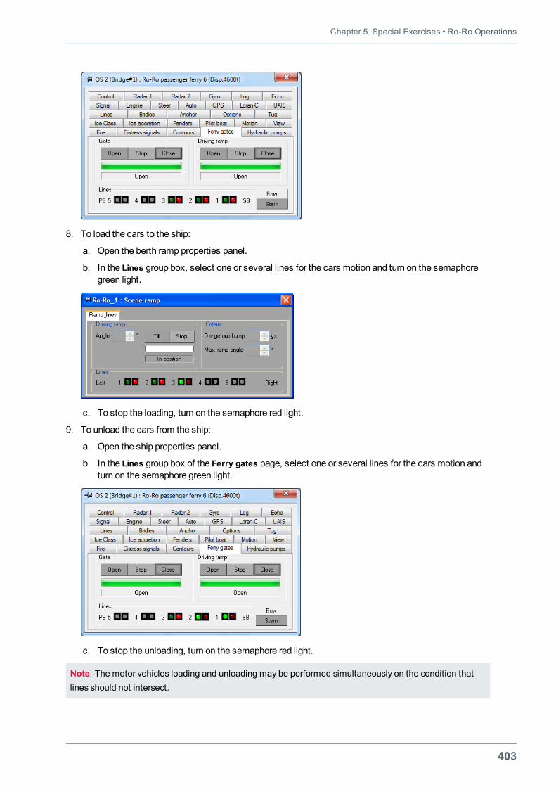
Chapter 5. Special Exercises • Ro-Ro Operations
403
8. To load the cars to the ship:
a. Open the berth ramp properties panel.
b. In the Lines group box, select one or several lines for the cars motion and turn on the semaphoregreen light.
c. To stop the loading, turn on the semaphore red light.
9. To unload the cars from the ship:
a. Open the ship properties panel.
b. In the Lines group box of the Ferry gates page, select one or several lines for the cars motion andturn on the semaphore green light.
c. To stop the unloading, turn on the semaphore red light.
Note: The motor vehicles loading and unloading may be performed simultaneously on the condition thatlines should not intersect.
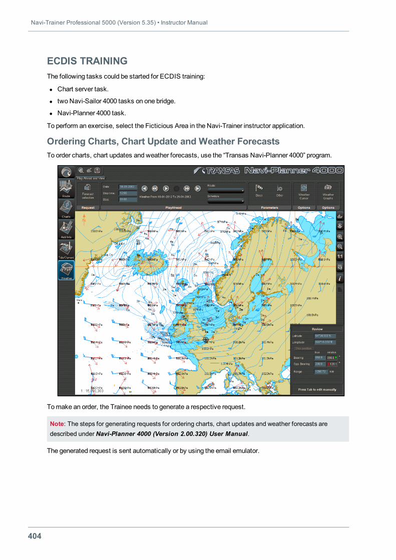
Navi-Trainer Professional 5000 (Version 5.35) • Instructor Manual
404
ECDIS TRAININGThe following tasks could be started for ECDIS training:
l Chart server task.
l two Navi-Sailor 4000 tasks on one bridge.
l Navi-Planner 4000 task.
To perform an exercise, select the Ficticious Area in the Navi-Trainer instructor application.
Ordering Charts, Chart Update and Weather ForecastsTo order charts, chart updates and weather forecasts, use the “Transas Navi-Planner 4000” program.
Tomake an order, the Trainee needs to generate a respective request.
Note: The steps for generating requests for ordering charts, chart updates and weather forecasts aredescribed under Navi-Planner 4000 (Version 2.00.320) User Manual.
The generated request is sent automatically or by using the email emulator.
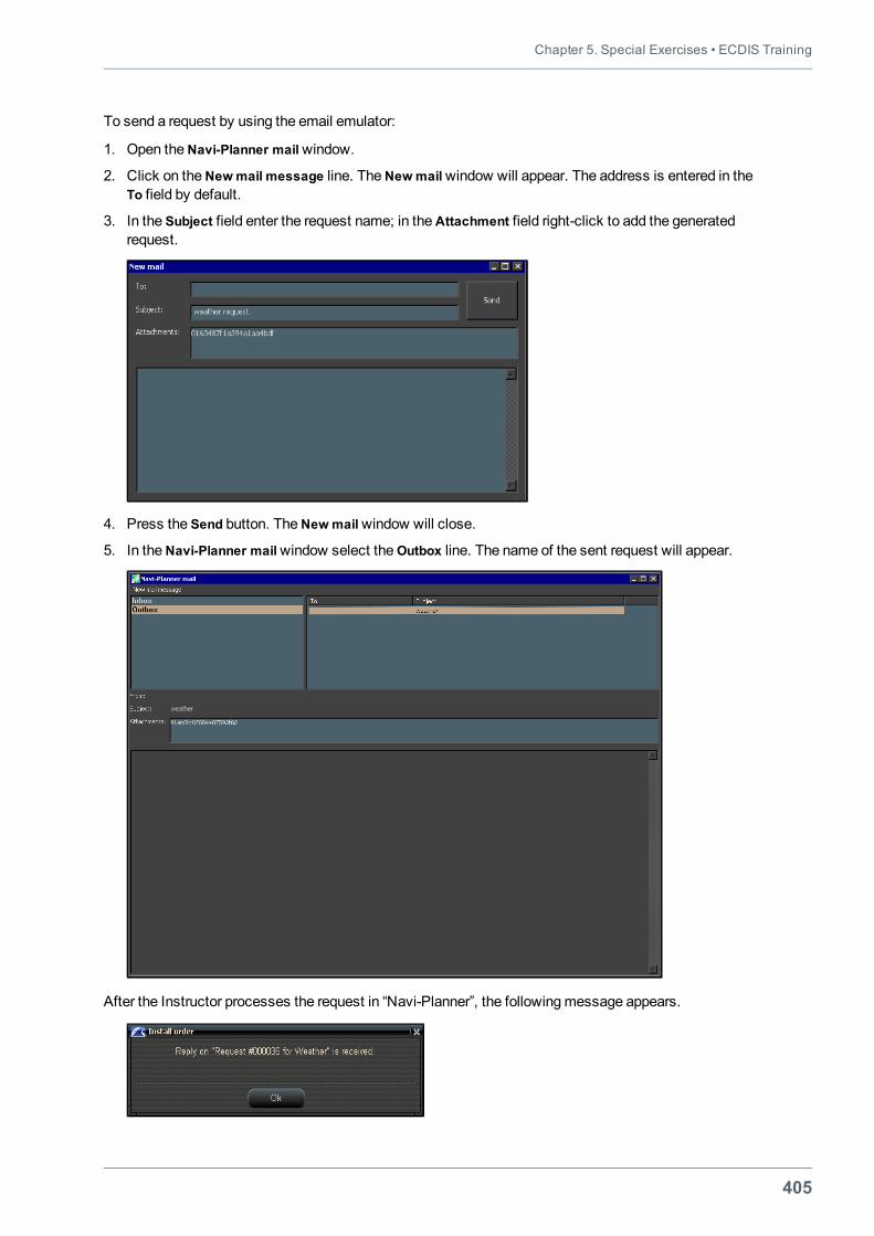
Chapter 5. Special Exercises • ECDIS Training
405
To send a request by using the email emulator:
1. Open theNavi-Planner mailwindow.
2. Click on theNewmail message line. TheNewmailwindow will appear. The address is entered in theTo field by default.
3. In the Subject field enter the request name; in theAttachment field right-click to add the generatedrequest.
4. Press the Send button. TheNewmailwindow will close.
5. In theNavi-Planner mailwindow select theOutbox line. The name of the sent request will appear.
After the Instructor processes the request in “Navi-Planner”, the followingmessage appears.
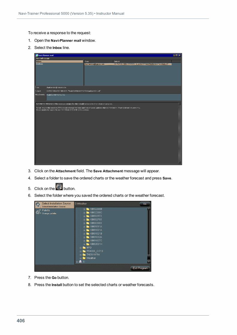
Navi-Trainer Professional 5000 (Version 5.35) • Instructor Manual
406
To receive a response to the request:
1. Open theNavi-Planner mailwindow.
2. Select the Inbox line.
3. Click on theAttachment field. The Save Attachmentmessage will appear.
4. Select a folder to save the ordered charts or the weather forecast and press Save.
5. Click on the button.
6. Select the folder where you saved the ordered charts or the weather forecast.
7. Press theGo button.
8. Press the Install button to set the selected charts or weather forecasts.
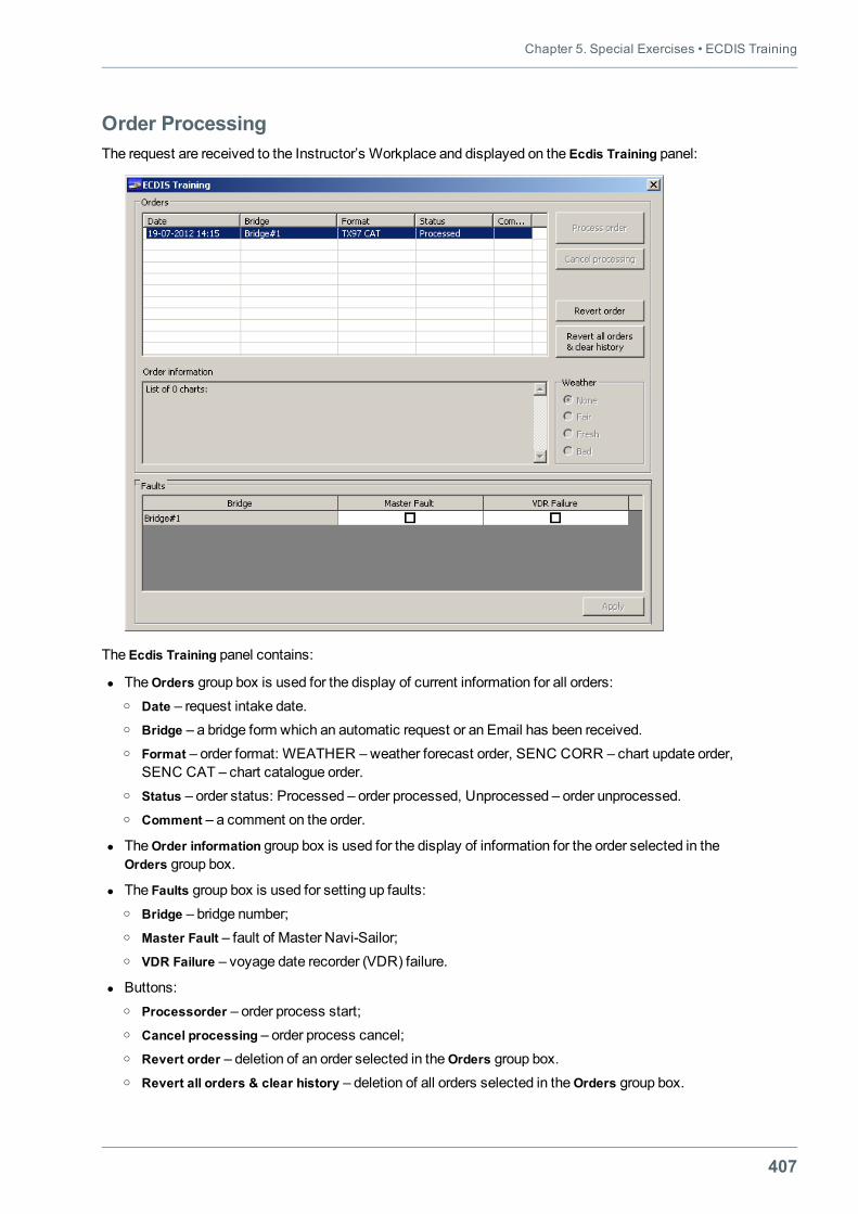
Chapter 5. Special Exercises • ECDIS Training
407
Order ProcessingThe request are received to the Instructor’s Workplace and displayed on the Ecdis Training panel:
The Ecdis Training panel contains:
l TheOrders group box is used for the display of current information for all orders:o Date – request intake date.o Bridge – a bridge form which an automatic request or an Email has been received.o Format – order format: WEATHER –weather forecast order, SENC CORR – chart update order,
SENC CAT – chart catalogue order.o Status – order status: Processed – order processed, Unprocessed – order unprocessed.o Comment – a comment on the order.
l TheOrder information group box is used for the display of information for the order selected in theOrders group box.
l The Faults group box is used for setting up faults:o Bridge – bridge number;o Master Fault – fault of Master Navi-Sailor;o VDR Failure – voyage date recorder (VDR) failure.
l Buttons:o Processorder – order process start;o Cancel processing – order process cancel;o Revert order – deletion of an order selected in theOrders group box.o Revert all orders & clear history – deletion of all orders selected in theOrders group box.
Navi-Trainer Professional 5000 (Version 5.35) • Instructor Manual
408
o TheWeather group box contains optional buttons for selecting the weather type. None, Faire, Fresh,Bad.
To process an order, perform the following:
1. In theOrders group box, select an order with the “Unprocessed” status.
2. If the order is in theWEATHER format, select the necessary weather type in theWeather group box.o Bad – stormy weather;o Fresh – fresh weather;o Fair – fair weather.
3. Press the Process button. The order status will change to “Processed”.
To set up faults:
1. To set up a fault Master Navi-Sailor, check theMaster Fault check box on the Ecdis Training panel andpress Apply. Master Navi-Sailor will stop working. Slave Navi-Sailor will becomeMaster. To turn offthe Navi-Sailor fault, clear theMaster Fault check box and press Apply. The turned-off Navi-Sailor willstart working and become Slave.
2. To set up a voyage date recorder failure, check the VDR Failure check box and press Apply. The VDRAlarm will light up in Master Navi-Sailor and Slave. To turn off the alarm, clear the VDR Failure checkbox and press Apply.
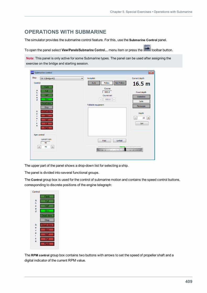
Chapter 5. Special Exercises • Operations with Submarine
409
OPERATIONS WITH SUBMARINEThe simulator provides the submarine control feature. For this, use the Submarine Control panel.
To open the panel select View\Panels\Submarine Control…menu item or press the toolbar button.
Note: This panel is only active for some Submarine types. The panel can be used after assigning theexercise on the bridge and starting session.
The upper part of the panel shows a drop-down list for selecting a ship.
The panel is divided into several functional groups.
TheControl group box is used for the control of submarinemotion and contains the speed control buttons,corresponding to discrete positions of the engine telegraph:
TheRPM control group box contains two buttons with arrows to set the speed of propeller shaft and adigital indicator of the current RPM value.
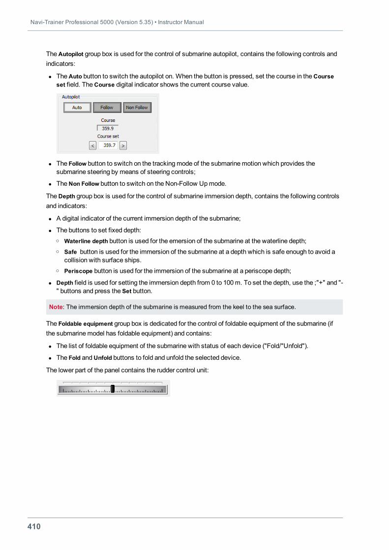
Navi-Trainer Professional 5000 (Version 5.35) • Instructor Manual
410
TheAutopilot group box is used for the control of submarine autopilot, contains the following controls andindicators:
l TheAuto button to switch the autopilot on. When the button is pressed, set the course in theCourseset field. TheCourse digital indicator shows the current course value.
l The Follow button to switch on the trackingmode of the submarinemotion which provides thesubmarine steering by means of steering controls;
l TheNon Follow button to switch on the Non-Follow Upmode.
TheDepth group box is used for the control of submarine immersion depth, contains the following controlsand indicators:
l A digital indicator of the current immersion depth of the submarine;
l The buttons to set fixed depth:o Waterline depth button is used for the emersion of the submarine at the waterline depth;o Safe button is used for the immersion of the submarine at a depth which is safe enough to avoid a
collision with surface ships.o Periscope button is used for the immersion of the submarine at a periscope depth;
l Depth field is used for setting the immersion depth from 0 to 100m. To set the depth, use the ;"+" and "-" buttons and press the Set button.
Note: The immersion depth of the submarine is measured from the keel to the sea surface.
The Foldable equipment group box is dedicated for the control of foldable equipment of the submarine (ifthe submarinemodel has foldable equipment) and contains:
l The list of foldable equipment of the submarine with status of each device ("Fold/"Unfold").
l The Fold andUnfold buttons to fold and unfold the selected device.
The lower part of the panel contains the rudder control unit:
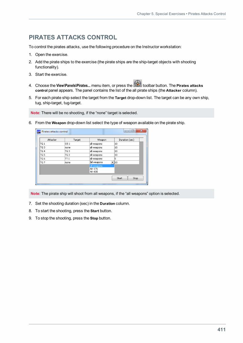
Chapter 5. Special Exercises • Pirates Attacks Control
411
PIRATES ATTACKS CONTROLTo control the pirates attacks, use the following procedure on the Instructor workstation:
1. Open the exercise.
2. Add the pirate ships to the exercise (the pirate ships are the ship-target objects with shootingfunctionality).
3. Start the exercise.
4. Choose the View\Panels\Pirates...menu item, or press the toolbar button. The Pirates attackscontrol panel appears. The panel contains the list of the all pirate ships (theAttacker column).
5. For each pirate ship select the target from the Target drop-down list. The target can be any own ship,tug, ship-target, tug-target.
Note: There will be no shooting, if the “none” target is selected.
6. From theWeapon drop-down list select the type of weapon available on the pirate ship.
Note: The pirate ship will shoot from all weapons, if the “all weapons” option is selected.
7. Set the shooting duration (sec) in theDuration column.
8. To start the shooting, press the Start button.
9. To stop the shooting, press the Stop button.
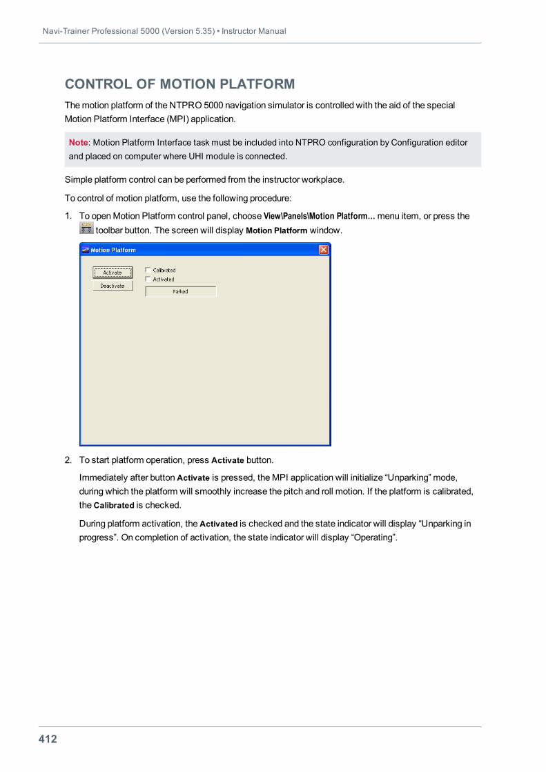
Navi-Trainer Professional 5000 (Version 5.35) • Instructor Manual
412
CONTROL OF MOTION PLATFORMThemotion platform of the NTPRO 5000 navigation simulator is controlled with the aid of the specialMotion Platform Interface (MPI) application.
Note: Motion Platform Interface task must be included into NTPRO configuration by Configuration editorand placed on computer where UHI module is connected.
Simple platform control can be performed from the instructor workplace.
To control of motion platform, use the following procedure:
1. To openMotion Platform control panel, choose View\Panels\Motion Platform…menu item, or press thetoolbar button. The screen will display Motion Platform window.
2. To start platform operation, press Activate button.
Immediately after buttonActivate is pressed, theMPI application will initialize “Unparking” mode,during which the platform will smoothly increase the pitch and roll motion. If the platform is calibrated,theCalibrated is checked.
During platform activation, theActivated is checked and the state indicator will display “Unparking inprogress”. On completion of activation, the state indicator will display “Operating”.
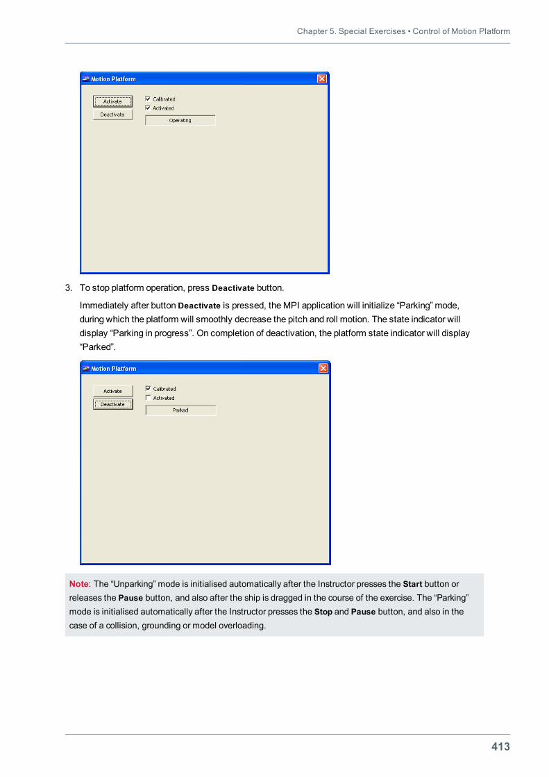
Chapter 5. Special Exercises • Control of Motion Platform
413
3. To stop platform operation, press Deactivate button.
Immediately after buttonDeactivate is pressed, theMPI application will initialize “Parking” mode,during which the platform will smoothly decrease the pitch and roll motion. The state indicator willdisplay “Parking in progress”. On completion of deactivation, the platform state indicator will display“Parked”.
Note: The “Unparking” mode is initialised automatically after the Instructor presses the Start button orreleases the Pause button, and also after the ship is dragged in the course of the exercise. The “Parking”mode is initialised automatically after the Instructor presses the Stop and Pause button, and also in thecase of a collision, grounding or model overloading.

415
CHAPTER 6.SHIP COMMUNICATION AIDS
This chapter contains:
Intercom 417Telephone Communication with Subscribers 417Playback of Radiotelephone Communications 419
VHF Communication 420Radio Traffic Monitoring 420Keeping of ListeningWatch 421Playback of Radiotelephone Communications 424

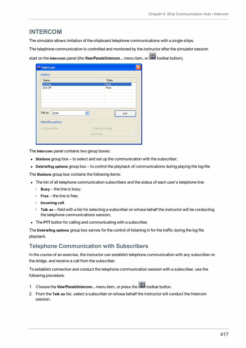
Chapter 6. Ship Communication Aids • Intercom
417
INTERCOMThe simulator allows imitation of the shipboard telephone communications with a single ships.
The telephone communication is controlled andmonitored by the instructor after the simulator session
start on the Intercom panel (the View\Panels\Intercom...menu item, or toolbar button).
The Intercom panel contains two group boxes:
l Stations group box – to select and set up the communication with the subscriber;
l Debriefing options group box – to control the playback of communications during playing the log-file.
The Stations group box contains the following items:
l The list of all telephone communication subscribers and the status of each user’s telephone line:o Busy – the line is busy;o Free – the line is free;o Incoming call.o Talk as – field with a list for selecting a subscriber on whose behalf the instructor will be conducting
the telephone communications session;
l The PTT button for calling and communicating with a subscriber.
TheDebriefing options group box serves for the control of listening in for the traffic during the log fileplayback.
Telephone Communication with SubscribersIn the course of an exercise, the instructor can establish telephone communication with any subscriber onthe bridge, and receive a call from the subscriber.
To establish connection and conduct the telephone communication session with a subscriber, use thefollowing procedure:
1. Choose the View\Panels\Intercom...menu item, or press the toolbar button.
2. From the Talk as list, select a subscriber on whose behalf the Instructor will conduct the Intercomsession.
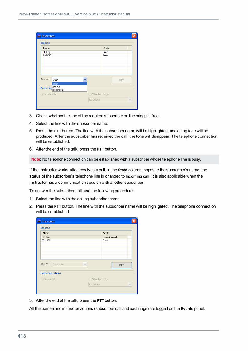
Navi-Trainer Professional 5000 (Version 5.35) • Instructor Manual
418
3. Check whether the line of the required subscriber on the bridge is free.
4. Select the line with the subscriber name.
5. Press the PTT button. The line with the subscriber namewill be highlighted, and a ring tone will beproduced. After the subscriber has received the call, the tone will disappear. The telephone connectionwill be established.
6. After the end of the talk, press the PTT button.
Note: No telephone connection can be established with a subscriber whose telephone line is busy.
If the Instructor workstation receives a call, in the State column, opposite the subscriber’s name, thestatus of the subscriber’s telephone line is changed to Incoming call. It is also applicable when theInstructor has a communication session with another subscriber.
To answer the subscriber call, use the following procedure:
1. Select the line with the calling subscriber name.
2. Press the PTT button. The line with the subscriber namewill be highlighted. The telephone connectionwill be established:
3. After the end of the talk, press the PTT button.
All the trainee and instructor actions (subscriber call and exchange) are logged on the Events panel.
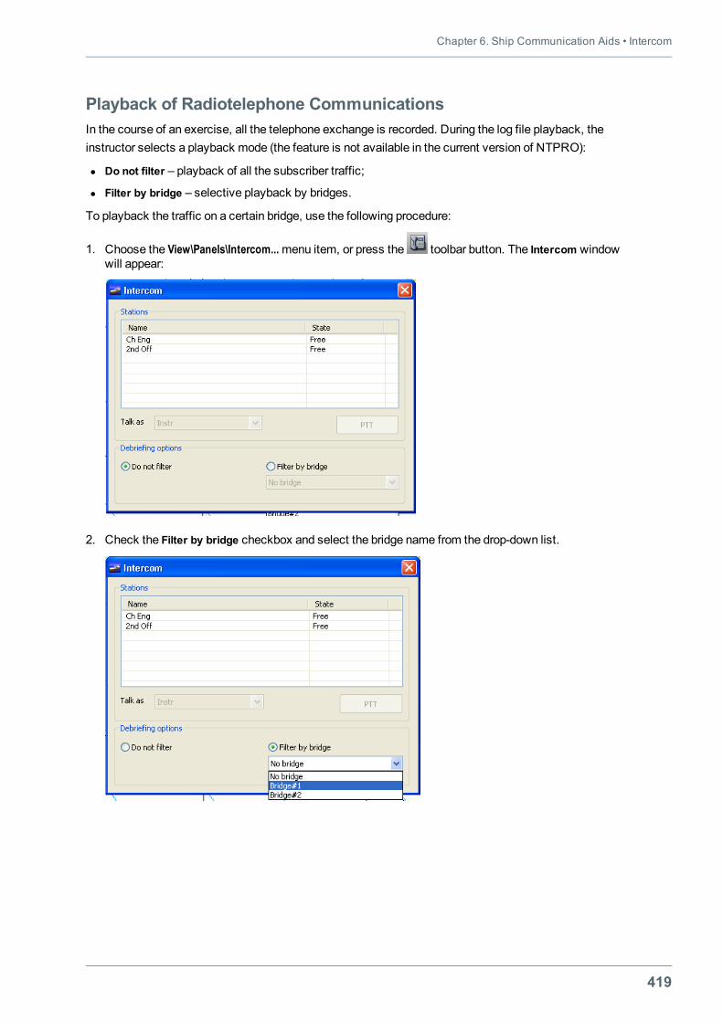
Chapter 6. Ship Communication Aids • Intercom
419
Playback of Radiotelephone CommunicationsIn the course of an exercise, all the telephone exchange is recorded. During the log file playback, theinstructor selects a playback mode (the feature is not available in the current version of NTPRO):
l Do not filter – playback of all the subscriber traffic;
l Filter by bridge – selective playback by bridges.
To playback the traffic on a certain bridge, use the following procedure:
1. Choose the View\Panels\Intercom...menu item, or press the toolbar button. The Intercom windowwill appear:
2. Check the Filter by bridge checkbox and select the bridge name from the drop-down list.
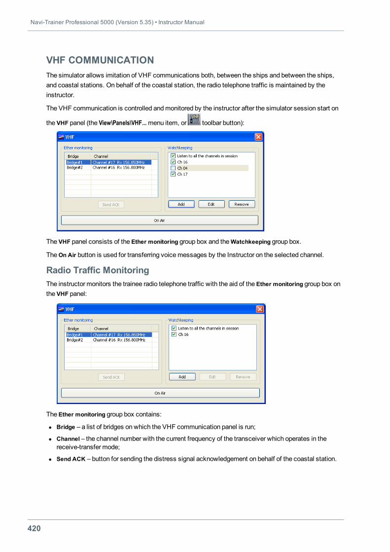
Navi-Trainer Professional 5000 (Version 5.35) • Instructor Manual
420
VHF COMMUNICATIONThe simulator allows imitation of VHF communications both, between the ships and between the ships,and coastal stations. On behalf of the coastal station, the radio telephone traffic is maintained by theinstructor.
The VHF communication is controlled andmonitored by the instructor after the simulator session start on
the VHF panel (the View\Panels\VHF...menu item, or toolbar button):
The VHF panel consists of the Ether monitoring group box and theWatchkeeping group box.
TheOn Air button is used for transferring voicemessages by the Instructor on the selected channel.
Radio Traffic MonitoringThe instructor monitors the trainee radio telephone traffic with the aid of the Ether monitoring group box onthe VHF panel:
The Ether monitoring group box contains:
l Bridge – a list of bridges on which the VHF communication panel is run;
l Channel – the channel number with the current frequency of the transceiver which operates in thereceive-transfer mode;
l Send ACK – button for sending the distress signal acknowledgement on behalf of the coastal station.
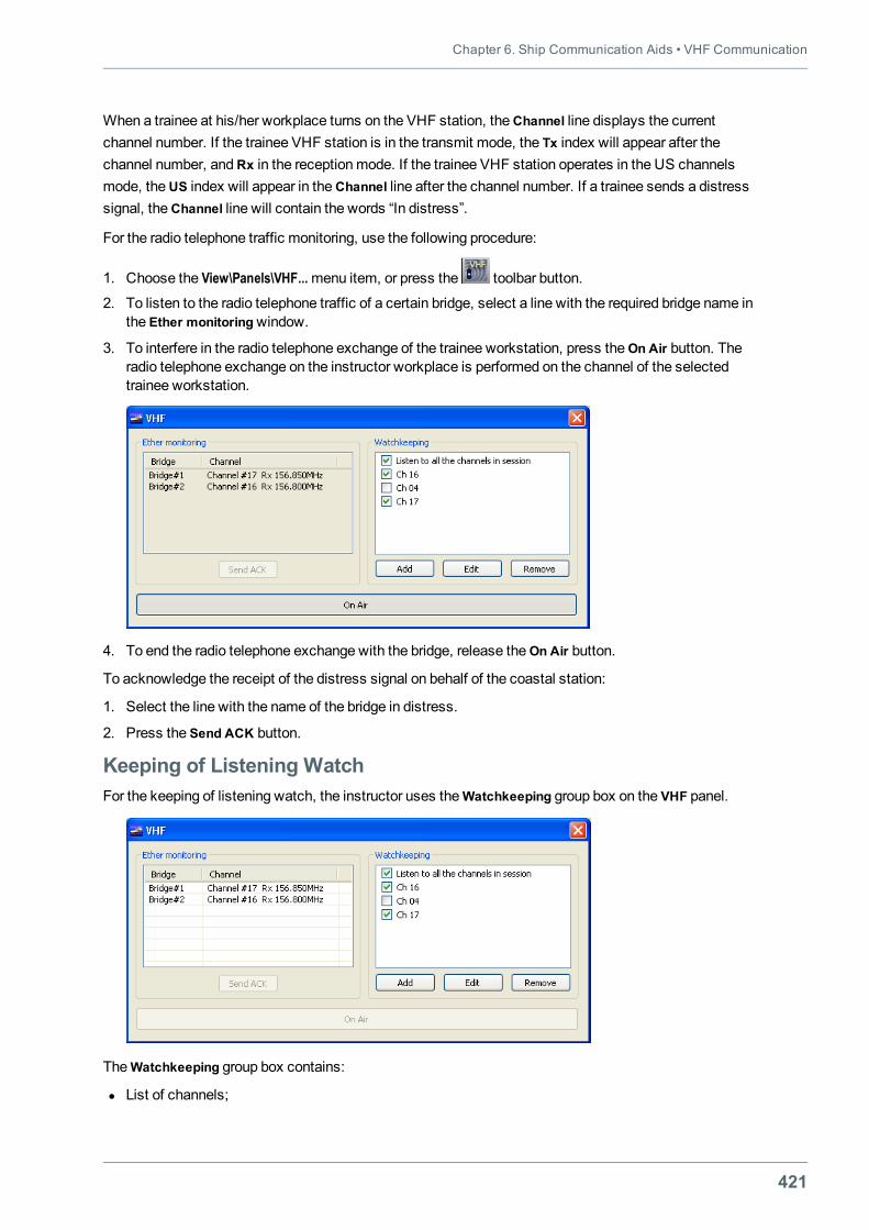
Chapter 6. Ship Communication Aids • VHF Communication
421
When a trainee at his/her workplace turns on the VHF station, theChannel line displays the currentchannel number. If the trainee VHF station is in the transmit mode, the Тх index will appear after thechannel number, andRх in the receptionmode. If the trainee VHF station operates in the US channelsmode, theUS index will appear in theChannel line after the channel number. If a trainee sends a distresssignal, theChannel line will contain the words “In distress”.
For the radio telephone traffic monitoring, use the following procedure:
1. Choose the View\Panels\VHF...menu item, or press the toolbar button.
2. To listen to the radio telephone traffic of a certain bridge, select a line with the required bridge name inthe Ether monitoringwindow.
3. To interfere in the radio telephone exchange of the trainee workstation, press theOn Air button. Theradio telephone exchange on the instructor workplace is performed on the channel of the selectedtrainee workstation.
4. To end the radio telephone exchange with the bridge, release theOn Air button.
To acknowledge the receipt of the distress signal on behalf of the coastal station:
1. Select the line with the name of the bridge in distress.
2. Press the Send ACK button.
Keeping of Listening WatchFor the keeping of listening watch, the instructor uses theWatchkeeping group box on the VHF panel.
TheWatchkeeping group box contains:
l List of channels;
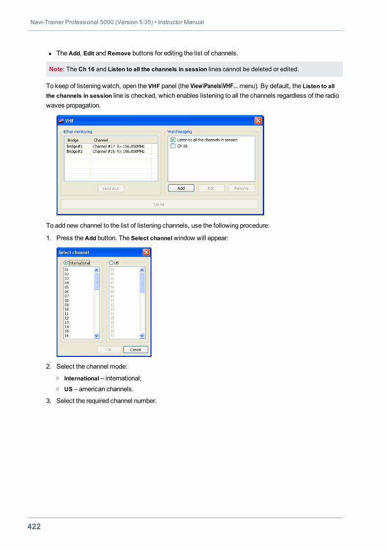
Navi-Trainer Professional 5000 (Version 5.35) • Instructor Manual
422
l TheAdd, Edit andRemove buttons for editing the list of channels.
Note: The Ch 16 and Listen to all the channels in session lines cannot be deleted or edited.
To keep of listening watch, open the VHF panel (the View\Panels\VHF...menu). By default, the Listen to allthe channels in session line is checked, which enables listening to all the channels regardless of the radiowaves propagation.
To add new channel to the list of listening channels, use the following procedure:
1. Press theAdd button. The Select channelwindow will appear:
2. Select the channel mode:o International – international;o US – american channels.
3. Select the required channel number.
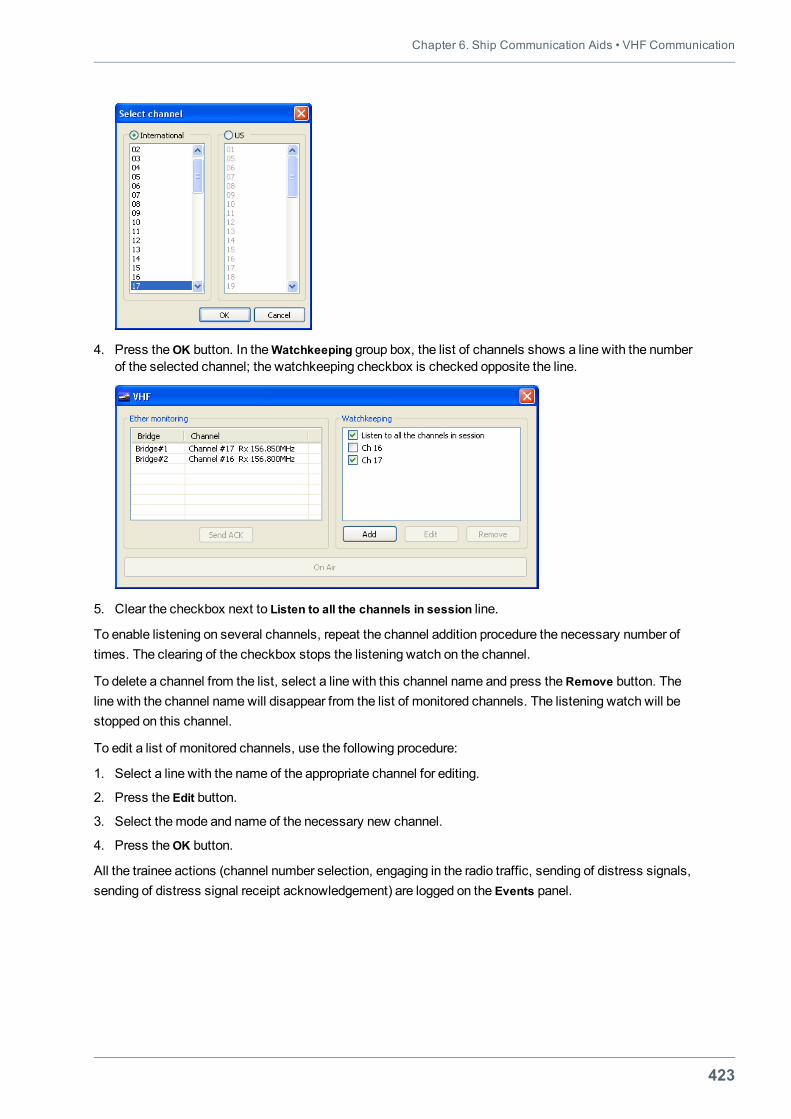
Chapter 6. Ship Communication Aids • VHF Communication
423
4. Press theОK button. In theWatchkeeping group box, the list of channels shows a line with the numberof the selected channel; the watchkeeping checkbox is checked opposite the line.
5. Clear the checkbox next to Listen to all the channels in session line.
To enable listening on several channels, repeat the channel addition procedure the necessary number oftimes. The clearing of the checkbox stops the listening watch on the channel.
To delete a channel from the list, select a line with this channel name and press the Remove button. Theline with the channel namewill disappear from the list of monitored channels. The listening watch will bestopped on this channel.
To edit a list of monitored channels, use the following procedure:
1. Select a line with the name of the appropriate channel for editing.
2. Press the Edit button.
3. Select themode and name of the necessary new channel.
4. Press theОK button.
All the trainee actions (channel number selection, engaging in the radio traffic, sending of distress signals,sending of distress signal receipt acknowledgement) are logged on the Events panel.

Navi-Trainer Professional 5000 (Version 5.35) • Instructor Manual
424
Playback of Radiotelephone CommunicationsIn the course of an exercise, all the radio telephone traffic is recorded. During the playback, the instructorselects the playback mode (the feature is not available in the current version of NTPRO):
l Simultaneous playback of all the traffic on all the channels;
l Selective playback by bridges and channels.
425
CHAPTER 7.JOINT OPERATION OF NTPRO WITH OTHER
SIMULATORS
This chapter contains:
Joint Exercises on NTPRO and VTMS Simulator 427Creating NTPROExercise 427Creating VTMS Configuration 431
Joint Exercises on NTPRO and ERS/TechSim Simulators 447Preparation of Joint Exercises 447Establishing Connection with ERS/TechSim Simulator 450Running Joint Exercises 451
Joint Exercises on NTPRO and TGS Simulators 453Establishing Connection with TGS Simulator 453Running Joint Exercises 454

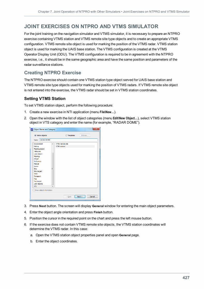
Chapter 7. Joint Operation of NTPRO with Other Simulators • Joint Exercises on NTPRO and VTMS Simulator
427
JOINT EXERCISES ON NTPRO AND VTMS SIMULATORFor the joint training on the navigation simulator and VTMS simulator, it is necessary to prepare an NTPROexercise containing VTMS station and VTMS remote site type objects and to create an appropriate VTMSconfiguration. VTMS remote site object is used for marking the position of the VTMS radar. VTMS stationobject is used for marking the UAIS base station. The VTMS configuration is created at the VTMSOperator Display Unit (ODU). The VTMS configuration is required to be in agreement with the NTPROexercise, i.e., it should be in the same geographic area and have the same position and parameters of theradar surveillance stations.
Creating NTPRO ExerciseThe NTPRO exercise should contain one VTMS station type object served for UAIS base station andVTMS remote site type objects used for marking the position of VTMS radars. If VTMS remote site objectis not entered into the exercise, the VTMS radar should be set in VTMS station coordinates.
Setting VTMS StationTo set VTMS station object, perform the following procedure:
1. Create a new exercise in NTI application (menu File\New…).
2. Open the window with the list of object categories (menu Edit\New Object…), select VTMS stationobject in VTS category and enter the name (for example, “RADAR DOME”).
3. Press Next button. The screen will display Generalwindow for entering the main object parameters.
4. Enter the object angle orientation and press Finish button.
5. Position the cursor in the required point on the chart and press the left mouse button.
6. If the exercise does not contain VTMS remote site objects, the VTMS station coordinates willdetermine the VTMS radar. In this case:
a. Open the VTMS station object properties panel and openGeneral page.
b. Enter the object coordinates.
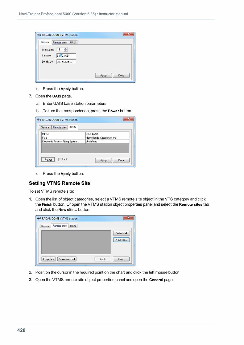
Navi-Trainer Professional 5000 (Version 5.35) • Instructor Manual
428
c. Press theApply button.
7. Open theUAIS page.
a. Enter UAIS base station parameters.
b. To turn the transponder on, press the Power button.
c. Press theApply button.
Setting VTMS Remote SiteTo set VTMS remote site:
1. Open the list of object categories, select a VTMS remote site object in the VTS category and clickthe Finish button. Or open the VTMS station object properties panel and select theRemote sites taband click theNew site… button.
2. Position the cursor in the required point on the chart and click the left mouse button.
3. Open the VTMS remote site object properties panel and open the General page.
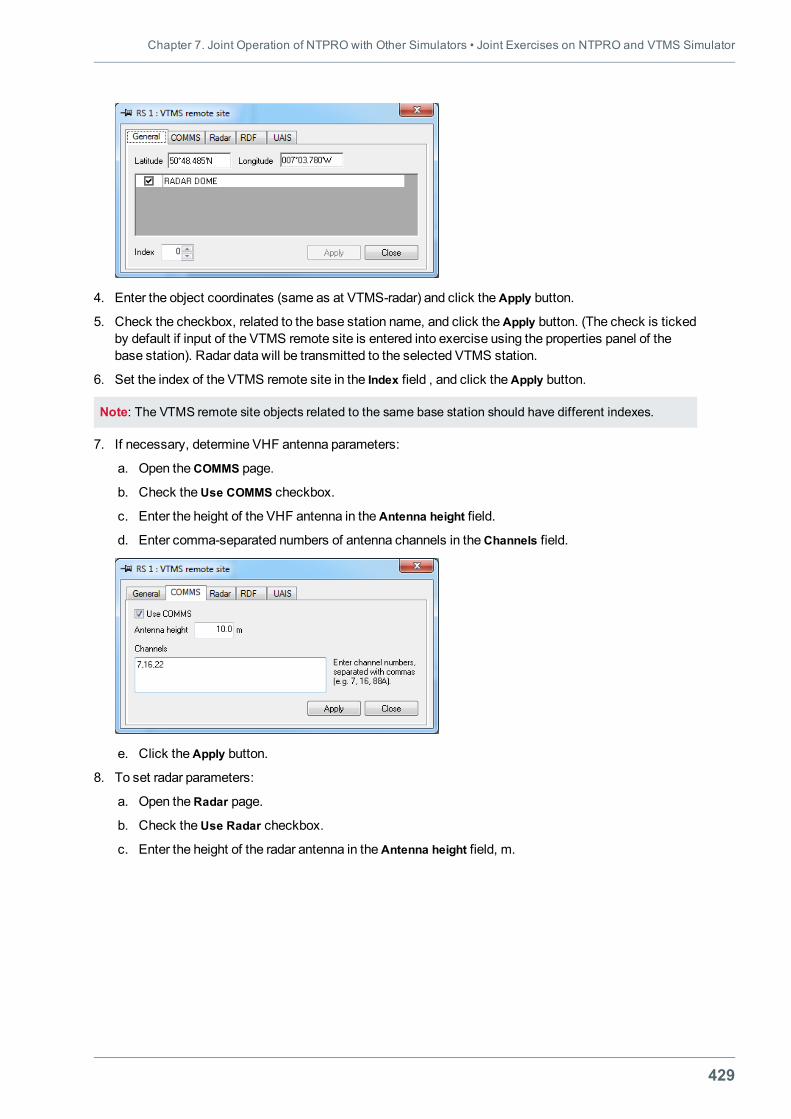
Chapter 7. Joint Operation of NTPRO with Other Simulators • Joint Exercises on NTPRO and VTMS Simulator
429
4. Enter the object coordinates (same as at VTMS-radar) and click theApply button.
5. Check the checkbox, related to the base station name, and click the Apply button. (The check is tickedby default if input of the VTMS remote site is entered into exercise using the properties panel of thebase station). Radar data will be transmitted to the selected VTMS station.
6. Set the index of the VTMS remote site in the Index field , and click the Apply button.
Note: The VTMS remote site objects related to the same base station should have different indexes.
7. If necessary, determine VHF antenna parameters:
a. Open theCOMMS page.
b. Check theUse COMMS checkbox.
c. Enter the height of the VHF antenna in theAntenna height field.
d. Enter comma-separated numbers of antenna channels in theChannels field.
e. Click theApply button.
8. To set radar parameters:
a. Open theRadar page.
b. Check theUse Radar checkbox.
c. Enter the height of the radar antenna in theAntenna height field, m.
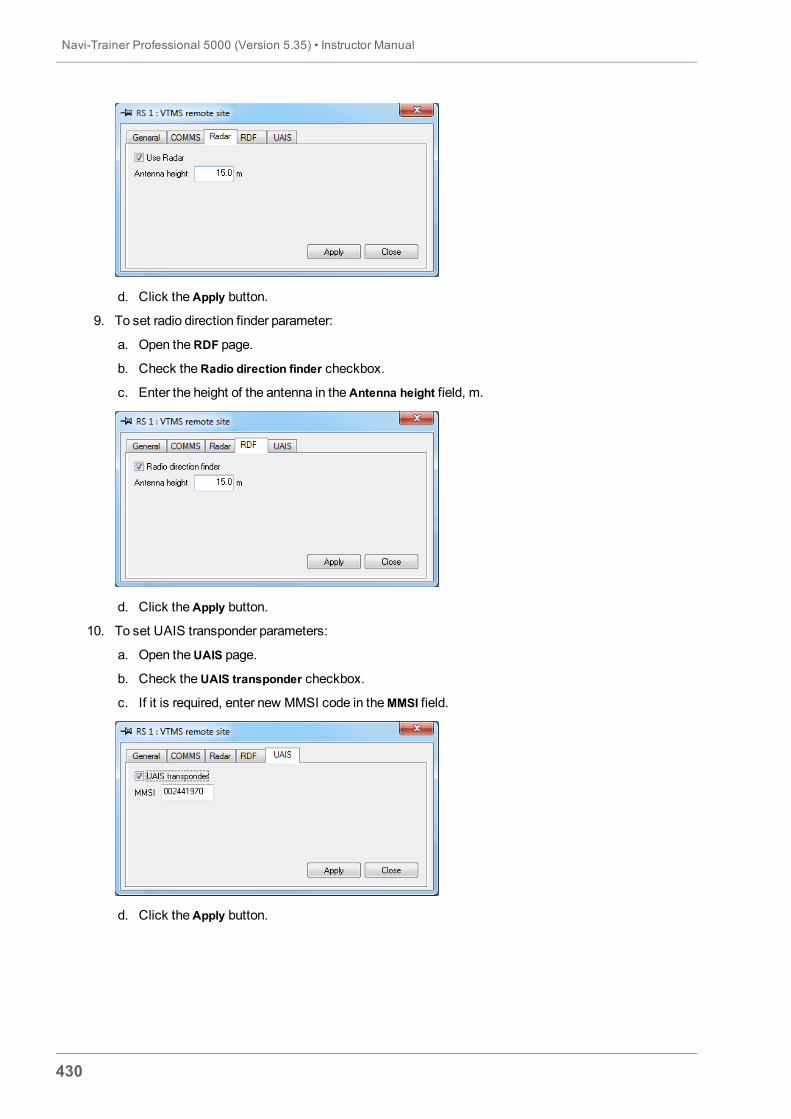
Navi-Trainer Professional 5000 (Version 5.35) • Instructor Manual
430
d. Click theApply button.
9. To set radio direction finder parameter:
a. Open theRDF page.
b. Check theRadio direction finder checkbox.
c. Enter the height of the antenna in theAntenna height field, m.
d. Click theApply button.
10. To set UAIS transponder parameters:
a. Open theUAIS page.
b. Check theUAIS transponder checkbox.
c. If it is required, enter new MMSI code in theMMSI field.
d. Click theApply button.
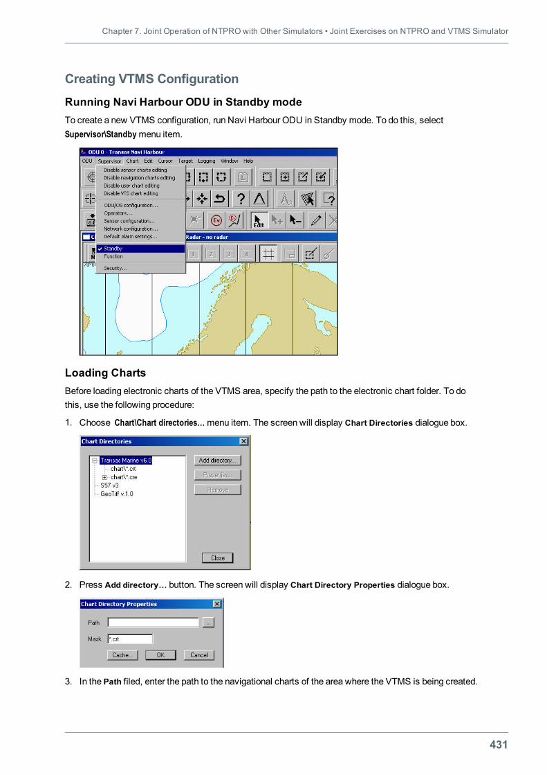
Chapter 7. Joint Operation of NTPRO with Other Simulators • Joint Exercises on NTPRO and VTMS Simulator
431
Creating VTMS Configuration
Running Navi Harbour ODU in Standby modeTo create a new VTMS configuration, run Navi Harbour ODU in Standby mode. To do this, selectSupervisor\Standbymenu item.
Loading ChartsBefore loading electronic charts of the VTMS area, specify the path to the electronic chart folder. To dothis, use the following procedure:
1. Choose Chart\Chart directories…menu item. The screen will display Chart Directories dialogue box.
2. Press Add directory… button. The screen will display Chart Directory Properties dialogue box.
3. In the Path filed, enter the path to the navigational charts of the area where the VTMS is being created.
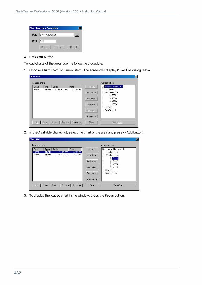
Navi-Trainer Professional 5000 (Version 5.35) • Instructor Manual
432
4. Press OK button.
To load charts of the area, use the following procedure:
1. Choose Chart\Chart list…menu item. The screen will display Chart List dialogue box.
2. In theAvailable charts list, select the chart of the area and press <<Add button.
3. To display the loaded chart in the window, press the Focus button.
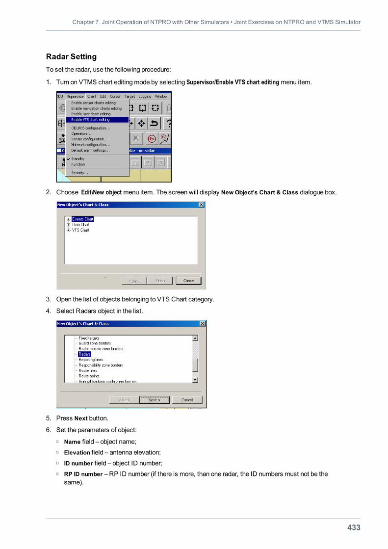
Chapter 7. Joint Operation of NTPRO with Other Simulators • Joint Exercises on NTPRO and VTMS Simulator
433
Radar SettingTo set the radar, use the following procedure:
1. Turn on VTMS chart editingmode by selecting Supervisor/Enable VTS chart editing menu item.
2. Choose Edit\New object menu item. The screen will display New Object’s Chart & Class dialogue box.
3. Open the list of objects belonging to VTS Chart category.
4. Select Radars object in the list.
5. Press Next button.
6. Set the parameters of object:o Name field – object name;o Elevation field – antenna elevation;o ID number field – object ID number;o RP ID number – RP ID number (if there is more, than one radar, the ID numbers must not be the
same).
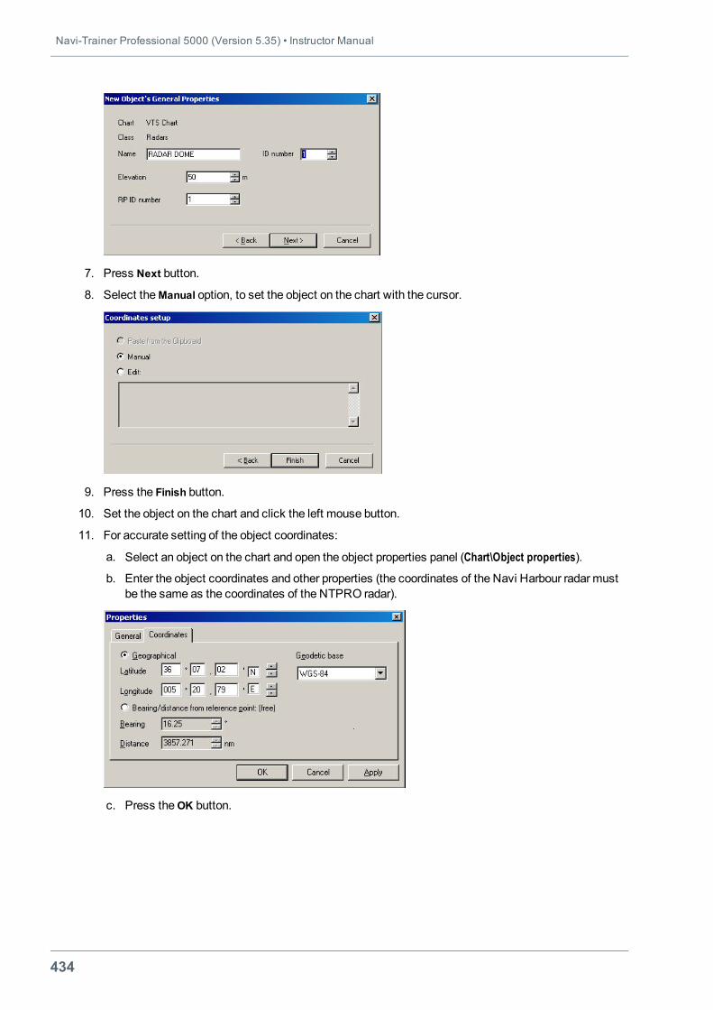
Navi-Trainer Professional 5000 (Version 5.35) • Instructor Manual
434
7. Press Next button.
8. Select theManual option, to set the object on the chart with the cursor.
9. Press the Finish button.
10. Set the object on the chart and click the left mouse button.
11. For accurate setting of the object coordinates:
a. Select an object on the chart and open the object properties panel (Chart\Object properties).
b. Enter the object coordinates and other properties (the coordinates of the Navi Harbour radar mustbe the same as the coordinates of the NTPRO radar).
c. Press theOK button.
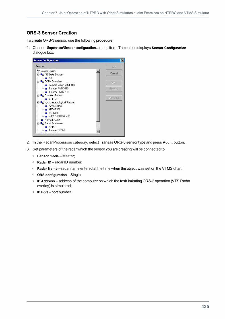
Chapter 7. Joint Operation of NTPRO with Other Simulators • Joint Exercises on NTPRO and VTMS Simulator
435
ORS-3 Sensor CreationTo create ORS-3 sensor, use the following procedure:
1. Choose Supervisor\Sensor configuration...menu item. The screen displays Sensor Configurationdialogue box.
2. In the Radar Processors category, select Transas ORS-3 sensor type and press Add… button.
3. Set parameters of the radar which the sensor you are creating will be connected to:o Sensor mode –Master;o Radar ID – radar ID number;o Radar Name – radar name entered at the time when the object was set on the VTMS chart;o ORS configuration – Single;o IP Address – address of the computer on which the task imitating ORS-2 operation (VTS Radar
overlay) is simulated;o IP Port – port number.
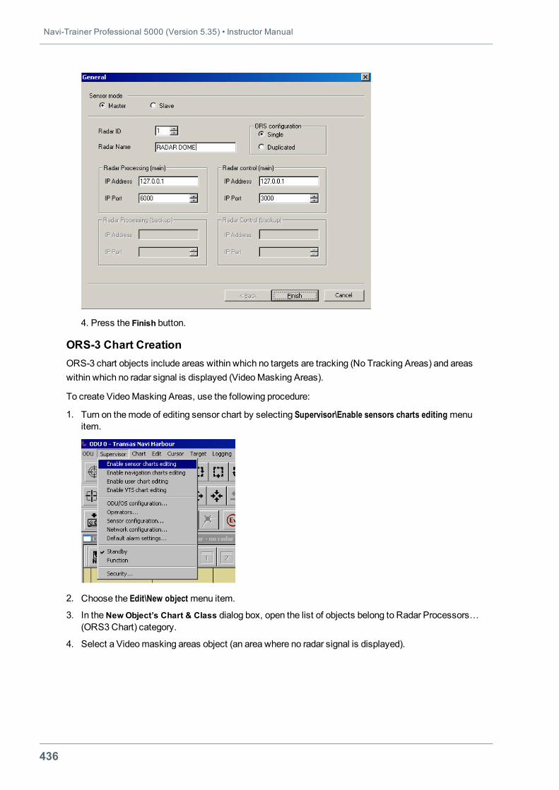
Navi-Trainer Professional 5000 (Version 5.35) • Instructor Manual
436
4. Press the Finish button.
ORS-3 Chart CreationORS-3 chart objects include areas within which no targets are tracking (No Tracking Areas) and areaswithin which no radar signal is displayed (VideoMasking Areas).
To create VideoMasking Areas, use the following procedure:
1. Turn on themode of editing sensor chart by selecting Supervisor\Enable sensors charts editing menuitem.
2. Choose the Edit\New object menu item.
3. In theNew Object’s Chart & Class dialog box, open the list of objects belong to Radar Processors…(ORS3Chart) category.
4. Select a Videomasking areas object (an area where no radar signal is displayed).
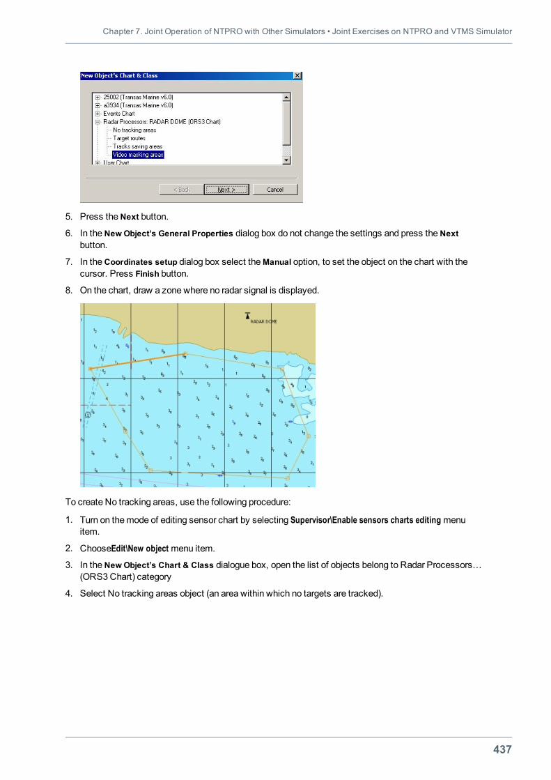
Chapter 7. Joint Operation of NTPRO with Other Simulators • Joint Exercises on NTPRO and VTMS Simulator
437
5. Press theNext button.
6. In theNew Object’s General Properties dialog box do not change the settings and press theNextbutton.
7. In theCoordinates setup dialog box select theManual option, to set the object on the chart with thecursor. Press Finish button.
8. On the chart, draw a zone where no radar signal is displayed.
To create No tracking areas, use the following procedure:
1. Turn on themode of editing sensor chart by selecting Supervisor\Enable sensors charts editing menuitem.
2. ChooseEdit\New object menu item.
3. In theNew Object’s Chart & Class dialogue box, open the list of objects belong to Radar Processors…(ORS3Chart) category
4. Select No tracking areas object (an area within which no targets are tracked).
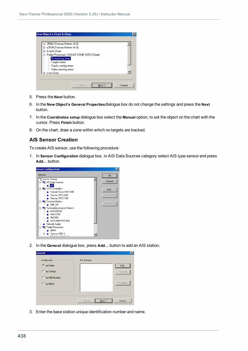
Navi-Trainer Professional 5000 (Version 5.35) • Instructor Manual
438
5. Press theNext button.
6. In theNew Object’s General Propertiesdialogue box do not change the settings and press theNextbutton.
7. In theCoordinates setup dialogue box select theManual option, to set the object on the chart with thecursor. Press Finish button.
8. On the chart, draw a zone within which no targets are tracked.
AIS Sensor CreationTo create AIS sensor, use the following procedure:
1. In Sensor Configuration dialogue box, in AIS Data Sources category select AIS type sensor and pressAdd… button.
2. In theGeneral dialogue box, press Add… button to add an AIS station.
3. Enter the base station unique identification number and name.
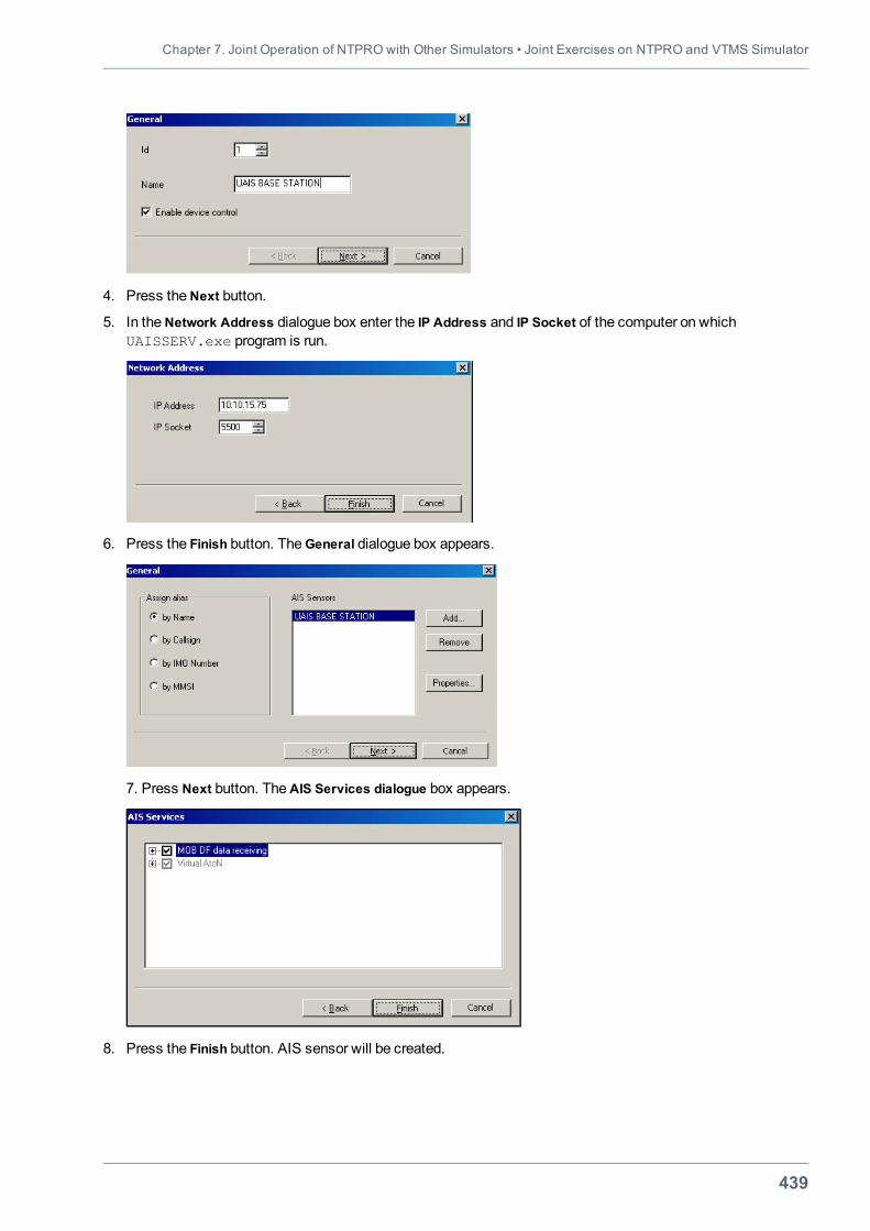
Chapter 7. Joint Operation of NTPRO with Other Simulators • Joint Exercises on NTPRO and VTMS Simulator
439
4. Press theNext button.
5. In theNetwork Address dialogue box enter the IP Address and IP Socket of the computer on whichUAISSERV.exe program is run.
6. Press the Finish button. TheGeneral dialogue box appears.
7. Press Next button. TheAIS Services dialogue box appears.
8. Press the Finish button. AIS sensor will be created.
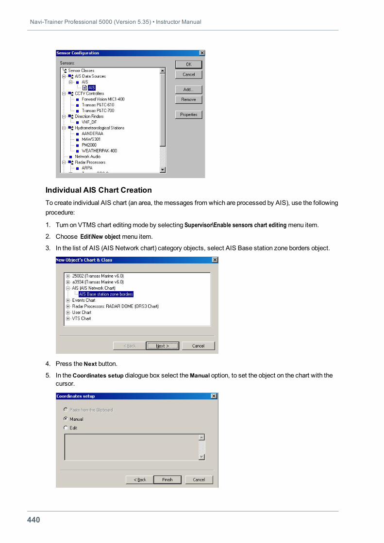
Navi-Trainer Professional 5000 (Version 5.35) • Instructor Manual
440
Individual AIS Chart CreationTo create individual AIS chart (an area, themessages from which are processed by AIS), use the followingprocedure:
1. Turn on VTMS chart editingmode by selecting Supervisor\Enable sensors chart editing menu item.
2. Choose Edit\New object menu item.
3. In the list of AIS (AIS Network chart) category objects, select AIS Base station zone borders object.
4. Press theNext button.
5. In theCoordinates setup dialogue box select theManual option, to set the object on the chart with thecursor.
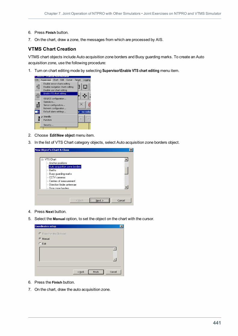
Chapter 7. Joint Operation of NTPRO with Other Simulators • Joint Exercises on NTPRO and VTMS Simulator
441
6. Press Finish button.
7. On the chart, draw a zone, themessages from which are processed by AIS.
VTMS Chart CreationVTMS chart objects include Auto acquisition zone borders and Buoy guardingmarks. To create an Autoacquisition zone, use the following procedure:
1. Turn on chart editingmode by selecting Supervisor\Enable VTS chart editing menu item.
2. Choose Edit\New object menu item.
3. In the list of VTS Chart category objects, select Auto acquisition zone borders object.
4. Press Next button.
5. Select theManual option, to set the object on the chart with the cursor.
6. Press the Finish button.
7. On the chart, draw the auto acquisition zone.
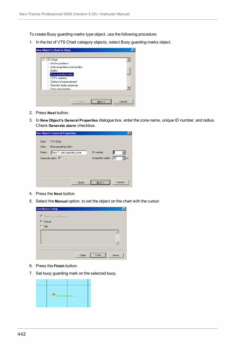
Navi-Trainer Professional 5000 (Version 5.35) • Instructor Manual
442
To create Buoy guardingmarks type object, use the following procedure:
1. In the list of VTS Chart category objects, select Buoy guardingmarks object.
2. Press Next button.
3. InNew Object’s General Properties dialogue box, enter the zone name, unique ID number, and radius.Check Generate alarm checkbox.
4. Press theNext button.
5. Select theManual option, to set the object on the chart with the cursor.
6. Press the Finish button.
7. Set buoy guardingmark on the selected buoy.
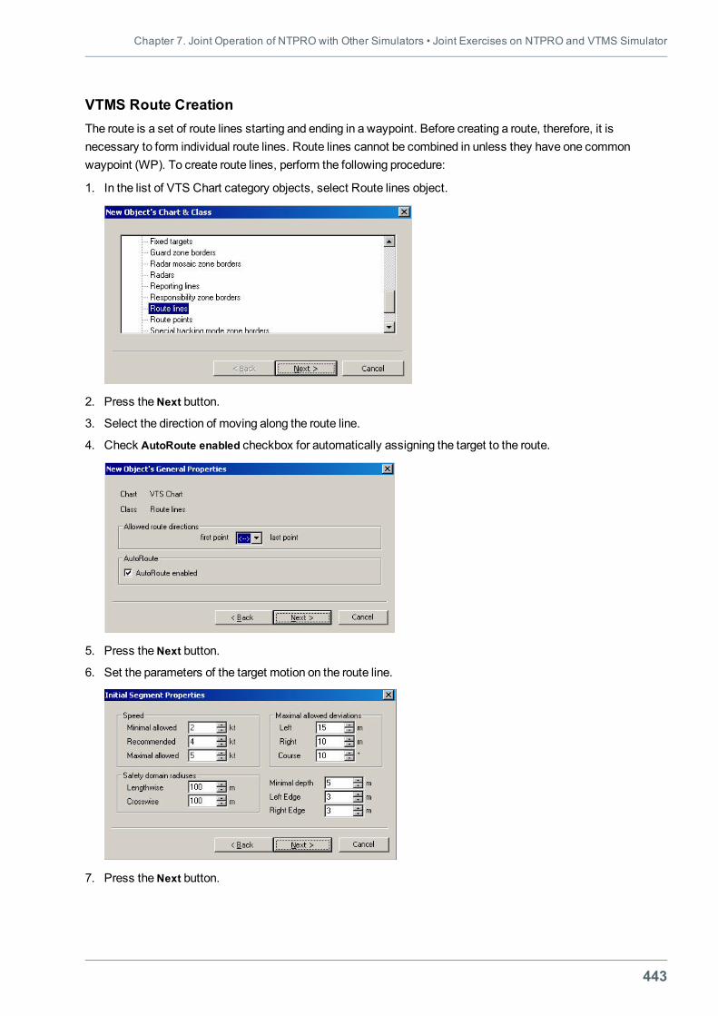
Chapter 7. Joint Operation of NTPRO with Other Simulators • Joint Exercises on NTPRO and VTMS Simulator
443
VTMS Route CreationThe route is a set of route lines starting and ending in a waypoint. Before creating a route, therefore, it isnecessary to form individual route lines. Route lines cannot be combined in unless they have one commonwaypoint (WP). To create route lines, perform the following procedure:
1. In the list of VTS Chart category objects, select Route lines object.
2. Press theNext button.
3. Select the direction of moving along the route line.
4. Check AutoRoute enabled checkbox for automatically assigning the target to the route.
5. Press theNext button.
6. Set the parameters of the target motion on the route line.
7. Press theNext button.
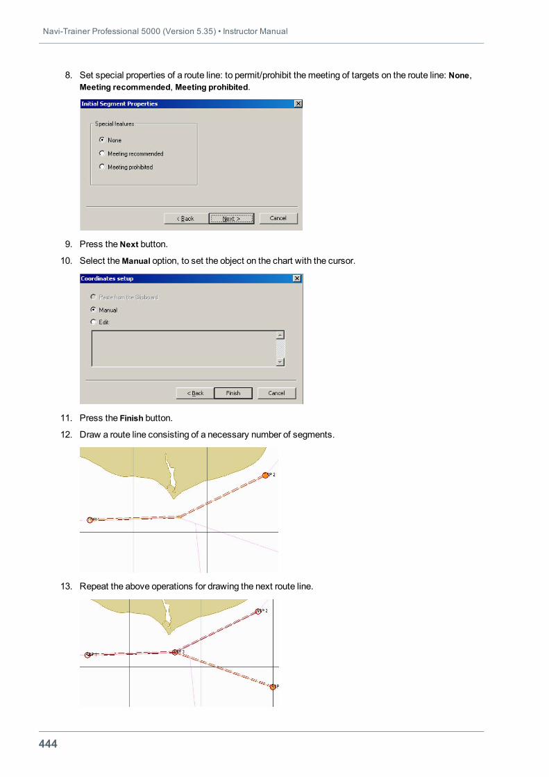
Navi-Trainer Professional 5000 (Version 5.35) • Instructor Manual
444
8. Set special properties of a route line: to permit/prohibit themeeting of targets on the route line: None,Meeting recommended, Meeting prohibited.
9. Press theNext button.
10. Select theManual option, to set the object on the chart with the cursor.
11. Press the Finish button.
12. Draw a route line consisting of a necessary number of segments.
13. Repeat the above operations for drawing the next route line.
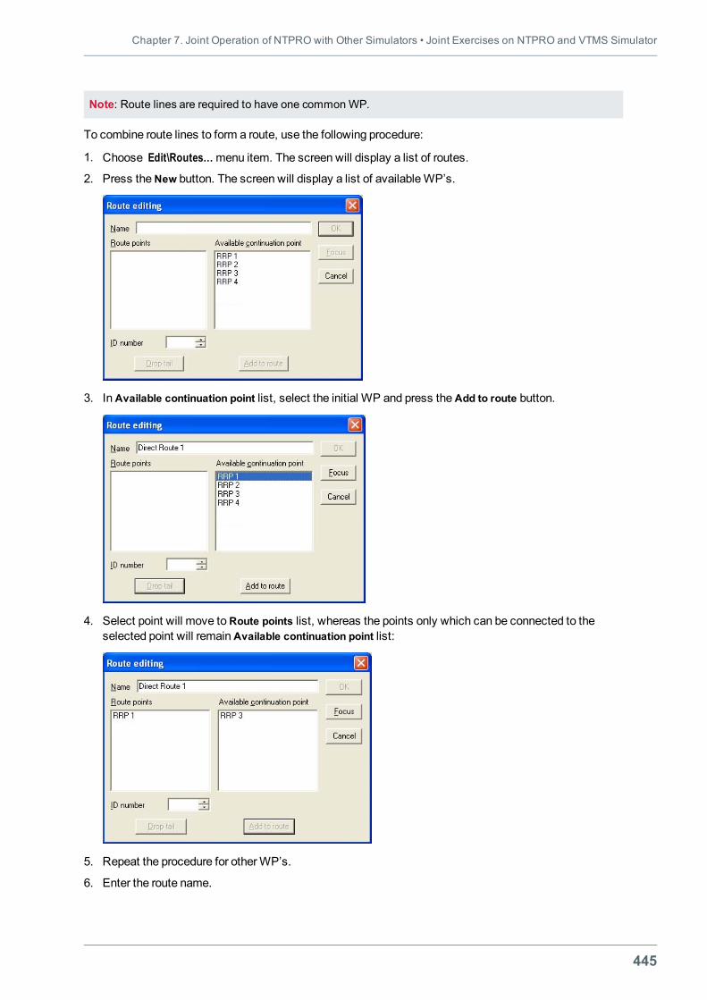
Chapter 7. Joint Operation of NTPRO with Other Simulators • Joint Exercises on NTPRO and VTMS Simulator
445
Note: Route lines are required to have one commonWP.
To combine route lines to form a route, use the following procedure:
1. Choose Edit\Routes…menu item. The screen will display a list of routes.
2. Press theNew button. The screen will display a list of availableWP’s.
3. InAvailable continuation point list, select the initial WP and press theAdd to route button.
4. Select point will move toRoute points list, whereas the points only which can be connected to theselected point will remainAvailable continuation point list:
5. Repeat the procedure for otherWP’s.
6. Enter the route name.
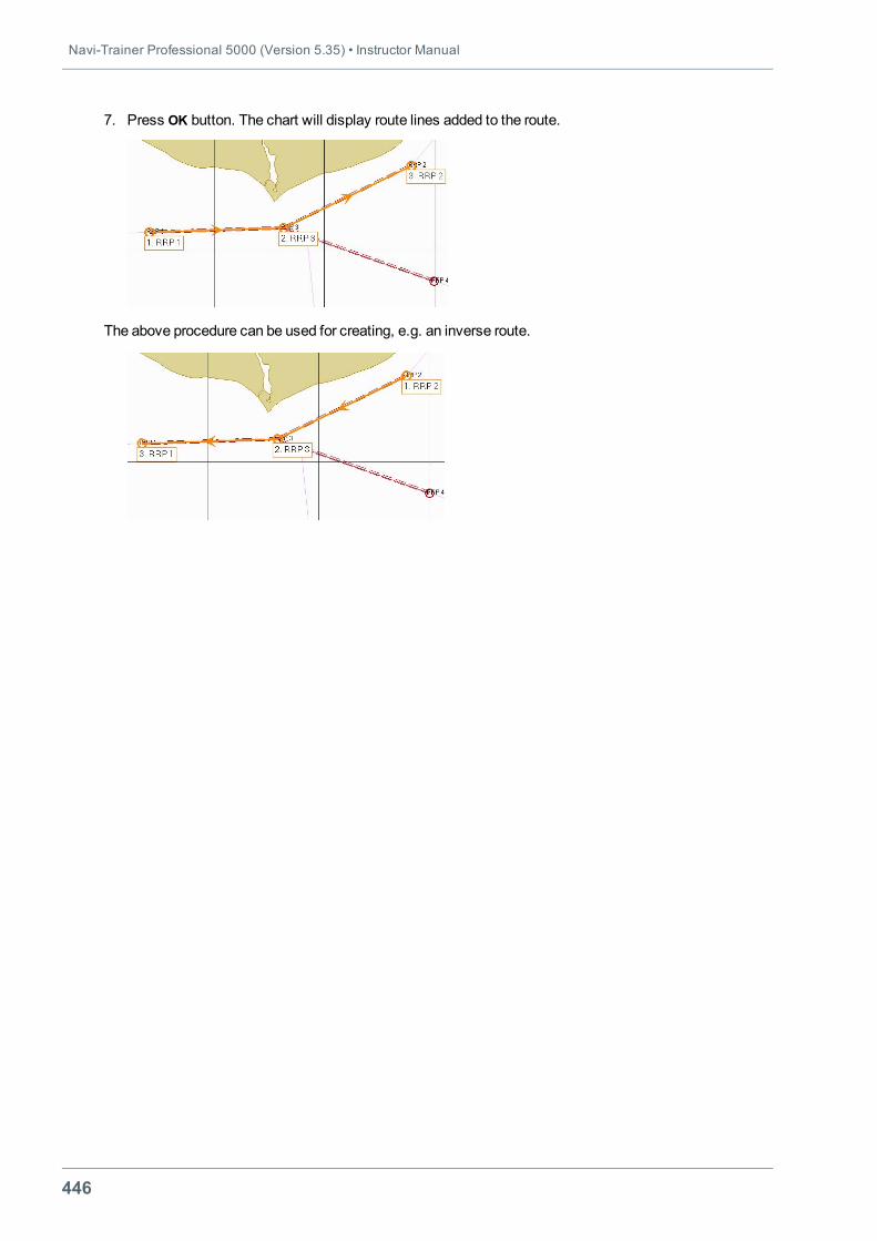
Navi-Trainer Professional 5000 (Version 5.35) • Instructor Manual
446
7. Press OK button. The chart will display route lines added to the route.
The above procedure can be used for creating, e.g. an inverse route.
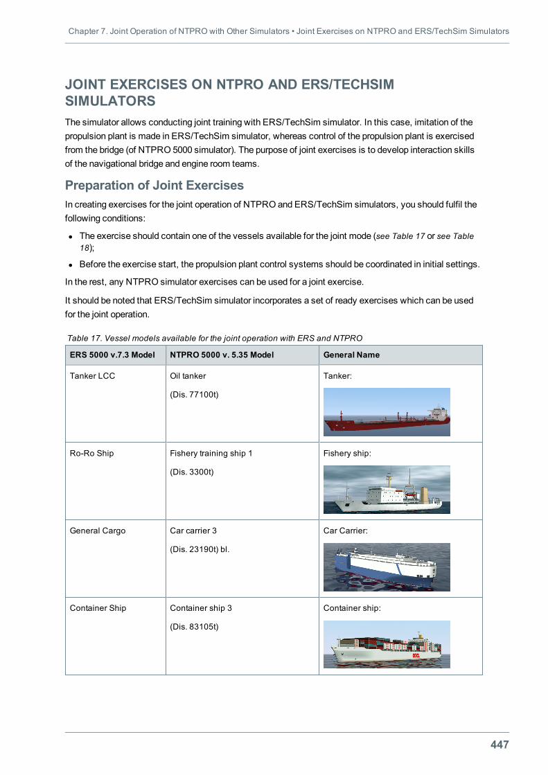
Chapter 7. Joint Operation of NTPRO with Other Simulators • Joint Exercises on NTPRO and ERS/TechSim Simulators
447
JOINT EXERCISES ON NTPRO AND ERS/TECHSIMSIMULATORSThe simulator allows conducting joint training with ERS/TechSim simulator. In this case, imitation of thepropulsion plant is made in ERS/TechSim simulator, whereas control of the propulsion plant is exercisedfrom the bridge (of NTPRO 5000 simulator). The purpose of joint exercises is to develop interaction skillsof the navigational bridge and engine room teams.
Preparation of Joint ExercisesIn creating exercises for the joint operation of NTPRO and ERS/TechSim simulators, you should fulfil thefollowing conditions:
l The exercise should contain one of the vessels available for the joint mode (see Table 17 or see Table18);
l Before the exercise start, the propulsion plant control systems should be coordinated in initial settings.
In the rest, any NTPRO simulator exercises can be used for a joint exercise.
It should be noted that ERS/TechSim simulator incorporates a set of ready exercises which can be usedfor the joint operation.
ERS 5000 v.7.3 Model NTPRO 5000 v. 5.35 Model General Name
Tanker LCC Oil tanker
(Dis. 77100t)
Tanker:
Ro-Ro Ship Fishery training ship 1
(Dis. 3300t)
Fishery ship:
General Cargo Car carrier 3
(Dis. 23190t) bl.
Car Carrier:
Container Ship Container ship 3
(Dis. 83105t)
Container ship:
Table 17. Vessel models available for the joint operation with ERS and NTPRO
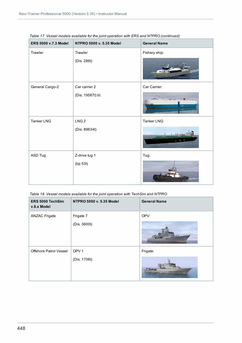
Navi-Trainer Professional 5000 (Version 5.35) • Instructor Manual
448
ERS 5000 v.7.3 Model NTPRO 5000 v. 5.35 Model General Name
Trawler Trawler
(Dis. 286t)
Fishery ship:
General Cargo-2 Car carrier 2
(Dis. 19587t) bl.
Car Carrier:
Tanker LNG LNG 2
(Dis. 89634t)
Tanker LNG:
ASD Tug Z-drive tug 1
(bp 53t)
Tug:
Table 17. Vessel models available for the joint operation with ERS and NTPRO (continued)
ERS 5000 TechSimv.8.x Model
NTPRO 5000 v. 5.35 Model General Name
ANZAC Frigate Frigate 7
(Dis. 3600t)
OPV:
Offshore Patrol Vessel OPV 1
(Dis. 1706t)
Frigate:
Table 18. Vessel models available for the joint operation with TechSim and NTPRO
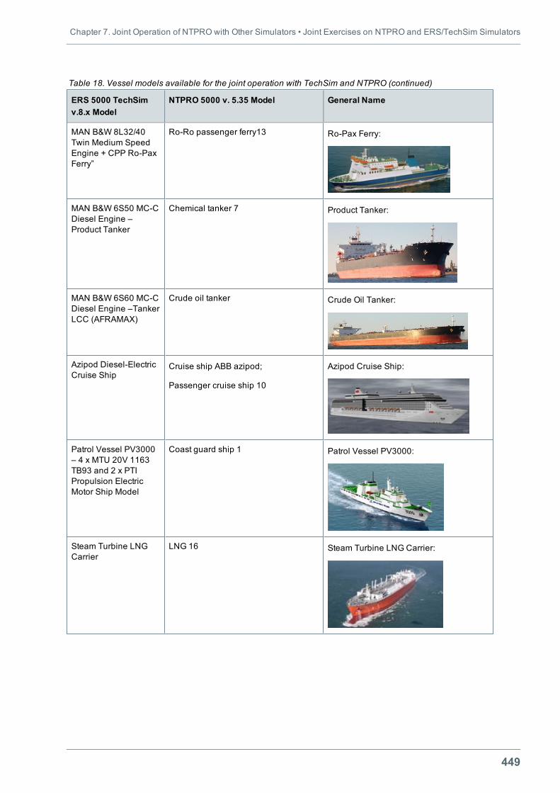
Chapter 7. Joint Operation of NTPRO with Other Simulators • Joint Exercises on NTPRO and ERS/TechSim Simulators
449
ERS 5000 TechSimv.8.x Model
NTPRO 5000 v. 5.35 Model General Name
MAN B&W 8L32/40Twin Medium SpeedEngine + CPP Ro-PaxFerry”
Ro-Ro passenger ferry13 Ro-Pax Ferry:
MAN B&W 6S50 MC-CDiesel Engine –Product Tanker
Chemical tanker 7 Product Tanker:
MAN B&W 6S60 MC-CDiesel Engine –TankerLCC (AFRAMAX)
Crude oil tanker Crude Oil Tanker:
Azipod Diesel-ElectricCruise Ship
Cruise ship ABB azipod;
Passenger cruise ship 10
Azipod Cruise Ship:
Patrol Vessel PV3000– 4 x MTU 20V 1163TB93 and 2 x PTIPropulsion ElectricMotor Ship Model
Coast guard ship 1 Patrol Vessel PV3000:
Steam Turbine LNGCarrier
LNG 16 Steam Turbine LNG Carrier:
Table 18. Vessel models available for the joint operation with TechSim and NTPRO (continued)
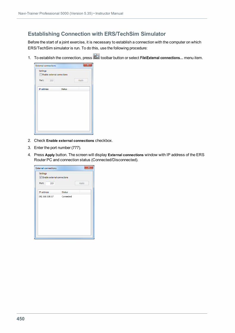
Navi-Trainer Professional 5000 (Version 5.35) • Instructor Manual
450
Establishing Connection with ERS/TechSim SimulatorBefore the start of a joint exercise, it is necessary to establish a connection with the computer on whichERS/TechSim simulator is run. To do this, use the following procedure:
1. To establish the connection, press toolbar button or select File\External connections…menu item.
2. Check Enable external connections checkbox.
3. Enter the port number (777).
4. Press Apply button. The screen will display External connections window with IP address of the ERSRouter PC and connection status (Connected/Disconnected).
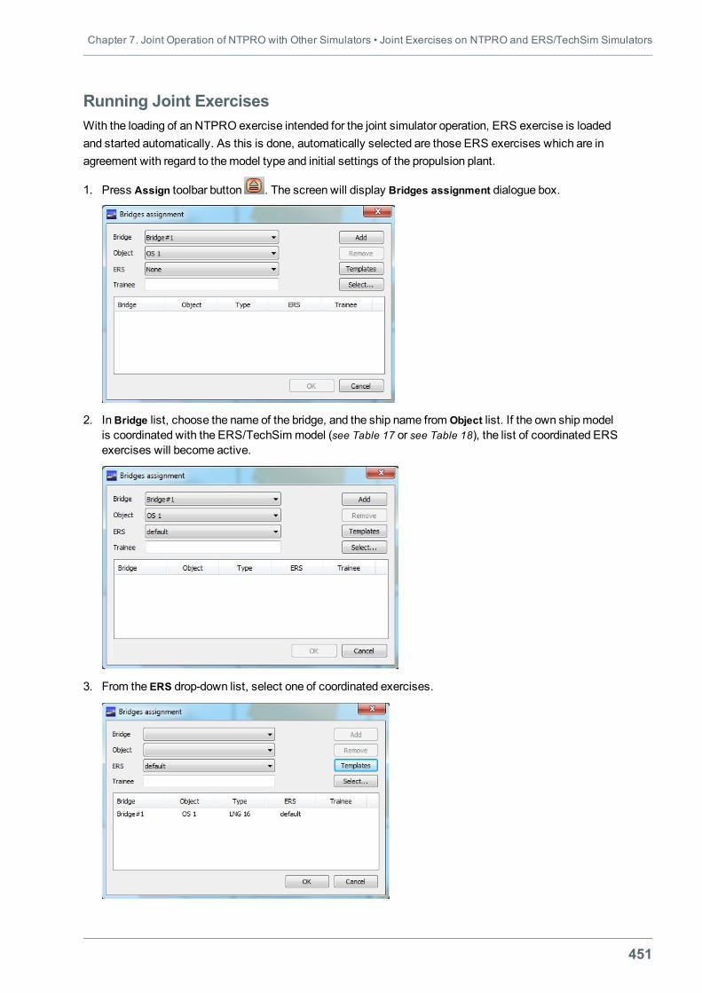
Chapter 7. Joint Operation of NTPRO with Other Simulators • Joint Exercises on NTPRO and ERS/TechSim Simulators
451
Running Joint ExercisesWith the loading of an NTPRO exercise intended for the joint simulator operation, ERS exercise is loadedand started automatically. As this is done, automatically selected are those ERS exercises which are inagreement with regard to themodel type and initial settings of the propulsion plant.
1. Press Assign toolbar button . The screen will display Bridges assignment dialogue box.
2. InBridge list, choose the name of the bridge, and the ship name from Object list. If the own shipmodelis coordinated with the ERS/TechSim model (see Table 17 or see Table 18), the list of coordinated ERSexercises will become active.
3. From the ERS drop-down list, select one of coordinated exercises.
Navi-Trainer Professional 5000 (Version 5.35) • Instructor Manual
452
4. Enter the trainee name (as required).
5. Press Add button. The exercise assignment line will display the name of the bridge, own ship name,and ERS exercise name.
6. Press OK button.
Note: If there are multiple bridges the procedure is repeated for each bridge. NTPRO and ERS bridgesshould have identical names.
Loading of an ERS exercisemay take some time whereupon the exercise start button on the toolbar will beactivated.
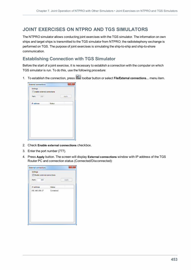
Chapter 7. Joint Operation of NTPRO with Other Simulators • Joint Exercises on NTPRO and TGS Simulators
453
JOINT EXERCISES ON NTPRO AND TGS SIMULATORSThe NTPRO simulator allows conducting joint exercises with the TGS simulator. The information on ownships and target ships is transmitted to the TGS simulator from NTPRO; the radiotelephony exchange isperformed on TGS. The purpose of joint exercises is simulating the ship-to-ship and ship-to-shorecommunication.
Establishing Connection with TGS SimulatorBefore the start of a joint exercise, it is necessary to establish a connection with the computer on whichTGS simulator is run. To do this, use the following procedure:
1. To establish the connection, press toolbar button or select File/External connections…menu item.
2. Check Enable external connections checkbox.
3. Enter the port number (777).
4. Press Apply button. The screen will display External connections window with IP address of the TGSRouter PC and connection status (Connected/Disconnected):
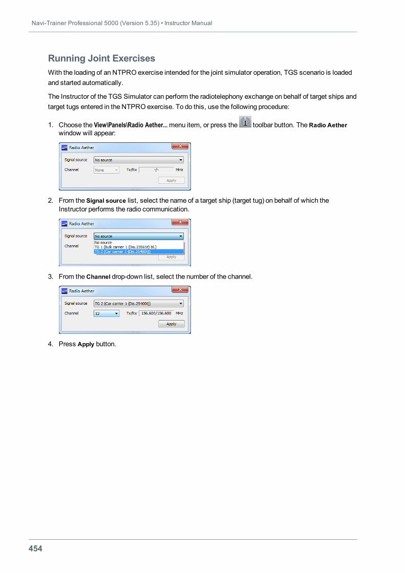
Navi-Trainer Professional 5000 (Version 5.35) • Instructor Manual
454
Running Joint ExercisesWith the loading of an NTPRO exercise intended for the joint simulator operation, TGS scenario is loadedand started automatically.
The Instructor of the TGS Simulator can perform the radiotelephony exchange on behalf of target ships andtarget tugs entered in the NTPRO exercise. To do this, use the following procedure:
1. Choose the View\Panels\Radio Aether...menu item, or press the toolbar button. TheRadio Aetherwindow will appear:
2. From the Signal source list, select the name of a target ship (target tug) on behalf of which theInstructor performs the radio communication.
3. From theChannel drop-down list, select the number of the channel.
4. Press Apply button.
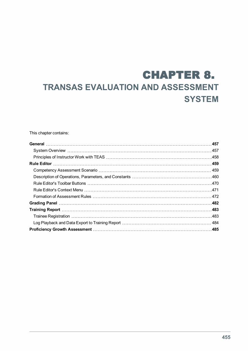
455
CHAPTER 8.TRANSAS EVALUATION AND ASSESSMENT
SYSTEM
This chapter contains:
General 457System Overview 457Principles of InstructorWork with TEAS 458
Rule Editor 459Competency Assessment Scenario 459Description of Operations, Parameters, and Constants 460Rule Editor's Toolbar Buttons 470Rule Editor's Context Menu 471Formation of Assessment Rules 472
Grading Panel 482Training Report 483Trainee Registration 483Log Playback and Data Export to Training Report 484
Proficiency Growth Assessment 485

Chapter 8. Transas Evaluation and Assessment System • General
457
GENERALThe Transas Evaluation and Assessment System (TEAS) allows assessing objectively the correctness ofan exercise fulfilment by a trainee on NTPRO 5000 navigation simulator.
The assessment is based on the check of the exercise fulfilment correctness with regard to the selectedset of criteria.
The by-criterion check consists in comparing the exercise assessment parameters to the set limit valuesaccording to the set rule.
In the by-criterion check, at eachmoment of time a relative error is recorded (relative deviation of theassessment parameter from the limit values), and penalty points are calculated as a function of the relativeerror and the “error weight”.
The overall sum of penalty points in the observation interval is calculated as a sum of penalties at eachmoment of time by each assessment parameter.
By-criterion check may be unconditional (i.e., it is performed throughout the exercise) or conditional(performed when the set logical condition is fulfilled).
The logical condition for the use of a criterionmay be: the ship turning up in the spatial zone, the shipturning up in the time window, or occurrence of another event in the exercise.
The trainee competency is assessed in points (Score%) starting from 100% minus penalty score.
Competency assessment can be obtained both in the process of the exercise and after its end.
For the final assessment of the trainee competency, the passing score can be entered.
System OverviewProgram files of the competency assessment system are installed as an addition to themain Instructorprogram from NTPRO 5000 distribution disk provided “EVALUATION AND ASSESSMENTFUNCTIONALITY MODULE – ENABLED” licensed option is available in the license.
The TEAS is comprised of three components:
l Rule Editor – the panel which is used for creation and editing assessment rules;
l Grading Panel – the panel which is used for displaying assessment process during exercise;
l Training Report – the report on any violations that will be generated after the completion of exercise.
The first two components are combined on a single panel called from View\Panels\TEAS…menu. TheTraining Report is called from View\Panels\Reports…menu.
During the exercise, information on violations and instructor prompts are displayed to the trainee on his/herConning Display (CAS page), an on top of the central visual channel if the channel has an appropriateparameter in the simulator configuration.
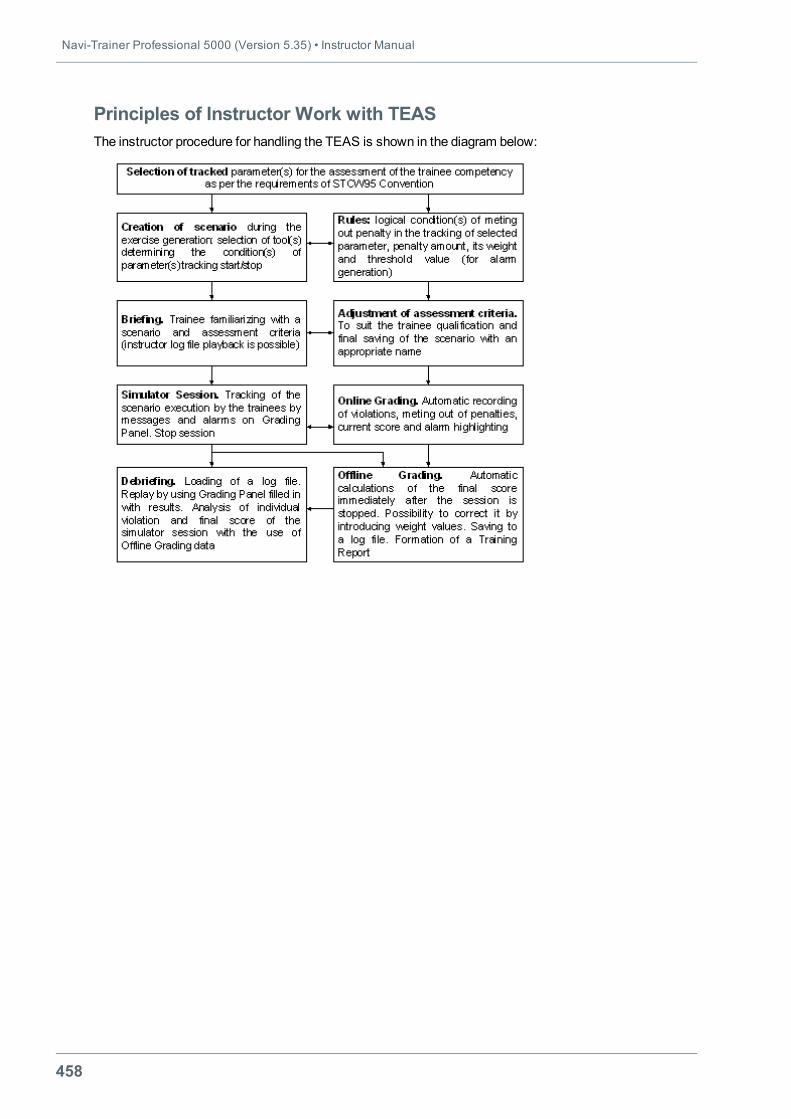
Navi-Trainer Professional 5000 (Version 5.35) • Instructor Manual
458
Principles of Instructor Work with TEASThe instructor procedure for handling the TEAS is shown in the diagram below:
Chapter 8. Transas Evaluation and Assessment System • Rule Editor
459
RULE EDITORThe Assessment Rules Editor is intended for creating, editing and saving a Competency AssessmentScenario as a set of rules for the assessment of exercises on NTPRO 5000 Navigational Simulator. Eachrule is described by logical expression built on principles of Boolean algebra.
Competency Assessment ScenarioCompetency Assessment Scenario is created together with the NTPRO 5000 exercise scenario and issaved in the exercise file. An exercise for Open Sea area containing a tentative TEAS scenario is installedtogether with the simulator software.
When plotting own ship routes in the exercise, the instructor forms another Competency AssessmentScenario rule taking into account navigational situation, weather conditions and target ship traffic in thegaming area.
The instructor formed rule includes:
l text description of the rule;
l tracked parameter;
l logical expression formalising the rule;
l penalty point amount charged for the violation of the rule;
l penalty point weight.
The list of tracked parameters is provided to the user ready made (this list may be extended from oneversion to another). The list currently contains more than 60 assessment parameters divided into Penaltycategories:
l Voyage planning;
l Watchkeeping;
l Navigation;
l COLREG;
l Traffic regulations;
l Shiphandling;
l Maneuvering.
The user forms logical expressions formalising the Violation rule user has described, with the help of theuser interface placed at his/her disposal. The expression operands are the simulator data and events,various types of constants. Operations performed for determining the expressions values use standardlogical operators (“and”, “or”, “equal”, “not equal”, “more or equal”, etc.).
An essential component of a rule is a time interval during which the expression formalising the rulecondition retains “True” value.
The instructor forms an assessment criterion for each assessment parameter as value of top and bottomlimits of the sample value.
Note: Recommendations on and examples of work with the rules are provided in Annex 2 (see on page497).
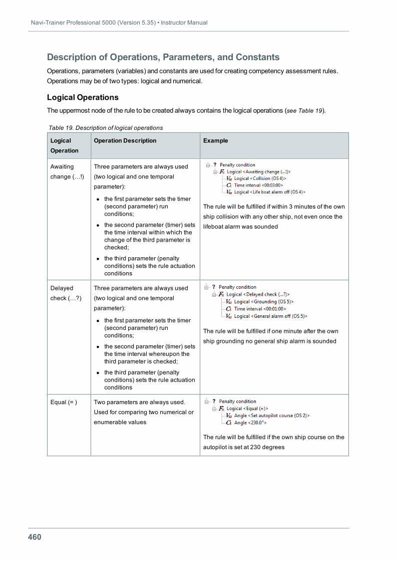
Navi-Trainer Professional 5000 (Version 5.35) • Instructor Manual
460
Description of Operations, Parameters, and ConstantsOperations, parameters (variables) and constants are used for creating competency assessment rules.Operations may be of two types: logical and numerical.
Logical OperationsThe uppermost node of the rule to be created always contains the logical operations (see Table 19).
LogicalOperation
Operation Description Example
Awaiting
change (…!)
Three parameters are always used
(two logical and one temporal
parameter):
l the first parameter sets the timer(second parameter) runconditions;
l the second parameter (timer) setsthe time interval within which thechange of the third parameter ischecked;
l the third parameter (penaltyconditions) sets the rule actuationconditions
The rule will be fulfilled if within 3 minutes of the own
ship collision with any other ship, not even once the
lifeboat alarm was sounded
Delayed
check (…?)
Three parameters are always used
(two logical and one temporal
parameter):
l the first parameter sets the timer(second parameter) runconditions;
l the second parameter (timer) setsthe time interval whereupon thethird parameter is checked;
l the third parameter (penaltyconditions) sets the rule actuationconditions
The rule will be fulfilled if one minute after the own
ship grounding no general ship alarm is sounded
Equal (= ) Two parameters are always used.
Used for comparing two numerical or
enumerable values
The rule will be fulfilled if the own ship course on the
autopilot is set at 230 degrees
Table 19. Description of logical operations
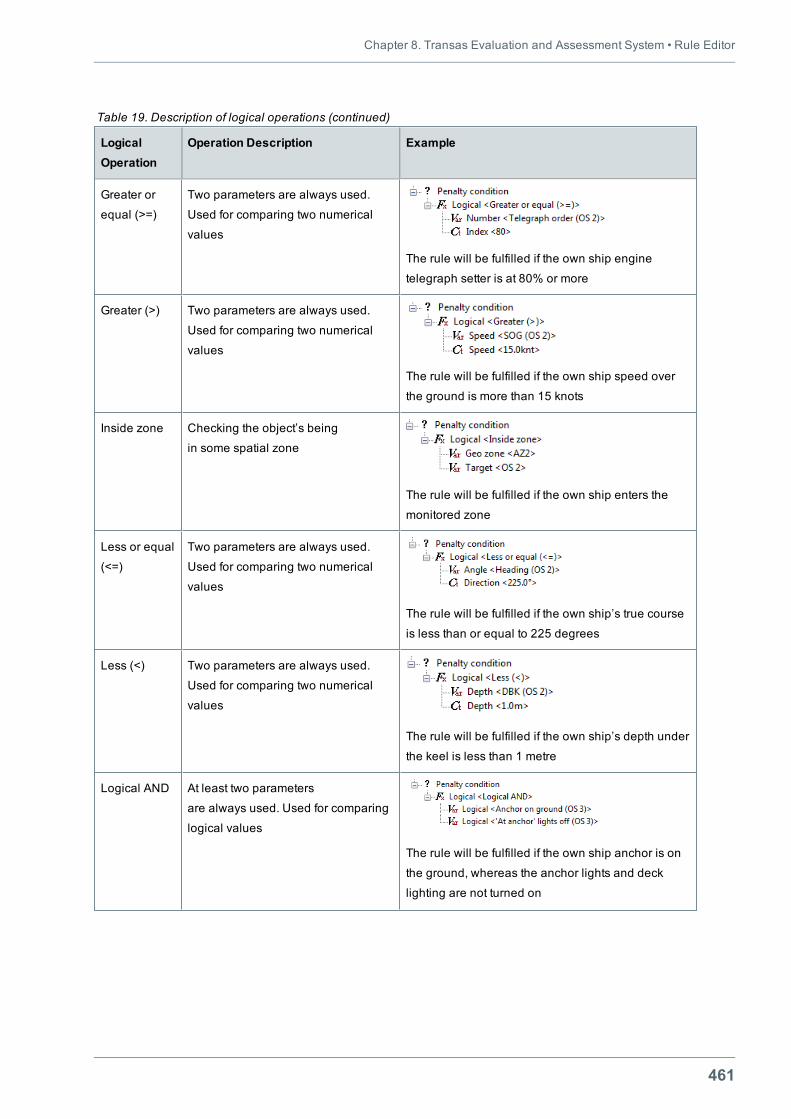
Chapter 8. Transas Evaluation and Assessment System • Rule Editor
461
LogicalOperation
Operation Description Example
Greater or
equal (>=)
Two parameters are always used.
Used for comparing two numerical
values
The rule will be fulfilled if the own ship engine
telegraph setter is at 80% or more
Greater (>) Two parameters are always used.
Used for comparing two numerical
values
The rule will be fulfilled if the own ship speed over
the ground is more than 15 knots
Inside zone Checking the object’s being
in some spatial zone
The rule will be fulfilled if the own ship enters the
monitored zone
Less or equal
(<=)
Two parameters are always used.
Used for comparing two numerical
values
The rule will be fulfilled if the own ship’s true course
is less than or equal to 225 degrees
Less (<) Two parameters are always used.
Used for comparing two numerical
values
The rule will be fulfilled if the own ship’s depth under
the keel is less than 1 metre
Logical AND At least two parameters
are always used. Used for comparing
logical values
The rule will be fulfilled if the own ship anchor is on
the ground, whereas the anchor lights and deck
lighting are not turned on
Table 19. Description of logical operations (continued)
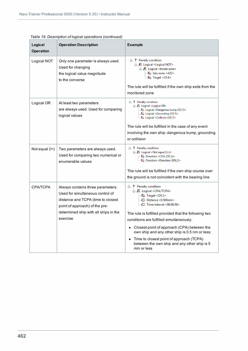
Navi-Trainer Professional 5000 (Version 5.35) • Instructor Manual
462
LogicalOperation
Operation Description Example
Logical NOT Only one parameter is always used.
Used for changing
the logical value magnitude
to the converse
The rule will be fulfilled if the own ship exits from the
monitored zone
Logical OR At least two parameters
are always used. Used for comparing
logical values
The rule will be fulfilled in the case of any event
involving the own ship: dangerous bump, grounding
or collision
Not equal (!=) Two parameters are always used.
Used for comparing two numerical or
enumerable values
The rule will be fulfilled if the own ship course over
the ground is not coincident with the bearing line
CPA/TCPA Always contains three parameters.
Used for simultaneous control of
distance and TCPA (time to closest
point of approach) of the pre-
determined ship with all ships in the
exerciseThe rule is fulfilled provided that the following two
conditions are fulfilled simultaneously:
l Closest point of approach (CPA) between theown ship and any other ship is 0.5 nm or less;
l Time to closest point of approach (TCPA)between the own ship and any other ship is 5min or less
Table 19. Description of logical operations (continued)
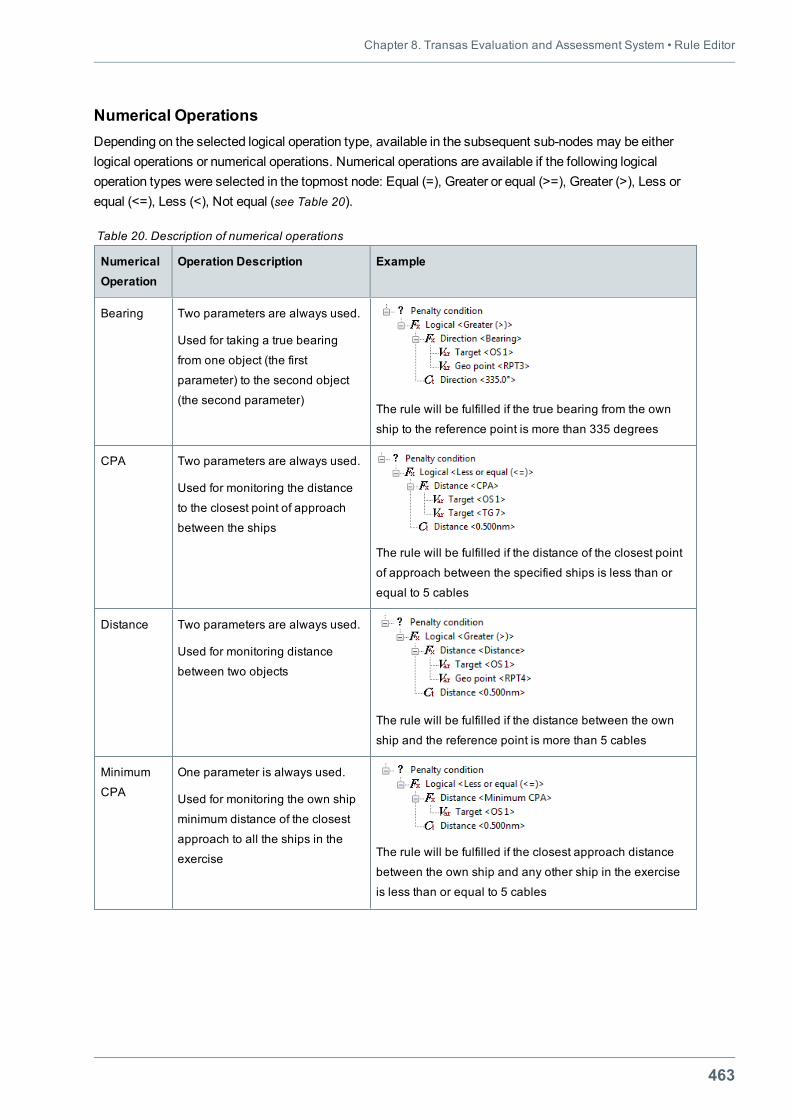
Chapter 8. Transas Evaluation and Assessment System • Rule Editor
463
Numerical OperationsDepending on the selected logical operation type, available in the subsequent sub-nodes may be eitherlogical operations or numerical operations. Numerical operations are available if the following logicaloperation types were selected in the topmost node: Equal (=), Greater or equal (>=), Greater (>), Less orequal (<=), Less (<), Not equal (see Table 20).
NumericalOperation
Operation Description Example
Bearing Two parameters are always used.
Used for taking a true bearing
from one object (the first
parameter) to the second object
(the second parameter)The rule will be fulfilled if the true bearing from the own
ship to the reference point is more than 335 degrees
CPA Two parameters are always used.
Used for monitoring the distance
to the closest point of approach
between the ships
The rule will be fulfilled if the distance of the closest point
of approach between the specified ships is less than or
equal to 5 cables
Distance Two parameters are always used.
Used for monitoring distance
between two objects
The rule will be fulfilled if the distance between the own
ship and the reference point is more than 5 cables
Minimum
CPA
One parameter is always used.
Used for monitoring the own ship
minimum distance of the closest
approach to all the ships in the
exercise The rule will be fulfilled if the closest approach distance
between the own ship and any other ship in the exercise
is less than or equal to 5 cables
Table 20. Description of numerical operations
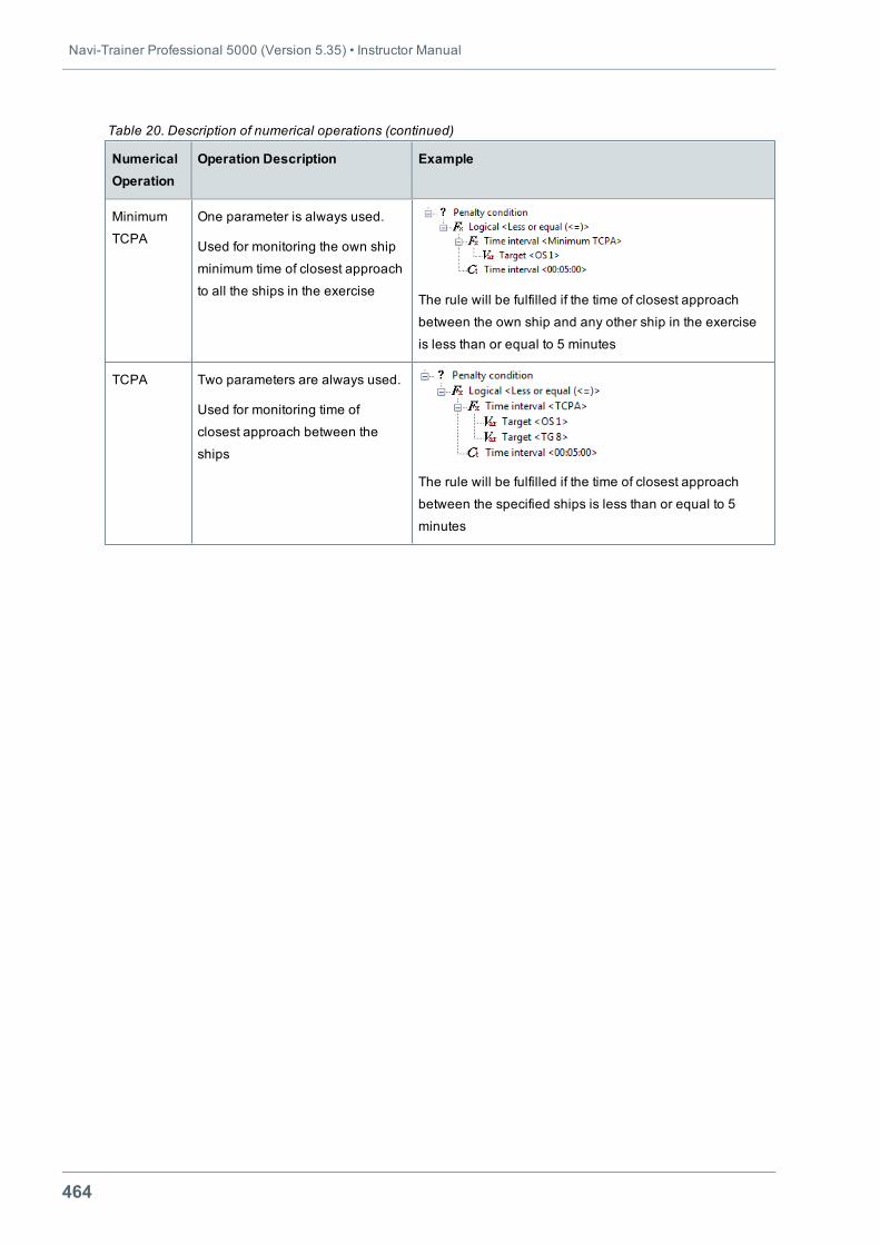
Navi-Trainer Professional 5000 (Version 5.35) • Instructor Manual
464
NumericalOperation
Operation Description Example
Minimum
TCPA
One parameter is always used.
Used for monitoring the own ship
minimum time of closest approach
to all the ships in the exerciseThe rule will be fulfilled if the time of closest approach
between the own ship and any other ship in the exercise
is less than or equal to 5 minutes
TCPA Two parameters are always used.
Used for monitoring time of
closest approach between the
ships
The rule will be fulfilled if the time of closest approach
between the specified ships is less than or equal to 5
minutes
Table 20. Description of numerical operations (continued)
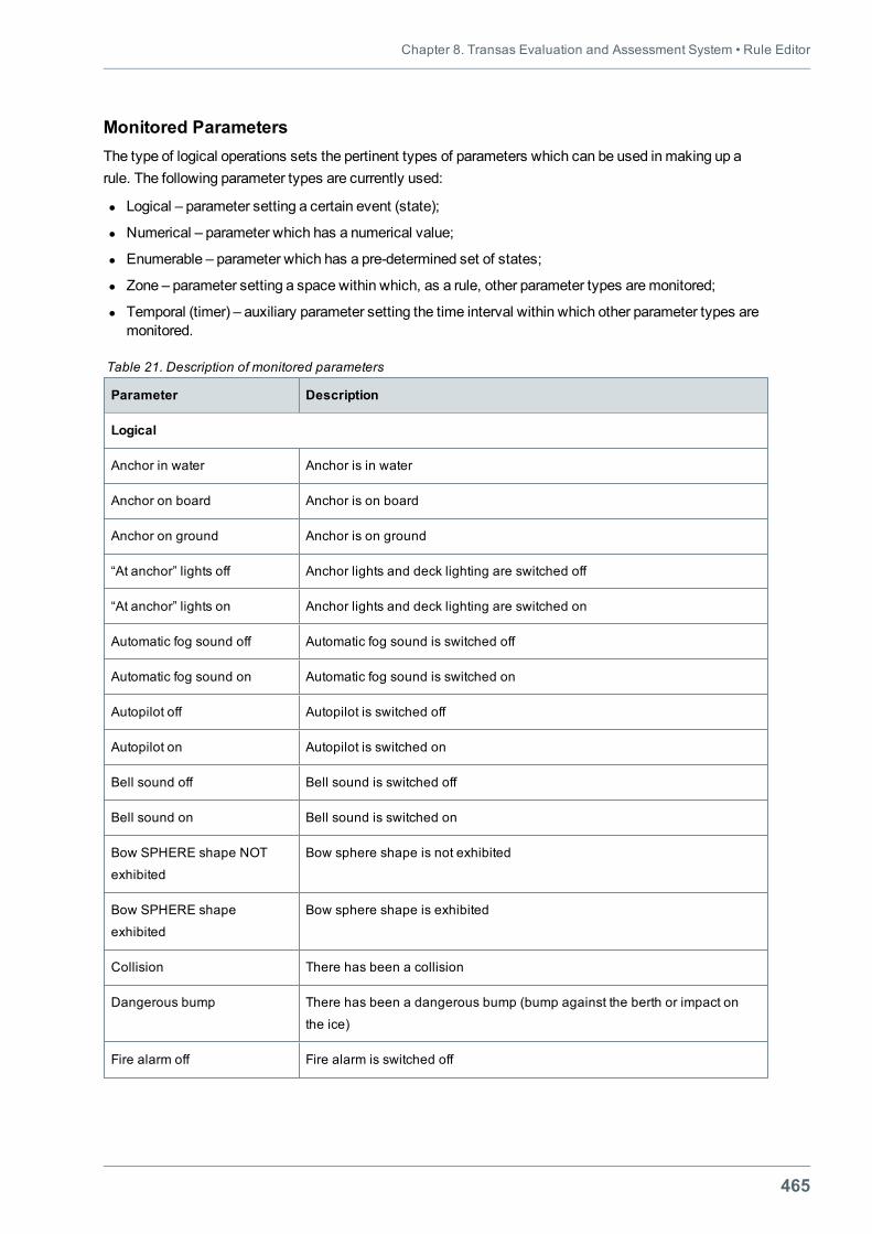
Chapter 8. Transas Evaluation and Assessment System • Rule Editor
465
Monitored ParametersThe type of logical operations sets the pertinent types of parameters which can be used inmaking up arule. The following parameter types are currently used:
l Logical – parameter setting a certain event (state);
l Numerical – parameter which has a numerical value;
l Enumerable – parameter which has a pre-determined set of states;
l Zone – parameter setting a space within which, as a rule, other parameter types aremonitored;
l Temporal (timer) – auxiliary parameter setting the time interval within which other parameter types aremonitored.
Parameter Description
Logical
Anchor in water Anchor is in water
Anchor on board Anchor is on board
Anchor on ground Anchor is on ground
“At anchor” lights off Anchor lights and deck lighting are switched off
“At anchor” lights on Anchor lights and deck lighting are switched on
Automatic fog sound off Automatic fog sound is switched off
Automatic fog sound on Automatic fog sound is switched on
Autopilot off Autopilot is switched off
Autopilot on Autopilot is switched on
Bell sound off Bell sound is switched off
Bell sound on Bell sound is switched on
Bow SPHERE shape NOT
exhibited
Bow sphere shape is not exhibited
Bow SPHERE shape
exhibited
Bow sphere shape is exhibited
Collision There has been a collision
Dangerous bump There has been a dangerous bump (bump against the berth or impact on
the ice)
Fire alarm off Fire alarm is switched off
Table 21. Description of monitored parameters
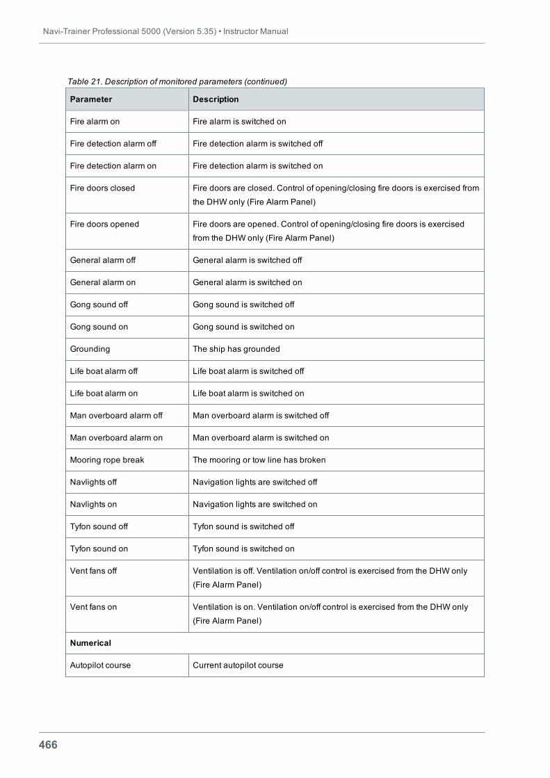
Navi-Trainer Professional 5000 (Version 5.35) • Instructor Manual
466
Parameter Description
Fire alarm on Fire alarm is switched on
Fire detection alarm off Fire detection alarm is switched off
Fire detection alarm on Fire detection alarm is switched on
Fire doors closed Fire doors are closed. Control of opening/closing fire doors is exercised from
the DHW only (Fire Alarm Panel)
Fire doors opened Fire doors are opened. Control of opening/closing fire doors is exercised
from the DHW only (Fire Alarm Panel)
General alarm off General alarm is switched off
General alarm on General alarm is switched on
Gong sound off Gong sound is switched off
Gong sound on Gong sound is switched on
Grounding The ship has grounded
Life boat alarm off Life boat alarm is switched off
Life boat alarm on Life boat alarm is switched on
Man overboard alarm off Man overboard alarm is switched off
Man overboard alarm on Man overboard alarm is switched on
Mooring rope break The mooring or tow line has broken
Navlights off Navigation lights are switched off
Navlights on Navigation lights are switched on
Tyfon sound off Tyfon sound is switched off
Tyfon sound on Tyfon sound is switched on
Vent fans off Ventilation is off. Ventilation on/off control is exercised from the DHW only
(Fire Alarm Panel)
Vent fans on Ventilation is on. Ventilation on/off control is exercised from the DHW only
(Fire Alarm Panel)
Numerical
Autopilot course Current autopilot course
Table 21. Description of monitored parameters (continued)
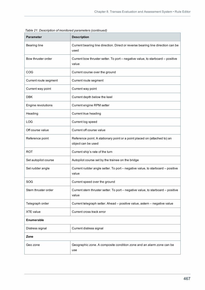
Chapter 8. Transas Evaluation and Assessment System • Rule Editor
467
Parameter Description
Bearing line Current bearing line direction. Direct or reverse bearing line direction can be
used
Bow thruster order Current bow thruster setter. To port – negative value, to starboard – positive
value
COG Current course over the ground
Current route segment Current route segment
Current way point Current way point
DBK Current depth below the keel
Engine revolutions Current engine RPM setter
Heading Current true heading
LOG Current log speed
Off course value Current off course value
Reference point Reference point. A stationary point or a point placed on (attached to) an
object can be used
ROT Current ship’s rate of the turn
Set autopilot course Autopilot course set by the trainee on the bridge
Set rudder angle Current rudder angle setter. To port – negative value, to starboard – positive
value
SOG Current speed over the ground
Stern thruster order Current stern thruster setter. To port – negative value, to starboard – positive
value
Telegraph order Current telegraph setter. Ahead – positive value, astern – negative value
XTE value Current cross track error
Enumerable
Distress signal Current distress signal
Zone
Geo zone Geographic zone. A composite condition zone and an alarm zone can be
use
Table 21. Description of monitored parameters (continued)
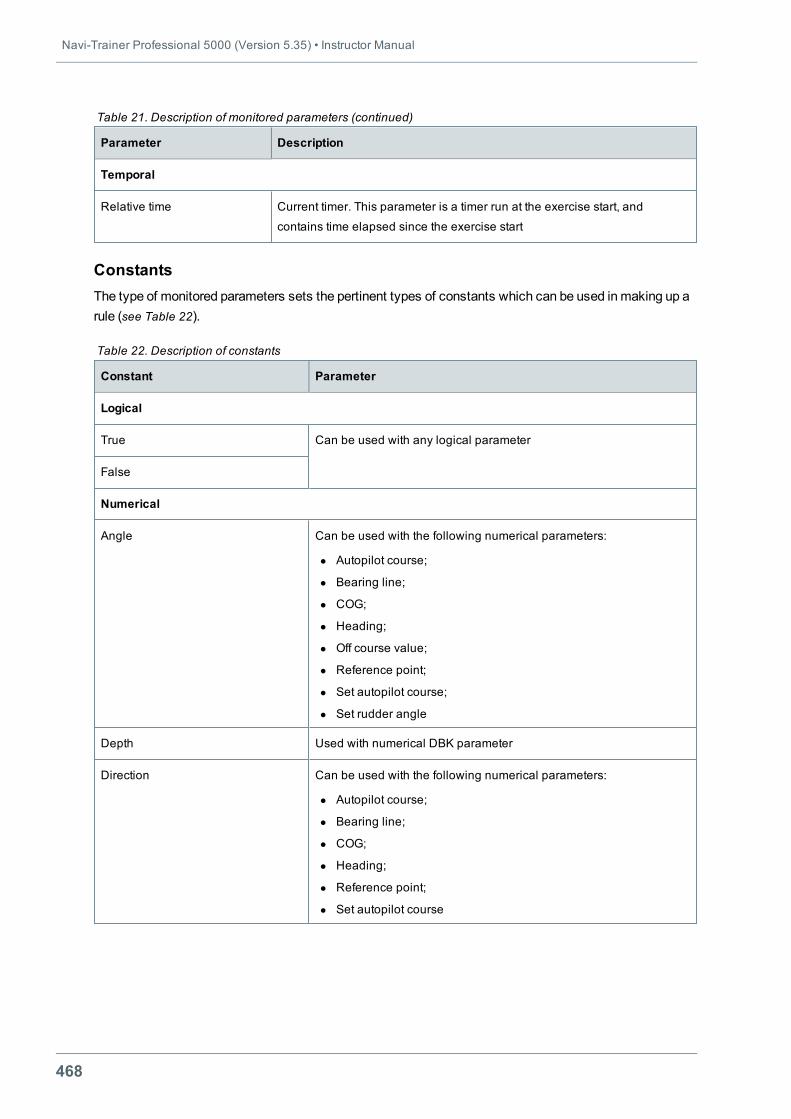
Navi-Trainer Professional 5000 (Version 5.35) • Instructor Manual
468
Parameter Description
Temporal
Relative time Current timer. This parameter is a timer run at the exercise start, and
contains time elapsed since the exercise start
Table 21. Description of monitored parameters (continued)
ConstantsThe type of monitored parameters sets the pertinent types of constants which can be used inmaking up arule (see Table 22).
Constant Parameter
Logical
True Can be used with any logical parameter
False
Numerical
Angle Can be used with the following numerical parameters:
l Autopilot course;
l Bearing line;
l COG;
l Heading;
l Off course value;
l Reference point;
l Set autopilot course;
l Set rudder angle
Depth Used with numerical DBK parameter
Direction Can be used with the following numerical parameters:
l Autopilot course;
l Bearing line;
l COG;
l Heading;
l Reference point;
l Set autopilot course
Table 22. Description of constants
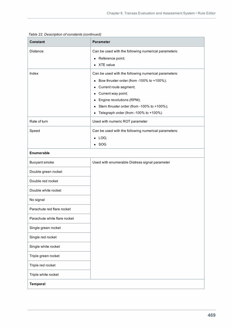
Chapter 8. Transas Evaluation and Assessment System • Rule Editor
469
Constant Parameter
Distance Can be used with the following numerical parameters:
l Reference point;
l XTE value
Index Can be used with the following numerical parameters:
l Bow thruster order (from -100% to +100%);
l Current route segment;
l Current way point;
l Engine revolutions (RPM);
l Stern thruster order (from -100% to +100%);
l Telegraph order (from -100% to +100%)
Rate of turn Used with numeric ROT parameter
Speed Can be used with the following numerical parameters:
l LOG;
l SOG
Enumerable
Buoyant smoke Used with enumerable Distress signal parameter
Double green rocket
Double red rocket
Double white rocket
No signal
Parachute red flare rocket
Parachute white flare rocket
Single green rocket
Single red rocket
Single white rocket
Triple green rocket
Triple red rocket
Triple white rocket
Temporal
Table 22. Description of constants (continued)
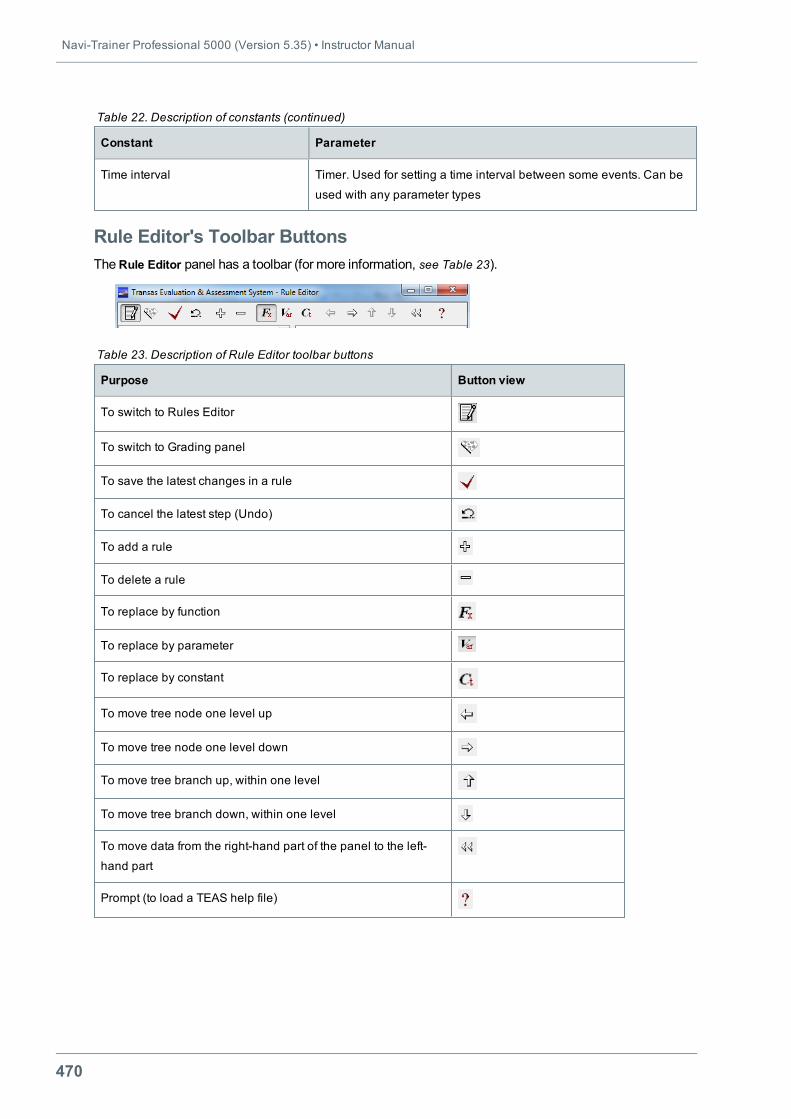
Navi-Trainer Professional 5000 (Version 5.35) • Instructor Manual
470
Constant Parameter
Time interval Timer. Used for setting a time interval between some events. Can be
used with any parameter types
Table 22. Description of constants (continued)
Rule Editor's Toolbar ButtonsTheRule Editor panel has a toolbar (for more information, see Table 23).
Purpose Button view
To switch to Rules Editor
To switch to Grading panel
To save the latest changes in a rule
To cancel the latest step (Undo)
To add a rule
To delete a rule
To replace by function
To replace by parameter
To replace by constant
To move tree node one level up
To move tree node one level down
To move tree branch up, within one level
To move tree branch down, within one level
To move data from the right-hand part of the panel to the left-
hand part
Prompt (to load a TEAS help file)
Table 23. Description of Rule Editor toolbar buttons
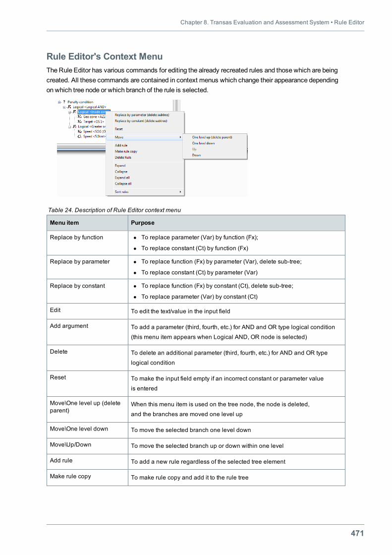
Chapter 8. Transas Evaluation and Assessment System • Rule Editor
471
Rule Editor's Context MenuThe Rule Editor has various commands for editing the already recreated rules and those which are beingcreated. All these commands are contained in context menus which change their appearance dependingon which tree node or which branch of the rule is selected.
Menu item Purpose
Replace by function l To replace parameter (Var) by function (Fx);
l To replace constant (Ct) by function (Fx)
Replace by parameter l To replace function (Fx) by parameter (Var), delete sub-tree;
l To replace constant (Ct) by parameter (Var)
Replace by constant l To replace function (Fx) by constant (Ct), delete sub-tree;
l To replace parameter (Var) by constant (Ct)
Edit To edit the text/value in the input field
Add argument To add a parameter (third, fourth, etc.) for AND and OR type logical condition
(this menu item appears when Logical AND, OR node is selected)
Delete To delete an additional parameter (third, fourth, etc.) for AND and OR type
logical condition
Reset To make the input field empty if an incorrect constant or parameter value
is entered
Move\One level up (deleteparent)
When this menu item is used on the tree node, the node is deleted,
and the branches are moved one level up
Move\One level down To move the selected branch one level down
Move\Up/Down To move the selected branch up or down within one level
Add rule To add a new rule regardless of the selected tree element
Make rule copy To make rule copy and add it to the rule tree
Table 24. Description of Rule Editor context menu
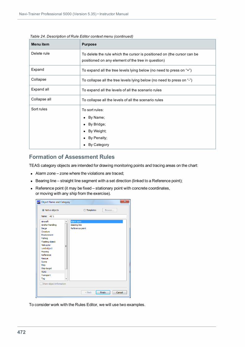
Navi-Trainer Professional 5000 (Version 5.35) • Instructor Manual
472
Menu item Purpose
Delete rule To delete the rule which the cursor is positioned on (the cursor can be
positioned on any element of the tree in question)
Expand To expand all the tree levels lying below (no need to press on “+”)
Collapse To collapse all the tree levels lying below (no need to press on “-”)
Expand all To expand all the levels of all the scenario rules
Collapse all To collapse all the levels of all the scenario rules
Sort rules To sort rules:
l By Name;
l By Bridge;
l By Weight;
l By Penalty;
l By Category
Table 24. Description of Rule Editor context menu (continued)
Formation of Assessment RulesTEAS category objects are intended for drawingmonitoring points and tracing areas on the chart:
l Alarm zone – zone where the violations are traced;
l Bearing line – straight line segment with a set direction (linked to a Reference point);
l Reference point (it may be fixed – stationary point with concrete coordinates,or moving with any ship from the exercise).
To consider work with the Rules Editor, we will use two examples.
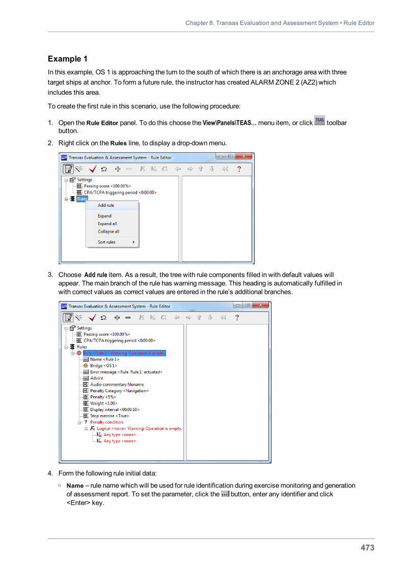
Chapter 8. Transas Evaluation and Assessment System • Rule Editor
473
Example 1In this example, OS 1 is approaching the turn to the south of which there is an anchorage area with threetarget ships at anchor. To form a future rule, the instructor has created ALARM ZONE 2 (AZ2) whichincludes this area.
To create the first rule in this scenario, use the following procedure:
1. Open theRule Editor panel. To do this choose the View\Panels\TEAS…menu item, or click toolbarbutton.
2. Right click on theRules line, to display a drop-downmenu.
3. Choose Add rule item. As a result, the tree with rule components filled in with default values willappear. Themain branch of the rule has warningmessage. This heading is automatically fulfilled inwith correct values as correct values are entered in the rule’s additional branches.
4. Form the following rule initial data:o Name – rule namewhich will be used for rule identification during exercisemonitoring and generation
of assessment report. To set the parameter, click the button, enter any identifier and click<Enter> key.
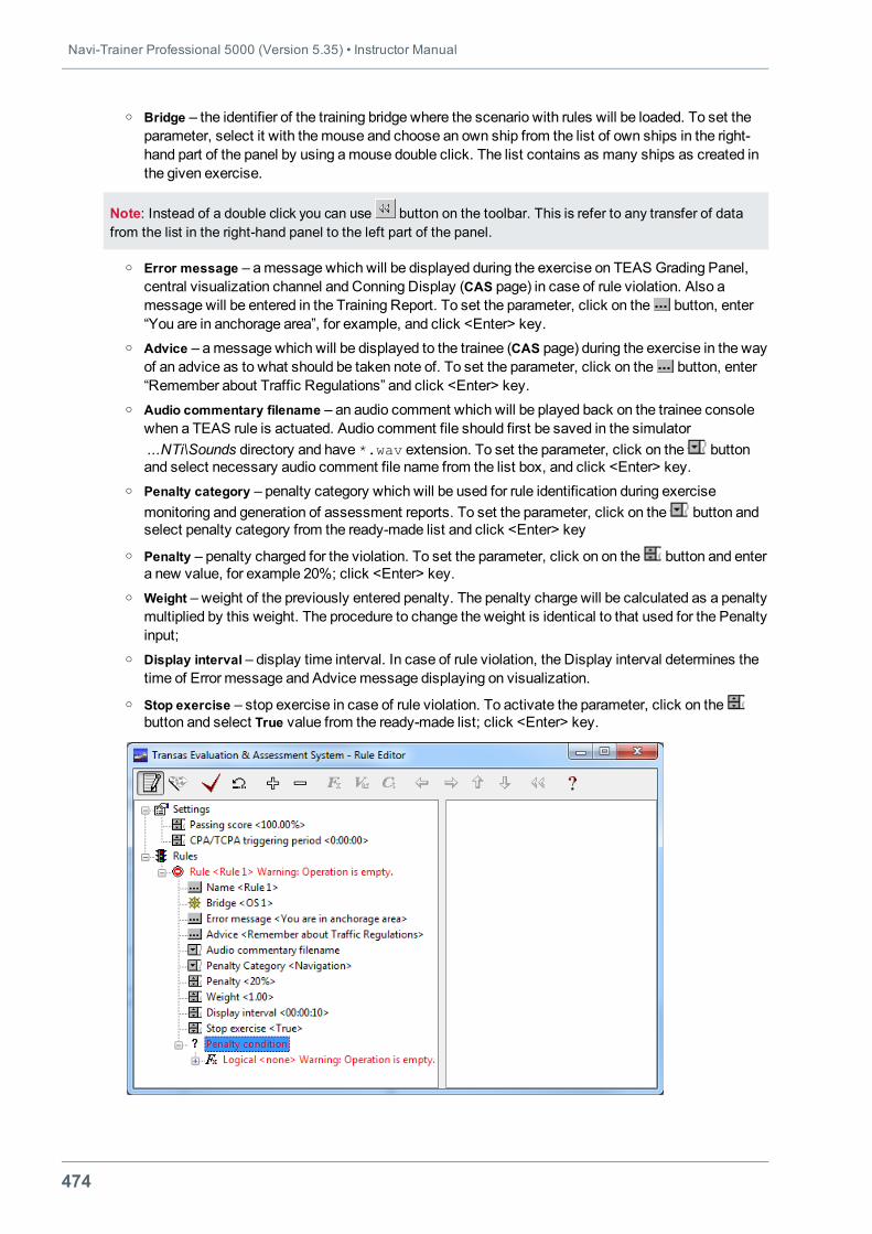
Navi-Trainer Professional 5000 (Version 5.35) • Instructor Manual
474
o Bridge – the identifier of the training bridge where the scenario with rules will be loaded. To set theparameter, select it with themouse and choose an own ship from the list of own ships in the right-hand part of the panel by using amouse double click. The list contains as many ships as created inthe given exercise.
Note: Instead of a double click you can use button on the toolbar. This is refer to any transfer of datafrom the list in the right-hand panel to the left part of the panel.
o Error message – amessage which will be displayed during the exercise on TEAS Grading Panel,central visualization channel and Conning Display (CAS page) in case of rule violation. Also amessage will be entered in the Training Report. To set the parameter, click on the button, enter“You are in anchorage area”, for example, and click <Enter> key.
o Advice – amessage which will be displayed to the trainee (CAS page) during the exercise in the wayof an advice as to what should be taken note of. To set the parameter, click on the button, enter“Remember about Traffic Regulations” and click <Enter> key.
o Audio commentary filename – an audio comment which will be played back on the trainee consolewhen a TEAS rule is actuated. Audio comment file should first be saved in the simulator...NTi\Sounds directory and have *.wav extension. To set the parameter, click on the buttonand select necessary audio comment file name from the list box, and click <Enter> key.
o Penalty category – penalty category which will be used for rule identification during exercisemonitoring and generation of assessment reports. To set the parameter, click on the button andselect penalty category from the ready-made list and click <Enter> key
o Penalty – penalty charged for the violation. To set the parameter, click on on the button and entera new value, for example 20%; click <Enter> key.
o Weight – weight of the previously entered penalty. The penalty charge will be calculated as a penaltymultiplied by this weight. The procedure to change the weight is identical to that used for the Penaltyinput;
o Display interval – display time interval. In case of rule violation, the Display interval determines thetime of Error message and Advicemessage displaying on visualization.
o Stop exercise – stop exercise in case of rule violation. To activate the parameter, click on thebutton and select True value from the ready-made list; click <Enter> key.
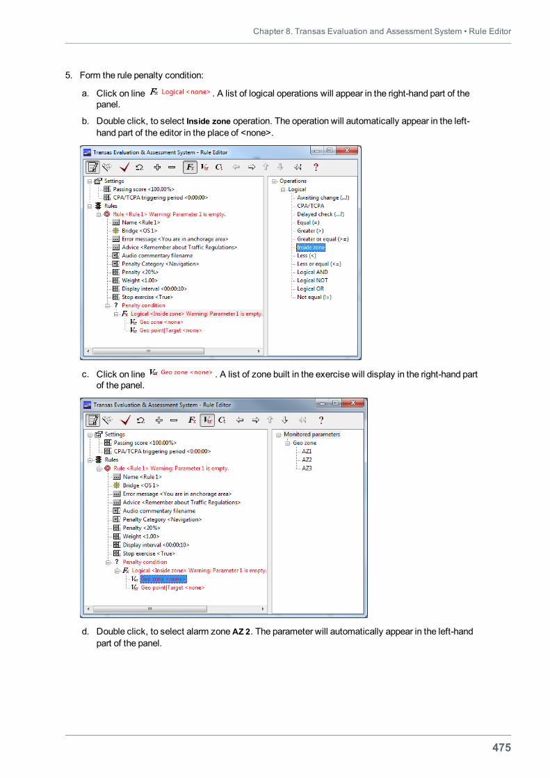
Chapter 8. Transas Evaluation and Assessment System • Rule Editor
475
5. Form the rule penalty condition:
a. Click on line . A list of logical operations will appear in the right-hand part of thepanel.
b. Double click, to select Inside zone operation. The operation will automatically appear in the left-hand part of the editor in the place of <none>.
c. Click on line . A list of zone built in the exercise will display in the right-hand partof the panel.
d. Double click, to select alarm zoneAZ 2. The parameter will automatically appear in the left-handpart of the panel.
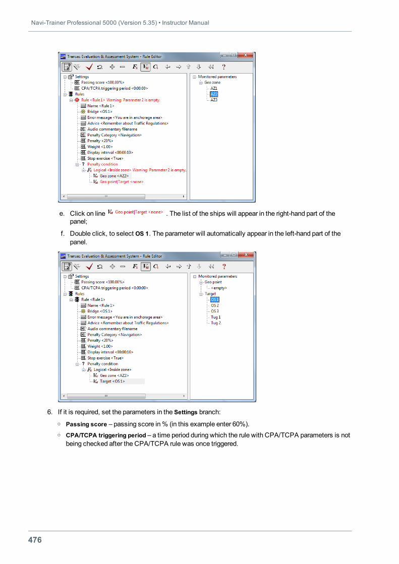
Navi-Trainer Professional 5000 (Version 5.35) • Instructor Manual
476
e. Click on line . The list of the ships will appear in the right-hand part of thepanel;
f. Double click, to select OS 1. The parameter will automatically appear in the left-hand part of thepanel.
6. If it is required, set the parameters in the Settings branch:o Passing score – passing score in% (in this example enter 60%).o CPA/TCPA triggering period – a time period during which the rule with CPA/TCPA parameters is not
being checked after the CPA/TCPA rule was once triggered.
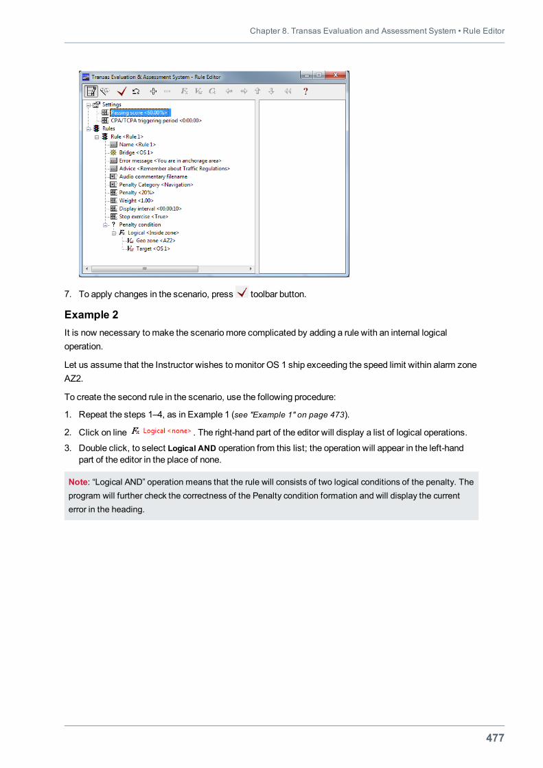
Chapter 8. Transas Evaluation and Assessment System • Rule Editor
477
7. To apply changes in the scenario, press toolbar button.
Example 2It is now necessary tomake the scenario more complicated by adding a rule with an internal logicaloperation.
Let us assume that the Instructor wishes tomonitor OS 1 ship exceeding the speed limit within alarm zoneAZ2.
To create the second rule in the scenario, use the following procedure:
1. Repeat the steps 1–4, as in Example 1 (see "Example 1" on page 473).
2. Click on line . The right-hand part of the editor will display a list of logical operations.
3. Double click, to select Logical AND operation from this list; the operation will appear in the left-handpart of the editor in the place of none.
Note: “Logical AND” operation means that the rule will consists of two logical conditions of the penalty. Theprogram will further check the correctness of the Penalty condition formation and will display the currenterror in the heading.
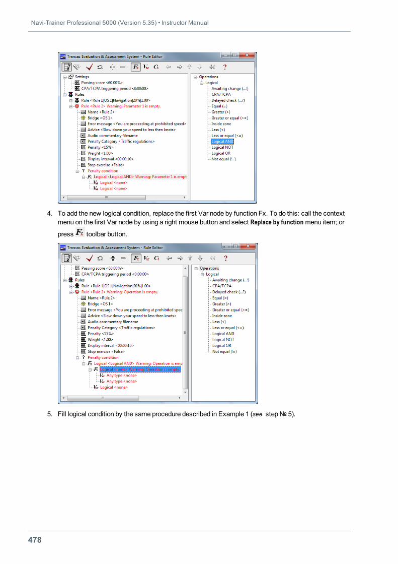
Navi-Trainer Professional 5000 (Version 5.35) • Instructor Manual
478
4. To add the new logical condition, replace the first Var node by function Fx. To do this: call the contextmenu on the first Var node by using a right mouse button and select Replace by function menu item; or
press toolbar button.
5. Fill logical condition by the same procedure described in Example 1 (see step№ 5).
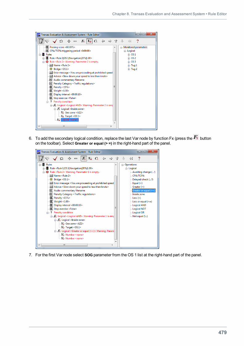
Chapter 8. Transas Evaluation and Assessment System • Rule Editor
479
6. To add the secondary logical condition, replace the last Var node by function Fx (press the buttonon the toolbar). Select Greater or equal (> =) in the right-hand part of the panel.
7. For the first Var node select SOG parameter from theOS 1 list at the right-hand part of the panel.
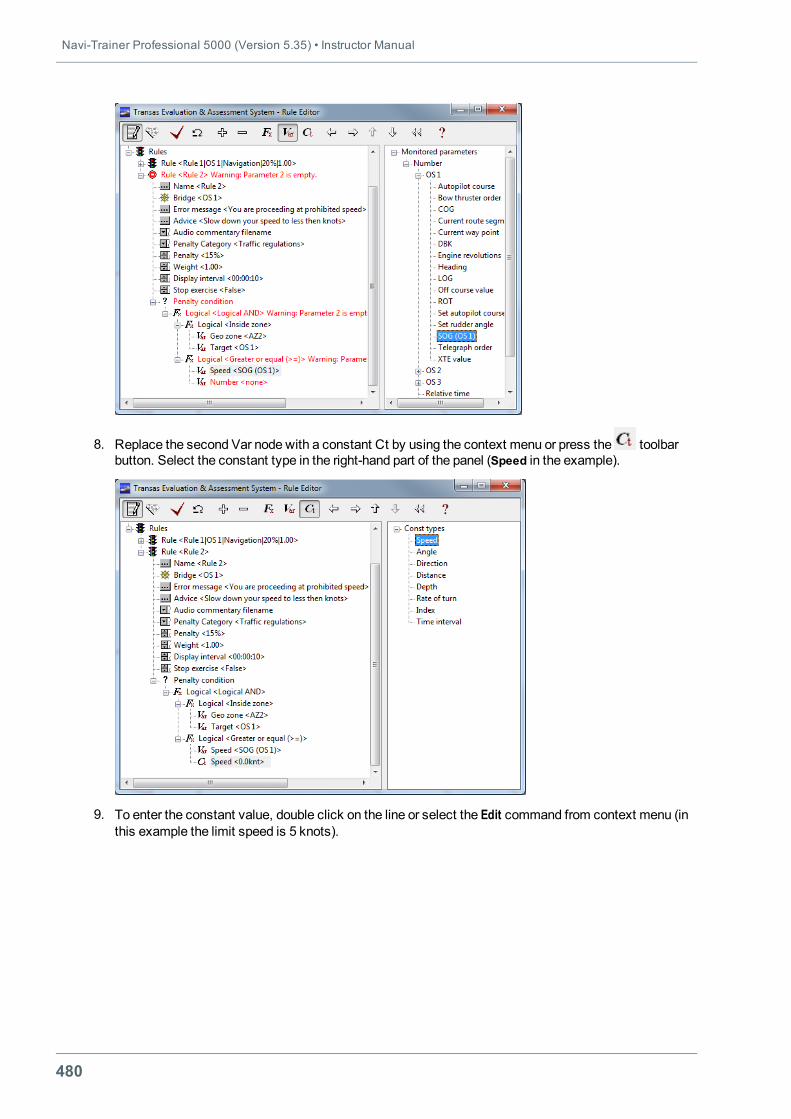
Navi-Trainer Professional 5000 (Version 5.35) • Instructor Manual
480
8. Replace the second Var node with a constant Ct by using the context menu or press the toolbarbutton. Select the constant type in the right-hand part of the panel (Speed in the example).
9. To enter the constant value, double click on the line or select the Edit command from context menu (inthis example the limit speed is 5 knots).
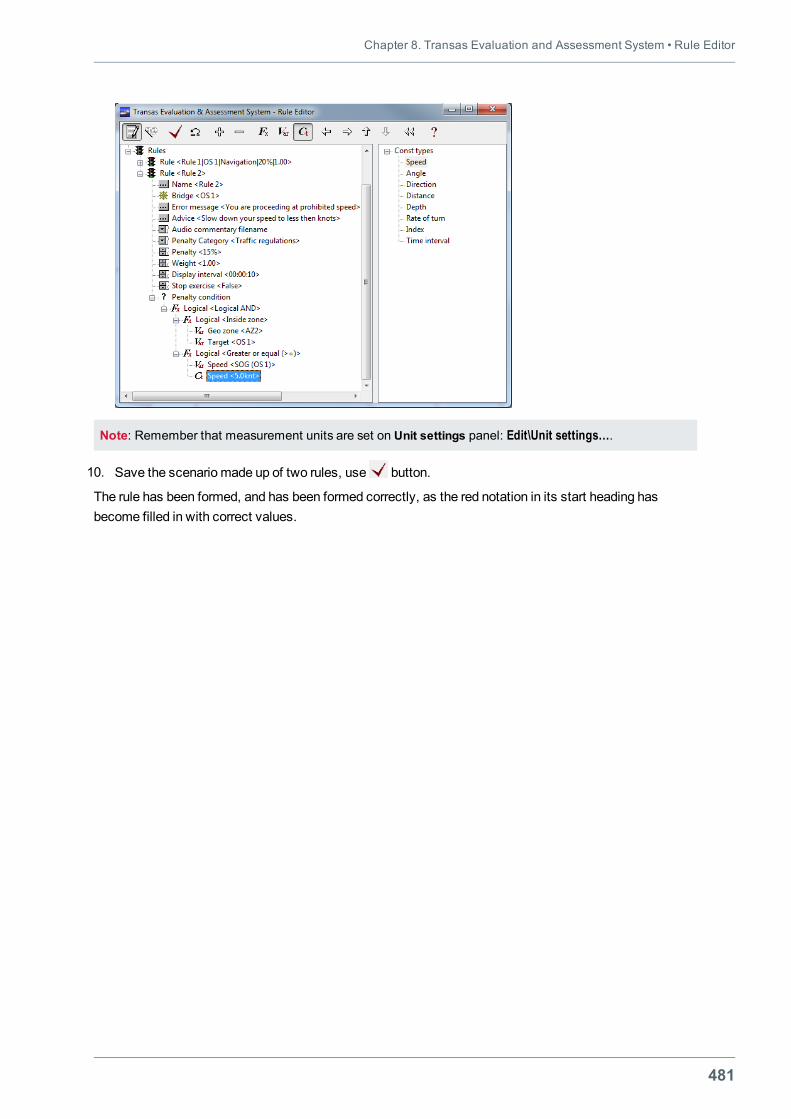
Chapter 8. Transas Evaluation and Assessment System • Rule Editor
481
Note: Remember that measurement units are set on Unit settings panel: Edit\Unit settings….
10. Save the scenario made up of two rules, use button.
The rule has been formed, and has been formed correctly, as the red notation in its start heading hasbecome filled in with correct values.
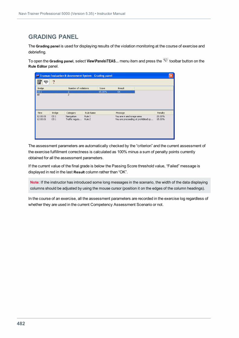
Navi-Trainer Professional 5000 (Version 5.35) • Instructor Manual
482
GRADING PANELTheGrading panel is used for displaying results of the violationmonitoring at the course of exercise anddebriefing.
To open theGrading panel, select View\Panels\TEAS…menu item and press the toolbar button on theRule Editor panel.
The assessment parameters are automatically checked by the “criterion” and the current assessment ofthe exercise fulfillment correctness is calculated as 100% minus a sum of penalty points currentlyobtained for all the assessment parameters.
If the current value of the final grade is below the Passing Score threshold value, “Failed” message isdisplayed in red in the last Result column rather than “OK”.
Note: If the instructor has introduced some long messages in the scenario, the width of the data displayingcolumns should be adjusted by using the mouse cursor (position it on the edges of the column headings).
In the course of an exercise, all the assessment parameters are recorded in the exercise log regardless ofwhether they are used in the current Competency Assessment Scenario or not.
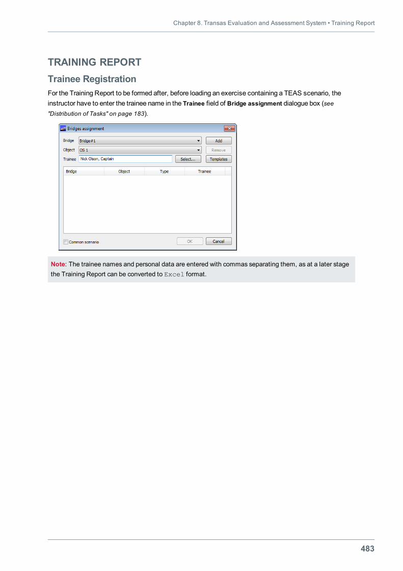
Chapter 8. Transas Evaluation and Assessment System • Training Report
483
TRAINING REPORTTrainee RegistrationFor the Training Report to be formed after, before loading an exercise containing a TEAS scenario, theinstructor have to enter the trainee name in the Trainee field of Bridge assignment dialogue box (see"Distribution of Tasks" on page 183).
Note: The trainee names and personal data are entered with commas separating them, as at a later stagethe Training Report can be converted to Excel format.
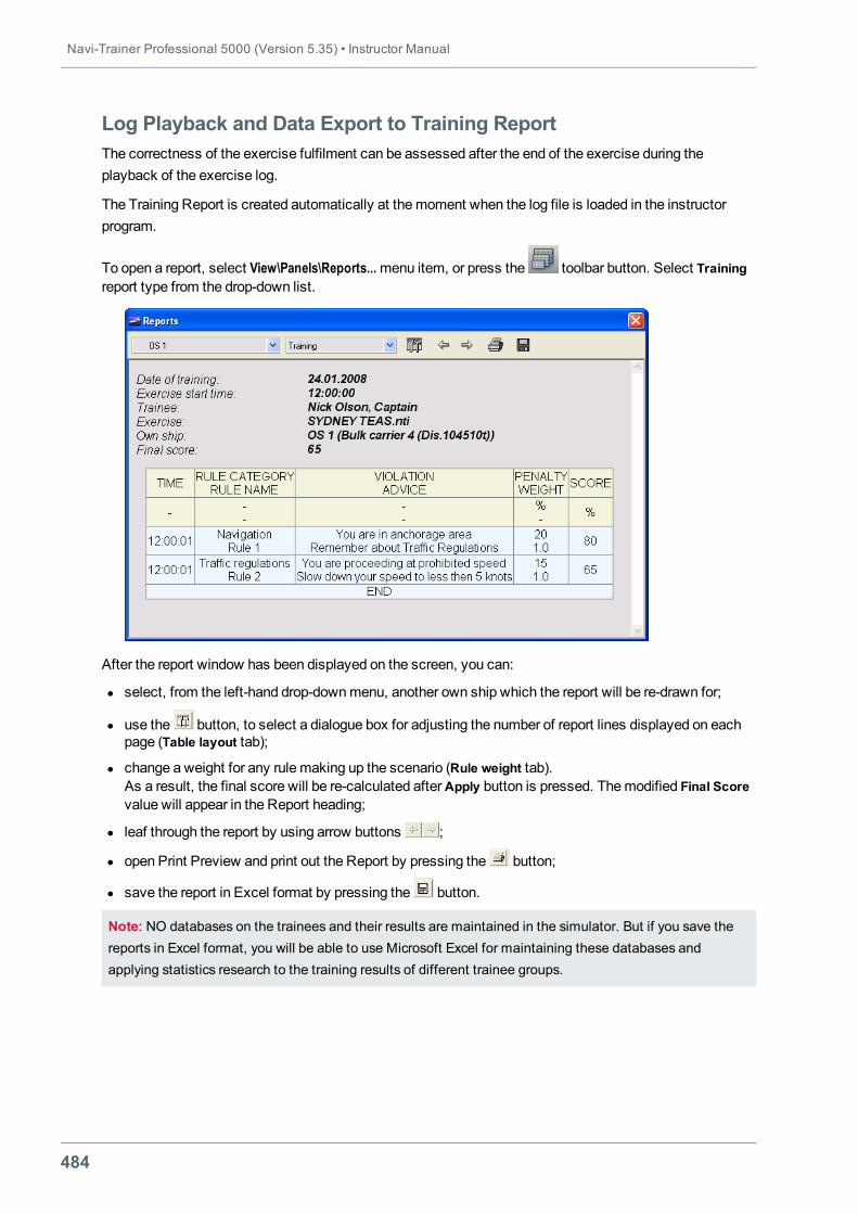
Navi-Trainer Professional 5000 (Version 5.35) • Instructor Manual
484
Log Playback and Data Export to Training ReportThe correctness of the exercise fulfilment can be assessed after the end of the exercise during theplayback of the exercise log.
The Training Report is created automatically at themoment when the log file is loaded in the instructorprogram.
To open a report, select View\Panels\Reports...menu item, or press the toolbar button. Select Trainingreport type from the drop-down list.
After the report window has been displayed on the screen, you can:
l select, from the left-hand drop-downmenu, another own ship which the report will be re-drawn for;
l use the button, to select a dialogue box for adjusting the number of report lines displayed on eachpage (Table layout tab);
l change a weight for any rule making up the scenario (Rule weight tab).As a result, the final score will be re-calculated afterApply button is pressed. Themodified Final Scorevalue will appear in the Report heading;
l leaf through the report by using arrow buttons ;
l open Print Preview and print out the Report by pressing the button;
l save the report in Excel format by pressing the button.
Note: NO databases on the trainees and their results are maintained in the simulator. But if you save thereports in Excel format, you will be able to use Microsoft Excel for maintaining these databases andapplying statistics research to the training results of different trainee groups.

Chapter 8. Transas Evaluation and Assessment System • Proficiency Growth Assessment
485
PROFICIENCY GROWTH ASSESSMENTThe trainee’s proficiency growth can be assessed by comparing the results achieved by the trainee on oneand the same exercise in different training periods.
The comparison uses a standard competency assessment procedure, except that for the “assessmentvalues” obtained during the previous training session (from the exercise log) serve as “sample” values.
Similarly, the competency assessment can be performed by comparing results gained by the trainee withthe “ideal” results.
For the “ideal” result, the log of the exercise completed by an expert (instructor) can be used.


487
ANNEX 1

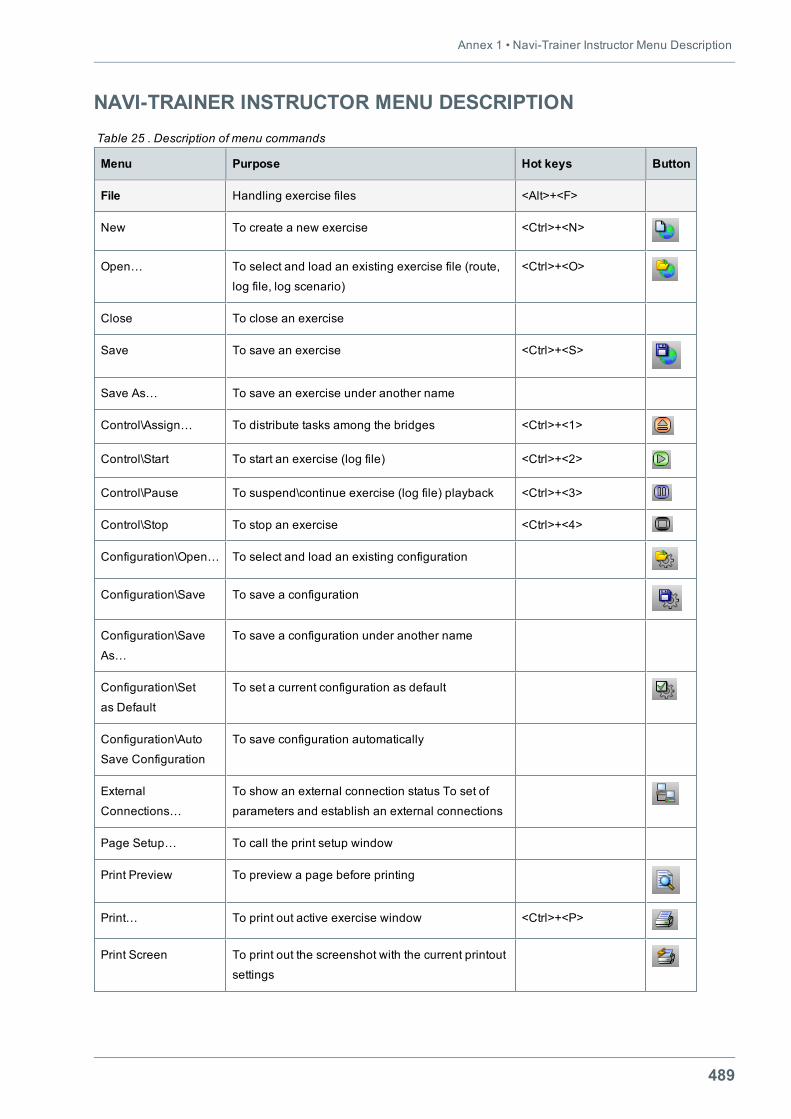
Annex 1 • Navi-Trainer Instructor Menu Description
489
NAVI-TRAINER INSTRUCTOR MENU DESCRIPTION
Menu Purpose Hot keys Button
File Handling exercise files <Alt>+<F>
New To create a new exercise <Ctrl>+<N>
Open… To select and load an existing exercise file (route,
log file, log scenario)
<Ctrl>+<O>
Close To close an exercise
Save To save an exercise <Ctrl>+<S>
Save As… To save an exercise under another name
Control\Assign… To distribute tasks among the bridges <Ctrl>+<1>
Control\Start To start an exercise (log file) <Ctrl>+<2>
Control\Pause To suspend\continue exercise (log file) playback <Ctrl>+<3>
Control\Stop To stop an exercise <Ctrl>+<4>
Configuration\Open… To select and load an existing configuration
Configuration\Save To save a configuration
Configuration\Save
As…
To save a configuration under another name
Configuration\Set
as Default
To set a current configuration as default
Configuration\Auto
Save Configuration
To save configuration automatically
External
Connections…
To show an external connection status To set of
parameters and establish an external connections
Page Setup… To call the print setup window
Print Preview To preview a page before printing
Print… To print out active exercise window <Ctrl>+<P>
Print Screen To print out the screenshot with the current printout
settings
Table 25 . Description of menu commands
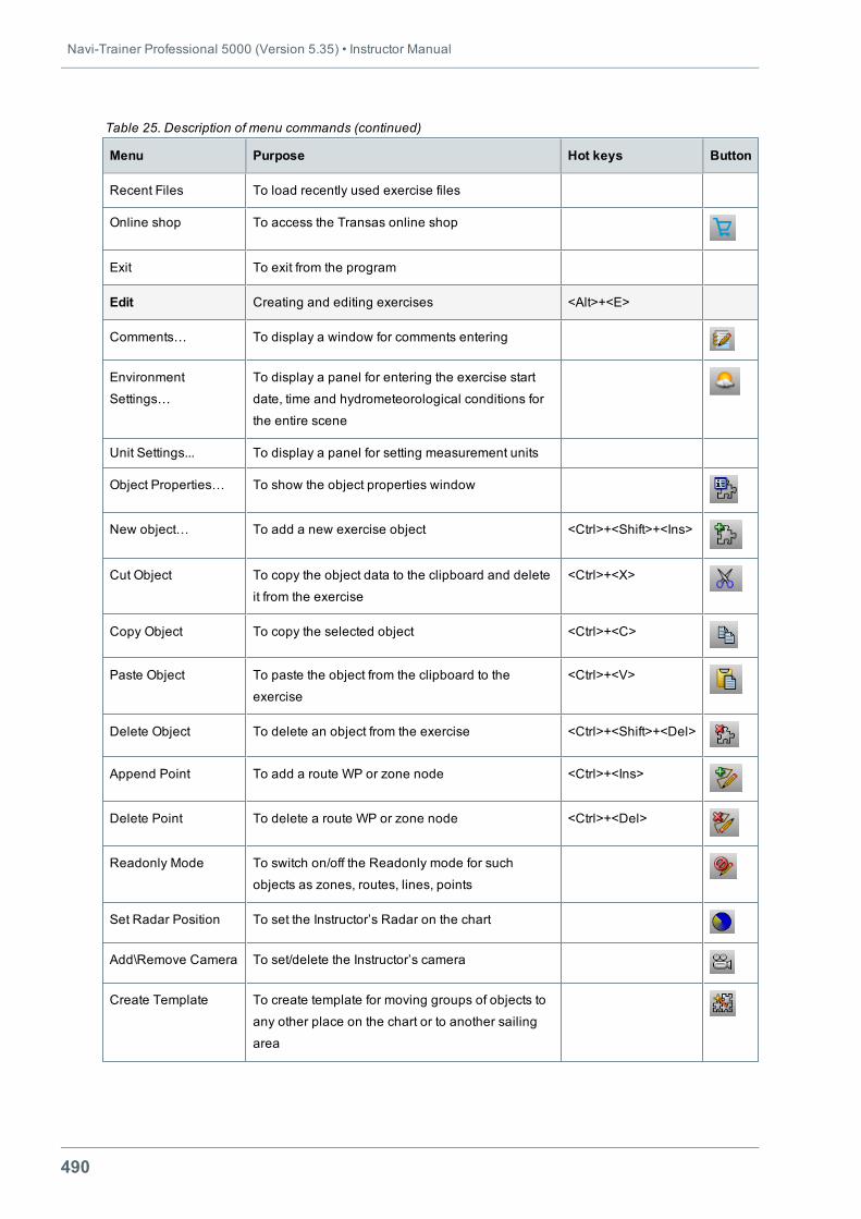
Navi-Trainer Professional 5000 (Version 5.35) • Instructor Manual
490
Menu Purpose Hot keys Button
Recent Files To load recently used exercise files
Online shop To access the Transas online shop
Exit To exit from the program
Edit Creating and editing exercises <Alt>+<E>
Comments… To display a window for comments entering
Environment
Settings…
To display a panel for entering the exercise start
date, time and hydrometeorological conditions for
the entire scene
Unit Settings... To display a panel for setting measurement units
Object Properties… To show the object properties window
New object… To add a new exercise object <Ctrl>+<Shift>+<Ins>
Cut Object To copy the object data to the clipboard and delete
it from the exercise
<Ctrl>+<X>
Copy Object To copy the selected object <Ctrl>+<C>
Paste Object To paste the object from the clipboard to the
exercise
<Ctrl>+<V>
Delete Object To delete an object from the exercise <Ctrl>+<Shift>+<Del>
Append Point To add a route WP or zone node <Ctrl>+<Ins>
Delete Point To delete a route WP or zone node <Ctrl>+<Del>
Readonly Mode To switch on/off the Readonly mode for such
objects as zones, routes, lines, points
Set Radar Position To set the Instructor’s Radar on the chart
Add\Remove Camera To set/delete the Instructor’s camera
Create Template To create template for moving groups of objects to
any other place on the chart or to another sailing
area
Table 25. Description of menu commands (continued)
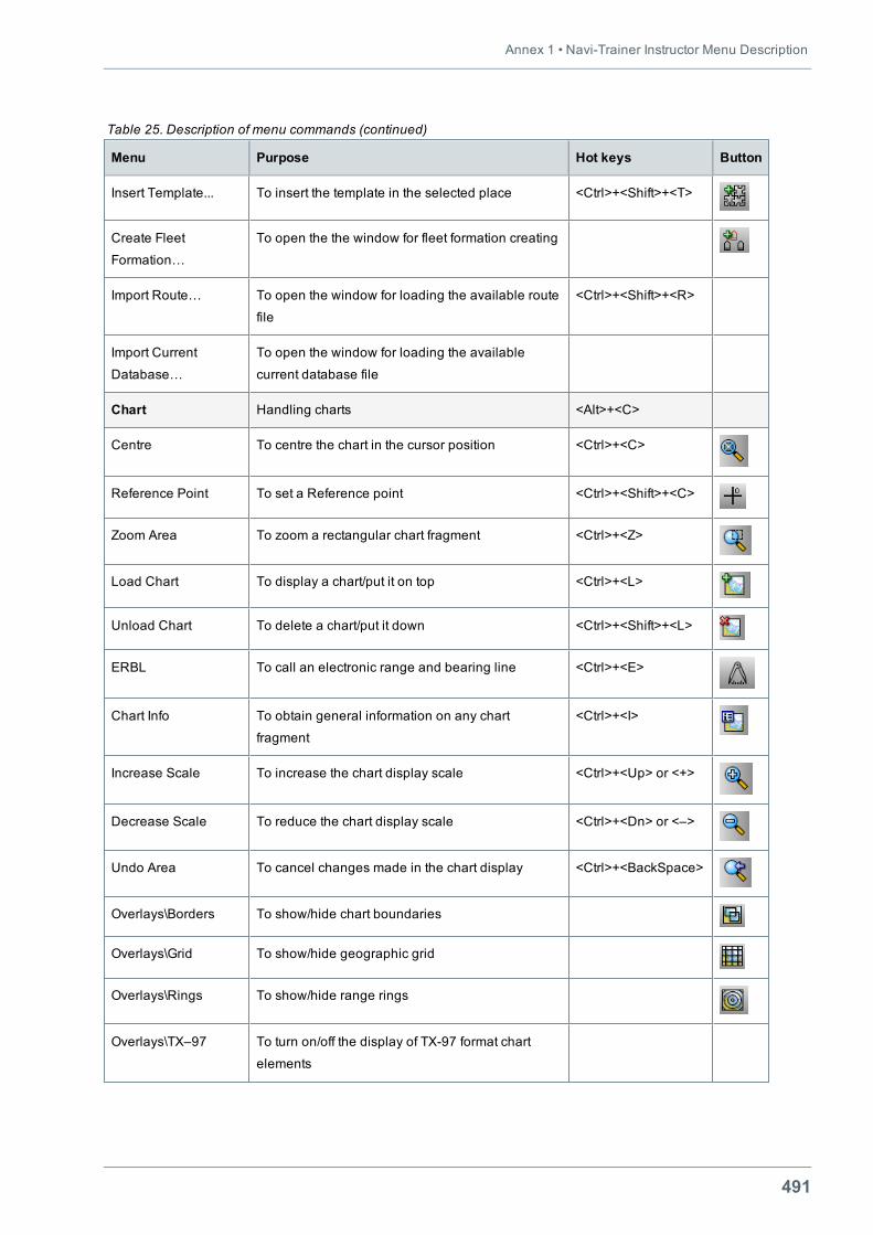
Annex 1 • Navi-Trainer Instructor Menu Description
491
Menu Purpose Hot keys Button
Insert Template... To insert the template in the selected place <Ctrl>+<Shift>+<T>
Create Fleet
Formation…
To open the the window for fleet formation creating
Import Route… To open the window for loading the available route
file
<Ctrl>+<Shift>+<R>
Import Current
Database…
To open the window for loading the available
current database file
Chart Handling charts <Alt>+<C>
Centre To centre the chart in the cursor position <Ctrl>+<C>
Reference Point To set a Reference point <Ctrl>+<Shift>+<C>
Zoom Area To zoom a rectangular chart fragment <Ctrl>+<Z>
Load Chart To display a chart/put it on top <Ctrl>+<L>
Unload Chart To delete a chart/put it down <Ctrl>+<Shift>+<L>
ERBL To call an electronic range and bearing line <Ctrl>+<E>
Chart Info To obtain general information on any chart
fragment
<Ctrl>+<I>
Increase Scale To increase the chart display scale <Ctrl>+<Up> or <+>
Decrease Scale To reduce the chart display scale <Ctrl>+<Dn> or <–>
Undo Area To cancel changes made in the chart display <Ctrl>+<BackSpace>
Overlays\Borders To show/hide chart boundaries
Overlays\Grid To show/hide geographic grid
Overlays\Rings To show/hide range rings
Overlays\TX–97 To turn on/off the display of TX-97 format chart
elements
Table 25. Description of menu commands (continued)
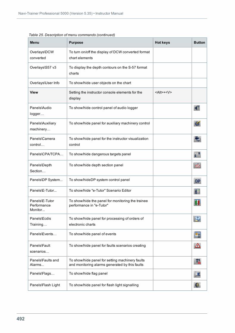
Navi-Trainer Professional 5000 (Version 5.35) • Instructor Manual
492
Menu Purpose Hot keys Button
Overlays\DCW
converted
To turn on/off the display of DCW converted format
chart elements
Overlays\S57 v3 To display the depth contours on the S-57 format
charts
Overlays\User Info To show/hide user objects on the chart
View Setting the instructor console elements for the
display
<Alt>+<V>
Panels\Audio
logger…
To show/hide control panel of audio logger
Panels\Auxiliary
machinery…
To show/hide panel for auxiliary machinery control
Panels\Camera
control…
To show/hide panel for the instructor visualization
control
Panels\CPA/TCPA… To show/hide dangerous targets panel
Panels\Depth
Section…
To show/hide depth section panel
Panels\DP System... To show/hideDP system control panel
Panels\E-Tutor... To show/hide "e-Tutor" Scenario Editor
Panels\E-TutorPerformanceMonitor...
To show/hide the panel for monitoring the traineeperformance in "e-Tutor"
Panels\Ecdis
Training…
To show/hide panel for processing of orders of
electronic charts
Panels\Events… To show/hide panel of events
Panels\Fault
scenarios…
To show/hide panel for faults scenarios creating
Panels\Faults andAlarms...
To show/hide panel for setting machinery faultsand monitoring alarms generated by this faults
Panels\Flags… To show/hide flag panel
Panels\Flash Light To show/hide panel for flash light signalling
Table 25. Description of menu commands (continued)
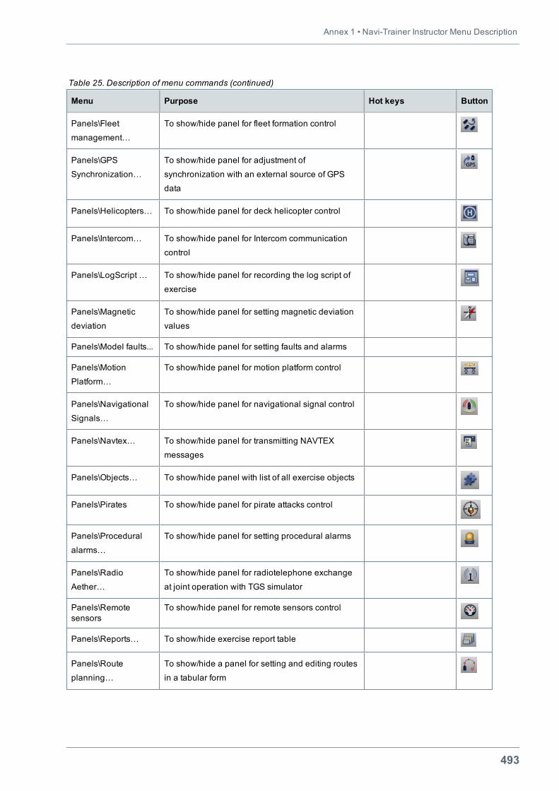
Annex 1 • Navi-Trainer Instructor Menu Description
493
Menu Purpose Hot keys Button
Panels\Fleet
management…
To show/hide panel for fleet formation control
Panels\GPS
Synchronization…
To show/hide panel for adjustment of
synchronization with an external source of GPS
data
Panels\Helicopters… To show/hide panel for deck helicopter control
Panels\Intercom… To show/hide panel for Intercom communication
control
Panels\LogScript … To show/hide panel for recording the log script of
exercise
Panels\Magnetic
deviation
To show/hide panel for setting magnetic deviation
values
Panels\Model faults... To show/hide panel for setting faults and alarms
Panels\Motion
Platform…
To show/hide panel for motion platform control
Panels\Navigational
Signals…
To show/hide panel for navigational signal control
Panels\Navtex… To show/hide panel for transmitting NAVTEX
messages
Panels\Objects… To show/hide panel with list of all exercise objects
Panels\Pirates To show/hide panel for pirate attacks control
Panels\Procedural
alarms…
To show/hide panel for setting procedural alarms
Panels\Radio
Aether…
To show/hide panel for radiotelephone exchange
at joint operation with TGS simulator
Panels\Remotesensors
To show/hide panel for remote sensors control
Panels\Reports… To show/hide exercise report table
Panels\Route
planning…
To show/hide a panel for setting and editing routes
in a tabular form
Table 25. Description of menu commands (continued)
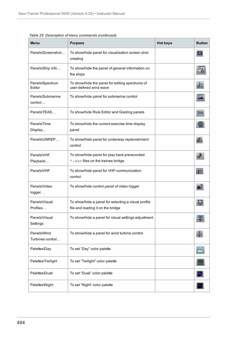
Navi-Trainer Professional 5000 (Version 5.35) • Instructor Manual
494
Menu Purpose Hot keys Button
Panels\Screenshot… To show/hide panel for visualization screen shot
creating
Panels\Ship info… To show/hide the panel of general information on
the ships
Panels\SpectrumEditor
To show/hide the panel for editing spectrums ofuser-defined wind wave
Panels\Submarine
control…
To show/hide panel for submarine control
Panels\TEAS… To show/hide Rule Editor and Grading panels
Panels\Time
Display…
To show/hide the current exercise time display
panel
Panels\UNREP… To show/hide panel for underway replenishment
control
Panels\VHF
Playback…
To show/hide panel for play back prerecorded
*.wav files on the trainee bridge
Panels\VHF To show/hide panel for VHF-communication
control
Panels\Video
logger…
To show/hide control panel of video logger
Panels\Visual
Profiles…
To show/hide a panel for selecting a visual profile
file and loading it on the bridge
Panels\Visual
Settings
To show/hide a panel for visual settings adjustment
Panels\Wind
Turbines control…
To show/hide a panel for wind turbine control
Palettes\Day To set “Day” color palette
Palettes\Twilight To set “Twilight” color palette
Palettes\Dusk To set “Dusk” color palette
Palettes\Night To set “Night” color palette
Table 25. Description of menu commands (continued)
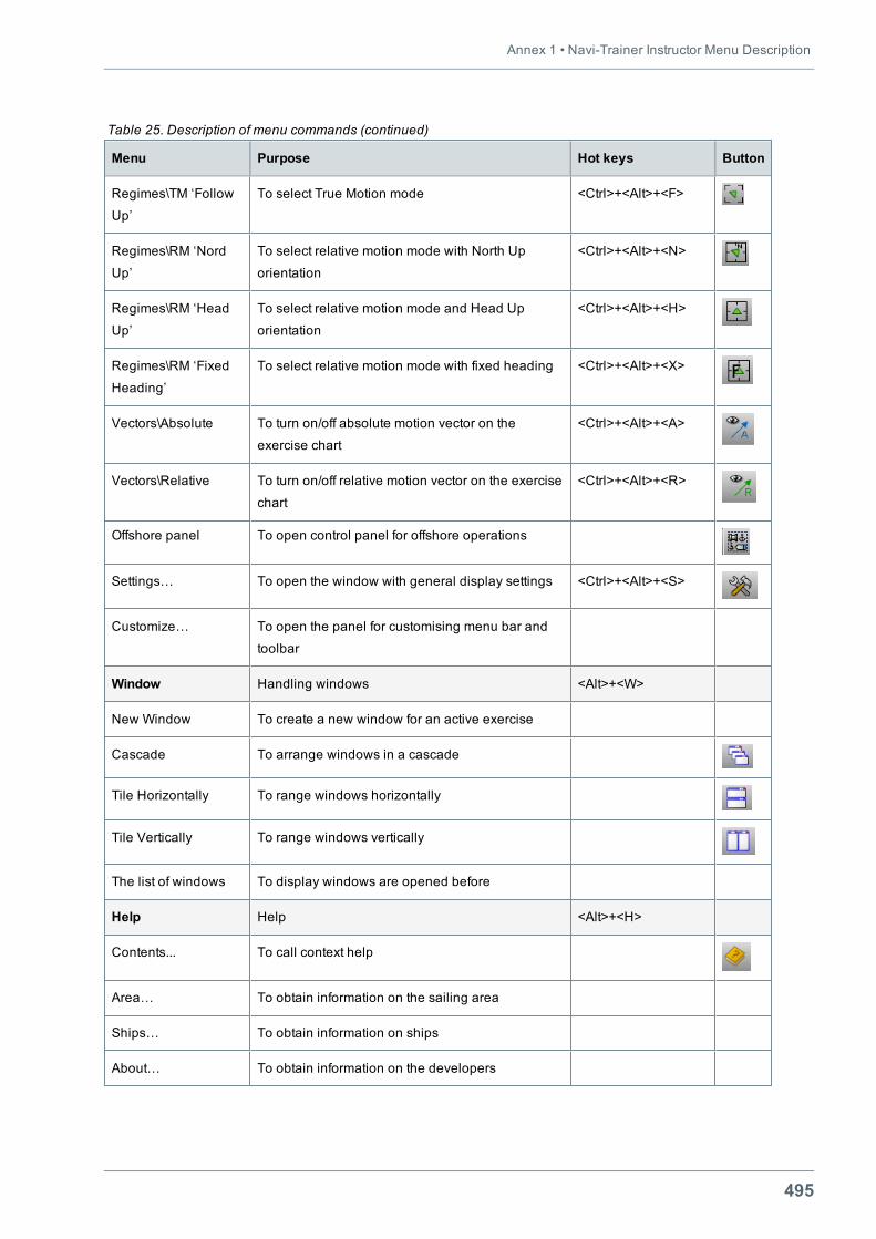
Annex 1 • Navi-Trainer Instructor Menu Description
495
Menu Purpose Hot keys Button
Regimes\TM ‘Follow
Up’
To select True Motion mode <Ctrl>+<Alt>+<F>
Regimes\RM ‘Nord
Up’
To select relative motion mode with North Up
orientation
<Ctrl>+<Alt>+<N>
Regimes\RM ‘Head
Up’
To select relative motion mode and Head Up
orientation
<Ctrl>+<Alt>+<H>
Regimes\RM ‘Fixed
Heading’
To select relative motion mode with fixed heading <Ctrl>+<Alt>+<X>
Vectors\Absolute To turn on/off absolute motion vector on the
exercise chart
<Ctrl>+<Alt>+<A>
Vectors\Relative To turn on/off relative motion vector on the exercise
chart
<Ctrl>+<Alt>+<R>
Offshore panel To open control panel for offshore operations
Settings… To open the window with general display settings <Ctrl>+<Alt>+<S>
Customize… To open the panel for customising menu bar and
toolbar
Window Handling windows <Alt>+<W>
New Window To create a new window for an active exercise
Cascade To arrange windows in a cascade
Tile Horizontally To range windows horizontally
Tile Vertically To range windows vertically
The list of windows To display windows are opened before
Help Help <Alt>+<H>
Contents... To call context help
Area… To obtain information on the sailing area
Ships… To obtain information on ships
About… To obtain information on the developers
Table 25. Description of menu commands (continued)


497
ANNEX 2

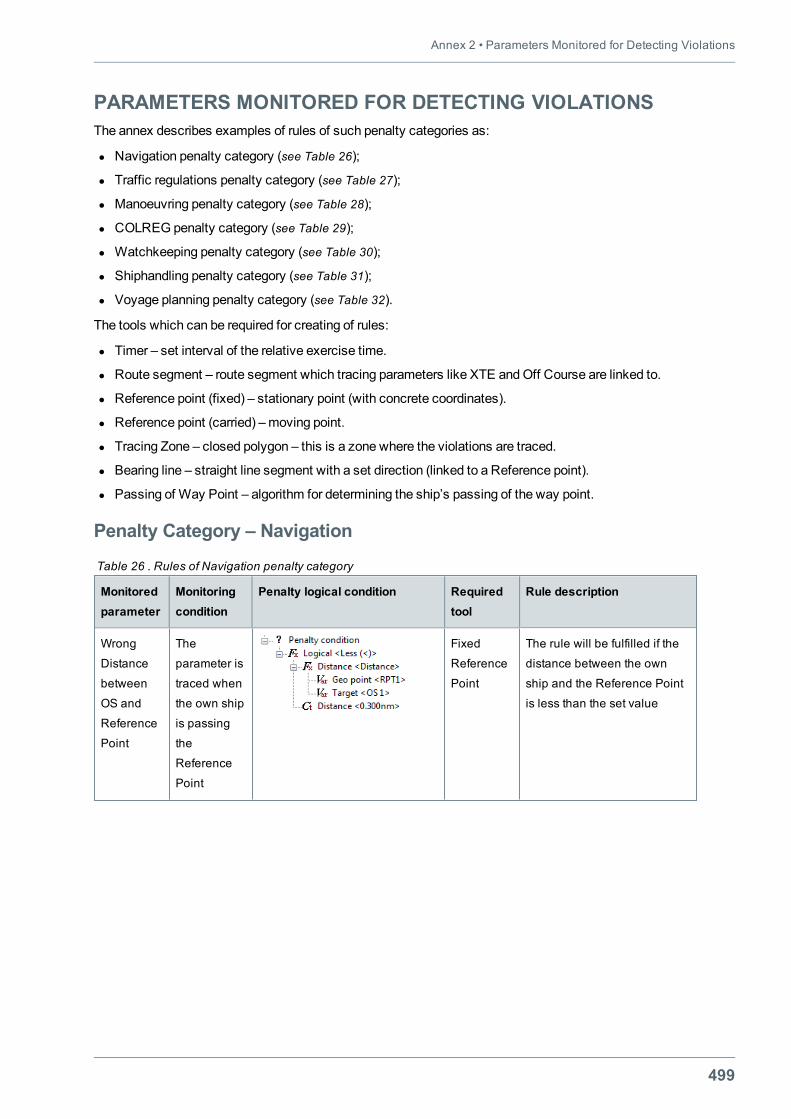
Annex 2 • Parameters Monitored for Detecting Violations
499
PARAMETERS MONITORED FOR DETECTING VIOLATIONSThe annex describes examples of rules of such penalty categories as:
l Navigation penalty category (see Table 26);
l Traffic regulations penalty category (see Table 27);
l Manoeuvring penalty category (see Table 28);
l COLREG penalty category (see Table 29);
l Watchkeeping penalty category (see Table 30);
l Shiphandling penalty category (see Table 31);
l Voyage planning penalty category (see Table 32).
The tools which can be required for creating of rules:
l Timer – set interval of the relative exercise time.
l Route segment – route segment which tracing parameters like XTE andOff Course are linked to.
l Reference point (fixed) – stationary point (with concrete coordinates).
l Reference point (carried) –moving point.
l Tracing Zone – closed polygon – this is a zone where the violations are traced.
l Bearing line – straight line segment with a set direction (linked to a Reference point).
l Passing of Way Point – algorithm for determining the ship’s passing of the way point.
Penalty Category – Navigation
Monitoredparameter
Monitoringcondition
Penalty logical condition Requiredtool
Rule description
Wrong
Distance
between
OS and
Reference
Point
The
parameter is
traced when
the own ship
is passing
the
Reference
Point
Fixed
Reference
Point
The rule will be fulfilled if the
distance between the own
ship and the Reference Point
is less than the set value
Table 26 . Rules of Navigation penalty category
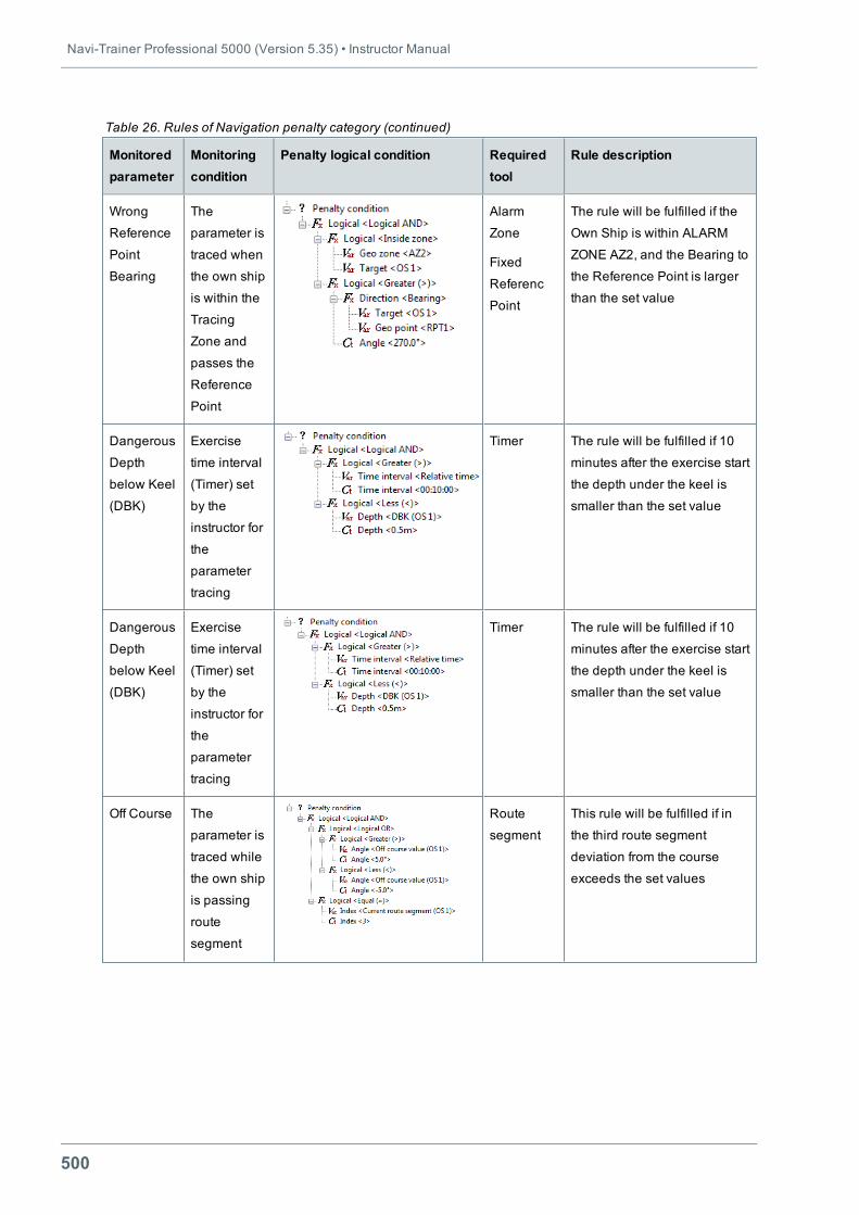
Navi-Trainer Professional 5000 (Version 5.35) • Instructor Manual
500
Monitoredparameter
Monitoringcondition
Penalty logical condition Requiredtool
Rule description
Wrong
Reference
Point
Bearing
The
parameter is
traced when
the own ship
is within the
Tracing
Zone and
passes the
Reference
Point
Alarm
Zone
Fixed
Referenc
Point
The rule will be fulfilled if the
Own Ship is within ALARM
ZONE AZ2, and the Bearing to
the Reference Point is larger
than the set value
Dangerous
Depth
below Keel
(DBK)
Exercise
time interval
(Timer) set
by the
instructor for
the
parameter
tracing
Timer The rule will be fulfilled if 10
minutes after the exercise start
the depth under the keel is
smaller than the set value
Dangerous
Depth
below Keel
(DBK)
Exercise
time interval
(Timer) set
by the
instructor for
the
parameter
tracing
Timer The rule will be fulfilled if 10
minutes after the exercise start
the depth under the keel is
smaller than the set value
Off Course The
parameter is
traced while
the own ship
is passing
route
segment
Route
segment
This rule will be fulfilled if in
the third route segment
deviation from the course
exceeds the set values
Table 26. Rules of Navigation penalty category (continued)
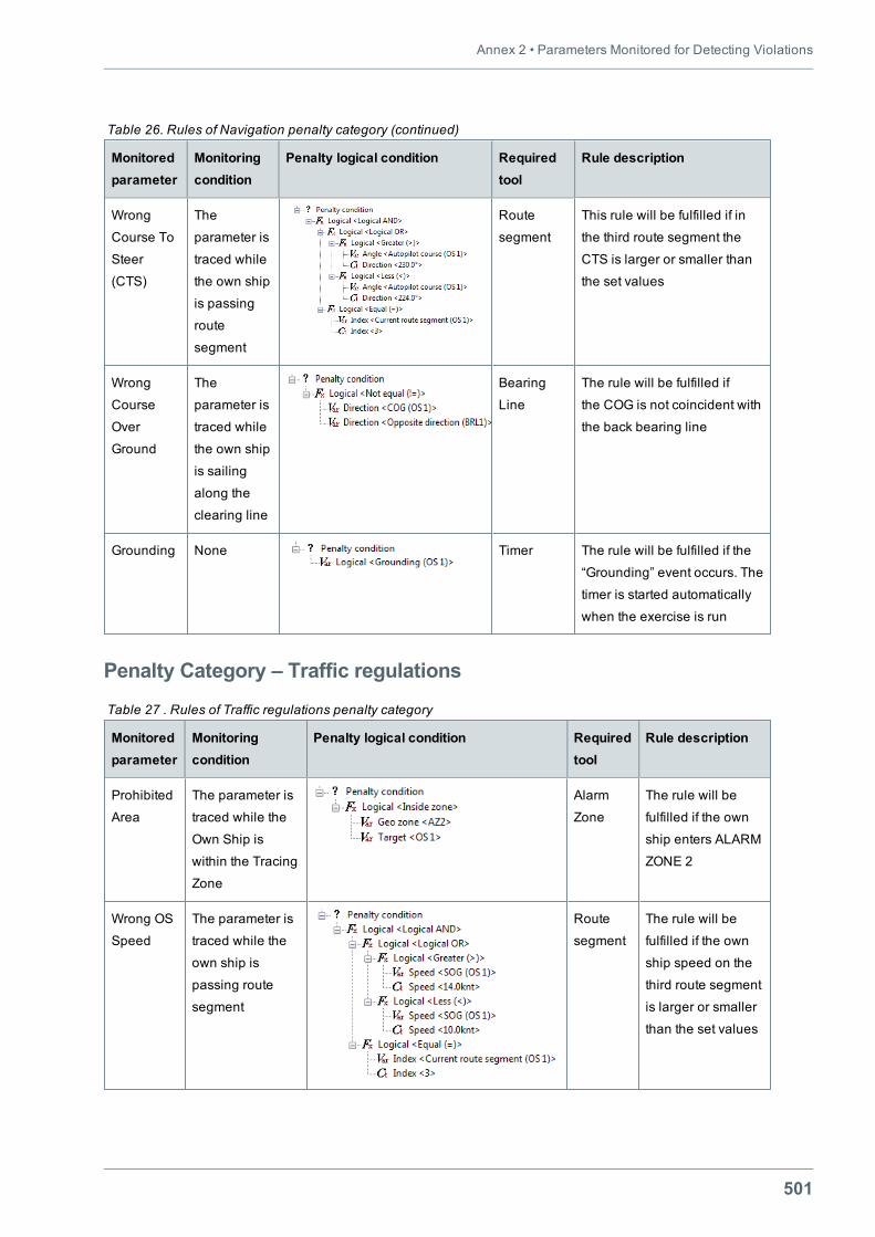
Annex 2 • Parameters Monitored for Detecting Violations
501
Monitoredparameter
Monitoringcondition
Penalty logical condition Requiredtool
Rule description
Wrong
Course To
Steer
(CTS)
The
parameter is
traced while
the own ship
is passing
route
segment
Route
segment
This rule will be fulfilled if in
the third route segment the
CTS is larger or smaller than
the set values
Wrong
Course
Over
Ground
The
parameter is
traced while
the own ship
is sailing
along the
clearing line
Bearing
Line
The rule will be fulfilled if
the COG is not coincident with
the back bearing line
Grounding None Timer The rule will be fulfilled if the
“Grounding” event occurs. The
timer is started automatically
when the exercise is run
Table 26. Rules of Navigation penalty category (continued)
Penalty Category – Traffic regulations
Monitoredparameter
Monitoringcondition
Penalty logical condition Requiredtool
Rule description
Prohibited
Area
The parameter is
traced while the
Own Ship is
within the Tracing
Zone
Alarm
Zone
The rule will be
fulfilled if the own
ship enters ALARM
ZONE 2
Wrong OS
Speed
The parameter is
traced while the
own ship is
passing route
segment
Route
segment
The rule will be
fulfilled if the own
ship speed on the
third route segment
is larger or smaller
than the set values
Table 27 . Rules of Traffic regulations penalty category
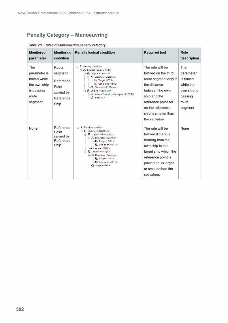
Navi-Trainer Professional 5000 (Version 5.35) • Instructor Manual
502
Penalty Category – Manoeuvring
Monitoredparameter
Monitoringcondition
Penalty logical condition Required tool Ruledescription
The
parameter is
traced while
the own ship
is passing
route
segment
Route
segment
Reference
Point
carried by
Reference
Ship
The rule will be
fulfilled on the third
route segment only if
the distance
between the own
ship and the
reference point set
on the reference
ship is smaller than
the set value
The
parameter
is traced
while the
own ship is
passing
route
segment
None ReferencePointcarried byReferenceShip
The rule will be
fulfilled if the true
bearing from the
own ship to the
target ship which the
reference point is
placed on, is larger
or smaller than the
set values
None
Table 28 . Rules of Manoeuvring penalty category
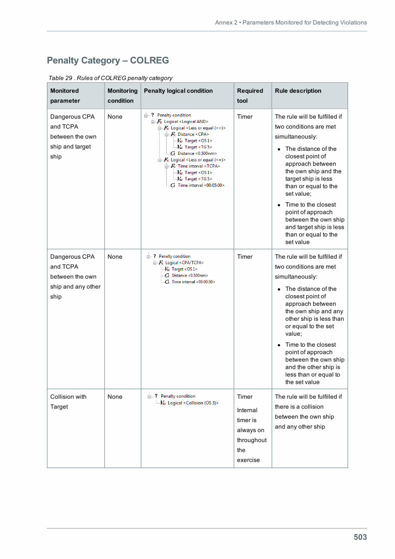
Annex 2 • Parameters Monitored for Detecting Violations
503
Penalty Category – COLREG
Monitoredparameter
Monitoringcondition
Penalty logical condition Requiredtool
Rule description
Dangerous СРА
and ТСРА
between the own
ship and target
ship
None Timer The rule will be fulfilled if
two conditions are met
simultaneously:
l The distance of theclosest point ofapproach betweenthe own ship and thetarget ship is lessthan or equal to theset value;
l Time to the closestpoint of approachbetween the own shipand target ship is lessthan or equal to theset value
Dangerous CPA
and TCPA
between the own
ship and any other
ship
None Timer The rule will be fulfilled if
two conditions are met
simultaneously:
l The distance of theclosest point ofapproach betweenthe own ship and anyother ship is less thanor equal to the setvalue;
l Time to the closestpoint of approachbetween the own shipand the other ship isless than or equal tothe set value
Collision with
Target
None Timer
Internal
timer is
always on
throughout
the
exercise
The rule will be fulfilled if
there is a collision
between the own ship
and any other ship
Table 29 . Rules of COLREG penalty category
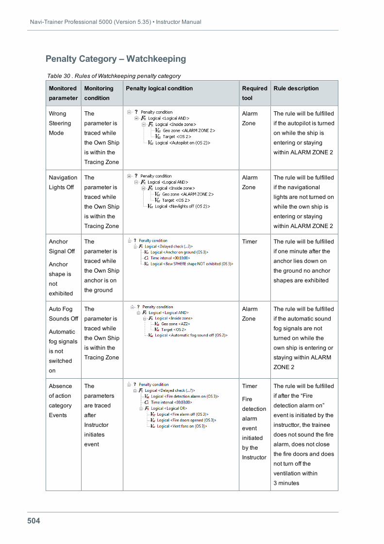
Navi-Trainer Professional 5000 (Version 5.35) • Instructor Manual
504
Penalty Category – Watchkeeping
Monitoredparameter
Monitoringcondition
Penalty logical condition Requiredtool
Rule description
Wrong
Steering
Mode
The
parameter is
traced while
the Own Ship
is within the
Tracing Zone
Alarm
Zone
The rule will be fulfilled
if the autopilot is turned
on while the ship is
entering or staying
within ALARM ZONE 2
Navigation
Lights Off
The
parameter is
traced while
the Own Ship
is within the
Tracing Zone
Alarm
Zone
The rule will be fulfilled
if the navigational
lights are not turned on
while the own ship is
entering or staying
within ALARM ZONE 2
Anchor
Signal Off
Anchor
shape is
not
exhibited
The
parameter is
traced while
the Own Ship
anchor is on
the ground
Timer The rule will be fulfilled
if one minute after the
anchor lies down on
the ground no anchor
shapes are exhibited
Auto Fog
Sounds Off
Automatic
fog signals
is not
switched
on
The
parameter is
traced while
the Own Ship
is within the
Tracing Zone
Alarm
Zone
The rule will be fulfilled
if the automatic sound
fog signals are not
turned on while the
own ship is entering or
staying within ALARM
ZONE 2
Absence
of action
category
Events
The
parameters
are traced
after
Instructor
initiates
event
Timer
Fire
detection
alarm
event
initiated
by the
Instructor
The rule will be fulfilled
if after the “Fire
detection alarm on”
event is initiated by the
instructtor, the trainee
does not sound the fire
alarm, does not close
the fire doors and does
not turn off the
ventilation within
3 minutes
Table 30 . Rules of Watchkeeping penalty category
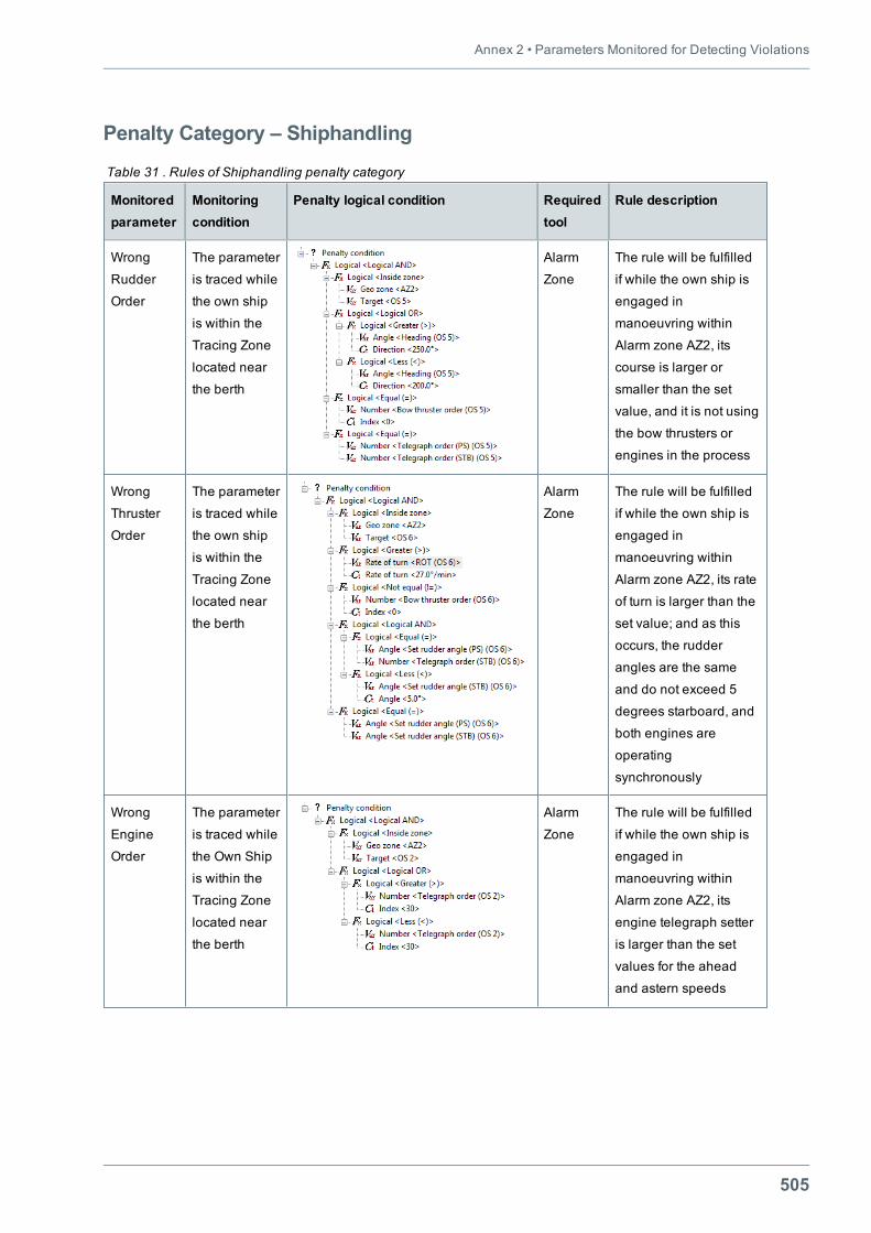
Annex 2 • Parameters Monitored for Detecting Violations
505
Penalty Category – Shiphandling
Monitoredparameter
Monitoringcondition
Penalty logical condition Requiredtool
Rule description
Wrong
Rudder
Order
The parameter
is traced while
the own ship
is within the
Tracing Zone
located near
the berth
Alarm
Zone
The rule will be fulfilled
if while the own ship is
engaged in
manoeuvring within
Alarm zone AZ2, its
course is larger or
smaller than the set
value, and it is not using
the bow thrusters or
engines in the process
Wrong
Thruster
Order
The parameter
is traced while
the own ship
is within the
Tracing Zone
located near
the berth
Alarm
Zone
The rule will be fulfilled
if while the own ship is
engaged in
manoeuvring within
Alarm zone AZ2, its rate
of turn is larger than the
set value; and as this
occurs, the rudder
angles are the same
and do not exceed 5
degrees starboard, and
both engines are
operating
synchronously
Wrong
Engine
Order
The parameter
is traced while
the Own Ship
is within the
Tracing Zone
located near
the berth
Alarm
Zone
The rule will be fulfilled
if while the own ship is
engaged in
manoeuvring within
Alarm zone AZ2, its
engine telegraph setter
is larger than the set
values for the ahead
and astern speeds
Table 31 . Rules of Shiphandling penalty category
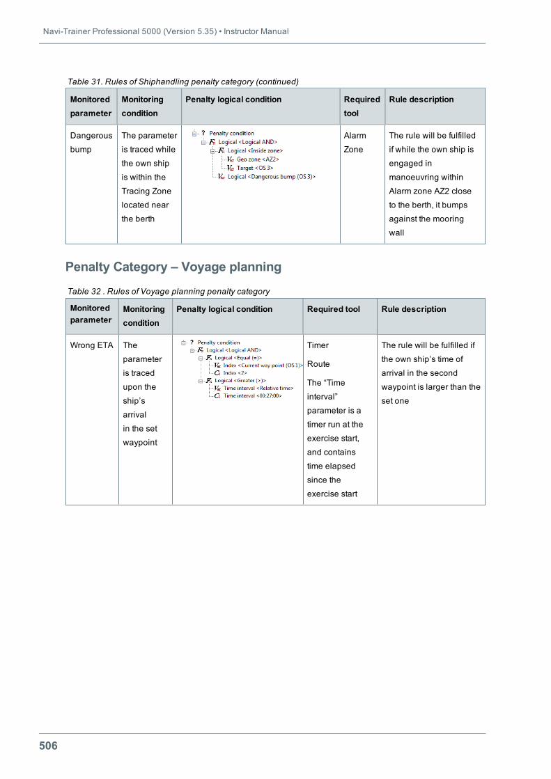
Navi-Trainer Professional 5000 (Version 5.35) • Instructor Manual
506
Monitoredparameter
Monitoringcondition
Penalty logical condition Requiredtool
Rule description
Dangerous
bump
The parameter
is traced while
the own ship
is within the
Tracing Zone
located near
the berth
Alarm
Zone
The rule will be fulfilled
if while the own ship is
engaged in
manoeuvring within
Alarm zone AZ2 close
to the berth, it bumps
against the mooring
wall
Table 31. Rules of Shiphandling penalty category (continued)
Penalty Category – Voyage planning
Monitoredparameter
Monitoringcondition
Penalty logical condition Required tool Rule description
Wrong ETA The
parameter
is traced
upon the
ship’s
arrival
in the set
waypoint
Timer
Route
The “Time
interval”
parameter is a
timer run at the
exercise start,
and contains
time elapsed
since the
exercise start
The rule will be fulfilled if
the own ship’s time of
arrival in the second
waypoint is larger than the
set one
Table 32 . Rules of Voyage planning penalty category

Navi-Trainer Professional 5000(Version 5.35)
Instructor Manual
Transas MIP LTD
phone: +46 31 769 56 00
e-mail: [email protected]
web: www.transas.com