
SIMATIC ET 200iS Distributed I/O Station - ADEGIS
434
Contents Preface 1 Product Overview 2 Brief Instructions on Commissioning 3 Configuration Options 4 Installation 5 Wiring 6 Commissioning and Diagnostics 7 Maintenance 8 General Technical Specifications 9 Terminal Modules 10 Power Supply Module 11 Interface Module 12 Digital Electronics Modules 13 Analog Electronics Modules 14 Analog Electronics Modules with HART 15 Appendix Order Numbers 16 Dimension Drawings 17 Reaction Times 18 Address Space of the Inputs and Outputs 19 Certifications 20 Marking 21 Glossary 22 Index SIMATIC ET 200iS Distributed I/O Station Manual This manual has the order number: 6ES7151-2AA00-8BA0 Edition 10/2001 A5E00087831-02 The following supplements are part of this documentation: No. Designation Drawing number Edition 1 Product information A5E00163808-02 06/2004 2 Product information A5E00207628-02 02/2004 2 Product information A5E00158421-01 06/2004
-
Upload
khangminh22 -
Category
Documents
-
view
0 -
download
0
Transcript of SIMATIC ET 200iS Distributed I/O Station - ADEGIS

Contents
Preface 1
Product Overview 2Brief Instructions onCommissioning 3Configuration Options 4Installation 5Wiring 6Commissioning and Diagnostics 7Maintenance 8General Technical Specifications 9Terminal Modules 10Power Supply Module 11Interface Module 12Digital Electronics Modules 13Analog Electronics Modules 14Analog Electronics Moduleswith HART 15Appendix
Order Numbers 16Dimension Drawings 17Reaction Times 18Address Space of the Inputsand Outputs 19Certifications 20Marking 21Glossary 22Index
SIMATIC
ET 200iS Distributed I/O Station
Manual
This manual has the order number:6ES7151-2AA00-8BA0
Edition 10/2001A5E00087831-02
The following supplements are part of this documentation:
No. Designation Drawing number Edition 1 Product information A5E00163808-02 06/2004 2 Product information A5E00207628-02 02/2004 2 Product information A5E00158421-01 06/2004
Copyright © Siemens AG 2001 All rights reserved
The reproduction, transmission or use of this document or itscontents is not permitted without express written authority.Offenders will be liable for damages. All rights, including rightscreated by patent grant or registration of a utility model or design,are reserved.
Siemens AGBereich Automatisierungs- und AntriebstechnikGeschaeftsgebiet Industrie-AutomatisierungssystemePostfach 4848, D- 90327 Nuernberg
Disclaimer of Liability
We have checked the contents of this manual for agreement withthe hardware and software described. Since deviations cannot beprecluded entirely, we cannot guarantee full agreement. However,the data in this manual are reviewed regularly and any necessarycorrections included in subsequent editions. Suggestions forimprovement are welcomed.
©Siemens AG 2001Technical data subject to change.
Siemens Aktiengesellschaft A5E00087831
Safety Guidelines
This manual contains notices intended to ensure personal safety, as well as to protect the products and
connected equipment against damage. These notices are highlighted by the symbols shown below and
graded according to severity by the following texts:
! Dangerindicates that death, severe personal injury or substantial property damage will result if properprecautions are not taken.
! Warningindicates that death, severe personal injury or substantial property damage can result if properprecautions are not taken.
! Cautionindicates that minor personal injury can result if proper precautions are not taken.
Cautionindicates that property damage can result if proper precautions are not taken.
Noticedraws your attention to particularly important information on the product, handling the product, or to aparticular part of the documentation.
Qualified Personnel
Only qualified personnel should be allowed to install and work on this equipment. Qualified persons are
defined as persons who are authorized to commission, to ground and to tag circuits, equipment, and
systems in accordance with established safety practices and standards.
Correct Usage
Note the following:
! WarningThis device and its components may only be used for the applications described in the catalog or the
technical description, and only in connection with devices or components from other manufacturers
which have been approved or recommended by Siemens.
This product can only function correctly and safely if it is transported, stored, set up, and installedcorrectly, and operated and maintained as recommended.
Trademarks
SIMATIC®, SIMATIC HMI® and SIMATIC NET® are registered trademarks of SIEMENS AG.
Third parties using for their own purposes any other names in this document which refer to trademarks might
infringe upon the rights of the trademark owners.
ET 200iS Distributed I/O StationA5E00087831-02 iii
Contents
1 1 Preface 1-1
1.1 Preface..............................................................................................................1-1
2 2 Product Overview 2-1
2.1 What are Distributed I/O Stations? ...................................................................2-12.2 What Is the ET 200iS Distributed I/O Station?..................................................2-32.3 ET 200iS in the Hazardous Area.......................................................................2-92.4 Integration in Process Control System............................................................2-13
3 3 Brief Instructions on Commissioning 3-1
3.1 Introduction........................................................................................................3-13.2 Requirements....................................................................................................3-13.3 Materials and Tools Required to Set Up the Example......................................3-23.4 Overview of the Setup.......................................................................................3-33.5 Setting Up the Configuration for the Example...................................................3-43.5.1 Setting up the ET 200iS ....................................................................................3-43.5.2 Setting Up the S7-400.......................................................................................3-43.5.3 Installing the Fieldbus Isolating Transformer ....................................................3-43.6 Wiring the Example Setup.................................................................................3-53.7 Insert the interface module and the electronics modules .................................3-83.8 Setting the PROFIBUS Address .......................................................................3-83.9 Configuring the Example...................................................................................3-93.9.1 Configuring the S7-400 .....................................................................................3-93.9.2 Configuration of the ET 200iS.........................................................................3-113.9.3 Setting Parameters for the ET 200iS ..............................................................3-133.10 Programming the Example..............................................................................3-143.11 Putting the Example into Operation ................................................................3-163.12 Evaluating the Diagnostics..............................................................................3-163.13 Removing and inserting modules....................................................................3-173.14 Wire break of the NAMUR encoder connected to the digital input module ....3-18
4 4 Configuration Options 4-1
4.1 System with Scalable Modularity ......................................................................4-14.2 Electronics Modules to Suit your Application ....................................................4-24.3 Which Electronics Modules Match the Terminal Modules? ..............................4-44.4 Configuration Options in Zones.........................................................................4-54.5 Power Supply of the ET 200iS ..........................................................................4-84.6 Direct Data Exchange .......................................................................................4-94.7 Using the ET 200iS in a Redundant Standard DP Master System.................4-104.8 Restricted Number of Connectable Electronics Modules/Maximum
Configuration...................................................................................................4-12
Contents
ET 200iS Distributed I/O Stationiv A5E00087831-02
5 5 Installation 5-1
5.1 Rules for Installation..........................................................................................5-15.2 Installing the Terminal Module for the Power Supply Module...........................5-55.3 Installing Terminal Modules for the Interface Module and Electronics
Modules.............................................................................................................5-75.4 Installing the Bus Termination Module............................................................5-105.5 Installing the Shield Contact............................................................................5-125.6 Fitting Slot Number Labels and Color Identification Labels ............................5-135.7 Replacing the Bus Interface Module and Terminal Box on the
Terminal Module..............................................................................................5-16
6 6 Wiring 6-1
6.1 General Rules and Regulations for Wiring........................................................6-16.2 Operate the ET 200iS with a Grounded-Neutral Supply...................................6-36.3 Electrical Design of the ET 200iS......................................................................6-56.4 Lightning and Overvoltage Protection...............................................................6-66.4.1 Overview ...........................................................................................................6-66.4.2 The Lightning Protection Zone Concept ...........................................................6-76.4.3 Rules for the Interface between Lightning Protection Zones 0...1 ..................6-106.4.4 Rules for the Interfaces between Lightning Protection Zones 1...2
and higher .......................................................................................................6-126.4.5 Example of Protection from Overvoltage for Networked ET 200iS Stations...6-136.5 Wiring the ET 200iS ........................................................................................6-156.5.1 Wiring Rules for the ET 200iS.........................................................................6-156.5.2 Wiring Terminal Module TM-E30S44-iS with Screw Terminals ......................6-166.5.3 Wiring Terminal Module TM-E30C44-iS with Spring Terminals .....................6-176.5.4 Wiring Terminal Module TM-PS......................................................................6-186.5.5 Wiring Terminal Module TM-IM.......................................................................6-206.5.6 Wiring Terminal Module TM-E ........................................................................6-226.5.7 Contacting the Cable Shields..........................................................................6-236.5.8 Grounding the DIN Rail ...................................................................................6-256.6 Inserting and Labeling the Power Supply, Interface Module, and
Electronics Modules ........................................................................................6-266.7 Setting the PROFIBUS Address .....................................................................6-31
7 7 Commissioning and Diagnostics 7-1
7.1 Overview of Defining the Configuration ............................................................7-17.2 Configuration .....................................................................................................7-57.3 Parameter Assignment......................................................................................7-77.4 Commissioning and Starting up the ET 200iS ................................................7-107.5 Reassign Parameters for the ET 200iS during Operation...............................7-147.6 Diagnostics Using the Process Image Input Table .........................................7-167.7 Status and Error LEDs on the IM 151-2..........................................................7-177.8 Diagnostics with STEP 5 and STEP 7 ............................................................7-227.8.1 Introduction......................................................................................................7-227.8.2 Reading out Diagnostic Information................................................................7-227.8.3 Diagnostic Messages of the Electronics Modules...........................................7-247.8.4 Evaluating Interrupts from the ET 200iS (S7-DP Slave/ DPV1 Slave) ...........7-267.8.5 Structure of the Slave Diagnostic Information.................................................7-297.8.6 Station Status 1 to 3........................................................................................7-307.8.7 Master PROFIBUS Address............................................................................7-327.8.8 Vendor ID ........................................................................................................7-327.8.9 ID-Related Diagnostics ...................................................................................7-33

Contents
ET 200iS Distributed I/O StationA5E00087831-02 v
7.8.10 Module Status .................................................................................................7-347.8.11 Channel-Related Diagnostics..........................................................................7-357.8.12 Interrupts .........................................................................................................7-387.8.13 Diagnostics for Incorrect Module Configuration of the ET 200iS....................7-46
8 8 Maintenance 8-1
8.1 Activities During Operation................................................................................8-18.2 Removing and Inserting Electronics Modules during Operation
(Hot Swapping) .................................................................................................8-28.3 Maintenance During Operation .........................................................................8-58.4 Cleaning ............................................................................................................8-5
9 9 General Technical Specifications 9-1
9.1 General Technical Specifications......................................................................9-19.2 Standards, certificates and approvals...............................................................9-19.3 Electromagnetic Compatibility, Transport and Storage Conditions ..................9-39.4 Mechanical and climatic environmental conditions...........................................9-69.5 Information on Dielectric Strength Tests, Class of Protection, Degree of
Protection and Rated Voltage of the ET 200iS .................................................9-7
10 10 Terminal Modules 10-1
10.1 Overview of the Contents................................................................................10-110.2 Terminal Module for the Power Supply Module TM-PS..................................10-210.3 Terminal Module for the Interface Module TM-IM...........................................10-410.4 Terminal Modules for Electronics Modules TM-E30S44-iS / TM-E30C44-iS .10-6
11 11 Power Supply Module 11-1
11.1 Power Supply Module .....................................................................................11-1
12 12 Interface Module 12-1
12.1 Interface module IM 151-2 ..............................................................................12-112.2 Parameters for the Interface Module ..............................................................12-412.3 Parameter Description ....................................................................................12-512.3.1 Startup when defined and actual configuration differ......................................12-512.3.2 Time stamping / edge evaluation ....................................................................12-512.3.3 Format of the analog values............................................................................12-712.3.4 Interference Frequency Suppression..............................................................12-712.3.5 Temperature unit .............................................................................................12-712.3.6 Slot Reference Junction/Reference Junction Input.........................................12-712.3.7 Identification Data ...........................................................................................12-7
13 13 Digital Electronics Modules 13-1
13.1 Digital Electronics Module 4DI NAMUR..........................................................13-113.2 Digital Electronics Module 2DO DC25V/25mA ...............................................13-713.3 Parameters of the Digital Electronics Modules .............................................13-1113.4 Parameter Description ..................................................................................13-1413.4.1 Pulse extension.............................................................................................13-1413.4.2 Flutter monitoring ..........................................................................................13-1513.4.3 Identification Data .........................................................................................13-1713.5 Diagnostics with the Changeover Transducer Type .....................................13-17

Contents
ET 200iS Distributed I/O Stationvi A5E00087831-02
14 14 Analog Electronics Modules 14-1
14.1 Analog Value Representation .........................................................................14-114.1.1 Overview .........................................................................................................14-114.1.2 Analog Value Representation for Measuring Ranges with SIMATIC S7 ........14-314.1.3 Analog Value Representation for the Measuring Ranges of the
Analog Input Modules in SIMATIC S7 Format ................................................14-414.1.4 Analog Value Representation for the Output Ranges of the
Analog Output Modules in SIMATIC S7 Format ...........................................14-2014.1.5 Analog Value Representation for Measuring Ranges with SIMATIC S5 ......14-2114.1.6 Analog Value Representation for the Measuring Ranges of the
Analog Input Modules in SIMATIC S5 Format ..............................................14-2214.1.7 Analog Value Representation for the Output Ranges of the
Analog Output Modules in SIMATIC S5 Format ...........................................14-3814.2 Basics of Analog Value Processing ..............................................................14-3914.2.1 Connecting Thermocouples ..........................................................................14-3914.3 Response of the Analog Modules during Operation and if Faults Occur......14-4314.4 Analog Electronics Module 2AI I 2WIRE.......................................................14-4514.5 Analog Electronics Module 2AI I 4WIRE.......................................................14-4914.6 Analog Electronics Module 2AI RTD.............................................................14-5314.7 Analog Electronics Module 2AI TC ...............................................................14-5714.8 Analog Electronics Module 2AO I .................................................................14-6114.9 Parameters of the Analog Electronics Modules ............................................14-6514.10 Parameter Description ..................................................................................14-6914.10.1 Reference Junction / Reference Junction Number .......................................14-6914.10.2 Smoothing .....................................................................................................14-6914.10.3 Identification Data..........................................................................................14-70
15 15 Analog Electronics Modules with HART 15-1
15.1 Basics of HART...............................................................................................15-115.1.1 What is HART?................................................................................................15-115.1.2 How Does HART Work? .................................................................................15-215.1.3 How Are HART Field Devices Used with the ET 200iS ..................................15-315.1.4 How Do You Use HART?................................................................................15-415.2 Analog Value Representation .........................................................................15-715.3 Basics of Analog Value Processing ................................................................15-715.4 Response of the Analog Modules with HART during Operation
and if Problems Occur.....................................................................................15-715.5 Analog Electronics Module 2AI I 2WIRE HART..............................................15-815.6 Analog Electronics Module 2AI I 4WIRE HART............................................15-1315.7 Analog Electronics Module 2AO I HART ......................................................15-1815.8 Parameters of the Analog Electronics Modules with HART..........................15-2215.9 Parameter Description ..................................................................................15-2415.9.1 Smoothing .....................................................................................................15-2415.9.2 Identification Data..........................................................................................15-2415.10 HART Data Records .....................................................................................15-25
16 16 Order Numbers 16-1
16.1 Order Numbers ...............................................................................................16-1
17 17 Dimension Drawings 17-1
17.1 Dimension Drawings .......................................................................................17-1

Contents
ET 200iS Distributed I/O StationA5E00087831-02 vii
18 18 Reaction Times 18-1
18.1 Introduction......................................................................................................18-118.2 Reaction Times on the DP Master ..................................................................18-218.3 Reaction Times on the ET 200iS ....................................................................18-218.4 Reaction Times with Digital Input Modules .....................................................18-318.5 Reaction Times with Digital Output Modules ..................................................18-318.6 Reaction Times of Analog Input Modules .......................................................18-418.7 Reaction Times of Analog Output Modules ....................................................18-5
19 19 Address Space of the Inputs and Outputs 19-1
19.1 Digital Electronics Modules .............................................................................19-119.2 Analog Electronics Modules............................................................................19-219.3 Analog Electronics Modules with HART .........................................................19-3
20 20 Certifications 20-1
20.1 EU Prototype Test Certificates........................................................................20-120.1.1 ET 200iS Distributed I/O Station .....................................................................20-120.1.2 Interface module IM151-2 ...............................................................................20-520.1.3 Power supply PS.............................................................................................20-720.1.4 4DI NAMUR.....................................................................................................20-920.1.5 2DO DC25V/25mA........................................................................................20-1220.1.6 2AI I 2WIRE, 2AI I 2WIRE HART..................................................................20-1420.1.7 2AI I 4WIRE, 2AI I 4WIRE HART..................................................................20-1620.1.8 2AI RTD.........................................................................................................20-1820.1.9 2AI TC ...........................................................................................................20-2020.1.10 2AO I, 2AO I HART .......................................................................................20-2220.2 EU Declarations of Conformity......................................................................20-2420.2.1 ET 200iS Distributed I/O Station ...................................................................20-2420.2.2 Interface module IM 151-2 ............................................................................20-2420.2.3 Power supply PS...........................................................................................20-2520.2.4 4DI NAMUR...................................................................................................20-2520.2.5 2DO DC25V/25mA........................................................................................20-2620.2.6 2AI I 2WIRE, 2AI I 2WIRE HART..................................................................20-2620.2.7 2AI I 4WIRE, 2AI I 4WIRE HART..................................................................20-2720.2.8 2AI RTD.........................................................................................................20-2720.2.9 2AI TC ...........................................................................................................20-2820.2.10 2AO I, 2AO I HART .......................................................................................20-28
21 21 Marking 21-1
21.1 Marking According to Divisions.......................................................................21-121.2 Marking According to Zones ...........................................................................21-3
22 22 Glossary 22-1
22.1 Glossary ..........................................................................................................22-1
23 Index

Contents
ET 200iS Distributed I/O Stationviii A5E00087831-02
Figures
1-1 SIMATIC Customer Support Hotline .................................................................1-42-1 Typical Structure of a PROFIBUS-DP Network ................................................2-22-2 View of the ET 200iS Distributed I/O Station ....................................................2-42-3 Identification Codes of the ET 200iS...............................................................2-122-4 Integration in the Control System....................................................................2-133-1 Overview of the Example Setup........................................................................3-33-2 Wiring TM-PS....................................................................................................3-53-3 Wiring Fieldbus Isolating Transformer ..............................................................3-63-4 Wiring the ET 200iS Modules............................................................................3-73-5 Setting PROFIBUS Address 3 ..........................................................................3-83-6 Configuration of the S7-400 ............................................................................3-103-7 Configuration of the ET 200iS .........................................................................3-123-8 Disabling ET 200iS Channels .........................................................................3-134-1 Example of an ET 200iS Configuration.............................................................4-24-2 Configuration Options for the ET 200iS in Zone 1 ............................................4-64-3 Power Supply Module PS .................................................................................4-94-4 Example of Direct Data Exchange ..................................................................4-104-5 ET 200iS and the Y-Link .................................................................................4-115-1 Enclosure for the ET 200iS in Zone 1 ...............................................................5-25-2 Enclosure for the ET 200iS in Zone 2 ...............................................................5-35-3 Minimum Clearances to the Enclosure .............................................................5-45-4 Installing the Terminal Module TM-PS..............................................................5-65-5 Installing the Terminal Module TM-IM and TM-E..............................................5-85-6 Uninstalling the Terminal Module TM-IM or TM-E from the Right ....................5-95-7 Installing the Bus Termination Module............................................................5-115-8 Installing the Shield Contact............................................................................5-135-9 Fitting Slot Number Labels and Color Identification Labels ............................5-155-10 Replacing the Bus Interface Module and Terminal Box..................................5-176-1 Operating the ET 200iS with a Grounded Reference Potential ........................6-46-2 Potentials on the ET 200iS................................................................................6-66-3 Lightning Protection Zones of a Building ..........................................................6-96-4 Example of Wiring Networked ET 200iS Stations...........................................6-136-5 Wiring with Spring Terminals ..........................................................................6-186-6 Connecting the Power Supply and Grounding Conductor on the TM-PS.......6-206-7 Wiring Terminal Module TM-IM.......................................................................6-226-8 Wiring Terminal Module TM-E ........................................................................6-236-9 Contacting the Cable Shields..........................................................................6-246-10 Inserting and Identifying the Power Supply Module PS..................................6-276-11 Inserting and Labeling the IM 151-2 and Electronics Modules .......................6-286-12 Removing Interface and Electronics Modules.................................................6-296-13 Replacing and Electronics Module with a Different Type................................6-306-14 Setting the PROFIBUS Address .....................................................................6-327-1 Basis on Which Configuration Takes Place ......................................................7-17-2 Starting up the ET 200iS .................................................................................7-127-3 Starting up the Time-of-Day Synchronization/Time Stamping........................7-137-4 Assignment of the Value Status to the Digital Input........................................7-167-5 LED Display on the Interface Module..............................................................7-177-6 Status LEDs on the Power Supply Module .....................................................7-197-7 Status and Error LEDs on the Digital Electronics Modules.............................7-207-8 Error LEDs on the Analog Electronics Modules..............................................7-21

Contents
ET 200iS Distributed I/O StationA5E00087831-02 ix
7-9 Interrupts from Analog Input Modules.............................................................7-277-10 Structure of the Slave Diagnostic Information.................................................7-297-11 Structure of the ID-Related Diagnostic Information for the ET 200iS .............7-337-12 Module Status .................................................................................................7-347-13 Structure of the Channel-Related Diagnostic Information ..............................7-367-14 Structure of the Interrupt Status of the Interrupt Section ................................7-397-15 Structure of Bytes x+4 to x+7 for Diagnostic Interrupts ..................................7-407-16 Structure Starting at Byte x+8 for Diagnostic Interrupts
(Input or OutputModules) ................................................................................7-417-17 Example of a Diagnostic Interrupt ...................................................................7-427-18 Example of a Diagnostic Interrupt (continued)................................................7-437-19 Structure Starting at Byte x+4 for Hardware Interrupts (Analog Input) ...........7-447-20 Structure Starting at Byte x+4 for Remove/Insert Interrupts ...........................7-447-21 Structure Starting at Byte x+4 for Update Interrupt.........................................7-458-1 Automatic Parameter Assignment after Replacing a Module ...........................8-39-1 Mark for Australia ..............................................................................................9-210-1 Block Diagram of the Terminal Module TM-PS...............................................10-310-2 Block Diagram of the Terminal Module TM-IM ...............................................10-510-3 Block Diagram of the Terminal Module TM-E30S44-iS / E30C44-iS..............10-711-1 Block Diagram of the Power Supply Module...................................................11-112-1 Block Diagram of the IM 151-2........................................................................12-212-2 Example of Time Stamping and Edge Evaluation...........................................12-613-1 Block Diagram of the 4DI NAMUR..................................................................13-413-2 Block Diagram of the 2DO DC25V/25mA .......................................................13-813-3 Output Curve.................................................................................................13-1113-4 Principle of Pulse Extension..........................................................................13-1413-5 Principle Behind Flutter Monitoring ...............................................................13-1614-1 Compensation by 2AI RTD ...........................................................................14-4014-2 Example of Parameter Assignment for Reference Junctions .......................14-4114-3 Block Diagram of the 2AI I 2WIRE................................................................14-4614-4 Block Diagram of the 2AI I 4WIRE................................................................14-5014-5 Block Diagram of the 2AI RTD......................................................................14-5414-6 Block Diagram of the 2AI TC.........................................................................14-5814-7 Block Diagram of the 2AO I...........................................................................14-6214-8 Example of the Influence of Smoothing on the Step Response ...................14-7015-1 The HART Signal ............................................................................................15-215-2 Location of the HART Analog Modules in the Distributed System .................15-415-3 System Environment for Using HART.............................................................15-515-4 Block Diagram of the 2AI I 2WIRE HART .......................................................15-915-5 Block Diagram of the 2AI I 4WIRE HART .....................................................15-1415-6 Block Diagram of the 2AO I HART................................................................15-1917-1 Terminal Module TM-PS with Power Supply Module PS Inserted..................17-117-2 Terminal Module TM-IM with Interface Module IM 151-2 Inserted .................17-217-3 Terminal Module TM-E with Electronics Module Inserted ..............................17-217-4 Bus Termination Module .................................................................................17-318-1 Reaction Times between the DP Master and ET 200iS .................................18-118-2 Calculating the Reaction Time ........................................................................18-218-3 Example of Calculating the ET 200iS Reaction Time .....................................18-318-4 Cycle Times of the Analog Input Channel.......................................................18-418-5 Cycle Time of the Analog Output Module .......................................................18-518-6 Response Time of an Analog Output Channel ...............................................18-619-1 Address Space of Digital Input Modules .........................................................19-119-2 Address Space of Digital Output Modules ......................................................19-1

Contents
ET 200iS Distributed I/O Stationx A5E00087831-02
19-3 Address Space of Analog Input Modules........................................................19-219-4 Address Space of Analog Output Modules .....................................................19-219-5 Address Space of Analog Input Modules with HART .....................................19-319-6 Address Space of Analog Output Modules with HART...................................19-321-1 Overview .........................................................................................................21-1
Tables
1-1 Qualified Personnel ...........................................................................................1-12-1 Components of the ET 200iS ............................................................................2-42-2 Properties and Uses..........................................................................................2-82-3 Classification of Zones ....................................................................................2-102-4 Properties and Types of Protection.................................................................2-103-1 Required Material and Tools .............................................................................3-23-2 Changes ..........................................................................................................3-143-3 Program for the Example ................................................................................3-154-1 Electronics Modules to Suit your Application ....................................................4-34-2 Which Electronics Modules Match the Terminal Modules? ..............................4-44-3 Rules for Configuration .....................................................................................4-74-4 Calculation Table for Current Consumption....................................................4-134-5 Example of a Calculation Table for Current Consumption..............................4-145-1 Installation Dimensions .....................................................................................5-25-2 Fitting Slot Number Labels and Color Identification Labels ............................5-145-3 Removing Slot Number Labels and Color Identification Labels......................5-156-1 Plant Startup after Certain Events.....................................................................6-26-2 System Power Supply in the Safe Area ............................................................6-26-3 24 V DC Supply in the Safe Area......................................................................6-26-4 Protection from External Electrical Influences ..................................................6-36-5 Components and Protective Measures.............................................................6-36-6 Lightning Protection Zones ...............................................................................6-76-7 Protection of Cables with Overvoltage Protection Components .....................6-116-8 Example of a Lightning-Protected Configuration ............................................6-146-9 Wiring Rules for the ET 200iS.........................................................................6-167-1 Comparison of DPV1, S7 DP and DPV0 ..........................................................7-37-2 Software Requirements.....................................................................................7-47-3 Configuration .....................................................................................................7-57-4 Including the GSD File in STEP 7 / COM-PROFIBUS......................................7-67-5 Setting Parameters with STEP 7 or PCS 7.......................................................7-77-6 Setting Parameters with SIMATIC PDM ...........................................................7-87-7 Requirements for Commissioning ...................................................................7-117-8 Commissioning the ET 200iS..........................................................................7-117-9 Reassigning Parameters.................................................................................7-157-10 Status and Error LEDs on the IM 151-2..........................................................7-187-11 Status LEDs on the Power Supply Module .....................................................7-197-12 LED Display on the Digital Electronics Modules .............................................7-207-13 Error LEDs on the Analog Electronics Modules..............................................7-217-14 Reading out Diagnostic Information with STEP 7 and STEP 5 ......................7-227-15 Digital Input Modules.......................................................................................7-247-16 Digital Output Modules....................................................................................7-257-17 Analog Input Modules .....................................................................................7-257-18 Analog Output Modules...................................................................................7-25

Contents
ET 200iS Distributed I/O StationA5E00087831-02 xi
7-19 Structure of Station Status 1 (Byte 0) .............................................................7-307-20 Structure of Station Status 2 (Byte 1) .............................................................7-317-21 Structure of Station Status 3 (Byte 2) .............................................................7-317-22 Structure of the Vendor ID (Byte 4, 5).............................................................7-327-23 Types of Error/Fault of the Electronics Modules .............................................7-377-24 Diagnostics for Incorrect Module Configuration of the ET 200iS....................7-468-1 Permitted Activities in Zone 1............................................................................8-18-2 Requirements....................................................................................................8-49-1 Pulse-Shaped Disturbances..............................................................................9-49-2 Sinusoidal Disturbances....................................................................................9-49-3 Emission of Radio Interference.........................................................................9-59-4 Transport and Storage Conditions ....................................................................9-59-5 Climatic Ambient Conditions .............................................................................9-69-6 Testing for Mechanical and Climatic Ambient Conditions.................................9-79-7 Dielectric Strength.............................................................................................9-79-8 Rated Voltage for Operation .............................................................................9-810-1 Terminal Modules and Electronics Modules ...................................................10-110-2 Terminal Assignment on the Terminal Module TM-PS ...................................10-210-3 Technical Specifications of the Terminal Module for the
Power Supply Module TM-PS.........................................................................10-310-4 Pinning of the PROFIBUS-DP Ex i Socket on the TM-IM...............................10-410-5 Technical Specifications of the Terminal Module for the Interface
Module TM-IM .................................................................................................10-510-6 Terminal Assignment of the Terminal Module TM-E30S44-iS / E30C44-iS ...10-610-7 Technical Data of the Terminal Modules for Electronics Modules
TM-E30S44iS/ TME30C44-iS .........................................................................10-711-1 Technical Specifications..................................................................................11-212-1 Technical Specifications..................................................................................12-212-2 Parameters for the Interface Module IM 151-2 ...............................................12-412-3 Identification Data ...........................................................................................12-512-4 Identification Data ...........................................................................................12-813-1 Terminal Assignment of NAMUR Sensors or Sensors Complying with
DIN 19234 .......................................................................................................13-113-2 Terminal Assignment of NAMUR Changeover Contacts or Changeover
Contacts Complying with DIN 19234 ..............................................................13-213-3 Terminal Assignment of a Single Contact Wired with 10 kΩ
(mechanical NO contact).................................................................................13-213-4 Terminal Assignment of a Changeover Contact Wired with 10 kΩ
(mechanical changeover contact) ...................................................................13-313-5 Terminal Assignment of a Single Contact Unswitched
( mechanical NO contact with single contact ) ................................................13-313-6 Terminal Assignment of a Changeover Contact Unswitched
(mechanical changeover contact) ...................................................................13-413-7 Technical Specifications..................................................................................13-513-8 Terminal Assignment of the 2DO DC25V/25mA.............................................13-713-9 Technical Specifications..................................................................................13-813-10 Parameters for 4 DI NAMUR.........................................................................13-1113-11 Parameters of the 2DO DC25V/25mA..........................................................13-1313-12 Identification Data .........................................................................................13-1313-13 Principle.........................................................................................................13-1814-1 Measured Values in the Event of Wire Break Dependent on Enabled
Diagnostics (Format S7) .................................................................................14-2

Contents
ET 200iS Distributed I/O Stationxii A5E00087831-02
14-2 Measured Values in the Event of Wire Break Dependent on EnabledDiagnostics (Format S5) .................................................................................14-2
14-3 Analog Value Representation (SIMATIC S7 Format) .....................................14-314-4 Examples.........................................................................................................14-314-5 Measured Value Resolution of the Analog Values (SIMATIC S7 Format) .....14-414-6 SIMATIC S7 format: Measuring range ± 80 mV .............................................14-514-7 SIMATIC S7 Format: Measuring Range 0/4 to 20 mA....................................14-614-8 SIMATIC S7 format: Measuring range 600 ohms absolute ............................14-614-9 SIMATIC S7 Format: Measuring Range Pt100 Standard in °C ......................14-714-10 SIMATIC S7 Format: Measuring Range Pt100 Standard in °F.......................14-714-11 SIMATIC S7 Format: Measuring Range Pt100 Climatic in °C ........................14-814-12 SIMATIC S7 Format: Measuring Range Pt100 Climatic in °F ........................14-814-13 SIMATIC S7 Format: Measuring Range Ni100 Standard in °C ......................14-914-14 SIMATIC S7 Format: Measuring Range Ni100 Standard in °F.......................14-914-15 SIMATIC S7 Format: Measuring Range Ni100 Climatic in °C ......................14-1014-16 SIMATIC S7 Format: Measuring Range Ni100 Climatic in °F ......................14-1014-17 SIMATIC S7 Format: Measuring Range Type E in °C..................................14-1114-18 SIMATIC S7 Format: Measuring Range Type E in °F ..................................14-1114-19 SIMATIC S7 Format: Measuring Range Type N in °C..................................14-1214-20 SIMATIC S7 Format: Measuring Range Type N in °F ..................................14-1214-21 SIMATIC S7 Format: Measuring Range Type J in °C...................................14-1314-22 SIMATIC S7 Format: Measuring Range Type J in °F...................................14-1314-23 SIMATIC S7 Format: Measuring Range Type K in °C..................................14-1414-24 SIMATIC S7 Format: Measuring Range Type K in °F ..................................14-1414-25 SIMATIC S7 Format: Measuring Range Type L in °C ..................................14-1514-26 SIMATIC S7 Format: Measuring Range Type L in °F...................................14-1514-27 SIMATIC S7 Format: Measuring Range Type S, R in °C .............................14-1614-28 SIMATIC S7 Format: Measuring Range Type S, R in °F..............................14-1614-29 SIMATIC S7 Format: Measuring Range Type B in °C..................................14-1714-30 SIMATIC S7 Format: Measuring Range Type B in °F ..................................14-1714-31 SIMATIC S7 Format: Measuring Range Type T in °C ..................................14-1814-32 SIMATIC S7 Format: Measuring Range Type T in °F...................................14-1814-33 SIMATIC S7 Format: Measuring Range Type U in °C..................................14-1914-34 SIMATIC S7 Format: Measuring Range Type U in °F ..................................14-1914-35 SIMATIC S7 Format: Measuring Range 0/4 to 20 mA..................................14-2014-36 Analog Value Representation of the Analog Inputs
(SIMATIC S5 Format) ...................................................................................14-2114-37 Analog Value Representation of the Analog Outputs
(SIMATIC S5 Format) ...................................................................................14-2214-38 SIMATIC S5 Format: Measuring Range ± 80 mV.........................................14-2314-39 SIMATIC S5 Format: Measuring Ranges 0 to 20 mA, 4 to 20 mA ...............14-2314-40 SIMATIC S5 format: Measuring range 600 ohms absolute ..........................14-2414-41 SIMATIC S5 Format: Measuring Range Pt100 Standard in °C ....................14-2514-42 SIMATIC S5 Format: Measuring Range Pt100 Standard in °F.....................14-2514-43 SIMATIC S5 Format: Measuring Range Pt100 Climatic in °C ......................14-2614-44 SIMATIC S5 Format: Measuring Range Pt100 Climatic in °F ......................14-2614-45 SIMATIC S5 Format: Measuring Range Ni100 Standard in °C ....................14-2714-46 SIMATIC S5 Format: Measuring Range Ni100 Standard in °F.....................14-2714-47 SIMATIC S5 Format: Measuring Range Ni100 Climatic in °C ......................14-2814-48 SIMATIC S5 Format: Measuring Range Ni100 Climatic in °F ......................14-2814-49 SIMATIC S5 Format: Measuring Range Type E in °C..................................14-2914-50 SIMATIC S5 Format: Measuring Range Type E in °F ..................................14-2914-51 SIMATIC S5 Format: Measuring Range Type N in °C..................................14-30

Contents
ET 200iS Distributed I/O StationA5E00087831-02 xiii
14-52 SIMATIC S5 Format: Measuring Range Type N in °F ..................................14-3014-53 SIMATIC S5 Format: Measuring Range Type J in °C ..................................14-3114-54 SIMATIC S5 Format: Measuring Range Type J in °F...................................14-3114-55 SIMATIC S5 Format: Measuring Range Type K in °C..................................14-3214-56 SIMATIC S5 Format: Measuring Range Type K in °F ..................................14-3214-57 SIMATIC S5 Format: Measuring Range Type L in °C ..................................14-3314-58 SIMATIC S5 Format: Measuring Range Type L in °F...................................14-3314-59 SIMATIC S5 Format: Measuring Range Type R, S in °C .............................14-3414-60 SIMATIC S5 Format: Measuring Range Type R, S in °F..............................14-3414-61 SIMATIC S5 Format: Measuring Range Type B in °C..................................14-3514-62 SIMATIC S5 Format: Measuring Range Type B in °F ..................................14-3514-63 SIMATIC S5 Format: Measuring Range Type T in °C ..................................14-3614-64 SIMATIC S5 Format: Measuring Range Type T in °F ..................................14-3614-65 SIMATIC S5 Format: Measuring Range Type U in °C..................................14-3714-66 SIMATIC S5 Format: Measuring Range Type U in °F ..................................14-3714-67 SIMATIC S5 Format: Measuring Ranges 0 to 20 mA, 4 to 20 mA ...............14-3814-68 Compensation of the Reference Junction Temperature ...............................14-3914-69 Reference Junction Parameters ...................................................................14-4114-70 Relevant Parameters for the Interface Module IM 151-2..............................14-4214-71 Relevant Parameters for 2AI RTD and 2AI TC.............................................14-4214-72 Dependence of the Input and Output Values on the Operating State
of the PLC (CPU of the DP master) and the Power Supply Voltage L+ .......14-4314-73 Response of the Analog Modules Depending on the Location
of the Analog Input Value in the Value Range..............................................14-4414-74 Response of the Analog Modules Depending on the Location
of the Analog Output Value in the Value Range ...........................................14-4414-75 Terminal Assignment of the 2AI I 2WIRE .....................................................14-4514-76 Technical Specifications................................................................................14-4614-77 Terminal Assignment of the 2AI I 4WIRE .....................................................14-4914-78 Technical Specifications................................................................................14-5014-79 Terminal Assignment of the 2AI RTD ...........................................................14-5314-80 Technical Specifications................................................................................14-5414-81 Terminal Assignment of the 2AI TC ..............................................................14-5714-82 Technical Specifications................................................................................14-5814-83 Terminal Assignment of the 2AO I ................................................................14-6114-84 Technical Specifications................................................................................14-6314-85 Parameters of 2AI I 2WIRE, 2AI I 4WIRE.....................................................14-6514-86 Parameters of 2AI RTD, 2AI TC ...................................................................14-6614-87 Parameters of 2AO I .....................................................................................14-6814-88 Identification Data .........................................................................................14-6915-1 Examples of HART Parameters......................................................................15-315-2 Properties of the ET 200iS HART Analog Modules ........................................15-615-3 Terminal Assignment of the 2AI I 2WIRE HART.............................................15-815-4 Technical Specifications................................................................................15-1015-5 Terminal Assignment of the 2AI I 4WIRE HART...........................................15-1315-6 Technical Specifications................................................................................15-1515-7 Terminal Assignment of the 2AO I HART .....................................................15-1815-8 Technical Specifications................................................................................15-2015-9 Parameter 2AI I 2WIRE HART; 2AI I 4WIRE HART.....................................15-2215-10 Parameters of 2AO I HART...........................................................................15-2315-11 Identification Data .........................................................................................15-2415-12 HART Data Records .....................................................................................15-2516-1 Interface Module .............................................................................................16-1
Contents
ET 200iS Distributed I/O Stationxiv A5E00087831-02
16-2 Terminal Modules............................................................................................16-116-3 Power Supply Module .....................................................................................16-216-4 Digital Electronics Modules .............................................................................16-216-5 Analog Electronics Modules............................................................................16-216-6 Analog Electronics Modules with HART .........................................................16-216-7 ET 200iS Accessories .....................................................................................16-316-8 Network Components for the ET 200iS ..........................................................16-416-9 Manuals on STEP 7 and SIMATIC S7 ............................................................16-516-10 Manual on the ET 200 in SIMATIC S5............................................................16-616-11 Book on PROFIBUS-DP with SIMATIC S7 and STEP 7 ................................16-621-1 Device group I .................................................................................................21-321-2 Device group II ................................................................................................21-421-3 Classification of Zones ....................................................................................21-421-4 Types of Protection .........................................................................................21-521-5 Explosion Groups............................................................................................21-621-6 Temperature Classes......................................................................................21-721-7 Classification of Gases and Vapors in Explosion Groups and
Temperature Classes......................................................................................21-7
ET 200iS Distributed I/O StationA5E00087831-02 1-1
1Preface 11.1 Preface
Purpose of the Manual
With the information in this manual, you will be able to operate the ET 200iSdistributed I/O station as a DP slave on PROFIBUS DP Ex i over a fieldbusisolating transformer.
Basic Knowledge Required
To understand the manual, you require general experience in the field ofautomation engineering.
The following qualifications are also required:
Table 1-1 Qualified Personnel
Activities Qualifications
Setting up the ET 200iS • Basic technical training
• Knowledge of safety regulations regarding theworkplace
Wiring the ET 200iS • Basic practical training in electro-engineering
• Knowledge of the relevant electrotechnical safetyregulations
• Knowledge of methods of installing explosion-proofelectrical equipment
• Knowledge of safety regulations regarding theworkplace
Commissioning the ET 200iS • Knowledge of all electrical and functional parametersand properties of the ET 200iS
• Knowledge of the functions and commissioning ofPROFIBUS-DP
• Knowledge of the connected encoders, actuators,and HART field devices
• Knowledge of the safety regulations regarding theworkplace, particularly regarding procedures inhazardous areas

Preface
ET 200iS Distributed I/O Station1-2 A5E00087831-02
Scope of the Manual
This manual is valid for the distributed I/O station ET 200iS.
Approbations, Standards, and Approvals
Approbations
The distributed I/O station ET 200iS complies with the following directives:
• EU directive 73/23/EEC on low voltages
• EU directive 89/336/EEC on electromagnetic compatibility
• EU directive 94/9/EC on correct usage in hazardous plants
Standards and Approvals
The distributed I/O station ET 200iS
• is based on the standard IEC 61158/ EN 50170, Volume 2, PROFIBUS.
• meets the requirements and criteria of IEC 61131-2 and the requirements forthe CE mark.
• is approved for FM (applied for), CENELEC.
For more detailed information on the standards and approvals, refer to GeneralTechnical Specifications.
Where this Documentation Fits In
In addition to this manual, you also require the manual for the DP master you areusing ( see Appendix Order Numbers).
In the Appendix Order Numbers, you will find a list with further sources ofinformation on SIMATIC S7 and the ET 200 distributed I/O system.
A description of the parameter assignment and configuration frame is not includedin this manual. You will find a description on the Internet athttp://www.ad.siemens.de/simatic-cs
Guide to the Manual
This manual describes the hardware of the ET 200iS distributed I/O station. Itconsists of introductory chapters and reference chapters (technical specifications).
The manual deals with the following topics:
• Installing and wiring the ET 200iS distributed I/O station
• Commissioning and diagnostics of the ET 200iS distributed I/O station
• Components of the ET 200iS distributed I/O station
• Order Numbers
Preface
ET 200iS Distributed I/O StationA5E00087831-02 1-3
Further Support
If you have questions about using the products described in the manual and youcannot find the answers here, please contact your local Siemens representative.
http://www.ad.siemens.de/partner
Training Centers
Courses are available to help you become familiar with the distributed I/O. Pleasecontact your regional or the central training center.
Phone: +49 (911) 895–3200
http://www.sitrain.com
SIMATIC Documentation on the Internet
You can obtain documentation free of charge on the Internet at:
http://www.ad.siemens.de/support
Here, you can use the Knowledge Manager to locate the documentation yourequire quickly. If you have questions or suggestions regarding the documentation,a "Documentation" conference is available in the Internet Forum.

Preface
ET 200iS Distributed I/O Station1-4 A5E00087831-02
SIMATIC Customer Support Hotline
Open round the clock, worldwide:
Figure 1-1 SIMATIC Customer Support Hotline
Worldwide (Nuremberg)Technical Support
(FreeContact)
Local time: Mo.-Fr. 7:00 to 17:00
Phone: +49 (180) 5050 222
Fax: +49 (180) 5050 223
E-mail:[email protected]
GMT: +1:00
Worldwide (Nuremberg)Technical Support
(charged, only with SIMATICCard)
Local time: Mo.-Fr. 0:00 to 24:00
Phone: +49 (911) 895-7777
Fax: +49 (911) 895-7001
GMT: +1:00
Europe / Africa (Nuremberg)Authorization
Local time: Mo.-Fr. 7:00 to 17:00
Phone: +49 (911) 895-7200
Fax: +49 (911) 895-7201
E-mail:[email protected]
GMT: +1:00
America (Johnson City)Technical Support andAuthorization
Local time: Mo.-Fr. 8:00 to 19:00
Phone: +1 423 262-2522
Fax: +1 423 262-2289
E-mail:[email protected]
GMT: –5:00
Asia / Australia (Singapore)Technical Support andAuthorization
Local time: Mo.-Fr. 8:30 to 17:30
Phone: +65 740-7000
Fax: +65 740-7001
E-mail:[email protected]
GMT: +8:00
English and German are spoken on all hotlines. On the authorization hotline, French, Italian and Spanishare also spoken.

Preface
ET 200iS Distributed I/O StationA5E00087831-02 1-5
Service & Support on the Internet
In addition to our documentation services, you can also make use of all ourknowledge on the Internet.
http://www.ad.siemens.de/support
Here, you will find:
• Current product information (Updates), FAQs (Frequently Asked Questions),Downloads, Tips and Tricks.
• The Newsletter keeps you constantly up to date with the latest information onthe products you use.
• The Knowledge Manager will find the documents you need.
• In the Forum, users and specialists exchange information and experience.
• You can find your local contact for Automation & Drives in our contactsdatabase.
• Information on local service, repair, spares and much more is available to youunder the rubric Service.

Preface
ET 200iS Distributed I/O Station1-6 A5E00087831-02

ET 200iS Distributed I/O StationA5E00087831-02 2-1
2Product Overview 22.1 What are Distributed I/O Stations?
Distributed I/O Stations - Area of Application
When designing a system, the inputs and outputs from and to the process are ofteninstalled in the programmable controller.
When the inputs/outputs are at a distance from the programmable controller, thewiring involved can be extensive and confusing; electromagnetic interference canalso reduce the reliability.
In such systems, it is often advisable to use distributed I/O stations:
• the control CPU is located centrally
• the I/O devices are distributed on site
• PROFIBUS-DP allows high data transmission rates so that the control CPU andI/O devices communicate both quickly and reliably.
• less installation effort since less cables are required.
What is PROFIBUS-DP?
PROFIBUS-DP is an open bus system complying with the IEC 61158/EN 50170,Volume 2, PROFIBUS standard with the "DP" protocol (DP stands for distributed(peripheral) I/O).
Physically, PROFIBUS-DP is an electrical network based on a shielded twisted pairor an optical network using fiber optic cable.
The "DP" protocol allows fast, cyclic data exchange between the control CPU andthe distributed I/O devices.
What is PROFIBUS-DP Ex i
In contrast to PROFIBUS-DP, PROFIBUS-DP Ex i is intrinsically save (type ofprotection intrinsically safe i). The intrinsic safety is assured by the use of a fieldbusisolating transformer that acts like a safety barrier.

Product Overview
ET 200iS Distributed I/O Station2-2 A5E00087831-02
What are DP Masters and DP Slaves?
The link between the control CPU and the distributed I/O devices is the DP master.The DP master exchanges data over PROFIBUS-DP with the distributed I/Odevices and monitors PROFIBUS-DP.
The distributed I/O devices (= DP slaves) prepare the data of the encoders andactuators locally so that they can be transferred to the control CPU overPROFIBUS-DP.
Which Devices Can Be Connected to PROFIBUS-DP?
A wide variety of devices can be attached to PROFIBUS-DP as DP masters or DPslaves providing they operate in compliance with the IEC 61158/EN 50170 ,Volume 2, PROFIBUS standard. These include the devices of the following productfamilies:
• SIMATIC S5
• SIMATIC S7/C7
• SIMATIC programming devices/PCs
• SIMATIC HMI (operator control and monitoring devices OP, OS, TD)
• Distributed I/O devices
• Devices from other vendors
Structure of a PROFIBUS-DP Network
The schematic below illustrates the typical structure of a PROFIBUS-DP network.The DP master is integrated in the relevant device, for example the S7-400 as aPROFIBUS-DP interface. The ET 200iS distributed I/O stations are connected tothe DP master over PROFIBUS-DP Ex i and PROFIBUS DP.
S7-400
Fieldbus isolating transformer
ET 200iS
Terminating resistor
PROFIBUS-DP
PROFIBUS-DP Ex i
PG/PCS7-300
ET 200iS
Hazardous area: zone 1 Hazardous area: zone 2
Figure 2-1 Typical Structure of a PROFIBUS-DP Network
Product Overview
ET 200iS Distributed I/O StationA5E00087831-02 2-3
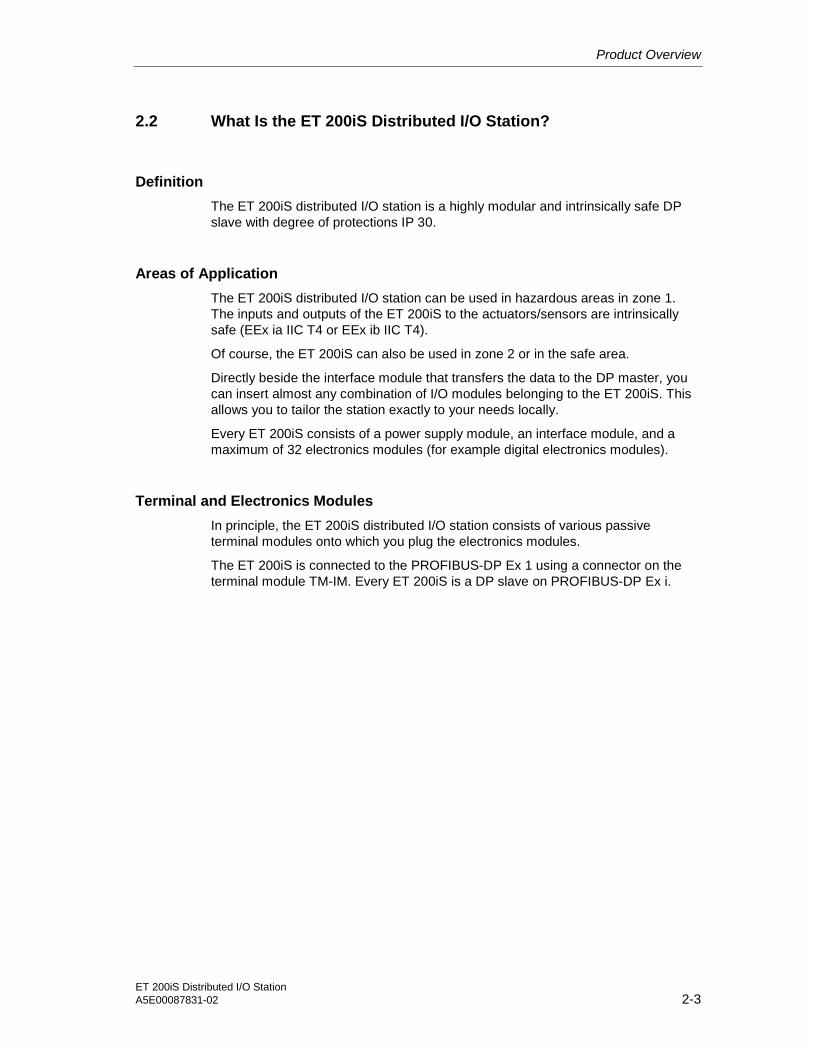
2.2 What Is the ET 200iS Distributed I/O Station?
Definition
The ET 200iS distributed I/O station is a highly modular and intrinsically safe DPslave with degree of protections IP 30.
Areas of Application
The ET 200iS distributed I/O station can be used in hazardous areas in zone 1.The inputs and outputs of the ET 200iS to the actuators/sensors are intrinsicallysafe (EEx ia IIC T4 or EEx ib IIC T4).
Of course, the ET 200iS can also be used in zone 2 or in the safe area.
Directly beside the interface module that transfers the data to the DP master, youcan insert almost any combination of I/O modules belonging to the ET 200iS. Thisallows you to tailor the station exactly to your needs locally.
Every ET 200iS consists of a power supply module, an interface module, and amaximum of 32 electronics modules (for example digital electronics modules).
Terminal and Electronics Modules
In principle, the ET 200iS distributed I/O station consists of various passiveterminal modules onto which you plug the electronics modules.
The ET 200iS is connected to the PROFIBUS-DP Ex 1 using a connector on theterminal module TM-IM. Every ET 200iS is a DP slave on PROFIBUS-DP Ex i.
Product Overview
ET 200iS Distributed I/O Station2-4 A5E00087831-02
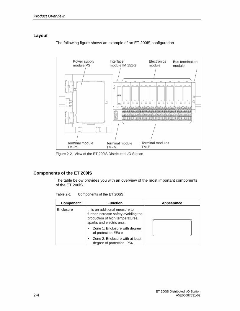
Layout
The following figure shows an example of an ET 200iS configuration.
Power supplymodule PS
Interfacemodule IM 151-2
Electronicsmodule
Bus terminationmodule
Terminal moduleTM-PS
Terminal modulesTM-E
Terminal moduleTM-IM
Figure 2-2 View of the ET 200iS Distributed I/O Station
Components of the ET 200iS
The table below provides you with an overview of the most important componentsof the ET 200iS.
Table 2-1 Components of the ET 200iS
Component Function Appearance
Enclosure ... is an additional measure tofurther increase safety avoiding theproduction of high temperatures,sparks and electric arcs.
• Zone 1: Enclosure with degreeof protection EEx e
• Zone 2: Enclosure with at leastdegree of protection IP54
Product Overview
ET 200iS Distributed I/O StationA5E00087831-02 2-5
Component Function Appearance
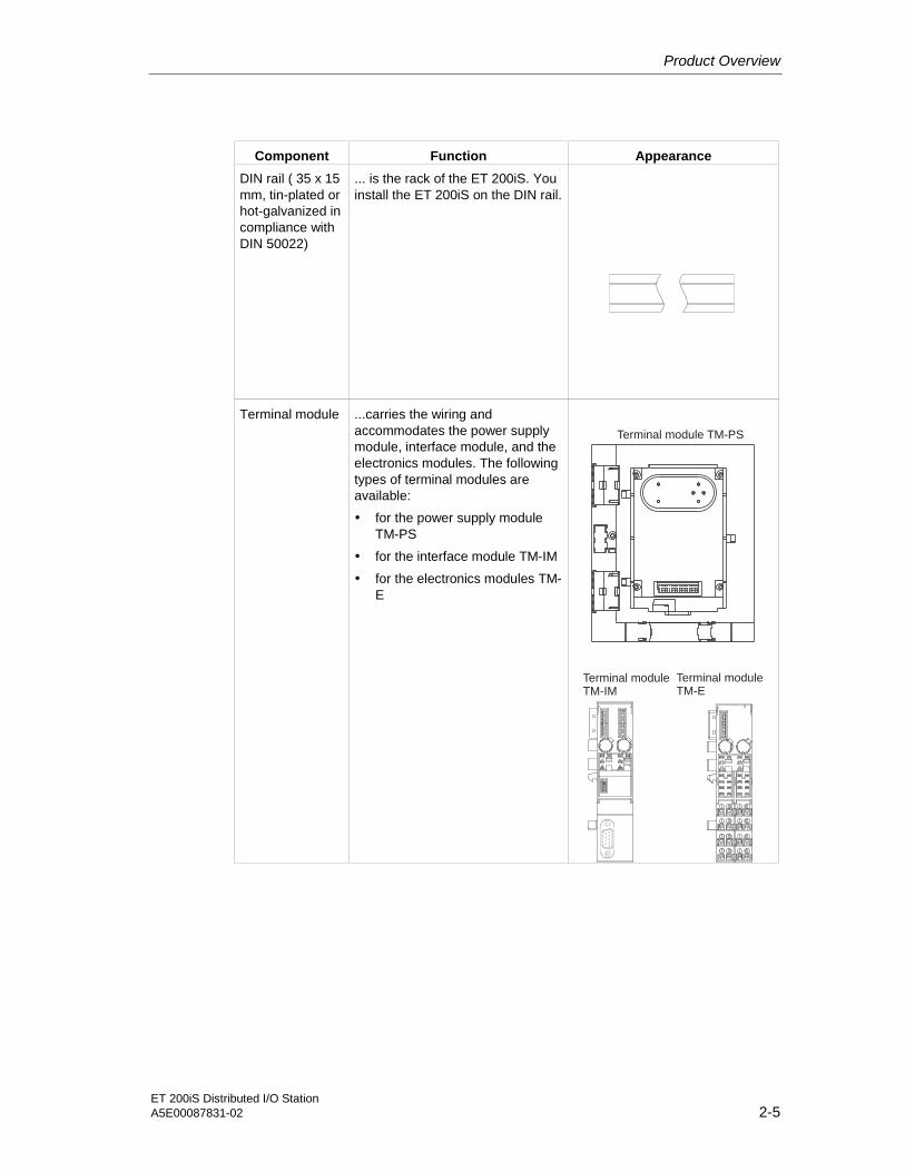
DIN rail ( 35 x 15mm, tin-plated orhot-galvanized incompliance withDIN 50022)
... is the rack of the ET 200iS. Youinstall the ET 200iS on the DIN rail.
Terminal module ...carries the wiring andaccommodates the power supplymodule, interface module, and theelectronics modules. The followingtypes of terminal modules areavailable:
• for the power supply moduleTM-PS
• for the interface module TM-IM
• for the electronics modules TM-E
Terminal module TM-PS
Terminal moduleTM-IM
Terminal moduleTM-E

Product Overview
ET 200iS Distributed I/O Station2-6 A5E00087831-02
Component Function Appearance
Power supplymodule
... is plugged onto the terminalmoduleTM-PS. The power supply modulesupplies the electronics andencoders with voltage.
Interface module ... is plugged onto the terminalmoduleTM-IM. The interface moduleconnects the ET 200iS with the DPmaster and conditions the data forthe inserted electronics modules.
Electronicsmodule
... is plugged onto the terminalmoduleTM-E and decides which functionis performed:
• Digital electronics modules forNAMUR encoders, digitaloutput
• Analog electronics moduleswith current and resistancemeasurement, thermoresistorsand thermocouples
• Analog electronics moduleswith HART, analog output

Product Overview
ET 200iS Distributed I/O StationA5E00087831-02 2-7
Component Function Appearance
Bus terminationmodule
...completes the ET 200iS.
Fieldbus isolatingtransformer
...converts PROFIBUS-DP toPROFIBUS-DP Ex i
Shield contact ...used to contact cable shields.
Label sheet (DINA4, perforated,foil)
...for machine labeling or printing;80 strips per sheet

Product Overview
ET 200iS Distributed I/O Station2-8 A5E00087831-02
Component Function Appearance
Slot numberlabels
...for identifying the slots on theterminal module
32
31
21
Color labels ...allow customer and country-specific identification of theterminals on the terminal module
PROFIBUS cablewith busconnector
...interconnects the nodes of aPROFIBUS-DP Ex i system orconnects the fieldbus isolatingtransformer with the ET 200iS.
Bus terminatingresistor
...terminates PROFIBUS-DP Ex i
Properties and Uses of the ET 200iS
Table 2-2 Properties and Uses
Features Uses
The design
Scalable modular design with 2 or 4-channelelectronics modules
• Station design optimized to contain costs
• Reduced configuration anddocumentation effort
• Space-saving with no fixed order for themodules
Wide range of electronics modules Extensive area of application
Permanent wiring by separating mechanicaland electronic components
• Prewiring possible
• Hot swapping of modules while the ET200iS is operating when at least twoelectronics modules are present.
Integrated powerbus Reduced wiring effort
Screw or spring terminals Use of most suitable terminating technique
Product Overview
ET 200iS Distributed I/O StationA5E00087831-02 2-9
Features Uses
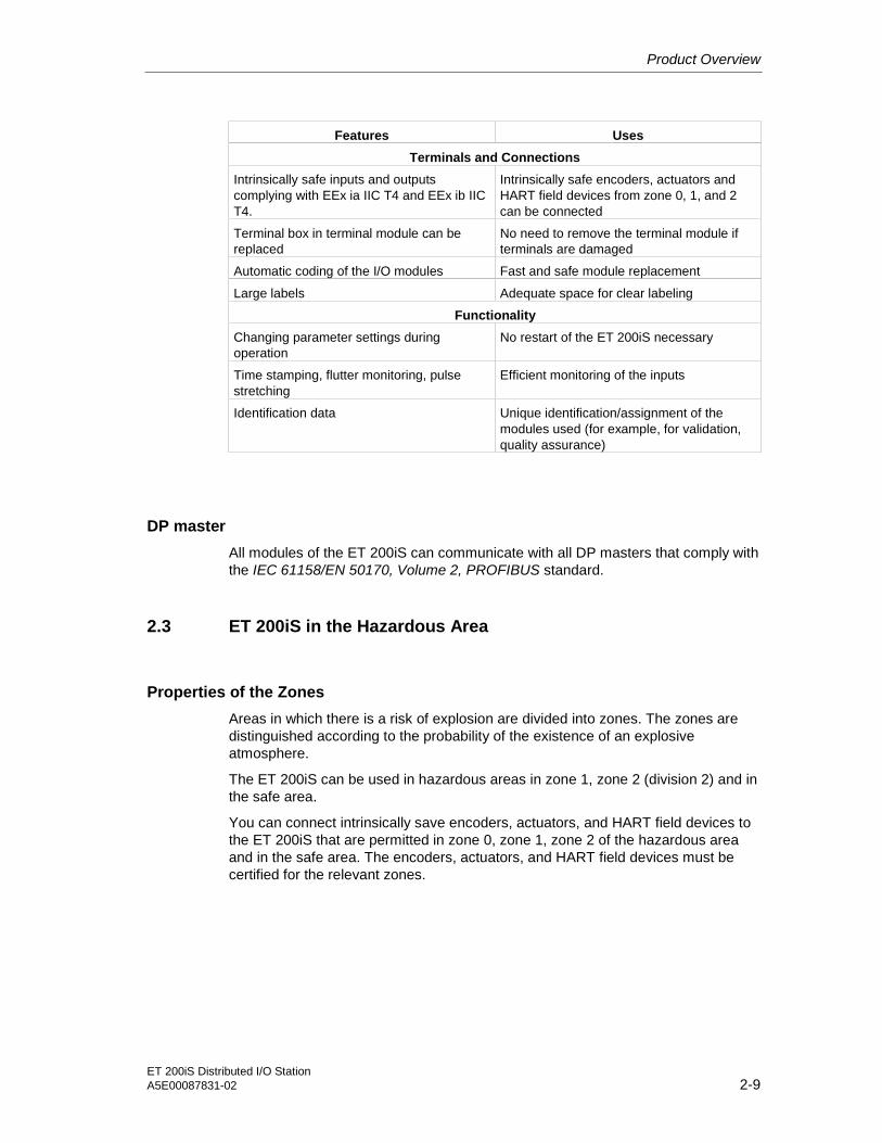
Terminals and Connections
Intrinsically safe inputs and outputscomplying with EEx ia IIC T4 and EEx ib IICT4.
Intrinsically safe encoders, actuators andHART field devices from zone 0, 1, and 2can be connected
Terminal box in terminal module can bereplaced
No need to remove the terminal module ifterminals are damaged
Automatic coding of the I/O modules Fast and safe module replacement
Large labels Adequate space for clear labeling
Functionality
Changing parameter settings duringoperation
No restart of the ET 200iS necessary
Time stamping, flutter monitoring, pulsestretching
Efficient monitoring of the inputs
Identification data Unique identification/assignment of themodules used (for example, for validation,quality assurance)
DP master
All modules of the ET 200iS can communicate with all DP masters that comply withthe IEC 61158/EN 50170, Volume 2, PROFIBUS standard.
2.3 ET 200iS in the Hazardous Area
Properties of the Zones
Areas in which there is a risk of explosion are divided into zones. The zones aredistinguished according to the probability of the existence of an explosiveatmosphere.
The ET 200iS can be used in hazardous areas in zone 1, zone 2 (division 2) and inthe safe area.
You can connect intrinsically save encoders, actuators, and HART field devices tothe ET 200iS that are permitted in zone 0, zone 1, zone 2 of the hazardous areaand in the safe area. The encoders, actuators, and HART field devices must becertified for the relevant zones.

Product Overview
ET 200iS Distributed I/O Station2-10 A5E00087831-02
The following table provides an overview of the zone categories:
Table 2-3 Classification of Zones
Zone Degree of Hazard Example
0 Explosive atmosphere is continuouslypresent or present for long periods oroften present
Within containers.
1 Explosive gas atmosphere issometimes present
In the region of openings for fillingand emptying.
2 Explosive gas atmosphere is seldompresent and then only for a short time
Areas bordering on zone 1
Safe area No Standard Applications ordistributed I/O
Types of Protection of the ET 200iS
The types of protection include design and electrical measures relating to theequipment to achieve explosion protection in the hazardous areas .
The ET 200iS has the following types of protection:
Properties and Types of Protection
The types of protection of the ET 200iS have the following significance:
Table 2-4 Properties and Types of Protection
Type ofProtection
Meaning Representation
Intrinsic safety i All voltages, currents, inductanceand capacitance occurring arelimited by electrical measures(intrinsically safe) - sparks orthermal effects capable of causingignition cannot occur.

Product Overview
ET 200iS Distributed I/O StationA5E00087831-02 2-11
Type ofProtection
Meaning Representation
Explosion-proofenclosure d
The power supply module isinstalled in a stable (explosion-proof) enclosure. If the explosiveatmosphere within the enclosureignites, the enclosure will withstandthe explosion and contain theexplosion within the power supplymodule.
Increased-safetyenclosure e
In zone 1 of the hazardous area,the ET 200iS must be installed inan additional enclosure. Theenclosure must have the increasedsafety e type of protection.
This type of protection involvesadditional measures to avoid theoccurrence of high temperatures,sparks and arc-over.
In zone 2 of the hazardous area,this type of protection isunnecessary. Here, the ET 200iSmust simply be installed in anenclosure suitable for zone 2 withat least degree of protection IP 54.

Product Overview
ET 200iS Distributed I/O Station2-12 A5E00087831-02
Identification Codes of the ET 200iS
All equipment intended for use in hazardous areas must have an identificationcode indicating the type of hazardous environment for which the equipment issuited.The ET 200iS has the following types of identification code:
mAHazardous area: zone 2
Hazardous area: zone 1
ET 200iS: EEx ib IIC T4
Terminals:EEx ib IIC T4 and EEx ia IIC T4
Power supplymodule:EEx de [ia/ib]IIC/IIB T4
Enclosure: EEx e
Key:
Eex:ib:ia:
:IIC:IIB:
Explosion-protection identifierType of protection: intrinsic safety (use of the ET 200iS in zone 1)Type of protection: intrinsic safety (use of sensors, actuators, HART field devicesup to zone 0)
ype of protection: explosion-proof enclosureType of protection: increased safety
Explosion group for hydrogenExplosion group for ethylene
de: T
PROFIBUS-DP Ex i
Figure 2-3 Identification Codes of the ET 200iS

Product Overview
ET 200iS Distributed I/O StationA5E00087831-02 2-13
2.4 Integration in Process Control System
PCS 7
PCS 7 is a powerful process control system. Through PCS 7, the ET 200iS has adirect attachment to the control system.
Configuration withSTEP7
Parameter assignmentwith SIMATIC PDM
Operator control andmonitoring with WinCC
Lowest level:actuators, sensors,
field devices
ET 200iS in enclosure
Industrial Ethernet
S7-400
PROFIBUS DP
PC
PC
Components of PCS 7
Fieldbus isolating transformer
Higher level
Hazardous area:zone 1
PCS7-OS
PCS7-ES
PROFIBUS-DP EX i
Zone 0 mA Hart
Figure 2-4 Integration in the Control System

Product Overview
ET 200iS Distributed I/O Station2-14 A5E00087831-02

ET 200iS Distributed I/O StationA5E00087831-02 3-1
3Brief Instructions on Commissioning 33.1 Introduction
Introduction
This manual guides you step-by-step through a concrete example until you havecreated a functioning application. While working through the example, you will learnthe basic hardware and software functions ET 200iS.
3.2 Requirements
Requirements
The following requirements must be met:
• You must be familiar with the basics of electrical and electronic engineering andthe procedures relating to hazardous areas as well as experience of workingwith computers and Microsoft(R) Windows(TM) 95/98/ME/NT/2000.
• Full versions of STEP 7 and SIMATIC PDM (Version 5.1, Service Pack 2, Hotfix1 or higher) are installed on your PG and you are familiar with the basics ofworking with STEP 7. Older versions of STEP 7 can also be used. SeeCommissioning and Diagnostics
• If you implement this example in zone 1 or zone 2, you must adhere to all therules and regulations explained and listed in this manual.
Note
When checking the functionality make sure that you keep to the stipulations inEN 60 079-17. This standard contains the regulations of the international standardIEC 60 079-17.
Danger
When laying cables and wiring, make sure that you adhere to the installationregulations complying with EN 60 079-14 and any regulations specific to yourcountry.

Brief Instructions on Commissioning
ET 200iS Distributed I/O Station3-2 A5E00087831-02
Warning
When used in systems, the ET 200iS is subject to special rules and regulationsdepending on the area of application.Please note and adhere to the valid safety and accident prevention regulations, forexample IEC 204 (EMERGENCY STOP devices).If you do not adhere to these regulations, this can result in serious injury anddamage to machines and facilities.
3.3 Materials and Tools Required to Set Up the Example
Table 3-1 Required Material and Tools
Number Article Order Number (Siemens)
2 Rails complying with EN 50022 (35 x 15 mm) e.g. 6ES5 710-8MA11
1 Enclosure for ET 200iS with degree of protection EEx e Contact your Siemensrepresentative
1 Terminal module TM-PS 6ES7 193-5DA00-0AA0
1 Terminal module TM-IM with bus termination module 6ES7 193-5DB00-0AA0
7 Terminal module TM-E30S44-iS 6ES7 193-5CB00-0AA0
1 Interface module IM 151-2 6ES7 151-2AA0-0AB0
1 Power supply PS 6ES7 138-5EA00-0AA0
3 4DI NAMUR 6ES7 131-5RD00-0AB0
3 2DO DC25V/25mA 6ES7 132-5SB00-0AB0
1 EEx e-terminal WPE 16/E 17522900 (manufacturerWeidmüller)
1 Fieldbus isolating transformer 9373 with terminatingresistor
Can be ordered fromR. Stahl Schaltgeräte GmbHorder number 93 730 05 01 2
2 PROFIBUS bus connector (for master) 6ES7 972-0BB10-0XA0
1 PROFIBUS bus connector (for ET 200iS) 6ES7 972-0BA30-0XA0
1 PROFIBUS-DP cable e.g. 6XV1 830-0EH10
2 NAMUR sensor e.g. BERO 3RG 4612-1NA00
1 1-wire On button normal suppliers
3 LEDs with series resistor normal suppliers
1 Power supply module PS S7-400 e.g. 6ES7 405-0KA00-0AA0
1 CPU S7-416-3 DP 6ES7 416-3XL00-0AB0
1 Rack for S7-400 e.g. 6ES7 400-1TA01-0AA0
1 Programming device (PG) with PROFIBUS-DP interface,installed software STEP 7 (Version 5.1, Service Pack 2,Hotfix 1 or higher) communications processor CP 5611and PG cable
various
1 Screwdriver with 3 mm blade normal suppliers

Brief Instructions on Commissioning
ET 200iS Distributed I/O StationA5E00087831-02 3-3
Number Article Order Number (Siemens)
1 Screwdriver with 7 mm blade normal suppliers
1 Cutting tool for the DIN rails normal suppliers
1 Cable cutters and wire stripping tools normal suppliers
1 Tool for crimping wire-end ferrules normal suppliers
X m Cable for grounding DIN rails with 10 mm cross-sectionwith terminal end to fit M6, length to suit local situation
normal suppliers
approx.2 m
Flexible lead with 1 mm2 cross section and suitable wire-end ferrules, form A, length 6 mm
normal suppliers
3.4 Overview of the Setup
Overview of the Example Setup (wiring and power sources not illustrated)
Fieldbusisolatingtransformer
ET 200iS
S7-400
Terminating resistor
3x
4D
IN
AM
RU
R
3x
2D
O
Ground bus PA
PG with CP 5611
Enclosure EEx e
Figure 3-1 Overview of the Example Setup
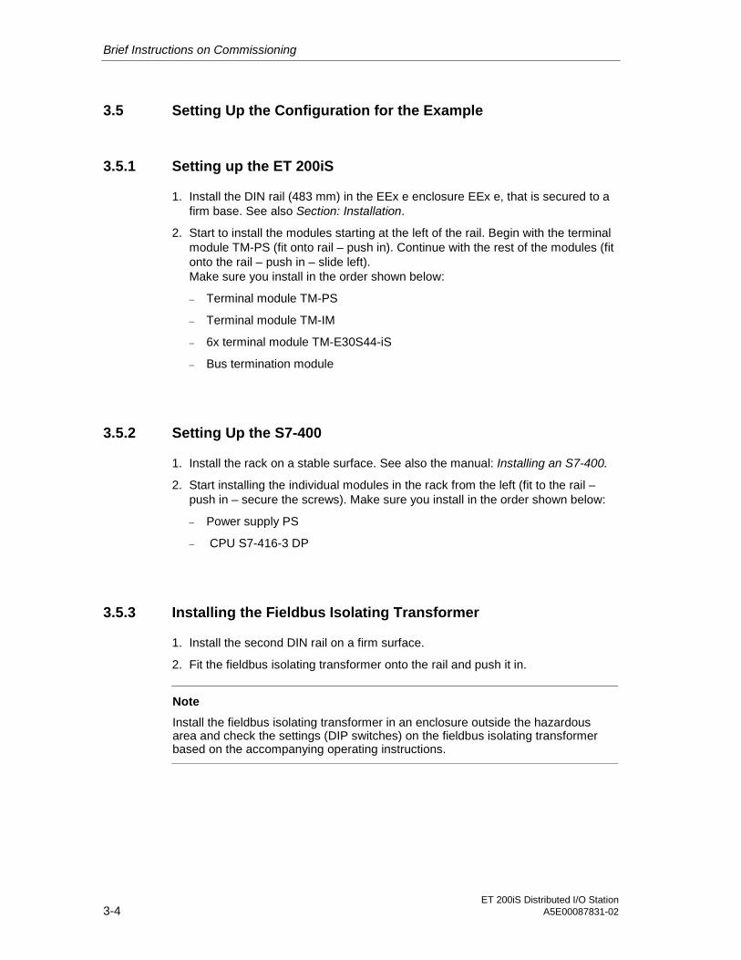
Brief Instructions on Commissioning
ET 200iS Distributed I/O Station3-4 A5E00087831-02
3.5 Setting Up the Configuration for the Example
3.5.1 Setting up the ET 200iS
1. Install the DIN rail (483 mm) in the EEx e enclosure EEx e, that is secured to afirm base. See also Section: Installation.
2. Start to install the modules starting at the left of the rail. Begin with the terminalmodule TM-PS (fit onto rail – push in). Continue with the rest of the modules (fitonto the rail – push in – slide left).Make sure you install in the order shown below:
– Terminal module TM-PS
– Terminal module TM-IM
– 6x terminal module TM-E30S44-iS
– Bus termination module
3.5.2 Setting Up the S7-400
1. Install the rack on a stable surface. See also the manual: Installing an S7-400.
2. Start installing the individual modules in the rack from the left (fit to the rail –push in – secure the screws). Make sure you install in the order shown below:
– Power supply PS
– CPU S7-416-3 DP
3.5.3 Installing the Fieldbus Isolating Transformer
1. Install the second DIN rail on a firm surface.
2. Fit the fieldbus isolating transformer onto the rail and push it in.
Note
Install the fieldbus isolating transformer in an enclosure outside the hazardousarea and check the settings (DIP switches) on the fieldbus isolating transformerbased on the accompanying operating instructions.

Brief Instructions on Commissioning
ET 200iS Distributed I/O StationA5E00087831-02 3-5
3.6 Wiring the Example Setup
1L+
2L+
1M
2M
1PA
2PA
Terminal module TM-PSfor power supplymodule PS
DC 24V
To ground bus PA
RL+
RM
Figure 3-2 Wiring TM-PS
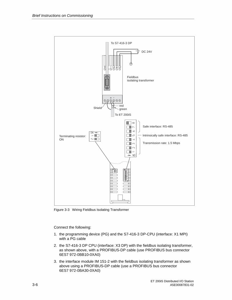
Brief Instructions on Commissioning
ET 200iS Distributed I/O Station3-6 A5E00087831-02
+ -
+ -
Shield
To S7-416-3 DP
To ET 200iS
Fieldbusisolating transformer
L1
DC 24V
L2
Transmission rate: 1.5 Mbps
Intrinsically safe interface: RS-485
Safe interface: RS-485
Terminating resistor:ON
redgreen
Figure 3-3 Wiring Fieldbus Isolating Transformer
Connect the following:
1. the programming device (PG) and the S7-416-3 DP-CPU (interface: X1 MPI)with a PG cable
2. the S7-416-3 DP CPU (interface: X3 DP) with the fieldbus isolating transformer,as shown above, with a PROFIBUS-DP cable (use PROFIBUS bus connector6ES7 972-0BB10-0XA0)
3. the interface module IM 151-2 with the fieldbus isolating transformer as shownabove using a PROFIBUS-DP cable (use a PROFIBUS bus connector6ES7 972-0BA30-0XA0)

Brief Instructions on Commissioning
ET 200iS Distributed I/O StationA5E00087831-02 3-7
4. the terminating resistor supplied with the fieldbus isolating transformer, with theinterface module IM 151-2
5. the power supply PS, the fieldbus isolating transformer, and the power supplyPS S7-400 with the power supply
6. the rack of the S7-400 with the grounding conductor
7. the DIN rail of the ET 200iS and the power supply module PS with theequipotential bonding system PA. To secure to the DIN rail, use the EEx e-terminal.
Wire the ET 200iS as shown below:
3x 4DI NAMUR 3x 2DO
12 12 12 3 4 33 4 4
NAMUR-encoder
LEDs
clamp
Figure 3-4 Wiring the ET 200iS Modules

Brief Instructions on Commissioning
ET 200iS Distributed I/O Station3-8 A5E00087831-02
3.7 Insert the interface module and the electronics modules
Start at the left by inserting the electronics modules. See also: Inserting andLabeling the Power Supply, Interface Module, and Electronics Modules.
Make sure you install in the order shown below:
• Power supply PS
• Interface module IM 151-2
• 3x 4DI NAMUR
• 3x 2DO DC25V/25mA
3.8 Setting the PROFIBUS Address
On the IM 151-2 interface module, set PROFIBUS address 3. See also: Setting thePROFIBUS Address.
64
32
16
8
4
2
1
ON
Interface module
OFF Example:
DP address=
+ 2
+ 1
= 3
_______*
* Intended for future expansion.Switch must be set to OFF.
Figure 3-5 Setting PROFIBUS Address 3

Brief Instructions on Commissioning
ET 200iS Distributed I/O StationA5E00087831-02 3-9
3.9 Configuring the Example
3.9.1 Configuring the S7-400
Step 1
Open STEP 7.
Step 2
If the New Project Wizard opens, close it with Cancel.
Step 3
Go to the main menu of the SIMATIC Manager and select File > New. A dialog boxopens in which you enter "ET 200iS" as the name and then close the dialog withOK.
Step 4
ClickInsertClick Insert > Station in the menu and select SIMATIC 400 Stationfrom the list. An icon with the name SIMATIC 400(1) is created in the right-handpane of the project window.
Step 5
Now double-click on the icon of the SIMATIC 400 station in the SIMATIC Manager.An icon labeled "Hardware" now appears in the right-hand pane of the window.Double-click on this icon. HW Config opens.
Step 6
If no catalog with components is displayed on the right-hand side of the window,activate the display by selecting View > Catalog in the menu.
Expand the SIMATIC 400 folder and RACK-400 folder until you can see UR1.Double-click on this icon. In the lower part of the window on the left, you can nowsee the slots.
Step 7
Select slot 1 (it changes to blue) and then return to the catalog and open thefolders SIMATIC 400, PS 400 and Standard PS 400 until you can see PS 407 10A.Double-click on this icon. The power supply module now occupies slots 1 and 2.

Brief Instructions on Commissioning
ET 200iS Distributed I/O Station3-10 A5E00087831-02
Step 8
Next, select slot 3 and then return to the catalog and open folders SIMATIC 400,CPU 400, CPU 416-3 DP and 6ES7 416-3XL00-0AB0 until you can see V1.2.When you double-click on the icon, a window with the title "Properties - PROFIBUSinterface DP R0/S3.1)“ opens and you can acknowledge this window with OK. TheCPU is entered in slots 3 and 4.
Step 9
In the lower left-hand window, locate the row labeled DP and select it. Right-clickon the row and select Object Properties. The "Properties DP (R0/S3.1)" dialogopens. Click the Properties button and in the next dialog, click New. A new DPsubnet operating at 1.5 Mbps is created. Now confirm by clicking OK three times insuccession.
Step 10
In the main menu, you can save the changes with Station > Save and Compile.
Figure 3-6 Configuration of the S7-400

Brief Instructions on Commissioning
ET 200iS Distributed I/O StationA5E00087831-02 3-11
3.9.2 Configuration of the ET 200iS
Step 1
In the upper left-hand window of HW Config, click on the stylized PROFIBUS toselect it. Now go to the catalog and open PROFIBUS DP and ET 200iS so that youcan see IM 151-2. Double-click on this icon to insert an ET 200iS station. In thedialog box that opens, change the address to 3 and confirm with OK. At the bottomleft, you can now see the new slots with an IM 151-2 in slot 2.
Step 2
Select slot 1 and then go the catalog to power module PS, which is located underIM 151-2 in the tree, and insert this by double-clicking on it.
Step 3
Since slot 3 must remain free, select slot 4 and starting from there insert threeNAMUR 4DI modules and three 2DO DC25V/25mA modules.

Brief Instructions on Commissioning
ET 200iS Distributed I/O Station3-12 A5E00087831-02
Figure 3-7 Configuration of the ET 200iS
Step 4
After saving the project with the menu command Station > Save and Compile,you can exit HW Config.

Brief Instructions on Commissioning
ET 200iS Distributed I/O StationA5E00087831-02 3-13
3.9.3 Setting Parameters for the ET 200iS
Requirements
To be able to work online with SIMATIC PDM, you must set the CP 5611 to thePROFIBUS-DP interface (in the SIMATIC Manager: menu command Options >Set PG/ PC Interface).
Step 1
You are still in HW Config. Double-click on the first module in the configurationtable (slot 4: 4DI NAMUR).
Step 2
In the next dialog, select "Specialist" as the user and confirm with "OK". In thismode, you can make parameter settings.
Result: SIMATIC PDM is started with the parameters and identification data of themodule.
Step 3
For channels 1-3 change the encoder type to "channel disabled" and save thechanges with File > Save. With Device > Download to Device, you can downloadthe parameters to the ET 200iS. Close SIMATIC PDM.
Figure 3-8 Disabling ET 200iS Channels

Brief Instructions on Commissioning
ET 200iS Distributed I/O Station3-14 A5E00087831-02
Step 4
Follow the same procedure as described in points 1 through 3 for each of the ET200iS modules and make the changes as outlined in the table below.
Table 3-2 Changes
Module
Slot Type Channel 0 Channel 1 Channel 2-3
1 4 4xDI NAMUR No change Encoder type: Channeldisabled
Encoder type: Channeldisabled
2 5 4xDI NAMUR No change Encoder type: Channeldisabled
Encoder type: Channeldisabled
3 6 4xDI NAMUR No change Encoder type: Channeldisabled
Encoder type: Channeldisabled
4 7 2xDO No change No change -
5 8 2xDO No change No change -
6 9 2xDO No change No change -
Note
If you double-click on the DP slave "IM 151-2" (in the upper part of the stationwindow) in HW Config, SIMATIC PDM starts and all the modules of the ET 200iSare downloaded. If you then select the menu command Device > Full Upload toPG/PC all the parameters and identification data of the ET 200iS are loaded. InSIMATIC PDM, you can select individual modules, assign the parameters for them,and save them (menu command File > Save) and download them to the ET 200iS(Menu command Device > Full Download to Device).
3.10 Programming the Example
How it Works
The state of the encoders connected to inputs I512.0 , I513.0 and I514.0 is queriedand evaluated. I512.0 increments an internal counter and I513.0 decrements it.Input I514.0 resets the counter to zero.
Depending on the counter value, outputs Q512.0, Q513.0 and Q514.0 are set ordeleted. Q512.0 is set when the counter value is 0. At a counter value < 3, Q514.0is set and at ≥ 3, Q513.0 is set.

Brief Instructions on Commissioning
ET 200iS Distributed I/O StationA5E00087831-02 3-15
Programming
Change to the component view with View > Component View.
Open the following in succession: SIMATIC 400(1), CPU 416-3 DP, S7 Program(1)and Blocks until you can see OB1. Double-click on OB1 and confirm the dialog withOK.
Enter the following STL program:
Table 3-3 Program for the Example
STL Remarks
A I 514.0 If button 514.0 is active,
R C 0 set counter to 0
A I 512.0 If BERO 512.0 is active,
CU C 0 increment by 1
A I 513.0 If BERO 513.0 is active
CD C 0 decrement by 1
AN C 0 Is counter = 0 ?
= Q 512.0 YES, then output 512.0 is active
L C 0 Load counter in ACCU
L 3 Load 10 in ACCU
>=I Is counter => 3 ?
= Q 513.0 YES, then output 513.0 is active
<I Is counter < 3 ?
= Q 514.0 YES, then output 514.0 is active
Save the program with File > Save and download it to the CPU withPLCwith PLC> Download.

Brief Instructions on Commissioning
ET 200iS Distributed I/O Station3-16 A5E00087831-02
3.11 Putting the Example into Operation
Turn on the power supply of the ET 200iS.
Watch the status LEDs on the S7-400 and on the ET 200iS:
• CPU 416-3 DP :
DC 5V: lit
SF DP: off
BUSF: off
• ET 200iS:
SF: off
BF: off
ON: lit
3.12 Evaluating the Diagnostics
If an error occurs, OB82 is started. Evaluate the startup information in OB82.
Tip: Call SFC13 in OB82 and evaluate the diagnostic frame. See Commissioningand Diagnostics.

Brief Instructions on Commissioning
ET 200iS Distributed I/O StationA5E00087831-02 3-17
3.13 Removing and inserting modules
Removing and Inserting Digital Electronics Module 4 DI NAMUR
1. Remove the first of the three electronics modules 4 DI NAMUR from theterminal module during operation.
2. Monitor the status LEDs on the IM 151-2:
– SF: lit -> diagnostic message exists
– BF: off
– ON: litResult: The ET 200iS continues to operate problem-free.
3. Evaluate the diagnostic messageResult:
– Station status 1 (byte 0): Bit 3 is set -> External diagnostics
– ID-related diagnostics : Bit 3 in byte 7 is set -> slot 4
– Module status: Byte 16.7/16.6: 11B -> no module
4. Insert the removed electronics module in the terminal module againResult:
– Status LEDs IM 151-2:SF: offBF: offON: lit
– The diagnostic message is deleted

Brief Instructions on Commissioning
ET 200iS Distributed I/O Station3-18 A5E00087831-02
3.14 Wire break of the NAMUR encoder connected to the digital inputmodule
1. Remove the wire from terminal 1 of the first of the three electronics modules4 DI NAMUR.
2. Monitor the status LEDsIM 151-2:
– SF: lit
– Electronics module 4 DI NAMUR
– SF: lit -> diagnostic message exists
– 1: off -> output is not activated
3. Evaluate the diagnostic messageResult:
– Station status 1 (byte 0): Bit 3 is set -> External diagnostics
– ID-related diagnostics: Byte 7.3 is set -> slot 4
– Channel-related diagnostics:Byte 25: 10000011B -> slot 4Byte 26: 01000000B -> channel 0byte 27: 00110B -> wire break
4. Secure the wire to the BERO again in terminal 1 and evaluate the diagnosticsagain:
– Status LED IM151-2SF: off
– Status LEDs electronics module 4 DI NAMUR:SF: off1: off/on
– The diagnostic message is deleted.
ET 200iS Distributed I/O StationA5E00087831-02 4-1
4Configuration Options 44.1 System with Scalable Modularity
System with Scalable Modularity
With the ET 200iS scalable modularity means that you can adapt the structureexactly to match your applications with 2 and 4-channel electronics modules.
Example
The following schematic shows an example of a possible configuration of the ET200iS distributed I/O station:

Configuration Options
ET 200iS Distributed I/O Station4-2 A5E00087831-02
Switches,
Relays
NAMUR sensors
2/4-wire transducers
Resistance thermometers
Thermocouples
Loads at current output
HART field devices
4DI NAMUR
2 DO DC25V/25mA
2AI I 2WIRE2AI I 4WIRE
2AI RTD
2AI TC
2AO I 2AI I 2WIRE HART2AI I 4WIRE HART2AO I HART
IM 151-2Power supply module PS
mA
Figure 4-1 Example of an ET 200iS Configuration
4.2 Electronics Modules to Suit your Application
Which Electronics Module Does What?
In the following table, you will find a guide to the applications of the electronicsmodules of the ET 200iS distributed I/O station.
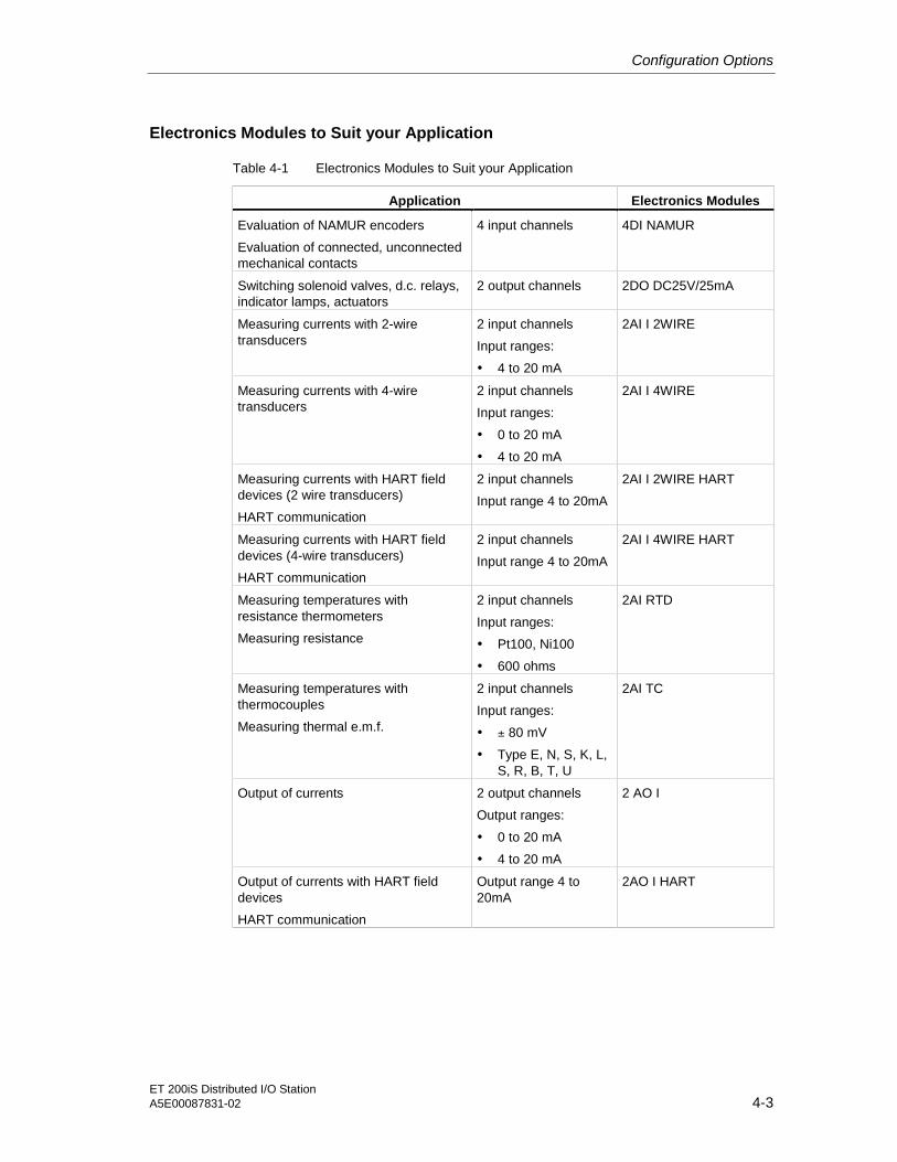
Configuration Options
ET 200iS Distributed I/O StationA5E00087831-02 4-3
Electronics Modules to Suit your Application
Table 4-1 Electronics Modules to Suit your Application
Application Electronics Modules
Evaluation of NAMUR encoders
Evaluation of connected, unconnectedmechanical contacts
4 input channels 4DI NAMUR
Switching solenoid valves, d.c. relays,indicator lamps, actuators
2 output channels 2DO DC25V/25mA
Measuring currents with 2-wiretransducers
2 input channels
Input ranges:
• 4 to 20 mA
2AI I 2WIRE
Measuring currents with 4-wiretransducers
2 input channels
Input ranges:
• 0 to 20 mA
• 4 to 20 mA
2AI I 4WIRE
Measuring currents with HART fielddevices (2 wire transducers)
HART communication
2 input channels
Input range 4 to 20mA
2AI I 2WIRE HART
Measuring currents with HART fielddevices (4-wire transducers)
HART communication
2 input channels
Input range 4 to 20mA
2AI I 4WIRE HART
Measuring temperatures withresistance thermometers
Measuring resistance
2 input channels
Input ranges:
• Pt100, Ni100
• 600 ohms
2AI RTD
Measuring temperatures withthermocouples
Measuring thermal e.m.f.
2 input channels
Input ranges:
• ± 80 mV
• Type E, N, S, K, L,S, R, B, T, U
2AI TC
Output of currents 2 output channels
Output ranges:
• 0 to 20 mA
• 4 to 20 mA
2 AO I
Output of currents with HART fielddevices
HART communication
Output range 4 to20mA
2AO I HART

Configuration Options
ET 200iS Distributed I/O Station4-4 A5E00087831-02
4.3 Which Electronics Modules Match the Terminal Modules?
Selecting the Terminal Modules
In the following table, you will find information to help you select the terminalmodules you require.
Which Electronics Modules Match the Terminal Modules?
Table 4-2 Which Electronics Modules Match the Terminal Modules?
Electronics Modules Terminal Modules
Power supply module PS Terminal module TM-PS
Interface module IM 151-2 Terminal module TM-IM
• 4DI NAMUR
• 2DO DC25V/25mA
• 2AI I 2WIRE
• 2AI I 4WIRE
• 2AI I 2WIRE HART
• 2AI I 2WIRE HART
• 2AI RTD
• 2AI TC
• 2 AO I
• 2AO I HART
Terminal module TM-E30S44-iS (screwterminal)
or
Terminal module TM-E30C44-iS (springterminal)
Bus termination module ---

Configuration Options
ET 200iS Distributed I/O StationA5E00087831-02 4-5
4.4 Configuration Options in Zones
General Rules
Regardless of the configuration of the ET 200iS in zone 1, zone 2 or in the safearea, the following rules apply:
If the inputs and outputs to the actuators are intrinsically safe, thenPROFIBUS-DP must also be intrinsically safe (Ex i):
1. Fieldbus isolating transformer required (for example, from R. STAHLSchaltgeräte GmbH; Refer to the order numbers)
2. Marking of PROFIBUS-DP as Ex i (not only in zone 1!)
3. Marking of the cables/wires to the actuators and sensors as Ex i (for example,using the color light blue).
Warning
All devices you connect to PROFIBUS-DP Ex i (on the Ex side of the fieldbusisolating transformer) must be intrinsically safe.
Connecting voltage measurement devices, oscillographs, and bus testers toPROFIBUS-DP Ex i is not permitted.
Rules for Configuring the ET 200iS in Zone 1:
If you use the ET 200iS in zone 1, you must adhere to the following rules:
1. The ET 200iS must be installed in an enclosure with type of protection EEx e(increased safety). For information on ordering such enclosures, contact yourSiemens representative
2. PROFIBUS-DP must be isolated using a fieldbus isolating transformer. Thefieldbus isolating transformer (for example from R. STAHL Schaltgeräte GmbH;refer to the section Order Numbers) guarantees degree of protection EEx i forPROFIBUS-DP in hazardous areas (zone 1).The fieldbus isolating transformer must be installed in the safe area. SeeAppendix Order Numbers.
3. Normal PROFIBUS-DP bus cables can be used in zone 1. See appendix OrderNumbers. You must, however, mark these as "EEx i bus cable" (for examplewith a blue band/blue shrink-on sleeve at the ends or mark the cable with a bluecolor).

Configuration Options
ET 200iS Distributed I/O Station4-6 A5E00087831-02
4. The PROFIBUS-DP bus cable must be connected to the IM 151-2 over the busconnectors operating at 1.5 Mbps (order number 6ES7 972-0BA30-0XA0).
5. PROFIBUS-DP Ex i must be terminated in zone 1 with the RS-485 terminatingresistor (included with the fieldbus isolating transformer). The maximum length(total length of PROFIBUS-DP cabling) is 200m.
Hazardous area: zone 1
Safearea
Enclosure type of protection EEx e
Bus connector 1.5 Mbps
Fieldbus isolating transformer
PROFIBUS-DPbus cable
RS-485terminating resistor
Enclosure type of protection EEx e
PROFIBUS-DPEx i
ET200iS ET200iS
Figure 4-2 Configuration Options for the ET 200iS in Zone 1
Rules for Configuring the ET 200iS in Zone 2:
If you use the ET 200iS in zone 2, you must adhere to the following rules:
1. The ET 200iS must be installed in an enclosure with at least degree ofprotection IP 54. The enclosure must have a manufacturer's certification forzone 2 (complying with EN 50021: Protection from mechanical damage; degreeof protection IP 54; avoidance of ignition due to electrostatic charge).
2. See points 2 to 5: Rules for Configuring the ET 200iS in Zone 1
Rules for Configuring the ET 200iS in the Safe Area:
If you use the ET 200iS in the safe area, you must adhere to the following rules:
1. The ET 200iS must be installed in a metallic enclosure with at least degree ofprotection IP 20.
2. See points 2, 4 and 5: Rules for Configuring the ET 200iS in Zone 1

Configuration Options
ET 200iS Distributed I/O StationA5E00087831-02 4-7
Rules for Configuring Encoders, Actuators, HART Field Devices in Zone 1 andZone 0
The verification of intrinsic safety for each field circuit must be made according tothe regulations stipulated by the relevant standards for configuration, selection andinstallation.
A simple, intrinsically safe circuit results from attaching an encoder, actuator orHART field device to an input or output of an electronics module.
The following table describes the conditions for checking the maximum safe valuesfor a simple, intrinsically safe circuit:
Table 4-3 Rules for Configuration
Relevant Standard / Conditions forElectrical Parameters
Usable Encoders and Actuators
Standard: EN 60 079-14The electrical parameters must be asfollows:
• Uo ≤ Ui
• Io ≤ Ii
• Po ≤ Pi
• Co ≥ Ci + Ccable
• Lo ≥ Li + Lcable
The maximum safe values of the encodersand actuators must be adapted to themaximum values of the electronics modules.You will find these maximum values
• in the Ex certification of the encodersand actuators
• in the technical specifications of theelectronics modules of the ET 200iS
ET 200iS modules
SensorsactuatorsHART field devices
U max. input voltage
I max. input current
P max. input power
C max. internal capacitance
L max. internal inductance
i
i
i
i
i
C max. capacitance wire/cable
L max. inductance wire/cablecable
cable
U max. output voltage
I max. output current
P max. output power
C max. external capacitance
L max. external inductance
0
0
0
0
0

Configuration Options
ET 200iS Distributed I/O Station4-8 A5E00087831-02
Safety-Related Notices
Note
During configuration, make sure that you keep to the stipulations in EN 60 079-14.See table above.
Warning
Connecting an intrinsically safe sensor, actuator, or HART field device to theinput/output of an electronics module must produce an intrinsically safe circuit! Forthis reason:
When you select the encoder, actuator, or HART field device to be connected tothe electronics module, the resulting safety-related values must be checked!
The inductance and capacitance of the cable must also be taken into account!
4.5 Power Supply of the ET 200iS
Power supply PS
Connect the power supply of the ET 200iS to the TM-PS terminal module of thepower supply module PS. The power supply module PS provides the requiredoutput voltages for the ET 200iS. The output voltages are electrically isolated fromthe supply voltage and intrinsically safe.
• Electronics of the IM 151-2/ backplane bus
• PROFIBUS-DP Ex i interface
• Powerbus

Configuration Options
ET 200iS Distributed I/O StationA5E00087831-02 4-9
Output voltage for powerbus
Electronics IM 151-2/backplane bus
PROFIBUS-DP-Ex i interface
Power supplyDC 24 V
Groundingconductor PA
Figure 4-3 Power Supply Module PS
Powerbus
The electronics modules are supplied with the necessary supply and rated loadvoltages over the powerbus.
4.6 Direct Data Exchange
Requirements
The ET 200iS can be used as publisher for direct data exchange (crosscommunication). This requires no configuration.
Naturally, the DP master used must also support direct data exchange. You willfind information on this in the description of the DP master.
Principle
The main feature of direct data exchange is that PROFIBUS-DP nodes "listen in"and know which data a DP slave returns to its DP master. With this mechanism,the "listener" (recipient) can access changes to the input data of remote DP slavesdirectly.
During configuration in STEP 7, you use the peripheral input addresses to specifythe address area of the recipient in which the required data of the publisher will beread.

Configuration Options
ET 200iS Distributed I/O Station4-10 A5E00087831-02
Example
The schematic below illustrates the direct data exchange "relationships" that youcan configure with an ET 200iS as publisher and which nodes can "listen in" aspotential recipients.
CPU 31x-2 asDP master 1
PROFIBUS-DP Ex i
CPU 31x-2
DP slave
DP mastersystem 1
DP mastersystem 2
CPU 31x-2 asDP master 2
CPU 31x-2 as DPslave
ET 200iS ET 200iS
ET 200iS
Figure 4-4 Example of Direct Data Exchange
4.7 Using the ET 200iS in a Redundant Standard DP Master System
Features
The ET 200iS can be included in a redundant DP standard master system as aDPV0 slave using the Y-Link.
Requirements
• STEP 7
• GSD file
• SIMATIC PDM

Configuration Options
ET 200iS Distributed I/O StationA5E00087831-02 4-11
ET 200iS
Redundant standard DP master system
Redundant PROFIBUS-DP
Y-Link
IM 157
Y-chain
Distributed1/0 devices
ET 200MET 200M
Fieldbus isolating transformer
Zone 1 EEx e
Terminating resistor
Figure 4-5 ET 200iS and the Y-Link
Procedure
1. Configure the redundant DP standard master system (redundant DP master,PROFIBUS-DP, slaves)
2. Configure the ET 200iS with the GSD file (DPV0 slave)
3. Make the parameter settings for the ET 200iS with SIMATIC PDM.

Configuration Options
ET 200iS Distributed I/O Station4-12 A5E00087831-02
Restrictions
• The ET 200iS can only be configured as a DPV0 slave;in other words,
– no time stamp
– no interrupts
– no support by the PCS 7 drivers supplied with PCS 7. If you want to includethe ET 200iS into PCS 7, you must create your own drivers.
• Configuration is in two stages (with the GSD file and SIMATIC PDM):It is not possible to exchange the data of the configuration between STEP 7 andSIMATIC PDM.
• The transfer of the diagnostic messages of the ET 200iS to the DP master isrestricted (only the module status per module, no channel-related diagnostics).
Reference
You will find further information in the documentation on the Y-Link (manual orproduct information bulletin).
4.8 Restricted Number of Connectable ElectronicsModules/Maximum Configuration
Number of ET 200iS Stations
You can operate a maximum of 16 ET 200iS stations on one chain of PROFIBUS-DP Ex i (over a fieldbus isolating transformer).

Configuration Options
ET 200iS Distributed I/O StationA5E00087831-02 4-13
Number of Electronics Modules
Each ET 200iS station consists of a maximum of 32 electronics modules. Theseinclude digital and analog electronics modules.
The actual number of electronics modules is limited by the current of the powersupply module PS.
The limit value for the maximum permitted current is < 4300 mA. This valuemust not be exceeded.
• ET 200iS with up to 15 electronics modules:The current consumption is < 4300 mA. The configuration is OK.
• ET 200iS with 16 to 32 electronics modules:You must check the maximum current consumption of the electronics modulesusing the following calculation table:
– Multiply the current consumption per module by the number of modules andenter the values in the columns x Number of Modules and = CurrentConsumption in mA .
– Add all modules and enter the value in the Total Modules box (maximum of32 electronics modules)
– Add the current consumption and enter the value in the Total CurrentConsumption box (< 4300 mA)
Table 4-4 Calculation Table for Current Consumption
ElectronicsModules
CurrentConsumptionper Module in
mA
x Number ofModules
= Current Consumption inmA
Enter the values in these columns!
2DO DC25V/25mA x =
2AI I 2WIRE x =
2AI I 2WIRE HART x =
2 AO I x =
2AO I HART
280 mA
x =
4DI NAMUR 140 mA x =
2AI I 4WIRE x =
2AI I 4WIRE HART x =
2AI RTD x =
2AO TC
70 mA
x =
Total Modules
=
Total Current Consumption
=
max. 32 modules < 4300 mA

Configuration Options
ET 200iS Distributed I/O Station4-14 A5E00087831-02
• ExampleAn ET 200iS consists of 10 x 4DI NAMUR modules, 7 x 2DO DC25V/25mAmodules and 10 x 2AI I 4WIRE modules.This configuration therefore consists of 30 electronics modules; in other words,you must calculate the current consumption (16 to 32 electronics modules):
Table 4-5 Example of a Calculation Table for Current Consumption
ElectronicsModules
CurrentConsumptionper Module in
mA
x Number ofModules
= Current Consumption inmA
Enter the values in these columns!
2DO DC25V/25mA x 7 = 1960 mA
2AI I 2WIRE x =
2AI I 2WIRE HART x =
2 AO I x =
2AO I HART
280 mA
x =
4DI NAMUR 140 mA x 10 = 1400 mA
2AI I 4WIRE x 10 = 700 mA
2AI I 4WIRE HART x =
2AI RTD x =
2AO TC
70 mA
x =
Total Modules
= 27 modules
Total Current Consumption
= 4060 mA
The configuration is OK
max. 32 modules < 4300 mA
Current Consumption of the ET 200iS with its Maximum Configuration
See Technical Specifications of the Power Supply Module PS.
Width of the ET 200iS:
The maximum width of the ET 200iS is 1.17 m (power supply module + interfacemodule + 32 electronics modules).
Address Space:
The maximum address space depends on the DP master you are using. Theinterface module supports a maximum of 128 input and 128 output bytes.

ET 200iS Distributed I/O StationA5E00087831-02 5-1
5Installation 55.1 Rules for Installation
Safety-Related Notices
Danger
During installation, make sure that you keep to the stipulations in EN 60079-14.The conditions for the electrical parameters in the standard apply to simpleelectrical circuits. See section Configuration Options.
Danger
In some circumstances, sparks or unacceptable surface temperatures capable ofignition can occur during installation.
Never install when an explosive atmosphere is present!
The following activities/jobs are forbidden when the ET 200iS is operating and theDC 24 V power supply is applied to the terminal module TM-PS:
Disconnecting the DC 24V power supply and the terminal module TM-PS.
Uninstalling the bus termination module and any other modifications that affect theconfiguration of the terminal modules.
Releasing the screw terminal element on the terminal module TM-PS and on thebus termination module. The screw terminal element on the terminal module TM-PS and on the bus termination module lock the ET 200iS in position mechanically.

Installation
ET 200iS Distributed I/O Station5-2 A5E00087831-02
Installation Dimensions
Table 5-1 Installation Dimensions
Dimensions
Terminal module with power supply module 165 mm
Terminal module with interface module 30 mm
Terminal modules with electronics modules 30 mm
Width
Bus Termination Module 12.5 mm
Terminal module with power supply module 200 mm
Terminal module with interface module 132 mm
Terminal modules with electronics modules 132 mm
Height
Bus Termination Module 106.2 mm
Depth ET 200iS on DIN rail with depth of 15 mm 176.2 mm
Enclosure for the ET 200iS in Zone 1
The ET 200iS must be installed in an enclosure with type of protection EEx e(increased safety). For information on ordering such enclosures, contact yourSiemens representative
Use the following cable glands:
• Power supply: type of protection EEx e
• PROFIBUS-DP Ex i, inputs and outputs Ex i: type of protection EEx i
Power supply PROFIBUS-DP Ex i
Input and outputEx i
EEx icable gland
EEx ecable gland
Enclosure EEx e
Zone 1
Figure 5-1 Enclosure for the ET 200iS in Zone 1

Installation
ET 200iS Distributed I/O StationA5E00087831-02 5-3
Enclosure for the ET 200iS in Zone 2
The ET 200iS must be installed in an enclosure with at least degree of protectionIP 54. The enclosure must have a manufacturer's certification for zone 2(complying with EN 50021).
Use the following cable glands:
• Power supply and PROFIBUS-DP Ex i: Cable gland with manufacturer'scertification for Zone 2
• Inputs and outputs Ex i: type of protection EEx i
Power supply PROFIBUS-DP Ex i
Input and outputEx i
EEx icable gland
* There must be a manufacturer’s certification for zone 2
Cable gland*
Enclosure IP 54
Zone 2
Figure 5-2 Enclosure for the ET 200iS in Zone 2
Enclosure for ET 200iS in the Safe Area
The ET 200iS must be installed in a metallic enclosure with at least degree ofprotection IP 20.
Installation Position
The ideal installation position is horizontal on a vertical surface. All other positionsare possible although there are then restrictions regarding the ambienttemperature.
DIN Rail
The ET 200iS distributed I/O station is installed on a tin-plated or galvanized DINrail complying with EN 50022 (35 x 15 mm).

Installation
ET 200iS Distributed I/O Station5-4 A5E00087831-02
Note
If the ET 200iS distributed I/O station will be subjected to higher levels of vibrationand shock, we recommend that you screw the DIN rail to the mounting surfaceapproximately every 200 mm.
Minimum Clearances to the Enclosure for Installation, Wiring, and Ventilation
40 mm
40 mm
80 mm
20 mmDistance to enclosure cover atleast 3 mm
Figure 5-3 Minimum Clearances to the Enclosure
Rules for Installation
During installation, make sure that you keep to the following rules:
• The mechanical installation of the ET 200iS begins with the terminal moduleTM-PS.
• The terminal module TM-PS is followed by the terminal module TM-IM.
• These are followed by the terminal modules TM-E.
• The ET 200iS is completed by the bus termination module. The bus terminationmodule is supplied with the terminal module TM-IM.
• The maximum configuration of the distributed I/O station ET 200iS is 1 powersupply module, 1 interface module and 32 electronics modules. Make sure thatyou do not exceed the maximum current consumption (see sectionConfiguration Options).
Installation
ET 200iS Distributed I/O StationA5E00087831-02 5-5
5.2 Installing the Terminal Module for the Power Supply Module
Features
• The terminal module TM-PS is used to accommodate the power supply modulePS.
• The terminal module TM-PS can be prewired (without the power supply modulePS).
• All other terminal modules are installed to the right of the terminal module TM-PS.
Requirements
The DIN rail is already installed.
Required Tools
Screwdriver with 7 mm blade
Installing the Terminal Module TM-PS
1. Fit the terminal module onto the rail.
2. Push in the terminal module at the bottom until you can hear the catch lock.
3. Tighten the securing screw of the screw terminal element with a 7 mm screwdriver (tightening torque 1.5 - 2 Nm).
To avoid the ET 200iS slipping to the side, you must secure the terminal modulemechanically with the screw terminal element. The securing screw of the screwterminal element is located at the front left on the terminal module.
You can recognize whether or not it is mechanically secured by the colordisplayed in the opening directly below the securing screw:
– Orange signal color: Terminal module TM-PS is not secured to the DIN rail.
– No signal color: Terminal module TM-PS is secured to the DIN rail.

Installation
ET 200iS Distributed I/O Station5-6 A5E00087831-02
1
2
3
Slider
Figure 5-4 Installing the Terminal Module TM-PS
Uninstalling Terminal Module TM-PS
The terminal module is wired up and there are further terminal modules to the rightof it.
1. Turn off the power supply on the terminal module TM-PS.
2. Open the hinged cover on the screw terminal and release the wiring on theterminal module TM-PS with the screwdriver.
3. Release the mechanical securing mechanism of the terminal module: Orangesignal color in the opening below the securing screw.
4. Using the screwdriver press down the slider on the terminal module TM-PS asfar as it will go and shift the terminal module to the left.
Note: The slider is located below the terminal module. See figure above.
5. Holding down the slider, pull the bottom of the terminal module away from theDIN rail.
Installation
ET 200iS Distributed I/O StationA5E00087831-02 5-7
5.3 Installing Terminal Modules for the Interface Module andElectronics Modules
Features
• The terminal modules are used to accommodate the interface module and theelectronics modules
– TM-IM: The terminal module for the interface module is located directly tothe right beside the terminal module TM-PS
– TM-E: The terminal modules for the electronics modules are located to theright of the terminal module TM-IM
• The terminal modules can be prewired (without electronics modules).
Requirements
The DIN rail is already installed.
Required Tools
Screwdrivers with 7 and 3 mm blades
Installing the Terminal Module TM-IM and TM-E
1. Fit the terminal module onto the rail.
2. Push in the terminal module at the bottom until you can hear the catch lock.
3. Push the terminal module to the left until you hear it lock into the previousterminal module.

Installation
ET 200iS Distributed I/O Station5-8 A5E00087831-02
1
2
3
Figure 5-5 Installing the Terminal Module TM-IM and TM-E
Uninstalling the Terminal Module TM-IM or TM-E
The terminal module is wired up and there are further terminal modules to the rightof it.
It is only possible to uninstall a single terminal module within the ET 200iS whenthere is a clearance of approximately 8 mm to the adjacent terminal modules(created by moving the adjacent modules to the side).
It is possible to uninstall a single terminal module within the configuration both fromthe right (starting with the bus termination module) or from the left (starting with theTM-PS).
The description below explains how to uninstall from the right:
1. Turn off the power supply on the power supply module.
2. Release the wiring on the terminal module with a screwdriver (3 mm).
3. Release the mechanical locking mechanism on the bus termination module(orange signal color) with a screwdriver (7 mm) and move the bus terminationmodule approximately 8 mm to the right.
4. Using the screwdriver press down the slider on the adjacent (left) terminalmodule is far as it will go.
5. And the same time, move the terminal module (you want to remove) to the right.

Installation
ET 200iS Distributed I/O StationA5E00087831-02 5-9
6. Holding down the slider, pull the bottom of the terminal module away from theDIN rail.
Note
To remove the terminal box, you do not need to remove the terminal module! SeeReplacing the Terminal Box on a Terminal Module.
4
5
6
Sliders
Figure 5-6 Uninstalling the Terminal Module TM-IM or TM-E from the Right

Installation
ET 200iS Distributed I/O Station5-10 A5E00087831-02
5.4 Installing the Bus Termination Module
Features
• The ET 200iS distributed I/O station is terminated with the bus terminationmodule at the right hand end of the ET 200iS. If you do not insert a bustermination module, the ET 200iS cannot be operated.
• To secure the ET 200iS mechanically, the bus termination module has a screwterminal element.
Requirements
The last terminal module of the ET 200iS has been installed.
Required Tools
Screwdriver with 7 mm blade
Installing the Bus Termination Module
1. Fit the bus termination module onto the rail to the right of the last terminalmodule.
2. Push in the bus termination module onto the DIN rail.
3. Push the bus termination module to the left until you hear it lock into the lastterminal module.
4. Tighten the securing screw of the screw terminal element with a 7 mm screwdriver (tightening torque 1.5 - 2 Nm).
To avoid the ET 200iS slipping to the side, you must secure the bus terminationmodule mechanically with the screw terminal element. The securing screw ofthe screw terminal element is located at the front on the bus terminationmodule.
You can recognize whether or not it is mechanically secured by the colordisplayed in the opening directly below the securing screw.
– Orange signal color: Bus termination module not screwed to DIN rail.
– Nor signal color: Bus termination module is screwed to the DIN rail.

Installation
ET 200iS Distributed I/O StationA5E00087831-02 5-11
3
1
4
2
Figure 5-7 Installing the Bus Termination Module
Uninstalling the Bus Termination Module
1. Turn off the power supply on the power supply module.
2. Release the mechanical securing mechanism of the terminal module: Orangesignal color in the opening above the securing screw.
3. Using the screwdriver press down the slider on the last terminal module as faras it will go and shift the bus termination module to the right.
4. Pull the bottom of the bus termination module away from the DIN rail.

Installation
ET 200iS Distributed I/O Station5-12 A5E00087831-02
5.5 Installing the Shield Contact
Features
• You require the shield contact so that you can contact the cable shields (forexample on the analog electronics modules).
• You secure the shield contact to the terminal module.
• The shield contact consists of a shield contact element, conductor bar(3 x 10 mm), ground connection terminal (ZB 16 of obtainable from Weidmüller,see order numbers) and shield terminal.
Requirements
• The terminal modules are installed.
Required Tools
• Screwdriver with 3 mm blade
• Tool for stripping the conductor bar (3 x 10 mm)
Installing the Shield Contact
1. Push the shield contact element onto the first terminal module TM-E (requiring ashield contact) from below.
2. Push the shield contact element onto the last terminal module TM-E (requiring ashield contact) from below.
To retain the stability of the conductor bar between two shield contact elementsunder stress, you must insert a further screen contract element after every thirdterminal module.
3. Saw off a suitable piece of conductor bar. The conductor bar must be cut sothat it extends at least 15 mm to the right and left of the shield contract element.This extra length is required to fit the ground connection terminals.
4. Press the conductor bar into the shield contact element.
5. Secure a ground connection terminal to both ends of the conductor bar. Toavoid the conductor bar from slipping to the side, the ground connectionterminals must be located directly at the shield contact elements. Use groundconnection terminals ZB 16 from Weidmüller, see order numbers.

Installation
ET 200iS Distributed I/O StationA5E00087831-02 5-13
Conductor bar
Ground connection terminals
Shield contact elements
Figure 5-8 Installing the Shield Contact
5.6 Fitting Slot Number Labels and Color Identification Labels
Features
• The slot number labels identify the individual I/O modules with a slot (1 to 32).
• The color identification labels allow you to color code the terminals individuallyaccording to company or national regulations. The color identification labels areavailable in the colors white, red, yellow, blue, brown, yellow-green andturquoise. Every terminal on the terminal module can be labeled with a color.

Installation
ET 200iS Distributed I/O Station5-14 A5E00087831-02
Requirements
• The terminal modules are installed.
• You can only fit the slot number labels when no electronics modules areinstalled.
• You can only fit the color identification labels when the terminal modules are stillunwired.
• The slot number labels and the color identification labels are fitted to theterminal modules.
– Position of the slot number labels: Below the right coding element on theterminal module.
– Position of the color identification labels: Directly beside each terminal on theterminal box.
Required Tools
Screwdriver with 3 mm blade (only for removal)
Fitting Slot Number Labels and Color Identification Labels
Table 5-2 Fitting Slot Number Labels and Color Identification Labels
Step Slot Number Labels Color Identification Labels
1 Break the slot number label (1 to 32) outof the strip.
You can insert the colour identification labelsdirectly from the strip into the opening beside theterminal and twist off the label.
2 Using a finger, press the slot numberlabel into the terminal module.
Using a finger, press the color identification labelinto the terminal module.

Installation
ET 200iS Distributed I/O StationA5E00087831-02 5-15
Slot number labels
Color identification labels
22
2
Figure 5-9 Fitting Slot Number Labels and Color Identification Labels
Removing Slot Number Labels and Color Identification Labels
Table 5-3 Removing Slot Number Labels and Color Identification Labels
Step Slot Number Labels Color Identification Labels
1 Remove the electronics module from theterminal module.
Lever the color identification label out of the holderwith the screwdriver.
2 Lever the slot number label out of theholder with the screwdriver.
---

Installation
ET 200iS Distributed I/O Station5-16 A5E00087831-02
5.7 Replacing the Bus Interface Module and Terminal Box on theTerminal Module
Features
The terminal box/bus interface module is part of the terminal modules TM-IM/ TM-E. When necessary, you can replace the terminal box/bus interface module. Youdo not need to remove the terminal module.
Required Tools
Screwdriver with 3 mm blade
Replacing the Bus Interface Module on the Terminal Module TM-IM
The terminal module is installed, connected to PROFIBUS-DP Ex i and theinterface module is inserted.
1. Release the bus connector on the terminal module and remove it.
2. Press the upper and lower release buttons on the interface module at the sametime and pull it out of the terminal module.
3. To the left of the slot number label, there is a small opening: Press thescrewdriver into the upper opening from the front.
4. At the same time, pull the bus interface module down as far as it will go.
5. Then pull the bus interface module up and out of the terminal module.
6. Replace the bus interface module and insert it into the terminal module from thefront. Then push the bus interface module up until the catch locks.
7. Plug the bus connector into the terminal module.
8. Insert the interface module into the terminal module.
Replacing the Terminal Box on the Terminal Module TM-E
The terminal module is installed, wired, and the electronics module is inserted.
1. Release the wiring on the terminal module.
2. Press the upper and lower release buttons on the electronics module at thesame time and pull it out of the terminal module.
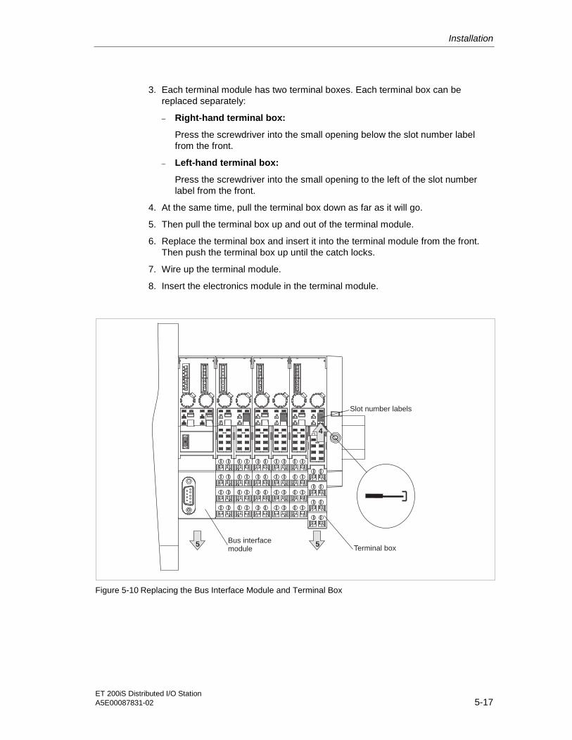
Installation
ET 200iS Distributed I/O StationA5E00087831-02 5-17
3. Each terminal module has two terminal boxes. Each terminal box can bereplaced separately:
– Right-hand terminal box:
Press the screwdriver into the small opening below the slot number labelfrom the front.
– Left-hand terminal box:
Press the screwdriver into the small opening to the left of the slot numberlabel from the front.
4. At the same time, pull the terminal box down as far as it will go.
5. Then pull the terminal box up and out of the terminal module.
6. Replace the terminal box and insert it into the terminal module from the front.Then push the terminal box up until the catch locks.
7. Wire up the terminal module.
8. Insert the electronics module in the terminal module.
Slot number labels
4
5Terminal box
5Bus interfacemodule
Figure 5-10 Replacing the Bus Interface Module and Terminal Box

Installation
ET 200iS Distributed I/O Station5-18 A5E00087831-02
ET 200iS Distributed I/O StationA5E00087831-02 6-1
6Wiring 66.1 General Rules and Regulations for Wiring
Introduction
As a component in plants or systems, the distributed I/O station ET 200iS is subjectto special rules and regulations depending on its application.
This chapter provides you with an overview of the most important rules whenintegrating the ET 200iS distributed I/O system in a plant or system.
Specific Applications
Make sure that you and adhere to the valid safety and accident preventionregulations, for example machine protection regulations for your specificapplication.
When laying cables and wiring, make sure that you adhere to the installationregulations complying with EN 60 079-14 and any regulations specific to yourcountry.
EMERGENCY STOP Mechanisms in the Safe Area
EMERGENCY STOP mechanisms in compliance with IEC 204 (corresponds toDIN VDE 113) must remain effective in all statuses of the plant or system.
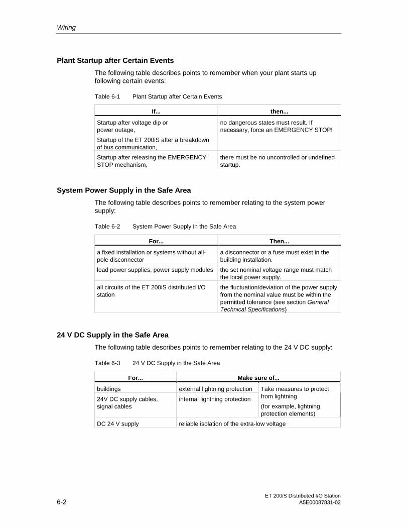
Wiring
ET 200iS Distributed I/O Station6-2 A5E00087831-02
Plant Startup after Certain Events
The following table describes points to remember when your plant starts upfollowing certain events:
Table 6-1 Plant Startup after Certain Events
If... then...
Startup after voltage dip orpower outage,
Startup of the ET 200iS after a breakdownof bus communication,
no dangerous states must result. Ifnecessary, force an EMERGENCY STOP!
Startup after releasing the EMERGENCYSTOP mechanism,
there must be no uncontrolled or undefinedstartup.
System Power Supply in the Safe Area
The following table describes points to remember relating to the system powersupply:
Table 6-2 System Power Supply in the Safe Area
For... Then...
a fixed installation or systems without all-pole disconnector
a disconnector or a fuse must exist in thebuilding installation.
load power supplies, power supply modules the set nominal voltage range must matchthe local power supply.
all circuits of the ET 200iS distributed I/Ostation
the fluctuation/deviation of the power supplyfrom the nominal value must be within thepermitted tolerance (see section GeneralTechnical Specifications)
24 V DC Supply in the Safe Area
The following table describes points to remember relating to the 24 V DC supply:
Table 6-3 24 V DC Supply in the Safe Area
For... Make sure of...
buildings external lightning protection
24V DC supply cables,signal cables
internal lightning protection
Take measures to protectfrom lightning
(for example, lightningprotection elements)
DC 24 V supply reliable isolation of the extra-low voltage

Wiring
ET 200iS Distributed I/O StationA5E00087831-02 6-3
Protection from External Electrical Influences
The following table describes points to remember relating to the protection fromelectrical influences or faults:
Table 6-4 Protection from External Electrical Influences
For... make sure that...
all plants or systems in which the ET 200iSis installed
the plant or system is connected to agrounding conductor to divertelectromagnetic interference.
power supply, signal, and bus cables the cables are installed and routed correctly.
signal and bus cables a cable or wire break cannot lead toundefined statuses in the plant or system.
6.2 Operate the ET 200iS with a Grounded-Neutral Supply
Definition: Grounded-Neutral Supply
With a grounded-neutral supply, the neutral lead of the power supply is grounded.A single ground fault between a live conductor and ground or a grounded part ofthe system causes the protection devices to react.
Components and Protective Measures
When setting up a system, various components and protective devices aremandatory. The type of component and the necessity of the protective measuresdepends on the DIN VDE regulations that apply to your system configuration. Thetable below relates to the schematic that follows.
Table 6-5 Components and Protective Measures
Compare... Relates tofigure
DIN VDE 0100 DIN VDE 0113
Shutdown device forcontrollers, transducers andactuators
(1) ...Part 460: mainswitch
...Part 1:disconnector
Short-circuit and overloadprotection
(2) ...Part 725: Singlepole fusing ofcircuits
...Part 1: singlepole fusing ofgroundedsecondary circuit

Wiring
ET 200iS Distributed I/O Station6-4 A5E00087831-02
Reliable Electrical Isolation
Reliable electrical isolation is required with modules that are powered with voltages≤ DC 60 V or ≤ AC 25 V, in other words, the power supply of the ET 200iS must bereliably electrically isolated.
Setting up the ET 200iS with a Grounded Reference Potential
When the ET 200iS distributed I/O station is configured with a grounded referencepotential, any interference currents are diverted to the grounding conductor.
ET 200iS within the Entire System
The following schematic shows the ET 200iS distributed I/O station within the entiresystem in zone 1 (power supply and grounding concept) when powered from a TN-S system.
AC
DC
Ground bus
(1)
(2)
L1L2L3NPE
Low voltage distribution, e.g.TN-S system (3x400V)
ET200iS
FE FE FE FE FE FE
FE: Functional earth for directdiversion of noise levels onthe DIN rail over spring contacts DIN rail
1L+2L+1M2M
1PA2PA
Enclosure EEx e
Hazardous area zone 1
Safe
are
a
Shield contact element forcontacting cable shields
Figure 6-1 Operating the ET 200iS with a Grounded Reference Potential

Wiring
ET 200iS Distributed I/O StationA5E00087831-02 6-5
Equipotential Bonding
The following must be connected to the equipotential bonding system
• the DIN rail of the ET 200iS system with an EEx e terminal
• the terminal module TM-PS via the connecting terminal 1PA or 2PA
Danger
It is not permitted to connect the equipotential bonding system to the ground inconductor of the power supply system.
The equipotential bonding system is the equipotential bonding in hazardous areascomplying with EN 50 079-14.
6.3 Electrical Design of the ET 200iS
Electrical isolation between...
• the load circuits/process and all other circuitry of the ET 200iS
• the PROFIBUS-DP interface in the interface module and all other circuits
The following schematic shows the various potentials with the ET 200iS. The figureshows only the most important components:

Wiring
ET 200iS Distributed I/O Station6-6 A5E00087831-02
Processelectronics
Processelectronics
Processelectronics
Logic,bus
DPinterface
1L+2L+
1M2M
1PA2PA
Power supply module
IM 151-2 Electronics modules
DIN rail
Bus terminationmodule
Electricalisolation
Bus interface
Backplane bus ET 200iS
Powerbus
Potential powerbus
Potential DP interface
Potential I/O EEx i
Potential logic EEx i
1PA2PA
Figure 6-2 Potentials on the ET 200iS
6.4 Lightning and Overvoltage Protection
6.4.1 Overview
Introduction
One of the most common causes of failure is overvoltage caused by:
• Atmospheric discharge or
• Electrostatic discharge
First, will show the basis of the theory of overvoltage protection: The lightningprotection zone concept.
We will then outline the rules for the transitions between the individual lightningprotection zones.

Wiring
ET 200iS Distributed I/O StationA5E00087831-02 6-7
Note
This section can only provide you with the general guide on protecting the ET200iS from overvoltage.
Complete protection from overvoltage is only guaranteed when the entire system isdesigned to protect from overvoltage. This relates particularly to building structuresincluded in the planning of the building.
We therefore recommend that you contact your Siemens representative or acompany specialized in lightning protection if you require more detailed informationabout overvoltage.
Further Sources
The solutions explained in these manuals are based on the lightning protectionzone concept described in the standard IEC IEC 61312-1 - "Protection againstLEMP".
6.4.2 The Lightning Protection Zone Concept
Principal of the Lightning Protection Zone Concept complying with IEC 61312-1/DIN VDE 0185 T103
The principle of a lightning protection zone requires that facilities to be protectedfrom overvoltages, for example a control room, should be divided into lightningprotection zones based on EMC considerations (see figure below).
The individual lightning protection zones are formed as follows:
Table 6-6 Lightning Protection Zones
Lightning Protection Zones
the external lightning protection of thebuilding
peripheral parts of the system in which nogalvanic coupling of lightning stroke currentcan occur (field side)
Lightning protection zone 0A
Lightning protection zone 0B
the shielding of
• buildings
• rooms and/or
• Devices
Lightning protection zones 1
Lightning protection zones 2
Lightning protection zones 3
Wiring
ET 200iS Distributed I/O Station6-8 A5E00087831-02
Effects of a Lightning Stroke
Direct lightning strokes occur in lightning protection zone 0A. The effects of thelightning stroke are high-energy, electromagnetic fields that must be reduced orweakened from one lightning protection zone to the next using suitable lightningprotection elements/measures.
As described in the EN 1127-1 standard, lightning strokes ignite explosiveatmospheres directly. For this reason, our advice is to prevent the effects of directlightning strokes (galvanic coupling) reaching hazardous areas by taking suitablebuilding measures.
Lightning protection measures can, for example, prevent direct lightning strikes inhazardous zones or to cables leading into hazardous zones. A closely meshedequipotential bonding system involving all parts of the plant with a minimum of 16mm Cu, prevents the flow of lightning currents within the plant. If these measuresare taken in the building, lightning protection zone 0B results for installation in theouter area. Indirect lighting effects (inductive, capacitive) can be reduced to aharmless level with suitable shielding measures and surge arresters.
Overvoltages
In lightning protection zone 0B, lightning currents can no longer occur, however,pulse overvoltages can be expected in the magnitude of 10 kV and more. Inlightning protection zone 1 and high, in addition to the effects of a lightning strike,overvoltages can also occur as a result of switching, induced voltage etc.
Lightning Protection Zone Scheme
The following schematic illustrates the lightning protection zone concept for a free-standing building.

Wiring
ET 200iS Distributed I/O StationA5E00087831-02 6-9
Lightning protection zone 0 (field side)
Lightning protectionzone 2
Lightning protection zone 1
Information technology cable
Powercable
Externallightningprotection
Internalcable
Metalpart
Lightningprotection
zone 3device
Building shield(steel reinforced)
Room shield
(steel reinforced)
Metal shield(metal housing)
Non-electricalpiping
Lightning protectionequipotential bonding
Localequipotential bonding
Electricalconnection
Figure 6-3 Lightning Protection Zones of a Building
Principle of the Interfaces between Lightning Protection Zones
At the interfaces between the lightning protection zones, you must implementmeasures to prevent the transfer of overvoltages.
The principle of a lightning protection zone also requires that at the interfacesbetween the lightning protection zones, all cables and piping capable of carryinglightning stroke current (!) must be included in the equipotential bonding system.
The cables and piping capable of carrying lightning stroke current include:
• metal pipes (for example water, gas, and heat),
• active cables
– power cables (for example, system power supply, 24 V power supply)
– signal cables (for example a bus cable).
Wiring
ET 200iS Distributed I/O Station6-10 A5E00087831-02
6.4.3 Rules for the Interface between Lightning Protection Zones 0...1
Rule for the interface 0A <-> 1 (lightning protection equipotential bonding)
The following measures are suitable for lightning protection equipotential bondingat the interface lightning protection zone 0 <-> 1:
• Keep lightning stroke currents away from hazardous areas and cables that leadinto hazardous areas.
• Define the zone transition 0A <-> 1 in the non-hazardous area.
Since this zone transition is not relevant for the typical applications of the ET 200iS,this will be discussed in no further detail in this manual.
Rule for the interface 0B <-> 1 (strong electromagnetic coupling)
The following measures are suitable for overvoltage protection at the interfacelightning protection zone 0B <-> 1:
• Use conductive spiral metal bands or metal braids, grounded at both ends asthe cable shields, for example, NYCY or A2Y(K)Y
• and run the cables
– through metal pipes without breaks and grounded at both ends or
– in conduits of reinforces concrete with interconnected armour or
– on closed metal cable racks grounded at both ends.
• as an alternative, you can use fiber-optic cable instead of metal cables.
Additional Measures
If you are not able to take the measures outlined above, provide protection at theinterface 0B <-> 1 with a surge voltage protector. The following table lists thecomponents you can use to provide coarse protection for your system.
Lightning protection zone 1 can, for example, be defined as the interior of abuilding with a shielded outer skin or as the interior of a metal distributor. If theshielding effect of the building outer skin is uncertain, the metal distributor ispreferable. We recommend that you install overvoltage protection devices for thesignal lines in metal distributors. The protective devices for the 24 V supply mustbe integrated in an explosion-proof enclosure and should also be installed in themetal distributor.

Wiring
ET 200iS Distributed I/O StationA5E00087831-02 6-11
Danger
To increase the availability of a cable connection with overvoltage protection, bothends of the cable should be connected to protective devices.
Overvoltage Protection Components
Table 6-7 Protection of Cables with Overvoltage Protection Components
Cons.No.
Cables for ... ... connect at the interface 0B <-> 1with:
Order Number
1 Power supply module PS for powersupply and looping through
• DC 24V
1 x Netz-AK/1+1/ÜS/FM/Ex d
with EEx d enclosure, explosion-proof,ready to connect
4225* (serialnumber)
2 Interface module IM 151-2
• PROFIBUS-DP Ex i
1 x Blitzductor CT Type MD HFD Ex 6
2 x shield clamps for bus cable
919507* and919 583*
919 508*
3 • 4DI NAMUR 4 x Blitzductor CT Type MD/Ex 30 919 507* and
919 581*
4 • 2DO 2 x Blitzductor CT Type MD/Ex 30 919 507* and
919 581*
5 • 2AI I 2 x Blitzductor CT Type MD/Ex 30 919 507* and
919 581*
6 • 2AI HART 2 x Blitzductor CT Type MD/Ex 30 919 507* and
919 581*
7 • 2AO 2 x Blitzductor CT Type MD/Ex 30 919 507* and
919 581*
8 • 2AO I HART 2 x Blitzductor CT Type MD/Ex 30 919 507* and
919 581*
9 • 2AI RTD 2 x Blitzductor CT Type MD/Ex 30 919 507* and
919 581*
10 • 2AI TC 2 x Blitzductor CT Type MD/Ex 30 919 507* and
919 581*
* These components can be ordered directly from:
DEHN +SÖHNEGmbH + Co. KGElektrotechnische FabrikHans-Dehn-Str. 1D-92318 Neumarkt, Germanywww.dehn.de
Wiring
ET 200iS Distributed I/O Station6-12 A5E00087831-02
Note
For all the other PROFIBUS-DP components outside the hazardous area, werecommend that you follow the instructions in the PROFIBUS SIMATIC NETmanual.
Caution
If you use overvoltage protection devices, the equipotential bonding should beinstalled using a minimum cross section of 6 mm2.
6.4.4 Rules for the Interfaces between Lightning Protection Zones1...2 and higher
Rules of Interfaces 1 <-> 2 and higher (local equipotential bonding)
The following rules apply to lightning protection zone interfaces 1 <-> 2 and higher:
• Implement local equipotential bonding at every other lightning protection zoneinterface.
• At all other lightning protection zone interfaces, include all cables as well asmetal pipes in the local equipotential bonding system.
• Include all metal installations located within the lightning protection zone in thelocal equipotential bonding system (for example, metal parts within lightningprotection zone 2 at interface 1 <-> 2).
Additional Measures
We recommend additional protection
• for all lightning protection zone interfaces 1 <-> 2 and higher and
• for all cables that run through a lightning protection zone and that are longerthan 100 m.
Lightning Protection Elements for the 24 V DC Power Supply
Danger
To protect the TM-PS module, the lightning protection element must be installed inan EEx d enclosure. One protective device per TM-PS module is adequate evenwhen the 24 V power supply is looped through.The overload of the protective element is indicated by a floating contact led out tothe exterior.

Wiring
ET 200iS Distributed I/O StationA5E00087831-02 6-13
Lightning Protection Element for Signal Modules
The protective devices have a shield connecting clamp and the input and output. Ifthe bus connection is looped through, two protective devices must be used per IMmodule. The overload of a lightning protection element is indicated by thepermanent short-circuit (fail-safe) between the signal cores.
Protective Elements for 1 <-> 2 and higher
When installing the ET 200iS, zone transition 1 <-> 2 and higher is not normallyused. If it is required, consult the table above and discuss the required measureswith your Siemens representative.
6.4.5 Example of Protection from Overvoltage for Networked ET 200iSStations
Wiring Example
The schematic below shows an example of how to wire two networked ET 200iSstations to achieve effective protection from overvoltages:
PS IM EM
PA
6mm²
Lightning protection zone 1
(6) (1)
(4)
(2)
(3)
(5)16mm²
(1)
(4)
(2)
(3)
(6)6mm²
PS IM EM
Lightning protection zone 1
Enclosure EEx e
Lightning protection zone 0 , field sideB
PA
Enclosure EEx e
Figure 6-4 Example of Wiring Networked ET 200iS Stations

Wiring
ET 200iS Distributed I/O Station6-14 A5E00087831-02
Components for the Wiring Example
The following table explains the consecutive numbers in the wiring example.
Table 6-8 Example of a Lightning-Protected Configuration
Cons. no.from figure
Component Meaning
(1) 24 V supply surge arrester, depending onEEx d enclosure:
1 x Netz-AK/1+1/ÜS/FM/Ex dSerial number 4225*
Protection from indirect lightning effects andovervoltages from interface 0B <-> 1 onwards
(2) PROFIBUS-DP Ex i surge arrester,dependent on looping through
1 St. Blitzductor CT Typ MD HFD Ex 6Order no.: 919 507* and 919 583*
1 x Blitzductor CT Typ MD HFD Ex 6Order no.: 919 507* and 919 583*
Protection from indirect lightning effects andovervoltages from interface 0B <-> 1 onwards
(3) I/O surge arrester dependent on thenumber of double cores used
1 x Blitzductor CT Typ MD/Ex 30Order no.: 919 507* and 919 581*
per double core
Protection from indirect lightning effects andovervoltages from interface 0B <-> 1 onwards
(4) Shield clamp for bus cable via EMC springterminal on the face section of theBlitzductor CT
Order no.: 919 508*
Diverting interference currents
(5) Equipotential bonding cable 16 mm2 Establishment of uniform reference potentials
(6) Equipotential bonding cable 6 mm2 Diverting interference currents
* These components can be ordered directly from
DEHN + SÖHNEGmbH + Co. KGElektrotechnische FabrikHans-Dehn-Str. 1D-92318 Neumarkt, Germanywww.dehn.de
Wiring
ET 200iS Distributed I/O StationA5E00087831-02 6-15
6.5 Wiring the ET 200iS
6.5.1 Wiring Rules for the ET 200iS
Safety-Related Notices
Danger
When laying cables and wiring, make sure that you adhere to the installationregulation complying with EN 60 079-14 and any regulations specific to yourcountry.
Danger
Connecting an intrinsically safe sensor, actuator, or HART field device to theinput/output of an electronics module must produce an intrinsically safe circuit! Forthis reason:
When you select the encoder, actuator, or HART field device to be connected tothe electronics module, the resulting safety-related values must be checked!
The inductance and capacitance of the cable must also be taken into account! SeesectionConfiguration Options.
Warning
If the wrong electronics module is used all the terminals are connected incorrectlyto the sensors, actuators, or HART field devices, the intrinsic safety is put at risk:Connect only EEx i circuits to the intrinsically safe inputs and outputs of theelectronics modules!Check the wiring between the electronics modules and sensors, actuators, andHART field devices!

Wiring
ET 200iS Distributed I/O Station6-16 A5E00087831-02
Table 6-9 Wiring Rules for the ET 200iS
Wiring Rules for... TM-PS TM-E (spring andscrew terminals)
Connectable wire cross-sections for solid-core cables
0.5 to 4 mA 0.14 to 2.5 mA
Without wire-endferrule
0.5 to 2.5 mA 0.14 to 2.5 mAConnectable wirecross-sections forflexible cables With wire-end ferrule 0.5 to 2.5 mA 0.14 to 1.5 mA
Number of wires per connection 1 wire 1 or combination of 2wires up to 1.5mm(total) in a commonwire-end ferrule
Length of insulation to be stripped 9 mm
Without installationcollar
Shape A, 8 to 9 mmlong
Shape A, up to 21mm long
Wire-end ferrulescomplying with DIN46228 With insulation collar
0.25 to 1.5 mmShape E, 8 to 9 mmlong
Shape E, up to 12mm long
Tightening torque 0.5 - 0.7 Nm
Danger
When connecting the wiring to the TM-PS, you must keep to degree of protectionIP 30. This is only possible if you keep to the values specified in the column WiringRules for... TM-PS.
6.5.2 Wiring Terminal Module TM-E30S44-iS with Screw Terminals
Features
• When wiring terminal modules with screw terminals, the wires are secured inthe terminal by screwing down the terminal.
• Wire-end ferrules are not necessary.
Requirements
Keep to the wiring rules.
Required Tools
Screwdriver with 3 mm blade
Wiring
ET 200iS Distributed I/O StationA5E00087831-02 6-17
Wiring a Terminal Module with Screw Terminals
1. Strip 9 mm of insulation from the wire.
2. Insert the individual wires into the terminal.
3. Tighten the screw. Result: The wire is clamped into the terminal module.
6.5.3 Wiring Terminal Module TM-E30C44-iS with Spring Terminals
Features
When wiring terminal modules with spring terminals, the wires are secured in theterminal simply by inserting them into the terminal.
Requirements
Keep to the wiring rules.
Required Tools
Screwdriver with 3 mm blade
Wiring a Terminal Module with Spring Terminals
1. Strip 9 mm of insulation from the wire.
2. Insert the screwdriver into the upper (round) opening of the terminal and press itinto the opening.
3. Insert the wire as far as it will go into the lower (square) opening in the terminal.
4. Remove the screwdriver.
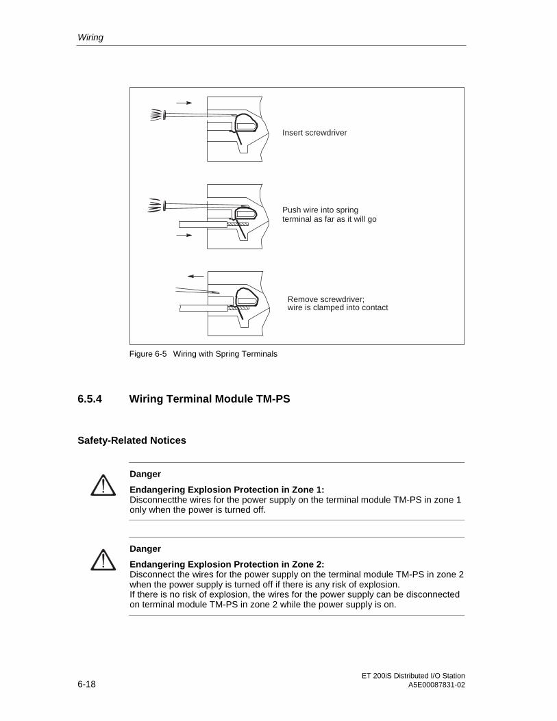
Wiring
ET 200iS Distributed I/O Station6-18 A5E00087831-02
Insert screwdriver
Push wire into springterminal as far as it will go
Remove screwdriver;wire is clamped into contact
Figure 6-5 Wiring with Spring Terminals
6.5.4 Wiring Terminal Module TM-PS
Safety-Related Notices
Danger
Endangering Explosion Protection in Zone 1:Disconnectthe wires for the power supply on the terminal module TM-PS in zone 1only when the power is turned off.
Danger
Endangering Explosion Protection in Zone 2:Disconnect the wires for the power supply on the terminal module TM-PS in zone 2when the power supply is turned off if there is any risk of explosion.If there is no risk of explosion, the wires for the power supply can be disconnectedon terminal module TM-PS in zone 2 while the power supply is on.

Wiring
ET 200iS Distributed I/O StationA5E00087831-02 6-19
Features
You connect the power supply for the ET 200iS at terminal module PM-PS. Thisvoltage supplies the interface module IM 151-2 and all the electronics modules.
Requirements
• Wire the terminal module with the power supply turned off.
• Keep to the wiring rules.
Required Tools
• Screwdriver with 3 mm blade
• Insulation stripper
Connecting the Power Supply to Terminal Module TM-PS
1. Strip the wires for the power supply to the ET 200iS.
2. Each terminal on the terminal module TM-PS is fitted with a cover. Insert thescrewdriver between the cover and the terminal and break out the cover.
Note: The covers of the terminals are required for degree of protection IP 30; inother words, remove the covers only from the terminals you intend to use.
3. Open the hinged cover of the screw turned and secure the individual wires withthe screwdriver.
4. Close the cover again.
Note: The closed cover of the screw terminal provides degree of protection IP30.
Wiring the Grounding Conductor PA on the Terminal Module TM-PS
1. Strip the wire for protective ground PA. Note: Die The grounding conductormust have a cross-section of at least 4 mm2 or 2 x 1.5 mm2.
2. Insert the screwdriver between the cover and the terminal and break out thecover.
3. Open the hinged cover of the screw turned and secure the wire with thescrewdriver.
4. Close the cover again
5. Connect the protective ground conductor PA to the ground bus.

Wiring
ET 200iS Distributed I/O Station6-20 A5E00087831-02
Power supply1L+, 2L+, 1M, 2M
Grounding conductor1PA, 2PA
Covers
1M
2PA
1PA
2M
1L+
2L+
Terminal module TM-PS
Terminal assignmentsee section:
Terminal modules
RM
RL+
Figure 6-6 Connecting the Power Supply and Grounding Conductor on the TM-PS
6.5.5 Wiring Terminal Module TM-IM
Features
You connect the bus connector (RS-485) for PROFIBUS-DP Ex i at the TM-IMterminal module.
Requirements for Zone 1
Keep to the following rules in zone 1:
1. Use the fieldbus isolating transformer (from R. STAHL Schaltgeräte GmbH;Refer to the order numbers).
2. Connect PROFIBUS-DP Ex i to the RS-485 terminating resistor. The RS-485terminating resistor is supplied with the fieldbus isolating transformer.
3. Use bus connector 1.5 Mbps (order number 6ES7 972-0BA30-0XA0). If youwant to loop PROFIBUS-DP Ex i through to the next ET 200iS, connect the buscable to the second cable outlet of the bus connector.

Wiring
ET 200iS Distributed I/O StationA5E00087831-02 6-21
4. Use the bus cable specified in the Order Numbers appendix for PROFIBUS-DPEx i and mark the bus cable as "EEx i bus cable". If you use a color as theidentifier, you must select light blue.
5. The shield of the bus cable can be connected to one of the following locationsproviding a sure ground connection PA:
– Either at the transition of the bus cable from the safe area to the hazardousarea
– or in the safe area directly at the fieldbus isolating transformer. In this case,the shield must be installed like an active circuit; in other words, protectionagainst accidental touch must also exist for the shield of the bus cable (IP20).
Requirements for Zone 2
Keep to the following rules in zone 2:
• See points 1 to 5: Requirements for Zone 1
Requirements for the Safe Area
• See points 1 to 4: Requirements for Zone 1
Note
If the inputs and outputs to the actuators/sensors are intrinsically safe, thenPROFIBUS-DP must also be intrinsically safe (Ex i).
Wiring Terminal Module TM-IM
1. Insert the bus connector into the PROFIBUS-DP connector.Note: During operation, the cable shield of the PROFIBUS-DP cable isconnected to the DIN rail and therefore with the equipotential bonding via aspring contact in the terminal module TM-IM.
2. Tighten the securing screws of the bus connector.
3. Mark the bus cable as "EEx i bus cable".

Wiring
ET 200iS Distributed I/O Station6-22 A5E00087831-02
PROFIBUS-DP Ex i
Terminal module TM-IM
Terminal assignmentsee section:
Interface module
Figure 6-7 Wiring Terminal Module TM-IM
Note
The PROFIBUS-DP of the ET 200iS is intrinsically safe due to the fieldbus isolatingtransformer. This means that removing and inserting the bus connector ispermitted during operation in zone 1, zone 2, and in the safe area.
6.5.6 Wiring Terminal Module TM-E
Features
The terminal module TM-E is the interface to the actuators and sensors.
Requirements
• Keep to the wiring rules.
Required Tools
Screwdriver with 3 mm blade

Wiring
ET 200iS Distributed I/O StationA5E00087831-02 6-23
Wiring Terminal Module TM-E
1. Strip the insulation from the wires to the sensors / actuators.
2. Secure the individual wires in the screw or spring terminals.
Terminal module TM-E
1
2
3
4
5
6
7
8
9
10
11
12
13
14
15
16
Channel 2Channel 3
Channel 1Channel 0
Terminal assignment seesection:
Digital electronicsmodules
Analog electronicsmodules
Analog electronicsmodules with HART
Figure 6-8 Wiring Terminal Module TM-E
Note
The inputs and outputs of the ET 200iS distributed I/O station are intrinsically safe.Disconnecting wires to the sensors, actuators and HART field devices on theterminal module TM-E is permitted during operation in zone 1 and zone 2.
6.5.7 Contacting the Cable Shields
Features
• To contact the cable shields (for the analog electronics modules), werecommend that use the shield contact.

Wiring
ET 200iS Distributed I/O Station6-24 A5E00087831-02
Requirements
• The shield contact element has been fitted.
Required Tools
• Screwdriver with 7 mm blade
• Insulation stripper
Contacting the Cable Shields
1. Remove the insulating material in the vicinity of the conductor bar(approximately 25 mm) and clamp the cable shield into the shield clamp (abovethe conductor bar).
2. Place the cable shield on the conductor bar and fit the shield clamp over thecable shield from below as far as it will go. Make sure that the shield clampcontacts only the cable shield. Use the shield clamp KLBÜ CO 1, fromWeidmüller, see Order Numbers.
3. Repeat steps 1 and 2 if you want to contact further cable shields.
Shield
approx. 25 mm
Conductor bar
Shield clamp
Figure 6-9 Contacting the Cable Shields
Wiring
ET 200iS Distributed I/O StationA5E00087831-02 6-25
Connecting the Conductor Bar to the Ground Bus PA
1. Strip the insulation from the wire you want to ground (from 4 to 16 mm2) andinsert it in one of the ground connector terminals (below the conductor bar).Tighten the ground connector terminal(2 to 2.5 Nm).
2. Use ground connection terminals ZB 16 from Weidmüller, see ordernumbers.
3. At the other end, make contact with the ground bus PA.
6.5.8 Grounding the DIN Rail
Features
The DIN rail of the distributed I/O station must be connected to the ground bus.
Requirements
• Perform the wiring with the power supply turned off .
• Keep to the wiring rules.
• Secure the grounding conductor:
– Zone 1: EEx e terminal. Use the terminal WP 16/E, from Weidmüller, seeOrder Numbers.
– Zone 2 or safe area: e terminal or cable lug
• To avoid interference, the cross-section of the grounding conductor for the DINrail must be greater than the cross-section of the grounding conductor on theterminal module TM-PS.
Required Tools
• Screwdrivers with 3 and 7 mm blades
• Insulation stripper
• Possibly cable lug pliers
Wiring
ET 200iS Distributed I/O Station6-26 A5E00087831-02
Grounding the DIN Rail
1. Strip the insulation from the grounding conductor. Note: The groundingconductor must have a cross-section of at least 4 mm2 or 2 x 1.5 mm2.
2. Secure the grounding conductor to the DIN rail to the right beside the bustermination module:
– Zone 1: EEx e terminal
– Zone 2 and safe area: e terminal or cable lug
– Torque: 2 to 2.5 Nm
3. Secure the other end to the ground bus PA.
6.6 Inserting and Labeling the Power Supply, Interface Module, andElectronics Modules
Features
• The modules are inserted in the relevant terminal modules.
• Using a labeling strip, you can identify the interface module and the electronicsmodules.
• When you first insert an interface or electronics module, coding elements slotinto the terminal module. This prevents the wrong module being inserted.
The interface module and the electronics modules are
– self-coding
– type-coded
Requirements
Keep to the wiring rules. See Configuration Options.
Inserting the Power Supply Module PS
1. Press the button and the same time pulldown the release slider as far as it willgo. The release slider with the button is located on the bottom front of theterminal module.
2. Insert the power supply module into the terminal module until it locks in place.

Wiring
ET 200iS Distributed I/O StationA5E00087831-02 6-27
3. Press the button again and push the release slider up until it catches. Result:The power supply module is pulled into the terminal module TM-PS, iscontacted, and secured.
4. To allow identification, take the labeling strip out of the terminal module TM-PStowards the top. The labeling strip is on the terminal module TM-PS to the left.
5. Finally, reinsert the labeling strip in the terminal module TM-PS again.
1
2
1
3
4
5
Figure 6-10 Inserting and Identifying the Power Supply Module PS
Caution
Risk of Injury!Due to its compact design, the power supply module PS weighs 2.5 kg despite itssmall size; in other words, get a good hold of the power supply module PS.
Removing the Power Supply Module PS
1. Press the button and the same time pulldown the release slider as far as it willgo. Result: The power supply module is ejected and the contact with theterminal module is broken. Release the button when the release slider hasreached the stop.
2. Press the button again and pull the release slider further down and hold itagainst the limit stop.

Wiring
ET 200iS Distributed I/O Station6-28 A5E00087831-02
3. Pull the power supply module PS out of the terminal module TM-PS keeping afirm hold on it (weight, approx. 2.5 kg).
4. Now push the release slider fully up while pressing in the button.
Inserting and Labeling the Interface Module and Electronics Modules
1. Insert the interface or electronics module into the terminal module until you hearit lock in place.
2. To allow identification, take the labeling strip out of the interface or electronicsmodule towards the top.
3. Finally, reinsert the labeling strip in the interface or electronics module again.
1
23
Figure 6-11 Inserting and Labeling the IM 151-2 and Electronics Modules
Note
To operate the ET 200iS, and electronics module must be inserted on everyterminal module TM-E.
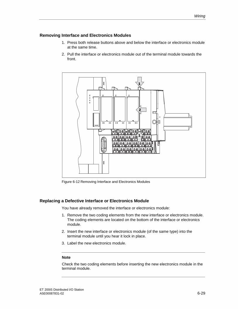
Wiring
ET 200iS Distributed I/O StationA5E00087831-02 6-29
Removing Interface and Electronics Modules
1. Press both release buttons above and below the interface or electronics moduleat the same time.
2. Pull the interface or electronics module out of the terminal module towards thefront.
1
1
2
Figure 6-12 Removing Interface and Electronics Modules
Replacing a Defective Interface or Electronics Module
You have already removed the interface or electronics module:
1. Remove the two coding elements from the new interface or electronics module.The coding elements are located on the bottom of the interface or electronicsmodule.
2. Insert the new interface or electronics module (of the same type) into theterminal module until you hear it lock in place.
3. Label the new electronics module.
Note
Check the two coding elements before inserting the new electronics module in theterminal module.

Wiring
ET 200iS Distributed I/O Station6-30 A5E00087831-02
Replacing and Electronics Module with a Different Type
You have already removed the electronics module:
1. Work out the two coding elements from the terminal module using ascrewdriver.
2. Insert these coding elements in the old electronics module.
3. Insert the new electronics module (of a different type) into the terminal moduleuntil you hear it lock in place.
4. Label the new electronics module.
Danger
If you make changes to the coding, this can lead to dangerous states in your plant.
3
Coding element
Figure 6-13 Replacing and Electronics Module with a Different Type

Wiring
ET 200iS Distributed I/O StationA5E00087831-02 6-31
6.7 Setting the PROFIBUS Address
Features
With the PROFIBUS address, you specify the address at which the ET 200iSdistributed I/O station will be accessed on PROFIBUS-DP.
Requirements
• The PROFIBUS-DP address for the ET 200iS is set on the interface moduleusing DIL switches. The DIL switches are located on the front of the interfacemodule protected by a sliding window.
• The permitted PROFIBUS-DP addresses are 1 to 125
• An address can only be assigned once on PROFIBUS-DP.
Required Tools
Screwdriver with 3 mm blade
Setting the PROFIBUS Address
1. Push up the window on the interface module.
2. Set the required PROFIBUS-DP address with the DIL switches using ascrewdriver.
3. Close the window.
Changing the PROFIBUS Address
You change the PROFIBUS-DP address in exactly the same way as you set it. Achange to the PROFIBUS-DP address takes effect following POWER UP on thepower supply module for the ET 200iS.
Note
If you change the PROFIBUS address, the flash memory (parameters andidentification data) of the interface module is erased.
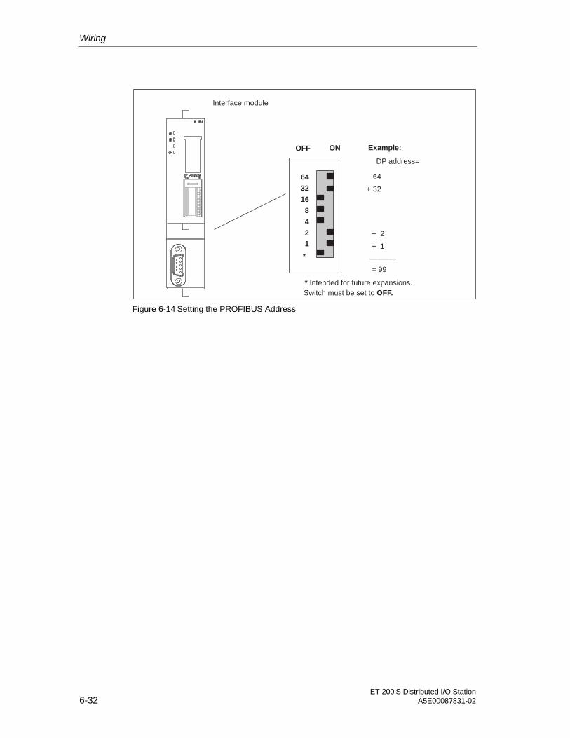
Wiring
ET 200iS Distributed I/O Station6-32 A5E00087831-02
64
32
16
8
4
2
1
ON
Interface module
OFF Example:
DP address=
64
+ 32
+ 2
+ 1
= 99
_______*
* Intended for future expansions.
Switch must be set to OFF.
Figure 6-14 Setting the PROFIBUS Address

ET 200iS Distributed I/O StationA5E00087831-02 7-1
7Commissioning and Diagnostics 77.1 Overview of Defining the Configuration
Principle of Defining a Configuration
Parameter assignmentwith SIMATIC PDM
Configuration with STEP7
Operator control andmonitoring with WinCC
mA Hart
Industrial Ethernet
PROFIBUS DP
ET 200iS in enclosure
PC
PCS7-OS
S7-400
Parameters (e.g.for networkconfiguration)
Plant visualization
CPU
(1) (2)
Cyclic data exchange:User data inputs/outputsand value status
(1)
Acyclic data exchange:ET 200iS parametersIdentification dataAccess to HART
(3)
CFC
PCS7 driver
Hazardousarea:zone 1
(3)
Acyclic data exchange:Configuration and busparameters (e.g. fornetwork configuration)Diagnostic interrupts(S7, DP V1 only)
(2)
Fieldbus isolating transformer
Figure 7-1 Basis on Which Configuration Takes Place

Commissioning and Diagnostics
ET 200iS Distributed I/O Station7-2 A5E00087831-02
Defining a Configuration
Configuration involves configuring and setting parameters for the ET 200iS with aprogramming device (PG).
Configuration
When you configure your project, you set the basic characteristics of the DP slaves(for example, network parameters, module selection in HW Config).
You configure the ET 200iS with
• STEP 7
• COM PROFIBUS or with suitable configuration software (using the GSD file).
Parameter Assignment
When you make the parameter assignments, you set the parameters of the ET200iS and the HART field devices.
• With STEP 7, you make the parameter settings for the ET 200iS in HW Config.SIMATIC PDM is integrated as an optional package in STEP 7.
• Outside STEP 7, you set the parameters for the ET 200iS and the HART fielddevices with SIMATIC PDM. SIMATIC PDM installed as a standalone version.
Cyclic Data Transfer Via PROFIBUS DP
Data is exchanged between the CPU (for example, S7-400) and the ET 200iS. Thefollowing data is transferred:
• the cyclic user data of the inputs and outputs including the value status of theinputs
On the CPU, this data is prepared by the PCS 7 drivers and CFC (ContinuousFunction Chart) for plant visualization. This data is then presented on the OS bymeans of WINCC.
For plant visualization, this data can be prepared by the PCS 7 drivers and CFC(Continuous Function Chart) on the CPU and then displayed on the OS withWINCC.
The parameters (for network configuration, for example) are also transferredcyclically.
Acyclic Data Transfer Via PROFIBUS DP
Acyclic data exchange takes place between the ET 200iS and the PG / PC(SIMATIC PDM). The ET 200iS receives its parameters using acyclic dataexchange. Identification data is also transferred and displayed in SIMATIC PDM.
• Diagnostics and interrupts
• Data records (S7 only)

Commissioning and Diagnostics
ET 200iS Distributed I/O StationA5E00087831-02 7-3
PROFIBUS DPV1
The ET 200iS meet the requirements of DPV1. Naturally, the DP master must alsomeet the requirements of DPV1 (refer to the documentation of the DP master).
The following table shows the new functions of PROFIBUS DPV1 slaves comparedwith an S7 DP and PROFIBUS DPV0 slave:
Table 7-1 Comparison of DPV1, S7 DP and DPV0
Function DPV0Slave
S7 DPSlave
DPV1Slave
Note
Parameter assignment and configuration withGSD file
X --- ---
Parameter assignment and configuration withHW Config
x x x
Cyclic data exchange X X X
Class 1services(parameterassignmentmaster, e.g.PLC)
--- X XAcyclic data exchange(read/write data record):
• Free access to parameterson the field device
• Reassignment ofparameters of theapplication process Class 2
services (e.g.PG/OP)
X X X
Diagnostics
• ID-Related diagnostics X X X
• Module status X --- X
• Channel-related diagnostics X --- X
Interrupts
• Diagnostic interrupt --- X X*
• Hardware interrupt --- X X*
• Remove/insert interrupt --- X X*
• Update interrupt --- --- X*
One interrupt can bereported per diagnosticframe. In DPV1 and S7DP, an interrupt consistsof a slave diagnosticmessage that isaccompanied by anacknowledgmentmechanism that does notexist in DPV0.
• Time stamp --- X X
* in DPV1, interrupts are also reported with the CPU in the RUN mode. Exception If you operate the ET 200iS with anS7-400, the interrupts are only reported when the CPU is in the STOP mode.

Commissioning and Diagnostics
ET 200iS Distributed I/O Station7-4 A5E00087831-02
Software Requirements
Table 7-2 Software Requirements
Configuration SoftwareUsed
Version Notes
STEP 7 and SIMATIC PDM(SIMATIC PDM isembedded in STEP 7 HWConfig and is available as anadd-on package)
or
PCS 7 (includes, amongother things STEP 7 andSIMATIC PDM)
STEP 7 Version5.1 Service Pack2 Hotfix 1 orhigher SIMATIC PDMVersion 5.1Service Pack 2or higher
PCS 7 Version5.2 or higher
• Configuring with STEP 7 The ET200iS is included in the hardwarecatalog.
• To make the parameter settings,SIMATIC PDM is startedautomatically in HW Config.
STEP 7 and SIMATIC PDM(SIMATIC PDM can also beobtained as a stand-aloneversion)
STEP 7 Version4.02 or higher SIMATIC PDMVersion 5.1Service Pack 2or higher
• You require the GSD file of the ET200iS and configure with STEP 7.
• Setting Parameters with SIMATICPDM
COM PROFIBUS withSIMATIC PDM (SIMATICPDM can also be obtainedas a stand-alone version)
COMPROFIBUSVersion 3.0 orhigher SIMATIC PDMVersion 5.1Service Pack 2or higher
• You require the GSD file of the ET200iS and configure with COMPROFIBUS.
• Setting Parameters with SIMATICPDM
Other configuration softwareand SIMATIC PDM(SIMATIC PDM can also beobtained as a stand-aloneversion)
Configurationsoftware seemanufacturer SIMATIC PDMVersion 5.1Service Pack 2or higher
• You require the DDB file, and youcarry out configuration withappropriate configuration software.
• Setting Parameters with SIMATICPDM

Commissioning and Diagnostics
ET 200iS Distributed I/O StationA5E00087831-02 7-5
7.2 Configuration
Configuration
The following table describes the most important steps in configuration:
Table 7-3 Configuration
STEP 7 Version 5.1, ServicePack 2, Hotfix 1 or higher
or
PCS 7 Version 5.2 or higher
STEP 7Version 4.02 or higher
COM PROFIBUS Version 3.0 orhigher
or
Other configuration software
Features • The ET 200iS is includedin the hardware catalog ofSTEP 7
• Diagnostic interrupts,hardware interrupts,remove & insert interruptsand time stamps aresupported
• You require the GSD file
• The ET 200iS is entered in the project as a DP standardslave
Requirements
The required software has been installed on the PG/ PC or PCS7-ES.
Procedure 1. Start the SIMATICManager.
2. Configure the ET 200iSwith HW Config.
– Create a new project.
– Drag modules from thehardware catalog tothe configuration table
3. Configure the timestamping (option)
4. Save the configurationand download theconfiguration to the DPmaster.
1. Start the SIMATICManager.
2. Include the GSD filein HW Config.
3. Configure the ET200iS with HWConfig.
– Create a newproject.
– Drag modulesfrom thehardware catalogto theconfigurationtable
4. Save theconfiguration anddownload theconfiguration to theDP master.
1. Start COM PROFIBUS /configuration software.
2. Include the GSD file in COMPROFIBUS / configurationsoftware.
3. Configure the ET 200iS withCOM PROFIBUS / yourconfiguration software.
4. Save the configuration anddownload the configuration tothe DP master.
Reference: For more detailed information on configuring, refer to the online help of STEP 7 / COM PROFIBUS.

Commissioning and Diagnostics
ET 200iS Distributed I/O Station7-6 A5E00087831-02
Including the GSD File in STEP 7 / COM PROFIBUS
The name of the GSD file for the ET 200iS is sir3806e.gse.
The following table describes how to include the GSD file in SIMATIC S7 orSIMATIC S5 (COM PROFIBUS).
Table 7-4 Including the GSD File in STEP 7 / COM-PROFIBUS
STEP 7 COM PROFIBUS, as of V3.0
1. Start STEP 7, open HW Config, andselect the menu command Options / InstallNew GSD File.
1. Copy the GSD file of the ET 200iS to theCOM PROFIBUS folder: ...COMPB3\GSD(default)Copy the bitmap file to thefolder:...COMPB3\BITMAPS
2. In the next dialog, select the GSD file youwant to install and confirm with OK.Result: The field device is displayed in thehardware catalog in the PROFIBUS-DPdirectory.
2. Start COM PROFIBUS and select themenu command File / Read in GSD File.Result: ET 200iS is displayed in thehardware catalog during the slaveconfiguration
Downloading the GSD File
You can download the GSD file sir3806e.gse for the ET 200iS
• On the Internet at http//www.ad.siemens.de/csi_e/gsd
• Via modem on +49 (911) 73 79 72

Commissioning and Diagnostics
ET 200iS Distributed I/O StationA5E00087831-02 7-7
7.3 Parameter Assignment
Setting Parameters with STEP 7
The following table describes the most important steps in parameter assignment:
Table 7-5 Setting Parameters with STEP 7 or PCS 7
STEP 7 Version 5.1, Service Pack 2, Hotfix 1 or higher and optional package SIMATIC PDMVersion 5.1, Service Pack 2 or higher
or
PCS 7 Version 5.2 or higher
Features You set the parameters for the ET 200iS.
Requirements • The required software has been installed on the PG/ PC or PCS7-ES.
• To work with PDM online, you require a PROFIBUS-DP interface, for example CP5611 (6GK1 561-1AA00). The CP must be set to the PROFIBUS-DP interface (inthe SIMATIC Manager: menu command Options > Set PG/PC Interface).
1. You are still in HW Config. Double-click on the first electronics module in theconfiguration table.
2. In the next dialog, select "Specialist" as the user and confirm with "OK". In thismode, you can make parameter settings.
Result: SIMATIC PDM is started with the current parameters and identificationdata of the module.
3. Set the parameters of the electronics module with SIMATIC PDM, save theparameters (menu command File > Save) and download the parameters to theelectronics module with the menu command Device > Download to Device.Close SIMATIC PDM.
How to setparameters forthe electronicsmodules
4. Double-click on the next electronics module in the configuration table and repeatsteps 2 and 3 until you have set the parameters for all the electronics modules.
1. Double-click on the DP slave "IM 151-2" in HW Config (in the upper part of thestation window). Select "Specialist" in the next window. Result: SIMATIC PDM isstarted.
How to setparameters forthe interfacemodule 2. Set the parameters of the interface module IM 151-2, save the parameters (menu
command File > Save) and download the parameters to the interface modulewith the menu command Device > Download to Device. Close SIMATIC PDM.

Commissioning and Diagnostics
ET 200iS Distributed I/O Station7-8 A5E00087831-02
STEP 7 Version 5.1, Service Pack 2, Hotfix 1 or higher and optional package SIMATIC PDMVersion 5.1, Service Pack 2 or higher
or
PCS 7 Version 5.2 or higher
1. Double-click on the DP slave "IM 151-2" in HW Config (in the upper part of thestation window). Select "Specialist" in the next window. Result: SIMATIC PDM isstarted and all modules of the ET 200iS are loaded.
2. Upload all parameters of the modules (menu command File > Full Upload toPG/PC ).
3. Set the parameters for all required modules. In the left-hand pane of the SIMATICPDM window, you can select all the modules of the ET 200iS.
4. Save the changes (menu command File > Save) so that the file is updated.
How to setparameters forall modules ofthe ET 200iS
5. Download all parameters to the modules (menu command Device > FullDownload to Device). Close SIMATIC PDM.
Setting Parameters with SIMATIC PDM (stand-alone version)
The following table describes the most important steps in parameter assignment:
Table 7-6 Setting Parameters with SIMATIC PDM
SIMATIC PDM Version 5.1, Service Pack 2 or higher (stand-alone version)
Characteristics • You set the parameters for the ET 200iS.
Requirements • The required software has been installed on the PG/ PC or PCS7-ES.
• To work with PDM online, you require a PROFIBUS-DP interface, for example CP5611 (6GK1 561-1AA00). The CP must be set to the PROFIBUS-DP interface (inthe SIMATIC Manager: menu command Options > Set PG/PC Interface).
1. Start the SIMATIC Manager.
2. Select the process device network view as the standard view with the menucommand Options > Settings > View > Process Network View.
3. Create a new project with the menu command File > New. The "New" dialogopens in which you enter the required project name and confirm with "OK".
4. Now select the Networks icon, right-click and select Insert New Object > PC andInsert New Object > PROFIBUS DP Network
How to setparameters forthe electronicsmodules
5. In the left-hand pane of the window, select the PC icon. An icon labeled DPInterface now appears in the right-hand pane of the window. Right-click on thisicon and select "Object Properties". In the next dialog, select "PROFIBUS-DPNetworks" under networks and confirm with "OK".

Commissioning and Diagnostics
ET 200iS Distributed I/O StationA5E00087831-02 7-9
SIMATIC PDM Version 5.1, Service Pack 2 or higher (stand-alone version)
6. Now select the icon labeled "PROFIBUS DP Network", right-click and selectInsert New Object > Remote I/O. Make the following entries in the dialog thatopens:
Name of the ET 200iS station (for example ET 200iS)
Address: PROFIBUS address you set on the interface module
Number of "Remote I/O" objects: Number of ET 200iS stations for which youare setting parameters
Confirm with "OK". Result: The ET 200iS station is now displayed in the right-hand pane of the window.
7. Now select the remote I/O object you created in the previous step (ET 200iS),right-click and select the Insert New Object > Remote I/O Module menucommand. Make the following entries in the dialog that opens:
Name: Name of the module (for example 4DI NAMUR)
Address: Slot of the first electronics module in the ET 200iS station (4)
Number of "Remote I/O" objects: Number of electronics modules in theET 200iS station.
Confirm with "OK". Result: The electronics modules are now displayed in theright-hand pane of the window.
8. Select the first remote I/O object (electronics module in the left pane of theSIMATIC Manager), right-click and select the Open Objects menu command. Inthe next dialog, "SIMATIC PDM Select Device", select SIEMENS > ET 200iS >Modules and confirm with "OK".
9. In the next dialog, select "Specialist" as the user and confirm with "OK". In thismode, you can make parameter settings. Result: SIMATIC PDM is started.
10. Once SIMATIC PDM has started, select the relevant electronics module as the"module type". Then click in one of the gray fields to update the window. Result:The parameters and identification data of the electronics module are displayed.
11. Now set the parameters of the electronics module.Save the changes with theFile > Save menu commandand download the parameters to the electronics module with theDevice >Download to Device menu command. Close SIMATIC PDM.
12. Follow the same procedure as described in points 8 through 11 for each of theET 200iS objects (electronics modules).
1. Select the first remote I/O object (ET 200iS in the left pane of the SIMATICManager), right-click and select the Open Objects menu command. In the nextdialog, "SIMATIC PDM Select Device", select SIEMENS > ET 200iS > Head-endStation and confirm with "OK".
2. In the next dialog, select "Specialist" as the user and confirm with "OK". In thismode, you can make parameter settings. Result: SIMATIC PDM is started.
How to setparameters forthe interfacemodule
3. Now set the parameters of the interface module.Save the changes with theFile > Savemenu command and download the parameters to the interface module withtheDevice > Download to Device menu command. Close SIMATIC PDM.

Commissioning and Diagnostics
ET 200iS Distributed I/O Station7-10 A5E00087831-02
SIMATIC PDM Version 5.1, Service Pack 2 or higher (stand-alone version)
1. Select the first remote I/O object (ET 200iS in the left pane of the SIMATICManager), right-click and select the Open Objects menu command. In the nextdialog, "SIMATIC PDM Select Device", select SIEMENS > ET 200iS > Head-endStation and confirm with "OK".
2. In the next dialog, select "Specialist" as the user and confirm with "OK".
3. Upload all parameters of the modules (menu command File > Full Upload toPG/PC ).
4. Set the parameters for all required modules. In the left-hand pane of the SIMATICPDM window, you can select all the modules of the ET 200iS.
5. Save the changes (menu command File > Save) so that the file is updated.
How to setparameters forall modules ofthe ET 200iS
6. Download all parameters to the modules (menu command Device > FullDownload to Device). Close SIMATIC PDM.
Reference
For more detailed information on parameter assignment, refer to thedocumentation and online help of SIMATIC PDM.
7.4 Commissioning and Starting up the ET 200iS
Safety-Related Notices
Note
When you commission the ET 200iS, make sure that you adhere to the nationalregulations!
Note
When checking the functionality, make sure that you keep to the stipulations inEN 60 079-17. This standard contains the regulations of the international standardIEC 60 079-17.

Commissioning and Diagnostics
ET 200iS Distributed I/O StationA5E00087831-02 7-11
Requirements for Commissioning
Table 7-7 Requirements for Commissioning
Step Prior Activity See...
1 ET 200iS is installed Section Installation
2 PROFIBUS address is set on the ET 200iS Section Wiring
3 ET 200iS is wired up Section Wiring
4 Zone 1 and Zone 2: Additional check of theinstallation and wiring of the ET 200iS,connections, enclosure, and supply lines.
5 ET 200iS is configured and the parameters areset
Section Commissioning andDiagnostics
6 The power supply for the DP master is on DP Master Manual
7 The DP master has been set to RUN mode DP Master Manual
Commissioning the ET 200iS
Table 7-8 Commissioning the ET 200iS
Step Procedure See...
1 Turn on the power supply for the ET 200iS. Section Wiring
2 Observe the STATUS LEDs on the ET 200iSand on the DP master.
• Section Commissioning andWiring
• DP Master Manual

Commissioning and Diagnostics
ET 200iS Distributed I/O Station7-12 A5E00087831-02
Startup of the ET 200iS
“ON” LED lit and “BF” LED flashesor “BF” lit (no DP master exists)
DP slave sets output to “0”and adopts set
PROFIBUS address
DP slave receives configurationdata from DP master
Configuration datacorrect
“BF” LED goes off; inputs are enabled.Outputs when DP master in STOP:
substitute values; when DP master inRUN: current output values; data
exchange is possible
Remedy: compare configurationdata and actual configuration, or
vice versa
Parameter “Startup when defined and actualconfiguration differ” disabled (DPV0 only)
ET 200iS has parameters (last validparameter assignment)
Turn on power supply forDP slave
No
Yes
Figure 7-2 Starting up the ET 200iS

Commissioning and Diagnostics
ET 200iS Distributed I/O StationA5E00087831-02 7-13
Starting up the Time-of-Day Synchronization/Time Stamping of Signal Changes(STEP 7 only)
Startup of the ET 200iS is completed.IM 151-2 is ready for data exchange
with the DP master.
Do time stampparameters suitable forthe configuration exist?
Clock set on theIM151-2?
Create startup data:Read states of the configured digital
inputs; hardware interrupt to DP masterso that message buffer is read.
Monitoring of the configured digitalinputs:
If a change occurs, create the messageand entry in the message buffer.
Diagnostics of the time-of-day frame:If failure or jump in time greater thanpermitted tolerance, create a specialmessage and entry in the message
buffer.
Hardware interrupt to DP master so thatmessage buffer is read.
Error message to DPmaster; digital inputsignals are not time
stamped.
“Normal” data exchangewith the DP master is not
affected
Yes
No
NoRead time-of-day frame
Set clock of the IM 151-2
Current time of day
Clock on the IM 151-2
Note: If the IM 151-2 does notreceive a time-of-day frameafter one minute, it enters aspecial message in themessage buffer and triggers ahardware interrupt on the DPmaster.
Figure 7-3 Starting up the Time-of-Day Synchronization/Time Stamping
Commissioning and Diagnostics
ET 200iS Distributed I/O Station7-14 A5E00087831-02
7.5 Reassign Parameters for the ET 200iS during Operation
Features
• All modules have basic parameter settings when they leave the factory (refer tothe parameter defaults). After you turn on the power supply for the ET 200iS,the modules are initially in a safe state:
– Digital inputs: input values 0, value status 0
– Digital outputs: no current or voltage (no substitute values)
– Analog inputs: input value 7FFFH
– Analog outputs: no current or voltage (no substitute values)
– All parameters (that you can set with SIMATIC PDM): deactivated
Note
The modules of the ET 200iS only change to the operating state after you havefirst loaded the parameters from the module to SIMATIC PDM using SIMATICPDM (for example, menu command Device > Full Upload to PG/ PC) and thenwrite the parameters back from SIMATIC PDM to the module (for example, menucommand Device > Full Download to Device).
• Using the parameter assignment function with STEP 7, HW Config, SIMATICPDM you can also reassign module parameters during operation. Each newparameter setting that is correct is adopted by the module and stored in non-volatile memory.
• When the modules are restarted (after turning the power supply of the ET 200iSoff--> on) the currently stored parameter settings on the modules are adopted (SFLED of the modules goes off). The modules are then in a safe state (seeabove).
Note
Adopting the retentive parameter settings on modules takes place regardless ofthe communication between the ET 200iS and the DP master.
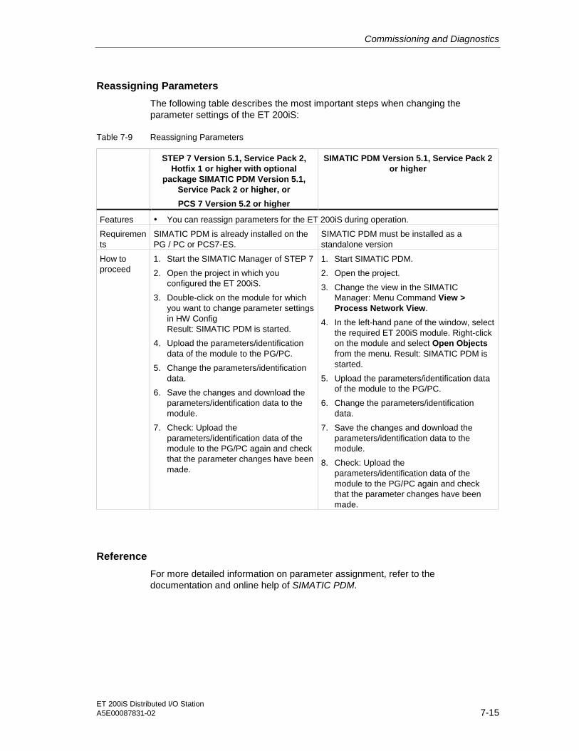
Commissioning and Diagnostics
ET 200iS Distributed I/O StationA5E00087831-02 7-15
Reassigning Parameters
The following table describes the most important steps when changing theparameter settings of the ET 200iS:
Table 7-9 Reassigning Parameters
STEP 7 Version 5.1, Service Pack 2,Hotfix 1 or higher with optional
package SIMATIC PDM Version 5.1,Service Pack 2 or higher, or
PCS 7 Version 5.2 or higher
SIMATIC PDM Version 5.1, Service Pack 2or higher
Features • You can reassign parameters for the ET 200iS during operation.
Requirements
SIMATIC PDM is already installed on thePG / PC or PCS7-ES.
SIMATIC PDM must be installed as astandalone version
How toproceed
1. Start the SIMATIC Manager of STEP 7
2. Open the project in which youconfigured the ET 200iS.
3. Double-click on the module for whichyou want to change parameter settingsin HW ConfigResult: SIMATIC PDM is started.
4. Upload the parameters/identificationdata of the module to the PG/PC.
5. Change the parameters/identificationdata.
6. Save the changes and download theparameters/identification data to themodule.
7. Check: Upload theparameters/identification data of themodule to the PG/PC again and checkthat the parameter changes have beenmade.
1. Start SIMATIC PDM.
2. Open the project.
3. Change the view in the SIMATICManager: Menu Command View >Process Network View.
4. In the left-hand pane of the window, selectthe required ET 200iS module. Right-clickon the module and select Open Objectsfrom the menu. Result: SIMATIC PDM isstarted.
5. Upload the parameters/identification dataof the module to the PG/PC.
6. Change the parameters/identificationdata.
7. Save the changes and download theparameters/identification data to themodule.
8. Check: Upload theparameters/identification data of themodule to the PG/PC again and checkthat the parameter changes have beenmade.
Reference
For more detailed information on parameter assignment, refer to thedocumentation and online help of SIMATIC PDM.

Commissioning and Diagnostics
ET 200iS Distributed I/O Station7-16 A5E00087831-02
7.6 Diagnostics Using the Process Image Input Table
Introduction
In addition to the diagnostic information available with the LEDs and module/DPdiagnostics, the module also provides information about the validity of every inputsignal – the value status. The value status is entered in the process image alongwith the input signal.
Value Status of the Digital Input Modules
The value status is additional binary information on a digital input signal. The valuestatus is entered in the process image input table at the same time as the processsignal and provides information on the validity of the input signal. The value statusis influenced by the following:
• Wire break check / short circuit
• Flutter monitoring
• Pulse extension
• Validation check of changeover contacts
Significance of the value status:
• “1“: Input signal is valid
• “0“: Input signal is invalid
Digital Input and Value Status Assignment
In the process image, a value status is assigned to every input in the input byte IBx of the module.
Input signal channel 1
Meaning of value status: 1: signal valid0: signal invalid
Input signal channel 0
IB x
7 6 5 4 3 2 1 0
Value status for channel 1
Value status for channel 0
Input signal channel 2Input signal channel 3
Value status for channel 2Value status for channel 3
Figure 7-4 Assignment of the Value Status to the Digital Input

Commissioning and Diagnostics
ET 200iS Distributed I/O StationA5E00087831-02 7-17
Value Status of the Analog Input Modules
The input values of the analog input modules are entered in the process imageinput table. If a measured value is invalid, the following value status is entered asthe input value:
• in S7: 7FFFH
• in S5: 7FFBH
Evaluation of the Value Status in PCS 7
The value status is evaluated using the PCS 7 channel driver.
1. The PCS 7 channel driver reads the value status from the process image inputtable...
2. ...and forms the quality code for PCS 7.
Detailed Description
You will find a detailed description of evaluating and processing the input signals inthe PCS 7 Documentation.
7.7 Status and Error LEDs on the IM 151-2
Interface module IM 151-2
SF
BF
ON
SF Group error (red)
BF Bus error (red)
ON Power supply (green)
Figure 7-5 LED Display on the Interface Module
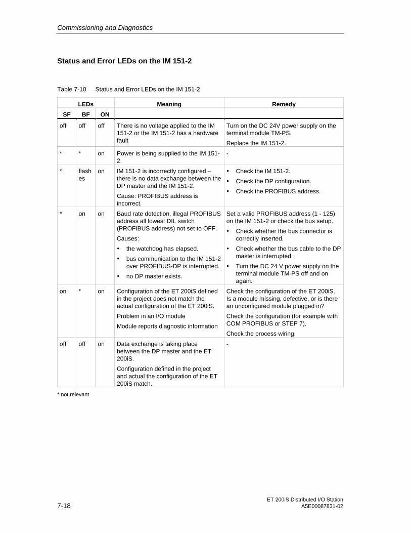
Commissioning and Diagnostics
ET 200iS Distributed I/O Station7-18 A5E00087831-02
Status and Error LEDs on the IM 151-2
Table 7-10 Status and Error LEDs on the IM 151-2
LEDs Meaning Remedy
SF BF ON
off off off There is no voltage applied to the IM151-2 or the IM 151-2 has a hardwarefault
Turn on the DC 24V power supply on theterminal module TM-PS.
Replace the IM 151-2.
* * on Power is being supplied to the IM 151-2.
-
* flashes
on IM 151-2 is incorrectly configured –there is no data exchange between theDP master and the IM 151-2.
Cause: PROFIBUS address isincorrect.
• Check the IM 151-2.
• Check the DP configuration.
• Check the PROFIBUS address.
* on on Baud rate detection, illegal PROFIBUSaddress all lowest DIL switch(PROFIBUS address) not set to OFF.
Causes:
• the watchdog has elapsed.
• bus communication to the IM 151-2over PROFIBUS-DP is interrupted.
• no DP master exists.
Set a valid PROFIBUS address (1 - 125)on the IM 151-2 or check the bus setup.
• Check whether the bus connector iscorrectly inserted.
• Check whether the bus cable to the DPmaster is interrupted.
• Turn the DC 24 V power supply on theterminal module TM-PS off and onagain.
on * on Configuration of the ET 200iS definedin the project does not match theactual configuration of the ET 200iS.
Problem in an I/O module
Module reports diagnostic information
Check the configuration of the ET 200iS.Is a module missing, defective, or is therean unconfigured module plugged in?
Check the configuration (for example withCOM PROFIBUS or STEP 7).
Check the process wiring.
off off on Data exchange is taking placebetween the DP master and the ET200iS.
Configuration defined in the projectand actual the configuration of the ET200iS match.
-
* not relevant

Commissioning and Diagnostics
ET 200iS Distributed I/O StationA5E00087831-02 7-19
Power Supply Module
POWER Status of output voltageon power supply module (green)
DC 24 V Status of power supply (green)
Figure 7-6 Status LEDs on the Power Supply Module
Status LEDs on the Power Supply Module
Table 7-11 Status LEDs on the Power Supply Module
LEDs
DC 24 V POWER
Meaning Remedy
off No power supply on the terminalmodule TM-PS.
Check the power supply on theterminal module TM-PS.
off Some of the output voltages of thepower supply module do not exist.
Replace the power supply module.

Commissioning and Diagnostics
ET 200iS Distributed I/O Station7-20 A5E00087831-02
Digital Electronics Modules
SF Group error (red)SF
1 5 9 13
3 15
3 15Status for state ofoutput (green)
Status for state ofinput (green)
1 5 9 13
Figure 7-7 Status and Error LEDs on the Digital Electronics Modules
Status and Error LEDs on the Digital Electronics Modules
Table 7-12 LED Display on the Digital Electronics Modules
LEDs
SF 1 5 9 13 3 15
Meaning Remedy
on Wrong module inserted.Diagnostic message exists.
Evaluate the diagnosticinformation.
on Input DI 0 activated
on Input DI 1 activated
on Input DI 2 activated
on Input DI 3 activated
on Output DO 0 activated
on Output DO 3 activated

Commissioning and Diagnostics
ET 200iS Distributed I/O StationA5E00087831-02 7-21
Analog Electronics Modules
SF Group error (red)SF
Figure 7-8 Error LEDs on the Analog Electronics Modules
Error LEDs on the Analog Electronics Modules
Table 7-13 Error LEDs on the Analog Electronics Modules
LED
SF
Meaning Remedy
on Wrong module inserted.Diagnostic message exists.
Evaluate the diagnosticinformation.

Commissioning and Diagnostics
ET 200iS Distributed I/O Station7-22 A5E00087831-02
7.8 Diagnostics with STEP 5 and STEP 7
7.8.1 Introduction
Introduction
Slave diagnostics complies with the standard EN 50170, Volume 2, PROFIBUS.Depending on the DP master, diagnostic information can be read out for all DPslaves that comply with the standard using STEP 7 or STEP 5.
Reading out slave diagnostic information and the structure of the information isdescribed in the following sections.
7.8.2 Reading out Diagnostic Information
Options for Reading out Diagnostic Information
Table 7-14 Reading out Diagnostic Information with STEP 7 and STEP 5
ProgrammableController with
DP Master
Block or Tab in STEP 7 Application See...
"DP Slave Diagnostics"tab
Slave diagnostic informationin plain language on theSTEP 7 user interface
"Hardware Diagnostics" inthe STEP 7 online help
SFC13 "DPNRM_DG" Reading out the slavediagnostic information(storing in the data area ofthe user program)
SIMATIC S7
SFC59 "RD_REC" Reading out data records ofS7 diagnostics (storing inthe data area of the userprogram)
For the structure, seesection Structure of theSlave DiagnosticInformation; SFC seereference manual Systemand Standard Functions
SIMATIC S5 withIM 308C as DPmaster
FB192 "IM308C" Reading out slavediagnostic information(storing in the data area ofthe user program)
For the structure, seesection Structure of theSlave DiagnosticInformation; FB seemanual ET 200 DistributedI/O Station

Commissioning and Diagnostics
ET 200iS Distributed I/O StationA5E00087831-02 7-23
Example of Reading out S7 Diagnostic Information with SFC13 "DPNRM _DG"
Here, you will find an example of how you can read out the slave diagnosticinformation for a DP slave in the STEP 7 user program using SFC13.
Assumptions
For this STEP 7 user program, the following is assumed:
• The diagnostic address of the ET 200iS is 1022 (3FEH).
• The slave diagnostic information will be stored in DB82: starting at address 0.0,length 96 bytes.
• The slave diagnostic information consists of 96 bytes.
STEP 7 User Program
STL Explanation
CALL SFC 13
REQ :=TRUE Read request
LADDR :=W#16#3FE Diagnostic address of the ET 200iS
RET_VAL :=MW 0 RET_VAL of SFC 13
RECORD :=P#DB82.DBX 0.0 BYTE 96 Data record for the diagnostic informationin DB82
BUSY :=M2.0 Reading takes several OB1 cycles
Example of Reading out the Slave Diagnostic Information with FB192 "IM 308C"
Here, you will find an example of how you can read out the slave diagnosticinformation for a DP slave in the STEP 5 user program using FB192.
Assumptions
For this STEP 5 user program, the following is assumed:
• The IM 308-C as DP master occupies pages 0 to 15 (number 0 of the IM 308-C).
• The DP slave has PROFIBUS address 3.
• The slave diagnostic information will be entered in DB20. You can also use adifferent data block.
• The slave diagnostic information consists of 96 bytes.

Commissioning and Diagnostics
ET 200iS Distributed I/O Station7-24 A5E00087831-02
STEP 5 User Program
STL Explanation
:C DB 30
:JU FB 192
Name :IM308C
DPAD : KH F800 Default address range of the IM 308-C
IMST : KY 0, 3 IM no. = 0, PROFIBUS address of the DP slave = 3
FCT : KS SD Function: Read out slave diagnostic information
GCGR : KM 0 not evaluated
TYP : KY 0, 20 S5 data area: DB20
STAD : KF +1 Diagnostic data starting and data word 1
LENG : KF -1 Diagnostic length = joker length (all permittedbytes)
ERR : DW 0 Error code stored in DW 0 of DB 30
7.8.3 Diagnostic Messages of the Electronics Modules
Introduction
With SIMATIC PDM, you can set the diagnostic messages for the followingmodules:
• Digital input modules
• Digital output modules
• Analog input modules
• Analog output modules
Digital Input Modules
Table 7-15 Digital Input Modules
Diagnostic Message Effective for Parameters canbe assigned
Short circuit Channel yes
Wire break Channel yes
Error Module No
Bad parameter Module No
External error Channel No
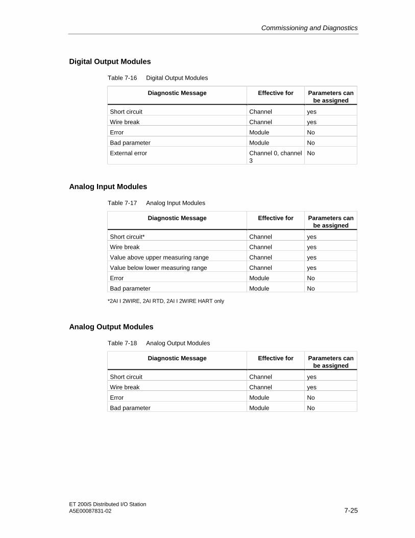
Commissioning and Diagnostics
ET 200iS Distributed I/O StationA5E00087831-02 7-25
Digital Output Modules
Table 7-16 Digital Output Modules
Diagnostic Message Effective for Parameters canbe assigned
Short circuit Channel yes
Wire break Channel yes
Error Module No
Bad parameter Module No
External error Channel 0, channel3
No
Analog Input Modules
Table 7-17 Analog Input Modules
Diagnostic Message Effective for Parameters canbe assigned
Short circuit* Channel yes
Wire break Channel yes
Value above upper measuring range Channel yes
Value below lower measuring range Channel yes
Error Module No
Bad parameter Module No
*2AI I 2WIRE, 2AI RTD, 2AI I 2WIRE HART only
Analog Output Modules
Table 7-18 Analog Output Modules
Diagnostic Message Effective for Parameters canbe assigned
Short circuit Channel yes
Wire break Channel yes
Error Module No
Bad parameter Module No
Commissioning and Diagnostics
ET 200iS Distributed I/O Station7-26 A5E00087831-02
Actions Following a Diagnostic Message in STEP 7 or DPV1
Every diagnostic message leads to the following actions:
• In S7 or DPV1 mode, diagnostic information is reported as a diagnosticinterrupt.
• In DPV1 mode, diagnostic information is also reported when the CPU is inSTOP mode. The diagnostic frame also includes the module status andchannel-related diagnostics.
• Following a diagnostic message,- it is entered in the diagnostic frame as a diagnostic interrupt field (always oneinterrupt only)- it is stored in the diagnostic buffer of the CPU
• The SF-LED on the IM 151-2 is lit.
• OB82 is called. If OB82 does not exist, the CPU changes to STOP mode.
• Acknowledgment of the diagnostic interrupt (following this a new interrupt ispossible)
Actions Following a Diagnostic Message in DPV0
The error is entered in the channel-related diagnostic information in the diagnosticframe:
• The SF-LED on the IM 151-2 is lit.
• There can be more than one diagnostic message at the same time.
Causes of Errors and Remedies
The causes of errors and remedies following diagnostic messages are described insection Channel-Related Diagnostics.
7.8.4 Evaluating Interrupts from the ET 200iS (S7-DP Slave/ DPV1Slave)
Introduction
Certain error scores the DP slave to trigger an interrupt. Depending on the DPmaster you are using, the evaluation of the interrupt follows different procedures.

Commissioning and Diagnostics
ET 200iS Distributed I/O StationA5E00087831-02 7-27
Evaluating Interrupts with an S7 DP Master or DPV1 Master
Requirement: You have configured the ET 200iS with STEP 7 (Version 5.1, ServicePack 2, Hotfix 1 or higher) or PCS 7 (Version 5.2 or higher); in other words,interrupts are only supported if the ET 200iS functions as an S7-DP slave or DPV1slave.
If an interrupt occurs, interrupt LPs are called automatically in the CPU of the DPmaster (see programming manual System Software for S7-300/S7-400, ProgramDesign).
Evaluating Interrupts with Other DP Masters
If you operate the ET 200iS with a different DP master or as a DP standard slave,no interrupts are generated.
Triggering a Diagnostic Interrupt
When an event (for example wire break) enters all leaves the state, the moduletriggers a diagnostic interrupt if "Enable: Diagnostic interrupt“ is set.
The CPU interrupts execution of the user program and runs the diagnostic blockOB82. The event that led to the interrupt been triggered is entered in the startupinformation of OB82.
Triggering a Hardware Interrupt
If a hardware interrupt occurs, the CPU interrupts execution of the user programand runs the hardware interrupt block OB40.
The channel of the module that triggered the hardware interrupt is entered in thestartup information of OB40 in the variable OB40_POINT_ADDR. The schematicbelow shows the assignment to the bits of the local data double word 8.
• Analog input modules
31 30 29 28 27 26 25 24 17 16 1 0 Bit-No.
LB 8 LB 9 LB 11
1 1 1 1 LD 8
Below lower limit value channel 1
Below lower limit value channel 0
Above upper limit value channel 1
Above upper limit value channel 0
LB 10
Figure 7-9 Interrupts from Analog Input Modules

Commissioning and Diagnostics
ET 200iS Distributed I/O Station7-28 A5E00087831-02
Note
You will find a description of OB40 in the reference manual System and StandardFunctions
Triggering a Remove/Insert Interrupt
Remove/insert interrupts are supported only by S7-400s and in the DPV1 mode.
The CPU (S7-400) interrupts execution of the user program and runs thediagnostic block OB83. The event that led to the interrupt been triggered is enteredin the startup information of OB83.
Triggering an Update Interrupt
Update interrupts are supported only in the DPV1 mode.
The CPU interrupts execution of the user program and runs the diagnostic blockOB56. The event that led to the interrupt been triggered is entered in the startupinformation of OB56.

Commissioning and Diagnostics
ET 200iS Distributed I/O StationA5E00087831-02 7-29
7.8.5 Structure of the Slave Diagnostic Information
Structure of the Slave Diagnostic Information
Byte 0
Byte 1
Byte 2
Station status 1 to 3
Byte 3
Byte 4
Byte 5
Master PROFIBUS address
High byte
Low byteVendor ID
ID-related diagnostics
Byte 6..
Byte 11
Byte 12..
Byte 24
Module
Byte 25
Channel-related diagnostics**(3 bytes per channel)
To max.byte 95
.
.
.
Interrupts*(Only 1 interrupt per slavediagnostic framepossible)
* Interrupts are supported only when you configure the ET 200iS with STEP 7 asS7-DP or DPV1 slave.
** Module status and channel-related diagnostics are available only when you configurethe ET 200iS as a DP standard slave or as a DPV1 slave.
DPV1S7-DPDPV0
.
.
.
.
.
.
.
.
.
.
.
.
.
.
.
.
.
.max. 48 bytes
.
.
.
.
.
.
Figure 7-10 Structure of the Slave Diagnostic Information

Commissioning and Diagnostics
ET 200iS Distributed I/O Station7-30 A5E00087831-02
7.8.6 Station Status 1 to 3
Definition
Stations status 1 to 3 provides an overview of the status of a DP slave.
Station Status 1
Table 7-19 Structure of Station Status 1 (Byte 0)
Bit Meaning Cause / Remedy
0 1: The DP slave cannot be accessedby the DP master. The bit on the DPslave is always "0".
• Is the correct PROFIBUS address seton the DP slave?
• Is the bus connector plugged in?
• Is the power supply for the DP slaveon?
• RS-485 repeater set correctly?
• Has there been a RESET on the DPslave (off/on)?
1 1: The DP slave is not yet ready fordata exchange.
• Wait, the DP slave is currentlystarting up.
2 1: The configuration data sent to theDP slave by the DP master do notmatch the actual configuration of theDP slave.
Has the correct station type or correctconfiguration of the DP slave beenentered in the configuration software?
3 1: External diagnostic informationexists.
Evaluate the channel-related diagnosticinformation, the module status and/or thechannel-related diagnostic information.As soon as all errors have beeneliminated, bit 3 will be reset. The bit willbe set again when there is a newdiagnostic message in the bytes of thediagnostic information.
4 1: The requested function is notsupported by the DP slave (forexample, changing the PROFIBUSaddressusing the software).
Check the configuration.
5 1: The DP master cannot interpret thereply from the DP slave.
Check the bus configuration.
6 1: The DP slave type does not matchthe software configuration.
Compare the defined and actualconfiguration.
7 1: The parameters for the DP slavewere set by a different DP master (notby the DP master that currently hasaccess to the DP slave).
The bit is always 1 if, for example, youare currently accessing the DP slavefrom the programming device or adifferent DP master.
The PROFIBUS address of the DPmaster that set the parameters for theDP slave is in the diagnostic byte"master PROFIBUS address".

Commissioning and Diagnostics
ET 200iS Distributed I/O StationA5E00087831-02 7-31
Station Status 2
Table 7-20 Structure of Station Status 2 (Byte 1)
Bit Meaning
0 1: The parameters for the DP slave must be reassigned.
1 1: A diagnostic message exists. The DP slave will not operate until the problem iseliminated (static diagnostic message).
2 1: The bit on the DP slave is always "1".
3 1: The watchdog is activated for this DP slave.
4 1: The DP slave has received the "FREEZE" control command.
5 1: The DP slave has received the "SYNC" control command.
6 0: The bit is always "0".
7 1: Bit is always "0". Note: When reading the station status from the DP master,the bit is "1" if the DP slave was deactivated in the DP master. The DP slave isactivated; in other words, it is not included in the current processing.
Station Status 3
Table 7-21 Structure of Station Status 3 (Byte 2)
Bit Meaning
0 to 6 0: Bits are always "0".
7 1: There are more channel-related diagnostic messages than can be shown in thediagnostic frame

Commissioning and Diagnostics
ET 200iS Distributed I/O Station7-32 A5E00087831-02
7.8.7 Master PROFIBUS Address
Definition
The diagnostic byte master PROFIBUS address contains the PROFIBUS addressof the DP master:
• that assigned the parameters to the DP slave and
• that has read and write access to the DP slave.
The master PROFIBUS address is in byte 3 of the slave diagnostic information.
DP Slave not Assigned Parameters by the DP Master (Class 1)
If the value FFH is entered as the master PROFIBUS address in byte 3, the DPslave was not assigned parameters by the DP master.
No cyclic data exchange takes place.
7.8.8 Vendor ID
Definition
The vendor ID contains a code describing the type of the DP slave.
Vendor ID
Table 7-22 Structure of the Vendor ID (Byte 4, 5)
Byte 4 Byte 5 Vendor ID for
80 6E IM 151-2
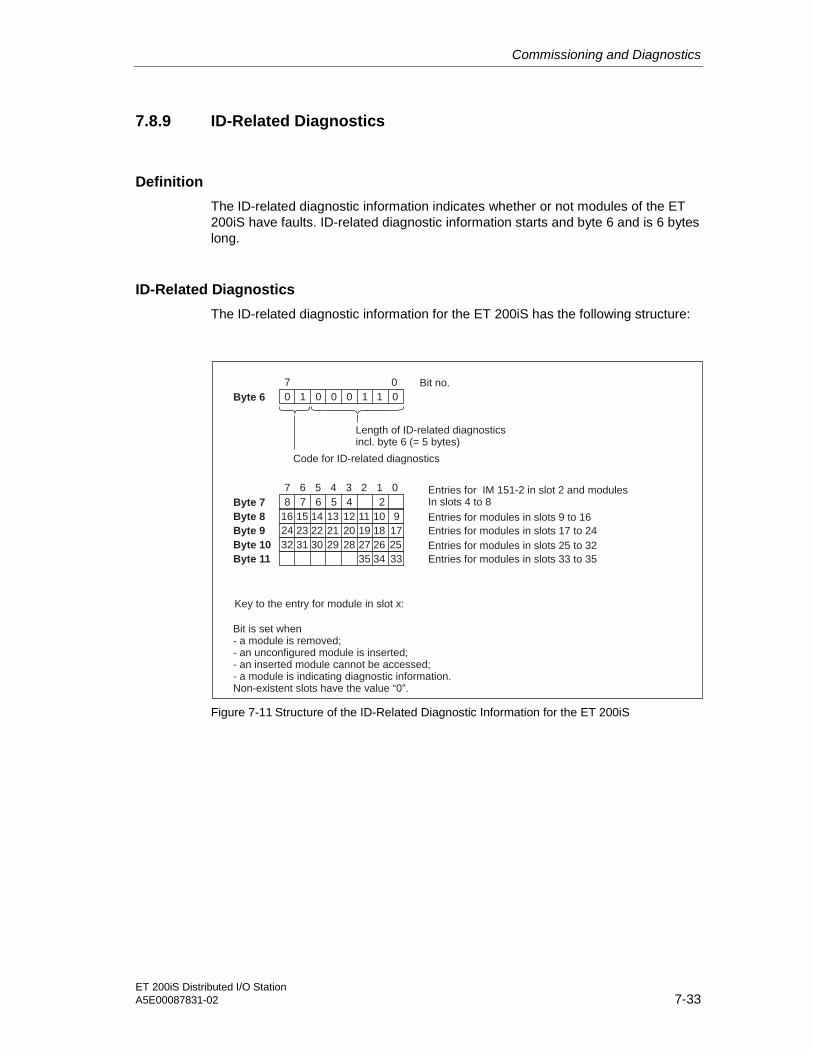
Commissioning and Diagnostics
ET 200iS Distributed I/O StationA5E00087831-02 7-33
7.8.9 ID-Related Diagnostics
Definition
The ID-related diagnostic information indicates whether or not modules of the ET200iS have faults. ID-related diagnostic information starts and byte 6 and is 6 byteslong.
ID-Related Diagnostics
The ID-related diagnostic information for the ET 200iS has the following structure:
Byte 6
Bit no.
Length of ID-related diagnosticsincl. byte 6 (= 5 bytes)
0 1 0 0 0 1 1 0
7
Code for ID-related diagnostics
Byte 7 8 7 6 5 4 2
7 6 5 4 3 2 1 0 Entries for IM 151-2 in slot 2 and modulesIn slots 4 to 8
0
Byte 8 16 15 14 13 12 11 10 9
Byte 9 24 23 22 21 20 19 18 17
Byte 10 32 31 30 29 28 27 26 25
Byte 11 35 34 33
Entries for modules in slots 9 to 16
Entries for modules in slots 17 to 24
Entries for modules in slots 25 to 32
Entries for modules in slots 33 to 35
Key to the entry for module in slot x:
Bit is set when- a module is removed;- an unconfigured module is inserted;- an inserted module cannot be accessed;- a module is indicating diagnostic information.Non-existent slots have the value “0”.
Figure 7-11 Structure of the ID-Related Diagnostic Information for the ET 200iS

Commissioning and Diagnostics
ET 200iS Distributed I/O Station7-34 A5E00087831-02
7.8.10 Module Status
Definition
The module status indicates the status of the configured modules and providesdetails of the ID-related diagnostic information relating to the configuration andindicates any module fault.The module status follows the ID-related diagnosticinformation and is 13 bytes long.
Module Status
The module status for the ET 200iS is structured as follows:
Byte 12
Bit no.
Length of module statusincl. byte 12 (= 13 bytes)
0 0 0 0 1 1 0 1
7 6 5 4 3 2 1 0
Code for module status
Byte 13
Bit no.
2 = module statusH
1 0 0 0 0 0 1 0
7 6 5 4 3 2 1 0
Code for status message
Byte 14
Byte 15
7 0
0H
0H
7 6 5 4 3 2 1 0
4
8 7 6 5
12 11 10 912 11 10 9
16 15 14 13
20 19 18 17
24 23 22 21
28 27 26 25
32 31 30 29
35 34 33
Byte 16
Byte 17
Byte 18
Byte 19
Byte 20
Byte 22
Byte 23
Byte 21
Byte 24
Bit no.
module in slot 4
modules in slots 5 to 8
modules in slots 9 to 12
modules in slots 13 to 16
modules in slots 17 to 20
modules in slots 21 to 24
modules in slots 25 to 28
modules in slots 29 to 32
modules in slots 33 to 35
always “0”
always “0”
00 : module ok; valid dataB
01 : module error; invalid dataB
10 : wrong module; invalid dataB
11 : no module (or module failure); invalid dataB
Status type: module
Key: non-existent slots are “00”
Figure 7-12 Module Status

Commissioning and Diagnostics
ET 200iS Distributed I/O StationA5E00087831-02 7-35
7.8.11 Channel-Related Diagnostics
Definition
Channel-related diagnostics provides information about channel errors of modulesand provides details of the ID-related diagnostics.
For each item of channel-related diagnostic information, three bytes are inserted incompliance with the standard IEC 61158/EN 50170, Volume 2, PROFIBUS.
The channel-related diagnostic information follows the module status.
The channel-related diagnostic information does not influence the module status.
Important: Group diagnostics must be activated for each module!
Channel-Related Diagnostics
The maximum amount of channel-related diagnostic information is limited by themaximum total length of the slave diagnostic information of 96 bytes for the IM 151-2. The length of the slave diagnostic information depends on the number of itemsof channel-related diagnostic information currently pending. If there is morechannel-related diagnostic information than can be included in the slave diagnosticinformation, bit 7 "diagnostics overflow“ is set in station status 3.

Commissioning and Diagnostics
ET 200iS Distributed I/O Station7-36 A5E00087831-02
Error type according to PROFIBUS standard
from byte 25
Byte x
Bit no.
000001 to 001000 : ID number of the module that supplies
channel-related diagnostics.(Example: slot 4 has ID number 3;
slot 5 has ID number 4 etc.)
B B
1 0
Code for channel-related diagnostics
7 6 5 4 3 2 1 0
Byte x+1
Bit no.
000000 to 111111 : Number of the channel or
channel group supplying diagnostic informationB B
Input/output: 01 : Input
10B
B
B
: Output
11 : Input/output
7 6 5 4 3 2 1 0
Byte x+2
Bit no.
Channel type
001 : bitB
010 : 2 bits
011 : 4 bits
100 : byte
101 : word
110 : 2 words
B
B
B
B
B
7 6 5 4 3 2 1 0
max. byte 95 for IM 151-2
Byte x+3bis x+5
.
.
Next channel-realted diagnostic message(Assignment as for bytes 25 to 27)
Figure 7-13 Structure of the Channel-Related Diagnostic Information

Commissioning and Diagnostics
ET 200iS Distributed I/O StationA5E00087831-02 7-37
Types of Error/Fault of the Electronics Modules
Table 7-23 Types of Error/Fault of the Electronics Modules
Error/Fault Type Error Text Meaning Remedy
• Sensor cable short-circuitedto P potential
• Sensor cable short-circuitedto M potential
• Output cable short-circuitedto P potential
• Output cable short-circuitedto M potential
Correct the process wiring
Defective sensor Replace the sensor
Wrong sensor type set Correct the parametersettings
00001B 1D Short circuit
Output overload Eliminate overload
• Break on the signal line to asensor
• Break on the signal linefrom an actuator
• Break on the sensor powersupply cable
Correct the process wiring
Fault on the external circuit(resistor)
Eliminate problem
Defective sensor Replace the sensor
Wrong sensor type set Correct the parametersettings
Input/output channel unused(open)
Deactivate the "groupdiagnostics" parameter forthis output channel
00110B 6D Wire break
Load impedance too high Use an actuator with a lowerload impedance
00111B 7D Value over upperlimit
The value is above the over-range
• Match the module/actuatorcorrectly
• Change the measuringrange in the parametersettings
01000B 8D Value under lowerlimit
The value is below the under-range
• Match the module/actuatorcorrectly
• Change the measuringrange in the parametersettings
EMC problem Eliminate the cause of theproblem
Hardware fault on the module Replace the module
01001B 9D Error
Sensor signal flutters Eliminate the cause of theproblem

Commissioning and Diagnostics
ET 200iS Distributed I/O Station7-38 A5E00087831-02
Error/Fault Type Error Text Meaning Remedy
10000B 16D Bad parameter The module cannot evaluateparameters for the channel
Correct the parametersettings
11010B 26D External error • Sensor fault
• Actuator fault
• Changeover contact fault
• Replace thesensor/actuator
• Correct the process wiring
7.8.12 Interrupts
Definition
The interrupt section of the slave diagnostic information indicates the interrupt typeand the event that led to an interrupt being triggered. The interrupt section can be amaximum of 48 bytes long.
Position in the Diagnostic Frame
The interrupt section is located after the channel-related diagnostic information orafter the ID-related diagnostic information (with STEP 7)
Example: If there are three items of channel-related diagnostic information, theinterrupt section starts at byte 34.
Content
The content of the interrupt function depends on the interrupt type:
With diagnostic interrupts, diagnostic data record 1 for SIMATIC S7 (44 bytes) issent as additional interrupt information (starting at byte x+4).
With hardware interrupts, the length of the additional interrupt information is 4bytes.
With remove/insert interrupts, the length of the interrupt information is 5 bytes.
The following pages describe the significance of these bytes.

Commissioning and Diagnostics
ET 200iS Distributed I/O StationA5E00087831-02 7-39
Interrupts
The interrupt section for the ET 200iS is structured as follows:
02: IM 151-2 supplies interrupt (hardware interrupt when time stamping)04 to 35: Slot of the module supplying interrupt
Byte xBit no.
0 0 0 1 0 0 0 0
Code for device-specific diagnostics
7 6 5 0
Byte x+1
Interrupt type: 0000001 : Diagnostic interrupt
0000010 : Hardware interrupt
0000011 : Remove interrupt
0000100 : Insert interrupt
0000110 Update interrupt
B
B
B
B
B
Byte x+2
.
.
.
Length of the interrupt part incl. byte x (=max. 48 bytes)
0
Slot number
Byte x+3
Interrupt sequencenumber (1 to 31)
00 : Hardware, remove or insert interrupt
01 : At least one error exists
10 : Error leaving state
11 : reserved
B
B
B
B
Byte x+4 to ... ...Byte x+43
Diagnostic data(content of datarecords 0 and 1)
...Byte x+7
Hardwareinterrupt data
...Byte x+8
Remove/insertinterrupt data
7 6 0
7 0
7 3 1 0
...Byte x+6
Updateinterrupt
Figure 7-14 Structure of the Interrupt Status of the Interrupt Section

Commissioning and Diagnostics
ET 200iS Distributed I/O Station7-40 A5E00087831-02
Diagnostic Interrupt, Bytes x+4 to x+7
Bytes x+4 to x+7 correspond to a diagnostic data record 0 in STEP 7.
The bytes from byte x+8 to x+43 correspond to diagnostic data record1 in STEP 7.
Byte x+4
External error: module no longer accessible
Channel error on module
Internal error/fault on module
Module problem, error/fault detected
7 6 5 4 3 2 1 0 Bit no.
Byte x+5
Channel information exists
User information exists
7 0
0 0
Module class:0100 for the IM 151-2: set with message for time stamping1111 for digital electronics module: from byte x+80101 for analog electronics module: from byte x+8
Byte x+6
7 6 5 4 3 2 1 0
Byte x+7
0
7 0
always "0"
always "0"
00 0
Figure 7-15 Structure of Bytes x+4 to x+7 for Diagnostic Interrupts
Diagnostic Interrupt of Input or Output Modules
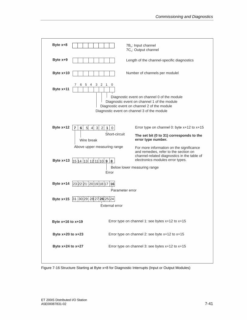
Commissioning and Diagnostics
ET 200iS Distributed I/O StationA5E00087831-02 7-41
Byte x+8
Diagnostic event on channel 2 of the module
Diagnostic event on channel 3 of the module
Diagnostic event on channel 1 of the module
Diagnostic event on channel 0 of the module
Byte x+11
7B : Input channel
7C : Output channelH
H
Byte x+9 Length of the channel-specific diagnostics
Byte x+10 Number of channels per modulel
Byte x+12 Error type on channel 0: byte x+12 to x+15
For more information on the significanceand remedies, refer to the section onchannel-related diagnostics in the table ofelectronics modules error types.
The set bit (0 to 31) corresponds to theerror type number.
Byte x+13
Byte x+14
Byte x+15
15 14 13 12 11 10 9 8
7 6 15 4 3 2 0
23 22 21 20 19 18 17 16
31 30 29 28 27 25 2426
Byte x+16 to x+19
Error type on channel 3: see bytes x+12 to x+15
7 0123456
Byte x+20 to x+23
Byte x+24 to x+27
Error type on channel 2: see byte x+12 to x+15
Error type on channel 1: see bytes x+12 to x+15
Short-circuit
Error
Above upper measuring range
Below lower measuring range
Parameter error
External error
Wire break
Figure 7-16 Structure Starting at Byte x+8 for Diagnostic Interrupts (Input or Output Modules)

Commissioning and Diagnostics
ET 200iS Distributed I/O Station7-42 A5E00087831-02
Example of a Diagnostic Interrupt
Byte x
Interrupt sequence number =1
There is at least one error
Byte x+3
Byte x+1
Byte x+2
Example: The 4DI NAMUR electronics module reports the “wire break” diagnosticinterrupt on channel 2"
Length of interrupt part = 27 bytes
Byte x+4
Byte x+5
Bytes x+6 and x+7 always "0"
0 0 0 1 1 0 1 1
0 0 0 0 0 0 0 1
0 0 0 0 1 0 1 0
0 0 0 0 1 0 0 1
0 0 0 0 1 0 0 0
0 0 0 1 1 1 1 1
Diagnostic interrupt
Slot number 10
Digital electronics module
Channel information exists
Channel error
Figure 7-17 Example of a Diagnostic Interrupt

Commissioning and Diagnostics
ET 200iS Distributed I/O StationA5E00087831-02 7-43
Byte x+8
Diagnostic result exists on channel 2
Byte x+11
Byte x+9
Byte x+10
Input module = 7BH
Byte x+20
Byte x+16 and x+19 "0" (channel 1)
0 1 1 1 1 0 1 1
0 0 1 0 0 0 0 0
0 0 0 0 0 1 0 0
0 0 0 0 0 1 0 0
0 1 0 0 0 0 0 0
Number of channels per module = 4
Bit x+20.6 = error type 6 on channel 2 = wire break
Length of channel-related diagnostics = 32 bits
Byte x+12 to x+15 "0" (channel 0)
7 5 4 3 2 1 06
Byte x+24 and x+27 "0" (channel 3)
Byte x+21 to x+23 "0" (channel 2)
Figure 7-18 Example of a Diagnostic Interrupt (continued)

Commissioning and Diagnostics
ET 200iS Distributed I/O Station7-44 A5E00087831-02
Hardware Interrupt of Analog Input Modules
7 6 5 4 3 2 1 0
Byte x+4
Above upper limit value channel 1
Above upper limit value channel 0
7 6 5 4 3 2 1 0
Byte x+5
Below lower limit value channel 1
Below lower limit value channel 0
Byte x+6 and x+7: are always 00H
Figure 7-19 Structure Starting at Byte x+4 for Hardware Interrupts (Analog Input)
Remove/Insert Interrupt
Byte x+4
7 6 5 4 3 2 1 0
Byte x+5
Byte x+6
Byte x+7
Byte x+8
not relevant
Type ID of the module; high byte
Type ID of the module; low byte
SKFID(STEP 7)
Key: type ID of a removed module: 8FC0 (empty slot)H
Figure 7-20 Structure Starting at Byte x+4 for Remove/Insert Interrupts
Bytes x+4 to x+8 contain the ID of the module that was removed or inserted. TheIDs of the modules can be found in the GSD file.
You can recognize whether the modules were removed or inserted by the interrupttype in byte x+1. (See Structure of the Interrupt Status of the Interrupt Section)

Commissioning and Diagnostics
ET 200iS Distributed I/O StationA5E00087831-02 7-45
Update Interrupt
The update interrupt is signaled when the following conditions are met:
• The parameter assignment is a free of errors.
• The parameter settings for the ET 200iS differ from the parameters andidentification data stored in retentive memory on the modules.
Byte x+4
Byte x+5
Data record index: is the numberof the parameter assignment datarecord that led to the update interrupt.
Number of updates that couldnot be signaled to the CPU.
Figure 7-21 Structure Starting at Byte x+4 for Update Interrupt

Commissioning and Diagnostics
ET 200iS Distributed I/O Station7-46 A5E00087831-02
7.8.13 Diagnostics for Incorrect Module Configuration of the ET 200iS
Incorrect Module Configuration
The following incorrect module configurations in the ET 200iS lead to an ET 200iSstation failure or prevent startup of the data exchange. These reactions are notdependent on whether or not IM 151-2 parameter "Startup when defined and actualconfiguration differ" is enabled:
• 2 modules missing
• Bus termination module missing
• Number of modules exceeds maximum configuration
• Module in the slot 1 missing
• Backplane bus fault (for example defective terminal module)
Note
If a module is missing (there is a gap) and the ET 200iS power supply is turned offand then on again, this leads to an ET 200iS station failure.
Diagnostics
You can recognize all the incorrect module configuration states based on thefollowing diagnostic information:
Table 7-24 Diagnostics for Incorrect Module Configuration of the ET 200iS
ID-Related Diagnostics Module Status
All the bits from slot 4 to 35 are set 01B: "Module error, invalid user data" fromslot 4 to 35

ET 200iS Distributed I/O StationA5E00087831-02 8-1
8Maintenance 88.1 Activities During Operation
Features
The table below describes the activities that can be performed on the ET 200iS inzone 1 and zone 2:
Requirements
The ET 200iS is in operation.
Permitted Activities in Zone 1
Table 8-1 Permitted Activities in Zone 1
Activities See...
Removing and inserting modules duringoperation (hot swapping)
Section Maintenance
Maintenance during operation (visual checks) Section Maintenance
Cleaning Section Maintenance
Removing and inserting the bus connector at theterminal module TM-IM
Section Wiring
Disconnecting the cables to the sensors,actuators, and HART field devices and theterminal module TM-E
Section Wiring
Making new parameter settings and diagnosticsfor the ET 200iS
Section Commissioning andDiagnostics
Permitted Activities in Zone 2
In addition to the activities permitted in zone 1, the following activity is alsopermitted:
Caution
Disconnecting and connecting cables for the DC 24V power supply at the terminalmodule TM-PS during operation. This activity is permitted only when there is norisk of explosion or when there is no power applied to the terminal module TM-PS.
Maintenance
ET 200iS Distributed I/O Station8-2 A5E00087831-02
8.2 Removing and Inserting Electronics Modules during Operation(Hot Swapping)
Features
• The ET 200iS distributed I/O station supports the removal and insertion of oneelectronics module (1 gap) during operation (RUN mode).
• If one electronics module is removed, the ET 200iS remains in the RUN mode.
• If you remove more than one electronics module, this leads to an ET 200iSstation failure. Once you have inserted all the electronics modules again, youmust restart the ET 200iS; in other words, turn the power supply off and on atthe power supply module PS.
• If you install only one electronics module in an ET 200iS, removing thiselectronics module will lead to an ET 200iS station failure. When you insert theelectronics module, the ET 200iS starts up again.
• All current parameters and identification data of the ET 200iS are stored in aninternal flash memory on the IM 151-2. After replacing a module, IM 151-2automatically transfers the current parameters and identification data to the newmodule. This function is always active on the ET 200iS and cannot beinfluenced by the user.
– The current parameters and identification data are retained on the IM 151-2even if the power supply for the ET 200iS fails.
– The default parameters of an electronics module are overwritten.
Note
The flash memory (parameters and identification data) of the IM 151-2 is erased ifyou change the PROFIBUS address and turn on the power supply for the ET 200iSat the power supply module.

Maintenance
ET 200iS Distributed I/O StationA5E00087831-02 8-3
PROFIBUS-DP
Parameters and identificationdata are stored non-volatile inflash memory
Following module replacement,parameter and identification data aretransferred automatically to the newmodule
IM 151-2 New electronics module
Figure 8-1 Automatic Parameter Assignment after Replacing a Module
Requirements
• When the ET 200iS starts up, all modules must be inserted.
• Removing and inserting electronics modules during operation (RUN mode) ispossible only if you have enabled the Startup when defined and actualconfiguration differ parameter for the IM 151-2.
• Only one electronics module may be removed and one time.
• The following table describes which modules you can remove and insert duringoperation:

Maintenance
ET 200iS Distributed I/O Station8-4 A5E00087831-02
Table 8-2 Requirements
Module Removeand Insert
Effects on the ET 200iS
Power supplymodule PS
yes Remove: Failure of the ET 200iS (the same statusas if the power supply is turned off).
Insert: Startup of the ET 200iS
Interface module IM151-2
yes Remove: Failure of the ET 200iS
Insert: The ET 200iS parameters must be assignedfrom a PG.
Electronics module yes Remove: Failure of the sensor/actuator
Insert: Sensor/actuator operational
Removing and Inserting Electronics Modules
Remove and insert the electronics modules as described in the section Wiring.
Note
Check the two coding elements before inserting the new electronics module in theterminal module.

Maintenance
ET 200iS Distributed I/O StationA5E00087831-02 8-5
8.3 Maintenance During Operation
Features
Maintenance of the ET 200iS is effectively restricted to visual inspections. Thesecan be performed while the ET 200iS is operating.
Requirements
In zone 1 and zone 2, a visual inspection should be made every six months.
Procedure
1. Check that the cable inlets in the enclosure are sealed and intact.
2. Check whether there is any water or liquid inside the enclosure. If there is, findout how it got there.
3. Check that the wiring is secure (connectors, cables).
8.4 Cleaning
Note on Safety
Warning
Plastics can develop an electrostatic charge when they are cleaned. If you areoperating the ET 200iS in zone 1 or zone 2, this can represent a danger:
Clean the ET 200iS only with damp cloths.
A sign with the warning "Clean the ET 200iS only with damp cloths" must beplaced inside the enclosure.
Following cleaning, run a functional check of the ET 200iS.

Maintenance
ET 200iS Distributed I/O Station8-6 A5E00087831-02

ET 200iS Distributed I/O StationA5E00087831-02 9-1
9General Technical Specifications 99.1 General Technical Specifications
What Are General Technical Specifications?
The general technical specifications contain the standards and test values to whichthe ET 200iS distributed I/O station complies and adheres and the test criteria withwhich the ET 200iS distributed I/O station was tested.
9.2 Standards, certificates and approvals
Introduction
This section contains the following information on the components of the ET 200iS:
• The most important standards, with which the ET 200iS complies
• Approvals for the ET 200iS
PROFIBUS Standard
The ET 200iS distributed I/O station is based on the standard IEC 61158/EN50170, Volume 2, PROFIBUS.
IEC 61131
The ET 200iS distributed I/O station meets the requirements and criteria of the IEC61131-2 standard.

General Technical Specifications
ET 200iS Distributed I/O Station9-2 A5E00087831-02
CE Mark
Our products meet the requirements and protective aims of the following EUdirectives and comply with the harmonized European standards (EN) published bythe European Union for programmable logic controllers:
• 89/336/EEC "Electromagnetic Compatibility" (EMC Directive)
• 73/23/EEC" Electrical Equipment Designed for Use within Certain VoltageLimit"s (Low Voltage Directive)
The EU declarations of conformity are available for the relevant authorities and arekept at:
Siemens AktiengesellschaftBereich AutomatisierungstechnikA & D AS E 4Postfach 1963D-92209 Amberg
CE Mark in Compliance with ATEX 100a
In addition to the information on the CE mark above, the ET 200iS also meets thefollowing harmonized European directive (EN) for use explosive atmospheres:
94/9/EC "Equipment and Protective Systems for Use in Explosive Atmosphere"s.
Mark for Australia
Our products meet the requirements of the AS/NZS 2064 standard (Class A).
Figure 9-1 Mark for Australia
Safety Standards Complying with CENELEC
The ET 200iS meets the following safety standards
• EN 50014
• EN 50018
• EN 50019
• EN 50020
• EN 50284
General Technical Specifications
ET 200iS Distributed I/O StationA5E00087831-02 9-3
FM Approval (applied for)
Factory Mutual Approval Standard Class Number 3611, Class I, Division 2, GroupA, B, C, D, Class I, Zone 2
Factory Mutual Approval Standard Class Number 3610, Class I, Zone 1
Note
Please observe the instructions in the sections Installation, Wiring andMaintenance!
Shipbuilding Approvals (applied for)
Classification Societies:
• ABS (American Bureau of Shipping)
• BV (Bureau Veritas)
• DNV (Det Norske Veritas)
• GL (Germanischer Lloyd)
• LRS (Lloyds Register of Shipping)
9.3 Electromagnetic Compatibility, Transport and StorageConditions
Definition
Electromagnetic compatibility is the ability of electrical equipment to functionsatisfactorily in its electromagnetic environment without influencing thisenvironment.
The ET 200iS distributed I/O station also meets the requirements of the EMC lawsof the European Single Market. This is only possible if the ET 200iS distributed I/Ostation corresponds to the regulations and directives for electrical installation.

General Technical Specifications
ET 200iS Distributed I/O Station9-4 A5E00087831-02
Pulse-Shaped Disturbance
The following table shows the electromagnetic compatibility of the ET 200iSdistributed I/O station with relation to pulse-shaped disturbances.
Table 9-1 Pulse-Shaped Disturbances
Pulse-Shaped Disturbance Tested with Corresponds toseverity
Electrostatic discharge accordingto IEC 61000-4-2
8 kV
4 kV
3(air discharge)
2(contact discharge)
Burst pulse (fast transients)according to IEC 61000-4-4
2 kV (power supply line)
2 kV (signal line)
3
3
Surge according to IEC 61000-4-5
Only with lightning protectionelements (see section Wiring)
• asymmetrical coupling
• symmetrical coupling
2 kV (power supply line) 2kV (signal/data line)
1 kV (power supply line) 1kV (signal/data line)
3
Sinusoidal Disturbances
The following table shows the electromagnetic compatibility of the ET 200iSdistributed I/O station with relation to sinusoidal disturbances.
Table 9-2 Sinusoidal Disturbances
Radiated electromagnetic energy according to IEC61000-4-3
Radio frequency electromagnetic field
amplitude modulated pulse modulated
Induced RF voltageaccording toIEC 61000-4-6
80 to 1000 MHz 900 MHz ± 5 MHz 0.15 to 80 MHz
10 V/m 10 Veff unmodulated
80 % AM (1 kHz) 50 % ED 80 % AM (1 kHz)
200 Hz repetition frequency 150 ohms sourceimpedance
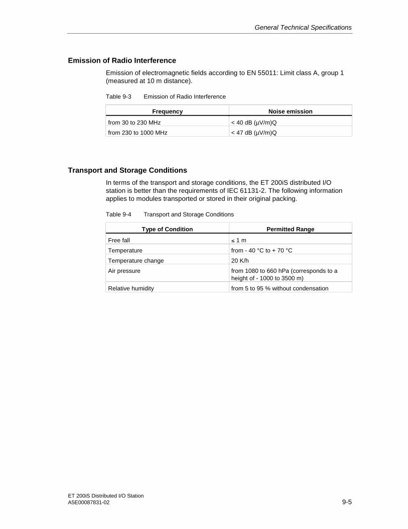
General Technical Specifications
ET 200iS Distributed I/O StationA5E00087831-02 9-5
Emission of Radio Interference
Emission of electromagnetic fields according to EN 55011: Limit class A, group 1(measured at 10 m distance).
Table 9-3 Emission of Radio Interference
Frequency Noise emission
from 30 to 230 MHz < 40 dB (µV/m)Q
from 230 to 1000 MHz < 47 dB (µV/m)Q
Transport and Storage Conditions
In terms of the transport and storage conditions, the ET 200iS distributed I/Ostation is better than the requirements of IEC 61131-2. The following informationapplies to modules transported or stored in their original packing.
Table 9-4 Transport and Storage Conditions
Type of Condition Permitted Range
Free fall ≤ 1 m
Temperature from - 40 °C to + 70 °C
Temperature change 20 K/h
Air pressure from 1080 to 660 hPa (corresponds to aheight of - 1000 to 3500 m)
Relative humidity from 5 to 95 % without condensation

General Technical Specifications
ET 200iS Distributed I/O Station9-6 A5E00087831-02
9.4 Mechanical and climatic environmental conditions
Climatic Ambient Conditions
The following climatic ambient conditions apply:
Table 9-5 Climatic Ambient Conditions
Ambient Conditions Applications Remarks
from - 20 to 60°C for horizontal installationTemperature
from - 20 to 40°C for all other installation positions
Temperature change 10 K/h
Relative humidity from 5 to max. 95 % intermittent condensation for brieftime
Air pressure from 1080 to 795 hPa corresponds to a height of -1000to 2000 m
Pollutant concentration SO2: < 0.5 ppm;rel. humidity < 60 %, nocondensation H2S: < 0.1 ppm;rel. humidity < 60 %, nocondensation
Test:
10 ppm; 4 days 1 ppm; 4 days
Mechanical Ambient Conditions
The mechanical ambient conditions are shown in the following table in the form ofsinusoidal oscillations.
Mechanical Ambient Conditions
Frequency Range Permanent Intermittent
5 ≤ f ≤ 9 Hz 3.5 mm amplitude 7 mm amplitude
9 ≤ f ≤ 150 Hz 1 g constant acceleration 2 g constant acceleration

General Technical Specifications
ET 200iS Distributed I/O StationA5E00087831-02 9-7
Testing for Mechanical and Climatic Ambient Conditions
The following table contains information on the type and scope of the testing formechanical ambient conditions.
Table 9-6 Testing for Mechanical and Climatic Ambient Conditions
Testing for ... Test Standard Terminal and Electronics Modules
Oscillation Oscillation testaccording to IEC60068-2-6 (sine)
Type of oscillation: Frequency sweep with a rate of change of1 octave/minute.5 Hz≤ f ≤ 9 Hz, constant amplitude 7 mm9 Hz≤ f ≤ 150 Hz, constant acceleration 2 gPeriod of oscillation: 10 frequency sweeps per axis in each ofthe 3 mutually vertical axes
Shock Shock test accordingto IEC 60068-2-27
Type of shock: half sineStrength of shock: 15 g peak value, 11 ms durationDirection of shock: 3 shocks each in +/- direction in each ofthe 3 mutually vertical axes
9.5 Information on Dielectric Strength Tests, Class of Protection,Degree of Protection and Rated Voltage of the ET 200iS
Dielectric Strength
The dielectric strengthis tested in the routine tests with the following test voltageaccording to IEC 61131-2:
Table 9-7 Dielectric Strength
Circuits with rated voltage Ue withrespect to other circuits or ground
Dielectric Strength
0 V < Ue ≤ 50 V DC 500 V
50 V < Ue ≤ 300 V
300 V < Ue ≤ 600 V
2 x URATED + 1000 V
Degree of Pollution / Overvoltage Category according to IEC 61131
• Pollution degree 2
• Overvoltage category
– At UN = DC 24 V: II
Class of Protection
Class of protection I according to IEC 60536
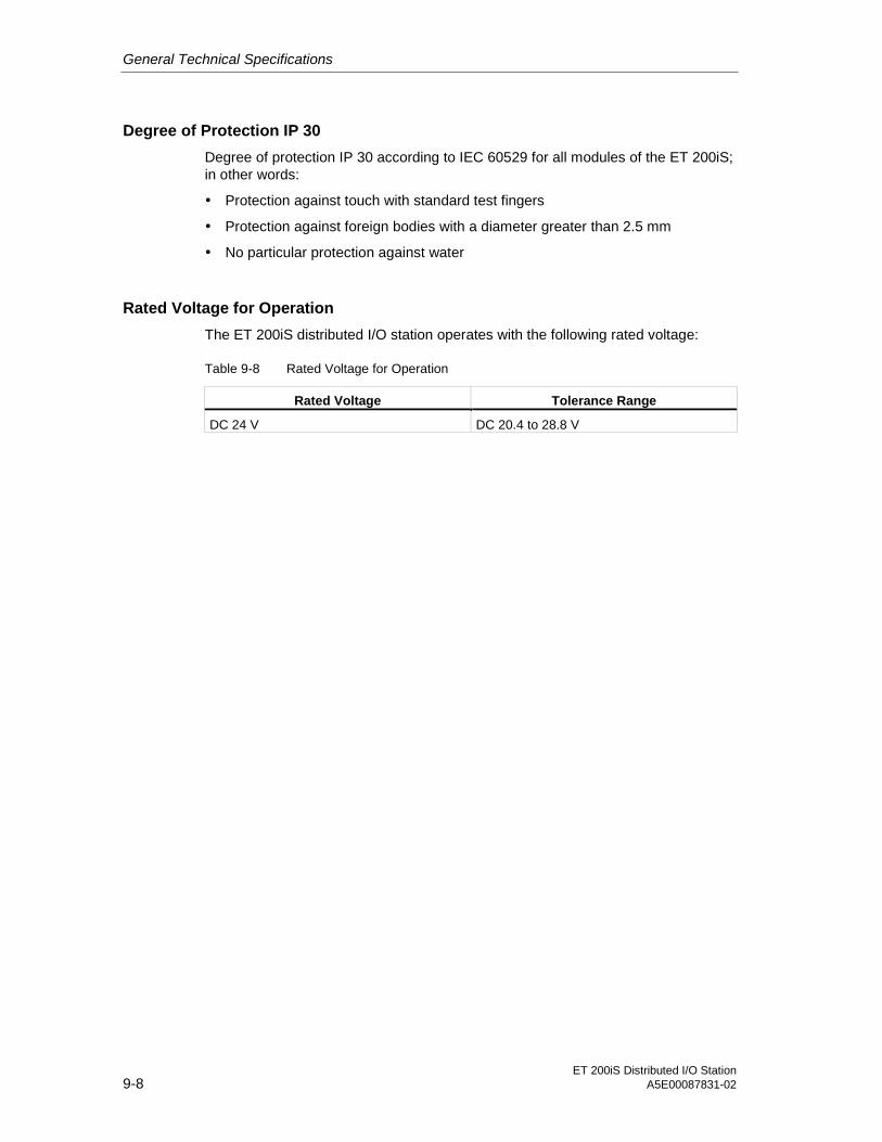
General Technical Specifications
ET 200iS Distributed I/O Station9-8 A5E00087831-02
Degree of Protection IP 30
Degree of protection IP 30 according to IEC 60529 for all modules of the ET 200iS;in other words:
• Protection against touch with standard test fingers
• Protection against foreign bodies with a diameter greater than 2.5 mm
• No particular protection against water
Rated Voltage for Operation
The ET 200iS distributed I/O station operates with the following rated voltage:
Table 9-8 Rated Voltage for Operation
Rated Voltage Tolerance Range
DC 24 V DC 20.4 to 28.8 V

ET 200iS Distributed I/O StationA5E00087831-02 10-1
10Terminal Modules 1010.1 Overview of the Contents
Assignment of Electronics Modules to Terminal Modules
The table below shows you which modules you can use on the various terminalmodules.
Table 10-1 Terminal Modules and Electronics Modules
Terminal ModulesElectronics Modules
TM-PS TM-IM TM-E30S44-iS /TM-E30C44-iS
Order number 6ES7 193- 5DA00-0AA0 5DB00-0AA0 5CB00-0AA0 /5CB10-0AA0
Power supply module PS X
Interface module IM 151-2 X
I/O modules:
4DI NAMUR
2DO DC25V/25mA
2AI I 2WIRE
2AI I 4WIRE
2AI RTD
2AI TC
2 AO I
2AI I 2WIRE HART
2AI I 4WIRE HART
2AO I HART
X
X
X
X
X
X
X
X
X
X

Terminal Modules
ET 200iS Distributed I/O Station10-2 A5E00087831-02
10.2 Terminal Module for the Power Supply Module TM-PS
Order Number
6ES7 193-5DA00-0AA0
Features
• Terminal module for the power supply module
• Provides power for the entire ET 200iS station
• Connected using screw terminals
• 3 terminals for connection of the supply voltage/ equipotential bonding (loadvoltage)
• 3 terminals for looping through the supply voltage / equipotential bonding
• 2 terminals for looping through the powerbus voltage (prepared)
• Prewiring of the terminal module possible
• Automatic interference diversion from the power supply module to the DIN railvia spring contacts
• Polarity reversal protection guaranteed by the power supply module.
Terminal Assignment
The following table shows the terminal assignment on the terminal module.
Table 10-2 Terminal Assignment on the Terminal Module TM-PS
Layout Terminal Description
1 L+
1 M
Load voltage for inserted power supply module (20 to30 V DC)
1 PA Equipotential bonding
2 L+
2 M
Loop through the load voltage
2 PA Equipotential bonding
RL+
1L+
2L+1M
2M
1PA
2PARL+
RM
RM
Powerbus voltage for looping through (prepared)

Terminal Modules
ET 200iS Distributed I/O StationA5E00087831-02 10-3
Block Diagram
Powerbus
Power supplymodule PS
Terminal forload voltage
Equipotentialbonding
IM151-2electronics/backplane bus
Supply of thePROFIBUS-DPEx i interface
Powerbus voltagefor looping through(prepared)
Figure 10-1 Block Diagram of the Terminal Module TM-PS
Technical Specifications
Table 10-3 Technical Specifications of the Terminal Module for the Power Supply ModuleTM-PS
Dimensions and Weight
Dimensions
W x H x D (mm)
Weight
165 x 200 x 75
approx. 700 g
Data Specific to the Module
Number of terminals 3 low voltage/ equipotential bonding
3 loop through the load voltage/equipotential bonding
2 loop through powerbus voltage (prepared)
Cable cross-section 0.5 to 4 mm2 **Keep to the wiring rules. See section Wiring.

Terminal Modules
ET 200iS Distributed I/O Station10-4 A5E00087831-02
10.3 Terminal Module for the Interface Module TM-IM
Order Number
6ES7 193-5DB00-0AA0
Features
• Terminal module for the interface module
• PROFIBUS-DP Ex i connection over 9-pin sub-D female connector
• Bus interface module (can be replaced when necessary)
• The shape of the protective collars on the left-hand connectors only permitsinsertion of the TM-IM on a terminal module for the power supply module TM-PS
• Automatic interference diversion from the interface module to the DIN rail viaspring contact
Note
The spring contact to the DIN rail is used to connect the cable shield of thePROFIBUS DP cable with the equipotential bonding system during operation.
Terminal Assignment
The following table shows the pinning of the PROFIBUS-DP Ex i socket on theterminal module.
Table 10-4 Pinning of the PROFIBUS-DP Ex i Socket on the TM-IM
Layout Signal Name Description
1 - -
2 - -
3 RxD / TxD-P Data line B
4 - -
5 - -
6 - -
7 - -
8 RxD / TxD-N Data line A
54321
9876
9 - -

Terminal Modules
ET 200iS Distributed I/O StationA5E00087831-02 10-5
Block Diagram
Interfacemodule
IM 151-2
Backplane bus
Powerbus
A
B
PROFIBUS-DP-Ex i socket
EEx i barrier
Figure 10-2 Block Diagram of the Terminal Module TM-IM
Technical Specifications
Table 10-5 Technical Specifications of the Terminal Module for the Interface Module TM-IM
Dimensions and Weight
DimensionsW x H x D (mm)
Weight
30 x 132 x 43.5
approx. 90 g
Data Specific to the Module
Connectors 1 x 9-pin sub-D female connector forPROFIBUS-DP Ex i
Data Relevant to Safety
Maximum values of the RS-485 interface
• Uo ± 4.2 V
• Io max. 100 mA
• Po 106 mW
• Ui ± 4.2 V

Terminal Modules
ET 200iS Distributed I/O Station10-6 A5E00087831-02
10.4 Terminal Modules for Electronics Modules TM-E30S44-iS / TM-E30C44-iS
Order Numbers
6ES7 193-5CB00-0AA0 (screw terminal)
6ES7 193-5CB10-0AA0 (spring terminal)
Features
• Terminal module for electronics modules (I/O modules)
• Connection using screw terminals with TM-E30S44-iS
• Connection using spring terminals with TM-E30C44-iS
• 2 terminal blocks each with 2 x 4 terminals for process wiring
• Prewiring of the terminal module possible
• The shape of the connectors on the left-hand side of the terminal module TM-E30S44-iS / E30C44-iS allows only insertion in a terminal module for theinterface module TM-IM or in an already inserted terminal module forelectronics modules TM-E30S44-iS / E30C44-iS
• Automatic interference diversion from the electronics module to the DIN rail viaspring contact
Terminal Assignment
The following table shows the terminal assignment of the terminal module.
Table 10-6 Terminal Assignment of the Terminal Module TM-E30S44-iS / E30C44-iS
Layout Terminal Description
9 13
2 6 10 14
3 7 11 15
4 8 12 16
1 5
0 1 2 3
1 5 9 13
2 6 10 14
3 7 11 15
4 8 12 16
The assignment depends on the electronicsmodule inserted

Terminal Modules
ET 200iS Distributed I/O StationA5E00087831-02 10-7
Block Diagram
Electronicsmodule
Backplane bus
Powerbus
Terminals with connectionto electronics module
Figure 10-3 Block Diagram of the Terminal Module TM-E30S44-iS / E30C44-iS
Technical Specifications
Table 10-7 Technical Data of the Terminal Modules for Electronics Modules TM-E30S44iS/TME30C44-iS
Dimensions and Weight
DimensionsW x H x D (mm)
Weight
30 x 132 x 43.5
approx. 150 g
Data Specific to the Module
Number of terminals 4 x 4
Wire cross-sections 0.14 to 2.5 mm2 **Keep to the wiring rules. See section Wiring.

Terminal Modules
ET 200iS Distributed I/O Station10-8 A5E00087831-02

ET 200iS Distributed I/O StationA5E00087831-02 11-1
11Power Supply Module 1111.1 Power Supply Module
Order Number
6ES7 138-5EA00-0AA0
Features
• Supplies the ET 200iS with the required operating voltages for the followingwhile providing reliable electrical isolation:
– Electronics of the IM 151-2/ backplane bus
– PROFIBUS-DP Ex i interface of the IM 151-2
– Powerbus
• Handles the safety-related limitation of the output voltages
Block Diagram
PA
+24 V
M
Electronics ofthe IM 151-2 /backplane bus
PROFIBUS-DP Ex iinterface of theIM 151-2
Powerbus
RL+
RM
Figure 11-1 Block Diagram of the Power Supply Module

Power Supply Module
ET 200iS Distributed I/O Station11-2 A5E00087831-02
Technical Specifications
Table 11-1 Technical Specifications
Dimensions and Weights
Dimensions
W x H x D (mm)
96.5 x 150 x 150
Weight approx. 2500 g
Data Specific to the Module
Type of protection of the module
• CENELEC
II2G EEx de [ia/ib] IIC/IIB T4 CE0344
• FM (applied for) Class Number 3611:
Class I, Division 2, Group A, B, C, D,Class I, Zone 2
Class Number 3610:
Class I, Zone 1
Tu = - 20 to 60°C
Voltages, Currents, Potentials
Power supply DC 24 V*
• Polarity reversal protection yes
• Power failure buffering min. 20 ms
(for the backplane bus/ electronics of the IM151-2 and for the PROFIBUS-DP Ex iinterface)
Electrical isolation
• between the supply voltage andpowerbus
yes
• between the supply voltage andbackplane bus and PROFIBUS-DP Ex iinterface
yes
• between Powerbus and backplane busandPROFIBUS-DP Ex i interface
yes
• between the backplane bus andPROFIBUS-DP Ex i interface
yes
Permitted potential difference
• between supply voltage and all outputvoltages
375 V
Insulation tested with
• between supply voltage and allsecondary voltages
AC 1500 V
• between all output voltages AC 500 V

Power Supply Module
ET 200iS Distributed I/O StationA5E00087831-02 11-3
Dimensions and Weights
Current consumption
• Power supply module PS max. 2.8 A
Power loss power supply module PS max. 14 W
Status, Interrupts, Diagnostic Information
Interrupts No
Diagnostic Functions
Supply voltage display (primary side) green LED "DC24V“
Output voltage display green LED "POWER“
Diagnostic information readable No
Data Relevant to Safety
Um 250 V* Protected by circuit breaker

Power Supply Module
ET 200iS Distributed I/O Station11-4 A5E00087831-02

ET 200iS Distributed I/O StationA5E00087831-02 12-1
12Interface Module 1212.1 Interface module IM 151-2
Order Number
6ES7 151-2AA00-0AB0
Features
The IM 151-2 interface module has the following characteristics:
• Connects the ET 200iS to PROFIBUS-DP Ex i
• Prepares the data for the inserted electronics modules
• The PROFIBUS address of the ET 200iS can be set at a switch
• Turning off the DC 24V supply voltage at the terminal module TM-PS also turnsoff the IM 151-2 interface module.
• The maximum area for addresses is 128 bytes for inputs and 128 bytes foroutputs.

Interface Module
ET 200iS Distributed I/O Station12-2 A5E00087831-02
Block Diagram
Ba
ckp
lan
eb
us ET 200iS
backplanebus interface
Electronics
Electricalisolation
PROFIBUS-DPconnection
PROFIBUSaddress
A1A2B1B2
SF BF ON
Bus interface module
Figure 12-1 Block Diagram of the IM 151-2
Technical Specifications
Table 12-1 Technical Specifications
Dimensions and Weights
Dimensions
W x H x D (mm) 30 x 81 x 76
Weight approx. 80 g
Data Specific to the Module
Transmission rate 9.6; 19.2; 45.45; 93.75; 187.5; 500 Kbps;1.5 Mbps
Bus protocol PROFIBUS-DP Ex i
Interface RS-485 (intrinsically safe)
SYNC capability yes
FREEZE capability yes
Vendor ID 806EH
PROFIBUS addresses 1 to 125 permitted
Direct Data Exchange yes, slave to slave as publisher
Constant scan time mode No

Interface Module
ET 200iS Distributed I/O StationA5E00087831-02 12-3
Dimensions and Weights
Time stamping yes (STEP 7 only)
• Accuracy class 10 ms
• Time resolution 1 ms
• Number of digital input signals max. 128
• Message buffer 15 message buffers each for a maximum of20 messages
• Time interval for sending the messagebuffers when a message is pending
1 s
• per digital input
• per digital input module
• Time stamp
• entire ET 200iS
• Time stamp for rising/falling change as signal entering orleaving state
• Time-of-day format RFC 1119 Internet (ISP)
Acyclic function
• Interrupts yes
• Diagnostics yes
• Parameters yes
• Data records yes
Type of protection of the module
• CENELEC II2G EEx ib IIC T4 CE0344
• FM (applied for) Class Number 3611:
Class I, Division 2, Group A, B, C, D,Class I, Zone 2
Class Number 3610:
Class I, Zone 1
Voltage, Currents, Potentials
Electrical isolation
• between backplane bus and electronics No
• between PROFIBUS-DP Ex i andelectronics
yes
Permitted potential difference
• Insulation tested with DC 500 V
Power loss of the module typ. 0.5 W
Status, Interrupts, Diagnostics
Interrupts yes
Diagnostic Functions yes
• Group error red LED "SF"
• Bus monitoring red LED "B"F
• Monitoring of the supply voltage of theelectronics
green LED "ON"

Interface Module
ET 200iS Distributed I/O Station12-4 A5E00087831-02
12.2 Parameters for the Interface Module
Parameters for the Interface Module IM 151-2
The parameters can be set using the GSD file, HW Config and SIMATIC PDM.
Table 12-2 Parameters for the Interface Module IM 151-2
IM 151-2 Parameter Range of Values Default Effective for
Startup when defined andactual configuration differ *
• disable
• enable
enabled ET 200iS
Time stamping ** (enableparameter)
• yes
• no
No ET 200iS
Edge evaluation evententering state **
• rising edge (0-->1)
• falling edge (1-->0)
• channel-specific
rising edge (0-->1)
ET 200iS
Format of the analog values • SIMATIC S5
• SIMATIC S7
SIMATIC S7 ET 200iS
Interference frequencysuppression
• 50 Hz
• 60 Hz
50 Hz ET 200iS
Temperature unit • Celsius
• Fahrenheit
Celsius ET 200iS
Slot reference junction 1 to8***
• none
• 4 to 35
none ET 200iS
Input reference junction 1 to8
• RTD on channel 0
• RTD on channel 1
RTD on channel0
ET 200iS
Apart from the following exceptions, all the parameters are set with SIMATIC PDM:* Parameters can be set using the GSD file and in HW Config.** Parameters can be set only in HW Config and when you operate the ET 200iS as an S7 DP slave.*** Here, SIMATIC PDM offers you the slots you set as reference junctions.

Interface Module
ET 200iS Distributed I/O StationA5E00087831-02 12-5
Identification Data
The identification data contain further information on the module and are read outwith SIMATIC PDM. The identification data are resident on the module.
Table 12-3 Identification Data
Identification Data Range of Values Default Effective for
Device
Vendor read SIEMENS AG
Device identification read Order Number
Device serial number read
Hardware revision read
Software revision read
depends on theproduct version
Static revision no. read ---
Installation date read/ write (max. 16 characters) ---
Module
Operating unit
TAG read/ write (max. 32 characters) ---
Description read/ write (max. 54 characters) ---
Module
12.3 Parameter Description
12.3.1 Startup when defined and actual configuration differ
Parameter
The effect of this parameter is that ET 200iS distributed I/O station starts up even ifthe defined and actual configuration do not match.
12.3.2 Time stamping / edge evaluation
Time stamping / edge evaluation
The time stamping of binary signal changes is supported in the PCS 7 system byall hardware and software components: from the ET 200iS over the S7-400 right tothe OS.
Time stamping parameter: With this parameter, you activate time stamping for allthe digital input modules of the ET 200iS.

Interface Module
ET 200iS Distributed I/O Station12-6 A5E00087831-02
Edge evaluation parameter: With this parameter, you specify the type of signalchange that is time stamped. You can decide whether you want to report the risingor falling signal edge as a signal entering the state.
Example of a Configuration with the ET 200iS and Time Stamping of SignalChanges.
Example
You can configure the monitoring of digital inputs for signal changes in HW Config.The following can be monitored: " Signal entering/leaving state“ (as "rising or fallingedge“). The ET 200iS adds the current time of day (time stamp) to these changedinput signals and saves them as message lists. Such a message list is a datarecord with a maximum of 20 messages about time-stamped signal changes. TheET 200iS can store up to 15 data records.
After a certain time and if messages exist or when a data record is full, the ET200iS triggers a hardware interrupt on the DP master (S7-400). The CPU thenreads the data record and passes on the message lists to WinCC on an OS usingthe driver block FB90 "IM_DRV".
For a detailed description of time stamps and time-of-day synchronization, refer tothe PCS 7 documentation.
Distributed I/OET 200iS
Programmable controllerS7-400
Industrial Ethernet
WINCCOperator Station (OS)(Plant visualization)
PROFIBUS
Time-of-daytransmitter(SICLOCK)
CP 443-1
CP 443-5(DP master)
Digital inputmodules
Fieldbus isolating transformer
Figure 12-2 Example of Time Stamping and Edge Evaluation
Interface Module
ET 200iS Distributed I/O StationA5E00087831-02 12-7
12.3.3 Format of the analog values
Parameter
With this parameter, you set the numeric format of all analog electronics modulesof the ET 200iS. You can select between SIMATIC S5 and SIMATIC S7.
12.3.4 Interference Frequency Suppression
Parameter
The frequency of your a.c. power system can interfere with the measured value,particularly when measuring in low voltage ranges and when using thermocouples.Here, you enter the frequency of the power supply in your system (50 Hz or 60 Hz).
The interference frequency suppression parameter is valid for all analog electronicsmodules of the ET 200iS that use this parameter. With this parameter, you alsospecify the integration and conversion time of the individual modules. SeeTechnical Specifications of the Analog Electronics Modules.
12.3.5 Temperature unit
Parameter
With this parameter, you set the temperature unit for the temperature sensor andthermocouples. You can choose between "Celsius" and "Fahrenheit". Theparameter is valid for all analog electronics modules of the ET 200iS that use thisparameter.
12.3.6 Slot Reference Junction/Reference Junction Input
See also
Connecting Thermocouples [ Page 14-33]

Interface Module
ET 200iS Distributed I/O Station12-8 A5E00087831-02
12.3.7 Identification Data
Identification Data
Table 12-4 Identification Data
Identification Data Explanation
Vendor The name of the manufacturer is storedhere.
Device identification Order number of the module.
Device serial number The serial number of the module is storedhere. This makes unique identification of themodule possible.
Hardware revision This provides information on the productversion of the module. This is incrementedwhen the product version and/or thefirmware of the module changes.
Software revision This indicates the firmware version of themodule. If the firmware version isincremented, then the version (hardwareversion) of the module is incremented aswell.
Static revision no. Provides information on the parameterchanges on the module. Depending on thechange, the static revision no. isincremented.
Installation date The date the module was installed. Enterthe date here. DD.MM.YYYY format
TAG Location designation of the module. Enter aunique tag for the module here.
Description Free text stored in the module. Here, youcan enter an additional information on thecharacteristics of the module.

ET 200iS Distributed I/O StationA5E00087831-02 13-1
13Digital Electronics Modules 1313.1 Digital Electronics Module 4DI NAMUR
Order Number
6ES7 131-5RD00-0AB0
Features
• Digital electronics module with four inputs
• Sensor power supply DC 8V
• Suitable for NAMUR sensors and wired and unwired mechanical contacts
Terminal Assignment of NAMUR Sensors or Sensors Complying with DIN 19234
Table 13-1 Terminal Assignment of NAMUR Sensors or Sensors Complying with DIN 19234
Terminal Assignment and View Remarks
9 13
2 6 10 14
3 7 11 15
4 8 12 16
1 5
Channel
DI0 DI1 DI2 DI3
VS VS VS VS
- - - -
- - - -
0 1 2 3 0 1 2 3
1
210 k
1
2
or
1 k
Example of connectingup channel 0
Sensor 1:Channel 0: Terminals 1 and 2
Sensor 2:Channel 1: Terminals 5 and 6
Sensor 3:Channel 2: Terminals 9 and 10
Sensor 4:Channel 3: Terminals 13 and14
DI: Input signal
Vs: Sensor supply

Digital Electronics Modules
ET 200iS Distributed I/O Station13-2 A5E00087831-02
Terminal Assignment of NAMUR Changeover Contacts or Changeover ContactsComplying with DIN 19234
Table 13-2 Terminal Assignment of NAMUR Changeover Contacts or Changeover Contacts Complyingwith DIN 19234
Terminal Assignment and View Remarks
9 13
2 6 10 14
3 7 11 15
4 8 12 16
1 5
Channel
DI0 DI1 DI2 DI3
VS VS VS VS
- - - -
- - - -
0 1 2 3 0 1 2 3
1
2
51
5
2
or
NO contact
NC contact
Example of connecting upchannel 0 and channel 1
1 k10 k
Changeover contact 1Channel 0: Terminals 1 and 2
Channel 1: Terminal 5
Changeover contact 2Channel 2: Terminals 9 and 10
Channel 3: Terminal 13
DI: Input signal
Vs: Sensor supply
Terminal Assignment of a Single Contact Wired with 10 kΩ (mechanical NOcontact)
Table 13-3 Terminal Assignment of a Single Contact Wired with 10 kΩ (mechanical NO contact)
Terminal Assignment and View Remarks
9 13
2 6 10 14
3 7 11 15
4 8 12 16
1 5
Channel
DI0 DI1 DI2 DI3
VS VS VS VS
- - - -
- - - -
0 1 2 3
1
2
0 1 2 3
10 k
Example of connectingchannel 0
Single contact 1:Channel 0: Terminals 1 and 2
Single contact 2:Channel 1: Terminals 5 and 6
Single contact 3:Channel 2: Terminals 9 and 10
Single contact 4:Channel 3: Terminals 13 and14
DI: Input signal
Vs: Sensor supply
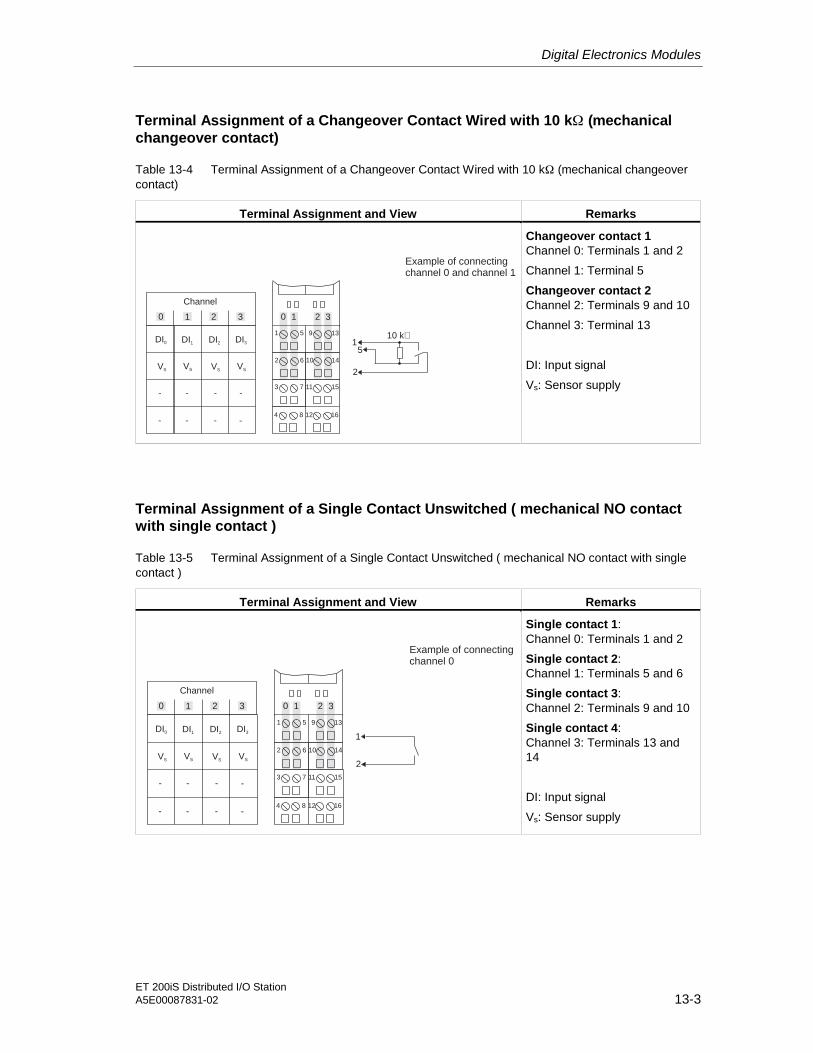
Digital Electronics Modules
ET 200iS Distributed I/O StationA5E00087831-02 13-3
Terminal Assignment of a Changeover Contact Wired with 10 kΩ (mechanicalchangeover contact)
Table 13-4 Terminal Assignment of a Changeover Contact Wired with 10 kΩ (mechanical changeovercontact)
Terminal Assignment and View Remarks
9 13
2 6 10 14
3 7 11 15
4 8 12 16
1 5
Channel
DI0 DI1 DI2 DI3
VS VS VS VS
- - - -
- - - -
0 1 2 3 0 1 2 3
1
2
5
10 k
Example of connectingchannel 0 and channel 1
Changeover contact 1Channel 0: Terminals 1 and 2
Channel 1: Terminal 5
Changeover contact 2Channel 2: Terminals 9 and 10
Channel 3: Terminal 13
DI: Input signal
Vs: Sensor supply
Terminal Assignment of a Single Contact Unswitched ( mechanical NO contactwith single contact )
Table 13-5 Terminal Assignment of a Single Contact Unswitched ( mechanical NO contact with singlecontact )
Terminal Assignment and View Remarks
9 13
2 6 10 14
3 7 11 15
4 8 12 16
1 5
Channel
DI0 DI1 DI2 DI3
VS VS VS VS
- - - -
- - - -
0 1 2 3
1
2
0 1 2 3
Example of connectingchannel 0
Single contact 1:Channel 0: Terminals 1 and 2
Single contact 2:Channel 1: Terminals 5 and 6
Single contact 3:Channel 2: Terminals 9 and 10
Single contact 4:Channel 3: Terminals 13 and14
DI: Input signal
Vs: Sensor supply
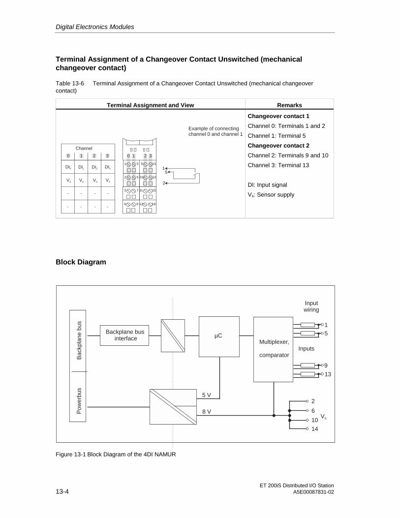
Digital Electronics Modules
ET 200iS Distributed I/O Station13-4 A5E00087831-02
Terminal Assignment of a Changeover Contact Unswitched (mechanicalchangeover contact)
Table 13-6 Terminal Assignment of a Changeover Contact Unswitched (mechanical changeovercontact)
Terminal Assignment and View Remarks
9 13
2 6 10 14
3 7 11 15
4 8 12 16
1 5
Channel
DI0 DI1 DI2 DI3
VS VS VS VS
- - - -
- - - -
0 1 2 3 0 1 2 3
1
2
5
Example of connectingchannel 0 and channel 1
Changeover contact 1
Channel 0: Terminals 1 and 2
Channel 1: Terminal 5
Changeover contact 2
Channel 2: Terminals 9 and 10
Channel 3: Terminal 13
DI: Input signal
Vs: Sensor supply
Block Diagram
Backplane businterface
µCMultiplexer,
comparator
5 V
8 V
Inputs
1
5
9
13
Ba
ckp
lan
eb
us
Po
we
rbu
s
2
6
10
14
VS
Inputwiring
Figure 13-1 Block Diagram of the 4DI NAMUR
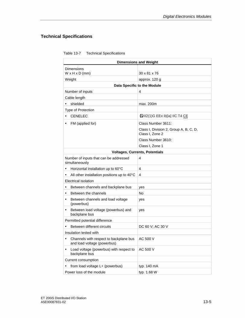
Digital Electronics Modules
ET 200iS Distributed I/O StationA5E00087831-02 13-5
Technical Specifications
Table 13-7 Technical Specifications
Dimensions and Weight
DimensionsW x H x D (mm) 30 x 81 x 76
Weight approx. 120 g
Data Specific to the Module
Number of inputs 4
Cable length
• shielded max. 200m
Type of Protection
• CENELEC II2(1)G EEx ib[ia] IIC T4 CE0344
• FM (applied for) Class Number 3611:
Class I, Division 2, Group A, B, C, D,Class I, Zone 2
Class Number 3610:
Class I, Zone 1
Voltages, Currents, Potentials
Number of inputs that can be addressedsimultaneously
4
• Horizontal installation up to 60°C 4
• All other installation positions up to 40°C 4
Electrical isolation
• Between channels and backplane bus yes
• Between the channels No
• Between channels and load voltage(powerbus)
yes
• Between load voltage (powerbus) andbackplane bus
yes
Permitted potential difference
• Between different circuits DC 60 V; AC 30 V
Insulation tested with
• Channels with respect to backplane busand load voltage (powerbus)
AC 500 V
• Load voltage (powerbus) with respect tobackplane bus
AC 500 V
Current consumption
• from load voltage L+ (powerbus) typ. 140 mA
Power loss of the module typ. 1.68 W
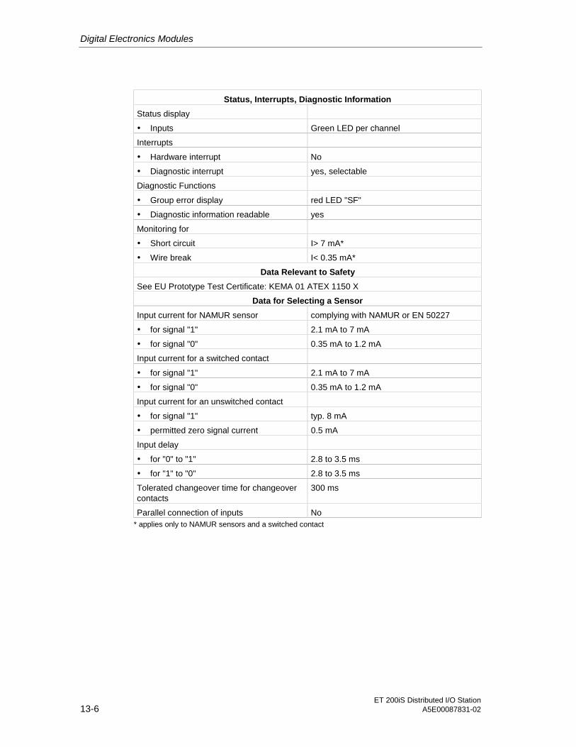
Digital Electronics Modules
ET 200iS Distributed I/O Station13-6 A5E00087831-02
Status, Interrupts, Diagnostic Information
Status display
• Inputs Green LED per channel
Interrupts
• Hardware interrupt No
• Diagnostic interrupt yes, selectable
Diagnostic Functions
• Group error display red LED "SF"
• Diagnostic information readable yes
Monitoring for
• Short circuit I> 7 mA*
• Wire break I< 0.35 mA*
Data Relevant to Safety
See EU Prototype Test Certificate: KEMA 01 ATEX 1150 X
Data for Selecting a Sensor
Input current for NAMUR sensor complying with NAMUR or EN 50227
• for signal "1" 2.1 mA to 7 mA
• for signal "0" 0.35 mA to 1.2 mA
Input current for a switched contact
• for signal "1" 2.1 mA to 7 mA
• for signal "0" 0.35 mA to 1.2 mA
Input current for an unswitched contact
• for signal "1" typ. 8 mA
• permitted zero signal current 0.5 mA
Input delay
• for "0" to "1" 2.8 to 3.5 ms
• for "1" to "0" 2.8 to 3.5 ms
Tolerated changeover time for changeovercontacts
300 ms
Parallel connection of inputs No* applies only to NAMUR sensors and a switched contact

Digital Electronics Modules
ET 200iS Distributed I/O StationA5E00087831-02 13-7
13.2 Digital Electronics Module 2DO DC25V/25mA
Order Number
6ES7 132-5SB00-0AB0
Features
• Digital electronics module with two outputs
• A rated load voltage of 25 VDC
• Outputs suitable for EX i solenoid valves, d.c. relay and actuators
Terminal Assignment
The following table shows the terminal assignment of the 2DO DC25V/25mA.
Table 13-8 Terminal Assignment of the 2DO DC25V/25mA
Terminal Assignment and View Remarks
9 13
2 6 10 14
3 7 11 15
4 8 12 16
1 5
Channel
- -
0 1 2 3 0 1 2 3
Example of connectingchannel 0
DO0 DO0 DO1 DO1
M M
- -
- - - -
- -
3
4
Actuator
Actuator 1
Channel 0: Terminals 3 and 4
Actuator 2
Channel 3: Terminals 15 and 16
Increased power
Jumper between terminal7 and 11
DO: Output signal
M: Load power supply chassis
Note
To increase the power, the two digital outputs on the 2DO DC25V/25mA can beconnected in parallel by inserting a jumper between terminals 7 and 11. Such apower increase is only permitted on the same module. In this case, only oneactuator is connected to the module.

Digital Electronics Modules
ET 200iS Distributed I/O Station13-8 A5E00087831-02
Block Diagram
Backplaneinterface
µC
5 V
Backpla
ne
bus
Pow
erb
us
11/15
3/7Outputs
4
16M
25 V
Figure 13-2 Block Diagram of the 2DO DC25V/25mA
Technical Specifications
Table 13-9 Technical Specifications
Dimensions and Weight
DimensionsW x H x D (mm) 30 x 81 x 76
Weight approx. 130 g
Data Specific to the Module
Number of outputs 2
Cable length
• Unshielded max. 200m
• shielded max. 200m
Type of Protection
• CENELEC II2(1)G EEx ib[ia] IIC T4 CE0344
• FM (applied for) Class Number 3611:
Class I, Division 2, Group A, B, C, D,Class I, Zone 2
Class Number 3610:
Class I, Zone 1
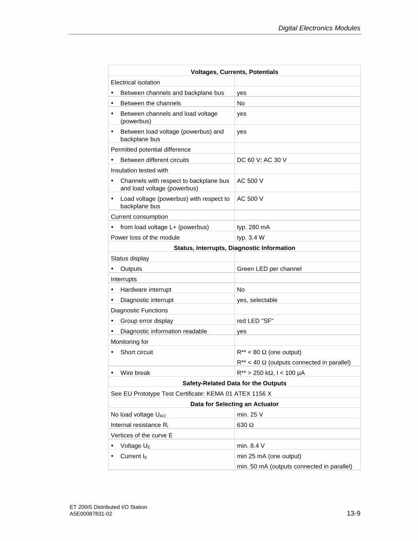
Digital Electronics Modules
ET 200iS Distributed I/O StationA5E00087831-02 13-9
Voltages, Currents, Potentials
Electrical isolation
• Between channels and backplane bus yes
• Between the channels No
• Between channels and load voltage(powerbus)
yes
• Between load voltage (powerbus) andbackplane bus
yes
Permitted potential difference
• Between different circuits DC 60 V; AC 30 V
Insulation tested with
• Channels with respect to backplane busand load voltage (powerbus)
AC 500 V
• Load voltage (powerbus) with respect tobackplane bus
AC 500 V
Current consumption
• from load voltage L+ (powerbus) typ. 280 mA
Power loss of the module typ. 3.4 W
Status, Interrupts, Diagnostic Information
Status display
• Outputs Green LED per channel
Interrupts
• Hardware interrupt No
• Diagnostic interrupt yes, selectable
Diagnostic Functions
• Group error display red LED "SF"
• Diagnostic information readable yes
Monitoring for
• Short circuit R** < 80 Ω (one output)
R** < 40 Ω (outputs connected in parallel)
• Wire break R** > 250 kΩ, I < 100 µA
Safety-Related Data for the Outputs
See EU Prototype Test Certificate: KEMA 01 ATEX 1156 X
Data for Selecting an Actuator
No load voltage UAO min. 25 V
Internal resistance Ri 630 Ω
Vertices of the curve E
• Voltage UE min. 8.4 V
• Current IE min 25 mA (one output)
min. 50 mA (outputs connected in parallel)

Digital Electronics Modules
ET 200iS Distributed I/O Station13-10 A5E00087831-02
Voltages, Currents, Potentials
Output delay (with ohmic load)
• for "0" to "1" 2 ms
• for "1" to "0" 1.5 ms
Connecting 2 outputs in parallel yes
Switching frequency
• with ohmic load 100 Hz
• with inductive load (L < LO) 2 Hz
Short-circuit protection of the output yes
• Response threshold > 25 mA
Leakage current of the output max. 25µA ** Required for operation of piezo-valves
** R = Load impedance + cable impedance

Digital Electronics Modules
ET 200iS Distributed I/O StationA5E00087831-02 13-11
Output characteristics curve
U [V]
30
25
20
15
10
5
00 10 20 30 40 50 60
I [mA]
0 0
8,37 V 8,37 V
two outputs connected in parallel
one output
25
Figure 13-3 Output Curve
13.3 Parameters of the Digital Electronics Modules
4 DI NAMUR Parameters
All parameters are set with SIMATIC PDM and HW Config.
Table 13-10 Parameters for 4 DI NAMUR
4 DI NAMUR Parameters Range of Values Default Effectivefor
Time stamping* • enabled
• disabled
disabled Channel
Edge evaluation event entering state* • falling edge(1-->0)
• rising edge(0-->1)
rising edge(1-->0)
Channel
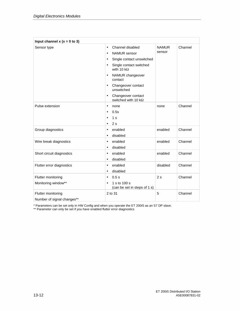
Digital Electronics Modules
ET 200iS Distributed I/O Station13-12 A5E00087831-02
Input channel x (x = 0 to 3)
Sensor type • Channel disabled
• NAMUR sensor
• Single contact unswitched
• Single contact switchedwith 10 kΩ
• NAMUR changeovercontact
• Changeover contactunswitched
• Changeover contactswitched with 10 kΩ
NAMURsensor
Channel
Pulse extension • none
• 0.5s
• 1 s
• 2 s
none Channel
Group diagnostics • enabled
• disabled
enabled Channel
Wire break diagnostics • enabled
• disabled
enabled Channel
Short circuit diagnostics • enabled
• disabled
enabled Channel
Flutter error diagnostics • enabled
• disabled
disabled Channel
Flutter monitoring
Monitoring window**
• 0.5 s
• 1 s to 100 s(can be set in steps of 1 s)
2 s Channel
Flutter monitoring
Number of signal changes**
2 to 31 5 Channel
* Parameters can be set only in HW Config and when you operate the ET 200iS as an S7 DP slave.** Parameter can only be set if you have enabled flutter error diagnostics

Digital Electronics Modules
ET 200iS Distributed I/O StationA5E00087831-02 13-13
Parameters of the 2DO DC25V/25mA
All parameters are set with SIMATIC PDM.
Table 13-11 Parameters of the 2DO DC25V/25mA
Parameters of the 2DO DC25V/25mA Range of Values Default Effectivefor
Parallel connection of channels • yes
• no
no Module
Output channel x (x = 0 to 1)
Response to CPU/ master STOP • Apply substitute value
• Hold last value
Applysubstitutevalue
Channel
Substitute value • 0
• 1
0 Channel
Group diagnostics • enabled
• disabled
enabled Module
Wire break diagnostics • enabled
• disabled
enabled Channel
Short circuit diagnostics • enabled
• disabled
enabled Channel
Identification Data
The identification data contain further information on the module and are read outwith SIMATIC PDM. The identification data are resident on the module.
Table 13-12 Identification Data
Identification Data Range of Values Default Effective for
Device
Vendor read SIEMENS AG
Device identification read Order Number
Device serial number read
Hardware revision read
Software revision read
depends on theproduct version
Static revision no. read ---
Installation date read/ write (max. 16 characters) ---
Module
Operating unit
TAG read/ write (max. 32 characters) ---
Description read/ write (max. 54 characters) ---
Module

Digital Electronics Modules
ET 200iS Distributed I/O Station13-14 A5E00087831-02
13.4 Parameter Description
13.4.1 Pulse extension
Introduction
Pulse extension is a function for changing a digital input signal. A pulse at a digitalinput is extended to at least the length set in the parameters. If the input pulse isalready longer than the selected length, it is not changed
Principle Behind Pulse Lengthening
The following figure illustrates with examples if and how input pulses are changed.
Pulse is longer than T1and is not changed
Parameter for pulse lengthening = T1
T for 0 1 edge1
Process signal
Processedinput signal
Pulse is shorterthan T and is lengthened1to T1
Short pulses that occurduring pulse lengtheningare ignored.
Process signal
The second pulse, which occursduring pulse lengthening, isdelayed until completion of pulselengthening.
T for 1 0 edge1
Processedinput signal
Figure 13-4 Principle of Pulse Extension
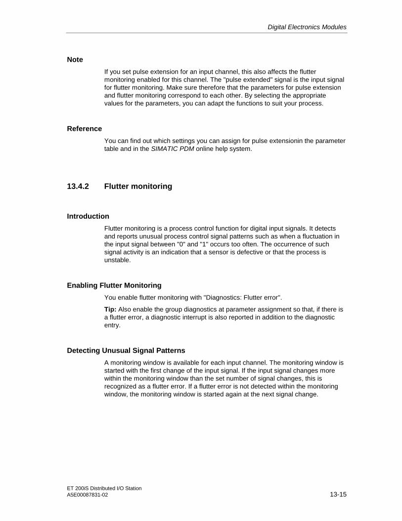
Digital Electronics Modules
ET 200iS Distributed I/O StationA5E00087831-02 13-15
Note
If you set pulse extension for an input channel, this also affects the fluttermonitoring enabled for this channel. The "pulse extended" signal is the input signalfor flutter monitoring. Make sure therefore that the parameters for pulse extensionand flutter monitoring correspond to each other. By selecting the appropriatevalues for the parameters, you can adapt the functions to suit your process.
Reference
You can find out which settings you can assign for pulse extensionin the parametertable and in the SIMATIC PDM online help system.
13.4.2 Flutter monitoring
Introduction
Flutter monitoring is a process control function for digital input signals. It detectsand reports unusual process control signal patterns such as when a fluctuation inthe input signal between "0" and "1" occurs too often. The occurrence of suchsignal activity is an indication that a sensor is defective or that the process isunstable.
Enabling Flutter Monitoring
You enable flutter monitoring with "Diagnostics: Flutter error".
Tip: Also enable the group diagnostics at parameter assignment so that, if there isa flutter error, a diagnostic interrupt is also reported in addition to the diagnosticentry.
Detecting Unusual Signal Patterns
A monitoring window is available for each input channel. The monitoring window isstarted with the first change of the input signal. If the input signal changes morewithin the monitoring window than the set number of signal changes, this isrecognized as a flutter error. If a flutter error is not detected within the monitoringwindow, the monitoring window is started again at the next signal change.

Digital Electronics Modules
ET 200iS Distributed I/O Station13-16 A5E00087831-02
Reporting a Flutter Error
If a flutter error occurs, the current signal state is entered in the process image andthe value status of the signal is set to "invalid". The diagnostic information "fluttererror" is entered and a diagnostic interrupt entering the state is triggered.
You must evaluate and process the value status and the diagnostic information inthe user program.
Resetting a Flutter Error
If no further fluttering of the input signal is detected during the triple monitoringwindow, the diagnostic entry is removed and an outgoing diagnostic interrupt istriggered. The value status of the current signal in the process image is set to"valid".
Principle
The following figure illustrates the principle behind flutter monitoring.
Parameter for number of signal changes = 9
Parameter for monitoring window t = x
Processsignal
Module diagnosisIncoming flutter error= report
3 x monitoring window t = 3x
Diagnosis
Module diagnosisOutgoing flutter error= reset
Detect
Figure 13-5 Principle Behind Flutter Monitoring
Reference
You can find out which settings you can make for flutter monitoring in theparameter table and in the SIMATIC PDM online help system.
Digital Electronics Modules
ET 200iS Distributed I/O StationA5E00087831-02 13-17
13.4.3 Identification Data
13.5 Diagnostics with the Changeover Transducer Type
Brief Description
With the diagnostic functions for the changeover transducer type, the digitalelectronics module checks the switchover between two input channels. If there isno signal change after the specified switchover time (see technical specifications),the module signals diagnostic information.
Purpose
You can use the diagnosis as follows:
• for diagnostic checking of the transducer
• to make certain that the switchover between NO contact and NC contact tookplace
Principle
If the digital inputs of a channel group are set to "changeover", the module runsdiagnostics for the changeover transducer type for this channel group. Thetolerated switchover time between the two channels is set to the fixed value of 300ms.
If the validation is negative,
• the module indicates the value status of the NO channel as "invalid",
• The module creates a diagnostic entry for the normally open contact channel.
• triggers a diagnostic interrupt.
The digital input signal and the value status are updated only for the NO channel(channel 0, 2). For the NC channel (channel 1, 3), the digital input signal is set tothe fixed value "zero" and the value status is "invalid" since this channel is usedonly for the validation of the sensor.

Digital Electronics Modules
ET 200iS Distributed I/O Station13-18 A5E00087831-02
Note the following points in the diagnosis for the changeover contact type ofsensor:
• If there is already an error on the normally open contact channel (a wire break,for example), the module no longer carries out a diagnosis for changeovercontact errors. Changeover errors are still monitored on the second channel.
• You will find further details in the table below:
Table 13-13 Principle
Changeover Switch Negative check means ...
Changeover switch asNAMUR
• Short circuit or
• Wire break
Switched changeoverswitch
• Transducer defective or short circuit
Here, no distinction between a defectivetransducer and short circuit is possible.
Unswitched changeoverswitch
Caution: no difference possible between
• Signal "0" and wire break
• Signal "1" and short circuit
Also:
Changeover error orexternal error (in DPdiagnostics)

ET 200iS Distributed I/O StationA5E00087831-02 14-1
14Analog Electronics Modules 1414.1 Analog Value Representation
14.1.1 Overview
Electronics Modules with Analog Inputs
With the electronics module with analog inputs, continuously variable signals, suchas those occurring in temperature measurement and pressure measurement, canbe acquired, evaluated, and converted to digital values for further processing.
Electronics Modules with Analog Outputs
With the electronics modules with analog outputs, digital values set by a controllercan be converted to a corresponding analog signal (current) in an analog outputmodule and used to control suitable actuators (setpoint input for speed controllers,temperature controllers and similar).
Measured Values in the Event of Wire Break Dependent on Enabled Diagnostics
For the measuring range tables
• 4 to 20 mA
• temperature sensor Pt100 standard and climatic, Ni100 standard and climatic
• Thermocouples types E, N, J, K, L, S, R, B, T, U
the following additional information and rules apply in the S7 and S5 format:

Analog Electronics Modules
ET 200iS Distributed I/O Station14-2 A5E00087831-02
Format of the Analog Values S7
Table 14-1 Measured Values in the Event of Wire Break Dependent on Enabled Diagnostics (FormatS7)
Measured ValuesModules Parameter Assignment
dec. hex.
Notes
• "Wire break" diagnosticsenabled
32767 7FFFH • Wire break" diagnosticmessage
• "Wire break" diagnosticsdisabled *
• "Overflow/underflow"diagnostics enabled
-32768 8000H • Measured value after leavingthe under-range
• "Value under lower limit"diagnostic message
2AI I
• "Wire break" diagnosticsdisabled *
• "Overflow/underflow"diagnostics disabled
- - • Measured value after leavingthe under-range
• "Wire break" diagnosticsenabled
32767 7FFFH • Wire break" diagnosticmessage
2AI RTD
2AI TC• "Wire break" diagnostics
disabled- - • Open input: Undefined
measured value
* Measured value limits for wire break detection:4 to 20 mA: at 3.6 mA
Format of the Analog Values S5
Table 14-2 Measured Values in the Event of Wire Break Dependent on Enabled Diagnostics (FormatS5)
Measured ValuesModules Parameter Assignment
dec. hex.
Notes
• "Wire break" diagnosticsenabled *
4095
(20 to 212)
7FFBH • "Wire break" diagnostic message
• "Wire break" diagnosticsdisabled *
• "Overflow/underflow"diagnostics enabled
150 04B1H • Measured value after leaving theunder-range
• "Value under lower limit"diagnostic message
2AI I
• "Wire break" diagnosticsdisabled *
• "Overflow/underflow"diagnostics disabled
- - • Measured value after leaving theunder-range
• "Wire break" diagnosticsenabled
4095
(20 to 212)
7FFBH • "Wire break" diagnostic message2AI RTD
2AI TC
• "Wire break" diagnosticsdisabled
- - • Open input: Undefinedmeasured value
* Measured value limits for wire break/underflow detection:4 to 20 mA: at 3.6 mA
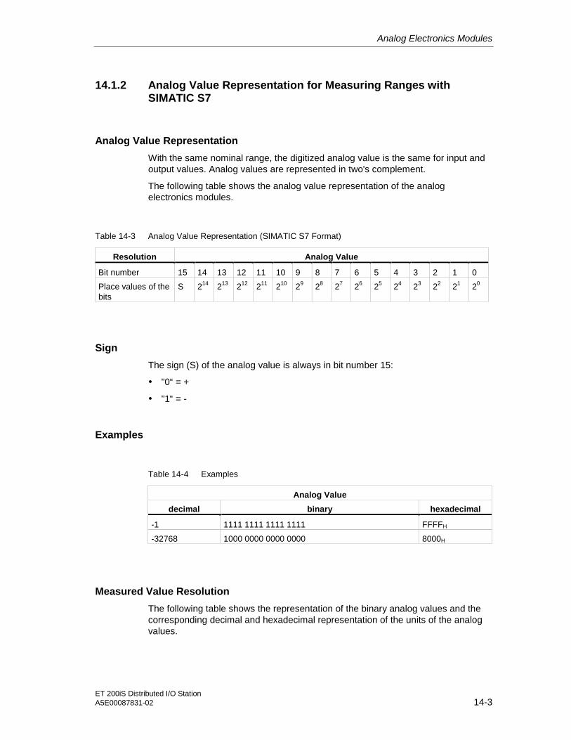
Analog Electronics Modules
ET 200iS Distributed I/O StationA5E00087831-02 14-3
14.1.2 Analog Value Representation for Measuring Ranges withSIMATIC S7
Analog Value Representation
With the same nominal range, the digitized analog value is the same for input andoutput values. Analog values are represented in two's complement.
The following table shows the analog value representation of the analogelectronics modules.
Table 14-3 Analog Value Representation (SIMATIC S7 Format)
Resolution Analog Value
Bit number 15 14 13 12 11 10 9 8 7 6 5 4 3 2 1 0
Place values of thebits
S 214 213 212 211 210 29 28 27 26 25 24 23 22 21 20
Sign
The sign (S) of the analog value is always in bit number 15:
• "0“ = +
• "1“ = -
Examples
Table 14-4 Examples
Analog Value
decimal binary hexadecimal
-1 1111 1111 1111 1111 FFFFH
-32768 1000 0000 0000 0000 8000H
Measured Value Resolution
The following table shows the representation of the binary analog values and thecorresponding decimal and hexadecimal representation of the units of the analogvalues.
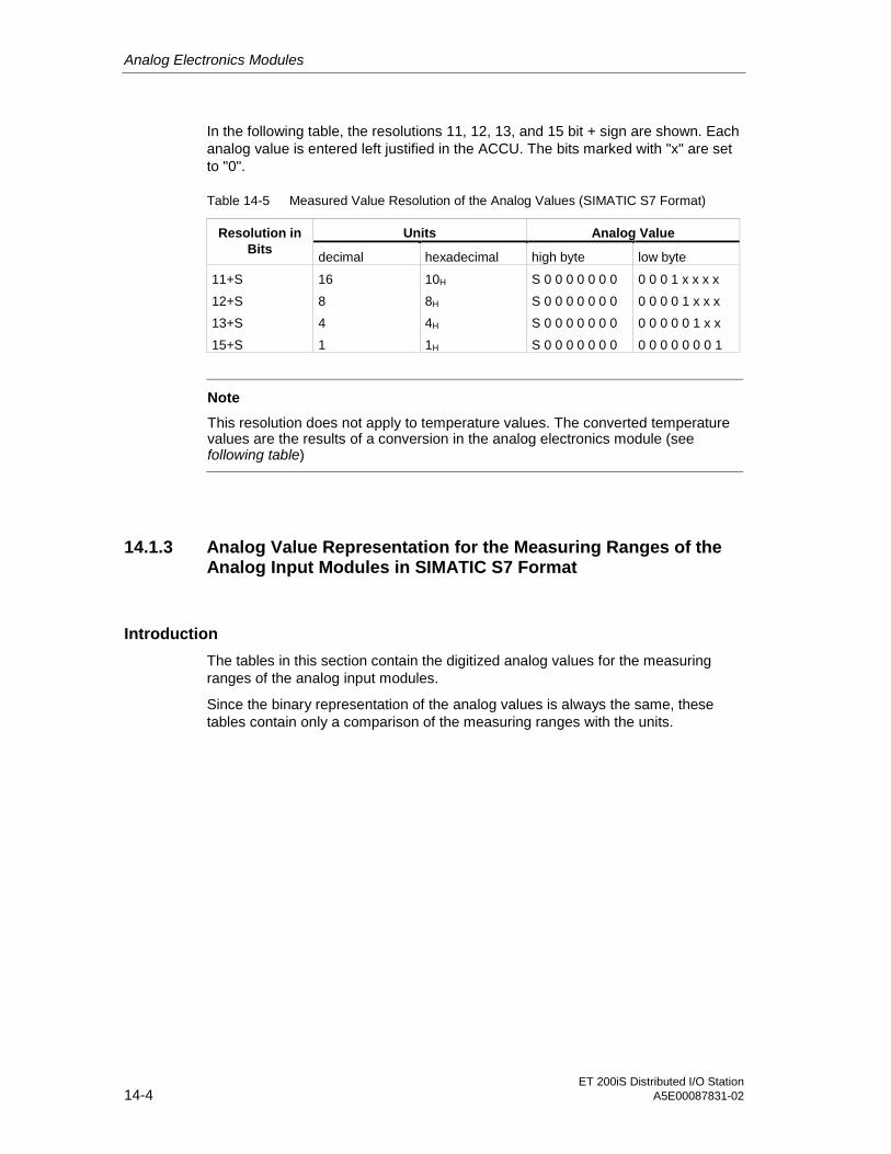
Analog Electronics Modules
ET 200iS Distributed I/O Station14-4 A5E00087831-02
In the following table, the resolutions 11, 12, 13, and 15 bit + sign are shown. Eachanalog value is entered left justified in the ACCU. The bits marked with "x" are setto "0".
Table 14-5 Measured Value Resolution of the Analog Values (SIMATIC S7 Format)
Units Analog ValueResolution inBits
decimal hexadecimal high byte low byte
11+S
12+S
13+S
15+S
16
8
4
1
10H
8H
4H
1H
S 0 0 0 0 0 0 0
S 0 0 0 0 0 0 0
S 0 0 0 0 0 0 0
S 0 0 0 0 0 0 0
0 0 0 1 x x x x
0 0 0 0 1 x x x
0 0 0 0 0 1 x x
0 0 0 0 0 0 0 1
Note
This resolution does not apply to temperature values. The converted temperaturevalues are the results of a conversion in the analog electronics module (seefollowing table)
14.1.3 Analog Value Representation for the Measuring Ranges of theAnalog Input Modules in SIMATIC S7 Format
Introduction
The tables in this section contain the digitized analog values for the measuringranges of the analog input modules.
Since the binary representation of the analog values is always the same, thesetables contain only a comparison of the measuring ranges with the units.

Analog Electronics Modules
ET 200iS Distributed I/O StationA5E00087831-02 14-5
Measuring Range for Thermal e.m.f.: ± 80 mV
Table 14-6 SIMATIC S7 format: Measuring range ± 80 mV
UnitsMeasuring Range
± 80 mV decimal hexadecimal
Range
>94.071 32767 7FFFH Overflow
94.071
:
80,003
32511
:
27649
7EFFH
:
6C01H
Over-range
80,000
60,000
:
-60,000
-80,000
27648
20736
:
-20736
-27648
6C00H
5100H
:
AF00H
9400H
Nominal range
-80,003
:
-94,074
-27649
:
-32512
93FFH
:
8100H
Under-range
<-94.074 -32768 8000H Underflow

Analog Electronics Modules
ET 200iS Distributed I/O Station14-6 A5E00087831-02
Measuring Ranges for Current: 0 to 20 mA, 4 to 20 mA
Table 14-7 SIMATIC S7 Format: Measuring Range 0/4 to 20 mA
UnitsMeasuringRange
0 to 20 mA
MeasuringRange
4 to 20 mAdecimal hexadecimal
Range
>23.5178 >22.8142 32767 7FFFH Overflow
23,5178
:
20,0007
22,8142
:
20,0006
32511
:
27649
7EFFH
:
6C01H
Over-range
20,0000
16,0000
:
0,0000
20,0000
16,0000
:
4,0000
27648
20736
:
0
6C00H
5100H
:
0H
Nominal range
3,9994
3.6000*
:
1,1852
-1
-691*
:
-4864*
FFFFH
FD4DH *
:
ED00H *
Under-rangeneg. values notpossible
<1.1852 -32768* 8000H * Underflow* If you have enabled the wire break diagnostic parameter, the wire break diagnostic message is
reported if the value drops below 3.6 mA and the following values are entered: decimal 32767/
hexadecimal 7FFF.
Measuring Ranges for Resistance-type Sensor: 600 ohms absolute
Table 14-8 SIMATIC S7 format: Measuring range 600 ohms absolute
UnitsMeasuring Range
0 to 600 ohms absolute decimal hexadecimal
Range
>705.534 32767 7FFFH Overflow
705,534
:
600,022
32511
:
27649
7EFFH
:
6C01H
Over-range
600,000
450,000
:
0,000
27648
20736
:
0
6C00H
5100H
:
0H
Nominal range
-1
:
-4864
FFFFH
:
ED00H
Under-range(negative values are not physicallypossible)
-32768 8000H Underflow** If resistors are connected incorrectly

Analog Electronics Modules
ET 200iS Distributed I/O StationA5E00087831-02 14-7
Measuring Range for Temperature Sensors: Pt100 Standard
Table 14-9 SIMATIC S7 Format: Measuring Range Pt100 Standard in °C
UnitsPt100 Standard in °C
(1 digit = 0.1°C) decimal hexadecimal
Range
>1000.0 32767 7FFFH Overflow
1000,0
:
850,1
10000
:
8501
2710H
:
2135H
Over-range
850,0
:
-200,0
8500
:
-2000
2134H
:
F830H
Nominal range
-200,1
:
-234,0
-2001
:
-2340
F82FH
:
F682H
Under-range
<-243.0 -32768 8000H Underflow
Table 14-10 SIMATIC S7 Format: Measuring Range Pt100 Standard in °F
UnitsPt100 Standard in °F
(1 digit = 0.1°F) decimal hexadecimal
Range
>1832.0 32767 7FFFH Overflow
1832,0
:
1562,1
18320
:
15621
4790H
:
3D05H
Over-range
1562,0
:
-328,0
15620
:
-3280
3D04H
:
F330H
Nominal range
-328,1
:
-405,4
-3281
:
-4054
F32FH
:
F02AH
Under-range
<-405.4 -32768 8000H Underflow

Analog Electronics Modules
ET 200iS Distributed I/O Station14-8 A5E00087831-02
Measuring Range for Temperature Sensors: Pt100 Climatic
Table 14-11 SIMATIC S7 Format: Measuring Range Pt100 Climatic in °C
UnitsPt100 Climatic in °C
(1 digit = 0.01°C) decimal hexadecimal
Range
>155.00 32767 7FFFH Overflow
155,00
:
130,01
15500
:
13001
3C8CH
:
32C9H
Over-range
130,00
:
-120,00
13000
:
-12000
32C8H
:
D120H
Nominal range
-120,01
:
-145,00
-12001
:
-14500
D11FH
:
C75CH
Under-range
<-145.00 -32768 8000H Underflow
Table 14-12 SIMATIC S7 Format: Measuring Range Pt100 Climatic in °F
UnitsPt100 Climatic in °F
(1 digit = 0.01°F) decimal hexadecimal
Range
>311.00 32767 7FFFH Overflow
311,00
:
266,01
31100
:
26601
797CH
:
67E9H
Over-range
266,00
:
-184,00
26600
:
-18400
67E8H
:
B820H
Nominal range
-184,01
:
-229,00
-18401
:
-22900
B81FH
:
A68CH
Under-range
<-229.00 -32768 8000H Underflow

Analog Electronics Modules
ET 200iS Distributed I/O StationA5E00087831-02 14-9
Measuring Range for Temperature Sensors: Ni100 Standard
Table 14-13 SIMATIC S7 Format: Measuring Range Ni100 Standard in °C
UnitsNi100 Standard in °C
(1 digit = 0.1°C) decimal hexadecimal
Range
>295.0 32767 7FFFH Overflow
295,0
:
250,1
2950
:
2501
B86H
:
9C5H
Over-range
250,0
:
-60,0
2500
:
-600
9C4H
:
FDA8H
Nominal range
-60,1
:
-105,0
-601
:
-1050
FDA7H
:
FBE6H
Under-range
<-105.0 -32768 8000H Underflow
Table 14-14 SIMATIC S7 Format: Measuring Range Ni100 Standard in °F
UnitsNi100 Standard in °F
(1 digit = 0.1°F) decimal hexadecimal
Range
>563.0 32767 7FFFH Overflow
563,0
:
482,1
5630
:
4821
15FEH
:
12D5H
Over-range
482,0
:
-76,0
4820
:
-760
12D4H
:
FD08H
Nominal range
-76,1
:
-157,0
-761
:
-1570
FD07H
:
F9DEH
Under-range
<-157.0 -32768 8000H Underflow

Analog Electronics Modules
ET 200iS Distributed I/O Station14-10 A5E00087831-02
Measuring Range for Temperature Sensors: Ni100 Climatic
Table 14-15 SIMATIC S7 Format: Measuring Range Ni100 Climatic in °C
UnitsNi100 Climatic in °C
(1 digit = 0.01°C) decimal hexadecimal
Range
>295.00 32767 7FFFH Overflow
295,00
:
250,01
29500
:
25001
733CH
:
61A9H
Over-range
250,00
:
-60,00
25000
:
-6000
61A8H
:
E890H
Nominal range
-60,01
:
-105,00
-6001
:
-10500
E88FH
:
D6FCH
Under-range
<-105.00 -32768 8000H Underflow
Table 14-16 SIMATIC S7 Format: Measuring Range Ni100 Climatic in °F
UnitsNi100 Climatic in °F
(1 digit = 0.01°F) decimal hexadecimal
Range
>325.11 32767 7FFFH Overflow
327,66
:
280,01
32766
:
28001
7FFEH
:
6D61H
Over-range
280,00
:
-76,00
28000
:
-7600
6D60H
:
E250H
Nominal range
-76,01
:
-157,00
-7601
:
-15700
E24FH
:
C2ACH
Under-range
<-157.00 -32768 8000H Underflow

Analog Electronics Modules
ET 200iS Distributed I/O StationA5E00087831-02 14-11
Measuring Range for Thermocouple: Type E
Table 14-17 SIMATIC S7 Format: Measuring Range Type E in °C
UnitsType E in °C
(1 digit = 0.1°C) decimal hexadecimal
Range
>1200.0 32767 7FFFH Overflow
1200,0
:
1000,1
12000
:
10001
2EE0H
:
2711H
Over-range
1000,0
:
-270,0
10000
:
-2700
2710H
:
F574H
Nominal range
<-270.0 -32768 8000H Underflow
Table 14-18 SIMATIC S7 Format: Measuring Range Type E in °F
UnitsType E in °F
(1 digit = 0.1°F) decimal hexadecimal
Range
>2192.0 32767 7FFFH Overflow
2192,0
:
1832,1
21920
:
18321
55A0H
:
4791H
Over-range
1832,0
:
-454,0
18320
:
-4540
4790H
:
EE44H
Nominal range
<-454.0 -32768 8000H Underflow

Analog Electronics Modules
ET 200iS Distributed I/O Station14-12 A5E00087831-02
Measuring Range for Thermocouple: Type N
Table 14-19 SIMATIC S7 Format: Measuring Range Type N in °C
UnitsType N in °C
(1 digit = 0.1°C) decimal hexadecimal
Range
>1550.0 32767 7FFFH Overflow
1550,0
:
1300,1
15500
:
13001
3C8CH
:
32C9H
Over-range
1300,0
:
-270,0
13000
:
-2700
32C8H
:
F574H
Nominal range
<-270.0 -32768 8000H Underflow
Table 14-20 SIMATIC S7 Format: Measuring Range Type N in °F
UnitsType N in °F
(1 digit = 0.1°F) decimal hexadecimal
Range
>2822.0 32767 7FFFH Overflow
2822,0
:
2372,1
28220
:
23721
6E3CH
:
5CA9H
Over-range
2372,0
:
-454,0
23720
:
-4540
5CA8H
:
EE44H
Nominal range
<-454.0 -32768 8000H Underflow

Analog Electronics Modules
ET 200iS Distributed I/O StationA5E00087831-02 14-13
Measuring Range for Thermocouple: Type J
Table 14-21 SIMATIC S7 Format: Measuring Range Type J in °C
UnitsType J in °C
(1 digit = 0.1°C) decimal hexadecimal
Range
>1450.0 32767 7FFFH Overflow
1450,0
:
1200,1
14500
:
12001
38A4H
:
2EE1H
Over-range
1200,0
:
-210,0
12000
:
-2100
2EE0H
:
F7CCH
Nominal range
<-210.0 -32768 8000H Underflow
Table 14-22 SIMATIC S7 Format: Measuring Range Type J in °F
UnitsType J in °F
(1 digit = 0.1°F) decimal hexadecimal
Range
>2642.0 32767 7FFFH Overflow
2642,0
:
2192,1
26420
:
21921
6734H
:
55A1H
Over-range
2192,0
:
-346,0
21920
:
-3460
55A0H
:
F27CH
Nominal range
<-346.0 -32768 8000H Underflow

Analog Electronics Modules
ET 200iS Distributed I/O Station14-14 A5E00087831-02
Measuring Range for Thermocouple: Type K
Table 14-23 SIMATIC S7 Format: Measuring Range Type K in °C
UnitsType K in °C
(1 digit = 0.1°C) decimal hexadecimal
Range
>1622.0 32767 7FFFH Overflow
1622,0
:
1372,1
16220
:
13721
3F5CH
:
3599H
Over-range
1372,0
:
-270,0
13720
:
-2700
3598H
:
F574H
Nominal range
<-270.0 -32768 8000H Underflow
Table 14-24 SIMATIC S7 Format: Measuring Range Type K in °F
UnitsType K in °F
(1 digit = 0.1°F) decimal hexadecimal
Range
>2951.6 32767 7FFFH Overflow
2951,6
:
2501,7
29516
:
25062
734CH
:
61B9H
Over-range
2501,6
:
-454,0
25061
:
-4540
61B8H
:
EE44H
Nominal range
<-454.0 -32768 8000H Underflow
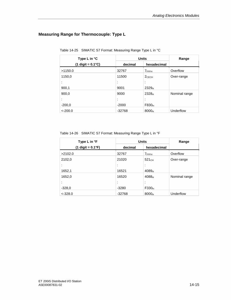
Analog Electronics Modules
ET 200iS Distributed I/O StationA5E00087831-02 14-15
Measuring Range for Thermocouple: Type L
Table 14-25 SIMATIC S7 Format: Measuring Range Type L in °C
UnitsType L in °C
(1 digit = 0.1°C) decimal hexadecimal
Range
>1150.0 32767 7FFFH Overflow
1150,0
:
900,1
11500
:
9001
2CECH
:
2329H
Over-range
900,0
:
-200,0
9000
:
-2000
2328H
:
F830H
Nominal range
<-200.0 -32768 8000H Underflow
Table 14-26 SIMATIC S7 Format: Measuring Range Type L in °F
UnitsType L in °F
(1 digit = 0.1°F) decimal hexadecimal
Range
>2102.0 32767 7FFFH Overflow
2102,0
:
1652,1
21020
:
16521
521CH
:
4089H
Over-range
1652,0
:
-328,0
16520
:
-3280
4088H
:
F330H
Nominal range
<-328.0 -32768 8000H Underflow

Analog Electronics Modules
ET 200iS Distributed I/O Station14-16 A5E00087831-02
Measuring Range for Thermocouple: Type S, R
Table 14-27 SIMATIC S7 Format: Measuring Range Type S, R in °C
UnitsType S, R in °C
(1 digit = 0.1°C) decimal hexadecimal
Range
>2019.0 32767 7FFFH Overflow
2019,0
:
1769,1
20190
:
17691
4EDEH
:
451BH
Over-range
1769,0
:
-50,0
17690
:
-500
451AH
:
FE0CH
Nominal range
-50,1
:
-170,0
-501
:
-1700
FE0BH
:
F95CH
Under-range
<-170.0 -32768 8000H Underflow
Table 14-28 SIMATIC S7 Format: Measuring Range Type S, R in °F
UnitsType S, R in °F
(1 digit = 0.1°F) decimal hexadecimal
Range
>3276.6 32767 7FFFH Overflow
3276,6
:
3216,3
32766
:
32163
7FFEH
:
7DA3H
Over-range
3216,2
:
-58,0
32162
:
-580
7DA2H
:
FDBCH
Nominal range
-58,1
:
-274,0
-581
:
-2740
FDBBH
:
F54CH
Under-range
<-274.0 -32768 8000H Underflow

Analog Electronics Modules
ET 200iS Distributed I/O StationA5E00087831-02 14-17
Measuring Range for Thermocouple: Type B
Table 14-29 SIMATIC S7 Format: Measuring Range Type B in °C
UnitsType B in °C
(1 digit = 0.1°C) decimal hexadecimal
Range
>2070.0 32767 7FFFH Overflow
2070,0
:
1820,1
20700
:
1820,1
50DCH
:
4719H
Over-range
1820,0
:
0,0
18200
:
0
4718H
:
0000H
Nominal range
-0,1
:
-120,0
-1
:
-1200
FFFFH
:
FB50H
Under-range
< -120.0 -32768 8000H Underflow
Table 14-30 SIMATIC S7 Format: Measuring Range Type B in °F
UnitsType B in °F
(1 digit = 0.1°F) decimal hexadecimal
Range
>3276.6 32767 7FFFH Overflow
3276,6
:
2786,6
32766
:
27866
7FFEH
:
6CDAH
Over-range
2786,5
:
32
27865
:
320
6CD9H
:
0140H
Nominal range
31,9
:
-184
319
:
-1840
013FH
:
F8D0H
Under-range
<-184 -32768 8000H Underflow
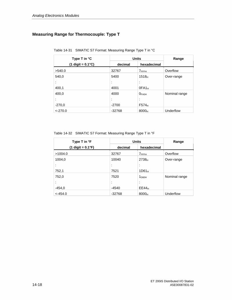
Analog Electronics Modules
ET 200iS Distributed I/O Station14-18 A5E00087831-02
Measuring Range for Thermocouple: Type T
Table 14-31 SIMATIC S7 Format: Measuring Range Type T in °C
UnitsType T in °C
(1 digit = 0.1°C) decimal hexadecimal
Range
>540.0 32767 7FFFH Overflow
540,0
:
400,1
5400
:
4001
1518H
:
0FA1H
Over-range
400,0
:
-270,0
4000
:
-2700
0FA0H
:
F574H
Nominal range
<-270.0 -32768 8000H Underflow
Table 14-32 SIMATIC S7 Format: Measuring Range Type T in °F
UnitsType T in °F
(1 digit = 0.1°F) decimal hexadecimal
Range
>1004.0 32767 7FFFH Overflow
1004,0
:
752,1
10040
:
7521
2738H
:
1D61H
Over-range
752,0
:
-454,0
7520
:
-4540
1D60H
:
EE44H
Nominal range
<-454.0 -32768 8000H Underflow
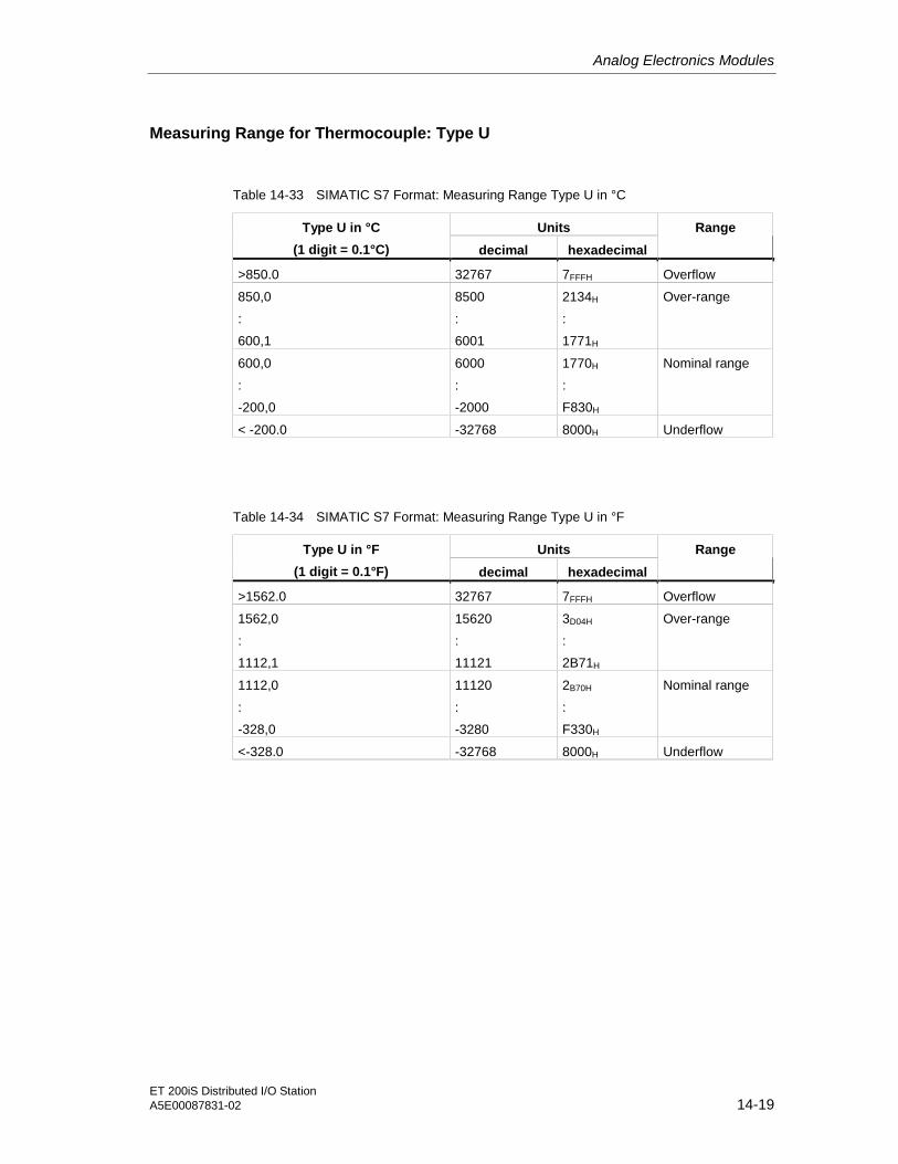
Analog Electronics Modules
ET 200iS Distributed I/O StationA5E00087831-02 14-19
Measuring Range for Thermocouple: Type U
Table 14-33 SIMATIC S7 Format: Measuring Range Type U in °C
UnitsType U in °C
(1 digit = 0.1°C) decimal hexadecimal
Range
>850.0 32767 7FFFH Overflow
850,0
:
600,1
8500
:
6001
2134H
:
1771H
Over-range
600,0
:
-200,0
6000
:
-2000
1770H
:
F830H
Nominal range
< -200.0 -32768 8000H Underflow
Table 14-34 SIMATIC S7 Format: Measuring Range Type U in °F
UnitsType U in °F
(1 digit = 0.1°F) decimal hexadecimal
Range
>1562.0 32767 7FFFH Overflow
1562,0
:
1112,1
15620
:
11121
3D04H
:
2B71H
Over-range
1112,0
:
-328,0
11120
:
-3280
2B70H
:
F330H
Nominal range
<-328.0 -32768 8000H Underflow

Analog Electronics Modules
ET 200iS Distributed I/O Station14-20 A5E00087831-02
14.1.4 Analog Value Representation for the Output Ranges of theAnalog Output Modules in SIMATIC S7 Format
Introduction
The table in this section contains the digitized analog values for the measuringranges of the analog output modules.
Since the binary representation of the analog values is always the same, this tablecontains only a comparison of the output ranges with the units.
Output Ranges for Current: 0 to 20 mA, 4 to 20 mA
Table 14-35 SIMATIC S7 Format: Measuring Range 0/4 to 20 mA
UnitsOutput Range
0 to 20 mA
Output Range
4 to 20 mA decimal hexadecimal
Range
0 0 >32511 >7EFFH Overflow
23,5178
:
20,0007
22,8142
:
20,0006
32511
:
27649
7EFFH
:
6C01H
Over-range
20,0000
:
0
20,0000
:
4,0000
27648
:
0
6C00H
:
0H
Nominal range
0
:
0
3,9994
:
0
-1
:
-6912
FFFFH
:
E500H
Under-range
0 0 <-6912 <E4FFH Underflow
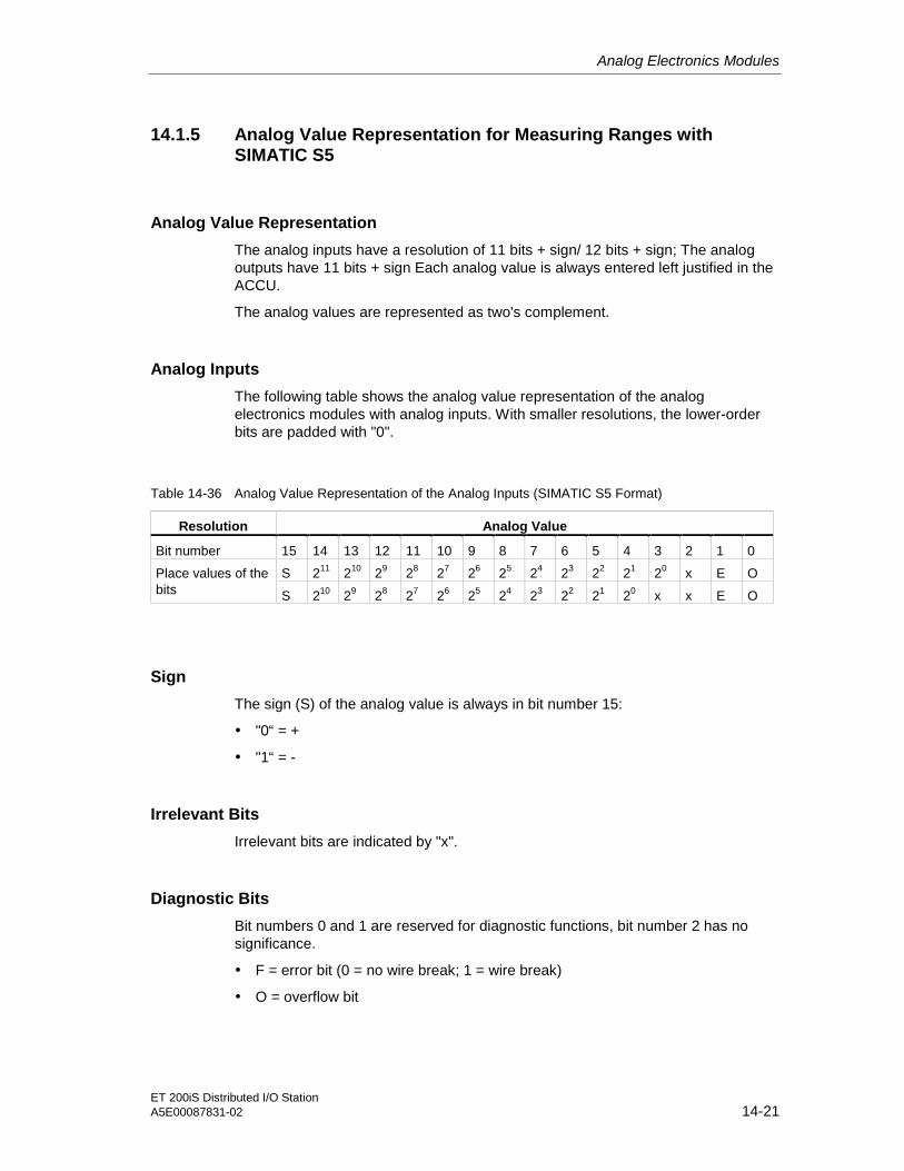
Analog Electronics Modules
ET 200iS Distributed I/O StationA5E00087831-02 14-21
14.1.5 Analog Value Representation for Measuring Ranges withSIMATIC S5
Analog Value Representation
The analog inputs have a resolution of 11 bits + sign/ 12 bits + sign; The analogoutputs have 11 bits + sign Each analog value is always entered left justified in theACCU.
The analog values are represented as two's complement.
Analog Inputs
The following table shows the analog value representation of the analogelectronics modules with analog inputs. With smaller resolutions, the lower-orderbits are padded with "0".
Table 14-36 Analog Value Representation of the Analog Inputs (SIMATIC S5 Format)
Resolution Analog Value
Bit number 15 14 13 12 11 10 9 8 7 6 5 4 3 2 1 0
S 211 210 29 28 27 26 25 24 23 22 21 20 x E OPlace values of thebits S 210 29 28 27 26 25 24 23 22 21 20 x x E O
Sign
The sign (S) of the analog value is always in bit number 15:
• "0“ = +
• "1“ = -
Irrelevant Bits
Irrelevant bits are indicated by "x".
Diagnostic Bits
Bit numbers 0 and 1 are reserved for diagnostic functions, bit number 2 has nosignificance.
• F = error bit (0 = no wire break; 1 = wire break)
• O = overflow bit

Analog Electronics Modules
ET 200iS Distributed I/O Station14-22 A5E00087831-02
Analog Outputs
The following table shows the analog value representation of the electronicsmodules with analog outputs.
Table 14-37 Analog Value Representation of the Analog Outputs (SIMATIC S5 Format)
Resolution Analog Value
Bit number 15 14 13 12 11 10 9 8 7 6 5 4 3 2 1 0
Place values of thebits
S 210 29 28 27 26 25 24 23 22 21 20 x x x x
14.1.6 Analog Value Representation for the Measuring Ranges of theAnalog Input Modules in SIMATIC S5 Format
Introduction
The tables in this section contain the digitized analog values for the measuringranges of the analog input modules.
Calculation
The SIMATIC S5 format is calculated from the SIMATIC S7 format in the analogmodule. The over-range therefore has the same magnitude in both formats(approximately 17.6%).

Analog Electronics Modules
ET 200iS Distributed I/O StationA5E00087831-02 14-23
Measuring Range for Thermal e.m.f.: ± 80 mV
Table 14-38 SIMATIC S5 Format: Measuring Range ± 80 mV
Data WordMeasuringRange± 80 mV
Units(decimal) 1
211
10
9 8 7 6 5 4 3 2 1 0 X E O
Range
>94.071 2409 0 1 0 0 1 0 1 1 0 1 0 0 1 0 0 1 Overflow
94,071
80,040
2408
2049
0
0
1
1
0
0
0
0
1
0
0
0
1
0
1
0
0
0
1
0
0
0
0
0
0
1
0
0
0
0
0
0
Over-range
80,000
0,039
0,0
-0,039
-80,000
2048
1
0
-1
-2048
0
0
0
1
1
1
0
0
1
1
0
0
0
1
0
0
0
0
1
0
0
0
0
1
0
0
0
0
1
0
0
0
0
1
0
0
0
0
1
0
0
0
0
1
0
0
0
0
1
0
0
0
0
1
0
0
0
0
1
0
0
1
0
1
0
0
0
0
0
0
0
0
0
0
0
0
0
0
0
0
Nominalrange
-80,040
-94,074
-2049
-2408
1
1
0
0
1
1
1
1
1
0
1
1
1
0
1
0
1
1
1
1
1
0
1
0
1
0
0
0
0
0
0
0
Underrange
< -94.074 -2409 1 0 1 1 0 1 0 0 1 0 1 1 1 0 0 1 Underflow
Measuring Ranges for Current: 0 to 20 mA, 4 to 20 mA
Table 14-39 SIMATIC S5 Format: Measuring Ranges 0 to 20 mA, 4 to 20 mA
Measuring Range Data Word
0 to 20mA
4 to 20mA
Units(decimal)
12
11
10
9 8 7 6 5 4 3 2 1 0 X E O
Range
>22.8125 >22.8142 2921 0 1 0 1 1 0 1 1 0 1 0 0 1 0 0 1 Overflow
22,8125
20,0078
22,8142
20,0078
2920
2561
0
0
1
1
0
0
1
1
1
0
0
0
1
0
1
0
0
0
1
0
0
0
0
0
0
1
0
0
0
0
0
0
Over-range
20
:
0
20
4,0078
4
2560
513
512
0
0
0
1
0
0
0
0
0
1
1
1
0
0
0
0
0
0
0
0
0
0
0
0
0
0
0
0
0
0
0
0
0
0
0
0
0
1
0
0
0
0
0
0
0
0
0
0
Nominalrange
3,9922
3.6000*
1,1852
511
461*
151*
0
0
0
0
0
0
0
0
0
0
0
0
1
1
0
1
1
1
1
1
0
1
0
0
1
0
1
1
1
0
1
1
1
1
0
1
1
1
1
0
0
0
0
0
0
0
0
0
UnderrangeNegativevaluesare notpossible
<1.1852 150* 0 0 0 0 0 1 0 0 1 0 1 1 0 0 0 1 Underflow
* If you have enabled the wire break diagnostic parameter, the wire break diagnostic message is reported if the valuedrops below 3.6 mA and the following values are entered: decimal 4095 (bits 0 to 12)/ hexadecimal 7FFB.

Analog Electronics Modules
ET 200iS Distributed I/O Station14-24 A5E00087831-02
Measuring Range for Resistance-type Sensor: 600 ohms absolute
Table 14-40 SIMATIC S5 format: Measuring range 600 ohms absolute
Measuredvalue °C
Data Word
600 ohms
Units(decimal)
12
11
10
9 8 7 6 5 4 3 2 1 0 X E O
Range
>705.534 2409 0 1 0 0 1 0 1 1 0 1 0 0 1 0 0 1 Overflow
705,534
600,29
2408
2049
0
0
1
1
0
0
0
0
1
0
0
0
1
0
1
0
0
0
1
0
0
0
0
0
0
1
0
0
0
0
0
0
Over-range
600
0,288
0
2048
1
0
0
0
0
1
0
0
0
0
0
0
0
0
0
0
0
0
0
0
0
0
0
0
0
0
0
0
0
0
0
0
0
0
0
0
0
0
0
1
0
0
0
0
0
0
0
0
0
0
Nominalrange
-1
-360
1
1
1
1
1
1
1
1
1
0
1
1
1
0
1
0
1
1
1
1
1
0
1
0
1
0
0
0
0
0
0
0
Underrange*
negative values(not physicallypossible)
-361 1 1 1 1 0 1 0 0 1 0 1 1 1 0 0 1 Underflow*
* If resistors are connected incorrectly

Analog Electronics Modules
ET 200iS Distributed I/O StationA5E00087831-02 14-25
Measuring Range for Temperature Sensors: Pt100 Standard
Table 14-41 SIMATIC S5 Format: Measuring Range Pt100 Standard in °C
Data WordMeas. val. in°C (1 digit =
0.5 °C)
Units(decimal) 1
211
10
9 8 7 6 5 4 3 2 1 0 X E O
Range
> 1000 2001 0 0 1 1 1 1 1 0 1 0 0 0 1 0 0 1 Overflow
1000
850,5
2000
1701
0
0
0
0
1
1
1
1
1
0
1
1
1
0
0
1
1
0
0
0
0
1
0
0
0
1
0
0
0
0
0
0
Over-range
850,0
0,5
0,0
-0,5
-200,0
1700
1
0
-1
-400
0
0
0
1
1
0
0
0
1
1
1
0
0
1
1
1
0
0
1
1
0
0
0
1
0
1
0
0
1
0
0
0
0
1
1
1
0
0
1
1
0
0
0
1
1
0
0
0
1
0
1
0
0
1
0
0
0
0
1
0
0
1
0
1
0
0
0
0
0
0
0
0
0
0
0
0
0
0
0
0
Nominalrange
-200,5
-243
-401
-486
1
1
1
1
1
1
1
1
0
0
0
0
1
0
1
0
0
1
1
1
1
0
1
1
1
0
0
0
0
0
0
0
Underrange
< -243.0 -487 1 1 1 1 0 0 0 0 1 1 0 0 1 0 0 1 Underflow
Table 14-42 SIMATIC S5 Format: Measuring Range Pt100 Standard in °F
Data WordMeas. val. in°F (1 digit =
0.5 °F)
Units(decimal) 1
211
10
9 8 7 6 5 4 3 2 1 0 X E O
Range
> 1832 3665 0 1 1 1 0 0 1 0 1 0 0 0 1 0 0 1 Overflow
1832
1562,5
3664
3125
0
0
1
1
1
1
1
0
0
0
0
0
1
0
0
1
1
1
0
0
0
1
0
0
0
1
0
0
0
0
0
0
Over-range
1562
0,5
0,0
-0,5
-328
3124
1
0
-1
-656
0
0
0
1
1
1
0
0
1
1
1
0
0
1
1
0
0
0
1
0
0
0
0
1
1
0
0
0
1
0
0
0
0
1
1
1
0
0
1
1
1
0
0
1
1
0
0
0
1
0
1
0
0
1
0
0
0
0
1
0
0
0
0
1
0
0
0
0
0
0
0
0
0
0
0
0
0
0
0
0
Nominalrange
-328,5
-405,4
-657
-811
1
1
1
1
1
1
0
0
1
0
0
1
1
1
1
0
0
1
1
0
1
1
1
0
1
1
0
0
0
0
0
0
Underrange
< -405.4 -812 1 1 0 0 1 1 0 1 0 1 0 0 0 0 0 1 Underflow

Analog Electronics Modules
ET 200iS Distributed I/O Station14-26 A5E00087831-02
Measuring Range for Temperature Sensors: Pt100 Climatic
Table 14-43 SIMATIC S5 Format: Measuring Range Pt100 Climatic in °C
Data WordMeas. val. in°C (1 digit =
0.05 °C)
Units(decimal) 1
211
10
9 8 7 6 5 4 3 2 1 0 X E O
Range
> 155 3101 0 1 1 0 0 0 0 0 1 1 1 0 1 0 0 1 Overflow
155
130,05
3100
2601
0
0
1
1
1
0
0
1
0
0
0
0
0
0
0
1
1
0
1
1
1
0
0
0
0
1
0
0
0
0
0
0
Over-range
130
0,05
0,0
-0,05
-120
2600
1
0
-1
-2400
0
0
0
1
1
1
0
0
1
0
0
0
0
1
1
1
0
0
1
1
0
0
0
1
0
0
0
0
1
1
0
0
0
1
0
1
0
0
1
1
0
0
0
1
0
1
0
0
1
0
0
0
0
1
0
0
0
0
1
0
0
1
0
1
0
0
0
0
0
0
0
0
0
0
0
0
0
0
0
0
Nominalrange
-120,05
-145
-2401
-2900
1
1
0
0
1
1
1
0
0
0
1
1
0
0
0
1
1
0
1
1
1
1
1
0
1
0
0
0
0
0
0
0
Underrange
< -145 -2901 1 0 1 0 0 1 0 1 0 1 0 1 1 0 0 1 Underflow
Table 14-44 SIMATIC S5 Format: Measuring Range Pt100 Climatic in °F
Data WordMeas. val. in°F (1 digit =
0.1 °F)
Units(decimal) 1
211
10
9 8 7 6 5 4 3 2 1 0 X E O
Range
> 311 3111 0 1 1 0 0 0 0 1 0 0 1 1 1 0 0 1 Overflow
311
266,1
3110
2661
0
0
1
1
1
0
0
1
0
0
0
0
0
1
1
1
0
0
0
0
1
1
1
0
0
1
0
0
0
0
0
0
Over-range
266
0,1
0,0
-0,1
-184
2660
1
0
-1
-1840
0
0
0
1
1
1
0
0
1
1
0
0
0
1
0
1
0
0
1
0
0
0
0
1
0
0
0
0
1
1
1
0
0
1
1
1
0
0
1
0
0
0
0
1
1
0
0
0
1
0
1
0
0
1
0
0
0
0
1
0
0
1
0
1
0
0
0
0
0
0
0
0
0
0
0
0
0
0
0
0
Nominalrange
-184,1
-229
-1841
-2290
1
1
1
0
0
1
0
1
0
1
1
0
1
0
0
0
0
0
1
1
1
1
1
1
1
0
0
0
0
0
0
0
Underrange
< -229 -2291 1 0 1 1 1 0 0 0 0 1 1 0 1 0 0 1 Underflow

Analog Electronics Modules
ET 200iS Distributed I/O StationA5E00087831-02 14-27
Measuring Range for Temperature Sensors: Ni100 Standard
Table 14-45 SIMATIC S5 Format: Measuring Range Ni100 Standard in °C
Data WordMeas. val. in°C (1 digit =
0.5 °C)
Units(decimal) 1
211
10
9 8 7 6 5 4 3 2 1 0 X E O
Range
> 295 591 0 0 0 1 0 0 1 0 0 1 1 1 1 0 0 1 Overflow
295
250,5
590
501
0
0
0
0
0
0
1
0
0
1
0
1
1
1
0
1
0
1
1
0
1
1
1
0
0
1
0
0
0
0
0
0
Over-range
250
0,5
0,0
-0,5
-60,0
500
1
0
-1
-120
0
0
0
1
1
0
0
0
1
1
0
0
0
1
1
0
0
0
1
1
1
0
0
1
1
1
0
0
1
1
1
0
0
1
0
1
0
0
1
0
1
0
0
1
0
0
0
0
1
1
1
0
0
1
0
0
0
0
1
0
0
1
0
1
0
0
0
0
0
0
0
0
0
0
0
0
0
0
0
0
Nominalrange
-60,5
-105
-121
-210
1
1
1
1
1
1
1
1
1
1
1
0
1
0
1
1
0
0
0
1
0
1
0
1
1
0
0
0
0
0
0
0
Underrange*
< -105.0 -211 1 1 1 1 1 0 0 1 0 1 1 0 1 0 0 1 Underflow
* In the over-range and range, the existing slope of the characteristic curve is retained when the value leaves thelinearized nominal range.
Table 14-46 SIMATIC S5 Format: Measuring Range Ni100 Standard in °F
Data WordMeas. val. in°F (1 digit =
0.5 °F)
Units(decimal) 1
211
10
9 8 7 6 5 4 3 2 1 0 X E O
Range
> 563 1127 0 0 1 0 0 0 1 1 0 0 1 1 1 0 0 1 Overflow
563
482,5
1126
965
0
0
0
0
1
0
0
0
0
1
0
1
1
1
1
1
0
0
0
0
1
0
1
0
0
1
0
0
0
0
0
0
Over-range
482
0,5
0,0
-0,5
-76
964
1
0
-1
-152
0
0
0
1
1
0
0
0
1
1
0
0
0
1
1
1
0
0
1
1
1
0
0
1
1
1
0
0
1
0
1
0
0
1
1
0
0
0
1
1
0
0
0
1
0
0
0
0
1
1
1
0
0
1
0
0
0
0
1
0
0
1
0
1
0
0
0
0
0
0
0
0
0
0
0
0
0
0
0
0
Nominalrange
-76,5
-157
-153
-314
1
1
1
1
1
1
1
1
1
0
0
1
1
1
1
0
0
0
0
0
1
1
1
1
1
0
0
0
0
0
0
0
Underrange*
< -157 -315 1 1 1 1 0 1 1 0 0 0 1 0 1 0 0 1 Underflow
* In the over-range and range, the existing slope of the characteristic curve is retained when the value leaves thelinearized nominal range.

Analog Electronics Modules
ET 200iS Distributed I/O Station14-28 A5E00087831-02
Measuring Range for Temperature Sensors: Ni100 Climatic
Table 14-47 SIMATIC S5 Format: Measuring Range Ni100 Climatic in °C
Data WordMeas. val. in°C (1 digit =
0.1 °C)
Units(decimal) 1
211
10
9 8 7 6 5 4 3 2 1 0 X E O
Range
> 295 2951 0 1 0 1 1 1 0 0 0 0 1 1 1 0 0 1 Overflow
295
250,1
2950
2501
0
0
1
1
0
0
1
0
1
1
1
1
0
1
0
0
0
0
0
0
1
1
1
0
0
1
0
0
0
0
0
0
Over-range*
250
0,1
0,0
-0,1
-60,0
2500
1
0
-1
-600
0
0
0
1
1
1
0
0
1
1
0
0
0
1
1
0
0
0
1
0
1
0
0
1
1
1
0
0
1
1
1
0
0
1
0
0
0
0
1
1
0
0
0
1
0
0
0
0
1
1
1
0
0
1
0
0
0
0
1
0
0
1
0
1
0
0
0
0
0
0
0
0
0
0
0
0
0
0
0
0
Nominalrange
-60,1
-105
-601
-1050
1
1
1
1
1
0
0
1
1
1
1
1
0
1
1
1
0
0
0
0
1
1
1
1
1
0
0
0
0
0
0
0
Underrange*
< -105 -1051 1 1 0 1 1 1 1 1 0 0 1 0 1 0 0 1 Underflow
* In the over-range and range, the existing slope of the characteristic curve is retained when the value leaves thelinearized nominal range.
Table 14-48 SIMATIC S5 Format: Measuring Range Ni100 Climatic in °F
Data WordMeas. val. in°F (1 digit =
0.2 °F)
Units(decimal) 1
211
10
9 8 7 6 5 4 3 2 1 0 X E O
Range
> 563 2816 0 1 0 1 1 0 0 0 0 0 0 0 0 0 0 1 Overflow
563
482,2
2815
2411
0
0
1
1
0
0
1
0
0
1
1
0
1
1
1
1
1
0
1
1
1
0
1
1
1
1
0
0
0
0
0
0
Over-range*
482
0,2
0,0
-0,2
-76
2410
1
0
-1
-380
0
0
0
1
1
1
0
0
1
1
0
0
0
1
1
0
0
0
1
1
1
0
0
1
0
0
0
0
1
1
1
0
0
1
0
1
0
0
1
0
0
0
0
1
0
1
0
0
1
0
0
0
0
1
1
1
0
0
1
0
0
1
0
1
0
0
0
0
0
0
0
0
0
0
0
0
0
0
0
0
Nominalrange
-76,2
-157
-381
-785
1
1
1
1
1
1
1
0
0
0
1
1
0
1
0
1
0
0
0
1
0
1
1
1
1
1
0
0
0
0
0
0
Underrange*
< -157 -786 1 1 1 0 0 1 1 1 0 1 1 1 0 0 0 1 Underflow
* In the over-range and range, the existing slope of the characteristic curve is retained when the value leaves thelinearized nominal range.

Analog Electronics Modules
ET 200iS Distributed I/O StationA5E00087831-02 14-29
Measuring Range for Thermocouple: Type E
Table 14-49 SIMATIC S5 Format: Measuring Range Type E in °C
Data WordMeas. val. °C Units(decimal) 1
211
10
9 8 7 6 5 4 3 2 1 0 X E O
Range
> 1200 1201 0 0 1 0 0 1 0 1 1 0 0 0 1 0 0 1 Overflow
1200
1001
1200
1001
0
0
0
0
1
0
0
1
0
1
1
1
0
1
1
1
1
0
0
1
0
0
0
0
0
1
0
0
0
0
0
0
Over-range
1000
1
0
-1
-270
1000
1
0
-1
-270
0
0
0
1
1
0
0
0
1
1
0
0
0
1
1
1
0
0
1
1
1
0
0
1
0
1
0
0
1
1
1
0
0
1
1
1
0
0
1
1
0
0
0
1
1
1
0
0
1
0
0
0
0
1
0
0
0
0
1
1
0
1
0
1
0
0
0
0
0
0
0
0
0
0
0
0
0
0
0
0
Nominalrange
< -270 -271 1 1 1 1 0 1 1 1 1 0 0 0 1 0 0 1 Underflow
Table 14-50 SIMATIC S5 Format: Measuring Range Type E in °F
Data WordMeas. val. in°F
Units(decimal) 1
211
10
9 8 7 6 5 4 3 2 1 0 X E O
Range
> 2192 2193 0 1 0 0 0 1 0 0 1 0 0 0 1 0 0 1 Overflow
2192
1833
2192
1833
0
0
1
0
0
1
0
1
0
1
1
0
0
0
0
1
1
0
1
1
0
0
0
0
0
1
0
0
0
0
0
0
Over-range
1832
1
0
-1
-454
1832
1
0
-1
-454
0
0
0
1
1
0
0
0
1
1
1
0
0
1
1
1
0
0
1
1
1
0
0
1
0
0
0
0
1
0
0
0
0
1
0
1
0
0
1
1
0
0
0
1
1
1
0
0
1
1
0
0
0
1
0
0
0
0
1
1
0
1
0
1
0
0
0
0
0
0
0
0
0
0
0
0
0
0
0
0
Nominalrange
< -454 -455 1 1 1 1 0 0 0 1 1 1 0 0 1 0 0 1 Underflow

Analog Electronics Modules
ET 200iS Distributed I/O Station14-30 A5E00087831-02
Measuring Range for Thermocouple: Type N
Table 14-51 SIMATIC S5 Format: Measuring Range Type N in °C
Data WordMeas. val. in°C
Units(decimal) 1
211
10
9 8 7 6 5 4 3 2 1 0 X E O
Range
> 1550 1551 0 0 1 1 0 0 0 0 0 1 1 1 1 0 0 1 Overflow
1550
1301
1550
1301
0
0
0
0
1
1
1
0
0
1
0
0
0
0
0
0
0
1
1
0
1
1
1
0
0
1
0
0
0
0
0
0
Over-range
1300
1
0
-1
-270
1300
1
0
-1
-270
0
0
0
1
1
0
0
0
1
1
1
0
0
1
1
0
0
0
1
1
1
0
0
1
0
0
0
0
1
1
0
0
0
1
1
0
0
0
1
1
1
0
0
1
1
0
0
0
1
0
1
0
0
1
0
0
0
0
1
1
0
1
0
1
0
0
0
0
0
0
0
0
0
0
0
0
0
0
0
0
Nominalrange
< -270 -271 1 1 1 1 0 1 1 1 1 0 0 0 1 0 0 1 Underflow
Table 14-52 SIMATIC S5 Format: Measuring Range Type N in °F
Data WordMeas. val. in°F
Units(decimal) 1
211
10
9 8 7 6 5 4 3 2 1 0 X E O
Range
> 2822 2823 0 1 0 1 1 0 0 0 0 0 1 1 1 0 0 1 Overflow
2822
2373
2822
2373
0
0
1
1
0
0
1
0
1
1
0
0
0
1
0
0
0
0
0
0
1
1
1
0
0
1
0
0
0
0
0
0
Over-range
2372
1
0
-1
-454
2372
1
0
-1
-454
0
0
0
1
1
1
0
0
1
1
0
0
0
1
1
0
0
0
1
1
1
0
0
1
0
0
0
0
1
0
1
0
0
1
0
0
0
0
1
1
0
0
0
1
1
0
0
0
1
1
1
0
0
1
0
0
0
0
1
1
0
1
0
1
0
0
0
0
0
0
0
0
0
0
0
0
0
0
0
0
Nominalrange
< -454 -455 1 1 1 1 0 0 0 1 1 1 0 0 1 0 0 1 Underflow

Analog Electronics Modules
ET 200iS Distributed I/O StationA5E00087831-02 14-31
Measuring Range for Thermocouple: Type J
Table 14-53 SIMATIC S5 Format: Measuring Range Type J in °C
Data WordMeas. val. in°C
Units(decimal) 1
211
10
9 8 7 6 5 4 3 2 1 0 X E O
Range
> 1450 1451 0 0 1 0 1 1 0 1 0 1 0 1 1 0 0 1 Overflow
1450
1201
1450
1201
0
0
0
0
1
1
0
0
1
0
1
1
0
0
1
1
0
1
1
0
0
0
1
0
0
1
0
0
0
0
0
0
Over-range
1200
1
0
-1
-210
1200
1
0
-1
-210
0
0
0
1
1
0
0
0
1
1
1
0
0
1
1
0
0
0
1
1
0
0
0
1
1
1
0
0
1
0
0
0
0
1
0
1
0
0
1
1
1
0
0
1
0
0
0
0
1
1
0
0
0
1
1
0
0
0
1
1
0
1
0
1
0
0
0
0
0
0
0
0
0
0
0
0
0
0
0
0
Nominalrange
< -210 -211 1 1 1 1 1 0 0 1 0 1 1 0 1 0 0 1 Underflow
Table 14-54 SIMATIC S5 Format: Measuring Range Type J in °F
Data WordMeas. val. in°F
Units(decimal) 1
211
10
9 8 7 6 5 4 3 2 1 0 X E O
Range
> 2642 2643 0 1 0 1 0 0 1 0 1 0 0 1 1 0 0 1 Overflow
2642
2193
2642
2193
0
0
1
1
0
0
1
0
0
0
0
1
1
0
0
0
1
1
0
0
0
0
1
0
0
1
0
0
0
0
0
0
Over-range
2192
1
0
-1
-346
2192
1
0
-1
-346
0
0
0
1
1
1
0
0
1
1
0
0
0
1
1
0
0
0
1
1
0
0
0
1
0
1
0
0
1
1
0
0
0
1
0
0
0
0
1
1
1
0
0
1
0
0
0
0
1
0
0
0
0
1
1
0
0
0
1
1
0
1
0
1
0
0
0
0
0
0
0
0
0
0
0
0
0
0
0
0
Nominalrange
< -346 -347 1 1 1 1 0 1 0 1 0 0 1 0 1 0 0 1 Underflow

Analog Electronics Modules
ET 200iS Distributed I/O Station14-32 A5E00087831-02
Measuring Range for Thermocouple: Type K
Table 14-55 SIMATIC S5 Format: Measuring Range Type K in °C
Data WordMeas. val. in°C
Units(decimal) 1
211
10
9 8 7 6 5 4 3 2 1 0 X E O
Range
> 1622 1623 0 0 1 1 0 0 1 0 1 0 1 1 1 0 0 1 Overflow
1622
1373
1622
1373
0
0
0
0
1
1
1
0
0
1
0
0
1
1
0
0
1
1
0
1
1
1
1
0
0
1
0
0
0
0
0
0
Over-range
1372
1
0
-1
-270
1372
1
0
-1
-270
0
0
0
1
1
0
0
0
1
1
1
0
0
1
1
0
0
0
1
1
1
0
0
1
0
0
0
0
1
1
1
0
0
1
1
0
0
0
1
1
1
0
0
1
1
1
0
0
1
0
1
0
0
1
0
0
0
0
1
1
0
1
0
1
0
0
0
0
0
0
0
0
0
0
0
0
0
0
0
0
Nominalrange
< -270 -271 1 1 1 1 0 1 1 1 1 0 0 0 1 0 0 1 Underflow
Table 14-56 SIMATIC S5 Format: Measuring Range Type K in °F
Data WordMeas. val. in°F
Units(decimal) 1
211
10
9 8 7 6 5 4 3 2 1 0 X E O
Range
> 2952 2953 0 1 0 1 1 1 0 0 0 1 0 0 1 0 0 1 Overflow
2952
2503
2952
2503
0
0
1
1
0
0
1
0
1
1
1
1
0
1
0
0
0
0
1
0
0
1
0
1
0
1
0
0
0
0
0
0
Over-range
2502
1
0
-1
-454
2502
1
0
-1
-454
0
0
0
1
1
1
0
0
1
1
0
0
0
1
1
0
0
0
1
1
1
0
0
1
0
1
0
0
1
0
1
0
0
1
0
0
0
0
1
1
0
0
0
1
1
0
0
0
1
1
1
0
0
1
0
1
0
0
1
1
0
1
0
1
0
0
0
0
0
0
0
0
0
0
0
0
0
0
0
0
Nominalrange
< -454 -455 1 1 1 1 0 0 0 1 1 1 0 0 1 0 0 1 Underflow

Analog Electronics Modules
ET 200iS Distributed I/O StationA5E00087831-02 14-33
Measuring Range for Thermocouple: Type L
Table 14-57 SIMATIC S5 Format: Measuring Range Type L in °C
Data WordMeas. val. in°C
Units(decimal) 1
211
10
9 8 7 6 5 4 3 2 1 0 X E O
Range
> 1150 1151 0 0 1 0 0 0 1 1 1 1 1 1 1 0 0 1 Overflow
1150
901
1150
901
0
0
0
0
1
0
0
1
0
1
0
1
1
0
1
0
1
0
1
0
1
1
1
0
0
1
0
0
0
0
0
0
Over-range
900
1
0
-1
-200
900
1
0
-1
-200
0
0
0
1
1
0
0
0
1
1
0
0
0
1
1
1
0
0
1
1
1
0
0
1
1
1
0
0
1
0
0
0
0
1
0
0
0
0
1
1
0
0
0
1
1
0
0
0
1
1
1
0
0
1
0
0
0
0
1
0
0
1
0
1
0
0
0
0
0
0
0
0
0
0
0
0
0
0
0
0
Nominalrange
< -200 -201 1 1 1 1 1 0 0 1 1 0 1 1 1 0 0 1 Underflow
Table 14-58 SIMATIC S5 Format: Measuring Range Type L in °F
Data WordMeas. val. in°F
Units(decimal) 1
211
10
9 8 7 6 5 4 3 2 1 0 X E O
Range
> 2102 2103 0 1 0 0 0 0 0 1 1 0 1 1 1 0 0 1 Overflow
2102
1653
2102
1653
0
0
1
0
0
1
0
1
0
0
0
0
0
1
1
1
1
1
0
0
1
1
1
0
0
1
0
0
0
0
0
0
Over-range
1652
1
0
-1
-328
1652
1
0
-1
-328
0
0
0
1
1
0
0
0
1
1
1
0
0
1
1
1
0
0
1
1
0
0
0
1
0
0
0
0
1
1
1
0
0
1
0
1
0
0
1
1
1
0
0
1
1
0
0
0
1
1
1
0
0
1
0
0
0
0
1
0
0
1
0
1
0
0
0
0
0
0
0
0
0
0
0
0
0
0
0
0
Nominalrange
< -328 -329 1 1 1 1 0 1 0 1 1 0 1 1 1 0 0 1 Underflow

Analog Electronics Modules
ET 200iS Distributed I/O Station14-34 A5E00087831-02
Measuring Range for Thermocouple: Type R, S
Table 14-59 SIMATIC S5 Format: Measuring Range Type R, S in °C
Data WordMeas. val. in°C
Units(decimal) 1
211
10
9 8 7 6 5 4 3 2 1 0 X E O
Range
> 2019 2020 0 0 1 1 1 1 1 1 0 0 1 0 0 0 0 1 Overflow
2019
1770
2019
1770
0
0
0
0
1
1
1
1
1
0
1
1
1
1
1
1
0
0
0
1
0
0
1
1
1
0
0
0
0
0
0
0
Over-range
1769
1
0
-1
-50
1769
1
0
-1
-50
0
0
0
1
1
0
0
0
1
1
1
0
0
1
1
1
0
0
1
1
0
0
0
1
1
1
0
0
1
1
1
0
0
1
1
1
0
0
1
0
0
0
0
1
0
1
0
0
1
1
0
0
0
1
1
0
0
0
1
1
1
1
0
1
0
0
0
0
0
0
0
0
0
0
0
0
0
0
0
0
Nominalrange
-51
-170
-51
-170
1
1
1
1
1
1
1
1
1
1
1
0
1
1
0
0
0
1
1
0
1
1
0
1
1
0
0
0
0
0
0
0
Underrange
< -170 -171 1 1 1 1 1 0 1 0 1 0 1 0 1 0 0 1 Underflow
Table 14-60 SIMATIC S5 Format: Measuring Range Type R, S in °F
Data WordMeas. val. in°F
Units(decimal) 1
211
10
9 8 7 6 5 4 3 2 1 0 X E O
Range
> 3666 3667 0 1 1 1 0 0 1 0 1 0 0 1 1 0 0 1 Overflow
3666
3217
3666
3217
0
0
1
1
1
1
1
0
0
0
0
1
1
0
0
0
1
1
0
0
0
0
1
0
0
1
0
0
0
0
0
0
Over-range
3216
1
0
-1
-58
3216
1
0
-1
-58
0
0
0
1
1
1
0
0
1
1
1
0
0
1
1
0
0
0
1
1
0
0
0
1
1
1
0
0
1
1
0
0
0
1
1
0
0
0
1
0
1
0
0
1
0
0
0
0
1
0
0
0
0
1
1
0
0
0
1
1
0
1
0
1
0
0
0
0
0
0
0
0
0
0
0
0
0
0
0
0
Nominalrange
-59
-274
-59
-274
1
1
1
1
1
1
1
1
1
0
1
1
1
1
0
1
0
0
0
1
1
1
0
1
1
0
0
0
0
0
0
0
Underrange
< -274 -275 1 1 1 1 0 1 1 1 0 1 1 0 1 0 0 1 Underflow

Analog Electronics Modules
ET 200iS Distributed I/O StationA5E00087831-02 14-35
Measuring Range for Thermocouple: Type B
Table 14-61 SIMATIC S5 Format: Measuring Range Type B in °C
Data WordMeas. val. in°C
Units(decimal) 1
211
10
9 8 7 6 5 4 3 2 1 0 X E O
Range
> 2070 2071 0 1 0 0 0 0 0 0 1 0 1 1 1 0 0 1 Overflow
2070
1821
2070
1821
0
0
1
0
0
1
0
1
0
1
0
0
0
0
0
0
1
1
0
1
1
1
1
0
0
1
0
0
0
0
0
0
Over-range
1820
1
0
1820
1
0
0
0
0
0
0
0
1
0
0
1
0
0
1
0
0
0
0
0
0
0
0
0
0
0
1
0
0
1
0
0
1
0
0
0
0
0
0
1
0
0
0
0
0
0
0
0
0
0
Nominalrange
-1
-120
-1
-120
1
1
1
1
1
1
1
1
1
1
1
1
1
0
1
0
1
0
1
1
1
0
1
0
1
0
0
0
0
0
0
0
Underrange
< -120 -121 1 1 1 1 1 1 0 0 0 0 1 1 1 0 0 1 Underflow
Table 14-62 SIMATIC S5 Format: Measuring Range Type B in °F
Data WordMeas. val. in°F
Units(decimal) 1
211
10
9 8 7 6 5 4 3 2 1 0 X E O
Range
> 3758 3759 0 1 1 1 0 1 0 1 0 1 1 1 1 0 0 1 Overflow
3758
3309
3758
3309
0
0
1
1
1
1
1
0
0
0
1
1
0
1
1
1
0
0
1
1
1
1
1
0
0
1
0
0
0
0
0
0
Over-range
3308
1
0
3308
1
0
0
0
0
1
0
0
1
0
0
0
0
0
0
0
0
1
0
0
1
0
0
1
0
0
0
0
0
1
0
0
1
0
0
0
0
0
0
1
0
0
0
0
0
0
0
0
0
0
Nominalrange
-1
-184
-1
-184
1
1
1
1
1
1
1
1
1
1
1
0
1
1
1
0
1
0
1
1
1
0
1
0
1
0
0
0
0
0
0
0
Underrange
< -184 -185 1 1 1 1 1 0 1 0 0 0 1 1 1 0 0 1 Underflow

Analog Electronics Modules
ET 200iS Distributed I/O Station14-36 A5E00087831-02
Measuring Range for Thermocouple: Type T
Table 14-63 SIMATIC S5 Format: Measuring Range Type T in °C
Data WordMeas. val. in°C
Units(decimal) 1
211
10
9 8 7 6 5 4 3 2 1 0 X E O
Range
> 540 541 0 0 0 1 0 0 0 0 1 1 1 0 1 0 0 1 Overflow
540
401
540
401
0
0
0
0
0
0
1
0
0
1
0
1
0
0
0
0
1
1
1
0
1
0
0
0
0
1
0
0
0
0
0
0
Over-range
400
1
0
-1
-270
400
1
0
-1
-270
0
0
0
1
1
0
0
0
1
1
0
0
0
1
1
0
0
0
1
1
1
0
0
1
0
1
0
0
1
1
0
0
0
1
1
0
0
0
1
1
1
0
0
1
1
0
0
0
1
0
0
0
0
1
0
0
0
0
1
1
0
1
0
1
0
0
0
0
0
0
0
0
0
0
0
0
0
0
0
0
Nominalrange
< -270 -271 1 1 1 1 0 1 1 1 1 0 0 0 1 0 0 1 Underflow
Table 14-64 SIMATIC S5 Format: Measuring Range Type T in °F
Data WordMeas. val. in°F
Units(decimal) 1
211
10
9 8 7 6 5 4 3 2 1 0 X E O
Range
> 1004 1005 0 0 0 1 1 1 1 1 0 1 1 0 1 0 0 1 Overflow
1004
753
1004
753
0
0
0
0
0
0
1
1
1
0
1
1
1
1
1
1
0
1
1
0
1
0
0
0
0
1
0
0
0
0
0
0
Over-range
752
1
0
-1
-454
752
1
0
-1
-454
0
0
0
1
1
0
0
0
1
1
0
0
0
1
1
1
0
0
1
1
0
0
0
1
0
1
0
0
1
0
1
0
0
1
0
1
0
0
1
1
1
0
0
1
1
0
0
0
1
1
0
0
0
1
0
0
0
0
1
1
0
1
0
1
0
0
0
0
0
0
0
0
0
0
0
0
0
0
0
0
Nominalrange
< -454 -455 1 1 1 1 0 0 0 1 1 1 0 0 1 0 0 1 Underflow

Analog Electronics Modules
ET 200iS Distributed I/O StationA5E00087831-02 14-37
Measuring Range for Thermocouple: Type U
Table 14-65 SIMATIC S5 Format: Measuring Range Type U in °C
Data WordMeas. val. in°C
Units(decimal) 1
211
10
9 8 7 6 5 4 3 2 1 0 X E O
Range
> 850 851 0 0 0 1 1 0 1 0 1 0 0 1 1 0 0 1 Overflow
850
601
850
601
0
0
0
0
0
0
1
1
1
0
0
0
1
1
0
0
1
1
0
1
0
0
1
0
0
1
0
0
0
0
0
0
Over-range
600
1
0
-1
-200
600
1
0
-1
-200
0
0
0
1
1
0
0
0
1
1
0
0
0
1
1
1
0
0
1
1
0
0
0
1
1
0
0
0
1
0
1
0
0
1
0
0
0
0
1
1
1
0
0
1
1
1
0
0
1
1
0
0
0
1
0
0
0
0
1
0
0
1
0
1
0
0
0
0
0
0
0
0
0
0
0
0
0
0
0
0
Nominalrange
< -200 -201 1 1 1 1 1 0 0 1 1 0 1 1 1 0 0 1 Underflow
Table 14-66 SIMATIC S5 Format: Measuring Range Type U in °F
Data WordMeas. val. in°F
Units(decimal) 1
211
10
9 8 7 6 5 4 3 2 1 0 X E O
Range
> 1562 1563 0 0 1 1 0 0 0 0 1 1 0 1 1 0 0 1 Overflow
1562
1113
1562
1113
0
0
0
0
1
1
1
0
0
0
0
0
0
1
0
0
1
1
1
1
0
0
1
0
0
1
0
0
0
0
0
0
Over-range
1112
1
0
-1
-328
1112
1
0
-1
-328
0
0
0
1
1
0
0
0
1
1
1
0
0
1
1
0
0
0
1
1
0
0
0
1
0
0
0
0
1
1
1
0
0
1
0
0
0
0
1
1
1
0
0
1
1
1
0
0
1
1
0
0
0
1
0
0
0
0
1
0
0
1
0
1
0
0
0
0
0
0
0
0
0
0
0
0
0
0
0
0
Nominalrange
< -328 -329 1 1 1 1 0 1 0 1 1 0 1 1 1 0 0 1 Underflow
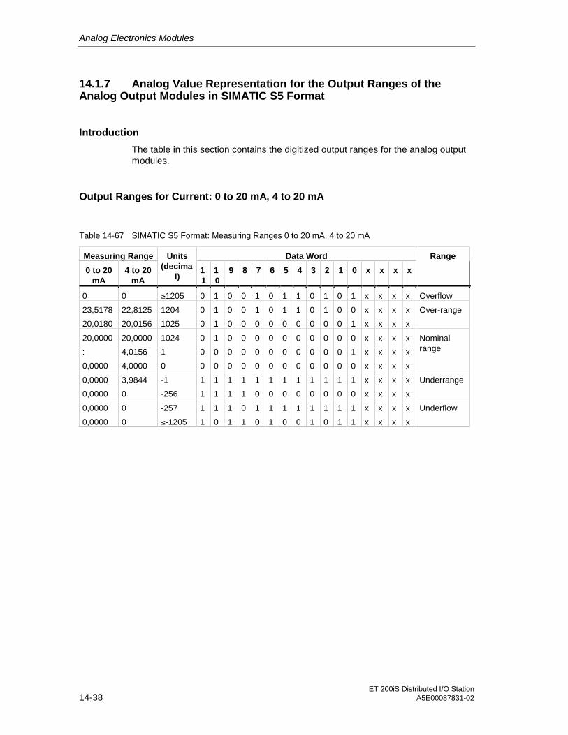
Analog Electronics Modules
ET 200iS Distributed I/O Station14-38 A5E00087831-02
14.1.7 Analog Value Representation for the Output Ranges of theAnalog Output Modules in SIMATIC S5 Format
Introduction
The table in this section contains the digitized output ranges for the analog outputmodules.
Output Ranges for Current: 0 to 20 mA, 4 to 20 mA
Table 14-67 SIMATIC S5 Format: Measuring Ranges 0 to 20 mA, 4 to 20 mA
Measuring Range Data Word
0 to 20mA
4 to 20mA
Units(decima
l)11
10
9 8 7 6 5 4 3 2 1 0 x x x x
Range
0 0 ≥1205 0 1 0 0 1 0 1 1 0 1 0 1 x x x x Overflow
23,5178
20,0180
22,8125
20,0156
1204
1025
0
0
1
1
0
0
0
0
1
0
0
0
1
0
1
0
0
0
1
0
0
0
0
1
x
x
x
x
x
x
x
x
Over-range
20,0000
:
0,0000
20,0000
4,0156
4,0000
1024
1
0
0
0
0
1
0
0
0
0
0
0
0
0
0
0
0
0
0
0
0
0
0
0
0
0
0
0
0
0
0
0
0
0
0
0
1
0
x
x
x
x
x
x
x
x
x
x
x
x
Nominalrange
0,0000
0,0000
3,9844
0
-1
-256
1
1
1
1
1
1
1
1
1
0
1
0
1
0
1
0
1
0
1
0
1
0
1
0
x
x
x
x
x
x
x
x
Underrange
0,0000
0,0000
0
0
-257
≤-1205
1
1
1
0
1
1
0
1
1
0
1
1
1
0
1
0
1
1
1
0
1
1
1
1
x
x
x
x
x
x
x
x
Underflow
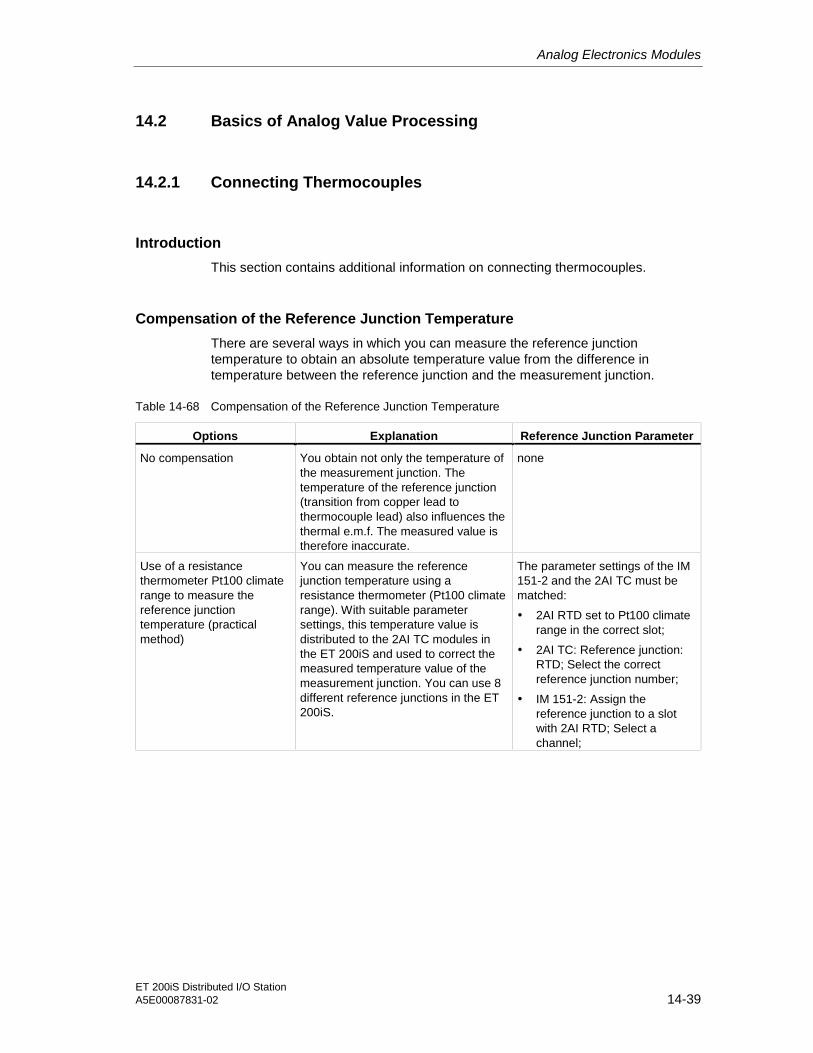
Analog Electronics Modules
ET 200iS Distributed I/O StationA5E00087831-02 14-39
14.2 Basics of Analog Value Processing
14.2.1 Connecting Thermocouples
Introduction
This section contains additional information on connecting thermocouples.
Compensation of the Reference Junction Temperature
There are several ways in which you can measure the reference junctiontemperature to obtain an absolute temperature value from the difference intemperature between the reference junction and the measurement junction.
Table 14-68 Compensation of the Reference Junction Temperature
Options Explanation Reference Junction Parameter
No compensation You obtain not only the temperature ofthe measurement junction. Thetemperature of the reference junction(transition from copper lead tothermocouple lead) also influences thethermal e.m.f. The measured value istherefore inaccurate.
none
Use of a resistancethermometer Pt100 climaterange to measure thereference junctiontemperature (practicalmethod)
You can measure the referencejunction temperature using aresistance thermometer (Pt100 climaterange). With suitable parametersettings, this temperature value isdistributed to the 2AI TC modules inthe ET 200iS and used to correct themeasured temperature value of themeasurement junction. You can use 8different reference junctions in the ET200iS.
The parameter settings of the IM151-2 and the 2AI TC must bematched:
• 2AI RTD set to Pt100 climaterange in the correct slot;
• 2AI TC: Reference junction:RTD; Select the correctreference junction number;
• IM 151-2: Assign thereference junction to a slotwith 2AI RTD; Select achannel;

Analog Electronics Modules
ET 200iS Distributed I/O Station14-40 A5E00087831-02
Extension to a Reference Junction
From their connection sides, the thermocouples can be extended by compensationcables as far as the reference junction (transition to copper wiring) or to thecompensation box. The reference junction can also be an ET 200iS terminalmodule.
The compensation cables are made of the same material as the wires of thethermocouple. The connecting cables are copper. When connecting up, make surethat you do not reverse the polarity.
Compensation by Resistance Thermometer on the 2AI RTD
If thermocouples connected to the inputs of the 2AI TC have the same referencejunction, compensate using a 2AI RTD.
For both channels of the 2AI TC module, you can select "RTD" or "none" as thereference junction. If you select "RTD", the same reference junction (RTD channel)is always used for both channels.
2
3
4
6
7
8
1 5
2
3
4
6
7
8
1 5
2
3
4
6
7
8
1 5
2
3
4
6
7
8
1 5
2AI RTD 2AI TC
M-
M+
IC+
M-
M+
IC-
Abbreviations:M+: measuring circuit positiveM-: measuring circuit negativeIC+: constant current line positiveIC-: constant current line
Insulated thermocouplewith externalcompensation by aresistance thermometerconnected to 2AI RTD(channel 0)
2AI RTD set to measuringrange Pt100 climate
Figure 14-1 Compensation by 2AI RTD

Analog Electronics Modules
ET 200iS Distributed I/O StationA5E00087831-02 14-41
Setting Parameters for the Reference Junction
You can set the reference junction for the 2AI TC electronics modules using thefollowing parameters:
Table 14-69 Reference Junction Parameters
Parameter Module Range of Values Explanation
Slot referencejunction 1 to slotreference junction8
IM 151-2 none, 4 to 35 With this parameter, you can assign upto 8 slots (none, 4 to 35), in which thechannels for reference temperaturemeasurement (calculating thecompensation value).
Input referencejunction 1 to inputreference junction8
IM 151-2 RTD on channel0 RTD onchannel 1
With this parameter you specify thechannel for reference temperaturemeasurement (calculating thecompensation value) for the relevantslot.
Reference junctionI0 and referencejunction I1
2AI TC none, RTD With these parameters, you can enablethe use of the reference junction.
Reference junctionnumber
2AI TC 1 to 8 With this parameter, you assign thereference junction (1 to 8) containing thereference temperature (compensationvalue).
Example of Parameter Assignment for Reference Junctions
• Structure: To simplify the situation, the following schematic shows only RTDand TC modules:
2A
IR
TD
K0
K1
2A
IR
TD
K0
K1
2A
IT
CK
0
K1
2A
IT
CK
0
K1
2A
IT
CK
0
K1
8 11 15 22 34 Slot
... ... ... ... ... ...
Referencejunction 1
Compensation with 2AI RTD modules
Example
Referencejunction 8
Figure 14-2 Example of Parameter Assignment for Reference Junctions

Analog Electronics Modules
ET 200iS Distributed I/O Station14-42 A5E00087831-02
• Relevant Parameters for the Interface Module IM 151-2
Table 14-70 Relevant Parameters for the Interface Module IM 151-2
Parameter Value
Slot reference junction 1 8
Input reference junction 1 RTD on channel 0
Slot reference junction 8 11
Input reference junction 8 RTD on channel 1
• Relevant Parameters for 2AI RTD and 2AI TC:
Table 14-71 Relevant Parameters for 2AI RTD and 2AI TC
Slot Parameter Value
8 (2AI RTD) Measurement type / range I0 4-wire (temperature) / Pt 100climate
11 (2AI RTD) Measurement type / range I1 4-wire (temperature) / Pt 100climate
Reference junction I0 RTD
Reference junction I1 none
Reference junction number 8
Measuring range I0 Type...
15 (2AI TC)
Measuring range I1 (any)
Reference junction I0 RTD
Reference junction I1 RTD
Reference junction number 1
Measuring range I0 Type...
22 (2AI TC)
Measuring range I1 Type...
Reference junction I0 none
Reference junction I1 RTD
Reference junction number 1
Measuring range I0 (any)
34 (2AI TC)
Measuring range I1 Type...
Uninsulated Thermocouples
If you use uninsulated thermocouples, make sure that you adhere to the permittedcommon mode voltage.

Analog Electronics Modules
ET 200iS Distributed I/O StationA5E00087831-02 14-43
14.3 Response of the Analog Modules during Operation and if FaultsOccur
Chapter Overview
This chapter describes the following:
• The dependence of the analog input and output values on the power supply ofthe electronics module and the operating states of the PLC.
• The response of the analog electronics modules depending on the location ofthe analog values in the relevant range.
• The influence of errors on the analog inputs/outputs.
• Use of the shield contact.
Influence of the Power Supply and the Operating State
The input and output values of the analog modules are dependent on the powersupply for electronics/sensors and on the operating state of the PLC (CPU of theDP master).
Table 14-72 Dependence of the Input and Output Values on the Operating State of the PLC (CPU of theDP master) and the Power Supply Voltage L+
Operating Stateof the PLC (CPU
of the DPMaster)
Supply Voltage L+on ET 200iS (Power
Supply Module)
Input Value of the ElectronicsModule with Analog Inputs(Evaluation Possible on the
CPU of the DP Master)
Output Value of theElectronics Module with
Analog Outputs
Process values PLC valuesPOWER ON
RUN L + present
7FFFH until first change afterstartup or after assignment ofparameters for the module iscompleted.
Until first value output:
• After startup, a signal of0 mA is output.
• Dependent on theparameter "CPU/ masterSTOP"
POWER ON
STOP L + present Process value Dependent on theparameter "CPU/ masterSTOP"
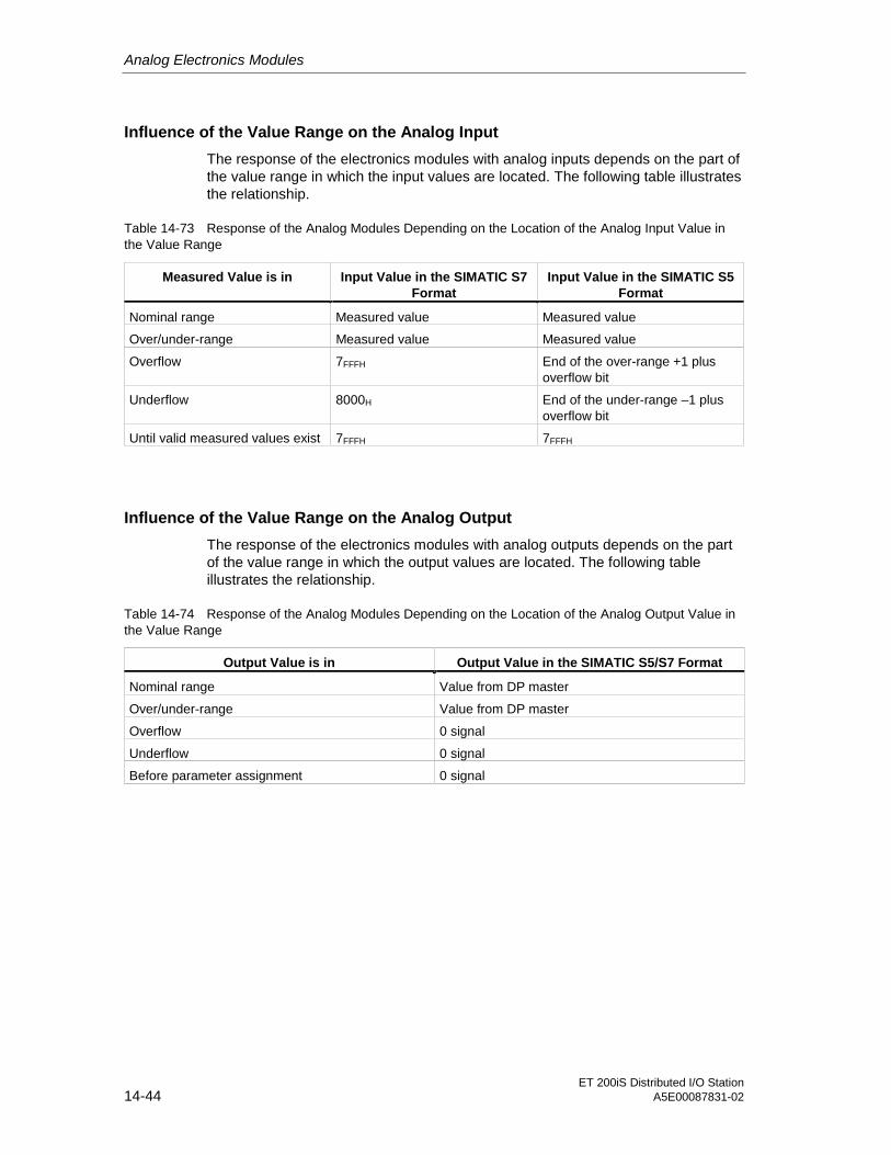
Analog Electronics Modules
ET 200iS Distributed I/O Station14-44 A5E00087831-02
Influence of the Value Range on the Analog Input
The response of the electronics modules with analog inputs depends on the part ofthe value range in which the input values are located. The following table illustratesthe relationship.
Table 14-73 Response of the Analog Modules Depending on the Location of the Analog Input Value inthe Value Range
Measured Value is in Input Value in the SIMATIC S7Format
Input Value in the SIMATIC S5Format
Nominal range Measured value Measured value
Over/under-range Measured value Measured value
Overflow 7FFFH End of the over-range +1 plusoverflow bit
Underflow 8000H End of the under-range –1 plusoverflow bit
Until valid measured values exist 7FFFH 7FFFH
Influence of the Value Range on the Analog Output
The response of the electronics modules with analog outputs depends on the partof the value range in which the output values are located. The following tableillustrates the relationship.
Table 14-74 Response of the Analog Modules Depending on the Location of the Analog Output Value inthe Value Range
Output Value is in Output Value in the SIMATIC S5/S7 Format
Nominal range Value from DP master
Over/under-range Value from DP master
Overflow 0 signal
Underflow 0 signal
Before parameter assignment 0 signal
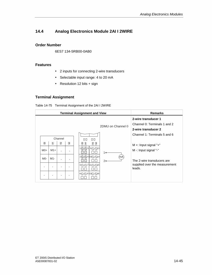
Analog Electronics Modules
ET 200iS Distributed I/O StationA5E00087831-02 14-45
14.4 Analog Electronics Module 2AI I 2WIRE
Order Number
6ES7 134-5RB00-0AB0
Features
• 2 inputs for connecting 2-wire transducers
• Selectable input range: 4 to 20 mA
• Resolution 12 bits + sign
Terminal Assignment
Table 14-75 Terminal Assignment of the 2AI I 2WIRE
Terminal Assignment and View Remarks
9 13
2 6 10 14
3 7 11 15
4 8 12 16
1 5
Channel
M0+ M1+
M0- M1-
- - - -
- - - -
0 1 2 3
1
2
0 1 2 3
2DMU on Channel 0
- -
- -mA
2-wire transducer 1
Channel 0: Terminals 1 and 2
2-wire transducer 2
Channel 1: Terminals 5 and 6
M +: Input signal "+"
M -: Input signal "-"
The 2-wire transducers aresupplied over the measurementleads.

Analog Electronics Modules
ET 200iS Distributed I/O Station14-46 A5E00087831-02
Block Diagram
Backplane businterface
µC Multiplexer,
converter
5 V
26 V
Inputs
1
2
5
6
Ba
ckp
lan
eb
us
Po
we
rbu
s
Figure 14-3 Block Diagram of the 2AI I 2WIRE
Technical Specifications
Table 14-76 Technical Specifications
Dimensions and Weight
DimensionsW x H x D (mm) 30 x 81 x 76
Weight approx. 120 g
Data Specific to the Module
Number of inputs 2
Cable length
• shielded max. 200m

Analog Electronics Modules
ET 200iS Distributed I/O StationA5E00087831-02 14-47
Data Specific to the Module
Type of Protection
• CENELEC II2(1)G EEx ib[ia] IIC T4 CE0344
• FM (applied for) Class Number 3611:
Class I, Division 2, Group A, B, C, D,Class I, Zone 2
Class Number 3610:
Class I, Zone 1
Voltages, Currents, Potentials
Power supply of the transducers yes
• Supply current max. 23mA (per channel)
• Short-circuit proof yes
Electrical isolation
• Between channels and backplane bus yes
• Between the channels No
• Between channels and load voltage(powerbus)
yes
• Between load voltage (powerbus) andbackplane bus
yes
Insulation tested with AC 500 V
Current consumption
• from load voltage L+ (powerbus) max. 280 mA
Power loss of the module typ. 3.36 W
Analog Value Formation
Measurement principle integrating (Sigma-Delta)
Integration / conversion time / resolution(per channel)
• Integration time selectable No
• Interference frequency suppression inHz
60; 50
• Basic conversion time includingintegration time (per channel) in ms
30
• Cycle time in ms Number of active channels per module xbasic conversion time
• Resolution (incl. over-range) 12 bits + sign
yes, selectable in 4 levels:
Level Time constant
none 1 x cycle time
weak 4 x cycle time
medium 32 x cycle time
Smoothing of measured values
strong 64 x cycle time

Analog Electronics Modules
ET 200iS Distributed I/O Station14-48 A5E00087831-02
Interference Suppression, Error Limits
Interference voltage suppression for f = n x(f1 ± 1 %), (f1 = interference frequency)
• Normal-mode interference (peak valueof the interference < nominal value ofthe input range)
min. 70 dB
Crosstalk between the inputs min. -50 dB
Operational limits (in the entire temperaturerange, relative to the input range)
± 0.15 %
Basic error limit (operational limit at 25°C,related to the input range)
± 0.1 %
Temperature error (relative to the inputrange)
± 0.03 %
Linearity error (relative to the input range) ± 0.0015 %
Repeatability (in the settled state at 25°C,relative to the input range)
± 0.01 %
Status, Interrupts, Diagnostic Information
Interrupts
• Limit value interrupt yes, selectable
• Diagnostic interrupt yes, selectable
Diagnostic Functions
• Group error display red LED "SF"
• Diagnostic information readable yes
Monitoring for
• Short circuit I < 23.8 mA*
• Wire break I < 3.6 mA
Data Relevant to Safety
See EU Prototype Test Certificate: KEMA 01 ATEX 1152 X
Data for Selecting a Sensor
Input ranges (nominal values) / inputresistance
• Current 4 to 20 mA
Permitted input current for current input(destruction limit)
90 mA
Connection of transducers
• For current measurement
As 2-wire transducer possible
• Load impedance of the 2-wiretransducer
max. 750 Ω
* I is in the current limitation. The current limitation cuts in at 27.2 mA. Short circuit at load impedance <
370 Ω.

Analog Electronics Modules
ET 200iS Distributed I/O StationA5E00087831-02 14-49
14.5 Analog Electronics Module 2AI I 4WIRE
Order Number
6ES7 134-5RB50-0AB0
Features
• 2 inputs for connecting 4-wire transducers
• Selectable input range: 0 to 20 mA / 4 to 20 mA
• Resolution 12 bits + sign
Terminal Assignment
Table 14-77 Terminal Assignment of the 2AI I 4WIRE
Terminal Assignment and View Remarks
9 13
2 6 10 14
3 7 11 15
4 8 12 16
1 5
Channel
M0+ M1+
M0- M1-
- - - -
- - - -
0 1 2 3
1
2
0 1 2 3
4DMU on channel 0
- -
- -mA
4-wire transducer 1
Channel 0: Terminals 1 and 2
4-wire transducer 2
Channel 1: Terminals 5 and 6
M +: Input signal "+"
M -: Input signal "-"
The 4-wire transducers are supplied externally by aseparate power supply.

Analog Electronics Modules
ET 200iS Distributed I/O Station14-50 A5E00087831-02
Block Diagram
Backplane businterface
µC
Multiplexer,
converter
5 V
Inputs
1
2
5
6
Backpla
ne
bus
Pow
erb
us
Figure 14-4 Block Diagram of the 2AI I 4WIRE
Technical Specifications
Table 14-78 Technical Specifications
Dimensions and Weight
DimensionsW x H x D (mm) 30 x 81 x 76
Weight approx. 120 g
Data for Specific Module
Number of inputs 2
Cable length
• shielded max. 200m
Type of Protection
• CENELEC II2(1)G EEx ib[ia] IIC T4 CE0344

Analog Electronics Modules
ET 200iS Distributed I/O StationA5E00087831-02 14-51
Data for Specific Module
• FM (applied for) Class Number 3611:
Class I, Division 2, Group A, B, C, D,Class I, Zone 2
Class Number 3610:
Class I, Zone 1
Voltages, Currents, Potentials
Power supply of the transducers No
Electrical isolation
• Between channels and backplane bus yes
• Between the channels No
• Between channels and load voltage(powerbus)
yes
• Between load voltage (powerbus) andbackplane bus
yes
Insulation tested with AC 500 V
Current consumption
• from load voltage L+ (powerbus) typ. 70 mA
Power loss of the module typ. 0.84 W
Analog Value Formation
Measurement principle integrating (Sigma-Delta)
Integration / conversion time / resolution(per channel)
• Integration time selectable yes
• Interference frequency suppression inHz
60, 50
• Integration time 16.7 ms; 20 ms
• Basic conversion time includingintegration time (per channel) in ms
30
• Cycle time in ms Number of active channels per module xbasic conversion time
• Resolution (incl. over-range) 12 bits + sign
yes, selectable in 4 levels:
Level Time constant
none 1 x cycle time
weak 4 x cycle time
medium 32 x cycle time
Smoothing of measured values
strong 64 x cycle time

Analog Electronics Modules
ET 200iS Distributed I/O Station14-52 A5E00087831-02
Interference Suppression, Error Limits
Interference voltage suppression for f = n x(f1 ± 1 %), (f1 = interference frequency)
• Normal-mode interference (peak valueof the interference < nominal value ofthe input range)
min. 70 dB
Crosstalk between the inputs min. -50 dB
Operational limits (in the entire temperaturerange, relative to the input range)
± 0.15 %
Basic error limit (operational limit at 25°C,related to the input range)
± 0.1 %
Temperature error (relative to the inputrange)
± 0.03 %
Linearity error (relative to the input range) ± 0.015 %
Repeatability (in the settled state at 25°C,relative to the input range)
± 0.01 %
Status, Interrupts, Diagnostic Information
Interrupts
• Limit value interrupt yes, selectable
• Diagnostic interrupt yes, selectable
Diagnostic Functions
• Group error display red LED "SF"
• Diagnostic information readable yes
Monitoring for
• Wire break I < 3.6 mA
Data Relevant to Safety
Input 4DMU *
See EU Prototype Test Certificate: KEMA 01 ATEX 1151 X
Data for Selecting a Sensor
Input ranges (nominal values) / inputresistance
• Current 0 to 20 mA/ min. 285 Ω
4 to 20 mA/ min. 285 Ω
Permitted input current for current input(destruction limit)
50 mA
Connection of transducers
• For current measurement
As 4-wire transducer possible
Internal resistance of the output for 4DMU min. 300 Ω* Output parameters are negligibly small.

Analog Electronics Modules
ET 200iS Distributed I/O StationA5E00087831-02 14-53
14.6 Analog Electronics Module 2AI RTD
Order Number
6ES7 134-5SB50-0AB0
Features
• 2 inputs for resistance thermometer or resistance measurement
• Input ranges:
– Resistance thermometer: Pt100; Ni100
– Resistance measurement: 600 ohms
• Electrically isolated from load voltage L+
• Linearization of the sensor characteristic curves
• Resolution 15 bits + sign
Terminal Assignment
The following table shows the terminal assignments of the 2AI RTD on the terminalmodule.
Table 14-79 Terminal Assignment of the 2AI RTD
Terminal Assignment and View Remarks
Resistancethermometer 1
Channel 0: Terminals 1to 4
Resistancethermometer 2
Channel 1:Terminals 5 to 8
M+: Measuring cablepositive
M-: Measuring cablenegative
9 13
2 6 10 14
3 7 11 15
4 8 12 16
1 5
Channel
I +C0 I +C1
I -C0 I -C1
- -
- -
0 1 2 3 0 1 2 3
Resistance thermometeron channel 0
- -
- -
1
2
1
2
3
1
2
3
4
2-wire 3-wire 4-wireM0+ M1+
M0- M1-
Ic+: Constant currentcable positive
Ic-: Constant currentcable negative

Analog Electronics Modules
ET 200iS Distributed I/O Station14-54 A5E00087831-02
Block Diagram
Backplane businterface
µC Multiplexer,
converter
5 V
Inputs
1
2
5
6
3
4
7
8
Backpla
ne
bus
Pow
erb
us
Figure 14-5 Block Diagram of the 2AI RTD
Technical Specifications
Table 14-80 Technical Specifications
Dimensions and Weight
DimensionsW x H x D (mm) 30 x 81 x 52
Weight approx. 120 g
Data Specific to the Module
Number of inputs 2
• with resistance-type sensor 2
Cable length
• shielded max. 200m
Type of Protection
• CENELEC II2(1)G EEx ib[ia] IIC T4 CE0344

Analog Electronics Modules
ET 200iS Distributed I/O StationA5E00087831-02 14-55
Data Specific to the Module
• FM (applied for) Class Number 3611:
Class I, Division 2, Group A, B, C, D,Class I, Zone 2
Class Number 3610:
Class I, Zone 1
Voltages, Currents, Potentials
Constant measurement current forresistance-type sensor
typ. 1 mA
Electrical isolation
• Between channels and backplane bus yes
• Between the channels No
• Between channels and load voltage(powerbus)
yes
• Between load voltage (powerbus) andbackplane bus
yes
Insulation tested with AC 500 V
Current consumption
• from load voltage L+ (powerbus) typ. 70 mA
Power loss of the module typ. 0.84 W
Analog Value Formation
Measurement principle integrating (Sigma-Delta)
Integration / conversion time / resolution(per channel)
• Integration time selectable yes
• Interference frequency suppression inHz
60; 50
• Integration time in ms 66; 80
• Basic conversion time includingintegration time (per channel) in ms
66; 80
• Additional conversion time for wire breakcheck in ms
5
• Cycle time in ms Number of active channels per module xbasic conversion time
• Resolution (incl. over-range) 15 bits + sign
yes, selectable in 4 levels:
Level Time constant
none 1 x cycle time
weak 4 x cycle time
medium 32 x cycle time
Smoothing of measured values
strong 64 x cycle time

Analog Electronics Modules
ET 200iS Distributed I/O Station14-56 A5E00087831-02
Interference Suppression, Error Limits
Interference voltage suppression for f = n x(f1 ± 1 %), (f1 = interference frequency)
• Common-mode interference (UCM < 60V)
min. 90 dB
• Normal-mode interference (peak valueof the interference < nominal value ofthe input range)
min. 70 dB
Crosstalk between the inputs min. -50 dB
Operational limits (in the entire temperaturerange, relative to the input range)
± 0.8 K standard range± 0.3 K climatic range
Basic error limit (operational limit at 25°C,related to the input range)
± 0.5 K standard range± 0.2 K climatic range
Temperature error (relative to the inputrange)
± 0.03 %
Linearity error (relative to the input range) ± 0.015 %
Repeatability (in the settled state at 25°C,relative to the input range)
± 0.01 %
Status, Interrupts, Diagnostic Information
Interrupts
• Limit value interrupt yes, selectable
• Diagnostic interrupt yes, selectable
Diagnostic Functions
• Group error display red LED "SF"
• Diagnostic information readable yes
Data Relevant to Safety
See EU Prototype Test Certificate: KEMA 01 ATEX 1153 X
Data for Selecting a Sensor
Input ranges (nominal values) / inputresistance
• Resistance 600 ohms / min. 2 Mohms
• Resistance thermometer Pt100 / min. 2 MohmsNi100 / min. 2 Mohms
Connection of transducers
• For resistance measurement / RTD
4-wire connection possible
3-wire connection possible
2-wire connection possible
Characteristic curve linearization yes
• For resistance Nominal range linearized to 0 to 100% forresistance-type sensor (600 ohms),absolute

Analog Electronics Modules
ET 200iS Distributed I/O StationA5E00087831-02 14-57
Interference Suppression, Error Limits
• For passive resistance thermometer Pt100; Ni100
Technical unit for data formats Parameters can be assigned* Line compensation possible with SIMATIC PDM
14.7 Analog Electronics Module 2AI TC
Order Number
6ES7 134-5SB00-0AB0
Features
• 2 inputs for thermocouple or voltage measurement
• Input ranges:
– Thermal e.m.f. measurement: +/- 80 mV
– Thermocouples: types E, N, J, K, L, S, R, B, T, U
– Electrically isolated from load voltage L+
• Linearization of the sensor characteristic curves
• Permitted common-mode voltage DC 6.5 V, AC 30 VPP
• Resolution 15 bits + sign
Terminal Assignment
The following table shows the terminal assignments of the 2AI TC on the terminalmodule.
Table 14-81 Terminal Assignment of the 2AI TC
Terminal Assignment and View Remarks
Thermocouple 1
Channel 0: Terminals 1 and 2
Thermocouple 2
Channel 1: Terminals 5 and 6
9 13
2 6 10 14
3 7 11 15
4 8 12 16
1 5
Channel
M0+ M1+
M0- M1-
- - - -
- - - -
0 1 2 3
1
2
0 1 2 3
Thermocouple on channel 0
- -
- -
M+: Measuring cable positive
M-: Measuring cable negative

Analog Electronics Modules
ET 200iS Distributed I/O Station14-58 A5E00087831-02
Block Diagram
Backplane businterface
µC Opto-Multiplexer,
converter
5 V
Inputs
1
2
5
6
Ba
ckp
lan
eb
us
Po
we
rbu
s
Figure 14-6 Block Diagram of the 2AI TC
Technical Specifications
Table 14-82 Technical Specifications
Dimensions and Weight
DimensionsW x H x D (mm) 30 x 81 x 52
Weight approx. 120 g
Data Specific to the Module
Number of inputs 2
Cable length
• shielded max. 50m
Type of Protection
• CENELEC
II2(1)G EEx ib[ia] IIC T4 CE0344
• FM (applied for) Class Number 3611:
Class I, Division 2, Group A, B, C, D,Class I, Zone 2
Class Number 3610:
Class I, Zone 1

Analog Electronics Modules
ET 200iS Distributed I/O StationA5E00087831-02 14-59
Voltages, Currents, Potentials
Electrical isolation
• Between channels and backplane bus yes
• Between the channels yes, functional
• Between channels and load voltage(powerbus)
yes
• Between load voltage (powerbus) andbackplane bus
yes
Permitted potential difference
• between the inputs (UCM) DC 6,5 V; AC 30 V
Insulation tested with AC 500 V
Current consumption
• from load voltage L+ (powerbus) typ. 70 mA
Power loss of the module typ. 0.84 W
Analog Value Formation
Measurement principle integrating (Sigma-Delta)
Integration / conversion time / resolution(per channel)
• Integration time selectable yes
• Interference frequency suppression inHz
60; 50
• Integration time in ms 66; 80
• Basic conversion time includingintegration time (per channel) in ms
min. 66; min. 80
• Additional conversion time for wire breakmonitoring in ms
5
• Resolution (incl. over-range) 15 bits + sign
yes, selectable in 4 levels:
Level Time constant
none 1 x cycle time
weak 4 x cycle time
medium 32 x cycle time
Smoothing of measured values
strong 64 x cycle time
Interference Suppression, Error Limits
Interference voltage suppression for f = n x(f1 ± 1 %), (f1 = interference frequency)
• Common-mode interference (UCM < 60V)
min. 90 dB
• Normal-mode interference (peak valueof the interference < nominal value ofthe input range)
min. 70 dB
Crosstalk between the inputs min. -50 dB
Operational limits (in the entire temperaturerange, relative to the input range)
± 1.5 K
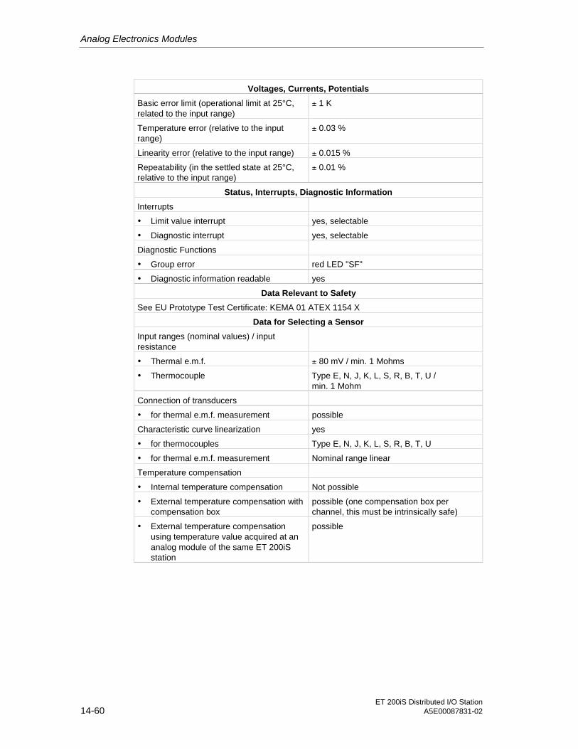
Analog Electronics Modules
ET 200iS Distributed I/O Station14-60 A5E00087831-02
Voltages, Currents, Potentials
Basic error limit (operational limit at 25°C,related to the input range)
± 1 K
Temperature error (relative to the inputrange)
± 0.03 %
Linearity error (relative to the input range) ± 0.015 %
Repeatability (in the settled state at 25°C,relative to the input range)
± 0.01 %
Status, Interrupts, Diagnostic Information
Interrupts
• Limit value interrupt yes, selectable
• Diagnostic interrupt yes, selectable
Diagnostic Functions
• Group error red LED "SF"
• Diagnostic information readable yes
Data Relevant to Safety
See EU Prototype Test Certificate: KEMA 01 ATEX 1154 X
Data for Selecting a Sensor
Input ranges (nominal values) / inputresistance
• Thermal e.m.f. ± 80 mV / min. 1 Mohms
• Thermocouple Type E, N, J, K, L, S, R, B, T, U /min. 1 Mohm
Connection of transducers
• for thermal e.m.f. measurement possible
Characteristic curve linearization yes
• for thermocouples Type E, N, J, K, L, S, R, B, T, U
• for thermal e.m.f. measurement Nominal range linear
Temperature compensation
• Internal temperature compensation Not possible
• External temperature compensation withcompensation box
possible (one compensation box perchannel, this must be intrinsically safe)
• External temperature compensationusing temperature value acquired at ananalog module of the same ET 200iSstation
possible

Analog Electronics Modules
ET 200iS Distributed I/O StationA5E00087831-02 14-61
14.8 Analog Electronics Module 2AO I
Order Number
6ES7 135-5RB00-0AB0
Features
• 2 outputs for current output
• Output range (selectable)
– 4 to 20 mA
– 0 to 20 mA
• Electrically isolated from load voltage L+
• Resolution 14 bits
Terminal Assignment
The following table shows the terminal assignments of the 2AO I on the terminalmodule.
Table 14-83 Terminal Assignment of the 2AO I
Terminal Assignment and View Remarks
Actuator 1
Channel 0: Terminals 3 and 4
Actuator 2
Channel 1: Terminals 7 and 8
9 13
2 6 10 14
3 7 11 15
4 8 12 16
1 5
Channel
QI0 QI1
M0- M1-
- - - -
- - - -
0 1 2 3
3
4
0 1 2 3
Actuator on channel 0
- -
- -
QI: Positive output (analog output current)
M: Chassis ground

Analog Electronics Modules
ET 200iS Distributed I/O Station14-62 A5E00087831-02
Block Diagram
Backplane businterface
µC Currentcontroller,
converter
5 V
26 V
Outputs
3
4
7
8
Ba
ckp
lan
eb
us
Po
we
rbu
s
Figure 14-7 Block Diagram of the 2AO I

Analog Electronics Modules
ET 200iS Distributed I/O StationA5E00087831-02 14-63
Technical Specifications
Table 14-84 Technical Specifications
Dimensions and Weight
DimensionsW x H x D (mm) 30 x 81 x 76
Weight approx. 120 g
Data Specific to the Module
Number of outputs 2
Cable length
• shielded max. 200m
Type of Protection
• CENELEC II2(1)G EEx ib[ia] IIC T4 CE0344
• FM (applied for) Class Number 3611:
Class I, Division 2, Group A, B, C, D,Class I, Zone 2
Class Number 3610:
Class I, Zone 1
Voltages, Currents, Potentials
Electrical isolation
• Between channels and backplane bus yes
• Between the channels No
• Between channels and load voltage(powerbus)
yes
• Between load voltage (powerbus) andbackplane bus
yes
Insulation tested with AC 500 V
Current consumption max. 230 mA
• from load voltage L+ (powerbus) typ. 280 mA
Power loss of the module typ. 2.5 W
Analog Value Formation
Resolution (incl. over-range) 14 bits
Cycle time 3.5 ms
Settling Time
• for resistive load max. 40 ms
• for capacitive load max. 40 ms
• for inductive load max. 40 ms
Substitute values connectable yes

Analog Electronics Modules
ET 200iS Distributed I/O Station14-64 A5E00087831-02
Interference Suppression, Error Limits
Crosstalk between the outputs min. - 50 dB
Operational limits (in the entire temperaturerange, relative to the output range)
± 0.2 %
Basic error limit (operational limit at 25°C,related to the output range)
± 0.1 %
Temperature error (relative to the outputrange)
± 0.01 % / K
Linearity error (relative to the output range) ± 0.02 %
Repeatability (in the settled state at 25°C,relative to the output range)
± 0.05 %
Output ripple; Bandwidth 0 to 50 kHz(relative to the output range)
± 0.05 %
Status, Interrupts, Diagnostic Information
Interrupts
• Diagnostic interrupt yes, selectable
Diagnostic Functions
• Group error display red LED "SF"
• Diagnostic information readable yes
Monitoring for
• Short circuit R* < 30 Ω
• Wire break R* > 30 kΩ
Substitute values connectable yes, selectable
Data Relevant to Safety
See EU Prototype Test Certificate: KEMA 01 ATEX 1155 X
Data for Selecting an Actuator
Output ranges (nominal values)
• Current 0 to 20 mA / 4 to 20 mA
Load impedance (in the nominal range ofthe output)
max. 750 Ω*
• No-load voltage 17 V
Connection of actuators
• for current output
2-wire connection possible* R = load impedance + cable resistance

Analog Electronics Modules
ET 200iS Distributed I/O StationA5E00087831-02 14-65
14.9 Parameters of the Analog Electronics Modules
Parameters of 2AI I 2WIRE, 2AI I 4WIRE
All parameters are set with SIMATIC PDM.
Table 14-85 Parameters of 2AI I 2WIRE, 2AI I 4WIRE
Parameter
2AI I 2WIRE 2AI I 4WIRE
Range of Values Default Effectivefor
Format of the analog values * • SIMATIC S7
• SIMATIC S5
SIMATIC S7 ET 200iS
Interference frequency suppression * • 50 Hz
• 60 Hz
50 Hz ET 200iS
Channel x ( x = 0, 1)
Measurementtype
--- 2DMU (current) 2DMU (current) Channel
--- Measurement type • 4DMU (current)
• deactivated
4DMU (current) Channel
MeasuringRange
--- 4 to 20 mA 4 to 20 mA Channel
--- Measuring Range • 4 to 20 mA
• 0 to 20 mA
4 to 20 mA Channel
Smoothing • none
• weak
• medium
• strong
none Channel
Process alarm (when limit valueexceeded)
• enabled
• disabled
enabled Channel
Upper limit value Lower to upper value of theover-range
Upper nominalvalue
Channel
Lower limit value Lower to upper value of theover-range
Lower nominalvalue
Channel
Group diagnostics • enabled
• disabled
enabled Channel
Overflow/underflow diagnostics • enabled
• disabled
enabled Channel
Wire break diagnostics • enabled
• disabled
enabled Channel
Short circuitdiagnostics
--- • enabled
• disabled
enabled Channel
* Entered automatically by SIMATIC PDM. See IM 151-2 parameters.

Analog Electronics Modules
ET 200iS Distributed I/O Station14-66 A5E00087831-02
Parameters of 2AI RTD, 2AI TC
All parameters are set with SIMATIC PDM.
Table 14-86 Parameters of 2AI RTD, 2AI TC
Parameter
2AI RTD 2AI TC
Range of Values Default Effectivefor
Format of the analog values * • SIMATIC S7
• SIMATIC S5
SIMATIC S7 ET 200iS
Interference frequency suppression * • 50 Hz
• 60 Hz
50 Hz ET 200iS
Temperature unit* • Celsius
• Fahrenheit
Celsius ET 200iS
Reference junction number 1 to 8 1 Module
Channel x ( x = 0, 1)
Measurementtype
--- • 4-wire (temperature)
• 3-wire (temperature)
• 2-wire (temperature)
• 4-wire (resistance)
• 3-wire (resistance)
• 2-wire (resistance)
4-wire(temperature)
Channel
--- Measurement type • Thermocouple
• Thermal e.m.f.
• deactivated
Thermocouple
Channel
MeasuringRange
--- • Pt 100 standard range
• Pt 100 climate range
• Ni 100 standard range
• Ni 100 climate range
• 600 Ω (absolute)
Pt 100standardrange
Channel
--- Measuring Range • Type B [PtRh-PtRh]
• Type N [NiCrSi-NiSi]
• Type E [NiCr-CuNi]
• Type R [PtRh-Pt]
• Type S [PtPh-Pt]
• Type J [Fe-CuNi]
• Type L [Fe-CuNi]
• Type T [Cu-CuNi]
• Type K [NiCr-Ni]
• Type U [Cu-CuNi]
• ± 80 mV
Type K [NiCr-Ni]
Channel

Analog Electronics Modules
ET 200iS Distributed I/O StationA5E00087831-02 14-67
Parameter
2AI RTD 2AI TC
Range of Values Default Effectivefor
Referencejunction
--- • none
• RTD
none Channel
--- Reference junction • none none Channel
Smoothing • none
• weak
• medium
• strong
none Channel
Process alarm (when limit valueexceeded)
• enabled
• disabled
enabled Channel
Upper limit value Lower to upper limit value of theover-range
Upper limitvalue
Channel
Lower limit value Lower to upper limit value of theover-range
Lower limitvalue
Channel
Group diagnostics • enabled
• disabled
enabled Channel
Overflow/underflow diagnostics • enabled
• disabled
enabled Channel
Wire break diagnostics • enabled
• disabled
enabled Channel
Short circuitdiagnostics
--- • enabled
• disabled
enabled Channel
* Entered automatically by SIMATIC PDM. See IM 151-2 parameters.** Does not exist for Pt 100 climate range, Ni 100 climate range

Analog Electronics Modules
ET 200iS Distributed I/O Station14-68 A5E00087831-02
Parameters of 2AO I
All parameters are set with SIMATIC PDM.
Table 14-87 Parameters of 2AO I
Parameters of 2AO I Range of Values Default Effective for
Format of the analogvalues *
• SIMATIC S7
• SIMATIC S5
SIMATIC S7 ET 200iS
Channel x ( x = 0, 1)
Output type • I (current)
• deactivated
I (current) Channel
Output range • 4 to 20 mA
• 0 to 20 mA
4 to 20 mA Channel
Response to CPU/ masterSTOP
• Output no current/voltage
• Apply substitute value
• Hold last value
Output nocurrent/voltage
Channel
Substitute value Every value of the nominalrange
4.0000 mA Channel
Group diagnostics • enabled
• disabled
enabled Channel
Wire break diagnostics • enabled
• disabled
enabled Channel
Short circuit diagnostics • enabled
• disabled
enabled Channel
* Entered automatically by SIMATIC PDM. See IM 151-2 parameters.
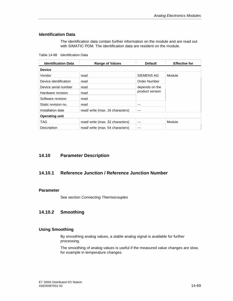
Analog Electronics Modules
ET 200iS Distributed I/O StationA5E00087831-02 14-69
Identification Data
The identification data contain further information on the module and are read outwith SIMATIC PDM. The identification data are resident on the module.
Table 14-88 Identification Data
Identification Data Range of Values Default Effective for
Device
Vendor read SIEMENS AG
Device identification read Order Number
Device serial number read
Hardware revision read
Software revision read
depends on theproduct version
Static revision no. read ---
Installation date read/ write (max. 16 characters) ---
Module
Operating unit
TAG read/ write (max. 32 characters) ---
Description read/ write (max. 54 characters) ---
Module
14.10 Parameter Description
14.10.1 Reference Junction / Reference Junction Number
Parameter
See section Connecting Thermocouples
14.10.2 Smoothing
Using Smoothing
By smoothing analog values, a stable analog signal is available for furtherprocessing.
The smoothing of analog values is useful if the measured value changes are slow,for example in temperature changes.

Analog Electronics Modules
ET 200iS Distributed I/O Station14-70 A5E00087831-02
Parameter
The measured values are smoothed using digital filters. Smoothing is achieved bythe module forming a mean value from a specified number of converted (digitized)analog values.
The user can set the smoothing in a maximum of four stages (none, weak,medium, strong). The stage determines the number of analog signals used to formthe mean value.
The stronger the smoothing, the more stable the smoothed analog value and thelonger it takes until the smoothed analog signal is applied following a stepresponse (refer to the following example).
Example
The following schematic illustrates the number of module cycles it takes for thesmoothed analog value to be applied at approaching 100% following a stepresponse depending on the selected smoothing. The schematic applies to everysignal change at the analog input.
50
100
0
63
100 200 300
Module cycles
400 500 600
x x x x
Step response for any analog input signal
Smoothing weakmediumstrong
Signal changein percent
Figure 14-8 Example of the Influence of Smoothing on the Step Response
14.10.3 Identification Data
See also
Identification Data [ Page 12-8]

ET 200iS Distributed I/O StationA5E00087831-02 15-1
15Analog Electronics Modules with HART 1515.1 Basics of HART
15.1.1 What is HART?
What is HART?
With the HART functionality, you can operate analog modules with additional digitalcommunications options. The HART protocol has become established as the "defacto" standard protocol for communication with intelligent field devices: HART is aregistered trademark of the "HART Communication Foundation" (HCF) that ownsall the rights for the HART protocol.
Note
The HART analog modules are based on the HART protocol Version 5.2.
What Are the Advantages of HART
Using HART analog modules has the following advantages:
• Compatible connection with the analog modules: current loop 4 - 20 mA
• Additional digital communication using the HART protocol
• Low energy requirements of HART, important for use in the hazardous area
• Numerous field device with HART functions are in use
What Are the Typical Applications for HART?
The following applications are typical for HART:
• Commissioning of field devices (centralized parameter assignment)
• Online modification of field device parameters
• Information, maintenance and diagnostic displays for the field devices

Analog Electronics Modules with HART
ET 200iS Distributed I/O Station15-2 A5E00087831-02
15.1.2 How Does HART Work?
Introduction
The HART protocol describes the physical form of the transfer:
Transmission procedures, message structure, data formats and commands.
HART Signal
The following schematic shows the analog signal with the HART signalsuperimposed on it (FSK technique). The signal is composed of sine waves of1200 Hz and 2200 Hz having an average value of zero. It can be filtered out usingan input filter so that the original analog signal is available again.
+0.5 mA
0
-0.5 mA1200 Hz
"1"2200 Hz
"0"
Analog signal
4 mA
20 mA
Time (seconds)
R=response
CR C R C
R
C=command
0
Figure 15-1 The HART Signal

Analog Electronics Modules with HART
ET 200iS Distributed I/O StationA5E00087831-02 15-3
HART Commands and Parameters
With SIMATIC PDM, you can set the parameters of the HART field devices usingHART commands and read them out with the HART response messages. HARTcommands and their parameters are divided into three groups with the followingproperties:
• universal
• common practice
• device-specific
Universal commands must be supported by all manufacturers of HART fielddevices and common practice commands should be supported. There are alsocommands specific to the device that apply only to the particular device.
Examples of HART Parameters
The following table shows the HART parameters of the various groups:
Table 15-1 Examples of HART Parameters
Parameter Group Parameters of the HART Field Device
universal Measured value or manipulated variable(primary variable), manufacturer, tag, oridentifier for actuator, other measuredvalues or manipulated variables
common practice Measuring range, filter time, alarmparameters (message, alarm and warninglimits, output range
Device-specific Special diagnostic information
15.1.3 How Are HART Field Devices Used with the ET 200iS
Use in the ET 200iS
With a HART analog module, you can connect a field device to each of the twochannels: The module operates as the HART master, the field devices as HARTslaves.
SIMATIC PDM sends and receives data via the HART analog module, comparablewith a client served by the HART analog module.

Analog Electronics Modules with HART
ET 200iS Distributed I/O Station15-4 A5E00087831-02
ET 200iS in enclosure
2AI I 2WIRE HART = HART master 2AO I HART = HART master
Lowestlevel
Transducers Actuators
e.g.SIPART PS
HART slave
Smart fielddevices, e.g.SITRAS P
Figure 15-2 Location of the HART Analog Modules in the Distributed System
15.1.4 How Do You Use HART?
System Environment for Using HART
To operate an intelligent field device with HART functionality, you require thefollowing system environment:
Current loop 4 – 20 mA via the analog electronics modules: 2AI I 2WIRE HART,2AI I 4WIRE HART or 2AO I HART
The HART analog module takes over the function of a "master" by receiving thecommands from the HART parameter assignment tool, passing them on to thesmart field device and then returning the reply messages. The interface of theHART analog module is made up data records that are transferred over the I/Obus. These data records are generated and interpreted by the HART parameterassignment tool (SIMATIC PDM).
Only the primary variable of the measured value is entered in the process imageinput and output tables.
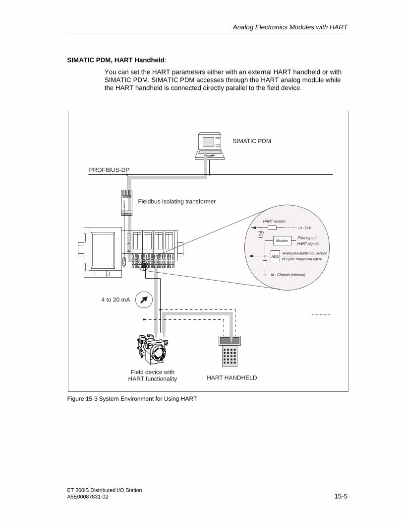
Analog Electronics Modules with HART
ET 200iS Distributed I/O StationA5E00087831-02 15-5
SIMATIC PDM, HART Handheld:
You can set the HART parameters either with an external HART handheld or withSIMATIC PDM. SIMATIC PDM accesses through the HART analog module whilethe HART handheld is connected directly parallel to the field device.
L+: 24V
ADU
HART resistor
Analog-to-digital conversion
of cyclic measured value
ModemFiltering out
M : Chassis (internal)
HART signals
PROFIBUS-DP
SIMATIC PDM
Fieldbus isolating transformer
4 to 20 mA
HART HANDHELDField device with
HART functionality
Figure 15-3 System Environment for Using HART
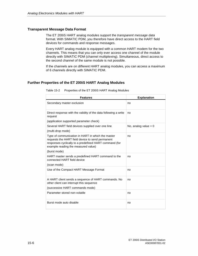
Analog Electronics Modules with HART
ET 200iS Distributed I/O Station15-6 A5E00087831-02
Transparent Message Data Format
The ET 200iS HART analog modules support the transparent message dataformat. With SIMATIC PDM, you therefore have direct access to the HART fielddevices for commands and response messages.
Every HART analog module is equipped with a common HART modem for the twochannels. This means that you can only ever access one channel of the moduledirectly with SIMATIC PDM (channel multiplexing). Simultaneous, direct access tothe second channel of the same module is not possible.
If the channels are on different HART analog modules, you can access a maximumof 6 channels directly with SIMATIC PDM.
Further Properties of the ET 200iS HART Analog Modules
Table 15-2 Properties of the ET 200iS HART Analog Modules
Features Explanation
Secondary master exclusion no
Direct response with the validity of the data following a writerequest
(application supported parameter check)
no
Several HART field devices supplied over one line
(multi-drop mode)
No, analog value = 0
Type of communication in HART in which the masterrequests the HART field device to send permanentresponses cyclically to a predefined HART command (forexample reading the measured value)
(burst mode)
no
HART master sends a predefined HART command to theconnected HART field device
(scan mode)
no
Use of the Compact HART Message Format no
A HART client sends a sequence of HART commands. Noother client can interrupt this sequence
(successive HART commands mode)
no
Parameter stored non-volatile no
Burst mode auto disable no

Analog Electronics Modules with HART
ET 200iS Distributed I/O StationA5E00087831-02 15-7
Features Explanation
Maximum PDU length 64 bytes (corresponds to 75byte data record in thetransparent message dataformat)
Client management No, only 1 client per channel(2 "mailboxes" per module)
15.2 Analog Value Representation
See also
Overview [ Page 14-1]
15.3 Basics of Analog Value Processing
See also
Connecting Thermocouples [ Page 14-33]
15.4 Response of the Analog Modules with HART during Operationand if Problems Occur
See also
Response of the Analog Modules during Operation and if FaultsOccur [ Page 14-43]
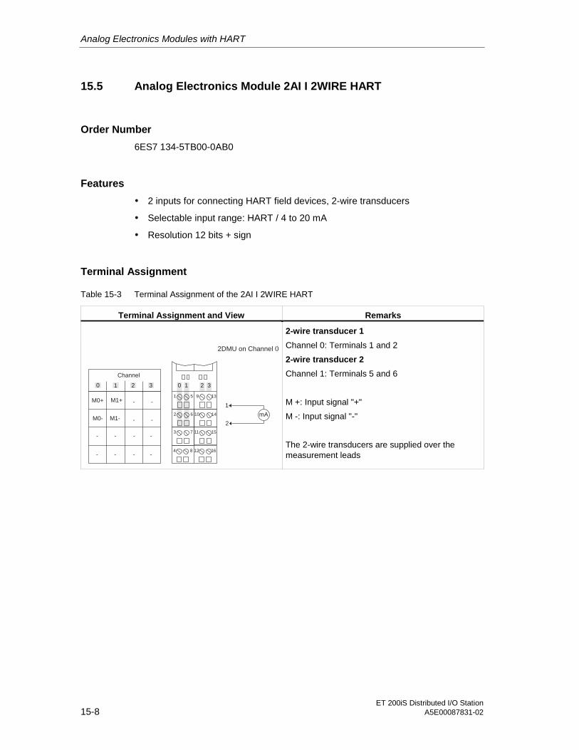
Analog Electronics Modules with HART
ET 200iS Distributed I/O Station15-8 A5E00087831-02
15.5 Analog Electronics Module 2AI I 2WIRE HART
Order Number
6ES7 134-5TB00-0AB0
Features
• 2 inputs for connecting HART field devices, 2-wire transducers
• Selectable input range: HART / 4 to 20 mA
• Resolution 12 bits + sign
Terminal Assignment
Table 15-3 Terminal Assignment of the 2AI I 2WIRE HART
Terminal Assignment and View Remarks
9 13
2 6 10 14
3 7 11 15
4 8 12 16
1 5
Channel
M0+ M1+
M0- M1-
- - - -
- - - -
0 1 2 3
1
2
0 1 2 3
2DMU on Channel 0
- -
- -mA
2-wire transducer 1
Channel 0: Terminals 1 and 2
2-wire transducer 2
Channel 1: Terminals 5 and 6
M +: Input signal "+"
M -: Input signal "-"
The 2-wire transducers are supplied over themeasurement leads

Analog Electronics Modules with HART
ET 200iS Distributed I/O StationA5E00087831-02 15-9
Block Diagram
Backplane businterface
µC Multiplexer,
converter
5 V
26 V
Inp
uts
1
2
5
6
Ba
ckp
lan
eb
us
Po
we
rbu
s
HARTmodem
Figure 15-4 Block Diagram of the 2AI I 2WIRE HART

Analog Electronics Modules with HART
ET 200iS Distributed I/O Station15-10 A5E00087831-02
Technical Specifications
Table 15-4 Technical Specifications
Dimensions and Weight
DimensionsW x H x D (mm) 30 x 81 x 76
Weight approx. 120 g
Data Specific to the Module
Number of inputs 2
Cable length
• shielded max. 200m
Type of Protection
• CENELEC II2(1)G EEx ib[ia] IIC T4 CE0344
• FM (applied for) Class Number 3611:
Class I, Division 2, Group A, B, C, D,Class I, Zone 2
Class Number 3610:
Class I, Zone 1
Voltages, Currents, Potentials
Power supply of the transducers yes
• Supply current max. 23mA (per channel)
• Short-circuit proof yes
Electrical isolation
• Between channels and backplane bus yes
• Between the channels No
• Between channels and load voltage(powerbus)
yes
• Between load voltage (powerbus) andbackplane bus
yes
Insulation tested with AC 500 V
Current consumption
• from load voltage L+ (powerbus) typ. 280 mA
Power loss of the module typ. 3.36 W
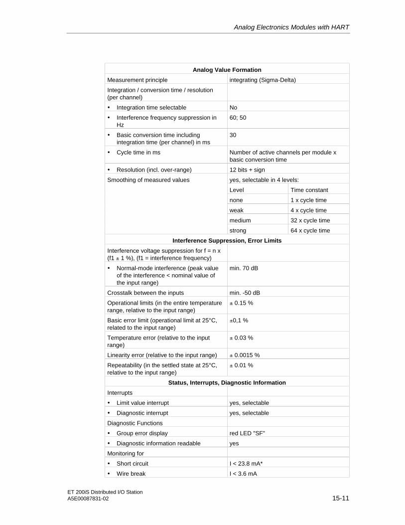
Analog Electronics Modules with HART
ET 200iS Distributed I/O StationA5E00087831-02 15-11
Analog Value Formation
Measurement principle integrating (Sigma-Delta)
Integration / conversion time / resolution(per channel)
• Integration time selectable No
• Interference frequency suppression inHz
60; 50
• Basic conversion time includingintegration time (per channel) in ms
30
• Cycle time in ms Number of active channels per module xbasic conversion time
• Resolution (incl. over-range) 12 bits + sign
yes, selectable in 4 levels:
Level Time constant
none 1 x cycle time
weak 4 x cycle time
medium 32 x cycle time
Smoothing of measured values
strong 64 x cycle time
Interference Suppression, Error Limits
Interference voltage suppression for f = n x(f1 ± 1 %), (f1 = interference frequency)
• Normal-mode interference (peak valueof the interference < nominal value ofthe input range)
min. 70 dB
Crosstalk between the inputs min. -50 dB
Operational limits (in the entire temperaturerange, relative to the input range)
± 0.15 %
Basic error limit (operational limit at 25°C,related to the input range)
±0,1 %
Temperature error (relative to the inputrange)
± 0.03 %
Linearity error (relative to the input range) ± 0.0015 %
Repeatability (in the settled state at 25°C,relative to the input range)
± 0.01 %
Status, Interrupts, Diagnostic Information
Interrupts
• Limit value interrupt yes, selectable
• Diagnostic interrupt yes, selectable
Diagnostic Functions
• Group error display red LED "SF"
• Diagnostic information readable yes
Monitoring for
• Short circuit I < 23.8 mA*
• Wire break I < 3.6 mA

Analog Electronics Modules with HART
ET 200iS Distributed I/O Station15-12 A5E00087831-02
Data Relevant to Safety
See EU Prototype Test Certificate: KEMA 01 ATEX 1152 X
Data for Selecting a Sensor
Input ranges (nominal values) / inputresistance
• Current 0 to 20 mA
4 to 20 mA
Permitted input current for current input(destruction limit)
90 mA
Connection of transducers
• For current measurement
As 2-wire transducer possible
• Load impedance of the 2-wiretransducer
max. 750 ohms
* I is in the current limitation. The current limitation cuts in at 27.2 mA. Short circuit at load impedance <
370 Ω.

Analog Electronics Modules with HART
ET 200iS Distributed I/O StationA5E00087831-02 15-13
15.6 Analog Electronics Module 2AI I 4WIRE HART
Order Number
6ES7 134-5TB50-0AB0
Features
• 2 inputs for connecting HART field devices, 4-wire transducers
• Selectable input range: HART / 0 to 20 mA / 4 to 20 mA
• Resolution 12 bits + sign
Terminal Assignment
Table 15-5 Terminal Assignment of the 2AI I 4WIRE HART
Terminal Assignment and View Remarks
9 13
2 6 10 14
3 7 11 15
4 8 12 16
1 5
Channel
M0+ M1+
M0- M1-
- - - -
- - - -
0 1 2 3
1
2
0 1 2 3
4DMU on channel 0
- -
- -mA
4-wire transducer 1
Channel 0: Terminals 1 and 2
4-wire transducer 2
Channel 1: Terminals 5 and 6
M +: Input signal "+"
M -: Input signal "-"
The 4-wire transducers are supplied externally byseparate power supplies.

Analog Electronics Modules with HART
ET 200iS Distributed I/O Station15-14 A5E00087831-02
Block Diagram
Backplane businterface
µC
Multiplexer,
converter
5 V
Inp
uts
1
2
5
6
Ba
ckp
lan
eb
us
Po
we
rbu
s
HARTmodem
Figure 15-5 Block Diagram of the 2AI I 4WIRE HART

Analog Electronics Modules with HART
ET 200iS Distributed I/O StationA5E00087831-02 15-15
Technical Specifications
Table 15-6 Technical Specifications
Dimensions and Weight
DimensionsW x H x D (mm) 30 x 81 x 76
Weight approx. 120 g
Data for Specific Module
Number of outputs 2
Cable length
• shielded max. 200m
Type of Protection
• CENELEC II2(1)G EEx ib[ia] IIC T4 CE0344
• FM (applied for) Class Number 3611:
Class I, Division 2, Group A, B, C, D,Class I, Zone 2
Class Number 3610:
Class I, Zone 1
Voltages, Currents, Potentials
Power supply of the transducers No
Electrical isolation
• Between channels and backplane bus yes
• Between the channels No
• Between channels and load voltage(powerbus)
yes
• Between load voltage (powerbus) andbackplane bus
yes
Insulation tested with AC 500 V
Current consumption
• from load voltage L+ (powerbus) typ. 70 mA
Power loss of the module typ. 0.84 W

Analog Electronics Modules with HART
ET 200iS Distributed I/O Station15-16 A5E00087831-02
Analog Value Formation
Measurement principle integrating (Sigma-Delta)
Integration / conversion time / resolution(per channel)
• Integration time selectable yes
• Interference frequency suppression inHz
60; 50
• Basic conversion time includingintegration time (per channel) in ms
22; 25
• Cycle time in ms Number of active channels per module xbasic conversion time
• Resolution (incl. over-range) 12 bits + sign
yes, selectable in 4 levels:
Level Time constant
none 1 x cycle time
weak 4 x cycle time
medium 32 x cycle time
• Smoothing of measured values
strong 64 x cycle time
Interference Suppression, Error Limits
Interference voltage suppression forf = n x (f1± 1 %), (f1 = interferencefrequency)
• Normal-mode interference (peak valueof the interference < nominal value ofthe input range)
min. 70 dB
Crosstalk between the outputs min. - 50dB
Operational limits (in the entire temperaturerange, relative to the output range)
± 0.15 %
Basic error limit (operational limit at 25°C,related to the input range)
± 0.1 %
Temperature error (relative to the inputrange)
± 0.03 %
Linearity error (relative to the input range) ± 0.015 %
Repeatability (in the settled state at 25°C,relative to the input range)
± 0.01 %

Analog Electronics Modules with HART
ET 200iS Distributed I/O StationA5E00087831-02 15-17
Status, Interrupts, Diagnostic Information
Interrupts
• Limit value interrupt yes, selectable
• Diagnostic interrupt yes, selectable
Diagnostic Functions
• Group error display red LED "SF"
• Diagnostic information readable yes
Monitoring for
• Wire break I < 3.6 mA
Data Relevant to Safety
Input 4DMU *
See EU Prototype Test Certificate: KEMA 01 ATEX 1151 X
Data for Selecting a Sensor
Input ranges (nominal values) / inputresistance
• Current 0 to 20 mA/ min. 285 Ω
4 to 20 mA/ min. 285 Ω
Permitted input current for current input(destruction limit)
50 mA
Connection of transducers
• For current measurement
As 4-wire transducer possible
Internal resistance of the output for 4DMU min. 300 Ω* Output parameters are negligibly small.

Analog Electronics Modules with HART
ET 200iS Distributed I/O Station15-18 A5E00087831-02
15.7 Analog Electronics Module 2AO I HART
Order Number
6ES7 135-5TB00-0AB0
Features
• 2 outputs for current output
• Output range (selectable)
– HART
– 4 to 20 mA
– 0 to 20 mA
• Electrically isolated from load voltage L+
• Resolution 14 bits
Terminal Assignment
Table 15-7 Terminal Assignment of the 2AO I HART
Terminal Assignment and View Remarks
Actuator 1
Channel 0: Terminals 3 and 4
Actuator 2
Channel 1: Terminals 7 and 8
9 13
2 6 10 14
3 7 11 15
4 8 12 16
1 5
Channel
QI0 QI1
M0- M1-
- - - -
- - - -
0 1 2 3
3
4
0 1 2 3
Actuator on channel 0
- -
- -
QI: Positive output (analog output current)
M: Chassis ground

Analog Electronics Modules with HART
ET 200iS Distributed I/O StationA5E00087831-02 15-19
Block Diagram
Backplane businterface
µC Currentcontroller,,
converter
5 V
26 V
3
4
7
8
Backpla
ne
bus
Pow
erb
us
HARTmodem
Outputs
Figure 15-6 Block Diagram of the 2AO I HART

Analog Electronics Modules with HART
ET 200iS Distributed I/O Station15-20 A5E00087831-02
Technical Specifications
Table 15-8 Technical Specifications
Dimensions and Weight
DimensionsW x H x D (mm) 30 x 81 x 76
Weight approx. 120 g
Data Specific to the Module
Number of outputs 2
Cable length
• shielded max. 200m
Type of Protection
• CENELEC II2(1)G EEx ib[ia] IIC T4 CE0344
• FM (applied for) Class Number 3611:
Class I, Division 2, Group A, B, C, D,Class I, Zone 2
Class Number 3610:
Class I, Zone 1
Voltages, Currents, Potentials
Electrical isolation
• Between channels and backplane bus yes
• Between the channels No
• Between channels and load voltage(powerbus)
yes
• Between load voltage (powerbus) andbackplane bus
yes
Insulation tested with AC 500 V
Current consumption
• from load voltage L+ (powerbus) typ. 230 mA
Power loss of the module typ. 2.5 W
Analog Value Formation
Resolution (incl. over-range) 14 bits
Cycle time 3.6 ms
Settling Time
• for resistive load max. 40 ms
• for capacitive load max. 40 ms
• for inductive load max. 40 ms
Substitute values connectable yes

Analog Electronics Modules with HART
ET 200iS Distributed I/O StationA5E00087831-02 15-21
Interference Suppression, Error Limits
Crosstalk between the outputs min. - 50 dB
Operational limits (in the entire temperaturerange, relative to the output range)
± 0.2 %
Basic error limit (operational limit at 25°C,related to the output range)
± 0.1 %
Temperature error (relative to the outputrange)
± 0.01 % / K
Linearity error (relative to the output range) ± 0.02 %
Repeatability (in the settled state at 25°C,relative to the output range)
± 0.05 %
Output ripple; Bandwidth 0 to 50 kHz(relative to the output range)
± 0.05 %
Status, Interrupts, Diagnostic Information
Interrupts
• Diagnostic interrupt yes, selectable
Diagnostic Functions
• Group error display red LED "SF"
• Diagnostic information readable yes
Monitoring for
• Short circuit R* < 30 Ω
• Wire break R* > 30 kΩ
Substitute values connectable yes, selectable
Data Relevant to Safety
See EU Prototype Test Certificate: KEMA 01 ATEX 1155 X
Data for Selecting an Actuator
Output ranges (nominal values)
• Current 0 to 20 mA / 4 to 20 mA
Load impedance (in the nominal range ofthe output)
max. 750 Ω*
• No-load voltage 17 V
Connection of actuators
• for current output
2-wire connection possible* R = load impedance + cable resistance
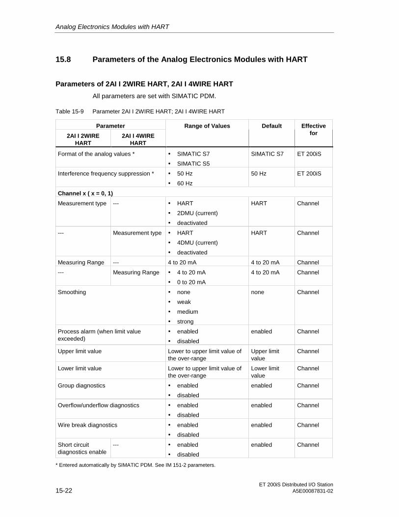
Analog Electronics Modules with HART
ET 200iS Distributed I/O Station15-22 A5E00087831-02
15.8 Parameters of the Analog Electronics Modules with HART
Parameters of 2AI I 2WIRE HART, 2AI I 4WIRE HART
All parameters are set with SIMATIC PDM.
Table 15-9 Parameter 2AI I 2WIRE HART; 2AI I 4WIRE HART
Parameter
2AI I 2WIREHART
2AI I 4WIREHART
Range of Values Default Effectivefor
Format of the analog values * • SIMATIC S7
• SIMATIC S5
SIMATIC S7 ET 200iS
Interference frequency suppression * • 50 Hz
• 60 Hz
50 Hz ET 200iS
Channel x ( x = 0, 1)
Measurement type --- • HART
• 2DMU (current)
• deactivated
HART Channel
--- Measurement type • HART
• 4DMU (current)
• deactivated
HART Channel
Measuring Range --- 4 to 20 mA 4 to 20 mA Channel
--- Measuring Range • 4 to 20 mA
• 0 to 20 mA
4 to 20 mA Channel
Smoothing • none
• weak
• medium
• strong
none Channel
Process alarm (when limit valueexceeded)
• enabled
• disabled
enabled Channel
Upper limit value Lower to upper limit value ofthe over-range
Upper limitvalue
Channel
Lower limit value Lower to upper limit value ofthe over-range
Lower limitvalue
Channel
Group diagnostics • enabled
• disabled
enabled Channel
Overflow/underflow diagnostics • enabled
• disabled
enabled Channel
Wire break diagnostics • enabled
• disabled
enabled Channel
Short circuitdiagnostics enable
--- • enabled
• disabled
enabled Channel
* Entered automatically by SIMATIC PDM. See IM 151-2 parameters.

Analog Electronics Modules with HART
ET 200iS Distributed I/O StationA5E00087831-02 15-23
Parameters of 2AO I HART
All parameters are set with SIMATIC PDM.
Table 15-10 Parameters of 2AO I HART
Parameters of 2AO IHART
Range of Values Default Effective for
Format of the analogvalues *
• SIMATIC S7
• SIMATIC S5
SIMATIC S7 ET 200iS
Channel x ( x = 0.1)
Output type • I HART (currentHART)
• I (current)
I (current) Channel
Output range • 4 to 20 mA
• 0 to 20 mA
4 to 20 mA Channel
Response to CPU/master STOP
• Apply substitutevalue
• Output nocurrent/voltage
• Hold last value
Apply substitute value (with IHART output type)
Output no current / voltage(with I output type)
Channel
Substitute value Every value of thenominal range
4.0000 mA Channel
Group diagnostics • enabled
• disabled
enabled Channel
Wire break diagnostics • enabled
• disabled
enabled Channel
Short circuit diagnostics • enabled
• disabled
enabled Channel
* Entered automatically by SIMATIC PDM. See IM 151-2 parameters.

Analog Electronics Modules with HART
ET 200iS Distributed I/O Station15-24 A5E00087831-02
Identification Data
The identification data contain further information on the module and are read outwith SIMATIC PDM. The identification data are resident on the module.
Table 15-11 Identification Data
Identification Data Range of Values Default Effective for
Device
Vendor read SIEMENS AG
Device identification read Order Number
Device serial number read
Hardware revision read
Software revision read
depends on theproduct version
Static revision no. read ---
Installation date read/ write (max. 16 characters) ---
Module
Operating unit
TAG read/ write (max. 32 characters) ---
Description read/ write (max. 54 characters) ---
Module
15.9 Parameter Description
15.9.1 Smoothing
See also
Smoothing [ Page 14-69]
15.9.2 Identification Data
See also
Identification Data [ Page 12-8]

Analog Electronics Modules with HART
ET 200iS Distributed I/O StationA5E00087831-02 15-25
15.10 HART Data Records
Introduction
This section contains information on assigning parameters, diagnostics, andcommunication with the HART analog modules. You require this information if youwant to go beyond the standard applications of STEP 7 and PDM or want to useyour own configuration tool for HART communication.
Data Record Interface
The analog modules with HART use data records as the input and output interface:
The mapping of HART commands and HART responses in PROFIBUS-DP datarecords is based on the PROFIBUS Profile HART Version 1.0. For more detailedinformation on the HART protocol, refer to PROFIBUS DP HART ProfileApplication Guidelines.
You can obtain this documentation from the PNO (PROFIBUS users organization)on the Internet http://www.profibus.com.
Table 15-12 HART Data Records
RecordNumber
Read / Write Size in Bytes Description
read 13 Directory process data148
DR information (data record directory): This data record contains the data record numbers(index) of all HART data records and information on numbers and revisions.
read 3 HMD Feature Parameter Process Data149
HART Feature Flags: This data record describes which optional HART features aresupported.
Read / Write 6 HMD Parameter Process Data129
HART-Parameter: This data record contains the parameters for the HART master. When thisdata record is read, you can evaluated the status of the parameter assignment. There are novendor-specific parameters for the analog modules with HART.
write 75 HART Request Write Process Data80
Mailbox channel 0: This data record contains the transfer data for the command from theclient to the HART field device (on channel 0).
read 75 HART Response Read Process Data81
Mailbox channel 0: This data record contains the transfer data for the reply from the HARTfield device (on channel 0) to the client.
write 75 HART Request Write Process Data82
Mailbox channel 1: This data record contains the transfer data for the command from theclient to the HART field device (on channel 1).
read 75 HART Response Read Process Data83
Mailbox channel 1: This data record contains the transfer data for the reply from the HARTfield device (on channel 1) to the client.

Analog Electronics Modules with HART
ET 200iS Distributed I/O Station15-26 A5E00087831-02
Reading and Writing Data Records
To read and write data records, use the following SFCs:
• Read data record: SFC59 "RD_REC"
• Write data record: SFC58 "WR_REC"
For more detailed information on SFCs, refer to the manual System Software forS7-300/400 System and Standard Functions.

ET 200iS Distributed I/O StationA5E00087831-02 16-1
16Order Numbers 1616.1 Order Numbers
Introduction
You will find the order numbers for the ET 200iS distributed I/O station and thePROFIBUS accessories that you may need in conjunction with the ET 200iS below.
Interface Module
Table 16-1 Interface Module
Description Number Order Number
Interface module IM 151-2 1 6ES7 151-2AA00-0AB0
Terminal Modules
Table 16-2 Terminal Modules
Description Number Order Number
TM-PS 1 6ES7 193-5DA00-0AA0
TM-IM and bus termination module 1 6ES7 193-5DB00-0AA0
TM-E30S44-iS (screw terminals) 5 6ES7 193-5CB00-0AA0
TM-E30C44-iS (spring terminals) 5 6ES7 193-5CB10-0AA0

Order Numbers
ET 200iS Distributed I/O Station16-2 A5E00087831-02
Power Supply Module
Table 16-3 Power Supply Module
Description Number Order Number
Power supply PS 1 6ES7 138-5EA00-0AA0
Digital Electronics Modules
Table 16-4 Digital Electronics Modules
Description Number Order Number
4DI NAMUR 1 6ES7 131-5RD00-0AB0
2DO DC25V/25mA 1 6ES7 132-5SB00-0AB0
Analog Electronics Modules
Table 16-5 Analog Electronics Modules
Description Number Order Number
2AI I 2WIRE 1 6ES7 134-5RB00-0AB0
2AI I 4WIRE 1 6ES7 134-5RB50-0AB0
2AI RTD 1 6ES7 134-5SB50-0AB0
2AI TC 1 6ES7 134-5SB00-0AB0
2 AO I 1 6ES7 135-5RB00-0AB0
Analog Electronics Modules with HART
Table 16-6 Analog Electronics Modules with HART
Description Number Order Number
2AI I 2WIRE HART 1 6ES7 134-5TB00-0AB0
2AI I 4WIRE HART 1 6ES7 134-5TB50-0AB0
2AO I HART 1 6ES7 135-5TB00-0AB0

Order Numbers
ET 200iS Distributed I/O StationA5E00087831-02 16-3
ET 200iS Accessories
Table 16-7 ET 200iS Accessories
Description Number Order Number
Shield contact element 5 6ES7 193-4GA00-0AA0
Conductor bar, 3x10 mm, 1 m 10 8WA2 842
Shield clamp KLBÜ CO 1 1753311001*
Ground connection terminal ZB 16 031660*
EEx e terminal WPE 16/E (for DIN rail) 17522900*
Sheet of labels DIN A4, white 10 6ES7 193-4BA00-0AA0
Sheet of labels DIN A4, red 10 6ES7 193-4BD00-0AA0
Sheet of labels DIN A4, yellow 10 6ES7 193-4BB00-0AA0
Sheet of labels DIN A4, petrol 10 6ES7 193-4BH00-0AA0
Color identification labels, assorted:
white
red
yellow
yellow-green
brown
blue
turquoise
10 strips à20 labelsper color
6ES7 193-4LA10-0AA0
6ES7 193-4LD10-0AA0
6ES7 193-4LB10-0AA0
6ES7 193-4LC10-0AA0
6ES7 193-4LG10-0AA0
6ES7 193-4LF10-0AA0
6ES7 193-4LH10-0AA0
Slot number labels, 10 x (1 to 20) 200 8WA8 861-0AB
Slot number labels, 5 x (1 to 40) 200 8WA8 861-0AC
Enclosure for ET 200iS with degree of protectionEEx e
stainless steel, sheet steel
For information onordering suchenclosures, contact yourSiemens representative
* Order numbers from Weidmüller GmbH, An der Talle 89, 33102 Paderborn, Tel: 05252-960-0, Fax:
05252-960-116

Order Numbers
ET 200iS Distributed I/O Station16-4 A5E00087831-02
Network Components
The following table list all the network components you require to operate the ET200iS.
Table 16-8 Network Components for the ET 200iS
Description Order Number
Fieldbus isolating transformer 9373/21-12-10 and RS-485 terminating resistor
93 730 05 01 2
Can be ordered, for examplefrom:
R. STAHL Schaltgeräte GmbH
Postfach 40
D-74636 Waldenburg, Germany
Phone: +49–7942/9 43 – 0
Fax: +49–7942/9 43 – 43 33
Internet: http://www.stahl.de
PROFIBUS bus connector (1.5 Mbps) 6ES7 972-0BA30-0XA0
Bus cable for PROFIBUS
• Normal 6XV1 830-0EH10

Order Numbers
ET 200iS Distributed I/O StationA5E00087831-02 16-5
Manuals on STEP 7 and SIMATIC S7
To program and commission the ET 200iS with STEP 7, you require one of thefollowing manuals.
Table 16-9 Manuals on STEP 7 and SIMATIC S7
Description Content
S7-300 Programmable Controller, Hardwareand Installation
Includes
• Description of the PROFIBUS-DPmaster interface of the CPU 315-2 DP
• Structure of a PROFIBUS-DP network
• RS-485 repeater
M7-300 Installation and Hardware Includes
• Description of the PROFIBUS-DPmaster interface in M7-300
• Structure of a PROFIBUS-DP network
• RS-485 repeater
S7-400, M7-400 Hardware and Installation Includes
• Description of the PROFIBUS-DPmaster interface in S7-400 and M7-400
• Structure of a PROFIBUS-DP network
• RS-485 repeater
System Software for S7-300/ ProgramDesign programming manual
Includes
Description of addressing and diagnostics inSIMATIC S7
System Software for S7-300/400 Systemand Standard Functions reference manual
Description of the SFCs in STEP 7
Description SIMATIC NET PROFIBUS networks - wiringand cabling
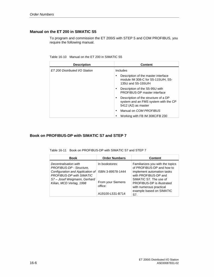
Order Numbers
ET 200iS Distributed I/O Station16-6 A5E00087831-02
Manual on the ET 200 in SIMATIC S5
To program and commission the ET 200iS with STEP 5 and COM PROFIBUS, yourequire the following manual.
Table 16-10 Manual on the ET 200 in SIMATIC S5
Description Content
ET 200 Distributed I/O Station Includes
• Description of the master interfacemodule IM 308-C for S5-115U/H, S5-135U and S5-155U/H
• Description of the S5-95U withPROFIBUS-DP master interface
• Description of the structure of a DPsystem and an FMS system with the CP5412 (A2) as master
• Manual on COM PROFIBUS
• Working with FB IM 308C/FB 230
Book on PROFIBUS-DP with SIMATIC S7 and STEP 7
Table 16-11 Book on PROFIBUS-DP with SIMATIC S7 and STEP 7
Book Order Numbers Content
Decentralisation withPROFIBUS-DP - Structure,Configuration and Application ofPROFIBUS-DP with SIMATICS7 – Josef Weigmann, GerhardKilian, MCD Verlag, 1998
In bookstores:
ISBN 3-89578-1444
From your Siemensoffice:
A19100-L531-B714
Familiarizes you with the topicsof PROFIBUS-DP and how toimplement automation taskswith PROFIBUS-DP andSIMATIC S7. The use ofPROFIBUS-DP is illustratedwith numerous practicalexample based on SIMATICS7.

ET 200iS Distributed I/O StationA5E00087831-02 17-1
17Dimension Drawings 1717.1 Dimension Drawings
Introduction
This chapter contains the dimension drawings of the most important components ofthe ET 200iS.
Terminal Module TM-PS with Power Supply Module PS Inserted200
140
92.5
107.5
160.5
DINrail support
165
174.4
74.75
Figure 17-1 Terminal Module TM-PS with Power Supply Module PS Inserted
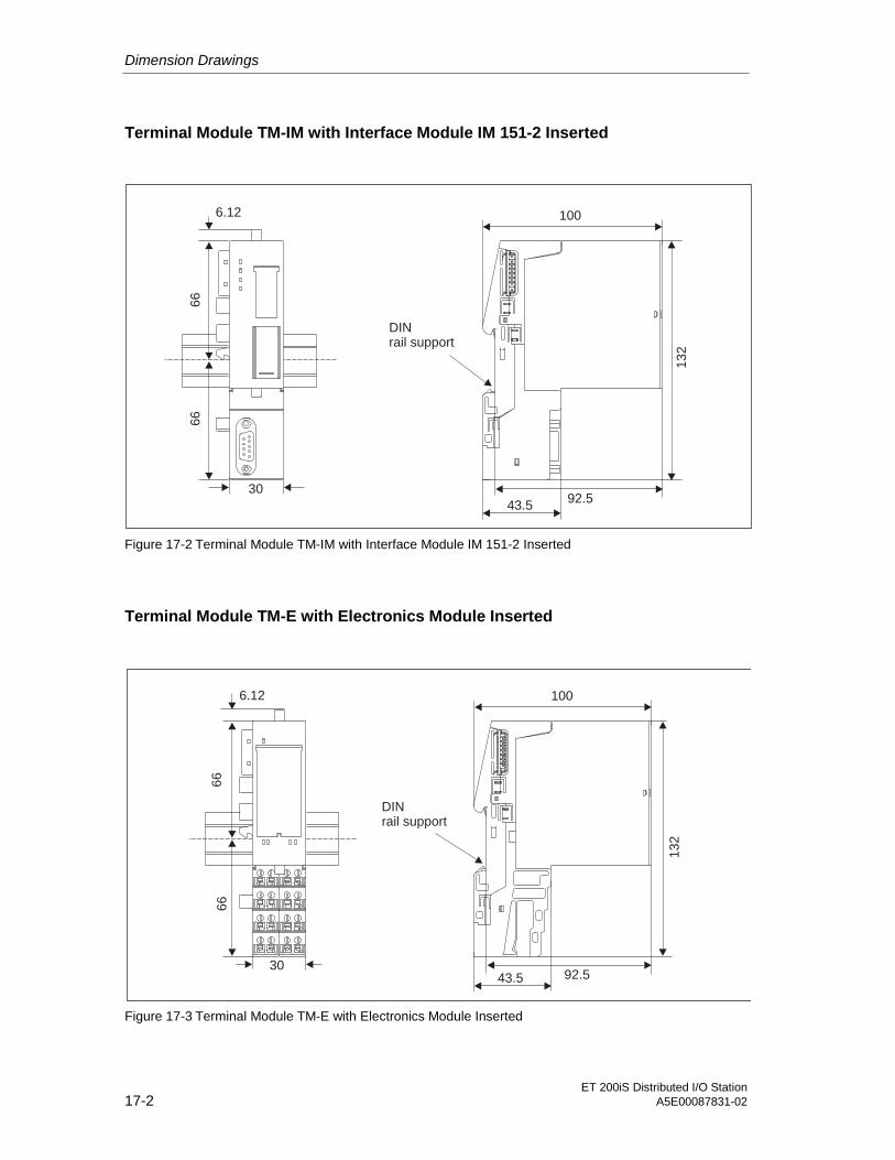
Dimension Drawings
ET 200iS Distributed I/O Station17-2 A5E00087831-02
Terminal Module TM-IM with Interface Module IM 151-2 Inserted
92.5
132
6.12
66
66
30
DINrail support
100
43.5
Figure 17-2 Terminal Module TM-IM with Interface Module IM 151-2 Inserted
Terminal Module TM-E with Electronics Module Inserted
66
66
6.12
3092.5
13
2
DINrail support
43.5
100
Figure 17-3 Terminal Module TM-E with Electronics Module Inserted

Dimension Drawings
ET 200iS Distributed I/O StationA5E00087831-02 17-3
Bus Termination Module
66
12.536.4
40.2
10
6.2
DINrail support
43.5
Figure 17-4 Bus Termination Module

Dimension Drawings
ET 200iS Distributed I/O Station17-4 A5E00087831-02

ET 200iS Distributed I/O StationA5E00087831-02 18-1
18Reaction Times 1818.1 Introduction
The following schematic shows the different reaction times between the DP masterand ET 200iS.
DP master
DPinterface
DP cycle
DP slave
ET 200iS
ET 200iS
DI DO AI AOIM 151-2
CPU
Figure 18-1 Reaction Times between the DP Master and ET 200iS

Reaction Times
ET 200iS Distributed I/O Station18-2 A5E00087831-02
18.2 Reaction Times on the DP Master
You will find information on the reaction times in the manual of the DP master youare using.
18.3 Reaction Times on the ET 200iS
Reaction Time
The reaction time on the ET 200iS depends on:
• The number of modules
• The number of diagnostic messages
• Removing and inserting modules
• Interrupts
Calculating the Reaction Time
Using the formula below, you can calculate the approximate reaction time of the ET200iS:
reaction time [µs] = 550 + 130 * m
Figure 18-2 Calculating the Reaction Time
Explanation of the Parameters:
• m: Total number of electronics modules

Reaction Times
ET 200iS Distributed I/O StationA5E00087831-02 18-3
Example of Calculating the ET 200iS Reaction Time
4D
IN
AM
UR
4D
IN
AM
UR
4D
IN
AM
UR
4D
IN
AM
UR
4D
IN
AM
UR
4D
IN
AM
UR
2A
II2W
IRE
2A
II4W
IRE
2A
IR
TD
2A
IR
TD
2A
IT
C
2A
IT
C
2A
OI
2A
OI
2A
OI
Inte
rface
module
Bus
term
ination
Power supplymodule
m = 15
Reaction time = 550 + 130 * mReaction time = 550 + 130 * 15Reaction time = 2500 µs = 2.5 ms
1 2 3 4 5 6 7 8 9 10 11 12 13 14 15
Figure 18-3 Example of Calculating the ET 200iS Reaction Time
18.4 Reaction Times with Digital Input Modules
Input delay
The reaction times of the digital input modules depend on the input delay. Seetechnical specifications Section Digital Electronics Modules.
18.5 Reaction Times with Digital Output Modules
Output Delay
The reaction times correspond to the output delay. See technical specificationsSection Digital Electronics Modules

Reaction Times
ET 200iS Distributed I/O Station18-4 A5E00087831-02
18.6 Reaction Times of Analog Input Modules
Conversion Time
The conversion time is made up of the basic conversion time and the time forprocessing wire break monitoring diagnostics (see Technical Specifications 2AI TCand 2AI RTD, section Analog Electronics Modules ).
With integrating conversion procedures, the integration time is included directly inthe conversion time.
Cycle time
The analog-to-digital conversion and the transfer of the digitized measured valuesto memory or to the backplane bus is sequential; in other words, the analog inputchannels are converted one after the other. The cycle time; in other words, the timeuntil an analog input value is converted again is the sum of the conversion times ofall active analog input channels of the input modules. Unused analog inputchannels should be deactivated in the parameter settings to reduce the cycle time.The conversion and integration time for a deactivated channel is = 0.
The following schematic provides an overview of how the cycle time for an n-channel analog input module is made up.
Cycle timeConversion time channel 0
Conversion time channel 1
Figure 18-4 Cycle Times of the Analog Input Channel

Reaction Times
ET 200iS Distributed I/O StationA5E00087831-02 18-5
18.7 Reaction Times of Analog Output Modules
Conversion Time
The conversion time of the analog output channels includes the time for taking thedigitized output values from the internal memory and the digital-to-analogconversion.
Cycle time
The conversion of the analog output channels involves a processing time for themodule and sequential conversion times for channels 0 and 1.
The cycle time, the other words, the time until an analog output value is convertedagain is the sum of the conversion times of all activated analog output channelsand the processing time of the analog output module.
The following schematic provides an overview of how the cycle time for an analogoutput module is made up.
Cycle time
Module processing time
Conversion time channel 0
Conversion time channel 1
Figure 18-5 Cycle Time of the Analog Output Module
Settling Time
The settling time (t1 to t3), in other words, the time from applying the convertedvalue to reaching the specified value at the analog output is load dependent. Adistinction must be made between resistive, capacitive, and inductive load.

Reaction Times
ET 200iS Distributed I/O Station18-6 A5E00087831-02
Response Time
The worst-case response time (t1 to t3), in other words, the time from the availabilityof the digital output values in the internal memory until the specified value isreached and the analog output is the sum of the cycle time and settling time. Theworst case occurs when the analog channel was converted shortly beforetransferring a new output value and will only the converted again following theconversion of the other channels (cycle time).
The following schematic shows the response time of an analog output channel.
tA
tZ
tE
t1t2
t = Response timeA
t = Cycle time is the processing time of the
module and the conversion time of the channelZ
t = Settling timeE
t = New digital output value applied1
t = Output value adopted and converted2
t = Specified out put value reached3
t3
Figure 18-6 Response Time of an Analog Output Channel

ET 200iS Distributed I/O StationA5E00087831-02 19-1
19Address Space of the Inputs andOutputs 1919.1 Digital Electronics Modules
Digital Input Modules
Assignment of the process image input table PII per module:
Input signal channel 1
Meaning of value status: 1: signal valid0: signal invalid
Input signal channel 0
IB x
7 6 5 4 3 2 1 0
Value status for channel 1
Value status for channel 0
Input signal channel 2Input signal channel 3
Value status for channel 2Value status for channel 3
Figure 19-1 Address Space of Digital Input Modules
Digital Output Modules
Assignment of the process image output table PII per module:
Output signal channel 1
Output signal channel 0
QB x
7 6 5 4 3 2 1 0
Figure 19-2 Address Space of Digital Output Modules
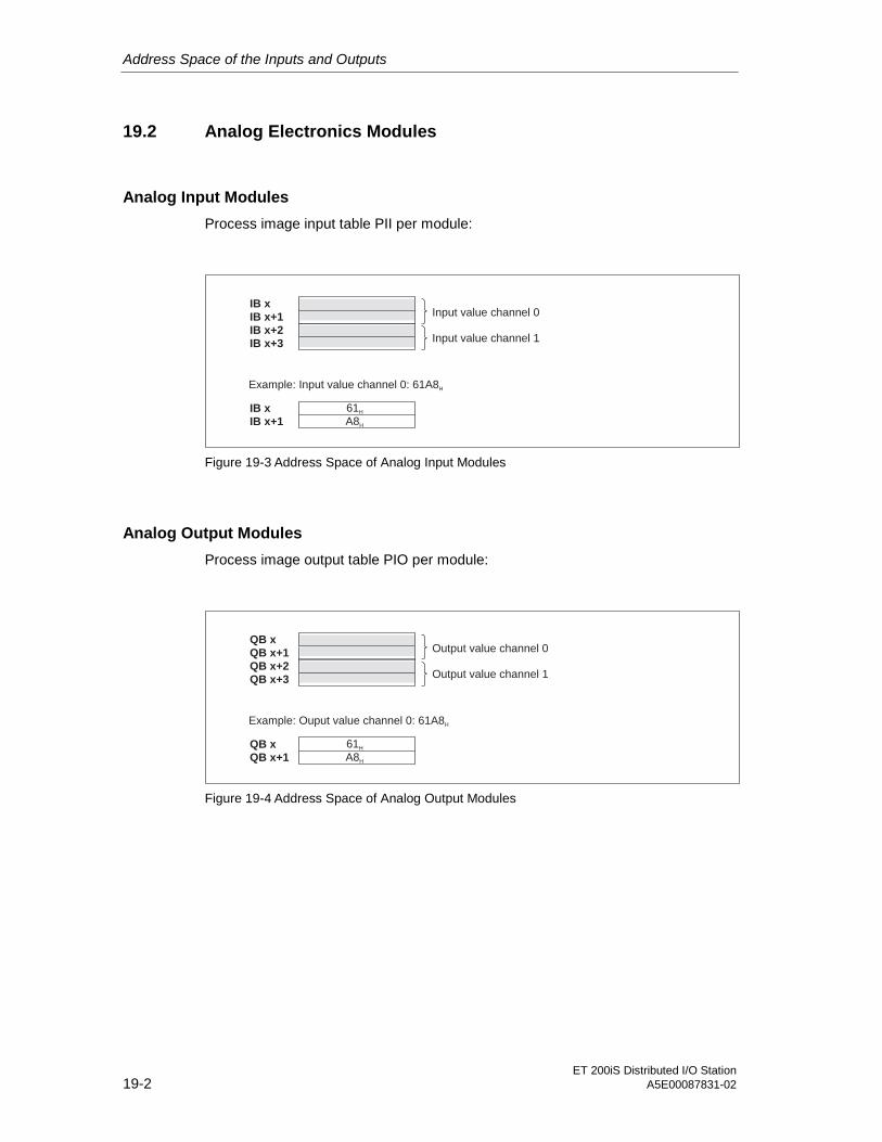
Address Space of the Inputs and Outputs
ET 200iS Distributed I/O Station19-2 A5E00087831-02
19.2 Analog Electronics Modules
Analog Input Modules
Process image input table PII per module:
Input value channel 0IB x
IB x+1
IB x+2
IB x+3 Input value channel 1
Example: Input value channel 0: 61A8H
IB x
IB x+1
61H
A8H
Figure 19-3 Address Space of Analog Input Modules
Analog Output Modules
Process image output table PIO per module:
Output value channel 0QB x
QB x+1
QB x+2
QB x+3 Output value channel 1
Example: Ouput value channel 0: 61A8H
QB x
QB x+1
61H
A8H
Figure 19-4 Address Space of Analog Output Modules

Address Space of the Inputs and Outputs
ET 200iS Distributed I/O StationA5E00087831-02 19-3
19.3 Analog Electronics Modules with HART
Analog Input Modules with HART
Process image input table PII per module:
Input value channel 0 (primary variable in S7 format)IB x
IB x+1
IB x+2
IB x+3 Input value channel 1 (primary variable in S7 format)
Example: Input value channel 0: 61A8H
IB x
IB x+1
61H
A8H
Input value channel 0 = +25000 (primary variable)
Figure 19-5 Address Space of Analog Input Modules with HART
Analog Output Modules with HART
Process image output table PIO per module:
Output value channel 0 (primary variable in S7 format)QB x
QB x+1
QB x+2
QB x+3 Output value channel 1 (primary variable in S7 format)
Example: Output value channel 0: 61A8H
QB x
QB x+1
61H
A8H
Output value channel 0 = +25000 (primary variable)
Figure 19-6 Address Space of Analog Output Modules with HART


ET 200iS Distributed I/O StationA5E00087831-02 20-1
20Certifications 2020.1 EU Prototype Test Certificates
20.1.1 ET 200iS Distributed I/O Station
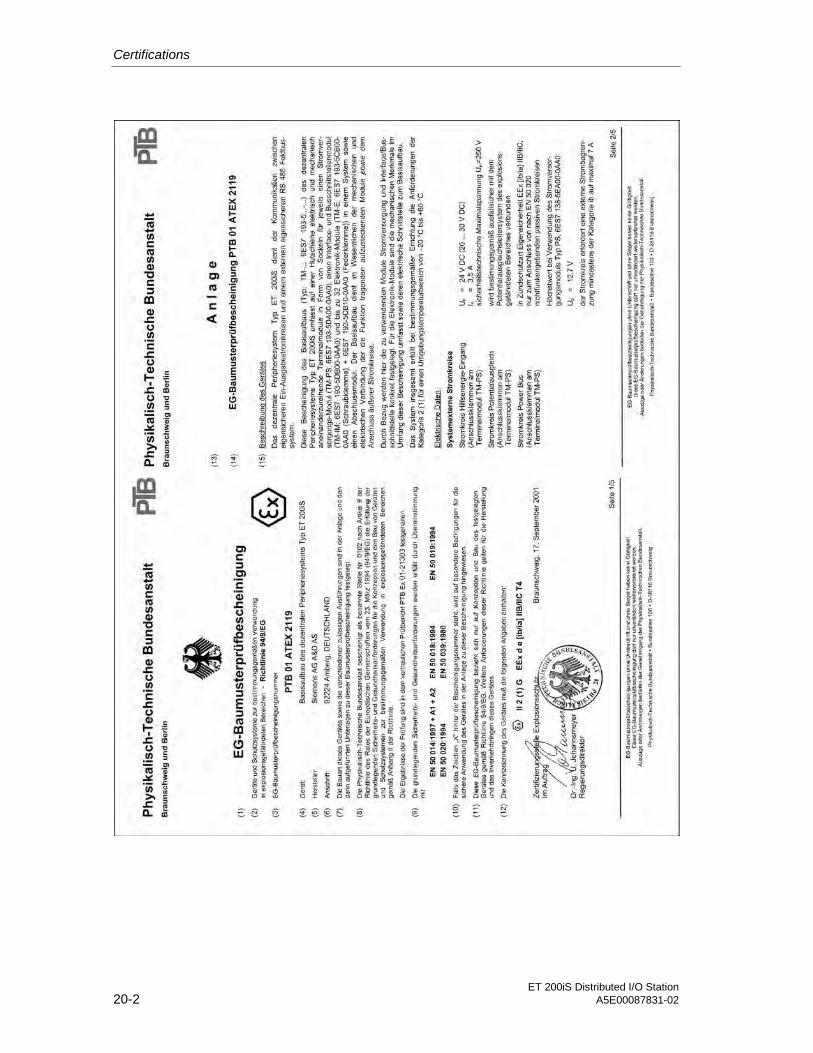
Certifications
ET 200iS Distributed I/O Station20-2 A5E00087831-02

Certifications
ET 200iS Distributed I/O StationA5E00087831-02 20-3

Certifications
ET 200iS Distributed I/O Station20-4 A5E00087831-02

Certifications
ET 200iS Distributed I/O StationA5E00087831-02 20-5
20.1.2 Interface module IM151-2

Certifications
ET 200iS Distributed I/O Station20-6 A5E00087831-02

Certifications
ET 200iS Distributed I/O StationA5E00087831-02 20-7
20.1.3 Power supply PS

Certifications
ET 200iS Distributed I/O Station20-8 A5E00087831-02

Certifications
ET 200iS Distributed I/O StationA5E00087831-02 20-9
20.1.4 4DI NAMUR

Certifications
ET 200iS Distributed I/O Station20-10 A5E00087831-02

Certifications
ET 200iS Distributed I/O StationA5E00087831-02 20-11

Certifications
ET 200iS Distributed I/O Station20-12 A5E00087831-02
20.1.5 2DO DC25V/25mA
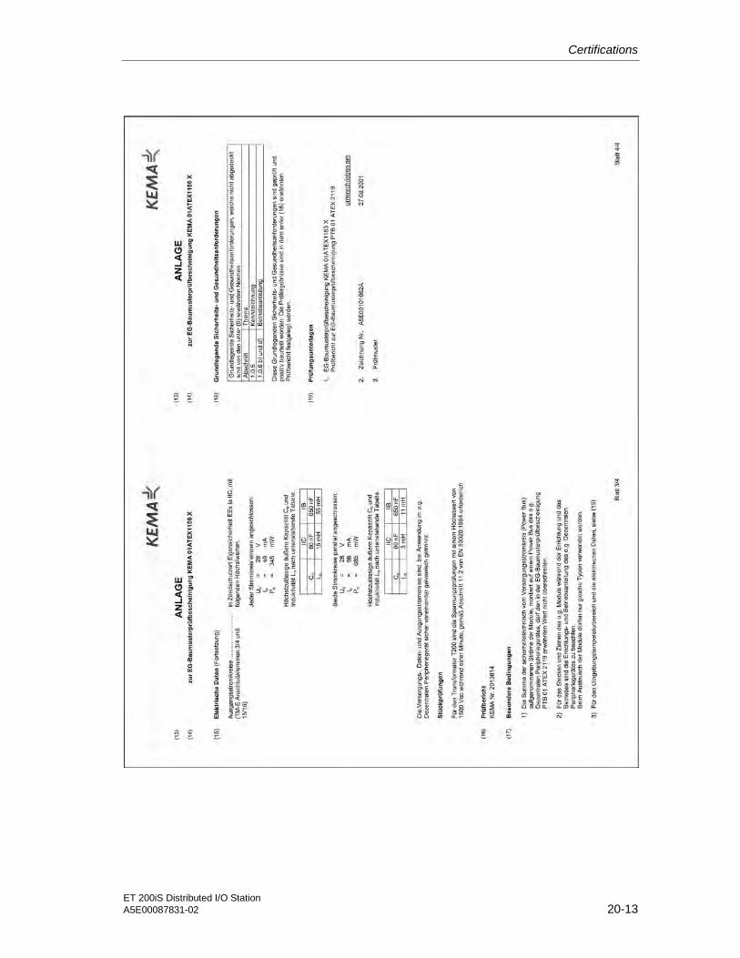
Certifications
ET 200iS Distributed I/O StationA5E00087831-02 20-13
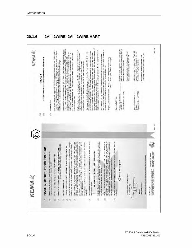
Certifications
ET 200iS Distributed I/O Station20-14 A5E00087831-02
20.1.6 2AI I 2WIRE, 2AI I 2WIRE HART

Certifications
ET 200iS Distributed I/O StationA5E00087831-02 20-15
o
1 1
Preface
1-1
1

Certifications
ET 200iS Distributed I/O Station20-16 A5E00087831-02
20.1.7 2AI I 4WIRE, 2AI I 4WIRE HART

Certifications
ET 200iS Distributed I/O StationA5E00087831-02 20-17

Certifications
ET 200iS Distributed I/O Station20-18 A5E00087831-02
20.1.8 2AI RTD

Certifications
ET 200iS Distributed I/O StationA5E00087831-02 20-19
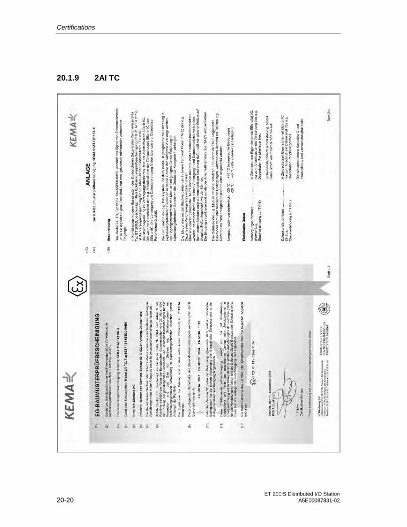
Certifications
ET 200iS Distributed I/O Station20-20 A5E00087831-02
20.1.9 2AI TC
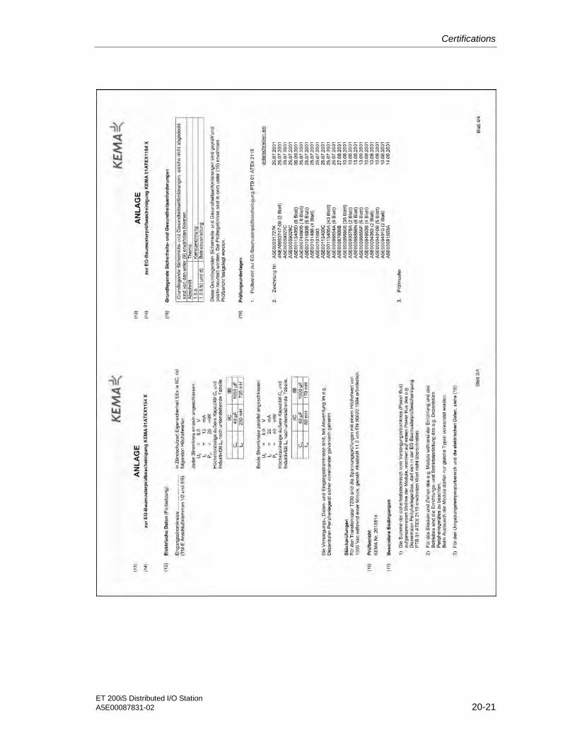
Certifications
ET 200iS Distributed I/O StationA5E00087831-02 20-21

Certifications
ET 200iS Distributed I/O Station20-22 A5E00087831-02
20.1.10 2AO I, 2AO I HART

Certifications
ET 200iS Distributed I/O StationA5E00087831-02 20-23
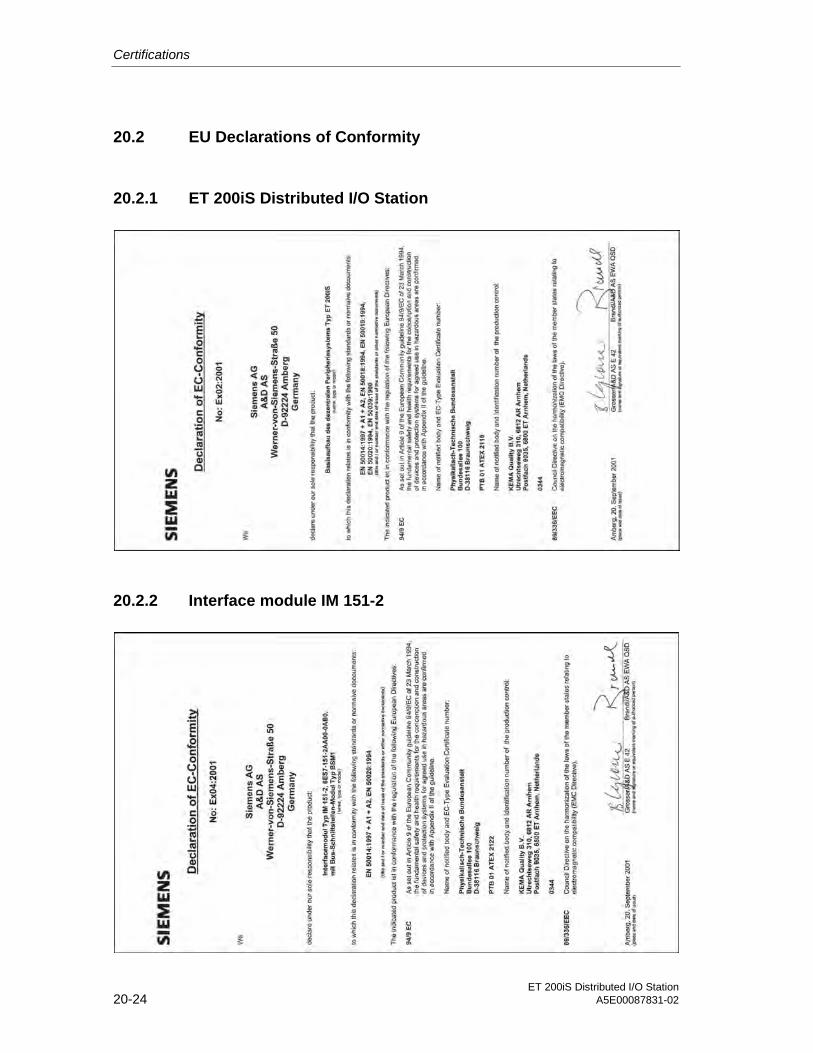
Certifications
ET 200iS Distributed I/O Station20-24 A5E00087831-02
20.2 EU Declarations of Conformity
20.2.1 ET 200iS Distributed I/O Station
20.2.2 Interface module IM 151-2

Certifications
ET 200iS Distributed I/O StationA5E00087831-02 20-25
20.2.3 Power supply PS
20.2.4 4DI NAMUR
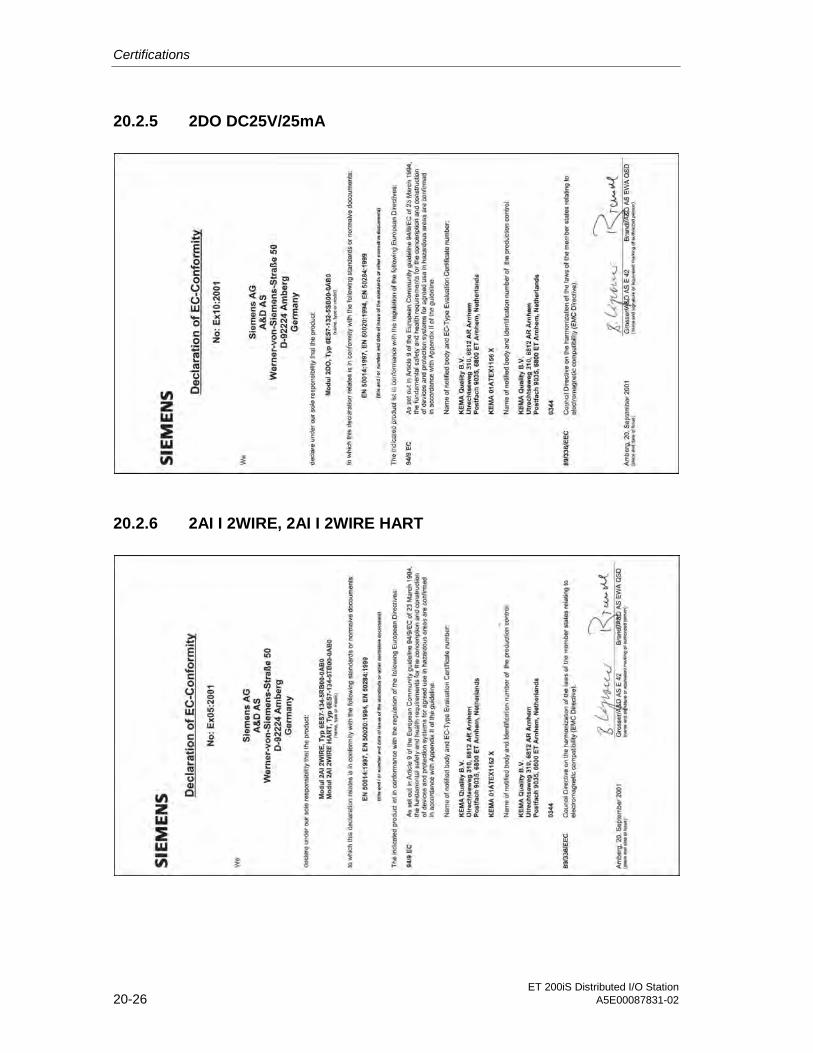
Certifications
ET 200iS Distributed I/O Station20-26 A5E00087831-02
20.2.5 2DO DC25V/25mA
20.2.6 2AI I 2WIRE, 2AI I 2WIRE HART

Certifications
ET 200iS Distributed I/O StationA5E00087831-02 20-27
20.2.7 2AI I 4WIRE, 2AI I 4WIRE HART
20.2.8 2AI RTD

Certifications
ET 200iS Distributed I/O Station20-28 A5E00087831-02
20.2.9 2AI TC
20.2.10 2AO I, 2AO I HART

ET 200iS Distributed I/O StationA5E00087831-02 21-1
21Marking 2121.1 Marking According to Divisions
Overview
Temperature classes
Division of the hazardousareas
Class I, Division 1, Groups A, B, C, D, T6
NEC 500:
Classes and groupsacc. to NEC 500
Figure 21-1 Overview
Division of the Hazardous Areas
Division of the Hazardous Areas
Danger continuously orintermittently
Danger seldom and for ashort time
USA NEC 500
Class I (gas)
Class II (dust)
Class III (fibers)
Division 1 Division 2

Marking
ET 200iS Distributed I/O Station21-2 A5E00087831-02
Temperature Classes
Temperature Classes
Highest Permitted Surface Temperature USA (NEC 500)
450°C T1
300°C T2
280°C T2A
260°C T2B
230°C T2C
215°C T2D
200°C T3
180°C T3A
165°C T3B
160°C T3C
135°C T4
120°C T4A
100°C T5
85°C T6
Classes and Groups According to NEC 500
Classes and Groups According to NEC 500
Typical Gases / Dusts /Flyings / Fibers
Group
Acetylene Class I Group A
Hydrogen Class I Group B
Ethylene Class I Group C
Propane Class I Group D
Methane Mining
Metal dust Class II Group E
Carbon dust Class II Group F
Grain dust Class II Group G
Fibers / flyings Class III

Marking
ET 200iS Distributed I/O StationA5E00087831-02 21-3
21.2 Marking According to Zones
Overview
II 2 G EEx ed IIC T6
Device group I
Device group II
Type of protection
Categorization of gases, vapors inexplosion groups and temperature
classes
Explosion groups acc. toCENELEC
Temperature classes
Zone division
Zone1, AEx ed IIC T6Class I,
CENELEC:
NEC 505:
Figure 21-2 Overview
Device group I
Table 21-1 Device group I
Device group I
(Mining)
Category M1
Extremely high degree ofsafety
Category M2
High degree of safety
Adequate safety with 2 protective measures/if two faults occur
must be turned off if anexplosive atmosphereoccurs

Marking
ET 200iS Distributed I/O Station21-4 A5E00087831-02
Device group II
Table 21-2 Device group II
Device group II
(Other Hazardous Areas)
Category 1*
Extremely highdegree of safety
Category 2*
High degree ofsafety
Category 3*
Normal degree ofsafety
Adequate safety with 2 protectivemeasures/ if twofaults occur
if device problemsoccur often/ if 1 faultoccurs
in problem-freeoperation
Use in Zone 0 Zone 20 Zone 1 Zone 21 Zone 2 Zone 22
Atmosphere
G = Gas, D = Dust
G D G D G D
* II (1) G = relevant electrical equipment – Installation in safe area
Classification of Zones
Table 21-3 Classification of Zones
Classification of Zones
Danger continuously,
over long periods oroften
Danger intermittently Danger seldom andfor a short time
IEC Zone 0
(Zone 20 - dust)
Zone 1
(Zone 21 - dust)
Zone 2
(Zone 22 - dust)
USA NEC 505
Class I(gas)
Zone 0 Zone 1 Zone 0

Marking
ET 200iS Distributed I/O StationA5E00087831-02 21-5
Types of Protection
Table 21-4 Types of Protection
Types of Protection
Type of Protection SchematicRepresentation
Main Application Standard
Increased safety e Terminals and terminal boxes,control boxes for installation ofcomponents (with a different typeof explosion protection), cagemotors, lamps
EN 50 019
IEC 60 079-7
FM 3600
UL 2279
Explosion-proofenclosure
d Switching device and switchgear,control and display devices,controllers, motors, transformers,heaters, lamps
EN 50 018
IEC 60 079-1
FM 3600
UL 2279
Pressurizedenclosure
p Switch gear and control cubicles,analytic devices, large motors
EN 50 016
IEC 60 079-2
FM 3620
NFPA 496
Intrinsic safety i* Instrumentation and controlengineering, communicationsengineering, sensors, actuators
EN 50 020
IEC 60 079-11
FM 3610
UL 2279
Oil immersion o Transformers, starting resistors EN 50 015
IEC 60 079-6
FM 3600
UL 2279

Marking
ET 200iS Distributed I/O Station21-6 A5E00087831-02
Types of Protection
Sand filling q Transformers, capacitors, heatingconductor terminal box
EN 50 017
IEC 60 079-5
FM 3600
UL 2279
Encapsulation m Switching devices for small loads,command and signaling devices,display devices, sensors
EN 50 028
IEC 60 079-18
FM 3600
UL 2279
Type of Protection n Zone 2
Several methods ofignition protectionmethods are included inthis type of protection
All electrical equipment for zone 2,less suitable for switching devicesand switchgear
EN 50 021
IEC 60 079-15
* ia = use in zone 0, 1, 2; ib = use in zone 1,2; [EEx ib] = corresponding electrical equipment – installationin safe area
Explosion Groups
Table 21-5 Explosion Groups
Explosion Groups according to CENELEC / NEC 505
Explosion group Typical gas
I Methane
II A Propane
II B Ethylene
II C Hydrogen

Marking
ET 200iS Distributed I/O StationA5E00087831-02 21-7
Temperature Classes
Table 21-6 Temperature Classes
Temperature Classes
Highest Permitted Surface Temperature CENELEC / USA (NEC 505)
450 °C T1
300 °C T2
200 °C T3
135 °C T4
100 °C T5
85 °C T6
Classification of Gases and Vapors in Explosion Groups and TemperatureClasses
Table 21-7 Classification of Gases and Vapors in Explosion Groups and Temperature Classes
Classification of Gases and Vapors in Explosion Groups and Temperature Classes
T1 T2 T3 T4 T5 T6
I Methane
II A Acetone
Ethane
Ethyl acetate
Ammonia
Benzol (pure)
Acetic acid
Carbon oxide
Methane
Methanol
Propane
Toluol
Ethyl alcohol
i-amyl acetate
n-butane
n-butyl alcohol
Gasoline
Diesel fuel
Aircraft fuel
Fuel oils
n-hexane
Acet aldehyde
Ethylester
II B Town gas
(lighting gas)
Ethylene
II C Hydrogen Acetylene Hydrogensulphide

Marking
ET 200iS Distributed I/O Station21-8 A5E00087831-02

ET 200iS Distributed I/O StationA5E00087831-02 22-1
22Glossary 2222.1 Glossary
ACCU
The accumulators are registers on the CPU and serve as buffers for load, transfer,compare, calculation and conversion operations.
Backplane bus
The backplane bus is a serial data bus over which the interface module IM 151-2communicates with the electronics modules and supplies them with the requiredvoltage. The connection between the individual modules is established using theterminal modules.
Bus
Common transmission path to which all nodes are connected. It has two definedends.
With the ET 200, the bus is a twisted-pair cable or a fibre-optic cable.
Bus connector
Physical connection between the nodes and LAN cable.
Bus termination module
The ET 200iS distributed I/O station is terminated by the bus termination module. Ifyou do not insert a bus termination module, the ET 200iS cannot be operated.
Chassis ground
Chassis ground includes all the interconnected inactive parts of equipment thatmust not carry a hazardous voltage even in the event of a fault.
Glossary
ET 200iS Distributed I/O Station22-2 A5E00087831-02
Diagnostics
Diagnostics is the detection, localization, classification, indication and furtherevaluation of errors, faults and messages.
Diagnostics provides monitoring functions that run automatically when the plant isoperational. This increases plant availability by reducing commissioning and downtimes.
Distributed I/O devices
These are input/output units that are not installed in the central rack but aredistributed and a distance from the CPU, for example:
• ET 200M, ET 200B, ET 200X, ET 200L, ET 200S, ET 200iS
• DP/AS-I Link
• For the DP slaves from Siemens or other vendors.
The distributed I/O devices are connected to the DP master over PROFIBUS DP.
DP master
A master complying with the standard IEC 61158/EN 50170, Volume 2, PROFIBUSis known as a DP master.
DP standard
The DP standard is the bus protocol of the ET 200 distributed I/O station complyingwith the standard IEC 61158/EN 50170, Volume 2, PROFIBUS.
DP slave
A slave operated on PROFIBUS with the PROFIBUS-DP protocol and complyingwith the standard IEC 61158/EN 50170, Volume 2, PROFIBUS is known as a DPslave.
DPV1
Expansion of DPV0.
Equipotential bonding
Electrical connection (equipotential bonding conductor) that keeps electricalequipment and extraneous conductive objects to the same or almost the samepotential to prevent disturbing or dangerous voltages between these objects.

Glossary
ET 200iS Distributed I/O StationA5E00087831-02 22-3
ET 200
The ET 200 distributed I/O station with the PROFIBUS-DP protocol allowsconnection of the distributed I/O to a CPU or adequate DP master. One of the mainfeatures of the ET 200 is it is fast reaction times since only a few data (bytes) istransferred.
The ET 200 is based on the standard IEC 61158/ EN 50170, Volume 2,PROFIBUS.
The ET 200 operates according to the master-slave principle. The DP master can,for example, be the master interface module IM 308-C or the CPU 315-2 DP.
DP slaves can be the distributed I/O stations ET 200B, ET 200M, ET 200X, ET200L, ET 200S, ET 200iS or DP slaves from Siemens or other vendors.
Floating
With floating input/output modules, the reference potentials of the control and loadcircuit are electrically isolated, for example, by optocouplers, relay contacts ortransformers.
Flutter monitoring
Flutter monitoring is a process control function for digital input signals. Fluttermonitoring detects and reports untypical series of signal changes.
• Detection: If a selectable number of signal changes occurs in a monitoringwindow.
• Report: Entry of diagnostic information and triggering of a diagnostic interrupt;Evaluation and processing of the value status and the diagnostic information.
Freeze
This is a control command that the DP master can send to a group of DP slaves.
After receiving the FREEZE control command, the DP slave freezes the currentstate of the inputs and transfers this cyclically to the DP master.
With every new FREEZE control command, the DP slave freezes the state of theinputs again.
The input data are only sent cyclically by the DP slave to the DP master again afterthe DP master has sent the UNFREEZE control command.
Ground
Ground is the conductive ground area whose electrical potential at any point canbe taken as zero. In the vicinity of grounding elements, the ground may have apotential other than zero. For this reason, the term "reference ground" is oftenused.

Glossary
ET 200iS Distributed I/O Station22-4 A5E00087831-02
Grounding
Grounding means connecting a conductive part to ground via a grounding system.
Grounding conductor PA
Term for electrical equipment used in the hazardous area to which theequipotential bonding is connected.
GSD file
A GSD file (device database file) contains all the properties specific to a DP slave.The format of the GSD file is specified in the standard IEC 61158/EN 50170,Volume 2, PROFIBUS.
HART
Highway Adressable Remote Transducer
Hot swapping
Removing and inserting modules while the ET 200iS is operational.
Identification data
The identification data allow you to read out module information (vendor, type,product version etc.) using SIMATIC PDM. The module information is resident inthe module memory.
Line compensation
Resistance and RTD measurements with 2/3-wire connection without measuringcircuits result in additional measuring inaccuracies. These are compensated by linecompensation.
Master
When a master is in possession of the token, it can send data to other nodes andrequest data from other nodes (= active node). The DP master can, for example,be the master interface module IM 308 C or the CPU 315-2 DP.
Node
Device that sends, receives, or amplifies data over the network, for example, DPmaster, DP slave, RS-485 repeater.

Glossary
ET 200iS Distributed I/O StationA5E00087831-02 22-5
Non-floating
With non-floating input/output modules, the reference potentials of the control andload circuit are electrically connected.
Output characteristics curve
This is the graphic representation of the voltage-current characteristic curve of adigital output module.
Parameter Assignment
Parameter assignment is a transfer of slave parameters from the DP master to theDP slave.
PCS 7 OS
Operator station (operator control and monitoring system) for the process controlsystem SIMATIC PCS 7.
Permanent wiring
All the elements carrying wiring (terminal modules) are installed on a DIN rail. Theelectronics modules are inserted in the terminal modules.
Prewiring
Wiring the terminal modules before the electronics modules are inserted.
Process image
The process image contains the cyclically updated signal state of the inputs andoutputs. The process image is part of the system memory of the DP master. At thestart of the cyclic program, the signal states of the input modules are transferred tothe process image input table. And the end of the cyclic program, the processimage output table is transferred to the DP slave as the signal state.
PROFIBUS
PROcess FIeld BUS specified in the standard EN 50170, Volume 2, PROFIBUS.This specifies the functional, electrical and mechanical characteristics of a bit-serialfieldbus system.
PROFIBUS is available with the protocols DP (= Distributed Peripheral I/O), FMS(= Fieldbus Message Specification), PA (= Process Automation) or TF (=Technological Functions).
Glossary
ET 200iS Distributed I/O Station22-6 A5E00087831-02
PROFIBUS address
To allow it to be identified uniquely on PROFIBUS, every node must have aPROFIBUS address.
PCs/PGs have the PROFIBUS address "0".
For the ET 200iS distributed I/O station, the PROFIBUS addresses 1 to 125 arepermitted.
Programmable controller
A programmable controller is a controller with programmable memory consisting ofat least one CPU, various input and output modules and operator control andmonitoring devices.
Pulse extension
Pulse extension is a function with which the length of a digital input signal can beextended. A pulse at a digital input is extended by a selected length.
Reference potential
The voltages of circuits are considered and/or measured relative to this potential.
RTD
Measuring temperatures with resistance thermometers (resistance temperaturedetection).
Segment
The LAN cable between two terminating resistors forms a segment. A segment cancontain 0 to 32 nodes. Segments can be connected using RS-485 repeaters.
SIMATIC PCS 7
PCS 7 is a powerful process control system with integrated "programming,operator control and monitoring". Through PCS 7, you have a direct attachment tothe control system. For more detailed information, refer to the St 70 catalog and theintegrated PCS 7 online help.
SIMATIC PDM
SIMATIC PDM (Process Device Manager) is a versatile tool for configuring, settingparameters, commissioning, and diagnostics of intelligent process devices (notonly from Siemens). SIMATIC PDM allows you to configure a wide range ofprocess devices with a uniform user interface.

Glossary
ET 200iS Distributed I/O StationA5E00087831-02 22-7
Slave
A slave can only exchange data with a master after it has been requested to senddata by the master. Slaves include all DP slaves such as the ET 200B, ET 200X,ET 200M, ET 200S, ET 200iS etc.
SYNC
This is a control command that the DP master can send to a group of DP slaves.
With the SYNC control command, the DP master instructs the DP slave to hold thestates of the outputs at the current value. The output data of the next frames arestored by the DP slave, however, the state of the outputs remains unchanged.
After the next SYNC control command, the DP slave sets the outputs that is storedas output data. The outputs are only updated cyclically again when the DP mastersends the UNSYNC control command.
TC
Measuring temperatures with thermocouples.
Time-of-day synchronization
Time-of-day synchronization ensures that all the clocks in a system are set to thesame time. A master clock distributes the time to all other components in thesystem that have a clock in a configurable cycle. The components use this time toset their own clocks.
Time stamp
Information on the date and time of messages.
Time stamping
When time stamping is used, binary input signals are given a time stamp whenthey change. All the binary input signals selected for time stamping must be timestamped with a specified accuracy throughout the system when they change. Thismeans that when 2 transducers on different stations in different PROFIBUS-DPmaster systems respond at the same time, the time stamps of these signalchanges must not differ by more than this selected accuracy.
Total current
Total current of all output channels of a digital output module.

Glossary
ET 200iS Distributed I/O Station22-8 A5E00087831-02
Transmission rate
The transmission rate is the speed at which data is transmitted and is specified asthe number of the bits transferred per second (= bit rate).
With the ET 200iS, transmission rates of 9.6 Kbps to 1.5 Mbps are possible.
Value status
The value status is additional binary information on a digital input signal. The valuestatus is entered in the process image input table at the same time as the processsignal and provides information on the validity of the input signal. The value statusis influenced by the following:
• Wire break check
• Flutter monitoring
• Pulse extension
WinCC
Basic package of PCS 7.

ET 200iS Distributed I/O StationA5E00087831-02 Index-1
Index
22AI I 2WIRE HART 15-82AI I 4WIRE HART 15-132AO I HART 15-18
AAccessories 16-1Accident prevention regulations 3-2ACCU 22-1Actuators 4-3Additional interrupt information 7-38Address 6-31Address area 4-9Address range 12-1address space 4-14Ambient conditions 9-7Analog input modules 7-24Analog output modules 7-24Application 3-1Approvals 9-1arc-over 2-11Area of application 3-2ATEX 100a 9-2
BBackplane bus 4-8, 22-1Bad parameter 7-24, 7-38Basic functions 3-1Basic knowledge required 1-1Burst pulse 9-4Bus cable 4-5bus connector 3-6Bus connector 6-20Bus connectors 4-6Bus interface module 5-16, 10-4Bus terminating resistor 2-8Bus termination module 2-7, 4-4, 5-4, 5-10,
22-1
CCable glands 5-2, 5-3Cable shields 6-23, 6-24Calculation table current consumption 4-13CE mark 9-2CENELEC 9-2CFC 7-2Channel errors 7-35Channel-related diagnostics 3-18Classification of zones 21-4Cleaning 8-5Color identification labels 5-13Color labels 2-8COM PROFIBUS 7-5Components of the ET 200iS 2-4Configuration 4-9CPU 3-4Current consumption 11-3
Dd.c. relay 4-3Degree of hazard 2-10Degree of protection 2-11, 9-8Degree of protection IP 20 5-3Degree of protection IP 54 4-6, 5-3Device group I 21-3Device group II 21-4Diagnostic block 7-27Diagnostic byte 7-32Diagnostic data record 7-40Diagnostic frame 3-16Diagnostic information 7-16Diagnostic message 3-17, 3-18Diagnostics 7-20, 7-22, 22-2Diagnostics overflow 7-35Dielectric strength 9-7Digital input modules 7-24Digital output modules 7-24Dimension drawings 17-1DIN rail 2-5, 3-4, 5-3, 5-5, 6-25, 10-2Direct data exchange 4-9Distributed I/O stations
Area of application 2-1DP master 2-9, 4-9, 4-14, 7-5

Index
ET 200iS Distributed I/O StationIndex-2 A5E00087831-02
DP slave 4-9, 7-30DP standard 22-2DP-Master 2-2DP-Slave 2-2, 7-2DPV1 mode 7-26
EEdge evaluation 12-4Edge evaluation parameter 12-6Electronics module 2-6Electronics modules 3-8, 4-2, 4-4, 5-17,
6-26EMC Directive 9-2enclosure 3-4, 5-3Enclosure 4-5, 4-6Equipment 2-10Equipment for use in hazardous areas 2-12Error 3-16, 7-24, 7-37ET 200iS distributed I/O station
Area of application 2-3Definition 2-3
EU declarations of conformity 9-2Ex i interface 11-1Example 3-1Example Setup 3-3Explosion groups 21-6Explosion-proof enclosure d 2-11External error 7-24, 7-38
FFieldbus isolating transformer 2-7, 3-6, 4-5,
4-12, 6-20Flutter monitoring 2-9, 7-16, 13-15FM approval 9-3Functional check 8-5Functionality checks 3-1
GGround bus 6-19, 6-25Ground connection 6-21Ground connection terminal 5-12Ground connector terminal 6-25grounding conductor 6-25Grounding conductor 3-7, 6-4, 6-19, 6-25Grounding conductor PA 22-4Group diagnostics 7-35GSD file 7-44, 12-4, 22-4
Download 7-6
HHardware interrupt 7-27, 12-6Hardware interrupt block 7-27HART 15-1
Advantages 15-1Applications 15-1Protocol 15-2Signal 15-2System environment 15-4Use in ET 200iS 15-3
HART communication 4-3HART field devices 4-3, 4-7, 7-15Hot swapping 8-1, 22-4HW Config 7-2, 7-14
II/O modules 5-13Identification code 2-12Identification data 2-9, 8-2, 22-4ID-related diagnostics 3-18Increased safety 5-2Increased-safety enclosure e 2-11Indicator lamps 4-3Input data 4-9Installation 3-4, 5-4Installation dimensions 5-2Installation position 5-3Installation regulations 3-1Interface 3-6, 6-22Interface module 2-6, 4-4, 4-14, 6-5, 6-19,
6-26Interface module IM 151-2 5-4, 6-31Interference diversion 10-4Interference frequency suppression 12-4,
12-7Internet 1-5Interrupt evaluation 7-26Interrupt function 7-38Interrupt section 7-38Interrupt type 7-38Intrinsic safety 4-7Intrinsic safety i 2-10intrinsically safe circuit 4-7
LLabel sheet 2-7labeling strip 6-26Large labels 2-9Line compensation 22-4

Index
ET 200iS Distributed I/O StationA5E00087831-02 Index-3
Mmanufacturer's certification 5-3Manufacturer's certification 4-6Master PROFIBUS address 7-30, 7-32Maximum configuration 5-4Maximum safe values 4-7Message lists 12-6Module fault 7-34Module status 7-34, 7-35
NNAMUR encoders 4-3Noise emission 9-5
OOB82 3-16Operating voltages 11-1Order numbers 16-1Output voltages 4-8Overvoltage category 9-7
PParameter
2AI I 2WIRE HART 15-222AI I 4WIRE HART 15-22Flutter monitoring 13-15Pulse extension 13-14
PCS 7 2-13, 7-5, 7-7PCS7-ES 7-15Permanent wiring 22-5PG 7-2Power supply 3-7, 3-16, 4-8, 6-4, 6-19,
6-25Power supply frequency 12-7Power supply module 4-8Power supply module PS 2-6, 2-11, 4-4,
5-5Powerbus 2-8, 4-8Powerbus voltage 10-2Process control system 2-13Process image 7-16, 19-1, 22-5Process image 19-2, 19-3Process signal 7-16PROFIBUS address 7-30, 12-1PROFIBUS cable 2-8PROFIBUS DPV0 7-3PROFIBUS DPV1 7-3PROFIBUS standard 9-1
PROFIBUS-DP 2-1, 4-5, 4-8, 4-9, 6-20Devices 2-2Structure 2-2
PROFIBUS-DP Ex i 2-1Programmable controller 22-6Protective devices 6-3Protective ground 6-19Protective measures 6-3Pulse extension 7-16, 13-14, 22-6Pulse stretching 2-9Pulse-shaped disturbances 9-4Purpose of the documentation 1-1
QQuality code 7-17
RRack 3-4Recipient 4-9Redundancy 4-10reference potential 6-4Reference potential 22-6Remove/insert interrupts 7-28, 7-38Requirements 3-1Risk of explosion 6-18, 8-1RS-485 4-6Rules for installation 5-4
SSafe area 4-6Safety-related notices 4-8, 5-1Screw terminal 10-6Selection guide 4-2Service 1-5SFC13 3-16Shield contact 2-7, 5-12, 6-23Shield contact element 6-24Shipbuilding approvals 9-3Shock 5-4Short circuit 7-16, 7-24, 7-37SIMATIC PCS 7 22-6SIMATIC PDM 7-8, 7-14, 22-6SIMATIC S5 7-6Slave diagnostic information 7-22, 7-35Slot number labels 2-8, 5-13Solenoid valves 4-3Sparks 2-11Spring terminal 10-6Standards 9-1Start information 7-27

Index
ET 200iS Distributed I/O StationIndex-4 A5E00087831-02
Startup information 3-16STEP 7 4-9, 7-5, 7-7, 7-14STL program 3-15Supply voltage 10-2, 12-1Support 1-5System power supply 6-2
TTAG 12-8Temperature classes 21-2, 21-7Terminal and electronics modules 2-3Terminal box 2-9, 5-9Terminal boxes 5-17Terminal module 2-5, 5-5
Terminal module TM-E30S44-iS 4-4Terminal module TM-IM 4-4Terminal module TM-PS 4-4Terminal module TM-PS 5-1
Terminal module TM-IM 5-4Terminal module TM-PS 5-4, 5-5Terminal modules 4-4, 5-7, 5-12, 5-16,
6-16Terminal modules TM-E 5-4terminating resistor 3-7, 4-6Terminating resistor 6-20Thermocouples 12-7Time stamping 2-9, 7-13, 12-4, 12-5, 22-7time-of-day synchronization 12-6Timeofday synchronization 22-7Time-of-day synchronization 7-13Transmission protocol 2-1Transmission rate 22-8Transport and storage conditions 9-5
Type of protection EEx i 5-3Types of protection 2-10, 21-5
VValidation check 7-16Value above upper measuring range 7-25Value below lower measuring range 7-25Value over upper limit 7-37Value status 7-16, 22-8Value under lower limit 7-37Vendor ID 7-32
WWINCC 7-2Wire break 7-24, 7-37Wire break check 7-16Wire cross-sections 6-16Wiring rules 6-16
YY-Link 4-10, 4-11
ZZone 1 4-5Zone 2 4-6, 5-3Zones 2-9
Copyright 2004 by Siemens AGA5E00163808-02
Product Information to the manual
Distributed I/O device ET 200iS, Version 10/2001
Introduction
This product information contains fixes and additional information relevant to theuser manual ”Distributed I/O device ET 200iS”, versions 10/2001, order no.6ES7 151-2AA00-8BA0.
1 Configuration options in zones: see Chapter 4.4 in the ET 200iSManual
Rules for the configuration of ET 200iS in Zone 1, Zone 2 and in the safety area
Note
Connect the fieldbus isolation transformer to the start of the PROFIBUS-DPsegment. The fieldbus transformer is always required and must be installed inthe safety area!
Enable the terminating resistor on the fieldbus isolation transformer.

2Product Information to the manual Distributed I/O device ET 200iS, Version 10/2001
A5E00163808-02
2 Using ET 200iS in a redundant DP standard master system: seeChapter 4.7 of the ET 200iS manual
Restrictions
Since SIMATIC PDM can not access ET 200iS via the Y link, it must be connectedto the PROFIBUS-DP segment downstream of the Y link (secondary side).
3 Limitation of the number of connectible electronicmodules/maximum configuration: see Chapter 4.8 of theET 200iS manual
Number of electronic modules
Each ET 200iS station consists of a maximum of 32 electronic modules, includingdigital and analog electronic modules.
The actual number of electronic modules is often limited by
the safety–relevant maximum current for which the system is designed (Limitvalue: < 7000 mA).
the current of the power supply module PS. This limit (maximum permitted)current depends on ambient temperature at the PS power supply module andmay not be exceeded.
Unrestricted use and combination of modules in an ET 200iS is possible with theconfigurations shown below:
ET 200iS up to 20 electronic modules, at an ambient temperature of 40 C(Limit value: < 5000 mA)
ET 200iS up to 19 electronic modules, at an ambient temperature of 50 C (Limit value: < 4650 mA)
ET 200iS up to 17 electronic modules, at an ambient temperature of 60 C (Limit value: < 4300 mA)
For operation with a higher number of electronic modules (maximum 32) youmust check you configuration according to the calculation table (see Table 1).

3Product Information to the manual Distributed I/O device ET 200iS, Version 10/2001A5E00163808-02
Calculation table
Use the calculation table to check the safety–relevant and typical currentconsumption of ET 200iS.
These typical current values represent those of an average plant configuration.The following simultaneity factors apply to the ET 200iS station:
with DI of 65 %
with DO of 80 %
with AI of 80 %
with AO of 80 %
If the specified simultaneity factors are too low for your application, you must basethe calculated current consumption on maximum values (see Chapter 5 in thisproduct info).
Procedure
You must check the safety–relevant and typical current consumption of yourET200iS configuration!The limit values specified in the table columns=safety–relevant current consumption in mA and = typical current consumption inmA must not be exceeded.
1. Multiply the safety–relevant current value of each module by the number ofmodules and then enter the result in the column x Number of modules and =and safety–relevant current consumption in mA .
2. Multiply the typical current value of each module by the number of modules andthen enter the result in the column = typical current consumption in mA .
3. Add all modules and enter the value in the field Total number of modules (max.32 electronic modules).
4. Add the safety–relevant current consumption and enter the sum in the fieldAccumulative current consumption.
5. Add the typical current consumption and enter the sum in the field Accumulativecurrent consumption.
6. Compare the calculated sum totals with the specified limit values.

4Product Information to the manual Distributed I/O device ET 200iS, Version 10/2001
A5E00163808-02
Table 1 Current consumption calculation table
Electronic modules x numberof
modules
safety–relevant current per
module in mA
=safety–relevant
currentconsumption in
mA .
typicalcurrent per
module in mA
= typicalcurrent
consumptionin mA
4DI NAMUR x 200 mA = 80 mA =
2DO 25VDC/25mA1 x 330 mA = 240 mA =
2DO 25VDC/25mA2 x 330 mA = 160 mA =
2AI I 2WIRE x 330 mA = 200 mA =
2AI I 4WIRE x 120 mA = 50 mA =
2AI RTD x 120 mA = 50 mA =
2AI TC x 120 mA = 50 mA =
2AO I x 330 mA = 200 mA =
2AI I 2WIRE HART x 330 mA = 200 mA =
2AI I 4WIRE HART x 120 mA = 50 mA =
2AO I HART x 330 mA = 200 mA =
Totalnumber ofmodules
=
Total currentconsumption
=
Simultaneityfactors with typ.current
DI: 65%, DO: 80%,
Accumulativecurrentconsumption
=
max. 32 < 7000 mA
DI: 65%, DO: 80%,AI: 80%,AO: 80%
< 5000 mA at 40 C
AO: 80%< 4650 mA at 50 C
< 4300 mA at 60 C
1 The maximum current consumption of the connected valves is 25 mA.2 The maximum current consumption of the connected valves is 12 mA.
Example
An ET 200iS is operated at an ambient temperature of 50 °C . It consists of thefollowing electronic modules:
5 modules 4DI NAMUR,
5 modules 2DO 25VDC/25mA with 25–mA valves
2 modules 2DO 25VDC/12mA with 25–mA valves
3 modules 2AI I 2WIRE

5Product Information to the manual Distributed I/O device ET 200iS, Version 10/2001A5E00163808-02
5 modules 2AI I 4WIRE
5 modules 2AI RTD
4 modules 2AI TC
3 modules 2AO I
When operating with 32 electronic modules at an ambient temperature of 50 °C,the current consumption needs to be checked (< 4650 mA and < 7000 mA):
Table 2 Current consumption calculation table
Electronic modules x numberof
modules
safety–relevant current per
module in mA
=safety–relevant
currentconsumption in
mA .
typical currentper module in
mA
= typicalcurrent
consumptionin mA
4DI NAMUR x 5 200 mA = 1000 mA 80 mA = 400 mA
2DO 25VDC/25mA1 x 5 330 mA = 1650 mA 240 mA = 1200 mA
2DO 25VDC/25mA2 x 2 330 mA = 660 mA 160 mA = 320 mA
2AI I 2WIRE x 3 330 mA = 990 mA 200 mA = 600 mA
2AI I 4WIRE x 5 120 mA = 600 mA 50 mA = 250 mA
2AI RTD x 5 120 mA = 600 mA 50 mA = 250 mA
2AI TC x 4 120 mA = 480 mA 50 mA = 200 mA
2AO I x 3 330 mA = 990 mA 200 mA = 600 mA
2AI I 2WIRE HART x 330 mA = 200 mA =
2AI I 4WIRE HART x 120 mA = 50 mA =
2AO I HART x 330 mA = 200 mA =
Totalnumber ofmodules
= 32 modules
Total currentconsumption
= 6970 mAresult is OK!
Simultaneityfactors with typ.current
DI: 65%, DO: 80%,AI: 80%,
Total currentconsumption
= 3820 mAresult is OK!
max. 32 < 7000 mAAI: 80%,AO: 80%
< 5000 mA at 40 °C
< 4650 mA at 50 C
< 4300 mA at 60 °C
1 The maximum current consumption of the connected valves is 25 mA.2 The maximum current consumption of the connected valves is 12 mA.

6Product Information to the manual Distributed I/O device ET 200iS, Version 10/2001
A5E00163808-02
Note
The limit values were complied with under both conditions (safety–relevant andtypical current consumption). The ET 200iS can therefore be operated with thisconfiguration.
It must be ensured that the maximum ambient temperature of 50 °C at the powersupply module PS is not exceeded.
4 Installation rules: see Chapter 5.1 of the ET 200iS manual
Cubicle for ET 200iS in Zone 1
The ET 200iS must be installed in a metal cubicle (stainless steel or steel sheet) ofthe protection class EEx e (Increased safety).
Cubicle for ET 200iS in Zone 2
The ET 200iS must be installed in a metal cubicle (stainless steel or steel sheet) ofthe minimum protection class IP 54. A manufacturer’s declaration of compatibilityhas to be available for operation of the cubicle in Zone 2 (according to EN 50021).
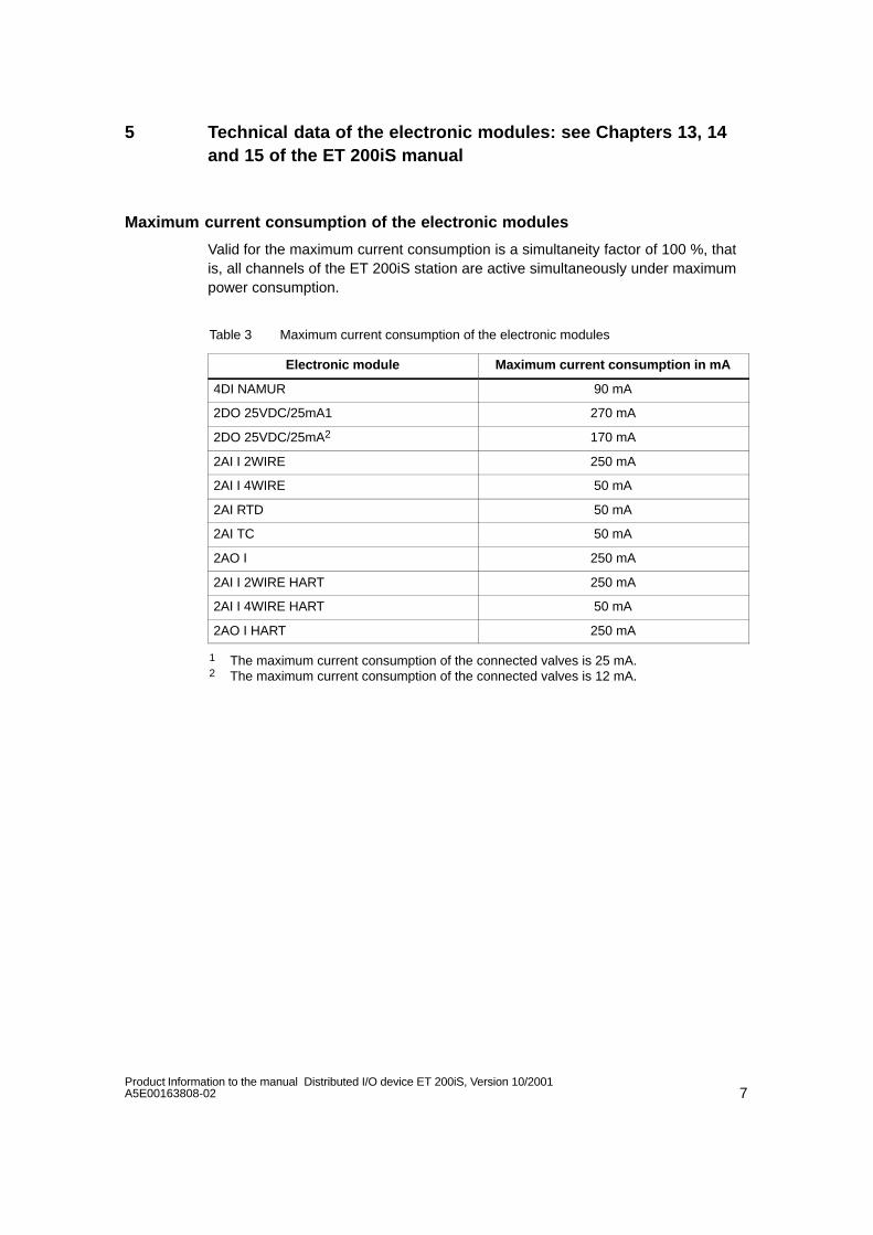
7Product Information to the manual Distributed I/O device ET 200iS, Version 10/2001A5E00163808-02
5 Technical data of the electronic modules: see Chapters 13, 14and 15 of the ET 200iS manual
Maximum current consumption of the electronic modules
Valid for the maximum current consumption is a simultaneity factor of 100 %, thatis, all channels of the ET 200iS station are active simultaneously under maximumpower consumption.
Table 3 Maximum current consumption of the electronic modules
Electronic module Maximum current consumption in mA
4DI NAMUR 90 mA
2DO 25VDC/25mA1 270 mA
2DO 25VDC/25mA2 170 mA
2AI I 2WIRE 250 mA
2AI I 4WIRE 50 mA
2AI RTD 50 mA
2AI TC 50 mA
2AO I 250 mA
2AI I 2WIRE HART 250 mA
2AI I 4WIRE HART 50 mA
2AO I HART 250 mA
1 The maximum current consumption of the connected valves is 25 mA.2 The maximum current consumption of the connected valves is 12 mA.
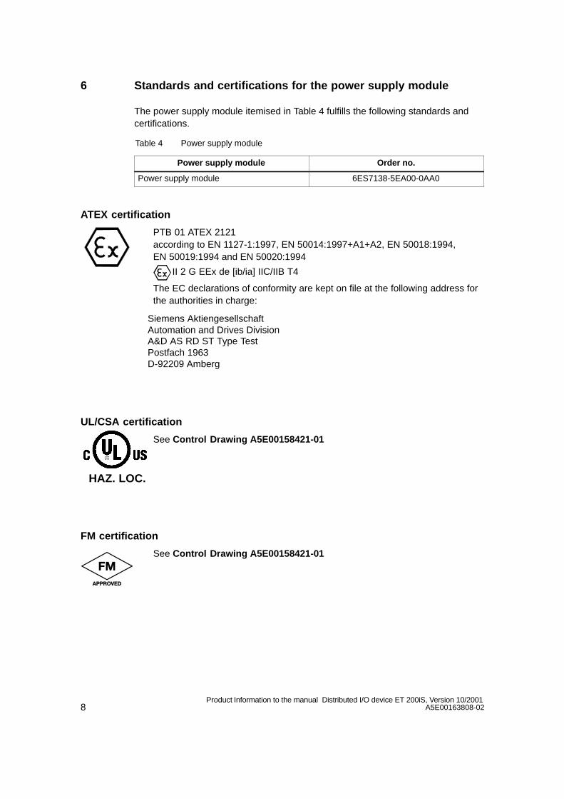
8Product Information to the manual Distributed I/O device ET 200iS, Version 10/2001
A5E00163808-02
6 Standards and certifications for the power supply module
The power supply module itemised in Table 4 fulfills the following standards andcertifications.
Table 4 Power supply module
Power supply module Order no.
Power supply module 6ES7138-5EA00-0AA0
ATEX certification
PTB 01 ATEX 2121according to EN 1127-1:1997, EN 50014:1997+A1+A2, EN 50018:1994,EN 50019:1994 and EN 50020:1994
II 2 G EEx de [ib/ia] IIC/IIB T4
The EC declarations of conformity are kept on file at the following address forthe authorities in charge:
Siemens AktiengesellschaftAutomation and Drives Division A&D AS RD ST Type TestPostfach 1963D-92209 Amberg
UL/CSA certification
See Control Drawing A5E00158421-01
FM certification
See Control Drawing A5E00158421-01
HAZ. LOC.
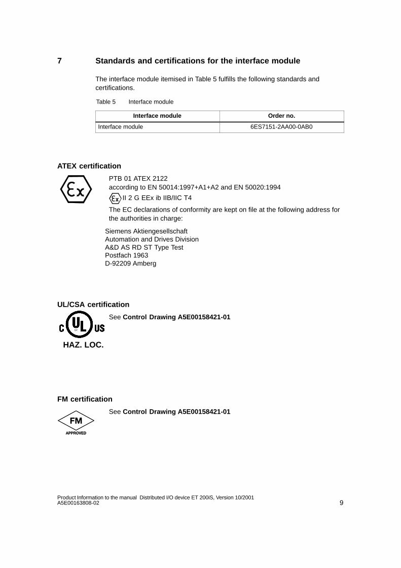
9Product Information to the manual Distributed I/O device ET 200iS, Version 10/2001A5E00163808-02
7 Standards and certifications for the interface module
The interface module itemised in Table 5 fulfills the following standards andcertifications.
Table 5 Interface module
Interface module Order no.
Interface module 6ES7151-2AA00-0AB0
ATEX certification
PTB 01 ATEX 2122 according to EN 50014:1997+A1+A2 and EN 50020:1994
II 2 G EEx ib IIB/IIC T4
The EC declarations of conformity are kept on file at the following address forthe authorities in charge:
Siemens AktiengesellschaftAutomation and Drives Division A&D AS RD ST Type TestPostfach 1963D-92209 Amberg
UL/CSA certification
See Control Drawing A5E00158421-01
FM certification
See Control Drawing A5E00158421-01
HAZ. LOC.

10Product Information to the manual Distributed I/O device ET 200iS, Version 10/2001
A5E00163808-02
8 Standards and certifications of the electronics modules
The electronics modules itemised in Table 6 fulfill the following standards andcertifications.
Table 6 Electronics modules
Electronics modules Order no.
4DI NAMUR 6ES7131-5RD00-0AB0
2DO DC25V/25mA 6ES7132-5SB00-0AB0
2AI I 2WIRE 6ES7134-5RB00-0AB0
2AI I 4WIRE 6ES7134-5RB50-0AB0
2AI RTD 6ES7134-5SB50-0AB0
2AI TC 6ES7134-5SB00-0AB0
2AI I 2WIRE HART 6ES7134-5TB00-0AB0
2AI I 4WIRE HART 6ES7134-5TB50-0AB0
2AO I 6ES7135-5RB00-0AB0
2AO I HART 6ES7135-5TB00-0AB0
ATEX certification
KEMA 01 ATEX 1150, 1151, 1152, 1153, 1154, 1155, 1156 X according to EN 50014:1997, EN 50020:1994 and EN 50284:1999
II 2 G (1) GD EEx ib [ia] IIC T4
The EC declarations of conformity are kept on file at the following address forthe authorities in charge:
Siemens AktiengesellschaftAutomation and Drives Division A&D AS RD ST Type TestPostfach 1963D-92209 Amberg
Note
Electronics modules of device category 2G may be used in zone 1 hazardousareas. Sensors of device categories 1G, 2G and 3G may be connected to theintrinsically safe inputs of the electronics modules for zones 0, 1 and 2; sensors ofdevice categories 1D, 2D and 3D may be used for zones 20, 21 and 22.

11Product Information to the manual Distributed I/O device ET 200iS, Version 10/2001A5E00163808-02
UL/CSA certification
See Control Drawing A5E00158421-01
FM certification
See Control Drawing A5E00158421-01
HAZ. LOC.

12Product Information to the manual Distributed I/O device ET 200iS, Version 10/2001
A5E00163808-02

Copyright 2004 by Siemens AGA5E00207628-02
Product Information
Release 02.2004
RS 485-IS Coupler (6ES7 972-0AC80-0XA0)
This Product Information contains important information concerning the “ET 200iS Distribute I/OStation” Manual, order no. 6ES7 151-2AA00-8BA0. Its is to be understood as separate part ofthe documentation, and in case of any uncertainty overrides all other information in manualsand catalogs.
Special information
This product information refers to PROFIBUS RS 485-IS, and includes adescription of PROFIBUS DP Ex i.
Differences between PROFIBUS RS 485-IS and PROFIBUS DP Ex i aredocumented separately.
Chapter overview
Chapter Topic Page
1 Function 2
2 Features 4
3 Installation / Removal 6
4 Wiring 8
5 Commissioning 18
6 Diagnostics 18
7 Maximum configuration 19
8 Technical Specifications 20
9 Order Numbers 25
10 Certifications 25

2Product Information RS 485-IS Coupler (6ES7 972-0AC80-0XA0)
A5E00207628-02
1 Function
The RS 485-IS Coupler converts PROFIBUS-DP to PROFIBUS RS 485-IS withintrinsic safety (intrinsic safety ignition type i). The RS 485-IS coupler operateshere as a safety barrier. IS stands for “Intrinsically Safe”.
Fields of application
The RS 485-IS Coupler is used to isolate the intrinsically safe PROFIBUS RS 485-IS from PROFIBUS-DP which is not intrinsically safe.
Note
You may connect to the RS 485-IS Coupler:
Up to 31 stations (Field Devices RS 485-IS) with PROFIBUS RS 485-ISinterface,
or
Up to 16 stations (ET 200iS stations) with PROFIBUS DP Ex i interface.
Mixed mode within the same segment is not permitted!
Structure
You need an RS 485-IS Coupler in order to be able to operate RS 485-IS fielddevices or an ET 200iS in potentially explosive atmospheres (see and ).
You need two RS 485-IS Couplers to amplify data signals on the bus andcouple bus segments (see ).
The repeater function by means of two RS 485-IS Couplers is required:
– When the number of stations operated in the Ex area exceeds the approvednumber
– When the maximum cable length is exceeded at a segment in the Ex area
– To couple a PROFIBUS RS 485-IS segment to a PROFIBUS DP Ex i segment
The RS 485-IS Coupler also allows you to connect devices to PROFIBUS RS485-IS which can be operated only in Zone 2, e.g. operating panels (see ).

3Product Information RS 485-IS Coupler (6ES7 972-0AC80-0XA0)A5E00207628-02
Note
The internal bus terminator of the RS 485 IS Coupler must be switched on foroperation on PROFIBUS DP Ex i. Looping of the PROFIBUS DP Ex i is not permitted (see )!
ET 200iS
PROFIBUS DP
PROFIBUS RS 485-IS
PROFIBUS RS 485-IS
Zone 1
Zone 2
Field Device RS 485-IS
PROFIBUS RS 485-IS
PROFIBUS DP Ex i
Field Device RS 485-IS
Field DeviceRS 485-IS Field Device
RS 485-IS
PROFIBUS DP Ex i
ET 200iSET 200iS
Figure 1 RS 485-IS Coupler Fields of Application
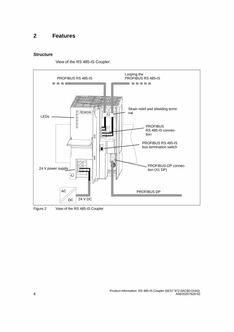
4Product Information RS 485-IS Coupler (6ES7 972-0AC80-0XA0)
A5E00207628-02
2 Features
Structure
View of the RS 485-IS Coupler:
AC
DC
PROFIBUS DP
24 V power supply
Strain relief and shielding termi-nal
PROFIBUS RS 485-IS connec-tion
PROFIBUS-DP connec-tion (X1 DP)
24 V DC
PROFIBUS RS 485-IS bus termination switch
PROFIBUS RS 485-ISLooping the PROFIBUS RS 485-IS
LEDs
Figure 2 View of the RS 485-IS Coupler
5Product Information RS 485-IS Coupler (6ES7 972-0AC80-0XA0)A5E00207628-02
Features
Characteristics of the RS 485-IS Coupler:
Transmission speed between 9.6 kbps and 1.5 Mbps
Diagnostics by means of LED indicators
Integrated bus termination for PROFIBUS RS 485-IS
Up to 31 / 16 stations can be operated on any RS 485-IS Coupler (see Chapter8.3 Technical data).
Repeater function for the Ex area by means two RS 485-IS Couplers (sameresponse as RS 485 Repeater)
Certification to ATEX 100a
Corresponding equipment for use in potentially explosive areas Zone 1, 2
Intrinsic safety for PROFIBUS RS 485-IS subnet
Operation of the RS 485-IS Coupler as RS 485 Repeater
In order to be able to increase the lengths of your PROFIBUS RS 485-ISsegments in the Ex area, you may operate two RS 485-IS Couplers in RS 485repeater mode. Please note:
You may operate a maximum of five segments in series.
The segment cable length specified in the technical data in Chapter 8.3 must beadhered to.

6Product Information RS 485-IS Coupler (6ES7 972-0AC80-0XA0)
A5E00207628-02
3 Installation / Removal
Installation Position
The RS 485-IS Coupler can be mounted vertically or horizontally. The maximumambient temperature in vertical mounting position is 40 C.
Open Equipment
The RS 485-IS Coupler is an of the open equipment class, i.e. it may only beinstalled in lockable or mechanically secured enclosures, cabinets or electricalswitch rooms. Access to these enclosures, cabinets or electrical switch rooms isonly permitted to instructed or authorized personnel.
Installation technique
The RS 485-IS Coupler is mounted on a DIN rail for S7 installation technology.Make allowances for trouble–free installation by maintaining a clearance of 40 mmat the bottom and the top of the module.
For further information relating to the S7 installation technique for modules, refer tothe S7-300 Automation System, Installation Installation Manual.
Note
The RS 485-IS Coupler does not transfer signals on the S7 backplane bus.
Installation location
The RS 485-IS Coupler may be operated in potentially explosive atmospheres ofZone 2, provided it is mounted in suitable enclosures. The PROFIBUS RS 485-ISbus cable may be routed from the potentially explosive area to Zone 1.
Enclosures for Zone 2
The RS 485-IS Coupler must be installed in an enclosure with minimum IP 54. Foroperation of the enclosure and cable glands in Zone 2 a declaration of conformityto EN 50021 must be provided by the manufacturer.

7Product Information RS 485-IS Coupler (6ES7 972-0AC80-0XA0)A5E00207628-02
!Danger
Installation procedures may cause ignition by sparking or impermissible surfacetemperatures.
Never install the equipment under potentially explosive conditions !
Components Required
Profile rail for S7 installation technology
RS 485-IS Coupler
The order numbers are found in Chapter 9.
Installation
1. Mount the S7 profile rail onto a solid carrier.
2. Suspend the RS 485-IS Coupler onto the S7 profile rail, and then swivel itdownwards.
3. Screw-tighten the RS 485-IS Coupler.
Removal
You remove the RS 485-IS Couplers in reverse sequence.
Before you remove an RS 485-IS Coupler that is in operation, switch off the 24 V DC power supply to the coupler.
8Product Information RS 485-IS Coupler (6ES7 972-0AC80-0XA0)
A5E00207628-02
4 Wiring
Note
Before you start wiring the system, please note the information in “General rulesand regulations for wiring” in Chapter 6 of the Distributed i/O device ET 200iSManual.
Chapter overview
Chapter Topic Page
4.1 Potential Isolation and Grounding 8
4.2 Operation on a grounded power supply 9
4.3 Operation with ungrounded reference potential 11
4.4 Terminals of the RS 485-IS Coupler 12
4.5 Connecting the power supply 13
4.6 Connecting PROFIBUS-DP 14
4.7 Connecting PROFIBUS RS 485-IS 15
4.1 Potential Isolation and Grounding
You may wire up a grounded or ungrounded 24 V power supply system, dependingon the requirements of your assembly.
Characteristics of the RS 485-IS Coupler
PROFIBUS-DP and the internal logic are galvanically interconnected
PROFIBUS-DP and PROFIBUS RS 485-IS are galvanically isolated from the24 V power supply
PROFIBUS-DP is galvanically isolated from PROFIBUS RS 485-IS

9Product Information RS 485-IS Coupler (6ES7 972-0AC80-0XA0)A5E00207628-02
4.2 Operation on a grounded power supply
Definition: Grounded–Neutral Supply
In a grounded power supply system, the neutral conductor of the mains is bondedto earth. A short of the live conductor to ground or to chassis ground of the systemtrips the protective devices.
Components and Protective Measures
Regulations prescribe various system components and compulsory protectivemeasures for the installation of a plant. The type of components and compulsoryprotective measures depends on which DIN VDE regulation applies to your systeminstallation.
Master switch (see Figure 3, ): DIN VDE 0100 Part 460
Isolating link (see Figure 3, ): DIN VDE 0113 part 1
RS 485-IS Coupler on Grounded–Neutral Power Supply
Figure 3 shows the position of the RS 485-IS Coupler in a system connected to aTN-S power network. When the RS 485-IS Coupler is connected to groundedreference potential, all parasitic currents are discharged to ground via thegrounding conductor.
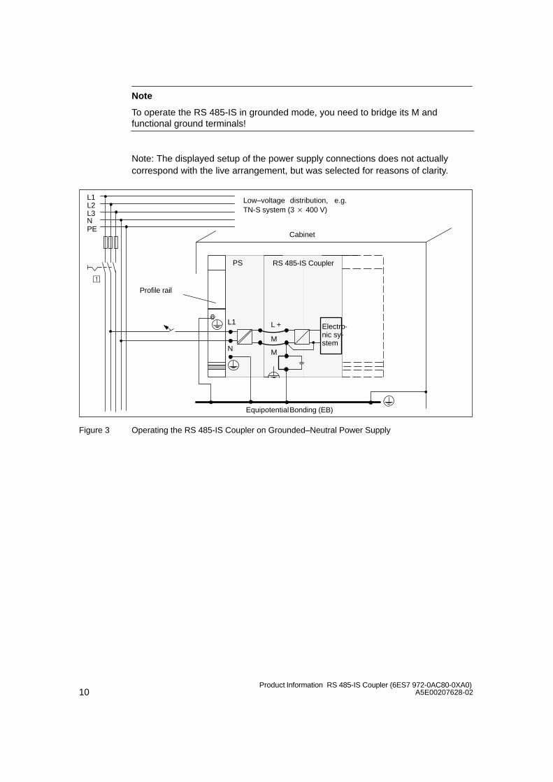
10Product Information RS 485-IS Coupler (6ES7 972-0AC80-0XA0)
A5E00207628-02
Note
To operate the RS 485-IS in grounded mode, you need to bridge its M andfunctional ground terminals!
Note: The displayed setup of the power supply connections does not actuallycorrespond with the live arrangement, but was selected for reasons of clarity.
Equipotential Bonding (EB)
N M
L1 L +
M
PS
L1L2L3N
Cabinet
Low–voltage distribution, e.g.TN-S system (3 400 V)
PE
Profile rail
RS 485-IS Coupler
Electro-nic sy-stem
Figure 3 Operating the RS 485-IS Coupler on Grounded–Neutral Power Supply

11Product Information RS 485-IS Coupler (6ES7 972-0AC80-0XA0)A5E00207628-02
4.3 Operation with ungrounded reference potential
Application
In large–scale systems you may have to install the RS 485-IS Coupler withungrounded reference potential, for example, for monitoring short–circuit toground. This applies in particular to systems operated in the chemical industry or inpower plants, for example.
Discharging Parasitic Currents
In RS 485-IS Coupler installations with ungrounded reference potential, developingparasitic currents are discharged to protective ground via an integral capacitor (seeFigure 4).
Wiring Diagram
Figure 4 shows an installation of the RS 485-IS Coupler with ungrounded referencepotential. If you choose not to ground the reference potential of the 24 V power ofyour RS 485-IS Coupler, you need to remove the jumper between the Mterminals and system ground. As long as this jumper is removed, the referencepotential of the RS 485-IS Coupler is connected internally to the profile rail and thegrounding conductor via a capacitor.
M
L
+M
Equipotential Bonding (EB)
M22 nF
Figure 4 Installing the RS 485-IS Coupler with Ungrounded Reference Potential
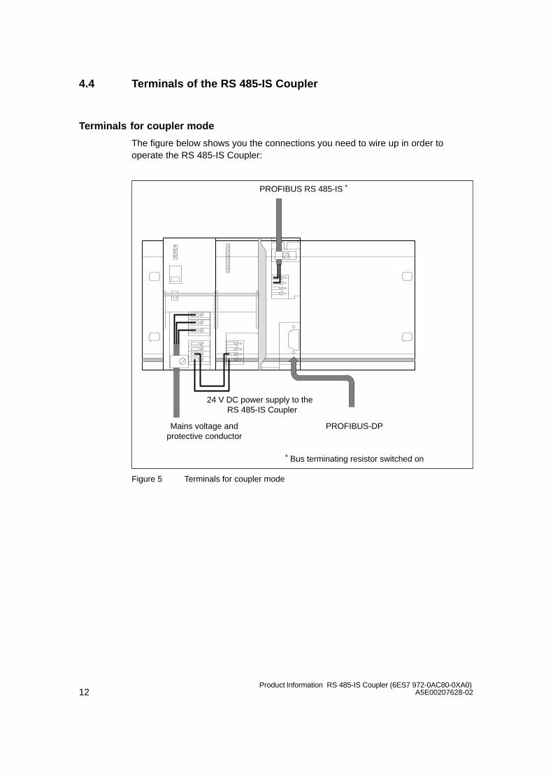
12Product Information RS 485-IS Coupler (6ES7 972-0AC80-0XA0)
A5E00207628-02
4.4 Terminals of the RS 485-IS Coupler
Terminals for coupler mode
The figure below shows you the connections you need to wire up in order tooperate the RS 485-IS Coupler:
Mains voltage andprotective conductor
24 V DC power supply to the RS 485-IS Coupler
PROFIBUS-DP
PROFIBUS RS 485-IS *
* Bus terminating resistor switched on
Figure 5 Terminals for coupler mode

13Product Information RS 485-IS Coupler (6ES7 972-0AC80-0XA0)A5E00207628-02
Terminals for RS 485 Repeatermode
You need two RS 485-IS Couplers for operation in RS 485 Repeater mode. Thefigure below shows you the connections required for operation in RS 485-Repeatermode in Ex areas:
Line voltage andprotective conductor
24 V DC power supply to the RS 485-ISCoupler
PROFIBUS RS 485-IS *PROFIBUS RS 485-IS *
PROFIBUS-DP
* Bus terminating resistor switched on
Figure 6 Terminals for RS 485 Repeatermode
4.5 Connecting the power supply
Tools required
You need a screwdriver with a 3 mm blade to terminate the power supply cables.

14Product Information RS 485-IS Coupler (6ES7 972-0AC80-0XA0)
A5E00207628-02
Power supply terminals
Pin assignment of the 4-pole screw terminals for the 24 V power supply:
ML +M
System Ground
M (24 V DC)
L+ (24 V DC)
M (24 V DC)
Removablejumper forungroundedinstallation
Figure 7 Power supply for the RS 485-IS Coupler
The maximum conductor cross-section is 2.5 mm2. A strain relief is not provided.
4.6 Connecting PROFIBUS-DP
Tools required
You need a screwdriver with a 3 mm blade to terminate the power supply cables.
Bus cables and connectors
Always use the accessories specified in Chapter 4.7 for PROFIBUS-DP.
PROFIBUS-DP Connector
The 9-pin PROFIBUS-DP connector is located behind the bottom of the right-handfront-panel door of your RS 485-IS Coupler. Designation of the terminals:
Table 1 Pin-assignment of the PROFIBUS-DP connector
View Pin Signal Description
1 – –
52 – –
4
59 3 RxD / TxD–P Data line B (suggested: red)
3
48
9
4 RTS Request To Send3
7
85 M5V Data reference potential (from station)
6 2
76 P5V Power supply + (from station)
6
1
27 – –
18 RxD / TxD–N Data line A (suggested: green)
9 – –

15Product Information RS 485-IS Coupler (6ES7 972-0AC80-0XA0)A5E00207628-02
Procedure
To connect your PROFIBUS-DP:
1. Insert the bus connector into the PROFIBUS socket.
2. Screw–tighten the bus connector.
3. When you install the RS 485-IS Coupler at the end of the PROFIBUS-DPsegment, you need to switch on the terminating resistor on the bus connector.
4.7 Connecting PROFIBUS RS 485-IS
The following contents are mandatory for the installation of PROFIBUS RS 485-IS:
PNO guideline “PROFIBUS RS 485-IS User and Installation Guide, Version 1.0,May 2003PROFIBUS-Nutzerorganisation e. V., Haid-und-Neu-Straße 7, D-76131 Karlsruhe, Germany
Further information is found on the Internet:
http://www.profibus.com.
Installation regulations to IEC 60079-14 (Installation of Electrical Systems inPotentially Explosive Atmospheres)
!Warning
Always bond the RS 485-IS Coupler to equipotential ground before you connectthe PROFIBUS RS 485-IS at its terminals!
Tools required
You need a screwdriver with a 3 mm blade to terminate the PROFIBUS RS 485-IScables.

16Product Information RS 485-IS Coupler (6ES7 972-0AC80-0XA0)
A5E00207628-02
PROFIBUS RS 485-IS connector
The 4-pole screw terminals for the PROFIBUS RS 485-IS are located below theright–hand side of the front door of the RS 485-IS Coupler. Designation of theterminals:
Strain reliefand shieldingterminal
outgoing line A, terminal A’
Bus cable
outgoing line B, terminal B’
Shielding
incoming line A, terminal Aincoming line B, terminal B
PROFIBUS RS 485-IS through-looping:Position of the PROFIBUS RS 485-IS bustermination switch: OFF
OFF
ON
Bus cable(through-looping)
Figure 8 PROFIBUS RS 485-IS connection
Note
The signal is not amplified between the two screw terminals of the PROFIBUS RS 485-IS cable!
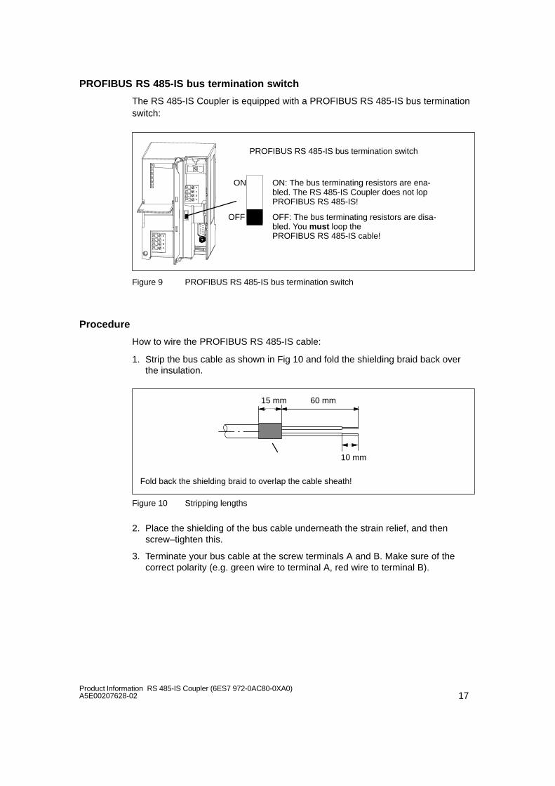
17Product Information RS 485-IS Coupler (6ES7 972-0AC80-0XA0)A5E00207628-02
PROFIBUS RS 485-IS bus termination switch
The RS 485-IS Coupler is equipped with a PROFIBUS RS 485-IS bus terminationswitch:
PROFIBUS RS 485-IS bus termination switch
OFF
ON
OFF: The bus terminating resistors are disa-bled. You must loop the PROFIBUS RS 485-IS cable!
ON: The bus terminating resistors are ena-bled. The RS 485-IS Coupler does not lopPROFIBUS RS 485-IS!
Figure 9 PROFIBUS RS 485-IS bus termination switch
Procedure
How to wire the PROFIBUS RS 485-IS cable:
1. Strip the bus cable as shown in Fig 10 and fold the shielding braid back overthe insulation.
Fold back the shielding braid to overlap the cable sheath!
15 mm 60 mm
10 mm
Figure 10 Stripping lengths
2. Place the shielding of the bus cable underneath the strain relief, and thenscrew–tighten this.
3. Terminate your bus cable at the screw terminals A and B. Make sure of thecorrect polarity (e.g. green wire to terminal A, red wire to terminal B).
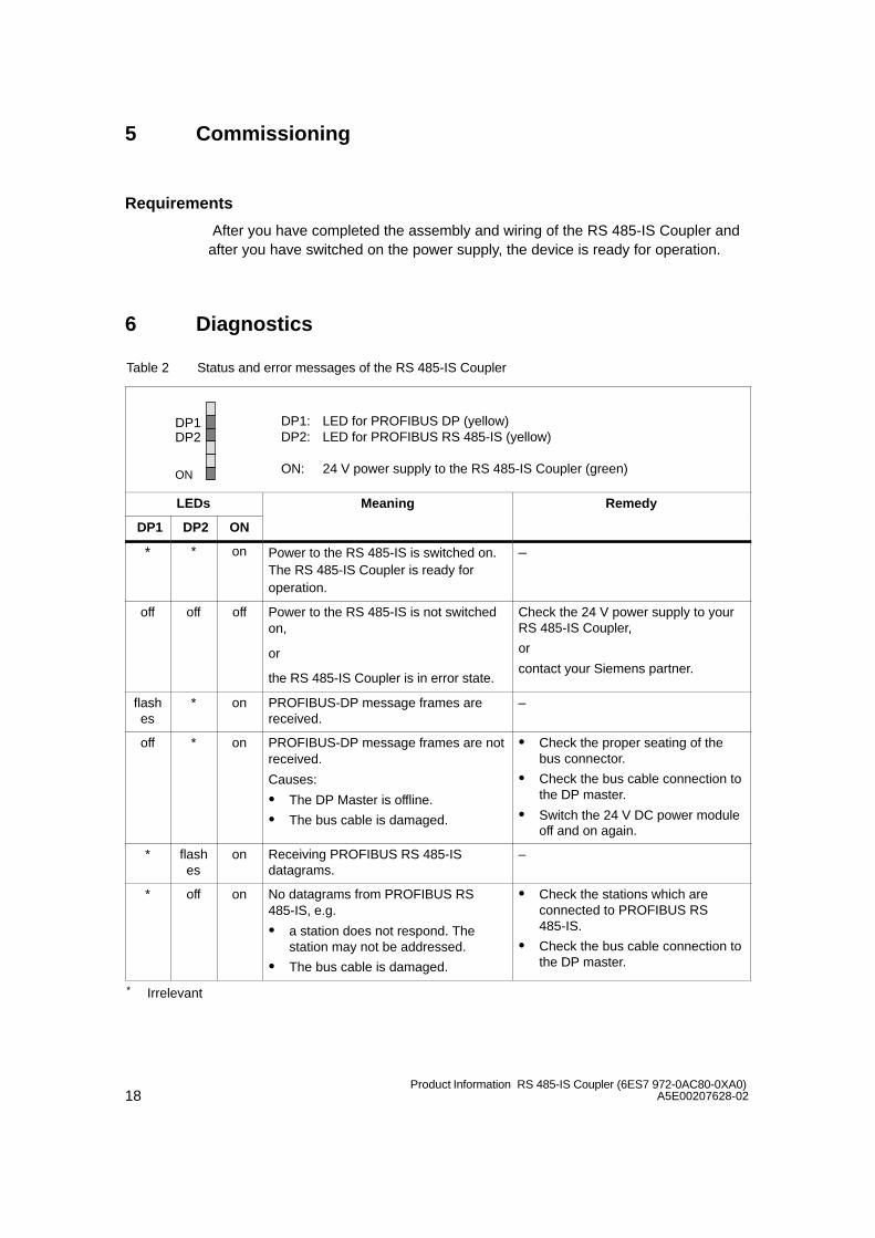
18Product Information RS 485-IS Coupler (6ES7 972-0AC80-0XA0)
A5E00207628-02
5 Commissioning
Requirements
After you have completed the assembly and wiring of the RS 485-IS Coupler andafter you have switched on the power supply, the device is ready for operation.
6 Diagnostics
Table 2 Status and error messages of the RS 485-IS Coupler
DP1
ON
DP2DP1: LED for PROFIBUS DP (yellow)DP2: LED for PROFIBUS RS 485-IS (yellow)
ON: 24 V power supply to the RS 485-IS Coupler (green)
LEDs Meaning Remedy
DP1 DP2 ON
* * on Power to the RS 485-IS is switched on.The RS 485-IS Coupler is ready foroperation.
–
off off off Power to the RS 485-IS is not switchedon,
or
the RS 485-IS Coupler is in error state.
Check the 24 V power supply to yourRS 485-IS Coupler,
or
contact your Siemens partner.
flashes
* on PROFIBUS-DP message frames arereceived.
–
off * on PROFIBUS-DP message frames are notreceived.
Causes:
The DP Master is offline.
The bus cable is damaged.
Check the proper seating of thebus connector.
Check the bus cable connection tothe DP master.
Switch the 24 V DC power moduleoff and on again.
* flashes
on Receiving PROFIBUS RS 485-ISdatagrams.
–
* off on No datagrams from PROFIBUS RS485-IS, e.g.
a station does not respond. Thestation may not be addressed.
The bus cable is damaged.
Check the stations which areconnected to PROFIBUS RS485-IS.
Check the bus cable connection tothe DP master.
* Irrelevant

19Product Information RS 485-IS Coupler (6ES7 972-0AC80-0XA0)A5E00207628-02
7 Maximum configuration
Introduction
In order to be able to use distributed i/O devices in Ex area Zone 1, thePROFIBUS DP must be installed intrinsically safe. You can separate theintrinsically safe PROFIBUS RS 485 IS from PROFIBUS DP with the help of theRS 485-IS Coupler.
Safety Data
At the RS 485-IS Coupler, you may only connect field devices which are certifiedfor operation on a PROFIBUS RS 485-IS interface or ET 200iS with PROFIBUSDP Ex i interface:
Up to 31 stations (Field Devices RS 485-IS) with PROFIBUS RS 485-ISinterface,
Up to 16 stations (ET 200iS stations) with PROFIBUS DP Ex i interface.
Mixed mode within the same segment is not permitted!

20Product Information RS 485-IS Coupler (6ES7 972-0AC80-0XA0)
A5E00207628-02
8 Technical Specifications
Chapter overview
Chapter Topic Page
8.1 General Technical Specifications 20
8.2 Standards, Certificates and Approvals 21
8.3 Technical Specifications 24
8.1 General Technical Specifications
General technical data of the RS 485-IS Coupler are found in Chapter 9 of theDistributed I/O Device ET 200iS Manual. Standards and approvals for theRS 485-IS Coupler are found in the following chapter 8.2.
Climatic Ambient Conditions
The following specification concerning the ambient climatic conditions for operationthe of RS 485-IS Coupler overrides the general technical data in the Distributed I/ODevices ET 200iS Manual:
Table 3 Climatic Ambient Conditions
Ambient Conditions Permissible Range
Temperature
Horizontal mounting position
Vertical mounting position
– 25 to 60 C
– 25 to 40 C

21Product Information RS 485-IS Coupler (6ES7 972-0AC80-0XA0)A5E00207628-02
8.2 Standards, Certificates and Approvals
The RS 485-IS Coupler is compliant with the following standards and approvals.
CE Certification
The RS 485-IS Coupler meets the requirements and safety objectives of thefollowing EC directives, and it is compliant with the harmonized Europeanstandards (EN) which are published in the official documentation of the EuropeanUnion:
89/336/EC ”Electromagnetic Compatibility” (EMC Guideline)
73/23/EC ”Electrical Equipment for Operation Within Specific Voltage Limits”(low-voltage guideline)
The EC Declarations of Conformity are available to the relevant authorities at:
Siemens AktiengesellschaftAutomation and Drives A&D AS RD ST PLCPO-Box 1963D-92209 Amberg
UL and CSA certification
Underwriters Laboratories Inc. to
UL 508 (Industrial Control Equipment)
CAN/CSA C22.2 No. 14-M91 (Process Control Equipment)
UL 1604, Third Edition (Hazardous Location)
UL 913, Sixth Edition (Hazardous Location)
UL 2279, First Edition (Hazardous Location)
CAN/CSA C22.2 No. 213-M1987
CAN/CSA C22.2 No. 157-92
E79-11 und E79-15
APPROVED for use inClass I, Division 2, Group A, B, C, D T4;Class I, Zone 2, Group IIC T4AIS Class I, Division 1, Group A, B, C, D[AExib] IIC, Class I, Zone 1, 2, Group IIC
HAZ. LOC.
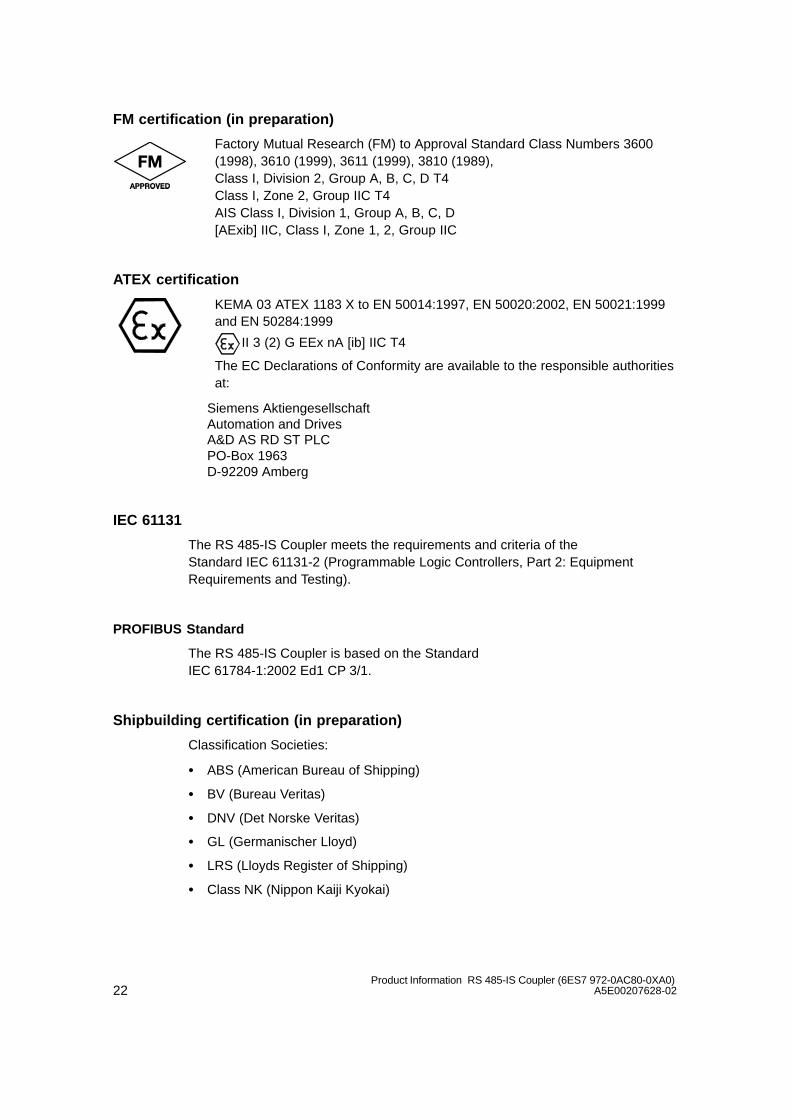
22Product Information RS 485-IS Coupler (6ES7 972-0AC80-0XA0)
A5E00207628-02
FM certification (in preparation)
Factory Mutual Research (FM) to Approval Standard Class Numbers 3600(1998), 3610 (1999), 3611 (1999), 3810 (1989),Class I, Division 2, Group A, B, C, D T4Class I, Zone 2, Group IIC T4AIS Class I, Division 1, Group A, B, C, D[AExib] IIC, Class I, Zone 1, 2, Group IIC
ATEX certification
KEMA 03 ATEX 1183 X to EN 50014:1997, EN 50020:2002, EN 50021:1999and EN 50284:1999
II 3 (2) G EEx nA [ib] IIC T4
The EC Declarations of Conformity are available to the responsible authoritiesat:
Siemens AktiengesellschaftAutomation and Drives A&D AS RD ST PLCPO-Box 1963D-92209 Amberg
IEC 61131
The RS 485-IS Coupler meets the requirements and criteria of the Standard IEC 61131-2 (Programmable Logic Controllers, Part 2: EquipmentRequirements and Testing).
PROFIBUS Standard
The RS 485-IS Coupler is based on the Standard IEC 61784-1:2002 Ed1 CP 3/1.
Shipbuilding certification (in preparation)
Classification Societies:
ABS (American Bureau of Shipping)
BV (Bureau Veritas)
DNV (Det Norske Veritas)
GL (Germanischer Lloyd)
LRS (Lloyds Register of Shipping)
Class NK (Nippon Kaiji Kyokai)

23Product Information RS 485-IS Coupler (6ES7 972-0AC80-0XA0)A5E00207628-02
Industrial Use
SIMATIC products are designed for industrial applications.
Table 4 Industrial Use
Fields of application Requirements on
Noise emission Interference-proofing
Industry EN 61000-6-4: 2001 EN 61000-6-2: 2001
Operation in Residential Areas
To operate the RS 485-IS Coupler in residential areas, the degree of radiointerference must comply with limit class B to EN 55011.
Suitable measures for ensuring radio interference limit class B are:
Installation of the RS 485-IS Coupler in grounded switch cabinets/cubicles
Installation of noise filters in the supply lines
!Warning
There is a risk of harm to persons and material damage.
In potentially explosive locations there is a risk of harm to persons and materialdamage, if you disconnect a connector while the RS 485-IS Coupler is inoperation.
In potentially explosive locations, always switch off power before you disconnectany one of the RS 485 Coupler connectors.

24Product Information RS 485-IS Coupler (6ES7 972-0AC80-0XA0)
A5E00207628-02
8.3 Technical data RS 485-IS Coupler (6ES7 972-0AC80-0XA0)
Dimensions and Weight
Dimensions WHD (mm)
80125130
Weight approx. 500 g
Module–specific Data
Transmission rate onPROFIBUS-DP, PROFIBUS RS 485-IS
9.6; 19.2; 45.45; 93.75;187.5; 500 kbps; 1.5 Mbps
Bus protocol PROFIBUS-DP
Voltages, Currents, Potentials
Power supplyvoltage to theRS 485-IS Coupler
24 V DC(20.4 V to 28.8 V)
Polarity reversalprotection
yes
Power failurebuffering
min. 5 ms
Potential isolation of the 24 V power supply
to PROFIBUS-DP yesto PROFIBUS-DP
Tested with
yes
DC 500 V
to PROFIBUS RS 485-IS
yes RS 485-IS
Tested with
AC 1500 V
Current consumptionof theRS 485-IS Coupler (24 V DC)
max. 150 mA
Power loss of themodule
typically 3 W
Status, Interrupts, Diagnostics
Status display No
Interrupts none
Diagnostic Functions yes
PROFIBUS-DP (primary) busmonitoring
yellow LED ”DP1”
PROFIBUS RS 485-IS (secondary) busmonitoring
yellow LED ”DP2”
24 V power supplymonitoring
green LED ”ON”
Notes on safety
U0 = VDC = 4.2 V
I0 = ISC = 93 mA
P0 = 0.1 W
Ui Vmax.= 4.2 V
Li, Ci 0 (can be neglected)
Am = 250 VAC
Ta = -25 to +60 C
RS 485-IS segment
permissible cablelength for one segment
9.6 to 187.5 kbps
500 kbps
1.5 Mbps
RS 485-IS
1000 m
400 m
200 m
DP Ex i
200 m
200 m
200 m
Maximum number ofstations on PROFIBUSDP
max. 31 max. 16
PROFIBUS RS 485-ISbus termination switch
integral, switched

25Product Information RS 485-IS Coupler (6ES7 972-0AC80-0XA0)A5E00207628-02
9 Order numbers
Table 5 RS 485-IS Coupler Order Number
Component Order Number
RS 485-IS Coupler 6ES7 972-0AC80-0XA0
Profile rail for S7 installation technology
480 mm
530 mm
620 mm
2000 mm
6ES7 390-1AE80-0AA0
6ES7 390-1AF30-0AA0
6ES7 390-1AJ30-0AA0
6ES7 390-1BC00-0AA0
PROFIBUS-DPbus connector
for PROFIBUS-DP through–loop (without PG socket)
6ES7 972-0BA30-0XA0
PROFIBUS-DP bus cable
standard (flexible) 6XV1 830-0EH10
10 Certifications
Chapter overview
Topic
EC-TYPE EXAMINATION CERTIFICATE
Declaration of EC-Conformity
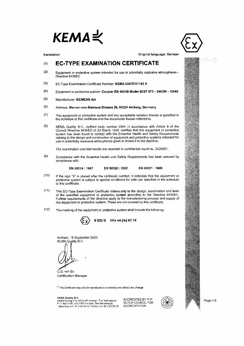
26Product Information RS 485-IS Coupler (6ES7 972-0AC80-0XA0)
A5E00207628-01

27Product Information RS 485-IS Coupler (6ES7 972-0AC80-0XA0)A5E00207628-01

28Product Information RS 485-IS Coupler (6ES7 972-0AC80-0XA0)
A5E00207628-01
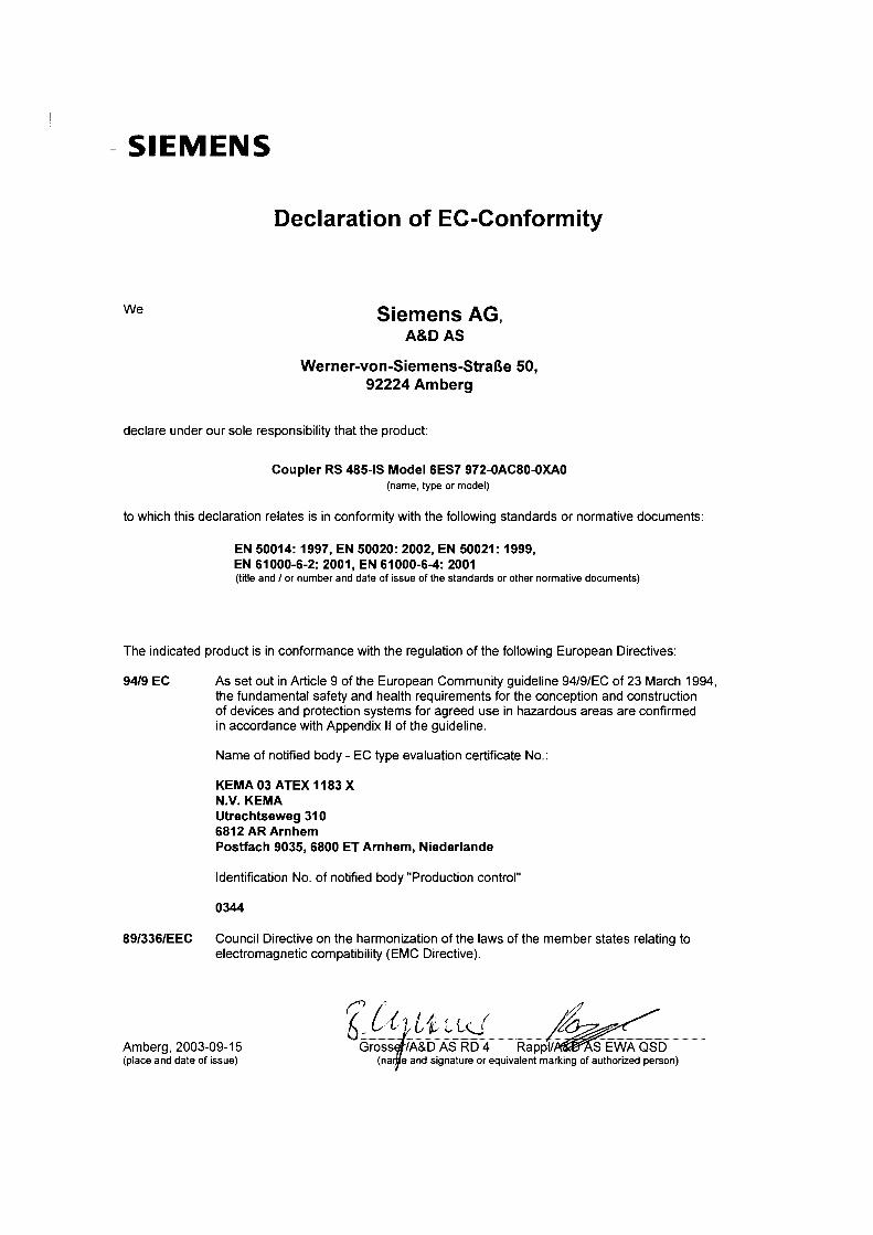
28Produktinformation RS 485-IS Koppler (6ES7 972-0AC80-0XA0)
A5E00207082-01

28Product Information RS 485-IS Coupler (6ES7 972-0AC80-0XA0)
A5E00207628-02
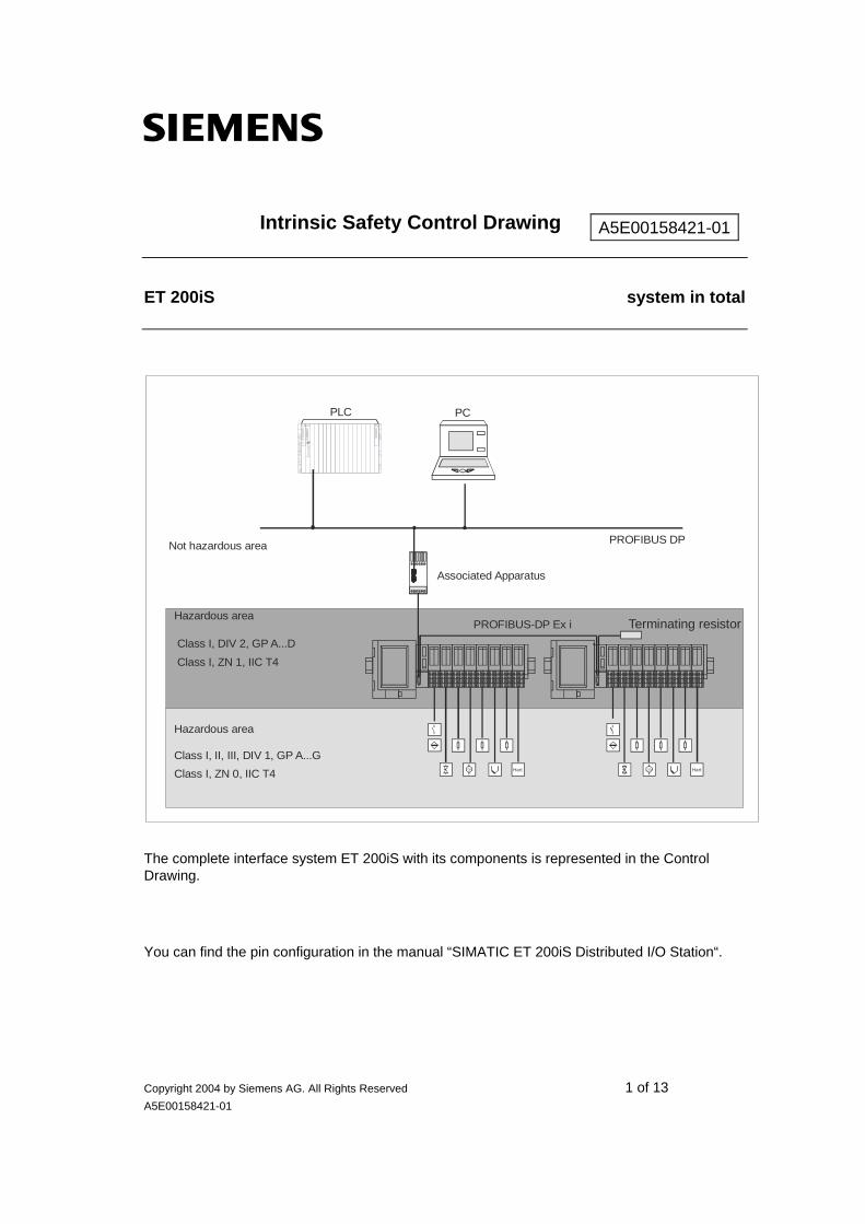
s
Copyright 2004 by Siemens AG. All Rights Reserved 1 of 13 A5E00158421-01
Intrinsic Safety Control Drawing
ET 200iS system in total
The complete interface system ET 200iS with its components is represented in the Control Drawing.
You can find the pin configuration in the manual “SIMATIC ET 200iS Distributed I/O Station“.
A5E00158421-01
PC
Associated Apparatus
PLC
PROFIBUS DPNot hazardous area
Hazardous area
Class I, DIV 2, GP A...D Class I, ZN 1, IIC T4
Hazardous area
Class I, II, III, DIV 1, GP A...GClass I, ZN 0, IIC T4
PROFIBUS-DP Ex i Terminating resistor
Hart Hart

Intrinsic Safety Control Drawing A5E00158421-01
Copyright 2004 by Siemens AG. All Rights Reserved 2 of 13 A5E00158421-01
ET 200iS system in total
The supply (of electrical energy) of the components is represented in the following drawing.
Notes
1. POWER SUPPLY The power supply supplies the Interface Module, the I/O electronic modules and the field circuit. The power supply provides the following supplies: - Power Bus for the I/O modules and the field circuit - Electrical circuit for S-Bus and Interface Module - Electrical circuit for external field bus system The power supply is specified in the following.
2. INTERFACE MODULE The Interface Module is the connector between the fieldbus and the internal Bus of the ET 200iS with the I/O modules. The input and output data are processed.
3. I / O MODULES There are as many as 32 I/O modules arranged in the internal bus system (taking into account a maximum supply current of 7 A total). You can find the rule to determine the maximum number of modules in the manual “SIMATIC ET 200iS Distributed I/O Station“. Respective to the module type they enable the activation of the process interface. This applies to the complete system installed within the hazardous (classified) area. The maximum current drawn by each module is shown as Isupply on the following pages.

Intrinsic Safety Control Drawing A5E00158421-01
Copyright 2004 by Siemens AG. All Rights Reserved 3 of 13 A5E00158421-01
ET 200iS system in total
4. The above mentioned power supply, the IM and the I/O modules may be inserted and
removed within the (classified) hazardous area while powered.
5. Third party approved associated apparatus must be installed in accordance with manufacturer instructions.
6. The maximum voltage UM used or generated by the equipment installed outside the hazardous area may not exceed 250 Vac.
7. The installation must be in accordance with NEC ANSI / NFPA 70 Article 504 or 505, ANSI / ISA-RP 12.6 and CEC section 18.
8. For installation in Class II, Division 1 or 2 and Class III, Divison 1 or 2 Hazardous (Classified) Locations, the system must be installed in an NRTL listed dust-ignition-proof enclosure suitable for such locations.
9. The entity concept allows connection between intrinsically safe apparatus and intrinsically safe and associated apparatus when the following rules are followed: Uo, Voc < Ui, Vmax
Io, Isc < Ii, Imax
Po < Pi, Pmax
Co, Ca > Ci + Ccable
Lo, La > Li + Lcable
10. WARNING: SUBSTITUTION OF COMPONENTS MAY IMPAIR THE INTRINSIC SAFETY OR SUITABILITY FOR DIVISION 2
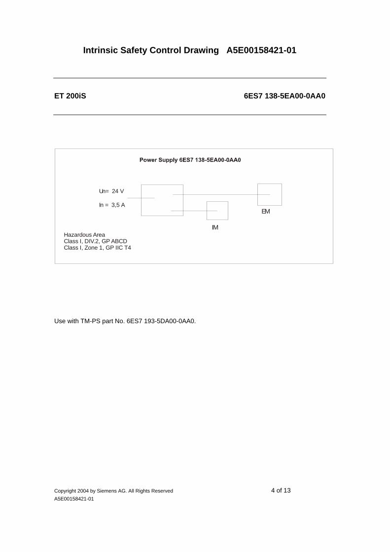
Intrinsic Safety Control Drawing A5E00158421-01
Copyright 2004 by Siemens AG. All Rights Reserved 4 of 13 A5E00158421-01
ET 200iS 6ES7 138-5EA00-0AA0
Use with TM-PS part No. 6ES7 193-5DA00-0AA0.
IM
EM
Un= 24 V
In = 3,5 A
Hazardous AreaClass I, DIV.2, GP ABCDClass I, Zone 1, GP IIC T4

Intrinsic Safety Control Drawing A5E00158421-01
Copyright 2004 by Siemens AG. All Rights Reserved 5 of 13 A5E00158421-01
ET 200iS 6ES7 151-2AA00-0AB0
You can find the pin configuration in the manual „SIMATIC ET 200iS Distributed I/O Station“, chapter 12.
Use with TM-IM/BSM P/N 6ES7 193-5DB00-0AA0.
The following parameters for the RS 485 fieldbus connection apply to the interface module:
Fieldbus Uo, Voc [ Vdc ] 4,2
Isc, Io [ mA ] 100
Po, [ mW ] 106
Ui, Vmax [ Vdc ] 4,2 (*)
(*) Ii, Imax, Pi can be any value
The following merits apply to the fieldbus line:
Must be in accordance with NEC 504.30B:
• L‘ / R‘ ≤ 22 µH / Ω (loopresistance)
• C‘ ≤ 250 nF / km
• Litz wire diameter ≤ 0,2 mm
• Concentrated inductance and capacitance are not allowed in the running of the external RS 485 fieldbus system.
• In applications where concentrated inductance and capacitance are considered the following values apply: Co, Ca < 100 µF (A, B/IIC) or < 1000 µF (C, D/IIB) and Lo, La < 3mH (A, B/IIC) or < 15 mH (C, D/IIB)
Associated Apparatus
Not hazardous area
Hazardous area
Class I, DIV 2, GP A....D Class I, Zone 1, IIC T4 Interface module IM 151-2
BSM 1
I = 81 mAsupply
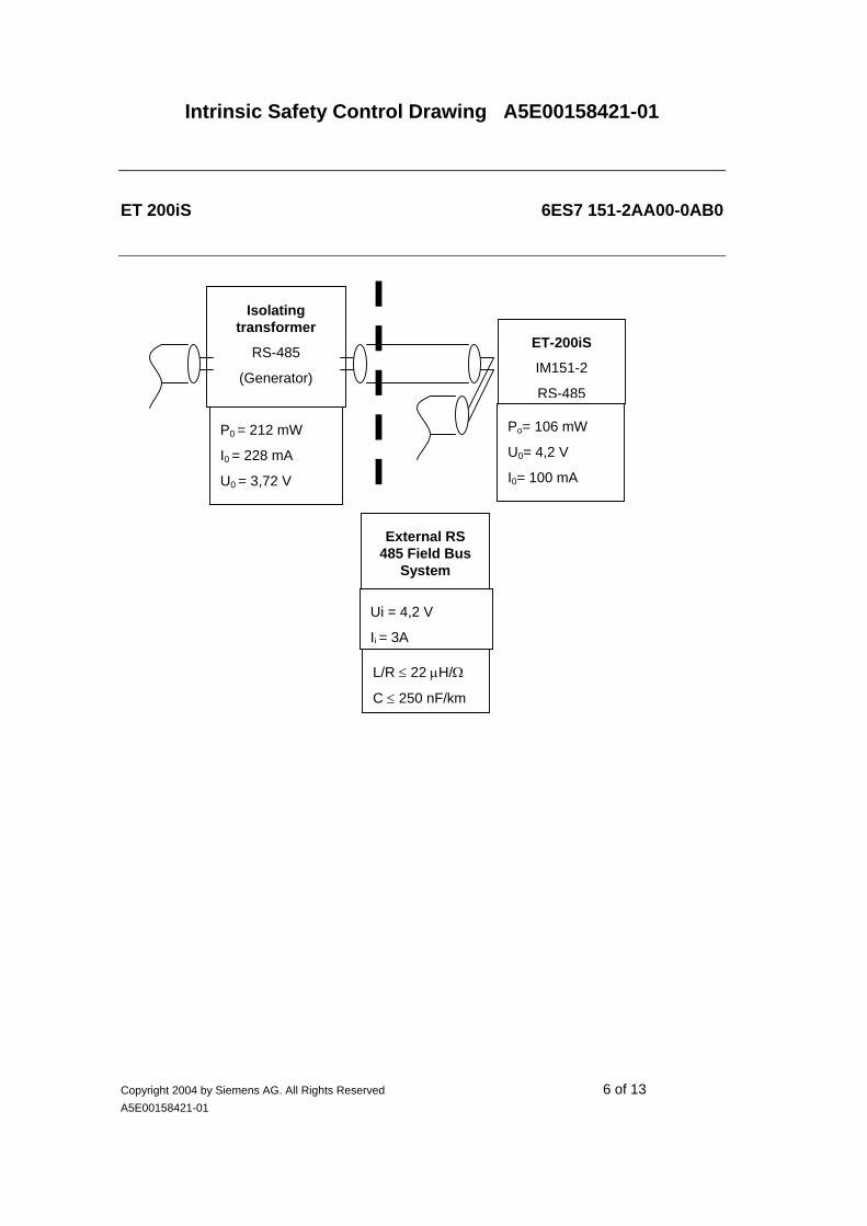
Intrinsic Safety Control Drawing A5E00158421-01
Copyright 2004 by Siemens AG. All Rights Reserved 6 of 13 A5E00158421-01
ET 200iS 6ES7 151-2AA00-0AB0
ET-200iS
IM151-2
RS-485
Isolating transformer
RS-485
(Generator)
Po= 106 mW
U0= 4,2 V
I0= 100 mA
P0 = 212 mW
I0 = 228 mA
U0 = 3,72 V
External RS 485 Field Bus
System
Ui = 4,2 V
Ii = 3A
L/R ≤ 22 µH/Ω
C ≤ 250 nF/km

Intrinsic Safety Control Drawing A5E00158421-01
Copyright 2004 by Siemens AG. All Rights Reserved 7 of 13 A5E00158421-01
ET 200iS 6ES7 131-5RD00-0AB0
You can find the pin configuration in the manual “SIMATIC ET 200iS Distributed I/O Station”, chapter 13.1. Also see notes under “system in total”.
Use with TM-E P/N 6ES7 193-5CB*0-0AA0.
The following parameters for the input circuits are applicable for the electronic module:
1 input 2 inputs // 3 inputs // 4 inputs //
Uo, Voc [ Vdc ] 9,6 9,6 9,6 9,6
Io, Isc [ mA ] 11 21 32 42
Po [ mW ] 26 50 77 101
A,B/IIC C-G/IIB A,B/IIC C-G/IIB A,B/IIC C-G/IIB A,B/IIC C-G/IIB
Co, Ca [ µF ] 3,6 26 3,6 26 3,6 26 3,6 26
Lo, La [ mH ] 240 1000 80 280 35 110 19 65
Hazardous area
Class I, DIV 2, GP A...DClass I, ZN 1, IIC T4
Hazardous area
Class I, II, III, DIV 1, GP A...GClass I, ZN 0, IIC T4
9 13
2 6 10 14
3 7 11 15
4 8 12 16
1 5
Digital electronic module 4 DI NAMUR 6ES7 131-5RD00-0AB0
Switches
NAMUR sensors

Intrinsic Safety Control Drawing A5E00158421-01
Copyright 2004 by Siemens AG. All Rights Reserved 8 of 13 A5E00158421-01
ET 200iS 6ES7 132-5SB00-0AB0
You can find the pin configuration in the manual “SIMATIC 200iS Distributed I/O Station“, chapter 13.2 . Also see notes under “system in total”.
Use with TM-E P/N 6ES7 193-5CB*0-0AA0.
The following parameters for the output circuits are applicable for the electronic module:
1 output 2 outputs //
Uo, Voc [ Vdc ] 28 28
Io, Isc [ mA ] 49 98
Po [ mW ] 345 685
A,B/IIC C-G/IIB A,B/IIC C-G/IIB
Co, Ca [ nF ] 80 650 80 650
Lo, La [ mH ] 15 55 3 11
Hazardous area
Class I, ZN 1, IIC T4
Hazardous area
Class I, II, III, DIV 1, GP A...GClass I, ZN 0, IIC T4
9 13
2 6 10 14
3 7 11 15
4 8 12 16
1 5
Digital electronic module 2 DO DC25V/25mA 6ES7 132-5SB00-0AB0
I = 330 mAsupply
Relays
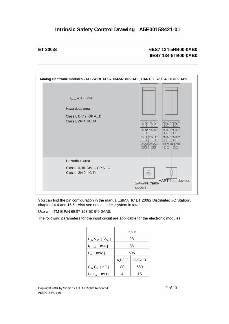
Intrinsic Safety Control Drawing A5E00158421-01
Copyright 2004 by Siemens AG. All Rights Reserved 9 of 13 A5E00158421-01
ET 200iS 6ES7 134-5RB00-0AB0 6ES7 134-5TB00-0AB0
You can find the pin configuration in the manual „SIMATIC ET 200iS Distributed I/O Station“, chapter 14.4 and 15.5 . Also see notes under „system in total“.
Use with TM-E P/N 6ES7 193-5CB*0-0AA0.
The following parameters for the input circuit are applicable for the electronic modules:
input
Uo, Voc [ Vdc ] 28
Io, Isc [ mA ] 85
Po [ mW ] 595
A,B/IIC C-G/IIB
Co, Ca [ nF ] 80 650
Lo, La [ mH ] 4 15
Hazardous area
Class I, DIV 2, GP A...D
Hazardous area
Class I, II, III, DIV 1, GP A...GClass I, ZN 0, IIC T4
9 13
2 6 10 14
3 7 11 15
4 8 12 16
1 5
mA
I = 330 mAsupply
2/4-wire trans-ducers
9 13
2 6 10 14
3 7 11 15
4 8 12 16
1 5
HART field devices
Analog electronic modules 2AI I 2WIRE 6ES7 134-5RB00-0AB0, HART 6ES7 134-5TB00-0AB0

Intrinsic Safety Control Drawing A5E00158421-01
Copyright 2004 by Siemens AG. All Rights Reserved 10 of 13 A5E00158421-01
ET 200iS 6ES7 134-5RB50-0AB0 6ES7 134-5TB50-0AB0
You can find the pin configuration in the manual „SIMATIC ET 200iS Distributed I/O Station“, chapter 14.5 and 15.6. Also see notes under „system in total“.
Use with TM-E P/N 6ES7 193-5CB*0-0AA0.
The following parameters for the input circuits are applicable for the electronic modules:
input
Ui, Vmax [ Vdc ] 30
Ii, Imax [ mA ] 150
Pi [ W ] 1,2
Ci [nF] 2
Li [mH] 0
Hazardous area
Class I, DIV 2, GP A...D Class I, ZN 1, IIC T4
Hazardous area
Class I, II, III, DIV 1, GP A...G
9 13
2 6 10 14
3 7 11 15
4 8 12 16
1 5
Analog electronic module 2 AI I 4WIRE 6ES7 134-5RB50-0AB0, HART 6ES7 134-5TB50-0AB0
mA
I = 120 mAsupply
2/4-wire trans-ducers
9 13
2 6 10 14
3 7 11 15
4 8 12 16
1 5
Hart field devices

Intrinsic Safety Control Drawing A5E00158421-01
Copyright 2004 by Siemens AG. All Rights Reserved 11 of 13 A5E00158421-01
ET 200iS 6ES7 134-5SB50-0AB0
You can find the pin configuration in the manual „SIMATIC ET 200iS Distributed I/O Station“, chapter 14.6 . Also see notes under „system in total“.
Use with TM-E P/N 6ES7 193-5CB*0-0AA0.
The following parameters for the input circuits are applicable for the electronic module:
1 input 2 inputs //
Uo, Voc [ Vdc ] 6,0 6,0
Io, Isc [ mA ] 16 28
Po [ mW ] 24 42
A,B/IIC C-G/IIB A,B/IIC C-G/IIB
Co, Ca [ µF ] 40 1000 40 1000
Lo, La [ mH ] 120 430 40 160
Hazardous area
Class I, ZN 1, IIC T4
Hazardous area
Class I, II, III, DIV 1, GP A...GClass I, ZN 0, IIC T4
9 13
2 6 10 14
3 7 11 15
4 8 12 16
1 5
Analog electronic module 2 AI RTD 6ES7 134-5SB50-0AB0
I = 120 mAsupply
Resistance thermometers

Intrinsic Safety Control Drawing A5E00158421-01
Copyright 2004 by Siemens AG. All Rights Reserved 12 of 13 A5E00158421-01
ET 200iS 6ES7 134-5SB00-0AB0
You can find the pin configuration in the manual „SIMATIC ET 200iS Distributed I/O Station“, chapter 14.7 . Also see notes under „system in total“.
Use with TM-E P/N 6ES7 193-5CB*0-0AA0.
The following parameters for the input circuits are applicable for the electronic module:
1 input 2 inputs //
Uo, Voc [ Vdc ] 6,0 6,0
Io, Isc [ mA ] 13 26
Po [ mW ] 20 40
A,B/IIC C-G/IIB A,B/IIC C-G/IIB
Co, Ca [ µF ] 40 1000 40 1000
Lo, La [ mH ] 200 730 50 170
Hazardous area
Class I, DIV 2, GP A...DClass I, ZN 1, IIC T4
Hazardous area
Class I, II, III, DIV 1, GP A...GClass I, ZN 0, IIC T4
9 13
2 6 10 14
3 7 11 15
4 8 12 16
1 5
Analog electronic module 2 AI TC 6ES7 134-5SB00-0AB0
I = 120 mAsupply
Thermocouplers
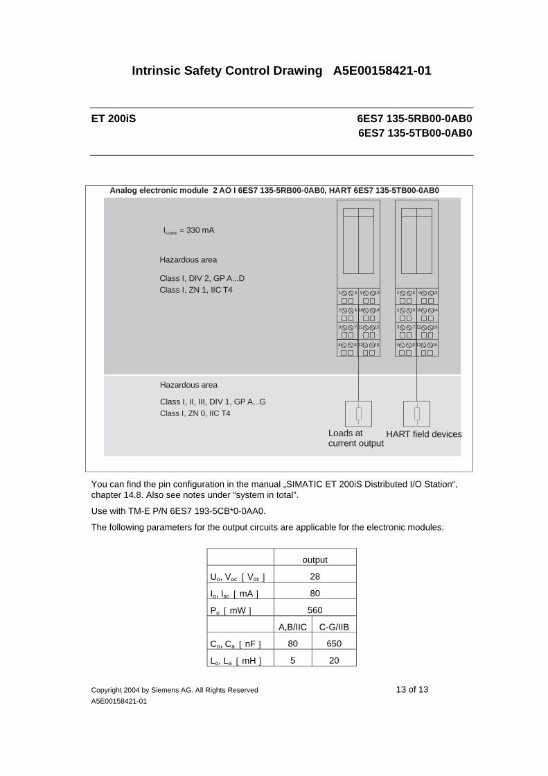
Intrinsic Safety Control Drawing A5E00158421-01
Copyright 2004 by Siemens AG. All Rights Reserved 13 of 13 A5E00158421-01
ET 200iS 6ES7 135-5RB00-0AB0 6ES7 135-5TB00-0AB0
You can find the pin configuration in the manual „SIMATIC ET 200iS Distributed I/O Station“, chapter 14.8. Also see notes under “system in total”.
Use with TM-E P/N 6ES7 193-5CB*0-0AA0.
The following parameters for the output circuits are applicable for the electronic modules:
output
Uo, Voc [ Vdc ] 28
Io, Isc [ mA ] 80
Po [ mW ] 560
A,B/IIC C-G/IIB
Co, Ca [ nF ] 80 650
Lo, La [ mH ] 5 20
Hazardous area
Class I, DIV 2, GP A...DClass I, ZN 1, IIC T4
Hazardous area
Class I, II, III, DIV 1, GP A...GClass I, ZN 0, IIC T4
9 13
2 6 10 14
3 7 11 15
4 8 12 16
1 5
Analog electronic module 2 AO I 6ES7 135-5RB00-0AB0, HART 6ES7 135-5TB00-0AB0
I = 330 mAsupply
Loads at current output
9 13
2 6 10 14
3 7 11 15
4 8 12 16
1 5
HART field devices

Intrinsic Safety Control Drawing A5E00158421-01
Copyright 2004 by Siemens AG. All Rights Reserved 14 of 14 A5E00158421-01