Linergy - RS Components
140
Catalogue│2013 Linergy Distribution & Connection systems Low Voltage
-
Upload
khangminh22 -
Category
Documents
-
view
4 -
download
0
Transcript of Linergy - RS Components
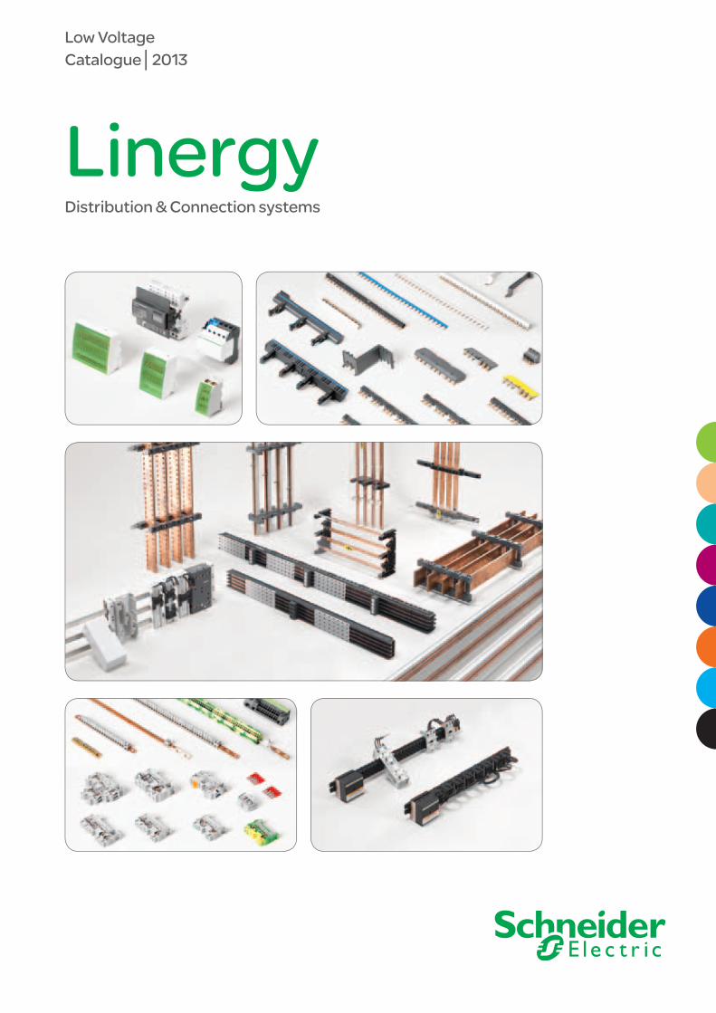
Catalogue│2013
LinergyDistribution & Connection systems
Low Voltage

25/01/2013 3
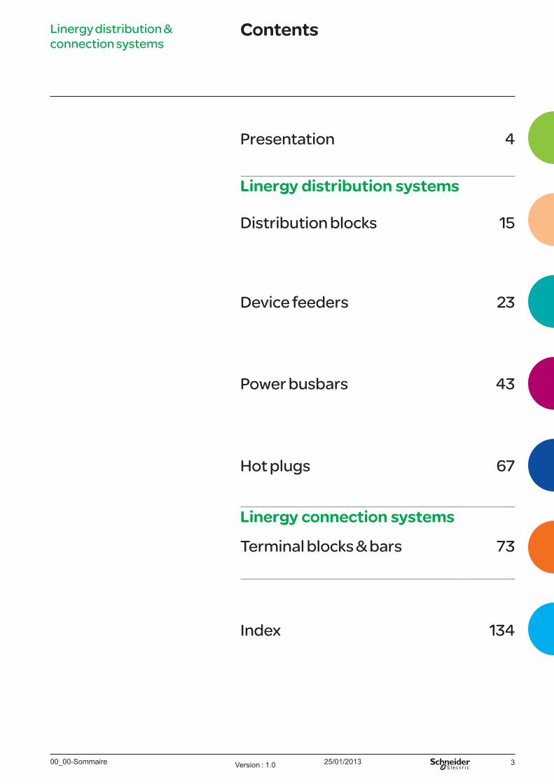
Presentation 4
Linergy distribution systems
Distribution blocks 15
Device feeders 23
Power busbars 43
Hot plugs 67
Linergy connection systems
Terminal blocks & bars 73
Index 134
Linergy distribution & connection systems
Contents
00_00-Sommaire Version : 1.0
25/01/2013 EDCED112024Version : 1.044
All Schneider Electric distribution and connection systems have now been brought together into a single brand name:
Linergy

25/01/2013EDCED112024 Version : 1.0 5
Now,think Linergy!
Because Linergy is…
Reliable > Linergy is fully compliant with IEC standards, and some systems are also multi-standard.
> All Linergy distribution and connection systems have been designed and tested to work together (synergies with Schneider Electric devices).
> Linergy, brings you the benefit of an energy-efficient switchboard.
Safer > Linergy IPxxB everywhere.
> Linergy is a "Hot plug" solution, enabling connections without turning off the switchboard (energised connection).
> Linergy simplifies wiring, thus directly contributing to enhancing panel reliability.
Flexible > Linergy is a complete range of more than 800 references, suitable for all type of applications (electrical distribution, process and control, datacenters, etc.).
> Linergy can be easily adapted to technical demand, customer habits and preferences.
> Thanks to their compactness, Linergy products can be easily installed into a minimum of space.
> Linergy is easy to implement in the shortest possible time.
> With Linergy you can make changes to your panel on the installation site, right up to the last minute.
And much more…
Available
everywhere
25/01/2013 EDCED112024Version : 1.06
Linergy
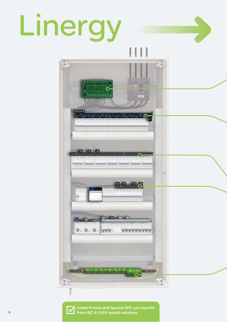
6Inside Prisma and Spacial SFP, you benefit from IEC 61439 tested solutions

25/01/2013EDCED112024 Version : 1.0 7
With Linergy, you will be able to connect your rows regardless of the enclosure you have chosen.
Linergy DSDistribution Blocks
> Compact solution
> Cabling capacity of up to 60 connection points
> Screw connection models
> Minimum space required
> Quick connection models
Linergy TBTerminal Blocks and Bars
> Quick distribution of up to 54 outgoers
> Maximum flexibility to balance your phases
> No creepage campaign thanks to clamp technology
Linergy FM Device Feeders
> Complete family of products to cover all needs
> Easy to install
> Compactness up to 100 A
Linergy FH Device Feeders
25/01/2013 EDCED112024Version : 1.08
Linergy
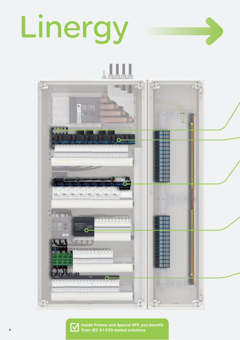
8Inside Prisma and Spacial SFP, you benefit from IEC 61439 tested solutions
25/01/2013EDCED112024 Version : 1.0 9
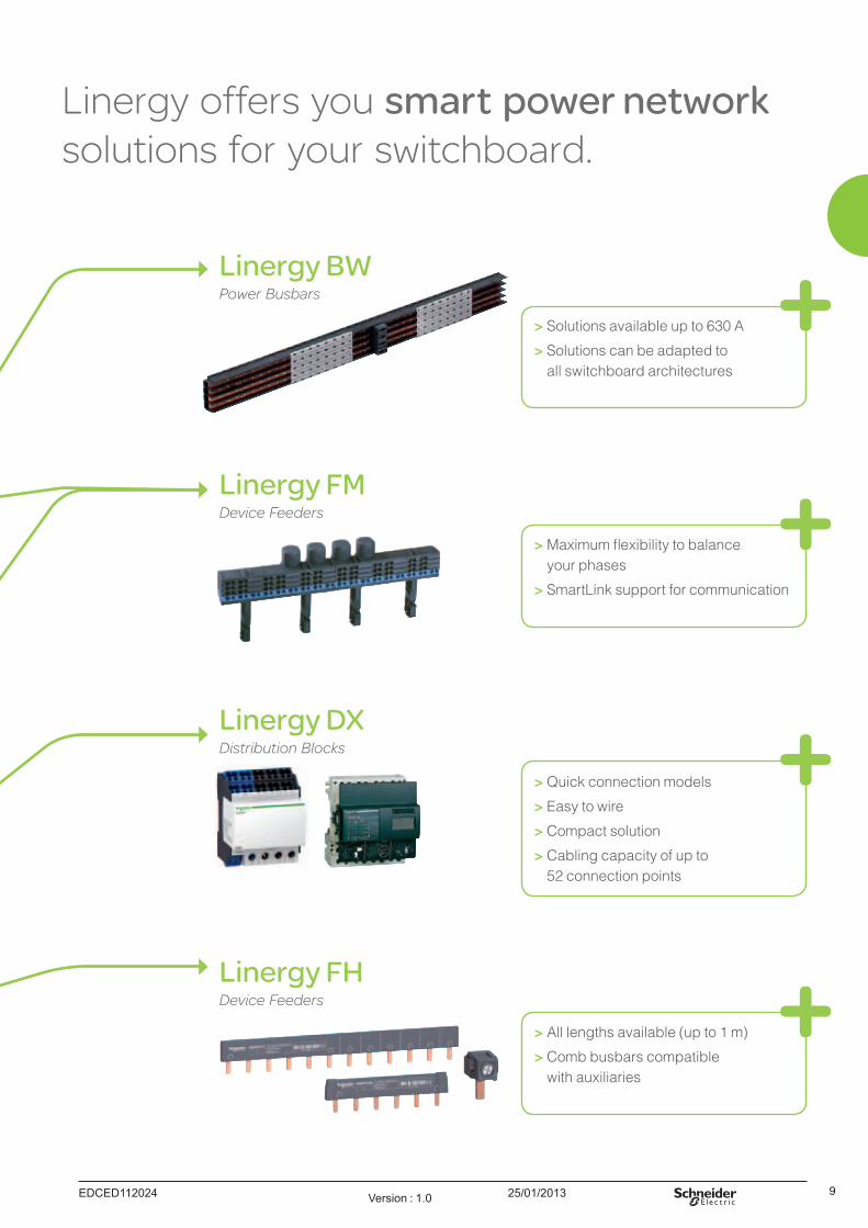
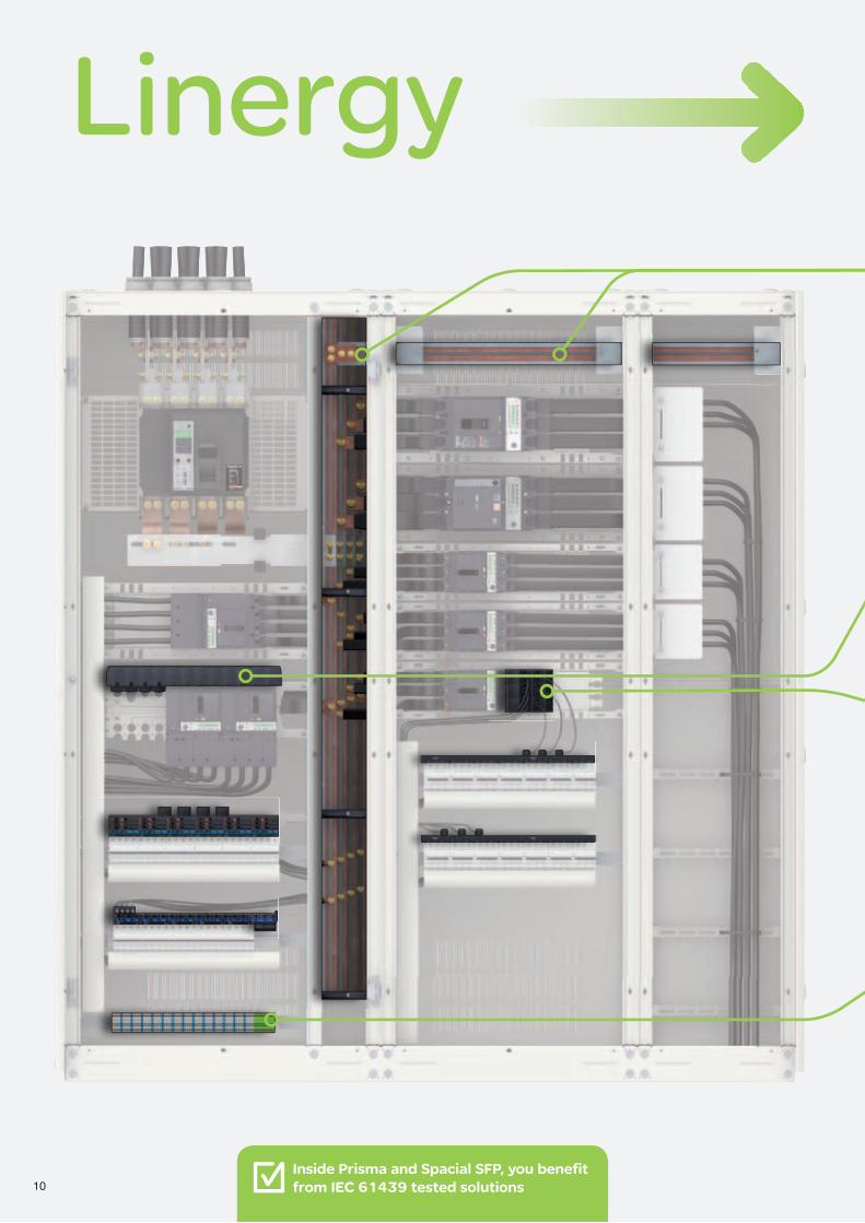
Linergy offers you smart power network solutions for your switchboard.
Linergy BWPower Busbars
> Solutions available up to 630 A
> Solutions can be adapted to all switchboard architectures
> Maximum flexibility to balance your phases
> SmartLink support for communication
Linergy FMDevice Feeders
Linergy FHDevice Feeders
> All lengths available (up to 1 m)
> Comb busbars compatible with auxiliaries
> Quick connection models
> Easy to wire
> Compact solution
> Cabling capacity of up to 52 connection points
Linergy DX Distribution Blocks
25/01/2013 EDCED112024Version : 1.010
Linergy
10Inside Prisma and Spacial SFP, you benefit from IEC 61439 tested solutions
25/01/2013EDCED112024 Version : 1.0 11
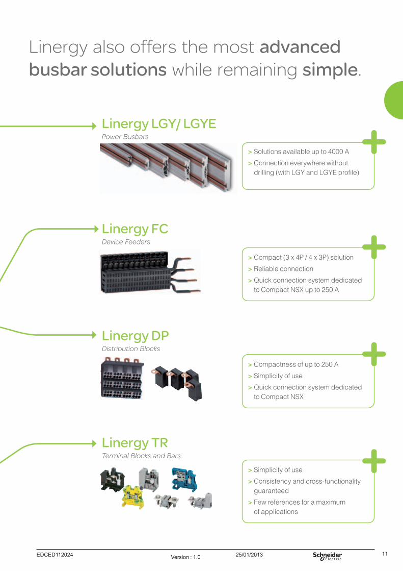
Linergy also offers the most advanced busbar solutions while remaining simple.
> Compact (3 x 4P / 4 x 3P) solution
> Reliable connection
> Quick connection system dedicated to Compact NSX up to 250 A
Linergy FC Device Feeders
> Compactness of up to 250 A
> Simplicity of use
> Quick connection system dedicated to Compact NSX
Linergy DPDistribution Blocks
Linergy LGY/ LGYE Power Busbars
> Solutions available up to 4000 A
> Connection everywhere without drilling (with LGY and LGYE profile)
Linergy TR Terminal Blocks and Bars
> Simplicity of use
> Consistency and cross-functionality guaranteed
> Few references for a maximum of applications
25/01/2013 EDCED112024Version : 1.012
Linergy
12
25/01/2013EDCED112024 Version : 1.0 13
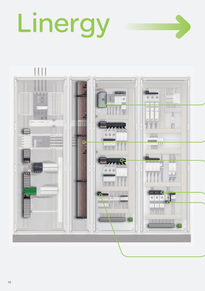
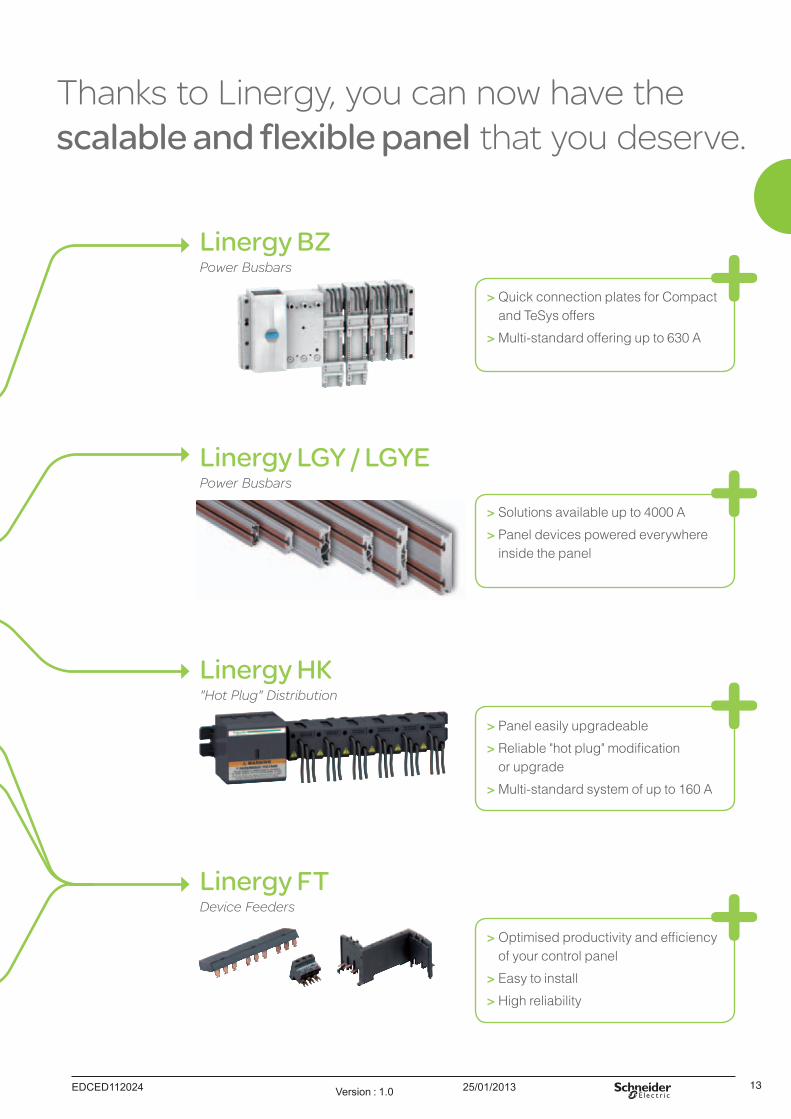
Thanks to Linergy, you can now have the scalable and flexible panel that you deserve.
Linergy FT Device Feeders
> Optimised productivity and efficiency of your control panel
> Easy to install
> High reliability
> Solutions available up to 4000 A
> Panel devices powered everywhere inside the panel
Linergy LGY / LGYE Power Busbars
> Quick connection plates for Compact and TeSys offers
> Multi-standard offering up to 630 A
Linergy BZ Power Busbars
Linergy HK "Hot Plug" Distribution
> Panel easily upgradeable
> Reliable "hot plug" modification or upgrade
> Multi-standard system of up to 160 A

14
25/01/2013 15
Linergy distribution systems Distribution blocksContents
Linergy DS 16
Screw distribution blocks 16
Linergy DX 18
Quick distribution blocks 18
Linergy DP 20
Quick distribution blocks 20
01_00-Sommaire Version : 1.0
Version : 1.2 25/01/2013 CA907023-EN_FR
PB
1112
50-2
0
PB
1112
51-2
0
PB
1112
52-2
0
PB
1112
43-2
0
PB
1112
54-3
0P
B11
1253
-30
16
Linergy DSScrew distribution blocks
Linergy distribution systems Distribution blocks
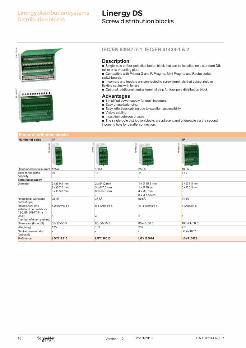
Descrip t io n b Single-pole or four-pole distribution block that can be installed on a standard DIN
rail or on a mounting plate. b Compatible with Prisma G and P, Pragma, Mini Pragma and Resbo series
switchboards. b Incomers and feeders are connected to screw terminals that accept rigid or
flexible cables with ferrule. b O ptional: additional neutral terminal strip for four-pole distribution block.
Ad v ant ages b Simplified power supply for main incomers. b Easy phase balancing. b Easy, effortless cabling due to excellent accessibility. b Visible cabling. b Insulation between phases. b The single-pole distribution blocks are adj acent and bridgeable via the second
incoming hole for parallel connection.
I EC/ EN 60947- 7- 1, I EC/ EN 61439- 1 & 2
Screw d ist rib u t io n b l o ck sNu m b er o f p o l es 1P 4P Neu t ral t erm inal st rip
Rated operational current 125 A 160 A 250 A 100 A 125 A 160 A 100 A 125 ATotal connections capacity
10 13 14 4 x 7 4 x 12 4 x 15 4 x 12 7 12 15
Term inal cap acit yDiameter 2 x Ø 9.5 mm 2 x Ø 12 mm 1 x Ø 15.3 mm 2 x Ø 7.5 mm 1 x Ø 9 mm 1 x Ø 9.5 mm 1 x Ø 12 mm 2 x Ø 7.5 mm 1 x Ø 9 mm 1 x Ø 9.5 mm
2 x Ø 7.5 mm 3 x Ø 7.5 mm 1 x Ø 10 mm 5 x Ø 5.5 mm 7 x Ø 7.5 mm 3 x Ø 8.5 mm 3 x Ø 9 mm 5 x Ø 5.5 mm 7 x Ø 7.5 mm 3 x Ø 8.5 mm6 x Ø 5.8 mm 8 x Ø 5.8 mm 4 x Ø 6 mm - 4 x Ø 6.5 mm 11 x Ø 6.5 mm 8 x Ø 7.5 mm - 4 x Ø 6.5 mm 11 x Ø 6.5 mm- - 8 x Ø 7.5 mm - - - - - - -
Rated peak withstand current ( Ipk)
25 k 36 k 60 k 24 k 26 k 28 k 36 k - - -
Rated short-time withstand current ( Icw) ( IEC/EN 60947-7-1)
4.2 kArms/1 s 8.4 kArms/1 s 14.4 kArms/1 s 3 kArms/1 s 4.2 kArms/1 s 4.2 kArms/1 s 8.4 kArms/1 s - - -
W idth ( number of 9 mm pitches)
3 4 5 8 14 20 18 7 14 17
Dimension (HxWxD) 85x27x50.5 85x36x50.5 85x45x50.5 100x71x50.5 100x126x50.5 100x162x50.5 100x174x50.5 20x70x35 20x125x35 20x155x35W eight ( g) 125 163 239 210 390 559 567 63 111 149Neutral terminal strip ( optional)
- - - LGY N1007 LGY N12512 LGY N12515 LGY N12512 - - -
Reference LGY112510 LGY116013 LGY125014 LGY410028 LGY412548 LGY412560 LGY416048 LGYN1007 LGYN12512 LGYN12515
Version : 1.2 25/01/2013CA907023-EN_FR
PB
1112
44-2
0
PB
1112
45-2
0
PB
1112
46-2
0
PB
1112
47-2
0
PB
1112
48-2
0
PB
1112
49-2
0
DB
4050
05
17
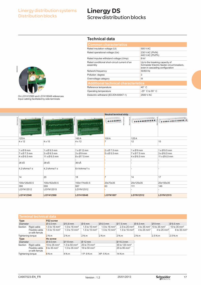
Tech nical d at aCo m m o n ch aract erist ics
Rated insulation voltage ( U i) 500 V ACRated operational voltage ( U e) 230 V AC ( Ph/N)
440 V AC ( Ph/Ph)Rated impulse withstand voltage ( U imp) 8 kVRated conditional short-circuit current of an assembly
Up to the breaking capacity of Schneider Electric feeder circuit breakers, even in cascading configuration
Network frequency 50/60 HzPollution degree 3Overvoltage category III
Ad d it io nal t ech nical ch aract erist icsReference temperature 40° CO perating temperature -25° C to 55° CDielectric withstand ( IEC/EN 60947-1) 2500 V AC
Linergy DSScrew distribution blocks
Linergy distribution systems Distribution blocks
Screw d ist rib u t io n b l o ck sNu m b er o f p o l es 1P 4P Neu t ral t erm inal st rip
Rated operational current 125 A 160 A 250 A 100 A 125 A 160 A 100 A 125 ATotal connections capacity
10 13 14 4 x 7 4 x 12 4 x 15 4 x 12 7 12 15
Term inal cap acit yDiameter 2 x Ø 9.5 mm 2 x Ø 12 mm 1 x Ø 15.3 mm 2 x Ø 7.5 mm 1 x Ø 9 mm 1 x Ø 9.5 mm 1 x Ø 12 mm 2 x Ø 7.5 mm 1 x Ø 9 mm 1 x Ø 9.5 mm
2 x Ø 7.5 mm 3 x Ø 7.5 mm 1 x Ø 10 mm 5 x Ø 5.5 mm 7 x Ø 7.5 mm 3 x Ø 8.5 mm 3 x Ø 9 mm 5 x Ø 5.5 mm 7 x Ø 7.5 mm 3 x Ø 8.5 mm6 x Ø 5.8 mm 8 x Ø 5.8 mm 4 x Ø 6 mm - 4 x Ø 6.5 mm 11 x Ø 6.5 mm 8 x Ø 7.5 mm - 4 x Ø 6.5 mm 11 x Ø 6.5 mm- - 8 x Ø 7.5 mm - - - - - - -
Rated peak withstand current ( Ipk)
25 k 36 k 60 k 24 k 26 k 28 k 36 k - - -
Rated short-time withstand current ( Icw) ( IEC/EN 60947-7-1)
4.2 kArms/1 s 8.4 kArms/1 s 14.4 kArms/1 s 3 kArms/1 s 4.2 kArms/1 s 4.2 kArms/1 s 8.4 kArms/1 s - - -
W idth ( number of 9 mm pitches)
3 4 5 8 14 20 18 7 14 17
Dimension (HxWxD) 85x27x50.5 85x36x50.5 85x45x50.5 100x71x50.5 100x126x50.5 100x162x50.5 100x174x50.5 20x70x35 20x125x35 20x155x35W eight ( g) 125 163 239 210 390 559 567 63 111 149Neutral terminal strip ( optional)
- - - LGY N1007 LGY N12512 LGY N12515 LGY N12512 - - -
Reference LGY112510 LGY116013 LGY125014 LGY410028 LGY412548 LGY412560 LGY416048 LGYN1007 LGYN12512 LGYN12515
On LGY412560 and LGY416048 referencesInput cabling facilitated by side terminals
Term inal t ech nical d at aTyp e PZ2 screwDiameter Ø 5.5 mm Ø 5.8 mm Ø 6 mm Ø 6.5 mm Ø 7.5 mm Ø 8.5 mm Ø 9 mm Ø 9.5 mm
Section Rigid cable 1.5 to 16 mm² 1.5 to 16 mm² 1.5 to 16 mm² 1.5 to 16 mm² 2.5 to 25 mm² 6 to 35 mm² 10 to 35 mm² 10 to 35 mm²Flexible cable or with ferrule
1.5 to 10 mm² 1.5 to 10 mm² 1.5 to 10 mm² 1.5 to 10 mm² 1.5 to 16 mm² 4 to 25 mm² 4 to 25 mm² 6 to 35 mm²
Tightening torq ue 2 N.m 2 N.m 2 N.m 2 N.m 2 N.m 2 N.m 2.5 N.m 2.5 N.mTyp e Hc screwDiameter Ø 9.5 mm Ø 10 mm Ø 12 mm Ø 15.3 mm -
Section Rigid cable 10 to 35 mm² 1.5 to 50 mm² 25 to 70 mm² 35 to 120 mm²Flexible cable or with ferrule
6 to 35 mm² 1.5 to 35 mm² 16 to 50 mm² 25 to 95 mm²
Tightening torq ue 8 N.m 4 N.m 1 P: 9 N.m 4P: 5 N.m 14 N.m
25/01/201318
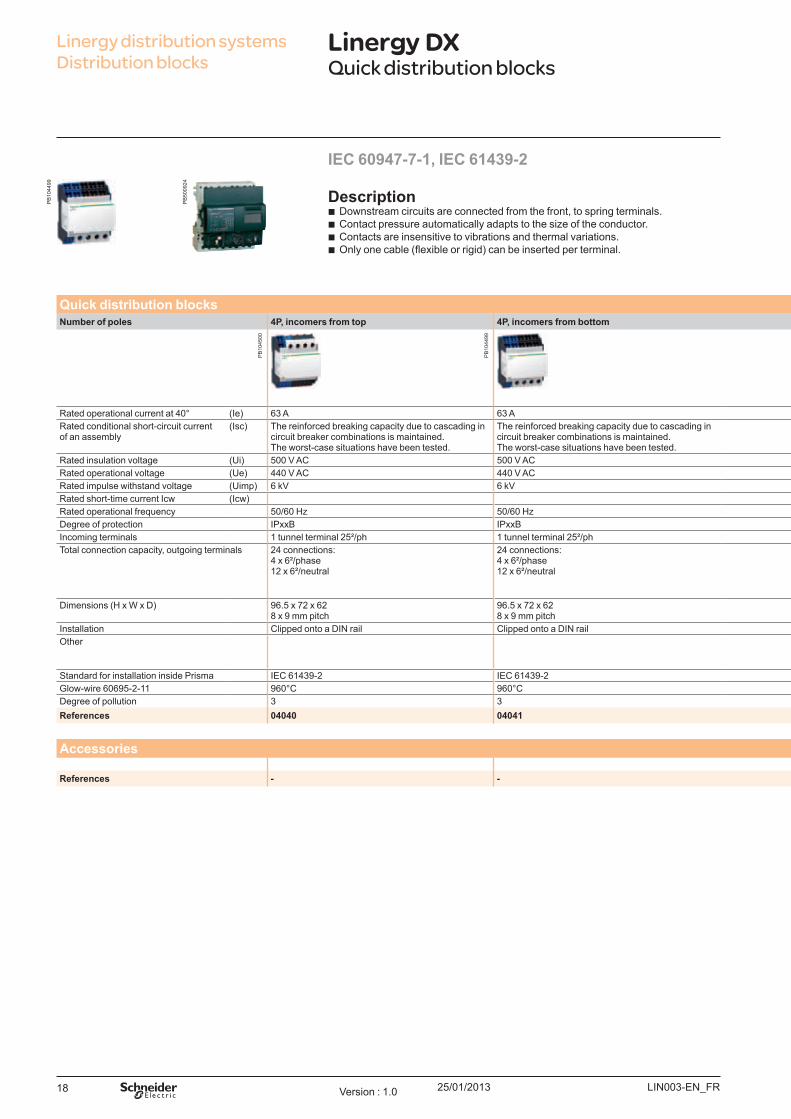
IEC 60947-7-1, IEC 61439-2
Description b Downstream circuits are connected from the front, to spring terminals. b Contact pressure automatically adapts to the size of the conductor. b Contacts are insensitive to vibrations and thermal variations. b Only one cable (flexible or rigid) can be inserted per terminal.
Linergy distribution systems Distribution blocks
Linergy DXQuick distribution blocks
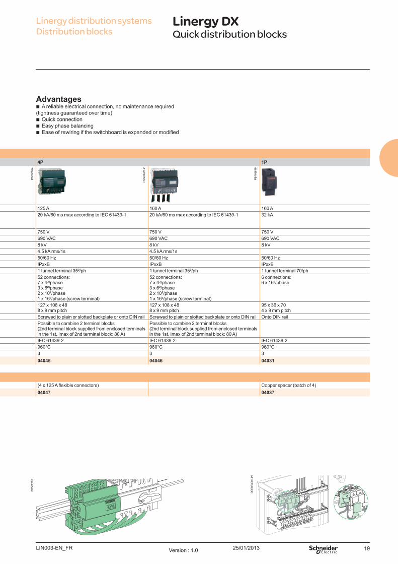
Quick distribution blocksNumber of poles 4P, incomers from top 4P, incomers from bottom 4P 1P
Rated operational current at 40° (Ie) 63 A 63 A 125 A 160 A 160 ARated conditional short-circuit current of an assembly
(Isc) The reinforced breaking capacity due to cascading in circuit breaker combinations is maintained. The worst-case situations have been tested.
The reinforced breaking capacity due to cascading in circuit breaker combinations is maintained. The worst-case situations have been tested.
20 kA/60 ms max according to IEC 61439-1 20 kA/60 ms max according to IEC 61439-1 32 kA
Rated insulation voltage (Ui) 500 V AC 500 V AC 750 V 750 V 750 VRated operational voltage (Ue) 440 V AC 440 V AC 690 VAC 690 VAC 690 VACRated impulse withstand voltage (Uimp) 6 kV 6 kV 8 kV 8 kV 8 kVRated short-time current Icw (Icw) 4.5 kA rms/1s 4.5 kA rms/1sRated operational frequency 50/60 Hz 50/60 Hz 50/60 Hz 50/60 Hz 50/60 HzDegree of protection IPxxB IPxxB IPxxB IPxxB IPxxBIncoming terminals 1 tunnel terminal 25²/ph 1 tunnel terminal 25²/ph 1 tunnel terminal 35²/ph 1 tunnel terminal 35²/ph 1 tunnel terminal 70/phTotal connection capacity, outgoing terminals 24 connections:
4 x 6²/phase12 x 6²/neutral
24 connections:4 x 6²/phase12 x 6²/neutral
52 connections:7 x 4²/phase3 x 6²/phase2 x 10²/phase1 x 16²/phase (screw terminal)
52 connections:7 x 4²/phase3 x 6²/phase2 x 10²/phase1 x 16²/phase (screw terminal)
6 connections:6 x 16²/phase
Dimensions (H x W x D) 96.5 x 72 x 628 x 9 mm pitch
96.5 x 72 x 628 x 9 mm pitch
127 x 108 x 488 x 9 mm pitch
127 x 108 x 488 x 9 mm pitch
95 x 36 x 704 x 9 mm pitch
Installation Clipped onto a DIN rail Clipped onto a DIN rail Screwed to plain or slotted backplate or onto DIN rail Screwed to plain or slotted backplate or onto DIN rail Onto DIN railOther Possible to combine 2 terminal blocks
(2nd terminal block supplied from enclosed terminals in the 1st, Imax of 2nd terminal block: 80 A)
Possible to combine 2 terminal blocks (2nd terminal block supplied from enclosed terminals in the 1st, Imax of 2nd terminal block: 80 A)
Standard for installation inside Prisma IEC 61439-2 IEC 61439-2 IEC 61439-2 IEC 61439-2 IEC 61439-2Glow-wire 60695-2-11 960°C 960°C 960°C 960°C 960°CDegree of pollution 3 3 3 3 3References 04040 04041 04045 04046 04031
Accessories(4 x 125 A flexible connectors) Copper spacer (batch of 4)
References - - 04047 04037
LIN003-EN_FRVersion : 1.0
PB
1044
99
PB
5009
24
PB
1045
00
PB
1044
99
25/01/2013 19
Advantages b A reliable electrical connection, no maintenance required
(tightness guaranteed over time) b Quick connection b Easy phase balancing b Ease of rewiring if the switchboard is expanded or modified
Linergy distribution systems Distribution blocks
Linergy DXQuick distribution blocks
Quick distribution blocksNumber of poles 4P, incomers from top 4P, incomers from bottom 4P 1P
Rated operational current at 40° (Ie) 63 A 63 A 125 A 160 A 160 ARated conditional short-circuit current of an assembly
(Isc) The reinforced breaking capacity due to cascading in circuit breaker combinations is maintained. The worst-case situations have been tested.
The reinforced breaking capacity due to cascading in circuit breaker combinations is maintained. The worst-case situations have been tested.
20 kA/60 ms max according to IEC 61439-1 20 kA/60 ms max according to IEC 61439-1 32 kA
Rated insulation voltage (Ui) 500 V AC 500 V AC 750 V 750 V 750 VRated operational voltage (Ue) 440 V AC 440 V AC 690 VAC 690 VAC 690 VACRated impulse withstand voltage (Uimp) 6 kV 6 kV 8 kV 8 kV 8 kVRated short-time current Icw (Icw) 4.5 kA rms/1s 4.5 kA rms/1sRated operational frequency 50/60 Hz 50/60 Hz 50/60 Hz 50/60 Hz 50/60 HzDegree of protection IPxxB IPxxB IPxxB IPxxB IPxxBIncoming terminals 1 tunnel terminal 25²/ph 1 tunnel terminal 25²/ph 1 tunnel terminal 35²/ph 1 tunnel terminal 35²/ph 1 tunnel terminal 70/phTotal connection capacity, outgoing terminals 24 connections:
4 x 6²/phase12 x 6²/neutral
24 connections:4 x 6²/phase12 x 6²/neutral
52 connections:7 x 4²/phase3 x 6²/phase2 x 10²/phase1 x 16²/phase (screw terminal)
52 connections:7 x 4²/phase3 x 6²/phase2 x 10²/phase1 x 16²/phase (screw terminal)
6 connections:6 x 16²/phase
Dimensions (H x W x D) 96.5 x 72 x 628 x 9 mm pitch
96.5 x 72 x 628 x 9 mm pitch
127 x 108 x 488 x 9 mm pitch
127 x 108 x 488 x 9 mm pitch
95 x 36 x 704 x 9 mm pitch
Installation Clipped onto a DIN rail Clipped onto a DIN rail Screwed to plain or slotted backplate or onto DIN rail Screwed to plain or slotted backplate or onto DIN rail Onto DIN railOther Possible to combine 2 terminal blocks
(2nd terminal block supplied from enclosed terminals in the 1st, Imax of 2nd terminal block: 80 A)
Possible to combine 2 terminal blocks (2nd terminal block supplied from enclosed terminals in the 1st, Imax of 2nd terminal block: 80 A)
Standard for installation inside Prisma IEC 61439-2 IEC 61439-2 IEC 61439-2 IEC 61439-2 IEC 61439-2Glow-wire 60695-2-11 960°C 960°C 960°C 960°C 960°CDegree of pollution 3 3 3 3 3References 04040 04041 04045 04046 04031
Accessories(4 x 125 A flexible connectors) Copper spacer (batch of 4)
References - - 04047 04037
LIN003-EN_FR Version : 1.0
PB
5023
70
DD
3833
00-L
IN
PB
5009
24
PB
5009
25-2
PB
1038
10

25/01/201320
Description b The Linergy DP Quick distribution block is designed for installation directly
downstream of Compact NSX and INS up to 250 A. It can also be clipped onto a modular rail.
Advantages b It is quick to mount in the horizontal position. E lectrical connections are made
directly to the device terminals. b It is the same width as the devices and does not take up any additional space
in the switchboard. b The connection terminals are slanted to facilitate cable entry and avoid exc eeding
the bending radius of the flexible and rigid cables.
IEC 60947-7-1, IEC 61439-1 & 2
Linergy distribution systems Distribution blocks
Linergy DPQuick distribution blocks
Quick distribution blocks for compact devices Additional blockNumber of poles 3P 4P 3P 4P
Rated operational current (Ie) 250 A 250 A 250 A 250 ARated peak withstand current (Ipk) 32 kA 32 kATotal connection capacity, outgoing terminals 27 connections:
6 x 10²/phase3 x 16²/phase
36 connections:6 x 10²/phase3 x 16²/phase
2 connections:2 x 35² per pole
2 connections:2 x 35² per pole
Incomer terminals 1 cable lug 120 mm² per poleDimensions (H x W x D) 105 x 138 x 63 140 x 138 x 64Installation On mounting plate or DIN rail On mounting plateProduct certifications ASE F A - K E M A ASE F A - K E M AStandard for installation inside Prisma IE C 61439 -1-2 IE C 61439 -1 & 2G low-wire 6069 5-2-11 9 60°C 9 60°CReferences 04033 04034 04155 04156
Accessories
Description 2 x 352
3P for Linergy DP 250 A2 x 352 4P for Linergy DP 250 A
References 04155 04156
LIN002-E N_ F RVersion : 1.0
PB
5023
71
PB
5023
71
PB
1038
12
PB
1038
11P
B50
2371
PB
5023
71
PB
1038
12

25/01/2013 21
InstallationIt can also be mounted downstream of vertically mounted Compact NS X 100/ 250 and Interpact INS 250 devices in the enclosures.In this case, the Linergy DP is mounted on a depth-adj ustable modular rail.
Directly on the mounting plates of horizontally mounted Compact NS X 100/ 250 and Interpact INS 250 devices in the enclosures.
T ech nical dataCommon ch aracteristicsRated conditional short-circuit current of an assembly
(Icc) The reinforced breaking capacity due to cascading in circuit-breaker combinations is maintained.The worst-case situations have been tested.
Rated insulation voltage (U i) 750 V ACRated operational voltage (U e) 69 0 VRated impulse withstand voltage (U imp) 8 kVNetwork frequency 50/60 HzDegree of protection IPxxBDegree of pollution 3Overvoltage category III
Additional tech nical ch aracteristicsReference temperature 40°COperating temperature -25°C to 55°C
Linergy distribution systems Distribution blocks
Linergy DPQuick distribution blocks
LIN002-E N_ F R Version : 1.0
DD
3807
80D
D38
1346

22
25/01/2013 23
Linergy distribution systems Device feedersContents
Linergy FM 24
Quick device feeders 24
Linergy FH 26
Horizontal comb busbar for 27 mm pitch for C120, NG125Horizontal comb busbar for 18 mm pitch for Acti 9 / Multi 9Horizontal comb busbar for 9 mm pitch for Acti 9, C60Horizontal comb busbar for 18 mm pitch for DomaeHorizontal biconnect comb busbar for 18 mm pitch
2627293132
Linergy FV 33
Vertical comb busbar 33
Linergy FC 34
Feeders for Compact NSX & INS 34
Linergy FT 36
Tesys comb busbar 36
02_00-Sommaire Version : 1.0
25/01/201324
Linergy distribution systems Device feeders
Linergy FMQuick device feeders
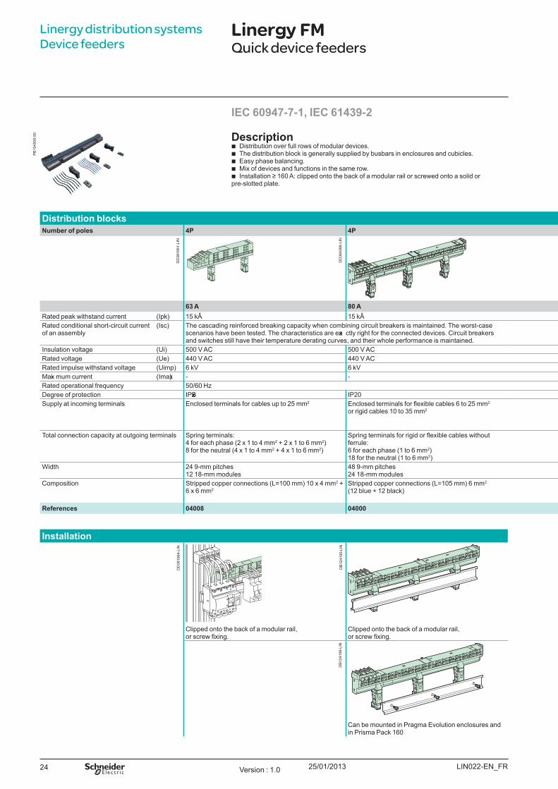
Description b Distribution over full rows of modular devices. b The distribution block is generally supplied by busbars in enclosures and cubicles. b E asy phase balancing. b M ix of devices and functions in the same row. b Installation 160 A: clipped onto the back of a modular rail or screwed onto a solid or
pre-slotted plate.
Distribution blocksNumber of poles 4P 4P 4P 2P 3P 4P 4P
63 A 8 0 A 160 A 200 A 200 A 200 A 200 ARated peak withstand current (Ipk) 15 k 15 k 27 k 25 k 25 k 30 k 27 kÂRated conditional short-circuit current of an assembly
(Isc) The cascading reinforced breaking capacity when combining circuit breakers is maintained. The worst-case scenarios have been tested. The characteristics are exa ctly right for the connected devices. Circuit breakers and switches still have their temperature derating curves, and their whole performance is maintained.
The cascading reinforced breaking capacity when combining circuit breakers is maintained. The worst-case scenarios have been tested.
Insulation voltage (U i) 500 V AC 500 V AC 750 V AC 750 V AC 750 V AC 750 V ACRated voltage (U e) 440 V AC 440 V AC 690 V AC 690 V AC 690 V AC 690 V ACRated impulse withstand voltage (U imp) 6 kV 6 kV 8 kV 8 kV 8 kV 8 kVM axi mum current (Imax) - - 50 A for feeder for 10 mm2 cable/63 A for feeder for 2 10 mm2 cablesRated operational frequency 50/60 H 50/60 HDegree of protection IPxxB IP20 IPxxBSupply at incoming terminals E nclosed terminals for cables up to 25 mm2 Enclosed terminals for flexible cables 6 to 25 mm2
or rigid cables 10 to 35 mm2Direct onto the row by cable 50 mm2 with crimped lug, or flexible bar 20 x 3F rom Linergy B W insulated busbar in enclosure or cubicle with connection ref. 04021F rom Linergy B S sheathed busbar with connection ref. 04024F rom Linergy B S rear busbar with connection ref. 04029
Total connection capacity at outgoing terminals pring terminals: 4 for each phase (2 x 1 to 4 mm2 2 x 1 to 6 mm2) 8 for the neutral (4 x 1 to 4 mm2 4 x 1 to 6 mm2)
pring terminals for rigid or flexible cables without ferrule: 6 for each phase (1 to 6 mm2)18 for the neutral (1 to 6 mm2)
6 connection points for each phase9 connection points for the neutral
12 connection points for the phase and the neutral
12 connection points for each phase18 connection points for the neutral
W idth 24 9-mm pitches 12 18-mm modules
48 9-mm pitches 24 18-mm modules
24 9-mm pitches 12 18-mm modules
48 9-mm pitches24 18-mm modules
72 9-mm pitches36 18-mm modules
Composition Stripped copper connections (L= 100 mm) 10 x 4 mm2 + 6 x 6 mm2
tripped copper connections (L 105 mm) 6 mm2 (12 blue + 12 black)
2 sachets with 12 stripped copper connections 10 mm2 (L= 100 mm)Protective covers for power supply rows (IPxxB )F ixi ng accessories for power supply rows
References 04008 04000 04018 04012 04013 04014 04026
Installation
Clipped onto the back of a modular rail, or screw fixing.
Clipped onto the back of a modular rail, or screw fixing.
Can be mounted in Pragma E volution enclosures and in Prisma Pack 160
IEC 60947-7-1, IEC 61439-2
LIN022-E N_ F RVersion : 1.0
PB
1045
05-5
0
DD
3816
61-L
IN
DD
3840
88-L
IN
DD
3816
64-L
IN
DB
1241
95-L
IND
B12
4196
-LIN
25/01/2013 25
Linergy distribution systems Device feeders
Linergy FMQuick device feeders
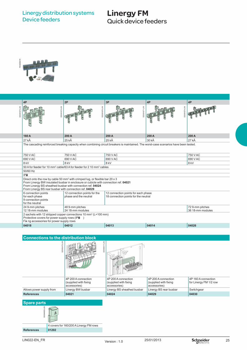
Distribution blocksNumber of poles 4P 4P 4P 2P 3P 4P 4P
63 A 8 0 A 160 A 200 A 200 A 200 A 200 ARated peak withstand current (Ipk) 15 k 15 k 27 k 25 k 25 k 30 k 27 kÂRated conditional short-circuit current of an assembly
(Isc) The cascading reinforced breaking capacity when combining circuit breakers is maintained. The worst-case scenarios have been tested. The characteristics are exa ctly right for the connected devices. Circuit breakers and switches still have their temperature derating curves, and their whole performance is maintained.
The cascading reinforced breaking capacity when combining circuit breakers is maintained. The worst-case scenarios have been tested.
Insulation voltage (U i) 500 V AC 500 V AC 750 V AC 750 V AC 750 V AC 750 V ACRated voltage (U e) 440 V AC 440 V AC 690 V AC 690 V AC 690 V AC 690 V ACRated impulse withstand voltage (U imp) 6 kV 6 kV 8 kV 8 kV 8 kV 8 kVM axi mum current (Imax) - - 50 A for feeder for 10 mm2 cable/63 A for feeder for 2 10 mm2 cablesRated operational frequency 50/60 H 50/60 HDegree of protection IPxxB IP20 IPxxBSupply at incoming terminals E nclosed terminals for cables up to 25 mm2 Enclosed terminals for flexible cables 6 to 25 mm2
or rigid cables 10 to 35 mm2Direct onto the row by cable 50 mm2 with crimped lug, or flexible bar 20 x 3F rom Linergy B W insulated busbar in enclosure or cubicle with connection ref. 04021F rom Linergy B S sheathed busbar with connection ref. 04024F rom Linergy B S rear busbar with connection ref. 04029
Total connection capacity at outgoing terminals pring terminals: 4 for each phase (2 x 1 to 4 mm2 2 x 1 to 6 mm2) 8 for the neutral (4 x 1 to 4 mm2 4 x 1 to 6 mm2)
pring terminals for rigid or flexible cables without ferrule: 6 for each phase (1 to 6 mm2)18 for the neutral (1 to 6 mm2)
6 connection points for each phase9 connection points for the neutral
12 connection points for the phase and the neutral
12 connection points for each phase18 connection points for the neutral
W idth 24 9-mm pitches 12 18-mm modules
48 9-mm pitches 24 18-mm modules
24 9-mm pitches 12 18-mm modules
48 9-mm pitches24 18-mm modules
72 9-mm pitches36 18-mm modules
Composition Stripped copper connections (L= 100 mm) 10 x 4 mm2 + 6 x 6 mm2
tripped copper connections (L 105 mm) 6 mm2 (12 blue + 12 black)
2 sachets with 12 stripped copper connections 10 mm2 (L= 100 mm)Protective covers for power supply rows (IPxxB )F ixi ng accessories for power supply rows
References 04008 04000 04018 04012 04013 04014 04026
Connections to th e distribution block
4P 200 A connection (supplied with fixing accessories)
4P 200 A connection (supplied with fixing accessories)
4P 200 A connection (supplied with fixing accessories)
4P 160 A connection for Linergy F M 1/2 row
Allows power supply from Linergy B W busbar Linergy B S sheathed busbar Linergy B S rear busbar SwitchgearReferences 04021 04024 04029 04030
S pare parts
4 covers for 160/200 A Linergy F rowsReferences 01202
LIN022-E N_ F R Version : 1.0
DD
3816
73-L
IN
DD
3816
72-L
IN
DD
3816
70-L
IN
DD
3816
71-L
IN
DD
3816
74-L
IN
DD
3834
72-L
IN
DD
3836
17-L
IN
DD
3845
05-L
IN
PD
3906
61R
25/01/201326
Linergy distribution systems Device feeders
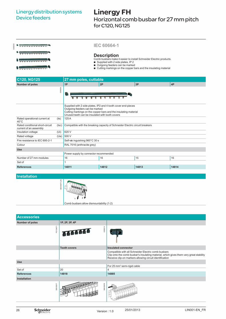
Linergy FHHorizontal comb busbar for 27 mm pitchfor C120, NG125
DescriptionComb busbars make it easier to install Schneider E lectric products.
b Supplied with 2 side plates, IP 2 b Outgoing feeders can be marked b Cutting markings on the copper bars and the insulating material
IEC 60664-1
C120, NG 125 27 mm poles, cuttableNumber of poles 1P 2P 3P 4P
Supplied with 2 side plates, IP2 and 4 tooth cover end-piecesOutgoing feeders can be markedCutting markings on the copper bars and the insulating materialU nused teeth can be insulated with tooth covers
Rated operational current at 40°C
(Ie) 125 A
Rated conditional short-circuit current of an assembly
(Isc) Compatible with the breaking capacity of Schneider E lectric circuit breakers
Insulation voltage (U i) 620 VRated voltage (U e) 500 VF ire resistance to IE C 69 5-2-1 Self-ext inguishing 9 60°C 30 sColour RAL 7016 (anthracite grey)
U se Power supply by connector recommended
Number of 27 mm modules 16 16 15 16Set of 1
References 148 11 148 12 148 13 148 14
Installation
1 2
Comb busbars allow dismountability (1-2)
AccessoriesNumber of poles 1P, 2P, 3P, 4P
T ooth covers Insulated connectorCompatible with all Schneider E lectric comb busbarsClip onto the comb busbar' s insulating material, which gives them very great stabilityReceive clip-on markers allowing circuit identification
U seF or 25 mm2 semi-rigid cable
Set of 20 4References 148 18 148 8 5
Installation
LIN001-E N_ F RVersion : 1.0
0309
20d
0309
20d
DB
1059
77-L
IN
0309
21d
DB
1059
77
DB
1059
76
PG
1340
71
25/01/2013 27
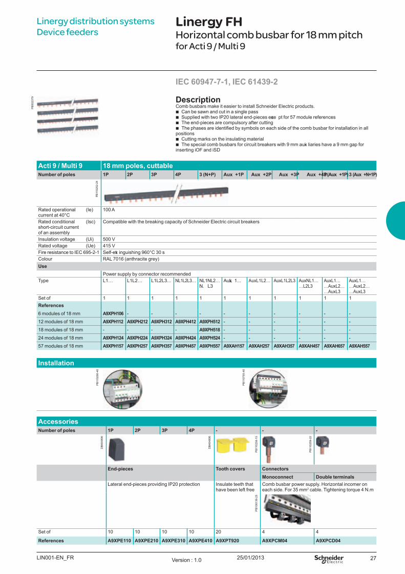
Linergy FHHorizontal comb busbar for 18 mm pitchfor Acti 9 / Multi 9
Linergy distribution systems Device feeders
DescriptionComb busbars make it easier to install Schneider E lectric products.
b Can be sawn and cut in a single pass b Supplied with two IP20 lateral end-pieces exce pt for 57 module references b The end-pieces are compulsory after cutting b he phases are identified by symbols on each side of the comb busbar for installation in all
positions b Cutting marks on the insulating material b The special comb busbars for circuit breakers with 9 mm auxi liaries have a 9 mm gap for
inserting iOF and iSD
IEC 60947-7-1, IEC 61439-2
Acti 9 / M ulti 9 18 mm poles, cuttableNumber of poles 1P 2P 3P 4P 3 ( N+ P) Aux + 1P Aux + 2P Aux + 3P Aux + 4P 3 ( Aux + 1P) 3 ( Aux + N+ 1P)
Rated operational current at 40°C
(Ie) 100 A
Rated conditional short-circuit current of an assembly
(Isc) Compatible with the breaking capacity of Schneider E lectric circuit breakers
Insulation voltage (U i) 500 VRated voltage (U e) 415 VF ire resistance to IE C 69 5-2-1 Self-ext inguishing 9 60°C 30 sColour RAL 7016 (anthracite grey)U se
Power supply by connector recommended Type L1… L1L2… L1L2L3... NL1L2L3… NL1NL2…
…N L3AuxL 1... Aux L1L2… Aux L1L2L3 Aux NL1…
… L2L3Aux L1… … Aux L2… … Aux L3
Aux L1… … Aux L2… … Aux L3
Set of 1 1 1 1 1 1 1 1 1 1 1References6 modules of 18 mm A9X PH 106 - - - - - - - - - -
12 modules of 18 mm A9X PH 112 A9X PH 212 A9X PH 312 A9X PH 412 A9X PH 512 - - - - - -
18 modules of 18 mm - - - - A9X PH 518 - - - - - -
24 modules of 18 mm A9X PH 124 A9X PH 224 A9X PH 324 A9X PH 424 A9X PH 524 - - - - - -
57 modules of 18 mm A9X PH 157 A9X PH 257 A9X PH 357 A9X PH 457 A9X PH 557 A9X AH 157 A9X AH 257 A9X AH 357 A9X AH 457 A9X AH 657 A9X AH 557
Installation
AccessoriesNumber of poles 1P 2P 3P 4P - - -
End-pieces T ooth covers ConnectorsM onoconnect Double terminals
Lateral end-pieces providing IP20 protection Insulate teeth that have been left free
Comb busbar power supply. Horizontal incomer on each side. F or 35 mm2 cable. Tightening torque 4 N.m
Set of 10 10 10 10 20 4 4
References A9X PE110 A9X PE210 A9X PE310 A9X PE410 A9X PT 920 A9X PCM 04 A9X PCD04
LIN001-E N_ F R Version : 1.0
PB
1102
52-2
4
PB
5023
79
PB
1102
90-4
0
PB
1107
93-4
0
DB
4048
06
DB
4048
06
PB
1102
58-1
5
PB
1102
59-2
2
PB
1081
38-2
5
25/01/201328
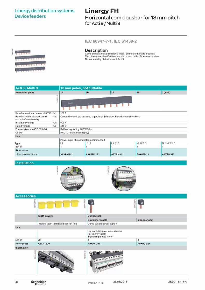
Linergy distribution systems Device feeders
Linergy FHHorizontal comb busbar for 18 mm pitchfor Acti 9 / Multi 9
DescriptionComb busbars make it easier to install Schneider E lectric products.
he phases are identified by symbols on each side of the comb busbar.Dismountability of devices with Acti 9 .
IEC 60947-7-1, IEC 61439-2
Acti 9 / M ulti 9 18 mm poles, not cuttableNumber of poles 1P 2P 3P 4P 3 ( N+ P)
Rated operational current at 40°C (Ie) 100 ARated conditional short-circuit current of an assembly
(Isc) Compatible with the breaking capacity of Schneider E lectric circuit breakers
Insulation voltage (U i) 500 VRated voltage (U e) 415 VF ire resistance to IE C 69 5-2-1 Self-ext inguishing 9 60°C 30 sColour RAL 7016 (anthracite grey)U se
Power supply by connector recommended Type L1 L1L2 L1L2L3 NL1L2L3 NL1NL2NL3Set of 1 1 1 1 1References12 modules of 18 mm A9X PM 112 A9X PM 212 A9X PM 312 A9X PM 412 A9X PM 512
Installation
Accessories
T ooth covers ConnectorsDouble terminals M onoconnect
Insulate teeth that have been left free Comb busbar power supply U se
Horizontal incomer on each sideF or 35 mm2 cableTightening torque 4 N.m
Set of 20 4 4References A9X PT 920 A9X PCD04 A9X PCM 04Installation
LIN001-E N_ F RVersion : 1.0
PB
1102
31-1
5
PB
5023
80
PB
1102
90-4
0
PB
1107
93-4
0
PB
1102
57-1
0
PB
1102
59-1
5
PB
1102
58-2
2
PB
1081
62-3
8
PB
1081
64-3
8

25/01/2013 29
Linergy distribution systems Device feeders
DescriptionComb busbars ensure:
b E asy, reliable mounting of 1P+ N and 3P+ N, TL, CT, ID, V, B P and Cm switchgear: tooth positioning opposite the device terminals is ensured by indexi ng of copper parts
b C60/ID G roup F eeder comb busbars contain two different parts: v Connection of G roup F eeder switchgear: C60 (3P+ N) or ID (3P+ N) circuit breaker in 18 mm
modules, powered by cables, through the bottom, directly by the terminals v Connection of Clario, Prodis and Librio switchgear in 9 mm modules
IEC 60439-1
Linergy FHHorizontal comb busbar for 9 mm pitchfor Acti 9, C60
Acti 9 Ph + N 9 mm poles, cuttableNumber of poles 1P+ N 3P+ N
21501 21505Complete comb busbars (supplied with 4 side plates and 1 tooth cover)
Rated operational current at 40°C (Ie) 80 ARated conditional short-circuit current of an assembly
(Isc) Compatible with the breaking capacity of Schneider E lectric circuit breakers
Insulation voltage (U i) 440 VRated voltage (U e) 230 V (P4 + N) - 400 V (3Ph + N)Rated impulse withstand voltage (U imp) 6 kVDegree of protection IP20F ire resistance to IE C 69 5-2-1 Self-ext inguishing 9 60°C 30 sColour RAL 7035Number of 18 mm modules Comb
busbar12 18 24 12 18 24
Tooth cover
3 3 6 3 3 6
References 21501 19512 21503 21505 09516 21507Comb busbars aloneNumber of 18 mm modules Comb
busbar48 48
References 2108 9 21093
C60/ ID G roup F eeder comb busbars aloneNumber of poles 3P+ N
Rated operational current at 40°C (Ie) 80 ARated conditional short-circuit current of an assembly
(Isc) Compatible with the breaking capacity of Schneider E lectric circuit breakers
Insulation voltage (U i) 440 VRated voltage (U e) 230 V (P4 + N) - 400 V (3Ph + N)Rated impulse withstand voltage (U imp) 6 kVDegree of protection IP20F ire resistance to IE C 69 5-2-1 Self-ext inguishing 9 60°C 30 sColour RAL 7035Number of 18-mm modules 12 48 48Power supply Through left-hand Through left-hand Through right-handReferences 10545 10546 10547
AccessoriesNumber of poles 1P+ N 3P+ N
End-pieces T ooth covers ( 3 x 18 -mm modules) T ooth covers ( 1 x 18 -mm module) Connectors ( grey )Set of 40 12 10 4References 021094 021095 021096 010405 021098
LIN001-E N_ F R Version : 1.0
DB
1237
29
DB
1237
30
DB
1011
84-1
0
DB
1237
32
DB
1237
33
DB
1237
31
PB
5023
82
25/01/201330
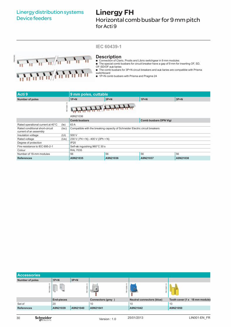
Acti 9 9 mm poles, cuttableNumber of poles 1P+ N 3P+ N 1P+ N 3P+ N
A9 N21036Comb busbars Comb busbars DPN V igi
Rated operational current at 40°C (Ie) 63 ARated conditional short-circuit current of an assembly
(Isc) Compatible with the breaking capacity of Schneider E lectric circuit breakers
Insulation voltage (U i) 500 VRated voltage (U e) 230 V ( P4 + N) - 400 V (3Ph + N)Degree of protection IP20F ire resistance to IE C 69 5-2-1 Self-ext inguishing 9 60°C 30 sColour RAL 7035Number of 18-mm modules 56 56 56 56References A9N21035 A9N21036 A9N21037 A9N21038
AccessoriesNumber of poles 1P+ N 3P+ N
End-pieces Connectors ( grey ) Neutral connectors ( blue) T ooth cover ( 1 x 18 mm module)Set of 20 10 10 10References A9N21039 A9N21040 A9N21041 A9N21042 A9N21050
Linergy distribution systems Device feeders
Linergy FHHorizontal comb busbar for 9 mm pitchfor Acti 9
IEC 60439-1
Description b Connection of Clario, Prodis and Librio switchgear in 9 mm modules b The special comb busbars for circuit breaker have a gap of 9 mm for inserting OF , SD,
OF -SD/OF auxi liaries b The comb busbars for 3P+ N circuit breakers and auxi liaries are compatible with Prisma
switchboard b 1P+ N comb busbars with Prisma and Pragma 24
LIN001-E N_ F RVersion : 1.0
PB
1108
04-1
0
PB
1108
05-1
0
PB
1108
06-1
0
PB
1108
07-1
0
PB
1108
01-1
0
PB
5023
83
25/01/2013 31
Linergy distribution systems Device feeders
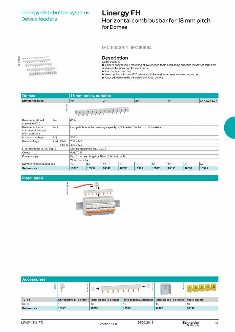
Linergy FHHorizontal comb busbar for 18 mm pitchfor Domae
DescriptionComb busbars:
b E nsure easy reliable mounting of switchgear: tooth positioning opposite the device terminals is ensured by indexi ng of copper parts.
b Can be sawn and cut. b Are supplied with two IP20 lateral end-pieces (the end-pieces are compulsory) . b U nused teeth can be insulated with tooth covers.
IEC 60439-1, IEC60664
Domae 18 mm poles, cuttableNumber of poles 1P 2P 3P 4P L 1N/ L 2N/ L 3N
Rated operational current at 40°C
(Ie) 63 A
Rated conditional short-circuit current of an assembly
(Isc) Compatible with the breaking capacity of Schneider E lectric circuit breakers
Insulation voltage (U i) 500 VRated voltage (U e) Ph/N 230 V AC
Ph/Ph 400 V ACF ire resistance to IE C 69 5-2-1 Self-ext inguishing 850°C 30 sColour RAL 7035Power supply B y 16 mm2 semi-rigid or 10 mm2 flexible cable
W ith connectorNumber of 18 mm modules 12 57 12 57 12 57 12 57 57References 1038 7 1038 8 1038 9 10390 10391 10392 10393 10394 10395
Installation
Accessories
T y pe Connectors ( 4, 35 mm² ) End-pieces ( 2 ph ases) End-pieces ( 3 ph ases) End-pieces ( 4 ph ases) T ooth coversSet of 1 10 10 10 10References 10397 10398 10399 10405 10396
LIN001-E N_ F R Version : 1.0
PB
1016
26-3
5
PB
5023
72P
B10
1630
_SE
-40
PB
1016
32-1
0
PB
5023
76
PB
1108
98
PB
5023
73
25/01/201332
Linergy distribution systems Device feeders
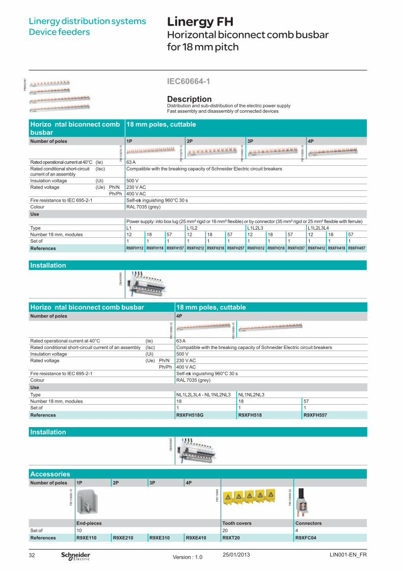
Linergy FHHorizontal biconnect comb busbar for 18 mm pitch
DescriptionDistribution and sub-distribution of the electric power supplyF ast assembly and disassembly of connected devices
IEC60664-1
H orizo ntal biconnect comb busbar
18 mm poles, cuttable
Number of poles 1P 2P 3P 4P
Rated operational current at 40°C (Ie) 63 ARated conditional short-circuit current of an assembly
(Isc) Compatible with the breaking capacity of Schneider E lectric circuit breakers
Insulation voltage (U i) 500 VRated voltage (U e) Ph/N 230 V AC
Ph/Ph 400 V ACF ire resistance to IE C 69 5-2-1 Self-ext inguishing 9 60°C 30 sColour RAL 7035 (grey)U se
Power supply: into box lug (25 mm² rigid or 16 mm² flexible) or by connector (35 mm² rigid or 25 mm² flexible with ferrule)Type L1 L1L2 L1L2L3 L1L2L3L4Number 18 mm, modules 12 18 57 12 18 57 12 18 57 12 18 57Set of 1 1 1 1 1 1 1 1 1 1 1 1References R9X F H 112 R9X F H 118 R9X F H 157 R9X F H 212 R9X F H 218 R9X F H 257 R9X F H 312 R9X F H 318 R9X F H 357 R9X F H 412 R9X F H 418 R9X F H 457
Installation
H orizo ntal biconnect comb busbar 18 mm poles, cuttableNumber of poles 4P
Rated operational current at 40°C (Ie) 63 ARated conditional short-circuit current of an assembly (Isc) Compatible with the breaking capacity of Schneider E lectric circuit breakersInsulation voltage (U i) 500 VRated voltage (U e) Ph/N 230 V AC
Ph/Ph 400 V ACF ire resistance to IE C 69 5-2-1 Self-ext inguishing 9 60°C 30 sColour RAL 7035 (grey)U se Type NL1L2L3L4 - NL1NL2NL3 NL1NL2NL3Number 18 mm, modules 18 18 57Set of 1 1 1References R9X F H 518 G R9X F H 518 R9X F H 557
Installation
AccessoriesNumber of poles 1P 2P 3P 4P
End-pieces T ooth covers ConnectorsSet of 10 20 4References R9X E110 R9X E210 R9X E310 R9X E410 R9X T 20 R9X F C04
LIN001-E N_ F RVersion : 1.0
PB
1108
76-1
5
PB
1108
79-1
5
PB
1108
82-1
5
PB
1108
85-1
5
PB
1108
88-1
5
PB
1108
89-1
5
PB
5023
81
DB
4059
95
DB
4059
95
PB
1108
95-1
5
PB
1108
98
PB
1108
99-3
0
25/01/2013 33
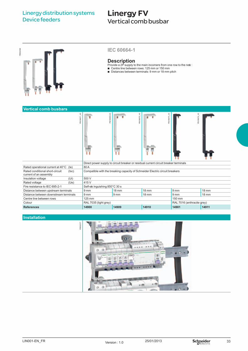
Linergy distribution systems Device feeders
Linergy FVVertical comb busbar
DescriptionProvide a 2P supply to the main incomers from one row to the next :
b Centre line between rows: 125 mm or 150 mm b Distances between terminals: 9 mm or 18 mm pitch
IEC 60664-1
V ertical comb busbars
Direct power supply to circuit breaker or residual current circuit breaker terminalsRated operational current at 40°C (Ie) 80 ARated conditional short-circuit current of an assembly
(Isc) Compatible with the breaking capacity of Schneider E lectric circuit breakers
Insulation voltage (U i) 500 VRated voltage (U e) 415 VF ire resistance to IE C 69 5-2-1 Self-ext inguishing 850°C 30 sDistance between upstream terminals 9 mm 18 mm 18 mm 9 mm 18 mmDistance between downstream terminals 9 mm 9 mm 18 mm 9 mm 18 mmCentre line between rows 125 mm 150 mmColour RAL 7035 (light grey) RAL 7016 (anthracite grey)References 14900 14909 14910 14901 14911
Installation
LIN001-E N_ F R Version : 1.0
PB
5023
84
PB
5023
77P
B10
6071
_40
PB
1060
73_4
0
PB
1060
63-4
0
PB
1060
72_4
0
PB
1060
74_4
0
25/01/201334
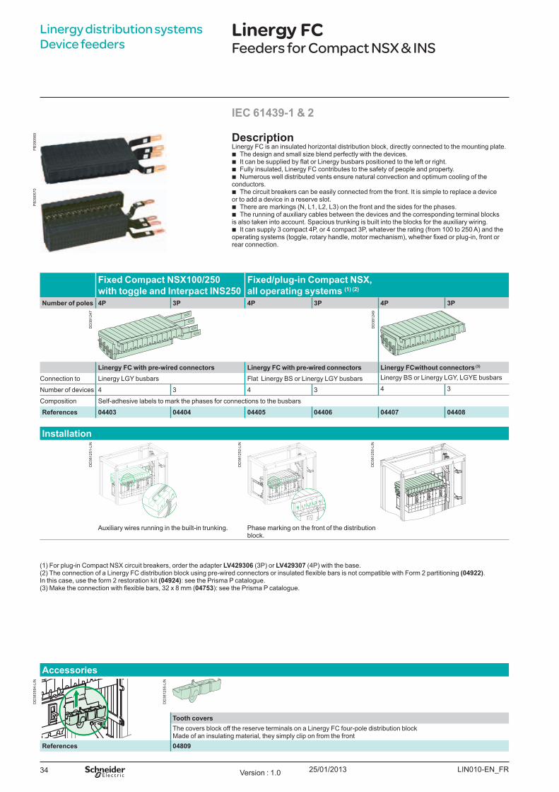
Fix ed Co m p act NSX100/ 250 w it h t o ggl e and I nt erp act I NS250
Fix ed / p l u g- in Co m p act NSX, al l o p erat ing syst em s (1) (2)
Nu m b er o f p o l es 4P 3P 4P 3P 4P 3P
Linergy FC w it h p re- w ired co nnect o rs Linergy FC w it h p re- w ired co nnect o rs Linergy FCw it h o u t co nnect o rs (3)
Connection to Linergy LGY busbars Flat Linergy B S or Linergy LGY busbars Linergy B S or Linergy LGY , LGY E busbars
Number of devices 4 3 4 3 4 3
Composition Self-adhesive labels to mark the phases for connections to the busbars
References 04403 04404 04405 04406 04407 04408
I nst al l at io n
Auxiliary wires running in the built-in trunking. Phase marking on the front of the distribution block.
Linergy distribution systems Device feeders
Linergy FCFeeders for Compact NSX & INS
Descrip t io nLinergy FC is an insulated horizontal distribution block, directly connected to the mounting plate.
b The design and small size blend perfectly with the devices. b It can be supplied by flat or Linergy busbars positioned to the left or right. b Fully insulated, Linergy FC contributes to the safety of people and property. b Numerous well distributed vents ensure natural convection and optimum cooling of the
conductors. b The circuit breakers can be easily connected from the front. It is simple to replace a device
or to add a device in a reserve slot. b There are markings ( N, L1, L2, L3) on the front and the sides for the phases. b The running of auxiliary cables between the devices and the corresponding terminal blocks
is also taken into account. Spacious trunking is built into the blocks for the auxiliary wiring. b It can supply 3 compact 4P, or 4 compact 3P, whatever the rating ( from 100 to 250 A) and the
operating systems (toggle, rotary handle, motor mechanism), whether fixed or plug-in, front or rear connection.
I EC 61439- 1 & 2
( 1) For plug-in Compact NSX circuit breakers, order the adapter LV429306 ( 3P) or LV429307 ( 4P) with the base.(2) he connection of a Linergy F distribution block using pre-wired connectors or insulated flexible bars is not compatible with Form 2 partitioning (04922).In this case, use the form 2 restoration kit (04924): see the Prisma P catalogue.(3) ake the connection with flexible bars, 32 x 8 mm (04753 ) : see the Prisma P catalogue.
Accesso ries
To o t h co v ersThe covers block off the reserve terminals on a Linergy FC four-pole distribution blockMade of an insulating material, they simply clip on from the front
References 04809
LIN010-EN_FRVersion : 1.0
DD
3812
47
DD
3812
49
DD
3812
51-L
IN
DD
3812
52-L
IN
DD
3812
50-L
IN
DD
3835
94-L
IN
DD
3812
55-L
IN
PB
3905
69P
B39
0570
25/01/2013 35
Linergy distribution systems Device feeders
Linergy FCFeeders for Compact NSX & INS
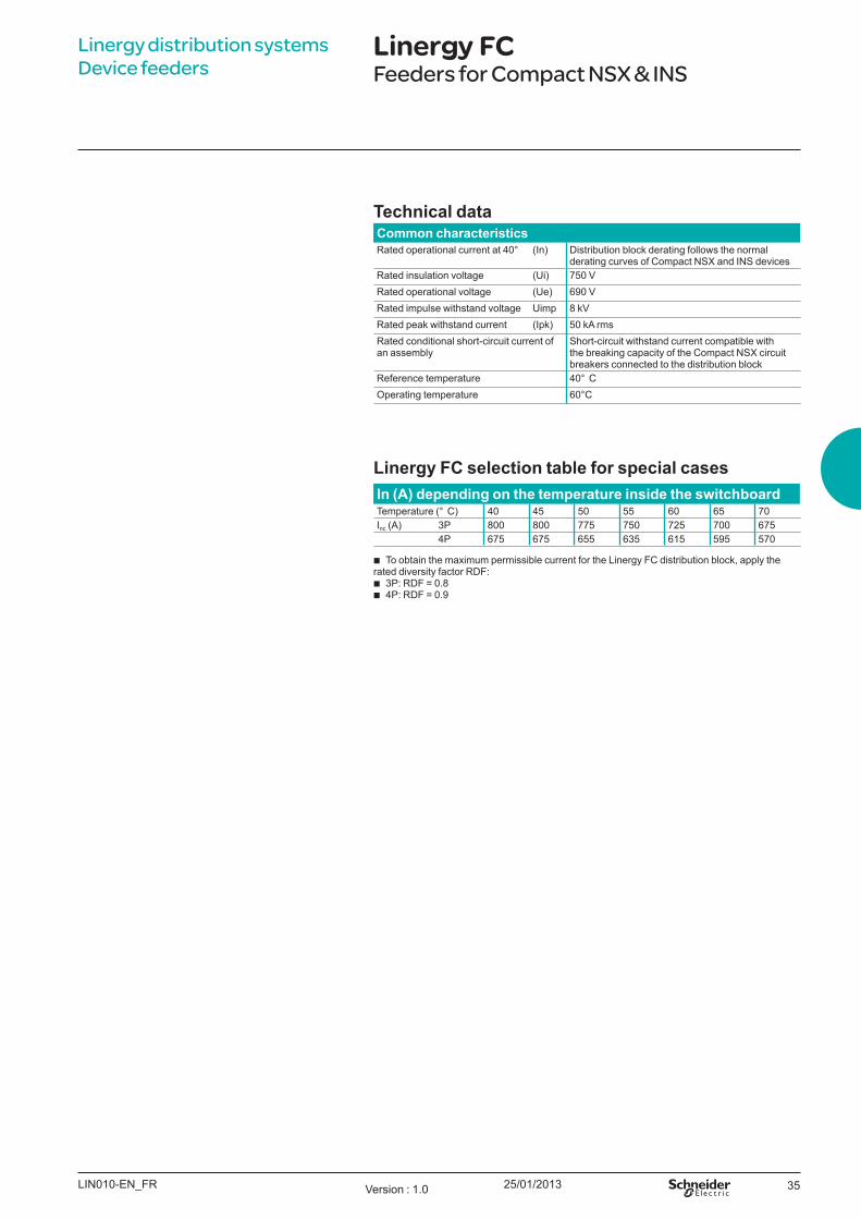
Tech nical d at a Co m m o n ch aract erist icsRated operational current at 40° ( In) Distribution block derating follows the normal
derating curves of Compact NSX and INS devicesRated insulation voltage ( U i) 750 VRated operational voltage ( U e) 690 VRated impulse withstand voltage U imp 8 kVRated peak withstand current ( Ipk) 50 kA rmsRated conditional short-circuit current of an assembly
Short-circuit withstand current compatible with the breaking capacity of the Compact NSX circuit breakers connected to the distribution block
Reference temperature 40° CO perating temperature 60
Linergy FC sel ect io n t ab l e fo r sp ecial casesI n (A) d ep end ing o n t h e t em p erat u re insid e t h e sw it ch b o ardTemperature ( ° C) 40 45 50 55 60 65 70Inc ( A) 3P 800 800 775 750 725 700 675
4P 675 675 655 635 615 595 570
b To obtain the maximum permissible current for the Linergy FC distribution block, apply the rated diversity factor RDF:
b 3P DF 0.8 b 4P DF 0.9
LIN010-EN_FR Version : 1.0
25/01/201336
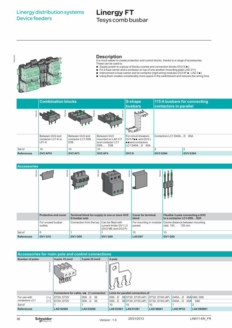
Co m b inat io n b l o ck s S- sh ap e b u sb ars
115 A b u sb ars fo r co nnect ing co nt act o rs in p aral l el
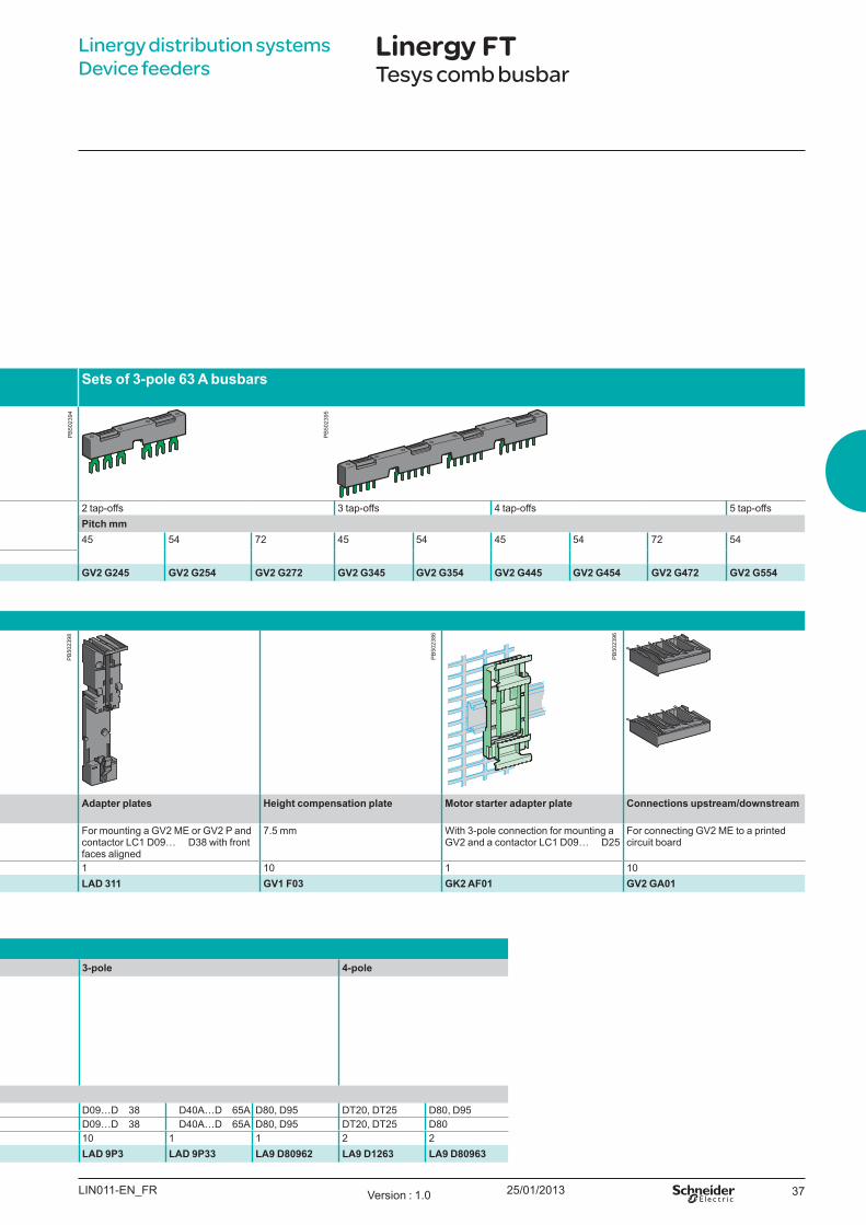
Set s o f 3- p o l e 63 A b u sb ars
B etween GV2 and contactor LC1 K or LP1 K
B etween GV2 and contactor LC1 D09… D38
B etween GV2 mounted on LAD 311 and contactor LC1 D09… D38
For circuit-breakers GV3 P and GV3 L
and contactors LC1 D40A…D 65A
Contactors LC1 D40A…D 65A 2 tap-offs 3 tap-offs 4 tap-offs 5 tap-offsPit ch m m45 54 72 45 54 45 54 72 54
Set of 10 10 10 2 3References GV2 AF01 GV2 AF3 GV2 AF4 GV3 S GV3 G264 GV3 G364 GV2 G245 GV2 G254 GV2 G272 GV2 G345 GV2 G354 GV2 G445 GV2 G454 GV2 G472 GV2 G554
Linergy distribution systems Device feeders
Linergy FTTesys comb busbar
Accesso ries
Pro t ect iv e end co v er Term inal b l o ck fo r su p p l y t o o ne o r m o re GV2 G b u sb ar set s
Co v er fo r t erm inal b l o ck
Fl ex ib l e 3- p o l e co nnect ing a GV2 t o a co nt act o r LC1- D09… D25
Ad ap t er p l at es Heigh t co m p ensat io n p l at e Mo t o r st art er ad ap t er p l at e Co nnect io ns u p st ream / d o w nst ream
For unused busbar outlets
Connection from the top an be fitted with current limiter GV1 L3 ( GV2 ME and GV2 P)
For mounting in modular panels
Centre distance between mounting rails: 100… 120 mm
For mounting a GV2 ME or GV2 P and contactor LC1 D09… D38 with front faces aligned
7.5 mm W ith 3-pole connection for mounting a GV2 and a contactor LC1 D09… D25
For connecting GV2 ME to a printed circuit board
Set of 5 1 1 10 10 1 10 1 10References GV1 G10 GV1 G09 GV1 G05 LA9 E07 GV1 G02 LAD 311 GV1 F03 GK2 AF01 GV2 GA01
Accesso ries fo r m ain p o l e and co nt ro l co nnect io nsNu m b er o f p o l es 4- p o l e 10 m m 2 3- p o l e 25 m m 2 2- p o l e 3- p o l e 4- p o l e
Co nnect o rs fo r cab l e, size (1 co nnect o r) Link s fo r p aral l el co nnect io n o fFor use with contactors LC1
( a) DT20, DT25 D09…D 38 D09…D 38 DT20, DT25 ( 4P) DT32, DT40 ( 4P) D40A…D 65A D80, D95 D09…D 38 D40A…D 65A D80, D95 DT20, DT25 D80, D95( c) DT20, DT25 D09…D 38 D09…D 38 DT20, DT25 ( 4P) DT32, DT40 ( 4P) D40A…D 65A D80 D09…D 38 D40A…D 65A D80, D95 DT20, DT25 D80
Set of 1 1 10 10 10 1 2 10 1 1 2 2References LAD 92560 LA9 D3260 LA9 D2561 LA9 D1261 LAD 96061 LAD 9P32 LA9 D80961 LAD 9P3 LAD 9P33 LA9 D80962 LA9 D1263 LA9 D80963
Descrip t io nIt is much easier to create protection and control blocks, thanks to a range of accessories.These can be used to:
b Supply power to a group of blocks ( combs and connection blocks GV2 G ) b Fix a fuse-carrier and a contactor on top of one another ( mounting plate LAD 311) b Interconnect a fuse-carrier and its contactor ( rigid wiring modules GV2 AF , LAD 3 ) b U sing them creates considerably more space in the switchboard and reduces the wiring time
LIN011-EN_FRVersion : 1.0
PB
5023
91
PB
5023
99
PB
5023
92
PB
5023
93
DF5
3779
2-LI
N
DF5
3779
7-LI
N
DF5
1099
5-LI
N
PB
5023
90
PB
5023
89
PB
5023
88
PB
5023
97
PB
5023
87
25/01/2013 37
Co m b inat io n b l o ck s S- sh ap e b u sb ars
115 A b u sb ars fo r co nnect ing co nt act o rs in p aral l el
Set s o f 3- p o l e 63 A b u sb ars
B etween GV2 and contactor LC1 K or LP1 K
B etween GV2 and contactor LC1 D09… D38
B etween GV2 mounted on LAD 311 and contactor LC1 D09… D38
For circuit-breakers GV3 P and GV3 L
and contactors LC1 D40A…D 65A
Contactors LC1 D40A… D65A 2 tap-offs 3 tap-offs 4 tap-offs 5 tap-offsPit ch m m45 54 72 45 54 45 54 72 54
Set of 10 10 10 2 3References GV2 AF01 GV2 AF3 GV2 AF4 GV3 S GV3 G264 GV3 G364 GV2 G245 GV2 G254 GV2 G272 GV2 G345 GV2 G354 GV2 G445 GV2 G454 GV2 G472 GV2 G554
Linergy distribution systems Device feeders
Linergy FTTesys comb busbar
Accesso ries
Pro t ect iv e end co v er Term inal b l o ck fo r su p p l y t o o ne o r m o re GV2 G b u sb ar set s
Co v er fo r t erm inal b l o ck
Fl ex ib l e 3- p o l e co nnect ing a GV2 t o a co nt act o r LC1- D09… D25
Ad ap t er p l at es Heigh t co m p ensat io n p l at e Mo t o r st art er ad ap t er p l at e Co nnect io ns u p st ream / d o w nst ream
For unused busbar outlets
Connection from the top an be fitted with current limiter GV1 L3 ( GV2 ME and GV2 P)
For mounting in modular panels
Centre distance between mounting rails: 100… 120 mm
For mounting a GV2 ME or GV2 P and contactor LC1 D09… D38 with front faces aligned
7.5 mm W ith 3-pole connection for mounting a GV2 and a contactor LC1 D09… D25
For connecting GV2 ME to a printed circuit board
Set of 5 1 1 10 10 1 10 1 10References GV1 G10 GV1 G09 GV1 G05 LA9 E07 GV1 G02 LAD 311 GV1 F03 GK2 AF01 GV2 GA01
Accesso ries fo r m ain p o l e and co nt ro l co nnect io nsNu m b er o f p o l es 4- p o l e 10 m m 2 3- p o l e 25 m m 2 2- p o l e 3- p o l e 4- p o l e
Co nnect o rs fo r cab l e, size (1 co nnect o r) Link s fo r p aral l el co nnect io n o fFor use with contactors LC1
( a) DT20, DT25 D09…D 38 D09…D 38 DT20, DT25 ( 4P) DT32, DT40 ( 4P) D40A…D 65A D80, D95 D09…D 38 D40A…D 65A D80, D95 DT20, DT25 D80, D95( c) DT20, DT25 D09…D 38 D09…D 38 DT20, DT25 ( 4P) DT32, DT40 ( 4P) D40A…D 65A D80 D09…D 38 D40A…D 65A D80, D95 DT20, DT25 D80
Set of 1 1 10 10 10 1 2 10 1 1 2 2References LAD 92560 LA9 D3260 LA9 D2561 LA9 D1261 LAD 96061 LAD 9P32 LA9 D80961 LAD 9P3 LAD 9P33 LA9 D80962 LA9 D1263 LA9 D80963
LIN011-EN_FR Version : 1.0
PB
5023
94
PB
5023
95
PB
5023
86
PB
5023
98
PB
5023
96

25/01/201338
Linergy distribution systems Device feeders
Linergy FTTesys comb busbar
Fo r 3- p o l e rev ersing co nt act o rs
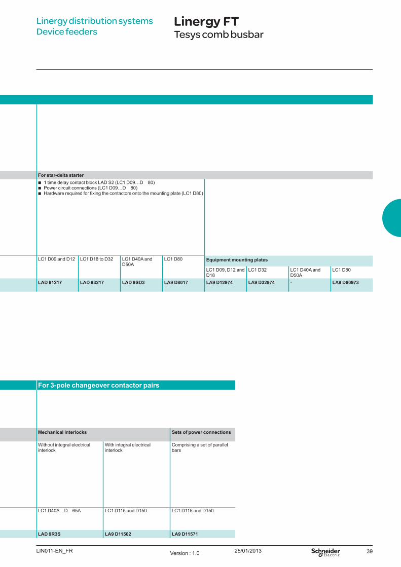
LAD 9R1 LAD 9R3 LA9 D8069Kit s fo r assem b l y o f rev ersing co nt act o rs Po w er co nnect io ns Fo r st ar- d el t a st art er
Composition b A mechanical interlock LAD 9V2 with electrical interlock LAD 9V1
b A set of power connections LAD 9V5 ( parallel) and LAD 9V6 ( reversing)
b A mechanical interlock LAD 9V2 without electrical interlock
b A set of power connections LAD 9V5 ( parallel) and LAD 9V6 ( reversing)
b A mechanical interlock LAD 4CM
b A set of power connections LA9 D65A69
b A set of parallel bars b A set of reverser bars
b 1 time delay contact block LAD S2 ( LC1 D09…D 80) b Power circuit connections ( LC1 D09…D 80) b Hardware required for fixing the contactors onto the mounting plate (L 1 D80)
For contactors LC1 D09 to D38 LC1 D40A to D65A
LC1 D09 to D38 with screw terminals or connectors
LC1 D09…D 32 with spring terminal connections
LC1 D40A to D65A
LC1 D80 and D95 ( a)
LC1 D80 and D95 ( c)
LC1 D115 and D150
LC1 D09 and D12 LC1 D18 to D32 LC1 D40A and D50A
LC1 D80 Eq u ip m ent m o u nt ing p l at es
LC1 D09, D12 and D18
LC1 D32 LC1 D40A and D50A
LC1 D80
References LAD 9R1V LAD 9R1 LAD 9R3 LAD 9V5 + LAD 9V6
LAD 9V12 + LAD 9V13
LA9 D65A69 LA9 D8069 LA9 D8069 LA9 D11569 LAD 91217 LAD 93217 LAD 9SD3 LA9 D8017 LA9 D12974 LA9 D32974 - LA9 D80973
Fo r 4- p o l e ch angeo v er co nt act o r Fo r 3- p o l e ch angeo v er co nt act o r p airs
LA9 D6570 LA9 D8070Kit s fo r assem b l y o f ch angeo v er co nt act o r p airs
Set s o f p o w er co nnect io ns Mech anical int erl o ck s Set s o f p o w er co nnect io ns
Composition b A mechanical interlock LAD 9V2 with electrical interlock LAD 9V1
b A set of power connections ( changeover) LAD 9V7
b A mechanical interlock LAD 9V2 without electrical interlock
b A set of power connections ( changeover) LAD 9V7
Comprising a set of parallel bars W ithout integral electrical interlock
W ith integral electrical interlock
Comprising a set of parallel bars
For contactors LC1 DT20 to DT40 withscrew terminals or connectors
LC1 DT60A and DT80A
LC1 D80004 LP1 D80004 LC1 D115004 LC1 DT203 to DT403with spring terminals
LC1 D80004 LP1 D80004 LC1 D40A…D 65A LC1 D115 and D150 LC1 D115 and D150
References LAD T9R1V LAD T9R1 LA9 D65A70 LA9 D8070 LA9 D8070 LA9 D11570 LAD 9V9 LA9 D8070 LA9 D8070 LAD 9R3S LA9 D11502 LA9 D11571
LIN011-EN_FRVersion : 1.0
DF5
3772
9-LI
N
DF5
3773
0-LI
N
DF5
3773
1-LI
N
DF5
3773
4-LI
N
DF5
3773
5-LI
N
25/01/2013 39
Linergy distribution systems Device feeders
Linergy FTTesys comb busbar
Fo r 3- p o l e rev ersing co nt act o rs
LAD 9R1 LAD 9R3 LA9 D8069Kit s fo r assem b l y o f rev ersing co nt act o rs Po w er co nnect io ns Fo r st ar- d el t a st art er
Composition b A mechanical interlock LAD 9V2 with electrical interlock LAD 9V1
b A set of power connections LAD 9V5 ( parallel) and LAD 9V6 ( reversing)
b A mechanical interlock LAD 9V2 without electrical interlock
b A set of power connections LAD 9V5 ( parallel) and LAD 9V6 ( reversing)
b A mechanical interlock LAD 4CM
b A set of power connections LA9 D65A69
b A set of parallel bars b A set of reverser bars
b 1 time delay contact block LAD S2 ( LC1 D09…D 80) b Power circuit connections ( LC1 D09…D 80) b Hardware required for fixing the contactors onto the mounting plate (L 1 D80)
For contactors LC1 D09 to D38 LC1 D40A to D65A
LC1 D09 to D38 with screw terminals or connectors
LC1 D09…D 32 with spring terminal connections
LC1 D40A to D65A
LC1 D80 and D95 ( a)
LC1 D80 and D95 ( c)
LC1 D115 and D150
LC1 D09 and D12 LC1 D18 to D32 LC1 D40A and D50A
LC1 D80 Eq u ip m ent m o u nt ing p l at es
LC1 D09, D12 and D18
LC1 D32 LC1 D40A and D50A
LC1 D80
References LAD 9R1V LAD 9R1 LAD 9R3 LAD 9V5 + LAD 9V6
LAD 9V12 + LAD 9V13
LA9 D65A69 LA9 D8069 LA9 D8069 LA9 D11569 LAD 91217 LAD 93217 LAD 9SD3 LA9 D8017 LA9 D12974 LA9 D32974 - LA9 D80973
Fo r 4- p o l e ch angeo v er co nt act o r Fo r 3- p o l e ch angeo v er co nt act o r p airs
LA9 D6570 LA9 D8070Kit s fo r assem b l y o f ch angeo v er co nt act o r p airs
Set s o f p o w er co nnect io ns Mech anical int erl o ck s Set s o f p o w er co nnect io ns
Composition b A mechanical interlock LAD 9V2 with electrical interlock LAD 9V1
b A set of power connections ( changeover) LAD 9V7
b A mechanical interlock LAD 9V2 without electrical interlock
b A set of power connections ( changeover) LAD 9V7
Comprising a set of parallel bars W ithout integral electrical interlock
W ith integral electrical interlock
Comprising a set of parallel bars
For contactors LC1 DT20 to DT40 withscrew terminals or connectors
LC1 DT60A and DT80A
LC1 D80004 LP1 D80004 LC1 D115004 LC1 DT203 to DT403with spring terminals
LC1 D80004 LP1 D80004 LC1 D40A…D 65A LC1 D115 and D150 LC1 D115 and D150
References LAD T9R1V LAD T9R1 LA9 D65A70 LA9 D8070 LA9 D8070 LA9 D11570 LAD 9V9 LA9 D8070 LA9 D8070 LAD 9R3S LA9 D11502 LA9 D11571
LIN011-EN_FR Version : 1.0
25/01/201340
Linergy distribution systems Device feeders
Linergy FTTesys comb busbar
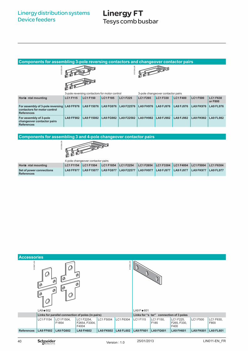
Co m p o nent s fo r assem b l ing 3- p o l e rev ersing co nt act o rs and ch angeo v er co nt act o r p airs
3-pole reversing contactors for motor control 3-pole changeover contactor pairsHo rizo nt al m o u nt ing LC1 F115 LC1 F150 LC1 F185 LC1 F225 LC1 F265 LC1 F330 LC1 F400 LC1 F500 LC1 F630
o r F800Fo r assem b l y o f 3- p o l e rev ersing co nt act o rs fo r m o t o r co nt ro l References
LA9 FF976 LA9 F15076 LA9 FG976 LA9 F22576 LA9 FH976 LA9 FJ976 LA9 FJ976 LA9 FK976 LA9 FL976
Fo r assem b l y o f 3- p o l e ch angeo v er co nt act o r p airs References
LA9 FF982 LA9 F15082 LA9 FG982 LA9 F22582 LA9 FH982 LA9 FJ982 LA9 FJ982 LA9 FK982 LA9 FL982
Co m p o nent s fo r assem b l ing 3 and 4- p o l e ch angeo v er co nt act o r p airs
4-pole changeover contactor pairsHo rizo nt al m o u nt ing LC1 F1154 LC1 F1504 LC1 F1854 LC1 F2254 LC1 F2654 LC1 F3304 LC1 F4004 LC1 F5004 LC1 F6304Set o f p o w er co nnect io ns References
LA9 FF977 LA9 F15077 LA9 FG977 LA9 F22577 LA9 FH977 LA9 FJ977 LA9 FJ977 LA9 FK977 LA9 FL977
Accesso ries
LA9 602 LA9 F 601Link s fo r p aral l el co nnect io n o f p o l es (in p airs) Link s fo r “s t ar” co nnect io n o f 3 p o l esLC1 F1154 LC1 F1504,
F1854LC1 F2254, F2654, F3304, F4004
LC1 F5004 LC1 F6304 LC1 F115 LC1 F150, F185
LC1 F225, F265, F330, F400
LC1 F500 LC1 F630, F800
References LA9 FF602 LA9 FG602 LA9 FH602 LA9 FK602 LA9 FL602 LA9 FF601 LA9 FG601 LA9 FH601 LA9 FK601 LA9 FL601
LIN011-EN_FRVersion : 1.0
8131
55-L
IN81
3168
-LIN
8131
54-L
IN
8130
87-L
IN
8130
88-L
IN
25/01/2013 41
Linergy distribution systems Device feeders
Linergy FTTesys comb busbar
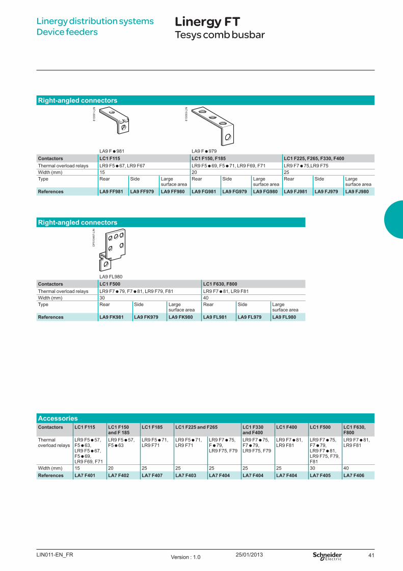
Righ t - angl ed co nnect o rs
LA9 F 981 LA9 F 979Co nt act o rs LC1 F115 LC1 F150, F185 LC1 F225, F265, F330, F400Thermal overload relays LR9 F5 67, LR9 F67 LR9 F5 69, F5 71, LR9 F69, F71 LR9 F7 75,LR9 F75W idth ( mm) 15 20 25Type Rear Side Large
surface areaRear Side Large
surface areaRear Side Large
surface areaReferences LA9 FF981 LA9 FF979 LA9 FF980 LA9 FG981 LA9 FG979 LA9 FG980 LA9 FJ981 LA9 FJ979 LA9 FJ980
Righ t - angl ed co nnect o rs
LA9 FL980Co nt act o rs LC1 F500 LC1 F630, F800Thermal overload relays LR9 F7 79, F7 81, LR9 F79, F81 LR9 F7 81, LR9 F81W idth ( mm) 30 40Type Rear Side Large
surface areaRear Side Large
surface areaReferences LA9 FK981 LA9 FK979 LA9 FK980 LA9 FL981 LA9 FL979 LA9 FL980
Accesso riesCo nt act o rs LC1 F115 LC1 F150
and F 185LC1 F185 LC1 F225 and F265 LC1 F330
and F400LC1 F400 LC1 F500 LC1 F630,
F800Thermal overload relays
LR9 F5 57, F5 63, LR9 F5 67, F5 69, LR9 F69, F71
LR9 F5 57, F5 63
LR9 F5 71, LR9 F71
LR9 F5 71, LR9 F71
LR9 F7 75, F 79, LR9 F75, F79
LR9 F7 75, F7 79, LR9 F75, F79
LR9 F7 81, LR9 F81
LR9 F7 75, F7 79, LR9 F7 81, LR9 F75, F79, F81
LR9 F7 81, LR9 F81
W idth ( mm) 15 20 25 25 25 25 25 30 40References LA7 F401 LA7 F402 LA7 F407 LA7 F403 LA7 F404 LA7 F404 LA7 F404 LA7 F405 LA7 F406
LIN011-EN_FR Version : 1.0
8130
91-L
IN
8130
93-L
IN
DF5
1048
7-LI
N

42
25/01/2013 43
Linergy distribution systems Power busbarsContents
Linergy BS 44
ear flat busbars up to 400 AMulti-stage busbars up to 630 AMulti-stage distribution block up to 630 ACommon accessories up to 630 A
44454647
Linergy BW 48
Insulated busbars up to 630 A 48
Linergy LGY, LGYE, BS 50
Selection guide up to 4000 A 50
Linergy LGY, LGYE, BS 51
Lateral 51
Linergy LGY, BS 54
Rear 54
Linergy LGYE, BS 56
Horizontal 56
Linergy BZ 58
Quick busbar systems 58
03_00-Sommaire Version : 1.0
25/01/201344
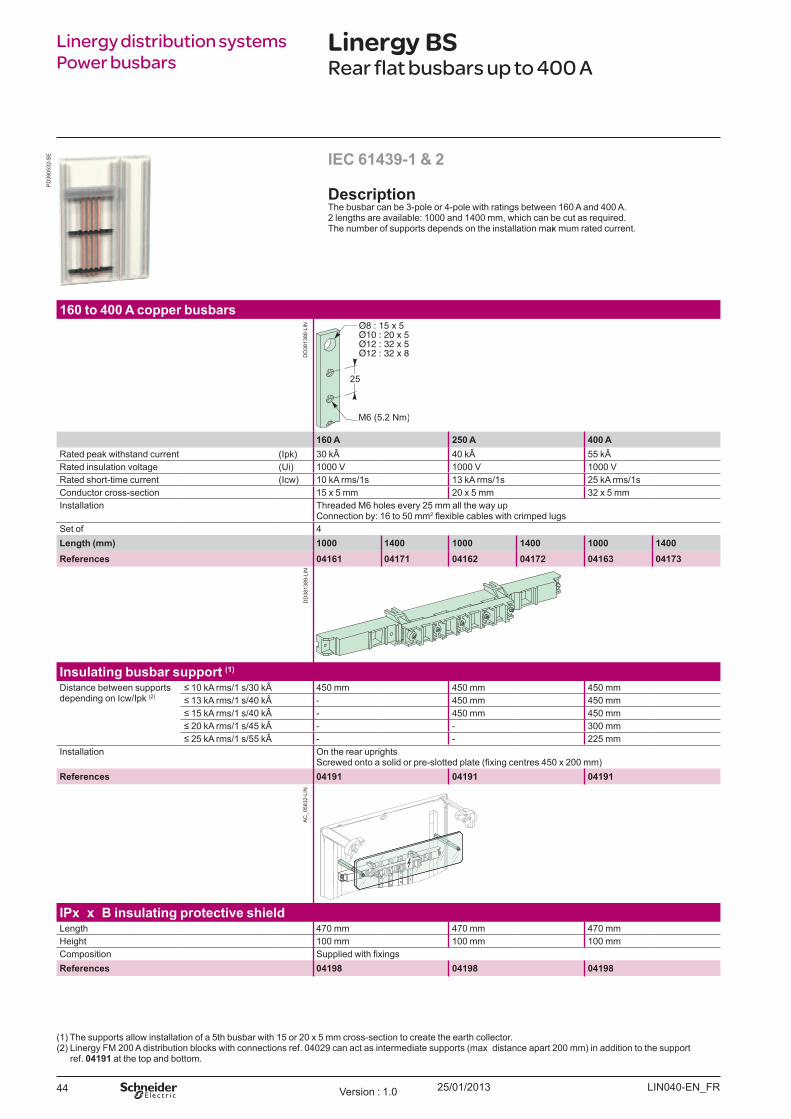
Linergy distribution systems Power busbars
Linergy BSRear flat busbars up to 400 A
DescriptionThe busbar can be 3-pole or 4-pole with ratings between 160 A and 400 A. 2 lengths are available: 1000 and 1400 mm, which can be cut as required. The number of supports depends on the installation maxi mum rated current.
160 to 400 A copper busbars
160 A 250 A 400 ARated peak withstand current (Ipk) 30 k 40 k 55 kÂRated insulation voltage (U i) 1000 V 1000 V 1000 VRated short-time current (Icw) 10 kA rms/1s 13 kA rms/1s 25 kA rms/1sConductor cross-section 15 x 5 mm 20 x 5 mm 32 x 5 mmInstallation Threaded M 6 holes every 25 mm all the way up
Connection by: 16 to 50 mm2 flexible cables with crimped lugsSet of 4L ength ( mm) 1000 1400 1000 1400 1000 1400References 04161 04171 04162 04172 04163 04173
Insulating busbar support ( 1)
Distance between supports depending on Icw/Ipk (2)
10 kA rms/1 s/30 k 450 mm 450 mm 450 mm 13 kA rms/1 s/40 k - 450 mm 450 mm 15 kA rms/1 s/40 k - 450 mm 450 mm 20 kA rms/1 s/45 k - - 300 mm 25 kA rms/1 s/55 k - - 225 mm
Installation On the rear uprightscrewed onto a solid or pre-slotted plate (fixing centres 450 x 200 mm)
References 04191 04191 04191
IPx x B insulating protective sh ieldLength 470 mm 470 mm 470 mmHeight 100 mm 100 mm 100 mmComposition upplied with fixingsReferences 04198 04198 04198
(1) The supports allow installation of a 5th busbar with 15 or 20 x 5 mm cross-section to create the earth collector.(2) Linergy F M 200 A distribution blocks with connections ref. 04029 can act as intermediate supports (max. distance apart 200 mm) in addition to the support
ref. 04191 at the top and bottom.
IEC 61439-1 & 2
LIN040-E N_ F RVersion : 1.0
PD
3905
32-S
E
DD
3813
88-L
IND
D38
1389
-LIN
AC
_058
32-L
IN

25/01/2013 45
Linergy distribution systems Power busbars
Linergy BSMulti-stage busbars up to 630 A
DescriptionM ulti-stage busbars are installed in a sheath L = 300 mm.W e strongly recommend dividing the current between 2 cubicles or enclosures j oined on either side.All the connection points are easily accessible from the front.The busbar orientation makes them easier to tighten and facilitates running the cables between them.The current can be 3-pole or 4-pole with ratings between 160 A and 630 A.2 lengths are available: 1000 and 1400 mm, which can be cut as required.The number of supports depends on the installation maxi mum rated current.
160 to 630 A copper busbars
160 A 250 A 400 A 630 ARated peak withstand current (Ipk) 30 k 40 k 55 k 55 kÂRated insulation voltage (U i) 750 V 750 V 750 V 750 VRated short-time current (Icw) 10 kA rms/1s 13 kA rms/1s 15, 20 kA rms/1s 25 kA rms/1sSupply at incoming terminals Connection by: 16 to 50 mm2 flexible cables with crimped lugsConductor cross-section 15 x 5 mm 20 x 5 mm 32 x 5 mm 32 x 8 mmInstallation F lat copper busbar with threaded M 6 holes every 25 mm all the way upSet of 4L ength ( mm) 1000 1400 1000 1400 1000 1400 1000 1400References 04161 04171 04162 04172 04163 04173 Pending 04174
Insulating busbar support ( 1)
upport fixing centres in accordance with Icw/Ipk (2)
10 kA rms/1 s/30 k 450 mm 450 mm 450 mm 450 mm 13 kA rms/1 s/40 k - 450 mm 450 mm 450 mm 15 kA rms/1 s/40 k - 450 mm 450 mm 20 kA rms/1 s/45 k - - 300 mm 300 mm 25 kA rms/0.6 s/55 k - - 300 mm - 25 kA rms/1 s/55 k - - - 300 mm
Installation Installation on functional uprights in Prisma. crewed onto a solid or pre-slotted plate (450 x 200 mm fixing centres)
References 04192 04192 04192 04192
IPx x B insulating protective sh ieldLength 250 mm 250 mm 250 mm 250 mmHeight 1500 mm 1500 mm 1500 mm 1500 mmComposition F ixi ng accessories supplied with support ref. 04192References 04197 04197 04197 04197
IEC 61439-1 & 2
LIN040-E N_ F R Version : 1.0
PD
3905
33_S
E
DD
3813
88-L
IND
D38
1395
-LIN
DD
3813
96-L
IN
25/01/201346
Linergy distribution systems Power busbars
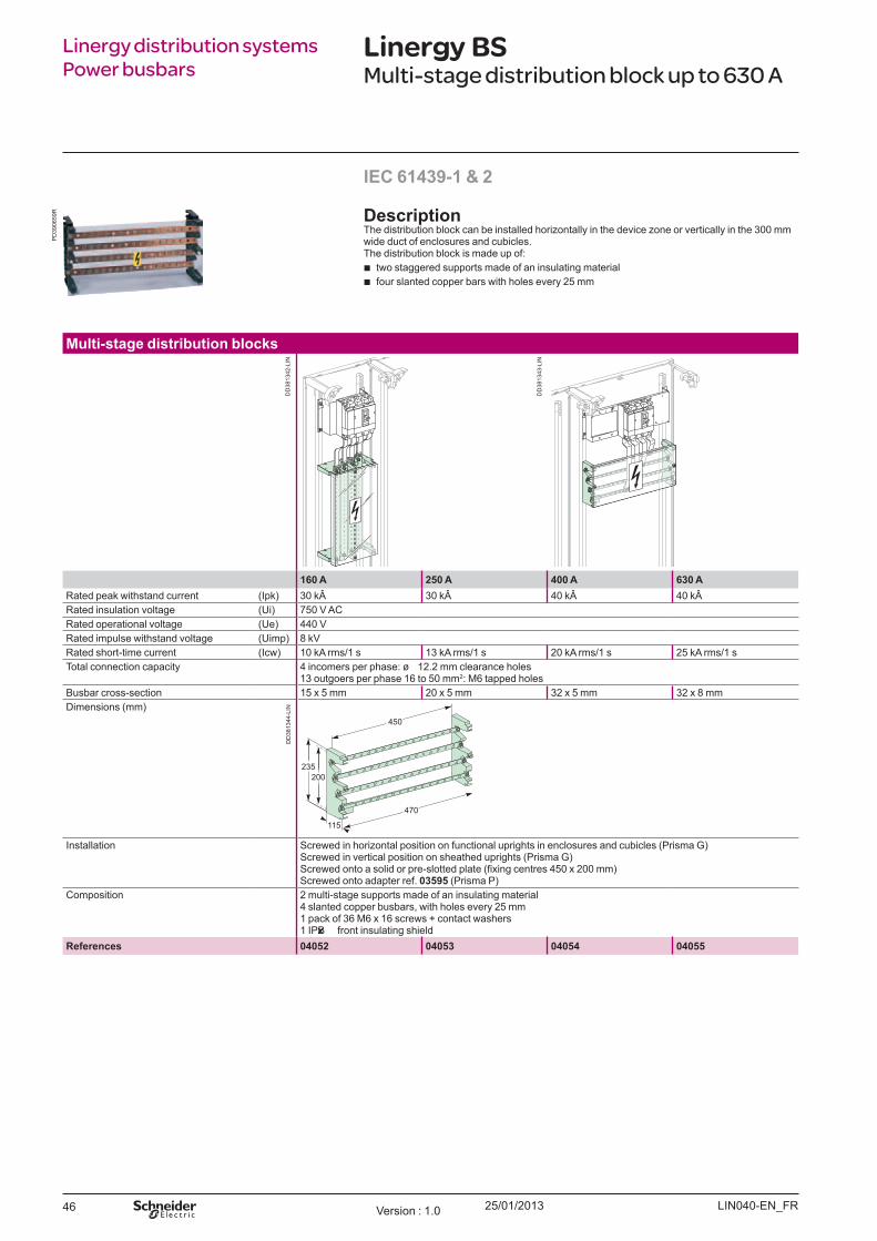
Linergy BSMulti-stage distribution block up to 630 A
M ulti-stage distribution blocks
160 A 250 A 400 A 630 ARated peak withstand current (Ipk) 30 k 30 k 40 k 40 kÂRated insulation voltage (U i) 750 V ACRated operational voltage (U e) 440 VRated impulse withstand voltage (U imp) 8 kVRated short-time current (Icw) 10 kA rms/1 s 13 kA rms/1 s 20 kA rms/1 s 25 kA rms/1 sTotal connection capacity 4 incomers per phase: ø 12.2 mm clearance holes
13 outgoers per phase 16 to 50 mm2: M 6 tapped holesB usbar cross-section 15 x 5 mm 20 x 5 mm 32 x 5 mm 32 x 8 mmDimensions (mm)
Installation Screwed in horizontal position on functional uprights in enclosures and cubicles (Prisma G )Screwed in vertical position on sheathed uprights (Prisma G )
crewed onto a solid or pre-slotted plate (fixing centres 450 x 200 mm)Screwed onto adapter ref. 03595 (Prisma P)
Composition 2 multi-stage supports made of an insulating material4 slanted copper busbars, with holes every 25 mm1 pack of 36 M 6 x 16 screws + contact washers1 IPxxB front insulating shield
References 04052 04053 04054 04055
IEC 61439-1 & 2
DescriptionThe distribution block can be installed horizontally in the device zone or vertically in the 300 mm wide duct of enclosures and cubicles.The distribution block is made up of:
b two staggered supports made of an insulating material b four slanted copper bars with holes every 25 mm
LIN040-E N_ F RVersion : 1.0
PD
3906
59R
DD
3813
42-L
IN
DD
3813
43-L
IN
DD
3813
44-L
IN

25/01/2013 47
Incomer accessories
Connectors for copper or aluminium cablesRated operational current at 40 (Ie) 160 A 250 A 400 ASupply at incoming terminals 70 mm2 cables 16 to 185 mm2 cables 70 to 300 mm2 cablesComposition upplied with fixings at busbar endSet of 4References 07051 07052 07053
O utgoer accessories
Class 8.8 fixingsComposition 20 M 6 x 20 screws + 20 nuts
+ 40 contact washers40 M 6 x 16 screws + 40 contact washers
References 04194 04195
Linergy distribution systems Power busbars
Linergy BSCommon accessories up to 630 A
LIN040-E N_ F R Version : 1.0
E56
852
E56
851
E56
850
DD
3813
98-L
IN
25/01/201348
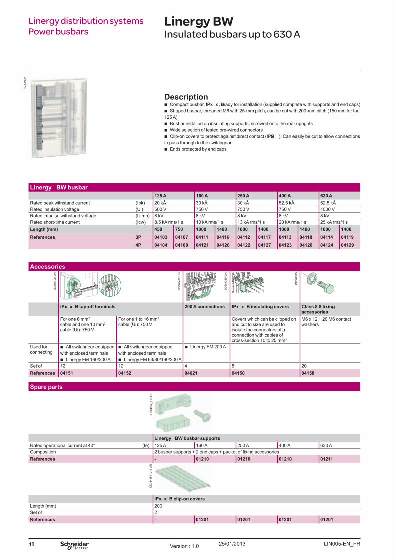
Linergy BWInsulated busbars up to 630 A
Linergy distribution systems Power busbars
Description b Compact busbar, IPx x B , ready for installation (supplied complete with supports and end caps) b Shaped busbar, threaded M 6 with 25-mm pitch, can be cut with 200-mm pitch (150 mm for the
125 A) b B usbar installed on insulating supports, screwed onto the rear uprights b W ide selection of tested pre-wired connectors b Clip-on covers to protect against direct contact (IPxxB ) . Can easily be cut to allow connections
to pass through to the switchgear b E nds protected by end caps
L inergy B W busbar125 A 160 A 250 A 400 A 630 A
Rated peak withstand current (Ipk) 20 k 30 k 30 k 52.5 k 52.5 kÂRated insulation voltage (U i) 500 V 750 V 750 V 750 V 1000 VRated impulse withstand voltage (U imp) 8 kV 8 kV 8 kV 8 kV 8 kVRated short-time current (Icw) 8.5 kA rms/1 s 10 kA rms/1 s 13 kA rms/1 s 20 kA rms/1 s 25 kA rms/1 sL ength ( mm) 450 750 1000 1400 1000 1400 1000 1400 1000 1400References 3P 04103 04107 04111 04116 04112 04117 04113 04118 04114 04119
4P 04104 04108 04121 04126 04122 04127 04123 04128 04124 04129
S pare parts
L inergy B W busbar supportsRated operational current at 40° (Ie) 125 A 160 A 250 A 400 A 630 AComposition 2 busbar supports 2 end caps packet of fixing accessoriesReferences - 01210 01210 01210 01211
IPx x B clip-on coversLength (mm) 200Set of 2References - 01201 01201 01201 01201
Accessories
IPx x B tap-off terminals 200 A connections IPx x B insulating covers Class 8.8 fixing accessories
F or one 6 mm2 cable and one 10 mm2 cable (U i) : 750 V
F or one 1 to 16 mm2 cable (U i) : 750 V
Covers which can be clipped on and cut to size are used to isolate the connectors of a connection with cables of cross-section 10 to 25 mm2
M 6 x 12 + 20 M 6 contact washers
U sed for connecting
b All switchgear equipped with enclosed terminals
b Linergy F M 160/200 A
b All switchgear equipped with enclosed terminals
b Linergy F M 63/80/160/200 A
b Linergy F M 200 A
Set of 12 12 4 8 20References 04151 04152 04021 04150 04158
LIN005-E N_ F RVersion : 1.0
PD
3903
37
PB
5023
75
DD
3813
85-L
IN
DD
3834
72-L
IN
DD
3834
98-L
IN
DD
3849
52_L
13-L
IND
D38
4951
_L13
-LIN
25/01/2013 49
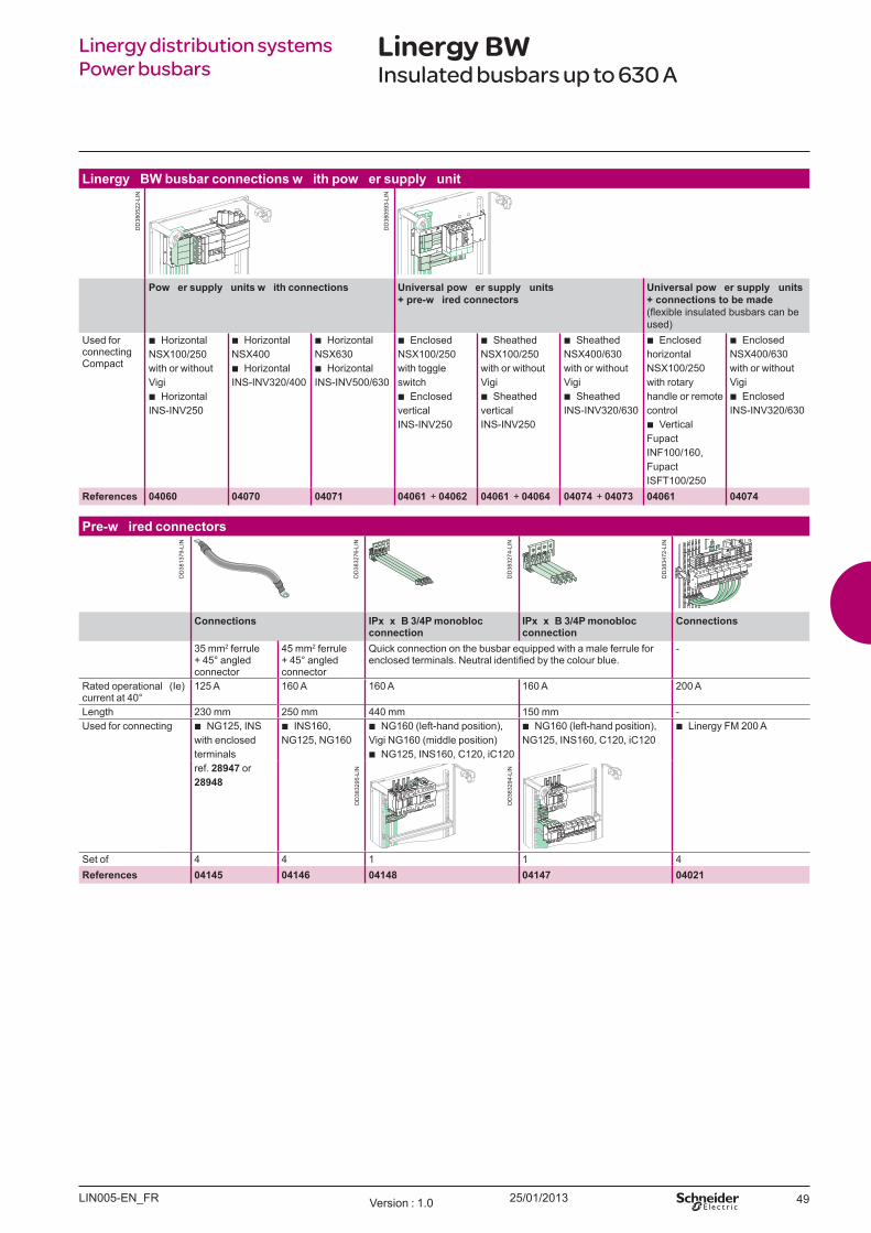
Linergy distribution systems Power busbars
Linergy BWInsulated busbars up to 630 A
L inergy B W busbar connections w ith pow er supply unit
Pow er supply units w ith connections U niversal pow er supply units + pre-w ired connectors
U niversal pow er supply units + connections to be made (flexible insulated busbars can be used)
U sed for connecting Compact
b Horizontal NSX 100/250 with or without Vigi
b Horizontal INS-INV250
b Horizontal NSX 400
b Horizontal INS-INV320/400
b Horizontal NSX 630
b Horizontal INS-INV500/630
b E nclosed NSX 100/250 with toggle switch
b E nclosed vertical INS-INV250
b Sheathed NSX 100/250 with or without Vigi
b Sheathed vertical INS-INV250
b Sheathed NSX 400/630 with or without Vigi
b Sheathed INS-INV320/630
b E nclosed horizontal NSX 100/250 with rotary handle or remote control
b Vertical F upact INF 100/160, F upact ISF T100/250
b E nclosed NSX 400/630 with or without Vigi
b E nclosed INS-INV320/630
References 04060 04070 04071 04061 + 04062 04061 + 04064 04074 + 04073 04061 04074
Pre-w ired connectors
Connections IPx x B 3/ 4P monobloc connection
IPx x B 3/ 4P monobloc connection
Connections
35 mm2 ferrule + 45° angled connector
45 mm2 ferrule + 45° angled connector
Quick connection on the busbar equipped with a male ferrule for enclosed terminals. Neutral identified by the colour blue.
-
Rated operational current at 40°
(Ie) 125 A 160 A 160 A 160 A 200 A
Length 230 mm 250 mm 440 mm 150 mm -U sed for connecting b NG 125, INS
with enclosed terminals ref. 28 947 or 28 948
b INS160, NG 125, NG 160
b NG 160 (left-hand position) , Vigi NG 160 (middle position)
b NG 125, INS160, C120, iC120
b NG 160 (left-hand position) , NG 125, INS160, C120, iC120
b Linergy F M 200 A
Set of 4 4 1 1 4References 04145 04146 04148 04147 04021
LIN005-E N_ F R Version : 1.0
DD
3805
22-L
IN
DD
3805
93-L
IN
DD
3813
79-L
IN
DD
3832
76-L
IN
DD
3832
74-L
IN
DD
3834
72-L
IN
DD
3832
94-L
IN
DD
3832
95-L
IN

25/01/201350
Linergy distribution systems Power busbars
Linergy LGY, LGYE, BSSelection guide up to 4000 A
Descrip t io nPrisma P and SFP/PH switchboards have a complete, coherent system for routing the electrical current:
b optimised busbars b pre-wired connectors b customised distribution blocks
I EC 61439- 1 & 2
Ho rizo nt al b u sb ar
Permissible current U p to 4000 A U p to 4000 AMaterial Linergy profile Copper solid busbarsB usbar type 9 profile types depending on
the current5 mm up to 1600 A 10 mm up to 4000 A
B usbar length 2000 mm 2000 mmInstallation At the top or bottom of the cubicle, horizontally
400 or 600 mm deep for Prisma P 500, 600 or 800 mm deep for SFP/PH
Vert ical b u sb arLat eral in sh eat h
Linergy BS
Permissible current U p to 3200 A U p to 4000 A U p to 3200 AMaterial Linergy profile Linergy profile Pre-slotted copperB usbar 5 profile types
depending on the current
9 profile types depending on the current
Th. 5 mm up to 1600 A Th. 10 mm up to 3200 A
B usbar length 1670 mm 2000 mm 1675 mmInstallation in Prisma P sheath
150 mm wide U p to 1600 A U p to 2500 A U p to 2500 A2 x 150 mm wide U p to 3200 A U p to 3200 A300 mm wide For 3200-4000 A U p to 4000 A
Installation in SFP/PH sheath
300 mm wide 500 mm deep 500, 600 or 800 mm deep
At t h e b ack o f a cu b icl e
Permissible current U p to 1600 A U p to 1600 AMaterial Linergy profile Pre-slotted copperB usbar type 5 profile types depending on the
current10 mm thick up to 1600 A
B usbar length 1670 mm 1675 mmInstallation In 650 mm wide Prisma cubicle or 700 mm wide Prisma PH/SFP
cubicle regardless of depth
LIN039-EN_FRVersion : 1.0
DD
3846
07-L
IN
E97
011-
LIN
DD
3812
37-L
IN
DD
3845
50-L
IN
AC
_058
33-L
IN
DD
3812
37-L
IN
AC
_058
33-L
IN
DD
3846
07-L
INE
7954
4-LI
N
DD
3845
41-L
IN
AC
_058
32-L
IN
25/01/2013 51
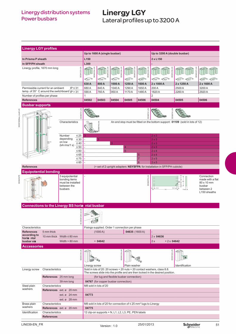
Linergy distribution systems Power busbars
Linergy LGYLateral profiles up to 3200 A
U p t o 1600 A (singl e b u sb ar) U p t o 3200 A (d o u b l e b u sb ar)
I n Prism a P sh eat h L150 2 x L150I n SFP/ PH sh eat h L300 -Linergy profile, 1670 mm long
630 A 800 A 1000 A 1250 A 1600 A 2 x 1000 A 2 x 1250 A 2 x 1600 APermissible current for an ambient temp. of 35° C around the switchboard
IP 31 680 A 840 A 1040 A 1290 A 1650 A 200 A 2500 A 3200 AIP > 31 590 A 760 A 950 A 1170 A 1480 A 1820 A 2260 A 2920 A
Number of profiles per phase 1 2References 04502 04503 04504 04505 04506 04504 04505 04506
Bu sb ar su p p o rt s
700 mmmax.
700 mmmax.
387.5 mmmax.
Characteristics An end stop must be fitted on the bottom support 01109 ( sold in lots of 12)
Number depending on Icw ( kA rms/1 s)
25 3 2 x 3 30 - 3 2 x 3 40 - 3 2 x 3 50 - 4 2 x 3 60 - 5 2 x 4 65 - 5 2 x 4 75 - 7 2 x 5 85 - 8 2 x 5
References ( + set of 2 upright adapters NSYSFPA for installation in SFP/PH cubicle)
Eq u ip o t ent ial b o nd ing3 eq uipotential bonding items must be installed between the busbars
- Connection made with a flat 80 x 10 mm busbar between 2 L150 sheaths
Co nnect io ns t o t h e Linergy BS h o rizo nt al b u sb ar
Characteristics Fixings supplied. O rder 1 connection per phaseReferences acco rd ing t o h o rizo nt al b u sb ar size
5 mm thick ( 1000 A) 04635 ( 1600 A) -
10 mm thick Width 80 mm 2 x 04636W idth > 80 mm + 04642 2 x + 2 x 04642
Accesso ries
Linergy screw Plain washer IdentificationLinergy screw Characteristics Sold in lots of 20: 20 screws + 20 nuts + 20 contact washers, class 8.8.
he screws slide into the profile and are then locked in the desired position.References 25 mm long (for lug and flexible busbar connection)
39 mm long 04767 ( for copper busbar connection)Steel plain washers
Characteristics M8 sold in lots of 20References ext. ø 20 mm
ext. ø 24 mm 04773ext. ø 28 mm
B rass plain washers
Characteristics 8 sold in lots of 20 for connection of 25 mm2 lugs to LinergyReferences ext. ø 20 mm 04775
Identification Characteristics 12 clip-on supports + N, L1, L2, L3, PE, PEN labelsReferences
LIN039-EN_FR Version : 1.0
DD
3812
33-L
IN
DD
3812
34-L
IN
DD
3812
35-L
IN
DD
3812
36-L
IN
DD
3812
37-L
IN
DD
3812
35-L
IN
DD
3812
36-L
IN
DD
3812
37-L
IN
DD
3815
09N
ew_m
odif-
LIN
DD
3807
41-L
IN
DD
3807
41-L
IN
DD
3807
41-L
IN
DD
3807
42-L
IN
DD
3823
27R
DD
3825
76-L
IN
8C-D
D38
1240
-ret
-LIN
DD
3812
18-L
IN
DD
3812
19-L
IN
DD
3812
22-L
IN
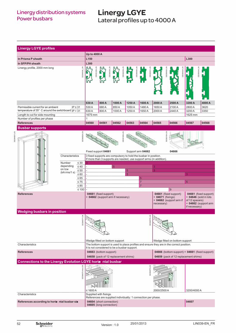
25/01/201352
Linergy distribution systems Power busbars
Linergy LGYELateral profiles up to 4000 A
U p t o 4000 AI n Prism a P sh eat h L150 L300I n SFP/ PH sh eat h L300Linergy profile, 2000 mm long
630 A 800 A 1000 A 1250 A 1600 A 2000 A 2500 A 3200 A 4000 APermissible current for an ambient temperature of 35° C around the switchboard
IP 31 530 A 680 A 850 A 1050 A 1480 A 1650 A 2100 A 2800 A 3620IP > 31 630 A 800 A 1000 A 1250 A 1650 A 2000 A 2440 A 3200 A 3350
Length to cut for side mounting 1675 mm 1625 mmNumber of profiles per phase 1References 04560 04561 04562 04563 04564 04565 04566 04567 04568
Bu sb ar su p p o rt s
Fixed support 04661 Support arm 04662 04666Characteristics 3 fixed supports are compulsory to hold the busbar in position.
If more than 3 supports are needed, use support arms ( in addition) .Number depending on Icw ( kA rms/1 s)
30 3 40 - 5 3 50 - 5 3 60 - 5 3 65 - 5 75 - 7 5 85 - 7 100 - 9
References 04661 (fixed support) + 04662 ( support arm if necessary)
04661 (fixed support) + 04671 (fixings) + 04662 ( support arm if necessary)
04661 (fixed support) + 04646 ( sold in lots of 12 spacers) + 04662 ( support arm if necessary)
Wed ging b u sb ars in p o sit io n
Wedge fitted on bottom support Wedge fitted on bottom supportCharacteristics he bottom support is used to place profiles and ensure they are in the correct position.
It is not considered to be a busbar support.References 04663 ( bottom support) 04666 ( bottom support) + 04661 (fixed support)
04658 ( pack of 12 replacement shims) 04659 ( pack of 12 replacement shims)
Co nnect io ns t o t h e Linergy Ev o l u t io n LGYE h o rizo nt al b u sb ar
1600 A 2000/2500 A 3200/4000 ACharacteristics Supplied with fixings.
References are supplied individually: 1 connection per phase.References acco rd ing t o h o rizo nt al b u sb ar size 04604 ( short connection)
04605 ( long connection)04607
LIN039-EN_FRVersion : 1.0
DD
3845
36_L
IN
DD
3812
26-L
IN
DD
3845
38-L
IN
DD
3845
39-L
IN
DD
3845
40-L
IN
DD
3845
41-L
IN
DD
3845
42-L
IN
DD
3845
43-L
IN
DD
3845
44-L
IN
DD
3846
07-L
IN
DD
3808
29-L
IN
DD
3816
50-L
IN
DD
3831
94-L
IN
DD
3845
77-L
IN
DD
3845
76-L
IN
DD
3845
75-4
vis-
LIN
DD
3845
75-L
IN
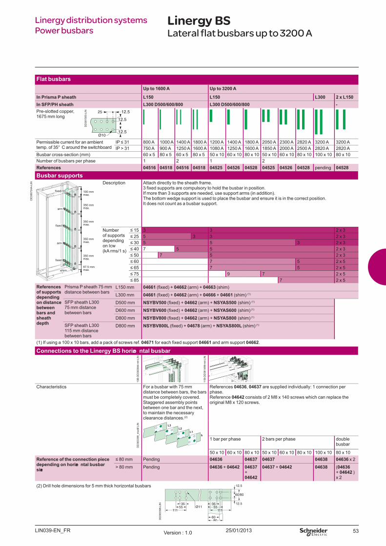
25/01/2013 53
Linergy distribution systemsPower busbars
Linergy BSLateral flat busbars up to 3200 A
Fl at b u sb arsU p t o 1600 A U p t o 3200 A
I n Prism a P sh eat h L150 L150 L300 2 x L150I n SFP/ PH sh eat h L300 D500/ 600/ 800 L300 D500/ 600/ 800 -Pre-slotted copper,1675 mm long
12.5
12.5
12.5
Permissible current for an ambient temp. of 35° C around the switchboard
IP 31 800 A 1000 A 1400 A 1800 A 1200 A 1400 A 1800 A 2050 A 2300 A 2820 A 3200 A 3200 AIP > 31 750 A 900 A 1250 A 1600 A 1080 A 1250 A 1600 A 1850 A 2000 A 2500 A 2820 A 2820 A
B usbar cross-section ( mm) 60 x 5 80 x 5 60 x 5 80 x 5 50 x 10 60 x 10 80 x 10 50 x 10 60 x 10 80 x 10 100 x 10 80 x 10Number of busbars per phase 1 2 1 2References 04516 04518 04516 04518 04525 04526 04528 04525 04526 04528 pending 04528
Bu sb ar su p p o rt sDescription Attach directly to the sheath frame.
3 fi xed supports are compulsory to hold the busbar in position. If more than 3 supports are needed, use support arms ( in addition) .The bottom wedge support is used to place the busbar and ensure it is in the correct position. It does not count as a busbar support.
Number of supportsdepending on Icw ( kA rms/1 s)
15 3 3 2 x 3 25 5 3 3 2 x 3 30 5 5 3 2 x 3 40 7 5 5 2 x 3 50 7 5 2 x 3 60 7 5 2 x 5 65 7 5 2 x 5 75 9 7 2 x 5 85 7 2 x 5
References o f su p p o rt s d ep end ing o n d ist ance b et w een b ars and sh eat h d ep t h
Prisma P sheath 75 mm distance between bars
L150 mm 04661 (fi xed) 04662 ( arm) + 04663 ( shim)
L300 mm 04661 (fi xed) 04662 ( arm) + 04666 + 04661 ( shim) ( 1)
SFP sheath L30075 mm distance between bars
D500 mm NSYBV500 (fi xed) 04662 ( arm) + NSYAS500 ( shim) ( 1)
D600 mm NSYBV600 (fi xed) 04662 ( arm) + NSYAS600 ( shim) ( 1)
D800 mm NSYBV800 (fi xed) 04662 ( arm) + NSYAS800 ( shim) ( 1)
SFP sheath L300115 mm distance between bars
D800 mm NSYBV800L (fi xed) 04678 ( arm) + NSYAS800L ( shim) ( 1)
( 1) If using a 100 x 10 bars, add a pack of screws ref. 04671 for each fi xed support 04661 and arm support 04662.
Co nnect io ns t o t h e Linergy BS h o rizo nt al b u sb ar
Characteristics For a busbar with 75 mm distance between bars, the bars must be completely covered.Staggered assembly points between one bar and the next, to maintain the necessary clearance distances.( 2)
References 04636, 04637 are supplied individually: 1 connection per phase.Reference 04642 consists of 2 M8 x 140 screws which can replace the original M8 x 120 screws.
1 bar per phase 2 bars per phase double busbar
50 x 10 60 x 10 80 x 10 50 x 10 60 x 10 80 x 10 100 x 10 80 x 10Reference o f t h e co nnect io n p iece d ep end ing o n h o rizo nt al b u sb ar size
80 mm Pending 04636 04637 04637 04638 04636 x 2
> 80 mm Pending 04636 + 04642 04637+ 04642
04637 + 04642 04638 ( 04636+ 04642 ) x 2
( 2) Drill hole dimensions for 5 mm thick horizontal busbars
12.5
12.5
LIN039-EN_FR Version : 1.0
DD
3833
98-L
IN
DD
3815
05-L
IN
DD
3807
24A
-LIN
10B
-DD
3838
44-r
et-L
IN
11B
-DD
3814
99-r
et-L
IN
DD
3833
99_m
odif-
LIN

25/01/201354
Linergy distribution systems Power busbars
Linergy LGYRear profiles up to 1600 A
U p t o 1600 A
At t h e b ack o f a Prism a P cu b icl e L650At t h e b ack o f a SFP/ PH cu b icl e L700Linergy profile, 1670 mm long
630 A 800 A 1000 A 1250 A 1600 APermissible current for an ambient temp. of 35° C around the switchboard
IP 31 680 A 840 A 1040 A 1290 A 1650 AIP > 31 590 A 760 A 950 A 1170 A 1480 A
Number of profiles per phase 1References 04502 04503 04504 04505 04506
Bu sb ar su p p o rt s
350 mmmax.
350 mmmax.
350 mmmax.
350 mmmax.
387.5 mmmax.
Number depending on Icw ( kA rms/1 s)
25 3 30 4 40 5 50 7
Characteristics An end stop must be fitted on the bottom support 01109 ( sold in lots of 12)
References 04652
04635 connection to 5 mm thick horizontal busbar
04036 connection to 10 mm thick horizontal busbar
Characteristics Fixings supplied, order 1 connection per phase.For part of the connection, flexible insulated busbars are needed.
References acco rd ing t o h o rizo nt al b u sb ar size
5 mm thick 0463510 mm thick
Width 80 mm 04636W idth > 80 mm 04636 + 04642
Accesso ries
Screw + nut + contact washer Plain washer IdentificationLinergy screw Characteristics Sold in lots of 20: 20 screws + 20 nuts + 20 contact washers, class 8.8
he screws slide into the profile and are then locked in the desired positionReference 25 mm wide 04766 (for lug and flexible busbar connection)
39 mm wide 04767 ( for copper busbar connection)Steel plain washers
Characteristics M8 sold in lots of 20Reference ext. ø 20 mm 04772
ext. ø 24 mm 04773ext. ø 28 mm 04774
B rass plain washers
Characteristics 8 sold in lots of 20 for connection of 25 mm2 lugs to LinergyReference ext. ø 20 mm 04775
Identification Characteristics 12 clip-on supports + N, L1, L2, L3, PE, PEN labelsReference 04794
LIN039-EN_FRVersion : 1.0
DD
3812
33-L
IN
DD
3812
34-L
IN
DD
3812
35-L
IN
DD
3812
36-L
IN
DD
3812
37-L
IN
DD
3812
42-L
IND
D38
1243
-LIN
DD
3812
41N
ew_m
odif-
LIN
DD
3812
44-L
IN
9C-D
D38
1245
-ret
-LIN
DD
3812
18-L
IN
DD
3812
19-L
IN
DD
3812
22-L
IN
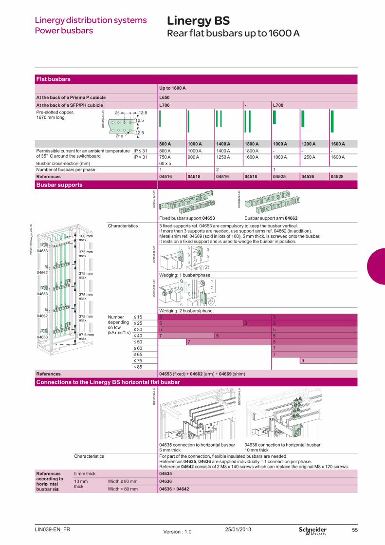
25/01/2013 55
Linergy distribution systemsPower busbars
Linergy BSRear flat busbars up to 1600 A
Fl at b u sb arsU p t o 1600 A
At t h e b ack o f a Prism a P cu b icl e L650At t h e b ack o f a SFP/ PH cu b icl e L700 - L700Pre-slotted copper,1670 mm long
12.5
12.5
12.5
800 A 1000 A 1400 A 1800 A 1000 A 1200 A 1600 APermissible current for an ambient temperature of 35° C around the switchboard
IP 31 800 A 1000 A 1400 A 1800 A - - -IP > 31 750 A 900 A 1250 A 1600 A 1080 A 1250 A 1600 A
B usbar cross-section ( mm) 60 x 5Number of busbars per phase 1 2 1References 04516 04518 04516 04518 04525 04526 04528
Bu sb ar su p p o rt s
Fixed busbar support 04653 B usbar support arm 04662Characteristics 3 fi xed supports ref. 04653 are compulsory to keep the busbar vertical.
If more than 3 supports are needed, use support arms ref. 04662 ( in addition) .Metal shim ref. 04669 ( sold in lots of 100) , 5 mm thick, is screwed onto the busbar.It rests on a fi xed support and is used to wedge the busbar in position.
W edging: 1 busbar/phase
W edging: 2 busbars/phaseNumber depending on Icw ( kA rms/1 s)
15 3 3 25 5 3 3 30 5 5 40 7 5 5 50 7 5 60 7 65 7 75 9 85
References 04653 (fi xed) 04662 ( arm) + 04669 ( shim)
04635 connection to horizontal busbar5 mm thick
04636 connection to horizontal busbar10 mm thick
Characteristics For part of the connection, fl exible insulated busbars are needed.References 04635, 04636 are supplied individually = 1 connection per phase.Reference 04642 consists of 2 M8 x 140 screws which can replace the original M8 x 120 screws.
References acco rd ing t o h o rizo nt al b u sb ar size
5 mm thick 0463510 mm thick
Width 80 mm 04636W idth > 80 mm 04636 + 04642
LIN039-EN_FR Version : 1.0
DD
3815
05-L
IN
DD
3807
32-L
IN
DD
3816
52-L
IN
DD
3808
15-L
IND
D38
0815
-LIN
DD
3815
03N
ew_m
odif-
LIN
DD
3812
44-L
IN
DD
3812
44-L
IN
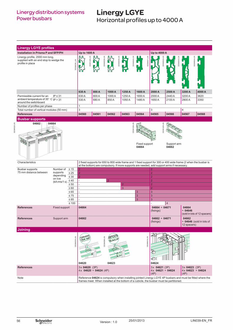
25/01/201356
I nst al l at io n in Prism a P and SFP/ PH U p t o 1600 A U p t o 4000 ALinergy profile, 2000 mm long, supplied with an end stop to wedge the profile in place
630 A 800 A 1000 A 1250 A 1600 A 2000 A 2500 A 3200 A 4000 APermissible current for an ambient temperature of 35° C around the switchboard
IP 31 630 A 800 A 1000 A 1250 A 1650 A 2000 A 2440 A 3200 A 3620IP > 31 530 A 680 A 850 A 1050 A 1480 A 1650 A 2100 A 2800 A 3350
Number of profiles per phase 1Total number of vertical modules ( 50 mm) 3 3 4References 04560 04561 04562 04563 04564 04565 04566 04567 04568
Bu sb ar su p p o rt s04662 04664
Fixed support04664
Support arm 04662
Characteristics 2 fixed supports for 650 to 800 wide frame and 1 fixed support for 300 or 400 wide frame (2 when the busbar is at the bottom) are compulsory. If more supports are needed, add support arms if necessary.
B usbar supports 75 mm distance between
Number of supports depending on Icw ( kA rms/1 s)
15 2 2 25 2 2 30 2 2 40 - 2 2 50 - 2 2 60 - 3 2 65 - 3 3 75 - 3 3 85 - 3 3 100 - - 4
References Fixed support 04664 04664 + 04671(fixings)
04664 + 04646 ( sold in lots of 12 spacers)
References Support arm 04662 04662 + 04671 (fixings)
04662 + 04646 ( sold in lots of 12 spacers)
Jo ining
04620 04623 04624References 3 x 04620 ( 3P)
4 x 04620 + 04624 ( 4P)3 x 04621 ( 3P) 4 x 04621 + 04624( 4P)
3 x 04623 ( 3P) 4 x 04623 + 04624 ( 4P)
Note Reference 04624 is compulsory when installing ointed Linergy LGYE 4P busbars and must be fitted where the frames meet. W hen installed at the bottom of a cubicle, the busbar must be partitioned.
Linergy distribution systems Power busbars
Linergy LGYEHorizontal profiles up to 4000 A
LIN039-EN_FRVersion : 1.0
DD
3846
15-L
IN
DD
3845
88-L
IN
DD
3845
35-L
IN
DD
3845
20-L
IN
DD
3812
26-L
IN
DD
3812
25-L
IN
DD
3845
36_L
IN
DD
3812
26-L
IN
DD
3845
38-L
IN
DD
3845
39-L
IN
DD
3845
40-L
IN
DD
3845
41-L
IN
DD
3845
42-L
IN
DD
3845
43-L
IN
DD
3845
44-L
IN
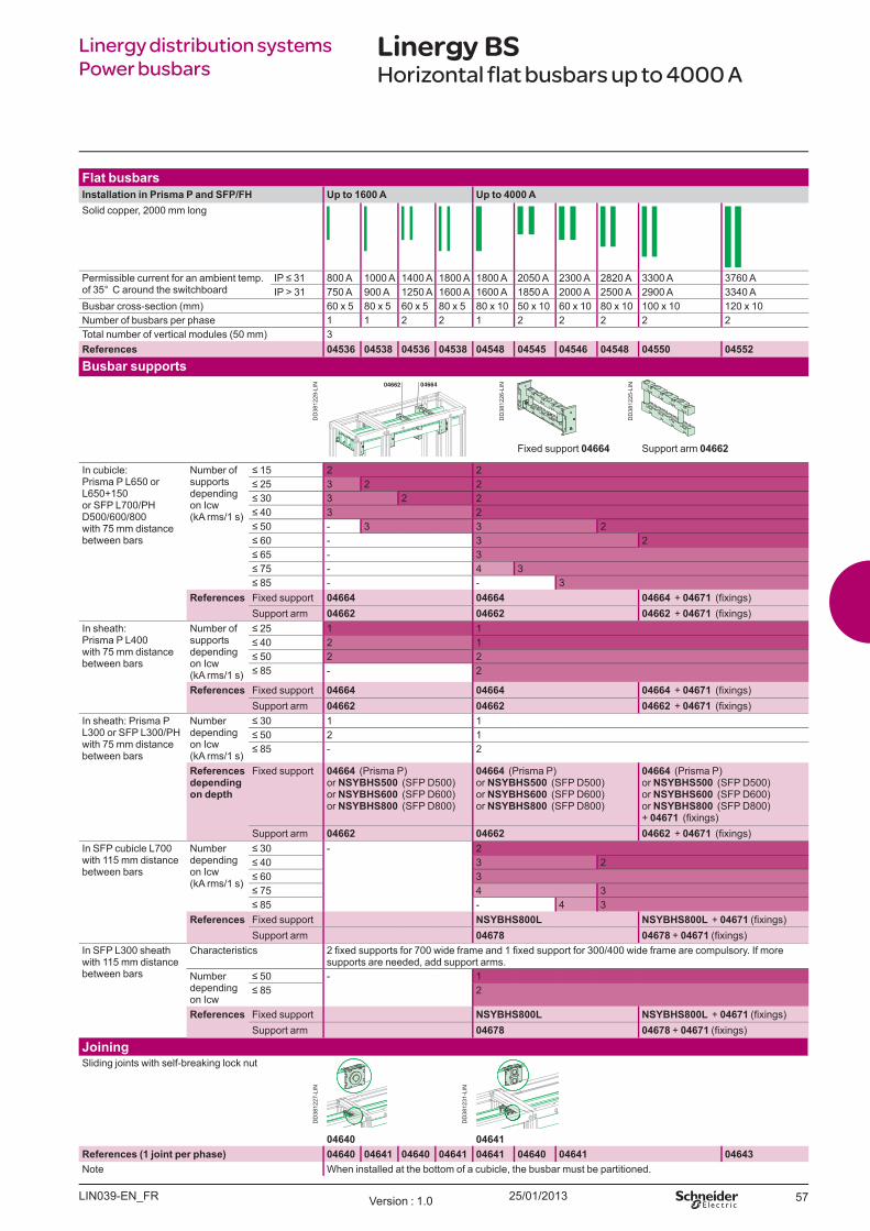
25/01/2013 57
Linergy distribution systemsPower busbars
Linergy BSHorizontal flat busbars up to 4000 A
Fl at b u sb arsI nst al l at io n in Prism a P and SFP/ FH U p t o 1600 A U p t o 4000 ASolid copper, 2000 mm long
Permissible current for an ambient temp. of 35° C around the switchboard
IP 31 800 A 1000 A 1400 A 1800 A 1800 A 2050 A 2300 A 2820 A 3300 A 3760 AIP > 31 750 A 900 A 1250 A 1600 A 1600 A 1850 A 2000 A 2500 A 2900 A 3340 A
B usbar cross-section ( mm) 60 x 5 80 x 5 60 x 5 80 x 5 80 x 10 50 x 10 60 x 10 80 x 10 100 x 10 120 x 10Number of busbars per phase 1 1 2 2 1 2 2 2 2 2Total number of vertical modules ( 50 mm) 3References 04536 04538 04536 04538 04548 04545 04546 04548 04550 04552
Bu sb ar su p p o rt s
Fixed support 04664 Support arm 04662
In cubicle: Prisma P L650 or L650+ 150or SFP L700/PHD500/600/800with 75 mm distance between bars
Number of supports depending on Icw ( kA rms/1 s)
15 2 2 25 3 2 2 30 3 2 2 40 3 2 50 - 3 3 2 60 - 3 2 65 - 3 75 - 4 3 85 - - 3
References Fixed support 04664 04664 04664 + 04671 (fi xings)Support arm 04662 04662 04662 + 04671 (fi xings)
In sheath:Prisma P L400with 75 mm distance between bars
Number of supports depending on Icw ( kA rms/1 s)
25 1 1 40 2 1 50 2 2 85 - 2
References Fixed support 04664 04664 04664 + 04671 (fi xings)Support arm 04662 04662 04662 + 04671 (fi xings)
In sheath: Prisma P L300 or SFP L300/PHwith 75 mm distance between bars
Number depending on Icw ( kA rms/1 s)
30 1 1 50 2 1 85 - 2
References d ep end ing o n d ep t h
Fixed support 04664 ( Prisma P)or NSYBHS500 ( SFP D500)or NSYBHS600 ( SFP D600)or NSYBHS800 ( SFP D800)
04664 ( Prisma P)or NSYBHS500 ( SFP D500)or NSYBHS600 ( SFP D600)or NSYBHS800 ( SFP D800)
04664 ( Prisma P)or NSYBHS500 ( SFP D500)or NSYBHS600 ( SFP D600)or NSYBHS800 ( SFP D800) + 04671 (fi xings)
Support arm 04662 04662 04662 + 04671 (fi xings)In SFP cubicle L700with 115 mm distance between bars
Number depending on Icw ( kA rms/1 s)
30 - 2 40 3 2 60 3 75 4 3 85 - 4 3
References Fixed support NSYBHS800L NSYBHS800L + 04671 (fi xings)Support arm 04678 04678 + 04671 (fi xings)
In SFP L300 sheathwith 115 mm distance between bars
Characteristics 2 fi xed supports for 700 wide frame and 1 fi xed support for 300/400 wide frame are compulsory. If more supports are needed, add support arms.
Number depending on Icw
50 - 1 85 2
References Fixed support NSYBHS800L NSYBHS800L + 04671 (fi xings)Support arm 04678 04678 + 04671 (fi xings)
Jo iningSliding j oints with self-breaking lock nut
04640 04641References (1 j o int p er p h ase) 04640 04641 04640 04641 04641 04640 04641 04643Note W hen installed at the bottom of a cubicle, the busbar must be partitioned.
LIN039-EN_FR Version : 1.0
DD
3812
29-L
IN
DD
3812
26-L
IN
DD
3812
25-L
IN
DD
3812
27-L
IN
DD
3812
31-L
IN
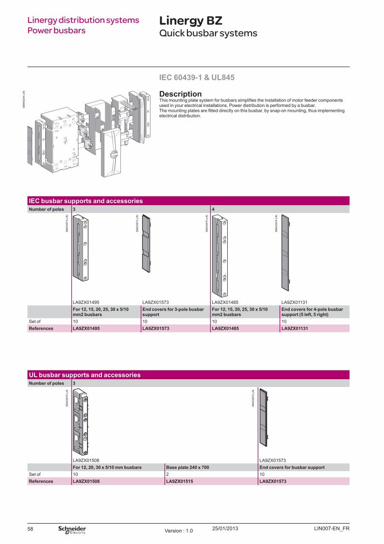
25/01/201358
Linergy distribution systems Power busbars
Linergy BZQuick busbar systems
I EC 60439- 1 & U L845
Descrip t io nhis mounting plate system for busbars simplifies the installation of motor feeder components
used in your electrical installations. Power distribution is performed by a busbar. he mounting plates are fitted directly on this busbar, by snap-on mounting, thus implementing
electrical distribution.
I EC b u sb ar su p p o rt s and accesso riesNu m b er o f p o l es 3 4
LA9Z X01495 LA9Z X01573 LA9Z X01485 LA9Z X01131Fo r 12, 15, 20, 25, 30 x 5/ 10 m m 2 b u sb ars
End co v ers fo r 3- p o l e b u sb ar su p p o rt
Fo r 12, 15, 20, 25, 30 x 5/ 10 m m 2 b u sb ars
End co v ers fo r 4- p o l e b u sb ar su p p o rt (5 l eft , 5 righ t )
Set of 10 10 10 10References LA9ZX01495 LA9ZX01573 LA9ZX01485 LA9ZX01131
U L b u sb ar su p p o rt s and accesso riesNu m b er o f p o l es 3
LA9Z X01508 LA9Z X01573Fo r 12, 20, 30 x 5/ 10 m m b u sb ars Base p l at e 240 x 700 End co v ers fo r b u sb ar su p p o rt
Set of 10 2 10References LA9ZX01508 LA9ZX01515 LA9ZX01573
LIN007-EN FVersion 1.0
DB
4002
44-L
IN
DB
4038
72-L
IN
DB
4038
75-L
IN
DB
4038
74-L
IN
DB
4038
73-L
IN
DB
4038
72-L
IN
DB
4038
76-L
IN
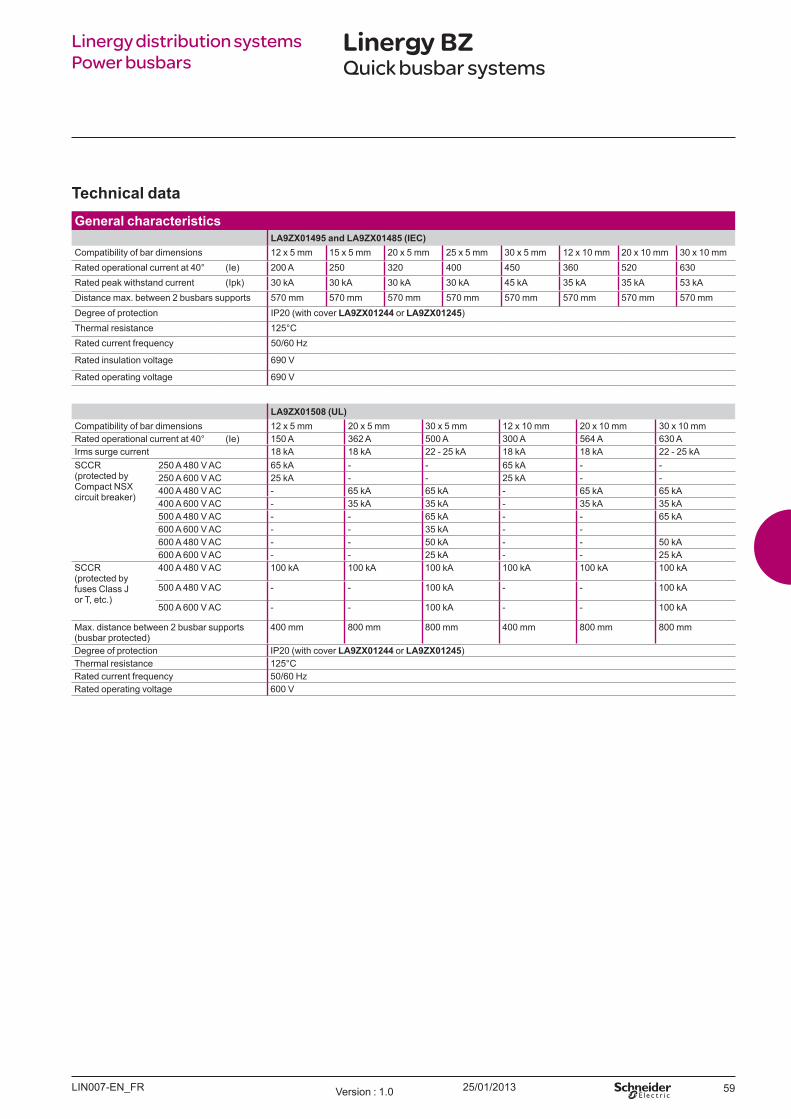
25/01/2013 59
Linergy distribution systems Power busbars
Linergy BZQuick busbar systems
Tech nical d at a General ch aract erist ics
LA9ZX01495 and LA9ZX01485 (I EC)ompatibility of bar dimensions 12 x 5 mm 15 x 5 mm 20 x 5 mm 25 x 5 mm 30 x 5 mm 12 x 10 mm 20 x 10 mm 30 x 10 mmated operational current at 40 ( Ie) 200 A 250 320 400 450 360 520 630ated peak withstand current (Ipk) 30 kA 30 kA 30 kA 30 kA 45 kA 35 kA 35 kA 53 kA
Distance max. between 2 busbars supports 570 mm 570 mm 570 mm 570 mm 570 mm 570 mm 570 mm 570 mmDegree of protection IP20 (with cover LA9ZX01244 or LA9ZX01245 )
hermal resistance 125ated current frequency 50/60 Hz
ated insulation voltage 690 V
ated operating voltage 690 V
LA9ZX01508 (U L)ompatibility of bar dimensions 12 x 5 mm 20 x 5 mm 30 x 5 mm 12 x 10 mm 20 x 10 mm 30 x 10 mmated operational current at 40 ( Ie) 150 A 362 A 500 A 300 A 564 A 630 A
Irms surge current 18 kA 18 kA 22 - 25 kA 18 kA 18 kA 22 - 25 kAS (protected by
ompact NS circuit breaker)
250 A 480 V AC 65 kA - - 65 kA - -250 A 600 V AC 25 kA - - 25 kA - -400 A 480 V AC - 65 kA 65 kA - 65 kA 65 kA400 A 600 V AC - 35 kA 35 kA - 35 kA 35 kA500 A 480 V AC - - 65 kA - - 65 kA600 A 600 V AC - - 35 kA - -600 A 480 V AC - - 50 kA - - 50 kA600 A 600 V AC - - 25 kA - - 25 kA
S (protected by fuses Class J or , etc.)
400 A 480 V AC 100 kA 100 kA 100 kA 100 kA 100 kA 100 kA
500 A 480 V AC - - 100 kA - - 100 kA
500 A 600 V AC - - 100 kA - - 100 kA
ax. distance between 2 busbar supports (busbar protected)
400 mm 800 mm 800 mm 400 mm 800 mm 800 mm
Degree of protection IP20 (with cover LA9ZX01244 or LA9ZX01245 )hermal resistance 125ated current frequency 50/60 Hzated operating voltage 600 V
LIN007-EN F Version 1.0

25/01/201360
Fo r TeSys GV2 m o t o r circu it b reak ers
LA9 A32443, LA9 A32621 LA9 A32434, LA9 A32442 LA9 A32622, LA9 A32623Mo u nt ing p l at e, 1- w ay Mo u nt ing p l at e, 2- w ay
Operating current A -3 440 V 25 A 32 A 25 A 32 AProtection by motor circuit breaker GV2 E
GV2 PGV2 LE
GV2 EGV2 PGV2 LE
GV2 EGV2 PGV2 LE
GV2 EGV2 PGV2 LE
For contactor LC1 DLC1 KLP4 06- 12
LC1 D LC1 DLC1 KLP4 06- 12
LC1 D
Dimensions ( L x H x W ) ( mm) 45 x 200 x 63 45 x 200 x 6354 x 200 x 6363 x 200 x 63
90 x 200 x 63 90 x 200 x 63
Set of 4 444
2 2
References LA9ZA32621 LA9ZA32434 LA9ZA32622 LA9ZA32623LA9ZA32442LA9ZA32443
TeSys U st art er- co nt ro l l ers
LA9Z A32427 LA9Z A32428Mo u nt ing p l at e, 1- w ay Mo u nt ing p l at e, 2- w ay
Operating current A -3 440 V 32 A 32 AProtection by power base LUB12, LUB32 LUB12, LUB32Dimensions ( L x H x W ) ( mm) 45 x 200 x 63 45 x 200 x 63Set of 4 4References LA9ZA32427 LA9ZA32428
Linergy distribution systems Power busbars
Linergy BZQuick busbar systems
LIN007-EN FVersion 1.0
DB
4038
77
DB
4038
78
DB
4038
46
DB
4038
79
DB
4038
80

25/01/2013 61
Linergy distribution systems Power busbars
Linergy BZQuick busbar systems
Det erm ining t h e sp acing b et w een b u sb ar su p p o rt s (LA9ZX01495 and LA9ZX01485), acco rd ing t o I EC 60439- 1(1)
Sh o rt - circu it w it h st and d iagram acco rd ing t o U L845 (LA9ZX01508)
Pea
k cu
rren
t Ipk
(kA
)
Irms
surg
e cu
rren
t (k
A)
Spacing between busbar supports (mm) Spacing between busbar supports (mm)
(1) Depending on the short-circuit current.
LIN007-EN F Version 1.0
DB
4013
92-L
IN
DB
4041
33-L
IN
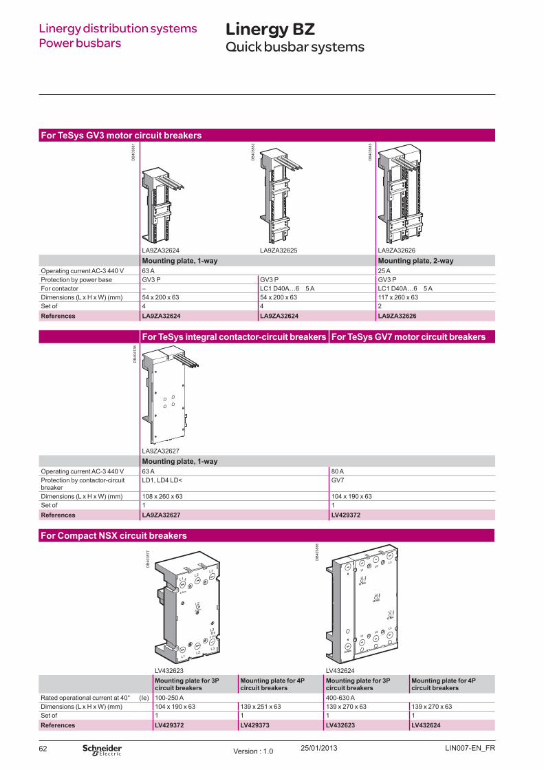
25/01/201362
Fo r TeSys GV3 m o t o r circu it b reak ers
LA9Z A32624 LA9Z A32625 LA9Z A32626Mo u nt ing p l at e, 1- w ay Mo u nt ing p l at e, 2- w ay
Operating current A -3 440 V 63 A 25 AProtection by power base GV3 P GV3 P GV3 PFor contactor – LC1 D40A…6 5 A LC1 D40A…6 5 ADimensions ( L x H x W ) ( mm) 54 x 200 x 63 54 x 200 x 63 117 x 260 x 63Set of 4 4 2References LA9ZA32624 LA9ZA32624 LA9ZA32626
Fo r TeSys int egral co nt act o r- circu it b reak ers Fo r TeSys GV7 m o t o r circu it b reak ers
LA9Z A32627Mo u nt ing p l at e, 1- w ay
Operating current A -3 440 V 63 A 80 AProtection by contactor-circuit breaker
LD1, LD4 LD GV7
Dimensions ( L x H x W ) ( mm) 108 x 260 x 63 104 x 190 x 63Set of 1 1References LA9ZA32627 LV429372
Fo r Co m p act NSX circu it b reak ers
LV432623 LV432624Mo u nt ing p l at e fo r 3P circu it b reak ers
Mo u nt ing p l at e fo r 4P circu it b reak ers
Mo u nt ing p l at e fo r 3P circu it b reak ers
Mo u nt ing p l at e fo r 4P circu it b reak ers
ated operational current at 40 ( Ie) 100-250 A 400-630 ADimensions ( L x H x W ) ( mm) 104 x 190 x 63 139 x 251 x 63 139 x 270 x 63 139 x 270 x 63Set of 1 1 1 1References LV429372 LV429373 LV432623 LV432624
Linergy distribution systems Power busbars
Linergy BZQuick busbar systems
LIN007-EN FVersion 1.0
DB
4038
81
DB
4038
82
DB
4038
83
DB
4041
38
DB
4038
77
DB
4038
86
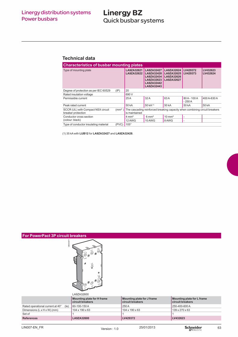
25/01/2013 63
Fo r Po w erPact 3P circu it b reak ers
LA9Z A32600Mo u nt ing p l at e fo r H fram e circu it b reak ers
Mo u nt ing p l at e fo r J fram e circu it b reak ers
Mo u nt ing p l at e fo r L fram e circu it b reak ers
ated operational current at 40 ( Ie) 60-100-150 A 250 A 250-400-600 ADimensions ( L x H x W ) ( mm) 104 x 190 x 63 104 x 190 x 63 139 x 270 x 63Set of 1 1 1References LA9ZA32600 LV429372 LV432623
Linergy distribution systems Power busbars
Linergy BZQuick busbar systems
Tech nical d at aCh aract erist ics o f b u sb ar m o u nt ing p l at esType of mounting plate LA9ZA32621
LA9ZA32622LA9ZA32427 LA9ZA32428 LA9ZA32434 LA9ZA32623LA9ZA32442LA9ZA32443
LA9ZA32624 LA9ZA32625 LA9ZA32626 LA9ZA32627
LV429372LV429373
LV432623LV432624
Degree of protection as per IE 60529 (IP) 20ated insulation voltage 690 V
Permissible current 25 A 32 A 63 A 80 A - 100 A - 250 A
400 A-630 A
Peak rated current 50 kA 50 kA ( 1) 50 kA 50 kA 50 kAS (UL) with ompact NS circuit breaker protection
( mm² ) he cascading reinforced breaking capacity when combining circuit breakers is maintained
onductor cross section (colour black)
4 mm² 6 mm² 10 mm² -12 AW G 10 AW G 8 AW G -
ype of conductor insulating material (PV ) 105
(1) 35 kA with LU B12 for LA9ZA32427 and LA9ZA32428.
LIN007-EN F Version 1.0
DB
4038
77
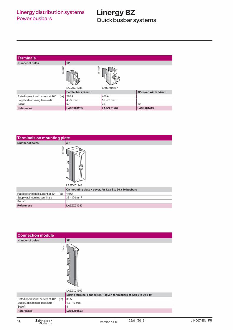
25/01/201364
Term inal sNu m b er o f p o l es 1P
LA9Z X01285 LA9Z X012873P co v er, w id t h 84 m m
ated operational current at 40 ( Ie) 270 A 400 ASupply at incoming terminals 4 - 35 mm2 16 - 70 mm2
Set of 50 25 10References LA9ZX01285 LA9ZX01287 LA9ZX01413
Term inal s o n m o u nt ing p l at eNu m b er o f p o l es 3P
LA9Z X01243On m o u nt ing p l at e + co v er, fo r 12 x 5 t o 30 x 10 b u sb ars
ated operational current at 40 ( Ie) 440 ASupply at incoming terminals 35 - 120 mm2
Set of 1References LA9ZX01243
Co nnect io n m o d u l eNu m b er o f p o l es 3P
LA9Z X01563Sp ring t erm inal co nnect io n + co v er, fo r b u sb ars o f 12 x 5 t o 30 x 10
ated operational current at 40 ( Ie) 80 ASupply at incoming terminals 1.5 - 16 mmSet of 8References LA9ZX01563
Linergy distribution systems Power busbars
Linergy BZQuick busbar systems
LIN007-EN FVersion 1.0
DB
4002
27
DB
4002
27
DB
4002
27D
B40
0227
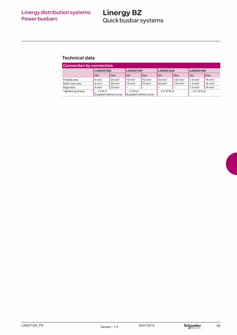
25/01/2013 65
Linergy distribution systems Power busbars
Linergy BZQuick busbar systems
Tech nical d at aCo nnect io n b y co nnect o rs
LA9ZX01285 LA9ZX01287 LA9ZX01243 LA9ZX01563in. ax. in. ax. in. ax. in. ax.
Flexible wire 4 mm2 35 mm2 16 mm2 70 mm2 35 mm2 120 mm2 1.5 mm2 16 mm2
ulti-core wire 4 mm2 35 mm2 16 mm2 70 mm2 35 mm2 120 mm2 1.5 mm2 16 mm2
igid wire 4 mm2 35 mm2 – – – – 1.5 mm2 16 mm2
ightening torque ... x 5 N.mSupplied without cover
... x 5 N.mSupplied without cover
... x 5-10 N.m ... x 5-10 N.m
LIN007-EN F Version 1.0

66
25/01/2013 67
Linergy distribution systems Hot plugsContents
Linergy HK 68
Hot plug pre-assembled busbar systems 68
04_00-Sommaire Version : 1.0

25/01/201368
Linergy HKHot plug pre-assembled busbar systems
Linergy distribution systems Hot plug busbar system
Descrip t io nThe assembly of automated control and distribution panels req uires the use of products that are not only safe, but also simple and q uick to mount and wire up. These pre-assembled busbar systems meet all these criteria.
Bu sb ar syst em s
Number of conductors 4Number of tap-offs at 18 mm intervals 12 18 24 30 48 54Length ( mm) 344 452 560 668 992 1100Suitable for mounting in enclosure width ( mm) 600 800 800 800 1200 1200References AK5 JB143 AK5 JB144 AK5 JB145 AK5 JB146 AK5 JB149 AK5 JB1410
I EC 60439
LIN013-EN_FRVersion : 1.0
DB
3007
85-L
IN
DB
3007
86

25/01/2013 69
Linergy HKHot plug pre-assembled busbar systems
Linergy distribution systems Hot plug busbar system
Tech nical d at aBu sb ar syst em ch aract erist icsProduct certifications U L, CSA, DNV, LRO S Degree of protection Against access to live parts IPxxB conforming to IEC 60529Flame resistance Conforming to IEC 60695 850 ° C ( incandescent wire)
Conforming to standard U L 94 V0Number of conductors AK 5 JB 14p 4Supply current a
Rated operational current ( Ie) Ambient temperature 35° C 160 A coefficient to be applied according
to the ambient temperature35° C 40° C 45° C 50° C 55° C 60° C1 K 0.96 K 0.92 K 0.88 K 0.83 K 0.78 K
Rated insulation voltage ( U i) Conforming to IEC 60439-1 690 VConforming to U L and CSA 600 V
O perational voltage ( U e) O ff-load plugging-in and unplugging, with power onConforming to IEC 60439-1 400 VConforming to U L, CSA 480 V
Plugging-in and unplugging, with power offConforming to IEC 60439-1 690 VConforming to U L, CSA 600 V
Maximum permissible peak current 25 kAMaximum let-through energy
( I2t) 1 x 10⁷ A2s
Rated operational freq uency 50 Hz or 60 HzU pstream short-circuit ( 1) and overload protection
Type of protection Schneider Electric circuit-breaker FusesNSX 160 N NSX 160 H aM gF
Rating 160 A 160 A 160 A 160 AProspective short-circuit current 36 kA 70 kA 100 kA 100 kA
O perational current 160 160 160 160Supply incoming terminals Maximum c.s.a. Minimum c.s.a.
Flexible cable with cable end 70 mm2 2.5Solid cable 70 mm2 2.5Tightening torq ue 10 Nm
Installation Horizontal or vertical ( 2) Fixing with screws provided
( 1) For conditions where conditional short-circuit current exceeds 25 kA.( 2) U sing side stop AK5 BT01 on mounting plates AK5 PA.
LIN013-EN_FR Version : 1.0
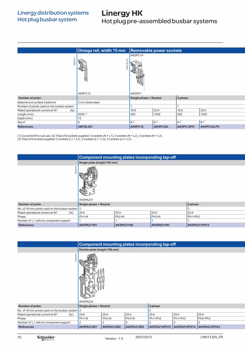
25/01/201370
Linergy HKHot plug pre-assembled busbar systems
Co m p o nent m o u nt ing p l at es inco rp o rat ing t ap - o ffSingl e p l at e (h eigh t 105 m m )
AK 5PA231Nu m b er o f p o l es Singl e- p h ase + Neu t ral 2- p h ase 3- p h ase 3- p h ase + Co m m o n 3- p h ase + Neu t ral
No. of 18 mm points used on the busbar system 3 3 3 3 3Rated operational current at 40° ( Ie) 25 A 25 A 25 A 25 A 25 A 25 A 25 A 25 A 25 APhase Ph1+ N Ph2+ N Ph3+ N Ph1+ Ph2 Ph1+ Ph3 Ph2+ Ph3 - - -Number of 6 rails for component support 1 1 1 1 1 1 1 1 1References AK5PA211N1 AK5PA211N2 AK5PA211N3 AK5PA211PH12 AK5PA211PH13 AK5PA211PH23 AK5PA231 AK5PA2311 AK5PA241
Co m p o nent m o u nt ing p l at es inco rp o rat ing t ap - o ffDo u b l e p l at e (h eigh t 190 m m )
AK 5PA232Nu m b er o f p o l es Singl e- p h ase + Neu t ral 2- p h ase 3- p h ase 3- p h ase + Neu t ral 3- p h ase + Co m m o n 3- p h ase + Neu t ral
No. of 18 mm points used on the busbar system 3 3 3 6 3 3 6 6Rated operational current at 40° ( Ie) 25 A 25 A 25 A 25 A 25 A 25 A 25 A 25 A 50 A 25 A 25 A ( 10 Common) 25 A ( 10 Common) 50 A ( 10 Common) 50 APhase Ph1+ N Ph2+ N Ph3+ N Ph1+ Ph2 Ph1+ Ph3 Ph2+ Ph3 - - - - - -Number of 6 rails for component support 2 2 2 2 2 2 2 2 1 2 2 2 1 1References AK5PA212N1 AK5PA212N2 AK5PA212N3 AK5PA212PH12 AK5PA212PH13 AK5PA212PH23 AK5PA232 AK5PA232S AK5PA532 AK5PA242 AK5PA2312 AK5PA2312S AK5PA5312 AK5PA542
Om ega rail , w id t h 75 m m Rem o v ab l e p o w er so ck et sAK 5PC14
AK 5PC12 AK 5GF1Nu m b er o f p o l es Singl e- p h ase + Neu t ral 2- p h ase 3- p h ase 3- p h ase + Neu t ral 3- p h ase + Co m m o n
Material and surface treatment 2 mm sheet steelNumber of points used on the busbar system 1 1 2 2 2Rated operational current at 40° ( Ie) 16 A 32 A 16 A 32 A 16 A 32 A 16 A 32 A 16 A ( 10 Common) 32 A ( 10 Common)Length ( mm) 2000 ( 1) 200 1000 200 1000 200 250 1000 200 250 1000 200 250Depth ( mm) 15Set of 6 6 ( 2) 6 ( 2) 6 ( 3) 6 ( 3) 6 6 6 6 6 6 6 6References AM1DL201 AK5PC12 AK5PC32L AK5PC12PH AK5PC32LPH AK5PC13 AK5PC33 AK5PC33L AK5PC14 AK5PC34 AK5PC34L AK5PC131 AK5PC331
( 1) Cut and drill to suit use. ( 2) Total of 6 sockets supplied: 2 sockets ( N + L1) , 2 sockets ( N + L2) . 2 sockets ( N + L3) . ( 3) Total of 6 sockets supplied: 2 sockets ( L1 + L2) , 2 sockets ( L1 + L3) . 2 sockets ( L2 + L3) .
Linergy distribution systems Hot plug busbar system
LIN013-EN_FRVersion : 1.0
DB
3007
87
DB
3007
88-L
IN
DB
3007
89D
B30
0790
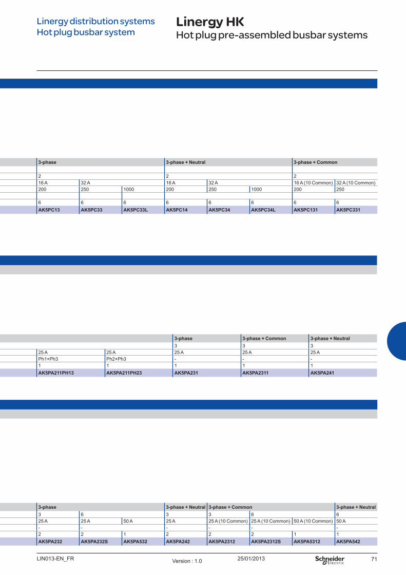
25/01/2013 71
Linergy HKHot plug pre-assembled busbar systems
Co m p o nent m o u nt ing p l at es inco rp o rat ing t ap - o ffSingl e p l at e (h eigh t 105 m m )
AK 5PA231Nu m b er o f p o l es Singl e- p h ase + Neu t ral 2- p h ase 3- p h ase 3- p h ase + Co m m o n 3- p h ase + Neu t ral
No. of 18 mm points used on the busbar system 3 3 3 3 3Rated operational current at 40° ( Ie) 25 A 25 A 25 A 25 A 25 A 25 A 25 A 25 A 25 APhase Ph1+ N Ph2+ N Ph3+ N Ph1+ Ph2 Ph1+ Ph3 Ph2+ Ph3 - - -Number of 6 rails for component support 1 1 1 1 1 1 1 1 1References AK5PA211N1 AK5PA211N2 AK5PA211N3 AK5PA211PH12 AK5PA211PH13 AK5PA211PH23 AK5PA231 AK5PA2311 AK5PA241
Co m p o nent m o u nt ing p l at es inco rp o rat ing t ap - o ffDo u b l e p l at e (h eigh t 190 m m )
AK 5PA232Nu m b er o f p o l es Singl e- p h ase + Neu t ral 2- p h ase 3- p h ase 3- p h ase + Neu t ral 3- p h ase + Co m m o n 3- p h ase + Neu t ral
No. of 18 mm points used on the busbar system 3 3 3 6 3 3 6 6Rated operational current at 40° ( Ie) 25 A 25 A 25 A 25 A 25 A 25 A 25 A 25 A 50 A 25 A 25 A ( 10 Common) 25 A ( 10 Common) 50 A ( 10 Common) 50 APhase Ph1+ N Ph2+ N Ph3+ N Ph1+ Ph2 Ph1+ Ph3 Ph2+ Ph3 - - - - - -Number of 6 rails for component support 2 2 2 2 2 2 2 2 1 2 2 2 1 1References AK5PA212N1 AK5PA212N2 AK5PA212N3 AK5PA212PH12 AK5PA212PH13 AK5PA212PH23 AK5PA232 AK5PA232S AK5PA532 AK5PA242 AK5PA2312 AK5PA2312S AK5PA5312 AK5PA542
Om ega rail , w id t h 75 m m Rem o v ab l e p o w er so ck et sAK 5PC14
AK 5PC12 AK 5GF1Nu m b er o f p o l es Singl e- p h ase + Neu t ral 2- p h ase 3- p h ase 3- p h ase + Neu t ral 3- p h ase + Co m m o n
Material and surface treatment 2 mm sheet steelNumber of points used on the busbar system 1 1 2 2 2Rated operational current at 40° ( Ie) 16 A 32 A 16 A 32 A 16 A 32 A 16 A 32 A 16 A ( 10 Common) 32 A ( 10 Common)Length ( mm) 2000 ( 1) 200 1000 200 1000 200 250 1000 200 250 1000 200 250Depth ( mm) 15Set of 6 6 ( 2) 6 ( 2) 6 ( 3) 6 ( 3) 6 6 6 6 6 6 6 6References AM1DL201 AK5PC12 AK5PC32L AK5PC12PH AK5PC32LPH AK5PC13 AK5PC33 AK5PC33L AK5PC14 AK5PC34 AK5PC34L AK5PC131 AK5PC331
Linergy distribution systems Hot plug busbar system
LIN013-EN_FR Version : 1.0

72
25/01/2013 73
Linergy connection systems Terminal blocks & barsContents
Linergy TR 74
Selection guide: Screw terminal blocksSelection guide: Spring terminal blocksSelection guide: Push-in terminal blocksHybrid terminal blocksMarking accessories
7496
114124126
Linergy TB 130
Earth barsPE conductors
130131
Linergy TA 132
Auxiliary connections 132
05_00-Sommaire Version : 1.0

25/01/201374
Linergy connection systems Terminal blocks and bars
Linergy TRSelection guide: Screw terminals
Snap - o n PE fo o t
Earth terminal blocks are simply snapped onto the DIN rail to make contact. his mechanically and electrically efficient connection meets all the req uirements of standard IEC 60947-7-2.
Passt h ro u gh Lu g- l u g Lu g- co nnect o r
Pro t ect iv e eart h
Passt h ro u gh
Nominal c.s.a ( mm² ) 2.5 4 6 10 & 16 35 to 70 95 & 150 2.5 4 6 & 10 16 to 50Number of poles 1 - 1 x 1 NSYTRV22 NSYTRV42 NSYTRV62 NSYTRV102 NSYTRV352 NSYTRV952BB NSYTRV22PE NSYTRV42PE NSYTRV62PE NSYTRV162PE
NSYTRV162 NSYTRV502 NSYTRV952BC NSYTRV102PE NSYTRV352PENSYTRV702 NSYTRV1502BB NSYTRV502PE
2 - 1 x 1 - - - - - - - - - -3 - 1 x 1 - - - - - - - - - -5 - 1 x 1 - - - - - - - - - -10 - 1 x 1 - - - - - - - - - -1 - 1 x 2 - - - - - - - NSYTRV43PE - -1 - 2 x 2 - - - - - - - NSYTRV44PE - -W ith LED - - - - - - - - - -
Colours Grey - - - -B lue NSYTRV22BL NSYTRV42BL NSYTRV62BL NSYTRV102BL NSYTRV352BL - - - - -
NSYTRV162BL NSYTRV502BLGreen/yellow ( PE) - - - - - -O range NSYTRV22AR NSYTRV42AR - - - - - - - -Red NSYTRV22RD NSYTRV42RD - - - - - - - -Green - NSYTRV42GN - - - - - - - -W hite NSYTRV22WH NSYTRV42WH - - - - - - - -B lack - NSYTRV42BK - - - - - - - -
Mounting on 35 mm
35 mmTeleq uick - - - - - - - - - -15 mm - - - - - - - - - -
See pages 78 78 78 79 79/80 80/81 82 82 82/83 83
Descrip t io n b NSYTRV screw technology terminal blocks are components that are well
established throughout the world and are suitable for the vast maj ority of connection applications, due to their wide range of functions and connection possibilities.
b NSYTRV terminal blocks ensure q uality, safety and the operational availability of eq uipment. In addition to these advantages, they optimise the setting up and operation of installations, due to their simplicity and integrated functions.
LIN043-EN_FRVersion : 1.0
PB
5020
81
PB
5021
66
PB
5021
67
PB
5021
73
PB
5021
90
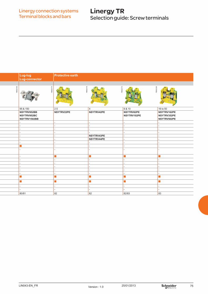
25/01/2013 75
Linergy connection systems Terminal blocks and bars
Linergy TRSelection guide: Screw terminals
Passt h ro u gh Lu g- l u g Lu g- co nnect o r
Pro t ect iv e eart h
Passt h ro u gh
Nominal c.s.a ( mm² ) 2.5 4 6 10 & 16 35 to 70 95 & 150 2.5 4 6 & 10 16 to 50Number of poles 1 - 1 x 1 NSYTRV22 NSYTRV42 NSYTRV62 NSYTRV102 NSYTRV352 NSYTRV952BB NSYTRV22PE NSYTRV42PE NSYTRV62PE NSYTRV162PE
NSYTRV162 NSYTRV502 NSYTRV952BC NSYTRV102PE NSYTRV352PENSYTRV702 NSYTRV1502BB NSYTRV502PE
2 - 1 x 1 - - - - - - - - - -3 - 1 x 1 - - - - - - - - - -5 - 1 x 1 - - - - - - - - - -10 - 1 x 1 - - - - - - - - - -1 - 1 x 2 - - - - - - - NSYTRV43PE - -1 - 2 x 2 - - - - - - - NSYTRV44PE - -W ith LED - - - - - - - - - -
Colours Grey - - - -B lue NSYTRV22BL NSYTRV42BL NSYTRV62BL NSYTRV102BL NSYTRV352BL - - - - -
NSYTRV162BL NSYTRV502BLGreen/yellow ( PE) - - - - - -O range NSYTRV22AR NSYTRV42AR - - - - - - - -Red NSYTRV22RD NSYTRV42RD - - - - - - - -Green - NSYTRV42GN - - - - - - - -W hite NSYTRV22WH NSYTRV42WH - - - - - - - -B lack - NSYTRV42BK - - - - - - - -
Mounting on 35 mm
35 mmTeleq uick - - - - - - - - - -15 mm - - - - - - - - - -
See pages 78 78 78 79 79/80 80/81 82 82 82/83 83
LIN043-EN_FR Version : 1.0
PB
5021
74
PB
5021
76
PB
5021
75
PB
5021
85
PB
5021
99
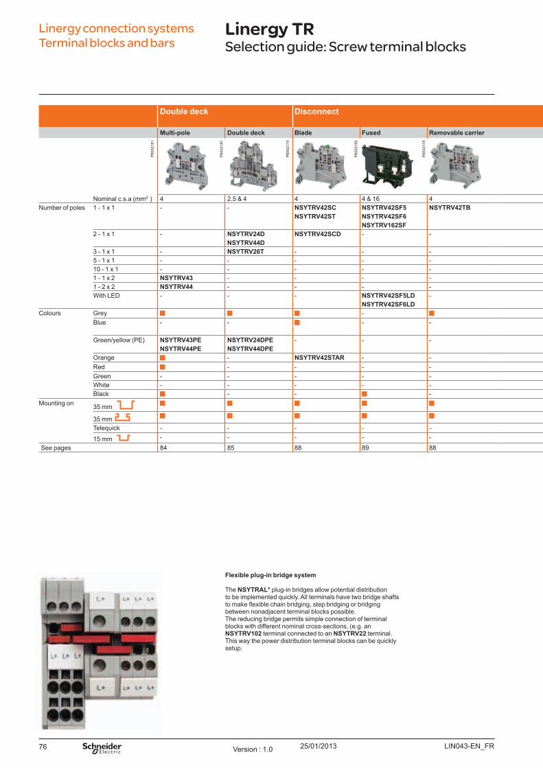
25/01/201376
Linergy connection systems Terminal blocks and bars
Linergy TRSelection guide: Screw terminal blocks
Do u b l e d eck Disco nnect Measu ring Fo r neu t ral co nd u ct o rs
Miniat u re DB6
Mu l t i- p o l e Do u b l e d eck Bl ad e Fu sed Rem o v ab l e carrier Passt h ro u gh Wit h Tel eq u ick u niv ersal fo o t
Nominal c.s.a ( mm² ) 4 2.5 & 4 4 4 & 16 4 6 4 to 10 2.5 & 4 4 6 16 & 35Number of poles 1 - 1 x 1 - - NSYTRV42SC NSYTRV42SF5 NSYTRV42TB NSYTRV62TTD NSYTRV42NE NSYTRV22M - - DB6ED01
NSYTRV42ST NSYTRV42SF6 NSYTRV62NE NSYTRV42M DB6FD01NSYTRV162SF
2 - 1 x 1 - NSYTRV24D NSYTRV42SCD - - - - - DB6CD102 DB6DD102 -NSYTRV44D
3 - 1 x 1 - NSYTRV26T - - - - - - - DB6DD103 -5 - 1 x 1 - - - - - - - - DB6CD105 - -10 - 1 x 1 - - - - - - - - DB6CD110 - -1 - 1 x 2 NSYTRV43 - - - - - - - - - -1 - 2 x 2 NSYTRV44 - - - - - - - - - -W ith LED - - - NSYTRV42SF5LD - - - - - - -
NSYTRV42SF6LDColours Grey - -
B lue - - - - - NSYTRV22MBL - - -NSYTRV42MBL
Green/yellow ( PE) NSYTRV43PE NSYTRV24DPE - - - NSYTRV62TTPE - NSYTRV22MPE - - -NSYTRV44PE NSYTRV44DPE NSYTRV42MPE
O range - NSYTRV42STAR - - - - - - - -Red - - - - - - - - - -Green - - - - - - - - - - -W hite - - - - - - - - - - -B lack - - - - - - - - -
Mounting on 35 mm -
35 mm -
Teleq uick - - - - - - - -
15 mm - - - - - - - - - -See pages 84 85 88 89 88 90 92 94/95 - - -
Fl ex ib l e p l u g- in b rid ge syst em
The NSYTRAL* plug-in bridges allow potential distribution to be implemented q uickly. All terminals have two bridge shafts to make flexible chain bridging, step bridging or bridging between nonadj acent terminal blocks possible.The reducing bridge permits simple connection of terminal blocks with different nominal cross-sections, ( e.g. an NSYTRV102 terminal connected to an NSYTRV22 terminal. This way the power distribution terminal blocks can be q uickly setup.
LIN043-EN_FRVersion : 1.0
PB
5021
81
PB
5021
87
PB
5021
79
PB
5021
95
PB
5021
78

25/01/2013 77
Linergy connection systems Terminal blocks and bars
Linergy TRSelection guide: Screw terminal blocks
Do u b l e d eck Disco nnect Measu ring Fo r neu t ral co nd u ct o rs
Miniat u re DB6
Mu l t i- p o l e Do u b l e d eck Bl ad e Fu sed Rem o v ab l e carrier Passt h ro u gh Wit h Tel eq u ick u niv ersal fo o t
Nominal c.s.a ( mm² ) 4 2.5 & 4 4 4 & 16 4 6 4 to 10 2.5 & 4 4 6 16 & 35Number of poles 1 - 1 x 1 - - NSYTRV42SC NSYTRV42SF5 NSYTRV42TB NSYTRV62TTD NSYTRV42NE NSYTRV22M - - DB6ED01
NSYTRV42ST NSYTRV42SF6 NSYTRV62NE NSYTRV42M DB6FD01NSYTRV162SF
2 - 1 x 1 - NSYTRV24D NSYTRV42SCD - - - - - DB6CD102 DB6DD102 -NSYTRV44D
3 - 1 x 1 - NSYTRV26T - - - - - - - DB6DD103 -5 - 1 x 1 - - - - - - - - DB6CD105 - -10 - 1 x 1 - - - - - - - - DB6CD110 - -1 - 1 x 2 NSYTRV43 - - - - - - - - - -1 - 2 x 2 NSYTRV44 - - - - - - - - - -W ith LED - - - NSYTRV42SF5LD - - - - - - -
NSYTRV42SF6LDColours Grey - -
B lue - - - - - NSYTRV22MBL - - -NSYTRV42MBL
Green/yellow ( PE) NSYTRV43PE NSYTRV24DPE - - - NSYTRV62TTPE - NSYTRV22MPE - - -NSYTRV44PE NSYTRV44DPE NSYTRV42MPE
O range - NSYTRV42STAR - - - - - - - -Red - - - - - - - - - -Green - - - - - - - - - - -W hite - - - - - - - - - - -B lack - - - - - - - - -
Mounting on 35 mm -
35 mm -
Teleq uick - - - - - - - -
15 mm - - - - - - - - - -See pages 84 85 88 89 88 90 92 94/95 - - -
LIN043-EN_FR Version : 1.0
PB
5023
35
PB
5022
21
PB
5018
74
PB
5022
08
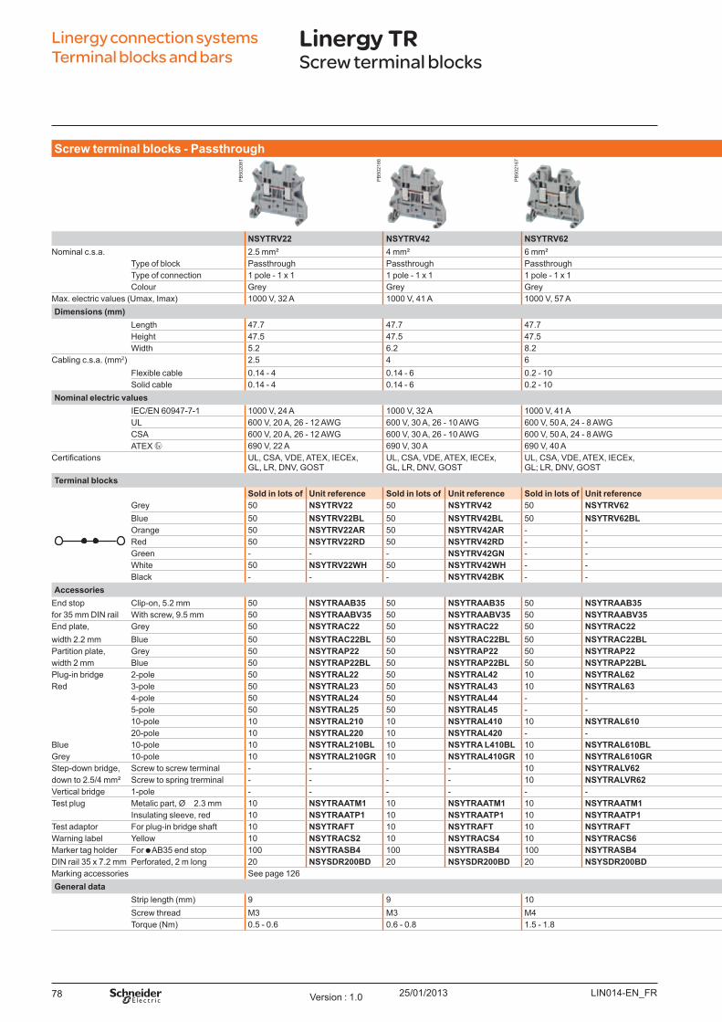
25/01/201378
Screw t erm inal b l o ck s - Passt h ro u gh
NSYTRV22 NSYTRV42 NSYTRV62 NSYTRV102 NSYTRV162 NSYTRV352 NSYTRV502Nominal c.s.a. 2.5 mm² 4 mm² 6 mm² 10 mm² 16 mm² 35 mm² 50 mm²
Type of block Passthrough Passthrough Passthrough Passthrough Passthrough Passthrough PassthroughType of connection 1 pole - 1 x 1 1 pole - 1 x 1 1 pole - 1 x 1 1 pole - 1 x 1 1 pole - 1 x 1 1 pole - 1 x 1 1 pole - 1 x 1Colour Grey Grey Grey Grey Grey Grey Grey
Max. electric values ( U max, Imax) 1000 V, 32 A 1000 V, 41 A 1000 V, 57 A 1000 V, 76 A 1000 V, 101 A 1000 V, 125 A 1000 V, 150 ADim ensio ns (m m )
Length 47.7 47.7 47.7 47.7 55.5 60.2 70.5Height 47.5 47.5 47.5 47.5 55 65.7 83.5W idth 5.2 6.2 8.2 10.2 12.2 16 20
Cabling c.s.a. ( mm2) 2.5 4 6 10 16 35 50Flexible cable 0.14 - 4 0.14 - 6 0.2 - 10 0.5 - 16 1.5 - 25 1.5 - 50 25 - 70Solid cable 0.14 - 4 0.14 - 6 0.2 - 10 0.5 - 16 1.5 - 25 1.5 - 50 16 - 70
No m inal el ect ric v al u esIEC/EN 60947-7-1 1000 V, 24 A 1000 V, 32 A 1000 V, 41 A 1000 V, 57 A 1000 V, 76 A 1000 V, 125 A 1000 V, 150 AU L 600 V, 20 A, 26 - 12 AW G 600 V, 30 A, 26 - 10 AW G 600 V, 50 A, 24 - 8 AW G 600 V, 65 A, 20 - 6 AW G 600 V, 85 A, 16 - 4 AW G 600 V, 150 A, 14 - 1/0 AW G 600 V, 150 A, 6 - 1/0 AW GCSA 600 V, 20 A, 26 - 12 AW G 600 V, 30 A, 26 - 10 AW G 600 V, 50 A, 24 - 8 AW G 600 V, 65 A, 20 - 6 AW G 600 V, 85 A, 16 - 4 AW G 600 V, 150 A, 14 - 1/0 AW G 600 V, 150 A, 6 - 1/0 AW GATEX 690 V, 22 A 690 V, 30 A 690 V, 40 A 690 V, 54 A 690 V, 73 A 690 V, 126 A 690 V, 137 A
ertifications U L, CSA, VDE, ATEX, IECEx, GL, LR, DNV, GO ST
U L, CSA, VDE, ATEX, IECEx, GL, LR, DNV, GO ST
U L, CSA, VDE, ATEX, IECEx, GL; LR, DNV, GO ST
U L, CSA, VDE, ATEX, IECEx, GL, LR, DNV, GO ST
U L, CSA, VDE, ATEX, IECEx, GL, LR, DNV, GO ST
U L, CSA, VDE, ATEX, IECEx, GL, GO ST
U L, CSA, VDE, ATEX, IECEx, GL, LR, DNV, GO ST
Term inal b l o ck sSo l d in l o t s o f U nit reference So l d in l o t s o f U nit reference So l d in l o t s o f U nit reference So l d in l o t s o f U nit reference So l d in l o t s o f U nit reference So l d in l o t s o f U nit reference So l d in l o ts o f U nit reference
Grey 50 NSYTRV22 50 NSYTRV42 50 NSYTRV62 50 NSYTRV102 50 NSYTRV162 50 NSYTRV352 10 NSYTRV502B lue 50 NSYTRV22BL 50 NSYTRV42BL 50 NSYTRV62BL 50 NSYTRV102BL 50 NSYTRV162BL 50 NSYTRV352BL 10 NSYTRV502BLO range 50 NSYTRV22AR 50 NSYTRV42AR - - - - - - - - - - Red 50 NSYTRV22RD 50 NSYTRV42RD - - - - - - - - - - Green - - - NSYTRV42GN - - - - - - - - - - W hite 50 NSYTRV22WH 50 NSYTRV42WH - - - - - - - - - - B lack - - - NSYTRV42BK - - - - - - - - - -
Accesso riesEnd stop Clip-on, 5.2 mm 50 NSYTRAAB35 50 NSYTRAAB35 50 NSYTRAAB35 50 NSYTRAAB35 50 NSYTRAAB35 50 NSYTRAAB35 50 NSYTRAAB35for 35 mm DIN rail W ith screw, 9.5 mm 50 NSYTRAABV35 50 NSYTRAABV35 50 NSYTRAABV35 50 NSYTRAABV35 50 NSYTRAABV35 50 NSYTRAABV35 50 NSYTRAABV35End plate, Grey 50 NSYTRAC22 50 NSYTRAC22 50 NSYTRAC22 50 NSYTRAC22 50 NSYTRAC162 - Included - Includedwidth 2.2 mm B lue 50 NSYTRAC22BL 50 NSYTRAC22BL 50 NSYTRAC22BL 50 NSYTRAC22BL - - - - - - Partition plate, Grey 50 NSYTRAP22 50 NSYTRAP22 50 NSYTRAP22 50 NSYTRAP22 - - - - - - width 2 mm B lue 50 NSYTRAP22BL 50 NSYTRAP22BL 50 NSYTRAP22BL 50 NSYTRAP22BL - - - - - - Plug-in bridge 2-pole 50 NSYTRAL22 50 NSYTRAL42 10 NSYTRAL62 10 NSYTRAL102 10 NSYTRAL162 10 NSYTRAL352 10 NSYTRAL502 *Red 3-pole 50 NSYTRAL23 50 NSYTRAL43 10 NSYTRAL63 - - - - - - 10 NSYTRAL503 *
4-pole 50 NSYTRAL24 50 NSYTRAL44 - - - - - - - - - - 5-pole 50 NSYTRAL25 50 NSYTRAL45 - - - - - - - - - - 10-pole 10 NSYTRAL210 10 NSYTRAL410 10 NSYTRAL610 - - - - - - - - 20-pole 10 NSYTRAL220 10 NSYTRAL420 - - - - - - - - - -
B lue 10-pole 10 NSYTRAL210BL 10 NSYTRA L410BL 10 NSYTRAL610BL - - - - - - - -Grey 10-pole 10 NSYTRAL210GR 10 NSYTRAL410GR 10 NSYTRAL610GR - - - - - - - -Step-down bridge, Screw to screw terminal - - - - 10 NSYTRALV62 10 NSYTRALV102 10 NSYTRALV162 10 NSYTRALV352 - - down to 2.5/4 mm² Screw to spring trerminal - - - - 10 NSYTRALVR62 10 NSYTRALVR102 10 NSYTRALVR162 10 NSYTRALVR352 - - Vertical bridge 1-pole - - - - - - - - - - - - - - Test plug Metalic part, Ø 2.3 mm 10 NSYTRAATM1 10 NSYTRAATM1 10 NSYTRAATM1 10 NSYTRAATM1 10 NSYTRAATM1 10 NSYTRAATM1 10 NSYTRAATM1
Insulating sleeve, red 10 NSYTRAATP1 10 NSYTRAATP1 10 NSYTRAATP1 10 NSYTRAATP1 10 NSYTRAATP1 10 NSYTRAATP1 10 NSYTRAATP1Test adaptor For plug-in bridge shaft 10 NSYTRAFT 10 NSYTRAFT 10 NSYTRAFT 10 NSYTRAFT 10 NSYTRAFT 10 NSYTRAFT - -W arning label Y ellow 10 NSYTRACS2 10 NSYTRACS4 10 NSYTRACS6 10 NSYTRACS10 10 NSYTRACS10 10 NSYTRACS10 10 NSYTRACS10Marker tag holder For AB 35 end stop 100 NSYTRASB4 100 NSYTRASB4 100 NSYTRASB4 100 NSYTRASB4 100 NSYTRASB4 100 NSYTRASB4 100 NSYTRASB4DIN rail 35 x 7.2 mm Perforated, 2 m long 20 NSYSDR200BD 20 NSYSDR200BD 20 NSYSDR200BD 20 NSYSDR200BD 20 NSYSDR200BD 20 NSYSDR200BD 20 NSYS DR200BDMarking accessories See page 126General d at a
Strip length ( mm) 9 9 10 10 14 18 24Screw thread M3 M3 M4 M4 M5 M6 M6Torq ue ( Nm) 0.5 - 0.6 0.6 - 0.8 1.5 - 1.8 1.5 - 1.8 2.5 - 3 3.2 - 3.7 6 - 8
* Screw bridge
Linergy connection systems Terminal blocks and bars
Linergy TRScrew terminal blocks
LIN014-EN_FRVersion : 1.0
PB
5020
81
PB
5021
66
PB
5021
67
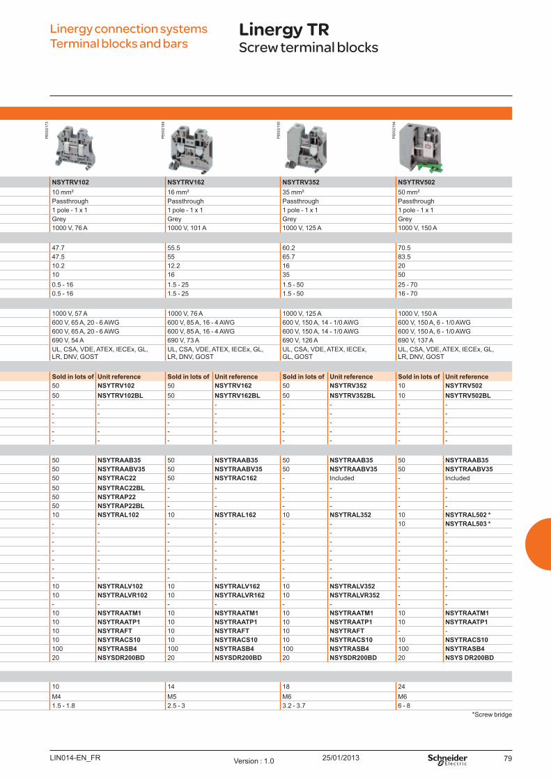
25/01/2013 79
Screw t erm inal b l o ck s - Passt h ro u gh
NSYTRV22 NSYTRV42 NSYTRV62 NSYTRV102 NSYTRV162 NSYTRV352 NSYTRV502Nominal c.s.a. 2.5 mm² 4 mm² 6 mm² 10 mm² 16 mm² 35 mm² 50 mm²
Type of block Passthrough Passthrough Passthrough Passthrough Passthrough Passthrough PassthroughType of connection 1 pole - 1 x 1 1 pole - 1 x 1 1 pole - 1 x 1 1 pole - 1 x 1 1 pole - 1 x 1 1 pole - 1 x 1 1 pole - 1 x 1Colour Grey Grey Grey Grey Grey Grey Grey
Max. electric values ( U max, Imax) 1000 V, 32 A 1000 V, 41 A 1000 V, 57 A 1000 V, 76 A 1000 V, 101 A 1000 V, 125 A 1000 V, 150 ADim ensio ns (m m )
Length 47.7 47.7 47.7 47.7 55.5 60.2 70.5Height 47.5 47.5 47.5 47.5 55 65.7 83.5W idth 5.2 6.2 8.2 10.2 12.2 16 20
Cabling c.s.a. ( mm2) 2.5 4 6 10 16 35 50Flexible cable 0.14 - 4 0.14 - 6 0.2 - 10 0.5 - 16 1.5 - 25 1.5 - 50 25 - 70Solid cable 0.14 - 4 0.14 - 6 0.2 - 10 0.5 - 16 1.5 - 25 1.5 - 50 16 - 70
No m inal el ect ric v al u esIEC/EN 60947-7-1 1000 V, 24 A 1000 V, 32 A 1000 V, 41 A 1000 V, 57 A 1000 V, 76 A 1000 V, 125 A 1000 V, 150 AU L 600 V, 20 A, 26 - 12 AW G 600 V, 30 A, 26 - 10 AW G 600 V, 50 A, 24 - 8 AW G 600 V, 65 A, 20 - 6 AW G 600 V, 85 A, 16 - 4 AW G 600 V, 150 A, 14 - 1/0 AW G 600 V, 150 A, 6 - 1/0 AW GCSA 600 V, 20 A, 26 - 12 AW G 600 V, 30 A, 26 - 10 AW G 600 V, 50 A, 24 - 8 AW G 600 V, 65 A, 20 - 6 AW G 600 V, 85 A, 16 - 4 AW G 600 V, 150 A, 14 - 1/0 AW G 600 V, 150 A, 6 - 1/0 AW GATEX 690 V, 22 A 690 V, 30 A 690 V, 40 A 690 V, 54 A 690 V, 73 A 690 V, 126 A 690 V, 137 A
ertifications U L, CSA, VDE, ATEX, IECEx, GL, LR, DNV, GO ST
U L, CSA, VDE, ATEX, IECEx, GL, LR, DNV, GO ST
U L, CSA, VDE, ATEX, IECEx, GL; LR, DNV, GO ST
U L, CSA, VDE, ATEX, IECEx, GL, LR, DNV, GO ST
U L, CSA, VDE, ATEX, IECEx, GL, LR, DNV, GO ST
U L, CSA, VDE, ATEX, IECEx, GL, GO ST
U L, CSA, VDE, ATEX, IECEx, GL, LR, DNV, GO ST
Term inal b l o ck sSo l d in l o t s o f U nit reference So l d in l o t s o f U nit reference So l d in l o t s o f U nit reference So l d in l o t s o f U nit reference So l d in l o t s o f U nit reference So l d in l o t s o f U nit reference So l d in l o t s o f U nit reference
Grey 50 NSYTRV22 50 NSYTRV42 50 NSYTRV62 50 NSYTRV102 50 NSYTRV162 50 NSYTRV352 10 NSYTRV502B lue 50 NSYTRV22BL 50 NSYTRV42BL 50 NSYTRV62BL 50 NSYTRV102BL 50 NSYTRV162BL 50 NSYTRV352BL 10 NSYTRV502BLO range 50 NSYTRV22AR 50 NSYTRV42AR - - - - - - - - - - Red 50 NSYTRV22RD 50 NSYTRV42RD - - - - - - - - - - Green - - - NSYTRV42GN - - - - - - - - - - W hite 50 NSYTRV22WH 50 NSYTRV42WH - - - - - - - - - - B lack - - - NSYTRV42BK - - - - - - - - - -
Accesso riesEnd stop Clip-on, 5.2 mm 50 NSYTRAAB35 50 NSYTRAAB35 50 NSYTRAAB35 50 NSYTRAAB35 50 NSYTRAAB35 50 NSYTRAAB35 50 NSYTRAAB35for 35 mm DIN rail W ith screw, 9.5 mm 50 NSYTRAABV35 50 NSYTRAABV35 50 NSYTRAABV35 50 NSYTRAABV35 50 NSYTRAABV35 50 NSYTRAABV35 50 NSYTRAABV35End plate, Grey 50 NSYTRAC22 50 NSYTRAC22 50 NSYTRAC22 50 NSYTRAC22 50 NSYTRAC162 - Included - Includedwidth 2.2 mm B lue 50 NSYTRAC22BL 50 NSYTRAC22BL 50 NSYTRAC22BL 50 NSYTRAC22BL - - - - - - Partition plate, Grey 50 NSYTRAP22 50 NSYTRAP22 50 NSYTRAP22 50 NSYTRAP22 - - - - - - width 2 mm B lue 50 NSYTRAP22BL 50 NSYTRAP22BL 50 NSYTRAP22BL 50 NSYTRAP22BL - - - - - - Plug-in bridge 2-pole 50 NSYTRAL22 50 NSYTRAL42 10 NSYTRAL62 10 NSYTRAL102 10 NSYTRAL162 10 NSYTRAL352 10 NSYTRAL502 *Red 3-pole 50 NSYTRAL23 50 NSYTRAL43 10 NSYTRAL63 - - - - - - 10 NSYTRAL503 *
4-pole 50 NSYTRAL24 50 NSYTRAL44 - - - - - - - - - - 5-pole 50 NSYTRAL25 50 NSYTRAL45 - - - - - - - - - - 10-pole 10 NSYTRAL210 10 NSYTRAL410 10 NSYTRAL610 - - - - - - - - 20-pole 10 NSYTRAL220 10 NSYTRAL420 - - - - - - - - - -
B lue 10-pole 10 NSYTRAL210BL 10 NSYTRA L410BL 10 NSYTRAL610BL - - - - - - - -Grey 10-pole 10 NSYTRAL210GR 10 NSYTRAL410GR 10 NSYTRAL610GR - - - - - - - -Step-down bridge, Screw to screw terminal - - - - 10 NSYTRALV62 10 NSYTRALV102 10 NSYTRALV162 10 NSYTRALV352 - - down to 2.5/4 mm² Screw to spring trerminal - - - - 10 NSYTRALVR62 10 NSYTRALVR102 10 NSYTRALVR162 10 NSYTRALVR352 - - Vertical bridge 1-pole - - - - - - - - - - - - - - Test plug Metalic part, Ø 2.3 mm 10 NSYTRAATM1 10 NSYTRAATM1 10 NSYTRAATM1 10 NSYTRAATM1 10 NSYTRAATM1 10 NSYTRAATM1 10 NSYTRAATM1
Insulating sleeve, red 10 NSYTRAATP1 10 NSYTRAATP1 10 NSYTRAATP1 10 NSYTRAATP1 10 NSYTRAATP1 10 NSYTRAATP1 10 NSYTRAATP1Test adaptor For plug-in bridge shaft 10 NSYTRAFT 10 NSYTRAFT 10 NSYTRAFT 10 NSYTRAFT 10 NSYTRAFT 10 NSYTRAFT - -W arning label Y ellow 10 NSYTRACS2 10 NSYTRACS4 10 NSYTRACS6 10 NSYTRACS10 10 NSYTRACS10 10 NSYTRACS10 10 NSYTRACS10Marker tag holder For AB 35 end stop 100 NSYTRASB4 100 NSYTRASB4 100 NSYTRASB4 100 NSYTRASB4 100 NSYTRASB4 100 NSYTRASB4 100 NSYTRASB4DIN rail 35 x 7.2 mm Perforated, 2 m long 20 NSYSDR200BD 20 NSYSDR200BD 20 NSYSDR200BD 20 NSYSDR200BD 20 NSYSDR200BD 20 NSYSDR200BD 20 NSYS DR200BDMarking accessories See page 126General d at a
Strip length ( mm) 9 9 10 10 14 18 24Screw thread M3 M3 M4 M4 M5 M6 M6Torq ue ( Nm) 0.5 - 0.6 0.6 - 0.8 1.5 - 1.8 1.5 - 1.8 2.5 - 3 3.2 - 3.7 6 - 8
* Screw bridge
Linergy connection systems Terminal blocks and bars
Linergy TRScrew terminal blocks
LIN014-EN_FR Version : 1.0
PB
5021
73
PB
5021
89
PB
5021
90
PB
5021
94
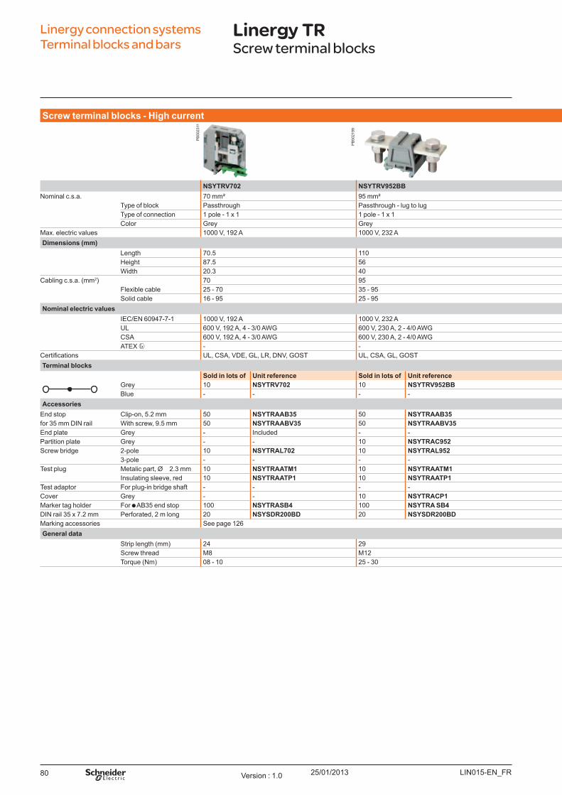
25/01/201380
Screw t erm inal b l o ck s - High cu rrent
NSYTRV702 NSYTRV952BB NSYTRV952BC NSYTRV1502BBNominal c.s.a. 70 mm² 95 mm² 95 mm² 150 mm²
Type of block Passthrough Passthrough - lug to lug Passthrough - lug to connector Passthrough - lug to lugType of connection 1 pole - 1 x 1 1 pole - 1 x 1 1 pole - 1 x 1 1 pole - 1 x 1Color Grey Grey Grey Grey
Max. electric values 1000 V, 192 A 1000 V, 232 A 1000 V, 232 A 1000 V, 309 ADim ensio ns (m m )
Length 70.5 110 114 119Height 87.5 56 86 100W idth 20.3 40 40 46
Cabling c.s.a. ( mm2) 70 95 95 150Flexible cable 25 - 70 35 - 95 35 - 95 50 - 150Solid cable 16 - 95 25 - 95 25 - 95 35 - 150
No m inal el ect ric v al u esIEC/EN 60947-7-1 1000 V, 192 A 1000 V, 232 A 1000 V, 232 A 1000 V, 309 AU L 600 V, 192 A, 4 - 3/0 AW G 600 V, 230 A, 2 - 4/0 AW G 600 V, 230 A, 2 - 4/0 AW G 600 V, 285 A, 2 - 300 AW G/kcmilCSA 600 V, 192 A, 4 - 3/0 AW G 600 V, 230 A, 2 - 4/0 AW G 600 V, 230 A, 2 - 4/0 AW G 600 V, 285 A, 2 - 300 AW G/kcmilATEX - -
ertifications U L, CSA, VDE, GL, LR, DNV, GO ST U L, CSA, GL, GO ST U L, CSA, GL, GO ST U L, CSA, GLTerm inal b l o ck s
So l d in l o t s o f U nit reference So l d in l o t s o f U nit reference So l d in l o t s o f U nit reference So l d in l o t s o f U nit referenceGrey 10 NSYTRV702 10 NSYTRV952BB 10 NSYTRV952BC 10 NSYTRV1502BBB lue - - - - - - - -
Accesso riesEnd stop Clip-on, 5.2 mm 50 NSYTRAAB35 50 NSYTRAAB35 50 NSYTRAAB35 50 NSYTRAAB35for 35 mm DIN rail W ith screw, 9.5 mm 50 NSYTRAABV35 50 NSYTRAABV35 50 NSYTRAABV35 50 NSYTRAABV35End plate Grey - Included - - - - - - Partition plate Grey - - 10 NSYTRAC952 10 NSYTRAC952 10 NSYTRAC952Screw bridge 2-pole 10 NSYTRAL702 10 NSYTRAL952 10 NSYTRAL952 10 NSYTRAL1502
3-pole - - - - - - - -Test plug Metalic part, Ø 2.3 mm 10 NSYTRAATM1 10 NSYTRAATM1 10 NSYTRAATM1 10 NSYTRAATM1
Insulating sleeve, red 10 NSYTRAATP1 10 NSYTRAATP1 10 NSYTRAATP1 10 NSYTRAATP1Test adaptor For plug-in bridge shaft - - - - - - - - Cover Grey - - 10 NSYTRACP1 10 NSYTRACP1 10 NSYTRACP2Marker tag holder For AB 35 end stop 100 NSYTRASB4 100 NSYTRA SB4 100 NSYTRASB4 100 NSYTRA SB4DIN rail 35 x 7.2 mm Perforated, 2 m long 20 NSYSDR200BD 20 NSYSDR200BD 20 NSYSDR200BD 20 NSYSDR200BDMarking accessories See page 126General d at a
Strip length ( mm) 24 29 29 29Screw thread M8 M12 M8 / M12 M12Torq ue ( Nm) 08 - 10 25 - 30 15 - 20 / 25 - 30 25 - 30
Linergy connection systems Terminal blocks and bars
Linergy TRScrew terminal blocks
LIN015-EN_FRVersion : 1.0
PB
5023
11
PB
5021
99
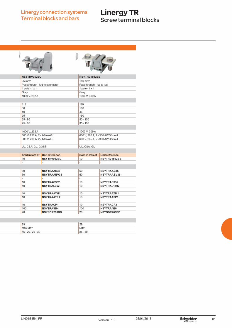
25/01/2013 81
Screw t erm inal b l o ck s - High cu rrent
NSYTRV702 NSYTRV952BB NSYTRV952BC NSYTRV1502BBNominal c.s.a. 70 mm² 95 mm² 95 mm² 150 mm²
Type of block Passthrough Passthrough - lug to lug Passthrough - lug to connector Passthrough - lug to lugType of connection 1 pole - 1 x 1 1 pole - 1 x 1 1 pole - 1 x 1 1 pole - 1 x 1Color Grey Grey Grey Grey
Max. electric values 1000 V, 192 A 1000 V, 232 A 1000 V, 232 A 1000 V, 309 ADim ensio ns (m m )
Length 70.5 110 114 119Height 87.5 56 86 100W idth 20.3 40 40 46
Cabling c.s.a. ( mm2) 70 95 95 150Flexible cable 25 - 70 35 - 95 35 - 95 50 - 150Solid cable 16 - 95 25 - 95 25 - 95 35 - 150
No m inal el ect ric v al u esIEC/EN 60947-7-1 1000 V, 192 A 1000 V, 232 A 1000 V, 232 A 1000 V, 309 AU L 600 V, 192 A, 4 - 3/0 AW G 600 V, 230 A, 2 - 4/0 AW G 600 V, 230 A, 2 - 4/0 AW G 600 V, 285 A, 2 - 300 AW G/kcmilCSA 600 V, 192 A, 4 - 3/0 AW G 600 V, 230 A, 2 - 4/0 AW G 600 V, 230 A, 2 - 4/0 AW G 600 V, 285 A, 2 - 300 AW G/kcmilATEX - -
ertifications U L, CSA, VDE, GL, LR, DNV, GO ST U L, CSA, GL, GO ST U L, CSA, GL, GO ST U L, CSA, GLTerm inal b l o ck s
So l d in l o t s o f U nit reference So l d in l o t s o f U nit reference So l d in l o t s o f U nit reference So l d in l o t s o f U nit referenceGrey 10 NSYTRV702 10 NSYTRV952BB 10 NSYTRV952BC 10 NSYTRV1502BBB lue - - - - - - - -
Accesso riesEnd stop Clip-on, 5.2 mm 50 NSYTRAAB35 50 NSYTRAAB35 50 NSYTRAAB35 50 NSYTRAAB35for 35 mm DIN rail W ith screw, 9.5 mm 50 NSYTRAABV35 50 NSYTRAABV35 50 NSYTRAABV35 50 NSYTRAABV35End plate Grey - Included - - - - - - Partition plate Grey - - 10 NSYTRAC952 10 NSYTRAC952 10 NSYTRAC952Screw bridge 2-pole 10 NSYTRAL702 10 NSYTRAL952 10 NSYTRAL952 10 NSYTRAL1502
3-pole - - - - - - - -Test plug Metalic part, Ø 2.3 mm 10 NSYTRAATM1 10 NSYTRAATM1 10 NSYTRAATM1 10 NSYTRAATM1
Insulating sleeve, red 10 NSYTRAATP1 10 NSYTRAATP1 10 NSYTRAATP1 10 NSYTRAATP1Test adaptor For plug-in bridge shaft - - - - - - - - Cover Grey - - 10 NSYTRACP1 10 NSYTRACP1 10 NSYTRACP2Marker tag holder For AB 35 end stop 100 NSYTRASB4 100 NSYTRA SB4 100 NSYTRASB4 100 NSYTRA SB4DIN rail 35 x 7.2 mm Perforated, 2 m long 20 NSYSDR200BD 20 NSYSDR200BD 20 NSYSDR200BD 20 NSYSDR200BDMarking accessories See page 126General d at a
Strip length ( mm) 24 29 29 29Screw thread M8 M12 M8 / M12 M12Torq ue ( Nm) 08 - 10 25 - 30 15 - 20 / 25 - 30 25 - 30
Linergy connection systems Terminal blocks and bars
Linergy TRScrew terminal blocks
LIN015-EN_FR Version : 1.0
PB
5022
00
PB
5023
53
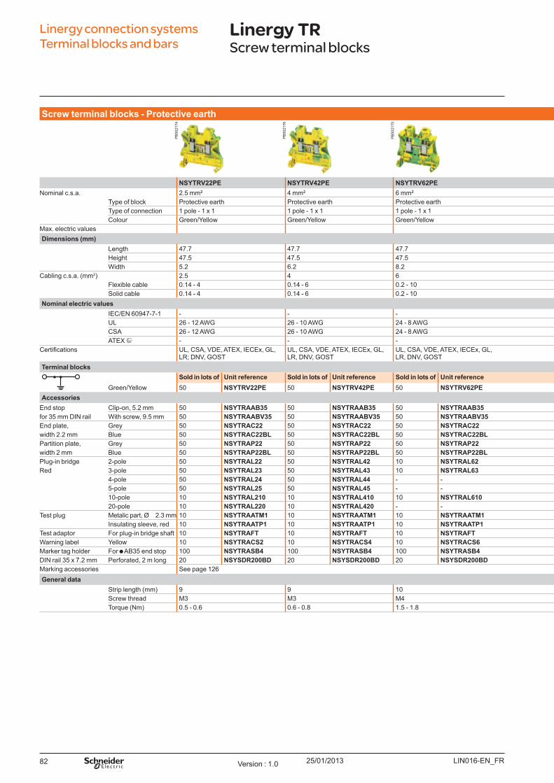
25/01/201382
Screw t erm inal b l o ck s - Pro t ect iv e eart h
NSYTRV22PE NSYTRV42PE NSYTRV62PE NSYTRV102PE NSYTRV162PE NSYTRV352PE NSYTRV502PENominal c.s.a. 2.5 mm² 4 mm² 6 mm² 10 mm² 16 mm² 35 mm² 50 mm²
Type of block Protective earth Protective earth Protective earth Protective earth Protective earth Protective earth Protective earthType of connection 1 pole - 1 x 1 1 pole - 1 x 1 1 pole - 1 x 1 1 pole - 1 x 1 1 pole - 1 x 1 1 pole - 1 x 1 1 pole - 1 x 1Colour Green/Y ellow Green/Y ellow Green/Y ellow Green/Y ellow Green/Y ellow Green/Y ellow Green/Y ellow
Max. electric valuesDim ensio ns (m m )
Length 47.7 47.7 47.7 47.7 55 65.7 70.5Height 47.5 47.5 47.5 47.5 55.5 60.2 83.5W idth 5.2 6.2 8.2 10.2 12.2 16 20
Cabling c.s.a. ( mm2) 2.5 4 6 10 16 35 50Flexible cable 0.14 - 4 0.14 - 6 0.2 - 10 0.5 - 16 1.5 - 25 1.5 - 35 25 - 70Solid cable 0.14 - 4 0.14 - 6 0.2 - 10 0.5 - 16 1.5 - 25 1.5 - 35 16 - 70
No m inal el ect ric v al u esIEC/EN 60947-7-1 - - - 76 A 101 A 125 A 150 AU L 26 - 12 AW G 26 - 10 AW G 24 - 8 AW G 20 - 6 AW G 16 - 4 AW G 14 - 1/0 AW G 6 - 1/0 AW GCSA 26 - 12 AW G 26 - 10 AW G 24 - 8 AW G 20 - 6 AW G 16 - 4 AW G 14 - 1/0 AW G 6 - 1/0 AW G ATEX - - - - - - -
ertifications U L, CSA, VDE, ATEX, IECEx, GL, LR; DNV, GO ST
U L, CSA, VDE, ATEX, IECEx, GL, LR, DNV, GO ST
U L, CSA, VDE, ATEX, IECEx, GL, LR, DNV, GO ST
U L, CSA, VDE, ATEX, IECEx, GL, LR; DNV, GO ST
U L, CSA, VDE, ATEX, IECEx, GL, LR, DNV, GO ST
U L, CSA, VDE, ATEX, IECEx, GL, GO ST
U L, CSA, ATEX, IECEx, GL, LR, DNV, GO ST
Term inal b l o ck sSo l d in l o t s o f U nit reference So l d in l o t s o f U nit reference So l d in l o t s o f U nit reference So l d in l o t s o f U nit reference So l d in l o t s o f U nit reference So l d in l o t s o f U nit reference So l d in l o t s o f U nit reference
Green/Y ellow 50 NSYTRV22PE 50 NSYTRV42PE 50 NSYTRV62PE 50 NSYTRV102PE 50 NSYTRV162PE 50 NSYTRV352PE 50 NSYTRV502PEAccesso ries
End stop Clip-on, 5.2 mm 50 NSYTRAAB35 50 NSYTRAAB35 50 NSYTRAAB35 50 NSYTRAAB35 50 NSYTRAAB35 50 NSYTRAAB35 50 NSYTRAAB35for 35 mm DIN rail W ith screw, 9.5 mm 50 NSYTRAABV35 50 NSYTRAABV35 50 NSYTRAABV35 50 NSYTRAABV35 50 NSYTRAABV35 50 NSYTRAABV35 50 NSYTRAABV35End plate, Grey 50 NSYTRAC22 50 NSYTRAC22 50 NSYTRAC22 50 NSYTRAC22 50 NSYTRAC162 - Included - Includedwidth 2.2 mm B lue 50 NSYTRAC22BL 50 NSYTRAC22BL 50 NSYTRAC22BL 50 NSYTRAC22BL - - - - - - Partition plate, Grey 50 NSYTRAP22 50 NSYTRAP22 50 NSYTRAP22 50 NSYTRAP22 - - - - - - width 2 mm B lue 50 NSYTRAP22BL 50 NSYTRAP22BL 50 NSYTRAP22BL 50 NSYTRAP22BL - - - - - - Plug-in bridge 2-pole 50 NSYTRAL22 50 NSYTRAL42 10 NSYTRAL62 10 NSYTRAL102 10 NSYTRAL162 10 NSYTRAL352 - - Red 3-pole 50 NSYTRAL23 50 NSYTRAL43 10 NSYTRAL63 - - - - - - - -
4-pole 50 NSYTRAL24 50 NSYTRAL44 - - - - - - - - - - 5-pole 50 NSYTRAL25 50 NSYTRAL45 - - - - - - - - - - 10-pole 10 NSYTRAL210 10 NSYTRAL410 10 NSYTRAL610 - - - - - - - - 20-pole 10 NSYTRAL220 10 NSYTRAL420 - - - - - - - - - -
Test plug Metalic part, Ø 2.3 mm 10 NSYTRAATM1 10 NSYTRAATM1 10 NSYTRAATM1 10 NSYTRAATM1 10 NSYTRAATM1 10 NSYTRAATM1 10 NSYTRAATM1Insulating sleeve, red 10 NSYTRAATP1 10 NSYTRAATP1 10 NSYTRAATP1 10 NSYTRAATP1 10 NSYTRAATP1 10 NSYTRAATP1 10 NSYTRAATP1
Test adaptor For plug-in bridge shaft 10 NSYTRAFT 10 NSYTRAFT 10 NSYTRAFT 10 NSYTRAFT 10 NSYTRAFT 10 NSYTRAFT 10 NSYTRAFTW arning label Y ellow 10 NSYTRACS2 10 NSYTRACS4 10 NSYTRACS6 10 NSYTRACS10 10 NSYTRACS10 10 NSYTRACS10 10 NSYTRACS10Marker tag holder For AB 35 end stop 100 NSYTRASB4 100 NSYTRASB4 100 NSYTRASB4 100 NSYTRASB4 100 NSYTRASB4 100 NSYTRASB4 100 NSYTRASB4DIN rail 35 x 7.2 mm Perforated, 2 m long 20 NSYSDR200BD 20 NSYSDR200BD 20 NSYSDR200BD 20 NSYSDR200BD 20 NSYSDR200BD 20 NSYSDR200BD 20 NSYSDR200BDMarking accessories See page 126General d at a
Strip length ( mm) 9 9 10 10 14 18 24Screw thread M3 M3 M4 M4 M5 M6 M6Torq ue ( Nm) 0.5 - 0.6 0.6 - 0.8 1.5 - 1.8 1.5 - 1.8 2.5 - 3 3.2 - 3.7 6 - 8
Linergy connection systems Terminal blocks and bars
Linergy TRScrew terminal blocks
LIN016-EN_FRVersion : 1.0
PB
5021
74
PB
5021
76
PB
5021
75
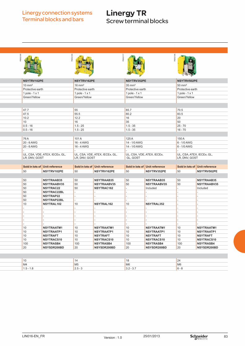
25/01/2013 83
Screw t erm inal b l o ck s - Pro t ect iv e eart h
NSYTRV22PE NSYTRV42PE NSYTRV62PE NSYTRV102PE NSYTRV162PE NSYTRV352PE NSYTRV502PENominal c.s.a. 2.5 mm² 4 mm² 6 mm² 10 mm² 16 mm² 35 mm² 50 mm²
Type of block Protective earth Protective earth Protective earth Protective earth Protective earth Protective earth Protective earthType of connection 1 pole - 1 x 1 1 pole - 1 x 1 1 pole - 1 x 1 1 pole - 1 x 1 1 pole - 1 x 1 1 pole - 1 x 1 1 pole - 1 x 1Colour Green/Y ellow Green/Y ellow Green/Y ellow Green/Y ellow Green/Y ellow Green/Y ellow Green/Y ellow
Max. electric valuesDim ensio ns (m m )
Length 47.7 47.7 47.7 47.7 55 65.7 70.5Height 47.5 47.5 47.5 47.5 55.5 60.2 83.5W idth 5.2 6.2 8.2 10.2 12.2 16 20
Cabling c.s.a. ( mm2) 2.5 4 6 10 16 35 50Flexible cable 0.14 - 4 0.14 - 6 0.2 - 10 0.5 - 16 1.5 - 25 1.5 - 35 25 - 70Solid cable 0.14 - 4 0.14 - 6 0.2 - 10 0.5 - 16 1.5 - 25 1.5 - 35 16 - 70
No m inal el ect ric v al u esIEC/EN 60947-7-1 - - - 76 A 101 A 125 A 150 AU L 26 - 12 AW G 26 - 10 AW G 24 - 8 AW G 20 - 6 AW G 16 - 4 AW G 14 - 1/0 AW G 6 - 1/0 AW GCSA 26 - 12 AW G 26 - 10 AW G 24 - 8 AW G 20 - 6 AW G 16 - 4 AW G 14 - 1/0 AW G 6 - 1/0 AW G ATEX - - - - - - -
ertifications U L, CSA, VDE, ATEX, IECEx, GL, LR; DNV, GO ST
U L, CSA, VDE, ATEX, IECEx, GL, LR, DNV, GO ST
U L, CSA, VDE, ATEX, IECEx, GL, LR, DNV, GO ST
U L, CSA, VDE, ATEX, IECEx, GL, LR; DNV, GO ST
U L, CSA, VDE, ATEX, IECEx, GL, LR, DNV, GO ST
U L, CSA, VDE, ATEX, IECEx, GL, GO ST
U L, CSA, ATEX, IECEx, GL, LR, DNV, GO ST
Term inal b l o ck sSo l d in l o t s o f U nit reference So l d in l o t s o f U nit reference So l d in l o t s o f U nit reference So l d in l o t s o f U nit reference So l d in l o t s o f U nit reference So l d in l o t s o f U nit reference So l d in l o t s o f U nit reference
Green/Y ellow 50 NSYTRV22PE 50 NSYTRV42PE 50 NSYTRV62PE 50 NSYTRV102PE 50 NSYTRV162PE 50 NSYTRV352PE 50 NSYTRV502PEAccesso ries
End stop Clip-on, 5.2 mm 50 NSYTRAAB35 50 NSYTRAAB35 50 NSYTRAAB35 50 NSYTRAAB35 50 NSYTRAAB35 50 NSYTRAAB35 50 NSYTRAAB35for 35 mm DIN rail W ith screw, 9.5 mm 50 NSYTRAABV35 50 NSYTRAABV35 50 NSYTRAABV35 50 NSYTRAABV35 50 NSYTRAABV35 50 NSYTRAABV35 50 NSYTRAABV35End plate, Grey 50 NSYTRAC22 50 NSYTRAC22 50 NSYTRAC22 50 NSYTRAC22 50 NSYTRAC162 - Included - Includedwidth 2.2 mm B lue 50 NSYTRAC22BL 50 NSYTRAC22BL 50 NSYTRAC22BL 50 NSYTRAC22BL - - - - - - Partition plate, Grey 50 NSYTRAP22 50 NSYTRAP22 50 NSYTRAP22 50 NSYTRAP22 - - - - - - width 2 mm B lue 50 NSYTRAP22BL 50 NSYTRAP22BL 50 NSYTRAP22BL 50 NSYTRAP22BL - - - - - - Plug-in bridge 2-pole 50 NSYTRAL22 50 NSYTRAL42 10 NSYTRAL62 10 NSYTRAL102 10 NSYTRAL162 10 NSYTRAL352 - - Red 3-pole 50 NSYTRAL23 50 NSYTRAL43 10 NSYTRAL63 - - - - - - - -
4-pole 50 NSYTRAL24 50 NSYTRAL44 - - - - - - - - - - 5-pole 50 NSYTRAL25 50 NSYTRAL45 - - - - - - - - - - 10-pole 10 NSYTRAL210 10 NSYTRAL410 10 NSYTRAL610 - - - - - - - - 20-pole 10 NSYTRAL220 10 NSYTRAL420 - - - - - - - - - -
Test plug Metalic part, Ø 2.3 mm 10 NSYTRAATM1 10 NSYTRAATM1 10 NSYTRAATM1 10 NSYTRAATM1 10 NSYTRAATM1 10 NSYTRAATM1 10 NSYTRAATM1Insulating sleeve, red 10 NSYTRAATP1 10 NSYTRAATP1 10 NSYTRAATP1 10 NSYTRAATP1 10 NSYTRAATP1 10 NSYTRAATP1 10 NSYTRAATP1
Test adaptor For plug-in bridge shaft 10 NSYTRAFT 10 NSYTRAFT 10 NSYTRAFT 10 NSYTRAFT 10 NSYTRAFT 10 NSYTRAFT 10 NSYTRAFTW arning label Y ellow 10 NSYTRACS2 10 NSYTRACS4 10 NSYTRACS6 10 NSYTRACS10 10 NSYTRACS10 10 NSYTRACS10 10 NSYTRACS10Marker tag holder For AB 35 end stop 100 NSYTRASB4 100 NSYTRASB4 100 NSYTRASB4 100 NSYTRASB4 100 NSYTRASB4 100 NSYTRASB4 100 NSYTRASB4DIN rail 35 x 7.2 mm Perforated, 2 m long 20 NSYSDR200BD 20 NSYSDR200BD 20 NSYSDR200BD 20 NSYSDR200BD 20 NSYSDR200BD 20 NSYSDR200BD 20 NSYSDR200BDMarking accessories See page 126General d at a
Strip length ( mm) 9 9 10 10 14 18 24Screw thread M3 M3 M4 M4 M5 M6 M6Torq ue ( Nm) 0.5 - 0.6 0.6 - 0.8 1.5 - 1.8 1.5 - 1.8 2.5 - 3 3.2 - 3.7 6 - 8
Linergy connection systems Terminal blocks and bars
Linergy TRScrew terminal blocks
LIN016-EN_FR Version : 1.0
PB
5021
80
PB
5021
85
PB
5021
77
PB
5021
86
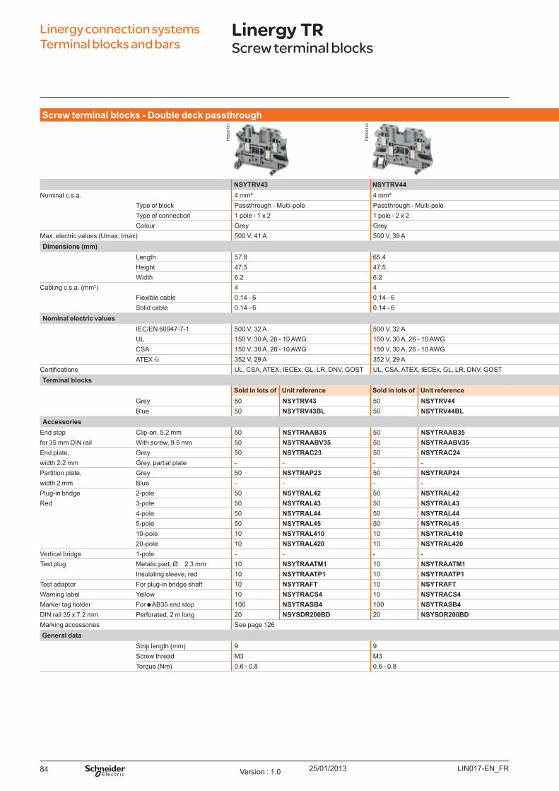
25/01/201384
Linergy connection systems Terminal blocks and bars
Linergy TRScrew terminal blocks
Screw t erm inal b l o ck s - Do u b l e d eck p asst h ro u gh
NSYTRV43 NSYTRV44 NSYTRV24D NSYTRV44D NSYTRV26TNominal c.s.a. 4 mm² 4 mm² 2.5 mm² 4 mm² 2.5 mm²
Type of block Passthrough - Multi-pole Passthrough - Multi-pole Passthrough - Double deck Passthrough - Double deck Passthrough - Triple deckType of connection 1 pole - 1 x 2 1 pole - 2 x 2 2 pole - 1 x 1 2 pole - 1 x 1 3 pole - 1 x 1Colour Grey Grey Grey Grey Grey
Max. electric values ( U max, Imax) 500 V, 41 A 500 V, 39 A 500 V, 28 A 800 V, 36 A 500 V, 24 ADim ensio ns (m m )
Length 57.8 65.4 69.9 69.9 90Height 47.5 47.5 65 65 77.5W idth 6.2 6.2 5.2 6.2 5.2
Cabling c.s.a. ( mm2) 4 4 2.5 4 2.5Flexible cable 0.14 - 6 0.14 - 6 0.14 - 4 0.14 - 6 0.14 - 4Solid cable 0.14 - 6 0.14 - 6 0.14 - 4 0.14 - 6 0.14 - 4
No m inal el ect ric v al u esIEC/EN 60947-7-1 500 V, 32 A 500 V, 32 A 500 V, 24 A 800 V, 30 A 500 V, 20 AU L 150 V, 30 A, 26 - 10 AW G 150 V, 30 A, 26 - 10 AW G 600 V, 20 A, 26 - 12 AW G 600 V, 30 A, 26 - 10 AW G 600 V, 20 A, 26 - 12 AW G CSA 150 V, 30 A, 26 - 10 AW G 150 V, 30 A, 26 - 10 AW G 600 V, 20 A, 26 - 12 AW G 600 V, 30 A, 26 - 10 AW G 600 V, 20 A, 26 - 12 AW G ATEX 352 V, 29 A 352 V, 29 A 352 V, 20 A 440 V, 25.5 A -
ertifications U L, CSA, ATEX, IECEx, GL, LR, DNV, GO ST U L, CSA, ATEX, IECEx, GL, LR, DNV, GO ST U L, CSA, ATEX, IECEx, GL, LR, DNV, GO ST U L, CSA, ATEX, IECEx, GL, LR, DNV, GO ST U L, CSA, GO STTerm inal b l o ck s
So l d in l o t s o f U nit reference So l d in l o t s o f U nit reference So l d in l o t s o f U nit reference So l d in l o t s o f U nit reference So l d in l o t s o f U nit referenceGrey 50 NSYTRV43 50 NSYTRV44 50 NSYTRV24D 50 NSYTRV44D 50 NSYTRV26TB lue 50 NSYTRV43BL 50 NSYTRV44BL 50 NSYTRV24DBL 50 NSYTRV44DBL - -
Accesso riesEnd stop Clip-on, 5.2 mm 50 NSYTRAAB35 50 NSYTRAAB35 50 NSYTRAAB35 50 NSYTRAAB35 50 NSYTRAAB35for 35 mm DIN rail W ith screw, 9.5 mm 50 NSYTRAABV35 50 NSYTRAABV35 50 NSYTRAABV35 50 NSYTRAABV35 50 NSYTRAABV35End plate, Grey 50 NSYTRAC23 50 NSYTRAC24 50 NSYTRACE24 50 NSYTRACE24 50 NSYTRACE26width 2.2 mm Grey, partial plate - - - - 50 NSYTRACEP24 50 NSYTRACEP24 - - Partition plate, Grey 50 NSYTRAP23 50 NSYTRAP24 50 NSYTRAPE24 50 NSYTRAPE24 - - width 2 mm B lue - - - - - - - - - Plug-in bridge 2-pole 50 NSYTRAL42 50 NSYTRAL42 50 NSYTRAL22 50 NSYTRAL42 50 NSYTRAL22Red 3-pole 50 NSYTRAL43 50 NSYTRAL43 50 NSYTRAL23 50 NSYTRAL43 50 NSYTRAL23
4-pole 50 NSYTRAL44 50 NSYTRAL44 50 NSYTRAL24 50 NSYTRAL44 50 NSYTRAL245-pole 50 NSYTRAL45 50 NSYTRAL45 50 NSYTRAL25 50 NSYTRAL45 50 NSYTRAL2510-pole 10 NSYTRAL410 10 NSYTRAL410 10 NSYTRAL210 10 NSYTRAL410 10 NSYTRAL21020-pole 10 NSYTRAL420 10 NSYTRAL420 10 NSYTRAL220 10 NSYTRAL420 10 NSYTRAL220
Vertical bridge 1-pole - - - - 50 NSYTRALV24 50 NSYTRALV24 - - Test plug Metalic part, Ø 2.3 mm 10 NSYTRAATM1 10 NSYTRAATM1 10 NSYTRAATM1 10 NSYTRAATM1 10 NSYTRAATM1
Insulating sleeve, red 10 NSYTRAATP1 10 NSYTRAATP1 10 NSYTRAATP1 10 NSYTRAATP1 10 NSYTRAATP1Test adaptor For plug-in bridge shaft 10 NSYTRAFT 10 NSYTRAFT 10 NSYTRAFT 10 NSYTRAFT 10 NSYTRAFTW arning label Y ellow 10 NSYTRACS4 10 NSYTRACS4 10 NSYTRACS2 10 NSYTRACS4 10 NSYTRACS2Marker tag holder For AB 35 end stop 100 NSYTRASB4 100 NSYTRASB4 100 NSYTRASB4 100 NSYTRASB4 100 NSYTRASB4DIN rail 35 x 7.2 mm Perforated, 2 m long 20 NSYSDR200BD 20 NSYSDR200BD 20 NSYSDR200BD 20 NSYSDR200BD 20 NSYSDR200BDMarking accessories See page 126General d at a
Strip length ( mm) 9 9 9 9 9Screw thread M3 M3 M3 M3 M3Torq ue ( Nm) 0.6 - 0.8 0.6 - 0.8 0.5 - 0.6 0.6 - 0.8 0.5 - 0.6
LIN017-EN_FRVersion : 1.0
PB
5021
81
PB
5021
83
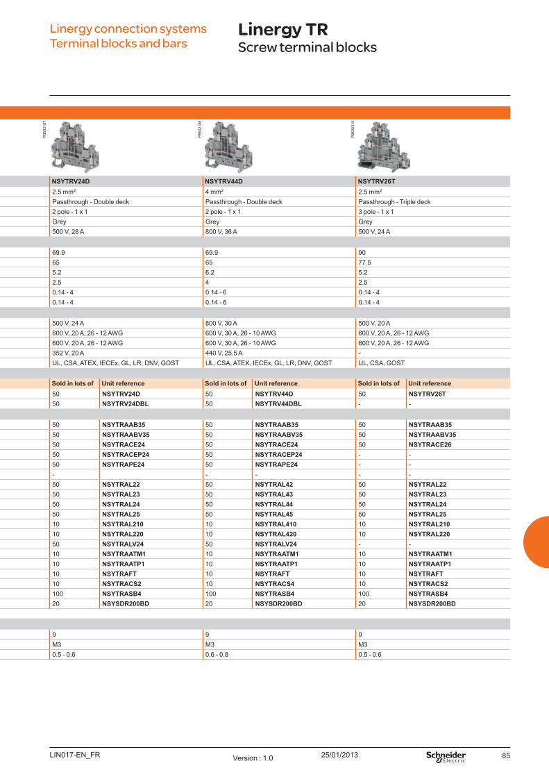
25/01/2013 85
Linergy connection systems Terminal blocks and bars
Linergy TRScrew terminal blocks
Screw t erm inal b l o ck s - Do u b l e d eck p asst h ro u gh
NSYTRV43 NSYTRV44 NSYTRV24D NSYTRV44D NSYTRV26TNominal c.s.a. 4 mm² 4 mm² 2.5 mm² 4 mm² 2.5 mm²
Type of block Passthrough - Multi-pole Passthrough - Multi-pole Passthrough - Double deck Passthrough - Double deck Passthrough - Triple deckType of connection 1 pole - 1 x 2 1 pole - 2 x 2 2 pole - 1 x 1 2 pole - 1 x 1 3 pole - 1 x 1Colour Grey Grey Grey Grey Grey
Max. electric values ( U max, Imax) 500 V, 41 A 500 V, 39 A 500 V, 28 A 800 V, 36 A 500 V, 24 ADim ensio ns (m m )
Length 57.8 65.4 69.9 69.9 90Height 47.5 47.5 65 65 77.5W idth 6.2 6.2 5.2 6.2 5.2
Cabling c.s.a. ( mm2) 4 4 2.5 4 2.5Flexible cable 0.14 - 6 0.14 - 6 0.14 - 4 0.14 - 6 0.14 - 4Solid cable 0.14 - 6 0.14 - 6 0.14 - 4 0.14 - 6 0.14 - 4
No m inal el ect ric v al u esIEC/EN 60947-7-1 500 V, 32 A 500 V, 32 A 500 V, 24 A 800 V, 30 A 500 V, 20 AU L 150 V, 30 A, 26 - 10 AW G 150 V, 30 A, 26 - 10 AW G 600 V, 20 A, 26 - 12 AW G 600 V, 30 A, 26 - 10 AW G 600 V, 20 A, 26 - 12 AW G CSA 150 V, 30 A, 26 - 10 AW G 150 V, 30 A, 26 - 10 AW G 600 V, 20 A, 26 - 12 AW G 600 V, 30 A, 26 - 10 AW G 600 V, 20 A, 26 - 12 AW G ATEX 352 V, 29 A 352 V, 29 A 352 V, 20 A 440 V, 25.5 A -
ertifications U L, CSA, ATEX, IECEx, GL, LR, DNV, GO ST U L, CSA, ATEX, IECEx, GL, LR, DNV, GO ST U L, CSA, ATEX, IECEx, GL, LR, DNV, GO ST U L, CSA, ATEX, IECEx, GL, LR, DNV, GO ST U L, CSA, GO STTerm inal b l o ck s
So l d in l o t s o f U nit reference So l d in l o t s o f U nit reference So l d in l o t s o f U nit reference So l d in l o t s o f U nit reference So l d in l o t s o f U nit referenceGrey 50 NSYTRV43 50 NSYTRV44 50 NSYTRV24D 50 NSYTRV44D 50 NSYTRV26TB lue 50 NSYTRV43BL 50 NSYTRV44BL 50 NSYTRV24DBL 50 NSYTRV44DBL - -
Accesso riesEnd stop Clip-on, 5.2 mm 50 NSYTRAAB35 50 NSYTRAAB35 50 NSYTRAAB35 50 NSYTRAAB35 50 NSYTRAAB35for 35 mm DIN rail W ith screw, 9.5 mm 50 NSYTRAABV35 50 NSYTRAABV35 50 NSYTRAABV35 50 NSYTRAABV35 50 NSYTRAABV35End plate, Grey 50 NSYTRAC23 50 NSYTRAC24 50 NSYTRACE24 50 NSYTRACE24 50 NSYTRACE26width 2.2 mm Grey, partial plate - - - - 50 NSYTRACEP24 50 NSYTRACEP24 - - Partition plate, Grey 50 NSYTRAP23 50 NSYTRAP24 50 NSYTRAPE24 50 NSYTRAPE24 - - width 2 mm B lue - - - - - - - - - Plug-in bridge 2-pole 50 NSYTRAL42 50 NSYTRAL42 50 NSYTRAL22 50 NSYTRAL42 50 NSYTRAL22Red 3-pole 50 NSYTRAL43 50 NSYTRAL43 50 NSYTRAL23 50 NSYTRAL43 50 NSYTRAL23
4-pole 50 NSYTRAL44 50 NSYTRAL44 50 NSYTRAL24 50 NSYTRAL44 50 NSYTRAL245-pole 50 NSYTRAL45 50 NSYTRAL45 50 NSYTRAL25 50 NSYTRAL45 50 NSYTRAL2510-pole 10 NSYTRAL410 10 NSYTRAL410 10 NSYTRAL210 10 NSYTRAL410 10 NSYTRAL21020-pole 10 NSYTRAL420 10 NSYTRAL420 10 NSYTRAL220 10 NSYTRAL420 10 NSYTRAL220
Vertical bridge 1-pole - - - - 50 NSYTRALV24 50 NSYTRALV24 - - Test plug Metalic part, Ø 2.3 mm 10 NSYTRAATM1 10 NSYTRAATM1 10 NSYTRAATM1 10 NSYTRAATM1 10 NSYTRAATM1
Insulating sleeve, red 10 NSYTRAATP1 10 NSYTRAATP1 10 NSYTRAATP1 10 NSYTRAATP1 10 NSYTRAATP1Test adaptor For plug-in bridge shaft 10 NSYTRAFT 10 NSYTRAFT 10 NSYTRAFT 10 NSYTRAFT 10 NSYTRAFTW arning label Y ellow 10 NSYTRACS4 10 NSYTRACS4 10 NSYTRACS2 10 NSYTRACS4 10 NSYTRACS2Marker tag holder For AB 35 end stop 100 NSYTRASB4 100 NSYTRASB4 100 NSYTRASB4 100 NSYTRASB4 100 NSYTRASB4DIN rail 35 x 7.2 mm Perforated, 2 m long 20 NSYSDR200BD 20 NSYSDR200BD 20 NSYSDR200BD 20 NSYSDR200BD 20 NSYSDR200BDMarking accessories See page 126General d at a
Strip length ( mm) 9 9 9 9 9Screw thread M3 M3 M3 M3 M3Torq ue ( Nm) 0.6 - 0.8 0.6 - 0.8 0.5 - 0.6 0.6 - 0.8 0.5 - 0.6
LIN017-EN_FR Version : 1.0
PB
5021
87
PB
5021
88
PB
5023
15
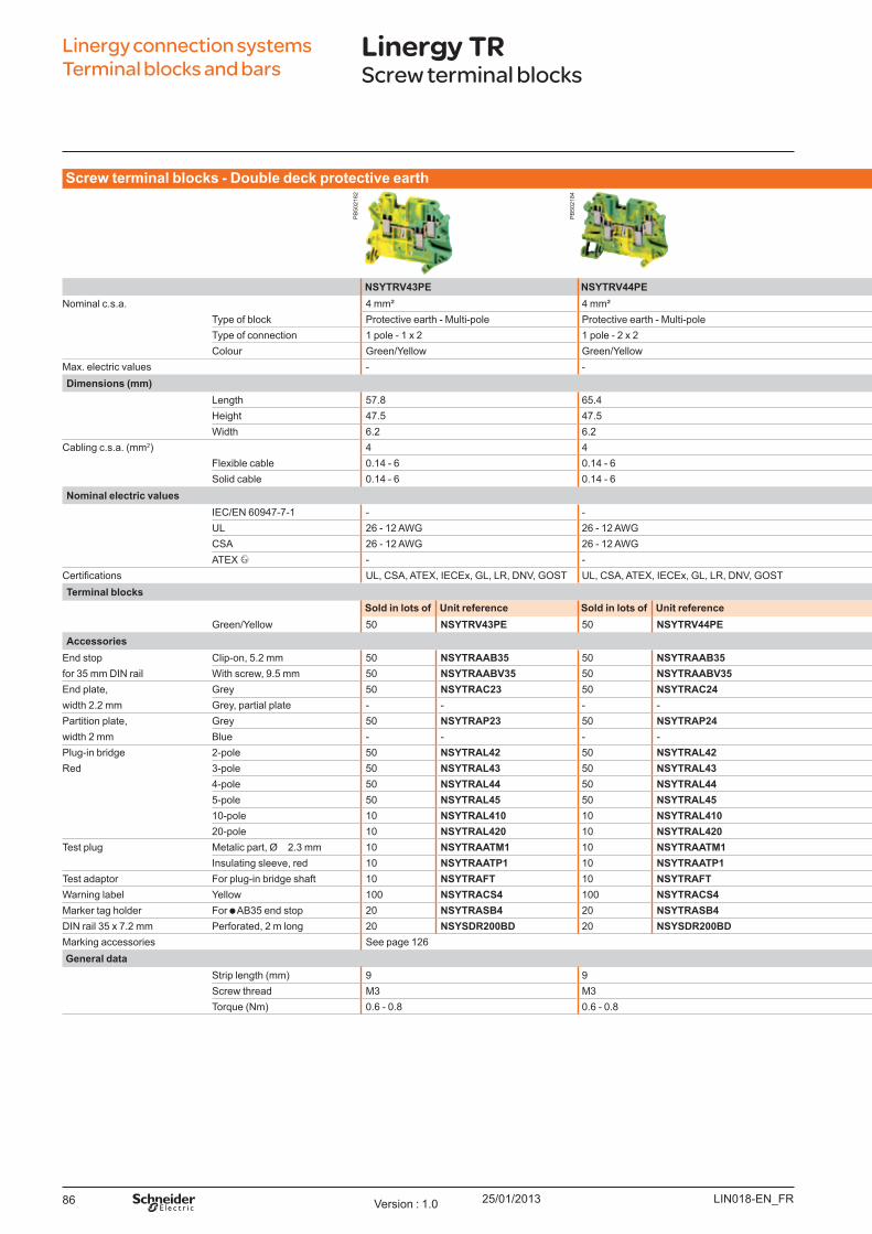
25/01/201386
Linergy connection systems Terminal blocks and bars
Linergy TRScrew terminal blocks
Screw t erm inal b l o ck s - Do u b l e d eck p ro t ect iv e eart h
NSYTRV43PE NSYTRV44PE NSYTRV24DPE NSYTRV44DPENominal c.s.a. 4 mm² 4 mm² 2.5 mm² 4 mm²
Type of block Protective earth - Multi-pole Protective earth - Multi-pole Protective earth - Double deck Protective earth - Double deckType of connection 1 pole - 1 x 2 1 pole - 2 x 2 1 pole - 2 x 2 1 pole - 2 x 2Colour Green/Y ellow Green/Y ellow Green/Y ellow Green/Y ellow
Max. electric values - - - -Dim ensio ns (m m )
Length 57.8 65.4 69.9 69.9Height 47.5 47.5 65 65W idth 6.2 6.2 5.2 6.2
Cabling c.s.a. ( mm2) 4 4 2.5 4Flexible cable 0.14 - 6 0.14 - 6 0.14 - 4 0.14 - 6Solid cable 0.14 - 6 0.14 - 6 0.14 - 4 0.14 - 6
No m inal el ect ric v al u esIEC/EN 60947-7-1 - - - - U L 26 - 12 AW G 26 - 12 AW G 26 - 12 AW G 26 - 10 AW GCSA 26 - 12 AW G 26 - 12 AW G 26 - 12 AW G 26 - 10 AW GATEX - - - -
ertifications U L, CSA, ATEX, IECEx, GL, LR, DNV, GO ST U L, CSA, ATEX, IECEx, GL, LR, DNV, GO ST U L, CSA, ATEX, IECEx, GL, LR, DNV, GO ST U L, CSA, ATEX, IECEx, GL, LR, DNV, GO STTerm inal b l o ck s
So l d in l o t s o f U nit reference So l d in l o t s o f U nit reference So l d in l o t s o f U nit reference So l d in l o t s o f U nit referenceGreen/Y ellow 50 NSYTRV43PE 50 NSYTRV44PE 50 NSYTRV24DPE 50 NSYTRV44DPE
Accesso riesEnd stop Clip-on, 5.2 mm 50 NSYTRAAB35 50 NSYTRAAB35 50 NSYTRAAB35 50 NSYTRAAB35for 35 mm DIN rail W ith screw, 9.5 mm 50 NSYTRAABV35 50 NSYTRAABV35 50 NSYTRAABV35 50 NSYTRAABV35End plate, Grey 50 NSYTRAC23 50 NSYTRAC24 50 NSYTRACE24 50 NSYTRACE24width 2.2 mm Grey, partial plate - - - - 50 NSYTRACEP24 50 NSYTRACEP24Partition plate, Grey 50 NSYTRAP23 50 NSYTRAP24 50 NSYTRAPE24 50 NSYTRAPE24width 2 mm B lue - - - - - - - - Plug-in bridge 2-pole 50 NSYTRAL42 50 NSYTRAL42 50 NSYTRAL22 50 NSYTRAL42Red 3-pole 50 NSYTRAL43 50 NSYTRAL43 50 NSYTRAL23 50 NSYTRAL43
4-pole 50 NSYTRAL44 50 NSYTRAL44 50 NSYTRAL24 50 NSYTRAL445-pole 50 NSYTRAL45 50 NSYTRAL45 50 NSYTRAL25 50 NSYTRAL4510-pole 10 NSYTRAL410 10 NSYTRAL410 10 NSYTRAL210 10 NSYTRAL41020-pole 10 NSYTRAL420 10 NSYTRAL420 10 NSYTRAL220 10 NSYTRAL420
Test plug Metalic part, Ø 2.3 mm 10 NSYTRAATM1 10 NSYTRAATM1 10 NSYTRAATM1 10 NSYTRAATM1Insulating sleeve, red 10 NSYTRAATP1 10 NSYTRAATP1 10 NSYTRAATP1 10 NSYTRAATP1
Test adaptor For plug-in bridge shaft 10 NSYTRAFT 10 NSYTRAFT 10 NSYTRAFT 10 NSYTRAFTW arning label Y ellow 100 NSYTRACS4 100 NSYTRACS4 100 NSYTRACS2 100 NSYTRACS4Marker tag holder For AB 35 end stop 20 NSYTRASB4 20 NSYTRASB4 20 NSYTRASB4 20 NSYTRASB4DIN rail 35 x 7.2 mm Perforated, 2 m long 20 NSYSDR200BD 20 NSYSDR200BD 20 NSYSDR200BD 20 NSYSDR200BDMarking accessories See page 126General d at a
Strip length ( mm) 9 9 9 9Screw thread M3 M3 M3 M3Torq ue ( Nm) 0.6 - 0.8 0.6 - 0.8 0.5 - 0.6 0.6 - 0.8
LIN018-EN_FRVersion : 1.0
PB
5021
82
PB
5021
84
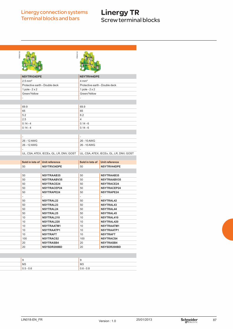
25/01/2013 87
Linergy connection systems Terminal blocks and bars
Linergy TRScrew terminal blocks
Screw t erm inal b l o ck s - Do u b l e d eck p ro t ect iv e eart h
NSYTRV43PE NSYTRV44PE NSYTRV24DPE NSYTRV44DPENominal c.s.a. 4 mm² 4 mm² 2.5 mm² 4 mm²
Type of block Protective earth - Multi-pole Protective earth - Multi-pole Protective earth - Double deck Protective earth - Double deckType of connection 1 pole - 1 x 2 1 pole - 2 x 2 1 pole - 2 x 2 1 pole - 2 x 2Colour Green/Y ellow Green/Y ellow Green/Y ellow Green/Y ellow
Max. electric values - - - -Dim ensio ns (m m )
Length 57.8 65.4 69.9 69.9Height 47.5 47.5 65 65W idth 6.2 6.2 5.2 6.2
Cabling c.s.a. ( mm2) 4 4 2.5 4Flexible cable 0.14 - 6 0.14 - 6 0.14 - 4 0.14 - 6Solid cable 0.14 - 6 0.14 - 6 0.14 - 4 0.14 - 6
No m inal el ect ric v al u esIEC/EN 60947-7-1 - - - - U L 26 - 12 AW G 26 - 12 AW G 26 - 12 AW G 26 - 10 AW GCSA 26 - 12 AW G 26 - 12 AW G 26 - 12 AW G 26 - 10 AW GATEX - - - -
ertifications U L, CSA, ATEX, IECEx, GL, LR, DNV, GO ST U L, CSA, ATEX, IECEx, GL, LR, DNV, GO ST U L, CSA, ATEX, IECEx, GL, LR, DNV, GO ST U L, CSA, ATEX, IECEx, GL, LR, DNV, GO STTerm inal b l o ck s
So l d in l o t s o f U nit reference So l d in l o t s o f U nit reference So l d in l o t s o f U nit reference So l d in l o t s o f U nit referenceGreen/Y ellow 50 NSYTRV43PE 50 NSYTRV44PE 50 NSYTRV24DPE 50 NSYTRV44DPE
Accesso riesEnd stop Clip-on, 5.2 mm 50 NSYTRAAB35 50 NSYTRAAB35 50 NSYTRAAB35 50 NSYTRAAB35for 35 mm DIN rail W ith screw, 9.5 mm 50 NSYTRAABV35 50 NSYTRAABV35 50 NSYTRAABV35 50 NSYTRAABV35End plate, Grey 50 NSYTRAC23 50 NSYTRAC24 50 NSYTRACE24 50 NSYTRACE24width 2.2 mm Grey, partial plate - - - - 50 NSYTRACEP24 50 NSYTRACEP24Partition plate, Grey 50 NSYTRAP23 50 NSYTRAP24 50 NSYTRAPE24 50 NSYTRAPE24width 2 mm B lue - - - - - - - - Plug-in bridge 2-pole 50 NSYTRAL42 50 NSYTRAL42 50 NSYTRAL22 50 NSYTRAL42Red 3-pole 50 NSYTRAL43 50 NSYTRAL43 50 NSYTRAL23 50 NSYTRAL43
4-pole 50 NSYTRAL44 50 NSYTRAL44 50 NSYTRAL24 50 NSYTRAL445-pole 50 NSYTRAL45 50 NSYTRAL45 50 NSYTRAL25 50 NSYTRAL4510-pole 10 NSYTRAL410 10 NSYTRAL410 10 NSYTRAL210 10 NSYTRAL41020-pole 10 NSYTRAL420 10 NSYTRAL420 10 NSYTRAL220 10 NSYTRAL420
Test plug Metalic part, Ø 2.3 mm 10 NSYTRAATM1 10 NSYTRAATM1 10 NSYTRAATM1 10 NSYTRAATM1Insulating sleeve, red 10 NSYTRAATP1 10 NSYTRAATP1 10 NSYTRAATP1 10 NSYTRAATP1
Test adaptor For plug-in bridge shaft 10 NSYTRAFT 10 NSYTRAFT 10 NSYTRAFT 10 NSYTRAFTW arning label Y ellow 100 NSYTRACS4 100 NSYTRACS4 100 NSYTRACS2 100 NSYTRACS4Marker tag holder For AB 35 end stop 20 NSYTRASB4 20 NSYTRASB4 20 NSYTRASB4 20 NSYTRASB4DIN rail 35 x 7.2 mm Perforated, 2 m long 20 NSYSDR200BD 20 NSYSDR200BD 20 NSYSDR200BD 20 NSYSDR200BDMarking accessories See page 126General d at a
Strip length ( mm) 9 9 9 9Screw thread M3 M3 M3 M3Torq ue ( Nm) 0.6 - 0.8 0.6 - 0.8 0.5 - 0.6 0.6 - 0.8
LIN018-EN_FR Version : 1.0
PB
5021
92
PB
5021
91
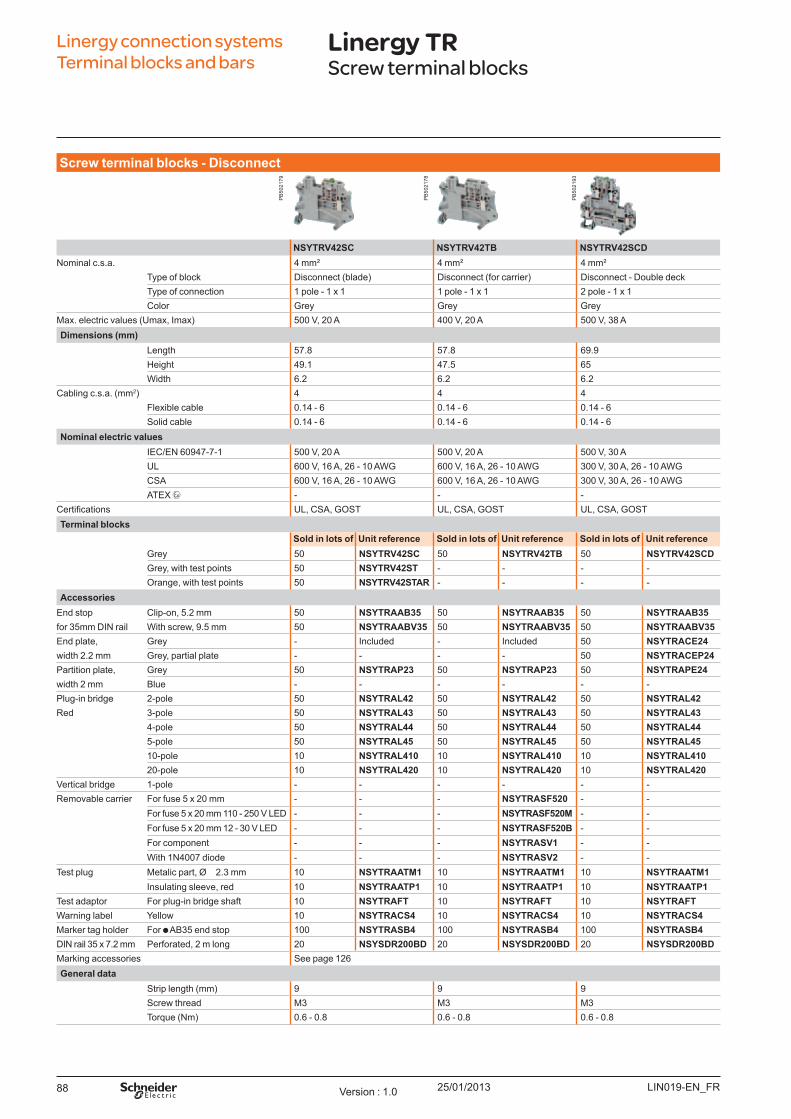
25/01/201388
Linergy connection systems Terminal blocks and bars
Linergy TRScrew terminal blocks
Screw t erm inal b l o ck s - Disco nnect
NSYTRV42SC NSYTRV42TB NSYTRV42SCDNominal c.s.a. 4 mm² 4 mm² 4 mm²
Type of block Disconnect ( blade) Disconnect ( for carrier) Disconnect - Double deckType of connection 1 pole - 1 x 1 1 pole - 1 x 1 2 pole - 1 x 1Color Grey Grey Grey
Max. electric values ( U max, Imax) 500 V, 20 A 400 V, 20 A 500 V, 38 ADim ensio ns (m m )
Length 57.8 57.8 69.9Height 49.1 47.5 65W idth 6.2 6.2 6.2
Cabling c.s.a. ( mm2) 4 4 4Flexible cable 0.14 - 6 0.14 - 6 0.14 - 6Solid cable 0.14 - 6 0.14 - 6 0.14 - 6
No m inal el ect ric v al u esIEC/EN 60947-7-1 500 V, 20 A 500 V, 20 A 500 V, 30 AU L 600 V, 16 A, 26 - 10 AW G 600 V, 16 A, 26 - 10 AW G 300 V, 30 A, 26 - 10 AW GCSA 600 V, 16 A, 26 - 10 AW G 600 V, 16 A, 26 - 10 AW G 300 V, 30 A, 26 - 10 AW GATEX - - -
ertifications U L, CSA, GO ST U L, CSA, GO ST U L, CSA, GO STTerm inal b l o ck s
So l d in l o t s o f U nit reference So l d in l o t s o f U nit reference So l d in l o t s o f U nit referenceGrey 50 NSYTRV42SC 50 NSYTRV42TB 50 NSYTRV42SCDGrey, with test points 50 NSYTRV42ST - - - - O range, with test points 50 NSYTRV42STAR - - - -
Accesso riesEnd stop Clip-on, 5.2 mm 50 NSYTRAAB35 50 NSYTRAAB35 50 NSYTRAAB35for 35mm DIN rail W ith screw, 9.5 mm 50 NSYTRAABV35 50 NSYTRAABV35 50 NSYTRAABV35End plate, Grey - Included - Included 50 NSYTRACE24width 2.2 mm Grey, partial plate - - - - 50 NSYTRACEP24Partition plate, Grey 50 NSYTRAP23 50 NSYTRAP23 50 NSYTRAPE24width 2 mm B lue - - - - - - Plug-in bridge 2-pole 50 NSYTRAL42 50 NSYTRAL42 50 NSYTRAL42Red 3-pole 50 NSYTRAL43 50 NSYTRAL43 50 NSYTRAL43
4-pole 50 NSYTRAL44 50 NSYTRAL44 50 NSYTRAL445-pole 50 NSYTRAL45 50 NSYTRAL45 50 NSYTRAL4510-pole 10 NSYTRAL410 10 NSYTRAL410 10 NSYTRAL41020-pole 10 NSYTRAL420 10 NSYTRAL420 10 NSYTRAL420
Vertical bridge 1-pole - - - - - - Removable carrier For fuse 5 x 20 mm - - - NSYTRASF520 - -
For fuse 5 x 20 mm 110 - 250 V LED - - - NSYTRASF520M - -For fuse 5 x 20 mm 12 - 30 V LED - - - NSYTRASF520B - -For component - - - NSYTRASV1 - -W ith 1N4007 diode - - - NSYTRASV2 - -
Test plug Metalic part, Ø 2.3 mm 10 NSYTRAATM1 10 NSYTRAATM1 10 NSYTRAATM1Insulating sleeve, red 10 NSYTRAATP1 10 NSYTRAATP1 10 NSYTRAATP1
Test adaptor For plug-in bridge shaft 10 NSYTRAFT 10 NSYTRAFT 10 NSYTRAFTW arning label Y ellow 10 NSYTRACS4 10 NSYTRACS4 10 NSYTRACS4Marker tag holder For AB 35 end stop 100 NSYTRASB4 100 NSYTRASB4 100 NSYTRASB4DIN rail 35 x 7.2 mm Perforated, 2 m long 20 NSYSDR200BD 20 NSYSDR200BD 20 NSYSDR200BDMarking accessories See page 126General d at a
Strip length ( mm) 9 9 9Screw thread M3 M3 M3Torq ue ( Nm) 0.6 - 0.8 0.6 - 0.8 0.6 - 0.8
LIN019-EN_FRVersion : 1.0
PB
5021
79
PB
5021
78
PB
5021
93
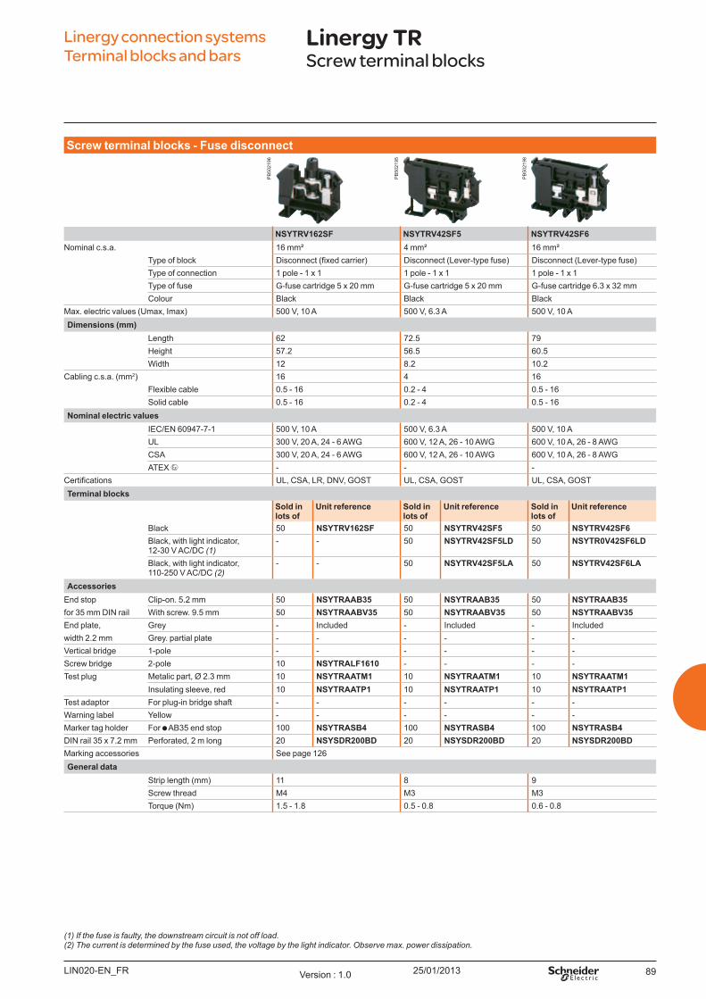
25/01/2013 89
Linergy connection systems Terminal blocks and bars
Linergy TRScrew terminal blocks
Screw t erm inal b l o ck s - Fu se d isco nnect
NSYTRV162SF NSYTRV42SF5 NSYTRV42SF6Nominal c.s.a. 16 mm² 4 mm² 16 mm²
Type of block Disconnect (fixed carrier) Disconnect (Lever-type fuse) Disconnect (Lever-type fuse)Type of connection 1 pole - 1 x 1 1 pole - 1 x 1 1 pole - 1 x 1ype of fuse G-fuse cartridge 5 x 20 mm G-fuse cartridge 5 x 20 mm G-fuse cartridge 6.3 x 32 mmolour B lack B lack B lack
ax. electric values (Umax, Imax) 500 V, 10 A 500 V, 6.3 A 500 V, 10 ADim ensio ns (m m )
Length 62 72.5 79Height 57.2 56.5 60.5Width 12 8.2 10.2
abling c.s.a. (mm2) 16 4 16Flexible cable 0.5 - 16 0.2 - 4 0.5 - 16Solid cable 0.5 - 16 0.2 - 4 0.5 - 16
No m inal el ect ric v al u esIE /EN 60947-7-1 500 V, 10 A 500 V, 6.3 A 500 V, 10 AUL 300 V, 20 A, 24 - 6 AWG 600 V, 12 A, 26 - 10 AWG 600 V, 10 A, 26 - 8 AWG
SA 300 V, 20 A, 24 - 6 AWG 600 V, 12 A, 26 - 10 AWG 600 V, 10 A, 26 - 8 AWGA E - - -
ertifications UL, SA, L , DNV, GOS UL, SA, GOS UL, SA, GOSTerm inal b l o ck s
So l d in l o t s o f
U nit reference So l d in l o t s o f
U nit reference So l d in l o t s o f
U nit reference
B lack 50 NSYTRV162SF 50 NSYTRV42SF5 50 NSYTRV42SF6Black, with light indicator, 12-30 V A /D (1)
- - 50 NSYTRV42SF5LD 50 NSYTR0V42SF6LD
Black, with light indicator, 110-250 V A /D (2)
- - 50 NSYTRV42SF5LA 50 NSYTRV42SF6LA
Accesso riesEnd stop lip-on. 5.2 mm 50 NSYTRAAB35 50 NSYTRAAB35 50 NSYTRAAB35for 35 mm DIN rail With screw. 9.5 mm 50 NSYTRAABV35 50 NSYTRAABV35 50 NSYTRAABV35End plate, Grey - Included - Included - Includedwidth 2.2 mm Grey. partial plate - - - - - - Vertical bridge 1-pole - - - - - - Screw bridge 2-pole 10 NSYTRALF1610 - - - -est plug etalic part, Ø 2.3 mm 10 NSYTRAATM1 10 NSYTRAATM1 10 NSYTRAATM1
Insulating sleeve, red 10 NSYTRAATP1 10 NSYTRAATP1 10 NSYTRAATP1est adaptor For plug-in bridge shaft - - - - - -
Warning label Yellow - - - - - - arker tag holder For AB35 end stop 100 NSYTRASB4 100 NSYTRASB4 100 NSYTRASB4
DIN rail 35 x 7.2 mm Perforated, 2 m long 20 NSYSDR200BD 20 NSYSDR200BD 20 NSYSDR200BDarking accessories See page 126
General d at aStrip length (mm) 11 8 9Screw thread M4 M3 M3orque (Nm) 1.5 - 1.8 0.5 - 0.8 0.6 - 0.8
(1) If the fuse is faulty, the downstream circuit is not off load.(2) The current is determined by the fuse used, the voltage by the light indicator. Observe max. power dissipation.
LIN020-EN F Version 1.0
PB
5021
96
PB
5021
95
PB
5021
98
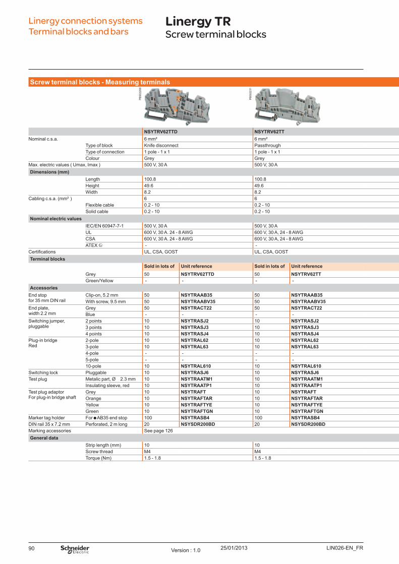
25/01/201390
Screw t erm inal b l o ck s - Measu ring t erm inal s
NSYTRV62TTD NSYTRV62TT NSYTRV62TTPENominal c.s.a. 6 mm² 6 mm² 6 mm²
Type of block K nife disconnect Passthrough Protective earthType of connection 1 pole - 1 x 1 1 pole - 1 x 1 1 pole - 1 x 1Colour Grey Grey Green/Y ellow
Max. electric values ( U max, Imax ) 500 V, 30 A 500 V, 30 A - Dim ensio ns (m m )
Length 100.8 100.8 100.8Height 49.6 49.6 49.6W idth 8.2 8.2 8.2
Cabling c.s.a. ( mm² ) 6 6 6Flexible cable 0.2 - 10 0.2 - 10 0.2 - 10Solid cable 0.2 - 10 0.2 - 10 0.2 - 10
No m inal el ect ric v al u esIEC/EN 60947-7-1 500 V, 30 A 500 V, 30 A - U L 600 V, 30 A. 24 - 8 AW G 600 V, 30 A, 24 - 8 AW G 24 - 8 AW GCSA 600 V, 30 A. 24 - 8 AW G 600 V, 30 A, 24 - 8 AW G 24 - 8 AW GATEX - - -
ertifications U L, CSA, GO ST U L, CSA, GO ST U L, CSA, GO STTerm inal b l o ck s
So l d in l o t s o f U nit reference So l d in l o t s o f U nit reference So l d in l o t s o f U nit referenceGrey 50 NSYTRV62TTD 50 NSYTRV62TT - - Green/Y ellow - - - - 50 NSYTRV62TTPE
Accesso riesEnd stopfor 35 mm DIN rail
Clip-on, 5.2 mm 50 NSYTRAAB35 50 NSYTRAAB35 50 NSYTRAAB35W ith screw, 9.5 mm 50 NSYTRAABV35 50 NSYTRAABV35 50 NSYTRAABV35
End plate,width 2.2 mm
Grey 50 NSYTRACT22 50 NSYTRACT22 50 NSYTRACT22B lue - - - - - -
Switching j umper,pluggable
2 points 10 NSYTRASJ2 10 NSYTRASJ2 - - 3 points 10 NSYTRASJ3 10 NSYTRASJ3 - - 4 points 10 NSYTRASJ4 10 NSYTRASJ4 - -
Plug-in bridgeRed
2-pole 10 NSYTRAL62 10 NSYTRAL62 10 NSYTRAL623-pole 10 NSYTRAL63 10 NSYTRAL63 10 NSYTRAL634-pole - - - - - - 5-pole - - - - - - 10-pole 10 NSYTRAL610 10 NSYTRAL610 10 NSYTRAL610
Switching lock Pluggable 10 NSYTRASJ6 10 NSYTRASJ6 - - Test plug Metalic part, Ø 2.3 mm 10 NSYTRAATM1 10 NSYTRAATM1 10 NSYTRAATM1
Insulating sleeve, red 10 NSYTRAATP1 10 NSYTRAATP1 10 NSYTRAATP1Test plug adaptorFor plug-in bridge shaft
Grey 10 NSYTRAFT 10 NSYTRAFT 10 NSYTRAFTO range 10 NSYTRAFTAR 10 NSYTRAFTAR 10 NSYTRAFTARY ellow 10 NSYTRAFTYE 10 NSYTRAFTYE 10 NSYTRAFTYEGreen 10 NSYTRAFTGN 10 NSYTRAFTGN 10 NSYTRAFTGN
Marker tag holder For AB 35 end stop 100 NSYTRASB4 100 NSYTRASB4 100 NSYTRASB4DIN rail 35 x 7.2 mm Perforated, 2 m long 20 NSYSDR200BD 20 NSYSDR200BD 20 NSYSDR200BDMarking accessories See page 126General d at a
Strip length ( mm) 10 10 10Screw thread M4 M4 M4Torq ue ( Nm) 1.5 - 1.8 1.5 - 1.8 1.5 - 1.8
Linergy connection systems Terminal blocks and bars
Linergy TRScrew terminal blocks
LIN026-EN_FRVersion : 1.0
PB
5022
08
PB
5022
11
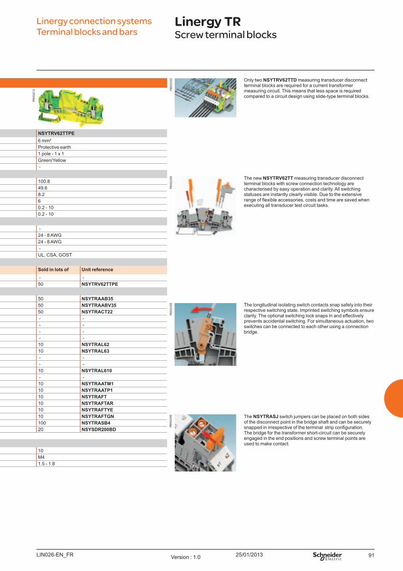
25/01/2013 91
Screw t erm inal b l o ck s - Measu ring t erm inal s
NSYTRV62TTD NSYTRV62TT NSYTRV62TTPENominal c.s.a. 6 mm² 6 mm² 6 mm²
Type of block K nife disconnect Passthrough Protective earthType of connection 1 pole - 1 x 1 1 pole - 1 x 1 1 pole - 1 x 1Colour Grey Grey Green/Y ellow
Max. electric values ( U max, Imax ) 500 V, 30 A 500 V, 30 A - Dim ensio ns (m m )
Length 100.8 100.8 100.8Height 49.6 49.6 49.6W idth 8.2 8.2 8.2
Cabling c.s.a. ( mm² ) 6 6 6Flexible cable 0.2 - 10 0.2 - 10 0.2 - 10Solid cable 0.2 - 10 0.2 - 10 0.2 - 10
No m inal el ect ric v al u esIEC/EN 60947-7-1 500 V, 30 A 500 V, 30 A - U L 600 V, 30 A. 24 - 8 AW G 600 V, 30 A, 24 - 8 AW G 24 - 8 AW GCSA 600 V, 30 A. 24 - 8 AW G 600 V, 30 A, 24 - 8 AW G 24 - 8 AW GATEX - - -
ertifications U L, CSA, GO ST U L, CSA, GO ST U L, CSA, GO STTerm inal b l o ck s
So l d in l o t s o f U nit reference So l d in l o t s o f U nit reference So l d in l o t s o f U nit referenceGrey 50 NSYTRV62TTD 50 NSYTRV62TT - - Green/Y ellow - - - - 50 NSYTRV62TTPE
Accesso riesEnd stopfor 35 mm DIN rail
Clip-on, 5.2 mm 50 NSYTRAAB35 50 NSYTRAAB35 50 NSYTRAAB35W ith screw, 9.5 mm 50 NSYTRAABV35 50 NSYTRAABV35 50 NSYTRAABV35
End plate,width 2.2 mm
Grey 50 NSYTRACT22 50 NSYTRACT22 50 NSYTRACT22B lue - - - - - -
Switching j umper,pluggable
2 points 10 NSYTRASJ2 10 NSYTRASJ2 - - 3 points 10 NSYTRASJ3 10 NSYTRASJ3 - - 4 points 10 NSYTRASJ4 10 NSYTRASJ4 - -
Plug-in bridgeRed
2-pole 10 NSYTRAL62 10 NSYTRAL62 10 NSYTRAL623-pole 10 NSYTRAL63 10 NSYTRAL63 10 NSYTRAL634-pole - - - - - - 5-pole - - - - - - 10-pole 10 NSYTRAL610 10 NSYTRAL610 10 NSYTRAL610
Switching lock Pluggable 10 NSYTRASJ6 10 NSYTRASJ6 - - Test plug Metalic part, Ø 2.3 mm 10 NSYTRAATM1 10 NSYTRAATM1 10 NSYTRAATM1
Insulating sleeve, red 10 NSYTRAATP1 10 NSYTRAATP1 10 NSYTRAATP1Test plug adaptorFor plug-in bridge shaft
Grey 10 NSYTRAFT 10 NSYTRAFT 10 NSYTRAFTO range 10 NSYTRAFTAR 10 NSYTRAFTAR 10 NSYTRAFTARY ellow 10 NSYTRAFTYE 10 NSYTRAFTYE 10 NSYTRAFTYEGreen 10 NSYTRAFTGN 10 NSYTRAFTGN 10 NSYTRAFTGN
Marker tag holder For AB 35 end stop 100 NSYTRASB4 100 NSYTRASB4 100 NSYTRASB4DIN rail 35 x 7.2 mm Perforated, 2 m long 20 NSYSDR200BD 20 NSYSDR200BD 20 NSYSDR200BDMarking accessories See page 126General d at a
Strip length ( mm) 10 10 10Screw thread M4 M4 M4Torq ue ( Nm) 1.5 - 1.8 1.5 - 1.8 1.5 - 1.8
O nly two NSYTRV62TTD measuring transducer disconnect terminal blocks are req uired for a current transformer measuring circuit. This means that less space is req uired compared to a circuit design using slide-type terminal blocks.
The new NSYTRV62TT measuring transducer disconnect terminal blocks with screw connection technology are characterised by easy operation and clarity. All switching statuses are instantly clearly visible. Due to the extensive range of flexible accessories, costs and time are saved when executing all transducer test circuit tasks.
The longitudinal isolating switch contacts snap safely into their respective switching state. Imprinted switching symbols ensure clarity. The optional switching lock snaps in and effectively prevents accidental switching. For simultaneous actuation, two switches can be connected to each other using a connection bridge.
The NSYTRASJ switch j umpers can be placed on both sides of the disconnect point in the bridge shaft and can be securely snapped in irrespective of the terminal strip configuration. The bridge for the transformer short-circuit can be securely engaged in the end positions and screw terminal points are used to make contact.
Linergy connection systems Terminal blocks and bars
Linergy TRScrew terminal blocks
LIN026-EN_FR Version : 1.0
PB
5022
12 PB
5023
55P
B50
2359
PB
5023
58P
B50
2356
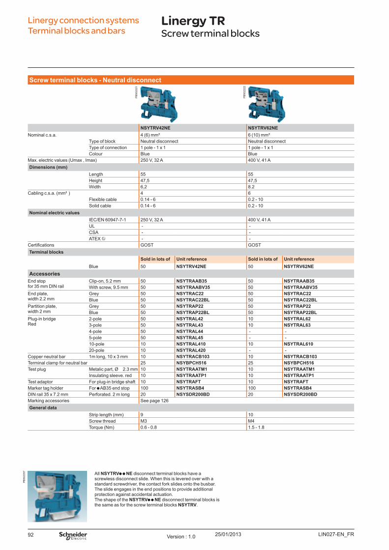
25/01/201392
Screw t erm inal b l o ck s - Neu t ral d isco nnect
NSYTRV42NE NSYTRV62NENominal c.s.a. 4 ( 6) mm² 6 ( 10) mm²
Type of block Neutral disconnect Neutral disconnectType of connection 1 pole - 1 x 1 1 pole - 1 x 1Colour B lue B lue
Max. electric values ( U max , Imax) 250 V, 32 A 400 V, 41 ADim ensio ns (m m )
Length 55 55Height 47,5 47,5W idth 6,2 8.2
Cabling c.s.a. ( mm² ) 4 6Flexible cable 0.14 - 6 0.2 - 10Solid cable 0.14 - 6 0.2 - 10
No m inal el ect ric v al u esIEC/EN 60947-7-1 250 V, 32 A 400 V, 41 AU L - - CSA - - ATEX - -
ertifications GO ST GO STTerm inal b l o ck s
So l d in l o t s o f U nit reference So l d in l o t s o f U nit referenceB lue 50 NSYTRV42NE 50 NSYTRV62NE
Accesso riesEnd stopfor 35 mm DIN rail
Clip-on, 5.2 mm 50 NSYTRAAB35 50 NSYTRAAB35W ith screw, 9.5 mm 50 NSYTRAABV35 50 NSYTRAABV35
End plate,width 2.2 mm
Grey 50 NSYTRAC22 50 NSYTRAC22B lue 50 NSYTRAC22BL 50 NSYTRAC22BL
Partition plate,width 2 mm
Grey 50 NSYTRAP22 50 NSYTRAP22B lue 50 NSYTRAP22BL 50 NSYTRAP22BL
Plug-in bridgeRed
2-pole 50 NSYTRAL42 10 NSYTRAL623-pole 50 NSYTRAL43 10 NSYTRAL634-pole 50 NSYTRAL44 - - 5-pole 50 NSYTRAL45 - - 10-pole 10 NSYTRAL410 10 NSYTRAL61020-pole 10 NSYTRAL420 - -
Copper neutral bar 1m long, 10 x 3 mm 10 NSYTRACB103 10 NSYTRACB103Terminal clamp for neutral bar 25 NSYBPCH516 25 NSYBPCH516Test plug Metalic part, Ø 2.3 mm 10 NSYTRAATM1 10 NSYTRAATM1
Insulating sleeve. red 10 NSYTRAATP1 10 NSYTRAATP1Test adaptor For plug-in bridge shaft 10 NSYTRAFT 10 NSYTRAFTMarker tag holder For AB 35 end stop 100 NSYTRASB4 100 NSYTRASB4DIN rail 35 x 7.2 mm Perforated. 2 m long 20 NSYSDR200BD 20 NSYSDR200BDMarking accessories See page 126General d at a
Strip length ( mm) 9 10Screw thread M3 M4Torq ue ( Nm) 0.6 - 0.8 1.5 - 1.8
All NSYTRV NE disconnect terminal blocks have a screwless disconnect slide. W hen this is levered over with a standard screwdriver, the contact fork slides onto the busbar. The slide engages in the end positions to provide additional protection against accidental actuation.The shape of the NSYTRV NE disconnect terminal blocks is the same as for the screw terminal blocks NSYTRV.
Linergy connection systems Terminal blocks and bars
Linergy TRScrew terminal blocks
LIN027-EN_FRVersion : 1.0
PB
5022
21
PB
5022
22
PB
5023
57

25/01/2013 93LIN027-EN_FR Version : 1.0
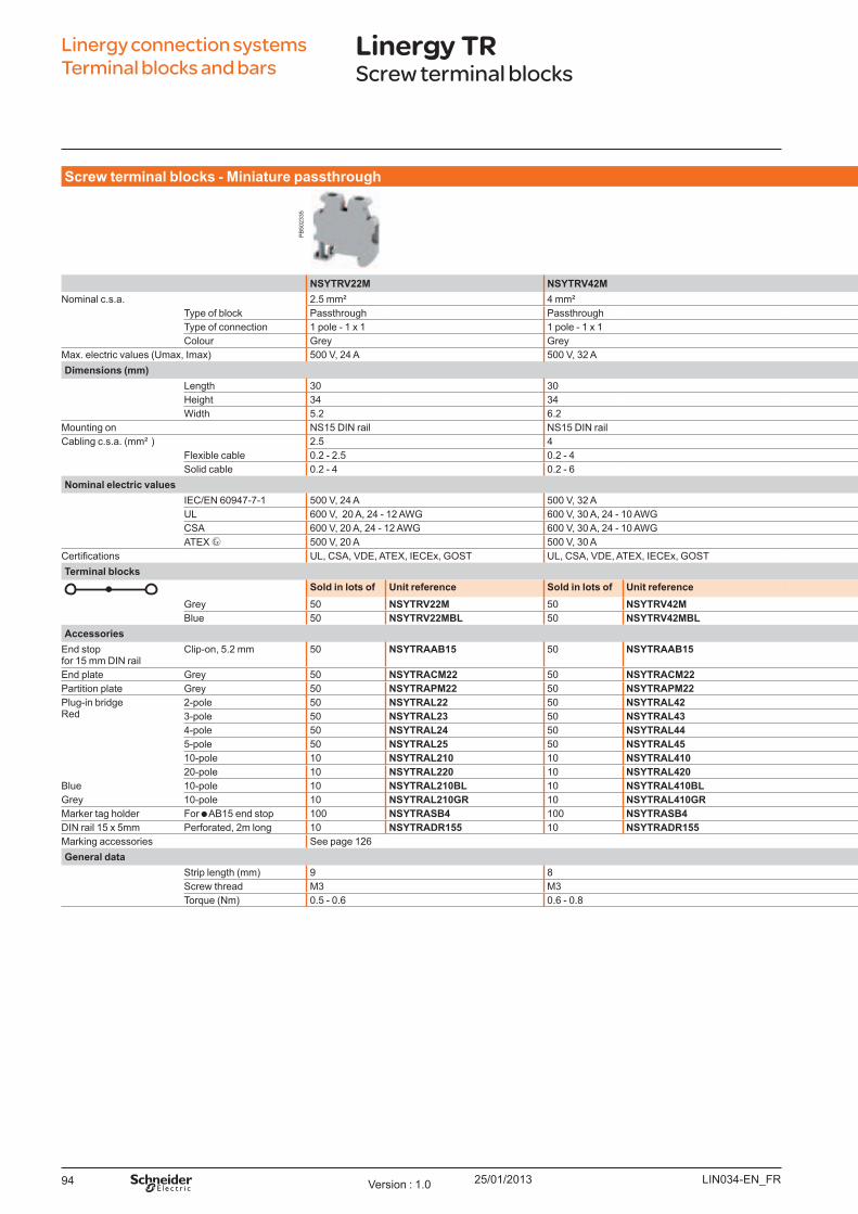
25/01/201394
Screw t erm inal b l o ck s - Miniat u re p asst h ro u gh Screw t erm inal b l o ck s - Miniat u re p ro t ect iv e eart h
NSYTRV22M NSYTRV42M NSYTRV22MPE NSYTRV42MPENominal c.s.a. 2.5 mm² 4 mm² 2.5 mm² 4 mm²
Type of block Passthrough Passthrough Protective earth Protective earthType of connection 1 pole - 1 x 1 1 pole - 1 x 1 1 pole - 1 x 1 1 pole - 1 x 1Colour Grey Grey Green/Y ellow Green/Y ellow
Max. electric values ( U max, Imax) 500 V, 24 A 500 V, 32 A - -Dim ensio ns (m m )
Length 30 30 30 30Height 34 34 34 34W idth 5.2 6.2 5.2 6.2
Mounting on NS15 DIN rail NS15 DIN rail NS15 DIN rail NS15 DIN railCabling c.s.a. ( mm² ) 2.5 4 2.5 4
Flexible cable 0.2 - 2.5 0.2 - 4 0.2 - 2.5 0.2 - 4Solid cable 0.2 - 4 0.2 - 6 0.2 - 4 0.2 - 6
No m inal el ect ric v al u esIEC/EN 60947-7-1 500 V, 24 A 500 V, 32 A - -U L 600 V, 20 A, 24 - 12 AW G 600 V, 30 A, 24 - 10 AW G 24 - 12 AW G 24 - 10 AW GCSA 600 V, 20 A, 24 - 12 AW G 600 V, 30 A, 24 - 10 AW G 24 - 12 AW G 24 - 10 AW GATEX 500 V, 20 A 500 V, 30 A - -
ertifications U L, CSA, VDE, ATEX, IECEx, GO ST U L, CSA, VDE, ATEX, IECEx, GO ST U L, CSA, VDE, ATEX, IECEx, GO ST U L, CSA, VDE, ATEX, IECEx, GO STTerm inal b l o ck s
So l d in l o t s o f U nit reference So l d in l o t s o f U nit reference So l d in l o t s o f U nit reference So l d in l o t s o f U nit referenceGrey 50 NSYTRV22M 50 NSYTRV42M 50 NSYTRV22MPE 50 NSYTRV42MPEB lue 50 NSYTRV22MBL 50 NSYTRV42MBL - - - -
Accesso riesEnd stopfor 15 mm DIN rail
Clip-on, 5.2 mm 50 NSYTRAAB15 50 NSYTRAAB15 50 NSYTRAAB15 50 NSYTRAAB15
End plate Grey 50 NSYTRACM22 50 NSYTRACM22 50 NSYTRACM22 50 NSYTRACM22Partition plate Grey 50 NSYTRAPM22 50 NSYTRAPM22 50 NSYTRAPM22 50 NSYTRAPM22Plug-in bridgeRed
2-pole 50 NSYTRAL22 50 NSYTRAL42 - - - - 3-pole 50 NSYTRAL23 50 NSYTRAL43 - - - - 4-pole 50 NSYTRAL24 50 NSYTRAL44 - - - - 5-pole 50 NSYTRAL25 50 NSYTRAL45 - - - - 10-pole 10 NSYTRAL210 10 NSYTRAL410 - - - - 20-pole 10 NSYTRAL220 10 NSYTRAL420 - - - -
B lue 10-pole 10 NSYTRAL210BL 10 NSYTRAL410BL - - - - Grey 10-pole 10 NSYTRAL210GR 10 NSYTRAL410GR - - - - Marker tag holder For AB 15 end stop 100 NSYTRASB4 100 NSYTRASB4 100 NSYTRASB4 100 NSYTRASB4DIN rail 15 x 5mm Perforated, 2m long 10 NSYTRADR155 10 NSYTRADR155 10 NSYTRADR155 10 NSYTRADR155Marking accessories See page 126General d at a
Strip length ( mm) 9 8 9 8Screw thread M3 M3 M3 M3Torq ue ( Nm) 0.5 - 0.6 0.6 - 0.8 0.5 - 0.6 0.6 - 0.8
Linergy connection systems Terminal blocks and bars
Linergy TRScrew terminal blocks
LIN034-EN_FRVersion : 1.0
PB
5023
35
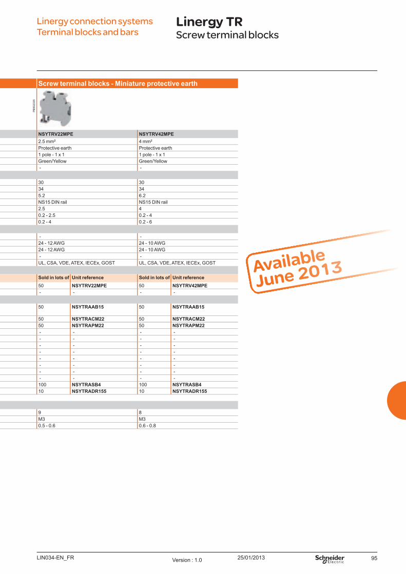
25/01/2013 95
Screw t erm inal b l o ck s - Miniat u re p asst h ro u gh Screw t erm inal b l o ck s - Miniat u re p ro t ect iv e eart h
NSYTRV22M NSYTRV42M NSYTRV22MPE NSYTRV42MPENominal c.s.a. 2.5 mm² 4 mm² 2.5 mm² 4 mm²
Type of block Passthrough Passthrough Protective earth Protective earthType of connection 1 pole - 1 x 1 1 pole - 1 x 1 1 pole - 1 x 1 1 pole - 1 x 1Colour Grey Grey Green/Y ellow Green/Y ellow
Max. electric values ( U max, Imax) 500 V, 24 A 500 V, 32 A - -Dim ensio ns (m m )
Length 30 30 30 30Height 34 34 34 34W idth 5.2 6.2 5.2 6.2
Mounting on NS15 DIN rail NS15 DIN rail NS15 DIN rail NS15 DIN railCabling c.s.a. ( mm² ) 2.5 4 2.5 4
Flexible cable 0.2 - 2.5 0.2 - 4 0.2 - 2.5 0.2 - 4Solid cable 0.2 - 4 0.2 - 6 0.2 - 4 0.2 - 6
No m inal el ect ric v al u esIEC/EN 60947-7-1 500 V, 24 A 500 V, 32 A - -U L 600 V, 20 A, 24 - 12 AW G 600 V, 30 A, 24 - 10 AW G 24 - 12 AW G 24 - 10 AW GCSA 600 V, 20 A, 24 - 12 AW G 600 V, 30 A, 24 - 10 AW G 24 - 12 AW G 24 - 10 AW GATEX 500 V, 20 A 500 V, 30 A - -
ertifi cations U L, CSA, VDE, ATEX, IECEx, GO ST U L, CSA, VDE, ATEX, IECEx, GO ST U L, CSA, VDE, ATEX, IECEx, GO ST U L, CSA, VDE, ATEX, IECEx, GO STTerm inal b l o ck s
So l d in l o t s o f U nit reference So l d in l o t s o f U nit reference So l d in l o t s o f U nit reference So l d in l o t s o f U nit referenceGrey 50 NSYTRV22M 50 NSYTRV42M 50 NSYTRV22MPE 50 NSYTRV42MPEB lue 50 NSYTRV22MBL 50 NSYTRV42MBL - - - -
Accesso riesEnd stopfor 15 mm DIN rail
Clip-on, 5.2 mm 50 NSYTRAAB15 50 NSYTRAAB15 50 NSYTRAAB15 50 NSYTRAAB15
End plate Grey 50 NSYTRACM22 50 NSYTRACM22 50 NSYTRACM22 50 NSYTRACM22Partition plate Grey 50 NSYTRAPM22 50 NSYTRAPM22 50 NSYTRAPM22 50 NSYTRAPM22Plug-in bridgeRed
2-pole 50 NSYTRAL22 50 NSYTRAL42 - - - - 3-pole 50 NSYTRAL23 50 NSYTRAL43 - - - - 4-pole 50 NSYTRAL24 50 NSYTRAL44 - - - - 5-pole 50 NSYTRAL25 50 NSYTRAL45 - - - - 10-pole 10 NSYTRAL210 10 NSYTRAL410 - - - - 20-pole 10 NSYTRAL220 10 NSYTRAL420 - - - -
B lue 10-pole 10 NSYTRAL210BL 10 NSYTRAL410BL - - - - Grey 10-pole 10 NSYTRAL210GR 10 NSYTRAL410GR - - - - Marker tag holder For AB 15 end stop 100 NSYTRASB4 100 NSYTRASB4 100 NSYTRASB4 100 NSYTRASB4DIN rail 15 x 5mm Perforated, 2m long 10 NSYTRADR155 10 NSYTRADR155 10 NSYTRADR155 10 NSYTRADR155Marking accessories See page 126General d at a
Strip length ( mm) 9 8 9 8Screw thread M3 M3 M3 M3Torq ue ( Nm) 0.5 - 0.6 0.6 - 0.8 0.5 - 0.6 0.6 - 0.8
Available
June 2013
Linergy connection systemsTerminal blocks and bars
Linergy TRScrew terminal blocks
LIN034-EN_FR Version : 1.0
PB
5023
35
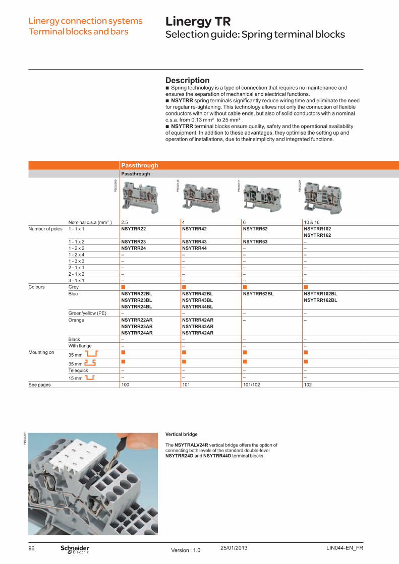
25/01/201396
Linergy connection systems Terminal blocks and bars
Linergy TRSelection guide: Spring terminal blocks
Vert ical b rid ge
The NSYTRALV24R vertical bridge offers the option of connecting both levels of the standard double-level NSYTRR24D and NSYTRR44D terminal blocks.
Passt h ro u gh Pro t ect iv e eart hPasst h ro u gh
Nominal c.s.a ( mm² ) 2.5 4 6 10 & 16 2.5 4 6 10 & 16Number of poles 1 - 1 x 1 NSYTRR22 NSYTRR42 NSYTRR62 NSYTRR102 NSYTRR22PE NSYTRR42PE NSYTRR62PE NSYTRR102PE
NSYTRR162 NSYTRR162PE1 - 1 x 2 NSYTRR23 NSYTRR43 NSYTRR63 – NSYTRR23PE NSYTRR43PE – –1 - 2 x 2 NSYTRR24 NSYTRR44 – – NSYTRR24PE NSYTRR44PE – –1 - 2 x 4 – – – – – – – –1 - 3 x 3 – – – – – – – –2 - 1 x 1 – – – – – – – –2 - 1 x 2 – – – – – – – –3 - 1 x 1 – – – – – – – –
Colours Grey – – – –B lue NSYTRR22BL NSYTRR42BL NSYTRR62BL NSYTRR102BL – – – –
NSYTRR23BL NSYTRR43BL NSYTRR162BLNSYTRR24BL NSYTRR44BL
Green/yellow ( PE) – – – –O range NSYTRR22AR NSYTRR42AR – – – – – –
NSYTRR23AR NSYTRR43ARNSYTRR24AR NSYTRR42AR
B lack – – – – – – – –With flange – – – – – – – –
Mounting on 35 mm
35 mmTeleq uick – – – – – – – –15 mm – – – – – – – –
See pages 100 101 101/102 102 104 105 106 106
Descrip t io n b Spring technology is a type of connection that req uires no maintenance and
ensures the separation of mechanical and electrical functions. b NSYTRR spring terminals significantly reduce wiring time and eliminate the need
for regular re-tightening. his technology allows not only the connection of flexible conductors with or without cable ends, but also of solid conductors with a nominal c.s.a. from 0.13 mm² to 25 mm² .
b NSYTRR terminal blocks ensure q uality, safety and the operational availability of eq uipment. In addition to these advantages, they optimise the setting up and operation of installations, due to their simplicity and integrated functions.
LIN044-EN_FRVersion : 1.0
PB
5020
80
PB
5021
45
PB
5021
51
PB
5022
84
PB
5023
54
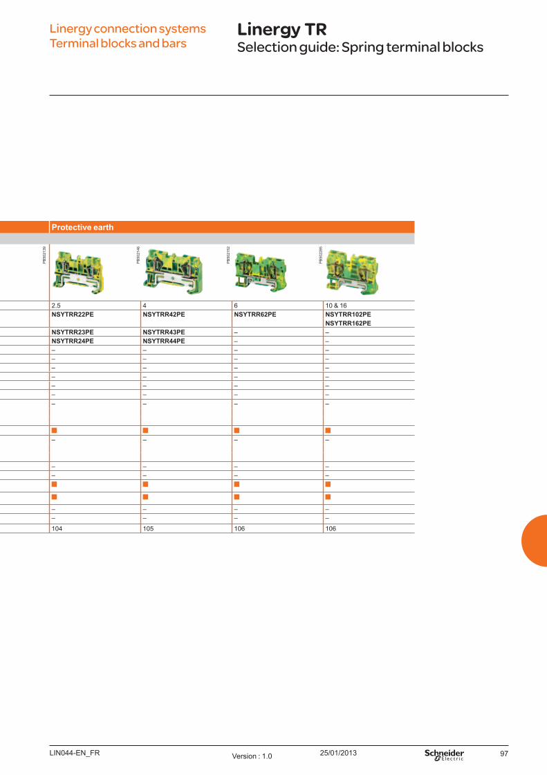
25/01/2013 97
Linergy connection systems Terminal blocks and bars
Linergy TRSelection guide: Spring terminal blocks
Passt h ro u gh Pro t ect iv e eart hPasst h ro u gh
Nominal c.s.a ( mm² ) 2.5 4 6 10 & 16 2.5 4 6 10 & 16Number of poles 1 - 1 x 1 NSYTRR22 NSYTRR42 NSYTRR62 NSYTRR102 NSYTRR22PE NSYTRR42PE NSYTRR62PE NSYTRR102PE
NSYTRR162 NSYTRR162PE1 - 1 x 2 NSYTRR23 NSYTRR43 NSYTRR63 – NSYTRR23PE NSYTRR43PE – –1 - 2 x 2 NSYTRR24 NSYTRR44 – – NSYTRR24PE NSYTRR44PE – –1 - 2 x 4 – – – – – – – –1 - 3 x 3 – – – – – – – –2 - 1 x 1 – – – – – – – –2 - 1 x 2 – – – – – – – –3 - 1 x 1 – – – – – – – –
Colours Grey – – – –B lue NSYTRR22BL NSYTRR42BL NSYTRR62BL NSYTRR102BL – – – –
NSYTRR23BL NSYTRR43BL NSYTRR162BLNSYTRR24BL NSYTRR44BL
Green/yellow ( PE) – – – –O range NSYTRR22AR NSYTRR42AR – – – – – –
NSYTRR23AR NSYTRR43ARNSYTRR24AR NSYTRR42AR
B lack – – – – – – – –With flange – – – – – – – –
Mounting on 35 mm
35 mmTeleq uick – – – – – – – –15 mm – – – – – – – –
See pages 100 101 101/102 102 104 105 106 106
LIN044-EN_FR Version : 1.0
PB
5021
39
PB
5021
52
PB
5022
85
PB
5021
46

25/01/201398
Linergy connection systems Terminal blocks and bars
Linergy TRSelection guide: Spring terminal blocks
Miniat u re t em inal b l o ck s w it h m ax im u m u sage
Due to its space saving design, mini spring-cage terminal blocks are ideal for wiring in extremely restricted spaces. The generous connection space enables fast wiring of both stranded and solid conductors.They can be mounted on NS 15 DIN rail or directly mounted using screw flange or engagement pins.
Do u b l e d eck Disco nnect Miniat u rePasst h ro u gh Bl ad e Rem o v ab l e carrier DI N rail m o u nt ing Direct m o u nt ing Pin m o u nt ing
Nominal c.s.a ( mm² ) 2.5 & 4 2.5 2.5 2.5 2.5 2.5Number of poles 1 - 1 x 1 – NSYTRR22SC NSYTRR22TB NSYTRR22M NSYTRR22MF NSYTRR22MP
1 - 1 x 2 – NSYTRR23SC NSYTRR23TB – – –1 - 2 x 2 – – – NSYTRR24M NSYTRR24MF NSYTRR22MP1 - 2 x 4 – – – – – –1 - 3 x 3 – – – – – –2 - 1 x 1 NSYTRR24D NSYTRR24SCD – – – –
NSYTRR44D2 - 1 x 2 – – – – – –3 - 1 x 1 NSYTRR26T – – – – –
Colours GreyB lue NSYTRR24DBL – – NSYTRR22MBL NSYTRR22MFBL NSYTRR22MPBL
NSYTRR44DBL NSYTRR24MBL NSYTRR24MFBL NSYTRR22MPBLNSYTRR26TBL
Green/yellow ( PE) NSYTRR24DPE – – NSYTRR22MPE – –NSYTRR44DPE
O range – NSYTRR22SCAR – – – –NSYTRR23SCAR
B lack – – – – – –With flange – – – – NSYTRR22MFF –
NSYTRR24MFFMounting on 35 mm x – – –
35 mm x – – –
Teleq uick – – – – – –15 mm – – – – –
See pages 108 110 111 112 113 113
LIN044-EN_FRVersion : 1.0
PB
5022
15
PB
5022
13
PB
5022
14
PB
5021
64
PB
5021
59
PB
5021
62
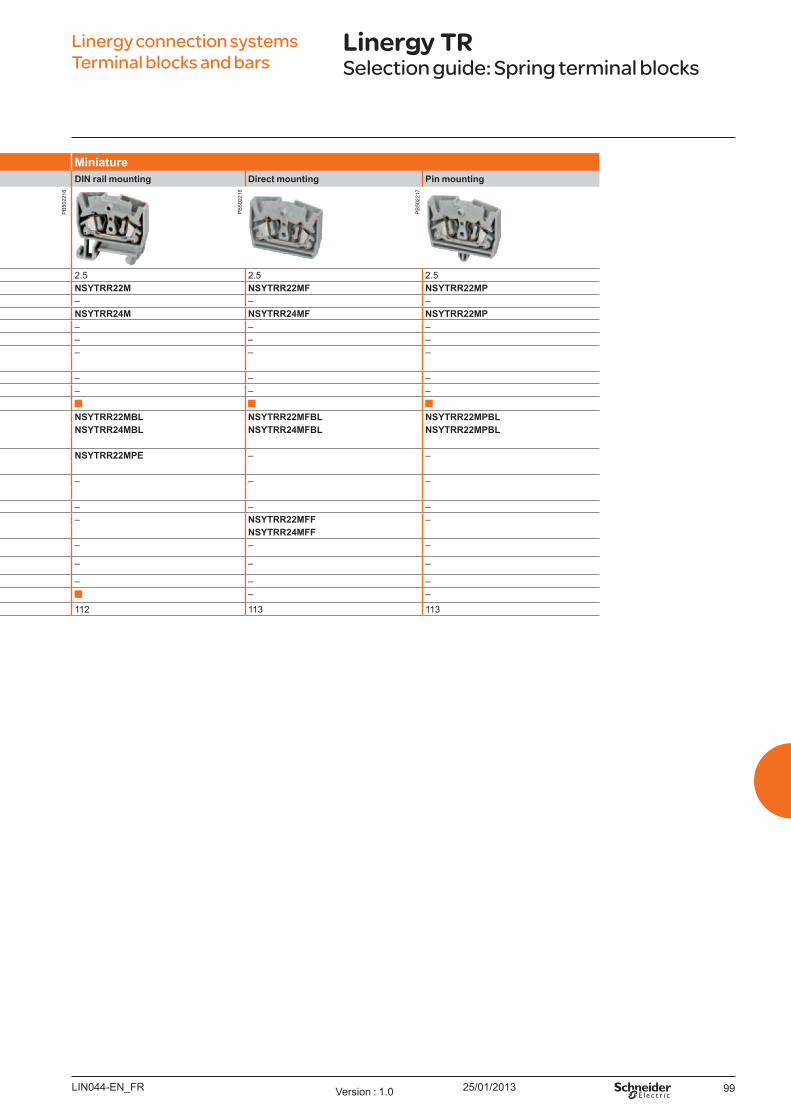
25/01/2013 99
Linergy connection systems Terminal blocks and bars
Linergy TRSelection guide: Spring terminal blocks
Do u b l e d eck Disco nnect Miniat u rePasst h ro u gh Bl ad e Rem o v ab l e carrier DI N rail m o u nt ing Direct m o u nt ing Pin m o u nt ing
Nominal c.s.a ( mm² ) 2.5 & 4 2.5 2.5 2.5 2.5 2.5Number of poles 1 - 1 x 1 – NSYTRR22SC NSYTRR22TB NSYTRR22M NSYTRR22MF NSYTRR22MP
1 - 1 x 2 – NSYTRR23SC NSYTRR23TB – – –1 - 2 x 2 – – – NSYTRR24M NSYTRR24MF NSYTRR22MP1 - 2 x 4 – – – – – –1 - 3 x 3 – – – – – –2 - 1 x 1 NSYTRR24D NSYTRR24SCD – – – –
NSYTRR44D2 - 1 x 2 – – – – – –3 - 1 x 1 NSYTRR26T – – – – –
Colours GreyB lue NSYTRR24DBL – – NSYTRR22MBL NSYTRR22MFBL NSYTRR22MPBL
NSYTRR44DBL NSYTRR24MBL NSYTRR24MFBL NSYTRR22MPBLNSYTRR26TBL
Green/yellow ( PE) NSYTRR24DPE – – NSYTRR22MPE – –NSYTRR44DPE
O range – NSYTRR22SCAR – – – –NSYTRR23SCAR
B lack – – – – – –With flange – – – – NSYTRR22MFF –
NSYTRR24MFFMounting on 35 mm x – – –
35 mm x – – –
Teleq uick – – – – – –15 mm – – – – –
See pages 108 110 111 112 113 113
LIN044-EN_FR Version : 1.0
PB
5022
18
PB
5022
16
PB
5022
17
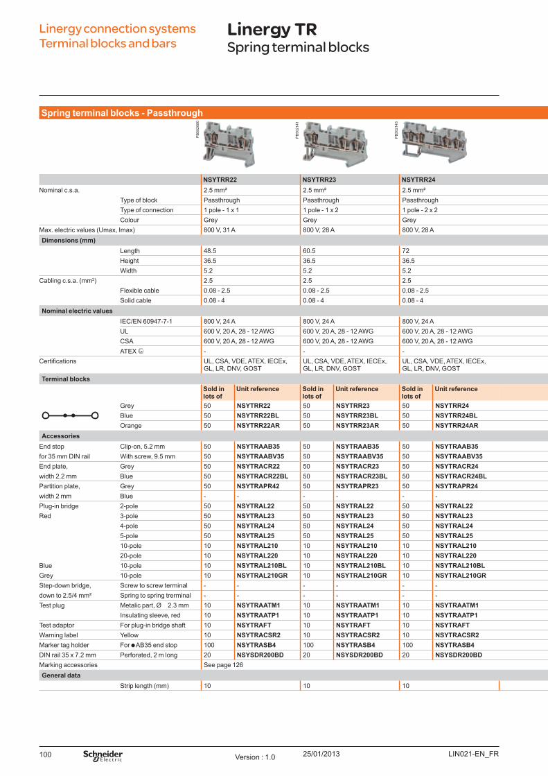
25/01/2013100
Linergy connection systems Terminal blocks and bars
Linergy TRSpring terminal blocks
Sp ring t erm inal b l o ck s - Passt h ro u gh
NSYTRR22 NSYTRR23 NSYTRR24 NSYTRR42 NSYTRR43 NSYTRR44 NSYTRR62Nominal c.s.a. 2.5 mm² 2.5 mm² 2.5 mm² 4 mm² 4 mm² 4 mm² 6 mm²
Type of block Passthrough Passthrough Passthrough Passthrough Passthrough Passthrough PassthroughType of connection 1 pole - 1 x 1 1 pole - 1 x 2 1 pole - 2 x 2 1 pole - 1 x 1 1 pole - 1 x 2 1 pole - 2 x 2 1 pole - 1 x 1Colour Grey Grey Grey Grey Grey Grey Grey
Max. electric values ( U max, Imax) 800 V, 31 A 800 V, 28 A 800 V, 28 A 800 V, 40 A 800 V, 40 A 800 V, 40 A 1000 V, 52 ADim ensio ns (m m )
Length 48.5 60.5 72 56 71.5 87 69.5Height 36.5 36.5 36.5 36.5 36.5 36.5 43.5W idth 5.2 5.2 5.2 6.2 6.2 6.2 8.2
Cabling c.s.a. ( mm2) 2.5 2.5 2.5 4 4 4 6Flexible cable 0.08 - 2.5 0.08 - 2.5 0.08 - 2.5 0.08 - 4 0.08 - 4 0.08 - 4 0.5 - 6Solid cable 0.08 - 4 0.08 - 4 0.08 - 4 0.08 - 6 0.08 - 6 0.08 - 6 0.2 - 10
No m inal el ect ric v al u esIEC/EN 60947-7-1 800 V, 24 A 800 V, 24 A 800 V, 24 A 800 V, 32 A 800 V, 32 A 800 V, 32 A 800 V, 41 AU L 600 V, 20 A, 28 - 12 AW G 600 V, 20 A, 28 - 12 AW G 600 V, 20 A, 28 - 12 AW G 600 V, 30 A, 28 -10 AW G 600 V, 30 A, 28 -10 AW G 600 V, 30 A, 28 -10 AW G 600 V, 50 A, 24 - 8 AW GCSA 600 V, 20 A, 28 - 12 AW G 600 V, 20 A, 28 - 12 AW G 600 V, 20 A, 28 - 12 AW G 600 V, 30 A, 28 -10 AW G 600 V, 30 A, 28 -10 AW G 600 V, 30 A, 28 -10 AW G 600 V, 50 A, 24 - 8 AW GATEX - - - - - - -
ertifications U L, CSA, VDE, ATEX, IECEx, GL, LR, DNV, GO ST
U L, CSA, VDE, ATEX, IECEx, GL, LR, DNV, GO ST
U L, CSA, VDE, ATEX, IECEx, GL, LR, DNV, GO ST
U L, CSA, VDE, ATEX, IECEx, GL, LR; DNV, GO ST
U L, CSA, VDE, ATEX, IECEx, GL, LR, DNV, GO ST
U L, CSA, VDE, ATEX, IECEx, GL, LR, DNV, GO ST
U L, CSA, VDE, ATEX, IECEx, GL, LR, DNV, GO ST
Term inal b l o ck sSo l d in l o t s o f
U nit reference So l d in l o t s o f
U nit reference So l d in l o t s o f
U nit reference So l d in l o t s o f
U nit reference So l d in l o t s o f
U nit reference So l d in l o t s o f
U nit reference So l d in l o t s o f
U nit reference
Grey 50 NSYTRR22 50 NSYTRR23 50 NSYTRR24 50 NSYTRR42 50 NSYTRR43 50 NSYTRR44 50 NSYTRR62B lue 50 NSYTRR22BL 50 NSYTRR23BL 50 NSYTRR24BL 50 NSYTRR42BL 50 NSYTRR43BL 50 NSYTRR44BL 50 NSYTRR62BLO range 50 NSYTRR22AR 50 NSYTRR23AR 50 NSYTRR24AR 50 NSYTRR42AR 50 NSYTRR43AR 50 NSYTRR44BL
Accesso riesEnd stop Clip-on, 5.2 mm 50 NSYTRAAB35 50 NSYTRAAB35 50 NSYTRAAB35 50 NSYTRAAB35 50 NSYTRAAB35 50 NSYTRAAB35 50 NSYTRAAB35for 35 mm DIN rail W ith screw, 9.5 mm 50 NSYTRAABV35 50 NSYTRAABV35 50 NSYTRAABV35 50 NSYTRAABV35 50 NSYTRAABV35 50 NSYTRAABV35 50 NSYTRAABV35End plate, Grey 50 NSYTRACR22 50 NSYTRACR23 50 NSYTRACR24 50 NSYTRACR42 50 NSYTRACR43 50 NSYTRACR44 50 NSYTRACR62width 2.2 mm B lue 50 NSYTRACR22BL 50 NSYTRACR23BL 50 NSYTRACR24BL - - - - - - - -Partition plate, Grey 50 NSYTRAPR42 50 NSYTRAPR23 50 NSYTRAPR24 50 NSYTRA PR42 - - - - - -width 2 mm B lue - - - - - - - - - - - - - -Plug-in bridge 2-pole 50 NSYTRAL22 50 NSYTRAL22 50 NSYTRAL22 50 NSYTRAL42 50 NSYTRAL42 50 NSYTRAL42 10 NSYTRAL62Red 3-pole 50 NSYTRAL23 50 NSYTRAL23 50 NSYTRAL23 50 NSYTRAL43 50 NSYTRAL43 50 NSYTRAL43 10 NSYTRAL63
4-pole 50 NSYTRAL24 50 NSYTRAL24 50 NSYTRAL24 50 NSYTRAL44 50 NSYTRAL44 50 NSYTRAL44 - -5-pole 50 NSYTRAL25 50 NSYTRAL25 50 NSYTRAL25 50 NSYTRAL45 50 NSYTRAL45 50 NSYTRAL45 - -10-pole 10 NSYTRAL210 10 NSYTRAL210 10 NSYTRAL210 10 NSYTRAL410 10 NSYTRAL410 10 NSYTRAL410 10 NSYTRAL61020-pole 10 NSYTRAL220 10 NSYTRAL220 10 NSYTRAL220 10 NSYTRAL420 10 NSYTRAL420 10 NSYTRAL420 - -
B lue 10-pole 10 NSYTRAL210BL 10 NSYTRAL210BL 10 NSYTRAL210BL 10 NSYTRAL410BL 10 NSYTRAL410BL 10 NSYTRAL410BL 10 NSYTRAL610BLGrey 10-pole 10 NSYTRAL210GR 10 NSYTRAL210GR 10 NSYTRAL210GR 10 NSYTRAL410GR 10 NSYTRAL410GR 10 NSYTRAL410GR 10 NSYTRAL610GRStep-down bridge, Screw to screw terminal - - - - - - - - - - - - - -down to 2.5/4 mm² Spring to spring trerminal - - - - - - - - - - - - 10 NSYTRALR62Test plug Metalic part, Ø 2.3 mm 10 NSYTRAATM1 10 NSYTRAATM1 10 NSYTRAATM1 10 NSYTRAATM1 10 NSYTRAATM1 10 NSYTRAATM1 10 NSYTRAATM1
Insulating sleeve, red 10 NSYTRAATP1 10 NSYTRAATP1 10 NSYTRAATP1 10 NSYTRAATP1 10 NSYTRAATP1 10 NSYTRAATP1 10 NSYTRAATP1Test adaptor For plug-in bridge shaft 10 NSYTRAFT 10 NSYTRAFT 10 NSYTRAFT 10 NSYTRAFT 10 NSYTRAFT 10 NSYTRAFT 10 NSYTRAFTW arning label Y ellow 10 NSYTRACSR2 10 NSYTRACSR2 10 NSYTRACSR2 10 NSYTRACSR4 10 NSYTRACSR4 10 NSYTRACSR4 10 NSYTRACSR6Marker tag holder For AB 35 end stop 100 NSYTRASB4 100 NSYTRASB4 100 NSYTRASB4 100 NSYTRASB4 100 NSYTRASB4 100 NSYTRASB4 100 NSYTRASB4DIN rail 35 x 7.2 mm Perforated, 2 m long 20 NSYSDR200BD 20 NSYSDR200BD 20 NSYSDR200BD 20 NSYSDR200BD 20 NSYSDR200BD 20 NSYSDR200BD 20 NSYSDR200BDMarking accessories See page 126General d at a
Strip length ( mm) 10 10 10 10 10 10 12
LIN021-EN_FRVersion : 1.0
PB
5020
80
PB
5021
41
PB
5021
43
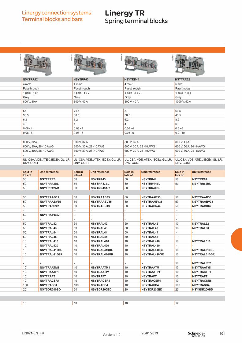
25/01/2013 101
Linergy connection systems Terminal blocks and bars
Linergy TRSpring terminal blocks
Sp ring t erm inal b l o ck s - Passt h ro u gh
NSYTRR22 NSYTRR23 NSYTRR24 NSYTRR42 NSYTRR43 NSYTRR44 NSYTRR62Nominal c.s.a. 2.5 mm² 2.5 mm² 2.5 mm² 4 mm² 4 mm² 4 mm² 6 mm²
Type of block Passthrough Passthrough Passthrough Passthrough Passthrough Passthrough PassthroughType of connection 1 pole - 1 x 1 1 pole - 1 x 2 1 pole - 2 x 2 1 pole - 1 x 1 1 pole - 1 x 2 1 pole - 2 x 2 1 pole - 1 x 1Colour Grey Grey Grey Grey Grey Grey Grey
Max. electric values ( U max, Imax) 800 V, 31 A 800 V, 28 A 800 V, 28 A 800 V, 40 A 800 V, 40 A 800 V, 40 A 1000 V, 52 ADim ensio ns (m m )
Length 48.5 60.5 72 56 71.5 87 69.5Height 36.5 36.5 36.5 36.5 36.5 36.5 43.5W idth 5.2 5.2 5.2 6.2 6.2 6.2 8.2
Cabling c.s.a. ( mm2) 2.5 2.5 2.5 4 4 4 6Flexible cable 0.08 - 2.5 0.08 - 2.5 0.08 - 2.5 0.08 - 4 0.08 - 4 0.08 - 4 0.5 - 6Solid cable 0.08 - 4 0.08 - 4 0.08 - 4 0.08 - 6 0.08 - 6 0.08 - 6 0.2 - 10
No m inal el ect ric v al u esIEC/EN 60947-7-1 800 V, 24 A 800 V, 24 A 800 V, 24 A 800 V, 32 A 800 V, 32 A 800 V, 32 A 800 V, 41 AU L 600 V, 20 A, 28 - 12 AW G 600 V, 20 A, 28 - 12 AW G 600 V, 20 A, 28 - 12 AW G 600 V, 30 A, 28 -10 AW G 600 V, 30 A, 28 -10 AW G 600 V, 30 A, 28 -10 AW G 600 V, 50 A, 24 - 8 AW GCSA 600 V, 20 A, 28 - 12 AW G 600 V, 20 A, 28 - 12 AW G 600 V, 20 A, 28 - 12 AW G 600 V, 30 A, 28 -10 AW G 600 V, 30 A, 28 -10 AW G 600 V, 30 A, 28 -10 AW G 600 V, 50 A, 24 - 8 AW GATEX - - - - - - -
ertifications U L, CSA, VDE, ATEX, IECEx, GL, LR, DNV, GO ST
U L, CSA, VDE, ATEX, IECEx, GL, LR, DNV, GO ST
U L, CSA, VDE, ATEX, IECEx, GL, LR, DNV, GO ST
U L, CSA, VDE, ATEX, IECEx, GL, LR; DNV, GO ST
U L, CSA, VDE, ATEX, IECEx, GL, LR, DNV, GO ST
U L, CSA, VDE, ATEX, IECEx, GL, LR, DNV, GO ST
U L, CSA, VDE, ATEX, IECEx, GL, LR, DNV, GO ST
Term inal b l o ck sSo l d in l o t s o f
U nit reference So l d in l o t s o f
U nit reference So l d in l o t s o f
U nit reference So l d in l o t s o f
U nit reference So l d in l o t s o f
U nit reference So l d in l o t s o f
U nit reference So l d in l o t s o f
U nit reference
Grey 50 NSYTRR22 50 NSYTRR23 50 NSYTRR24 50 NSYTRR42 50 NSYTRR43 50 NSYTRR44 50 NSYTRR62B lue 50 NSYTRR22BL 50 NSYTRR23BL 50 NSYTRR24BL 50 NSYTRR42BL 50 NSYTRR43BL 50 NSYTRR44BL 50 NSYTRR62BLO range 50 NSYTRR22AR 50 NSYTRR23AR 50 NSYTRR24AR 50 NSYTRR42AR 50 NSYTRR43AR 50 NSYTRR44BL
Accesso riesEnd stop Clip-on, 5.2 mm 50 NSYTRAAB35 50 NSYTRAAB35 50 NSYTRAAB35 50 NSYTRAAB35 50 NSYTRAAB35 50 NSYTRAAB35 50 NSYTRAAB35for 35 mm DIN rail W ith screw, 9.5 mm 50 NSYTRAABV35 50 NSYTRAABV35 50 NSYTRAABV35 50 NSYTRAABV35 50 NSYTRAABV35 50 NSYTRAABV35 50 NSYTRAABV35End plate, Grey 50 NSYTRACR22 50 NSYTRACR23 50 NSYTRACR24 50 NSYTRACR42 50 NSYTRACR43 50 NSYTRACR44 50 NSYTRACR62width 2.2 mm B lue 50 NSYTRACR22BL 50 NSYTRACR23BL 50 NSYTRACR24BL - - - - - - - -Partition plate, Grey 50 NSYTRAPR42 50 NSYTRAPR23 50 NSYTRAPR24 50 NSYTRA PR42 - - - - - -width 2 mm B lue - - - - - - - - - - - - - -Plug-in bridge 2-pole 50 NSYTRAL22 50 NSYTRAL22 50 NSYTRAL22 50 NSYTRAL42 50 NSYTRAL42 50 NSYTRAL42 10 NSYTRAL62Red 3-pole 50 NSYTRAL23 50 NSYTRAL23 50 NSYTRAL23 50 NSYTRAL43 50 NSYTRAL43 50 NSYTRAL43 10 NSYTRAL63
4-pole 50 NSYTRAL24 50 NSYTRAL24 50 NSYTRAL24 50 NSYTRAL44 50 NSYTRAL44 50 NSYTRAL44 - -5-pole 50 NSYTRAL25 50 NSYTRAL25 50 NSYTRAL25 50 NSYTRAL45 50 NSYTRAL45 50 NSYTRAL45 - -10-pole 10 NSYTRAL210 10 NSYTRAL210 10 NSYTRAL210 10 NSYTRAL410 10 NSYTRAL410 10 NSYTRAL410 10 NSYTRAL61020-pole 10 NSYTRAL220 10 NSYTRAL220 10 NSYTRAL220 10 NSYTRAL420 10 NSYTRAL420 10 NSYTRAL420 - -
B lue 10-pole 10 NSYTRAL210BL 10 NSYTRAL210BL 10 NSYTRAL210BL 10 NSYTRAL410BL 10 NSYTRAL410BL 10 NSYTRAL410BL 10 NSYTRAL610BLGrey 10-pole 10 NSYTRAL210GR 10 NSYTRAL210GR 10 NSYTRAL210GR 10 NSYTRAL410GR 10 NSYTRAL410GR 10 NSYTRAL410GR 10 NSYTRAL610GRStep-down bridge, Screw to screw terminal - - - - - - - - - - - - - -down to 2.5/4 mm² Spring to spring trerminal - - - - - - - - - - - - 10 NSYTRALR62Test plug Metalic part, Ø 2.3 mm 10 NSYTRAATM1 10 NSYTRAATM1 10 NSYTRAATM1 10 NSYTRAATM1 10 NSYTRAATM1 10 NSYTRAATM1 10 NSYTRAATM1
Insulating sleeve, red 10 NSYTRAATP1 10 NSYTRAATP1 10 NSYTRAATP1 10 NSYTRAATP1 10 NSYTRAATP1 10 NSYTRAATP1 10 NSYTRAATP1Test adaptor For plug-in bridge shaft 10 NSYTRAFT 10 NSYTRAFT 10 NSYTRAFT 10 NSYTRAFT 10 NSYTRAFT 10 NSYTRAFT 10 NSYTRAFTW arning label Y ellow 10 NSYTRACSR2 10 NSYTRACSR2 10 NSYTRACSR2 10 NSYTRACSR4 10 NSYTRACSR4 10 NSYTRACSR4 10 NSYTRACSR6Marker tag holder For AB 35 end stop 100 NSYTRASB4 100 NSYTRASB4 100 NSYTRASB4 100 NSYTRASB4 100 NSYTRASB4 100 NSYTRASB4 100 NSYTRASB4DIN rail 35 x 7.2 mm Perforated, 2 m long 20 NSYSDR200BD 20 NSYSDR200BD 20 NSYSDR200BD 20 NSYSDR200BD 20 NSYSDR200BD 20 NSYSDR200BD 20 NSYSDR200BDMarking accessories See page 126General d at a
Strip length ( mm) 10 10 10 10 10 10 12
LIN021-EN_FR Version : 1.0
PB
5021
45
PB
5021
47
PB
5021
49
PB
5021
51
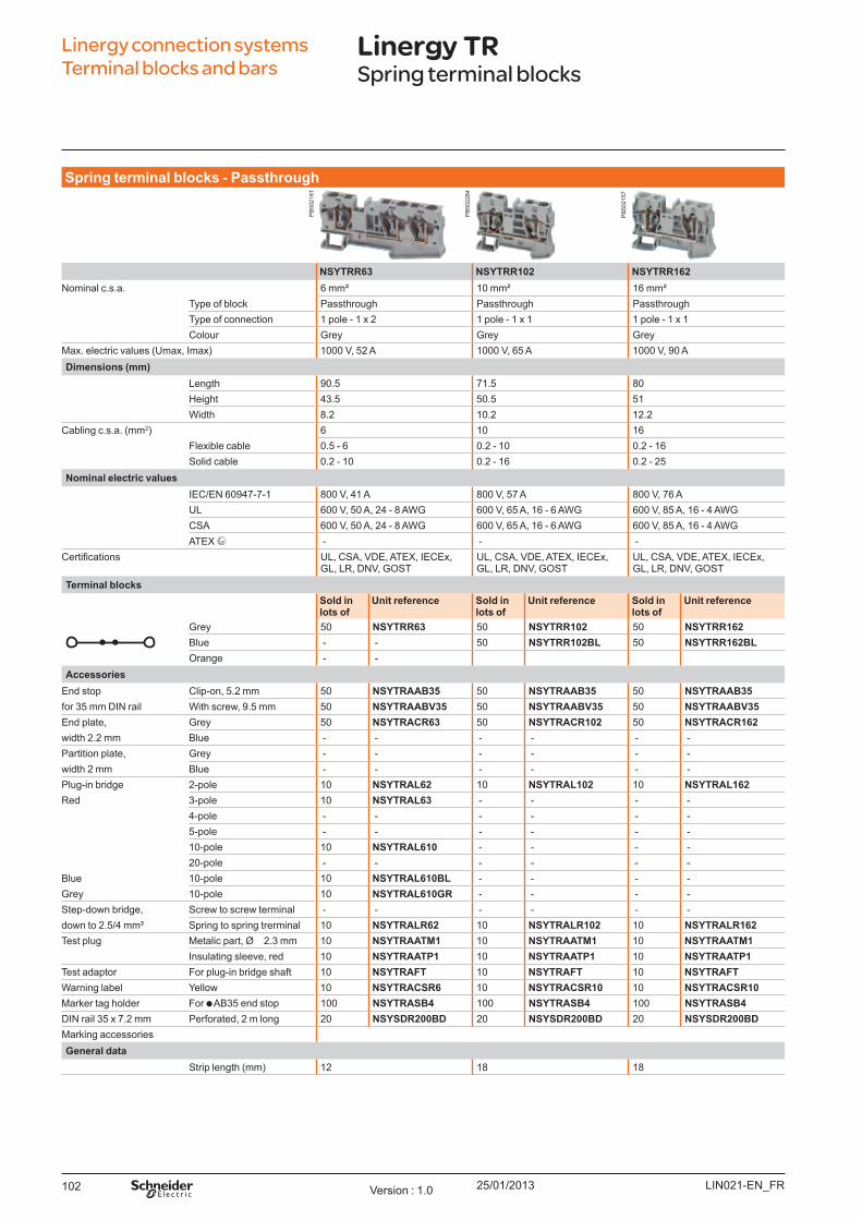
25/01/2013102
Linergy connection systems Terminal blocks and bars
Linergy TRSpring terminal blocks
Sp ring t erm inal b l o ck s - Passt h ro u gh
NSYTRR63 NSYTRR102 NSYTRR162Nominal c.s.a. 6 mm² 10 mm² 16 mm²
Type of block Passthrough Passthrough PassthroughType of connection 1 pole - 1 x 2 1 pole - 1 x 1 1 pole - 1 x 1Colour Grey Grey Grey
Max. electric values ( U max, Imax) 1000 V, 52 A 1000 V, 65 A 1000 V, 90 ADim ensio ns (m m )
Length 90.5 71.5 80Height 43.5 50.5 51W idth 8.2 10.2 12.2
Cabling c.s.a. ( mm2) 6 10 16Flexible cable 0.5 - 6 0.2 - 10 0.2 - 16Solid cable 0.2 - 10 0.2 - 16 0.2 - 25
No m inal el ect ric v al u esIEC/EN 60947-7-1 800 V, 41 A 800 V, 57 A 800 V, 76 AU L 600 V, 50 A, 24 - 8 AW G 600 V, 65 A, 16 - 6 AW G 600 V, 85 A, 16 - 4 AW GCSA 600 V, 50 A, 24 - 8 AW G 600 V, 65 A, 16 - 6 AW G 600 V, 85 A, 16 - 4 AW GATEX - - -
ertifications U L, CSA, VDE, ATEX, IECEx, GL, LR, DNV, GO ST
U L, CSA, VDE, ATEX, IECEx, GL, LR, DNV, GO ST
U L, CSA, VDE, ATEX, IECEx, GL, LR, DNV, GO ST
Term inal b l o ck sSo l d in l o t s o f
U nit reference So l d in l o t s o f
U nit reference So l d in l o t s o f
U nit reference
Grey 50 NSYTRR63 50 NSYTRR102 50 NSYTRR162B lue - - 50 NSYTRR102BL 50 NSYTRR162BLO range - -
Accesso riesEnd stop Clip-on, 5.2 mm 50 NSYTRAAB35 50 NSYTRAAB35 50 NSYTRAAB35for 35 mm DIN rail W ith screw, 9.5 mm 50 NSYTRAABV35 50 NSYTRAABV35 50 NSYTRAABV35End plate, Grey 50 NSYTRACR63 50 NSYTRACR102 50 NSYTRACR162width 2.2 mm B lue - - - - - - Partition plate, Grey - - - - - - width 2 mm B lue - - - - - - Plug-in bridge 2-pole 10 NSYTRAL62 10 NSYTRAL102 10 NSYTRAL162Red 3-pole 10 NSYTRAL63 - - - -
4-pole - - - - - - 5-pole - - - - - - 10-pole 10 NSYTRAL610 - - - - 20-pole - - - - - -
B lue 10-pole 10 NSYTRAL610BL - - - - Grey 10-pole 10 NSYTRAL610GR - - - - Step-down bridge, Screw to screw terminal - - - - - - down to 2.5/4 mm² Spring to spring trerminal 10 NSYTRALR62 10 NSYTRALR102 10 NSYTRALR162Test plug Metalic part, Ø 2.3 mm 10 NSYTRAATM1 10 NSYTRAATM1 10 NSYTRAATM1
Insulating sleeve, red 10 NSYTRAATP1 10 NSYTRAATP1 10 NSYTRAATP1Test adaptor For plug-in bridge shaft 10 NSYTRAFT 10 NSYTRAFT 10 NSYTRAFTW arning label Y ellow 10 NSYTRACSR6 10 NSYTRACSR10 10 NSYTRACSR10Marker tag holder For AB 35 end stop 100 NSYTRASB4 100 NSYTRASB4 100 NSYTRASB4DIN rail 35 x 7.2 mm Perforated, 2 m long 20 NSYSDR200BD 20 NSYSDR200BD 20 NSYSDR200BDMarking accessoriesGeneral d at a
Strip length ( mm) 12 18 18
LIN021-EN_FRVersion : 1.0
PB
5021
61
PB
5022
84
PB
5021
57

25/01/2013 103LIN021-EN_FR Version : 1.0
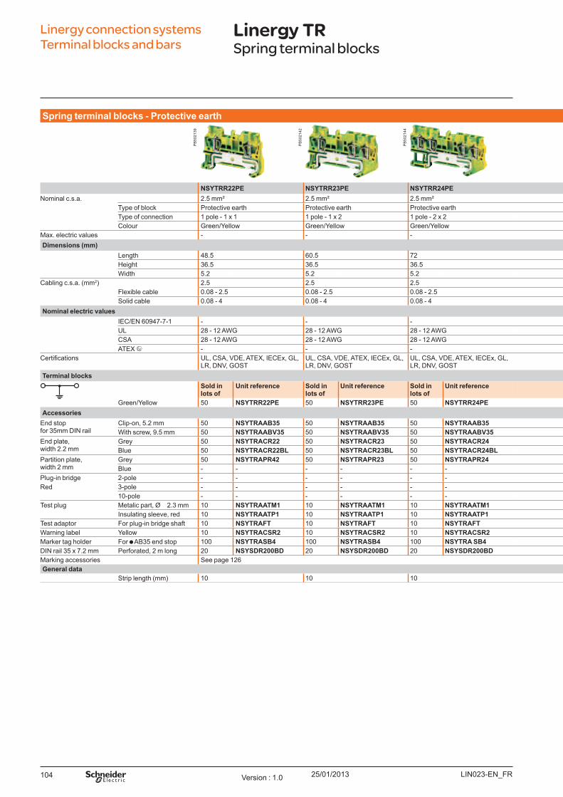
25/01/2013104
Sp ring t erm inal b l o ck s - Pro t ect iv e eart h
NSYTRR22PE NSYTRR23PE NSYTRR24PE NSYTRR42PE NSYTRR43PE NSYTRR44PENominal c.s.a. 2.5 mm² 2.5 mm² 2.5 mm² 4 mm² 4 mm² 4 mm²
Type of block Protective earth Protective earth Protective earth Protective earth Protective earth Protective earthType of connection 1 pole - 1 x 1 1 pole - 1 x 2 1 pole - 2 x 2 1 pole - 1 x 1 1 pole - 1 x 2 1 pole - 2 x 2Colour Green/Y ellow Green/Y ellow Green/Y ellow Green/Y ellow Green/Y ellow Green/Y ellow
Max. electric values - - - - - -Dim ensio ns (m m )
Length 48.5 60.5 72 56 71.5 87Height 36.5 36.5 36.5 36.5 36.5 36.5W idth 5.2 5.2 5.2 6.2 6.2 6.2
Cabling c.s.a. ( mm2) 2.5 2.5 2.5 4 4 4Flexible cable 0.08 - 2.5 0.08 - 2.5 0.08 - 2.5 0.08 - 4 0.08 - 4 0.08 - 4Solid cable 0.08 - 4 0.08 - 4 0.08 - 4 0.08 - 6 0.08 - 6 0.08 - 6
No m inal el ect ric v al u esIEC/EN 60947-7-1 - - - - - - U L 28 - 12 AW G 28 - 12 AW G 28 - 12 AW G 28 -10 AW G 28 -10 AW G 28 -10 AW GCSA 28 - 12 AW G 28 - 12 AW G 28 - 12 AW G 28 -10 AW G 28 -10 AW G 28 -10 AW GATEX - - - - - -
ertifications U L, CSA, VDE, ATEX, IECEx, GL, LR, DNV, GO ST
U L, CSA, VDE, ATEX, IECEx, GL, LR, DNV, GO ST
U L, CSA, VDE, ATEX, IECEx, GL, LR, DNV, GO ST
U L, CSA, VDE, ATEX, IECEx, GL, LR, DNV, GO ST U L, CSA, VDE, ATEX, IECEx, GL, LR, DNV, GO ST U L, CSA, VDE, ATEX, IECEx, GL, LR, DNV, GO ST
Term inal b l o ck sSo l d in l o t s o f
U nit reference So l d in l o t s o f
U nit reference So l d in l o t s o f
U nit reference So l d in l o t s o f U nit reference So l d in l o t s o f U nit reference So l d in l o t s o f U nit reference
Green/Y ellow 50 NSYTRR22PE 50 NSYTRR23PE 50 NSYTRR24PE 50 NSYTRR42PE 50 NSYTRR43PE 50 NSYTRR44PEAccesso ries
End stopfor 35mm DIN rail
Clip-on, 5.2 mm 50 NSYTRAAB35 50 NSYTRAAB35 50 NSYTRAAB35 50 NSYTRAAB35 50 NSYTRAAB35 50 NSYTRAAB35W ith screw, 9.5 mm 50 NSYTRAABV35 50 NSYTRAABV35 50 NSYTRAABV35 50 NSYTRAABV35 50 NSYTRAABV35 50 NSYTRAABV35
End plate,width 2.2 mm
Grey 50 NSYTRACR22 50 NSYTRACR23 50 NSYTRACR24 50 NSYTRACR42 50 NSYTRACR43 50 NSYTRACR44B lue 50 NSYTRACR22BL 50 NSYTRACR23BL 50 NSYTRACR24BL - - - - - -
Partition plate,width 2 mm
Grey 50 NSYTRAPR42 50 NSYTRAPR23 50 NSYTRAPR24 50 NSYTRAPR42 - - - - B lue - - - - - - - - - - - -
Plug-in bridge 2-pole - - - - - - - - - - - - Red 3-pole - - - - - - - - - - - -
10-pole - - - - - - - - - - - - Test plug Metalic part, Ø 2.3 mm 10 NSYTRAATM1 10 NSYTRAATM1 10 NSYTRAATM1 10 NSYTRAATM1 10 NSYTRAATM1 10 NSYTRAATM1
Insulating sleeve, red 10 NSYTRAATP1 10 NSYTRAATP1 10 NSYTRAATP1 10 NSYTRAATP1 10 NSYTRAATP1 10 NSYTRAATP1Test adaptor For plug-in bridge shaft 10 NSYTRAFT 10 NSYTRAFT 10 NSYTRAFT 10 NSYTRAFT 10 NSYTRAFT 10 NSYTRAFTW arning label Y ellow 10 NSYTRACSR2 10 NSYTRACSR2 10 NSYTRACSR2 10 NSYTRACSR4 10 NSYTRACSR4 10 NSYTRACSR4Marker tag holder For AB 35 end stop 100 NSYTRASB4 100 NSYTRASB4 100 NSYTRA SB4 100 NSYTRASB4 100 NSYTRASB4 100 NSYTRASB4DIN rail 35 x 7.2 mm Perforated, 2 m long 20 NSYSDR200BD 20 NSYSDR200BD 20 NSYSDR200BD 20 NSYSDR200BD 20 NSYSDR200BD 20 NSYSDR200BDMarking accessories See page 126General d at a
Strip length ( mm) 10 10 10 10 10 10
Linergy connection systems Terminal blocks and bars
Linergy TRSpring terminal blocks
LIN023-EN_FRVersion : 1.0
PB
5021
39
PB
5021
42
PB
5021
44
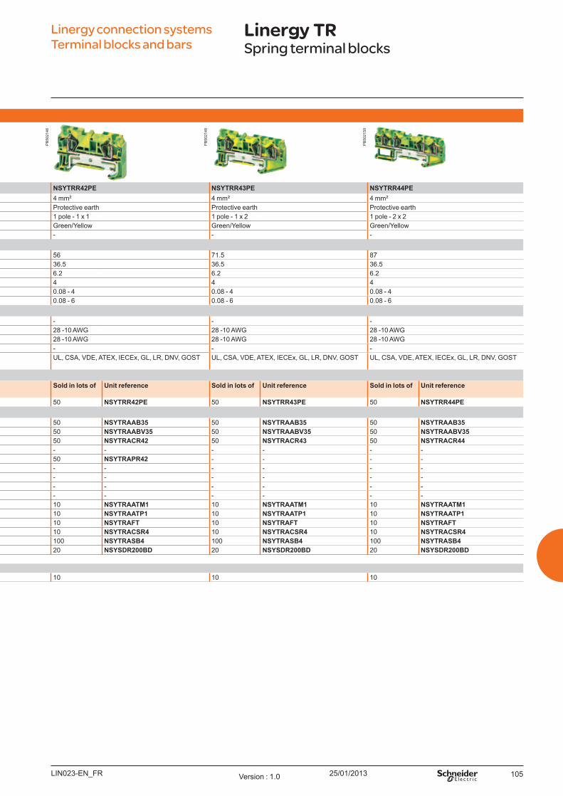
25/01/2013 105
Sp ring t erm inal b l o ck s - Pro t ect iv e eart h
NSYTRR22PE NSYTRR23PE NSYTRR24PE NSYTRR42PE NSYTRR43PE NSYTRR44PENominal c.s.a. 2.5 mm² 2.5 mm² 2.5 mm² 4 mm² 4 mm² 4 mm²
Type of block Protective earth Protective earth Protective earth Protective earth Protective earth Protective earthType of connection 1 pole - 1 x 1 1 pole - 1 x 2 1 pole - 2 x 2 1 pole - 1 x 1 1 pole - 1 x 2 1 pole - 2 x 2Colour Green/Y ellow Green/Y ellow Green/Y ellow Green/Y ellow Green/Y ellow Green/Y ellow
Max. electric values - - - - - -Dim ensio ns (m m )
Length 48.5 60.5 72 56 71.5 87Height 36.5 36.5 36.5 36.5 36.5 36.5W idth 5.2 5.2 5.2 6.2 6.2 6.2
Cabling c.s.a. ( mm2) 2.5 2.5 2.5 4 4 4Flexible cable 0.08 - 2.5 0.08 - 2.5 0.08 - 2.5 0.08 - 4 0.08 - 4 0.08 - 4Solid cable 0.08 - 4 0.08 - 4 0.08 - 4 0.08 - 6 0.08 - 6 0.08 - 6
No m inal el ect ric v al u esIEC/EN 60947-7-1 - - - - - - U L 28 - 12 AW G 28 - 12 AW G 28 - 12 AW G 28 -10 AW G 28 -10 AW G 28 -10 AW GCSA 28 - 12 AW G 28 - 12 AW G 28 - 12 AW G 28 -10 AW G 28 -10 AW G 28 -10 AW GATEX - - - - - -
ertifications U L, CSA, VDE, ATEX, IECEx, GL, LR, DNV, GO ST
U L, CSA, VDE, ATEX, IECEx, GL, LR, DNV, GO ST
U L, CSA, VDE, ATEX, IECEx, GL, LR, DNV, GO ST
U L, CSA, VDE, ATEX, IECEx, GL, LR, DNV, GO ST U L, CSA, VDE, ATEX, IECEx, GL, LR, DNV, GO ST U L, CSA, VDE, ATEX, IECEx, GL, LR, DNV, GO ST
Term inal b l o ck sSo l d in l o t s o f
U nit reference So l d in l o t s o f
U nit reference So l d in l o t s o f
U nit reference So l d in l o t s o f U nit reference So l d in l o t s o f U nit reference So l d in l o t s o f U nit reference
Green/Y ellow 50 NSYTRR22PE 50 NSYTRR23PE 50 NSYTRR24PE 50 NSYTRR42PE 50 NSYTRR43PE 50 NSYTRR44PEAccesso ries
End stopfor 35mm DIN rail
Clip-on, 5.2 mm 50 NSYTRAAB35 50 NSYTRAAB35 50 NSYTRAAB35 50 NSYTRAAB35 50 NSYTRAAB35 50 NSYTRAAB35W ith screw, 9.5 mm 50 NSYTRAABV35 50 NSYTRAABV35 50 NSYTRAABV35 50 NSYTRAABV35 50 NSYTRAABV35 50 NSYTRAABV35
End plate,width 2.2 mm
Grey 50 NSYTRACR22 50 NSYTRACR23 50 NSYTRACR24 50 NSYTRACR42 50 NSYTRACR43 50 NSYTRACR44B lue 50 NSYTRACR22BL 50 NSYTRACR23BL 50 NSYTRACR24BL - - - - - -
Partition plate,width 2 mm
Grey 50 NSYTRAPR42 50 NSYTRAPR23 50 NSYTRAPR24 50 NSYTRAPR42 - - - - B lue - - - - - - - - - - - -
Plug-in bridge 2-pole - - - - - - - - - - - - Red 3-pole - - - - - - - - - - - -
10-pole - - - - - - - - - - - - Test plug Metalic part, Ø 2.3 mm 10 NSYTRAATM1 10 NSYTRAATM1 10 NSYTRAATM1 10 NSYTRAATM1 10 NSYTRAATM1 10 NSYTRAATM1
Insulating sleeve, red 10 NSYTRAATP1 10 NSYTRAATP1 10 NSYTRAATP1 10 NSYTRAATP1 10 NSYTRAATP1 10 NSYTRAATP1Test adaptor For plug-in bridge shaft 10 NSYTRAFT 10 NSYTRAFT 10 NSYTRAFT 10 NSYTRAFT 10 NSYTRAFT 10 NSYTRAFTW arning label Y ellow 10 NSYTRACSR2 10 NSYTRACSR2 10 NSYTRACSR2 10 NSYTRACSR4 10 NSYTRACSR4 10 NSYTRACSR4Marker tag holder For AB 35 end stop 100 NSYTRASB4 100 NSYTRASB4 100 NSYTRA SB4 100 NSYTRASB4 100 NSYTRASB4 100 NSYTRASB4DIN rail 35 x 7.2 mm Perforated, 2 m long 20 NSYSDR200BD 20 NSYSDR200BD 20 NSYSDR200BD 20 NSYSDR200BD 20 NSYSDR200BD 20 NSYSDR200BDMarking accessories See page 126General d at a
Strip length ( mm) 10 10 10 10 10 10
Linergy connection systems Terminal blocks and bars
Linergy TRSpring terminal blocks
LIN023-EN_FR Version : 1.0
PB
5021
46
PB
5021
48
PB
5021
50
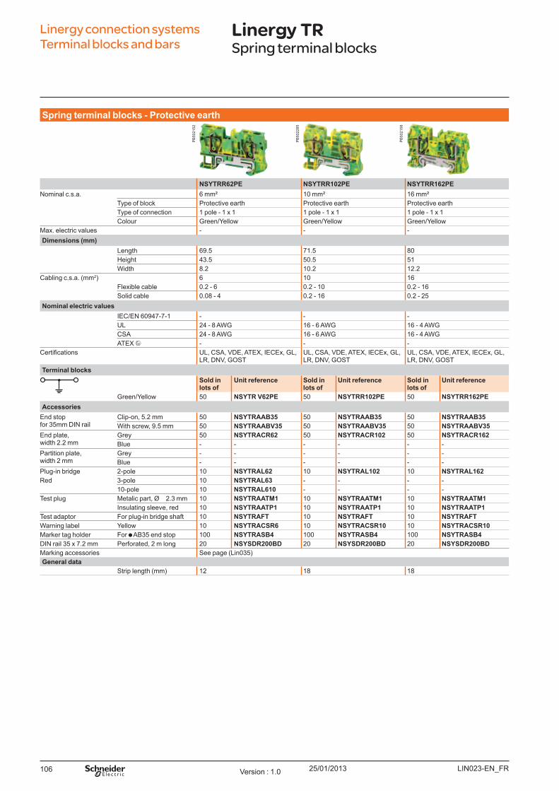
25/01/2013106
Sp ring t erm inal b l o ck s - Pro t ect iv e eart h
NSYTRR62PE NSYTRR102PE NSYTRR162PENominal c.s.a. 6 mm² 10 mm² 16 mm²
Type of block Protective earth Protective earth Protective earthType of connection 1 pole - 1 x 1 1 pole - 1 x 1 1 pole - 1 x 1Colour Green/Y ellow Green/Y ellow Green/Y ellow
Max. electric values - - -Dim ensio ns (m m )
Length 69.5 71.5 80Height 43.5 50.5 51W idth 8.2 10.2 12.2
Cabling c.s.a. ( mm2) 6 10 16Flexible cable 0.2 - 6 0.2 - 10 0.2 - 16Solid cable 0.08 - 4 0.2 - 16 0.2 - 25
No m inal el ect ric v al u esIEC/EN 60947-7-1 - - - U L 24 - 8 AW G 16 - 6 AW G 16 - 4 AW GCSA 24 - 8 AW G 16 - 6 AW G 16 - 4 AW GATEX - - -
ertifications U L, CSA, VDE, ATEX, IECEx, GL, LR, DNV, GO ST
U L, CSA, VDE, ATEX, IECEx, GL, LR, DNV, GO ST
U L, CSA, VDE, ATEX, IECEx, GL, LR, DNV, GO ST
Term inal b l o ck sSo l d in l o t s o f
U nit reference So l d in l o t s o f
U nit reference So l d in l o t s o f
U nit reference
Green/Y ellow 50 NSYTR V62PE 50 NSYTRR102PE 50 NSYTRR162PEAccesso ries
End stopfor 35mm DIN rail
Clip-on, 5.2 mm 50 NSYTRAAB35 50 NSYTRAAB35 50 NSYTRAAB35W ith screw, 9.5 mm 50 NSYTRAABV35 50 NSYTRAABV35 50 NSYTRAABV35
End plate,width 2.2 mm
Grey 50 NSYTRACR62 50 NSYTRACR102 50 NSYTRACR162B lue - - - - - -
Partition plate,width 2 mm
Grey - - - - - - B lue - - - - - -
Plug-in bridge 2-pole 10 NSYTRAL62 10 NSYTRAL102 10 NSYTRAL162Red 3-pole 10 NSYTRAL63 - - - -
10-pole 10 NSYTRAL610 - - - - Test plug Metalic part, Ø 2.3 mm 10 NSYTRAATM1 10 NSYTRAATM1 10 NSYTRAATM1
Insulating sleeve, red 10 NSYTRAATP1 10 NSYTRAATP1 10 NSYTRAATP1Test adaptor For plug-in bridge shaft 10 NSYTRAFT 10 NSYTRAFT 10 NSYTRAFTW arning label Y ellow 10 NSYTRACSR6 10 NSYTRACSR10 10 NSYTRACSR10Marker tag holder For AB 35 end stop 100 NSYTRASB4 100 NSYTRASB4 100 NSYTRASB4DIN rail 35 x 7.2 mm Perforated, 2 m long 20 NSYSDR200BD 20 NSYSDR200BD 20 NSYSDR200BDMarking accessories See page ( Lin035)General d at a
Strip length ( mm) 12 18 18
Linergy connection systems Terminal blocks and bars
Linergy TRSpring terminal blocks
LIN023-EN_FRVersion : 1.0
PB
5021
52
PB
5022
85
PB
5021
58

25/01/2013 107LIN023-EN_FR Version : 1.0
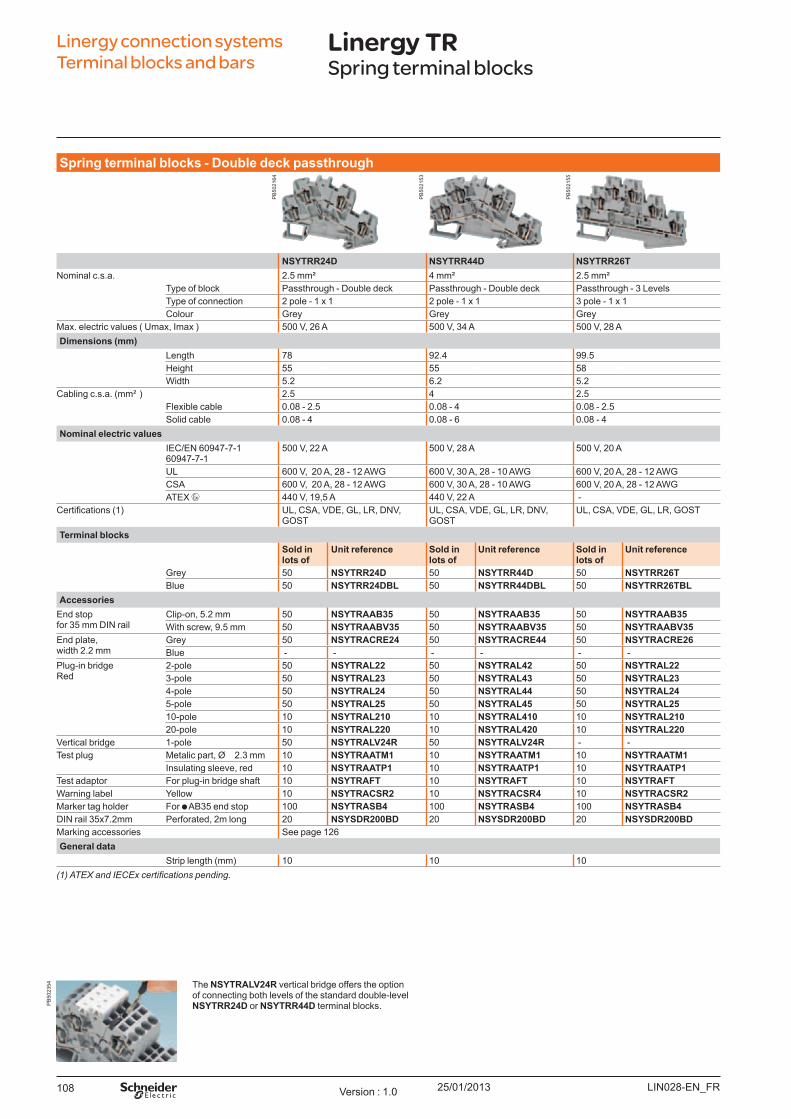
25/01/2013108
Sp ring t erm inal b l o ck s - Do u b l e d eck p asst h ro u gh
NSYTRR24D NSYTRR44D NSYTRR26TNominal c.s.a. 2.5 mm² 4 mm² 2.5 mm²
Type of block Passthrough - Double deck Passthrough - Double deck Passthrough - 3 LevelsType of connection 2 pole - 1 x 1 2 pole - 1 x 1 3 pole - 1 x 1Colour Grey Grey Grey
Max. electric values ( U max, Imax ) 500 V, 26 A 500 V, 34 A 500 V, 28 ADim ensio ns (m m )
Length 78 92.4 99.5Height 55 55 58W idth 5.2 6.2 5.2
Cabling c.s.a. ( mm² ) 2.5 4 2.5Flexible cable 0.08 - 2.5 0.08 - 4 0.08 - 2.5Solid cable 0.08 - 4 0.08 - 6 0.08 - 4
No m inal el ect ric v al u esIEC/EN 60947-7-1 60947-7-1
500 V, 22 A 500 V, 28 A 500 V, 20 A
U L 600 V, 20 A, 28 - 12 AW G 600 V, 30 A, 28 - 10 AW G 600 V, 20 A, 28 - 12 AW GCSA 600 V, 20 A, 28 - 12 AW G 600 V, 30 A, 28 - 10 AW G 600 V, 20 A, 28 - 12 AW GATEX 440 V, 19,5 A 440 V, 22 A -
ertifications (1) U L, CSA, VDE, GL, LR, DNV, GO ST
U L, CSA, VDE, GL, LR, DNV, GO ST
U L, CSA, VDE, GL, LR, GO ST
Term inal b l o ck sSo l d in l o t s o f
U nit reference So l d in l o t s o f
U nit reference So l d in l o t s o f
U nit reference
Grey 50 NSYTRR24D 50 NSYTRR44D 50 NSYTRR26TB lue 50 NSYTRR24DBL 50 NSYTRR44DBL 50 NSYTRR26TBL
Accesso riesEnd stopfor 35 mm DIN rail
Clip-on, 5.2 mm 50 NSYTRAAB35 50 NSYTRAAB35 50 NSYTRAAB35W ith screw, 9.5 mm 50 NSYTRAABV35 50 NSYTRAABV35 50 NSYTRAABV35
End plate,width 2.2 mm
Grey 50 NSYTRACRE24 50 NSYTRACRE44 50 NSYTRACRE26B lue - - - - - -
Plug-in bridgeRed
2-pole 50 NSYTRAL22 50 NSYTRAL42 50 NSYTRAL223-pole 50 NSYTRAL23 50 NSYTRAL43 50 NSYTRAL234-pole 50 NSYTRAL24 50 NSYTRAL44 50 NSYTRAL245-pole 50 NSYTRAL25 50 NSYTRAL45 50 NSYTRAL2510-pole 10 NSYTRAL210 10 NSYTRAL410 10 NSYTRAL21020-pole 10 NSYTRAL220 10 NSYTRAL420 10 NSYTRAL220
Vertical bridge 1-pole 50 NSYTRALV24R 50 NSYTRALV24R - - Test plug Metalic part, Ø 2.3 mm 10 NSYTRAATM1 10 NSYTRAATM1 10 NSYTRAATM1
Insulating sleeve, red 10 NSYTRAATP1 10 NSYTRAATP1 10 NSYTRAATP1Test adaptor For plug-in bridge shaft 10 NSYTRAFT 10 NSYTRAFT 10 NSYTRAFTW arning label Y ellow 10 NSYTRACSR2 10 NSYTRACSR4 10 NSYTRACSR2Marker tag holder For AB 35 end stop 100 NSYTRASB4 100 NSYTRASB4 100 NSYTRASB4DIN rail 35x7.2mm Perforated, 2m long 20 NSYSDR200BD 20 NSYSDR200BD 20 NSYSDR200BDMarking accessories See page 126General d at a
Strip length ( mm) 10 10 10
The NSYTRALV24R vertical bridge offers the option of connecting both levels of the standard double-level NSYTRR24D or NSYTRR44D terminal blocks.
(1) ATEX and IECEx certifications pending.
Linergy connection systems Terminal blocks and bars
Linergy TRSpring terminal blocks
LIN028-EN_FRVersion : 1.0
PB
5021
64
PB
5021
53
PB
5021
55
PB
5023
54
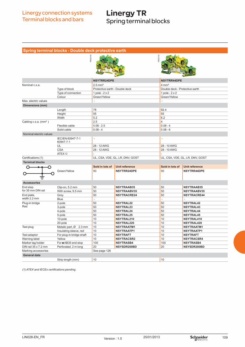
25/01/2013 109
(1) ATEX and IECEx certifications pending.
Linergy connection systems Terminal blocks and bars
Linergy TRSpring terminal blocks
Sp ring t erm inal b l o ck s - Do u b l e d eck p ro t ect iv e eart h
NSYTRR24DPE NSYTRR44DPENominal c.s.a. 2.5 mm² 4 mm²
Type of block Protective earth - Double deck Double deck - Protective earthType of connection 1 pole - 2 x 2 1 pole - 2 x 2Colour Green/Y ellow Green/Y ellow
Max. electric values - - Dim ensio ns (m m )
Length 78 92.4Height 55 55W idth 5.2 6.2
Cabling c.s.a. ( mm² ) 2.5 4Flexible cable 0.08 - 2.5 0.08 - 4Solid cable 0.08 - 4 0.08 - 6
Nominal electric valuesIEC/EN 60947-7-1 60947-7-1
- -
U L 28 - 12 AW G 28 - 10 AW GCSA 28 - 12 AW G 28 - 10 AW GATEX - -
ertifications (1) U L, CSA, VDE, GL, LR, DNV, GO ST U L, CSA, VDE, GL, LR, DNV, GO STTerm inal b l o ck s
So l d in l o t s o f U nit reference So l d in l o t s o f U nit referenceGreen/Y ellow 50 NSYTRR24DPE 50 NSYTRR44DPE
Accesso riesEnd stopfor 35 mm DIN rail
Clip-on, 5.2 mm 50 NSYTRAAB35 50 NSYTRAAB35W ith screw, 9.5 mm 50 NSYTRAABV35 50 NSYTRAABV35
End plate,width 2.2 mm
Grey 50 NSYTRACRE24 50 NSYTRACRE44B lue - - - -
Plug-in bridgeRed
2-pole 50 NSYTRAL22 50 NSYTRAL423-pole 50 NSYTRAL23 50 NSYTRAL434-pole 50 NSYTRAL24 50 NSYTRAL445-pole 50 NSYTRAL25 50 NSYTRAL4510-pole 10 NSYTRAL210 10 NSYTRAL41020-pole 10 NSYTRAL220 10 NSYTRAL420
Test plug Metalic part, Ø 2.3 mm 10 NSYTRAATM1 10 NSYTRAATM1Insulating sleeve, red 10 NSYTRAATP1 10 NSYTRAATP1
Test adaptor For plug-in bridge shaft 10 NSYTRAFT 10 NSYTRAFTW arning label Y ellow 10 NSYTRACSR2 10 NSYTRACSR4Marker tag holder For AB 35 end stop 100 NSYTRASB4 100 NSYTRASB4DIN rail 35 x 7.2 mm Perforated, 2 m long 20 NSYSDR200BD 20 NSYSDR200BDMarking accessories See page 126General d at a
Strip length ( mm) 10 10
LIN028-EN_FR Version : 1.0
PB
5021
65
PB
5021
54

25/01/2013110
Sp ring t erm inal b l o ck s - Disco nnect
NSYTRR22SC NSYTRR23SC NSYTRR22TB NSYTRR23TB NSYTRR24SCDNominal c.s.a. 2.5 mm² 2.5 mm² 2.5 mm² 2.5 mm² 2.5 mm²
Type of block Disconnect ( blade) Disconnect ( blade) Disconnect ( for carrier) Disconnect ( for carrier) Disconnect ( blade)Type of connection 1 pole - 1 x 1 1 pole - 1 x 2 1 pole - 1 x 1 1 pole - 1 x 2 2 pole - 1 x 1Colour Grey Grey Grey Grey Grey
Max. electric values ( U max, Imax) 400 V, 20 A 400 V, 20 A 400 V, 20 A 400 V, 20 A 400 V, 16 ADim ensio ns (m m )
Length 60.5 72 60.5 72 107Height 36.5 36.5 36.5 36.5 55W idth 5.2 5.2 5.2 5.2 5.2
Cabling c.s.a. ( mm² ) 2.5 2.5 2.5 2.5 2.5Flexible cable 0.08 - 2.5 0.08 - 2.5 0.08 - 2.5 0.08 - 2.5 0.08 - 2.5Solid cable 0.08 - 4 0.08 - 4 0.08 - 4 0.08 - 4 0.08 - 4
No m inal el ect ric v al u esIEC/EN 60947-7-1 400 V, 20 A 400 V, 20 A 400 V, 20 A 400 V, 20 A 400 V, 16 AU L 600 V, 16 A, 28 - 12 AW G 600 V, 16 A, 28 - 12 AW G 300 V, 16 A, 28 - 12 AW G 300 V, 16 A, 28 - 12 AW G 300 V, 10 A, 28 - 12 AW GCSA 300 V, 16 A, 28 - 12 AW G 300 V, 16 A, 28 - 12 AW G 300 V, 16 A, 28 - 12 AW G 300 V, 16 A, 28 - 12 AW G 300 V, 10 A, 28 - 12 AW GATEX - - - - -
ertifications U L, CSA, GO ST U L, CSA, GO ST U L, CSA, GO ST U L, CSA, GO ST U L, CSA, GO STTerm inal b l o ck s
So l d in l o t s o f U nit reference So l d in l o t s o f U nit reference So l d in l o t s o f U nit reference So l d in l o t s o f U nit reference So l d in l o t s o f U nit referenceGrey 50 NSYTRR22SC 50 NSYTRR23SC 50 NSYTRR22TB 50 NSYTRR23TB 50 NSYTRR24SCDO range 50 NSYTRR22SCAR 50 NSYTRR23SCAR - - - - - -
Accesso riesEnd stopfor 35 mm DIN rail
Clip-on, 5.2 mm 50 NSYTRAAB35 50 NSYTRAAB35 50 NSYTRAAB35 50 NSYTRAAB35 50 NSYTRAAB35W ith screw, 9.5 mm 50 NSYTRAABV35 50 NSYTRAABV35 50 NSYTRAABV35 50 NSYTRAABV35 50 NSYTRAABV35
End plate,width 2.2 mm
Grey 50 NSYTRACR23 50 NSYTRACR24 50 NSYTRACR23 50 NSYTRACR24 - IncludedB lue - - - - - - - - - -
Partition plate,width 2 mm
Grey 50 NSYTRAPR23 50 NSYTRAPR24 50 NSYTRAPR23 50 NSYTRAPR24 - -B lue - - - - - - - - - -
Plug-in bridgeRed
2-pole 50 NSYTRAL22 50 NSYTRAL22 50 NSYTRAL22 50 NSYTRAL22 50 -3-pole 50 NSYTRAL23 50 NSYTRAL23 50 NSYTRAL23 50 NSYTRAL23 50 -4-pole 50 NSYTRAL24 50 NSYTRAL24 50 NSYTRAL24 50 NSYTRAL24 50 -5-pole 50 NSYTRAL25 50 NSYTRAL25 50 NSYTRAL25 50 NSYTRAL25 50 -10-pole 10 NSYTRAL210 10 NSYTRAL210 10 NSYTRAL210 10 NSYTRAL210 10 -20-pole 10 NSYTRAL220 10 NSYTRAL220 10 NSYTRAL220 10 NSYTRAL220 10 -
Removable carrier For fuse 5 x 20 mm - - - - 10 NSYTRASF520 10 NSYTRASF520 - -For fuse 5 x 20 mm 110 - 250 V LED - - - - 10 NSYTRASF520M 10 NSYTRASF520M - -For fuse 5 x 20 mm 12 - 30 V LED - - - - 10 NSYTRASF520B 10 NSYTRASF520B - -For component - - - - 10 NSYTRASV1 10 NSYTRASV1 - -W ith 1N4007 diode - - - - 10 NSYTRASV2 10 NSYTRASV2 - -
Test plug Metalic part, Ø 2.3 mm 10 NSYTRAATM1 10 NSYTRAATM1 10 NSYTRAATM1 10 NSYTRAATM1 10 NSYTRAATM1Insulating sleeve, red 10 NSYTRAATP1 10 NSYTRAATP1 10 NSYTRAATP1 10 NSYTRAATP1 10 NSYTRAATP1
Test adaptor For plug-in bridge shaft 10 NSYTRAFT 10 NSYTRAFT 10 NSYTRAFT 10 NSYTRAFT 10 NSYTRAFTW arning label Y ellow 50 NSYTRACSR2 50 NSYTRACSR2 50 NSYTRACSR2 50 NSYTRACSR2 50 NSYTRACSR2Marker tag holder For AB 35 end stop 100 NSYTRASB4 100 NSYTRASB4 100 NSYTRASB4 100 NSYTRASB4 100 NSYTRASB4DIN rail 35 x 7.2 mm Perforated, 2 m long 20 NSYSDR200BD 20 NSYSDR200BD 20 NSYSDR200BD 20 NSYSDR200BD 20 NSYSDR200BDMarking accessories See page 126General d at a
Strip length ( mm) 10 10 10 10 10
Linergy connection systems Terminal blocks and bars
Linergy TRSpring terminal blocks
LIN029-EN_FRVersion : 1.0
PB
5021
59
PB
5021
60
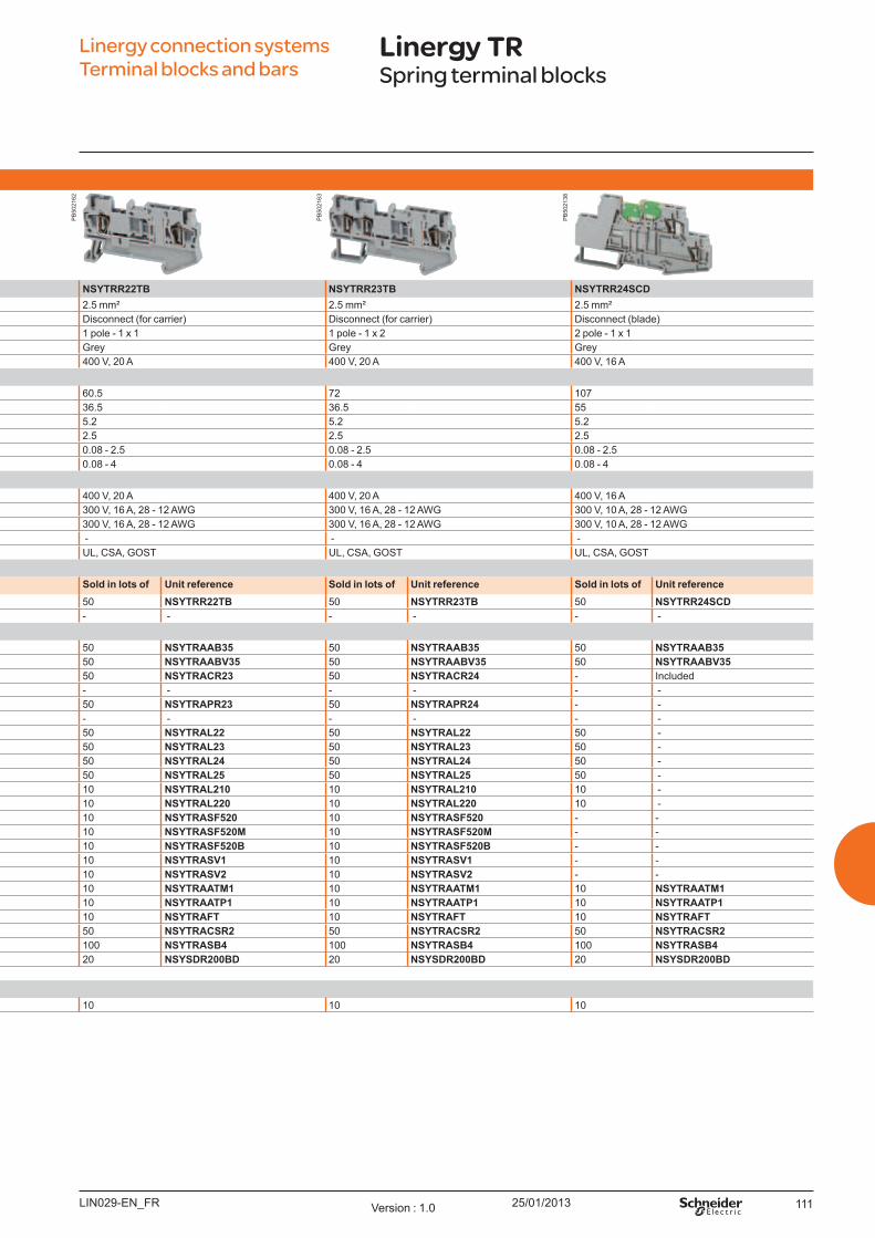
25/01/2013 111
Sp ring t erm inal b l o ck s - Disco nnect
NSYTRR22SC NSYTRR23SC NSYTRR22TB NSYTRR23TB NSYTRR24SCDNominal c.s.a. 2.5 mm² 2.5 mm² 2.5 mm² 2.5 mm² 2.5 mm²
Type of block Disconnect ( blade) Disconnect ( blade) Disconnect ( for carrier) Disconnect ( for carrier) Disconnect ( blade)Type of connection 1 pole - 1 x 1 1 pole - 1 x 2 1 pole - 1 x 1 1 pole - 1 x 2 2 pole - 1 x 1Colour Grey Grey Grey Grey Grey
Max. electric values ( U max, Imax) 400 V, 20 A 400 V, 20 A 400 V, 20 A 400 V, 20 A 400 V, 16 ADim ensio ns (m m )
Length 60.5 72 60.5 72 107Height 36.5 36.5 36.5 36.5 55W idth 5.2 5.2 5.2 5.2 5.2
Cabling c.s.a. ( mm² ) 2.5 2.5 2.5 2.5 2.5Flexible cable 0.08 - 2.5 0.08 - 2.5 0.08 - 2.5 0.08 - 2.5 0.08 - 2.5Solid cable 0.08 - 4 0.08 - 4 0.08 - 4 0.08 - 4 0.08 - 4
No m inal el ect ric v al u esIEC/EN 60947-7-1 400 V, 20 A 400 V, 20 A 400 V, 20 A 400 V, 20 A 400 V, 16 AU L 600 V, 16 A, 28 - 12 AW G 600 V, 16 A, 28 - 12 AW G 300 V, 16 A, 28 - 12 AW G 300 V, 16 A, 28 - 12 AW G 300 V, 10 A, 28 - 12 AW GCSA 300 V, 16 A, 28 - 12 AW G 300 V, 16 A, 28 - 12 AW G 300 V, 16 A, 28 - 12 AW G 300 V, 16 A, 28 - 12 AW G 300 V, 10 A, 28 - 12 AW GATEX - - - - -
ertifications U L, CSA, GO ST U L, CSA, GO ST U L, CSA, GO ST U L, CSA, GO ST U L, CSA, GO STTerm inal b l o ck s
So l d in l o t s o f U nit reference So l d in l o t s o f U nit reference So l d in l o t s o f U nit reference So l d in l o t s o f U nit reference So l d in l o t s o f U nit referenceGrey 50 NSYTRR22SC 50 NSYTRR23SC 50 NSYTRR22TB 50 NSYTRR23TB 50 NSYTRR24SCDO range 50 NSYTRR22SCAR 50 NSYTRR23SCAR - - - - - -
Accesso riesEnd stopfor 35 mm DIN rail
Clip-on, 5.2 mm 50 NSYTRAAB35 50 NSYTRAAB35 50 NSYTRAAB35 50 NSYTRAAB35 50 NSYTRAAB35W ith screw, 9.5 mm 50 NSYTRAABV35 50 NSYTRAABV35 50 NSYTRAABV35 50 NSYTRAABV35 50 NSYTRAABV35
End plate,width 2.2 mm
Grey 50 NSYTRACR23 50 NSYTRACR24 50 NSYTRACR23 50 NSYTRACR24 - IncludedB lue - - - - - - - - - -
Partition plate,width 2 mm
Grey 50 NSYTRAPR23 50 NSYTRAPR24 50 NSYTRAPR23 50 NSYTRAPR24 - -B lue - - - - - - - - - -
Plug-in bridgeRed
2-pole 50 NSYTRAL22 50 NSYTRAL22 50 NSYTRAL22 50 NSYTRAL22 50 -3-pole 50 NSYTRAL23 50 NSYTRAL23 50 NSYTRAL23 50 NSYTRAL23 50 -4-pole 50 NSYTRAL24 50 NSYTRAL24 50 NSYTRAL24 50 NSYTRAL24 50 -5-pole 50 NSYTRAL25 50 NSYTRAL25 50 NSYTRAL25 50 NSYTRAL25 50 -10-pole 10 NSYTRAL210 10 NSYTRAL210 10 NSYTRAL210 10 NSYTRAL210 10 -20-pole 10 NSYTRAL220 10 NSYTRAL220 10 NSYTRAL220 10 NSYTRAL220 10 -
Removable carrier For fuse 5 x 20 mm - - - - 10 NSYTRASF520 10 NSYTRASF520 - -For fuse 5 x 20 mm 110 - 250 V LED - - - - 10 NSYTRASF520M 10 NSYTRASF520M - -For fuse 5 x 20 mm 12 - 30 V LED - - - - 10 NSYTRASF520B 10 NSYTRASF520B - -For component - - - - 10 NSYTRASV1 10 NSYTRASV1 - -W ith 1N4007 diode - - - - 10 NSYTRASV2 10 NSYTRASV2 - -
Test plug Metalic part, Ø 2.3 mm 10 NSYTRAATM1 10 NSYTRAATM1 10 NSYTRAATM1 10 NSYTRAATM1 10 NSYTRAATM1Insulating sleeve, red 10 NSYTRAATP1 10 NSYTRAATP1 10 NSYTRAATP1 10 NSYTRAATP1 10 NSYTRAATP1
Test adaptor For plug-in bridge shaft 10 NSYTRAFT 10 NSYTRAFT 10 NSYTRAFT 10 NSYTRAFT 10 NSYTRAFTW arning label Y ellow 50 NSYTRACSR2 50 NSYTRACSR2 50 NSYTRACSR2 50 NSYTRACSR2 50 NSYTRACSR2Marker tag holder For AB 35 end stop 100 NSYTRASB4 100 NSYTRASB4 100 NSYTRASB4 100 NSYTRASB4 100 NSYTRASB4DIN rail 35 x 7.2 mm Perforated, 2 m long 20 NSYSDR200BD 20 NSYSDR200BD 20 NSYSDR200BD 20 NSYSDR200BD 20 NSYSDR200BDMarking accessories See page 126General d at a
Strip length ( mm) 10 10 10 10 10
Linergy connection systems Terminal blocks and bars
Linergy TRSpring terminal blocks
LIN029-EN_FR Version : 1.0
PB
5021
62
PB
5021
63
PB
5021
38
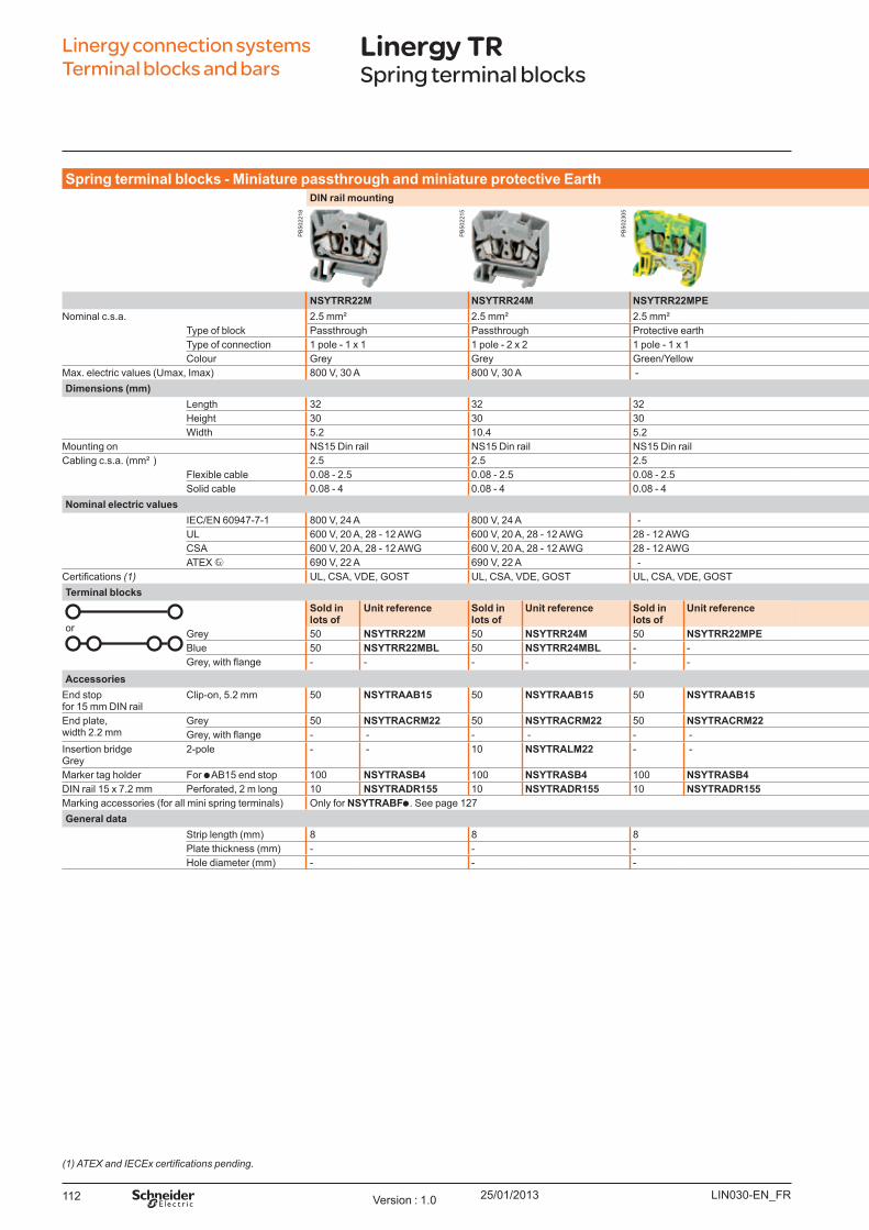
25/01/2013112
Sp ring t erm inal b l o ck s - Miniat u re p asst h ro u gh and m iniat u re p ro t ect iv e Eart hDI N rail m o u nt ing Fo r m icro - p erfo rat ed m o u nt ing p l at es
NSYTRR22M NSYTRR24M NSYTRR22MPE NSYTRR22MF NSYTRR24MF NSYTRR22MP NSYTRR24MPNominal c.s.a. 2.5 mm² 2.5 mm² 2.5 mm² 2.5 mm² 2.5 mm² 2.5 mm² 2.5 mm²
Type of block Passthrough Passthrough Protective earth Passthrough Passthrough Passthrough PassthroughType of connection 1 pole - 1 x 1 1 pole - 2 x 2 1 pole - 1 x 1 1 pole - 1 x 1 1 pole - 2 x 2 1 pole - 1 x 1 1 pole - 2 x 2Colour Grey Grey Green/Y ellow Grey Grey Grey Grey
Max. electric values ( U max, Imax) 800 V, 30 A 800 V, 30 A - 800 V, 30 A 800 V, 30 A 800 V, 30 A 800 V, 30 A
Length 32 32 32 32 32 32 32Height 30 30 30 22 22 22 22W idth 5.2 10.4 5.2 5.2 10.4 5.2 10.4
Mounting on NS15 Din rail NS15 Din rail NS15 Din rail Direct mounting Direct mounting Pin mounting Pin mountingCabling c.s.a. ( mm² ) 2.5 2.5 2.5 2.5 2.5 2.5 2.5
Flexible cable 0.08 - 2.5 0.08 - 2.5 0.08 - 2.5 0.08 - 2.5 0.08 - 2.5 0.08 - 2.5 0.08 - 2.5Solid cable 0.08 - 4 0.08 - 4 0.08 - 4 0.08 - 4 0.08 - 4 0.08 - 4 0.08 - 4
No m inal el ect ric v al u esIEC/EN 60947-7-1 800 V, 24 A 800 V, 24 A - 800 V, 24 A 800 V, 24 A 800 V, 24 A 800 V, 24 AU L 600 V, 20 A, 28 - 12 AW G 600 V, 20 A, 28 - 12 AW G 28 - 12 AW G 600 V, 20 A, 28 - 12 AW G 600 V, 20 A, 28 - 12 AW G 600 V, 20 A, 28 - 12 AW G 600 V, 20 A, 28 - 12 AW GCSA 600 V, 20 A, 28 - 12 AW G 600 V, 20 A, 28 - 12 AW G 28 - 12 AW G 600 V, 20 A, 28 - 12 AW G 600 V, 20 A, 28 - 12 AW G 600 V, 20 A, 28 - 12 AW G 600 V, 20 A, 28 - 12 AW GATEX 690 V, 22 A 690 V, 22 A - 550 V, 22 A 550 V, 22 A 550 V, 22 A 550 V, 22 A
ertifications (1) U L, CSA, VDE, GO ST U L, CSA, VDE, GO ST U L, CSA, VDE, GO ST U L, CSA, VDE, GO ST U L, CSA, VDE, GO ST U L, CSA, VDE, GO ST U L, CSA, VDE, GO STTerm inal b l o ck s
or
So l d in l o t s o f
U nit reference So l d in l o t s o f
U nit reference So l d in l o t s o f
U nit reference So l d in l o t s o f U nit reference So l d in l o t s o f U nit reference So l d in l o t s o f U nit reference So l d in l o ts o f U nit reference
Grey 50 NSYTRR22M 50 NSYTRR24M 50 NSYTRR22MPE 50 NSYTRR22MF 50 NSYTRR24MF 50 NSYTRR22MP 10 NSYTRR24MPB lue 50 NSYTRR22MBL 50 NSYTRR24MBL - - 50 NSYTRR22MFBL 50 NSYTRR24MFBL 50 NSYTRR22MPBL 10 NSYTRR24MPBLGrey, with flange - - - - - - 50 NSYTRR22MFF (2) 50 NSYTRR24MFF (2) - - - -
Accesso riesEnd stopfor 15 mm DIN rail
Clip-on, 5.2 mm 50 NSYTRAAB15 50 NSYTRAAB15 50 NSYTRAAB15 - - - - - - - -
End plate,width 2.2 mm
Grey 50 NSYTRACRM22 50 NSYTRACRM22 50 NSYTRACRM22 50 NSYTRACRM22 50 NSYTRACRM22 50 NSYTRACRM22 50 NSYTRACRM22Grey, with flange - - - - - - 50 NSYTRACRMF22 (2) 50 NSYTRACRMF22 (2) - - - -
Insertion bridgeGrey
2-pole - - 10 NSYTRALM22 - - - - 10 NSYTRALM22 - - 10 NSYTRALM22
Marker tag holder For AB 15 end stop 100 NSYTRASB4 100 NSYTRASB4 100 NSYTRASB4 100 NSYTRASB4 100 NSYTRASB4 100 NSYTRASB4 100 -DIN rail 15 x 7.2 mm Perforated, 2 m long 10 NSYTRADR155 10 NSYTRADR155 10 NSYTRADR155 - - - - - - - -Marking accessories ( for all mini spring terminals) O nly for NSYTRABF . See page 127General d at a
Strip length ( mm) 8 8 8 8 8 8 8Plate thickness ( mm) - - - - - 0.6 - 1.5 0.6 - 1.5Hole diameter ( mm) - - - - - 3.5 3.5
(1) ATEX and IECEx certifications pending.
Linergy connection systems Terminal blocks and bars
Linergy TRSpring terminal blocks
LIN030-EN_FRVersion : 1.0
PB
5022
18
PB
5022
15
PB
5023
05

25/01/2013 113
Sp ring t erm inal b l o ck s - Miniat u re p asst h ro u gh and m iniat u re p ro t ect iv e Eart hDI N rail m o u nt ing Fo r m icro - p erfo rat ed m o u nt ing p l at es
NSYTRR22M NSYTRR24M NSYTRR22MPE NSYTRR22MF NSYTRR24MF NSYTRR22MP NSYTRR24MPNominal c.s.a. 2.5 mm² 2.5 mm² 2.5 mm² 2.5 mm² 2.5 mm² 2.5 mm² 2.5 mm²
Type of block Passthrough Passthrough Protective earth Passthrough Passthrough Passthrough PassthroughType of connection 1 pole - 1 x 1 1 pole - 2 x 2 1 pole - 1 x 1 1 pole - 1 x 1 1 pole - 2 x 2 1 pole - 1 x 1 1 pole - 2 x 2Colour Grey Grey Green/Y ellow Grey Grey Grey Grey
Max. electric values ( U max, Imax) 800 V, 30 A 800 V, 30 A - 800 V, 30 A 800 V, 30 A 800 V, 30 A 800 V, 30 A
Length 32 32 32 32 32 32 32Height 30 30 30 22 22 22 22W idth 5.2 10.4 5.2 5.2 10.4 5.2 10.4
Mounting on NS15 Din rail NS15 Din rail NS15 Din rail Direct mounting Direct mounting Pin mounting Pin mountingCabling c.s.a. ( mm² ) 2.5 2.5 2.5 2.5 2.5 2.5 2.5
Flexible cable 0.08 - 2.5 0.08 - 2.5 0.08 - 2.5 0.08 - 2.5 0.08 - 2.5 0.08 - 2.5 0.08 - 2.5Solid cable 0.08 - 4 0.08 - 4 0.08 - 4 0.08 - 4 0.08 - 4 0.08 - 4 0.08 - 4
No m inal el ect ric v al u esIEC/EN 60947-7-1 800 V, 24 A 800 V, 24 A - 800 V, 24 A 800 V, 24 A 800 V, 24 A 800 V, 24 AU L 600 V, 20 A, 28 - 12 AW G 600 V, 20 A, 28 - 12 AW G 28 - 12 AW G 600 V, 20 A, 28 - 12 AW G 600 V, 20 A, 28 - 12 AW G 600 V, 20 A, 28 - 12 AW G 600 V, 20 A, 28 - 12 AW GCSA 600 V, 20 A, 28 - 12 AW G 600 V, 20 A, 28 - 12 AW G 28 - 12 AW G 600 V, 20 A, 28 - 12 AW G 600 V, 20 A, 28 - 12 AW G 600 V, 20 A, 28 - 12 AW G 600 V, 20 A, 28 - 12 AW GATEX 690 V, 22 A 690 V, 22 A - 550 V, 22 A 550 V, 22 A 550 V, 22 A 550 V, 22 A
ertifications (1) U L, CSA, VDE, GO ST U L, CSA, VDE, GO ST U L, CSA, VDE, GO ST U L, CSA, VDE, GO ST U L, CSA, VDE, GO ST U L, CSA, VDE, GO ST U L, CSA, VDE, GO STTerm inal b l o ck s
or
So l d in l o t s o f
U nit reference So l d in l o t s o f
U nit reference So l d in l o t s o f
U nit reference So l d in l o t s o f U nit reference So l d in l o t s o f U nit reference So l d in l o t s o f U nit reference So l d in l o t s o f U nit reference
Grey 50 NSYTRR22M 50 NSYTRR24M 50 NSYTRR22MPE 50 NSYTRR22MF 50 NSYTRR24MF 50 NSYTRR22MP 10 NSYTRR24MPB lue 50 NSYTRR22MBL 50 NSYTRR24MBL - - 50 NSYTRR22MFBL 50 NSYTRR24MFBL 50 NSYTRR22MPBL 10 NSYTRR24MPBLGrey, with flange - - - - - - 50 NSYTRR22MFF (2) 50 NSYTRR24MFF (2) - - - -
Accesso riesEnd stopfor 15 mm DIN rail
Clip-on, 5.2 mm 50 NSYTRAAB15 50 NSYTRAAB15 50 NSYTRAAB15 - - - - - - - -
End plate,width 2.2 mm
Grey 50 NSYTRACRM22 50 NSYTRACRM22 50 NSYTRACRM22 50 NSYTRACRM22 50 NSYTRACRM22 50 NSYTRACRM22 50 NSYTRACRM22Grey, with flange - - - - - - 50 NSYTRACRMF22 (2) 50 NSYTRACRMF22 (2) - - - -
Insertion bridgeGrey
2-pole - - 10 NSYTRALM22 - - - - 10 NSYTRALM22 - - 10 NSYTRALM22
Marker tag holder For AB 15 end stop 100 NSYTRASB4 100 NSYTRASB4 100 NSYTRASB4 100 NSYTRASB4 100 NSYTRASB4 100 NSYTRASB4 100 -DIN rail 15 x 7.2 mm Perforated, 2 m long 10 NSYTRADR155 10 NSYTRADR155 10 NSYTRADR155 - - - - - - - -Marking accessories ( for all mini spring terminals) O nly for NSYTRABF . See page 127General d at a
Strip length ( mm) 8 8 8 8 8 8 8Plate thickness ( mm) - - - - - 0.6 - 1.5 0.6 - 1.5Hole diameter ( mm) - - - - - 3.5 3.5
Linergy connection systems Terminal blocks and bars
Linergy TRSpring terminal blocks
( ) Can on e sed at t e end o a gro p o ter ina s.
LIN030-EN_FR Version : 1.0
PB
5022
16
PB
5022
14
PB
5022
17
PB
5022
13
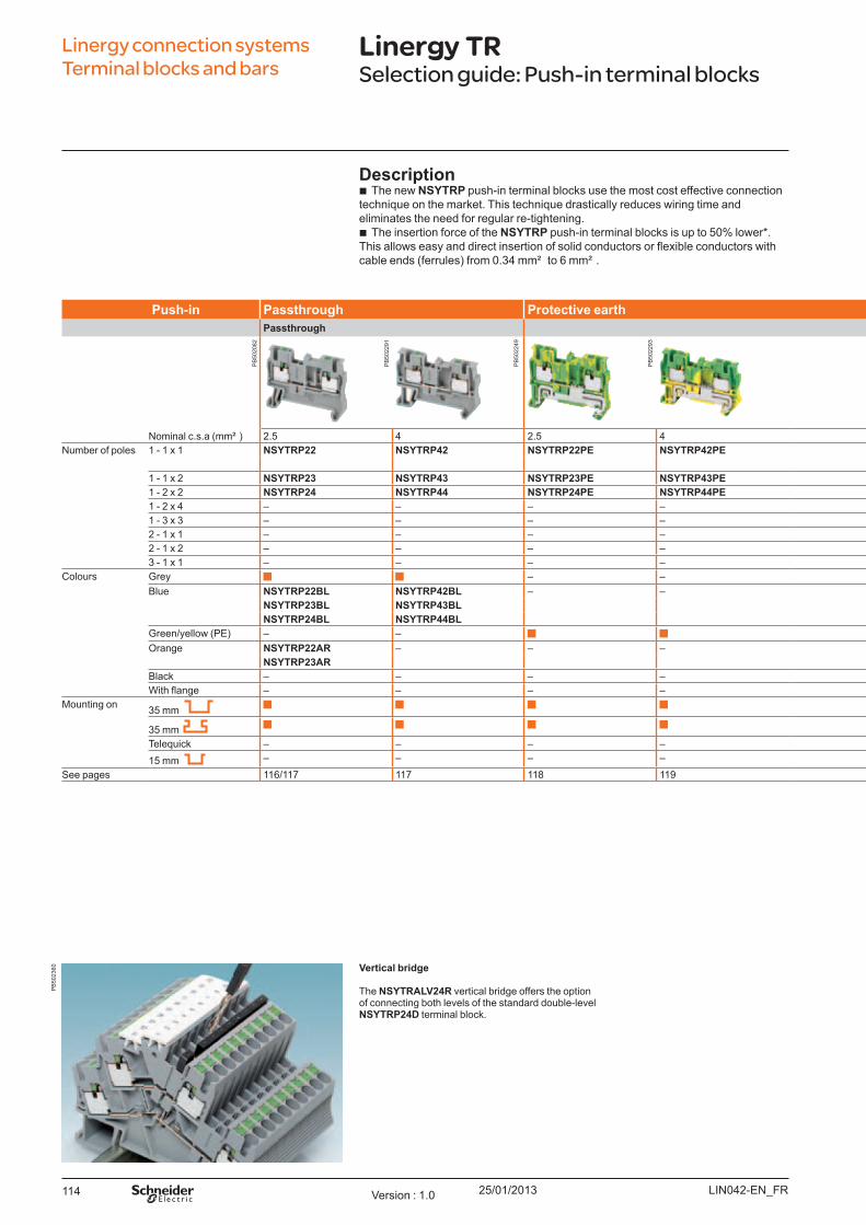
25/01/2013114
Linergy connection systems Terminal blocks and bars
Linergy TRSelection guide: Push-in terminal blocks
Pu sh - in Passt h ro u gh Pro t ect iv e eart h Do u b l e d eck Disco nnect Hyb rid : Screw - I DC co nnect io nPasst h ro u gh Bl ad e Rem o v ab l e carrier Passt h ro u gh
Nominal c.s.a ( mm² ) 2.5 4 2.5 4 2.5 2.5 2.5 & 4 1.5 2.5Number of poles 1 - 1 x 1 NSYTRP22 NSYTRP42 NSYTRP22PE NSYTRP42PE – NSYTRP22SC NSYTRP22TB NSYTRH12 NSYTRH22
NSYTRP42TB1 - 1 x 2 NSYTRP23 NSYTRP43 NSYTRP23PE NSYTRP43PE – NSYTRP23SC – NSYTRH13 –1 - 2 x 2 NSYTRP24 NSYTRP44 NSYTRP24PE NSYTRP44PE – NSYTRP24SC – – –1 - 2 x 4 – – – – – – – – –1 - 3 x 3 – – – – – – – – –2 - 1 x 1 – – – – NSYTRP24D - – – –2 - 1 x 2 – – – – – – – – –3 - 1 x 1 – – – – – – – – –
Colours Grey – –B lue NSYTRP22BL NSYTRP42BL – – NSYTRP24DBL – – – –
NSYTRP23BL NSYTRP43BLNSYTRP24BL NSYTRP44BL
Green/yellow ( PE) – – NSYTRP24DPE – – NSYTRH12PE –O range NSYTRP22AR – – – – – – – –
NSYTRP23ARB lack – – – – – – – – –With flange – – – – – – – – –
Mounting on 35 mm – –
35 mm – –
Teleq uick – – – – – – – – –15 mm – – – – – – –
See pages 116/117 117 118 119 120 122 123 124 125
Vert ical b rid ge
The NSYTRALV24R vertical bridge offers the option of connecting both levels of the standard double-level NSYTRP24D terminal block.
Descrip t io n b The new NSYTRP push-in terminal blocks use the most cost effective connection
techniq ue on the market. This techniq ue drastically reduces wiring time and eliminates the need for regular re-tightening.
b The insertion force of the NSYTRP push-in terminal blocks is up to 50% lower* . his allows easy and direct insertion of solid conductors or flexible conductors with
cable ends ( ferrules) from 0.34 mm² to 6 mm² .
LIN042-EN_FRVersion : 1.0
PB
5020
82
PB
5022
91
PB
5022
49
PB
5022
93
PB
5023
60

25/01/2013 115
Linergy connection systems Terminal blocks and bars
Linergy TRSelection guide: Push-in terminal blocks
Pu sh - in Passt h ro u gh Pro t ect iv e eart h Do u b l e d eck Disco nnect Hyb rid : Screw - I DC co nnect io nPasst h ro u gh Bl ad e Rem o v ab l e carrier Passt h ro u gh
Nominal c.s.a ( mm² ) 2.5 4 2.5 4 2.5 2.5 2.5 & 4 1.5 2.5Number of poles 1 - 1 x 1 NSYTRP22 NSYTRP42 NSYTRP22PE NSYTRP42PE – NSYTRP22SC NSYTRP22TB NSYTRH12 NSYTRH22
NSYTRP42TB1 - 1 x 2 NSYTRP23 NSYTRP43 NSYTRP23PE NSYTRP43PE – NSYTRP23SC – NSYTRH13 –1 - 2 x 2 NSYTRP24 NSYTRP44 NSYTRP24PE NSYTRP44PE – NSYTRP24SC – – –1 - 2 x 4 – – – – – – – – –1 - 3 x 3 – – – – – – – – –2 - 1 x 1 – – – – NSYTRP24D - – – –2 - 1 x 2 – – – – – – – – –3 - 1 x 1 – – – – – – – – –
Colours Grey – –B lue NSYTRP22BL NSYTRP42BL – – NSYTRP24DBL – – – –
NSYTRP23BL NSYTRP43BLNSYTRP24BL NSYTRP44BL
Green/yellow ( PE) – – NSYTRP24DPE – – NSYTRH12PE –O range NSYTRP22AR – – – – – – – –
NSYTRP23ARB lack – – – – – – – – –With flange – – – – – – – – –
Mounting on 35 mm – –
35 mm – –
Teleq uick – – – – – – – – –15 mm – – – – – – –
See pages 116/117 117 118 119 120 122 123 124 125
LIN042-EN_FR Version : 1.0
PB
5022
56
PB
5022
57
PB
5023
02
PB
5021
17
PB
5021
19
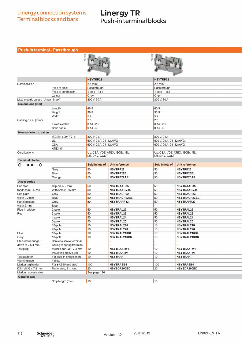
25/01/2013116
Pu sh - in t erm inal - Passt h ro u gh
NSYTRP22 NSYTRP23 NSYTRP24 NSYTRP42 NSYTRP43 NSYTRP44Nominal c.s.a. 2.5 mm² 2.5 mm² 2.5 mm² 4 mm² 4 mm² 4 mm²
Type of block Passthrough Passthrough Passthrough Passthrough Passthrough PassthroughType of connection 1 pole - 1 x 1 1 pole - 1 x 2 1 pole - 2 x 2 1 pole - 1 x 1 1 pole - 1 x 2 1 pole - 2 x 2Colour Grey Grey Grey Grey Grey Grey
Max. electric values ( U max , Imax) 800 V, 30 A 800 V, 30 A 800 V, 30 A 800 V, 38 A 800 V, 38 A 800 V, 38 ADim ensio ns (m m )
Length 48.5 60.5 72 56 66.5 77Height 36.5 36.5 36.5 36.5 36.5 36.5W idth 5.2 5.2 5.2 6.2 6.2 6.2
Cabling c.s.a. ( mm2) 2.5 2.5 2.5 4 4 4Flexible cable 0.14 - 2.5 0.14 - 2.5 0.14 - 2.5 0.2 - 4 0.2 - 4 0.2 - 4Solid cable 0.14 - 4 0.14 - 4 0.14 - 4 0.2 - 6 0.2 - 6 0.2 - 6
No m inal el ect ric v al u esIEC/EN 60947-7-1 800 V, 24 A 800 V, 24 A 800 V, 24 A 800 V, 32 A 800 V, 32 A 800 V, 32 AU L 600 V, 20 A, 24 -12 AW G 600 V, 20 A, 24 -12 AW G 600 V, 20 A, 24 -12 AW G 600 V, 30 A, 24 - 10 AW G 600 V, 30 A, 24 - 10 AW G 600 V, 30 A, 24 - 10 AW GCSA 600 V, 20 A, 24 -12 AW G 600 V, 20 A, 24 -12 AW G 600 V, 20 A, 24 -12 AW G 600 V, 30 A, 24 - 10 AW G 600 V, 30 A, 24 - 10 AW G 600 V, 30 A, 24 - 10 AW GATEX - - - - - -
ertifications U L, CSA, VDE, ATEX, IECEx, GL, LR, DNV, GO ST
U L, CSA, VDE, ATEX, IECEx, GL, LR, DNV, GO ST
U L, CSA, VDE, ATEX, IECEx, GL, LR, DNV, GO ST
U L, CSA, VDE, ATEX, IECEx, GL, LR, DNV, GO ST
U L, CSA, VDE, ATEX, IECEx, GL, LR, DNV, GO ST
U L, CSA, VDE, ATEX, IECEx, GL, LR, DNV, GO ST
Term inal b l o ck sSo l d in l o t s o f U nit reference So l d in l o t s o f U nit reference So l d in l o t s o f U nit reference So l d in l o t s o f U nit reference So l d in l o t s o f U nit reference So l d in l o ts o f U nit reference
Grey 50 NSYTRP22 50 NSYTRP23 50 NSYTRP24 50 NSYTRP42 50 NSYTRP43 50 NSYTRP44B lue 50 NSYTRP22BL 50 NSYTRP23BL 50 NSYTRP24BL 50 NSYTRP42BL 50 NSYTRP43BL 50 NSYTRP44BLO range 50 NSYTRP22AR 50 NSYTRP23AR - - - - - - - -
Accesso riesEnd stop Clip-on, 5.2 mm 50 NSYTRAAB35 50 NSYTRAAB35 50 NSYTRAAB35 50 NSYTRAAB35 50 NSYTRAAB35 50 NSYTRAAB35for 35 mm DIN rail W ith screw, 9.5 mm 50 NSYTRAABV35 50 NSYTRAABV35 50 NSYTRAABV35 50 NSYTRAABV35 50 NSYTRAABV35 50 NSYTRAABV35End plate Grey 50 NSYTRACR22 50 NSYTRACR23 50 NSYTRACR24 50 NSYTRACR42 50 NSYTRACP43 50 NSYTRACP44width 2.2 mm B lue 50 NSYTRACR22BL 50 NSYTRACR23BL 50 NSYTRACR24BL - - - - - -Partition plate Grey 50 NSYTRAPR42 50 NSYTRAPR23 50 NSYTRAPR24 50 NSYTRAPR42 - - - -width 2 mm B lue - - - - - - - - - - - -Plug-in bridge 2-pole 50 NSYTRAL22 50 NSYTRAL22 50 NSYTRAL22 50 NSYTRAL42 50 NSYTRAL42 50 NSYTRAL42Red 3-pole 50 NSYTRAL23 50 NSYTRAL23 50 NSYTRAL23 50 NSYTRAL43 50 NSYTRAL43 50 NSYTRAL43
4-pole 50 NSYTRAL24 50 NSYTRAL24 50 NSYTRAL24 50 NSYTRAL44 50 NSYTRAL44 50 NSYTRAL445-pole 50 NSYTRAL25 50 NSYTRAL25 50 NSYTRAL25 50 NSYTRAL45 50 NSYTRAL45 50 NSYTRAL4510-pole 10 NSYTRAL210 10 NSYTRAL210 10 NSYTRAL210 10 NSYTRAL410 10 NSYTRAL410 10 NSYTRAL41020-pole 10 NSYTRAL220 10 NSYTRAL220 10 NSYTRAL220 10 NSYTRAL420 10 NSYTRAL420 10 NSYTRAL420
B lue 10-pole 10 NSYTRAL210BL 10 NSYTRAL210BL 10 NSYTRAL210BL 10 NSYTRAL410BL 10 NSYTRAL410BL 10 NSYTRAL410BLGrey 10-pole 10 NSYTRAL210GR 10 NSYTRAL210GR 10 NSYTRAL210GR 10 NSYTRAL410GR 10 NSYTRAL410GR 10 NSYTRAL410BLStep-down bridge, Screw to screw terminal - - - - - - - - - - - - down to 2.5/4 mm² Spring to spring trerminal - - - - - - - - - - - - Test plug Metalic part, Ø 2.3 mm 10 NSYTRAATM1 10 NSYTRAATM1 10 NSYTRAATM1 10 NSYTRAATM1 10 NSYTRAATM1 10 NSYTRAATM1
Insulating sleeve, red 10 NSYTRAATP1 10 NSYTRAATP1 10 NSYTRAATP1 10 NSYTRAATP1 10 NSYTRAATP1 10 NSYTRAATP1Test adaptor For plug-in bridge shaft 10 NSYTRAFT 10 NSYTRAFT 10 NSYTRAFT 10 NSYTRAFT 10 NSYTRAFT 10 NSYTRAFTW arning label Y ellow - - - - - - - - - - - - Marker tag holder For AB 35 end stop 100 NSYTRASB4 100 NSYTRASB4 100 NSYTRASB4 100 NSYTRASB4 100 NSYTRASB4 100 NSYTRASB4DIN rail 35 x 7.2 mm Perforated, 2 m long 20 NSYSDR200BD 20 NSYSDR200BD 20 NSYSDR200BD 20 NSYSDR200BD 20 NSYSDR200BD 20 NSYSDR200BDMarking accessories See page 126General d at a
Strip length ( mm) 10 10 10 12 12 12
Linergy connection systems Terminal blocks and bars
Linergy TRPush-in terminal blocks
LIN024-EN_FRVersion : 1.0
PB
5020
82
PB
5022
52
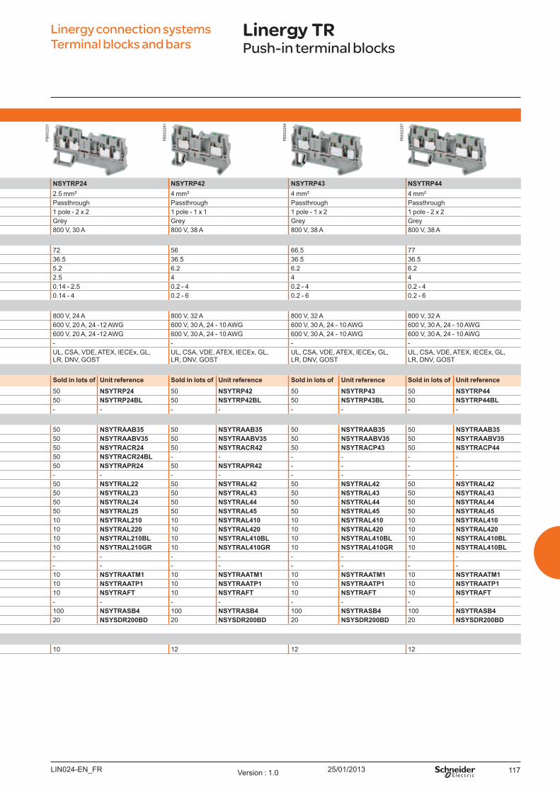
25/01/2013 117
Pu sh - in t erm inal - Passt h ro u gh
NSYTRP22 NSYTRP23 NSYTRP24 NSYTRP42 NSYTRP43 NSYTRP44Nominal c.s.a. 2.5 mm² 2.5 mm² 2.5 mm² 4 mm² 4 mm² 4 mm²
Type of block Passthrough Passthrough Passthrough Passthrough Passthrough PassthroughType of connection 1 pole - 1 x 1 1 pole - 1 x 2 1 pole - 2 x 2 1 pole - 1 x 1 1 pole - 1 x 2 1 pole - 2 x 2Colour Grey Grey Grey Grey Grey Grey
Max. electric values ( U max , Imax) 800 V, 30 A 800 V, 30 A 800 V, 30 A 800 V, 38 A 800 V, 38 A 800 V, 38 ADim ensio ns (m m )
Length 48.5 60.5 72 56 66.5 77Height 36.5 36.5 36.5 36.5 36.5 36.5W idth 5.2 5.2 5.2 6.2 6.2 6.2
Cabling c.s.a. ( mm2) 2.5 2.5 2.5 4 4 4Flexible cable 0.14 - 2.5 0.14 - 2.5 0.14 - 2.5 0.2 - 4 0.2 - 4 0.2 - 4Solid cable 0.14 - 4 0.14 - 4 0.14 - 4 0.2 - 6 0.2 - 6 0.2 - 6
No m inal el ect ric v al u esIEC/EN 60947-7-1 800 V, 24 A 800 V, 24 A 800 V, 24 A 800 V, 32 A 800 V, 32 A 800 V, 32 AU L 600 V, 20 A, 24 -12 AW G 600 V, 20 A, 24 -12 AW G 600 V, 20 A, 24 -12 AW G 600 V, 30 A, 24 - 10 AW G 600 V, 30 A, 24 - 10 AW G 600 V, 30 A, 24 - 10 AW GCSA 600 V, 20 A, 24 -12 AW G 600 V, 20 A, 24 -12 AW G 600 V, 20 A, 24 -12 AW G 600 V, 30 A, 24 - 10 AW G 600 V, 30 A, 24 - 10 AW G 600 V, 30 A, 24 - 10 AW GATEX - - - - - -
ertifications U L, CSA, VDE, ATEX, IECEx, GL, LR, DNV, GO ST
U L, CSA, VDE, ATEX, IECEx, GL, LR, DNV, GO ST
U L, CSA, VDE, ATEX, IECEx, GL, LR, DNV, GO ST
U L, CSA, VDE, ATEX, IECEx, GL, LR, DNV, GO ST
U L, CSA, VDE, ATEX, IECEx, GL, LR, DNV, GO ST
U L, CSA, VDE, ATEX, IECEx, GL, LR, DNV, GO ST
Term inal b l o ck sSo l d in l o t s o f U nit reference So l d in l o t s o f U nit reference So l d in l o t s o f U nit reference So l d in l o t s o f U nit reference So l d in l o t s o f U nit reference So l d in l o t s o f U nit reference
Grey 50 NSYTRP22 50 NSYTRP23 50 NSYTRP24 50 NSYTRP42 50 NSYTRP43 50 NSYTRP44B lue 50 NSYTRP22BL 50 NSYTRP23BL 50 NSYTRP24BL 50 NSYTRP42BL 50 NSYTRP43BL 50 NSYTRP44BLO range 50 NSYTRP22AR 50 NSYTRP23AR - - - - - - - -
Accesso riesEnd stop Clip-on, 5.2 mm 50 NSYTRAAB35 50 NSYTRAAB35 50 NSYTRAAB35 50 NSYTRAAB35 50 NSYTRAAB35 50 NSYTRAAB35for 35 mm DIN rail W ith screw, 9.5 mm 50 NSYTRAABV35 50 NSYTRAABV35 50 NSYTRAABV35 50 NSYTRAABV35 50 NSYTRAABV35 50 NSYTRAABV35End plate Grey 50 NSYTRACR22 50 NSYTRACR23 50 NSYTRACR24 50 NSYTRACR42 50 NSYTRACP43 50 NSYTRACP44width 2.2 mm B lue 50 NSYTRACR22BL 50 NSYTRACR23BL 50 NSYTRACR24BL - - - - - -Partition plate Grey 50 NSYTRAPR42 50 NSYTRAPR23 50 NSYTRAPR24 50 NSYTRAPR42 - - - -width 2 mm B lue - - - - - - - - - - - -Plug-in bridge 2-pole 50 NSYTRAL22 50 NSYTRAL22 50 NSYTRAL22 50 NSYTRAL42 50 NSYTRAL42 50 NSYTRAL42Red 3-pole 50 NSYTRAL23 50 NSYTRAL23 50 NSYTRAL23 50 NSYTRAL43 50 NSYTRAL43 50 NSYTRAL43
4-pole 50 NSYTRAL24 50 NSYTRAL24 50 NSYTRAL24 50 NSYTRAL44 50 NSYTRAL44 50 NSYTRAL445-pole 50 NSYTRAL25 50 NSYTRAL25 50 NSYTRAL25 50 NSYTRAL45 50 NSYTRAL45 50 NSYTRAL4510-pole 10 NSYTRAL210 10 NSYTRAL210 10 NSYTRAL210 10 NSYTRAL410 10 NSYTRAL410 10 NSYTRAL41020-pole 10 NSYTRAL220 10 NSYTRAL220 10 NSYTRAL220 10 NSYTRAL420 10 NSYTRAL420 10 NSYTRAL420
B lue 10-pole 10 NSYTRAL210BL 10 NSYTRAL210BL 10 NSYTRAL210BL 10 NSYTRAL410BL 10 NSYTRAL410BL 10 NSYTRAL410BLGrey 10-pole 10 NSYTRAL210GR 10 NSYTRAL210GR 10 NSYTRAL210GR 10 NSYTRAL410GR 10 NSYTRAL410GR 10 NSYTRAL410BLStep-down bridge, Screw to screw terminal - - - - - - - - - - - - down to 2.5/4 mm² Spring to spring trerminal - - - - - - - - - - - - Test plug Metalic part, Ø 2.3 mm 10 NSYTRAATM1 10 NSYTRAATM1 10 NSYTRAATM1 10 NSYTRAATM1 10 NSYTRAATM1 10 NSYTRAATM1
Insulating sleeve, red 10 NSYTRAATP1 10 NSYTRAATP1 10 NSYTRAATP1 10 NSYTRAATP1 10 NSYTRAATP1 10 NSYTRAATP1Test adaptor For plug-in bridge shaft 10 NSYTRAFT 10 NSYTRAFT 10 NSYTRAFT 10 NSYTRAFT 10 NSYTRAFT 10 NSYTRAFTW arning label Y ellow - - - - - - - - - - - - Marker tag holder For AB 35 end stop 100 NSYTRASB4 100 NSYTRASB4 100 NSYTRASB4 100 NSYTRASB4 100 NSYTRASB4 100 NSYTRASB4DIN rail 35 x 7.2 mm Perforated, 2 m long 20 NSYSDR200BD 20 NSYSDR200BD 20 NSYSDR200BD 20 NSYSDR200BD 20 NSYSDR200BD 20 NSYSDR200BDMarking accessories See page 126General d at a
Strip length ( mm) 10 10 10 12 12 12
Linergy connection systems Terminal blocks and bars
Linergy TRPush-in terminal blocks
LIN024-EN_FR Version : 1.0
PB
5022
51
PB
5022
91
PB
5022
94
PB
5022
97
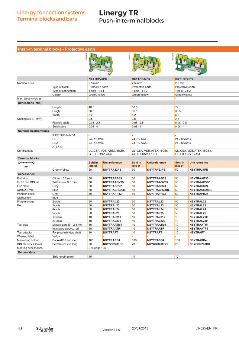
25/01/2013118
Pu sh - in t erninal b l o ck s - Pro t ect iv e eart h
NSYTRP22PE NSYTRP23PE NSYTRP24PE NSYTRP42PE NSYTRP43PE NSYTRP44PENominal c.s.a. 2.5 mm² 2.5 mm² 2.5 mm² 4 mm² 4 mm² 4 mm²
Type of block Protective earth Protective earth Protective earth Protective earth Protective earth Protective earthType of connection 1 pole - 1 x 1 1 pole - 1 x 2 1 pole - 2 x 2 1 pole - 1 x 1 1 pole - 1 x 2 1 pole - 2 x 2Colour Green/Y ellow Green/Y ellow Green/Y ellow Green/Y ellow Green/Y ellow Green/Y ellow
Max. electric values - - - - - -Dim ensio ns (m m )
Length 48.5 60.5 72 56 66.5 77Height 36.5 36.5 36.5 36.5 36.5 36.5W idth 5.2 5.2 5.2 6.2 6.2 6.2
Cabling c.s.a. ( mm2) 2.5 2.5 2.5 4 4 4Flexible cable 0.08 - 2.5 0.08 - 2.5 0.08 - 2.5 0.08 - 4 0.08 - 4 0.08 - 4Solid cable 0.08 - 4 0.08 - 4 0.08 - 4 0.08 - 6 0.08 - 6 0.08 - 6
No m inal el ect ric v al u esIEC/EN 60947-7-1 - - - - - - U L 24 - 12 AW G 24 - 12 AW G 24 - 12 AW G 24 - 10 AW G 24 - 10 AW G 24 - 10 AW GCSA 24 - 12 AW G 24 - 12 AW G 24 - 12 AW G 24 - 10 AW G 24 - 10 AW G 24 - 10 AW GATEX - - - - - -
ertifications U L, CSA, VDE, ATEX, IECEx, GL, LR, DNV, GO ST
U L, CSA, VDE, ATEX, IECEx, GL, LR, DNV, GO ST
U L, CSA, VDE, ATEX, IECEx, GL, LR, DNV, GO ST
U L, CSA, VDE, ATEX, IECEx, GL, LR, DNV, GO ST
U L, CSA, VDE, ATEX, IECEx, GL, LR, DNV, GO ST
U L, CSA, VDE, ATEX, IECEx, GL, LR, DNV, GO ST
Term inal b l o ck sSo l d in l o t s o f
U nit reference So l d in l o t s o f
U nit reference So l d in l o t s o f
U nit reference So l d in l o t s o f U nit reference So l d in l o t s o f U nit reference So l d in l o t s o f U nit reference
Green/Y ellow 50 NSYTRP22PE 50 NSYTRP23PE 50 NSYTRP24PE 50 NSYTRP42PE 50 NSYTRP43PE 50 NSYTRP44PEAccesso ries
End stop Clip-on, 5.2 mm 50 NSYTRAAB35 50 NSYTRAAB35 50 NSYTRAAB35 50 NSYTRAAB35 50 NSYTRAAB35 50 NSYTRAAB35for 35 mm DIN rail W ith screw, 9.5 mm 50 NSYTRAABV35 50 NSYTRAABV35 50 NSYTRAABV35 50 NSYTRAABV35 50 NSYTRAABV35 50 NSYTRAABV35End plate, Grey 50 NSYTRACR22 50 NSYTRACR23 50 NSYTRACR24 50 NSYTRACR42 50 NSYTRACP43 50 NSYTRACP44width 2.2 mm B lue 50 NSYTRACR22BL 50 NSYTRACR23BL 50 NSYTRACR24BL - - - - - - Partition plate, Grey 50 NSYTRAPR42 50 NSYTRAPR23 50 NSYTRAPR24 50 NSYTRAPR42 - - - - width 2 mm B lue - - - - - - - - - - - - Plug-in bridge 2-pole 50 NSYTRAL22 50 NSYTRAL22 50 NSYTRAL22 50 NSYTRAL42 50 NSYTRAL42 50 NSYTRAL42Red 3-pole 50 NSYTRAL23 50 NSYTRAL23 50 NSYTRAL23 50 NSYTRAL43 50 NSYTRAL43 50 NSYTRAL43
4-pole 50 NSYTRAL24 50 NSYTRAL24 50 NSYTRAL24 50 NSYTRAL44 50 NSYTRAL44 50 NSYTRAL445-pole 50 NSYTRAL25 50 NSYTRAL25 50 NSYTRAL25 50 NSYTRAL45 50 NSYTRAL45 50 NSYTRAL4510-pole 10 NSYTRAL210 10 NSYTRAL210 10 NSYTRAL210 10 NSYTRAL410 10 NSYTRAL410 10 NSYTRAL41020-pole 10 NSYTRAL220 10 NSYTRAL220 10 NSYTRAL220 10 NSYTRAL420 10 NSYTRAL420 10 NSYTRAL420
Test plug Metalic part, Ø 2.3 mm 10 NSYTRAATM1 10 NSYTRAATM1 10 NSYTRAATM1 10 NSYTRAATM1 10 NSYTRAATM1 10 NSYTRAATM1Insulating sleeve, red 10 NSYTRAATP1 10 NSYTRAATP1 10 NSYTRAATP1 10 NSYTRAATP1 10 NSYTRAATP1 10 NSYTRAATP1
Test adaptor For plug-in bridge shaft 10 NSYTRAFT 10 NSYTRAFT 10 NSYTRAFT 10 NSYTRAFT 10 NSYTRAFT 10 NSYTRAFTW arning label Y ellow - - - - - - - - - - - - Marker tag holder For AB 35 end stop 100 NSYTRASB4 100 NSYTRASB4 100 NSYTRASB4 100 NSYTRASB4 100 NSYTRASB4 100 NSYTRASB4DIN rail 35 x 7.2 mm Perforated, 2 m long 20 NSYSDR200BD 20 NSYSDR200BD 20 NSYSDR200BD 20 NSYSDR200BD 20 NSYSDR200BD 20 NSYSDR200BDMarking accessories See page 126General d at a
Strip length ( mm) 10 10 10 12 12 12
Linergy connection systems Terminal blocks and bars
Linergy TRPush-in terminal blocks
LIN025-EN_FRVersion : 1.0
PB
5022
49
PB
5022
50
PB
5022
48
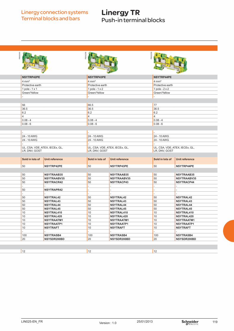
25/01/2013 119
Pu sh - in t erninal b l o ck s - Pro t ect iv e eart h
NSYTRP22PE NSYTRP23PE NSYTRP24PE NSYTRP42PE NSYTRP43PE NSYTRP44PENominal c.s.a. 2.5 mm² 2.5 mm² 2.5 mm² 4 mm² 4 mm² 4 mm²
Type of block Protective earth Protective earth Protective earth Protective earth Protective earth Protective earthType of connection 1 pole - 1 x 1 1 pole - 1 x 2 1 pole - 2 x 2 1 pole - 1 x 1 1 pole - 1 x 2 1 pole - 2 x 2Colour Green/Y ellow Green/Y ellow Green/Y ellow Green/Y ellow Green/Y ellow Green/Y ellow
Max. electric values - - - - - -Dim ensio ns (m m )
Length 48.5 60.5 72 56 66.5 77Height 36.5 36.5 36.5 36.5 36.5 36.5W idth 5.2 5.2 5.2 6.2 6.2 6.2
Cabling c.s.a. ( mm2) 2.5 2.5 2.5 4 4 4Flexible cable 0.08 - 2.5 0.08 - 2.5 0.08 - 2.5 0.08 - 4 0.08 - 4 0.08 - 4Solid cable 0.08 - 4 0.08 - 4 0.08 - 4 0.08 - 6 0.08 - 6 0.08 - 6
No m inal el ect ric v al u esIEC/EN 60947-7-1 - - - - - - U L 24 - 12 AW G 24 - 12 AW G 24 - 12 AW G 24 - 10 AW G 24 - 10 AW G 24 - 10 AW GCSA 24 - 12 AW G 24 - 12 AW G 24 - 12 AW G 24 - 10 AW G 24 - 10 AW G 24 - 10 AW GATEX - - - - - -
ertifications U L, CSA, VDE, ATEX, IECEx, GL, LR, DNV, GO ST
U L, CSA, VDE, ATEX, IECEx, GL, LR, DNV, GO ST
U L, CSA, VDE, ATEX, IECEx, GL, LR, DNV, GO ST
U L, CSA, VDE, ATEX, IECEx, GL, LR, DNV, GO ST
U L, CSA, VDE, ATEX, IECEx, GL, LR, DNV, GO ST
U L, CSA, VDE, ATEX, IECEx, GL, LR, DNV, GO ST
Term inal b l o ck sSo l d in l o t s o f
U nit reference So l d in l o t s o f
U nit reference So l d in l o t s o f
U nit reference So l d in l o t s o f U nit reference So l d in l o t s o f U nit reference So l d in l o t s o f U nit reference
Green/Y ellow 50 NSYTRP22PE 50 NSYTRP23PE 50 NSYTRP24PE 50 NSYTRP42PE 50 NSYTRP43PE 50 NSYTRP44PEAccesso ries
End stop Clip-on, 5.2 mm 50 NSYTRAAB35 50 NSYTRAAB35 50 NSYTRAAB35 50 NSYTRAAB35 50 NSYTRAAB35 50 NSYTRAAB35for 35 mm DIN rail W ith screw, 9.5 mm 50 NSYTRAABV35 50 NSYTRAABV35 50 NSYTRAABV35 50 NSYTRAABV35 50 NSYTRAABV35 50 NSYTRAABV35End plate, Grey 50 NSYTRACR22 50 NSYTRACR23 50 NSYTRACR24 50 NSYTRACR42 50 NSYTRACP43 50 NSYTRACP44width 2.2 mm B lue 50 NSYTRACR22BL 50 NSYTRACR23BL 50 NSYTRACR24BL - - - - - - Partition plate, Grey 50 NSYTRAPR42 50 NSYTRAPR23 50 NSYTRAPR24 50 NSYTRAPR42 - - - - width 2 mm B lue - - - - - - - - - - - - Plug-in bridge 2-pole 50 NSYTRAL22 50 NSYTRAL22 50 NSYTRAL22 50 NSYTRAL42 50 NSYTRAL42 50 NSYTRAL42Red 3-pole 50 NSYTRAL23 50 NSYTRAL23 50 NSYTRAL23 50 NSYTRAL43 50 NSYTRAL43 50 NSYTRAL43
4-pole 50 NSYTRAL24 50 NSYTRAL24 50 NSYTRAL24 50 NSYTRAL44 50 NSYTRAL44 50 NSYTRAL445-pole 50 NSYTRAL25 50 NSYTRAL25 50 NSYTRAL25 50 NSYTRAL45 50 NSYTRAL45 50 NSYTRAL4510-pole 10 NSYTRAL210 10 NSYTRAL210 10 NSYTRAL210 10 NSYTRAL410 10 NSYTRAL410 10 NSYTRAL41020-pole 10 NSYTRAL220 10 NSYTRAL220 10 NSYTRAL220 10 NSYTRAL420 10 NSYTRAL420 10 NSYTRAL420
Test plug Metalic part, Ø 2.3 mm 10 NSYTRAATM1 10 NSYTRAATM1 10 NSYTRAATM1 10 NSYTRAATM1 10 NSYTRAATM1 10 NSYTRAATM1Insulating sleeve, red 10 NSYTRAATP1 10 NSYTRAATP1 10 NSYTRAATP1 10 NSYTRAATP1 10 NSYTRAATP1 10 NSYTRAATP1
Test adaptor For plug-in bridge shaft 10 NSYTRAFT 10 NSYTRAFT 10 NSYTRAFT 10 NSYTRAFT 10 NSYTRAFT 10 NSYTRAFTW arning label Y ellow - - - - - - - - - - - - Marker tag holder For AB 35 end stop 100 NSYTRASB4 100 NSYTRASB4 100 NSYTRASB4 100 NSYTRASB4 100 NSYTRASB4 100 NSYTRASB4DIN rail 35 x 7.2 mm Perforated, 2 m long 20 NSYSDR200BD 20 NSYSDR200BD 20 NSYSDR200BD 20 NSYSDR200BD 20 NSYSDR200BD 20 NSYSDR200BDMarking accessories See page 126General d at a
Strip length ( mm) 10 10 10 12 12 12
Linergy connection systems Terminal blocks and bars
Linergy TRPush-in terminal blocks
LIN025-EN_FR Version : 1.0
PB
5022
93
PB
5022
96
PB
5022
99
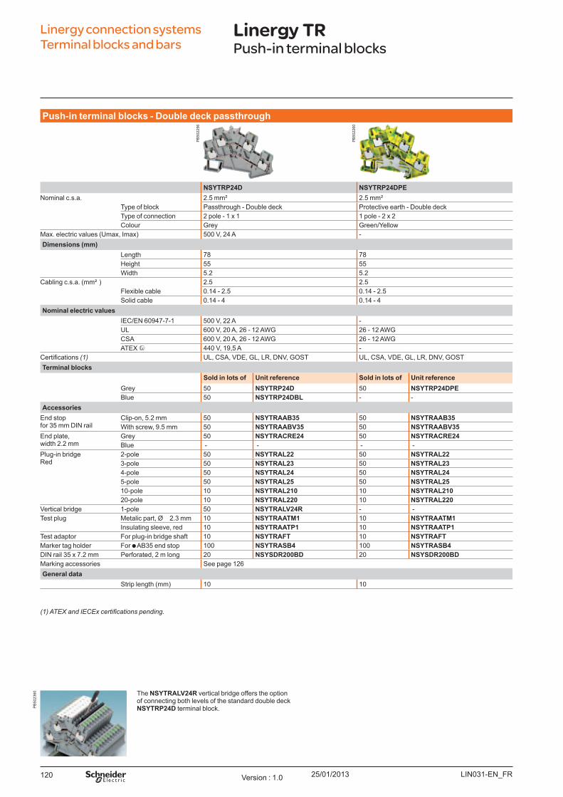
25/01/2013120
Pu sh - in t erm inal b l o ck s - Do u b l e d eck p asst h ro u gh
NSYTRP24D NSYTRP24DPENominal c.s.a. 2.5 mm² 2.5 mm²
Type of block Passthrough - Double deck Protective earth - Double deckType of connection 2 pole - 1 x 1 1 pole - 2 x 2Colour Grey Green/Y ellow
Max. electric values ( U max, Imax) 500 V, 24 A - Dim ensio ns (m m )
Length 78 78Height 55 55W idth 5.2 5.2
Cabling c.s.a. ( mm² ) 2.5 2.5Flexible cable 0.14 - 2.5 0.14 - 2.5Solid cable 0.14 - 4 0.14 - 4
No m inal el ect ric v al u esIEC/EN 60947-7-1 500 V, 22 A - U L 600 V, 20 A, 26 - 12 AW G 26 - 12 AW GCSA 600 V, 20 A, 26 - 12 AW G 26 - 12 AW GATEX 440 V, 19,5 A -
ertifications (1) U L, CSA, VDE, GL, LR, DNV, GO ST U L, CSA, VDE, GL, LR, DNV, GO STTerm inal b l o ck s
So l d in l o t s o f U nit reference So l d in l o t s o f U nit referenceGrey 50 NSYTRP24D 50 NSYTRP24DPEB lue 50 NSYTRP24DBL - -
Accesso riesEnd stopfor 35 mm DIN rail
Clip-on, 5.2 mm 50 NSYTRAAB35 50 NSYTRAAB35W ith screw, 9.5 mm 50 NSYTRAABV35 50 NSYTRAABV35
End plate,width 2.2 mm
Grey 50 NSYTRACRE24 50 NSYTRACRE24B lue - - - -
Plug-in bridgeRed
2-pole 50 NSYTRAL22 50 NSYTRAL223-pole 50 NSYTRAL23 50 NSYTRAL234-pole 50 NSYTRAL24 50 NSYTRAL245-pole 50 NSYTRAL25 50 NSYTRAL2510-pole 10 NSYTRAL210 10 NSYTRAL21020-pole 10 NSYTRAL220 10 NSYTRAL220
Vertical bridge 1-pole 50 NSYTRALV24R - -Test plug Metalic part, Ø 2.3 mm 10 NSYTRAATM1 10 NSYTRAATM1
Insulating sleeve, red 10 NSYTRAATP1 10 NSYTRAATP1Test adaptor For plug-in bridge shaft 10 NSYTRAFT 10 NSYTRAFTMarker tag holder For AB 35 end stop 100 NSYTRASB4 100 NSYTRASB4DIN rail 35 x 7.2 mm Perforated, 2 m long 20 NSYSDR200BD 20 NSYSDR200BDMarking accessories See page 126General d at a
Strip length ( mm) 10 10
The NSYTRALV24R vertical bridge offers the option of connecting both levels of the standard double deck NSYTRP24D terminal block.
(1) ATEX and IECEx certifications pending.
Linergy connection systems Terminal blocks and bars
Linergy TRPush-in terminal blocks
LIN031-EN_FRVersion : 1.0
PB
5022
56
PB
5022
60
PB
5023
60

25/01/2013 121LIN031-EN_FR Version : 1.0
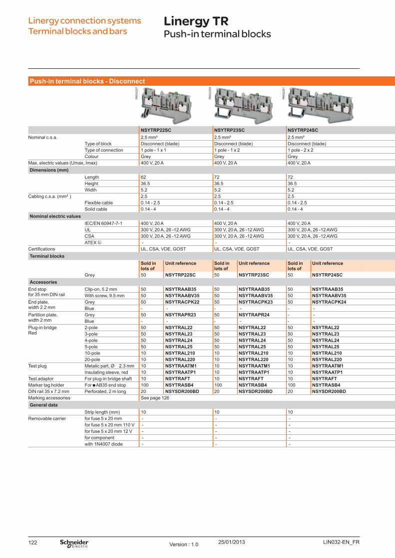
25/01/2013122
Pu sh - in t erm inal b l o ck s - Disco nnect
NSYTRP22SC NSYTRP23SC NSYTRP24SC NSYTRP22TB NSYTRP42TBNominal c.s.a. 2.5 mm² 2.5 mm² 2.5 mm² 2.5 mm² 4 mm²
Type of block Disconnect ( blade) Disconnect ( blade) Disconnect ( blade) Disconnect ( for carrier) Disconnect ( for carrier)Type of connection 1 pole - 1 x 1 1 pole - 1 x 2 1 pole - 2 x 2 1 pole - 1 x 1 1 pole - 1 x 1Colour Grey Grey Grey Grey Grey
Max. electric values ( U max, Imax) 400 V, 20 A 400 V, 20 A 400 V, 20 A 400 V, 20 A 400 V, 20 ADim ensio ns (m m )
Length 62 72 72 62 56Height 36.5 36.5 36.5 36.5 36.5W idth 5.2 5.2 5.2 5.2 6.2
Cabling c.s.a. ( mm² ) 2.5 2.5 2.5 2.5 4Flexible cable 0.14 - 2.5 0.14 - 2.5 0.14 - 2.5 0.14 - 2.5 0.2 - 4Solid cable 0.14 - 4 0.14 - 4 0.14 - 4 0.14 - 4 0.2 - 6
No m inal el ect ric v al u esIEC/EN 60947-7-1 400 V, 20 A 400 V, 20 A 400 V, 20 A 400 V, 20 A 400 V, 20 AU L 300 V, 20 A, 26 -12 AW G 300 V, 20 A, 26 -12 AW G 300 V, 20 A, 26 -12 AW G 300 V, 20 A, 26 -12 AW G 300 V, 20 A, 24 -12 AW GCSA 300 V, 20 A, 26 -12 AW G 300 V, 20 A, 26 -12 AW G 300 V, 20 A, 26 -12 AW G 300 V, 20 A, 26 -12 AW G 300 V, 20 A, 24 -12 AW GATEX - - - - -
ertifications U L, CSA, VDE, GO ST U L, CSA, VDE, GO ST U L, CSA, VDE, GO ST U L, CSA, VDE, GO ST U L, CSA, VDE, GO STTerm inal b l o ck s
So l d in l o t s o f
U nit reference So l d in l o t s o f
U nit reference So l d in l o t s o f
U nit reference So l d in l o t s o f U nit reference So l d in l o t s o f U nit reference
Grey 50 NSYTRP22SC 50 NSYTRP23SC 50 NSYTRP24SC 50 NSYTRP22TB 50 NSYTRP42TBAccesso ries
End stopfor 35 mm DIN rail
Clip-on, 5.2 mm 50 NSYTRAAB35 50 NSYTRAAB35 50 NSYTRAAB35 50 NSYTRAAB35 50 NSYTRAAB35W ith screw, 9.5 mm 50 NSYTRAABV35 50 NSYTRAABV35 50 NSYTRAABV35 50 NSYTRAABV35 50 NSYTRAABV35
End plate,width 2.2 mm
Grey 50 NSYTRACPK22 50 NSYTRACPK23 50 NSYTRACPK24 50 NSYTRACPK22 50 NSYTRACR42B lue - - - - - - - - - -
Partition plate,width 2 mm
Grey 50 NSYTRAPR23 50 NSYTRAPR24 - - - - 50 NSYTRAPR24B lue - - - - - - - - - -
Plug-in bridgeRed
2-pole 50 NSYTRAL22 50 NSYTRAL22 50 NSYTRAL22 50 NSYTRAL22 50 NSYTRAL423-pole 50 NSYTRAL23 50 NSYTRAL23 50 NSYTRAL23 50 NSYTRAL23 50 NSYTRAL434-pole 50 NSYTRAL24 50 NSYTRAL24 50 NSYTRAL24 50 NSYTRAL24 50 NSYTRAL445-pole 50 NSYTRAL25 50 NSYTRAL25 50 NSYTRAL25 50 NSYTRAL25 50 NSYTRAL4510-pole 10 NSYTRAL210 10 NSYTRAL210 10 NSYTRAL210 10 NSYTRAL210 10 NSYTRAL41020-pole 10 NSYTRAL220 10 NSYTRAL220 10 NSYTRAL220 10 NSYTRAL220 10 NSYTRAL420
Test plug Metalic part, Ø 2.3 mm 10 NSYTRAATM1 10 NSYTRAATM1 10 NSYTRAATM1 10 NSYTRAATM1 10 NSYTRAATM1Insulating sleeve, red 10 NSYTRAATP1 10 NSYTRAATP1 10 NSYTRAATP1 10 NSYTRAATP1 10 NSYTRAATP1
Test adaptor For plug-in bridge shaft 10 NSYTRAFT 10 NSYTRAFT 10 NSYTRAFT 10 NSYTRAFT 10 NSYTRAFTMarker tag holder For AB 35 end stop 100 NSYTRASB4 100 NSYTRASB4 100 NSYTRASB4 100 NSYTRASB4 100 NSYTRASB4DIN rail 35 x 7.2 mm Perforated, 2 m long 20 NSYSDR200BD 20 NSYSDR200BD 20 NSYSDR200BD 20 NSYSDR200BD 20 NSYSDR200BDMarking accessories See page 126General d at a
Strip length ( mm) 10 10 10 10 12Removable carrier for fuse 5 x 20 mm - - - NSYTRASF520 NSYTRASF520
for fuse 5 x 20 mm 110 V - - - NSYTRASF520M NSYTRASF520Mfor fuse 5 x 20 mm 12 V - - - NSYTRASF520B NSYTRASF520Bfor component - - - NSYTRASV1 NSYTRASV1with 1N4007 diode - - - NSYTRASV2 NSYTRASV2
Linergy connection systems Terminal blocks and bars
Linergy TRPush-in terminal blocks
LIN032-EN_FRVersion : 1.0
PB
5022
57
PB
5022
59
PB
5022
61
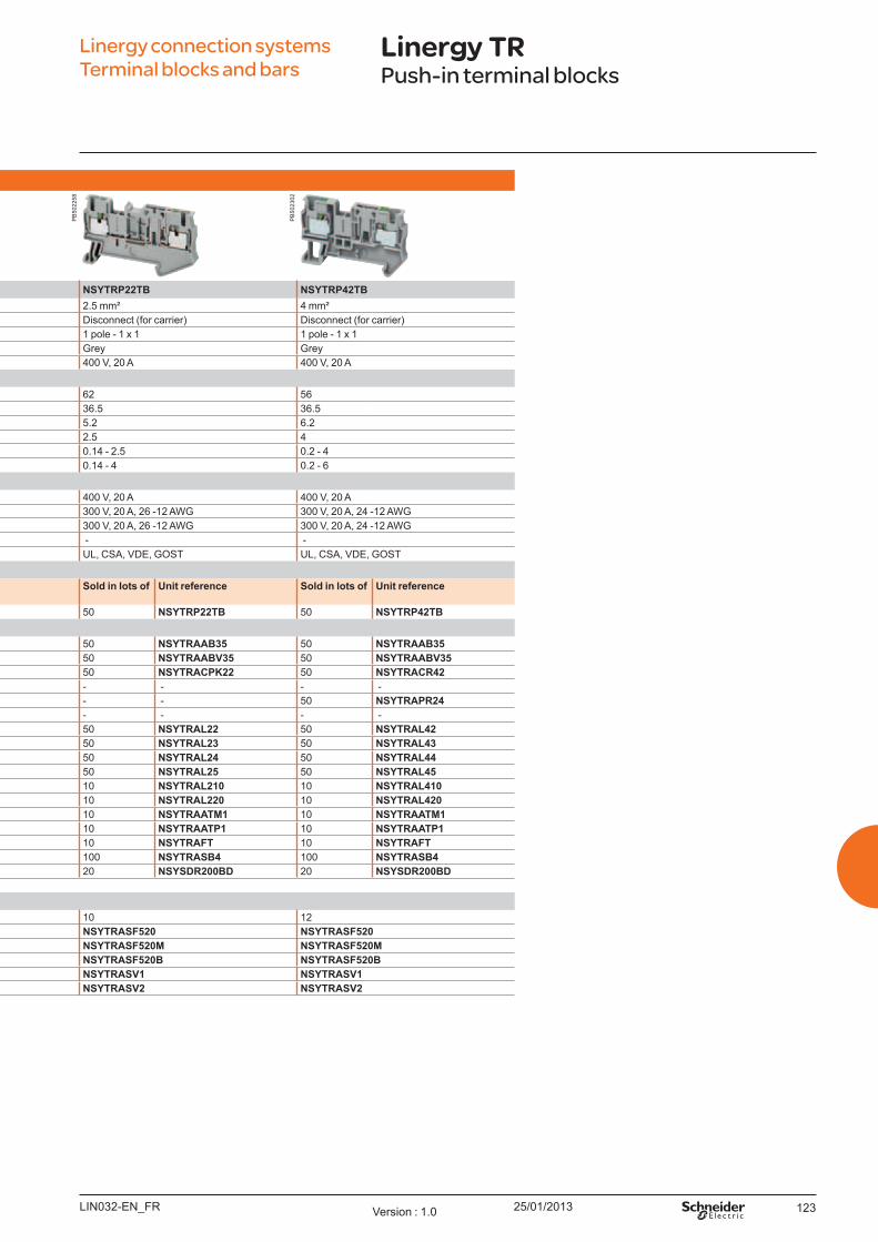
25/01/2013 123
Pu sh - in t erm inal b l o ck s - Disco nnect
NSYTRP22SC NSYTRP23SC NSYTRP24SC NSYTRP22TB NSYTRP42TBNominal c.s.a. 2.5 mm² 2.5 mm² 2.5 mm² 2.5 mm² 4 mm²
Type of block Disconnect ( blade) Disconnect ( blade) Disconnect ( blade) Disconnect ( for carrier) Disconnect ( for carrier)Type of connection 1 pole - 1 x 1 1 pole - 1 x 2 1 pole - 2 x 2 1 pole - 1 x 1 1 pole - 1 x 1Colour Grey Grey Grey Grey Grey
Max. electric values ( U max, Imax) 400 V, 20 A 400 V, 20 A 400 V, 20 A 400 V, 20 A 400 V, 20 ADim ensio ns (m m )
Length 62 72 72 62 56Height 36.5 36.5 36.5 36.5 36.5W idth 5.2 5.2 5.2 5.2 6.2
Cabling c.s.a. ( mm² ) 2.5 2.5 2.5 2.5 4Flexible cable 0.14 - 2.5 0.14 - 2.5 0.14 - 2.5 0.14 - 2.5 0.2 - 4Solid cable 0.14 - 4 0.14 - 4 0.14 - 4 0.14 - 4 0.2 - 6
No m inal el ect ric v al u esIEC/EN 60947-7-1 400 V, 20 A 400 V, 20 A 400 V, 20 A 400 V, 20 A 400 V, 20 AU L 300 V, 20 A, 26 -12 AW G 300 V, 20 A, 26 -12 AW G 300 V, 20 A, 26 -12 AW G 300 V, 20 A, 26 -12 AW G 300 V, 20 A, 24 -12 AW GCSA 300 V, 20 A, 26 -12 AW G 300 V, 20 A, 26 -12 AW G 300 V, 20 A, 26 -12 AW G 300 V, 20 A, 26 -12 AW G 300 V, 20 A, 24 -12 AW GATEX - - - - -
ertifications U L, CSA, VDE, GO ST U L, CSA, VDE, GO ST U L, CSA, VDE, GO ST U L, CSA, VDE, GO ST U L, CSA, VDE, GO STTerm inal b l o ck s
So l d in l o t s o f
U nit reference So l d in l o t s o f
U nit reference So l d in l o t s o f
U nit reference So l d in l o t s o f U nit reference So l d in l o t s o f U nit reference
Grey 50 NSYTRP22SC 50 NSYTRP23SC 50 NSYTRP24SC 50 NSYTRP22TB 50 NSYTRP42TBAccesso ries
End stopfor 35 mm DIN rail
Clip-on, 5.2 mm 50 NSYTRAAB35 50 NSYTRAAB35 50 NSYTRAAB35 50 NSYTRAAB35 50 NSYTRAAB35W ith screw, 9.5 mm 50 NSYTRAABV35 50 NSYTRAABV35 50 NSYTRAABV35 50 NSYTRAABV35 50 NSYTRAABV35
End plate,width 2.2 mm
Grey 50 NSYTRACPK22 50 NSYTRACPK23 50 NSYTRACPK24 50 NSYTRACPK22 50 NSYTRACR42B lue - - - - - - - - - -
Partition plate,width 2 mm
Grey 50 NSYTRAPR23 50 NSYTRAPR24 - - - - 50 NSYTRAPR24B lue - - - - - - - - - -
Plug-in bridgeRed
2-pole 50 NSYTRAL22 50 NSYTRAL22 50 NSYTRAL22 50 NSYTRAL22 50 NSYTRAL423-pole 50 NSYTRAL23 50 NSYTRAL23 50 NSYTRAL23 50 NSYTRAL23 50 NSYTRAL434-pole 50 NSYTRAL24 50 NSYTRAL24 50 NSYTRAL24 50 NSYTRAL24 50 NSYTRAL445-pole 50 NSYTRAL25 50 NSYTRAL25 50 NSYTRAL25 50 NSYTRAL25 50 NSYTRAL4510-pole 10 NSYTRAL210 10 NSYTRAL210 10 NSYTRAL210 10 NSYTRAL210 10 NSYTRAL41020-pole 10 NSYTRAL220 10 NSYTRAL220 10 NSYTRAL220 10 NSYTRAL220 10 NSYTRAL420
Test plug Metalic part, Ø 2.3 mm 10 NSYTRAATM1 10 NSYTRAATM1 10 NSYTRAATM1 10 NSYTRAATM1 10 NSYTRAATM1Insulating sleeve, red 10 NSYTRAATP1 10 NSYTRAATP1 10 NSYTRAATP1 10 NSYTRAATP1 10 NSYTRAATP1
Test adaptor For plug-in bridge shaft 10 NSYTRAFT 10 NSYTRAFT 10 NSYTRAFT 10 NSYTRAFT 10 NSYTRAFTMarker tag holder For AB 35 end stop 100 NSYTRASB4 100 NSYTRASB4 100 NSYTRASB4 100 NSYTRASB4 100 NSYTRASB4DIN rail 35 x 7.2 mm Perforated, 2 m long 20 NSYSDR200BD 20 NSYSDR200BD 20 NSYSDR200BD 20 NSYSDR200BD 20 NSYSDR200BDMarking accessories See page 126General d at a
Strip length ( mm) 10 10 10 10 12Removable carrier for fuse 5 x 20 mm - - - NSYTRASF520 NSYTRASF520
for fuse 5 x 20 mm 110 V - - - NSYTRASF520M NSYTRASF520Mfor fuse 5 x 20 mm 12 V - - - NSYTRASF520B NSYTRASF520Bfor component - - - NSYTRASV1 NSYTRASV1with 1N4007 diode - - - NSYTRASV2 NSYTRASV2
Linergy connection systems Terminal blocks and bars
Linergy TRPush-in terminal blocks
LIN032-EN_FR Version : 1.0
PB
5022
58
PB
5023
02

25/01/2013124
Hyb rid t erm inal b l o ck s - Passt h ro u gh
NSYTRH12 NSYTRH13 NSYTRH22 NSYTRH12PENominal c.s.a. 1.5 mm² 1.5 mm² 2.5 mm² 1.5 mm²
Type of block Passthrough Passthrough Passthrough Protective earthType of connection 1 pole - 1 x 1 1 pole - 1 x 2 ( 1 screw x 2 IDC) 1 pole - 1 x 1 1 pole - 1 x 1Colour Grey Grey Grey Green/Y ellow
Max. electric values ( U max, Imax) 800 V, 17 A 800 V, 17 A 800 V, 24 A - Dim ensio ns (m m )
Length 58.8 76.4 62.6 58.8Height 42.8 42.8 42.8 42.8W idth 5.2 5.2 6.2 5.2
Cabling c.s.a. ( mm² ) IDC connection 1.5 1.5 2.5 1.5Flexible cable 0.5 - 1.5 0.5 - 1.5 0.5 - 2.5 0.5 - 1.5
Cabling c.s.a. ( mm² ) Screw connection 1.5 1.5 2.5 1.5Flexible cable 0.14 - 2.5 0.14 - 2.5 0.14 - 4 0.14 - 2.5Solid cable 0.14 - 4 0.14 - 4 0.14 - 6 0.14 - 4
No m inal el ect ric v al u esIEC/EN 60947-7-1 800 V, 17 A 800 V, 17 A 800 V, 24 A - U L 600 V, 10 A, 24 - 16 AW G 600 V, 10 A, 24 - 16 AW G 600 V, 15 A, 20 - 14 AW G 24 - 16 AW GCSA 600 V, 10 A, 24 - 16 AW G 600 V, 10 A, 24 - 16 AW G 600 V, 15 A, 20 - 14 AW G 24 - 16 AW GATEX 550 V, 16.5 A 550 V, 16.5 A 550 V, 22 A -
ertifications U L, CSA, ATEX, IECEx, GO ST U L, CSA, ATEX, IECEx, GO ST U L, CSA, ATEX, IECEx, GO ST U L, CSA, ATEX, IECEx, GO STTerm inal b l o ck s
So l d in l o t s o f U nit reference So l d in l o t s o f U nit reference So l d in l o t s o f U nit reference So l d in l o t s o f U nit referenceGrey 50 NSYTRH12 50 NSYTRH13 50 NSYTRH22 50 NSYTRH12PE
Accesso riesEnd stopfor 35 mm DIN rail
Clip-on, 5.2 mm 50 NSYTRAAB35 50 NSYTRAAB35 50 NSYTRAAB35 50 NSYTRAAB35W ith screw, 9.5 mm 50 NSYTRAABV35 50 NSYTRAABV35 50 NSYTRAABV35 50 NSYTRAABV35
End plate,width 2.2 mm
Grey 50 NSYTRACH12 50 NSYTRACH13 50 NSYTRACH22 50 NSYTRACH12B lue - - - - - - - -
Partition plate,width 2 mm
Grey 50 NSYTRAPD12 50 NSYTRAPD13 - - 50 NSYTRAPD12B lue - - - - - - - -
Plug-in bridgeRed
2-pole 50 NSYTRAL22 50 NSYTRAL22 50 NSYTRAL42 50 NSYTRAL223-pole 50 NSYTRAL23 50 NSYTRAL23 50 NSYTRAL43 50 NSYTRAL234-pole 50 NSYTRAL24 50 NSYTRAL24 50 NSYTRAL44 50 NSYTRAL245-pole 50 NSYTRAL25 50 NSYTRAL25 50 NSYTRAL45 50 NSYTRAL2510-pole 10 NSYTRAL210 10 NSYTRAL210 10 NSYTRAL410 10 NSYTRAL21020-pole 10 NSYTRAL220 10 NSYTRAL220 10 NSYTRAL420 10 NSYTRAL220
Test plug Metalic part, Ø 2.3 mm 10 NSYTRAATM1 10 NSYTRAATM1 10 NSYTRAATM1 10 NSYTRAATM1Insulating sleeve, red 10 NSYTRAATP1 10 NSYTRAATP1 10 NSYTRAATP1 10 NSYTRAATP1
Test adaptor For plug-in bridge shaft 10 NSYTRAFT 10 NSYTRAFT 10 NSYTRAFT 10 NSYTRAFTMarker tag holder For AB 35 end stop 100 NSYTRASB4 100 NSYTRASB4 100 NSYTRASB4 100 NSYTRASB4DIN rail 35 x 7.2 mm Perforated, 2 m long 20 NSYSDR200BD 20 NSYSDR200BD 20 NSYSDR200BD 20 NSYSDR200BDMarking accessories See page 126General d at a
Strip length ( mm) 9 9 10 14Screw thread M3 M3 M4 M5Torq ue ( Nm) 0.5 - 0.6 0.6 - 0.8 1.5 - 1.8 2.5 - 3
Linergy connection systems Terminal blocks and bars
Linergy TRHybrid terminal blocks
LIN033-EN_FRVersion : 1.0
PB
5021
17
PB
5021
18
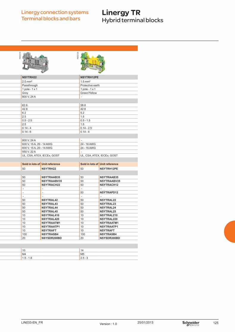
25/01/2013 125
Hyb rid t erm inal b l o ck s - Passt h ro u gh
NSYTRH12 NSYTRH13 NSYTRH22 NSYTRH12PENominal c.s.a. 1.5 mm² 1.5 mm² 2.5 mm² 1.5 mm²
Type of block Passthrough Passthrough Passthrough Protective earthType of connection 1 pole - 1 x 1 1 pole - 1 x 2 ( 1 screw x 2 IDC) 1 pole - 1 x 1 1 pole - 1 x 1Colour Grey Grey Grey Green/Y ellow
Max. electric values ( U max, Imax) 800 V, 17 A 800 V, 17 A 800 V, 24 A - Dim ensio ns (m m )
Length 58.8 76.4 62.6 58.8Height 42.8 42.8 42.8 42.8W idth 5.2 5.2 6.2 5.2
Cabling c.s.a. ( mm² ) IDC connection 1.5 1.5 2.5 1.5Flexible cable 0.5 - 1.5 0.5 - 1.5 0.5 - 2.5 0.5 - 1.5
Cabling c.s.a. ( mm² ) Screw connection 1.5 1.5 2.5 1.5Flexible cable 0.14 - 2.5 0.14 - 2.5 0.14 - 4 0.14 - 2.5Solid cable 0.14 - 4 0.14 - 4 0.14 - 6 0.14 - 4
No m inal el ect ric v al u esIEC/EN 60947-7-1 800 V, 17 A 800 V, 17 A 800 V, 24 A - U L 600 V, 10 A, 24 - 16 AW G 600 V, 10 A, 24 - 16 AW G 600 V, 15 A, 20 - 14 AW G 24 - 16 AW GCSA 600 V, 10 A, 24 - 16 AW G 600 V, 10 A, 24 - 16 AW G 600 V, 15 A, 20 - 14 AW G 24 - 16 AW GATEX 550 V, 16.5 A 550 V, 16.5 A 550 V, 22 A -
ertifications U L, CSA, ATEX, IECEx, GO ST U L, CSA, ATEX, IECEx, GO ST U L, CSA, ATEX, IECEx, GO ST U L, CSA, ATEX, IECEx, GO STTerm inal b l o ck s
So l d in l o t s o f U nit reference So l d in l o t s o f U nit reference So l d in l o t s o f U nit reference So l d in l o t s o f U nit referenceGrey 50 NSYTRH12 50 NSYTRH13 50 NSYTRH22 50 NSYTRH12PE
Accesso riesEnd stopfor 35 mm DIN rail
Clip-on, 5.2 mm 50 NSYTRAAB35 50 NSYTRAAB35 50 NSYTRAAB35 50 NSYTRAAB35W ith screw, 9.5 mm 50 NSYTRAABV35 50 NSYTRAABV35 50 NSYTRAABV35 50 NSYTRAABV35
End plate,width 2.2 mm
Grey 50 NSYTRACH12 50 NSYTRACH13 50 NSYTRACH22 50 NSYTRACH12B lue - - - - - - - -
Partition plate,width 2 mm
Grey 50 NSYTRAPD12 50 NSYTRAPD13 - - 50 NSYTRAPD12B lue - - - - - - - -
Plug-in bridgeRed
2-pole 50 NSYTRAL22 50 NSYTRAL22 50 NSYTRAL42 50 NSYTRAL223-pole 50 NSYTRAL23 50 NSYTRAL23 50 NSYTRAL43 50 NSYTRAL234-pole 50 NSYTRAL24 50 NSYTRAL24 50 NSYTRAL44 50 NSYTRAL245-pole 50 NSYTRAL25 50 NSYTRAL25 50 NSYTRAL45 50 NSYTRAL2510-pole 10 NSYTRAL210 10 NSYTRAL210 10 NSYTRAL410 10 NSYTRAL21020-pole 10 NSYTRAL220 10 NSYTRAL220 10 NSYTRAL420 10 NSYTRAL220
Test plug Metalic part, Ø 2.3 mm 10 NSYTRAATM1 10 NSYTRAATM1 10 NSYTRAATM1 10 NSYTRAATM1Insulating sleeve, red 10 NSYTRAATP1 10 NSYTRAATP1 10 NSYTRAATP1 10 NSYTRAATP1
Test adaptor For plug-in bridge shaft 10 NSYTRAFT 10 NSYTRAFT 10 NSYTRAFT 10 NSYTRAFTMarker tag holder For AB 35 end stop 100 NSYTRASB4 100 NSYTRASB4 100 NSYTRASB4 100 NSYTRASB4DIN rail 35 x 7.2 mm Perforated, 2 m long 20 NSYSDR200BD 20 NSYSDR200BD 20 NSYSDR200BD 20 NSYSDR200BDMarking accessories See page 126General d at a
Strip length ( mm) 9 9 10 14Screw thread M3 M3 M4 M5Torq ue ( Nm) 0.5 - 0.6 0.6 - 0.8 1.5 - 1.8 2.5 - 3
Linergy connection systems Terminal blocks and bars
Linergy TRHybrid terminal blocks
LIN033-EN_FR Version : 1.0
PB
5021
19
PB
5021
20
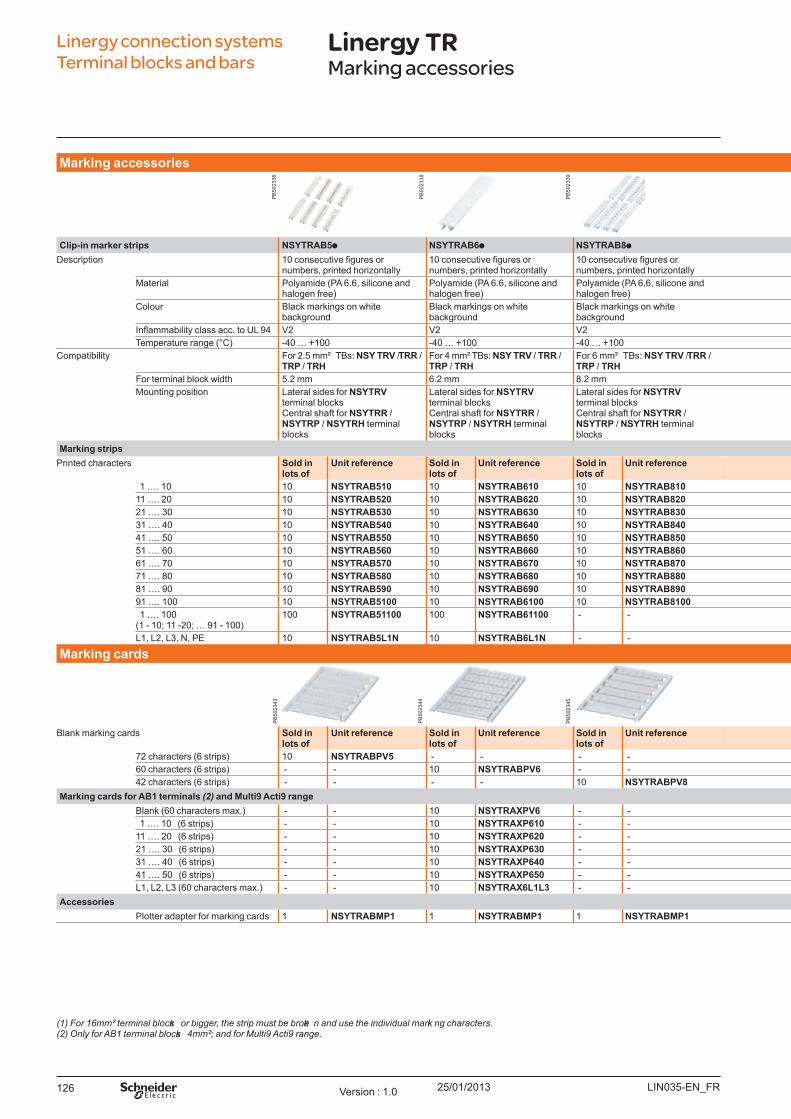
25/01/2013126
Mark ing accesso ries
Cl ip - in m ark er st rip s NSYTRAB5 NSYTRAB6 NSYTRAB8 NSYTRAB10 NSYTRABF5 NSYTRABF6Description 10 consecutive figures or
numbers, printed horizontally10 consecutive figures or numbers, printed horizontally
10 consecutive figures or numbers, printed horizontally
10 consecutive figures or numbers, printed horizontally
10 consecutive figures or numbers, printed horizontally
10 consecutive figures or numbers, printed horizontally
Material Polyamide ( PA 6.6, silicone and halogen free)
Polyamide ( PA 6.6, silicone and halogen free)
Polyamide ( PA 6.6, silicone and halogen free)
Polyamide (PA 6.6, silicone and halogen free)
Polyamide (PA 6.6, silicone and halogen free)
Polyamide (PA 6.6, silicone and halogen free)
Colour Black markings on white background
Black markings on white background
Black markings on white background
Black markings on white background Black markings on white background Black markings on white background
Inflammability class acc. to UL 94 V2 V2 V2 V2 V2 V2emperature range ( ) -40 100 -40 100 -40 100 -40 100 -40 100 -40 100
Compatibility For 2.5 mm² TB s: NSY TRV / TRR / TRP / TRH
For 4 mm Bs NSY TRV / TRR / TRP / TRH
For 6 mm² TB s: NSY TRV / TRR / TRP / TRH
For > = 10 mm² TB s: NSY TRV / TRR / TRP / TRH
For 2.5 mm² TB s: NSY TRV / TRR / TRP / TRH
For 4 mm Bs NSY TRV / TRR / TRP / TRH
For terminal block width 5.2 mm 6.2 mm 8.2 mm 10.2 mm (1) 5.2 mm 6.2 mmounting position Lateral sides for NSYTRV
terminal blocksentral shaft for NSYTRR /
NSYTRP / NSYTRH terminal blocks
Lateral sides for NSYTRV terminal blocks
entral shaft for NSYTRR / NSYTRP / NSYTRH terminal blocks
Lateral sides for NSYTRV terminal blocks
entral shaft for NSYTRR / NSYTRP / NSYTRH terminal blocks
Lateral sides for NSYTRV terminal blocksentral shaft for NSYTRR / NSYTRP /
NSYTRH terminal blocks
entral shaft for NSYTRR / NSYTRP / NSYTRH terminal blocksLateral sides for NSYTRV terminal blocks
entral shaft for NSYTRR / NSYTRP / NSYTRH terminal blocksLateral sides for NSYTRV terminal blocks
Mark ing st rip sPrinted characters So l d in
l o t s o fU nit reference So l d in
l o t s o fU nit reference So l d in
l o t s o fU nit reference So l d in l o t s o f U nit reference So l d in l o t s o f U nit reference So l d in l o t s o f U nit reference
1 . 10 10 NSYTRAB510 10 NSYTRAB610 10 NSYTRAB810 10 NSYTRAB1010 10 NSYTRABF510 10 NSYTRABF61011 . 20 10 NSYTRAB520 10 NSYTRAB620 10 NSYTRAB820 10 NSYTRAB1020 10 NSYTRABF520 10 NSYTRABF62021 . 30 10 NSYTRAB530 10 NSYTRAB630 10 NSYTRAB830 10 NSYTRAB1030 10 NSYTRABF530 10 NSYTRABF63031 . 40 10 NSYTRAB540 10 NSYTRAB640 10 NSYTRAB840 10 NSYTRAB1040 10 NSYTRABF540 10 NSYTRABF64041 . 50 10 NSYTRAB550 10 NSYTRAB650 10 NSYTRAB850 10 NSYTRAB1050 10 NSYTRABF550 10 NSYTRABF65051 . 60 10 NSYTRAB560 10 NSYTRAB660 10 NSYTRAB860 10 NSYTRAB1060 - - - - 61 . 70 10 NSYTRAB570 10 NSYTRAB670 10 NSYTRAB870 10 NSYTRAB1070 - - - - 71 . 80 10 NSYTRAB580 10 NSYTRAB680 10 NSYTRAB880 10 NSYTRAB1080 - - - - 81 . 90 10 NSYTRAB590 10 NSYTRAB690 10 NSYTRAB890 10 NSYTRAB1090 - - - - 91 . 100 10 NSYTRAB5100 10 NSYTRAB6100 10 NSYTRAB8100 10 NSYTRAB10100 - - - - 1 . 100 (1 - 10 11 -20 91 - 100)
100 NSYTRAB51100 100 NSYTRAB61100 - - - - - - - -
L1, L2, L3, N, PE 10 NSYTRAB5L1N 10 NSYTRAB6L1N - - - - - - - -
Mark ing card s
Blank marking cards So l d in l o t s o f
U nit reference So l d in l o t s o f
U nit reference So l d in l o t s o f
U nit reference So l d in l o t s o f U nit reference So l d in l o t s o f U nit reference So l d in l o t s o f U nit reference
72 characters (6 strips) 10 NSYTRABPV5 - - - - - - - - - - 60 characters (6 strips) - - 10 NSYTRABPV6 - - - - 10 NSYTRABFPV5 10 NSYTRABFPV642 characters (6 strips) - - - - 10 NSYTRABPV8 - - - - - -
Mark ing card s fo r AB1 t erm inal s (2) and Mu l t i9 Act i9 rangeBlank (60 characters max.) - - 10 NSYTRAXPV6 - - - - - - - - 1 . 10 (6 strips) - - 10 NSYTRAXP610 - - - - - - - - 11 . 20 (6 strips) - - 10 NSYTRAXP620 - - - - - - - - 21 . 30 (6 strips) - - 10 NSYTRAXP630 - - - - - - - - 31 . 40 (6 strips) - - 10 NSYTRAXP640 - - - - - - - - 41 . 50 (6 strips) - - 10 NSYTRAXP650 - - - - - - - - L1, L2, L3 (60 characters max.) - - 10 NSYTRAX6L1L3 - - - - - - - -
Accesso riesPlotter adapter for marking cards 1 NSYTRABMP1 1 NSYTRABMP1 1 NSYTRABMP1 - - 1 NSYTRABMP2 1 NSYTRABMP2
(1) F or 16 mm² terminal blocks or bigger, the strip must be broke n and use the individual marki ng characters.(2) Only for A B 1 terminal blocks 4 mm² ; and for M ulti9 A cti9 range.
Linergy connection systems Terminal blocks and bars
Linergy TRMarking accessories
LIN035-EN FVersion : 1.0
PB
5023
36
PB
5023
38
PB
5023
39
PB
5023
43
PB
5023
44
PB
5023
45
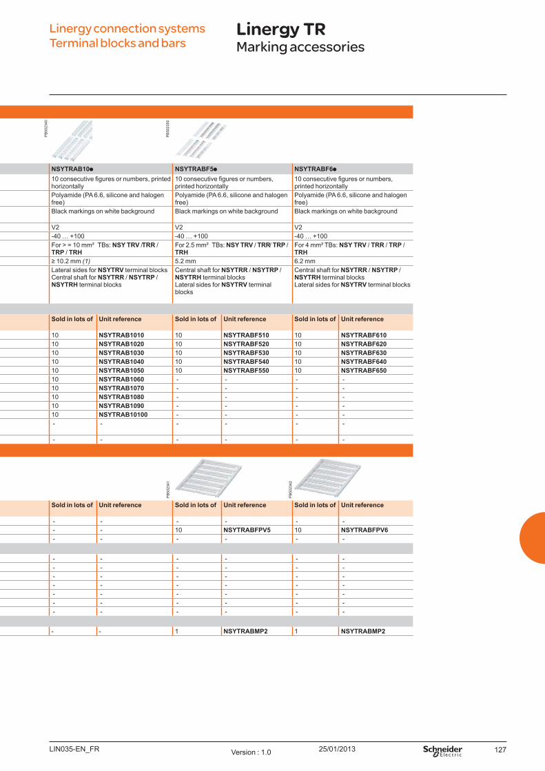
25/01/2013 127
Mark ing accesso ries
Cl ip - in m ark er st rip s NSYTRAB5 NSYTRAB6 NSYTRAB8 NSYTRAB10 NSYTRABF5 NSYTRABF6Description 10 consecutive figures or
numbers, printed horizontally10 consecutive figures or numbers, printed horizontally
10 consecutive figures or numbers, printed horizontally
10 consecutive figures or numbers, printed horizontally
10 consecutive figures or numbers, printed horizontally
10 consecutive figures or numbers, printed horizontally
Material Polyamide ( PA 6.6, silicone and halogen free)
Polyamide ( PA 6.6, silicone and halogen free)
Polyamide ( PA 6.6, silicone and halogen free)
Polyamide (PA 6.6, silicone and halogen free)
Polyamide (PA 6.6, silicone and halogen free)
Polyamide (PA 6.6, silicone and halogen free)
Colour Black markings on white background
Black markings on white background
Black markings on white background
Black markings on white background Black markings on white background Black markings on white background
Inflammability class acc. to UL 94 V2 V2 V2 V2 V2 V2emperature range ( ) -40 100 -40 100 -40 100 -40 100 -40 100 -40 100
Compatibility For 2.5 mm² TB s: NSY TRV / TRR / TRP / TRH
For 4 mm Bs NSY TRV / TRR / TRP / TRH
For 6 mm² TB s: NSY TRV / TRR / TRP / TRH
For > = 10 mm² TB s: NSY TRV / TRR / TRP / TRH
For 2.5 mm² TB s: NSY TRV / TRR / TRP / TRH
For 4 mm Bs NSY TRV / TRR / TRP / TRH
For terminal block width 5.2 mm 6.2 mm 8.2 mm 10.2 mm (1) 5.2 mm 6.2 mmounting position Lateral sides for NSYTRV
terminal blocksentral shaft for NSYTRR /
NSYTRP / NSYTRH terminal blocks
Lateral sides for NSYTRV terminal blocks
entral shaft for NSYTRR / NSYTRP / NSYTRH terminal blocks
Lateral sides for NSYTRV terminal blocks
entral shaft for NSYTRR / NSYTRP / NSYTRH terminal blocks
Lateral sides for NSYTRV terminal blocksentral shaft for NSYTRR / NSYTRP /
NSYTRH terminal blocks
entral shaft for NSYTRR / NSYTRP / NSYTRH terminal blocksLateral sides for NSYTRV terminal blocks
entral shaft for NSYTRR / NSYTRP / NSYTRH terminal blocksLateral sides for NSYTRV terminal blocks
Mark ing st rip sPrinted characters So l d in
l o t s o fU nit reference So l d in
l o t s o fU nit reference So l d in
l o t s o fU nit reference So l d in l o t s o f U nit reference So l d in l o t s o f U nit reference So l d in l o t s o f U nit reference
1 . 10 10 NSYTRAB510 10 NSYTRAB610 10 NSYTRAB810 10 NSYTRAB1010 10 NSYTRABF510 10 NSYTRABF61011 . 20 10 NSYTRAB520 10 NSYTRAB620 10 NSYTRAB820 10 NSYTRAB1020 10 NSYTRABF520 10 NSYTRABF62021 . 30 10 NSYTRAB530 10 NSYTRAB630 10 NSYTRAB830 10 NSYTRAB1030 10 NSYTRABF530 10 NSYTRABF63031 . 40 10 NSYTRAB540 10 NSYTRAB640 10 NSYTRAB840 10 NSYTRAB1040 10 NSYTRABF540 10 NSYTRABF64041 . 50 10 NSYTRAB550 10 NSYTRAB650 10 NSYTRAB850 10 NSYTRAB1050 10 NSYTRABF550 10 NSYTRABF65051 . 60 10 NSYTRAB560 10 NSYTRAB660 10 NSYTRAB860 10 NSYTRAB1060 - - - - 61 . 70 10 NSYTRAB570 10 NSYTRAB670 10 NSYTRAB870 10 NSYTRAB1070 - - - - 71 . 80 10 NSYTRAB580 10 NSYTRAB680 10 NSYTRAB880 10 NSYTRAB1080 - - - - 81 . 90 10 NSYTRAB590 10 NSYTRAB690 10 NSYTRAB890 10 NSYTRAB1090 - - - - 91 . 100 10 NSYTRAB5100 10 NSYTRAB6100 10 NSYTRAB8100 10 NSYTRAB10100 - - - - 1 . 100 (1 - 10 11 -20 91 - 100)
100 NSYTRAB51100 100 NSYTRAB61100 - - - - - - - -
L1, L2, L3, N, PE 10 NSYTRAB5L1N 10 NSYTRAB6L1N - - - - - - - -
Mark ing card s
Blank marking cards So l d in l o t s o f
U nit reference So l d in l o t s o f
U nit reference So l d in l o t s o f
U nit reference So l d in l o t s o f U nit reference So l d in l o t s o f U nit reference So l d in l o t s o f U nit reference
72 characters (6 strips) 10 NSYTRABPV5 - - - - - - - - - - 60 characters (6 strips) - - 10 NSYTRABPV6 - - - - 10 NSYTRABFPV5 10 NSYTRABFPV642 characters (6 strips) - - - - 10 NSYTRABPV8 - - - - - -
Mark ing card s fo r AB1 t erm inal s (2) and Mu l t i9 Act i9 rangeBlank (60 characters max.) - - 10 NSYTRAXPV6 - - - - - - - - 1 . 10 (6 strips) - - 10 NSYTRAXP610 - - - - - - - - 11 . 20 (6 strips) - - 10 NSYTRAXP620 - - - - - - - - 21 . 30 (6 strips) - - 10 NSYTRAXP630 - - - - - - - - 31 . 40 (6 strips) - - 10 NSYTRAXP640 - - - - - - - - 41 . 50 (6 strips) - - 10 NSYTRAXP650 - - - - - - - - L1, L2, L3 (60 characters max.) - - 10 NSYTRAX6L1L3 - - - - - - - -
Accesso riesPlotter adapter for marking cards 1 NSYTRABMP1 1 NSYTRABMP1 1 NSYTRABMP1 - - 1 NSYTRABMP2 1 NSYTRABMP2
Linergy connection systems Terminal blocks and bars
Linergy TRMarking accessories
LIN035-EN F Version : 1.0
PB
5023
40
PB
5023
41
PB
5023
42
PB
5023
50
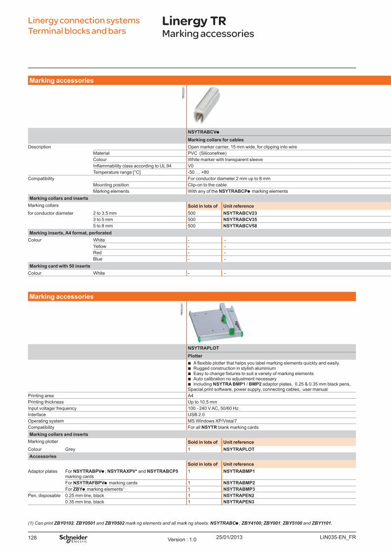
25/01/2013128
Linergy connection systems Terminal blocks and bars
Linergy TRMarking accessories
Mark ing accesso ries
NSYTRABCV NSYTRABC NSYTRABCP5Mark ing co l l ars fo r cab l es Mark ing insert s fo r co l l ars Mark ing card fo r co l l ars
Description Open marker carrier, 15 mm wide, for clipping into wire 360 inserts for marking collars, A4 format, perforated 15 x 4 mm inserts arking card with 50 inserts for marking collars 15 x 4 mm insertsMaterial PV (Siliconefree) Polyester (Silicone and halogen free) PolycarbonateColour White marker with transparent sleeve White, yellow, red or blue W hiteInflammability class according to UL 94 V0 V0 V0emperature range -50 80 40 100 -40 120
Compatibility For conductor diameter 2 mm up to 8 mm For all NSYTRABCV marking collars For all NSYTRABCV marking collarsounting position Clip-on to the cable Slides inside the collar sleeve Slides inside the collar sleevearking elements With any of the NSYTRABCP marking elements an be printed with any office printer, plotter or pen an be printed with plotter or pen
Mark ing co l l ars and insert sarking collars So l d in l o t s o f U nit reference So l d in l o t s o f U nit reference So l d in l o t s o f U nit reference
for conductor diameter 2 to 3.5 mm 500 NSYTRABCV23 - - - - 3 to 5 mm 500 NSYTRABCV35 - - - - 5 to 8 mm 500 NSYTRABCV58 - - - -
Mark ing insert s, A4 fo rm at , p erfo rat edColour W hite - - 10 NSYTRABCP1 - -
Yellow - - 10 NSYTRABCP2 - - ed - - 10 NSYTRABCP3 - -
B lue - - 10 NSYTRABCP4 - - Mark ing card w it h 50 insert s
Colour W hite - - - - 10 NSY AB P5
Mark ing accesso ries
NSYTRAPLOTPl o t t er
b A flexible plotter that helps you label marking elements quickly and easily. b ugged construction in stylish aluminium b Easy to change fixtures to suit a variety of marking elements b Auto calibration no adj ustment necessary b Including NSYTRA BMP1 / BMP2 adaptor plates, 0.25 & 0.35 mm black pens,
Spacial.print software, power supply, connecting cables, user manualPrinting area A4Printing thickness Up to 10.5 mmInput voltage/ frequency 100 - 240 V A , 50/60 HInterface USB 2.0Operating system S Windows P/Vista/7Compatibility For all NSYTR blank marking cardsMark ing co l l ars and insert sarking plotter So l d in l o t s o f U nit reference
Colour Grey 1 NSYTRAPLOTAccesso ries
So l d in l o t s o f U nit referenceAdaptor plates For NSYTRABPV ; NSYTRAXPV* and NSYTRABCP5
marking cards1 NSYTRABMP1
For NSYTRAFBPV marking cards 1 NSYTRABMP2For ZBY marking elements1 1 NSYTRABMP3
Pen, disposable 0.25 mm line, black 1 NSYTRAPEN20.35 mm line, black 1 NSYTRAPEN3
(1) C an print ZBY0102 ; ZBY0501 and ZBY0502 marki ng elements and all marki ng sheets: NSYTRABC ; ZBY4100; ZBY001; ZBY5100 and ZBY1101.
LIN035-EN FVersion : 1.0
PB
5022
01P
B50
2351
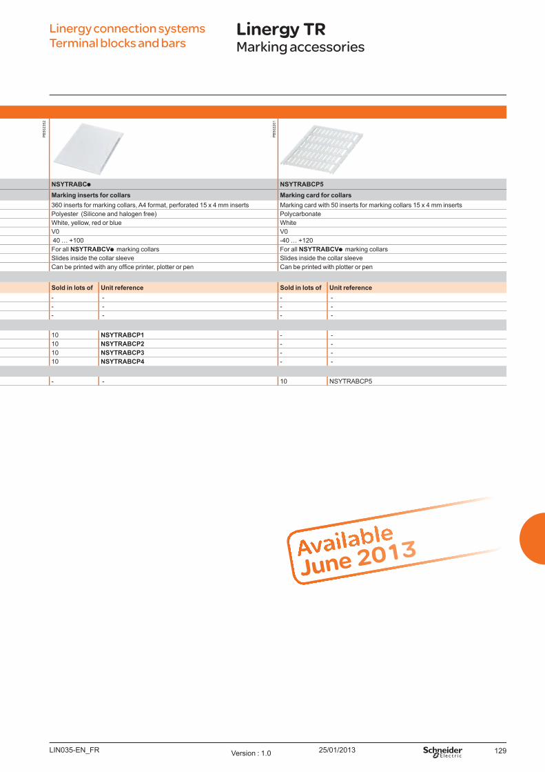
25/01/2013 129
Linergy connection systemsTerminal blocks and bars
Linergy TRMarking accessories
Mark ing accesso ries
NSYTRABCV NSYTRABC NSYTRABCP5Mark ing co l l ars fo r cab l es Mark ing insert s fo r co l l ars Mark ing card fo r co l l ars
Description Open marker carrier, 15 mm wide, for clipping into wire 360 inserts for marking collars, A4 format, perforated 15 x 4 mm inserts arking card with 50 inserts for marking collars 15 x 4 mm insertsMaterial PV (Siliconefree) Polyester (Silicone and halogen free) PolycarbonateColour White marker with transparent sleeve White, yellow, red or blue W hiteInfl ammability class according to UL 94 V0 V0 V0emperature range -50 80 40 100 -40 120
Compatibility For conductor diameter 2 mm up to 8 mm For all NSYTRABCV marking collars For all NSYTRABCV marking collarsounting position Clip-on to the cable Slides inside the collar sleeve Slides inside the collar sleevearking elements With any of the NSYTRABCP marking elements an be printed with any offi ce printer, plotter or pen an be printed with plotter or pen
Mark ing co l l ars and insert sarking collars So l d in l o t s o f U nit reference So l d in l o t s o f U nit reference So l d in l o t s o f U nit reference
for conductor diameter 2 to 3.5 mm 500 NSYTRABCV23 - - - - 3 to 5 mm 500 NSYTRABCV35 - - - - 5 to 8 mm 500 NSYTRABCV58 - - - -
Mark ing insert s, A4 fo rm at , p erfo rat edColour W hite - - 10 NSYTRABCP1 - -
Yellow - - 10 NSYTRABCP2 - - ed - - 10 NSYTRABCP3 - -
B lue - - 10 NSYTRABCP4 - - Mark ing card w it h 50 insert s
Colour W hite - - - - 10 NSY AB P5
Available
June 2013
LIN035-EN F Version : 1.0
PB
5022
01
PB
5023
52
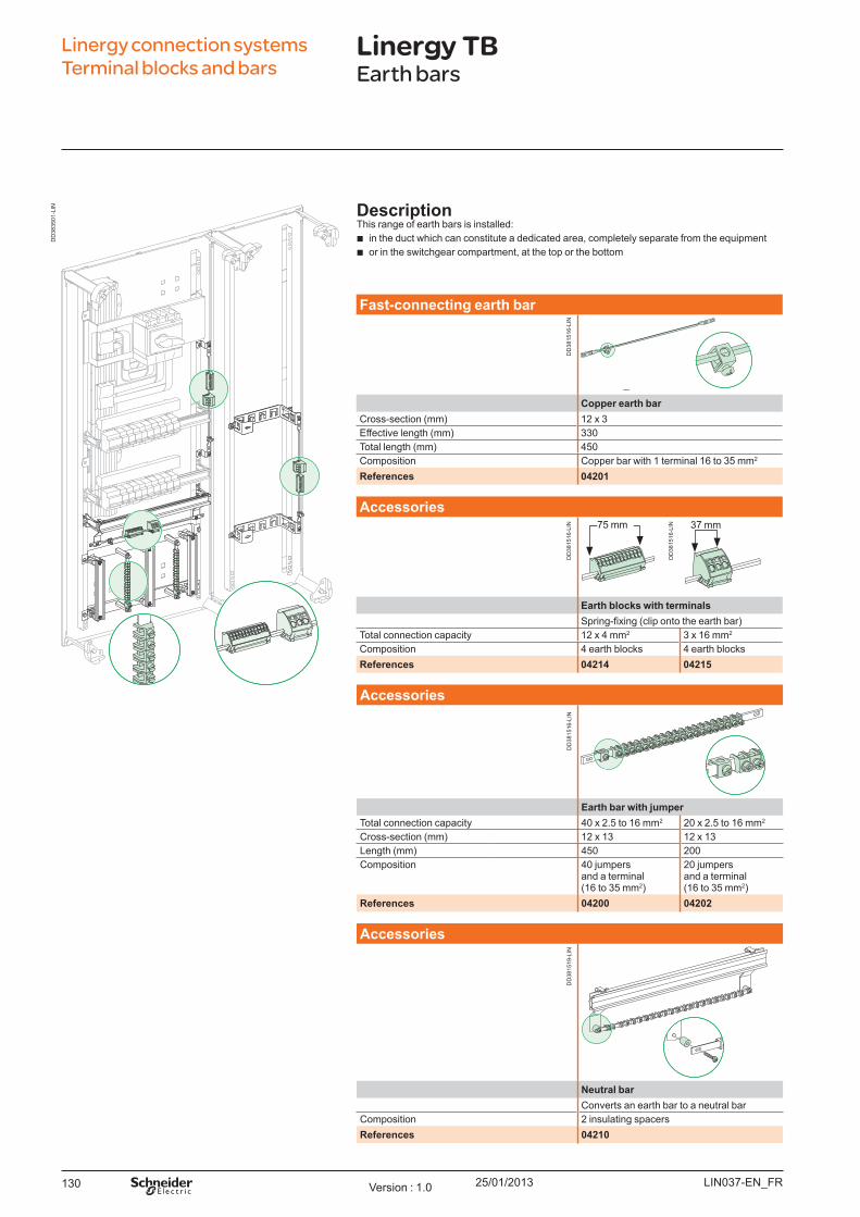
25/01/2013130
Linergy connection systems Terminal blocks and bars
Linergy TBEarth bars
Fast - co nnect ing eart h b ar
Co p p er eart h b arCross-section ( mm) 12 x 3Effective length ( mm) 330Total length ( mm) 450Composition Copper bar with 1 terminal 16 to 35 mm2
References 04201
Accesso ries75 mm 37 mm
Eart h b l o ck s w it h t erm inal sSpring-fixing (clip onto the earth bar)
Total connection capacity 12 x 4 mm2 3 x 16 mm2
Composition 4 earth blocks 4 earth blocks References 04214 04215
Accesso ries
Eart h b ar w it h j u m p erTotal connection capacity 40 x 2.5 to 16 mm2 20 x 2.5 to 16 mm2
Cross-section ( mm) 12 x 13 12 x 13Length ( mm) 450 200Composition 40 j umpers
and a terminal ( 16 to 35 mm2)
20 j umpers and a terminal ( 16 to 35 mm2)
References 04200 04202
Accesso ries
Neu t ral b arConverts an earth bar to a neutral bar
Composition 2 insulating spacersReferences 04210
Descrip t io nThis range of earth bars is installed:
b in the duct which can constitute a dedicated area, completely separate from the eq uipment b or in the switchgear compartment, at the top or the bottom
LIN037-EN_FRVersion : 1.0
DD
3815
16-L
IND
D38
1516
-LIN
DD
3835
01-L
IN
DD
3815
16-L
IN
DD
3815
16-L
IND
D38
1519
-LIN
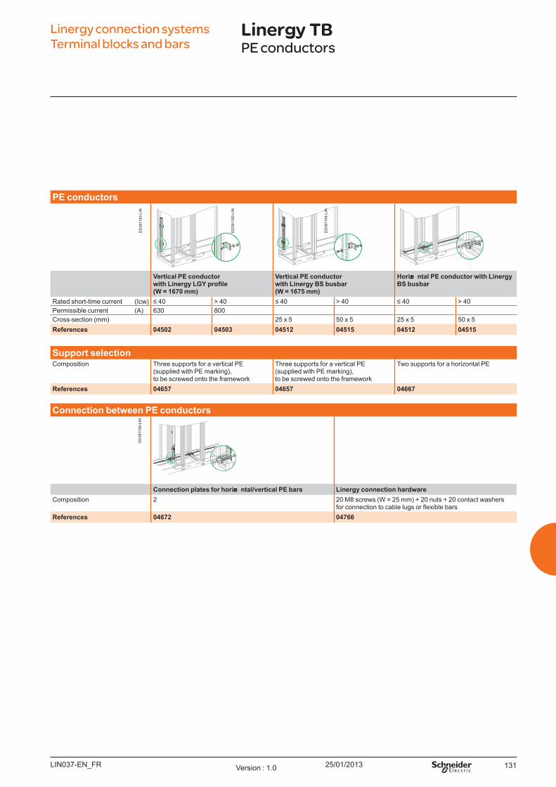
25/01/2013 131
Linergy connection systems Terminal blocks and bars
Linergy TBPE conductors
PE co nd u ct o rs
Vert ical PE co nd u ct o r
(W = 1670 m m )
Vert ical PE co nd u ct o r w it h Linergy BS b u sb ar (W = 1675 m m )
Ho rizo nt al PE co nd u ct o r w it h Linergy BS b u sb ar
Rated short-time current ( Icw) 40 > 40 40 > 40 40 > 40Permissible current ( A) 630 800Cross-section ( mm) 25 x 5 50 x 5 25 x 5 50 x 5References 04502 04503 04512 04515 04512 04515
Su p p o rt sel ect io nComposition Three supports for a vertical PE
( supplied with PE marking) , to be screwed onto the framework
Three supports for a vertical PE ( supplied with PE marking) , to be screwed onto the framework
Two supports for a horizontal PE
References 04657 04657 04667
Co nnect io n b et w een PE co nd u ct o rs
Co nnect io n p l at es fo r h o rizo nt al / v ert ical PE b ars Linergy co nnect io n h ard w areComposition 2 20 M8 screws ( W = 25 mm) + 20 nuts + 20 contact washers
for connection to cable lugs or flexible barsReferences 04672 04766
LIN037-EN_FR Version : 1.0
DD
3811
83-L
IN
DD
3811
82-L
IN
DD
3811
84-L
IN
DD
3811
58-L
IN

25/01/2013132
Linergy TAAuxiliary connections
Linergy connection systems Terminal blocks and bars
Descrip t io nFor distributing auxiliary voltages in power and regulation eq uipment.
Term inal b l o ck fo r au x il iary w iring
Standards IEC U LRated operational current at 40° ( Ie) 12 A 20 ARated operational voltage ( U e) 250 V 300 VRated impulse withstand voltage ( U imp) 4 kVConnection capacity Input 10 ( grey)
O utput 2 x 10 ( grey)Dimensions ( HxW xD) ( mm) 61 x 48 x 45Cross-section 0.2 to 4 mmTightening torq ue 0.5 to 0.6 NmComposition 3.5 18-mm modulesReferences 04228
Fo u r- p o l e au x il iary b u s d u ct
Du ct fo r 4 co nd u ct o rs166 tap-off points with Faston connectors, per linear meter
Rated operational current at 40° ( Ie) 32 ARated insulation voltage ( U i) 660 VLength ( mm) 1755Composition Supplied with 2 end clamps and 1 lateral clamp
for mounting on cable-tie supportsReferences 04203
LIN036-EN_FRVersion : 1.0
DD
3808
67-L
IN
DD
3816
44-L
IND
D38
1602
-LIN

25/01/2013 133LIN036-EN_FR Version : 1.0
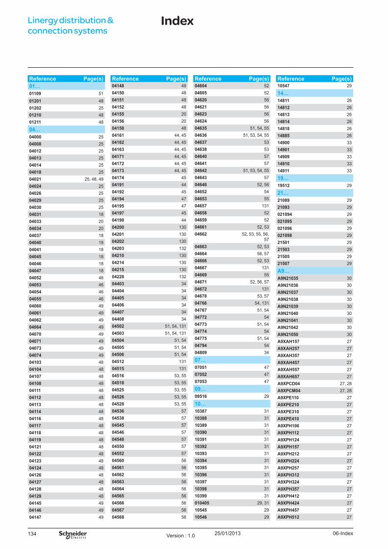
25/01/2013134
Reference Page(s)01…01109 5101201 4801202 2501210 4801211 48
04…04000 2504008 2504012 2504013 2504014 2504018 2504021 25, 48, 4904024 2504026 2504029 2504030 2504031 1804033 2004034 2004037 1804040 1804041 1804045 1804046 1804047 1804052 4604053 4604054 4604055 4604060 4904061 4904062 4904064 4904070 4904071 4904073 4904074 4904103 4804104 4804107 4804108 4804111 4804112 4804113 4804114 4804116 4804117 4804118 4804119 4804121 4804122 4804123 4804124 4804126 4804127 4804128 4804129 4804145 4904146 4904147 49
Reference Page(s)04148 4904150 4804151 4804152 4804155 2004156 2004158 4804161 44, 4504162 44, 4504163 44, 4504171 44, 4504172 44, 4504173 44, 4504174 4504191 4404192 4504194 4704195 4704197 4504198 4404200 13004201 13004202 13004203 13204210 13004214 13004215 13004228 13204403 3404404 3404405 3404406 3404407 3404408 3404502 51, 54, 13104503 51, 54, 13104504 51, 5404505 51, 5404506 51, 5404512 13104515 13104516 53, 5504518 53, 5504525 53, 5504526 53, 5504528 53, 5504536 5704538 5704545 5704546 5704548 5704550 5704552 5704560 5604561 5604562 5604563 5604564 5604565 5604566 5604567 5604568 56
Reference Page(s)04604 5204605 5204620 5604621 5604623 5604624 5604635 51, 54, 5504636 51, 53, 54, 5504637 5304638 5304640 5704641 5704642 51, 53, 54, 5504643 5704646 52, 5604652 5404653 5504657 13104658 5204659 5204661 52, 5304662 52, 53, 55, 56,
5704663 52, 5304664 56, 5704666 52, 5304667 13104669 5504671 52, 56, 5704672 13104678 53, 5704766 54, 13104767 51, 5404772 5404773 51, 5404774 5404775 51, 5404794 5404809 34
07…07051 4707052 4707053 47
09…09516 29
10…10387 3110388 3110389 3110390 3110391 3110392 3110393 3110394 3110395 3110396 3110397 3110398 3110399 31010405 29, 3110545 2910546 29
Reference Page(s)10547 29
14…14811 2614812 2614813 2614814 2614818 2614885 2614900 3314901 3314909 3314910 3314911 33
19…19512 29
21…21089 2921093 29021094 29021095 29021096 29021098 2921501 2921503 2921505 2921507 29
A9…A9N21035 30A9N21036 30A9N21037 30A9N21038 30A9N21039 30A9N21040 30A9N21041 30A9N21042 30A9N21050 30A9XAH157 27A9XAH257 27A9XAH357 27A9XAH457 27A9XAH557 27A9XAH657 27A9XPCD04 27, 28A9XPCM04 27, 28A9XPE110 27A9XPE210 27A9XPE310 27A9XPE410 27A9XPH106 27A9XPH112 27A9XPH124 27A9XPH157 27A9XPH212 27A9XPH224 27A9XPH257 27A9XPH312 27A9XPH324 27A9XPH357 27A9XPH412 27A9XPH424 27A9XPH457 27A9XPH512 27
Linergy distribution & connection systems
Index
06-IndexVersion : 1.0
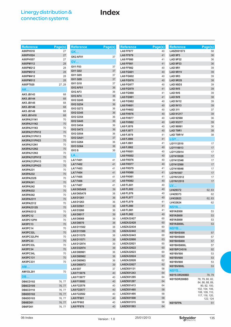
25/01/2013 135
Reference Page(s)A9XPH518 27A9XPH524 27A9XPH557 27A9XPM112 28A9XPM212 28A9XPM312 28A9XPM412 28A9XPM512 28A9XPT920 27, 28
AK…AK5 JB143 68AK5 JB144 68AK5 JB145 68AK5 JB146 68AK5 JB149 68AK5 JB1410 68AK5PA211N1 70AK5PA211N2 70AK5PA211N3 70AK5PA211PH12 70AK5PA211PH13 70AK5PA211PH23 70AK5PA212N1 70AK5PA212N2 70AK5PA212N3 70AK5PA212PH12 70AK5PA212PH13 70AK5PA212PH23 70AK5PA231 70AK5PA232 70AK5PA232S 70AK5PA241 70AK5PA242 70AK5PA532 70AK5PA542 70AK5PA2311 70AK5PA2312 70AK5PA2312S 70AK5PA5312 70AK5PC12 70AK5PC12PH 70AK5PC13 70AK5PC14 70AK5PC32L 70AK5PC32LPH 70AK5PC33 70AK5PC33L 70AK5PC34 70AK5PC34L 70AK5PC131 70AK5PC331 70
AM…AM1DL201 70
DB…DB6CD102 76, 77DB6CD105 76, 77DB6CD110 76, 77DB6DD102 76, 77DB6DD103 76, 77DB6ED01 76, 77DB6FD01 76, 77
Reference Page(s)GK…GK2 AF01 37
GV…GV1 F03 37GV1 G02 37GV1 G05 37GV1 G09 37GV1 G10 37GV2 AF01 36GV2 AF3 36GV2 AF4 36GV2 G245 36GV2 G254 36GV2 G272 36GV2 G345 36GV2 G354 36GV2 G445 36GV2 G454 36GV2 G472 36GV2 G554 36GV2 GA01 37GV3 G264 36GV3 G364 36GV3 S 36
LA…LA7 F401 41LA7 F402 41LA7 F403 41LA7 F404 41LA7 F405 41LA7 F406 41LA7 F407 41LA9 D65A69 39LA9 D65A70 38LA9 D1261 36LA9 D1263 36LA9 D2561 36LA9 D3260 36LA9 D8017 39LA9 D8069 39LA9 D8070 38LA9 D11502 38LA9 D11569 39LA9 D11570 38LA9 D11571 38LA9 D12974 39LA9 D32974 39LA9 D80961 36LA9 D80962 36LA9 D80963 36LA9 D80973 39LA9 E07 37LA9 F15076 40LA9 F15077 40LA9 F15082 40LA9 F22576 40LA9 F22577 40LA9 F22582 40LA9 FF601 40LA9 FF602 40LA9 FF976 40
Reference Page(s)LA9 FF977 40LA9 FF979 41LA9 FF980 41LA9 FF981 41LA9 FF982 40LA9 FG601 40LA9 FG602 40LA9 FG976 40LA9 FG977 40LA9 FG979 41LA9 FG980 41LA9 FG981 41LA9 FG982 40LA9 FH601 40LA9 FH602 40LA9 FH976 40LA9 FH977 40LA9 FH982 40LA9 FJ976 40LA9 FJ977 40LA9 FJ979 41LA9 FJ980 41LA9 FJ981 41LA9 FJ982 40LA9 FK601 40LA9 FK602 40LA9 FK976 40LA9 FK977 40LA9 FK979 41LA9 FK980 41LA9 FK981 41LA9 FK982 40LA9 FL601 40LA9 FL602 40LA9 FL976 40LA9 FL977 40LA9 FL979 41LA9 FL980 41LA9 FL981 41LA9 FL982 40LA9ZA32427 60LA9ZA32428 60LA9ZA32434 60LA9ZA32442 60LA9ZA32443 60LA9ZA32600 63LA9ZA32621 60LA9ZA32622 60LA9ZA32623 60LA9ZA32624 62LA9ZA32626 62LA9ZA32627 62LA9ZX01131 58LA9ZX01243 64LA9ZX01285 64LA9ZX01287 64LA9ZX01413 64LA9ZX01485 58LA9ZX01495 58LA9ZX01508 58LA9ZX01515 58LA9ZX01563 64
Reference Page(s)LA9ZX01573 58LAD 9P3 36LAD 9P32 36LAD 9P33 36LAD 9R1 39LAD 9R1V 39LAD 9R3 39LAD 9R3S 38LAD 9SD3 39LAD 9V5 39LAD 9V6 39LAD 9V9 38LAD 9V12 39LAD 9V13 39LAD 311 37LAD 91217 39LAD 92560 36LAD 93217 39LAD 96061 36LAD T9R1 38LAD T9R1V 38
LGY…LGY112510 17LGY116013 17LGY125014 17LGY410028 17LGY412548 17LGY412560 17LGY416048 17LGYN1007 17LGYN12512 17LGYN12515 17
LV…LV429372 62, 63LV429373 62LV432623 62, 63LV432624 62
NSYA…NSYAS500 53NSYAS600 53NSYAS800 53NSYAS800L 53
NSYB…NSYBHS500 57NSYBHS600 57NSYBHS800 57NSYBHS800L 57NSYBPCH516 92NSYBV500 53NSYBV600 53NSYBV800 53NSYBV800L 53
NSYS…NSYS DR200BD 78, 79NSYSDR200BD 78, 79, 80, 82,
84, 86, 88, 89, 90, 92, 100,
102, 104, 106, 108, 109, 110, 117, 118, 120,
122, 124NSYSFPA 51
Linergy distribution & connection systems
Index
06-Index Version : 1.0
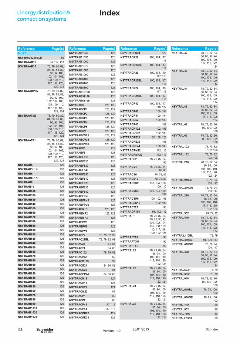
25/01/2013136
Reference Page(s)NSYT…NSYTR0V42SF6LD 89NSYTRAAB15 94, 112, 113NSYTRAAB35 78, 79, 80, 82,
84, 86, 88, 89, 90, 92, 100,
102, 104, 106, 108, 109, 110, 117, 118, 120,
122, 124NSYTRAABV35 78, 79, 80, 82,
84, 86, 88, 89, 90, 92, 100,
102, 104, 106, 108, 109, 110, 117, 118, 120,
122, 124NSYTRAATM1 78, 79, 80, 82,
84, 86, 88, 89, 90, 92, 100,
102, 104, 106, 108, 109, 110, 117, 118, 120,
122, 124NSYTRAATP1 78, 79, 80, 82,
84, 86, 88, 89, 90, 92, 100,
102, 104, 106, 108, 109, 110, 117, 118, 120,
122, 124NSYTRAB5 126NSYTRAB5L1N 126NSYTRAB6 126NSYTRAB6L1N 126NSYTRAB8 126NSYTRAB10 126NSYTRAB510 126NSYTRAB520 126NSYTRAB530 126NSYTRAB540 126NSYTRAB550 126NSYTRAB560 126NSYTRAB570 126NSYTRAB580 126NSYTRAB590 126NSYTRAB610 126NSYTRAB620 126NSYTRAB630 126NSYTRAB640 126NSYTRAB650 126NSYTRAB660 126NSYTRAB670 126NSYTRAB680 126NSYTRAB690 126NSYTRAB810 126NSYTRAB820 126NSYTRAB830 126NSYTRAB840 126NSYTRAB850 126NSYTRAB860 126NSYTRAB870 126NSYTRAB880 126NSYTRAB890 126NSYTRAB1010 126NSYTRAB1020 126NSYTRAB1030 126
Reference Page(s)NSYTRAB1040 126NSYTRAB1050 126NSYTRAB1060 126NSYTRAB1070 126NSYTRAB1080 126NSYTRAB1090 126NSYTRAB5100 126NSYTRAB6100 126NSYTRAB8100 126NSYTRAB10100 126NSYTRAB51100 126NSYTRAB61100 126NSYTRABC 128, 129NSYTRABCP1 128, 129NSYTRABCP2 128, 129NSYTRABCP3 128, 129NSYTRABCP4 128, 129NSYTRABCP5 128, 129NSYTRABCV 128, 129NSYTRABCV23 128, 129NSYTRABCV35 128, 129NSYTRABCV58 128, 129NSYTRABF5 126NSYTRABF6 126NSYTRABF510 126NSYTRABF520 126NSYTRABF530 126NSYTRABF540 126NSYTRABF550 126NSYTRABF610 126NSYTRABF620 126NSYTRABF630 126NSYTRABF640 126NSYTRABF650 126NSYTRABFPV5 126NSYTRABFPV6 126NSYTRABMP1 126, 128NSYTRABMP2 126, 128NSYTRABMP3 128NSYTRABPV5 126NSYTRABPV6 126NSYTRABPV8 126NSYTRAC22 78, 79, 82, 92NSYTRAC22BL 78, 79, 82, 92NSYTRAC23 84, 86NSYTRAC24 84, 86NSYTRAC162 78, 79, 82NSYTRAC952 80NSYTRACB103 92NSYTRACE24 84, 86, 88NSYTRACE26 84NSYTRACEP24 84, 86, 88NSYTRACH12 124NSYTRACH13 124NSYTRACH22 124NSYTRACM22 94NSYTRACP1 80NSYTRACP2 80NSYTRACP43 117, 118NSYTRACP44 117, 118NSYTRACPK22 122NSYTRACPK23 122
Reference Page(s)NSYTRACPK24 122NSYTRACR22 100, 104, 117,
118NSYTRACR22BL 100, 104, 117,
118NSYTRACR23 100, 104, 110,
117, 118NSYTRACR23BL 100, 104, 117,
118NSYTRACR24 100, 104, 110,
117, 118NSYTRACR24BL 100, 104, 117,
118NSYTRACR42 100, 104, 117,
118, 122NSYTRACR43 100, 104NSYTRACR44 100, 104NSYTRACR62 100, 106NSYTRACR63 102NSYTRACR102 102, 106NSYTRACR162 102, 106NSYTRACRE24 108, 109, 120NSYTRACRE26 108NSYTRACRE44 108, 109NSYTRACRM22 112, 113NSYTRACRMF22 112, 113NSYTRACS2 78, 79, 82, 84,
86NSYTRACS4 78, 79, 82, 84,
86, 88NSYTRACS6 78, 79, 82NSYTRACS10 78, 79, 82NSYTRACSR2 100, 104, 108,
109, 110NSYTRACSR4 100, 104, 108,
109NSYTRACSR6 100, 102, 106NSYTRACSR10 102, 106NSYTRACT22 90NSYTRADR155 94, 112, 113NSYTRAFT 78, 79, 82, 84,
86, 88, 90, 92, 100, 102, 104, 106, 108, 109, 110, 117, 118, 120, 122, 124
NSYTRAFTAR 90NSYTRAFTGN 90NSYTRAFTYE 90NSYTRAL22 78, 79, 82, 84,
86, 94, 100, 108, 109, 110, 117, 118, 120,
122, 124NSYTRAL23 78, 79, 82, 84,
86, 94, 100, 108, 109, 110, 117, 118, 120,
122, 124NSYTRAL24 78, 79, 82, 84,
86, 94, 100, 108, 109, 110, 117, 118, 120,
122, 124NSYTRAL25 78, 79, 82, 84,
86, 94, 100, 108, 109, 110, 117, 118, 120,
122, 124
Reference Page(s)NSYTRAL42 78, 79, 82, 84,
86, 88, 92, 94, 100, 108, 109, 117, 118, 122,
124NSYTRAL43 78, 79, 82, 84,
86, 88, 92, 94, 100, 108, 109, 117, 118, 122,
124NSYTRAL44 78, 79, 82, 84,
86, 88, 92, 94, 100, 108, 109, 117, 118, 122,
124NSYTRAL45 78, 79, 82, 84,
86, 88, 92, 94, 100, 108, 109, 117, 118, 122,
124NSYTRAL62 78, 79, 82, 90,
92, 100, 102, 106
NSYTRAL63 78, 79, 82, 90, 92, 100, 102,
106NSYTRAL102 78, 79, 82,
102, 106NSYTRAL162 78, 79, 82,
102, 106NSYTRAL210 78, 79, 82, 84,
86, 94, 100, 108, 109, 110, 117, 118, 120,
122, 124NSYTRAL210BL 78, 79, 94,
100, 117NSYTRAL210GR 78, 79, 94,
100, 117NSYTRAL220 78, 79, 82, 84,
86, 94, 100, 108, 109, 110, 117, 118, 120,
122, 124NSYTRAL352 78, 79, 82NSYTRAL410 78, 79, 82, 84,
86, 88, 92, 94, 100, 108, 109, 117, 118, 122,
124NSYTRA L410BL 78, 79NSYTRAL410BL 94, 100, 117NSYTRAL410GR 78, 79, 94,
100, 117NSYTRAL420 78, 79, 82, 84,
86, 88, 92, 94, 100, 108, 109, 117, 118, 122,
124NSYTRAL502 * 78, 79NSYTRAL503 * 78, 79NSYTRAL610 78, 79, 82, 90,
92, 100, 102, 106
NSYTRAL610BL 78, 79, 100, 102
NSYTRAL610GR 78, 79, 100, 102
NSYTRAL702 80NSYTRAL952 80NSYTRAL1502 80NSYTRALF1610 89
Linergy distribution & connection systems
Index
06-IndexVersion : 1.0
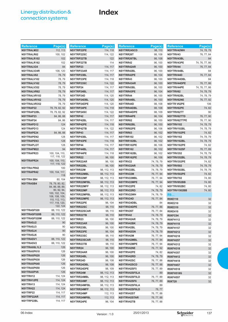
25/01/2013 137
Reference Page(s)NSYTRALM22 112, 113NSYTRALR62 100, 102NSYTRALR102 102NSYTRALR162 102NSYTRALV24 84NSYTRALV24R 108, 120NSYTRALV62 78, 79NSYTRALV102 78, 79NSYTRALV162 78, 79NSYTRALV352 78, 79NSYTRALVR62 78, 79NSYTRALVR102 78, 79NSYTRALVR162 78, 79NSYTRALVR352 78, 79NSYTRAP22 78, 79, 82, 92NSYTRAP22BL 78, 79, 82, 92NSYTRAP23 84, 86, 88NSYTRAP24 84, 86NSYTRAPD12 124NSYTRAPD13 124NSYTRAPE24 84, 86, 88NSYTRAPEN2 128NSYTRAPEN3 128NSYTRAPLOT 128NSYTRAPM22 94NSYTRAPR23 100, 104, 110,
117, 118, 122NSYTRAPR24 100, 104, 110,
117, 118, 122NSYTRA PR42 100NSYTRAPR42 100, 104, 117,
118NSYTRA SB4 80, 104NSYTRASB4 78, 79, 80, 82,
84, 86, 88, 89, 90, 92, 94,
100, 102, 104, 106, 108, 109, 110, 112, 113, 117, 118, 120,
122, 124NSYTRASF520 88, 110, 122NSYTRASF520B 88, 110, 122NSYTRASF520M 88, 110, 122NSYTRASJ2 90NSYTRASJ3 90NSYTRASJ4 90NSYTRASJ6 90NSYTRASV1 88, 110, 122NSYTRASV2 88, 110, 122NSYTRAX6L1L3 126NSYTRAXP610 126NSYTRAXP620 126NSYTRAXP630 126NSYTRAXP640 126NSYTRAXP650 126NSYTRAXPV6 126NSYTRH12 114, 124NSYTRH12PE 114, 124NSYTRH13 114, 124NSYTRH22 114, 124NSYTRP22 114, 117NSYTRP22AR 114, 117NSYTRP22BL 114, 117
Reference Page(s)NSYTRP22PE 114, 118NSYTRP22SC 114, 122NSYTRP22TB 122NSYTRP22TB 114NSYTRP23 114, 117NSYTRP23AR 114, 117NSYTRP23BL 114, 117NSYTRP23PE 114, 118NSYTRP23SC 114, 122NSYTRP24 114, 117NSYTRP24BL 114, 117NSYTRP24D 114, 120NSYTRP24DBL 114, 120NSYTRP24DPE 114, 120NSYTRP24PE 114, 118NSYTRP24SC 114, 122NSYTRP42 114, 117NSYTRP42BL 114, 117NSYTRP42PE 114, 118NSYTRP42TB 114, 122NSYTRP43 114, 117NSYTRP43BL 114, 117NSYTRP43PE 114, 118NSYTRP44 114, 117NSYTRP44BL 114, 117NSYTRP44PE 114, 118NSYTRR22 96, 100NSYTRR22AR 96, 100NSYTRR22BL 96, 100NSYTRR22M 98, 112, 113NSYTRR22MBL 98, 112, 113NSYTRR22MF 98, 112, 113NSYTRR22MFBL 98, 112, 113NSYTRR22MFF 98, 112, 113NSYTRR22MP 98, 112, 113NSYTRR22MPBL 98, 112, 113NSYTRR22MPE 98, 112, 113NSYTRR22PE 96, 104NSYTRR22SC 98, 110NSYTRR22SCAR 98, 110NSYTRR22TB 98, 110NSYTRR23 96, 100NSYTRR23AR 96, 100NSYTRR23BL 96, 100NSYTRR23PE 96, 104NSYTRR23SC 98, 110NSYTRR23SCAR 98, 110NSYTRR23TB 98, 110NSYTRR24 96, 100NSYTRR24AR 96, 100NSYTRR24BL 96, 100NSYTRR24D 98, 108NSYTRR24DBL 98, 108NSYTRR24DPE 98, 109NSYTRR24M 98, 112, 113NSYTRR24MBL 98, 112, 113NSYTRR24MF 98, 112, 113NSYTRR24MFBL 98, 112, 113NSYTRR24MFF 98, 112, 113NSYTRR24MP 112, 113NSYTRR24MPBL 112, 113NSYTRR24PE 96, 104
Reference Page(s)NSYTRR24SCD 98, 110NSYTRR26T 98, 108NSYTRR26TBL 98, 108NSYTRR42 96, 100NSYTRR42AR 96, 100NSYTRR42BL 96, 100NSYTRR42PE 96, 104NSYTRR43 96, 100NSYTRR43AR 96, 100NSYTRR43BL 96, 100NSYTRR43PE 96, 104NSYTRR44 96, 100NSYTRR44BL 96, 100NSYTRR44D 98, 108NSYTRR44DBL 98, 108NSYTRR44DPE 98, 109NSYTRR44PE 96, 104NSYTRR62 96, 100NSYTRR62BL 96, 100NSYTRR62PE 96, 106NSYTRR63 96, 102NSYTRR102 96, 102NSYTRR102BL 96, 102NSYTRR102PE 96, 106NSYTRR162 96, 102NSYTRR162BL 96, 102NSYTRR162PE 96, 106NSYTRV22 74, 78, 79NSYTRV22AR 74, 78, 79NSYTRV22BL 74, 78, 79NSYTRV22M 76, 77, 94NSYTRV22MBL 76, 77, 94NSYTRV22MPE 76, 77, 94NSYTRV22PE 74, 82NSYTRV22RD 74, 78, 79NSYTRV22WH 74, 78, 79NSYTRV24D 76, 77, 84NSYTRV24DBL 84NSYTRV24DPE 76, 77, 86NSYTRV26T 76, 77, 84NSYTRV42 74, 78, 79NSYTRV42AR 74, 78, 79NSYTRV42BK 74, 78, 79NSYTRV42BL 74, 78, 79NSYTRV42GN 74, 78, 79NSYTRV42M 76, 77, 94NSYTRV42MBL 76, 77, 94NSYTRV42MPE 76, 77, 94NSYTRV42NE 76, 77, 92NSYTRV42PE 74, 82NSYTRV42RD 74, 78, 79NSYTRV42SC 76, 77, 88NSYTRV42SCD 76, 77, 88NSYTRV42SF5 76, 77, 89NSYTRV42SF5LA 89NSYTRV42SF5LD 76, 77, 89NSYTRV42SF6 76, 77, 89NSYTRV42SF6LA 89NSYTRV42SF6LD 76, 77NSYTRV42ST 76, 77, 88NSYTRV42STAR 76, 77, 88NSYTRV42TB 76, 77, 88
Reference Page(s)NSYTRV42WH 74, 78, 79NSYTRV43 76, 77, 84NSYTRV43BL 84NSYTRV43PE 74, 76, 77, 86NSYTRV44 76, 77, 84NSYTRV44BL 84NSYTRV44D 76, 77, 84NSYTRV44DBL 84NSYTRV44DPE 76, 77, 86NSYTRV44PE 74, 76, 77, 86NSYTRV62 74, 78, 79NSYTRV62BL 74, 78, 79NSYTRV62NE 76, 77, 92NSYTR V62PE 106NSYTRV62PE 74, 82NSYTRV62TT 90NSYTRV62TTD 76, 77, 90NSYTRV62TTPE 76, 77, 90NSYTRV102 74, 78, 79NSYTRV102BL 74, 78, 79NSYTRV102PE 74, 82NSYTRV162 74, 78, 79NSYTRV162BL 74, 78, 79NSYTRV162PE 74, 82NSYTRV162SF 76, 77, 89NSYTRV352 74, 78, 79NSYTRV352BL 74, 78, 79NSYTRV352PE 74, 82NSYTRV502 74, 78, 79NSYTRV502BL 74, 78, 79NSYTRV502PE 74, 82NSYTRV702 74, 80NSYTRV952BB 74, 80NSYTRV952BC 74, 80NSYTRV1502BB 74, 80
R9…R9XE110 32R9XE210 32R9XE310 32R9XE410 32R9XFC04 32R9XFH112 32R9XFH118 32R9XFH157 32R9XFH212 32R9XFH218 32R9XFH257 32R9XFH312 32R9XFH318 32R9XFH357 32R9XFH412 32R9XFH418 32R9XFH457 32R9XFH518 32R9XFH518G 32R9XFH557 32R9XT20 32
Linergy distribution & connection systems
Index
06-Index Version : 1.0
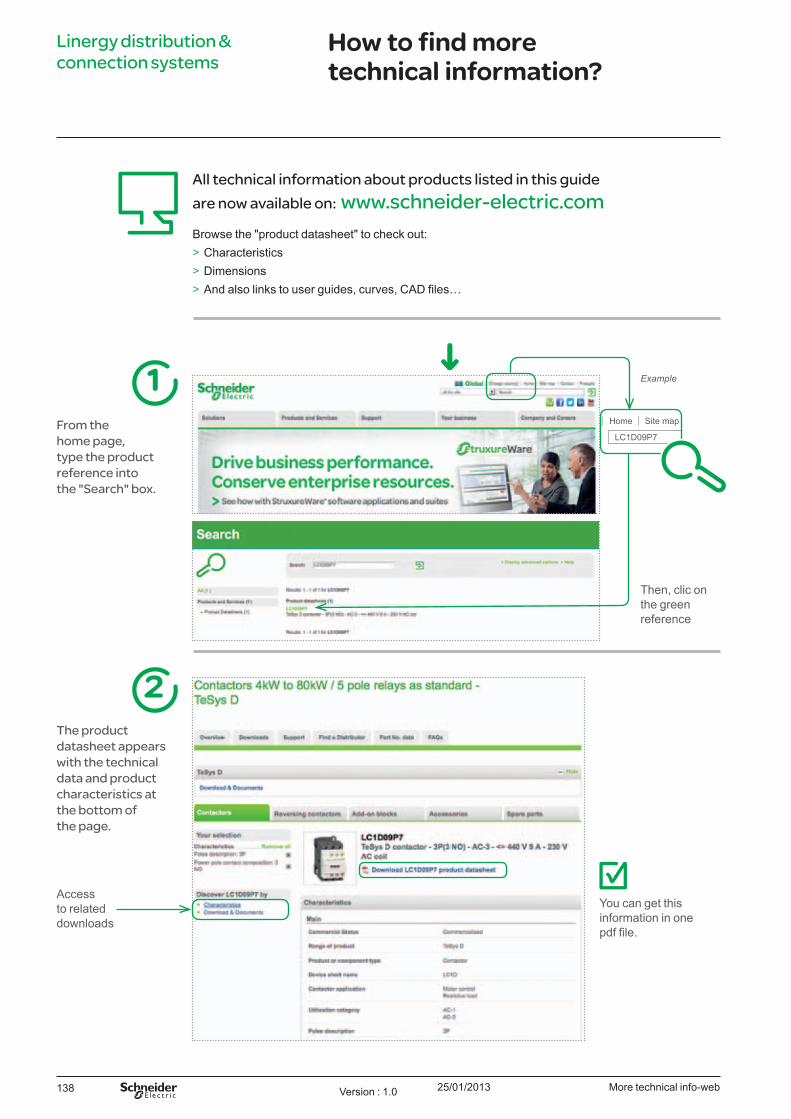
25/01/2013138
Linergy distribution & connection systems
How to find more technical information?
All technical information about products listed in this guide are now available on: www.schneider-electric.comB rowse the " product datasheet" to check out:
> Characteristics > Dimensions > And also links to user guides, curves, AD files
From the home page, type the product reference into the "Search" box.
1 E xample
Y ou can get this information in one pdf file.
The product datasheet appears with the technical data and product characteristics at the bottom of the page.
2
Then, clic on the green reference
Access to related downloads
More technical info-webVersion 1.0


01-2013LVY ED213001EN
Sch neid er El ect ric I nd u st ries SAS
© 2
013
- Sch
neid
er E
lect
ric -
All
right
s re
serv
ed
As standards specifications and designs c ange ro ti e to ti e p ease as or confir ation o t e in or ation gi en in t is p ication.
Publication: Schneider Electric Industries SASPhotos: Schneider ElectricPrinted:
T is doc ent as een printed on eco ogica paper.
35, rue Jo seph MonierCS 3032392506 Rueil Malmaison Cedex France
RCS Nanterre 954 503 439Capital social 896 313 776 €www.schneider-electric.com
10-31-1247
Make the most of your energy™
www.schneider-electric.com