8845A/8846A - RS Components
100
® 8845A/8846A Digital Multimeter Programmers Manual September 2006 © 2006 Fluke Corporation, All rights reserved. All product names are trademarks of their respective companies.
-
Upload
khangminh22 -
Category
Documents
-
view
0 -
download
0
Transcript of 8845A/8846A - RS Components
®
8845A/8846A Digital Multimeter
Programmers Manual
September 2006 © 2006 Fluke Corporation, All rights reserved. All product names are trademarks of their respective companies.
LIMITED WARRANTY AND LIMITATION OF LIABILITY
Each Fluke product is warranted to be free from defects in material and workmanship under normal use and service. The warranty period is one year and begins on the date of shipment. Parts, product repairs, and services are warranted for 90 days. This warranty extends only to the original buyer or end-user customer of a Fluke authorized reseller, and does not apply to fuses, disposable batteries, or to any product which, in Fluke's opinion, has been misused, altered, neglected, contaminated, or damaged by accident or abnormal conditions of operation or handling. Fluke warrants that software will operate substantially in accordance with its functional specifications for 90 days and that it has been properly recorded on non-defective media. Fluke does not warrant that software will be error free or operate without interruption.
Fluke authorized resellers shall extend this warranty on new and unused products to end-user customers only but have no authority to extend a greater or different warranty on behalf of Fluke. Warranty support is available only if product is purchased through a Fluke authorized sales outlet or Buyer has paid the applicable international price. Fluke reserves the right to invoice Buyer for importation costs of repair/replacement parts when product purchased in one country is submitted for repair in another country.
Fluke's warranty obligation is limited, at Fluke's option, to refund of the purchase price, free of charge repair, or replacement of a defective product which is returned to a Fluke authorized service center within the warranty period.
To obtain warranty service, contact your nearest Fluke authorized service center to obtain return authorization information, then send the product to that service center, with a description of the difficulty, postage and insurance prepaid (FOB Destination). Fluke assumes no risk for damage in transit. Following warranty repair, the product will be returned to Buyer, transportation prepaid (FOB Destination). If Fluke determines that failure was caused by neglect, misuse, contamination, alteration, accident, or abnormal condition of operation or handling, including overvoltage failures caused by use outside the product’s specified rating, or normal wear and tear of mechanical components, Fluke will provide an estimate of repair costs and obtain authorization before commencing the work. Following repair, the product will be returned to the Buyer transportation prepaid and the Buyer will be billed for the repair and return transportation charges (FOB Shipping Point).
THIS WARRANTY IS BUYER'S SOLE AND EXCLUSIVE REMEDY AND IS IN LIEU OF ALL OTHER WARRANTIES, EXPRESS OR IMPLIED, INCLUDING BUT NOT LIMITED TO ANY IMPLIED WARRANTY OF MERCHANTABILITY OR FITNESS FOR A PARTICULAR PURPOSE. FLUKE SHALL NOT BE LIABLE FOR ANY SPECIAL, INDIRECT, INCIDENTAL, OR CONSEQUENTIAL DAMAGES OR LOSSES, INCLUDING LOSS OF DATA, ARISING FROM ANY CAUSE OR THEORY.
Since some countries or states do not allow limitation of the term of an implied warranty, or exclusion or limitation of incidental or consequential damages, the limitations and exclusions of this warranty may not apply to every buyer. If any provision of this Warranty is held invalid or unenforceable by a court or other decision-maker of competent jurisdiction, such holding will not affect the validity or enforceability of any other provision.
Fluke Corporation P.O. Box 9090 Everett, WA 98206-9090 U.S.A.
Fluke Europe B.V. P.O. Box 1186 5602 BD Eindhoven The Netherlands
11/99 To register your product online, visit register.fluke.com
i
Table of Contents
Title Page Introduction........................................................................................................ 1 Safety Information ............................................................................................. 1
Symbols ......................................................................................................... 2 Local and Remote Operation......................................................................... 2 Computer Interfaces ...................................................................................... 2
Selecting the Remote Interface Port .................................................................. 3 Configuring the IEEE-448 Port ......................................................................... 3
IEEE 488 Operating Limitations ................................................................... 3 Setting the IEEE 488 (GPIB) Port Address................................................... 3 Capability Commands ................................................................................... 4 Interconnections ............................................................................................ 4
Configuring the RS-232 Port ............................................................................. 4 Setting RS-232 Baud Rate............................................................................. 5 Setting RS-232 Parity and Data Bits ............................................................. 6 Setting RS-232 Flow Control ........................................................................ 6 Setting RS-232 End-Of-Line Character ........................................................ 6 Enabling and Disabling Fluke 45 Emulation Echo........................................ 6 RS-232 Modes of Operation.......................................................................... 6 Interconnections ............................................................................................ 8
Configuring the Ethernet (LAN) Port ................................................................ 9 Setting the IP Address ................................................................................... 9 Setting the LAN Subnet Mask....................................................................... 10 Reading the Domain Name ........................................................................... 10 Configuring the Host Name........................................................................... 10 Reading the MAC Address............................................................................ 11 Configuring the LAN Default Gateway ........................................................ 11 Configuring the General Network Socket Port.............................................. 11
Establishing an Ethernet Connection ................................................................. 12 Terminating an Ethernet Connection ................................................................. 12 Selecting the Programming Language ............................................................... 13 Getting Started With an Installation Test........................................................... 13
Installation Test for RS-232 Connections ..................................................... 13 Installation Test for IEEE 488 Connections .................................................. 14 If Test Fails.................................................................................................... 14
How the Meter Processes Input ......................................................................... 14
8845A/8846A Programmers Manual
ii
Input Strings .................................................................................................. 14 Input Terminators .......................................................................................... 15 Typical IEEE 488 Input Strings..................................................................... 15 Sending Numeric Values to the Meter .......................................................... 15 Sending Command Strings to the Meter........................................................ 16
How the Meter Processes Output....................................................................... 18 Triggering Input................................................................................................. 18
Internal Triggering......................................................................................... 18 External Triggering ....................................................................................... 18
Service Requests (IEEE 488 Only) and Status Registers .................................. 19 Standard Event Status and Standard Event Status Enable Registers ............. 20 Questionable Data Event Register and Questionable Data Enable Register . 21 Status Byte Register ...................................................................................... 22 Reading the Status Byte Register .................................................................. 22 Service Request Enable Register................................................................... 23
Supported SCPI Commands .............................................................................. 24 SCPI Command Summary ............................................................................ 24 SCPI Command Details................................................................................. 33 Using the Configure Command..................................................................... 35 Using the READ? Command ........................................................................ 38 Using the Initiate Command.......................................................................... 38 Using the FETCh? Command ....................................................................... 38 Using the Sense Subsystem to Configure the Meter ..................................... 38 Programming for Math Operations................................................................ 45 Programming the Trigger System.................................................................. 50 Using System-Related Commands ................................................................ 53 Using Status Reporting Commands............................................................... 55 Calibration Commands.................................................................................. 57 Using RS-232/Ethernet Interface Commands ............................................... 59 Command Terminators .................................................................................. 60 Alternate Programming Language Compatibility ......................................... 61
Fluke 45 Command Emulation Summary.......................................................... 62 Computer Interface Command Set ................................................................ 62 IEEE 488 Capabilities and Common Commands.......................................... 62 Triggering Output.......................................................................................... 69
Using FlukeView Forms.................................................................................... 70 Introduction........................................................................................................ 73 Introduction........................................................................................................ 81 Incompatible Fluke 45 Commands .................................................................... 81
Dual Functions............................................................................................... 82 Reading Rates................................................................................................ 82 Ranges ........................................................................................................... 82
Introduction........................................................................................................ 85 Your Meter and Your Network Administrator .................................................. 85 Network Primer.................................................................................................. 86
Physical Layer Wiring Schemes Supported by the Meter ............................. 86 Network Interconnection Devices ................................................................. 87 Basic Network Packet and Frame Contents .................................................. 87 IP Addresses and Segmented Networks ........................................................ 88 TCP/IP Protocol Stack................................................................................... 90
Index

iii
List of Tables
Table Title Page
1. Safety and Electrical Symbols................................................................................ 2 2. IEEE-488 Compatibility Codes.............................................................................. 4 3. Factory Settings of RS-232 Communications Parameters ..................................... 5 4. Status Register Summary ....................................................................................... 19 5. Description of Bits in ESR and ESE ...................................................................... 21 6. Description of Bits in the Questionable Data Register........................................... 22 7. Description of Bits in the Status Byte Register...................................................... 23 8. Calibration command summary ............................................................................. 24 9. Configure command summary ............................................................................... 25 10. IEEE-488.2 common command summary ............................................................. 25 11. Math command summary....................................................................................... 26 12. Measure command summary ................................................................................. 26 13. Measurement configuration command summary ................................................... 27 14. RS-232 interface command summary .................................................................... 30 15. Status reporting command summary...................................................................... 31 16. System-Related command summary...................................................................... 32 17. Triggering command summary .............................................................................. 33 18. Preset Conditions for the MEASure? and CONFigure Commands ....................... 37 19. Allowed math/measurement function combinations .............................................. 46 20. IEEE Common Commands .................................................................................... 62 21. Fluke 45 Function Commands and Queries ........................................................... 64 22. Function Modifier Commands and Queries ........................................................... 65 23. Range and Measurement Rate Commands and Querie .......................................... 66 24. Measurement Queries............................................................................................. 67 25. Compare Commands and Queries.......................................................................... 68 26. Trigger Configuration Commands ......................................................................... 68 27. Miscellaneous Commands and Queries ................................................................. 69 28. Remote/Local Configuration Commands............................................................... 69 29. Trigger Types ......................................................................................................... 70 30. Execution Error Codes and Descriptions ............................................................... 73 31. Ethernet/GPIB Configuration Errors...................................................................... 77 32. Calibration Errors................................................................................................... 78 33. Non-compatible Fluke 45 Remote Commands ...................................................... 81 34. Fluke 45 Dual Function Compatibility Matrix....................................................... 82 35. IP Address Assignments ........................................................................................ 89

8845A/8846A Programmers Manual
iv
v
List of Figures
Figure Title Page
1. RS-232 Pin-out and Cable Interconnect................................................................. 8 2. Typical IEEE-488 Input String .............................................................................. 17 3. Overview of Status Data Structure......................................................................... 20 4. 884XA Triggering System ..................................................................................... 50

8845A/8846A Programmers Manual
vi
1
Remote Operation
Introduction Remote operation of the 8845A or 8846A Digital Multimeters (hereafter “the Meter”) from a host, that is, a terminal, controller, PC, or computer, is accomplished by sending commands to it through one of its remote interfaces. This manual describes how to setup, configure, and operate the Meter through each of the remote interfaces. The Meter is controlled remotely using either Standard Commands for Programmable Instruments (SCPI) or Fluke 45 commands. Detailed information on the SCPI command set, and how the Meter processes those commands is included in this manual. Fluke 45 command limitations are covered in Appendix B in this manual.
Note For more information regarding the SCPI programming language, visit http://www.scpiconsortium.org. A free copy of the SCPI standard can be found at http://www.scpiconsortium.org/SCPI-99.pdf.
The level of detail in this chapter is based on the assumption that the reader is familiar with the basics of data communication interface, and the IEEE 488 bus.
Safety Information This section addresses safety considerations and describes symbols that may appear on the Meter or in the manual. A XW Warning statement identifies conditions or practices that could result in injury or death. A W Caution statement identifies conditions or practices that could result in damage to the Meter or equipment to which it is connected.
XW Warning To avoid electric shock, personal injury, or death, carefully read the information under “Safety Information” before attempting to install, use, or service the Meter.

8845A/8846A Programmers Manual
2
Symbols Table 1 is a list of safety and electrical symbols that appear on the Meter or in this manual.
Table 1. Safety and Electrical Symbols
Symbol Description Symbol Description
W Risk of danger. Important information. See manual
O Display ON / OFF
X Hazardous voltage. Voltage > 30 V dc or ac peak might be present
J Earth ground
B AC (Alternating Current) E Capacitance
F DC (Direct Current) G Diode
I Fuse D or
C
AC or DC (Alternating or Direct Current) Ψ Digital signal
R Continuity test or continuity beeper tone
U Maintenance or Service
Y Potentially hazardous voltage CAT II IEC 61010 Overvoltage (installation or measurement) Category 2.
T Double insulated < Recycle
h Static awareness. Static discharge can damage part(s) ~ Do not dispose of this product as unsorted
municipal waste. Contact Fluke or a qualified recycler for disposal
Local and Remote Operation When the Meter is operated from a host, it is said to be operated remotely. When operated from the front panel, it is said to be operated locally. Most operations that can be performed locally can also be performed remotely over the remote interface. Some operations, like setting communications parameters for the RS-232 interface, and addressing the Meter for IEEE 488 operations can only be set through the front panel.
XW Warning To avoid electric shock, turn off the signal source to the Meter before touching the test leads. The front panel display may not indicate the true input voltage while in remote mode. Always assume lethal voltages exist on the front-panel inputs.
Computer Interfaces Both the 8845A and 8846A Multimeters come equipped with an RS-232, Ethernet, and IEEE 488 interface. Only one remote interface can be enabled at a time. Using any of the interfaces turns the Meter into a fully programmable instrument that can be integrated into an automated instrumentation system. For a PC with only USB ports, Fluke makes a cable (Fluke PN 2675479) that converts between USB and RS-232 ports.
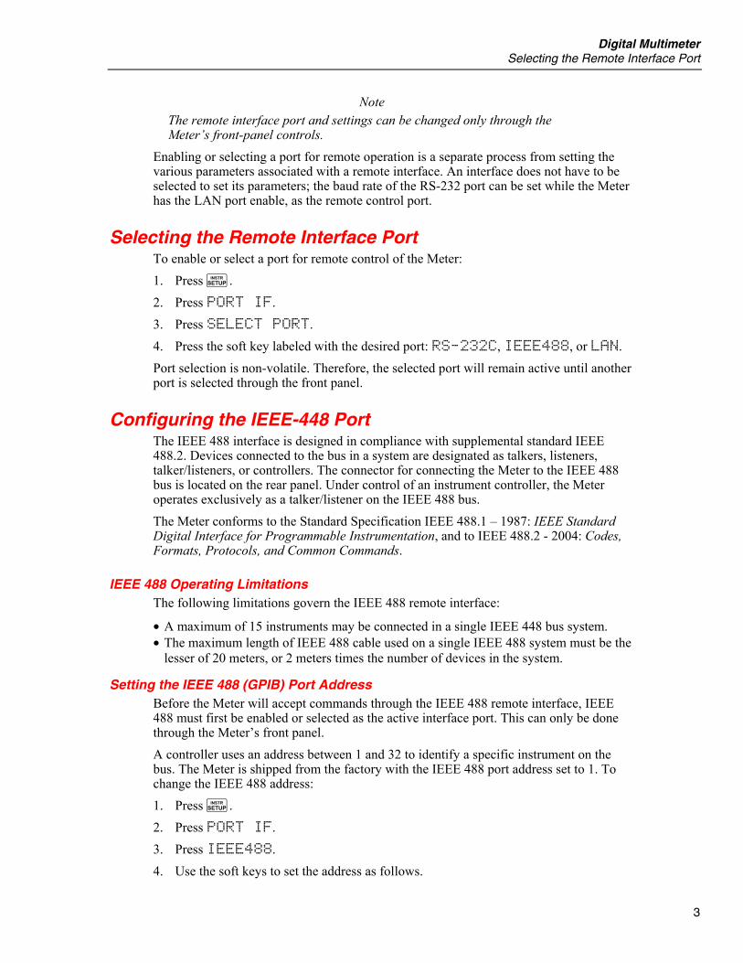
Digital Multimeter Selecting the Remote Interface Port
3
Note The remote interface port and settings can be changed only through the Meter’s front-panel controls.
Enabling or selecting a port for remote operation is a separate process from setting the various parameters associated with a remote interface. An interface does not have to be selected to set its parameters; the baud rate of the RS-232 port can be set while the Meter has the LAN port enable, as the remote control port.
Selecting the Remote Interface Port To enable or select a port for remote control of the Meter: 1. Press I. 2. Press PORT IF. 3. Press SELECT PORT. 4. Press the soft key labeled with the desired port: RS-232C, IEEE488, or LAN. Port selection is non-volatile. Therefore, the selected port will remain active until another port is selected through the front panel.
Configuring the IEEE-448 Port The IEEE 488 interface is designed in compliance with supplemental standard IEEE 488.2. Devices connected to the bus in a system are designated as talkers, listeners, talker/listeners, or controllers. The connector for connecting the Meter to the IEEE 488 bus is located on the rear panel. Under control of an instrument controller, the Meter operates exclusively as a talker/listener on the IEEE 488 bus. The Meter conforms to the Standard Specification IEEE 488.1 – 1987: IEEE Standard Digital Interface for Programmable Instrumentation, and to IEEE 488.2 - 2004: Codes, Formats, Protocols, and Common Commands.
IEEE 488 Operating Limitations The following limitations govern the IEEE 488 remote interface:
• A maximum of 15 instruments may be connected in a single IEEE 448 bus system. • The maximum length of IEEE 488 cable used on a single IEEE 488 system must be the
lesser of 20 meters, or 2 meters times the number of devices in the system.
Setting the IEEE 488 (GPIB) Port Address Before the Meter will accept commands through the IEEE 488 remote interface, IEEE 488 must first be enabled or selected as the active interface port. This can only be done through the Meter’s front panel. A controller uses an address between 1 and 32 to identify a specific instrument on the bus. The Meter is shipped from the factory with the IEEE 488 port address set to 1. To change the IEEE 488 address: 1. Press I. 2. Press PORT IF. 3. Press IEEE488. 4. Use the soft keys to set the address as follows.
8845A/8846A Programmers Manual
4
Select the address digit to adjust by pressing either <-- or -->. With the desired digit selected, press the soft key labeled -- to decrement the digit or ++ to increment the character.
5. With the desired address set, press ENTER.
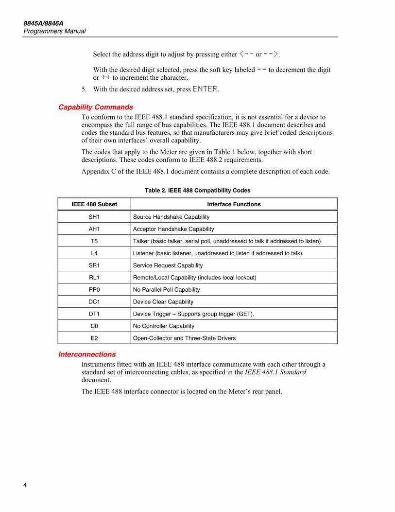
Capability Commands To conform to the IEEE 488.1 standard specification, it is not essential for a device to encompass the full range of bus capabilities. The IEEE 488.1 document describes and codes the standard bus features, so that manufacturers may give brief coded descriptions of their own interfaces’ overall capability. The codes that apply to the Meter are given in Table 1 below, together with short descriptions. These codes conform to IEEE 488.2 requirements. Appendix C of the IEEE 488.1 document contains a complete description of each code.
Table 2. IEEE 488 Compatibility Codes
IEEE 488 Subset Interface Functions
SH1 Source Handshake Capability
AH1 Acceptor Handshake Capability
T5 Talker (basic talker, serial poll, unaddressed to talk if addressed to listen)
L4 Listener (basic listener, unaddressed to listen if addressed to talk)
SR1 Service Request Capability
RL1 Remote/Local Capability (includes local lockout)
PP0 No Parallel Poll Capability
DC1 Device Clear Capability
DT1 Device Trigger – Supports group trigger (GET).
C0 No Controller Capability
E2 Open-Collector and Three-State Drivers
Interconnections Instruments fitted with an IEEE 488 interface communicate with each other through a standard set of interconnecting cables, as specified in the IEEE 488.1 Standard document. The IEEE 488 interface connector is located on the Meter’s rear panel.
Digital Multimeter Configuring the RS-232 Port
5
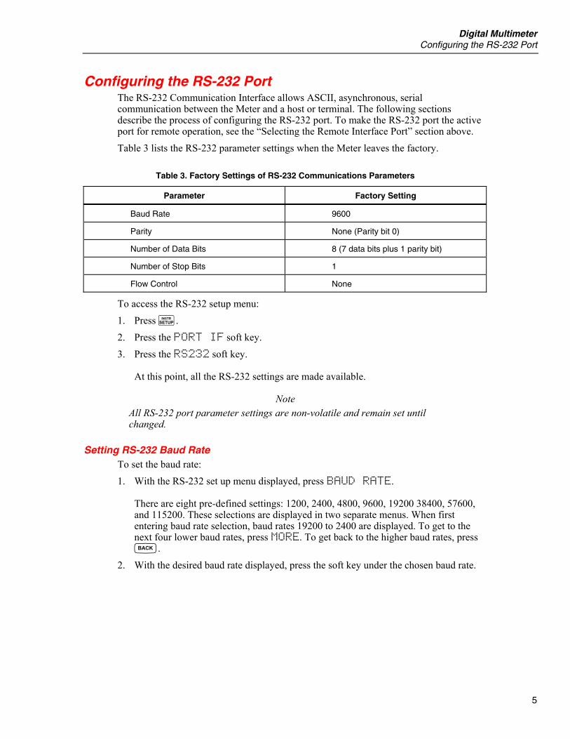
Configuring the RS-232 Port The RS-232 Communication Interface allows ASCII, asynchronous, serial communication between the Meter and a host or terminal. The following sections describe the process of configuring the RS-232 port. To make the RS-232 port the active port for remote operation, see the “Selecting the Remote Interface Port” section above. Table 3 lists the RS-232 parameter settings when the Meter leaves the factory.
Table 3. Factory Settings of RS-232 Communications Parameters
Parameter Factory Setting
Baud Rate 9600
Parity None (Parity bit 0)
Number of Data Bits 8 (7 data bits plus 1 parity bit)
Number of Stop Bits 1
Flow Control None
To access the RS-232 setup menu: 1. Press I. 2. Press the PORT IF soft key. 3. Press the RS232 soft key.
At this point, all the RS-232 settings are made available.
Note All RS-232 port parameter settings are non-volatile and remain set until changed.
Setting RS-232 Baud Rate To set the baud rate: 1. With the RS-232 set up menu displayed, press BAUD RATE.
There are eight pre-defined settings: 1200, 2400, 4800, 9600, 19200 38400, 57600, and 115200. These selections are displayed in two separate menus. When first entering baud rate selection, baud rates 19200 to 2400 are displayed. To get to the next four lower baud rates, press MORE. To get back to the higher baud rates, press B.
2. With the desired baud rate displayed, press the soft key under the chosen baud rate.
8845A/8846A Programmers Manual
6
Setting RS-232 Parity and Data Bits To set the data bits: 1. With the RS-232 set up menu displayed, press PARITY DATA BIT. 2. Press the soft key under the desired parity, and data bit parameter.
NONE 8B DATA = No parity with 8 data bits ODD 7B DATA = Odd parity with 7 data bits EVEN 7B DATA = Even parity with 7 data bits
Setting RS-232 Flow Control To set flow control: 1. With the RS-232 set up menu displayed, press FLOW CONTROL. 2. Press the soft key under the desired flow control.
NONE = No flow control XON = Software flow control Xon (hex 11) and Xoff (hex 13) RTS = Hardware flow control, RTS/DTS
Setting RS-232 End-Of-Line Character To set the End-Of-Line (EOL) character: 1. With the RS-232 set up menu displayed, press EOL. 2. Press the soft key labeled with the desired End-Of-Line character(s).
CR = Carriage return only LF = Line Feed only CR LF = Carriage Return and Line Feed
Enabling and Disabling Fluke 45 Emulation Echo Although you can turn echo on or off at anytime, the selection is used only when the Meter’s command mode is set to Fluke 45 emulation. To enable or disable Echo for the RS-232 port: 1. With the RS-232 set up menu displayed, press COMP/TERM ECHO. 2. Press either the ECHO or NO ECHO soft key.
RS-232 Modes of Operation RS-232 communication is slightly different between the 884X and Fluke 45 emulation modes. Switching between these two commands sets is covered in the “Selecting the Programming Language” section later in this manual. The following sections explain the differences in communications protocol and how to set the Meter and computer parameters for proper operation.
884X Mode There are two modes of RS-232 operation when the Meter has the 884X command set selected: TERMINAL and COMPUTER. The terminal mode is an interactive mode where an operator inputs commands, with immediate returns for requested information (queries) and interface messages. In terminal mode, characters sent to the Meter are echoed on the host’s display screen and a command prompt (for example 3>) is returned

Digital Multimeter Configuring the RS-232 Port
7
after the CR/LF is entered by the terminal. If you send a character to the Meter over the RS-232 interface, pressing the <DELETE> or <BACKSPACE> key deletes the previous character. A backspace is echoed to the host terminal.
Note ^C (CNTRL C) is the RS-232 equivalent of IEEE 488 DCI (device clear), causing “1>” followed by a carriage return and line feed to be output.
The computer mode is used when the Meter is operated by computer program. In this mode, requested information is returned by query, and interface messages are queued and returned by command. Characters are not echoed on the host computer and command prompts are suppressed. The <DELETE> or <BACKSPACE> keys are ignored.
Selecting Between Computer and Terminal Mode Although you can select between Computer and Terminal mode at any time, the selection is used only when the Meter’s command mode is set to 884X. To select computer or terminal mode: 1. With the RS-232 set up menu displayed, press COMP/TERM ECHO. 2. Press either COMPUTER or TERMINAL.
Fluke 45 Mode In the Fluke 45 Command emulation mode, there are two modes of RS-232 operation: ECHO or NO ECHO. In Echo mode, characters sent to the Meter are echoed on the host’s display screen. In No Echo mode, characters sent are not echoed. To set the echo parameter, refer to the "Enabling and Disabling RS-232 Echo" section earlier in this manual. If you send a character to the Meter over the RS-232 interface, pressing the <DELETE> or <BACKSPACE> key deletes the previous character. A backspace is echoed to the display screen if Echo On mode is set. In either mode, when the host sends a command to the Meter over the RS-232 interface, the Meter parses and executes the command, and returns a response if appropriate, and sends one of three prompts:
=> No errors were detected and the command was successfully parsed and executed.
?> A Command Error was detected. The command was not executed because it was not understood. For instance, this prompt would be returned if the Meter was sent an input string that contained a syntax error.
!> An Execution Error was detected. The command was understood but not executed (i.e., a device-dependent error). For instance, this prompt would be returned if you attempted to use the decibels modifier (dB) on a frequency measurement (FREQ).
Note ^C (CNTRL C) is the RS-232 equivalent of IEEE-488 DCI (device clear), causing "=>" followed by a carriage return and line feed to be output.
Terminations for the end of line can be set to carriage return (CR), line feed (LF), or both (CRLF). Terminations for the end of line can be set in the <Instr SETUP><PORT IF><RS232C> selection.
8845A/8846A Programmers Manual
8
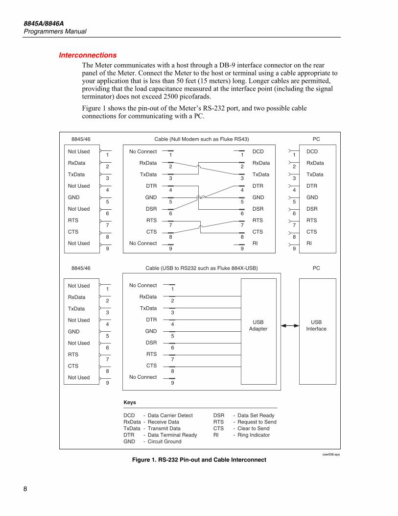
Interconnections The Meter communicates with a host through a DB-9 interface connector on the rear panel of the Meter. Connect the Meter to the host or terminal using a cable appropriate to your application that is less than 50 feet (15 meters) long. Longer cables are permitted, providing that the load capacitance measured at the interface point (including the signal terminator) does not exceed 2500 picofarads. Figure 1 shows the pin-out of the Meter’s RS-232 port, and two possible cable connections for communicating with a PC.
Not Used
RxData
TxData
Not Used
GND
Not Used
RTS
CTS
Not Used
Not Used
RxData
TxData
Not Used
GND
Not Used
RTS
CTS
Not Used
Keys
DCDRxDataTxDataDTRGND
-----
Data Carrier DetectReceive DataTransmit DataData Terminal ReadyCircuit Ground
DSRRTSCTSRI
----
Data Set ReadyRequest to SendClear to SendRing Indicator
DCD
RxData
TxData
DTR
GND
DSR
RTS
CTS
RI
DCD
RxData
TxData
DTR
GND
DSR
RTS
CTS
RI
No Connect
RxData
TxData
DTR
GND
DSR
RTS
CTS
No Connect
No Connect
RxData
TxData
DTR
GND
DSR
RTS
CTS
No Connect
1
2
3
4
5
6
7
8
9
1
2
3
4
5
6
7
8
9
1
2
3
4
5
6
7
8
9
1
2
3
4
5
6
7
8
9
1
2
3
4
5
6
7
8
9
1
2
3
4
5
6
7
8
9
8845/46 Cable (Null Modem such as Fluke RS43) PC
8845/46 Cable (USB to RS232 such as Fluke 884X-USB) PC
USBInterface
USBAdapter
caw058.eps
Figure 1. RS-232 Pin-out and Cable Interconnect
Digital Multimeter Configuring the Ethernet (LAN) Port
9
Configuring the Ethernet (LAN) Port The Meter can be remotely controlled through the LAN port on the Meter’s rear panel. To select the LAN port as the remote control port, see the “Selecting the Remote Interface” above. Configuring the LAN port is accomplished through the Instrument Setup function. The selectable LAN port parameters are: DHCP (Dynamic Host Configuration Protocol), IP Address, Net mask, Host Name, Mac Address, Gateway, Port number, and Domain. When setting IP addresses, subnet masks, and default gateways on the Meter, keep in mind they are stored as 32-bit binary numbers and expressed as four 3-digit segments in dot-notation form. For example, xxx.xxx.xxx.xxx where xxx is a byte value. To avoid confusion, use only decimal expressions of byte values (0 to 255) with no leading zeroes. To set the LAN port parameters: 1. Press I. 2. Press the PORT IF soft key. 3. Press the LAN soft key.
Setting the IP Address An internet (IP) address is required for all internet and TCP/IP communications. If DHCP is enabled, the Meter will use the temporary address supplied by the DHCP server. However, if the DHCP server fails to supply the address, or DHCP is disabled, the currently configured IP address will be used.
Selecting Dynamic Host Configuration Protocol (DHCP) Dynamic Host Configuration Protocol (DHCP) is a client-server protocol that eliminates having to manually set permanent IP addresses. The DHCP server provides configuration parameters (temporary IP address, subnet mask, and default gateway IP addresses) which are required for a client host to participate in an IP network. Using DHCP is the easiest way to configure the Meter for remote communication through the LAN interface. DHCP is enabled when the Meter is shipped from the factory. When connected to a network, and the LAN port enabled, the Meter will try and retrieve the parameters from a DHCP server necessary for communications. If the parameters can’t be obtained, the Meter switches to the parameters that were manually entered into the Meter. To disable or enable DHCP on the Meter: From the PORT IF menu, press LAN. If DHCP is already enabled, then DHCP will be highlighted in the display. Pressing DHCP will toggle between enabled and disabled.
Setting a Static Internet Address The Meter comes from the factory with 000.000.000.000 in the static IP address register.
Note If you are planning to use the Meter on a corporate LAN, contact your network administrator for a static IP address to be used exclusively in your Meter.
To change the Meter’s static IP Address: 1. From the LAN Port setup menu, press the IP_ADDR soft key.

8845A/8846A Programmers Manual
10
2. Use the soft keys to set the IP Address as follows: To select the address character to adjust, press either <-- or -->. With the desired digit selected, press the soft key labeled -- to decrement the digit or ++ to increment the character.
3. Press the ENTER soft key.
Note The IP address is stored in non-volatile memory, and does not change when power is removed and reapplied to the Meter or receives an *RST command.
Setting the LAN Subnet Mask If communication between the host computer and the Meter passes through a router or gateway, and DHCP is disabled, you must set the subnet mask and default gateway address on both the host computer and the Meter. Get the correct subnet mask and gateway address from your network administrator. The LAN Subnet Mask is a 32-bit number. This number is represented as four 3-digit segment numbers on the front-panel display. The default subnet mask set at the factory is 255.255.254.0. To change the Meter’s subnet mask: 1. From the LAN Port setup menu, press the NETMASK soft key. 2. Use the soft keys to set the subnet mask as follows:
To select the mask character to adjust, press either <-- or -->. With the desired digit selected, press the soft key labeled -- to decrement the digit or ++ to increment the character.
3. Press the ENTER soft key. The new Subnet Mask will not take effect until the Meter has been powered down and back up again using the rear-panel power switch.
Reading the Domain Name The Domain Name is supplied by the DHCP server and can not be changed. To read the domain name: 1. From the LAN Port setup menu, press MORE. 2. Press the DOMAIN soft key. 3. Press B to return to the LAN Port setup menu.
Configuring the Host Name The Host Name is the host portion of the domain name, which is translated into an IP address. The Meter’s default host name is “test1”. To change the Host Name: 1. From the LAN Port setup menu, press the HOSTNAME soft key.
Digital Multimeter Configuring the Ethernet (LAN) Port
11
2. Use the soft keys to set the Host Name as follows: To select the mask character to adjust, press either <-- or -->. With the desired digit selected, press the soft key labeled -- to decrement the digit or ++ to increment the character.
3. Press the ENTER soft key. The new Host Name will not take effect until the Meter has been powered down and back up again using the rear-panel power switch.
Reading the MAC Address The MAC Address is set at the factory and cannot be changed. To read the MAC Address: 1. From the LAN Port setup menu, press MORE. 2. Press the MAC_ADDR soft key. 3. Press B to return to the LAN Port setup menu.
Configuring the LAN Default Gateway The default gateway IP address is the IP address of a gateway (router) attached to the same network as the device. When the instrument detects that a host computer is not on the same network (using the network number), the data is sent through the gateway to reach the host computer. The default for the Meter is “0” (no gateway, and subnetting is not being used). To set the LAN Default Gateway: 1. From the LAN Port setup menu, press MORE. 2. Press GATEWAY. 3. To select the digit to adjust, press either <-- or -->.
With the desired digit selected, press the soft key labeled -- to decrement the digit or ++ to increment the character.
4. Press the ENTER soft key. The new gateway address will not take effect until the Meter has been powered down and back up again using the rear-panel power switch.
Configuring the General Network Socket Port In order to communicate with each other, a host computer and the Meter must use the same socket port number. The default port is 3490. Typically, the default port does not need to be changed. If the socket port must be changed, enter the Socket Port number supplied by your network administrator. To change the port: 1. From the LAN Port setup menu, press the MORE soft key. 2. Press the PORT # soft key.
8845A/8846A Programmers Manual
12
3. To select the digit to adjust, press either <-- or -->. With the desired digit selected, press the soft key labeled -- to decrement the digit or ++ to increment the character.
4. Press the ENTER soft key. The Network Socket Port becomes effective immediately.
Note The Network Socket Port Number is stored in non-volatile memory.
Establishing an Ethernet Connection The easiest method of establishing an Ethernet connection with the Meter is through the commonly available program: Telnet. Telnet is a client-server protocol, based on TCP. The Telnet Protocol provides a fairly general, bi-directional, eight-bit byte oriented communications facility. Telnet is available on all UNIX servers and on most PCs. Telnet clients typically connect to hosts on socket port 23. The LAN connection to the Meter must be established using the specified Network Socket Port. See the “Configuring the General Network Socket Port” section above. When the remote interface port is changed to LAN from the Meter’s front panel, a LAN server is initiated in the Meter which listens for client connections on the socket port at the specified IP address. To establish a LAN connection to the Meter from a PC using either UNIX or MS-DOS command prompt, perform the following procedure: 1. On the Meter’s front panel, change the remote interface port to LAN 2. At the Unix or DOS command prompt on the client PC, enter: telnet IP Address Socket Port Alternatively, if you are using DHCP and would like to connect using the host name
rather than the IP address, from the Unix or DOS command prompt enter: telnet Domain Name Socket Port As an example, if you know the IP address is 129.196.136.131 and the Socket Port is set to 3490, enter the following at a UNIX or DOS command prompt from any client PC: telnet 129.196.136.131 3490 If you are using DHCP and the host name is test1 and the fully qualified domain name is test1.na.flukecorp.com and the Socket Port is set to 3490, enter the following at the UNIX or DOS command prompt: telnet test1.na.flukecorp.com 3490 Once the internal LAN server connects with the client computer, the LAN server will reject any other connection attempts by other computers and will “tunnel” a channel to the connected computer. This prevents multiple computers from trying to control the Meter.
Digital Multimeter Terminating an Ethernet Connection
13
Terminating an Ethernet Connection When you wish to terminate the Ethernet connection, you may do so one of two ways: 1. Change the Meter’s remote interface port to something other than LAN 2. Terminate the Telnet session on the client computer If you have established a LAN connection to the Meter using Telnet and change the remote interface port using the Meter’s front panel, the LAN server in the Meter will automatically terminate the Telnet session on the client computer. On the other hand, you may wish to terminate the Telnet session on the client computer but maintain the current LAN remote interface port configuration. To do this, you terminate the Telnet session on the client computer. Client Telnet session termination can vary from computer to computer, but typically terminating the shell (or command window in DOS) will terminate the telnet session. When the client terminates the Telnet session, the LAN server in the Meter will go back into listen mode waiting for a new client to make a LAN connection request.
Selecting the Programming Language The Meter’s remote command set is switchable between 8845 and Fluke 45 commands. The Meter’s standard remote command set (8845) is compatible with Agilent’s 34401A command set. Although every effort was made to make the Meter compatible with Fluke 45 commands, there are some commands that are not compatible. See Appendix B, “Fluke 45 Emulation Limitations” for details on commands that are not compatible with this Meter. To change the Meter’s remote command set: 1. Press I. 2. Press the COMMANDS soft key. 3. Press the soft key labeled with the desired command set.
Getting Started With an Installation Test After the Meter has been cabled to a host, and prepared to communicate with it via the RS-232 or IEEE 488 interface (as described above), test the system to verify that it is operational.
Installation Test for RS-232 Connections The procedure below illustrates how the Meter performs a computer interface command and, at the same time, confirms that the Meter has been properly set up and connected for RS-232 remote operations: 1. Press the POWER button in to turn the Meter on. 2. Start up a computer terminal program. 3. Verify that the computer interface parameters (e.g., baud, parity) are set correctly. 4. Send the Meter the following command.
*IDN? <CR> 5. Verify that the Meter sends the following response:
8845A/8846A Programmers Manual
14
In Fluke 8845 mode (includes 8846A): Fluke, 884XA, nnnnnnnm, mm/dd/yy – tt:tt In Fluke 45 mode: FLUKE, 45, nnnnnnn, n.n Dn.n Of these results, nnnnnnn is your Meter's serial number; n.n identifies the main software version; and Dn.n identifies the display software version.
Installation Test for IEEE 488 Connections The procedure below illustrates how the Meter performs a computer interface command and, at the same time, confirms that the Meter has been properly set up, and connected for IEEE 488 operations: 1. Turn the Meter on. 2. Verify that the meter's IEEE 488 address is set correctly.
3. Turn on the host or controller.
4. Enter the following at the host:
Note This is a BASIC program to give an idea of how the test could be done. Syntax may vary with the host.
INIT PORT 0<CR> CLEAR PORT 0<CR> PRINT @<address of meter>, "*IDN?"<CR> INPUT LINE @<address of meter>, A$<CR> PRINT A$<CR>
5. Verify that the meter sends the following response In Fluke 8845 mode (includes 8846A): Fluke, 884XA, nnnnnnnm, mm/dd/yy – tt:tt In Fluke 45 mode: FLUKE, 45, nnnnnnn, n.n Dn.n Of these results, nnnnnnn is your meter's serial number, n.n identifies the main software version, and Dn.n identifies the display software version.
If Test Fails If the Meter does not respond to the test procedure as indicated:
1. Check all cable connections.
2. Check to see the remote interface has been properly enabled and addressed.
Digital Multimeter How the Meter Processes Input
15
How the Meter Processes Input The following paragraphs summarize how the Meter processes input that is received from a host or stand-alone terminal.
Note In this manual input means a string sent to the Meter from a host. Output means a string sent from the meter through the computer interface to the host.
Input Strings The meter processes and executes valid input strings sent by the host. A valid input string is one or more syntactically correct commands followed by an input terminator. When the meter receives input, it stores it in a 350-byte input buffer.
Note Input strings received over the RS-232 interface are not executed or checked for proper syntax until an input terminator is received or the input buffer becomes full.
The Meter accepts alphabetic characters in either upper- or lower-case. If a command cannot be understood (i.e. the equivalent of an IEEE 488 Command Error), the remainder of the command line is ignored.
Input Terminators An input terminator is a character or command (IEEE 488.1) sent by the host that identi-fies the end of a string. In RS-232 applications, when the Meter receives an input terminator, it executes all com-mands entered since the last terminator was received on a first-in, first-out basis. As input characters are processed and executed, space is made available in the input buffer for new characters. In RS-232 applications, if a communications error (e.g., parity, framing, over-run) is detected, a device-dependent error is generated, and the input string discarded. If the Meter's input buffer becomes full when it is used with the RS-232 interface, a device-dependent error is generated (see "Event Status and Event Status Enable Register"), and the input string is discarded. If, on the other hand, the input buffer becomes full when the IEEE 488 interface is used, the Meter stops accepting characters until there is room in the buffer. Characters in the input buffer cannot be over-written with the IEEE 488 interface. Valid terminators for the RS-232 interface are: • LF (Line Feed) • CR (Carriage Return) • CR LF (Carriage Return/ Line Feed) Valid terminators for the IEEE 488 interface are: • EOI (End or Identity) on any character • LF (Line Feed) In some instances, a terminator is automatically transmitted at the end of the host's output string (i.e., the Meter's input string). For example, in Fluke BASIC, the PRINT statement finishes with a CR LF pair.
8845A/8846A Programmers Manual
16
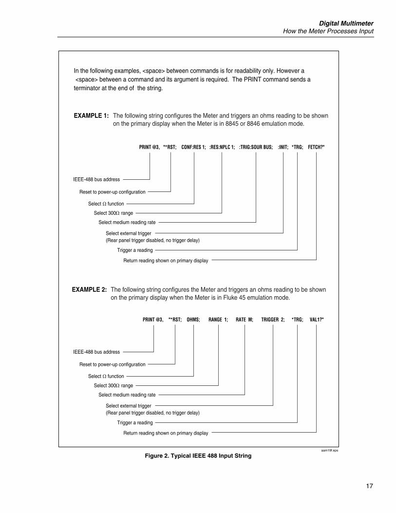
Typical IEEE 488 Input Strings Two typical strings that could be sent to the Meter over the IEEE 488 interface are shown in Figure 2. These strings are written in Fluke BASIC to be sent from a Fluke 1722A Instrument Controller.
Sending Numeric Values to the Meter Numeric values can be sent to the Meter as integers, real numbers, or real numbers with exponents, as shown in the following examples: EXAMPLE EXPLANATION +12345689 Sends the signed integer +12345689 -1.2345E2 Sends -1.2345 x 10²
Sending Command Strings to the Meter Observe the following rules when you construct strings to be sent to the Meter over the computer interface: • RULE 1: READ METER'S OUTPUT BUFFER ONLY ONCE FOR EACH QUERY
COMMAND. The Meter’s output buffer is cleared after it has been read. This prevents previously read data from being read a second time by mistake. If you attempt to read the meter’s output buffer twice without an intervening query, the Meter will not respond to the second read.
• RULE 2: READ QUERY RESPONSES BEFORE SENDING ANOTHER QUERY COMMAND STRING.
Output data remains available in the output buffer until read by the host or until the next command string is received by the Meter. This means the Meter’s output buffer must be read by the host before, rather than after, the next command string is sent to the Meter.
• RULE 3: THE METER EXECUTES EACH COMMAND COMPLETELY, IN THE ORDER RECEIVED, BEFORE MOVING ON TO THE NEXT COMMAND.
If an input string contains a trigger, enter the commands in the following order, that is, from left to right, as written: 1. Commands (if any) to configure the Meter. 2. The trigger command. 3. Commands to read the result of a triggered measurement (FETCh? or READ? for
the 884XA and VAL? for the Fluke 45 emulation), or to reconfigure the instrument (if any).
4. The terminator. Figure 2 gives two examples of a command string for the Meter. The first example is a command recognized by the Meter in the 8845 or 8846 command mode. The second example is for the Fluke 45 command mode.
Digital Multimeter How the Meter Processes Input
17
In the following examples, <space> between commands is for readability only. However a <space> between a command and its argument is required. The PRINT command sends a terminator at the end of the string.
The following string configures the Meter and triggers an ohms reading to be shownon the primary display when the Meter is in Fluke 45 emulation mode.
EXAMPLE 2:
The following string configures the Meter and triggers an ohms reading to be shownon the primary display when the Meter is in 8845 or 8846 emulation mode.
EXAMPLE 1:
PRINT @3, "*RST;
IEEE-488 bus address
Reset to power-up configuration
Select 300 range
Select function
Select external trigger(Rear panel trigger disabled, no trigger delay)
Trigger a reading
Return reading shown on primary display
Select medium reading rate
PRINT @3, "*RST; CONF:RES 1; :RES:NPLC 1; :TRIG:SOUR BUS; :INIT; *TRG; FETCH?"
IEEE-488 bus address
Reset to power-up configuration
Select 300 range
Select function
Select external trigger(Rear panel trigger disabled, no trigger delay)
Trigger a reading
Return reading shown on primary display
Select medium reading rate
OHMS; RANGE 1; RATE M; TRIGGER 2; *TRG; VAL1?"
aam19f.eps
Figure 2. Typical IEEE 488 Input String
8845A/8846A Programmers Manual
18
How the Meter Processes Output The following paragraphs summarize how the Meter processes output. The Meter outputs an alphanumeric string in response to a query command from the host. Query commands are easily identified because they all end with "?". An output string is terminated by a Carriage Return and Line Feed (<CR><LF>) for RS-232 or Ethernet applications, or a Line Feed with End or Identity (<LF><EOI>) for IEEE 488. After sending the Meter a query command via the RS-232 interface, wait for the Meter to return a prompt before sending another query command. Although the Meter will accept and process all commands other than a query command, a device-dependent command error is generated; and the second command is discarded if it is a query command. If the Meter is part of an IEEE 488 bus system, the output data is not actually sent onto the bus until the host addresses the Meter as a talker. When the output buffer is loaded, the Message Available (MAV) bit in the Status Byte Register is set true. (For more information, see "Status Byte Register.”) Numeric output from the Meter is displayed as shown in the following examples: EXAMPLE EXPLANATION +1.2345E+0 Measured value of 1.2345 +1.2345E+6 Measured value of 1.2345 x 10⁶
Triggering Input While under remote control, the Meter must be placed in a wait-for-trigger state before a measurement can be triggered. The INITiate and READ? commands set the Meter in to a wait-for-trigger state. The number of measurements (samples) and the number of triggers the Meter will accept after being put in a wait-for-trigger state are variables set using remote commands. The defaults for these variables are one sample per trigger and one trigger per wait-for-trigger state. See the Trigger and Sample remote commands to set these values. All available trigger methods fall into two basic categories: • Internal triggering uses the Meter’s internal trigger circuit for a continuous source of
triggers. • External triggering comes from a source outside the Meter controlled by the user.
Internal Triggering When the Meter’s trigger source is set to immediate, measurements are triggered by the Meter’s internal trigger circuit. As an example, with the sample count set to 5 and the trigger count set to 2, the Meter will collect 10 measurements after it receives an INITiate or READ? command and then stop taking measurements. The READ? command will return all 10 readings immediately while the INITiate command must be followed by a FETCh? command to retrieve the measurements.
Digital Multimeter Service Requests (IEEE 488 Only) and Status Registers
19
External Triggering There are three methods of triggering the Meter externally: • A trigger signal applied to the external trigger jack on the Meter’s rear panel.
When the Meter’s trigger source is set to external and the Meter is in a wait-for-trigger state, a negative-going signal on the external trigger jack will trigger a measurement cycle.
• IEEE 488.1 GET command (IEEE Interface only) • *TRG command
When the Meter’s trigger source is set to BUS and the Meter is in a wait-for-trigger state, either a *TRG or bus GET command will trigger the Meter to take measurements.
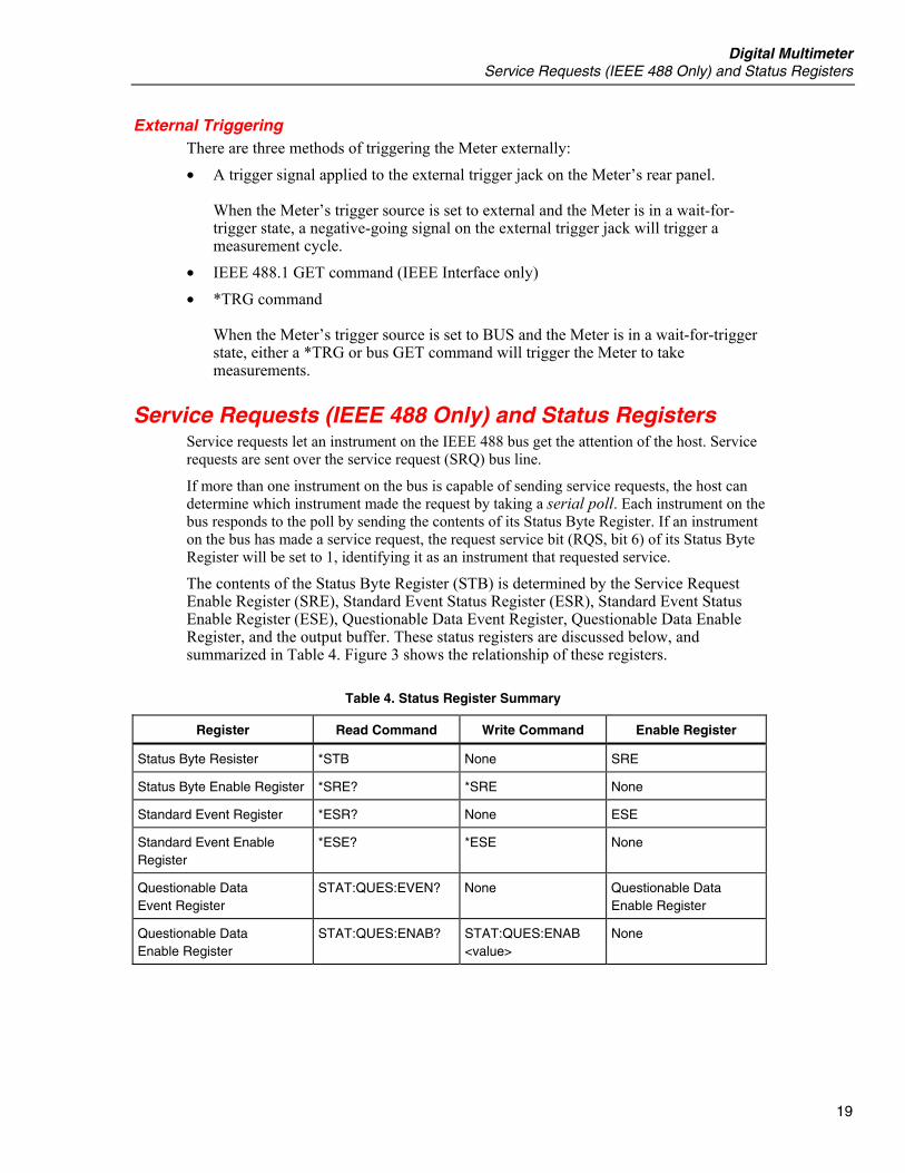
Service Requests (IEEE 488 Only) and Status Registers Service requests let an instrument on the IEEE 488 bus get the attention of the host. Service requests are sent over the service request (SRQ) bus line.
If more than one instrument on the bus is capable of sending service requests, the host can determine which instrument made the request by taking a serial poll. Each instrument on the bus responds to the poll by sending the contents of its Status Byte Register. If an instrument on the bus has made a service request, the request service bit (RQS, bit 6) of its Status Byte Register will be set to 1, identifying it as an instrument that requested service.
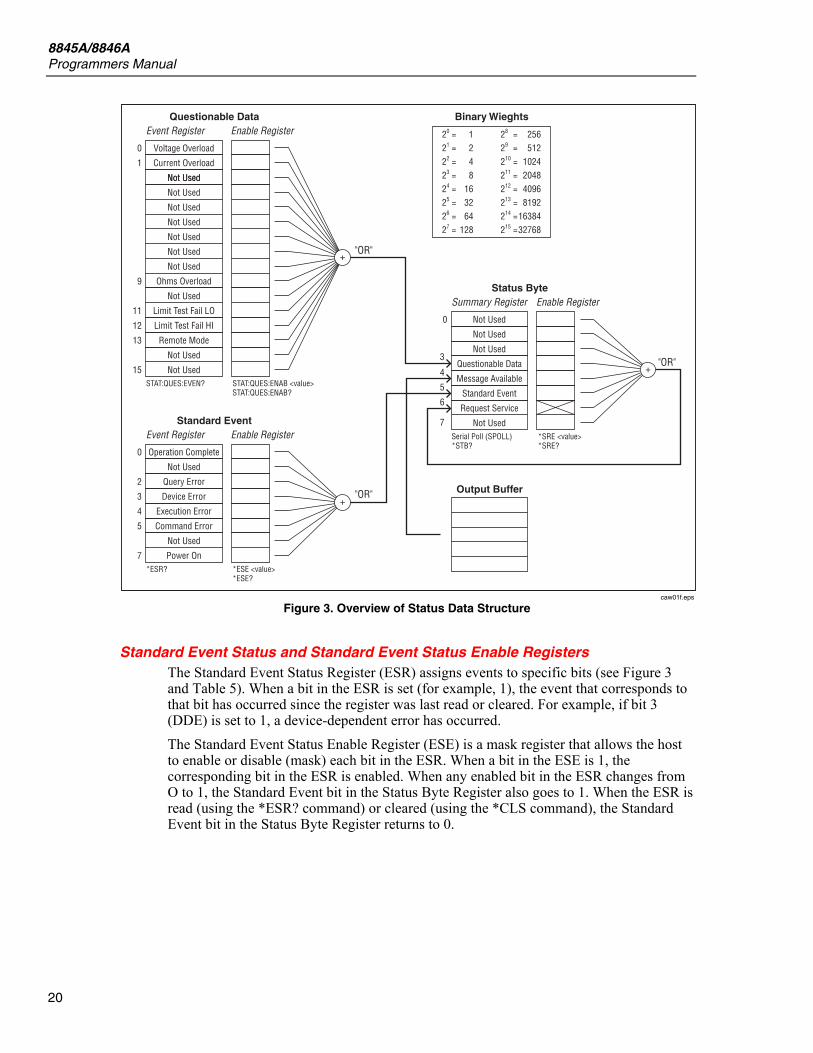
The contents of the Status Byte Register (STB) is determined by the Service Request Enable Register (SRE), Standard Event Status Register (ESR), Standard Event Status Enable Register (ESE), Questionable Data Event Register, Questionable Data Enable Register, and the output buffer. These status registers are discussed below, and summarized in Table 4. Figure 3 shows the relationship of these registers.
Table 4. Status Register Summary
Register Read Command Write Command Enable Register
Status Byte Resister *STB None SRE
Status Byte Enable Register *SRE? *SRE None
Standard Event Register *ESR? None ESE
Standard Event Enable Register
*ESE? *ESE None
Questionable Data Event Register
STAT:QUES:EVEN? None Questionable Data Enable Register
Questionable Data Enable Register
STAT:QUES:ENAB? STAT:QUES:ENAB <value>
None
8845A/8846A Programmers Manual
20
Voltage Overload20 = 1 28 = 25621 = 2 29 = 51222 = 4 210 = 102423 = 8 211 = 204824 = 16 212 = 409625 = 32 213 = 819226 = 64 214 = 1638427 = 128 215 = 32768
Questionable Data Binary WieghtsEvent Register Enable Register
STAT:QUES:EVEN? STAT:QUES:ENAB <value>STAT:QUES:ENAB?
"OR"
0
Current Overload1
Not Used
Not Used
Not Used
Not Used
Not Used
Not Used
Not Used
Ohms Overload
Not Used
9
Limit Test Fail LO11
Limit Test Fail HI12
13 Remote Mode
15
Not Used
Not Used
Not Used
Operation Complete
Standard EventEvent Register Enable Register
*ESR? *ESE <value>*ESE?
"OR"
0
Not Used
Query Error2
Device Error3
Execution Error4
5 Command Error
7
Not Used
Power On
Not Used
Status Byte
Output Buffer
Summary Register Enable Register
Serial Poll (SPOLL)*STB?
*SRE <value>*SRE?
"OR"
0
Not Used
Not Used
Questionable Data3
Message Available4
5Standard Event
7
6Request Service
Not Used
caw01f.eps
Figure 3. Overview of Status Data Structure
Standard Event Status and Standard Event Status Enable Registers
The Standard Event Status Register (ESR) assigns events to specific bits (see Figure 3 and Table 5). When a bit in the ESR is set (for example, 1), the event that corresponds to that bit has occurred since the register was last read or cleared. For example, if bit 3 (DDE) is set to 1, a device-dependent error has occurred. The Standard Event Status Enable Register (ESE) is a mask register that allows the host to enable or disable (mask) each bit in the ESR. When a bit in the ESE is 1, the corresponding bit in the ESR is enabled. When any enabled bit in the ESR changes from O to 1, the Standard Event bit in the Status Byte Register also goes to 1. When the ESR is read (using the *ESR? command) or cleared (using the *CLS command), the Standard Event bit in the Status Byte Register returns to 0.
Digital Multimeter Service Requests (IEEE 488 Only) and Status Registers
21
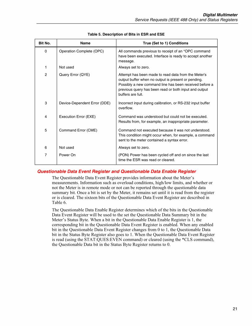
Table 5. Description of Bits in ESR and ESE
Bit No. Name True (Set to 1) Conditions
0
1
2
3
4
5
6
7
Operation Complete (OPC)
Not used
Query Error (QYE)
Device-Dependent Error (DDE)
Execution Error (EXE)
Command Error (CME)
Not used
Power On
All commands previous to receipt of an *OPC command have been executed. Interface is ready to accept another message.
Always set to zero.
Attempt has been made to read data from the Meter's output buffer when no output is present or pending. Possibly a new command line has been received before a previous query has been read or both input and output buffers are full.
Incorrect input during calibration, or RS-232 input buffer overflow.
Command was understood but could not be executed. Results from, for example, an inappropriate parameter.
Command not executed because it was not understood. This condition might occur when, for example, a command sent to the meter contained a syntax error.
Always set to zero.
(PON) Power has been cycled off and on since the last time the ESR was read or cleared.
Questionable Data Event Register and Questionable Data Enable Register The Questionable Data Event Register provides information about the Meter’s measurements. Information such as overload conditions, high/low limits, and whether or not the Meter is in remote mode or not can be reported through the questionable data summary bit. Once a bit is set by the Meter, it remains set until it is read from the register or is cleared. The sixteen bits of the Questionable Data Event Register are described in Table 6. The Questionable Data Enable Register determines which of the bits in the Questionable Data Event Register will be used to the set the Questionable Data Summary bit in the Meter’s Status Byte. When a bit in the Questionable Data Enable Register is 1, the corresponding bit in the Questionable Data Event Register is enabled. When any enabled bit in the Questionable Data Event Register changes from 0 to 1, the Questionable Data bit in the Status Byte Register also goes to 1. When the Questionable Data Event Register is read (using the STAT:QUES:EVEN command) or cleared (using the *CLS command), the Questionable Data bit in the Status Byte Register returns to 0.

8845A/8846A Programmers Manual
22
Table 6. Description of Bits in the Questionable Data Register
Bit No. Name True (Set to 1) Condition
0 Voltage Overload Input voltage has exceeded the upper limit of the range.
1 Current Overload Input current has exceeded the upper limit or the range.
2 – 8 Not Used
9 Ohms Overload The resistance measurement has exceeded the upper limit of the range.
10 Not Used
11 Limit Test Fail Lo The measurement is below the low end of the test limit.
12 Limit Test Fail Hi The measurement is above the high end of the test limit.
13 Remote Mode The Meter is set in the remote mode.
14 – 15 Not Used
Status Byte Register The Status Byte Register (STB) is a binary-encoded register that contains eight bits. Note that the Service Request Enable Register (SRE) uses bits 1 through 5, and bit 7 to set, the request service (RQS) bit 6, as enabled by the SRE. When the RQS bit is set true (l), the Meter sets the SRQ line true (1), which generates a service request. The eight bits of the Status Byte Register (as read by the *STB? command) are described in Table 7.
Reading the Status Byte Register The host can read the Status Byte Register by performing a serial poll, or sending the Meter a *STB? query. The value of the status byte is not affected by the STB? query. When the Status Byte Register is read, an integer is returned. This integer is the decimal equivalent of an 8-bit binary number. For example 48 is the decimal equivalent of the binary 00110000, and means that bit 4 (Message Available) and bit 5 (Standard Event) are set to “1”. If the status byte is read by serial poll, bit 6 is returned as a request service (RQS); if it is read with an *STB? query, bit 6 is returned as Master Summary Status (MSS). EXAMPLE EXPLANATION *STB? Reads the Status Byte Register. Assume that “32” is returned. Converting 32
to the binary 00100000 indicates that bit 5 (Standard Event) is set to 1. To determine the event status, you would have to read the Standard Event Register in the same manner, using the ESR? command.

Digital Multimeter Service Requests (IEEE 488 Only) and Status Registers
23
Table 7. Description of Bits in the Status Byte Register
Bit No. Name True (Set to 1) Condition
0 Not used Always set to 0.
1 Not used Always set to 0.
2 Not used Always set to 0.
3 Questionable Data One or more of the enabled events in the Questionable Data Event Register have occurred. To determine which Questionable Data events have occurred, send the Meter STAT:QUES:EVEN? to read the Questionable Data Event Register.
4 Message Available (MAV) Data is available in the output buffer. Bit set to 1 when response to query placed in output buffer. Bit cleared (set to 0) when output terminator sent to host.
5 Standard Event Status (ESB) One or more of the enabled events in the Event Status Register have occurred. To determine which events have occurred, send the Meter *ESR? to read the Event Status Register.
6 Master Summary Status† (MSS) Set to 1 if any enabled bit in the STB (MSS) register is set to 1, otherwise set to 0. Status of MSS bit returned by *STB? query command.
Request Service (RQS) Set to 1 if service requested from front panel, or MSS set to 1. Status of bit returned by serial poll, which clears RQS.
7 Not Used.
† As read by *STB? command. If the Status Byte Register is read by a serial poll, bit 6 is returned as RQS.
Service Request Enable Register The SRE Register is an 8-bit register that enables or disables (i.e., masks) corresponding summary messages in the Status Byte Register. The Meter may be programmed to make a service request on errors, questionable data, or when output is available. Conditions that trigger a service request are specified by writing a binary weighted value to the SRE Register, using the *SRE command. EXAMPLE EXPLANATION *SRE 16 Enables the generation of an SRQ when bit 4 (Measurement
Available) in the Status Byte Register is set to 1. 16 is the decimal equivalent of 00010000 binary. This means that bit 4 in SRE Register (that corresponds to the Measurement Available bit in the Status Byte Register) is 1, and all other bits are 0.
EXAMPLE EXPLANATION *SRE 48 Enables the generation of an SRQ when bits 4 or 5 (Measurement
Available or Standard Event) in the Status Byte Register are set to 1. The binary equivalent of 48 is 00110000, indicating that bits 4 and 5 are set to 1.
8845A/8846A Programmers Manual
24
If any bit in the SRE is set to 1, the RQS bit (bit 6) in the Status Byte Register is enabled, meaning a service request can be generated when the appropriate bits in STB become 1. Use the *SRE? query (see Table 10) to read the SRE Register. The Meter returns a binary-weighted integer that represents the enabled bits in the register. (The value of bit 6 will always be zero.) Convert the returned value to binary to determine the status of register bits. EXAMPLE EXPLANATION *SRE? Reads the value of the SRE Register. Assume "32" is returned.
Converting 32 to the binary 00100000 indicates that bit 5 in the SRE is set to 1.
Supported SCPI Commands This section explains the SCPI (Standard Commands for Programmable Instruments) commands available to program the Meter. This section includes the following information:
• A list of the supported SCPI Commands • A discussion of how to use the command set • A detailed description of each command in the set • Error handling for the 8845/8846
Note Throughout this document, the following conventions are used for SCPI command syntax. Square brackets ( [ ] ) indicate optional keywords or parameters. Braces ( ) enclose parameters within a command string. Triangle brackets ( < > ) indicate that you must substitute a value for the enclosed parameter.
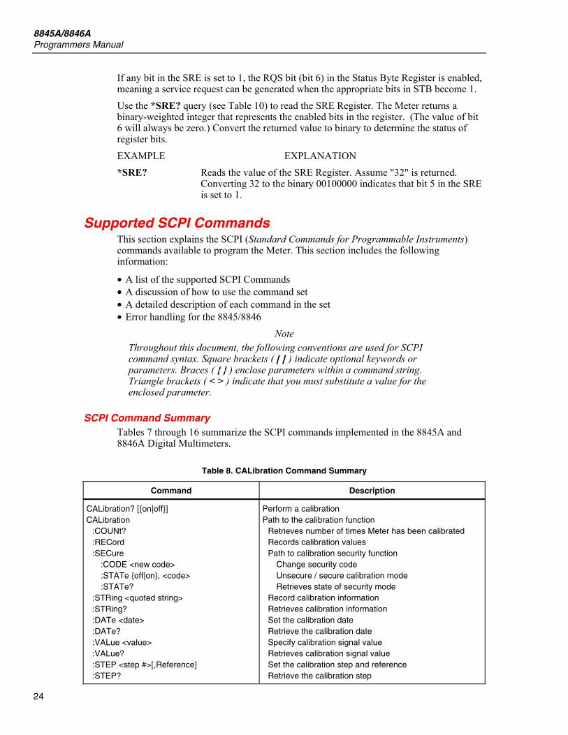
SCPI Command Summary Tables 7 through 16 summarize the SCPI commands implemented in the 8845A and 8846A Digital Multimeters.
Table 8. CALibration Command Summary
Command Description
CALibration? [on|off] CALibration :COUNt? :RECord :SECure :CODE <new code> :STATe off|on, <code> :STATe? :STRing <quoted string> :STRing? :DATe <date> :DATe? :VALue <value> :VALue? :STEP <step #>[,Reference] :STEP?
Perform a calibration Path to the calibration function Retrieves number of times Meter has been calibrated Records calibration values Path to calibration security function Change security code Unsecure / secure calibration mode Retrieves state of security mode Record calibration information Retrieves calibration information Set the calibration date Retrieve the calibration date Specify calibration signal value Retrieves calibration signal value Set the calibration step and reference Retrieve the calibration step
Digital Multimeter Supported SCPI Commands
25
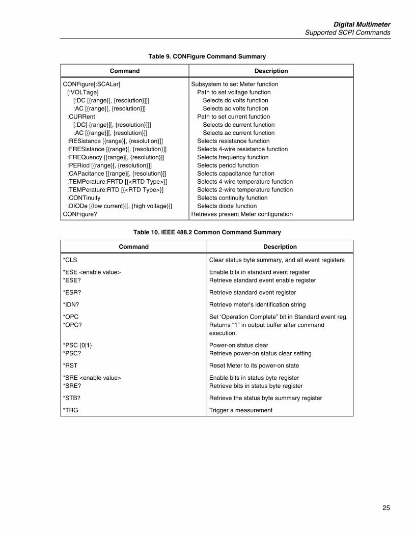
Table 9. CONFigure Command Summary
Command Description
CONFigure[:SCALar] [:VOLTage] [:DC [range[, resolution]]] :AC [range[, resolution]] :CURRent [:DC[ range][, resolution]]] :AC [range][, resolution]] :RESistance [range[, resolution]] :FRESistance [range[, resolution]] :FREQuency [range[, resolution]] :PERiod [range[, resolution]] :CAPacitance [range[, resolution]] :TEMPerature:FRTD [<RTD Type>] :TEMPerature:RTD [<RTD Type>] :CONTinuity :DIODe [low current][, high voltage]] CONFigure?
Subsystem to set Meter function Path to set voltage function Selects dc volts function Selects ac volts function Path to set current function Selects dc current function Selects ac current function Selects resistance function Selects 4-wire resistance function Selects frequency function Selects period function Selects capacitance function Selects 4-wire temperature function Selects 2-wire temperature function Selects continuity function Selects diode function Retrieves present Meter configuration
Table 10. IEEE 488.2 Common Command Summary
Command Description
*CLS
*ESE <enable value> *ESE?
*ESR?
*IDN?
*OPC *OPC?
*PSC 0|1 *PSC?
*RST
*SRE <enable value> *SRE?
*STB?
*TRG
Clear status byte summary, and all event registers
Enable bits in standard event register Retrieve standard event enable register
Retrieve standard event register
Retrieve meter’s identification string
Set ‘Operation Complete” bit in Standard event reg. Returns “1” in output buffer after command execution.
Power-on status clear Retrieve power-on status clear setting
Reset Meter to its power-on state
Enable bits in status byte register Retrieve bits in status byte register
Retrieve the status byte summary register
Trigger a measurement
8845A/8846A Programmers Manual
26
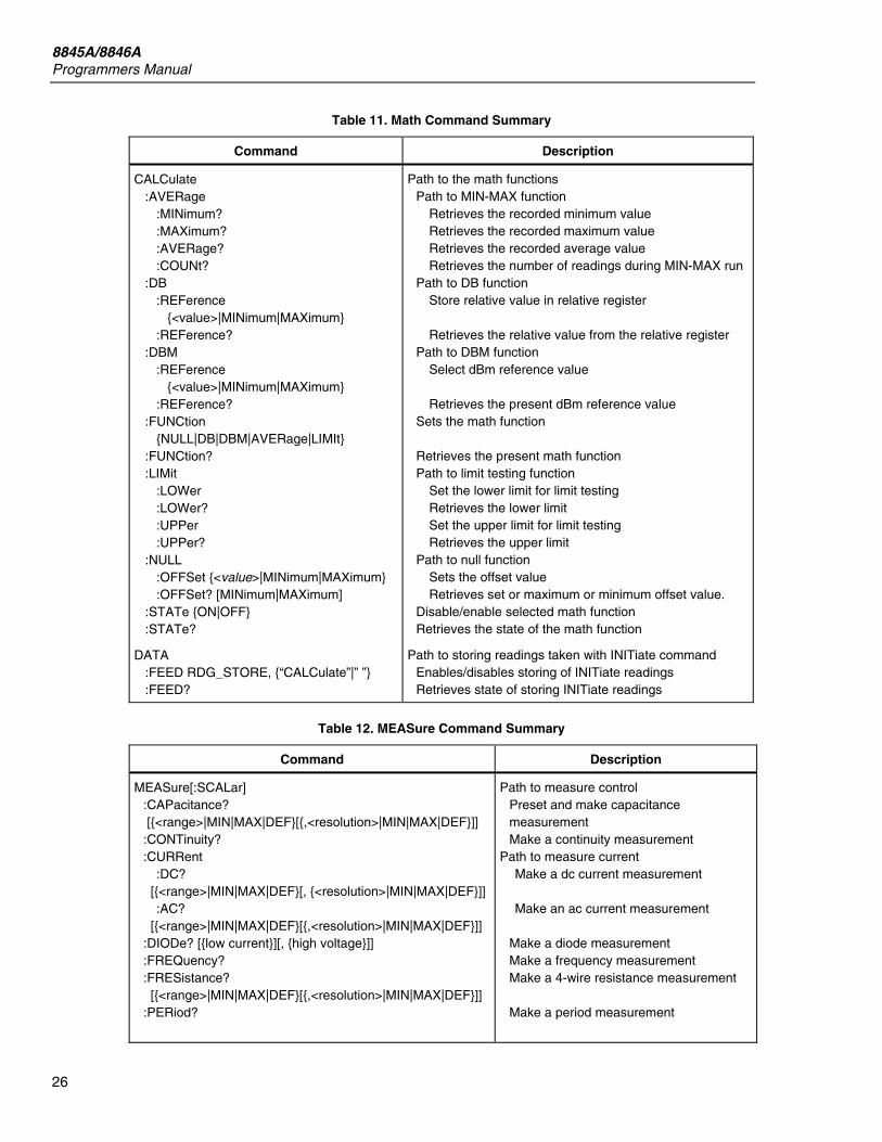
Table 11. Math Command Summary
Command Description
CALCulate :AVERage :MINimum? :MAXimum? :AVERage? :COUNt? :DB :REFerence <value>|MINimum|MAXimum :REFerence? :DBM :REFerence <value>|MINimum|MAXimum :REFerence? :FUNCtion NULL|DB|DBM|AVERage|LIMIt :FUNCtion? :LIMit :LOWer :LOWer? :UPPer :UPPer? :NULL :OFFSet <value>|MINimum|MAXimum :OFFSet? [MINimum|MAXimum] :STATe ON|OFF :STATe?
DATA :FEED RDG_STORE, “CALCulate”|” ” :FEED?
Path to the math functions Path to MIN-MAX function Retrieves the recorded minimum value Retrieves the recorded maximum value Retrieves the recorded average value Retrieves the number of readings during MIN-MAX run Path to DB function Store relative value in relative register Retrieves the relative value from the relative register Path to DBM function Select dBm reference value Retrieves the present dBm reference value Sets the math function Retrieves the present math function Path to limit testing function Set the lower limit for limit testing Retrieves the lower limit Set the upper limit for limit testing Retrieves the upper limit Path to null function Sets the offset value Retrieves set or maximum or minimum offset value. Disable/enable selected math function Retrieves the state of the math function
Path to storing readings taken with INITiate command Enables/disables storing of INITiate readings Retrieves state of storing INITiate readings
Table 12. MEASure Command Summary
Command Description
MEASure[:SCALar] :CAPacitance? [<range>|MIN|MAX|DEF[,<resolution>|MIN|MAX|DEF]] :CONTinuity? :CURRent :DC? [<range>|MIN|MAX|DEF[, <resolution>|MIN|MAX|DEF]] :AC? [<range>|MIN|MAX|DEF[,<resolution>|MIN|MAX|DEF]] :DIODe? [low current][, high voltage]] :FREQuency? :FRESistance? [<range>|MIN|MAX|DEF[,<resolution>|MIN|MAX|DEF]] :PERiod?
Path to measure control Preset and make capacitance measurement Make a continuity measurement Path to measure current Make a dc current measurement Make an ac current measurement Make a diode measurement Make a frequency measurement Make a 4-wire resistance measurement Make a period measurement
Digital Multimeter Supported SCPI Commands
27
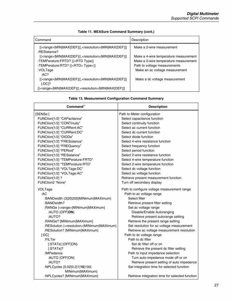
Table 11. MEASure Command Summary (cont.)
Command Description
[<range>|MIN|MAX|DEF[,<resolution>|MIN|MAX|DEF]] :RESistance? [<range>|MIN|MAX|DEF[,<resolution>|MIN|MAX|DEF]] :TEMPerature:FRTD? [<RTD Type] :TEMPerature:RTD? [<RTD> Type>] :VOLTage :AC? [<range>|MIN|MAX|DEF[,<resolution>|MIN|MAX|DEF]] [:DC]? [<range>|MIN|MAX|DEF[,<resolution>|MIN|MAX|DEF]]
Make a 2-wire measurement Make a 4-wire temperature measurement Make a 2-wire temperature measurement Path to voltage measurements Make an ac voltage measurement Make a dc voltage measurement
Table 13. Measurement Configuration Command Summary
Command[1] Description
[SENSe:] FUNCtion[1/2] “CAPacitance” FUNCtion[1/2] “CONTinuity” FUNCtion[1/2] “CURRent:AC” FUNCtion[1/2] “CURRent:DC” FUNCtion[1/2] “DIODe” FUNCtion[1/2] “FRESistance” FUNCtion[1/2] “FREQuency” FUNCtion[1/2] “PERiod” FUNCtion[1/2] “RESistance” FUNCtion[1/2] “TEMPerature:FRTD” FUNCtion[1/2] “TEMPerature:RTD” FUNCtion[1/2] “VOLTage:DC” FUNCtion[1/2] “VOLTage:AC” FUNCtion[1/2] ? FUNCtion2 “None”
VOLTage :AC :BANDwidth 3|20|200|MINimum|MAXimum :BANDwidth? :RANGe <range>|MINimum|MAXimum :AUTO OFF|ON :AUTO? :RANGe? [MINimum|MAXimum] :RESolution <resolution>|MINimum|MAXimum :RESolution? [MINimum|MAXimum] [:DC] :FILTer [:STATe] OFF|ON [:STATe]? :IMPedance :AUTO OFF|ON :AUTO? :NPLCycles 0.02|0.2|1|10|100| MINimum|MAXimum :NPLCycles? [MINimum|MAXimum]
Path to Meter configuration Select capacitance function Select continuity function Select ac current function Select dc current function Select diode function Select 4-wire resistance function Select frequency function Select period function Select 2-wire resistance function Select 4-wire temperature function Select 2-wire temperature function Select dc voltage function Select ac voltage function Retrieve present measurement function Turn off secondary display
Path to configure voltage measurement range Path to ac voltage range Select filter Retrieve present filter setting Set ac voltage range Disable/Enable Autoranging Retrieve present autorange setting Retrieve the present range setting Set resolution for ac voltage measurement Retrieve ac voltage measurement resolution Path to dc voltage range Path to dc filter Set dc filter off or on Retrieve the present dc filter setting Path to input impedance selection Turn auto-impedance mode off or on Retrieve present setting of auto impedance Set integration time for selected function Retrieve integration time for selected function

8845A/8846A Programmers Manual
28
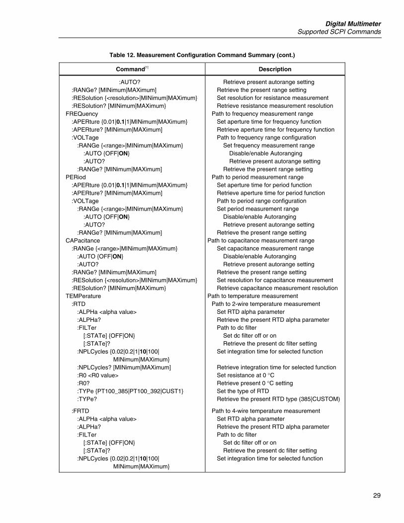
Table 12. Measurement Configuration Command Summary (cont.)
Command[1] Description
:RANGe <range>|MINimum|MAXimum :AUTO OFF|ON :AUTO? :RANGe? [MINimum|MAXimum] :RESolution <resolution>|MINimum|MAXimum :RESolution? [MINimum|MAXimum] CURRent :AC :BANDwidth 3|20|200|MINimum|MAXimum :BANDwidth? :RANGe <range>|MINimum|MAXimum :AUTO OFF|ON :AUTO? :RANGe? [MINimum|MAXimum] :RESolution <resolution>|MINimum|MAXimum :RESolution? [MINimum|MAXimum] [:DC] :FILTer [:STATe] OFF|ON [:STATe]? :NPLCycles 0.02|0.2|1|10|100| MINimum|MAXimum :NPLCycles? [MINimum|MAXimum] :RANGe <range>|MINimum|MAXimum :AUTO OFF|ON :AUTO? :RANGe? [MINimum|MAXimum] :RESolution <resolution>|MINimum|MAXimum :RESolution? [MINimum|MAXimum] RESistance :FILTer [:STATe] OFF|ON [:STATe]? :NPLCycles 0.02|0.2|1|10|100| MINimum|MAXimum :NPLCycles? [MINimum|MAXimum] :RANGe <range>|MINimum|MAXimum :AUTO OFF|ON :AUTO? :RANGe? [MINimum|MAXimum] :RESolution <resolution>|MINimum|MAXimum :RESolution? [MINimum|MAXimum FRESistance :FILTer :STATe OFF|ON :STATe? :NPLCycles 0.02|0.2|1|10|100| MINimum|MAXimum :NPLCycles? [MINimum|MAXimum] :RANGe <range>|MINimum|MAXimum :AUTO OFF|ON
Set dc voltage range Disable/enable Autoranging Retrieve present autorange setting Retrieve the present range setting Set resolution for dc voltage measurement Retrieve dc voltage measurement resolution Path to configure current measurement range Path to ac current range Select filter Retrieve present filter setting Set ac current range Disable/enable Autoranging Retrieve present autorange setting Retrieve the present range setting Set resolution for ac current measurement Retrieve ac current measurement resolution Path to dc current range Path to dc filter Set dc filter off or on Retrieve the present dc filter setting Set integration time for selected function Retrieve integration time for selected function Set dc current range Disable/enable Autoranging Retrieve present autorange setting Retrieve the present range setting Set resolution for dc current measurement Retrieve dc current measurement resolution Path to 2–wire resistance measurement range Path to dc filter Set dc filter off or on Retrieve the present dc filter setting Set integration time for selected function Retrieve integration time for selected function Set resistance measurement range Disable/enable Autoranging Retrieve present autorange setting Retrieve the present range setting Set resolution for resistance measurement Retrieve resistance measurement resolution Path to 4–wire resistance measurement range Path to dc filter Set dc filter off or on Retrieve the present dc filter setting Set integration time for selected function Retrieve integration time for selected function Set resistance measurement range Disable/enable Autoranging
Digital Multimeter Supported SCPI Commands
29
Table 12. Measurement Configuration Command Summary (cont.)
Command[1] Description
:AUTO? :RANGe? [MINimum|MAXimum] :RESolution <resolution>|MINimum|MAXimum :RESolution? [MINimum|MAXimum FREQuency :APERture 0.01|0.1|1|MINimum|MAXimum :APERture? [MINimum|MAXimum] :VOLTage :RANGe <range>|MINimum|MAXimum :AUTO OFF|ON :AUTO? :RANGe? [MINimum|MAXimum] PERiod :APERture 0.01|0.1|1|MINimum|MAXimum :APERture? [MINimum|MAXimum] :VOLTage :RANGe <range>|MINimum|MAXimum :AUTO OFF|ON :AUTO? :RANGe? [MINimum|MAXimum] CAPacitance :RANGe <range>|MINimum|MAXimum :AUTO OFF|ON :AUTO? :RANGe? [MINimum|MAXimum] :RESolution <resolution>|MINimum|MAXimum :RESolution? [MINimum|MAXimum TEMPerature :RTD :ALPHa <alpha value> :ALPHa? :FILTer [:STATe] OFF|ON [:STATe]? :NPLCycles 0.02|0.2|1|10|100| MINimum|MAXimum :NPLCycles? [MINimum|MAXimum] :R0 <R0 value> :R0? :TYPe PT100_385|PT100_392|CUST1 :TYPe?
:FRTD :ALPHa <alpha value> :ALPHa? :FILTer [:STATe] OFF|ON [:STATe]? :NPLCycles 0.02|0.2|1|10|100| MINimum|MAXimum
Retrieve present autorange setting Retrieve the present range setting Set resolution for resistance measurement Retrieve resistance measurement resolution Path to frequency measurement range Set aperture time for frequency function Retrieve aperture time for frequency function Path to frequency range configuration Set frequency measurement range Disable/enable Autoranging Retrieve present autorange setting Retrieve the present range setting Path to period measurement range Set aperture time for period function Retrieve aperture time for period function Path to period range configuration Set period measurement range Disable/enable Autoranging Retrieve present autorange setting Retrieve the present range setting Path to capacitance measurement range Set capacitance measurement range Disable/enable Autoranging Retrieve present autorange setting Retrieve the present range setting Set resolution for capacitance measurement Retrieve capacitance measurement resolution Path to temperature measurement Path to 2-wire temperature measurement Set RTD alpha parameter Retrieve the present RTD alpha parameter Path to dc filter Set dc filter off or on Retrieve the present dc filter setting Set integration time for selected function Retrieve integration time for selected function Set resistance at 0 °C Retrieve present 0 °C setting Set the type of RTD Retrieve the present RTD type (385|CUSTOM)
Path to 4-wire temperature measurement Set RTD alpha parameter Retrieve the present RTD alpha parameter Path to dc filter Set dc filter off or on Retrieve the present dc filter setting Set integration time for selected function
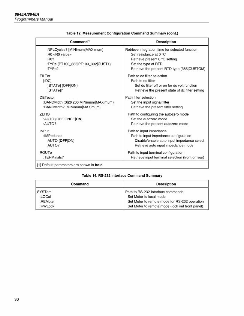
8845A/8846A Programmers Manual
30
Table 12. Measurement Configuration Command Summary (cont.)
Command[1] Description
:NPLCycles? [MINimum|MAXimum] :R0 <R0 value> :R0? :TYPe PT100_385|PT100_392|CUST1 :TYPe?
FILTer [:DC] [:STATe] OFF|ON [:STATe]?
DETector :BANDwidth 3|20|200|MINimum|MAXimum :BANDwidth? [MINimum|MAXimum]
ZERO :AUTO OFF|ONCE|ON :AUTO?
INPut :IMPedance :AUTO OFF|ON :AUTO?
ROUTe :TERMinals?
Retrieve integration time for selected function Set resistance at 0 °C Retrieve present 0 °C setting Set the type of RTD Retrieve the present RTD type (385|CUSTOM)
Path to dc filter selection Path to dc filter Set dc filter off or on for dc volt function Retrieve the present state of dc filter setting
Path filter selection Set the input signal filter Retrieve the present filter setting
Path to configuring the autozero mode Set the autozero mode Retrieve the present autozero mode
Path to input impedance Path to input impedance configuration Disable/enable auto input impedance select Retrieve auto input impedance mode
Path to input terminal configuration Retrieve input terminal selection (front or rear)
[1] Default parameters are shown in bold
Table 14. RS-232 Interface Command Summary
Command Description
SYSTem :LOCal :REMote :RWLock
Path to RS-232 Interface commands Set Meter to local mode Set Meter to remote mode for RS-232 operation Set Meter to remote mode (lock out front panel)
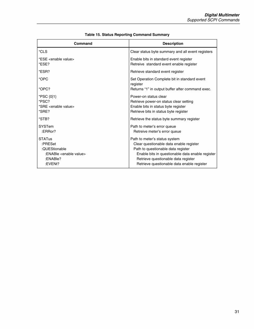
Digital Multimeter Supported SCPI Commands
31
Table 15. Status Reporting Command Summary
Command Description
*CLS
*ESE <enable value> *ESE?
*ESR?
*OPC *OPC?
*PSC 0|1 *PSC? *SRE <enable value> *SRE?
*STB?
SYSTem :ERRor?
STATus :PRESet :QUEStionable :ENABle <enable value> :ENABle? :EVENt?
Clear status byte summary and all event registers
Enable bits in standard event register Retreive standard event enable register
Retrieve standard event register
Set Operation Complete bit in standard event register Returns “1” in output buffer after command exec.
Power-on status clear Retrieve power-on status clear setting Enable bits in status byte register Retrieve bits in status byte register
Retrieve the status byte summary register
Path to meter’s error queue Retreive meter’s error queue
Path to meter’s status system Clear questionable data enable register Path to questionable data register Enable bits in questionable data enable register Retrieve questionable data register Retrieve questionable data enable register
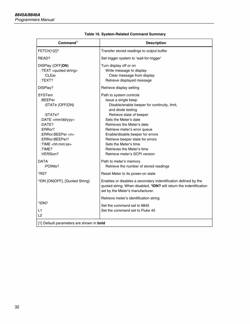
8845A/8846A Programmers Manual
32
Table 16. System-Related Command Summary
Command[1] Description
FETCh[1|2]?
READ?
DISPlay OFF|ON :TEXT <quoted string> :CLEar :TEXT?
DISPlay?
SYSTem :BEEPer :STATe OFF|ON :STATe? :DATE <mm/dd/yyy> :DATE? :ERRor? :ERRor:BEEPer <n> :ERRor:BEEPer? :TIME <hh:mm:ss> :TIME? :VERSion?
DATA :POINts?
*RST
*IDN [ON|OFF], [Quoted String]
*IDN?
L1 L2
Transfer stored readings to output buffer
Set trigger system to ‘wait-for-trigger’
Turn display off or on Write message to display Clear message from display Retreive displayed message
Retrieve display setting
Path to system controls Issue a single beep Disable/enable beeper for continuity, limit, and diode testing Retrieve state of beeper Sets the Meter’s date Retrieves the Meter’s date Retrieve meter’s error queue Enable/disable beeper for errors Retrieve beeper state for errors Sets the Meter’s time Retrieves the Meter’s time Retrieve meter’s SCPI version
Path to meter’s memory Retrieve the number of stored readings
Reset Meter to its power-on state
Enables or disables a secondary indentification defined by the quoted string. When disabled, *IDN? will return the indentification set by the Meter’s manufacturer.
Retrieve meter’s identification string
Set the command set to 8845 Set the command set to Fluke 45
[1] Default parameters are shown in bold
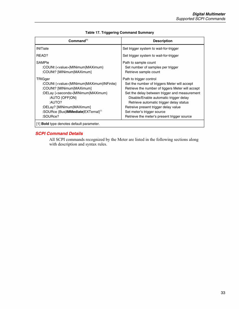
Digital Multimeter Supported SCPI Commands
33
Table 17. Triggering Command Summary
Command[1] Description
INITiate
READ?
SAMPle :COUNt <value>|MINimum|MAXimum :COUNt? [MINimum|MAXimum]
TRIGger :COUNt <value>|MINimum|MAXimum|INFinite :COUNt? [MINimum|MAXimum] :DELay <seconds>|MINimum|MAXimum :AUTO OFF|ON :AUTO? :DELay? [MINimum|MAXimum] :SOURce Bus|IMMediate|EXTernal[1] :SOURce?
Set trigger system to wait-for-trigger
Set trigger system to wait-for-trigger
Path to sample count Set number of samples per trigger Retrieve sample count
Path to trigger control Set the number of triggers Meter will accept Retrieve the number of tiggers Meter will accept Set the delay between trigger and measurement Disable/Enable automatic trigger delay Retrieve automatic trigger delay status Retreive present trigger delay value Set meter’s trigger source Retrieve the meter’s present trigger source
[1] Bold type denotes default parameter.
SCPI Command Details All SCPI commands recognized by the Meter are listed in the following sections along with description and syntax rules.
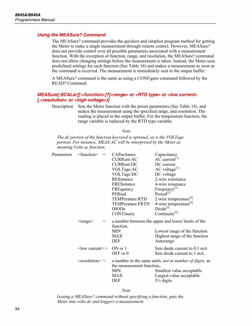
8845A/8846A Programmers Manual
34
Using the MEASure? Command The MEASure? command provides the quickest and simplest program method for getting the Meter to make a single measurement through remote control. However, MEASure? does not provide control over all possible parameters associated with a measurement function. With the exception of function, range, and resolution, the MEASure? command does not allow changing settings before the measurement is taken. Instead, the Meter uses predefined settings for each function (See Table 18) and makes a measurement as soon as the command is received. The measurement is immediately sent to the output buffer. A MEASure? command is the same as using a CONFigure command followed by the READ? Command.
MEASure[:SCALar][:<function>]?[<range> or <RTD type> or <low current> [,<resolution> or <high voltage>]]
Description Sets the Meter function with the preset parameters (See Table 18), and makes the measurement using the specified range, and resolution. The reading is placed in the output buffer. For the temperature function, the range variable is replaced by the RTD type variable.
Note The dc portion of the function keyword is optional, as is the VOLTage portion. For instance, MEAS:AC will be interpreted by the Meter as meaning Volts ac function.
Parameters <function> = CAPacitance Capacitance CURRent:AC AC current[1] CURRent:DC DC current VOLTage:AC AC voltage[1] VOLTage:DC DC voltage RESistance 2-wire resistance FRESistance 4-wire resistance FREquency Frequency[2] PERiod Period[3] TEMPerature:RTD 2-wire temperature[4] TEMPerature:FRTD 4-wire temperature[4] DIODe Diode[5] CONTinuity Continuity[6]
<range> = a number between the upper and lower limits of the function. MIN Lowest range of the function MAX Highest range of the function DEF Autorange
<low current> = ON or 1 Sets diode current to 0.1 mA OFF or 0 Sets diode current to 1 mA. <resolution> = a number in the same units, not in number of digits, as
the measurement function,. MIN Smallest value acceptable MAX Largest value acceptable DEF 5½ digits
Note Issuing a MEASure? command without specifying a function, puts the Meter into volts dc and triggers a measurement.

Digital Multimeter Supported SCPI Commands
35
Note You must specify a range to use a resolution parameter.
<high voltage> = ON or 1 Sets diode voltage to 10 volts OFF or 0 Sets diode voltage to 5 volts. Example MEAS:volt:ac? 10 = Returns a measurement after configuring the
Meter for volts ac and setting the range to the 10 volt range.
MEAS:diod? ON = Sets diode function using low current and returns the diode measurement. 9.90000000E+37 is the value returned for an open diode.
Notes [1] For ac measurements, resolution is fixed at 6½ digits. The resolution parameter only affects the front panel display.
[2] For frequency measurements, the multimeter uses one “range” for all inputs between 3 Hz, and 300 kHz. With no input signal applied, frequency measurements return zero.
[3] For period measurements, the multimeter uses one “range” for all inputs between 0.33 seconds, and 3.3 µsec. With no input signal applied, period measurements return zero.
[4] The range and resolution are fixed for temperature measurements. However, placing PT100_385 or PT100_392 into the range field will set the RTD type. Placing CUST1 into the range field will cause the Meter to use the values set into the R0 and Alpha parameters.
[5] The range and resolution are fixed for diode test: 1 Vdc range and 5½ digits. When set to ON, the low current parameter sets the diode test current to 0.1 mA. When OFF, the current is 1 mA. When set to ON, the high voltage parameter sets the diode test voltage to 10 volts. When OFF, the voltage is 5 volts. To specify a diode test voltage, you must also include ON or OFF for the low current parameter.
[6] The range and resolution are fixed for continuity tests: 1 kΩ range and 5½ digits.
Using the CONFigure Command The CONFigure command allows more configuration control than the MEASure command. As with the MEASure command, the CONFigure command presets the Meter’s parameters for the desired configuration (See Table 18). However, a measurement does not start automatically, and therefore affords the opportunity to change measurement parameters prior to triggering a measurement. The CONFigure command is very useful when most of the parameters preset by CONFigure are what you want and you only need to change one or two parameters. The SENSe:FUNCtion command provides a means of changing a function’s parameters. Other commands, such as INPut, SENSe, CALCulate, and TRIGger allow for more detailed control of the Meter’s parameters. The CONFigure command does not initiate a measurement and will need to be followed by READ? command, or the INITiate and FETCh? commands.
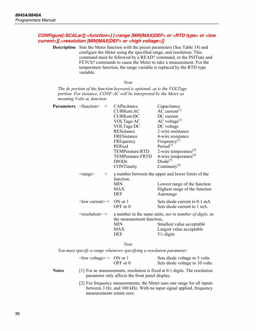
8845A/8846A Programmers Manual
36
CONFigure[:SCALar][:<function>] [<range |MIN|MAX|DEF> or <RTD type> or <low current>][,<resolution |MIN|MAX|DEF> or <high voltage>]]
Description Sets the Meter function with the preset parameters (See Table 18) and configure the Meter using the specified range, and resolution. This command must be followed by a READ? command, or the INITiate and FETCh? commands to cause the Meter to take a measurement. For the temperature function, the range variable is replaced by the RTD type variable.
Note The dc portion of the function keyword is optional, as is the VOLTage portion. For instance, CONF:AC will be interpreted by the Meter as meaning Volts ac function.
Parameters <function> = CAPacitance Capacitance CURRent:AC AC current[1] CURRent:DC DC current VOLTage:AC AC voltage[1] VOLTage:DC DC voltage RESistance 2-wire resistance FRESistance 4-wire resistance FREquency Frequency[2] PERiod Period[3] TEMPerature:RTD 2-wire temperature[4] TEMPerature:FRTD 4-wire temperature[4] DIODe Diode[5] CONTinuity Continuity[6]
<range> = a number between the upper and lower limits of the function. MIN Lowest range of the function MAX Highest range of the function DEF Autorange
<low current> = ON or 1 Sets diode current to 0.1 mA OFF or 0 Sets diode current to 1 mA. <resolution> = a number in the same units, not in number of digits, as
the measurement function,. MIN Smallest value acceptable MAX Largest value acceptable DEF 5½ digits
Note You must specify a range whenever specifying a resolution parameter.
<low voltage> = ON or 1 Sets diode voltage to 5 volts OFF or 0 Sets diode voltage to 10 volts. Notes [1] For ac measurements, resolution is fixed at 6½ digits. The resolution
parameter only affects the front panel display. [2] For frequency measurements, the Meter uses one range for all inputs
between 3 Hz, and 300 kHz. With no input signal applied, frequency measurements return zero.
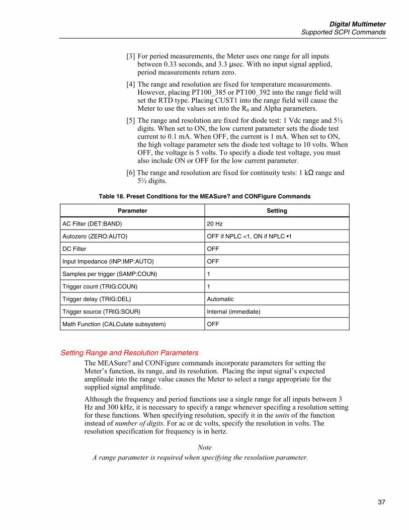
Digital Multimeter Supported SCPI Commands
37
[3] For period measurements, the Meter uses one range for all inputs between 0.33 seconds, and 3.3 µsec. With no input signal applied, period measurements return zero.
[4] The range and resolution are fixed for temperature measurements. However, placing PT100_385 or PT100_392 into the range field will set the RTD type. Placing CUST1 into the range field will cause the Meter to use the values set into the R0 and Alpha parameters.
[5] The range and resolution are fixed for diode test: 1 Vdc range and 5½ digits. When set to ON, the low current parameter sets the diode test current to 0.1 mA. When OFF, the current is 1 mA. When set to ON, the high voltage parameter sets the diode test voltage to 10 volts. When OFF, the voltage is 5 volts. To specify a diode test voltage, you must also include ON or OFF for the low current parameter.
[6] The range and resolution are fixed for continuity tests: 1 kΩ range and 5½ digits.
Table 18. Preset Conditions for the MEASure? and CONFigure Commands
Parameter Setting
AC Filter (DET:BAND) 20 Hz
Autozero (ZERO:AUTO) OFF if NPLC <1, ON if NPLC •1
DC Filter OFF
Input Impedance (INP:IMP:AUTO) OFF
Samples per trigger (SAMP:COUN) 1
Trigger count (TRIG:COUN) 1
Trigger delay (TRIG:DEL) Automatic
Trigger source (TRIG:SOUR) Internal (immediate)
Math Function (CALCulate subsystem) OFF
Setting Range and Resolution Parameters The MEASure? and CONFigure commands incorporate parameters for setting the Meter’s function, its range, and its resolution. Placing the input signal’s expected amplitude into the range value causes the Meter to select a range appropriate for the supplied signal amplitude. Although the frequency and period functions use a single range for all inputs between 3 Hz and 300 kHz, it is necessary to specify a range whenever specifing a resolution setting for these functions. When specifying resolution, specify it in the units of the function instead of number of digits. For ac or dc volts, specify the resolution in volts. The resolution specification for frequency is in hertz.
Note A range parameter is required when specifying the resolution parameter.
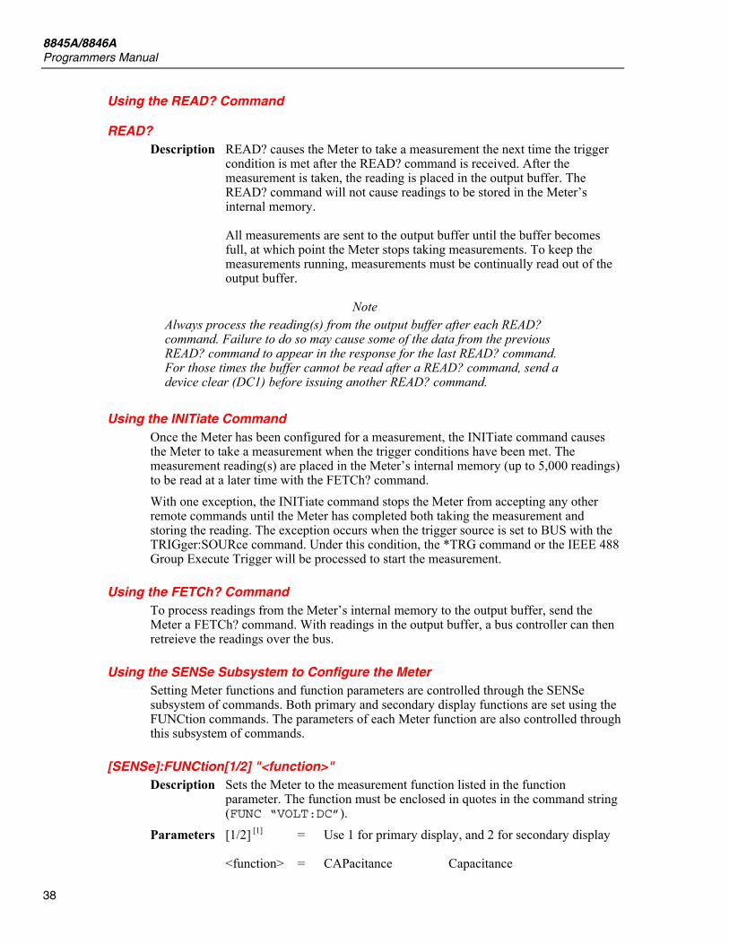
8845A/8846A Programmers Manual
38
Using the READ? Command
READ? Description READ? causes the Meter to take a measurement the next time the trigger
condition is met after the READ? command is received. After the measurement is taken, the reading is placed in the output buffer. The READ? command will not cause readings to be stored in the Meter’s internal memory. All measurements are sent to the output buffer until the buffer becomes full, at which point the Meter stops taking measurements. To keep the measurements running, measurements must be continually read out of the output buffer.
Note Always process the reading(s) from the output buffer after each READ? command. Failure to do so may cause some of the data from the previous READ? command to appear in the response for the last READ? command. For those times the buffer cannot be read after a READ? command, send a device clear (DC1) before issuing another READ? command.
Using the INITiate Command Once the Meter has been configured for a measurement, the INITiate command causes the Meter to take a measurement when the trigger conditions have been met. The measurement reading(s) are placed in the Meter’s internal memory (up to 5,000 readings) to be read at a later time with the FETCh? command. With one exception, the INITiate command stops the Meter from accepting any other remote commands until the Meter has completed both taking the measurement and storing the reading. The exception occurs when the trigger source is set to BUS with the TRIGger:SOURce command. Under this condition, the *TRG command or the IEEE 488 Group Execute Trigger will be processed to start the measurement.
Using the FETCh? Command To process readings from the Meter’s internal memory to the output buffer, send the Meter a FETCh? command. With readings in the output buffer, a bus controller can then retreieve the readings over the bus.
Using the SENSe Subsystem to Configure the Meter Setting Meter functions and function parameters are controlled through the SENSe subsystem of commands. Both primary and secondary display functions are set using the FUNCtion commands. The parameters of each Meter function are also controlled through this subsystem of commands.
[SENSe]:FUNCtion[1/2] "<function>" Description Sets the Meter to the measurement function listed in the function
parameter. The function must be enclosed in quotes in the command string (FUNC “VOLT:DC”).
Parameters [1/2] [1] = Use 1 for primary display, and 2 for secondary display <function> = CAPacitance Capacitance
Digital Multimeter Supported SCPI Commands
39
CURRent:AC AC current CURRent:DC DC current VOLTage:AC AC voltage VOLTage:DC DC voltage RESistance 2-wire resistance FRESistance 4-wire resistance FREQuency Frequency PERiod Period TEMPerature:RTD 2-wire temperature TEMPerature:FRTD 4-wire temperature DIODe Diode CONTinuity Continuity
NONe[2] Turn off secondary display Examples FUNC “VOLT:DC” Sets the Meter to volts dc FUNC1 “VOLT:DC”; FUNC2 “VOLT:AC” Dual function command Query FUNCtion[1/2]? Query measurement function
Note FUNC2? will return the measurement mode selected for the secondary display (assuming its been enabled using the FUNC2 command). FUNC1? or FUNC? will return the measurement mode for the primary display.
Notes [1] Using FUNC without a 1 or 2 will default to 1 for the primary display. [2] Valid only when used with FUNC2.
[SENSe:]<function> The SENSe subsystem allows configuring the Meter’s functions. Parameters <function> = CAPacitance Capacitance
CURRent:AC AC current CURRent[:DC] DC current VOLTage:AC AC voltage VOLTage[:DC] DC voltage RESistance 2-wire resistance FRESistance 4-wire resistance FREQuency Frequency PERiod Period TEMPerature:RTD 2-wire temperature TEMPerature:FRTD 4-wire temperature DIODe Diode CONTinuity Continuity
NONe[1] Turn off secondary display Notes [1] Valid only when used with FUNC2.
[SENSe:]<function>:RANGe(?) <n> Description Sets the range according to the value supplied for n, of the Meter function
specified in the variable <function>. Not having selectable ranges, an error is returned when using temperature, diode test, or continuity as the function in the RANGe command. This setting is stored in volatile memory For the frequency and period functions, the range command value refers to the signal’s input voltage and not the range of the frequency or period

8845A/8846A Programmers Manual
40
measurement. Also, the word VOLTage must follow the function before the RANGe command. See examples below.
Parameters <n> = value of reading Expected reading in volts, amps or ohms MINimum Lowest range MAXimum Highest range
Examples VOLT:RANG 10 Sets the Meter’s dc volts to the 10 volt range. CURR:AC:RANG 1e-3 Sets the Meter’s ac amps to the 100 mA range. RES:RANG 20e3 Sets the Meter’s ohms to the 100 kΩ range. FREQ:VOLT:RANG 5 Sets the voltage input range to the 10 volt range
while making a frequency measurement. Query VOLT:RANG? Returns the set range for dc volts. VOLT:RANG? MIN Returns the minimum range of the dc volts
function. (1.00000000E-01 or 100 mV) RES:RANG? MAX Returns the maximum range of the 2-wire
resistance function. (1.00000000E+09 or 1 GΩ)
[SENSe:]<function>:RANGe:AUTO(?) OFF|ON Description Switches the Meter between autoranging and manual ranging. Not having
selectable ranges, an error is returned when the temperature, diode test, or continuity function is used with the RANGe:AUTO function. This setting is stored in volatile memory For the frequency and period functions, the RANGe:AUTO command refers to the signal’s input voltage and not the range of the frequency or period measurement. Also, the word VOLTage must follow the function before the RANGe command. See examples below.
Note Autorange thresholds are set down range with readings <10 % of range and up range with readings >120 % of range.
Examples VOLT:RANG:AUTO ON Sets the Meter’s dc volts to autorange. CURR:AC:AUTO OFF Sets the Meter’s ac amps manual ranging. FREQ:VOLT:RANG ON Sets the Meter’s voltage input to autorange while
making a frequency measurement. Query VOLT:RANG:AUTO? Returns a zero for off and a one for on.
[SENSe:]<function>:RESolution(?) <n> Description Sets the resolution according to the value supplied for n, of the Meter
function specified in the variable <function>. Resolution is specified in the same units as the function. i.e., volts for the volts ac and dc functions. This setting is stored in volatile memory Not having selectable ranges, an error is returned when using frequency, period, temperature, diode test, or continuity as the function in the RESolution command.
Parameters <n> = resolution value Desired resolution in volts, amps, ohms, and farads.
MIN Highest resolution MAX Lowest resolution
Examples VOLT:RES 1e-4 Sets the dc volts resolution to 100 µV.
Digital Multimeter Supported SCPI Commands
41
CURR:AC:RES 1e-8 Sets the ac amps resolution to the 10 pA. Query VOLT:RES? Returns the set resolution for dc volts. VOLT:RES? MIN Returns the minimum resolution of the dc volts
function.
[SENSe:]<function>:NPLCycles(?) <n> Description Sets the Meter’s integration time for the function specified on <function>,
based on the number of power line cycles. This setting is stored in volatile memory This command is only valid for dc voltage, dc current, temperature, and resistance (2-wire and 4-wire) functions.
Parameters <n> = 0.02 to 100 sets integration time to a preset value of a power line cycle (0.02, 0.2, 1, 10, and 100)
MIN 0.02 NPLC MAX 100 NPLC
Examples VOLT:DC:NPLC .2 Sets the dc volts integration time to 0.2 of a
power line cycle. Query VOLT:NPLC? Returns the integration time for dc volts. CURR:NPLC? MIN Returns the minimum integration time for the dc
current function.
[SENSe:]TEMPerature:[TRANsducer:]<subfunction>:R0(?) <n> Description Sets the resistance at zero degrees C specified by <n> for the R0 parameter
of the temperature function. This setting is stored in volatile memory. Parameters <subfunction> = RTD 2-wire RTD FRTD 4-wire RTD <n> = 0 to 1010 Resistance at 0 °C Examples TEMP:RTD:R0 120 Sets the resistance a 0 °C to 120 ohms. Query TEMP:RTD:R0? Returns the set resistance a 0 °C.
[SENSe:]TEMPerature:[TRANsducer:]<subfunction>:TYPe(?) <n> Description Sets the RTD type for the temperature function. This setting is stored in
volatile memory. Parameters <subfunction> = RTD 2-wire RTD FRTD 4-wire RTD <n> = PT100_385 Sets the RTD type to PT100 385 PT100_392 Sets R0 to 100 and Alpha to 392 CUST1 Sets the RTD type to be set by R0 and Alpha
settings. Examples TEMP:RTD:TYP PT100_385 Sets the RTD type to PT100 385. Query TEMP:RTD:TYP? Returns 385 or CUSTOM.
[SENSe:]TEMPerature:[TRANsducer:]<subfunction>:ALPHa(?) <n> Description Sets the alpha variable for the temperature function. This setting is stored
in volatile memory.
8845A/8846A Programmers Manual
42
Parameters <subfunction> = RTD 2-wire RTD FRTD 4-wire RTD <n> = .00374 to .00393 Sets the alpha parameter Examples TEMP:RTD:ALPH 392 Sets the alpha parameter to 392. Query TEMP:RTD:ALPH? Returns the alpha setting of the temperature
function.
[SENSe:]FREQuency:APERature(?) <n> Description Sets the gate time for the frequency function to the value spedified by <n>.
This setting is stored in volatile memory. Parameters <n> = 0.01 Gate time of 10 ms (4½ digits) 0.1 (default) Gate time of 100 ms (5½ digits) 1 Gate time of 1 second (6½ digits) MIN Gate time of 10 ms (4½ digits) MAX Gate time of 1 second (6½ digits)
Examples FREQ:APER 0.1 Sets the frequency measurement gate time to 100
ms. Query FREQ:APER? Returns the gate time for the frequency function.
[SENSe:]PERiod:APERature(?) <n> Description Sets the gate time for the period function to the value spedified by <n>.
This setting is stored in volatile memory. Parameters <n> = 0.01 Gate time of 10 ms (4½ digits) 0.1 (default) Gate time of 100 ms (5½ digits) 1 Gate time of 1 second (6½ digits) MIN Gate time of 10 ms (4½ digits) MAX Gate time of 1 second (6½ digits)
Examples PER:APER 0.1 Sets the period measurement gate time to 100
ms. Query PER:APER? Returns the gate time for the period function.
[SENSe:]CURRent:AC:BANDwidth(?) <n> Description Sets the appropriate filter for the frequency specified by <n>. This setting
is stored in volatile memory. Parameters <n> = 3 Selects slow filter 20 (default) Selects medium filter 200 Selects fast filter MIN Selects slow filter MAX Selects fast filter
Examples CURR:AC:BAND 200 Sets the filter for ac current to fast. Query CURR:AC:BAND? Returns the filter selection.
[SENSe:]VOLTage:AC:BANDwidth(?) <n> Description Sets the appropriate filter for the frequency specified by <n>. This setting
is stored in volatile memory.
Digital Multimeter Supported SCPI Commands
43
Parameters <n> = 3 Selects slow filter 20 (default) Selects medium filter 200 Selects fast filter MIN Selects slow filter MAX Selects fast filter
Examples VOLT:AC:BAND 20 Sets the filter for ac voltage to medium. Query VOLT:AC:BAND? Returns the filter selection.
[SENSe:]DETector:BANDwidth(?) <n> Description Sets the appropriate filter for the frequency specified by <n>. This setting
is stored in volatile memory and sets the filter for all functions that use an ac filter.
Parameters <n> = 3 Selects slow filter 20 Selects medium filter 200 Selects fast filter MIN Selects slow filter MAX Selects fast filter
Examples DET:BAND 20 Sets the filter to medium. Query DET:BAND? Returns the filter selection. DET:BAND? MAX Returns +2.00000000E+02 to indicate the slow
filter.
[SENSe:]FILTer[:DC][:STATe](?) <n> Description Activates or deactivates the dc voltage filter to improve noise immunity.
This setting is stored in volatile memory. Parameters <n> = OFF or 0 Turns the dc voltage filter off. ON or 1 Turns the dc voltage filter on.
Examples FILT ON Turns the dc voltage filter on. Query FILT? Returns the dc voltage filter setting.
[SENSe:]VOLTage[:DC]:FILTer[:STATe](?) <n> Description Activates or deactivates the dc voltage filter to improve noise immunity.
This setting is stored in volatile memory. Parameters <n> = OFF or 0 Turns the dc voltage filter off. ON or 1 Turns the dc voltage filter on.
Examples VOLT:FILT ON Turns the dc voltage filter on. Query VOLT:FILT? Returns the dc voltage filter setting.
[SENSe:]CURRent[:DC]:FILTer[:STATe](?) <n> Description Activates or deactivates the dc current filter to improve noise immunity.
This setting is stored in volatile memory. Parameters <n> = OFF or 0 Turns the dc current filter off. ON or 1 Turns the dc current filter on.
8845A/8846A Programmers Manual
44
Examples CURR:FILT ON Turns the dc current filter on. Query CURR:FILT? Returns the dc current filter setting. (0 = OFF
and 1 = ON)
[SENSe:]RESistance[:DC]:FILTer[:STATe](?) <n> Description Activates or deactivates the dc 2-wire resistance filter to improve noise
immunity. This setting is stored in volatile memory. Parameters <n> = OFF or 0 Turns the dc 2-wire resistance filter off. ON or 1 Turns the dc 2-wire resistance filter on.
Examples RES:FILT ON Turns the dc 2-wire resistance filter on. Query RES:FILT? Returns the dc 2-wire resistance filter setting. (0
= OFF and 1 = ON)
[SENSe:]FRESistance[:DC]:FILTer[:STATe](?) <n> Description Activates or deactivates the dc 4-wire resistance filter to improve noise
immunity. This setting is stored in volatile memory. Parameters <n> = OFF or 0 Turns the dc 4-wire resistance filter off. ON or 1 Turns the dc 4-wire resistance filter on.
Examples FRES:FILT ON Turns the dc 4-wire resistance filter on. Query FRES:FILT? Returns the dc 4-wire resistance filter setting. (0
= OFF and 1 = ON)
[SENSe:]TEMPerature[:TRANsducer]:<subfunction>:FILTer[:STATe](?) <n> Description Activates or deactivates the dc 2-wire/4-wire resistance filter to improve
noise immunity. This setting is stored in volatile memory. Parameters <subfunction> = RTD 2-wire RTD FRTD 4-wire RTD <n> = OFF or 0 Turns the dc resistance filter off. ON or 1 Turns the dc resistance filter on.
Examples TEMP:RTD:FILT ON Turns the dc resistance filter on. Query FRES:RTD:FILT? Returns the dc resistance filter setting. (0 = OFF
and 1 = ON)
[SENSe:]UNIT:TEMPerature(?) <units> Description Sets the temperature units for the temperature function. This setting is
stored in volatile memory. Parameters <units> = Cel Sets temperature units to Celsius Far Sets temperature units to Fahrenheit
Kel Sets temperature units to Kelvin
Examples UNIT:TEMP C Sets temperature units to Celsius. Query UNIT:TEMP? Returns the temperature units setting. (C =
Celsius, F = Fahrenheit, and K = Kelvin)

Digital Multimeter Supported SCPI Commands
45
[SENSe:]ZERO:AUTO <n> Description Activates (default) or deactivates the autozero mode. This setting is stored
in volatile memory. Parameters <n> = OFF Turns Autozero mode off. ON Turns autozero mode on. ONCE Initiates a zero measurement immediately.
Examples ZERO:AUTO ON Turns autozero mode on. Query ZERO:AUTO? Returns the state of the autozero mode. (0 = OFF
and 1 = ON)
[SENSe:]VOLTage[:DC]:IMPedance:AUTO(?) <n> Description Activates or deactivates (default) the automatic input impedance mode for
dc voltage measurements. With AUTO OFF, the input impedance is fixed at 10 MΩ for all ranges. With AUTO ON, the input impedance is set to >10 GΩ for the 100 mV, 1 V, and 10 V ranges. This setting is stored in volatile memory.
Parameters <n> = OFF or 0 Turns off automatic input impedance. ON or 1 Turns on automatic input impedance.
Examples VOLT:IMP:AUTO ON Turns on automatic input impedance. Query VOLT:IMP:AUTO? Returns the state of the input impedance mode.
(0 = OFF and 1 = ON)
INPut:IMPedance:AUTO(?) <n> Description Activates or deactivates (default) the automatic input impedance mode for
dc voltage measurements. With AUTO OFF, the input impedance is fixed at 10 MΩ for all ranges. With AUTO ON, the input impedance is set to >10 GΩ for the 100 mV, 1 V, and 10 V ranges. This setting is stored in volatile memory.
Parameters <n> = OFF or 0 Turns off automatic input impedance. ON or 1 Turns on automatic input impedance.
Examples IMP:AUTO ON Turns on automatic input impedance. Query IMP:AUTO? Returns the state of the input impedance mode.
(0 = OFF and 1 = ON)
ROUTe:TERMinals? Description A query that returns the state of the front to rear panel input terminals
switch. Examples ROUT:TERM? Returns “FRON” or “REAR”.
Programming for Math Operations Of the five possible Meter math functions, only one can be enabled at a time. Once a math function is selected, it stays selected until the Meter is powered down, or another math function is set. A reset command received through the remote interface will also disable the math function. Presetting some math registers are possible.
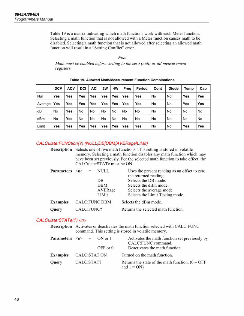
8845A/8846A Programmers Manual
46
Table 19 is a matrix indicating which math functions work with each Meter function. Selecting a math function that is not allowed with a Meter function causes math to be disabled. Selecting a math function that is not allowed after selecting an allowed math function will result in a “Setting Conflict” error.
Note Math must be enabled before writing to the zero (null) or dB measurement registers.
Table 19. Allowed Math/Measurement Function Combinations
DCV ACV DCI ACI 2W 4W Freq Period Cont Diode Temp Cap
Null Yes Yes Yes Yes Yes Yes Yes Yes No No Yes Yes
Average Yes Yes Yes Yes Yes Yes Yes Yes No No Yes Yes
dB No Yes No No No No No No No No No No
dBm No Yes No No No No No No No No No No
Limit Yes Yes Yes Yes Yes Yes Yes Yes No No Yes Yes
CALCulate:FUNCtion(?) NULL|DB|DBM|AVERage|LIMit Description Selects one of five math functions. This setting is stored in volatile
memory. Selecting a math function disables any math function which may have been set previously. For the selected math function to take effect, the CALCulate:STATe must be ON.
Parameters <n> = NULL Uses the present reading as an offset to zero the returned reading.
DB Selects the DB mode. DBM Selects the dBm mode. AVERage Selects the average mode LIMit Selects the Limit Testing mode. Examples CALC:FUNC DBM Selects the dBm mode. Query CALC:FUNC? Returns the selected math function.
CALCulate:STATe(?) <n> Description Activates or deactivates the math function selected with CALC:FUNC
command. This setting is stored in volatile memory. Parameters <n> = ON or 1 Activates the math function set previously by
CALC:FUNC command. OFF or 0 Deactivates the math function. Examples CALC:STAT ON Turned on the math function. Query CALC:STAT? Returns the state of the math function. (0 = OFF
and 1 = ON)

Digital Multimeter Supported SCPI Commands
47
CALCulate:AVERage:MINimum? Description Retrieves the minimum value measured during a statistics operation. This
value is cleared whenever the Meter is powered off then back on, a statistics function is enabled, or receives a reset through the remote interface. This setting is stored in volatile memory.
Query CALC:AVER:MIN? Returns the minimum value of statistics operation.
CALCulate:AVERage:MAXimum? Description Retrieves the maximum value measured during a statistics operation. This
value is cleared whenever the Meter is powered off then back on, a statistics function is enabled, or receives a reset through the remote interface. This setting is stored in volatile memory.
Query CALC:AVER:MAX? Returns the maximum value of statistics operation.
CALCulate:AVERage:AVERage? Description Retrieves the average value measured during a statistics operation. This
value is cleared whenever the Meter is powered off then back on, a statistics function is enabled, or receives a reset through the remote interface. This setting is stored in volatile memory.
Query CALC:AVER:AVER? Returns the maximum value of statistics operation.
CALCulate:AVERage:COUNt? Description Retrieves the number of measurements taken during a statistics operation.
This value is cleared whenever the Meter is powered off then back on, a statistics function is enabled, or receives a reset through the remote interface. This setting is stored in volatile memory.
Query CALC:AVER:COUN? Returns the maximum value of statistics operation.
CALCulate:NULL:OFFSet(?) <value>|MINimum|MAXimum Description Sets the offset value used for the zero function. Math operation must be
enabled to write to the zero offset register. This setting is stored in volatile memory.
Parameters <value> = 0 to 120 % of highest range. MINimum Sets offset register to -120 % of highest
range of selected function. MAXimum Sets offset register to 120 % of highest range
of selected function. Examples CALC: NULL:OFFS 100 Sets zero offset register to 100. Query CALC:NULL:OFFS? Returns the zero offset register value.
CALCulate:DB:REFerence(?) <value >|MINimum|MAXimum Description Sets the relative value used for the dB function. Math operation must be
enabled to write to the zero offset register. This setting is stored in volatile memory.
Parameters <value> = 0 to ±200 dBm. MINimum Sets dB relative register to -200 dBm. MAXimum Sets dB relative register to 200 dBm.
8845A/8846A Programmers Manual
48
Examples CALC:DB:REF 25 Sets dB relative register to 25 dBm. Query CALC:DB:REF? Retrieves the dB relative register value.
CALCulate:DBM:REFerence(?) <value>|MINimum|MAXimum Description Sets the reference impedance for the dBm function. Math operation must
be enabled to write to the zero offset register. This setting is stored in volatile memory.
Parameters <value> = 50, 75, 93, 110, 124, 125, 135, 150, 250, 300, 500, 600 (default), 800, 900, 1000, 1200, or 8000 Ω.
MINimum Sets dBm reference impedance register 50 Ω. MAXimum Sets dBm reference impedance register to
8000 Ω. Examples CALC:DBM:REF 110 Sets dBm reference impedance register to 110 Ω. Query CALC:DB:REF? Retrieves the present dBm reference impedance
register value. CALC:DB:REF? MIN Returns 50 CALC:DB:REF? MAX Returns 8000
CALCulate:LIMit:LOWer(?) <value >|MINimum|MAXimum Description Sets the lower limit value used for limit testing. This setting is stored in
volatile memory. Parameters <value> = 0 to 120 % of highest range. MINimum Sets lower limit register to -120 % of highest
range of selected function. MAXimum Sets lower limit register to 120 % of highest
range of selected function. Examples CALC:LIM:LOW 235 Sets lower limit register to 235. Query CALC: LIM:LOW? Retrieves the lower limit register value. CALC:LIM:LOW? MIN Returns -120 % of highest range of selected
function. CALC:LIM:LOW? MAX Returns 120 % of highest range of selected
function.
CALCulate:LIMit:UPPer <value >|MINimum|MAXimum Description Sets the upper limit value used for limit testing. This setting is stored in
volatile memory. Parameters <value> = 0 to 120 % of highest range. MINimum Sets upper limit register to -120 % of highest
range of selected function. MAXimum Sets upper limit register to 120 % of highest
range of selected function. Examples CALC:LIM:UPP -150 Sets upper limit register to -150. Query CALC: LIM:UPP? Retrieves the upper limit register value. CALC:LIM:UPP? MIN Returns -120 % of highest range of selected
function. CALC:LIM:UPP? MAX Returns 120 % of highest range of selected
function.

Digital Multimeter Supported SCPI Commands
49
DATA:FEED RDG_STORE, <n> Description Enables (default) or disables storing measurements in the Meter’s internal
memory when an INITiate command is executed. When enabled, 5,000 measurements are stored in the Meter’s memory when executing an INITiate command.
Note The MEASure? and CONFigure commands automatically enable the storing of measurements.
Disabling the storage of readings may be beneficial when performing statistics operations. Minimum, maximum, and average values can be calculated without storing each measurement.
Note While readings are disabled, attempting to transfer readings to the output buffer with a FETCh? command will generate an error.
Parameters <n> = “CALCulate” Enable the storing of measurements. “” Disable the storage of measurements. Example DATA:FEED:RDG_STORE “CALC”.
DATA:FEED? Description Retrieves the state of the reading store setting. Query DATA:FEED? Returns CALC or “”.
CALCulate:KMATh:MMFactor(?) <value> Description Sets the value in the “m” register for the mx+b calculation. Parameters <value> = 0 to ±999.999999 Examples CALC:KMAT:MMF 37 Sets “m” register to 37. Query CALC: KMAT:MMF? Retrieves the “m” register value.
CALCulate:KMATh:MBFactor(?) <value> Description Sets the value in the “b” register for the mx+b calculation. Parameters <value> = 0 to ±999.999999 Examples CALC:KMAT:MBF 37 Sets “b” register to 37. Query CALC: KMAT:MBF? Retrieves the “b” register value.
CALCulate:KMATh:MUNits(?) <name> = 3 characters using ‘A’ through ‘Z’ Description Sets the units for the mx+b calculation. Parameters <name> = A to ZZZ Up to three letters Examples CALC:KMAT:MUN VOL Sets units to “VOL”. Query CALC: KMAT:MUN? Retrieves the set units value.
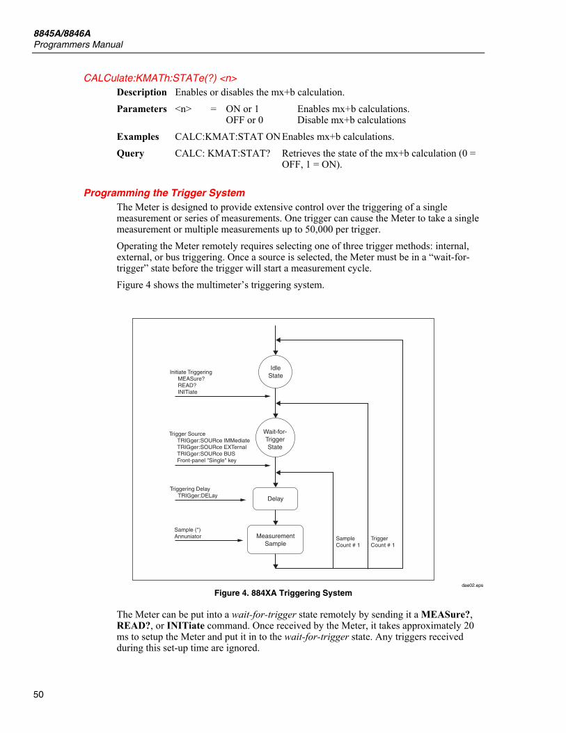
8845A/8846A Programmers Manual
50
CALCulate:KMATh:STATe(?) <n> Description Enables or disables the mx+b calculation. Parameters <n> = ON or 1 Enables mx+b calculations. OFF or 0 Disable mx+b calculations Examples CALC:KMAT:STAT ON Enables mx+b calculations. Query CALC: KMAT:STAT? Retrieves the state of the mx+b calculation (0 =
OFF, 1 = ON).
Programming the Trigger System The Meter is designed to provide extensive control over the triggering of a single measurement or series of measurements. One trigger can cause the Meter to take a single measurement or multiple measurements up to 50,000 per trigger. Operating the Meter remotely requires selecting one of three trigger methods: internal, external, or bus triggering. Once a source is selected, the Meter must be in a “wait-for-trigger” state before the trigger will start a measurement cycle. Figure 4 shows the multimeter’s triggering system.
SampleCount # 1
MeasurementSample
Delay
Wait-for-TriggerState
IdleState
Initiate TriggeringMEASure?READ?INITiate
Triggering DelayTRIGger:DELay
Sample (*)Annuniator
Trigger SourceTRIGger:SOURce IMMediateTRIGger:SOURce EXTernalTRIGger:SOURce BUSFront-panel "Single" key
TriggerCount # 1
dae02.eps
Figure 4. 884XA Triggering System
The Meter can be put into a wait-for-trigger state remotely by sending it a MEASure?, READ?, or INITiate command. Once received by the Meter, it takes approximately 20 ms to setup the Meter and put it in to the wait-for-trigger state. Any triggers received during this set-up time are ignored.
Digital Multimeter Supported SCPI Commands
51
Using the Triggering Commands
INITiate
Description Sets the Meter to the wait-for-trigger state in which the next trigger from the selected source triggers a measurement cycle. Up to 5,000 measurements are placed into the Meter’s internal memory, where they can be retrieved with the FETCh? command.
Examples INIT Sets the Meter to the wait-for-trigger state.
READ? Description Sets the Meter in to the wait-for-trigger state where the next trigger from
the selected source triggers a measurement cycle. Measurements are sent directly to the output buffer.
Examples READ? Sets the Meter to the wait-for-trigger state.
TRIGger:SOURce(?) BUS|IMMediate|EXTernal Description Sets the source from which the Meter will sense a measurement trigger. Parameters <n> = BUS Sets the Meter to expect a trigger through the
IEEE bus or upon execution of a *TRG command.
IMMediate Selects Meter’s internal triggering system. EXTernal Sets Meter to sense triggers through the
trigger jack on the rear panel of the Meter. Examples TRIG:SOUR BUS Sets the Meter to expect a trigger through the
IEEE bus or upon execution of a *TRG command.
Query TRIG:SOUR? Retrieves trigger source to which the Meter has been set (BUS, IMM, or EXT).
TRIGger:DELay <n> Description Sets the delay between receiving a trigger and the beginning of
measurement cycle. If the command is used without a value for n, the Meter automatically sets a delay time.
Parameters <n> = 0 to 3600 Delay specified in seconds. MINimum Delay set to 0 seconds. MAXimum Delay set to 3600 seconds. Examples TRIG:DEL 14 Sets the trigger delay to 14 seconds. Query TRIG:DEL? Retrieves the amount of time set for a trigger
delay. TRIG:DEL? MIN Returns 0 seconds TRIG:DEL? MAX Returns 3600 seconds
TRIGger:DELay:AUTO <n> Description Enables or disables automatic trigger delay. The amount of delay is set
based on selected function, integration time, and ac filter setting. When a specific trigger delay is set using TRIG:DELAY <n> command, automatic trigger delay is disabled. Setting is stored in volatile memory.
8845A/8846A Programmers Manual
52
Parameters <n> = ON or 1 Automatic trigger delay enabled. OFF or 0 Automatic trigger delay disabled. Examples TRIG:DEL:AUTO ON Enables automatic trigger delay Query TRIG:DEL:AUTO? Retrieves the state of the automatic trigger delay
( 0 = OFF, 1 = ON).
SAMPle:COUNt <value>|MINimum|MAXimum Description Sets the number of measurements the Meter takes per trigger. This setting
is stored in volatile memory. Parameters <n> = 0 to 50,000 Number of measurements per trigger MINimum Number of measurements per trigger set to 1. MAXimum Number of measurements per trigger set to
50,000. Examples SAMP:COUN 2450 Number of measurements per trigger set to
2,450. Query SAMP:COUN? Retrieves the number of samples per trigger
presently set in the Meter. SAMP:COUN? MIN Returns 1 to indicate the minimum number of
samples the Meter will accept per trigger. SAMP:COUN? MAX Returns 50,000 to indicate the maximum number
of measuremens the Meter will accept per trigger.
TRIGger:COUNt <n> Description Sets the number of triggers the Meter will take before switching to an idle
state. This setting is stored in volatile memory. Parameters <n> = 0 to 50,000 Number of triggers before Meter becomes
idle. MINimum Number of triggers is set to 1. MAXimum Number of triggers is set to 50,000. INFinite Continuously accepts triggers. A device clear
is required to set the Meter to idle state after INFinite has been set.
Examples TRIG:COUN 430 Number of triggers set to 430. Query TRIG:COUN? Retrieves the number of triggers presently set in
the Meter. Returns 9.90000000E+37 if trigger count has been set to INFinite.
TRIG:COUN? MIN Returns 1 to indicate the minimum number of triggers the Meter will accept per trigger.
TRIG:COUN? MAX Returns 50,000 to indicate the maximum number of triggers the Meter will accept per trigger.
Digital Multimeter Supported SCPI Commands
53
Using System-Related Commands
FETCh[1/2]? Description Moves measurements stored in the Meter’s internal memory to the output
buffer. FETCh1? or FETCh? returns measurements from the primary display. FETCh2? Returns readings from the secondary display.
Example FETCh2? Retrieves a single measurement from the Meter’s internal memory that was taken by the secondary display.
DISPlay <n> Description Enables or disables the Meter’s display. This setting is stored in volatile
memory. Parameters <n> = ON or 1 Enables display. OFF or 0 Disables display. Examples DISP ON Enables the Meter’s display. Query DISP? Retrieves the state of the display ( 0 = OFF and 1
= ON).
DISPlay:TEXT(?) <quoted string > Description Displays message on the Meter’s display. This setting is stored in volatile
memory. Parameters <quoted string> = Up to 12 characters. Additional characters are
truncated. Examples DISP:TEXT “Hello” Hello is displayed in the Meter’s display. Query DISP:TEXT? Retrieves the text sent to the Meter in a
DISP:TEXT command.
DISPlay:TEXT:CLEar Description Clears the displayed message on the Meter’s display. Examples DISP:CLE Meter’s display message is cleared.
SYSTem:BEEPer Description Causes the Meter to beep once. Examples SYST:BEEP Meter beeps.
SYSTem:BEEPer:STATe? <n> Description Enables or disables the Meter’s beeper. This setting is stored in volatile
memory. Disabling the beeper causes the Meter to not beep for the following conditions: a new minimum or maximum is detected during statistics a limit is exceeded during a limits test a forward-biased diode is measured during a diode test
Parameters <n> = ON or 1 Enables Meter’s beeper.

8845A/8846A Programmers Manual
54
OFF or 0 Disables Meter’s beeper. Examples SYST:BEEP Meter beeps. Query SYST:BEEP? Retrieves the state of the Meter’s beeper ( 0 =
OFF and 1 = ON).
SYSTem:ERRor? Description Retrieves errors from the Meter’s error queue. Errors are retrieved in first-
in, first-out (FIFO) order. Each error may contain up to 80 characters. Examples SYST:ERR? Returns error.
SYSTem:ERRor:BEEPer(?) <n> Description Enable or disables the Meter’s beeper for error messages. This setting is
stored in volatile memory. Parameters <n> = ON or 1 Enables beeper for error messages. OFF or 0 Disables beeper for error messages. Examples SYST:ERR:BEEP ON Set Meter to beep when errors are detected. Query SYST:ERR:BEEP? Returns state of beeper for error messages ( 0 =
OFF and 1 = ON).
SYSTem:DATe(?) <date> Description Sets the system clock date. Parameters <date> = MM/DD/YYYY or MM-DD-YYYY. MM between 1 and 12 DD between 1 and 31 YYYY between 1970 and 2038 Examples SYST:DAT 10/25/2007 Query SYST:DAT? Returns the Meter’s system clock date.
SYSTem:TIMe(?) <time> Description Sets the system clock time in 24 format. Parameters <time> = HH:MM:SS or HH-MM-SS HH between 0 and 23 MM between 0 and 59 SS between 0 and 59 Examples SYST:TIM 14:25:10 Sets time to 2:25:10 PM Query SYST:TIM? Returns the Meter’s system clock time.
SYSTem:VERSion? Description Retrieves the Meter’s present SCPI command version. Examples SYST:VERS? Returns SCPI version.
Digital Multimeter Supported SCPI Commands
55
DATA:POINts? Description Retrieves the number of measurements contained the Meter’s internal
memory. Examples DATA:POIN? Returns number of measurements in internal
memory.
*RST Description Resets the Meter to its power-up configuration. Examples *RST Resets the Meter.
*IDN <n>, [<quoted string>] Description Enables or disables the retrieval of a user-specified IDN string or factory-
set IDN string with the *IDN? command. Also sets the user defined IDN string.
Parameters <n> = ON or 1 Enables user-defined string. OFF or 0 Disables user defined string and causes the
factory IDN string to be returned for an *IDN? command.
<quoted string> = Up to 35 character string. If the Meter is in 8846 mode, returned string is “FLUKE 8846A default 08/03/06-16:23”
Example *IDN ON, “My Meter” Sets the IDN string to My Meter and enables the user defined string to be returned when the *IDN? command is received by the Meter.
*IDN? Description Returns the IDN string. If *IDN is enabled (ON), then the Meter returns
the user defined string. If *IDN is disabled (OFF), the the Meter returns the IDN string set at the factory.
Query *IDN? Returns up to 35 character string.
Using Status Reporting Commands
SYSTem:ERRor? Description Retrieves errors from the Meter’s error queue. Errors are retrieved in first-
in, first-out (FIFO) order. Each error may contain up to 80 characters. Examples SYST:ERR? Returns the next error in the error queue.
Performing a SYST:ERR? command when the error queue is empty causes +0,″No error″ to be returned.
STATus:QUEStionable:ENABle(?) <n> Description Enables or disables bits in the Meter’s Questionable Data enable register. Parameters <n> = 0 to 65535 Binary-weighted decimal value representing the
bits to set in the register. Although a 16-bit register that will accept a number between 0 and 65535, only bits 0, 1, 9, 11, 12, and 13 are used.
8845A/8846A Programmers Manual
56
Examples STAT:QUES:ENAB 4 Sets bit 2 to one and all others to zero. Query STAT:QUES:ENAB? Retrieves a binary-weighted decimal value
representing the bits set in the questionable data enable register.
STATus:QUEStionable:EVENt? Description Enables or disables bits in the Meter’s Questionable Data event register. Parameters <n> = 0 to 65535 Binary-weighted decimal value representing the
bits to set in the register. Although a 16-bit register that will accept a number between 0 and 65535, only bits 0, 1, 9, 11, 12, and 13 are used.
Query STAT:QUES:ENAB? Retrieves a binary-weighted decimal value representing the bits set in the questionable data event register.
STATus:PRESet Description Sets all bits to zero in the Meter’s Questionable Data enable register. Examples STAT:PRES Sets all bits to zero.
*CLS Description Sets all bits to zero in the Meter’s status byte register and all event
registers. Also clears the error queue. Examples *CLS Sets all bits to zero and clear error queue.
*ESE <enable value> Description Enables or disables bits in the Meter’s Standard Event enable register. Parameters <n> = 0 to 255 Binary-weighted decimal value representing the
bits to set in the register. Although this register has 8 bits and will accept a number from 0 to 255, only bits 0, 2 through 5, and 7 are used.
Examples *ESE 160 Sets bits 5 and 7 to one and all other bits to zero.
*ESE? Description Retrieves the value in the Meter’s Standard Event enable register. Examples *ESE? Retrieves a binary-weighted decimal value
representing the bits set in the Standard Event enable register.
*ESR? Description Retrieves the value in the Meter’s Standard Event register. Examples *ESR? Retrieves a binary-weighted decimal value
representing the bits set in the Standard Event register.
*OPC Description Sets bit 0 (Operation complete) in the Meter’s Standard Event register.
Digital Multimeter Supported SCPI Commands
57
Examples *OPC Sets bit 0 in Standard Event register.
*OPC? Description Returns a one to the Meter’s output buffer. Examples *OPC?
*PSC <n> Description Enables or disables the clearing of the Status Byte Enable register and
Standard Event Enable register when Meter power is turned on. This setting is stored in volatile memory.
Parameters <n> = 0 Disables clearing Status Byte and Standard Event Enable register at power-up.
1 Enables clearing Status Byte and Standard Event Enable register at power-up.
*PSC? Description Returns the state of the clearing of the Status Byte and Standard Event
Enable registers at power-up. Examples *PSC? Returns zero if clearing is disabled. Returns one
if clearing enabled.
*SRE <enable value> Description Enables or disables bits in the Meter’s Status Byte enable register. Parameters <n> = 0 to 255 Binary-weighted decimal value representing the
bits to set in the register. Although this register has 8 bits and will accept a number from 0 to 255, only bits 3 through 5 are used.
Examples *SRE 48 Sets bits 4 and 5 to one and all other bits to zero.
*SRE? Description Retrieves the value in the Meter’s Status Byte enable register. Examples *SRE? Retrieves a binary-weighted decimal value
representing the bits set in the enable register.
*STB? Description Retrieves the value in the Meter’s Status Byte summary register. Although
like a serial poll, this command is processed as an instrument command. Returned results are the same a when receiving a serial poll, but the SRQ bit is not cleared if a serial poll has occurred.
Examples *STB?
Calibration Commands
CALibration? [ON|OFF] Description After entering the proper code using the CAL:SEC:CODE command, this
command causes the Meter to perform an adjustment using the values

8845A/8846A Programmers Manual
58
supplied with the CAL:VAL command. See the 8845A/8846A Service Manual for details on using this command.
Parameters <n> = ON or 1 Execute only one calibration step. OFF or 0 Execute a group (mode) of related calibration
steps at one time. Examples CAL? ON Execute one step of the calibration steps for the
calibration group specified by the CAL:VAL command.
CAL? Returns +1 (good) or +0 (failed)
CALibration:COUNt? Description Retrieves the number of times the Meter has been calibrated. Read this
value just after receiving the Meter to have a starting value. This setting is stored in non-volatile memory.
Note This value increments once for each calibration point. A complete calibration will increment this value many times. The maximum count is 4,294,967,295, at which point the next calibration causesthis value to reset to zero.
Examples CAL:COUN?
CALibration:RECord Description Stores the calibration values. Example CAL:REC Stores all of the Meter’s changed calibration
values.
CALibration:SECure:CODE <new code > Description Sets a new calibration password. Before entering a new code, you must
first enter the old password using the CAL:SEC:STAT command. The Meter has a password of FLUKE884X when shipped from the factory.
Parameters <new code> = Up to 12 characters of capital letters and numerials (A-Z, 0-9).
Example CAL:SEC:CODE 12B Sets the new calibration password to 12B. If the password can not be recalled, the password can be reset to the factory default without returning the Meter to service.
XW Warning To avoid electric shock and or injury, do not open the Meter unless you are qualified to do so.
Follow the instructions in the 8845A/8846A Service Manual for opening the Meter case. Located at the rear of the chassis, behind the Ethernet connector (J17), there is a jumper connector labeled W2. Short the pins of W2 together for one second to reset the password to FLUKE884X.
Digital Multimeter Supported SCPI Commands
59
CALibration:SECure:STATe(?) <n>,<code > Description Secure or unsecure the Meter for calibration. This setting is stored in non-
volatile memory. Parameters <n> = ON or 1 Secures the Meter from calibration. OFF or 0 Unsecures the Meter for calibration. <code> = Up to 12 character string. Example CAL:SEC:STAT OFF 12B Unsecures the Meter for calibration when the
password is 12B. Query CAL:SEC:STAT? Retrieves the state of the Meter’s calibration
security ( 0 = OFF and 1 = ON).
CALibration:STRing(?) <quoted string> Description Store calibration information in the Meter’s memory. This setting is stored
in non-volatile memory. Parameters <quoted string> = Up to a 40 character string. Query CAL:STR? Retrieves the Meter’s calibration string.
CALibration:DATE(?) <date> Description Sets the calibration date on the 8845A only. Parameters <date> = MM/DD/YYYY or MM-DD-YYYY. MM between 1 and 12 DD between 1 and 31 YYYY between 1970 and 2038 Examples CAL:DATE 10/25/2007 Query CAL:DATE? Returns the Meter’s calibration date.
CALibration:VALue(?) <mode>, <value > Description Sets up the Meter for a calibration point. The mode parameter is the name
of the functional group being calibrated. The value parameter is the Meter’s range for the calibration point. Refer to the calibration procedure in the 8845A/8846A Service Manual for mode names and values.
Parameters <mode> = See 8845A/8846A Service Manual <value> = See 8845A/8846A Service Manual Query CAL:VAL? Retrieves the Meter’s calibration value.
CALibration:STEP(?) <step #> [,Reference] Description Specifies the calibration step number and the optional reference value of
the known calibration signal used by the calibration procedure. See the 8845A/8846A Service Manual for a list of calibration steps with values.
Parameters <step #> = Number from 1 to 114. Examples CAL:STEP 5 Sets the calibration step to number 5. Query CAL:STEP? Returns the Meter’s calibration step.
8845A/8846A Programmers Manual
60
Using RS-232/Ethernet Interface Commands There are four remote commands that are specifically applicable to controlling the Meter using the RS-232 or Ethernet remote interface.
SYSTem:LOCal Description Places the Meter in the local mode. Front-panel keys still function. Example SYST:LOC
SYSTem:REMote Description Places the Meter in the remote mode for RS-232 or Ethernet remote
control. All front-panel keys, except the local key, are disabled. Example SYST:REM
Note To avoid unpredictable operation, send a SYS:REM command to the Meter before sending or receiving data over the RS-232 or Ethernet interface.
SYSTem:RWLock Description Like the SYST:REM command, this command places the Meter into
remote mode, but with all front-panel keys, including the local key, disabled.
Example SYST:RWL
Ctrl-C Description Immediately stops transfers of data over the RS-232 interface and clears
any output data.
Note This the same as sending a device clear over the IEEE bus.
Command Terminators A command string sent to the Meter must terminate with a <new line> character. The IEEE 488 EOI (end-or-identify) message is interpreted as a <new line> character and can be used to terminate a command string in place of a <new line> character. A <carriage return> followed by a <new line> is also accepted. Command string termination will always reset the current SCPI command path to the root level.
SCPI Parameter Types The SCPI language defines several different data formats to be used in program messages and response messages.
Numeric Parameters Commands that require numeric parameters will accept all commonly used decimal representations of numbers including optional signs, decimal points, and scientific notation. Special values for numeric parameters like MINimum, MAXimum, and DEFault are also accepted. You can also send engineering unit suffixes with numeric parameters (e.g., M, K, or u). If only specific numeric values are accepted, the Meter will
Digital Multimeter Supported SCPI Commands
61
automatically round the input numeric parameters. The following command uses a numeric parameter:
VOLTage:DC:RANGe <range>|MINimum|MAXimum
Discrete Parameters Discrete parameters are used to program settings that have a limited number of values (like BUS, IMMediate, EXTernal). They have a short form and a long form just like command keywords. You can mix upper- and lower-case letters. Query responses will always return the short form in all upper-case letters. The following command uses discrete parameters:
TRIGger:SOURce BUS|IMMediate|EXTernal
Boolean Parameters Boolean parameters represent a single binary condition that is either true or false. For a false condition, the Meter will accept OFF or 0. For a true condition, the Meter will accept ON or 1. When you query a boolean setting, the instrument will always return “0” or “1”. The following command uses a boolean parameter:
INPut:IMPedance:AUTO OFF|ON
String Parameters String parameters can contain virtually any set of ASCII characters. A string must begin and end with matching quotes; either with a single quote or with a double quote. You can include the quote delimiter as part of the string by typing it twice without any characters in between. The following command uses a string parameter:
DISPlay:TEXT <quoted string>
Alternate Programming Language Compatibility The Meter can be configured to accept and execute 884XA SCPI commands (HP 34401A compatible) or Fluke 45 multimeter commands. Remote operation will only allow you to access the functionality of the multimeter language selected. Full Meter capability is available through the 884XA SCPI programming language. For more information on selecting the alternate languages from the front panel menu, see Selecting the Programming Language earlier in this manual. From the remote interface, use the following commands to select the alternate languages:
L1 selects SCPI language L2 selects Fluke 45A language
The Meter implements virtually all of the commands available for the Fluke 45 and HP 34401A, with the exception of the self-test and calibration commands. You must always calibrate the Meter using the SCPI language setting. The calibration commands from the other multimeters will not be executed. Be aware that measurement timing may be different in the alternate language compatibility modes.
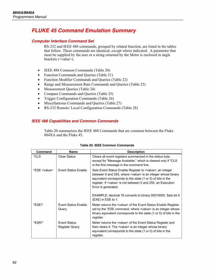
8845A/8846A Programmers Manual
62
FLUKE 45 Command Emulation Summary
Computer Interface Command Set RS-232 and IEEE 488 commands, grouped by related function, are listed in the tables that follow. These commands are identical, except where indicated. A parameter that must be supplied by the user or a string returned by the Meter is enclosed in angle brackets (<value>).
• IEEE 488 Common Commands (Table 20) • Function Commands and Queries (Table 21) • Function Modifier Commands and Queries (Table 22) • Range and Measurement Rate Commands and Queries (Table 23) • Measurement Queries (Table 24) • Compare Commands and Queries (Table 25) • Trigger Configuration Commands (Table 26) • Miscellaneous Commands and Queries (Table 27) • RS-232 Remote/ Local Configuration Commands (Table 28)
IEEE 488 Capabilities and Common Commands
Table 20 summarizes the IEEE 488 Commands that are common between the Fluke 884XA and the Fluke 45.
Table 20. IEEE Common Commands
Command Name Description *CLS Clear Status Clears all event registers summarized in the status byte,
except for "Message Available," which is cleared only if *CLS is the first message in the command line.
*ESE <value> Event Status Enable Sets Event Status Enable Register to <value>, an integer between 0 and 255, where <value> is an integer whose binary equivalent corresponds to the state (1 or 0) of bits in the register. If <value> is not between 0 and 255, an Execution Error is generated. EXAMPLE: decimal 16 converts to binary 00010000. Sets bit 4 (EXE) in ESE to 1.
*ESE? Event Status Enable Query
Meter returns the <value> of the Event Status Enable Register set by the *ESE command, where <value> is an integer whose binary equivalent corresponds to the state (1 or 0) of bits in the register.
*ESR? Event Status Register Query
Meter returns the <value> of the Event Status Register and then clears it. The <value> is an integer whose binary equivalent corresponds to the state (1 or 0) of bits in the register.

Digital Multimeter FLUKE 45 Command Emulation Summary
63
Table 20. IEEE Common Commands (cont.)
Command Name Description
*IDN? Identification Query Meter returns the identification code of the meter as four fields separated by commas. These fields are: manufacturer ("FLUKE"); model (“45"); seven-digit serial number; version of main software and version of display software. (example: FLUKE, 45, 9080025, 2.0, D2.0)
*OPC Operation Complete Command
Meter sets the Operation Complete bit in the Standard Event Status Register when parsed.
*OPC? Operation Complete Query
Meter places an ASCII "1 " in the output queue when parsed.
*RST Reset Meter performs power-up reset, except that the state of IEEE 488 interface is unchanged, including: instrument address, Status Byte, and Event Status Register.
*SRE <value> Service Request
Enable
Sets the "Service Request Enable Register" to <value>, an integer between 0 and 255. The value of bit six is ignored because it is not used by the Service Request Enable Register.
Note that <value> is an integer whose binary equivalent corresponds to the state (1 or 0) of bits in the register. If <value> is not between 0 and 255, an Execution Error is generated.
*SRE? Service Request
Enable Query
Meter returns the <value> of the Service Request Enable Register (with bit six set to zero); <value> is an integer whose binary equivalent corresponds to the state (1 or 0) of bits in the register.
*STB? Read Status Byte Meter returns the <value> of the Status Byte with bit six as the Master Summary bit.
<value> is an integer whose binary equivalent corresponds to the state (1 or 0) of bits in the register.
*TRG Trigger Causes the meter to trigger a measurement when parsed.
*WAI Wait-to-continue Command required by IEEE 488.2 standard. Non-operational in Fluke 45 Dual Display Multimeter. Command accepted but has no effect.
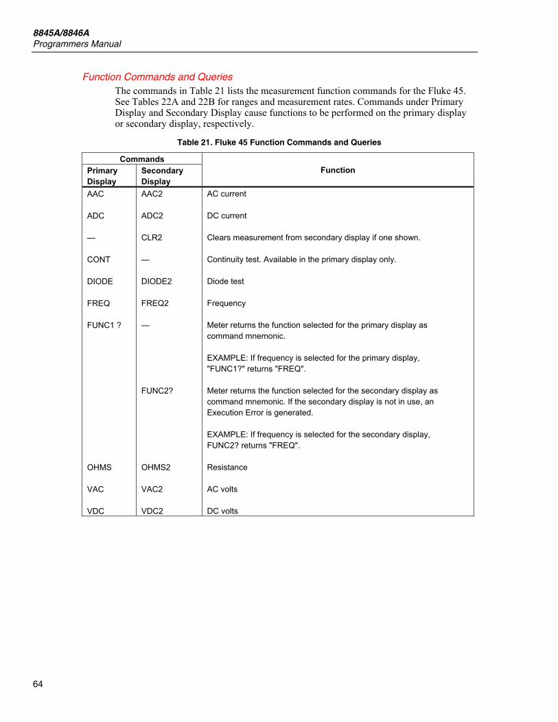
8845A/8846A Programmers Manual
64
Function Commands and Queries The commands in Table 21 lists the measurement function commands for the Fluke 45. See Tables 22A and 22B for ranges and measurement rates. Commands under Primary Display and Secondary Display cause functions to be performed on the primary display or secondary display, respectively.
Table 21. Fluke 45 Function Commands and Queries
Commands Primary Display
Secondary Display
Function
AAC ADC — CONT DIODE FREQ FUNC1 ? OHMS VAC VDC
AAC2 ADC2 CLR2 — DIODE2 FREQ2 — FUNC2? OHMS2 VAC2 VDC2
AC current DC current Clears measurement from secondary display if one shown. Continuity test. Available in the primary display only. Diode test Frequency Meter returns the function selected for the primary display as command mnemonic. EXAMPLE: If frequency is selected for the primary display, "FUNC1?" returns "FREQ". Meter returns the function selected for the secondary display as command mnemonic. If the secondary display is not in use, an Execution Error is generated. EXAMPLE: If frequency is selected for the secondary display, FUNC2? returns "FREQ". Resistance AC volts DC volts
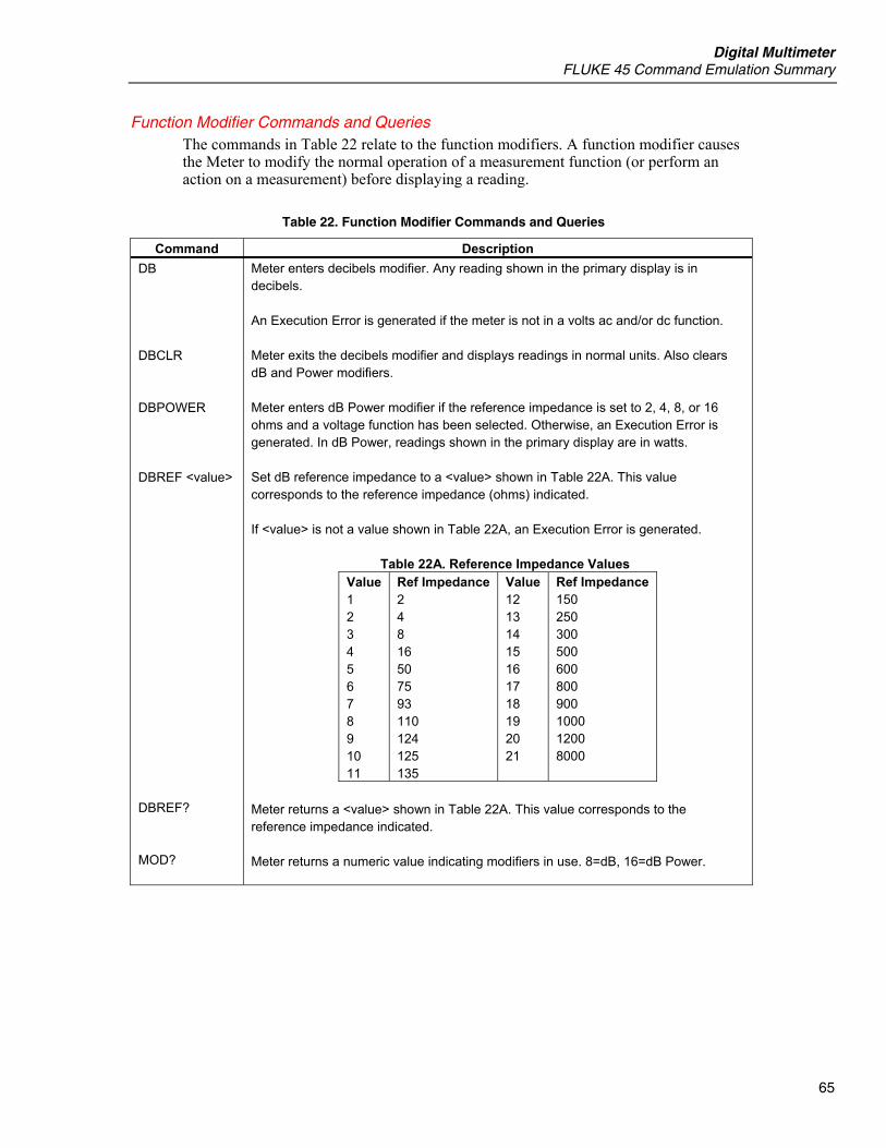
Digital Multimeter FLUKE 45 Command Emulation Summary
65
Function Modifier Commands and Queries The commands in Table 22 relate to the function modifiers. A function modifier causes the Meter to modify the normal operation of a measurement function (or perform an action on a measurement) before displaying a reading.
Table 22. Function Modifier Commands and Queries
Command Description DB DBCLR DBPOWER DBREF <value> DBREF? MOD?
Meter enters decibels modifier. Any reading shown in the primary display is in decibels. An Execution Error is generated if the meter is not in a volts ac and/or dc function. Meter exits the decibels modifier and displays readings in normal units. Also clears dB and Power modifiers. Meter enters dB Power modifier if the reference impedance is set to 2, 4, 8, or 16 ohms and a voltage function has been selected. Otherwise, an Execution Error is generated. In dB Power, readings shown in the primary display are in watts. Set dB reference impedance to a <value> shown in Table 22A. This value corresponds to the reference impedance (ohms) indicated. If <value> is not a value shown in Table 22A, an Execution Error is generated.
Table 22A. Reference Impedance Values Value 1 2 3 4 5 6 7 8 9 10 11
Ref Impedance 2 4 8 16 50 75 93 110 124 125 135
Value 12 13 14 15 16 17 18 19 20 21
Ref Impedance 150 250 300 500 600 800 900 1000 1200 8000
Meter returns a <value> shown in Table 22A. This value corresponds to the reference impedance indicated. Meter returns a numeric value indicating modifiers in use. 8=dB, 16=dB Power.

8845A/8846A Programmers Manual
66
Range and Measurement Rate Commands and Queries The commands in Table 23 relate to ranging and measurement rates (i.e., readings/ second). In the autorange mode, the Meter automatically selects a range for each reading; in the manual range mode, the user selects a fixed range.
Table 23. Range and Measurement Rate Commands and Queries
Command Description AUTO AUTO? FIXED RANGE <range>
Causes the meter to enter the autoranging mode on the primary display. If the autorange mode cannot be selected (e.g., if dB or diode/continuity test is selected), an Execution Error is generated. Causes meter to return "1" in autorange, or "0" if it is not. Causes the meter to exit autoranging on the primary display and enter manual ranging. The present range becomes the selected range. Sets the primary display to the range designated by <range>, where <range> is a number between 1 and 7 that corresponds to a range shown in Tables 23A and 23B.
Table 23A. Ranges at Fast & Medium Measurement Rate Range Value
Voltage Range
Ohms Range
Current Range
Frequency Range
1 2 3 4 5 6 7
300 mV 3 V 30 V
300 V 1000 V dc*
ERROR ERROR
300 Ω 3 k Ω
30 k Ω 300 k Ω 3 M Ω
30 M Ω 300 M Ω
30 mA 100 mA
10 A ERROR ERROR ERROR ERROR
1000 Hz 10 kHz
100 kHz 1000 kHz
1 MHz ERROR ERROR
* 1000 V dc, 750 V ac
Table 23B. Ranges at Slow Measurement Rate Range Value
Voltage Range
Ohms Range
Current Range
Frequency Range
1 2 3 4 5 6 7
100 mV 1000 mV 10 V 100 V 1000 V dc* ERROR ERROR
100 Ω 1000 Ω 10 k Ω 100 k Ω 1000 k Ω 10 M Ω 100 M Ω
10 mA 100 mA 10 A ERROR ERROR ERROR ERROR
1000 Hz 10 kHz 100 kHz 1000 kHz 1 MHz ERROR ERROR
* 1000 V dc, 750 V ac

Digital Multimeter FLUKE 45 Command Emulation Summary
67
Table . Range and Measurement Rate Commands and Queries (cont.)
Command Description RANGE1? RANGE2? RATE <speed> RATE?
Returns the range presently selected on the primary display. Returns the range presently selected on the secondary display. If the secondary display is inactive, an Execution Error is generated. Sets the measurement rate to <speed>. RATE <speed> is either "S" for slow (2.5 readings/second), "M" for medium (5 readings/second), or "F" for fast (20 readings/second). "S", "M", and "F" can be sent as either upper- or lower-case letters. Any other entry for <speed> generates an Execution Error. Returns <speed> as "S" for slow (2.5 readings/second), "M" for medium (5.0 readings/second), or "F" for fast (20 readings/second).
Measurement Queries The commands in Table 24 cause the Meter to return readings shown on the primary and/or secondary displays.
Table 24. Measurement Queries
Command Description MEAS1? MEAS2? MEAS? VAL1? VAL2? VAL?
Meter returns the value shown on the primary display after the next triggered measurement is complete. Meter returns the value shown on the secondary display after the next triggered measurement is complete. If the secondary display is off, an Execution Error is generated. If both displays are on, the Meter returns the value shown on both displays after the next triggered measurement is complete in the format selected. These values are separated by a comma (format 1) or a space, measurement units, a comma and space (format 2). Example: +1.2345E+0,+6.7890E+3<CR><LF> If the secondary display is not on, MEAS? is equivalent to MEAS1?
Note If MEAS is used in external trigger (TRIGGER 2 through TRIGGER 5), unexpected results will be obtained. Meter returns the value shown on the primary display. If the primary display is blank, the next triggered measurement is returned. Meter returns the value shown on the secondary display. If the secondary display is blank, the next triggered measurement is returned. If the secondary display is off, an execution error is generated. If both displays are on, the Meter returns the value shown on both displays. These values are separated by a comma. Example: +1.2345E+0,+6.7890E+3<CR><LF>. If the secondary display is not on, VAL is equivalent to VAL1. If a display is blank, the next triggered measurement on that display (or displays) is returned.
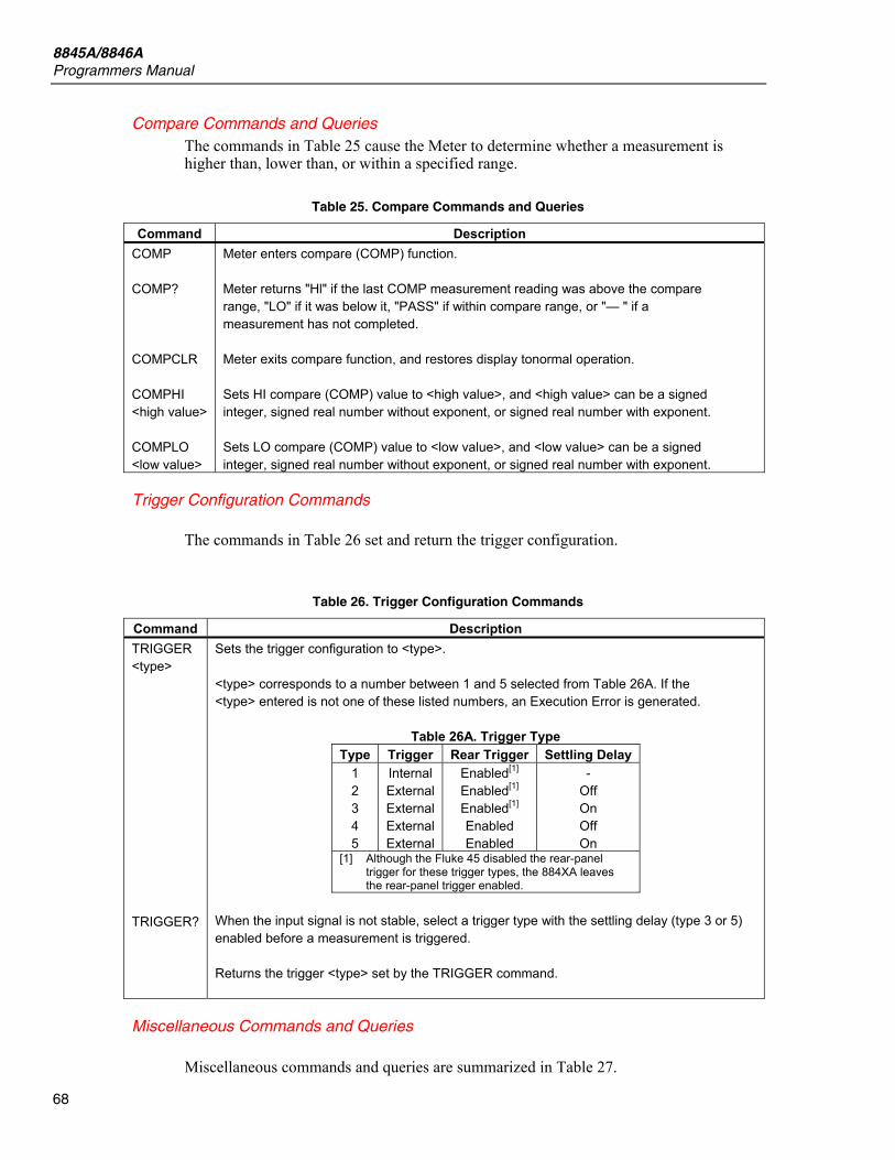
8845A/8846A Programmers Manual
68
Compare Commands and Queries The commands in Table 25 cause the Meter to determine whether a measurement is higher than, lower than, or within a specified range.
Table 25. Compare Commands and Queries
Command Description COMP COMP? COMPCLR COMPHI <high value> COMPLO <low value>
Meter enters compare (COMP) function. Meter returns "Hl" if the last COMP measurement reading was above the compare range, "LO" if it was below it, "PASS" if within compare range, or "— " if a measurement has not completed. Meter exits compare function, and restores display tonormal operation. Sets HI compare (COMP) value to <high value>, and <high value> can be a signed integer, signed real number without exponent, or signed real number with exponent. Sets LO compare (COMP) value to <low value>, and <low value> can be a signed integer, signed real number without exponent, or signed real number with exponent.
Trigger Configuration Commands
The commands in Table 26 set and return the trigger configuration.
Table 26. Trigger Configuration Commands
Command Description TRIGGER <type> TRIGGER?
Sets the trigger configuration to <type>. <type> corresponds to a number between 1 and 5 selected from Table 26A. If the <type> entered is not one of these listed numbers, an Execution Error is generated.
Table 26A. Trigger Type Type Trigger Rear Trigger Settling Delay
1 2 3 4 5
Internal External External External External
Enabled[1] Enabled[1] Enabled[1] Enabled Enabled
- Off On Off On
[1] Although the Fluke 45 disabled the rear-panel trigger for these trigger types, the 884XA leaves the rear-panel trigger enabled.
When the input signal is not stable, select a trigger type with the settling delay (type 3 or 5) enabled before a measurement is triggered. Returns the trigger <type> set by the TRIGGER command.
Miscellaneous Commands and Queries
Miscellaneous commands and queries are summarized in Table 27.
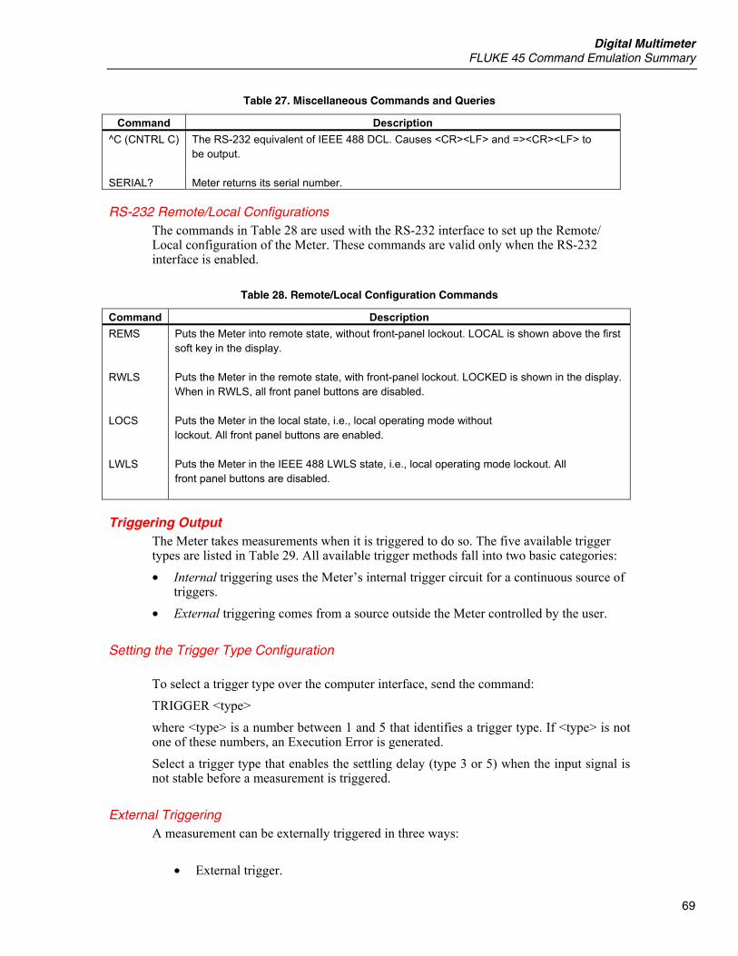
Digital Multimeter FLUKE 45 Command Emulation Summary
69
Table 27. Miscellaneous Commands and Queries
Command Description ^C (CNTRL C) SERIAL?
The RS-232 equivalent of IEEE 488 DCL. Causes <CR><LF> and =><CR><LF> to be output. Meter returns its serial number.
RS-232 Remote/Local Configurations The commands in Table 28 are used with the RS-232 interface to set up the Remote/ Local configuration of the Meter. These commands are valid only when the RS-232 interface is enabled.
Table 28. Remote/Local Configuration Commands
Command Description REMS RWLS LOCS LWLS
Puts the Meter into remote state, without front-panel lockout. LOCAL is shown above the first soft key in the display. Puts the Meter in the remote state, with front-panel lockout. LOCKED is shown in the display. When in RWLS, all front panel buttons are disabled. Puts the Meter in the local state, i.e., local operating mode without lockout. All front panel buttons are enabled. Puts the Meter in the IEEE 488 LWLS state, i.e., local operating mode lockout. All front panel buttons are disabled.
Triggering Output The Meter takes measurements when it is triggered to do so. The five available trigger types are listed in Table 29. All available trigger methods fall into two basic categories: • Internal triggering uses the Meter’s internal trigger circuit for a continuous source of
triggers. • External triggering comes from a source outside the Meter controlled by the user.
Setting the Trigger Type Configuration
To select a trigger type over the computer interface, send the command: TRIGGER <type> where <type> is a number between 1 and 5 that identifies a trigger type. If <type> is not one of these numbers, an Execution Error is generated. Select a trigger type that enables the settling delay (type 3 or 5) when the input signal is not stable before a measurement is triggered.
External Triggering A measurement can be externally triggered in three ways:
• External trigger.

8845A/8846A Programmers Manual
70
• GET command (IEEE Interface only) • *TRG command
To trigger a measurement over the RS-232 or IEEE 488 computer interface, send the Meter a *TRG command over the computer interface. The GET command is only valid for the IEEE interface. When set for external trigger, the Meter will trigger measurements when a negative-going signal is applied to the rear-panel trigger jack.
Note The Fluke 45 provides a method of triggering through its RS-232 port. The 8845A and 8846A do not provide this method of triggering.
Table 29. Trigger Types
Type Trigger Rear Trigger Settling Delay 1 2 3 4 5
Internal External External External External
Enabled[1]
Enabled[1]
Enabled[1]
Enabled Enabled
- Off On Off On
[1] Although the Fluke 45 disabled the rear-panel trigger for these trigger types, the 884XA leaves the rear-panel trigger enabled.
Using FlukeView Forms You can use FlukeView Forms to download and store readings from the Meter to a PC running MicroSoft’s Windows operating system. FlukeView Forms Basic Documenting Software must first be installed on the PC. Refer to the FlukeView Forms Installation Guide to install FlukeView Forms on your Windows PC.
Note The Meter’s RS-232 port must be enabled and properly configured before FlukeView forms will communicate with the Meter. In addition, the Fluke 45 command set must be selected in the Meter.
To connect and configure the Meter to the PC with the installed FlukeView Forms Basic Documenting Software: 1. Connect a null-modem cable between the RS-232 port of the Meter and the PC’s RS-
232 port. 2. Open FlukeView Forms Documenting Software. 3. The current COM serial port setting is displayed at the bottom right of the FlukeView
Forms Basic window. Double-click on it to change the COM port setting to the virtual COM port used by the null-modem cable.
4. Turn the Meter on. 5. Select the Fluke 45 Command set by following the instructions in the Selecting the
Program Language section of Chapter 3 of the Users Manual. 6. Ensure the Meter’s RS-232 port is set to 9600 Baud, No parity, and Echo Off using
the instructions found in the Configuring the RS-232 Port section of Chapter 3 Users Manual.
7. Follow the instructions for transferring data from the Meter to the PC, found in the online FlukeView Forms Users Manual.
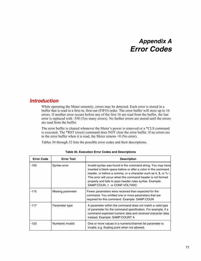
71
Appendix A Error Codes
Introduction While operating the Meter remotely, errors may be detected. Each error is stored in a buffer that is read in a first-in, first-out (FIFO) order. The error buffer will store up to 16 errors. If another error occurs before any of the first 16 are read from the buffer, the last error is replaced with -350 (Too many errors). No further errors are stored until the errors are read from the buffer. The error buffer is cleared whenever the Meter’s power is removed or a *CLS command is executed. The *RST (reset) command does NOT clear the error buffer. If no errors are in the error buffer when it is read, the Meter returns +0 (No error). Tables 30 through 32 lists the possible error codes and their descriptions.
Table 30. Execution Error Codes and Descriptions
Error Code Error Text Description
-102 Syntax error Invalid syntax was found in the command string. You may have inserted a blank space before or after a colon in the command header, or before a comma, or a character such as #, $, or % \. This error will occur when the command header is not formed properly and fails to pass header rules syntax. Example: SAMP:COUN ,1 or CONF:VOLT#DC
-115 Missing parameter Fewer parameters were received than expected for the command. You omitted one or more parameters that are required for this command. Example: SAMP:COUN
-117 Parameter type A parameter within the command does not match a valid type of parameter for the command specification. For example, if a command expected numeric data and received character data instead. Example: SAMP:COUNT A
-120 Numberic invalid One or more values in a numeric/channel list parameter is invalid, e.g. floating point when not allowed.
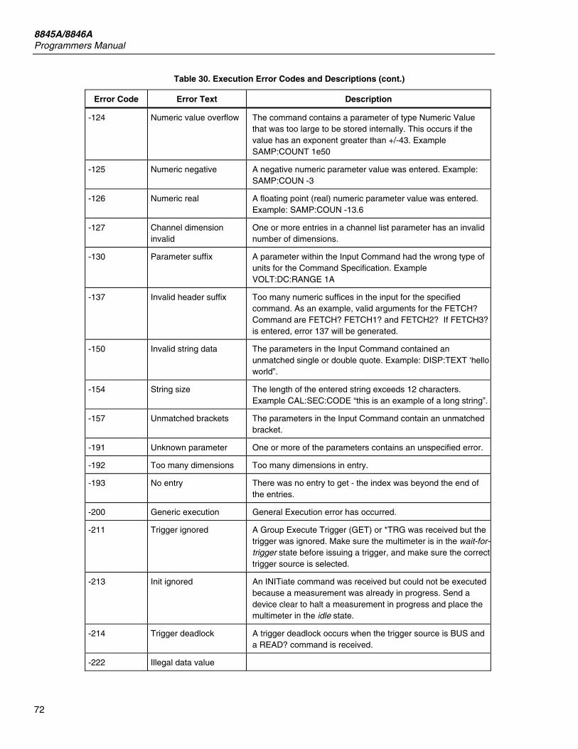
8845A/8846A Programmers Manual
72
Table 30. Execution Error Codes and Descriptions (cont.)
Error Code Error Text Description
-124 Numeric value overflow The command contains a parameter of type Numeric Value that was too large to be stored internally. This occurs if the value has an exponent greater than +/-43. Example SAMP:COUNT 1e50
-125 Numeric negative A negative numeric parameter value was entered. Example: SAMP:COUN -3
-126 Numeric real A floating point (real) numeric parameter value was entered. Example: SAMP:COUN -13.6
-127 Channel dimension invalid
One or more entries in a channel list parameter has an invalid number of dimensions.
-130 Parameter suffix A parameter within the Input Command had the wrong type of units for the Command Specification. Example VOLT:DC:RANGE 1A
-137 Invalid header suffix Too many numeric suffices in the input for the specified command. As an example, valid arguments for the FETCH? Command are FETCH? FETCH1? and FETCH2? If FETCH3? is entered, error 137 will be generated.
-150 Invalid string data The parameters in the Input Command contained an unmatched single or double quote. Example: DISP:TEXT ‘hello world”.
-154 String size The length of the entered string exceeds 12 characters. Example CAL:SEC:CODE “this is an example of a long string”.
-157 Unmatched brackets The parameters in the Input Command contain an unmatched bracket.
-191 Unknown parameter One or more of the parameters contains an unspecified error.
-192 Too many dimensions Too many dimensions in entry.
-193 No entry There was no entry to get - the index was beyond the end of the entries.
-200 Generic execution General Execution error has occurred.
-211 Trigger ignored A Group Execute Trigger (GET) or *TRG was received but the trigger was ignored. Make sure the multimeter is in the wait-for-trigger state before issuing a trigger, and make sure the correct trigger source is selected.
-213 Init ignored An INITiate command was received but could not be executed because a measurement was already in progress. Send a device clear to halt a measurement in progress and place the multimeter in the idle state.
-214 Trigger deadlock A trigger deadlock occurs when the trigger source is BUS and a READ? command is received.
-222 Illegal data value
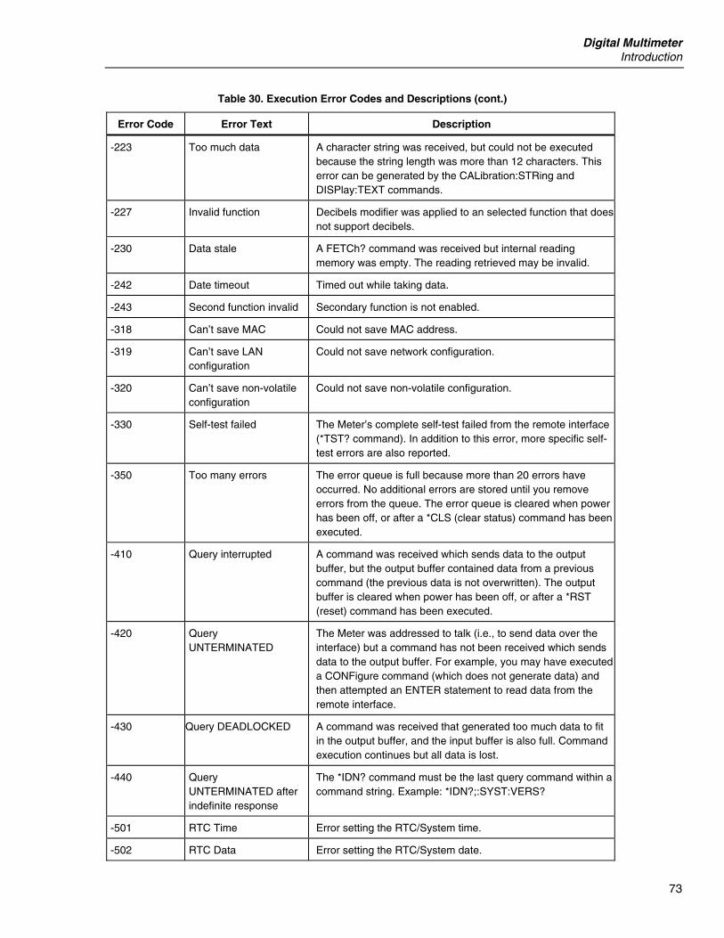
Digital Multimeter Introduction
73
Table 30. Execution Error Codes and Descriptions (cont.)
Error Code Error Text Description
-223 Too much data A character string was received, but could not be executed because the string length was more than 12 characters. This error can be generated by the CALibration:STRing and DISPlay:TEXT commands.
-227 Invalid function Decibels modifier was applied to an selected function that does not support decibels.
-230 Data stale A FETCh? command was received but internal reading memory was empty. The reading retrieved may be invalid.
-242 Date timeout Timed out while taking data.
-243 Second function invalid Secondary function is not enabled.
-318 Can’t save MAC Could not save MAC address.
-319 Can’t save LAN configuration
Could not save network configuration.
-320 Can’t save non-volatile configuration
Could not save non-volatile configuration.
-330 Self-test failed The Meter’s complete self-test failed from the remote interface (*TST? command). In addition to this error, more specific self-test errors are also reported.
-350 Too many errors The error queue is full because more than 20 errors have occurred. No additional errors are stored until you remove errors from the queue. The error queue is cleared when power has been off, or after a *CLS (clear status) command has been executed.
-410 Query interrupted A command was received which sends data to the output buffer, but the output buffer contained data from a previous command (the previous data is not overwritten). The output buffer is cleared when power has been off, or after a *RST (reset) command has been executed.
-420 Query UNTERMINATED
The Meter was addressed to talk (i.e., to send data over the interface) but a command has not been received which sends data to the output buffer. For example, you may have executed a CONFigure command (which does not generate data) and then attempted an ENTER statement to read data from the remote interface.
-430 Query DEADLOCKED A command was received that generated too much data to fit in the output buffer, and the input buffer is also full. Command execution continues but all data is lost.
-440 Query UNTERMINATED after indefinite response
The *IDN? command must be the last query command within a command string. Example: *IDN?;:SYST:VERS?
-501 RTC Time Error setting the RTC/System time.
-502 RTC Data Error setting the RTC/System date.
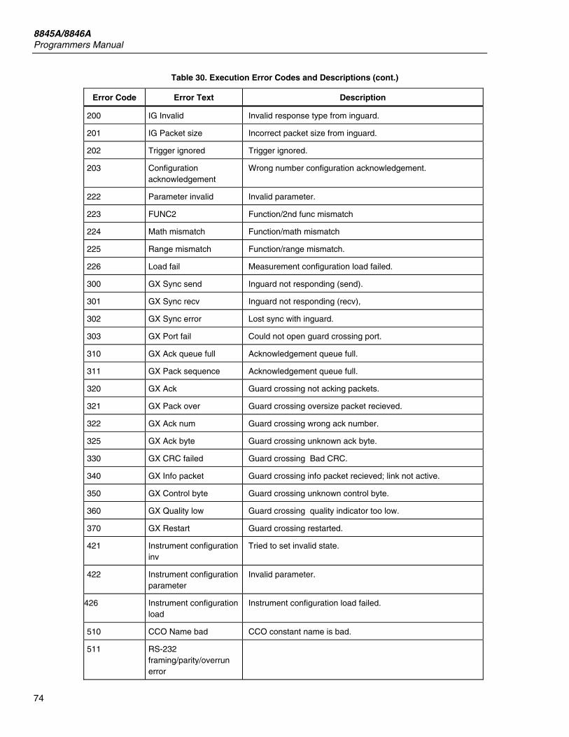
8845A/8846A Programmers Manual
74
Table 30. Execution Error Codes and Descriptions (cont.)
Error Code Error Text Description
200 IG Invalid Invalid response type from inguard.
201 IG Packet size Incorrect packet size from inguard.
202 Trigger ignored Trigger ignored.
203 Configuration acknowledgement
Wrong number configuration acknowledgement.
222 Parameter invalid Invalid parameter.
223 FUNC2 Function/2nd func mismatch
224 Math mismatch Function/math mismatch
225 Range mismatch Function/range mismatch.
226 Load fail Measurement configuration load failed.
300 GX Sync send Inguard not responding (send).
301 GX Sync recv Inguard not responding (recv),
302 GX Sync error Lost sync with inguard.
303 GX Port fail Could not open guard crossing port.
310 GX Ack queue full Acknowledgement queue full.
311 GX Pack sequence Acknowledgement queue full.
320 GX Ack Guard crossing not acking packets.
321 GX Pack over Guard crossing oversize packet recieved.
322 GX Ack num Guard crossing wrong ack number.
325 GX Ack byte Guard crossing unknown ack byte.
330 GX CRC failed Guard crossing Bad CRC.
340 GX Info packet Guard crossing info packet recieved; link not active.
350 GX Control byte Guard crossing unknown control byte.
360 GX Quality low Guard crossing quality indicator too low.
370 GX Restart Guard crossing restarted.
421 Instrument configuration inv
Tried to set invalid state.
422 Instrument configuration parameter
Invalid parameter.
426 Instrument configuration load
Instrument configuration load failed.
510 CCO Name bad CCO constant name is bad.
511 RS-232 framing/parity/overrun error
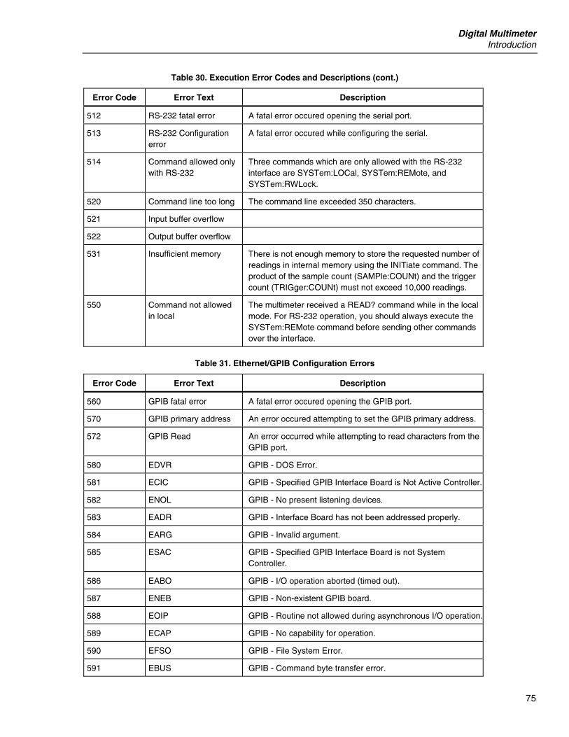
Digital Multimeter Introduction
75
Table 30. Execution Error Codes and Descriptions (cont.)
Error Code Error Text Description
512 RS-232 fatal error A fatal error occured opening the serial port.
513 RS-232 Configuration error
A fatal error occured while configuring the serial.
514 Command allowed only with RS-232
Three commands which are only allowed with the RS-232 interface are SYSTem:LOCal, SYSTem:REMote, and SYSTem:RWLock.
520 Command line too long The command line exceeded 350 characters.
521 Input buffer overflow
522 Output buffer overflow
531 Insufficient memory There is not enough memory to store the requested number of readings in internal memory using the INITiate command. The product of the sample count (SAMPle:COUNt) and the trigger count (TRIGger:COUNt) must not exceed 10,000 readings.
550 Command not allowed in local
The multimeter received a READ? command while in the local mode. For RS-232 operation, you should always execute the SYSTem:REMote command before sending other commands over the interface.
Table 31. Ethernet/GPIB Configuration Errors
Error Code Error Text Description
560 GPIB fatal error A fatal error occured opening the GPIB port.
570 GPIB primary address An error occured attempting to set the GPIB primary address.
572 GPIB Read An error occurred while attempting to read characters from the GPIB port.
580 EDVR GPIB - DOS Error.
581 ECIC GPIB - Specified GPIB Interface Board is Not Active Controller.
582 ENOL GPIB - No present listening devices.
583 EADR GPIB - Interface Board has not been addressed properly.
584 EARG GPIB - Invalid argument.
585 ESAC GPIB - Specified GPIB Interface Board is not System Controller.
586 EABO GPIB - I/O operation aborted (timed out).
587 ENEB GPIB - Non-existent GPIB board.
588 EOIP GPIB - Routine not allowed during asynchronous I/O operation.
589 ECAP GPIB - No capability for operation.
590 EFSO GPIB - File System Error.
591 EBUS GPIB - Command byte transfer error.
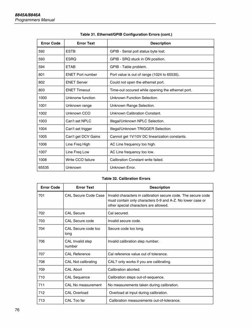
8845A/8846A Programmers Manual
76
Table 31. Ethernet/GPIB Configuration Errors (cont.)
Error Code Error Text Description
592 ESTB GPIB - Serial poll status byte lost.
593 ESRQ GPIB - SRQ stuck in ON position.
594 ETAB GPIB - Table problem.
801 ENET Port number Port value is out of range (1024 to 65535).
802 ENET Server Could not open the ethernet port.
803 ENET Timeout Time-out occured while opening the ethernet port.
1000 Unknonw function Unknown Function Selection.
1001 Unknown range Unknown Range Selection.
1002 Unknown CCO Unknown Calibration Constant.
1003 Can’t set NPLC Illegal/Unknown NPLC Selection.
1004 Can’t set trigger Illegal/Unknown TRIGGER Selection.
1005 Can’t get DCV Gains Cannot get 1V/10V DC linearization constants.
1006 Line Freq High AC Line frequency too high.
1007 Line Freq Low AC Line frequency too low.
1008 Write CCO failure Calibration Constant write failed.
65535 Unknown Unknown Error.
Table 32. Calibration Errors
Error Code Error Text Description
701 CAL Secure Code Case Invalid characters in calibration secure code. The secure code must contain only characters 0-9 and A-Z. No lower case or other special characters are allowed.
702 CAL Secure Cal secured.
703 CAL Secure code Invalid secure code.
704 CAL Secure code too long
Secure code too long.
706 CAL Invalid step number
Invalid calibration step number.
707 CAL Reference Cal reference value out of tolerance.
708 CAL Not calibrating CAL? only works if you are calibrating.
709 CAL Abort Calibration aborted.
710 CAL Sequence Calibration steps out-of-sequence.
711 CAL No measurement No measurements taken during calibration.
712 CAL Overload Overload at input during calibration.
713 CAL Too far Calibration measurements out-of-tolerance.

Digital Multimeter Introduction
77
Table 32. Calibration Errors (cont.)
Error Code Error Text Description
714 CAL Math Math error during calibration.
715 CAL Timeout Timeout error during calibration.

8845A/8846A Programmers Manual
78
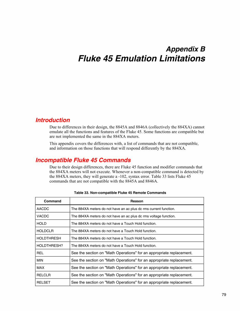
79
Appendix B Fluke 45 Emulation Limitations
Introduction Due to differences in their design, the 8845A and 8846A (collectively the 884XA) cannot emulate all the functions and features of the Fluke 45. Some functions are compatible but are not implemented the same in the 884XA meters. This appendix covers the differences with, a list of commands that are not compatible, and information on those functions that will respond differently by the 884XA.
Incompatible Fluke 45 Commands Due to their design differences, there are Fluke 45 function and modifier commands that the 884XA meters will not execute. Whenever a non-compatible command is detected by the 884XA meters, they will generate a -102, syntax error. Table 33 lists Fluke 45 commands that are not compatible with the 8845A and 8846A.
Table 33. Non-compatible Fluke 45 Remote Commands
Command Reason
AACDC The 884XA meters do not have an ac plus dc rms current function.
VACDC The 884XA meters do not have an ac plus dc rms voltage function.
HOLD The 884XA meters do not have a Touch Hold function.
HOLDCLR The 884XA meters do not have a Touch Hold function.
HOLDTHRESH The 884XA meters do not have a Touch Hold function.
HOLDTHRESH? The 884XA meters do not have a Touch Hold function.
REL See the section on "Math Operations" for an appropriate replacement.
MIN See the section on "Math Operations" for an appropriate replacement.
MAX See the section on "Math Operations" for an appropriate replacement.
RELCLR See the section on "Math Operations" for an appropriate replacement.
RELSET See the section on "Math Operations" for an appropriate replacement.
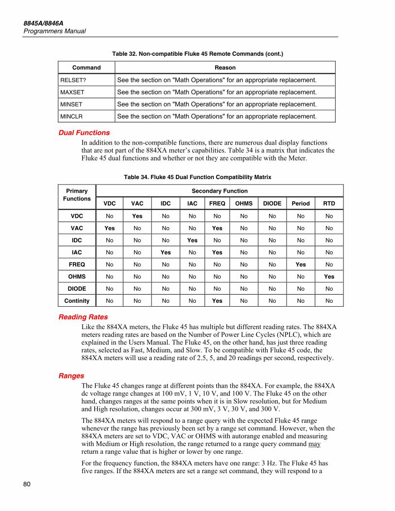
8845A/8846A Programmers Manual
80
Table 32. Non-compatible Fluke 45 Remote Commands (cont.)
Command Reason
RELSET? See the section on "Math Operations" for an appropriate replacement.
MAXSET See the section on "Math Operations" for an appropriate replacement.
MINSET See the section on "Math Operations" for an appropriate replacement.
MINCLR See the section on "Math Operations" for an appropriate replacement.
Dual Functions In addition to the non-compatible functions, there are numerous dual display functions that are not part of the 884XA meter’s capabilities. Table 34 is a matrix that indicates the Fluke 45 dual functions and whether or not they are compatible with the Meter.
Table 34. Fluke 45 Dual Function Compatibility Matrix
Secondary Function Primary Functions
VDC VAC IDC IAC FREQ OHMS DIODE Period RTD
VDC No Yes No No No No No No No
VAC Yes No No No Yes No No No No
IDC No No No Yes No No No No No
IAC No No Yes No Yes No No No No
FREQ No No No No No No No Yes No
OHMS No No No No No No No No Yes
DIODE No No No No No No No No No
Continity No No No No Yes No No No No
Reading Rates Like the 884XA meters, the Fluke 45 has multiple but different reading rates. The 884XA meters reading rates are based on the Number of Power Line Cycles (NPLC), which are explained in the Users Manual. The Fluke 45, on the other hand, has just three reading rates, selected as Fast, Medium, and Slow. To be compatible with Fluke 45 code, the 884XA meters will use a reading rate of 2.5, 5, and 20 readings per second, respectively.
Ranges The Fluke 45 changes range at different points than the 884XA. For example, the 884XA dc voltage range changes at 100 mV, 1 V, 10 V, and 100 V. The Fluke 45 on the other hand, changes ranges at the same points when it is in Slow resolution, but for Medium and High resolution, changes occur at 300 mV, 3 V, 30 V, and 300 V. The 884XA meters will respond to a range query with the expected Fluke 45 range whenever the range has previously been set by a range set command. However, when the 884XA meters are set to VDC, VAC or OHMS with autorange enabled and measuring with Medium or High resolution, the range returned to a range query command may return a range value that is higher or lower by one range. For the frequency function, the 884XA meters have one range: 3 Hz. The Fluke 45 has five ranges. If the 884XA meters are set a range set command, they will respond to a

Digital Multimeter Incompatible Fluke 45 Commands
81
range query with the set range value. If, however, the frequency function is in autorange, the 884XA meters will respond with the value of zero. The Fluke 45 allows range selection in CONTINUITY and DIODE TEST. The 884XA meters have only one range for these functions. Therefore, whenever a RANGE command is detected in the Fluke 45 emulation mode, the 884XA meters will respond with an error.

8845A/8846A Programmers Manual
82

83
Appendix C Network Considerations
Introduction This tutorial provides information on commonly used network communication technology, and describes how to get started using the Meter. It is not necessary to know the details of network communication methods in order to use the Meter effectively. The Meter and host computer software use Ethernet wiring and low level protocols and TCP/IP high level protocols, and the UNIX telnet application interface program. These are all public domain, non-proprietary standards with multiple-company support. Use of these non-proprietary protocols and hardware ensures the Meter and software will operate on most installed networks and have the lowest possible cost using off-the-shelf commercial networking products. Read “Network Primer” later in this Appendix for more information on these standards.
Your Meter and Your Network Administrator Before you place the Meter on your company network, you need to coordinate with your Network Administrator. Specifically, before installing and setting up your Meter and host PC, you need to ask the following questions: 1. Does the network allow static addresses? If so, what values should I use for my IP
addresses, and Subnet Mask? Does the Socket Port Number need to be changed from the default (3490)?
2. Does the network contain more than one subnet? If so, what is the IP address of my default gateway or router device?
3. Will all the routers route IP packets? 4. What are my domain and host names (optional)? The minimum information you need to get is the IP Addresses for each meter. If your network contains more than one subnet and you want to place the host PC and one or more instruments in different subnets, you must also set the default gateway address and subnet mask on the Meter and the host PC. The Meter may use DHCP to get an IP address, subnet mask, and default gateway address automatically on the network.

8845A/8846A Programmers Manual
84
Your Network Administrator may also need to know the Ethernet (MAC) addresses of each Meter that you will attach to the network. You may obtain the address of the Meter by using the front panel controls. Read “Network Primer” for more information on IP addressing and the other information needed to operate the Meter on a local area network (LAN).
Network Primer In the early days of computer networking, vendors used many proprietary communication schemes. These forced users to purchase equipment and software from one or a few companies. As networking became more popular, users placed pressure on vendors to establish standards to allow interoperation of various types of computers, operating system software, and interface hardware. One of these standardization efforts was started by the DARPA agency of the U.S. Defense department. Another was headed up by the DEC and Xerox companies. This effort resulted in the Ethernet wiring and low-level protocol scheme. The DARPA effort resulted in the TCP/IP high-level protocols. Ethernet became an international standard by the efforts of the IEEE-802.3 committee. TCP/IP is the protocol used on the international Internet network, and is supported by consensus of the users of that network (many thousands of hosts). The sockets API was developed at UC Berkeley and was widely adopted by the UNIX community to support direct host-to-host communication within a TCP/IP network. WINSOCK is an MS Windows Dynamic Link Library (DLL) version of the original UNIX Sockets library, and has been standardized by a large number of PC Software and Hardware Vendors. WINSOCK has been included with Windows since the introduction of Windows 95 and Windows NT 4.0. To reduce the complexity of network schemes and to encourage interoperation between varieties of networks, the protocols are built up of several layers that are isolated from each other by well-described interfaces. Usually, the lowest layers of the protocol are implemented in hardware logic on the interface circuits used by the computers and other devices attached to the network wiring. The Ethernet standard consists of a set of low-level addressing and data transmission protocols that run on several different wiring schemes. Computers on a network are commonly referred to as a host. The Meter is a host in this context. Devices that facilitate communication between different sections of a network are called by names that indicate their function, for example, routers, bridges, and repeaters.
Physical Layer Wiring Schemes Supported by the Meter The Meter supports the most common wiring scheme used in Ethernet networks: 10/100BaseT Unshielded Twisted Pair (or UTP). The 10/100BaseT wiring method uses two or four pairs of twisted wires. This wiring method supports only two connections to any one run of wire. To support more than two physical connections, an active instrument called a hub must be used. A hub is an active device that supports multiple 10/100BaseT connections. The network host attached to each connection of the hub may communicate with every other host attached to the hub. Hubs also may allow other types of cable connections, such as 10Base2 and 10Base5 (fat coax). This is done to allow a hub to communicate with other network hosts, such as other hubs, routers, and bridges. A hub is sometimes referred to as a network switch.
Digital Multimeter Network Primer
85
The 10/100BaseT wiring method is very popular because the wire is inexpensive to purchase and install, the use of a hub allows some protection from malfunctioning network hosts, and this type of wiring is easier for network administrators to manage and control.
Network Interconnection Devices The following basic devices are used in networks to extend, partition, and interconnect networks:
• A repeater is a device used to physically isolate and extend the length of a network segment, but it does not divide the network into subnets.
• A hub is a device that allows communication among multiple 10/100BaseT network hosts and allows these hosts to communicate with other Ethernet wiring. Some hubs also perform Router functions.
• A Bridge is used on Ethernet networks to isolate two portions of the network at the Frame level (see “Basic Network Packet and Frame Contents” later in this appendix). This is done to minimize transmission collisions, but the two portions isolated by a Bridge remain on the same subnet. A Bridge also acts as a Repeater.
• A Router is used to isolate two portions of the network into subnets, as described in IP Addresses and Segmented Networks in this appendix. A router also acts as a bridge. Make sure your router will route IP packets if you want to place the PC and the Meter in different subnets.
• A Gateway is used to connect two networks with different architecture and protocols. For example, a Gateway could be used to connect an Ethernet to an X.25 net running on public telephone wiring. Gateways also perform router, bridge, and repeater functions.
The operation of the Meter and its software should be unaffected by a properly designed network using any of these network devices. However, you must use extra care when setting up host PCs and the Meter in a network containing multiple subnets (net containing one or more routers and/or gateways). The IP addresses assigned to the host PC and instruments must be carefully selected in this case. See IP Addresses and Segmented Networks for more information on IP address assignment. When a bridge, router, or gateway is used in a network containing the Meter and hosts, be sure to reboot the host PC whenever an instrument is moved from one segment of the network to another. This is required to allow the network hardware devices to initialize bridging and routing tables. Also, when an 8845/8846 Series instrument is used in a different subnet from the host PC, the routers and gateways used to connect the subnets must be able to route IP packets across the segments. The default gateway addresses on the the Meter and host PC must be set properly as well.
Basic Network Packet and Frame Contents Network messages consist of short (mostly less than 1 KB) chunks of data, surrounded by header and error detection information used by the protocols. The message, together with the protocol information, is called a "packet." When physical network information (clock synchronization, error detection, etc.) is wrapped around the packet, it is called a "frame." The interface hardware adds and strips off the Frame information around the packet as it moves through a network. So, unless you’re doing low level analysis of network traffic, you never need to deal with frame information.

8845A/8846A Programmers Manual
86
For any protocol, the packet consists of a destination address, a source address, some protocol type information, a message length field, and error detection information. The TCP/IP protocol adds additional fields to the packet for message sequence determination and application port ID. The sequence number allows multi-packet messages to be assembled into the correct order. The port ID specifies which application running on a system is sending or receiving the message. Support of port IDs allow multi-tasking within a computer system, with messages being sent and received from the individual task. In the TCP/IP protocol, error detection is supported by adding a checksum of the data in the packet to the end of each packet. Using this checksum, the receiving system can detect a bad packet and request a re-transmit (using the source address). Each host (device attached to the network wiring) in an Ethernet network has a unique address that is assigned by the interface hardware vendor. Each vendor is assigned a block of addresses and it is required that each device produced have a unique Ethernet address. Users of the TCP/IP protocol very rarely need to know or deal with the Ethernet address. When TCP/IP is used, each host is also assigned a unique IP address, but this address is assigned when the TCP/IP protocol software is initialized. In contrast to the Ethernet address, IP addresses have a structure that can be used by Network Management to facilitate breaking the network into segments (subnets) that make better use of the available data communication capacity (bandwidth). Use of IP addressing and the network segmentation scheme is described in “IP Addresses and Segmented Networks” in this appendix. The relationship between a host’s Ethernet address and its IP address is established by the TCP/IP protocol software. No user interaction is needed to establish this relationship. However, some network management systems require that the Ethernet address of each network host be kept in a database. So, it is sometimes necessary to communicate the Ethernet addresses of all devices on the network to the Network Administrator.
IP Addresses and Segmented Networks If all networks consisted of a few computers and other devices attached to each other locally, use of IP addressing and network segmentation schemes would not be necessary. However, networks have evolved past simple work groups into campus-wide, inter-campus, and even international interconnect schemes. This makes it necessary to divide the network into segments know as subnets. The IP address provides two pieces of information: the network ID and the host ID. The network ID must be unique among all network subnets within a connected Internet. It identifies the network subnet to which a host is connected. The host ID must be unique among hosts within a network subnet and identifies the host within the subnet. Network subnets connected to the public Internet must obtain an official network ID from a registrar approved by the Internet Network Information Center (http://www.internic.net/) to preserve the unique network IDs within the Internet. However, if you never intend to connect to the public Internet, you’re free to select your own network IDs. The IP address is a 32-bit numeric address written in four numbers separated by periods. Each of these four numbers can have a value in the range 1 to 254. An IP address is written in the form w.x.y.z. For example, "198.178.246.10" (or "C6.B2.F6.0A" in hexadecimal) is a valid IP address. Table 35 lists the three commonly used classes of IP address assignments.
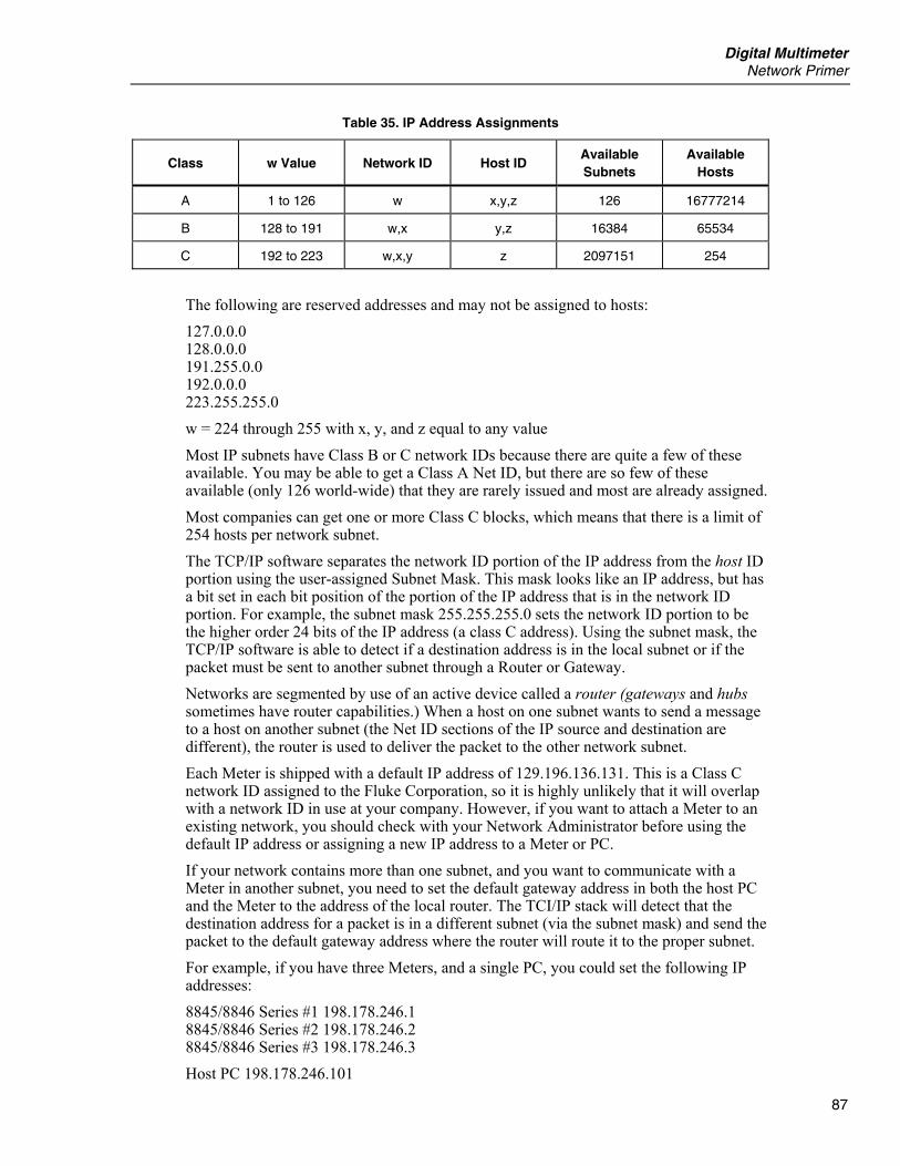
Digital Multimeter Network Primer
87
Table 35. IP Address Assignments
Class w Value Network ID Host ID Available Subnets
Available Hosts
A 1 to 126 w x,y,z 126 16777214
B 128 to 191 w,x y,z 16384 65534
C 192 to 223 w,x,y z 2097151 254
The following are reserved addresses and may not be assigned to hosts: 127.0.0.0 128.0.0.0 191.255.0.0 192.0.0.0 223.255.255.0 w = 224 through 255 with x, y, and z equal to any value Most IP subnets have Class B or C network IDs because there are quite a few of these available. You may be able to get a Class A Net ID, but there are so few of these available (only 126 world-wide) that they are rarely issued and most are already assigned. Most companies can get one or more Class C blocks, which means that there is a limit of 254 hosts per network subnet. The TCP/IP software separates the network ID portion of the IP address from the host ID portion using the user-assigned Subnet Mask. This mask looks like an IP address, but has a bit set in each bit position of the portion of the IP address that is in the network ID portion. For example, the subnet mask 255.255.255.0 sets the network ID portion to be the higher order 24 bits of the IP address (a class C address). Using the subnet mask, the TCP/IP software is able to detect if a destination address is in the local subnet or if the packet must be sent to another subnet through a Router or Gateway. Networks are segmented by use of an active device called a router (gateways and hubs sometimes have router capabilities.) When a host on one subnet wants to send a message to a host on another subnet (the Net ID sections of the IP source and destination are different), the router is used to deliver the packet to the other network subnet. Each Meter is shipped with a default IP address of 129.196.136.131. This is a Class C network ID assigned to the Fluke Corporation, so it is highly unlikely that it will overlap with a network ID in use at your company. However, if you want to attach a Meter to an existing network, you should check with your Network Administrator before using the default IP address or assigning a new IP address to a Meter or PC. If your network contains more than one subnet, and you want to communicate with a Meter in another subnet, you need to set the default gateway address in both the host PC and the Meter to the address of the local router. The TCI/IP stack will detect that the destination address for a packet is in a different subnet (via the subnet mask) and send the packet to the default gateway address where the router will route it to the proper subnet. For example, if you have three Meters, and a single PC, you could set the following IP addresses: 8845/8846 Series #1 198.178.246.1 8845/8846 Series #2 198.178.246.2 8845/8846 Series #3 198.178.246.3 Host PC 198.178.246.101
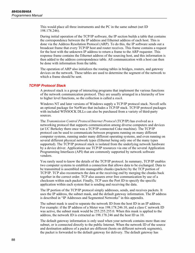
8845A/8846A Programmers Manual
88
This would place all three instruments and the PC in the same subnet (net ID 198.178.246). During initial operation of the TCP/IP software, the IP section builds a table that contains the correspondence between the IP address and Ethernet address of each host. This is done via the Address Resolution Protocol (ARP). To do this, the IP software sends out a broadcast frame that every TCP/IP host and router receives. This frame contains a request for the host with the unknown IP address to return a frame to the ARP requester. This response frame contains the Ethernet address of the sourcing host, and this information is then added to the address correspondence table. All communication with a host can then be done with information from the table. The operation of ARP also initializes the routing tables in bridges, routers, and gateway devices on the network. These tables are used to determine the segment of the network to which a frame should be sent.
TCP/IP Protocol Stack A protocol stack is a group of interacting programs that implement the various functions of the network communication protocol. They are usually arranged in a hierarchy of low to higher level functions, so the collection is called a stack. Windows NT and later versions of Windows supply a TCP/IP protocol stack. Novell sells an optional package for NetWare that includes a TCP/IP stack. TCP/IP protocol packages with included WINSOCK DLLs can also be purchased from a variety of third-party sources. The Transmission Control Protocol/Internet Protocol (TCP/IP) has evolved as a networking protocol that supports communication among diverse computers and devices (at UC Berkeley there once was a TCP/IP-connected Coke machine). The TCP/IP protocol can be used to communicate between programs running on many different computer systems, running under many different operating systems, and even running on several different physical network types (Ethernet being only one of the many types supported). The TCP/IP protocol stack is isolated from the underlying network hardware by a device driver. Applications use TCP/IP resources via one of the several Application Programming Interfaces (API) that are commonly supported by network software vendors. You rarely need to know the details of the TCP/IP protocol. In summary, TCP/IP enables two computer systems to establish a connection that allows data to be exchanged. Data to be transmitted is assembled into manageable chunks (packets) by the TCP portion of TCP/IP. TCP also reconstructs the data at the receiving end by merging the chunks back together in the correct order. TCP also assures error free communication by use of a checksum within each packet. Finally, TCP uses the Port ID to specify the specific application within each system that is sending and receiving the data. The IP portion of the TCP/IP protocol simply addresses, sends, and receives packets. It uses the IP address, the subnet mask, and the default gateway information. The IP address is described in “IP Addresses and Segmented Networks” in this appendix. The subnet mask is used to separate the network ID from the host ID in an IP address. For example: if the IP address of a Meter was 198.178.246.10, and a class C network ID was active, the subnet mask would be 255.255.255.0. When this mask is applied to the address, the network ID is extracted as 198.178.246 and the host ID as 10. The default gateway information is only used when your network contains more than one subnet, or is connected directly to the public Internet. When the network ID of the source and destination address of a packet are different (hosts on different network segments), the packet is forwarded to the default gateway for delivery. The default gateway has
Digital Multimeter Network Primer
89
knowledge of the network IDs of the other network segments, so it forwards the packet to other gateways on the network until the packet is delivered to the gateway attached to the destination segment with the matching network ID. This process is generally referred to as routing the packet, and devices that do this are also referred to as Routers. In many modern networks, the use of subnet masking and the default gateway is not necessary. These networks contain routers and gateways that support the proxy ARP protocol. In this protocol, the routing path between any two hosts is automatically established by the routers during the ARP process. As a result, the user does not need to manually enter the subnet mask and default gateway information. When the TCP/IP protocol stack software starts operation, it communicates with an NDIS or ODI driver in a process called binding. During this process, the stack tells the driver which protocol it is handling. In this way, a driver can direct packets to more than one protocol stack. For example, it is quite common to have the Novell IPX/SPX protocol stack and the TCP/IP protocol stack operating over the same ODI multi-protocol driver.

8845A/8846A Programmers Manual
90
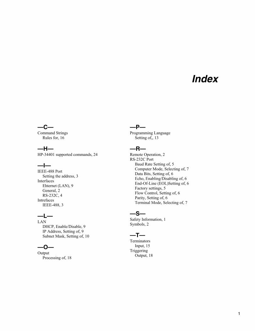
1
Index
—C— Command Strings
Rules for, 16
—H— HP-34401 supported commands, 24
—I— IEEE-488 Port
Setting the address, 3 Interfaces
Ehternet (LAN), 9 General, 2 RS-232C, 4
Intrefaces IEEE-488, 3
—L— LAN
DHCP, Enable/Disable, 9 IP Address, Setting of, 9 Subnet Mask, Setting of, 10
—O— Output
Processing of, 18
—P— Programming Language
Setting of,, 13
—R— Remote Operation, 2 RS-232C Port
Baud Rate Setting of, 5 Computer Mode, Selecting of, 7 Data Bits, Setting of, 6 Echo, Enabling/Disabling of, 6 End-Of-Line (EOL)Setting of, 6 Factory settings, 5 Flow Control, Setting of, 6 Parity, Setting of, 6 Terminal Mode, Selecting of, 7
—S— Safety Information, 1 Symbols, 2
—T— Terminators
Input, 15 Triggering
Output, 18

8845A/8846A Programmers Manual
2