SMISSLINE Index - RS Components
26
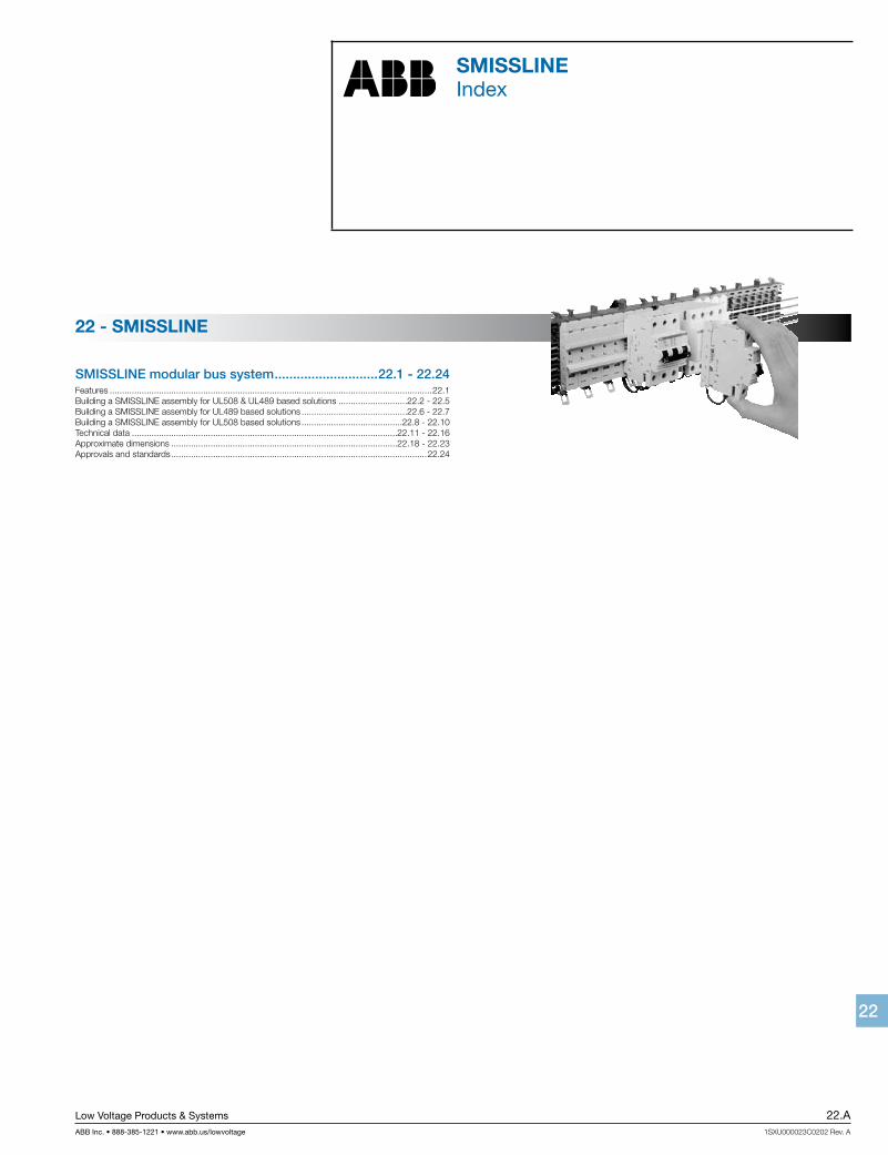
Low Voltage Products & Systems 22.A ABB Inc. • 888-385-1221 • www.abb.us/lowvoltage 1SXU000023C0202 Rev. A SMISSLINE 22 SMISSLINE Index SMISSLINE modular bus system ............................ 22.1 - 22.24 Features ................................................................................................................................... 22.1 Building a SMISSLINE assembly for UL508 & UL489 based solutions ............................22.2 - 22.5 Building a SMISSLINE assembly for UL489 based solutions ...........................................22.6 - 22.7 Building a SMISSLINE assembly for UL508 based solutions .........................................22.8 - 22.10 Technical data ............................................................................................................22.11 - 22.16 Approximate dimensions ............................................................................................22.18 - 22.23 Approvals and standards ........................................................................................................ 22.24 22 - SMISSLINE
-
Upload
khangminh22 -
Category
Documents
-
view
0 -
download
0
Transcript of SMISSLINE Index - RS Components
Low Voltage Products & Systems 22.AABB Inc. • 888-385-1221 • www.abb.us/lowvoltage 1SXU000023C0202 Rev. A
SMISSLINE
2222
SMISSLINEIndex
SMISSLINE modular bus system ............................22.1 - 22.24Features ...................................................................................................................................22.1Building a SMISSLINE assembly for UL508 & UL489 based solutions ............................22.2 - 22.5Building a SMISSLINE assembly for UL489 based solutions ...........................................22.6 - 22.7Building a SMISSLINE assembly for UL508 based solutions .........................................22.8 - 22.10Technical data ............................................................................................................22.11 - 22.16Approximate dimensions ............................................................................................22.18 - 22.23Approvals and standards ........................................................................................................22.24
22 - SMISSLINE

22.B Low Voltage Products & Systems
1SXU000023C0202 Rev. A ABB Inc. • 888-385-1221 • www.abb.us/lowvoltage
SMISSLINE
2222
Notes
SMISSLINE
Low Voltage Products & Systems 22.1ABB Inc. • 888-385-1221 • www.abb.us/lowvoltage 1SXU000023C0202 Rev. A
2222
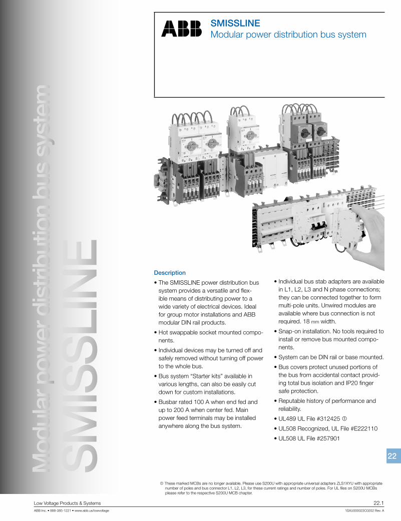
SMISSLINEModular power distribution bus system
Description
• The SMISSLINE power distribution bus system provides a versatile and flex-ible means of distributing power to a wide variety of electrical devices. Ideal for group motor installations and ABB modular DIN rail products.
• Hot swappable socket mounted compo-nents.
• Individual devices may be turned off and safely removed without turning off power to the whole bus.
• Bus system “Starter kits” available in various lengths, can also be easily cut down for custom installations.
• Busbar rated 100 A when end fed and up to 200 A when center fed. Main power feed terminals may be installed anywhere along the bus system.
• Individual bus stab adapters are available in L1, L2, L3 and N phase connections; they can be connected together to form multi-pole units. Unwired modules are available where bus connection is not required. 18 mm width.
• Snap-on installation. No tools required to install or remove bus mounted compo-nents.
• System can be DIN rail or base mounted.
• Bus covers protect unused portions of the bus from accidental contact provid-ing total bus isolation and IP20 finger safe protection.
• Reputable history of performance and reliability.
• UL489 UL File #312425 1
• UL508 Recognized, UL File #E222110
• UL508 UL File #257901
Mod
ular
pow
er d
istri
butio
n bu
s sy
stem
SM
ISS
LIN
E
1 These marked MCBs are no longer available. Please use S200U with appropriate universal adapters ZLS1XYU with appropriate number of poles and bus connector L1, L2, L3, for these current ratings and number of poles. For UL files on S200U MCBs please refer to the respective S200U MCB chapter.
SMISSLINE
22.2 Low Voltage Products & Systems
1SXU000023C0202 Rev. A ABB Inc. • 888-385-1221 • www.abb.us/lowvoltage
2222
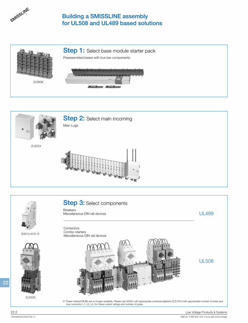
Building a SMISSLINE assemblyfor UL508 and UL489 based solutions
Step 1: Select base module starter packPreassembled bases with bus bar components
ZLS808
ZLS224
S401U-K10 1
ZLS325
Step 2: Select main incomingMain Lugs
Step 3: Select componentsBreakersMiscellaneous DIN rail devices UL489
UL508
ContactorsCombo startersMiscellaneous DIN rail devices
1 These marked MCBs are no longer available. Please use S200U with appropriate universal adapters ZLS1XYU with appropriate number of poles and bus connector L1, L2, L3, for these current ratings and number of poles.
SMISSLINE
Low Voltage Products & Systems 22.3ABB Inc. • 888-385-1221 • www.abb.us/lowvoltage 1SXU000023C0202 Rev. A
2222
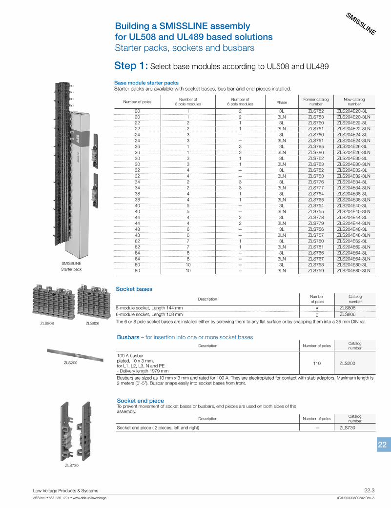
Building a SMISSLINE assemblyfor UL508 and UL489 based solutionsStarter packs, sockets and busbars
SMISSLINE
Starter pack
Step 1: Select base modules according to UL508 and UL489
Base module starter packs Starter packs are available with socket bases, bus bar and end pieces installed.
Number of poles Number of
8 pole modulesNumber of
6 pole modules PhaseFormer catalog
numberNew catalog
number
20 1 2 3L ZLS782 ZLS204E20-3L20 1 2 3LN ZLS783 ZLS204E20-3LN22 2 1 3L ZLS760 ZLS204E22-3L22 2 1 3LN ZLS761 ZLS204E22-3LN24 3 — 3L ZLS750 ZLS204E24-3L24 3 — 3LN ZLS751 ZLS204E24-3LN26 1 3 3L ZLS785 ZLS204E26-3L26 1 3 3LN ZLS786 ZLS204E26-3LN30 3 1 3L ZLS762 ZLS204E30-3L30 3 1 3LN ZLS763 ZLS204E30-3LN32 4 — 3L ZLS752 ZLS204E32-3L32 4 — 3LN ZLS753 ZLS204E32-3LN34 2 3 3L ZLS776 ZLS204E34-3L34 2 3 3LN ZLS777 ZLS204E34-3LN38 4 1 3L ZLS764 ZLS204E38-3L38 4 1 3LN ZLS765 ZLS204E38-3LN40 5 — 3L ZLS754 ZLS204E40-3L40 5 — 3LN ZLS755 ZLS204E40-3LN44 4 2 3L ZLS778 ZLS204E44-3L44 4 2 3LN ZLS779 ZLS204E44-3LN48 6 — 3L ZLS756 ZLS204E48-3L48 6 — 3LN ZLS757 ZLS204E48-3LN62 7 1 3L ZLS780 ZLS204E62-3L62 7 1 3LN ZLS781 ZLS204E62-3LN64 8 — 3L ZLS766 ZLS204E64-3L64 8 — 3LN ZLS767 ZLS204E64-3LN80 10 — 3L ZLS758 ZLS204E80-3L80 10 — 3LN ZLS759 ZLS204E80-3LN
Socket bases
DescriptionNumber of poles
Catalognumber
8-module socket, Length 144 mm 8 ZLS8086-module socket, Length 108 mm 6 ZLS806
The 6 or 8 pole socket bases are installed either by screwing them to any flat surface or by snapping them into a 35 mm DIN rail.
Busbars – for insertion into one or more socket basesDescription Number of poles
Catalognumber
100 A busbar
110 ZLS200 plated, 10 x 3 mm, for L1, L2, L3, N and PE- Delivery length 1979 mm
Busbars are sized as 10 mm x 3 mm and rated for 100 A. They are electroplated for contact with stab adaptors. Maximum length is 2 meters (6’-5”). Busbar snaps easily into socket bases from front.
Socket end pieceTo prevent movement of socket bases or busbars, end pieces are used on both sides of the assembly.
Description Number of polesCatalognumber
Socket end piece ( 2 pieces, left and right) — ZLS730
ZLS200
ZLS730
ZLS808 ZLS806
SMISSLINE
22.4 Low Voltage Products & Systems
1SXU000023C0202 Rev. A ABB Inc. • 888-385-1221 • www.abb.us/lowvoltage
2222
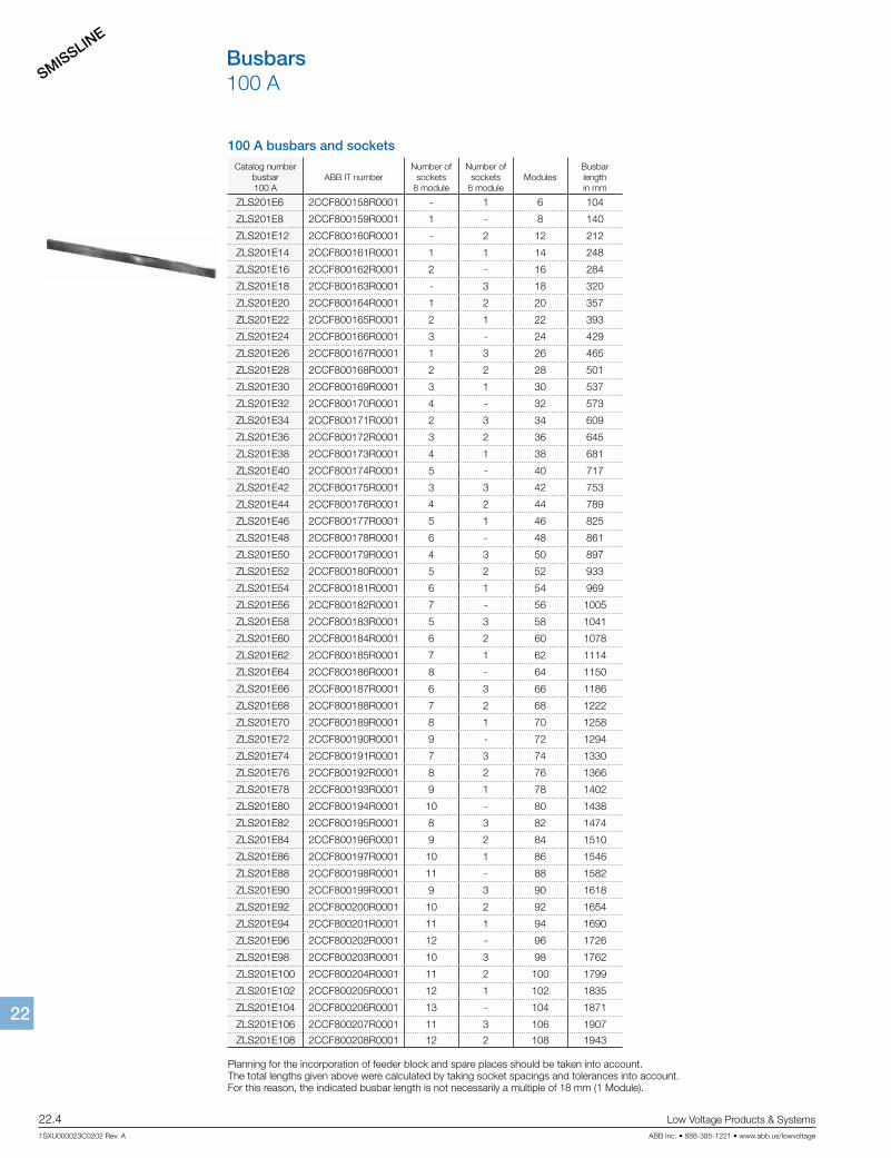
Busbars100 A
100 A busbars and sockets
Catalog numberbusbar 100 A
ABB IT numberNumber of
sockets 8 module
Number of sockets
6 moduleModules
Busbar length in mm
ZLS201E6 2CCF800158R0001 - 1 6 104
ZLS201E8 2CCF800159R0001 1 - 8 140
ZLS201E12 2CCF800160R0001 - 2 12 212
ZLS201E14 2CCF800161R0001 1 1 14 248
ZLS201E16 2CCF800162R0001 2 - 16 284
ZLS201E18 2CCF800163R0001 - 3 18 320
ZLS201E20 2CCF800164R0001 1 2 20 357
ZLS201E22 2CCF800165R0001 2 1 22 393
ZLS201E24 2CCF800166R0001 3 - 24 429
ZLS201E26 2CCF800167R0001 1 3 26 465
ZLS201E28 2CCF800168R0001 2 2 28 501
ZLS201E30 2CCF800169R0001 3 1 30 537
ZLS201E32 2CCF800170R0001 4 - 32 573
ZLS201E34 2CCF800171R0001 2 3 34 609
ZLS201E36 2CCF800172R0001 3 2 36 645
ZLS201E38 2CCF800173R0001 4 1 38 681
ZLS201E40 2CCF800174R0001 5 - 40 717
ZLS201E42 2CCF800175R0001 3 3 42 753
ZLS201E44 2CCF800176R0001 4 2 44 789
ZLS201E46 2CCF800177R0001 5 1 46 825
ZLS201E48 2CCF800178R0001 6 - 48 861
ZLS201E50 2CCF800179R0001 4 3 50 897
ZLS201E52 2CCF800180R0001 5 2 52 933
ZLS201E54 2CCF800181R0001 6 1 54 969
ZLS201E56 2CCF800182R0001 7 - 56 1005
ZLS201E58 2CCF800183R0001 5 3 58 1041
ZLS201E60 2CCF800184R0001 6 2 60 1078
ZLS201E62 2CCF800185R0001 7 1 62 1114
ZLS201E64 2CCF800186R0001 8 - 64 1150
ZLS201E66 2CCF800187R0001 6 3 66 1186
ZLS201E68 2CCF800188R0001 7 2 68 1222
ZLS201E70 2CCF800189R0001 8 1 70 1258
ZLS201E72 2CCF800190R0001 9 - 72 1294
ZLS201E74 2CCF800191R0001 7 3 74 1330
ZLS201E76 2CCF800192R0001 8 2 76 1366
ZLS201E78 2CCF800193R0001 9 1 78 1402
ZLS201E80 2CCF800194R0001 10 - 80 1438
ZLS201E82 2CCF800195R0001 8 3 82 1474
ZLS201E84 2CCF800196R0001 9 2 84 1510
ZLS201E86 2CCF800197R0001 10 1 86 1546
ZLS201E88 2CCF800198R0001 11 - 88 1582
ZLS201E90 2CCF800199R0001 9 3 90 1618
ZLS201E92 2CCF800200R0001 10 2 92 1654
ZLS201E94 2CCF800201R0001 11 1 94 1690
ZLS201E96 2CCF800202R0001 12 - 96 1726
ZLS201E98 2CCF800203R0001 10 3 98 1762
ZLS201E100 2CCF800204R0001 11 2 100 1799
ZLS201E102 2CCF800205R0001 12 1 102 1835
ZLS201E104 2CCF800206R0001 13 - 104 1871
ZLS201E106 2CCF800207R0001 11 3 106 1907
ZLS201E108 2CCF800208R0001 12 2 108 1943
Planning for the incorporation of feeder block and spare places should be taken into account.The total lengths given above were calculated by taking socket spacings and tolerances into account.For this reason, the indicated busbar length is not necessarily a multiple of 18 mm (1 Module).
SMISSLINE
Low Voltage Products & Systems 22.5ABB Inc. • 888-385-1221 • www.abb.us/lowvoltage 1SXU000023C0202 Rev. A
2222
Building a SMISSLINE assemblyfor UL508 and UL489 based solutions
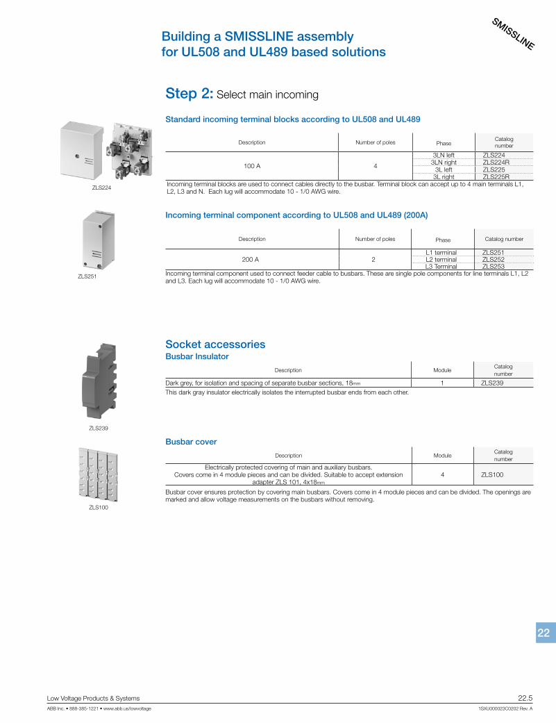
Step 2: Select main incoming
Standard incoming terminal blocks according to UL508 and UL489
Description Number of poles PhaseCatalognumber
100 A 4
3LN left ZLS2243LN right ZLS224R
3L left ZLS2253L right ZLS225R
Incoming terminal blocks are used to connect cables directly to the busbar. Terminal block can accept up to 4 main terminals L1, L2, L3 and N. Each lug will accommodate 10 - 1/0 AWG wire.
Incoming terminal component according to UL508 and UL489 (200A)
Description Number of poles Phase Catalog number
200 A 2L1 terminal ZLS251L2 terminal ZLS252L3 Terminal ZLS253
Incoming terminal component used to connect feeder cable to busbars. These are single pole components for line terminals L1, L2 and L3. Each lug will accommodate 10 - 1/0 AWG wire.
ZLS224
ZLS251
Socket accessoriesBusbar Insulator
Description ModuleCatalognumber
Dark grey, for isolation and spacing of separate busbar sections, 18mm 1 ZLS239This dark gray insulator electrically isolates the interrupted busbar ends from each other.
Busbar cover
Description ModuleCatalognumber
Electrically protected covering of main and auxiliary busbars. Covers come in 4 module pieces and can be divided. Suitable to accept extension
adapter ZLS 101, 4x18mm
4 ZLS100
Busbar cover ensures protection by covering main busbars. Covers come in 4 module pieces and can be divided. The openings are marked and allow voltage measurements on the busbars without removing.
ZLS239
ZLS100
SMISSLINE
22.6 Low Voltage Products & Systems
1SXU000023C0202 Rev. A ABB Inc. • 888-385-1221 • www.abb.us/lowvoltage
2222
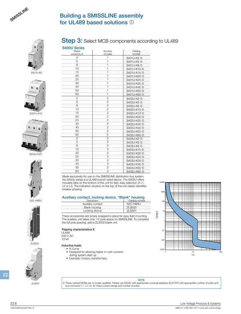
Building a SMISSLINE assemblyfor UL489 based solutions 1
S400U SeriesRated
current IN ANumber of poles
Catalog number
2 1 S401U-K2 15 1 S401U-K5 18 1 S401U-K8 110 1 S401U-K10 115 1 S401U-K15 120 1 S401U-K20 125 1 S401U-K25 130 1 S401U-K30 140 1 S401U-K40 150 1 S401U-K50 160 1 S401U-K60 12 2 S402U-K2 15 2 S402U-K5 18 2 S402U-K8 110 2 S402U-K10 115 2 S402U-K15 120 2 S402U-K20 125 2 S402U-K25 130 2 S402U-K30 140 2 S402U-K40 150 2 S402U-K50 160 2 S402U-K60 12 3 S403U-K2 15 3 S403U-K5 18 3 S403U-K8 110 3 S403U-K10 120 3 S403U-K20 125 3 S403U-K25 130 3 S403U-K30 140 3 S403U-K40 150 3 S403U-K50 160 3 S403U-K60 1
Made exclusively for use on the SMISSLINE distribution bus system, the S400U series is a UL489 branch rated device. The S400U offers movable tabs on the bottom of the unit for fast, easy selection of L1, L2 or L3. The indication window on the top of the unit clearly identifies breaker phasing.
ZLS501
S401U-K5
S401U-K10
S403U-K20
S2C-H6RU
ZLS502
I/In
t [ s
ec ]
10 000
1000
100
10
1
0,1
0,01
0,0011 10 100
Tripping characteristics KUL489240 V AC10 kA
Inductive loads • K Curve • Designed for allowing higher in-rush currents during system start up • Example: motors, transformers
Auxiliary contact, locking device, “Blank” housingDescription Catalog number
Auxiliary contact S2C-H6RUBlank housing ZLS502Locking device ZLS501
These accessories are simply snapped in place for easy field mounting. The auxiliary unit takes only 1/2 pole space on SMISSLINE. To complete the full pole spacing, add a ZLS502 blank unit.
Step 3: Select MCB components according to UL489
NOTE 1 These marked MCBs are no longer available. Please use S200U with appropriate universal adapters ZLS1XYU with appropriate number of poles and
bus connector L1, L2, L3, for these current ratings and number of poles.
SMISSLINE
Low Voltage Products & Systems 22.7ABB Inc. • 888-385-1221 • www.abb.us/lowvoltage 1SXU000023C0202 Rev. A
2222
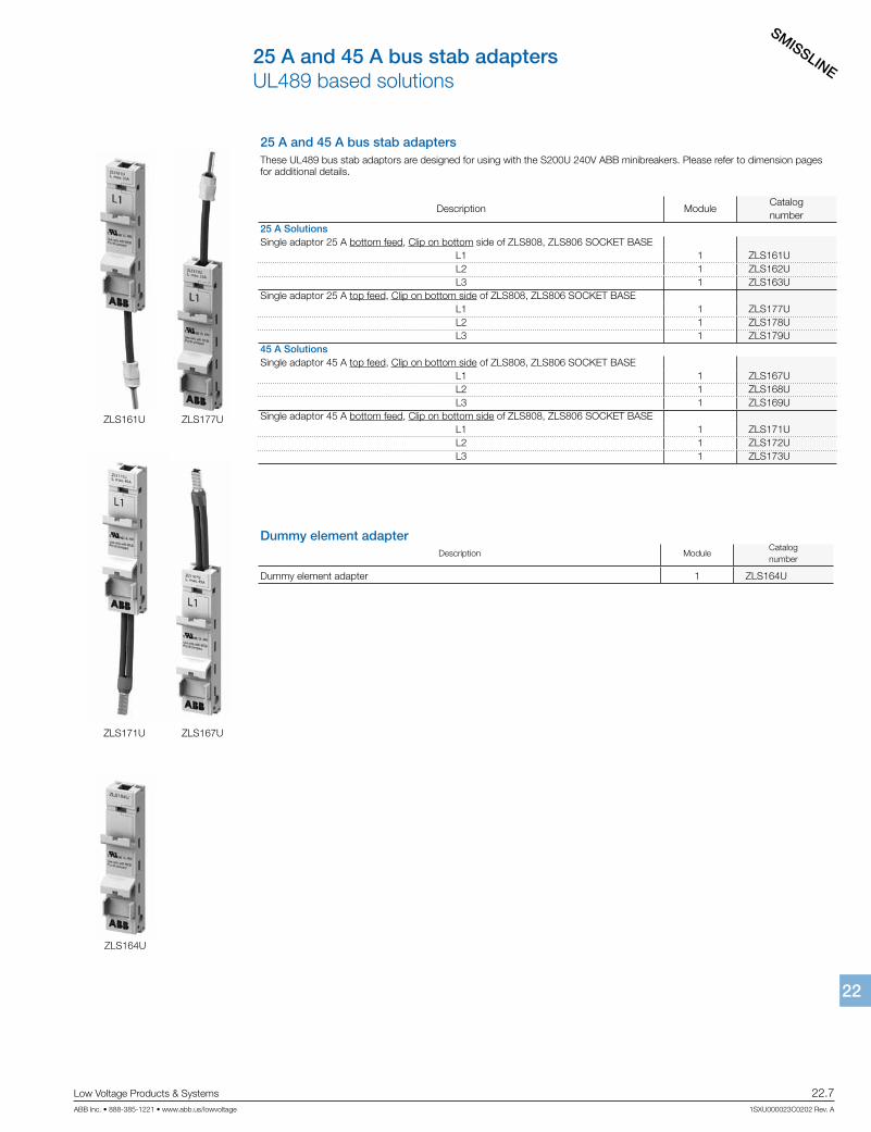
25 A and 45 A bus stab adapters UL489 based solutions
25 A and 45 A bus stab adaptersThese UL489 bus stab adaptors are designed for using with the S200U 240V ABB minibreakers. Please refer to dimension pages for additional details.
Description ModuleCatalognumber
25 A SolutionsSingle adaptor 25 A bottom feed, Clip on bottom side of ZLS808, ZLS806 SOCKET BASE
L1 1 ZLS161UL2 1 ZLS162UL3 1 ZLS163U
Single adaptor 25 A top feed, Clip on bottom side of ZLS808, ZLS806 SOCKET BASEL1 1 ZLS177UL2 1 ZLS178UL3 1 ZLS179U
45 A SolutionsSingle adaptor 45 A top feed, Clip on bottom side of ZLS808, ZLS806 SOCKET BASE
L1 1 ZLS167UL2 1 ZLS168UL3 1 ZLS169U
Single adaptor 45 A bottom feed, Clip on bottom side of ZLS808, ZLS806 SOCKET BASEL1 1 ZLS171UL2 1 ZLS172UL3 1 ZLS173U
ZLS161U ZLS177U
ZLS171U ZLS167U
Dummy element adapterDescription Module
Catalognumber
Dummy element adapter 1 ZLS164U
ZLS164U
SMISSLINE
22.8 Low Voltage Products & Systems
1SXU000023C0202 Rev. A ABB Inc. • 888-385-1221 • www.abb.us/lowvoltage
2222
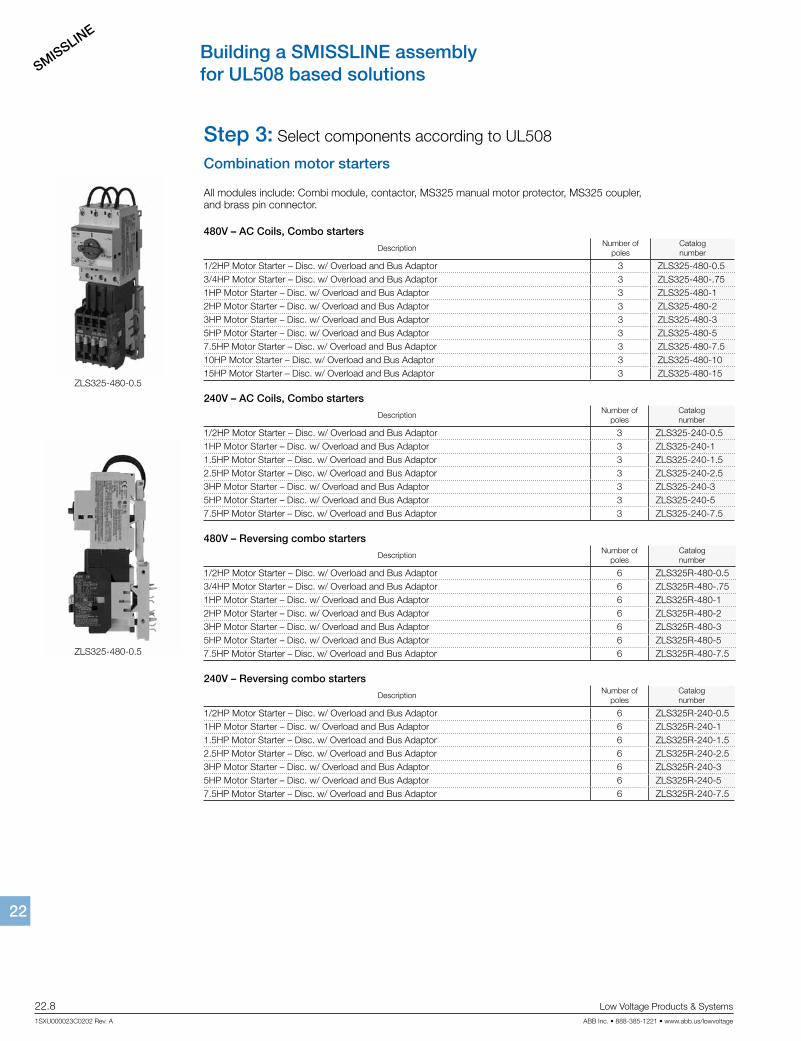
Building a SMISSLINE assemblyfor UL508 based solutions
Combination motor starters
All modules include: Combi module, contactor, MS325 manual motor protector, MS325 coupler, and brass pin connector.
480V – AC Coils, Combo starters
DescriptionNumber of
polesCatalognumber
1/2HP Motor Starter – Disc. w/ Overload and Bus Adaptor 3 ZLS325-480-0.53/4HP Motor Starter – Disc. w/ Overload and Bus Adaptor 3 ZLS325-480-.751HP Motor Starter – Disc. w/ Overload and Bus Adaptor 3 ZLS325-480-12HP Motor Starter – Disc. w/ Overload and Bus Adaptor 3 ZLS325-480-23HP Motor Starter – Disc. w/ Overload and Bus Adaptor 3 ZLS325-480-35HP Motor Starter – Disc. w/ Overload and Bus Adaptor 3 ZLS325-480-57.5HP Motor Starter – Disc. w/ Overload and Bus Adaptor 3 ZLS325-480-7.510HP Motor Starter – Disc. w/ Overload and Bus Adaptor 3 ZLS325-480-1015HP Motor Starter – Disc. w/ Overload and Bus Adaptor 3 ZLS325-480-15
240V – AC Coils, Combo starters
DescriptionNumber of
polesCatalognumber
1/2HP Motor Starter – Disc. w/ Overload and Bus Adaptor 3 ZLS325-240-0.51HP Motor Starter – Disc. w/ Overload and Bus Adaptor 3 ZLS325-240-11.5HP Motor Starter – Disc. w/ Overload and Bus Adaptor 3 ZLS325-240-1.52.5HP Motor Starter – Disc. w/ Overload and Bus Adaptor 3 ZLS325-240-2.53HP Motor Starter – Disc. w/ Overload and Bus Adaptor 3 ZLS325-240-35HP Motor Starter – Disc. w/ Overload and Bus Adaptor 3 ZLS325-240-57.5HP Motor Starter – Disc. w/ Overload and Bus Adaptor 3 ZLS325-240-7.5
480V – Reversing combo starters
DescriptionNumber of
polesCatalognumber
1/2HP Motor Starter – Disc. w/ Overload and Bus Adaptor 6 ZLS325R-480-0.53/4HP Motor Starter – Disc. w/ Overload and Bus Adaptor 6 ZLS325R-480-.751HP Motor Starter – Disc. w/ Overload and Bus Adaptor 6 ZLS325R-480-12HP Motor Starter – Disc. w/ Overload and Bus Adaptor 6 ZLS325R-480-23HP Motor Starter – Disc. w/ Overload and Bus Adaptor 6 ZLS325R-480-35HP Motor Starter – Disc. w/ Overload and Bus Adaptor 6 ZLS325R-480-57.5HP Motor Starter – Disc. w/ Overload and Bus Adaptor 6 ZLS325R-480-7.5
240V – Reversing combo starters
DescriptionNumber of
polesCatalognumber
1/2HP Motor Starter – Disc. w/ Overload and Bus Adaptor 6 ZLS325R-240-0.51HP Motor Starter – Disc. w/ Overload and Bus Adaptor 6 ZLS325R-240-11.5HP Motor Starter – Disc. w/ Overload and Bus Adaptor 6 ZLS325R-240-1.52.5HP Motor Starter – Disc. w/ Overload and Bus Adaptor 6 ZLS325R-240-2.53HP Motor Starter – Disc. w/ Overload and Bus Adaptor 6 ZLS325R-240-35HP Motor Starter – Disc. w/ Overload and Bus Adaptor 6 ZLS325R-240-57.5HP Motor Starter – Disc. w/ Overload and Bus Adaptor 6 ZLS325R-240-7.5
Step 3: Select components according to UL508
ZLS325-480-0.5
ZLS325-480-0.5
SMISSLINE
Low Voltage Products & Systems 22.9ABB Inc. • 888-385-1221 • www.abb.us/lowvoltage 1SXU000023C0202 Rev. A
2222
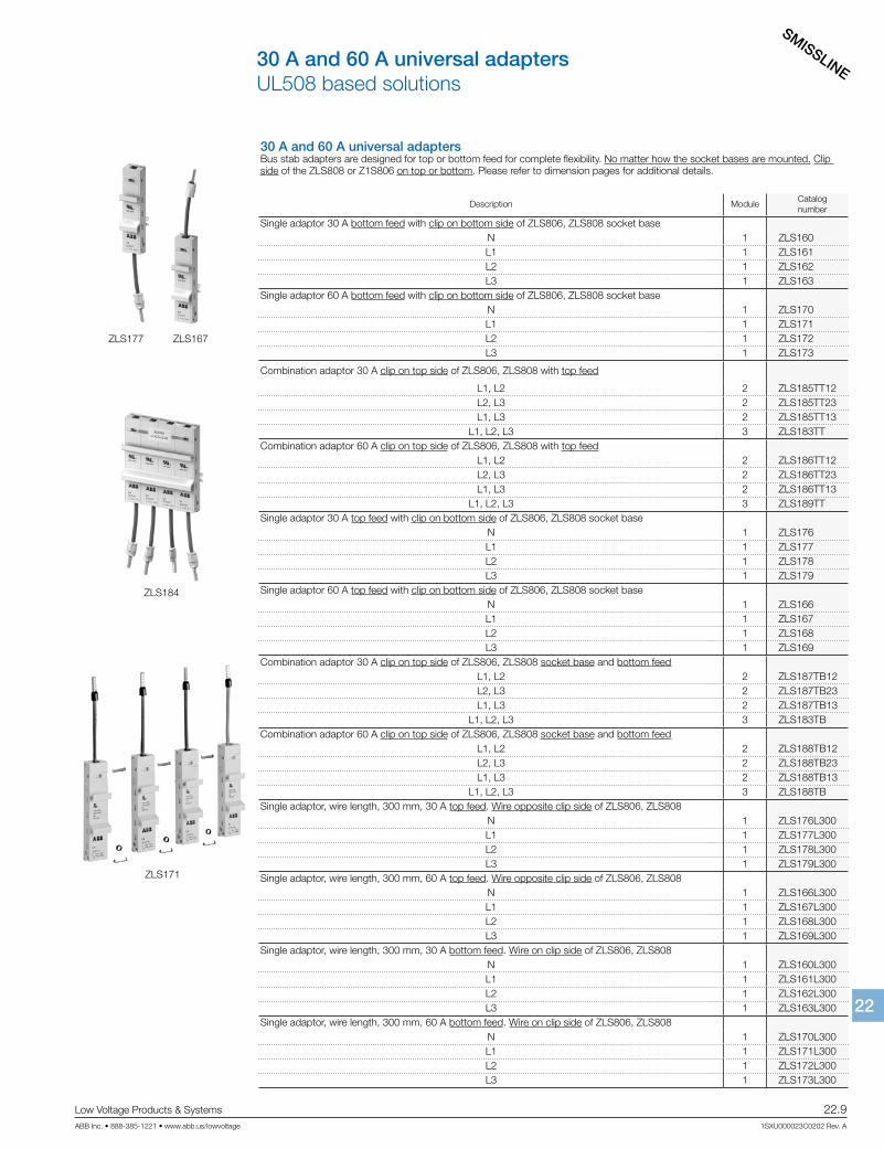
30 A and 60 A universal adapters UL508 based solutions
30 A and 60 A universal adaptersBus stab adapters are designed for top or bottom feed for complete flexibility. No matter how the socket bases are mounted. Clip side of the ZLS808 or Z1S806 on top or bottom. Please refer to dimension pages for additional details.
Description ModuleCatalognumber
Single adaptor 30 A bottom feed with clip on bottom side of ZLS806, ZLS808 socket base N 1 ZLS160L1 1 ZLS161L2 1 ZLS162L3 1 ZLS163
Single adaptor 60 A bottom feed with clip on bottom side of ZLS806, ZLS808 socket baseN 1 ZLS170L1 1 ZLS171L2 1 ZLS172L3 1 ZLS173
Combination adaptor 30 A clip on top side of ZLS806, ZLS808 with top feed
L1, L2 2 ZLS185TT12L2, L3 2 ZLS185TT23L1, L3 2 ZLS185TT13
L1, L2, L3 3 ZLS183TTCombination adaptor 60 A clip on top side of ZLS806, ZLS808 with top feed
L1, L2 2 ZLS186TT12L2, L3 2 ZLS186TT23L1, L3 2 ZLS186TT13
L1, L2, L3 3 ZLS189TTSingle adaptor 30 A top feed with clip on bottom side of ZLS806, ZLS808 socket base
N 1 ZLS176L1 1 ZLS177L2 1 ZLS178L3 1 ZLS179
Single adaptor 60 A top feed with clip on bottom side of ZLS806, ZLS808 socket baseN 1 ZLS166L1 1 ZLS167L2 1 ZLS168L3 1 ZLS169
Combination adaptor 30 A clip on top side of ZLS806, ZLS808 socket base and bottom feedL1, L2 2 ZLS187TB12L2, L3 2 ZLS187TB23L1, L3 2 ZLS187TB13
L1, L2, L3 3 ZLS183TBCombination adaptor 60 A clip on top side of ZLS806, ZLS808 socket base and bottom feed
L1, L2 2 ZLS188TB12L2, L3 2 ZLS188TB23L1, L3 2 ZLS188TB13
L1, L2, L3 3 ZLS188TBSingle adaptor, wire length, 300 mm, 30 A top feed. Wire opposite clip side of ZLS806, ZLS808
N 1 ZLS176L300L1 1 ZLS177L300L2 1 ZLS178L300L3 1 ZLS179L300
Single adaptor, wire length, 300 mm, 60 A top feed. Wire opposite clip side of ZLS806, ZLS808N 1 ZLS166L300L1 1 ZLS167L300L2 1 ZLS168L300L3 1 ZLS169L300
Single adaptor, wire length, 300 mm, 30 A bottom feed. Wire on clip side of ZLS806, ZLS808N 1 ZLS160L300L1 1 ZLS161L300L2 1 ZLS162L300L3 1 ZLS163L300
Single adaptor, wire length, 300 mm, 60 A bottom feed. Wire on clip side of ZLS806, ZLS808N 1 ZLS170L300L1 1 ZLS171L300L2 1 ZLS172L300L3 1 ZLS173L300
ZLS177 ZLS167
ZLS184
ZLS171
SMISSLINE
22.10 Low Voltage Products & Systems
1SXU000023C0202 Rev. A ABB Inc. • 888-385-1221 • www.abb.us/lowvoltage
2222
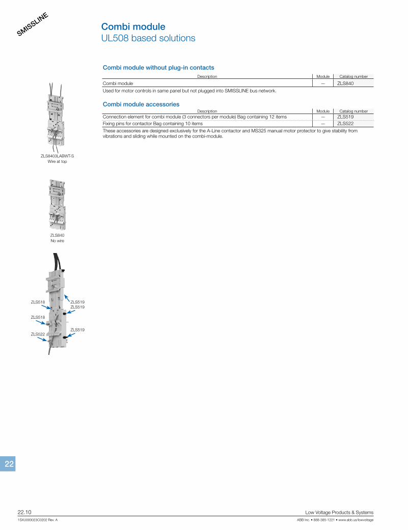
Combi module UL508 based solutions
Combi module without plug-in contactsDescription Module Catalog number
Combi module — ZLS840
Used for motor controls in same panel but not plugged into SMISSLINE bus network.
Combi module accessoriesDescription Module Catalog number
Connection element for combi module (3 connectors per module) Bag containing 12 items — ZLS519Fixing pins for contactor Bag containing 10 items — ZLS522
These accessories are designed exclusively for the A-Line contactor and MS325 manual motor protector to give stability from vibrations and sliding while mounted on the combi-module.
ZLS8403LABWT-SWire at top
ZLS840No wire
ZLS518
ZLS522
ZLS519
ZLS519
ZLS519
ZLS518
SMISSLINE
Low Voltage Products & Systems 22.11ABB Inc. • 888-385-1221 • www.abb.us/lowvoltage 1SXU000023C0202 Rev. A
2222
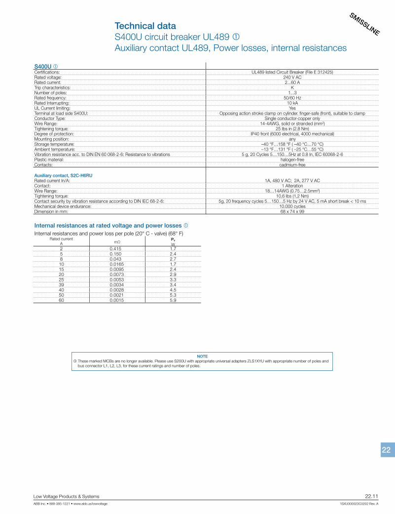
Technical dataS400U circuit breaker UL489 1 Auxiliary contact UL489, Power losses, internal resistances
S400U 1Certifications: UL489 listed Circuit Breaker (File E 312425) Rated voltage: 240 V ACRated current: 2...60 ATrip characteristics: KNumber of poles: 1...3Rated frequency: 50/60 HzRated Interrupting: 10 kAUL Current limiting: YesTerminal at load side S400U: Opposing action stroke clamp on cylinder. finger-safe (front), suitable to clampConductor Type: Single conductor-copper onlyWire Range: 14-4AWG, solid or stranded (mm2)Tightening torque: 25 Ibs in (2.8 Nm)Degree of protection: IP40 front (6000 electrical, 4000 mechanical)Mounting position: anyStorage temperature: –40 °F…158 °F ( –40 °C…70 °C)Ambient temperature: –13 °F…131 °F ( –25 °C…55 °C)Vibration resistance acc. to DIN EN 60 068-2-6: Resistance to vibrations 5 g, 20 Cycles 5…150…5Hz at 0.8 In, IEC 60068-2-6Plastic material: halogen-freeContacts: cadmium-free
Auxiliary contact, S2C-H6RURated current In/A: 1A, 480 V AC; 2A, 277 V ACContact: 1 AlterationWire Range: 18…14AWG (0.75…2.5mm2)Tightening torque: 10,6 Ibs (1,2 Nm)Contact security by vibration resistance according to DIN IEC 68-2-6: 5g, 20 frequency cycles 5…150…5 Hz by 24 V AC, 5 mA short break < 10 msMechanical device endurance: 10.000 cyclesDimension in mm: 68 x 74 x 99
Internal resistances at rated voltage and power losses 1Internal resistances and power loss per pole (20° C - valve) (68° F)
Rated currentA mΩ
Pv
W2 0.415 1.75 0.150 2.48 0.043 2.710 0.0165 1.715 0.0095 2.420 0.0073 2.925 0.0053 3.339 0.0034 3.440 0.0028 4.550 0.0021 5.360 0.0015 5.9
NOTE 1 These marked MCBs are no longer available. Please use S200U with appropriate universal adapters ZLS1XYU with appropriate number of poles and
bus connector L1, L2, L3, for these current ratings and number of poles.

SMISSLINE
22.12 Low Voltage Products & Systems
1SXU000023C0202 Rev. A ABB Inc. • 888-385-1221 • www.abb.us/lowvoltage
2222
Technical dataS400U circuit breaker UL489 1Let through energies I2t
0.50.1 1 5 10 30100
1000
10 000
100 000
Prospective short-circuit current Icc [kA]
5A
2A
Let-
thro
ugh
ener
gy [A
2 s]
20A
10A
15A
50/60A40A25A
8A
S400U characteristics at 240 V AC 1
S400U-K Maximum Ipeak and I2 t Values 1
TypeAmpere
Ratings (A)Voltage (V) Frequency (Hz) Phase Current (A)
Maximum ValuesIpeak (kA) I2 t (kA2s)
S401U-K 0.2–15 240 60 1 4095 2.5 8S401U-K 0.2–15 240 60 1 7500 3.5 20S401U-K 0.2–15 240 60 1 10 000 6 40S401U-K 16 – 30 240 60 1 4095 4 35S401U-K 16 – 30 240 60 1 7500 5 45S401U-K 16 – 30 240 60 1 10 000 6.8 80S401U-K 40 – 60 240 60 1 4095 4.6 56S401U-K 40 – 60 240 60 1 7500 6.8 75S401U-K 40 – 60 240 60 1 10 000 7.5 90S403U-K 0.2–15 240 60 3 4095 2.3 6S403U-K 0.2–15 240 60 3 7500 2.8 10S403U-K 0.2–15 240 60 3 10 000 5.5 30S403U-K 16 – 30 240 60 3 4095 3.3 15S403U-K 16 – 30 240 60 3 7500 4 22S403U-K 16 – 30 240 60 3 10 000 6 35S403U-K 40 – 60 240 60 3 4095 4.4 35S403U-K 40 – 60 240 60 3 7500 6.6 56S403U-K 40 – 60 240 60 3 10 000 7 60
Threshold Current Rating: 4095 AIntermediate Current Rating: 7500 AMaximum Interrupting Current Rating: 10 000 A
NOTE 1 These marked MCBs are no longer available. Please use S200U with appropriate universal adapters ZLS1XYU with appropriate number of poles and
bus connector L1, L2, L3, for these current ratings and number of poles.
SMISSLINE
Low Voltage Products & Systems 22.13ABB Inc. • 888-385-1221 • www.abb.us/lowvoltage 1SXU000023C0202 Rev. A
2222
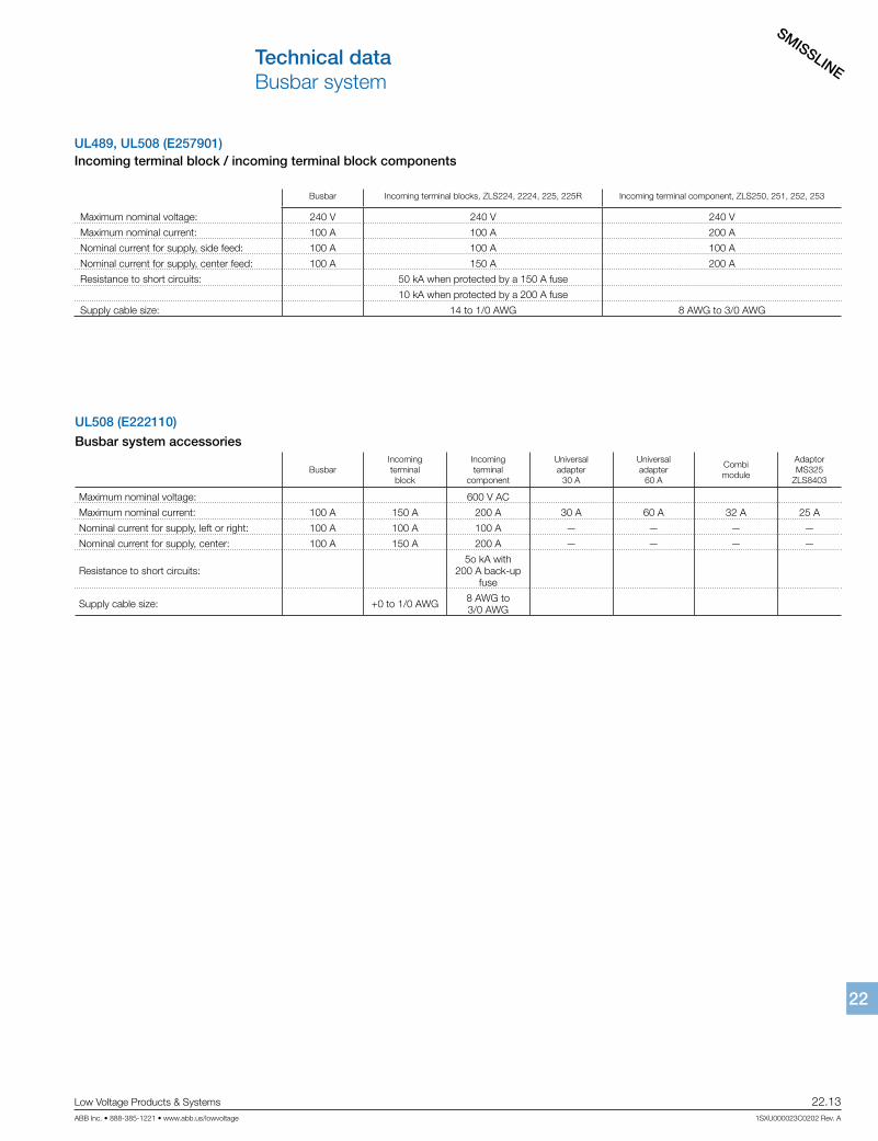
Technical data Busbar system
UL489, UL508 (E257901)Incoming terminal block / incoming terminal block components
Busbar Incoming terminal blocks, ZLS224, 2224, 225, 225R Incoming terminal component, ZLS250, 251, 252, 253
Maximum nominal voltage: 240 V 240 V 240 V
Maximum nominal current: 100 A 100 A 200 A
Nominal current for supply, side feed: 100 A 100 A 100 A
Nominal current for supply, center feed: 100 A 150 A 200 A
Resistance to short circuits: 50 kA when protected by a 150 A fuse
10 kA when protected by a 200 A fuse
Supply cable size: 14 to 1/0 AWG 8 AWG to 3/0 AWG
UL508 (E222110)
Busbar system accessories
BusbarIncomingterminalblock
Incomingterminal
component
Universaladapter
30 A
Universaladapter
60 A
Combimodule
AdaptorMS325
ZLS8403
Maximum nominal voltage: 600 V AC
Maximum nominal current: 100 A 150 A 200 A 30 A 60 A 32 A 25 A
Nominal current for supply, left or right: 100 A 100 A 100 A — — — —
Nominal current for supply, center: 100 A 150 A 200 A — — — —
Resistance to short circuits: 5o kA with
200 A back-up fuse
Supply cable size: +0 to 1/0 AWG 8 AWG to 3/0 AWG
SMISSLINE
22.14 Low Voltage Products & Systems
1SXU000023C0202 Rev. A ABB Inc. • 888-385-1221 • www.abb.us/lowvoltage
2222
I/In
t [ s
ec ]
10 000
1000
100
10
1
0,1
0,01
0,0011 10 100
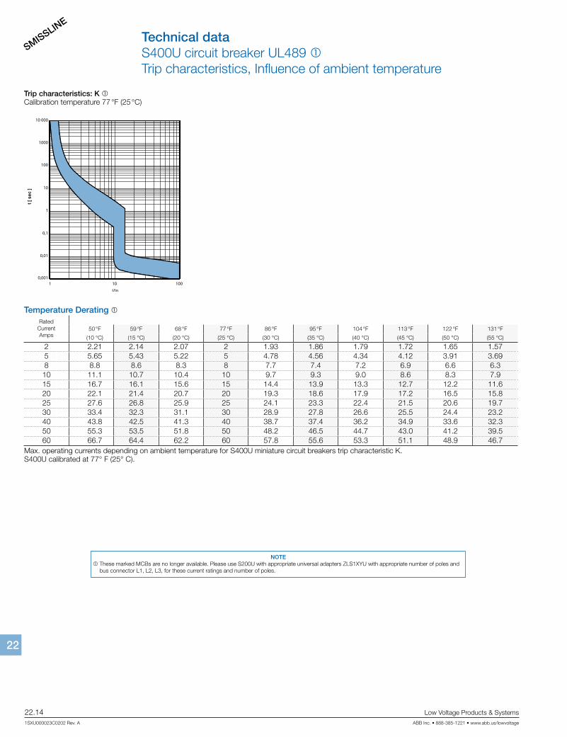
Trip characteristics: K 1Calibration temperature 77 °F (25 °C)
Temperature Derating 1Rated
CurrentAmps
50 °F 59 °F 68 °F 77 °F 86 °F 95 °F 104 °F 113 °F 122 °F 131 °F
(10 °C) (15 °C) (20 °C) (25 °C) (30 °C) (35 °C) (40 °C) (45 °C) (50 °C) (55 °C)
2 2.21 2.14 2.07 2 1.93 1.86 1.79 1.72 1.65 1.575 5.65 5.43 5.22 5 4.78 4.56 4.34 4.12 3.91 3.698 8.8 8.6 8.3 8 7.7 7.4 7.2 6.9 6.6 6.310 11.1 10.7 10.4 10 9.7 9.3 9.0 8.6 8.3 7.915 16.7 16.1 15.6 15 14.4 13.9 13.3 12.7 12.2 11.620 22.1 21.4 20.7 20 19.3 18.6 17.9 17.2 16.5 15.825 27.6 26.8 25.9 25 24.1 23.3 22.4 21.5 20.6 19.730 33.4 32.3 31.1 30 28.9 27.8 26.6 25.5 24.4 23.240 43.8 42.5 41.3 40 38.7 37.4 36.2 34.9 33.6 32.350 55.3 53.5 51.8 50 48.2 46.5 44.7 43.0 41.2 39.560 66.7 64.4 62.2 60 57.8 55.6 53.3 51.1 48.9 46.7
Max. operating currents depending on ambient temperature for S400U miniature circuit breakers trip characteristic K.S400U calibrated at 77° F (25° C).
Technical dataS400U circuit breaker UL489 1Trip characteristics, Influence of ambient temperature
NOTE 1 These marked MCBs are no longer available. Please use S200U with appropriate universal adapters ZLS1XYU with appropriate number of poles and
bus connector L1, L2, L3, for these current ratings and number of poles.
SMISSLINE
Low Voltage Products & Systems 22.15ABB Inc. • 888-385-1221 • www.abb.us/lowvoltage 1SXU000023C0202 Rev. A
2222
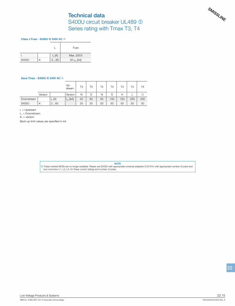
Class J Fuse - S400U @ 240V AC 1
L. Fuse
I. ln [A] Max. 200 S
S400U K 2…60 50 lcu [kA]
Sace Tmax - S400U @ 240V AC 1
Up-stream T3 T3 T4 T4 T4 T4 T4
Version Version N S N S H L U
Downstream ln [A] lcu [kA] 50 65 65 100 150 200 200
S400U K 2…60 25 25 50 50 50 50 50
Technical dataS400U circuit breaker UL489 1Series rating with Tmax T3, T4
I. = UpstreamL. = DownstreamA. = version
Back-up limit values are specified in kA
NOTE 1 These marked MCBs are no longer available. Please use S200U with appropriate universal adapters ZLS1XYU with appropriate number of poles and
bus connector L1, L2, L3, for these current ratings and number of poles.

SMISSLINE
22.16 Low Voltage Products & Systems
1SXU000023C0202 Rev. A ABB Inc. • 888-385-1221 • www.abb.us/lowvoltage
2222
Technical dataMiniature circuit breaker S400U 1Selectivity to Sace Tmax T3, T4
Tmax T3 - S400U @ 240V 1
I.T3
Version N, S
Release TM, M
Frame size 250
L. Char. ln [A] 60 80 100 125 150 175 200
S400U K
2 10 10 10 10 10 10 10
5 10 10 10 10 10 10 10
10 10 8.5 10 10 10 10 10
15 4.5 7.5 10 10 10 10 10
20 4.5 5.5 6.5 10 10 10 10
25 3.5 5.5 6 9.5 10 10 10
30 4.5 6 9.5 10 10 10
40 5 8 10 10 10
50 3 6 9.5 10 10
60 3 5.5 9.5 10 10
Tmax T4 - S400U @ 240V 1
I.T4
Version N, S, H, L, V
Release TM, M EL
Frame size 200 200
L. Char. ln [A] 20 25 30 50 80 100 125 160 200 100 160 200
S400U K
2 50 50 50 50 50 50 50 50 50 50 50 50
5 10 10 10 10 10 10 10 10 10 10 10 10
10 5 5 5 9 10 10 10 10 10 10 10
15 5 5 8 10 10 10 10 10 10 10
20 5 6 10 10 10 10 10 10 10
25 5 6 10 10 10 10 10 10 10
30 5 6 10 10 10 10 10 10 10
40 5.5 10 10 10 10 10 10 10
50 5 10 10 10 10 10 10 10
60 10 10 10 10 10 10 10
NOTE 1 These marked MCBs are no longer available. Please use S200U with appropriate universal adapters ZLS1XYU with appropriate number of poles and
bus connector L1, L2, L3, for these current ratings and number of poles.
SMISSLINE
Low Voltage Products & Systems 22.17ABB Inc. • 888-385-1221 • www.abb.us/lowvoltage 1SXU000023C0202 Rev. A
2222
Building a SMISSLINE assemblyModule socket assembly rail orientation andadapter configuration definitions
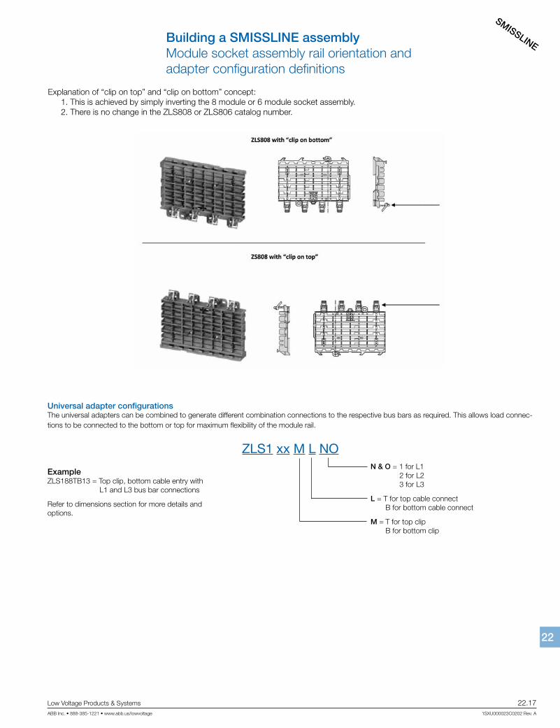
Explanation of “clip on top” and “clip on bottom” concept: 1. This is achieved by simply inverting the 8 module or 6 module socket assembly. 2. There is no change in the ZLS808 or ZLS806 catalog number.
Universal adapter configurationsThe universal adapters can be combined to generate different combination connections to the respective bus bars as required. This allows load connec-tions to be connected to the bottom or top for maximum flexibility of the module rail.
ZLS1 xx M L NON & O = 1 for L1 2 for L2 3 for L3
L = T for top cable connect B for bottom cable connect
M = T for top clip B for bottom clip
ExampleZLS188TB13 = Top clip, bottom cable entry with L1 and L3 bus bar connections
Refer to dimensions section for more details and options.
SMISSLINE
22.18 Low Voltage Products & Systems
1SXU000023C0202 Rev. A ABB Inc. • 888-385-1221 • www.abb.us/lowvoltage
2222
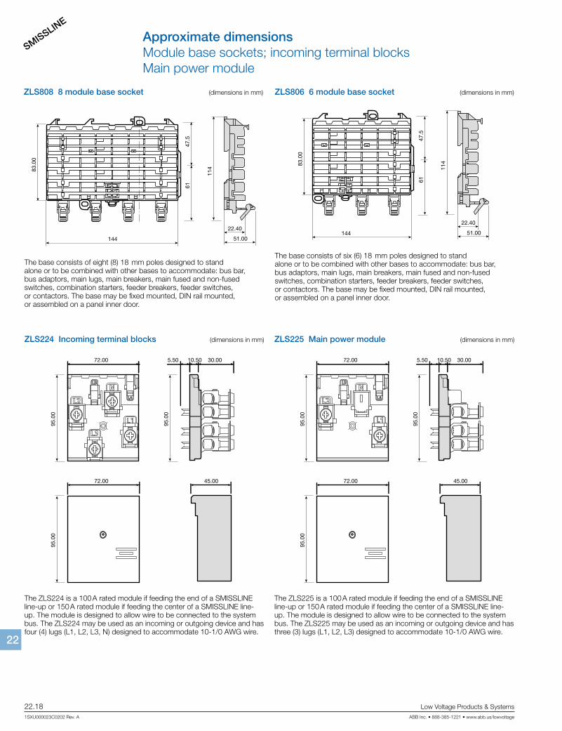
Approximate dimensionsModule base sockets; incoming terminal blocksMain power module
ZLS808 8 module base socket (dimensions in mm)
83.0
0
61
114
47.5
144
22.40
51.00 2CC
C45
1076
Z010
1The base consists of eight (8) 18 mm poles designed to stand alone or to be combined with other bases to accommodate: bus bar, bus adaptors, main lugs, main breakers, main fused and non-fused switches, combination starters, feeder breakers, feeder switches, or contactors. The base may be fixed mounted, DIN rail mounted, or assembled on a panel inner door.
ZLS806 6 module base socket (dimensions in mm)
The base consists of six (6) 18 mm poles designed to stand alone or to be combined with other bases to accommodate: bus bar, bus adaptors, main lugs, main breakers, main fused and non-fused switches, combination starters, feeder breakers, feeder switches, or contactors. The base may be fixed mounted, DIN rail mounted, or assembled on a panel inner door.
83.0
0
61
114
47.5
144
22.40
51.00 2CC
C45
1077
Z010
1
ZLS224 Incoming terminal blocks (dimensions in mm)
The ZLS224 is a 100 A rated module if feeding the end of a SMISSLINE line-up or 150 A rated module if feeding the center of a SMISSLINE line-up. The module is designed to allow wire to be connected to the system bus. The ZLS224 may be used as an incoming or outgoing device and has four (4) lugs (L1, L2, L3, N) designed to accommodate 10-1/0 AWG wire.
2CC
C45
1062
Z01
01
72.00 30.0010.505.50
95.0
095
.00
72.00 45.00
95.0
0
2CC
C45
1083
Z010
1
72.00 30.0010.505.50
95.0
095
.00
72.00 45.00
95.0
0
ZLS225 Main power module (dimensions in mm)
The ZLS225 is a 100 A rated module if feeding the end of a SMISSLINE line-up or 150 A rated module if feeding the center of a SMISSLINE line-up. The module is designed to allow wire to be connected to the system bus. The ZLS225 may be used as an incoming or outgoing device and has three (3) lugs (L1, L2, L3) designed to accommodate 10-1/0 AWG wire.
SMISSLINE
Low Voltage Products & Systems 22.19ABB Inc. • 888-385-1221 • www.abb.us/lowvoltage 1SXU000023C0202 Rev. A
2222
Approximate dimensionsMain power modules
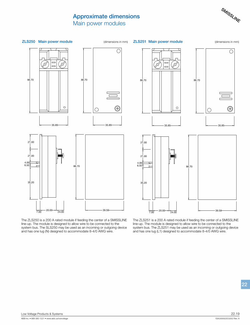
ZLS250 Main power module (dimensions in mm)
The ZLS250 is a 200 A rated module if feeding the center of a SMISSLINE line-up. The module is designed to allow wire to be connected to the system bus. The SLS250 may be used as an incoming or outgoing device and has one lug (N) designed to accommodate 8-4/0 AWG wire.
ZLS251 Main power module (dimensions in mm)
The ZLS251 is a 200 A rated module if feeding the center of a SMISSLINE line-up. The module is designed to allow wire to be connected to the system bus. The ZLS251 may be used as an incoming or outgoing device and has one lug (L1) designed to accommodate 8-4/0 AWG wire.
86.70
35.85 35.85
86.70
6.50 86.70
20.007.00 24.00
21.00
21.00
35.20
4.00
39.50
86.70
35.85 35.85
86.70
6.50 86.70
20.007.00 24.00
21.00
21.00
35.20
4.00
39.50
SMISSLINE
22.20 Low Voltage Products & Systems
1SXU000023C0202 Rev. A ABB Inc. • 888-385-1221 • www.abb.us/lowvoltage
2222
Approximate dimensionsMain power modules
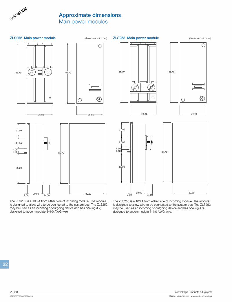
ZLS252 Main power module (dimensions in mm)
The ZLS252 is a 100 A from either side of incoming module. The module is designed to allow wire to be connected to the system bus. The ZLS252 may be used as an incoming or outgoing device and has one lug (L2) designed to accommodate 8-4/0 AWG wire.
ZLS253 Main power module (dimensions in mm)
The ZLS253 is a 100 A from either side of incoming module. The module is designed to allow wire to be connected to the system bus. The ZLS253 may be used as an incoming or outgoing device and has one lug (L3) designed to accommodate 8-4/0 AWG wire.
86.70
35.85 35.85
86.70
6.50 86.70
20.007.00 24.00
21.00
21.00
35.20
4.00
39.50
86.70
35.85 35.85
86.70
6.50 86.70
20.007.00 24.00
21.00
21.00
35.20
4.00
39.50
SMISSLINE
Low Voltage Products & Systems 22.21ABB Inc. • 888-385-1221 • www.abb.us/lowvoltage 1SXU000023C0202 Rev. A
2222
Approximate dimensionsBase end stopBus stab adaptor
21.00
104.
0036
.00
21.00
104.
0036
.00
2CC
C45
1066
Z02
01
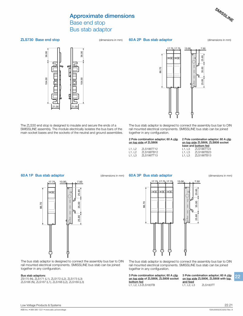
ZLS730 Base end stop (dimensions in mm)
The ZLS30 end stop is designed to insulate and secure the ends of a SMISSLINE assembly. The module electrically isolates the bus bars of the main socket bases and the sockets of the neutral and ground assemblies.
60 A 1P Bus stab adaptor (dimensions in mm)
The bus stab adaptor is designed to connect the assembly bus bar to DIN rail mounted electrical components. SMISSLINE bus stab can be joined together in any configuration.
Bus stab adaptors:ZS170 (N), ZLS171 (L1), ZLS172 (L2), ZLS173 (L3)ZLS166 (N), ZLS167 (L1), ZLS168 (L2), ZLS169 (L3)
86.7
0
35.0
025
.85
25.8
5
13.00 7.5017.75
60 A 2P Bus stab adaptor (dimensions in mm)
The bus stab adaptor is designed to connect the assembly bus bar to DIN rail mounted electrical components. SMISSLINE bus stab can be joined together in any configuration.
2 Pole combination adaptor; 60 A clip 2 Pole combination adaptor; 60 A clipon top side of ZLS806 on top side ZLS806, ZLS808 socket base and bottom fedL1, L2 ZLS186TT12 L1, L3 ZLS186TT23 L1, L2 ZLS188TB12 L1, L3 ZLS188TB23L1, L3 ZLS186TT13 L1, L3 ZLS188TB13
2CC
C45
1073
Z01
01
86.7
0
35.0
025
.85
25.8
5
13.00 7.5017.75 17.75
60 A 3P Bus stab adaptor (dimensions in mm)
The bus stab adaptor is designed to connect the assembly bus bar to DIN rail mounted electrical components. SMISSLINE bus stab can be joined together in any configuration.
3 Pole combination adaptor; 60 A clip 3 Pole combination adaptor; 60 A clip on top side of ZLS806, ZLS808 socket on top side ZLS806, ZLS808 with top bottom fed and feedL1, L2, L3 ZLS183TB L1, L2, L3 ZLS183TT
86.7
0
35.0
025
.85
25.8
5
13.00 7.5017.75 17.75 17.75
SMISSLINE
22.22 Low Voltage Products & Systems
1SXU000023C0202 Rev. A ABB Inc. • 888-385-1221 • www.abb.us/lowvoltage
2222
[ ]
Approximate dimensions
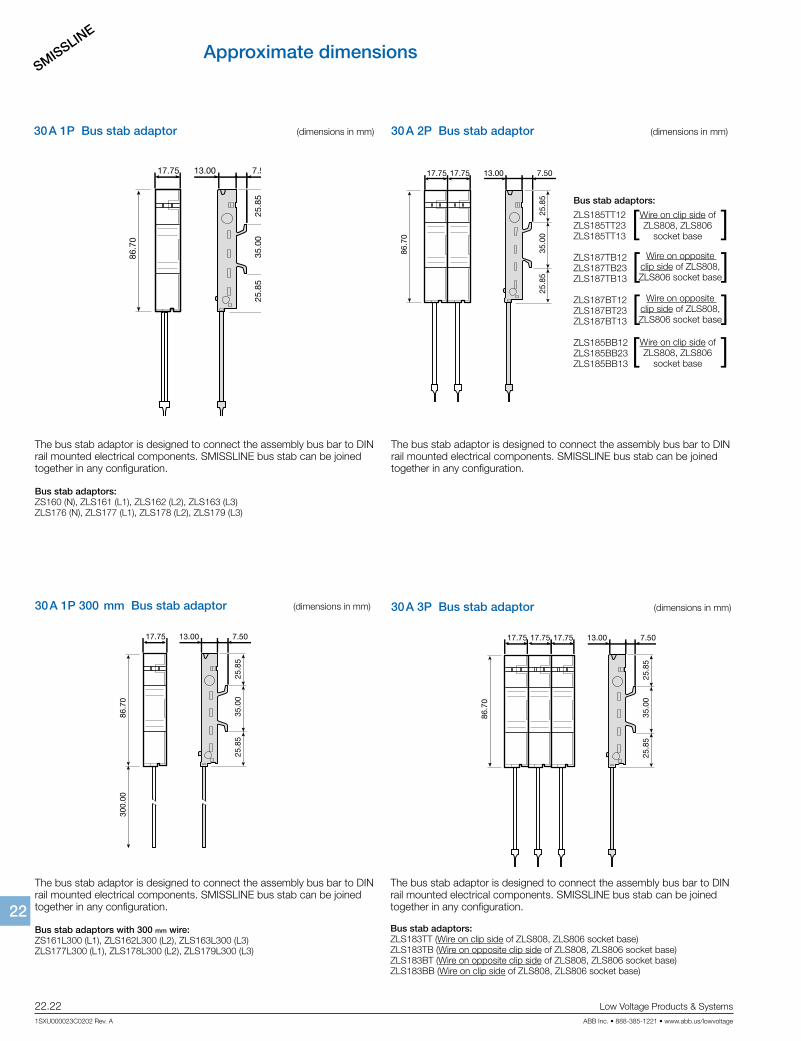
30 A 1P Bus stab adaptor (dimensions in mm)
The bus stab adaptor is designed to connect the assembly bus bar to DIN rail mounted electrical components. SMISSLINE bus stab can be joined together in any configuration.
Bus stab adaptors:ZS160 (N), ZLS161 (L1), ZLS162 (L2), ZLS163 (L3)ZLS176 (N), ZLS177 (L1), ZLS178 (L2), ZLS179 (L3)
86.7
0
35.0
025
.85
25.8
5
13.00 7.5017.75
30 A 1P 300 mm Bus stab adaptor (dimensions in mm)
The bus stab adaptor is designed to connect the assembly bus bar to DIN rail mounted electrical components. SMISSLINE bus stab can be joined together in any configuration.
Bus stab adaptors with 300 mm wire:ZS161L300 (L1), ZLS162L300 (L2), ZLS163L300 (L3) ZLS177L300 (L1), ZLS178L300 (L2), ZLS179L300 (L3)
2C C
C45
1070
Z01
01
86.7
030
0.00
35.0
025
.85
25.8
5
13.00 7.5017.75
30 A 3P Bus stab adaptor (dimensions in mm)
The bus stab adaptor is designed to connect the assembly bus bar to DIN rail mounted electrical components. SMISSLINE bus stab can be joined together in any configuration.
Bus stab adaptors:ZLS183TT (Wire on clip side of ZLS808, ZLS806 socket base)ZLS183TB (Wire on opposite clip side of ZLS808, ZLS806 socket base)ZLS183BT (Wire on opposite clip side of ZLS808, ZLS806 socket base)ZLS183BB (Wire on clip side of ZLS808, ZLS806 socket base)
2CC
C45
1072
Z01
01
86.7
0
35.0
025
.85
25.8
513.00 7.5017.75 17.75 17.75
30 A 2P Bus stab adaptor (dimensions in mm)
Bus stab adaptors:
ZLS185TT12ZLS185TT23ZLS185TT13
ZLS187TB12ZLS187TB23ZLS187TB13
ZLS187BT12 ZLS187BT23ZLS187BT13
ZLS185BB12 ZLS185BB23ZLS185BB13
2CC
C45
1079
Z01
01
86.7
0
35.0
025
.85
25.8
5
13.00 7.5017.75 17.75
Wire on clip side of ZLS808, ZLS806
socket base
Wire on clip side of ZLS808, ZLS806
socket base
Wire on opposite clip side of ZLS808, ZLS806 socket base
Wire on opposite clip side of ZLS808, ZLS806 socket base
[ ][ ][ ]
The bus stab adaptor is designed to connect the assembly bus bar to DIN rail mounted electrical components. SMISSLINE bus stab can be joined together in any configuration.
SMISSLINE
Low Voltage Products & Systems 22.23ABB Inc. • 888-385-1221 • www.abb.us/lowvoltage 1SXU000023C0202 Rev. A
2222
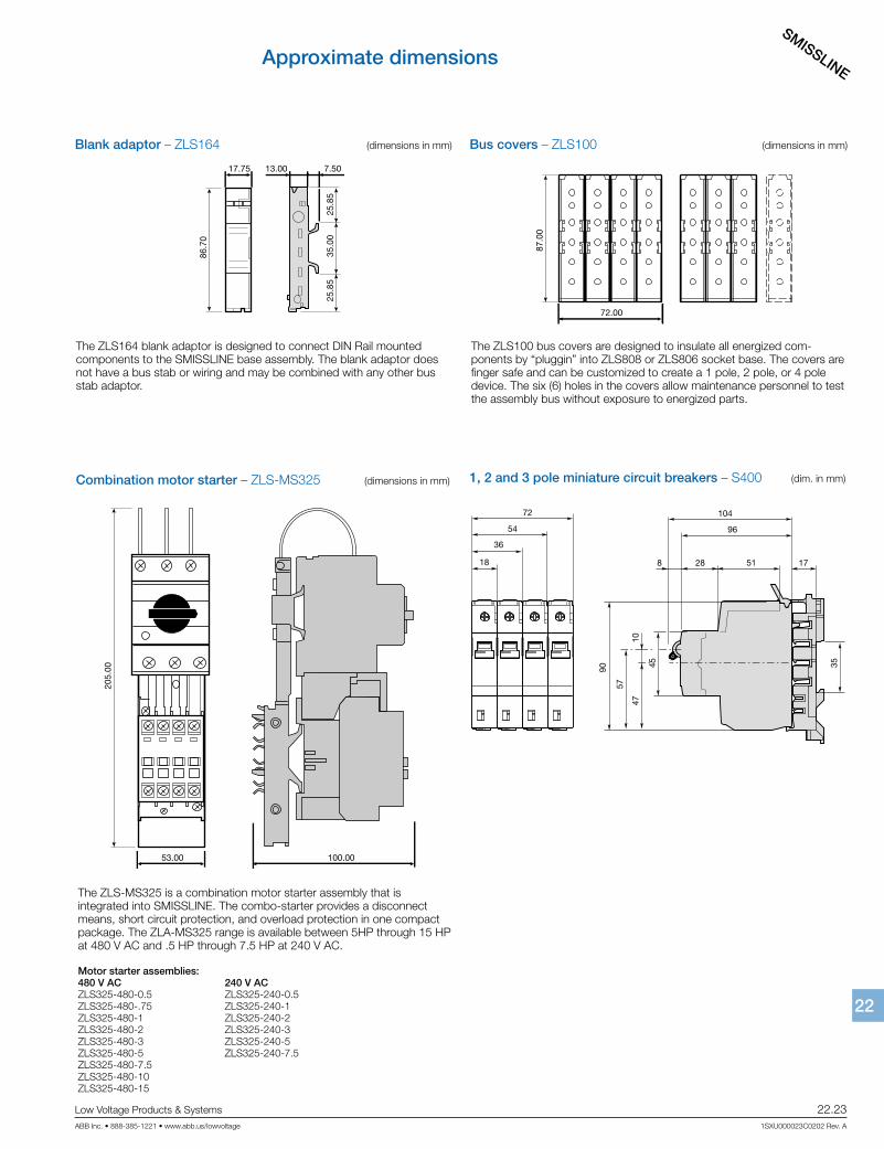
Bus covers – ZLS100 (dimensions in mm)
The ZLS100 bus covers are designed to insulate all energized com-ponents by “pluggin” into ZLS808 or ZLS806 socket base. The covers are finger safe and can be customized to create a 1 pole, 2 pole, or 4 pole device. The six (6) holes in the covers allow maintenance personnel to test the assembly bus without exposure to energized parts.
72.00
87.0
0
2CC
C45
1078
Z010
1
Approximate dimensions
Blank adaptor – ZLS164 (dimensions in mm)
The ZLS164 blank adaptor is designed to connect DIN Rail mounted components to the SMISSLINE base assembly. The blank adaptor does not have a bus stab or wiring and may be combined with any other bus stab adaptor.
2CC
C45
1068
Z01
01
86.7
0
35.0
025
.85
25.8
5
13.00 7.5017.75
Combination motor starter – ZLS-MS325 (dimensions in mm)
The ZLS-MS325 is a combination motor starter assembly that is integrated into SMISSLINE. The combo-starter provides a disconnect means, short circuit protection, and overload protection in one compact package. The ZLA-MS325 range is available between 5HP through 15 HP at 480 V AC and .5 HP through 7.5 HP at 240 V AC.
Motor starter assemblies:480 V AC 240 V ACZLS325-480-0.5 ZLS325-240-0.5ZLS325-480-.75 ZLS325-240-1ZLS325-480-1 ZLS325-240-2ZLS325-480-2 ZLS325-240-3ZLS325-480-3 ZLS325-240-5ZLS325-480-5 ZLS325-240-7.5ZLS325-480-7.5 ZLS325-480-10ZLS325-480-15
205.
00
53.00 100.00
2CC
C45
1080
Z01
01
1, 2 and 3 pole miniature circuit breakers – S400 (dim. in mm)
47
57
10
90 45 35
104
96
51 178 28
54
72
36
18
SMISSLINE
22.24 Low Voltage Products & Systems
1SXU000023C0202 Rev. A ABB Inc. • 888-385-1221 • www.abb.us/lowvoltage
2222
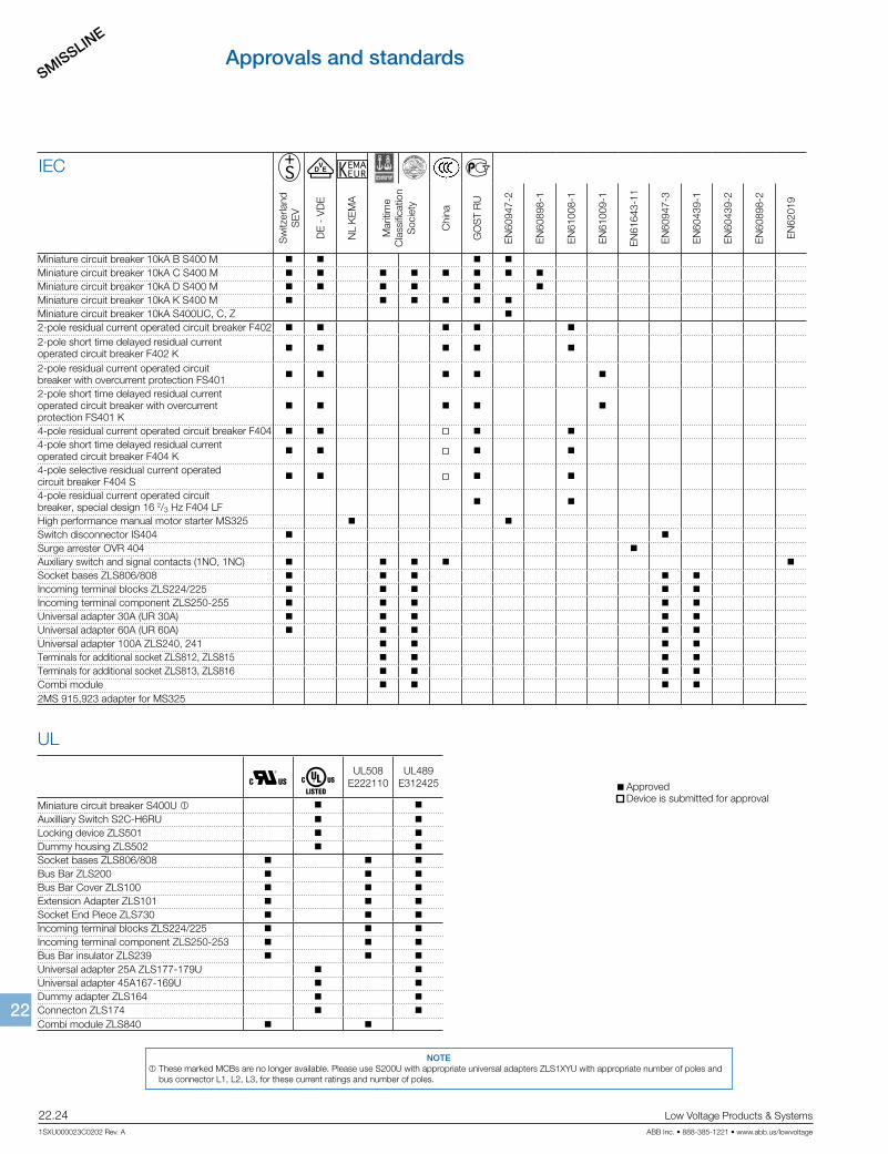
Approvals and standards
UL
ApprovedDevice is submitted for approval
n a UL508E222110
UL489E312425
Miniature circuit breaker S400U 1
Auxilliary Switch S2C-H6RU
Locking device ZLS501
Dummy housing ZLS502
Socket bases ZLS806/808
Bus Bar ZLS200
Bus Bar Cover ZLS100
Extension Adapter ZLS101
Socket End Piece ZLS730
Incoming terminal blocks ZLS224/225
Incoming terminal component ZLS250-253
Bus Bar insulator ZLS239
Universal adapter 25A ZLS177-179U
Universal adapter 45A167-169U
Dummy adapter ZLS164
Connecton ZLS174
Combi module ZLS840
e
Sw
itzer
land
SE
V
DE
- V
DE
NL
KE
MA
Mar
itim
eC
lass
ifica
tion
Soc
iety
Chi
na
GO
ST
RU
EN
6094
7-2
EN
6089
8-1
EN
6100
8-1
EN
6100
9-1
EN
6164
3-11
EN
6094
7-3
EN
6043
9-1
EN
6043
9-2
EN
6089
8-2
EN
6201
9
Miniature circuit breaker 10kA B S400 M
Miniature circuit breaker 10kA C S400 M
Miniature circuit breaker 10kA D S400 M
Miniature circuit breaker 10kA K S400 M
Miniature circuit breaker 10kA S400UC, C, Z
2-pole residual current operated circuit breaker F402
2-pole short time delayed residual current operated circuit breaker F402 K
2-pole residual current operated circuitbreaker with overcurrent protection FS401
2-pole short time delayed residual currentoperated circuit breaker with overcurrent protection FS401 K
4-pole residual current operated circuit breaker F404
4-pole short time delayed residual current operated circuit breaker F404 K
4-pole selective residual current operatedcircuit breaker F404 S
4-pole residual current operated circuit breaker, special design 16 2/3 Hz F404 LF
High performance manual motor starter MS325
Switch disconnector IS404
Surge arrester OVR 404
Auxiliary switch and signal contacts (1NO, 1NC)
Socket bases ZLS806/808
Incoming terminal blocks ZLS224/225
Incoming terminal component ZLS250-255
Universal adapter 30A (UR 30A)
Universal adapter 60A (UR 60A)
Universal adapter 100A ZLS240, 241
Terminals for additional socket ZLS812, ZLS815
Terminals for additional socket ZLS813, ZLS816
Combi module
2MS 915,923 adapter for MS325
IEC
NOTE 1 These marked MCBs are no longer available. Please use S200U with appropriate universal adapters ZLS1XYU with appropriate number of poles and
bus connector L1, L2, L3, for these current ratings and number of poles.