Membrane Air Dryer - RS Components
56
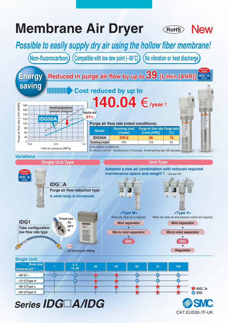
Standard dew point Body size −20°C/— −15°C/Type H −40°C/Type L −60°C/Type S IDGA IDG I I 1 3, 5 10, 20 30 50 60 75 100 Purge air flow rate (rated conditions) IDG50A Existing model Possible to easily supply dry air using the hollow fiber membrane! 0 40 60 80 100 120 140 160 180 0.0 0.5 1.0 Inlet air pressure [MPa] Purge air flow rate [L/min [ANR]] IDG50A IDGA Purge air flow reduction type A white body is introduced. Variations Single Unit RoHS Adopted a new air combination with reduced required maintenance space and weight ∗ ! ∗ Except AR ø6 One-touch fitting ·Rc · NPT ·G Thread type Non-fluorocarbon No vibration or heat discharge Compatible with low dew point (–60°C) Cost reduced by up to Reduced in purge air flow by up to 39 [L/min [ANR]] R R Energy saving IDGA Series Reduced purge Existing model Reduction ratio 31% Model Single Unit Type Unit Type IDGA Series Reduced purge IDG1 Tube configuration low flow rate type + + Mist separator Micro mist separator IDG <Type M> When dry clean air is required. + + Mist separator Micro mist separator + Regulator IDG <Type V> When dry clean air and pressure control are required. Purge air flow rate [L/min [ANR]] Running cost [€/year] Purge ratio [%] [Calculation conditions] Air unit price: 0.02 €/m 3 Operating hours: 12 hours/day Annual operating days: 250 days/year 140.04 € /year ! 86 125 309.6 450 15 20 CAT.EUS30-7F-UK New New Series IDG A/IDG Membrane Air Dryer
-
Upload
khangminh22 -
Category
Documents
-
view
0 -
download
0
Transcript of Membrane Air Dryer - RS Components
Standard dew point
Body size
−20°C/—
−15°C/Type H
−40°C/Type L
−60°C/Type SIDG�AIDGII
1 3, 510, 20
30 50 60 75 100
Purge air flow rate (rated conditions)
IDG50AExisting model
Possible to easily supply dry air using the hollow fiber membrane!
0
40
60
80
100
120
140
160
180
0.0 0.5 1.0
Inlet air pressure [MPa]
Pur
ge a
ir flo
w r
ate
[L/m
in [A
NR
]]
IDG50A
IDG�APurge air flow reduction type
A white body is introduced.
Variations
Single Unit
RoHS
Adopted a new air combination with reduced required maintenance space and weight∗! ∗ Except AR
ø6 One-touch fitting
·Rc·NPT·G
Thread type
Non-fluorocarbon No vibration or heat dischargeCompatible with low dew point (–60°C)
Cost reduced by up to
Reduced in purge air flow by up to 39 [L/min [ANR]]RREnergysaving
IDG�ASeries
Reducedpurge
Existing modelReduction ratio
31%
Model
Single Unit Type Unit Type
IDG�ASeries
Reducedpurge
IDG1Tube configurationlow flow rate type
+
+
Mist separator
Micro mist separator
IDG
<Type M>When dry clean air is required.
+
+
Mist separator
Micro mist separator
+Regulator
IDG
<Type V>When dry clean air and pressure control are required.
Purge air flow rate[L/min [ANR]]
Running cost[€/year]
Purge ratio[%]
[Calculation conditions]Air unit price: 0.02 €/m3 Operating hours: 12 hours/day Annual operating days: 250 days/year
140.04 € /year !
86125
309.6450
1520
CAT.EUS30-7F-UK
NewNew
Series IDG�A/IDG
Membrane Air Dryer
( )
Dew point indicator
Fitting for exhausting purgeair for dew point indicator
Fitting for exhausting purge airfor dehumidification
Except IDG1, IDG3, IDG3H, IDG5, IDG5H, IDG30A, IDG30HA, IDG30LA, IDG50A, IDG50HA, IDG50LA
Membrane Air Dryer
Inspectionequipment
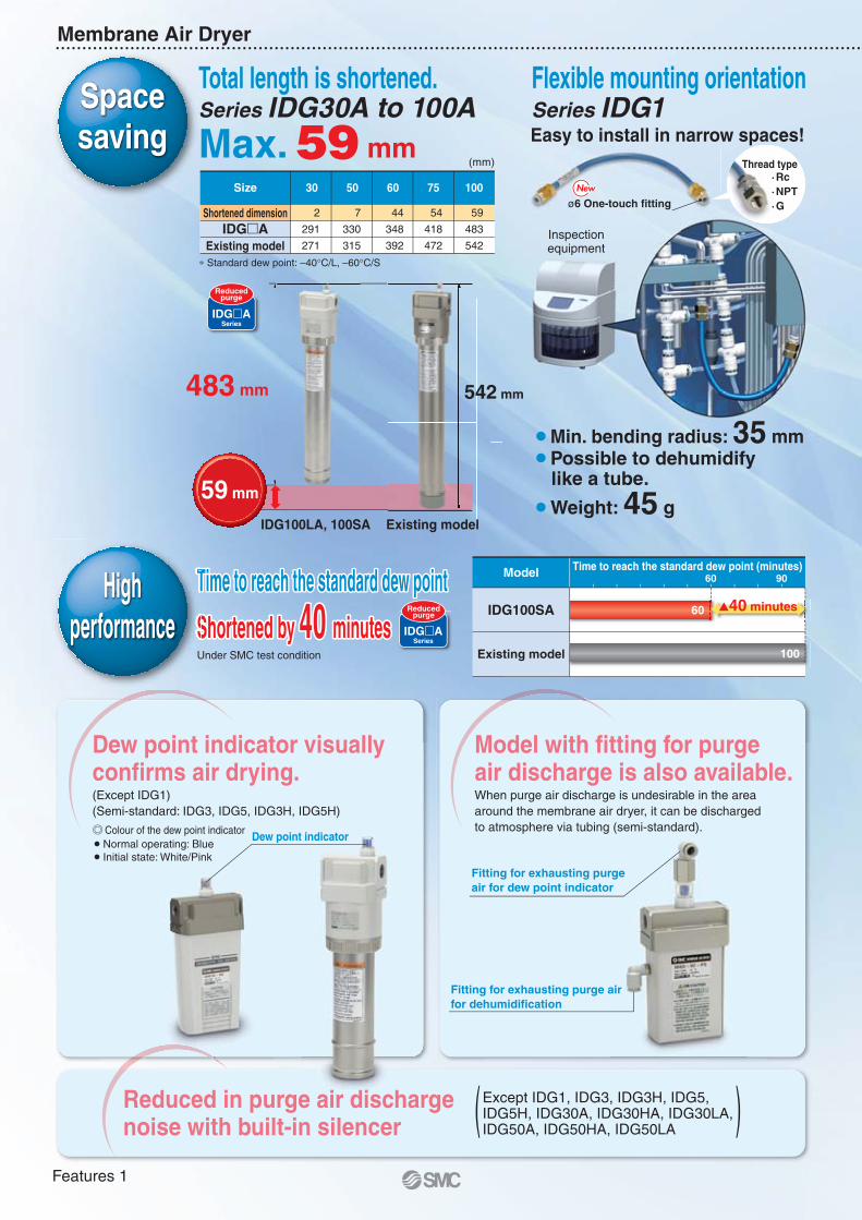
¡Min. bending radius: 35 mm¡Possible to dehumidify like a tube.
¡Weight: 45 gExisting model
Max. 59 mm
542 mm483 mm
IDG100SA
Existing model
Time to reach the standard dew point (minutes)60 90Time to reach the standard dew point Time to reach the standard dew point
Shortened by 40 minutesShortened by 40 minutes
ModelTTT
SSSUnder SMC test condition
60
100
�40 minutes
Size
∗ Standard dew point: –40°C/L, –60°C/S
30
2
291
271
50
7
330
315
60
44
348
392
75
54
418
472
100
59
483
542
Shortened dimensionIDG�A
Existing model
IDG100LA, 100SA
59 mm
Total length is shortened.Series IDG30A to 100A
(mm)
Flexible mounting orientationSeries IDG1Easy to install in narrow spaces!
ø6 One-touch fitting
·Rc·NPT·G
Thread type
Spacesaving
IDG�ASeries
Reducedpurge
Highperformance IDG�A
Series
Reducedpurge
Dew point indicator visually confirms air drying.(Except IDG1)(Semi-standard: IDG3, IDG5, IDG3H, IDG5H)
Colour of the dew point indicator� Normal operating: Blue� Initial state: White/Pink
Model with fitting for purgeair discharge is also available.When purge air discharge is undesirable in the areaaround the membrane air dryer, it can be dischargedto atmosphere via tubing (semi-standard).
Reduced in purge air discharge noise with built-in silencer
Features 1
Dehumidification Principle
Series IDG�A/IDG
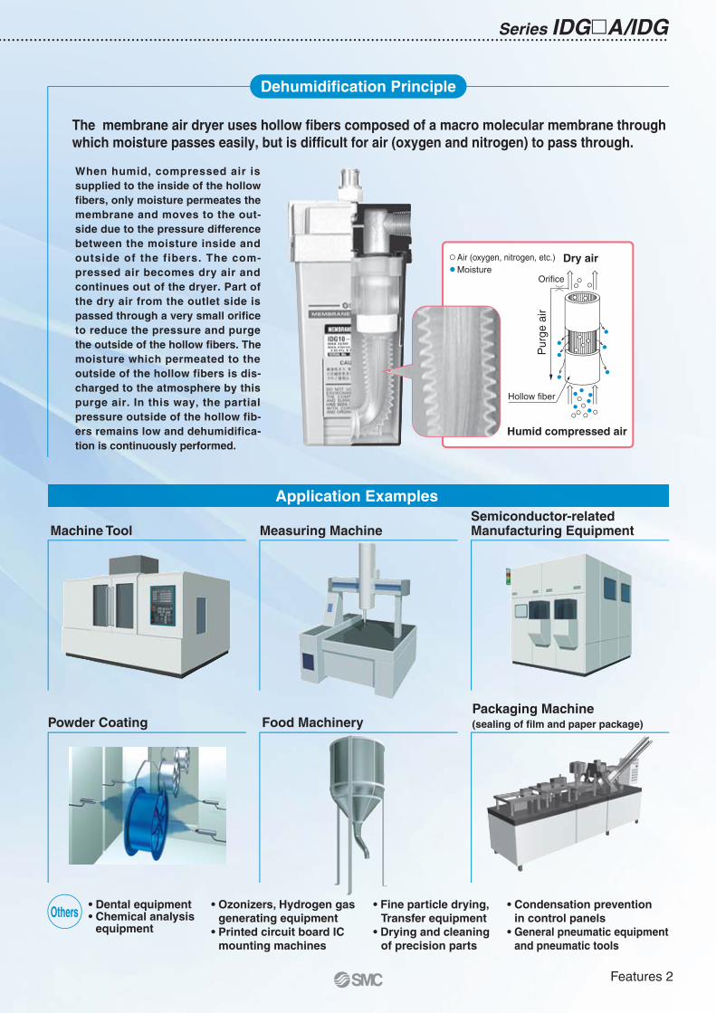
The membrane air dryer uses hollow fibers composed of a macro molecular membrane through which moisture passes easily, but is difficult for air (oxygen and nitrogen) to pass through.
Orifice
Hollow fiber
Humid compressed air
Dry air
Pur
ge a
ir
Air (oxygen, nitrogen, etc.)Moisture
Measuring MachineSemiconductor-relatedManufacturing Equipment
Packaging Machine(sealing of film and paper package)
Machine Tool
Powder Coating Food Machinery
Dental equipmentChemical analysisequipment
Ozonizers, Hydrogen gasgenerating equipment
Printed circuit board ICmounting machines
Fine particle drying,Transfer equipment
Drying and cleaningof precision parts
Condensation preventionin control panelsGeneral pneumatic equipmentand pneumatic tools
Others
Application Examples
When humid, compressed air is supplied to the inside of the hollow fibers, only moisture permeates the membrane and moves to the out-side due to the pressure difference between the moisture inside and outside of the fibers. The com-pressed air becomes dry air and continues out of the dryer. Part of the dry air from the outlet side is passed through a very small orifice to reduce the pressure and purge the outside of the hollow fibers. The moisture which permeated to the outside of the hollow fibers is dis-charged to the atmosphere by this purge air. In this way, the partial pressure outside of the hollow fib-ers remains low and dehumidifica-tion is continuously performed.
Features 2
= Reduced purge
Series Variations
SeriesOutlet air flow rate
[L/min [ANR]]
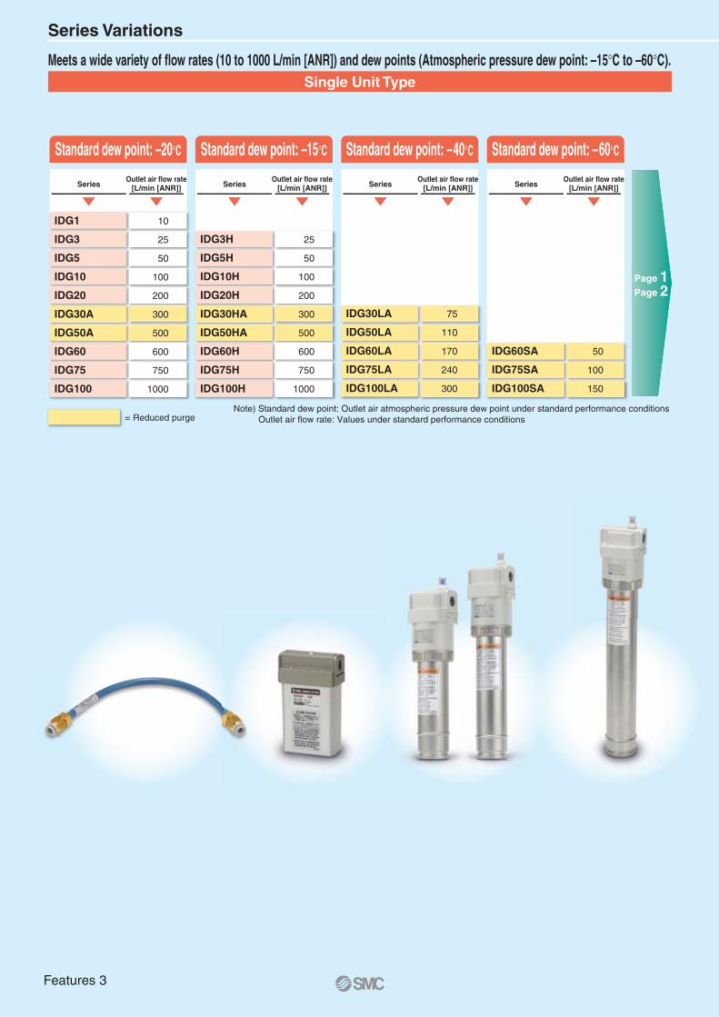
Meets a wide variety of flow rates (10 to 1000 L/min [ANR]) and dew points (Atmospheric pressure dew point: –15°C to –60°C).
SeriesOutlet air flow rate
[L/min [ANR]] SeriesOutlet air flow rate
[L/min [ANR]] SeriesOutlet air flow rate
[L/min [ANR]]
Standard dew point: –20°C Standard dew point: –15°C Standard dew point: –40°C Standard dew point: –60°C
Page 1Page 2
Single Unit Type
IDG1
IDG3
IDG5
IDG10
IDG20
IDG30A
IDG50A
IDG60
IDG75
IDG100
10
25
50
100
200
300
500
600
750
1000
Note) Standard dew point: Outlet air atmospheric pressure dew point under standard performance conditionsOutlet air flow rate: Values under standard performance conditions
IDG3H
IDG5H
IDG10H
IDG20H
IDG30HA
IDG50HA
IDG60H
IDG75H
IDG100H
25
50
100
200
300
500
600
750
1000
IDG30LA
IDG50LA
IDG60LA
IDG75LA
IDG100LA
75
110
170
240
300
IDG60SA
IDG75SA
IDG100SA
50
100
150
Features 3
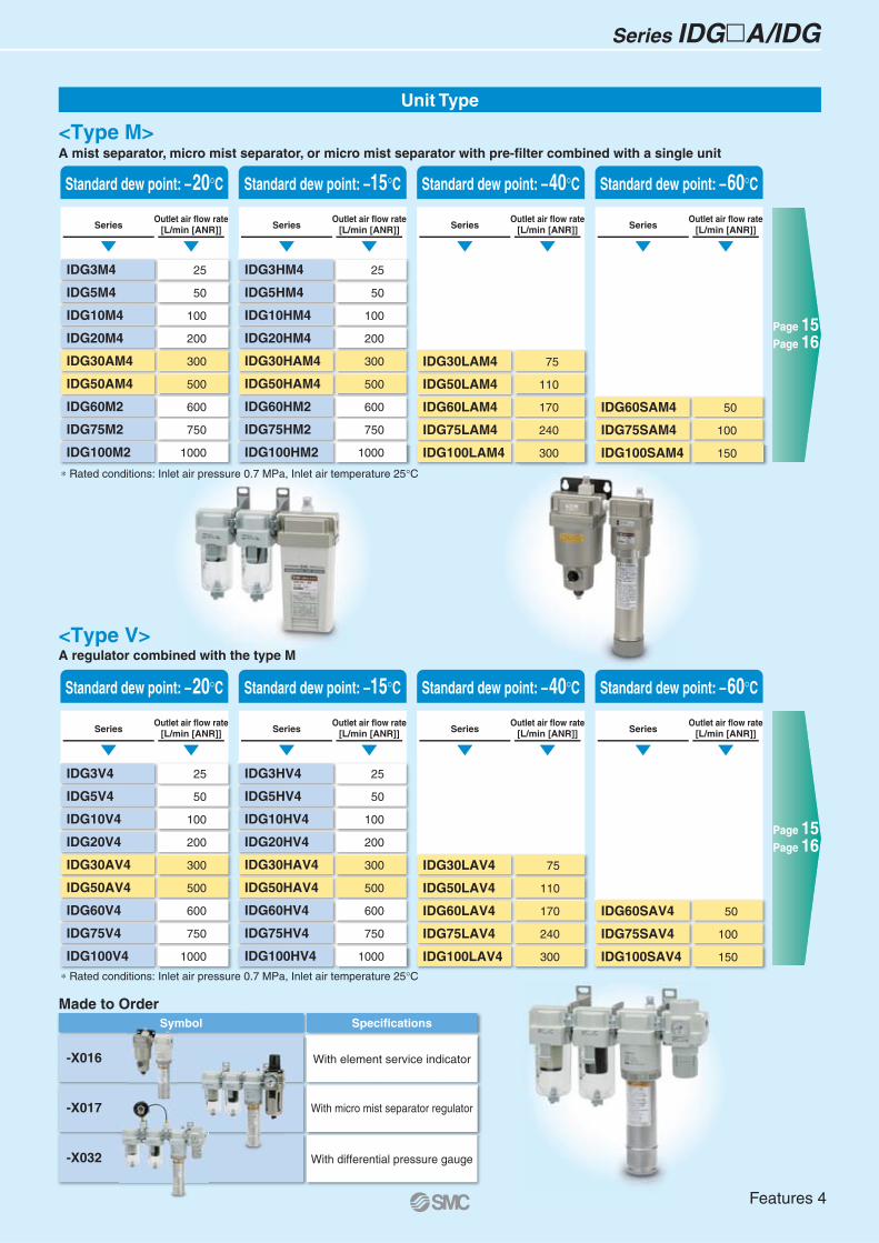
-X016
-X032
-X017
Symbol Specifications
With element service indicator
With differential pressure gauge
With micro mist separator regulator
Sym
∗ Rated conditions: Inlet air pressure 0.7 MPa, Inlet air temperature 25°C
∗ Rated conditions: Inlet air pressure 0.7 MPa, Inlet air temperature 25°C
<Type M>A mist separator, micro mist separator, or micro mist separator with pre-filter combined with a single unit
A regulator combined with the type M
Standard dew point: –20°C Standard dew point: –15°C Standard dew point: –40°C Standard dew point: –60°C
Page 15Page 16
Page 15Page 16
<Type V>
Unit Type
Made to Order
Series IDG�A/IDG
SeriesOutlet air flow rate
[L/min [ANR]]
IDG3M4
IDG5M4
IDG10M4
IDG20M4
IDG30AM4
IDG50AM4
IDG60M2
IDG75M2
IDG100M2
25
50
100
200
300
500
600
750
1000
SeriesOutlet air flow rate
[L/min [ANR]]
IDG3HM4
IDG5HM4
IDG10HM4
IDG20HM4
IDG30HAM4
IDG50HAM4
IDG60HM2
IDG75HM2
IDG100HM2
25
50
100
200
300
500
600
750
1000
SeriesOutlet air flow rate
[L/min [ANR]]
IDG30LAM4
IDG50LAM4
IDG60LAM4
IDG75LAM4
IDG100LAM4
75
110
170
240
300
SeriesOutlet air flow rate
[L/min [ANR]]
IDG60SAM4
IDG75SAM4
IDG100SAM4
50
100
150
Standard dew point: –20°C Standard dew point: –15°C Standard dew point: –40°C Standard dew point: –60°C
SeriesOutlet air flow rate
[L/min [ANR]]
IDG3V4
IDG5V4
IDG10V4
IDG20V4
IDG30AV4
IDG50AV4
IDG60V4
IDG75V4
IDG100V4
25
50
100
200
300
500
600
750
1000
SeriesOutlet air flow rate
[L/min [ANR]]
IDG3HV4
IDG5HV4
IDG10HV4
IDG20HV4
IDG30HAV4
IDG50HAV4
IDG60HV4
IDG75HV4
IDG100HV4
25
50
100
200
300
500
600
750
1000
SeriesOutlet air flow rate
[L/min [ANR]]
IDG30LAV4
IDG50LAV4
IDG60LAV4
IDG75LAV4
IDG100LAV4
75
110
170
240
300
SeriesOutlet air flow rate
[L/min [ANR]]
IDG60SAV4
IDG75SAV4
IDG100SAV4
50
100
150
Features 4
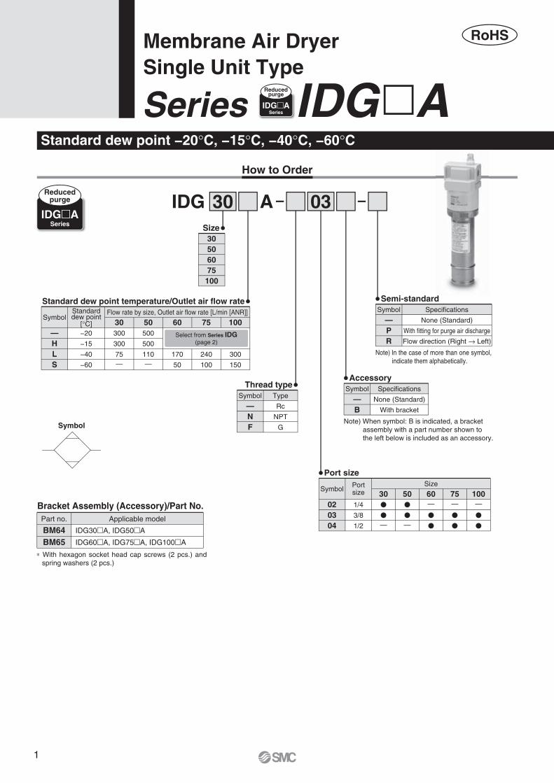
Standard dew point −20°C, −15°C, −40°C, −60°C
AIDG 0330
30506075
100
Size
—HLS
SymbolFlow rate by size, Outlet air flow rate [L/min [ANR]]Standard
dew point[°C] 30−20
−15
−40
−60
300
300
75—
50500
500
110—
60
170
50
75
240
100
100
300
150
Standard dew point temperature/Outlet air flow rate
020304
Symbol Portsize
Size
301/4
3/8
1/2
�
�
—
50�
�
—
60—
�
�
75—
�
�
100—
�
�
Port size
Thread type
—NF
Type
Rc
NPT
G
Symbol
Semi-standard
—PR
Specifications
None (Standard)
With fitting for purge air discharge
Flow direction (Right → Left)
Symbol
Note) In the case of more than one symbol, indicate them alphabetically.
Accessory
—B
Specifications
None (Standard)
With bracket
Symbol
Note) When symbol: B is indicated, a bracket assembly with a part number shown to the left below is included as an accessory.
∗ With hexagon socket head cap screws (2 pcs.) and spring washers (2 pcs.)
Bracket Assembly (Accessory)/Part No.Part no. Applicable model
BM64BM65
IDG30�A, IDG50�A
IDG60�A, IDG75�A, IDG100�A
Membrane Air DryerSingle Unit Type
How to Order
Symbol
Select from Series IDG(page 2)
Series IDG�AIDG�ASeries
Reducedpurge
IDG�ASeries
Reducedpurge
RoHS
d
1
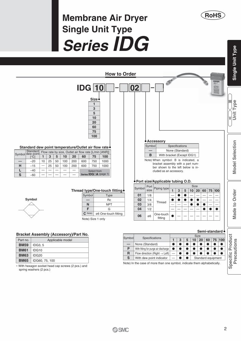
Series IDGMembrane Air DryerSingle Unit Type
RoHS
IDG 0210
01020304
06
SymbolPortsize
Piping typeSize
11/8
1/4
3/8
1/2
ø6
—
�
—
—
�
3�
�
—
—
—
5�
�
—
—
—
10—
�
�
—
—
20—
�
�
—
—
60—
—
�
�
—
—
—
—
�
—
—
—
—
�
—
75 100
Port size/Applicable tubing O.D.
Thread type/One-touch fitting
—NF
C Note)
Type
Rc
NPT
G
ø6 One-touch fitting One-touchfitting
Thread
Symbol
Note) Size 1 only
How to Order
Semi-standard
Symbol SpecificationsSize
1 5 10 20�
�
�
�
�
�
—PRS
None (Standard)
With fitting for purge air discharge
Flow direction (Right → Left)
With dew point indicator
�
�
—
—
�
�
�
�
3�
�
�
� Standard equipment
60�
�
�
75�
�
�
100�
�
�
Note) In the case of more than one symbol, indicate them alphabetically.
Accessory
—B
Specifications
None (Standard)
With bracket (Except IDG1)
Symbol
Note) When symbol: B is indicated, a bracket assembly with a part num-ber shown to the left below is in-cluded as an accessory.
135
10206075
100
Size
Standard dew point temperature/Outlet air flow rate
—HLS
SymbolFlow rate by size, Outlet air flow rate [L/min [ANR]]Standard
dew point[°C] 1−20
−15
−40
−60
10—
—
—
20200
200—
—
10100
100—
—
550
50—
—
325
25—
—
60600
600
75750
750
1001000
1000
Select fromSeries IDG�A (page 1)
Symbol
∗ With hexagon socket head cap screws (2 pcs.) and spring washers (2 pcs.)
Bracket Assembly (Accessory)/Part No.Part no. Applicable model
BM59BM61BM63BM65
IDG3, 5
IDG10
IDG20
IDG60, 75, 100
M
V
Sin
gle
Un
it T
ype
Mo
del
Sel
ecti
on
Mad
e to
Ord
erS
pec
ific
Pro
du
ctP
reca
uti
on
sU
nit
Typ
e
2
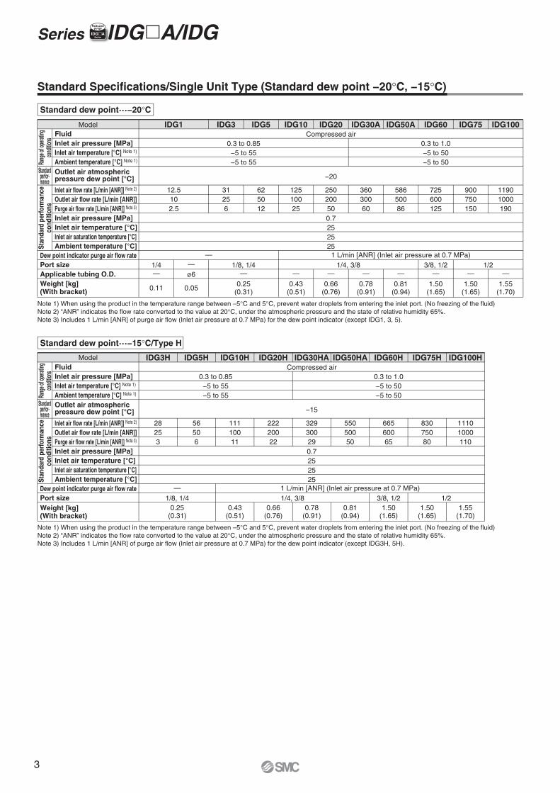
Standard Specifications/Single Unit Type (Standard dew point −20°C, −15°C)
IDG1 IDG5 IDG10 IDG30A IDG60 IDG75
12.5102.5
625012
−20
IDG3
31256
12510025
IDG20
25020050
Compressed air
0.7252525
1 L/min [ANR] (Inlet air pressure at 0.7 MPa)—
0.3 to 0.85−5 to 55−5 to 55
0.3 to 1.0−5 to 50−5 to 50
36030060
IDG50A
58650086
725600125
900750150
IDG100
11901000190
0.11 0.25(0.31)
0.43(0.51)
0.66(0.76)
0.78(0.91)
0.81(0.94)
1.50(1.65)
1.50(1.65)
1/4—
1/8, 1/4—
1/4, 3/8 3/8, 1/2 1/2
1.55(1.70)
FluidInlet air pressure [MPa]Inlet air temperature [°C] Note 1)
Ambient temperature [°C] Note 1)
Inlet air pressure [MPa]Inlet air temperature [°C]Inlet air saturation temperature [°C]Ambient temperature [°C]
Outlet air atmospheric pressure dew point [°C]
Inlet air flow rate [L/min [ANR]] Note 2)
Outlet air flow rate [L/min [ANR]]Purge air flow rate [L/min [ANR]] Note 3)
Dew point indicator purge air flow ratePort sizeApplicable tubing O.D.
Rang
e of o
perat
ingco
nditio
nsSt
anda
rd p
erfo
rman
ceco
nditi
ons
Stan
dard
per
form
ance
cond
ition
s
Weight [kg](With bracket)
Standardperfor-mance
Model IDG3H IDG10H IDG20H IDG50HA IDG75H IDG100H
56506
−15
IDG5H
28253
11110011
IDG30HA
22220022
Compressed air
0.7252525
1 L/min [ANR] (Inlet air pressure at 0.7 MPa)—
0.3 to 0.85−5 to 55−5 to 55
0.3 to 1.0−5 to 50−5 to 50
32930029
IDG60H
55050050
66560065
83075080
0.25(0.31)
0.43(0.51)
0.66(0.76)
0.78(0.91)
0.81(0.94)
1.50(1.65)
1.50(1.65)
11101000110
1.55(1.70)
1/8, 1/4 1/4, 3/8 3/8, 1/2 1/2
FluidInlet air pressure [MPa]Inlet air temperature [°C] Note 1)
Ambient temperature [°C] Note 1)
Inlet air pressure [MPa]Inlet air temperature [°C]Inlet air saturation temperature [°C]Ambient temperature [°C]
Outlet air atmospheric pressure dew point [°C]
Inlet air flow rate [L/min [ANR]] Note 2)
Outlet air flow rate [L/min [ANR]]Purge air flow rate [L/min [ANR]] Note 3)
Dew point indicator purge air flow ratePort size
Rang
e of o
perat
ingco
nditio
ns
Weight [kg](With bracket)
Standardperfor-mance
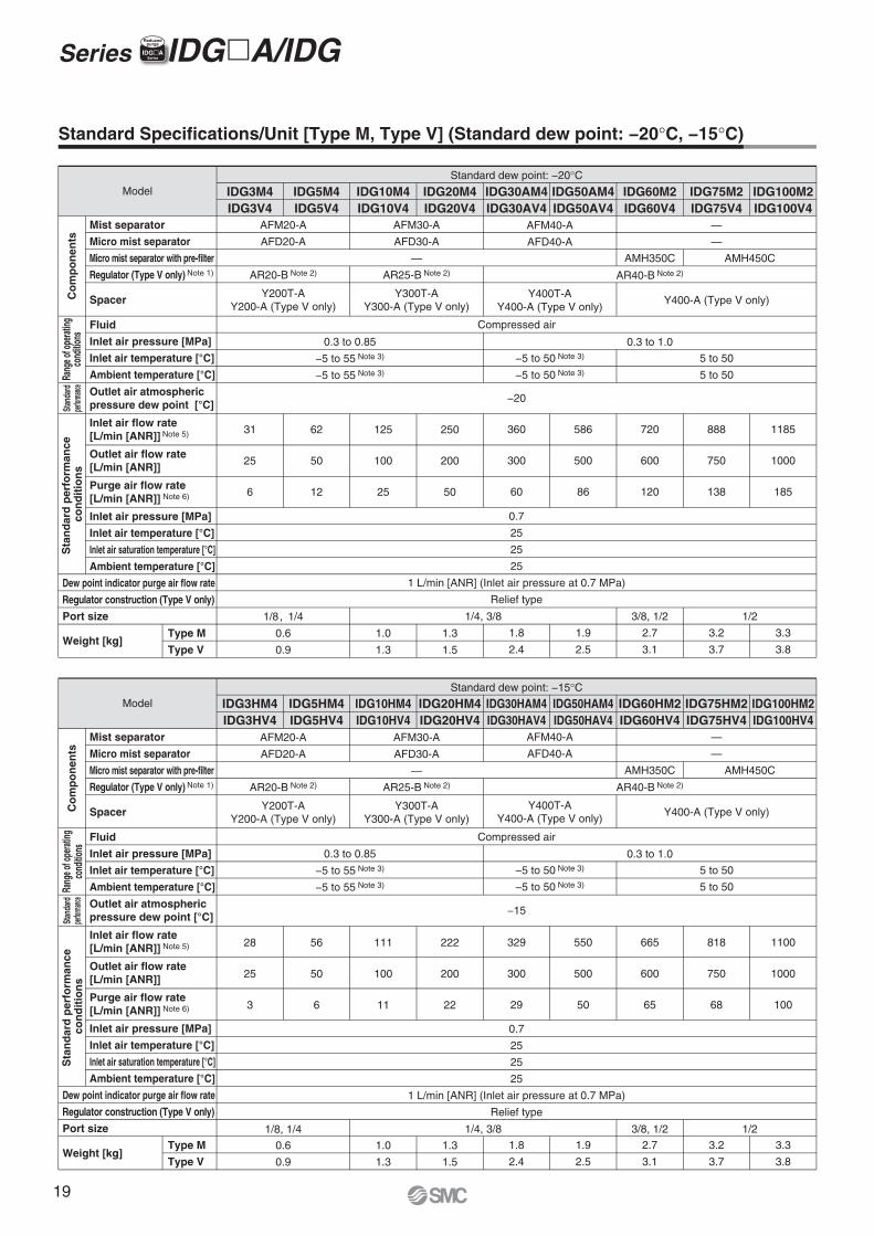
Note 1) When using the product in the temperature range between –5°C and 5°C, prevent water droplets from entering the inlet port. (No freezing of the fluid)Note 2) “ANR” indicates the flow rate converted to the value at 20°C, under the atmospheric pressure and the state of relative humidity 65%.Note 3) Includes 1 L/min [ANR] of purge air flow (Inlet air pressure at 0.7 MPa) for the dew point indicator (except IDG1, 3, 5).
Note 1) When using the product in the temperature range between –5°C and 5°C, prevent water droplets from entering the inlet port. (No freezing of the fluid)Note 2) “ANR” indicates the flow rate converted to the value at 20°C, under the atmospheric pressure and the state of relative humidity 65%.Note 3) Includes 1 L/min [ANR] of purge air flow (Inlet air pressure at 0.7 MPa) for the dew point indicator (except IDG3H, 5H).
Standard dew point…−20°C
Standard dew point…−15°C/Type H
—
ø6 — — — — — — —
0.05
Model
Series IDG�A/IDGIIDG�ASeries
Reducedpurge
3
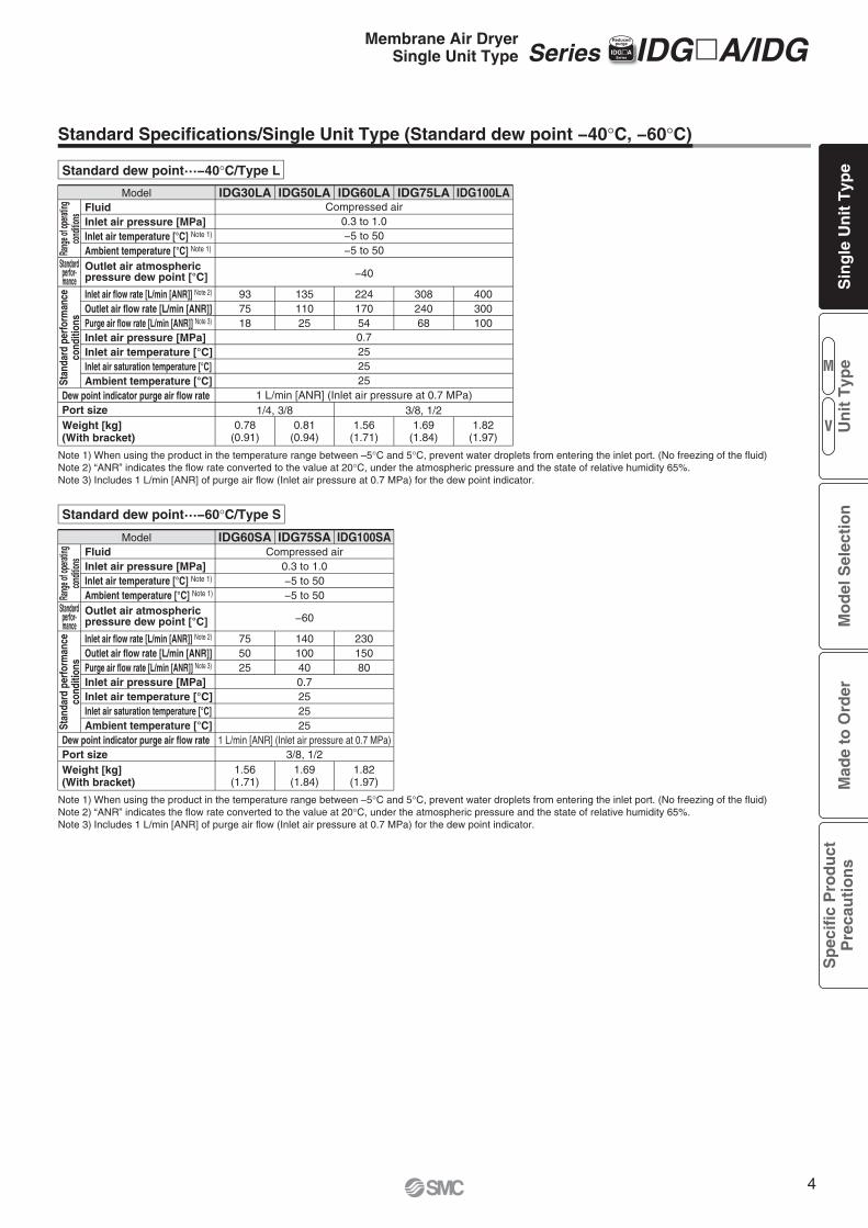
Model IDG30LA IDG60LA IDG75LA
937518
22417054
−40
IDG50LA
13511025
30824068
IDG100LA
400300100
Compressed air0.3 to 1.0−5 to 50−5 to 50
0.7252525
1 L/min [ANR] (Inlet air pressure at 0.7 MPa)
0.78(0.91)
1.56(1.71)
0.81(0.94)
1.69(1.84)
1.82(1.97)
1/4, 3/8 3/8, 1/2
FluidInlet air pressure [MPa]Inlet air temperature [°C] Note 1)
Ambient temperature [°C] Note 1)
Inlet air pressure [MPa]Inlet air temperature [°C]Inlet air saturation temperature [°C]Ambient temperature [°C]
Outlet air atmospheric pressure dew point [°C]
Inlet air flow rate [L/min [ANR]] Note 2)
Outlet air flow rate [L/min [ANR]]Purge air flow rate [L/min [ANR]] Note 3)
Dew point indicator purge air flow ratePort sizeWeight [kg](With bracket)
Rang
e of o
perat
ingco
nditio
ns
Standardperfor-mance
Standard Specifications/Single Unit Type (Standard dew point −40°C, −60°C)
Standard dew point…−40°C/Type L
Note 1) When using the product in the temperature range between –5°C and 5°C, prevent water droplets from entering the inlet port. (No freezing of the fluid)Note 2) “ANR” indicates the flow rate converted to the value at 20°C, under the atmospheric pressure and the state of relative humidity 65%.Note 3) Includes 1 L/min [ANR] of purge air flow (Inlet air pressure at 0.7 MPa) for the dew point indicator.
Model IDG60SA IDG100SA
−60
Compressed air0.3 to 1.0−5 to 50−5 to 50
0.7252525
1 L/min [ANR] (Inlet air pressure at 0.7 MPa)3/8, 1/2
755025
IDG75SA
14010040
23015080
1.56(1.71)
1.69(1.84)
1.82(1.97)
FluidInlet air pressure [MPa]Inlet air temperature [°C] Note 1)
Ambient temperature [°C] Note 1)
Inlet air pressure [MPa]Inlet air temperature [°C]Inlet air saturation temperature [°C]Ambient temperature [°C]
Outlet air atmospheric pressure dew point [°C]
Inlet air flow rate [L/min [ANR]] Note 2)
Outlet air flow rate [L/min [ANR]]Purge air flow rate [L/min [ANR]] Note 3)
Dew point indicator purge air flow ratePort sizeWeight [kg](With bracket)
Rang
e of o
perat
ingco
nditio
ns
Standardperfor-mance
Standard dew point…−60°C/Type S
Note 1) When using the product in the temperature range between –5°C and 5°C, prevent water droplets from entering the inlet port. (No freezing of the fluid)Note 2) “ANR” indicates the flow rate converted to the value at 20°C, under the atmospheric pressure and the state of relative humidity 65%.Note 3) Includes 1 L/min [ANR] of purge air flow (Inlet air pressure at 0.7 MPa) for the dew point indicator.
Stan
dard
per
form
ance
cond
ition
sSt
anda
rd p
erfo
rman
ceco
nditi
ons
Series IDG�A/IDGIIDG�ASeries
ReducedpurgeMembrane Air Dryer
Single Unit Type
M
V
Sin
gle
Un
it T
ype
Mo
del
Sel
ecti
on
Mad
e to
Ord
erS
pec
ific
Pro
du
ctP
reca
uti
on
sU
nit
Typ
e
4
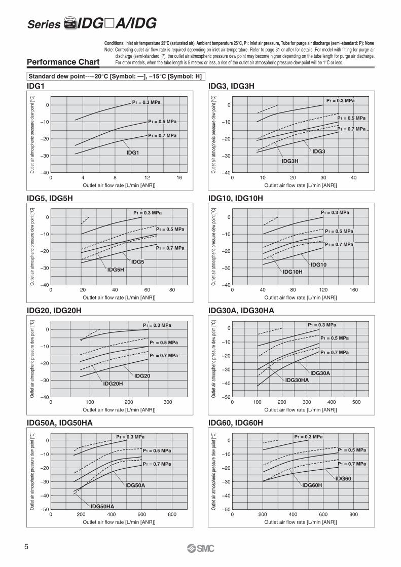
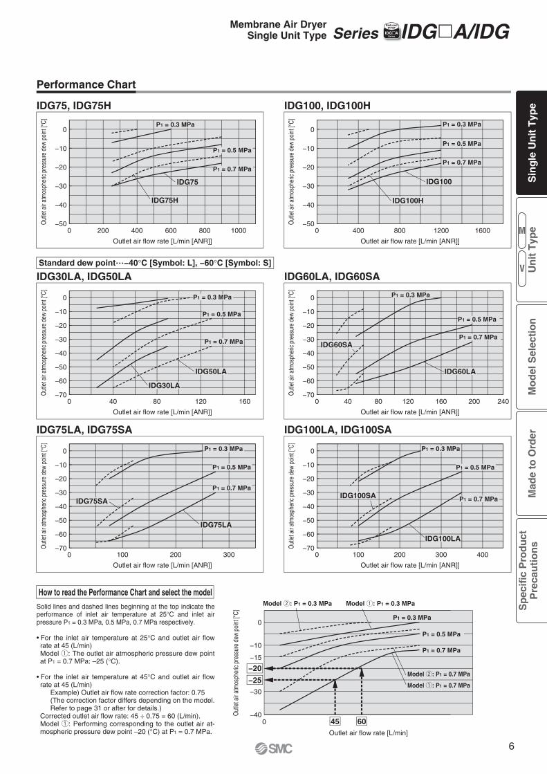
Performance Chart
0 4 8 12 16
IDG1
Outlet air flow rate [L/min [ANR]]
Out
let a
ir at
mos
pher
ic pr
essu
re d
ew p
oint
[°C]
−40
−30
−20
−10
0
0 10 20 30 40
IDG3, IDG3H
Outlet air flow rate [L/min [ANR]]
Out
let a
ir at
mos
pher
ic pr
essu
re d
ew p
oint
[°C]
−40
−30
−20
−10
0P1 = 0.3 MPa
P1 = 0.5 MPa
P1 = 0.7 MPa
IDG1
P1 = 0.3 MPa
P1 = 0.5 MPa
P1 = 0.7 MPa
0 100 200 300 400 500
IDG30A, IDG30HA
Outlet air flow rate [L/min [ANR]]
Out
let a
ir at
mos
pher
ic pr
essu
re d
ew p
oint
[°C]
0 100 200 300
IDG20, IDG20H
Outlet air flow rate [L/min [ANR]]
Out
let a
ir at
mos
pher
ic pr
essu
re d
ew p
oint
[°C]
−40
−30
−20
−10
0
0 40 80 120 160
IDG10, IDG10H
Outlet air flow rate [L/min [ANR]]
Out
let a
ir at
mos
pher
ic pr
essu
re d
ew p
oint
[°C]
−40
−30
−20
−10
0
0 20 40 60 80
IDG5, IDG5H
Outlet air flow rate [L/min [ANR]]
Out
let a
ir at
mos
pher
ic pr
essu
re d
ew p
oint
[°C]
−40
−30
−20
−10
0
−50
−40
−30
−20
−10
0
0 200 400 600 800
IDG60, IDG60H
Outlet air flow rate [L/min [ANR]]
Out
let a
ir at
mos
pher
ic pr
essu
re d
ew p
oint
[°C]
−50
−40
−30
−20
−10
0
0 200 400 600 800
IDG50A, IDG50HA
Outlet air flow rate [L/min [ANR]]
Out
let a
ir at
mos
pher
ic pr
essu
re d
ew p
oint
[°C]
−50
−40
−30
−20
−10
0P1 = 0.3 MPa
P1 = 0.5 MPa
P1 = 0.7 MPa
P1 = 0.3 MPa
P1 = 0.5 MPa
P1 = 0.7 MPa
P1 = 0.3 MPa
P1 = 0.5 MPa
P1 = 0.7 MPa
P1 = 0.3 MPa
P1 = 0.5 MPa
P1 = 0.7 MPa
IDG5IDG5H
P1 = 0.3 MPa
P1 = 0.5 MPa
P1 = 0.7 MPa
IDG10IDG10H
IDG60IDG60H
IDG30AIDG30HA
IDG50A
IDG50HA
P1 = 0.3 MPa
P1 = 0.5 MPa
P1 = 0.7 MPa
IDG20IDG20H
IDG3
IDG3H
Standard dew point…−20°C [Symbol: —], −15°C [Symbol: H]
Conditions: Inlet air temperature 25°C (saturated air), Ambient temperature 25°C, P1: Inlet air pressure, Tube for purge air discharge (semi-standard: P): NoneNote: Correcting outlet air flow rate is required depending on inlet air temperature. Refer to page 31 or after for details. For model with fitting for purge air
discharge (semi-standard: P), the outlet air atmospheric pressure dew point may become higher depending on the tube length for purge air discharge. For other models, when the tube length is 5 meters or less, a rise of the outlet air atmospheric pressure dew point will be 1°C or less.
Series IDG�A/IDG IIDG�ASeries
Reducedpurge
5
Performance Chart
0 40 80 120 160
IDG30LA, IDG50LA
Outlet air flow rate [L/min [ANR]]
Out
let a
ir at
mos
pher
ic pr
essu
re d
ew p
oint
[°C]
0 400 800 1200 1600
IDG100, IDG100H
Outlet air flow rate [L/min [ANR]]
Out
let a
ir at
mos
pher
ic pr
essu
re d
ew p
oint
[°C]
−50
−40
−30
−20
−10
0
0 200 400 600 800 1000
IDG75, IDG75H
Outlet air flow rate [L/min [ANR]]
Out
let a
ir at
mos
pher
ic pr
essu
re d
ew p
oint
[°C]
−50
−40
−30
−20
−10
0
−70
−60
−50
−40
−30
−20
−10
0
0 40 80 120 160 200 240
IDG60LA, IDG60SA
Outlet air flow rate [L/min [ANR]]
Out
let a
ir at
mos
pher
ic pr
essu
re d
ew p
oint
[°C]
−70
−60
−50
−40
−30
−20
−10
0
0 100 200 300 400
IDG100LA, IDG100SA
Outlet air flow rate [L/min [ANR]]
Out
let a
ir at
mos
pher
ic pr
essu
re d
ew p
oint
[°C]
−70
−60
−50
−40
−30
−20
−10
0
0 100 200 300
IDG75LA, IDG75SA
Outlet air flow rate [L/min [ANR]]
Out
let a
ir at
mos
pher
ic pr
essu
re d
ew p
oint
[°C]
−70
−60
−50
−40
−30
−20
−10
0 P1 = 0.3 MPa
P1 = 0.5 MPa
P1 = 0.7 MPa
P1 = 0.3 MPa
P1 = 0.5 MPa
P1 = 0.7 MPa
P1 = 0.3 MPa
P1 = 0.5 MPa
P1 = 0.7 MPa
P1 = 0.3 MPa
P1 = 0.5 MPa
P1 = 0.7 MPa
P1 = 0.3 MPa
P1 = 0.5 MPa
P1 = 0.7 MPa
P1 = 0.3 MPa
P1 = 0.5 MPa
P1 = 0.7 MPa
IDG75LA
IDG75SA
IDG60LA
IDG60SA
IDG50LA
IDG30LA
IDG100LA
IDG100SA
IDG100
IDG100H
IDG75
IDG75H
How to read the Performance Chart and select the modelSolid lines and dashed lines beginning at the top indicate the performance of inlet air temperature at 25°C and inlet air pressure P1 = 0.3 MPa, 0.5 MPa, 0.7 MPa respectively.
For the inlet air temperature at 25°C and outlet air flow rate at 45 (L/min)Model q: The outlet air atmospheric pressure dew point at P1 = 0.7 MPa: –25 (°C).
For the inlet air temperature at 45°C and outlet air flow rate at 45 (L/min)
Example) Outlet air flow rate correction factor: 0.75(The correction factor differs depending on the model. Refer to page 31 or after for details.)
Corrected outlet air flow rate: 45 ÷ 0.75 = 60 (L/min).Model q: Performing corresponding to the outlet air at-mospheric pressure dew point –20 (°C) at P1 = 0.7 MPa. Outlet air flow rate [L/min]
Model q: P1 = 0.3 MPaModel w: P1 = 0.3 MPa
0−40
−30
−20
−10
0
−15
−25
Out
let a
ir at
mos
pher
ic pr
essu
re d
ew p
oint
[°C]
45 60
P1 = 0.3 MPa
P1 = 0.5 MPa
P1 = 0.7 MPa
Model q: P1 = 0.7 MPa
Model w: P1 = 0.7 MPa
Standard dew point…−40°C [Symbol: L], −60°C [Symbol: S]
Series IDG�A/IDG IIDG�ASeries
ReducedpurgeMembrane Air Dryer
Single Unit Type
M
V
Sin
gle
Un
it T
ype
Mo
del
Sel
ecti
on
Mad
e to
Ord
erS
pec
ific
Pro
du
ctP
reca
uti
on
sU
nit
Typ
e
6
0 161284Inlet air flow rate [L/min [ANR]]
Pre
ssur
e dr
op [M
Pa]
0.00 0.00
0.00
0.00
0.00
Inlet air flow rate [L/min [ANR]]
Pre
ssur
e dr
op [M
Pa]
0 40302010
Inlet air flow rate [L/min [ANR]]
Pre
ssur
e dr
op [M
Pa]
Inlet air flow rate [L/min [ANR]]
Pre
ssur
e dr
op [M
Pa]
0 80604020
Inlet air flow rate [L/min [ANR]]
Pre
ssur
e dr
op [M
Pa]
0 16080 12040
0 200 300100 0 500400300200100Inlet air flow rate [L/min [ANR]]
Pre
ssur
e dr
op [M
Pa]
0.03
0.02
0.01
0.00
Inlet air flow rate [L/min [ANR]]
Pre
ssur
e dr
op [M
Pa]
0 800600400200
0.08
0.06
0.04
0.02
0.00
Inlet air flow rate [L/min [ANR]]
Pre
ssur
e dr
op [M
Pa]
0.06
0.05
0.04
0.03
0.02
0.01
0.000 800600400200 1000
0.01
0.02
0.03
0.04
0.01
0.02
0.03
0.04
0.01
0.02
0.03
0.04
0.02
0.04
0.06
0.02
0.04
0.06
0.08
P1 = 0.3 MPa
P1 = 0.5 MPa
P1 = 0.7 MPa
P1 = 0.3 MPa
P1 = 0.5 MPa
P1 = 0.7 MPa
P1 = 0.3 MPa
P1 = 0.5 MPa
P1 = 0.7 MPa
P1 = 0.3 MPa
P1 = 0.5 MPa
P1 = 0.7 MPa
P1 = 0.3 MPa
P1 = 0.5 MPa
P1 = 0.7 MPa
P1 = 0.3 MPa
P1 = 0.5 MPa
P1 = 0.7 MPa
P1 = 0.3 MPa
P1 = 0.5 MPa
P1 = 0.7 MPa
P1 = 0.3 MPa
P1 = 0.5 MPa
P1 = 0.7 MPa
IDG1
IDG5, IDG5H
IDG3, IDG3H
IDG10, IDG10H
IDG20, IDG20H IDG30A, IDG30HA
IDG60A, IDG60HAIDG50A, IDG50HA
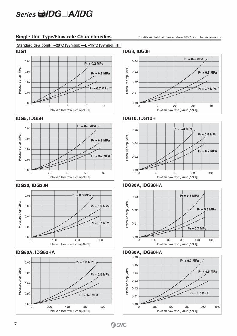
Standard dew point…−20°C [Symbol: —], −15°C [Symbol: H]
Single Unit Type/Flow-rate Characteristics Conditions: Inlet air temperature 25°C, P1: Inlet air pressure
Series IDG�A/IDGIIDG�ASeries
Reducedpurge
7
0 300200100Inlet air flow rate [L/min [ANR]]
Pre
ssur
e dr
op [M
Pa]
Inlet air flow rate [L/min [ANR]]
Pre
ssur
e dr
op [M
Pa]
Inlet air flow rate [L/min [ANR]]
Pre
ssur
e dr
op [M
Pa]
0 400300200100
Inlet air flow rate [L/min [ANR]]
Pre
ssur
e dr
op [M
Pa]
0.08
0.06
0.04
0.02
0.000 1000600 800400200 1200
0 200 300 400100
Inlet air flow rate [L/min [ANR]]
Pre
ssur
e dr
op [M
Pa]
0.10
0.08
0.06
0.04
0.02
0.000 800 1200400 1600
0.00 0.00
0.00
0.002
0.004
0.006
0.008
0.01
0.004
0.008
0.012
0.016
0.02
0.01
0.02
0.03
P1 = 0.3 MPa
P1 = 0.5 MPa
P1 = 0.7 MPa
P1 = 0.3 MPa
P1 = 0.5 MPa
P1 = 0.7 MPa
P1 = 0.3 MPa
P1 = 0.5 MPa
P1 = 0.7 MPa
P1 = 0.3 MPa
P1 = 0.5 MPa
P1 = 0.7 MPa
P1 = 0.3 MPa
P1 = 0.5 MPa
P1 = 0.7 MPa
Inlet air flow rate [L/min [ANR]]
Pre
ssur
e dr
op [M
Pa]
Inlet air flow rate [L/min [ANR]]
Pre
ssur
e dr
op [M
Pa]
0 100 200 300 400 500
0.01
0.02
0.03P1 = 0.3 MPa
P1 = 0.5 MPa
P1 = 0.7 MPa
0 200 400 600 800
0.02
0.04
0.06
0.08 P1 = 0.3 MPa
P1 = 0.5 MPa
P1 = 0.7 MPa
IDG60LA, IDG60SA IDG75LA, IDG75SA
IDG75, IDG75H
IDG100LA, IDG100SA
IDG100, IDG100H
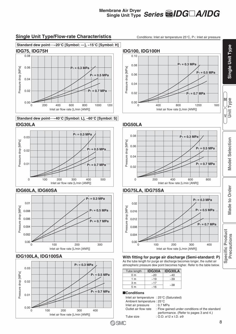
Standard dew point…−40°C [Symbol: L], −60°C [Symbol: S]
Single Unit Type/Flow-rate Characteristics Conditions: Inlet air temperature 25°C, P1: Inlet air pressure
Standard dew point…−20°C [Symbol: —], −15°C [Symbol: H]
IDG30LA IDG50LA
Tube length
�ConditionsInlet air temperature : 25°C (Saturated)Ambient temperature : 25°CInlet air pressure : 0.7 MPaOutlet air flow rate : Flow gained under conditions of the standard
performance. (Refer to pages 3 and 4.)Tube size : O.D. ø12 x I.D. ø9
IDG30A IDG30LA−20−19−17−16
−40−39
−38
0 m1 m3 m5 m
With fitting for purge air discharge (Semi-standard: P)As the tube length for purge air discharge becomes longer, the outlet air atmospheric pressure dew point becomes higher. Refer to the table below.
Series IDG�A/IDGIIDG�ASeries
ReducedpurgeMembrane Air Dryer
Single Unit Type
M
V
Sin
gle
Un
it T
ype
Mo
del
Sel
ecti
on
Mad
e to
Ord
erS
pec
ific
Pro
du
ctP
reca
uti
on
sU
nit
Typ
e
8
0
Inlet air pressure [MPa]
Pur
ge a
ir flo
w r
ate
[L/m
in]
0 0.5 1.00.5 1.0
Inlet air pressure [MPa]
Pur
ge a
ir flo
w r
ate
[L/m
in]
0 0.5 1.0
Inlet air pressure [MPa]
Pur
ge a
ir flo
w r
ate
[L/m
in]
Inlet air pressure [MPa]
Pur
ge a
ir flo
w r
ate
[L/m
in]
0
125
100
75
50
25
0
150
100
50
0
40
50
60
10
20
30
240
200
160
120
80
40
280
1.00
0.50
IDG20H
IDG10H
IDG3, IDG5H
IDG3H
IDG20
IDG10
IDG1
IDG5
IDG75
IDG60
IDG100
IDG75H
IDG100H
IDG60H
IDG100SA
IDG100LA
IDG75LA
IDG60LA
IDG60SA
IDG75SA
IDG50A
IDG30A
IDG50HA
IDG30HA
IDG50LA
IDG30LA
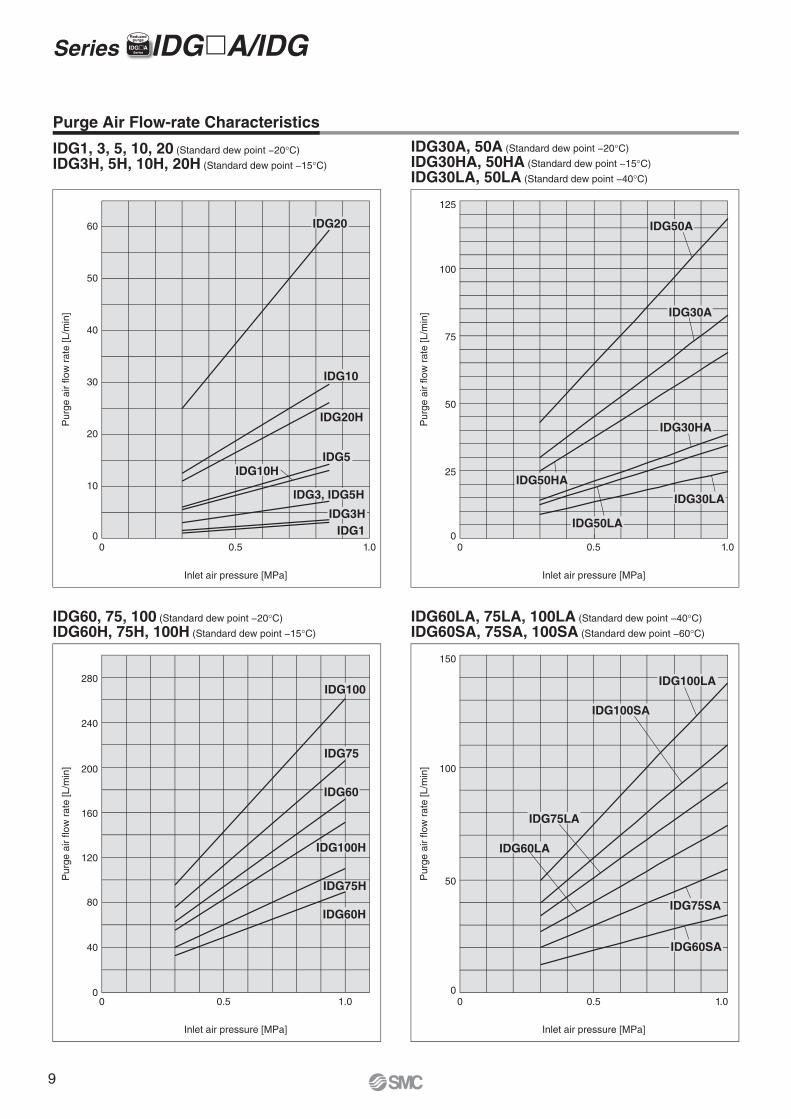
Purge Air Flow-rate Characteristics
IDG1, 3, 5, 10, 20 (Standard dew point −20°C)
IDG3H, 5H, 10H, 20H (Standard dew point −15°C)
IDG30A, 50A (Standard dew point −20°C)
IDG30HA, 50HA (Standard dew point −15°C)
IDG30LA, 50LA (Standard dew point −40°C)
IDG60LA, 75LA, 100LA (Standard dew point −40°C)
IDG60SA, 75SA, 100SA (Standard dew point −60°C)
IDG60, 75, 100 (Standard dew point −20°C)
IDG60H, 75H, 100H (Standard dew point −15°C)
Series IDG�A/IDGIIDG�ASeries
Reducedpurge
9
t
e
q
q
o
t
!0q
y
t
i
r
w
i
IDG1
Semi-standardWith fitting for purge air discharge (Semi-standard: P)
Purge air for dehumidification
Semi-standard
With fitting for purge air discharge
(Semi-standard: P)
Semi-standard
With fitting for purgeair discharge
(Semi-standard: P)
IDG3, 5IDG3H, 5H
IDG10, 20IDG10H, 20H
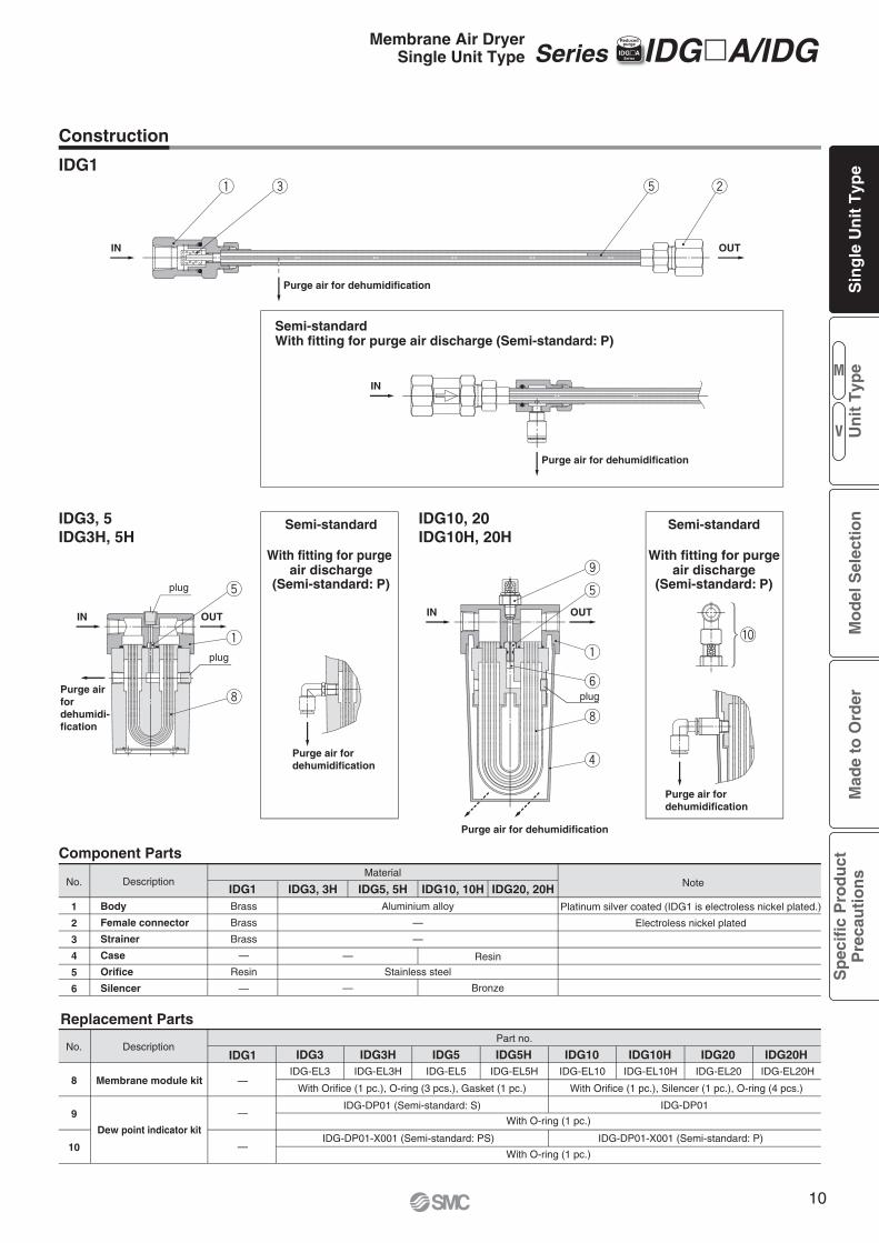
Replacement Parts
Component Parts
No.
1
2
3
4
5
6
Description
Body
Female connector
Strainer
Case
Orifice
Silencer
Brass
Brass
Brass
—
Resin
—
Aluminium alloy
—
—
Stainless steel
IDG1 IDG5, 5H IDG10, 10H IDG20, 20H
Resin
Material
Platinum silver coated (IDG1 is electroless nickel plated.)
Electroless nickel plated
Note
—
— Bronze
IDG3, 3H
Purge air for dehumidification
Purge air for dehumidification
Purge air for dehumidification
Purge air for dehumidification
IN
Purge airfordehumidi-fication
OUT
OUTIN
IN
IN OUT
plug
plug
plug
IDG1 IDG3H IDG5 IDG5H IDG10 IDG10H IDG20 IDG20HNo.
8
9
10
Description
IDG-DP01-X001 (Semi-standard: P)
IDG-EL10 IDG-EL20
Dew point indicator kit
Membrane module kit
IDG-DP01 (Semi-standard: S)
IDG-DP01-X001 (Semi-standard: PS)
IDG-EL5
IDG-DP01
With Orifice (1 pc.), O-ring (3 pcs.), Gasket (1 pc.) With Orifice (1 pc.), Silencer (1 pc.), O-ring (4 pcs.)
With O-ring (1 pc.)
With O-ring (1 pc.)
—
—
—
IDG3IDG-EL3
Part no.
IDG-EL3H IDG-EL5H IDG-EL10H IDG-EL20H
Construction
Series IDG�A/IDGIIDG�ASeries
ReducedpurgeMembrane Air Dryer
Single Unit Type
M
V
Sin
gle
Un
it T
ype
Mo
del
Sel
ecti
on
Mad
e to
Ord
erS
pec
ific
Pro
du
ctP
reca
uti
on
sU
nit
Typ
e
10
!0
o
q
i
w
r
te
e
oq
i
w
r
y
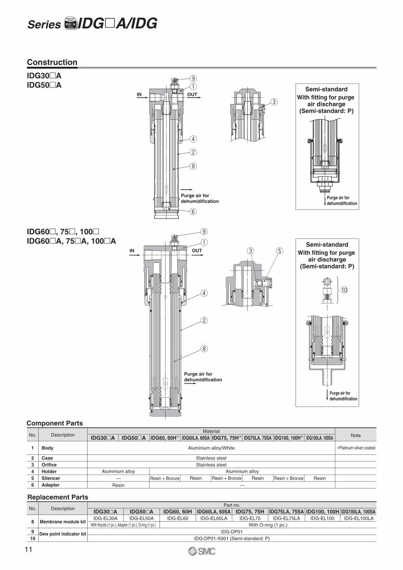
Component Parts
No.
1
23456
Description
Body
CaseOrificeHolderSilencerAdapter
Aluminium alloy
—Resin
Aluminium alloy
—
Aluminium alloy/White
Stainless steelStainless steel
IDG30�A IDG50�A IDG60, 60H∗ IDG60LA, 60SA IDG75LA, 75SAIDG75, 75H∗ IDG100LA, 100SAIDG100, 100H∗
IDG30�A IDG50�A IDG60, 60H IDG60LA, 60SA IDG75, 75H IDG75LA, 75SA IDG100, 100H IDG100LA, 100SA
Material
∗Platinum silver coated
Replacement Parts
No.
8
910
Description
Note
IDG-EL60 IDG-EL60LA IDG-EL75LAIDG-EL75 IDG-EL100 IDG-EL100LAWith O-ring (1 pc.)
Membrane module kit
IDG-DP01IDG-DP01-X001 (Semi-standard: P)
IDG-EL30AWith Nozzle (1 pc.), Adapter (1 pc.), O-ring (1 pc.)
IDG-EL50A
Part no.
Resin + Bronze Resin Resin + Bronze Resin Resin + Bronze Resin
Dew point indicator kit
Series IDG�A/IDG IIDG�ASeries
Reducedpurge
Construction
IDG60�, 75�, 100�IDG60�A, 75�A, 100�A
IDG30�AIDG50�A
Semi-standardWith fitting for purge
air discharge(Semi-standard: P)
Purge air fordehumidification
IN OUT
Purge air fordehumidification
Purge air fordehumidification
Purge air for dehumidification
OUTINSemi-standard
With fitting for purge air discharge
(Semi-standard: P)
No. DescriptionIDG30�A IDG50�A IDG60, 60H∗ IDG60LA, 60SA IDG75LA, 75SAIDG75, 75H∗ IDG100LA, 100SAIDG100, 100H∗
IDG30�A IDG50�A IDG60, 60H IDG60LA, 60SA IDG75, 75H IDG75LA, 75SA IDG100, 100H IDG100LA, 100SA
Material
No. Description
Note
Part no.
11

(Maintenance space 100 mm or more)
Purge air fordehumidification
Purge air for dewpoint indicator
(Maintenance space 100 mm or more)
IN
16
D
B
OUT
7
Purge air for dewpoint indicator
EA
Bracket(Accessory: B)
ø8
30
40
22
2.3
11
14
Purge air fordehumidification
Port sizeL
73
17
IN
Dew point indicator(Semi-standard: S)
38With fitting for purge air discharge(Semi-standard: P)
2.3
Purge air fordehumidification
Bracket(Accessory: B)
2311
8 140
C41
6
12
OUT
IDG10, 10HIDG20, 20H Values inside [ ] are for NPT thread.
Model
1/4, 3/8
Semi-standard: PPort sizeL A B C D E
83
113
187
212
53
54
165
190
62
82
F HG J114
140 [139]
8
10
225
250
5/16
3/8
With fitting for purge air discharge (Semi-standard: P)
With fitting for purge air discharge (Semi-standard: P)IDG1-C06: With One-touch fitting
Port size: 1/8, 1/4
14
(46)
(67)
(293)
Purge air for dehumidification
(26)
INPort size: 1/4
Hexagon widthacross flats 19 Hexagon width
across flats 17
OUTPort size: 1/4
OUTApplicable tubing O.D.: ø6
Purge air discharge portApplicable tubing O.D.: ø6
Hexagon width across flats 17
Hexagon width across flats 14
(67)
(86) Purge air for dehumidification(33)
(23)
INApplicable tubing O.D.: ø6
(92)
OUTIN
Purge air discharge tubing port for dehumidification
Applicable tubing O.D.Rc thread and G thread: øHNPT thread: øJ"
Purge air discharge tubingport for dew point indicator
Applicable tubing O.D.Rc thread and G thread: ø8NPT thread: ø5/16"
IN OUT
(F)(G
)
Purge air discharge tubing port for dehumidification
Applicable tubing O.D.Rc thread and G thread: ø8NPT thread: ø5/16"
Series IDG�A/IDG IIDG�ASeries
Reducedpurge
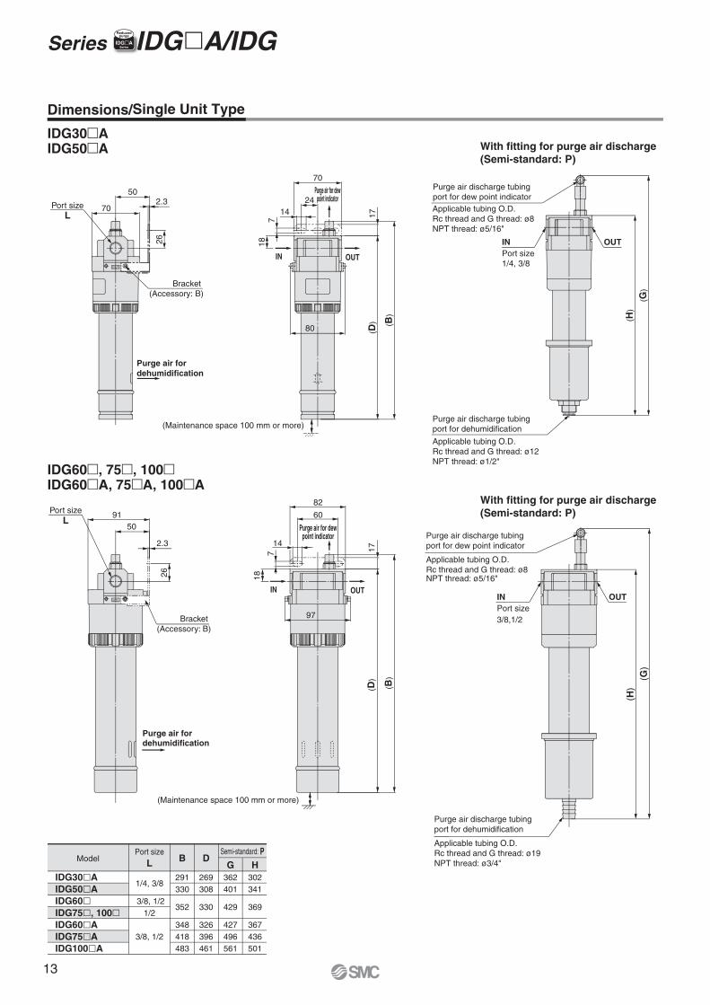
Dimensions/Single Unit Type
IDG1
IDG3, 5IDG3H, 5H
IDG10, 20IDG10H, 20H
Purge air discharge tubing portfor dehumidificationApplicable tubing O.D.: ø6(NPT thread: ø1/4")
With fitting for purge air discharge(Semi-standard: P)
(23) (50)
ø8
(280)
Purge air discharge port(50)
Membrane Air DryerSingle Unit Type
M
V
Sin
gle
Un
it T
ype
Mo
del
Sel
ecti
on
Mad
e to
Ord
erS
pec
ific
Pro
du
ctP
reca
uti
on
sU
nit
Typ
e
12
OUT
IN OUT
50
2.3
91
82
97
7 17
26
(B)
(D)
18
60
14
2.350
26
80
18
17( D
) ( B)
14
7
24
70
70
OUT
IN OUT
OUTINPort size1/4, 3/8
(G)
( H)
Purge air discharge tubingport for dehumidification
Applicable tubing O.D.Rc thread and G thread: ø12NPT thread: ø1/2"
Purge air for dewpoint indicator
Purge air fordehumidification
(Maintenance space 100 mm or more)
Bracket(Accessory: B)
Purge air discharge tubingport for dew point indicatorApplicable tubing O.D.Rc thread and G thread: ø8NPT thread: ø5/16"
Purge air for dewpoint indicator
(Maintenance space 100 mm or more)
Purge air fordehumidification
Bracket (Accessory: B)
Port sizeL
With fitting for purge air discharge(Semi-standard: P)
With fitting for purge air discharge(Semi-standard: P)Port size
L
1/4, 3/8
3/8, 1/21/2
3/8, 1/2
DBHG
IDG30�AIDG50�AIDG60�IDG75�, 100�IDG60�AIDG75�AIDG100�A
269308
330
326396461
291330
352
348418483
302341
369
367436501
362401
429
427496561
(G)
(H)
OUTINPort size3/8,1/2
Purge air discharge tubingport for dew point indicator
Applicable tubing O.D.Rc thread and G thread: ø19NPT thread: ø3/4"
Purge air discharge tubingport for dehumidification
Dimensions/Single Unit Type
ModelSemi-standard: PPort size
L
IDG60�, 75�, 100�IDG60�A, 75�A, 100�A
IDG30�AIDG50�A
Applicable tubing O.D.Rc thread and G thread: ø8NPT thread: ø5/16"
Series IDG�A/IDG IIDG�ASeries
Reducedpurge
13
M
V
Sin
gle
Un
it T
ype
Mo
del
Sel
ecti
on
Mad
e to
Ord
erS
pec
ific
Pro
du
ctP
reca
uti
on
sU
nit
Typ
e
14
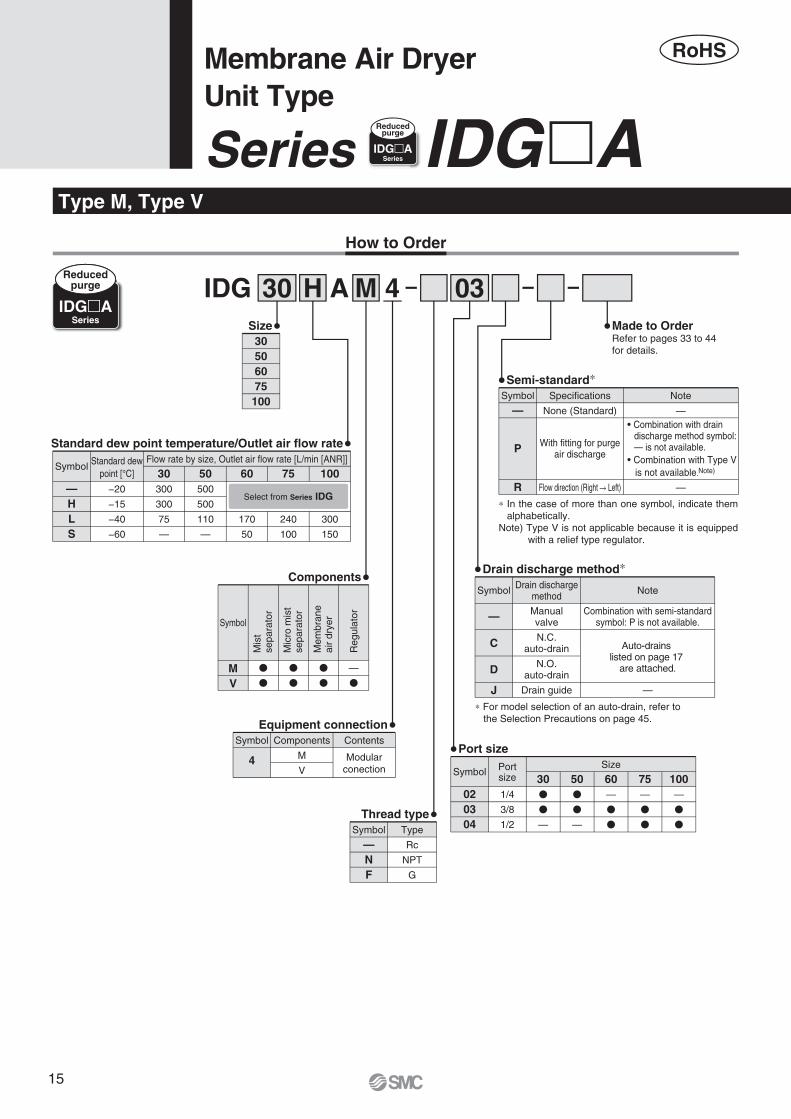
AIDG 0330
30506075
100
Size
Components
Standard dew point temperature/Outlet air flow rate
Made to OrderRefer to pages 33 to 44 for details.
MH 4
MV
Symbol
Reg
ulat
or
Mem
bran
eai
r dr
yer
Mic
ro m
ist
sepa
rato
r
Mis
tse
para
tor
�
�
�
�
�
�
—
�
How to Order
—HLS
SymbolFlow rate by size, Outlet air flow rate [L/min [ANR]]Standard dew
point [°C] 30−20
−15
−40
−60
300
300
75
—
50500
500
110
—
60
170
50
75
240
100
100
300
150
Type M, Type V
Select from Series IDG
RoHS
—
C
NoteSymbol Drain dischargemethod
Manualvalve
Combination with semi-standardsymbol: P is not available.
N.C.auto-drain Auto-drains
listed on page 17 are attached.D N.O.
auto-drain
J Drain guide —
Drain discharge method∗
020304
Symbol Portsize
Size
301/4
3/8
1/2
�
�
—
50�
�
—
60—
�
�
75—
�
�
100—
�
�
Port size
Thread type
—NF
Type
Rc
NPT
G
Symbol
Equipment connection
4
Components
M
V
Contents
Modularconection
Symbol
Semi-standard∗
—
P
R
Specifications
None (Standard)
With fitting for purgeair discharge
Flow direction (Right � Left)
Note
—
—
Symbol
∗ In the case of more than one symbol, indicate them alphabetically.
Note) Type V is not applicable because it is equipped with a relief type regulator.
∗ For model selection of an auto-drain, refer to the Selection Precautions on page 45.
Combination with drain discharge method symbol: — is not available.
Combination with Type V is not available.Note)
IDG�ASeries
Reducedpurge
Membrane Air DryerUnit Type
Series IDG�AIDG�ASeries
Reducedpurge
15
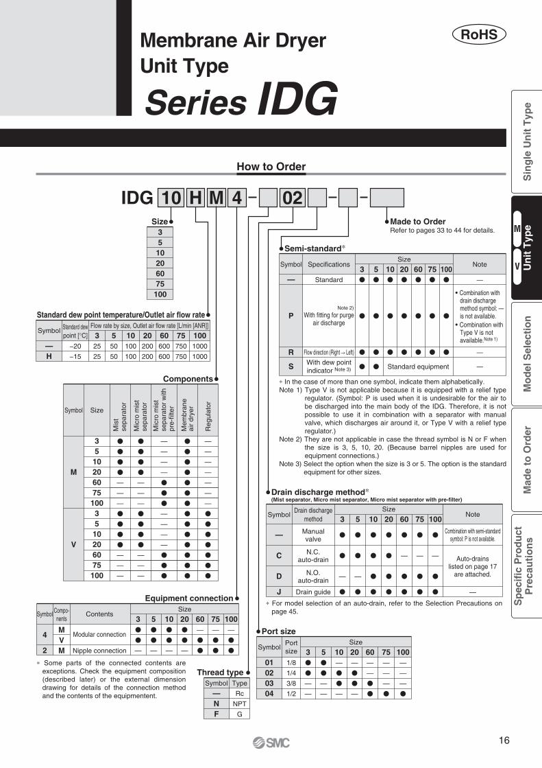
IDG 0210
35
10206075
100
Size
Components
Standard dew point temperature/Outlet air flow rate
—
SizeSymbol
Drain dischargemethod 3 5 10 20 60 75 100
Manualvalve
N.C.auto-drain
N.O.auto-drain
C
D
J Drain guide
�
�
—
�
�
�
—
�
�
�
�
�
�
�
�
�
�
—
�
�
�
—
�
�
�
—
�
�
Drain discharge method∗(Mist separator, Micro mist separator, Micro mist separator with pre-filter)
4
2
Modular connection
Nipple connection
Symbol ContentsSize
MVM
3�
�
—
5�
�
—
10�
�
—
20�
�
—
60—
�
�
75—
�
�
100—
�
�
Equipment connection
01020304
SymbolPortsize
Size
1/8
1/4
3/8
1/2
20—
�
�
—
10—
�
�
—
5�
�
—
—
3�
�
—
—
60—
—
�
�
75—
—
—
�
100—
—
—
�
Port size
Thread type
—NF
Type
Rc
NPT
G
Symbol
Semi-standard∗
Made to OrderRefer to pages 33 to 44 for details.
MH 4
How to Order
M
V
Symbol Size
�
�
�
�
—
—
—
�
�
�
�
—
—
—
�
�
�
�
�
�
�
�
�
�
�
�
�
�
—
—
—
—
—
—
—
�
�
�
�
�
�
�
35102060751003510206075100
�
�
�
�
—
—
—
�
�
�
�
—
—
—
—
—
—
—
�
�
�
—
—
—
—
�
�
�
—H
SymbolFlow rate by size, Outlet air flow rate [L/min [ANR]]Standard dew
point [°C] 10−20
−15
100
100
550
50
325
25
20200
200
60600
600
75750
750
1001000
1000
∗ In the case of more than one symbol, indicate them alphabetically.Note 1) Type V is not applicable because it is equipped with a relief type
regulator. (Symbol: P is used when it is undesirable for the air to be discharged into the main body of the IDG. Therefore, it is not possible to use it in combination with a separator with manual valve, which discharges air around it, or Type V with a relief type regulator.)
Note 2) They are not applicable in case the thread symbol is N or F when the size is 3, 5, 10, 20. (Because barrel nipples are used for equipment connections.)
Note 3) Select the option when the size is 3 or 5. The option is the standard equipment for other sizes.
Standard
Note 2)
With fitting for purgeair discharge
Symbol Specifications NoteSize
Standard equipment
—
P
R
S
Flow direction (Right � Left)
With dew pointindicator Note 3)
—
—
—
∗ For model selection of an auto-drain, refer to the Selection Precautions on page 45.
∗ Some parts of the connected contents are exceptions. Check the equipment composition (described later) or the external dimension drawing for details of the connection method and the contents of the equipmentent.
RoHS
3
�
�
�
�
5
�
�
�
�
10�
�
�
20�
�
�
60�
�
�
75�
�
�
100�
�
�
Note
—
Auto-drains listed on page 17
are attached.
Combination with semi-standardsymbol: P is not available.
Combination with drain discharge method symbol: — is not available.
Combination with Type V is not available.Note 1)
Reg
ulat
or
Mem
bran
eai
r dr
yer
Mic
ro m
ist
sepa
rato
r w
ith
pre-
filte
r
Mic
ro m
ist
sepa
rato
r
Mis
tse
para
tor
Compo-nents
Series IDG Membrane Air DryerUnit Type
M
V
Sin
gle
Un
it T
ype
Mo
del
Sel
ecti
on
Mad
e to
Ord
erS
pec
ific
Pro
du
ctP
reca
uti
on
sU
nit
Typ
e
16
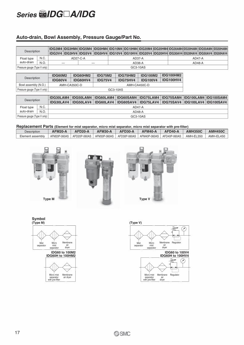
DescriptionIDG30AM4IDG30AV4
IDG20M4IDG20V4
IDG10M4IDG10V4
IDG10HM4IDG10HV4
IDG20HM4IDG20HV4
IDG5M4IDG5V4
IDG5HM4IDG5HV4
IDG3M4IDG3V4
IDG3HM4IDG3HV4
——
IDG50AM4IDG50AV4
AD47-A
AD48-A
AD37-A
AD38-A
AD27-C-A
IDG30HAM4IDG30HAV4
IDG50HAM4IDG50HAV4
GC3-10AS
Description AFM40-AAFM40P-060AS
AMH350CAMH-EL350
AFD40-AAFD40P-060AS
AMH450CAMH-EL450
AFM20-AAFM20P-060AS
AFM30-AAFM30P-060AS
AFD20-AAFD20P-060AS
AFD30-AAFD30P-060AS
DescriptionIDG30LAM4IDG30LAV4
IDG60LAM4IDG60LAV4
AD47-A
AD48-A
GC3-10AS
IDG50LAM4IDG50LAV4
IDG60SAM4IDG60SAV4
IDG75LAM4IDG75LAV4
IDG75SAM4IDG75SAV4
IDG100LAM4IDG100LAV4
IDG100SAM4IDG100SAV4
Float typeauto-drain
Pressure gauge (Type V only)
N.C.
N.O.
DescriptionIDG60M2IDG60V4
GC3-10AS
AMH-CA350C-D AMH-CA450C-D
IDG60HM2IDG60HV4
IDG75M2IDG75V4
IDG75HM2IDG75HV4
IDG100M2IDG100V4
IDG100HM2IDG100HV4
Bowl assembly (N.O.)
Pressure gauge (Type V only)
Float typeauto-drain
Pressure gauge (Type V only)
N.C.
N.O.
Element assembly
Replacement Parts (Element for mist separator, micro mist separator, micro mist separator with pre-filter)
Type M Type V
Auto-drain, Bowl Assembly, Pressure Gauge/Part No.
Symbol(Type M)
IDG60 to 100M2IDG60H to 100HM2
(Type V)
IDG60 to 100V4IDG60H to 100HV4
Mistseparator
Micromist
separator
RegulatorMembraneair
dryer
Mistseparator
Micromist
separator
Membraneair
dryer
Micro mistseparator
with pre-filter
Membraneair dryer
Micro mistseparator
with pre-filter
RegulatorMembraneair
dryer
Series IDG�A/IDG IIDG�ASeries
Reducedpurge
17
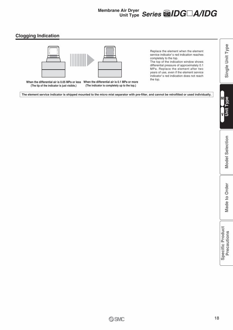
When the differential air is 0.05 MPa or less(The tip of the indicator is just visible.)
When the differential air is 0.1 MPa or more(The indicator is completely up to the top.)
Replace the element when the element service indicator’ s red indication reaches completely to the top.The top of the indication window shows differential pressure of approximately 0.1 MPa. Replace the element after two years of use, even if the element service indicator’ s red indication does not reach the top.
The element service indicator is shipped mounted to the micro mist separator with pre-filter, and cannot be retrofitted or used individually.
Clogging Indication
Series IDG�A/IDG IIDG�ASeries
ReducedpurgeMembrane Air Dryer
Unit Type
M
V
Sin
gle
Un
it T
ype
Mo
del
Sel
ecti
on
Mad
e to
Ord
erS
pec
ific
Pro
du
ctP
reca
uti
on
sU
nit
Typ
e
18
Model IDG30AM4IDG30AV4
IDG60M2IDG60V4
IDG75M2IDG75V4
Standard dew point: −20°C
360
300
60
720
600
120
−20
IDG50AM4IDG50AV4
586
500
86
888
750
138
AFM40-A
AFD40-A
Y400T-AY400-A (Type V only)
Y400-A (Type V only)
Y400-A (Type V only)
—
—
AMH350C AMH450C
IDG100M2IDG100V4
1185
1000
185
0.7
25
25
25
1 L/min [ANR] (Inlet air pressure at 0.7 MPa)
Relief type
AR40-B Note 2)
0.3 to 1.0
Compressed air
1/4, 3/8 3/8, 1/2 1/2
1.8
2.4
2.7
3.1
1.9
2.5
3.2
3.7
3.3
3.8
Mist separator
Micro mist separator
Micro mist separator with pre-filter
Regulator (Type V only) Note 1)
Spacer
Fluid
Inlet air pressure [MPa]
Inlet air temperature [°C]
Ambient temperature [°C]
Inlet air pressure [MPa]
Inlet air temperature [°C]
Inlet air saturation temperature [°C]
Ambient temperature [°C]
Outlet air atmospheric pressure dew point [°C]
Purge air flow rate[L/min [ANR]] Note 6)
Outlet air flow rate[L/min [ANR]]
Inlet air flow rate[L/min [ANR]] Note 5)
Dew point indicator purge air flow rate
Regulator construction (Type V only)
Port size
Weight [kg]Type M
Type V
Model IDG30HAM4IDG30HAV4
IDG60HM2IDG60HV4
Standard dew point: −15°CIDG75HM2IDG75HV4
−15
AFM40-A
AFD40-A
Y400T-AY400-A (Type V only)
—
—
AMH350C AMH450C
0.7
25
25
25
1 L/min [ANR] (Inlet air pressure at 0.7 MPa)
Relief type
AR40-B Note 2)
0.3 to 1.0
Compressed air
329
300
29
IDG50HAM4IDG50HAV4
550
500
50
665
600
65
818
750
68
IDG100HM2IDG100HV4
1100
1000
100
1/4, 3/8 3/8, 1/2 1/2
Mist separator
Micro mist separator
Micro mist separator with pre-filter
Regulator (Type V only) Note 1)
Spacer
Fluid
Inlet air pressure [MPa]
Inlet air temperature [°C]
Ambient temperature [°C]
Inlet air pressure [MPa]
Inlet air temperature [°C]
Inlet air saturation temperature [°C]
Ambient temperature [°C]
Outlet air atmospheric pressure dew point [°C]
Purge air flow rate[L/min [ANR]] Note 6)
Outlet air flow rate[L/min [ANR]]
Inlet air flow rate[L/min [ANR]] Note 5)
Dew point indicator purge air flow rate
Regulator construction (Type V only)
Port size
Weight [kg]Type M
Type V
0.3 to 0.85
−5 to 55 Note 3)
−5 to 55 Note 3)
IDG5M4IDG5V4
IDG10M4IDG10V4
IDG20M4IDG20V4
62
50
12
125
100
25
250
200
50
0.6
0.9
1.0
1.3
1.3
1.5
1.8
2.4
2.7
3.1
1.9
2.5
3.2
3.7
3.3
3.8
0.6
0.9
1.0
1.3
1.3
1.5
1/8, 1/4
IDG3M4IDG3V4
31
25
6
AFM20-A
AFD20-A
AR20-B Note 2)
Y200T-AY200-A (Type V only)
AFM30-A
AFD30-A
—
AR25-B Note 2)
Y300T-AY300-A (Type V only)
0.3 to 0.85
−5 to 55 Note 3)
−5 to 55 Note 3)
IDG5HM4IDG5HV4
IDG10HM4IDG10HV4
IDG20HM4IDG20HV4
56
50
6
111
100
11
222
200
22
1/8, 1/4
IDG3HM4IDG3HV4
28
25
3
AFM20-A
AFD20-A
AR20-B Note 2)
Y200T-AY200-A (Type V only)
AFM30-A
AFD30-A
—
AR25-B Note 2)
Y300T-AY300-A (Type V only)
−5 to 50 Note 3)
−5 to 50 Note 3)
5 to 50
5 to 50
5 to 50
5 to 50
−5 to 50 Note 3)
−5 to 50 Note 3)
Series IDG�A/IDG IIDG�ASeries
Reducedpurge
Standard Specifications/Unit [Type M, Type V] (Standard dew point: −20°C, −15°C)
Rang
e of o
perat
ingco
nditio
nsC
om
po
nen
tsS
tan
dar
d p
erfo
rman
ce
con
dit
ion
sSt
anda
rdper
forma
nceC
om
po
nen
tsS
tan
dar
d p
erfo
rman
ce
con
dit
ion
sRa
nge o
f ope
rating
cond
itions
Stan
dard
perfor
mance
19
Model IDG30LAM4IDG30LAV4
IDG60LAM4IDG60LAV4
IDG75LAM4IDG75LAV4
Standard dew point: −40°C
93
75
18
224
170
54
−40 Note 4)
IDG50LAM4IDG50LAV4
135
110
25
308
240
68
IDG100LAM4IDG100LAV4
400
300
100
AFM40-A
AFD40-A
AR40-B Note 2)
Compressed air
0.3 to 1.0
−5 to 50 Note 3)
−5 to 50 Note 3)
0.7
25
25
25
1 L/min [ANR] (Inlet air pressure at 0.7 MPa)
Relief type
1/4, 3/8 3/8, 1/2
1.8
2.4
2.6
3.1
1.9
2.5
2.8
3.3
2.9
3.4
Mist separator
Micro mist separator
Regulator (Type V only) Note 1)
Spacer
Fluid
Inlet air pressure [MPa]
Inlet air temperature [°C]
Ambient temperature [°C]
Inlet air pressure [MPa]
Inlet air temperature [°C]
Inlet air saturation temperature [°C]
Ambient temperature [°C]
Outlet air atmospheric pressure dew point [°C]
Purge air flow rate[L/min [ANR]] Note 6)
Outlet air flow rate[L/min [ANR]]
Inlet air flow rate[L/min [ANR]] Note 5)
Dew point indicator purge air flow rate
Regulator construction (Type V only)
Port size
Weight [kg]Type M
Type V
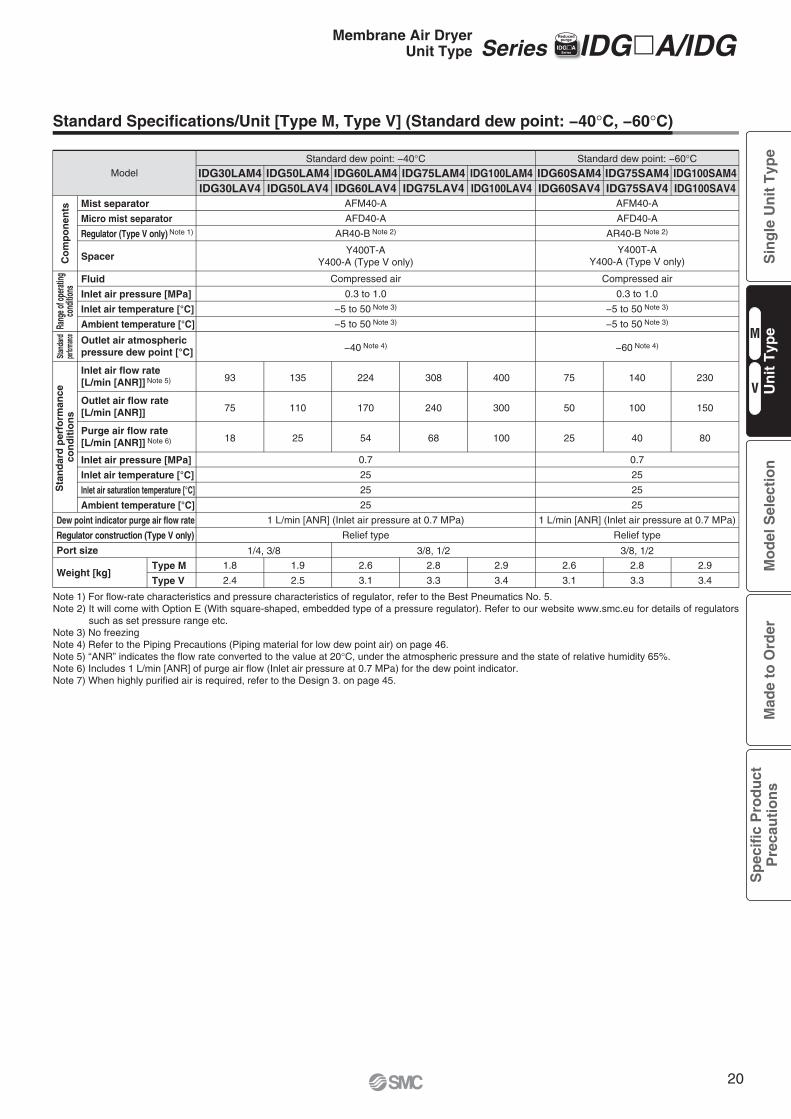
Note 1) For flow-rate characteristics and pressure characteristics of regulator, refer to the Best Pneumatics No. 5.Note 2) It will come with Option E (With square-shaped, embedded type of a pressure regulator). Refer to our website www.smc.eu for details of regulators
such as set pressure range etc.Note 3) No freezingNote 4) Refer to the Piping Precautions (Piping material for low dew point air) on page 46.Note 5) “ANR” indicates the flow rate converted to the value at 20°C, under the atmospheric pressure and the state of relative humidity 65%.Note 6) Includes 1 L/min [ANR] of purge air flow (Inlet air pressure at 0.7 MPa) for the dew point indicator.Note 7) When highly purified air is required, refer to the Design 3. on page 45.
IDG60SAM4IDG60SAV4
IDG100SAM4IDG100SAV4
Standard dew point: −60°C
−60 Note 4)
AFM40-A
AFD40-A
AR40-B Note 2)
Compressed air
0.3 to 1.0
−5 to 50 Note 3)
−5 to 50 Note 3)
0.7
25
25
25
1 L/min [ANR] (Inlet air pressure at 0.7 MPa)
Relief type
75
50
25
IDG75SAM4IDG75SAV4
140
100
40
230
150
80
3/8, 1/2
2.6
3.1
2.8
3.3
2.9
3.4
Y400T-AY400-A (Type V only)
Series IDG�A/IDGIIDG�ASeries
Reducedpurge
Standard Specifications/Unit [Type M, Type V] (Standard dew point: −40°C, −60°C)
Stan
dard
perfor
mance
Co
mp
on
ents
Sta
nd
ard
per
form
ance
co
nd
itio
ns
Rang
e of o
perat
ingco
nditio
ns
Membrane Air DryerUnit Type
Y400T-AY400-A (Type V only)
M
V
Sin
gle
Un
it T
ype
Mo
del
Sel
ecti
on
Mad
e to
Ord
erS
pec
ific
Pro
du
ctP
reca
uti
on
sU
nit
Typ
e
20
IDG3M4, 3V4 IDG3HM4, 3HV4
IDG5M4, 5V4 IDG5HM4, 5HV4
IDG10M4, 10V4 IDG10HM4, 10HV4
IDG20M4, 20V4IDG20HM4, 20HV4
IDG30AM4, IDG30HAV4 IDG50AM4, IDG50HAV4
IDG60M2, 60HM2 IDG60V4, 60HV4
IDG75M2, 75HM2 IDG75V4, 75HV4
0 40302010Inlet air flow rate [L/min [ANR]]
Pre
ssur
e dr
op [M
Pa]
0 1601208040Inlet air flow rate [L/min [ANR]]
Pre
ssur
e dr
op [M
Pa]
0 300200100Inlet air flow rate [L/min [ANR]]
Pre
ssur
e dr
op [M
Pa]
Inlet air flow rate [L/min [ANR]]
Pre
ssur
e dr
op [M
Pa]
0 80604020
0 0
0 0
0.02
0.04
0.06
0.08
0.10
0.12
0.02
0.04
0.06
0.08
0.10
0.12
0.02
0.04
0.06
0.08
0.10
0.12
0.02
0.04
0.06
0.08
0.10
0.12 P1 = 0.3 MPaP1 = 0.5 MPaP1 = 0.7 MPaP1 = 0.3 MPaP1 = 0.5 MPaP1 = 0.7 MPa
P1 = 0.3 MPaP1 = 0.5 MPaP1 = 0.7 MPaP1 = 0.3 MPaP1 = 0.5 MPaP1 = 0.7 MPa
P1 = 0.3 MPaP1 = 0.5 MPaP1 = 0.7 MPa
P1 = 0.3 MPaP1 = 0.5 MPaP1 = 0.7 MPa
P1 = 0.3 MPaP1 = 0.5 MPaP1 = 0.7 MPa
P1 = 0.3 MPaP1 = 0.5 MPaP1 = 0.7 MPa
0 500400300200100Inlet air flow rate [L/min [ANR]]
Pre
ssur
e dr
op [M
Pa] 0.08
0.06
0.04
0.02
0
Inlet air flow rate [L/min [ANR]]
Pre
ssur
e dr
op [M
Pa]
0 800600400200
0.12
0.10
0.08
0.06
0.04
0.02
0
P1 = 0.3 MPaP1 = 0.5 MPaP1 = 0.7 MPa
P1 = 0.3 MPaP1 = 0.5 MPaP1 = 0.7 MPa
P1 = 0.3 MPaP1 = 0.5 MPaP1 = 0.7 MPa
P1 = 0.3 MPaP1 = 0.5 MPaP1 = 0.7 MPa
0 800600400200Inlet air flow rate [L/min [ANR]]
Pre
ssur
e dr
op [M
Pa]
0
0.02
0.04
0.06
0.08
0.10
0.12 P1 = 0.3 MPaP1 = 0.5 MPaP1 = 0.7 MPaP1 = 0.3 MPaP1 = 0.5 MPaP1 = 0.7 MPa
0 1200900600300Inlet air flow rate [L/min [ANR]]
Pre
ssur
e dr
op [M
Pa]
0
0.02
0.04
0.06
0.08
0.10
0.12 P1 = 0.3 MPaP1 = 0.5 MPaP1 = 0.7 MPa
P1 = 0.3 MPaP1 = 0.5 MPaP1 = 0.7 MPa
Element saturated state (AMH) Element initial state (AMH) Element saturated state (AMH) Element initial state (AMH)
Element saturated state (AFM, AFD) Element initial state (AFM, AFD)
Element saturated state (AFM, AFD) Element initial state (AFM, AFD)
Element saturated state (AFM, AFD) Element initial state (AFM, AFD)Element saturated state (AFM, AFD) Element initial state (AFM, AFD)
Element saturated state (AFM, AFD) Element initial state (AFM, AFD)
Element saturated state (AFM, AFD) Element initial state (AFM, AFD)
Series IDG�A/IDGIIDG�ASeries
Reducedpurge
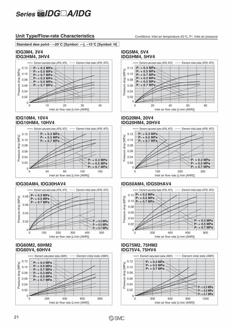
Unit Type/Flow-rate Characteristics
Standard dew point…−20°C [Symbol: —], −15°C [Symbol: H]
Conditions: Inlet air temperature 25°C, P1: Inlet air pressure
21
IDG60LAM4, 60SAM4 IDG60LAV4, 60SAV4
IDG75LAM4, 75SAM4 IDG75LAV4, 75SAV4
IDG100M2, 100HM2IDG100V4, 100HV4
IDG100LAM4, 100SAM4IDG100LAV4, 100SAV4
IDG30LAM4, IDG30LAV4 IDG50LAM4, IDG50LAV4
0 16001200800400Inlet air flow rate [L/min [ANR]]
Pre
ssur
e dr
op [M
Pa]
0
0.02
0.04
0.06
0.08
0.10
0.12 P1 = 0.3 MPaP1 = 0.5 MPaP1 = 0.7 MPa
P1 = 0.3 MPaP1 = 0.5 MPaP1 = 0.7 MPa
Element saturated state (AMH) Element initial state (AMH)
0 24016080Inlet air flow rate [L/min [ANR]]
Pre
ssur
e dr
op [M
Pa]
0 300200100Inlet air flow rate [L/min [ANR]]
Pre
ssur
e dr
op [M
Pa]
0 400300200100Inlet air flow rate [L/min [ANR]]
Pre
ssur
e dr
op [M
Pa]
0 0
0
0.02
0.04
0.06
0.08
0.02
0.04
0.06
0.08
0.10
0.12
0.02
0.04
0.06
0.08
0.10
0.12
P1 = 0.3 MPaP1 = 0.5 MPaP1 = 0.7 MPaP1 = 0.3 MPaP1 = 0.5 MPaP1 = 0.7 MPa
P1 = 0.3 MPaP1 = 0.5 MPaP1 = 0.7 MPaP1 = 0.3 MPaP1 = 0.5 MPaP1 = 0.7 MPa
P1 = 0.3 MPaP1 = 0.5 MPaP1 = 0.7 MPaP1 = 0.3 MPaP1 = 0.5 MPaP1 = 0.7 MPa
0 500400300200100Inlet air flow rate [L/min [ANR]]
Pre
ssur
e dr
op [M
Pa] 0.08
0.06
0.04
0.02
0
Inlet air flow rate [L/min [ANR]]
Pre
ssur
e dr
op [M
Pa]
0 800600400200
0.12
0.10
0.08
0.06
0.04
0.02
0
P1 = 0.3 MPaP1 = 0.5 MPaP1 = 0.7 MPa
P1 = 0.3 MPaP1 = 0.5 MPaP1 = 0.7 MPa
P1 = 0.3 MPaP1 = 0.5 MPaP1 = 0.7 MPa
P1 = 0.3 MPaP1 = 0.5 MPaP1 = 0.7 MPa
Element saturated state (AFM, AFD) Element initial state (AFM, AFD)Element saturated state (AFM, AFD) Element initial state (AFM, AFD)
Element saturated state (AFM, AFD) Element initial state (AFM, AFD) Element saturated state (AFM, AFD) Element initial state (AFM, AFD)
Element saturated state (AFM, AFD) Element initial state (AFM, AFD)
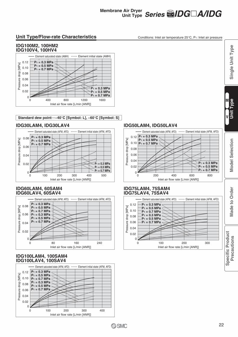
Unit Type/Flow-rate Characteristics Conditions: Inlet air temperature 25°C, P1: Inlet air pressure
Series IDG�A/IDG IIDG�ASeries
Reducedpurge
Standard dew point…−40°C [Symbol: L], −60°C [Symbol: S]
Membrane Air DryerUnit Type
M
V
Sin
gle
Un
it T
ype
Mo
del
Sel
ecti
on
Mad
e to
Ord
erS
pec
ific
Pro
du
ctP
reca
uti
on
sU
nit
Typ
e
22
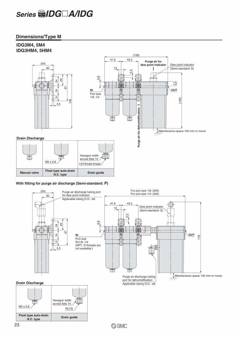
INPort size1/8, 1/4
9.8
12
5.5
43.241.6
(159)
Dew point indicator(Semi-standard: S)
OUT
(140
)
11
(54)
3013
6
67
292424
9
3.5
INPort sizeRc1/8, 1/4(NPT, G threads are not available.)
For port size 1/8: (204)For port size 1/4: (202)
9.8
5.5
43.241.6
12 Dew point indicator(Semi-standard: S)
OUT
178
Purge air discharge tubing port for dehumidificationApplicable tubing O.D.: ø8
30
(54) Purge air discharge tubing portfor dew point indicatorApplicable tubing O.D.: ø8
67
292424
9
3.5
(Maintenance space 100 mm or more)
(Maintenance space 100 mm or more)
Purge air fordew point indicator
Pu
rge
air
for
deh
um
idif
icat
ion
Hexagon widthacross flats 14
1/8 Female thread
Hexagon widthacross flats 14
Rc1/8
M5 x 0.8
M5 x 0.8
Dimensions/Type M
IDG3M4, 5M4IDG3HM4, 5HM4
With fitting for purge air discharge (Semi-standard: P)
Drain Discharge
Float type auto-drainN.C. type
Drain guide
Drain Discharge
Manual valveFloat type auto-drain
N.C. typeDrain guide
Series IDG�A/IDG IIDG�ASeries
Reducedpurge
23
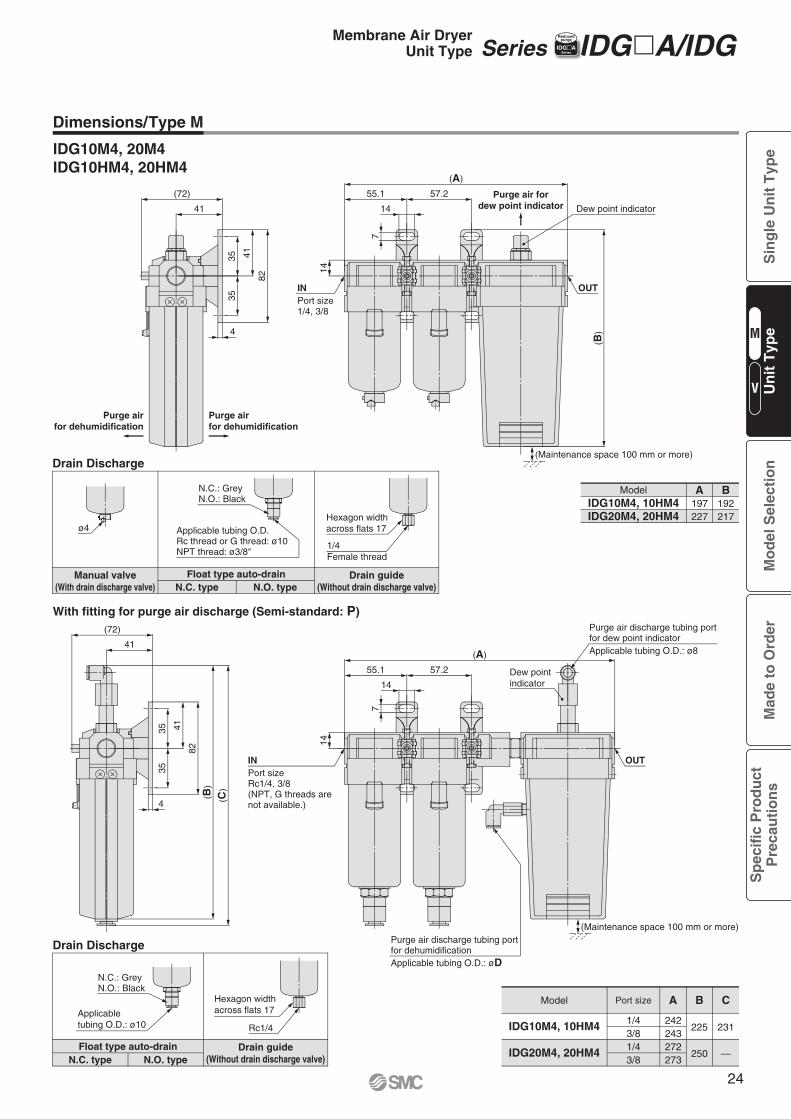
INPort size1/4, 3/8
(A)
57.255.1
14
7
14
Dew point indicator
OUT
(B)
(Maintenance space 100 mm or more)
(72)
41
82
413535
4
Purge air fordew point indicator
Purge airfor dehumidification
Purge airfor dehumidification
N.C.: GreyN.O.: Black
ø4Hexagon widthacross flats 17
1/4 Female thread
Applicable tubing O.D.Rc thread or G thread: ø10NPT thread: ø3/8"
With fitting for purge air discharge (Semi-standard: P)
14
7
14
57.255.1
(A)
Dew pointindicator
Purge air discharge tubing portfor dew point indicatorApplicable tubing O.D.: ø8
(72)
41
Purge air discharge tubing portfor dehumidificationApplicable tubing O.D.: øD
(C)
( B)
82
41
3535
4
(Maintenance space 100 mm or more)
INPort sizeRc1/4, 3/8(NPT, G threads are not available.)
OUT
N.C.: GreyN.O.: Black
Applicabletubing O.D.: ø10
Hexagon widthacross flats 17
Rc1/4
IDG10M4, 20M4IDG10HM4, 20HM4
Model
IDG10M4, 10HM4
IDG20M4, 20HM4
ModelIDG10M4, 10HM4IDG20M4, 20HM4
A B
231
—
C
225
250
1/43/81/43/8
242243272273
A B192217
197227
Drain Discharge
Manual valve(With drain discharge valve)
Drain guide(Without drain discharge valve)
Float type auto-drainN.C. type N.O. type
Drain Discharge
Drain guide(Without drain discharge valve)N.C. type
Float type auto-drainN.O. type
Port size
Series IDG�A/IDG IIDG�ASeries
Reducedpurge
Dimensions/Type M
Membrane Air DryerUnit Type
M
V
Sin
gle
Un
it T
ype
Mo
del
Sel
ecti
on
Mad
e to
Ord
erS
pec
ific
Pro
du
ctP
reca
uti
on
sU
nit
Typ
e
24
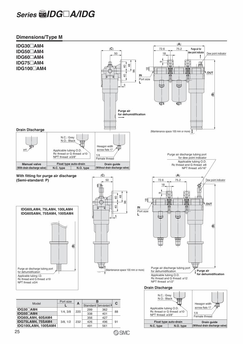
N.C.: GreyN.O.: Black
ø4 Applicable tubing O.D.Rc thread or G thread: ø10NPT thread: ø3/8"
Hexagon widthacross flats 17
Purge air discharge tubing portfor dehumidificationApplicable tubing I.D.Rc thread and G thread: ø19NPT thread: ø3/4
(B)
Purge air discharge tubing portfor dehumidificationApplicable tubing O.D.Rc thread and G thread: ø12NPT thread: ø1/2"
Purge air discharge tubing portfor dew point indicatorApplicable tubing O.D.
Rc thread and G thread: ø8NPT thread: ø5/16"
9
18
72.6 75.2
(A)
Dew point indicator
(B)
OUT
(C)
96
484040
5
50
(Maintenance space 100 mm or more) Purge airfor dehumidification
INPort sizeL
18
9
18 Dew point indicator
(B)
OUT
(C)
50
96
484040
5
(Maintenance space 100 mm or more)
Purge air fordew point indicator
Purge airfor dehumidification
72.6 75.2
(A)
INPort sizeL
18
N.C.: GreyN.O.: Black
Hexagon widthacross flats 17
1/4 Female thread
Applicable tubing O.D.Rc thread or G thread: ø10NPT thread: ø3/8"
1/4 Female thread
IDG30�AM4IDG50�AM4IDG60�AM4IDG75�AM4IDG100�AM4
Port sizeL Standard Semi-standard: P
A
220
232
1/4, 3/8
3/8, 1/2
B
299338356426491
362401427496561
C
88
91
Model
IDG30�AM4IDG50�AM4IDG60LAM4, 60SAM4IDG75LAM4, 75SAM4IDG100LAM4, 100SAM4
With fitting for purge air discharge(Semi-standard: P)
IDG60LAM4, 75LAM4, 100LAM4IDG60SAM4, 75SAM4, 100SAM4
Drain Discharge
Manual valve(With drain discharge valve)
Drain guide(Without drain discharge valve)
Float type auto-drainN.C. type N.O. type
Drain Discharge
Drain guide(Without drain discharge valve)
Float type auto-drainN.C. type N.O. type
Dimensions/Type M
Series IDG�A/IDG IIDG�ASeries
Reducedpurge
25
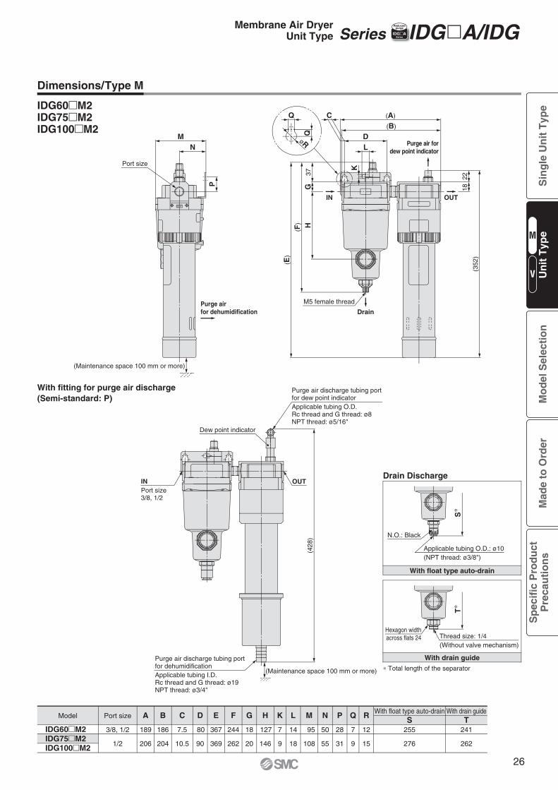
OUT
(A)
(B)
DL
Q
Q
C
(352
)
1822
K
37G
H(F)
( E)
M5 female thread
Port size
MN
P
øR Purge air fordew point indicator
IN OUT
Drain
(Maintenance space 100 mm or more)
Purge airfor dehumidification
Thread size: 1/4(Without valve mechanism)
Hexagon widthacross flats 24
Applicable tubing O.D.: ø10(NPT thread: ø3/8")
N.O.: Black
S∗
T∗
(Maintenance space 100 mm or more)
Dew point indicator
(428
)
Purge air discharge tubing portfor dehumidificationApplicable tubing I.D.Rc thread and G thread: ø19NPT thread: ø3/4"
Purge air discharge tubing portfor dew point indicatorApplicable tubing O.D.Rc thread and G thread: ø8NPT thread: ø5/16"
INPort size3/8, 1/2
OUT
IDG60�M2IDG75�M2IDG100�M2
Port sizeWith float type auto-drain With drain guideA
189
206 204 10.5 90 262 20 146 9 18 108 55 31 9 15
B
186
C
7.5
D
80
E
367
F
244
G
18
H
127
K
7
L
14
M
95
N
50
P
28
Q
7
R
12
276
255
262
241S T
3/8, 1/2
1/2
Model
IDG60�M2IDG75�M2IDG100�M2
With fitting for purge air discharge(Semi-standard: P)
369
Drain Discharge
With drain guide
With float type auto-drain
∗ Total length of the separator
Dimensions/Type M
Series IDG�A/IDG IIDG�ASeries
ReducedpurgeMembrane Air Dryer
Unit Type
M
V
Sin
gle
Un
it T
ype
Mo
del
Sel
ecti
on
Mad
e to
Ord
erS
pec
ific
Pro
du
ctP
reca
uti
on
sU
nit
Typ
e
26
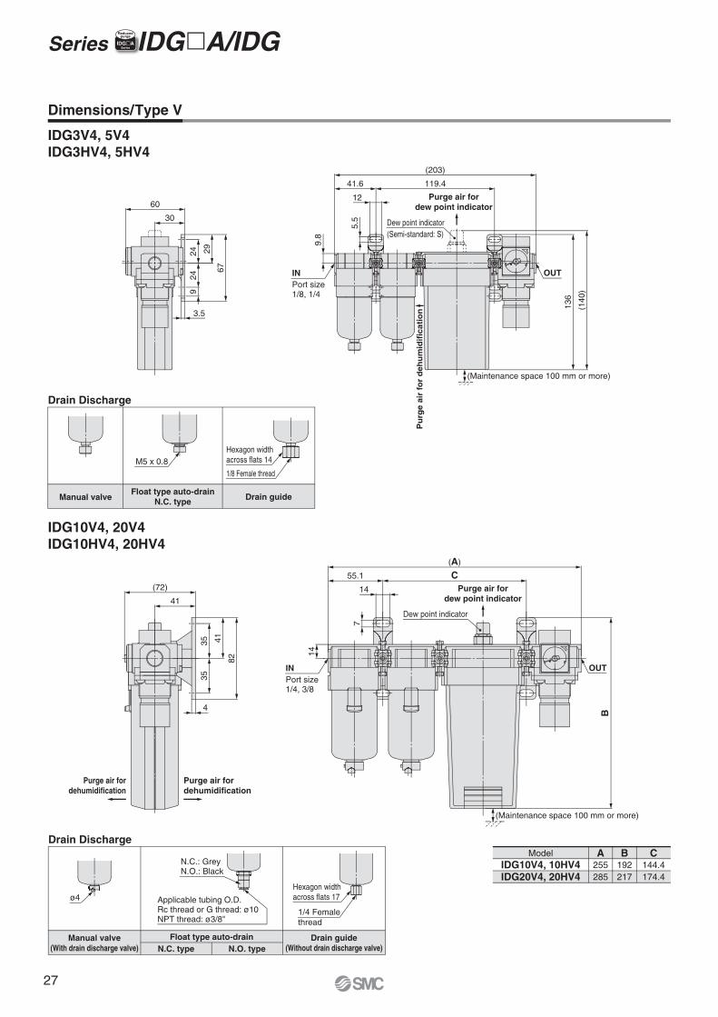
Purge air fordehumidification
Purge air fordehumidification
Purge air fordew point indicator
INPort size1/8, 1/4
9.8
(203)
41.6 119.4
Dew point indicator(Semi-standard: S)
12
5.5
OUT
INPort size1/4, 3/8
OUT
(140
)
136
60
3067
292424
9
3.514
7
14
55.1 C(A)
Dew point indicatorB
(72)
41
82
413535
4
(Maintenance space 100 mm or more)
(Maintenance space 100 mm or more)
Purge air fordew point indicator
N.C.: GreyN.O.: Black
Hexagon widthacross flats 14
1/8 Female thread
Hexagon widthacross flats 17
1/4 Femalethread
M5 x 0.8
ø4 Applicable tubing O.D.Rc thread or G thread: ø10NPT thread: ø3/8"
Pu
rge
air
for
deh
um
idif
icat
ion
IDG3V4, 5V4IDG3HV4, 5HV4
IDG10V4, 20V4IDG10HV4, 20HV4
IDG10V4, 10HV4IDG20V4, 20HV4
Model A255285
B192217
C144.4174.4
Drain Discharge
Manual valve Drain guideFloat type auto-drain
N.C. type
Drain Discharge
Manual valve(With drain discharge valve)
Drain guide(Without drain discharge valve)
Float type auto-drainN.C. type N.O. type
Dimensions/Type V
Series IDG�A/IDG IIDG�ASeries
Reducedpurge
27
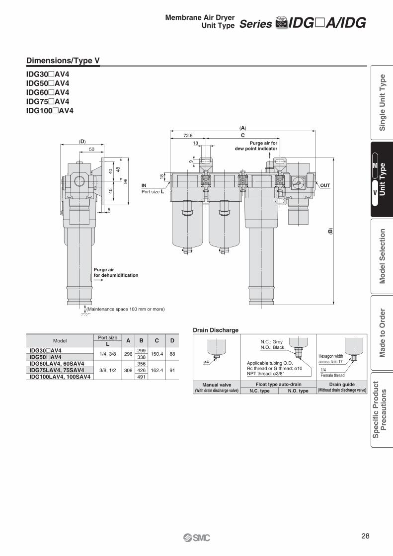
Purge airfor dehumidification
INPort size L
18
9
18
72.6 C(A)
OUT
(B)
(D)
50
96
484040
5
(Maintenance space 100 mm or more)
Purge air fordew point indicator
N.C.: GreyN.O.: Black
Hexagon width across flats 17
1/4Female thread
ø4 Applicable tubing O.D.Rc thread or G thread: ø10NPT thread: ø3/8"
Drain Discharge
Manual valve(With drain discharge valve)
Drain guide(Without drain discharge valve)
Float type auto-drainN.C. type N.O. type
Dimensions/Type V
IDG30�AV4IDG50�AV4IDG60�AV4IDG75�AV4IDG100�AV4
Port sizeL
A B
299338356426491
C
150.4
162.4
D
88
91
1/4, 3/8
3/8, 1/2
Model
IDG30�AV4IDG50�AV4IDG60LAV4, 60SAV4IDG75LAV4, 75SAV4IDG100LAV4, 100SAV4
296
308
Series IDG�A/IDGIIDG�ASeries
ReducedpurgeMembrane Air Dryer
Unit Type
M
V
Sin
gle
Un
it T
ype
Mo
del
Sel
ecti
on
Mad
e to
Ord
erS
pec
ific
Pro
du
ctP
reca
uti
on
sU
nit
Typ
e
28
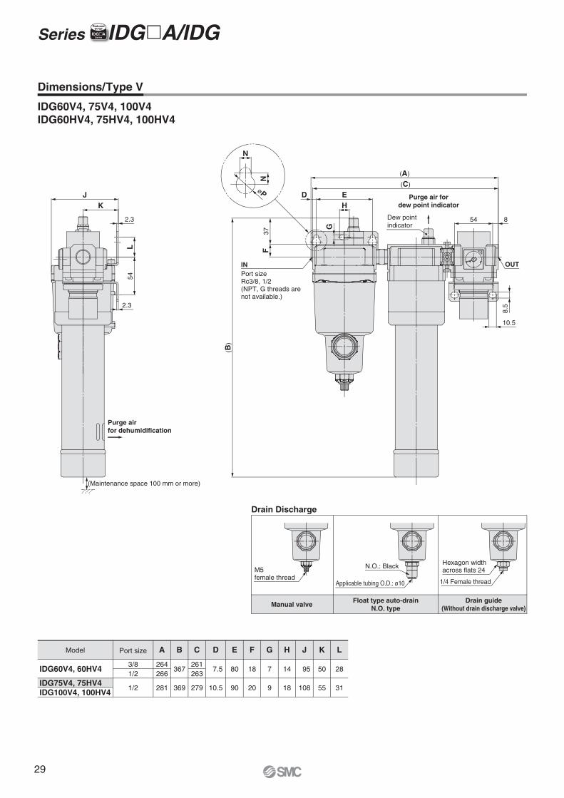
Purge airfor dehumidification
Purge air fordew point indicator
øP
INPort sizeRc3/8, 1/2(NPT, G threads are not available.)
(B)
OUT37
F
N
N
HED
G
(C)
(A)
Dew pointindicator
54 8
8.5
10.5
JK
2.3
L54
2.3
(Maintenance space 100 mm or more)
Applicable tubing O.D.: ø10
Hexagon widthacross flats 24
1/4 Female thread
N.O.: BlackM5female thread
IDG60V4, 75V4, 100V4IDG60HV4, 75HV4, 100HV4
A
264266
281
3/81/2
1/2
B
367
369
C
261263
279
D
7.5
10.5
E
80
90
F
18
20
G
7
9
H
14
18
J
95
108
K
50
55
L
28
31
Model
IDG60V4, 60HV4
IDG75V4, 75HV4IDG100V4, 100HV4
Drain Discharge
Drain guide(Without drain discharge valve)
Float type auto-drainN.O. type
Manual valve
Port size
Series IDG�A/IDG IIDG�ASeries
Reducedpurge
Dimensions/Type V
29
M
V
Sin
gle
Un
it T
ype
Mo
del
Sel
ecti
on
Mad
e to
Ord
erS
pec
ific
Pro
du
ctP
reca
uti
on
sU
nit
Typ
e
30
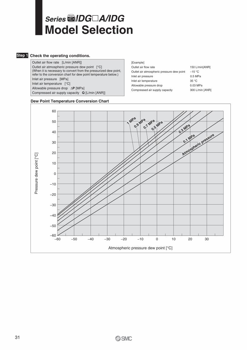
[Example]
Outlet air flow rate 150 L/min[ANR]
Outlet air atmospheric pressure dew point −15 °C
Inlet air pressure 0.5 MPa
Inlet air temperature 35 °C
Allowable pressure drop 0.03 MPa
Compressed air supply capacity 300 L/min [ANR]
Atmospheric pressure dew point [°C]
Pre
ssur
e de
w p
oint
[°C
]
−60 −50 −40 −30
60
50
40
30
20
10
0
−10
−20
−30
−40
−50
−60−20 −10 0 10 20 30
Dew Point Temperature Conversion Chart
Outlet air flow rate [L/min [ANR]]Outlet air atmospheric pressure dew point [°C](When it is necessary to convert from the pressurized dew point,refer to the conversion chart for dew point temperature below.)Inlet air pressure [MPa]Inlet air temperature [°C]Allowable pressure drop ΔP [MPa]Compressed air supply capacity Q [L/min [ANR]]
Step 1 Check the operating conditions.
Atmospheric
pressure
0.1 MPa
0.3 MPa
0.5 MPa
0.7 MPa
0.9 MPa
1 MPa
Model SelectionSeries IDG�A/IDG IIDG�A
Series
Reducedpurge
31
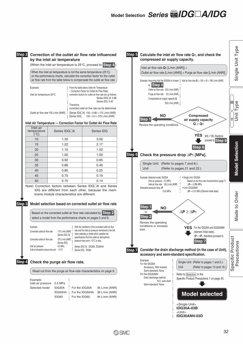
Step 6
Step 7
Step 4
Step 5 Calculate the inlet air flow rate Q1, and check thecompressed air supply capacity.
Step 2 Correction of the outlet air flow rate influencedby the inlet air temperature(When the inlet air temperature is 25°C, proceed to ) Step 4
Check the purge air flow rate.
Model selection based on corrected outlet air flow rate
When the inlet air temperature is not the same temperature (25°C)on the performance charts, calculate the correction factor for the outletair flow rate from the table below to compensate the outlet air flow rate.
Read out from the purge air flow-rate characteristics on page 9.
Based on the corrected outlet air flow rate calculated by ,
select a model from the performance charts on pages 5 and 6.
Example: From the table below (Inlet Air Temperature – Correction Factor for Outlet Air Flow Rate),Inlet air temperature 35°C correction factors for outlet air flow rate are as follows. Series IDG�A: 0.86 Series IDG: 0.40 Therefore, corrected outlet air flow rate can be determined.
Outlet air flow rate 150 L/min [ANR] [Series IDG�A] 150 ÷ 0.86 = 175 L/min [ANR] [Series IDG] 150 ÷ 0.4 = 375 L/min [ANR]
Example:Inlet air pressure 0.5 MPa
Selected model IDG30A For the IDG30A 45 L/min [ANR]
IDG50HA For the IDG50HA 38 L/min [ANR]
IDG60 For the IDG60 94 L/min [ANR]
Inlet airtemperature
[°C]
Inlet Air Temperature — Correction Factor for Outlet Air Flow Rate
Note) Correction factors between Series IDG�A and Series IDG are different from each other, because the mem-brane module characteristics are different.
With the conditions of the corrected outlet air flow rate and the inlet air pressure mentioned to the left, when selecting a model which satisfies the specifications that the outlet air atmospheric pressure dew point –15°C or less,
[Series IDG�A] IDG30A, IDG50HA[Series IDG] IDG60
Example:
Corrected outlet air flow rate 175 L/min [ANR] [Series IDG�A]
Corrected outlet air flow rate 375 L/min [ANR] [Series IDG]Inlet air pressure 0.5 MPaOutlet air atmospheric pressure dew point –15°C
Series IDG�A Series IDG
10
15
20
25
30
35
40
45
50
3.00
2.17
1.52
1.00
0.65
0.40
0.25
0.19
0.14
1.35
1.22
1.10
1.00
0.92
0.86
0.80
0.75
0.70
Step 3
Inlet air flow rate Q1 [L/min [ANR]] =
Outlet air flow rate [L/min [ANR]] + Purge air flow rate [L/min [ANR]]
Example: Assuming that the IDG30A is chosen Inlet air flow rate Q1 = 150 + 45 = 195 L/min [ANR]
by
Outlet air flow rate 150 L/min [ANR]
Purge air flow rate 45 L/min [ANR]
Compressed air supply capacity Q
300 L/min [ANR]
Step 4
Step 6
Step 1NO
Review the operating conditions.
YES
Compressedair supply capacity
Q ≥ Q1
300 ≥ 195, thereforeproceed to Step 6
Model selected
or
Check the pressure drop ΔP1 [MPa].
Step 1
Step 2
Single Unit (Refer to pages 7 and 8.)
Unit (Refer to pages 21 and 22.)
Single Unit (Refer to pages 1 and 2.)
Unit (Refer to pages 15 and 16.)
Consider the drain discharge method (in the case of Unit), accessory and semi-standard specification.
NO
Review the operatingconditions or increasesize. YES
ΔP ≥ ΔP1
Refer to in theSpecific Product Precautions 1 on page 45.
<Single Unit>IDG30A-03B<Unit>IDG30AM4-03D
Example: Selected model: IDG30A Single Unit: IDG30A Inlet air pressure 0.5 MPa Based on the flow-rate characteristics (page 7), Inlet air flow rate 195 L/min [ANR] ΔP1 = 0.006 MPaAllowable pressure drop ΔP Unit: IDG30AM4 0.03 MPa ΔP1 = 0.01 MPa (Element initial state)
Example:For the IDG30A Accessory: With bracket Semi-standard: NoneFor the IDG30AM4 Drain discharge method:
N.O. auto-drain Semi-standard: None
For the IDG30A and IDG30AM4 (element initial state), ΔP ≥ ΔP1, therefore proceed to
Step 7
Selection
Step 2
Model Selection Series IDG�A/IDGIIDG�ASeries
Reducedpurge
M
V
Sin
gle
Un
it T
ype
Mo
del
Sel
ecti
on
Mad
e to
Ord
erS
pec
ific
Pro
du
ctP
reca
uti
on
sU
nit
Typ
e
32
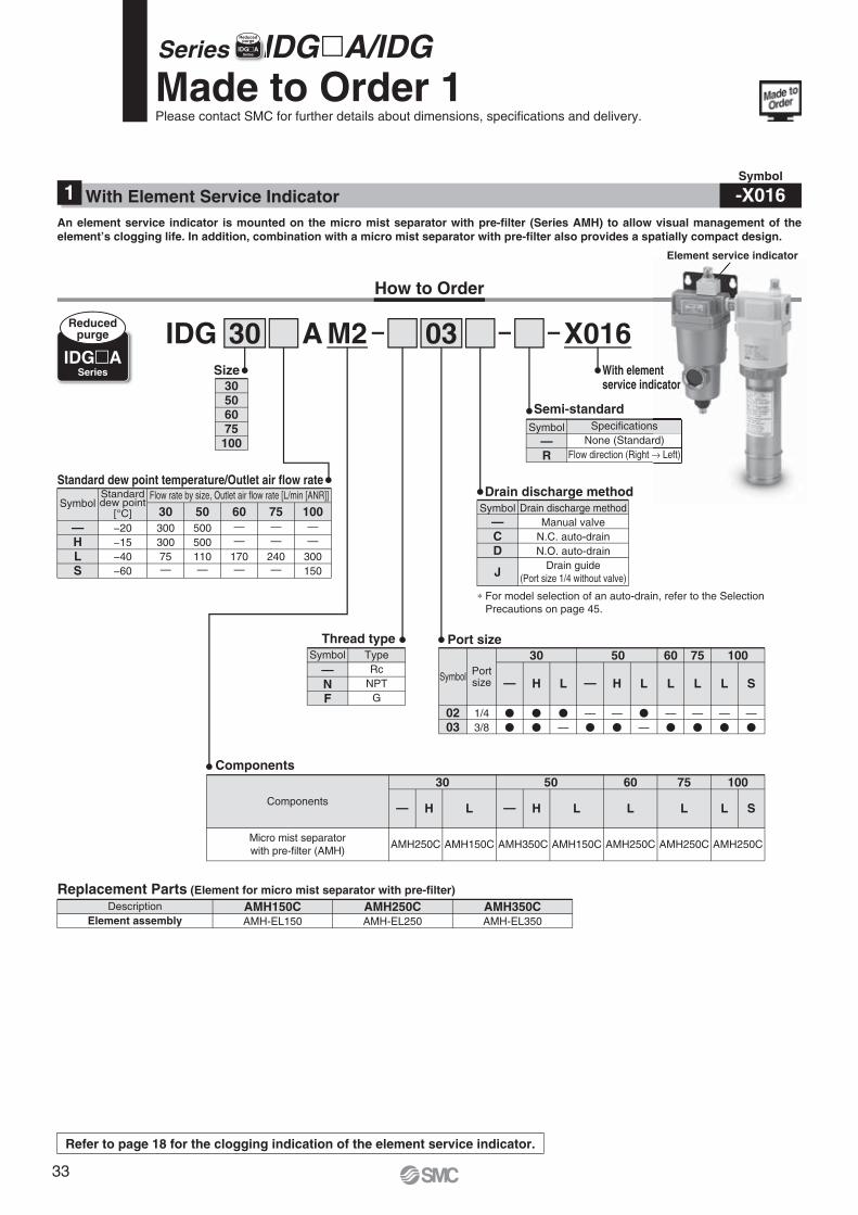
Made to Order 1Please contact SMC for further details about dimensions, specifications and delivery.
Series IDG�A/IDG IIDG�ASeries
Reducedpurge
M2AIDG 30 03 X016
How to Order
TypeRc
NPTG
Thread type
—NF
Symbol
With elementservice indicator
SpecificationsNone (Standard)
Flow direction (Right → Left)
Semi-standard
—R
Symbol
Drain discharge methodManual valve
N.C. auto-drainN.O. auto-drain
Drain guide(Port size 1/4 without valve)
Drain discharge method
—CD
J
Symbol
Standard dew point temperature/Outlet air flow rate
Replacement Parts (Element for micro mist separator with pre-filter)
Portsize
1/43/8
�
�
10030
H L
50 60 75Port size
0203
Symbol
Description AMH150C AMH250C AMH350CAMH-EL150 AMH-EL250 AMH-EL350Element assembly
30506075
100
Size
— H L L L L S—
�
�
�
——�
—�
�
——�
—�
—�
—�
Components
Micro mist separatorwith pre-filter (AMH)
AMH250C AMH150C AMH350C AMH150C AMH250C AMH250C AMH250C
10030
H L
50 60 75Components
— H L L L L S—
—HLS
SymbolFlow rate by size, Outlet air flow rate [L/min [ANR]]
30−20−15−40−60
30030075—
50500500110—
60——
170—
75——
240—
100——
300150
IDG�ASeries
Reducedpurge
∗ For model selection of an auto-drain, refer to the Selection Precautions on page 45.
Standarddew point
[°C]
Symbol
-X016With Element Service Indicator1An element service indicator is mounted on the micro mist separator with pre-filter (Series AMH) to allow visual management of the element’s clogging life. In addition, combination with a micro mist separator with pre-filter also provides a spatially compact design.
Element service indicator
Refer to page 18 for the clogging indication of the element service indicator.
entdicator
srd)→ Left)
Element service indicator
33
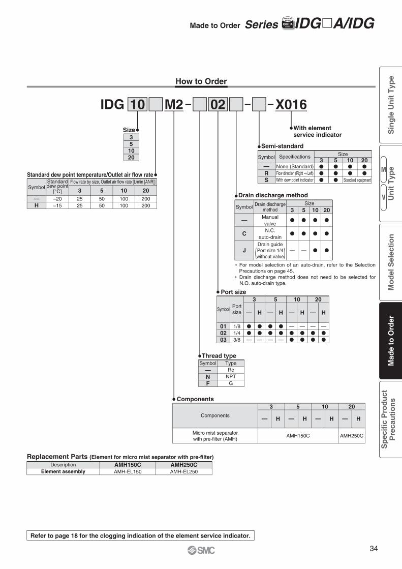
Made to Order Series IDG�A/IDGIIDG�ASeries
Reducedpurge
M2IDG 10 02
How to Order
TypeRc
NPTG
Thread type
—NF
Symbol
Semi-standard
ManualvalveN.C.
auto-drain
Drain dischargemethod
Drain guidePort size 1/4without valve
Drain discharge method
—
C
J
Symbol
Standard dew point temperature/Outlet air flow rate
Replacement Parts (Element for micro mist separator with pre-filter)Description AMH150C AMH250C
AMH-EL150 AMH-EL250Element assembly
35
1020
Size
Portsize
1/81/43/8
�
�
—
3
H
5 10 20Port size
010203
Symbol— — — —H
�
�
—
�
�
—
�
�
—
—�
�
—�
�
—�
�
—�
�
H H
Components
—H
SymbolFlow rate by size, Outlet air flow rate [L/min [ANR]]Standard
dew point[°C]
−20−15
20200200
10100100
55050
32525
—RS
None (Standard)Flow direction (Right → Left)With dew point indicator
Symbol Specifications Size3 10 20
�
�
�
�
�
�
�
5�
�
�
Size3
�
�
—
5
�
�
—
10
�
�
�
20
�
�
�
Standard equipment
X016
With elementservice indicator
Components
Micro mist separatorwith pre-filter (AMH)
3
H
10 205
— H—H— H—
AMH150C AMH250C
∗ For model selection of an auto-drain, refer to the Selection Precautions on page 45.
∗ Drain discharge method does not need to be selected for N.O. auto-drain type.
Refer to page 18 for the clogging indication of the element service indicator.
( )
M
V
Sin
gle
Un
it T
ype
Mo
del
Sel
ecti
on
Mad
e to
Ord
erS
pec
ific
Pro
du
ctP
reca
uti
on
sU
nit
Typ
e
34
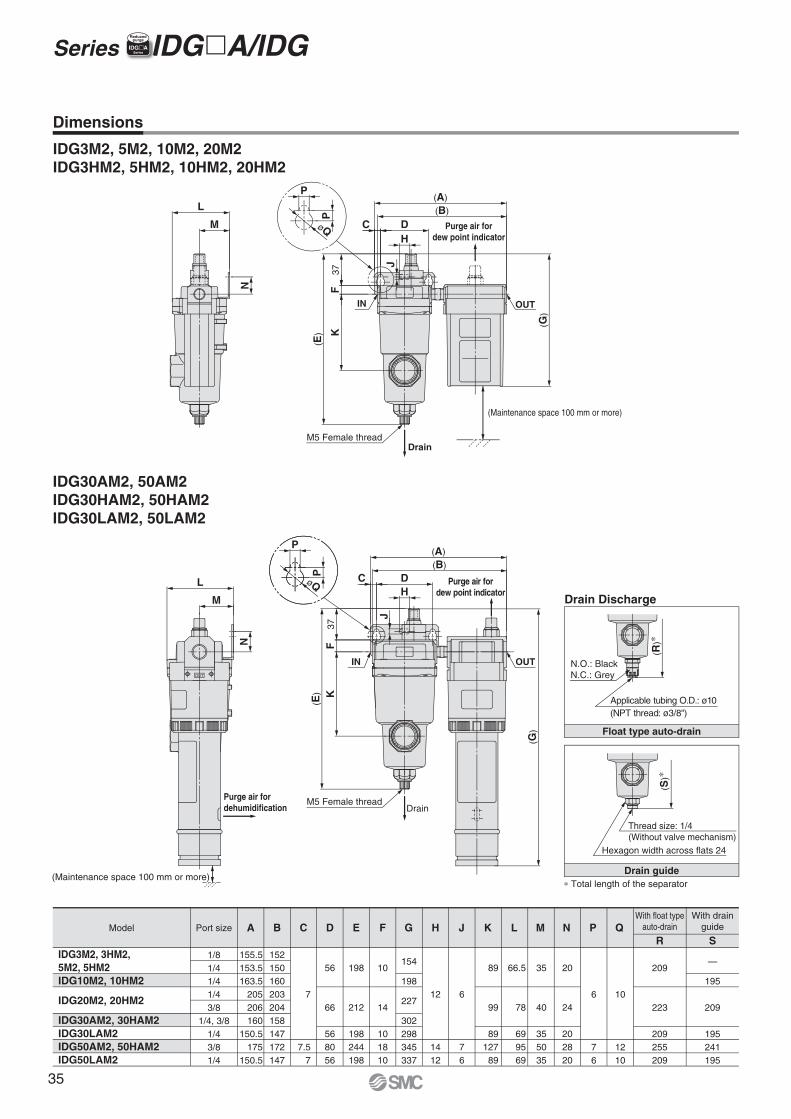
Drain Discharge
Float type auto-drain
Drain guide
(R)∗
∗ Total length of the separator
N.O.: BlackN.C.: Grey
Applicable tubing O.D.: ø10(NPT thread: ø3/8")
(S)∗
Hexagon width across flats 24
Thread size: 1/4(Without valve mechanism)
øQ
P
P
(E)
(G)
C
FK
37
J
H
(B)(A)
D
N
M
L
Purge air fordew point indicator
M5 Female thread
IN OUT
(Maintenance space 100 mm or more)
Drain
P
øQ
P
(A)
(G)
(E)
37F
(B)
DC
J
H
K
M5 Female thread
Purge air fordew point indicator
OUT
Drain
IN
L
M
N
Purge air fordehumidification
OUT
(Maintenance space 100 mm or more)
IDG3M2, 5M2, 10M2, 20M2IDG3HM2, 5HM2, 10HM2, 20HM2
IDG30AM2, 50AM2IDG30HAM2, 50HAM2IDG30LAM2, 50LAM2
IDG3M2, 3HM2, 5M2, 5HM2IDG10M2, 10HM2
IDG20M2, 20HM2
IDG30AM2, 30HAM2IDG30LAM2IDG50AM2, 50HAM2IDG50LAM2
Model
1/81/41/41/43/8
1/4, 3/81/43/81/4
With float typeauto-drain
With drainguidePort size A B C D E
155.5153.5163.5
205206160
150.5175
150.5
152150160203204158147172147
7
7.57
198
212
198244198
10
14
101810
12
1412
6
76
89
99
8912789
66.5
78
699569
35
40
355035
20
24
202820
56
66
568056
F G H J L M N
6
76
P
10
1210
QR
209
223
209255209
S
—
195
209
195241195
K
154
198
227
302298345337
Dimensions
Series IDG�A/IDG IIDG�ASeries
Reducedpurge
35
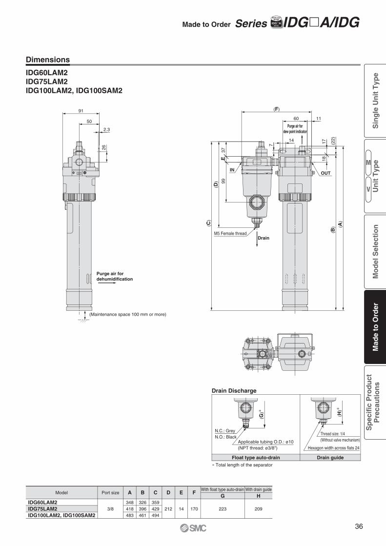
OUT
(22)
(D)
91
50
2.3
(C)
99E
37
(F)
1718
1160
7
14
(B)
26
(A)
M5 Female thread
(Maintenance space 100 mm or more)
Purge air fordehumidification
Purge air fordew point indicator
OUT
Drain
IN
(H)∗
Hexagon width across flats 24
Thread size: 1/4(Without valve mechanism)
SM
C
(G)∗
N.C.: GreyN.O.: Black
Applicable tubing O.D.: ø10(NPT thread: ø3/8")
Drain Discharge
Drain guide∗ Total length of the separator
Float type auto-drain
IDG60LAM2IDG75LAM2IDG100LAM2, IDG100SAM2
Model A FG H
348418483
Port size
3/8 170
E
14
D
212
C
359429494
B
326396461
223 209IDG60LAM2IDG75LAM2IDG100LAM2, IDG100SAM2
With float type auto-drain With drain guide
Dimensions
Made to Order Series IDG�A/IDG IIDG�ASeries
Reducedpurge
M
V
Sin
gle
Un
it T
ype
Mo
del
Sel
ecti
on
Mad
e to
Ord
erS
pec
ific
Pro
du
ctP
reca
uti
on
sU
nit
Typ
e
36
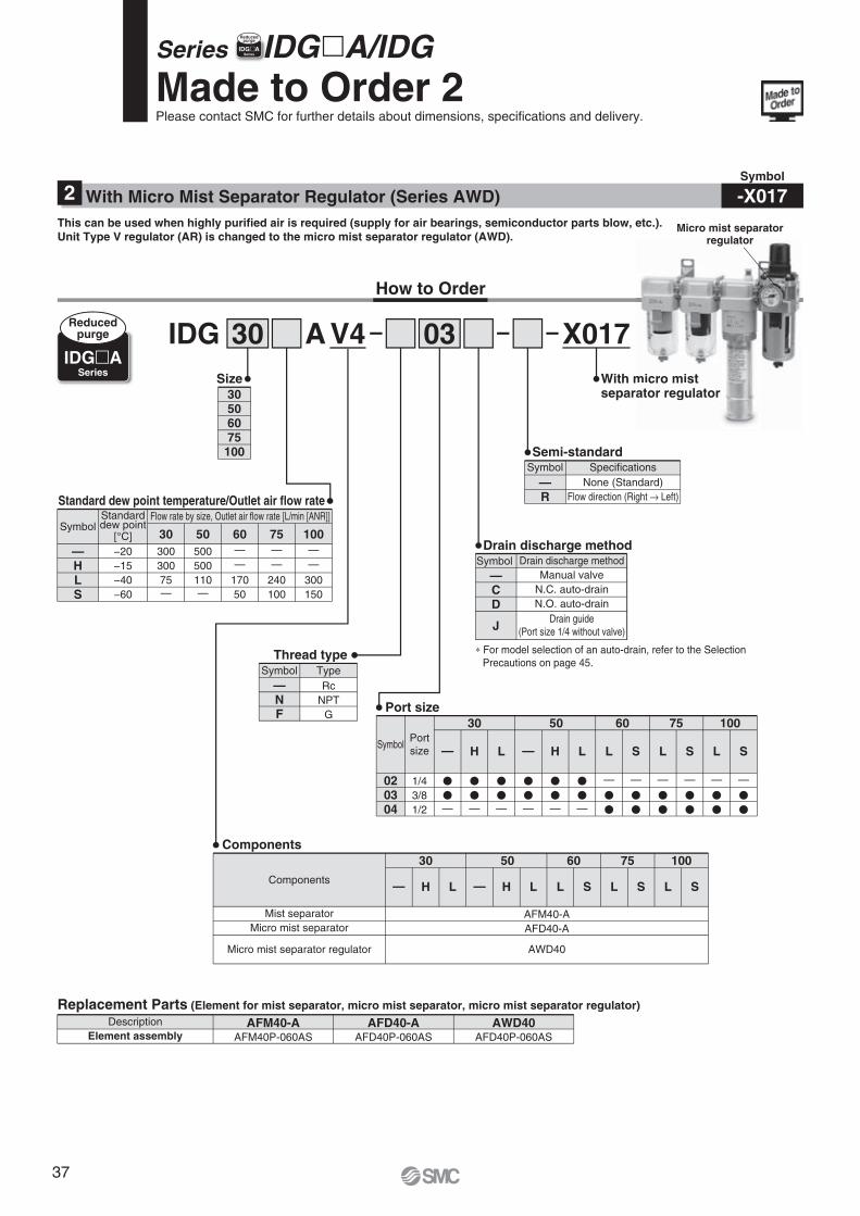
V4AIDG 30 03 X017
How to Order
RcNPT
G
Thread type
—NF
Symbol Type
With micro mistseparator regulator
None (Standard)Flow direction (Right → Left)
Semi-standard
—R
Symbol Specifications
Drain discharge methodManual valve
N.C. auto-drainN.O. auto-drain
Drain guide(Port size 1/4 without valve)
Drain discharge method
—CD
J
Symbol
Standard dew point temperature/Outlet air flow rate
Replacement Parts (Element for mist separator, micro mist separator, micro mist separator regulator)Description AFM40-A AFD40-A AWD40
AFM40P-060AS AFD40P-060AS AFD40P-060ASElement assembly
30506075
100
Size
Made to Order 2Please contact SMC for further details about dimensions, specifications and delivery.
Portsize
1/43/81/2
�
�—
10030
H L
50 60 75Port size
020304
Symbol — H L L S L S L S—
�
�—
�
�—
�
�—
�
�—
�
�—
—
�
�
—
�
�
—
�
�
—
�
�
—
�
�
—
�
�
Series IDG�A/IDG
IDG�ASeries
Reducedpurge
∗ For model selection of an auto-drain, refer to the Selection Precautions on page 45.
Components
Mist separatorMicro mist separator
Micro mist separator regulator
AFM40-AAFD40-A
AWD40
10030
H L
50 60 75Components
— H L L S L S L S—
—HLS
SymbolFlow rate by size, Outlet air flow rate [L/min [ANR]]Standard
dew point[°C] 30−20−15−40−60
30030075—
50500500110—
60——
17050
75——
240100
100——
300150
Symbol
-X017With Micro Mist Separator Regulator (Series AWD) 2This can be used when highly purified air is required (supply for air bearings, semiconductor parts blow, etc.).Unit Type V regulator (AR) is changed to the micro mist separator regulator (AWD).
IIDG�ASeries
Reducedpurge
micro mistator regulator
Micro mist separatorregulator
37
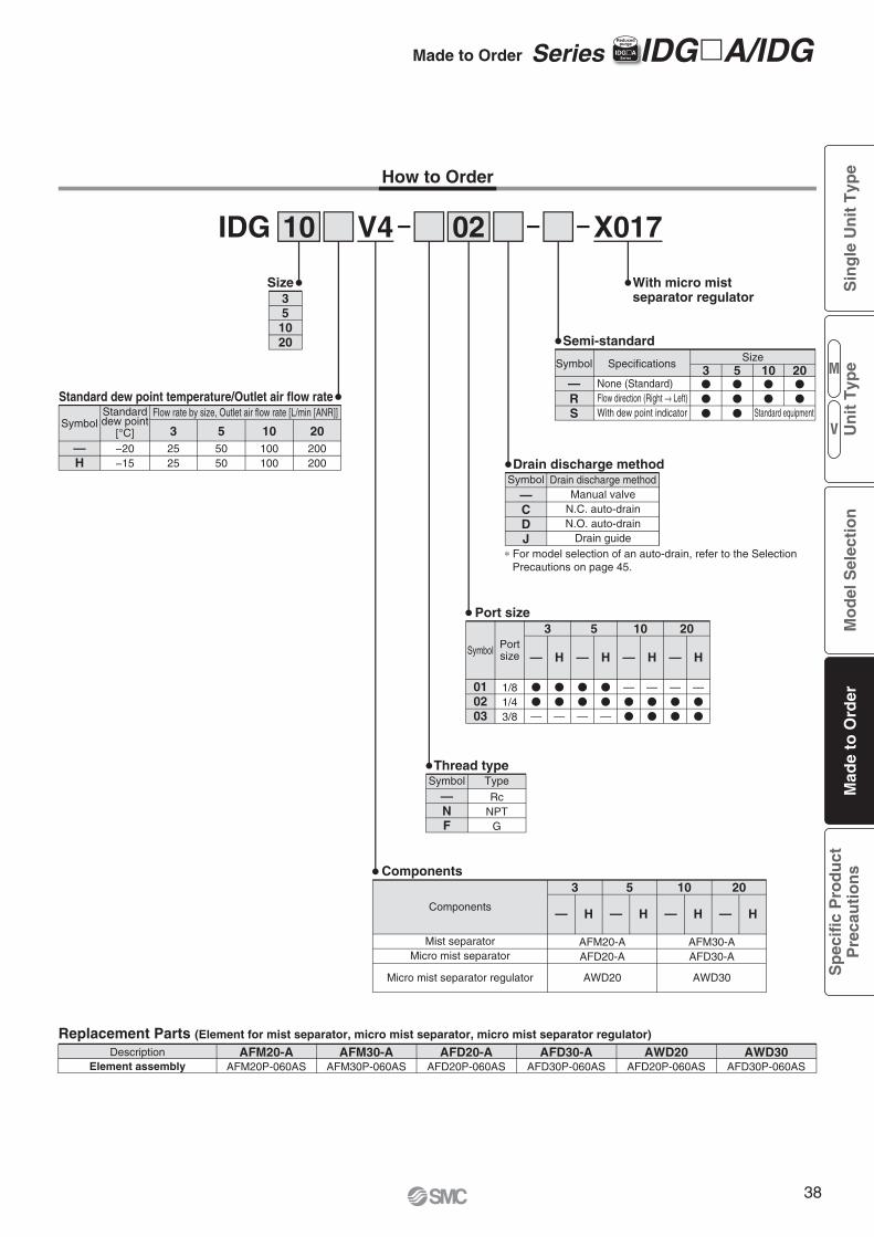
V4IDG 10 02
How to Order
RcNPT
G
Thread type
—NF
Symbol Type
Semi-standard
Drain discharge methodManual valve
N.C. auto-drainN.O. auto-drain
Drain guide
Drain discharge method
—CDJ
Symbol
Standard dew point temperature/Outlet air flow rate
Replacement Parts (Element for mist separator, micro mist separator, micro mist separator regulator)Description AFM20-A
AFM20P-060ASAFM30-A
AFM30P-060ASAFD20-A
AFD20P-060ASAFD30-A
AFD30P-060ASAWD20
AFD20P-060ASAWD30
AFD30P-060ASElement assembly
35
1020
Size
Portsize
1/81/43/8
�
�
—
3
H
5 10 20Port size
010203
SymbolH
�
�
—
�
�
—
�
�
—
—�
�
—�
�
—�
�
—�
�
H H
Components
—H
SymbolFlow rate by size, Outlet air flow rate [L/min [ANR]]Standard
dew point[°C]−20−15
20200200
10100100
55050
32525
—RS
None (Standard)Flow direction (Right → Left)With dew point indicator
Symbol SpecificationsSize
3 10 20�
�
�
�
�
�
�
5�
�
� Standard equipment
X017
With micro mistseparator regulator
Components
Mist separatorMicro mist separator
Micro mist separator regulator
3
H
10 205
— H—H— H—
AFM30-AAFD30-A
AFM20-AAFD20-A
AWD30AWD20
∗ For model selection of an auto-drain, refer to the Selection Precautions on page 45.
Made to Order Series IDG�A/IDGIIDG�ASeries
Reducedpurge
— — — —
M
V
Sin
gle
Un
it T
ype
Mo
del
Sel
ecti
on
Mad
e to
Ord
erS
pec
ific
Pro
du
ctP
reca
uti
on
sU
nit
Typ
e
38
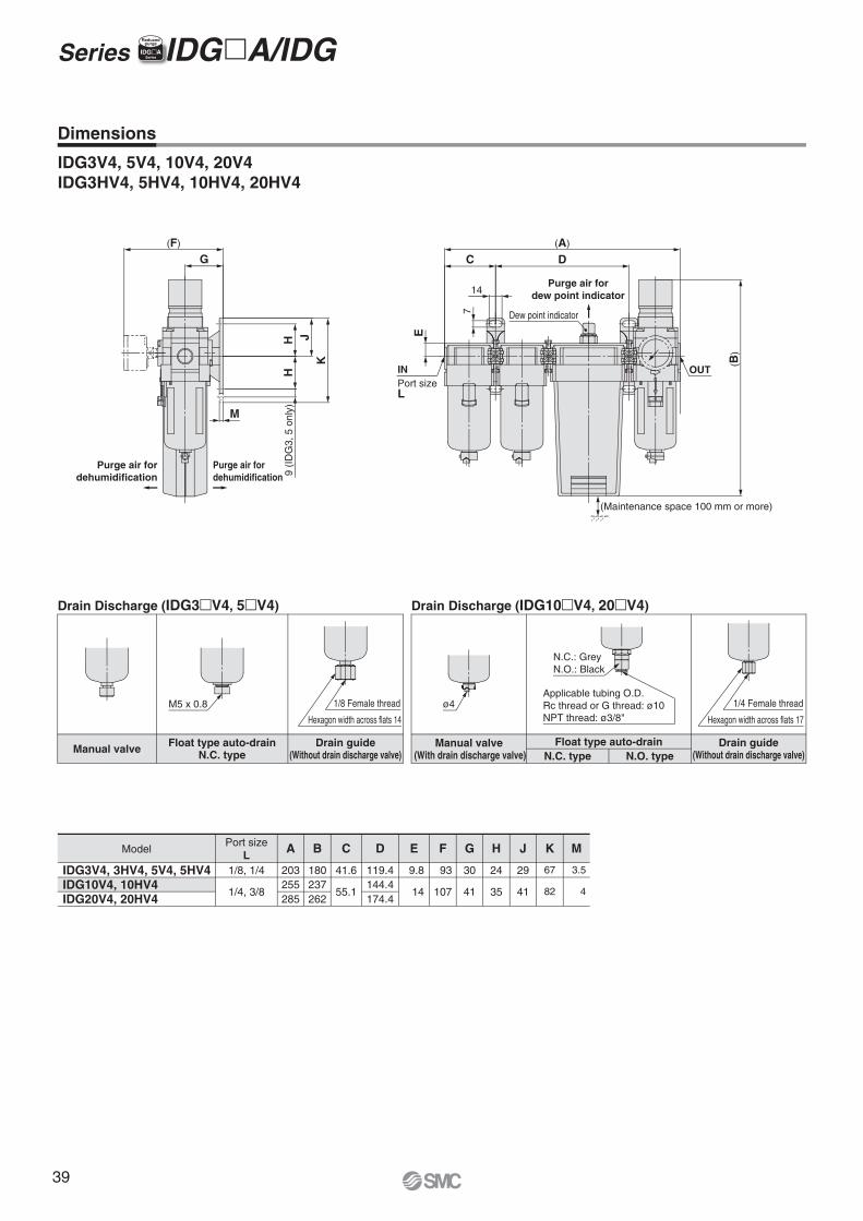
(Maintenance space 100 mm or more)
Purge air fordew point indicator
Purge air fordehumidification
Purge air fordehumidification
(A)
C D
14
7
E
INPort sizeL
Dew point indicator
OUT
(B)
(F)
G
M
KJH
H9
(ID
G3,
5 o
nly)
1/8 Female thread
Hexagon width across flats 14
1/4 Female thread
Hexagon width across flats 17
Applicable tubing O.D.Rc thread or G thread: ø10NPT thread: ø3/8"
N.C.: GreyN.O.: Black
M5 x 0.8 ø4
Drain Discharge (IDG3�V4, 5�V4)
Manual valve Drain guide(Without drain discharge valve)
Float type auto-drainN.C. type
Drain Discharge (IDG10�V4, 20�V4)
Manual valve (With drain discharge valve)
Drain guide(Without drain discharge valve)
Float type auto-drainN.C. type N.O. type
IDG3V4, 5V4, 10V4, 20V4IDG3HV4, 5HV4, 10HV4, 20HV4
IDG3V4, 3HV4, 5V4, 5HV4IDG10V4, 10HV4IDG20V4, 20HV4
Model A B C D E F G H J K MPort sizeL
1/8, 1/4
1/4, 3/8
41.6
55.1
9.8
14
93
107
30
41
24
35
29
41
67
82
3.5
4
203255285
180237262
119.4144.4174.4
Dimensions
Series IDG�A/IDG IIDG�ASeries
Reducedpurge
39
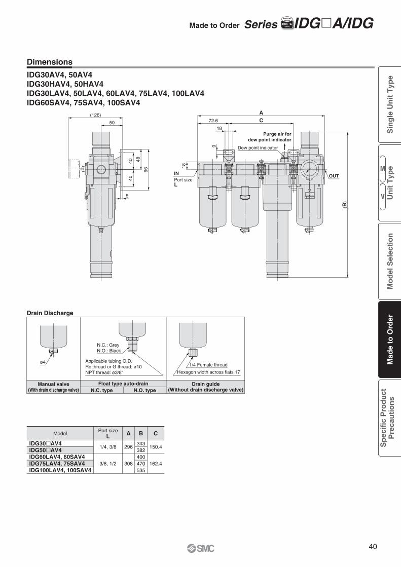
Purge air fordew point indicator
A72.6 C
18
18
9
INPort sizeL
OUT
(B)
Dew point indicator
(126)
50
96
484040
5
N.C.: GreyN.O.: Black
Applicable tubing O.D.Rc thread or G thread: ø10NPT thread: ø3/8" Hexagon width across flats 17
1/4 Female threadø4
Drain Discharge
Manual valve(With drain discharge valve)
Drain guide(Without drain discharge valve)
Float type auto-drainN.C. type N.O. type
IDG30AV4, 50AV4IDG30HAV4, 50HAV4IDG30LAV4, 50LAV4, 60LAV4, 75LAV4, 100LAV4IDG60SAV4, 75SAV4, 100SAV4
Dimensions
ModelPort size
L A B C
1/4, 3/8
3/8, 1/2
296
308
343382400470535
150.4
162.4
IDG30�AV4IDG50�AV4IDG60LAV4, 60SAV4IDG75LAV4, 75SAV4IDG100LAV4, 100SAV4
Made to Order Series IDG�A/IDGIIDG�ASeries
Reducedpurge
M
V
Sin
gle
Un
it T
ype
Mo
del
Sel
ecti
on
Mad
e to
Ord
erS
pec
ific
Pro
du
ctP
reca
uti
on
sU
nit
Typ
e
40
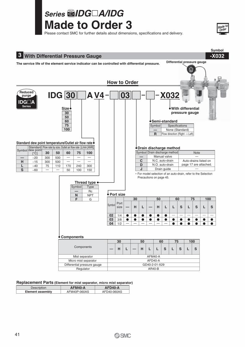
V4AIDG 30 03 X032
How to Order
RcNPT
G
Thread type
—NF
Symbol Type
With differentialpressure gauge
Semi-standard
None (Standard)Flow direction (Right → Left)
—R
Symbol Specifications
Drain discharge methodManual valve
N.C. auto-drainN.O. auto-drain
Drain guide
Note—
—
Auto-drains listed onpage 17 are attached.
Drain discharge method
—CDJ
Symbol
Standard dew point temperature/Outlet air flow rate
Replacement Parts (Element for mist separator, micro mist separator)Description AFM40-A AFD40-A
AFM40P-060AS AFD40-060ASElement assembly
30506075
100
Size
Components
Mist separatorMicro mist separator
Differential pressure gaugeRegulator
AFM40-AAFD40-A
GD40-2-01-X29AR40-B
10030
H L
50 60 75Components
— H L L S L S L S—
Made to Order 3Please contact SMC for further details about dimensions, specifications and delivery.
Portsize
1/43/81/2
�
�—
10030
H L
50 60 75Port size
020304
Symbol — H L L S L S L S—
�
�—
�
�—
�
�—
�
�—
�
�—
—
�
�
—
�
�
—
�
�
—
�
�
—
�
�
—
�
�
Series IDG�A/IDG
IDG�ASeries
Reducedpurge
∗ For model selection of an auto-drain, refer to the Selection Precautions on page 45.
—HLS
SymbolFlow rate by size, Outlet air flow rate [L/min [ANR]]Standard
dew point[°C] 30−20−15−40−60
30030075—
50500500110—
60——
17050
75——
240100
100——
300150
IIDG�ASeries
Reducedpurge
2h differentialssure gauge
Differential pressure gauge
Symbol
-X032With Differential Pressure Gauge3The service life of the element service indicator can be controlled with differential pressure.
41
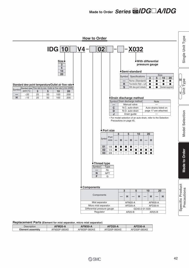
V4IDG 10 02
How to Order
RcNPT
G
Thread type
—NF
Symbol Type
Semi-standard
Drain discharge methodManual valve
N.C. auto-drainN.O. auto-drain
Drain guide
Note—
—
Auto-drains listed onpage 17 are attached.
Drain discharge method
—CDJ
Symbol
Standard dew point temperature/Outlet air flow rate
Replacement Parts (Element for mist separator, micro mist separator)
Portsize
1/81/43/8
�
�—
3
H
5 10 20Port size
010203
Symbol
Description AFM20-A AFM30-A AFD20-AAFM20P-060AS AFM30P-060AS AFD20P-060AS
AFD30-AAFD30P-060ASElement assembly
35
1020
Size
— H—
�
�—
�
�—
�
�—
—
�
�
—
�
�
—
�
�
—
�
�
H— H—
Components
—H
SymbolFlow rate by size, Outlet air flow rate [L/min [ANR]]Standard dew
point [°C]
−20−15
20200200
10100100
55050
32525
—RS
None (Standard)Flow direction (Right → Left)With dew point indicator
Symbol SpecificationsSize
3 10 20�
�
�
�
�
�
�
5�
�
� Standard equipment
X032
With differentialpressure gauge
Components
Mist separatorMicro mist separator
Differential pressure gaugeRegulator
3
H
10 205
— H—H— H—
AFM30-AAFD30-A
AR25-B
AFM20-AAFD20-A
AR20-BGD40-2-01-X29
∗ For model selection of an auto-drain, refer to the Selection Precautions on page 45.
Made to Order Series IDG�A/IDGIIDG�ASeries
Reducedpurge
M
V
Sin
gle
Un
it T
ype
Mo
del
Sel
ecti
on
Mad
e to
Ord
erS
pec
ific
Pro
du
ctP
reca
uti
on
sU
nit
Typ
e
42
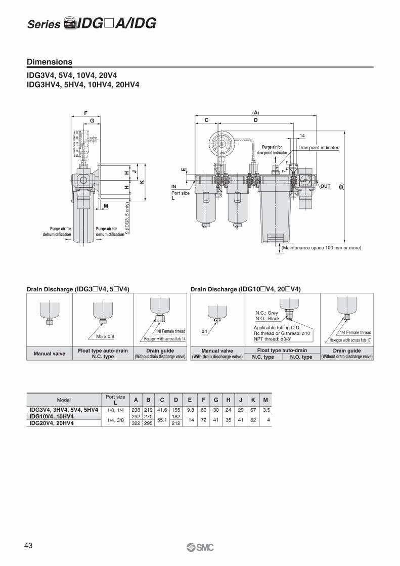
(Maintenance space 100 mm or more)
Purge air fordew point indicator
Purge air fordehumidification
Purge air fordehumidification
(A)
C D
EINPort sizeL
14
7
Dew point indicator
(B)OUT
FG
KJH
H9
(IDG
3, 5
onl
y)M
1/8 Female thread
Hexagon width across flats 14
N.C.: GreyN.O.: Black
Applicable tubing O.D.Rc thread or G thread: ø10NPT thread: ø3/8"
1/4 Female thread
Hexagon width across flats 17
ø4M5 x 0.8
Drain Discharge (IDG3�V4, 5�V4)
Manual valve Drain guide(Without drain discharge valve)
Float type auto-drainN.C. type
Drain Discharge (IDG10�V4, 20�V4)
Manual valve(With drain discharge valve)
Drain guide(Without drain discharge valve)
Float type auto-drainN.C. type N.O. type
Model A
238292322
B
219270295
C
41.6
55.1
D
155182212
E
9.8
14
F
60
72
G
30
41
H
24
35
J
29
41
K
67
82
M
3.5
4
Dimensions
IDG3V4, 5V4, 10V4, 20V4IDG3HV4, 5HV4, 10HV4, 20HV4
Port sizeL
1/8, 1/4
1/4, 3/8
IDG3V4, 3HV4, 5V4, 5HV4IDG10V4, 10HV4IDG20V4, 20HV4
IDG�ASeries
Reducedpurge
Series IDG�A/IDG
43
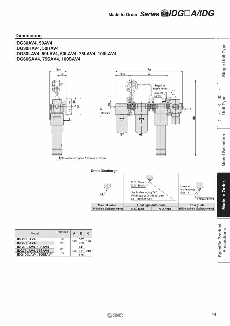
Dimensions
(A)
C72.6
(B)
18Dew point indicator
OUTINPort sizeL
(88)
50
96
484040
5
1/4Female thread
Applicable tubing O.D.Rc thread or G thread: ø10NPT thread: ø3/8"
Purge air fordew point indicator
Float type auto-drainManual valve (With drain discharge valve)
Drain guide(Without drain discharge valve)
Drain Discharge
N.O. typeN.C. type
(Maintenance space 100 mm or more)
9
IDG30�AV4IDG50�AV4IDG60LAV4, 60SAV4IDG75LAV4, 75SAV4IDG100LAV4, 100SAV4
Model
IDG30AV4, 50AV4IDG30HAV4, 50HAV4IDG30LAV4, 50LAV4, 60LAV4, 75LAV4, 100LAV4IDG60SAV4, 75SAV4, 100SAV4
N.C.: GreyN.O.: Black
ø4
Hexagon width across flats 17
18
Port sizeL
1/43/8
3/81/2
A B C
343
355
387423441511576
198
210
Made to Order Series IDG�A/IDGIIDG�ASeries
Reducedpurge
M
V
Sin
gle
Un
it T
ype
Mo
del
Sel
ecti
on
Mad
e to
Ord
erS
pec
ific
Pro
du
ctP
reca
uti
on
sU
nit
Typ
e
44
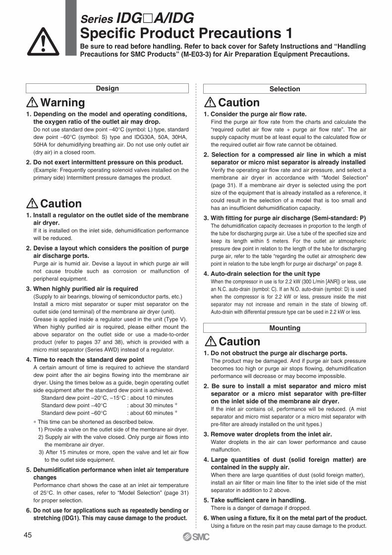
Selection
Caution1. Consider the purge air flow rate.
Find the purge air flow rate from the charts and calculate the “required outlet air flow rate + purge air flow rate”. The air supply capacity must be at least equal to the calculated flow or the required outlet air flow rate cannot be obtained.
2. Selection for a compressed air line in which a mist separator or micro mist separator is already installedVerify the operating air flow rate and air pressure, and select a membrane air dryer in accordance with “Model Selection” (page 31). If a membrane air dryer is selected using the port size of the equipment that is already installed as a reference, it could result in the selection of a model that is too small and has an insufficient dehumidification capacity.
3. With fitting for purge air discharge (Semi-standard: P)The dehumidification capacity decreases in proportion to the length of the tube for discharging purge air. Use a tube of the specified size and keep its length within 5 meters. For the outlet air atmospheric pressure dew point in relation to the length of the tube for discharging purge air, refer to the table “regarding the outlet air atmospheric dew point in relation to the tube length for purge air discharge” on page 8.
4. Auto-drain selection for the unit typeWhen the compressor in use is for 2.2 kW (300 L/min [ANR]) or less, use an N.C. auto-drain (symbol: C). If an N.O. auto-drain (symbol: D) is used when the compressor is for 2.2 kW or less, pressure inside the mist separator may not increase and remain in the state of blowing off. Auto-drain with differential pressure type can be used in 2.2 kW or less.
Mounting
Caution1. Do not obstruct the purge air discharge ports.
The product may be damaged. And if purge air back pressure becomes too high or purge air stops flowing, dehumidification performance will decrease or may become impossible.
2. Be sure to install a mist separator and micro mist separator or a micro mist separator with pre-filter on the inlet side of the membrane air dryer.If the inlet air contains oil, performance will be reduced. (A mist separator and micro mist separator or a micro mist separator with pre-filter are already installed on the unit types.)
3. Remove water droplets from the inlet air.Water droplets in the air can lower performance and cause malfunction.
4. Large quantities of dust (solid foreign matter) are contained in the supply air. When there are large quantities of dust (solid foreign matter), install an air filter or main line filter to the inlet side of the mist separator in addition to 2 above.
5. Take sufficient care in handling.There is a danger of damage if dropped.
6. When using a fixture, fix it on the metal part of the product.Using a fixture on the resin part may cause damage to the product.
Caution1. Install a regulator on the outlet side of the membrane
air dryer.If it is installed on the inlet side, dehumidification performance will be reduced.
2. Devise a layout which considers the position of purge air discharge ports.Purge air is humid air. Devise a layout in which purge air will not cause trouble such as corrosion or malfunction of peripheral equipment.
3. When highly purified air is required(Supply to air bearings, blowing of semiconductor parts, etc.)Install a micro mist separator or super mist separator on the outlet side (end terminal) of the membrane air dryer (unit).Grease is applied inside a regulator used in the unit (Type V). When highly purified air is required, please either mount the above separator on the outlet side or use a made-to-order product (refer to pages 37 and 38), which is provided with a micro mist separator (Series AWD) instead of a regulator.
4. Time to reach the standard dew pointA certain amount of time is required to achieve the standard dew point after the air begins flowing into the membrane air dryer. Using the times below as a guide, begin operating outlet side equipment after the standard dew point is achieved. Standard dew point −20°C, −15°C : about 10 minutes Standard dew point −40°C : about 30 minutes ∗ Standard dew point −60°C : about 60 minutes ∗
∗ This time can be shortened as described below. 1) Provide a valve on the outlet side of the membrane air dryer. 2) Supply air with the valve closed. Only purge air flows into
the membrane air dryer. 3) After 15 minutes or more, open the valve and let air flow
to the outlet side equipment.
5. Dehumidification performance when inlet air temperature changesPerformance chart shows the case at an inlet air temperature of 25°C. In other cases, refer to “Model Selection” (page 31) for proper selection.
6. Do not use for applications such as repeatedly bending or stretching (IDG1). This may cause damage to the product.
Design
Warning1. Depending on the model and operating conditions,
the oxygen ratio of the outlet air may drop.Do not use standard dew point –40°C (symbol: L) type, standard dew point –60°C (symbol: S) type and IDG30A, 50A, 30HA, 50HA for dehumidifying breathing air. Do not use only outlet air (dry air) in a closed room.
2. Do not exert intermittent pressure on this product.(Example: Frequently operating solenoid valves installed on the primary side) Intermittent pressure damages the product.
Series IDG�A/IDGSpecific Product Precautions 1Be sure to read before handling. Refer to back cover for Safety Instructions and “Handling Precautions for SMC Products” (M-E03-3) for Air Preparation Equipment Precautions.
45
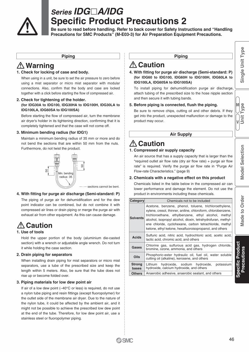
50
50
Min. bendingradius: 35
sections cannot be bent.
4. With fitting for purge air discharge (Semi-standard: P)(for IDG60 to IDG100, IDG60H to IDG100H, IDG60LA to IDG100LA, IDG60SA to IDG100SA)
To install piping for dehumidification purge air discharge, attach tubing of the prescribed size to the hose nipple section and then secure it with tubing bands.
5. Before piping is connected, flush the piping.Be sure to remove chips, cutting oil and other debris. If they get into the product, unexpected malfunction or damage to the product may occur.
Air Supply
1. Compressed air supply capacityAn air source that has a supply capacity that is larger than the “required outlet air flow rate (dry air flow rate) + purge air flow rate” is required. Verify the purge air flow rate in “Purge Air Flow-rate Characteristics.” (page 9)
2. Chemicals with a negative effect on this productChemicals listed in the table below in the compressed air can lower performance and damage the element. Do not use the product in environments including these chemicals.
Caution
Piping Piping
Warning
1. Use of toolsHold the upper portion of the body (aluminium die-casted section) with a wrench or adjustable angle wrench. Do not turn it while holding the case section.
2. Drain piping for separatorsWhen installing drain piping for mist separators or micro mist separators, use a tube of the prescribed size and keep the length within 5 meters. Also, be sure that the tube does not rise up or become folded over.
3. Piping materials for low dew point airIf air of a low dew point (–40°C or less) is required, do not use a nylon tube piping and resin fittings (except fluoropolymer) for the outlet side of the membrane air dryer. Due to the nature of the nylon tube, it could be affected by the ambient air, and it might not be possible to achieve the prescribed low dew point at the end of the tube. Therefore, for low dew point air, use a stainless steel or fluoropolymer piping.
Caution
1. Check for locking of case and body.When using in a unit, be sure to set the air pressure to zero before using a mist separator or micro mist separator with modular connections. Also, confirm that the body and case are locked together with a click before starting the flow of compressed air.
2. Check for tightening of the holder.(for IDG30A to IDG100, IDG30HA to IDG100H, IDG30LA to IDG100LA, IDG60SA to IDG100SA)
Before starting the flow of compressed air, turn the membrane air dryer's holder in its tightening direction, confirming that it is completely tightened and that the case will not come off.
3. Minimum bending radius (for IDG1)Maintain a minimum bending radius of 35 mm or more and do not bend the sections that are within 50 mm from the nuts. Furthermore, do not twist the product.
4. With fitting for purge air discharge (Semi-standard: P)The piping of purge air for dehumidification and for the dew point indicator can be combined, but do not combine it with compressed air lines or drain piping or merge the purge air with exhaust air from other equipment. As this can cause damage.
Caution
Series IDG�A/IDGSpecific Product Precautions 2Be sure to read before handling. Refer to back cover for Safety Instructions and “Handling Precautions for SMC Products” (M-E03-3) for Air Preparation Equipment Precautions.
Solvents
Acids
Gases
Oils
Strongbases
Others
Category Chemicals not to be included
Acetone, benzene, phenol, toluene, trichloroethylene, xylene, cresol, thinner, aniline, chloroform, chlorobenzene, trichloroethane, ethylbenzene, ethyl alcohol, methyl alcohol, isopropyl alcohol, dioxin, tetrahydrofuran, methyl-ene chloride, cyclohexane, carbon tetrachloride, methyl ketone, ethyl ketone, hexafluoroisopropanol, and others
Sulfuric acid, nitric acid, hydrochloric acid, acetic acid, lactic acid, chromic acid, and others
Chlorine gas, sulfurous acid gas, hydrogen chloride, bromine, ozone, ammonia, and others
Phosphoric-ester hydraulic oil, fuel oil, water soluble cutting oil (alkaline), kerosene, and others
Lithium hydroxide, sodium hydroxide, potassium hydroxide, calcium hydroxide, and others
Anaerobic adhesive, anaerobic sealant, and others
M
V
Sin
gle
Un
it T
ype
Mo
del
Sel
ecti
on
Mad
e to
Ord
erS
pec
ific
Pro
du
ctP
reca
uti
on
sU
nit
Typ
e
46
Colour of the dew point indicator Note
There are both white and pink grains.
Air flow rate etc. can be outside of the specifications.
Contained oils can lower the performance.
Performance state
White/Pink
Blue
White/Pink
Brown/Black
Initial state
Normal operating
Decrease in performance
Series IDG�A/IDGSpecific Product Precautions 3Be sure to read before handling. Refer to back cover for Safety Instructions and “Handling Precautions for SMC Products” (M-E03-3) for Air Preparation Equipment Precautions.
Maintenance
Maintenance
Caution
Warning
Caution
1. Do not remove the parts or piping when in a pressu-rised state.Never remove them while under pressure, as this could cause dangerous situations.
3. Element replacement periodRefer to the following guide when replacing the elements in the mist separator and in the micro mist separator, or micro mist separator with prefilter that are installed on the inlet side of the membrane air dryer.
1) When two years have passed since installation.
2) When the unit’s pressure drop reaches 0.2 MPa, even before the two year period is reached.
3) When the red portion of the element service indicator reaches the upper limit. (With micro mist separator with pre-filter)[IDG60M to IDG100M, IDG60HM to IDG100HM, IDG60V to IDG100V, IDG60HV to IDG100HV] Note)
Note) For other models as well, they are available with the element service indicator under made-to-order. Refer to pages 33 and 34.
4. Membrane module replacement periodReplace the membrane module when the colour of the dew point indicator turns white or pink. As a guideline, unit should be replaced after approximately 10 years of use (10 hours/day operation). Replace it when the colour of the dew point indicator turns white or pink, even if it is within the period.
5. Tightening torque for installing the membrane module and the case (for IDG5, 10, 20, 5H, 10H, 20H)Use caution not to tighten excessively.It may result in a breakdown of membrane module, case and mounting screws or insufficient sealing.(Check the tightening torque range in the Operation Manual.)
6. Installing a pressure gaugeA pressure gauge should be installed on the inlet and outlet sides of the membrane air dryer (unit) for the maintenance and inspection purposes.
Metrology (Measurement) Law
Caution1. SMC products are not intended for use as instruments
for legal metrology.Measurement instruments that SMC manufactures or sells have not been qualified by type approval tests relevant to the metrology (measurement) laws of each country.Therefore, SMC products cannot be used for business or certification ordained by the metrology (measurement) laws of each country.
1. Check the dehumidification function with the dew point indicator.Observe the colour of the dew point indicator to confirm whether the membrane air dryer is functioning normally.[When dew point indicator colour is blue: Functioning normally][When dew point indicator colour is pink: Dew point temperature is high. (Outlet air is humid.) Note: Atmospheric pressure dew point approximately –10°C minimum]
If humid air flowing in turns the colour pink, and then if dry air enters, the colour turns back to blue. It takes about 1 hour from the start of air flow for the dew point indicator colour to change.
2. Dew point indicator replacement periodThe absorbent is used in the dew point indicator. It absorbs the gasified oil in the compressed air and/or the gaseous elements other than the air, and then may turn brown.When it turned brown, replace the dew point indicator. Besides, in the event of replacing them periodically, carry out after two-year operation as a guideline. (For the part number of the dew point indicator, refer to pages 10 and 11.)
Operating Environment
Caution1. Do not use at temperatures (fluid or ambient tempera-
tures) higher than the prescribed operating conditions.Resin is used in the membrane module, and it can be damaged by operation at high temperatures. Especially when installed immediately after a reciprocating type air compressor, confirm that the fluid temperature does not exceed the range of operating conditions during use.
2. Keep the inlet air temperature lower than the ambient temperature.If the membrane air dryer body is cooled by the surrounding air, water drops may accumulate inside and reduce its dehumidification capacity.
47

48


Lithuania +370 5 2308118 www.smclt.lt [email protected] +31 (0)205318888 www.smcpneumatics.nl [email protected] +47 67129020 www.smc-norge.no [email protected] +48 (0)222119616 www.smc.pl [email protected] +351 226166570 www.smc.eu [email protected] +40 213205111 www.smcromania.ro [email protected] +7 8127185445 www.smc-pneumatik.ru [email protected] +421 (0)413213212 www.smc.sk [email protected] +386 (0)73885412 www.smc.si [email protected] +34 902184100 www.smc.eu [email protected] +46 (0)86031200 www.smc.nu [email protected] +41 (0)523963131 www.smc.ch [email protected] +90 212 489 0 440 www.smcpnomatik.com.tr [email protected] UK +44 (0)845 121 5122 www.smcpneumatics.co.uk [email protected]
Specifications are subject to change without prior notice and any obligation on the part of the manufacturer.SMC CORPORATION Akihabara UDX 15F, 4-14-1, Sotokanda, Chiyoda-ku, Tokyo 101-0021, JAPAN Phone: 03-5207-8249 FAX: 03-5298-5362
1st printing SU printing SU 00 Printed in Spain
Austria +43 (0)2262622800 www.smc.at [email protected] +32 (0)33551464 www.smcpneumatics.be [email protected] +359 (0)2807670 www.smc.bg [email protected] Croatia +385 (0)13707288 www.smc.hr [email protected] Republic +420 541424611 www.smc.cz [email protected] Denmark +45 70252900 www.smcdk.com [email protected] Estonia +372 6510370 www.smcpneumatics.ee [email protected] +358 207513513 www.smc.fi [email protected] +33 (0)164761000 www.smc-france.fr [email protected] +49 (0)61034020 www.smc-pneumatik.de [email protected] +30 210 2717265 www.smchellas.gr [email protected] +36 23511390 www.smc.hu [email protected] +353 (0)14039000 www.smcpneumatics.ie [email protected] +39 0292711 www.smcitalia.it [email protected] +371 67817700 www.smclv.lv [email protected]
Safety Instructions Be sure to read “Handling Precautions for SMC Products” (M-E03-3) before using.
SMC Corporation (Europe)
1. The compatibility of the product is the responsibility of the person who designs the equipment or decides its specifications.Since the product specified here is used under various operating conditions, its compatibility with specific equipment must be decided by the person who designs the equipment or decides its specifications based on necessary analysis and test results. The expected performance and safety assurance of the equipment will be the responsibility of the person who has determined its compatibility with the product. This person should also continuously review all specifications of the product referring to its latest catalogue information, with a view to giving due consideration to any possibility of equipment failure when configuring the equipment.
2. Only personnel with appropriate training should operate machinery and equipment.The product specified here may become unsafe if handled incorrectly. The assembly, operation and maintenance of machines or equipment including our products must be performed by an operator who is appropriately trained and experienced.
3. . Do not service or attempt to remove product and machinery/equipment until safety is confirmed.1. The inspection and maintenance of machinery/equipment should only be
performed after measures to prevent falling or runaway of the driven objects have been confirmed.
2. When the product is to be removed, confirm that the safety measures as mentioned above are implemented and the power from any appropriate source is cut, and read and understand the specific product precautions of all relevant products carefully.
3. Before machinery/equipment is restarted, take measures to prevent unexpected operation and malfunction.
4. Contact SMC beforehand and take special consideration of safety measures if the product is to be used in any of the following conditions. 1. Conditions and environments outside of the given specifications, or use
outdoors or in a place exposed to direct sunlight.2. Installation on equipment in conjunction with atomic energy, railways, air
navigation, space, shipping, vehicles, military, medical treatment, combustion and recreation, or equipment in contact with food and beverages, emergency stop circuits, clutch and brake circuits in press applications, safety equipment or other applications unsuitable for the standard specifications described in the product catalogue.
3. An application which could have negative effects on people, property, or animals requiring special safety analysis.
4. Use in an interlock circuit, which requires the provision of double interlock for possible failure by using a mechanical protective function, and periodical checks to confirm proper operation.
Warning
Limited warranty and Disclaimer/Compliance Requirements The product used is subject to the following “Limited warranty and Disclaimer” and “Compliance Requirements”.Read and accept them before using the product.
1. The product is provided for use in manufacturing industries.The product herein described is basically provided for peaceful use in manufacturing industries. If considering using the product in other industries, consult SMC beforehand and exchange specifications or a contract if necessary. If anything is unclear, contact your nearest sales branch.
Caution
Limited warranty and Disclaimer1. The warranty period of the product is 1 year in service or 1.5 years after
the product is delivered.∗2)
Also, the product may have specified durability, running distance or replacement parts. Please consult your nearest sales branch.
2. For any failure or damage reported within the warranty period which is clearly our responsibility, a replacement product or necessary parts will be provided. This limited warranty applies only to our product independently, and not to any other damage incurred due to the failure of the product.
3. Prior to using SMC products, please read and understand the warranty terms and disclaimers noted in the specified catalogue for the particular products.
∗2) Vacuum pads are excluded from this 1 year warranty.A vacuum pad is a consumable part, so it is warranted for a year after it is delivered. Also, even within the warranty period, the wear of a product due to the use of the vacuum pad or failure due to the deterioration of rubber material are not covered by the limited warranty.
Compliance Requirements1. The use of SMC products with production equipment for the manufacture of
weapons of mass destruction (WMD) or any other weapon is strictly prohibited.
2. The exports of SMC products or technology from one country to another are governed by the relevant security laws and regulations of the countries involved in the transaction. Prior to the shipment of a SMC product to another country, assure that all local rules governing that export are known and followed.
These safety instructions are intended to prevent hazardous situations and/or equipment damage. These instructions indicate the level of potential hazard with the labels of “Caution,” “Warning” or “Danger.” They are all important notes for safety and must be followed in addition to International Standards (ISO/IEC)∗1), and other safety regulations.
∗1) ISO 4414: Pneumatic fluid power – General rules relating to systems. ISO 4413: Hydraulic fluid power – General rules relating to systems. IEC 60204-1: Safety of machinery – Electrical equipment of machines. (Part 1: General requirements) ISO 10218-1: Manipulating industrial robots - Safety. etc.
Caution indicates a hazard with a low level of risk which, if not avoided, could result in minor or moderate injury.
Warning indicates a hazard with a medium level of risk which, if not avoided, could result in death or serious injury.
Caution:
Warning:
Danger :Danger indicates a hazard with a high level of risk which, if not avoided, will result in death or serious injury.
Safety Instructions