ZOOM Series - RS Components
56
ZOOM Series GPRS/UMTS/LTE Embedded Socket Modem with USB and TTL RS232 Interfaces Hardware Reference Manual Rev 4.7
-
Upload
khangminh22 -
Category
Documents
-
view
1 -
download
0
Transcript of ZOOM Series - RS Components

ZOOM SeriesGPRS/UMTS/LTE Embedded Socket Modem with USB and TTL RS232 Interfaces
Hardware Reference ManualRev 4.7

A member of the Olancha Group Ltd
Registered in England No. 08405712VAT Registration No. GB163 04 0349
Siretta LtdBasingstoke Road
Spencers WoodReading
Berkshire RG7 1PW
salesfaxemailweb
+44(0)118 976 9014+44(0)118 976 9020
2
ZOOM SeriesGPRS/UMTS/LTE Embedded Socket Modem with
USB and TTL RS232 Interfaces
Table of ContentsPage
Introduction 3
About Siretta 4
General Description 5
Specifications 5
AT Commands 7
ZOOM Interface 8
System Diagram 10
System Overview 11
Modes of Operation 12
Ordering Information 13
Dimensions 14
ZOOM Series Images 17
ZOOM LED Indicators 18
User Programmable LED Status Control 19
Device States 20
ZOOM Series Connections 22
Power Supply Requirements 23
Interfaces 24
Function Header Interface 25
Communication Header Interface 26
Header Connector Considerations 27
USB Interface Drivers 30
Digital Functions 31
Digital Output 31
Digital Input 32
SIM Socket 33
SIM Requirements 33
Antenna Connectors 34
GSM/UMTS Antenna Connector 35
GPS Antenna Connector (Optional) 36
GPS 37
ZOOM-G-GPRS Socket Modem 37
ZOOM-G-UMTS Socket Modem 37
GPS Performance (ZOOM-G Variants) 37
Power 39
Measured Power Consumption 39
Switching the Modem ON/OFF 40
Embedded Software Support 42
Telit AppZone 42
Telit Easy Script in Python 43
Debug Headers 44
Siretta Recommends 46
Installation 47
Considers for Installations Incorporating the ZOOM Socket Modem
47
Power Supply Installations 48
Securing the Modem 48
Safety and Product Care 49
General Precautions 49
SIM Card Precautions 49
Antenna Precautions 50
Exposure to RF Energy 50
Safety Recommendations 52
Conformity Assessment 53
Disclaimer 54
Definitions 55

A member of the Olancha Group Ltd
Registered in England No. 08405712VAT Registration No. GB163 04 0349
Siretta LtdBasingstoke Road
Spencers WoodReading
Berkshire RG7 1PW
salesfaxemailweb
+44(0)118 976 9014+44(0)118 976 9020
3
ZOOM SeriesGPRS/UMTS/LTE Embedded Socket Modem with
USB and TTL RS232 Interfaces
This document is intended to provide guidance when adding a modem from the ZOOM Series to your system. The ZOOM Series is a range of general purpose GPRS/UMTS/LTE embedded socket modems for communicating with other equipment via a USB / TTL RS232 serial interface.
This document is aimed at engineers and describes the electrical characteristics, hardware and software operation of the ZOOM modem.
Introduction

A member of the Olancha Group Ltd
Registered in England No. 08405712VAT Registration No. GB163 04 0349
Siretta LtdBasingstoke Road
Spencers WoodReading
Berkshire RG7 1PW
salesfaxemailweb
+44(0)118 976 9014+44(0)118 976 9020
4
ZOOM SeriesGPRS/UMTS/LTE Embedded Socket Modem with
USB and TTL RS232 Interfaces
Siretta, located in Reading, United Kingdom have been manufacturing antennas, cable assemblies and cellular terminals for over 10 years. We supply our products globally to many of the world’s leading organisations.
Whether you require an off the shelf or custom solution, Siretta has a wide portfolio of antenna, RF cable assemblies and terminals to fit your application.
Our extensive knowledge and experience in the wireless market allows us to support a wide range of customer applications, focusing on frequencies typically within the 75MHz - 5.8GHz range. These encompass the HF, VHF, ISM, GSM/GPRS/3G/4G and GPS frequencies as well as industrial WLAN and VHF/UHF antenna/Wi-Fi antenna solutions.
With a heavy emphasis on design, we have a team of dedicated Application Engineers and Product Managers, backed up by Field Sales Engineers, who specialise in wireless applications.
We have made significant investments in R&D facilities which boast GPS hardware development equipment and a GSM Pico Cell on site, as well as development software and a comprehensive suite of Industrial, Scientific and Medical band, and non ISM band frequency products. We have many technology partners enabling us to keep at the forefront of the communications industry and offer class leading wireless solutions.
About Siretta

A member of the Olancha Group Ltd
Registered in England No. 08405712VAT Registration No. GB163 04 0349
Siretta LtdBasingstoke Road
Spencers WoodReading
Berkshire RG7 1PW
salesfaxemailweb
+44(0)118 976 9014+44(0)118 976 9020
5
ZOOM SeriesGPRS/UMTS/LTE Embedded Socket Modem with
USB and TTL RS232 Interfaces
Specifications
ZOOM GPRS ZOOM UMTS
2G frequency band: 850, 900, 1800, 1900MHz 850, 900, 1800, 1900MHz
3G frequency band: 850, 900, 1700, 1900, 2100MHz
GPS support (optional): GPS, Glonass, Galileo, QZSS GPS
Dimensions: 86mm x 60mm x 24mm 86mm x 60mm x 24mm
Weight: 54g 54g
Supply voltage: 5V - 42V 5V - 42V
Temperature range: -40 to 85°C -30 to +85 °C
GSM antenna: SMA Female SMA Female
GPS antenna (optional): SMA Female SMA Female
General Description
Table 1. Specifications of ZOOM modem
The ZOOM series of GPRS/UMTS/LTE socket modems are fully designed, developed and ready to integrate into your equipment, easily, and with a low overall cost.
The ZOOM series answers the need for an economic, fully functional and tested cel-lular modem platform that can be easily incorporated into your equipment with little knowledge of modem technology. With a highly plug-n-play design, the ZOOM offers a common platform across the range, enabling all technologies to be evaluated easily, including GPRS, UMTS, LTE and all variants with GPS.
The ZOOM socket modems are designed to be plugged onto your own PCB via standard 2 x 20 way pin header connectors. The two headers incorporate TTL level RS232 and USB interfaces, 10 GPIO lines and power. The ZOOM series also has an unusually wide power supply capability of 5-42V, enabling compatibility with a wide range of applications.

A member of the Olancha Group Ltd
Registered in England No. 08405712VAT Registration No. GB163 04 0349
Siretta LtdBasingstoke Road
Spencers WoodReading
Berkshire RG7 1PW
salesfaxemailweb
+44(0)118 976 9014+44(0)118 976 9020
6
ZOOM SeriesGPRS/UMTS/LTE Embedded Socket Modem with
USB and TTL RS232 Interfaces
Table 2. Socket modem data transfer speeds
Model Region Coverage Max Download Max Upload
ZOOM-N-GPRS Global 236.8Kbps 59.2Kbps
ZOOM-G-GPRS Global 236.8Kbps 59.2Kbps
ZOOM-N-UMTS Global 21Mbps 5.76Mbps
ZOOM-G-UMTS Global 21Mbps 5.76Mbps
ZOOM-N-UMTS (EU) (Europe) 7.2Mbps 5.76Mbps
ZOOM-G-UMTS (EU) (Europe) 7.2Mbps 5.76Mbps
ZOOM-N-LTE (EU) (Europe) 100Mbps 50Mbps
ZOOM-G-LTE (EU) (Europe) 100Mbps 50Mbps
NOTE - For part numbering and ordering information see page 13

A member of the Olancha Group Ltd
Registered in England No. 08405712VAT Registration No. GB163 04 0349
Siretta LtdBasingstoke Road
Spencers WoodReading
Berkshire RG7 1PW
salesfaxemailweb
+44(0)118 976 9014+44(0)118 976 9020
7
ZOOM SeriesGPRS/UMTS/LTE Embedded Socket Modem with
USB and TTL RS232 Interfaces
AT CommandsThe ZOOM range of wireless socket modems has a GSM engine at its heart which can be controlled via the serial interface using standard AT commands.
The AT command is an ATTENTION command and is used as a prefix to other parameters in a formatted string. The AT command combined with other parameters can be sent to the terminal with your preferred terminal emulator package (TMSTerm/TeraTerm/HyperTerminal) and typed in manually as a command line instruction.
The wireless module is compliant with the following AT command formats:
1. Hayes standard AT command set, in order to maintain the compatibility with existing software programs.
2. 3GPP 27.007 specific AT command and GPRS specific commands.
3. 3GPP 27.005 specific AT commands for SMS (Short Message Service) and CBS (Cell Broadcast Service)
4. FAX Class 1 compatible commands
5. Propietary command set, the module family also supports a proprietary set of AT commands for special purposes outside of the standard AT specification.
To obtain the latest AT command reference guide with a full list of supported AT commands, please contact your Siretta representative or alternatively visit:
www.siretta.co.uk
NOTE - This following document refers to useful AT commands throughout and offers descriptions of how to use the AT commands with the ZOOM wireless socket modem family.

A member of the Olancha Group Ltd
Registered in England No. 08405712VAT Registration No. GB163 04 0349
Siretta LtdBasingstoke Road
Spencers WoodReading
Berkshire RG7 1PW
salesfaxemailweb
+44(0)118 976 9014+44(0)118 976 9020
8
ZOOM SeriesGPRS/UMTS/LTE Embedded Socket Modem with
USB and TTL RS232 Interfaces
ZOOM Interface
Standard Hardware Interfaces
The ZOOM series embedded socket modems comes with the following interfaces:
» 1 x SMA female GSM antenna connector
» 1 x SMA female GPS antenna connector (optional)
» 1 x SIM card reader (push-push)
» 3 x external LED status indicators (Red, Blue, Green)
» 20-Way Communication Header connector
○ 1 x TTL RS232 serial port interface for direct serial connection to module (TX,RX,CTS,RTS,GND)
○ 1 x TTL Debug/Trace serial port for direct serial connection to debug port (TX,RX,GND)
○ 1 x USB serial port interface for direct connection to module (D+,D-,VBUS,GND)
○ 1 x RTC power connection for powering real time clock
○ 1 x Vcc power connection (VIN,GND)
○ 3 x power control (ON_OFF,HW_SHUTDOWN,PWRMON)
» 20-Way Function Header connector
○ 6 x General purpose output interfaces (GPO)
○ 4 x General purpose input interfaces (GPI)
○ 1 x 10-bit ADC interface (0-1.2V tolerant)
○ 3 x LED interfaces (Red,Green,Blue)
○ 1 x Automatic power control (HLDLORST)
○ 1 x Vcc power connection (VIN,GND)
○ 3 x power control (ON_OFF,HW_SHUTDOWN,PWRMON)
○

A member of the Olancha Group Ltd
Registered in England No. 08405712VAT Registration No. GB163 04 0349
Siretta LtdBasingstoke Road
Spencers WoodReading
Berkshire RG7 1PW
salesfaxemailweb
+44(0)118 976 9014+44(0)118 976 9020
9
ZOOM SeriesGPRS/UMTS/LTE Embedded Socket Modem with
USB and TTL RS232 Interfaces
Optional Gateway Software Package
The ZOOM series embedded socket modems have the following optional software packages available:
» V-Link232 Software
Wireless cable replacement using RS232 serial cable over GPRS/UMTS
Optional Coverage
The ZOOM series embedded socket modems have the following coverage options available:
» (EU) European Union
» (NA) North America
Optional Technologies
The ZOOM series embedded socket modems have the following optional technologies available:
» GPRS (2G)
» UMTS (3G)
» LTE (4G)
Optional Socket Modem Features*
Optional Hardware
The ZOOM series embedded socket modems have the following optional hardware features:
» High performance SirfStarIV GPS engine (Options available for GPS/Glonass/Galileo/QZSS)

A member of the Olancha Group Ltd
Registered in England No. 08405712VAT Registration No. GB163 04 0349
Siretta LtdBasingstoke Road
Spencers WoodReading
Berkshire RG7 1PW
salesfaxemailweb
+44(0)118 976 9014+44(0)118 976 9020
10
ZOOM SeriesGPRS/UMTS/LTE Embedded Socket Modem with
USB and TTL RS232 Interfaces
System Diagram
Figure 1. ZOOM system diagram
The ZOOM series is a range of embedded cellular socket modems. It has been designed to easily integrate directly to you existing application simply via 2 x 20-way IDE headers.
Alternatively the ZOOM can be used as an OEM board for new product designs. The system diagram below gives a visual representation of the ZOOM interfaces available to the user through the header interfaces and shows the various subsections which make up the complete ZOOM socket modem.
GSM
5 - 42VPSU
SIM
Visual Indicators
Debug Serial Port
ZOOM Interfaces
Communication Subsection
RTC
TTL RS232 Serial Port
USB Serial Port
Power Control
Power InputTelit xE910 Module
GPS

A member of the Olancha Group Ltd
Registered in England No. 08405712VAT Registration No. GB163 04 0349
Siretta LtdBasingstoke Road
Spencers WoodReading
Berkshire RG7 1PW
salesfaxemailweb
+44(0)118 976 9014+44(0)118 976 9020
11
ZOOM SeriesGPRS/UMTS/LTE Embedded Socket Modem with
USB and TTL RS232 Interfaces
This ZOOM can be used in a number of applications, some examples are shown below:
» V-Link232 Software (Wireless cable replacement using RS232 serial cable over GPRS/3G)
» GPIO Monitor (Monitor/Set and report on GPIO status) » Standard RS232 terminal attached to existing equipment (PC/MAC/Server etc.)
Typically connected devices are:
» PC/MAC/Linux platforms for use as modem » Embedded (connected directly to remote equipment without a PC attached)
Operating System Connected Terminal
» Internet enable a remote device with RS232 connectivity over 2.5G/3G. Internet connectivity can be retrofitted to end equipment without changing the software or configuration of the remote device.
» Used in countries or places where broadband and WiFi is a less common method to connect to the internet or where services are unavailable. The ZOOM terminal can overcome this restriction by providing a mobile internet solution over the GPRS/3G network.
Embedded Systems
The V-Link software can be used with an embedded system where automated end to end communication is required.
If the embedded system has limited intelligence or has limited configuration capability the Siretta V-Link software can be used to connect the system to a central server easily and simply.
The V-Link software can also be used to control and manage the remote terminal so that the connection from the embedded system to the central server/control head office is seamless and reliable.
System Overview

A member of the Olancha Group Ltd
Registered in England No. 08405712VAT Registration No. GB163 04 0349
Siretta LtdBasingstoke Road
Spencers WoodReading
Berkshire RG7 1PW
salesfaxemailweb
+44(0)118 976 9014+44(0)118 976 9020
12
ZOOM SeriesGPRS/UMTS/LTE Embedded Socket Modem with
USB and TTL RS232 Interfaces
Examples:
» Vending machine where the head office would poll for drinks remaining/money taken etc. This would be an on-demand pull to obtain results in real time.
» Monitoring AMR/temperature/equipment in a home, i.e. Interrogate lights etc. » Monitoring GPIO, i.e. Open doors/windows » Remote entry system, i.e. Send a message to the terminal to open a gate/door to
allow access. » Streaming live data from remote system to a central location » Remote printing applications (remotely print over the GPRS network) » Polling remote devices for information to prevent an engineer callout
USB Interface
This is a USB standard Communication Device Class (CDC) device. This is provided with a driving for the OS, i.e. a standard OS supported driver.
V-Link Software
Embedded systems can use the RS232 serial port to connect to a remote device to a central server. The serial configuration supports most configurations and can be changed either via the USB interface, or via SMS commands.
Modes of Operation

A member of the Olancha Group Ltd
Registered in England No. 08405712VAT Registration No. GB163 04 0349
Siretta LtdBasingstoke Road
Spencers WoodReading
Berkshire RG7 1PW
salesfaxemailweb
+44(0)118 976 9014+44(0)118 976 9020
13
ZOOM SeriesGPRS/UMTS/LTE Embedded Socket Modem with
USB and TTL RS232 Interfaces
Ordering Information
ZOOM X XXXX (XX) (XXXX)
Module Type
N = Without GPSG = With GPS
Product Module Version
GPRS = GPRS Technology
UMTS = UMTS Technology
LTE = LTE Technology
Coverage Options
(EU) = European Coverage of GSM and UMTS Only
(NA) = North American Coverage of GSM and UMTS Only
Software Package Options
(V-Link232) = V-Link232 Software
Part Numbering Examples
» ZOOM-N-GPRS = GPRS Embedded Socket Modem with USB and TTL RS232 Interfaces, without GPS
» ZOOM-G-UMTS (EU) (V-Link232) = EU Coverage UMTS and GPS Embedded Socket Modem with USB and TTL RS232 Interfaces and V-Link232 Software
Terminal Identifier
ZOOM = Embedded Socket Modem with USB and TTL RS232 Interfaces
- -

A member of the Olancha Group Ltd
Registered in England No. 08405712VAT Registration No. GB163 04 0349
Siretta LtdBasingstoke Road
Spencers WoodReading
Berkshire RG7 1PW
salesfaxemailweb
+44(0)118 976 9014+44(0)118 976 9020
14
ZOOM SeriesGPRS/UMTS/LTE Embedded Socket Modem with
USB and TTL RS232 Interfaces
DimensionsAll dimensions are shown in mm. The mounting holes are suitable for an M3 fixing screw.
Figure 2. Front view of ZOOM - dimensions
77
60
51
4.5
0
4.50
86
1mm clearance around mounting holes
18
5.10
5.10
35.50 36.50
6.5
0
10.
80
2.4
0
1.6
0
15.10 45
10.
70
76.50 1.75
Pin 1 Pin 1
1:1 @ A3 Sheet Size
A B C D E F G H I
7
6
5
4
3
IHGFEDCB
2
A1
AMENDMENTS
JOB NUMBER
DRAWING TITLE
STATUS
PROJECT INFO
COPYRIGHT WARNINGThese drawings and designs remain the property of Sequoia Technology Group. Any unauthorised use will render the offender liable for damages.
ALL DIMENSIONS ARE IN Millimeters UNLESS OTHERWISE STATED
ZOOM
DR
AWIN
G: X
:\Seq
uoia
Des
ign\
Sire
tta\Z
OO
M\ Z
OO
MM
OD
EL: X
:\Seq
uoia
Des
ign\
Sire
tta\Z
OO
M\ Z
OO
M
DESIGNER
25/06/2014ISSUE DATE
DO NOT SCALE OFF DRAWINGEMAIL [email protected] FOR DXFS OR OTHER SCALABLE FILES.
Page
No:
01
/01GENERAL NOTES:
PART NUMBER REV
SCALE

A member of the Olancha Group Ltd
Registered in England No. 08405712VAT Registration No. GB163 04 0349
Siretta LtdBasingstoke Road
Spencers WoodReading
Berkshire RG7 1PW
salesfaxemailweb
+44(0)118 976 9014+44(0)118 976 9020
15
ZOOM SeriesGPRS/UMTS/LTE Embedded Socket Modem with
USB and TTL RS232 Interfaces
Figure 3. Front elevation view of ZOOM - dimensions
77
60
51
4.5
0
4.50
86
1mm clearance around mounting holes
18
5.10
5.10
35.50 36.50
6.5
0
10.
80
2.4
0
1.6
0
15.10 45
10.
70
76.50 1.75
Pin 1 Pin 1
1:1 @ A3 Sheet Size
A B C D E F G H I
7
6
5
4
3
IHGFEDCB
2
A1
AMENDMENTS
JOB NUMBER
DRAWING TITLE
STATUS
PROJECT INFO
COPYRIGHT WARNINGThese drawings and designs remain the property of Sequoia Technology Group. Any unauthorised use will render the offender liable for damages.
ALL DIMENSIONS ARE IN Millimeters UNLESS OTHERWISE STATED
ZOOM
DR
AWIN
G: X
:\Seq
uoia
Des
ign\
Sire
tta\Z
OO
M\ Z
OO
MM
OD
EL: X
:\Seq
uoia
Des
ign\
Sire
tta\Z
OO
M\ Z
OO
M
DESIGNER
25/06/2014ISSUE DATE
DO NOT SCALE OFF DRAWINGEMAIL [email protected] FOR DXFS OR OTHER SCALABLE FILES.
Page
No:
01
/01GENERAL NOTES:
PART NUMBER REV
SCALE

A member of the Olancha Group Ltd
Registered in England No. 08405712VAT Registration No. GB163 04 0349
Siretta LtdBasingstoke Road
Spencers WoodReading
Berkshire RG7 1PW
salesfaxemailweb
+44(0)118 976 9014+44(0)118 976 9020
16
ZOOM SeriesGPRS/UMTS/LTE Embedded Socket Modem with
USB and TTL RS232 Interfaces
Figure 4. Bottom view of ZOOM - dimensions to interface headers centre
77
60
51
4.5
0
4.50
86
1mm clearance around mounting holes
18
5.10
5.10
35.50 36.50
6.5
0
10.
80
2.4
0
1.6
0
15.10 45
1.75
78.25
10.
70
6.05
14.
23
82.55
14.
23
Pin 1 Pin 1
1:1 @ A3 Sheet Size
A B C D E F G H I
7
6
5
4
3
IHGFEDCB
2
A1
AMENDMENTS
JOB NUMBER
DRAWING TITLE
STATUS
PROJECT INFO
COPYRIGHT WARNINGThese drawings and designs remain the property of Sequoia Technology Group. Any unauthorised use will render the offender liable for damages.
ALL DIMENSIONS ARE IN Millimeters UNLESS OTHERWISE STATED
ZOOM
DR
AWIN
G: X
:\Seq
uoia
Des
ign\
Sire
tta\Z
OO
M\ Z
OO
MM
OD
EL: X
:\Seq
uoia
Des
ign\
Sire
tta\Z
OO
M\ Z
OO
M
DESIGNER
27/08/2014ISSUE DATE
DO NOT SCALE OFF DRAWINGEMAIL [email protected] FOR DXFS OR OTHER SCALABLE FILES.
Page
No:
01
/01GENERAL NOTES:
PART NUMBER REV
SCALE

A member of the Olancha Group Ltd
Registered in England No. 08405712VAT Registration No. GB163 04 0349
Siretta LtdBasingstoke Road
Spencers WoodReading
Berkshire RG7 1PW
salesfaxemailweb
+44(0)118 976 9014+44(0)118 976 9020
17
ZOOM SeriesGPRS/UMTS/LTE Embedded Socket Modem with
USB and TTL RS232 Interfaces
ZOOM Series ImagesFigure 5. 3D view of the ZOOM-G-UMTS Figure 6. Front view of the ZOOM-G-UMTS
Figure 7. Side view of the ZOOM-G-UMTS Figure 8. Back view of the ZOOM-G-UMTS

A member of the Olancha Group Ltd
Registered in England No. 08405712VAT Registration No. GB163 04 0349
Siretta LtdBasingstoke Road
Spencers WoodReading
Berkshire RG7 1PW
salesfaxemailweb
+44(0)118 976 9014+44(0)118 976 9020
18
ZOOM SeriesGPRS/UMTS/LTE Embedded Socket Modem with
USB and TTL RS232 Interfaces
The current GSM network registration state of the ZOOM modem is indicated by the status LEDs as shown in table 3 below.
LED colour State
Red
Constant ON: Network search / not registered / turning off
Slow rate once every 3 seconds: Registered full service
Constant ON: Ringing or call in progress
OFF: Module power down*
Green User programmable in software**
Blue User programmable in software**
*LED default state is off. Need to configure AT#SLED command to enable software control of LED flashing state.
AT#GPIO=1,0,2
AT#SLED=2
AT#SLEDSAV
**See ‘User Programmable LED Status Control’ section on page 19.
Table 3. Device status LED
Figure 9. ZOOM LED’s
Red LEDBlue LEDGreen LED
ZOOM LED Indicators

A member of the Olancha Group Ltd
Registered in England No. 08405712VAT Registration No. GB163 04 0349
Siretta LtdBasingstoke Road
Spencers WoodReading
Berkshire RG7 1PW
salesfaxemailweb
+44(0)118 976 9014+44(0)118 976 9020
19
ZOOM SeriesGPRS/UMTS/LTE Embedded Socket Modem with
USB and TTL RS232 Interfaces
The green and blue LED's can be controlled in two different ways:
1) The connected equipment can directly connect to the LED control lines and control the LED's independently to the ZOOM socket modem.
2) The control lines can be connected to the GPIO lines on the ZOOM and allow the ZOOM socket modem to control the LED's via standard AT commands or using python to indicate device status to the user.
Example AT Commands to Control LED Status
In the example below the green LED is directly connected to GPIO2 and the blue LED is directly connected to GPIO3.
AT#GPIO=2,1,1 (switch general purpose output 2 on, PIN2, function header connected to green LED on PIN14)
AT#GPIO=2,0,1 (switch general purpose output 2 off, PIN2, function header connected to green LED on PIN14)
AT#GPIO=3,1,1 (switch general purpose output 3 on, PIN3, function header connected to blue LED on PIN13)
AT#GPIO=3,0,1 (switch general purpose output 3 off, PIN3, function header connected to blue LED on PIN13)
User Programmable LED Status Control

A member of the Olancha Group Ltd
Registered in England No. 08405712VAT Registration No. GB163 04 0349
Siretta LtdBasingstoke Road
Spencers WoodReading
Berkshire RG7 1PW
salesfaxemailweb
+44(0)118 976 9014+44(0)118 976 9020
20
ZOOM SeriesGPRS/UMTS/LTE Embedded Socket Modem with
USB and TTL RS232 Interfaces
Table 4. Device states (assume AT#SLED=2*)
Current Device State Input Next state Indication of new state
Power Off Connect power Run ModeRed LED will be on continuously*
Run Mode Insert a valid SIM card On NetworkRed LED will flash once every 3 seconds*
On NetworkHold ON_OFF (Pin 18 on either header) to 0.5V - 42V for >0.5 seconds
Power off No activity on any LED**
Run ModeHold ON_OFF (Pin 18 on either header) to 0.5V - 42V for >0.5 seconds
Power off No activity on any LED**
Power OffHold ON_OFF (Pin 18 on either header) to 0.5V - 42V for >0.5 seconds
Run Mode Red LED will be on*
Run Mode Insert a valid SIM card On NetworkRed LED will flash once every 3 seconds*
The current device state and function is shown below in table 4.
*LED default state is off. Need to configure AT#SLED command to enable software control of LED flashing state.
AT#GPIO=1,0,2
AT#SLED=2
AT#SLEDSAV
**When the command SLED=2 has been set then no activity on the red LED indicates that the unit is powered off.
Device States

A member of the Olancha Group Ltd
Registered in England No. 08405712VAT Registration No. GB163 04 0349
Siretta LtdBasingstoke Road
Spencers WoodReading
Berkshire RG7 1PW
salesfaxemailweb
+44(0)118 976 9014+44(0)118 976 9020
21
ZOOM SeriesGPRS/UMTS/LTE Embedded Socket Modem with
USB and TTL RS232 Interfaces
NOTE - Normal Operation: When the terminal is first switched on with a valid SIM card, the red LED will be on continuously. The terminal will attempt to join a network and should take about 10-15 seconds (this may vary considerably) whilst the terminal searches for the network. During this period you can determine the registration status of the network using the AT command ‘AT+CREG?’ which will return one of 4 states as shown below:
+CREG: 0,1 – Indicates that the terminal is registered to the home network
+CREG: 0,2 – Indicates that the terminal is searching for a network
+CREG: 0,3 – Indicates that the terminal has been denied network access
+CREG: 0,4 – Indicates that the terminal has a network problem
+CREG: 0,5 – Indicates that the terminal is registered to a roaming network
If the response ‘+CREG:0,2’ is returned for a long period of time (more than 5 minutes) then this suggests that there may be a problem with the SIM setup, the network signal or the antenna connection.

A member of the Olancha Group Ltd
Registered in England No. 08405712VAT Registration No. GB163 04 0349
Siretta LtdBasingstoke Road
Spencers WoodReading
Berkshire RG7 1PW
salesfaxemailweb
+44(0)118 976 9014+44(0)118 976 9020
22
ZOOM SeriesGPRS/UMTS/LTE Embedded Socket Modem with
USB and TTL RS232 Interfaces
» Polarised 20 way IDE communication header
» Polarised 20 way IDE function header
» SIM card reader
» SMA female bulkhead (GSM antenna connector)
» SMA female bulkhead (GPS antenna connector) (Only on ZOOM-G variants)
ZOOM Series Connections
ZOOM Series
DC input voltage 5 to 42V
Recommended input voltage 12V DC
Supply current @ 12V:
Peak (20ms at registration) 2A
Average standby 25mA
Call in progress 250mA
Ringing 250mA
The ZOOM socket modem has the ability to be powered from 5V to 42V. Powering the modem can be done in 2 different ways:
» ZOOM EVK - Siretta have designed and manufactured the ZOOM-EVK board which comes with a 12V mains adapter to power your ZOOM modem. The ZOOM-EVK has been tested and is highly recommended for product development.
» Application - The ZOOM socket modem can be powered directly from the end application it is being used with. This is achieved by providing a DC power supply, as shown in table 5 above.
Table 5. Characteristics of power input
Power Supply RequirementsA DC power supply must be connected to the power input.

A member of the Olancha Group Ltd
Registered in England No. 08405712VAT Registration No. GB163 04 0349
Siretta LtdBasingstoke Road
Spencers WoodReading
Berkshire RG7 1PW
salesfaxemailweb
+44(0)118 976 9014+44(0)118 976 9020
23
ZOOM SeriesGPRS/UMTS/LTE Embedded Socket Modem with
USB and TTL RS232 Interfaces
ZOOM-EVK
Figure 10. ZOOM-EVK
The ZOOM-EVK development board is the ideal way of developing an application to integrate into your equipment. The ZOOM module plugs directly onto the EVK providing convenient access to all of the ZOOM interfaces via the EVK’s RS232, USB and terminal block connectors.
The ZOOM-EVK PCB allows access to all of the ZOOM interfaces through standard 2 x 20 way pin headers, allowing you to control the modem from a connected PC or embedded micro controller. Please turn to page 46 for ordering details for the ZOOM-EVK, alternatively visit www.siretta.co.uk/zoom-evaluation-development-platform-p-402.html for more information about this product.
NOTE - The current requirements of the ZOOM embedded socket modem will scale with input voltage. The higher the input voltage the lower the current consumption, the power consumption will remain constant. Recommended input voltage is 12V.
The ZOOM socket modem has the following input power supply protection:
» On board voltage reverse polarity protection
» Overvoltage spike protection to 70V for 1mS.
» ESD protection to +/-4KV contact discharge and +/-8KV air discharge.
A member of the Olancha Group Ltd
Registered in England No. 08405712VAT Registration No. GB163 04 0349
Siretta LtdBasingstoke Road
Spencers WoodReading
Berkshire RG7 1PW
salesfaxemailweb
+44(0)118 976 9014+44(0)118 976 9020
24
ZOOM SeriesGPRS/UMTS/LTE Embedded Socket Modem with
USB and TTL RS232 Interfaces
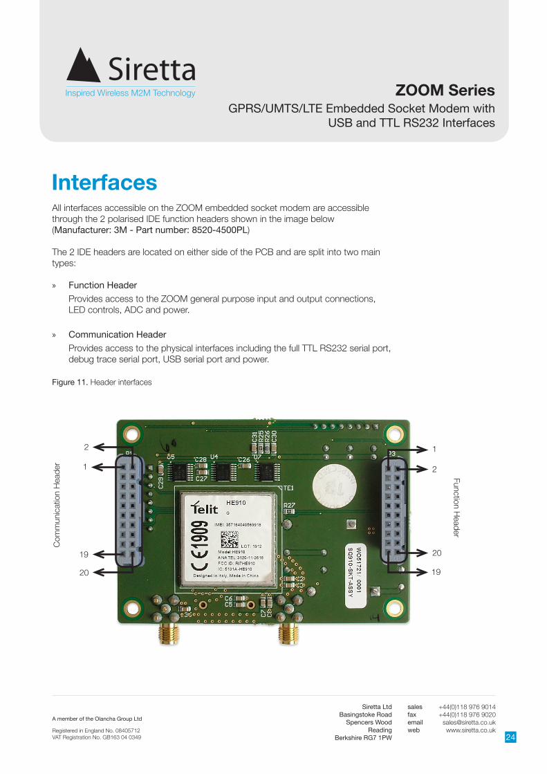
Interfaces
Figure 11. Header interfaces
1
Com
mun
icat
ion
Hea
der
2
19
20
1
2
19
20
Function Header
All interfaces accessible on the ZOOM embedded socket modem are accessible through the 2 polarised IDE function headers shown in the image below (Manufacturer: 3M - Part number: 8520-4500PL)
The 2 IDE headers are located on either side of the PCB and are split into two main types:
» Function Header
Provides access to the ZOOM general purpose input and output connections, LED controls, ADC and power.
» Communication Header
Provides access to the physical interfaces including the full TTL RS232 serial port, debug trace serial port, USB serial port and power.

A member of the Olancha Group Ltd
Registered in England No. 08405712VAT Registration No. GB163 04 0349
Siretta LtdBasingstoke Road
Spencers WoodReading
Berkshire RG7 1PW
salesfaxemailweb
+44(0)118 976 9014+44(0)118 976 9020
25
ZOOM SeriesGPRS/UMTS/LTE Embedded Socket Modem with
USB and TTL RS232 Interfaces
Function Header Interface
An IDE type connector is provided for general purpose IO. ESD protection to ±4KV contact discharge and ±8KV air discharge is provided. Pins on this connector are available for control from the embedded application as shown below in table 6.
IDE Pin Module Function Voltage Level Function Direction Description
1 GPO1 CMOS 3.3V GPO1 OUT General Purpose Output
2 GPO2 CMOS 3.3V GPO2 OUT General Purpose Output
3 GPO3 CMOS 3.3V GPO3 OUT General Purpose Output
4 GPO4 CMOS 3.3V GPO4 OUT General Purpose Output
5 GPI1 CMOS 3.3V GPI1 IN General Purpose Input
6 GPI2 CMOS 3.3V GPI2 IN General Purpose Input
7 GPI3 CMOS 3.3V GPI3 IN General Purpose Input
8 GPI4 CMOS 3.3V GPI4 IN General Purpose Input
9 GPO5 CMOS 3.3V GP05 OUT General Purpose Output
10 GPO6 CMOS 3.3V GP06 OUT General Purpose Output
11 ADC_IN 0 - 1.2V ADC INPUT IN Analogue to Digital Input
12 STAT_LED CMOS 3.3V GSM STATUS INGSM Status LED (Indicates GSM network registration when configured)
13 BLUE_LED CMOS 3.3V BLUE LED IN GPO LED
14 GREEN_LED CMOS 3.3V GREEN LED IN GPO LED
15* HW_SHUTDOWN 0.5 - 40V SHUTDOWN INHardware shutdown disaster recovery reset (Active high 0.5 - 40V)
16 HLDLORST CMOS 3.3V AUTO POWERUP IN Auto restart modem (Active low)
17* PWRMON CMOS 1.8V POWER STATUS OUTModem power status (Indicates power on when high)
18* ON_OFF 0.5 - 40V TURN ON/OFF INModem power control line (Active high 0.5 - 40V)
19* GND 0V GND POWER IN Modem power ground
20* Vcc 5 - 42V VIN POWER IN Modem power positive
Table 6. Functions of the function header interface*
*See section ‘Header Connector Considerations’ on page 27.

A member of the Olancha Group Ltd
Registered in England No. 08405712VAT Registration No. GB163 04 0349
Siretta LtdBasingstoke Road
Spencers WoodReading
Berkshire RG7 1PW
salesfaxemailweb
+44(0)118 976 9014+44(0)118 976 9020
26
ZOOM SeriesGPRS/UMTS/LTE Embedded Socket Modem with
USB and TTL RS232 Interfaces
Communication Header Interface
An IDE type connector is provided for general purpose IO. ESD protection ± 4KV contact discharge and ± 8KV air discharge is provided. Pins on this connector are available for control from the embedded application as shown below in table 7.
IDE Pin Module Function Voltage Level Function Direction Description
1 VUSB 5V USB Power IN USB Power
2 TTL RS232 TX CMOS 3.3V Serial TX IN TTL RS232 serial transmit
3 TTL RS232 RX CMOS 3.3V Serial RX OUT TTL RS232 serial receive
4 TTL RS232 RTS CMOS 3.3V Serial RTS IN TTL RS232 serial request to send
5 TTL RS232 CTS CMOS 3.3V Serial CTS OUT TTL RS232 serial clear to send
6 TTL RS232 DSR CMOS 3.3V Serial DSR OUT TTL RS232 data set ready
7 TTL RS232 RI CMOS 3.3V Serial RI OUT TTL RS232 ring indicator
8 TTL RS232 DCD CMOS 3.3V Serial DCD OUT TTL RS232 data carrier detect
9 TTL RS232 DTR CMOS 3.3V Serial DTR IN TTL RS232 data terminal ready
10 TTL RS232 GND 0V Serial GND IN/OUT TTL RS232 signal ground
11 DEBUG RX CMOS 3.3V Debug RX INDebug data input for Python engine and real time debugging
12 USB DATA+ CMOS 3.3V USB Data + OUT USB data line
13 DEBUG TX CMOS 3.3V Debug TX OUTDebug data output for Python engine and real time debugging
14 USB DATA- CMOS 3.3V USB Data - OUT USB data line
15* HW_SHUTDOWN 0.5 - 40V SHUTDOWN INHardware shutdown disaster recovery reset (Active high 0.5 - 40V)
16 VRTC See table 10 RTC IN Real time clock input
17* PWRMON CMOS 1.8V POWER STATUS OUTModem power status (Indicates power on when high)
18* ON_OFF 0.5 - 40V TURN ON/OFF INModem power control line (Active high 0.5 - 40V)
19* GND 0V GND POWER IN Modem power ground
20* Vcc 5 - 42V VIN POWER IN Modem power positive
Table 7. Functions of the communication header interface*
*See section ‘Header Connector Considerations’ on page 27.

A member of the Olancha Group Ltd
Registered in England No. 08405712VAT Registration No. GB163 04 0349
Siretta LtdBasingstoke Road
Spencers WoodReading
Berkshire RG7 1PW
salesfaxemailweb
+44(0)118 976 9014+44(0)118 976 9020
27
ZOOM SeriesGPRS/UMTS/LTE Embedded Socket Modem with
USB and TTL RS232 Interfaces
Header Connector ConsiderationsThe following signals are available on both the function and communication header connectors:
Control Signals
» HW_SHUTDOWN - PIN15 on function and communication header
» PWRMON - PIN17 on function and communication header
» ON_OFF - PIN18 on function and communication header
Power Signals
» Vcc - PIN20 on function and communication header
» GND - PIN19 on function and communication header
These signals are electrically connected together on the ZOOM PCB. The control signals only need to be connected at one connector (whichever is the most convenient for the application). Siretta recommends connecting the Vcc and GND signals on both connectors to your application for best performance.
Also note that the control signals are also available on the debug connectors, see section ‘Debug Headers’ on page 44.

A member of the Olancha Group Ltd
Registered in England No. 08405712VAT Registration No. GB163 04 0349
Siretta LtdBasingstoke Road
Spencers WoodReading
Berkshire RG7 1PW
salesfaxemailweb
+44(0)118 976 9014+44(0)118 976 9020
28
ZOOM SeriesGPRS/UMTS/LTE Embedded Socket Modem with
USB and TTL RS232 Interfaces
Parameter Minimum Nominal Maximum
Input high level 2V 3.3V 3.6V
Input low level 0V 0V 0.8V
Output High Level (I=100µA) 3.1V 3.2V 3.3V
Output High Level (I=12mA) 2.31V 2.6V 3.3V
Output Low Level (I=12mA) 0.0V 0.7V 0.9V
Table 8. Minimum/maximum voltage for ZOOM series CMOS 3.3V GPIO
Parameter Minimum Typical Maximum
Input high level 1.5V 1.8V 1.9V
Input low level 0V 0.2V 0.35V
Output high level 1.6V 1.8V 1.9V
Output low level 0V 0.1V 0.2V
Output current - 1mA -
Input current - 1µA -
Table 9. Minimum/maximum voltage for ZOOM series CMOS 1.8V GPIO
NOTE - The input level on any CMOS 1.8 pin has an absolute maximum rating from -0.3V to 3.1V. This is not for normal use and may cause damage to the device if exceeded.

A member of the Olancha Group Ltd
Registered in England No. 08405712VAT Registration No. GB163 04 0349
Siretta LtdBasingstoke Road
Spencers WoodReading
Berkshire RG7 1PW
salesfaxemailweb
+44(0)118 976 9014+44(0)118 976 9020
29
ZOOM SeriesGPRS/UMTS/LTE Embedded Socket Modem with
USB and TTL RS232 Interfaces
All TTL RS232 pins provide the following ESD protection:
» ± 15kV - Human Body Model
» ± 8kV - IEC61000-4-2, Contact Dischare
» ± 15kV - IEC61000-4-2, Air Gap Discharge
As a minimum, TXD, RXD and GND are required to set up serial communications with the module.
ZOOM GPRS ZOOM UMTS
Typical voltage 2.3V 1.8V
Minimum voltage 1.1V 1.1V
Table 10. VRTC Voltage
VRTC Voltage
VRTC Example Circuit
VRTC
2K4
1F 5.5V (KR-5R5H105-R)

A member of the Olancha Group Ltd
Registered in England No. 08405712VAT Registration No. GB163 04 0349
Siretta LtdBasingstoke Road
Spencers WoodReading
Berkshire RG7 1PW
salesfaxemailweb
+44(0)118 976 9014+44(0)118 976 9020
30
ZOOM SeriesGPRS/UMTS/LTE Embedded Socket Modem with
USB and TTL RS232 Interfaces
The ZOOM series embedded socket modems support a standard USB 2.0 device interface compatible with USB 2.0 specifications and supporting the USB low-speed [1.5 Mb/s] and full-Speed (12 Mb/s) modes. The USB port can be used to send AT-commands, reprogram the modems and view debug output. The maximum baud rate available to communicate with the ZOOM series modem is up to 12 Mbit/s.
Drivers are required to use the USB port and are available for several operating systems including Windows/Linux. Please contact Siretta for more information.
In HSDPA (High Speed Downlink Packet Access) mode, the downlink data speed rates can be up to 7.2Mbps. To achieve this network data rate using the ZOOM, integrators need to interface the ZOOM-N-UMTS to their applications in full-speed (12 Mb/s) mode.
The device driver creates 6 virtual COM ports on the system for non-GPS modems and 6 virtual COM ports for GPS enabled modems:
USB0 → AT Command Interface 1
USB1 → Trace Port
USB2 → Unused
USB3 → AT Command Interfaces 2
USB4 → Unused
USB5 → Unused
The ZOOM series modems do not support autobauding. Integrators have to set the correct speed for serial communication before device initialization. If the right speed is set, the device responds with OK. The default baudrate is 115200.
To change the baudrate:
» Send command AT+IPR=<rate><cr>
» Wait for ‘OK’ response
USB Interface Drivers
Supported baudrates <CR>
» 2400 Carriage return
» 4800
» 9600
» 19200
» 38400
» 57600
» 115200
» 230400

A member of the Olancha Group Ltd
Registered in England No. 08405712VAT Registration No. GB163 04 0349
Siretta LtdBasingstoke Road
Spencers WoodReading
Berkshire RG7 1PW
salesfaxemailweb
+44(0)118 976 9014+44(0)118 976 9020
31
ZOOM SeriesGPRS/UMTS/LTE Embedded Socket Modem with
USB and TTL RS232 Interfaces
» Switch voltage is 3.3V high side switch » Maximum output current 1mA » Under full control of embedded application
The following command has to be used to initialise and to set the digital output:
AT#GPIO=1,1,1 (switch general purpose output 1 on, PIN1, function header)AT#GPIO=1,0,1 (switch general purpose output 1 off, PIN1, function header)AT#GPIO=2,1,1 (switch general purpose output 2 on, PIN2, function header)AT#GPIO=2,0,1 (switch general purpose output 2 off, PIN2, function header)AT#GPIO=3,1,1 (switch general purpose output 3 on, PIN3, function header)AT#GPIO=3,0,1 (switch general purpose output 3 off, PIN3, function header)AT#GPIO=4,1,1 (switch general purpose output 4 on, PIN4, function header)AT#GPIO=4,0,1 (switch general purpose output 4 off, PIN4, function header)
AT#GPIO=9,1,1 (switch general purpose output 9 on, PIN9 , function header)AT#GPIO=9,0,1 (switch general purpose output 9 off, PIN9, function header)AT#GPIO=10,1,1 (switch general purpose output 10 on, PIN10, function header)AT#GPIO=10,0,1 (switch general purpose output 10 off, PIN10, function header)
Digital Output
Digital Functions
Optional input (default setup as output)

A member of the Olancha Group Ltd
Registered in England No. 08405712VAT Registration No. GB163 04 0349
Siretta LtdBasingstoke Road
Spencers WoodReading
Berkshire RG7 1PW
salesfaxemailweb
+44(0)118 976 9014+44(0)118 976 9020
32
ZOOM SeriesGPRS/UMTS/LTE Embedded Socket Modem with
USB and TTL RS232 Interfaces
» Maximum voltage defined in table 8 » Under full control of embedded application
The following AT commands can be used to initialise and to read the status of the GPIO:
AT#GPIO=5,2,0 (read general purpose input 5, PIN5, function header)AT#GPIO=6,2,0 (read general purpose input 6, PIN6, function header)AT#GPIO=7,2,0 (read general purpose input 7, PIN7, function header)AT#GPIO=8,2,0 (read general purpose input 8, PIN8, function header)
AT#GPIO=9,2,0 (read general purpose input 9, PIN9, function header)AT#GPIO=10,2,0 (read general purpose input 10, PIN10, function header)
Digital Input
Optional input (default setup as output)

A member of the Olancha Group Ltd
Registered in England No. 08405712VAT Registration No. GB163 04 0349
Siretta LtdBasingstoke Road
Spencers WoodReading
Berkshire RG7 1PW
salesfaxemailweb
+44(0)118 976 9014+44(0)118 976 9020
33
ZOOM SeriesGPRS/UMTS/LTE Embedded Socket Modem with
USB and TTL RS232 Interfaces
SIM Socket
Figure 12. ZOOM series SIM socket
SIM Socket
Figure 13. SIM card dimensions
SIM Requirements
1.8V/3.3V Mini SIM (2FF) supported on the ZOOM series embedded socket modems.
SIM services available for the ZOOM GPRS series include:
» 2G GSM (850/900/1800/1900MHz)
» SM,
» GPRS
» CSD
SIM services available for the ZOOM UMTS series include:
» 2G GSM (850/900/1800/1900MHz)
» 3G UMTS (850/900/1700/1900/2100MHz)
» SMS
» GPRS
» CSD
The ZOOM embedded socket modem supports fixed SIMs locked to a network and roaming SIMs which can operate on more than one network within the home country. This allows for least cost routing for roaming mobile data and machine to machine applications where signal strength is variable in any given area and network selection is required.
The ZOOM also supports global roaming SIMs which will work with any network it can detect, at home or abroad and can be chosen for best performance.
NOTE - 3G only SIM will not be supported on 2G GSM only modem. Please ensure SIM is 2G and 3G capable for greatest compatibility.

A member of the Olancha Group Ltd
Registered in England No. 08405712VAT Registration No. GB163 04 0349
Siretta LtdBasingstoke Road
Spencers WoodReading
Berkshire RG7 1PW
salesfaxemailweb
+44(0)118 976 9014+44(0)118 976 9020
34
ZOOM SeriesGPRS/UMTS/LTE Embedded Socket Modem with
USB and TTL RS232 Interfaces
Figure 14. ZOOM Series Antenna Connectors
Antenna Connectors
GPS Antenna Connector (optional)
GSM/UMTS Antenna Connector
Antenna PlacementWhen in service the antenna should be placed away from electronic devices or other antennas. The recommended minimum distance between adjacent antennas, operating on a similar radio band, is at least 50cm.
Antenna Connection CableIf a cable is used to connect the device to the antenna this cable must be a high quality low loss cable. The cable and any connectors used should have 50 ohms impedance.

A member of the Olancha Group Ltd
Registered in England No. 08405712VAT Registration No. GB163 04 0349
Siretta LtdBasingstoke Road
Spencers WoodReading
Berkshire RG7 1PW
salesfaxemailweb
+44(0)118 976 9014+44(0)118 976 9020
35
ZOOM SeriesGPRS/UMTS/LTE Embedded Socket Modem with
USB and TTL RS232 Interfaces
GSM Antenna
Figure 15. Mike 1A GSM antenna
The GSM/UMTS antenna we recommend to use for the ZOOM Series is the Mike 1A SMA male magnetic mount antenna, (Most other Siretta styles of GSM/UMTS antennas are usable depending on customer preference). Please turn to page 46 for ordering details for the Mike 1A, alternatively visit www.siretta.co.uk/mike1a-p-339.html for more information about this antenna.
A female SMA connector is provided to allow connection of a passive antenna. For optimum performance the antenna assembly connected to this device is required to have the following characteristics:
» For 2G GSM operation specified operation in the following bands: GSM 850/900/1800/1900MHz
» For 3G UMTS operation specified operation in the following bands: GSM 800/850/1700/1900/2100MHz
» The characteristic impedance on any antenna or cable assembly attached to this device should be 50 ohms
» The antenna must be capable of handling a minimum of 2W output power
» The VSWR should be less than 3:1 to avoid damage to the device
GSM/UMTS Antenna Connector

A member of the Olancha Group Ltd
Registered in England No. 08405712VAT Registration No. GB163 04 0349
Siretta LtdBasingstoke Road
Spencers WoodReading
Berkshire RG7 1PW
salesfaxemailweb
+44(0)118 976 9014+44(0)118 976 9020
36
ZOOM SeriesGPRS/UMTS/LTE Embedded Socket Modem with
USB and TTL RS232 Interfaces
GPS Antenna GainAntenna gain is defined as the extra signal power from the antenna as compared to a theoretical isotropic antenna (equally sensitive in all directions).
It is important to note that GPS antenna gain is not the same thing as external LNA gain. Most antenna vendors will specify these numbers separately, but some combine them into a single number. It is important to know both numbers when designing and evaluating the front end of a GPS receiver.
An antenna with higher gain will generally outperform an antenna with lower gain. Once the signals are above about -130 dBm for a particular satellite, no improvement in performance would be gained. However, for those satellites that are below about -125 dBm, a higher gain antenna would improve the gain and improve the performance of the GPS receiver. In the case of really weak signals, a good antenna could mean the difference between being able to use a particular satellite signal or not.
As the GPS antenna needs to be located away from the ZOOM Series modem then an active antenna will be required to obtain the best system performance. The active antenna has its own built in low noise amplifier to overcome RF trace or cable losses after the active antenna. The active antenna has a low noise amplifier (LNA) with associated gain and noise figure.
GPS Antenna Connector (Optional)
GPS Antenna PolarizationThe GPS signal as broadcast is a right hand circularly polarized signal. The best antenna to receive the GPS signal is a right hand circularly (RHCP) polarized antenna.
GPS AntennaThe GPS antenna we recommend to use for the ZOOM Series is the Mike 3A SMA male magnetic mount antenna. Please turn to page 46 for ordering details on the Mike 3A, alternatively visit www.siretta.co.uk/mike3a-p-302.html for more information about this antenna.
Figure 15. Mike 3A GPS antenna

A member of the Olancha Group Ltd
Registered in England No. 08405712VAT Registration No. GB163 04 0349
Siretta LtdBasingstoke Road
Spencers WoodReading
Berkshire RG7 1PW
salesfaxemailweb
+44(0)118 976 9014+44(0)118 976 9020
37
ZOOM SeriesGPRS/UMTS/LTE Embedded Socket Modem with
USB and TTL RS232 Interfaces
GPSZOOM-G-GPRS Socket ModemThe ZOOM-G-GPRS socket modem is a cutting edge GPS receiver that can simultaneously search and track satellite signals from multiple satellite constellations. This multi-GNSS receiver uses the entire spectrum of Global Navigation Satellite Systems available: GPS, Glonass, Galileo and QZSS.
The ZOOM GPRS socket modem features an advanced real time hardware correlation engine for enhanced sensitivity navigation (PVT), Fast Acquisition giving rapid Time-to-First-Fix (TTFF), low power consumption, 32 track verification channels, stand Alone and Assisted mode and Satellite Based Augmentation Systems (SBAS): WAAS, EGNOS, and MSAS.
ZOOM-G-UMTS Socket ModemThe ZOOM-G-UMTS socket modem features a high performance GPS receiver which provides fast Time-To-First-Fix (TTFF), low power consumption and Satellite Based Augmentation Systems (SBAS): WAAS, EGNOS, and MSAS. The receiver can be used in both autonomous and assisted mode and supports advanced digital signal processing to achieve GPS sensitivity better than -165 dBm which enable indoor tracking applications.
The ZOOM-G-UMTS socket modem also supports advanced real time hardware correlation engine and offers the capability to monitor up to 28 channels simultaneously in stand alone or assisted mode.
GPS Performance (ZOOM-G Variants) » Advanced real time hardware correlation engine for enhanced sensitivity (better
than -165dBm for A-GPS)
» Fast Acquisition giving rapid Time-to-First-Fix (TTFF)
» Capability to monitor up to 28 channel
» Stand Alone and Assisted mode
» Integrated LNA

A member of the Olancha Group Ltd
Registered in England No. 08405712VAT Registration No. GB163 04 0349
Siretta LtdBasingstoke Road
Spencers WoodReading
Berkshire RG7 1PW
salesfaxemailweb
+44(0)118 976 9014+44(0)118 976 9020
38
ZOOM SeriesGPRS/UMTS/LTE Embedded Socket Modem with
USB and TTL RS232 Interfaces
Table 11. Main characteristics of GPS
Characteristic Typical Values
GPS RX Sensitivity -164dBm
GPS Cold Start Autonomous -147dBm
GPS Hot Start Autonomous -161dBm
GPS Tracking Mode -166dBm
GPS Accuracy 3m
TTFF from Cold Start 42 secs
TTFF from Warm Start 30 secs
TTFF from Hot Start 1.8 secs
GPS Output Power
Min Nom Max
Output enabled 2.8V 3.0V 3.3V
Output disabled - 0.0V 0.2V
Output current 0mA 20mA 28mA
Table 13. GPS antenna connection output characteristics
NOTE: Power supply is enabled when GPS engine is powered with the following AT command:
AT$GPSP=1 - will turn the GPS engine on
AT$GPSP=0 - will turn the GPS engine off
To output NMEA data, please refer to AT$GPSNMUN command in the AT command reference guide.
GPS Characteristics
GPS antenna power supply is generated internally by the ZOOM socket modem and is a stable high accuracy low dropout supply designed to give very good GPS performance.
Table 12. GPS power consumption
GPS Power Supply
Characteristic Typical Values
Power Consumption in Acquisition 46.4mA
Power Consumption in Tracking 37.8 mA
Power Consumption in Low Power Tracking 25.7mA

A member of the Olancha Group Ltd
Registered in England No. 08405712VAT Registration No. GB163 04 0349
Siretta LtdBasingstoke Road
Spencers WoodReading
Berkshire RG7 1PW
salesfaxemailweb
+44(0)118 976 9014+44(0)118 976 9020
39
ZOOM SeriesGPRS/UMTS/LTE Embedded Socket Modem with
USB and TTL RS232 Interfaces
PowerMeasured Power ConsumptionThe measurement was taken at 2 Voltages with GPS inactive (5V and 12V).
The ZOOM modem was connected via TTL RS232 to a PC in order to send/receive AT commands. The temperature was maintained in a temperature chamber. The voice call with Power level 5 in GSM 900 was established with a GSM signal generator test set.
5V 12V
Modem switched off 0.01 mA 0.67 mA
On, network connection (Idle mode - 60dBm RSSI) 71 mA 25 mA
On, network connection voice call (power level 5) GSM 900 235 mA 98 mA
Table 14. ZOOM modem current consumption
Function State Current
Modem on (Not registered) Idle 39mA
Modem on (Registered) Idle 36mA
Modem on (Registered with IP address) Idle 40mA
Modem on (Registered with socket connected) Idle 41mA
Modem On (Registered with socket connected) - Peak Transmitting 109mA
Modem on (Registered with socket connected) - Average Transmitting 98mA
Table 15. ZOOM module current consumption

A member of the Olancha Group Ltd
Registered in England No. 08405712VAT Registration No. GB163 04 0349
Siretta LtdBasingstoke Road
Spencers WoodReading
Berkshire RG7 1PW
salesfaxemailweb
+44(0)118 976 9014+44(0)118 976 9020
40
ZOOM SeriesGPRS/UMTS/LTE Embedded Socket Modem with
USB and TTL RS232 Interfaces
Switching the Modem ON/OFF
Power on the ZOOM
The ZOOM series embedded modem has several options to power on. The 2 main options are shown below:
1) Auto power up using HLDLORST pin on the function header (Pin16). Hold this pin to ground and when Vcc is applied to the modem the auto power on circuit will automatically power up the modem.
2) Manually power up the modem using the ON_OFF pin on the function and communication header (Pin18). When this pin is connected to logic high (0.5-42V) for >5 seconds the modem will power up.
In both cases you can monitor PWRMON pin on the function and communication header (Pin17) to determine the modem status. When PWRMON is logic high (1.8V) then the modem is powered on.
NOTE - The modem is fully operational after it has powered on and PWRMON is asserted to logic high (1.8V). This may take anything from 2 to 6 seconds depending on the startup procedure. Once the modem is powered up it will automatically attempt to logon to the GSM network and may take anything from 10 seconds to 4 minutes depending on the network. This is outside the control of the modem and is network and frequency dependant.
Power off the ZOOM
The ZOOM series embedded modem has several options to power off. The 2 main options are shown below:
1) Manually power down the modem using the ON_OFF pin on the function and communication header (Pin18). When this pin is connected to logic high (0.5-42V) for >2 seconds the modem will power off.
2) Manually power down the modem using the AT command AT#SHDN. This command will safely disconnect from the network and power down the module.
In both cases you can monitor PWRMON pin on the function and communication header (Pin17) to determine the modem status. When PWRMON is logic low (0V) then the modem is powered off.
A member of the Olancha Group Ltd
Registered in England No. 08405712VAT Registration No. GB163 04 0349
Siretta LtdBasingstoke Road
Spencers WoodReading
Berkshire RG7 1PW
salesfaxemailweb
+44(0)118 976 9014+44(0)118 976 9020
41
ZOOM SeriesGPRS/UMTS/LTE Embedded Socket Modem with
USB and TTL RS232 Interfaces
Considerations when manually powering the ZOOM on and off
The ON_IN signal requires a positive “edge” (a “sharp” signal transition from low to high) to turn the modem on. This transition should be a rising signal from 0V (GND) up to Vcc (max 40V), or at least a large fraction of that voltage range (>0.5V). Very slow transitions (significantly slower than many milliseconds) or very small transitions (e.g. only a few millivolts instead of 0V to 0.5V) will not turn on the modem (since they are not considered to be a “positive edge”).
Although this will not be an issue in almost all typical applications of the modem, under the following condition special design care has to be taken:
» Large capacitors in your power supply which will lead to slow leading and falling edges
The case above might prevent the modem from recognizing the power-up signal. This is no failure of the modem itself, the same would apply to almost any electronic device that provides a separate “power-on” or “reset” signal.
If you are in doubt, please use the following recommendations:
» Use the ZOOM-EVK (available from Siretta) to test your application with a known working hardware platform. Use the Vcc power supply signal from the EVK to test the power on signal function.
» Make sure that your signal and system design adheres to the recommendations mentioned above
» Consult our support team and we will be more than happy to assist you.
Disaster recovery power down reset procedure
The ZOOM embedded socket modem has a special power down function for disaster recovery and modem system failures
This function should only be used in the event of the standard power down function using the ON_OFF pin or the software shutdown AT command failing to operate correctly.
» The disaster recovery reset HW_SHTDWN (Pin15) is available on both the communication and function headers
» The disaster recovery reset is active high (0.5 - 42V) for >2 seconds
NOTE - Misuse of this function can cause latch up problems on the modem and improper functioning of the unit. It will also not detach safely from the GSM network and may cause the modem to become blacklisted.

A member of the Olancha Group Ltd
Registered in England No. 08405712VAT Registration No. GB163 04 0349
Siretta LtdBasingstoke Road
Spencers WoodReading
Berkshire RG7 1PW
salesfaxemailweb
+44(0)118 976 9014+44(0)118 976 9020
42
ZOOM SeriesGPRS/UMTS/LTE Embedded Socket Modem with
USB and TTL RS232 Interfaces
Embedded Software SupportWhen developing your application you may decide to use an external micro controller to manage your applications functionality. Depending on your exact requirements you may need to have the added flexibility of using an external microprocessor to manage power constraints or enable high performance functionality. If you do not have very specific requirements then you may have the option to use the embedded software package included within the GSM/UMTS engine. All the modules used within the ZOOM embedded socket modem support 2 embedded software platforms which are available for use and can be chosen to suit your exact design requirements.
The available platforms for the ZOOM socket modem are shown below:
» Telit AppZone
» Telit Easy Script in Python
Telit AppZoneTelit AppZone is a high-level optimized standard C development environment that has been developed as an integrated platform to run within the GSM module and provides an advantageous “all-in-one” solution. This allows you to save time and money because the M2M module can perform all the key tasks normally associated with an external microprocessor.
The development environment offers a flexible platform whether you are planning on developing a new tracking application, an innovative healthcare device, a trend-setting Automatic Meter Reading component or any other m2m application. The Telit AppZone could meet your needs whilst minimizing your development effort and design costs. The end result is a much faster TTM (Time to Market).
Some of the key distinguishing features of AppZone include:
» Fast Interrupt Latency (130µsec)
» AT command tunneling
» Multi-tasking with IPC feature and application priority
» Over-The-Air (OTA) updates
» Low power consumption (Deep Sleep mode 75µA)
» File System and memory (FS NVM, Flash and RAM)
NOTE - Contact your Siretta representative for information about these 2 programming environments.

A member of the Olancha Group Ltd
Registered in England No. 08405712VAT Registration No. GB163 04 0349
Siretta LtdBasingstoke Road
Spencers WoodReading
Berkshire RG7 1PW
salesfaxemailweb
+44(0)118 976 9014+44(0)118 976 9020
43
ZOOM SeriesGPRS/UMTS/LTE Embedded Socket Modem with
USB and TTL RS232 Interfaces
Telit Easy Script in PythonTelit Easy Script in Python is a high-level Python programming language script interpreter. Python is often characterized as minimalist, although this applies mainly to the language’s core syntax and semantics. The standard library provided within the development environment offers a large number of additional extensions to perform many complex tasks to enable fast application development.
The ZOOM embedded socket modems offer the Python script interpreter engine with around 3 MB of non-volatile memory for the user application scripts and data storage. There is an additional 1.2 MB of RAM reserved for Python engine usage and integrated TCP/IP stack. There are many befenits of the Python programming language and it is already being used in a wide variety of applications.
Some of the key distinguishing features of Python include:
» Extremely clear, readable syntax
» Strong introspection capabilities
» Intuitive object orientation
» Natural expression of procedural code
» Full modularity, supporting hierarchical packages
» Exception-based error handling
» High level dynamic data types
» Extensive standard libraries and third party modules

A member of the Olancha Group Ltd
Registered in England No. 08405712VAT Registration No. GB163 04 0349
Siretta LtdBasingstoke Road
Spencers WoodReading
Berkshire RG7 1PW
salesfaxemailweb
+44(0)118 976 9014+44(0)118 976 9020
44
ZOOM SeriesGPRS/UMTS/LTE Embedded Socket Modem with
USB and TTL RS232 Interfaces
Debug Headers
Figure 16. Debug headers
1 2 3 4 5 6 7 8
12
34
56
78
Power Debug Header
Com
muncation D
ebug H
eader
In addition to the standard 2x20 way IDE header interfaces on the underside of the ZOOM socket modem there are an additional set of debug headers on the top of the ZOOM socket modem. These headers are both 8 way standard 0.1” pitch and connect directly to the same signal names as the 2x20 way headers on the underside of the board. These headers provide access to some of the functions available on the standard 2x20 way IDE headers and are useful for in system debug of your application when the ZOOM socket modem is connected.
These headers are split into two main types.
» Power Debug Header
Provides access to the main ZOOM power control functionality including ON_OFF, PWRMON and Telit Trace Debug TTL RS232 port.
» Communication Debug Header
Provides access to the physical interfaces including the full TTL RS232 serial port.

A member of the Olancha Group Ltd
Registered in England No. 08405712VAT Registration No. GB163 04 0349
Siretta LtdBasingstoke Road
Spencers WoodReading
Berkshire RG7 1PW
salesfaxemailweb
+44(0)118 976 9014+44(0)118 976 9020
45
ZOOM SeriesGPRS/UMTS/LTE Embedded Socket Modem with
USB and TTL RS232 Interfaces
Table 16. Power debug header pin functions
Table 17. Communication debug header pin functions
IDE Pin Module Function Voltage Level Function Direction Description
1 GND 0V GND POWER IN Modem power ground
2 DEBUG TX CMOS 3.3V Debug TX OUTDebug data output for Python engine and real time debugging
3 DEBUG RX CMOS 3.3V Debug RX INDebug data input for Python engine and real time debugging
4 ON_OFF 0.5 - 40V TURN ON/OFF INModem power control line (Active high 0.5 - 40V)
5 PWRMON CMOS 1.8VPOWER STATUS
OUTModem power status (Indicates power on when high)
6HW_SHUTDOWN
0.5 - 40V SHUTDOWN INHardware shutdown disaster recovery reset (Active high 0.5 - 40V)
7 ADC_IN 0 - 1.2V ADC INPUT IN Analogue to Digital Input
8 TTL RS232 RI CMOS 3.3V Serial RI OUT TTL RS232 ring indicator
IDE Pin Module Function Voltage Level Function Direction Description
1 TTL RS232 GND 0V Serial GND IN/OUT TTL RS232 signal ground
2 TTL RS232 TX CMOS 3.3V Serial TX IN TTL RS232 serial transmit
3 TTL RS232 RX CMOS 3.3V Serial RX OUT TTL RS232 serial receive
4 TTL RS232 RTS CMOS 3.3V Serial RTS IN TTL RS232 serial request to send
5 TTL RS232 CTS CMOS 3.3V Serial CTS OUT TTL RS232 serial clear to send
6 TTL RS232 DSR CMOS 3.3V Serial DSR OUT TTL RS232 data set ready
7 TTL RS232 DCD CMOS 3.3V Serial DCD OUT TTL RS232 data carrier detect
8 TTL RS232 DTR CMOS 3.3V Serial DTR IN TTL RS232 data terminal ready

A member of the Olancha Group Ltd
Registered in England No. 08405712VAT Registration No. GB163 04 0349
Siretta LtdBasingstoke Road
Spencers WoodReading
Berkshire RG7 1PW
salesfaxemailweb
+44(0)118 976 9014+44(0)118 976 9020
46
ZOOM SeriesGPRS/UMTS/LTE Embedded Socket Modem with
USB and TTL RS232 Interfaces
Product Part No. Description
Evaluation and Development
ZOOM-EVK 33727 The ZOOM-EVK development board is the ideal way of developing an application to integrate into your equipment. The ZOOM module plugs directly onto the EVK providing convenient access to all of the ZOOM interfaces via the EVK’s RS232, USB and terminal block connectors.
The ZOOM-EVK PCB allows access to all of the ZOOM interfaces through standard 2 x 20 way pin headers, allowing you to control the modem from a connected PC or embedded micro controller.
Antennas
Mike 1A 33529 /33530
The Mike 1A is a versatile ¼ wave magnetic mount antenna, and is very popular being used by many users of GSM / GPRS and 3G equipment. Of rigid construction with a unity gain whip, the magnetic mount base ensures a solid connection to metallic surfaces.
33529 - Cable length: 1.2m
Connector: SMA Male
33530 - Cable length: 2.5m
Connector: SMA Male
Mike 3A 33312 The Mike 3A antenna is embedded with the latest generation, two stage, preamplifier circuit offering 28dB gain. Capable at operating within 3.0-5.0V. Its low current draw of just 10mA at 3V helps keep the operating voltage to a minimum making it suitable for applications where power saving is important.
33312 - Cable length: 3m
Connector: SMA Male
Siretta RecommendsAll ZOOM Series embedded socket modems will require extra product which are all available from Siretta. Below are some of the products we recommend for your modem:

A member of the Olancha Group Ltd
Registered in England No. 08405712VAT Registration No. GB163 04 0349
Siretta LtdBasingstoke Road
Spencers WoodReading
Berkshire RG7 1PW
salesfaxemailweb
+44(0)118 976 9014+44(0)118 976 9020
47
ZOOM SeriesGPRS/UMTS/LTE Embedded Socket Modem with
USB and TTL RS232 Interfaces
InstallationConsiderations for Installations Incorporating the ZOOM Socket ModemThere are several conditions which need to be taken into consideration when designing your application as they might affect the modem and its functionality. These are:
Environmental conditions: The modem must be installed so that the environmental conditions stated such as temperature, humidity and vibration are satisfied. Additionally, the electrical specifications must not be exceeded.
GSM signal strength: The modem/antenna has to be placed in a position that ensures sufficient GSM signal strength. To improve signal strength, the antenna can be moved to a more elevated position. Signal strength usually depends on how close the modem is to GSM base station. You must ensure that the location at which you intend to use the modem is within the network coverage area. Degradation in signal strength can be the result of a disturbance from another source, for example an electronic device in the immediate vicinity.
When the application is operational, you can verify signal strength by issuing the AT command:
AT+CSQSee “AT+CSQ Signal Strength” in the AT command manual
Tip: Before installing the modem you can use an ordinary mobile telephone to check the signal strength in each possible installation location. Siretta can also provide a GSM signal tester which provides a full breakdown of the GSM signal received.*
When considering the location for the modem and antenna placement, you must consider received signal strength as well as cable length as long cable runs can attenuate the received signal strength.
Connections of components to ZOOM Series embedded socket modems: The system integrator is responsible for the final system solution. If external components are incorrectly designed or installed it may cause radiation limits to be exceeded. For instance, improper cable connections or incorrectly installed antennas can disturb the network and lead to modem malfunction.
*Please contact your Siretta representative for more information

A member of the Olancha Group Ltd
Registered in England No. 08405712VAT Registration No. GB163 04 0349
Siretta LtdBasingstoke Road
Spencers WoodReading
Berkshire RG7 1PW
salesfaxemailweb
+44(0)118 976 9014+44(0)118 976 9020
48
ZOOM SeriesGPRS/UMTS/LTE Embedded Socket Modem with
USB and TTL RS232 Interfaces
Power Supply Installations » Use a high-quality power supply with short tracks. This ensures that the voltages
at the connector pins are within the specified range, especially during the maximum peak current of approximately 2A.
» When the unit is powered from a battery or a high current supply, connect a fast 1.25A fuse in line with the positive supply. This protects the power cabling and modem from damage.
» The ZOOM modem is filled with a fast blow 4A fuse
Network and subscription: Before your application is used, you must ensure that your chosen network provides the necessary telecommunication services. Contact your service provider to obtain the necessary information.
» If you intend to use SMS in the application, ensure this is included in your subscription.
» Consider the choice of the supplementary services such as GPRS and CSD.
Securing the ModemBefore securing the modem please take into account the amount of additional space required for the mating connectors and cables that will be used with the modem in the application.
» Where access is restricted, it may be easier to connect all the cables to the modem prior to placing it in the application on the headers.
» Securely attach the ZOOM Series modem to the host application using 4 corner mounting holes and board spacers.

A member of the Olancha Group Ltd
Registered in England No. 08405712VAT Registration No. GB163 04 0349
Siretta LtdBasingstoke Road
Spencers WoodReading
Berkshire RG7 1PW
salesfaxemailweb
+44(0)118 976 9014+44(0)118 976 9020
49
ZOOM SeriesGPRS/UMTS/LTE Embedded Socket Modem with
USB and TTL RS232 Interfaces
Safety and Product CarePlease read the information on this page and page 47 “Installation” before you begin your system integration.
General Precautions
» The ZOOM series of socket modems are designed for integrating into existing application or for integrating in a new piece of equipment and are for indoor use only.
» Do not exceed the environmental and electrical limits as specified.
» Avoid exposing the socket modems to lit cigarettes, naked flames or to extreme hot or cold temperatures.
» Never try to dismantle the modem. There are no components on the modem that can be serviced by the user. If you attempt to dismantle the modem, you will invalidate the warranty.
» The ZOOM series socket modems must not be installed or located where the surface temperature of the installed application may exceed 85°C.
» All cables connected to the ZOOM series modems must be secured or clamped, immediately adjacent to the modem’s connectors, to provide strain relief and to avoid transmitting excessive vibration to the modem in the installation.
» To protect power supply and to meet the fire safety requirements when the unit is powered from a battery or a high current supply, connect a fast 1.25A fuse in line with the positive supply.
» Do not connect any incompatible component or product to the ZOOM series socket modems.
SIM Card PrecautionsBefore handling the SIM card in your application, ensure that you have discharged any static electricity. Use standard precautions to avoid electrostatic discharges.
» When designing a ZOOM Series modem into your application, the accessibility of the SIM card should be taken into account so that it can be removed or changed.
» We always recommend that you have the SIM card protected by a PIN code. This will ensure that the SIM card cannot be used by an unauthorized person.

A member of the Olancha Group Ltd
Registered in England No. 08405712VAT Registration No. GB163 04 0349
Siretta LtdBasingstoke Road
Spencers WoodReading
Berkshire RG7 1PW
salesfaxemailweb
+44(0)118 976 9014+44(0)118 976 9020
50
ZOOM SeriesGPRS/UMTS/LTE Embedded Socket Modem with
USB and TTL RS232 Interfaces
Antenna PrecautionsIf the antenna is to be mounted outside, always consider the risk of a lightning strike. Follow the instructions provided by the antenna manufacturer. In addition please observe the following:
» Never connect more than one modem to a single antenna. The modem can be damaged by radio frequency energy from the transmitter of another modem.
» With all mobile station equipment, the antenna of the modem emits radio frequency energy. To avoid EMI (electromagnetic interference) you must determine if the application or equipment in the application’s proximity, needs further protection against radio emission and the disturbances it might cause. Protection is secured either by shielding the surrounding electronics or by moving the antenna away from the electronics and external signal cables.
» The modem and antenna may be damaged if either come into contact with ground potentials other than the ground potential used in your application. Beware, ground potentials can vary significantly between hardware platforms.
Exposure to RF EnergyThere has been some public concern about possible health effects of using GSM equipment in close proximity to a person or body. Although research on health effects from RF energy has focused for many years on the current RF technology, research has begun on new radio technologies, such as GSM and UMTS. After existing research had been reviewed, and after compliance to all applicable safety standards has been tested, it has been concluded that the ZOOM series modem is fit for use.
If you are concerned about exposure to RF energy, there are a number of things you can do to minimize exposure. Obviously, limiting the duration of time near a device will reduce your exposure to RF energy. In addition, you can reduce RF exposure by operating our modem efficiently by adhering to the following guidelines:
Electronic devices: Most electronic equipment, for example in hospitals and motor vehicles is shielded from RF energy. However, RF energy may affect some malfunctioning or improperly shielded electronic equipment.
Vehicle electronic equipment: Check your vehicle manufacturer’s representative to determine if any on board electronic equipment is adequately shielded from external RF energy.

A member of the Olancha Group Ltd
Registered in England No. 08405712VAT Registration No. GB163 04 0349
Siretta LtdBasingstoke Road
Spencers WoodReading
Berkshire RG7 1PW
salesfaxemailweb
+44(0)118 976 9014+44(0)118 976 9020
51
ZOOM SeriesGPRS/UMTS/LTE Embedded Socket Modem with
USB and TTL RS232 Interfaces
Medical electronic equipment: Consult the manufacturer of any personal medical devices (such as pacemakers, hearing aids, etc.) to determine if they are adequately shielded from external RF energy.
Turn your device OFF in health care facilities when any regulations posted in the area instruct you to do so. Hospitals or health care facilities may be using RF monitoring equipment.
Aircraft: Turn your device OFF before boarding any aircraft. To prevent possible interference with aircraft systems, Federal Aviation Administration (FAA) regulations require you to have permission from a crewmember to use your modem equipment whilst the plane is on the ground. To prevent interference with cellular systems, local RF regulations prohibit using your modem whilst in the air.
Blasting areas: To avoid interfering with blasting operations, turn your device OFF when in a “blasting area” or in areas posted: “turn off two-way radio“. Construction crew often uses remote control RF devices to set off explosives.
Potentially explosive atmospheres: Turn your device OFF when in any area with a potentially explosive atmosphere. It is rare, but your modems or their accessories could generate sparks. Sparks in such areas could cause an explosion or fire resulting in bodily injury or even death.
Areas with a potentially explosive atmosphere are often, but not always, clearly marked. They include fuelling areas such as petrol stations, below deck on boats, fuel or chemical transfer or storage facilities and areas where the air contains chemicals or particles, such as grain, dust or metal powders. Do not transport or store flammable gas, liquid or explosives, in the compartment of your vehicle, which contains your modem or accessories. Before using your modem in a vehicle powered by liquefied petroleum gas (such as propane or butane) ensure that the vehicle complies with the relevant fire and safety regulations of the country in which the vehicle is to be used.

A member of the Olancha Group Ltd
Registered in England No. 08405712VAT Registration No. GB163 04 0349
Siretta LtdBasingstoke Road
Spencers WoodReading
Berkshire RG7 1PW
salesfaxemailweb
+44(0)118 976 9014+44(0)118 976 9020
52
ZOOM SeriesGPRS/UMTS/LTE Embedded Socket Modem with
USB and TTL RS232 Interfaces
Safety RecommendationsPLEASE READ CAREFULLY
Be sure the use of this product is allowed in the country intended and the environment required. The use of this product may be dangerous and has to be used with caution in the following areas:
» Where it can interfere with other electronic devices in environments such as hospitals, airports, aircrafts, etc
» Where there is risk of explosion such as gasoline stations, oil refineries, gas works etc
It is responsibility of the user to enforce the country regulation and the specific environment regulation.
Do not disassemble the product, any mark of tampering will compromise the warranty.
We recommend following the instructions of this hardware user guide for the correct wiring of the product. The product has to be supplied with a stabilized voltage source and the wiring has to conform to the security and fire prevention regulations.
The product has to be handled with care, avoid any direct contact with the pins because electrostatic discharge may damage the product. The same precautions have to be observed for the SIM card installation. Do not insert or remove the SIM when the product is in power saving mode. (AT+CFUN=5).
The system integrator is responsible for the complete functionality of the final product. Therefore, care has to be taken with the external components used with the module, as well as any installation issue.
Should there be any doubt, please refer to the technical documentation and the regulations in force. Every module has to be equipped with a suitable antenna with characteristics which match the product requirements.
The antenna has to be installed with care in order to avoid any interference with other electronic devices and has to guarantee a minimum distance from the body (20 cm). In case this requirement cannot be satisfied, the system integrator has to assess the final product against the SAR regulation EN 50360.

A member of the Olancha Group Ltd
Registered in England No. 08405712VAT Registration No. GB163 04 0349
Siretta LtdBasingstoke Road
Spencers WoodReading
Berkshire RG7 1PW
salesfaxemailweb
+44(0)118 976 9014+44(0)118 976 9020
53
ZOOM SeriesGPRS/UMTS/LTE Embedded Socket Modem with
USB and TTL RS232 Interfaces
Conformity AssessmentThe ZOOM series of embedded socket modems conform to the EMC Directive as an embedded device to be incorporated as part of another product. If the socket modem is installed in a product further work must be carried out to be compliant with the R&TTE Directive and further involvement of an R&TTE Directive Notified Body is required to complete the final product.
» EMC Directive - EN55022 - Open PCB modem with pre-approved Telit module.
» Diligence testing to EN 55022 for operation of ZOOM PCB.
» CE Mark to Article 3.2 using approved Telit module.
This testing is for confidence that the modem circuitry operates correctly using the Siretta power supply and Siretta ZOOM EVK.
When manufacturing the final product then the equipment which the ZOOM series of modem is integrated with must be assessed against Article 3.2 of the R&TTE Directive. It is also necessary to be assessed against the Essential requirements of the R&TTE Directive Articles 3.1(a) and (b), safety and EMC and any relevant Article 3.3 requirements.
The ZOOM series of embedded socket modems conform to the following European Union Directives:
» EMC Directive – EN55022
» Low Voltage Directive 73/23/EEC and product safety
» LVD (Low Voltage Directive) Standards: EN 60 950

A member of the Olancha Group Ltd
Registered in England No. 08405712VAT Registration No. GB163 04 0349
Siretta LtdBasingstoke Road
Spencers WoodReading
Berkshire RG7 1PW
salesfaxemailweb
+44(0)118 976 9014+44(0)118 976 9020
54
ZOOM SeriesGPRS/UMTS/LTE Embedded Socket Modem with
USB and TTL RS232 Interfaces
The information contained in this document is proprietary to Siretta Ltd. Siretta has made every effort to ensure that the accuracy of the information contained within this document is accurate. Siretta does not make any warranty as to the information contained within this document and does not accept any liability for any injury, loss or damage of any kind incurred by the use of this information.
Siretta does not take responsibility for any application developed using the device characterized in this document and notes that any application of this device must comply with the safety standards of the applicable country and comply with the relevant wiring rules. Siretta reserves the right to make modifications, additions and deletions to this document due to typographical errors, inaccurate information, or improvements to equipment at any time and without notice. Such changes will be incorporated into new editions of this document.
All rights reserved.
© 2014 Siretta Ltd
Disclaimer

A member of the Olancha Group Ltd
Registered in England No. 08405712VAT Registration No. GB163 04 0349
Siretta LtdBasingstoke Road
Spencers WoodReading
Berkshire RG7 1PW
salesfaxemailweb
+44(0)118 976 9014+44(0)118 976 9020
55
ZOOM SeriesGPRS/UMTS/LTE Embedded Socket Modem with
USB and TTL RS232 Interfaces
DefinitionsTerm Definition
2FF 2nd Form Factor
2G 2nd Generation Mobile Telecommunications
3G 3rd Generation Mobile Telecommunications
ADC Analog to Digital Converter
AT Attention command
CMOS Complementary Metal-Oxide-Semiconductor
COM Communication
CSD Circuit Switched Dial Up
CTS Clear to Send
dBm Decibel Per Meter
DC Direct Current
DCD Data Carrier Detect
DSR Data Set Ready
DTR Data Terminal Ready
ESD Electro-Static Discharge
EVK Evaluation Kit
GND Ground (0V)
GPI General Purpose Input
GPIO General Purpose Input Output
GPO General Purpose Output
GPRS General Packet Radio Service
GPS Global Positioning System
GSM Global System for Mobile Communications
I/O Input/Output
IDE Integrated Drive Electronics
LED Light Emitting Diode
LNA Low Noise Amplifier
LTE Long Term Evolution
Ohms Value of Resistance
PCB Printed Circuit Board
RF Radio Frequency
RI Ring Indicator
RS232 Radio Sector
RTC Real Time Clock
RTS Request to Send
RX Receive Signal
RXD Receive Signal
SIM Subscriber Identity Module
SMA Sub Miniature version A
SMS Short Message Service
TTFF Time to First Fix
TTL Transistor - Transistor Logic
TX Transmit Signal
TXD Transmit Signal
UMTSUniversal Mobile Telecommunications System (Same as 3G)
USB Universal Serial Bus
Vcc Positive Power Supply
Vin Input Voltage
VSWR Voltage Standing Wave Ratio
VRTC Real Time Clock Voltage

Siretta is currently growing its worldwide distributor and reseller base. Distributors can benefi t from an excellent product range, marketing and technical support, along with the widest range of Antennas, Connectors, Cable Assemblies and Wireless Terminals.
Siretta LtdBasingstoke RoadSpencers WoodReadingBerkshireRG7 1PWUnited Kingdom
salesfax
accountsemail
Company No. 08405712VAT Registration No. GB163 04 0349
A member of the Olancha Group Ltd
+44 (0)118 976 9014+44 (0)118 976 9020+44 (0)118 976 [email protected]
www.siretta.co.uk
Become A Distributor
Rev 4.7 - August 2015