
Handbook Index - RS Components
123
all htm pages hb022.htm hb022 earthing power conditioners ● hb003.htm hb003 CVT background hb003 CVT background data Introduction The effect was discovered during the 1930's in the USA by Joseph Sola a German born ● hb006.htm hb006 CVT how does it work ● hb009.htm hb009 CVTgives lightning protection ● hb010.htm hb010 health and safety data - PCBs in CVT capacitors ● hb011.htm hb011 health and safety data - PCBs ● hb017.htm hb017 CVTs with generators ● hb025.htm hb025 CVTs outside specification ● hb026.htm hb026 AIT vs GT ● hb027.htm hb027 3rd world power protection ● hb028.htm hb028 sizing refrigerator conditioners ● hb029.htm hb029 health and safety data - CVTs ● hb807.htm hb807 Emergency Power Off (EPO) and ETA\RTA & ETD ● hb036.htm hb036 CVTs with UPSs ● hb039.htm hb039 CVT start-up surges + fuses 400Vac ● hb048.htm hb048 maintenance of CVTs hb048maintenance of CVTs Routine maintenance Routine checks should be made to ensure that the ventilation for the power conditioner is properly maintained. ● hb053.htm hb053 CE marking of power conditioners hb053 CE marking of power conditioners Introduction We are actively pursuing a policy of CE marking all products where we are required and permitted to so do. It should be noted that AEL sells professional products ● hb072.htm hb072 ICT installation considerations hb072 ICT installation considerations Introduction Installers of permanent electrical wiring are required to ensure that ● hb054.htm hb054 CVTs approval to international standards ● Handbook Index http://adv9000/advance-galatrek.co.uk/lowlevel/hb/indexit.php (1 of 4) [05/08/2002 18:08:16]
-
Upload
khangminh22 -
Category
Documents
-
view
0 -
download
0
Transcript of Handbook Index - RS Components
all htm pageshb022.htm hb022 earthing power conditioners●
hb003.htm hb003 CVT background hb003 CVT background data Introduction The effect wasdiscovered during the 1930's in the USA by Joseph Sola a German born
●
hb006.htm hb006 CVT how does it work●
hb009.htm hb009 CVTgives lightning protection●
hb010.htm hb010 health and safety data - PCBs in CVT capacitors●
hb011.htm hb011 health and safety data - PCBs●
hb017.htm hb017 CVTs with generators●
hb025.htm hb025 CVTs outside specification●
hb026.htm hb026 AIT vs GT●
hb027.htm hb027 3rd world power protection●
hb028.htm hb028 sizing refrigerator conditioners●
hb029.htm hb029 health and safety data - CVTs●
hb807.htm hb807 Emergency Power Off (EPO) and ETA\RTA & ETD●
hb036.htm hb036 CVTs with UPSs●
hb039.htm hb039 CVT start-up surges + fuses 400Vac●
hb048.htm hb048 maintenance of CVTs hb048maintenance of CVTs Routine maintenance Routinechecks should be made to ensure that the ventilation for the power conditioner is properly maintained.
●
hb053.htm hb053 CE marking of power conditioners hb053 CE marking of power conditionersIntroduction We are actively pursuing a policy of CE marking all products where we are required andpermitted to so do. It should be noted that AEL sells professional products
●
hb072.htm hb072 ICT installation considerations hb072 ICT installation considerations IntroductionInstallers of permanent electrical wiring are required to ensure that
●
hb054.htm hb054 CVTs approval to international standards●
Handbook Index
http://adv9000/advance-galatrek.co.uk/lowlevel/hb/indexit.php (1 of 4) [05/08/2002 18:08:16]

hb056.htm hb056 special casework for 3-15kVA CVT's●
hb057.htm hb057 CE conformance certificate●
hb058.htm hb058 selecting power conditioners●
hb059.htm hb059 weighing memorandum for special applications●
hb810.htm hb810 Battery racks●
hb061.htm hb061 AIT series type-test results●
hb066.htm hb066 Safe Installation + 7671 - pt1●
hb067.htm hb067 Safe Installation + 7671 - pt 2●
hb068.htm hb068 Laboratory power facilities●
hb069.htm hb069 CVTs pairing and monitoring●
hb070.htm hb070 3ph open delta transformers●
hb071.htm hb071 digital camera problems hb071digital camera problems Introduction The advent ofvery high quality scanning backs for studio cameras has caused a new interest in mains related imagenoise problems. Most photographers are
●
hb811.htm hb811 World wide Plugs and Sockets hb811 World wide Plugs and Sockets AdvanceGalatrek supply plugs and sockets to suit the country and application.
●
hb101.htm hb101 retrofit wiring for EPoS●
hb514.htm hb514 COSHH data sheet UPS + PC hb514 COSHH datasheet for Advance Galatrek UPS +Power Conditioners Scope This sheet refers to all catalogue UPS and Power
●
hb757.htm hb757 earth leakage current with UPSs●
hb758.htm hb758 Environment for power centre hb758 Environment recommendations for your powercentre
●
hb764.htm hb764 UPS fed from 2 sub stations●
hb805.htm hb805 Automatic Battery Test Elite range●
hb806.htm hb806 Parallel operation Master Elite range hb806 Parallel Operation Master Elite rangeScope This document describes the parallel card option available to the
●
hb001.htm hb001 CVT introduction - the perfect sine wave hb001 CVT introduction the perfect sinewave Outstanding Spike and electrical noise protection:
●
hb808.htm hb808 MTBF and reliability ETA\RTA and ETD hb808 Mean Time Before Failure (MTBF)and reliability ETA\RTA and ETD Calculating Mean Time Before Failure of a UPS is
●
hb809.htm hb809 Cable length recommendations hb809 Cable length recommendations The most●
Handbook Index
http://adv9000/advance-galatrek.co.uk/lowlevel/hb/indexit.php (2 of 4) [05/08/2002 18:08:16]
common telecoms installation of an Advance Galatrek UPS is at or around 1500VA.
hb702.htm hb702 bypass operation●
hb704.htm hb704 delivery and siting●
hb707.htm hb707 UPS vs power conditioning hb707 UPS vs. Power Conditioning At the heart of mostcomputer and telecommunications hardware is a Switch Mode Power Supply (SMPS). The SMPSconverts the ac (alternating current)
●
hb921.htm hb921 safe battery disposal hb921 Safe battery disposal UPS batteries are generally similarto automotive batteries heavy full of environmentally unfriendly materials and of limited life
●
hb952.htm hb952 Safe battery handling hb952 Safe battery handling Large dc voltages are moredangerous than similar ac voltages Only trained competent people should handle large batteries. (largeis anything
●
hb511.htm hb511 MTBF of GT series with ambient hb511 GT series MTBF with ambient AdvanceGalatrek's GT series power conditioners have an ambient temperature rating of 40C. The family can beused in higher ambients without
●
hb563.htm hb563 Preventative maintenance checklist hb563 Preventative Maintenance Checklist●
hb572.htm hb572 customer actions - top 10 sb072 UPS ideal customer - top ten actions Introduction:Occasionally we are asked by companies who are unfamiliar with the application
●
hb609.htm hb609 risk assessment for install of UPS Risk assessment for installation + commission of aUPS This assessment is predicated on the user providing
●
hb594.htm hb594 method statement for install and commission of UPS Method statement for install andcommission of UPS
●
hb607.htm hb607 method statement for fault-find + repair of UPS Method statement for repair of UPS●
hb608.htm hb608 risk assessment for fault-find + repair of UPS Risk assessment for service or repair ofa UPS This assessment is predicated on the user providing
●
hb712.htm hb712 Elite Operation hb712 Description Of Operation - Elite UPS Elite is an on-lineUninterruptible Power System (UPS) with an automatic bypass in case of system fault or overloadcondition.
●
hb756.htm hb756 generators with UPS hb756 Generators driving UPS Sophisticated ICT systemssometimes use local engine driven generators for backup in case of mains failure
●
hb708.htm hb708 Plug 'n Play battery packs hb708UPS Plug 'n Play battery packs An UninterruptiblePower System (UPS) typically has a standard runtime of 10 minutes.
●
hb709.htm hb709 battery recharge times●
hb725.htm hb725 UPS overloads hb725UPS overloads Introduction Modern UPS products are designedto cope with overloads. An overload can take one of several forms and current
●
Handbook Index
http://adv9000/advance-galatrek.co.uk/lowlevel/hb/indexit.php (3 of 4) [05/08/2002 18:08:16]
hb713.htm hb713 PowerElite Operation●
hb720.htm hb720 UPS monitoring and remote interfacing●
hb714.htm hb714 MicroBak Operation●
hb726.htm hb726 bypass considerations●
hb715.htm hb715 PC-Power Operation●
hb716.htm hb716 bypass schematics hb716maintenance bypass schematics Introduction●
hb721.htm hb721 mission critical installations hb721 UPS mission critical installations Installing anUninterruptible Power System (UPS) can demand more than simply finding a space large enough inwhich to site it. For critical installations special considerations need to be given to the following
●
hb718.htm hb718 planning an installation hb718UPS Planning an installation●
hb719.htm hb719 bypass schematic - 3 position●
hb724.htm hb724 sources of spikes hb724 sources of spikes Spikes cause untold damage on modernelectronic equipment. This page addresses some of the sources of spikes and their expected
●
hb727.htm hb727 battery testing hb727UPS battery testing Introduction as the UK’s premier supplier ofextended runtime packs for telecommunications
●
hb730.htm hb730 Series/Parallel Redundancy●
hb732.htm hb732 health and safety data - UPSs●
hb733.htm hb733 MasterElite longest run-times●
hb734.htm hb734 MicroBak programming●
hb735.htm hb735 power factor considerations●
hb738.htm hb738 MicroBak performance●
hb753.htm hb753 CE marking of UPS + EN references●
hb754.htm hb754 bypass - special needs auto type●
Handbook Index
http://adv9000/advance-galatrek.co.uk/lowlevel/hb/indexit.php (4 of 4) [05/08/2002 18:08:16]

hb022 : earthing power conditioners - 4 options
The earthing connections for conditioners installed to isolate noise are very important.
The unit is designed to isolate the load from the building earth as well as to provide voltage stabilisation and noise attenuation.
The earth on the protected load may be connected to the safety earth but it must be realised that noise spikes on the safety earth maycause problems.
This applies to so-called `clean’ or `dedicated’ earths run from the main building power distribution box.
Ideal installations have the input of the conditioner protected by the safety earth and a separate clean earth provided for the criticalload.
This can be achieved by an earth rod, water pipe (when suitably tested), or structure in tall buildings.
A `clean’ earth may be made by employing any of the following:
Earth rodMost installations can be earthed by driving a 10 mm x 2.5 m long earth rod within 30 m of the critical load.
This rod is then connected using at least the same size wire as the feeder circuit.
Water pipeA water pipe can be used if the resistance to earth is less than 6 Ohms. Make certain by testing that the water pipe is not isolated byplastic connections, especially where it leaves the building.
Building structuresWhen the installation is in a multistorey building it will be necessary to connect to the structural steel for the clean earth. Choose apoint that is close to the conditioner and bolt a wire to the structure. Connections to the structure are usually better than running awire to the basement.
Earth usageIn those cases where the load is partially protected (some peripherals unprotected by the conditioner) we recommend that the low orpseudo neutral side of the conditioner output is connected to the clean earth to avoid voltages appearing between the floating outputof the double wound CVT and the unprotected peripheral.
Further attention should be given to ensure that earth connections are `star-wired’ to the clean earth.
Local permanent wiring regulations should always be observed.
The four major options are as follows:
1 the output of the conditioner is floating with the safety earthwired through. Advance plug/socket units are like this. Unitfails normal earth loop impedance testing but is safe to BS3535. If one output is fault connected to earth the otherbecomes hazardous. The conditioner will work OK. If bothoutputs are earthed the unit will close down to a safecondition. Note that some poorly designed SMPS aresensitive to floating neutrals.
2 hardwired using separate clean earth. This gives goodoverall noise performance. Clean earth must test out properlyand be isolated form safety earth. Clean earth should belabelled in UK to 514-7.
3 as 2 but establishment of quasi neutral. Output high is nowpotentially hazardous and should be connected via an RCCDif feeding sockets. Common mode noise may be better than 2above in some situations. For first time installations thisoption gives the most straightforward solution. Theconditioner operates like a new distribution transformer.
hb022 earthing power conditioners
http://adv9000/advance-galatrek.co.uk/lowlevel/hb/hb022.htm (1 of 2) [05/08/2002 18:08:16]
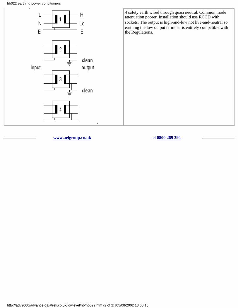
4 safety earth wired through quasi neutral. Common modeattenuation poorer. Installation should use RCCD withsockets. The output is high-and-low not live-and-neutral soearthing the low output terminal is entirely compatible withthe Regulations.
www.aelgroup.co.uk tel 0800 269 394
hb022 earthing power conditioners
http://adv9000/advance-galatrek.co.uk/lowlevel/hb/hb022.htm (2 of 2) [05/08/2002 18:08:16]
hb003 CVT background data
Introduction
The effect was discovered during the 1930's in the USA by Joseph Sola a German born engineer.
The industrial use of ferroresonant transformers goes back to early 1940’s. Through the last 5 decades a series of applications hasbeen found for products based on the technique. In each case the CVT has some feature which made it the most reliable and costeffective solution to the problem. These characteristics continue to make the CVT one of the most cost effective ac powerconditioners available.
Although different manufacturers use varying techniques the Advance CVT is normally based on a single transformer rather than anarrangement of transformer and separate filters. This lends itself to one of the most important aspects of the CVT its inherentreliability. Ignoring nuts bolts and other small components the unit consists of 3 or 4 windings and a special capacitor. With goodmanufacturing technique only the capacitor fails and a considerable time and effort goes into making this as unlikely as is practical.
The second major characteristics that the CVT is almost indestructible. It can be completely and continuously short circuited in useeither at switch—on or from full load and the unit will be unaffected.
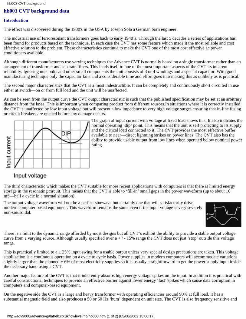
As can be seen from the output curve the CVT output characteristic is such that the published specification may be set at an arbitrarydistance from the knee. This is important when comparing product from different sources.In situations where it is correctly installedthe CVT is unaffected by low input voltage but will present a low impedance to very high voltage surges ensuring that in-line fusingor circuit breakers are opened before any damage occurs.
The graph of input current with voltage at fixed load shows this. It also indicates thenormal operating ‘dip’ point. This means that the unit is self protecting to its supplyand the critical load connected to it. The CVT provides the most effective bufferavailable to near—direct lightning strikes on power lines. The CVT also has theability to provide usable output from low lines when operated below nominal powerrating.
The third characteristic which makes the CVT suitable for more recent applications with computers is that there is limited energystorage in the resonating circuit. This means that the CVT is able to ‘fill-in’ small gaps in the power waveform (up to about 10mS—half a cycle in a normal situation).
The output voltage waveform will not be a perfect sinewave but certainly one that will satisfactorily drivemodern computer based equipment. This waveform remains the same even if the input voltage is very severelynon-sinusoidal.
There is a limit to the dynamic range afforded by most designs but all CVT’s exhibit the ability to provide a stable output voltagecurve from a varying source. Although usually specified over a + / - 15% range the CVT does not just ‘stop’ outside this voltagerange.
This is practically limited to a ± 25% input swing for a usable output unless very special design precautions are taken. This voltagestabilisation is a continuous operation on a cycle to cycle basis. Power supplies in modern computers will accommodate variationsslightly larger than the planned ± 6% of most electricity supplies so it is usually straightforward to get the power supply input insidethe necessary band using a CVT.
Another major feature of the CVT is that it inherently absorbs high energy voltage spikes on the input. In addition it is practical withcareful constructional techniques to provide an effective barrier against lower energy ‘fast’ spikes which cause data corruption incomputers and computer-based equipment.
On the negative side the CVT is a large and heavy transformer with operating efficiencies around 90% at full load. It has asubstantial magnetic field and also produces a 50 or 60 Hz ‘hum’ dependent on unit size. The CVT is also frequency sensitive and
hb003 CVT background
http://adv9000/advance-galatrek.co.uk/lowlevel/hb/hb003.htm (1 of 2) [05/08/2002 18:08:17]

will normally work at either 50 or 60 Hz.
We feel these features are more than offset by the knowledge that a properly selected and installed unit will usually cure mainsproblems on sensitive equipment. There is still a limited number of applications for specially wound CVT’s with output waveformswhich are essentially ‘square’ rather than sinusoidal for use in simple power supplies or heating/lighting arrangements.
www.aelgroup.co.uk tel 0800 269 394
hb003 CVT background
http://adv9000/advance-galatrek.co.uk/lowlevel/hb/hb003.htm (2 of 2) [05/08/2002 18:08:17]
hb006CVT how does it work?
Introduction
AC stabilisation can be achieved using a simple magnetic device which has no moving parts.
This is a process of producing a constant ac voltage from a varying ac voltage supply and involves the use of saturable reactors. Thelatter may be incorporated in a special transformer magnetic saturation being produced in a part of the magnetic circuit.
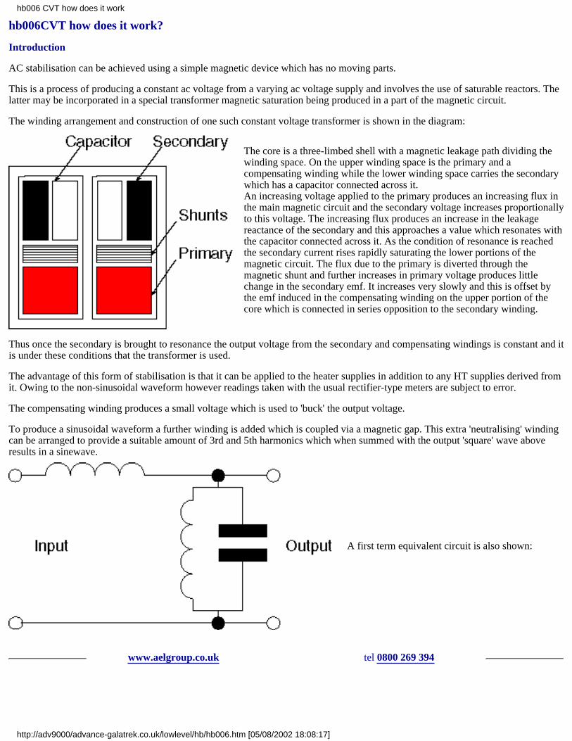
The winding arrangement and construction of one such constant voltage transformer is shown in the diagram:
The core is a three-limbed shell with a magnetic leakage path dividing thewinding space. On the upper winding space is the primary and acompensating winding while the lower winding space carries the secondarywhich has a capacitor connected across it.An increasing voltage applied to the primary produces an increasing flux inthe main magnetic circuit and the secondary voltage increases proportionallyto this voltage. The increasing flux produces an increase in the leakagereactance of the secondary and this approaches a value which resonates withthe capacitor connected across it. As the condition of resonance is reachedthe secondary current rises rapidly saturating the lower portions of themagnetic circuit. The flux due to the primary is diverted through themagnetic shunt and further increases in primary voltage produces littlechange in the secondary emf. It increases very slowly and this is offset bythe emf induced in the compensating winding on the upper portion of thecore which is connected in series opposition to the secondary winding.
Thus once the secondary is brought to resonance the output voltage from the secondary and compensating windings is constant and itis under these conditions that the transformer is used.
The advantage of this form of stabilisation is that it can be applied to the heater supplies in addition to any HT supplies derived fromit. Owing to the non-sinusoidal waveform however readings taken with the usual rectifier-type meters are subject to error.
The compensating winding produces a small voltage which is used to 'buck' the output voltage.
To produce a sinusoidal waveform a further winding is added which is coupled via a magnetic gap. This extra 'neutralising' windingcan be arranged to provide a suitable amount of 3rd and 5th harmonics which when summed with the output 'square' wave aboveresults in a sinewave.
A first term equivalent circuit is also shown:
www.aelgroup.co.uk tel 0800 269 394
hb006 CVT how does it work
http://adv9000/advance-galatrek.co.uk/lowlevel/hb/hb006.htm [05/08/2002 18:08:17]

hb009CVT gives lightning protection
IntroductionWhen lightning strikes enormous amounts of energy are dissipated. If the strike is in any way direct or near direct then mostsubstances hit will be locally vapourised. Electrical distribution systems have special isolating devices to restrict the effects oflightning strikes on overhead wires. However overhead lines can pick up serious transients which will destroy sensitive electronics ifthe `spike' gets all the way into the equipment.
LightningA typical lightning strike produces a waveshape which has a front edge of about 1.2µS and after 50µS the voltage will have droppedto half its peak value. Special test equipment is available which generates a 8/20 µS waveform which represents the lightning effectif the voltage is 6kV and the source impedance less than 2 ohms. A further popular test is based on a 10/350 shape which is used intelecoms applications.
It is not generally appreciated that office and domestic electrical distribution wiring will normally `flash over' at about 6kV whichlimits the voltage expectation from local lightning strikes.
A typical `strike' may carry about 200 000 Amps which when applied to an earthed conductor will cause a huge rise in the localearth potential. This effect can cause quite large amounts of energy to be carried along local earth wiring. Particular attention needsto be given to this problem. See ICT wiring and considerations.
Bullet proof protectionAdvance CVTs especially designed for computer protection provide one of the most effective barriers against lightning damage. TheCVT has a magnetic circuit which becomes a very low impedance when fed with high voltage.
If the unit is correctly installed with a protecting fuse or circuit breaker then the CVT will open the protection before damagingenergy gets to the electronic equipment being protected.
This means that the computer or other equipment may be turned off inadvertently but it will be protected from the resultingdistributed energy from the lightning strike. Such energy spikes are relatively common.
The only user action required is to replace the fuse or reset the circuit breaker and continue using the equipment.
If the strike is of sufficient energy to damage the incoming distribution wiring because of a direct strike then anything may happen.
This is extremely unusual.
www.aelgroup.co.uk tel 0800 269 394
hb009 CVTgives lightning protection
http://adv9000/advance-galatrek.co.uk/lowlevel/hb/hb009.htm [05/08/2002 18:08:17]

hb010Polychlorinated biphenyl (PCB) in CVT capacitors
We are still servicing old CVTs made as early as 1943. Some of our suppliers have historically used PCB in the electrolyte of highvoltage capacitors. These capacitors were incorporated in the manufacture of constant voltage transformers for a period during the1960’s and 70’s. Non-PCB capacitors were introduced in the period 1972-75. Advance/Gould transformer model numbers changedwhen the units ceased using PCBs in capacitors. Specifically:
CV prefix became ECV
CVN became ECVN
some CVN models later became TCVN and all of these are safe. The `E’ signifies `ecological’ and means that no further checks arerequired.
1 CVT’s labelled Advance in our current red/antelope colours definitely use non-PCB capacitors.
2 CVT’s labelled Gould probably do not contain PCB in the capacitors.
3 CVT’s labelled Advance and coloured black grey or silver may contain PCB in the capacitors.
If a unit in use is reported by model and serial number to Advance Electronics we can advise on the likely capacitor type.
We offer to service any suspect CVT capacitors at cost and properly dispose of the offending component.
Please note that most newer capacitors are actually marked `No-PCBs’ or `Non-PCB’.
We have never used PCB in the actual transformer only in capacitor electrolyte.
Recent medical work suggests that PCB may be a carcinogen.
PCBs in capacitors used in CVT’s prior to 1972
A single capacitor may be disposed of as part of 1 cubic metre of bland rubbish having carefully wrapped the capacitor to avoidcontamination during handling.
Significant quantities should be disposed of via :
Capacitor Services Limited 24 Bridge Road Cove Farnborough Hants GU14 0HP
Telephone 01252-521911
The handbook sheet hb011 health and safety data is copied from the EEC directive on PCBs.
www.aelgroup.co.uk tel 0800 269 394
hb010 health and safety data - PCBs in CVT capacitors
http://adv9000/advance-galatrek.co.uk/lowlevel/hb/hb010.htm [05/08/2002 18:08:17]

hb011PCB Health and Safety data
POLYCHLORINATED BIPHENYLS (PCBs) were used as a liquid impregnant in power and lighting capacitors during the period1950 - 1980 under such trade names as AROCLOR ASKAREL BICLOR CLOPHEN DUCONOL PYROCLOR.
It is now known that PCBs are NON-BIODEGRADABLE are stored by body tissue and build up in the FOOD CHAIN give offTOXIC FUMES when operated at HIGH TEMPERATURES and increase the risk of cancer in animals and humans under thesecircumstances. There is strong evidence to show that PCBs attack welded metal seams and so produce a leak without any externalinfluence thus necessitating early removal action as no practical drainage techniques are available.
This major health hazard is now under review by an EEC committee and all knowledgeable Authorities are recommending earlyattention to the problems of identification and approved disposal of this substance.
HAZARDS
PCBs give off FUMES and VAPOURS above 55º C and most capacitors operate at this level. Strict precautions must be taken toprevent the INHALATION of these under conditions of container LEAKAGE and FIRE and any such exposure must be reported toHealth and Safety Officials concerned. Skin and eye CONTACT must be avoided at all costs and under such circumstances copiousIRRIGATION with EYEWASH or WATER becomes an immediate necessity followed by urgent MEDICAL ATTENTION. Theirrigation fluid now becomes a hazard and must be CONTAINED. All TOOLS and CONTAINERS and MATERIALS which havebeen exposed to the FUME or LIQUID versions of PCBs must be SEGREGATED to avoid any CROSS CONTAMINATION.INHALATION INGESTION OPEN WOUND and SKIN ABRASION contact with PCBs is a medical EMERGENCY.
PRECAUTIONS
Avoid all DIRECT CONTACT with the body and ensure that an IMPERVIOUS barrier is protecting the skin being particularly waryof the presence of CUTS and ABRASIONS. Never use clothing made of an absorbent material at the contact layer. All rubbers andmost plastics are unsuitable for PCBs contact. POLYTHENE or similar material affords the best protection when used as GLOVESOVERSHOES HATS OVERALLS ETC. GOGGLES should be of a CHEMICAL grade. The possibility of EXPOSURE to FUMESand VAPOURS necessitate the use of SELF CONTAINED BREATHING APPARATUS. DO NOT SMOKE in the presence ofPCBs. Do not dispose of neat or suspended PCBs in Drains Sewers Streams Effluent courses or any normal Waste Channels. Affix aprominent LABEL to all equipment which contains PCBs and initiate a formal COLLECTION and DISPOSAL PROGRAMME.
EMERGENCIES
CASUALTIES must be moved to FRESH AIR kept WARM at rest with OXYGEN if necessary and have contaminated clothingremoved if possible. Urgent evacuation to hospital under medical supervision is necessary. CONTAMINATED CLOTHING mustbe removed as soon as possible to a suitable CONTAINER marked `PCB’. CONTAMINATED SKIN must be thoroughly cleanedwith soap and water in a PCBs CONTAINER. INGESTION OF PCBs and any SKIN or CHEST or THROAT IRRITATION mustbe treated as a MEDICAL EMERGENCY. SPILLAGE must be absorbed with SAND ASH SAWDUST etc. and collected in a PCBsCONTAINER. All WETTED areas must be mopped using absorbent material soaked in PERCHLORETHYLENE or proprietarysolvent such as GENKLENE and then collected in the PCBs CONTAINER.
PROTECTIVE CLOTHING
Pocketless Terylene Boiler Suit with elasticated waist ankle and wrist grips. Chemical grade goggles. Heavy duty PolytheneGauntlet gloves with thin Polythene disposable gloves inside the gauntlet and boiler suit sleeves. Protective Overshoes fitted insidethe boiler suit leg bottoms. Self-contained Breathing Apparatus. Impervious overall.
ACTIONS
Identify all Capacitors which are suspect of containing PCBs and obtain a COMPETENT VERIFICATION of the impregnant usedtherein. LABEL as PCBs all Capacitors which are verified as such and institute a removal and replacement programme of workfollowing a competent understanding of the activity involved. All REMOVAL ACTIVITY must give priority to the prevention ofleakage from an undamaged Capacitor and the minimising of contamination from a leaking CAPACITOR by way of fixing clampsand terminals. All PCB CAPACITOR UNITS should be placed in a SEALED STEEL CONTAINER for subsequent transportationpurposes. MOP UP all SPILLAGE and WETTED AREAS placing all agents and protective garments in the PCBs CONTAINERincluding washing solutions. Consider the need to replace cabinets and switchgear which may have been significantly contaminatedwith PCBs.
DO NOT SOLICIT INCOMPETENT JUDGEMENT on the suspect Capacitors.
DO NOT WAIT for the LEAKAGE to occur and make your Staff aware of the problems NOW.
hb011 health and safety data - PCBs
http://adv9000/advance-galatrek.co.uk/lowlevel/hb/hb011.htm (1 of 2) [05/08/2002 18:08:17]

www.aelgroup.co.uk tel 0800 269 394
hb011 health and safety data - PCBs
http://adv9000/advance-galatrek.co.uk/lowlevel/hb/hb011.htm (2 of 2) [05/08/2002 18:08:17]

hb017generators with CVTs
Sophisticated computer systems sometimes use diesel engine driven generators for backup in case of mains failure.
Where our CVT’s are used for power conditioning in the normal mains mode it is desirable to take advantage of the CVTperformance when using the generator.
These notes provide some guidance on the potential problems which can be met together with solutions.
Neutral
Some generators do not refer the low side of the output to earth. This MUST be tied down to avoid damage to any of our largercatalogue units which have double primary shields.
Care must also be taken that the generator neutral is not connected to the CVT output low.
Frequency
All ferroresonant devices are frequency sensitive.
The generator must run close to 50 Hz for the unit to operate correctly.
Unfortunately the speed/output voltage curve for the generator goes the same way as the CVT so speed should be adjusted at actualrunning load.
We publish a curve for the effect of frequency variation in our CVT Handbook.
Short term off-frequency operation will not damage the CVT.
Phase
The output from the CVT will be out of phase with the input in cases where the generator supplies other equipment directly somecare is needed if a phase sensitive triac firing circuit is installed.
Safety
Unless phasing circuits are fitted all circuits should use ‘break before make’ contactors and enforced supply separation.
Some thought needs to be given to the Regulations regarding out of phase supplies in the same area.
www.aelgroup.co.uk tel 0800 269 394
hb017 CVTs with generators
http://adv9000/advance-galatrek.co.uk/lowlevel/hb/hb017.htm [05/08/2002 18:08:17]

hb025using CVT's outside published specification
All Advance catalogue CVTs are supplied and guaranteed to a published specification. In general the CVT is specified to industryrecognised norms and can be operated well outside its described performance specification. This note describes where liberties maybe taken and should be read in conjunction with our GT generic specification which gives curves for many situations. This veryrobust product is particularly suitable for the unpredictable electrical mains supply in third world countries. Our CVTs are still themost reliable and effective mains protection for such applications.
High input voltage
if the CVT is operated with the correct input fuse or circuit breaker it should work OK until the protection opens at about 150% ofthe nominal input voltage rating. The output voltage will rise with increasing input at about 20% of the change - i.e. if the input goesup 5% the output will go up about 1%.
Low input voltage
the output voltage will sag as the input voltage falls. To operate under expected very low input voltage select a larger unit thannormally required. Under loading the unit will provide significantly improved results. Most units will provide usable power down to30% of the rated input voltage.
Non-sinusoidal input voltage
If it is the correct frequency and alternating the CVT will operate. A THD up to 25% or even a square wave is NO problem for shortterm durations.
Overloading
The CVT may deliver up to 50% more power than specified this is very dependant on actual input voltage. After this the unit willself protect by reducing the output voltage progressively until it reaches nearly zero. The unit can be operated into a short circuitindefinitely. Electric motors take large currents at switch on. If the CVT will start the motor it is big enough.
Power factor loads
Inductive loads depress output voltages and can usually be corrected by adding capacitors. Capacitive loads have the opposite effect.If you can tell us about the load we can usually advise how to drive it.
Switching loads
Ordinary switched mode power supplies are particularly suitable for use with our CVTs. Care must be taken with units with selfadjusting input voltage arrangements. Some dimmer circuits or phase controlled circuits can cause problems.
Wrong frequency
1 or 2 Hz off the correct frequency will produce low output volts for low frequency and vice versa. 50 Hz units will function at 52Hz but will eventually fail if operated at 60 Hz.
Low temperature
Down to -25 ºC is usually no problem after that the capacitor bank becomes the limiting factor.
High temperature
For short term excursions of ambient temperature up to 70 ºC the only damage is to the life of the capacitor bank. For every 5 ºCabove 40 ºC expect the life to be halved from the calculated 200 000 hours MTBF.
High humidity
If the unit is stored at 100% RH it will probably require drying before starting up. The unit will operate at 99% RH withoutproblems.
Failed capacitor
If the unit has several capacitors and one fails the unit may still provide reduced power. Shorted capacitors will stop operation butopen circuit failures can be tolerated. Problems will occur at switch on if the unit is operated at high input voltage and light loads
hb025 CVTs outside specification
http://adv9000/advance-galatrek.co.uk/lowlevel/hb/hb025.htm (1 of 2) [05/08/2002 18:08:17]

when a capacitor has failed. If the unit makes a ‘humping’ or ‘motor-boating’ noise it should be turned off and on again. Failedcapacitors should be replaced as soon as possible.
Damaged casework
We recommend that a thorough visual examination be made by a competent person prior to switch on. Don’t connect a critical loadwithout prior testing. Light bulbs and fan heaters make excellent test gear in remote locations. So long as all the wiring andinsulation seems intact and the situation demands it we suggest you try it.
Other problems
Please ask for technical assistance via our sales office.
www.aelgroup.co.uk tel 0800 269 394
hb025 CVTs outside specification
http://adv9000/advance-galatrek.co.uk/lowlevel/hb/hb025.htm (2 of 2) [05/08/2002 18:08:17]
hb026 : power conditioner comparison AIT vs GT differences
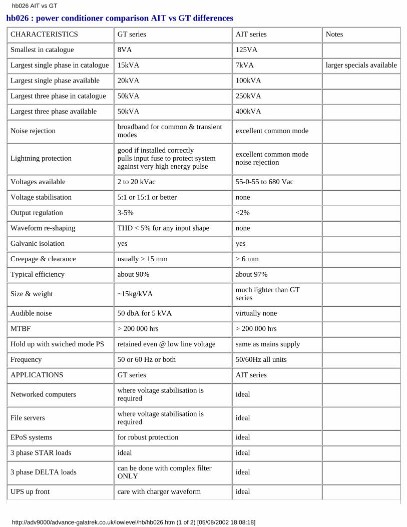
CHARACTERISTICS GT series AIT series Notes
Smallest in catalogue 8VA 125VA
Largest single phase in catalogue 15kVA 7kVA larger specials available
Largest single phase available 20kVA 100kVA
Largest three phase in catalogue 50kVA 250kVA
Largest three phase available 50kVA 400kVA
Noise rejection broadband for common & transientmodes excellent common mode
Lightning protectiongood if installed correctlypulls input fuse to protect systemagainst very high energy pulse
excellent common modenoise rejection
Voltages available 2 to 20 kVac 55-0-55 to 680 Vac
Voltage stabilisation 5:1 or 15:1 or better none
Output regulation 3-5% <2%
Waveform re-shaping THD < 5% for any input shape none
Galvanic isolation yes yes
Creepage & clearance usually > 15 mm > 6 mm
Typical efficiency about 90% about 97%
Size & weight ~15kg/kVA much lighter than GTseries
Audible noise 50 dbA for 5 kVA virtually none
MTBF > 200 000 hrs > 200 000 hrs
Hold up with swiched mode PS retained even @ low line voltage same as mains supply
Frequency 50 or 60 Hz or both 50/60Hz all units
APPLICATIONS GT series AIT series
Networked computers where voltage stabilisation isrequired ideal
File servers where voltage stabilisation isrequired ideal
EPoS systems for robust protection ideal
3 phase STAR loads ideal ideal
3 phase DELTA loads can be done with complex filterONLY ideal
UPS up front care with charger waveform ideal
hb026 AIT vs GT
http://adv9000/advance-galatrek.co.uk/lowlevel/hb/hb026.htm (1 of 2) [05/08/2002 18:08:18]

UPS bypass care with phasing ideal
UPS output voltage step up/down GT can be difficult to drive ideal
Generators care with frequency stability ideal
Phase controlled loads care with current waveform ideal
www.aelgroup.co.uk tel 0800 269 394
hb026 AIT vs GT
http://adv9000/advance-galatrek.co.uk/lowlevel/hb/hb026.htm (2 of 2) [05/08/2002 18:08:18]
hb027power protection in the third world
Background
Those of us who are used to the high standard of electricity utility supplies in the industrialised world sometimes forget the problemsfaced by users of high tech equipment in the third world. This page describes a strategy for planning electrical power protection in asmall business or professional office application. These notes may also be helpful to householders facing regular damage toelectrical equipment - even just ordinary light bulbs.
The problems
These fall into different categories the critical load must be protected from one or more of the following:
out of tolerance voltages
(sags surges and brownouts)
spikes on the line
and/or keep working when
out of tolerance voltages occur
mains supply fails.
Most electrical equipment is able to function normally if the voltage varies by less than ±10%.
Modern equipment is also usually able to operate satisfactorily in an environment where small noise spikes (less than 100V) arrivedown the line.
However the data handled in modern digital equipment is sometimes corrupted by severe spikes.
Some of the equipment may be so critical that it needs protection from both noise spikes and power failure.
Other equipment may need protection from brownouts and/or very high voltages.
Planning a solution
A thorough survey of the various equipment loads around the business or office location should be prepared.
Each equipment needs to be classified. For example - critical essential non-essential.
The actual load of each item needs to be expressed in watts.
It is often misleading to take electrical ratings from external labels on the equipment to be protected.
Fuse ratings can also be much higher than actual consumption and should only be used as a guide where no measuring equipment isavailable.
Separate lists need to be made for the various loads showing which ones are critical and others which just need protection.
Consideration should be given to the possible need for a few lights to be supported when the mains fails so that critical equipment(keyboards!) can actually be seen.
Attention needs to be paid to the problems of separating the various electrical wiring circuits.
It also makes sense to adopt some procedure for ensuring that the load is not used on the wrong supply.
Typical approaches include labelling or the use of different style plugs and sockets.
For some systems permanent wiring is sometimes an alternate solution.
For more information or assistance in preparing a strategy please ask our sales office.
Typical strategy
hb027 3rd world power protection
http://adv9000/advance-galatrek.co.uk/lowlevel/hb/hb027.htm (1 of 2) [05/08/2002 18:08:18]

Load Watts Protection equipment
light bulbsTVvideofreezerhi-fi
2600300754502003625
Advance power monitor disconnects the load when voltage goes outsidepredetermined limits
air conditioner 3000 tapping voltage stabiliser to maintain or APM as above
digital GSM phone 100 Advance low impedance power conditioner prevents spikes getting tothe phone memory
fax machine forincoming orders 150 Galatrek ByteBak uninterruptible power supply brownout protection
and batteries when mains fails - specify backup time
personal computer with data which is essential 450 Galatrek MicroBak UPS noise spike protection brown out protection +must be protected and batteries when mains fails - specify backup time
laser printermodemscanner
120040120
Advance GT power conditioner noise spike protection brown outprotection from mains supply these un-essential items go off whenpower fails
www.aelgroup.co.uk tel 0800 269 394
hb027 3rd world power protection
http://adv9000/advance-galatrek.co.uk/lowlevel/hb/hb027.htm (2 of 2) [05/08/2002 18:08:18]

hb028Sizing conditioners for refrigerator compressors
Background
Those of us who are used to the high standard of electricity utility supplies in the industrialised world sometimes forget the problemsfaced by users of high tech equipment in the third world.
This page describes how the World Health Organisation addresses the problems associated with protecting the compressor motors onrefrigerators.
The data is extracted from the WHO document entitled `Guideline for establishing or improving national regional and districtvaccine stores.'
Factors requiring consideration
The WHO presents data to assist in the selection of power protection equipment in section six of their recommendations:
"
6. Power Factors
6.1 Reliability
The reliability of the electricity supply is a key issue when choosing refrigeration equipment. Where power cuts exceed 8 hours in 24hours the use of ice-lined refrigerators and freezers is essential.
6.2 Standby generators
No refrigeration equipment currently available has a holdover time greater than 2.5 days. Vaccine will be destroyed if there is anextended mains power failure unless there is an alternative source of power. It is essential to assess the risk of such failure. Failuresmay arise for many reasons. Examples include overloading of the power supply network; mechanical breakdown; lack of fuel orseasonal storms.
Replacing large quantities of damaged vaccine is expensive and extremely disruptive. It may not be possible to replace vaccinesquickly because world stocks are limited. Emergency replacement from a finite world stock also disrupts the supply of vaccine toother countries.
All sites stoning large quantities of vaccine should have a standby power supply. Often this is achieved most economically bylocating the vaccine store in a hospital compound or on some other site which already has a standby generator. When this is notpossible it may be necessary to install a generator to serve the vaccine store alone.
6.2.1 Generator sizing and selection
The Product Information Sheets give advice on choosing and buying a generator and the EPI Equipment Performance Specificationsprovide detailed specifications. Wherever possible the final sizing of generators should be made the responsibility of the cold chainequipment supplier.
6.2.2 Generator control and operation
Generators serving vaccine stores only should be fitted with automatic starting devices linked into the cold room orrefrigerator/freezer alarm system. If the vaccine store is served by a compound generator this will generally be started by anautomatic mains failure device. In such cases alarm-triggered start-up is not required.
All generators should be run at least once per week and should be regularly serviced to ensure that they remain operational. Thefuel tank should be kept full at all times.
6.2.3 Generator siting security and fire protection
A generator should be sited so that it does not create a fire hazard. Typically it should be located in a separate building orweatherproof enclosure. The fuel tank should be isolated and should be surrounded by a low wall or an earth bank to prevent fuel
hb028 sizing refrigerator conditioners
http://adv9000/advance-galatrek.co.uk/lowlevel/hb/hb028.htm (1 of 2) [05/08/2002 18:08:18]

spills from spreading. Both the generator and the fuel tank should be located in a secure compound to prevent theft. The fuel fillercap tank should be locked and the fuel line should be protected so that it cannot be tampered with. Fire extinguishers capable ofextinguishing fuel oil engine and electrical fires should be fitted dose to the generator and fuel tank.
6.2.4 Assuring fuel supplies
Fuel supply for the generator must be a priority allocation. A running log should be kept in order to monitor fuel consumption.
6.3 Voltage stability
In many countries severe voltage fluctuations occur in the mains power supply. Voltage fluctuations greater than 15% will damagecompressor motors. The problem can be overcome by fitting each piece of refrigeration equipment with a voltage stabiliser. Some ofthe refrigerators and freezers in the Product Information Sheets are supplied with integral voltage stabilisers.
Voltage stabilisers for cold rooms should be specified by the cold room supplier. When a voltage stabiliser is ordered for arefrigerator or freezer the following information should be given to the supplier:
¤ Actual voltage fluctuations (recorded by an engineer or electrician)
¤ Nominal voltage
¤ Single or three phase supply
¤ Frequency (50 Hz or 60 Hz)
¤ Nominal power of compressor in watts
The nominal power of the stabiliser should be about five times greater than the nominal power of the compressor to allow for thestarting load."
We are grateful to the WHO for the opportunity to reproduce their recommendations.
www.aelgroup.co.uk tel 0800 269 394
hb028 sizing refrigerator conditioners
http://adv9000/advance-galatrek.co.uk/lowlevel/hb/hb028.htm (2 of 2) [05/08/2002 18:08:18]

hb029Safety data on CVT based power conditioners
Scope
These notes apply to all ferroresonant transformers made by Advance Electronics Ltd. at Wrexham.
Construction
The transformer consists of insulated copper wires wound onto an insulated former subsequently assembled onto steel laminations.Advance power conditioners are double-wound transformers with tested secondary isolation from the mains. In addition high voltagecapacitors are added into a resonant circuit configuration.
Installation
Advance provides detail installation instructions for all models and care should be taken to use them. It is practical to meet thefundamental safety needs and yet retain a high level of earth integrity with a little care at the planning and wiring stages.
Hazards
High voltage
The transformer must be correctly installed according to the requirements both of the latest edition of local wiring regulations andmanufacturers recommendations. Specifically proper in-line fusing or other suitable protection must be installed. Output voltagescan be as high as 650 volts and suitable RCCD protection and proper insulated fittings must be used in accordance with the needs ofthe application. The internal capacitors may run at 660 volts ac and are lethal when operating. The capacitors are safe when the unitis switched off SO LONG AS THE ‘CAPACITOR TO WINDING’ CONNECTIONS are SOUND. Only authorised and trainedpersonnel should attempt repair.
Power
The unit is incapable of delivering more than 2 or 3 times its rated current in a failed mode and a maximum of less than 75% of itsrated output voltage.
Temperature
The steel stack of the unit may reach 60 ºC in normal air and precautions must be taken when repairing or testing exposed units. Theexposed stack on small units does not reach an unsafe temperature but may feel quite warm to touch. All units should be wellventilated as power ratings assume natural air cooling.
Chemicals
Once completed and all solvents have been burned off the transformer is chemically benign. The capacitors contain paper insulationsoaked in transformer oil which is relatively odourless and harmless to human skin. Although messy this oil is only found if acapacitor leaks through some internal electrical fault in the capacitor. If the capacitor is leaking the transformer is faulty and shouldbe switched off. Historically PCB’s have been used in the capacitors but Advance has not used any since about 1972.
Mass
All the transformers have a high density and suitable precautions should be taken in respect of the size under consideration.
Noise
Audible noise at 50 Hz is emitted at different intensities depending on unit size. Levels range 45 - 65 dBA. If other higherfrequencies are present - checks should be made for potential faults.
Multi phase systems
Advance power systems can be wired in several different configurations. In cases where more than one 240 volt phase is to beconnected into one enclosure attention must be given to external safety labelling. The wiring regulations demand that 415 voltwarning labels be affixed in visually prominent positions after installation. Suitable labels are enclosed if appropriate andreplacements are available on request from Advance at no charge to systems customers.
Self setting power supplies
hb029 health and safety data - CVTs
http://adv9000/advance-galatrek.co.uk/lowlevel/hb/hb029.htm (1 of 2) [05/08/2002 18:08:18]

During recent months an application problem has arisen with some types of UPS. The problem specifically relates to customer loadswhich have self-adjusting voltage power supplies. This type of power supply looks at the incoming mains and typically sets itself toeither 115 or 230 Vac. If driven with any current limiting source such as a CVT or CVT based UPS the power supply sets itself to115 V and then is promptly supplied with 230 V which usually means destruction of the customers' power supply.
Customers who have selected products with a load using this kind of SMPS should select a CVT which corresponds to the lowervoltage input rating of the power supply or ensure that the CVT/UPS is switched on before the load. Most of the equipment we haveseen with this type of 'world wide' power supply is small and rated below 1 kVA for razors and portable TV sets.
www.aelgroup.co.uk tel 0800 269 394
hb029 health and safety data - CVTs
http://adv9000/advance-galatrek.co.uk/lowlevel/hb/hb029.htm (2 of 2) [05/08/2002 18:08:18]

hb807 Emergency Power off (EPO) and Elite ETA\RTA & ETD
UPS that this applies to
Elite ETA/RTA 700VA-3kVA
ETD 1k5VA-5kVA
The UPS is not capable of a TRUE EPO as defined by the regulations.
A shut down signal can be applied to the UPS but this is not a true Emergency Power Off because of the delays involved
The UPS is equipped with a sub-D 9 pin connector carrying the signals for the RS232 interface and for the alarms.
Apply a voltage (+5 to -15Vdc) for at least 3 seconds to pins 6 and 4 of the connector. The UPS will perform a shutdown.Beware - if the UPS is configured (in the software) for auto restart removal of the signal will result in a UPS restart
NOTE: the RS232 communications interface needs (+10 - 15) Vdc between pins 8 and 4 in order to function correctly.
www.aelgroup.co.uk tel 0800 269 394
hb807 Emergency Power Off (EPO) and ETA\RTA & ETD
http://adv9000/advance-galatrek.co.uk/lowlevel/hb/hb807.htm [05/08/2002 18:08:18]
hb036using CVTs with a UPS
Introduction
Modern on-line Uninterruptible Power Supplies (UPS) give excellent performance when applied as expected by the designer.
Sometimes superior noise immunity or voltage variation handling is required. This is usually accommodated by adding a powerconditioning product to the UPS. Such installations are attempting to provide a much higher protection than provided by the simpleRF filters in the UPS which are designed to stop internal noise leaving the UPS.
Potential pitfalls
The UPS was probably not designed with the expectation that it would be driven from something other than an ordinary mainssupply. Some UPS have output circuitry which does not manage difficult loads very well. Once the user decides to add the twoproducts together it becomes apparent that there are several different ways to connect up the critical load. These different approachesgive rise to various problems which can cause problems to the unwary.
Alternate scenarios
The UPS will normally have an automatic bypass if it is of the on-line type. We recommend that all such units should also be fittedwith a maintenance bypass (either manual or automatic) for properly planned installations. The main problem is to assess whether ornot the power conditioner should be put in front or behind the UPS. There also needs to be some consideration about how the bypassoperates and whether or not power conditioning is available in either bypass mode.
Considerations
It is not often realised that a UPS supplied in today's modern market place may have characteristics which are not properly describedin the sales literature.
For example the UPS output power rating is usually quoted with a `power factor’. The implication of this is that the unit may berated at 1000 VA but is quite incapable of supplying 1000 watts.
An on-line UPS has to support the full rated load whilst the system is recharging it’s batteries. This usually means that the unitrequires considerably more input power than expected from the output rating.
The UPS may not have facilities to allow the bypass line to be connected to a different supply from the normal incoming mains.
The two major transformer based power conditioning technologies are `ferro-resonant’ or `low impedance’ types. Both also haveinternal inefficiencies and will require more power at the input when fully loaded than is available at the output.
The ferro-resonant types often based on constant voltage transformer (CVT) technology also have power factor considerations atboth input and output.
The CVT is also less efficient than conventional transformers. However the CVT represents one of the most effective ways to solvenoise and voltage problems when applying UPS products in tough working environments.
Working solutions
UPS + low impedance conditioner (AIT)
In this case the conditioner may be used in front of the UPS to protect it against mains borne spikes and common mode noise.Clearly if it protects the UPS then it will protect the load against the same mains borne problems. The AIT must be rated to provideenough power for the worst case input requirements of the UPS. These must be considered for an exhausted battery full load andworst case temperature conditions. In the absence of proper data use a rule that the AIT should have a rating which is at least 50%bigger than the UPS.
It is also possible to use the AIT after the UPS to provide galvanic isolation and/or protect the critical load against common modenoise generated by the UPS. The AIT will NOT provide any protection to the UPS input circuitry. With this connection attentionmust be given to the capacity of the UPS to drive the AIT. Typically the AIT wattage rating should be no larger than about 50% ofthe rated VA of the UPS.
UPS + CVT power conditioner
hb036 CVTs with UPSs
http://adv9000/advance-galatrek.co.uk/lowlevel/hb/hb036.htm (1 of 2) [05/08/2002 18:08:18]

There are huge benefits to feeding a UPS from a CVT based power conditioner. These include lightning protection better batteryrecharge times and a benign mains feed for the UPS. The mains becomes essentially clean and complements the battery back upfeatures of the UPS. In this case however more problems are apparent.
The CVT is a resonant device which has unusual input characteristics. (See ds047) Consideration must given to the fact that theinput power factor of the CVT is affected by line voltage and load value. Some UPS units will not drive inductive loads at all. Othersmay struggle to cope with the varying power factor. Either way the UPS load rated at 1000VA with a 0.6 PF rating on the output canonly drive a CVT which is considerably smaller than one designed to deliver 1000 watts. A useful rule is that the CVT should beconsidered to be 80% efficient and therefore the rating is:
UPS load rating VA * PF * 0.8
So a normal 1000VA UPS may only be adequate to drive a 480 watt CVT! For CVTs driving the input of the UPS the issue isentirely one of the worst case UPS needs. The rule above for the AIT can be used. Further attention should be given to the fact thatthe CVT may provide a clean sinewave into a resistive load but it may not provide the low distortion waveform required by someUPS chargers. This can cause the UPS to run it’s batteries flat.
Summary
The combination of a UPS and a power conditioner requires serious planning BEFORE buying equipment. If the two units havesimilar ratings they will probably not operate satisfactorily in any combination.
If one item is already installed it probably means that the only combination which will work is either a larger unit in front or asmaller unit after the existing one. This usually means the second unit is too small to drive the critical load!
Our engineers would be delighted to assist with any problems relating to a specific installation.
www.aelgroup.co.uk tel 0800 269 394
hb036 CVTs with UPSs
http://adv9000/advance-galatrek.co.uk/lowlevel/hb/hb036.htm (2 of 2) [05/08/2002 18:08:18]
hb039Start up surges on (CVT's)
The switch on current surge for a CVT consists of two components. One of these is fixed at about 8 times running current for 5 - 10mSec. Superimposed on this will be a ‘spike’ which will be dependent on where in the mains cycle the transformer was last turnedoff and where in the cycle it is turned back on. The spike will be less than 1 mSec and varies from zero to 25 times running current ifthe supply is very `stiff’. The input surge current at switch on is not significantly affected by the output load condition. The surgecurrent will be substantially proportional to applied line voltage. Our normal circuit breaker recommendation is to fit a ‘Type 4 ‘ or‘Curve 66’ unit which should function without nuisance tripping. Fuse earth loop impedance and cable size suggestions are shown.
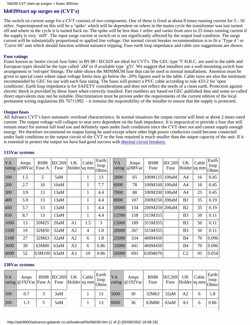
Fuse ratingsFuses known as 'motor circuit fuse links' in BS 88 / IEC629 are ideal for CVT's. The GEC type 'T' H.R.C. are used in the table andEuropean types should be the type called `aM' or if available type `gTr'. We suggest that installers use a wall-mounting switch fusearrangement or 'red-spot' fittings. The table shows the MINIMUM fuse that can be used in normal installations. Attention must begiven to special cases where input voltage limits may go below the -20% figures used in the table. Cable sizes are also the minimumrecommended by GEC for use with each fuse rating. The fuses will protect a PVC cable according to rule 433-2 for 'openconditions'. Earth loop impedance is for SAFETY considerations and does not reflect the needs of a clean earth. Protection againstelectric shock is provided by these fuses when correctly installed. Part numbers are based on GEC published data and some so-calleddirect equivalents may not be suitable. Discrimination must be proven under the requirements of the current edition of the localpermanent wiring regulations BS 76711992 - it remains the responsibility of the installer to ensure that the supply is protected.
Output fusesAll Advance CVT’s have automatic overload characteristics. In normal situations the output current will limit at about 2 times ratedcurrent. The output voltage will collapse to near zero dependent on the fault impedance. It is impractical to provide a fuse that willremain intact for normal full load use and definitely open under fault conditions since the CVT does not and cannot supply enoughenergy. We therefore recommend no output fusing be used except where other high power conductors could become connectedunder fault conditions to the output circuit of the CVT or the fuse required is much smaller than the output capacity of the unit. If itis essential to protect the output we have had good success with thermal circuit breakers.
115Vac systems
VArating
Amps@88Vac
BS88Fuse A
IEC269Fuse
UKHolder
Cablesq mm
Earthloop
Ohms VA
ratingAmps
@88VacBS88Fuse
IEC269Fuse
UKHolder
Cablesq mm
Earthloop
Ohms
100 1.5 5 5aM 1 13 5000 65 100M125 100aM A4 16 0.45
200 2.7 10 10aM 1 7.7 6000 78 100M160 100aM A4 16 0.45
300 3.9 13 13aM 1 4.4 7000 88 100M200 100aM A4 25 0.45
400 5.0 13 13aM 1 4.4 8000 107 200M250 200aM B2 35 0.19
450 5.7 13 13aM 1 4.4 10000 134 200M250 200aM B2 35 0.19
650 8.7 13 13aM 1 4.4 12500 158 315M355 B3 50 0.11
1000 13 20M25 20aM A1 1.5 3 15000 189 315M355 B3 50 0.11
1500 19 32M50 32aM A2 4 1.8 20000 267 315M355 B3 50 0.11
2100 27 32M63 32aM A2 6 1.8 25000 334 400M450 B4 70 0.096
3000 39 63M80 63aM A3 6 0.86 33000 441 400M450 B4 70 0.096
4000 52 63M100 63aM A3 10 0.86 50000 693 630M670 C2 95 0.054
230Vac systems
VArating
Amps@192Vac
BS88Fuse A
IEC269Fuse
UKHolder
Cablesq mm
Earthloop
Ohms
VArating
Amps@192Vac
BS88Fuse
IEC269Fuse
UKHolder
Cablesq mm
Earthloop
Ohms
100 0.7 3 3aM 1 13 5000 30 32M63 32aM A2 6 1.8
200 1.3 5 5aM 1 13 6000 36 63M80 63aM A3 6 0.86
hb039 CVT start-up surges + fuses 400Vac
http://adv9000/advance-galatrek.co.uk/lowlevel/hb/hb039.htm (1 of 2) [05/08/2002 18:08:19]
300 1.8 5 5aM 1 13 7000 41 63M80 63aM A3 6 0.86
400 2.3 10 10aM 1 7.7 8000 49 63M100 63aM A3 10 0.86
450 2.6 10 10aM 1 7.7 10000 61 100M125 100aM A4 16 0.45
650 4 10 10aM 1 7.7 12500 72 100M160 100aM A4 16 0.45
1000 6 13 13aM 1 4.4 15000 87 100M200 100aM A4 25 0.45
1500 9 13 13aM 1 4.4 20000 123 200M250 200aM B2 35 0.19
2100 12 20M25 20aM A1 1.5 3 25000 153 200M250 200aM B2 35 0.19
3000 18 20M32 20aM A1 2.5 3 33000 202 200M315 200aM B2 35 0.19
4000 24 32M50 32aM A2 4 1.8 50000 318 315M355 B3 50 0.11
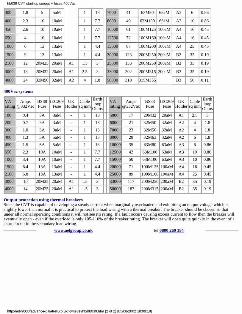
400Vac systems
VArating
Amps@332Vac
BS88Fuse
IEC269Fuse
UKHolder
Cablesq mm
Earthloop
Ohms VA
ratingAmps
@332VacBS88Fuse
IEC269Fuse
UKHolder
Cablesq mm
Earthloop
Ohms
100 0.4 3A 3aM - 1 13 5000 17 20M32 20aM A1 2.5 3
200 0.7 3A 3aM - 1 13 6000 21 32M50 32aM A2 4 1.8
300 1.0 3A 3aM - 1 13 7000 23 32M50 32aM A2 4 1.8
400 1.3 5A 5aM - 1 13 8000 28 32M63 32aM A2 6 1.8
450 1.5 5A 5aM - 1 13 10000 35 63M80 63aM A3 6 0.86
650 2.3 10A 10aM - 1 7.7 12500 42 63M100 63aM A3 10 0.86
1000 3.4 10A 10aM - 1 7.7 15000 50 63M100 63aM A3 10 0.86
1500 6.4 13A 13aM - 1 4.4 20000 71 100M125 100aM A4 16 0.45
2100 6.8 13A 13aM - 1 4.4 25000 89 100M160 100aM A4 25 0.45
3000 10 20M25 20aM A1 1.5 3 33000 117 200M250 200aM B2 35 0.19
4000 14 20M25 20aM A1 1.5 3 50000 187 200M315 200aM B2 35 0.19
Output protection using thermal breakersSince the CVT is capable of developing a steady current when marginally overloaded and exhibiting an output voltage which isslightly lower than normal it is practical to protect the load wiring with a thermal breaker. The breaker should be chosen so thatunder all normal operating conditions it will not see it's rating. If a fault occurs causing excess current to flow then the breaker willeventually open - even if the overload is only 105-110% of the breaker rating. The breaker will open quite quickly in the event of ashort circuit in the secondary load wiring.
www.aelgroup.co.uk tel 0800 269 394
hb039 CVT start-up surges + fuses 400Vac
http://adv9000/advance-galatrek.co.uk/lowlevel/hb/hb039.htm (2 of 2) [05/08/2002 18:08:19]

hb048maintenance of CVTs
Routine maintenance
Routine checks should be made to ensure that the ventilation for the power conditioner is properly maintained. The unit should bepositioned in a well ventilated location as power ratings assume natural air cooling. Annual checks of capacitor integrity may beworthwhile once the unit is more than five years old.
Preventative maintenance
Visual examination of capacitors on large units can often indicate a local fault through leakage of oil - in this case replace the faultypart. To prolong usable life it can be beneficial to replace the capacitor bank every five years. Some larger power conditioners arefitted with fans to assist with cooling. Under normal circumstances the only preventative maintenance required is the cleaning offans if fitted.
Replacement of capacitors
We are occasionally asked to supply replacement capacitors for old CVT's. Capacitors are subject to two characteristics which affectthe use of these spare components in CVT's.
a value tolerance
b physical dimensions
a - changes in capacitance value will result in differences in the CVT output voltage.
In general terms we expect normal production tolerances in the value of a spare capacitor to make less than a 1% change to theoriginal output voltage nominal setting. This situation can be improved when a coloured dot is noted on the failed capacitor and it'scolour dot is defined at the time of ordering a spare. The output voltage variation expected with CVT's using a spare capacitor of thesame colour dot will be less than 0.3%.
b - the physical dimensions of commercial capacitors change over extended periods of time. In general terms our capacitors will beof similar size or smaller. In case of any anticipated problem we recommend a factory repair for units up to 3 kVA. Care must betaken when handling high voltage capacitor installations. Replaced capacitors must have an adequate Vac rating for duty with highharmonic currents.
www.aelgroup.co.uk tel 0800 269 394
hb048 maintenance of CVTs
http://adv9000/advance-galatrek.co.uk/lowlevel/hb/hb048.htm [05/08/2002 18:08:19]
hb053 CE marking of power conditioners
Introduction We are actively pursuing a policy of CE marking all products where we are required and permitted to so do. It shouldbe noted that AEL sells professional products intended for use by professionally qualified users.
Validity Care should be taken to check that this is the most recent issue of this document which during 1995 was expected to changefrequently!
Policy Due to the wide range of Advance products we are having third party test houses provide us with test history and certificationon a few core products. It is our intention that Advance will `self certify’ and the CE mark will be applied to similar products usingcommon sub-assemblies but minor differences in construction. Catalogue and core OEM products will be assembled from newstandard sub-assemblies which once approved will be used wherever possible. As of now most of the common and preferred subassemblies are documented and global drawing revision is in progress. CE marking on OEM product will be addressed on a case bycase basis. Product files will be maintained for all derivatives.
Relevant Directives Advance products fall under the scope of two Directives:Low Voltage 73/23/EECEMC 89/336/EEC as amended by 91/263/EEC + 92/31/EEC.
Other DirectivesMachinery 89/392/EEC amended 91/368/EECTelecom terminal 91/263/EECNo Advance products come under the scope of these Directives.As far as we have been able to ascertain no other Directive is applicable.
Timing of testing/approvals We are in the process of seeking 3rd party testing and approval on specific products and will declarethe success of these tests as the results become available. Target completion dates for the main line catalogue products are about theend of the second quarter 1995.
CE marking Products shipped after January 1st 1996 will have the CE mark if it is appropriate. The CE mark will usually be addedto the product serial label. Where appropriate packing cartons will have the CE mark shown on the outside probably on newlabelling.
Certificates Certificates of conformity will only be issued by arrangement with customers. UK customers requiring certificates byunit or batch will be asked to pay for them at current prices. Customers will be required to enter the need for the C of C as an orderitem on EACH order placed. Certificates of conformity will be available FOC to our European importing agents where required bythe EC.A generic certificate of conformity is to be found as hb057
Relevant Specifications The table on hb057 shows which specifications have been selected by Advance for various products. Pleasenote that our plain transformers and CVTs are EMC benign and require only safety certification. We have had them tested anywayand the table indicates relevant standards. CVTs can be used to make existing equipment meet line conducted noise requirements.
Feedback We would be pleased to review this document with any interested party.
www.aelgroup.co.uk tel 0800 269 394
hb053 CE marking of power conditioners
http://adv9000/advance-galatrek.co.uk/lowlevel/hb/hb053.htm [05/08/2002 18:08:19]

hb072 ICT installation considerations
IntroductionInstallers of permanent electrical wiring are required to ensure that new work meets current regulations. These regulations aredesigned to save life in the case of faulty wiring or equipment. Further the practice is regulated to make our offices factories andhomes safe places to live from a fire risk point of view.
ICT systemsUnfortunately modern equipment suffers from a wide range of other influences. Some of these may actually cause sensitiveelectronic chips to fail. Just wiring up and performing routine regulation oriented checks is inadequate when mission critical orcrucial systems are involved.
ConsiderationsBy the time the wiring is being installed it is already too late. The retro-fitting of a star earthing system after a computer room hasjust been quite safely wired up involves a full strip out and re-install.
SafetyThe regulations require that all permanent wiring is compliant with safe practice. Normally this means calculating fuse sizes andselecting wire sizes to create protection discrimination and quick disconnect.
The electrician is required to bond all exposed conducting elements in an equipotential zone together. As a practical matter this isnormally done in a daisy chain fashion which is entirely safe. From a noise diversion point of view it can be a disaster. Just checkingearth loop impedances does not mean that no earth loops exist in the protective wiring. A proper star plan must be evolved and theinstaller should prove the installation before connecting sensitive equipment. The regulations are covered by BS 7671 (until recently`the 16th edition').
NoiseTransients can occur naturally in our environment (lightning) and in heavy equipment switching. Specific attention must be given tothe likelihood for such occurrences and a planned approach used to divert them as quickly as possible to earth.
Earth cabling should not be connected to more than one star point and all cables should radiate like spokes in a wheel.
Data cables between equipment must be checked for earth isolation at one end of the screen.
Data cables going outside the equipotential zone may require specific fitting of surge diversion boxes. This also applies to phonelines. Recommendations are given in BS 6651.
Static electricityThe static charge commonly experienced as a definite spark between humans and earthed objects in dry weather will destroy thesilicon chips in a computer or telephone switch.
AliensICT equipment mains circuitry should never be available (preferably by the use of hardwiring or special plug tops) to alien loadssuch as the office kettle or vacuum cleaner.
NetworkingAs our systems become more complex and critical to our daily business operations all installations should be planned for bestpractice. Networked systems are particularly prone to problems appearing in unexpected places. Modem lines monitoringcommunications and transducer signals with long wires connected to the network are perfect aerials to collect harmful spikes.
to avoid earth loops
IntroductionWith the ever increasing use of Information + Computer Technology (ICT) equipment there is a greater chance of installation withunsatisfactory wiring.
HistoryThe traditional UK electrician is taught to earth all metallic chassis. His training is directed towards making all installations safe. Ifsingle phase work is properly carried out he will check that the three conductors are definitely connected where they should be anddefinitely not where they should not be! Clearly he will also check for correct use of live and neutral and prove discrimination onfusing. He may also install added safety protection in the form of an RCCD.
hb072 ICT installation considerations
http://adv9000/advance-galatrek.co.uk/lowlevel/hb/hb072.htm (1 of 3) [05/08/2002 18:08:19]
TodayThese checks are no longer adequate. We have found that some wiring which is perfectly safe is quite unsuitable for ICT equipment.In some cases the use of mains noise protection equipment could be avoided by better wiring practice. However it is usually lessexpensive to retrofit protection rather than re-wire a whole building or even just the computer network. A better solution is toapproach the problem at the planning stage. In addition to ensuring that the wiring is safe some specific attention must be made asearly as the planning stage for wiring practice which ensures the best results for data processing equipment. After the installation iscomplete some extra checks should be carried out while the system is not connected to the supply and conductors may betemporarily disconnected.
PracticeThe objective is to provide a totally safe installation without any earth `loops’. An earth loop can give rise to surprisingly largecurrents in low impedance circuits.
These currents can cause mysterious data processing faults hum problems and failed communication ports on PCBs in EPoSequipment.
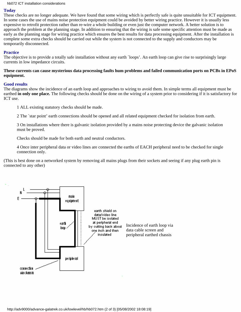
Good resultsThe diagrams show the incidence of an earth loop and approaches to wiring to avoid them. In simple terms all equipment must beearthed in only one place. The following checks should be done on the wiring of a system prior to considering if it is satisfactory forICT use.
1 ALL existing statutory checks should be made.
2 The `star point’ earth connections should be opened and all related equipment checked for isolation from earth.
3 On installations where there is galvanic isolation provided by a mains noise protecting device the galvanic isolationmust be proved.
Checks should be made for both earth and neutral conductors.
4 Once inter peripheral data or video lines are connected the earths of EACH peripheral need to be checked for singleconnection only.
(This is best done on a networked system by removing all mains plugs from their sockets and seeing if any plug earth pin isconnected to any other)
Incidence of earth loop viadata cable screen andperipheral earthed chassis
hb072 ICT installation considerations
http://adv9000/advance-galatrek.co.uk/lowlevel/hb/hb072.htm (2 of 3) [05/08/2002 18:08:19]
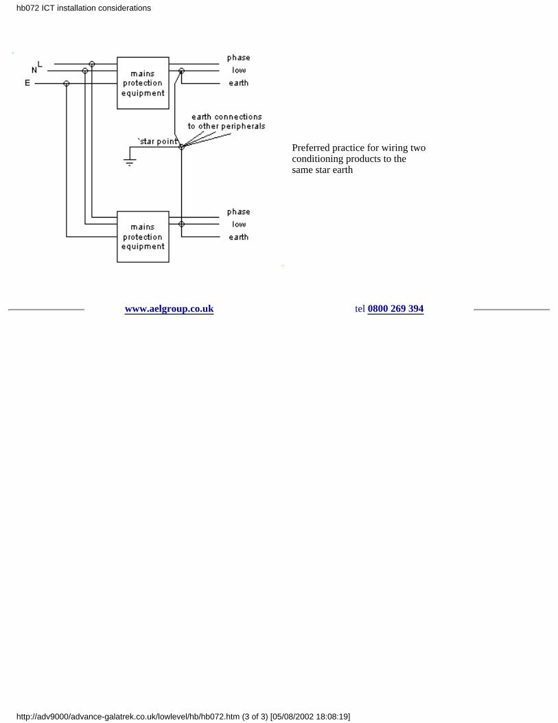
Preferred practice for wiring twoconditioning products to thesame star earth
www.aelgroup.co.uk tel 0800 269 394
hb072 ICT installation considerations
http://adv9000/advance-galatrek.co.uk/lowlevel/hb/hb072.htm (3 of 3) [05/08/2002 18:08:19]

hb054CVTs approval to international standards
Background
There is currently no international specification which relates directly to constant voltage transformers.
A draft specification exists for UPS products (BS EN50091-93) but this is unlikely to be more applicable to CVTs than currentspecifications.
Existing approvals
The CIT range up to 1500VA has been approved to NEMKO NEK-EN 60742 and SEMKO 115X.
The Smartstab conditioners rated 100-1000VA have been designed to meet SEMKO 115X.
Potential approvals
UL
Some of the GT series were approved by UL but we have allowed this to lapse through lack of sales to interested parties.
We also used to have an insulation system approval but this has been allowed to lapse for the same reason.
We have no technical problems with meeting relevant UL specifications but the commercial cost of upkeep is uneconomic.
Customers who must have approval for their equipment may request that we design for the standard required.
When the equipment comes up for overall approval we provide constructional data to facilitate the approval process of ourcomponent.
Our customer remains responsible for the commercial upkeep of the approval as required.
CSA
Generally as per UL.
CE
We expect to comply with all the European Directives as and when applicable.
By getting certification to EN 60950 or EN 60742 we hope to have product safety acceptable for the USA and Canada as well asEEC member countries.
Current status on CE marking is covered on handbook sheet HB 53.
A generic Certificate of Conformance for CE requirements is available as HB 57.
EMC
We are in the process of having sample catalogue units third-party tested and plan to use the self certification method for most OEMitems.
Our product is particularly suitable for filtering out mains conducted noise on old equipment.
Safety
We are in the process of having sample catalogue units third-party tested and plan to use the self certification method for most OEMitems.
There are a number of transformer related specifications. There are also relevant specifications in the office equipment andinformation technology areas.
Where necessary we can review any one of our units to a particular specification.
We have supplied a number of different designs to meet various specifications as components and are happy to do this where
hb054 CVTs approval to international standards
http://adv9000/advance-galatrek.co.uk/lowlevel/hb/hb054.htm (1 of 2) [05/08/2002 18:08:19]

customers need it.
Component Approvals
We maintain a computer file of international specifications held by various components which we use.
This is integrated with our Bill of Materials software and can be used to print a list of approved items in any of our products.
A file of master copies of component approval certificates is maintained.
Feedback
We would be pleased to review this document with any interested party.
www.aelgroup.co.uk tel 0800 269 394
hb054 CVTs approval to international standards
http://adv9000/advance-galatrek.co.uk/lowlevel/hb/hb054.htm (2 of 2) [05/08/2002 18:08:19]
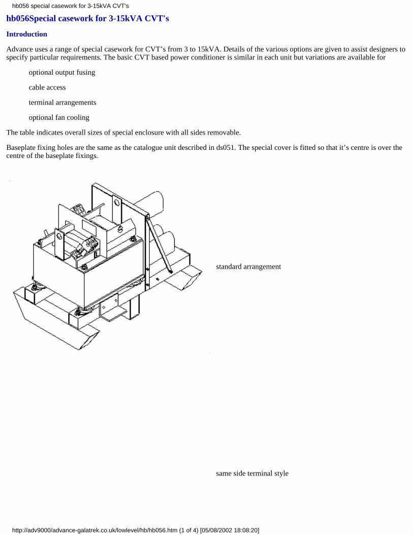
hb056Special casework for 3-15kVA CVT's
Introduction
Advance uses a range of special casework for CVT’s from 3 to 15kVA. Details of the various options are given to assist designers tospecify particular requirements. The basic CVT based power conditioner is similar in each unit but variations are available for
optional output fusing
cable access
terminal arrangements
optional fan cooling
The table indicates overall sizes of special enclosure with all sides removable.
Baseplate fixing holes are the same as the catalogue unit described in ds051. The special cover is fitted so that it’s centre is over thecentre of the baseplate fixings.
standard arrangement
same side terminal style
hb056 special casework for 3-15kVA CVT's
http://adv9000/advance-galatrek.co.uk/lowlevel/hb/hb056.htm (1 of 4) [05/08/2002 18:08:20]
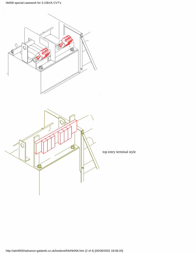
top entry terminal style
hb056 special casework for 3-15kVA CVT's
http://adv9000/advance-galatrek.co.uk/lowlevel/hb/hb056.htm (2 of 4) [05/08/2002 18:08:20]
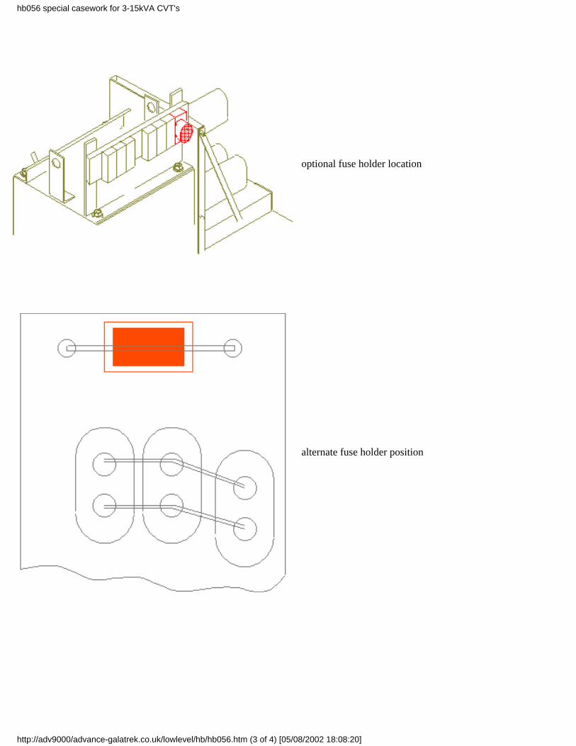
optional fuse holder location
alternate fuse holder position
hb056 special casework for 3-15kVA CVT's
http://adv9000/advance-galatrek.co.uk/lowlevel/hb/hb056.htm (3 of 4) [05/08/2002 18:08:20]
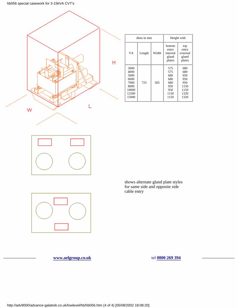
dims in mm Height with
VA Length Width
bottomentry
internalglandplates
topentry
externalglandplates
300040005000600070008000
100001250015000
725 505
575575680680680950950
11501150
680680950950950
1150115013201320
shows alternate gland plate stylesfor same side and opposite sidecable entry
www.aelgroup.co.uk tel 0800 269 394
hb056 special casework for 3-15kVA CVT's
http://adv9000/advance-galatrek.co.uk/lowlevel/hb/hb056.htm (4 of 4) [05/08/2002 18:08:20]

hb057CE Certificate - Declaration of Conformity
Manufacturers name : Advance Electronics Ltd t/a Advance Galatrek
Manufacturers address : Wrexham
Importers name/address : None
Type of equipment : Specialised transformer based products as shown in the table
Model prefix : See table
Serial no : Units manufactured after Jan 1st 1995 with the CE mark on the serial no label
Standard to which conformity is declared: see table
I the undersigned hereby declare that the equipment described conforms to all the relevant Directives.
Signature Full name Michael John Briggs
Status: Director
Place: Wrexham UK
Date 4th January 1996
Directive
Low Voltage EMC
73/23/EEC89/336/EEC91/263/EEC92/31/EEC
Productprefix Standard Status Standard Status
AIT
EN60742
OK
EN6100-3-2EN55022 class C
OK
CIT
CP CPECQ
SP SPETP TPE
ECV ECVN
GT up to 5kVA OK
GTI EN50081 pt1EN55022 in progress
HDCEN55014EN60555-2 + -3EN50082-1
OK
STX (some) ask factory/check labels EN6100-3-2
EN55022 class C
ask factory/check labels
TCVN OK OK
TT OK n/a n/a
hb057 CE conformance certificate
http://adv9000/advance-galatrek.co.uk/lowlevel/hb/hb057.htm (1 of 2) [05/08/2002 18:08:20]

www.aelgroup.co.uk tel 0800 269 394
hb057 CE conformance certificate
http://adv9000/advance-galatrek.co.uk/lowlevel/hb/hb057.htm (2 of 2) [05/08/2002 18:08:20]

hb058selecting power conditioners
Mains Monitoring
It is not essential to take on-site measurements but this process can be useful when the status of a site is unknown. Sometimes it ismore economic to just experiment with a known good filter such as a CVT.
We offer a loan scheme to potential and existing customers.
Advance can also provide ac mains monitors for checking of local mains supplies. Our monitors check the incoming supply againstvarious voltage and noise thresholds which are adjustable by the user. Some other environment data can also be recorded such as thetemperature. Results are normally printed out but can be RS232 linked via a modem to a remote site.
Interpretation of readings
Over the years we have had some problems with various monitors providing misleading results. Care must be taken to evaluate theresults obtained against reasonable expectation for the site. Common pitfalls include using the same monitor to measure the inputand output of a filtering device. This results in the noise spikes bypassing the filter through the monitor! Sometimes there is a verypoorly defined line between cause and effect.
On particularly bad sites we have eventually connected a conditioner to a simple resistive load on the secondary of our conditionerand monitored the voltage across the load. This removes the chance of extraneous noise data coming from an unknown load situationSuch practice can also alleviate the problems of mains difficulties being mixed with unrelated data corruptions and failures due toother causes.
Specifying the conditioner
The application must be reviewed for some basic parameters before we can quote for the supply of a suitable unit. In additionbackground information can be very helpful in choosing the right technological solution.
The technical information suggested on hb055 is a good starting point.
www.aelgroup.co.uk tel 0800 269 394
hb058 selecting power conditioners
http://adv9000/advance-galatrek.co.uk/lowlevel/hb/hb058.htm [05/08/2002 18:08:20]

hb059Special applications - UK weighing memorandum
Background
The National Weights and Measures Laboratory (NWML) is a section within the Department of Trade + Industry.
NWML has instructed officers in the field to ensure that remote weighing sites are properly protected from an electrical supply pointof view.
In cases where remote weighbridges and similar equipment is operated from small generator supplies there is a mandatoryrequirement to fit power protection devices in series with the electrical supply.
It should be noted that the main magnetic in the Galatrek UPS family called MicroBak uses the same technology to conditionelectrical power in ALL operating modes of the UPS.
Memorandum WM 429
The NWML has issued a Memorandum describing both the equipment which must be protected and how. The main part of of theMemorandum is transcribed here: An original is available on request from your local Weights + Measures.
DTI logo NATIONAL WEIGHTS AND MEASURES LABORATORY WM 429
Department of Trade and Industry (November 1988)
Stanton Avenue Teddington Middlesex TW11 0JZ
Memorandum for the guidance of Inspectors of Weights and Measures
WEIGHTS AND MEASURES ACT 1985
Section 12
The Secretary of State has issued the following amendments to the respective Notices of Examination/Certificates of Approval.
Generator powered equipment amendment No. 1 dated 14 October 1988
Type of Machine Code Index
Counter machines V (2) dV (2) e
Platform machines V (6) d
Weighbridges V(6) d
Person weighing machines V (6) f
Overhead weighing machines V (7)
Milk weighing machines V (8)
Suspended weighing machines V (9) a
Crane weighing machines V (9) b
Issued by NWML
Digital electronic machines and associated approved peripheral equipment.
As described in the Notice or minor modification to the Notice of Certificate or authorised variant thereof but having whereappropriate the supply from a local generator in place of the mains supply.
hb059 weighing memorandum for special applications
http://adv9000/advance-galatrek.co.uk/lowlevel/hb/hb059.htm (1 of 2) [05/08/2002 18:08:20]

In which case there shall be between the generator and the weighing equipment a constant voltage transformer Advance GT series ofbetween 100 VA and 1000 VA rating. The rating chosen must be such that the minimum load on the CVT is not less than 5% of therated output of the CVT and the maximum load including transient loads such as printing does not exceed the rating of the CVT.
The output of the CVT must be dedicated to the weighing systems and either:-
(i) hard wired directly to the system or
(ii) via a non standard connector in which case the output shall be marked "for weighing system only".
end of memorandum
www.aelgroup.co.uk tel 0800 269 394
hb059 weighing memorandum for special applications
http://adv9000/advance-galatrek.co.uk/lowlevel/hb/hb059.htm (2 of 2) [05/08/2002 18:08:20]
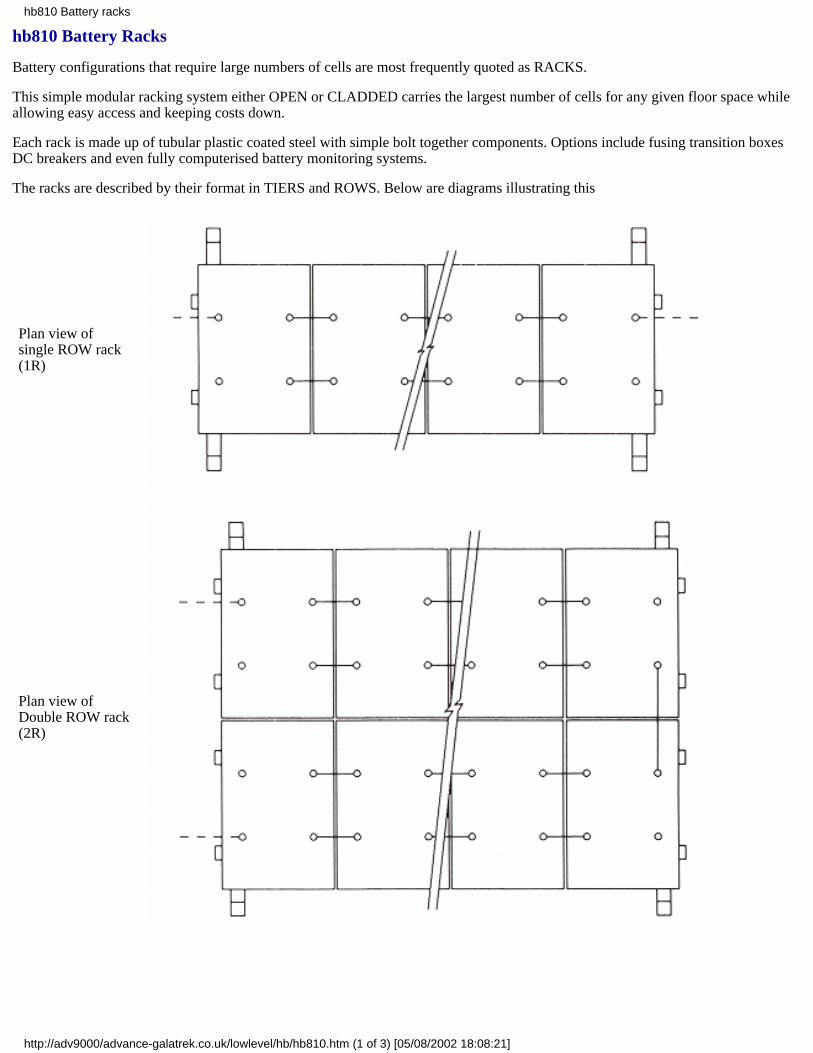
hb810 Battery Racks
Battery configurations that require large numbers of cells are most frequently quoted as RACKS.
This simple modular racking system either OPEN or CLADDED carries the largest number of cells for any given floor space whileallowing easy access and keeping costs down.
Each rack is made up of tubular plastic coated steel with simple bolt together components. Options include fusing transition boxesDC breakers and even fully computerised battery monitoring systems.
The racks are described by their format in TIERS and ROWS. Below are diagrams illustrating this
Plan view ofsingle ROW rack(1R)
Plan view ofDouble ROW rack(2R)
hb810 Battery racks
http://adv9000/advance-galatrek.co.uk/lowlevel/hb/hb810.htm (1 of 3) [05/08/2002 18:08:21]
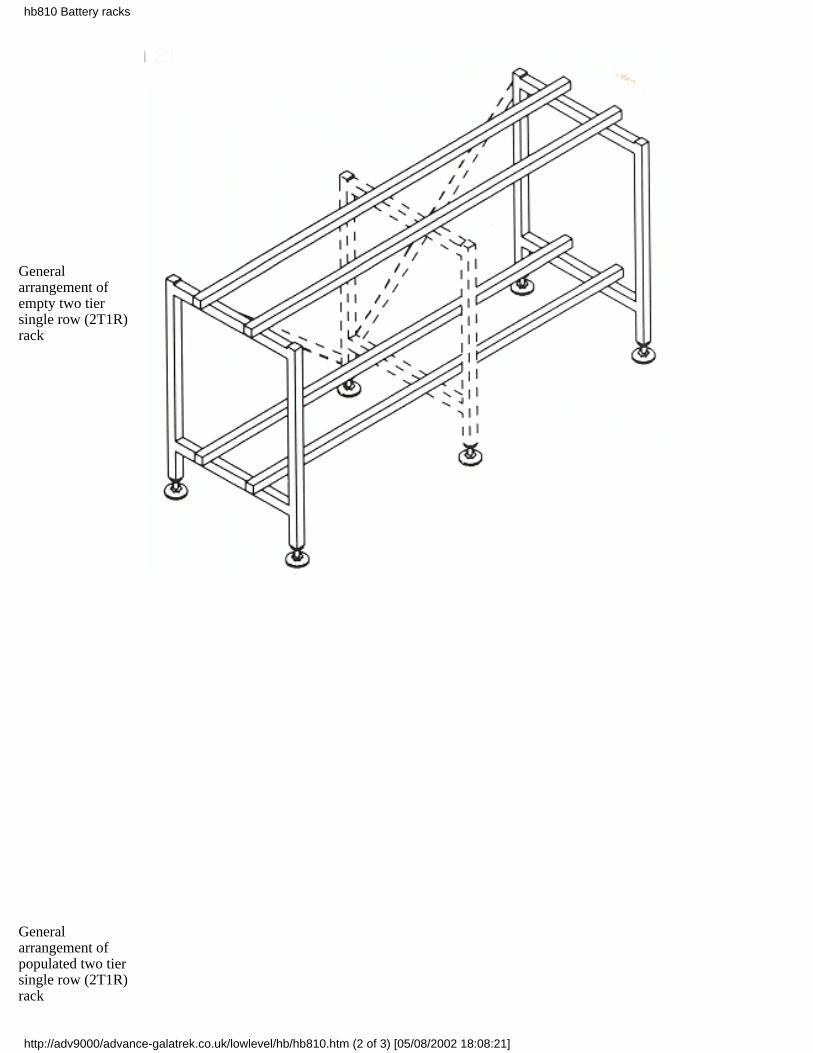
Generalarrangement ofempty two tiersingle row (2T1R)rack
Generalarrangement ofpopulated two tiersingle row (2T1R)rack
hb810 Battery racks
http://adv9000/advance-galatrek.co.uk/lowlevel/hb/hb810.htm (2 of 3) [05/08/2002 18:08:21]
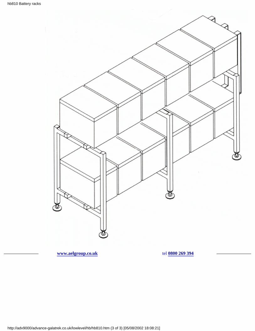
www.aelgroup.co.uk tel 0800 269 394
hb810 Battery racks
http://adv9000/advance-galatrek.co.uk/lowlevel/hb/hb810.htm (3 of 3) [05/08/2002 18:08:21]

hb061A-G AIT series type test results
Introduction The Advance series of AIT power conditioners was introduced some years ago to provide a highly effective noisefilter for modern ICT equipment. The technical differences between the AIT and our traditional ferroresonant power conditioners arecovered in hb026. However we are routinely asked for type test results relating to their performance. Perhaps the best test is the highintegrity of all the thousands of installations world-wide in telecomm and EPoS applications.
Features The technical results show that the electrical performance of this type of conditioner is second to none for noise spikeattenuation. Common mode noise is virtually eliminated and transverse mode noise is reduced well below any CBEAMA threshold.In addition the unit provides galvanic isolation between the input and output. These conditioners have conservatively ratedmagnetics to accommodate the large surges and high crest factor loads found in modern SMPS. The AIT is ideally suited to officeapplications where small size and low audible noise are of paramount importance.
Benefits Protected ICT systems will not be damaged by the high energy spikes associated with lightning striking overheaddistribution wires. Other electrical mains-borne noise will either be reduced to an acceptable level or completely eliminated. TheAIT reduces warranty and power supply maintenance costs of ICT equipment to a minimum.
Results The results shown are typical for a range of type tests designed to stress the unit as far as possible without destroying it.
Electrical safety AITs comply with Class 1 to EN 60950 BS 1362:1973 BS 1363:1984 sect 12 + 13 BS 2754:1977 Units were testedwith BS standard finger and pin and found compliant.
Breaking capacity Fuses comply with BS 1362.
Flammability Materials found to be compliant with UL 94VO.
Insulation resistance Between any two terminals the insulation resistance was >2MOhms measured at 500Vac. (Mains neon andprotection elements removed).
Voltage regulation A step change from 10 to 90% in applied load was made in less than 1mS. The output voltage decreased by lessthan 5%.
Critical phase angle The AIT is insensitive to the effects of phase angle.
Load side surge protection An impulse generator capable of producing a combination waveshape of 2.4kV open circuit and 200Ashort circuit was used for this test. No electrical or mechanical damage occurred.
Electrical fast transient The surge generator used is capable of producing a 5nS/50nS waveshape of 2kV open circuit voltage and a2.5kHz repetition frequency. The test waveform is applied for 15mS every 300mS for 10 minutes. The waveform is described in IEC801-4 1988. For both polarities the peak voltage appearing on the output terminals was <400V.
0.5çS 100kHz ring wave test Positive and negative polarity tests were made LN/LE/NE. Output voltages were <10V symmetric and<0.5V asymmetric.
Impulse discharge limiting voltage A generator capable of a current of 5kA peak 8 x 20uS waveshape into a short circuit was usedto apply 30 tests incorporating both polarities and all terminals. Output voltage peaks were all < 800V.
Failure modes The 5kA 8 x 20uS waveshape blew the input fuse as required on all tested samples.
Overcurrent performance The units were tested with slowly increased loads until the overload protection operated. Units must runfor >2 hours at a load just below the point at which protection operates. Case temperatures remained below 46¤C
Mode transfer The 5kA 8 x 20uS waveshape was applied between LE and measured between LN + NE. The 5kA 8 x 20uSwaveshape was applied between NE and measured between LN + LE. At no time did the peak impulse output voltage exceed 200V.
Insertion loss The symmetric and asymmetric insertion losses were measured using both methods described in BS 6299 section 4.1Appendix A. Insertion loss was <65db over the range 10kHZ to 30MHz. Negligible noise is transferred between modes. Waveformsrelating to these tests can be viewed at the factory.
www.aelgroup.co.uk tel 0800 269 394
hb061 AIT series type-test results
http://adv9000/advance-galatrek.co.uk/lowlevel/hb/hb061.htm (1 of 2) [05/08/2002 18:08:21]

hb061 AIT series type-test results
http://adv9000/advance-galatrek.co.uk/lowlevel/hb/hb061.htm (2 of 2) [05/08/2002 18:08:21]
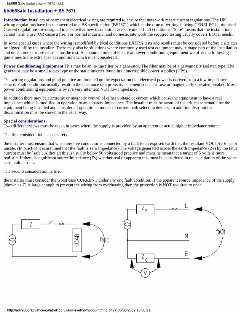
hb066Safe Installation + BS 7671
Introduction Installers of permanent electrical wiring are required to ensure that new work meets current regulations. The UKwiring regulations have been converted to a BS specification (BS7671) which at the time of writing is being CENELEC harmonised.Current regulations are designed to ensure that new installations are safe under fault conditions. `Safe’ means that the installationcannot harm a user OR cause a fire. For normal industrial and domestic site work the required testing usually covers BOTH needs.
In some special cases where the wiring is modified by local conditions EXTRA tests and results must be considered before a site canbe signed off by the installer. There may also be situations where commonly used test equipment may damage part of the installationand defeat one or more reasons for the test. As manufacturers of electrical power conditioning equipment we offer the followingguidelines to the extra special conditions which must considered.
Power Conditioning Equipment This may be an in-line filter or a generator. The filter may be of a galvanically isolated type. Thegenerator may be a small rotary type or the static inverter found in uninterruptible power supplies (UPS).
The wiring regulations and good practice are founded on the expectation that electrical power is derived from a low impedancesource. Fault conditions usually result in the clearance of a protective element such as a fuse or magnetically operated breaker. Mostpower conditioning equipment is by it’s very intention NOT low impedance.
In addition there may be electronic or magnetic control of either voltage or current which cause the equipment to have a realimpedance which is modified in operation to an apparent impedance. The installer must be aware of the critical schematic for theequipment being installed and consider all operational modes of current path selection devices. In addition distributiondiscrimination must be shown in the usual way.
Special considerationsTwo different views must be taken in cases where the supply is provided by an apparent or actual higher impedance source:
The first consideration is user safety:
the installer must ensure that when any live conductor is connected by a fault to an exposed earth that the resultant VOLTAGE is notunsafe. (In practice it is assumed that the fault is zero impedance) The voltage generated across the earth impedance (Ze) by the faultcurrent must be `safe’. Although this is usually below 50 volts good practice and margins mean that a target of 5 volts is morerealistic. If there is significant source impedance (Zs) whether real or apparent this must be considered in the calculation of the worstcase fault current.
The second consideration is fire:
the installer must consider the worst case CURRENT under any one fault condition. If the apparent source impedance of the supply(shown as Z) is large enough to prevent the wiring from overheating then the protection is NOT required to open.
hb066 Safe Installation + 7671 - pt1
http://adv9000/advance-galatrek.co.uk/lowlevel/hb/hb066.htm (1 of 2) [05/08/2002 18:08:21]

Since there is an almost infinite variety of potential installation variations even using our own products some further suggestions forensuring safe installation are outlined in hb067.
www.aelgroup.co.uk tel 0800 269 394
hb066 Safe Installation + 7671 - pt1
http://adv9000/advance-galatrek.co.uk/lowlevel/hb/hb066.htm (2 of 2) [05/08/2002 18:08:21]
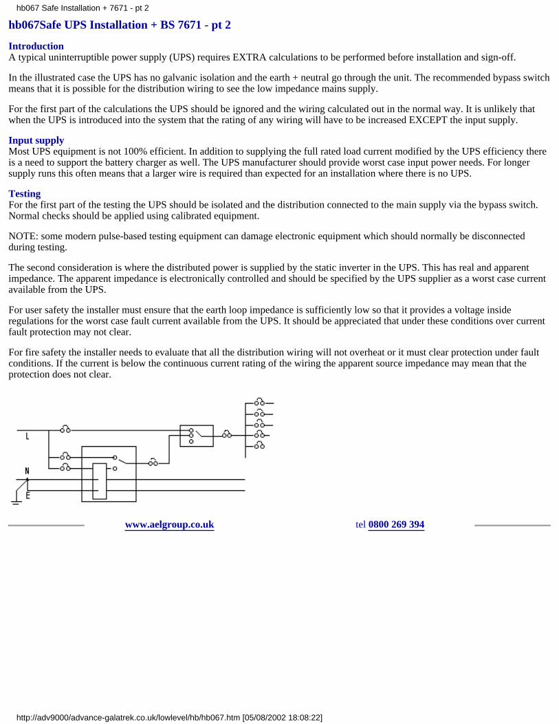
hb067Safe UPS Installation + BS 7671 - pt 2
IntroductionA typical uninterruptible power supply (UPS) requires EXTRA calculations to be performed before installation and sign-off.
In the illustrated case the UPS has no galvanic isolation and the earth + neutral go through the unit. The recommended bypass switchmeans that it is possible for the distribution wiring to see the low impedance mains supply.
For the first part of the calculations the UPS should be ignored and the wiring calculated out in the normal way. It is unlikely thatwhen the UPS is introduced into the system that the rating of any wiring will have to be increased EXCEPT the input supply.
Input supplyMost UPS equipment is not 100% efficient. In addition to supplying the full rated load current modified by the UPS efficiency thereis a need to support the battery charger as well. The UPS manufacturer should provide worst case input power needs. For longersupply runs this often means that a larger wire is required than expected for an installation where there is no UPS.
TestingFor the first part of the testing the UPS should be isolated and the distribution connected to the main supply via the bypass switch.Normal checks should be applied using calibrated equipment.
NOTE: some modern pulse-based testing equipment can damage electronic equipment which should normally be disconnectedduring testing.
The second consideration is where the distributed power is supplied by the static inverter in the UPS. This has real and apparentimpedance. The apparent impedance is electronically controlled and should be specified by the UPS supplier as a worst case currentavailable from the UPS.
For user safety the installer must ensure that the earth loop impedance is sufficiently low so that it provides a voltage insideregulations for the worst case fault current available from the UPS. It should be appreciated that under these conditions over currentfault protection may not clear.
For fire safety the installer needs to evaluate that all the distribution wiring will not overheat or it must clear protection under faultconditions. If the current is below the continuous current rating of the wiring the apparent source impedance may mean that theprotection does not clear.
www.aelgroup.co.uk tel 0800 269 394
hb067 Safe Installation + 7671 - pt 2
http://adv9000/advance-galatrek.co.uk/lowlevel/hb/hb067.htm [05/08/2002 18:08:22]

hb068Laboratory power facilities
IntroductionThere are inevitable compromises with ALL methods of Electrical Power Conditioning. It is up to the USER to establish whichtechnology provides the most attractive solution.Flexible power solutions for Laboratory InstallationsIn the Test House or Specialised Test Facility where a variety of solutions can be required it may seem that the most flexible solutionis to provide a number of small stabilisers and battery back-up units which can be moved around to the point of application.Experience shows that there is one extra major advantage to planning the needs when the facility is under construction and wiringout several power supply options to every general purpose test station. The advantage is that ALL power conditioning products haveratings which are determined by cost and if the distributed conditioning is combined into a central facility it is less likely that a testpiece will be too large for a mobile conditioning solution.
-- screened tx --- noise free|
incoming supply ---|--- ferro --- noise free clean sinewave stable voltage||--- UPS on line --- continuous power|--- rotary --- 60Hz
There are several other considerations including efficiency impedance/shared usage load effects and MTBF. These are summarisedin the table:
Topology prime characteristic features benefits considerations
surge diversion lightning protection low cost zero series impedancevery high MTBF fit to guidelines in BS6601
notch filter narrow band noise attenuation low cost unwanted frequency rejection only works over design frequencyband
isolation transformer galvanic isolation low impedance safety of personnel use RCCDs for protection
low impedance conditioner galvanic isolationnoise attenuation
exceptional common-mode noiseprotection
ease of applicationefficiency
leakage inductance adds to mainsimpedance
ferro resonant conditioner transverse-mode noise attenuationvoltage stabilisation
exceptionally robust noise filterwaveform notch replacementsine waveform re-building2-way filteringvoltage stabilisation
clean mains supplyMTBF=200kHroverload proof
weightefficiency3-phase delta loadsinput protectiondown stream protection
UPS off line normally on standby lower cost provides emergency powerswitch over timeusually lower power ratingsbattery maintenance
UPS on line load runs on inverter full time provides 2nd source supply provides emergency power
non unity PF loads3-phase delta loadsbattery run timesefficiencybattery maintenanceMTBF=20kHr
rotary converter 50 to 60Hz etc low technology solution virtually perfect noise rejectionusually fixed frequencyMTBF=5kHrmaintenance cost
generator chemical energy source huge range of options permits manual frequency variationnoisemaintenanceenvironmental problems
Advance Galatrek supplies a UPS combined with a low impedance transformer. If you need any more help - please ask!
www.aelgroup.co.uk tel 0800 269 394
hb068 Laboratory power facilities
http://adv9000/advance-galatrek.co.uk/lowlevel/hb/hb068.htm [05/08/2002 18:08:22]
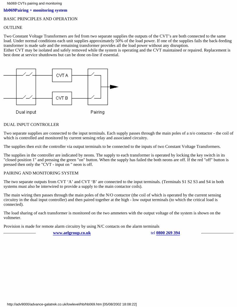
hb069Pairing + monitoring system
BASIC PRINCIPLES AND OPERATION
OUTLINE
Two Constant Voltage Transformers are fed from two separate supplies the outputs of the CVT’s are both connected to the sameload. Under normal conditions each unit supplies approximately 50% of the load power. If one of the supplies fails the back-feedingtransformer is made safe and the remaining transformer provides all the load power without any disruption.Either CVT may be isolated and safely removed while the system is operating and the CVT maintained or repaired. Replacement isbest done at service shutdowns but can be done on-line if essential.
DUAL INPUT CONTROLLER
Two separate supplies are connected to the input terminals. Each supply passes through the main poles of a n/o contactor - the coil ofwhich is controlled and monitored by current sensing relay and associated circuitry.
The supplies then exit the controller via output terminals to be connected to the inputs of two Constant Voltage Transformers.
The supplies in the controller are indicated by neons. The supply to each transformer is operated by locking the key switch in its"closed position 1" and pressing the green "on" button. When the supply has failed the both neons are off. If the red "off" button ispressed then only the "CVT - input on " neon is off.
PAIRING AND MONITORING SYSTEM
The two separate outputs from CVT ‘A’ and CVT ‘B’ are connected to the input terminals. (Terminals S1 S2 S3 and S4 in bothsystems must also be interwired to provide a supply to the main contactor coils).
The main wiring then passes through the main poles of the N/O contactor (the coil of which is operated by the current sensingcircuitry in the dual input controller) and then paired together at the high - low output terminals (to which the critical load isconnected).
The load sharing of each transformer is monitored on the two ammeters with the output voltage of the system is shown on thevoltmeter.
Provision is made for remote alarm circuitry by using N/C contacts on the alarm terminals
www.aelgroup.co.uk tel 0800 269 394
hb069 CVTs pairing and monitoring
http://adv9000/advance-galatrek.co.uk/lowlevel/hb/hb069.htm [05/08/2002 18:08:22]
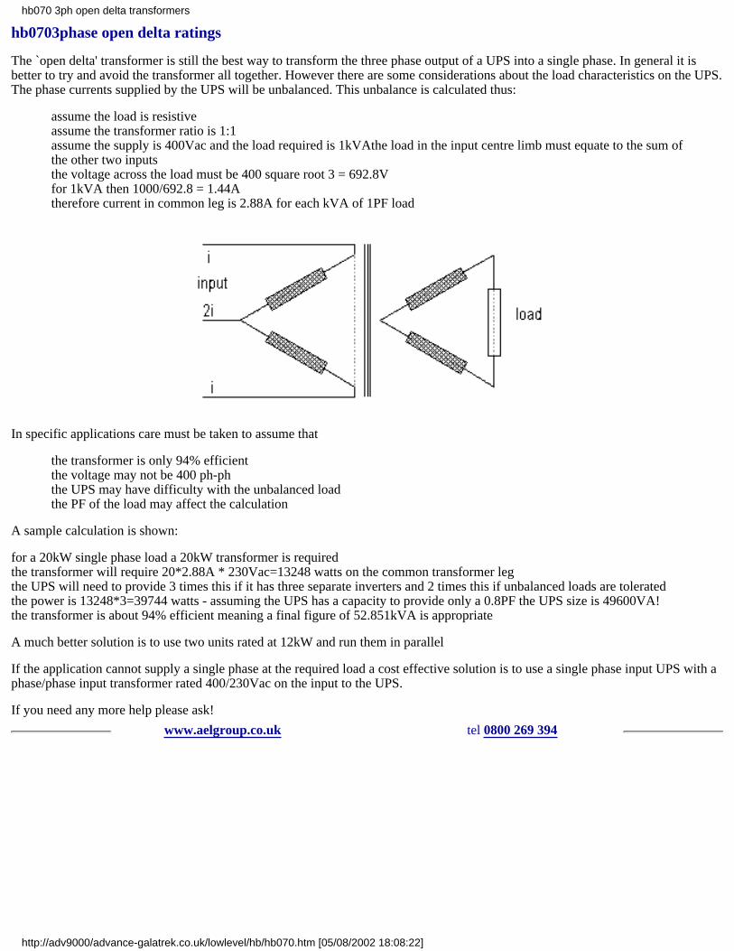
hb0703phase open delta ratings
The `open delta' transformer is still the best way to transform the three phase output of a UPS into a single phase. In general it isbetter to try and avoid the transformer all together. However there are some considerations about the load characteristics on the UPS.The phase currents supplied by the UPS will be unbalanced. This unbalance is calculated thus:
assume the load is resistiveassume the transformer ratio is 1:1assume the supply is 400Vac and the load required is 1kVAthe load in the input centre limb must equate to the sum ofthe other two inputsthe voltage across the load must be 400 square root 3 = 692.8Vfor 1kVA then 1000/692.8 = 1.44Atherefore current in common leg is 2.88A for each kVA of 1PF load
In specific applications care must be taken to assume that
the transformer is only 94% efficientthe voltage may not be 400 ph-phthe UPS may have difficulty with the unbalanced loadthe PF of the load may affect the calculation
A sample calculation is shown:
for a 20kW single phase load a 20kW transformer is requiredthe transformer will require 20*2.88A * 230Vac=13248 watts on the common transformer legthe UPS will need to provide 3 times this if it has three separate inverters and 2 times this if unbalanced loads are toleratedthe power is 13248*3=39744 watts - assuming the UPS has a capacity to provide only a 0.8PF the UPS size is 49600VA!the transformer is about 94% efficient meaning a final figure of 52.851kVA is appropriate
A much better solution is to use two units rated at 12kW and run them in parallel
If the application cannot supply a single phase at the required load a cost effective solution is to use a single phase input UPS with aphase/phase input transformer rated 400/230Vac on the input to the UPS.
If you need any more help please ask!
www.aelgroup.co.uk tel 0800 269 394
hb070 3ph open delta transformers
http://adv9000/advance-galatrek.co.uk/lowlevel/hb/hb070.htm [05/08/2002 18:08:22]

hb071digital camera problems
IntroductionThe advent of very high quality scanning backs for studio cameras has caused a new interest in mains related image noise problems.Most photographers are not engineers and this page attempts to provide enough information for a studio camera user to try andevaluate whether or not a particular problem may be solved with mains power protection devices.
Diagnosis before cureIn most technical applications where problems occur it is usually easier to effect a cure if the problem is actually understood.By examining images which have been produced by a suspect digital camera under differerent conditions it may be possible toeliminate possible causes of a problem.
It is also necessary to have to hand the expected performance for the camera. If the camera was never intended to produce anacceptable image under the conditions of test - then no amount of mains protection is going to improve it! (Some cameramanufacturers have been reluctant to give measurable figures for performance and we feel this is unacceptable.)
Popular image problemsWe usually ask photographers to examine poor images for the following problems:
variation in lighting conditions during the scanAn example of this is in a studio where ambient daylight is illuminating the subject and the sun goes in or out during the scan. In thesimplest example where the sun starts behind a cloud and comes out during the scan there will be an overall brightness increaseacross the image in the direction of the scan. The change will be directly related to the rate of change of sunlight variation comparedto the rate of scan. Clearly elimination is straightforward.
variation in artificial lighting due to mains problemsSPIKES - these short duration occurrences can produce bright spots in one line of pixels caused by the light actually brightening upmomentarily - unusual even in direct off mains tungsten lighting because the spike energy has to be quite large. This effect isnormally completely random.
BROWNOUTS - this is where the mains voltage sags and the light given out by unstabilised tungsten lights literally dims down forthe same period as the voltage droops. The result is similar to the sun going behind a cloud during the scan. (This process can workthe other way with voltage surges) and may vary considerably during a scan.
variation in artificial lighting due to mains frequency beatsThe UK mains supply is modulated at 50 Hz (cycles per second) and direct-off-mains tungsten lights (ordinary bulbs) flicker at thisfrequency ALL THE TIME! The human eye `integrates’ the effect and does not notice it.
This causes a problem which is always difficult for non-physicists to understand but musical people are familiar with tones which`beat’ and the same effect can happen when the effective scan rate is close to 50Hz or a multiple. The result is that some lines ofpixels see bright light and some dark.
The picture will have a series of `fringes' parallel to the scanning sensor - width and spacing of the fringes will be set-up andscan-rate dependent. Cameras have anti-fringing software to combat this problem. Usually the result looks like a venetian blindshadow over the image. It can also produce multicoloured effects not just light and dark beacuse only one colour channel may bebeating.
light path obstructionIf a piece of dirt is stuck to the scanning sensor it will produce a (usually coloured) line in the direction of the scan. Usually the lineis across the entire frame and the problem can only be corrected by using cleaner techniques. If the sensor is clean and the line isalways the same colour it suggests that the sensor is faulty.
camera technologythis is a huge subject and only briefly touched here
the image faulty areas should be pushed to the limits of installed software using mainly contrast and brightness adjustments to viewthe image pixel by pixel to try and assess what is actually happening as the sensor moves along.
If there is quite a lot of colour variation along the line of pixels when scanning an evenly illuminated area it is probably directlyrelated to any interpolation in the process or sensor/amplifier inconsistencies. (Users should appreciate that the analogue scanningdata is converted to digital information right after the scanner head. The A to D process is where the electronics value really costs!)
hb071 digital camera problems
http://adv9000/advance-galatrek.co.uk/lowlevel/hb/hb071.htm (1 of 2) [05/08/2002 18:08:22]

Colour variation in the image under these conditions must be reviewed with the supplier specification to assess if it is typical orworse than usual for the camera back. Tests should be done at different scan rates and exposure combinations (f-stop & light change)to try and discern the relavance of the fault to external influences.
`Fringes’ which occur along a distinct line of pixels across the scanning sensor are consistent with a change in camera systemamplifier gain between successive pixel rows and really should not happen.
If a step function in the overall `gain' characteristic occurs on a random basis check the fringe to see if it gives the impression thatthe back slowly drifts in it’s gain value and then suddenly regains control going back to a figure from several pixel lines previouslyin the scan. If so it can be either mechanical sticking of the traverse lack of amplifier gain control or a voltage fluctuation caused bychanging loads elsewhere.
SummarySometimes it helps to build a test setup to eliminate external influences and still demonstrate that the back produces problems. Asimple battery driven lamp which has no 50Hz and no spikes! It can be arranged to have no droop through the actual scan process byusing a relatively large battery. The best approach would be a car battery and a couple of headlamp bulbs. To be utterly pedantic thebulb voltage could be monitored during the scan.
The subject should be a nice plain background with a small object used temporarily to set up the correct focus to simulate an actualshooting scenario. This test would eliminate a large proportion of the external influences which could otherwise be erroneouslyblamed.
Finally if after evaluation it is felt that the camera is really suffering from a direct or indirect mains related problem please ask us forhelp.
We can provide a UPS to provide power when the mains is down a power conditioner to remove spikes or a more sophisticated onewhich stabilises the voltage suppliying either the camera lights or both. Normally we would loan a unit to allow the photographer achance to prove what may be an expensive cure actually solves the problem. We have at least one obsessive photographer on site!
If you need any more info please ask!
www.aelgroup.co.uk tel 0800 269 394
hb071 digital camera problems
http://adv9000/advance-galatrek.co.uk/lowlevel/hb/hb071.htm (2 of 2) [05/08/2002 18:08:22]
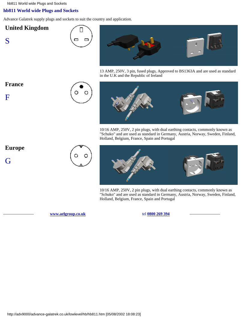
hb811 World wide Plugs and Sockets
Advance Galatrek supply plugs and sockets to suit the country and application.
United Kingdom
S
13 AMP, 250V, 3 pin, fused plugs, Approved to BS1363A and are used as standardin the U.K and the Republic of Ireland
France
F
10/16 AMP, 250V, 2 pin plugs, with dual earthing contacts, commonly known as"Schuko" and are used as standard in Germany, Austria, Norway, Sweden, Finland,Holland, Belgium, France, Spain and Portugal
Europe
G
10/16 AMP, 250V, 2 pin plugs, with dual earthing contacts, commonly known as"Schuko" and are used as standard in Germany, Austria, Norway, Sweden, Finland,Holland, Belgium, France, Spain and Portugal
www.aelgroup.co.uk tel 0800 269 394
hb811 World wide Plugs and Sockets
http://adv9000/advance-galatrek.co.uk/lowlevel/hb/hb811.htm [05/08/2002 18:08:23]

hb101retrofit wiring for EPoS systems
BackgroundA number of customers have asked us to document an approach to the replacement of poor EPoS wiring in recreationalestablishments
The need to re-wire is usually to ensure that the EPoS systemis correctly connected and that no unrelated loads are on thesame circuit
Where a site is prone to noise related problems caused byunknown or unpreventable causes the re-wiring will notnecessarily make all the historical problems disappear.However it does mean that the wiring arrangement is clearlydefined and will not have any earth loops
In addition the provision of both a dedicated line clean earthand the absence of all earth loops often solves transient noiserelated problems. In all cases the current regulations must beobserved. The diagram shows the principles of the new wiringarrangement
The SpurThe EPoS equipment is generally fed from a single spur protected by an MCB
This spur should be routed around the building avoiding runs close to other wires - especially high power cables. The wire(conventional twin and earth) must be sized according to current regulations
The MCB Type 4 is desirable to allow for the high switch on surges of CVT types of Power Conditioner
The EarthThe earth is derived from a dedicated earth rod of suitable impedance. NO other equipment should be attached to this earth. Caremust be taken to ensure no earth loops exist. This can be tested by disconnecting the earth rod from the spur and checking all gear isisolated from earth
The Power Conditioner (PC)This will usually be one of two types.
1) CVT based unit with voltage stabilisation and `bullet proof' noise protection. The CVT also provides soft start to the load andwaveform re-build and well an enhanced ride-through for mains micro breaks
2) AIT series low impedance conditioner designed to remove ALL common mode noise
In either case the clean earth is fed to the unit as a safety earth. If a CVT is fitted the output `low' MUST also be connected to theearth. For the AIT series this connection is internal
GeneralIt is good practice to ensure that no free sockets are available for non EPosS loads - kettles vacuums etc.
If for any reason RCCDs are to be fitted they will only protect the load if installed AFTER the PC
The installer should check the wiring is NOT connected to any other circuit
The system data cabling MUST be checked to ensure that the earth screens are only connected at ONE end
A diagram of the completed installation MUST be kept to assist further investigation if problems persist
www.aelgroup.co.uk tel 0800 269 394
hb101 retrofit wiring for EPoS
http://adv9000/advance-galatrek.co.uk/lowlevel/hb/hb101.htm [05/08/2002 18:08:23]

hb514 COSHH datasheet for Advance Galatrek UPS + Power Conditioners
Scope
This sheet refers to all catalogue UPS and Power Conditioner products supplied by Advance Galatrek.
Policy statement
The company does not use any of the following substances in the manufacture of its products:
Asbestos (blue/brown or white)Benzene or related carcinogensCadmium for plating componentsHalogenated (Chlorinated/Fluorinated) solventsOzone depleting substancesPolychlorinated Biphenyls
UPS + Power Condtioners
Although we are required to control some of the substances produced during the manufacture of these products all are covered by theguidelines provided by COSHH consultant ORL dated Oct 1989.
No substances described in COSHH regulations are present in significant volumes in finished product EXCEPT for those found inelectrical storage batteries in UPS products.
These items are manufactured to be leak free and can only be a chemical hazard if damaged.
Attention is drawn to our Health + Safety data sheets safe battery handling and safe battery disposal..
www.aelgroup.co.uk tel 0800 269 394
hb514 COSHH data sheet UPS + PC
http://adv9000/advance-galatrek.co.uk/lowlevel/hb/hb514.htm [05/08/2002 18:08:23]

hb757earth leakage current with UPS
Introduction
When electrical equipment is connected to people for example in a medical application extra regulations apply.
Such regulations are designed to ensure that a patient cannot be harmed by a fault in the electrical supply.
Specific details for patient connect equipment are outlined in IEC 601 / EN 50601
UPS measurements
Customers with UPS equipment may test the equipment using off the shelf testers to ensure it is safe in person-connected situationsor where the general integrity of the equipment is being checked.
We have found instances where the test results are confusing because the test equipment performs an earth leakage measurementbetween Live and Neutral and also between Neutral and Live.
The reversal of the input connections can give rise to unexpected results.
Our UPS products are designed and manufactured to meet the EMC requirements of current legislation. In normal use the live andneutral supplies are connected the `right' way around. To meet the regulations the input filtering may not be symmetrical about thetwo input wires and earth.
For example a capacitor connected between live and earth will see about 230Vac and a similar sized capacitor fitted between neutraland earth will normally see less than 10Vac. If these are checked at 50Hz for leakage current the results will be different by morethan an order of magnitude.
So an off the shelf tester measuring the combined effect of several such components will see different results for earth leakagedepending on the polarity of the test.
Recent calculations on the input filter fitted to a 1kVA MicroBak showed expected figures of 41 and 759 micro amps. Actualmeasurements provided figures of 75 and 800 micro amps.
www.aelgroup.co.uk tel 0800 269 394
hb757 earth leakage current with UPSs
http://adv9000/advance-galatrek.co.uk/lowlevel/hb/hb757.htm [05/08/2002 18:08:23]
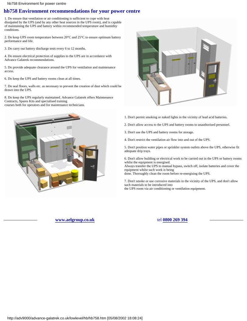
hb758 Environment recommendations for your power centre1. Do ensure that ventilation or air conditioning is sufficient to cope with heatdissipated by the UPS (and by any other heat sources in the UPS room), and is capableof maintaining the UPS and battery within recommended temperature and humidityconditions.
2. Do keep UPS room temperature between 20°C and 25°C to ensure optimum batteryperformance and life.
3. Do carry out battery discharge tests every 6 to 12 months.
4. Do ensure electrical protection of supplies to the UPS are in accordance withAdvance Galatrek recommendations.
5. Do provide adequate clearance around the UPS for ventilation and maintenanceaccess.
6. Do keep the UPS and battery rooms clean at all times.
7. Do seal floors, walls etc. as necessary to prevent the creation of dust which could bedrawn into the UPS.
8. Do keep the UPS regularly maintained. Advance Galatrek offers MaintenanceContracts, Spares Kits and specialised trainingcourses both for operators and for maintenance technicians.
1. Don't permit smoking or naked lights in the vicinity of lead acid batteries.
2. Don't allow access to the UPS and battery rooms to unauthorised personnel.
3. Don't use the UPS and battery rooms for storage.
4. Don't restrict the ventilation air flow into and out of the UPS.
5. Don't position water pipes or sprinkler system outlets above the UPS, otherwise fitadequate drip trays.
6. Don't allow building or electrical work to be carried out in the UPS or battery roomswhilst the equipment is energised.Always transfer the UPS to manual bypass, switch off, isolate batteries and cover theequipment whilst such work is beingdone. Thoroughly clean the room before re-energising the UPS.
7. Don't smoke or use corrosive materials in the vicinity of the UPS, and don't allowsuch materials to be introduced intothe UPS room via air conditioning or ventilation equipment.
www.aelgroup.co.uk tel 0800 269 394
hb758 Environment for power centre
http://adv9000/advance-galatrek.co.uk/lowlevel/hb/hb758.htm [05/08/2002 18:08:24]
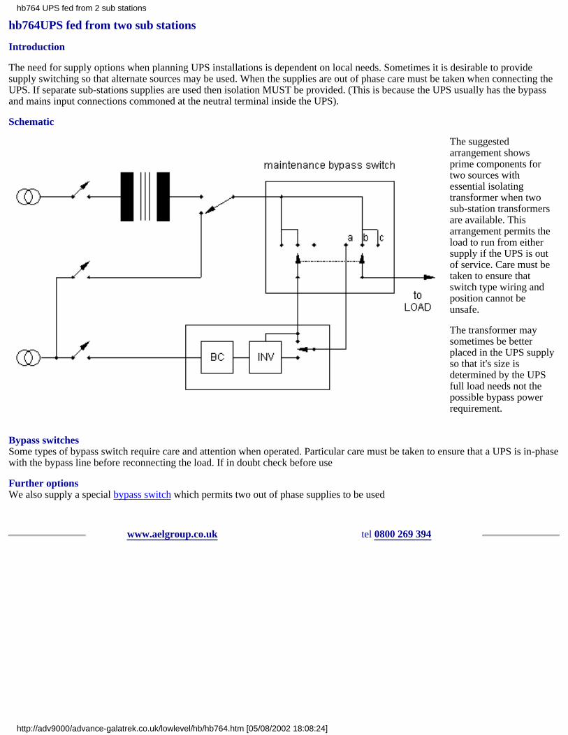
hb764UPS fed from two sub stations
Introduction
The need for supply options when planning UPS installations is dependent on local needs. Sometimes it is desirable to providesupply switching so that alternate sources may be used. When the supplies are out of phase care must be taken when connecting theUPS. If separate sub-stations supplies are used then isolation MUST be provided. (This is because the UPS usually has the bypassand mains input connections commoned at the neutral terminal inside the UPS).
Schematic
The suggestedarrangement showsprime components fortwo sources withessential isolatingtransformer when twosub-station transformersare available. Thisarrangement permits theload to run from eithersupply if the UPS is outof service. Care must betaken to ensure thatswitch type wiring andposition cannot beunsafe.
The transformer maysometimes be betterplaced in the UPS supplyso that it's size isdetermined by the UPSfull load needs not thepossible bypass powerrequirement.
Bypass switchesSome types of bypass switch require care and attention when operated. Particular care must be taken to ensure that a UPS is in-phasewith the bypass line before reconnecting the load. If in doubt check before use
Further optionsWe also supply a special bypass switch which permits two out of phase supplies to be used
www.aelgroup.co.uk tel 0800 269 394
hb764 UPS fed from 2 sub stations
http://adv9000/advance-galatrek.co.uk/lowlevel/hb/hb764.htm [05/08/2002 18:08:24]

hb805 Automatic Battery Test Elite range
ETC range 700 and 1KVAAutomatic battery testing occurs every 40 hours (excluding time spent with the battery not fully charged).
The test consists of disconnecting the mains momentarily the microprocessor then measures the load and detects the volt drop acrossthe batteries and from this calculates the battery efficiency. If the battery efficiency is calculated as below 50% the "Replace battery"alarm is activated on the front panel and an audible warning is started.
ETA range 700-3KVA and ETD range 1K5VA-5KVAAutomatic battery testing occurs every 40 hours (excluding time spent with the battery not fully charged).
The test consists of connecting the batteries to an internal load (approximately 30A) for 1ms. Knowing the Ah and detecting the voltdrop across the batteries this figure is compared against a table in the microprocessor memory. An audible alarm and front panelwarning are activated if the volt drop is too great.
ERM ERT ERX Master Elite range 6KVA-120KVAAutomatic battery testing occurs every 24 hours. The test decreases the rectifier voltage to 350V for 6 sec to supply the load from thebattery.
www.aelgroup.co.uk tel 0800 269 394
hb805 Automatic Battery Test Elite range
http://adv9000/advance-galatrek.co.uk/lowlevel/hb/hb805.htm [05/08/2002 18:08:24]

hb806 Parallel Operation Master Elite range
ScopeThis document describes the parallel card option available to the Master Elite range of products. Parallel operation can be used toprovide redundancy in a UPS system or to increase the maximum capacity. Because the parallel option is an addition to the standardproduct it can be retro-fitted by a trained engineer in addition the unit can be ordered "parallel ready" but not enabled to reducesystem downtime when a second unit is installed.
DescriptionBetween two and six UPS can be connected with parallel input and output connections and configured to behave as one largersystem. In the 100-120KVA versions units in a parallel system can share one battery bank.
System data is communicated using an opto-isolated "daisy-chain" cable. The cable transmits up to 5 signals from from the "master"unit to it's "slaves".
Systems made up of Master Elites up to 80KVA require each unit has its own battery bank.
RequirementsEach UPS must be fitted with its own parallel card option this can be disabled using a special terminator if it has been fitted forfuture expansion. Special care must be taken in installing the UPS power cabling to ensure all units have the same length of cables.
Redundancy can only be achieved by fitting one UPS extra to those required by the load requirement. It is recommended thatisolators are fitted at the input output and battery input for each UPS to allow ease of maintenance.
The daisy-chain cable must be well protected any break in this communication will switch the entire system to bypass.
A simple system is shown below.
hb806 Parallel operation Master Elite range
http://adv9000/advance-galatrek.co.uk/lowlevel/hb/hb806.htm (1 of 2) [05/08/2002 18:08:24]

www.aelgroup.co.uk tel 0800 269 394
hb806 Parallel operation Master Elite range
http://adv9000/advance-galatrek.co.uk/lowlevel/hb/hb806.htm (2 of 2) [05/08/2002 18:08:24]

hb001 CVT introduction the perfect sine wave
Outstanding Spike and electrical noise protection:The very best power protection comes from a special type of transformer known as a Constant Voltage Transformer (CVT). Providingunparalleled reliability and conditioning performance, spikes and electrical noise are neutralised with attenuation as high as 75dB.
In addition the input and output transformer windings are physically separated. Known as Galvanic isolation this separation ensures that thereis no direct connection between the mains supply and load.
A CVT therefore provides an impenetrable barrier to spikes and high frequency electrical noise. This barrier also works in reverse mode toprevent a 'noisy' load from polluting the mains supply itself.
Superior sag surge and brownout protection:Mains voltage sags and surges are automatically corrected by a CVT.
When faced with an extreme surge voltage such as a local lightning strike the power conditioner will present a low impedance to the mains toprotect both itself and any connected loads.
Automatic sine-wave generation:using ferro resonant transformer technology means that each power conditioner will always generate a pure stable sine-wave even when fedfrom a polluted mains or square-wave supply.
A = INPUTB = OUTPUT
NO moving partsNO electronicsONLY magnetic magic
Perfect switched-mode-power-supply (SMPS) driver:ferro resonant transformer technology provides waveform shoulder-lifting - the CVT is the kindest way to drive a switched mode powersupply. Input surges are reduced prolonging life and conduction times are lengthened. In addition the CVT provides harmonic buffering andimproved reservoir capacitor hold up for the inevitable supply micro breaks which occur with grid protection switching.
Oscilloscope hold-up picture ride-through picture
Something for nothing:so long as at least 30% of the normal supply voltage is present the suitably selected CVT can provide adequate power for your critical load.
Common mode noise attenuation Series mode noise attenuation
hb001 CVT introduction - the perfect sine wave
http://adv9000/advance-galatrek.co.uk/lowlevel/hb/hb001.htm (1 of 4) [05/08/2002 18:08:25]

>
Regulation
Output within 5% for zero to full load Outstanding output regulation at low loads or high input voltages
Regulation outside of specification
Output within 8% for zero to full load and nominal input +/-20%
Stabilisation
hb001 CVT introduction - the perfect sine wave
http://adv9000/advance-galatrek.co.uk/lowlevel/hb/hb001.htm (2 of 4) [05/08/2002 18:08:25]
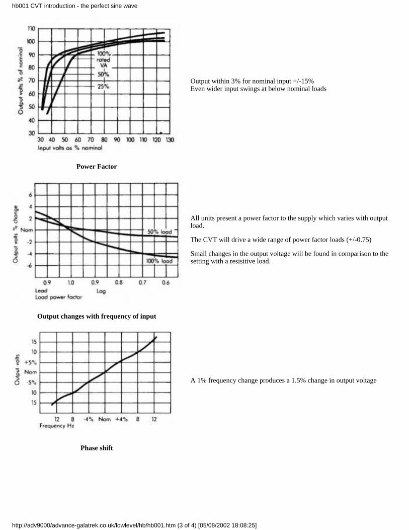
Output within 3% for nominal input +/-15%Even wider input swings at below nominal loads
Power Factor
All units present a power factor to the supply which varies with outputload.
The CVT will drive a wide range of power factor loads (+/-0.75)
Small changes in the output voltage will be found in comparison to thesetting with a resisitive load.
Output changes with frequency of input
A 1% frequency change produces a 1.5% change in output voltage
Phase shift
hb001 CVT introduction - the perfect sine wave
http://adv9000/advance-galatrek.co.uk/lowlevel/hb/hb001.htm (3 of 4) [05/08/2002 18:08:25]

There is a smal phase shift across the CVT varying with load
www.aelgroup.co.uk tel 0800 269 394
hb001 CVT introduction - the perfect sine wave
http://adv9000/advance-galatrek.co.uk/lowlevel/hb/hb001.htm (4 of 4) [05/08/2002 18:08:25]

hb808 Mean Time Before Failure (MTBF) and reliability ETA\RTA and ETD
Calculating Mean Time Before Failure of a UPS is difficult when you take into account its automatic static switch bypass.
Typical figures for the Elite range are quoted as 600 000 hours.
A more meaningful representation of reliability can be gained from the Mean Time to Repair (MTR) in the case of the Elite this isless than 15 minutes. The use of matched PCBs and quick assembly techniques means the entire boardset can be changed in 30minutes.
There is a large world population of the elite in many different geographical areas and applications and the inside warranty failurerate is less than 4%.
In addition Advance Galatrek can now offer a five year warranty on the Elite unit when installed with one of our special transientsuppression bypass switches
www.aelgroup.co.uk tel 0800 269 394
hb808 MTBF and reliability ETA\RTA and ETD
http://adv9000/advance-galatrek.co.uk/lowlevel/hb/hb808.htm [05/08/2002 18:08:25]

hb809 Cable length recommendations
The most common telecoms installation of an Advance Galatrek UPS is at or around 1500VA.
The recommendations quoted here apply to this case and can be extrapolated for all installations. If you need any help please ringservice on 01978 821 086.
Communications cablesAll units use the standard RS232 protocol. Without special equipment the cable length can run up to 200m. With special equipment(RS232 signal repeaters) this can be infinitely extended but it normally works out cheaper to use modems and a phone line. Volt freecontact cable runs of 200m are also possible
Supply cablesACIf the input cable to a UPS is properly sized distances of 50m will lead to approximately a three volt drop in supply voltage. Greaterdistances can be achieved by thicker cable and extreme distances can be achieved by stepping the voltage up to a suitable level forlong distance transmission and then stepping it down again at the UPS input.
DCSupplied cables for connection to battery extension packs are 1.5m. Longer lengths are available on request. Lengths longer than2.5m will lead to a decreased run time from the batteries due to volt drops in the cable.
Load cablesThe output of the UPS can effectively be treated as a new source of mains voltage so a further 50m can be gained if the load willaccept the three volt drop. Greater distances as above. The cable should be mineral insulated 3-core with shield for optimalresistance to mains borne Radio Frequency Interference (RFI).
www.aelgroup.co.uk tel 0800 269 394
hb809 Cable length recommendations
http://adv9000/advance-galatrek.co.uk/lowlevel/hb/hb809.htm [05/08/2002 18:08:25]

hb702maintenance bypass operation
Installation of a maintenance bypass removes the need to power down the load during routine maintenance or capacity upgrade of anUninterruptible Power System (UPS). The bypass switch has two positions
Mains powerUPS power
Manual operation of the switch directs whichsource of power feeds the load. A maintenancebypass is normally wall mounted adjacent to theUPS.
Maintenance bypass switch typesThere are two types of maintenance bypass switch:Make-Before-Break (MBB)Break-Before-Make (BBM)It is normal to install a MBB switch in an installation which requires a 'break-free' power supply as the BBM typically suffers from a5ms break when turned between switch positions.
Internal or external bypassesSome UPS boast that they incorporate an internal maintenance bypass switch. This has two drawbacks
If the UPS needs to be removed the load will still need to be powered down.As the UPS cannot be totally switched off
(dangerous ac and dc voltages may be present whilst the engineer performs routine maintenance)
'Plug and Play' or hardwiredThere are two types of bypass installation. An installation may be either hardwired or softwired (more commonly known as 'PlugAnd Play').
'Plug And Play'This uses standard IEC sockets and may be used with any UPS installation up to a maximum of 2kVA. Above this rating thehardwired approach is adopted due to the higher amperages involved.The 'Plug And Play' bypass helps to improve logistics co-ordination and reduce the higher installation costs associated with largerUPS and the more traditional hardwired approach.Its use of standard 'plug-in' connections removes the need to have an electrically qualified engineer attend site. An additional benefitis that UPS utilising the 'Plug And Play' approach are normally user commissionable.
HardwiredThe standard IEC sockets used on a 'Plug And Play' bypass and UPS have a maximum supply current 10A.Their use is restricted to UPS up to 2k5VA for 240Vac installations and 1kVA for 110Vac installations.
hb702 bypass operation
http://adv9000/advance-galatrek.co.uk/lowlevel/hb/hb702.htm (1 of 2) [05/08/2002 18:08:25]

In such instances the bypass must be hardwired.A typical installation powers the UPS from a fused spur. The output from the UPS is hardwired through the bypass to the load.
For more details see FBS series and special needs version or bypass considerations
www.aelgroup.co.uk tel 0800 269 394
hb702 bypass operation
http://adv9000/advance-galatrek.co.uk/lowlevel/hb/hb702.htm (2 of 2) [05/08/2002 18:08:25]
hb704UPS delivery + siting
Most Galatrek customers choose to allow the company to deliver their order to site. Where a customer wishes a collection can bemade from our UK factory. In either scenario the company recommends that consideration is given to the following:
UPS weight and sizeUPS weight increases with capacity and battery support time. If the UPS is of a large VA rating and/or has a large battery supporttime the floor loading of the system should be assessed. For some larger systems it may be necessary to install a spreader plate. Onraised platforms such as in computer room installations the platform may also need extra supports installing.
Delivery routeGalatrek sub contracts its delivery service to one of two specially chosen (and ISO9001 monitored) carriers. The chosen carrier mayuse a normal wagon or one with a tail lift. In either scenario the customer should ensure that adequate off-loading facilities exist suchas a fork lift and that the UPS can physically follow the delivery route to its final resting position. Where access is not direct andover level ground stair climbing and/or lifting gear may be required. If a lift is used its loading should be check. Customers shouldensure that they work to the gross packed dimensions and weights.
Access for maintenanceWhere a UPS is installed into a non-custom designed room the UPS may be sited into the most available space. Users should ensurethat access to the UPS is available for service and maintenance work. This can vary between UPS design and ratings.
Extended battery support times are normally supplied in matching battery cabinets. For some large installations battery racks may beused where the battery terminals may be exposed. In such instances it is recommended that the battery and UPS are installed in alockable room.
Delivery day and timeStandard deliveries take place inside normal working hours normal working days. Special rates apply for deliveries outside normaltimes.
Standard kerbside deliveryThe company uses the UK carrier network to provide a delivery to kerbside service. The service has a maximum weight limit peritem of 140kg.
The delivery company is contracted to deliver the consignment to the nearest vehicle access point to the final location.
The delivery driver does not carry any specialist lifting or siting equipment. For larger consignments customers are expected toprovide suitable lifting gear to take the equipment from the delivery vehicle. The carrier is not contracted to unpack the equipment ordispose of the packing materials. There are two delivery services: am next day and 2-3 day service.
Specialist delivery siting and positioning serviceThe company uses a specialist carrier to provide a full delivery service including siting and positioning. The carrier is contracted toprovide delivery over level ground with easy access to the agreed location on the customer's premises. The carrier may be asked tounpack the equipment and dispose of the packing materials. The delivery service has a delivery date and time arranged to suit thecustomer and the delivery route. The service can also provide a two man delivery with specialist equipment such as stair climbers byprior arrangement. Crane hire and removal of existing UPS systems can also be catered for.
www.aelgroup.co.uk tel 0800 269 394
hb704 delivery and siting
http://adv9000/advance-galatrek.co.uk/lowlevel/hb/hb704.htm [05/08/2002 18:08:25]
hb707 UPS vs. Power Conditioning
At the heart of most computer and telecommunications hardware is a Switch Mode Power Supply (SMPS).
The SMPS converts the ac (alternating current) mains supply into the levels of dc (direct current) required by the logic circuits.
It is designed to operate on a normal mains supply. Some may have the ability to cope with a limited range of mains fluctuations.Designed to a minimum cost base in a highly competitive market they are the first pressure point in an Information andCommunications Technology (ICT) application. A fluctuating mains supply causes ‘wear and tear’ on the SMPS’ components. Thisleads to operating conditions where it cannot perform crashes or eventually fails.
The second is the internal processing hardware. This requires ‘tight’ levels of dc to operate effectively and uses internal memories tostore data prior to saving to some type of storage device e.g. a hard disk floppy disk tape back up optical disk or flash ROM.
When mains problems cause the SMPS to operate erratically or fail information processing and operation are affected. Informationmay be lost the system may hang files can be corrupted and the hardware malfunction or even be damaged.
The ICT user is faced with hardware replacement file recreation and downtime costs. The hardware supplier incurs charges to writeoff against maintenance income.
Common mains power problems
When mains is present the most common types of power problems are spikes electrical noise sags and surges.
Spikes and electrical noise are associated with the use of modern office equipment heavy industrial machinery and nearby lightningstrikes.
Sags and surges can be less common unless there is a significant decrease in the capacity of the utility companies to provideelectrical power or the site is in a rural location.
Mains failures can be less damaging than spikes electrical noise sags and surges. However they can cause the maximuminstantaneous disruption.
Power protection
The natural reaction to mains power problems is to install some form of Uninterruptible Power System (UPS) protection. This maynot be the most suitable approach.
Galatrek tackles power problems by considering whether the application must be kept running at all times how long it should run forand the degree of mains pollution present.
Does the load have to be kept running at all times?
In such instances a UPS must be installed. It should have a sufficiently wide input voltage window to cope with sags and surges inthe mains supply.
How long must it run for?
The standard UPS runtime is typically 10 minutes. The UPS types shown below are those from the Galatrek range which can haveextended runtime packs (and chargers) fitted.
How polluted is the mains supply?
For sites where the mains supply is heavily polluted by spikes and electrical noise the UPS may need some form of GalvanicIsolation transformer. This forms a physical barrier between the input to the UPS and its load. It is the most effective protectionagainst spikes and electrical noise. It can be built-into the UPS at the design stage or installed as a second component in the UPSinstallation.
Types of UPS
UPS vary in performance and price. This is due to the technology used to provide an ac power source from the battery i.e. with abreak or without and the inclusion or not of a Galvanic Isolation transformer.
1. ByteBak®The UPS provides a clean stable electrical supply over a wide voltage window. It is a no-break system with some
hb707 UPS vs power conditioning
http://adv9000/advance-galatrek.co.uk/lowlevel/hb/hb707.htm (1 of 2) [05/08/2002 18:08:26]

protection from spikes and electrical noise. If Galvanic Isolation is required an AIT series power conditioner (see below) can beinstalled after the UPS.
2. Elite®The UPS is an on-line system with automatic system bypass in case of an overload or alarm condition. It provides someprotection from spikes and electrical noise and operates over a wide input voltage window. If Galvanic Isolation is required an AITseries power conditioner (see below) can be installed after the UPS.
3. MicroBak®The UPS is based on a similar transformer to the GT series power conditioner (see below). It provides the benefits ofGalvanic Isolation over a wide input voltage window and a no-break battery supply.
Can the load can stand a break in the mains supply?
Where the application is unaffected by a mains failure (or the budget is not available for a UPS) a power conditioner becomes thepreferred solution. Advance Galatrek power conditioners are transformer based and provide Galvanic Isolation. Any mains bornespikes and electrical noise are routed directly to earth. The protected load receives clean computer-grade power.
Types of power conditioner
1. AIT series power conditioners provide protection from spikes and electrical noise. They are a ‘fit and forget’ low-cost andmaintenance free product recommended for applications such as EPoS and small PBX applications.
2. GT series power conditioners provide the benefits of an AIT series power conditioner coupled with the ability to provide voltagestabilisation over a wide input voltage window. They are recommended for all SMPS and other applications which cannot cope witha widely fluctuating mains supply.
Other relevant topics
The bulletins listed below may also be relevant to this topic.
hb712 Elite operation and schematic.
hb714 MicroBak operation and schematic.
hb715 The definition of Galvanic Isolation.
www.aelgroup.co.uk tel 0800 269 394
hb707 UPS vs power conditioning
http://adv9000/advance-galatrek.co.uk/lowlevel/hb/hb707.htm (2 of 2) [05/08/2002 18:08:26]

hb921 Safe battery disposal
UPS batteries are generally similar to automotive batteries heavy full of environmentally unfriendly materials and of limited life
Even a single car battery requires proper disposal when it is no longer useful for it's original purpose
To assist customers in disposing of old batteries we offer `battery removal' as a part of our services
Any customer requiring this service can be assured that we dispose of used batteries in an ecologically satisfactory manner
We have access to specialist disposal units in the Midlands for large quantities and for smaller batches we find that most localcouncils are equipped to manage the disposal
UPS disposalAdvance Galatrek will also disconnect remove and dispose of any unwanted UPS product whether or not we have supplied it
We have qualified and trained personnel who will extract the product with the minimum of interruption to the daily business routine
We guarantee to ensure that each element of the product is environmentally safe prior to disposal.
www.aelgroup.co.uk tel 0800 269 394
hb921 safe battery disposal
http://adv9000/advance-galatrek.co.uk/lowlevel/hb/hb921.htm [05/08/2002 18:08:26]

hb952 Safe battery handling
Large dc voltages are more dangerous than similar ac voltagesOnly trained competent people should handle large batteries. (large is anything difficult to pick up with one hand). A single batteryis designed to provide huge reserves of power and a spanner across the terminals will usually spit metal and then heat up thespanner!
Special attention must be paid when working on long `strings' of batteries which provide several opportunities for DANGER ifprecautions are ignored. A string of batteries becomes more and more dangerous as the number of cells is increased. Voltages greaterthan 40 should be considered lethal.
Battery String Handling Do’s + Don'tsDON'Ts
Wear rings bracelets metal watch straps when working near batteries.●
Use or leave metal un-insulated tools where they could short across battery terminals.●
Work on high voltage dc strings unless another competent person is present in the room.●
Touch two points in a battery string at the same time.●
Expose batteries to naked flames or excessive heat.●
Work in an unventilated battery environment●
Force batteries into a limited space because they need to expand during use (1/Mar/2001)●
place tools or metal objects on batteries (1/Mar/2001)●
DO’s
Cover un-insulated battery terminals and termination points with an insulating material while working on aunit.
●
Make sure that any necklaces or chains are kept inside clothing and there is no danger of them dangling insidethe unit or near battery terminals.
●
Leave one link out of the string until the connections to the unit is made. Using a meter set to DC check forany voltage across the gap before fitting the last link. If the meter shows a voltage reading DO NOT MAKETHE CONNECTION. Check all other connections or ask for help.
●
Connect the earth side of the battery last●
Be aware of what you are working on. If in doubt ASK.●
Where practical use insulated gloves and tools●
Ensure installation is in accordance with an approved drawing (1/Mar/2001)●
NEVER SHORT CIRCUIT A BATTERY THEY ARE ALWAYS LIVE AND CAN EXPLODE.
Unlike AC high dc voltages will clamp you to the source and cause massive muscle contraction. At best you will end up with burnsand broken bones at worst your heart will stop.
www.aelgroup.co.uk tel 0800 269 394
hb952 Safe battery handling
http://adv9000/advance-galatrek.co.uk/lowlevel/hb/hb952.htm [05/08/2002 18:08:26]
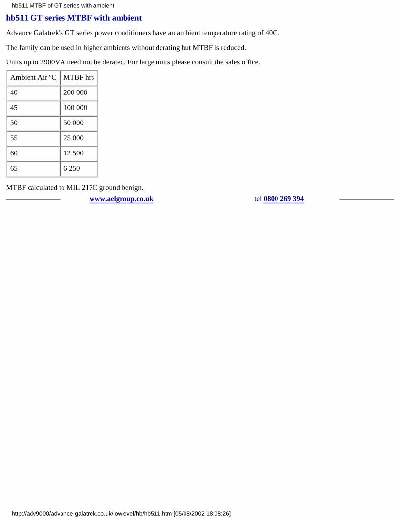
hb511 GT series MTBF with ambient
Advance Galatrek's GT series power conditioners have an ambient temperature rating of 40C.
The family can be used in higher ambients without derating but MTBF is reduced.
Units up to 2900VA need not be derated. For large units please consult the sales office.
Ambient Air ºC MTBF hrs
40 200 000
45 100 000
50 50 000
55 25 000
60 12 500
65 6 250
MTBF calculated to MIL 217C ground benign.
www.aelgroup.co.uk tel 0800 269 394
hb511 MTBF of GT series with ambient
http://adv9000/advance-galatrek.co.uk/lowlevel/hb/hb511.htm [05/08/2002 18:08:26]

hb563 Preventative Maintenance Checklist
Job# Customer
Model# Engineer
Serial# Date
Check that the customer does not have any problems or questions concerning the UPS.
Surrounding Environment
Bypass OK Needs Attention Not Applicable
Switch Fitted?
Condition
Operation
Terminal Tightness
Check auto bypass operation (if fitted)
UPS OK Needs Attention Not Applicable
Clean Fans and Ventilation Slots
Check Fan Operation
Internal Condition
Clean Boards
Check Wiring and PCBs for signs of heat damage and wear
Check that all connections are tight
Check that all earth points are tight
Check that any oil filled capacitors are not leaking
Check for old blue type capacitors change as necessary andremove thermal fuses
Check I/O voltage and battery voltage for calibration
Check that any internal/external chargers are functioningcorrectly
Batteries (Internal and External) OK Needs Attention Not Applicable
Check battery terminals for corrosion and tightness
Before load testing check battery float voltage
Load test UPS 100% and check battery
During battery discharge check dc current calibration
Check battery charge current
Logs OK Needs Attention Not Applicable
Check inverter logs for errors
hb563 Preventative maintenance checklist
http://adv9000/advance-galatrek.co.uk/lowlevel/hb/hb563.htm (1 of 2) [05/08/2002 18:08:26]
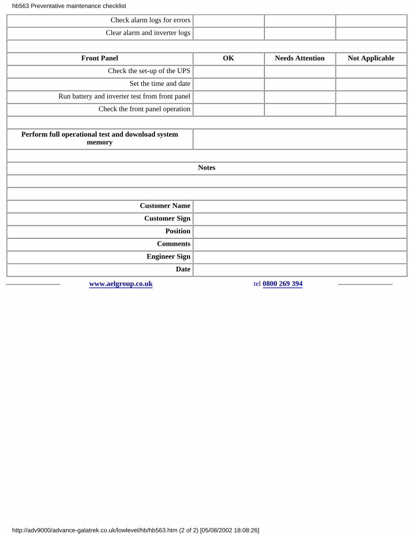
Check alarm logs for errors
Clear alarm and inverter logs
Front Panel OK Needs Attention Not Applicable
Check the set-up of the UPS
Set the time and date
Run battery and inverter test from front panel
Check the front panel operation
Perform full operational test and download systemmemory
Notes
Customer Name
Customer Sign
Position
Comments
Engineer Sign
Date
www.aelgroup.co.uk tel 0800 269 394
hb563 Preventative maintenance checklist
http://adv9000/advance-galatrek.co.uk/lowlevel/hb/hb563.htm (2 of 2) [05/08/2002 18:08:26]

sb072 UPS ideal customer - top ten actions
Introduction:Occasionally we are asked by companies who are unfamiliar with the application of UPS products to help with planning a newinstallation
This list of headings is a 'top ten' of considerations for a new installation:
1 Consider the whole picturethere is no point in making the computer or telephone switch operate when the lights are out the main ISDN is down or some localnetwork hub just went off with the mains power
2 Select the right topology UPSthere is a wide range of prices for any size of UPS ensure that you select the right variation for the application
3 Fit a bypassall electronic boxes fail at some time all batteries need replacing eventually. The correct bypass switch (auto or manual) protects thesystem the UPS and gives a genuine choice of power when all goes wrong! Maintenance can also be carried out during workinghours.
4 Install + commission the system properlyuse a qualified contractor - meet the current regulations - prove protection discrimination - get right size cables fitteduse a competent agent to demonstrate the unit functions properly and get the site signed off for safety + integrity
5 Plan maintenanceestablish a routine for battery discharge testing in REAL load situations to ensure an adequate capacity is available new batteries willbe fitted in time and NOT before necessaryif necessary clean fans
6 Buy a maintenance contractcontrol cost of ownership and ensure a fast response in times of need using a standard plan
7 Fit a status panelthere are low cost status monitoring boxes to enable you to keep an eye on the health of the UPS
8 Use the softwareif the mains fails at 7pm and the battery autonomy is only 4 hours the system should shut down the load long before the battery isuseless so that some options are available when power is needed the next day for business.UNIX and similar operating platforms REQUIRE orderly shutdown to avoid cost downtime during the rebuilding of a File System
9 Hook up to a national monitoring serviceif you need real protection get the supplier to monitor the UPS from his heavily protected national resource the service engineer maybe knocking on your door before you know you have a problem!
10 Read the manualat least TWO members of staff should be familiar with the usually simple external UPS controls and/or the bypass operation
www.aelgroup.co.uk tel 0800 269 394
hb572 customer actions - top 10
http://adv9000/advance-galatrek.co.uk/lowlevel/hb/hb572.htm [05/08/2002 18:08:26]
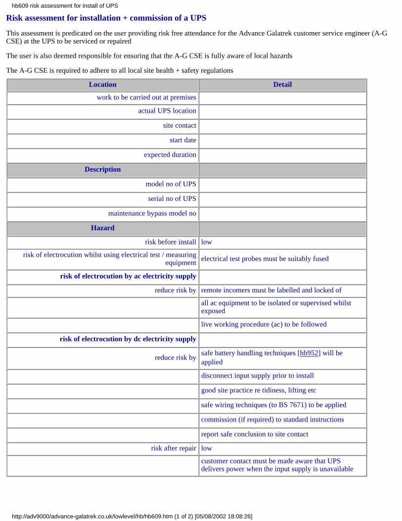
Risk assessment for installation + commission of a UPS
This assessment is predicated on the user providing risk free attendance for the Advance Galatrek customer service engineer (A-GCSE) at the UPS to be serviced or repaired
The user is also deemed responsible for ensuring that the A-G CSE is fully aware of local hazards
The A-G CSE is required to adhere to all local site health + safety regulations
Location Detail
work to be carried out at premises
actual UPS location
site contact
start date
expected duration
Description
model no of UPS
serial no of UPS
maintenance bypass model no
Hazard
risk before install low
risk of electrocution whilst using electrical test / measuringequipment electrical test probes must be suitably fused
risk of electrocution by ac electricity supply
reduce risk by remote incomers must be labelled and locked of
all ac equipment to be isolated or supervised whilstexposed
live working procedure (ac) to be followed
risk of electrocution by dc electricity supply
reduce risk bysafe battery handling techniques [hb952] will beapplied
disconnect input supply prior to install
good site practice re tidiness, lifting etc
safe wiring techniques (to BS 7671) to be applied
commission (if required) to standard instructions
report safe conclusion to site contact
risk after repair low
customer contact must be made aware that UPSdelivers power when the input supply is unavailable
hb609 risk assessment for install of UPS
http://adv9000/advance-galatrek.co.uk/lowlevel/hb/hb609.htm (1 of 2) [05/08/2002 18:08:26]

www.aelgroup.co.uk tel 0800 269 394
hb609 risk assessment for install of UPS
http://adv9000/advance-galatrek.co.uk/lowlevel/hb/hb609.htm (2 of 2) [05/08/2002 18:08:26]
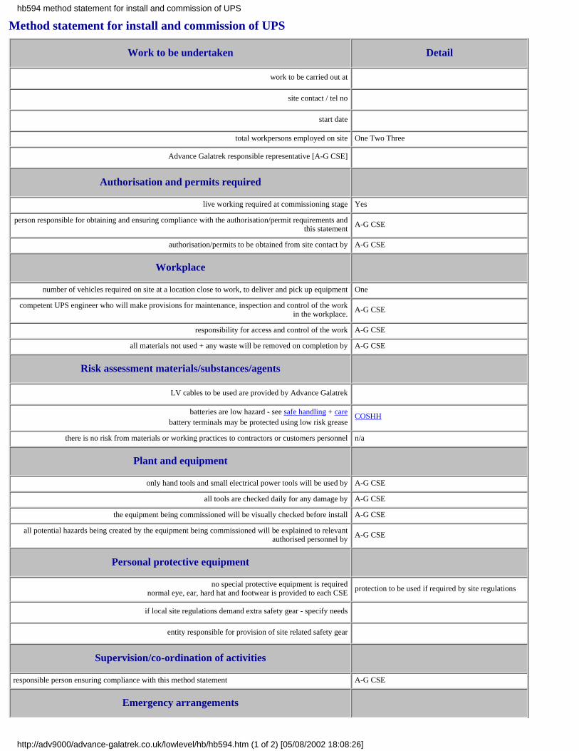
Method statement for install and commission of UPS
Work to be undertaken Detail
work to be carried out at
site contact / tel no
start date
total workpersons employed on site One Two Three
Advance Galatrek responsible representative [A-G CSE]
Authorisation and permits required
live working required at commissioning stage Yes
person responsible for obtaining and ensuring compliance with the authorisation/permit requirements andthis statement A-G CSE
authorisation/permits to be obtained from site contact by A-G CSE
Workplace
number of vehicles required on site at a location close to work, to deliver and pick up equipment One
competent UPS engineer who will make provisions for maintenance, inspection and control of the workin the workplace. A-G CSE
responsibility for access and control of the work A-G CSE
all materials not used + any waste will be removed on completion by A-G CSE
Risk assessment materials/substances/agents
LV cables to be used are provided by Advance Galatrek
batteries are low hazard - see safe handling + carebattery terminals may be protected using low risk grease
COSHH
there is no risk from materials or working practices to contractors or customers personnel n/a
Plant and equipment
only hand tools and small electrical power tools will be used by A-G CSE
all tools are checked daily for any damage by A-G CSE
the equipment being commissioned will be visually checked before install A-G CSE
all potential hazards being created by the equipment being commissioned will be explained to relevantauthorised personnel by A-G CSE
Personal protective equipment
no special protective equipment is requirednormal eye, ear, hard hat and footwear is provided to each CSE protection to be used if required by site regulations
if local site regulations demand extra safety gear - specify needs
entity responsible for provision of site related safety gear
Supervision/co-ordination of activities
responsible person ensuring compliance with this method statement A-G CSE
Emergency arrangements
hb594 method statement for install and commission of UPS
http://adv9000/advance-galatrek.co.uk/lowlevel/hb/hb594.htm (1 of 2) [05/08/2002 18:08:26]

engineer to be informed by site contact of any procedure to be taken in the event of a local emergency A-G CSE
no emergency procedures are required by the work being carried out by the UPS engineer n/a
dry powder fire extinguisher is part of the kit being used in the event of a small fire created by the workbeing carried out n/a
Training and instruction
user manuals n/a
all personnel undertaking the work are trained to manufacturer's standards and are aware of all UPSrelated risk n/a
no training instruction is required by site staff on the safety aspect of the work n/a
Work procedures
equipment will be subject to a visual inspection by A-G CSE
adherence to Advance Galatrek installation instructions ensured by A-G CSE
compliance to current LV wiring regulations ensured by A-G CSE
mains power will be applied to unit and tests carried out to ensure correct operation by A-G CSE
operating parameters will be adjusted if needed by A-G CSE
external equipment will be tested by A-G CSE
mains failure test, bypass test and load test will be carried out by A-G CSE
basic operation training of essential personnel will be carried out by A-G CSE
finally the customers load, if available, will be connected to the output to complete the commissioning A-G CSE
www.aelgroup.co.uk tel 0800 269 394
hb594 method statement for install and commission of UPS
http://adv9000/advance-galatrek.co.uk/lowlevel/hb/hb594.htm (2 of 2) [05/08/2002 18:08:26]

Method statement for repair of UPS
Work to be undertaken Detail
work to be carried out at
site contact / tel no
start date
total workpersons employed on site One / Two / Three
Advance Galatrek responsible representative [A-G CSE]
Authorisation and permits required
live working required at re-commissioning stage Yes
person responsible for obtaining and ensuring compliance with the authorisation/permit requirements andthis statement A-G CSE
authorisation/permits to be obtained from site contact by A-G CSE
Workplace
number of vehicles required on site at a location close to work to deliver and pick up equipment One
competent UPS engineer who will make provisions for maintenance inspection and control of the work inthe workplace. A-G CSE
responsibility for access and control of the work A-G CSE
all materials not used + any waste will be removed on completion by A-G CSE
Risk assessment materials/substances/agents
spare parts to be used are provided by Advance Galatrek
batteries are low hazard - see safe handling + carebattery terminals may be protected using low risk grease
COSHH
there is no risk from materials or working practices to contractors or customers personnel n/a
Plant and equipment
only hand tools and small electrical power tools will be used by A-G CSE
all tools are checked daily for any damage by A-G CSE
the equipment being commissioned will be visually checked before install A-G CSE
all potential hazard being created by the equipment being commissioned will be explained to the relevantauthorised personnel by A-G CSE
Personal protective equipment
no special protective equipment is required apart from normal eye and ear n/a
Advance Galatrek is responsible for the provision of such equipment n/a
Supervision/co-ordination of activities
responsible person ensuring compliance with this method statement A-G CSE
Emergency arrangements
engineer to be informed by site contact of any procedure to be taken in the event of a local emergency A-G CSE
no emergency procedures are required by the work being carried out by the UPS engineer n/a
dry powder fire extinguisher is part of the kit being used in the event of a small fire created by the workbeing carried out n/a
Training and instruction
user manuals n/a
hb607 method statement for fault-find + repair of UPS
http://adv9000/advance-galatrek.co.uk/lowlevel/hb/hb607.htm (1 of 2) [05/08/2002 18:08:27]
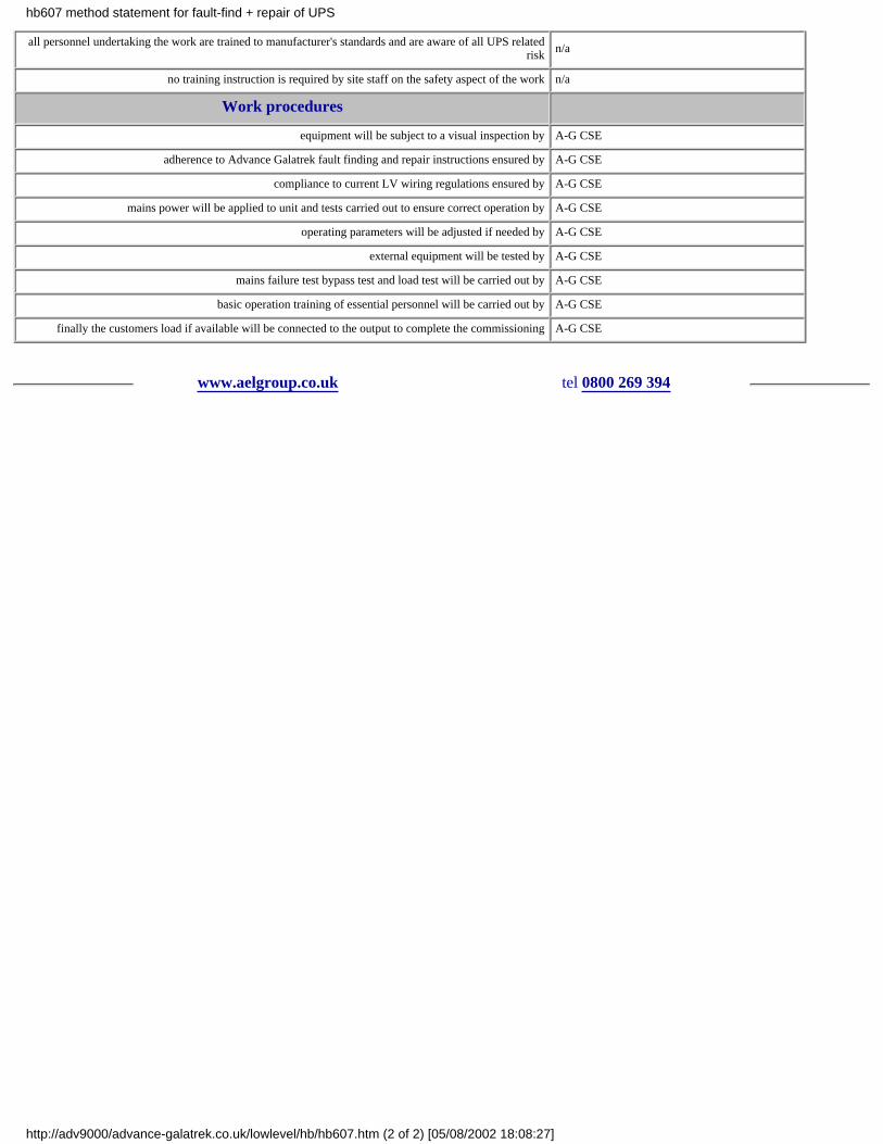
all personnel undertaking the work are trained to manufacturer's standards and are aware of all UPS relatedrisk n/a
no training instruction is required by site staff on the safety aspect of the work n/a
Work procedures
equipment will be subject to a visual inspection by A-G CSE
adherence to Advance Galatrek fault finding and repair instructions ensured by A-G CSE
compliance to current LV wiring regulations ensured by A-G CSE
mains power will be applied to unit and tests carried out to ensure correct operation by A-G CSE
operating parameters will be adjusted if needed by A-G CSE
external equipment will be tested by A-G CSE
mains failure test bypass test and load test will be carried out by A-G CSE
basic operation training of essential personnel will be carried out by A-G CSE
finally the customers load if available will be connected to the output to complete the commissioning A-G CSE
www.aelgroup.co.uk tel 0800 269 394
hb607 method statement for fault-find + repair of UPS
http://adv9000/advance-galatrek.co.uk/lowlevel/hb/hb607.htm (2 of 2) [05/08/2002 18:08:27]

Risk assessment for service or repair of a UPS
This assessment is predicated on the user providing risk free attendance for the Advance Galatrek customer service engineer (A-GCSE) at the UPS to be serviced or repaired
The user is also deemed responsible for ensuring that the A-G CSE is fully aware of local hazards
The A-G CSE is required to adhere to all local site health + safety regulations
Location Detail
work to be carried out at premises
actual UPS location
site contact
start date
expected duration
Description
model no of UPS
serial no of UPS
reported problem
maintenance bypass fitted
Hazard
risk before repair low
risk of electrocution by ac electricity supply if no bypass switch - load to be disconnected
all ac equipment to be isolated or supervised whilst exposed
remote incomers must be labelled and locked off
risk of electrocution by dc electricity supply safe battery handling techniques will be applied
reduce risk by disconnect input supply prior to service/repair
disable output inverter
safe repair techniques will be applied
re-connect in controlled sequence
report safe conclusion to site contact
risk after repair low
www.aelgroup.co.uk tel 0800 269 394
hb608 risk assessment for fault-find + repair of UPS
http://adv9000/advance-galatrek.co.uk/lowlevel/hb/hb608.htm [05/08/2002 18:08:27]

hb712 Description Of Operation - Elite UPS
Elite is an on-line Uninterruptible Power System (UPS) with an automatic bypass in case of system fault or overload condition.The input to the UPS incorporates a back feed isolator fuse protection and mains filter.
Mains operationThe filter prevents the UPS from polluting the mains supply with electromagnetic interference generated during normal UPSoperation. The output from the filter is fed into the converter.
ConverterThe converter generates two dc voltage levels from the ac mains supply. The first supplies the automatic battery charger.
Battery chargerThe battery charger maintains the dc level of the battery. The output from the battery powers the inverter.
BatteryThe internal battery is a sealed lead acid maintenance free battery.The battery runtime can be increased through the addition of 'Plug And Play' battery extensions.
BoosterThe booster increases the dc voltage of the battery supply to the higher level required by the inverter.
InverterThe Inverter draws its dc from either the converter (when mains is present) or the booster and inverts this into an ac electrical supply.A pure sine-wave is generated.The output from the inverter supplies the load through an output filter to remove any electromagnetic interference generated duringnormal UPS operation.
Mains failure or poor mainsIf the mains fails or the present voltage and/or frequency falls outside the set design parameters of the UPS the microprocessor willautomatically direct the constantly running inverter to draw its dc from the battery via the booster.
Overload or fault conditionThe static bypass automatically monitors the output voltage of the UPS.Should an overload condition occur or the UPS develop and internal fault the bypass automatically transfers the load to the mains.The raw mains is filtered by the input and output EMI filters.
Battery extension packs
hb712 Elite Operation
http://adv9000/advance-galatrek.co.uk/lowlevel/hb/hb712.htm (1 of 2) [05/08/2002 18:08:27]

The inverter is rated to supply its full rated capacity continuously. Using additional battery extension packs a standard runtime of 10minutes can be extended to over 7 hours.
19" Rackmount OptionAll models are available in 19" rackmount format with either internal batteries or additional matching battery trays.
Frequency conversionThe on-line topology of an Elite UPS allows the UPS to perform as a frequency converter 50 to 60Hz and 60 to 50Hz.
Additional Considerations:Maintenance BypassInstallation of a maintenance bypass removes the need to power down the load during routine maintenance or capacity upgrade of anUninterruptible Power System (UPS).A maintenance bypass may be hardwired or 'Plug And Play'.
Other relevant topicsThe bulletins listed below may also be relevant:hb702 Why install a maintenance bypass?Warranty periods and emergency callshb708 'Plug and Play' battery packshb709 UPS battery recharge times
www.aelgroup.co.uk tel 0800 269 394
hb712 Elite Operation
http://adv9000/advance-galatrek.co.uk/lowlevel/hb/hb712.htm (2 of 2) [05/08/2002 18:08:27]

hb756 Generators driving UPS
Sophisticated ICT systems sometimes use local engine driven generators for backup in case of mains failure
Some modern small UPS boxes are designed to operate primarily from traditional mains supplies and some care should be takenwhen operating them from a small generator
These notes provide some guidance on the potential problems which can be met together with suggested practice
Size of generatorThe average modern UPS need a much larger generator than one might expect. Allowance must be made for re-charging thebatteries as well as providing full load and the effects of UPS efficiency.
Typically Advance Galatrek recommends a generator capable of delivering at least TWICE the output power of the UPS howeversome generator manufacturers quote unrealistic performance specifications and it is best to check with our engineering team.
In addition some UPS input circuits have high crest factors and generator control circuits cannot handle them.
The Master Elite range of UPS has a specially developed input filter for use with generators and other sensitive sources.
NeutralSome generators do not refer the low side of the output to earth. This MUST be `tied down' to avoid possible damage to the UPS
Care must also be taken that the generator neutral is connected to the UPS input `low'
Conventional mains phasing is expected by the UPS and the generator should be wired through to the UPS input in the normal way
FrequencyThe generator must run close to 50 Hz for the unit to operate correctly if the frequency goes outside the UPS operating window itwill operate from the UPS battery which will not be re-charged
Electrical noiseSome medium sized generators may be connected to other loads. In this case care must be taken to ensure that the other loads do notcreate excessive spikes or other electrical noise
The generator exhibits a much higher impedance than a conventional mains supply. Noise from triac controlled motors etc. mayaffect the UPS rather than just disappear in the distribution system
Clearly any generator which is not brushless may also cause a similar problem
A generator providing a clean waveform with a reasonably stable frequency and voltage correctly connected only to the UPS is themost attractive arrangement
SafetySome thought needs to be given to the Regulations regarding out of phase supplies in the same work area
www.aelgroup.co.uk tel 0800 269 394
hb756 generators with UPS
http://adv9000/advance-galatrek.co.uk/lowlevel/hb/hb756.htm [05/08/2002 18:08:27]

hb708UPS Plug 'n Play battery packs
An Uninterruptible Power System (UPS) typically has a standard runtime of 10 minutes.
This can normally be extended through the addition of extra battery extension packs for critical computer and telecommunicationsapplications.
Battery extension packs
IntroductionMost of our UPS product is supplied with an internal battery pack to permit a minimum `run-time' performance.(Occasionally a unit may be supplied without batteries when customers have their own dc supply)
Run times + Battery sizingIt should be appreciated that batteries come in a range of fixed sizes and UPS products usually only work from one dc voltage
This means that if the required performance cannot be achieved with a certain battery configuration the next size up must beselected. Sometimes it is worthwhile reviewing the expected run-time using the smaller battery since it will provide a moreeconomical solution and may only miss the target by a few minutes
Performance with actual running loadAll our published run times are based on using the UPS at full load and with fresh batteries. A significant extra run-time will resultfrom operating the UPS at less than full load. This should encourage some users to consider having non-critical parts of the loadautomatically disconnected when the mains fails
Battery performance with lifeModern lead-acid sealed gel-cell batteries offer excellent performance. However the environment in which they are operated canseriously influence performance. Care should be taken to keep all batteries at or near to 20-25 deg C.
Battery safetyFor more information see battery handling and safe disposal.
The increased battery capacity can extend a UPS battery runtime up to 7 or more hours. When deciding which UPS to choose theuser needs to consider whether the battery packs are internal external ‘Hardwired’ or external ‘Plug and Play’.
External batteries ‘hardwired’
For longer runtimes additional battery cabinets need to be purchased to house the extra batteries and associated chargers. If the extracabinets require a hardwired final connection to the UPS this should be performed by a suitably electrically qualified person. Thebatteries may have also been despatched to site on a pallet and may require building into the cabinet. The complete system is notuser commissionable.
External batteries ‘Plug and Play’
The latest approach for UPS up to 3kVA is to supply battery cabinets to site with the batteries (and chargers if applicable) alreadyassembled inside the battery cabinet. Standard connector cables supplied with the battery cabinet simply plug directly into the UPS.Where an additional charger is fitted to the battery cabinet the battery cabinet may also require plugging in to a standard mainssupply. The system is classified as user commissionable.
Customer benefits
The supply of ‘Plug and Play’ battery extension packs simplifies logistics to the customer and reduces on-site installation costs.Deliveries to site may be quicker and the user can install and turn on the system in a matter of minutes. Using the ‘Plug and Play’approach and the facility to cascade multiple battery extension packs additional runtime can be purchased and installed at a laterdate.
Maintenance bypass
A maintenance bypass allows the UPS to be health checked or upgraded without interruption to the load. It allows work to be carriedout during normal working hours and should be an integral feature of any extended runtime application.
UPS Battery Recharge Times
hb708 Plug 'n Play battery packs
http://adv9000/advance-galatrek.co.uk/lowlevel/hb/hb708.htm (1 of 3) [05/08/2002 18:08:27]

Most Uninterruptible Power Systems (UPS) are only designed for short duration runtimes up to 10 minutesTheir internal battery chargers are sized to provide a recharge time to a set capacity such as 80% within 10 hours
Battery ExtensionsThe standard UPS runtime can be extended with additional internal and external battery packsTo maintain price competitiveness some UPS manufacturers rely on the UPS internal charger to recharge the extended batterycapacity
Recharge TimeWhere the battery capacity is increased the standard quoted specification of 'recharge time to 80% of capacity within 10 hours'rapidly increasesSome competitors UPS have been found with a recharge time of 50 hours (i.e. over 2 days) on a 7 hour system
Mains FailuresUnfortunately the erratic nature of mains failures is such that long duration failures are usually followed by frequent interruptionswhilst the electrical supply fault is correctedUnder these conditions UPS installed with extra runtime packs without the benefit of extra chargers will almost certainly switch offdue to low batteryThe UPS will not have been provided with mains power for sufficiently long enough to recharge the battery
Recharge Time CalculationA simple way to calculate the recharge time of the system quoted is to ask the UPS supplier for the Ampere hour (Ah) rating of thebattery pack and the Amperage (A) of the chargerThe calculation: Ah/A will provide a fast estimate of the time to recharge the battery to 80% capacity.As battery recharge is a non-linear function the calculation can only be used as a guideline
Using the Standard UPS chargerUsing only the standard UPS internal charger with an increased battery capacity the UPS struggles to recharge the batteryThe UPS eventually recharges its battery within 50 clock hours
Fast recharge optionWhen the application demands a faster re-charge larger modules can usually be fitted to customer bespoke requirements
UPS battery information
General
UPS batteries come in a variety of types. Most are selected for cost effectiveness. They are also dangerous! See safe batteryhandling.
In the case of larger systems batteries are selected for runtimes which are usually only slightly longer than the expected needconsistent with just meeting the requirements of back-up time at the end of life.
The UPS requires a fixed nominal battery voltage and to make up the overall capacity the batteries are supplied in a `string' ofstandard batteries each of which is also a standard size.This means that the total battery stack is built up from fixed size modules.The result of this arrangement is that there may be quite a discrepancy between perceived need and actual runtimes when the lowestcost set of batteries is selected.Advance Galatrek will occasionally indicate that a customer specified run-time of 30 minutes may require a 48-minute set ofbatteries whereas if the customer can accept 28 minutes then the smaller stack may be suitable.
This situation may be made more complicated if the customer VA load is in between UPS sizes and the autonomy time has to becalculated at less than full load.
Batteries decay with time.Batteries usually reach their specified capacity after several discharge/recharge cycles when new.Batteries will exhibit different life performance dependent on discharge rate depth and number of times actually used.Batteries are extremely sensitive to average operating ambient temperature and worst case extremes of temperature.Batteries used in strings will decay at different rates.
Advance Galatrek has to make an evaluation of the operating conditions and expected service before selecting cells for a particularservice.
hb708 Plug 'n Play battery packs
http://adv9000/advance-galatrek.co.uk/lowlevel/hb/hb708.htm (2 of 3) [05/08/2002 18:08:27]

Our recommendation is that any particular battery pack should be tested at installation for satisfactory performance.
Several discharge cycles may be needed to prove that the batteries can deliver the required autonomy (and some margin) if thebatteries are new. The normal practice is to time the discharge to the low battery alarm for each run. As each successive re-chargeoccurs the runtime will increase a little and then top out to a best value.
Particular attention should be paid to ensuring that dummy loads really are directly equivalent to the anticipated service load.
Environmental considerations will affect the run time over its life time. Standard Valve Regulated Lead Acid (VRLA) cells aredesigned for optimum performance at temperatures of 15-25 degrees Celsius. Most manufacturers produce five or ten year life cells.These lifetimes describe expected service life under idle conditions and reasonable cyclic rate.
As a rule of thumb for every five degrees over 25 Celsius the battery life will HALVE. This means that at temperatures above 40degrees the BEST expected lifetime is 8 months.
At the end of a batteries life it is important to dispose of it with regard to the local regulations
www.aelgroup.co.uk tel 0800 269 394
hb708 Plug 'n Play battery packs
http://adv9000/advance-galatrek.co.uk/lowlevel/hb/hb708.htm (3 of 3) [05/08/2002 18:08:27]

www.aelgroup.co.uk tel 0800 269 394
hb709 battery recharge times
http://adv9000/advance-galatrek.co.uk/lowlevel/hb/hb709.htm [05/08/2002 18:08:27]

hb725UPS overloads
IntroductionModern UPS products are designed to cope with overloads.
An overload can take one of several forms and current electronic solutions to limit system damage are based on simple principles.
The UPS is being overloaded if the load power demand is greater than the rating of the UPS.
The problemAn overload may happen quickly or slowly increase above the rating of the UPS. Inside the UPS there are current switching deviceswhich can cope with minor overloads for a considerable time until they become too hot. These switches will be damaged almostinstantaneously by currents way in excess of their rating.
It is commonplace to find overloads of 125% or 150% of rating being allowed by the electronics for some seconds or even minutes.However larger overloads for example 10x rating require faster action by the electronics.
Most users do not realise that some modern electronic power supplies take large currents when first powered up. It is not unusual fora small computer such as a PC controlling a process plant to be on 24/7. The operator may well choose to switch off the monitorduring the night when no-one is looking at it - either to save power or increase monitor life.
In the morning when the operator returns and switches on the monitor which normally consumes only about 50 watts the switch onsurge has a power equivalent of maybe 10000 watts albeit only for one thousandth of a second.
The solutionThis load would typically destroy the UPS and the normal solution is to detect the overload and divert it around the UPS. This isachieved entirely automatically by a small switch which quickly connects the load directly back to the mains until the overloaddisappears. This switch is called a `bypass'.
Application difficultiesSo far so good.The UPS happily protects itself and each morning when the monitor is switched on momentarily switches the load back to mains andreverts to the battery supply a very short time later.
During a power outage this option becomes unavailable. The UPS must NOT be overloaded during battery operation when the mainsis not present. If an overload occurs the UPS will protect itself and sadly drop the critical load because it has no power source for theoverload.
This problem can really only be managed by knowledge and discipline unless further investment is made (which is usually quitesubstantial) to overcome it.
www.aelgroup.co.uk tel 0800 269 394
hb725 UPS overloads
http://adv9000/advance-galatrek.co.uk/lowlevel/hb/hb725.htm [05/08/2002 18:08:28]
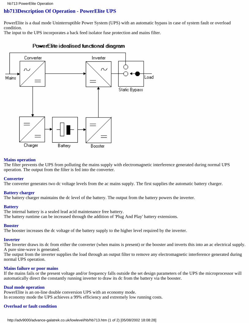
hb713Description Of Operation - PowerElite UPS
PowerElite is a dual mode Uninterruptible Power System (UPS) with an automatic bypass in case of system fault or overloadcondition.The input to the UPS incorporates a back feed isolator fuse protection and mains filter.
Mains operationThe filter prevents the UPS from polluting the mains supply with electromagnetic interference generated during normal UPSoperation. The output from the filter is fed into the converter.
ConverterThe converter generates two dc voltage levels from the ac mains supply. The first supplies the automatic battery charger.
Battery chargerThe battery charger maintains the dc level of the battery. The output from the battery powers the inverter.
BatteryThe internal battery is a sealed lead acid maintenance free battery.The battery runtime can be increased through the addition of 'Plug And Play' battery extensions.
BoosterThe booster increases the dc voltage of the battery supply to the higher level required by the inverter.
InverterThe Inverter draws its dc from either the converter (when mains is present) or the booster and inverts this into an ac electrical supply.A pure sine-wave is generated.The output from the inverter supplies the load through an output filter to remove any electromagnetic interference generated duringnormal UPS operation.
Mains failure or poor mainsIf the mains fails or the present voltage and/or frequency falls outside the set design parameters of the UPS the microprocessor willautomatically direct the constantly running inverter to draw its dc from the battery via the booster.
Dual mode operationPowerElite is an on-line double conversion UPS with an economy mode.In economy mode the UPS achieves a 99% efficiency and extremely low running costs.
Overload or fault condition
hb713 PowerElite Operation
http://adv9000/advance-galatrek.co.uk/lowlevel/hb/hb713.htm (1 of 2) [05/08/2002 18:08:28]

The static bypass automatically monitors the output voltage of the UPS.Should an overload condition occur or the UPS develop and internal fault the bypass automatically transfers the load to the mains.The raw mains is filtered by the input and output EMI filters.
Battery extension packsThe inverter is rated to supply its full rated capacity continuously. Using additional battery extension packs a standard runtime of 10minutes can be extended to over 7 hours.
Frequency conversionThe on-line topology of a PowerElite UPS allows the UPS to perform as a frequency converter 50 to 60Hz and 60 to 50Hz.
Additional Considerations:Maintenance BypassInstallation of a maintenance bypass removes the need to power down the load during routine maintenance or capacity upgrade of anUninterruptible Power System (UPS).A maintenance bypass may be hardwired or 'Plug And Play'.
Other relevant topicsThe bulletins listed below may also be relevant:hb702 Why install a maintenance bypass?Warranty periods and emergency callshb708 'Plug and Play' battery packshb709 UPS battery recharge times
www.aelgroup.co.uk tel 0800 269 394
hb713 PowerElite Operation
http://adv9000/advance-galatrek.co.uk/lowlevel/hb/hb713.htm (2 of 2) [05/08/2002 18:08:28]

hb720UPS Monitoring and remote interfacing
Modern Uninterruptible Power System (UPS) installations normally include some form of remote UPS monitoring and control.
The communication method may rely on RS232 communications or simple volt-free contact signals.
RS232 communications
This communication method provides access to the ‘intelligent’ microprocessor features of the UPS. As well as warning when theUPS changes operating condition it can also provide a wealth of operating information. The communication method requires a cableconnection between the UPS and the remote computer system. The remote computer system can be by the side of the UPS in thenext room building or on the other side of the world. To access the UPS and achieve communications the computer system requires aversion of the UPS monitoring and control package PowerShield compatible with its operating platform e.g. Windows Novell Unixetc.
PowerShield software
PowerShield is supplied on a CD-ROM. The software package contains versions of PowerShield for the various Galatrek UPS andmajor operation systems. The software package allows the user to interrogate the UPS and retrieve current real time informationstore historical information for further analysis and instigate self test routines. The software package can also be configured to closedown the computer system in an orderly manner when the UPS approaches a low battery condition. Galatrek can offer cablesmanufactured to specific custom requirements.
Multiple communications
Galatrek supply a range of Multi User Interfaces (MUIs) to allow a single Galatrek UPS to communicate with multiple operatingplatforms. A single cable connects the UPS to the MUI. The MUI is connected to each protected computer system. A version ofPowerShield is installed on each computer system.
SNMP - Simple Network Management Protocol
PowerShield also provides SNMP protocols and Management Information Bases (MIBs) to allow the UPS to become a networkmanaged node on the network.
Volt-free contact signals
This is the traditional form of communication commonly used by basic UPS monitoring and shutdown packages such as PowerMon.Signal contacts provide a low dc voltage when the UPS changes operating condition. Contacts are normally provided for mains failbattery low and UPS alarm. The volt-free contact method of communication allows a UPS to be interfaced into a BuildingManagement System (BMS) or other security alarm monitoring system. Galatrek can offer cables manufactured to specific customrequirements.
Emergency power off (EPO)
Galatrek UPS normally incorporate an EPO. shutdown contact. This allows the UPS to be connected into a central EPO. switch foremergency shutdown. Galatrek can offer cables manufactured to specific custom requirements.
Remote Modem Interface
Both the RS232 and volt-free contact communication methods can be used to provide remote indication of alarms conditions. Onlythe RS232 method allows two-way communication and access to the ‘intelligent’ microprocessor features. Certain Galatrek UPS canalso be programmed to dial up pagers when an alarm condition occurs. For each UPS with this facility please check which make andversion of modem Galatrek recommend.
www.aelgroup.co.uk tel 0800 269 394
hb720 UPS monitoring and remote interfacing
http://adv9000/advance-galatrek.co.uk/lowlevel/hb/hb720.htm [05/08/2002 18:08:28]
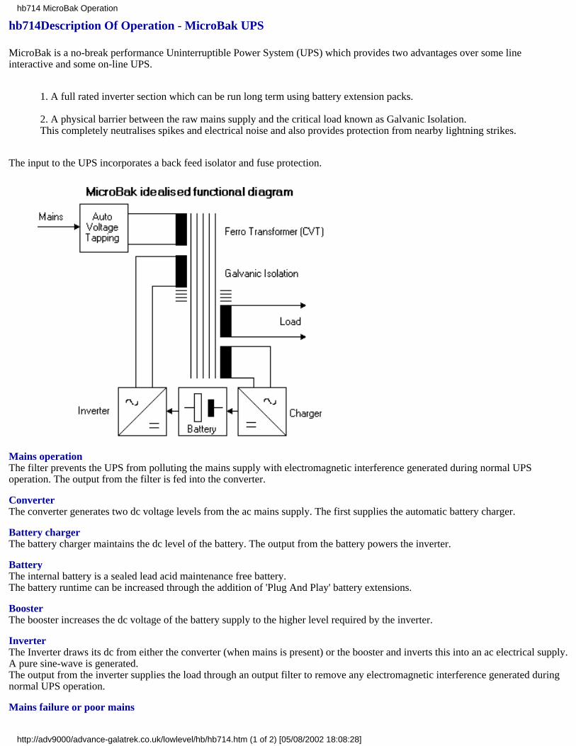
hb714Description Of Operation - MicroBak UPS
MicroBak is a no-break performance Uninterruptible Power System (UPS) which provides two advantages over some lineinteractive and some on-line UPS.
1. A full rated inverter section which can be run long term using battery extension packs.
2. A physical barrier between the raw mains supply and the critical load known as Galvanic Isolation.This completely neutralises spikes and electrical noise and also provides protection from nearby lightning strikes.
The input to the UPS incorporates a back feed isolator and fuse protection.
Mains operationThe filter prevents the UPS from polluting the mains supply with electromagnetic interference generated during normal UPSoperation. The output from the filter is fed into the converter.
ConverterThe converter generates two dc voltage levels from the ac mains supply. The first supplies the automatic battery charger.
Battery chargerThe battery charger maintains the dc level of the battery. The output from the battery powers the inverter.
BatteryThe internal battery is a sealed lead acid maintenance free battery.The battery runtime can be increased through the addition of 'Plug And Play' battery extensions.
BoosterThe booster increases the dc voltage of the battery supply to the higher level required by the inverter.
InverterThe Inverter draws its dc from either the converter (when mains is present) or the booster and inverts this into an ac electrical supply.A pure sine-wave is generated.The output from the inverter supplies the load through an output filter to remove any electromagnetic interference generated duringnormal UPS operation.
Mains failure or poor mains
hb714 MicroBak Operation
http://adv9000/advance-galatrek.co.uk/lowlevel/hb/hb714.htm (1 of 2) [05/08/2002 18:08:28]

If the mains fails or the present voltage and/or frequency falls outside the set design parameters of the UPS the microprocessor willautomatically direct the constantly running inverter to draw its dc from the battery via the booster.
Dual mode operationPowerElite is an on-line double conversion UPS with an economy mode.In economy mode the UPS achieves a 99% efficiency and extremely low running costs.
Overload or fault conditionThe static bypass automatically monitors the output voltage of the UPS.Should an overload condition occur or the UPS develop and internal fault the bypass automatically transfers the load to the mains.The raw mains is filtered by the input and output EMI filters.
Battery extension packsThe inverter is rated to supply its full rated capacity continuously. Using additional battery extension packs a standard runtime of 10minutes can be extended to over 7 hours.
Frequency conversionThe on-line topology of a PowerElite UPS allows the UPS to perform as a frequency converter 50 to 60Hz and 60 to 50Hz.
Additional Considerations:Maintenance BypassInstallation of a maintenance bypass removes the need to power down the load during routine maintenance or capacity upgrade of anUninterruptible Power System (UPS).A maintenance bypass may be hardwired or 'Plug And Play'.
Other relevant topicsThe bulletins listed below may also be relevant:hb702 Why install a maintenance bypass?Warranty periods and emergency callshb708 'Plug and Play' battery packshb709 UPS battery recharge times
www.aelgroup.co.uk tel 0800 269 394
hb714 MicroBak Operation
http://adv9000/advance-galatrek.co.uk/lowlevel/hb/hb714.htm (2 of 2) [05/08/2002 18:08:28]

hb726UPS bypass considerations
IntroductionMost users do not appreciate that there are several different kinds of UPS bypass. This note describes some of the variations andhighlights a common application problem.
The variationsLine interactive UPS usually just sit and wait for the mains power to go away and when it happens switch the critical load to thebattery supply. This means that overloads are supplied by the mains.
On more sophisticated products the critical load is supported by the battery and an internal bypass arrangement connects the load tothe mains for switch-on overload problems.
Advance Galatrek also recommends that an extra external manual bypass switch be installed to permit operation of the critical loadduring UPS maintenance.
On large UPS items (say 5kVA and above) it is quite common to find a maintenance bypass built into the unit. This is used fortesting and permits some system flexibility when doing battery tests etc. However we still recommend the use of an external bypass.
Application difficultiesIf the UPS is to automatically switch the critical load from bypass mains to battery supply then the two sources must be in phase. Ifthe mains supply has been interrupted the battery supply cannot know how to synchronise with the mains because it is not present. Ifthe maintenace bypass switch is operated during battery operation the critical load may see a supply which in the worst case can seea complete phase reversal. This is almost guaranteed to cause the load to be disrupted.
The solutionThis problem is solved by ensuring that only trained personnel operate a manual bypass switch. Advance Galatrek always labelsmanual bypass switch boxes with a warning not to operate it when the mains has failed.
It is important that responsible users differentiate between normal battery operation where the inverter and mains are synchronisedand the special case where the UPS is providing stand alone power.
Improving reliability in plug 'n play installationsAlmost all of the newer plug 'n play bypass boxes permit the entire UPS and maintenance bypass switch to be operated from a singleoutlet. We recommend that consideration is given to connecting the UPS mains supply and maintenance bypass switch to different inphase supplies. Ideally this is just a double 13A socket with one feeding the UPS and the other the bypass switch. With thisarrangement the critical load is no longer dependent on a single fuse. See also our pages on mission critical mission crucial andbypass schematics
www.aelgroup.co.uk tel 0800 269 394
hb726 bypass considerations
http://adv9000/advance-galatrek.co.uk/lowlevel/hb/hb726.htm [05/08/2002 18:08:28]
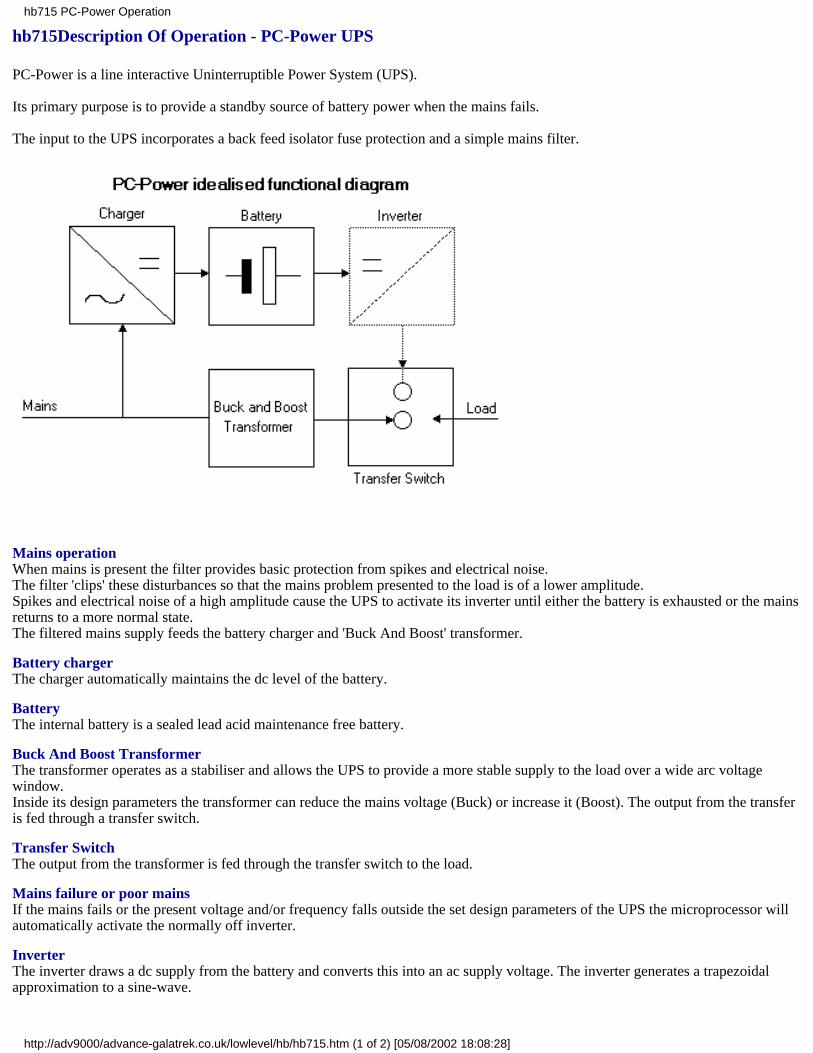
hb715Description Of Operation - PC-Power UPS
PC-Power is a line interactive Uninterruptible Power System (UPS).
Its primary purpose is to provide a standby source of battery power when the mains fails.
The input to the UPS incorporates a back feed isolator fuse protection and a simple mains filter.
Mains operationWhen mains is present the filter provides basic protection from spikes and electrical noise.The filter 'clips' these disturbances so that the mains problem presented to the load is of a lower amplitude.Spikes and electrical noise of a high amplitude cause the UPS to activate its inverter until either the battery is exhausted or the mainsreturns to a more normal state.The filtered mains supply feeds the battery charger and 'Buck And Boost' transformer.
Battery chargerThe charger automatically maintains the dc level of the battery.
BatteryThe internal battery is a sealed lead acid maintenance free battery.
Buck And Boost TransformerThe transformer operates as a stabiliser and allows the UPS to provide a more stable supply to the load over a wide arc voltagewindow.Inside its design parameters the transformer can reduce the mains voltage (Buck) or increase it (Boost). The output from the transferis fed through a transfer switch.
Transfer SwitchThe output from the transformer is fed through the transfer switch to the load.
Mains failure or poor mainsIf the mains fails or the present voltage and/or frequency falls outside the set design parameters of the UPS the microprocessor willautomatically activate the normally off inverter.
InverterThe inverter draws a dc supply from the battery and converts this into an ac supply voltage. The inverter generates a trapezoidalapproximation to a sine-wave.
hb715 PC-Power Operation
http://adv9000/advance-galatrek.co.uk/lowlevel/hb/hb715.htm (1 of 2) [05/08/2002 18:08:28]

The inverter output is fed into the transfer switch.
Transfer SwitchActivating the inverter and transfer of supply takes approximately 2-4ms. During this period the load is presented with a short breakin supply.The break can affect those loads which are sensitive to short millisecond breaks in supply.
www.aelgroup.co.uk tel 0800 269 394
hb715 PC-Power Operation
http://adv9000/advance-galatrek.co.uk/lowlevel/hb/hb715.htm (2 of 2) [05/08/2002 18:08:28]

hb716maintenance bypass schematics
IntroductionThere are several types of PowerSwitch bypasses available from Advance Galatrek
Manual simple maintenance switch
Automatic reverts to mains if UPS fails
Dual redundant for selecting between two in-phase supplies
Dual redundant used in `one fault tolerant' mode for mission crucial applications
HotSwitch for selecting between two out-of-phase supplies
Each logical schematic is shown in the `normal' mode
manual automatic
s1a and s1b are ganged wipers on a manual switchthe switch is MBB (make before break)
in bypass mode the UPS may be safely removedfrom the circuit
s1 is the same as the manual versionthe relay control detects the output voltage fromthe UPS.If the UPS output fails the Relay Control operatesthe two switches which connect the critical loadto the mains and the neon lights
Switches for more critical applications
dual redundant (DRS) hot switch
hb716 bypass schematics
http://adv9000/advance-galatrek.co.uk/lowlevel/hb/hb716.htm (1 of 2) [05/08/2002 18:08:29]
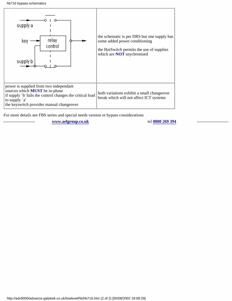
the schematic is per DRS but one supply hassome added power conditioning
the HotSwitch permits the use of supplieswhich are NOT snychronised
power is supplied from two independantsources which MUST be in-phaseif supply `b' fails the control changes the critical loadto supply `a'the keyswitch provides manual changeover
both variations exhibit a small changeoverbreak which will not affect ICT systems
For more details see FBS series and special needs version or bypass considerations
www.aelgroup.co.uk tel 0800 269 394
hb716 bypass schematics
http://adv9000/advance-galatrek.co.uk/lowlevel/hb/hb716.htm (2 of 2) [05/08/2002 18:08:29]

hb721 UPS mission critical installations
Installing an Uninterruptible Power System (UPS) can demand more than simply finding a space large enough in which to site it. Forcritical installations special considerations need to be given to the following areas:
Alarm ReportingIf the UPS is to be installed in a secure access room basement or confined environment consideration must be given to monitoring ofthe UPS’ status and alarms. Most UPS incorporate some form of system and battery testing to warn of potential problems prior to asystem failure. A UPS may seem to be performing normally but if the battery is very old it may only be capable of supplying 10% ofits originally installed capacity when new. The UPS will have raised an alarm condition that the battery needs to be checked orreplaced but this will be ignored if no remote monitoring is installed. A further complication can arise where the UPS has anautomatic system bypass. In this case the UPS may have failed due to a system overload or fault condition. The load will have beenautomatically transferred to an unprotected mains supply. To the UPS users the system will appear normal but the load will be atrisk. In either scenario only a mains failure highlights the fact that the UPS was actually in an alarm condition and was unable tosupport the load. It may have been operating for weeks in a near-to-fail or failed state.For critical applications the solution is to makeuse of the built-in communications port on the UPS. This normally provides both RS232 communications and signal contacts. Itallows the UPS to report changes in its operating status to a Building Management System (BMS) remote status panel or Local AreaNetwork (LAN). Failure to monitor the state of the UPS or to take advantage of automatic system and alarm reporting will seriouslyundermine the integrity of the UPS.
Ambient TemperatureMost UPS datasheets indicate that the UPS can work in ambient environments which range between 0 and 40°C. Such high ambientscan occur when the UPS is installed in a control panel or a small unventilated room. In such environments reliability problems willoccur. Most UPS will only work up to 40°C for short periods. If the UPS has not been designed and manufactured to workcontinuously inside such a temperature range users should assume that the actual expected ambient is nearer 25°C. At higherambients the UPS will almost certainly alarm and may shut itself down automatically to protect itself. Ambients above 25°C willalso dramatically reduce battery life by as much as 90%. For high ambient environments either choose a UPS designed for long termhigh ambient use or install forced air cooling.
Automatic System BypassOn-line UPS have an automatic bypass. This is a safety feature which allows the UPS to fail safely to mains without disrupting thesupply to the load. Such a transfer will occur when the UPS is overloaded to the extent that it cannot supply the requested capacity orit develops an internal fault condition. The load sees no break during the transfer.
Parallel RedundancyThe integrity of an on-line UPS installation can be further enhanced by installing two UPS in a parallel redundant configuration. Insuch a scenario each UPS is capable of supporting the full load should one of the UPS fail.
External Maintenance BypassA maintenance bypass allows the UPS to be manually bypassed. When activated the load is transferred from the output of the UPSto the raw mains. The load sees no break during the transfer from UPS to mains and vice versa. The process allows the UPS to beisolated for maintenance or simply swapped out. Whilst some UPS have a maintenance bypass built-into their design an externalwall mounted bypass is more practical. An external maintenance bypass allows the UPS to be fully isolated and switched off. It alsoallows the UPS to be physically replaced without disruption of supply to the load.
External Maintenance Bypass Supply ConditioningWhen powered through an external maintenance bypass the load is not protected from mains disturbances. Such a scenario can lastfor several hours. The solution is to install a power conditioner in the external maintenance bypass circuit. Whilst a powerconditioner cannot protect the load from a complete mains failure it can be specified to provide Galvanic Isolation and/or mainsvoltage regulation.
Line connectionCare should be taken to ensure supplies do not share common fuses.
Load ConnectionWhere a UPS powers a dedicated circuit some consideration should be given on how to control and restrict access to socket outletson the circuit. Without restricted access loads may be connected to the UPS which cause an overload and failure of the UPS. Accesscan be restricted through the installation of specially designed plugs and sockets colour coding and clear warning labels.
www.aelgroup.co.uk tel 0800 269 394
hb721 mission critical installations
http://adv9000/advance-galatrek.co.uk/lowlevel/hb/hb721.htm [05/08/2002 18:08:29]
hb718UPS Planning an installation
The decision making process of selecting an Uninterruptible Power System (UPS) becomes more complex as the UPS increases incapacity and battery support time. The following provides a simple check list of the items which should be considered:
UPS selection and orderingBefore ordering the UPS it is always worthwhile to ensure that the calculated load in VA and Watts (W) can be supported by theUPS. Galatrek recommend that a UPS is always sized to allow for a 25% increase in load expansion.
Further considerations should be applied to UPS installations with long battery support times. In such instances it may be necessaryto up rate the UPS charger or add extra chargers to maintain a reasonable battery recharge time. A choice between 5 year and 10 yeardesign life batteries may also be available. Every effort is made to ensure that UPS deliveries are to customer agreed delivery dates.However the dynamic nature of the business and the length of time that can elapse between quotation and order placement meansthat users should always check on the current lead time prior to order.
UPS environmentA UPS generates heat and noise. This varies with the UPS technology employed. In confined areas and/or areas where airconditioning is employed customers should assess the impact of the UPS on current ambient temperatures.
High ambient temperatures reduce battery design life.
High humidity can cause component corrosion and reduce design life. Extra ventilation or increased air conditioning may berequired.
The noise level generated by the UPS is always relative to the environment. In confined populated areas it may be necessary toconsider siting the UPS in a separate room or installing a low noise generating UPS technology. A UPS normally uses fans toprovide cooling to the internal components within the UPS. In rooms without sealed floors or dusty industrial environments dustmay be drawn into the UPS by the internal fans. This can cause the fans to fail early. In such environments it may be necessary toeither ‘cure’ the floor or install dust filters on the UPS air intakes.
In environments where safety sprinkler systems are fitted it is recommended that the UPS is not sited near the sprinklers and/or thatdrip trays are fitted above the UPS.
Maintenance plansA UPS represents a significant investment for any organisation. It should be adequately maintained and supported to ensure itcontinues to provide stable and secure operation. Galatrek offers a range of extended warranties and maintenance plans.
Other relevant topicsThe bulletins listed below may also be relevant to this topic.
Delivery and site considerations.
www.aelgroup.co.uk tel 0800 269 394
hb718 planning an installation
http://adv9000/advance-galatrek.co.uk/lowlevel/hb/hb718.htm [05/08/2002 18:08:29]

hb719bypass schematic - 3 position
This set of pictures shows the functional arrangement of Advance Galatrek 3 position bypass switches as used with UPS systems
The bypass switch must be correctly sized in terms of current capacity (Amps) for the UPS
Installers should be aware that the bypass must be installed in compliance with all relevant codes. The input, UPS and outputEARTH connections to the switch must ALL be made and tested for continuity
In normal use the switch is switched to `NORMAL' which provides the critical load with UPS protection. When the UPS is to betested, the critical load is operated from the main supply via the bypass switch in the `TEST' position. When the UPS is to bedisconnected, the switch is put in the `BYPASS' position
switch position connections diagram
NORMAL supply to UPS input andUPS supplies output supply load
TEST supply to UPS input and supply to load supply load
BYPASS supply to load via switchUPS isolated supply load
Switch type Switched connections
Single phase Live and neutral
Three phase L1,L2,L3 and neutral
hb719 bypass schematic - 3 position
http://adv9000/advance-galatrek.co.uk/lowlevel/hb/hb719.htm (1 of 2) [05/08/2002 18:08:29]

These notes are provided to assist trained electricians in the principle of operation and are not intended for use by unskilledpersonnel
www.aelgroup.co.uk tel 0800 269 394
hb719 bypass schematic - 3 position
http://adv9000/advance-galatrek.co.uk/lowlevel/hb/hb719.htm (2 of 2) [05/08/2002 18:08:29]
hb724 sources of spikes
Spikes cause untold damage on modern electronic equipment. This page addresses some of the sources of spikes and their expectedsize.
Human beingsWe have all experienced the effect of combing our hair using a plastic comb. The hair can become charged and because like chargesrepel the hair tends to `stand on end'. If the hair is vigourously combed in the dark under ideal conditions significant sparks will beseen.
Similar effects can be felt when walking over plastic carpet and then touching a grounded object such as a door handle or lift button.
This effect is caused by the generation and retention of static charge on the body. As far as we know it is harmless to human beingsif a little surprising occasionally.
Because our sister company Arbra Instruments supplies the mining industry we are aware of some useful technical data whichrelates to the build up of static charge on human beings. To avoid standard explosive detonators from being triggered by staticcharges a standard test is performed. A 300pF capacitor is charge to 15kV. The capacitor is then discharged into the detonator 10separate times. The detonator must reliably NOT fire!
These figures give us a useful baseline for the expected energy we can get from a human with plastic clothes or environment.
LightningThe UK experiences about 200 000 lightning strikes per annum. This is about 2 per square mile on average. However telecommsaerials and electricity distribution pylons probably collect far more than an average share.
A typical 200kV strike will result in a slow 3kV spike (when more than 1/2 mile from point of contact) travelling down copper wirestowards sensitive equipment.
In Europe isolating transformers are usually homologated to 4kV.
In an indoor 230Vac environment the wiring will flash over at about 6kV. This effectively limits the amplitude of spikes in an officeor household wiring system. In outdoor situations this may increase to 10 or even 20kV.
Applicable standardsEuropean test standards are defined in IEC 61000 and USA ones in IEEE587. The USA also uses ANSI/IEEE C62.41 which issimilar to BS6651.
www.aelgroup.co.uk tel 0800 269 394
hb724 sources of spikes
http://adv9000/advance-galatrek.co.uk/lowlevel/hb/hb724.htm [05/08/2002 18:08:29]
hb727UPS battery testing
Introductionas the UK’s premier supplier of extended runtime packs for telecommunications environments Advance Galatrek recognises thatthere are thousands of batteries installed in the UK with little if any ‘intelligent’ monitoring facility.
Battery TestingThis service provides for on-site testing during normal working hours to assess and then report on the general suitability of thebattery set to perform
Testing is based on a four part approach
Impedance testing Load testing Temperature logging Expert visual inspection
Impedance testing is now generally accepted as the best method of determining the condition of standby battery systems. We use theBitbox model 5 which allows us to check for
Individual cell Condition
Total battery Capacity
Remaining reliable operational Life
Action required to maintain operating Performance
We would be pleased to quote for testing a particular battery pack arrangement
www.aelgroup.co.uk tel 0800 269 394
hb727 battery testing
http://adv9000/advance-galatrek.co.uk/lowlevel/hb/hb727.htm [05/08/2002 18:08:29]
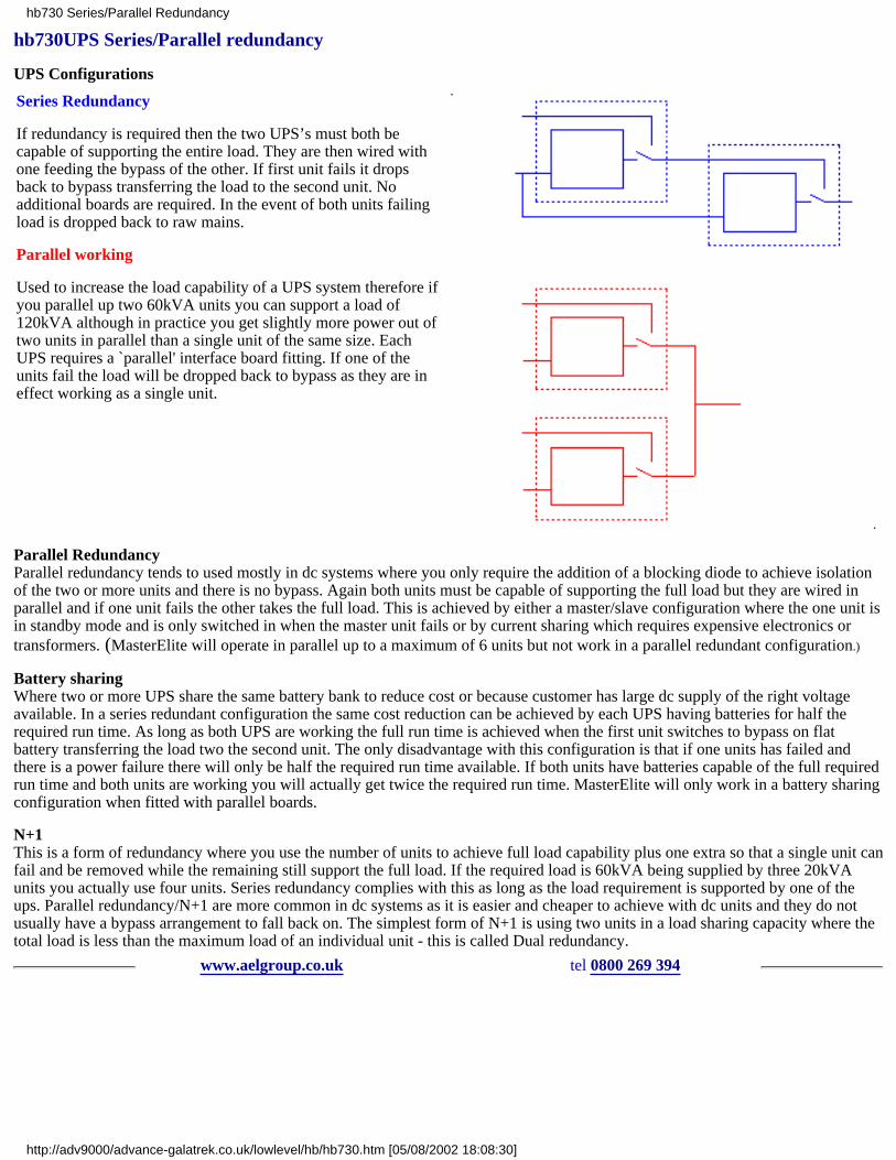
hb730UPS Series/Parallel redundancy
UPS Configurations
Series Redundancy
If redundancy is required then the two UPS’s must both becapable of supporting the entire load. They are then wired withone feeding the bypass of the other. If first unit fails it dropsback to bypass transferring the load to the second unit. Noadditional boards are required. In the event of both units failingload is dropped back to raw mains.
Parallel working
Used to increase the load capability of a UPS system therefore ifyou parallel up two 60kVA units you can support a load of120kVA although in practice you get slightly more power out oftwo units in parallel than a single unit of the same size. EachUPS requires a `parallel' interface board fitting. If one of theunits fail the load will be dropped back to bypass as they are ineffect working as a single unit.
Parallel RedundancyParallel redundancy tends to used mostly in dc systems where you only require the addition of a blocking diode to achieve isolationof the two or more units and there is no bypass. Again both units must be capable of supporting the full load but they are wired inparallel and if one unit fails the other takes the full load. This is achieved by either a master/slave configuration where the one unit isin standby mode and is only switched in when the master unit fails or by current sharing which requires expensive electronics ortransformers. (MasterElite will operate in parallel up to a maximum of 6 units but not work in a parallel redundant configuration.)
Battery sharingWhere two or more UPS share the same battery bank to reduce cost or because customer has large dc supply of the right voltageavailable. In a series redundant configuration the same cost reduction can be achieved by each UPS having batteries for half therequired run time. As long as both UPS are working the full run time is achieved when the first unit switches to bypass on flatbattery transferring the load two the second unit. The only disadvantage with this configuration is that if one units has failed andthere is a power failure there will only be half the required run time available. If both units have batteries capable of the full requiredrun time and both units are working you will actually get twice the required run time. MasterElite will only work in a battery sharingconfiguration when fitted with parallel boards.
N+1This is a form of redundancy where you use the number of units to achieve full load capability plus one extra so that a single unit canfail and be removed while the remaining still support the full load. If the required load is 60kVA being supplied by three 20kVAunits you actually use four units. Series redundancy complies with this as long as the load requirement is supported by one of theups. Parallel redundancy/N+1 are more common in dc systems as it is easier and cheaper to achieve with dc units and they do notusually have a bypass arrangement to fall back on. The simplest form of N+1 is using two units in a load sharing capacity where thetotal load is less than the maximum load of an individual unit - this is called Dual redundancy.
www.aelgroup.co.uk tel 0800 269 394
hb730 Series/Parallel Redundancy
http://adv9000/advance-galatrek.co.uk/lowlevel/hb/hb730.htm [05/08/2002 18:08:30]
hb732UPS Health and Safety information
Please note the following recommendations and guidelines for the safe operation of your Advance Galatrek UPS.
(a) All maintenance and service functions must be performed by authorised personnel. The UPS contains several internal powersources which can be hazardous.
(b) The internal battery can generate an electric shock. All batteries removed from the UPS for replacement must be disposed ofaccording to the current health and safety regulations.
DO NOT throw batteries into a fire: they might explode.
DO NOT attempt to open the batteries: they are sealed lead acid maintenance-free. The acid electrolyte can harmunprotected skin and eyes.
(c) The UPS contains its own energy source (the battery). The output connection may be live even when the UPS is not connected toa power source.
(d) DO NOT operate the UPS if it is appears to be leaking battery electrolyte or if a dry white power residue is present on thebatteries.
(e)
DO NOT allow water near the UPS.
DO NOT place a foreign object inside the UPS.
(f) The UPS generates approximately 1mA of leakage current. To ensure a safe maximum limit of 3.5mA limit the total leakagecurrent of the loads to a maximum of 2.5mA. Should the load leakage current be over this limit a qualified electrician should installthe UPS in compliance with IEC 309.
(g) In emergencies remove the fuse from the supply spur or switch off the MCB feeding the UPS and then turn off the UPS batteriesusing the rear ON/OFF switch.
(extracted from Elite UPS installation manual)
www.aelgroup.co.uk tel 0800 269 394
hb732 health and safety data - UPSs
http://adv9000/advance-galatrek.co.uk/lowlevel/hb/hb732.htm [05/08/2002 18:08:30]
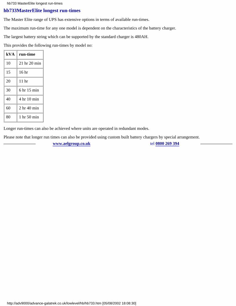
hb733MasterElite longest run-times
The Master Elite range of UPS has extensive options in terms of available run-times.
The maximum run-time for any one model is dependent on the characteristics of the battery charger.
The largest battery string which can be supported by the standard charger is 480AH.
This provides the following run-times by model no:
kVA run-time
10 21 hr 20 min
15 16 hr
20 11 hr
30 6 hr 15 min
40 4 hr 10 min
60 2 hr 40 min
80 1 hr 50 min
Longer run-times can also be achieved where units are operated in redundant modes.
Please note that longer run times can also be provided using custom built battery chargers by special arrangement.
www.aelgroup.co.uk tel 0800 269 394
hb733 MasterElite longest run-times
http://adv9000/advance-galatrek.co.uk/lowlevel/hb/hb733.htm [05/08/2002 18:08:30]

hb734reprogramming a MicroBak
The workhorse UPS family known as MicroBak can be programmed in a number of different ways.
Any simple terminal emulator program can be connected to the UPS using the following set-up information:
8bit one stop no parity and 9600 baud
the pin connections are RS232 standard ie 2 3 5 on D9 and 2 3 7 on D25
Once the terminal is set up and communicating enter FAO which should provide an `S' prompt.
To make the normal on-site de-sensitising settings use
SET GLITCHES TO nnn (max 300)
SET SLEW-RATE TO nnn (max 25)
SET FTRACK TO nnn (max 10)
RECALC
entering `RECALC' should take you back to the standard prompt and ensure changes are stored
For detailed information see the appropriate manual.
www.aelgroup.co.uk tel 0800 269 394
hb734 MicroBak programming
http://adv9000/advance-galatrek.co.uk/lowlevel/hb/hb734.htm [05/08/2002 18:08:30]

hb735UPS power factor considerations
Sinusoidal or not?The traditional approach to power factor leaves some gaps when reviewing modern power systems.
Most mature engineers think of power factor in terms of phase shift. This is because before modern switched mode power suppliesbecame commonplace in electronic systems most non-unity power factor loads were inductive. Typically these loads might be atransformer or electric motor.In a simple electric motor being run in a normal fashion at full speed one expects to see a laggingpower factor of around 0.8. The current is distinctly out of phase with the supplied voltage but it is sinusoidal.
In the case of a modern computer file-server or telephone switch the power factor is often quoted around 0.75 suggesting that thepower consideration is identical. However it is NOT. In the case of a SMPS based load the watts:VA ratio is caused by harmonics inthe current NOT phase shift. The load current will be `peaky' (have a high crest factor) and anything but sinusoidal.
In choosing a UPS and planning a power distribution system the power factor consideration is an essential term in the overallequation.
Rule 1: PF = watts/VA
Using old UPS systems when the load was sinusoidal and had a lagging power factor allowed some economies in the design. A10kVA motor rated at 0.8PF would only take 8kW. This means that the UPS battery and charge requires only to supply 8kW +re-charging current for the autonomy time. This led to UPS products being supplied with apparently quite small chargers to savecost.
In old UPS designs where the output stage was low frequency an output capacitor was sometimes added to effectively `power factorcorrect' the load. This permitted the designer to allow for only 8kW in the inverter again saving cost.
If we move onto SMPS loads this type of UPS is at a significant disadvantage because the capacitor now makes the situation evenworse. The correcting capacitor adds to the apparent load seen by the UPS. The use of a SMPS causes a much larger UPS to berequired. However it is true that the SMPS exhibits a non-unity PF (unless it is internally corrected) in that the VA is greater than thewatts consumed. The battery can still be sized for the watts.
TodayIn modern UPS boxes the designer is aware of a lot of these problems and the UPS is usually designed to accommodate large peakcurrents which occur at every cycle in the waveform. Current limiting to protect the UPS is usually vested in switching to bypassearlier than is necessary to maintain some thermal margins. However with microprocessor controlled inverters the output stage canhave several different overload checks - any one of which will activate protection. For example output switch heatsink temperatureactual peak current integrated current over time and many other solutions.
The methodWhen it comes to planning an installation there is a simple approach which although not entirely exhaustive provides a sensible wayto size the UPS.
The user should add up all the actual RMS currents being used in the system together with any expected expansion. (We propose30% is a good starting point for an expansion term). Do NOT use fuse ratings of equipment which bear little relation to the actualcurrent required. Assume all the load is unity power factor. This is nearly a worst case. The UPS is usually quoted with a powerfactor rating use this to identify its wattage rating and select a unit where the wattage exceeds the estimate above. Get the supplier tocalculate the battery run time based on the actual watts of load.
If you would like any more help on this subject please ask!
www.aelgroup.co.uk tel 0800 269 394
hb735 power factor considerations
http://adv9000/advance-galatrek.co.uk/lowlevel/hb/hb735.htm [05/08/2002 18:08:30]

hb738MicroBak performance
The workhorse UPS family known as MicroBak can be used to provide power to any suitably rated electronic load
Since the unit contains a voltage stabilising transformer when connected either to the main supply or the battery, some questionsabout voltage stability arise which are not described on the data sheet
For a typical 5kVA unit operating with 276Vac input the output voltage at full load (5kVA @ 0.7PF) is 246Vac(which is = 240 + 2.5%)
At 140Vac input the output drops to 237Vac (which is = 240 - 1.25%)
Operating on battery the unit delivers 243Vac from a fully charged battery under the same load conditions(which is = 240 + 2.5%) - the voltage drops to 240Vac at end of battery discharge
For detailed information see the appropriate manual
www.aelgroup.co.uk tel 0800 269 394
hb738 MicroBak performance
http://adv9000/advance-galatrek.co.uk/lowlevel/hb/hb738.htm [05/08/2002 18:08:30]

hb753CE marking of UPS and EN references
Introduction
The whole range of Advance Galatrek UPS products are certified compliant to the current legislation at the time of sale.
Relevant specifications
In general the UPS family is compliant with the Low Voltage Directive and the EMC regulations
Model range Specifications
BBD / RBD
EN 50091-1EN 60950EN 50081-1EN 50082-1EN 60555
FBS EN 60950
MBBS EN 60950
MBEB
EN 50091-1EN 60950EN 50081-1EN 50082-1EN 60555
MCA
EN 50091-1EN 50091-2EN 60950EN 50081-1EN 50082-1EN 60555
RCA
EN 50091-1EN 60950EN 50081-1EN 50082-1EN 60555
If you would like any more help on this subject please ask!
www.aelgroup.co.uk tel 0800 269 394
hb753 CE marking of UPS + EN references
http://adv9000/advance-galatrek.co.uk/lowlevel/hb/hb753.htm [05/08/2002 18:08:30]

hb754automatic bypass for use in special needs situations
Introduction
This unit provides an inexpensive solution which is very reliable when selecting between two supplies. Based on well knownelectrical components with no electronics this system has been evolved by a hospital customer for the operating theatre environment.The small supply break may mean some equipment has to be re-booted but the lights and other essentials just flicker briefly.
Schematic
Suggested arrangement shows prime components for it `MUST WORK' supply.
The mains supply is provided via MCBs to both the bypassand UPS. In the normal state the UPS is protecting the loadand R1 is energised. If the output of the UPS fails for anyreason R1 will drop out and operate the mechanicallyinterlocked contactors C1 + C2. If either fuse blows or R1fails the system will drop out to bypass because the rest stateof C1 + C2 is `on bypass'.
Of course the UPS will buffer the load from breaks in theinput supply.
There will be a small break in the transfer but the system isextremely robust and uses readily available components.
The four neons a b c d indicate status.
If you would like a bespoke unit making up for a particularapplcation - let us know so we can quote you.
A unit suitable for 30Amp single phase is about 12" cube.
www.aelgroup.co.uk tel 0800 269 394
hb754 bypass - special needs auto type
http://adv9000/advance-galatrek.co.uk/lowlevel/hb/hb754.htm [05/08/2002 18:08:30]