SIMATIC IPC227E - Siemens Industry Online Support
126
SIMATIC IPC227E ___________________ ___________________ ___________________ ___________________ ___________________ ___________________ ___________________ ___________________ ___________________ ___________________ SIMATIC Industrial PC SIMATIC IPC227E Operating Instructions 06/2015 A5E35782395-AA Preface Overview 1 Safety instructions 2 Installing and connecting the device 3 Commissioning the device and device functions 4 Expanding and assigning parameters to the device 5 Maintaining and repairing the device 6 Technical specifications 7 Technical support A List of abbreviations B
-
Upload
khangminh22 -
Category
Documents
-
view
1 -
download
0
Transcript of SIMATIC IPC227E - Siemens Industry Online Support

SIMATIC IPC227E
___________________
___________________
___________________
___________________
___________________
___________________
___________________
___________________
___________________
___________________
SIMATIC
Industrial PC SIMATIC IPC227E
Operating Instructions
06/2015 A5E35782395-AA
Preface
Overview 1
Safety instructions 2
Installing and connecting the device
3
Commissioning the device and device functions
4
Expanding and assigning parameters to the device
5
Maintaining and repairing the device
6
Technical specifications 7
Technical support A
List of abbreviations B

Siemens AG Division Digital Factory Postfach 48 48 90026 NÜRNBERG GERMANY
A5E35782395-AA Ⓟ 05/2015 Subject to change
Copyright © Siemens AG 2015. All rights reserved
Legal information Warning notice system
This manual contains notices you have to observe in order to ensure your personal safety, as well as to prevent damage to property. The notices referring to your personal safety are highlighted in the manual by a safety alert symbol, notices referring only to property damage have no safety alert symbol. These notices shown below are graded according to the degree of danger.
DANGER indicates that death or severe personal injury will result if proper precautions are not taken.
WARNING indicates that death or severe personal injury may result if proper precautions are not taken.
CAUTION indicates that minor personal injury can result if proper precautions are not taken.
NOTICE indicates that property damage can result if proper precautions are not taken.
If more than one degree of danger is present, the warning notice representing the highest degree of danger will be used. A notice warning of injury to persons with a safety alert symbol may also include a warning relating to property damage.
Qualified Personnel The product/system described in this documentation may be operated only by personnel qualified for the specific task in accordance with the relevant documentation, in particular its warning notices and safety instructions. Qualified personnel are those who, based on their training and experience, are capable of identifying risks and avoiding potential hazards when working with these products/systems.
Proper use of Siemens products Note the following:
WARNING Siemens products may only be used for the applications described in the catalog and in the relevant technical documentation. If products and components from other manufacturers are used, these must be recommended or approved by Siemens. Proper transport, storage, installation, assembly, commissioning, operation and maintenance are required to ensure that the products operate safely and without any problems. The permissible ambient conditions must be complied with. The information in the relevant documentation must be observed.
Trademarks All names identified by ® are registered trademarks of Siemens AG. The remaining trademarks in this publication may be trademarks whose use by third parties for their own purposes could violate the rights of the owner.
Disclaimer of Liability We have reviewed the contents of this publication to ensure consistency with the hardware and software described. Since variance cannot be precluded entirely, we cannot guarantee full consistency. However, the information in this publication is reviewed regularly and any necessary corrections are included in subsequent editions.

SIMATIC IPC227E Operating Instructions, 06/2015, A5E35782395-AA 3
Preface
These operating instructions contain all the information you need for commissioning and operation of the SIMATIC IPC227E.
It is intended both for programming and testing personnel who commission the device and connect it with other units (automation systems, programming devices), as well as for service and maintenance personnel who install add-ons or carry out fault/error analyses.
Basic knowledge requirements A solid background in personal computers and Microsoft operating systems is required to understand this manual. General knowledge in the field automation control engineering is recommended.
Scope of validity of this document These operating instructions are valid for all versions of the SIMATIC IPC227E.
Scope of this documentation The documentation for the SIMATIC IPC227E consists of:
● Product information, e.g. "Important notes on your device"
● Quick Install Guide SIMATIC IPC227E
● SIMATIC IPC227E operating instructions in English and German
The PDF version of the documentation is supplied with the device on the "Documentation and Drivers" CD/DVD.
Conventions The terms "PC" and "device" are sometimes used to refer to the SIMATIC IPC227E in this documentation.
In these operating instructions, "Windows Embedded Standard" is also used as a standard term for "Windows Embedded Standard 7". The abbreviation "Windows 7" denotes the term "Windows 7 Ultimate".
History The following editions of these operating instructions have been published: Edition Comment 06/2015 First edition

Preface
SIMATIC IPC227E 4 Operating Instructions, 06/2015, A5E35782395-AA

SIMATIC IPC227E Operating Instructions, 06/2015, A5E35782395-AA 5
Table of contents
Preface ................................................................................................................................................... 3
1 Overview................................................................................................................................................. 9
1.1 Product description ................................................................................................................... 9
1.2 Structure of the devices .......................................................................................................... 10 1.2.1 Views of the basic device ....................................................................................................... 10 1.2.2 Views of the PCIe device version ........................................................................................... 11 1.2.3 Interfaces and operator controls of the basic device .............................................................. 12 1.2.4 Interfaces and operator controls PCIe device version ............................................................ 13 1.2.5 Status displays ........................................................................................................................ 14
1.3 Accessories ............................................................................................................................. 15
2 Safety instructions ................................................................................................................................. 17
2.1 General safety instructions ..................................................................................................... 17
2.2 Notes on use ........................................................................................................................... 20
3 Installing and connecting the device ...................................................................................................... 21
3.1 Preparing for installation ......................................................................................................... 21 3.1.1 Checking the delivery package ............................................................................................... 21 3.1.2 Identification data of the device .............................................................................................. 22 3.1.3 Permitted mounting positions ................................................................................................. 24 3.1.4 Installing the cable strain relief ............................................................................................... 25 3.1.5 Installing Ethernet connector strain relief................................................................................ 25 3.1.6 Installing the ATEX cable strain relief ..................................................................................... 26
3.2 Mounting the device ................................................................................................................ 26 3.2.1 Mounting instructions .............................................................................................................. 26 3.2.2 Mounting on a standard rail .................................................................................................... 29 3.2.3 Wall mounting ......................................................................................................................... 30 3.2.4 Upright mounting ..................................................................................................................... 31
3.3 Connecting the device ............................................................................................................ 32 3.3.1 Notes on connecting ............................................................................................................... 32 3.3.2 Connecting the protective conductor ...................................................................................... 33 3.3.3 Connecting the power supply ................................................................................................. 34 3.3.4 Connect device to networks .................................................................................................... 35
4 Commissioning the device and device functions .................................................................................... 37
4.1 General information on commissioning .................................................................................. 37
4.2 Switching on the device .......................................................................................................... 38
4.3 Windows Security Center ....................................................................................................... 39
4.4 Advanced device functions ..................................................................................................... 39 4.4.1 Monitoring functions ................................................................................................................ 39 4.4.1.1 Overview of the monitoring functions ...................................................................................... 39

Table of contents
SIMATIC IPC227E 6 Operating Instructions, 06/2015, A5E35782395-AA
4.4.1.2 Temperature monitoring/display ............................................................................................ 40 4.4.1.3 Watchdog (WD)...................................................................................................................... 41 4.4.1.4 Battery monitoring .................................................................................................................. 42 4.4.2 Enhanced Write Filter ............................................................................................................ 42 4.4.3 File-Based Write Filter ........................................................................................................... 44 4.4.4 Buffer memory MRAM ........................................................................................................... 45
5 Expanding and assigning parameters to the device ............................................................................... 47
5.1 Open the device ..................................................................................................................... 47
5.2 Installing a PCIe module ........................................................................................................ 49
5.3 Installing and removing CFast cards...................................................................................... 51
6 Maintaining and repairing the device ..................................................................................................... 53
6.1 Maintenance ........................................................................................................................... 53
6.2 Repair information .................................................................................................................. 53
6.3 Recycling and disposal .......................................................................................................... 54
6.4 Installing and removing hardware .......................................................................................... 54 6.4.1 Replace the backup battery ................................................................................................... 54 6.4.2 Replacing the drive of a basic device .................................................................................... 57 6.4.3 Replacing a drive for the PCIe device version ....................................................................... 58
6.5 Installing the software ............................................................................................................ 59 6.5.1 Reinstalling the operating system .......................................................................................... 59 6.5.1.1 General installation procedure ............................................................................................... 59 6.5.1.2 Restoring the factory state of the software using the Restore DVD ...................................... 59 6.5.1.3 Installation of Windows 7 ....................................................................................................... 61 6.5.1.4 Windows with AHCI Controller ............................................................................................... 62 6.5.1.5 Setting up the language selection by means of the Multilanguage User Interface (MUI)...... 65 6.5.2 Partitioning data media .......................................................................................................... 66 6.5.2.1 Partitioning in Windows Embedded Standard 7 .................................................................... 66 6.5.2.2 Partitions under Windows 7 Ultimate ..................................................................................... 66 6.5.2.3 Adapting partitions in Windows 7 Ultimate and Windows Embedded Standard 7 ................ 67 6.5.3 Installing drivers and software ............................................................................................... 68 6.5.4 Installing updates ................................................................................................................... 69 6.5.4.1 Updating the operating system .............................................................................................. 69 6.5.4.2 Installing or updating application programs and drivers ........................................................ 69 6.5.5 Backing up data ..................................................................................................................... 69
7 Technical specifications ........................................................................................................................ 71
7.1 Certificates and approvals ..................................................................................................... 71
7.2 Directives and declarations .................................................................................................... 73 7.2.1 Electromagnetic compatibility, Industrial and Residential Areas ........................................... 73 7.2.2 ESD guideline ........................................................................................................................ 74
7.3 Dimension drawings ............................................................................................................... 76 7.3.1 Dimension drawing basic device............................................................................................ 76 7.3.2 Dimension drawing PCIe device version ............................................................................... 79
7.4 Technical data ........................................................................................................................ 82 7.4.1 General technical specifications ............................................................................................ 82 7.4.2 Ambient conditions ................................................................................................................. 84

Table of contents
SIMATIC IPC227E Operating Instructions, 06/2015, A5E35782395-AA 7
7.4.3 Shipbuilding ............................................................................................................................ 86 7.4.4 Power demand of the components ......................................................................................... 86 7.4.5 Direct current supply (DC) ...................................................................................................... 87
7.5 Hardware descriptions ............................................................................................................ 88 7.5.1 Technical features of the motherboard ................................................................................... 88 7.5.2 External interfaces .................................................................................................................. 88 7.5.2.1 Overview of interfaces ............................................................................................................ 88 7.5.2.2 Serial interface ........................................................................................................................ 89 7.5.2.3 CFast....................................................................................................................................... 90 7.5.2.4 USB 2.0 port ........................................................................................................................... 90 7.5.2.5 USB 3.0 port ........................................................................................................................... 91 7.5.2.6 DisplayPort .............................................................................................................................. 91 7.5.2.7 Ethernet port ........................................................................................................................... 92 7.5.3 Internal interfaces ................................................................................................................... 92 7.5.3.1 Overview of internal interfaces ............................................................................................... 92 7.5.3.2 PCIe interface ......................................................................................................................... 93 7.5.4 System resources ................................................................................................................... 93 7.5.4.1 Currently allocated system resources ..................................................................................... 93 7.5.4.2 System resources used by the BIOS/DOS ............................................................................. 94 7.5.5 Input/output address areas ..................................................................................................... 95 7.5.5.1 Overview of the internal module registers .............................................................................. 95 7.5.5.2 Watchdog enable register / 066h select register (read/write, address 062h) ......................... 95 7.5.5.3 Watchdog trigger register (read only, address 066h) ............................................................. 96 7.5.5.4 Output register user LED L1/L2/L3 (read/write, address 404Eh) ........................................... 96 7.5.5.5 Battery status register (read-only, address 50Ch) .................................................................. 96 7.5.5.6 MRAM address register .......................................................................................................... 97
7.6 BIOS description ..................................................................................................................... 97 7.6.1 Overview ................................................................................................................................. 97 7.6.2 Opening the BIOS selection menu ......................................................................................... 98 7.6.3 Configuration ........................................................................................................................... 99 7.6.4 Exit menu .............................................................................................................................. 100 7.6.5 Default BIOS Setup entries ................................................................................................... 101 7.6.6 BIOS update ......................................................................................................................... 103 7.6.7 Alarm, error and system messages ...................................................................................... 104
7.7 Functional scope in Windows ............................................................................................... 105 7.7.1 Windows Embedded Standard 7 .......................................................................................... 105
A Technical support ................................................................................................................................ 107
A.1 Service and support .............................................................................................................. 107
A.2 Troubleshooting .................................................................................................................... 108
A.3 Notes on the use of third-party modules ............................................................................... 109
B List of abbreviations ............................................................................................................................ 111
Glossary ............................................................................................................................................. 115
Index................................................................................................................................................... 123

Table of contents
SIMATIC IPC227E 8 Operating Instructions, 06/2015, A5E35782395-AA

SIMATIC IPC227E Operating Instructions, 06/2015, A5E35782395-AA 9
Overview 1 1.1 Product description

Overview 1.2 Structure of the devices
SIMATIC IPC227E 10 Operating Instructions, 06/2015, A5E35782395-AA
SIMATIC IPC227E provides high-level industrial functionality.
● Compact design
● High degree of ruggedness
● Maintenance-free operation possible
1.2 Structure of the devices
1.2.1 Views of the basic device
Front view and side view The front view on the left is the standard mounting position, side view on the right.
① Cooling fins ② LED display
Bottom view
① Protective conductor connection ② Memory card slot ③ Ports

Overview 1.2 Structure of the devices
SIMATIC IPC227E Operating Instructions, 06/2015, A5E35782395-AA 11
1.2.2 Views of the PCIe device version
Front view and side view The front view on the left is the standard mounting position, side view on the right.
① Cooling fins ② LED display
Bottom view
① Protective conductor connection ② Memory card slot ③ Ports
Overview 1.2 Structure of the devices
SIMATIC IPC227E 12 Operating Instructions, 06/2015, A5E35782395-AA
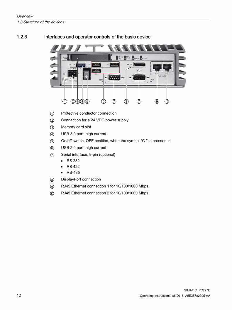
1.2.3 Interfaces and operator controls of the basic device
① Protective conductor connection
② Connection for a 24 VDC power supply
③ Memory card slot
④ USB 3.0 port, high current
⑤ On/off switch. OFF position, when the symbol "C-" is pressed in.
⑥ USB 2.0 port, high current
⑦ Serial interface, 9-pin (optional) • RS 232 • RS 422 • RS-485
⑧ DisplayPort connection
⑨ RJ45 Ethernet connection 1 for 10/100/1000 Mbps
⑩ RJ45 Ethernet connection 2 for 10/100/1000 Mbps

Overview 1.2 Structure of the devices
SIMATIC IPC227E Operating Instructions, 06/2015, A5E35782395-AA 13
1.2.4 Interfaces and operator controls PCIe device version
① Protective conductor connection
② Connection for a 24 VDC power supply
③ Memory card slot
④ USB 3.0 port, high current
⑤ On/off switch. OFF position, when the symbol "C-" is pressed in.
⑥ USB 2.0 port, high current
⑦ Serial interface, 9-pin • RS 232 • RS 422 • RS-485
⑧ DisplayPort connection
⑨ Slot for a PCIe x1 card
⑩ RJ45 Ethernet connection 1 for 10/100/1000 Mbps
⑪ RJ45 Ethernet connection 2 for 10/100/1000 Mbps

Overview 1.2 Structure of the devices
SIMATIC IPC227E 14 Operating Instructions, 06/2015, A5E35782395-AA
1.2.5 Status displays
LED State Description PC ON/WD Off -
Green BIOS ready to boot Flashing green/yellow (1 Hz) BIOS in POST, power switch on Yellow Idle state Flashing red (1 Hz) Watchdog status display: active
RUN/STOP / L1 Off - Green Can be controlled by user program / control
program (e.g. WinAC) Yellow ERROR / L2 Off -
Red Can be controlled by user program / control program (e.g. WinAC) Yellow
MAINT / L3
Off - Yellow Can be controlled by user program / control
program (e.g. WinAC) Red
You can find information on the individual LEDs in the section Output register user LED L1/L2/L3 (read/write, address 404Eh) (Page 96). Example programs for controlling the LEDs on Windows operating systems are available on the Customer Support page of Siemens Industry Automation and Drive Technologies. (http://www.siemens.com/automation/service&support)

Overview 1.3 Accessories
SIMATIC IPC227E Operating Instructions, 06/2015, A5E35782395-AA 15
1.3 Accessories This chapter contains the scope of accessories valid at the time these operating instructions were written. Additional accessories can be found on the Internet at:
● Expansion components and accessories (http://www.automation.siemens.com/mcms/pc-based-automation/en/industrial-pc/expansion_components_accessories)
● Industry Mall (https://mall.industry.siemens.com)
CFast cards
Note CFast cards can only be replaced with cards of the same manufacturing versions
This device supports only SIMATIC IPC CFast cards with version 02 or higher.
The following CFast cards can be ordered:
● CFast card, 4 GB
● CFast card, 8 GB
● CFast card, 16 GB
Strain relief The cable strain relief set con-tains: • 5 pieces cable strain relief ① • 5 pieces Ethernet connector
strain relief ② • Setscrews M3x8 • Allen key • Cable ties
Dust protection set The Dust protection set interfaces contains:
● 40 pieces covers for USB interface
● 20 pieces covers for RJ45 Ethernet connection
● 20 pieces DisplayPort cover
Graphics adapter ● DisplayPort DVI adapter
● DisplayPort VGA adapter

Overview 1.3 Accessories
SIMATIC IPC227E 16 Operating Instructions, 06/2015, A5E35782395-AA

SIMATIC IPC227E Operating Instructions, 06/2015, A5E35782395-AA 17
Safety instructions 2 2.1 General safety instructions
WARNING
Life-threatening voltages are present with an open control cabinet
When you install the device in a control cabinet, some areas or components in the open control cabinet may be carrying life-threatening voltages.
If you touch these areas or components, you may be killed by electric shock.
Switch off the power supply to the cabinet before opening it.
System expansions
NOTICE
Damage through system expansions
Device and system expansions may be faulty and can affect the entire machine or plant.
The installation of expansions can damage the device, machine or plant. Device and system expansions may violate safety rules and regulations regarding radio interference suppression. If you install or exchange system expansions and damage your device, the warranty becomes void.
Note the following for system expansions:
● Only install system expansion devices designed for this device. Contact your technical support team or where you purchased your PC to find out which system expansion devices may safely be installed.
● Observe the information on electromagnetic compatibility (Page 73).
WARNING
Risk of fire through expansion cards
Expansion cards generate additional heat. The device may overheat and cause a fire.
Please note the following: • Observe the safety and installation instructions for the expansion cards. • If in doubt, install the device in an enclosure that is compliant with sections 4.6 and 4.7.3
of the IEC/UL/EN/DIN-EN 60950-1 standard.

Safety instructions 2.1 General safety instructions
SIMATIC IPC227E 18 Operating Instructions, 06/2015, A5E35782395-AA
NOTICE
"Open Type" UL508
Note that the device is classified as "Open Type" for use in the area of Industrial Control Equipment (UL508). Installation of the device in an enclosure complying with UL508 is a prerequisite for approval or operation in accordance with UL508.
Battery and rechargeable battery
WARNING
Risk of explosion and release of harmful substances
Improper handling of lithium batteries can result in an explosion of the batteries.
Explosion of the batteries and the released pollutants can cause severe physical injury. Worn batteries jeopardize the function of the device.
Note the following when handling lithium batteries: • Replace used batteries in good time; see the section "Replacing the backup battery" in
the operating instructions. • Replace the lithium battery only with an identical battery or types recommended by the
manufacturer (order no.: A5E34345932). • Do not throw lithium batteries into fire, do not solder on the cell body, do not recharge,
do not open, do not short-circuit, do not reverse polarity, do not heat above 100°C and protect from direct sunlight, moisture and condensation.
Strong high-frequency radiation
NOTICE
Observe immunity to RF radiation
The device has an increased immunity to RF radiation according to the specifications on electromagnetic compatibility in the technical specifications.
Radiation exposure in excess of the specified immunity limits can impair device functions, result in malfunctions and therefore injuries or damages.
Read the information on immunity to RF radiation in the technical specifications.
Safety instructions 2.1 General safety instructions
SIMATIC IPC227E Operating Instructions, 06/2015, A5E35782395-AA 19
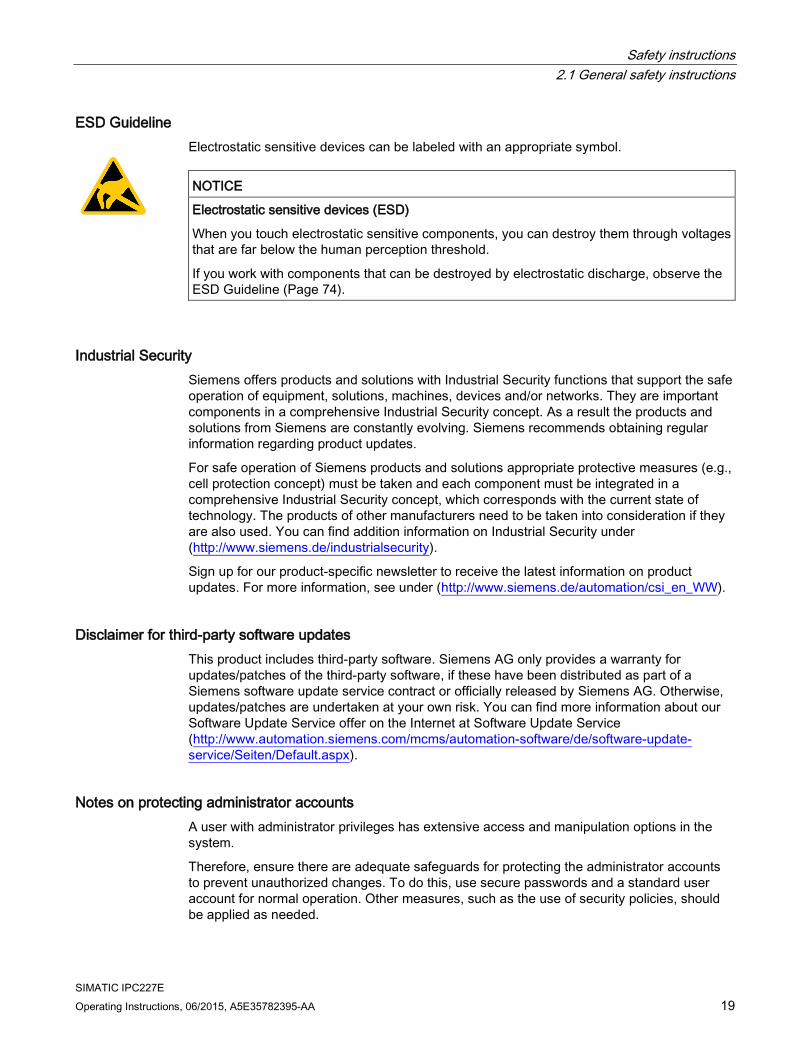
ESD Guideline Electrostatic sensitive devices can be labeled with an appropriate symbol.
NOTICE
Electrostatic sensitive devices (ESD)
When you touch electrostatic sensitive components, you can destroy them through voltages that are far below the human perception threshold.
If you work with components that can be destroyed by electrostatic discharge, observe the ESD Guideline (Page 74).
Industrial Security Siemens offers products and solutions with Industrial Security functions that support the safe operation of equipment, solutions, machines, devices and/or networks. They are important components in a comprehensive Industrial Security concept. As a result the products and solutions from Siemens are constantly evolving. Siemens recommends obtaining regular information regarding product updates.
For safe operation of Siemens products and solutions appropriate protective measures (e.g., cell protection concept) must be taken and each component must be integrated in a comprehensive Industrial Security concept, which corresponds with the current state of technology. The products of other manufacturers need to be taken into consideration if they are also used. You can find addition information on Industrial Security under (http://www.siemens.de/industrialsecurity).
Sign up for our product-specific newsletter to receive the latest information on product updates. For more information, see under (http://www.siemens.de/automation/csi_en_WW).
Disclaimer for third-party software updates This product includes third-party software. Siemens AG only provides a warranty for updates/patches of the third-party software, if these have been distributed as part of a Siemens software update service contract or officially released by Siemens AG. Otherwise, updates/patches are undertaken at your own risk. You can find more information about our Software Update Service offer on the Internet at Software Update Service (http://www.automation.siemens.com/mcms/automation-software/de/software-update-service/Seiten/Default.aspx).
Notes on protecting administrator accounts A user with administrator privileges has extensive access and manipulation options in the system.
Therefore, ensure there are adequate safeguards for protecting the administrator accounts to prevent unauthorized changes. To do this, use secure passwords and a standard user account for normal operation. Other measures, such as the use of security policies, should be applied as needed.
Safety instructions 2.2 Notes on use
SIMATIC IPC227E 20 Operating Instructions, 06/2015, A5E35782395-AA
2.2 Notes on use
NOTICE
Possible functional restrictions in case of non-validated plant operation
The device is tested and certified on the basis of the technical standards. In rare cases, functional restrictions can occur during plant operation.
Validate the correct functioning of the plant to avoid functional restrictions.
Note Use in an industrial environment without additional protective measures
This device was designed for use in a normal industrial environment according to IEC 60721-3-3.
SIMATIC IPC227E Operating Instructions, 06/2015, A5E35782395-AA 21
Installing and connecting the device 3 3.1 Preparing for installation
3.1.1 Checking the delivery package
Procedure 1. When accepting a delivery, please check the packaging for visible transport damage.
2. If any transport damage is present at the time of delivery, lodge a complaint at the shipping company in charge. Have the shipper confirm the transport damage immediately.
3. Unpack the device at its installation location.
4. Keep the original packaging in case you have to transport the unit again.
Note
Damage to the device during transport and storage
If a device is transported or stored without packaging, shocks, vibrations, pressure and moisture may impact the unprotected unit. A damaged packaging indicates that ambient conditions have already had a massive impact on the device.
The device may be damaged.
Do not dispose of the original packaging. Pack the device during transportation and storage.
5. Check the contents of the packaging and any accessories you may have ordered for completeness and damage.
6. If the contents of the packaging are incomplete, damaged or do not match your order, inform the responsible delivery service immediately. Fax the enclosed form "SIMATIC IPC/PG Quality Control Report".
WARNING
Electric shock and fire hazard due to damaged device
A damaged device can be under hazardous voltage and trigger a fire in the machine or plant. A damaged device has unpredictable properties and states.
Death or serious injury could occur.
Make sure that the damaged device is not inadvertently installed and put into operation. Label the damaged device and keep it locked away. Send off the device for immediate repair.
Installing and connecting the device 3.1 Preparing for installation
SIMATIC IPC227E 22 Operating Instructions, 06/2015, A5E35782395-AA
NOTICE
Damage from condensation
If the device is subjected to low temperatures or extreme fluctuations in temperature during transportation, for example in cold weather, moisture could build up on or inside the HMI device.
Moisture causes a short circuit in electrical circuits and damages the device.
In order to prevent damage to the device, proceed as follows: • Store the device in a dry place. • Bring the device to room temperature before starting it up. • Do not expose the device to direct heat radiation from a heating device. • If condensation develops, wait approximately 12 hours or until the device is
completely dry before switching it on.
7. Please keep the enclosed documentation in a safe place. It belongs to the device. You need the documentation when you commission the device for the first time.
8. Write down the identification data of the device.
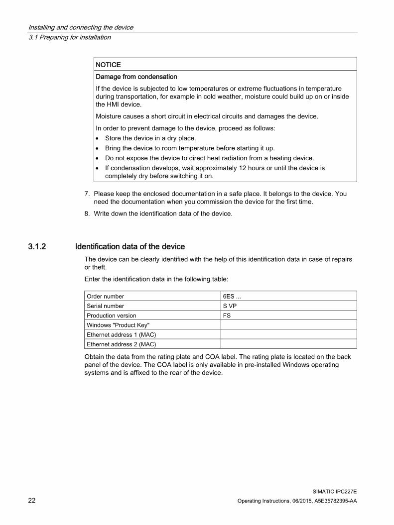
3.1.2 Identification data of the device The device can be clearly identified with the help of this identification data in case of repairs or theft.
Enter the identification data in the following table: Order number 6ES ... Serial number S VP Production version FS Windows "Product Key" Ethernet address 1 (MAC) Ethernet address 2 (MAC)
Obtain the data from the rating plate and COA label. The rating plate is located on the back panel of the device. The COA label is only available in pre-installed Windows operating systems and is affixed to the rear of the device.

Installing and connecting the device 3.1 Preparing for installation
SIMATIC IPC227E Operating Instructions, 06/2015, A5E35782395-AA 23
Procedure 1. Transfer order number, serial number, production version (FS), and Ethernet addresses
from the rating plate.
The Ethernet addresses can also be found in the BIOS Setup under "Main > Advanced > Peripheral Configuration" (see section "Technical Specifications").
Replacement device: On the rating plate, the order number of a replacement device which is available from stock at short notice is listed under "Spare Part Space Units". The replacement device is always supplied without storage media.
Note
Replacement device without storage media
When you order a replacement device, remove all the storage media from your device, for example SSD. Insert the storage media into the replacement device.
2. Transfer the Windows "Product Key" from the COA label.
Example of a COA label Microsoft Windows "Product Key" on the "Certificate of Authenticity" (COA): The COA label is only attached to the rear of the device containing a Windows Embedded Standard 7 or Windows 7 operating system.
● COA label of a device with Windows Embedded Standard 7 operating system
● COA label of a device with Windows 7 operating system

Installing and connecting the device 3.1 Preparing for installation
SIMATIC IPC227E 24 Operating Instructions, 06/2015, A5E35782395-AA
3.1.3 Permitted mounting positions The following mounting positions are permitted:
● Horizontal mounting position
The horizontal mounting position is the preferred position.
● Vertical mounting position – upright mounting
Take into account the permitted temperature range for operation that depends on the mounting position in accordance with the "Technical specifications (Page 82)" section.
Ensure that the following clearances measurements to another component or to a wall of a housing are complied with:
● Below the device: ≥ 100 mm
● Above the device: ≥ 50 mm

Installing and connecting the device 3.1 Preparing for installation
SIMATIC IPC227E Operating Instructions, 06/2015, A5E35782395-AA 25
3.1.4 Installing the cable strain relief The cable strain relief plate carries the cables and prevents unintentional loosening of the connector from the device. The cable strain relief is available as an accessory.
Procedure
Insert the metal plate of the strain relief into the last notch left and right.
Secure the strain relief on the left and right respective-ly with an M3x8 setscrew.
Secure the connection ca-bles with cable ties to the cable strain relief.
3.1.5 Installing Ethernet connector strain relief The Ethernet connector strain relief prevents accidental loosening of the Ethernet connector from the device. The Ethernet connector strain relief is available as an accessory.
Procedure
Insert the metal plate of the Ethernet connector strain relief into the sec-ond and third to the last notch.
Fasten the Ethernet con-nector strain relief with 2 setscrews.
Secure the Ethernet con-nector with cable ties.

Installing and connecting the device 3.2 Mounting the device
SIMATIC IPC227E 26 Operating Instructions, 06/2015, A5E35782395-AA
3.1.6 Installing the ATEX cable strain relief The special plate supports the cables for ATEX hazardous zones and prevents unintentional loosening of the connector from the device. The ATEX cable strain relief is included as an accessory for devices with ATEX approval.
NOTICE
Enclosure / control cabinet required
The device must comply with enclosure IP54 for ATEX approval. You must install the device in a protective enclosure / control cabinet to achieve this.
Procedure
Insert the metal plate of the strain relief left and right into the second to the last notch left and right.
Secure the strain relief on the left and right respective-ly with an M3x8 setscrew.
Secure the connection ca-bles with cable ties to the cable strain relief.
3.2 Mounting the device
3.2.1 Mounting instructions Note the following:
● The device is approved for operation in closed rooms only.
● For installation in a cabinet, observe the SIMATIC setup guidelines (http://support.automation.siemens.com/WW/view/de/1064706) as well as the relevant DIN/VDE requirements or the applicable country-specific regulations.
● When the device is used in the area of Industrial Control Equipment in accordance with UL508, note that the device is classified as "Open Type". The installation of the device in a housing conforming to UL508 is therefore a mandatory requirement for approval or operation in accordance with UL508.

Installing and connecting the device 3.2 Mounting the device
SIMATIC IPC227E Operating Instructions, 06/2015, A5E35782395-AA 27
Possible mounting types of the device: Mounting on a standard rail
Wall mounting
Upright mounting
The mounting types are described in the following sections using the basic device as an example.
Position of the interfaces For standard rails, the interface side of the device can point either up or down. In the case of wall mounting, the interface side of the device can point up, down, to the left or to the right. The position of the interface side is determined by the mounting of the mounting bracket.

Installing and connecting the device 3.2 Mounting the device
SIMATIC IPC227E 28 Operating Instructions, 06/2015, A5E35782395-AA
Fasten securely
NOTICE
Insufficient load carrying capacity
If the mounting surface for wall and vertical mounting does not have sufficient load carrying capability, the device may fall down and be damaged.
Ensure that the mounting surface on the wall can bear four times the total weight of the device, including fixing elements.
NOTICE
Incorrect fixing elements
If you use anchors and screws other than those specified below for wall and vertical mounting, safe mounting is not guaranteed. The device can fall and may be damaged.
Use only the anchors and screws specified in the following table.
Material Bore diameter Fixing element Concrete Select according to the
specification of the mounting elements used
• Anchor, ∅ 6 mm, 40 mm long • Screw, ∅ 4-5 mm, 40 mm long
Plasterboard, min. 13 mm thick
Toggle plug, ∅ 12 mm, 50 mm long
Metal, min. 2 mm thick
• Screw M4 × 15 • M4 nut

Installing and connecting the device 3.2 Mounting the device
SIMATIC IPC227E Operating Instructions, 06/2015, A5E35782395-AA 29
3.2.2 Mounting on a standard rail Mounting on a standard rail is suitable for horizontal and vertical mounting of the device.
Requirement ● A SIEMENS 35 mm standard rail TH35-15 conforming to EN 60715:2001
The standard rail is mounted.
● A standard rail bracket
The standard rail bracket and two screws are included in the order variant "Standard rail mounting".
● A T20 screwdriver
Procedure for mounting
Lay the standard rail bracket on the rear of the device.
Fasten the standard rail bracket with 2 screws.
Place the device with the stand-ard rail bracket onto the mount-ing rail from above. If the device is tilted when you place it down, the standard rail bracket does not grip.
Press the device down and to-ward the standard rail until the standard rail bracket engages.
Check whether the device is seated firmly on the standard rail。
Applies to vertical standard rail mounting: Fasten a standard rail ground terminal below the device。
Procedure for dismantling 1. Press the device down until the lower rail guide frees the device.
2. Swing the device out of the rails.
3. Remove the device from the rail.

Installing and connecting the device 3.2 Mounting the device
SIMATIC IPC227E 30 Operating Instructions, 06/2015, A5E35782395-AA
3.2.3 Wall mounting Wall mounting is suitable for horizontal mounting of the device.
Requirement ● Two mounting brackets
The mounting brackets are available in two versions - for the basic device versions and for the PCIe device version. The mounting bracket and four screws are included in the order variant "Wall mounting".
● A T20 screwdriver
● Four anchors and four screws
Procedure for mounting
Place the mounting bracket on the rear of the device.
Secure the mounting bracket with 2 screws.
Place the device with the mount-ing brackets onto the mounting surface.
Mark the fixing holes.
Drill the fixing holes.
Insert the anchors in the drilled holes.
Screw on the device.

Installing and connecting the device 3.2 Mounting the device
SIMATIC IPC227E Operating Instructions, 06/2015, A5E35782395-AA 31
3.2.4 Upright mounting Upright mounting is suitable for vertical mounting of the device. The corresponding mounting bracket allows mounting that requires less space than standard rail mounting and wall mounting.
Requirement ● Two mounting brackets
The mounting brackets are available in two versions - for the basic device version and for the PCIe device versions. The mounting bracket and four screws are included in the order variant "Upright mounting".
● A T20 screwdriver
● Four anchors and four screws
Procedure for mounting
Place the mounting bracket on the rear of the device.
Secure the mounting bracket with 2 screws.
Place the device with the mount-ing brackets onto the mounting surface.
Mark the fixing holes.
Drill the fixing holes.
Insert the anchors in the drilled holes.
Screw on the device.

Installing and connecting the device 3.3 Connecting the device
SIMATIC IPC227E 32 Operating Instructions, 06/2015, A5E35782395-AA
3.3 Connecting the device
3.3.1 Notes on connecting
WARNING
Risk of fire and electric shock
The on/off switch does not isolate the device from the power supply. Risk of electric shock if the device is opened incorrectly or defective. There is also a risk of fire if the device or connecting lines are damaged. Death or serious bodily injury can result.
You should therefore protect the device as follows: • Always pull out the power plug when you are not using the device or if the device is
defective. The power plug must be freely accessible. • Connect the device to a protective conductor as instructed (see "Connecting the
protective conductor"). • Use a central power isolating switch for cabinet installation.
WARNING
Risk of lightning strikes
A lightning flash may enter the mains cables and data transmission cables and jump to a person.
Death, serious injury and burns can be caused by lightning.
Take the following precautions: • Disconnect the device from the power supply in good time when a thunderstorm is
approaching. • Do not touch mains cables and data transmission cables during a thunderstorm. • Keep a sufficient distance from electric cables, distributors, systems, etc.
NOTICE
Fault caused by I/O devices
The connection of I/O devices can cause faults in the device.
The result may be personal injury and damage to the machine or plant.
Note the following when connecting I/O devices: • Read the documentation of the I/O devices. Follow all instructions in the documentation. • Only connect I/O devices which are approved for industrial applications in accordance
with EN 61000-6-2 and IEC 61000-6-2. • I/O devices that are not hotplug-capable may only be connected after the device has
been disconnected from the power supply.

Installing and connecting the device 3.3 Connecting the device
SIMATIC IPC227E Operating Instructions, 06/2015, A5E35782395-AA 33
NOTICE
Damage through regenerative feedback
Regenerative feedback of voltage to ground by a connected or installed component can damage the device.
Connected or built-in I/Os, for example, a USB drive, are not permitted to supply any voltage to the device. Regenerative feedback is generally not permitted.
3.3.2 Connecting the protective conductor A connected protective conductor discharges dangerous electrical charges from the metal enclosure. The current flowing through the protective conductor when such a fault occurs triggers an upstream protective device that disconnects the machine from the power supply.
The protective conductor also improves the discharge of interference generated by external power cables, signal cables or cables for I/O modules to ground.
The connection for the protective conductor is labeled with the following symbol:
WARNING
Electric shock and risk of fire
High voltage may be present in a defective device, which can cause fire or an electric shock if touched. Death and serious bodily injury can result. • Connect the device to the protective conductor before you put it into operation. • The PE terminal on the device must be connected to the protective conductor of the
control cabinet or system in which the device is installed. • Never operate the device without protective conductor. • If a device is defective, remove it from operation without delay and label it accordingly.
Requirement ● T20 screwdriver
● Cable lug for M4
● Protective conductor with minimum cross-section of 2.5 mm2
Procedure
Clamp the cable lug on the protective conductor.
Firmly attach the cable lug to the protec-tive conductor connection on the device using the M4 thread (see part labeled).
Connect the protective conductor to the protective conductor connection of the cabinet or the plant in which the device is installed.

Installing and connecting the device 3.3 Connecting the device
SIMATIC IPC227E 34 Operating Instructions, 06/2015, A5E35782395-AA
3.3.3 Connecting the power supply
Note
The device should only be connected to a 24 VDC power supply which satisfies the requirements of safe extra low voltage (SELV) according to IEC/EN/DIN EN/UL 60950-1.
The power supply must meet the requirement NEC Class 2 or LPS according to the IEC/EN/DIN EN/UL 60950-1.
Note
The 24 VDC power supply must be adapted to the input data of the device (see the technical specifications in the operating instructions).
Requirement ● The protective conductor is connected.
● You are using the supplied terminal.
● A two-core cable with a cable cross-section of 0.75 mm2 to 2.5 mm2 for the 24 VDC connection.
● A slotted screwdriver with a 3mm blade.
Procedure
Switch off the 24 VDC power supply.
Connect the cores of the power supply.
Insert the terminal at the indicated position.

Installing and connecting the device 3.3 Connecting the device
SIMATIC IPC227E Operating Instructions, 06/2015, A5E35782395-AA 35
3.3.4 Connect device to networks The following options are available for integrating the device in existing or planned system environments and networks.
Ethernet You can use the integrated Ethernet interfaces (10/100/1000 Mbps) for communication and data exchange with automation devices, e.g. SIMATIC S7.
You need a suitable software to use this functionality: STEP 7, WinCC, WinAC, SIMATIC NET.
Industrial Ethernet You can establish a network between the device and other computers via Industrial Ethernet. The on-board LAN interfaces are twisted-pair TP interfaces that support data transmission rates of 10/100/1000 Mbps.
Note
You need a category 6 Ethernet cable for operation at 1000 Mbps.
PROFINET PROFINET can be operated via:
● Standard Ethernet interfaces (RT)
SIMATIC NET Use this software package to create, operate and configure an innovative network for Field & Control level. Information on this can be found on the SIMATIC NET Manual Collection CD. The software package and the documentation are not included in the product package.
Additional information You can find additional information on the Internet at: Technical Support (http://www.siemens.de/automation/csi_en_WW)

Installing and connecting the device 3.3 Connecting the device
SIMATIC IPC227E 36 Operating Instructions, 06/2015, A5E35782395-AA

SIMATIC IPC227E Operating Instructions, 06/2015, A5E35782395-AA 37
Commissioning the device and device functions 4 4.1 General information on commissioning
CAUTION
Danger of burns
The surface of the device can reach temperatures of over 70 °C. Any unprotected contact may cause burns.
Avoid direct contact during operation of the device. Touch the device only with appropriate protective gloves.
Note Windows Embedded Standard 7
Read the EWF and FBWF information Two configurable write filters (Enhanced Write Filter and File Based Write Filter) are provided with Windows Embedded Standard. Read the EWF/FBWF information if you activate and use them, otherwise you may experience data loss.
Note Configuring memory cards in the device
Memory cards used in a device need to be configured on that device. Memory cards configured on other devices will not boot as the drive parameters will be different.
Requirement ● The device is connected to the power supply.
● The protective conductor is connected.
● The connection cables are plugged in correctly.
● The following hardware is available for initial commissioning:
– One USB keyboard
– One USB mouse
– A monitor/display

Commissioning the device and device functions 4.2 Switching on the device
SIMATIC IPC227E 38 Operating Instructions, 06/2015, A5E35782395-AA
4.2 Switching on the device Following the initial startup, the operating system preinstalled on the drive is automatically configured on the device.
NOTICE
Faulty installation
If you change the default values in the BIOS Setup or if you turn off the device during installation, you disrupt the installation and the operating system is not installed correctly. The operating safety of the device and the plant is at risk.
Do not switch off the device during the entire installation process. Do not change the default values in the BIOS Setup.
Procedure 1. Set the On/Off switch to "ON" position.
The "PC ON/WD" LED lights up. The device carries out a self-test. During the self-test, the following message appears:
Press Esc for Boot Options
2. Wait for the message to disappear.
3. Follow the instructions on the screen.
The following steps are required only when switching on the device for the first time after delivery:
4. Make the region and language settings.
If you want your system language to be international, select English. Information about changing the region and language settings is available in the chapter "Servicing and maintaining the device", under "Installing software".
Note
Once the operating system has been set up, the device may restart.
5. Type in the product key as required.
The product key is located below the identification data of the device on the "Certificate of Authentication" COA label, in the "Product Key" line.
6. If the device is connected with a SIMATIC Industrial Flat Panel, the setup of the SIMATIC IPC Wizard is started automatically after operating system installation (see next chapter).
The installation of the operating system is complete.
Commissioning the device and device functions 4.3 Windows Security Center
SIMATIC IPC227E Operating Instructions, 06/2015, A5E35782395-AA 39
4.3 Windows Security Center
Warning from the Windows Security Center A warning from the Windows Security Center is displayed the first time you switch on your device. The Security Center checks the status of the device in regard to the three important security aspects listed below. If a problem is detected (an outdated antivirus program, for example), the Security Center issues a warning and makes recommendations on how you can better protect the device.
● Firewall: The Windows Firewall adds protection to the device by blocking network or Internet access to the device by unauthorized users. Windows checks if the device is protected by a software firewall. The firewall is enabled by default in the delivery state.
● Antivirus software: Antivirus programs add protection to the device by searching for and eliminating viruses and other security threats. Windows checks if a full-range, up-to-date antivirus program is running on the device. No antivirus software is installed in the delivery state.
● Automatic updates: Using the Automatic Update feature allows Windows to regularly search for the latest critical updates for the device and to install them automatically. This feature is disabled in the delivery state.
● Real-time protection (Windows 7 only): Windows Defender displays warnings if spyware or possibly unwanted software is installed or executed on the computer. You will also receive a warning if programs attempt to modify important Windows settings.
Configure the Security Center according to your requirements.
4.4 Advanced device functions
4.4.1 Monitoring functions
4.4.1.1 Overview of the monitoring functions The basic version of the device also provides monitoring functions. The following display, monitoring and control functions are available when the appropriate software is used:
● Temperature monitoring (overtemperature, low temperature, or cable break at a temperature sensor)
● Monitoring of drives with S.M.A.R.T. functionality
● Watchdog (hardware or software reset of the computer)
● Operating hours meter (information on total runtime)

Commissioning the device and device functions 4.4 Advanced device functions
SIMATIC IPC227E 40 Operating Instructions, 06/2015, A5E35782395-AA
SIMATIC IPC DiagBase software Use the functions of the SIMATIC IPC DiagBase software included in the scope of delivery for local monitoring. Use the "DiagBase Management Explorer" application to obtain a clear overview of the controls. Use the DiagBase Alarm Manager to receive notifications about individual alarms.
Note
For more information on SIMATIC IPC DiagBase software functionality, please refer to the relevant Online Help.
SIMATIC IPC DiagMonitor software SIMATIC IPC DiagMonitor is available on CD (not included in the scope of delivery). This monitoring software comprises:
● The software for the stations to be monitored.
● A library for creating user-specific applications.
4.4.1.2 Temperature monitoring/display
Temperature monitoring Three temperature sensors monitor the temperature of the device at several positions:
● Processor temperature
● Temperature in proximity to the RAM ICs/blocks
● Temperature of the basic module
A temperature error is triggered when one of the three temperature values exceeds the set temperature threshold and the following reaction is initiated: Reaction Option The DiagBase or DiagMonitor software is enabled None
The temperature error is retained in memory until temperatures have fallen below the thresholds and it is reset by one of the following measures:
● Acknowledgment of the error message by the monitoring software
● Restart of the device

Commissioning the device and device functions 4.4 Advanced device functions
SIMATIC IPC227E Operating Instructions, 06/2015, A5E35782395-AA 41
4.4.1.3 Watchdog (WD)
Configuration You configure the watchdog with the DiagBase or DiagMonitor software.
Function The watchdog is able to monitor system runtime and informs the user about the different reactions that are triggered if the system does not respond to the watchdog within the specified monitoring time.
A watchdog alarm is retained after a restart and is reset and logged by the DiagBase or DiagMonitor software. The watchdog configuration is retained in the process.
Watchdog reactions The following reactions can occur if the watchdog is not addressed within the set time: Option Reaction Reset on Executes a hardware reset when the watchdog expires Reset off Executes no action when the watchdog expires Restart Restarts the operating system when the watchdog expires Shutdown Shuts down the operating system when the watchdog expires
NOTICE
"Reset on" option
The "Reset on" option immediately triggers a hardware reset that may result in loss of data under Windows and damage to the installation.
Watchdog monitoring times The hardware supports the following times:
● Normal mode: 94 ms, 210 ms, 340 ms, 460 ms, 590 ms, 710 ms, 840 ms and 960 ms.
● Macro mode: 2s, 4s, 6s, 8s, 16s, 32s, 48s and 64s.
Set the monitoring times in SIMATIC Diagnostics Management as integer in the range from 4 to 64 seconds.
Note
Contact Customer Support for a detailed description of the Watchdog functions.

Commissioning the device and device functions 4.4 Advanced device functions
SIMATIC IPC227E 42 Operating Instructions, 06/2015, A5E35782395-AA
4.4.1.4 Battery monitoring The installed backup battery has a limited service life, see section "Replace the backup battery (Page 54)". A two-tier battery monitoring checks the status of the backup battery. The SIMATIC DiagBase and SIMATIC DiagMonitor diagnostic software determines the status of the backup battery.
When the first warning level is reached, the battery for buffering CMOS data still has a remaining service life of at least one month.
4.4.2 Enhanced Write Filter
Purpose and function The EWF (Enhanced Write Filter) is a function that is only available for Windows Embedded operating systems. It provides write protection that can be configured by the user.
The Enhanced Write Filter enables you to boot Windows Embedded Standard from write-protected media (e.g. CD-ROM), set write protection for individual partitions, and adapt the file system performance to meet user requirements (when using memory cards, for example).
EWF can be used to minimize write access to memory cards. This is important because the write cycles on memory cards are limited due to technical reasons. We therefore recommend using EWF if you work with memory cards.
EWF is indispensable when HORM or compressed NTFS is used.
NOTICE
Activate only one write filter per partition - otherwise you risk data loss!
EWF and FBWF are preinstalled in the SIMATIC IPC images.
Ensure that only one write filter is enabled on a partition, otherwise you risk data loss!
Note
In Windows Embedded Standard, the Enhanced Write Filter is disabled by default. After the operating system has been set up, you should back up your date and then enable the EWF.
Set EWF The following programs can be used to install, enable or disable the EWF:
● EWFMGR.EXE
● SIMATIC IPC EWF Manager
The SIMATIC IPC EWF Manager is preinstalled and included on the supplied "Documentation and Drivers" CD/DVD. The SIMATIC EWF Manager can be started with an icon in the system tray on the task bar.

Commissioning the device and device functions 4.4 Advanced device functions
SIMATIC IPC227E Operating Instructions, 06/2015, A5E35782395-AA 43
EWFMGR.EXE is called with the command prompt. The following functions are available: Function Command Write-protect drive C: enable ewfmgr c: -enable
Write-protect drive C: disable (modified files are transferred)
ewfmgr c: -commitanddisable
Modified files on drive C: Accept ewfmgr c: -commit
Display information about the EWF drive ewfmgr c:
Display help ewfmgr /h
Note
The EWF commands affecting the write protection do not become active until after the next booting process.
Note
The EWF command ewfmgr c: -commitanddisable cannot be used with the –Live options (i.e. not like this: ewfmgr c: -commitanddisable –live).
Special features for the use of Enhanced Write Filters (EWF) ● In the event of a power failure, if the EWF is enabled changes made after the boot
sequence on drive C: are lost. To prevent data loss in the event of a power failure, the use of a UPS is recommended.
● You can save the data in the EWF RAM overlay to the memory card or the hard disk before you shut down the device. To do so, enter the following command in the command prompt:
ewfmgr c: -commit
Note
When the system is set to automatically adjust the clock for daylight saving time adjustment, systems without central time management and with activated EWF set the clock forward or backward by one hour in the daylight saving time or standard time period each time the system boots.
The reason for this behavior is that Windows Embedded Standard has a registry entry that detects whether the clock has been adjusted for daylight saving time. Since this file is also protected against modification by the EWF, the marker is lost during the boot sequence and the adjustment is made again.
We therefore recommend that you deactivate the automatic adjustment and change the clock manually.
Follow these steps: 1. Deactivate automatic adjustment in the Control Panel. In the "Time Zone" tab opened
with the menu command Start > Control Panel > Date and Time, remove the check mark from the "Automatically adjust clock for daylight saving changes" check box.
2. Save the change you have made with ewfmgr c: -commit and then reboot the system.

Commissioning the device and device functions 4.4 Advanced device functions
SIMATIC IPC227E 44 Operating Instructions, 06/2015, A5E35782395-AA
4.4.3 File-Based Write Filter
Purpose and function Microsoft introduced a second write filter with Feature Pack 2007 for Windows XP Embedded, namely the File Based Write Filter (FBWF).
In contrast to EWF, which protects partitions based on sectors, FBWF works on the file level. When FBWF is enabled, all files and folders of a partition are protected unless included in an exception list.
FBWF is disabled by factory default in the operating system image for SIMATIC IPC and must be enabled and configured by the user.
When you enable FBWF, the write access to the C:\FBWF and D:\FBWF folders is enabled by default.
Comparison between EWF and FBWF ● You should preferably use FBWF, as this allows a more flexible configuration and
immediate writing without rebooting.
● EWF is indispensable when HORM or compressed NTFS is used.
NOTICE
Activate only one write filter per partition - otherwise you risk data loss!
EWF and FBWF are preinstalled in the SIMATIC IPC images.
Ensure that only one write filter is enabled on a partition, otherwise you risk data loss!
Configuring the FBWF The FBWF can be configured in the command console using the program FBWFMGR.EXE.
Note
• Observe the following syntax: You must always append a space character to the colon following the drive letter.
• You must restart the system to activate the changes for direct write access. • Only existing files and folders can be included in the exception list.
Function Command Display the current FBWF status fbwfmgr /displayconfig
Enable FBWF after the next startup fbwfmgr /enable
Write to protected files fbwfmgr /commit c: \Test.txt
Adding/removing elements in the exception list:
• Add file fbwfmgr /addexclusion C: \Test.txt
• Add folder fbwfmgr /addexclusion C: \Test fold-er
• Remove file fbwfmgr /removeexclusion C: \Test.txt
• Remove folder fbwfmgr /removeexclusion C: \Test folder
Call up the help function fbwfmgr /?

Commissioning the device and device functions 4.4 Advanced device functions
SIMATIC IPC227E Operating Instructions, 06/2015, A5E35782395-AA 45
See also Instructions on FBWF (http://msdn.microsoft.com/en-us/library/aa940926(WinEmbedded.5).aspx)
4.4.4 Buffer memory MRAM The motherboard is equipped with an MRAM that applications can use to back up data in the event of a power failure. Failure of the supply voltage for a duration longer than 5 ms is indicated by the DC FAIL signal.
At least enough time is provided for copying data to the MRAM that 128 kB can be saved with the full configuration.
A memory window with a maximum size of 512 KB can be displayed by means of PCI address register. The start address is initialized by the BIOS (see "Hardware descriptions, input/output address areas").
A corresponding function is implemented in BIOS to enable the use of MRAM in WinAC RTX.

Commissioning the device and device functions 4.4 Advanced device functions
SIMATIC IPC227E 46 Operating Instructions, 06/2015, A5E35782395-AA

SIMATIC IPC227E Operating Instructions, 06/2015, A5E35782395-AA 47
Expanding and assigning parameters to the device 5 5.1 Open the device
Requirement ● The device is disconnected from the power supply.
● All connecting cables on the device have been removed.
● The device has been removed from the cabinet.
● A T20 screwdriver
Procedure - opening the device
Note
On the basic device the drive is located on the underside of the rear panel. • Carefully open the device. • You can not lay down the rear panel because of the drive's connecting cable. • The rear panel can only be completely removed after disconnecting the connection plug. • Read the information in section "Replacing the drive of a basic device (Page 57)".

Expanding and assigning parameters to the device 5.1 Open the device
SIMATIC IPC227E 48 Operating Instructions, 06/2015, A5E35782395-AA
Remove the marked screws. There are 4 screws on the basic device. There are 6 screws on the PCIe device version.
Carefully remove the device's rear panel.
Applies only to the basic device: Set the rear panel with the drive vertically against the device's side panel and prop it up. Notice: Connection plug and board can be damaged. • Ensure that the rear panel
does not fall. • Remove the connection plug
from the drive.
Procedure - closing the device To close the device, carry out the steps for opening the device in the reverse order.

Expanding and assigning parameters to the device 5.2 Installing a PCIe module
SIMATIC IPC227E Operating Instructions, 06/2015, A5E35782395-AA 49
5.2 Installing a PCIe module A PCIe x1 module can only be installed in the PCIe device version.
Note Power consumption
If the power consumption of the PCIe x1 module is too high, the device will be damaged.
Ensure that the power consumption amounts to a maximum of 5 W. Ambient temperature
The temperature in the enclosure of the IPC can be up to 30 °C above the maximum permissible ambient temperature of the device.
Make sure that the maximum permissible ambient temperature of the PCIe-x1 module is specified accordingly.
Requirement
● The device is opened.
● A plug-in card
● A T10 screwdriver
Procedure
Take the plug-in card holder out of the housing.
Loosen the screw at the slot plate. Do not remove the screw com-pletely.
Remove the slot plate by pulling it upwards.
Pull the plug-in card adapter from the motherboard.
Place the plug-in card onto the the plug-in card adapter.

Expanding and assigning parameters to the device 5.2 Installing a PCIe module
SIMATIC IPC227E 50 Operating Instructions, 06/2015, A5E35782395-AA
Insert the plug-in card. Ensure that the connector of the plug-in card adapter has been inserted correctly into the slot on the motherboard.
Tighten the screw.
Insert the plug-in card holder into the housing.
Turn the pressure piece on card holder if necessary to adjust the bracket to the height of the plug-in card.
Push the pressure piece against the plug-in card
Tighten the screw

Expanding and assigning parameters to the device 5.3 Installing and removing CFast cards
SIMATIC IPC227E Operating Instructions, 06/2015, A5E35782395-AA 51
5.3 Installing and removing CFast cards The device has a slot for a CFast card on the side with the interfaces. Always use SIMATIC IPC CFast cards for industrial applications.
NOTICE
Damage to the device
The CFast and CompactFlash connections are not compatible. The device is damaged.
Use the slot described here exclusively for a CFast card.
Note
Note the following: • Always insert a CFast card version 02 or higher. • Always replace a CFast card with a card of the same or higher version. • The production version can be found on the CFast card (see marking).
Requirement ● The device is switched off.
● SIMATIC IPC CFast card that is approved for industrial applications.

Expanding and assigning parameters to the device 5.3 Installing and removing CFast cards
SIMATIC IPC227E 52 Operating Instructions, 06/2015, A5E35782395-AA
Procedure
Installation
NOTICE
Inserting a memory card
If you are using the memory card in a device installed in a system, you must observe the safety regulations for work on electrical systems.
Insert the CFast card into the slot, working carefully and without applying excess force.
1. Release the lock of the cover.
Push against the cover in the direction indicated. Open the cover completely.
2. Insert the CFast card into the slot as shown in the figure. Push CFast card into the slot until it snaps into place (ball-point pen mecha-nism).
Similar to figure
3. Close and lock the cover.
Removal
Remove the CFast card from the memory slot by pushing it in until it is ejected by about 5 mm (ball-point pen mechanism).
Proceed in reverse order.

SIMATIC IPC227E Operating Instructions, 06/2015, A5E35782395-AA 53
Maintaining and repairing the device 6 6.1 Maintenance
To maintain high system availability, we recommend the preventative replacement of those PC components that are subject to wear in accordance with the intervals for replacement indicated in the table below. Component Replacement interval: HDD drive 3 years CMOS backup battery 5 years
6.2 Repair information
Carrying out repairs Only qualified personnel are permitted to repair the device.
WARNING
Unauthorized opening and improper repairs on the device may result in substantial damage to equipment or endanger the user. • Always disconnect the power plug before you open the device. • Only install system expansion devices designed for this device. If you install other
expansion devices, you may damage the device or violate the safety requirements and regulations on RF suppression. Contact your technical support team or where you purchased your PC to find out which system expansion devices may be installed.
If you install or exchange system expansions and damage your device, the warranty becomes void.
CAUTION
Electrostatic sensitive devices (ESD)
The device contains electronic components which are destroyed by electrostatic charges. This can result in malfunctions and damage to the machine or plant.
Make sure you take precautionary measures even when you open the device, for example, when opening device doors, device covers or the housing cover. For more information, refer to the chapter "ESD Guideline (Page 74)"

Maintaining and repairing the device 6.3 Recycling and disposal
SIMATIC IPC227E 54 Operating Instructions, 06/2015, A5E35782395-AA
Limitation of liability All technical specifications and approvals of the device only apply if you use expansion components that have a valid CE approval (CE mark). The installation instructions for expansion components in the associated documentation must be observed.
UL approval of the device only applies when the UL-approved components are used according to their "Conditions of Acceptability".
We are not liable for functional limitations caused by the use of third-party devices or components.
Tools Tools to open the device, see section "Opening the device". You can make repairs on the device with the following tools:
● T20 screwdriver for protective conductor connection and enclosure
● T10 screwdriver for all of the remaining screws
6.3 Recycling and disposal The devices described in these operating instructions can be recycled thanks to their low level of pollutants. Contact a certified disposal service company for environmentally sound recycling and disposal of your old devices.
6.4 Installing and removing hardware
6.4.1 Replace the backup battery
Prior to replacement
WARNING
Risk of explosion and release of harmful substances
Improper handling of lithium batteries can result in an explosion of the batteries.
Explosion of the batteries and the released pollutants can cause severe physical injury. Worn batteries jeopardize the function of the device.
Note the following when handling lithium batteries: • Replace the battery every 5 years. • Replace the lithium battery only with the type recommended by the manufacturer.
The order number is A5E34345932. • Do not throw lithium batteries into fire, do not solder on the cell body, do not recharge,
do not open, do not short-circuit, do not reverse polarity, do not heat above 100°C and protect from direct sunlight, moisture and condensation.

Maintaining and repairing the device 6.4 Installing and removing hardware
SIMATIC IPC227E Operating Instructions, 06/2015, A5E35782395-AA 55
NOTICE
Disposal of batteries and rechargeable batteries
Batteries and rechargeable batteries do not belong in domestic garbage. The user is legally obliged to return used batteries and rechargeable batteries.
Used batteries and rechargeable batteries pollute the environment as special waste. You as a user are liable to prosecution if you do not properly dispose of batteries and rechargeable batteries.
Please observe the following when disposing of batteries and rechargeable batteries: • Dispose of used batteries and rechargeable batteries separately as hazardous waste in
accordance with local regulations. • You can return used batteries and rechargeable batteries to public collection points and
wherever batteries or rechargeable batteries of the type in question are sold. • Label the battery container "Used batteries and rechargeable batteries".
Requirement ● The device is disconnected from the power supply.
● The device is opened.
● The drive has been removed, see section "Replacing the drive".
Procedure - removing
NOTICE
Time may be deleted
The time will be deleted if it takes you longer than 30 seconds to replace the battery. The device is no longer synchronous. Time-controlled programs will no longer run or will run at the wrong time. This may damage the plant.
Reset the time for the device.

Maintaining and repairing the device 6.4 Installing and removing hardware
SIMATIC IPC227E 56 Operating Instructions, 06/2015, A5E35782395-AA
Basic device
Lift up the cover slightly and open it carefully. Do not damage the seal in the process.
Lay the cover aside next to the device. The battery cables should not be subjected to any pressure in doing so.
Pull out the connection plug of the battery cable.
Remove the battery with the attached Velcro from the Velcro fastener on the cover. Remove also the Velcro fastener on the cover.
PCIe device version
Pull out the connector.
Remove the battery with the attached Velcro from the Velcro fastener on the enclosure. Remove also the Velcro fastener on the enclosure.
Procedure - installation 1. To install the replacement battery, follow the steps for removing the battery in the reverse
order. A Velcro fastener is provided with the replacement battery.
2. Stick a Velcro fastener on the battery.
3. Replace the Velcro on the cover/enclosure. When sticking on the new Velcro, pay attention to the position mark on the enclosure.
4. Attach the replacement battery with the Velcro to the Velcro on the cover/enclosure.

Maintaining and repairing the device 6.4 Installing and removing hardware
SIMATIC IPC227E Operating Instructions, 06/2015, A5E35782395-AA 57
6.4.2 Replacing the drive of a basic device The procedure only applies to the basic device: Carry out the procedure if you want to replace the hard disk drive with an SSD and vice versa or in the case of a fault.
Read the information in section "Repair information (Page 53)". Requirement
● The device is open.
● A hard disk drive or an SSD
● A T10 screwdriver
Procedure - removing
Pull out the connection plug.
Lay down the device's rear panel including the drive.
Remove the indicated screws.
Remove the drive rack and take out the SSD.
Procedure - installation Proceed in reverse order. When you mount the cover in step , make sure that the seal does not become pinched and thereby damaged. If you install a hard disk drive instead of the SSD, you will need to use insulating film between the hard disk drive and drive rack, as indicated in the following figure.
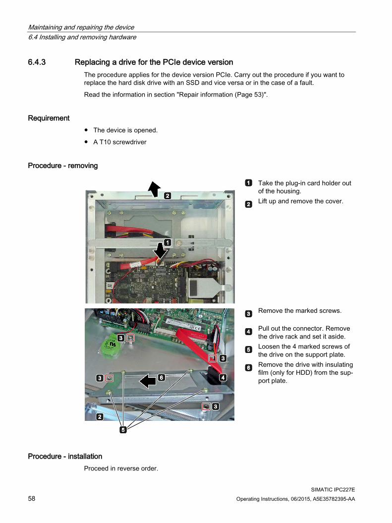
Maintaining and repairing the device 6.4 Installing and removing hardware
SIMATIC IPC227E 58 Operating Instructions, 06/2015, A5E35782395-AA
6.4.3 Replacing a drive for the PCIe device version The procedure applies for the device version PCIe. Carry out the procedure if you want to replace the hard disk drive with an SSD and vice versa or in the case of a fault.
Read the information in section "Repair information (Page 53)".
Requirement ● The device is opened.
● A T10 screwdriver
Procedure - removing
Take the plug-in card holder out of the housing.
Lift up and remove the cover.
Remove the marked screws.
Pull out the connector. Remove the drive rack and set it aside.
Loosen the 4 marked screws of the drive on the support plate.
Remove the drive with insulating film (only for HDD) from the sup-port plate.
Procedure - installation Proceed in reverse order.
Maintaining and repairing the device 6.5 Installing the software
SIMATIC IPC227E Operating Instructions, 06/2015, A5E35782395-AA 59
6.5 Installing the software
6.5.1 Reinstalling the operating system
6.5.1.1 General installation procedure If your operating system is no longer functioning correctly, you can reinstall it in one of two ways:
● With the recovery DVD and "Documentation and Drivers" CD/DVD
● With the Restore DVD
Recovery DVD
NOTICE
Windows Embedded
The Recovery DVD is not available for Windows Embedded operating systems.
The Recovery DVD contains the installation program with tools for configuring the drives and installing the operating system and the supported languages (MUI package).
The basic language of the installed operating system is English. To add other languages, install these languages from the Recovery DVD at a later time.
"Documentation and Drivers" CD/DVD
The "Documentation and Drivers" CD/DVD contains the documentation and the hardware drivers.
Restore DVD
The Restore DVD is included in the product package when you have ordered a device with operating system. The DVD contains an image file with the original software package: Operating system with installed hardware drivers and monitoring software, e.g. DiagBase.
6.5.1.2 Restoring the factory state of the software using the Restore DVD You can restore the original factory software using the Restore DVD. The DVD contains the necessary images and tools for transferring the factory software to the hard disk / SSD or memory card of your PC. The following options are available for restoring software:
● Restore the entire hard disk / SSD or memory card with drive C: (system) and drive D: Use the "Restore entire hard disk" option.
● Restore drive C: only This allows you to retain any user data on drive D: Use the "Restore system partition only" option.
Maintaining and repairing the device 6.5 Installing the software
SIMATIC IPC227E 60 Operating Instructions, 06/2015, A5E35782395-AA
NOTICE
Data are deleted
When you select the "Restore entire hard disk" option, all data, user settings and authorizations or license keys on the hard disk are lost. The hard disk is reset to the delivery state with partitions "C:" and "D:".
If the "Restore system partition only" option is set, all files on drive C: (System) are deleted. All data, user settings and existing authorizations or license keys on drive "C:" will be lost. Drive "C:" on the hard drive is completely erased, reformatted and the original software is written to it.
Restoring the factory state 1. If the device is not equipped with a DVD drive, connect a USB DVD ROM drive to the
device.
2. Insert the Restore DVD into the drive.
3. Restart the device.
4. Press <ESC> when the following BIOS message appears:
Press Esc for Boot Options
The BIOS selection menu is displayed when initialization is completed.
5. To boot from the Restore DVD, select the Boot Manager.
6. Select the CD/DVD drive from the Boot Manager and confirm the entry.
7. Immediately press any key when you see the following prompt to install the operating system from the Restore DVD.
Press any key to boot from CD or DVD ..
After a few seconds, you will see the installation program.
8. Follow the on-screen instructions.
Note
The "USB Boot" option has to be set to "Enabled" in the BIOS menu "Boot" so that the device can address a USB DVD-ROM drive.

Maintaining and repairing the device 6.5 Installing the software
SIMATIC IPC227E Operating Instructions, 06/2015, A5E35782395-AA 61
6.5.1.3 Installation of Windows 7
Note
Specific information on using the Windows operating systems is available in the following manual (not included in the product package): Microsoft Windows 7 - Technical Reference (MS Press No. 5927).
Requirement ● USB keyboard
● Internal or external DVD ROM drive
● Recovery DVD for the operating system you want to install, which is included in the product package.
Procedure 1. Enable "USB Boot" in the BIOS setup.
2. Insert the Recovery DVD into the DVD drive.
3. Restart the device.
4. Press <ESC> when the following BIOS message appears:
Press Esc for Boot Options
The BIOS selection menu is displayed when initialization is completed.
5. To boot from the Recovery DVD, select the Boot Manager.
6. Select the CD/DVD drive from the Boot Manager and confirm the entry.
7. Immediately press any key when you see the following prompt to install the operating system from the Recovery DVD.
Press any key to boot from CD or DVD ..
After a few seconds, you will see the "Install Windows" installation program.
NOTICE
Data deleted
All data, user settings and existing authorizations or license keys on drive C: are deleted during the installation of Windows 7. • Back up all data. • Check the data and time in the BIOS setup, "Main" menu and correct the displayed
time if necessary.
8. Follow the instructions in the installation program "Install Windows". You will find additional information in the operating system manual.

Maintaining and repairing the device 6.5 Installing the software
SIMATIC IPC227E 62 Operating Instructions, 06/2015, A5E35782395-AA
"Install Windows" installation program The language of the installation program and the operating system you want to install has been preset to English. You can change the language of the operating system after the installation. You can find information on this in section: "Setting up the language selection by means of the Multilanguage User Interface (MUI) (Page 65)".
6.5.1.4 Windows with AHCI Controller
Setting up partitions and integrating unknown data carrier controllers into the operating system You can set up partitions during the installation process and integrate data carrier controllers that are unknown to the operating system. To do so, select "Custom (advanced)" when prompted for the installation type in the "Install Windows" installation program.
The following dialog windows are then available (example):
Refresh Update Load Driver Integration of controller drivers unknown to the operating system and required for
installation. Read the information in the section "Information for systems with data storage medium controller".
Drive options (advanced)
For display of additional functions that you can use to set up the data carriers, see figure "Windows installation window "Drive options (advanced)"".

Maintaining and repairing the device 6.5 Installing the software
SIMATIC IPC227E Operating Instructions, 06/2015, A5E35782395-AA 63
Windows installation window "Drive options (advanced)":
Refresh Update Load Driver Integration of controller drivers unknown to the operating system and required for
installation. Read the information in the section "Information for systems with data storage medium controller".
Delete Deleting a partition Extend Changing the partition size Format Formatting a partition New Creating new partitions
Identification for error messages, for example, if the data carrier was not format-ted in the required "NTFS" format.

Maintaining and repairing the device 6.5 Installing the software
SIMATIC IPC227E 64 Operating Instructions, 06/2015, A5E35782395-AA
Procedure
Note
If you want to install the operating system on a data carrier connected to a data carrier controller unknown to the operating system, you have to integrate the driver of the data carrier controller. Integrate this driver before starting the partitioning of the data carrier and installing the operating system, see Section "Information for systems with data carrier controller".
1. Make sure that the partition on which you want to install the operating system is large enough and is set up with a NTFS file system.
The recommended minimum size of this partition varies, depending on the operating system, how much RAM you have available and how much additional software you want to use. Information on how the data carrier is partitioned in its factory state is available in the following tables.
2. Select the partition on which you want to install the operating system.
3. Click "Next".
Installation is started.
Examples of partitions in the factory state Windows 7 32 bit: Partition Name Size File system First SYSTEM 50 GB NTFS not compressed Second DATA Remainder NTFS not compressed
Information for systems with data carrier controller Data carrier controllers unknown to the operating system must be made known to the operating system prior to installation in the "Install Windows" installation program.
Requirement
You have copied the relevant controller driver to a USB stick.
Procedure
1. Connect the USB stick with the controller driver to the device.
2. Start the "Install Windows" installation program as described above.
3. Select "Load Drivers" in the Windows installation window.
4. Select the respective driver on the USB stick.

Maintaining and repairing the device 6.5 Installing the software
SIMATIC IPC227E Operating Instructions, 06/2015, A5E35782395-AA 65
6.5.1.5 Setting up the language selection by means of the Multilanguage User Interface (MUI) You can set the display of menus, dialogs or other information, such as date and time, to a different language. For this purpose, you can either select one of the preinstalled languages or install a new language package.
The following command sequences are described in English. Depending on the default setting, they can be displayed in another language.
Setting up the language selection in Windows 7
Note
Specific information on setting up the language selection for Windows operating systems can be found in the manual "Microsoft Windows 7, Technical Reference (MS Press No. 5927)", not included in the product package.
Changing the settings for language, region and formats of a registered user account
1. Choose:
"Start > Control Panel > Clock, Language, and Region > Regional and Language Options"
2. You can make the desired changes in the "Formats", "Location" and "Keyboards and Languages" tabs.
Changing the settings for language, region and formats of the system account and the standard user account
You can change the settings for language, region and formats of the system account (for example, the language in the user login dialog) and the settings of the standard user account (standard setting for new users). The settings of the registered user are copied to the system account and the standard user account for this purpose.
1. Choose:
"Start > Control Panel > Clock, Language, and Region > Regional and Language Options"
2. You can make the required changes in the "Administrative" tab. You copy the settings by clicking the respective button.
Installing new language packages
The available language packages are described in the section "Configuration of the device". Some language packages are available on the Recovery DVD in the "Languagepacks" folder.
1. Choose:
"Start > Control Panel > Clock, Language, and Region > Regional and Language Options"
2. Select the "Keyboards and Languages" tab.
3. Click the "Install/uninstall languages" button and make the required changes.
Maintaining and repairing the device 6.5 Installing the software
SIMATIC IPC227E 66 Operating Instructions, 06/2015, A5E35782395-AA
6.5.2 Partitioning data media
6.5.2.1 Partitioning in Windows Embedded Standard 7 You will need to reconfigure the partitions after installing a new drive, to repair corrupt partitions or to change the partitioning.
Partitioning of the SIMATIC IPC CFast card The SIMATIC IPC CFast card for Windows Embedded Standard 7 comes configured with the following default partitions: Partition Name Size of the card File system
8 GB 16 GB 1st Partition SYSTEM 7 GB 12 GB NTFS (compressed) 2nd Partition DATA Remainder Remainder NTFS (compressed)
* Due to partitioning/formatting, the actual CFast capacity does not correspond to the memory size specified on the SIMATIC IPC CFast card.
Partitioning of the HDD or SSD In the delivery state, the following partitions are configured on the HDD or SSD drive with the Windows Embedded Standard 7 operating system: Partition Name Size of data medium File system
>64 GB >100 GB Primary System 50 GB 100 GB NTFS not compressed Second Data Remainder Remainder NTFS not compressed
To restore the partitions to their original delivery state, we recommend you use the software SIMATIC IPC Image & Partition Creator. Additional information is available in the accompanying documentation.
6.5.2.2 Partitions under Windows 7 Ultimate If partitions become corrupted or partitioning has to be changed after the installation of a new drive, it is necessary to set up the partitions again.
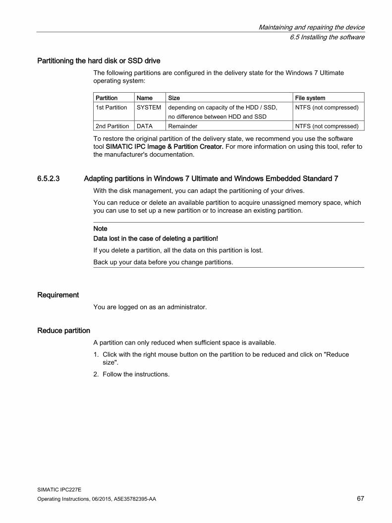
Maintaining and repairing the device 6.5 Installing the software
SIMATIC IPC227E Operating Instructions, 06/2015, A5E35782395-AA 67
Partitioning the hard disk or SSD drive The following partitions are configured in the delivery state for the Windows 7 Ultimate operating system: Partition Name Size File system 1st Partition SYSTEM depending on capacity of the HDD / SSD,
no difference between HDD and SSD NTFS (not compressed)
2nd Partition DATA Remainder NTFS (not compressed)
To restore the original partition of the delivery state, we recommend you use the software tool SIMATIC IPC Image & Partition Creator. For more information on using this tool, refer to the manufacturer's documentation.
6.5.2.3 Adapting partitions in Windows 7 Ultimate and Windows Embedded Standard 7 With the disk management, you can adapt the partitioning of your drives.
You can reduce or delete an available partition to acquire unassigned memory space, which you can use to set up a new partition or to increase an existing partition.
Note Data lost in the case of deleting a partition!
If you delete a partition, all the data on this partition is lost.
Back up your data before you change partitions.
Requirement You are logged on as an administrator.
Reduce partition A partition can only reduced when sufficient space is available.
1. Click with the right mouse button on the partition to be reduced and click on "Reduce size".
2. Follow the instructions.

Maintaining and repairing the device 6.5 Installing the software
SIMATIC IPC227E 68 Operating Instructions, 06/2015, A5E35782395-AA
Increase partition
Note
To increase a partition, this partition must not be formatted with a file system or the partition must be formatted with an "NTFS" file system.
1. Click in the partition manager with the right mouse button on the partition to be increased and click on "Increase size".
2. Follow the instructions on the screen.
Additional information is available in the "Help" menu under "Help topics" and "Search".
6.5.3 Installing drivers and software
Note
In the case of multilingual operating systems (MUI versions), you have to set the regional settings for menus and dialogs and the default language to English (US) before you install new drivers or operating system updates.
You can install an additional language package for service purposes at a later time with the Restore DVD under Windows Embedded Standard 7.
Procedure 1. If your device has no CD/DVD drive, connect an external USB CD/DVD drive to a USB
port.
2. Insert the "Documentation and Drivers" CD/DVD provided.
3. Start the "START" program.
4. Select "Drivers" from the index.
5. Select the device and operating system.
6. Select the desired driver
7. Open the folder with the driver data by clicking on the link next to "Driver path".
8. Start the setup program in this folder.
Note
For a new installation of Windows operating systems, the chipset driver must be installed before all other drivers, if required.

Maintaining and repairing the device 6.5 Installing the software
SIMATIC IPC227E Operating Instructions, 06/2015, A5E35782395-AA 69
6.5.4 Installing updates
6.5.4.1 Updating the operating system
Windows The latest updates for the Windows operating system are available on the Internet at Microsoft (http://www.microsoft.com) and on the device in the Start menu "Start > All Programs > Windows Update > Check for updates".
Note
Before you install new drivers or operating system updates for Windows MUI versions, configure the regional menu and dialog settings and the default English (US) language.
other operating systems Contact the corresponding manufacturer.
6.5.4.2 Installing or updating application programs and drivers To install software from a CD and/or floppy disk in a Windows operating system, you must connect a suitable external USB drive to the computer.
The drivers for USB floppy drives and USB CD-R drives are included in the operating system and do not have to be installed separately.
For information about installation of SIMATIC software packages, refer to the corresponding manufacturer documentation.
For updates of third-party drivers and application programs, contact the respective manufacturer.
6.5.5 Backing up data We recommend that you use the SIMATIC IPC Image & Partition Creator software tool for data backups in Windows Embedded Standard 7 and Windows 7 (as of V3.4). This tool provides convenient and efficient functions for backing up and restoring the full content of memory cards, hard disks and individual partitions (images).
SIMATIC IPC Image & Partition Creator supports the burning of DVD media only. You can order the tool using the Siemens online ordering system (https://mall.industry.siemens.com). For more information about SIMATIC IPC Image & Partition Creator, refer to its product documentation.

Maintaining and repairing the device 6.5 Installing the software
SIMATIC IPC227E 70 Operating Instructions, 06/2015, A5E35782395-AA

SIMATIC IPC227E Operating Instructions, 06/2015, A5E35782395-AA 71
Technical specifications 7 7.1 Certificates and approvals
The device meets the guidelines listed in the following sections.
EC Declaration of Conformity
The associated declaration of conformity is available on the Internet at the following address: EC declaration of conformity, UL approval for Canada/USA (http://support.automation.siemens.com/WW/view/en/48958203).
DIN ISO 9001 certificate The Siemens quality management system for all production processes (development, production and sales) meets the requirements of DIN ISO 9001:2000.
This has been certified by DQS (the German society for the certification of quality management systems).
Certificate registration no. DE-000656 QM08
Software license agreements If the device is supplied with preinstalled software, you must observe the corresponding license agreements.
UL approval The following approvals are available for the device:
● Underwriters Laboratories (UL) in accordance with Standard UL 60950-1 Second Edition, File E115352 (I.T.E)
● Underwriters Laboratories (UL) in accordance with Standard UL508 (IND.CONT.EQ), File E85972
● Canadian National Standard CAN/CSA-C22.2 No. 60950-1-07
● Canadian National Standard CAN/CSA-C22.2 No. 142
cULus HAZ. LOC. approval in file E223122 The following approvals are available for the device if specified on the rating plate:
Underwriters Laboratories Inc. according to
● ISA 12.12.01 (Hazardous Location)
● CSA C22.2 No. 213 (Hazardous Location)
APPROVED for use in
● Class I, Division 2, Group A, B, C, D Tx
● Class I, Zone 2, Group IIC Tx

Technical specifications 7.1 Certificates and approvals
SIMATIC IPC227E 72 Operating Instructions, 06/2015, A5E35782395-AA
Note the following information:
Note
This product must be installed according to the NEC (National Electric Code) stipulations.
When used in environments according to class I, division 2 (see above), the device must be mounted in an enclosure that corresponds to at least IP54 according to EN 60529.
ATEX and IECEx
Devices of Cat3G for use in Zone 2.
FCC and Canada USA Federal Commu-nications Commis-sion Radio Frequency Interference Statement
This equipment has been tested and found to comply with the limits for a Class A digital device, pursuant to Part 15 of the FCC Rules. These limits are designed to provide reasonable protection against harmful interference when the equip-ment is operated in a commercial environment. This equipment generates, uses, and can radiate radio frequency energy and, if not installed and used in accord-ance with the instruction manual, may cause harmful interference to radio com-munications. Operation of this equipment in a residential area is likely to cause harmful interference in which case the user will be required to correct the inter-ference at his own expense.
Shielded Cables Shielded cables must be used with this equipment to maintain compliance with FCC regulations.
Modifications Changes or modifications not expressly approved by the manufacturer could void the user's authority to operate the equipment.
Conditions of Operations
This device complies with Part 15 of the FCC Rules. Operation is subject to the following two conditions: (1) this device may not cause harmful interference, and (2) this device must accept any interference received, including interference that may cause undesired operation.
CANADA Canadian Notice This Class B digital apparatus complies with Canadian ICES-003 (B). Avis Canadien Cet appareil numérique de la classe B est conforme à la norme NMB-003
(B) du Canada.
AUSTRALIA / NEW ZEALAND This product meets the requirements of the standard EN 61000-6-3:2007 Generic standards - Emission standard for residential, commercial and light-industrial environments.
This product meets the requirements of the standard EN 61000-6-3:2007 Generic standards - Emission standard for residential, commercial and light-industrial environments.
Identification for Eurasion Customs Union ● EAC (Eurasian Conformity)
● Customs union of Russia, Belarus and Kazakhstan
● Declaration of conformity according to Technical Regulations of the Customs Union (TR CU)

Technical specifications 7.2 Directives and declarations
SIMATIC IPC227E Operating Instructions, 06/2015, A5E35782395-AA 73
KOREA This product meets the requirements of Korean certification.
This product satisfies the requirement of the Korean Certification (KC Mark).
이 기기는 업무용(A급) 전자파 적합기기로서 판매자 또는 사용자는 이 점을 주의하시기 바라며 가정 외의 지역에서 사용하는 것을 목적으로 합니다.
Marine approvals Acceptance procedures for shipping and offshore applications in preparation:
● ABS American Bureau of Shipping (USA)
● BV Bureau Vertias (France)
● DNV Det Norske Veritas (Norway)
● GL Germanische Lloyd
● LR Lloyds Register of Shipping
● Class NK Nippon Kaiji Kyokai (Japan)
7.2 Directives and declarations
7.2.1 Electromagnetic compatibility, Industrial and Residential Areas
Electromagnetic compatibility This product meets the requirements of EC Directive 2004/108/EC "Electromagnetic Compatibility".
The device is designed for the following areas of application corresponding to the CE marking: Scope of application Requirements for Interference emission Immunity to interference Industrial area EN 61000-6-4:2007 +A1:2011 EN 61000-6-2:2005 Residential and commercial are-as and small businesses
EN 61000-6-3:2007 +A1:2011 EN 61000-6-1:2007

Technical specifications 7.2 Directives and declarations
SIMATIC IPC227E 74 Operating Instructions, 06/2015, A5E35782395-AA
7.2.2 ESD guideline
What does ESD mean? An electronic module is equipped with highly integrated components. Due to their design, electronic components are highly sensitive to overvoltage and thus to the discharge of static electricity. Such electronic components or modules are labeled as electrostatic sensitive devices.
The following abbreviations are commonly used for electrostatic sensitive devices:
● ESD – Electrostatic sensitive device
● ESD – Electrostatic Sensitive Device as a common international designation
Electrostatic sensitive devices can be labeled with an appropriate symbol.
NOTICE
Damage to ESD from touch
Electrostatic sensitive devices, ESD, can be destroyed by voltages which are far below the human perception limit. If you touch a component or electrical connections of a module without discharging any electrostatic energy, these voltages may arise.
The damage to a module by an overvoltage can often not be immediately detected and only becomes evident after an extended period of operation. The consequences are incalculable and range from unforeseeable malfunctions to a total failure of the machine or system.
Avoid touching components directly. Make sure that persons, the workstation and the packaging are properly grounded.
Charge Every person without a conductive connection to the electrical potential of his/her surroundings can be electrostatically charged.
The material with which this person comes into contact is of particular significance. The figure shows the maximum electrostatic voltages with which a person is charged, depending on humidity and material. These values conform to the specifications of IEC 61000-4-2.

Technical specifications 7.2 Directives and declarations
SIMATIC IPC227E Operating Instructions, 06/2015, A5E35782395-AA 75
① Synthetic materials ② Wool ③ Antistatic materials such as wood or concrete
NOTICE
Grounding measures
There is no equipotential bonding without grounding. An electrostatic charge is not discharged and may damage the ESD.
Protect yourself against discharge of static electricity. When working with electrostatic sensitive devices, make sure that the person and the workplace are properly grounded.
Protective measures against discharge of static electricity ● Disconnect the power supply before you install or remove modules which are sensitive to
ESD.
● Pay attention to good grounding:
– When handling electrostatical sensitive devices, make sure that persons, the workstation and devices, tools and packaging used are properly grounded. This way you avoid static discharge.
● Avoid direct contact:
– As a general rule, do not touch electrostatic sensitive devices, except in the case of unavoidable maintenance work.
– Hold the modules at their edge so that you do not touch the connector pins or conductor paths. This way, the discharge energy does not reach and damage the sensitive components.
– Discharge your body electrostatically before you take a measurement at a module. Do so by touching grounded metallic parts. Always use grounded measuring instruments.

Technical specifications 7.3 Dimension drawings
SIMATIC IPC227E 76 Operating Instructions, 06/2015, A5E35782395-AA
7.3 Dimension drawings
7.3.1 Dimension drawing basic device
Mounting on a standard rail
all dimensions in mm

Technical specifications 7.3 Dimension drawings
SIMATIC IPC227E Operating Instructions, 06/2015, A5E35782395-AA 77
Wall mounting
all dimensions in mm

Technical specifications 7.3 Dimension drawings
SIMATIC IPC227E 78 Operating Instructions, 06/2015, A5E35782395-AA
Upright mounting
all dimensions in mm

Technical specifications 7.3 Dimension drawings
SIMATIC IPC227E Operating Instructions, 06/2015, A5E35782395-AA 79
7.3.2 Dimension drawing PCIe device version
Mounting on a standard rail
all dimensions in mm
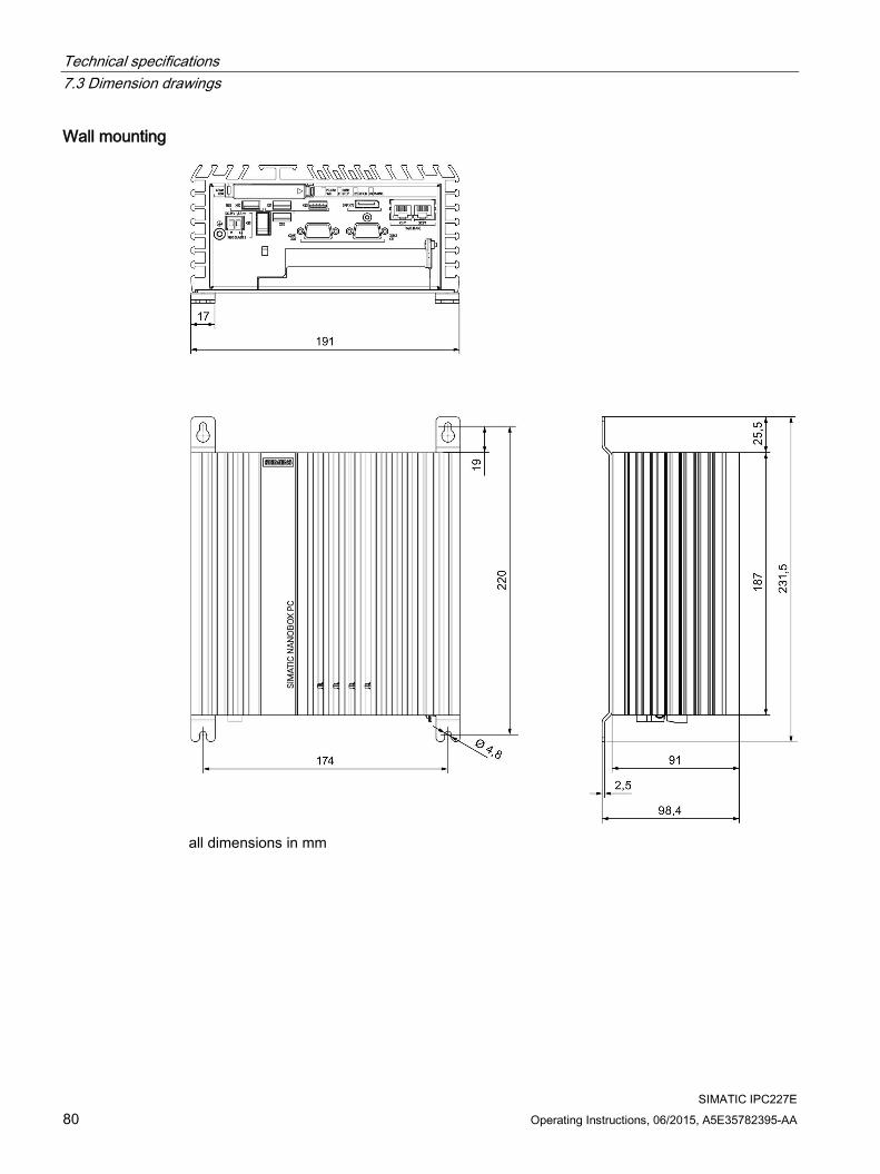
Technical specifications 7.3 Dimension drawings
SIMATIC IPC227E 80 Operating Instructions, 06/2015, A5E35782395-AA
Wall mounting
all dimensions in mm

Technical specifications 7.3 Dimension drawings
SIMATIC IPC227E Operating Instructions, 06/2015, A5E35782395-AA 81
Upright mounting
all dimensions in mm

Technical specifications 7.4 Technical data
SIMATIC IPC227E 82 Operating Instructions, 06/2015, A5E35782395-AA
7.4 Technical data
7.4.1 General technical specifications
General technical specifications Order number See order documents Weight with hard disk drive, without mounting brackets
• Basic: Approx. 1.4 kg • PCIe: Approx. 2.4 kg
Power supply 1 24 VDC (19.2 to 28.8 V) Brief voltage interruption in accord-ance with Namur
Up to 20 ms buffer time at full load Max. 10 events per hour; recovery time at least 1 s
Current consumption max. 1.8 A at 24 V Noise emission < 40 dB(A) according to DIN 45635-1 Degree of protection IP 40 in accordance with IEC 60529 Protection class Protection class I in accordance with IEC 61140 Quality assurance In accordance with ISO 9001 1 The device should only be connected to a 24 VDC power supply which meets the requirements of
safe extra low voltage (SELV) according to IEC/EN/DIN EN/UL 60950-1. The power supply must fulfill the requirement NEC Class 2 or LPS according to IEC/EN/DINEN/UL 60950-1.
Electromagnetic compatibility Immunity with regard to conduct-ed interference on the supply lines
± 2 kV in accordance with IEC 61000-4-4; Burst ± 1 kV in accordance with IEC 61000-4-5; symmetrical surge ± 2 kV in accordance with IEC 61000-4-5; asymmetrical surge
Noise immunity on signal lines ± 1 kV to IEC 61000-4-4; Burst; Length < 3 m ± 2 kV in accordance with IEC 61000-4-4; Burst; length > 3 m ± 2 kV in accordance with IEC 61000-4-5; Surge; length > 30 m
Immunity to discharges of static electricity
± 6 kV contact discharge in accordance with IEC 61000-4-2 ± 8 kV air discharge in accordance with IEC 61000-4-2
Immunity to RF interference 10 V/m, 80 … 2 GHz, 80 % AM according to IEC 61000-4-3 3 V/m, 2 … 2.7 GHz, 80 % AM according to IEC 61000-4-3 10 V, 10 KHz … 80 MHz, 80 % AM according to IEC 61000-4-6
Magnetic field 100 A/m, RMS value 50/60 Hz in accordance with IEC 61000-4-8

Technical specifications 7.4 Technical data
SIMATIC IPC227E Operating Instructions, 06/2015, A5E35782395-AA 83
Main circuit board Processor • Intel Celeron N2807: Dual Core, 1.58 GHz, burst frequency
2.16 GHz, 1 MB 2nd level cache, 4.3W TDP • Intel Celeron N2930: Quad Core, 1.83 GHz, burst frequency
2.16 GHz, 2 MB 2nd level cache, 7.5W TDP
RAM DDR3L memory up to 8 GB, 1× SODIMM modules / non-ECC Buffer memory 512 KB MRAM
128 KB of this can be backed up at full load in the buffer time of the power supply.
Expansion slots 1 x PCIe x1 for PCIe x1 cards up to a length of 175 mm The PCIe slot supports the "PCI Express 2.0" specification. You can find additional information in the section "Power re-quirements of the components".
Drive, memory medium Hard disk drive, optional ≥ 320 GB, 2.5" HDD Solid-state drive, optional ≥ 80 GB, 2.5" SATA SSD
≥ 160 GB, 2.5" SATA SSD CFast memory card, optional • 4 GB or
• 8 GB or • 16 GB
Floppy and CD-ROM drive External, can be connected via USB port 1 USB stick External, can be connected via USB port 1 Only to device USB port, not via USB hub
Graphics Graphics controller Integrated Graphic Controller Graphics memory Up to 512 MB, shared memory Resolution, graphics memory • DisplayPort resolution:
640 × 480 pixels to 2560 × 1600 pixels • up to 512 MB, graphics memory is taken from the main
memory, dynamic UMA

Technical specifications 7.4 Technical data
SIMATIC IPC227E 84 Operating Instructions, 06/2015, A5E35782395-AA
Ports COM • RS 232 1, max. 115 Kbps, D-sub connector, 9-pin
• RS 485 1 2/RS 422 1 (optional), max. 115 Kbps, D-sub con-nector, 9-pin
USB 3 × USB 2.0, high speed/high current, maximum of 2 can be operated in high-current mode at the same time, max. 6 W 1 × USB 3.0, high current You can find additional information in the section "Power re-quirements of the components".
LAN interface X1 P1, RJ45 3 Intel LAN Controller Springville i210 10, 100, 1000 Mbps, teaming 4
LAN interface X2 P1, RJ45 3 Intel LAN Controller Springville i210 10, 100, 1000 Mbps, teaming 4
Keyboard, mouse Connection via USB port 1 In BIOS Setup, you can configure support for RS 232 or RS 422 / RS 485 for each COM port.
Available parameters: - Autodirection
- Onboard termination - Half-duplex or Full-duplex
2 Termination can be set in BIOS. 3 For unique labeling, the LAN interfaces are numbered on the enclosure. The numbering by the
operating system can differ. 4 Teaming can be set and initiated in the configuration interface. In teaming operation, jumbo
frames, e.g. for the camera application, are not supported.
See also Permitted mounting positions (Page 24)
7.4.2 Ambient conditions
Climatic ambient conditions The temperature values have been checked in accordance with IEC 60068-2-1, IEC 60068-2-2 and IEC 60068-2-14. For permitted mounting positions, see section "Preparing installation".
Note Installation with temperatures > 50 °C only in RAL
If you want to operate the device at an ambient temperature of > +50 °C, you need to install it in a Restricted Access Location (RAL), for example in a locked control cabinet.
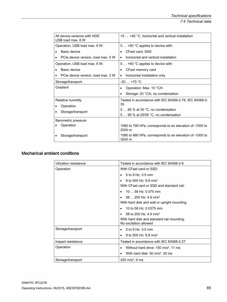
Technical specifications 7.4 Technical data
SIMATIC IPC227E Operating Instructions, 06/2015, A5E35782395-AA 85
All device versions with HDD USB load max. 6 W
+5 … +40 °C, horizontal and vertical installation
Operation, USB load max. 6 W: • Basic device • PCIe device version, load max. 5 W
0 … +50 °C applies to device with: • CFast card, SSD • horizontal and vertical installation
Operation, USB load max. 6 W: • Basic device • PCIe device version, load max. 3 W
0 … +60 °C applies to device with: • CFast memory card • horizontal installation only
Storage/transport -20 … +70 °C Gradient • Operation: Max. 10 °C/h
• Storage: 20 °C/h, no condensation
Relative humidity • Operation • Storage/transport
Tested in accordance with IEC 60068-2-78, IEC 60068-2-30 5 … 85 % at 30 °C, no condensation 5 … 95 % at 25/55 °C, no condensation
Barometric pressure • Operation
• Storage/transport
1080 to 795 hPa, corresponds to an elevation of -1000 to 2000 m 1080 to 660 hPa, corresponds to an elevation of -1000 to 3500 m
Mechanical ambient conditions Vibration resistance Tested in accordance with IEC 60068-2-6 Operation With CFast card or SSD:
• 5 to 9 Hz: 3.5 mm • 9 to 500 Hz: 9.8 m/s2 With CFast card or SSD and standard rail: • 10 ... 58 Hz: 0.075 mm • 58 ... 200 Hz: 4.9 m/s2 With hard disk and wall or upright mounting: • 10 to 58 Hz: 0.0375 mm • 58 to 200 Hz: 4.9 m/s² With hard disk and standard rail mounting: No excitation allowed
Storage/transport • 5 to 9 Hz: 3.5 mm • 9 to 500 Hz: 9.8 m/s2
Impact resistance Tested in accordance with IEC 60068-2-27 Operation • Without hard drive: 150 m/s2, 11 ms
• With hard disk: 50 m/s2, 30 ms
Storage/transport 250 m/s2, 6 ms

Technical specifications 7.4 Technical data
SIMATIC IPC227E 86 Operating Instructions, 06/2015, A5E35782395-AA
7.4.3 Shipbuilding
Ambient conditions for use of the devices in shipbuilding The device is suitable for shipping and offshore applications. The installation and attachment conditions are the same as those for industrial applications.
See the shipbuilding approvals of the individual shipbuilding companies in the section "Certificates and approvals" to learn about the required ambient conditions.
NOTICE
Ambient conditions and installation guidelines
The permissible ambient conditions and installation guidelines can be found in the certificates of the individual shipbuilding companies.
7.4.4 Power demand of the components
Maximum power consumption of the auxiliary components Auxiliary components Maximum permitted power con-
sumption Max. total power
+5 V +3.3 V +12 V USB device 3.0 High current 900 mA -- -- 6 W (for all USB devices) USB Device 2.0 High current 500 mA -- -- PCIe module Per slot -- 1.5 A 1 0.3 A 2 5 W in total 1 May amount to maximum 3.0 A for up to 100 ms at start-stop torque of device
2 May amount to maximum 1.2 A for up to 100 ms at start-stop torque of device
Note Device can overheat!
The power supply cannot make unlimited power available. The auxiliary components consume energy and produce heat.
The device may overheat. The auxiliary components will be damaged.

Technical specifications 7.4 Technical data
SIMATIC IPC227E Operating Instructions, 06/2015, A5E35782395-AA 87
7.4.5 Direct current supply (DC)
Technical specifications Input voltage 24 VDC (19.2 to 28.8 VDC) Power consumption Max. 32 W Buffering upon power failure Hold-up time > 15 ms (after > 5 ms, DC_FAIL becomes
active) Maximum continuous output power 1 27 W Protection class Safety class I (A protective conductor must be connected
to the device) 1 The power specifications apply to the power supply component not to the device.
Note Inrush current
The requirements in accordance with NAMUR NE21, Section 4.5 are complied with. The maximum inrush current does not exceed 4 A. Typical value with an input voltage of 24 V is 2 A for 25 ms. A 24 V power source with a limit current lower than 2.0 A is not permitted. A voltage drop under 18.0 V during booting of the device is not permitted.
Typical power consumption Power consumption
(at 24 V rated voltage) Basic device with Intel Celeron N2807 13 W Basic device with Intel Celeron N2930 15 W USB expansion See section "Power requirements of the components" Expansion PCIe

Technical specifications 7.5 Hardware descriptions
SIMATIC IPC227E 88 Operating Instructions, 06/2015, A5E35782395-AA
7.5 Hardware descriptions
7.5.1 Technical features of the motherboard Component / port
Description Parameters
Chipset integrated in CPU BIOS Core, Video, ACPI CPU Intel Celeron N2930 / N2807 Memory DDR3L SODIMM 2 GB, 4 GB and 8 GB Graphics Integrated graphics up to 512 MB graphics memory taken dynamically
from RAM
7.5.2 External interfaces
7.5.2.1 Overview of interfaces Interface Position Description COM External 9-pin D-sub, either:
• RS 232 • RS 485/RS 422
configurable in BIOS Setup
CFast External CFast card USB External 4 USB channels 3 × USB 2.0
1 × USB 3.0 Ethernet External 2 x RJ45 10/100/1000 Mbps DisplayPort External DP
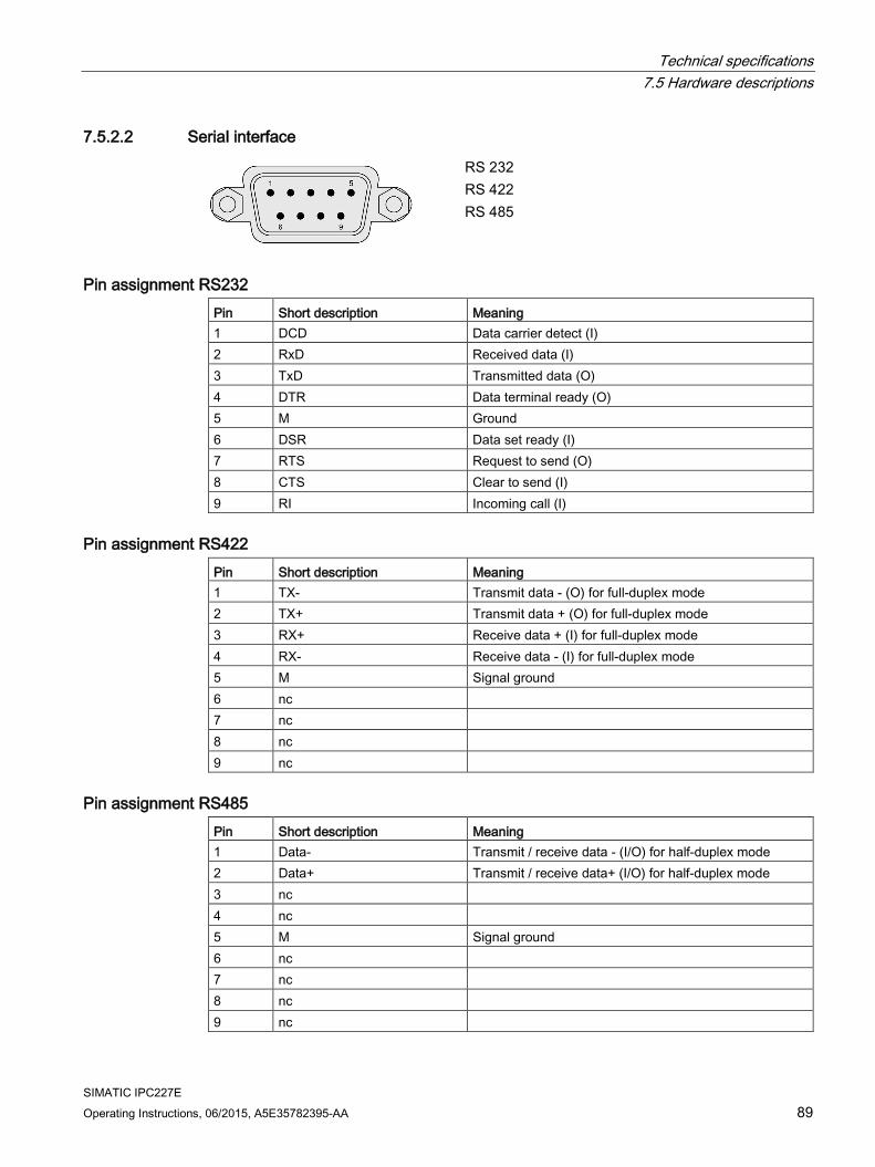
Technical specifications 7.5 Hardware descriptions
SIMATIC IPC227E Operating Instructions, 06/2015, A5E35782395-AA 89
7.5.2.2 Serial interface
RS 232 RS 422 RS 485
Pin assignment RS232 Pin Short description Meaning 1 DCD Data carrier detect (I) 2 RxD Received data (I) 3 TxD Transmitted data (O) 4 DTR Data terminal ready (O) 5 M Ground 6 DSR Data set ready (I) 7 RTS Request to send (O) 8 CTS Clear to send (I) 9 RI Incoming call (I)
Pin assignment RS422 Pin Short description Meaning 1 TX- Transmit data - (O) for full-duplex mode 2 TX+ Transmit data + (O) for full-duplex mode 3 RX+ Receive data + (I) for full-duplex mode 4 RX- Receive data - (I) for full-duplex mode 5 M Signal ground 6 nc 7 nc 8 nc 9 nc
Pin assignment RS485 Pin Short description Meaning 1 Data- Transmit / receive data - (I/O) for half-duplex mode 2 Data+ Transmit / receive data+ (I/O) for half-duplex mode 3 nc 4 nc 5 M Signal ground 6 nc 7 nc 8 nc 9 nc

Technical specifications 7.5 Hardware descriptions
SIMATIC IPC227E 90 Operating Instructions, 06/2015, A5E35782395-AA
7.5.2.3 CFast Pin Short name Meaning S1 SGND Signal GND (ground for signal integrity) S2 A+ SATA differential S3 A- SATA differential S4 SGND Signal GND (ground for signal integrity) S5 B- SATA differential S6 B+ SATA differential S7 SGND Signal GND (ground for signal integrity) PC1 CDI Card Detect In PC2 GND Device GND PC3 TBD TBD (not connected) PC4 TBD TBD (not connected) PC5 TBD TBD (not connected) PC6 TBD TBD (not connected) PC7 GND Device GND PC8 LED1 LED Output (not connected) PC9 LED2 LED Output (not connected) PC10 IO1 Reserved Input/Output (not connected) PC11 IO2 Reserved Input/Output (not connected) PC12 IO3 Reserved Input/Output (not connected) PC13 PWR Device Power (3.3V) PC14 PWR Device Power (3.3V) PC15 GND Device GND PC16 GND Device GND PC17 CDO Card Detect Out
7.5.2.4 USB 2.0 port
Pin Short description Meaning 1 USB_P5V_fused (O) +5 V, fused 2 USB_D0M (I/O) Data– 3 USB_D0P (I/O) Data+ 4 USB_GND GND

Technical specifications 7.5 Hardware descriptions
SIMATIC IPC227E Operating Instructions, 06/2015, A5E35782395-AA 91
7.5.2.5 USB 3.0 port
Pin Short name Meaning Input / output 1 VBUS + 5 V (fused) Output 2 D- Data channel USB2 Input / output 3 D+ Data channel USB2 Input / output 4 GND Ground – 5 RX- Data channel USB3 Input 6 RX+ Data channel USB3 Input 7 GND Ground – 8 TX- Data channel USB3 Output 9 TX+ Data channel USB3 Output
7.5.2.6 DisplayPort
Pin Short name Meaning Input / output 1 ML_Lane0+ DP data 0+ Output 2 GND Ground - 3 ML_Lane0- DP data 0- Output 4 ML_Lane1+ DP data 1+ Output 5 GND Ground - 6 ML_Lane1- DP data 1- Output 7 ML_Lane2+ DP data 2+ Output 8 GND Ground - 9 ML_Lane2- DP data 2- Output 10 ML_Lane3+ DP data 3+ Output 11 GND Ground - 12 ML_Lane3- DP data 3- Output 13 CONFIG1 CAD Cable Adapter Detect Input 14 CONFIG2 Ground (PullDown) - 15 AUX_CH+ Auxiliary channel+ Bidirectional 16 GND Ground - 17 AUX_CH- Auxiliary channel- Bidirectional 18 HPD Hot Plug Detect Input 19 GND Ground - 20 DP_PWR +3.3V (fused) Output

Technical specifications 7.5 Hardware descriptions
SIMATIC IPC227E 92 Operating Instructions, 06/2015, A5E35782395-AA
7.5.2.7 Ethernet port
Pin Short description Meaning 1 BI_DA+ Bidirectional data A+, input/output 2 BI_DA– Bidirectional data A–, input/output 3 BI_DB+ Bidirectional data B+, input/output 4 BI_DC+ Bidirectional data C+, input/output 5 BI_DC– Bidirectional data C–, input/output 6 BI_DB– Bidirectional data B–, input/output 7 BI_DD+ Bidirectional data D+, input/output 8 BI_DD– Bidirectional data D–, input/output
LED Short description Meaning 1 LED 1 Off: 10 Mbps
Lit green: 100 Mbps Lit orange: 1000 Mbps
2 LED 2 Lit orange: Connection established Flashes: Activity
7.5.3 Internal interfaces
7.5.3.1 Overview of internal interfaces Interface Position Connector Description PCIe x1 Internal PCIe x1 interface
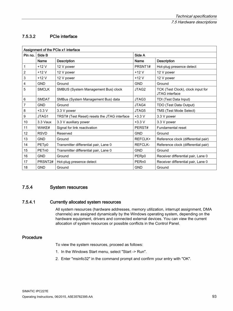
Technical specifications 7.5 Hardware descriptions
SIMATIC IPC227E Operating Instructions, 06/2015, A5E35782395-AA 93
7.5.3.2 PCIe interface
Assignment of the PCIe x1 interface Pin no. Side B Side A
Name Description Name Description 1 +12 V 12 V power PRSNT1# Hot-plug presence detect 2 +12 V 12 V power +12 V 12 V power 3 +12 V 12 V power +12 V 12 V power 4 GND Ground GND Ground 5 SMCLK SMBUS (System Management Bus) clock JTAG2 TCK (Test Clock), clock input for
JTAG interface 6 SMDAT SMBus (System Management Bus) data JTAG3 TDI (Test Data Input) 7 GND Ground JTAG4 TDO (Test Data Output) 8 +3.3 V 3.3 V power JTAG5 TMS (Test Mode Select) 9 JTAG1 TRST# (Test Reset) resets the JTAG interface +3.3 V 3.3 V power 10 3.3 Vaux 3.3 V auxiliary power +3.3 V 3.3 V power 11 WAKE# Signal for link reactivation PERST# Fundamental reset 12 RSVD Reserved GND Ground 13 GND Ground REFCLK+ Reference clock (differential pair) 14 PETp0 Transmitter differential pair, Lane 0 REFCLK- Reference clock (differential pair) 15 PETn0 Transmitter differential pair, Lane 0 GND Ground 16 GND Ground PERp0 Receiver differential pair, Lane 0 17 PRSNT2# Hot-plug presence detect PERn0 Receiver differential pair, Lane 0 18 GND Ground GND Ground
7.5.4 System resources
7.5.4.1 Currently allocated system resources All system resources (hardware addresses, memory utilization, interrupt assignment, DMA channels) are assigned dynamically by the Windows operating system, depending on the hardware equipment, drivers and connected external devices. You can view the current allocation of system resources or possible conflicts in the Control Panel.
Procedure To view the system resources, proceed as follows:
1. In the Windows Start menu, select "Start -> Run".
2. Enter "msinfo32" in the command prompt and confirm your entry with "OK".
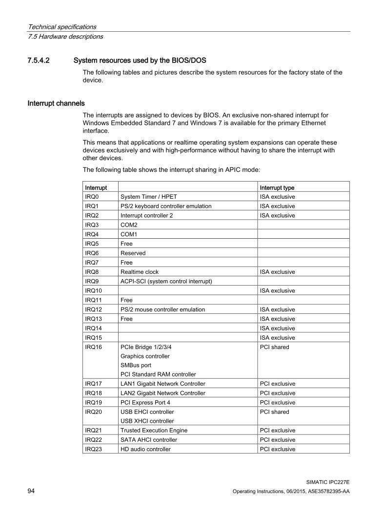
Technical specifications 7.5 Hardware descriptions
SIMATIC IPC227E 94 Operating Instructions, 06/2015, A5E35782395-AA
7.5.4.2 System resources used by the BIOS/DOS The following tables and pictures describe the system resources for the factory state of the device.
Interrupt channels The interrupts are assigned to devices by BIOS. An exclusive non-shared interrupt for Windows Embedded Standard 7 and Windows 7 is available for the primary Ethernet interface.
This means that applications or realtime operating system expansions can operate these devices exclusively and with high-performance without having to share the interrupt with other devices.
The following table shows the interrupt sharing in APIC mode: Interrupt Interrupt type IRQ0 System Timer / HPET ISA exclusive IRQ1 PS/2 keyboard controller emulation ISA exclusive IRQ2 Interrupt controller 2 ISA exclusive IRQ3 COM2 IRQ4 COM1 IRQ5 Free IRQ6 Reserved IRQ7 Free IRQ8 Realtime clock ISA exclusive IRQ9 ACPI-SCI (system control interrupt) IRQ10 ISA exclusive IRQ11 Free IRQ12 PS/2 mouse controller emulation ISA exclusive IRQ13 Free ISA exclusive IRQ14 ISA exclusive IRQ15 ISA exclusive IRQ16 PCIe Bridge 1/2/3/4
Graphics controller SMBus port PCI Standard RAM controller
PCI shared
IRQ17 LAN1 Gigabit Network Controller PCI exclusive IRQ18 LAN2 Gigabit Network Controller PCI exclusive IRQ19 PCI Express Port 4 PCI exclusive IRQ20 USB EHCI controller
USB XHCI controller PCI shared
IRQ21 Trusted Execution Engine PCI exclusive IRQ22 SATA AHCI controller PCI exclusive IRQ23 HD audio controller PCI exclusive

Technical specifications 7.5 Hardware descriptions
SIMATIC IPC227E Operating Instructions, 06/2015, A5E35782395-AA 95
7.5.5 Input/output address areas
7.5.5.1 Overview of the internal module registers The following addresses are used for the internal registers:
Addresses Input/output unit I/O 062h Watchdog enable register / 066h select register (Page 95) I/O 066h Watchdog trigger register (read only, address 066h) (Page 96) I/O 404Eh - 404Fh Output register LED 1/2/3 and SF LED / RUN/STOP LED (Page 96) I/O 404Dh Battery status register (read-only) (Page 96)
7.5.5.2 Watchdog enable register / 066h select register (read/write, address 062h)
Meaning of the bits
Watchdog enable register / 066h select register (r/w address 062h) Bit Meaning of the bits 7 6 5 4 3 2 1 0
Watchdog enable bit (WDE) 0 Watchdog circuit disabled 1 Watchdog circuit enabled
Watchdog Mode 0 Standard 1 Macro
066h select register selection 0 Reserved 1
Scaler watchdog time (Normal/Macro) 0 0 0 94 ms / 2 s (default) 0 0 1 210 ms / 4 s 0 1 0 340 ms / 6 s 0 1 1 460 ms / 8 s 1 0 0 590 ms / 16 s 1 0 1 710 ms / 32 s 1 1 0 840 ms / 48 s 1 1 1 960 ms / 64 s
Trigger red Watchdog LED 0 Red LED (WD) off 1 Red LED (WD) on
Watchdog error / Display and reset 0 WD inactive 1 WD triggered
Reset LED after watchdog alarm (Bit 7 = write 1)

Technical specifications 7.5 Hardware descriptions
SIMATIC IPC227E 96 Operating Instructions, 06/2015, A5E35782395-AA
7.5.5.3 Watchdog trigger register (read only, address 066h)
Watchdog trigger register
The watchdog is triggered by a read action (address 066h) by this register. The result of the read access can be disregarded (i.e., dummy read).
7.5.5.4 Output register user LED L1/L2/L3 (read/write, address 404Eh)
Meaning of the bits The "PC ON/WD" LED flashes yellow to indicate the progress of the BIOS self-test during device startup. After the BIOS self-test has been completed, the "PC ON/WD" LED lights up continuously green.
Output register L1/L2/L3 (read/write, address 404Eh) Bits 15 14 13 12-8 7 6 5 4-0 1 1 LED L1 / Run/Stop dark (default) 1 0 LED L1 / Run/Stop lit yellow 0 x LED L1 / Run/Stop lit green 1 1 LED L2 / SF dark (default) 0 x LED L2 / SF lit red 1 0 LED L2 / SF lit yellow 1 1 LED L3 / Maint dark (default) 0 x LED L3 / Maint lit red 1 0 LED L3 / Maint lit yellow xxxx
xx xxxx
xx Reserved (read/write)
7.5.5.5 Battery status register (read-only, address 50Ch) The status of the CMOS battery is monitored; the status (two-tier) can be read from the battery status register.
Meaning of the bits
Battery status register (read-only, address 404Dh) Bit Meaning 7 6 5 4 3 2 1 0 0 0 CMOS battery capacity is still sufficient. 0 1 CMOS battery capacity is exhausted (remaining capacity is
sufficient for approx. one month) 1 1 CMOS battery is empty

Technical specifications 7.6 BIOS description
SIMATIC IPC227E Operating Instructions, 06/2015, A5E35782395-AA 97
7.5.5.6 MRAM address register MRAM occupies a 512 KB memory address area that can be read via PCI registers.
Meaning of the bits MRAM address register PCI register address: MRAM base address register
PCI register content: MRAM memory address (default)
Length of the memory area
9060 0000h Address is assigned dynamically (depending on device configuration)
80000 h
7.6 BIOS description
7.6.1 Overview
BIOS Setup program The BIOS Setup program, or BIOS Setup for short, is located, together with the setup parameters, in a FLASH block on the motherboard.
You change the setup parameters of the device in the BIOS Setup. Examples: System time, hard disks or boot order.
Changing the device configuration Your device configuration is preset for operating with the included software. You should only change the default setup parameters if you have made technical changes to your device, or if a fault occurs when the device is switched on.
NOTICE
Malfunctions can occur with running software CPU
If a BIOS update of the PC is performed while SIMATIC software controller, a SIMATIC WinAC for example, is running, the software CPU can malfunction, resulting in communication interruptions or failures, for example. Other actions that put a heavy load on the PC hardware, for example, running hardware tests such as benchmarks, can result in malfunctions of the software CPU.
Do not run a BIOS update or other actions that would put a heavy load on the hardware during operation of a software CPU.
Switch the software CPU to "STOP" before you run a BIOS update or perform other critical actions.
Note Documentation
BIOS Setup is described for all devices and device configurations. Some BIOS submenus or Setup parameters may not be included, depending on your order. The interface of your BIOS Setup can deviate from the figures in this document.
You can find a detailed description of the BIOS on the Support website under Entry ID 92189185 (http://support.automation.siemens.com/WW/view/en/92189185).
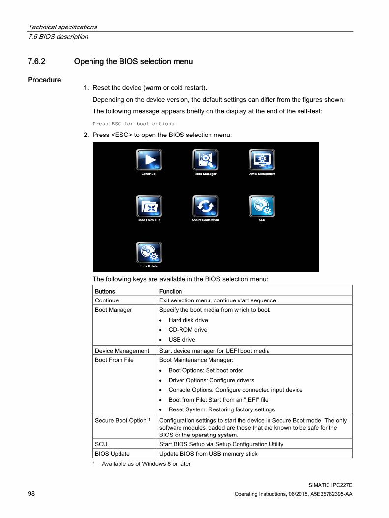
Technical specifications 7.6 BIOS description
SIMATIC IPC227E 98 Operating Instructions, 06/2015, A5E35782395-AA
7.6.2 Opening the BIOS selection menu
Procedure 1. Reset the device (warm or cold restart).
Depending on the device version, the default settings can differ from the figures shown.
The following message appears briefly on the display at the end of the self-test:
Press ESC for boot options
2. Press <ESC> to open the BIOS selection menu:
The following keys are available in the BIOS selection menu:
Buttons Function Continue Exit selection menu, continue start sequence Boot Manager Specify the boot media from which to boot:
• Hard disk drive • CD-ROM drive • USB drive
Device Management Start device manager for UEFI boot media Boot From File Boot Maintenance Manager:
• Boot Options: Set boot order • Driver Options: Configure drivers • Console Options: Configure connected input device • Boot from File: Start from an ".EFI" file • Reset System: Restoring factory settings
Secure Boot Option 1 Configuration settings to start the device in Secure Boot mode. The only software modules loaded are those that are known to be safe for the BIOS or the operating system.
SCU Start BIOS Setup via Setup Configuration Utility BIOS Update Update BIOS from USB memory stick 1 Available as of Windows 8 or later

Technical specifications 7.6 BIOS description
SIMATIC IPC227E Operating Instructions, 06/2015, A5E35782395-AA 99
7.6.3 Configuration The individual setup parameters are distributed between different menus and submenus. The menus always have the same layout.
Menu layout The following figure is an example for the main menu. Device-specific information is shown as blurred.
① Header ④ Help area
② Menu bar ⑤ Key assignment
③ Settings, submenus and device-specific information
A menu is divided into four areas:
● In the menu bar ② on top, you select from the different menus "Main", "Advanced", etc.
● The center left area ③ includes information on your device and you can edit settings that are partly available in submenus.
● The center right area ④ displays short help texts for the currently selected setup parameters.
● The key assignment ⑤ at the bottom shows the function keys and control keys available in BIOS Setup.
You can toggle between the menus with the "←" left and "→" right cursor keys.

Technical specifications 7.6 BIOS description
SIMATIC IPC227E 100 Operating Instructions, 06/2015, A5E35782395-AA
The following table shows the standard menus. Not all menus are included in each supplied device configuration. Menu Meaning Main Display system information, for example, BIOS version, processor and memory Advanced Configure hardware using different submenus Security Security functions, e.g., setting a password Power Specify CPU settings and switch-on functions. Boot Determine boot options, e.g., boot order Exit Save and exit (see Exit menu)
7.6.4 Exit menu You always exit BIOS Setup in this menu.
Exit Saving Changes All changes are saved and the system is restarted with the new Setup parameters.
Save Change Without Exit
All changes are saved
Exit Discarding Changes All changes are discarded and the system is restarted with the old Setup parameters.
Load Optimal Defaults All setup parameters are reset to the safe default values. Notice: The existing Setup parameters are overwritten by this.
Load Custom Defaults The profile must be loaded with the custom Setup parameters. Requirement: The parameters are saved prior to this with "Save Custom Defaults".
Save Custom Defaults The currently configured Setup parameters are saved as a custom profile (see also "Load Custom Defaults").
Discard Changes All changes are discarded.

Technical specifications 7.6 BIOS description
SIMATIC IPC227E Operating Instructions, 06/2015, A5E35782395-AA 101
7.6.5 Default BIOS Setup entries
Documenting your device configuration If you have changed any default settings in Setup, you can enter them in the following table. You can then refer to these entries for any future hardware modifications.
Note
Print out the table below and keep the pages in a safe place once you made your entries.
BIOS Setup default settings System parameters Defaults Custom entries Main System Time hh:mm:sss System Date MM/DD/YYYY
Boot configuration Numlock On POST errors All without keyboard
Peripheral Configuration Internal COM 1 Enabled Base I/O address 3F8 Interrupt IRQ4 Transceiver Mode RS232 Internal COM2 1 Enabled Base I/O address 1 2F8 Interrupt 1 IRQ3 Transceiver Mode 1 RS232 On-board Ethernet 1 Enabled Ethernet 1 Address 00:1B:1B:41:42:7B (exam-
ple)
On-board Ethernet 2 Enabled Ethernet 2 Address 00:1B:1B:0A:85:10 (exam-
ple)
1) Only for devices with COM2 USB Configuration USB BIOS Support Enabled xHCI Mode Auto USB Per-Port Control Enabled USB Port# Enabled
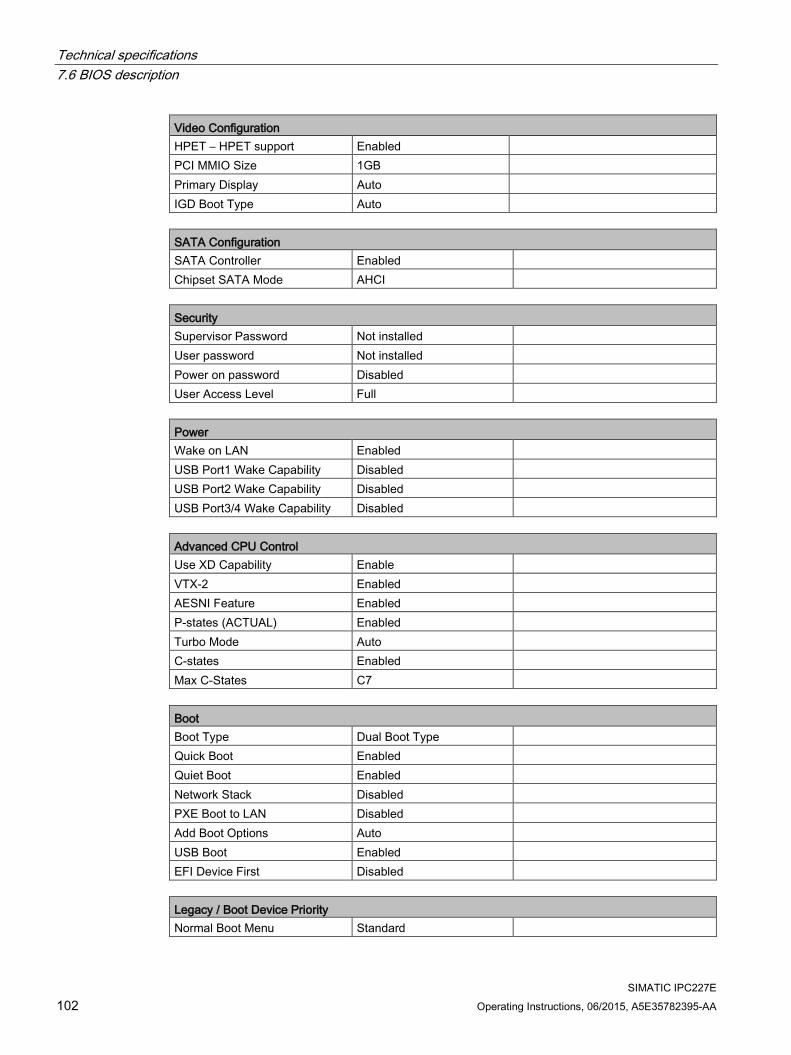
Technical specifications 7.6 BIOS description
SIMATIC IPC227E 102 Operating Instructions, 06/2015, A5E35782395-AA
Video Configuration HPET – HPET support Enabled PCI MMIO Size 1GB Primary Display Auto IGD Boot Type Auto
SATA Configuration SATA Controller Enabled Chipset SATA Mode AHCI
Security Supervisor Password Not installed User password Not installed Power on password Disabled User Access Level Full
Power Wake on LAN Enabled USB Port1 Wake Capability Disabled USB Port2 Wake Capability Disabled USB Port3/4 Wake Capability Disabled
Advanced CPU Control Use XD Capability Enable VTX-2 Enabled AESNI Feature Enabled P-states (ACTUAL) Enabled Turbo Mode Auto C-states Enabled Max C-States C7
Boot Boot Type Dual Boot Type Quick Boot Enabled Quiet Boot Enabled Network Stack Disabled PXE Boot to LAN Disabled Add Boot Options Auto USB Boot Enabled EFI Device First Disabled
Legacy / Boot Device Priority Normal Boot Menu Standard

Technical specifications 7.6 BIOS description
SIMATIC IPC227E Operating Instructions, 06/2015, A5E35782395-AA 103
7.6.6 BIOS update Check regularly if updates are available for download to your device.
Additional information can be found on the Internet at the following address:SIMATIC IPC after-sales information system (http://www.siemens.com/asis).
Noting down and restoring BIOS Setup settings
NOTICE
Irretrievable loss of data
All BIOS Setup settings are deleted after the BIOS update. This can put the system in an undefined state. This may damage the device and the plant. 1. Print out the table in the next section "General BIOS Setup settings". 2. Enter your specific BIOS Setup setting in this table before you run a BIOS update. 3. Start BIOS Setup after the BIOS update. 4. Load the BIOS Setup default settings with <F9> "Setup Defaults". Or use the BIOS
Setup command "Load Optimal Defaults" in the "Exit" menu. 5. Make your own Setup settings based on the table you have printed out. 6. Save the BIOS Setup settings with <F10> "Save and Exit".
Performing a BIOS update
NOTICE
Damage to the device
If you switch off the device during the update, the BIOS will be incomplete and corrupt. This may result in malfunctions.
Leave the device switched on during the update.
If you have purchased a new BIOS update for your device, follow these steps to install the update:
1. Copy the update to a USB memory stick.
2. Reset the device (warm or cold restart).
The following message appears briefly on the display at the end of the self-test:
Press ESC for boot options
3. Press <ESC> to open the BIOS selection menu.
4. Click the "BIOS Update" button.
5. Follow the instructions on the screen.
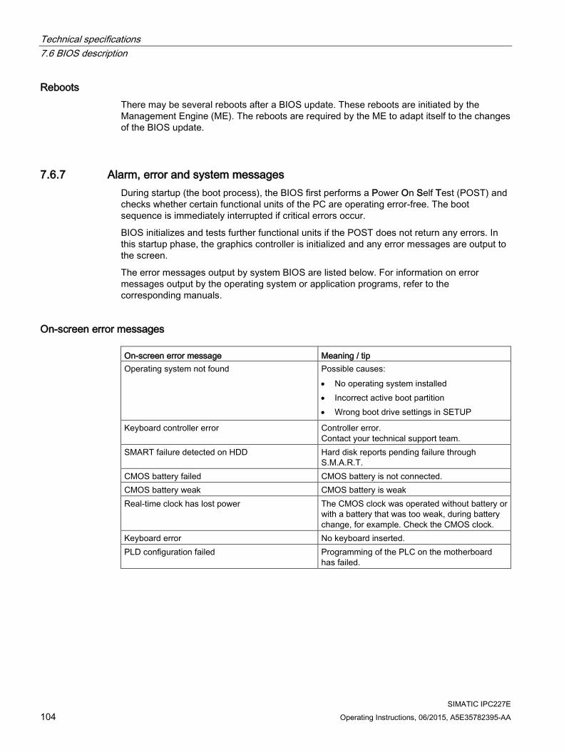
Technical specifications 7.6 BIOS description
SIMATIC IPC227E 104 Operating Instructions, 06/2015, A5E35782395-AA
Reboots There may be several reboots after a BIOS update. These reboots are initiated by the Management Engine (ME). The reboots are required by the ME to adapt itself to the changes of the BIOS update.
7.6.7 Alarm, error and system messages During startup (the boot process), the BIOS first performs a Power On Self Test (POST) and checks whether certain functional units of the PC are operating error-free. The boot sequence is immediately interrupted if critical errors occur.
BIOS initializes and tests further functional units if the POST does not return any errors. In this startup phase, the graphics controller is initialized and any error messages are output to the screen.
The error messages output by system BIOS are listed below. For information on error messages output by the operating system or application programs, refer to the corresponding manuals.
On-screen error messages On-screen error message Meaning / tip Operating system not found Possible causes:
• No operating system installed • Incorrect active boot partition • Wrong boot drive settings in SETUP
Keyboard controller error Controller error. Contact your technical support team.
SMART failure detected on HDD Hard disk reports pending failure through S.M.A.R.T.
CMOS battery failed CMOS battery is not connected. CMOS battery weak CMOS battery is weak Real-time clock has lost power The CMOS clock was operated without battery or
with a battery that was too weak, during battery change, for example. Check the CMOS clock.
Keyboard error No keyboard inserted. PLD configuration failed Programming of the PLC on the motherboard
has failed.

Technical specifications 7.7 Functional scope in Windows
SIMATIC IPC227E Operating Instructions, 06/2015, A5E35782395-AA 105
7.7 Functional scope in Windows
7.7.1 Windows Embedded Standard 7 The overview shows the most important device functions under Windows Embedded Standard 7: Function HDD / SSD version Memory card version .Net Framework Available, V3.5 Available, V3.5 Accessories Available Available Aero background Available Available Backup and Restore Available Available Bluetooth Available Available Dialog box filter Available Available DirectX and Windows Device Ex-perience
Available, V11 Available, V11
Domain services Available Available Driver database Available Not available Driver frameworks Available Available Encrypted File System (EFS) Available Available Enhanced Write Filter Available Available Fax and Scan Available Available File Based Write Filter (FBWF) Available Available Fonts 134 48 Help and Support Engine Available Available Hibernate Once Resume Many (HORM-EEF)
Available Available
Image Mastering API V2 Available Available IME Base Components Available Available Internet Explorer Available, IE 8 Available, IE 8 Internet Information Server (IIS) Available,V7.0 Available, V7.0 Language (Standard) English 1 English 1 Mobility Center Available Available Network and Sharing Center Available Available Network Diagnostics Available Available Pagefile Available Available Printing Utilities and Management Available Available Registry Filter Available Available Remote Assistance Available Available Remote Client Available Available Remote Desktop Available Available SIMATIC IPC DiagBase Available, V1.5 Available, V1.5 Speech Available Not available

Technical specifications 7.7 Functional scope in Windows
SIMATIC IPC227E 106 Operating Instructions, 06/2015, A5E35782395-AA
Function HDD / SSD version Memory card version System Management Administra-tive Tools
Available Available
Telnet Server Available Available User Account Control Available Available Windows Explorer Shell Available Available Windows Firewall Available Available Windows Installer Available Available Windows Media Player Available, V12 Available, V12 Windows PowerShell 2.0 Available Available Windows Search and Natural Language 6
Available Available
Windows Security Center Available Available Windows Update Available Available Wireless Networking Available Available
1 Note the licensing agreements for Windows Embedded Standard 7.
Additional information on language selection is available in the section "Setting up the language selection by means of the Multilanguage User Interface (MUI) (Page 65)".

SIMATIC IPC227E Operating Instructions, 06/2015, A5E35782395-AA 107
Technical support A A.1 Service and support
You can find additional information and support for the products described on the Internet at the following addresses:
● Technical support (http://www.siemens.de/automation/csi_en_WW)
● Support request form (http://www.siemens.com/automation/support-request)
● After Sales Information System SIMATIC IPC/PG (http://www.siemens.com/asis)
● SIMATIC Documentation Collection (http://www.siemens.com/simatic-tech-doku-portal)
● Your local representative (http://www.automation.siemens.com/mcms/aspa-db/en/Pages/default.aspx)
● Training center (http://sitrain.automation.siemens.com/sitrainworld/?AppLang=en)
● Industry Mall (https://mall.industry.siemens.com)
When contacting your local representative or Technical Support, please have the following information at hand:
● MLFB of the device
● BIOS version for industrial PC or image version of the device
● Other installed hardware
● Other installed software
Tools & downloads Please check regularly if updates and hotfixes are available for download to your device. The download area is available on the Internet at the following link:
After Sales Information System SIMATIC IPC/PG (http://www.siemens.com/asis)

Technical support A.2 Troubleshooting
SIMATIC IPC227E 108 Operating Instructions, 06/2015, A5E35782395-AA
A.2 Troubleshooting This chapter provides you with tips on how to locate and/or troubleshoot problems which occur.
Problem Possible cause Possible remedy The device is not operational No power supply • Check the power supply, the power cord and the
power plug. • Check if the On/Off switch is in the correct posi-
tion.
Device is being operated outside the specified ambient conditions
• Check the ambient conditions. • After transport in cold weather, wait approximate-
ly 12 hours before switching on the device.
The monitor remains dark The monitor is switched off Switch on the monitor. The monitor is in "power save" mode
Press any key on the keyboard.
The brightness button has been set to dark
Increase brightness using the brightness button. For detailed information, refer to the monitor operating instructions.
The power cord or the monitor cable is not connected.
• Check whether the power cord has been properly connected to the monitor and to the system unit or to the grounded shockproof outlet.
• Check whether the monitor cable has been properly connected to the system unit and to the monitor.
If the monitor screen still remains dark after you have performed these checks and measures, con-tact your technical support team.
The mouse pointer does not appear on the screen
The mouse driver is not loaded Check whether the mouse driver is properly installed and available when you start the user program. Detailed information about the mouse driver is avail-able in the corresponding documentation.
Mouse not connected • Check whether the mouse cord is properly con-nected to the system unit.
• If you use an adapter or extension for the mouse cable, also check these connectors.
If the mouse pointer still does not appear on the screen after you have performed these checks and actions, contact your technical support team.
Wrong time and/or date on the PC
1. Open the BIOS Setup. 2. Set the time or date.
Although the BIOS setting is OK, the time and data are still wrong
The backup battery is dead. Replace the backup battery.

Technical support A.3 Notes on the use of third-party modules
SIMATIC IPC227E Operating Instructions, 06/2015, A5E35782395-AA 109
Problem Possible cause Possible remedy USB device not responding The USB ports are not correctly
supported. • Turn on USB Legacy Support for mouse and
keyboard. • For other devices, you need the USB device
drivers for the required operating system.
DVD/CD drive door, if present, does not open
The device is switched off or the open/close button is disabled by a software application.
Emergency removal of the data medium: 1. Switch off the device. 2. Insert a pointed object, for example, an opened
paper clip, into the emergency extraction opening of the drive. Apply pressure carefully until the door opens.
3. Pull the door out further with your hand.
"chkdsk" is not functioning EWF (Enhanced Write Filter) has been activated. The "chkdsk" command is not supported if the EWF has been activated.
Deactivate the EWF or use an alternative method to "chkdsk".
A.3 Notes on the use of third-party modules Problem Possible cause Possible remedy The device crashes during startup
• Redundant I/O addresses • Redundant hardware interrupts
and/or DMA channels • Fluctuation of signal frequencies
or levels • Different pin assignment
Check your computer configuration: • If the computer configuration corresponds to the delivery
state, contact your technical support team. • If the configuration has changed, restore the factory state.
To do this, remove the third-party modules and restart the device. If the error no longer occurs, the third-party module being used was the cause of the fault. Replace the thrid-party module with a Siemens module or contact the module supplier.
If the device still crashes, contact your technical support team.
• Insufficient output of an external power supply, e.g. UPS
• Use a higher capacity power supply
The device does not start up or switches off im-mediately
• A counter voltage is fed into the device by connected or installed third-party components
Clarify the following with the supplier of the component: • The component can be operated without an external power
supply. • The component can be reconfigured so that it only uses the
external power supply or that of the device.

Technical support A.3 Notes on the use of third-party modules
SIMATIC IPC227E 110 Operating Instructions, 06/2015, A5E35782395-AA

SIMATIC IPC227E Operating Instructions, 06/2015, A5E35782395-AA 111
List of abbreviations B
AC Alternating current Alternating current ACPI Advanced Configuration and Power Interface AHCI Advanced Host Controller Interface Standardized controller interface for SATA devic-
es. This is supported in Microsoft Windows XP as of SP1 and IAA driver.
APIC Advanced Programmable Interrupt Controller AT Advanced Technology ATA Advanced Technology Attachment AWG American Wire Gauge Unit of measurement for wire diameter. Used in
North America and Canada. BIOS Basic Input Output System CAN Controller Area Network CD-ROM Compact Disc – Read Only Memory CE Communauté Européenne CF CompactFlash CMOS Complementary Metal Oxide Semiconductors COA Certificate of authentication COM Communications Port Term for the serial interface CPU Central Processing Unit CPU CSA Canadian Standards Association Canadian organization for tests and certifications
according to national or binational standards CTS Clear To Send Clear to send DC Direct Current DC current DCD Data Carrier Detect Data carrier signal detection DMA Direct Memory Access DOS Disk Operating System DP DisplayPort DQS Deutsche Gesellschaft zur Zertifizierung von
Qualitätsmanagement mBH
DSR Data Set Ready Ready for operation DTR Data Terminal Ready Data terminal is ready DVD Digital Versatile Disk ESD Components sensitive to electrostatic charge EN European standard EEPROM Electrically Erasable Programmable Read-Only
Memory

List of abbreviations
SIMATIC IPC227E 112 Operating Instructions, 06/2015, A5E35782395-AA
ESD Electrostatic Sensitive Device Electrostatic discharge
Electrostatic Sensitive Devices Electrostatic discharge
EWF Enhanced Write Filter FBWF File Based Write Filter GND Ground Chassis ground HD Hard disk Hard disk HDD Hard Disk Drive HDD HMI Human Machine Interface User interface HORM Hibernate Once - Resume Many HT Hyper Threading I/O Input/Output Data input/output for computers IDE Integrated Device Electronics IEC International Electronical Commission IGD Integrated Graphics Device IP International Protection
in English-speaking countries: Ingress Protec-tion
Degree of protection
IRQ Interrupt Request ISA Industry Standard Architecture Bus for expansion modules LAN Local Area Network Computer network that is limited to a local area. LEDs Light Emitting Diode Light emitting diode LPS Limited Power Source MAC Media access control Media access control MLFB Machine-readable product designation MRAM Magnetoresistive random-access memory Backup memory MS Microsoft MTBF Mean Time Between Failures MUI Multilanguage User Interface Language localization in Windows NTFS New Technology File System NVRAM Non Volatile Random Access Memory Non-volatile data memory. Data memory is re-
tained without external power supply. ODD Optical Disk Drive PC Personal computer PCI Peripheral Component Interconnect High-speed expansion bus PCIe Peripheral Component Interconnect express High-speed serial, differential full-duplex PtP inter-
face with high data rate. PG Programming device POST Power On Self Test PXE Preboot Execution Environment Software for running new PCs without hard disk
data via the network RAID Redundant Array of Independent Disks Redundant hard disk array RAL Restricted Access Location

List of abbreviations
SIMATIC IPC227E Operating Instructions, 06/2015, A5E35782395-AA 113
RAM Random Access Memory RI Ring Input Incoming call ROM Read-Only Memory RS 485 Reconciliation Sublayer 485 Bidirectional bus system RTC Real Time Clock Real-time clock RTS Request to send Request to send RxD Receive Data Data transfer signal SATA Serial Advanced Technology Attachment SCU Setup Configuration Utility SELV Safety Extra Low Voltage Safety extra low voltage SMART Self Monitoring Analysis and Reporting Tech-
nology Hard disk error diagnostics program
SRAM Static Random Access Memory Static RAM SSD Solid State Drive TFT Thin-Film-Transistor TxD Transmit Data Data transfer signal UEFI Unified Extensible Firmware Interface UL Underwriters Laboratories Inc. US organization for testing and certification ac-
cording to national or binational standards. USB Universal Serial Bus VDE Verband der Elektrotechnik, Elektronik und
Informationstechnik e.V (Association for Electri-cal, Electronic and Information Technologies)
VT Virtualization Technology Intel technology which provides a virtual, closed environment.
VT-d Virtualization Technology for Directed I/O Enables the direct assignment of a device (e.g. network adapter) to a virtual device.
WD Watchdog Program monitoring with error detection and alarm-ing.

List of abbreviations
SIMATIC IPC227E 114 Operating Instructions, 06/2015, A5E35782395-AA
SIMATIC IPC227E Operating Instructions, 06/2015, A5E35782395-AA 115
Glossary AHCI mode
AHCI is a standardized method to address the SATA controller. AHCI describes a structure in the RAM, which contains a general area for control and status, as well as a command list.
APIC mode Advanced peripheral interrupt controller. 24 interrupt lines are available.
Automation system A programmable controller (PLC) of the SIMATIC S7 system consist of a central controller, one or several CPUs, and various I/O modules.
Backup Duplicate of a program, data medium or database, used either for archiving purposes or for the protection of vital and non-replaceable data against loss when the working copy is corrupted. Certain applications automatically generate backup copies of data files, and manage both the current and the previous versions on the hard disk.
Baud Physical unit for the step speed in signal transmission. Defines the number of transferred signal states per second. With only two states, one baud is equivalent to a transmission rate of 1 bps.
Cache High-speed access buffer for interim storage (buffering) of requested data.
CE marking Communauté Européene: The CE symbol confirms the conformity of the product with all applicable EC directives such as the EMC Directive.
CFast The faster SATA protocol is used with the CFast standard for memory cards based on CompactFlash. The connectors on these cards are not compatible with a classic CompactFlash card.

Glossary
SIMATIC IPC227E 116 Operating Instructions, 06/2015, A5E35782395-AA
Chipset Located on the motherboard, connects the processor with the PCI or PCIe bus and the external interfaces.
Cold restart A start sequence, starting when the computer is switched on. The system usually performs some basic hardware checks within the cold start sequence, and then loads the operating system from the hard disk to work memory -> boot
COM interface The COM interface is a serial V.24 interface. The interface is suitable for asynchronous data transfer.
CompactFlash card CompactFlash is a digital storage medium in card format and without moving parts. The CF card contains the non-volatile memory and the controller. The interface of the CF card corresponds with the IDE interface. CF cards can be operated without additional electronics on PCMCIA or IDE hard disk controllers using a plug and socket adapter. There are two design forms: CF-I (42.6 x 36.4 x 3.3 mm) and CF-II (42.8 x 36.4 x 5 mm).
Configuration files These are files containing data which define the configuration after restart. Examples of such files are CONFIG.SYS, AUTOEXEC.BAT and the registry files .
Configuration software The configuration software updates the device configuration when new modules are installed . This is done either by copying the configuration files supplied with the module or by manual configuration using the configuration utility.
Controller Integrated hardware and software controllers that control the functions of certain internal or peripheral devices (for example, the keyboard controller).
Device configuration The configuration of a PC or programming device contains information on hardware and device options, such as memory configuration, drive types, monitor, network address, etc. The data are stored in a configuration file and enable the operating system to load the correct device drivers and configure the correct device parameters. . If changes are made to the hardware configuration, the user can change entries in the configuration file using the SETUP program. .

Glossary
SIMATIC IPC227E Operating Instructions, 06/2015, A5E35782395-AA 117
Drivers Program parts of the operating system. They adapt user program data to the specific formats required by I/O devices such as hard disk, printers, and monitors.
EMC directive Directive concerning Electromagnetic Compatibility. Compliance is confirmed by the CE symbol and the EC certificate of conformity.
Energy management The energy management functions of a modern PC allow individual control over the current consumption of vital computer components (e.g. of the monitor, hard disk and CPU), by restricting their activity based on the current system or component load. Energy management is of particular importance for mobile PCs.
Energy options The energy options can be used to reduce energy consumption of the computer, while keeping it ready for immediate use. This can be configured in Windows by selecting Settings > Control Panel > Energy options.
Enhanced Write Filter Configurable write filter that allows you to, for example, boot Windows Embedded Standard from write-protected media (e.g., CD-ROM), set write protection for individual partitions, and adapt the file system performance to user requirements (when using memory cards, for example).
ESD Guideline Guideline for using electrostatic sensitive components.
Ethernet Local network (bus structure) for text and data communication with a transfer rate of 10/100/1000 Mbps.
Execute Disable Capability Hardware implementation that prevents mutual memory accesses by programs and applications. It is only effective when all relevant system components, such as processors, operating systems and applications are supported.

Glossary
SIMATIC IPC227E 118 Operating Instructions, 06/2015, A5E35782395-AA
Extensible Firmware Interface Refers to the central interface between the firmware, the individual components of a computer and the operating system. EFI is located logically below the operating system and represents the successor to PC BIOS, focusing on 64-bit systems.
File Based Write Filter Configurable write filter to protect individual files from write access.
Formatting Basic partitioning of memory space on a magnetic data medium into tracks and segments. Formatting deletes all data on a data medium. All data media must be formatted prior to their first use.
HORM Hibernate once, resume many is a method for fast booting from a single Hibernate file that only needs to be created once. HORM ensures restoration of a uniform, saved system state when booting. This minimizes write access, for example to a memory card, when you start up and shut down Windows Embedded Standard 7.
Hub A term in network technology. In a network, a device joining communication lines at a central location, providing a common connection to all devices on the network.
Hyper Threading HT technology (multi-threading) enables the parallel computing of processes. HT is only effective when all relevant system components, such as processors, operating systems and applications are supported.
IGD Integrated Graphics Device. Graphics interface integrated in the chipset.
Image This refers to the image, for example, of hard disk partitions saved to a file in order to restore them when necessary.
Intel Active Management Technology This technology permits diagnostics, management and remote control of PCs. It is only effective when all relevant system components, such as processors, operating systems and applications are supported.

Glossary
SIMATIC IPC227E Operating Instructions, 06/2015, A5E35782395-AA 119
Intel VT The Intel Virtualization Technology (IVT) is the implementation of a secure closed environment for applications. Special (visualization) software an a VT-capable processor is required for its use.
Interface ● Physical interconnection (cable) of hardware elements such as PLCs, PCs, programming
devices, printers or monitors.
● Interface for interactive software applications.
LAN Local Area Network: LAN is a local network that consists of a group of computers and other devices that are distributed across a relatively restricted range and are linked with communication cables. The devices connected to a LAN are called nodes. The purpose of networks is the mutual use of files, printers or other resources.
Legacy Boot Device Conventional drives can be used as USB devices.
License key The license key represents the electronic license stamp of a license. Siemens AG issues a license key for each software that is protected by a license.
License key USB flash drive The license key USB flash drive contains the authorizations or license keys required to enable protected SIMATIC software.
Low-voltage directive EC Product Safety Directive relating to the safety of products which are operated on low voltage (50 V AC to 1000 V AC, 70 V DC to 1500 V DC) and not specified in other directives. Compliance is confirmed by the CE symbol and the EC certificate of conformity.
Module Modules are plug-in units for PLCs, programming devices or PCs. They are available as local modules, expansion modules, interfaces or mass storage (Mass storage module).
Motherboard The motherboard is the core of the computer. Here, data are processed and stored, and interfaces and device I/Os are controlled and managed.

Glossary
SIMATIC IPC227E 120 Operating Instructions, 06/2015, A5E35782395-AA
Operating system Generic term which describes all functions for controlling and monitoring user program execution, distribution of system resources to the user programs and the operating mode in cooperation with the hardware (for example, Windows 7 Ultimate).
Pixel The pixel represents the smallest element that can be reproduced on-screen or on a printer.
Plug&Play Generally, a reference to the ability of a computer to automatically configure the system for communication with peripheral devices (for example monitors, modems or printers). The user can plug in a peripheral and "play" it at once without manually configuring the system. A Plug&Play PC requires both a BIOS that supports Plug&Play and a Plug&Play expansion card.
POST Self-test performed by the BIOS after the computer is switched on. Performs a RAM test and a graphics controller test, for example. The system outputs audible signals (beep codes) if the BIOS detects any errors; the relevant message indicating cause of error is output on the screen.
Programmable controller The programmable controllers of the SIMATIC S7 system consist of a central controller, one or more CPUs, and various other modules (e.g. I/O modules).
PXE server A Preboot Execution Environment server is part of a network environment and can provide software to connected computers even before they boot. This can involve operating system installations or servicing tools, for example.
RAL Restricted Access Location: Installation of the device in a production facility with restricted access, for example, a locked control cabinet.
Recovery CD Contains the tools for configuring hard disks and the Windows operating system.
Reset Hardware reset: Reset/restart of the PC using a button/switch.

Glossary
SIMATIC IPC227E Operating Instructions, 06/2015, A5E35782395-AA 121
Restart Warm restart of a computer without switching the power off (Ctrl + Alt + Del)
Restore DVD The Restore DVD is used to restore the system partition or the entire hard disk to delivery state if the system has crashed. The DVD contains all the necessary image files and is bootable.
ROM Read-Only Memory ROM is a read-only memory in which every memory location can be addressed individually. The programs or data are permanently stored and are not lost in the event of a power failure.
S.M.A.R.T Self-Monitoring, Analysis and Reporting Technology (SMART or S.M.A.R.T.) is an industry standard integrated in storage media. It makes for permanent monitoring of important parameters and early detection of imminent problems.
SATA Serial ATA Interface for hard disk drives and optical drives with serial data transmission rates of up to 300 Mbps.
SETUP (BIOS Setup) A program in which information about the device configuration (that is the configuration of the hardware on the PC/PG) is defined. The device configuration of the PC/PG is preset with defaults. Changes must therefore be entered in the SETUP if a memory expansion, new modules or a new drive are added to the hardware configuration.
SSD (Solid State Drive) A Solid State Drive is a drive that can be installed like any other drive; it does not contain a rotating disk or other moving parts because only semiconductor memory chips of similar capacity will be used. This design makes SSDs more rugged, provides shorter access times, low energy consumption and rapid data transfer.
STEP 7 Programming software for the creation of user programs for SIMATIC S7 controllers.
Troubleshooting Error cause, cause analysis, remedy
Glossary
SIMATIC IPC227E 122 Operating Instructions, 06/2015, A5E35782395-AA
Trusted Execution Technology Hardware implementation that allows secured execution of programs and applications. It is only effective when all relevant system components, such as processors, operating systems and applications are supported.
Wake on LAN Wake on Local area network. This function allows the PC to be started via the LAN interface.
Warm restart The restart of a computer after a program was aborted. The operating system is loaded and restarted again. The CTRL+ ALT+ DEL hotkey can be used to initiate a warm restart.
SIMATIC IPC227E Operating Instructions, 06/2015, A5E35782395-AA 123
Index
A Adapting
Partitioning, 67 AHCI controller
Making known to the operating system, (See data carrier controllers)
Antivirus software, 39 Approval, (EAC)
Marine, 73 Australia, 72
B Backup battery, 42
Installing, 55 Battery monitoring, 42 BIOS Setup, 97
Defaults, 101 Exit menu, 100 Menu layout, 99
Boot sequence, 104 Bottom view, 10, 11
C CAN
Base address register, 96 CE marking, 71 Certificates, 71
Certifications and approvals, 71 CFast card
Interface, 90 chkdsk, 109 Closing
Device, 48 COA label, 23, 23 Components sensitive to electrostatic charge, 74 Condensation, 22 Connecting
Network, 35 Peripherals, 32 Protective conductor, 33
Creating an image, 69
D Data backup, 69 Data carrier controller
Making known to the operating system, 62 Data exchange, 35 DC power supply, 87 Degree of protection, 82 Device
Closing, 48 Open, 47 Power on, 38
Device configuration, 101 DiagBase software, 40 DiagMonitor
Temperature monitoring, 40 DiagMonitor software, 40 Diagnostics, 40, 40
DiagBase software, 40 DiagMonitor software, 40 Error Messages, 104
Directive ESD Directive, 74
DisplayPort Interface, 91
Documentation and Drivers CD/DVD, 59 Drive, 83
Installing, 58
E EAC, 72 EC Declaration of Conformity, 71 Enable register
Watchdog, 95 Enhanced Write Filter, 42 ESD, 74 ESD Directive, 74 Ethernet, 35, 88 EWF (Enhanced Write Filter), 42 Exit menu, 100 Expansion slot, 83
F Factory state, 60

Index
SIMATIC IPC227E 124 Operating Instructions, 06/2015, A5E35782395-AA
FBWF (File Based Write Filter), 44 FCC, 72 File-Based Write Filter, 44 Firewall, 39 Front view, 10, 11
G General technical specifications, 82 Graphics, 83
I Identification data, 22 Industrial Ethernet, 35 Initial commissioning, 38 Installation of operating system
Windows 7, 61 Installing
Backup battery, 55 Drive, 57, 58 PCIe plug-in card, 49
Installing language package, (See MUI) Integration
Ethernet, 35 Industrial Ethernet, 35 PROFINET, 35
Interface, 84 Interfaces
CFast card, 90 DisplayPort, 91 USB 2.0, 90 USB 3.0, 91
IT communication, 35
L Labeling, 73
Korea, 73 License key, 60 Limitation of liability, 54
M Marine approval, 73 Marking
EC Declaration of Conformity, 71 Memory medium, 83 Messages
On the screen, 104
Monitoring functions, 39 Motherboard
Technical features, 88 Mounting
Standard mounting rail, 29 Upright, 31 Wall, 30
Mounting on a standard rail, 29, 76, 79 Mounting type, 27 MRAM, 45 MUI, 65
N New Zealand, 72
O On-screen error messages, 104 Opening
Device, 47 Operating system
Initial commissioning, 38 Updates, 69, 69
P Package contents, 21
Checking, 21 Packaging, 21
Checking, 21 Removing, 21
Partition, 64 Windows 7 in factory state, 64
Partitioning Adapting, 67 CFast card, 66 SSD, 66 SSD drive, 66 Windows, 66 Windows Embedded Standard 7, 66
PCIe plug-in card Installing, 49
Power supply Connecting, 34 DC power supply, 87
Processor, 83 PROFINET, 35, 87 Protection class, 82 Protective conductor, 33
Connecting, 33

Index
SIMATIC IPC227E Operating Instructions, 06/2015, A5E35782395-AA 125
Protective measure Static electricity, 75
R Radiation, 18
High frequency radiation, 18 RAM, 83 Rating plate, 23 Real-time protection, 39 Recovery DVD, 59 Repairs, 53, 54 Restore CD/DVD for Windows Embeddded Standard, 59 Restore DVD, 59
S Safety information
Storage, 22 Transportation, 22
Setting up partitions, 62 Shipbuilding
Assembly for shipbuilding, 86 Side view, 10, 11 SIMATIC NET, 35 SIMATIC S7, 35
Integration, 35 SSD
Partitioning, 66, 66 Startup, 104 Static electricity
Protective measures, 75 Supply voltage, 82 System partition, 60 System resources, 93
Currently allocated system resources, 93
T Teaming, 84 Temperature monitoring, 40 Tools, 54 Trigger register
Watchdog, 96
U Updates
Application programs and drives, 69 Operating system, 69, 69
Upright mounting, 31, 78, 81 USB, 88 USB 2.0
Port, 90 USB 3.0
Interface, 91
W Wall mounting, 30, 77, 80 Warranty, 17 Watchdog, 41
Enable register, 95 Monitoring function, 41 Monitoring times, 41 Trigger register, 96
Weight, 82 Windows 7
Installation, 61 Windows 7 Ultimate
Data backup, 69 Partitioning the hard disk, 66
Windows Embedded Standard Data backup, 69
Windows Embedded Standard 7 Setting up partitions, 66
Windows Security Center, 39 Windows XP Professional
Data backup, 69

Index
SIMATIC IPC227E 126 Operating Instructions, 06/2015, A5E35782395-AA