Kinetix Servo Drives Specifications
156
Technical Data Kinetix Servo Drives Specifications Bulletin 2071, 2093, 2094, 2097, 2099, 2198 This document provides catalog numbers and product specifications, including power, performance, environmental, certifications, dimension drawings, and accessories for Allen-Bradley® servo drives. Use this publication with the Kinetix® Motion Control Selection Guide, publication KNX-SG001 , to help make decisions selecting the motion control products that are best suited for your system requirements. Topic Page Summary of Changes 2 Kinetix 5700 Servo Drives 2 Kinetix 5500 Servo Drives 47 Kinetix 6200 and Kinetix 6500 Modular Multi-axis Servo Drives 68 Kinetix 6000 Multi-axis Servo Drives 86 Kinetix 300 and Kinetix 350 EtherNet/IP Servo Drives 105 Kinetix 3 Component Servo Drives 119 Kinetix 2000 Multi-axis Servo Drives 126 Kinetix 7000 High Power Servo Drives 140 Motor Overload Protection 153 Additional Resources 154
-
Upload
khangminh22 -
Category
Documents
-
view
0 -
download
0
Transcript of Kinetix Servo Drives Specifications

Technical Data
Kinetix Servo Drives SpecificationsBulletin 2071, 2093, 2094, 2097, 2099, 2198
This document provides catalog numbers and product specifications, including power, performance, environmental, certifications, dimension drawings, and accessories for Allen-Bradley® servo drives.
Use this publication with the Kinetix® Motion Control Selection Guide, publication KNX-SG001, to help make decisions selecting the motion control products that are best suited for your system requirements.
Topic Page
Summary of Changes 2
Kinetix 5700 Servo Drives 2
Kinetix 5500 Servo Drives 47
Kinetix 6200 and Kinetix 6500 Modular Multi-axis Servo Drives 68
Kinetix 6000 Multi-axis Servo Drives 86
Kinetix 300 and Kinetix 350 EtherNet/IP Servo Drives 105
Kinetix 3 Component Servo Drives 119
Kinetix 2000 Multi-axis Servo Drives 126
Kinetix 7000 High Power Servo Drives 140
Motor Overload Protection 153
Additional Resources 154

Kinetix Servo Drives Specifications
Summary of Changes
This manual contains new and updated information as indicated in the following table.
Kinetix 5700 Servo Drives
The Kinetix 5700 drive family helps expand the value of integrated motion on EtherNet/IP™ to large, custom machine-builder applications. Drive modules connect and operate by using ControlLogix® controllers, GuardLogix® controllers, CompactLogix™ controllers, or Compact GuardLogix controllers.
With the Logix Designer application as a single control engine, and one design environment – Studio 5000® – machine builders now have more flexibility to scale, design, and control to help meet their needs. Kinetix 5700 servo drives can help reduce commissioning time and improve machine performance. They offer the simplicity, power, and space savings you need to help get your machine up and running faster.
Kinetix 5700 servo drives are designed for machines with high axis-counts and high-power requirements. Single and dual-axis inverters are available with integrated (drive-based and controller-based) safety functions and hardwired (drive-based) safety functions.
The iTRAK® power supply integrates the iTRAK system with the Kinetix 5700 drive family.
Topic Page
Added the following drive module product specifications to Kinetix 5700 Servo Drives:• 2198-RPxxx regenerative bus supplies• 2198-S263-ERSx and 2198-S312-ERSx single-axis inverters• 2198-DCBUSCOND-RP312 DC-bus conditioner module
Throughout
Added 2198-DBRxx-F AC line filters as compatible with Kinetix 5700 and Kinetix 5500 servo drive families. 34, 60
Added the 2198-BARCON-220DC200 DC-bus link to support 2198-S263-ERSx and 2198-S312-ERSx single-axis inverters.
39Added the following DC-bus links to support 2198-RPxxx regenerative bus supplies:• 2198-BARCON-165DC200• 2198-BARCON-275DC200• 2198-BARCON-440DC200
Updated the maximum current rating (40 A) for the 24V shared-bus connection system. 40
Added the 2198-S312-P-T shared-bus T-connector and bus-bar to support 2198-S263-ERSx and 2198-S312-ERSx single-axis inverters. 41
Added the following replacement connector sets to support 2198-RPxxx regenerative bus supplies:• 2198-KITCON-RP088• 2198-KITCON-RP200• 2198-KITCON-RP312
45Added a ground screw to the 2198-KITCON-D032-L and 2198-KITCON-D057-L replacement connector sets.Added the 2198-5700-DACLAMPKIT clamp kit.Added the 2198-KITCON-S312 replacement connector set to support the 2198-S263-ERSx and 2198-S312-ERSx single-axis inverters.
Added a ground jumper to the 2198-KITCON-D160-L replacement connector sets.Added the 2198-KITCON-DCBUSCOND replacement connector set to support the 2198-DCBUSCOND-RP312 DC-bus conditioner module.Added the following replacement fan kits to support the 2198-RPxxx regenerative bus supplies and 2198-S263-ERSx and 2198-S312-ERSx single-axis inverters:• 2198-SK1-FAN060• 2198-SK1-FAN090
46
2 Rockwell Automation Publication KNX-TD003E-EN-P - February 2019

Kinetix Servo Drives Specifications
Kinetix 5700 Drive Module Features and Indicators
DC-bus Power Supply Features and Indicators
Item Description Item Description Item Description
1 Digital inputs (IOD) connector 7 LCD display 13 Shunt resistor (RC) connector
2 Ethernet (PORT1) RJ45 connector 8 Navigation pushbuttons 14 DC bus (DC) connector
3 Ethernet (PORT2) RJ45 connector 9 Link speed status indicators 15 24V control input power (CP) connector
4 Zero-stack mounting tab/cutout 10 Link/Activity status indicators 16 AC Input power (IPD) connector
5 Module status indicator 11 Contactor enable (EN) connector 17 Cooling fan
6 Network status indicator 12 Ground terminal
5
210
3
7
6
9
4 4
1115
14
8
12
1
13MOD–
NET–
2
1
1
4
I/O
DC+
SH
DC+
DC–
24V–
24V+
L3 L2 L1
16
17
5700
DC-bus Power Supply, Top View(2198-P031 module is shown)
DC-bus Power Supply, Bottom View(2198-P031 module is shown)
DC-bus Power Supply, Front View(2198-P031 module is shown)
Shared-bus 24V Input Wiring Connector
Rockwell Automation Publication KNX-TD003E-EN-P - February 2019 3
Kinetix Servo Drives Specifications
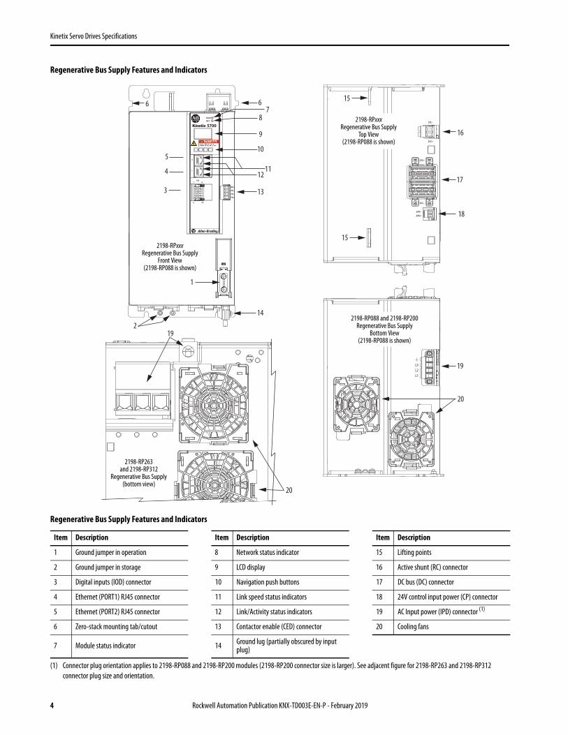
Regenerative Bus Supply Features and Indicators
Regenerative Bus Supply Features and Indicators
Item Description Item Description Item Description
1 Ground jumper in operation 8 Network status indicator 15 Lifting points
2 Ground jumper in storage 9 LCD display 16 Active shunt (RC) connector
3 Digital inputs (IOD) connector 10 Navigation push buttons 17 DC bus (DC) connector
4 Ethernet (PORT1) RJ45 connector 11 Link speed status indicators 18 24V control input power (CP) connector
5 Ethernet (PORT2) RJ45 connector 12 Link/Activity status indicators 19 AC Input power (IPD) connector (1)
(1) Connector plug orientation applies to 2198-RP088 and 2198-RP200 modules (2198-RP200 connector size is larger). See adjacent figure for 2198-RP263 and 2198-RP312 connector plug size and orientation.
6 Zero-stack mounting tab/cutout 13 Contactor enable (CED) connector 20 Cooling fans
7 Module status indicator 14 Ground lug (partially obscured by input plug)
7
4 12
5
9
8
11
6 6
1317
16
10
14
3
15
18
19
DC+
DC+
DC–
24V–
24V+
L3L2L1
MODNET
2
1
1I/O
6
5 10
OK+
OK–
EN–
EN+
5700DC–
2
1
15
20
19
20
2198-RP088 and 2198-RP200Regenerative Bus Supply
Bottom View(2198-RP088 is shown)
2198-RP263 and 2198-RP312
Regenerative Bus Supply(bottom view)
2198-RPxxx Regenerative Bus Supply
Top View(2198-RP088 is shown)
2198-RPxxx Regenerative Bus Supply
Front View(2198-RP088 is shown)
4 Rockwell Automation Publication KNX-TD003E-EN-P - February 2019
Kinetix Servo Drives Specifications
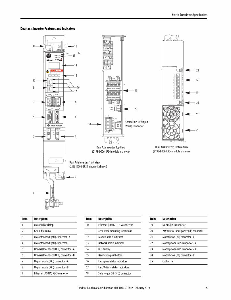
Dual-axis Inverter Features and Indicators
Item Description Item Description Item Description
1 Motor cable clamp 10 Ethernet (PORT2) RJ45 connector 19 DC bus (DC) connector
2 Ground terminal 11 Zero-stack mounting tab/cutout 20 24V control input power (CP) connector
3 Motor feedback (MF) connector - A 12 Module status indicator 21 Motor brake (BC) connector - A
4 Motor feedback (MF) connector - B 13 Network status indicator 22 Motor power (MP) connector - A
5 Universal feedback (UFB) connector - A 14 LCD display 23 Motor power (MP) connector - B
6 Universal feedback (UFB) connector - B 15 Navigation pushbuttons 24 Motor brake (BC) connector - B
7 Digital inputs (IOD) connector - A 16 Link speed status indicators 25 Cooling fan
8 Digital inputs (IOD) connector - B 17 Link/Activity status indicators
9 Ethernet (PORT1) RJ45 connector 18 Safe Torque Off (STO) connector
22
12
917
10
14
13
16
2
11 11
8
20
19
25
15
24
21
3 4
65
1
23
25
18
UFB-A UFB-B
D+D-
D+D-
MF-A MF-B
2
1
DC+
DC–
24V–
24V+
W-B V-B U
-BM
BRK-A– +
W-A
V-A U
-AM
BRK-B– +
MOD–NET–
5700
12345
6789
10
12345
6789
10
1
2
3456
78
9
10
11121314
1516
1I/O-A
6
5 10
1I/O-B
6
5 10
1 9
8 16
SB+/NC
NC
S1ASCAS2ASB-NCNC
7
Dual Axis Inverter, Front View(2198-D006-ERS4 module is shown)
Dual Axis Inverter, Top View(2198-D006-ERS4 module is shown)
Dual Axis Inverter, Bottom View(2198-D006-ERS4 module is shown)
Shared-bus 24V Input Wiring Connector
Rockwell Automation Publication KNX-TD003E-EN-P - February 2019 5

Kinetix Servo Drives Specifications
Single-axis Inverter Features and Indicators (catalog numbers 2198-S086-ERSx, 2198-S130-ERSx, and 2198-S160-ERSx)
10
6
7 15
8
12
11
14
9 9
13
4
5
2
18
16
19
17
20
20
1
DC+
DC–
24V–
24V+UFB
D+D-
MF
2
1
–MBRK
+3
21
MOD–NET–
5700
12345
6789
10
1
2
3456
78
9
10
11121314
1516
1 9
8 16
SB+/NC
NC
S1ASCAS2ASB-NCNC
1I/O
6
5 10
Single-axis Inverter, Front View(2198-S086-ERS4 module is shown)
Single-axis Inverter, Top View(2198-S086-ERS4 module is shown)
Single-axis Inverter, Bottom View(2198-S086-ERS4 module is shown)
Item Description Item Description
1 Motor cable clamp 12 LCD display
2 Motor feedback cable tie-wrap bracket 13 Navigation pushbuttons
3 Motor brake (BC) connector 14 Link speed status indicators
4 Motor feedback (MF) connector 15 Link/Activity status indicators
5 Universal feedback (UFB) connector 16 Safe Torque Off (STO) connector
6 Digital inputs (IOD) connector 17 DC bus (DC) connector
7 Ethernet (PORT1) RJ45 connector 18 24V control input power (CP) connector
8 Ethernet (PORT2) RJ45 connector 19 Motor power (MP) connector
9 Zero-stack mounting tab/cutout 20 Cooling fans
10 Module status indicator 21 Ground terminal
11 Network status indicator
Shared-bus 24V Input Wiring Connector
6 Rockwell Automation Publication KNX-TD003E-EN-P - February 2019

Kinetix Servo Drives Specifications
Single-axis Inverter Features and Indicators (catalog numbers 2198-S263-ERSx and 2198-S312-ERSx)
10
6
7 15
8
12
11
14
9 9
13
4
5
2
1
3 –MBRK
+
UFB
2
1
MOD–NET–
5700
12345
6789
10
1I/O
6
5 10
21mm (4 AWG-250 kcmil)15-20 Nm (132-177 lbin)
2
W V U
24V–
24V+
DC+
DC–
1
2
3456
78
9
10
11121314
1516
1 9
8 16
SB+/NC
NC
S1ASCAS2ASB-NCNC
W V U
16
19
23
17
1718
20
21
22
Single-axis Inverter, Front View(2198-S263-ERSx and 2198-S312-ERSx modules)
Single-axis Inverter, Top View(2198-S263-ERSx and 2198-S312-ERSx modules)
Single-axis Inverter, Bottom View(2198-S263-ERSx and 2198-S312-ERSx modules)
Item Description Item Description
1 Motor cable clamp 13 Navigation pushbuttons
2 Tie-wrap bracket for feedback cable 14 Link speed status indicators
3 Motor brake (BC) connector 15 Link/Activity status indicators
4 Motor feedback (MF) connector 16 Ground jumper in operation
5 Universal feedback (UFB) connector 17 Safe torque-off (STO) connector
6 Digital inputs (IOD) connector 18 Lifting points
7 Ethernet (PORT1) RJ45 connector 19 Motor power (MP) connector
8 Ethernet (PORT2) RJ45 connector 20 Ground terminal
9 Zero-stack mounting tab/cutout 21 DC bus (DC) connector
10 Module status indicator 22 24V control input power (CP) connector
11 Network status indicator 23 Cooling fans (replacement kits available)
12 LCD display
Rockwell Automation Publication KNX-TD003E-EN-P - February 2019 7

Kinetix Servo Drives Specifications
iTRAK Power Supply Features and Indicators
Item Description Item Description Item Description
1 Power bus cable clamp 8 Network status indicator 15 24V control input power (CP) connector
2 Ground lug (partially obscured by output plugs) 9 LCD display 16 24V control output power (ICP) connector -A
3 Digital inputs (IOD) connector 10 Navigation push buttons 17 DC bus output (IDC) connector - A
4 Ethernet (PORT1) RJ45 connector 11 Link speed status indicators 18 24V control output power (ICP) connector - B
5 Ethernet (PORT2) RJ45 connector 12 Link/Activity status indicators 19 DC bus output (IDC) connector - B
6 Zero-stack mounting tab/cutout 13 iTRAK PS ready (IR) connector 20 Cooling fan
7 Module status indicator 14 DC bus input (DC) connector 21 Power supply internal fuse
IMPORTANT See Additional Resources on page 154 for the publications that support the iTRAK system.
2
1
1 6I/O
5 10
–iPS RDY
+
IN 24V -
IN 24V +
DC+
DC-
5700
MOD–NET–
12345
6789
10
18
16
19
17
20
18
6
78
9
45
2
3
6
10
1211
13
1
15
14
21
2
iTRAK Power Supply(top view)
iTRAK Power Supply(bottom view)
iTRAK Power Supply(front view)
iTRAK Power Supply(left side view)
8 Rockwell Automation Publication KNX-TD003E-EN-P - February 2019

Kinetix Servo Drives Specifications
Technical Specifications - Kinetix 5700 Drive Modules
DC-bus Power Supply Specifications
Attribute 2198-P031 2198-P070 2198-P141 2198-P208
AC input voltage 324…528V rms, three-phase (480V nom)
AC input frequency 47…63 Hz
Main AC input current (1)
324…528V (rms) three-phase
(1) All modules are limited to 1 power cycle per minute.
11.2A 27.0 A 49.6 A 73.1 A
Max inrush (0-pk) 33.0 A 33.0 A 33.0 A 33.0 A
Peak AC input current324…528V (rms) three-phase 33.4 A 74.3 A 148.7 A 219.2 A
Line loss ride through 20 ms
Control power DC input voltage 24V DC ±10%
Control power DC input current (1) (2)
(2) For current values when motors include a holding brake and additional information, refer to Control Power Current Specifications on page 12.
0.8 ADC 1.9 ADC
Nominal bus output voltage 458…747V DC
Continuous output current to busThree-phase 10.5 ADC 25.5 ADC 46.9 ADC 69.2 ADC
Peak output current to bus Three-phase 31.6 ADC 70.3 ADC 140.8 ADC 207.6 ADC
Peak output current duration (3)
(3) Peak output current duration with 10% duty cycle.
1.0 s 1.0 s 1.0 s 0.1 s
Continuous output power to busNom (480V rms, three-phase) 7.0 kW 17.0 kW 31.0 kW 46.0 kW
Peak output power to busNom (480V rms, three-phase) 21.0 kW 46.0 kW 93.0 kW 138.0 kW
Bus overvoltage - 480V, nom AC input 832V DC
Internal shunt resistance 37.5 Ω 13.5 Ω
Internal shunt power 75 W 200 W
Shunt on 775V plus 30V x bus regulator capacity/utilization (4)
(4) The shunt on and shunt off voltages increase during periods of shunting activity to promote sharing of shunt power in multi-axis configurations. Shunt utilization is equivalent to the BusRegulatorCapacity tag in the Logix Designer application.
Shunt off 765V plus 30V x bus regulator capacity/utilization (4)
Efficiency 99%
Internal Capacitance 585 μF 780 μF 1640 μF 2050 μF
Capacitive energy absorption 129 J 172 J 362 J 453 J
Short-circuit current rating 200,000 A (rms) symmetrical
Rockwell Automation Publication KNX-TD003E-EN-P - February 2019 9

Kinetix Servo Drives Specifications
Regenerative Bus Supply Specifications
Attribute 2198-RP088 2198-RP200 2198-RP263 2198-RP312
AC input voltage (1)
(1) Applies when DC-bus voltage regulation is enabled. If DC-bus voltage regulation is not enabled, the input voltage range is 324….528V AC. For more information on these two modes of operation, see the Kinetix 5700 Servo Drives User Manual, publication 2198-UM002.
324…506V rms, three-phase (480V nom)
AC input frequency 47…63 Hz
Main AC input current (2)
324…506V (rms) three-phase
(2) All modules are limited to 1 power cycle per minute.
30.0 A 85.0 A 150.0 A 192.0 A
Max inrush (0-pk) 76.0 A 176.0 A 362.0 A 362.0 A
Peak AC input current324…506V (rms) three-phase 75.0 A 170.0 A 225.0 A 288.9 A
Line loss ride through 20 ms
Control power DC input voltage 24V DC ±10%
Control power DC input current (2) (3)
(3) For current values when motors include a holding brake and additional information, refer to Control Power Current Specifications on page 12.
4.3 ADC 5.4 ADC 9.1 ADC
Nominal bus output voltage 458…747V DC
Continuous output current to bus 35.3 ADC 100.0 ADC 176.4 ADC 207.0 ADC
Peak output current to bus 88.0 ADC 200.0 ADC 263.0 ADC 312.0 ADC
Peak output current duration (4)
(4) 1.0 second peak output current duration with 10% duty cycle.3.0 second peak output current duration with 5% duty cycle.
1.0 s/3.0 s
Continuous output power to busNom (480V rms, three-phase) 24.0 kW 67.0 kW 119.0 kW 140.0 kW
Peak output power to busNom (480V rms, three-phase) 60.0 kW 135.8 kW 179.7 kW 211.4 kW
Bus overvoltage - 480V, nom AC input 832V DC
Internal shunt resistance (5)
(5) The 2198-RPxxx regenerative bus supply has no internal shunt resistor.
– –
Efficiency 98%
Internal Capacitance 940 μF 2460 μF 4510 μF 5740 μF
Capacitive energy absorption 207 J 542 J 994 J 1265 J
Short-circuit current rating 200,000 A (rms) symmetrical
10 Rockwell Automation Publication KNX-TD003E-EN-P - February 2019

Kinetix Servo Drives Specifications
Single-axis Inverter Power Specifications
Dual-axis Inverter Power Specifications
iTRAK Power Supply Specifications
Attribute 2198-S086-ERS32198-S086-ERS4
2198-S130-ERS32198-S130-ERS4
2198-S160-ERS32198-S160-ERS4
2198-S263-ERS32198-S263-ERS4
2198-S312-ERS32198-S312-ERS4
Bandwidth (1)
Velocity loop, maxCurrent loop
(1) Bandwidth values vary based on tuning parameters and mechanical components.
400 Hz1000 Hz
PWM frequency 4 kHz
Continuous output current (rms) 43.0 A 65.0 A 85.0 A 150.0 A 192.0 A
Continuous output current (0-pk) 60.8 A 91.9 A 120.2 A 212.1 A 271.5 A
Peak output current (rms) 86.0 A (2)
(2) Peak current duration (TPKmax) equals 1.0 second.
130.0 A (2) 160.0 A (2) 263.0 A@ 1 and 3 s duration183.0 A@ 60 s duration
312.0 A@ 1 and 3 s duration234.0 A@ 60 s duration
Peak output current (0-pk) 121.6 A (2) 183.8 A (2) 226.2 A (2) 371.9 A@ 1 and 3 s duration258.8 A@ 60 s duration
441.2 A@ 1 and 3 s duration330.9 A@ 60 s duration
Continuous power out (nom)324…528V rms, three-phase 29.7 kW 44.9 kW 60.1 kW 90.0 kW 112.0 kW
DC input current @ 458…747V DC 45.7 ADC 69.0 ADC 92.3 ADC 164.0 ADC 207.0 ADC (3)
(3) UL tested to 175.0 ADC.
Internal Capacitance 560 μF 840 μF 1120 μF 2050 μF 2050 μF
Attribute Per Axis (3)
(3) These attributes apply to both of the axes in each dual-axis inverter.
2198-D006-ERS32198-D006-ERS4
2198-D012-ERS32198-D012-ERS4
2198-D020-ERS32198-D020-ERS4
2198-D032-ERS32198-D032-ERS4
2198-D057-ERS32198-D057-ERS4
Bandwidth (1)
Velocity loop, maxCurrent loop
(1) Bandwidth values vary based on tuning parameters and mechanical components.
400 Hz1000 Hz
PWM frequency 4 kHz
Continuous output current (rms) X 2.5 A 5.0 A 8.0 A 13.0 A 23.0 A
Continuous output current (0-pk) X 3.5 A 7.0 A 11.3 A 18.3 A 32.5 A
Peak output current (rms) (2)
(2) Peak current duration (TPKmax) equals 1.0 second.
X 6.3 A 12.5 A 20.0 A 32.5 A 57.5 A
Peak output current (0-pk) (2) X 8.8 A 17.6 A 28.2 A 45.9 A 81.3 A
Continuous power out (nom) 324…528V rms, three-phase X 1.7 kW 3.4 kW 5.5 kW 8.9 kW 15.9 kW
DC input current @ 458…747V DC X 2.7 ADC 5.3 ADC 8.5 ADC 13.7 ADC 24.5 ADC
Internal Capacitance 165 μF 330 μF 390 μF 705 μF
Attribute 2198T-W25K-ER
Input voltage 458…747V DC
Continuous output current (per output) 12.5 A
Peak output current 25 A
Continuous power outputDC-bus output (low voltage)DC-bus output (high voltage)
4.1 kW165V DC330V DC
DC input current (1)
@ 458V DC in@ 747V DC in
(1) Because the iTRAK power supply is a DC-DC converter with a constant output rating, input current varies linearly with input voltage.
10 A6.2 A
Internal capacitance 390 μF
Rockwell Automation Publication KNX-TD003E-EN-P - February 2019 11

Kinetix Servo Drives Specifications
Control Power Current Specifications
Kinetix 5700 servo drives, the accessory modules, and iTRAK power supply have different 24V DC power consumption. Factors to consider when calculating the combined current demand from your 24V DC power supply include the following:
• Catalog number for each drive in the system• Whether servo motors include the holding brake option• Whether the system includes capacitor modules or DC-bus conditioner modules• Whether the system includes 2198T-W25K-ER iTRAK power supplies and the number of iTRAK motor
modules supported
Control Power Current Specifications
Drive Module Drive ModuleCat. No.
24V Current Per Module(non-brake motor) ADC
24V Current, max(with maximum brake current)ADC
24V Inrush Current (5)
A
(5) Inrush current duration is less than 30 ms.
DC-bus Power Supplies
2198-P0310.8
– 4.02198-P070
2198-P1411.9
2198-P208
Regenerative Bus Supplies
2198-RP088 4.3
– 4.02198-RP200 5.4
2198-RP2639.1
2198-RP312
Dual-axis Inverters
2198-D006-ERSx
1.4 (2)
(2) Values are base current per module.
5.5 (3)
(3) Values assume two brake motors, each drawing the maximum rating of 2 A, are attached to each module.
4.0
2198-D012-ERSx
2198-D020-ERSx
2198-D032-ERSx 1.7 (2) 7.7 (3)
2198-D057-ERSx 2.3 (2) 8.3 (3)
Single-axis Inverters
2198-S086-ERSx
4.6 9.6 (4)
(4) Values assume the maximum rated brake current of 5 A.
4.0
2198-S130-ERSx
2198-S160-ERSx
2198-S263-ERSx
2198-S312-ERSx
iTRAK Power Supply (1)
(1) These values represent only the iTRAK power supply. They do not include the iTRAK motor modules that are connected to the iTRAK power supply and also draw current from this 24V control power input. For more information regarding 24V control power requirements, see the iTRAK System User Manual, publication 2198T-UM001.
2198T-W25K-ER 1.3 – 2.2
Capacitor Module 2198-CAPMOD-2240 0.1
–
7.0
Extension Module 2198-CAPMOD-DCBUS-IO – –
DC-bus Conditioner Module 2198-DCBUSCOND-RP312 0.1 7.0
IMPORTANT When the Kinetix 5700 inverter catalog number ends in -ERSx, for example 2198-D057-ERSx, the variable (x) indicates that the inverter (using this example) can be 2198-D057-ERS3 or 2198-D057-ERS4.
12 Rockwell Automation Publication KNX-TD003E-EN-P - February 2019

Kinetix Servo Drives Specifications
Peak Current Specifications
Load Duty-cycle Profile Example
The 2198-S263-ERSx and 2198-S312-ERSx single-axis inverters have overload ratings for 1, 3, and 60 second durations to simplify migration from Kinetix 7000 high-power servo drives.
Overload Ratings for 2198-S263-ERSx and 2198-S312-ERSx Servo Drives
Peak Duty Cycle Definition of Terms
DriveCat. No.
1 Second Overload Rating, max 3 Second Overload Rating, max 60 Second Overload Rating, max
Current for 1 s
Current for Off Period
Current for 3 s
Current for Off Period
Current for 60 s
Current for Off Period
Current for 3 s
Current for Off Period
2198-S263-ERSx 263 A rms 30 A for ≤9 s 263 A rms 30 A for ≤57 s 183 A rms 98 A for ≤540 s 183 A rms 98 A for ≤540 s
2198-S312-ERSx 312 A rms 30 A for ≤9 s 312 A rms 30 A for ≤57 s 234 A rms 98 A for ≤540 s 234 A rms 98 A for ≤540 s
Term Definition (1)
(1) All current values are specified as RMS.
Continuous Current Rating (ICont) The maximum value of current that can be output continuously.
Peak Current Rating (IPKmax) The maximum value of peak current that the drive can output. This rating is valid only for overload times less than TPKmax.
Duty Cycle (D) The ratio of time at peak to the Application Period is defined as:
Time at Peak (TPK) The time at peak current (IPK) for a given loading profile. Must be less than or equal to TPKmax.
Peak Current (IPK) The level of peak current for a given loading profile. IPK must be less than or equal to the Peak Current Rating (TPKMAX) of the drive.
Base Current (IBase) The level of current between the pulses of peak current for a given loading profile. IBase must be less than or equal to the continuous current rating (ICont) of the drive.
Loading ProfileThe loading profile is composed of IPK, IBase, TPK, and D (or T) values and completely specify the operation of the drive in an overload situation. These values are collectively defined as the Loading Profile of the drive.
Application Period (T) The sum of the times at IPK (TPK) and IBase.
I Cont
I Base
I PK
TPK
T
D = TT
PK x 100%
D = TT
PK x 100%
Rockwell Automation Publication KNX-TD003E-EN-P - February 2019 13

Kinetix Servo Drives Specifications
Peak Single-axis Inverter Overload (TPK < 1.0 s)
(1) Base current (IBase) and peak current (IPK) are a percentage of the continuous drive current rating (ICont).
Peak Dual-axis Inverter and iTRAK Power Supply Overload (TPK < 1.0 s)
(1) Base current (IBase) and peak current (IPK) are a percentage of the continuous drive current rating (ICont).
0% 60% 100%
50%
45%
40%
35%
30%
25%
20%
15%
10%
5%
0%
80%20% 40%
Applies to 2198-S086-ERSx and 2198-S130-ERSx single-axis inverters.
Applies to 2198-S160-ERSx single-axis inverters.
Applies to 2198-S263-ERSx single-axis inverters.
Applies to 2198-S312-ERSx single-axis inverters.
Max
imum
Dut
y Cyc
le (D
max
)
% Base Current (I Base /ICont)
Legend (1)
I pk = 162.5%
I pk = 200%
I pk = 175%
I pk = 188%
0% 60% 100%
50%
45%
40%
35%
30%
25%
20%
15%
10%
5%
0%
80%20% 40%
Applies to all 2198-Dxxx-ERSx dual-axis inverters and 2198T-W25K-ER iTRAK power supply.
Max
imum
Dut
y Cyc
le (D
max
)
% Base Current (I Base /ICont)
Legend (1)
I pk = 150%
I pk = 250%
I pk = 200%
14 Rockwell Automation Publication KNX-TD003E-EN-P - February 2019
Kinetix Servo Drives Specifications
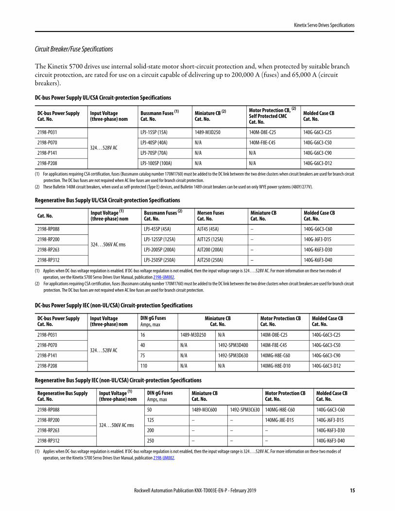
Circuit Breaker/Fuse Specifications
The Kinetix 5700 drives use internal solid-state motor short-circuit protection and, when protected by suitable branch circuit protection, are rated for use on a circuit capable of delivering up to 200,000 A (fuses) and 65,000 A (circuit breakers).
DC-bus Power Supply UL/CSA Circuit-protection Specifications
Regenerative Bus Supply UL/CSA Circuit-protection Specifications
DC-bus Power Supply IEC (non-UL/CSA) Circuit-protection Specifications
Regenerative Bus Supply IEC (non-UL/CSA) Circuit-protection Specifications
DC-bus Power SupplyCat. No.
Input Voltage(three-phase) nom
Bussmann Fuses (1)
Cat. No.
(1) For applications requiring CSA certification, fuses (Bussmann catalog number 170M1760) must be added to the DC link between the two drive clusters when circuit breakers are used for branch circuit protection. The DC bus fuses are not required when AC line fuses are used for branch circuit protection.
Miniature CB (2)
Cat. No.
(2) These Bulletin 140M circuit breakers, when used as self-protected (Type E) devices, and Bulletin 1489 circuit breakers can be used on only WYE power systems (480Y/277V).
Motor Protection CB, (2)
Self Protected CMCCat. No.
Molded Case CBCat. No.
2198-P031
324…528V AC
LPJ-15SP (15A) 1489-M3D250 140M-D8E-C25 140G-G6C3-C25
2198-P070 LPJ-40SP (40A) N/A 140M-F8E-C45 140G-G6C3-C50
2198-P141 LPJ-70SP (70A) N/A N/A 140G-G6C3-C90
2198-P208 LPJ-100SP (100A) N/A N/A 140G-G6C3-D12
Cat. No. Input Voltage (1)
(three-phase) nom
(1) Applies when DC-bus voltage regulation is enabled. If DC-bus voltage regulation is not enabled, then the input voltage range is 324….528V AC. For more information on these two modes of operation, see the Kinetix 5700 Servo Drives User Manual, publication 2198-UM002.
Bussmann Fuses (2)
Cat. No.
(2) For applications requiring CSA certification, fuses (Bussmann catalog number 170M1760) must be added to the DC link between the two drive clusters when circuit breakers are used for branch circuit protection. The DC bus fuses are not required when AC line fuses are used for branch circuit protection.
Mersen FusesCat. No.
Miniature CBCat. No.
Molded Case CBCat. No.
2198-RP088
324…506V AC rms
LPJ-45SP (45A) AJT45 (45A) – 140G-G6C3-C60
2198-RP200 LPJ-125SP (125A) AJT125 (125A) – 140G-J6F3-D15
2198-RP263 LPJ-200SP (200A) AJT200 (200A) – 140G-K6F3-D30
2198-RP312 LPJ-250SP (250A) AJT250 (250A) – 140G-K6F3-D40
DC-bus Power SupplyCat. No.
Input Voltage (three-phase) nom
DIN gG FusesAmps, max
Miniature CBCat. No.
Motor Protection CBCat. No.
Molded Case CBCat. No.
2198-P031
324…528V AC
16 1489-M3D250 N/A 140M-D8E-C25 140G-G6C3-C25
2198-P070 40 N/A 1492-SPM3D400 140M-F8E-C45 140G-G6C3-C50
2198-P141 75 N/A 1492-SPM3D630 140MG-H8E-C60 140G-G6C3-C90
2198-P208 110 N/A N/A 140MG-H8E-D10 140G-G6C3-D12
Regenerative Bus SupplyCat. No.
Input Voltage (1)
(three-phase) nom
(1) Applies when DC-bus voltage regulation is enabled. If DC-bus voltage regulation is not enabled, then the input voltage range is 324….528V AC. For more information on these two modes of operation, see the Kinetix 5700 Servo Drives User Manual, publication 2198-UM002.
DIN gG FusesAmps, max
Miniature CBCat. No.
Motor Protection CBCat. No.
Molded Case CBCat. No.
2198-RP088
324…506V AC rms
50 1489-M3C600 1492-SPM3C630 140MG-H8E-C60 140G-G6C3-C60
2198-RP200 125 – – 140MG-J8E-D15 140G-J6F3-D15
2198-RP263 200 – – – 140G-K6F3-D30
2198-RP312 250 – – – 140G-K6F3-D40
Rockwell Automation Publication KNX-TD003E-EN-P - February 2019 15

Kinetix Servo Drives Specifications
Contactor Specifications
The DC-bus power supply contactor enable relay (CED connector) is rated at 24V DC and 1.0 A, max.
DC-bus Power Supply Contactor Specifications
The regenerative power supply contactor enable relay (CED connector) is rated at 24V DC.
Regenerative Bus Supply Contactor Specifications
DC-bus Power SupplyCat. No.
Contactor (1) (2)
Cat. No.
(1) Auxiliary contact configuration (10) is for 1 N.O. 0 N.C. Other configurations are available.(2) For contactors that are not Bulletin 100-E type, the integrated diode is required with the contactor coil.
Intermediate Relay (3)
Cat. No.
(3) These DC-bus power supplies require an additional intermediate relay used with the contactor.
2198-P031 100-C16EJ10N/A
2198-P070 100-C37EJ10
2198-P141 100-C72DJ10
700-HB32Z24 (relay)700-HN153 (socket)
2198-P208 100-C97DJ10
2198-P208 (2 in parallel) 100-E190KJ11
2198-P208 (3 in parallel) 100-E305KJ11
Regenerative Bus Supply (1)
Cat. No.
(1) These regenerative bus supplies can require an additional intermediate relay to be used with the contactor. Verify the peak current rating of the main contactor coil.
Contactor (2) (3)
Cat. No.
(2) Auxiliary contact configuration (10) is for 1 N.O. 0 N.C. Other configurations are available.(3) For contactors that are not Bulletin 100-E type, the integrated diode is required with the contactor coil.
Intermediate RelayCat. No.
2198-RP088 100-C43EJ10
N/A2198-RP200 100-E116KJ11
2198-RP263 100-E205KJ11
2198-RP312 100-E265KJ11
16 Rockwell Automation Publication KNX-TD003E-EN-P - February 2019

Kinetix Servo Drives Specifications
Power Dissipation Specifications
Use this table to size an enclosure and calculate required ventilation for your Kinetix 5700 drive system.
DC-bus Power Supply Cat. No.Usage as % of Rated Power Output (watts)
20% 40% 60% 80% 100%
2198-P031 97 101 105 109 113
2198-P070 108 119 130 140 151
2198-P141 249 267 286 304 323
2198-P208 265 294 323 352 380
Regenerative Bus Supply Cat. No.
2198-RP088 253 399 544 690 835
2198-RP200 532 832 1132 1432 1732
2198-RP263 850 1261 1672 2083 2494
2198-RP312 1037 1576 2115 2654 3193
Dual-axis Inverter Cat. No. (1)
(1) Values for the dual-axis inverters are based on both axes (each axis dissipates half the rated power output). For example, the 2198-D006-ERSx dual-axis inverter (axis A) with usage of 20% (17/2=8.5 W) and (axis B) with usage of 60% (41/2= 20.5 W) dissipates a total of 29 W.
2198-D006-ERSx 17 29 41 53 65
2198-D012-ERSx 34 58 82 106 130
2198-D020-ERSx 52 84 116 148 180
2198-D032-ERSx 100 155 210 265 320
2198-D057-ERSx 252 354 456 558 660
Single-axis Inverter Cat. No.
2198-S086-ERSx 190 255 325 400 475
2198-S130-ERSx 225 340 460 590 725
2198-S160-ERSx 270 420 570 760 950
2198-S263-ERSx 556 759 989 1245 1529
2198-S312-ERSx 610 883 1200 1561 1965
iTRAK Power Supply Cat. No.
2198T-W25K-ER 206 272 338 404 470
Capacitor Module Cat. No.
2198-CAPMOD-2240 28 34 42 51 62
2198-CAPMOD-DCBUS-IO 1.1 1.4 1.6 2.1 2.5
DC-bus Conditioner Module Cat. No.
2198-DCBUSCOND-RP312 1.4 2.1 3.2 4.7 6.7
Rockwell Automation Publication KNX-TD003E-EN-P - February 2019 17

Kinetix Servo Drives Specifications
Weight Specifications
Maximum Motor Cable Lengths
Combined motor power cable length for all axes on the same DC bus depends on the Kinetix 5700 system power supply and EMC line filter in use.
• For applications that include the 2198-Pxxx DC-bus power supply and 2198-DBxx-F EMC line filter, the maximum length is up to 400 m (1312 ft)– When used with 2198-DBRxx-F EMC line filter, the maximum length is up to 1200 m (3937 ft)
• For applications that include the 2198-RPxxx regenerative bus supply and 2198-DBRxx-F EMC line filter, the maximum length is up to 1200 m (3937 ft)– 2198-DBxx-F EMC line filters are not compatible with 2198-RPxxx regenerative bus supplies
Drive-to-motor cables up to 90 m (295 ft) can be used, depending on the feedback type and overall system design. See the Kinetix Motion Accessories Technical Data, publication KNX-TD004, for cable specifications.
Drive-to-Motor Feedback Cable Length
For iTRAK systems, cables from iTRAK power supply to motor modules up to 30 m (98 ft) can be used. See the iTRAK System Technical Data, publication 2198T-TD001, for cable specifications.
DC-bus Power SupplyCat. No.
Weight, approxkg (lb)
Regenerative Bus SupplyCat. No.
Weight, approxkg (lb)
iTRAK Power SupplyCat. No.
Weight, approxkg (lb)
2198-P031 4.33 (9.55) 2198-RP088 13.61 (30.0) 2198T-W25K-ER 7.60 (16.8)
2198-P070 4.42 (9.74) 2198-RP200 38.56 (85.0)
2198-P141 6.91 (15.2) 2198-RP26361.23 (135)
2198-P208 7.04 (15.5) 2198-RP312
Dual-axis InverterCat. No.
Weight, approxkg (lb)
Single-axis InverterCat. No.
Weight, approxkg (lb)
2198-D006-ERSx
4.16 (9.17)
2198-S086-ERSx 5.21 (11.5)
2198-D012-ERSx 2198-S130-ERSx 5.44 (12.0)
2198-D020-ERSx 2198-S160-ERSx 6.80 (15.0)
2198-D032-ERSx 2198-S263-ERSx15.88 (35.0)
2198-D057-ERSx 6.76 (14.9) 2198-S312-ERSx
Feedback TypeCable Length, maxm (ft)
Single-turn or multi-turn absolute up to 90 (295)
Incremental up to 30 (98)
Heidenhain EnDat up to 90 (295)
IMPORTANT For more information on maximum motor cable lengths, see the Kinetix 5700 Servo Drives User Manual, publication 2198-UM002.
IMPORTANT System performance was tested at these cable lengths. These limitations also apply when meeting CE requirements.
18 Rockwell Automation Publication KNX-TD003E-EN-P - February 2019

Kinetix Servo Drives Specifications
Dimensions - Kinetix 5700 Servo Drives
These drawings provide mounting dimensions for Kinetix 5700 power supplies, servo drives, and iTRAK power supply. Also included are drawings showing the impact of compatible motor feedback connector kits on the mounting dimensions. Refer to page 23 for dimensions when using these kits.
DC-bus Power Supply Dimensions
DC-bus Power SupplyCat. No.
Amm (in.)
Bmm (in.)
Cmm (in.)
Dmm (in.)
2198-P03155 (2.17) 300 (11.81) 358 (14.09)
252 (9.92)2198-P070
2198-P14185 (3.35) 375 (14.76) 433 (17.04)
2198-P208
B
MODNET
2
1
1
4
I/O
C
A D12.0
(0.47)Dimensions are in mm (in.)
2198-P031DC-bus Power Supply is shown.
Rockwell Automation Publication KNX-TD003E-EN-P - February 2019 19

Kinetix Servo Drives Specifications
Regenerative Bus Supply Dimensions
Regenerative Bus SupplyCat. No.
Amm (in.)
Bmm (in.)
Cmm (in.)
Dmm (in.)
E (1)
mm (in.)
(1) Maximum distance between lift points.
2198-RP088 165 (6.50) 300 (11.8) 358 (14.1)
252 (9.92)
198 (7.80)
2198-RP200 275 (10.83)
420 (16.54) 478 (18.82)
225 (8.86), max
2198-RP263440 (17.32) 233 (9.17), max
2198-RP312
B
C
A D15.5
(0.61)
MODNET
2
1
1I/O
6
5 10
OK+
OK–
EN–
EN+
E
Ø16(0.63) Dimensions are in mm (in.)
2198-RP088Regenerative Bus Supply is shown.
20 Rockwell Automation Publication KNX-TD003E-EN-P - February 2019
Kinetix Servo Drives Specifications
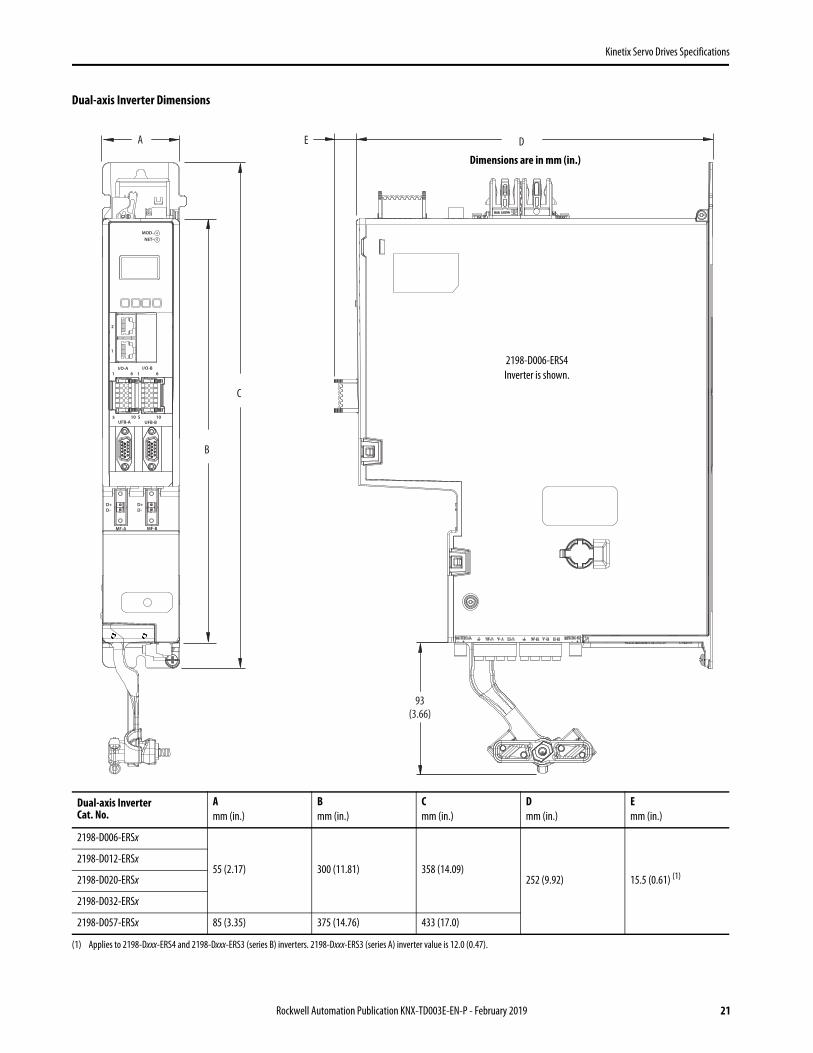
Dual-axis Inverter Dimensions
Dual-axis InverterCat. No.
Amm (in.)
Bmm (in.)
Cmm (in.)
Dmm (in.)
Emm (in.)
2198-D006-ERSx
55 (2.17) 300 (11.81) 358 (14.09)252 (9.92) 15.5 (0.61) (1)
(1) Applies to 2198-Dxxx-ERS4 and 2198-Dxxx-ERS3 (series B) inverters. 2198-Dxxx-ERS3 (series A) inverter value is 12.0 (0.47).
2198-D012-ERSx
2198-D020-ERSx
2198-D032-ERSx
2198-D057-ERSx 85 (3.35) 375 (14.76) 433 (17.0)
B
C
A D
1I/O-A
6
10
1I/O-B
6
5 10UFB-A UFB-B
D+D-
D+D-
MF-A MF-B
2
1
5
MOD–NET–
93(3.66)
E
Dimensions are in mm (in.)
2198-D006-ERS4Inverter is shown.
Rockwell Automation Publication KNX-TD003E-EN-P - February 2019 21

Kinetix Servo Drives Specifications
Single-axis Inverter Dimensions
Single-axis InverterCat. No.
Amm (in.)
Bmm (in.)
Cmm (in.)
Dmm (in.)
Emm (in.)
Fmm (in.)
2198-S086-ERSx85.0 (3.35) 375 (14.8) 433 (17.0)
252 (9.92)
15.5 (0.61) (1)
(1) Applies to 2198-Sxxx-ERS4 and 2198-Sxxx-ERS3 (series B) inverters. 2198-Sxxx-ERS3 (series A) inverter value is 12.0 (0.47).
185 (7.28)2198-S130-ERSx
2198-S160-ERSx 100 (3.94) 420 (16.54) 478 (18.82)
2198-S263-ERSx220 (8.66) 420 (16.54) 478 (18.82) 15.5 (0.61) 132 (5.19)
2198-S312-ERSx
1I/O
5UFB
D+D-
MF
2
1
6
10
–MBRK
+
MOD–NET–
B
C
F
A DEDimensions are in mm (in.)
2198-S086-ERS4Inverter is shown.
22 Rockwell Automation Publication KNX-TD003E-EN-P - February 2019

Kinetix Servo Drives Specifications
The 2198-KITCON-DSL feedback connector kit and 2198-H2DCK feedback converter kit do not affect the mounting dimensions of the drive. No portion of those kits extend out from the front of the drive or below the drive.
These examples show the 2198-K57CK-D15M universal feedback kit and 2090-CFBM7DD feedback cable that is mounted above (covering) the 2198-KITCON-DSL connector kit in the MF connector. You can replace the 2198-KITCON-DSL feedback kit with the 2198-H2DCK converter kit, if needed, without affecting these mounting dimensions.
Dual-axis Inverter With 2198-K57CK-D15M Universal Feedback Kit
Refer to Universal Feedback Connector Kit on page 43 for motor/actuator compatibility and product dimensions.
IMPORTANT The 2198-K57CK-D15M universal feedback kit and 2090-CFBM7DD (drive-end connector) feedback cable extend out from the UFB connector as shown and covers a portion of the other two kits (when they are used), which requires you to install feedback kits in the MF connector first.
1I/O-A
6
10
1I/O-B
6
5 10
UFB-A UFB-B
D+D-
D+D-
MF-A MF-B
5
286(11.26)
34(1.34)
300(11.81)
48(1.89)
Dimensions are in mm (in.)
2198-K57CK-D15MUniversal Feedback Kit
in UFB Connector
2198-Dxxx-ERSx Dual-axis Inverter(front view)
2198-Dxxx-ERSx Dual-axis Inverter(side view)
2198-KITCON-DSL Feedback Kit or2198-H2DCK Converter Kit in MF Connector(2198-KITCON-DSL kit is shown)
2090-CFBM7DD-CEAxxxFeedback Cable
(drive-end connector)
Cable must be secured at the drive tokeep the cable bend within the
recommended 300 mm (11.81 in.)minimum cabinet depth.
Rockwell Automation Publication KNX-TD003E-EN-P - February 2019 23

Kinetix Servo Drives Specifications
Single-axis Inverter With 2198-K57CK-D15M Universal Feedback Kit
Refer to Hiperface-to-DSL Feedback Converter Kit on page 44 for motor/actuator compatibility and page 66 product dimensions.
1I/O
5
UFB
D+D-
MF
6
10
–MBRK
+
286(11.26)
34(1.34)
48(1.89)
300(11.81)
Dimensions are in mm (in.)
2198-K57CK-D15M Universal Feedback Kit in UFB Connector
2198-Sxxx-ERSxSingle-axis Inverter
(front view)2198-Sxxx-ERSx Single-axis Inverter(side view)
2198-KITCON-DSL Feedback Kit or2198-H2DCK Converter Kit in MF Connector
(2198-KITCON-DSL kit is shown)
2198-Sxxx-ERSx Single-axis Inverter(side view)
2090-CFBM7DD-CEAxxxFeedback Cable(drive-end connector)
Cable must be secured at the drive to keep the cable bend within the recommended 300 mm (11.81 in.) minimum cabinet depth.
24 Rockwell Automation Publication KNX-TD003E-EN-P - February 2019

Kinetix Servo Drives Specifications
iTRAK Power Supply Dimensions
Environmental Specifications - Kinetix 5700 Servo Drives
Attribute Operational Range Storage Range (nonoperating)
Ambient temperature 0…50 °C (32…122 °F) -40…+70 °C (-40…+158 °F)
Relative humidity 5…95% noncondensing 5…95% noncondensing
Protection class (IEC 60529) IP20
Degree of pollution (IEC 61800-5-1) 2
Altitude• 1500 m (4921 ft) derate 3% per 300 m (984 ft) above 1500 m• 2000 m (6562 ft) max, with corner-grounded input power• 3000 m (9843 ft) max, with non corner-grounded input power
3000 m (9843 ft) during transport
Vibration 5…55 Hz @ 0.35 mm (0.014 in.) double amplitude, continuous displacement; 55…500 Hz @ 2.0 g peak constant acceleration
Shock 15 g, 11 ms half-sine pulse (3 pulses in each direction of 3 mutually perpendicular directions)
253(9.96)
12.0(0.47)
100(3.94)
433(17.0)
375 (14.8)
MODNET
93(3.66)
iPS RDY
2
1
1 6
5 10
I/O
Dimensions are in mm (in.)
2198T-W25K-ERiTRAK Power Supply is shown.
Rockwell Automation Publication KNX-TD003E-EN-P - February 2019 25

Kinetix Servo Drives Specifications
Certifications
Kinetix 5700 Servo Drives
Kinetix 5700 iTRAK Power Supply
Agency Certification (1)
(1) See rok.auto/certifications for declarations of conformity, certificates, and other certification details.
Standards
c-UL-us (2)
(2) UL has not evaluated the Safe Torque Off options in these products.
UL Listed to U.S. and Canadian safety standards (UL 61800-5-1, File E59272).
Solid-state motor overload protection provides dynamic fold-back of motor current when 110% of the motor rating is reached with a peak current limit based on the peak rating of the motor as investigated by UL to comply with UL 61800-5-1, (UL File E59272).
CEEuropean Union 2004/108/EC EMC Directive compliant with IEC 61800-3:2004 + A1:2012: Adjustable Speed Electrical Power Drive Systems - Part 3; EMC Product Standard including specific test methods.
European Union 2006/95/EC Low Voltage Directive compliant with IEC 61800-5-1:2007 - Adjustable speed electrical power drive systems.
Functional SafetyTÜV Certified for Functional Safety: up to SIL CL3, according to IEC 61800-5-2, IEC 61508, and IEC 62061; up to Performance Level PLe and Category 3, according to ISO 13849-1; when used as described in the Kinetix 5700 Servo Drives User Manual, publication 2198-UM002 or the Kinetix 5700 Safe Monitor Functions Safety Reference Manual, publication 2198-RM001.
C-Tick
Australian Radiocommunications Act, compliant with:• Radiocommunications Act: 1992• Radiocommunications (Electromagnetic Compatibility) Standard: 2008• Radiocommunications Labelling (Electromagnetic Compatibility) Notice: 2008
KCKorean Registration of Broadcasting and Communications Equipment, compliant with:• Article 58-2 of Radio Waves Act, Clause 3• Registration number: KCC-REM-RAA-2198
ODVA EtherNet/IP conformance tested.
OSHA Maximum audible noise from the servo drive system complies with OSHA standard 3074, Hearing Conservation (<85 dBA).
Agency Certification (1)
(1) See rok.auto/certifications for declarations of conformity, certificates, and other certification details.
Standards
c-UL-us UL Listed to U.S. and Canadian safety standards (UL 61800-5-1, File E59272 and CSA C22.2 No 274-13).
CEEuropean Union 2004/108/EC EMC Directive compliant with IEC 61800-3:2004 + A1:2012: Adjustable Speed Electrical Power Drive Systems - Part 3; EMC Product Standard including specific test methods.
European Union 2006/95/EC Low Voltage Directive compliant with IEC 61800-5-1:2007 - Adjustable speed electrical power drive systems.
C-Tick
Australian Radiocommunications Act, compliant with:• Radiocommunications Act: 1992• Radiocommunications (Electromagnetic Compatibility) Standard: 2008• Radiocommunications Labelling (Electromagnetic Compatibility) Notice: 2008
KCKorean Registration of Broadcasting and Communications Equipment, compliant with:• Article 58-2 of Radio Waves Act, Clause 3• Registration number: KCC-REM-RAA-2198
OSHA Maximum audible noise from the servo drive system complies with OSHA standard 3074, Hearing Conservation (<85 dBA).
26 Rockwell Automation Publication KNX-TD003E-EN-P - February 2019

Kinetix Servo Drives Specifications
Accessories - Kinetix 5700 Servo Drives
Kinetix 5700 drive accessories include the accessory modules, passive shunt modules, the encoder output module, line reactors, AC line filters, feedback connector kits, the system mounting toolkit, and shared-bus connector kits.
Accessory Modules
The 2198-CAPMOD-2240 capacitor module, 2198-CAPMOD-DCBUS-IO extension module, and 2198-DCBUSCOND-RP312 DC-bus conditioner module are referred to as Kinetix 5700 accessory modules.
Capacitor Module and DC-bus Conditioner Module Features and Indicators
Accessory Module (1)
Cat. No.
(1) Accessory modules can be used in any Kinetix 5700 drive system configurations with DC-bus power supplies, regenerative bus supplies, and 8720MC-RPS power supplies.
Description
2198-CAPMOD-2240 capacitor modules are used:
• For energy storage and to extend the DC-bus voltage to another inverter cluster• As connection points for an external active shunt module• In systems with external DC-bus current of up to 104 A, however, can parallel with itself or with another accessory module for up to 208 A.
2198-CAPMOD-DCBUS-IO extension modules are used:
• With another accessory module when the external DC-bus current is >104 A, up to a maximum of 208 A• To extend the DC-bus voltage to another inverter cluster
2198-DCBUSCOND-RP312 DC-bus conditioner modules are used:
• To decrease the voltage stress on isolation components in inverter systems with long cable lengths and other use cases• To extend the DC-bus voltage to another inverter cluster• In systems with external DC-bus current of up to 104 A, however, can parallel with itself or with another accessory module for up to 208 A.
Item Description Item Description Item Description
1 Ground stud 5 Stud/lug cover with wires (1)
(1) This example shows the lug cover oriented for wires exiting to the left (capacitor module is on the far left of the drive configuration). Rotate lug cover 180° when wires exit to the right (capacitor module is on the far right of the drive configuration).
9 DC– M8 stud (external DC-bus), shown with flexible bus-bar (2)
(2) Flexible bus-bars are included with only the 2198-CAPMOD-DCBUS-IO extension module. So, if you have two capacitor modules, two DC-bus conditioner modules, or a capacitor module and DC-bus conditioner module mounted side by side, you must order the 2198-KITCON-CAPMOD2240 or 2198-KITCON-DCBUSCOND connector set separately.
2 Module status (MS) connector 6 Stud cover without wires 10 DC+ M8 stud (external DC-bus), shown with wire lug
3 DC-bus status indicator 7 DC-bus (DC) connector 11 M8 hex nut
4 Module status indicator 8 24V control input power (CP) connector 12 Lug spacer
MODULESTATUS
MODDC BUS
824V–
24V+
2
34
1
7
6
24V–
24V+
10
9
1211
55700
2198-CAPMOD-2240 Capacitor Module and 2198-DCBUSCOND-RP312 DC-bus Conditioner Module (front view)
2198-CAPMOD-2240 Capacitor Module and 2198-DCBUSCOND-RP312 DC-bus Conditioner Module (side view, lug cover removed)
2198-CAPMOD-2240 Capacitor Module and 2198-DCBUSCOND-RP312 DC-bus Conditioner Module
(top views)
Rockwell Automation Publication KNX-TD003E-EN-P - February 2019 27

Kinetix Servo Drives Specifications
Extension Module Features and Indicators
Module Specifications
Item Description Item Description
1 Ground lug 5 DC– M8 stud (external DC-bus)
2 Stud/lug cover with wires (1)
(1) This example shows the lug cover oriented for wires exiting to the left (extension module is on the far left of drive configuration). Rotate lug cover 180° when wires exit to the right (extension module is on the far right of drive configuration).
6 DC+ M8 stud (external DC-bus), shown with flexible bus-bar (2)
(2) Flexible bus-bars are included with only the 2198-CAPMOD-DCBUS-IO extension module.
3 Stud cover without wires 7 M8 hex nut
4 DC-bus (DC) connector 8 Lug spacer
Module Cat. No.Voltage RangeV DC
CapacitanceμF
Energy StorageJ
Continuous CurrentA, avg
Weight, approxkg (lb)
2198-CAPMOD-2240
458…747
2240 734 104 3.3 (7.2)
2198-CAPMOD-DCBUS-IO – – 104 1.2 (2.7)
2198-DCBUSCOND-RP312 – – 104 2.0 (4.4)
1
4
3
6
5
87
2
5700
2198-CAPMOD-DCBUS-IO Extension Module (side view, lug cover removed)
2198-CAPMOD-DCBUS-IO Extension Module
(front view)
2198-CAPMOD-DCBUS-IO Extension Module
(top views)
28 Rockwell Automation Publication KNX-TD003E-EN-P - February 2019
Kinetix Servo Drives Specifications
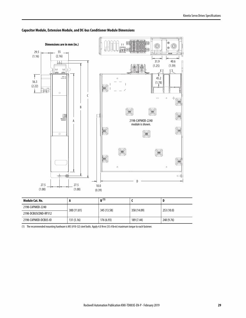
Capacitor Module, Extension Module, and DC-bus Conditioner Module Dimensions
Module Cat. No. A B (1)
(1) The recommended mounting hardware is M5 (#10-32) steel bolts. Apply 4.0 N•m (35.4 lb•in) maximum torque to each fastener.
C D
2198-CAPMOD-2240300 (11.81) 345 (13.58) 358 (14.09) 253 (10.0)
2198-DCBUSCOND-RP312
2198-CAPMOD-DCBUS-IO 131 (5.16) 176 (6.93) 189 (7.44) 248 (9.76)
MODULESTATUS A
C
55(2.16)
D27.5
(1.08)27.5(1.08)
B
MODDC BUS
10.0(0.39)
29.5(1.16)
56.3(2.22)
40.6(1.59)
31.9(1.25)
24V–
24V+
45.2(1.78)
2198-CAPMOD-2240 module is shown.
Dimensions are in mm (in.)
Rockwell Automation Publication KNX-TD003E-EN-P - February 2019 29

Kinetix Servo Drives Specifications
Passive Shunt Modules and Resistors
The Kinetix 5700 passive shunts are external modules that provide additional shunt capacity for applications where the DC-bus power supply’s internal shunt capacity is exceeded. Catalog numbers 2198-R014, 2198-R031, and 2198-R127 are composed of resistor coils that are housed inside an enclosure. Catalog number 2198-R004 is a shunt resistor without an enclosure.
Shunt Module Specifications
Shunt Module Dimensions (catalog numbers 2198-R014, 2198-R031, and 2198-R127)
Shunt ModuleCat. No.
ResistanceΩ
Continuous PowerW
Weight, approxkg (lb)
2198-R004 33 400 1.8 (4.0)
2198-R014 9.4 1400 9.1 (20)
2198-R031 33 3100 16.8 (37)
2198-R127 (1)
(1) This product presents a lift hazard. To avoid personal injury, use care when lifting the product.
13 12,700 22.2 (49)
Shunt ModuleCat. No. A B C D E F G
2198-R014 445 (17.5) 191 (7.5) 492 (19.38) 483 (19.0)178 (7.0)
254 (10.0) 251 (9.88)
2198-R031 635 (25.0) 343 (13.5) 683 (26.88) 673 (26.5) 406 (16.0) 403 (15.88)
2198-R127 673 (26.5) 267 (10.5) 721 (28.38) 711 (28.0) 305 (12.0) 330 (13.0) 327 (12.88)
2198-R014, 2198-R031,and 2198-R127Shunt Modules
2198-R004Shunt Resistor
A
B
D
C
E
F
G
Dimensions are in mm (in.)
Front ViewLeft Side View
Ø (5) Conduit Knockout12.7 (0.5)
Ø (4)11.1 (7/16) Mounting Holes
Top View (cover removed)
RemovableCover
5/16 in. Hex Screws
5/16 in. Hex Screws
30 Rockwell Automation Publication KNX-TD003E-EN-P - February 2019

Kinetix Servo Drives Specifications
Shunt Resistor Dimensions (catalog number 2198-R004)
Encoder Output Module
The Allen-Bradley encoder output module (catalog number 2198-ABQE) is a DIN-rail mounted EtherNet/IP network-based standalone module capable of outputting encoder pulses to a customer-supplied peripheral device (cameras, for example, used in line-scan vision systems). The encoder output module supports real and virtual axes for systems using the integrated motion on EtherNet/IP network.
Module Features and Indicators
38.1 (1.5)
76.2 (3.0)
292 (11.5)
305 (12.0) Dimensions are in mm (in.)
457 mm (18 in.) 450 °C (842 °F)High-temperature Wire Leads
Top View
Side View
Ø (2)5.6 (7/32) Mounting Holes
3
11
4
87
10
9
MODNET
5
6
24V–
24V+
OUTPUT-A OUTPUT-B
2
1
0 1 2 3 4 5 6
7 8 90 1 2 3 4 5
6 7 8 9
0 1 2 3 4 5 6
7 8 9
2
1
2198-ABQE Encoder Output Module, Top View
2198-ABQE Encoder Output Module, Front View
2198-ABQE Encoder Output Module, Side View Item Description
1 IP address switches
2 Mounting latch
3 15-pin output connector - A
4 15-pin output connector - B
5 Ethernet (PORT1) RJ45 connector
6 Ethernet (PORT2) RJ45 connector
7 Network status indicator
8 Module status indicator
9 24V control input power (CP) connector
10 Link speed status indicators
11 Link/Activity status indicators
Rockwell Automation Publication KNX-TD003E-EN-P - February 2019 31

Kinetix Servo Drives Specifications
These items are required for installation and are ordered separately:• 2198-K57CK-D15M connector kit, for terminating output cable conductors (1 for each output connector)• 2198-KITCON-ABQE spare connector and end-anchor set that includes the following:
– 24V wiring plug for control power input (replacement)– Label for recording the IP address and attaching to the encoder output module (replacement)– DIN-rail end-anchors for holding the module in position (2 per module)
Encoder Output Module Dimensions
Included in the dimensions are 2198-K57CK-D15M connector kits attached to the output connectors. End anchors, used to secure the module on the DIN rail, add 8 mm (0.31 in.) on either side of the module.
Encoder Output Module General Specifications
Attribute Value
Control input power (24V) ratings (SELV and LIM or Class 2 power supply)
21.6…26.4V DC (24 V DC, nom) 0.3 A, 7.2 W, max @ 24V DC
Control (input power) inrush current, max 3 A
Control input power connector wire size 16…24 AWG
Output supply power rating for single-ended outputs only (SELV and LIM or Class 2 power supply)
12…30V DC0.14 A, max
Output connector wire size 16…28 AWG
Output signal type Differential (RS422) or single-ended
Weight 0.50 kg (1.1 lb)
MODNET
OUTPUT-A OUTPUT-B
34(1.34)
Dimensions are in mm (in.)
2198-K57CK-D15M Connector Kits
2198-ABQE Encoder Output Module, Front View
2198-ABQEEncoder Output Module,
Side View150
(5.91) 158(6.22)
62(2.44)
154(6.06)
120(4.72)
50(1.97)
5.0(0.20)
32 Rockwell Automation Publication KNX-TD003E-EN-P - February 2019

Kinetix Servo Drives Specifications
Bulletin 1321 Line Reactors
Bulletin 1321 line reactors help keep equipment running longer by absorbing many of the power line disturbances that can shut down your power supply. For 2198-RPxxx regenerative bus supplies, line reactors can significantly reduce the amount of circulating currents between the integrated LC filter and other devices on the common AC input-power source. For multiple 2198-P208 DC-bus power supplies with common input power, each supply must have its own line reactor.
Bulletin 1321 Line Reactors
For line reactor use-cases with Kinetix 5700 power supplies, see the Kinetix 5700 Servo Drives User Manual, publication 2198-UM002.
Bulletin 1321 Line Reactor Selection
For line reactor specifications, terminations, and dimensions, see the 1321 Power Conditioning Products Technical Data, publication 1321-TD001.
Kinetix 5700Power Supply
Power SupplyCat. No.
Number of Power Supplies in a Bus Group
Bulletin 1321 Line ReactorCat. No. Status
DC-bus Power Supply
2198-P031 1 1321-3R12-B Recommended
2198-P070 1 1321-3R35-B Recommended
2198-P141 1 1321-3R55-B Recommended
2198-P208
1
1321-3R80-B
Recommended
2 Required
3 Required
Regenerative Bus Supply
2198-RP088 1 1321-3R35-A Recommended
2198-RP200 1 1321-3R100-A Recommended
2198-RP263 1 1321-3R160-B Recommended
2198-RP312 1 1321-3R200-A Recommended
Catalog Numbers1321-3R55-B and 1321-3R80-B
Catalog Numbers1321-3R12-B and 1321-3R35-B
Rockwell Automation Publication KNX-TD003E-EN-P - February 2019 33

Kinetix Servo Drives Specifications
Kinetix 5700 AC Line Filters
An AC line filter is required to meet CE requirements. Install an AC line filter for input power as close to the 2198-Pxxx DC-bus power supply or 2198-RPxxx regenerative bus supply as possible
AC Line Filter Selection
AC Line Filter Dimensions (catalog number 2198-DBR20-F)
DC-bus Power SupplyCat. No.
AC Line Filter (1)
Cat. No.
(1) The use of 2198-DBRxx-F line filters provide a maximum total motor-power cable length of up to 1200 m (3937 ft). Maximum total motor-power cable length with 2198-DBxx-F line filters is 400 m (1312 ft). See the Kinetix 5700 Servo Drives User Manual, publication 2198-UM002 for more information on maximum cable lengths and how the use of 2198-DBRxx-F line filters affect ground screw/jumper settings.
Regenerative Bus SupplyCat. No.
AC Line FilterCat. No.
2198-P031 • 2198-DBR20-F or• 2198-DB20-F 2198-RP088 2198-DBR40-F
2198-P070 • 2198-DBR40-F or• 2198-DB42-F 2198-RP200 2198-DBR90-F
2198-P1412198-P208
• 2198-DBR90-F or• 2198-DB80-F
2198-RP2632198-RP312 2198-DBR200-F
2198-P208 (2 in parallel)2198-P208 (3 in parallel)
• 2198-DBR200-F or• 2198-DB290-F
6.0(0.24)
R3.0(0.12)
217(8.54)
230(9.06)
229(9.02)
1.2(0.05)
116(4.57)
55(2.16)
42(1.65)
M5
5.6(0.22)
M5 x 4
Dimensions are in mm (in.).
34 Rockwell Automation Publication KNX-TD003E-EN-P - February 2019
Kinetix Servo Drives Specifications
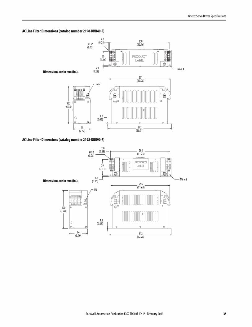
AC Line Filter Dimensions (catalog number 2198-DBR40-F)
AC Line Filter Dimensions (catalog number 2198-DBR90-F)
7.0 (0.28)R3.25
(0.13)
60(2.36)
258(10.16)
261(10.28)
1.2(0.05)
272(10.71)
73(2.87)
162(6.38)
5.9(0.23)
M6
M6 x 4Dimensions are in mm (in.).
298(11.73)
79(3.11)
Ø 7.0(0.28)
1.2(0.05)
312(12.28)
94(3.70)
190(7.48)
M8
7.0 (0.28)
6.3(0.25)
296(11.65)
M6 x 4Dimensions are in mm (in.).
Rockwell Automation Publication KNX-TD003E-EN-P - February 2019 35

Kinetix Servo Drives Specifications
AC Line Filter Dimensions (catalog number 2198-DBR200-F)
AC Line Filter Specifications
AC Line Filter Dimensions (catalog number 2198-DB20-F)
AC Line FilterCat. No.
Voltage Rating, max
Current RatingA @ 50 °C (122 °F)
Power LossW
Leakage CurrentmA
Weight, approxkg (lb)
Operating Temperature
2198-DBR20-F
528V ACthree-phase50/60 Hz
20 4.230.0
1.0 (2.20)
0…50 °C(32…122 °F)
2198-DBR40-F 40 9.6 3.3 (7.28)
2198-DBR90-F 90 16.8 34.0 4.1 (9.04)
2198-DBR200-F 200 34.5 46.0 7.2 (15.87)
298(11.73)
56(2.20)
R3.5(0.14)
1.2(0.05)
312(12.28)
126(4.96)
224(8.82)
M10
7.0 (0.28)
5.8(0.23)
336(13.23)
56(2.20)
M6 x 6
Dimensions are in mm (in.).
6.0(0.24)R3.0
(0.12)
217(8.54)
230(9.06)
229(9.02)
55(2.16)
42(1.65)
42(1.65)
M5
M5 x 45.6(0.22)
1.2(0.05)
116(4.57)
Dimensions are in mm (in.).
36 Rockwell Automation Publication KNX-TD003E-EN-P - February 2019

Kinetix Servo Drives Specifications
AC Line Filter Dimensions (catalog number 2198-DB42-F)
AC Line Filter Dimensions (catalog number 2198-DB80-F)
Ø 6.5 (0.26)
R3.25(0.13)
60(2.36)
60(2.36)
258(10.16)
261(14.21)
1.2(0.05)
272(10.71)
73(2.87)
M6
M6 x 47.0
(0.28)
5.9(0.23)
162(6.38)
Dimensions are in mm (in.).
298(11.73)
79(3.11)
79(3.11)
Ø 7.0(0.28)
1.2(0.05)
312(12.28)
94(3.70)
190(7.48)
M8
M6 x 4
7.0(0.28)
6.3(0.25)
298(11.73)
Dimensions are in mm (in.).
Rockwell Automation Publication KNX-TD003E-EN-P - February 2019 37

Kinetix Servo Drives Specifications
AC Line Filter Dimensions (catalog number 2198-DB290-F)
AC Line Filter Specifications
AC Line FilterCat. No.
Voltage Rating, max
Current RatingA @ 50 °C (122 °F)
Power LossW
Leakage CurrentmA
Weight, approxkg (lb)
Operating Temperature
2198-DB20-F
528V ACthree-phase50/60 Hz
20 5.1 5.2 1.63 (3.59)
0…50 °C(32…122 °F)
2198-DB42-F 42 14.7 4.0 2.70 (5.95)
2198-DB80-F 80 18.3 13.0 3.95 (8.71)
2198-DB290-F 290 32.7 19.4 4.20 (9.26)
90(3.54)
146(5.75)
208(8.19)
30(1.18)
Ø 10.5(0.41)
268(10.56)
39(1.54)
M8
170(6.69)
77(3.03)
186(7.32)
46 (1.81)
3 (0.12)
19 (0.75)
M10 x 4
7.0(0.28)
R5.25(0.21)
8.0(0.31)
18(0.71)
Dimensions are in mm (in.).
M4 threaded inserts foroptional terminal covers.
38 Rockwell Automation Publication KNX-TD003E-EN-P - February 2019

Kinetix Servo Drives Specifications
DC-bus Link Connector Kits
DC-bus link connector kits are used to extend DC-bus power from module-to-module.
The DC-bus link connector kits are required and comprised of these two components:• DC-bus links that are inserted between drive modules to extend the DC-bus from module-to-module. DC-bus
links are included with inverter modules and the iTRAK power supply as indicated in the table below.• DC-bus end-caps are inserted into the first and last drive modules to cover the exposed DC-bus connector on
both ends of the bus and are included with the DC-bus power supplies and regenerative bus supplies.
DC-bus Link Connector Example
(1) DC-bus links latch on both sides when inserted into the DC-bus connectors. To remove the DC-bus link, depress both sets of upper pivots to unlatch the lower pivots, hold the DC-bus link firmly, and pull upward.
IMPORTANT Use of the DC-bus link connector kits is required and the zero-stack tab and cutout must be engaged between adjacent drives.
DC-bus Link Connector Kit Catalog Numbers
Replacement KitCat. No. Description Module Type Module Cat. No. Illustration
2198-BARCON-55DC200 DC-bus link, 55 mm, 208 A Dual axis inverter
2198-D006-ERSx, 2198-D012-ERSx2198-D020-ERSx, 2198-D032-ERSx2198-CAPMOD-22402198-CAPMOD-DCBUS-IO2198-DCBUSCOND-RP312
2198-BARCON-85DC200 DC-bus link, 85 mm, 208 A
Dual axis inverter 2198-D057-ERSx
Single axis inverter 2198-S086-ERSx2198-S130-ERSx
2198-BARCON-100DC200 DC-bus link,100 mm, 208 A
Single axis inverter 2198-S160-ERSx
iTRAK power supply 2198T-W25K-ER
2198-BARCON-220DC200 DC-bus link, 220 mm, 208 A Single-axis inverter 2198-S263-ERSx
2198-S312-ERSx
Kinetix 5700 Drive System
End Caps (2)DC-bus Link, 85 mm
Zero-stack Taband Cutout Engaged
DC-bus Link, 55 mmDC-bus Link, 100 mm(seated)
DC-bus power supply is mountedleftmost followed by drive with
largest amp rating.
Latch
Align the DC-bus linklower pivots with the
latches and push downward until they latch.
Upper Pivot
Lower Pivot
Dual Axis Inverter, 55 mm
Single Axis Inverter, 85 mm
Single Axis Inverter, 100 mm
DC-bus Power Supply
DC-bus Link Latched (1)
Rockwell Automation Publication KNX-TD003E-EN-P - February 2019 39

Kinetix Servo Drives Specifications
24V Shared-bus Connector Kits
24V shared-bus connector kits are used to extend 24V control power from module-to-module. The 24V control power connection system is optional and mounted onto modules working from left to right. 24V shared-bus systems always start with a 24V DC input wiring connector followed by T-connectors and bus-bars. A 24V DC connection system is comprised of these three components:
• The 24V input wiring connector that plugs into the DC-bus power supply or regenerative bus supply and receives input wiring for 24V DC (catalog numbers 2198-TCON-24VDCIN36 or 2198T-W25K-P-IN)
• 24V DC T-connector that plugs into a module downstream and to the right of the 24V input wire connector or previous T-connector.
• Bus bars that connect between a 24V input wiring connector and one or more T-connectors to extend the 24V control power from module to module.
Control Power Connector Example
2198-BARCON-165DC200 DC-bus link,165 mm, 208 A Regenerative Bus Supply 2198-RP088
2198-BARCON-275DC200 DC-bus link, 275 mm, 208 A Regenerative Bus Supply 2198-RP200
2198-BARCON-440DC200 DC-bus link, 440 mm, 208 A Regenerative Bus Supply 2198-RP263
2198-RP312
2198-KITCON-ENDCAP200 DC-bus end caps, 208 A
DC-bus power supply 2198-P031, 2198-P0702198-P141, 2198-P208
Regenerative Bus Supply 2198-RP088, 2198-RP2002198-RP263, 2198-RP312
IMPORTANT The maximum current rating for the 24V input power connection system is 40 A. If needed, you can insert another 2198-TCON-24VDCIN36 or 2198T-W25K-P-IN control power input wiring connector at any point in the drive cluster.
DC-bus Link Connector Kit Catalog Numbers (continued)
Replacement KitCat. No. Description Module Type Module Cat. No. Illustration
24V Input WiringConnector
24V T-connectors
Bus-bar Connectors
24V Input Wiring
Zero-stack Taband Cutout Engaged
Kinetix 5700 Drive System
DC-bus power supply is mountedleftmost followed by drive with
largest amp rating.
100 mmBus-bar
85 mmBus-bar
55 mmBus-bar
40 Rockwell Automation Publication KNX-TD003E-EN-P - February 2019

Kinetix Servo Drives Specifications
24V Shared-bus Connector Kit Catalog Numbers
IMPORTANT The input wiring connector can be inserted into any drive module (mid-stream in the drive system) to begin a new 24V control bus when the maximum current value is reached. However, the input connector must always extend the 24V DC-bus from left to right.
Kit Cat. No. Description Module Type Module Cat. No. Illustration
2198-TCON-24VDCIN36
Control power input wiring connector
Regenerative bus suppliesDC-bus power suppliesDual-axis invertersSingle-axis invertersCapacitor moduleDC-bus conditioner module
2198-RP088, 2198-RP2002198-Pxxx2198-Dxxx-ERSx2198-S086-ERSx2198-S130-ERSx2198-S160-ERSx2198-CAPMOD-22402198-DCBUSCOND-RP312
2198T-W25K-P-IN
iTRAK power supply 2198T-W25K-ER
Regenerative bus supplies 2198-RP2632198-RP312
Single axis inverter 2198-S263-ERSx2198-S312-ERSx
2198T-W25K-P-T
Control power T-connectorBus-bar connectors, 100 mm, quantity 2
iTRAK power supply 2198T-W25K-ER
2198-S160-P-T Single axis inverter 2198-S160-ERSx
2198-S312-P-T Control power T-connectorBus-bar connector, 220 mm, quantity 1 Single axis inverter 2198-S263-ERSx
2198-S312-ERSx
2198-H070-P-T Control power T-connectorBus-bar connectors, 85 mm, quantity 2
DC-bus power supplies 2198-P1412198-P208
Dual axis inverter 2198-D057-ERSx
Single axis inverters 2198-S086-ERSx2198-S130-ERSx
2198-H040-P-T Control power T-connectorBus-bar connectors, 55 mm, quantity 2
DC-bus power supplies 2198-P0312198-P070
Dual axis inverters
2198-D006-ERSx2198-D012-ERSx2198-D020-ERSx2198-D032-ERSx
Capacitor moduleDC-bus conditioner module
2198-CAPMOD-22402198-DCBUSCOND-RP312
Control Power Input Connector
Bus-bar Connectors (2x)
T-connector
Bus-bar Connector
T-connector
Bus-bar Connectors (2x)
T-connector
Bus-bar Connectors (2x)
T-connector
Rockwell Automation Publication KNX-TD003E-EN-P - February 2019 41

Kinetix Servo Drives Specifications
System Mounting Toolkit
The 2198-K5700-MOUNTKIT system mounting toolkit is used to locate the drill-holes for your Kinetix 5700 drive system. Properly spaced drill-holes are essential for engaging the zero-stack tab and cutout from module-to-module so that the DC-bus connectors are spaced properly and accept the DC-bus links. The Kinetix 5700 system mounting toolkit includes the drill-hole guide and mounting bar. Two M4 thread-forming fasteners are also included.
The mounting bar is mounted horizontally on the system panel. The drill-hole guide inserts behind the mounting bar and slides left and right. Holes and slots in the drill-hole guide let you establish the location of each Kinetix 5700 drive module.
Kinetix 5700 System Mounting Toolkit
10010085 85
55
10085
55
10085
55
55EXT MODULE
55
100
85
100
85
Module-width holes are 55, 85, and 100 mm
Left-side Alignment Slots Right-side Alignment Slots
Extension Module Lower Hole
Upper Module-width Holes
Lower Module-width Holes
Mounting Bar
2198-K5700-MOUNTKITDrill-hole Guide
42 Rockwell Automation Publication KNX-TD003E-EN-P - February 2019

Kinetix Servo Drives Specifications
Universal Feedback Connector Kit
The 2198-K57CK-D15M universal feedback kit passes feedback signals straight through from the encoder to the universal feedback (UFB) connector on the drive. The following encoder feedback types are accepted:
• Hiperface high-resolution absolute (multi-turn and single-turn)• Heidenhain EnDat high-resolution absolute (digital)
– EnDat sine/cosine encoders support only RDD-Series™ direct-drive motors (Bulletin RDB)– EnDat digital encoders support only third-party motors
• Digital AqB (TTL) and Digital AqB (TTL) with UVW (incremental)• Sine/Cosine and Sine/Cosine with UVW (incremental)• Feedback-only, master feedback, or load feedback (absolute single-turn/multi-turn Hiperface)• Feedback-only, master feedback, or load feedback (incremental)• Feedback-only, master feedback, or load feedback (generic sine/cosine)
Use the universal feedback connector kit in the following types of installations:• New installations with Kinetix 5700 servo drives and the compatible motors and actuators• Existing motor/actuator installations when upgrading with Kinetix 5700 servo drives
Compatible Allen-Bradley Motors and Actuators
Universal Feedback Connector Kit Dimensions
Rotary Motors Linear Actuators 2090-Series Feedback Cables (3)
(3) These are typical feedback cables. Refer to the Kinetix 5700 Servo Drives Design Guide, publication KNX-RM010, for the cables required for specific drive and motor/actuator combinations.
Kinetix VP continuous-duty motors (VPC-Bxxxxx-S and VPC-Bxxxxx-Y) LDAT-Series integrated linear thrusters (1)
(1) LDAT-Series linear thrusters with absolute high-resolution encoders and incremental encoders are compatible.
2090-CFBM7DF-CEAAxx (standard, non-flex)2090-CFBM7DF-CEAFxx (continuous-flex)2090-XXNFMF-Sxx (standard, non-flex)2090-CFBM7DF-CDAFxx (continuous-flex)
MP-Series™ low-inertia motors (Bulletin MPL)
MP-Series medium-inertia motors (Bulletin MPM) MP-Series integrated linear stages (Bulletin MPAS) (2)
(2) Bulletin MPAS and MPMA (ballscrew) linear stages and direct-drive linear stages are compatible.
MP-Series food-grade motors (Bulletin MPF) MP-Series multi-axis linear stages (Bulletin MPMA) (2)
MP-Series stainless-steel motors (Bulletin MPS) MP-Series electric cylinders (Bulletin MPAR)
HPK-Series™ asynchronous servo motors MP-Series heavy-duty electric cylinders (Bulletin MPAI)
RDD-Series direct-drive motors (Bulletin RDB) LDC-Series™ iron-core linear motors
14.0(0.55)
38.5(1.52)
111(4.37)
34.0 (1.34)
20.75(0.82)
Dimensions are in mm (in.).
Rockwell Automation Publication KNX-TD003E-EN-P - February 2019 43

Kinetix Servo Drives Specifications
Hiperface-to-DSL Feedback Converter Kit
The 2198-H2DCK Hiperface-to-DSL feedback kit (series B or later) converts 15-pin Hiperface encoder feedback signals to 2-pin DSL feedback signals on the motor feedback (MF) connector. The following feedback types are accepted:
• Hiperface high-resolution absolute multi-turn and single-turn encoders• Feedback-only, master feedback, or load feedback (absolute single-turn/multi-turn Hiperface)
Use the converter kit for Hiperface auxiliary-encoder feedback in applications that require dual-loop or load feedback when the 15-pin universal feedback (UFB) connector is already in use for a different compatible feedback type.
Compatible Allen-Bradley Motors and Actuators
The 2198-H2DCK feedback converter kit can be used to convert Hiperface feedback signals from the motor encoder to DSL feedback signals that are accepted by the motor feedback (MF) connector. Compatible Allen-Bradley rotary motors and linear actuators must have high-resolution absolute encoders. Cable length restrictions also exist, refer toMaximum Motor Cable Lengths on page 18 for more information.
For product dimensions, refer to Hiperface-to-DSL Feedback Converter Kit on page 66.
Replacement Parts and Connector Kits - Kinetix 5700 Servo Drives
Replacement parts and kits available for Kinetix 5700 servo drives include the DSL feedback connector kit, power-sharing bus-bars, power connector sets, and fan kits.
DSL Feedback Connector Kit
The 2198-KITCON-DSL feedback connector kit is required for making feedback connections from Kinetix VP motors and actuators, and is included with each 2090-CSxM1DE cable. Motor power, brake, and the 2-wire feedback connections are made by using a single 2090-CSxM1DE cable. Refer to the Kinetix Motion Accessories Specifications Technical Data, publication KNX-TD004, for cable specifications.
2090-CSxM1DE Single Motor Cables
Rotary Motors Linear Actuators 2090-Series Feedback Cables (3)
(3) These are typical feedback cables. Refer to the Kinetix 5700 Servo Drives Design Guide, publication KNX-RM010, for the cables required for specific drive and motor/actuator combination.
Kinetix VP continuous-duty motors (VPC-Bxxxxx-Q)LDAT-Series integrated linear thrusters (1)
(1) LDAT-Series linear thrusters with absolute high-resolution encoders are compatible. Linear stages with incremental encoders are not compatible.
2090-CFBM7DF-CEAAxx (standard, non-flex)2090-CFBM7DF-CEAFxx (continuous-flex)2090-XXNFMF-Sxx (standard, non-flex)2090-CFBM7DF-CDAFxx (continuous-flex)
MP-Series low-inertia motors (Bulletin MPL)
MP-Series medium-inertia motors (Bulletin MPM) MP-Series integrated linear stages (Bulletin MPAS) ballscrew (2)
(2) Bulletin MPAS and MPMA (ballscrew) linear stages are compatible. Direct-drive linear stages are not compatible.
MP-Series food-grade motors (Bulletin MPF) MP-Series multi-axis linear stages (Bulletin MPMA) ballscrew (2)
MP-Series stainless-steel motors (Bulletin MPS) MP-Series electric cylinders (Bulletin MPAR)
HPK-Series asynchronous servo motors MP-Series heavy-duty electric cylinders (Bulletin MPAI)
2198-KITCON-DSL Feedback Connector Kit
44 Rockwell Automation Publication KNX-TD003E-EN-P - February 2019

Kinetix Servo Drives Specifications
Power Sharing Bus-bars and Connector SetsReplacement Power Sharing Bus-bars
Replacement Kit Cat. No. Description Module Type Module Cat. No. Illustration
2198-BARCON-55DCAC100 Bus-bar connectors, 55 mm, quantity 8
DC-bus power supplies 2198-P031, 2198-P070
Dual-axis inverters 2198-D006-ERSx2198-D012-ERSx
2198-D020-ERSx2198-D032-ERSx
Capacitor module 2198-CAPMOD-2240
DC-bus conditioner module 2198-DCBUSCOND-RP312
2198-BARCON-85DCAC100 Bus-bar connectors, 85 mm, quantity 8
DC-bus power supplies 2198-P141, 2198-P208
Dual-axis inverters 2198-D057-ERSx
Single-axis inverters 2198-S086-ERSx, 2198-S130-ERSx
2198-BARCON-100DC100 Bus-bar connectors, 100 mm, quantity 8
Single-axis inverters 2198-S160-ERSx
iTRAK power supply 2198T-W25K-ER
Replacement Connector Sets
Replacement Kit Cat. No. Description Module Type Module Cat. No. Illustration
2198-KITCON-P070 • One AC input power (IPD) connector• One 24V input power (CP) connector• One contactor enable (CED) connector• One passive shunt (RC) connector• One I/O (IOD) connector
DC-bus power supplies
2198-P0312198-P070
2198-KITCON-P208 2198-P1412198-P208
2198-KITCON-RP088 • One AC input power (IPD) connector• One 24V input power (CP) connector• One contactor enable (CED) connector• One active shunt (RC) connector• One I/O (IOD) connector Regenerative bus
supplies
2198-RP088
2198-KITCON-RP200 2198-RP200
2198-KITCON-RP312
• One 24V input power (CP) connector• One contactor enable (CED) connector• One active shunt (RC) connector• One I/O (IOD) connector
2198-RP2632198-RP312
2198-KITCON-D032-L
• One 24V input power (CP) connector• Two motor power (MP) connectors• Two motor brake (BC) connectors• Two I/O (IOD) connectors• One Safe Torque Off (STO) connector• One ground screwIOD and STO connector plugs are compatible with 2198-Dxxx-ERS4 drives and 2198-Dxxx-ERS3 (series B) drives.
Dual-axis inverters
2198-D006-ERSx2198-D012-ERSx2198-D020-ERSx2198-D032-ERSx
2198-KITCON-D057-L 2198-D057-ERSx
2198-KITCON-D032
• One 24V input power (CP) connector• Two motor power (MP) connectors• Two motor brake (BC) connectors• Two I/O (IOD) connectors• One Safe Torque Off (STO) connectorIOD and STO connector plugs are compatible with 2198-Dxxx-ERS3 (series A) drives.
Dual-axis inverters
2198-D006-ERS32198-D012-ERS32198-D020-ERS32198-D032-ERS3(series A drives)
2198-KITCON-D057 2198-D057-ERS3(series A drives)
2198-5700-CLAMPSPACER Two clamp spacers Dual-axis inverters 2198-Dxxx-ERSx
2198-5700-DACLAMPKIT One cable clamp Dual-axis inverters 2198-Dxxx-ERSx
Rockwell Automation Publication KNX-TD003E-EN-P - February 2019 45

Kinetix Servo Drives Specifications
Fan Kits
2198-KITCON-S160-L
• One 24V input power (CP) connector• One motor power (MP) connector
and clamp bracket• Two motor cable clamps• One motor brake (BC) connector• One I/O (IOD) connector• One Safe Torque Off (STO) connector• One ground jumperIOD and STO connector plugs are compatible with 2198-Sxxx-ERS4 drives and 2198-Sxxx-ERS3 (series B) drives.
Single-axis inverters
2198-S086-ERSx2198-S130-ERSx2198-S160-ERSx
2198-KITCON-S160
• One 24V input power (CP) connector• One motor power (MP) connector
and clamp bracket• Two motor cable clamps• One motor brake (BC) connector• One I/O (IOD) connector• One Safe Torque Off (STO) connectorIOD and STO connector plugs are compatible with 2198-Sxxx-ERS3 (series A) drives.
Single-axis inverters
2198-S086-ERS32198-S130-ERS32198-S160-ERS3(series A drives)
2198-KITCON-S3122198-KITCON-S312-L
• One 24V input power (CP) connector• One motor cable clamp• One motor brake (BC) connector• One I/O (IOD) connector• One Safe Torque Off (STO) connector• One ground jumperIOD and STO connector plugs are compatible with 2198-Sxxx-ERS4 drives and 2198-Sxxx-ERS3 (series B) drives.
Single-axis inverters
2198-S263-ERSx2198-S312-ERSx
2198T-W25K-KITCON
• One 24V input power (CP) connector• Two DC-bus output (IDC) connectors• Two control output (ICP) connectors• One I/O (IOD) connector• One iTRAK PS ready (IR) connector
iTRAK power supply 2198T-W25K-ER
2198-KITCON-CAPMOD2240 • One stud/lug cover with wires• One stud cover without wires• One bottom plate• One 24V input power (CP) connector• One module status (MS) connector• Two flexible bus-bars• Two lug spacers • Two M8 hex nuts
Capacitor module 2198-CAPMOD-2240
Extension module 2198-CAPMOD-DCBUS-IO
2198-KITCON-DCBUSCONDDC-bus conditioner module
2198-DCBUSCOND-RP312
Replacement Fan Kits
Replacement Kit Cat. No. Description Module Type Module Cat. No. Illustration
2198-SK1-FAN060 Replacement fan and carrier assembly Regenerative bus supply 2198-RP088
2198-SK1-FAN092 Replacement fan and carrier assembly
Regenerative bus supplies
2198-RP2002198-RP2632198-RP312
Single-axis inverters 2198-S263-ERSx2198-S312-ERSx
Replacement Connector Sets (continued)
Replacement Kit Cat. No. Description Module Type Module Cat. No. Illustration
46 Rockwell Automation Publication KNX-TD003E-EN-P - February 2019

Kinetix Servo Drives Specifications
Kinetix 5500 Servo Drives
The Kinetix 5500 servo drives and Kinetix VP servo motors provide a cost-effective motion solution that delivers high performance and scalability with motor windings matched to drive ratings for optimized system sizing.
Enhancing the current midrange architecture portfolio, this motion system is designed to connect and operate with the ControlLogix, GuardLogix, and CompactLogix controllers by using the Studio 5000 Logix Designer® application and supporting integrated motion and safety on the EtherNet/IP network. With the benefits of this motion system, you can now run motion applications on a single control platform by using a single network, simplifying the design, operation, and maintenance of equipment.
Kinetix 5500 Drive Features and Indicators
Item Description Item Description Item Description
1 Motor cable shield clamp 8 Module status indicator 15 Motor brake (BC) connector
2 Converter kit mounting hole (1)
(under cover)
(1) Protective knock-out covers the 2198-H2DCK Hiperface-to-DSL feedback converter kit mounting hole. Remove knock-out for use with the converter kit.
9 Network status indicator 16 Ground terminal
3 Motor feedback (MF) connector 10 LCD display 17 Shunt resistor (RC) connector
4 Digital inputs (IOD) connector 11 Navigation pushbuttons 18 AC mains input power (IPD) connector
5 Ethernet (PORT1) RJ45 connector 12 Link speed status indicators 19 DC bus (DC) connector (under cover) (2)
(2) DC-bus connector ships with protective knock-out cover that can be removed for use in shared-bus configurations.
6 Ethernet (PORT2) RJ45 connector 13 Link/Activity status indicators 20 24V control input power (CP) connector
7 Zero-stack mounting tab/cutout 14 Motor power (MP) connector 21 Safe Torque Off (STO) connector (3)
(does not apply to 2198-Hxxx-ERS2 drives)
(3) Protective knock-out cover is removed on 2198-Hxxx-ERS (hardwired STO) drives.
21
20
19
18
17
12
L3
L2
L1
1
2
+
–
1
8
3
4
135
6
11
10
9
12
16
7 7
U
V
W
21 15
14
2
12
Kinetix 5500 Drive, Top View(2198-Hxxx-ERS2 drive is shown)
Protective Knock-out
Shared-bus AC Input Wiring Connector
Shared-bus 24V Input Wiring Connector
Kinetix 5500 Drive, Front View(2198-H003-ERSx drive is shown) Kinetix 5500 Drive, Top View
(2198-H003-ERS drive is shown)
Rockwell Automation Publication KNX-TD003E-EN-P - February 2019 47
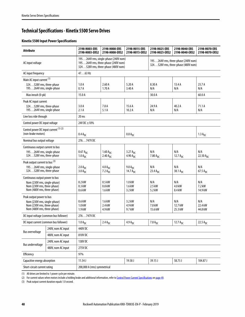
Kinetix Servo Drives Specifications
Technical Specifications - Kinetix 5500 Servo Drives
Kinetix 5500 Input Power Specifications
Attribute 2198-H003-ERS2198-H003-ERS2
2198-H008-ERS2198-H008-ERS2
2198-H015-ERS2198-H015-ERS2
2198-H025-ERS2198-H025-ERS2
2198-H040-ERS2198-H040-ERS2
2198-H070-ERS2198-H070-ERS2
AC input voltage195…264V rms, single-phase (240V nom)195…264V rms, three-phase (240V nom)324…528V rms, three-phase (480V nom)
195…264V rms, three-phase (240V nom)324…528V rms, three-phase (480V nom)
AC input frequency 47…63 Hz
Main AC input current (1)
324…528V rms, three-phase195…264V rms, single-phase
(1) All drives are limited to 1 power cycle per minute.
1.0 A0.7 A
2.60 A1.70 A
5.20 A3.40 A
8.30 AN/A
13.4 AN/A
23.7 AN/A
Max inrush (0-pk) 15.0 A 30.0 A 60.0 A
Peak AC input current324…528V rms, three-phase195…264V rms, single-phase
3.0 A2.1 A
7.8 A5.1 A
15.6 A10.2 A
24.9 AN/A
40.2 AN/A
71.1 AN/A
Line loss ride through 20 ms
Control power DC input voltage 24V DC ±10%
Control power DC input current (1) (2)
(non-brake motors)
(2) For current values when motors include a holding brake and additional information, refer to Control Power Current Specifications on page 49.
0.4 ADC 0.8 ADC 1.3 ADC
Nominal bus output voltage 276…747V DC
Continuous output current to bus195…264V rms, single-phase324…528V rms, three-phase
0.67 ADC1.0 ADC
1.60 ADC2.40 ADC
3.27 ADC4.90 ADC
N/A7.80 ADC
N/A12.7 ADC
N/A22.50 ADC
Peak output current to bus (3)
195…264V rms, single-phase324…528V rms, three-phase
(3) Peak output current duration equals 1.0 second.
2.0 ADC3.0 ADC
4.8 ADC7.2 ADC
9.8 ADC14.7 ADC
N/A23.4 ADC
N/A38.1 ADC
N/A67.5 ADC
Continuous output power to busNom (230V rms, single-phase)Nom (230V rms, three-phase)Nom (480V rms, three-phase)
0.2 kW0.3 kW0.6 kW
0.5 kW0.8 kW1.6 kW
1.0 kW1.6 kW3.2 kW
N/A2.5 kW5.2 kW
N/A4.0 kW8.4 kW
N/A7.2 kW14.9 kW
Peak output power to busNom (230V rms, single-phase)Nom (230V rms, three-phase)Nom (480V rms, three-phase)
0.6 kW1.0 kW1.9 kW
1.6 kW2.4 kW4.9 kW
3.2 kW4.9 kW9.7 kW
N/A7.8 kW15.6 kW
N/A12.7 kW25.3 kW
N/A22.4 kW44.8 kW
DC input voltage (common bus follower) 276…747V DC
DC input current (common bus follower) 1.0 ADC 2.4 ADC 4.9 ADC 7.8 ADC 12.7 ADC 22.5 ADC
Bus overvoltage 240V, nom AC input 440V DC
480V, nom AC input 810V DC
Bus undervoltage240V, nom AC input 138V DC
480V, nom AC input 275V DC
Efficiency 97%
Capacitive energy absorption 11.54 J 19.58 J 39.15 J 58.73 J 104.87 J
Short-circuit current rating 200,000 A (rms) symmetrical
48 Rockwell Automation Publication KNX-TD003E-EN-P - February 2019

Kinetix Servo Drives Specifications
Kinetix 5500 Output Power Specifications
Control Power Current Specifications
Kinetix 5500 servo drives and the Bulletin 2198 capacitor module have different 24V DC power consumption. Factors to consider when calculating the combined current demand from your 24V DC power supply include the following:
• Catalog number for each drive in the system• Whether servo motors include the holding brake option• Whether the system includes Bulletin 2198 capacitor modules (1 to 4 modules are possible)
Control Power Current Specifications
Attribute 2198-H003-ERS2198-H003-ERS2
2198-H008-ERS2198-H008-ERS2
2198-H015-ERS2198-H015-ERS2
2198-H025-ERS2198-H025-ERS2
2198-H040-ERS2198-H040-ERS2
2198-H070-ERS2198-H070-ERS2
Bandwidth (1)
Velocity loop, maxCurrent loop
(1) Bandwidth values vary based on tuning parameters and mechanical components.
300 Hz1000 Hz
PWM frequency 8 kHz 4 kHz
Continuous output current (rms) 1.0 A 2.5 A 5.0 A 8.0 A 13.0 A 23.0 A
Continuous output current (0-pk) 1.4 A 3.5 A 7.1 A 11.3 A 18.4 A 32.5 A
Peak output current (rms) (2)
(2) Peak current duration (TPKmax) equals 1.0 second.
2.5 A 6.25 A 12.5 A 20.0 A 32.5 A 57.5 A
Peak output current (0-pk) (2) 3.5 A 8.8 A 17.7 A 28.3 A 45.9A 81.3A
Continuous power out (nom)195…264V rms, single-phase195…264V rms, three-phase324…528V rms, three-phase
0.2 kW0.3 kW0.6 kW
0.5 kW0.8 kW1.6 kW
1.0 kW1.5 KW3.2 kW
N/A2.4 kW5.1 kW
N/A4.0 kW8.3 kW
N/A7.0 kW14.6 kW
Internal shunt resistance 100 Ω 60 Ω 40 Ω
Internal shunt power 30 W 50 W 75 W
Shunt on 775V plus 30V x bus regulator capacity/utilization (3)
(3) The shunt on and shunt off voltages increase during periods of shunting activity to promote sharing of shunt power in multi-axis configurations. Shunt utilization is equivalent to the BusRegulatorCapacity tag in the Logix Designer application.
Shunt off 765V plus 30V x bus regulator capacity/utilization (3)
Cat. No.24V Current (non-brake motor)ADC
24V Current (2 A brake motor)ADC
24V Inrush Current (1)
A
(1) Inrush current duration is less than 30 ms.
2198-H003-ERSx0.4 2.4 2.0
2198-H008-ERSx
2198-H015-ERSx
0.8 2.83.0
2198-H025-ERSx
2198-H040-ERSx
2198-H070-ERSx 1.3 3.3
2198-CAPMOD-1300 0.3 N/A 2.0
Rockwell Automation Publication KNX-TD003E-EN-P - February 2019 49

Kinetix Servo Drives Specifications
Peak Current Specifications
Load Duty-cycle Profile Example
Peak Duty Cycle Definition of Terms
Term Definition (1)
(1) All current values are specified as RMS.
Continuous Current Rating (ICont) The maximum value of current that can be output continuously.
Peak Current Rating (IPKmax) The maximum value of peak current that the drive can output. This rating is valid only for overload times less than TPKmax.
Duty Cycle (D) The ratio of time at peak to the Application Period is defined as:
Time at Peak (TPK) The time at peak current (IPK) for a given loading profile. Must be less than or equal to TPKmax.
Peak Current (IPK) The level of peak current for a given loading profile. IPK must be less than or equal to the Peak Current Rating (TPKMAX) of the drive.
Base Current (IBase) The level of current between the pulses of peak current for a given loading profile. IBase must be less than or equal to the continuous current rating (ICont) of the drive.
Loading ProfileThe loading profile is composed of IPK, IBase, TPK, and D (or T) values and completely specify the operation of the drive in an overload situation. These values are collectively defined as the Loading Profile of the drive.
Application Period (T) The sum of the times at IPK (TPK) and IBase.
I Cont
I Base
I PK
TPK
T
D = TT
PK x 100%
D = TT
PK x 100%
50 Rockwell Automation Publication KNX-TD003E-EN-P - February 2019
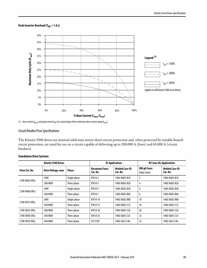
Kinetix Servo Drives Specifications
Peak Inverter Overload (TPK < 1.0 s)
(1) Base current (IBase) and peak current (IPK) are a percentage of the continuous drive current rating (ICont).
Circuit Breaker/Fuse Specifications
The Kinetix 5500 drives use internal solid-state motor short-circuit protection and, when protected by suitable branch circuit protection, are rated for use on a circuit capable of delivering up to 200,000 A (fuses) and 65,000 A (circuit breakers).
Standalone Drive Systems
Kinetix 5500 Drives UL Applications IEC (non-UL) Applications
Drive Cat. No. Drive Voltage, nom Phase Bussmann FusesCat. No.
Molded Case CB Cat. No.
DIN gG FusesAmps (max)
Molded Case CBCat. No.
2198-H003-ERSx240V Single-phase KTK-R-2 140U-D6D2-B10 2 140U-D6D2-B10
240/480V Three-phase KTK-R-3 140U-D6D3-B20 4 140U-D6D3-B20
2198-H008-ERSx240V Single-phase KTK-R-5 140U-D6D2-B20 6 140U-D6D2-B20
240/480V Three-phase KTK-R-7 140U-D6D3-B60 6 140U-D6D3-B60
2198-H015-ERSx240V Single-phase KTK-R-10 140U-D6D2-B80 10 140U-D6D2-B80
240/480V Three-phase KTK-R-15 140U-D6D3-C12 16 140U-D6D3-C12
2198-H025-ERSx 240/480V Three-phase KTK-R-20 140U-D6D3-C20 20 140U-D6D3-C20
2198-H040-ERSx 240/480V Three-phase KTK-R-25 140U-D6D3-C25 25 140U-D6D3-C25
2198-H070-ERSx 240/480V Three-phase LPJ-35SP 140G-G6C3-C40 35 140G-G6C3-C40
0% 60% 100%
50%
45%
40%
35%
30%
25%
20%
15%
10%
5%
0%
80%20% 40%
Applies to all Kinetix 5500 servo drives.
Max
imum
Dut
y Cyc
le (D
max
)
% Base Current (I Base /ICont)
Legend (1)
I pk = 150%
I pk = 200%
I pk = 250%
Rockwell Automation Publication KNX-TD003E-EN-P - February 2019 51

Kinetix Servo Drives Specifications
Shared DC (common-bus) Drive Systems
Shared AC Drive Systems
Input Power UL Circuit-protection Specifications
Input Power IEC (non-UL) Circuit-protection Specifications
Kinetix 5500 Drives Cat. No.
Drive Voltage,(three-phase)nom
UL Applications IEC (non-UL) Applications
Bussmann FusesCat. No.
Molded Case CB Cat. No.
DIN gG FusesAmps (max)
Molded Case CB Cat. No.
2198-H003-ERSx 240/480V KTK-R-10 140U-D6D3-C15 10 140U-D6D3-C15
2198-H008-ERSx 240/480V KTK-R-10 140U-D6D3-C15 10 140U-D6D3-C15
2198-H015-ERSx 240/480V KTK-R-15 140U-D6D3-C15 16 140U-D6D3-C15
2198-H025-ERSx 240/480V KTK-R-20 140U-D6D3-C20 20 140U-D6D3-C20
2198-H040-ERSx 240/480V KTK-R-25 140U-D6D3-C25 25 140U-D6D3-C25
2198-H070-ERSx 240/480V LPJ-35SP 140G-G6C3-C40 35 140G-G6C3-C40
Kinetix 5500 DrivesCat. No.
Drive Voltage,(three-phase)nom
Bussmann FusesCat. No.
Molded Case CB Cat. No.
2 Axes 3 Axes 4 Axes 5 Axes 2 Axes 3 Axes 4 Axes 5 Axes
2198-H003-ERSx 240/480V KTK-R-15 140U-D6D3-C15
2198-H008-ERSx 240/480V KTK-R-15 140U-D6D3-C15
2198-H015-ERSx 240/480V KTK-R-20 KTK-R-25 N/A 140U-D6D3-C15 140U-D6D3-C20 N/A
2198-H025-ERSx 240/480V KTK-R-30 N/A 140U-D6D3-C25 140U-D6D3-C30 N/A
2198-H040-ERSx 240/480V LPJ-35SP LPJ-45SP N/A 140G-G6C3-C40 140G-G6C3-C50 N/A
2198-H070-ERSx 240/480V LPJ-60SP N/A 140G-G6C3-C60 N/A
Kinetix 5500 DrivesCat. No.
Drive Voltage,(three-phase)nom
DIN gG FusesAmps (max)
Molded Case CB Cat. No.
2 Axes 3 Axes 4 Axes 5 Axes 2 Axes 3 Axes 4 Axes 5 Axes
2198-H003-ERSx 240/480V 16 140U-D6D3-C15
2198-H008-ERSx 240/480V 16 140U-D6D3-C15
2198-H015-ERSx 240/480V 20 25 N/A 140U-D6D3-C15 140U-D6D3-C20 N/A
2198-H025-ERSx 240/480V 32 N/A 140U-D6D3-C25 140U-D6D3-C30 N/A
2198-H040-ERSx 240/480V 35 50 140G-G6C3-C40 140G-G6C3-C50 N/A
2198-H070-ERSx 240/480V 63 N/A 140G-G6C3-C60 N/A
52 Rockwell Automation Publication KNX-TD003E-EN-P - February 2019

Kinetix Servo Drives Specifications
Shared AC/DC and Hybrid Systems
Input Power UL Circuit-protection Specifications
Input Power IEC (non-UL) Circuit-protection Specifications
Power Dissipation Specifications
Use this table to size an enclosure and calculate required ventilation for your Kinetix 5500 drive system.
Kinetix 5500 Drives Cat. No.
Drive Voltage,(three-phase)nom
Bussmann FuseCat. No.
Molded Case CB Cat. No.
2 Axes 3 Axes 4 Axes 5 Axes 6 Axes 7 Axes 8 Axes 2 Axes 3 Axes 4 Axes 5 Axes 6 Axes 7 Axes 8 Axes
2198-H003-ERSx 240/480V KTK-R-10 KTK-R-15 140U-D6D3-C15
2198-H008-ERSx 240/480V KTK-R-15 KTK-R-20 140U-D6D3-C15 140U-D6D3-C20
2198-H015-ERSx 240/480V KTK-R-20 N/A 140U-D6D3-C15 140U-D6D3-C20 N/A
2198-H025-ERSx 240/480V KTK-R-30 N/A 140U-D6D3-C20 140U-D6D3-C30 N/A
2198-H040-ERSx 240/480V KTK-R-30 LPJ-45SP LPJ-50SP N/A 140U-D6D3-C30 140G-G6C3-C50 N/A
2198-H070-ERSx 240/480V LPJ-50SP N/A 140G-G6C3-C50 N/A
Kinetix 5500 Drives Cat. No.
Drive Voltage,(three-phase)nom
DIN gG FusesAmps (max)
Molded Case CB Cat. No.
2 Axes 3 Axes 4 Axes 5 Axes 6 Axes 7 Axes 8 Axes 2 Axes 3 Axes 4 Axes 5 Axes 6 Axes 7 Axes 8 Axes
2198-H003-ERSx 240/480V 10 16 140U-D6D3-C15
2198-H008-ERSx 240/480V 16 20 140U-D6D3-C15 140U-D6D3-C20
2198-H015-ERSx 240/480V 20 N/A 140U-D6D3-C15 140U-D6D3-C20 N/A
2198-H025-ERSx 240/480V 32 N/A 140U-D6D3-C20 140U-D6D3-C30 N/A
2198-H040-ERSx 240/480V 32 50 N/A 140U-D6D3-C30 140G-G6C3-C50 N/A
2198-H070-ERSx 240/480V 50 N/A 140G-G6C3-C50 N/A
Kinetix 5500 DriveCat. No.
Usage as % of Rated Power Output (watts)
20% 40% 60% 80% 100%
2198-H003-ERSx2198-H008-ERSx 12 25 37 50 62
2198-H015-ERSx2198-H025-ERSx2198-H040-ERSx
40 80 120 160 200
2198-H070-ERSx 64 128 192 256 320
Rockwell Automation Publication KNX-TD003E-EN-P - February 2019 53

Kinetix Servo Drives Specifications
Weight Specifications
Maximum Motor Cable Lengths
Maximum cable length varies, depending on the Allen-Bradley motor or actuator used in the application. Refer to the Kinetix Motion Accessories Technical Data, publication KNX-TD004, for cable specifications.
Combined power cable lengths for all axes on the same DC bus must not exceed 250 m (820 ft).
Kinetix 5500 DriveCat. No.
Weight, approxkg (lb)
2198-H003-ERSx1.4 (3.0)
2198-H008-ERSx
2198-H015-ERSx
2.3 (5.0)2198-H025-ERSx
2198-H040-ERSx
2198-H070-ERSx 4.1 (9.0)
Kinetix 5500 Servo DriveCat. No.
Kinetix VP Servo Motors Other Compatible Rotary Motors and Linear Actuators (1)
(1) Requires use of the 2198-H2DCK Hiperface-to-DSL feedback converter kit. LDAT-Series linear thrusters and MP-Series (200V-class) rotary motors require 2198-H2DCK (series B or later) converter kits.
Standard (non-flex) Cables (cat. no. 2090-CSxM1DF-xxAAxx)m (ft)
Continuous-flex Cables (cat. no. 2090-CSBM1DF-xxAFxx)m (ft)
Bulletin 2090 Motor/Actuator Cables (2)
Cat. No. 2090-CxxM7DFm (ft)
(2) The 20 m (65.6 ft) limitation is attributed to the 2090-CPxM7DF power/brake cable. In 2198-H2DCK converter kit applications, you can replace the 2090-CPxM7DF power/brake cable with a 2090-CSBM1DF single motor cable (and reuse the 2090-CFBM7DF feedback cable) to increase the maximum cable length to 50 m (164 ft). Applies to only 18 and 14 AWG single cables. 2090-CSxM1DF-10Axxx (10 AWG) cables and any other 2090-CSxM1DF cables with M40 or M58 connectors do not support this 50 m (164 ft) option.
2198-H003-ERSx2198-H008-ERSx 50 (164) 30 (98.4)
20 (65.6)2198-H015-ERSx2198-H025-ERSx2198-H040-ERSx
50 (164)
2198-H070-ERSx 50 (164)
IMPORTANT System performance was tested at these cable lengths. These limitations also apply when meeting CE requirements.
54 Rockwell Automation Publication KNX-TD003E-EN-P - February 2019

Kinetix Servo Drives Specifications
Dimensions - Kinetix 5500 Servo Drives
Kinetix 5500 servo drives include the 2198-KITCON-DSL feedback connector kit for use with Kinetix VP motors. The 2198-H2DCK feedback converter kit, for Hiperface-to-DSL conversion, is used with LDAT-Series linear thrusters and MP-Series rotary motors and linear actuators. Refer to page 56 for dimensions when using the converter kit.
Kinetix 5500 Drives with 2198-KITCON-DSL Connector Kit
Kinetix 5500 Drive Cat. No. Frame Size
Amm (in.)
Bmm (in.)
Cmm (in.)
Dmm (in.)
Emm (in.)
2198-H003-ERSxFrame 1 50 (1.97) 170 (6.69)
200 (7.87) 226 (8.90)
215 (8.46)2198-H008-ERSx
2198-H015-ERSx
Frame 2 55 (2.16) 225 (8.86) 265 (10.43)2198-H025-ERSx
2198-H040-ERSx
2198-H070-ERSx Frame 3 85.2 (3.35) 250 (9.84) 294 (11.57)
E
D
CA
3.0(0.12)
B
Dimensions are in mm (in.)
2198-H003-ERSxservo drive is shown.
2198-KITCON-DSLConnector Kit Mounted
on Kinetix 5500 Drive
Rockwell Automation Publication KNX-TD003E-EN-P - February 2019 55

Kinetix Servo Drives Specifications
Kinetix 5500 Drives with 2198-H2DCK Converter Kit
Refer to Hiperface-to-DSL Feedback Converter Kit on page 66 for motor/actuator compatibility and product dimensions.
256(10.08)
56.0(2.20)
45.0(1.77)
256(10.08)
56.0(2.20)
256(10.08)
56.0(2.20)
Dimensions are in mm (in.)
Frame 1 Servo Drive
2198-H2DCKFeedback Converter Kit
Mounted on Frame 1 Drive
2198-H2DCKFeedback Converter Kit
Mounted on Frame 2 Drive
2198-H2DCKFeedback Converter Kit
Mounted on Frame 3 Drive
56 Rockwell Automation Publication KNX-TD003E-EN-P - February 2019

Kinetix Servo Drives Specifications
Environmental Specifications - Kinetix 5500 Servo Drives
Certifications - Kinetix 5500 Servo Drives
Attribute Operational Range Storage Range (nonoperating)
Ambient temperature (with 2198-KITCON-DSL connector kit) 0…50 °C (32…122 °F)
-40…+70 °C (-40…+158 °F)Ambient temperature (with 2198-H2DCK converter kit and the existing 2090-CPBM7DF motor power/brake cable and 2090-CFBM7DF motor feedback cable) (1)
(1) When the 2198-H2DCK converter kit is used with the existing motor feedback cable (catalog number 2090-CFBM7DF) and single motor cable (catalog number 2090-CSBM1DF) for power and brake connections, derating the operational ambient temperature is not required.
0…40 °C (32…104 °F)
Relative humidity 5…95% noncondensing 5…95% noncondensing
Protection class (IEC 60529) IP20
Degree of pollution (IEC 61800-5-1) 2
Altitude• 1000 m (3281 ft) derate 15% per 1000 m above 1000 m• 2000 m (6562 ft) max, with corner-grounded input power• 3000 m (9843 ft) max, with non corner-grounded input power
3000 m (9843 ft) during transport
Vibration 5…55 Hz @ 0.35 mm (0.014 in.) double amplitude, continuous displacement; 55…500 Hz @ 2.0 g peak constant acceleration
Shock 15 g, 11 ms half-sine pulse (3 pulses in each direction of 3 mutually perpendicular directions)
Agency Certification (1)
(1) See rok.auto/certifications for declarations of conformity, certificates, and other certification details.
Standards
c-UL-us (2)
(2) UL has not evaluated the Safe Torque Off or the Safe Speed Monitor options in these products.
UL Listed to U.S. and Canadian safety standards (UL 508C File E59272).
Solid-state motor overload protection provides dynamic fold-back of motor current when 110% of the motor rating is reached with a peak current limit based on the peak rating of the motor as investigated by UL to comply with UL 508C (UL File E59272).
CEEuropean Union 2004/108/EC EMC Directive compliant with IEC 61800-3:2004 + A1:2012: Adjustable Speed Electrical Power Drive Systems - Part 3; EMC Product Standard including specific test methods.
European Union 2006/95/EC Low Voltage Directive compliant with IEC 61800-5-1:2007 - Adjustable speed electrical power drive systems.
Functional Safety
TÜV certified for functional safety when used as described in the Kinetix 5500 Servo Drives User Manual, publication 2198-UM001.• 2198-Hxxx-ERS (hardwired safety) drive ratings: up to Performance Level (PL) d, Category 3 according to ISO 13849; up to SIL CL2 according to
IEC 61508, IEC 61800-5-2, and IEC 62061.• 2198-Hxxx-ERS2 (integrated safety) drive ratings: up to Performance Level (PL) e, Category 3 according to ISO 13849; up to SIL CL3 according to
IEC 61508, IEC 61800-5-2, and IEC 62061.
C-Tick
Australian Radiocommunications Act, compliant with:• Radiocommunications Act: 1992• Radiocommunications (Electromagnetic Compatibility) Standard: 1998• Radiocommunications (Compliance Labelling - Incidental Emissions) Notice: 1998• AS/NZS CISPR 11: 2002 (Group 1, Class A)
KCKorean Registration of Broadcasting and Communications Equipment, compliant with:• Article 58-2 of Radio Waves Act, Clause 3• Registration number: KCC-REM-RAA-2198
ODVA EtherNet/IP conformance tested.
OSHA Maximum audible noise from the servo drive system complies with OSHA standard 3074, Hearing Conservation (<85 dBA).
Rockwell Automation Publication KNX-TD003E-EN-P - February 2019 57

Kinetix Servo Drives Specifications
Accessories - Kinetix 5500 Servo Drives
Kinetix 5500 drive accessories include the Bulletin 2198 capacitor module, shunt resistors, the encoder output module, AC line filters, and the shared-bus connection system. Kinetix 5500 servo drives are also compatible with Bulletin 2097 external shunt resistors.
Capacitor Module
The Kinetix 5500 capacitor module provides 1360 μF capacitance for applications where the Kinetix 5500 internal shunt module capacity is exceeded. The capacitor module can be used alone or in combination with a Bulletin 2097 external shunt module for applications with excessive regenerative energy.
The Bulletin 2198-CAPMOD-1300 capacitor module is an option for Bulletin 2198 servo drive configurations with 200V or 400V-class operation. This section contains features, specifications, and product dimensions.
Capacitor Module Features and Indicators
Capacitor Module Support
IMPORTANT Use the 2198-CAPMOD-1300 capacitor module in Kinetix 5500 drive configurations where DC-bus power is shared through the shared-bus connection system. You cannot use the capacitor module in configurations where only AC input power is shared.
Kinetix 5500 Drive Cat. No.
Fram
e Size
Stan
dalo
neSi
ngle
Pha
se
Oper
atio
n
Three-phase Operation
Standalone Shared DC Shared AC/DC Shared AC/DC Hybrid
Number of capacitor modules connected, max
2198-H003-ERSx (1)
(1) Catalog number 2198-H003-ERS and any drive in standalone single-phase operation is not compatible with the Kinetix 5500 capacitor module.
10
0
2198-H008-ERSx (1)
12
2198-H015-ERSx (1)
2 42198-H025-ERSx
N/A3
2198-H040-ERSx
2198-H070-ERSx 3 4
21
12
1
2
3
4
Kinetix 5500 Capacitor Module (top view)
Kinetix 5500 Capacitor Module (front view)
Item Description
1 Module status (MS) connector
2 Module status indicator
3 DC bus (DC) connector (under cover) (1) (2)
(1) DC bus connector ships with protective knock-out cover that can be removed for use in shared-bus configurations.
(2) The shared-bus kit for the capacitor module, catalog number 2198-KITCON-CAP1300, is included. Replacement kits are also available, refer to Power-sharing Bus-bars and Connector Sets on page 68.
4 24V control input power (CP) connector (2)
58 Rockwell Automation Publication KNX-TD003E-EN-P - February 2019

Kinetix Servo Drives Specifications
Capacitor Module Dimensions
Capacitor Module Specifications
Shunt Resistor
The Bulletin 2097 passive shunts are compatible with Kinetix 5500 servo drives. The shunt resistor wires directly to the drive. Refer to Shunt Resistor on page 118, for dimensions and additional specifications.
Shunt Resistor Power Specifications
Capacitor Module Cat. No.
Voltage RangeV DC
CapacitanceμF
Energy StorageJ
Continuous CurrentA, 0-pk
Weightkg (lb)
2198-CAPMOD-1300 275…747 1360 446 (460V AC input)132 (230V AC input) 26.0 2.3 (5.0)
Shunt Module Cat. No.
ResistanceW
Continuous PowerW
Peak PowerkW
Peak CurrentA
D_Application, max (1)
%
(1) D_Application is the application duty cycle in percent. For the intermittent regeneration applications, use D_Application = t/T, where t is the duration when regeneration is needed and T is the time interval between two regenerations. Both t and T must use the same time units, for example, seconds.
Weightkg (lb)
Kinetix 5500 Drive Cat. No.
2097-R6 75 150 7.9 10.3 1.90 0.3 (0.7) 2198-H040-ERSx2198-H070-ERSx
2097-R7 150 80 4.0 5.1 2.02 0.2 (0.4)
2198-H003-ERSx2198-H008-ERSx2198-H015-ERSx2198-H025-ERSx
3.0(0.12)
225(8.86)
55(2.16)
200(7.87)
210(8.27)
265(10.43)
2198-CAPMOD-1300 Capacitor Module
Dimensions are in mm (in.)
Rockwell Automation Publication KNX-TD003E-EN-P - February 2019 59
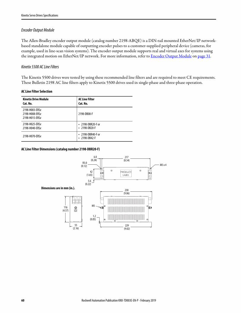
Kinetix Servo Drives Specifications
Encoder Output Module
The Allen-Bradley encoder output module (catalog number 2198-ABQE) is a DIN-rail mounted EtherNet/IP network-based standalone module capable of outputting encoder pulses to a customer-supplied peripheral device (cameras, for example, used in line-scan vision systems). The encoder output module supports real and virtual axes for systems using the integrated motion on EtherNet/IP network. For more information, refer to Encoder Output Module on page 31.
Kinetix 5500 AC Line Filters
The Kinetix 5500 drives were tested by using these recommended line filters and are required to meet CE requirements. These Bulletin 2198 AC line filters apply to Kinetix 5500 drives used in single-phase and three-phase operation.
AC Line Filter Selection
AC Line Filter Dimensions (catalog number 2198-DBR20-F)
Kinetix Drive Module Cat. No.
AC Line Filter Cat. No.
2198-H003-ERSx2198-H008-ERSx2198-H015-ERSx
2198-DB08-F
2198-H025-ERSx2198-H040-ERSx
• 2198-DBR20-F or• 2198-DB20-F
2198-H070-ERSx • 2198-DBR40-F or• 2198-DB42-F
6.0(0.24)
R3.0(0.12)
217(8.54)
230(9.06)
229(9.02)
1.2(0.05)
116(4.57)
55(2.16)
42(1.65)
M5
5.6(0.22)
M5 x 4
Dimensions are in mm (in.).
60 Rockwell Automation Publication KNX-TD003E-EN-P - February 2019

Kinetix Servo Drives Specifications
AC Line Filter Dimensions (catalog number 2198-DBR40-F)
AC Line Filter Specifications
AC Line Filter Dimensions (catalog number 2198-DB08-F)
AC Line FilterCat. No.
Voltage Rating, max
Current RatingA @ 50 °C (122 °F)
Power LossW
Leakage CurrentmA
Weight, approxkg (lb)
Operating Temperature
2198-DBR20-F 528V ACthree-phase50/60 Hz
20 4.230.0
1.0 (2.20) 0…50 °C(32…122 °F) 2198-DBR40-F 40 9.6 3.3 (7.28)
7.0 (0.28)R3.25
(0.13)
60(2.36)
258(10.16)
261(10.28)
1.2(0.05)
272(10.71)
73(2.87)
162(6.38)
5.9(0.23)
M6
M6 x 4Dimensions are in mm (in.).
Ø 6.0 (0.24)
167 (6.57)
R3.0 (0.12)32
(1.26)
173(6.81)
1.2(0.05)
179(7.05)
45(1.77)
79(3.11) M5
M5 x 4
6.0(0.24)
6.3(0.25)
Dimensions are in mm (in.).
Rockwell Automation Publication KNX-TD003E-EN-P - February 2019 61

Kinetix Servo Drives Specifications
AC Line Filter Dimensions (catalog number 2198-DB20-F)
AC Line Filter Dimensions (catalog number 2198-DB42-F)
AC Line Filter Specifications
AC Line FilterCat. No.
Voltage Rating,max
Current RatingA @ 50 °C (122 °F)
Power LossW
Leakage CurrentmA
Weight, approxkg (lb)
Operating Temperature
2198-DB08-F (1)
(1) Applies to installations with single-phase or three-phase input power.
528V ACthree-phase50/60 Hz
7.5 3.6 2.5 0.77 (1.70)0…50 °C(32…122 °F) 2198-DB20-F 20 5.1 5.2 1.63 (3.59)
2198-DB42-F 42 14.7 4.0 2.70 (5.95)
6.0(0.24)R3.0
(0.12)
217(8.54)
230(9.06)
229(9.02)
55(2.16)
42(1.65)
42(1.65)
M5
M5 x 45.6(0.22)
1.2(0.05)
116(4.57)
Dimensions are in mm (in.).
Ø 6.5 (0.26)
R3.25(0.13)
60(2.36)
60(2.36)
258(10.16)
261(14.21)
1.2(0.05)
272(10.71)
73(2.87)
M6
M6 x 47.0
(0.28)
5.9(0.23)
162(6.38)
Dimensions are in mm (in.).
62 Rockwell Automation Publication KNX-TD003E-EN-P - February 2019

Kinetix Servo Drives Specifications
Shared-bus Connection System
The shared-bus connection system is used to extend the mains AC input, 24V control input, and the DC-bus power from drive-to-drive in shared-bus multi-axis configurations.
The shared-bus connection system is composed of three components:• Input wiring connectors that plug into the leftmost drive and receive input wiring for mains AC and 24V DC.• AC bus, DC bus, and 24V DC T-connectors that plug into the drives downstream from the first where AC, DC,
and/or 24V control power is shared. DC bus T-connectors also plug into the first drive where DC-bus power is shared.
• Bus bars that connect between drives to extend the mains AC bus, DC bus, and 24V DC control power from drive-to-drive.
Shared-bus Connection System Example
For each shared-bus servo drive system, you’ll need one connector kit catalog number for each drive. Use these tables to determine which connector kits you’ll need for your system.
Input Power Connector Kit Catalog Numbers
IMPORTANT When the shared-bus connection system is used, the zero-stack tab and cutout must be engaged between adjacent drives.
Frame Size Kit Cat. No. Description Contents Illustration
1 and 2 2198-H040-ADP-INKinetix 5500 Frame 1 and 2 connectors for the first drive in a multi-axis system.
• AC input connector for frame 1 and 2 drives• DC bus T-connector• Control power input connector
3 2198-H070-ADP-IN Kinetix 5500 Frame 3 connectors for the first drive in a multi-axis system.
• AC input connector for frame 3 drive• DC bus T-connector• Control power input connector
2198-Hxxx-ERSx Drive System, top view(2198-Hxxx-ERS drive is shown)
Input Wiring Connector(mains AC input shown)
T-connectors(AC T-connectors shown)
Bus-bar Connectors(AC bus-bars shown)
Frame 2Drive
Frame 2Drive
Frame 2Drive
Input Wiring(AC input wiring is shown)
Zero-stack Taband Cutout Engaged
AC Input Connector
DC Bus T-connector
Control PowerInput Connector
Rockwell Automation Publication KNX-TD003E-EN-P - February 2019 63

Kinetix Servo Drives Specifications
Use these connector kits when the first drive is frame 1, 2, or 3 and the follower drive is frame 1 or 2.
Frame 1 or 2 Follower Drive Connector Kit Catalog Numbers
Kit Cat. No. Description Contents Illustration
2198-H040-A-T T-connector and bus-bars for the AC bus on Frame 1 or 2 follower drives
• AC bus T-connector• Bus-bar connectors, 55 mm, quantity 4
2198-H040-D-T T-connector and bus-bars for the DC bus on Frame 1 or 2 follower drives
• DC bus T-connector• Bus-bar connectors, 55 mm, quantity 2
2198-H040-P-T T-connector and bus-bars for control power on Frame 1 or 2 follower drives
• Control power T-connector• Bus-bar connectors, 55 mm, quantity 2
2198-H040-AD-T T-connectors and bus-bars for the AC and DC bus on Frame 1 or 2 follower drives
• AC bus T-connector• DC bus T-connector• Bus-bar connectors, 55 mm, quantity 6
2198-H040-AP-T T-connectors and bus-bars for the AC bus and control power on Frame 1 or 2 follower drives
• AC bus T-connector• Control power T-connector• Bus-bar connectors, 55 mm, quantity 6
2198-H040-DP-T T-connectors and bus-bars for the DC bus and control power on Frame 1 or 2 follower drives
• DC bus T-connector• Control power T-connector• Bus-bar connectors, 55 mm, quantity 4
2198-H040-ADP-TT-connectors and bus-bars for the AC bus, DC bus, and control power on Frame 1 or 2 follower drives
• AC bus T-connector• DC bus T-connector• Control power T-connector• Bus-bar connectors, 55 mm, quantity 8
Bus-bar Connectors (4x)
AC Bus T-connector
Bus-bar Connectors (2x)
T-connector
Bus-bar Connectors (4x)
AC Bus T-connector
Bus-bar Connectors (2x)
T-connector
Bus-bar Connectors (2x)
DC Bus T-connector
Bus-bar Connectors (2x)
Control Power T-connector
Bus-bar Connectors (4x)
AC Bus T-connector
Bus-bar Connectors (2x)
Control Power T-connector
DC Bus T-connectorBus-bar Connectors (2x)
64 Rockwell Automation Publication KNX-TD003E-EN-P - February 2019

Kinetix Servo Drives Specifications
Use these connector kits when the first drive is frame 3 and the follower drive is also frame 3.
Frame 3 Follower Drive Connector Kit Catalog Numbers
Kit Cat. No. Description Contents Illustration
2198-H070-A-T T-connector and bus-bars for the AC bus on Frame 3 follower drives
• AC bus T-connector• Bus-bar connectors, 85 mm, quantity 4
2198-H070-D-T T-connector and bus-bars for the DC bus on Frame 3 follower drives
• DC bus T-connector• Bus-bar connectors, 85 mm, quantity 2
2198-H070-P-T T-connector and bus-bars for control power on Frame 3 follower drives
• Control power T-connector• Bus-bar connectors, 85 mm, quantity 2
2198-H070-AD-T T-connectors and bus-bars for the AC and DC bus on Frame 3 follower drives
• AC bus T-connector• DC bus T-connector• Bus-bar connectors, 85 mm, quantity 6
2198-H070-AP-T T-connectors and bus-bars for the AC bus and control power on Frame 3 follower drives
• AC bus T-connector• Control power T-connector• Bus-bar connectors, 85 mm, quantity 6
2198-H070-DP-T T-connectors and bus-bars for the DC bus and control power on Frame 3 follower drives
• DC bus T-connector• Control power T-connector• Bus-bar connectors, 85 mm, quantity 4
2198-H070-ADP-TT-connectors and bus-bars for the AC bus, DC bus, and control power on Frame 3 follower drives
• AC bus T-connector• DC bus T-connector• Control power T-connector• Bus-bar connectors, 85 mm, quantity 8
Bus-bar Connectors (4x)
AC Bus T-connector
Bus-bar Connectors (2x)
T-connector
Bus-bar Connectors (4x)
AC Bus T-connector
T-connector
Bus-bar Connectors (2x)
Bus-bar Connectors (2x)
DC Bus T-connector
Bus-bar Connectors (2x)
Control Power T-connector
Bus-bar Connectors (4x)
AC Bus T-connector
Bus-bar Connectors (2x)
Control Power T-connector
DC Bus T-connectorBus-bar Connectors (2x)
Rockwell Automation Publication KNX-TD003E-EN-P - February 2019 65

Kinetix Servo Drives Specifications
Hiperface-to-DSL Feedback Converter Kit
The 2198-H2DCK Hiperface-to-DSL feedback kit (series B or later) converts 15-pin Hiperface encoder feedback signals to 2-pin DSL feedback signals. The following feedback types are accepted:
• Hiperface high-resolution absolute multi-turn and single-turn encoders• Feedback-only axes (absolute single-turn/multi-turn Hiperface)
Use the converter kit for new installations with Kinetix 5500 servo drives and existing compatible motor/actuator installations when upgrading with Kinetix 5500 servo drives.
Compatible Allen-Bradley Motors and Actuators
Converter Kit Dimensions
Rotary Motors Linear Actuators 2090-Series Feedback Cables (3)
(3) These are typical feedback cables. Refer to the Kinetix 5500 Servo Drives Design Guide, publication KNX-RM009, for the cables required for specific drive and motor/actuator combination.
MP-Series low-inertia motors (Bulletin MPL) LDAT-Series integrated linear thrusters (1)
(1) LDAT-Series linear thrusters with absolute high-resolution encoders are compatible. Linear stages with incremental encoders are not compatible.
2090-CFBM7DF-CEAAxx (standard, non-flex)2090-CFBM7DF-CEAFxx (continuous-flex)2090-XXNFMF-Sxx (standard, non-flex)2090-CFBM7DF-CDAFxx (continuous-flex)
MP-Series medium-inertia motors (Bulletin MPM) MP-Series integrated linear stages (Bulletin MPAS) (2)
(2) Bulletin MPAS and MPMA (ballscrew) linear stages are compatible. Direct-drive linear stages are not compatible.
MP-Series food-grade motors (Bulletin MPF) MP-Series multi-axis linear stages (Bulletin MPMA) (2)
MP-Series stainless-steel motors (Bulletin MPS)MP-Series electric cylinders (Bulletin MPAR)
MP-Series heavy-duty electric cylinders (Bulletin MPAI)
IMPORTANT The 2198-H2DCK feedback converter kit is required for converting Hiperface feedback signals from the motor encoder to DSL feedback signals that are accepted by the Kinetix 5500 drive.Compatible Allen-Bradley rotary motors and linear actuators must have high-resolution absolute encoders. Cable length restrictions also exist, refer to Maximum Motor Cable Lengths on page 54 for more information.
92.0(3.62)
62.0(2.44)
38.4(1.51)
28.5(1.12)
79.0(3.11)
91.0(3.58)
6.0(0.24)
18.8(0.74)
6.15(0.24)
Dimensions are in mm (in.).
66 Rockwell Automation Publication KNX-TD003E-EN-P - February 2019

Kinetix Servo Drives Specifications
Replacement Parts and Connector Kits - Kinetix 5500 Servo Drives
Replacement parts and kits available for Kinetix 5500 servo drives include the DSL feedback connector kit, power-sharing bus-bars, safety and digital input connectors, and power connector sets.
DSL Feedback Connector Kit
The Bulletin 2198-KITCON-DSL feedback connector kit is required for making feedback connections from Kinetix VP motors and actuators, and is included with each Kinetix 5500 servo drive. Motor power, brake, and the 2-wire feedback connections are made by using a single Bulletin 2090-CSxM1DF-xxAxxx cable. Refer to the Kinetix Motion Accessories Specifications Technical Data, publication KNX-TD004, for motor cable information.
DSL Feedback Connector Kit Features
2198-KITCON-DSLFeedback Connector Kit
ConnectorPlug
Grounding Plate
Clamp Screws (2)
Mounting Screws (2)
Exposed Shield
2090-CSxM1DF-xxAAxxFeedback Cable
Cover
Rockwell Automation Publication KNX-TD003E-EN-P - February 2019 67

Kinetix Servo Drives Specifications
Power-sharing Bus-bars and Connector Sets
Kinetix 6200 and Kinetix 6500 Modular Multi-axis Servo Drives
These modular Safe Speed Monitor servo drives help increase productivity and protect personnel with embedded safety features. Modular design and control provides ease of maintenance and greater flexibility as the drive easily transitions from Safe Torque Off to Safe Speed Monitor.
The Kinetix 6500 servo drives provide Integrated Motion on the EtherNet/IP network by using CIP Motion™ and CIP Sync™ technology from ODVA, all built on the Common Industrial Protocol (CIP™).
The Kinetix 6200 servo drives provide Integrated Motion capability through the sercos interface and compatibility with Kinetix 6000 drives, letting you migrate to the enhanced features exactly when and where you need them.
Replacement Kit Cat. No. Description Contents Illustration
2198-BARCON-85DCAC100
Replacement bus-bars for shared-bus connection system:• First drive is Frame 3• Adjacent drive is Frame 3
Bus-bar connectors, 85 mm, quantity 8
2198-BARCON-55DCAC100
Replacement bus-bars for shared-bus connection system:• First drive is Frame 1, 2, or 3• Adjacent drive is Frame 1 or 2
Bus-bar connectors, 55 mm, quantity 8
2198-KITCON-IOSP Replacement IOD and STO connectors with spring clamp • One (4-pin) digital inputs (IOD) connector
• One (5-pin) Safe Torque Off (STO) connector(two 5-pin connectors joined together)2198-KITCON-IOSC Replacement IOD and STO connectors with
screw clamp
2198-KITCON-PWR70 Replacement IDP, RC, CP, MP, and BC connectors for Frame 3 servo drives
• One AC input power (IPD) connector• One shunt (RC) connector• One control power (CP) connector• One motor power (MP) connector• One motor brake (BC) connector2198-KITCON-PWR40 Replacement IDP, RC, CP, MP, and BC
connectors for Frame 1 or 2 servo drives
2198-KITCON-CAP1300T-connectors and bus-bars for the DC bus and control power input on the Bulletin 2198 capacitor module
• DC bus T-connector• Control power T-connector• Bus-bar connectors, 55 mm, quantity 4
Bus-bar Connectors (2x)
DC Bus T-connector
Bus-bar Connectors (2x)
Control Power T-connector
68 Rockwell Automation Publication KNX-TD003E-EN-P - February 2019

Kinetix Servo Drives Specifications
Kinetix 6200 and Kinetix 6500 Drive Features and Indicators
2094-ACxx-Mxx-M and 2094-BCxx-Mxx-M IAM Power Module Features and Indicators
2094-AMxx-M and 2094-BMxx-M AM Power Module Features and Indicators
1 2
DC-DC+
L3L2L1
CONT EN-CONT EN+
CTRL 2CTRL 1
1 2 1
2 3
4 5
6
WVU
MBRK -MBRK +
COM PWR
DBRK -DBRK +
1 2
3 4
1 2
3 4
5 6
1
4
5
2
3
6
7
9
8
Kinetix 6200 or Kinetix 6500IAM Power Module, Top View(2094-BC01-MP5-M module is shown)
Kinetix 6200 or Kinetix 6500IAM Power Module, Front View
(2094-BC01-MP5-M module is shown)
Item Description
1 Control power (CPD) connector
2 DC bus/AC input power (IPD) connector
3 Contactor Enable (CED) connector
4 Motor cable shield clamp
5 Motor power (MP) connector
6 Motor/resistive brake (BC) connector
7 Node address switch
8 Power-applied indicator
9 Mounting screw
WVU
MBRK -MBRK +
COM PWR
DBRK -DBRK +
1 2
3 4
1 2
3 4
5 6
1 2
3
5
4
Kinetix 6200 or Kinetix 6500AM Power Module, Top View(2094-BMP5-M module is shown)
Kinetix 6200 or Kinetix 6500AM Power Module, Front View
(2094-BMP5-M module is shown)
Item Description
1 Motor cable shield clamp
2 Motor power (MP) connector
3 Motor/resistive brake (BC) connector
4 Power-applied indicator
5 Mounting screw
Rockwell Automation Publication KNX-TD003E-EN-P - February 2019 69

Kinetix Servo Drives Specifications
Control Module Features and Indicators (sercos)
2
4
6
5
3
2
1
12
14
13
62006200SAFE SPEED
7 8 9
1011
15
Kinetix 6200Control Module, Top View
(2094-SE02F-M00-S1 module is shown)
Kinetix 6200Control Module, Front View
(2094-SE02F-M00-S1 module is shown)
Item Description
1 Guide pins (2x)
2 Captive screw
3 Sercos communication rate and optical power switches
4 Sercos transmit (Tx) connector
5 Sercos receive (Rx) connector
Item Description
6 Four-character status display
7 PORT 1 status Indicator
8 Drive status indicator
9 Comm status indicator
10 DC bus status indicator
11 Safety lock status indicator(2094-SE02F-M00-S1 modules only)
12 I/O, safety, and aux feedback (IOD) connector
13 Power module mounting screw access hole
14 Motor feedback (MF) connector
Item Description
15 Ethernet (PORT1) connectorKinetix 6200
Control Module, Bottom View(2094-SE02F-M00-S1 module is shown)
70 Rockwell Automation Publication KNX-TD003E-EN-P - February 2019

Kinetix Servo Drives Specifications
Control Module Features and Indicators (EtherNet/IP network)
2
3
2
7
4 5 6
1
10
12
11
13
9
8
14
Item Description
1 Guide pins (2x)
2 Captive screw
Item Description
3 Four-character status display
4 PORT 1 status indicator
5 PORT 2 status indicator
6 Module status indicator
7 Network status indicator
8 DC bus status indicator
9 Safety lock status indicator(2094-EN02D-M01-S1 modules only)
10 I/O, safety, and aux feedback (IOD) connector
11 Power module mounting screw access hole
12 Motor feedback (MF) connector
Item Description
13 Ethernet (PORT1) connector
14 Ethernet (PORT2) connector
Kinetix 6500Control Module, Top View
(2094-EN02D-M01-S1 is shown)
Kinetix 6500Control Module, Front View
(2094-EN02D-M01-S1 is shown)
Kinetix 6500Control Module, Bottom View
(2094-EN02D-M01-S1 is shown)
Rockwell Automation Publication KNX-TD003E-EN-P - February 2019 71

Kinetix Servo Drives Specifications
Technical Specifications - Kinetix 6200 and Kinetix 6500 Control Modules
Control modules couple with IAM and AM power modules to provide drive status indicators and an interface to I/O, communication, functional safety, and feedback.
Features
Weight Specifications
FeatureSafe Torque Off Safe Speed Monitor
2094-EN02D-M01-S0 2094-SE02F-M00-S0 2094-EN02D-M01-S1 2094-SE02F-M00-S1
Ethernet ports 2 1 2 1
Sercos ports – Rx/Tx – Rx/Tx
DC-bus status indicator X X X X
Network status indicator X – X –
Module status indicator X – X –
Drive status indicator – X – X
Comm status indicator – X – X
Safety lock status indicator – – X X
PORT 1 status indicator X X X X
PORT 2 status indicator X – X –
IOD connector for I/O, safety, and auxiliary feedback X X X X
MF connector for motor feedback X X X X
Kinetix 6200 Control Module Cat. No.
Weight, approxkg (lb)
Kinetix 6500 Control Module Cat. No.
Weight, approxkg (lb)
Sercos interface2094-SE02F-M00-S0
0.68 (1.5) EtherNet/IP network2094-EN02D-M01-S0
0.68 (1.5)2094-SE02F-M00-S1 2094-EN02D-M01-S1
72 Rockwell Automation Publication KNX-TD003E-EN-P - February 2019

Kinetix Servo Drives Specifications
Technical Specifications - Kinetix 6200 and Kinetix 6500 Power Modules
IAM Module (converter, 400V-class) Power Specifications
Attribute 2094-BC01-MP5-M 2094-BC01-M01-M 2094-BC02-M02-M 2094-BC04-M03-M 2094-BC07-M05-M
AC input voltage 324…528V rms three-phase (360…480V nom)
AC input frequency 47…63 Hz
Main AC input current Nom (rms) Max inrush (0-pk) (1)
(1) All IAM power modules are limited to 2 contactor cycles per minute (with up to 4 axes), or 1 contactor cycle per minute (with 5…8 axes). The cycle capability also depends on the converter power rating and the total system capacitance. To calculate cycle capability, refer to the Kinetix 6200 and Kinetix 6500 Modular Multi-axis Servo Drives User Manual, publication 2094-UM002.
10.0 A11.0 A
24.0 A22.0 A
44.0 A31.1 A
71.0 A62.2 A
DC input voltage (common bus follower) 458…747V DC
DC input current (common-bus follower) 9.0 A 22.6 A 41.5 A 67.7 A
Control power AC input voltage 95…264V rms single-phase (110…240V rms nom)
Control power AC input currentNom (@ 220/230V AC) rmsNom (@ 110/115V AC) rmsMax inrush (0-pk)
6 A6 A98 A (3)
(3) For eight axis systems with 230V AC control input voltage and 50 °C (122°F) ambient temperature the maximum inrush duration is less than 1/2 line cycle. To calculate the maximum inrush duration for other configurations, refer to the Kinetix 6200 and Kinetix 6500 Modular Multi-axis Servo Drives User Manual, publication 2094-UM002.
Control power cycling, max 2 cycles per minute with a 90% on-time, 10% off-time duty cycle
Nominal bus output voltage 650V DC
Line loss ride through 20 ms
Continuous output current to bus (ADC) 9.0 A 22.6 A 41.5 A 67.7 A
Peak output current to bus (ADC) (2)
(2) Converter peak output duration equals 400 ms with a duty cycle of 16%.
22.6 A 56.4 A 103.8 A 203.2 A
Bus overvoltage 825V DC
Bus undervoltage 275V DC (when enabled) 425V DC (at the completion of pre-charge)
Internal shuntContinuous powerPeak power
50 W5.6 kW
200 W22.5 W
Internal shunt resistor 115 Ω 27.75 Ω
Shunt on 805V DC
Shunt off 765V DC
Continuous power output to bus 6 kW 15 kW 27.6 kW 45 kW
Peak power output at 480V (2) 15 kW 37.5 kW 69 kW 135 kW
Efficiency 97%
Converter inductance 500 μH 125 μH 75 μH
Converter capacitance 110 μF 220 μF 940 μF 1410 μF
Short-circuit current rating 200,000 A (rms) symmetrical
Rockwell Automation Publication KNX-TD003E-EN-P - February 2019 73

Kinetix Servo Drives Specifications
Control Power Current Requirements
AM Module (inverter, 400V-class) Power Specifications
Modules on Power Rail110/115V AC Input 220/230V AC Input
Input CurrentA
Input VAVA
Input CurrentA
Input VAVA
IAM module only 0.56 67 0.36 85
IAM and 1 AM module 0.99 119 0.64 153
IAM and 2 AM module 1.43 172 0.92 220
IAM and 3 AM module 1.87 224 1.20 287
IAM and 4 AM module 2.31 277 1.48 354
IAM and 5 AM module 2.74 329 1.75 421
IAM and 6 AM module 3.18 382 2.03 488
IAM and 7 AM module 3.62 434 2.31 555
Attribute (1)
(1) These specifications apply to the axis module specified in the column heading by catalog number and the same axis module (inverter section) that resides within an IAM power module.
2094-BMP5-M(2094-BC01-MP5-M)
2094-BM01-M(2094-BC01-M01-M)
2094-BM02-M(2094-BC02-M02-M)
2094-BM03-M(2094-BC04-M03-M)
2094-BM05-M(2094-BC07-M05-M)
Bandwidth (2)
Velocity loopCurrent loop
(2) Bandwidth values vary based on tuning parameters and mechanical components.
500 Hz1300 Hz
PWM frequency 8 kHz 4 kHz
Nominal input voltage 650V DC
Continuous current (rms) (3)
(3) Continuous and peak current ratings are for high-speed operation. For constant velocity operation at an electrical output frequency below 5 Hz (75 rpm for 8-pole motors), the output current rating is reduced. See Motion Analyzer software to correctly size your drive. Refer to Peak Current Specifications on page 75 for duty cycle capability.
2.8 A 6.1 A 10.3 A 21.2 A 34.6 A
Continuous current (sine) 0-pk (3) 4.0 A 8.6 A 14.6 A 30.0 A 48.9 A
Peak current (rms) (3) 7.0 A 15.3 A 25.8 A 53.0 A 69.2 A
Peak current (0-pk) (3) 9.9 A 21.6 A 36.4 A 75.0 A 97.9 A
Continuous power out (nom) 1.8 kW 3.9 kW 6.6 kW 13.5 kW 22.0 kW
Internal shuntContinuous powerPeak power
50 W5.6 kW
200 W22.5 kW
Internal shunt resistor 115 Ω 28.75 Ω
Shunt on 805V DC
Shunt off 765V DC
Efficiency 98%
Capacitance 75 μF 150 μF 270 μF 840 μF 1175 μF
Capacitive energy absorption 10 J 19 J 35 J 108 J 152 J
Short-circuit current rating 200,000 A (rms) symmetrical
74 Rockwell Automation Publication KNX-TD003E-EN-P - February 2019

Kinetix Servo Drives Specifications
Peak Current Specifications
Load Duty-cycle Profile Example
Peak Duty-cycle Definition of Terms
Term Definition (1)
(1) All current values are specified as RMS.
Continuous Current Rating (ICont) The maximum value of current that can be output continuously.
Peak Current Rating (IPKmax) The maximum value of peak current that the drive can output. This rating is valid for only overload times less than TPKmax.
Duty Cycle (D) The ratio of time at peak to the Application Period and is defined as:
Time at Peak (TPK) The time at peak current (IPK) for a given loading profile. Must be less than or equal to TPKmax.
Peak Current (IPK) The level of peak current for a given loading profile. IPK must be less than or equal to the Peak Current Rating (TPKMAX) of the drive.
Base Current (IBase) The level of current between the pulses of peak current for a given loading profile. IBase must be less than or equal to the continuous current rating (ICont) of the drive.
Loading Profile The loading profile is composed of IPK, IBase, TPK, and D (or T) values and completely specify the operation of the drive in an overload situation. These values are collectively defined as the Loading Profile of the drive.
Application Period (T) The sum of the times at IPK (TPK) and IBase.
D = TT
PK x 100%
I Pk
I Cont
I Base
T Pk
T
D = TT
PK x 100%
Rockwell Automation Publication KNX-TD003E-EN-P - February 2019 75

Kinetix Servo Drives Specifications
Peak Inverter Mode (TPK < 2.0 s)
(1) Base current (IBase) and peak current (IPK are a percentage of the continuous drive current rating (ICont).
Peak Inverter Overload (TPK < 2.0 s)
(1) Base current (IBase) and peak current (IPK) are a percentage of the continuous drive current rating (ICont).
0% 60% 100%
50%
45%
40%
35%
30%
25%
20%
15%
10%
5%
0%
80%20% 40%
Applies to these Bulletin 2094 power modules:2094-BC01-MP5-M, 2094-BMP5-M, 2094-BC01-M01-M, 2094-BM01-M, 2094-BC02-M02-M, 2094-BM02-M, 2094-BC04-M03-M, 2094-BM03-M
Max
imum
Dut
y Cyc
le (D
max
)
% Base Current (I Base /ICont)
Legend (1)
I Pk = 150%
I Pk = 200%
I Pk = 250%
0% 60% 100%
50%
45%
40%
35%
30%
25%
20%
15%
10%
5%
0%
80%20% 40%
Applies to these Bulletin 2094 power modules:2094-BC07-M05-M, 2094-BM05-M
Max
imum
Dut
y Cyc
le (D
max
)
% Base Current (I Base /ICont)
Legend (1)
I Pk = 150%
I Pk = 200%
76 Rockwell Automation Publication KNX-TD003E-EN-P - February 2019

Kinetix Servo Drives Specifications
Circuit Breaker/Fuse Specifications
The 2094-BCxx-Mxx-M and 2094-BMxx-M drive modules use internal solid-state motor short-circuit protection and, when protected by suitable branch circuit protection, are rated for use on a circuit capable of delivering up to 200,000 A.
Control and DC-bus Circuit-protection Specifications
Input Power Circuit Protection (LIM)
The 2094-BL02 line interface modules (LIM) contains supplementary protection devices and, when protected by suitable branch circuit protection, is rated for use on a circuit capable of delivering up to 5000 A. When this module is used, protection on the line side of the LIM module is required. Fuses must be class J or CC only.
The 2094-BLxxS and 2094-XL75S-Cx LIM modules contain branch circuit rated devices suitable for use on a circuit capable of delivering up to 65,000 A (400V-class). Refer to the Line Interface Module Installation Instructions, publication 2094-IN005, for power specifications and more information on using the LIM module.
Input Power Circuit Protection (without LIM)
The fuses and Allen-Bradley circuit breakers listed on page 77 are recommended for use with 2094-BCxx-Mxx-M IAM power modules when the line interface module (LIM) is not used.
Input Power UL Circuit-protection Specifications
IAM Power Module Cat. No.
Control Input Power DC-bus Power
Bussmann Fuse (1)
(1) Use FNQ-R-7.5 circuit breaker for higher single -cycle inrush current capability. This is recommended when the continuous control-power current exceeds 3.0 A.
Allen-Bradley Circuit Breaker (2) (non-UL)
(2) Use 1492-SPM1D150 circuit breaker for higher single -cycle inrush current capability. This is recommended when the continuous control-power current exceeds 3.0 A.
Bussmann Fuse Mersen Fuse (3)
(3) Mersen fuses were formerly known as Ferraz Shawmut.
2094-BC01-MP5-M
FNQ-R-10 (10 A) orFNQ-R-7.5 (7.5 A)
1492-SPM2D060 or1492-SPM1D150
FWJ-20A14F DCT20-22094-BC01-M01-M
2094-BC02-M02-M FWJ-40A A70QS40-4
2094-BC04-M03-M FWJ-70A A70QS70-4
2094-BC07-M05-M FWJ-125A A70QS125-4
IMPORTANT LIM modules (catalog numbers 2094-BLxxS and 2094-XL75S-Cx) can provide branch circuit protection to the IAM power module. Follow all applicable NEC and local codes.
Kinetix 6200 and Kinetix 6500 Drives UL Applications
IAM Power ModuleCat. No.
Drive Voltage(three-phase) nom
Bussmann FusesCat. No.
Miniature CB (1)
Cat. No.Motor Protection CB, (1)
Self-protected CMCCat. No.
(1) These Bulletin 140M circuit breakers, when used as self-protected (Type E) devices, and Bulletin 1489 circuit breakers can be used on only WYE power systems (480Y/277V).
Molded Case CBCat. No.
2094-BC01-MP5-M 360…480V KTK-R-20 (20 A) Class CC1489-M3D300
140M-F8E-C32
NA2094-BC01-M01-M 360…480V KTK-R-20 (20 A) Class CC 140M-F8E-C32
2094-BC02-M02-M 360…480V KTK-R-30 (30 A) Class CC 1489-M3D400 140M-F8E-C45
2094-BC04-M03-M 360…480V LPJ-45SP (45 A) Class JN/A NA
140G-G6C3-C50
2094-BC07-M05-M 360…480V LPJ-80SP (80 A) Class J 140G-G6C3-C90
Rockwell Automation Publication KNX-TD003E-EN-P - February 2019 77

Kinetix Servo Drives Specifications
Input Power IEC (non-UL) Circuit-protection Specifications
Contactor Ratings
This table provides the recommended contactor ratings for IAM power modules installed without a LIM module.
Input Transformer for Control Power
Kinetix 6200 and Kinetix 6500 Drives IEC (non-UL) Applications
IAM Power ModuleCat. No.
Drive Voltage(three-phase) nom
Miniature CBCat. No.
Motor Protection CBCat. No.
Molded Case CBCat. No.
2094-BC01-MP5-M 360…480V1492-SPM3D300 1489-M3D300
140M-F8E-C32
NA2094-BC01-M01-M 360…480V 140M-F8E-C32
2094-BC02-M02-M 360…480V 1492-SPM3D400 1489-M3D400 140M-F8E-C45
2094-BC04-M03-M 360…480VN/A N/A NA
140G-G6C3-C50
2094-BC07-M05-M 360…480V 140G-G6C3-C90
IAM Power Module Cat. No.
ContactorCat. No.
2094-BC01-MP5-M2094-BC01-M01-M
100-C23x10 (AC coil)100-C23xx10 (DC coil)
2094-BC02-M02-M 100-C37x10 (AC coil)100-C37xx10 (DC coil)
2094-BC04-M03-M 100-C60x10 (AC coil)100-C60xx10 (DC coil)
2094-BC07-M05-M 100-C85x10 (AC coil)100-C85xx10 (DC coil)
Attribute Value Cat. No. (1)
(1) Variables (xx-x) determine the input voltage and wiring configuration.
Input volt-amperes
750VA 1497B-A10-xx-x-N
1000VA 1497B-A11-xx-x-N
1500VA 1497B-A12-xx-x-N
Input voltage 460V AC
Output voltage 120…240V AC
78 Rockwell Automation Publication KNX-TD003E-EN-P - February 2019

Kinetix Servo Drives Specifications
Power Dissipation Specifications
Use this table to size an enclosure and calculate required ventilation for your Kinetix 6200 and Kinetix 6500 drive system.
Power dissipation specifications are based on these calculations. This is an example: 2094-BC02-M02-M with 4.52 Adc (=20%) converter DC current and 10.3 Arms (=100%) inverter output current.Converter loss (36 W) + Inverter loss (142 W) = 178 W total power dissipation.
Weight Specifications
Bulletin 2094 Drive Modules (1)
(1) Power dissipation for the Bulletin 2094 control modules, catalog numbers 2094-SE02F-M00-Sx and 2094-EN02D-M01-Sx, is included in the IAM and AM power module specifications.
Usage as % of Rated Power Output (watts)
20% 40% 60% 80% 100%
IAM (converter) module (2)
(2) Internal shunt power is not included in the calculations and must be added based on utilization.
2094-BC01-MP5-M18 21 25 29
34
2094-BC01-M01-M 33
2094-BC02-M02-M 36 44 54 64 75
2094-BC04-M03-M 50 67 87 110 135
2094-BC07-M05-M 71 101 137 179 226
IAM (inverter) module or AM module (2)
2094-BC01-MP5-M or 2094-BMP5-M 46 54 61 69 77
2094-BC01-M01-M or 2094-BM01-M 57 73 90 108 126
2094-BC02-M02-M or 2094-BM02-M 53 72 93 116 142
2094-BC04-M03-M or 2094-BM03-M 94 130 169 211 255
2094-BC07-M05-M or 2094-BM05-M 121 183 252 326 407
Shunt module - 2094-BSP2 68 121 174 227 280
Bulletin 2094 Drive Modules Cat. No.
Weight, approxkg (lb)
Bulletin 2094 Drive Modules Cat. No.
Weight, approxkg (lb)
IAM(400V-class)
2094-BC01-MP5-M 5.67 (12.5)
AM(400V-class)
2094-BMP5-M 3.18 (7.0)
2094-BC01-M01-M 5.67 (12.5) 2094-BM01-M 3.18 (7.0)
2094-BC02-M02-M 5.90 (13.0) 2094-BM02-M 3.40 (7.5)
2094-BC04-M03-M 9.53 (21.0) 2094-BM03-M 5.44 (12.0)
2094-BC07-M05-M 9.98 (22.0) 2094-BM05-M 5.90 (13.0)
Power rails(Slim)
2094-PRS1 1.05 (2.3)
2094-PRS2 1.59 (3.5) Shunt module 2094-BSP2 3.10 (6.8)
2094-PRS3 2.14 (4.7) Slot-filler module 2094-PRF 0.45 (1.0)
2094-PRS4 2.67 (5.9)
2094-PRS5 3.11 (6.8)
2094-PRS6 3.55 (7.8)
2094-PRS7 3.99 (8.8)
2094-PRS8 4.43 (9.7)
Rockwell Automation Publication KNX-TD003E-EN-P - February 2019 79

Kinetix Servo Drives Specifications
Maximum Feedback Cable Lengths
Although motor feedback cables are available in standard lengths up to 90 m (295.3 ft), the drive/motor/feedback combination can limit the maximum feedback cable length. These tables assume the use of recommended cables as shown in the Kinetix Motion Accessories Technical Data, publication KNX-TD004.
Cable Lengths for Compatible Rotary Motors
Cable Lengths for Compatible Linear Actuators
Cable Lengths for Compatible Linear Motors
Maximum Power Cable Length
Although motor power cables are available in standard lengths up to 90 m (295.3 ft) and the Kinetix 6000 power rail is available in sizes up to eight axes, to meet CE requirements and improve system performance the combined motor power length for all axes on the same DC bus must not exceed 240 m (787 ft) for 400V-class systems.
Motor Cat. No.Absolute High-resolution (5V) Encoderm (ft)
Absolute High-resolution (9V) Encoderm (ft)
Incremental/TTL (5V) Encoderm (ft)
MPL-B15xxx…MPL-B2xxx-E/V 90 (295.3)
MPL-B3xxx…MPL-B5xxx-S/M 90 (295.3)
MPL-B15xxx…MPL-B45xxx-H 30 (98.4)
MPM-Bxxxxx-S/M 90 (295.3)
MPF-Bxxxx-S/M 90 (295.3)
MPS-Bxxxx-S/M 90 (295.3)
RDB-B215xx-7/3 30 (98.4)
RDB-B290xx-7/3 orRDB-B410xx-7/3 90 (295.3)
Actuator Cat. No.Absolute High-resolution (9V) Encoderm (ft)
Incremental/TTL(5V) Encoderm (ft)
MPMA-Bxxxxx or MPAS-Bxxxxx-V (ballscrew) 90 (295.3)
MPMA-Bxxxxx or MPAS-Bxxxxx-A (direct drive) 30 (98.4)
MPAR-Bxxxxx-V/M 90 (295.3)
MPAI-BxxxxxM3 90 (295.3)
LDAT-Sxxxxxx-xBx 30 (98.4)
Motor Cat. No.Absolute High-resolution (5V) Encoderm (ft)
Incremental/TTL(5V) Encoderm (ft)
LDC-Series 30 (98.4) 30 (98.4)
80 Rockwell Automation Publication KNX-TD003E-EN-P - February 2019

Kinetix Servo Drives Specifications
Dimensions - Kinetix 6200 and Kinetix 6500 Modular Servo Drives
2094-BC01-MP5-M, 2094-BC01-M01-M, and 2094-BC02-M02-M IAM Modules
The IAM power module is shown mounted to the power rail with the control module attached.
IAM Power Module Dimensions
IAM Power Module Cat. No.
Amm (in.)
Bmm (in.)
Dmm (in.)
Emm (in.)
Fmm (in.)
2094-BC01-MP5-M
302 (11.9) 290 (11.4) 80.0 (3.2) 260 (10.25) 285 (11.2)2094-BC01-M01-M
2094-BC02-M02-M
125(4.9)
B
A
D
F
E
5.0(0.20)
51(2.0)
62 (2.45)
37 (1.5)
Dimensions are in millimeters (inches)
2094-BC01-M01-M IAM module is shown.
Bulletin 2094Control Module
2090-K6CK-D44xxLow-profile Connector Kit for I/O, Safety,
and Auxiliary Feedback Connections2090-K6CK-D15MLow-profile Connector Kit for Motor Feedback Connections
Bulletin 2094Power Rail
IMPORTANT: Additional clearance below the connector is necessary to provide the recommended cable bend radius.
2090-CFBM7DD-CEAAxx feedback cable with premolded connectors.
This view illustrates theadditional clearance required for
premolded cable connectors.
Rockwell Automation Publication KNX-TD003E-EN-P - February 2019 81

Kinetix Servo Drives Specifications
2094-BC04-M03-M and 2094-BC07-M05-M IAM Modules
The IAM power module is shown mounted to the power rail with the control module attached.
IAM Power Module Dimensions
IAM Power ModuleCat. No.
Amm (in.)
Bmm (in.)
Dmm (in.)
Emm (in.)
Fmm (in.)
2094-BC04-M03-M302 (11.9) 290 (11.4) 80 (3.1) 260 (10.25) 375 (14.7)
2094-BC07-M05-M
E
F
AB
196(7.7)
51(2.0)D
62 (2.45)
37 (1.5)
Dimensions are in millimeters (inches)
2094-BC07-M05-M IAM module is shown.
Bulletin 2094Control Module
2090-K6CK-D44xxLow-profile Connector Kit for I/O, Safety,
and Auxiliary Feedback Connections2090-K6CK-D15MLow-profile Connector Kit for Motor Feedback Connections
Bulletin 2094Power Rail
IMPORTANT: Additional clearance below the connector is necessary to provide the recommended cable bend radius.
2090-CFBM7DD-CEAAxx feedback cable with premolded connectors.
This view illustrates theadditional clearance required for
premolded cable connectors.
82 Rockwell Automation Publication KNX-TD003E-EN-P - February 2019

Kinetix Servo Drives Specifications
2094-BMP5-M, 2094-BM01-M, and 2094-BM02-M AM Modules
The AM power module is shown mounted to the power rail with the control module attached.
AM Power Module Dimensions
AM Power ModuleCat. No.
Amm (in.)
Bmm (in.)
Dmm (in.)
Emm (in.)
Fmm (in.)
2094-BMP5-M
302 (11.9) 290 (11.4) 80.0 (3.2) 260 (10.25) 285 (11.2)2094-BM01-M
2094-BM02-M
70(2.76)
A
D
F
E
B
51(2.0)
62 (2.45)
37 (1.5)
Dimensions are in millimeters (inches)
2094-BM01-M AM module is shown.
Bulletin 2094Control Module
2090-K6CK-D44xxLow-profile Connector Kit for I/O, Safety,
and Auxiliary Feedback Connections2090-K6CK-D15MLow-profile Connector Kit for Motor Feedback Connections
Bulletin 2094Power Rail
IMPORTANT: Additional clearance below the connector is necessary to provide the recommended cable bend radius.
2090-CFBM7DD-CEAAxx feedback cable with premolded connectors.
This view illustrates theadditional clearance required for
premolded cable connectors.
Rockwell Automation Publication KNX-TD003E-EN-P - February 2019 83

Kinetix Servo Drives Specifications
2094-BM03-M and 2094-BM05-M AM Modules
The AM power module is shown mounted to the power rail with the control module attached.
AM Power Module Dimensions
AM Power ModuleCat. No.
Amm (in.)
Bmm (in.)
Dmm (in.)
Emm (in.)
Fmm (in.)
2094-BM03-M302 (11.9) 290 (11.4) 80 (3.1) 260 (10.25) 375 (14.7)
2094-BM05-M
A
F
B
D
141(5.5)
E
51(2.0)
62 (2.45)
37 (1.5)
Dimensions are in millimeters (inches)
2090-K6CK-D44xxLow-profile Connector Kit for I/O, Safety,
and Auxiliary Feedback Connections
Bulletin 2094Power Rail
2094-BM03-M AM module is shown.
Bulletin 2094Control Module
2090-K6CK-D15MLow-profile Connector Kit for Motor Feedback Connections
IMPORTANT: Additional clearance below the connector is necessary to provide the recommended cable bend radius.
2090-CFBM7DD-CEAAxx feedback cable with premolded connectors.
This view illustrates theadditional clearance required for
premolded cable connectors.
84 Rockwell Automation Publication KNX-TD003E-EN-P - February 2019
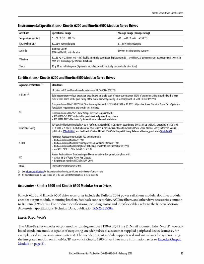
Kinetix Servo Drives Specifications
Environmental Specifications - Kinetix 6200 and Kinetix 6500 Modular Servo Drives
Certifications - Kinetix 6200 and Kinetix 6500 Modular Servo Drives
Accessories - Kinetix 6200 and Kinetix 6500 Modular Servo Drives
Kinetix 6200 and Kinetix 6500 drive accessories include the Bulletin 2094 power rail, shunt module, slot filler module, encoder output module, mounting brackets, feedback connector kits, AC line filters, and other drive accessories common to Bulletin 2094 drives. For product specifications, including motor and interface cables, refer to the Kinetix Motion Accessories Specifications Technical Data, publication KNX-TD004.
Encoder Output Module
The Allen-Bradley encoder output module (catalog number 2198-ABQE) is a DIN-rail mounted EtherNet/IP network-based standalone module capable of outputting encoder pulses to a customer-supplied peripheral device (cameras, for example, used in line-scan vision systems). The encoder output module supports real and virtual axes for systems using the integrated motion on EtherNet/IP network (Kinetix 6500 drives). For more information, refer to Encoder Output Module on page 31.
Attribute Operational Range Storage Range (nonoperating)
Temperature, ambient 0…50 °C (32…122 °F) -40…+70 °C (-40…+158 °F)
Relative humidity 5…95% noncondensing 5…95% noncondensing
Altitude 1000 m (3281 ft)3000 m (9843 ft) with derating 3000 m (9843 ft) during transport
Vibration 5…55 Hz @ 0.35 mm (0.014 in.) double amplitude, continuous displacement; 55…500 Hz @ 2.0 g peak constant acceleration (10 sweeps in each of 3 mutually perpendicular directions)
Shock 15 g, 11 ms half-sine pulse (3 pulses in each direction of 3 mutually perpendicular directions)
Agency Certification (1)
(1) See rok.auto/certifications for declarations of conformity, certificates, and other certification details.
Standards
c-UL-us (2)
(2) UL has not evaluated the Safe Torque Off or the Safe Speed Monitor options in these products.
UL Listed to U.S. and Canadian safety standards (UL 508C File E59272).
Solid-state motor overload protection provides dynamic fold-back of motor current when 110% of the motor rating is reached with a peak current limit based on the peak rating of the motor as investigated by UL to comply with UL 508C (UL File E59272).
CE
European Union 2004/108/EC EMC Directive compliant with IEC 61800-3:2004 + A1:2012: Adjustable Speed Electrical Power Drive Systems - Part 3; EMC requirements and specific test methods.
European Union 2006/95/EC Low Voltage Directive compliant with:• IEC 61800-5-1:2007 - Adjustable speed electrical power drive systems.• IEC 50178:1997 - Electronic Equipment for use in Power Installations.
Functional SafetyTÜV certified for functional safety: up to Performance Level (PL) e, Category 4 according to ISO 13849; up to SIL CL3 according to IEC 61508, IEC 61800-5-2, and IEC 62061 when used as described in the Kinetix 6200 and Kinetix 6500 Safe Speed Monitor Safety Reference Manual, publication 2094-RM001, and the Kinetix 6200 and Kinetix 6500 Safe Torque Off Safety Reference Manual, publication 2094-RM002.
C-Tick
Australian Radiocommunications Act, compliant with:• Radiocommunications Act: 1992• Radiocommunications (Electromagnetic Compatibility) Standard: 1998• Radiocommunications (Compliance Labelling - Incidental Emissions) Notice: 1998• AS/NZS CISPR 11: 2002 (Group 2, Class A)
KCKorean Registration of Broadcasting and Communications Equipment, compliant with:• Article 58-2 of Radio Waves Act, Clause 3• Registration number: KCC-REM-RAA-2094
ODVA EtherNet/IP conformance tested.
Rockwell Automation Publication KNX-TD003E-EN-P - February 2019 85

Kinetix Servo Drives Specifications
Kinetix 6000 Multi-axis Servo Drives
The Kinetix 6000 multi-axis servo drives provide powerful simplicity to handle even the most demanding applications quickly, easily, and cost-effectively. By providing advanced control capability along with innovative design and installation features, the Kinetix 6000 drives can significantly improve system performance while saving time and money. The compact size, simplified wiring, and easy-to-use components make the Kinetix 6000 drives an ideal choice for both OEMs and end-users. Target applications for the Kinetix 6000 drives include packaging, material handling, converting, and assembly.
The Kinetix 6000 servo drives provide Integrated Motion capability through sercos interface and compatibility with Kinetix 6200 drives, letting you migrate to the enhanced features exactly when and where you need them.
Kinetix 6000 Drive Features and Indicators
2094-ACxx-Mxx-S and 2094-BCxx-Mxx-S IAM Features and Indicators
Item Description Item Description Item Description
1 Safe Torque Off (STO) connector 8 Sercos communication rate and optical power switches 15 Seven-segment fault status indicator
2 Contactor enable (CED) connector 9 Sercos transmit (Tx) connector 16 Drive status indicator
3 DC bus/AC input power (IPD) connector 10 DPI connector 17 COMM status indicator
4 Control power (CPD) connector 11 Sercos receive (Rx) connector 18 Bus status indicator
5 Motor cable shield clamp 12 Mounting screw 19 Motor feedback (MF) connector
6 Motor power (MP) connector 13 I/O (IOD) connector 20 Auxiliary feedback (AF) connector
7 Motor/resistive brake (BC) connector 14 Sercos node address switch
BAUDRATE
TXRXDPI
DC-DC+
L3L2L1
CONT EN-CONT EN+
WVU
MBRK -MBRK +
COM PWR
DBRK -DBRK +
CTRL 2CTRL 1
1 2
3
41
2 3
4 5
6
1 2 1 2 3 4 5 6
1 2
1 2 3 4 5 6 7 8 9
910
19
14
15
161718
12
13 20
6
7
8
2
3
4
1
5
11
Integrated Axis Module(2094-AC05-M01-S top view is shown)
Integrated Axis Module(2094-AC05-M01-S front view is shown)
86 Rockwell Automation Publication KNX-TD003E-EN-P - February 2019

Kinetix Servo Drives Specifications
2094-AMxx-S and 2094-BMxx-S AM Features and Indicators
Item Description Item Description Item Description
1 Safe Torque Off (STO) connector 6 Sercos transmit (Tx) connector 11 Drive status indicator
2 Motor cable shield clamp 7 Sercos receive (Rx) connector 12 COMM status indicator
3 Motor power (MP) connector 8 Mounting screw 13 Bus status indicator
4 Motor/resistive brake (BC) connector 9 I/O (IOD) connector 14 Motor feedback (MF) connector
5 Sercos communication rate and optical power switches 10 Seven-segment fault status indicator 15 Auxiliary feedback (AF) connector
BAUDRATE
TXRX
WVU
MBRK -MBRK +
COM PWR
DBRK -DBRK +
1 2
3
41
2 3
4 5
6
1 2 3 4 5 6 7 8 9
1
23
4
5
67
14
10
111213
15
8
9
Axis Module(2094-AM01-S top view is shown)
Axis Module(2094-AM01-S front view is shown)
Rockwell Automation Publication KNX-TD003E-EN-P - February 2019 87

Kinetix Servo Drives Specifications
Technical Specifications - Kinetix 6000 Multi-axis Servo Drives
IAM Module (converter, 200V-class) Power Specifications (series A and C)
Attribute 2094-AC05-MP5-S 2094-AC05-M01-S 2094-AC09-M02-S 2094-AC16-M03-S 2094-AC32-M05-S
AC input voltage 195…264V rms, three-phase (230V nom)
AC input frequency 47…63 Hz
Main AC input current Nom (rms)Max inrush (0-pk) (1)
(1) All 2094-xCxx IAM modules are limited to 2 contactor cycles per minute (with up to 4 axes), or 1 contactor cycle per minute (with 5…8 axes). The cycle capability also depends on the converter power rating and the total system capacitance. To calculate cycle capability, refer to the Kinetix 6000 Multi-axis Servo Drives User Manual, publication 2094-UM001.
10 A19 A
19 A37 A
36 A73 A
71 A138 A
DC input voltage (common-bus follower) 275…375V DC
DC input current (common-bus follower) 10 A 19 A 36 A 71 A
Control power AC input voltage 95…264V rms, single-phase (110…240V nom)
Control power AC input currentNom (@ 220/230V AC) rmsNom (@ 110/115V AC) rmsMax inrush (0-pk)
3 A6 A20 A
3 A6 A83 A (3)
(3) For eight axis systems with 230V AC control input voltage and 50 °C (122°F) ambient temperature the maximum inrush duration is less than 1/2 line cycle. To calculate the maximum inrush duration for other configurations, refer to the Kinetix 6000 Multi-axis Servo Drives User Manual, publication 2094-UM001.
Nominal bus output voltage 325V DC
Line loss ride through 20 ms
Continuous output current to bus (ADC) 10 A 19 A 36 A 71 A
Peak output current to bus (ADC) (2)
(2) Peak output current duration equals 250 ms.
20 A 38 A 72 A 142 A
Bus overvoltage 415V DC
Bus undervoltage 138V DC
Internal shuntContinuous powerPeak power
N/AN/A
50 W8200 W
200 W5700 W
200 W5700 W
Internal shunt resistor N/A 20 Ω 28.75 Ω 28.75 Ω
Shunt on N/A 405V DC
Shunt off N/A 375V DC
Continuous power output to bus 3 kW 6 kW 11.3 kW 22.5 kW
Peak power output 6 kW 12 kW 22.6 kW 45.0 kW
Efficiency 95%
Converter inductance N/A 150 μH 75 μH
Converter capacitance 270 μF 540 μF 1320 μF 1980 μF
Short-circuit current rating 200,000 A (rms) symmetrical
88 Rockwell Automation Publication KNX-TD003E-EN-P - February 2019

Kinetix Servo Drives Specifications
IAM Module (converter, 400V-class) Power Specifications (series A, B, and C)
Attribute 2094-BC01-MP5-S 2094-BC01-M01-S 2094-BC02-M02-S 2094-BC04-M03-S 2094-BC07-M05-S
AC input voltage 324…528V rms three-phase (360…480V nom)
AC input frequency 47…63 Hz
Main AC input current Nom (rms) Max inrush (0-pk) (1)
(1) All 2094-xCxx IAM modules are limited to 2 contactor cycles per minute (with up to 4 axis modules), or 1 contactor cycle per minute (with 5 to 8 axis modules). The cycle capability also depends on the converter power rating and the total system capacitance. Refer to the Kinetix 6000 Multi-axis Servo Drives User Manual, publication 2094-UM001 when making calculations.
10.0 A11.0 A
24.0 A22.0 A
44.0 A31.1 A
71.0 A62.2 A
DC input voltage (common bus follower) 458…747V DC
DC input current (common-bus follower) 9.0 A 22.6 A 41.5 A 67.7 A
Control power AC input voltage 95…264V rms single-phase (110…240V rms nom)
Control power AC input currentNom (@ 220/230V AC) rmsNom (@ 110/115V AC) rmsMax inrush (0-pk)
6 A6 A98 A (3)
(3) For eight axis systems with 230V AC control input voltage and 50 °C (122°F) ambient temperature the maximum inrush duration is less than 1/2 line cycle. To calculate the maximum inrush duration for other configurations, refer to the Kinetix 6000 Multi-axis Servo Drives User Manual, publication 2094-UM001.
Control power cycling, max 2 cycles per minute with a 90% on-time, 10% off-time duty cycle
Nominal bus output voltage 650V DC
Line loss ride through 20 ms
Continuous output current to bus (ADC) 9.0 A 22.6 A 41.5 A 67.7 A
Peak output current to bus (ADC) Series A drives (2)
Series B and C drives
(2) Peak output current duration equals 250 ms.
18.1 A22.6 A (4)
(4) Converter peak output duration equals 400 ms with a duty cycle of 16%.
45.2 A56.4 A (4)
83.1 A103.8 A (4)
135.4 A203.2 A (5)
(5) Converter peak output duration equals 200 ms with a duty cycle of 3%.
Bus overvoltage 825V DC
Bus undervoltage 275V DC
Internal shuntContinuous powerPeak power
50 W5.6 kW
200 W22.5 kW
Internal shunt resistor 115 Ω 28.75 Ω
Shunt on 805V DC
Shunt off 755V DC
Continuous power output to bus 6 kW 15 kW 27.6 kW 45 kW
Peak power output Series A drives (2)
Series B and C drives 12 kW 15 kW (4)
30 kW37.5 kW (4)
55.2 kW69 kW (4)
90 kW135 kW (5)
Efficiency 97%
Converter inductance 500 μH 125 μH 75 μH
Converter capacitance 110 μF 220 μF 940 μF 1410 μF
Short-circuit current rating 200,000 A (rms) symmetrical
Rockwell Automation Publication KNX-TD003E-EN-P - February 2019 89

Kinetix Servo Drives Specifications
Control Power Current Requirements
AM Module (inverter, 200V-class) Power Specifications
Modules on Power Rail110/115V AC Input 220/230V AC Input
Input CurrentA
Input VAVA
Input CurrentA
Input VAVA
IAM module only 0.56 67 0.36 85
IAM and 1 AM module 0.99 119 0.64 153
IAM and 2 AM module 1.43 172 0.92 220
IAM and 3 AM module 1.87 224 1.20 287
IAM and 4 AM module 2.31 277 1.48 354
IAM and 5 AM module 2.74 329 1.75 421
IAM and 6 AM module 3.18 382 2.03 488
IAM and 7 AM module 3.62 434 2.31 555
Attribute (1)
(1) These specifications apply to the axis module specified in the column heading by catalog number and the same axis module (inverter section) that resides within an IAM power module.
2094-AMP5-S(2094-AC05-MP5-S)
2094-AM01-S(2094-AC05-M01-S)
2094-AM02-S(2094-AC09-M02-S)
2094-AM03-S(2094-AC16-M03-S)
2094-AM05-S(2094-AC32-M05-S)
Bandwidth (2)
Velocity loopCurrent loop
(2) Bandwidth values vary based on tuning parameters and mechanical components.
500 Hz1300 Hz
PWM frequency 8 kHz 4 kHz
Input voltage (nom) 325V DC
Continuous current (rms) 3.7 A 6.0 A 10.6 A 17.3 A 34.6 A
Continuous current (0-pk) 5.2 A 8.5 A 15.0 A 24.5 A 48.9 A
Peak current (rms) (3)
(3) Peak current duration equals 100 ms.
7.4 A 12.0 A 21.2 A 34.6 A 51.9 A
Peak current (0-pk) (3) 10.5 A 17.0 A 30.0 A 48.9 A 73.4 A
Continuous power out (nom) 1.2 kW 1.9 kW 3.4 kW 5.5 kW 11.0 kW
Internal shuntContinuous powerPeak power
N/AN/A
50 W1400 W
Internal shunt resistor N/A 115 Ω
Shunt on N/A 405V DC
Shunt off N/A 375V DC
Efficiency 98%
Capacitance 390 μF 660 μF 780 μF 1320 μF 2640 μF
Capacitive energy absorption 15 J 25 J 29 J 50 J 99 J
Short-circuit current rating 200,000 A (rms) symmetrical
90 Rockwell Automation Publication KNX-TD003E-EN-P - February 2019

Kinetix Servo Drives Specifications
AM Module (inverter, 400V-class) Power Specifications (series A, B, and C)
IMPORTANT The peak current ratings of the Kinetix 6000 AM modules (series A, B, and C) are configured at the factory as 150% of continuous current. You can program 2094-BMP5-S, 2094-BM01-S, 2094-BM02-S, and 2094-BM03-S series-B and C drives and their equivalent IAM (inverter) modules, up to 250% of continuous inverter current. You can program the 2094-BM05-S (AM module) and the 2094-BC07-M05-S (inverter) module up to 200% of continuous inverter current.
Attribute2094-BMP5-S(2094-BC01-MP5-S)
2094-BM01-S(2094-BC01-M01-S)
2094-BM02-S(2094-BC02-M02-S)
2094-BM03-S(2094-BC04-M03-S)
2094-BM05-S(2094-BC07-M05-S)
Bandwidth (1)
Velocity loopCurrent loop
(1) Bandwidth values vary based on tuning parameters and mechanical components.
500 Hz1300 Hz
PWM frequency 8 kHz 4 kHz
Nominal input voltage 650V DC
Continuous current (rms) (2)
(2) Continuous and peak current ratings are for high-speed operation. For constant velocity operation at an electrical output frequency below 5 Hz (75 rpm for 8-pole motors), the output current rating is reduced. See Motion Analyzer software to correctly size your drive.
2.8 A 6.1 A 10.3 A 21.2 A 34.6 A
Continuous current (sine) 0-pk (3) 4.0 A 8.6 A 14.6 A 30.0 A 48.9 A
Peak current (rms) (3)
Series A drivesSeries B and C drives (3)
(3) Applies to series-B and C drives when configured for Peak-enhanced mode. For more information on drive performance in the Peak-enhanced mode, refer to Peak Enhancement Specifications on page 92.
4.2 A7.0 A
9.2 A 15.3 A
15.5 A25.8 A
31.8 A53.0 A
51.9 A69.2 A
Peak current (0-pk) (3)
Series A drivesSeries B and C drives (3)
5.9 A 9.9 A
12.9 A 21.6 A
21.8 A 36.4 A
45.0 A 75.0 A
73.4 A 97.9 A
Continuous power out, nom 1.8 kW 3.9 kW 6.6 kW 13.5 kW 22.0 kW
Internal shuntContinuous powerPeak power
50 W5.6 kW
200 W22.5 kW
Internal shunt resistor 115 Ω 28.75 Ω
Shunt on 805V DC
Shunt off 755V DC
Efficiency 98%
Capacitance 75 μF 150 μF 270 μF 840 μF 1175 μF
Capacitive energy absorption 10 J 19 J 35 J 108 J 152 J
Short-circuit current rating 200,000 A (rms) symmetrical
Rockwell Automation Publication KNX-TD003E-EN-P - February 2019 91

Kinetix Servo Drives Specifications
Peak Enhancement Specifications
Drives that support the Peak-enhanced mode have the capability of increasing the maximum inverter peak current to achieve greater overload performance.
Peak Enhancement Software and Firmware Requirements
Kinetix 6000 Peak Overload Support
Kinetix 6000 Peak Current Ratings
IMPORTANT The peak enhancement feature requires the use of RSLogix 5000® software and drive firmware (as specified below) or the Studio 5000 Logix Designer application.
IAM ModuleCat. No.
AM ModuleCat. No.
RSLogix 5000 Software Version
Kinetix 6000 Drive Firmware Revision
2094-BC01-MP5-S 2094-BMP5-S 16 or later 1.111 or later
2094-BC01-M01-S 2094-BM01-S 16 or later 1.111 or later
2094-BC02-M02-S 2094-BM02-S 16 or later 1.111 or later
2094-BC04-M03-S 2094-BM03-S 17 or later 1.117 or later
2094-BC07-M05-S 2094-BM05-S 17 or later 1.117 or later
IAM/AM ModuleCat. No. Module Safe Torque Off Drive Series A Series B and C
2094-BCxx-Mxx IAMNon Safe Torque Off Standard N/A
2094-BMxx AM
2094-BCxx-Mxx-S IAMSafe Torque Off Standard Standard or
Peak enhanced (1)
(1) Standard mode is enabled by default to preserve backward compatibility, but you can enable the Peak-enhanced mode to achieve increased peak current performance. Refer to the Kinetix 6000 Multi-axis Servo Drives User Manual, publication 2094-UM001, for information on enabling the Peak-enhanced mode.
2094-BMxx-S AM
IAM/AM Module Cat. No.
Peak Inverter Current Rating Peak Converter Current Rating
Standard Peak Enhanced Series A Series B and C
2094-BC01-MP5-S 150% 250% 200% 250%
2094-BC01-M01-S 150% 250% 200% 250%
2094-BC02-M02-S 150% 250% 200% 250%
2094-BC04-M03-S 150% 250% 200% 250%
2094-BC07-M05-S 150% 200% 200% 300%
2094-BMP5-S 150% 250% N/A N/A
2094-BM01-S 150% 250% N/A N/A
2094-BM02-S 150% 250% N/A N/A
2094-BM03-S 150% 250% N/A N/A
2094-BM05-S 150% 200% N/A N/A
92 Rockwell Automation Publication KNX-TD003E-EN-P - February 2019

Kinetix Servo Drives Specifications
Load Duty-cycle Profile Example
Peak Duty-cycle Definition of Terms
Term Definition (1)
(1) All current values are specified as RMS.
Continuous Current Rating (ICont) The maximum value of current that can be output continuously.
Peak Current Rating (IPKmax) The maximum value of peak current that the drive can output. This rating is valid for only overload times less than TPKmax.
Duty Cycle (D) The ratio of time at peak to the Application Period and is defined as:
Time at Peak (TPK) The time at peak current (IPK) for a given loading profile. Must be less than or equal to TPKmax.
Peak Current (IPK) The level of peak current for a given loading profile. IPK must be less than or equal to the Peak Current Rating (TPKMAX) of the drive.
Base Current (IBase) The level of current between the pulses of peak current for a given loading profile. IBase must be less than or equal to the continuous current rating (ICont) of the drive.
Loading Profile The loading profile is composed of IPK, IBase, TPK, and D (or T) values and completely specify the operation of the drive in an overload situation. These values are collectively defined as the Loading Profile of the drive.
Application Period (T) The sum of the times at IPK (TPK) and IBase.
D = TT
PK x 100%
I Pk
I Cont
I Base
T Pk
T
D = TT
PK x 100%
Rockwell Automation Publication KNX-TD003E-EN-P - February 2019 93

Kinetix Servo Drives Specifications
Peak Enhanced Inverter Mode (TPK < 2.0 s)
(1) Base current (IBase) and peak current (IPK are a percentage of the continuous drive current rating (ICont).
Peak Inverter Overload (TPK < 2.0 s)
(1) Base current (IBase) and peak current (IPK) are a percentage of the continuous drive current rating (ICont).
0% 60% 100%
50%
45%
40%
35%
30%
25%
20%
15%
10%
5%
0%
80%20% 40%
Applies to these Kinetix 6000 drives:2094-BC01-MP5-S, 2094-BMP5-S, 2094-BC01-M01-S, 2094-BM01-S, 2094-BC02-M02-S, 2094-BM02-S, 2094-BC04-M03-S, 2094-BM03-S
Max
imum
Dut
y Cyc
le (D
max
)
% Base Current (I Base /ICont)
Legend (1)
I Pk = 150%
I Pk = 200%
I Pk = 250%
0% 60% 100%
50%
45%
40%
35%
30%
25%
20%
15%
10%
5%
0%
80%20% 40%
Applies to these Kinetix 6000 drives:2094-BC07-M05-S, 2094-BM05-SM
axim
um D
uty C
ycle
(D m
ax)
% Base Current (I Base /ICont)
Legend (1)
I Pk = 150%
I Pk = 200%
94 Rockwell Automation Publication KNX-TD003E-EN-P - February 2019

Kinetix Servo Drives Specifications
Circuit Breaker/Fuse Specifications
The 2094-xCxx-Mxx-S and 2094-xMxx-S drive modules use internal solid-state motor short-circuit protection and, when protected by suitable branch circuit protection, are rated for use on a circuit capable of delivering up to 200,000 A.
Control and DC-bus Circuit-protection Specifications
Input Power Circuit Protection (LIM)
The 2094-AL09 and 2094-BL02 line interface modules (LIM) contain supplementary protection devices and, when protected by suitable branch circuit protection, are rated for use on a circuit capable of delivering up to 5000 A. When these modules are used, protection on the line side of the LIM module is required. Fuses must be class J or CC only.
The 2094-ALxxS, 2094-BLxxS, and 2094-XL75S-Cx LIM modules contain branch circuit rated devices suitable for use on a circuit capable of delivering up to 65,000 A (400V-class) or 100,000 A (200V-class).
Refer to the Line Interface Module Installation Instructions, publication 2094-IN005, for power specifications and more information on using the LIM module.
Input Power Circuit Protection (without LIM)
These fuses and Allen-Bradley circuit breakers are recommended for use with 2094-xCxx-Mxx-S IAM modules when the line interface module (LIM) is not used.
IAM Module Cat. No.
Control Input Power DC-bus Power
Bussmann Fuse (1)
(1) Use FNQ-R-7.5 circuit breaker for higher single -cycle inrush current capability. This is recommended when the continuous control-power current exceeds 3.0 A.
Allen-Bradley Circuit Breaker (2) (non-UL)
(2) Use 1492-SPM1D150 circuit breaker for higher single -cycle inrush current capability. This is recommended when the continuous control-power current exceeds 3.0 A.
Bussmann Fuse Mersen Fuse (3)
(3) Mersen fuses were formerly known as Ferraz Shawmut.
2094-AC05-MP5-S
FNQ-R-10 (10 A)
1492-SPM2D060N/A A50P20-1
2094-AC05-M01-S
2094-AC09-M02-S FWH-35B A50P35-4
2094-AC16-M03-S1492-SPM2D200
FWH-60B A50P60-4
2094-AC32-M05-S FWH-125B A50P125-4
2094-BC01-MP5-S
FNQ-R-10 (10 A) orFNQ-R-7.5 (7.5 A)
1492-SPM2D060 or1492-SPM1D150
FWJ-20A14F DCT20-22094-BC01-M01-S
2094-BC02-M02-S FWJ-40A A70QS40-4
2094-BC04-M03-S FWJ-70A A70QS70-4
2094-BC07-M05-S FWJ-125A A70QS125-4
IMPORTANT LIM modules (catalog numbers 2094-ALxxS, 2094-BLxxS, and 2094-XL75S-Cx) can provide branch circuit protection to the IAM module. Follow all applicable NEC and local codes.
Rockwell Automation Publication KNX-TD003E-EN-P - February 2019 95

Kinetix Servo Drives Specifications
Input Power UL Circuit-protection Specifications
Input Power IEC (non-UL) Circuit-protection Specifications
Contactor Ratings
This table lists the recommended contactor ratings for integrated axis modules installed without a line interface module.
Kinetix 6000 Drives UL Applications
IAM ModuleCat. No.
Drive Voltage(three-phase) nom
Bussmann FusesCat. No.
Miniature CB (1)
Cat. No.Motor Protection CB, (1)
Self-protected CMC Cat. No.
(1) These Bulletin 140M circuit breakers, when used as self-protected (Type E) devices, and Bulletin 1489 circuit breakers can be used on only WYE power systems (480Y/277V).
Molded Case CBCat. No.
2094-AC05-MP5-S 230V KTK-R-20 (20 A) Class CC1489-M3D300
140M-F8E-C16
NA2094-AC05-M01-S 230V KTK-R-20 (20 A) Class CC 140M-F8E-C16
2094-AC09-M02-S 230V KTK-R-30 (30 A) Class CC 1489-M3D400 140M-F8E-C20
2094-AC16-M03-S 230V LPJ-45SP (45 A) Class JN/A NA
140G-G6C3-C50
2094-AC32-M05-S 230V LPJ-80SP (80 A) Class J 140G-G6C3-C90
2094-BC01-MP5-S 360…480V KTK-R-20 (20 A) Class CC1489-M3D300
140M-F8E-C32
NA2094-BC01-M01-S 360…480V KTK-R-20 (20 A) Class CC 140M-F8E-C32
2094-BC02-M02-S 360…480V KTK-R-30 (30 A) Class CC 1489-M3D400 140M-F8E-C45
2094-BC04-M03-S 360…480V LPJ-45SP (45 A) Class JN/A NA
140G-G6C3-C50
2094-BC07-M05-S 360…480V LPJ-80SP (80 A) Class J 140G-G6C3-C90
Kinetix 6000 Drives IEC (non-UL) Applications
IAM ModuleCat. No.
Drive Voltage(three-phase) nom
Miniature CBCat. No.
Motor Protection CBCat. No.
Molded Case CBCat. No.
2094-AC05-MP5-S 230V1492-SPM3D300 1489-M3D300
140M-F8E-C16
NA2094-AC05-M01-S 230V 140M-F8E-C16
2094-AC09-M02-S 230V 1492-SPM3D400 1489-M3D400 140M-F8E-C20
2094-AC16-M03-S 230VN/A N/A NA
140G-G6C3-C50
2094-AC32-M05-S 230V 140G-G6C3-C90
2094-BC01-MP5-S 360…480V1492-SPM3D300 1489-M3D300
140M-F8E-C32
NA2094-BC01-M01-S 360…480V 140M-F8E-C32
2094-BC02-M02-S 360…480V 1492-SPM3D400 1489-M3D400 140M-F8E-C45
2094-BC04-M03-S 360…480VN/A N/A NA
140G-G6C3-C50
2094-BC07-M05-S 360…480V 140G-G6C3-C90
IAM Module (200V-class)Cat. No. Contactor IAM Module (400V-class)
Cat. No. Contactor
2094-AC05-MP5-S 100-C23x10 (AC coil)100-C23xx10 (DC coil)
2094-BC01-MP5-S 100-C23x10 (AC coil)100-C23xx10 (DC coil)2094-AC05-M01-S 2094-BC01-M01-S
2094-AC09-M02-S 100-C37x10 (AC coil)100-C37xx10 (DC coil) 2094-BC02-M02-S 100-C37x10 (AC coil)
100-C37xx10 (DC coil)
2094-AC16-M03-S 100-C72x10 (AC coil)100-C72xx10 (DC coil) 2094-BC04-M03-S 100-C60x10 (AC coil)
100-C60xx10 (DC coil)
2094-AC32-M05-S 100-C85x10 (AC coil)100-C85xx10 (DC coil) 2094-BC07-M05-S 100-C85x10 (AC coil)
100-C85xx10 (DC coil)
96 Rockwell Automation Publication KNX-TD003E-EN-P - February 2019

Kinetix Servo Drives Specifications
Input Transformer for Control Power
Power Dissipation Specifications
Use this table to size an enclosure and calculate required ventilation for your Kinetix 6000 drive system.
Power dissipation specifications are based on these calculations. This is an example: 2094-BC02-M02-S with 4.52 ADC (=20%) converter DC current and 10.3 Arms (=100%) inverter output current.Converter loss (36 W) + Inverter loss (142 W) = 178 W total power dissipation.
Attribute Value Cat. No. (1)
(1) Variables (xx-x) determine the input voltage and wiring configuration.
Input volt-amperes
750VA 1497B-A10-xx-x-N
1000VA 1497B-A11-xx-x-N
1500VA 1497B-A12-xx-x-N
Input voltage 460V AC
Output voltage 120…240V AC
Bulletin 2094 Drive ModulesUsage as % of Rated Power Output (watts)
20% 40% 60% 80% 100%
IAM (converter) module (1)
(1) Internal shunt power is not included in the calculations and must be added based on utilization.
2094-AC05-MP5-S 8 11 15 19 24
2094-AC05-M01-S 9 12 16 20 25
2094-AC09-M02-S 14 20 28 36 46
2094-AC16-M03-S 19 30 43 58 74
2094-AC32-M05-S 41 68 100 136 176
2094-BC01-MP5-S18 21 25 29
34
2094-BC01-M01-S 33
2094-BC02-M02-S 36 44 54 64 75
2094-BC04-M03-S 50 67 87 110 135
2094-BC07-M05-S 71 101 137 179 226
IAM (inverter) module or AM module (2)
2094-AC05-MP5-S or 2094-AMP5-S 28 32 37 41 46
2094-AC05-M01-S or 2094-AM01-S 31 38 46 54 62
2094-AC09-M02-S or 2094-AM02-S 34 45 57 70 84
2094-AC16-M03-S or 2094-AM03-S 48 68 91 116 144
2094-AC32-M05-S or 2094-AM05-S 104 156 212 274 342
2094-BC01-MP5-S or 2094-BMP5-S 46 54 61 69 77
2094-BC01-M01-S or 2094-BM01-S 57 73 90 108 126
2094-BC02-M02-S or 2094-BM02-S 53 72 93 116 142
2094-BC04-M03-S or 2094-BM03-S 94 130 169 211 255
2094-BC07-M05-S or 2094-BM05-S 121 183 252 326 407
Shunt module - 2094-BSP2 68 121 174 227 280
Rockwell Automation Publication KNX-TD003E-EN-P - February 2019 97

Kinetix Servo Drives Specifications
Weight Specifications
Maximum Feedback Cable Lengths
Although motor feedback cables are available in standard lengths up to 90 m (295.3 ft), the drive/motor/feedback combination can limit the maximum feedback cable length. These tables assume the use of recommended cables as shown in the Kinetix Motion Accessories Technical Data, publication KNX-TD004.
Kinetix 6000 Drive Module Cat. No.
Weight, approxkg (lb)
Kinetix 6000 Drive Module Cat. No.
Weight, approxkg (lb)
IAM(200V-class)
2094-AC05-MP5-S 2.23 (4.9)
IAM(400V-class)
2094-BC01-MP5-S 4.98 (11.0)
2094-AC05-M01-S 2.27 (5.0) 2094-BC01-M01-S 5.03 (11.1)
2094-AC09-M02-S 2.31 (5.1) 2094-BC02-M02-S 5.08 (11.2)
2094-AC16-M03-S 4.71 (10.4) 2094-BC04-M03-S 9.60 (21.1)
2094-AC32-M05-S 7.43 (16.4) 2094-BC07-M05-S 10.1 (22.3)
AM(200V-class)
2094-AMP5-S 1.46 (3.2)
AM(400V-class)
2094-BMP5-S 2.44 (5.4)
2094-AM01-S 1.50 (3.3) 2094-BM01-S 2.49 (5.5)
2094-AM02-S 1.54 (3.4) 2094-BM02-S 2.54 (5.6)
2094-AM03-S 3.13 (6.9) 2094-BM03-S 4.58 (10.1)
2094-AM05-S 3.18 (7.0) 2094-BM05-S 4.98 (11.0)
Power rails(Slim)
2094-PRS1 1.05 (2.3)
2094-PRS2 1.59 (3.5) Shunt module 2094-BSP2 3.10 (6.8)
2094-PRS3 2.14 (4.7) Slot-filler module 2094-PRF 0.45 (1.0)
2094-PRS4 2.67 (5.9)
2094-PRS5 3.11 (6.8)
2094-PRS6 3.55 (7.8)
2094-PRS7 3.99 (8.8)
2094-PRS8 4.43 (9.7)
Cable Lengths for Compatible Rotary Motors
Motor Cat. No.Absolute High-resolution (5V) Encoderm (ft)
Absolute High-resolution (9V) Encoderm (ft)
Incremental/TTL (5V) Encoderm (ft)
Resolverm (ft)
MPL-A15xxx…MPL-A2xxx-E/V 30 (98.4)
MPL-A3xxx…MPL-A5xxx-S/M (1) 30 (98.4)
MPL-B15xxx…MPL-B2xxx-E/V 90 (295.3)
MPL-B3xxx…MPL-B5xxx-S/M 90 (295.3)
MPL-A/B15xxx…MPL-A/B45xxx-H 30 (98.4)
MPL-Bxxxx-R 90 (295.3)
MPM-Axxxxx-S/M 30 (98.4)
MPM-Bxxxxx-S/M 90 (295.3)
98 Rockwell Automation Publication KNX-TD003E-EN-P - February 2019
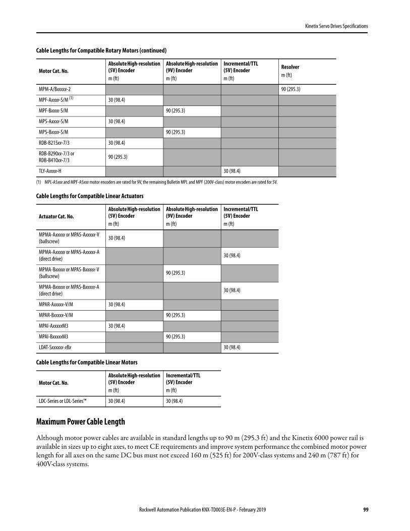
Kinetix Servo Drives Specifications
Cable Lengths for Compatible Linear Actuators
Cable Lengths for Compatible Linear Motors
Maximum Power Cable Length
Although motor power cables are available in standard lengths up to 90 m (295.3 ft) and the Kinetix 6000 power rail is available in sizes up to eight axes, to meet CE requirements and improve system performance the combined motor power length for all axes on the same DC bus must not exceed 160 m (525 ft) for 200V-class systems and 240 m (787 ft) for 400V-class systems.
MPM-A/Bxxxxx-2 90 (295.3)
MPF-Axxxx-S/M (1) 30 (98.4)
MPF-Bxxxx-S/M 90 (295.3)
MPS-Axxxx-S/M 30 (98.4)
MPS-Bxxxx-S/M 90 (295.3)
RDB-B215xx-7/3 30 (98.4)
RDB-B290xx-7/3 orRDB-B410xx-7/3 90 (295.3)
TLY-Axxxx-H 30 (98.4)
(1) MPL-A5xxx and MPF-A5xxx motor encoders are rated for 9V, the remaining Bulletin MPL and MPF (200V-class) motor encoders are rated for 5V.
Actuator Cat. No.Absolute High-resolution (5V) Encoderm (ft)
Absolute High-resolution (9V) Encoderm (ft)
Incremental/TTL (5V) Encoderm (ft)
MPMA-Axxxxx or MPAS-Axxxxx-V (ballscrew) 30 (98.4)
MPMA-Axxxxx or MPAS-Axxxxx-A (direct drive) 30 (98.4)
MPMA-Bxxxxx or MPAS-Bxxxxx-V (ballscrew) 90 (295.3)
MPMA-Bxxxxx or MPAS-Bxxxxx-A (direct drive) 30 (98.4)
MPAR-Axxxxx-V/M 30 (98.4)
MPAR-Bxxxxx-V/M 90 (295.3)
MPAI-AxxxxxM3 30 (98.4)
MPAI-BxxxxxM3 90 (295.3)
LDAT-Sxxxxxx-xBx 30 (98.4)
Motor Cat. No.Absolute High-resolution (5V) Encoderm (ft)
Incremental/TTL (5V) Encoderm (ft)
LDC-Series or LDL-Series™ 30 (98.4) 30 (98.4)
Cable Lengths for Compatible Rotary Motors (continued)
Motor Cat. No.Absolute High-resolution (5V) Encoderm (ft)
Absolute High-resolution (9V) Encoderm (ft)
Incremental/TTL (5V) Encoderm (ft)
Resolverm (ft)
Rockwell Automation Publication KNX-TD003E-EN-P - February 2019 99

Kinetix Servo Drives Specifications
Dimensions - Kinetix 6000 Multi-axis Servo Drives
2094-AC05-MP5-S, 2094-AC05-M01-S, and 2094-AC09-M02-S Dimensions (200V-class)2094-BC01-MP5-S, 2094-BC01-M01-S, and 2094-BC02-M02-S Dimensions (400V-class)
Modules are shown mounted to the power rail and the dimensions reflect that in the depth of the module.
IAM Module Dimensions
IAM ModuleCat. No. Series
Amm (in.)
Bmm (in.)
Dmm (in.)
Emm (in.)
Fmm (in.)
2094-AC05-MP5-S
A and C 198 (7.8) 176 (7.0) 51 (2.0) 206 (8.2) 237 (9.3)2094-AC05-M01-S
2094-AC09-M02-S
2094-BC01-MP5-S
A, B, and C 272 (10.7) 249 (9.8) 0 (0) 256 (10.1) 287 (11.3)2094-BC01-M01-S
2094-BC02-M02-S
AB
D
E
F
8.9(0.35)
125(4.9)
62(2.45)
51(2.00)
IMPORTANT: Additional clearance below the connector is necessary to provide the recommended cable bend radius.
Bulletin 2090 (flying lead) Feedback Cable with 2090-K6CK-D15MLow Profile Connector Kit
Bulletin 2094Power Rail
2094-AC05-M01-S IAM module is shown.
Dimensions are in millimeters (inches)
2090-CFBM7DD-CEAAxx feedback cable with premolded connectors.
This view illustrates theadditional clearance required for
premolded cable connectors.
100 Rockwell Automation Publication KNX-TD003E-EN-P - February 2019

Kinetix Servo Drives Specifications
2094-AC16-M03-S and 2094-AC32-M05-S Dimensions (200V-class)2094-BC04-M03-S and 2094-BC07-M05-S Dimensions (400V-class)
Modules are shown mounted to the power rail and the dimensions reflect that in the depth of the module.
IAM Module Dimensions
IAM ModuleCat. No. Series
Amm (in.)
Bmm (in.)
Cmm (in.)
Emm (in.)
Fmm (in.)
2094-AC16-M03-SA and C 198 (7.8) 176 (7.0)
125 (4.9)302 (11.9) 420 (16.5)
2094-AC32-M05-S 196 (7.7)
2094-BC04-M03-SA 272 (10.7) 249 (9.8) 196 (7.7)
256 (10.1) 375 (14.7)
2094-BC07-M05-S 318 (12.5) 436 (17.2)
2094-BC04-M03-SB and C 272 (10.7) 249 (9.8) 196 (7.7) 256 (10.1) 375 (14.7)
2094-BC07-M05-S
8.9(0.35)
AB C
E
F
62(2.45)
51(2.00)
IMPORTANT: Additional clearance below the connector is necessary to provide the recommended cable bend radius.
2094-BC04-M03-S IAM module is shown.
Bulletin 2090 (flying lead) Feedback Cable with 2090-K6CK-D15MLow Profile Connector Kit
Dimensions are in millimeters (inches)
Bulletin 2094Power Rail
This view illustrates theadditional clearance required for
premolded cable connectors.
2090-CFBM7DD-CEAAxx feedback cable with premolded connectors.
Rockwell Automation Publication KNX-TD003E-EN-P - February 2019 101

Kinetix Servo Drives Specifications
2094-AMP5-S, 2094-AM01-S, and 2094-AM02-S Dimensions (200V-class)2094-BMP5-S, 2094-BM01-S, and 2094-BM02-S Dimensions (400V-class)
Modules are shown mounted to the power rail and the dimensions reflect that in the depth of the module.
AM Module Dimensions
AM ModuleCat. No. Series
Amm (in.)
Bmm (in.)
Dmm (in.)
Emm (in.)
Fmm (in.)
2094-AMP5-S
A and C 198 (7.8) 176 (7.0) 51 (2.0) 206 (8.2) 237 (9.3)2094-AM01-S
2094-AM02-S
2094-BMP5-S
A, B, and C 272 (10.7) 249 (9.8) 0 (0) 256 (10.1) 287 (11.3)2094-BM01-S
2094-BM02-S
8.9(0.35)
70(2.76)
AB
D
E
F
62(2.45)
51(2.00)
2094-AM01-SAM module is shown.
Bulletin 2090 (flying lead)Feedback Cable with 2090-K6CK-D15MLow Profile Connector Kit
IMPORTANT: Additional clearance below the connector is necessary to provide the recommended cable bend radius.
Dimensions are in millimeters (inches)
Bulletin 2094Power Rail
2090-CFBM7DD-CEAAxx feedback cable with premolded connectors.
This view illustrates theadditional clearance required for
premolded cable connectors.
102 Rockwell Automation Publication KNX-TD003E-EN-P - February 2019

Kinetix Servo Drives Specifications
2094-AM03-S and 2094-AM05-S Dimensions (200V-class)2094-BM03-S and 2094-BM05-S Dimensions (400V-class)
Modules are shown mounted to the power rail and the dimensions reflect that in the depth of the module.
AM Module Dimensions
AM ModuleCat. No. Series
Amm (in.)
Bmm (in.)
Cmm (in.)
Emm (in.)
Fmm (in.)
2094-AM03-SA and C 198 (7.8) 176 (7.0) 70 (2.8) 302 (11.9) 420 (16.5)
2094-AM05-S
2094-BM03-SA 272 (10.7) 249 (9.8) 141 (5.5)
256 (10.1) 375 (14.7)
2094-BM05-S 318 (12.5) 436 (17.2)
2094-BM03-SB and C 272 (10.7) 249 (9.8) 141 (5.5) 256 (10.1) 375 (14.7)
2094-BM05-S
8.9(0.35)
AB C
E
F
62(2.45)
51(2.00)
2094-BM03-S AM module is shown.
Bulletin 2090 (flying lead)Feedback Cable with 2090-K6CK-D15MLow Profile Connector Kit
IMPORTANT: Additional clearance below the connector is necessary to provide the recommended cable bend radius.
Dimensions are in millimeters (inches)
Bulletin 2094Power Rail
2090-CFBM7DD-CEAAxx feedback cable with premolded connectors.
This view illustrates theadditional clearance required for
premolded cable connectors.
Rockwell Automation Publication KNX-TD003E-EN-P - February 2019 103

Kinetix Servo Drives Specifications
Environmental Specifications - Kinetix 6000 Servo Drives
Certifications - Kinetix 6000 Servo Drives
Accessories - Kinetix 6000 Servo Drives
Kinetix 6000 drive accessories include the Bulletin 2094 power rail, shunt module, slot filler module, mounting brackets, feedback connector kits, AC line filters, and other drive accessories common to Bulletin 2094 drives. For product specifications, including motor and interface cables, refer to the Kinetix Motion Accessories Specifications Technical Data, publication KNX-TD004.
Attribute Operational Range Storage Range (nonoperating)
Temperature, ambient 0…50 °C (32…122 °F) -40…+70 °C (-40…+158 °F)
Relative humidity 5…95% noncondensing 5…95% noncondensing
Altitude 1000 m (3281 ft)3000 m (9843 ft) with derating 3000 m (9843 ft) during transport
Vibration 5…55 Hz @ 0.35 mm (0.014 in.) double amplitude, continuous displacement; 55…500 Hz @ 2.0 g peak constant acceleration (10 sweeps in each of 3 mutually perpendicular directions)
Shock 15 g, 11 ms half-sine pulse (3 pulses in each direction of 3 mutually perpendicular directions)
Agency Certification (1)
(1) See rok.auto/certifications for declarations of conformity, certificates, and other certification details.
Standards
c-UL-us (2)
(2) UL has not evaluated the Safe Torque Off option in these products.
UL Listed to U.S. and Canadian safety standards (UL 508C File E59272).
Solid-state motor overload protection provides dynamic fold-back of motor current when 110% of the motor rating is reached with a peak current limit based on the peak rating of the motor as investigated by UL to comply with UL 508C (UL File E59272).
CE
European Union 2004/108/EC EMC Directive compliant with IEC 61800-3:2004 + A1:2012: Adjustable Speed Electrical Power Drive Systems - Part 3; EMC requirements and specific test methods.
European Union 2006/95/EC Low Voltage Directive compliant with:• IEC 61800-5-1:2007 - Adjustable speed electrical power drive systems.• IEC 50178:1997 - Electronic Equipment for use in Power Installations.
Functional Safety TÜV certified for functional safety: up to Performance Level (PL) e, Category 3 according to ISO 13849; up to SIL CL3 according to IEC 61508, IEC 61800-5-2, and IEC 62061 when used as described in the Kinetix Safe Torque Off Feature Safety Reference Manual, publication GMC-RM002.
C-Tick
Australian Radiocommunications Act, compliant with:• Radiocommunications Act: 1992• Radiocommunications (Electromagnetic Compatibility) Standard: 1998• Radiocommunications (Compliance Labelling - Incidental Emissions) Notice: 1998• AS/NZS CISPR 11: 2002 (Group 2, Class A)
KCKorean Registration of Broadcasting and Communications Equipment, compliant with:• Article 58-2 of Radio Waves Act, Clause 3• Registration number: KCC-REM-RAA-2094
104 Rockwell Automation Publication KNX-TD003E-EN-P - February 2019

Kinetix Servo Drives Specifications
Kinetix 300 and Kinetix 350 EtherNet/IP Servo Drives
The Kinetix 300 EtherNet/IP indexing drive provides a cost-effective single-axis solution for low axis-count motion control applications. By using one standard EtherNet/IP network for an entire machine - including Motion, Control, I/O, and HMI, simplifies wiring, reduces panel layout costs, and allows easy integration into manufacturing and enterprise systems. In addition, Safe Torque Off functionality helps protect personnel while increasing machine productivity.
The Kinetix 350 single-axis EtherNet/IP servo drive was developed to provide scalability for your motion control system by simplifying integration of the entire control solution on one network. The Kinetix 350 servo drive is designed to connect and operate with the ControlLogix controllers supporting Integrated Motion on the EtherNet/IP network. Combined as a system, they can provide you a cost-effective motion solution that delivers the high performance and scalability you need to compete in today’s industry. With its compact design, the Kinetix 350 requires less panel space and can be connected easily. In addition, you can reduce installation and commissioning time by reusing code across integrated products throughout your entire machine portfolio.
Kinetix 300 Servo Drive
Kinetix 350 Servo Drive
Rockwell Automation Publication KNX-TD003E-EN-P - February 2019 105

Kinetix Servo Drives Specifications
Kinetix 300 and Kinetix 350 Drive Features and Indicators
Item Description Item Description
1 Mains (IPD) connector 9 Motor feedback (MF) connector (2)
(2) The MF (15-pin) connector requires the 2090-K2CK-D15M low-profile connector kit.
2 Status and diagnostic display 10 Ground lug
3 Memory module socket 11 Shunt resistor and DC bus (BC) connector
4 Network status indicator (1)
(1) Status indicators apply to only Kinetix 350 servo drives.
12 Back-up power (BP) connector
5 Module status indicator (1) 13 Display control push buttons (3)
6 Axis status indicator (1) 14 Motor power (MP) connector
7 Ethernet communication port (Port 1) 15 Safe Torque Off (STO) connector
8 I/O (IOD) connector
10
34
2
56
7
9
8
1
12
13
11
14
15
10
0350
Kinetix 300/350 Drive, Front View(2097-V33PR5-LM drive is shown)
Kinetix 300/350 Drive, Bottom View(2097-V33PR5-xx drive is shown)
Kinetix 300/350 Drive, Top View(2097-V33PR5-xx drive is shown)
106 Rockwell Automation Publication KNX-TD003E-EN-P - February 2019

Kinetix Servo Drives Specifications
Technical Specifications - Kinetix 300 and Kinetix 350 Servo Drives
The 2097-V31PRx-xx drives with 120V input are capable of driving 240V motors at full speed.
Kinetix 300/350 Drive (single-phase) Power Specifications
Attribute 2097-V31PR02097-V31PR0-LM
2097-V31PR22097-V31PR2-LM
2097-V32PR02097-V32PR0-LM
2097-V32PR22097-V32PR2-LM
2097-V32PR42097-V32PR4-LM
AC input voltage70…132V rms single-phase
(120V nom) voltage-doubler mode80…264V rms single-phase (120/240V nom)
80…264V rms single-phase (240V nom)
AC input frequency 48…62 Hz
Main AC input current (1)
Nom (rms) 120V input (voltage doubler)Max inrush (0-pk) 120V input
Nom (rms) 120/240V inputMax inrush (0-pk) 240V input
(1) Kinetix 300/350 drive modules are limited to 1 AC mains power cycling per every 2 minutes.
9.70 A1.15 A
5.0 A1.1 A
15.0 A1.15 A
8.6 A1.1 A
5.0 A136 A
8.6 A2.3 A
15.0 A2.3 A
Integrated AC line filter No No Yes Yes Yes
Control power back-up input voltage 20…26V DC
Control power back-up input currentNomMax inrush (0-pk)
500 mA30 A
Continuous output current (rms) 2.0 A 4.0 A 2.0 A 4.0 A 8.0 A
Continuous output current (0-pk) 2.8 A 5.7 A 2.8 A 5.7 A 11.3 A
Peak output current (rms) (2)
(2) Peak RMS current allowed for up to 2 seconds with a 50% duty cycle.
6.0 A 12.0 A 6.0 A 12.0 A 24.0 A
Peak output current (0-pk) 8.5 A 17.0 A 8.5 A 17.0 A 33.9 A
Continuous power output (3)
@ 240V nom or 120V (voltage-doubler) mode
(3) Nominal continuous power output (kW) applies to 240V AC drives. Value is approximately one-half of this kW rating when using 120V AC.
0.40 kW (4)
(4) The 120V voltage-doubler mode applies to only the 2097-V31PRx-xx drives.
0.80 kW (4) 0.40 kW 0.80 kW 1.70 kW
Shunt on 390V DC
Shunt off 375V DC
Overvoltage 430V DC
Short-circuit current rating 100,000 A (rms) symmetrical
Rockwell Automation Publication KNX-TD003E-EN-P - February 2019 107
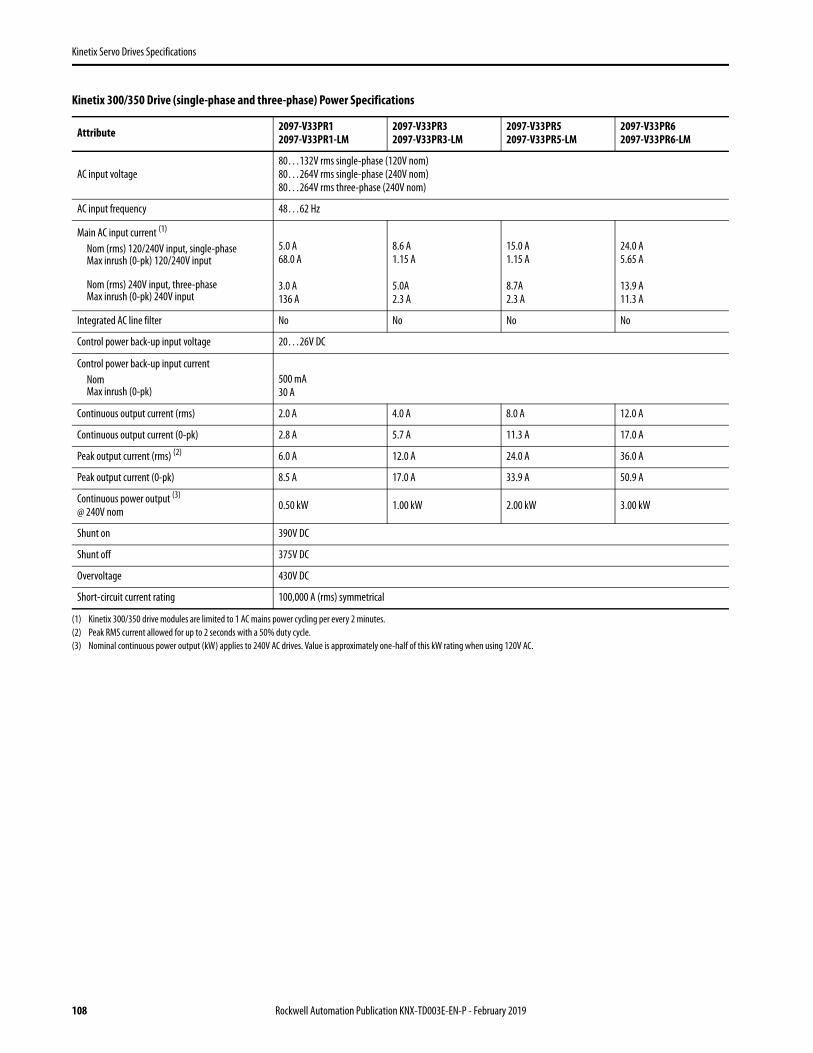
Kinetix Servo Drives Specifications
Kinetix 300/350 Drive (single-phase and three-phase) Power Specifications
Attribute 2097-V33PR12097-V33PR1-LM
2097-V33PR32097-V33PR3-LM
2097-V33PR52097-V33PR5-LM
2097-V33PR62097-V33PR6-LM
AC input voltage80…132V rms single-phase (120V nom)80…264V rms single-phase (240V nom)80…264V rms three-phase (240V nom)
AC input frequency 48…62 Hz
Main AC input current (1)
Nom (rms) 120/240V input, single-phaseMax inrush (0-pk) 120/240V input
Nom (rms) 240V input, three-phaseMax inrush (0-pk) 240V input
(1) Kinetix 300/350 drive modules are limited to 1 AC mains power cycling per every 2 minutes.
5.0 A68.0 A
3.0 A136 A
8.6 A1.15 A
5.0A2.3 A
15.0 A1.15 A
8.7A2.3 A
24.0 A5.65 A
13.9 A11.3 A
Integrated AC line filter No No No No
Control power back-up input voltage 20…26V DC
Control power back-up input currentNomMax inrush (0-pk)
500 mA30 A
Continuous output current (rms) 2.0 A 4.0 A 8.0 A 12.0 A
Continuous output current (0-pk) 2.8 A 5.7 A 11.3 A 17.0 A
Peak output current (rms) (2)
(2) Peak RMS current allowed for up to 2 seconds with a 50% duty cycle.
6.0 A 12.0 A 24.0 A 36.0 A
Peak output current (0-pk) 8.5 A 17.0 A 33.9 A 50.9 A
Continuous power output (3)
@ 240V nom
(3) Nominal continuous power output (kW) applies to 240V AC drives. Value is approximately one-half of this kW rating when using 120V AC.
0.50 kW 1.00 kW 2.00 kW 3.00 kW
Shunt on 390V DC
Shunt off 375V DC
Overvoltage 430V DC
Short-circuit current rating 100,000 A (rms) symmetrical
108 Rockwell Automation Publication KNX-TD003E-EN-P - February 2019

Kinetix Servo Drives Specifications
Kinetix 300/350 Drive (three-phase) Power Specifications
Circuit Breaker/Fuse Specifications
Kinetix 300 and Kinetix 350 servo drives use internal solid-state motor short-circuit protection and, when protected by suitable branch circuit protection, are rated for use on a circuit capable of delivering up to 100,000 A (fuses) and 65,000 A (circuit breakers). These fuses and Allen-Bradley circuit breakers are recommended for use with 2097-VxxPRx-xx drives.
Attribute 2097-V34PR32097-V34PR3-LM
2097-V34PR52097-V34PR5-LM
2097-V34PR62097-V34PR6-LM
AC input voltage 320…528V rms three-phase (480V nom)
AC input frequency 48…62 Hz
Main AC input current (1)
Nom (rms)Max inrush (0-pk)
(1) Kinetix 300/350 drive modules are limited to 1 AC mains power cycling per every 2 minutes.
2.7 A4.5 A
5.5 A4.5 A
7.9 A22.6 A
Integrated AC line filter No No No
Control power back-up input voltage 20…26V DC
Control power back-up input currentNomMax inrush (0-pk)
500 mA30 A
Continuous output current (rms) 2.0 A 4.0 A 6.0 A
Continuous output current (0-pk) 2.8 A 5.7 A 8.5 A
Peak output current (rms) (2)
(2) Peak RMS current allowed for up to 2 seconds with a 50% duty cycle.
6.0 A 12.0 A 18.0 A
Peak output current (0-pk) 8.5 A 17.0 A 25.5 A
Continuous power output@ 480V nom 1.00 kW 2.00 kW 3.00 kW
Shunt on 780V DC
Shunt off 750V DC
Overvoltage 850V DC
Short-circuit current rating 100,000 A (rms) symmetrical
Input Power UL Circuit-protection Specifications
Kinetix 300 and Kinetix 350 Drives UL Applications
Drive Cat. No. Drive Voltage Phase Fuses (Bussmann)Cat. No.
Miniature CB (1) (3)
Cat. No.Motor Protection CB, (1) (2) (3)
Self-protected CMCCat. No.
2097-V31PR0-xx120V Single-phase (voltage doubler) KTK-R-20 (20A) 1489-M1C200 140M-D8E-C20
120/240V Single-phase KTK-R-10 (10A) 1489-M1C100 140M-C2E-C10
2097-V31PR2-xx120V Single-phase (voltage doubler) KTK-R-30 (30A) 1489-M1C300 140M-F8E-C32
120/240V Single-phase KTK-R-20 (20A) 1489-M1C200 140M-D8E-C20
2097-V32PR0-xx
240V Single-phase
KTK-R-20 (20A) 1489-M1C150 140M-D8E-C16
2097-V32PR2-xx KTK-R-20 (20A) 1489-M1C200 140M-D8E-C20
2097-V32PR4-xx KTK-R-30 (30A) 1489-M1C300 140M-F8E-C32
Rockwell Automation Publication KNX-TD003E-EN-P - February 2019 109

Kinetix Servo Drives Specifications
Input Power IEC (non-UL) Circuit-protection Specifications
2097-V33PR1-xx120/240V Single-phase KTK-R-20 (20A) 1489-M1C200 140M-D8E-C20
240V Three-phase KTK-R-15 (15A) 1489-M3C150 140M-D8E-C16
2097-V33PR3-xx120/240V Single-phase KTK-R-20 (20A) 1489-M1C200 140M-D8E-C20
240V Three-phase KTK-R-15 (15A) 1489-M3C150 140M-D8E-C16
2097-V33PR5-xx120/240V Single-phase KTK-R-30 (30A) 1489-M1C300 140M-F8E-C32
240V Three-phase KTK-R-20 (20A) 1489-M3C200 140M-D8E-C20
2097-V33PR6-xx120/240V Single-phase LPJ-40SP (40A) Class J N/A
140M-F8E-C32240V Three-phase KTK-R-30 (30A) 1489-M3C300
2097-V34PR3-xx
480V Three-phase
KTK-R-10 (10A) 1489-M3C100 140M-C2E-C10
2097-V34PR5-xx KTK-R-10 (10A) 1489-M3C100 140M-C2E-C10
2097-V34PR6-xx KTK-R-20 (20A) 1489-M3C200 140M-D8E-C20
(1) Bulletin 1492 and 1489 circuit protection devices have lower short-circuit current ratings than Bulletin 140M devices. Refer to http://ab.rockwellautomation.com/allenbradley/productdirectory.page? for product literature with specific short-circuit ratings.
(2) For UL applications, Bulletin 140M devices are applied as self-protected combination motor controllers.(3) These Bulletin 140M circuit breakers, when used as self-protected (Type E) devices, and Bulletin 1489 circuit breakers can be used on only WYE power systems (480Y/277V).
Kinetix 300 and Kinetix 350 Drives IEC (non-UL) Applications
Drive Cat. No. Drive Voltage Phase Miniature CB (1)
Cat. No.Motor Protection CB (1)
Cat. No.
2097-V31PR0-xx120V Single-phase (voltage doubler) 1489-M1C200 1492-SPM1D200 140M-D8E-C20
120/240V Single-phase 1489-M1C100 1492-SPM1D100 140M-C2E-C10
2097-V31PR2-xx120V Single-phase (voltage doubler) 1489-M1C300 1492-SPM1D300 140M-F8E-C32
120/240V Single-phase 1489-M1C200 1492-SPM1D200 140M-D8E-C20
2097-V32PR0-xx
240V Single-phase
1489-M1C150 1492-SPM1D150 140M-D8E-C16
2097-V32PR2-xx 1489-M1C200 1492-SPM1D200 140M-D8E-C20
2097-V32PR4-xx 1489-M1C300 1492-SPM1D320 140M-F8E-C32
2097-V33PR1-xx120/240V Single-phase 1489-M1C200 1492-SPM1D200 140M-D8E-C20
240V Three-phase 1489-M3C150 1492-SPM3D150 140M-D8E-C16
2097-V33PR3-xx120/240V Single-phase 1489-M1C200 1492-SPM1D200 140M-D8E-C20
240V Three-phase 1489-M3C150 1492-SPM3D150 140M-D8E-C16
2097-V33PR5-xx120/240V Single-phase 1489-M1C300 1492-SPM1D300 140M-F8E-C32
240V Three-phase 1489-M3C200 1492-SPM3D200 140M-D8E-C20
2097-V33PR6-xx120/240V Single-phase N/A N/A
140M-F8E-C32240V Three-phase 1489-M3C300 1492-SPM3D300
2097-V34PR3-xx
480V Three-phase
1489-M3C100 1492-SPM3D100 140M-C2E-C10
2097-V34PR5-xx 1489-M3C100 1492-SPM3D100 140M-C2E-C10
2097-V34PR6-xx 1489-M3C200 1492-SPM3D200 140M-D8E-C20
Input Power UL Circuit-protection Specifications (continued)
Kinetix 300 and Kinetix 350 Drives UL Applications
Drive Cat. No. Drive Voltage Phase Fuses (Bussmann)Cat. No.
Miniature CB (1) (3)
Cat. No.Motor Protection CB, (1) (2) (3)
Self-protected CMCCat. No.
110 Rockwell Automation Publication KNX-TD003E-EN-P - February 2019

Kinetix Servo Drives Specifications
Contactor Ratings
Kinetix 300/350 Drives (120/240V)
Kinetix 300/350 Drives (240V)
Kinetix 300/350 Drives (480V)
Transformer Specifications for Control Input Power
Drive Cat. No. Drive Voltage AC Coil Contactor DC Coil Contactor
2097-V31PR0-xx120V 100-C23x10 100-C23Zx10
240V 100-C12x10 100-C12Zx10
2097-V31PR2-xx120V 100-C30x10 100-C30Zx10
240V 100-C23x10 100-C23Zx10
Drive Cat. No. Drive Voltage AC Coil Contactor DC Coil Contactor
2097-V32PR0-xx 240V 100-C23x10 100-C23Zx10
2097-V32PR2-xx 240V 100-C23x10 100-C23Zx10
2097-V32PR4-xx 240V 100-C30x10 100-C30Zx10
2097-V33PR1-xx120V 100-C23x10 100-C23Zx10
240V 100-C16x10 100-C16Zx10
2097-V33PR3-xx120V 100-C23x10 100-C23Zx10
240V 100-C16x10 100-C16Zx10
2097-V33PR5-xx120V 100-C30x10 100-C30Zx10
240V 100-C23x10 100-C23Zx10
2097-V33PR6-xx120V N/A N/A
240V 100-C30x10 100-C30Zx10
Drive Cat. No. Drive Voltage AC Coil Contactor DC Coil Contactor
2097-V34PR3-xx
480V
100-C12x10 100-C12Zx10
2097-V34PR5-xx 100-C12x10 100-C12Zx10
2097-V34PR6-xx 100-C23x10 100-C23Zx10
Attribute Value (400V-class system)
Input volt-amperes 750VA
Input voltage 460V AC
Output voltage 120…240V AC
Rockwell Automation Publication KNX-TD003E-EN-P - February 2019 111

Kinetix Servo Drives Specifications
Power Dissipation Specifications
Use this table to size an enclosure and calculate required ventilation for your Kinetix 300/350 drive system.
Weight Specifications
Maximum Feedback Cable Lengths
Although motor power and feedback cables are available in standard lengths up to 90 m (295.3 ft), Kinetix 300/350 drive maximum feedback cable length is 20 m (65.6 ft). These tables assume the use of recommended cables as shown in the Kinetix Motion Accessories Technical Data, publication KNX-TD004.
Drive Cat. No.Loss, maxW
Drive Cat. No.Loss, maxW
2097-V31PRO-xx 28 2097-V33PR3-xx 39
2097-V31PR2-xx 39 2097-V33PR5-xx 67
2097-V32PRO-xx 28 2097-V33PR6-xx 117
2097-V32PR2-xx 39 2097-V34PR3-xx 39
2097-V32PR4-xx 67 2097-V34PR5-xx 58
2097-V33PR1-xx 28 2097-V34PR6-xx 99
Drive Cat. No.Weight, approxkg (lb)
Drive Cat. No.Weight, approxkg (lb)
2097-V31PRO-xx 1.3 (2.9) 2097-V33PR3-xx 1.5 (3.3)
2097-V31PR2-xx 1.5 (3.3) 2097-V33PR5-xx 2.0 (4.4)
2097-V32PRO-xx 1.4 (3.1) 2097-V33PR6-xx 1.9 (4.2)
2097-V32PR2-xx 1.7 (3.7) 2097-V34PR3-xx 1.5 (3.3)
2097-V32PR4-xx 2.2 (4.9) 2097-V34PR5-xx 2.0 (4.4)
2097-V33PR1-xx 1.3 (2.9) 2097-V34PR6-xx 1.8 (4.0)
Cable Lengths for Compatible Rotary Motors
Motor Cat. No.Absolute High-resolution (5V) Encoderm (ft)
Absolute High-resolution (9V) Encoderm (ft)
Incremental/TTL (5V) Encoderm (ft)
Absolute High-resolution (5V) 17-bit Encoderm (ft)
MPL-A3xxx…MPL-A5xxx-S/M (1) 20 (65.6)
MPL-A15xxx…MPL-A2xxx-E/V 20 (65.6)
MPL-B3xxx…MPL-B9xxx-S/M 20 (65.6)
MPL-B15xxx…MPL-B2xxx-E/V 20 (65.6)
MPL-A/B15xxx…MPL-A/B45xxx-H 20 (65.6)
MPM-Axxxxx-S/M 20 (65.6)
MPM-Bxxxxx-S/M 20 (65.6)
MPF-Axxxx-S/M (1) 20 (65.6)
112 Rockwell Automation Publication KNX-TD003E-EN-P - February 2019

Kinetix Servo Drives Specifications
Cable Lengths for Compatible Linear Actuators
Cable Lengths for Compatible Linear Motors
MPF-Bxxxx-S/M 20 (65.6)
MPS-Axxxx-S/M 20 (65.6)
MPS-Bxxxx-S/M 20 (65.6)
TLY-Axxxx-B 20 (65.6)
TLY-Axxxx-H 20 (65.6)
(1) MPL-A5xxx and MPF-A5xxx motor encoders are rated for 9V, the remaining Bulletin MPL and MPF (200V-class) motor encoders are rated for 5V.
Actuator Cat. No.Absolute High-resolution (5V) Encoderm (ft)
Absolute High-resolution (9V) Encoderm (ft)
Incremental/TTL (5V) Encoderm (ft)
Absolute High-resolution (5V) 17-bit Encoderm (ft)
MPMA-Axxxxx or MPAS-Axxxxx-V (ballscrew) 20 (65.6)
MPMA-Axxxxx or MPAS-Axxxxx-A (direct drive) 20 (65.6)
MPMA-Bxxxxx or MPAS-Bxxxxx-V (ballscrew) 20 (65.6)
MPMA-Bxxxxx or MPAS-Bxxxxx-A (direct drive) 20 (65.6)
MPAR-Axxxxx-V/M 20 (65.6)
MPAR-Bxxxxx-V/M 20 (65.6)
MPAI-AxxxxxM3 20 (65.6)
MPAI-BxxxxxM3 20 (65.6)
LDAT-Sxxxxxx-xDx 20 (65.6)
LDAT-Sxxxxxx-xBx 20 (65.6)
Motor Cat. No.Absolute High-resolution (5V) Encoderm (ft)
Incremental/TTL (5V) Encoderm (ft)
LDC-Series or LDL-Series 20 (65.6) 20 (65.6)
Cable Lengths for Compatible Rotary Motors (continued)
Motor Cat. No.Absolute High-resolution (5V) Encoderm (ft)
Absolute High-resolution (9V) Encoderm (ft)
Incremental/TTL (5V) Encoderm (ft)
Absolute High-resolution (5V) 17-bit Encoderm (ft)
Rockwell Automation Publication KNX-TD003E-EN-P - February 2019 113

Kinetix Servo Drives Specifications
Dimensions - Kinetix 300 and Kinetix 350 Servo Drives
(1) Use the LDAT-CONKIT-ABS connector kit with added circuitry for Kinetix 300 drives and LDAT-Series linear thrusters with absolute high-resolution encoders. Both kits have the same physical dimensions.
Kinetix 300/350 Drive Dimensions
Environmental Specifications - Kinetix 300 and Kinetix 350 Servo Drives
Cat. No.Amm (in.)
Bmm (in.)
Cat. No.Amm (in.)
Bmm (in.)
2097-V31PR0-xx 185 (7.29) 68.0 (2.68) 2097-V33PR3-xx 185 (7.29) 69.0 (2.70)
2097-V31PR2-xx 185 (7.29) 69.0 (2.70) 2097-V33PR5-xx 185 (7.29) 94.0 (3.72)
2097-V32PR0-xx 230 (9.04) 68.0 (2.68) 2097-V33PR6-xx 230 (9.04) 68.0 (2.68)
2097-V32PR2-xx 230 (9.04) 69.0 (2.70) 2097-V34PR3-xx 185 (7.29) 69.0 (2.70)
2097-V32PR4-xx 230 (9.04) 87.0 (3.42) 2097-V34PR5-xx 185 (7.29) 94.0 (3.72)
2097-V33PR1-xx 185 (7.29) 68.0 (2.68) 2097-V34PR6-xx 230 (9.04) 68.0 (2.68)
Attribute Operational Range Storage Range (nonoperating)
Temperature, ambient 0…40 °C (32…104 °F) -10…+70 °C (14…158 °F)
Relative humidity 5…95% noncondensing 5…95% noncondensing
Altitude Derate by 1% per 300 m (1000 ft) above 1500 m (5000 ft) 3000 m (9842 ft) during transport
Vibration 5…2000 Hz @ 2.5 g peak, 0.015 mm (0.0006 in.) displacement, max
Shock 15 g, 11 ms half-sine pulse (3 pulses in each direction of 3 mutually perpendicular directions)
11.8(0.46)
6.6(0.26)
7.1(0.28)
B
38.1 (1.5)
182(7.18)
190(7.50)
30.8(1.21)
Ø 4.57(0.18) 3x
03 0
A
238(9.37)
9.7(0.38)
5.0(0.19)
0
61.0(2.40)
Dimensions are in mm (in.).
Additional clearance below the connector kit is necessary to provide the recommended cable bend radius.
2090-K2CK-D15M (1)
Low-profile Connector Kit forBulletin 2090 (flying-lead)
Feedback Cable
2097-Vxxxxx-xx Servo Drive
2097-TB1I/O Terminal
Expansion Block
114 Rockwell Automation Publication KNX-TD003E-EN-P - February 2019

Kinetix Servo Drives Specifications
Certifications - Kinetix 300 and Kinetix 350 Servo Drives
Accessories - Kinetix 300 and Kinetix 350 Servo Drives
Kinetix 300/350 drive accessories include the I/O terminal block, memory module programmer, memory modules, ABS connector kit, AC line filters, shunt resistors, and the encoder output module.
I/O Terminal Expansion Block
The 2097-TB1 I/O terminal expansion block is a drive-mounted breakout board for making flying-lead cable connections to the 50-pin IOD connector.
2097-TB1 I/O Terminal Block Specifications
Agency Certification (1)
(when product is marked)
(1) See rok.auto/certifications for declarations of conformity, certificates, and other certification details.
Standards
c-UL-us (2)
(2) UL has not evaluated the Safe Torque Off option in these products.
UL Listed to U.S. and Canadian safety standards (UL 508 C File E59272).
Solid-state motor overload protection provides dynamic fold-back of motor current when 110% of the motor rating is reached with a peak current limit based on the peak rating of the motor as investigated by UL to comply with UL 508C (UL File E59272).
CE
European Union 2004/108/EC EMC Directive compliant with IEC 61800-3:2004 + A1:2012: Adjustable Speed Electrical Power Drive Systems - Part 3; EMC Product Standard including specific test methods.
European Union 2006/95/EC Low Voltage Directive compliant with:• IEC 61800-5-1:2007 - Adjustable speed electrical power drive systems.• IEC 50178:1997 - Electronic Equipment for use in Power Installations.
Functional SafetyTÜV certified for functional safety: up to Performance Level (PL) d, Category 3 according to ISO 13849; up to SIL CL2 according to IEC 61508, IEC 61800-5-2, and IEC 62061 when used as described in the Kinetix 300 EtherNet/IP Indexing Servo Drives User Manual, publication 2097-UM001 and the Kinetix 350 Single-axis EtherNet/IP Servo Drives User Manual, publication 2097-UM002.
C-Tick
Australian Radiocommunications Act, compliant with:• Radiocommunications Act: 1992• Radiocommunications (Electromagnetic Compatibility) Standard: 1998• Radiocommunications (Compliance Labelling - Incidental Emissions) Notice: 1998• AS/NZS CISPR 11: 2002 (Group 1, Class A)
KCKorean Registration of Broadcasting and Communications Equipment, compliant with:• Article 58-2 of Radio Waves Act, Clause 3• Registration number: KCC-REM-RAA-2097
ODVA EtherNet/IP conformance tested (applies to Kinetix 350 servo drives).
Attribute Value
Wire size 1.5…0.2 mm2 (16…24 AWG)
Change in depth of drive (1) 11 mm (0.42 in.)
Change in width of drive (1)
(1) Add this value to the dimensions of your Kinetix 300 drive.
10 mm (0.38 in.)
Kinetix 300/350Drive
2097-TB1 TerminalExpansion Block 50-pin I/O (IOD)
Connector
Rockwell Automation Publication KNX-TD003E-EN-P - February 2019 115

Kinetix Servo Drives Specifications
Memory Module Programmer
The 2097-PGMR memory module programmer is a hand-held device for duplicating your Kinetix 300/350 drive configuration to reduce down-time and troubleshooting.
2097-PGMR Memory Module Programmer Specifications
Memory Module 12-packs
The 2097-MEM memory modules use EEPROM technology in a plastic casing for protection and ruggedness to safe-guard your Kinetix 300/350 drive configuration.
Use the 2097-MEM memory modules to back up your drive configuration for easy Automatic Device Replacement (ADR).
Connector Kit for Absolute Encoders
Use the LDAT-CONKIT-ABS connector kit on Kinetix 300 drives with LDAT-Series linear thrusters and absolute high-resolution encoders.
The LDAT-CONKIT-ABS connector kit has the same physical dimensions as catalog number 2090-K2CK-D15M, but contains added circuitry required for Kinetix 300 drives with absolute high-resolution encoders.
Attribute Value
DC supplyInternal batteries
+ 6V DC, min 150 mA supply
4 mono-cells (type D), 1.5V DC each
External power supply unit + 6V DC, 300 mA, stabilized
Display
Type LCD
Display format Text
Lines x characters 1 x 16
Contrast setting Via menu
Memory Data memory Up to 120 parameter files for inverter drive controllers
Serial interface DB9 connector RS-232
Weight 2097-PGMR 1.3 kg (2.87 lb), with batteries
4.0(0.16)
105(4.1)
76(3.0)
155(6.1)
Dimensions are in mm (in.)
2097-PGMR Memory Module Programmer
2097-MEM Memory Module
Front View Rear View
12
34
56
78
910
1112
1314
150
45(1.7)20
(0.8)
103(4.0)
61(2.4)
20(0.8)
Battery not required.
LDAT-CONKIT-ABS (15-pin) connector kit for absolute high-resolution encoder feedback.
116 Rockwell Automation Publication KNX-TD003E-EN-P - February 2019

Kinetix Servo Drives Specifications
AC Line Filters
The Kinetix 300/350 drives were tested by using recommended line filters. Use of these filters is also needed to meet CE requirements. The 2097-V32PR0-xx, 2097-V32PR2-xx, and 2097-V32PR4-xx drives have integrated AC line filters.
AC Line Filter Dimensions
2097-F1 and 2097-F2 side-mount line filters add 35.8 mm (1.41 in.) to the width of your drive.
2097-F4, 2097-F5, and 2097-F6 rear-mount line filters add 48 mm (1.89 in.) to the depth of your drive.
AC Line Filter Specifications
AC Line Filter Cat. No. Mount
Voltage50/60 Hz
PhaseCurrent A @ 40 °C (104 °F)
Power LossW
Leakage CurrentmA
Weight, approxkg (lb)
Kinetix 300/350 (2)
Drive Cat. No.
(2) Use 2090-UXLF-110 (single-phase) line filter for 2097-V31PR0-xx drive operation. Use 2090-XXLF-TC116 (single-phase) line filter for 2097-V31PR2-xx drive operation.
2097-F1Side
240V AC 1 24.0 5.2 9.00.6 (0.13)
2097-V33PR6-xx (3)
(3) Use 2097-F1 (single-phase) line filter for 2097-V33PR6-xx (single-phase) drive operation. Use the 2090-XXLF-TC316 (three-phase) line filter for 2097-V33PR6-xx (three-phase) drive operation.
2097-F2 480V AC 3 10.0 2.8 1.0 2097-V34PR6-xx
2097-F4 (1)
(1) This filter is rated for multiple voltage/phase line conditions.
Rear 240/480V AC 3
4.40 1.2
1.0 0.8 (0.18)
2097-V33PR1-xx (4)
(4) Use 2090-UXLF-106 (single-phase) line filter for 2097-V33PR1-xx (single-phase) drive operation.
2097-V34PR3-xx
2097-F5 (1) 6.90 1.32097-V34PR5-xx
2097-V33PR3-xx (5)
(5) Use 2090-UXLF-110 (single-phase) line filter for 2097-V33PR3-xx (single-phase) drive operation.
2097-F6 (1) 15.0 4.1 2097-V33PR5-xx (6)
(6) Use 2090-UXLF-123 (single-phase) line filter for 2097-V33PR5-xx (single-phase) drive operation.Refer to the Kinetix Motion Accessories Technical Data, publication KNX-TD004 for AC line filter specifications not listed here.
00300
35.8(1.41)
150(5.90)
166(6.52)
2097-F1 or 2097-F2 Side Mount
AC Line Filters
Kinetix 300/350Drive
Dimensions are in mm (in.)
This connector ships prewired to the AC line filter.
4.1(0.16)
219(8.62)
Ø 4.6 (0.18)
4.6(0.18)
68.6(2.70)
48.0(1.89)
38.1(1.50)
15.2(0.60)
211(8.31)
48.0(1.89)
2097-F4, 2097-F5, or 2097-F6 Rear Mount AC Line Filters
Kinetix 300/350Drive
Dimensions are in mm (in.)
This connector ships prewired to the AC line filter.
Rockwell Automation Publication KNX-TD003E-EN-P - February 2019 117

Kinetix Servo Drives Specifications
Shunt Resistor
The Bulletin 2097 passive shunt resistor wires directly to the Kinetix 300/350 drive.
Shunt Resistor Dimensions
Shunt Resistor Power Specifications
Encoder Output Module
The Allen-Bradley encoder output module (catalog number 2198-ABQE) is a DIN-rail mounted EtherNet/IP network-based standalone module capable of outputting encoder pulses to a customer-supplied peripheral device (cameras, for example, used in line-scan vision systems). The encoder output module supports real and virtual axes for systems using the integrated motion on EtherNet/IP network (Kinetix 350 drives). For more information, refer to Encoder Output Module on page 31.
Shunt Module Cat. No.
ResistanceW
Continuous PowerW
Peak PowerkW
Peak CurrentA
D_Application, max (1)
%
(1) D_Application is the application duty cycle in percent. For the intermittent regeneration applications, use D_Application = t/T, where t is the duration when regeneration is needed and T is the time interval between two regenerations. Both t and T must use the same time units, for example, seconds.
Weightkg (lb)
Kinetix 300/350Drive Cat. No.
2097-R2 20150
7.6 19.5 1.970.3 (0.7)
2097-V32PR4-xx2097-V33PR5-xx
2097-R3 30 5.1 13.0 2.96 2097-V33PR6-xx
2097-R4 40 80 3.8 9.8 2.10 0.2 (0.4)
2097-V31PR0-xx2097-V31PR2-xx2097-V32PR0-xx2097-V32PR2-xx2097-V33PR1-xx2097-V33PR3-xx
2097-R6 75 150 7.9 10.3 1.90 0.3 (0.7)2097-V34PR5-xx2097-V34PR6-xx
2097-R7 150 80 4.0 5.1 2.02 0.2 (0.4) 2097-V34PR3-xx
10.0(0.39
L2
12.0(0.47
4.3(0.17)
L3L1
41.0(1.6)
500(19.68)
10.0(0.39 12.0
(0.47
Dimensions are in mm (in.)
Shunt Resistor Cat. No. L1 L2 L3
2097-R2 210 (8.3) 197 (7.7) 170 (6.7)
2097-R3 210 (8.3) 197 (7.7) 170 (6.7)
2097-R4 150 (5.9) 137 (5.4) 110 (4.3)
2097-R6 210 (8.3) 197 (7.7) 170 (6.7)
2097-R7 150 (5.9) 137 (5.4) 110 (4.3)
Flying Leads
2.5 mm2
(14 AWG)
118 Rockwell Automation Publication KNX-TD003E-EN-P - February 2019

Kinetix Servo Drives Specifications
Kinetix 3 Component Servo Drives
The Kinetix 3 component servo drive provides a cost-effective motion control solution for smaller, low-axis count applications. By providing the ability to apply the appropriate level of control for the application along with download-able configuration software and automatic motor recognition, the Kinetix 3 servo drive delivers a motion solution that is easy to use at minimum cost. Its compact size and lower power ranges make it ideal for a variety of applications including indexing tables, medical manufacturing, laboratory automation equipment, and semiconductor processing.
Kinetix 3 Drive Features and Indicators
1
2
3
4
6
5
7
8
9
10
11
12
13
14
15Item Description
1 Left/right and up/down keys
2 Analog output (A.out) connector
3 RS-485 communication termination switch
4 Input power (IPD) connector
5 Main power status indicator
6 Shunt power (BC) connector
7 Motor power (MP) connector
8 Ground lug
9 Motor feedback (MF) connector
10 Input/output (IOD) connector
11 Serial interface (Comm0B) down
12 Serial interface (Comm0A) up
13 Enter key
14 Mode/set key
15 7-segment status indicator
Rockwell Automation Publication KNX-TD003E-EN-P - February 2019 119

Kinetix Servo Drives Specifications
Technical Specifications - Kinetix 3 Component Servo Drives
Kinetix 3 Servo Drive Power Specifications
Attribute 2071-AP0 2071-AP1 2071-AP2 2071-AP4 2071-AP8 2071-A10 2071-A15
AC input voltage 170…264V rms
AC input phase Single-phase Three-phase/Single-phase Three-phase
AC input frequency 47…63 Hz
Mains AC input current (1)
Nom (rms) Max inrush (0-pk)
(1) Kinetix 3 drive modules are limited to 1 AC mains power cycling every 2 minutes.
1.30 A 2.38 A 3.68 A 7.14 A6.25 A (three-phase)10.52 A (single-phase) 8.75 A 12.37 A
21.9 A 22.6 A
Mains AC line loss ride through 20 ms
Nominal bus output voltage 311V DC
Bandwidth (2)
Velocity loopCurrent loop
(2) Bandwidth values vary based on tuning parameters and mechanical components.
550 Hz2000 Hz
PWM frequency 10 kHz
Control power AC input voltage 170…264V rms
Control power input currentNom (rms) Max inrush (0-pk)
0.1 A31 A
Continuous output current (rms) 0.61 A 1.11 A 1.72 A 3.33 A 5.05 A 7.07 A 9.90 A
Continuous output current (0-pk) 0.85 A 1.56 A 2.40 A 4.67 A 7.07 A 9.90 A 13.99 A
Peak output current (rms) 1.80 A 3.30 A 5.10 A 9.90 A 14.99 A 18.88 A 29.69 A
Peak output current (0-pk) 2.55 A 4.67 A 7.21 A 14.0 A 21.21 A 26.70 A 41.99 A
Continuous output power 50 W 100 W 200 W 400 W 800 W 1.0 kW 1.5 kW
Bus overvoltage 405V DC
Bus undervoltage 190V DC
Internal shunt resistor N/A 50 Ω 30 Ω
Internal shuntContinuous powerPeak power
N/AN/A
30 W300 W
70 W700 W
Shunt on 390V DC
Shunt off 380V DC
Efficiency 90%
Bus capacitance 390 μF 780 μF 1170 μF
Capacitive energy absorption 13 J 26 J 39 J
Short-circuit current rating 100,000 A (rms) symmetrical
120 Rockwell Automation Publication KNX-TD003E-EN-P - February 2019

Kinetix Servo Drives Specifications
Fuse/Contactor Specifications
Make sure the selected components are properly coordinated and meet acceptable codes including any requirements for branch circuit protection. The following fuse examples are recommended for use with Kinetix 3 drives.
Fuse and Contactor Specifications
Power Dissipation Specifications
Use this table to size an enclosure and calculate required ventilation for your Kinetix 3 drive system.
Drive Cat. No. AC Input Power (1) (2) (3)
Recommended Fuse
(1) Fuses specified are Bussmann fuses.(2) FNQ-R fuses are described as time-delay fuses, Class CC.(3) LPJ fuses are described as dual-element time-delay fuses, Class J.
Control Power (2) (4)
Recommended Fuse
(4) FRS-R fuses are described as dual-element time-delay fuses, Class RK5.
Contactor (5)
(5) For contactors: x represents coil voltage, y represents the number of contacts.
2071-AP0
FNQ-R-7
FRS-R-2-1/2 FNQ-R-7-1/2 LPJ-6
100-K05xy 2071-AP1
2071-AP2 100-K09xy
2071-AP2 FNQ -R-10 100-K12xy
2071-AP8 FNQ-R-20 LPJ-20 100-C16xy
2071-A10
2071- A15 FNQ-R-30LPJ-30 100-C23xy
Drive Cat. No.Usage as % of Rated Power Output
(watts)
20% 40% 60% 80% 100%
2071-AP0 19.3 20.0 20.6 21.3 22.0
2071-AP1 20.1 21.6 23.1 24.6 26.2
2071-AP2 21.7 24.6 27.6 30.6 33.7
2071-AP4 25.6 31.9 38.4 45.2 52.2
2071-AP8 26.4 32.3 38.6 45.1 52.0
2071-A10 30.9 40.2 50.1 60.5 71.5
2071-A15 37.4 50.1 63.8 78.4 93.9
Rockwell Automation Publication KNX-TD003E-EN-P - February 2019 121

Kinetix Servo Drives Specifications
Weight Specifications
Maximum Feedback Cable Lengths
Although motor power and feedback cables are available in standard lengths up to 90 m (295.3 ft), Kinetix 3 drive maximum feedback cable length is 30 m (98.4 ft). These tables assume the use of recommended cables as shown in the Kinetix Motion Accessories Technical Data, publication KNX-TD004.
Maximum Cable Lengths for Compatible Motors and Actuators
Drive Cat. No.Weight, approxkg (lb)
2071-AP0 0.70 (1.5)
2071-AP10.75 (1.6)
2071-AP2
2071-AP4 1.0 (2.2)
2071-AP8
1.75 (3.9)2071-A10
2071-A15
Rotary Motor Cat. No.Incremental/TTL (5V) Encoderm (ft)
Absolute High-resolution (5V) 17-bit Encoderm (ft)
TL-Axxxx-B30 (98.4)
TLY-Axxxx-B
TLY-Axxxx-H 30 (98.4)
Actuator Cat. No.Incremental/TTL (5V) Encoderm (ft)
Absolute High-resolution (5V) 17-bit Encoderm (ft)
MPAS-Axxxx (direct drive) 30 (98.4)
LDAT-Sxxxxxx-xBx 30 (98.4)
Linear Motor Cat. No.Incremental/TTL (5V) Encoderm (ft)
LDC-Series or LDL-Series 30 (98.4)
122 Rockwell Automation Publication KNX-TD003E-EN-P - February 2019

Kinetix Servo Drives Specifications
Dimensions - Kinetix 3 Component Servo Drives
Kinetix 3 Drive Dimensions
Drive Cat. No.Amm (in.)
Bmm (in.)
Cmm (in.)
Dmm (in.)
2071-AP0
153(6.04)
141(5.55)
48.3(1.90)
53.0(2.09)2071-AP1
2071-AP2
2071-AP4 58.0(2.29)
2071-AP8198(7.82)
186(7.33)
59.0(2.32)
81.0(3.19)2071-A10
2071-A15
5.0(0.20)
155(6.11)
145(5.70)
A
B
D
5.0(0.20)
50.01.97
C
29.0(1.14)
32.0(1.26)
Dimensions are in mm (in.)
2071-AP0 drive is shown.
Mounting hole (top) and slot (bottom) require:M4 x 10 bolts (catalog numbers 2071-AP0, 2071-AP1, 2071-AP2, and 2071-AP4)M5 x 10 bolts (catalog numbers 2071-AP8, 2071-A10, 2071-A15)
Chassis Ground Terminals(2071-AP4, 2071-AP8, 2071-A10, 2071-A15 models include two terminal screws)
Chassis GroundTerminals
2071-TBIO I/O Breakout Board
2071-TBMF Motor Feedback Breakout Board for Bulletin 2090
Rockwell Automation Publication KNX-TD003E-EN-P - February 2019 123

Kinetix Servo Drives Specifications
Environmental Specifications - Kinetix 3 Component Servo Drives
Certifications - Kinetix 3 Component Servo Drives
Attribute Operational Range Storage Range (nonoperating)
Temperature, ambient 0…50 °C (32…122 °F) -25…+85 °C (-13…+185 °F)
Relative humidity 5…95% noncondensing 5…95% noncondensing
Altitude 1000 m (3281 ft) 3000 m (9843) with derating 3000 m (9843 ft) during transport
Vibration 5…55 Hz @ 0.35 mm (0.014 in.) double amplitude, continuous displacement; 55…500 Hz @ 2.0 g peak constant acceleration (10 sweeps in each of 3 mutually perpendicular directions)
Shock 15 g, 11 ms half-sine pulse (3 pulses in each direction of 3 mutually perpendicular directions)
Agency Certification (1)
(when product is marked)
(1) See rok.auto/certifications for declarations of conformity, certificates, and other certification details.
Standards
c-UL-us
UL Listed to U.S. and Canadian safety standards (UL 508 C File E59272).
This drive provides integral solid-state short-circuit protection, but does not provide branch circuit protection. Branch circuit protection must be provided in accordance with the National Electrical Code and any additional local codes. This drive provides solid-state motor overload protection that is adjustable. Refer to the Kinetix 3 Component Servo Drives User Manual, publication 2071-UM001, for more information.
CEEuropean Union 2004/108/EC EMC Directive compliant with IEC 61800-3:2004 + A1:2012: Adjustable Speed Electrical Power Drive Systems - Part 3; EMC Product Standard including specific test methods.
European Union 2006/95/EC Low Voltage Directive compliant with IEC 61800-5-1:2007 - Adjustable Speed Electrical Power Drive Systems.
C-Tick
Australian Radiocommunications Act, compliant with:• Radiocommunications Act: 1992• Radiocommunications (Electromagnetic Compatibility) Standard: 1998• Radiocommunications (Compliance Labelling - Incidental Emissions) Notice: 1998• AS/NZS CISPR 11: 2002 (Group 2, Class A)
KC
Korean Registration of Broadcasting and Communications Equipment, compliant with:• Article 58-2 of Radio Waves Act, Clause 3• Registration number: KCC-REM-RAA-2071-A15• Registration number: KCC-REM-RAA-2071-AP4
124 Rockwell Automation Publication KNX-TD003E-EN-P - February 2019

Kinetix Servo Drives Specifications
Accessories - Kinetix 3 Component Drives
Kinetix 3 drive accessories include drive-mounted 20-pin and 50-pin breakout boards for making flying-lead motor feedback and I/O connections. For control and configuration serial interface cable specifications, refer to the Kinetix Motion Accessories Technical Data, publication KNX-TD004.
Motor Feedback Breakout Board
Use the 2071-TBMF breakout board with 2090-CFBM6DF-CBAAxx flying-lead feedback cables or when your motor or actuator has high-resolution encoder feedback.
Motor Feedback Breakout Board Specifications
The customer-supplied 3.6V lithium battery, when installed in a motor feedback breakout board, provides multi-turn encoder operation to TL-Series™ (Bulletin TL and TLY) motors.
Battery Specifications
I/O Breakout Board
Use the 2071-TBIO breakout board for making flying-lead cable connections to twenty-four of the most commonly used terminals in the 50-pin IOD connector.
I/O Breakout Board Specifications
Attribute Value
Wire size 1.5…0.2 mm2 (16…24 AWG)
Change in depth of drive (1)
(1) Add this value to the dimensions of your Kinetix 3 drive. Refer to Dimensions - Kinetix 3 Component Servo Drives on page 123.
29 mm (1.14 in.)
Change in height of drive (1) 32 mm (1.26 in.)
Attribute Value
International size reference 1/2AA, ER14252
Capacity, nom @ 0.5 mA, to 2V 1.2 Ah
Rated voltage 3.6V
Recommended continuous current, max 50 mA
Attribute Value
Wire size 1.5…0.2 mm2 (16…24 AWG)
Change in depth of drive (1)
(1) Add this value to the dimensions of your Kinetix 3 drive. Refer to Dimensions - Kinetix 3 Component Servo Drives on page 123.
29 mm (1.14 in.)
52.0(2.05)
48.0(1.89)
18.0(0.71)
70.0(2.75)
48.0(1.89)
18.0(0.71)
Kinetix 3 Drive
20-pin Motor FeedbackBreakout Board
50-pin I/OBreakout Board
Battery
Dimensions are in mm (in.)
Kinetix 3 Drive
Rockwell Automation Publication KNX-TD003E-EN-P - February 2019 125

Kinetix Servo Drives Specifications
Kinetix 2000 Multi-axis Servo Drives
Extend the benefits of Kinetix Integrated Motion to low-power motion control applications with the Kinetix 2000 servo drive. This multi-axis servo drive provides simplicity at its best, letting you save time and money from initial wiring and programming to operation and diagnostics. With a continuous output current (rms) from 1.0…9.5 amps, the Kinetix 2000 drive offers the same compact design, exceptional performance, and cost saving features as the Kinetix 6000 drives. The commonality among Kinetix drives lets you learn once and reuse your product knowledge. Paired with the CompactLogix 1768-L4x controller, the Kinetix 2000 drive is ideal for small and mid-sized applications looking to improve productivity, quality, and time to market while reducing the total cost of ownership.
The Kinetix 2000 servo drives provide Integrated Motion capability through the sercos interface and are part of the Kinetix Integrated Motion solution.
Kinetix 2000 Features and Indicators
2093-AC05-MPx IAM Features and Indicators
1 2
1 2
3 4
1 2 3 4 5 61 2
1 2
3 4
5
67 8
9
111213
3
2
1
17
16
15
14
10
4
Integrated Axis Module(2093-AC05-MPx front view)
Item Description
1 DC Bus / AC input power (IPD) connector
2 Control power (CPD) connector
3 Contactor enable (CED) connector
4 Sercos communication rate and optical power switches
5 Sercos node address switch
6 DPI connector (facing up)
7 Mounting screw
8 Sercos receive (Rx) connector
9 Sercos transmit (Tx) connector
10 Seven-segment fault status indicator
11 Drive status indicator
12 COMM status indicator
13 Bus status indicator
14 I/O and auxiliary feedback (IOD/AF) connector
15 Motor feedback (MF) connector
16 Motor power (MP) connector
17 Motor brake (BC) connector
126 Rockwell Automation Publication KNX-TD003E-EN-P - February 2019

Kinetix Servo Drives Specifications
2093-AMxx AM Features and Indicators
2093-ASP06 Shunt Module Features and Indicators
1 2
3 4
1 2
3 4
45
6
89
102
1
12
11
73
Axis Module(2093-AMxx front view)
Item Description
1 Motor power (MP) connector
2 Motor brake (BC) connector
3 Sercos communication rate and optical power switches
4 Sercos receive (Rx) connector
5 Mounting screw
6 Sercos transmit (Tx) connector
7 Seven-segment fault status indicator
8 Drive status indicator
9 COMM status indicator
10 Bus status indicator
11 I/O and auxiliary feedback (IOD/AF) connector
12 Motor feedback (MF) connector
1 2
1 2
3
2
1
456
3
Shunt Module(2093-ASP06 front view)
Item Description
1 External shunt resistor (RC) connector
2 External thermal switch (TS) connector
3 Mounting screw
4 Shunt fault status indicator
5 Over-temp fault status indicator
6 Bus status indicator
Rockwell Automation Publication KNX-TD003E-EN-P - February 2019 127

Kinetix Servo Drives Specifications
Technical Specifications - Kinetix 2000 Multi-axis Servo Drives
The converter section of these modules is identical. Select your IAM module based on the inverter requirements of your application.
IAM Module (three-phase and single-phase) Power Specifications
Attribute 2093-AC05-MPxThree-phase Input (230V nom)
2093-AC05-MPxSingle-phase Input (230V nom)
AC input voltage 170…264V rms
AC input frequency 47…63 Hz
Main AC input current (1)
Nom (rms)Max inrush (0-pk)
(1) All 2093-AC05 integrated axis modules are limited to 2 contactor cycles per minute (with up to 4 axis modules), or 1 contactor cycle per minute (with 5…8 axis modules).
11.66 A34.0 A
10.95 A34.0 A
DC input voltage (common bus follower) 240…375V DC
DC input current (common bus follower) 9.76 A 6.42 A
Control power AC input voltage 170…264V rms, single-phase (230V nom)
Control power AC input currentNom (@ 230V AC) rmsMax inrush (0-pk)
1.25 A93.0 A (3)
(3) Maximum inrush duration is less than 1/2 line cycle.
Nominal bus output voltage 325V DC
Line loss ride through 20 ms
Continuous output current to bus (ADC) 9.67 A 6.42 A
Peak output current to bus (ADC) (2)
(2) Peak output current duration equals 250 ms.
19.34 A 12.84 A
Bus overvoltage 415V DC
Bus undervoltage 135.5V DC
Internal shuntContinuous powerPeak power
15 W3000 W
Internal shunt resistor 50 Ω
Shunt on 405V
Shunt off 375V
Continuous power output to bus 3.0 kW 2.0 kW
Peak power output 6.0 kW 4.0 kW
Efficiency 95%
Converter inductance N/A
Converter capacitance 540 μF
Converter leakage current (max) 2.0 mA
128 Rockwell Automation Publication KNX-TD003E-EN-P - February 2019

Kinetix Servo Drives Specifications
Control Power Current Requirements
These specifications apply to the axis module specified in the column heading by catalog number and the same axis module (inverter section) that resides within an integrated axis module.
AM Module Power Specifications
Modules on Power Rail220/230V AC InputA
Input VAVA
IAM only 0.15 50
IAM, 1 AM 0.30 99
IAM, 2 AM 0.45 148
IAM, 3 AM 0.60 197
IAM, 4 AM 0.75 247
IAM, 5 AM 0.90 296
IAM, 6 AM 1.05 345
IAM, 7 AM 1.20 395
IAM, 7 AM, 1 Shunt module 1.25 410
Attribute2093-AMP1(2093-AC05-MP1)
2093-AMP2(2093-AC05-MP2)
2093-AMP5(2093-AC05-MP5)
2093-AM01 2093-AM02
Bandwidth (1)
Velocity LoopCurrent Loop
(1) Bandwidth values vary based on tuning parameters and mechanical components.
500 Hz1300 Hz
PWM frequency 8 kHz
Nominal input voltage 325V DC
Continuous current (rms) 1.0 A 2.0 A 3.0 A 6.0 A 9.5 A
Continuous current (0-pk) 1.41 A 2.83 A 4.24 A 8.48 A 13.4 A
Peak current (rms) 3.0 A 6.0 A 9.0 A 18.0 A 28.5 A
Peak current (0-pk) 4.20 A 8.48 A 12.7 A 25.5 A 40.3 A
Peak output current time (max) 3 s from 0% drive utilization (0% soak)
Continuous power out (nom) 0.3 kW 0.6 kW 0.9 kW 1.9 kW 3.0 kW
Efficiency 98%
Capacitance 200 μF 540 μF
Capacitive energy absorption 7.5 J 20 J
Inverter PCB leakage current 1 mA
Rockwell Automation Publication KNX-TD003E-EN-P - February 2019 129

Kinetix Servo Drives Specifications
Circuit Breaker/Fuse Specifications
The following fuse examples and Allen-Bradley circuit breakers are recommended for control power and DC-bus power.
Control and DC-Bus Circuit-protection Specifications
These fuses and Allen-Bradley circuit breakers are recommended for use with 2093-ACxx-MPx IAM modules when the line interface (LIM) module is not used.
Input Power Circuit-protection Specifications
Contactor Ratings
This table lists the recommended contactor ratings for IAM modules installed without a LIM module.
Kinetix 2000 DrivesCat. No.
Control Input Power DC Common Bus
Bussmann Fuse Bulletin 1492 CB Mersen Fuse (1)
(1) Mersen fuses were formerly known as Ferraz Shawmut.
2093-AC05-MP1
FNQ-R-10 (10 A)Class CCorLPJ-10SP (10 A)Class J
1492-SPM2D060
A50P20-12093-AC05-MP2
2093-AC05-MP5
2093-AC05-MP1
A50P20-12093-AC05-MP2
2093-AC05-MP5
IMPORTANT 2094-ALxxS and 2094-XL75S-C2 line interface (LIM) modules can provide branch circuit protection to the IAM module. Follow all applicable NEC and local codes.
Kinetix 2000 Drives UL Applications IEC (non-UL) Applications
Drive Cat. No. Input Voltage/Phase
BussmannFuse
Miniature CB (1)
Cat. No.
Motor Protection CB, (1)
Self-protected CMCCat. No.
(1) These Bulletin 140M circuit breakers, when used as self-protected (Type E) devices, and Bulletin 1489 circuit breakers can be used on only WYE power systems (480Y/277V).
Miniature CBCat. No.
Motor Protection CBCat. No.
2093-AC05-MP1170…264 ACthree-phase(230V nom)
KTK-R-20 (20 A) 1489-M3D300 140M-F8E-C16 1489-M3D300 1492-SPM3D300 140M-F8E-C162093-AC05-MP2
2093-AC05-MP5
2093-AC05-MP1170…264 ACsingle-phase(230V nom)
KTK-R-20 (20 A) 1489-M3D300 N/A 1489-M3D300 1492-SPM3D300 N/A2093-AC05-MP2
2093-AC05-MP5
IAM Cat. No. Input Voltage Contactor
2093-AC05-MP1170…264 ACsingle-phase or three-phase operation
100-C23x10 (AC coil)100-C23Zx10 (DC coil)2093-AC05-MP2
2093-AC05-MP5
130 Rockwell Automation Publication KNX-TD003E-EN-P - February 2019

Kinetix Servo Drives Specifications
Transformer Specifications for Control Power Input
You can use any general purpose transformer with these ratings.
Power Dissipation Specifications
Use this table to size an enclosure and calculate required ventilation for your Kinetix 2000 drive system.
Weight Specifications
Attribute Value
Input volt-amperes 500VA
Output voltage 200…240V AC
Kinetix 2000 ModulesUsage as % of Rated Power Output (watts)
20% 40% 60% 80% 100%
Integrated Axis Module (IAM Converter) (1)
(1) Internal shunt power is not included in the calculations and must be added based on utilization.
2093-AC05-MP1
Three-phase input 7.0 10.5 14.0 17.4 20.92093-AC05-MP2
2093-AC05-MP5
2093-AC05-MP1
Single-phase input 5.8 8.0 10.3 12.6 14.82093-AC05-MP2
2093-AC05-MP5
Integrated Axis Module (IAM Inverter) or Axis Module (AM) (1)
2093-AC05-MP1 or 2093-AMP1 31.6 33.6 35.6 37.6 39.6
2093-AC05-MP2 or 2093-AMP2 33.0 36.4 39.8 43.3 46.8
2093-AC05-MP5 or 2093-AMP5 36.2 42.9 49.8 56.8 63.9
2093-AM01 38.3 46.7 55.3 64.1 73.1
2093-AM02 44.3 55.6 67.3 79.2 91.4
Shunt Module
2093-ASP06 35.8 45.8 55.8 65.8 75.8
Kinetix 2000 Module Cat. No.
Weight, approxkg (lb)
Kinetix 2000 Module Cat. No.
Weight, approxkg (lb)
IAM
2093-AC05-MP1
1.32 (2.9)
Power Rails(Slim)
2093-PRS1 0.27 (0.6)
2093-AC05-MP2 2093-PRS2 0.38 (0.8)
2093-AC05-MP5 2093-PRS3 0.51 (1.1)
AM
2093-AMP1
0.67 (1.5)
2093-PRS4 0.64 (1.4)
2093-AMP2 2093-PRS5 0.77 (1.7)
2093-AMP5 2093-PRS7 1.03 (2.3)
2093-AM010.95 (2.1)
2093-PRS8S 1.28 (2.8)
2093-AM02
Shunt module 2093-ASP06 0.59 (1.3) Slot-filler module 2093-PRF 0.15 (0.3)
Rockwell Automation Publication KNX-TD003E-EN-P - February 2019 131

Kinetix Servo Drives Specifications
Maximum Feedback Cable Lengths
Although motor feedback cables are available in standard lengths up to 90 m (295.3 ft), the Kinetix 2000 drive maximum feedback cable length is 30 m (98.4 ft). These tables assume the use of recommended cables as shown in the Kinetix Motion Accessories Technical Data, publication KNX-TD004.
Cable Lengths for Compatible Rotary Motors
Cable Lengths for Compatible Linear Actuators
Cable Lengths for Compatible Linear Motors
Maximum Power Cable Length
Although motor power cables are available in standard lengths up to 90 m (295.3 ft) and the Kinetix 2000 power rail is available in sizes up to eight axes, to meet CE requirements and improve system performance the combined motor power length for all axes on the same DC bus must not exceed 160 m (525 ft).
Motor Cat. No.Absolute High-resolution (5V) Encoderm (ft)
Incremental/TTL (5V) Encoderm (ft)
Absolute High-resolution (5V) 17-bit Encoderm (ft)
MPL-A3xxx…MPL-A5xxx-S/M (1)
(1) MPL-A5xxx and MPF-A5xxx motor encoders are rated for 9V, the remaining Bulletin MPL and MPF (200V-class) motor encoders are rated for 5V.
30 (98.4)
MPL-A15xxx…MPL-A2xxx-E/V 30 (98.4)
MPL-A15xxx…MPL-A45xxx-H 30 (98.4)
MPM-Axxxxx-S/M 30 (98.4)
MPF-Axxxx-S/M (1) 30 (98.4)
MPS-Axxxx-S/M 30 (98.4)
TLY-Axxxx-B 30 (98.4)
TLY-Axxxx-H 30 (98.4)
Actuator Cat. No.Absolute High-resolution (5V) Encoderm (ft)
Incremental/TTL (5V) Encoderm (ft)
Absolute High-resolution (5V) 17-bit Encoderm (ft)
MPMA-Axxxxx or MPAS-Axxxxx-V (ballscrew) 30 (98.4)
MPMA-Axxxxx or MPAS-Axxxxx-A (direct drive) 30 (98.4)
MPAR-Axxxxx-V/M 30 (98.4)
MPAI-AxxxxxM3 30 (98.4)
LDAT-Sxxxxxx-xBx 30 (98.4)
Motor Cat. No.Absolute High-resolution (5V) Encoderm (ft)
Incremental/TTL (5V) Encoderm (ft)
LDC-Series or LDL-Series 30 (98.4) 30 (98.4)
IMPORTANT Operating the Kinetix 2000 drive at maximum temperature with maximum cable length can necessitate derating of the drive.
132 Rockwell Automation Publication KNX-TD003E-EN-P - February 2019

Kinetix Servo Drives Specifications
Dimensions - Kinetix 2000 Multi-axis Servo Drives
2093-AC05-MP1, 2093-AC05-MP2, and 2093-AC05-MP5 Dimensions
Modules are shown mounted to the power rail and the dimensions reflect that in the depth of the module.
2093-AMP1, 2093-AMP2, 2093-AMP5, 2093-AM01, and 2093-AM02 Dimensions
Modules are shown mounted to the power rail and the dimensions reflect that in the depth of the module.
167.5(6.6)
90(3.5)
225(8.8)
173(6.8)
192(7.5)
137(5.4)
77(3.0)
Dimensions are in mm (in.)
PowerRail
Important: Additional clearance below the connectors is necessary to provide the
recommended cable bend radius.
2090-K2KSCLAMP-4Cable Clamp Bracket Kit
for Motor Power Cable
Refer to Kinetix 2000 CableClamp Bracket Kit on
page 135 for moreinformation.
Bulletin 2090 (flying lead) Feedback Cable with 2090-K2CK-D15MLow-profile Connector Kit
Feedback and I/O cable connector kit (2090-K2CK-COMBO) is also available. Refer to the Kinetix Motion Accessories Technical Data, publication KNX-TD004, for more information.
167.5(6.6)
40(1.6)173
(6.8)
225(8.8)
192(7.5) 80
(3.1)
77(3.0)
137(5.4)
Dimensions are in mm (in.)
PowerRail
Important: Additional clearance below the connectors is necessary to provide the
recommended cable bend radius.
2093-AM01,2093-AM02
2093-AMP1,2093-AMP2,2093-AMP5
Bulletin 2090 (flying lead) Feedback Cable with 2090-K2CK-D15MLow-profile Connector Kit
Feedback and I/O cable connector kit (2090-K2CK-COMBO) is also available. Refer to the Kinetix Motion Accessories Technical Data, publication KNX-TD004, for more information.
2090-K2KSCLAMP-4Cable Clamp Bracket Kit
for Motor Power Cable
Refer to Kinetix 2000 CableClamp Bracket Kit on
page 135 for moreinformation.
Rockwell Automation Publication KNX-TD003E-EN-P - February 2019 133

Kinetix Servo Drives Specifications
Environmental Specifications - Kinetix 2000 Multi-axis Servo Drives
Certifications - Kinetix 2000 Multi-axis Servo Drives
Attribute Operational Range Storage Range (nonoperating)
Temperature, ambient 0…50 °C (32…122 °F) -40…+85 °C (-40…+185 °F)
Relative humidity 5…95% noncondensing 5…95% noncondensing
Altitude 1000 m (3281 ft)3000 m (9843 ft) with derating 3000 m (9843 ft) during transport
Vibration 5…55 Hz @ 0.35 mm (0.014 in.) double amplitude, continuous displacement; 55…500 Hz @ 2.0 g peak constant acceleration (10 sweeps in each of 3 mutually perpendicular directions)
Shock 15 g, 11 ms half-sine pulse (3 pulses in each direction of 3 mutually perpendicular directions)
Agency Certification (1)
(1) See rok.auto/certifications for declarations of conformity, certificates, and other certification details.
Standards
c-UL-us UL Listed to U.S. and Canadian safety standards (UL 508C File E59272).
CEEuropean Union 2004/108/EC EMC Directive compliant with IEC 61800-3:2004 + A1:2012: Adjustable Speed Electrical Power Drive Systems - Part 3; EMC Product Standard including specific test methods.
European Union 2006/95/EC Low Voltage Directive compliant with IEC 50178:1997 - Electronic Equipment for use in Power Installations.
C-Tick
Australian Radiocommunications Act, compliant with:• Radiocommunications Act: 1992• Radiocommunications (Electromagnetic Compatibility) Standard: 1998• Radiocommunications (Compliance Labelling - Incidental Emissions) Notice: 1998• AS/NZS CISPR 11: 2002 (Group 2, Class A)
KC
Korean Registration of Broadcasting and Communications Equipment, compliant with:• Article 58-2 of Radio Waves Act, Clause 3• Registration number: KCC-REM-RAA-2093-AC05-MP5• Registration number: KCC-REM-RAA-2093-ASP06
134 Rockwell Automation Publication KNX-TD003E-EN-P - February 2019
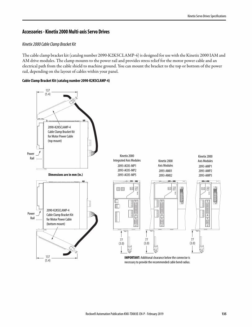
Kinetix Servo Drives Specifications
Accessories - Kinetix 2000 Multi-axis Servo Drives
Kinetix 2000 Cable Clamp Bracket Kit
The cable clamp bracket kit (catalog number 2090-K2KSCLAMP-4) is designed for use with the Kinetix 2000 IAM and AM drive modules. The clamp mounts to the power rail and provides stress relief for the motor power cable and an electrical path from the cable shield to machine ground. You can mount the bracket to the top or bottom of the power rail, depending on the layout of cables within your panel.
Cable Clamp Bracket Kit (catalog number 2090-K2KSCLAMP-4)
77(3.0)
77(3.0)
77(3.0)
137(5.4)
137(5.4)
Dimensions are in mm (in.)
PowerRail
IMPORTANT: Additional clearance below the connector is necessary to provide the recommended cable bend radius.
Kinetix 2000Axis Modules2093-AMP12093-AMP22093-AMP5
Kinetix 2000Axis Modules2093-AM012093-AM02
2090-K2KSCLAMP-4Cable Clamp Bracket Kitfor Motor Power Cable(top mount)
Kinetix 2000Integrated Axis Modules
2093-AC05-MP12093-AC05-MP22093-AC05-MP5
2090-K2KSCLAMP-4Cable Clamp Bracket Kitfor Motor Power Cable(bottom mount)
PowerRail
Rockwell Automation Publication KNX-TD003E-EN-P - February 2019 135

Kinetix Servo Drives Specifications
Kinetix 2000 Power Rail
Kinetix 2000 IAM, AM, and Shunt Module Slot Requirements
The far-left slot on each power rail is the converter slot and used by only the IAM. All other slots are inverter slots and are used by the IAM, AM, or shunt module (refer to the figure below). The power rail catalog number indicates the maximum number axes that each power rail can hold.
Power Rail Slots
IAM Cat. No. Converter Slot Used
Inverter Slots Used AM Cat. No. Converter Slot
UsedInverter Slots Used
2093-AC05-MP1
1
1 2093-AMP1
0
1
2093-AC05-MP2 1 2093-AMP2 1
2093-AC05-MP5 1 2093-AMP5 1
2093-AM01 2 (1)
(1) 2093-AM01 and 2093-AM02 axis modules are double-wide modules and require two slots on the power rail.
2093-AM02 2
Shunt Module Cat. No.
Converter Slot Used
Inverter Slots Used
2093-ASP06 0 1
Inverter SlotIAM Module
Inverter Slot (9)Shunt Module, Slot-filler Module, orDouble-wide AM Module
Inverter Slots (1…8)IAM Module,
Single-wide AM,Double-wide AM,Shunt Module, orSlot-filler Module
Converter SlotIAM Module
Converter SlotIAM Module
Power Rail2093-PRS1
Power Rail2093-PRS8S
136 Rockwell Automation Publication KNX-TD003E-EN-P - February 2019

Kinetix Servo Drives Specifications
For example, the 2093-PRS1 power rail contains one inverter slot. This limits the use of this power rail to systems requiring only one inverter slot. Similarly, the 2093-PRS2 power rail contains two inverter slots. This limits the use of this power rail to systems requiring up to two inverter slots. When selecting a power rail, determine the number of inverter slots required by all rail-mounted modules and select one with that minimum number of inverter slots.
The 2093-PRS8S power rail is unique in that it accommodates eight axes, but has nine inverter slots. The far-right (ninth) inverter slot is reserved for a shunt module, but could also be occupied by a slot-filler module or double-wide axis module. These power rail configurations are supported.
2093-PRS8S Configurations
IMPORTANT If you select a power rail with slots exceeding the minimum required for your system, you must install a 2093-PRF slot-filler module in each unused slot.
8-axis 7-axis 6-axis 5-axis
IAM IAM IAM IAM IAM IAM IAM IAM IAM
AM AM AM (double-wide)
AM (double-wide)
AM (double-wide)
AM (double-wide)
AM (double-wide)
AM (double-wide)
AM (double-wide)AM AM
AM AM AM AM AM (double-wide)
AM (double-wide)
AM (double-wide)
AM (double-wide)
AM (double-wide)AM AM AM AM
AM AM AM AM AM AM AM (double-wide)
AM (double-wide)
AM (double-wide)AM AM AM AM AM AM
AM AM AM AM AM AMAM (double-wide)
AM AM
Shunt module Slot-filler module Shunt module Slot-filler
module Shunt module Slot-filler module Shunt module Slot-filler
module
IMPORTANT The maximum number of axes supported by the 2093-PRS8S power rail is eight axes. Do not install an axis module (AM) in the far-right (ninth) inverter slot.
Rockwell Automation Publication KNX-TD003E-EN-P - February 2019 137

Kinetix Servo Drives Specifications
2093-PRS1, 2093-PRS2, 2093-PRS3, 2093-PRS4, 2093-PRS5, 2093-PRS7, and 2093-PRS8S Dimensions
Power RailCat. No. Description
Dimension Amm (in.)
Dimension Bmm (in.)
Dimension Cmm (in.)
2093-PRS1 1 axis power rail 90 (3.54) N/A N/A
2093-PRS2 2 axis power rail 130 (5.12) 40 (1.57) N/A
2093-PRS3 3 axis power rail 170 (6.69) 80 (3.15) N/A
2093-PRS4 4 axis power rail 210 (8.26) 120 (4.72) N/A
2093-PRS5 5 axis power rail 250 (9.84) 160 (6.30) N/A
2093-PRS7 7 axis power rail 330 (12.99) 240 (9.45) 120 (4.72)
2093-PRS8S 8 axis power rail 410 (16.14) 320 (12.60) 160 (6.30)
A45
(1.8)C
B
76(3.0)
15.1(0.59)
167.5(6.6)
M4 Screw
M4 Screw
32.6(1.3)
Dimensions are in mm (in.)
138 Rockwell Automation Publication KNX-TD003E-EN-P - February 2019

Kinetix Servo Drives Specifications
Kinetix 2000 Shunt Module
This section contains specifications, mounting dimensions, and catalog numbers for the 2093-ASP06 Shunt Module.
Shunt Module Power Specifications
For more information on external shunt resistors compatible with the Kinetix 2000 drive, refer to the Kinetix Motion Accessories Technical Data, publication KNX-TD004.
Shunt Module Dimensions
Modules are shown mounted to the power rail and the dimensions reflect that.
Drive Cat. No. Shunt Module Cat. No.
Drive VoltageV AC
ResistanceW
Peak PowerkW
Peak CurrentA
Continuous PowerW
CapacitanceμF
Fuse Replacement
2093-AC05-MP1
2093-ASP06 230 15.0 10.9 27.0 50 164 N/A (no internal fuse)2093-AC05-MP2
2093-AC05-MP5
167.5(6.6)
40(1.6)
183(7.2)
173(6.8)
Dimensions are in mm (in.)
PowerRail
2093-ASP06Shunt Module
Rockwell Automation Publication KNX-TD003E-EN-P - February 2019 139

Kinetix Servo Drives Specifications
Kinetix 2000 Slot-filler Module
This section contains dimensions and catalog numbers for the 2093-PRF slot-filler module.
Slot-filler Module Dimensions
Kinetix 7000 High Power Servo Drives
The Kinetix 7000 high-power servo drive is designed to accommodate the most demanding requirements and extends the benefits of Kinetix Integrated Motion to applications up to 149 kW. The Kinetix 7000 high power drive supports three-phase AC input power (380…480V AC) and DC input for common bus applications. In addition, the safe-off capability integrated into this drive increases productivity by allowing manufacturers and machine builders to implement machine solutions that provide both safety and maximum machine availability.
The Kinetix 7000 servo drives provide Integrated Motion capability through the sercos interface and are part of the Kinetix Integrated Motion solution.
IMPORTANT The Kinetix 2000 slot-filler module (catalog number 2093-PRF) is compatible with all Kinetix 2000 systems. Power rail slots not occupied by an IAM, AM, or shunt module, must have a slot-filler module installed.
167.5(6.6)
40(1.6)
53(2.1)
Dimensions are in mm (in.)
PowerRail
2093-PRFSlot-filler Module
140 Rockwell Automation Publication KNX-TD003E-EN-P - February 2019

Kinetix Servo Drives Specifications
Kinetix 7000 Servo Drive Features and Indicators
Kinetix 7000 Drive Features and Indicators
Item Description Item Description Item Description
1 General purpose (GPR) connector 7 Sercos receive (Rx) connector 13 Sercos node address switches
2 General purpose (GPIO) connector 8 Control power (CP) connector (facing down) 14 Seven-segment fault status indicator
3 Safe-off (SO) connector 9 Auxiliary feedback (AF) connector 15 Drive status indicator
4 Sercos communication rate and optical power switches 10 Motor feedback (MF) connector 16 COMM status indicator
5 Sercos transmit (Tx) connector 11 I/O (IOD) connector 17 Bus status indicator
6 DPI connector 12 Control power status indicator
151617
13
14
4
321
567
12
8
11
109
Kinetix 7000 Drive Module(2099-BM07-S top view is shown)
Kinetix 7000 Drive Module(2099-BM07-S front view is shown)
Power Terminal Block(beneath cover)
Refer to page 142 for terminal blockconfigurations.
Rockwell Automation Publication KNX-TD003E-EN-P - February 2019 141

Kinetix Servo Drives Specifications
Kinetix 7000 Power Terminal Blocks
DC+
DC-
U V W PE PE R (L1
)S (
L2)
T (L3
)
DC+
DC-
U V W PE PE R (L1
)
S (L2
)
T (L3
)
NC NC DC+
DC-
U V W R (L1
)S (
L2)
T (L3
)
DC Bus
Motor Power AC Line DC Bus Motor Power AC Line
DCBus
MotorPower
AC Line
UT1
VT2
WT3
RL1
SL2
INPUTOUTPUT
TL3
PE PE
DC-DC+PS+PS-
Reserved forFactory Use
240V AC
120V AC0V AC
Fan Pwr
Fan Pwr
0V AC
120V
AC24
0V ACPS+
PS-
PS+
PS-
0V AC
120V
AC24
0V AC
Fan Pwr
Reserved forFactory Use
Reserved forFactory Use
PE
Kinetix 7000 Drive Module, front view(2099-BM07-S is shown)
Power Terminal Block(beneath cover)
Power Terminal Block2099-BM06-S, 2099-BM07-S, and 2099-BM08-S
Power Terminal Block2099-BM09-S
Power Terminal Block2099-BM10-S
Power Terminal Block2099-BM11-S and 2099-BM12-S
Cable Shield Clamps forMotor and AC Inputs
142 Rockwell Automation Publication KNX-TD003E-EN-P - February 2019

Kinetix Servo Drives Specifications
Kinetix 7000 System Power Component Compatibility Charts
These tables provide input power component combinations for Kinetix 7000 drives with compatible motors. Combinations are designed to provide optimum performance in common-bus configurations.
Input Power Components with HPK-B (460V) Motors
Input Power Components with HPK-E (400V) Motors
Kinetix 7000 Drive Cat. No.
Common Bus Accessories
Compatible Motors8720MC Regenerative Power Supply (1)
8720MC-RPS
(1) Regenerative Power Supply (RPS) selection is for this single motor/drive combination. When combining multiple drives on the same RPS module, the selection can change.
8720MC Line Reactor (1)
2099-BM07-S
8720MC-RPS065BM8720MC-LR05-048B
HPK-B1307C
HPK-B1308C
2099-BM08-SHPK-B1307E
HPK-B1310C
2099-BM09-S
8720MC-LR10-062B HPK-B1308E
8720MC-RPS065BM and 8720MC-RPS065BS
8720MC-LR05-048B(two units)
HPK-B1609E
HPK-B1613C
2099-BM11-S
8720MC-LR10-062B(two units)
HPK-B1611E
HPK-B1815C
8720MC-RPS190BM 8720MC-LR10-100B(two units)
HPK-B1613E
HPK-B2010C
HPK-B2010E
HPK-B2212C
2099-BM12-S
HPK-B2010E
HPK-B2212C
HPK-B2510C
Kinetix 7000 Drive Cat. No.
Common Bus Accessories
Compatible Motors8720MC Regenerative Power Supply (1)
(1) Regenerative Power Supply (RPS) selection is for this single motor/drive combination. When combining multiple drives on the same RPS module, the selection can change.
8720MC Line Reactor (1)
8720MC-LRxx-xxxB
2099-BM08-S
8720MC-RPS065BM
8720MC-LR05-048B HPK-E1307C
2099-BM09-S8720MC-LR14-070B HPK-E1308E
8720MC-LR10-062B HPK-E1310C
2099-BM11-S
8720MC-RPS065BM and 8720MC-RPS065BS
8720MC-LR05-048B(two units) HPK-E1613C
8720MC-LR10-062B(two units)
HPK-E1609E
HPK-E1611E
HPK-E1815C
8720MC-RPS190BM 8720MC-LR10-100B(two units)
HPK-E1613E
HPK-E2010C
Rockwell Automation Publication KNX-TD003E-EN-P - February 2019 143

Kinetix Servo Drives Specifications
Input Power Components with MPL-B (460V) Motors
Input Power Components with MPM-B (480V) Motors
Kinetix 7000 Drive Cat. No.
Common Bus AccessoriesCompatible Motors
8720MC Regenerative Power Supply (1)
(1) Regenerative Power Supply (RPS) selection is for this single motor/drive combination. When combining multiple drives on the same RPS module, the selection can change.
8720MC Line Reactor (1)
2099-BM06-S
8720MC-RPS065BM
8720MC-LR05-048B
MPL-B540K
MPL-B560F
MPL-B580F
MPL-B580J
MPL-B640F
MPL-B660F
MPL-B680D
MPL-B680F
MPL-B860D
MPL-B960B
MPL-B980B
2099-BM07-SMPL-B880C
8720MC-LR10-062B
MPL-B880D
2099-BM08-S
MPL-B960C
MPL-B960D
MPL-B980C
MPL-B980D
Kinetix 7000 Drive Cat. No.
Common Bus AccessoriesCompatible Motors
8720MC Regenerative Power Supply (1)
(1) Regenerative Power Supply (RPS) selection is for this single motor/drive combination. When combining multiple drives on the same RPS module, the selection can change.
8720MC Line Reactor (1)
2099-BM06-S
8720MC-RPS065BM 8720MC-LR05-048B
MPM-B1651M
2099-BM06-S MPM-B1652E
2099-BM06-S MPM-B1652F
2099-BM06-S MPM-B1653C
2099-BM06-S MPM-B1653E
2099-BM06-S MPM-B1653F
2099-BM06-S MPM-B2152C
2099-BM07-S MPM-B2152F
2099-BM06-S MPM-B2152M
2099-BM06-S MPM-B2153B
2099-BM07-S MPM-B2153E
2099-BM07-S MPM-B2153F
2099-BM07-S MPM-B2154B
2099-BM07-S MPM-B2154E
2099-BM06-S MPM-B2154F
144 Rockwell Automation Publication KNX-TD003E-EN-P - February 2019

Kinetix Servo Drives Specifications
Input Power Components with RDB-B (480V) Motors
Kinetix 7000 Drive Cat. No.
Common Bus AccessoriesCompatible Motors8720MC Regenerative
Power Supply (1)
(1) Regenerative Power Supply (RPS) selection is for this single motor/drive combination. When combining multiple drives on the same RPS module, the selection can change.
8720MC Line Reactor (1)
2099-BM06-S
8720MC-RPS065BM 8720MC-LR05-048B
RDB-B2152C
2099-BM06-S RDB-B2153C
2099-BM07-S RDB-B29029
2099-BM06-S RDB-B29036
2099-BM08-S RDB-B29039
2099-BM06-S RDB-B41016
2099-BM08-S RDB-B41018
2099-BM06-S RDB-B41024
2099-BM09-S RDB-B41026
2099-BM09-S RDB-B41035
Rockwell Automation Publication KNX-TD003E-EN-P - February 2019 145

Kinetix Servo Drives Specifications
Technical Specifications - Kinetix 7000 High Power Servo Drives
Kinetix 7000 Drive Power Specifications
Attribute 2099-BM06-S 2099-BM07-S 2099-BM08-S 2099-BM09-S 2099-BM10-S 2099-BM11-S 2099-BM12-S
AC input voltage 342…528V AC rms three-phase (380…480V nom)
AC input frequency 47…63 Hz
Bandwidth (1)
Velocity loopCurrent loop
(1) Bandwidth values vary based on tuning parameters and mechanical components.
500 Hz1300 Hz
500 Hz500 Hz
PWM frequency 4 kHz 2 kHz
Main AC input currentNom (rms)Max inrush (A peak)
36.7 A18.0 A
47.7 A18.0 A
59.6 A18.0 A
90.1 A96.0 A
117 A118 A
169 A141 A
233 A141 A
DC input voltage 450…750V DC
DC input current 42.9 A 55.7 A 69.7 A 105 A 137 A 204 A 281 A
Control power input Voltage 18…30V DC (24V DC, nom)
Control power DC input currentNom (rms)Maximum inrush (rms)
3.3 A6.0 A
Continuous output current (rms) 40.0 A 52.0 A 65.0 A 96.0 A 125 A 180 A 248 A
Continuous output current (0-pk) 56.0 A 73.0 A 92.0 A 135 A 176 A 254 A 351 A
Peak output current (rms)3 s duration60 s duration
68.0 A51.0 A
80.0 A60.0 A
104 A78.0A
154 A115 A
163 A138 A
312 A234 A
372 A273 A
Peak output current (0-pk)3 s duration60 s duration
96.0 A72.0 A
113 A84.8 A
147 A110 A
217.7 A162.6 A
230.5 A195 A
441 A331 A
526 A386 A
Bus overvoltage 800V DC
Bus undervoltage 275…560V DC (3)
(3) Bus undervoltage can vary based on input line voltage.
Continuous power output, nom 22 kW 30 kW 37 kW 56 kW 75 kW 112 kW 149 kW
Continuous power output (Hp) 30 Hp 40 Hp 50 Hp 75 Hp 100 Hp 150 Hp 200 Hp
Maximum power cycles/minuteAC lineDC bus
4 per minute (pre-charge provided by drive)2 per minute (DC pre-charge provided by the regenerative power supply)
DC bus discharge time 3 minutes after removal of main AC power
Efficiency 97.5%
Total capacitance (2)
(2) If DC input is supplied to 2099-BM09-S, 2099-BM10-S, or 2099-BM11-S drives, the precharge capability must be provided at the system level. Disconnect switches must not be used between the input of the drive and a common DC bus without the use of an external precharge device.
1800 μF 2400 μF 3000 μF 4500 μF 6000 μF 8400 μF 8400 μF
Short-circuit current rating 200,000 A (rms) symmetrical
146 Rockwell Automation Publication KNX-TD003E-EN-P - February 2019

Kinetix Servo Drives Specifications
Circuit Breaker/Fuse Specifications
While circuit breakers offer some convenience, there are limitations for their use. Circuit breakers do not handle high current inrush as well as fuses. Make sure the selected components are properly coordinated and meet acceptable codes including any requirements for branch circuit protection. Evaluation of the short-circuit available current is critical and must be kept below the short-circuit current rating of the circuit breaker.
Use class CC, T, RK1, or J fuses, with current rating as indicated in the table below. The following fuse examples and short-circuit current ratings are recommended for use with the 2099-BMxx-S drives when the Line Interface Module (LIM) is not used.
Fuse Specifications (AC input)
Fuse Specifications (DC common bus)
Weight Specifications
IMPORTANT LIM modules (catalog numbers 2094-BLxxS and 2094-XL75S-Cx) provide branch circuit protection to the Kinetix 7000 drive. Follow all applicable NEC and local codes.
Drive Cat. No. Bussmann FuseDual Element Time Delay Fuse (min/max)A rms
Non-Time Delay Fuse (min/max)A rms
Motor Circuit Protector (max)A rms
2099-BM06-S LPJ-90SP 50/90 50/150 50
2099-BM07-S LPJ-110SP 60/110 60/200 70
2099-BM08-S LPJ-125SP 80/125 80/250 100
2099-BM09-S LPJ-200SP 125/200 125/300 125
2099-BM10-S LPJ-250SP 150/250 150/500 150
2099-BM11-S LPJ-400SP 225/400 225/600 250
2099-BM12-S LPJ-500SP 300/550 300/700 400
Drive Cat. No. Bussmann Fuse Mersen Fuse (1)
(1) Mersen fuses were formerly known as Ferraz Shawmut.
2099-BM06-S FWJ-80A HSJ80
2099-BM07-S FWJ-100A HSJ90
2099-BM08-S FWJ-125A HSJ100
2099-BM09-S FWJ-175A HSJ175
2099-BM10-S FWJ-200A HSJ200
2099-BM11-S FWJ-500A HSJ400
2099-BM12-S FWJ-500A HSJ400
Drive Cat. No.Weight, approxkg (lb)
Drive Cat. No.Weight, approxkg (lb)
2099-BM06-S
18.55 (40.9)
2099-BM09-S37.2 (82.0)
2099-BM07-S 2099-BM10-S
2099-BM08-S 2099-BM11-S71.4 (157.5)
2099-BM12-S
Rockwell Automation Publication KNX-TD003E-EN-P - February 2019 147

Kinetix Servo Drives Specifications
Contactor Ratings
The table below lists the recommended contactor ratings for Kinetix 7000 drives installed without a Line Interface Module.
Power Dissipation Specifications
Use this table to size an enclosure and calculate required ventilation for your Kinetix 7000 drive system.
Maximum Feedback Cable Lengths
Although motor power and feedback cables are available in standard lengths up to 90 m (295.3 ft), the drive/motor/feedback combination can limit the maximum feedback cable length. This table assumes the use of recommended cables as shown in the Kinetix Motion Accessories Technical Data, publication KNX-TD004.
Cable Lengths for Compatible Rotary Motors
Drive Cat. No. Contactor Safety Contactor Coil Type Coil Voltage Requirements
2099-BM06-S 100-C43DJ01 100S-C43-DJD4C Standard with Diode 24V DC
2099-BM07-S
100-D95EN11 100S-D95EN22C
Electronic Coil (1)
(1) Electronic coil control power requirements = 24V DC @ 15 mA.
24V DC for control and 480V AC for coil power
2099-BM08-S
2099-BM09-S
2099-BM10-S 100-D140EN11 100S-D140EN22C
2099-BM11-S 100-D180EN11 100S-D180EN22C
2099-BM12-S 100-D250EN11 100S-D250EN22C
Drive Cat. No.
Usage as % of Rated Power OutputW Drive Cat. No.
Usage as % of Rated Power OutputW
50% 100% 50% 100%
2099-BM06-S 294 465 2099-BM09-S 645 1072
2099-BM07-S 388 619 2099-BM10-S 882 1479
2099-BM08-S 452 730 2099-BM11-S 1275 2125
2099-BM12-S 1438 2437
Motor Cat. No.Absolute High-resolution (5V) Encoderm (ft)
Absolute High-resolution (9V) Encoderm (ft)
MPL-B5xxx…MPL-B9xxx-S/M 90 (295.3)
MPM-B165xx…MPM-B215xx-S/M 90 (295.3)
RDB-B215xx-7/3 30 (98.4)
RDB-B290xx-7/3 orRDB-B410xx-7/3 90 (295.3)
HPK-Bxxxxx-S/M orHPK-Exxxxx-S/M 90 (295.3)
148 Rockwell Automation Publication KNX-TD003E-EN-P - February 2019

Kinetix Servo Drives Specifications
Dimensions - Kinetix 7000 High Power Servo Drives
2099-BM06-S, 2099-BM07-S, and 2099-BM08-S Dimensions
224.3(8.82)
7.0(0.28)
31.9(1.26)
517.5(20.37)
495.0(19.49)
254.12(10.00)
192(7.56)
15.27(0.60)
7.0(0.28)
8.0(0.31)
Ø 7.0(0.28) X2
66.0(2.60)
97.0(3.82)
137.2(5.40)
187.0(7.36)
31.9(1.26)
151.1(5.95)
165.1(6.50)
160.1(6.30)
165.9(6.53)
Ø 37.3(1.47) X2
Ø 22.4(0.88)
Ø 28.7(1.13)
66.0(2.60)
130.0(5.19)
186.0(7.32)
31.9(1.26)
Ø 28.7(1.13)
Ø 47.0(1.85) 2X
Ø 34.9(1.37) 2X
165.9(6.53)
165.1(6.50)
160.1(6.30)
Dimensions are in mm (in.)
Bottom View(2099-BM06-S and 2099-BM07-S)
Bottom View(2099-BM08-S)
Rockwell Automation Publication KNX-TD003E-EN-P - February 2019 149

Kinetix Servo Drives Specifications
2099-BM09-S and 2099-BM10-S Dimensions
286.7(11.29)
644.5(25.37)
2099-BM09
6.5(0.26) 2X
31.9(1.26)
20.4(0.80) 2X
300.0(11.81)
259.1(10.20) 2X
Ø 15.0(0.59) 2X 225.0
(8.86) 37.5(1.48)
Ø 6.5(0.26) 2X
12.0(0.47)
644.5(25.37)
7.0(0.28)
625.0(24.61)
690.3(27.18)
2099-BM10
Ø 34.9(1.37) 2X
60.4(2.38)
159.5(6.28)
31.9(1.26)
85.1(3.35)
65.0(2.56) 2X
130(5.12)
170(6.69)
24.5(0.96) 2X
45.5(1.79)
Ø 22.2 (0.87) Ø 62.7 (2.47) 2X
70(2.75) 35
(1.38)
31.8(1.25)
153.5(6.04) 2X
Ø 34.9(1.37)
Ø 22.2(0.87) 3X
Ø 62.7(2.47) 2X
34.1(1.34)
22.4(0.88)
128.1(5.04)
53.0(2.08) 2X
104.3(4.10)
Dimensions are in mm (in.)
Some Components are Removed for Clarity
Bottom View(2099-BM09-S)
Bottom View(2099-BM10-S)
150 Rockwell Automation Publication KNX-TD003E-EN-P - February 2019

Kinetix Servo Drives Specifications
2099-BM11-S and 2099-BM12-S Dimensions
Ø 18.0(0.71) 2X
8.5(0.33) 2X
849.97(33.46)
300.0(11.81)
49.6(1.95)
7.9(0.31)
850.0(33.46)
824.0(32.44)
14.5(0.04)
30.0(1.18)
360.6(14.20) 2X
8.5(0.33) 2X
399.2(15.72)
282.8(11.13)
977.1(38.47)
Ø 34.9(1.37)
Ø 22.2 (0.87) 4X Ø 62.7 (2.47) 2X
73.8(2.90) 36.9 (1.45) 4X
148.4(5.84)
31.69 (1.25) 45.0(1.77)
22.0 (0.86) 2X128
(5.04)100
(3.94)150 (5.90) 2X
200 (7.87)
151.7(5.97)
67.2(2.64)
Dimensions are in mm (in.)
Rockwell Automation Publication KNX-TD003E-EN-P - February 2019 151

Kinetix Servo Drives Specifications
Environmental Specifications - Kinetix 7000 High Power Servo Drives
Certifications - Kinetix 7000 High Power Servo Drives
Accessories - Kinetix 7000 High Power Servo Drives
Attribute Operational Range Storage Range (nonoperating)
Temperature, ambient 0…50 °C (32…122 °F) -40…+70 °C (-40…+158 °F)
Relative humidity 5…95% noncondensing 5…95% noncondensing
Altitude 1000 m (3281 ft)3000 m (9843 ft) with derating 3000 m (9843 ft) during transport
Vibration 5…55 Hz @ 0.35 mm (0.014 in.) double amplitude, continuous displacement; 55…500 Hz @ 2.0 g peak constant acceleration (10 sweeps in each of 3 mutually perpendicular directions)
Shock 15 g, 11 ms half-sine pulse (3 pulses in each direction of 3 mutually perpendicular directions)
Agency Certification (1)
(1) See rok.auto/certifications for declarations of conformity, certificates, and other certification details.
Standards
c-UL-us (2)
(2) UL has not evaluated the safe-off option in these products.
UL Listed to U.S. and Canadian safety standards (UL 508C File E59272).
Solid-state motor overload protection provides dynamic fold-back of motor current when 110% of the motor rating is reached with a peak current limit based on the peak rating of the motor as investigated by UL to comply with UL 508C (UL File E59272).
CEEuropean Union 2004/108/EC EMC Directive compliant with IEC 61800-3:2004 + A1:2012: Adjustable Speed Electrical Power Drive Systems - Part 3; EMC Product Standard including specific test methods.
European Union 2006/95/EC Low Voltage Directive compliant with IEC 50178:1997 - Electronic Equipment for use in Power Installations.
Functional SafetyTÜV certified for functional safety: up to Performance Level (PL) e, Category 3 according to ISO 13849; up to SIL CL3 according to IEC 61508, IEC 61800-5-2, and IEC 62061 when used as described in the Kinetix Safe Torque Off Feature Safety Reference Manual, publicationGMC-RM002.
C-Tick
Australian Radiocommunications Act, compliant with:• Radiocommunications Act: 1992• Radiocommunications (Electromagnetic Compatibility) Standard: 1998• Radiocommunications (Compliance Labelling - Incidental Emissions) Notice: 1998• AS/NZS CISPR 11: 2002 (Group 2, Class A)
KCKorean Registration of Broadcasting and Communications Equipment, compliant with:• Article 58-2 of Radio Waves Act, Clause 3• Registration number: KCC-REM-RAA-2099
Cat. No. Description
2099-K7KCB-1 Control board assembly kit. Replacement control board for 2099-BMxx-S drives.
2099-K7KCP-1 DC-DC converter cassette kit. Replacement DC-DC converter for 2099-BMxx-S drives.
152 Rockwell Automation Publication KNX-TD003E-EN-P - February 2019

Kinetix Servo Drives Specifications
Motor Overload Protection
Allen-Bradley servo drives use solid-state motor overload protection that operates in accordance with UL requirements. Motor overload protection is provided by algorithms (thermal memory) that predict actual motor temperature based on operating conditions as long as control power is continuously applied.
In addition to thermal memory protection, these drives provide an input for an external temperature sensor/thermistor device, embedded in the motor, to support the UL requirement for motor overload protection.
Servo drives using DSL (digital servo link) encoder technology require the encoder to perform motor temperature monitoring and transmit the data over the single motor cable. Kinetix VP (Bulletin VPL, VPF, VPS, and VPC-Bxxxxx-Q) motors use DSL technology that performs this function. No additional wiring is required.
Some motors supported by Kinetix 5500 and Kinetix 5700 drives (firmware revision 3.001 or earlier) do not contain temperature sensors/thermistors; therefore, motor overload protection against excessive consecutive motor overloads with power cycling is not supported. For Kinetix 5500 and Kinetix 5700 drives with firmware revision 4.001 and later, thermal retention is supported regardless of the motor or encoder type in use.
These servo drives meet the following UL requirements for solid-state overload protection.
Refer to your servo drive user manual for the interconnect diagram that illustrates the wiring between your motor and drive.
Motor Overload Protection Trip Point Value
Ultimately 100% overload
Within 8 minutes 200% overload
Within 20 seconds 600% overload
ATTENTION: To avoid damage to your motor due to overheating caused by excessive, successive motor overload trips, follow the wiring diagram provided in the user manual for your motor and drive combination.
Rockwell Automation Publication KNX-TD003E-EN-P - February 2019 153

Kinetix Servo Drives Specifications
Additional Resources
These documents contain information concerning related products from Rockwell Automation.
You can view or download publications athttp://www.rockwellautomation.com/global/literature-library/overview.page.
Resource Description
Kinetix Rotary Motion Specifications Technical Data, publication KNX-TD001 Product specifications for Kinetix VP, MP-Series, Kinetix 6000M (Bulletin MDF), TL-Series, RDD-Series, and HPK-Series rotary motors.
Kinetix Linear Motion Specifications Technical Data, publication KNX-TD002 Product specifications for Bulletin MPAS and MPMA linear stages, Bulletin MPAR and MPAI electric cylinders, and LDC-Series and LDL-Series linear motors.
Kinetix Motion Accessories Specifications Technical Data, publication KNX-TD004 Product specifications for Bulletin 2090 motor and interface cables, low-profile connector kits, drive power components, and other servo drive accessory items.
iTRAK System Technical Data, publication 2198T-TD001 Product specifications for the iTRAK system components, motor modules, movers, and cables.
iTRAK System User Manual, publication 2198T-UM001 Information on how to install, configure, start, and troubleshoot the iTRAK system.
Encoder Output Module User Manual, publication 2198-UM003Provides information on how to access and install the Add On Profile (AOP) and Add On Instructions (AOI) for your drive system that includes an encoder output module. Also includes troubleshooting information for your encoder output module.
1321 Power Conditioning Products Technical Data, publication 1321-TD001 Information on typical use cases, specifications, terminations, and dimensions.
Kinetix 5700 Drive Systems, publication KNX-RM010
System design guide to determine and select the required (drive specific) drive module, power accessory, connector kit, motor cable, and interface cable catalog numbers for your drive and motor/actuator motion control system. Included are system performance specifications and torque/speed curves (rotary motion) and force/velocity curves (linear motion) for your motion application.
Kinetix 5500 Drive Systems, publication KNX-RM009
Kinetix 6000 and Kinetix 6200/6500 Drive Systems, publication KNX-RM003
Kinetix 300/350 Drive Systems, publication KNX-RM004
Kinetix 3 Drive Systems, publication GMC-RM005
Kinetix 2000 Drive Systems, publication GMC-RM006
Kinetix 7000 Drive Systems, publication GMC-RM007
Kinetix Motion Control Selection Guide, publication KNX-SG001 Overview of Kinetix servo drives, motors, actuators, and motion accessories designed to help make initial decisions for the motion control products best suited for your system requirements.
System Design for Control of Electrical Noise Reference Manual, publication GMC-RM001
Information, examples, and techniques designed to minimize system failures caused by electrical noise.
ControlLogix Selection Guide, publication 1756-SG001 Information to determine which ControlLogix controller fits your application and the product specifications to help design a ControlLogix system and select the appropriate components.
CompactLogix Selection Guide, publication 1769-SG001 Information to determine which CompactLogix controller fits your application and the product specifications to help design a CompactLogix system and select the appropriate components.
Industrial Ethernet Media Brochure, publication 1585-BR001 Information to determine which Bulletin 1585 Ethernet cable fits your application and the product specifications to help select the appropriate components.
Product Certifications website, rok.auto/certifications Provides declarations of conformity, certificates, and other certification details.
Motion Analyzer System Sizing and Selection Toolhttps://motionanalyzer.rockwellautomation.com/
Comprehensive motion application sizing tool used for analysis, optimization, selection, and validation of your Kinetix Motion Control system.
Rockwell Automation Product Selection websitehttp://www.rockwellautomation.com/global/support/selection.page Online product selection and system configuration tools, including AutoCAD (DXF) drawings.
154 Rockwell Automation Publication KNX-TD003E-EN-P - February 2019

Kinetix Servo Drives Specifications
Notes:
Rockwell Automation Publication KNX-TD003E-EN-P - February 2019 155

Allen-Bradley, CompactLogix, ControlLogix, GuardLogix, HPK-Series, iTRAK, Kinetix, LDC-Series, LDL-Series, LISTEN. THINK. SOLVE., MP-Series, RDD-Series, Rockwell Automation, Rockwell Software, RSLogix 5000, Studio 5000,Studio 5000 Logix Designer, and TL-Series are trademarks of Rockwell Automation, Inc.CIP, CIP Motion, CIP Sync, and EtherNet/IP are trademarks of ODVA, Inc.Trademarks not belonging to Rockwell Automation are property of their respective companies.
Publication KNX-TD003E-EN-P - February 2019
Rockwell Automation SupportUse the following resources to access support information.
Documentation FeedbackYour comments will help us serve your documentation needs better. If you have any suggestions on how to improve this document, complete the How Are We Doing? form at http://literature.rockwellautomation.com/idc/groups/literature/documents/du/ra-du002_-en-e.pdf.
Technical Support Center Knowledgebase Articles, How-to Videos, FAQs, Chat, User Forums, and Product Notification Updates. www.rockwellautomation.com/knowledgebase
Local Technical Support Phone Numbers Locate the phone number for your country. www.rockwellautomation.com/global/support/get-support-now.page
Direct Dial Codes Find the Direct Dial Code for your product. Use the code to route your call directly to a technical support engineer. www.rockwellautomation.com/global/support/direct-dial.page
Literature Library Installation Instructions, Manuals, Brochures, and Technical Data. www.rockwellautomation.com/literature
Product Compatibility and Download Center (PCDC)
Get help determining how products interact, check features and capabilities, and find associated firmware. www.rockwellautomation.com/global/support/pcdc.page
Rockwell Otomasyon Ticaret A.Ş., Kar Plaza İş Merkezi E Blok Kat:6 34752 İçerenköy, İstanbul, Tel: +90 (216) 5698400
Rockwell Automation maintains current product environmental information on its website at http://www.rockwellautomation.com/rockwellautomation/about-us/sustainability-ethics/product-environmental-compliance.page.
Supersedes Publication KNX-TD003D-EN-P - May 2018 Copyright © 2019 Rockwell Automation, Inc. All rights reserved. Printed in the U.S.A.