Servo Gun Setup - Application manual
82
ROBOTICS Application manual Servo Gun Setup
-
Upload
khangminh22 -
Category
Documents
-
view
3 -
download
0
Transcript of Servo Gun Setup - Application manual

ROBOTICS
Application manualServo Gun Setup

Trace back information:Workspace 21A version a10Checked in 2021-03-16Skribenta version 5.4.005

Application manualServo Gun Setup
RobotWare 6
Document ID: 3HAC065014-001Revision: E
© Copyright 2021 ABB. All rights reserved.Specifications subject to change without notice.

The information in this manual is subject to change without notice and should notbe construed as a commitment by ABB. ABB assumes no responsibility for any errorsthat may appear in this manual.Except as may be expressly stated anywhere in this manual, nothing herein shall beconstrued as any kind of guarantee or warranty by ABB for losses, damage to personsor property, fitness for a specific purpose or the like.In no event shall ABB be liable for incidental or consequential damages arising fromuse of this manual and products described herein.This manual and parts thereof must not be reproduced or copied without ABB'swritten permission.Keep for future reference.Additional copies of this manual may be obtained from ABB.
Original instructions.
© Copyright 2021 ABB. All rights reserved.Specifications subject to change without notice.

Table of contents7Overview of this manual ...................................................................................................................9Product documentation ....................................................................................................................
111 Introduction111.1 About Servo Gun Setup ......................................................................................121.2 Requirements ...................................................................................................131.3 Preparations ....................................................................................................
152 Installation
173 Servo Gun Setup wizard173.1 How to use the Servo Gun Setup wizard ................................................................193.2 Running the Servo Gun Setup wizard ....................................................................533.3 Commissioning mode ........................................................................................
574 System parameters
675 TuneMaster and tuning675.1 TuneMaster ......................................................................................................715.2 Tuning with movable gun arm search ....................................................................715.2.1 Movable gun arm search ..........................................................................745.2.2 RAPID references for MGAS .....................................................................745.2.2.1 SearchMoveCheck .......................................................................755.2.2.2 TuneDetectionParams ..................................................................
776 Motor type file
79Index
Application manual - Servo Gun Setup 53HAC065014-001 Revision: E
© Copyright 2021 ABB. All rights reserved.
Table of contents

This page is intentionally left blank
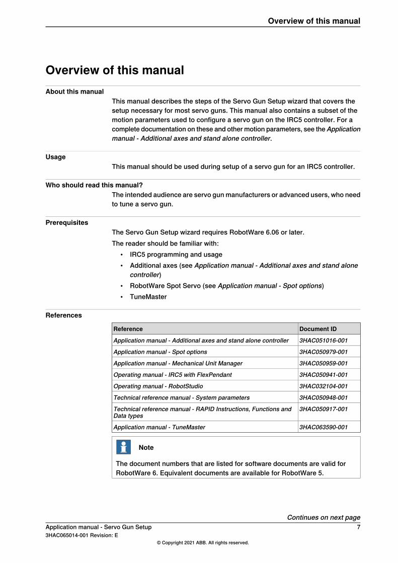
Overview of this manualAbout this manual
This manual describes the steps of the Servo Gun Setup wizard that covers thesetup necessary for most servo guns. This manual also contains a subset of themotion parameters used to configure a servo gun on the IRC5 controller. For acomplete documentation on these and other motion parameters, see theApplicationmanual - Additional axes and stand alone controller.
UsageThis manual should be used during setup of a servo gun for an IRC5 controller.
Who should read this manual?The intended audience are servo gun manufacturers or advanced users, who needto tune a servo gun.
PrerequisitesThe Servo Gun Setup wizard requires RobotWare 6.06 or later.The reader should be familiar with:
• IRC5 programming and usage• Additional axes (see Application manual - Additional axes and stand alone
controller)• RobotWare Spot Servo (see Application manual - Spot options)• TuneMaster
References
Document IDReference
3HAC051016-001Application manual - Additional axes and stand alone controller
3HAC050979-001Application manual - Spot options
3HAC050959-001Application manual - Mechanical Unit Manager
3HAC050941-001Operating manual - IRC5 with FlexPendant
3HAC032104-001Operating manual - RobotStudio
3HAC050948-001Technical reference manual - System parameters
3HAC050917-001Technical reference manual - RAPID Instructions, Functions andData types
3HAC063590-001Application manual - TuneMaster
Note
The document numbers that are listed for software documents are valid forRobotWare 6. Equivalent documents are available for RobotWare 5.
Continues on next pageApplication manual - Servo Gun Setup 73HAC065014-001 Revision: E
© Copyright 2021 ABB. All rights reserved.
Overview of this manual

Revisions
DescriptionRevision
First edition.A
Added installation description.B• Added possibility to run speed limit and acceleration tuning also in
manual full speed mode.• Delta position check restricted only to manual operating mode.• Corrected a problem with transmission check.
C
• Misc. documentation improvements.• Added possibility to enter a decimal value in transmission check.• Added possibility to enter acceleration data manually.• Reduction of Teach Max Speed Main/DSP at the end of tuning.• Added speed limit information displayed on TPU.• Max torque reduced at the end of tuning.• Added possibility to run force calibration again after completed tuning.• Other minor improvements.
D
Released with RobotWare 6.12.• Added information about Movable Gun Arm Search.
E
8 Application manual - Servo Gun Setup3HAC065014-001 Revision: E
© Copyright 2021 ABB. All rights reserved.
Overview of this manualContinued

Product documentationCategories for user documentation from ABB Robotics
The user documentation from ABB Robotics is divided into a number of categories.This listing is based on the type of information in the documents, regardless ofwhether the products are standard or optional.
Tip
All documents can be found via myABB Business Portal, www.abb.com/myABB.
Product manualsManipulators, controllers, DressPack/SpotPack, and most other hardware isdelivered with a Product manual that generally contains:
• Safety information.• Installation and commissioning (descriptions of mechanical installation or
electrical connections).• Maintenance (descriptions of all required preventive maintenance procedures
including intervals and expected life time of parts).• Repair (descriptions of all recommended repair procedures including spare
parts).• Calibration.• Decommissioning.• Reference information (safety standards, unit conversions, screw joints, lists
of tools).• Spare parts list with corresponding figures (or references to separate spare
parts lists).• References to circuit diagrams.
Technical reference manualsThe technical reference manuals describe reference information for roboticsproducts, for example lubrication, the RAPID language, and system parameters.
Application manualsSpecific applications (for example software or hardware options) are described inApplication manuals. An application manual can describe one or severalapplications.An application manual generally contains information about:
• The purpose of the application (what it does and when it is useful).• What is included (for example cables, I/O boards, RAPID instructions, system
parameters, software).• How to install included or required hardware.• How to use the application.• Examples of how to use the application.
Continues on next pageApplication manual - Servo Gun Setup 93HAC065014-001 Revision: E
© Copyright 2021 ABB. All rights reserved.
Product documentation

Operating manualsThe operating manuals describe hands-on handling of the products. The manualsare aimed at those having first-hand operational contact with the product, that isproduction cell operators, programmers, and troubleshooters.
10 Application manual - Servo Gun Setup3HAC065014-001 Revision: E
© Copyright 2021 ABB. All rights reserved.
Product documentationContinued

1 Introduction1.1 About Servo Gun Setup
Basic approachFor most servo guns it is enough to follow the Servo Gun Setup wizard, see ServoGun Setup wizard on page 17. Here you can specify known data or, in many stepsof the wizard, get recommended values for good performance.
Gun familiesWithin the same family, guns share mechanical characteristics such as motor,transmission ratio, friction (to some extent), stiffness, inertia, max allowed force,arm length and max opening distance.The force may vary somewhat between guns of the same family. The reason isthat the friction level, which has some influence on force, often differs a lot withinthe family. Therefore a force calibration and an update of the delta position shouldalways be done for each individual gun.
Gun designThe design of the gun also affects the tuning procedure. Flexible copper gun armsdriven by linear actuators are the easiest guns to tune. Aluminum arms are rigidand present a challenge.The recommendations and start values in this manual are mainly intended for gunswith copper arms.
Application manual - Servo Gun Setup 113HAC065014-001 Revision: E
© Copyright 2021 ABB. All rights reserved.
1 Introduction1.1 About Servo Gun Setup

1.2 Requirements
Requirements on motor and resolverThe motor and resolver should comply with the requirements given in Applicationmanual - Additional axes and stand alone controller.
Spot Servo option requiredUse a system with the RobotWare Spot Servo option installed.
Measuring equipmentThe following equipment is required:
• Force calibration sensor (required for force measurements)• Dial indicators (optional for gun deflection measurements)
TuneMasterThe TuneMaster program is useful for studying signals for position, speed, torque,etc. It is not required when using the Servo Gun Setup wizard, but if there is someunwanted behavior, TuneMaster is useful for detecting what happens and whatparameter that may need to be tuned.TuneMaster can be downloaded from:http://new.abb.com/products/robotics/robotstudio
System parametersFor the normal procedure, the configuration of most system parameters will bedone automatically by the Servo Gun Setup wizard. For some cases, there maybe a need to manually configure system parameters.A list of the system parameters that are primarily of interest when configuring aservo gun is presented in System parameters on page 57. Detailed description ofthe system parameters are found in Technical reference manual - Systemparameters.How to set system parameters with RobotStudio is described in Operatingmanual - RobotStudio.How to set system parameters with the FlexPendant is described in Operatingmanual - IRC5 with FlexPendant.
12 Application manual - Servo Gun Setup3HAC065014-001 Revision: E
© Copyright 2021 ABB. All rights reserved.
1 Introduction1.2 Requirements

1.3 Preparations
Tool and payload settingsBefore using Servo Gun Setup, the tool and the payload must be defined correctly.
Basic verificationFind out if there are any basic problems (i.e. bad parameters or ripple). Theseproblems must be fixed before the tuning of force and position control is started.For complete speed tuning, see Application manual - Additional axes and standalone controller.
Application manual - Servo Gun Setup 133HAC065014-001 Revision: E
© Copyright 2021 ABB. All rights reserved.
1 Introduction1.3 Preparations

This page is intentionally left blank

2 InstallationInstalling the Servo Gun Setup Add-in
1 In RobotStudio, click on the Add-Ins tab.2 Select ServoGun Setup.3 In the frame to the right, click Add.
xx1800000408
Continues on next pageApplication manual - Servo Gun Setup 153HAC065014-001 Revision: E
© Copyright 2021 ABB. All rights reserved.
2 Installation

Adding Servo Gun Setup to a systemThe product ServoGunSetup can be added when creating a new system, or addedto an existing system. In both cases it is done in Installation Manager inRobotStudio. In the tab Products, add ServoGunSetup in the same way asRobotWare. For more information about the Installation Manager, see Operatingmanual - RobotStudio.
xx1800000410
16 Application manual - Servo Gun Setup3HAC065014-001 Revision: E
© Copyright 2021 ABB. All rights reserved.
2 InstallationContinued

3 Servo Gun Setup wizard3.1 How to use the Servo Gun Setup wizard
The parts of Servo Gun SetupServo Gun Setup is a wizard that step-by-step takes you through the following:
• Load system parameter configuration file• Change motor type• Change connection• Change gun specific data• Fine calibration• Tune servo gun, which can be divided into:
- Tune transmission- Set alarm torque- Check delta collision position (initial value)- Force calibration (initial value)- Tune speed limit- Tune acceleration- Check delta collision position (final value)- Force calibration (final value)- Tune gun deflection parameters
• Save the configuration
Continues on next pageApplication manual - Servo Gun Setup 173HAC065014-001 Revision: E
© Copyright 2021 ABB. All rights reserved.
3 Servo Gun Setup wizard3.1 How to use the Servo Gun Setup wizard

Main viewBy going through the wizard, step by step, all these parts are being set upautomatically. In some steps, there is a button Main view that takes you to anoverview of the setup wizard:
xx1700002044
Tapping on one of the parts will take you directly to that part of the wizard (if youonly want to use one part of the Servo Gun Setup).
Meaning of buttonsThe steps of the Servo Gun Setup provides different choices.
• Next - Continue to the next step.• Back - return to the previous step.• Skip - Skips this part of the setup and jumps to the next part.• Change - Manually enter a value yourself instead of accepting the suggested
value.• Update - Update the controller with the value suggested by Servo Gun Setup.
18 Application manual - Servo Gun Setup3HAC065014-001 Revision: E
© Copyright 2021 ABB. All rights reserved.
3 Servo Gun Setup wizard3.1 How to use the Servo Gun Setup wizardContinued

3.2 Running the Servo Gun Setup wizard
Start Servo Gun SetupOn the FlexPendant, tap the ABB menu and select ServoGun Setup.
xx1700002045
Continues on next pageApplication manual - Servo Gun Setup 193HAC065014-001 Revision: E
© Copyright 2021 ABB. All rights reserved.
3 Servo Gun Setup wizard3.2 Running the Servo Gun Setup wizard

Load configurationLoad a system parameter configuration file for a servo gun. Browse to selectthe desired template file. For more information about template files, seeApplication manual - Additional axes and stand alone controller.If you want to change the name of the servo gun, type the new name.If you want, you can add the serial number of the servo gun. This will thenbe included in the saved data.
xx1700002046
Continues on next page20 Application manual - Servo Gun Setup
3HAC065014-001 Revision: E© Copyright 2021 ABB. All rights reserved.
3 Servo Gun Setup wizard3.2 Running the Servo Gun Setup wizardContinued
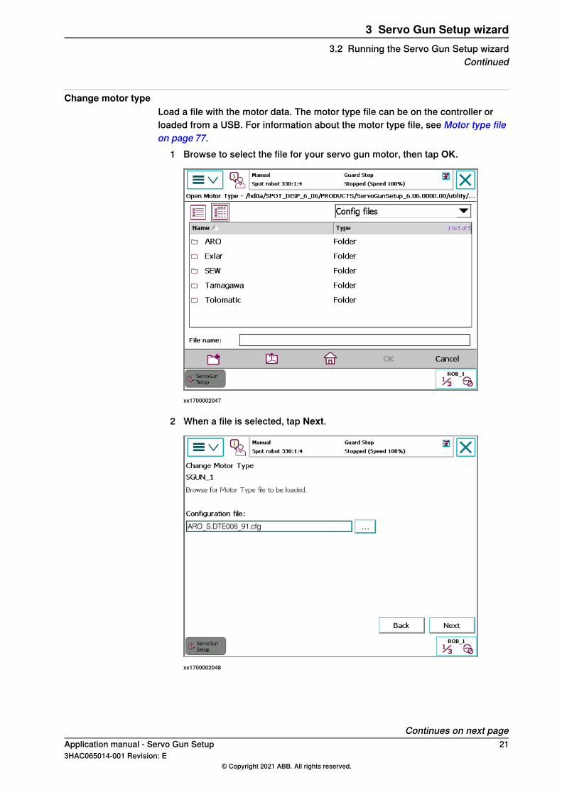
Change motor typeLoad a file with the motor data. The motor type file can be on the controller orloaded from a USB. For information about the motor type file, see Motor type fileon page 77.
1 Browse to select the file for your servo gun motor, then tap OK.
xx1700002047
2 When a file is selected, tap Next.
xx1700002048
Continues on next pageApplication manual - Servo Gun Setup 213HAC065014-001 Revision: E
© Copyright 2021 ABB. All rights reserved.
3 Servo Gun Setup wizard3.2 Running the Servo Gun Setup wizard
Continued

Change connectionIf previously loaded configuration file does not have the correct settings,change them to the values that apply to your servo gun. For informationabout the measurement system, see Application manual - Additional axesand stand alone controller.Tap Next.
xx1700002049
Change gun specific dataThe default values comes from Stress Duty Cycle in the motor type file.The Temporary Max Torque is used during the first steps of the tuning, until it isknown how much torque is needed to reach the desired max force. If the max
Continues on next page22 Application manual - Servo Gun Setup
3HAC065014-001 Revision: E© Copyright 2021 ABB. All rights reserved.
3 Servo Gun Setup wizard3.2 Running the Servo Gun Setup wizardContinued

torque is not known, use the stall torque or the continuous torque from the motordata sheet.
1 If needed, change values. Then tap Next.
xx1700002050
2 A restart is required for the changes to take effect. Tap Restart.
xx1700002051
Continues on next pageApplication manual - Servo Gun Setup 233HAC065014-001 Revision: E
© Copyright 2021 ABB. All rights reserved.
3 Servo Gun Setup wizard3.2 Running the Servo Gun Setup wizard
Continued
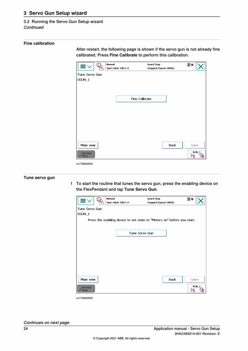
Fine calibrationAfter restart, the following page is shown if the servo gun is not already finecalibrated. Press Fine Calibrate to perform this calibration.
xx1700002052
Tune servo gun1 To start the routine that tunes the servo gun, press the enabling device on
the FlexPendant and tap Tune Servo Gun.
xx1700002053
Continues on next page24 Application manual - Servo Gun Setup
3HAC065014-001 Revision: E© Copyright 2021 ABB. All rights reserved.
3 Servo Gun Setup wizard3.2 Running the Servo Gun Setup wizardContinued

2 Tap Continue.
xx1700002054
3 If the correct tool and work object is used, tap Accept.
xx1700002055
Continues on next pageApplication manual - Servo Gun Setup 253HAC065014-001 Revision: E
© Copyright 2021 ABB. All rights reserved.
3 Servo Gun Setup wizard3.2 Running the Servo Gun Setup wizard
Continued

4 To let the wizard perform a complete tuning, tap Complete.To manually perform selected steps of the tuning, tap Manually.
xx1700002056
Tune transmission1 If the transmission gear ratio is known, tap Modify and type the value.
To automatically detect the transmission, tap Check.
xx1700002057
Continues on next page26 Application manual - Servo Gun Setup
3HAC065014-001 Revision: E© Copyright 2021 ABB. All rights reserved.
3 Servo Gun Setup wizard3.2 Running the Servo Gun Setup wizardContinued

2 Make sure the gun is opened approximately 20 mm. If not, open the Joggingwindow and jog the servo gun to 20 mm.Observe the servo gun when pressing OK.
xx1700002058
3 Observe the direction of the movement. If the gun opened, tap Open. If thegun closed, tap Close.
xx1700002059
Continues on next pageApplication manual - Servo Gun Setup 273HAC065014-001 Revision: E
© Copyright 2021 ABB. All rights reserved.
3 Servo Gun Setup wizard3.2 Running the Servo Gun Setup wizard
Continued

4 Tap OK to do an STCalib with low force to find an initial value for the servogun's zero position.
xx1700002060
5 Type the upper limit of the servo gun opening and tap OK.
xx1700002061
Continues on next page28 Application manual - Servo Gun Setup
3HAC065014-001 Revision: E© Copyright 2021 ABB. All rights reserved.
3 Servo Gun Setup wizard3.2 Running the Servo Gun Setup wizardContinued

6 Measure the gun opening. If it is not exactly 50 mm, tap No and type themeasured value.
xx1700002062
7 Tap OK to continue.
xx1700002063
Continues on next pageApplication manual - Servo Gun Setup 293HAC065014-001 Revision: E
© Copyright 2021 ABB. All rights reserved.
3 Servo Gun Setup wizard3.2 Running the Servo Gun Setup wizard
Continued

8 Measure the gun opening. If the measured value is not equal to the the valuein the text (140 mm in our example), tap No and type the measured value.
xx1700002064
Note
X-guns are more or less non-linear. It may be necessary to accept a positionerror in the upper range. The important thing is that they are accurate inthe lower range.See the following illustration.
Continues on next page30 Application manual - Servo Gun Setup
3HAC065014-001 Revision: E© Copyright 2021 ABB. All rights reserved.
3 Servo Gun Setup wizard3.2 Running the Servo Gun Setup wizardContinued

A
B
xx1700001574
The servo gun movement follows a circular arc path.A
The measured distance between the tips.B
The presented value is based on the servo gun movement which is longer(for example 140 mm) than the measured distance between the tips (forexample 138 mm). The greater the angle the x-gun opens to, the greater thedifference will be.
Continues on next pageApplication manual - Servo Gun Setup 313HAC065014-001 Revision: E
© Copyright 2021 ABB. All rights reserved.
3 Servo Gun Setup wizard3.2 Running the Servo Gun Setup wizard
Continued

Set alarm torqueThe gun will move slowly to measure the friction torque. An estimated alarmtorque is then presented.Tap Accept to use the estimated value.Tap Change to type a value.Tap Skip to keep the original value.
xx1700002065
Note
Depending on the gravity direction and mass of the moveable gun arm, themeasured value may need to be increased manually.
Continues on next page32 Application manual - Servo Gun Setup
3HAC065014-001 Revision: E© Copyright 2021 ABB. All rights reserved.
3 Servo Gun Setup wizard3.2 Running the Servo Gun Setup wizardContinued

Check delta position (initial value)The robot controller shall be in Manual speed mode.
1 Finding the servo gun's zero position is necessary to have an initial valuefor thickness estimation.Tap Check to perform this.
xx1700002066
Continues on next pageApplication manual - Servo Gun Setup 333HAC065014-001 Revision: E
© Copyright 2021 ABB. All rights reserved.
3 Servo Gun Setup wizard3.2 Running the Servo Gun Setup wizard
Continued

2 Look at the gap and tap the buttons to adjust the gap until it is closed withoutany force.Tip: If the gun is closed, tap +0.1 mm until there is a visible gap, then tap-0.1 mm to close the gap.When the gun is closed, tap Closed.
Note
It is important that there is no force applied on the servo gun tips.
xx1700002067
Continues on next page34 Application manual - Servo Gun Setup
3HAC065014-001 Revision: E© Copyright 2021 ABB. All rights reserved.
3 Servo Gun Setup wizard3.2 Running the Servo Gun Setup wizardContinued

3 The gun opens and closes.If the tips are in contact after this, tap Yes.If the tips are not in contact, tap No to redo the check of delta collisionposition.
xx1700002068
Force calibration (initial value)For this initial force calibration, it is enough to use two measurements at differentforce levels. Repeat the procedure until approximately reaching the max force(typically 2-3 times).
Continues on next pageApplication manual - Servo Gun Setup 353HAC065014-001 Revision: E
© Copyright 2021 ABB. All rights reserved.
3 Servo Gun Setup wizard3.2 Running the Servo Gun Setup wizard
Continued

Do not expect good repeatability in this initial force calibration. A more preciseforce calibration is made later in the wizard.
1 Tap OK to continue with the force calibration.
xx1700002069
2 Tap Setup.
xx1700002070
Continues on next page36 Application manual - Servo Gun Setup
3HAC065014-001 Revision: E© Copyright 2021 ABB. All rights reserved.
3 Servo Gun Setup wizard3.2 Running the Servo Gun Setup wizardContinued

3 By default, the force calibration is performed by doing two forcemeasurements (typically at half max force and at max force). To changenumber of measurements, tap 1 and then enter the number of measurements.To change the max force that the servo gun shall reach, tap 2 and then enterthe new value.To set the sensor thickness, tap 3 and enter the thickness of the sensor.
CAUTION
Incorrect value of the sensor thickness can damage the servo gun.
To change the time that the servo gun maintain the specified force, tap 4 andenter the new time.When the setup is done, tap Back.
xx1700002071
4 To start the force calibration, tap Run.5 Verify that the setup and tap OK if it is correct.
Continues on next pageApplication manual - Servo Gun Setup 373HAC065014-001 Revision: E
© Copyright 2021 ABB. All rights reserved.
3 Servo Gun Setup wizard3.2 Running the Servo Gun Setup wizard
Continued

6 The default force for the first measurement is half the max force. To changeit, type a new value.Hold the force sensor between the gun tips.Tap OK and read the measured force on the force sensor.
xx1700002073
7 If the measurement was successful and you read the value, tap OK.If you missed reading the value on the force sensor, just tap Retry.
xx1700002074
Continues on next page38 Application manual - Servo Gun Setup
3HAC065014-001 Revision: E© Copyright 2021 ABB. All rights reserved.
3 Servo Gun Setup wizard3.2 Running the Servo Gun Setup wizardContinued

8 Type the measured value and tap OK.
xx1700002075
9 Repeat step 6-8 for the second measurement, but with max force. (If morethan two measurements are used, repeat for each measurement withincreasing force.)
10 Tap OK.
xx1700002076
Continues on next pageApplication manual - Servo Gun Setup 393HAC065014-001 Revision: E
© Copyright 2021 ABB. All rights reserved.
3 Servo Gun Setup wizard3.2 Running the Servo Gun Setup wizard
Continued

11 The torque and force of the measurements are presented. Tap Next.
xx1700002077
12 Tap OK to update the servo gun's force calibration with the newmeasurements.
xx1700002078
13 Repeat step 4 to 12 until the max force has been reached (typically 2-3 times).Then tap End.If the temporary max torque (see Change gun specific data on page 22) wasset too low, you will be asked if this value can be increased in order to achievethe desired force.
Continues on next page40 Application manual - Servo Gun Setup
3HAC065014-001 Revision: E© Copyright 2021 ABB. All rights reserved.
3 Servo Gun Setup wizard3.2 Running the Servo Gun Setup wizardContinued

14 Confirm that the desired max force was reached by tapping Yes.
xx1700002079
Tune speed limit
Tip
A recommendation is to use TuneMaster to view relevant signals during thespeed tuning. If any problems occur, this can help you study the course of eventsin detail. For more information, see Speed limit tuning on page 68.
1 Set the robot controller in Auto or Manual full speed mode and press the
start button ( ) on the FlexPendant to resume the wizard.
Continues on next pageApplication manual - Servo Gun Setup 413HAC065014-001 Revision: E
© Copyright 2021 ABB. All rights reserved.
3 Servo Gun Setup wizard3.2 Running the Servo Gun Setup wizard
Continued

2 Tap OK to perform an automatic tuning of the speed limit.
xx1700002080
3 The servo gun will close to force mode several times to test the speedlimitation during force mode. A suggested speed limit is presented. TapAccept to set this value as speed limit or tap Change to set the speed limitmanually.
xx1700002081
Continues on next page42 Application manual - Servo Gun Setup
3HAC065014-001 Revision: E© Copyright 2021 ABB. All rights reserved.
3 Servo Gun Setup wizard3.2 Running the Servo Gun Setup wizardContinued

Tune acceleration
Tip
A recommendation is to use TuneMaster to view relevant signals during theacceleration tuning. If any problems occur, this can help you study the courseof events in detail. For more information, see Acceleration tuning on page 69.
The robot controller shall be in Auto or Manual full speed mode.1 Make sure the Upper Joint Bound and Transmission are correct, and then
tap OK to perform an automatic tuning of the acceleration.
xx1700002082
Continues on next pageApplication manual - Servo Gun Setup 433HAC065014-001 Revision: E
© Copyright 2021 ABB. All rights reserved.
3 Servo Gun Setup wizard3.2 Running the Servo Gun Setup wizard
Continued

2 If there is a known upper limit from data sheet or mechanical design, tapChange and enter the value.If the acceleration limit is unknown, tap OK to detect it automatically.
xx1700002083
3 Tap OK to start the tuning.
xx1700002084
Continues on next page44 Application manual - Servo Gun Setup
3HAC065014-001 Revision: E© Copyright 2021 ABB. All rights reserved.
3 Servo Gun Setup wizard3.2 Running the Servo Gun Setup wizardContinued

4 The servo gun opens and closes to test the acceleration. A suggestedacceleration limit is presented.Tap Yes to set this value as acceleration limit.
xx1700002085
Check delta position (final value)Now that force, speed and acceleration are calibrated, the servo gun's zeroposition has probably changed. Perform a new delta position check. SeeCheck delta position (initial value) on page 33.
Continues on next pageApplication manual - Servo Gun Setup 453HAC065014-001 Revision: E
© Copyright 2021 ABB. All rights reserved.
3 Servo Gun Setup wizard3.2 Running the Servo Gun Setup wizard
Continued

Force calibration (final value)Now that the delta position is definitively defined, a final force calibration canbe made.Perform this calibration just like Force calibration (initial value) on page 35with the difference that this time it is more important with the accuracy of theforce calibration.
xx1700002313
Continues on next page46 Application manual - Servo Gun Setup
3HAC065014-001 Revision: E© Copyright 2021 ABB. All rights reserved.
3 Servo Gun Setup wizard3.2 Running the Servo Gun Setup wizardContinued

Tune gun deflection parametersPlace dial indicators that measures the servo gun deflection in z and x direction.Normally there is no deflection in y direction, but if there is, measure this too.
xx1700001573
Dial indicator for detecting movement in x directionX
Dial indicator for detecting movement in z directionZ
Continues on next pageApplication manual - Servo Gun Setup 473HAC065014-001 Revision: E
© Copyright 2021 ABB. All rights reserved.
3 Servo Gun Setup wizard3.2 Running the Servo Gun Setup wizard
Continued

1 Tap OK to perform the gun deflection tuning.
xx1700002086
2 The suggested force for the gun deflection tuning is the max force. To changethis, tap Change and enter desired force value.Observe the dial indicators and tap Check to start the gun deflection tuning.
xx1700002087
Continues on next page48 Application manual - Servo Gun Setup
3HAC065014-001 Revision: E© Copyright 2021 ABB. All rights reserved.
3 Servo Gun Setup wizard3.2 Running the Servo Gun Setup wizardContinued

3 Read the deflection values from the dial indicators.The current deflection values are presented. If these values are correct, tapSave. To change the values, tap Change.
xx1700002088
4 Type the measured deflection in Z direction and tap OK.
xx1700002089
5 Type the measured deflection in X direction and tap OK.6 Type the measured deflection in Y direction (normally 0) and tap OK.
Continues on next pageApplication manual - Servo Gun Setup 493HAC065014-001 Revision: E
© Copyright 2021 ABB. All rights reserved.
3 Servo Gun Setup wizard3.2 Running the Servo Gun Setup wizard
Continued

7 The default deflection time is 0.1 mm. If the time it takes to build up thedeflection differ from this, type the correct value and tap OK.
xx1700002090
8 Tap Save to save the deflection values you have entered.9 Tap OK to confirm the saving of the deflection parameters.
End the Tune Servo Gun routineTap OK to step out of the Tune Servo Gun routine.
xx1700002092
Continues on next page50 Application manual - Servo Gun Setup
3HAC065014-001 Revision: E© Copyright 2021 ABB. All rights reserved.
3 Servo Gun Setup wizard3.2 Running the Servo Gun Setup wizardContinued

Save the configuration1 Tap Save to save the configuration.
xx1700002093
2 To save only the servo gun data to file, tap Save Servo Gun Types and selectname and location for the file.To save the servo gun data and all system parameters in the topic Motion,tap Save complete MOC and select name and location for the file.
xx1700002226
Continues on next pageApplication manual - Servo Gun Setup 513HAC065014-001 Revision: E
© Copyright 2021 ABB. All rights reserved.
3 Servo Gun Setup wizard3.2 Running the Servo Gun Setup wizard
Continued

Tip
If the gun should be used in many configurations, it is recommended to use thetool Mechanical Unit Manager to create variants of this configuration file. SeeApplication manual - Mechanical Unit Manager.
End the Servo Gun Setup wizardThe setup of the servo gun is now finished.Close the wizard by tapping the cross in the upper right corner.
52 Application manual - Servo Gun Setup3HAC065014-001 Revision: E
© Copyright 2021 ABB. All rights reserved.
3 Servo Gun Setup wizard3.2 Running the Servo Gun Setup wizardContinued

3.3 Commissioning mode
About commissioning modeIf you already have a file with configured servo gun data (button Save Servo GunTypes, see Save the configuration on page 51), a special commissioning modeallows for a shortcut through the Servo Gun Setup wizard.
Running the Servo Gun Setup wizard in commissioning modeStart the Servo Gun Setup wizard.Load the configuration file saved from previous configuration with the ServoGun Setup wizard. Browse to select the file.If you want to change the name of the servo gun, type the new name.If you want, you can add the serial number of the servo gun. This will thenbe included in the saved data.
xx1800000011
Continues on next pageApplication manual - Servo Gun Setup 533HAC065014-001 Revision: E
© Copyright 2021 ABB. All rights reserved.
3 Servo Gun Setup wizard3.3 Commissioning mode

If previously loaded configuration file does not have the correct settings,change them to the values that apply to your servo gun. For informationabout the measurement system, see Application manual - Additional axesand stand alone controller.Active at Start Up and Disconnect at Deactivate only needs to be changedif using a tool changer.Tap Next.
xx1800000012
4 A restart is required for the changes to take effect. Tap Restart.
xx1700002051
5 After the restart, start the Servo Gun Setup wizard again.Continues on next page54 Application manual - Servo Gun Setup
3HAC065014-001 Revision: E© Copyright 2021 ABB. All rights reserved.
3 Servo Gun Setup wizard3.3 Commissioning modeContinued

6 If you want to change anything in the configuration, press the enabling deviceon the FlexPendant and tap Tune ServoGun (see Tune servo gun). Configurethe steps necessary and skip the steps that are not needed.
xx1700002093
7 Tap Save to save the configuration.8 To save only the servo gun data to file, tap Save Servo Gun Types and select
name and location for the file.To save the servo gun data and all system parameters in the topic Motion,tap Save complete MOC and select name and location for the file.
Application manual - Servo Gun Setup 553HAC065014-001 Revision: E
© Copyright 2021 ABB. All rights reserved.
3 Servo Gun Setup wizard3.3 Commissioning mode
Continued

This page is intentionally left blank

4 System parametersAbout this section
This section only describes the system parameters that are most important forservo guns. How to configure additional axis in general is described in Applicationmanual - Additional axes and stand alone controller. All system parameters aredescribed in Technical reference manual - System parameters.
Acceleration DataChoose values for the acceleration parameters so that the gun can be controlledeven if the friction is sightly higher and also works in worst case gravity position.
DescriptionParameter nameCfg name
Servo gun acceleration in m/s2 .Nominal Accelerationwc_acc
If the value is too high, the motor will reach thetorque limit and result in poor path performance.Setting the value too low will create problems duringthe release force movement.The recommendation is to have about 20% marginto torque limit during acceleration phase of themovement.
Servo gun deceleration in m/s2 .Nominal Decelerationwc_dec
It is recommended to use the same value for Nom-inal Deceleration as for and Nominal Acceleration(although it often is possible to have a slightlyhigher value of Nominal Deceleration since thefriction always helps to decelerate the movement).
Arm
DescriptionParameter nameCfg name
Upper bound for the servo gun (in meters).The gun cannot be opened beyond this limitduring jogging or program execution.
Upper Joint Boundupper_joint_bound
Note: X-guns are non-linear in the upperrange, see step 8 on page 30.
This parameter defines the minimum openingstroke (in meters). Set it to -0.005. A negativevalue is needed in order to keep the gun in-side the working range if a stop occurs duringforce control.
Lower Joint Boundlower_joint_bound
Force Master
DescriptionParameter nameCfg
This defines the bandwidth (in Hz) of a lowpass filter used to filter the reference values.
References Band-width
bandwidth_ramping
A too high value can make the servo gun vi-brate due to irregular movements. A too lowvalue will make the servo gun slow. In mostcases, the default value can be used.
Parameter is kept for backward compatibility.Always use Ramp Time.
Use Ramp Timeramp_time_switch
Continues on next pageApplication manual - Servo Gun Setup 573HAC065014-001 Revision: E
© Copyright 2021 ABB. All rights reserved.
4 System parameters

DescriptionParameter nameCfg
Parameter is kept for backward compatibility.Should not be used.
Ramp when In-crease Force
ramp_torque_ref_closing
Determines how fast force is built up whileclosing the tool.
Ramp Timeramp_time
This should normally be between 0.050 and0.090 s. Setting too high value could causeskidding/sliding.
This defines the bandwidth (in Hz) of a lowpass filter used during tip wear calibration.
Collision LP Band-width
bandwidth_lp
In most cases, the default value can be used.
Determines how hard the tool tips will bepressed together during the first gun closingof new tips calibrations and tool change calib-rations.
Collision AlarmTorque
alarm_torque
Calculated by the wizard.
Determines the servo gun speed (m/s) duringthe first gun closing of new tips calibrationsand tool change calibrations.
Collision Speedcol_speed
Defines the distance the servo tool has gonebeyond the contact position when the motortorque has reached the value specified in Col-lision Alarm Torque.
Collision Delta Posi-tion (m)
distance_to_contact_position
The feedback motor speed is filtered througha LP filter with this bandwidth. This is to avoidthat variations in the speed will trigger theforce detection too early.
Force DetectionBandwidth
force_ready_detection_bandwidth
When the feedback motor speed is below thisvalue, it is considered that the ordered forceis reached.
Force DetectionSpeed
force_ready_detection_speed
Tip: If thickness check fails, both Force Detec-tion Bandwidth and Force Detection Speedcan be reduced . This will slightly increase thecycle time.
Delays the starting of torque ramp when forcecontrol is started.
Delay Rampdelay_ramp
Tip: If the speed signal shows a big overshootjust before the mode change of force mode,this parameter can be increased to avoid de-grading performance of squeeze mode.
When search for plate is activate in a spotwelding instruction, the servo gun will performa movement towards the plate and stops im-mediately when the plate is found. The plateis considered to be found when the signalvalue is bigger than Search Threshold.
Search Leak Subtra-hend
search_speed_leak_subtrahend
To avoid false search stops due to noisy sig-nals the speed error is filtered by a Low Passfilter. The cut-off frequency is set by the para-meter Search filter bandwidth.
Search filter band-width
search_speed_filter_bandwidth
When search for plate is activate in a spotwelding instruction, the servo gun will performa movement towards the plate and stops im-mediately when the plate is found. The plateis considered to be found when the signalvalue is bigger than Search Threshold.
Search Thresholdsearch_speed_threshold
Continues on next page58 Application manual - Servo Gun Setup
3HAC065014-001 Revision: E© Copyright 2021 ABB. All rights reserved.
4 System parametersContinued

DescriptionParameter nameCfg
When search for plate is activate in a spotwelding instruction, the servo gun will performa movement towards the plate and stops im-mediately when the plate is found. To reducesearch impact as much as possible the gunwill automatically move in the opposite direc-tion directly after the plate is found.
Search reverse dis-tance
search_reverse_dist
The return distance is set by the parameterSearch reverse distance.
Force Master Control
DescriptionParameter nameCfg name
The number of points used to define speed limit andspeed loop gain as functions of the torque. Up to 6points can be defined, but normally it is enough touse 2.
No. of Speed Limitsno_of_posts
The torque levels, corresponding to the ordered tipforce, for which the speed limit and speed loop gainvalues are defined.
Torque 1- Torque 6torque_1 -torque_6
Speed Limit 1 to Speed Limit 6 are used to define themaximum speed depending on the ordered tip force.
Speed Limit 1-6speed_lim_1 -speed_lim_6
Kv 1 to Kv 6 are used to define the speed loop gainfor reducing the speed when the speed limit is ex-ceeded.
Kv 1-6Kv_1 - Kv_6
In most cases, the default value can be used.
When a spot instruction is using a search argument,the gun will start a movement toward the plate withthe speed defined in the parameter Search Speed.
Search Speedsearch_speed
Search Kv is the proportional gain in the speed loopduring the search process.
Search Kvsearch_Kv
To be able to have a fixed search tuning of the speedloop a special proportional gain is used in the speedloop. This can in many cases be same value as inthe parameter Kv of Lag Control Master, but mightin some cases have to be tuned.
Search Ti defines the integration time in the speedloop during the search process.
Search Tisearch_Ti
To be able to have a fixed search tuning of the speedloop an integration time can be used in the speedloop. This can in many cases be same value as inthe parameter Ti of Lag Control Master, but might insome cases have to be tuned.
Lag Control Master 0
DescriptionParameter nameCfg name
The amplification of the position control. For a servogun this can normally be kept at default value. Other-wise, tune it according to the tuning chapter in Applic-ation manual - Additional axes and stand alone con-troller.
Kp, Gain PositionLoop
Kp
Continues on next pageApplication manual - Servo Gun Setup 593HAC065014-001 Revision: E
© Copyright 2021 ABB. All rights reserved.
4 System parametersContinued
DescriptionParameter nameCfg name
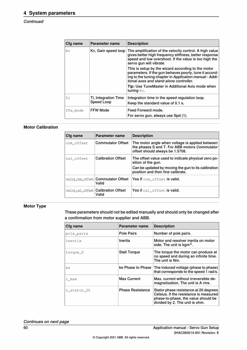
The amplification of the velocity control. A high valuegives better high frequency stiffness, better responsespeed and low overshoot. If the value is too high theservo gun will vibrate.
Kv, Gain speed loopKv
This is setup by the wizard according to the motorparameters. If the gun behaves poorly, tune it accord-ing to the tuning chapter in Application manual - Addi-tional axes and stand alone controller.Tip: Use TuneMaster in Additional Axis mode whentuning Kv.
Integration time in the speed regulation loop.Ti, Integration TimeSpeed Loop
Ti
Keep the standard value of 0.1 s.
Feed Forward mode.FFW Modeffw_mode
For servo gun, always use Spd (1).
Motor Calibration
DescriptionParameter nameCfg name
The motor angle when voltage is applied betweenthe phases S and T. For ABB motors Commutatoroffset should always be 1.5708.
Commutator Offsetcom_offset
The offset value used to indicate physical zero po-sition of the gun.
Calibration Offsetcal_offset
Can be updated by moving the gun to its calibrationposition and then fine calibrate.
Yes If com_offset is valid.Commutator OffsetValid
valid_com_offset
Yes if cal_offset is valid.Calibration OffsetValid
valid_cal_offset
Motor TypeThese parameters should not be edited manually and should only be changed aftera confirmation from motor supplier and ABB.
DescriptionParameter nameCfg name
Number of pole pairs.Pole Pairspole_pairs
Motor and resolver inertia on motorside. The unit is kgm2 .
Inertiainertia
The torque the motor can produce atno speed and during an infinite time.The unit is Nm.
Stall Torquetorque_0
The induced voltage (phase to phase)that corresponds to the speed 1 rad/s.
ke Phase to Phaseke
Max. current without irreversible de-magnetization. The unit is A rms.
Max Currenti_max
Stator phase resistance at 20 degreesCelsius. If the resistance is measuredphase-to-phase, the value should bedivided by 2. The unit is ohm.
Phase Resistancer_stator_20
Continues on next page60 Application manual - Servo Gun Setup
3HAC065014-001 Revision: E© Copyright 2021 ABB. All rights reserved.
4 System parametersContinued

DescriptionParameter nameCfg name
Stator phase inductance at zero cur-rent. The value should be measuredat a frequency of about 120Hz to cor-respond to what the drive expects. Ifthe inductance is measured phase-to-phase, the value should be divided by2. The unit is Henry.
Phase inductancel_stator
Temperature reduction coefficient forke, at 20 degrees. The unit is 1/K.
-ke_temp_coef_20 i
Long-term stability reduction constantfor ke after 4000 hours.
-ke_stability_coef_20 i
Minimum tolerance for ke (%/100)-ke_tolerance_min i
Min. ke= ke*(1+ke_tolerance_min).
Maximum tolerance for ke (%/100).-ke_tolerance_max i
Max. ke= ke*(1+ke_tolerance_max).
Current dependant reduction of ke attwo times rated current (%/100).
-ke_red_2i0 i
Total torque losses due to friction andiron losses at speed1. The unit is Nm.
-torque_losses_at_speed1 i
Total torque losses due to friction andiron losses at speed2. The unit is Nm.
-torque_losses_at_speed2 i
Total torque losses due to friction andiron losses at speed3. The unit is Nm.
-torque_losses_at_speed3 i
The speed at whichtorque_losses_at_speed1 is definedin rad/s.
-speed1 i
The speed at whichtorque_losses_at_speed2 is definedin rad/s.
-speed2 i
The speed at whichtorque_losses_at_speed3 is definedin rad/s.
-speed3 i
Maximum temperature for the statorwinding. The unit is degrees Celsius.
-temp_stator_max i
Maximum temperature rise for thestator winding. The unit is degreesCelsius.
-temp_stator_rise i
Maximum temperature for the rotor.The unit is degrees Celsius.
-temp_rotor_max i
Maximum temperature rise for the ro-tor. The unit is degrees Celsius.
-temp_rotor_rise i
Temperature coefficient for the statorresistance at 20 degrees Celsius.
-r_stator_temp_coef_20 i
i The parameter is recommended but not mandatory to use.
Continues on next pageApplication manual - Servo Gun Setup 613HAC065014-001 Revision: E
© Copyright 2021 ABB. All rights reserved.
4 System parametersContinued

SG Process
DescriptionParameter nameCfg name
Constant time adjustment (s), positive ornegative, of the moment when the gun tipsreach contact during a gun closure. This valueis normally zero. May be used to delay theclosing slightly when the synchronized preclosing is used for welding.
Close Time Adjustmin_close_time_adjust
Normally not used.
When the tool tips reach the position (platethickness) ordered by the close instruction,the force control starts. This tool tip positioncan be adjusted with Close Position Adjust tomake the force control start earlier.
Close Position Ad-just
close_position_adjust
Normally set to 0.001 to avoid that the gun hitsthe plates before force mode.
Constant time delay (s) before sending theweld ready signal after reaching the pro-grammed force.
Force Ready Delaypre_sync_delay_time
Normally set to 0.
Maximum allowed motor torque (Nm) duringforce control. The parameter will protect thegun from too high programmed force, by redu-cing the resulting motor torque to this upperlevel. A warning will be logged whenever thishappens. The value must not be set higherthan the Torque abs. max (type Stress dutycycle) which defines the maximum output ofmotor torque during both force and positioncontrol.
Max Force ControlMotor Torque
max_motor_torque
This value is also used as torque limit inmanual mode to avoid hard crashes whenjogging.
Release time anticipation (s) of the next robotmovement after a weld. This parameter canbe tuned to synchronize the gun opening withthe next robot movement. The synchronizationmay fail if the parameter is set too high.
Post-synchronizationTime
post_sync_time
Can normally be kept at zero.
The number of closings performed during aTipwear calibration. Normally 2 closings willbe ok. An increase may improve the accuracyof thickness detection for some servo guns.
Calibration Modecalib_mode
The maximum tip force (N) used during a Tip-Wear calibration.
Calibration ForceHigh
calib_force_high
The recommendation is that this value shouldbe between 2/3 of max force and max force.
The minimum tip force (N) used during a Tip-Wear calibration. For best result of the thick-ness detection, it is recommended to use theminimum programmed weld force.
Calibration ForceLow
calib_force_low
The recommendation is that this value shouldbe about a 1/3 of max force but never lowerthan the minimum force used for the gun.
Continues on next page62 Application manual - Servo Gun Setup
3HAC065014-001 Revision: E© Copyright 2021 ABB. All rights reserved.
4 System parametersContinued

DescriptionParameter nameCfg name
The wait time (s) during a calibration beforethe positional gun tip correction is done. Re-commended value ca: 0.5 s.
Calibration Timecalib_time
Number of stored forces in the force VS motortorque table. The minimum value allowed is2.
Number of StoredForces
no_of_active_db_posts
Normally this is set to between 2 and 4.
Gun tip force 1 (N) - Gun tip force 10 (N).Tip Forces 1 - 10squeeze_force_1-squeeze_force_10
Motor torque 1 (Nm) - Motor torque 10 (Nm).Motor Torque 1 - 10squeeze_torque_1-squeeze_torque_10
Stress Duty Cycle
DescriptionParameter nameCfg name
The absolute highest motor speed to be used.(rad/s)
Speed Absolute Maxspeed_absolute_max
The absolute highest motor torque to be used.(Nm)
Torque AbsoluteMax
torque_absolute_max
If torque_absolute_max is too high, it mayresult in a configuration error at restart. Toavoid this, make sure that:torque_absolute_max < √(3) * ke * i_max.
Automatically reduce the max speed if thereis no more available current at higher speed.
-speed_max_reduction_active
Supervision
DescriptionParameter nameCfg name
Speed supervision should be On.Speed Supervisionspeed_supervision_on
Position supervision should be On.Position Supervisionposition_supervision_on
Counter supervision On.Counter Supervisioncounter_supervision_on
Jam supervision On.Jam Supervisionjam_supervision_on
Load supervision On.Load Supervisionload_supervision_on
Power up position supervision On,default is Off.
Power Up PositionSupervision
power_up_position_on
Keep at default.In Position Rangein_position_range
Keep at default.Zero Speed (%)normalized_zero_speed
Determines whether this joint effectsforced gain control.
Affects Forced Con-trol
joint_affect_forced_Kp
Normally not used for servo gun.Keep at default value.
The upper position limit for forcedgain control.
Forced on PositionLimit
Kp_forced_on_limit
Normally not used for servo gun.Keep at default value.
Continues on next pageApplication manual - Servo Gun Setup 633HAC065014-001 Revision: E
© Copyright 2021 ABB. All rights reserved.
4 System parametersContinued

DescriptionParameter nameCfg name
The lower limit for forced gain control.Forced off PositionLimit
Kp_forced_off_limit
Normally not used for servo gun.Keep at default value.
Supervision Type
DescriptionParameter nameCfg name
Static power up position error limitat zero speed.The unit is radians,Min.=0 and Max.=30.
-static_power_up_position_limit
Normally not used for servo gun.Keep at default value.
Distance (in meters) that the gun canbend in force. Normally at defaultvalue.
-fc_position_limit
Makes speed supervision lesssensitive in force mode. Normally atdefault value.
-fc_speed_limit_factor
Dynamic power up position errorlimit at zero speed, the unit is radi-ans.
Dynamic Power UpPosition Limit
dynamic_power_up_position_limit
Normally not used for servo gun.Keep at default value.
Position error limit at zero speed, theunit is radians on motor side.
-static_position_limit
Normally not used for servo gun.Keep at default value.
Position error limit at max speed, theunit is radians on motor side.
-dynamic_postion_limit
Normally not used for servo gun.Keep at default value.
Speed error limit at zero speed. (%max. speed).
-static_normalized_speed_limit
Speed error limit at max speed (%max speed).
-dynamic_normalized_speed_limit
Defines the maximum allowed timewith maximum torque while moving.The unit is seconds, Min.=0 andMax.=20.
-max_overload_time
Defines the maximum allowed timewith maximum torque at zero speed.The unit is seconds, Min.=0 andMax.=20.
Max Jam Timemax_jam_time
Maximum ordered speed ratio inteach mode (% max speed). Min.=0,Max.=1, Deafult=0.15.
Teach Max SpeedMain
teach_mode_speed_max_main
This should be set according tochapter Limit peripheral speed ofexternal axis in Application manu-al - Additional axes and stand alonecontroller.
Continues on next page64 Application manual - Servo Gun Setup
3HAC065014-001 Revision: E© Copyright 2021 ABB. All rights reserved.
4 System parametersContinued

DescriptionParameter nameCfg name
Maximum supervision speed ratio inteach mode for axis computer (%max speed). Min.=0, Max.= 1, De-fault=0.28.
Teach Max SpeedDSP
teach_mode_speed_max_dsp
Take the value fromteach_mode_speed_max_mainandadd a margin for noise and vibra-tions.
Transmission
DescriptionParameter nameCfg name
Gear ratio between motor and gun, specified asmotor rotation in radians per meter linear move(-1050 denotes that when the motor rotates 1050radians - the axis moves 1 m).
Transmission GearRatio
transm_joint
Application manual - Servo Gun Setup 653HAC065014-001 Revision: E
© Copyright 2021 ABB. All rights reserved.
4 System parametersContinued

This page is intentionally left blank

5 TuneMaster and tuning5.1 TuneMaster
About TuneMasterTuneMaster can be used to study signals for position, speed, torque, etc.TuneMaster can be downloaded from:http://new.abb.com/products/robotics/robotstudio
For more information about TuneMaster, see Application manual - TuneMaster.
Define test signals with TuneMasterThe following test signals should be defined for the servo gun:
Recommended scaleSignal
0.16 speed
19 torque_ref
1000200 position
155 positive torque_limit
156 negative torque_limit
55 force mode
0.14 speed_ref
Continues on next pageApplication manual - Servo Gun Setup 673HAC065014-001 Revision: E
© Copyright 2021 ABB. All rights reserved.
5 TuneMaster and tuning5.1 TuneMaster

Speed limit tuningWhen tuning the speed limit, you want to allow as fast speed as possible withoutgetting a pushback from the servo gun that can severely reduce the accuracy ofthe force control.
Example of bad speed limit
A
B
C
D
E
xx1700001576
Speed limit signalA
Torque signalB
Force control mode signalC
Speed signalD
Large pushback from the servo gun is shown as a negative speed whenthe speed should be zero and full force should be applied. This can causethe actual force to differ from the ordered force.
E
Continues on next page68 Application manual - Servo Gun Setup
3HAC065014-001 Revision: E© Copyright 2021 ABB. All rights reserved.
5 TuneMaster and tuning5.1 TuneMasterContinued

Example of good speed limit
A
B
C
D
EF
xx1700001577
Torque signalA
Force control mode signalB
Speed limit signalC
Speed signalD
No pushback from the servo gun.E
A reduction in the torque when the speed reach the speed limit is per-fectly normal.
F
Acceleration tuningDuring acceleration tuning, it is important to look at the signal for the torque.
• The torque during acceleration when opening and when closing should befairly symmetrical. If gravity affects the servo gun, the acceleration torquefor opening and closing will not be totally symmetrical. If there are largedeviations from symmetry, verify that the commutation of the servo gun iscorrect (see Applicationmanual - Additional axes and stand alone controller).
• The torque during acceleration should be approximately 80% of the torquelimit.
Continues on next pageApplication manual - Servo Gun Setup 693HAC065014-001 Revision: E
© Copyright 2021 ABB. All rights reserved.
5 TuneMaster and tuning5.1 TuneMaster
Continued

Example of acceleration tuning
B
A
D
C
E
F
xx1700001578
Positive torque limit signalA
Speed signalB
Torque signalC
Negative torque limit signalD
Torque during acceleration when opening the gunE
Torque during deceleration when closing the gunF
70 Application manual - Servo Gun Setup3HAC065014-001 Revision: E
© Copyright 2021 ABB. All rights reserved.
5 TuneMaster and tuning5.1 TuneMasterContinued

5.2 Tuning with movable gun arm search
5.2.1 Movable gun arm search
About the functionalityThe tuning of moveable gun arm search is done by repeating search movementsand changing system parameters.Run the RAPID instruction SearchMoveCheck to perform a test run while findingvalues for parameters. The following test signals are useful in the tuning.
ScaleSignal numberSignal
0.14Speed reference
0.16Speed feedback
133Speed error
11230Search signal
During the movement from GunOpenPos between GunOpenPos and 5 mm beforeclosed the signals should be observed.Tuning of movable gun arm search is done in the following steps.
1 Tune the speed loop gain.2 Check and tune the speed error filter.3 Tune the leakage.4 Verify the threshold.
System parametersThe following system parameters are used for movable gun arm search:
• Search Leak Subtrahend• Search filter bandwidth• Search Threshold• Search reverse distance• Search Speed• Search Kv• Search Ti
See the descriptions for Force Master on page 57 and Force Master Control onpage 59.
Procedure1 Tune the speed gain.
Note that Search Kv and Search Ti are assumed to be tuned in a regularmanner for a fast step response without overshoot or oscillations, see belowfor an example.Rule of thumb: search Kv = 1.4* LCM0 Kv = 1,400 x Motor InertiaDuring the search sequence the servo gains of speed loop replaces thevalues set in LCM0.
Continues on next pageApplication manual - Servo Gun Setup 713HAC065014-001 Revision: E
© Copyright 2021 ABB. All rights reserved.
5 TuneMaster and tuning5.2.1 Movable gun arm search

Search Ti is active during ramp and search and Search Kv is active duringthe search.
xx2000001903
2 Check and tune the speed error filter.Run the search movement with selected values of Search Kv and Search Tifrom the previous step.Look at test signal 33. If there is an obvious pattern or noise speed then theerror filter can be lowered to flatten out the speed error. If no such patternis seen, keep the value quite high, that is, 15 Hz or higher.
3 Tune the leak and the threshold. Look at signal 1230 in TuneMaster.Leak:The goal is to find a value of search_speed_leak_subtrahend where about50% of the samples (seem in signal 1230) are equal to zero.In many cases it can be tricky to find start value so it is recommended to doa rough first tuning followed by a more detailed.Non wanted behaviors:
• There is a clear trend in the search signal, either increasing ordecreasing. This might be due to a poorly tuned gun. Ti should bere-tuned in order to remove trends. Try decrease Ti in steps of 50%until the trends disappears.
• A spike in the beginning of the search signal is much larger than therest. This might be due to either a poorly tuned gun or due to a shortIf the problem does not go away or the spike is during a longer periodof time try re-tuning the gun by decreasing Ti.
• There are a lot of oscillations in the search signal. Oscillations can bereduced by increasing Kv. Increase Kv until the signal looks appear tobe noisy rather than oscillatory. By looking at signal 33 (Speed Error)in TuneMaster it is easier to spot an oscillatory behavior.
• There is a clear pattern that comes cyclic (from gearbox etc) Thendecrease of speed error filter bandwidth (FilterCoeff) can help.
Iterate the leak tuning until signal 1230 looks noisy but controlled.
Continues on next page72 Application manual - Servo Gun Setup
3HAC065014-001 Revision: E© Copyright 2021 ABB. All rights reserved.
5 TuneMaster and tuning5.2.1 Movable gun arm searchContinued

An example of a correctly tuned gun can be seen in the following figure, notethat even though Kv is increased by about 200% an oscillatory behavior isseen and this is probably due to ripple effects in the motor.
xx2000001904
In the figure above, about 50% of the samples in the search signal are equalto zero. The Leak parameter is correctly tuned. Oscillations is due to ripple.Less ripple in the speed signal means less oscillations in the search signal.Note that speed is scaled by 0.1 and search signal is scaled by 10. Themaximal value of the search signal is 0.23, threshold is therefore set to 0.5.
4 Verify the threshold.When search_speed_leak_subtrahend has been set it is time for checkingthe threshold.Run search movement with all kinds of angles of the gun with respect togravity and see what they highest value of 1230 is. Set threshold to 1.5-2times higher than that value.Possible problems:
• The guns detects false collisions. Increase the Threshold parameter.If the false detections are removed but the force (either measured orseen by detecting a plate) is too high tuning of Ti and Kv might needa better tuning or the speed needs to be decreased.
5 Proceed with the configuration.6 When all tuning is done, all values should be saved to the configuration.
Application manual - Servo Gun Setup 733HAC065014-001 Revision: E
© Copyright 2021 ABB. All rights reserved.
5 TuneMaster and tuning5.2.1 Movable gun arm search
Continued

5.2.2 RAPID references for MGAS
5.2.2.1 SearchMoveCheck
UsageSearchMoveCheck is used to do search movements without any contact to repeatmovements during tuning procedures. A tuning procedure is typically used to findan optimal value for a parameter. A test movement (that is, a program executionwith a SearchMoveCheck) is repeated when using different parameter tune valuesset up by TuneDetectionParams.
Basic examplesThe following example illustrates the instruction SearchMoveCheck.
SearchMoveCheck gun1, \GunOpenPos:=100;
ArgumentsSearchMoveCheck gunnum [\GunOpenPos]
gunnum
Data type: numUsed gun number. Corresponding to the element number in the gundata arraycurr_gundata in the module SWUSER.SYS.
[\GunOpenPos]
Data type: numOptional parameter. The gun will open to the specified position [mm] (only servoguns).
SyntaxSearchMoveCheck
[GunNo ':='] < expression (IN) of num >
['\' GunOpenPos ':=' < expression (IN) of num > ] ';'
74 Application manual - Servo Gun Setup3HAC065014-001 Revision: E
© Copyright 2021 ABB. All rights reserved.
5 TuneMaster and tuning5.2.2.1 SearchMoveCheck

5.2.2.2 TuneDetectionParams
UsageTuneDetectionParams is used to change search parameters during tuningprocedures. A tuning procedure is typically used to find an optimal value for aparameter. A test movement (that is, a program execution with aSearchMoveCheck) is repeated when using different parameter tune values setup by TuneDetectionParams.
Basic examplesThe following example illustrates the instruction TuneDetectionParams.
FOR i FROM 1 TO 10 DO
TuneDetectionParamsGun1\Threshold:=10000\LeakSubtrahend:=1e-10\SearchKv:=0.1*i;
SearchMoveCheck gun1, \GunOpenPos:=100;
ENDFOR
ArgumentsTuneDetectionParams gunnum [\Threshold] [\LeakSubtrahend]
[\LeakSubtrahend] [\SearchKv] [\SearchTi] [\SearchSpeed][\FilterCoeff]
gunnum
Data type: numUsed gun number. Corresponding to the element number in the gundata arraycurr_gundata in the module SWUSER.SYS.
\Threshold
Data type: numThe value that should trigger the search stop. Start with high value to avoid falsealarms during initial tuning.
\LeakSubtrahend
Data type: numValue used to control the leak rate of the search signal seen in test signal 1230.Start with low value too see the search signal and gradually increase.
\SearchKv
Data type: numProportional gain in the speed regulation loop during the search part of themovement.
\SearchTi
Data type: numIntegration time in the speed regulation loop during the search part of themovement.
Continues on next pageApplication manual - Servo Gun Setup 753HAC065014-001 Revision: E
© Copyright 2021 ABB. All rights reserved.
5 TuneMaster and tuning5.2.2.2 TuneDetectionParams

\SearchSpeed
Data type: numSpeed during search movement mm/s.
\FilterCoeff
Data type: numCut off frequency for the speed error filter (Hz).
SyntaxTuneDetectionParams
[gunnum ':='] <expression (IN) of num>
['\' Threshold ':=' <expression (IN) of num>]
['\' LeakSubtrahend ':=' <expression (IN) of num>]
['\' SearchKv ':=' <expression (IN) of num>]
['\' SearchTi ':=' <expression (IN) of num>]
['\' SearchSpeed ':=' <expression (IN) of num>]
['\' FilterCoeff ':=' <expression (IN) of num>]';'
76 Application manual - Servo Gun Setup3HAC065014-001 Revision: E
© Copyright 2021 ABB. All rights reserved.
5 TuneMaster and tuning5.2.2.2 TuneDetectionParamsContinued

6 Motor type fileContent of motor type file
The motor type file must include the types:• MOTOR_TYPE
• STRESS_DUTY_CYCLE
If not using the default values for standard ABB motors, the motor type file caninclude (for example):
• MOTOR_CALIB
• LCM0
• AXC_FILTER
Example of motor type file
MOC:CFG_1.0::
#Technical spec S.DTE 008-91
#
MOTOR_TYPE:
-name "ARO_S.DTE008_91"\
-pole_pairs 4\
-inertia 0.00165\
-torque_0 18\
-ke 0.98365\
-ke_temp_coef_20 0.00035\
-ke_stability_coef_20 0.03\
-ke_tolerance_min -0.05\
-ke_tolerance_max 0.05\
-ke_red_2i0 0.06\
-i_max 19.5\
-torque_losses_at_speed1 0.2\
-torque_losses_at_speed2 0.3\
-torque_losses_at_speed3 0.4\
-speed1 104.72 -speed2 209.44\
-speed3 314.16\
-r_stator_20 1.225\
-r_stator_temp_coef_20 0.00263\
-l_stator 0.00325
#
STRESS_DUTY_CYCLE:
-name "SGUN_1"\
-speed_absolute_max 314\
-torque_absolute_max 30\
-speed_max_reduction_active
Application manual - Servo Gun Setup 773HAC065014-001 Revision: E
© Copyright 2021 ABB. All rights reserved.
6 Motor type file

This page is intentionally left blank

IndexAacceleration, 43alarm torque, 32
BBack button, 18buttons, 18
CChange button, 18commissioning mode, 53connection, 22
Ddeflection, 47delta position, 33
Ffine calibration, 24FlexPendant, 12force calibration, 35
Ggun deflection, 47gun specific data, 22
Lload a saved configuration, 53load configuration, 20
MMain view, 18motor type, 21motor type file, 77
NNext button, 18non-linear guns, 30
Rrequirements, 12RobotStudio, 12
Ssave configuration, 51Servo Gun Setup wizard, 17Skip button, 18speed limit, 41system parameters, 12, 57
TTest Signal Viewer, 67transmission, 26TuneMaster, 12, 41, 43tune servo gun, 24
UUpdate button, 18
Wwizard, 17
Xx-gun, 30
Application manual - Servo Gun Setup 793HAC065014-001 Revision: E
© Copyright 2021 ABB. All rights reserved.
Index


ABB ABRobotics & Discrete AutomationS-721 68 VÄSTERÅS, SwedenTelephone +46 (0) 21 344 400
ABB ASRobotics & Discrete AutomationNordlysvegen 7, N-4340 BRYNE, NorwayBox 265, N-4349 BRYNE, NorwayTelephone: +47 22 87 2000
ABB Engineering (Shanghai) Ltd.Robotics & Discrete AutomationNo. 4528 Kangxin HighwayPuDong DistrictSHANGHAI 201319, ChinaTelephone: +86 21 6105 6666
ABB Inc.Robotics & Discrete Automation1250 Brown RoadAuburn Hills, MI 48326USATelephone: +1 248 391 9000
abb.com/robotics
3HAC065014-001,Rev
E,en
© Copyright 2021 ABB. All rights reserved.Specifications subject to change without notice.