Maquet Servo 900c - User Manual - baixardoc
10
CRITICAL CARE SERVO VENTILATOR 900 C OPERATING MANUAL
-
Upload
khangminh22 -
Category
Documents
-
view
2 -
download
0
Transcript of Maquet Servo 900c - User Manual - baixardoc

CRITICAL CARE
SERVO VENTILATOR 900 C
OPERATING MANUAL

▲! General information• Servo Ventilator 900 C must be operated only by authorized
personnel who are well trained in its use.It must be operated according to the instructions in thisOperating Manual.
• After unpacking, the ventilator must be checked and, ifnecessary, calibrated.
• All data on pressures for Servo Ventilator 900 C are given incm H
2O.
1 kPa (kilopascal) ≈ 10 cm H2O
100 kPa = 1 bar ≈ 1 atm ≈ 1 kgf/cm2 (kp/cm2)100 kPa ≈ 15 psi
• Responsibility for the safe functioning of the equipmentreverts to the owner or user in all cases in which service orrepair has been done by a non-professional or by personswho are not employed or authorized by MAQUET, and whenthe equipment is used for other than its intended purpose.
• A full technical description – including circuit diagrams, partslist and service data – is contained in the servicedocumentation, copies of which are held by your supplier.
Connection• When connected to a patient, the ventilator must never be
left unattended.
• A check on functions must be done before a patient isconnected to the ventilator.
• When anaesthetic gas is metered via a flow meter on the lowpressure inlet, compressed air must not be connected at thesame time.
• To avoid explosion hazards, flammable agents such as etherand cyclopropane must not be used in this machine. Onlyagents which comply with the requirements on non-flammable agents in the IEC standard “Particularrequirements for electrical safety of anaesthetic machines”are suitable in this machine.
• As this machine is not suitable for use with flammable agentssuch as ether and cyclopropane, the use of antistaticbreathing tubes and face masks is not necessary.The use of antistatic or electrically conductive breathingtubes when using high frequency electric surgery equipment,may cause burns and is therefore not recommended in anyapplication of this machine.
• Never connect or disconnect auxiliary equipment to the outleton the rear of the ventilator when the ventilator is connectedto mains.
• All gases must fulfill the specifications for medical grade gas.The gases supplied must be dry and free from oil and dust.Air H
2O < 5 g/m3
Oil < 0.5 mg/m3
Oxygen H2O < 20 mg/m3
Nitrous oxide/gaseous phase) H2O < 58 ppm
Operation• The APNEA ALARM is not intended to and will not monitor
for disconnections.
• The APNEA ALARM is not functional in VOL. CONTR., VOL.CONTR. + SIGH, PRESS. CONTR. or MAN.
• In the case of a power failure, manual ventilation using aServo Ventilator 900 C is possible only with the help ofpower supply from external battery. A resuscitator shouldalways be available, however, as an extra safety measure.
• The SV 900 C is certified, with regard to safety, to becompatible with electromagnetic environments complyingwith IEC 601-1-2. It is the responsibility of the user to takenecessary measures in order to ascertain that the specifiedlimits are not exceeded as this may impair the safety of theventilator.
Such measures should include, but are not limited to:
– normal precautions with regard to relative humidity andconductive characteristics of clothing in order to minimize thebuild-up of electrostatic charges.
– avoiding the use of radio emitting devices in close
proximity of the ventilator, such as high-frequency surgeryapparatus or cordless (mobile) telephones, resulting in a fieldlevel exceeding 3 V/m (IEC 601-1-2).
Magnetic fields of MR equipment having flux densities above20 mT may cause deactivation of the ventilator functions andmay result in permanent damage to the Servo Ventilator.
• To protect the patient against high pressures, the WORKINGPRESSURE and UPPER PRESS. LIMIT must always be setat suitable values.
• Do not forget to set the manual ventilation valve to positionAUT after completed manual ventilation. Otherwise thepatient may be hypoventilated without any alarm from theventilator. (Not applicable to manual ventilation accessorywith motor).
• When mains supply is switched off or in the case of a mainspower failure, the inspiratory and expiratory valves willautomatically open. This may also occur in the case of aninternal electronic failure. Thus, if the WORKINGPRESSURE is set too high and the gas supply through thegas supply unit continues, this may result in increased airwaypressure.
• When excess gas is being scavenged, the scavengingsystem must meet the following requirements:– At the point at which the scavenging system isconnected to the ventilator, the sub-atmospheric pressuremust not exceed 0.5 cm H
2O or cause an induced flow from
the breathing system greater than 0.5 l/min.– With continuous air flows of 30 l/min and 90 l/min fornot less than 5 seconds at the inlet of the anaestheticgas scavenging system, the resistance in the systemshall not exceed 0.25 cm H
2O and 2.5 cm H
2O, respectively.
The Servo Evac 180 basic evacuation unit meets theserequirements.
• If the ventilator is equipped with electronic gas supply unit,the following applies:When mains supply is switched off or in the case of powerfailure, the gas supply is automatically blocked.
Cleaning• The ventilator must not be gas sterilized.
• The flow transducers must not be cleaned in a dish washingmachine, by ultrasonic methods or by using agents thatcontain aldehydes.
• Agents used for cleaning must have a pH value between4–8.5.
• Complete cleaning should be done after every 1000 hoursof operation or, at the latest, after every six months.
Service• The Servo Ventilator 900 C must be serviced at regular
intervals by specially trained personnel. Any maintenancemust be noted in the log book provided for that purpose,in accordance with national regulations. We recommend thatservice is done as a part of a service contract with MAQUET.
• The 1000 hours overhaul shall be done after every 1000operating hours or, at the latest, every six months. Inaddition, the ventilator shall undergo a technical safety checktwice a year, at six months intervals, according to nationalregulations.
• Service and repairs on the ventilator may be done onlyby MAQUET authorized personnel.
• Only original parts from MAQUET must be used in theventilator.
Equipment combinations• Only MAQUET-approved accessories and auxiliary
equipment may be connected to the ventilator.
• In order to maintain system safety and integrity onlyaccessories complying with IEC 601-1, or the safety of whichhas been verified in another way must beconnected to the signal outputs on the rear of the ventilator.For details on connections and allowedvoltages, please see Circuit Diagram.
Important
Product information program
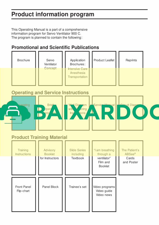
This Operating Manual is a part of a comprehensiveinformation program for Servo Ventilator 900 C.The program is planned to contain the following:
Promotional and Scientific Publications
Operating and Service Instructions
Product Training Material
Brochure Servo Application Product Leaflet Reprints
Ventilator Brochures:
Concept Intensive Care
Anesthesia
Transportation
Operating Brief Wall Diagram Service Manual Circuit Diagram
Manual Operating with Cleaning
Instructions Instructions
Training Advisory Slide Series “I am breathing The Patient’s
Instructions Booklet including through a ABSee®
for Instructors Textbook ventilator” Cards
Film and and Poster
Booklet
Front Panel Panel Block Trainee’s set Video programs
Flip-chart Video guide
Video news

Servo Ventilator 900 C-Front


Servo Ventilator 900 C is simple to operate.Operating instructions are found:
!
On the ventilator in the form of a panel andcleaning instructions on the lid of thepneumatic unit.
“Normal” settings are indicated in green onthe front panel. Settings indicated in redshould be used with caution, since thesesettings may involve a certain risk for thepatient.
@
In the Brief Operating Instructions in the drawerunder the ventilator.
A log sheet is available with the BriefOperating Instructions. After certain routines,e. g. cleaning etc., the person responsible forthe work should complete and sign the logsheet. The log sheet can then be filed.
#
On a separate wall poster with cleaninginstructions.
$
In this Operating Manual.
The inside of the cover shows a picture ofthe ventilator. This picture can be used as afoldout when reading the manual.
The following information is found in thecorresponding chapters:
Description ............................................ 1-3
Operating ............................................... 4-9
Maintenance ...................................... 10-13
Technical specifications ......................... 14
Operating instructions

1
1. Arbetsprincip
2. Kontrollpanel och ventilationssätt
3. Patientsäkerhet
4. Uppställningar
5. Förberedelser
6. Funktionskontroll
7. Anslutning till patient
8. Klinisk bedömning och felsökning
9. Registrering
10. Rutinrengöring
11. 1000-tim.-översyn med fullständig rengöring
12. Utbyte av O2-cell
13. Kalibrering
14. Tekniska specifikationer
Contents
1. Basic principles
2. Control panel and ventilation modes
3. Patient safety
4. Set-ups
5. Preparations
6. Check on functions
7. Connection to patient
8. Clinical judgement and troubleshooting
9. Recording
10. Routine cleaning
11. 1000 hours overhaul with complete cleaning
12. Replacement of O2 cell
13. Calibration
14. Technical specifications

2

11Basic principles
In this chapter:
General design .................1:2
Pneumatic unit..................1:3
Rear ...................................1:4
Chapter 1

12
General design
Low pressure
High pressure
Pneumatic unit
The pneumatic unit comprises the gasconduction system, pressure and flowtransducers and control valves.
The control of flow and pressure is done by afeed-back system. The transducers continuallymeasure the flow and pressures. Theinformation is compared with the panel settingsand a difference between the actual and thepreset values results in correction signals tothe control valves.
For detailed description, see chapter “Basicprinciples” in the Training Instructions.
Electronic unit
The electronic unit contains a number of plug-in PC-boards with the circuits for regulation,alarms and monitoring.
The unit effects the electronic control of thepneumatic unit.
Servicing of the ventilator is facilitated by thespare parts exchange system. The faulty partsare replaced by factory trimmed exchangeparts.
Service on the electronic unit must be doneby MAQUET, or by MAQUET authorizedpersonnel only.