BLHX Brushless Servo Drives User Guide - Parker Motion
153
BLHX Brushless Servo Drives User Guide For engineering For engineering assistance in Europe: assistance in the U.S.: Parker Hannifin plc Parker Hannifin Corporation Electromechanical Division - Digiplan Compumotor Division 21 Balena Close 5500 Business Park Drive, Suite D Poole, Dorset Rohnert Park, CA 94928 England, BH17 7DX USA Direct Lines for Technical Support Telephone: (800) 358-9070 Tel: 01202-699000 Fax: 01202-695750 Fax: (707) 584-3793 E-mail: [email protected] FaxBack System: (800) 936-6939 BBS: (707) 584-4059 E-mail: [email protected] Part No: 1600.224.01 November, 1996
-
Upload
khangminh22 -
Category
Documents
-
view
2 -
download
0
Transcript of BLHX Brushless Servo Drives User Guide - Parker Motion

BLHX Brushless Servo
Drives
User Guide
For engineering For engineeringassistance in Europe: assistance in the U.S.:Parker Hannifin plc Parker Hannifin CorporationElectromechanical Division - Digiplan Compumotor Division21 Balena Close 5500 Business Park Drive, Suite DPoole, Dorset Rohnert Park, CA 94928England, BH17 7DX USADirect Lines for Technical Support Telephone: (800) 358-9070Tel: 01202-699000 Fax: 01202-695750 Fax: (707) 584-3793E-mail: [email protected] FaxBack System: (800) 936-6939
BBS: (707) 584-4059E-mail: [email protected]
Part No: 1600.224.01 November, 1996

IMPORTANT INFORMATION FOR USERS
Installation and Operation of Digiplan Equipment
It is important that Digiplan motion control equipment is installed and operated in such a way that all applicablesafety requirements are met. Note that it may be necessary for the completed installation to comply with the LowVoltage Directive or the Machinery Directive. It is your responsibility as an installer to ensure that you identify therelevant safety standards and comply with them; failure to do so may result in damage to equipment and personalinjury. In particular, you should study the contents of this user guide carefully before installing or operating theequipment.
The installation, set-up, test and maintenance procedures given in this User Guide should only be carried out bycompetent personnel trained in the installation of electronic equipment. Such personnel should be aware of thepotential electrical and mechanical hazards associated with mains-powered motion control equipment - pleasesee the safety warning below. The individual or group having overall responsibility for this equipment mustensure that operators are adequately trained.
Under no circumstances will the suppliers of the equipment be liable for any incidental, consequential or specialdamages of any kind whatsoever, including but not limited to lost profits arising from or in any way connected withthe use of the equipment or this user guide.
SAFETY WARNING
High-performance motion control equipment is capable of producing rapid movement and very high forces.Unexpected motion may occur especially during the development of controller programs. KEEP WELLCLEAR of any machinery driven by stepper or servo motors. Never touch it while it is in operation.
This product is sold as a motion control component to be installed in a complete system using good engineeringpractice. Care must be taken to ensure that the product is installed and used in a safe manner according to localsafety laws and regulations. In particular, the product must be enclosed such that no part is accessible whilepower may be applied. If the equipment is used in any manner that does not conform to the instructions given inthis User Guide, then the protection provided by the equipment may be impaired.
EMC INFORMATIONEMC Information is presented in boxed paragraphs (such as this one). Information in this User Guide consists ofrecommendations only; compliance is not guaranteed. BLHX drives are sold as complex components for use by
professional system builders. They are not intended for sale to end users.
The information in this user guide, including any apparatus, methods, techniques, and concepts describedherein, are the proprietary property of Parker Digiplan or its licensors, and may not be copied, disclosed, or usedfor any purpose not expressly authorised by the owner thereof.
Since Digiplan constantly strives to improve all of its products, we reserve the right to modify equipment and userguides without prior notice. No part of this user guide may be reproduced in any form without the prior consentof Digiplan.
© Digiplan Division of Parker Hannifin plc, 1996– All Rights Reserved –

CONTENTS I
Contents
Contents.............................................................................................................iSection 1. INTRODUCTION..............................................................................1Section 2. GETTING STARTED ........................................................................5Section 3. INSTALLATION .............................................................................11Section 4. HARDWARE REFERENCE.............................................................45Section 5. BASIC MOTION CONTROL CONCEPTS........................................57Section 6. COMMUNICATING WITH THE POSITIONER..................................71Section 7. PROGRAMMING ............................................................................93Section 8. SERVO TUNING..........................................................................117Section 9. MAINTENANCE & TROUBLESHOOTING.....................................127Appendix A....................................................................................................133Appendix B....................................................................................................141Index .............................................................................................................145
User Guide Change SummaryThis user guide, version 1600.224.01, is the first version of the BLHX Brushless ServoDrives User Guide. Previously, both the BLH and the BLHX drives were described in oneuser guide called: BLH/BLHX Brushless Servo Drives User Guide (part number1600.188.03).
When a user guide is updated, the new or changed text is differentiated with a change bar inthe outside margin (this paragraph is an example). If an entire section is changed, thechange bar is located on the outside margin of the section title.
Associated DocumentationThis User Guide forms part of the documentation required to use the BLHX Series ofbrushless servo drives, it should be read in conjunction with the X150/X150E SoftwareReference User Guide (Part Number 1600.221.01) which provides details of individualcommands.
Warning symbols used on the BLHX series of drives have the following meanings:

BLHX SERVO DRIVES USER GUIDE
Product Type: BLHX30, BLHX75, BLHX150
The above products are in compliance with the requirements of the followingDirectives, when installed in accordance with the instructions contained inthis User Guide.
73/23/EEC Low Voltage Directive
93/68/EEC CE Marking Directive
The BLHX Series of drives are sold as complex components to professional assemblers, ascomponents they are not compliant with Electromagnetic Compatibility Directive89/336/EEC. However, information is offered in this User Guide on how to install thesedrives in a manner most likely to minimise the effects of drive emissions and to maximise theimmunity of drives from externally generated interference.

SECTION 1. INTRODUCTION 1
Section 1. INTRODUCTION
Product DescriptionThe BLHX Series drives are high performance, low-loss pulse width modulated DC servodrives suitable for use with Digiplan brushless (ML range) servo motors. The drives aresupplied with an integral positioner which accepts motion control commands over anRS232C link. They are supplied as boxed units and power-plate technology makes themcapable of delivering a continuous output power of 100W to 1.2kW. Adjustable currentlimiting allows them to be matched to a wide range of motors.
The drives are fully protected against damage caused by overheating and by short-circuitsacross motor connections or to earth. Additional protection circuitry monitors the voltagerails within the drives and disables the power switches if these fall outside the specification.
A choice of three current ratings are available:
BLHX30 3.75A continuous (7.5A peak)BLHX75 7.5A continuous (15A peak)BLHX150 15A continuous (30A peak)
Figure 1-1. BLHX Brushless Servo Drive

BLHX SERVO DRIVES USER GUIDE2
The built-in power supply operates from a single AC input voltage and uses a switchingregulator to generate low voltage supplies, including power for the positioner. The supplyhas a built-in power dump circuit which protects its circuits by absorbing the powergenerated by the motor during deceleration.
Product Features
Protection CircuitsAdjustable Current LimitOvercurrentOvertemperature (Motor or drive)OvervoltageOutput short circuit
Function IndicatorsCurrent LimitDrive FaultOvertemperatureLogic Supply On
Outputs and InputsReset/DisableFault outputIncremental encoder outputsDigital tachometer output
Other FeaturesPower dump
System OverviewThe drive contains all the necessary circuitry to control a brushless DC servo motor. It mustbe used with a mains isolating transformer to generate a suitable AC supply voltage fromthe AC mains supply. It must not be connected directly on-line to the AC mains supply asthis would damage the drive and is unsafe.
With the positioner fitted, commands entered at an RS232C terminal or from a computerresult in signals from the positioner to the drive which produce the commanded motioncontrol function. The drive generates motor currents required to achieve the motion from theservo motor and an encoder provides feedback to complete the basic system shown inFigure 1-2.

SECTION 1. INTRODUCTION 3
Figure 1-2. Main Components of a BLHX Servo Control System
Controls and Indicators
LEDs
Current Limit LED (Yellow)
Illumination of this LED indicates that the axis is in current limit (does not disable the axis ).This occurs if the rate of change of velocity demanded cannot be met by the drive or thetorque request is greater than the set peak current.
Overtemperature LED (Red)
Illumination of this LED indicates overtemperature in the drive or the motor connected to it.
Drive Fault LED (Red)
This LED, when illuminated, indicates that there has been an incremental encoder signalloss, overcurrent or overvoltage. It will also illuminate if the 24V DC is present but the ACinput is absent.
Logic Supply On (Green)
This LED indicates that the power to the logic circuits of the drive is present and correct.

BLHX SERVO DRIVES USER GUIDE4
Jumper LinksBLHX drive options are selected by means of nine jumper links as shown in Figure 1-3. Afull description of the jumper link functions will be found under "Setting Up the Drive". SeeTable 3-8 for Current Limit link settings and Figure 3-7 for Pull Up/Pull Down on disableinput.
Figure 1-3. Jumper Link Settings
Jumper/Link SettingsFactory default jumper/link settings are shown in Table 1-1.
FactoryDefault LinkPositions
1 2 3 4 5 6 7 8 9
BLHX C A A B A B A A A
Table 1-1. Factory Default Jumper Link Positions

SECTION 2. GETTING STARTED 5
Section 2. GETTING STARTED
What You Should HaveUpon receipt, you should inspect your BLHX Drive system delivery for obvious damage to itscontainer. Report any damage as soon as possible. The items listed in Table 2-1 should bepresent and in good condition. To verify that you have the proper drive model, check themodel number listed on the drive serial plate.
Ship Kit TablePart Description Part Number
BLHX Drive with integralpositioner BLHX30, BLHX75, BLHX150Optional Transformers:
Model TO92Model TO170Model TO171
2050.036.XX2050.120.XX2050.121.XX
BLHX User Guide 1600.224.XXX150/X150E SoftwareReference User Guide 1600.221.XXMotor Cables:For ML2340 motorFor ML3450/ML3475 motorFor ML1620
23M-CABLE-XX*34M-CABLE-XX*Supplied with motor, fixed lengthof 10 feet (3.0m).
Encoder CablesFor ML23 & ML34 motorsFor ML1620
MLEN-CABLE-XX*Supplied with motor, fixed lengthof 10 feet (3.0m).
* Length of cable specified in feet. Standard sizes are 10 (3.0m), 25 (7.6m),50 (15m), 75 (22.8m)
Table 2-1. BLHX Drive Ship Kit Systems may be shipped configured with drives and motors prewired or supplied asseparate units.
Pre-installation TestThis section provides procedures to help you to connect up your BLHX drive system for apre-installation test. A temporary bench-top configuration is used for the pre-installation test.Detailed permanent installation instructions are provided in Section 3, Installation.
Figure 2-1 illustrates the pre-installation test configuration for a BLHX system. BLHX Seriesdrives must be installed by competent personnel familiar with the installation,commissioning and operation of motion control equipment.

BLHX SERVO DRIVES USER GUIDE6
Figure 2-1. Pre-installation Test Configuration

SECTION 2. GETTING STARTED 7
RS232C ControllerThe RS232C connections from the controller to the positioner are as shown in Figure 2-2.Note that the Tx and Rx lines are cross-connected so that the transmit output is connected tothe receive input in each case.
Figure 2-2. Controller to Positioner RS232C Connections
Connect the Motor
WARNING - danger of electric shock
Ensure that AC power is disconnected before attempting to connect ordisconnect the motor. Hazardous voltages are present on the motor
connectors.
Motor and feedback connectors are pre-wired. Plug the 5-way screw terminal connectorinto the Motor socket and the 25-way D connector into the Motor Feedback socket. Duringfinal installation it may be necessary to extend the leads or re-wire the connectors -information on lead colours etc. will be found in Section 3, Installation.

BLHX SERVO DRIVES USER GUIDE8
Connect the TransformerThe motor and logic supplies are derived from a single-phase isolating transformer, whichshould be rated for the total loading. This clearly depends on the duty cycle, but would betypically 2.5A @ 61V for the BLHX30, 6A @ 107V for the BLHX75 and 11A @ 107V for theBLHX150. You should install an in-line fuse suitably rated for the AC supply and thetransformer loading in the live lead supplying the transformer primary (see Figure 2-1).Normally, the BLHX system is shipped with one of the Digiplan transformers: TO170, TO171or TO92.
Before connecting the AC supply leads, measure the secondary voltage(s)from the isolating transformer. These should not exceed 61V AC for theBLHX30 or 107V AC for the BLHX75 or BLHX150 at the nominal AC inputvoltage.
WARNING - danger of electric shock
Mains voltages are dangerous. Ensure that all terminals are adequatelyinsulated to prevent accidental contact.
Connection Examples
Figures 2-1 illustrates the connections required for the standard Digiplan transformers.
Testing the BLHX System1. Note: the drive potentiometers on BLHX drives are pre-set at the factory. No holes are
provided for access.
2. If the drive has been supplied configured for a particular motor type, the drive jumperlink settings need not be changed. Factory default settings can be used for performingthe pre-installation test.
Note: The BLHX is always supplied configured as a torque amplifier.
3. Make sure that the motor is held securely and the shaft is free to rotate.
4. Turn on the 24V supply (if used) and the main AC supply.
5. Check that the controller is communicating with the positioner by typing 1R<CR>(assuming the device address is 1). Note that all commands should be followed eitherby a space or carriage return <CR>. The positioner should respond with *R if it is readyto accept commands. If there is no response, or a different character is returned, referto the Troubleshooting section before going any further.Type OFF to ensure the drive is disabled.
6. Put a wire jumper link or normally closed push-button switch, between the stop inputand isolated 24V.

SECTION 2. GETTING STARTED 9
7. Type the following:
CPG5 CVG2 CFG0 CTG0 COFF0
8. Type the following:
MC V1 A500 ON G
9. The motor should rotate slowly. This confirms that the drive is working.
10. Type S OFF to stop the motor and to disable the drive.

BLHX SERVO DRIVES USER GUIDE10

SECTION 3. INSTALLATION 11
Section 3. INSTALLATION
Section ObjectivesThe information in this Section will enable you to do the following:
•Mount all system components•Connect all system inputs and outputs•Ensure that the system is installed properly•Perform basic system tests
The BLHX drive can be installed in two ways:
•Normal installation•EMC installation
The BLHX Series of drives are not EMC compliant, they are sold as a complex componentfor use by professional assemblers of motion control systems. Where a system is notrequired to conform with the European EMC directive the installation procedure described inthis Section may be followed. Systems which are are to conform to the European EMCdirective should be assembled using these procedures and additionally the EMC specificinstallation recommendations, described at the end of this Section. Digiplan cannotguarantee EMC compliance.
BLHX Series drives must be installed by competent personnel familiar with the installation,commissioning and operation of motion control equipment.
This section also covers mains transformer information.
EnvironmentThe operational temperature range for the drive system is 0°C to 50°C (32°F to 122°F) andat a relative humidity between 0 and 95% (non-condensing). Make sure the system isstored in temperatures within the range from -40°C to 85°C (-40°F to 185°F).
The mains input to the isolating transformer is Installation Category III maximum.
The BLHX Series of drives can be used in a Pollution Degree 2 environment i.e., one inwhich only non-conductive pollution occurs.
The drive system should be installed in an area where there is adequate ventilation aboveand below the packages. In some applications involving high duty cycles, ventilation fansmay be required. In the final application the equipment must be enclosed to prevent theoperator coming into contact with any high voltages. This includes the transformer, driveand motor terminations.
Metal equipment cabinets offer the most advantages for siting the equipment since they canprovide operator protection, EMC screening and can be readily fitted with interlocks

BLHX SERVO DRIVES USER GUIDE12
arranged to remove all AC power when the cabinet door is opened. This form of installationalso allows the fitting of metal trays beneath the equipment to act as a flame barrier, whichshould be provided in the final installation, in accordance with LVD requirements.
Mounting the DriveAll BLHX drives are supplied as packaged units. Figure 3-1 shows the mounting methodsand overall dimensions.
Enclosure Considerations
You should install the drive system in an enclosure to protect it against atmosphericcontaminants such as oil, moisture, dirt etc. and also to prevent operator access. Ideally,you should install the system in a rack cabinet. In the USA, the National ElectricalManufacturers Association (NEMA) has established standards that define the degree ofprotection that electrical enclosures provide. The enclosure should conform to NEMA Type12 standards if the intended environment is industrial and contains airborne contaminants.Proper layout of components is required to ensure sufficient cooling of equipment within theenclosure.
Figure 3-1. Mounting the Drive

SECTION 3. INSTALLATION 13
Package AssemblyYou can gain access to a drive or positioner card by removing the screws shown in Figure3-2.
WARNINGEnsure AC power is removed before removing any drive covers.
Note: the position of screws will vary depending on the drive type.
To avoid frequent removal and replacement of panels, you should determine the necessarylink connections by reference to Setting the Drive Jumper Links later in this Section.Link changes will not be necessary if a drive is used which has been pre-configured for aparticular motor type.
REMEMBER - SET LINKS BEFORE INSTALLATION.
Figure 3-2. Assembly Screw Locations

BLHX SERVO DRIVES USER GUIDE14
Screw Types
Screw types A and B, shown in Figure 3-2, are all M3 round head, screw type C is M3countersunk.
Mains TransformerThis section describes the range of mains transformers suitable for use with BLHX drivesavailable from Digiplan. It is advisable to test that either 61VAC (for an 85V DC motorsupply) or 107VAC (for a 150V DC motor supply) is obtained on the secondary of thetransformer used before connecting it to the equipment. The equipment will be damaged ifthe voltage is too high. A qualified electrician should carry out this work.
NOTE: It is our convention to quote transformer secondary voltages in the open circuitcondition.
To use the system on a different mains supply, you will need to change the transformerconnections. The information given in this sub-section will show you how to do this.
For mains wiring use an approved mains cable of at least 0.75mm2 CSA, taking care tokeep all mains wiring away from all secondary and signal wiring. Ensure that thetransformer terminations are suitably enclosed to prevent operator contact, either by fitting asuitable cover or enclosing the transformer within a housing. Note: If a low powersecondary winding is used, e.g., 20V AC, it must be separately fused with an in-line fuse inthe wire close to the transformer. The fuse value should be approximately twice the currentrating of the secondary winding being used.
Table 3-1 shows details of the transformers available. These are all for single phaseoperation.
If an alternative transformer is used it must have an earthed screen between the primary andsecondary windings. For safety reasons the insulation between the primary and secondarymust be adequate. A minimum of 2300V AC withstand voltage between the primary andsecondary is recommended.
Type DC Supply VA Rating Suitable DriveModel TO92 85v 700 BLXH30Model TO170 150v 1300 BLHX75, BLHX150Model TO171 150v 2500 BLHX75, BLHX150
Table 3-1. Optional Mains Transformers
Figures 3-3 and 3-4 show the transformer connections when used with 240VAC mainssupplies and 120VAC mains supplies respectively.

SECTION 3. INSTALLATION 15
Figure 3-3. 240VAC Connections
Figure 3-4. 120VAC Connections

BLHX SERVO DRIVES USER GUIDE16
Primary Fuse RatingsPrimary fuses need to be rated to protect the transformer and secondary wiring from shortcircuit faults whilst withstanding the primary in-rush current at power up. The fuse rating canbe calculated as follows:
Fuse rating (A)=Transformer VA × 1.5
Supply volts
Fuses need to be of the anti-surge high breaking capacity type, which have a limited rangeof values, consequently you may need to select the next highest standard value rather thanthe calculated value. For example, a 700VA transformer used with a supply of 240V willrequire a 4.4A fuse, consequently the next highest standard value of 5A will need to beselected.
Disconnect DeviceA disconnect device must be provided which isolates all mains supply current-carryingconductors. If the mains supply is permanently connected, a switch or circuit breaker mustbe included in the wiring. It must be placed close to the equipment (less than 1 metre) andmarked as the disconnecting device for the equipment.
Voltage AdjustmentTable 3-2 gives details of the terminal connections for the range of mains input voltages.Input voltages in the range 360 to 480V are for connection across two phases of a threephase supply.
Inputvoltage
Primaryconnections
Jumper Links
Line 1 Line 2100 1 9 1-2-3-4, 9-10-11-12110 5 13 5-6-7-8, 13-14-15-16120 1 13 1-2-3-4, 13-14-15-16200 1 10 9-2, 11-4, 1-3, 10-12220 5 14 13-6, 15-8, 5-7, 14-16230 1 14 1-3, 13-6, 15-8, 14-16240 1 14 1-3, 13-2, 15-4, 14-16360 5 12 9-6, 10-7, 11-8380 5 16 9-6, 10-7, 11-8400 1 12 9-2, 10-3, 11-4420 1 16 9-2, 10-3, 11-4440 5 16 13-6, 14-7, 15-8460 5 16 13-6, 14-3, 15-4480 1 16 13-2, 14-3, 15-4
Table 3-2. Transformer Connections

SECTION 3. INSTALLATION 17
The mains earth must be connected to the transformer screen on terminal SCN.
Transformer ConnectionsWhere several drives are to be operated from the same isolating transformer, it is desirablethat a separate secondary winding is provided for each drive. If this is not possible, ensurethat the wiring impedance of each drive is closely matched by connecting each unitindividually back to the transformer using equal lengths of wire. Do not 'daisy chain' drivesby looping the AC input from one to the next.
Insulation rating of the secondary power connections should be at least 600V, where this isbetween power and signal circuits. Insulation requirements to mains wiring are higher.
MotorThe motor body must be reliably earthed. The impedance to the earth star point should beless than 0.1Ω.
WARNING - Hot surface
The case of a motor can become hot. Precautions may need to be taken toprevent operator contact.

BLHX SERVO DRIVES USER GUIDE18
Drive Signal Connections
Figure 3-5. Connectors and Indicators

SECTION 3. INSTALLATION 19
User I/OConnectorPin Functions
Pin Signal Name Function SignalType
1 - reserved L2 - reserved L3 -15v Reference voltage O4 GND Ground Q5 RST Reset/Disable P
6 +15V Reference voltage O7 Tach out Digital tachometer
outputR
8 Not used9 FT Fault N
10 AOP * A output fromincremental encoder
M
11 AOP A output M
12 BOP * B output fromincremental encoder
M
13 BOP B output M
14 ZOP ** Z output fromincremental encoder
M
15 ZOP Z output M
* AOP leads BOP for CW motor rotation
** ZOP is a once-per-rev high-going pulse, covering 14 of a channel AOP cycle and
occurring when AOP and BOP are both high - see below;
Table 3-3. User I/O Connector Pin Functions

BLHX SERVO DRIVES USER GUIDE20
ML23/34MotorConnectorPin Functions
SignalName
Function SignalType
Lead Colour
Motor A1 Motor phase A1 I WhiteMotor A2 Motor phase A2 I YellowMOT GND Motor ground J GreenMotor B1 Motor phase B1 I BrownMotor B2 Motor phase B2 I Grey
Table 3-4. ML23/34 Motor Connector Pin Functions at the Drive End
ML1620MotorConnectorPin Functions
SignalName
Function SignalType
LeadColour
Motor A1 Motor phase A1 I RedMotor A2 Motor phase A2 I YellowMotor B1 Motor phase B1 I BrownMotor B2 Motor phase B2 I Orange
Table 3-5. ML1620 Motor Connector Pin Functions at the Drive End
Note: The ML1620 motor should only be used with the BLHX30.

SECTION 3. INSTALLATION 21
Motor Feedback Connector Pin Functions (25-way D-type)
PinNumber
Function SignalType
OriginalColours for
MotorConnections
Latest Coloursfor Motor
Connections
1 not used2 0V E twisted black black3 +5V D pair red red4 NC5 NC6 *MOT F twisted red grey7 MOT F pair green pink8 Z- C twisted red yellow/brown9 Z+ C pair white white/yellow10 B- C twisted black yellow11 B+ C pair orange green12 A- C twisted black white13 A+ C pair brown brown14 NC15 0V E twisted blue blue16 +5V D pair red violet17 NC18 *A3 C twisted black red/blue19 A3 C pair white grey/pink20 *A2 C twisted black white/grey21 A2 C pair green grey/brown22 *A1 C twisted black white/pink23 A1 C pair blue pink/brown24 *A0 C twisted black white/green25 A0 C pair yellow brown/green
*indicates the inverse of a signalTable 3-6. Motor Feedback Connector Pin Functions
Note: Encoder cable wire colours have been changed. Each wire now (far right column)has an individual colour, avoiding the potential problem of incorrect wiring caused bymultiple black wires. The wiring at the motor end depends upon the type of motor beingused ( ML2340 or ML3450/ML3475). For more details of motor wiring see the HardwareReference Section.

BLHX SERVO DRIVES USER GUIDE22
AC InConnector
SignalName
Function SignalType
AC IN AC supply voltage frommains transformer
G
AC IN AC supply voltage frommains transformer
G
GND Mains earth safetyconnection
H
Table 3-7. AC Input Connector Pin Functions
24V DCConnector
SignalName
Function SignalType
+24V DC +24V DC supply to drive A0V (24V DC) 0V of 24V DC supply to
driveB
Table 3-8. 24V Supply Connector Pin Functions
Key to Signal Types
A +24v supply to driveB 0V of 24V supply to driveC Differential encoder inputD Encoder supply voltageE Encoder supply 0VF Motor overtemperature inputG AC input from mains transformerH Ground for mains transformer screenI Motor supplyJ Motor GroundL Analogue velocity demand signalM Differential output from incremental encoderN Open collector outputO Reference voltage out (10mA max.)P Active low control inputQ Logic supply groundR Analogue tachometer output
Using an External +24V SupplyThe BLHX drive has an on-board switch-mode power supply which also supplies thepositioner. This supply normally runs from the AC input. If it is required that the logic supplyto the positioner be maintained even when the AC input is removed (to keep the positionercommunicating) a 24V DC supply can be connected to this 2 pin socket. This will maintain

SECTION 3. INSTALLATION 23
all the logic supplies when the AC input is removed. When the AC input is restored, thecurrent from the 24V DC supply, normally about 750mA, falls to zero.
Rewiring the Motor ConnectionsIf it is necessary to disconnect the feedback cable for any reason (to feed it through aconduit, for example) it is recommended that it is disconnected at the motor end. To do this,loosen both gland nuts, take off the terminal cover by removing the 4 retaining bolts, makea careful note of where each pair of wires is connected and then loosen all thescrew terminals to remove the cable.If you need to extend the feedback cable, use 20-way (10-pair) twisted-pair shielded cablesuch as Lapp 0035805, Cablemaster Type OS 10P 24 or Belden Type 9510. Where onelead of a twisted pair is black, take care to use the correct black lead at the other end. SeeAppendix B for more detailed information on extending the cable.
The main motor cable has 5 leads and is terminated in a 5-way screw terminal connector.This connector is easily removed and refitted where necessary. The lead colours are shownin Table 3-4; make a note of where each colour wire is connected before proceeding andtake particular care that the leads are reconnected correctly. If a longer motor cable isrequired, remove the existing cable completely and replace it with 5-core shielded cable asfollows:
1620 motor - 0.4mm2 (20AWG)2340 motor - 0.75mm2 (18AWG)3450 motor - 1.5mm2 (14AWG)3475 motor - 1.5mm2 (14AWG)
Please consult Digiplan if you propose to extend the motor and feedback leads beyond 50metres.
Setting Up the Drive
Setting the Drive Jumper LinksDepending on how you want to use the drive, you may need to change some of the factory-set link positions. Figure 3-6 shows the positions and functions of all the jumper links. SeeTable 3-8 for Current Limit link settings and Figure 3-7 for the Pull Up/Pull Down on DisableInput.
For the BLHX, normally only the peak current setting links 7-9 will need to be adjusted.

BLHX SERVO DRIVES USER GUIDE24
Figure 3-6. Jumper Link Setting Schematic
Polarity of the 'Disable' Input
Jumper link 2 determines whether the internal resistor on the disable input is pulled up ordown. In position A, the resistor is pulled up to +15V and the drive can be disabled byconnecting the disable input to 0V using a switch or open-collector transistor. In position Bthe input resistor is returned to 0V, requiring a normally-closed switch up to +15V to keepthe drive energised. The options are illustrated in Figure 3-7. The preferred 'fail safe'connection is with the link in position B, since the drive de-energises if the connection isbroken.
The link is fitted in position A in the BLHX indexer drive.
Figure 3-7. Reset/Disable Input Circuit Options
Encoder Resolution
With all standard motors, jumper link 3 should be left in position A. If the motor has beenfitted with a non-standard encoder (available to special order only), and its resolution isgreater than 1500 lines, transfer the jumper link to position B.

SECTION 3. INSTALLATION 25
Standard encoder resolutions are 500 lines for size 16 and 23 motors, and 1000 lines forsize 34 motors. After quadrature decoding these produce working resolutions of 2000 and4000 counts/rev respectively.
Current Limit Setting
Jumper links 7, 8 and 9 are used to set the peak current which the drive will deliver. Table3-9 shows the Jumper link settings for various peak current levels.
Table 3-9. Current Limit Link Settings

BLHX SERVO DRIVES USER GUIDE26
It is normal to set the peak current at approximately 3 times the continuous current rating ofthe motor. The table below shows the recommended peak current setting for each motorsize:
Motor PeakCurrent
BLHX30 BLHX75 BLHX150
LK7 LK8 LK9 LK7 LK8 LK9 LK7 LK8 LK9ML1620 3.75A B B A - - - - - -ML2340 7.5A B B B B B A B A AML3450 15A - - - B B B B B AML3475 30A - - - B B B B B BDefault A A A A A A A A A
Table 3-10. Recommended Peak Current
You can use peak current settings higher than the values shown above provided you takegreat care not to exceed the appropriate duty cycle, otherwise you may burn out the motor.Also, if you make the motor go unstable during tuning, disable the drive immediately toprevent damage to the motor.
Tuning the BLHX Drive
Please refer to the Servo Tuning section for this information.

SECTION 3. INSTALLATION 27
EMC InstallationIt should be stressed that although these recommendations are based on the expertiseacquired during the development of fully compliant products, and on tests carried out oneach of the product types, it is impossible for Digiplan to guarantee the compliance of anyparticular installation. This will be strongly influenced by the physical and electrical detailsof the installation and the performance of other system components. Nevertheless it isimportant to follow all the installation instructions if an adequate level of compliance is to beachieved.
External enclosures
The measures described in these recommendations are primarily for the purpose ofcontrolling conducted emissions. To control radiated emissions, all drives and rack systemsmust be installed in a steel equipment cabinet which will give adequate screening againstradiated emissions. This external enclosure is also required for safety reasons. With theexception of drive front panels in rack-based units, there must be no user access while theequipment is operating. This is usually achieved by fitting an isolator switch to the doorassembly. Packaged drives, transformers and filters must be mounted to a conductivepanel. If this has a paint finish, it will be necessary to remove the paint in certain areaswhere specified.
To achieve adequate screening of radiated emissions, all panels of the enclosure must bebonded to a central earth point. The enclosure may also contain other equipment such asmotion controllers, and the EMC requirements of these must be considered duringinstallation. Always ensure that drives and rack systems are mounted in such a way thatthere is adequate ventilation.
Before mounting the drive, remove the paint from the rear face of the lower mounting lug asshown in Fig. 3-8 (if not already paint free), and if necessary from the corresponding area onthe rear panel of the enclosure. This is to guarantee a good high-frequency low impedanceconnection between the drive case and the cabinet. Use petroleum jelly on the exposedmetal to minimise the risk of future corrosion.
Where P-clips and mains filter modules are specified, they must achieve a good highfrequency, low impedance, bond to the earth plane. The panels of the enclosure metalworkshould also be bonded to the earth plane.
AC Supply Filtering
These recommendations are based on the use of proprietary mains filter units which arereadily available. However, the full EMC test includes a simulated lightning strike which willdamage the filter unless adequate surge suppression devices are fitted. These are notnormally incorporated into commercial filters since the lightning strike test can bedestructive. This test is normally carried out on the overall system and not on individualcomponents, therefore the surge protection should be provided at the system boundary.

BLHX SERVO DRIVES USER GUIDE28
Try to arrange the layout of transformer and filter so that the AC input cable is kept awayfrom the filter output leads. It is preferable for the current path to be as linear as possiblewithout doubling back on itself - this can negate the effect of the filter. Mount the filter within50mm of the transformer, and run the input cable and any earth cables close to the panel. See Figure 3-9.
Figure 3-8. EMC Drive Installation
A filter must be installed between the incoming AC supply and the isolating transformer. Asuitable filter is Corcom 10VV1. Mount the filter within 50mm of the transformer as shown inFig. 3-9. Ensure that there is no paint on the mounting panel under the filter mounting lugs -it is vital that there is good large-area contact between the filter and the panel.

SECTION 3. INSTALLATION 29
Connect the incoming AC supply cable to the push-on terminals on the filter, with the earthlead connected to a local earth stud or bus bar. Route the supply cable so that it runs closeto the walls of the enclosure. Connect the filter output terminals to the transformer primary,keeping the leads twisted together and as short as possible. Take an earth connection fromthe stud to the SCN terminal on the transformer, and run this lead close to the AC supplyleads(see Fig. 3-9).
3-core 1.5mm2 screened cable (with a braided screen) should be used between thetransformer and the input to the drive. Use two cores for the output from the secondarywinding and the third core for an earth connection from the stud. Run this cable backtowards the mounting panel, expose a short length of the screen and anchor the cable closeto the filter with a P-clip. When routing this cable to the drive, keep it well away from theinput cable to the filter.
At the drive end, fit a ferrite absorber over the cable and connect the three cores to the drivepower connector. Locate the absorber as close as possible to the connector using heat-shrink sleeving. Run the cable back under the drive, expose a short length of the braidedscreen and anchor to the same mounting panel as the drive using a P-clip. Keep thisanchor point close to the drive and if necessary remove any paint from the mounting panelunder the clip.
Figure 3-9. EMC Transformer Installation

BLHX SERVO DRIVES USER GUIDE30
Motor and Encoder Connections
ML Series motors are being modified to accommodate EMC installation (ML2340, 3450 and3475). The modifications include changing the encoder cable to a braided-screen type andfitting different glands to the terminal housing. If it is necessary to adapt an existing motor,the encoder cable should be changed to a 10-pair braided screen type (Lapp Part No.0035805) and the terminal box glands changed to suit.
The standard 5-core motor cable fitted to the ML motor is retained. Expose a short length ofthe braided screen approximately 100mm from the drive connector, and use a P-clip toanchor the cable under the lower front panel screw as shown in the diagram. Run the cableunderneath the drive to the rear panel. Note that the motor cable should be kept at least300mm away from I/O cables carrying control signals.
When routing the cables to the motor, make sure that the motor and encoder cables are keptclose together throughout their whole length. Unless the cables are laid alongside eachother in trunking, use cable ties every 500mm to anchor the two cables together.
Ferrite absorber specifications
The absorbers described in these installation instructions are made from a low-grade ferritematerial which has high losses at radio frequencies. They therefore act like a highimpedance in this waveband.
The recommended components are produced by Parker Chomerics and are suitable for usewith cable having an outside diameter up to 10mm. The specification is as follows:
Chomerics part number H8FE-1115-NCOutside diameter 17.5mmInside diameter 10.7mmLength 28.5mmImpedance at 25MHz 80ΩImpedance at 100MHz 120ΩCurie temperature 130°C (the device should not be operated near this temperature)
Handling and installing the ferrite absorbers
Take care when handling the absorbers - they can shatter if dropped on a hard surface.For this reason the suggested method of installation is to use a short length of 19mmdiameter heat-shrink sleeving. This gives a degree of physical protection while the cable isbeing installed. The sleeving should have a shrink ratio of at least 2.5:1. Cable ties may beused as an alternative, however they give no physical protection to the absorber.

SECTION 3. INSTALLATION 31
Controller Interface
The X150 Controller interface connections are shown in Figure 3-10.
Figure 3-10. Controller Interface Connections

BLHX SERVO DRIVES USER GUIDE32
EXTERNALENCODER
Pin SignalName
Function Signal Type
1 A+/CLK+ Secondary Encoder C2 A-/CLK-3 B+/DIR+ Secondary Encoder C4 B-/DIR-5 Z+ Encoder Z channel C6 Z-7 5V ENC. Encoder supply D8 GND Encoder GND D9 GND Encoder GND D
RS232 1 TX Transmit E2 RX Receive E3 GND Signal GND. I
RP240 INTERFACE 1 +5V RP240 Supply G2 GND Signal GND I3 RX RP240 Receive F4 TX RP240 Transmit F5 SHIELD Shield I
MAIN CONN. 1 Vs +24/5V (100mA) DC OUTPUT2 LMT+ +Limit Switch Input A3 LMT- -Limit Switch Input A4 HOME Home Switch Input A5 STOP Stop Input A6 AUX-IN Registration Input A7 IN1 User Input 1 A8 IN2 User Input 2 A9 IN3 User Input 3 A
10 IN4 User Input 4 A11 IN5 User Input 5 A12 IN6 User Input 6 A13 IN7 User Input 7 A14 IN8 User Input 8 A15 IN9 User Input 9 A16 IN10 User Input 10 A17 OUT1 User Output 1 B18 OUT2 User Output 2 B19 OUT3 User Output 3 B20 OUT4 User Output 4 B21 OUT5 User Output 5 B22 OUT6 User Output 6 B23 Vs GND 24/5V GND DC GND RET.
Table 3-11. Controller Signal Types

SECTION 3. INSTALLATION 33
Signal TypesSignal Types identified by letters A, B, C, D, E, F, G and I inTable 3-11 are defined below.
Input Circuit Conventions
Inputs may be configured to be active high or active low.An active high input has a pull-down resistor inside the controller, and must be connected toVs to turn the input ON, i.e. make the input active. Alternatively, the input may be turned onby connecting it to an external +5V or +24V supply.An active low input has a pull-up resistor to Vs inside the controller, and must be connectedto 0V to make the input active.
Figure 3-11. Input Circuit Configurations
In either case, the input is OFF (i.e. inactive) when in the open circuit condition. Thiscondition is described as the logic 0 state and will return a ‘0’ in response to the input statusrequest IS.
Signal Type A
Apply to all dedicated and user definable inputs. Signal type A inputs can be operated at5V or 24V and can be configured for operation as active high or active low inputs - alldetermined by link settings. The input circuit for “A inputs” is shown in Figure 3-12.
Figure 3-12. Signal Type A Input Circuit

BLHX SERVO DRIVES USER GUIDE34
Table 3-12 defines the required link settings for 5V and 24V operation and the different inputcharacteristics between the two settings
5V Operation 24v OperationLink Settings
K12, 14, 16 B AInput Characteristics Active
highActive
lowActivehigh
Activelow
Logic 1 level (Input ON) >3.0v <2.5v >9.0v <5.7vLogic 0 level (Input OFF) <2.5v >3.0v <5.7v >9.0vHysteresis 0.5v 0.5v 3.3v 3.3vMax. input voltage range 0-30v 0-30v 0-30v 0-30v
Table 3-12. 5V and 24V Operation for Signal Type A Inputs
Signal type A inputs may be configured active low or active high depending upon thesettings of links LK13, 15, 17 (see Table 3-13).
Inputs activeLow
Inputs activeHigh
Link SettingsK13, 15, 17 A B
Table 3-13. Signal Type A Polarity Link Settings
Signal Type B
Signal type B outputs are defined at the time of purchase by the type of output boardspecified, either NPN or PNP. The circuit of each board type is shown in Figure 3-13.
Figure 3-13. NPN and PNP Output Boards

SECTION 3. INSTALLATION 35
The part numbers and characteristics of each board type are listed in Table 3-14.
NPN PNPPart Numbers 1369.947 1369.946Output Characteristics
Circuit configurationOutput current max.Max. OFF signal
voltageMode
Common emitter300mA at 1V
30V
Current sinking
Common emitter100mA at (Vs-2)V
30V
Current sourcing
Table 3-14. Signal Type B Output Board Characteristics
Signal Type C
Signal type C inputs are used for differential, optically isolated, encoder TTL level inputs.The maximum frequency handled by these inputs is 100KHz.
Signal Type D
Encoder supply of +5V DC at 250mA.
Signal Type E
RS232 data signals.
Signal Type F
RP240 RS232 data signals.
Signal Type G
RP240 +5V DC supply.
Signal Type I
Signal ground.

BLHX SERVO DRIVES USER GUIDE36
Signal Connections
In Position OutputUser outputs can be configured as in position outputs using the OUTnT command.
For example:
Output 2 is used as an in position indicator. Vs is set to 24V (LK1 in position A) and an NPNoutput module is used. The LED will be illuminated when the motor position is inside thedead band window defined by CEW for the time specified by CIT. The LED will be off whenoutside the dead band window.
1OUT2T Set output 2 as in position output.
Figure 3-14. In Position Indicator Connections

SECTION 3. INSTALLATION 37
Jog Inputs
Figure 3-15. JOG Switch Connections
Jog Input Example
Using the connections shown in Figure 3-15, INPUT 9 is CCW jog input and INPUT 10 isCW jog input. These inputs are configured to be active low, i.e. LK17=A
Command Description 1OSE1 Enable jogging1IN9K Set input 9 as CCW jog1IN10J Set input 10 as CW jog1JV10 Set jog velocity to 10 rps1JA2 Set jog acceleration to 2 rps2
When either input 9 or input 10 is taken to 0V the motor will jog at 10 rps in thecorresponding direction.
BLHX SERVO DRIVES USER GUIDE38
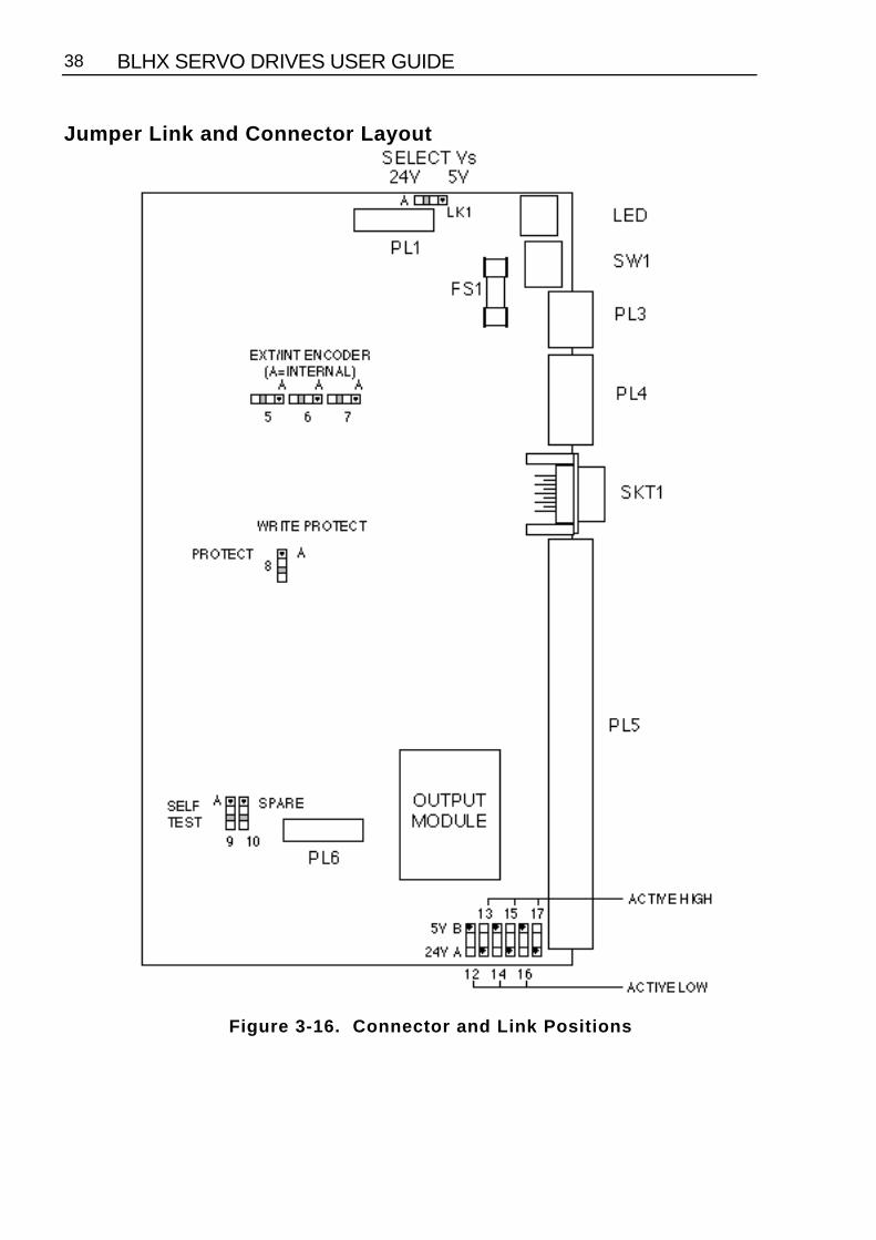
Jumper Link and Connector Layout
Figure 3-16. Connector and Link Positions

SECTION 3. INSTALLATION 39
Jumper LinksJumper links are used to configure the Controller for a particular application, or for use withother motion control equipment. You must remove power before making anyjumper link changes. Table 3-15 identifies the use of each jumper link.
Position JumperLink
Number(LK)
Function
A B24V 5V 1 5V or 24V selection for VsINT EXT 5 Internal/External encoder channel ZINT EXT 6 Internal/External encoder channel AINT EXT 7 Internal/External encoder channel B
Protect - 8 Write enableSelf Test - 9 Self test
- - 10 Spare24V 5V 12 Bank (1) 5V or 24V operation
Active Low Active High 13 Bank (1) active high or active low24V 5V 14 Bank (2)5V or 24V operation
Active Low Active High 15 Bank (2) active high or active low24V 5V 16 Bank (3) 5V or 24V operation
Active Low Active High 17 Bank (3) active high or active low
Table 3-15. Jumper Link Functions
Input Banks
The inputs are configured in 3 banks of 5 inputs.
BANK 1 BANK 2 BANK 3 LMT+ IN1 IN6LMT- IN2 IN7HOME IN3 IN8STOP IN4 IN9AUX_IN IN5 IN10

BLHX SERVO DRIVES USER GUIDE40
Thumbwheel Interface
This section assumes that you are using Parker's TM8 thumbwheel module.
You can use up to 16 digits of the thumbwheel. The controller uses a multiplexed BCD inputscheme to read the thumbwheel data. The commands and format that allow for thethumbwheel data entry are :
DRDxyz Read distance via thumbwheel.VRDxyz Read velocity via thumbwheel.LRDxyz Read loop count via thumbwheel.TRDxyz Read time delay via thumbwheel.VARDn,xyz Read variables via thumbwheel.XRDxyz Read sequence count via thumbwheel.FRDxyz Read following ratio via thumbwheel.
To request 1 digit x=y=the desired digit number.
To request all digits x=0 and y=7 (or do not set xyz fields).
To request a block of digits 0<x<y<7.
The Z field scales the thumbwheel value by 10. When reading digits from the thumbwheel,the least significant digit will be filled first. The z field allows you to position the decimalpoint were needed.
Note : Either all the fields (xy and z) or none of the fields must be used. Refer to the softwaresection for further explanation.
Using the TM8
Caution - possibility of equipment damage
THE TM8 REQUIRES A 5V SUPPLY. LINK 1 MUST BE IN POSITION BOTHERWISE DAMAGE WILL OCCUR.
1. Ensure that the controller is fitted with an NPN output stage.2. Set link 1 to position B. (5V DC operation).3. You can define any block of 5 inputs for use with the thumbwheel. Therefore you must
decide which inputs you intend to use for data (4 inputs required) and sign bit (1 inputrequired).
4. Once you have decided upon the block of inputs, configure the appropriate sense link(s) 12,14,16 to position B. (5V sense level).
5. As with point 4 set the appropriate polarity link(s) 13,15,17 to position A (Active low).6. Configure the defined inputs for TM8 operation using the INnN command.7. Configure the defined input for the TM8 sign bit using INnW command.8. Define appropriate outputs for TM8 operation using the OUTnJ command.

SECTION 3. INSTALLATION 41
The TM8 is now ready for operation.
Example:The TM8 is wired as shown in Figure 3-17.
Inputs 6 to 9 are to be used as data inputs.Input 10 is to be used as a sign input.Outputs 3 to 5 are to be used as strobe outputs.
Set up as follows:
1. Set link 1 to position B. Vs is now 5V.
2. Set link 16 to position B. Sensing levels are 5V.
3. Set link 17 to position A. The inputs are active low.
4. Set 1IN6NInput 6 is defined as data input.1IN7NInput 7 is defined as data input.1IN8NInput 8 is defined as data input.1IN9NInput 9 is defined as data input.1IN10W Input 10 is defined as sign bit.
5. Set 1OUT3J Output 3 is defined as data strobe.1OUT4J Output 4 is defined as data strobe.1OUT5J Output 5 is defined as data strobe.
The thumbwheel is now ready for use. Set the thumbwheel to the desired value and enterthe information using one of the data entry commands.
For example set the thumbwheel to +12345678
Command Description DRD Request distance data from all TM8 digits1D Display the distance read (D+12345678). If you do not receive
this response, return to step 1 and retry
For further information relating to Data entry commands refer to the X150/X150ESoftware Reference User Guide.

BLHX SERVO DRIVES USER GUIDE42
Figure 3-17. Connections to TM8 Thumbwheel Module
SECTION 3. INSTALLATION 43
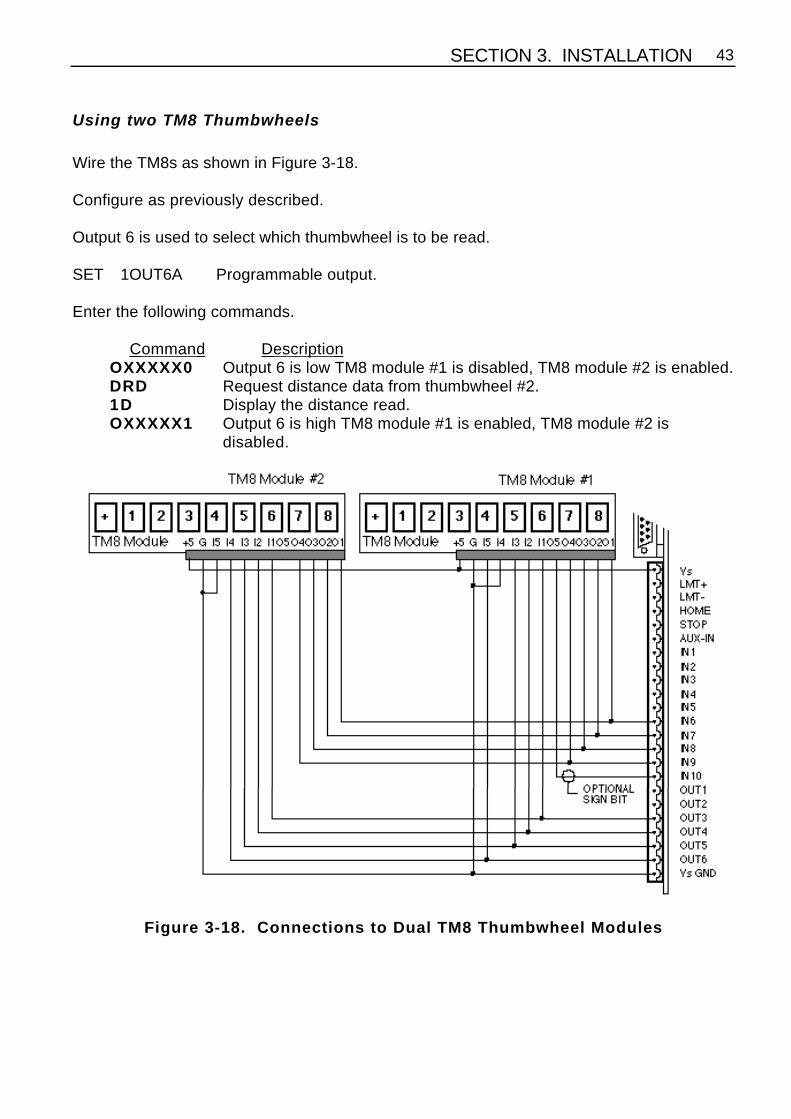
Using two TM8 Thumbwheels
Wire the TM8s as shown in Figure 3-18.
Configure as previously described.
Output 6 is used to select which thumbwheel is to be read.
SET 1OUT6A Programmable output.
Enter the following commands.
Command Description OXXXXX0 Output 6 is low TM8 module #1 is disabled, TM8 module #2 is enabled.DRD Request distance data from thumbwheel #2.1D Display the distance read.OXXXXX1 Output 6 is high TM8 module #1 is enabled, TM8 module #2 is
disabled.
Figure 3-18. Connections to Dual TM8 Thumbwheel Modules

BLHX SERVO DRIVES USER GUIDE44
RP240 ConnectionsThe Controller may be connected to the RP240 Operator Panel using the connectionsshown in Figure 3-19. You need to use 20 AWG 4-wire shielded cable with a maximumlength of 15 metres (50 feet).
Figure 3-19. Connections to RP240 Operator Panel

SECTION 4. HARDWARE REFERENCE 45
Section 4. HARDWARE REFERENCE
BLHX Drive Specification
BLHX30 BLHX75 BLHX150
Continuous Current 3.75A 7.5A 15APeak current 7.5A 15A 30ADC bus Voltage 85V 150V 150VAC Input Voltage: Nom.
Max.Min.
61V67V24V
107V118V48V
107V118V48V
Weights kg (lb) 3.8 (8.4) 4.8 (10.6) 6.0 (13.2)Motor Options ML-1620,
ML-2340ML-2340,ML-3450,
ML-3450,ML-3475
Power input Isolated AC direct from mains transformerFrequency 47-63 HzControl input ±10V analogue (torque or velocity)Reference outputs ±15V at 10mAVelocity feedback Built-in incremental encoderCommutation method 4 bit absolute encoderTorque amplifier bandwidth >2500HzSwitching frequency 20KhzContinuous input power (typ.) 2.5A @ 61V 6A @ 107V 11A @ 107VMax. input power (peak only) 7A @ 61V 14A @ 107V 28A @ 107VTorque amp gain 0.75AV 1.5AV 3AVGain linearity ±4%Typ. input amp drift 10µV/°CPower dump current 9A @ 100V 16A @ 100V 16A @ 100V
Max. cont. dump power 40WMin recommended loadinductance
0.5mH
Jumper link settings Input pull-up, current limit, encoder res.Diagnostic LED's (Front) Power on, current limit, overtemperature,
drive/motor faultDiagnostic LED's (Rear) Power on, composite faultDimensions See Figure 3-1 (Chapter 3)
Table 4-1. BLH Servo Drives Specification

BLHX SERVO DRIVES USER GUIDE46
Controller SpecificationParameter Value
Command Input RS232CType 3-wire (Tx, Rx, Gnd). Minimum voltage swing = ±3VParameters 9600 baud, 8 data bits, 1 stop bit, no parityConnector Removable screw terminalsConfiguration Up to 16 interfaces can be controlled from a single
RS232C port. Device address set up by DIL switchOperating Ranges
PositionVelocityAcceleration
±1 to 268,435,455 steps0.0001 to 200 revs/sec0.06 to 999,999 revs/sec2
Maximum Encoder Frequency 100 kHz (lines/sec before multiplication)Resolution Ranges
Feedback encoderUser-programmed
1 to 32,767 counts/rev1 to 32,767 steps/rev
Co-ordinate System Incremental or absoluteOperating Modes Preset, preset with speed change, continuous, registration,
electronic gearbox following, preset followingController Loop Update Every 2 millisecondsMotion Program Storage
Memory TypeMemory CapacityNumber of ProgramsProgram LengthProgram Selection
Battery-backed RAM8000 characters total64Variable up to memory limita) Via RS232Cb) Automatic execution at power upc) Binary address on sequence select inputsd) RP240e) Thumbwheel (TM8) f) PLC
Digital Servo LoopUpdate TimeServo Tuning
Tuning Parameters
500 microsecondsRS232C. Values stored in battery-backed RAM. Servoself-tuning facility.PIVF or PID options with digital filter
Opto-isolated I/P's Home, Limits, Aux-in, Stop, 10 user-definable inputs (alsoused for program selection)
Optically-isolated O/P's 6 programmableFuse
FS1 160mA QA External supply protection
Table 4-2. Controller Specification

SECTION 4. HARDWARE REFERENCE 47
Brushless Motor/Drive PackagesThe BLHX Series drives may be matched with motors in the Digiplan brushless range andsupplied as ready-wired motor/drive packages. Details of the range of four motors (TypesML-1620, ML-2340, ML-3450 and ML-3475) are given in Table 4-3.
Type Weights(including cable)
Rotor InertiaKg-cm2
IncrementalEncoder Line Count
ML-1620 0.85Kg 0.056 500ML-2340 2.1Kg 0.28 500ML-3450 5.1Kg 1.6 1000ML-3475 6.4Kg 2.4 1000
Table 4-3. Brushless Motor Data
The dimensions of the motors are shown in Figures 4-1 to 4-3.
Figure 4-1. Motor Type ML-1620 DimensionsNote: ML-1620 should only be used with the BLHX30 drive.
CAUTION - high temperatures
The motor case will exceed 85°C before the motor overtemperature tripoperates.

BLHX SERVO DRIVES USER GUIDE48
Figure 4-2. Motor Type ML-2340 Dimensions
Figure 4-3. Motor Type ML-3450 & ML-3475 Dimensions

SECTION 4. HARDWARE REFERENCE 49
Safety Earth
Impedance to main earth star point should be less than 0.1Ω. Use a ring terminal secureddirectly to the motor body (at the motor’s safety earth connection). Note: do not place anyform of washer between the ring terminal and the motor body - the connection must bedirect.
Transformer Dimensions
Dimensions T092 T0170 T0171A 136.0
(5.35)195.0(7.68)
215.0 (8.47)
B 126.0(4.96)
135.0(5.32)
172.0 (6.77)
C 155.0 Max.(6.10 Max.)
215.0 Max.(8.47 Max.)
242.0 Max.(9.53 Max.)
D 89.0 (3.50) 102.0(4.02)
115.0 (4.53)
E 89.0 (3.50) 82.0 (3.23) 110.0 (4.33)Weight 8Kg 15.5Kg 24.5Kg
Figure 4-4. Transformer Dimensions for T092, T0170 and T0171 - mm(ins)
CAUTION
Take particular care when lifting larger transformers. Do not lift by theterminal plate or cover, as these could break.

BLHX SERVO DRIVES USER GUIDE50
Motor/Drive Package Performance Data
Figure 4-5. Motor/Drive Packages Torque Curves

SECTION 4. HARDWARE REFERENCE 51
Fuse RatingsBLHX drive board has four fuses - two AC input fuses, a DC bus fuse and a power dumpfuse. Types and ratings are shown in Table 4-4.
Rating
FuseNo.
Circuit Type BLHX30 BLHX75 BLHX150
FS1 AC input 32mm TL HBC 8A 15 or 16A 30 or 32A
FS2 AC input 32mm TL HBC 8A 15 or 16A 30 or 32A
FS3 DC bus 32mm QA HBC 8A 10A 20A
FS10 Power dump 20mm TL LBC 2A 2A 2A
TL - Time lagQA - Quick actingHBC - High breaking capacityLBC - Low breaking capacity
Table 4-4. BLHX Drive Board Fuse Ratings
Controller Board Fuse
The controller board contains one fuse for external supply protection.
Fuse No. Circuit Type RatingFS1 Ext. supply 20mm QA 160mA
Table 4-5. BLHX Controller Board Fuse Rating

BLHX SERVO DRIVES USER GUIDE52
Motor Wiring
Earlier versions of motors were wired as shown in Figure 4-6.
Figure 4-6. Motor and Encoder Connections at the Motor

SECTION 4. HARDWARE REFERENCE 53
ML Motor PCB
Later versions of the ML motors will have a silkscreen PCB as shown in Figure 4-7. Refer toTables 4-6 and 4-7 which detail the encoder wiring required for the ML2340 andML3450/ML3475 motor types fitted with the PCB.
Figure 4-7. Motor PCB Silkscreen

BLHX SERVO DRIVES USER GUIDE54
ML2340 Encoder Connections
Motorconnector
number(TB3 &
TB2)
Motorfeedbackconnector
number (25-way D-type)
Originalcolours for
ML2340
New coloursfor ML2340
1 3 & 16 (+5V) red + red red + violet2 20 (*A2) black white/grey
& 11 21 (A2) green grey/brown3 6 (*MOT) red grey
& 12 7 (MOT) green pink4 24 (*A0) black white/green
& 13 25 (A0) yellow brown/green5 8 (Z-) red yellow/brown
& 14 9 (Z+) white white/yellow6 22 (*A1) black white/pink
& 15 23 (A1) blue pink/brown7 12 (A-) black white
& 16 13 (A+) brown brown8 18 (*A3) black red/blue
& 17 19 (A3) white grey/pink9 10 (B-) black yellow
& 18 11 (B+) orange green10 2 & 15 (0V) black + blue black + blue
* indicates the inverse of the signal.Table 4-6. ML2340 Motor Encoder/Drive Connections

SECTION 4. HARDWARE REFERENCE 55
ML3450/ML3475 Encoder Connections
Motorconnector
number(TB3 &
TB2)
Motorfeedbackconnector
number (25-way D-type)
Originalcolours forML3450 &
ML3475
New coloursfor ML3450 &
ML3475
1 3 & 16 (+5V) red + red red + violet2 20 (*A2) black white/grey
& 11 21 (A2) green grey/brown3 6 (*MOT) red grey
& 12 7 (MOT) green pink4 22 (*A1) black white/pink
& 13 23 (A1) blue pink/brown5 8 (Z-) red yellow/brown
& 14 9 (Z+) white white/yellow6 18 (*A3) black red/blue
& 15 19 (A3) white grey/pink7 12 (A-) black white
& 16 13 (A+) brown brown8 24 (*A0) black white/green
& 17 25 (A0) yellow brown/green9 10 (B-) black yellow
& 18 11 (B+) orange green10 2 & 15 (0V) black + blue blue + black
* indicates the inverse of the signal.Table 4-7. ML3450/ML3475 Motor Encoder/Drive Connections

BLHX SERVO DRIVES USER GUIDE56
ML1620 Encoder ConnectionsFigure 4-8 shows the ML1620 encoder connections at the drive and motor end of the multi-way cable. If you need to re-make this cable to allow routing through panels etc. the driveend connector should be removed in preference to the motor end connector.
Figure 4-8. ML1620 Encoder Connections
Note: The ML1620 motor should only be used with the BLHX30 drive.

SECTION 6. BASIC MOTION CONTROL CONCEPTS 57
Section 5. BASIC MOTION CONTROL CONCEPTS
Section ObjectivesTo describe some of the basic concepts of motion control systems.
Motion ProfilesIn any motion control application the most important requirement is precise shaft rotation,whether it be with respect to position, time or velocity. The type of motion profile needed willdepend upon the motion control requirement. The following sections describe the basictypes of motion profiles.
Preset MovesA preset move referred to in this manual is a move of a specified distance (in user steps).Preset moves allow the user to position in relation to the motor's previous stopped position(incremental moves) or in relation to a defined zero reference position (absolute moves).
Incremental Preset Moves
If the positioner is in the incremental mode (MPI command), a preset move will move theshaft of the motor the specified distance (in user steps) from its starting position. Forexample, to move the motor shaft 1.5 revolutions, a preset move with a distance of +6000steps would be specified, assuming a 4000 step per rev encoder resolution setup. Everytime this move is executed, the motor shaft will move 1.5 revolutions positive from its currentposition. The direction of the move can be specified at the same time as the distance byusing the optional sign (D+6000 or D-6000), or it can be defined separately with the Hcommand (H+ or H-).
Absolute Preset Moves
A preset move in absolute mode (MPA command) will move the shaft of the motor thespecified distance (in user steps) from the absolute zero position. The absolute position canbe set to zero with the PZ or SP commands, for instance at the end of a GO HOME move(GH command). The absolute zero position is initially the power-up position, and willremain that way until changed with a PZ command. Any preset move performed while in theabsolute mode will position the motor shaft the defined distance (in user steps) from theabsolute zero position. For example, with the positioner at the absolute zero position amove with a distance of +4000 will cause the motor shaft to turn 1 revolution in the positivedirection. If a move with the same defined distance is executed immediately after this move,the motor shaft will not turn, since it is already +4000 steps from the absolute zero position.
The direction of an absolute preset move will depend upon the shaft position at thebeginning of the move and the position that it is being commanded to move to. Forexample, if the motor shaft is at absolute position +12,800, and commanded position is+5000, then the motor shaft will move in the negative direction a distance of 7800 steps toabsolute position +5000.

BLHX SERVO DRIVES USER GUIDE58
The positioner saves the mode that it was in at power down and powers up again in thesame mode. Issuing the MPA command will set the mode to absolute. Issuing the MPIcommand or MN command will switch the mode from absolute to incremental. Thepositioner retains the absolute position referenced, even while in incremental mode.However, the counter does have an upper limit just slightly more than 268,400,000 counts.
Continuous Moves
Continuous moves (MC command) cause the motor to accelerate and attain the specifiedvelocity and then continue to move. To change velocity while the motor is moving use the Vcommand. Issuing a stop (the S command) will cause the motor to decelerate to a stop atthe last defined acceleration rate. The distance parameter is not used, although it is savedin case the mode is changed back to preset.
This mode is useful for applications which require constant spinning of the load, when themotor must stop after a period of time has elapsed rather than after a fixed distance, or whenthe motor must be synchronised to external events such as trigger input signals.
Registration Moves
A move may be programmed to end a specified distance after a registration pulse appearsat AUX-IN. The mode is selected using the TRR command with the required registrationdistance in the MQ or MC modes. Its use is easiest to understand in the context of anexample registration move:
Figure 5-1. Example Registration Move
Example ProgramMQ Select MQ modeD6200 Set move distance to 6200 stepsA100 Set all accelerations to 100 revs/sec2
V10 Set velocity to 10 revs/secG GoTRD4000 At distance = 4000 steps

SECTION 6. BASIC MOTION CONTROL CONCEPTS 59
V1 Change velocity to 1rev/secTRD6020 At distance 6020 look for registration pulseTRR1440 Travel 1440 steps from registration pulseV50 At a velocity of 50 revs/secTRIP Set Output 2 when in position
Program Operation
When executing this program, the axis will first accelerate at 100 steps/rev2 to 10 revs/sec(1) and when it reaches a distance of 4000 steps (2), its speed will be reduced to 1 rev/sec(3) whilst it is waiting for the registration pulse. Shortly after the pulse is received (6), theaxis will accelerate towards 50 revs/sec, but will not reach the speed before starting todecelerate (7) to stop at 1440 steps from where the pulse occurred (8).
If the pulse was not received after 6020 steps (4 - the hold off distance) and before 6200steps (the incremental distance), the axis will stop at 6200 steps (9). This sets a window of180 steps during which the pulse is expected.
Program CriteriaThe distance command(D6200)
This command sets the distance theaxis will travel if no registration pulseis received and the maximumdistance at which the pulse will berecognised.
Trigger distance command(TRD4000)
The distance at which the axis willstart to decelerate to the slowerspeed of 1 rev/sec (V1), in readinessfor the registration pulse, is set by thiscommand.
Trigger distance command(TRD6020)
This command sets the minimumdistance at which the system willrecognise the registration pulse.
The TRR command(TRR1440)
This command sets up theregistration mode and the registrationdistance (the distance the axis willtravel after the pulse is received).
Registration move velocity(V50)
To save time in travelling theregistration distance, the axis thenaccelerates towards 50 revs/sec(V50), but it does not reach thatspeed before starting to decelerate tostop at 1440 steps from where thepulse occurred.

BLHX SERVO DRIVES USER GUIDE60
Motion ProfilesVelocity, acceleration and distance must be defined before any preset move can beexecuted. The value of these parameters determines the type of motion profile as eithertriangular or trapezoidal.
Triangular ProfileA triangular profile will result when the velocity and acceleration are set such that thedesigned velocity is not attained before half of the specified distance has been travelled.This results from either a very low acceleration or a very high velocity or both over arelatively short distance. For example, if the acceleration is set to 1 rev/sec/sec, velocity isset to 5 revs/sec and distance is set to 16000 steps (2 revs), a triangular motion profile willresult. This is because by the time the motor shaft has reached a velocity of 2 revs/sec, it willalso have travelled half of the defined distance due to the acceleration setting of 1rev/sec/sec. The motion profile for this move is shown in Figure 5-2.
Figure 5-2. Triangular Profile
Trapezoidal ProfileA trapezoidal move profile results when the defined velocity is attained before the motorshaft has moved half of the specified distance. This is due to a defined velocity that is low, adefined acceleration that is high, a move distance that is long, or a combination of all three.For example, if the acceleration is set to 10 revs/sec/sec, velocity is set to 1 rev/sec, anddistance is specified as 20000 steps (5 revs), the resulting motion profile would look likethis:

SECTION 6. BASIC MOTION CONTROL CONCEPTS 61
ta = Acceleratetc = Constant velocitytd = Decelerate
Figure 5-3. Trapezoidal Profile
User ProfilesThe user may define a move profile using the MC command to establish the continuousmode. Velocity can be programmed on the fly by the V command.
The positioner also has a mode MQ, which is like the preset move mode in that the movedistance is pre-defined, but it is possible to change speed in the middle of the move asrequired based on a distance, input or time delay trigger.
Encoder FollowingThe commands SIM and CCS may be used to allow the motor of one axis to follow theencoder of another axis or an externally-generated step and direction signal. When thecontrol module is to be used in following mode, the input from the encoder to be followedshould be connected to the External Encoder connector pins 1 - 9 (as shown in Figure 2-1).These inputs can be configured using the CCS command as an encoder input (x1, x2 or x4)or as a step and direction input.
Externally generated STEP and DIR signals should be connected to pins 1 - 4 of theExternal Encoder connector (see Figure 2-1 and Table 2-1).
The SIM command may be used to select:
a) Normal indexer operation (SIM0), used for reverting to normal operation by overidingprevious SIM commands
b) Encoder following with indexer motion commands inoperative (SIM1).

BLHX SERVO DRIVES USER GUIDE62
c) Encoder following with indexer commands operative (SIM2), allowing thesuperimposing of indexer moves.
d) Software scaled encoder following (SIM3).
e) Software scaled encoder following with direction reversal (SIM4).
f) Preset following index mode (SIM5).
g) Load mounted encoder feedback (SIM6).
For SIM1 and SIM2 operation the motor output rate follows the encoder input, usinghardware scaling, at a ratio of 1 or less.
Hardware ScalingThis is the scaling of the second encoder input when using the SIM1 and SIM2 commandsto achieve following at a ratio of 1 or less relative to the following input. Scaling is achievedusing a hardware rate mutiplier, the division ratio of which is set by the RAT command, at aresolution of 16 bit or 24 bit operation determined by the OSJ command.
Figure 5-4. Simple Gearbox
The operation of the rate multiplier can be compared to that of a simple gearbox (see Figure5-4), where the ratio of output revolutions to the input revolutions (always less than or equalto 1) is determined by the number of teeth on n2 divided by the number of teeth on n1. If thenumber of teeth on n1 is fixed, but the number of teeth on n2 is allowed to vary (up to amaximum of n1 teeth), the gearbox will provide a variable output rate which is always afraction of the input rate. The resolution of the gearbox, that is how fine a gear ratio can beset, will be determined by the number of fixed teeth on n1. In the rate multiplier the RATvalue sets the number of teeth on n2, and the resolution (n1 teeth) can have one of two fixedvalues determined by the OSJ command.

SECTION 6. BASIC MOTION CONTROL CONCEPTS 63
Using hardware scaling the output motor rate is determined by :
Output Motor Rate = input rate x n
65536 for OSJ = 0
or
Output Motor Rate = input rate x n
16777216 for OSJ = 1
Where n = the RAT value
NOTE: RAT now controls the division ratio, and the direction will be determined by the signof the RAT value.
As the resolution (set by OSJ) is a large number, very fine adjustment of the ratio can be setby choosing a suitable value for the RAT command.
A limitation of binary hardware scaling is the lack of certain exact following ratios that can beobtained. Since the division ratio can only be a binary fraction it is impossible to choose anexact ratio such as 1:3, although it could be closely approximated if you were to choose aRAT value of 5592405 with 24-bit resolution selected.
Summary of hardware scaling :The scaling ratio is determined by the RAT value.Resolution is fixed at 16-bit or 24-bit , determined by the OSJ command.Non binary fraction exact division ratios cannot be obtained.
Software ScalingThis is the scaling of the encoder input when using the SIM3 or SIM4 commands to achievefollowing at a ratio greater or less than 1. Unlike hardware scaling, exact following ratioscan be achieved by controlling both the numerator and denominator parts of the fractionused to set the scaling ratio, thus ratios such as 3:1 can be obtained.
The scaling ratio is set using the CMR command value divided by the CUR command valueto give :
Motor Output Rate = input rate x CMRCUR
Both CMR values and CUR values are individually limited to a range of 1 to 32,767, andwhen combined as a fraction are further limited, by software scaling to having bothnumerator and denominator in the range 1 to 255. This results in a maximum division ratioof 1/255, or at the other extreme a maximum multiplication ratio of 255.Software scaling does not allow the superimposing of indexer moves.

BLHX SERVO DRIVES USER GUIDE64
When using SIM3 or SIM 4 operation for short moves it is possible to predict the number ofsteps the motor will take using the formula :
Number of motor steps to move =
INTCMR × no. of pulses received + prev. remainder
CUR
where INT means "take the integer part of", with the value rounded towards zero whetherpositive or negative. The controller can repeatedly apply this formula to establish aniterative calculation. In situations where short moves have been programmed the ratio ofCMR/CUR may only approximate the number of steps the motor is required to move, butsince the remainder is carried forward no steps are lost. This allows the CMR/CUR value tobetter approximate the following ratio in subsequent moves.In summary, short moves may only approximate the defined following ratio, but nopositioning accuracy is lost in later moves.
Buffered Clock ModeSIM3 or SIM4 work in a buffered clock mode, which allows the controller to buffer anunprofiled following-input pulse stream until the output velocity equals the following inputvelocity. The controller accelerates the output velocity to match the input velocity using anexponential acceleration profile, the time constant of which is set using the CAG command.The default time constant value of CAG is 1.00ms to accept already profiled follower inputs.
The input pulses are buffered (or stored) at the input resolution, the actual number beingstored at any particular instant being termed the following error. This can lead to inputpulses being lost above a maximum speed, due to excessive following error.
The maximum number of input pulses that can be buffered is
+/-32767 which requires CAG to be less than 32767
input pulse rate to prevent overflow.

SECTION 6. BASIC MOTION CONTROL CONCEPTS 65
Comparison offollowingfeatures
Hardware ScalingSIM1, SIM2
Software ScalingSIM3, SIM4
The motor always moves bythe same or fewer pulses thanreceived. The pulse stream iseffectively divided.
The motor can move by more orless pulses than received. Theinput pulse stream can bemultiplied or divided.
The ratio is programmed bythe RAT command with 16 or24 bit resolution as a binaryfraction.
The RAT command has no effect.
CMR and CUR have no effect. The ratio is programmed by CMRand CUR.
Superposition onto anadditional internallygenerated indexer motion isavailable.
Superposition is not available.
The pulse stream is followeddirectly without additionalprofiling.
The pulse stream is profiled(filtered) by a programmableexponential characteristic (CAGcommand)
Preset Following Index ModeThe following mode SIM5 selects indexing at a speed determined by the external input. Inthis mode the controller sets the motor velocity to a speed in rps determined as apercentage of the following input speed in rps. The percentage following factor is set by theFOL command which can be varied between 0.0 and 5000.0%.
When using this mode the acceleration is fixed to whatever is defined by the A command,and the V command value has no effect since the FOL command percentage value will nowcontrol the velocity.
The velocity is dependent on the user resolution (CUR value) and the motor resolution(CMR value). CUR and CMR set the encoder / motor resolution ratio so that the input shaftspeed will match the output shaft speed with FOL set to 100%.
The FOL value can be entered from a variable, for example:
1FOL(VAR1)
Pulses must be present at the input when the G command is executed.

BLHX SERVO DRIVES USER GUIDE66
Load Encoder Following (SIM 6)In certain applications it is beneficial to close the position loop around the actual loadposition rather than the motor position, in order to improve positional accuracy. A typical example is a feed-to-length system in which positioning accuracy is adverselyaffected by slippage and compression of the feed roller.
If we close the position loop around the load then we can compensate for the majority ofsystem errors, such as out of tolerance feed rollers and other transmission devices. This isachieved by mounting an incremental encoder to the load mechanics or via a low inertiawheel in the case of feed to length applications.
Position feedback is taken from this encoder rather than the incremental encoder fitted to themotor. The load position becomes the true closed loop controlled position, compensatingfor the effect of the indirect coupling between the motor and load.
The load encoder is connected to the EXT ENC 9 way D type. The motor encoder feedbackremains in use to provide velocity feedback. Velocity feedback is derived in this mannerrather than from the load encoder as the indirect coupling of the load encoder would resultin a low bandwidth system and therefore limit performance. In applications were the ratiobetween the load encoder and the motor is not 1:1 then the velocity feed forward gain (CFG)must be scaled by that ratio.Note that links 5, 6 and 7 are transferred to position B to use an external encoder.
In order to provide continuity between following modes, the current reported motor positionwill be retained when switching between modes. This prevents any anomalies whenentering and exiting the load encoder following mode.
When using this mode the motor resolution (CMR) should be set to the load encoderresolution. Velocity and acceleration will now be referenced to the load. Set OSO to 1, thiswill suppress units and will avoid later confusion.
Figure 5-5. SIM6 Operation

SECTION 6. BASIC MOTION CONTROL CONCEPTS 67
CouplingIn order to gain good system performance care must be taken in selection of the coupling.The quality of the coupling will have considerable effect on performance. Poor coupling willprevent CPG and CVG being set to the optimum, this will therefore affect speed of response,stiffness and accuracy of the system.
Note: As an additional safety feature and to prevent mechanical damage, the motor velocitytrip (CVT) should be set to a value just greater than the system requirements. If the couplingshould break and the motor race away, once the velocity has reached that set by CVT themotor will de-energise.
Torque control applicationsIn most applications, the fundamental parameter controlled is position. Velocity,acceleration and direction are all derived from position, so are automatically determined.The value we cannot directly control is torque, since this depends upon the loadcharacteristics as well as the move parameters.
However, there are applications in which the torque is the chief parameter we want tocontrol - winding material onto a drum is one example. When operating as a torque motorwe have no control over position, velocity, acceleration or direction, though we can set limitsto any of these parameters. (In the same way, we can set a limit to the torque in a positioncontrol application).
Tuning the Controller for torque controlMost torque applications need a limit to be placed on velocity should the load torque be lessthan the programmed value. In the winding application, this would limit the drum speed ifthe material breaks. We therefore set up the controller as a velocity controller but determinethe maximum torque using the clamp command CCP.
The proportional gain CPG must be set to zero for velocity control, and we must also setCPE to zero to stop the system tripping out on excessive position error. The feedforwardterm CFG, which depends on the rate of change of input position, converts the positiondemand to a velocity demand. We need to use CDG to set the velocity gain because it isessential that the feedforward and feedback terms are the same, otherwise the demandedvelocity will not be the same as the programmed V value. The block diagram of the servo isshown in Figure 5-6.

BLHX SERVO DRIVES USER GUIDE68
Figure 5-6. Torque Control Operation
The clamp command CCP can now be used to determine the torque - a value of 1023 willcorrespond with the peak torque available from the motor & drive. When the G is issued, themotor will accelerate at the programmed A value until the load torque matches the CCPlevel. If the load torque is less than the CCP value, the motor will run at the speedprogrammed by V. In practice there will be a small velocity error generating the torquenecessary to keep the motor running at this speed; setting CDG to a high value will minimisethis error. It will usually be necessary to increase the filter time constant CTG in order toreduce the bandwidth when using a high velocity gain.
The programmed D value will limit the overall distance if you are using the indexing modeMN. If there is no preset limit to the total travel you can use the continuous mode MC.
Switching between position and velocity modes
In an application like the closing and clamping of an injection mould, we need to switchbetween position control (when the mould is opening) to torque-limited velocity controlduring the closing process. This switchover demands a significant change to the tuningvalues on the fly, and could result in a large discontinuity in position or torque. Thecommand RST1 allows the torque demand to be frozen momentarily while we make thetuning changes, which effectively opens the control loop. RST0 then releases the torquedemand and closes the loop again. Between the RST1 and RST0 commands will be thenew tuning values entered as buffered commands, for example:
RST1 BCPG0 BCDG100 BCTG3 RST0
When switching between control modes, the difficulty arises in maintaining continuity of thetorque demand before and after the switch. In position mode, the torque demand arisesprimarily from a position error; in velocity mode it comes from a velocity error which iscomparatively small because gains are usually higher. So when switching modes, thecorrect error conditions must be established before the torque demand can be unfrozen.
The RST0 command achieves this by setting either a position error or a torque offset asappropriate. When the new value of CPG is zero (as in the example), the controller isconsidered to be entering velocity mode and a torque offset is introduced (COFF command)equivalent to the previous torque demand under position control. When the new value of

SECTION 6. BASIC MOTION CONTROL CONCEPTS 69
CPG is greater than zero, the controller must be returning to position mode; the demandposition is adjusted so that previously-existing torque is now generated by a position error.
The following points should be kept in mind when switching between control modes:
Aim to switch from position to velocity mode when there is no torque on the shaft, preferablywhen stationary. This will minimise the COFF value introduced.
You can switch from velocity to position mode on the fly provided that the system is undervelocity control at the time, i.e. the load torque is less than the CCP value. You should notallow the system to become saturated (i.e. CCP-limited) in position mode; this will cause aposition error to build up.
When returning to position mode, include BCOFF0 to clear the torque offset.
If your application requires mode-switching we recommend that you request programmingassistance from Digiplan.
Program StorageThe non-volatile program memory is battery backed up RAM with memory retention of10,000 hours. The RAM has 8K characters available for sequence storage and a writeprotect facility is provided.Programs are stored in variable length buffers and the total length cannot exceed 8K.
Write ProtectionA write protection facility is incorporated for the protection of stored sequences andparameters, stored by the SV command. If LK8 on the positioner card (see Figure 2-6) isfitted in position A then the memory is write protected. An attempted SV command when thejumper link is in position A will result in the following error message being displayed:
#15 BACKUP RAM IS WRITE PROTECTED
Motion Program SelectionThe system may be set up so that no sequence is executed at power-up. In this casesequence execution would be initiated from the controller over the RS232C.
Alternatively, a single sequence to be automatically executed at power-up can beprogrammed. After that sequence is executed, control can pass to another sequence or tothe RS232C interface.
Sequence selection may also be initiated via thumbwheel, RP240, and PLC inputs. Up to64 user defined sequences can be selected for execution in this way.

BLHX SERVO DRIVES USER GUIDE70
Parameter RangesTable 5-1 gives the internal arithmetic positioner limits based on 4000 encoder steps/rev.These parameters apply only to the positioner, the motor/drive combination will notnecessarily be able to respond to the full ranges stated:
Position Velocity Acceleration
Smallest 1 step 0.488 steps/sec
0.000122 RPS
0.00732 RPM
244 steps/sec/sec
0.061 RPS2
3.66 RPM/sec
Largest ±268,435,455 steps
±67,108 revs at 4000
steps/rev
4 x 10⁶ steps/sec
999 RPS
4 x 10⁹ steps/sec/sec
999,999 RPS2
Table 5-1. Parameter Ranges
NOTE: Longer distances than 268,435,455 steps can be achieved using a sequence ofincremental moves or continuous motion mode.

SECTION 6. COMMUNICATING WITH THE POSITIONER 71
Section 6. COMMUNICATING WITH THE POSITIONER
Section ObjectivesThe information contained in this chapter will enable you to set up communications with thepositioner. If more than one positioner is present in the system, details are provided on theconnection of multiple positioners using the RS-232 Daisy Chain.
Command InterfaceThe interface is a three wire implementation (Tx, Rx, Ground) ofRS232C. The Tx and Rx lines require a minimum voltage swing of ±3 volts.
Hardware handshaking is not supported in any form. The computer or terminal sendingcharacters to the positioner should have its handshaking disabled by either hardware orsoftware.
Communication ParametersThe positioner communications protocol is fixed and as follows:
9600 baud, 8 data bits, no parity, 1 start bit, 1 stop bit
Device address: 1-16
Echo function: all characters received are immediately re-transmitted. This function can beenabled using the SSA0 command or disabled using the SSA1 command.
Once entered, a parameter will be remembered until power down. It is not necessary tokeep re-stating the same parameter value.
When you power up the positioner all parameters are assigned default values which the1DR command will show you. You can change any of these and then make them the newdefault value by typing the SV (Save) command - see also commands RFS and RIFS.
XON, XOFF software handshaking is supported.
Installing the RS232CRS232C connections from the controller to the positioner are as shown in Figure 6-1. Notethat the Tx and Rx lines are cross-connected so that transmit output is connected to receiveinput.

BLHX SERVO DRIVES USER GUIDE72
Address SelectionA unique address must be assigned to each positioner in the chain. Normally positioner 1will be the first in the serial communications link. The positioner's address is assigned byconfiguring DIL switch SW1 (refer to Figure 3-16) on each Controller Module in a binarypattern as shown in Table 6-1.
SW1 4 Bit DIL Switch Setting
Address Bit 4 Bit 3 Bit 2 Bit 11 ON OFF OFF OFF2 OFF ON OFF OFF3 ON ON OFF OFF4 OFF OFF ON OFF5 ON OFF ON OFF6 OFF ON ON OFF7 ON ON ON OFF8 OFF OFF OFF ON9 ON OFF OFF ON10 OFF ON OFF ON11 ON ON OFF ON12 OFF OFF ON ON13 ON OFF ON ON14 OFF ON ON ON15 ON ON ON ON16 OFF OFF OFF OFF
Table 6-1. Positioner Address Selection
Figure 6-1. RS232 Input Circuit
Controller Daisy Chain WiringYou may daisy chain up to 16 axes. Individual drive addresses are set with the ControllerDIP switches (see Table 6-1). When daisy chained, the units may be addressed individuallyor simultaneously. You should establish a unique address for each axis. Refer to Figure 6-2 for Controller daisy chain wiring configuration.

SECTION 6. COMMUNICATING WITH THE POSITIONER 73
Commands prefixed with a device address command only the unit specified. Commandswithout an address command all units on the daisy chain. The general rule is: Anycommand that causes the drive to transmit information from the RS-232C port (such as astatus or report command), must be prefixed with a device address. This prevents daisychained units from all transmitting at the same time.
Attach device identifiers to the front of the command. The Go (G) command instructs all unitson the daisy chain to go, while 1G tells only unit #1 to go.
When you use a single communications port to control more than one Controller, all units inthe daisy chain receive and echo the same commands. Each device executes thesecommands, unless this command is preceded with an address that differs from the units onthe daisy chain. This becomes critical if you instruct any indexer to transmit information. Toprevent all of the units on the daisy chain from responding to a command, you must precedethe command with the device address of the designated unit.
No Controller executes a device-specific command unless the unit number specified withthe command matches the Controller unit number. Device-specific commands include bothbuffered and immediate commands.
You must use status-request commands in an orderly fashion. Commands should only beissued when the host is ready to read the response. You should not send new commandsuntil you receive a response from the previous status-request command. In particular, youshould not issue an immediate-status command until the host receives a buffered commandstatus response. If this is not followed, the command responses will be intertwined,rendering the data useless.
If you enable the Interactive mode (EX1), the Controller that is currently echoing will respondwith a prompt (>). This prevents all the Controllers from sending out > in a daisy chain.Typically, you should disable the Interactive mode when you use a host computer with theController. The default for the EX command is enabled (EX1).
Figure 6-2 shows a multiple-drive configuration (daisy-chain) of RS-232C ports from onecontrolling terminal or computer.

BLHX SERVO DRIVES USER GUIDE74
Figure 6-2. RS-232C Daisy Chain Configuration
ExampleThree Controllers are connected to an RS-232C daisy chain. Send the followingcommands:
Command Description MN Sets unit to Preset mode for all three controllersA5 Sets acceleration to 5 rps2 for all three controllersV10 Sets velocity to 10 rps for all three controllersLD3 Disables limits (if they are not connected)1D25000 Sets axis 1 distance to 25,000 steps2D50000 Sets axis 2 distance to 50,000 steps3D100000 Sets axis 3 distance to 100,000 stepsG Moves all axes
Unit 1 moves 25,000 steps, unit 2 moves 50,000 steps and unit 3 moves 100,000 steps. Allthree units use the same acceleration and velocity rates.

SECTION 6. COMMUNICATING WITH THE POSITIONER 75
Interactive operation with a PC/PLCTo create a reliable, trouble free interactive RS232 communications control programbetween a PC/PLC and the serial interface you should note the following points :
• Use the X-WARE package for terminal emulation on an IBM PC or equivalentcomputer system.
• The interface should only be operated in computer mode to suppress error messagesand extended text output.
• The program should operate the interface with a response check during critical processes, such as sequence download. The response check will need to detect :
• No response at all• Incorrect characters• More characters than expected• Less characters than expected• Control characters such as EOF caused by errors• Correct response
The response expected should be either echoback, or characters returned by interrogationcommands, or a sequence of the two.
•If there is no check for echoback on each character, you should include a delay of up to1ms between each character sent . This may require characters to be sent individuallyrather than as strings.
•You should not use the simple BASIC INPUT statement as this 'hangs' the link without timeout if an error causes no carriage-return character to be received from the interface.
•Interpreted BASIC should not be used, as it is too slow for most applications.
•Interrupt error handling, such as the BASIC 'ON ERROR" statement, should be enabled.
•Commands such as SV, Z, RFS and RIFS take several seconds to execute. This alsoapplies to status commands like DR and HELP. It is recommended you insert a suitabledelay after these commands to allow them to fully execute their intended function withoutcorrupting immediately following commands, although the use of these commands in aninteractive situation is unlikely.
•If problems arise, the communications error responses actioned by the R command willhelp diagnosis. In some cases a recovery can be attempted by sending the command again(such as the R command itself). But this may not always be appropriate, for example LD3altered to L3 would not be fully corrected by simply sending LD3 again.

BLHX SERVO DRIVES USER GUIDE76
•A routine that breaks some of these rules may appear to work satisfactorily, but is notnecessarily safe. The worst case communications response condition may involve anumber of coincidences, such as sending a status request just as the interface hits a limit,just as it starts decelerating. Any motion control requirement explicitly takes priority overcommunications under these circumstances, and can therefore cause a communicationsproblem unless you wait for echoback. Also different issues of software may have differentexecution time characteristics which can make a routine based on delays work at onesoftware issue, and not another.
Accurate defensive programming is required if safety constraints are to be met and possibledamage to hardware prevented.
Using Windows™Microsoft Windows™ comes with a terminal emulation program which can be used in placeof XWARE. The terminal emulation program is configured as follows:
Run the terminal program.
From the FILE menu select NEW.
From the SETTINGS menu, setup the following options:
Terminal emulation sub-menu DEC VT-100 (ANSI)Terminal preferences sub-menu Terminal modes Line wrap ON
Local echo OFFCR_>CR/LF Inbound ON
Communications sub-menu Baud rate 9600Data bits 8Stop bits 1Parity NONEFlow control NONE
Also choose the appropriate connector
These basic configurations will allow operation with the terminal only.

SECTION 6. COMMUNICATING WITH THE POSITIONER 77
Interactive ProgrammingTo help you achieve reliable, trouble free interactive programming between a ControllerPositioner and a PC/PLC the following guidelines will be useful.
•The interface should be operated in terse mode (EX0) to suppress unsolicited errormessages and extended text output. This will also allow for extra communication time.
•The program should include an interface response check, especially during criticalprocesses such as sequence download. Checks should be made for:
*No response at all*Incorrect characters*More or less characters than expected*Control characters such as EOF formed by errors*The correct response
Where the correct response is the echoback of the transmitted characters or charactersreturned by interrogation commands or a combination of the two.
•The command buffer is 256 characters long. When it has filled up, the interface will echo a<CTRL>G instead of the correct character. Subsequent characters received will ‘overwrite’the last character in the buffer until a ‘free’ space occurs.
•Given the above, it is preferable to transmit one character and wait for correct echobackbefore transmitting the next character. This enables an error to be rectified immediately.
•When monitoring the echoback characters in verbose mode (EX1), some are echoed as acombination of characters, for example:
<CR> is echoed as <CR> <LF>.This is not the case in terse mode (EX0).
•If there is no check for echoback on each individual character, an explicit delay of at least1ms between each character must be included. This may mean sending charactersindividually rather than in strings.
•Certain interface commands, notably ON, Z etc. take some time to execute andconsequently momentarily interfere with communications. An explicit delay (severalseconds is typical) should be inserted after these commands before another is sent.
•This interference of communications can involve temporarily not servicing the RS-232interrupt on the Controller, allowing subsequent characters received by the UART, duringthis condition, to cause an overrun error within the UART. The status request command (R)can be used to provide helpful diagnostics. The responses generated by the interface areas follows:
*R<CR> - ready for a command with no errors*S<CR> - ready for a command with function error*T<CR> - ready for a command with previous comms error*U<CR> - ready for a command with function error and previous comms error
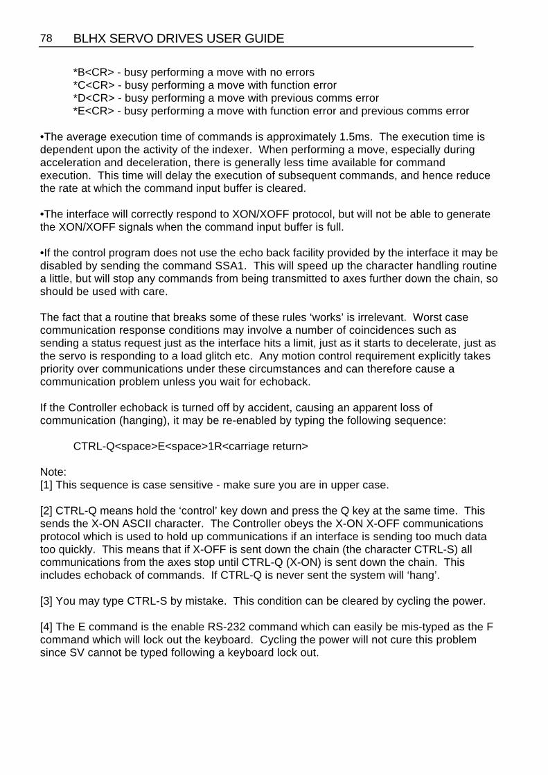
BLHX SERVO DRIVES USER GUIDE78
*B<CR> - busy performing a move with no errors*C<CR> - busy performing a move with function error*D<CR> - busy performing a move with previous comms error*E<CR> - busy performing a move with function error and previous comms error
•The average execution time of commands is approximately 1.5ms. The execution time isdependent upon the activity of the indexer. When performing a move, especially duringacceleration and deceleration, there is generally less time available for commandexecution. This time will delay the execution of subsequent commands, and hence reducethe rate at which the command input buffer is cleared.
•The interface will correctly respond to XON/XOFF protocol, but will not be able to generatethe XON/XOFF signals when the command input buffer is full.
•If the control program does not use the echo back facility provided by the interface it may bedisabled by sending the command SSA1. This will speed up the character handling routinea little, but will stop any commands from being transmitted to axes further down the chain, soshould be used with care.
The fact that a routine that breaks some of these rules ‘works’ is irrelevant. Worst casecommunication response conditions may involve a number of coincidences such assending a status request just as the interface hits a limit, just as it starts to decelerate, just asthe servo is responding to a load glitch etc. Any motion control requirement explicitly takespriority over communications under these circumstances and can therefore cause acommunication problem unless you wait for echoback.
If the Controller echoback is turned off by accident, causing an apparent loss ofcommunication (hanging), it may be re-enabled by typing the following sequence:
CTRL-Q<space>E<space>1R<carriage return>
Note:[1] This sequence is case sensitive - make sure you are in upper case.
[2] CTRL-Q means hold the ‘control’ key down and press the Q key at the same time. Thissends the X-ON ASCII character. The Controller obeys the X-ON X-OFF communicationsprotocol which is used to hold up communications if an interface is sending too much datatoo quickly. This means that if X-OFF is sent down the chain (the character CTRL-S) allcommunications from the axes stop until CTRL-Q (X-ON) is sent down the chain. Thisincludes echoback of commands. If CTRL-Q is never sent the system will ‘hang’.
[3] You may type CTRL-S by mistake. This condition can be cleared by cycling the power.
[4] The E command is the enable RS-232 command which can easily be mis-typed as the Fcommand which will lock out the keyboard. Cycling the power will not cure this problemsince SV cannot be typed following a keyboard lock out.

SECTION 6. COMMUNICATING WITH THE POSITIONER 79
[5] The <space>1 in <space>1R is important. It sets axis 1 as the echoback device (aswould <carriage return>1). If you make a typing error, such as TRD<space>3000 instead ofTRD3000 the <space>3 sets axis 3 as the echoback device, where R can be any command.
Certain ‘tidy up’ commands can be useful. For example:
• If you are not getting the typed characters echoed back you may need to use the SSA0 command.
• To get a prompt ($ or >) you may need to use the EX1 command.
• To get out of a $ prompt (indicating a sequence definition) type XT.
• If buffered commands are being ignored, type S in case the indexer is busy. You should avoid typing Z or cycling the power.
In summary:
• Don’t type CTRL-S• Don’t type the command F• Don’t address a non-existent axis• Don’t rubout a device address• Type carefully
None of the above conditions is an error so the status LED on the Controller will not indicatea fault and the axis may well be energised or even moving.
Programming With the RP240
Prompting an Operator or Displaying InformationIn many motion control applications, the most important requirement is the operatorinterface. Presenting information to an operator in a desired format is often difficult. TheRP240 has two visual indicators to help present information to the operator . The simplestindicator is the set of 8 LEDs on the panel. These LEDs can be turned on or off with theDLED command. The LEDs can be used in conjunction with the outputs to show the state ofan output, or they can be used to show status, such as motor moving, specific sequences inprogress, etc.
If a DLED10001011 command is issued, the LEDs shown below would be illuminated.These eight LEDs can be labelled, using the slide in card provided, to represent cyclestatus, output status, etc.

BLHX SERVO DRIVES USER GUIDE80
Figure 6-3. Status LEDs
The other indicator is the two line, 40 character LCD display. This display can be controlledwith specific Extended X Code commands. The Position Cursor (DPC) command allows theuser to program the location of the cursor on the LCD display. The ‘Display Text Data onRP240 Display (DTXT) command allows the user to place text, beginning at the currentcursor location, on the LCD display. For example: A user wishes their operator to see themessage ENTER THE CYCLE COUNT. The user wants this message placed on line two,starting after two spaces in from the left. Following the message by three spaces the cyclecount is to be entered. Below are the steps required to accomplish this.
The cursor does not appear on the display. The cursor is displayed when the VARn=NUMor DPC commands are used.
Step 1Issue the DPC202 command
Cursor Location
Step 2Issue the DTXT”ENTER THE CYCLE COUNT” command.
Cursor Location
ENT ER T HE CYCL E COUNT

SECTION 6. COMMUNICATING WITH THE POSITIONER 81
Step 3Issue the DPC225 command.
Cursor Location
ENT ER T HE CYCL E COUNT
Once the operator has been provided with the prompting message, the actual cycle countdata is provided using the Read and Enable Numeric Keypad (VARn=NUM) or Read andEnable Function Keys (VARn=FUN). The VARn=NUM command will enable the numerickeypad and allow the operator to enter information. The numbers, as entered, will bedisplayed at the current cursor location. Once the ENTER key is pressed, the number will beaccepted by the Controller.
Step 4Issue the VAR1=NUM command.
Cursor Location
ENT ER T HE CYCL E COUNT
Step 5Press a 2, followed by a 5.
Cursor Location
ENT ER T HE CYCL E COUNT 2 5
If the wrong value is entered press the C/E key and re-enter the value.
Step 6Press the C/E key.
Cursor Location
ENT ER T HE CYCL E COUNT 2

BLHX SERVO DRIVES USER GUIDE82
Step 7Press a 0 followed by an ENTER.
Cursor Location
ENT ER T HE CYCL E COUNT 2 0
Step 8DCLR0 command is issued.
Cursor Location
Step 9Issue the DPC105 command.
Cursor Location
Step 10Issue the DTXT”WHICH PART DO YOU WANT TO RUN?” command.
Cursor Location
WH I CH PAR DO Y U WAN TOT O T R NU ?
Step 11Issue the DPC200 command.
Cursor Location
WH I CH PAR DO Y U WAN TOT O T R NU ?

SECTION 6. COMMUNICATING WITH THE POSITIONER 83
Step 12Issue the DTXT”PART1 PART2 PART3 PART4 PART5 PART6” command. This text servesas an operator menu for the function keys.
Cursor Location
WH I CH PAR DO Y U WAN TOT O T R NU ?PART1 PART2 PART3 PART4 PART5 PART6
Step 13Issue the VAR2=FUN command.
The VARn=FUN command enables the function (F1 - F6), and the MENU RECALL keys.When any of these keys are pressed, the number corresponding to the function key will betransmitted from the RP240 to the Controller. Function keys 1 - 6 will return the values 1 - 6.The MENU RECALL key will return a zero.
Step 14Press F1
After the F1 key is pressed, the RP240 will transmit the value 1 to the Controller. This valuewill be stored in variable 2.
Processing InformationVariables can be used in conditional statements like IF, WHILE and REPEAT or as datavalues in D, V, A, L, or T commands. In step 7 above, the value 20 was entered and storedin variable 1 to be used as the cycle count. The following is a command example:
Command Description D2400 Set distance to 2400 stepsV1 Set velocity to 1 rpsL(VAR1) Loop the number of times as specified by variable 1G Initiate motionT1 Wait one secondN End the loop

BLHX SERVO DRIVES USER GUIDE84
In step 14 above, the operator pressed the F1 key. This value was stored in variable 2, andwas used to select PART1. The following is a command example:
Command DescriptionL Infinite loopIF(VAR2=1) XG11 NIF Branch to sequence 11 if F1 is pressedIF(VAR2=2) XG12 NIF Branch to sequence 12 if F2 is pressedIF(VAR2=3) XG13 NIF Branch to sequence 13 if F3 is pressedIF(VAR2=4) XG14 NIF Branch to sequence 14 if F4 is pressedIF(VAR2=5) XG15 NIF Branch to sequence 15 if F5 is pressedIF(VAR2=6) XG16 NIF Branch to sequence 16 if F6 is pressedN End the loop
For further information on the commands used in the example above, refer to the softwarereference guide for the Controller.
Enabling STOP and PAUSE KeysIn addition to the function keys and numeric keypad, there are three other keys. The STOPkey, and the PAUSE and CONTINUE keys are enabled by default, and can be disabled byuser commands.
Typically, if an application uses the STOP key, the key will be enabled (DSTP1) in thepower-up sequence. However, the STOP key can be enabled and disabled in anysequence, and at any time.
The PAUSE and CONTINUE keys can be enabled in any sequence. The DCNT commandenables the PAUSE and CONTINUE keys.
If SSH is enabled (SSH1), the STOP key will function as a controlled stop. After motion ishalted, the Controller will resume command processing with the command directly followingthe command that was stopped with the STOP key.
Sample ProgramThis section provides an example of an RP240 application program. Refer to the SoftwareReference Guide for a more detailed description of the commands.

SECTION 6. COMMUNICATING WITH THE POSITIONER 85
Power-up Sequence
A configuration sequence can be used to initialize the Controller to a state compatible withthe RP240 and used to initialize variables.
XE63XD63LD3 1DSTP1VAR20=5VAR21=1XG21XT
Sequence
In this example sequence #21 provides the main menu for a demonstration program.Control is transferred to another sequence based on a function key input.
XE21XD211DCLR01DPC1061DTXT”DIGIPLAN’S RP240 DEMO PROGRAM”1DPC2001DTXT”ACCESS”1DPC2351DTXT”EXIT”VAR1=FUNIF(VAR1=1)
XG22ELSE
IF(VAR1=6)1DCLR0HALT
ELSE1DPC2201DTXT”WRONG BUTTON!”T1XG21
NIFNIFXT
Sequence #22
Sequence #22 prompts you for a password, and then transfers control to sequence #23. Ifthe password is incorrect, control is passed to sequence #21.
XE22XD221DCLR01DPC1001DTXT”ENTER CODE NUMBER xxxx”1DPC118VAR1=NUMIF(VAR1<1234 OR VAR1>1234)
1DPC2201DTXT”WRONG NUMBER”

BLHX SERVO DRIVES USER GUIDE86
T1XG21
ELSEXG23
NIFXT
Sequence #23
Sequence #23 asks you to make a selection via the function keys. Control is passed to asequence based upon the function key pressed.
XE23XD231DCLR01DPC1011DTXT”JOG I/O TEACH MAKE FEED EXIT”1DPC2011DTXT”AXIS TEST MODE MOVE TO LENGTH”VAR1=FUNIF(VAR1=1)
XR24ELSE
IF(VAR1=2)XR25
ELSEIF(VAR1=3)
XR26ELSE
IF(VAR=4)XR27
ELSEIF(VAR1=5)
XG28ELSE
IF(VAR1=6)XG21
NIFNIF
NIFNIF
NIFNIFXG23XT
Note a more compact form of the IF, ELSE code would be:.IF(VAR1=1) XR24 NIFIF (VAR1=2) XR25 NIFIF (VAR1=3) XR26 NIF.etc

SECTION 6. COMMUNICATING WITH THE POSITIONER 87
Sequence #24
Sequence #24 simulates jogging. You can select CW or CCW jog options of either high orlow velocity. The default jog velocities are stored in variables 20 and 21, which wereassigned in sequence #63. The MENU RECALL key is used to exit Jog mode.
XE24XD24A75VAR1=01DCLR01DPC1011DTXT"CW CW CCW CCW STOP"1DPC2011DTXT"LOW HIGH LOW HIGH MOTION"MCVAR1=FUNREPEAT
VAR3=0WHILE(VAR3=0)
IF(VAR1=1) H+ V(VAR21) G NIFIF(VAR1=2) H+ V(VAR20) G NIFIF(VAR1=3) H- V(VAR21) G NIFIF(VAR1=4) H- V(VAR20) G NIFIF(VAR1=5) 1DCLR0 1DPC212 1DTXT"INVALID SELECTION" T1 XG23 NIF
VAR3=1NWHILEREPEAT
VAR1=FUNUNTIL(VAR1=6)SBT0.3VAR1=FUN
UNTIL(VAR1=0)V0MNXT

BLHX SERVO DRIVES USER GUIDE88
Sequence #25
Sequence #25 provides input status information and changes the state of LEDs.
XE25XD251DCLR01DPC1001DTXT"INPUT STATUS"1DPC2001DTXT"UPDATES"1DPC2331DTXT"OUTPUTS"REPEAT
VAR1=FUN1DPC113IF(IN_1) 1DTXT"1" ELSE 1DTXT"0" NIFIF(IN_X1) 1DTXT"1" ELSE 1DTXT"0" NIFIF(IN_XX1) 1DTXT"1" ELSE 1DTXT"0" NIFIF(IN_XXX1) 1DTXT"1" ELSE 1DTXT"0" NIFIF(IN_XXXX1) 1DTXT"1" ELSE 1DTXT"0" NIFIF(IN_XXXXX1) 1DTXT"1" ELSE 1DTXT"0" NIFIF(IN_XXXXXX1) 1DTXT"1" ELSE 1DTXT"0" NIFIF(IN_XXXXXXX1) 1DTXT"1" ELSE 1DTXT"0" NIFIF(IN_XXXXXXXX1) 1DTXT"1" ELSE 1DTXT"0" NIFIF(IN_XXXXXXXXX1) 1DTXT"1" ELSE 1DTXT"0" NIF
UNTIL(VAR1=6)1DCLR01DPC1001DTXT"THE LEDS BELOW WILL CHANGE STATE"1DLED00000001 T11DLED00000011 T11DLED00000111 T11DLED00001111 T11DLED00011111 T11DLED00111111 T11DLED01111111 T11DLED11111111 T11DLED00000000 T1VAR=0XT
The 10 input bits in sequence #25 correspond to the total number of Controller user inputs.

SECTION 6. COMMUNICATING WITH THE POSITIONER 89
Sequence #26
Sequence #26 sets up the learning mode for moves.
XE26XD26MPAMNVAR30=1VAR29=1VAR28=33REPEAT
1DCLR01DTXT"HOW MANY MOVES TO TEACH?_x"1DPC2001DTXT"(MAXIMUM OF THREE MOVES)"1DPC125VAR30=NUM
UNTIL(VAR30>0 AND VAR30<4)L(VAR30)PZ1DCLR01DTXT"PLEASE MAKE MOVE# "1DVO29,2 ,0 ,01DPC200T1XR24XR(VAR28)VAR29=VAR29+1VAR28=VAR28+1NVAR1=0XT
Sequence #27
Sequence #27 runs the pre-programmed moves defined by sequence #28.
XE27XD27A100MPIPZV10VAR29=40L(VAR30)XR(VAR29)GVAR29=VAR29+1NVAR1=0XT

BLHX SERVO DRIVES USER GUIDE90
Sequence #28
Sequence #28 prompts the operator to select the feed length, maximum speed and to countthe number of items to be cut.
XE28 XD281DCLR0 1DPC1001DTXT"SELECT FEED LENGTH, MAX SPEED, AND COUNT"T2 1DCLR1REPEAT
VAR30=01DPC1021DTXT"ENTER FEED LENGTH IN INCHES: (0-99.9)"1DPC2121DTXT"FEED LENGTH=xx.x"1DPC224VAR2=NUMIF(VAR2>99.9 OR VAR2<0)
1DCLR01DPC2151DTXT"OUT OF RANGE"T21DCLR2VAR30=1
NIFIF(VAR30=0)
1DCLR01DPC1121DTXT"FEED LENGTH="1DPC1251DVO2,2 ,1 ,01DPC2021DTXT"YES"1DPC2361DTXT"NO"VAR22=FUN
NIFIF(VAR22>1)
1DCLR01VAR30=1
NIFUNTIL(VAR30=0)1DCLR0REPEAT
VAR30=01DPC1011DTXT"ENTER MAX SPEED (RPM): (0-2400RPM)"1DPC2151DTXT"MAX SPEED=xxxx"1DPC225VAR3=NUMIF(VAR3>2400 OR VAR3<0)
1DCLR01DPC2151DTXT"OUT OF RANGE"T21DCLR2VAR30=1
NIF

SECTION 6. COMMUNICATING WITH THE POSITIONER 91
IF(VAR30=0)1DCLR01DPC1141DTXT"MAX SPEED"1DPC1251DVO3,4 ,2 ,01DPC2021DTXT"YES"1DPC2361DTXT"NO"VAR22=FUN
NIFIF(VAR22>1)
1DCLR0VAR30=1
NIFUNTIL(VAR30=0)1DCLR0REPEAT
VAR30=01DPC1031DTXT"ENTER TOTAL NUMBER OF CUTS: (1-100)"1DPC2101DTXT"TOTAL # OF CUTS=xxx"1DPC226VAR4=NUMIF(VAR>4100 OR VAR4<1)
1DCLR21DPC2151DTXT"OUT OF RANGE"T21DCLR2VAR30=1
NIFIF(VAR30=0)
1DCLR01DPC1131DTXT"# OF CUTS="1DPC1241DVO4,3 ,0 ,01DPC2021DTXT"YES"1DPC2361DTXT"NO"VAR22=FUN
NIFIF(VAR22>1)
1DCLR0VAR30=1
NIFUNTIL(VAR30=0)1DCLR01DPC2011DTXT"START"1DPC2351DTXT"EXIT"REPEAT
VAR22=FUNIF(VAR22<6 AND VAR22>1)
1DCLR01DPC212
BLHX SERVO DRIVES USER GUIDE92
1DTXT"INVALID SELECTION"T21DCLR0
NIFUNTIL(VAR22=6 OR VAR22=1)IF(VAR22=6)
XG23NIF1DCLR0VAR5=VAR2*25000VAR6=VAR3/60VAR7=VAR4
LD3 MN A100 V(VAR6) D(VAR5) 1DPC211 1DTXT"# LEFT TO CUT:"L(VAR4) 1DPC225 1DVO7,3,0,0G VAR7=VAR7-1T.1 N1DCLR0 1DPC213 1DTXT"JOB COMPLETED!" T1.5 1DCLR0 XG23XT
Short service sequences used to set up distances in the self learn mode.
XE33 XD33VAR6=POS XTXE34 XD34VAR7=POS XTXE35 XD35VAR8=POS XTXE40 XD40D(VAR6) XTXE41 XD41D(VAR7) XTXE42 XD42D(VAR8) XT

SECTION 7. PROGRAMMING 93
Section 7. PROGRAMMING
Communicating with the PositionerThe positioner is designed to work in one of two modes:
a) The human interactive mode
b) The computer host mode
The command EX1 enables the first of these and the command EX0 the second. In thehuman interactive mode, the positioner will respond to a dumb terminal in an intelligent,user friendly manner and provide the user with help facilities and error messages if errorsoccur. In the host computer mode all unsolicited output and help information is suppressedso that communication may be handled by software resident in the host computer.
If a computer is to be used for the terminal function, terminal emulation software will berequired. The X-Ware program available from Digiplan for use with IBM PC's andcompatibles is suitable for this purpose. X-Ware is supplied with the product.
Individual CommandsAn individual positioner command controls a single parameter, function, or action such asacceleration, velocity, position, time delay, pause, loop, go, etc. There are two classes ofindividual commands, Immediate and Buffered.
Individual commands are variable in length. They can consist of one or more letters with adelimiter (carriage return or space character) and one or more letters and numbers with adelimiter. Each command is entered as a character/delimiter combination. Somecommands include a sign (±) to denote direction of motion. The number of characters useddepends on the type of command entered.
Typical commands have the form:
1ESA10V3D46000
When two or more individual commands are entered on the same line, they are separatedby spaces, and multiple command entries will be displayed on a single line of your terminalscreen.

BLHX SERVO DRIVES USER GUIDE94
The example below shows a set of individual command entries with space delimiters on thesame line:
MN A10 V2 D25000 L10 G N
If spaces are used as the delimiter and a large number of multiple command entries aremade, you could exceed the ability of your terminal to display characters as a single line (80characters per line is a typical value). When the carriage return is used as a delimiter, thecursor returns to the beginning of the next line.
NOTE: The Positioner will normally echo carriage return with carriage return line feed interminal mode. If you get double line spacing you need to turn off the auto line feed facilityon your terminal. In computer mode (EX0) only the characters received are echoed.
The example that follows shows the effect of using carriage return as the delimiter when theterminal is not in auto line feed.
MNA10V2D25000L10G
Immediate CommandsCommands that are identified as "Immediate" are executed immediately on receipt and willtake priority over whatever operation is in progress. These commands include various Stopcommands that clear the command buffer, and various Status Request commands that haveno effect on the command buffer.
Buffered CommandsCommands that are identified as "Buffered" are received by the positioner and stored (in thecommand buffer) if the positioner is not free to execute them. Stored commands areexecuted as soon as the positioner gets to them, in the order that they were received.
Buffer Capacity
Any combination of individual commands and command groups can be entered in the bufferuntil the total number of characters currently stored (including the delimiters) equals 2000.The positioner uses a first-in-first-out serial buffer. As the commands are read from thebuffer, additional commands can be entered to replace them. Therefore, the possibilityexists that a command set could actually consist of more than 2000 characters. Examples ofcommand sets that might be used for different applications are presented later.
The sequence buffer is different from the command buffer in that it can be copied to batterybacked up RAM using the SV command, while the command buffer is not battery backed up,so its contents are lost on power down.

SECTION 7. PROGRAMMING 95
Multiple Positioner CommandsWhen multiple positioners are on the communications daisy chain, commands like theprevious example are executed by all positioners on the chain. To send commands to asingle positioner, the device address of that positioner should be put in front of theinstruction. The device address is set using the DIP switch on the individual positioner.
Example:
Three positioners are on an RS232C chain. They are sent the following commands:
MN A10 V10 1D25000 2D50000 3T1 3D100000 G
Unit 1 moves 25000 steps, unit 2 moves 50000 steps, and unit 3 waits 1 second and moves100000 steps. All three use the same move profile rates.
During sequence download to one axis in a chain, all of the other axes must have theircommunication switched off by use of the F command. The alternative is to make eachcommand in the sequence device specific by adding the device address.
Programming Modes
Normal ModeThe command MN selects normal mode. In this mode moves are set by the D command.Within normal mode there are two options, absolute mode and incremental mode.
Absolute Mode
The command MPA puts the positioner into absolute position mode. Distances enteredusing the D command are interpreted as absolute positions relative to absolute zero.
Example:
MPA Sets absolute modePZ Sets current position to be absolute zeroD4000 Sets move to absolute position 4000G Execute moveD2500 Sets move to absolute position 2500G Executes move of 1500 steps CCW
Incremental Mode
The command MPI puts the positioner into incremental positioning mode. D commanddistances are interpreted as the number of steps to move from the current position.

BLHX SERVO DRIVES USER GUIDE96
Example:
1MPI Sets incremental mode1PR Response=1500 (current position)1D4000 Sets move to be 4000 steps CW1G Executes move to position 55001D-3000 Sets move to 3000 steps CCW1G Executes move to position 2500
Continuous Mode
The command MC selects continuous mode in which the motor runs continuously at thespecified velocity until stopped or a new velocity is programmed. Distance data is ignored.
Example:
MC Sets continuous modeD4000 Ignored in continuous modeA50 Sets acceleration to 50 revs/sec2
V20 Sets velocity to 20 revs/secG Motor runs at 20 revs/sec continuouslyV10 Motor speed changes to 10 revs/secS Motor stops
The MQ command allows speed changes to be made during a preset move. The speedchanges can be triggered at a set distance using the TRD command or by an input using theTRE command.
Example:
3MQ Set MQ mode for axis 33A50 Set axis 3 acceleration to 50 revs/sec2
V15 Set velocity to 15 revs/secD8000 Set move distance to 8000 stepsG Start moveTRD3000 Go to next command at D = 3000 stepsV5 Change velocity to 5 revs/secTRE_X1 Go to next command when Input 2 goes highV2 Change velocity to 2 revs/sec

SECTION 7. PROGRAMMING 97
Figure 7-1. Speed Change Mode
Command Types
Start Move CommandsThe positioner reads and stores individual commands in the order they are entered. Eachcommand is read and executed before the next command is read. The GO command "G" isthe principal buffered command that initiates shaft motion. When the buffer reads a GOcommand, the motor will then move in accordance with the move parameters that reside inthe positioner at the time the Go command is read.
When the Go command is read, the positioner will incorporate any motion parametercommand that was encountered prior to the Go command. For example, the "A " commandwould be combined with the Go command to change the acceleration value as follows:
A123 G
These commands instructs the Positioner to change the acceleration value to 123rev/sec/sec and then execute the move using the last mode, velocity, and distance valuesthat were previously entered.
When the RS232C positioner is initially activated, a series of commands of the form " MN AnVn Dn G " is required. These command sets up the initial operating conditions for thepositioner. After the positioner has been initialised, single move parameter commands canbe used.
If only "G " is entered, the positioner will repeat the previous motion pattern. For example, astring of Go commands:
G G G G
would instruct the positioner to move the motor the same way four times.

BLHX SERVO DRIVES USER GUIDE98
There is no need to re-enter all the shaft motion commands to change one of the variables.If one or more of the motion parameters is changed by a command entry and the Gocommand is then entered, the prior pattern will be repeated using the new motionparameter(s) that were entered prior to the latest GO command.
For example:
A14 G V2.6 G D-27634 G
would change acceleration to 14 and move, then change velocity to 2.6 and move with 14as the acceleration value, then change position and move again using 14 and 2.6 as theacceleration and velocity values.The CONTINUE command "C " is used following execution of a PAUSE command, "PS " or"U ". CONTINUE will allow execution of the next command waiting in the command buffer (ifany command is stored).
Loop CommandsThe LOOP command allows a cycle to be repeated continuously "L" or a given number oftimes "Ln" up to 65535. The END-OF-LOOP command "N" indicates where the loop ends.The "N" command can be used to indicate that the positioner should proceed with furthercommands after the designated numbers of loops have been executed, or in combinationwith the "Y" command to indicate where execution is to stop. The "U" command may beused to temporarily halt Loop execution, the C command will then cause the loop to resumeexecution.
Stop Move CommandsThe STOP MOVE commands are presented in order of severity of response. SOFTWARERESET "Z" command is the most abrupt and severe stop command you can use. The STOPAT END OF CURRENT LOOP command "Y" is the least abrupt and severe stop command.
Stop at End of Current Loop Y
Also the 'stop sequence' command.
This command will not halt processing until command processing reaches the character Nat the end of the command loop. At that time, the Positioner will execute the next commandin the buffer after N, if any. The command loop cannot be restarted without re-entering thecommands.
Controlled Stop command S
In the PRESET or CONTINUOUS mode this command will decelerate the motor to a stop atthe last used acceleration rate.
An "S " command will always cause a deceleration to velocity zero at the last usedacceleration.
The "S " command clears any remaining commands in the command buffer unlessprevented from doing so via the SSH command.
SECTION 7. PROGRAMMING 99
NOTE: Normally, the motor is decelerated to a stop at the same rate as it was accelerated.
Controlled Stop command LS
The LS or 'Limit Stop' command will decelerate the motor to a stop at the deceleration ratedefined by the LA or 'Limit Acceleration' command.
Kill Command K
This command stops positioner commands to the motor. In addition it terminates a loop,ends a time delay, and aborts a command sequence download in progress (XD command).The command buffer is also cleared.
Software Power-on Reset Z
The "Z " command is equivalent to cycling the AC power to the Positioner; that is, it disablesthe communications interface and returns all internal settings to their power-on values. Thecommand buffer is cleared. Like the "K " command, "Z " causes an immediate cessation oftorque signal to the motor. Z also de-energises and resets the drive ready for re-initialisation at power up.
NOTE: When the "Z " command is used, the Positioner is busy for up to 2 sec and willignore any commands. The status indicator will be blank for this period.
Pause CommandsThere are four types of pause commands available as follows:
Pause and wait for continue command C to continue
A common use of the Buffered Pause PS is to hold execution of individual commands in aCommand Loop until the entire loop has been loaded.
Tnnn
Pause in processing commands for a given number of seconds and then continue.
U
Hold (pause) now and wait for continue. This is an immediate command.
TRE
Pause in processing commands until the designated TRIGGER condition is met.
Triggers are used to synchronise positioner operations with external events. They can beused to implement a "handshaking" function with other devices. See command details forexact syntax.
Status Request CommandsAll status request commands result in data being returned to the controller from thepositioner. To prevent multiple positioners from all responding at once, the status requestcommands are given the classification "Device Specific" meaning that the device address of

BLHX SERVO DRIVES USER GUIDE100
the responding positioner must be placed in front of the command. No positioner willexecute a Device Specific command without its device number.
The use of status request commands must be conducted in an orderly fashion. Commandsshould only be issued when the host is ready to read the response. New commands shouldnot be sent until the response is received. In particular, after a buffered status command, animmediate status command should not be sent until the response has been received by thehost. If this procedure is not followed, the command responses will be intertwined,rendering the information useless.
There are two status commands that can be used to request position.
The DPA Command will report how many steps the motor has moved relative to theabsolute zero position. This position is calculated by summing the total number of movescommanded since the positioner was at the absolute zero position. If position reports areneeded that are relative to the beginning of each individual move, the PR command shouldbe used.
Using the Evaluation CommandsThe IF, WHILE and UNTIL commands contain fields that are evaluated to provideconditional program flow. The evaluation statement is contained in parentheses after the IF,WHILE and UNTIL commands. A space or underscore (_) indicates each comparison.
IF(condition)..commands..ELSE..commands..NIFREPEAT..commands..UNTIL(condition)WHILE(conditional)..commands..NWHILE
The conditions take the form of a set of evaluation statements:
1. INnnnnn_nnnnnnnnnn: compare to input status
LMT+ LMT- HOME AUX_IN STOP _IN1 IN2 IN3 IN4 IN5 IN6 IN7 IN8 IN9 IN10
2. Variable compares:
VARn>VARnVARn=VARnVARn<VARn
A constant, POS (the present value of the position counter), ABS (the present value of theabsolute position) or FEP (follower encoder position) can be substituted for the variable.
3. AND: Boolean AND operation
4. OR: Boolean OR operation

SECTION 7. PROGRAMMING 101
Example Command Description IF(IN_10 OR VAR1=3) If input 1 is active and input 2 inactive or the user
variable 1 equals 3 then execute sequence 1, else execute sequence 2
XR1 Execute sequence 1ELSE ELSE commandXR2 Execute sequence 2NIF End of IFVAR5=POS Set variable 5 to current indexer positionREPEAT Repeat commandXR5 Execute sequence 5T5.0 Delay 5 secondsH Change directionUNTIL(POS>VAR5 AND IN_00) If inputs 1 and 2 are inactive and the position
counter is greater than VAR5, execute the next command. Else, jump to the repeat command
VAR6=POS Set variable 6 to current indexer positionWHILE(ABS>VAR6 AND IN_00) If the absolute position is greater than VAR6 and
inputs 1 and 2 are inactive, execute the following commands, else execute the command following theNWHILE command
XR7 Execute sequence 7T2.0 Delay 2 secondsNWHILE End of WHILE - jump to WHILE command
Drive Energise/De-energise FunctionEnergising and de-energising the drive is subject to the commands given and error statusas follows:
The drive will energise if:-
The ST0 or ON command is given when the WATCHDOG signal is inactive.
The drive will de-energise if :-
The ST1 or OFF command is given.
The WATCHDOG signal become operative.
An EXCESSIVE POSITIONING ERROR or an EXCESS TORQUE demand occurs.
The de-energising signal must be restored, then the ST0 or ON command must be given tore-energise the drive.

BLHX SERVO DRIVES USER GUIDE102
Homing FunctionThe GH command causes the motor to rotate in the direction and at the speed specified untilthe home position is reached. In practice, it continues a little beyond this point but you canlocate the home position accurately by then using the commands:
MPA D0 G
This move is unnecessary if the first move after homing is made in absolute mode (MPA).(The GH command always makes the home position zero)
The SP command can be used after homing to change the accurate home position fromzero if required.
If the home position is not found in the direction given in the GH command, the limit switchposition will be reached and the switch will be operated. The motor will then reverse andseek the home position in the opposite direction. For recognised home detection, the homeswitch must always be activated from the direction specified in the command (shown by thearrow in Figure 7-2), so as illustrated in this figure, a limit switch reversal will take place if thedirection given in the GH command is away from the home position (GH+ in the illustration).
If the limit switches are activated and no home position is found, the homing routine isaborted and an error message is returned.
Figure 7-2. Positive Homing

SECTION 7. PROGRAMMING 103
Figure 7-3. Negative Homing
Option OSA enables homing to an encoder index mark within the home proximity range, asopposed to the home switch edge. The mark is always approached from the specifieddirection. Using an index mark to determine the stopping point results in the home positionremaining fixed even if there are small variations in the operating point of the home switch.The final home position will be the leading edge of the first index pulse following detectionof the home switch edge.
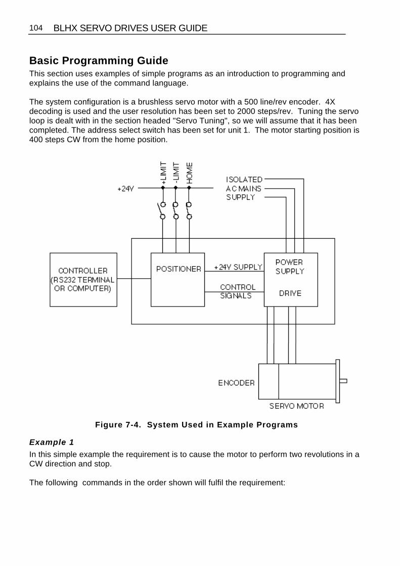
BLHX SERVO DRIVES USER GUIDE104
Basic Programming GuideThis section uses examples of simple programs as an introduction to programming andexplains the use of the command language.
The system configuration is a brushless servo motor with a 500 line/rev encoder. 4Xdecoding is used and the user resolution has been set to 2000 steps/rev. Tuning the servoloop is dealt with in the section headed "Servo Tuning", so we will assume that it has beencompleted. The address select switch has been set for unit 1. The motor starting position is400 steps CW from the home position.
Figure 7-4. System Used in Example Programs
Example 1
In this simple example the requirement is to cause the motor to perform two revolutions in aCW direction and stop.
The following commands in the order shown will fulfil the requirement:

SECTION 7. PROGRAMMING 105
Command Purpose MN Set move mode to normal1A10 Set acceleration motor 1 = 101V5 Set velocity motor 1 = 51D8000 Set move distance motor 1 = CW 2 revs1G Start move - motor 1 moves 2 revs CW
Description
Commands cause motor 1 to accelerate at 10 revs/sec2 to a velocity of 5 RPM, travellingCW for 8000 steps (2 revs) at the G command.
Example 2
This example causes axis 1 to go to the home position, then turn 5 revolutions CCW at 10revs/sec and set the resulting position as absolute zero. The motor finally turns 8revolutions CW to finish at absolute position 32000.
Command Purpose ST1 Energise the driveA10 Set acceleration to 10 revs/sec2
V10 Set velocity to 10 revs/secGH-2 Send axis 1 to go home (2 revs/sec CCW)1D-20000 Set axis 1 to go 5 revs CCWG The axis moves to the required absolute positionMPA Set absolute position modePZ Set position to absolute zero1D32000 Set move to abs. position 32000 (8 revs CW)G Move to position 32000 (1 rev CW from starting
position)1PR Report absolute position
Description
Commands 2 - 6 cause the motor to go to the home position and then turn 5 revolutionsCCW. Command 7 sets the absolute positioning mode and Command 8 sets the resultingposition as absolute zero. Commands 9 and 10 cause the motor to turn 8 revolutions CW toabsolute position 32000.

BLHX SERVO DRIVES USER GUIDE106
Programmable I/O Functions
Programmable InputsYou can program each input or define them to correspond to a function. To define an inputto a particular function use the IN command. The user definable inputs are labeled IN1 toIN10 on the front panel. The remaining inputs are dedicated as Limit+, Limit-, Home, Stopand Aux-In.
All input functions have be assigned a letter - refer to the IN command in the X150/X150ESoftware Reference User Guide.
To program an input to perform a function, use the IN command followed by the inputnumber and the corresponding function letter.
For example
1IN7H Set input 7 as direction toggle.
The active input level can be defined using the polarity links 13,15 and 17. Refer to Section3 for information relating to link selection.
To view the current status of the user definable inputs type 1IN. All user definable inputs willbe displayed.
Verifing Input WiringTo verify that you have wired the inputs correctly for your application use the IS command.This command reports the active state of all inputs regardless of the function assigned tothem.
Command Response 1IS 000000_0000000000
This indicates that no inputs are active.
The switching level and active state of the inputs can be configured using links. 3 banks of 5inputs can be set using links 12-17. The active level of the input will be affected by theposition of these links, however the IS command will always indicate the on/off status of anyinput regardless of the position of these links.
Command Response 1IS 000000_1000000000
This indicates that input 1 is active.

SECTION 7. PROGRAMMING 107
Set Up Example
The limit inputs are to be connected to PNP normally closed proximity switches. The Homeswitch is connected to a normally open PNP proximity switch. Input 4 is to be configured asa kill input active when 0V is applied to the input. Inputs 6,7 and 8 are sequence select linesand input 9 is a sequence strobe line which is connected to the PNP ouput stages of a PLC.The stop input is active when +24V is applied to the input. All inputs operate at 24V dc.
LK1 in position A (+24V DC)LK12 in position A (+24V DC sense)LK13 in position B (active high)LK14 in position A (+24V DC sense)LK15 in position A (active low)LK16 in position A (+24V DC sense)LK17 in position A (active low)
Configure inputs as follows :
1IN4CConfigure input 4 as kill input1IN6NConfigure input 6 as a data input1IN7NConfigure input 7 as a data input1IN8NConfigure input 8 as a data input1IN9NConfigure input 9 as a data input1IN10W Configure input 10 as a sign bit1OUT3J Configure output 3 as a strobe output1OUT4J Configure output 4 as a strobe output1OUT5J Configure output 5 as a strobe output
Note the limit switches are normally closed. When a limit is reached the switch will openand the controller input will get pulled low by the pull-down resistor on the active high input.This is the reverse of what the controller is expecting, therefore the sense levels of both limitinputs will need to be reveresed using the INL command.

BLHX SERVO DRIVES USER GUIDE108
Figure 7-5 Input Example
Programmable OutputYou can program each output, or configure it to perform to a particular function. There are 6user definable outputs which can be NPN or PNP (specified by the user at purchase). Theoutputs are provided on an interchangeable PCB (refer to Section 3).
To allocate an output to a particular function use the OUT command. The user definableoutputs are labelled OUT1 to OUT6 on the front panel. All output functions have beenassigned a letter, refer to the OUT command in the software section.
To program an output to perform a function, use the OUT command followed by the outputnumber and the corresponding function letter.
For example
1OUT3T Set output 3 as in position.
To view the current status of the user definable output type 1OUT. All user definable outputswill be displayed.

SECTION 7. PROGRAMMING 109
The response of the output to an active level will depend upon the type of output modulefitted.
Note: Although it has been stated that all output functions can be defined using the OUTcommand there is one exception to this:
OUTPUT 1 can be configured as a composite fault output using the SSD command. WhenSSD is set to 1 then output 1 is configured as a composite fault output and overrides thefunction defined by OUT. SSD must be set to 0 for output 1 to be configured using the OUTcommand.
Verifying Output Operation
You can directly control each output using the output command 0. Using this command youcan force any output to the desired state, in order to do this the output must be configured asa programmable output (function A).
Command Description > 1O1X0 Turn output 1 on, ignore output 2 and turn off
output 3.
Using Programmable Outputs
Programmable outputs can be used to interface with other parts of the system in order toindicate such things as in position, sequence in progress, fault or a user defined function.
The following steps demonstrate how you can configure these outputs.
ExampleOutput 1 is to be configured as a composite fault output. Output 3 is to indicate when themotor is moving and Output 5 is to indicate when the motor is in position.
1SSD1 Set output 1 as composite fault1OUT3B Set output 3 as moving / not moving1OUT5T Set output 5 as in position output
Typing 1OUT will display
;Output 01 Function F;Output 02 Function A;Output 03 Function B;Output 04 Function A;Output 05 Function T;Output 06 Function A
Output HardwareOutputs can be NPN or PNP, supplied on a plug in module. The two possible output circuitsare shown in Figure 7-6.

BLHX SERVO DRIVES USER GUIDE110
Figure 7-6 Output Hardware Modules
Sequences
IntroductionA sequence is a series of commands that is executed in order whenever the sequence isrun. Immediate commands cannot be stored in a sequence since they cannot be stored inthe command buffer. The only "saveable in sequence" commands are buffered commands.
The positioner has a section of non-volatile RAM totalling 8000 characters allocated forstoring up to 64 sequences. The sequence buffers are of variable length, so they can storelong sequences of up to 8000 characters or several shorter ones, provided that the totallength of all sequences does not exceed the allocated 8000 character space.
During normal operation a command can specify the execution of any sequence stored inmemory.
Sequence identifiers: number from 1 - 64.
When a sequence is programmed, the controller automatically calculates a checksum forthe sequence and stores the length of the sequence and its checksum in an internaldirectory.
The command XSS can be used to verify the existence of a sequence.
If a power-on sequence is used, the sequence and its sequence number are stored in thenon-volatile RAM.
Programming SequencesSequences are programmed by first sending a special start command XD, which clears thecommand buffer. All subsequent commands are stored in the command buffer (but not

SECTION 7. PROGRAMMING 111
executed) until an end of sequence command (XT) is received. Any condition whichprevents proper recording of the sequence is saved and can be accessed with the statuscommand XSD. The programmed sequence can be tested with the run sequencecommand XR, which executes any specified sequence.
The XU command can be used to read back the entered sequence.
To begin the programming of a sequence, the XD command immediately followed bysequence identifier number (1 to 64) and a delimiter must be entered. An XT commandends the sequence. The save command SV should be used to store the sequence into thecontroller's non-volatile memory.
The commands entered after the XD command and before the XT command will beexecuted in the order in which they were entered when the sequence is run.
Example:
NOTE: The ">" prompt is replaced by the "$" prompt when in sequence edit mode. If thenumbered sequence already exists, it must first be erased using the XE command.
Command Description XE1 Erase previous sequence No.1XD1 Begin definition of sequence No.1A10 Set acceleration to 10 revs/sec/secV10 Set velocity to 10 revs/secD4000 Set move distance to 4000 stepsG GoH Reverse next moveG GoXT End of sequence
* The definition of sequence No.1 is terminated by XT but the sequence is NOT stored innon-volatile memory untilthe save command SV is given.
NOTE: Put LK8 in position A on the controller card (see Figure 3-16) to write-protectsequences.
Whenever the above sequence is run, the motor will turn 1 revolution CW and then 1revolution CCW.
Running Sequences
By Command Input
A sequence can be run by entering the XR command immediately followed by a sequenceidentifier number (1 - 64) and a delimiter.

BLHX SERVO DRIVES USER GUIDE112
Example:
XR3[space] runs sequence No.3
Standalone Operation
Stored sequences may be automatically executed when you power up the system orexecuted by remote switches, RP240, TM8 and thumbwheel.
A sequence selected as a binary pattern, set on inputs using the INnO command can be runin response to a sequence strobe set on an input using the INnB command.
ExampleInputs 1 to 4 are to be used as sequence select lines.Input 5 is to be used as a sequence strobe line.Programs have been stored in sequences 1 to 16.
LSD 1IN1OSet input 1 as sequence data input . 1IN2OSet input 2 as sequence data input . 1IN3OSet input 3 as sequence data input . 1IN4OSet input 4 as sequence data inputMSD 1IN5BSet input 5 as sequence strobe input.
A binary pattern is configured on the inputs corresponding to the decimal sequence number.On a logic 0 to 1 transition of the sequence strobe input, the sequence corresponding to thebinary pattern will be executed.
If a sequence is already running when the sequence strobe is activated the sequencestrobe will be ignored. A sequence in progress must be terminated before execution of thenext sequence strobe.
Power On Sequence
One of the stored sequences can be designated to be executed when the device is poweredup. The sequence to be executed can be selected by prior RS232C command (XP1-64).The single sequence specified is executed once; control then passes to the RS232 link.Alternatively, power-on execution can be disabled with either the XP0 or XZ commands.
It is possible to have the controller execute a sequence on power up by defining thecommands within a sequence using the XD, XT and XP commands. To define sequenceNo.1 the operator enters:
XP1 XD1 MN A10 V5 D40000 G XT 1SV
In this example the operator would not power the unit on until he was ready for thesequence to begin. The XP1 command enables a single run of sequence No.1 after poweron. The XD1 command signifies the start of the definition of sequence No.1 and the XT

SECTION 7. PROGRAMMING 113
command signifies the end of the sequence No.1 definition. When the operator appliespower to the positioner, sequence number 1 will be executed (the motor will turn 10revolutions in the positive direction). The sequence can be stopped using the S commandor, if necessary, by using the emergency stop.
Changing a Programmed Sequence
Once a sequence is defined it cannot be redefined until it has been deleted. A newsequence cannot be downloaded over an existing one.
To change a sequence, it must be deleted from memory and then redefined as a newsequence using the same number.
First, the sequence must be deleted from memory using the XE command. It will not bedeleted from back-up RAM unless the SV command is used after the XE.
Example:
XE1 erases sequence No.1
The changed sequence should then be entered. It will not be saved to non-volatile memoryuntil the SV command is issued.
Examining the Contents of a Sequence
If the operator wishes to check the contents of the sequence, he would enter:1XU1
This would cause the positioner to send the contents of sequence number 1 to the terminal'sscreen. The 1 preceding the XU command is the device address which must be presentsince the XU command is a "device specific" command. After issuing this command thefollowing will be displayed on the terminal's screen:
;Sequence 1 is: MN A10 V5 D40000 G
This is the command string that is performed when sequence number 1 is executed.
If the operator does not wish to have the sequence execute on power up, it can be cancelledby issuing either the XP0 or XZ command.
Sequence no.1 can also be run manually using the XR command.
Sequence Status Requests
Sequence status commands include XC, XSD, XSP, XSR, XSS. The XC command can beused to verify that the memory in the back-up RAM has not been corrupted in any way sincelast power down. The XC command will cause the positioner to send a checksum in theform of three decimal digits (000 - 255) to the terminal. The checksum may be recordedwhen sequences have been defined, so that it may be used for comparison later, such aseach time the positioner is powered up.

BLHX SERVO DRIVES USER GUIDE114
Sequence Debugging Tools
After creating your sequences, you may need to debug them to ensure that they areperforming properly. The Controller provides several debugging tools.
• In trace mode, you can trace a sequence as it is executing• You can single step through a program• Error messages can be enabled explaining why the Controller has stopped execution
Trace Mode
You can use the trace mode to debug a sequence or a program of sequences. The tracemode allows you to track, command by command, the entire sequence. It displays to yourterminal, over the RS-232C serial link, all of the commands as they are executed. Thefollowing example demonstrates the trace mode.
Step 1Create the following sequence:
Command Description XE1 Erases sequence #1XD1 Begins definition of sequence #1A10 Acceleration is 10 rps2
V5 Velocity is 5 rpsL5 Loop 5 timesGOSUB3 Jump to sequence #3N Ends the loopXT Ends the definition of sequence #1
Step 2Define the sequence #3.
Command Description XE3 Erases sequence #3XD3 Begins definition of sequence #3D50000 Sets the distance to 50000 stepsG Initiates motionXT Ends the definition of sequence #3
Step 3Enter the following command to enable the Trace mode.
Command Description 1XTR1 Enable the trace mode

SECTION 7. PROGRAMMING 115
Step 4You will now execute the sequence. The commands will be displayed on the terminal aseach command in the sequence is run. Enter the following command:
Command Description XR1 Run sequence #1 - response is:
*SEQUENCE 001 COMMAND A10*SEQUENCE 001 COMMAND V5*SEQUENCE 001 COMMAND L5*SEQUENCE 001 COMMAND GOSUB3 LOOP COUNT 1*SEQUENCE 003 COMMAND D50000 LOOP COUNT 1*SEQUENCE 003 COMMAND G LOOP COUNT 1*SEQUENCE 003 COMMAND XT LOOP COUNT 1*SEQUENCE 001 COMMAND N LOOP COUNT 1*SEQUENCE 001 COMMAND GOSUB3 LOOP COUNT 2*SEQUENCE 003 COMMAND D50000 LOOP COUNT 2*SEQUENCE 003 COMMAND G LOOP COUNT 2*SEQUENCE 003 COMMAND XT LOOP COUNT 2*SEQUENCE 001 COMMAND N LOOP COUNT 2*SEQUENCE 001 COMMAND GOSUB3 LOOP COUNT 3*SEQUENCE 003 COMMAND D50000 LOOP COUNT 3.....*SEQUENCE 003 COMMAND G LOOP COUNT 5*SEQUENCE 003 COMMAND XT LOOP COUNT 5*SEQUENCE 001 COMMAND N LOOP COUNT 5*SEQUENCE 001 COMMAND XT
The format for the trace mode display is:
Sequence Number Command Loop Count
Step 5To exit the trace mode, enter the following command:
Command Description XTR0 Exits Trace mode
Single-Step Mode
You can debug your program with another level of debugging using the Single-Step mode.Single-Step mode allows you to execute one command at a time when you want the

BLHX SERVO DRIVES USER GUIDE116
command to be executed. Use the XST command to enable Single-Step mode. Once youare in the mode, you can execute a sequence one command at a time. To execute acommand, you must use the # sign. By entering a # followed by a delimiter, you will executethe next command in the sequence. If you follow the # sign with a number (n) and adelimiter, you will execute the next n commands. The following steps illustrate the use ofSingle Step mode:
Step 1Enter Single-Step mode
XST1
Step 2Begin execution of sequence #1
XR1
Step 3You will not execute any commands until you use the # command. Type the following:
Command Description # Executes one command
The response will be:
*SEQUENCE 001 COMMAND A10
Step 4To execute more than one command at a time, follow the # sign with the number ofcommands you want executed.
Command Description #3 Executes 3 commands, then pauses sequence execution
To complete the sequence, use the # sign until all the commands are completed. To exitSingle-Step mode, type:
XST0

SECTION 8. SERVO TUNING 117
Section 8. SERVO TUNING
Tuning the Drive with a PositionerThe positioner is designed to operate with the drive configured as a torque amp, and this isthe usual mode of operation described here.
Tuning Positioner with Drive in Torque AmpTo obtain smooth rotation at optimum speed and accurate positioning of the motor withoutovershoot or oscillation, with the motor connected to your system, you must tune the gainand damping characteristics of the servo loop. The TUNET command provides a self-tuningfeature but for some applications the best results will be obtained by manual tuning usingthe commands listed at the end of this appendix, together with those from the X150/X150ESoftware Reference User Guide. Refer to the servo loop block diagram shown inFigure 8-1. The parameters affecting tuning are as follows.
Tuning Parameters
Proportional gain (CPG command)
Proportional gain determines the amount of torque produced in response to a given positionerror. It sets the stiffness of the system and affects the following error. A high proportionalgain gives a stiff, responsive system but results in overshoot and oscillation which requiredamping.
Velocity gain (CVG command)
Velocity feedback is a signal which increases with shaft speed. It acts in a negative senseopposing the proportional action and helping to stabilise the motion. The damping action ofvelocity feedback allows a higher proportional gain to be used.
Integral gain (CIG command)
Proportional action may be insufficient to overcome static position errors due to friction.Integral action accumulates a steady state error until sufficient torque is produced to movethe load. It improves overall positioning accuracy but may produce low frequency oscillationaround the commanded position.
Feedforward gain (CFG command)
The opposing action of proportional and velocity gains result in a position error whichdepends on speed. This is called "following error". Feedforward gain can be used to offsetthe following error and improve tracking accuracy. This is important in contouringapplications.
Filter time constant (CTG command)
Fast positioning systems need high proportional and velocity gains. By limiting thebandwidth, the digital filter prevents a high gain system from becoming too lively. The filteralso serves to average the effects of the digital control loop, reducing the jitter at standstilland the audible noise. The value of CTG should be kept as low as possible.

BLHX SERVO DRIVES USER GUIDE118
You can examine these parameters by using the DR command.
Figure 8-1. Servo Control Loop
Terminal/Computer
The terminal/computer communication should be set to to 9600 baud, no parity, full duplex(not local), 1 stop bit.
After power up, the sign on message "DON'T PANIC Type HELP'" and the > prompt willappear on the screen unless you have previously set the positioner into the terse computercommunications mode using EX0. In any case using the command 1DR will display thestatus of the positioner.
Connecting the Loop
Safety
It is advisable to have the STOP input wired to a stop switch located in an easily accessibleposition so that the system can be halted quickly in the event of instability causingoscillation. An alternative is to cut the power using the command OFF[CR] but this takeslonger.
Unless you have saved data in the past while the motor was energised, the positioner willpower on without attempting to move or energise the motor.
If any of the motor or encoder connections have been re-made or changed, the first step is tocheck the integrity and polarity of the motor connections. Proceed as follows:

SECTION 8. SERVO TUNING 119
Make sure the axis is de-energized, type OFF[CR], if in doubt. Use the command :
aDS3[CR]
where a = the device addressto display the feedback position continuously (approximately 0).
Turn the motor shaft CW and check that the displayed value increases, turn the shaft CCWand it should decrease. If this does not happen you must not close the loop with ON at anytime since the feedback will be positive.
Press [CR] to restore the > prompt.
Manual Tuning Procedure
1. Initial Setting Up
Type the commands CFG0 CPG0 CVG0 COFF0 CIG0 CTG0 to software disable the servo.Check the result of these commands with the command 1DR.
When the axis is energised, it will be open loop with a slight torque demand due to amplifieroffsets. This may cause motion of the motor. You may have to restrain the axis and beprepared to switch off, or type OFF[CR]. In any case there is an automatic software limit setby the command CPE on the distance it will drift.
2. Position Error Window Setting
The drive is disabled to protect the system if the position error goes outside of the positionerror window. The window can be set to a low number of steps to avoid damage due toovershoot or oscillation.
The value of CPE defines the size of the window in steps. It can be displayed by using theCPE command.
During tuning, CPE is normally set to 4000 steps i.e. 1 rev either way at the usual 4000steps/rev. If in doubt set a lower value. The effect of going beyond the set error limit will beto automatically de-energise the motor.
Type the command RSE (report servo errors). This may show quite a list of errors. "Drivedisabled by software command", "error limit exceeded" and "failed checksum of backup ram"are all acceptable at this point but "Drive fault" should not come up. If it does, check the LEDon the drive front panel and try powering down the system and then powering it up again.
DO NOT PROCEED IF A DRIVE FAULT PERSISTS

BLHX SERVO DRIVES USER GUIDE120
3. Energising the Axis
Energise the axis by typing ON [CR]. You may find it convenient to restrain the axis to stop itdrifting out of the error limit and de-energising. If it does de-energise, it can be restarted bytyping ON.
4. Cancelling Drift
Cancel any offset using the command aCOFF<value>[CR]. Negative values stop CW drift;positive values stop CCW drift. Values up to a few thousand are acceptable (the maximumis 32,000 corresponding to full torque demand). Only small values are normally required,for example 1COFF10.
Check that making COFF more positive tends to turn the motor CW and making it morenegative tends to turn it CCW. If this does not happen, do not proceed, as the loop will havea net positive feedback and will oscillate (although probably slowly) when the loop isclosed.
5. Closing the Loop
Set a small position error limit (2000 steps for example) so that if oscillation occurs duringtuning, the resulting overshoot producing large position errors will exceed the limit set byCPE and shut down the drive.
If necessary, first move the axis to a good starting point, then type ON[CR] to energise themotor and CPG1[CR] to close the loop. If a slight vibration appears at this point, it indicatespositive feedback.This should only occur if you have changed the motor or encoder connections. Taking care,displace the axis slightly and then let go. You should experience a slight spring effect andthe axis should return to its original position - approximately. The closed loop is nowworking.
Setting Up Servo ParametersNOTE: When setting up servo parameters, do not allow the motor to go unstable for morethan a second or two.
Tracking Applications
For tracking applications (PID tuning), where minimum following error is required, velocityfeedforward should be used to improve the tracking accuracy. This can be set using theCFG command or the CDG command can be used to set feedforward gain and velocityfeedback gain to the same value.
Point to Point Positioning ApplicationsFor fast point to point positioning applications (PIVF tuning), a high proportional gain (CPG)damped by velocity gain (CVG)should be used.

SECTION 8. SERVO TUNING 121
Help Setting Loop Parameters
A guide to servo loop parameter settings for a fully damped non-oscillating response isprovided in HELP 11. To use HELP 11 you will need to be in terminal mode (EX set to 1)and you will need to provide a terminal address for the CJL and CTQ commands for theentry of inertia and torque data.
HELP 11 uses the maximum low speed motor torque entered by the CTQ command and thetotal moment of inertia entered by the CJL command in calculating suggested settings forthe loop parameters.
First enter the values of CTQ and CJL (Motor + load inertia) for your system, then use HELP11 to display recommended servo loop parameter settings calculated from the data youhave entered. For example, if 3.6 is entered for the CTQ command to indicate a maximumtorque of 3.6 Nm available and 1.6 is entered for the CJL command indicating a total inertiaof 1.6 Kg/cm2 , the following table will be displayed:
GainCPG
VelocityGain
CVG/CFG/CDG
StiffnessmNm/step
Error @maximum
torque(fb steps)
DoubledT
Constant(msecs)
1/2moved
time(msecs)
Closedloop
bandwidth(3db) (Hz)
1000 190 110 33 1 2 67500 130 55 66 2 3 48250 95 27 130 3 5 34120 67 14 260 7 7 24
62 47 6 520 6 10 17
Table 8-1. HELP 11 - Servo Setup TableEach successive line of the table corresponds to a less highly tuned servo system withreduced stiffness and speed of response. These reduced values may be used in matchingthe servo to lower specification mechanics.
The following describes in more detail the terms used in the table:
Velocity Gain
The settings of CVG, CDG and CFG depend upon the application as described above.
For the figures in the rest of the line of the table to apply, the CDG or CVG setting should beas in column 2.
For Position Integral Derivative (PID) applications, setting CDG to the figure quoted in thetable will automatically set CVG and CFG to the same value.

BLHX SERVO DRIVES USER GUIDE122
Stiffness
Stiffness is the restoring force per unit of displacement. The force is dependent on thenumber of steps displaced from the demanded position. For example, a displacement of100 steps with a stiffness of 10 mNm/step would produce a restoring force of 1 Nm.
Error at Maximum Torque
As the axis is increasingly displaced from the demanded position, the restoring torqueincreases at the quoted stiffness until the maximum available torque is applied. The Error atMax Torque is the number of steps of displacement required to produce a restoring force ofthe maximum available torque.
Doubled T Constant
When the damping is critical, the response of the servo loop is that of two simple filters inseries, each having a time constant T. The value of T is quoted in the table.
1/2 Moved Time
The following is an example move using servo values taken from the top line of the HELP 11table to show the 1/2 moved time. The move is at maximum acceleration and velocity and itis initiated by the command string: D100 A0 V0 G
Figure 8-2 represents instantaneous position plotted against time for the resulting servomovement .
Figure 8-2. Example Servo Response Curve
The 1/2 moved time is the time taken to complete half of the move, 50 steps in this example.

SECTION 8. SERVO TUNING 123
The move will be half complete in the time 1.7T (column 6 of the table) or 1.7 x 5 = 8milliseconds approx.
The move will be 96% complete at time 5T. In the example, the motor will have moved 96steps in 25ms.
Bandwidth
The bandwidth of the servo system is the range of frequencies at which a sine wave movepattern input will be followed within 3db by the actual motion of the motor. Figure 8-3 showsthe sine wave position demand input and the graphical representation of the motormovement.
Figure 8-3. Servo System Bandwidth
As the frequency of the sine wave of demanded positions at the input (Ai) increases, theability of the servo system to follow is reduced and the amplitude of the sine wave of theresulting output positions (Ao) decreases. The frequency at which it is reduced by 3db isthe upper limit of the bandwidth.
Coarse Tuning the Loop
Attach a nylon cable tie to the shaft of the motor. The loose end can be used as a coarseindicator for overshoot and oscillation.
Use the command string A0 V0 D200 G to produce a short, sharp rotation of the shaft.Observe the movement, watching the cable tie for overshoot and oscillation. Repeat themovement, increasing CPG using the settings suggested in HELP11 until overshoot justoccurs.
Balance the increasing gain with damping by setting CVG to 10, 20, 40 ... Increase it untilthe oscillation and overshoot indicated by the cable tie ceases.

BLHX SERVO DRIVES USER GUIDE124
Fine Tuning
After coarse tuning the loop, continue balancing the gain and damping, monitoring theovershoot at the terminal by typing:
aDPE [space] G [space] [CR]
where a=the device address.
The CR should be entered quickly after typing the space following the G command - this willstop the position error display with the final positioning readings on screen to allow you toanalyse them. Overshoot is indicated by the position error reading passing through zero atthe end of the movement, then returning back through zero in the opposite direction,oscillating with decreasing error readings about the zero position before finally settlingwithin the position error window. The damping should be increased to the point whereovershoot just disappears. Too much damping will result in a sluggish movement.
Figure 8-4. Overshoot During Positioning

SECTION 8. SERVO TUNING 125
The following table shows the DPE readings for the final positioning graph of Figure 8-4.This is only an example to illustrate the general principles involved in tuning - in practice,the resulting figures may differ considerably from those given, but they will follow thegeneral pattern shown. The overshoot shown here is rather more severe than might begenerally expected.
Samples Readings1 - 7 23 22 -17 -20 -5 14 12
8 - 14 -7 -10 0 6 4 -3 -415 - 21 -2 4 3 -2 -3 -1 0
Table 8-2. DPE Readings During Final Positioning
Notes on Tuning
The TUNE command will show how much torque was used, with 1023 corresponding tosaturation. If the maximum torque demand is significantly less than 1023 you should tryincreasing CPG. You will normally need to increase CVG as well in order to preventovershoot. Make sure that the maximum torque never exceeds about 1000 to guaranteethat the servo loop does not saturate.
The TUNE command also shows the time taken for the complete move as well as thesettling time. This information is also useful in optimising the response.
To summarise:1. Use DPE to look for overshoot and oscillation.2. Use TUNE to check maximum torque demand, move time and
settling time.
CFG, the feedforward gain should never be set very much larger than the velocity feedbackgain (CVG). A setting of 20% more than CVG is the largest practical value.
An increase in gain is always best matched by an increase in damping; when this is nolonger true you have reached the optimum values. A useful guideline is that an increase oftimes X in gain is best matched by an increase of times square root X in velocity feedback(think of this as an X% increase in gain matches an X/2% increase in damping e.g. 30%more gain matches 15% more damping). This will keep the shape of the response the sameand just increase its frequency (you are holding a quantity called the damping ratioconstant).

BLHX SERVO DRIVES USER GUIDE126
Servo Self-tuning
A facility for self-tuning the servo is included in the positioner software, using the commandTUNET. The servo parameters are set at the time that they are executed and there is nocontinuous on-going adjustment (known as adaptive control).
Tuning is for the following characteristics:
• Stability - does not oscillate as it moves or settles
• Maximised stiffness and accuracy - deflects as little as possible in response to external forces
• Maximised bandwidth and speed of response - settles to the commanded position as quickly as possible at the end of a move
• Does not overshoot the end position in a move
• Minimal sound during motion or when holding position
• Tracks a profile of constantly changing position or velocity with as little error as possible
• Resistant to change as friction and other load characteristics vary from time to time, machine to machine, application to application and with production variations
• Operates for smaller loads than that used for tuning down to no load.
There are a number of other move related requirements:
• Make full use of the torque and power available so that the longest, fastest move possible can be made
• Perform equally well for fast or slow motions and for short or long moves
• Minimise heating effects in the motor and drive
It is not correct to adjust the servo loop parameters to meet these requirements as thegeneral servo performance would be adversely affected. They are best met by adjusting themove profile (D, V and A values) and possibly the feedforward CFG value whilst watchingfor saturation effects.
If the application is purely velocity control with no requirement for positioning, then thetuning is best carried out manually. The self-tuning settings will work, but they will notproduce the best achievable results.

MAINTENANCE & TROUBLESHOOTING 127
Section 9. MAINTENANCE & TROUBLESHOOTING
Section ObjectivesThe information within this section will help you to isolate and resolve system problems.
GeneralIn order to minimise field failures, all drives are soak tested at elevated temperatures. Inspite of this the occasional failure may still occur and the following notes are intended as abrief guide to enable the cause of the fault to be located.
Drive RemovalBefore disconnecting a drive prior to removal, ensure that all supplies are switched off andwait for the Power On LED to go out.
Drive Fault LEDThe majority of faults that can occur in the drive will result in illumination of the Drive FaultLED. The causes of this are as follows:
HT Overvoltage
Failure of the dump circuit to cope with regeneration. Check the dump fuse, FS4. Check ifthe fault occurs during a period of deceleration, if so, then consult Digiplan with a view toincreasing the dump capability. If when the motor is stationary the DC supply normally hasa value of more than 165V then there is a danger of the overvoltage protection operatingunder average regeneration conditions. Lowering the normal operating value of the supplymay well cure this apparent fault.
Overcurrent
The drive fault LED will also be illuminated in the event of a short circuit occurring betweenthe motor terminals or if either terminal is shorted to earth.
If no external reason can be found, switch off the supply, then remove the associated motorconnections. Switch on the supply. If the fault LED is now illuminated then the drive is atfault and should be returned for repair. It may be necessary to request motion in eitherdirection to obtain the fault.

BLHX SERVO DRIVES USER GUIDE128
Loss of Incremental Encoder Signal
The LED will be illuminated if the signal from the incremental encoder is not present. Themotor would run away out of control if this was not detected.
If previous tests have not enabled the fault to be isolated, then substitution of the driveshould enable the fault to be narrowed down to one drive which can then be returned forrepair.
Overtemperature LED
This LED indicates an overtemperature fault. It may be the result of a drive fault, which canof course be proven by substitution. If this does not identify the fault then checks should bemade to ensure that the ambient temperature does not exceed 50°C, when all units in thevicinity of the drive have reached their normal operating temperature. A cooling fan may benecessary if high duty cycles are required. The LED may also indicate motorovertemperature.
Power On LED
This LED indicates that the logic supplies are present. It will remain illuminated for a shorttime after the drive has been switched off, due to the stored charge in the capacitors.

MAINTENANCE & TROUBLESHOOTING 129
LED Display Messages
Symptoms Possible Causes SolutionLED display 1 Drive has been de-
energised by userEnergise using STO or ONcommand
LED display 2 Drive has failed See drive manualLED display 3 Memory erased Reconfigure controllerLED display 4 Excessive positioning error Check mechanics and
system parameters. Checkintegrity of drive
LED display 5 Memory failure Reconfigure controller andsave parameters, if faultpersists contact Parkerrepresentative
LED display 7 Torque demand exceeded Ensure drive is capable ofproducing torque required.Check mechanics.
LED display 8 Watchdog failure -Processor has run out oftime
Cycle power. If faultpersists contact Parkerrepresentative
LED display U Communication error Type 1R at system prompt.Check communicationparameters
LED display E Non recoverablecommunication error
Cycle power to controller
LED display P Power levels to controllerincorrect
Contact Parkerrepresentative
Motor will notmove, butcontroller displayis 0
Stop or limits active Ensure that the limits are setor disabled. Ensure stop isactive
Cannotcommunicate withcontroller, butdisplay is 0.
Ensure communication hasnot been disabled using theF command
Issue <a>E command
Table 9-1. LED Display Messages

BLHX SERVO DRIVES USER GUIDE130
RS-232C ProblemsUse the following procedure to troubleshoot communication problems that you may havewith the controller.
[1] Be sure that the host computer’s transmit (Tx) wire is connected to the peripheral’sreceiver (Rx) connection and the host computer’s receive (Rx) wire is connected to theperipheral’s transmit (Tx) connection. Switch the receive and transmit wires on either thehost or peripheral if the problem persists.
[2] Confirm that the host is configured for 9600 baud, 8 data bits, 1 stop bit and no parity.
[3] If you receive double characters, for instance typing A and receiving AA, the computer isset to half duplex mode. Change the setup to full duplex mode.
[4 Cable lengths should not exceed 15 metres (50 ft.) unless you are using some form ofline driver, optical coupler, or shield.
[5] To test the terminal or terminal emulation software and the RS-232C cable for 3-wirecommunication, disconnect the controller end and enter a character. You should notreceive an echoed character. If you do, you are in half duplex mode. Connect the host’stransmit and receive lines together and send another character. You should receive theechoed character. If not, consult the manufacturer of the host’s serial interface for proper pinouts.
Software Debugging TipsThis section offers some helpful tips for debugging your programs. The controller hasseveral tools that can be used to diagnose system design problems. The software tools arelisted below:
IS Input statusR Report statusRA Report limit statusRB Report miscellaneous statusRE Report drive statusRS Report sequence statusRSE Report servo errorsXSD Report sequence downloadXSR Report sequence run statusXSS Report sequence statusXST Single step modeXTR Trace mode

MAINTENANCE & TROUBLESHOOTING 131
Trace Mode
Trace mode is used to display what is occurring as you execute a sequence. By running thetrace mode you can see what commands are being executed and if the program stopsrunning you can see what command was last executed. The trace mode will help you to findcommands that the indexer may not recognise. Trace mode is enabled and disabled withthe XTR command. When enabled, you will execute sequences as you normally wouldusing XR. As the sequence is running, the commands are displayed on the screen. XTR1enables the Trace mode, XTR0 disables it.
Displaying Status
There are several command that you can use to check the controller status. You can reportback the value or setting of almost all commands by typing the device address followed bythe command then a carriage return or a space bar. In this way, you can find out whatvalues you have entered in different commands. The DR command reports the current stateof the controller. Use this to verify that the controller is configured as you want it.
The DFX command is also useful in determining the current status of the controller. Thelisting in chapter 5 (Software Reference) will allow you to interpret the response to DFX.
Returning the System
Contact the Parker Automation Technology Centre or the machinery manufacturer whosupplied the product. Equipment for repair should NOT be returned directly to Digiplanwithout prior authorisation. Repairs will be carried out by Digiplan but will be processed viayour supplier.
Digiplan may at their discretion authorise direct shipment to and from Poole or Rohnert Park,but only by prior arrangement with your supplier. Existing UK and USA customers whopurchase equipment directly from Digiplan should contact Poole or Rohnert Park for furtherinformation (contact numbers are at the front of this User Guide).

BLHX SERVO DRIVES USER GUIDE132

APPENDIX A. SAMPLE COMMS PROGRAM 133
Appendix ASIMPLE X150 COMMUNICATIONS PROGRAM FOR IBM PCOR COMPATIBLE (TURBO C)
#include <dos.h>#include <bios.h>#include <conio.h>
#define COM1 0 /* Port number */#define PORT 0x3F8 /* Port address */#define DATA_READY 0x01 /* Line Status for Received data */#define TRUE 1#define FALSE (!TRUE)
#define SETTINGS (0xE0 | 0x03 | 0x00 | 0x00) /* 9600 BAUD, 8 Data bitNo Parity, 1 Stop bit */
void main(void)
int ky, end = FALSE;char ch;
clrscr();bioscom (0, SETTINGS, COM1); /* Setup port */cprintf("LIMITED X150 TERMINAL [ESC] to exit ...\n\r");while (!end) /* Main loop */
while (inportb (PORT+5) & DATA_READY) * Data received ? */
if ((ch = inportb (PORT)) != 0)putch(ch); /* Show character */if (ch == 0x0D) putch ('\n');
if (kbhit()) /* Keyboard pressed */if ((ky = getch()) == '\x1B') /* Was it ESCape ? */
end = TRUE; /* Signal quit */outportb (PORT, ky); /* Transmit keypress */

BLHX SERVO DRIVES USER GUIDE134
BUFFERED COMMUNICATION PROGRAM USING COM1 ON AN IBM PCOR COMPATIBLE (BORLAND TURBO C)
#include <conio.h>#include <dos.h>#include <stdio.h>#include <bios.h>#include "X150.h" /* Header file for serial interface */
static char CircBuf [BSize]; /* Declare circular buffer */unsigned int BufStart = 0, BufEnd = 0; /* Set buffer pointers up */int Port; /* Contains serial port address */char *X150 = "\r1D\r1V\r1A\r1R\r"; /* Settings commands for X150 */
void interrupt (*orgvect)(); /* Interrupt function pointer */
/* Function prototypes */void Enable_Int (void); /* Start everything */void Disable_Int (void); /* Reset serial port */void interrupt RX_Handler (void); /* Data Received handler */int Send (char c); /* Transmit a character */void SendAString (char *string); /* Transmit a string */int Receive (void); /* Get received data from buffer */
void main (void)
int c, end = FALSE;
clrscr();Enable_Int(); /* Start Interrupts */fprintf(stdout, "X150 TERMINAL\npress [ESC] to quit...\n\n");SendAString (X150); /* Interrogate X150 status */do /* Main loop */
if (kbhit()) /* Keyboard pressed ? */if ((c = getch()) == 0x1B)
end = TRUE; /* if Escape pressed end program */Send (c); /* Transmit character */
if ((c = Receive()) != FALSE) /* Anything received from X150 ? */fputc (c & 0x07F, stdout); /* Display character */ if (c == 0x0D) fputc ('\n', stdout); /* If CR do Carriage Return */
while (!end);Disable_Int(); /* Stop interrupts and tidy up */
void Enable_Int (void) /* Turn on communications interrupts */
int c, far *Addr;
bioscom (0, SETTINGS, 0); /* Setup comms parameters */Addr = MK_FP (0x0040, 0x00); /* Find address of COM1 */Port = *Addr;
APPENDIX A. SAMPLE COMMS PROGRAM 135
orgvect = getvect (0x0C); /* Install the interrupt handler */disable();setvect (0x0C, RX_Handler);c = inportb (Port + MCR) | MC_INT; /* Setup Modem Control Register */outportb (Port + MCR, c);outportb (Port + IER, RX_INT); /* Enable interrupts for data received */c = inportb (IMR) & IRQ4; /* Tell PIC to interrupt on COM1 */outportb (IMR, c);enable();
void Disable_Int (void) /* Turn off communications interrupts */
int c;
disable();c = inportb (IMR) | ~IRQ4; /* Stop PIC interrupts for COM1 */outportb (IMR, c);outportb (Port + IER, 0); /* Reset Interrupt Enable Register */outportb (Port + MCR, 0); /* Reset Modem Control Register */setvect (0x0C, orgvect); /* Restore original vector */enable();
void interrupt RX_Handler (void) /* Interrupt handler - data to CircBuf */
disable();if ((inportb (Port + IIR) & RX_MASK) == RX_ID) /* Data received ? */
CircBuf[BufEnd++] = inportb (Port);BufEnd &= BSize - 1;
outportb (ICR, EOI); /* Acknowledge end of hardware interrupt */enable();
int Send (char c) /* Output character to the serial port */
long int TimeOut = 0xFFFFL;
while ((inportb (Port + LSR) & XMTRDY) == 0) /* Wait for transmitter */if (!(--TimeOut)) return (FALSE);disable();outportb (Port, c); /* Do transmit */enable();return (TRUE);

BLHX SERVO DRIVES USER GUIDE136
void SendAString (char *string) /* Output a string to the serial port */
while (*string)delay(25); Send (*string++);
int Receive (void) /* Get the current value in the buffer */
int RX;
if (BufEnd == BufStart) return (FALSE); /* Nothing received/Overflow */RX = (int) CircBuf[BufStart++];BufStart %= BSize;return (RX);

APPENDIX A. SAMPLE COMMS PROGRAM 137
X150.H HEADER FILE FOR BUFFERED COMMUNICATION PROGRAM (BORLAND TURBO C)
#define BAUD 0xE0 /* BAUD rate of 9600 */#define DATA 0x03 /* 8 Data bits */#define NOPARITY 0x00 /* No parity */#define STOP 0x00 /* 1 Stop bit */#define SETTINGS (BAUD | DATA | NOPARITY | STOP)
#define IER 1 /* Interrupt Enable */#define IIR 2 /* Interrupt ID */#define MCR 4 /* Modem control */#define LSR 5 /* Line Status */
#define XMTRDY 0x20 /* Line Status Register TX ready */#define MC_INT 0x0F /* Modem Control Register Setup */
#define RX_INT 0x01 /* Interrupt when data is received */
#define RX_ID 0x04 /* Interrupt Ident. Register Data Received */#define RX_MASK 0x07 /* Interrupt Ident. Register Mask */
/* 8259 Programmable Interrupt Controller port addresses */#define IMR 0x21 /* Interrupt Mask Register port */#define ICR 0x20 /* Interrupt Control Port */#define EOI 0x20 /* 8259 end of hardware interrupt */#define IRQ4 0xEF /* COM1 mask for PIC */
/* General definitions */#define FALSE 0#define TRUE (!FALSE)#define BSize 0x4000 /* Serial buffer size */

BLHX SERVO DRIVES USER GUIDE138
QUICK BASIC COMMUNICATIONS PROGRAM USING COM1 ON AN IBM PCOR COMPATIBLE
DECLARE SUB CommsError ()DECLARE SUB ReportStat ()
FALSE = 0TRUE = NOT (FALSE)
Setup the RS232 port to the following:-9600 BAUD, No Parity, 8 Data bits, 1 Stop bit. Buffer size is 512 bytesOPEN "COM1:9600,N,8,1,RS,CS,DS,CD,RB512" FOR RANDOM AS #1PRINT #1, "" 'Clear the bufferCLOSE #1
'Re-establish communication port settings and data streamOPEN "COM1:9600,N,8,1,RS,CS,DS,CD,RB512" FOR RANDOM AS #1
Finish = FALSECLSDO
INPUT "Enter the move or status string : "; STEPMOVE$ 'Read in commandIF STEPMOVE$ = "QUIT" THEN
Finish = TRUE ‘Enter QUIT to stop programELSE
FOR C = 1 TO LEN(STEPMOVE$) 'Set loop count to string lengthB$ = MID$(STEPMOVE$, C, 1) 'Get one char from stringPRINT #1, B 'Transmit char to RS232 serial portR$ = INPUT$(1, #1) 'Read char in from port (Echoed char)IF R$ <> B$ THEN CommsErrorNEXT C
PRINT #1, CHR$(13); ‘Send a carriage returnR$ = INPUT$(1, #1) 'Get Echoed response
FOR cnt = 1 TO 500 ‘A short delay before responseNEXT cnt
CLSIF LOC(1) > 0 THEN ReportStat 'Now check for rec buffer not emptyEND IF
LOOP UNTIL (Finish = TRUE)CLOSE #1END
SUB CommsErrorPRINT "There has been a communications error"CLOSE #1STOP
END SUB

APPENDIX A. SAMPLE COMMS PROGRAM 139
SUB ReportStatPRINT : PRINT "The reported status is as follows :-";PRINT : PRINTDO WHILE NOT (LOC(1) = 0)
Report$ = INPUT$(1, #1) 'Input status string dataPRINT Report$; 'Display status string
LOOPPRINT
END SUB

BLHX SERVO DRIVES USER GUIDE140

APPENDIX B. EXTENDING MOTOR CABLES 141
Appendix B
Fitting Longer CablesWhen you order an ML motor, you can specify cable lengths up to 75 feet (22.5 metres). Ifpossible, it is better to order the motor with the required cable length rather than try to extendit afterwards. If you need cables longer than 75 feet, you can make your own up to amaximum of 300 feet (90 metres) provided you follow the guidelines below.Note: extending cables as described here will degrade EMC performance of the system, byreducing the effectiveness of screen connections.Motor cables can be lengthened by simply replacing the cable with a longer one using thestandard cable as a pattern. It should have 5 cores with an overall screen. Use 1 mm2 (or16 AWG) cores with a 2340 motor, and 1.5 mm2 (or 14 AWG) with a 3450 or 3475.
The 1620 motor is pre-wired with 4-core cable, so it is only necessary to use 4-corescreened cable when extending the lead.
Recommended Cable Sizes
MotorFrame Size
Motor Cable
<100ft 100-300ft
16 0.5mm2
20 AWG4-core
0.75mm2
18 AWG4-core
23 0.75mm2
18 AWG5-core
1mm2
16 AWG5-core
34 1.5mm2
14 AWG5-core
1.5mm2
14 AWG5-core
Table B-1. Motor Cable Sizes
Feedback CablesThe feedback cable may be extended up to a maximum of 50 feet (15 metres) using thesame type of cable as that supplied with the motor. Each conductor in this cable is 0.2mm2
(24 AWG). This type of cable is unsuitable for longer lengths owing to the voltage drop inthe 5-volt supply to the encoder.
Encoder cables can be up to 300 feet long before any noise problem is encountered, but it’simportant to consider the voltage drop in the 5V supply leads to the encoder. If the voltageat the encoder is too low, it can cause curious problems such as continuous illumination ofthe overtemperature LED. The encoder must have a minimum supply voltage of 4.5 volts

142 BLHX SERVO DRIVES USER GUIDE
and it draws a current of about 300mA. Thus the total resistance of the 5V and 0V wiresmust be less than about 1.7 ohms. When you calculate this resistance, remember tomultiply the resistance per metre (or per foot) by twice the cable length.
Probably the easiest way to lengthen the encoder cable is to cut the existing cable close tothe motor and again close to the drive, and to insert a new length of the same type of cableusing in-line connectors or terminal boxes. Suitable cable types are Lapp 0035805,Cablemaster OS1024P and Belden 9510. Try to keep the two wires in any pair close toeach other as they pass through the terminal box. Remember to connect the screen of thenew section to the screens of the two short lengths of original cable.
Having done this, now locate the red and black pair (which carry 5V and 0V) and run twolarger wires in parallel with this pair between the two terminal boxes. Each of these wiresmust have a resistance of less than 0.85 ohm. For example, use 1 mm2 (or 16 AWG) cablefor leads up to 150 feet (45m) long (Lapp 0034802 1 mm2) and 2.5 mm2 (or 14 AWG) cablefor leads up to 300 feet (90m) long.
Inserting in-line connectorsIt is sometimes necessary to be able to disconnect the motor easily, and a convenientsolution is to fit in-line connectors. Generally the closer the connector is to the motor thebetter. Here are the part numbers for suitable MIL Spec connectors from Amphenol:
19-way Encoder Connectors 62GB-11F14-19PN 62GB-16F14-19SN5-way Motor Connectors 62GB-11F14-05PN 62GB-16F14-05SN8-way Motor Connectors 62GB-11F16-08PN 62GB-16F16-08SN
The connector shown above for the encoder cable has 19 pins; the 19th pin is used for thedrain wire, i.e. the connection to the cable screen. If the connectors are within 500mm (18”)of the motor, you can use a 5-way connector in the motor cable and leave the screenunconnected. In other cases, use the 8-way (which is a larger shell size) and use pin 6 tolink the screens on either side of the connector. Do not connect the screen or drain wire to0v.
Take great care to make sure that both connector halves are wired correctly, otherwise theencoder or drive may be damaged. If the encoder cable has 10 pairs, the red and blue pairshould be connected in parallel with the red and black pair (i.e. red parallel with red, blueparallel with black).

APPENDIX B. EXTENDING MOTOR CABLES 143
Proprietary Cable Types
MotorSize
No. ofcores
mm2 ODmm Lapp Belden Alpha
16 4 0.5 7.0 0034604
16 4 0.5 6.0 5464C16 4 0.75 6.0 941823 5 0.75 8.2 0034
70523 5 1.0 9.0 0034
80523 6 1.0 8.9 5366C23 6 0.75 7.8 5386C34 5 1.5 9.9 0034
90534 5 1.5 13.2 5450/5
Table B-2. Motor Cable Types
No. ofcores
mm2 ODmm Lapp Cable-master
Belden Alpha National
10 x 2 0.2 9.7 OS10P24 951010 x 2 0.25 10.1 003580510 x 2 0.5 11.8 NQP-
1020FSJ12 x 2 0.75 16.8 2249/12C12 x 2 0.75 14.0 NQP-
1218FSJ
Table B-3. Feedback Cable Types

144 BLHX SERVO DRIVES USER GUIDE

INDEX 145
Index
"$" prompt, 111+24V PSU, 23120V connections, 15150V DC motor supply, 14240V connections, 1524V DC connections, 2285V DC motor supply, 14
Absolute mode, 95AC input connections, 22Addressing - daisy chain, 73
Bandwidth, 123BLHX types, 1Buffered clock mode, 64Buffered commands, 93
Cable layout precautions, 28Checksum, 110Command buffer, 94, 110Command types, 97Communications program, 133Communications protocol, 71Computer host mode, 93Conducted emissions, 27CONTINUE key - RP240, 84Continuous mode, 96Controller connections, 31Controller fuse, 51Cooling fan, 128Coupling optimization, 67Current limit LED, 3Current limit link settings, 25
Daisy chain wiring, 73Damping, 123Debugging Tips, 130Default values, 71Digiplan transformers, 8Dimensions of drives, 12Disable input polarity, 24Disconnect device, 16Drive fault LED, 3Drive types, 1
Dump fuse, 127
Echo function, 71Echoback, 75EMC filter types, 28EMC Installation, 27Enclosure considerations, 12Encoder cable order code, 5Encoder Connections, 52Encoder connections for ML1620, 56Encoder following, 61, 66Encoder resolution, 24Encoder timing, 19Energising/De-energising commands, 101Environment considerations, 11Evaluation commands (use of), 100
Factory default jumper/link positions, 4Fault LED illumination, 127Feedback cable lengths, 141Feedforward gain, 117, 125Ferrite absorber handling procedures, 30Ferrite absorber specification, 30Filter time constant, 117Filtering of AC supply, 28Function indicators, 2Function keys - RP240, 83Fuse rating calculation, 16Fuse types, 51
Handshaking, 71Hardware scaling, 62Homing function, 102Human interactive mode, 93
Immediate commands, 93In position outputs, 36Incremental mode, 95Index mark, 103Individual commands, 93In-line connectors, 142Input circuit conventions, 33Input wiring verification, 106Installation, 11

146 BLHX SERVO DRIVES USER GUIDE
Interactive programming, 77Isolating transformer, 8
Jog input example, 37Jumper factory defaults, 4Jumper link adjustment, 23Jumper link configuration, 39
Kill command, 99
LED Display Messages, 129LED indicators, 3LEDs, 2Link access, 13Links factory default settings, 4Logic supplies, 128Logic supply ON LED, 3Long cables, 141
ML1620 connections, 20ML1620 encoder connections, 56ML-1620 motor dimensions, 47ML23/34 connections, 20ML-2340 motor dimensions, 48ML-3450 & ML-3475 motor dimensions,48Motion profiles, 60Motion program selection, 69Motor cable order code, 5Motor cable size, 23Motor cables (extending), 141Motor connection, 7Motor connections, 52Motor dimensions, 47Motor peak currents, 26Motor selection, 47Motor wiring, 23, 52Mounting methods, 12Move time, 123Moves absolute preset, 57Moves continuous, 58Moves incremental, 57Moves preset, 57Moves registration, 58Multi positioner commands, 95
NEMA, 12
Non-volatile RAM, 110NPN Output boards, 35
Oscillation, 118, 123OUTnT command example, 36Output operation verification, 109Overshoot, 124, 125Overtemperature, 128Overtemperature LED, 3Overvoltage protection, 127
Package screw positions, 13Parameter settings, 121Pause Commands, 99PAUSE key - RP240, 84PC/PLC Interactive use, 75Performance curves, 50PID applications, 121PID tuning, 120PNP Output boards, 35Pollution specification, 11Position error, 124Position error window, 119Positioner, 1Power dump, 2Power supply (built-in), 2Preset following index mode, 62Product description, 1Product range, 1Program storage, 69Programmable I/O Functions, 106Programmable output, 108Programming guide, 104Programming modes, 95Programming sequences, 111Proportional gain, 117Protection circuits, 2
Radiated emissions, 27RAM, 69RAM Write protection, 69Regeneration, 127Registration, 58Registration move example, 59RP240 Connections, 44RP240 Display, 80RP240 Example programs, 84

INDEX 147
RP240 Function keys, 83RP240 Operating keys, 84RP240 Operation, 79RP240 Programming, 79RS232C Controller, 7RS232C Installation, 71RS-232C Problems, 130
Scaling H/W S/W comparison, 65Screw types (case), 14Sequence, 110Sequence buffer, 94Sequence buffers, 110Sequence debugging, 114Sequence examination, 113Sequence identifiers, 110Sequence redefining, 113Sequence selection, 112Sequence selection example, 112Sequence status requests, 113Sequences - programming, 111Sequences running, 112Serial connections, 7Servo loop, 117Servo parameters - set up, 120Servo self tuning, 126Servo tuning, 117Shipping list, 5Signal connections diagram, 18Signal type A inputs, 33Signal type B outputs, 34Signal type C inputs, 35Signal type D inputs, 35Signal type E inputs, 35Signal type F inputs, 35Signal type G inputs, 35Signal type I inputs, 35Signal types, 22, 33Signal types key, 22SIM0, 61SIM1, 61SIM2, 62SIM3, 62SIM4, 62SIM5, 62SIM6, 62SIM6 Operation, 66
Single-Step mode, 115Size of drive, 12Status Display, 131Status request command, 77STOP input, 118STOP key - RP240, 84Surge protection, 28Switching between modes, 68System Overview, 2
Temperature - operating, 11Temperature - storage, 11Temperature of motor warning, 17Terminal connections, 16Terminal/computer communication, 118Terse mode, 77Test configuration (pre-installation), 5Testing the BLHX, 8Testing the drive, 5Thumbwheel interface, 40TM8 (Dual) example, 43TM8 Example, 41TM8 Thumbwheel, 40Torque control applications, 67Torque curves, 50Torque vs speed curves, 50Torque-limited velocity control, 68Trace Mode, 131Trace modes, 114Transformer connections, 17Transformer dimensions, 49Transformer options (mains), 14Transformer primary voltage adjustment,16Transformer rating, 8Transformer selection, 14Trapezoidal profile, 60Triangular profiles, 60Tuning (BLHX drive), 26Tuning notes, 125
UART Overrun error, 77User profiles, 61
Velocity feedback gain, 125Velocity gain, 117Voltage drop, 141

148 BLHX SERVO DRIVES USER GUIDE
Windows terminal emulator, 76Write-protect sequences, 111
XON, XOFF, 71
XON/XOFF, 78X-WARE, 75, 93
Z Command, 99

INDEX149