
Parker Industrial Hose - TCH Industries
218
Parker Industrial Hose Catalog 4800 December 2020 VIEW CONTENTS
-
Upload
khangminh22 -
Category
Documents
-
view
4 -
download
0
Transcript of Parker Industrial Hose - TCH Industries

Parker Industrial Hose
Catalog 4800 December 2020
VIEW CONTENTS

Offer of SaleParker Hannifin Corporation, its subsidiaries or its authorized distributors hereby offer the items described in this document for sale. The provisions in the “Offer of Sale” stated at the end of this catalog govern this offer and its acceptance.
® Copyright 2018, Parker Hannifi n Corporation, All Rights Reserved. Trademarks used herein are the property of their respective owners.
WARNING – USER RESPONSIBILITY
FAILURE OR IMPROPER SELECTION OR IMPROPER USE OF THE PRODUCTS DESCRIBED HEREIN OR RELATED ITEMS CAN CAUSE DEATH, PERSONAL INJURY AND PROPERTY DAMAGE.
• This document and other information from Parker-Hannifin Corporation, its subsidiaries and authorized distributors provide product or system options for further investigation by users having technical expertise.
• The user, through its own analysis and testing, is solely responsible for making the final selection of the system and components and assuring that all performance, endurance, maintenance, safety and warning requirements of the application are met. The user must analyze all aspects of the application, follow applicable industry standards, and follow the information concerning the product in the current product catalog and in any other materials provided from Parker or its subsidiaries or authorized distributors.
• To the extent that Parker or its subsidiaries or authorized distributors provide component or system options based upon data or specifications provided by the user, the user is responsible for determining that such data and specifications are suitable and sufficient for all applications and reasonably foreseeable uses of the components or systems.
This QR tag enables you to see additional product and other content
on the web using your mobile phone. You will need a QR reader to get
started. Please visit www.mobile-barcodes.com/qr-code-software for
more information and a list of QR code readers you can install at no cost.
Parker Safety Guide for Selecting and Using Hose, Tubing, Fittings, Connectors,Conductors, Valves and Related Accessories
Parker Publication No. 4400-B.1
WARNING: Failure or improper selection or improper use of hose, tubing, fi ttings, assemblies, valves, connectors, conductors or related accessories (“Products”) can cause death, personal injury and property damage. Possible consequences of failure or improper selection or improper use of these Products include but are not limited to:
• Fittings thrown off at high speed.• High velocity fl uid discharge.• Explosion or burning of the conveyed fl uid.• Electrocution from high voltage electric powerlines.• Contact with suddenly moving or falling objects that are controlled by the conveyed fl uid.• Injections by high-pressure fl uid discharge.• Dangerously whipping Hose.
Before selecting or using any of these Products, it is important that you read and follow the instructions in this Industrial Hose Catalog 4800 and the complete Parker Safety Guide for Selecting and Using Hose, Tubing, Fittings, Connectors, Conductors, Valves and Related Accessories, Parker Publication No. 4400-B.1 (refer to the Safety & Technical Information section of this catalog). No product from any division in Parker Fluid Connectors Group is approved for in-fl ight aerospace applications. For hoses and fi ttings used in in-fl ight aerospace applications, please contact Parker Aerospace Group.
!
• Tube or pipe burst.• Weld joint fracture.• Contact with conveyed fl uids that may be hot, cold, toxic or otherwise injurious.• Sparking or explosion caused by static electricity buildup or other sources of electricity.• Sparking or explosion while spraying paint or fl ammable liquids.• Injuries resulting from inhalation, ingestion or exposure to fl uids.

1
Industrial Hose Products, Catalog 4800Table of Contents
Introduction ............................................................... 2
Air & Multipurpose Hose and Assemblies .............. 18
Chemical Hose ....................................................... 44
Coolant and Engine Hose ....................................... 52
Fuel Dispenser Hose .............................................. 74
LPG / Propane Hose and Assemblies ..................... 80
Material Handling Hose .......................................... 90
Oilfi eld Hose ......................................................... 103
Petroleum Transfer Hose ...................................... 107
PVC Hose and Tubing .......................................... 112
Steam Hose .......................................................... 121
Water Hose and Assemblies ................................ 129
Welding Hose and Assemblies ............................. 144
Couplings .............................................................. 154
Safety & Technical Information ............................. 164
Media Compatibility .............................................. 182
Hose Selector Guides at the beginning of each section identify products and provide product overviews.

2
Intr
oducti
on
Marketsn Agriculture n Construction n Food & Beverage n General Industrial n Marine n Material Handling n Militaryn Mobile Equipment n Oil and Gasn Petrochemicaln Transportation
Market-Oriented SolutionsParker penetrates new markets with new capabilities, products and services, leveraging our corporate economic power to pursue a program of aggressive, synergistic growth. These initiatives enable Parker to participate more fully in existing markets and establish a commanding position in emerging markets.
n Introduction of innovative prod-ucts, such as ultra-flexible E-Z Form™ hose for coolant and oil suction/transfer service:
• Handles extreme bends while allowing full-flow, kink-free performance
• Replaces formed hoses in many applications
Parker Industrial HoseParker industrial hose products are the preferred choice for transferring abrasive materials, acid and chemicals, air, compressed gases, food, fuel, oil, sanitary materials, steam, welding gases, water and many other materials. We manufacture a variety of hoses with covers that are resistant to abrasion, chemicals, flame, heat, oil, ozone, ultraviolet light and weathering. Our products provide value through robust performance and long service life.
• Eliminates special tooling costs and orders for minimum production quantities
• Minimizes potential leak points created by multiple hose/ tubing system connections
n Development of leading product solutions, such as the Twinhammer dual hose system for compliance with OSHA Respirable Crystalline Silica (RCS) safety standard:
• Delivers both air and water in a single, unitized configuration for silica dust suppression in pneumatic jackhammer applications
• Provides easy and safe handling for operators
• Color-coded hoses allow for quick identification of air and water lines
• Features secure, maintenance-free connections with permanent crimp couplings
n Institution of Select Hose Assembly Fabricator programs for anhydrous ammonia hose.

3
Parker Hannifin is a global Fortune 250 company and the world’s leading supplier of motion control products, systems and solutions. The corporation posts over $14 billion in annual sales (fiscal year 2019) and delivers hydraulic, pneumatic, electro-mechanical, fluid connector and filtration technology to more than 13,000 worldwide distribution and MRO outlets.
Parker’s extensive product lines encourage single-sourcing of fluid and material transfer, fluid power and motion control applications, and Parker’s state-of-the-art solutions—such as integrated systems, kitting services and standard and customized products—are supported by superior application engineering and technical expertise.
With global headquarters in Cleveland, Ohio, and manufacturing and distribution facilities located strategically throughout North America, South America, Europe and Asia-Pacific, Parker is truly a global partner. Parker is listed on the New York Stock Exchange (NYSE) as PH.
Intr
oducti
on
Your Partner for Motion Control Solutions
Parker's industrial and transfer hoses are the preferred choice across diverse applications, industries and markets, from the global leader in hose manu-facturing and design. Whatever the need, Parker has the right industrial hose for your job.

Intr
oducti
on
4
Parker tests and qualifies crimp specifications then enters them into CrimpSource®, a real-time online database accessible through www.parker.com/crimpsource. And as Parker adds new hoses to its product offering, they are tested, qualified with appropriate couplings then added to the CrimpSource database. Additional crimp specifications are established based upon an easy distributor-request procedure, also accessible through CrimpSource.
The Parker Circle of Safety pro-gram was the first to recognize and address the exorbitant costs of industrial hose litigation. Although organizations such as NAHAD, in cooperation with Parker and other industry leaders, have established basic hose
assembly design and fabrication training programs, there are few comprehensive industrial hose assembly safety standards similar to those established for high-pres-sure hydraulic hose applications. Because many suppliers in this industry manufacture only one hose assembly component—hose, couplings or attachment devices—there is great risk for a hose assembly failure due to mismatched or unqualified components. The innovative Parker Circle of Safety program was the first to build a tested and validated link between the component supplier (Parker), the distributor/ fabricator and the end-user of the industrial hose assembly. No more mixing and matching of components means no more worries. Parker is the preferred single source for safe and reliable hose assembly solutions in a wide range of applications and markets.
When hose assemblies must operate under high pressures or in critical applications, crimping is recommended over bands or clamps to attach couplings. The Circle of Safety program enables selection of the most appropriate hose, crimp couplings and fabrication methods to ensure that a hose assembly meets the maximum rated working pressure and design factor of the hose.
Designed and built for long-lasting performance and superior value, Parker’s industrial hoses are available in a wide variety of hose constructions and material options to meet tough performance criteria.
Circle of Safety

Intr
oducti
on
5
Association for Rubber Products Manufacturers (ARPM)In 2010 Parker transferred its membership from the Rubber Manufacturers Association (RMA) when the Elastomerics Products Group of the RMA formed the ARPM, a separate and distinct organization focusing on hose, belting, molded products, seals and related rubber products and markets. Refer to the Safety and Technical Information section of this catalog for ARPM contact and ordering information.
NAHAD (Association for Hose and Accessories Distribution) Parker continues a proud legacy, through acquisition of Dayco and Titan, as a charter member of NAHAD, one of the industry’s oldest and most respected organizations. Parker supports the NAHAD Industrial Hose Assembly Specification Guidelines, which were established by NAHAD member volunteers. The guidelines provide performance recommendations for the specification, design and fabrication of hose assemblies and set a benchmark in our industry for quality, reliability and safety.
Industry Organizations Parker is well represented and has a strong voice in key industrial hose organizations.
Parker industrial hoses are designed and constructed to withstand the demanding requirements of harsh fluids and extreme environments.

WARNING! Failure to follow recommended application information and recommended procedures for selection, installation, care, maintenance and storage of hose, couplings or hose assemblies may result in failure of the product to perform properly and may result in damage to property, serious bodily injury or death. Make sure that hose selected for any application is appropriate and suitable for that service. Application information is given with each hose listed in this Parker catalog. Refer to the Safety and Technical Data section of this catalog for information regarding safety, care, maintenance and storage. Contact Parker or your local Parker distributor for assistance.
Intr
oducti
on
6
When ordering, use this guide to assist in determining the correct hose, coupling and attachment method.
S IZE Hose inside diameter, outside diameter and overall length
T EMPERATURE Maximum temperature of the material being conveyed and of the application environment
A PPLICATION External conditions/environment such as abrasion, bend radius, climate/temperature, crushing, color, conductivity/nonconductivity, flexing, industry or regulatory specifications, kinking and exposure to chemicals, oil, ozone and ultraviolet light
M EDIA Type and concentration of material being conveyed and compatibility with the hose
P RESSURE Maximum system pressure, including pressure spikes, suction/vacuum
E NDS Style, type, attachment method, pressure rating and material compatibility of end couplings & connections
D ELIVERY Testing, packaging and delivery requirements
Not Sure Which Hose You Need? Use the "STAMPED" Guide
WARNING! Product pages may contain comparisons to competitor products. These are provided as a tool to identify parts similar in form, fit, or function and are not intended as direct cross-references or direct interchanges to Parker products. The user must take care to compare any variances in materials and constructions between manufacturers, and to ensure the selected hose does not constitute a safety risk or change in required performance.
!
Hose Selection This catalog provides guidance for selecting the proper hose for the applications listed herein. It contains many cautions, descriptions, directions and warnings for the safe and proper use of Parker industrial hose. All aspects of hose selection criteria should be clearly understood before recommending, suggesting, specifying or using any hoses.
The hose listings in this catalog provide detailed information to help select the correct hose for most applications. Also refer to the Safety and Technical section of this catalog for general product information. The hose listings include recommended coupling styles. Refer to the Couplings and Equipment section of this catalog for specific product information.
Need Additional Help?If you can’t determine the appropriate or suitable hose or have special requirements, call Parker Customer Service at (440) 943-5700.
!

Intr
oducti
on
7
Making Safe Hose Assemblies CrimpSource® Industrial Hose Crimp Specification System
The Parker CrimpSource system provides validated crimp specifications for permanent fittings used as components of industrial hose assemblies.
The Parker CrimpSource crimp specification system provides:
n Live, online, real-time access to current crimp specification data
n Crimp specifications based on actual physical testing/data, not mathematical calculations
n Data for hoses from 1/4" ID to 10" ID
Industrial hose frequently conveys harsh fluids that can be dangerous and challenging if a leak or spill occurs. Parker industrial hose assemblies that incorporate
Customer Service, Sales and Online SupportParker offers a variety of avenues to support your needs. Our customer service team is available 12 hours a day to assist with your product questions or order inquiries. Our Industrial Hose Specialists are a specialized sales force trained in industrial applications and are available to collaborate on any project you may have. Visit our website to learn more about our products and access additional product literature for download.
Customer Service Email Website (440) 943-5700 [email protected] parker.com/safehose
Additional SupportParker’s product experts have developed additional market specific resources as a commitment to our customers and an important part of our value-added service.
Please visit the following:
Blogs: parker.com/HPD_BlogsProduct Videos: solutions.parker.com/HPD-product-videosCAD: parker.com/HPD_CAD
To access CrimpSource for industrial hose, visit parker.com/crimpsource.
permanent crimped-on fittings applied to CrimpSource specifica-tions provide an extra measure of performance, reliability and safety for workers and the environment.
8
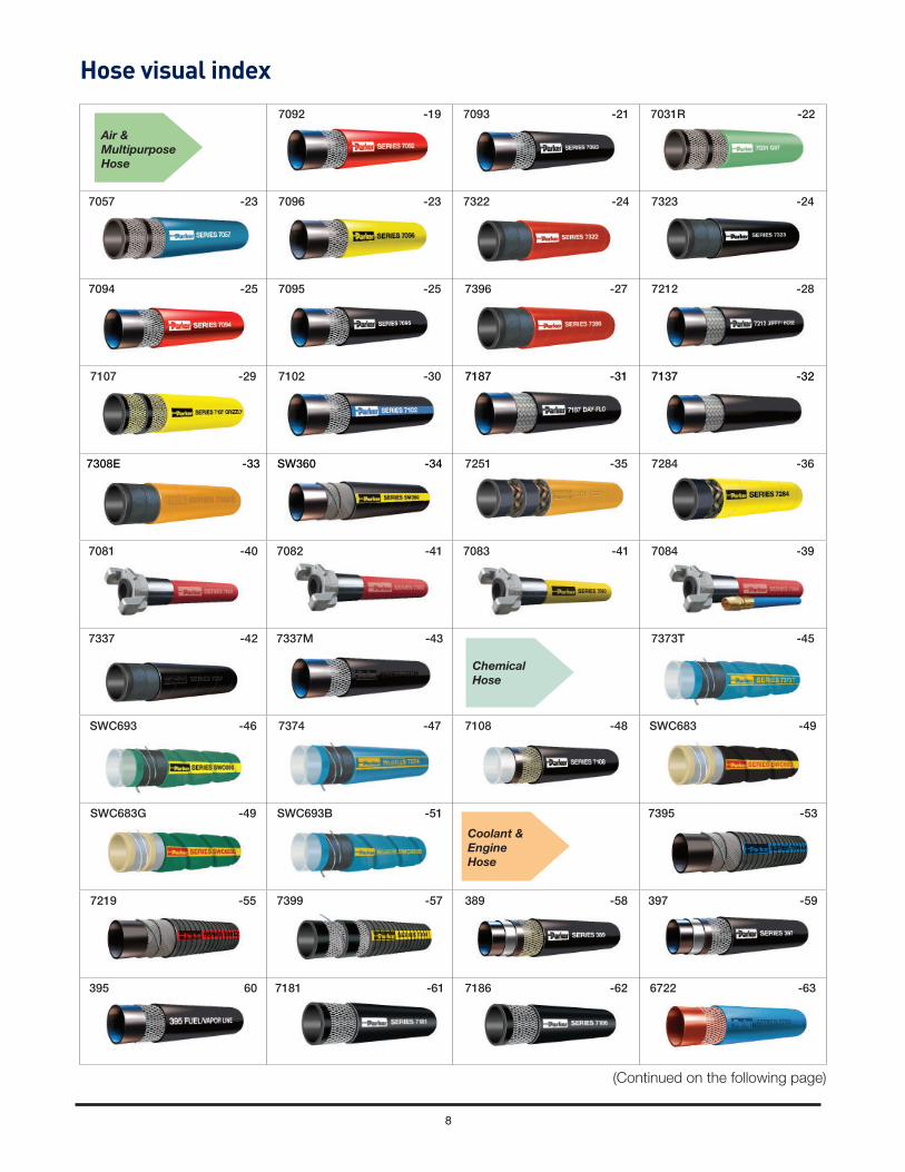
7092 -19 7093 -21 7031R -22
7057 -23 7096 -23 7322 -24 7323 -24
7094 -25 7095 -25 7396 -27 7212 -28
7107 -29 7102 -30 7187 -31 7137 -32
7308E -33 SW360 -34 7251 -35 7284 -36
7081 -40 7082 -41 7083 -41 7084 -39
7337 -42 7337M -43 7373T -45
SWC693 -46 7374 -47 7108 -48 SWC683 -49
SWC683G -49 SWC693B -51 7395 -53
7219 -55 7399 -57 389 -58 397 -59
395 60 7181 -61 7186 -62 6722 -63
Hose visual index
Chemical
Hose
Air &
Multipurpose
Hose
Coolant &
Engine
Hose
(Continued on the following page)

9
6723 -64 6724 -65 6750 -66 6823 -67
6621 -68 7116M -69 SW569 -70 SS269 -72
7165 -73 7280 -75 7282 -76
7124 -77 7114 -78 7175 -79
7132 -81 7132XTC -83 7232 -85 SS106 -87
7122 -88 SS25UL/7243 -89 7204 -91
SW387 -92 SS111 -93 7234 -94 7331XT -95
7244 -96 7363 -97 8341 -98 8341HD -99
SS135 -100 SS247 -101 SW409 -102
7213E -104 7301 -105 7311N -106 7311NXT -106
7216E -108 SWC609 -109 SWC609R -109
Material
Handling
Hose
LPG/Propane
Hose &
Assemblies
Hose visual index
Petroleum
Transport
Hose
(Continued on the following page)
Fuel
Dispenser
Hose
Oil Field
Hose

10
SWC325 -110 7705 -111 100 -113
GPH -115 125 -117 126 -117 7541 -119
7542 -120 7285 -122 7263C -123
7264C -124 7264 -125 7263E -126 7288 -127
7200 -128 7392E -130 SS122 -131
7268E -132 7258 -133 7258BK -134 7143 -135
7079 -136 7080 -137 7360 -138 7055 -139
7093CW -139 7385 -140 7306E -141
7109 -145 7141 -146 7142 -147 7126 -148
7120 -149 7121 -150 7123 -151 7172 -152
7293 -153
Welding
Hose &
Assembly
Hose visual index
Water Hose
& Assembly
Steam
Hose
PVC Hose
and
Tubing

11
Hose Size
Hose Construction
Pressure PSI Standard Temp.
Range °FStandards Page
-3 –4 –5 –6 –8 –10 –12 –16 –20 –24 –32 –40 –48 4” 5” 6” >6”
7092 200200-300
200-300
200-300
200-300
200-300
200-300
200-300
200 200 200 –40/+212 19
7093 200200-300
200-300
200-300
200-300
200-300
200-300
200-300
200 200 200 –40/+212 21
7031 300+ –40/+212 ARPM IP-7 22
7057 250 300 –40/+212 21
7096 300 –40/+212 23
7322 200 200 200 –40/+212 24
7323 200 200 200Air -20 / -158
Other -20/+21224
7094 200-300
300200-300
200-300
300200-300
200-300
200 200Air -20 / -158
Other -20/+212
Electrically nonconductive*
25
7095 200-300
300200-300
200-300
300200-300
200-300
200 200Air -20 / -158
Other -20/+212
Electrically nonconductive*
25
7396 300 300 300Air -20 / -158
Other -20/+212
Electrically nonconductive*,
MSHA27
7212 300 300 300 300 300Air -20 / -158
Other -20/+212MSHA 28
7107 500 500 500 500 500 500 500 500Air -40 / -158
Other -40/+212
Electrically nonconductive*,
MSHA29
7102 300 300 300 300 300 300Air -70 / -158
Other -70/+21230
7187 250 250 300Air -20 / -158
Other -20/+21231
7137 200 200Air -40 / -158
Other -40/+21232
7308E 300 -20 / +212 33
SW360 200 200 200 125 100 –40/+350 34
7251 600 600 500 500 400 –20/+212 MSHA 35
7284 1500 1000 1000 –20/+212 MSHA 36
7081 200 –40/+212 40
7082 300 –40/+212 41
WARNING: The products described in this brochure can expose you to Carbon Black, DEHP, Ethylene Thiourea, and Lead, which are known to the State of California to cause cancer, and DBP,
DEHP, Ethylene Thiourea, and Lead which is known to the State of California to cause birth defect or other reproductive harm. For more information go to www.p65warnings.ca.gov.
HOSE OVERVIEW CHARTA
ir /
Mu
ltip
urp
os
e
(*min. resistance of one megaohm p/in. at 1000 volts DC)
111720_HoseOverviewChart.indd 11 11/17/2020 7:08:34 PM

12
Hose Size
Hose Construction
Pressure PSI Standard Temp.
Range °FStandards Page
-3 –4 –5 –6 –8 –10 –12 –16 –20 –24 –32 –40 –48 4” 5” 6” >6”
7083 300 –40/+212 41
7084 300 –40/+212 39
7337** N/A N/A N/A N/A N/A –30/+180 MSHA 42
7337M** N/A N/A N/A N/A N/A –30/+180 MSHA 43
7373T 200 200 200 200 200 200 200 –40/+180 45
SWC693 250 250 250 250 200 200 –40/+180 46
7374 600 400 400 400 –40/+180 47
7108 500 500 0/ +200 48
SWC683-SWC683G†SWC683 Only
250 250 250 200 175 125† -40/+250 49
SWC693B 250 250 250 250 200 200 -40/+180 51
7395** 75 75 75 75 75 75 75 75 75 75 -50/+257SAE J20R2-D1 performance
53
7219** 75 75 75 75 75* 75* 75* 75* 75* 75* -30/+212*/+257 55
7399** 150 150 150 150 -40/+257 57
389 100 100 100 100 100 100 100 –40/+257SAEJ30R7 &
R14 T258
397 100 100 100 100 100 35 35 59
395 75 50 50 50 35 60
7181 65 65 65 65 65 50 45 –40/+257 SAEJ20R3 D-2 61
7186 125 90 70 -40/+212 62
6722 83 83 83 83 83 83 83 –65/+350SAEJ20R3
Class A63
6723 83 83 83 83 83 –65/+350 64
HOSE OVERVIEW CHART
WARNING: The products described in this brochure can expose you to Carbon Black, DEHP, Ethylene Thiourea, and Lead, which are known to the State of California to cause cancer, and DBP,
DEHP, Ethylene Thiourea, and Lead which is known to the State of California to cause birth defect or other reproductive harm. For more information go to www.p65warnings.ca.gov.
Air
/ M
ult
ipu
rpo
se
Ch
em
ica
lC
oo
lan
t &
En
gin
e H
os
e
**See product page for additional sizes
111720_HoseOverviewChart.indd 12 11/17/2020 7:08:44 PM

13
Hose Size
Hose Construction
Pressure PSI Standard Temp.
Range °FStandards Page
-3 –4 –5 –6 –8 –10 –12 –16 –20 –24 –32 –40 –48 4” 5” 6” >6”
6724 83 83 –65/+500 65
6750 142 108 100 92 83 67 50 29 17 17 –65/+350 66
6823 27 27 –65/+500 67
6621 225 225 225 –76/+392SAE J20R2
Class A and TMC68
7116M 150 150 150 150 -40/+212 69
SW569** 75 75 75 75 75 50 50 50 40 40 -20/+212
ABYC H-24, NMMA, SAE
J1527 A1/A2,SAE J1942 Code:
F / VW / NVW, SAE J2006 R2, SAE J20R2 B,SAE J20R4 B, SAE J20R5 B, SAE J30R5,
ISO 7840:2004 A2, ISO 8469 B1,
USCG
70
SS269** 50 50 50 50 25 25 25 25 -40/+200ABYC, USCG/SAE
J2006R172
7165 100 100 100 100 75 -20/+212
ABYC, CARB, CE, EPA, ISO 7840 A1, NMMA, SAE J1527, A1-15,
USCG A1
73
7280 50 50 50 -40/+180
UL330/ULC; NFPA 30A;
UL30N4 (factory assemblies)
75
7282 150 150 150 -40/+180
CARB CP-206; UL330/ULC;
NFPA 30A (factory assemblies)
76
7124 50 50 50 -40/+180
UL330/ULC; NFPA 30A;
UL30N4 (factory assemblies)
77
7114 50 50 50 -40/+180
UL330/ULC; NFPA 30A;
UL30N4 (factory assemblies)
78
7175 50 50 -40/+180 79
7132 350 350 350 350 350 -40/+180* 81
7132XTC 350 -65/+180*
UL21; CSA 8.1
Type I; optional
DOT factory hose
assembly testing
and marking
available for sizes
smaller than 3/4”
83
7232 350 350 350 -40/+180*
UL21; CSA 8.1
Type I; optional
DOT factory hose
assembly testing
and marking
available
85
HOSE OVERVIEW CHART
WARNING: The products described in this brochure can expose you to Carbon Black, DEHP, Ethylene Thiourea, and Lead, which are known to the State of California to cause cancer, and DBP,
DEHP, Ethylene Thiourea, and Lead which is known to the State of California to cause birth defect or other reproductive harm. For more information go to www.p65warnings.ca.gov.
Co
ola
nt
& E
ng
ine
Ho
se
Fu
el D
isp
en
se
r H
os
eL
PG
/Pro
pa
ne
Ho
se
& A
ss
em
bli
es
**See product page for additional sizes * (working pressures are at +68, higher temps reduce the available working pressure)
111720_HoseOverviewChart.indd 13 11/17/2020 7:08:45 PM

14
Hose Size
Hose Construction
Pressure PSI Standard Temp.
Range °FStandards Page
-3 –4 –5 –6 –8 –10 –12 –16 –20 –24 –32 –40 –48 4” 5” 6” >6”
SS106 350 -22/+158*ISO 2928-1986
(E)87
7122 125 -20/+160 88
SS25UL/7243 350 350 350 350 -40/+180* UL21 89
7204 1000 1000
Air -20/+158; Steam -20/+368 (saturated steam to 150 psi max); Other -20/+300
91
SW387 150 150 150 150 150 -40/+350 92
SS111 55 55 55 55 35 35 -40/+180 93
7234 3000 –40/+200 94
7331/7331XT
†7331XT only
400 400 400 400 -40/+200 95
7244 50 50 50 50 50 -20/+160 96
7363 100 100 100 100 100 -40/+160 97
8341 75 75 75 75 75 75 -40/+180 98
8341HD 75 99
SS135** 100 100 100 -40/+180 100
SS247** 100 100 100 100 -40/+180 101
SW409 200 175 150 100 100 -40/+180 102
HOSE OVERVIEW CHART
WARNING: The products described in this brochure can expose you to Carbon Black, DEHP, Ethylene Thiourea, and Lead, which are known to the State of California to cause cancer, and DBP,
DEHP, Ethylene Thiourea, and Lead which is known to the State of California to cause birth defect or other reproductive harm. For more information go to www.p65warnings.ca.gov.
Ma
teri
al H
an
dli
ng
**See product page for additional sizes
LP
G/P
rop
an
e H
os
e &
As
se
mb
lie
s
111720_HoseOverviewChart.indd 14 11/17/2020 7:08:45 PM

15
Hose Size
Hose Construction
Pressure PSI Standard Temp.
Range °FStandards Page
-3 –4 –5 –6 –8 –10 –12 –16 –20 –24 –32 –40 –48 4” 5” 6” >6”
7213E 150 150 150 150 150 -22/+185 104
7301 2250 -40/+275 105
7311N 400 400 400 400 400 -40/+200 106
7311NXT 400 400 -40/+200 106
7216E 150 150 150 150 150 -22/+185 108
SWC609/SCW609R†SWC609 only
250 250 250 200 200 150 150† 150†
(8”)–40/+200 109
SWC325 150 150 150 150 150 125 –67/+180 110
7705 200 200 200 200 200 200 200 –20/+180 111
100 55-60 55-60 50-55 45-55 30-45 25-45 35 25-30 113
GPH 300 300 300 300 300 300 300 250 –15/+150* Electrically nonconductive** 115
125 250 250 250 225 200 200 150 125 100 100 75 –25/+150* FDA; EU 117
126 350 275 250 250 200 150 125 100 –25/+150* FDA; EU 117
7541 70 70 60 60 60 4545
(8”)–5/+170* 119
7542 150 150 150 150 140 10080
(8”)–5/+170* MSHA 120
7285 261 261 261-40/+406 saturated steam; +450 super-
heated steamISO 6134 Type2 122
7263C 261 261-40/+406 saturated steam; +450 super-
heated steamISO 6134 Type2 123
7264C 261-40/+406 saturated steam; +450 super-
heated steamISO 6134 Type2 124
7264 261 261 261 261 261 261-40/+406 saturated steam; +450 super-
heated steamISO 6134 Type2 125
7263E 261-40/+406 saturated steam; +450 super-
heated steamISO 6134 Type2 126
7288 261 261-40/+406 saturated steam; +450 super-
heated steamISO 6134 Type2 127
7200 350 350-20/+300;+350
intermittent128
HOSE OVERVIEW CHART
* (working pressures are at +68, higher temps reduce the available working pressure)
WARNING: The products described in this brochure can expose you to Carbon Black, DEHP, Ethylene Thiourea, and Lead, which are known to the State of California to cause cancer, and DBP,
DEHP, Ethylene Thiourea, and Lead which is known to the State of California to cause birth defect or other reproductive harm. For more information go to www.p65warnings.ca.gov.
PV
C H
os
e a
nd
Tu
bin
gS
tea
m H
os
eP
etr
ole
um
Tra
ns
po
rt H
os
eO
il F
ield
111720_HoseOverviewChart.indd 15 2/9/2021 6:37:54 AM

16
Hose Size
Hose Construction
Pressure PSI Standard Temp.
Range °FStandards Page
-3 –4 –5 –6 –8 –10 –12 –16 –20 –24 –32 –40 –48 4” 5” 6” >6”
7392E 150 150 150 150 150 150 -40/+180 130
SS122 500 500 500 500 500 500 -40/+180 131
7268E 1000 1000 1000 1000 1000 -20/+212 MSHA 132
72583000 3000 2500 –40/+250 133
7258BK 3000 3000 2500 –40/+250 134
7143 1500 –40/+250 135
7079 150 –40/+212 136
7080 300 –40/+212 137
7360 150 –20/+212 138
7055 100 100 –40/+180 139
7093CW 200 –40/+180 139
14
0
7385 150 150 150 150 150 150-20/+212 (internal)
+572 (external)140
7306E 100 100 100 100 100 -20/+180 141
HOSE OVERVIEW CHART
WARNING: The products described in this brochure can expose you to Carbon Black, DEHP, Ethylene Thiourea, and Lead, which are known to the State of California to cause cancer, and DBP,
DEHP, Ethylene Thiourea, and Lead which is known to the State of California to cause birth defect or other reproductive harm. For more information go to www.p65warnings.ca.gov.
Wa
ter
Ho
se
& A
ss
em
bly
111720_HoseOverviewChart.indd 16 11/17/2020 7:08:47 PM
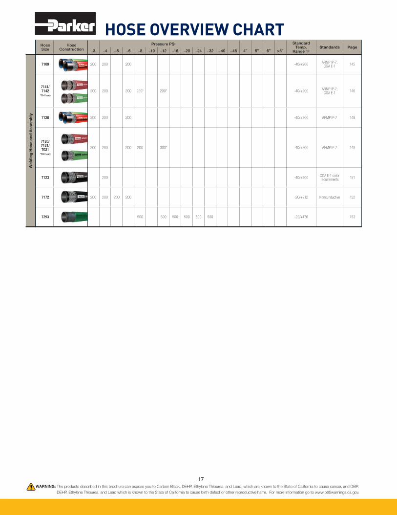
17
Hose Size
Hose Construction
Pressure PSI Standard Temp.
Range °FStandards Page
-3 –4 –5 –6 –8 –10 –12 –16 –20 –24 –32 –40 –48 4” 5” 6” >6”
7109 200 200 200 -40/+200ARMP IP-7;
CGA E-1145
7141/7142
*7141 only
200 200 200 200* 200* -40/+200ARMP IP-7;
CGA E-1146
7126 200 200 200 -40/+200 ARMP IP-7 148
7120/7121/7031
*7031 only
200 200 200 200 300* -40/+200 ARMP IP-7 149
7123 200 -40/+200CGA E-1 color requirements
151
7172 200 200 200 200 -20/+212 Noncunductive 152
7293 500 500 500 500 500 500 -22/+176 153
HOSE OVERVIEW CHART
WARNING: The products described in this brochure can expose you to Carbon Black, DEHP, Ethylene Thiourea, and Lead, which are known to the State of California to cause cancer, and DBP,
DEHP, Ethylene Thiourea, and Lead which is known to the State of California to cause birth defect or other reproductive harm. For more information go to www.p65warnings.ca.gov.
We
ldin
g H
os
e a
nd
As
se
mb
iy
111720_HoseOverviewChart.indd 17 11/17/2020 7:08:47 PM

1818
Air and MultipurposeHose

19
Air
& M
ult
ipu
rpo
se H
ose
an
d A
sse
mb
lie
s
Other cover colors available:
7031(R) (Green)
7096 (Yellow)
GST® IIGeneral Service HoseSeries 7031(R) (Green), Series 7057 (Blue),
Series 7092 (Red), Series 7093 (Black),
and Series 7096 (Yellow)
GST® II hose is a versatile general purpose hose designed to handle air, mild chemicals and water. Th e hose construction incorporates a tube that is compatible with light oil mists found in air tool lubricating systems, and the multiple plies of textile reinforcement provide fl exibility. Th e cover is resistant to abrasion, heat and ozone, and is available in multiple standard colors for color-coded identifi cation.
NOTE: Do not with use with oil or refi ned fuel.
Series 7092 (Red)
Crimp Specifi cationsFor currently qualifi ed crimp specifi cations including coupling designation, refer to CrimpSource at www.parker.com/crimpsource.
Part Number
ID(in)
ID (mm)
ReinfLayers
OD (in)
OD(mm)
Approx Wt
(lbs/ft)
Approx Wt
(kg/m)
Min Bend Rad (in)
Min Bend Rad (mm)
Max WP (psi)
Max WP (bar)
PermCplgRec
*
Nom Std Pack Qty(ft)
Pkg Type
-25200 1/4 6.4 2 0.5 12.7 0.09 0.13 3 64 200 14 HY 800 Reel
-25300 1/4 6.4 2 0.6 14.0 0.12 0.18 3 84 300 21 HY 800 Reel
-31300 5/16 7.9 2 0.6 15.9 0.14 0.21 4 89 300 21 HY 750 Reel
-382003/8 9.5 2 0.7 16.7 0.14 0.21 4 89 200 14
HY 700 Reel
-3820050 HY 50 Carton
Factory Assemblies: Air, Service Station Air, Jackhammer and Sledgehammer hose assemblies are available from stock in popular confi gurations and appear at the end of this section.
(Continued on the following page)
WARNING! Couplings attached with bands or clamps may reduce the working pressure of the hose assembly to less than the maximum rated working pressure of the hose. Refer to the NAHAD Industrial Hose Assembly Guidelines.
!
WARNING: This product can expose you to chemicals including Carbon Black, which is known to the State of California to cause cancer. For
more information go to www.p65warnings.ca.gov.
Tube: Black EPDM; ARPM Class C oil resistanceReinforcement: Multiple textile pliesCover: Black, blue, green, red, yellow EPDM; smooth fi nishTemp. Range: -40°F to +212°F (-40°C to +100°C)Brand Method: White ink on black, blue, green, red hose;
black ink on yellow hoseBrand Example: PARKER (SERIES) GST® II (ID) XXX PSI
MAX WP
Design Factor: 4:1Industry Standards: ARPM IP-7 (7031R only)Applications:
• Air (including oil mist), mild chemicals, water • Agriculture, construction, general industrialVacuum: Not recommendedCompare to: Boston Bosfl ex A/W; ContiTech Frontier
General Purpose; Gates Adapta Flex; Thermoid Valufl ex GS

20
Air
& M
ult
ipu
rpo
se H
ose
an
d A
sse
mb
lie
s Series 7031(R), Series 7057, Series 7092, Series 7093, and Series 7096 – GST® II General Service Air & Water Hose (Continued)
(Continued on the following page)
Part Number
7092
ID(in)
ID (mm)
ReinfLayers
OD (in)
OD(mm)
Approx Wt
(lbs/ft)
Approx Wt
(kg/m)
Min Bend Rad (in)
Min Bend Rad (mm)
Max WP (psi)
Max WP (bar)
PermCplgRec
*
Nom Std Pack Qty(ft)
Pkg Type
-383003/8 9.5 2 0.7 17.5 0.16 0.24 4 102 300 21
HY 700 Reel
-3830050 HY 50 Carton
-50200 1/2 12.7 2 0.8 20.7 0.20 0.30 5 114 200 14 HY 550 Reel
-503041/2 12.7 4 0.9 22.2 0.24 0.36 5 127 300 21
HY 500 Reel
-5030450 HY 50 Carton
-632005/8 15.9 2 1.0 24.6 0.24 0.36 6 140 200 14
HY 450 Reel
-6320050 HY 50 Carton
-63304 5/8 15.9 4 1.1 27.0 0.35 0.52 6 140 300 21 HY 450 Reel
-752003/4 19.1 2 1.1 28.2 0.32 0.48 6 152 200 14
HY 400 Reel
-7520050 HY 50 Carton
-752543/4 19.1 4 1.2 29.4 0.37 0.55 6 152 250 17
HY 400 Reel
-7525450 HY 50 Carton
-753043/4 19.1 4 1.2 29.4 0.37 0.55 6 152 300 21
HY 400 Reel
-7530450 HY 50 Carton
-100200 1 25.4 2 1.4 35.7 0.47 0.70 7 178 200 14 HY 300 Reel
-100304 1 25.4 4 1.4 36.5 0.51 0.76 8 203 300 21 HY 300 Reel
-125204 1-1/4 31.8 4 1.8 45.2 0.77 1.15 9 229 200 14 HY 250 Reel
-150204
1-1/2 38.1 4 2.0 51.6 0.84 1.25 10 254 200 14
43 200 Reel
-15020450 43 50 Carton
-150204100 43 100 Reel
-200154 2 50.8 4 2.6 64.8 1.13 1.68 14 356 200 14 43 250 Reel
Factory Assemblies: Air, Service Station Air, Jackhammer and Sledgehammer hose assemblies are available from stock in popular confi gurations and appear at the end of this section.
Series 7092 (Red)
WARNING: This product can expose you to chemicals including Carbon Black, which is known to the State of California to cause cancer. For
more information go to www.p65warnings.ca.gov.

21
Air
& M
ult
ipu
rpo
se H
ose
an
d A
sse
mb
lie
s
Series 7093 (Black)
Crimp Specifi cationsFor currently qualifi ed crimp specifi cations including coupling designation, refer to CrimpSource at www.parker.com/crimpsource.
Part Number
ID(in)
ID (mm)
ReinfLayers
OD (in)
OD(mm)
Approx Wt
(lbs/ft)
Approx Wt
(kg/m)
Min Bend Rad (in)
Min Bend Rad (mm)
Max WP (psi)
Max WP (bar)
PermCplgRec
*
Nom Std Pack Qty(ft)
Pkg Type
-19200 3/16 4.8 2 0.4 11.1 0.07 0.10 2 51 200 14 * 800 Reel
-25200 1/4 6.4 2 0.5 12.7 0.09 0.13 3 64 200 14 HY 800 Reel
-25250 1/4 6.4 2 0.5 12.9 0.10 0.15 3 76 250 17 HY 800 Reel
-25300 1/4 6.4 2 0.6 14.0 0.12 0.18 3 84 300 21 HY 800 Reel
Factory Assemblies: Air, Service Station Air, Jackhammer and Sledgehammer hose assemblies are available from stock in popular confi gurations and appear at the end of this section.
GST® IIGeneral Service HoseSeries 7031(R) (Green),
Series 7057 (Blue), Series 7092 (Red),
Series 7093 (Black), and Series 7096 (Yellow)
GST® II hose is a versatile general purpose hose designed to handle air, mild chemicals and water. Th e hose construction incorporates a tube that is compatible with light oil mists found in air tool lubricating systems, and the multiple plies of textile reinforcement provide fl exibility. Th e cover is resistant to abrasion, heat and ozone, and is available in multiple standard colors for color-coded identifi cation.
NOTE: Do not with use with oil or refi ned fuel.
WARNING! Couplings attached with bands or clamps may reduce the working pressure of the hose assembly to less than the maximum rated working pressure of the hose. Refer to the NAHAD Industrial Hose Assembly Guidelines.
!
Other cover colors available:
7031(R) (Green)
7057 (Blue)
7096 (Yellow)
WARNING: This product can expose you to chemicals including Carbon Black, which is known to the State of California to cause cancer. For
more information go to www.p65warnings.ca.gov.
(Continued on the following page)
Tube: Black EPDM; ARPM Class C oil resistanceReinforcement: Multiple textile pliesCover: Black, blue, green, red, yellow EPDM; smooth fi nishTemp. Range: -40°F to +212°F (-40°C to +100°C)Brand Method: White ink on black, blue, green, red hose;
black ink on yellow hoseBrand Example: PARKER (SERIES) GST® II (ID) XXX PSI
MAX WP Design Factor: 4:1
Industry Standards: ARPM IP-7 (7031R only)Applications:
• Air (including oil mist), mild chemicals, water• Agriculture, construction, general industrialVacuum: Not recommendedCompare to: Boston Bosfl ex A/W; ContiTech
FrontierGeneral Purpose; Gates Adapta Flex; Thermoid Valufl ex GS

22
Air
& M
ult
ipu
rpo
se H
ose
an
d A
sse
mb
lie
s
Part Number
ID(in)
ID (mm)
ReinfLayers
OD (in)
OD(mm)
Approx Wt
(lbs/ft)
Approx Wt
(kg/m)
Min Bend Rad (in)
Min Bend Rad (mm)
Max WP (psi)
Max WP (bar)
PermCplgRec
*
Nom Std Pack Qty(ft)
Pkg Type
-31200 5/16 7.9 2 0.6 15.1 0.12 0.18 3 84 200 14 HY 750 Reel
-31300 5/16 7.9 2 0.6 15.9 0.14 0.21 4 89 300 21 HY 750 Reel
-38200 3/8 9.5 2 0.7 16.7 0.14 0.21 4 89 200 14 HY 700 Reel
-38300 3/8 9.5 2 0.7 17.5 0.16 0.24 4 102 300 21 HY 700 Reel
-50200 1/2 12.7 2 0.8 20.7 0.20 0.30 5 114 200 14 HY 550 Reel
-50250 1/2 12.7 2 0.8 21.4 0.22 0.33 5 114 250 17 HY 550 Reel
-50304 1/2 12.7 4 0.9 22.2 0.24 0.36 5 127 300 21 HY 500 Reel
-63200 5/8 15.9 2 1.0 24.6 0.24 0.36 6 140 200 14 HY 450 Reel
-63304 5/8 15.9 4 1.1 27.0 0.35 0.52 6 140 300 21 HY 450 Reel
-752003/4 19.1 2 1.1 28.2 0.32 0.48 6 152 200 14
HY 400 Reel
-7520050 HY 50 Carton
-75304 3/4 19.1 4 1.2 29.4 0.37 0.55 6 152 300 21 HY 400 Reel
-100200 1 25.4 2 1.4 35.7 0.47 0.70 7 178 200 14 HY 300 Reel
-100304 1 25.4 4 1.4 36.5 0.51 0.76 8 203 300 21 HY 300 Reel
-125204 1-1/4 31.8 4 1.8 45.2 0.77 1.15 9 229 200 14 HY 250 Reel
-150204 1-1/2 38.1 4 2.0 51.6 0.84 1.25 10 254 200 14 43 200 Reel
-200154 2 50.8 4 2.6 64.8 1.13 1.68 14 356 200 14 43 250 Reel
Factory Assemblies: Air, Service Station Air, Jackhammer and Sledgehammer hose assemblies are available from stock in popular confi gurations and appear at the end of this section.
Series 7031 / 7031(R) (Green)7031R meets ARPM IP-7 requirements for Grade R oxygen service in welding applications.Brand Example: PARKER 7031 GST® II/OXYGEN 3/4 ID (19.1mm) MAX WP 300 PSI (200 PSI OXYGEN) ARPM IP-7-2008 STD DUTY GRADE R
Crimp Specifi cationsFor currently qualifi ed crimp specifi cations including coupling designation, refer to CrimpSource at www.parker.com/crimpsource.
Part Number
ID(in)
ID (mm)
ReinfLayers
OD (in)
OD(mm)
Approx Wt
(lbs/ft)
Approx Wt
(kg/m)
Min Bend Rad (in)
Min Bend Rad (mm)
Max WP (psi)
Max WP (bar)
PermCplgRec
*
Nom Std Pack Qty(ft)
Pkg Type
7031-75304R3/4 19.1 4 1.2 29.4 0.37 0.55 6 152 300† 21†
HY 400 Reel
7031-7530450R HY 50 Carton
† 200 psi (13.8 bar) maximum recommended working pressure for oxygen service.
Series 7031(R), Series 7057, Series 7092, Series 7093, and Series 7096 – GST® II General Service Air & Water Hose (Continued)
Series 7093 (Black) (Continued)
WARNING: This product can expose you to chemicals including Carbon Black, which is known to the State of California to cause cancer. For
more information go to www.p65warnings.ca.gov.

23
Air
& M
ult
ipu
rpo
se H
ose
an
d A
sse
mb
lie
s
Series 7057 (Blue)
Crimp Specifi cationsFor currently qualifi ed crimp specifi cations including coupling designation, refer to CrimpSource at www.parker.com/crimpsource.
Part Number
ID(in)
ID (mm)
ReinfLayers
OD (in)
OD(mm)
Approx Wt
(lbs/ft)
Approx Wt
(kg/m)
Min Bend Rad (in)
Min Bend Rad (mm)
Max WP (psi)
Max WP (bar)
PermCplgRec
*
Nom Std Pack Qty(ft)
Pkg Type
7057-50250 1/2 12.7 2 0.8 21.4 0.23 0.34 5 114 250 17 HY 500 Reel
7057-753043/4 19.1 4 1.2 29.4 0.37 0.55 6 152 300 21
HY 350 Reel
7057-7530450 HY 50 Carton
Series 7096 (Yellow)
Crimp Specifi cationsFor currently qualifi ed crimp specifi cations including coupling designation, refer to CrimpSource at www.parker.com/crimpsource.
Part Number
ID(in)
ID (mm)
ReinfLay-ers
OD (in)
OD(mm)
Approx Wt
(lbs/ft)
Approx Wt
(kg/m)
Min Bend Rad (in)
Min Bend Rad (mm)
Max WP (psi)
Max WP (bar)
PermCplgRec
*
Nom Std Pack Qty(ft)
Pkg Type
7096-753043/4 19.1 4 1.2 29.4 0.37 0.55 6 152 300 21
HY 400 Reel
7096-7530450 HY 50 Carton
Series 7031(R), Series 7057, Series 7092, Series 7093, and Series 7096 – GST® II General Service Air & Water Hose (Continued)
WARNING: This product can expose you to chemicals including Carbon Black, which is known to the State of California to cause cancer. For
more information go to www.p65warnings.ca.gov.
WARNING: This product can expose you to chemicals including Carbon Black, which is known to the State of California to cause cancer.
For more information go to www.p65warnings.ca.gov.

24
Air
& M
ult
ipu
rpo
se H
ose
an
d A
sse
mb
lie
s
Series 7322 (Red) and Series 7323 (Black)
Crimp Specifi cationsFor currently qualifi ed crimp specifi cations including coupling designation, refer to CrimpSource at www.parker.com/crimpsource.
Part Number
7322 or 7323
ID(in)
ID (mm)
ReinfLayers
OD (in)
OD(mm)
Approx Wt
(lbs/ft)
Approx Wt
(kg/m)
Min BendRad(in)
Min BendRad(mm)
Max WP (psi)
Max WP (bar)
PermCplgRec
*
Nom Std Pack Qty(ft)
Pkg Type
-125200 1-1/4 31.8 2 1.7 44.2 0.71 1.06 8 191 200 14 43 200 Coil
-150200 1-1/2 38.1 2 2.0 50.4 0.82 1.22 9 216 200 14 43 200 Coil
-200200 2 50.8 4 2.6 65.2 1.23 1.83 12 305 200 14 43 200 Coil
SUPER-FLEX® GSGeneral Service Air & Water HoseSeries 7322 (Red) and
Series 7323 (Black)
Series 7322/7323 is a versatile general purpose hose designed to handle air, mild chemicals and water. Th e hose incorporates a tube that is compatible with light oil mists, and features a rigid mandrel construction that produces a true round, concentric profi le for superior coupling fi t and retention. Th e cover is resistant to abrasion, heat and ozone.
NOTE: Do not with use with oil or refi ned fuel.
WARNING! Couplings attached with bands or clamps may reduce the working pressure of the hose assembly to less than the maximum rated working pressure of the hose. Refer to the NAHAD Industrial Hose Assembly Guidelines.
!
WARNING: This product can expose you to chemicals including Carbon Black, which is known to the State of California to cause cancer. For
more information go to www.p65warnings.ca.gov.
Tube: Black EPDM; ARPM Class C oil resistanceReinforcement: Multiple textile pliesCover: 7322: Red EPDM, wrapped fi nish
7323: Black EPDM, wrapped fi nishTemp. Range: -40°F to +212°F (-40°C to +100°C)Brand Method: 7322: White text on red stripe
7323: White text on black stripeBrand Example: PARKER SERIES (7322) (7323) SUPER-
FLEX® GS 200 PSI MAX WP GENERAL SERVICE
Design Factor: 4:1
Vacuum: Not recommendedIndustry Standards: None applicableApplications:
• Air (including oil mist), mild chemicals, water• Agriculture, construction, general industrialCompare to: ContiTech Frontier; Gates AdaptaFlex

25
Air
& M
ult
ipu
rpo
se H
ose
an
d A
sse
mb
lie
sMPT® IIMultipurpose Oil Resistant HoseSeries 7094 (Red) and
Series 7095 (Black)
Series 7094/7095 hose construction is electrically nonconductive multipurpose hose with a minimum resistance of one megaohm per inch at 1000 volts DC. Th e multiple plies of textile reinforcement provide fl exibility and the cover is resistant to oil and weathering. NOTES: • Do not use in dry air applications (typically, air systems that do not expose the tube
of the hose to lubricating oil mist from the compressor). • Th e user must determine if the hose is suitable for applications subject to electrical
hazard. Contact Parker for additional information. • Do not use to dispense or transfer biodiesel, diesel fuel, or gasoline.
(Continued on the following page)
WARNING! Couplings attached with bands or clamps may reduce the working pressure of the hose assembly to less than the maximum rated working pressure of the hose. Refer to the NAHAD Industrial Hose Assembly Guidelines.
!
WARNING: This product can expose you to chemicals including DEHP, which is known to the State of California to cause cancer and birth
defects or other reproductive harm. For more information go to www.p65warnings.ca.gov.
Series 7094 (Red)
Crimp Specifi cationsFor currently qualifi ed crimp specifi cations including coupling designation, refer to CrimpSource at www.parker.com/crimpsource.
Part Number
7094
ID(in)
ID (mm)
ReinfLayers
OD (in)
OD(mm)
Approx Wt
(lbs/ft)
Approx Wt
(kg/m)
Min Bend Rad (in)
Min Bend Rad (mm)
Max WP (psi)
Max WP (bar)
PermCplgRec
*
Nom Std Pack
Qty(ft)
Pkg Type
-252001/4 6.4 2
0.5 12.7 0.10 0.15 2 51 200 14 HY 800 Reel
-25300 0.6 14.0 0.12 0.18 3 64 300 21 HY 800 Reel
-31300 5/16 7.9 2 0.6 15.1 0.13 0.19 3 84 300 21 HY 750 Reel
-38200 3/8 9.5 2 0.7 16.7 0.15 0.22 4 97 200 14 HY 700 Reel
-38300 3/8 9.5 2 0.7 17.5 0.17 0.25 4 97 300 21 HY 650 Reel
-50200 1/2 12.7 2 0.8 20.7 0.21 0.31 5 127 200 14 HY 550 Reel
-50304 1/2 12.7 4 0.9 22.2 0.26 0.39 5 127 300 21 HY 500 Reel
-63304 5/8 15.9 4 1.1 27.0 0.38 0.57 6 155 300 21 HY 450 Reel
-75200 3/4 19.1 2 1.1 28.2 0.34 0.51 8 191 200 14 HY 400 Reel
-75304 3/4 19.1 4 1.2 29.4 0.40 0.60 6 152 300 21 HY 400 Reel
-1002001 25.4 2 1.4
35.7 0.49 0.73 10 254 200 14 HY 300 Reel
-100304 36.5 0.54 0.80 8 203 300 21 HY 300 Reel
-125204 1-1/4 31.8 4 1.8 45.2 0.82 1.22 9 229 200 14 HY 250 Reel
-150204 1-1/2 38.1 4 2.0 51.6 0.90 1.34 10 254 200 14 HY 200 Reel

26
Air
& M
ult
ipu
rpo
se H
ose
an
d A
sse
mb
lie
s Series 7094 (Red) and Series 7095 (Black) – MPT® II Multipurpose Oil Resistant Hose – Nonconductive (Continued)
WARNING: This product can expose you to chemicals including DEHP, which is known to the State of California to cause cancer and birth
defects or other reproductive harm. For more information go to www.p65warnings.ca.gov.
Tube: Black nitrile; ARPM Class A oil resistanceReinforcement: Multiple textile pliesCover: 7094: Red chloroprene, smooth fi nish7095: Black chloroprene, smooth fi nishTemp. Range: Air: -20°F to +158°F (-29°C to +70°C)Other Media: -20°F to +212°F (-29°C to +100°C)Brand Method: White inkBrand Example: PARKER SERIES (7094) (7095) MPT® II
(ID) XXX PSI MAX WP ELECTRICALLY NONCONDUCTIVE
Design Factor: 4:1
Industry Standards: Electrically nonconductive with a minimum resistance of one megaohm per inch at 1000 volts DC
Applications:
• Air, mild chemicals, oil, water• Cooling lines for electric furnaces and pot lines; lubrication
systems• Agriculture, construction, foundries, general industrialVacuum: Not recommendedCompare to: Boston Shock Safe; ContiTech Ortac/Varifl ex;
Gates PremoFlex/19B
Series 7095 (Black)
Crimp Specifi cationsFor currently qualifi ed crimp specifi cations including coupling designation, refer to CrimpSource at www.parker.com/crimpsource.
Part Number
ID(in)
ID (mm)
ReinfLayers
OD (in)
OD(mm)
Approx Wt
(lbs/ft)
Approx Wt
(kg/m)
Min Bend Rad (in)
Min Bend Rad (mm)
Max WP (psi)
Max WP (bar)
PermCplgRec
*
Nom Std Pack
Qty(ft)
Pkg Type
-25300 0.6 14.0 0.12 0.18 3 64 300 21 HY 800 Reel
-31300 5/16 7.9 2 0.6 15.1 0.13 0.19 3 84 300 21 HY 750 Reel
-38200 3/8 9.5 2 0.7 16.7 0.15 0.22 4 97 200 14 HY 700 Reel
-38300 3/8 9.5 2 0.7 17.5 0.17 0.25 4 97 300 21 HY 650 Reel
-50200 1/2 12.7 2 0.8 20.7 0.21 0.31 5 127 200 14 HY 550 Reel
-50304 1/2 12.7 4 0.9 22.2 0.26 0.39 5 127 300 21 HY 500 Reel
-63304 5/8 15.9 4 1.1 27.0 0.38 0.57 6 155 300 21 HY 450 Reel
-75200 3/4 19.1 2 1.1 28.2 0.34 0.51 8 191 200 14 HY 400 Reel
-75304 3/4 19.1 4 1.2 29.4 0.40 0.60 6 152 300 21 HY 400 Reel
-100304 1 25.4 2 1.4 36.5 0.54 0.80 8 203 300 21 HY 300 Reel
-125204 1-1/4 31.8 4 1.8 45.2 0.82 1.22 9 229 200 14 HY 250 Reel
-150204 1-1/2 38.1 4 2.0 51.6 0.90 1.34 10 254 200 14 HY 200 Reel

27
Air
& M
ult
ipu
rpo
se H
ose
an
d A
sse
mb
lie
sSUPER MPT® IIMultipurpose Oil Resistant HoseSeries 7396
Series 7396 is a versatile, nonconductive multipurpose hose designed to handle air, mild chemicals, oil and water. Th e hose is electrically nonconductive with a minimum resistance of one megaohm per inch at 1000 volts DC. Th e rigid mandrel construction produces a true round, concentric profi le for superior coupling fi t and retention. Th e cover is resistant to oil and weathering.
NOTES: • Do not use in dry air applications (typically, air systems that do not expose the tube of the hose to lubricating oil mist from the compressor).
• Th e user must determine if the hose is suitable for applications subject to electrical hazard. Contact Parker for additional information.
• Do not use to dispense or transfer biodiesel, diesel fuel or gasoline in regulated service (API, NFPA, UL, ULC or any other agency approval or listing).
• Do not use in vehicle engine applications. • Refer to the Refi ned Fuel/Hose Compatibility Table in the Media Compatibility
section.
WARNINGS!Couplings attached with bands or clamps may reduce the working pressure of the hose assembly to less than the maximum rated working
pressure of the hose. Refer to the NAHAD Industrial Hose Assembly Guidelines.The hose does not incorporate a helical wire; transfer of refi ned fuel may create an accumulation – and catastrophic distcharge – of static
electrical buildup.
!
Crimp Specifi cationsFor currently qualifi ed crimp specifi cations including coupling designation, refer to CrimpSource at www.parker.com/crimpsource.
Part Number
ID(in)
ID (mm)
ReinfLayers
OD (in)
OD(mm)
Approx Wt
(lbs/ft)
Approx Wt
(kg/m)
Min Bend Rad (in)
Min Bend Rad (mm)
Max WP (psi)
Max WP (bar)
PermCplgRec
*
Nom Std Pack Qty(ft)
Pkg Type
7396-125300200 1-1/4 31.8 4 1.8 45.7 0.79 1.18 8 191 300 21 * 200 Coil
7396-150300200 1-1/2 38.1 4 2.0 51.4 0.87 1.30 9 216 300 21 * 200 Coil
7396-200300200 2 50.8 4 2.6 66.0 1.29 1.92 12 305 300 21 * 200 Coil
WARNING: This product can expose you to chemicals including DEHP, which is known to the State of California to cause cancer and birth
defects or other reproductive harm. For more information go to www.p65warnings.ca.gov.
Tube: Black nitrile; ARPM Class A oil resistanceReinforcement: Multiple textile pliesCover: Red chloroprene, wrapped fi nishTemp. Range: Air: -20°F to +158°F (-29°C to +70°C)Other Media: -20°F to +212°F (-29°C to +100°C)Brand Method: White text on red stripeBrand Example: PARKER SERIES 7396 SUPER-MPT®
MULTIPURPOSE HOSE XXX PSI MAX WP ELECTRICALLY NONCONDUCTIVE
Design Factor: 4:1
Industry Standards: Electrically nonconductive with a minimum resistance of one megaohm per inch at 1000 volts DC
Applications:
• Air, mild chemicals, oil, water• Cooling lines for electric furnaces and pot lines; lubrication
systems• Agriculture, construction, foundries, general industrialVacuum: Not recommendedCompare to: ContiTech Ortac 250; Gates Durofl ex

28
Air
& M
ult
ipu
rpo
se H
ose
an
d A
sse
mb
lie
s JIFFY™Push-On Multipurpose Hose Series 7212
Series 7212 hose construction incorporates a silicone-free tube that does not contaminate air powered paint spray systems. Th e braided textile reinforcement is applied at a precise angle to provide kink resistance and superior coupling retention—to be used with push-on couplings which do not require bands, clamps or special tools for installation. Th e fl ame resistant cover meets MSHA requirements and is resistant to oil and weathering.
NOTES: • Do not use in dry air applications (typically, air systems that do not expose the tube to a lubricating oil mist). • Do not use to dispense or transfer biodiesel, diesel fuel, or gasoline in regulated service (API, NFPA, UL, ULC or any other agency approval or listing).• Do not use in vehicle engine applications. • Refer to the Refi ned Fuel/Hose Compatibility Table in the Media Compatibility section. • Do not use bands or clamps to attach push-on couplings.
Crimp Specifi cationsFor currently qualifi ed crimp specifi cations including coupling designation, refer to CrimpSource at www.parker.com/crimpsource.
Part Number
ID(in)
ID (mm)
ReinfLayers
OD (in)
OD(mm)
Approx Wt
(lbs/ft)
Approx Wt
(kg/m)
Min Bend Rad (in)
Min Bend Rad (mm)
Max WP (psi)
Max WP (bar)
PermCplgRec
*
Nom Std Pack Qty(ft)
Pkg Type
7212-251XX 1/4 6.4 1 0.5 12.5 0.09 0.13 3 76 300 21 HY 700 Reel
7212-381XX 3/8 9.5 1 0.6 15.7 0.12 0.18 3 76 300 21 HY 700 Reel
7212-501XX 1/2 12.7 1 0.8 19.1 0.15 0.22 5 127 300 21 HY 600 Reel
7212-631XX 5/8 15.9 1 0.9 23.0 0.21 0.31 6 152 300 21 HY 500 Reel
7212-750XX 3/4 19.1 1 1.1 27.7 0.30 0.45 7 178 300 21 HY 400 Reel
XX in Part Number = BK (black), BL (blue), GN (green), GY (grey), RD (red), YL (yellow)
Factory Cut Lengths: Blue and gray hose available from stock in 50-ft. coils. See the following page.Reattachable Couplings: Parker Series 82 Push-Lok® couplings.
WARNING!The hose does not include a static wire; transfer of refi ned fuel may create an
accumulation – and catastrophic distcharge – of static electrical buildup.
!
Other colors available:
7212-BL
7212-GN
7212-GY
7212-RD
7212-YL
WARNING: This product can expose you to chemicals including 1,3-Butadiene, which is known to the State of California to cause cancer and
birth defects or other reproductive harm. For more information go to www.p65warnings.ca.gov.
Tube: Black nitrile; ARPM Class A oil resistanceReinforcement: One textile braidCover: Black, blue, gray, green, red or yellow chloroprene;
smooth fi nishTemp. Range: Air: -40°F to +158°F (-40°C to +70°C)Other Media: -40°F to +212°F (-40°C to +100°C)Brand Method: White ink on black, blue and red hose; black ink
on green, gray and yellow hoseBrand Example: PARKER 7212 JIFFY™ HOSE PUSH-ON (ID)
300 PSI MAX WP MSHA # Design Factor: 4:1Industry Standards: MSHA
Applications:
• Air, mild chemicals, oil, water; biodiesel (to B20 in dedicated service), diesel, ethanol, gasoline
• Air operated paint systems, air tools, transfer lines, vacuum lines
• Agriculture, construction, general industrial; automotive/factory color-coded assembly equipment
Compare to: ContiTech Autogrip; Gates Python Plus; Thermoid Flex Loc 300
Vacuum: 1/4" ID through 1/2" ID @ 28" Hg (711 mm Hg); 5/8" ID through 3/4" ID @ 15" Hg (381 mm Hg)

29
Air
& M
ult
ipu
rpo
se H
ose
an
d A
sse
mb
lie
sGRIZZLY™ 500Multipurpose HoseSeries 7107
Series 7107 hose is multipurpose hose that is electrically nonconductive with a minimum resistance of one megaohm per inch at 1000 volts DC. Th e bright yellow fl ame resistant modifi ed nitrile/PVC cover is resistant to abrasion, oil and weathering.
NOTES: • Do not use in dry air applications (typically, air systems that do not expose the tube to a lubricating oil mist). • Th e user must determine if the hose is suitable for applications subject to electrical hazard. Review the safety guide for electrical resistance. • Do not use to dispense or transfer biodiesel, diesel fuel, or gasoline.
WARNING! Couplings attached with bands or clamps may reduce the working pressure of the hose assembly to less than the maximum rated working pressure of the hose. Refer to the NAHAD Industrial Hose Assembly Guidelines.
!
Crimp Specifi cationsFor currently qualifi ed crimp specifi cations including coupling designation, refer to CrimpSource at www.parker.com/crimpsource.
Part Number
ID(in)
ID (mm)
ReinfLayers
OD (in)
OD(mm)
Approx Wt
(lbs/ft)
Approx Wt
(kg/m)
Min Bend Rad (in)
Min Bend Rad (mm)
Max WP (psi)
Max WP (bar)
PermCplgRec
*
Nom Std Pack Qty
(ft)
Pkg Type
7107-25500 1/4 6.4 4 0.6 15.9 0.16 0.24 2 51 500 34 * 750 Reel
7107-38500 3/8 9.5 4 0.8 19.1 0.20 0.30 3 76 500 34 HY 600 Reel
7107-50500 1/2 12.7 4 0.9 22.2 0.27 0.40 3 76 500 34 * 500 Reel
7107-755003/4 19.1 4 1.2 30.1 0.40 0.60 5 127 500 34
HY 400 Reel
7107-75500050 HY 24 x 50 Carton
7107-100500 1 25.4 4 1.5 38.1 0.59 0.88 6 152 500 34 * 300 Reel
7107-125500 1-1/4 31.8 4 1.8 45.7 0.80 1.19 9 229 500 34 43 250 Reel
7107-150500 1-1/2 38.1 4 2.0 51.6 0.91 1.36 12 305 500 34 43 200 Reel
7107-200500 2 50.8 4 2.685 68.2 1.31 1.95 24.0 609.6 500 34 * 100 Coil
WARNING: This product can expose you to chemicals including DEHP, which is known to the State of California to cause cancer and birth
defects or other reproductive harm. For more information go to www.p65warnings.ca.gov.
Tube: Black nitrile; ARPM Class A oil resistanceReinforcement: Multiple aramid plies; 2" ID (only) multiple
textile pliesCover: Yellow nitrile/PVC, smooth fi nish; 2" ID (only)
wrapped fi nishTemp. Range: Air: -40°F to +158°F (-40°C to +70°C)Other Media: -40°F to +212°F (-40°C to +100°C)Brand Method: Black inkBrand Example: PARKER SERIES 7107 GRIZZLY (ID)
500 PSI MAX WP ELECTRICALLY NONCONDUCTIVE MSHA #
Design Factor: 4:1Industry Standards: Electrically nonconductive with a
minimum resistance of one megaohm per inch at 1000 volts DC; MSHA
Applications:
• Air, oil, mild chemicals, water• Agriculture, construction, foundries, general industrial,
mines Vacuum: Not recommendedCompare to: Boston Mineforce; ContiTech Gorilla; Gates
Terminator

30
Air
& M
ult
ipu
rpo
se H
ose
an
d A
sse
mb
lie
s ARCTIC EDGE™Low Temperature MultipurposeHoseSeries 7102
Series 7102 hose construction is a low temperature multipurpose hose that incorporates a static wire as a path to conduct an electrical charge to ground. Th e multiple plies of textile reinforcement provide fl exibility and kink resistance to -70°F (-57°C). Th e cover is resistant to oil and weathering, and incorporates a longitudinal solid blue stripe for color-coded identifi cation.
NOTES: • Do not use in dry air applications (typically, air systems that do not expose the tube to a lubricating oil mist).• Do not use to dispense or transfer biodiesel, diesel fuel, or gasoline in regulated service (API, NFPA, UL, ULC or any other agency approval or listing). • Do not use in vehicle engine applications. • Refer to the Refi ned Fuel/Hose Compatibility Table in the Media Compatibility
section.
Crimp Specifi cationsFor currently qualifi ed crimp specifi cations including coupling designation, refer to CrimpSource at www.parker.com/crimpsource.
Part Number
ID(in)
ID (mm)
ReinfLayers
OD (in)
OD(mm)
Approx Wt
(lbs/ft)
Approx Wt
(kg/m)
Min Bend Rad (in)
Min Bend Rad (mm)
Max WP (psi)
Max WP (bar)
PermCplgRec
*
Nom Std Pack Qty(ft)
Pkg Type
7102-38304 3/8 9.5 4 0.8 19.1 0.21 0.31 4 97 300 21 HY 650 Reel
7102-50304 1/2 12.7 4 0.9 23.0 0.28 0.42 5 127 300 21 * 500 Reel
7102-75304 3/4 19.1 4 1.2 29.4 0.37 0.55 6 152 300 21 HY 400 Reel
7102-100304 1 25.4 4 1.5 37.0 0.54 0.80 8 203 300 21 HY 300 Reel
7102-125304 1-1/4 31.8 4 1.8 46.0 0.83 1.24 9 229 300 21 HY 250 Reel
7102-138304 1-3/8 34.9 4 1.9 48.9 0.89 1.33 10 241 300 21 * 200 Reel
WARNING! Couplings attached with bands or clamps may reduce the working pressure of the hose assembly to less than the maximum rated working pressure of the hose. Refer to the NAHAD Industrial Hose Assembly Guidelines.
!
WARNING: This product can expose you to chemicals including DEHP, which is known to the State of California to cause cancer and birth
defects or other reproductive harm. For more information go to www.p65warnings.ca.gov.
Tube: Black nitrile; ARPM Class A oil resistanceReinforcement: Multiple textile plies with static wireCover: Black chloroprene; smooth fi nishTemp. Range: Air: -70°F to +158°F (-57°C to +70°C)Other Media: -70°F to +212°F (-57°C to +100°C)Brand Method: White ink; solid blue stripe on reverseBrand Example: PARKER SERIES 7102 ARCTIC EDGE™
(-70°F) LOW TEMP (ID) 300 PSI MAX WPDesign Factor: 4:1
Industry Standards: None applicableApplications:
• Air, mild chemicals, oil, water; biodiesel (to B20 in dedicated service), diesel, ethanol, gasoline
• Cold weather, refrigerated applications• Agriculture, construction, general industrialVacuum: Not recommendedCompare to: ContiTech Arctic Ortac; Thermoid Glacier
Multipurpose

31
Air
& M
ult
ipu
rpo
se H
ose
an
d A
sse
mb
lie
sDAY-FLO®
Multipurpose Oil Resistant HoseSeries 7187
Series 7187 is a versatile, multipurpose hose. Th e braided textile reinforcement provides kink resistance and superior coupling retention, and the cover is resistant to oil and weathering.
NOTES: • Do not use in dry air applications (typically, air systems that do not expose the tube of the hose to lubricating oil mist from the compressor). • Do not use to dispense or transfer biodiesel, diesel fuel, or gasoline
Crimp Specifi cationsFor currently qualifi ed crimp specifi cations including coupling designation, refer to CrimpSource at www.parker.com/crimpsource.
Part Number
7187
ID(in)
ID (mm)
ReinfLayers
OD (in)
OD (mm)
Approx Wt
(lbs/ft)
Approx Wt
(kg/m)
Min Bend Rad (in)
Min Bend Rad (mm)
Max WP (psi)
Max WP (bar)
PermCplgRec
*
Nom Std Pack Qty(ft)
PkgType
7187-191 1/2 12.7 2 0.9 22.2 0.26 0.39 5 122 300 21 HY 600 Reel
7187-2511/4 6.4
1 0.5 12.7 0.09 0.13 3 64 250 17 HY 700 Reel
7187-252 2 0.6 15.1 0.15 0.22 3 84 300 21 HY 700 Reel
7187-382 3/8 9.5 2 0.7 18.3 0.19 0.28 4 102 300 21 HY 700 Reel
WARNING! Couplings attached with bands or clamps may reduce the working pressure of the hose assembly to less than the maximum rated working pressure of the hose. Refer to the NAHAD Industrial Hose Assembly Guidelines.
!
Tube: Black nitrile; ARPM Class A oil resistanceReinforcement: One or multiple textile braidsCover: 7187: Black chloroprene, smooth fi nishTemp. Range: Air: -20°F to +158°F (-29°C to +70°C)Other Media: -20°F to +212°F (-29°C to +100°C)Brand Method: White inkBrand Example: PARKER SERIES (7187) DAY-FLO® (ID)
XXX PSI MAX WPDesign Factor: 4:1Industry Standards: None applicable
Applications:
• Air, mild chemicals, oil, water• Agriculture, construction, general industrialVacuum: Not recommendedCompare to: Boston Easy Couple

32
Air
& M
ult
ipu
rpo
se H
ose
an
d A
sse
mb
lie
s WHIPPET® 200Multipurpose HoseSeries 7137
Series 7137multipurpose hose has a braided textile reinforcement that provides kink resistance and superior coupling retention, and the cover is resistant to oil and weathering.
NOTES: • Do not use in dry air applications (typically, air systems that do not expose the tube of the hose to lubricating oil mist from the compressor). • Do not use to dispense or transfer biodiesel, diesel fuel, or gasoline.
Crimp Specifi cationsFor currently qualifi ed crimp specifi cations including coupling designation, refer to CrimpSource at www.parker.com/crimpsource.
Part Number
ID(in)
ID (mm)
ReinfLay-ers
OD (in)
OD(mm)
Approx Wt
(lbs/ft)
Approx Wt
(kg/m)
Min Bend Rad (in)
Min Bend Rad (mm)
Max WP (psi)
Max WP (bar)
PermCplgRec
*
Nom Std Pack Qty (ft)
Pkg Type
7137-251 1/4 6.4 1 0.4 11.0 0.06 0.09 2 51 200 14 HY 700 Reel
7137-311 5/16 7.9 1 0.5 13.5 0.09 0.13 3 64 200 14 HY 700 Reel
WARNING! Couplings attached with bands or clamps may reduce the working pressure of the hose assembly to less than the maximum rated working pressure of the hose. Refer to the NAHAD Industrial Hose Assembly Guidelines.
!
WARNING: This product can expose you to chemicals including 1,3-Butadiene, which is known to the State of California to cause cancer and
birth defects or other reproductive harm. For more information go to www.p65warnings.ca.gov.
Tube: Black nitrile; ARPM Class A oil resistanceReinforcement: One textile braidCover: Black chloroprene; smooth fi nishTemp. Range: Air: -40°F to +158°F (-40°C to +70°C)Other Media: -40°F to +212°F (-40°C to +100°C)Brand Method: Not brandedDesign Factor: 4:1
Industry Standards: None applicableApplications:
• Air, mild chemicals, oil, water• Air tools, hose whips• Assembly lines, general industrialVacuum: Not recommendedCompare to: Boston Easy Couple

33
Air
& M
ult
ipu
rpo
se H
ose
an
d A
sse
mb
lie
s
Crimp Specifi cationsFor currently qualifi ed crimp specifi cations including coupling designation, refer to CrimpSource at www.parker.com/crimpsource.
Part Number
ID(in)
ID (mm)
ReinfLayers
OD (in)
OD(mm)
Approx Wt
(lbs/ft)
Approx Wt
(kg/m)
Max WP (psi)
Max WP (bar)
PermCplgRec
*
Nom Std Pack Qty
(ft)
Pkg Type
7308E-2000 2 50.8 4 2.6 66.0 1.16 1.73 300 21 * 100 Coil
MAXIFLEX®
Lightweight Air HoseSeries 7308E
Series 7308E is a fl exible, lightweight, medium pressure hose designed to handle air, including light oil lubricating mists found in air tool lubricating systems, mild chemicals and water. Th e rugged cover is resistant to abrasion and weathering. Series 7308E provides service for low to medium pressure air and water applications in construction, general industrial, mines and quarries.
WARNING! Couplings attached with bands or clamps may reduce the working pressure of the hose assembly to less than the maximum rated working pressure of the hose. Refer to the NAHAD Industrial Hose Assembly Guidelines.
!
WARNING: This product can expose you to chemicals including Carbon Black, which is known to the State of California to cause cancer. For
more information go to www.p65warnings.ca.gov.
Tube: Black SBRReinforcement: Multiple textile pliesCover: Yellow SBR; wrapped fi nishTemp. Range: -20°F to +212°F (-29°C to +100°C)Brand Method: EmbossedBrand Example: PARKER SERIES 7308E MAXIFLEX AIR
HOSE 300 PSI WPDesign Factor: 3:1
Industry Standards: None applicableApplications:
• Air, water• Heavy duty air tools, compressors• Construction, general industrial, mines, quarriesVacuum: Not recommendedCompare to: ContiTech Plicord Air 300

34
Air
& M
ult
ipu
rpo
se H
ose
an
d A
sse
mb
lie
s
Crimp Specifi cationsFor currently qualifi ed crimp specifi cations including coupling designation, refer to CrimpSource at www.parker.com/crimpsource.
Part Number
ID(in)
ID (mm)
ReinfLayers
OD (in)
OD (mm)
Approx Wt
(lbs/ft)
Approx Wt
(kg/m)
Min Bend Rad (in)
Min Bend Rad (mm)
Max WP (psi)
Max WP (bar)
PermCplgRec
*
Nom Std Pack Qty (ft)
Pkg Type
SW360-1500 1-1/2 38.1 2 2.0 51.0 1.06 1.58 5 127 200 14 * 100 Coil
SW360-2000 2 50.8 2 2.5 64.7 1.52 2.26 6 152 200 14 * 100 Coil
SW360-3000 3 76.2 2 3.6 90.9 2.54 3.78 12 305 200 14 * 100 Coil
SW360-4000 4 101.6 2 4.6 116.6 3.73 5.55 16 406 125 9 * 100 Coil
SW360-6000 6 152.4 2 6.7 169.4 4.65 6.92 24 610 100 7 * 100 Coil
DRAGON BREATH®
Hot Air Blower HoseSeries SW360
Series SW360 hose transfers hot air from a truck's compressor to the storage bin/cargo bay to blow out bulk material. Th e hose off ers full suction capability, kink resistance, fl exibility for ease of handling and a path to conduct a static electrical charge to ground. Th e cover resists abrasion, heat and ozone.
WARNINGS!Couplings attached with bands or clamps may reduce the working pressure of the hose assembly to less than the maximum rated working
pressure of the hose. Refer to the NAHAD Industrial Hose Assembly Guidelines.Do not use with cam and groove couplings, which are designed for use with liquids.
!
WARNING: This product can expose you to chemicals including Carbon Black, which is known to the State of California to cause cancer. For
more information go to www.p65warnings.ca.gov.
Tube: Black EPDMReinforcement: Multiple textile plies with single or dual wire
helixCover: Black EPDM; wrapped fi nishTemp. Range: -40°F to +350°F (-40°C to +177°C)Brand Method: Black text on yellow stripeBrand Example: PARKER DRAGON BREATH SW360 HOT
AIR BLOWER HOSE XXX PSI WPDesign Factor: 4:1
Industry Standards: None applicableApplications:
• Hot air blower systems• In-plant transfer; delivery, loading/unloading• General industrial, transportationCompare to: ContiTech Plicord Torrid Air; Eaton Boston
Wildcat Hot Air; Gates Hot Air BlowerVacuum: 29" Hg (737 mm Hg)
35
Air
& M
ult
ipu
rpo
se H
ose
an
d A
sse
mb
lie
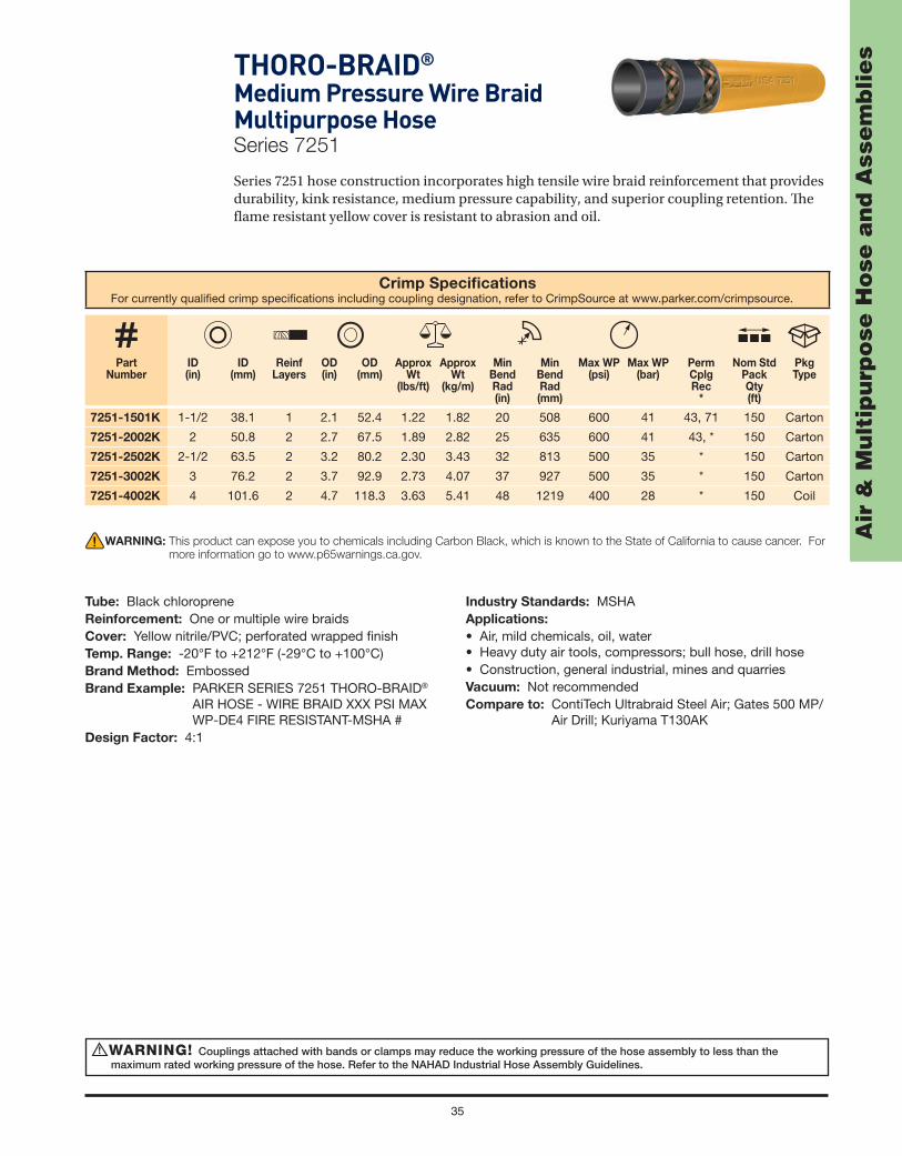
sTHORO-BRAID®
Medium Pressure Wire Braid Multipurpose HoseSeries 7251
Series 7251 hose construction incorporates high tensile wire braid reinforcement that provides durability, kink resistance, medium pressure capability, and superior coupling retention. Th e fl ame resistant yellow cover is resistant to abrasion and oil.
Crimp Specifi cationsFor currently qualifi ed crimp specifi cations including coupling designation, refer to CrimpSource at www.parker.com/crimpsource.
Part Number
ID(in)
ID (mm)
ReinfLayers
OD (in)
OD(mm)
Approx Wt
(lbs/ft)
Approx Wt
(kg/m)
Min Bend Rad (in)
Min Bend Rad (mm)
Max WP (psi)
Max WP (bar)
PermCplgRec
*
Nom Std Pack Qty(ft)
Pkg Type
7251-1501K 1-1/2 38.1 1 2.1 52.4 1.22 1.82 20 508 600 41 43, 71 150 Carton
7251-2002K 2 50.8 2 2.7 67.5 1.89 2.82 25 635 600 41 43, * 150 Carton
7251-2502K 2-1/2 63.5 2 3.2 80.2 2.30 3.43 32 813 500 35 * 150 Carton
7251-3002K 3 76.2 2 3.7 92.9 2.73 4.07 37 927 500 35 * 150 Carton
7251-4002K 4 101.6 2 4.7 118.3 3.63 5.41 48 1219 400 28 * 150 Coil
WARNING! Couplings attached with bands or clamps may reduce the working pressure of the hose assembly to less than the maximum rated working pressure of the hose. Refer to the NAHAD Industrial Hose Assembly Guidelines.
!
WARNING: This product can expose you to chemicals including Carbon Black, which is known to the State of California to cause cancer. For
more information go to www.p65warnings.ca.gov.
Tube: Black chloropreneReinforcement: One or multiple wire braidsCover: Yellow nitrile/PVC; perforated wrapped fi nishTemp. Range: -20°F to +212°F (-29°C to +100°C)Brand Method: EmbossedBrand Example: PARKER SERIES 7251 THORO-BRAID®
AIR HOSE - WIRE BRAID XXX PSI MAX WP-DE4 FIRE RESISTANT-MSHA #
Design Factor: 4:1
Industry Standards: MSHAApplications:
• Air, mild chemicals, oil, water• Heavy duty air tools, compressors; bull hose, drill hose• Construction, general industrial, mines and quarriesVacuum: Not recommendedCompare to: ContiTech Ultrabraid Steel Air; Gates 500 MP/
Air Drill; Kuriyama T130AK

36
Air
& M
ult
ipu
rpo
se H
ose
an
d A
sse
mb
lie
s YELLOW BIRD®
High Pressure Wire Braid Mine and Multipurpose HoseSeries 7284
Series 7284 is a versatile, heavy duty high pressure hose commonly used in mining. Th e construction incorporates high tensile wire braid reinforcement that provides durability, kink resistance, high pressure capability, and superior coupling retention. Th e fl ame resistant bright yellow cover meets MSHA requirements and is also resistant to abrasion and oil.
Crimp Specifi cationsFor currently qualifi ed crimp specifi cations including coupling designation, refer to CrimpSource at www.parker.com/crimpsource.
Part Number
ID(in)
ID (mm)
ReinfLayers
OD (in)
OD(mm)
Approx Wt
(lbs/ft)
Approx Wt
(kg/m)
Min Bend Rad (in)
Min Bend Rad (mm)
Max WP (psi)
Max WP (bar)
PermCplgRec
*
Nom Std Pack Qty
(ft)
Pkg Type
7284-381050 3/8 9.5 1 0.7 17.8 0.23 0.34 6 152 1500 103 HY 50 Carton
7284-501050 1/2 12.7 1 1.0 24.6 0.37 0.55 7 178 1000 69 * 50 Carton
7284-751050 3/4 19.1 1 1.2 31.0 0.50 0.75 10 241 1000 69 HY 50 Carton
WARNING! Couplings attached with bands or clamps may reduce the working pressure of the hose assembly to less than the maximum rated working pressure of the hose. Refer to the NAHAD Industrial Hose Assembly Guidelines.
!
WARNING: This product can expose you to chemicals including Carbon Black, which is known to the State of California to cause cancer. For
more information go to www.p65warnings.ca.gov.
Tube: Black SBRReinforcement: One wire braidCover: Yellow nitrile/PVC; perforated wrapped fi nishTemp. Range: -20°F to +212°F (-29°C to +100°C)Brand Method: Black inkBrand Example: PARKER SERIES 7284 YELLOW BIRD®
HOSE XXXX PSI MAX WP MSHA #—FLAME RESISTANT
Design Factor: 4:1
Industry Standards: MSHAApplications:
• Air, water• Heavy duty air tools, compressors; drill hose, dust
suppression in mines• Construction, general industrial, mines and quarriesVacuum: Not recommendedCompare to: Boston Concord Yellow Jack; Gates 1000MP/
Mine Spray; Thermoid Hercules 1000

37
Air
& M
ult
ipu
rpo
se H
ose
an
d A
sse
mb
lie
s
Air HoseSeries 7092 (Red) and
Series 7093 (Black)
Series 7092/7093 factory-installed, crimped- on lightweight brass couplings provide a secure hose/fi tting interface, and the rigid male NPT ends provide easy, quick and secure connections.
Factory Assemblies
Part Number
ID(in)
ID (mm)
Length(ft)
Length(m)
Approx Wt
(lbs/ea)
Approx Wt
(kg/ea)
Max WP (psi)
Max WP (bar)
PermCplgRec
*
Std Pack Qty(ea)
Pkg Type
7092253-KAA1/4 6.4
50 15.24 6.01 2.73300 21
* 5 Carton
7092253-KAB 25 7.62 3.15 1.43 * 10 Carton
7092382-KAC 3/8 9.5 50 15.24 7.37 3.34 200 14 * 5 Carton
7092383-KAA3/8 9.5
50 15.24 8.33 3.78300 21
* 5 Carton
7092383-KAB 25 7.62 4.34 1.87 * 10 Carton
Series 7093 (Black)
Part Number
ID(in)
ID (mm)
Length(ft)
Length(m)
Approx Wt
(lbs/ea)
Approx Wt
(kg/ea)
Max WP (psi)
Max WP (bar)
PermCplgRec
*
Std Pack Qty(ea)
Pkg Type
7093383-KAA 3/8 9.5 50 15.24 8.09 3.67 300 21 * 5 Carton
WARNING: This product can expose you to chemicals including Carbon Black, which is known to the State of California to cause
cancer. For more information go to www.p65warnings.ca.gov.
WARNING: This product can expose you to chemicals including Carbon Black, which is known to the State of California to cause
cancer. For more information go to www.p65warnings.ca.gov.
Temp Range: -40°F to +160°F (-40°C to +100°C)Design Factor: 4:1Crimped-on Brass: Rigid Male 1/4" x 1/4" NPT Thread Couplings Each EndDisplay Cartons with Parker Center Retail Packaging DiscSeries 7092 (Red)

38
Air
& M
ult
ipu
rpo
se H
ose
an
d A
sse
mb
lie
s Factory Assemblies
Service Station Air HoseSeries 7092 (Red)
Series 7092 is designed as an abrasion and weather resistant hose for service station compressor and general industrial air service. Th e factory-installed, crimped-on lightweight brass couplings provide a secure hose/fi tting interface, and the rigid male NPT ends provide easy, quick and secure connections.
Part Number
ID(in)
Length(ft)
Approx Wt
(lbs/ea)
Approx Wt
(kg/ea)
Max WP (psi)
Cplg Thread Size
(in)
PermCplgRec
*
Std Pack Qty(ea)
Pkg Type
7092RLC-3003/8
25 4.34 1.97300 1/4 x 1/4
* 10 Carton
7092RLC-600 50 8.33 3.78 * 5 Carton
WARNING: This product can expose you to chemicals including Carbon Black, which is known to the State of
California to cause cancer. For more information go to www.p65warnings.ca.gov.
Temp Range: -40°F to +212°F (-40°C to +100°C)Design Factor: 4:1Crimped-on Brass: Rigid Male NPT Thread Couplings Each EndCartoned and Tied: No Center DiscCarton

39
Air
& M
ult
ipu
rpo
se H
ose
an
d A
sse
mb
lie
sTWINHAMMER™Air / Water Jackhammer Hose SystemSeries 7084
Th e Parker jackhammer hose spray kit provides an engineered transfer of water from the supply hose to the jackhammer bit. Th e kit is easy to install and provides consistent water angle, distance, fl ow and spray pattern for eff ective silica dust control. Th e kit can be used as part of an OSHA-compliant wet method hose system for silica dust suppression. Th e kit includes the hardware and attachment components to apply to many models and generations of jackhammers*:
• Couplings/connectors • Straps • Water nozzle • Jumper hose • Th read tape • Installation instructions • Shims • Water valve
(Continued on the following page)
WARNING! Couplings attached with bands or clamps may reduce the working pressure of the hose assembly to less than the maximum rated working pressure of the hose. Refer to the NAHAD Industrial Hose Assembly Guidelines.
!
Crimp Specifi cationsFor currently qualifi ed crimp specifi cations including coupling designation, refer to CrimpSource at www.parker.com/crimpsource.
Part Number
Hose Color
ID(in)
ID (mm)
ReinfLayers
OD (in)
OD(mm)
Approx Wt
(lbs/ft)
Approx Wt
(kg/m)
Length (ft/ea)
Length(m/ea)
Max WP (psi)
Max WP (bar)
PermCplgRec
*
Std Pack Qty(ea)
Pkg Type
7084JHT75-600 Red 3/4 19.1 2 1.16 29.4 26.7 39.78 50 15.2 300 21 * 1 Carton
7084JHT75-600B Red 3/4 19.1 2 1.16 29.4 26.7 39.78 50 15.2 300 21 * 15 Carton
Air hose is rated to 300 psi maximum working pressure. Finished hose assembly is rated to 150 psi due to limitation of the industry preferred fi tting end style/connection.
WARNING: This product can expose you to chemicals including Lead, which is known to the State of California to cause cancer and birth defects or other
reproductive harm. For more information go to www.p65warnings.ca.gov.
Tube: Black EPDMReinforcement: Multiple textile pliesCover: Air Hose: Red EPDM
Water Hose: Blue EPDMTemp. Range: -40°F to +212°F (-40°C to +100C)Brand Method: Air Hose: White inkWater Hose: No brandBrand Example: PARKER SERIES 7084 300 PSI MAX WPDesign Factor: 3:1
Industry Standards: None applicableApplications:
• Wet method dust suppression hose system for pneumatic jackhammers
Vacuum: Not recommendedCouplings: Air Hose: Crimped carbon steel universal each
end Water Hose: Crimped brass 3/8" x 3/8" rigid
male NPT each end

40
Air
& M
ult
ipu
rpo
se H
ose
an
d A
sse
mb
lie
s
WARNING: This product can expose you to chemicals including Lead, which is known to the State of California to cause cancer and birth defects or other
reproductive harm. For more information go to www.p65warnings.ca.gov.
Jackhammer Hose Spray Kit
Th e Parker jackhammer hose spray kit provides an engineered transfer of water from the supply hose to the jackhammer bit. Th e kit is easy and convenient to install and provides effi cient and consistent water angle, distance, fl ow and spray pattern for eff ective silica dust control. Th e kit can be used as part of an OSHA-compliant wet method hose system for silica dust suppression.
Th e kit includes the hardware and attachment components to apply to many models and generations of jackhammers*:
• Couplings/connectors • Straps • Water nozzle • Jumper hose • Th read tape • Installation instructions • Shims • Water valve
TWINHAMMER™Air / Water Jackhammer Hose SystemSeries 7084
WARNING: This product can expose you to chemicals including Lead, which is known to the State of California to cause cancer and birth
defects or other reproductive harm. For more information go to www.p65warnings.ca.gov.
Part Number
ID(in)
ID (mm)
Length(ft)
Length(m)
Approx Wt
(lbs/ea)
Approx Wt
(kg/ea)
Max WP (psi)*
Max WP (bar)*
PermCplgRec
*
Std Pack Qty(ea)
Pkg Type
7081JHE75-6003/4 19.1 50 15.24 16.84 7.64 200 14
* 1 Carton
7081JHE75-600B * 36 Carton
* NOTE: Air hose is rated to 200 psi maximum working pressure. Finished hose assembly is rated to 150 psi due to limitation of the industry preferred fi tting end.
Factory Assemblies Jackhammer HoseSeries 7081 (Red EPDM)
Temp Range: -40°F to +212°F (-40°C to +100°C)Crimped-on Universal Couplings Each EndCartoned and Tied: No Center Disc
Twinhammer Hose Assembly ordered separately.
Part Number
Individual Carton Dimensions (in)
Approx Wt
(lbs/kit)
Approx Wt
(kg/kit)
PermCplgRec
*
Std Pack Qty (ea)
Pkg Type
7084JHT75-KIT 10" x 10" x 3" 4 1.35 * 3 Carton
Packaging: 3 individually boxed kits per master carton. No broken package shipments.

41
Air
& M
ult
ipu
rpo
se H
ose
an
d A
sse
mb
lie
sSledgehammer HoseSeries 7082 (Red EPDM) and
Series 7083 (Yellow EPDM)
WARNING: This product can expose you to chemicals including Lead, which is known to the State of California to cause cancer and birth defects or other
reproductive harm. For more information go to www.p65warnings.ca.gov.
Temp Range: -40°F to +212°F (-40°C to +100°C)Crimped-on Universal Couplings Each EndCartoned and Tied: No Center Disc
Temp Range: -40°F to +212°F (-40°C to +100°C)Crimped-on Universal Couplings Each EndCartoned and Tied: No Center Disc
Series 7083 (Yellow)
Part Number
ID(in)
ID (mm)
Length(ft)
Length(m)
Approx Wt
(lbs/ea)
Approx Wt
(kg/ea)
Max WP (psi)*
Max WP (bar)*
PermCplgRec
*
Std Pack Qty(ea)
Pkg Type
7083JHP75-6003/4 19.1 50 15.24 19.23 8.72 300 21
* 1 Carton
7083JHP75-600B * 36 Carton
* NOTE: Air hose is rated to 300 psi maximum working pressure. Finished hose assembly is rated to 150 psi due to limitation of the industry preferred fi tting end.
Series 7082 (Red)
Part Number
ID(in)
ID (mm)
Length(ft)
Length(m)
Approx Wt
(lbs/ea)
Approx Wt
(kg/ea)
Max WP (psi)*
Max WP (bar*)
PermCplgRec
*
Std Pack Qty(ea)
Pkg Type
7082JHP75-6003/4 19.1 50 15.24 19.15 8.69 300 21
* 1 Carton
7082JHP75-600B * 36 Carton

42
Air
& M
ult
ipu
rpo
se H
ose
an
d A
sse
mb
lie
s Reinforced Conduit HoseSeries 7337
Series 7337 is a durable cable cover with a rugged, abrasion resistant construction that is ideal for extreme service conditions in mining application Meets MSHA requirements for fl ame resistance and wall thickness.
Part Number
ID(in)
ID (mm)
ReinfLayers
OD (in)
OD(mm)
Approx Wt
(lbs/ft)
Approx Wt
(kg/m)
Nom Std Pack Qty
(ft)
Pkg Type
7337-1382 1-3/8 34.9 2 1.8 46.0 0.68 1.01 50 Coil
7337-1502 1-1/2 38.1 2 1.9 49.0 0.72 1.07 50 Coil
7337-1752 1-3/4 44.5 2 2.2 55.4 0.83 1.24 50 Coil
7337-1882 1-7/8 47.6 2 2.3 58.6 0.88 1.31 50 Coil
7337-2002 2 50.8 2 2.4 61.8 0.94 1.40 50 Coil
7337-2252 2-1/4 57.2 2 2.7 68.2 1.05 1.56 50 Coil
7337-2382 2-3/8 60.3 2 2.8 71.3 1.10 1.64 50 Coil
7337-2502 2-1/2 63.5 2 2.9 74.5 1.15 1.71 50 Coil
7337-3002 3 76.2 2 3.4 87.2 1.37 2.04 50 Coil
7337-3502 3-1/2 90.0 2 4.0 101.0 1.59 2.37 50 Coil
7337-4002 4 102.0 2 4.4 113.0 1.79 2.67 50 Coil
WARNING: This product can expose you to chemicals including Carbon Black, which is known to the State of California to cause cancer. For
more information go to www.p65warnings.ca.gov.
Tube: Black synthetic rubberReinforcement: Multiple textile pliesCover: Black synthetic rubber; wrapped fi nishTemp. Range: -30°F to +180°F (-34°C to +82°C)Brand Method: EmbossedBrand Example: PARKER SERIES 7337 PREMIUM
CONDUIT HOSE FLAME RESISTANT MINE CONDUIT USMSHA
Industry Standards: MSHAApplications:
• Conduit• Underground mining equipmentVacuum: Not recommended

43
Air
& M
ult
ipu
rpo
se H
ose
an
d A
sse
mb
lie
s
Part Number
ID(in)
ID (mm)
ReinfLayers
OD (in)
OD(mm)
Approx Wt
(lbs/ft)
Approx Wt
(kg/m)
Nom Std Pack Qty
(ft)
Pkg Type
7337M-5021/2 12.7 2 1.0 24.6 0.31 0.46
450 Reel
7337M-502050 50 Carton
7337M-6325/8 15.9 2 1.1 27.8 0.37 0.55
400 Reel
7337M-632050 50 Carton
7337M-7523/4 19.1 2 1.2 30.8 0.41 0.61
350 Reel
7337M-752050 50 Carton
7337M-10021 25.4 2 1.5 37.2 0.52 0.77
250 Reel
7337M-1002050 50 Carton
7337M-11321-1/8 28.6 2 1.6 40.5 0.57 0.85
250 Reel
7337M-1132050 50 Carton
7337M-12521-1/4 31.8 2 1.7 43.6 0.63 0.94
250 Reel
7337M-1252050 50 Carton
Reinforced Conduit HoseSeries 7337M
Series 7337M is a durable, smooth fi nish cable cover with a rugged, abrasion resistant construction that is ideal for extreme service in mining applications, and meets MSHA requirements for fl ame resistance and wall thickness.
WARNING: This product can expose you to chemicals including Carbon Black, which is known to the State of California to cause cancer. For
more information go to www.p65warnings.ca.gov.
Tube: Black synthetic rubberReinforcement: Multiple textile pliesCover: Black synthetic rubber; smooth fi nishTemp. Range: -30°F to +180°F (-34°C to +82°C)Brand Method: Impression (2-sided)Brand Example: Side 1: PARKER 7337M PREMIUM MINE
CONDUIT HOSE FLAME RESISTANT USMSHA Side 2: (ID) USMSHA
Industry Standards: MSHAApplications:
• Conduit• Underground mining equipmentVacuum: Not recommended

Ch
em
ica
l H
ose Chemical Hose

45
Ch
em
ica
l H
ose
WARNINGS!The data tables published in the Media Compatibility secton of Catalog 4800 are based on tests and believed to be reliable—but the data
should be used ONLY as a guide. The compatibility ratings for rubber/non-PVC materials apply to media at 70°F (21°C). However, chemicalsmay become increasingly aggressive as their temperatures progress above that level. Chemicals at elevated temperatures typically exceedthe performance capability of a hose, even if that hose’s general rating exceeds 70°F (21°C). Contact Parker for chemical compatibility dataat elevated temperatures. If no data exists, it is the user's responsibility to determine hose/chemical/temperature compatibility. All criticalapplications should be tested.
At operating temperatures of 125°F and above, only permanently attached couplings should be installed. At any operating temperature,couplings attached with bands or clamps may reduce the working pressure of the hose assembly to less than the maximum rated workingpressure of the hose. Refer to the NAHAD Industrial Hose Assembly Guidelines.
Do not use with internally expanded couplings. Refer to chemical hoses that incorporate a MXLPE tube.
!
BLUE THUNDER®
UHMWPE Chemical HoseSeries 7373T
Series 7373T is a high pressure suction and discharge hose designed to handle the vast majority of commonly used acids, chemicals and solvents. Th e ultra high molecular weight polyethylene (UHMWPE) tube will not leach into and contaminate the product being conveyed, and features a temperature rating to 180°F (82°C). Th e corrugated hose construction incorporates a dual wire helix that provides full suction capability, kink resistance, fl exibility for ease of handling, and a path to conduct a static electrical charge to ground. Th e cover is resistant to abrasion, mild chemicals and ozone.
NOTE: Refer to the Safety and Technical Information section of this catalog for safety, handling and use information. Refer to the Media Compatibility section to determine compatibility with specifi c chemicals. Contact Parker for additional chemical compatibility information.
Crimp Specifi cationsFor currently qualifi ed crimp specifi cations including coupling designation, refer to CrimpSource at www.parker.com/crimpsource.
Part Number
ID(in)
ID (mm)
ReinfLayers
OD (in)
OD(mm)
Approx Wt
(lbs/ft)
Approx Wt
(kg/m)
Min Bend Rad (in)
Min Bend Rad (mm)
Max WP (psi)
Max WP (bar)
PermCplgRec
*
Nom Std Pack Qty(ft)
Pkg Type
7373T-750 3/4 19.1 2 1.2 30.3 0.40 0.60 3 76 200 14 43 100 Coil
7373T-1000 1 25.4 2 1.5 37.0 0.55 0.82 3 76 200 14 43 100 Coil
7373T-1250 1-1/4 31.8 2 1.7 43.2 0.64 0.95 4 102 200 14 43 100 Coil
7373T-1500 1-1/2 38.1 2 2.0 49.9 0.79 1.18 5 127 200 14 43 100 Coil
7373T-2000 2 50.8 2 2.6 65.0 1.27 1.89 6 152 200 14 43 100 Coil
7373T-2500 2-1/2 63.5 4 3.2 80.1 1.73 2.58 7 178 200 14 * 100 Coil
7373T-3000 3 76.2 4 3.6 92.6 2.12 3.16 7 178 200 14 * 100 Coil
7373T-4000 4 101.6 4 4.7 120.0 3.02 4.50 8 203 200 14 * 100 Coil
WARNING: This product can expose you to chemicals including Carbon Black, which is known to the State of California to cause cancer. For
more information go to www.p65warnings.ca.gov.
Tube: Translucent ultra high molecular weight polyethylene (UHMWPE)
Reinforcement: Multiple textile plies with dual wire helixCover: Blue EPDM; corrugated wrapped fi nishTemp. Range: -40°F to +180°F (-40°C to +82°C)Brand Method: Yellow text on blue stripeBrand Example: PARKER SERIES 7373T BLUE THUNDER®
UHMWPE TUBE MAX WP 200 PSI
Design Factor: 4:1Industry Standards: None applicableApplications: • Acid, chemicals, solvents
• In-plant and storage tank transfer• Delivery, transport
Vacuum: 29" Hg (737 mm Hg)Compare to: Boston Chemcat; ContiTech Fabchem; Gates
Renegade

46
Ch
em
ica
l H
ose
WARNINGS!The data tables published in the Media Compatibility secton of Catalog 4800 are based on tests and believed to be reliable—but the data
should be used ONLY as a guide. The compatibility ratings for rubber/non-PVC materials apply to media at 70°F (21°C). However, chemicals may become increasingly aggressive as their temperatures progress above that level. Chemicals at elevated temperatures typically exceed the performance capability of a hose, even if that hose’s general rating exceeds 70°F (21°C). Contact Parker for chemical compatibility data at elevated temperatures. If no data exists, it is the user's responsibility to determine hose/chemical/temperature compatibility. All critical applications should be tested.
At operating temperatures of 125°F and above, only permanently attached couplings should be installed. At any operating temperature, couplings attached with bands or clamps may reduce the working pressure of the hose assembly to less than the maximum rated working pressure of the hose. Refer to the NAHAD Industrial Hose Assembly Guidelines.
Do not use with internally expanded couplings. Refer to chemical hoses that incorporate a MXLPE tube.
!
WILDCATTER®
Green Corrugated Chemical HoseSeries SWC693
Series SWC693 is an extremely fl exible high pressure suction and discharge hose designed to handle the vast majority of commonly used acids, chemicals and solvents. Th e ultra high molecular weight polyethylene (UHMWPE) tube will not leach into and contaminate the product being conveyed. Th e lightweight corrugated hose construction incorporates a dual wire helix that provides full suction capability, superior kink resistance, minimal force-to bend and a path to conduct a static electrical charge to ground. Th e cover is resistant to abrasion, mild chemicals and ozone.
NOTE: Refer to the Safety and Technical Information section of this catalog for safety, handling and use information. Refer to the Media Compatibility section to determine compatibility with specifi c chemicals. Contact Parker for additional chemical compatibility information. Contact Parker for additional chemical compatibility information.
Th e Wildcatter trade name indicates the product is designed and manufactured for premium service in oilfi eld applications. However, Wildcatter products may be used in other industries, markets and applications where the product meets the required performance criteria.
Crimp Specifi cationsFor currently qualifi ed crimp specifi cations including coupling designation, refer to CrimpSource at www.parker.com/crimpsource.
Part Number
ID(in)
ID (mm)
ReinfLayers
OD (in)
OD(mm)
Approx Wt
(lbs/ft)
Approx Wt
(kg/m)
Min Bend Rad (in)
Min Bend Rad (mm)
Max WP (psi)
Max WP (bar)
PermCplgRec
*
Nom Std Pack Qty(ft)
Pkg Type
SWC693-1000 1 25.4 2 1.5 37 0.53 0.79 1.0 25 250 17 * 100 Coil
SWC693-1250 1-1/4 31.8 2 1.7 44 0.67 1.00 1.3 33 250 17 * 100 Coil
SWC693-1500 1-1/2 38.1 2 2.0 50 0.78 1.16 1.5 38 250 17 * 100 Coil
SWC693-2000 2 50.8 2 2.5 65 1.14 1.70 2.0 51 250 17 * 100 Coil
SWC693-3000 3 76.2 2 3.5 90 1.76 2.62 4.5 114 200 14 * 100 Coil
SWC693-4000 4 101.6 2 4.6 117 2.52 3.75 8.0 203 200 14 * 100 Coil
WARNING: This product can expose you to chemicals including Titanium Dioxide, which is known to the State of California to cause cancer. For more information
go to www.p65warnings.ca.gov.
Tube: Translucent ultra high molecular weight polyethylene (UHMWPE)
Reinforcement: Multiple textile plies with dual wire helixCover: Green EPDM; corrugated wrapped fi nishTemp. Range: -40°F to +180°F (-40°C to +82°C)Brand Method: Black text on yellow stripeBrand Example: PARKER SWC693 CHEMICAL
HOSE UHMW TUBE MAX WP XXX PSI
Design Factor: 4:1Industry Standards: None applicableApplications:
• Acids, chemicals, solvents• In-plant and tank transfer, delivery, transportVacuum: 29" Hg (737 mm Hg)

47
Ch
em
ica
l H
oseWILDCATTER®
High Pressure Chemical HoseSeries 7374
Series 7374 is a high pressure, high temperature chemical suction and discharge hose designed for high pressure chemical blending functions on oilfi eld service equipment. Th e hose handles abrasive solutions and the vast majority of commonly used acids, chemicals and solvents to 180°F (82°C).
Th e hose construction incorporates a dual wire helix that provides full suction capability, kink resistance, fl exibility for ease of handling and a path to conduct a static electrical charge to ground. Th e cover is resistant to abrasion, mild chemicals and ozone.
Th e Wildcatter trade name indicates the product is designed and manufactured for premium service in oilfi eld applications. However, Wildcatter products may be used in other industries, markets and applications where the product meets the required performance criteria.
Crimp Specifi cationsFor currently qualifi ed crimp specifi cations including coupling designation, refer to CrimpSource at www.parker.com/crimpsource.
Part Number
ID(in)
ID (mm)
ReinfLayers
OD (in)
OD(mm)
Approx Wt
(lbs/ft)
Approx Wt
(kg/m)
MinBendRad(in)
MinBendRad(mm)
Max WP (psi)
Max WP (bar)
PermCplgRec
*
Nom Std Pack Qty(ft)
Pkg Type
7374-1000 1 25.4 4 1.6 40.1 0.68 1.01 4 102 600 41 * 100 Coil
7374-1250 1-1/4 31.8 4 1.8 46.9 0.83 1.24 5 127 400 28 * 100 Coil
7374-1500 1-1/2 38.1 4 2.1 53.1 1.00 1.49 6 152 400 28 * 100 Coil
7374-2000 2 50.8 4 2.7 68.1 1.48 2.21 8 203 400 28 * 100 Coil
WARNINGS!The data tables published in the Media Compatibility secton of Catalog 4800 are based on tests and believed to be reliable—but the data
should be used ONLY as a guide. The compatibility ratings for rubber/non-PVC materials apply to media at 70°F (21°C). However, chemicals may become increasingly aggressive as their temperatures progress above that level. Chemicals at elevated temperatures typically exceed the performance capability of a hose, even if that hose’s general rating exceeds 70°F (21°C). Contact Parker for chemical compatibility data at elevated temperatures. If no data exists, it is the user's responsibility to determine hose/chemical/temperature compatibility. All critical applications should be tested.
At operating temperatures of 125°F and above, only permanently attached couplings should be installed. At any operating temperature, couplings attached with bands or clamps may reduce the working pressure of the hose assembly to less than the maximum rated working pressure of the hose. Refer to the NAHAD Industrial Hose Assembly Guidelines.
Do not use with internally expanded couplings. Refer to chemical hoses that incorporate a MXLPE tube.
!
WARNING: This product can expose you to chemicals including Carbon Black, which is known to the State of California to cause cancer. For
more information go to www.p65warnings.ca.gov.
Tube: Translucent ultra high molecular weight polyethylene (UHMWPE)
Reinforcement: Multiple textile plies with dual wire helixCover: Black EPDM; wrapped fi nishTemp. Range: -40°F to +180°F (-40°C to +82°C)Brand Method: Yellow text on blue stripeBrand Example: PARKER 7374 HP CHEMICAL
HOSE UHMW TUBE MAX WP XXX PSIDesign Factor: 4:1
Industry Standards: None applicableApplications:
• Abrasive solutions, acids, chemicals, solvents• OEM aftermarket/replacement• Oilfi eld blender service equipmentVacuum: 29" Hg (737 mm Hg)

48
Ch
em
ica
l H
ose Paint Fluid Hose
Series 7108
Series 7108 is a medium pressure transfer hose designed to handle high aromatic content products such as ketone solvents, lacquers, paint thinners, oil-based and water-based paints and many common chemicals. Th e hose construction incorporates a nylon tube that will not leach into and contaminate the product being conveyed, and the robust aramid reinforcement provides kink resistance, strength and superior coupling retention. Th e cover is resistant to mild chemicals, oil and ozone.
NOTES: • Refer to the Safety and Technical Information section of this catalog for safety, handling and use information. Refer to the Media Compatibility section to determine compatibility with specifi c chemicals. Contact Parker for additional chemical compatibility information.
• Do not use in high pressure paint spray applications.
Crimp Specifi cationsFor currently qualifi ed crimp specifi cations including coupling designation, refer to CrimpSource at www.parker.com/crimpsource.
Part Number
ID(in)
ID (mm)
ReinfLayers
OD (in)
OD(mm)
Approx Wt
(lbs/ft)
Approx Wt
(kg/m)
MinBendRad(in)
MinBendRad(mm)
Max WP (psi)
Max WP (bar)
PermCplgRec
*
Nom Std Pack Qty(ft)
Pkg Type
7108-251 1/4 6.4 2 0.5 12.4 0.09 0.13 3 76 500 35 HY, 43 500 Reel
7108-381 3/8 9.5 2 0.7 17.3 0.16 0.24 4 102 500 35 HY, 43 500 Reel
7108-501 1/2 12.7 2 0.9 22.2 0.25 0.37 5 127 750 52 HY, 43 500 Reel
WARNINGS!It is the responsibility of the user to determine if the hose is suitable for the application. Most chemical resistance guides are based on
temperatures of 70°F (21°C). Elevated temperatures can change the chemical resistance ratings. Many chemicals will become more aggressive as temperatures increase, reducing the ability of hose compounds to withstand them. Contact Parker for chemical compatibility data at elevated temperatures. If no data exists, users are required to perform compatibility testing at the desired temperature.
Do not use in high pressure paint spray applications requring a statically conductive hose.
!
WARNING: This product can expose you to chemicals including DEHP, which is known to the State of California to cause cancer and birth
defects or other reproductive harm. For more information go to www.p65warnings.ca.gov.
Tube: Translucent nylonReinforcement: Multiple aramid pliesCover: Black chloroprene; smooth fi nishTemp. Range: 0°F to +200°F (-18°C to +93°C)Brand Method: White inkBrand Example: PARKER SERIES 7108 PAINT FLUID
HOSE (ID) XXX PSI MAX WPDesign Factor: 4:1
Industry Standards: None applicableApplications:
• Lacquers, light chemicals, paints, solvents, thinners• Connector, mixing, transfer serviceVacuum: Not ratedCompare to: Boston Nyall; ContiTech NR Spray; Gates 77B

49
Ch
em
ica
l H
oseTITANFLEX®
Modifi ed XLPE Chemical HoseSeries SWC683 (Black) and
Series SWC683G (Green)
Series SWC683/SWC683G is a fl exible, lightweight, high pressure, high temperature suction and discharge hose designed to handle many commonly used acids, chemicals and solvents. Th e modifi ed cross-linked polyethylene (MXLPE) tube will not leach into and contaminate the product being conveyed, and features a temperature rating to 250°F (121°C). Series SWC683/SWC683G can be cleaned with a 10% alkali bath, hot water or low pressure steam. Th e corrugated hose construction incorporates a dual wire helix that provides full suction capability, fl exibility, kink resistance and a path to conduct a static electrical charge to ground, and is suitable for use with internally expanded couplings. Th e cover is resistant to abrasion, mild chemicals and ozone.
NOTE: Refer to the Safety and Technical Information section of this catalog for safety, handling and use information. Refer to the Media Compatibility section to determine compatibility with specifi c chemicals. Contact Parker for additional chemical compatibility information.
WARNINGS!The data tables published in the Media Compatibility secton of Catalog 4800 are based on tests and believed to be reliable—but the data
should be used ONLY as a guide. The compatibility ratings for rubber/non-PVC materials apply to media at 70°F (21°C). However, chemicals may become increasingly aggressive as their temperatures progress above that level. Chemicals at elevated temperatures typically exceed the performance capability of a hose, even if that hose’s general rating exceeds 70°F (21°C). Contact Parker for chemical compatibility data at elevated temperatures. If no data exists, it is the user's responsibility to determine hose/chemical/temperature compatibility. All critical applications should be tested.
At operating temperatures of 125°F and above, only permanently attached couplings should be installed. At any operating temperature, couplings attached with bands or clamps may reduce the working pressure of the hose assembly to less than the maximum rated working pressure of the hose. Refer to the NAHAD Industrial Hose Assembly Guidelines.
!
(Continued on the following page)
WARNING: This product can expose you to chemicals including Carbon Black, which is known to the State of California to cause cancer. For
more information go to www.p65warnings.ca.gov.
Tube: Tan modifi ed cross-linked polyethylene (MXLPE)Reinforcement: Multiple textile plies with dual wire helixCover: SWC683: Black EPDM, corrugated wrapped fi nish
SWC683G: Green EPDM, corrugated wrapped fi nishTemp. Range: -40°F to +250°F (-40°C to +121°C)Brand Method: Red text on yellow stripeBrand Example: PARKER SERIES SWC683 (SWC683G)
TITANFLEX® MOD XLPE CHEMICAL SUCTION XXX PSI WP
Design Factor: 4:1
Industry Standards: None applicableApplications:
• Acid, chemicals, solvents• In-plant tank transfer• Delivery, transportVacuum: 29" Hg (737 mm Hg)Compare To: Gates Mustang

50
Ch
em
ica
l H
ose
Series SWC683G (Green)
Crimp Specifi cationsFor currently qualifi ed crimp specifi cations including coupling designation, refer to CrimpSource at www.parker.com/crimpsource.
Part Number
ID(in)
ID (mm)
ReinfLayers
OD (in)
OD(mm)
Approx Wt
(lbs/ft)
Approx Wt
(kg/m)
Min Bend Rad (in)
Min Bend Rad (mm)
Max WP (psi)
Max WP (bar)
PermCplgRec
*
Nom Std Pack Qty(ft)
Pkg Type
SWC683G-1000 1 25.4 2 1.5 38.1 0.49 0.73 2 51 250 17 * 100 Coil
SWC683G-1500 1-1/2 38.1 2 2.0 51.6 0.77 1.15 3 76 250 17 * 100 Coil
SWC683G-2000 2 50.8 2 2.6 65.1 1.04 1.55 4 102 250 17 * 100 Coil
SWC683G-2500 2-1/2 63.5 2 3.0 76.6 1.48 2.21 5 127 200 14 * 100 Coil
SWC683G-3000 3 76.2 2 3.6 92.1 1.98 2.95 6 152 200 14 * 100 Coil
SWC683G-4000 4 101.6 2 4.6 117.5 2.66 3.96 8 203 175 12 * 100 Coil
Series SWC683 (Black) and Series SWC683G (Green) Hose – Titanfl ex® Modifi ed XLPE Chemical Hose (Continued)Series SWC683 (Black)
Crimp Specifi cationsFor currently qualifi ed crimp specifi cations including coupling designation, refer to CrimpSource at www.parker.com/crimpsource.
Part Number
ID(in)
ID (mm)
ReinfLayers
OD (in)
OD(mm)
Approx Wt
(lbs/ft)
Approx Wt
(kg/m)
Min Bend Rad (in)
Min Bend Rad (mm)
Max WP (psi)
Max WP (bar)
PermCplgRec
*
Nom Std Pack Qty(ft)
Pkg Type
SWC683-1000 1 25.4 2 1.5 38.1 0.49 0.73 2 51 250 17 * 100 Coil
SWC683-1500 1-1/2 38.1 2 2.0 51.6 0.71 1.06 3 76 250 17 * 100 Coil
SWC683-2000 2 50.8 2 2.6 65.1 1.05 1.56 4 102 250 17 * 100 Coil
SWC683-2500 2-1/2 63.5 2 3.0 76.6 1.47 2.19 5 127 200 14 * 100 Coil
SWC683-3000 3 76.2 2 3.6 92.1 1.93 2.88 6 152 200 14 * 100 Coil
SWC683-4000 4 101.6 2 4.6 117.5 2.60 3.87 8 203 175 12 * 100 Coil
SWC683-6000 6 152.4 2 6.8 171.5 4.22 6.29 18 457 125 9 * 100 Coil
WARNING: This product can expose you to chemicals including Carbon Black, which is known to the State of California to cause cancer. For
more information go to www.p65warnings.ca.gov.
WARNING: This product can expose you to chemicals including Carbon Black, which is known to the State of California to cause cancer. For
more information go to www.p65warnings.ca.gov.
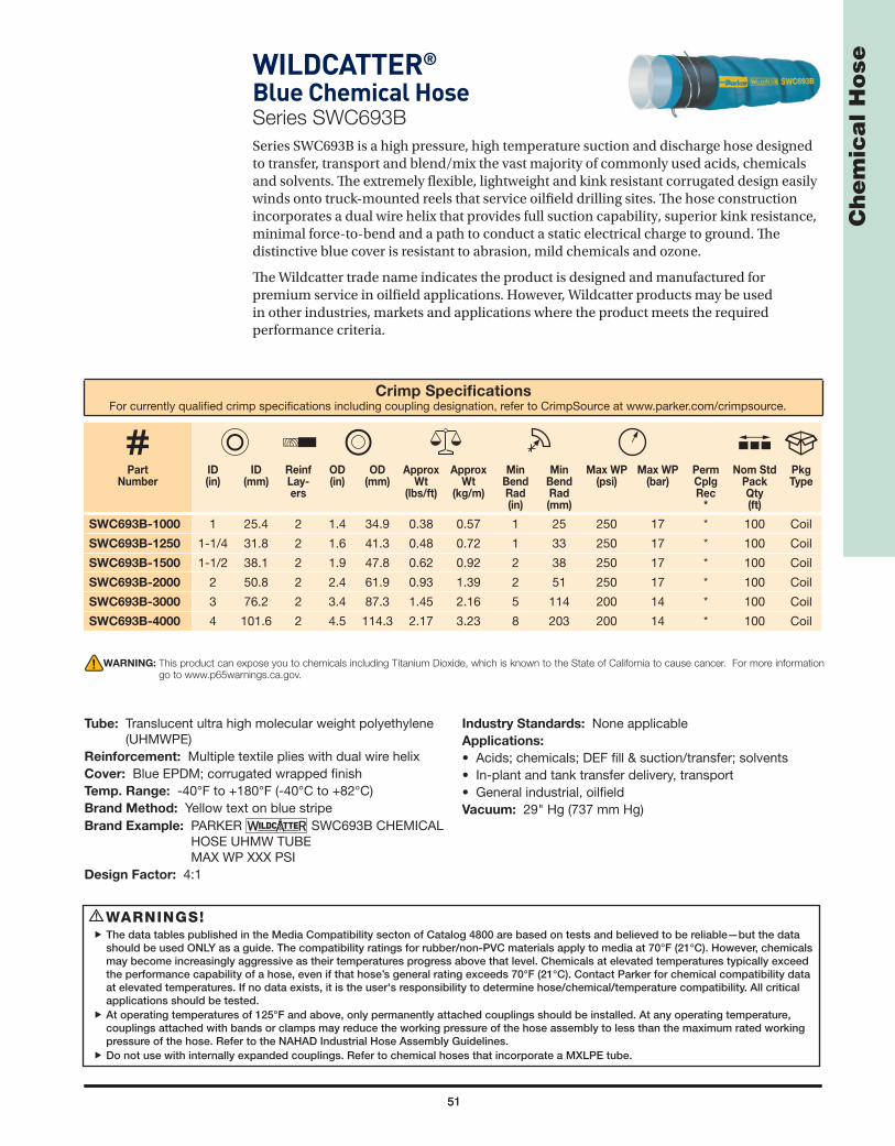
51
Ch
em
ica
l H
ose
51
WILDCATTER®
Blue Chemical HoseSeries SWC693B
Series SWC693B is a high pressure, high temperature suction and discharge hose designed to transfer, transport and blend/mix the vast majority of commonly used acids, chemicals and solvents. Th e extremely fl exible, lightweight and kink resistant corrugated design easily winds onto truck-mounted reels that service oilfi eld drilling sites. Th e hose construction incorporates a dual wire helix that provides full suction capability, superior kink resistance, minimal force-to-bend and a path to conduct a static electrical charge to ground. Th e distinctive blue cover is resistant to abrasion, mild chemicals and ozone.
Th e Wildcatter trade name indicates the product is designed and manufactured for premium service in oilfi eld applications. However, Wildcatter products may be used in other industries, markets and applications where the product meets the required performance criteria.
WARNINGS!The data tables published in the Media Compatibility secton of Catalog 4800 are based on tests and believed to be reliable—but the data
should be used ONLY as a guide. The compatibility ratings for rubber/non-PVC materials apply to media at 70°F (21°C). However, chemicals may become increasingly aggressive as their temperatures progress above that level. Chemicals at elevated temperatures typically exceed the performance capability of a hose, even if that hose’s general rating exceeds 70°F (21°C). Contact Parker for chemical compatibility data at elevated temperatures. If no data exists, it is the user's responsibility to determine hose/chemical/temperature compatibility. All critical applications should be tested.
At operating temperatures of 125°F and above, only permanently attached couplings should be installed. At any operating temperature, couplings attached with bands or clamps may reduce the working pressure of the hose assembly to less than the maximum rated working pressure of the hose. Refer to the NAHAD Industrial Hose Assembly Guidelines.
Do not use with internally expanded couplings. Refer to chemical hoses that incorporate a MXLPE tube.
!
Crimp Specifi cationsFor currently qualifi ed crimp specifi cations including coupling designation, refer to CrimpSource at www.parker.com/crimpsource.
Part Number
ID(in)
ID (mm)
ReinfLay-ers
OD (in)
OD(mm)
Approx Wt
(lbs/ft)
Approx Wt
(kg/m)
Min Bend Rad (in)
Min Bend Rad (mm)
Max WP (psi)
Max WP (bar)
PermCplgRec
*
Nom Std Pack Qty(ft)
Pkg Type
SWC693B-1000 1 25.4 2 1.4 34.9 0.38 0.57 1 25 250 17 * 100 Coil
SWC693B-1250 1-1/4 31.8 2 1.6 41.3 0.48 0.72 1 33 250 17 * 100 Coil
SWC693B-1500 1-1/2 38.1 2 1.9 47.8 0.62 0.92 2 38 250 17 * 100 Coil
SWC693B-2000 2 50.8 2 2.4 61.9 0.93 1.39 2 51 250 17 * 100 Coil
SWC693B-3000 3 76.2 2 3.4 87.3 1.45 2.16 5 114 200 14 * 100 Coil
SWC693B-4000 4 101.6 2 4.5 114.3 2.17 3.23 8 203 200 14 * 100 Coil
WARNING: This product can expose you to chemicals including Titanium Dioxide, which is known to the State of California to cause cancer. For more information
go to www.p65warnings.ca.gov.
Tube: Translucent ultra high molecular weight polyethylene (UHMWPE)
Reinforcement: Multiple textile plies with dual wire helixCover: Blue EPDM; corrugated wrapped fi nishTemp. Range: -40°F to +180°F (-40°C to +82°C)Brand Method: Yellow text on blue stripeBrand Example: PARKER SWC693B CHEMICAL
HOSE UHMW TUBE MAX WP XXX PSI
Design Factor: 4:1
Industry Standards: None applicableApplications:
• Acids; chemicals; DEF fi ll & suction/transfer; solvents • In-plant and tank transfer delivery, transport• General industrial, oilfi eldVacuum: 29" Hg (737 mm Hg)

5252
Engine and Coolant Hose

53
En
gin
e a
nd
Co
ola
nt
Ho
seE-Z FORM™ GSGeneral Service HoseSeries 7395
Series 7395 hose construction incorporates a tube that is resistant to commonly used coolant mixtures, a wire helix that provides full suction/vacuum capability and a path to conduct a static electrical charge to ground, and a cover that is resistant to abrasion, mild chemicals, heat and ozone. Th e unique Greek cover corrugations are tightly pitched and precision-engineered, providing minimal force-to-bend, superior kink resistance, and extreme fl exibility to allow for routing through confi ned spaces where formed hose is normally required.
NOTE: Do not drag across sharp edges or highly abrasive surfaces.
(Continued on the following page)
WARNING: This product can expose you to chemicals including Carbon Black, which is known to the State of California to cause cancer. For
more information go to www.p65warnings.ca.gov.
Tube: Black EPDMReinforcement: Multiple textile braids or plies with wire
helixCover: Black EPDM; Greek corrugated fi nishTemp. Range: -50°F to +257°F (-45°C to +125°C)Brand Method: Black text on blue stripeBrand Example: PARKER SERIES 7395 E-Z FORM™ GS
HOSE XXX PSI MAX WPDesign Factor: 4:1
Industry Standards: SAE J20R2-D1 performanceApplications:
• Air, coolant, mild chemicals, water• Coolant systems, drain lines, vacuum service• SAE-performance in engine coolant service, general
industrialVacuum: 29" Hg (737 mm Hg)

54
En
gin
e a
nd
Co
ola
nt
Ho
se
WARNING! Couplings attached with bands or clamps may reduce the working pressure of the hose assembly to less than the maximum rated working pressure of the hose. Refer to the NAHAD Industrial Hose Assembly Guidelines.
!
Series 7395 – E-Z FORM™ GS General Service Hose (Continued)
WARNING: This product can expose you to chemicals including Carbon Black, which is known to the State of California to cause cancer. For
more information go to www.p65warnings.ca.gov.
Crimp Specifi cationsFor currently qualifi ed crimp specifi cations including coupling designation, refer to CrimpSource at www.parker.com/crimpsource.
Part Number
NomID(in)
NomID
(mm)
ReinfLayers
OD (in)
OD(mm)
Approx Wt
(lbs/ft)
Approx Wt
(kg/m)
MinBendRad(in)
MinBendRad(mm)
Max WP (psi)
Max WP (bar)
PermCplgRec
*
Nom Std
Pack Qty(ft)
Pkg Type
7395-05000251/2 12.7 2 0.9 23.8 0.27 0.40 0.9 24.1 75 5 HY
25 Carton
7395-0500300 300 Reel
7395-06250255/8 15.9 2 1.1 27.0 0.33 0.49 1.3 32.7 75 5 HY
25 Carton
7395-0625300 300 Reel
7395-07500253/4 19.1 2 1.2 30.0 0.35 0.52 1.4 36.3 75 5 HY
25 Carton
7395-0750300 300 Reel
7395-08750257/8 22.2 2 1.3 32.8 0.38 0.57 1.4 36.3 75 5 *
25 Carton
7395-0875300 300 Reel
7395-10000251 25.4 2 1.4 36.0 0.41 0.61 1.4 36.3 75 5 HY
25 Carton
7395-1000300 300 Reel
7395-1125025 1-1/8 28.6 2 1.5 38.0 0.42 0.63 1.8 46.5 75 5 * 25 Carton
7395-12500251-1/4 31.8 2 1.7 43.0 0.50 0.75 2.2 56.7 75 5 HY
25 Carton
7395-1250130 130 Coil
7395-13750251-3/8 34.9 2 1.8 46.0 0.54 0.80 2.8 70.5 75 5 *
25 Carton
7395-1375130 130 Coil
7395-15000251-1/2 38.1 2 1.9 49.0 0.58 0.86 2.9 74.1 75 5 43
25 Carton
7395-1500130 130 Coil
7395-1750025 1-3/4 44.5 2 2.2 56.0 0.68 1.01 4.0 101.0 75 5 * 25 Carton
7395-20000252 50.8 2 2.5 63.0 0.96 1.43 4.6 117.4 75 5 43
25 Carton
7395-2000130 130 Coil
7395-22500252-1/4 57.1 2 2.8 70.0 1.08 1.61 6.5 165.2 75 5 *
25 Carton
7395-2250130 130 Coil
7395-25000252-1/2 63.5 2 3.0 76.5 1.17 1.74 7.2 182.5 75 5 *
25 Carton
7395-2500130 130 Coil
7395-30000253 76.2 2 3.5 90.0 1.51 2.25 8.8 224.2 75 5 *
25 Carton
7395-3000130 130 Coil
7395-35000253-1/2 88.9 2 4.1 104.0 1.92 2.86 11.7 298.0 75 5 *
25 Carton
7395-3500130 130 Coil
7395-40000254 101.6 2 4.6 116.0 2.20 3.28 13.4 340.3 75 5 *
25 Carton
7395-4000130 130 Coil

55
En
gin
e a
nd
Co
ola
nt
Ho
seE-Z FORM™ MPMultipurpose Oil Resistant HoseSeries 7219
Series 7219 hose construction incorporates a tube that is resistant to a oil and refi ned fuels, a wire helix that provides full suction/vacuum capability and a path to conduct a static electrical charge to ground, and a cover that is resistant to oil and weathering. Th e unique Greek corrugations are tightly pitched and precision-engineered, providing minimal force-to-bend, superior kink resistance, extreme fl exibility and allow for routing through confi ned spaces where formed hose is normally required.
NOTES: • Do not use in fuel dispensing or service applications requiring API, NFPA, UL, ULC or any other agency approval or listing.• Refer to the Refi ned Fuel/Hose Compatibility Table in the Media Compatibility section.• Do not drag across sharp edges or highly abrasive surfaces.
WARNING! Couplings attached with bands or clamps may reduce the working pressure of the hose assembly to less than the maximum rated working pressure of the hose. Refer to the NAHAD Industrial Hose Assembly Guidelines.
!
(Continued on the following page)
WARNING: This product can expose you to chemicals including Carbon Black, which is known to the State of California to cause cancer. For
more information go to www.p65warnings.ca.gov.
Tube: Black nitrileReinforcement: Multiple textile plies with wire helixCover: Black chloroprene; Greek corrugated fi nishTemp. Range: Sizes 1/2", 5/8", 3/4" and 1": -30F° to
+250°F (-34°C to +121°C)All other sizes: -30°F to +212°F (-34°C to +100°C)
Brand Method: Black text on red stripeBrand Example: PARKER SERIES 7219 E-Z FORM™ MP
HOSE 75 PSI MAX WPDesign Factor: 4:1
Industry Standards: None applicableApplications: • Biodiesel (to B20 in dedicated and non-dedicated service),
diesel, ethanol, gasoline, oil• Oil suction/return lines; vehicle fuel fi ll connector lines;
drain lines• Buses, cranes, mobile off-road equipmentVacuum: 29" Hg (737 mm Hg)

56
En
gin
e a
nd
Co
ola
nt
Ho
se
Crimp Specifi cationsFor currently qualifi ed crimp specifi cations including coupling designation, refer to CrimpSource at www.parker.com/crimpsource.
Part Number
NomID(in)
NomID
(mm)
ReinfLayers
OD (in)
OD(mm)
Approx Wt
(lbs/ft)
Approx Wt
(kg/m)
MinBendRad(in)
MinBendRad(mm)
Max WP (psi)
Max WP (bar)
PermCplgRec
*
Nom Std
Pack Qty(ft)
Pkg Type
7219-05000251/2 12.7 2 0.9 23.8 0.30 0.45 0.9 24.1 75 5 HY
25 Carton
7219-0500300 300 Reel
7219-06250255/8 15.9 2 1.1 27.0 0.37 0.55 1.3 32.7 75 5 HY
25 Carton
7219-0625300 300 Reel
7219-07500253/4 19.1 2 1.2 30.0 0.39 0.58 1.4 36.3 75 5 HY
25 Carton
7219-0750300 300 Reel
7219-10000251 25.4 2 1.4 36.0 0.46 0.69 1.4 36.3 75 5 HY
25 Carton
7219-1000300 300 Reel
7219-12500251-1/4 31.8 2 1.7 43.0 0.50 0.75 2.2 56.7 75 5 HY
25 Carton
7219-1250130 130 Coil
7219-15000251-1/2 38.1 2 1.9 49.0 0.58 0.86 2.9 74.1 75 5 43
25 Carton
7219-1500130 130 Coil
7219-1625025 1-5/8 41.3 2 2.1 53.0 0.64 0.95 3.6 92.4 75 5 * 25 Carton
7219-1750025 1-3/4 44.5 2 2.2 56.0 0.68 1.01 4.0 101.0 75 5 * 25 Carton
7219-20000252 50.8 2 2.5 63.0 0.96 1.43 4.6 117.4 75 5 43
25 Carton
7219-2000130 130 Coil
7219-2250025 2-1/4 57.2 2 2.8 70.0 1.08 1.61 6.5 165.2 75 5 * 25 Carton
7219-25000252-1/2 63.5 2 3.0 76.5 1.17 1.74 7.2 182.5 75 5 *
25 Carton
7219-2500130 130 Coil
7219-3000025 3 76.2 2 3.5 90.0 1.51 2.25 8.8 224.2 75 5 * 25 Carton
7219-3500025 3-1/2 88.9 2 4.1 104.0 1.92 2.86 11.7 298.0 75 5 * 25 Carton
7219-4000025 4 101.6 2 4.6 116.0 2.20 3.28 13.4 340.3 75 5 * 25 Carton
Series 7219 – E-Z FORM™ MP Multipurpose Oil Resistant Hose (Continued)
WARNING: This product can expose you to chemicals including Carbon Black, which is known to the State of California to cause cancer.
For more information go to www.p65warnings.ca.gov.
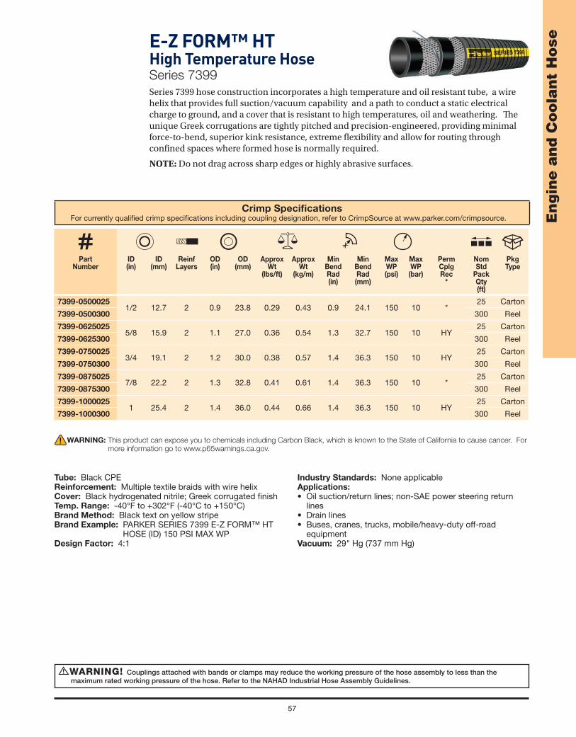
57
En
gin
e a
nd
Co
ola
nt
Ho
seE-Z FORM™ HTHigh Temperature HoseSeries 7399
Series 7399 hose construction incorporates a high temperature and oil resistant tube, a wire helix that provides full suction/vacuum capability and a path to conduct a static electrical charge to ground, and a cover that is resistant to high temperatures, oil and weathering. Th e unique Greek corrugations are tightly pitched and precision-engineered, providing minimal force-to-bend, superior kink resistance, extreme fl exibility and allow for routing through confi ned spaces where formed hose is normally required.
NOTE: Do not drag across sharp edges or highly abrasive surfaces.
Crimp Specifi cationsFor currently qualifi ed crimp specifi cations including coupling designation, refer to CrimpSource at www.parker.com/crimpsource.
Part Number
ID(in)
ID (mm)
ReinfLayers
OD (in)
OD(mm)
Approx Wt
(lbs/ft)
Approx Wt
(kg/m)
MinBendRad(in)
MinBendRad(mm)
Max WP (psi)
Max WP (bar)
PermCplgRec
*
Nom Std
Pack Qty(ft)
Pkg Type
7399-05000251/2 12.7 2 0.9 23.8 0.29 0.43 0.9 24.1 150 10 *
25 Carton
7399-0500300 300 Reel
7399-06250255/8 15.9 2 1.1 27.0 0.36 0.54 1.3 32.7 150 10 HY
25 Carton
7399-0625300 300 Reel
7399-07500253/4 19.1 2 1.2 30.0 0.38 0.57 1.4 36.3 150 10 HY
25 Carton
7399-0750300 300 Reel
7399-08750257/8 22.2 2 1.3 32.8 0.41 0.61 1.4 36.3 150 10 *
25 Carton
7399-0875300 300 Reel
7399-10000251 25.4 2 1.4 36.0 0.44 0.66 1.4 36.3 150 10 HY
25 Carton
7399-1000300 300 Reel
WARNING! Couplings attached with bands or clamps may reduce the working pressure of the hose assembly to less than the maximum rated working pressure of the hose. Refer to the NAHAD Industrial Hose Assembly Guidelines.
!
WARNING: This product can expose you to chemicals including Carbon Black, which is known to the State of California to cause cancer. For
more information go to www.p65warnings.ca.gov.
Tube: Black CPEReinforcement: Multiple textile braids with wire helixCover: Black hydrogenated nitrile; Greek corrugated fi nishTemp. Range: -40°F to +302°F (-40°C to +150°C)Brand Method: Black text on yellow stripeBrand Example: PARKER SERIES 7399 E-Z FORM™ HT
HOSE (ID) 150 PSI MAX WPDesign Factor: 4:1
Industry Standards: None applicableApplications: • Oil suction/return lines; non-SAE power steering return
lines• Drain lines• Buses, cranes, trucks, mobile/heavy-duty off-road
equipmentVacuum: 29" Hg (737 mm Hg)

58
En
gin
e a
nd
Co
ola
nt
Ho
se
Crimp Specifi cationsFor currently qualifi ed crimp specifi cations including coupling designation, refer to CrimpSource at www.parker.com/crimpsource.
Part Number
ID(in)
ID (mm)
ReinfLayers
OD (in)
OD(mm)
Approx Wt
(lbs/ft)
Approx Wt
(kg/m)
MinBendRad(in)
MinBendRad(mm)
Max WP (psi)
Max WP (bar)
PermCplgRec
*
Nom Std Pack Qty(ft)
Pkg Type
38903 3/16 4.8 2 0.4 10.3 0.06 0.09 1 33 100 7 * 250 Reel
38904 1/4 6.4 2 0.5 12.7 0.09 0.13 2 38 100 7 HY 250 Reel
38905 5/16 7.9 2 0.6 14.3 0.11 0.16 2 51 100 7 HY 250 Reel
38906 3/8 9.8 2 0.6 15.8 0.12 0.18 3 64 100 7 HY 250 Reel
38908 1/2 12.7 2 0.8 19.8 0.18 0.27 4 102 100 7 HY 250 Reel
38910 5/8 15.9 2 0.9 23.9 0.24 0.36 5 127 100 7 * 250 Reel
SUPER-FLEX® FL-7Barrier Fuel Line HoseSeries 389
Series 389 hose incorporates a THV barrier to resist permeation, multiple aramid plies of reinforcement for coupling retention, durability and kink resistance. Th e cover is resistant to abrasion, oil and weathering. Th e hose is fl exible for easy routing around small engines and compartments. Series 389 surpasses all of the current California Air Resource Board (CARB)/Small Off -Road Engine (SORE) and Environmental Protection Agency (EPA) strin-gent permeation requirements of 15g/m2/day. It also meets or exceeds SAE J30R7 and SAE J30R14T2 specifi cations.
NOTES: • Refer to the Refi ned Fuel/Hose Compatibility Table in the Media Compatibility section. • Do not use in marine fuel applications. Refer to Series 7165.
WARNING! Couplings attached with bands or clamps may reduce the working pressure of the hose assembly to less than the maximum rated working pressure of the hose. Refer to the NAHAD Industrial Hose Assembly Guidelines.
!
WARNING: This product can expose you to chemicals including DEHP, which is known to the State of California to cause cancer and birth
defects or other reproductive harm. For more information go to www.p65warnings.ca.gov.
Tube: Black nitrile and translucent THV barrierReinforcement: Multiple aramid pliesCover: Black CPE, smooth fi nishTemp. Range: -40°F to + 257 °F (-40°C to +125°C)Brand Method: White inkBrand Example: PARKER SERIES 389 SUPER-FLEX® FL-7
(ID) SAE J30R7/R14T2 FUEL LINE (x)PKHPLINE 389 EPA COMPLIANT 15 g/m2/day CARB Q-08-013 MAX WP 100 PSI
NOTE: (x) changes every yearDesign Factor: 5:1Industry Standards: CARB 2020 SORE, EPA, SAE J30R7,
SAE J30R14T2
Applications:
• Low pressure fuel lines on blowers, grinders, mowers, off-road engines, pressure washers, saws
• Biodiesel (to B20 in dedicated and non-dedicated service), diesel, ethanol, gasoline
• Agricultural equipment, autos, buses, construction equipment, off-road equipment
Vacuum: 3/16" ID through 3/8" ID @ 24" Hg (609 mm Hg); 1/2" ID through 3/4" ID @ 10" Hg (254 mm Hg)
Compare to: Avon Greenbar 700, Gates 4219B

59
En
gin
e a
nd
Co
ola
nt
Ho
se
Crimp Specifi cationsFor currently qualifi ed crimp specifi cations including coupling designation, refer to CrimpSource at www.parker.com/crimpsource.
Part Number
ID(in)
ID (mm)
ReinfLayers
OD (in)
OD(mm)
Approx Wt
(lbs/ft)
Approx Wt
(kg/m)
MinBendRad(in)
MinBendRad(mm)
Max WP (psi)
Max WP (bar)
PermCplgRec
*
Nom Std Pack Qty(ft)
Pkg Type
39703 3/16 4.7 1 0.4 11.1 0.06 0.09 1 33 100 7 * 250 Reel
39704 1/4 6.4 1 0.5 12.7 0.09 0.13 2 38 100 7 HY 250 Reel
39705 5/16 7.9 1 0.6 14.2 0.11 0.16 2 51 100 7 HY 250 Reel
39706 3/8 9.5 1 0.7 16.7 0.12 0.18 3 64 100 7 HY 250 Reel
39708 1/2 12.7 1 0.8 21.0 0.18 0.27 4 102 100 7 HY 250 Reel
39710 5/8 15.9 2 0.9 23.9 0.23 0.34 5 127 35 2 * 250 Reel
SUPER-FLEX® FLBarrier Fuel Line HoseSeries 397
Series 397 incorporates a barrier to resist permeation and the cover is resistant to abrasion, oil and weathering. Th e hose is fl exible for easy routing around small engines and compartments. Series 397 surpasses requirements of 15g/m2/day, and provides SAE J30R7/30R14T2 performance.
NOTES: • Refer to the Refi ned Fuel/Hose Compatibility Table in the Media Compatibility section. • Do not use in marine fuel applications. Refer to Series 7165.
WARNING! Couplings attached with bands or clamps may reduce the working pressure of the hose assembly to less than the maximum rated working pressure of the hose. Refer to the NAHAD Industrial Hose Assembly Guidelines.
!
WARNING: This product can expose you to chemicals including Carbon Black, which is known to the State of California to cause cancer. For
more information go to www.p65warnings.ca.gov.
Tube: Black nitrile and translucent thermoplastic barrierReinforcement: One textile braid or multiple textile pliesCover: Black CPE, smooth fi nishTemp. Range: -30°F to +257°F (-34°C to +125°C)Brand Method: White inkBrand Example: PARKER SERIES 397 (P/N) SUPER-FLEX®
FL (ID) LOW PERMEATION FUEL LINE (x)PKHPLINE 397 EPA COMPLIANT EPA COMPLIANT 15 g/m2/day C-U-06-010 MAX WP 100 PSI
NOTE: (x) changes every yearDesign Factor: 5:1Industry Standards: CARB 2006 SORE, EPA, SAE J30R7/
J30R14T2 (Performance)
Applications: • Low pressure fuel lines on blowers, grinders, mowers, off-
road engines, pressure washers, saws• Biodiesel (to B100 in dedicated and non-dedicated
service), diesel, ethanol, gasoline• Agricultural equipment, autos, buses, construction
equipment, off-road equipmentVacuum: 3/16" ID through 3/8" ID @ 24" Hg (609 mm Hg);
1/2" ID through 3/4" ID @ 10" Hg (254 mm Hg)Compare to: Avon Greenbar, Mark IV PermaSeal

60
En
gin
e a
nd
Co
ola
nt
Ho
se
Crimp Specifi cationsFor currently qualifi ed crimp specifi cations including coupling designation, refer to CrimpSource at www.parker.com/crimpsource.
Part Number
ID(in)
ID (mm)
ReinfLayers
OD (in)
OD(mm)
Approx Wt
(lbs/ft)
Approx Wt
(kg/m)
MinBendRad(in)
MinBendRad(mm)
Max WP (psi)
Max WP (bar)
PermCplgRec
*
Nom Std Pack Qty
(ft)
Pkg Type
39553 3/16 4.8 2 0.4 10.3 0.07 0.10 2 51 75 5 * 250 Carton
39550 1/4 6.4 2 0.5 12.7 0.10 0.15 2 51 50 3 HY 250 Carton
39551 5/16 7.9 2 0.6 14.3 0.11 0.16 3 76 50 3 * 250 Carton
39552 3/8 9.5 2 0.6 15.9 0.14 0.21 4 89 50 3 HY 250 Carton
39554 1/2 12.7 2 0.8 19.8 0.17 0.25 4 102 35 2 HY 250 Reel
Fuel Line/Vapor Emission HoseSeries 395
Series 395 hose is fl exible for easy routing in and around small engines and small engine compartments, and the cover is resistant to abrasion, oil and weathering.
NOTES: • Refer to the Refi ned Fuel/Hose Compatibility Table in the Media Compatibility section. • Do not use in marine fuel applications. Refer to Series 7165.
WARNING! Couplings attached with bands or clamps may reduce the working pressure of the hose assembly to less than the maximum rated working pressure of the hose. Refer to the NAHAD Industrial Hose Assembly Guidelines.
!
WARNING: This product can expose you to chemicals including Carbon Black, which is known to the State of California to cause cancer. For
more information go to www.p65warnings.ca.gov.
Tube: Black nitrileReinforcement: Multiple textile pliesCover: Black chloroprene; smooth fi nishTemp. Range: -40°F to +257 °F (-40°C to +125°C)Brand Method: White inkBrand Example: (ID) FUEL/VAPOR LINE SAE 30R7Design Factor: 5:1Industry Standards: SAE J30R7
Applications:
• Low pressure fuel lines, vapor emission service• Biodiesel (to B20 in dedicated and non-dedicated service),
diesel, ethanol, gasoline• Agricultural equipment, autos, buses, construction
equipment, off-road equipmentVacuum: 24" Hg (3/16" ID through 3/8" ID); 10" Hg (1/2" ID)Compare to: Thermoid Fueling, Vapor Emission and
Crankcase Ventilation SAE 30R7

61
En
gin
e a
nd
Co
ola
nt
Ho
se
Crimp Specifi cationsFor currently qualifi ed crimp specifi cations including coupling designation, refer to CrimpSource at www.parker.com/crimpsource.
Part Number
ID(in)
ID (mm)
ReinfLayers
OD (in)
OD(mm)
Approx Wt
(lbs/ft)
Approx Wt
(kg/m)
MinBendRad(in)
MinBendRad(mm)
Max WP (psi)
Max WP (bar)
PermCplgRec
*
Nom Std Pack Qty(ft)
Pkg Type
7181-251 1/4 6.4 2 0.5 13.4 0.10 0.15 3 64 65 5 * 700 Reel
7181-311 5/16 8.0 2 0.6 15.0 0.18 0.27 5 127 65 5 * 700 Reel
7181-381 3/8 9.5 2 0.7 17.5 0.16 0.24 5 127 65 5 * 600 Reel
7181-501 1/2 12.7 2 0.8 20.7 0.19 0.28 6 152 65 5 * 500 Reel
7181-631 5/8 15.9 2 0.9 23.9 0.23 0.34 8 203 65 5 HY 500 Reel
7181-631050 5/8 15.9 2 0.9 23.9 0.23 0.37 8 203 65 5 HY 5 x 50 Carton
7181-751 3/4 19.1 2 1.1 27.1 0.27 0.40 9 229 50 3 * 500 Reel
7181-1001 1 25.4 2 1.3 34.0 0.37 0.55 12 305 45 3 * 300 Reel
Heater HoseSeries 7181
Series 7181 hose construction designed to SAEJ20R3 D-2 provides electrochemical resistance (ECR) to inhibit striations and rusting of hose-to-metal interfaces, and high temperature performance. Th e hose is resistant to abrasion, mild chemicals and weathering.
WARNING! Couplings attached with bands or clamps may reduce the working pressure of the hose assembly to less than the maximum rated working pressure of the hose. Refer to the NAHAD Industrial Hose Assembly Guidelines.
!
WARNING: This product can expose you to chemicals including Carbon Black, which is known to the State of California to cause cancer.
For more information go to www.p65warnings.ca.gov.
Tube: Black EPDMReinforcement: Multiple textile pliesCover: Black EPDM; smooth fi nishTemp. Range: -40°F to +257°F (-40°C to +125°C)Brand Method: White inkBrand Example: PARKER SERIES 7181 HEATER HOSE
SAE 20R3EC D-2 (ID) XX PSI MAX WP ELECTROCHEMICALLY RESISTANT
Design Factor: 4:1Industry Standards: SAE J20R3EC Class D2
Applications:
• Coolant, hot water, mild chemicals• Industrial and vehicle coolant systems; low pressure
drain lines• Agriculture, construction, general industrial, transportationVacuum: 1/4" ID through 1/2" ID @ 10" Hg (254 mm Hg);
5/8" ID @ 8" Hg (203 mm Hg); 3/4" ID @ 7 "Hg (179 mm Hg); 1" ID @ 6" Hg (152 mm Hg)
Compare to: ContiTech OEM; Gates Green Stripe

62
En
gin
e a
nd
Co
ola
nt
Ho
se
Crimp Specifi cationsFor currently qualifi ed crimp specifi cations including coupling designation, refer to CrimpSource at www.parker.com/crimpsource.
Part Number
ID(in)
ID (mm)
ReinfLayers
OD (in)
OD(mm)
Approx Wt
(lbs/ft)
Approx Wt
(kg/m)
MinBendRad(in)
MinBendRad(mm)
Max WP (psi)
Max WP (bar)
PermCplgRec
*
Nom Std Pack Qty(ft)
Pkg Type
7186-5011/2 12.7 2 0.8 19.8 0.17 0.25 6 152 125 9 *
500 Reel
7186-501050 5 x 50 Carton
7186-6315/8 15.9 2 0.9 23.0 0.20 0.30 8 203 90 6 *
500 Reel
7186-631050 5 x 50 Carton
7186-7513/4 19.1 2 1.0 26.2 0.24 0.36 9 229 70 5 *
500 Reel
7186-751050 5 x 50 Carton
Heater HoseSeries 7186
Series 7186 is a fl exible, lightweight coolant/heater/water hose for standard duty service. Th e EPDM construction is resistant to abrasion, mild chemicals and weathering.
WARNING! Couplings attached with bands or clamps may reduce the working pressure of the hose assembly to less than the maximum rated working pressure of the hose. Refer to the NAHAD Industrial Hose Assembly Guidelines.
!
WARNING: This product can expose you to chemicals including Carbon Black, which is known to the State of California to cause cancer.
For more information go to www.p65warnings.ca.gov.
Tube: Black EPDMReinforcement: Multiple textile pliesCover: Black EPDM; smooth fi nishTemp. Range: -40°F to +212°F (-40°C to +100°C)Brand Method: White inkBrand Example: PARKER SERIES 7186 HEATER HOSE (ID) Design Factor: 4:1Industry Standards: None applicable
Applications:
• Coolant, hot water, mild chemicals• Industrial and vehicle coolant systems; low pressure
drain line• Agriculture, construction, general industrial, transportationVacuum: 1/2" ID @ 10" Hg (254 mm Hg);
5/8" ID @ 8" Hg (203 mm Hg); 3/4" ID @ 7" Hg (179 mm Hg)
Compare to: Thermoid Black Standard Heater

63
En
gin
e a
nd
Co
ola
nt
Ho
seSilicone Heater Hose / Standard WallSeries 6722
Series 6722 silicone heater hose meets or exceeds SAE J20R3 Class A requirements. Th e multiple plies of textile reinforcement and extruded construction provide long and fl exible lengths that resist coolant solutions, aging, cold leaks, cracking, delamination, ozone and peeling.
WARNING! Couplings attached with bands or clamps may reduce the working pressure of the hose assembly to less than the maximum rated working pressure of the hose. Refer to the NAHAD Industrial Hose Assembly Guidelines.
!
Crimp Specifi cationsFor currently qualifi ed crimp specifi cations including coupling designation, refer to CrimpSource at www.parker.com/crimpsource.
Part Number
Size(in)
ID(in)
ID (mm)
OD (in)
OD(mm)
Approx Wt
(lbs/ft)
Approx Wt
(kg/m)
MinBendRad(in)
MinBendRad(mm)
MinBurstPress(psi)
MinBurstPress(bar)
Nom Std Pack Qty
(ft)
Pkg Type
6722-02500501/4 0.250 6.4 0.5 13.4 0.10 0.15 1 13 250 17
50 Carton
6722-0250250 250 Reel
6722-0313100 5/16 0.313 8.0 0.6 15.0 0.12 0.18 1 18 250 17 100 Reel
6722-03750503/8 0.375 9.5 0.7 17.5 0.13 0.19 1 19 250 17
50 Carton
6722-0375250 250 Reel
6722-05000501/2 0.500 12.7 0.8 20.7 0.17 0.25 2 38 250 17
50 Carton
6722-0500250 250 Reel
6722-0625050
5/8 0.625 15.9 0.9 23.9 0.24 0.36 2 45 250 17
50 Carton
6722-0625100 100 Reel
6722-0625250 250 Reel
6722-07500503/4 0.750 19.1 1.1 27.1 0.26 0.39 3 70 200 14
50 Carton
6722-0750100 100 Reel
6722-10000501 1.000 25.4 1.3 34.0 0.34 0.51 5 127 175 12
50 Carton
6722-1000100 100 Reel
Tube: Brick red siliconeReinforcement: Multiple high temperature textile pliesCover: Blue silicone, glossy fi nishTemp. Range: -65°F to +347°F (-53°C to +175°C)Brand Method: ImpressionBrand Example: PARKER SILICONE SERIES 6722 (ID)
-65°F TO +350°FMax. Rec. WP: 1/3 of minimum burst pressure shown in
table below
Industry Standards: SAE J20R3 Class AApplications:
• Automobiles, buses, mobile/off-road equipment, trucks• Other equipment or vehicles with heating linesVacuum: Not recommendedCompare to: Federal 5526; Flexfab Blue 5526; Purosil 80

64
En
gin
e a
nd
Co
ola
nt
Ho
se
WARNING! Couplings attached with bands or clamps may reduce the working pressure of the hose assembly to less than the maximum rated working pressure of the hose. Refer to the NAHAD Industrial Hose Assembly Guidelines.
!
Silicone Heater Hose / Heavy WallSeries 6723
Series 6723 thick wall silicone heater hose meets or exceeds SAE J20R3 Class A requirements. Th e multiple plies of textile reinforcement and extruded construction provide long and fl exible lengths that resist coolant solutions, aging, cold leaks, cracking, delamination, ozone and peeling.
Crimp Specifi cationsFor currently qualifi ed crimp specifi cations including coupling designation, refer to CrimpSource at www.parker.com/crimpsource.
Part Number
Size(in)
ID(in)
ID (mm)
OD (in)
OD(mm)
Approx Wt
(lbs/ft)
Approx Wt
(kg/m)
MinBendRad(in)
MinBendRad(mm)
MinBurstPress(psi)
MinBurstPress(bar)
PermCplgRec
*
Nom Std Pack Qty(ft)
Pkg Type
6723-0375250 3/8 0.375 9.5 0.8 19.4 0.15 0.22 1 16 250 17 HY 250 Reel
6723-0625050 5/8 0.625 15.9 1.0 25.8 0.27 0.40 2 38 250 17 HY 50 Carton
6723-0750100 3/4 0.750 19.1 1.1 29.0 0.29 0.43 2 60 200 14 HY 100 Reel
6723-1000050 1 1.000 25.4 1.4 35.3 0.39 0.58 4 102 175 12 HY 50 Carton
Tube: Brick red siliconeReinforcement: Multiple high temperature textile pliesCover: Blue silicone, glossy fi nishTemp. Range: -65°F to +350°F (-53°C to +176°C)Brand Method: ImpressionBrand Example: PARKER SILICONE SERIES 6723 (ID)
-65°F TO +350°Max. Rec. WP: 1/3 of minimum burst pressure shown in
table below
Industry Standards: SAE J20R3 Class AApplications:
• Automobiles, buses, mobile/off-road equipment, trucks• Other equipment or vehicles with heating linesVacuum: Not recommendedCompare to: Flexfab Green 5521

65
En
gin
e a
nd
Co
ola
nt
Ho
se
WARNING! Couplings attached with bands or clamps may reduce the working pressure of the hose assembly to less than the maximum rated working pressure of the hose. Refer to the NAHAD Industrial Hose Assembly Guidelines.
!
Silicone Heater HoseSeries 6724
Series 6724 silicone high temperature heater hose meets or exceeds SAE J20R3 Class A requirements. Th e multiple plies of textile reinforcement and extruded construction provide long and fl exible lengths that resist coolant solutions, aging, cold leaks, cracking, delamination, ozone and peeling.
Crimp Specifi cationsFor currently qualifi ed crimp specifi cations including coupling designation, refer to CrimpSource at www.parker.com/crimpsource.
Part Number
Size(in)
ID(in)
ID (mm)
OD (in)
OD(mm)
Approx Wt
(lbs/ft)
Approx Wt
(kg/m)
MinBendRad(in)
MinBendRad(mm)
MinBurstPress(psi)
MinBurstPress(bar)
Nom Std Pack Qty(ft)
Pkg Type
6724-0250250 1/4 0.250 6.4 0.5 13.4 0.10 0.15 1 13 250 17 250 Reel
6724-0375250 3/8 0.375 9.5 0.7 17.5 0.13 0.19 1 19 250 17 250 Reel
Tube: Brick red siliconeReinforcement: Multiple high temperature textile pliesCover: Blue silicone, glossy fi nishTemp. Range: -65°F to +500°F (-53°C to +260°C)Brand Method: ImpressionBrand Example: PARKER SILICONE SERIES 6724 -65°F
TO +500°FMax. Rec. WP: 1/3 of minimum burst pressure shown in
table below
Industry Standards: SAE J20R3 Class AApplications:
• Automobiles, buses, mobile/off-road equipment, trucks• Other equipment or vehicles with heating linesVacuum: Not recommended
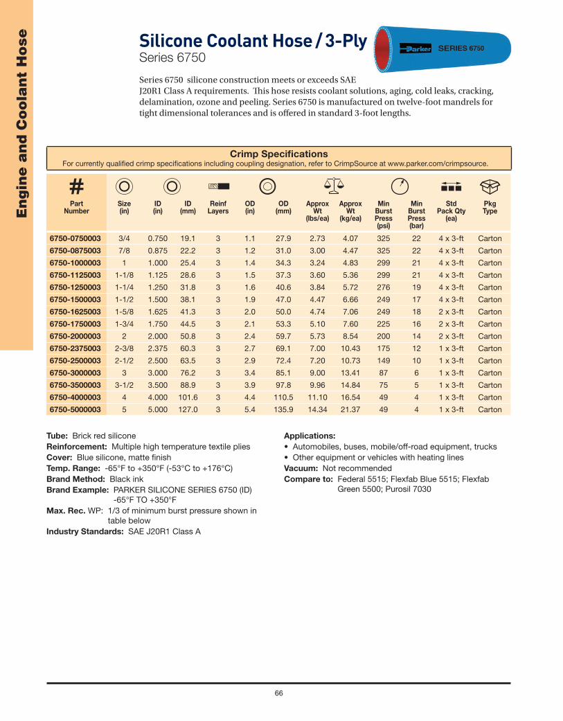
66
En
gin
e a
nd
Co
ola
nt
Ho
se Silicone Coolant Hose / 3-PlySeries 6750
Series 6750 silicone construction meets or exceeds SAE J20R1 Class A requirements. Th is hose resists coolant solutions, aging, cold leaks, cracking, delamination, ozone and peeling. Series 6750 is manufactured on twelve-foot mandrels for tight dimensional tolerances and is off ered in standard 3-foot lengths.
Crimp Specifi cationsFor currently qualifi ed crimp specifi cations including coupling designation, refer to CrimpSource at www.parker.com/crimpsource.
Part Number
Size(in)
ID(in)
ID (mm)
ReinfLayers
OD (in)
OD(mm)
Approx Wt
(lbs/ea)
Approx Wt
(kg/ea)
MinBurstPress(psi)
MinBurstPress(bar)
Std Pack Qty
(ea)
Pkg Type
6750-0750003 3/4 0.750 19.1 3 1.1 27.9 2.73 4.07 325 22 4 x 3-ft Carton
6750-0875003 7/8 0.875 22.2 3 1.2 31.0 3.00 4.47 325 22 4 x 3-ft Carton
6750-1000003 1 1.000 25.4 3 1.4 34.3 3.24 4.83 299 21 4 x 3-ft Carton
6750-1125003 1-1/8 1.125 28.6 3 1.5 37.3 3.60 5.36 299 21 4 x 3-ft Carton
6750-1250003 1-1/4 1.250 31.8 3 1.6 40.6 3.84 5.72 276 19 4 x 3-ft Carton
6750-1500003 1-1/2 1.500 38.1 3 1.9 47.0 4.47 6.66 249 17 4 x 3-ft Carton
6750-1625003 1-5/8 1.625 41.3 3 2.0 50.0 4.74 7.06 249 18 2 x 3-ft Carton
6750-1750003 1-3/4 1.750 44.5 3 2.1 53.3 5.10 7.60 225 16 2 x 3-ft Carton
6750-2000003 2 2.000 50.8 3 2.4 59.7 5.73 8.54 200 14 2 x 3-ft Carton
6750-2375003 2-3/8 2.375 60.3 3 2.7 69.1 7.00 10.43 175 12 1 x 3-ft Carton
6750-2500003 2-1/2 2.500 63.5 3 2.9 72.4 7.20 10.73 149 10 1 x 3-ft Carton
6750-3000003 3 3.000 76.2 3 3.4 85.1 9.00 13.41 87 6 1 x 3-ft Carton
6750-3500003 3-1/2 3.500 88.9 3 3.9 97.8 9.96 14.84 75 5 1 x 3-ft Carton
6750-4000003 4 4.000 101.6 3 4.4 110.5 11.10 16.54 49 4 1 x 3-ft Carton
6750-5000003 5 5.000 127.0 3 5.4 135.9 14.34 21.37 49 4 1 x 3-ft Carton
Tube: Brick red siliconeReinforcement: Multiple high temperature textile pliesCover: Blue silicone, matte fi nishTemp. Range: -65°F to +350°F (-53°C to +176°C)Brand Method: Black inkBrand Example: PARKER SILICONE SERIES 6750 (ID)
-65°F TO +350°FMax. Rec. WP: 1/3 of minimum burst pressure shown in
table belowIndustry Standards: SAE J20R1 Class A
Applications:
• Automobiles, buses, mobile/off-road equipment, trucks• Other equipment or vehicles with heating linesVacuum: Not recommendedCompare to: Federal 5515; Flexfab Blue 5515; Flexfab
Green 5500; Purosil 7030

67
En
gin
e a
nd
Co
ola
nt
Ho
seSilicone Charge Air Cooler Hose / 4-PlyHot SideSeries 6823
Series 6823 is a 4-ply silicone Charge Air Cooler (CAC) hose designed to connect and align segments of the air charge system of a heavy duty engine. Th e air charge system manages the fl ow of the cool/hot air between the turbocharger and the engine; the hot side CAC hose transfers hot air from the engine and also helps stabilize the system by compensating for vibrations. Series 6823 features a maximum temperature to +500°F (+260°C), while the red color is used for color-coding the hot side of the system.
Crimp Specifi cationsFor currently qualifi ed crimp specifi cations including coupling designation, refer to CrimpSource at www.parker.com/crimpsource.
Part Number
6823
Size(in)
ID(in)
ID (mm)
ReinfLayers
OD (in)
OD(mm)
Approx Wt
(lbs/ea)
Approx Wt
(kg/ea)
MinBendRad(in)
MinBendRad(mm)
MinBurstPress(psi)
MinBurstPress(bar)
Std Pack Qty(ea)
Pkg Type
-30006000 3 3.00 76.2 4 3.2 81.8 0.37 0.55 n/a n/a 80 6 6 x 6-in Carton
-3000350060003 x
3-1/23.00 x 3.50
76.2 x 88.9
43.2 x 3.7
81.8 x 94.5
0.40 0.60 n/a n/a 80 6 6 x 6-in Carton
-35006000 3-1/2 3.50 88.9 4 3.7 94.5 0.43 0.64 n/a n/a 80 6 6 x 6-in Carton
-40006000 4 4.00 101.6 4 4.22 107.2 0.55 0.82 n/a n/a 80 6 6 x 6-in Carton
-40008000 4 4.00 101.6 4 4.2 107.2 0.74 1.10 n/a n/a 80 5.5 6 x 8-in Carton
Tube: Brick red siliconeReinforcement: Multiple high temperature aramid plies with
external stainless steel retaining ringsCover: Brick red silicone, matte fi nishTemp. Range: -65°F to +500°F (-53°C to +260°C)Brand Method: Black inkBrand Example: PARKER SERIES 6823Max. Rec. WP: 1/3 of minimum burst pressure shown in
table below
Industry Standards: None applicableApplications:
• Hot air connection between engine charge air system components
• Automobiles, buses, mobile/off-road equipment, trucks• Other equipment or vehicles with heating linesVacuum: Not recommendedCompare to: Purosil 367

68
En
gin
e a
nd
Co
ola
nt
Ho
se Silicone Coolant / Heater HoseSeries 6621
Series 6621hose constructionmeets SAE J20R2 Class A performance criteria and incorporates multiple plies of textile reinforcement for durability, a helical wire for limited suction capability and collapse/kink resistance, and resists coolant solutions, aging, cold leaks, cracking, delamination, ozone and peeling. Th e unique Greek corrugations are precision engineered, providing extreme fl exibility and kink resistance for applications that require tight bends for routing through confi ned spaces where formed hoses might normally be required. Series 6621 is manufactured on 130-foot mandrels—providing the longest and most fl exible continuous hose lengths in the industry—for tight dimensional tolerances and maximum inventory utilization.
NOTE: Do not drag across sharp edges or highly abrasive services.
Crimp Specifi cationsFor currently qualifi ed crimp specifi cations including coupling designation, refer to CrimpSource at www.parker.com/crimpsource.
Part Number
Size(in)
ID(in)
ID (mm)
OD (in)
OD(mm)
Approx Wt
(lbs/ft)
Approx Wt
(kg/m)
MinBendRad(in)
MinBendRad(mm)
MinBurstPress(psi)
MinBurstPress(bar)
Nom Std Pack Qty
(ft)
Pkg Type
6621-1000025 1 0.984 25.0 14 35.0 0.30 0.52 2 50 225 16 25 Carton
6621-1250025 1-1/4 1.260 32.0 1.7 43.0 0.40 0.60 3 80 225 16 25 Carton
6621-2000025 2 2.008 51.0 2.5 64.0 0.88 1.31 6 150 225 16 25 Carton
Tube: Black silicone (other colors available; contact Parker)Reinforcement: Multiple high temperature textile plies with
wire helixCover: Red Greek corrugated silicone, matte fi nish (other
colors available; contact Parker)Temp. Range: -76°F to +392°F (-60°C to +200°C)Brand Method: Black text on yellow stripeBrand Example: PARKER SILICONE SERIES 6621 -76°F to
+392°FMax. Rec. WP: 1/3 of minimum burst pressure shown in
table below
Industry Standards: SAE J20R2 Class A and TMC RP303B performance; ISO 1307-1997 dimensional tolerance
Applications:
• Coolant transfer in heater and coolant circuits • Automobiles, buses, mobile/off-road equipment, trucksVacuum: 18" hg (457 mm Hg)

69
En
gin
e a
nd
Co
ola
nt
Ho
seSOFT-FLEX™DEF Dispenser HoseSeries 7116M
Series 7116M hose construction incorporates a specially formulated EPDM tube and multiple plies of textile reinforcement for fl exibility and kink resistance. Th e EPDM cover is resistant to abrasion, mild chemicals and ozone.
NOTES: • To avoid DEF contamination, use only hose designed for the application, and stainless steel couplings to fabricate hose assemblies. • Do not use for oil or fuel service.
Crimp Specifi cationsFor currently qualifi ed crimp specifi cations including coupling designation, refer to CrimpSource at www.parker.com/crimpsource.
Part Number
ID(in)
ID (mm)
ReinfLayers
OD (in)
OD(mm)
Approx Wt
(lbs/ft)
Approx Wt
(kg/m)
MinBendRad(in)
MinBendRad(mm)
Max WP (psi)
Max WP (bar)
PermCplgRec
*
Nom Std Pack Qty(ft)
Pkg Type
7116M-380 3/8 9.5 2 0.7 16.7 0.13 0.19 4 97 150 10 * 700 Reel
7116M-500 1/2 12.7 4 0.9 22.7 0.24 0.36 5 127 150 10 * 550 Reel
7116M-750 3/4 19.1 4 1.2 29.4 0.34 0.51 6 152 150 10 * 400 Reel
WARNING! Couplings attached with bands or clamps may reduce the working pressure of the hose assembly to less than the maximum rated working pressure of the hose. Refer to the NAHAD Industrial Hose Assembly Guidelines.
!
WARNING: This product can expose you to chemicals including DEHP, which is known to the State of California to cause cancer and birth
defects or other reproductive harm. For more information go to www.p65warnings.ca.gov.
Tube: Black EPDM, peroxide curedReinforcement: Multiple textile pliesCover: Black EPDM; smooth fi nishTemp. Range: -40°F to +212°F (-40°C to +100°C)Brand Method: White inkBrand Example: PARKER SERIES 7116M DEF SOFT-
FLEX™ (ID) MAX WP 150 PSI Design Factor: 4:1Industry Standards: None applicable
Applications:
• DEF fl uids, urea• Dispensing for buses, trucks, mobile equipment• Agriculture, construction, transportationVacuum: Not recommendedCompare to: ContiTech DEF Dispensing Hose; Flextral
PE60

70
En
gin
e a
nd
Co
ola
nt
Ho
se ARMADA®
Marine Multipurpose, Fuel Fill / Vent and Hardwall Wet Exhaust HoseSeries SW569
Series SW569 is an extremely versatile suction and discharge hose for diverse applications such as bilge pump intake, discharge and ventilation; cabin heating; coolant and radiator service; oil and fuel systems using biodiesel (to B100 in dedicated service), ethanol, and gasoline; lubrication systems; wet exhaust systems; nonpotable water systems; and toilet and bath connections. Series SW569 incorporates a dual wire helix that provides full suction capability, fl exibility and kink resistance, and the cover is resistant to oil and ozone. Th e hose is available in multiple incremental sizes for connection to various sizes of pipe used in the marine industry.
NOTES: • Refer to the Refi ned Fuel/Hose Compatibility Table in the Media Compatibility section.
• Do not use in applications requiring low-permeation fuel feed hose (SAE J1527 A1-15).
(Continued on the following page)
WARNING! Couplings attached with bands or clamps may reduce the working pressure of the hose assembly to less than the maximum rated working pressure of the hose. Refer to the NAHAD Industrial Hose Assembly Guidelines.
!
Tube: Black nitrileReinforcement: Multiple textile plies with dual wire helixCover: Black chloroprene; wrapped fi nishTemp. Range: -20°F to +212°F (-29°C to +100°C)Brand Method: Black text on yellow stripeBrand Example: PARKER SERIES SW569 ARMADA (ID)
MARINE FUEL/WET EXHAUST HOSE XX PSI WP
Design Factor: 4:1Industry Standards: ABYC H-24; NMMA; SAE J1527 A1
and A2 Style R2; SAE J1942 Codes F, VW, NVW; SAE J2006 R2; SAE J20R2 B; SAE J20R4 B; SAE J20R5 B; SAE J30R5; ISO 7840:2004 A2; ISO 8469 B1; USCG
Applications:
• Biodiesel (to B100 in dedicated service), diesel, ethanol, gasoline, oil
• Hot exhaust fumes, nonpotable water• Marine coolant and fuel/vent systems,wet exhaustVacuum: 29" Hg (737 mm Hg)Compare to: Thermoid 7910 Bellowsfl ex A

71
En
gin
e a
nd
Co
ola
nt
Ho
seSeries SW569 – ARMADA® Marine Multipurpose, Fuel Fill / Vent and Hardwall Wet Exhaust Hose (Continued)
Crimp Specifi cationsFor currently qualifi ed crimp specifi cations including coupling designation, refer to CrimpSource at www.parker.com/crimpsource.
Part Number
ID(in)
ID (mm)
ReinfLayers
OD (in)
OD(mm)
Approx Wt
(lbs/ft)
Approx Wt
(kg/m)
MinBendRad(in)
MinBendRad(mm)
Max WP (psi)
Max WP (bar)
PermCplgRec
*
Nom Std Pack Qty(ft)
Pkg Type
SW569-500 1/2 12.7 2 0.9 22.6 0.29 0.43 2 38 75 5 * 50 Coil
SW569-625 5/8 15.9 2 1.0 26.4 0.37 0.55 2 38 75 5 * 50 Coil
SW569-750 3/4 19.1 2 1.2 29.4 0.42 0.63 2 38 75 5 * 50 Coil
SW569-1000 1 25.4 2 1.4 35.8 0.53 0.79 2 51 75 5 * 50 Coil
SW569-1125 1-1/8 28.6 2 1.6 39.6 0.62 0.92 3 64 75 5 * 50 Coil
SW569-1250 1-1/4 31.8 2 1.7 42.2 0.64 0.95 3 64 75 5 * 50 Coil
SW569-1500 1-1/2 38.1 2 1.9 48.4 0.78 1.16 3 76 50 3 * 50 Coil
SW569-1625 1-5/8 41.3 2 2.0 51.9 0.87 1.30 4 89 50 3 * 50 Coil
SW569-1750 1-3/4 44.5 2 2.2 55.4 0.96 1.43 4 89 50 3 * 50 Coil
SW569-1875 1-7/8 47.6 2 2.4 59.8 1.14 1.70 4 102 50 3 * 50 Coil
SW569-2000 2 50.8 2 2.5 63.0 1.18 1.76 5 114 50 3 * 50 Coil
SW569-2250 2-1/4 57.2 2 2.7 67.6 1.33 1.98 5 114 50 3 * 50 Coil
SW569-2375 2-3/8 60.3 2 2.8 71.9 1.40 2.09 6 152 50 3 * 50 Coil
SW569-2500 2-1/2 63.5 2 2.9 73.3 1.41 2.10 7 178 50 3 * 50 Coil
SW569-3000 3 76.2 2 3.5 87.8 1.74 2.59 9 229 40 3 * 50 Coil
SW569-3500 3-1/2 88.9 2 4.0 101.2 2.13 3.17 10 254 40 3 * 50 Coil
SW569-4000 4 101.6 2 4.5 114.4 2.50 3.73 12 305 40 3 * 25 Coil
WARNING: This product can expose you to chemicals including DEHP, which is known to the State of California to cause cancer and birth
defects or other reproductive harm. For more information go to www.p65warnings.ca.gov.

72
En
gin
e a
nd
Co
ola
nt
Ho
se Marine Softwall Wet Exhaust HoseSeries SS269
Series SS269 hose is easier to install and absorbs more vibration than rigid pipe or tubing. Th e cover is resistant to oil and ozone, and is available in multiple incremental sizes for connection to various sizes of pipe used in the marine industry.
NOTE: Do not use with refi ned oil or fuel, or in suction applications.
WARNING! Couplings attached with bands or clamps may reduce the working pressure of the hose assembly to less than the maximum rated working pressure of the hose. Refer to the NAHAD Industrial Hose Assembly Guidelines.
!
Crimp Specifi cationsFor currently qualifi ed crimp specifi cations including coupling designation, refer to CrimpSource at www.parker.com/crimpsource.
Part Number
ID(in)
ID (mm)
ReinfLayers
OD (in)
OD(mm)
Approx Wt
(lbs/ft)
Approx Wt
(kg/m)
Max WP (psi)
Max WP (bar)
PermCplgRec
*
Nom Std Pack Qty
(ft)
Pkg Type
SS269-1000 1 25.4 2 1.4 36.6 0.45 0.20 200 14 * 50 Coil
SS269-1250 1-1/4 31.8 2 1.8 45.4 0.71 0.32 200 14 * 50 Coil
SS269-1500 1-1/2 38.1 2 2.0 51.7 0.81 0.37 200 14 * 50 Coil
SS269-1625 1-5/8 41.3 2 2.2 55.6 0.90 0.41 200 14 * 50 Coil
SS269-1750 1-3/4 44.5 2 2.3 58.0 0.91 0.41 200 14 * 50 Coil
SS269-1875 1-7/8 47.6 2 2.4 61.2 0.96 0.44 200 14 * 50 Coil
SS269-2000 2 50.8 4 2.6 65.2 1.11 0.50 200 14 * 50 Coil
SS269-2250 2-1/4 57.2 4 2.8 71.6 1.24 0.56 200 14 * 25 Coil
SS269-2375 2-3/8 60.3 4 3.0 75.3 1.33 0.60 200 14 * 25 Coil
SS269-2625 2-5/8 66.7 4 3.2 81.3 1.43 0.65 200 14 * 25 Coil
SS269-2750 2-3/4 69.9 4 3.3 84.0 1.45 0.66 200 14 * 25 Coil
SS269-2875 2-7/8 66.7 4 3.4 87.0 1.46 0.66 200 14 * 25 Coil
SS269-3000 3 76.2 4 3.7 93.0 1.83 0.83 200 14 * 25 Coil
SS269-3500 3-1/2 88.9 4 4.1 105.3 2.08 0.94 200 14 * 25 Coil
SS269-4000 4 101.6 4 4.6 117.6 2.32 1.05 200 14 * 25 Coil
SS269-4500 4-1/2 114.3 4 5.1 130.7 2.55 1.16 200 14 * 25 Coil
SS269-5000 5 127.0 6 5.9 148.6 3.69 1.68 200 14 * 25 Coil
SS269-5562 5-9/16 141.3 6 6.4 162.8 4.09 1.86 200 14 * 25 Coil
WARNING: This product can expose you to chemicals including DEHP, which is known to the State of California to cause cancer and birth
defects or other reproductive harm. For more information go to www.p65warnings.ca.gov.
Tube: Black nitrileReinforcement: Multiple textile pliesCover: Black nitrile; wrapped fi nishTemp. Range: -40°F to +200°F (-40°C to +93°C)Brand Method: Black text on blue stripeBrand Example: PARKER SERIES SS269 (ID) SOFTWALL
MARINE WET EXHAUST HOSE XXX PSI WP U.S.C.G. TYPE SAE J2006R1 MEETS STANDARDS FOR ABYC
Design Factor: 4:1Industry Standards: ABYC; USCG; SAE J2006R1Applications:
• Hot exhaust fumes; oil, nonpotable water• Marine coolant systems, wet exhaustVacuum: Not recommended

73
En
gin
e a
nd
Co
ola
nt
Ho
seWAVEMASTER™Marine Barrier Fuel Line / Vent HoseSeries 7165
Series 7165 hose incorporates a thermoplastic barrier to resist fuel permeation and the cover is resistant to abrasion, oil and weathering. Th e hose is fl exible for easy routing in engine compartments and used as a feed line to fuel tanks where liquid fuel is continuously in the hose under normal conditions.
NOTE: Refer to the Refi ned Fuel/Hose Compatibility Table in the Media Compatibility section.
Crimp Specifi cationsFor currently qualifi ed crimp specifi cations including coupling designation, refer to CrimpSource at www.parker.com/crimpsource.
Part Number
ID(in)
ID (mm)
ReinfLayers
OD (in)
OD(mm)
Approx Wt
(lbs/ft)
Approx Wt
(kg/m)
MinBendRad(in)
MinBendRad(mm)
Max WP (psi)
Max WP (bar)
PermCplgRec
*
Nom Std Pack
Qty(ft)
Pkg Type
7165-25250 1/4 6.3 2 0.5 13.6 0.11 0.16 3 64 100 7 * 250 Reel
7165-31250 5/16 7.9 2 0.6 15.5 0.13 0.19 3 64 100 7 * 250 Reel
7165-38250 3/8 9.5 2 0.7 17.3 0.16 0.24 3 64 100 7 * 250 Reel
7165-50250 1/2 12.7 2 0.8 20.9 0.20 0.30 5 114 100 7 * 250 Reel
7165-63250 5/8 16.0 2 1.0 25.4 0.30 0.45 5 114 75 5 * 250 Reel
WARNING! Couplings attached with bands or clamps may reduce the working pressure of the hose assembly to less than the maximum rated working pressure of the hose. Refer to the NAHAD Industrial Hose Assembly Guidelines.
!
WARNING: This product can expose you to chemicals including Carbon Black, which is known to the State of California to cause cancer.
For more information go to www.p65warnings.ca.gov.
Tube: Translucent NylonReinforcement: Multiple textile pliesCover: Black nitrile/PVC; smooth fi nishTemp. Range: -20°F to +212°F (-29°C to +100°C)Brand Method: Side One: White ink
Side Two: Solid red stripeBrand Example: PARKER SERIES 7165 WAVEMASTER
MARINE FUEL HOSE – EPA COMPLIANT – (x)9PKHPLINE165 – SAE J1527 USCG TYPE A1-15 ISO 7840 A1 CE NMMA TYPE ACCEPTED (ID) PH USE WITH ABYC COMPLIANT SYSTEMS AND FITTINGS ONLY
NOTE: (x) changes every yearDesign Factor: 4:1Industry Standards: ABYC, CARB, CE, EPA, ISO 7840 A1,
NMMA, SAE J1527 A1-15, USCG A1Applications:
• Biodiesel (to B100 in dedicated and non-dedicated service), diesel, ethanol, gasoline, oil
• Marine fuel/vent systemsVacuum: Not recommendedCompare to: ContiTech Marine Fuel Line FlexshieldCouplings: ABYC compliant

Fuel Dispenser Hose

75
Fu
el D
isp
en
ser
Ho
se
Crimp Specifi cationsFor currently qualifi ed crimp specifi cations including coupling designation, refer to CrimpSource at www.parker.com/crimpsource.
Part Number
ID(in)
ID (mm)
ReinfLayers
OD (in)
OD(mm)
Approx Wt
(lbs/ft)
Approx Wt
(kg/m)
MinBendRad(in)
MinBendRad(mm)
Max WP (psi)
Max WP (bar)
PermCplgRec
*
Nom Std Pack Qty(ft)
Pkg Type
7280-632A 5/8 15.9 2 1.0 26.2 0.39 0.58 3 76 50 10 * 500 Reel
7280-752A 3/4 19.1 2 1.2 29.8 0.47 0.70 4 102 50 10 * 500 Reel
7280-1002A 1 25.4 2 1.5 36.9 0.64 0.95 5 127 50 10 * 500 Reel
Couplings: Bulk gasoline dispenser hose couplings are not sold separately by Parker.
FLEX-EVER™ 2000Hardwall Gasoline Dispenser HoseSeries 7280
Series 7280 hardwall construction incorporates a dual wire helix that provides full suction capability, kink resistance, and a path to conduct a static electrical charge to ground. Th e cover is resistant to abrasion, cuts, oil and ozone, and will not mar the fi nish of a vehicle. Series 7280 is suitable for use with reeling devices or applications where retractable cables are employed.
NOTES: • Th e symbol in the brand/layline signifi es the hose as a “UL Recognized Component” for UL gasoline dispenser hose assemblies. • Not UL listed for E85 service. • Refer to the Refi ned Fuel/Hose Compatibility Table in the Media Compatibility section. • Refer to the Safety and Technical Information section of this catalog for safety,
handling and use information.
WARNINGS!Couplings attached with bands or clamps may reduce the working pressure of the hose assembly to less than the maximum rated working
pressure of the hose. Refer to the NAHAD Industrial Hose Assembly Guidelines.Do not use Parker gasoline dispenser hose for aircraft fueling applications. Use only API/NFPA qualifi ed hose for aircraft fueling
applications.
!
WARNING: This product can expose you to chemicals including Carbon Black, which is known to the State of California to cause cancer. For
more information go to www.p65warnings.ca.gov.
Tube: Black nitrileReinforcement: Multiple textile braids with dual wire helixCover: Black CPE; wrapped fi nishTemp. Range: -40°F to +180°F (-40°C to +82°C)Brand Method: White inkBrand Example: PARKER SERIES 7280 FLEX-EVER™ 2000
GASOLINE HOSE 655N MH530 PN16 TRbF131T.2
Design Factor: 5:1
Industry Standards: UL330/ULC; NFPA 30A and UL30N4 (factory assemblies)
Applications:
• Biodiesel (to B20 in dedicated service), diesel, ethanol, gasoline, oil
• Gasoline dispensers and pumpsVacuum: 29" Hg (737 mm Hg)Compare to: ContiTech BC Gasoline; Gates Curb Pump
124HW

76
Fu
el D
isp
en
ser
Ho
se
Crimp Specifi cationsFor currently qualifi ed crimp specifi cations including coupling designation, refer to CrimpSource at www.parker.com/crimpsource.
Part Number
ID(in)
ID (mm)
ReinfLayers
OD (in)
OD(mm)
Approx Wt
(lbs/ft)
Approx Wt
(kg/m)
MinBendRad(in)
MinBendRad(mm)
Max WP (psi)
Max WP (bar)
Nom Std Pack Qty(ft)
Pkg Type
7282-632 5/8 15.9 2 1.0 26.2 0.37 0.55 3 76 150 10 500 Reel
7282-752 3/4 19.1 2 1.27 29.8 0.44 0.66 4 102 150 10 500 Reel
7282-1002 1 25.4 2 1.5 36.9 0.59 0.88 5 127 150 10 500 Reel
Couplings: Bulk gasoline dispenser hose couplings are not sold separately by Parker.
FLEX-EVER™Barrier Gasoline Dispenser HoseSeries 7282
Series 7282 hardwall construction incorporates a barrier layer for permeation resistance, a dual wire helix that reduces meter creep and provides full suction capability, kink resistance and a path to conduct a static electrical charge to ground. Th e cover is resistant to abrasion, cuts, oil and ozone, and will not mar the fi nish of a vehicle.
NOTES: • Th e symbol in the brand/layline signifi es the hose as a “UL Recognized Component” for UL gasoline dispenser hose assemblies. • Not UL listed for E85 service. • Refer to the Refi ned Fuel/Hose Compatibility Table in the Media Compatibility section. • Refer to the Safety and Technical Information section of this catalog for safety,
handling and use information.
WARNINGS!Couplings attached with bands or clamps may reduce the working pressure of the hose assembly to less than the maximum rated working
pressure of the hose. Refer to the NAHAD Industrial Hose Assembly Guidelines.Do not use Parker gasoline dispenser hose for aircraft fueling applications. Use only API/NFPA qualifi ed hose for aircraft fueling
applications.
!
WARNING: This product can expose you to chemicals including Carbon Black, which is known to the State of California to cause cancer. For
more information go to www.p65warnings.ca.gov.
Tube: Black nitrile with THV barrierReinforcement: Multiple textile braids with dual wire helixCover: Black CPE; wrapped fi nishTemp. Range: -40°F to +180°F (-40°C to +82°C)Brand Method: White text on orange stripeBrand Example: PARKER SERIES 7282 FLEX-EVER™
ECO LOW PERM HARDWALL GASOLINE DISPENSING HOSE MH530
Design Factor: 4:1
Industry Standards: CARB CP-206; UL330/ULC; NFPA 30A (factory assemblies)
Applications:
• Biodiesel (to B20 in dedicated service), diesel, ethanol, gasoline, oil
• Gasoline dispensers and pumpsVacuum: 29" Hg (737 mm Hg)Compare to: ContiTech Flexsteel Futura Low Perm

77
Fu
el D
isp
en
ser
Ho
se
Crimp Specifi cationsFor currently qualifi ed crimp specifi cations including coupling designation, refer to CrimpSource at www.parker.com/crimpsource.
Part Number
ID(in)
ID (mm)
ReinfLayers
OD (in)
OD(mm)
Approx Wt
(lbs/ft)
Approx Wt
(kg/m)
MinBendRad(in)
MinBendRad(mm)
Max WP (psi)
Max WP (bar)
PermCplgRec
*
Nom Std Pack Qty(ft)
Pkg Type
7124-631A 5/8 15.9 1 1.0 24.6 0.35 0.52 3 76 50 10 * 500 Reel
7124-751A 3/4 19.1 1 1.1 28.2 0.42 0.63 4 102 50 10 * 500 Reel
7124-1001A 1 25.4 1 1.3 34.0 0.50 0.75 5 127 50 10 * 500 Reel
Couplings: Bulk gasoline dispenser hose couplings are not sold separately by Parker.
SUPER-FLEX® 2000Semi-Hardwall Gasoline Dispenser HoseSeries 7124
Series 7124 construction provides superior strength, crush-resistant durability, kink resistance and a path to conduct a static electrical charge to ground. Th e cover is resistant to abrasion, cuts, oil and ozone, and will not mar the fi nish of a vehicle.
NOTES: • Th e symbol in the brand/layline signifi es the hose as a “UL Recognized Component” for UL gasoline dispenser hose assemblies. • Not UL listed for E85 service. • Refer to the Refi ned Fuel/Hose Compatibility Table in the Media Compatibility section.• Refer to the Safety and Technical Information section of this catalog for safety,
handling and use information.
WARNINGS!Couplings attached with bands or clamps may reduce the working pressure of the hose assembly to less than the maximum rated working
pressure of the hose. Refer to the NAHAD Industrial Hose Assembly Guidelines.Do not use Parker gasoline dispenser hose for aircraft fueling applications. Use only API/NFPA qualifi ed hose for aircraft fueling
applications.
!
WARNING: This product can expose you to chemicals including Carbon Black, which is known to the State of California to cause cancer.
For more information go to www.p65warnings.ca.gov.
Tube: Black nitrileReinforcement: One wire braidCover: Black CPE; wrapped fi nishTemp. Range: -40°F to +180°F (-40°C to +82°C)Brand Method: White inkBrand Example: PARKER SERIES 7124 SUPER-FLEX®
2000 GASOLINE HOSE 655N MH530
Design Factor: 5:1
Industry Standards: UL330/ULC; NFPA 30A and UL30N4 (factory assemblies)
Applications:
• Biodiesel (to B20 in dedicated service), diesel, ethanol, gasoline, oil
• Gasoline dispensers and pumpsVacuum: Not recommendedCompare to: ContiTech Flexsteel Hardwall; Thermoid
Pumpfl ex II Hardwall

78
Fu
el D
isp
en
ser
Ho
se SOFT-FLEX™ 2000Softwall Gasoline Dispenser HoseSeries 7114
Series 7114 softwall construction incorporates multiple textile plies of reinforcement for fl exibility and kink resistance, and a static wire as a path to conduct a static electrical charge to ground. Th e cover is resistant to abrasion, cuts, oil and ozone, and will not mar the fi nish of a vehicle.
NOTES: • Th e symbol in the brand/layline signifi es the hose as a “UL Recognized Component” for UL gasoline dispenser hose assemblies. • Not UL listed for E85 service. • Refer to the Refi ned Fuel/Hose Compatibility Table in the Media Compatibility section. • Refer to the Safety and Technical Information section of this catalog for safety,
handling and use information.
Crimp Specifi cationsFor currently qualifi ed crimp specifi cations including coupling designation, refer to CrimpSource at www.parker.com/crimpsource.
Part Number
ID(in)
ID (mm)
ReinfLayers
OD (in)
OD(mm)
Approx Wt
(lbs/ft)
Approx Wt
(kg/m)
MinBendRad(in)
MinBendRad(mm)
Max WP (psi)
Max WP (bar)
PermCplgRec
*
Nom Std Pack Qty(ft)
Pkg Type
7114-63154A 5/8 15.9 4 1.0 24.4 0.27 0.40 5 127 50 10 * 475 Reel
7114-75154A 3/4 19.1 4 1.1 27.9 0.34 0.51 6 152 50 10 * 350 Reel
7114-100154A 1 25.4 4 1.4 35.3 0.47 0.70 8 203 50 10 * 250 Reel
Couplings: Bulk gasoline dispenser hose couplings are not sold separately by Parker.
WARNINGS!Couplings attached with bands or clamps may reduce the working pressure of the hose assembly to less than the maximum rated working
pressure of the hose. Refer to the NAHAD Industrial Hose Assembly Guidelines.Do not use Parker gasoline dispenser hose for aircraft fueling applications. Use only API/NFPA qualifi ed hose for aircraft fueling
applications.
!
WARNING: This product can expose you to chemicals including Carbon Black, which is known to the State of California to cause cancer,
and DBP, which is known to the State of California to cause birth defects or other reproducive harm. For more information go to
www.p65warnings.ca.gov.
Tube: Black nitrileReinforcement: Multiple textile plies with static wireCover: Black CPE; smooth fi nishTemp. Range: -40°F to +180°F (-40°C to +82°C)Brand Method: White inkBrand Example: PARKER SERIES 7114 SOFT-FLEX™ 2000
GASOLINE HOSE 4SP 655N MH530
Design Factor: 5:1
Industry Standards: UL330/ULC; NFPA 30A and UL30N4 (factory assemblies)
Applications:
• Biodiesel (to B20 in dedicated service), diesel, ethanol, gasoline, oil
• Gasoline dispensers and pumpsVacuum: Not recommendedCompare to: ContiTech Pacer; Thermoid Pumpfl ex I
Softwall
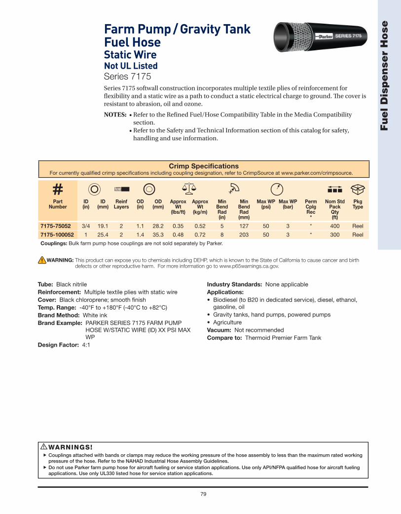
79
Fu
el D
isp
en
ser
Ho
se
Crimp Specifi cationsFor currently qualifi ed crimp specifi cations including coupling designation, refer to CrimpSource at www.parker.com/crimpsource.
Part Number
ID(in)
ID (mm)
ReinfLayers
OD (in)
OD(mm)
Approx Wt
(lbs/ft)
Approx Wt
(kg/m)
MinBendRad(in)
MinBendRad(mm)
Max WP (psi)
Max WP (bar)
PermCplgRec
*
Nom Std Pack Qty(ft)
Pkg Type
7175-75052 3/4 19.1 2 1.1 28.2 0.35 0.52 5 127 50 3 * 400 Reel
7175-100052 1 25.4 2 1.4 35.3 0.48 0.72 8 203 50 3 * 300 Reel
Couplings: Bulk farm pump hose couplings are not sold separately by Parker.
Farm Pump / Gravity Tank Fuel HoseStatic WireNot UL ListedSeries 7175
Series 7175 softwall construction incorporates multiple textile plies of reinforcement for fl exibility and a static wire as a path to conduct a static electrical charge to ground. Th e cover is resistant to abrasion, oil and ozone.
NOTES: • Refer to the Refi ned Fuel/Hose Compatibility Table in the Media Compatibility section.• Refer to the Safety and Technical Information section of this catalog for safety,
handling and use information.
WARNINGS!Couplings attached with bands or clamps may reduce the working pressure of the hose assembly to less than the maximum rated working
pressure of the hose. Refer to the NAHAD Industrial Hose Assembly Guidelines.Do not use Parker farm pump hose for aircraft fueling or service station applications. Use only API/NFPA qualifi ed hose for aircraft fueling
applications. Use only UL330 listed hose for service station applications.
!
WARNING: This product can expose you to chemicals including DEHP, which is known to the State of California to cause cancer and birth
defects or other reproductive harm. For more information go to www.p65warnings.ca.gov.
Tube: Black nitrileReinforcement: Multiple textile plies with static wireCover: Black chloroprene; smooth fi nishTemp. Range: -40°F to +180°F (-40°C to +82°C)Brand Method: White inkBrand Example: PARKER SERIES 7175 FARM PUMP
HOSE W/STATIC WIRE (ID) XX PSI MAX WP
Design Factor: 4:1
Industry Standards: None applicableApplications:
• Biodiesel (to B20 in dedicated service), diesel, ethanol, gasoline, oil
• Gravity tanks, hand pumps, powered pumps• AgricultureVacuum: Not recommendedCompare to: Thermoid Premier Farm Tank

LPG/Propane Hose and Assemblies

81
LP
G / P
rop
an
e H
ose
an
d A
sse
mb
lie
sLP Gas HoseSeries 7132
Series 7132 is a fl exible, lightweight liquefi ed petroleum gas (LPG)/propane delivery and transfer hose. Th e hose meets all Underwriters Laboratories (UL21) and Canadian Standards Association (CSA Type I) requirements. Th e construction incorporates multiple textile plies of reinforcement forfl exibility and kink resistance. Th e perforated cover is resistant to mild chemicals, oil andozone.NOTE: Refer to the Safety and Technical Information section of this catalog for safety,
handling and use information.
Series 7132 and DOT: LPG hose assemblies installed on on-road vehicles must meet Department of Transportation (DOT) requirements. Factory assemblies (3/4" and larger) are pressure tested, one of the fi ttings is etched with a unique DOT certifi cation number, and a document incorporating the identical certifi cation number accompanies each assembly. Metal DOT identifi cation bands are also available/attached for an additional charge at customer request.
Series 7132 and Natural Gas: Series 7132 may be used for natural gas service, but ONLY under ALL of the following conditions:
1) Th e application must be in a well-ventilated environment: Outdoors, or indoors withsignifi cant continuous air movement.
2) Series 7132 is not to replace fi xed/rigid pipe where that material is more appropriatedue to reduced permeation and overall strength and durability. Use rigid pipe, non-permeable tubing or hose with barrier constructions to convey natural gas wheneverpossible.
Series 7132 and Compressed Natural Gas (CNG): Series 7132 is not for use in any CNG application, including fuel dispensing, on-board vehicle fuel lines, or fuel transfer.
Series 7132 and Anhydrous Ammonia (NH3): Series 7132 is not for use with anhydrous ammonia.
(Continued on the following page)
WARNINGS! Use only with couplings qualifi ed by Parker. Do not use with male swivel couplings or other couplings containing o-rings, which may dry
out, crack and fail over time.When using this product in a mobile application such as delivery or service vehicles, the inspection procedures detailed in DOT regulation
49CFR 180.416 must be strictly adhered to.
!
WARNING: This product can expose you to chemicals including 1,3-Butadiene, which is known to the State of California to cause cancer and
birth defects or other reproductive harm. For more information go to www.p65warnings.ca.gov.
Tube: Black nitrileReinforcement: Multiple textile pliesCover: Black chloroprene; perforated smooth fi nishTemp. Range: -40°F to +180°F (-40°C to +82°C) (The hose
construction is capable of this rating, but LP Gas should NEVER be conveyed over 140°F/60°C)
Brand Method: ImpressionBrand Example: PARKER SERIES 7132 (ID) CSA® 8.1 TYPE
I CAUTION - LP GAS HOSE MH6737 C U R® US ISSUE NO. XXXXX 350 PSI MAX WP
Design Factor: 5:1Industry Standards: UL21; CSA 8.1 Type I; optional DOT
factory hose assembly testing and marking also available for sizes smaller than 3/4". Contact Parker.
Applications:
• LP gas/propane• Cookers, grills, heaters, weed burners; delivery, transfer• Agriculture, commercial and residential heating,
construction, general industrialVacuum: Not recommendedCompare to: Boston Blackline (LPG); Gates LP350;
Thermoid Type 75

82
LP
G / P
rop
an
e H
ose
an
d A
sse
mb
lie
s
Crimp Specifi cationsFor currently qualifi ed crimp specifi cations including coupling designation, refer to CrimpSource at www.parker.com/crimpsource.
Part Number
ID(in)
ID (mm)
ReinfLayers
OD (in)
OD(mm)
Approx Wt
(lbs/ft)
Approx Wt
(kg/m)
MinBendRad(in)
MinBendRad(mm)
Max WP (psi)
Max WP (bar)
PermCplgRec
*
Nom Std Pack Qty
(ft)
Pkg Type
7132-253541/4 6.4 4 0.6 15.5 0.15 0.22 3 64 350 24 *
750 Reel
7132-25354E 350 Reel
7132-383543/8 9.5 4 0.8 19.1 0.22 0.33 4 89 350 24 HY
600 Reel
7132-38354E 300 Reel
7132-50354 1/2 12.7 4 0.9 23.8 0.32 0.48 5 114 350 24 * 500 Reel
7132-75354
3/4 19.1 4 1.3 31.8 0.50 0.75 7 165 350 24 HY
350 Reel
7132-75354100 2 x 100 Carton
7132-75354150 1 x 150 Carton
7132-75354200 1 x 200 Carton
7132-100354
1 25.4 4 1.5 38.1 0.63 0.94 8 191 350 24 *
300 Reel
7132-100354100 100 Carton
7132-100354150 1 x 150 Carton
7132-100354200 200 Reel
NOTE: “E” reel part numbers are UPS-able.
Series 7132 – LP Gas Hose (Continued)
WARNING: This product can expose you to chemicals including 1,3-Butadiene, which is known to the State of California to cause cancer and
birth defects or other reproductive harm. For more information go to www.p65warnings.ca.gov.

83
LP
G / P
rop
an
e H
ose
an
d A
sse
mb
lie
sX-TREME™
Low Temperature LP Gas HoseSeries 7132XTC
Series 7132XTC is a fl exible, lightweight, low temperature liquefi ed petroleum gas (LPG)/propane delivery and transfer hose. Th e hose meets all Underwriters Laboratories (UL21) and Canadian Standards Association (CSA Type I) requirements. Th e construction stays fl exible to -65°F (-53°C) and incorporates multiple textile plies of reinforcement for fl exibility and kink resistance. Th e perforated cover is resistant to mild chemicals, oil and ozone. NOTE: Refer to the Safety and Technical Information section of this catalog for safety, handling
and use information.
Series 7132XTC and DOT: LPG hose assemblies installed on on-road vehicles must meet Department of Transportation (DOT) requirements. Factory assemblies (3/4" and larger) are pressure tested, one of the fi ttings is etched with a unique DOT certifi cation number, and a document incorporating the identical certifi cation number accompanies each shipment. Metal DOT identifi cation bands are also attached at an additional charge per customer request.
Series 7132XTC and Natural Gas: Series 7132XTC may be used for natural gas service, but ONLY under ALL of the following conditions:
1) Th e application must be in a well-ventilated environment: Outdoors, or indoors with signifi cant continuous air movement.
2) Series 7132XTC is not to replace fi xed/rigid pipe where that material is more appropriate due to reduced permeation and overall strength and durability. Use rigid pipe, non-permeable tubing or hose with barrier constructions to convey natural gas whenever possible.
Series 7132XTC and Compressed Natural Gas (CNG): Series 7132XTC is not for use in any CNG application, including fuel dispensing, on-board vehicle fuel lines, or fuel transfer.
Series 7132XTC and Anhydrous Ammonia (NH3): Series 7132XTC is not for use with anhydrous ammonia.
(Continued on the following page)
WARNINGS!Use only with couplings qualifi ed by Parker. Do not use with male swivel couplings or other couplings containing o-rings, which may dry
out, crack and fail over time.When using this product in a mobile application such as delivery or service vehicles, the inspection procedures detailed in DOT regulation
49CFR 180.416 must be strictly adhered to.
!
WARNING: This product can expose you to chemicals including 1,3-Butadiene, which is known to the State of California to cause cancer and
birth defects or other reproductive harm. For more information go to www.p65warnings.ca.gov.
Tube: Black nitrileReinforcement: Multiple textile pliesCover: Black chloroprene; perforated smooth fi nishTemp. Range: -65°F to +180°F (-53°C to +82°C) (The hose
construction is capable of this rating, but LP Gas should NEVER be conveyed over 140°F/60°C)
Brand Method: ImpressionBrand Example: PARKER SERIES 7132XTC X-TREME CSA
8.1 TYPE I CAUTION - LP GAS HOSE (-65°F) MH6737 C U R® US ISSUE NO. XXXXX 350 PSI MAX WP
Design Factor: 5:1
Industry Standards: UL21; CSA 8.1 Type I; optional DOT factory hose assembly testing and marking also available for sizes smaller than 3/4". Contact Parker.
Applications:
• LP gas/propane• Low temperature delivery, transfer• Agriculture, commercial and residential heating, construction,
general industrialVacuum: Not recommendedCompare to: Thermoid Polarfl ex

84
LP
G / P
rop
an
e H
ose
an
d A
sse
mb
lie
s
Crimp Specifi cationsFor currently qualifi ed crimp specifi cations including coupling designation, refer to CrimpSource at www.parker.com/crimpsource.
Part Number
ID(in)
ID (mm)
ReinfLayers
OD (in)
OD(mm)
Approx Wt
(lbs/ft)
Approx Wt
(kg/m)
Min Bend Rad (in)
Min Bend Rad(mm)
Max WP (psi)
Max WP (bar)
PermCplgRec
*
Nom Std Pack Qty(ft)
Pkg Type
7132XTC-1000125 1 25.4 4 1.5 38.1 0.63 0.94 8 191 350 24 * 1 x 125 Carton
7132XTC-1000150 1 25.4 4 1.5 38.1 0.63 0.94 8 191 350 24 * 1 x 150 Carton
Series 7132XTC – X-TREME™ Low Temperature LP Gas Hose (Continued)
WARNING: This product can expose you to chemicals including 1,3-Butadiene, which is known to the State of California to cause cancer and
birth defects or other reproductive harm. For more information go to www.p65warnings.ca.gov.

85
LP
G / P
rop
an
e H
ose
an
d A
sse
mb
lie
s(Continued on the following page)
LP Gas HoseSeries 7232
Series 7232 is a large diameter, fl exible liquifi ed petroleum gas (LPG)/propane transfer hose for large volume bulk loading/unloading and vibration-resistant onboard vehicle connections. Th e hose meets all Underwriters Laboratories (UL21) and Canadian Standards Association (CSA Type I) requirements. Th e construction incorporates multiple braids or plies of textile reinforcement for kink resistance and superior coupling retention. Th e perforated cover is resistant to mild chemicals, oil and ozone. NOTE: Refer to the Safety and Technical Information section of this catalog for safety,
handling and use information.Series 7232 and DOT: LPG hose assemblies installed on on-road vehicles must meet Department of Transportation (DOT) requirements. Factory assemblies (all sizes) are pressure tested, one of the fi ttings is etched with a unique DOT certifi cation number, and a document incorporating the identical certifi cation number accompanies each assembly. Metal DOT identifi cation bands are also available/attached for an additional charge at customer request. Series 7232 and Natural Gas: Series 7232 may be used for natural gas service, but ONLY under ALL of the following conditions:
1) Th e application must be in a well-ventilated environment: Outdoors, or indoors with signifi cant continuous air movement.
2) Series 7232 is not to replace fi xed/rigid pipe where that material is more appropriate due to reduced permeation and overall strength and durability. Use rigid pipe, non-permeable tubing or hose with barrier constructions to convey natural gas whenever possible.
Series 7232 and Compressed Natural Gas (CNG): Series 7232 is not to be used for any CNG application, including fuel dispensing, on-board vehicle fuel lines, or fuel transfer.
Series 7232 and Anhydrous Ammonia (NH3): Series 7232 is not for use with anhydrous ammonia.
WARNINGS!Use only with couplings qualifi ed by Parker. Do not use with male swivel couplings or other couplings containing o-rings, which may dry
out, crack and fail over time.When using this product in a mobile application such as delivery or service vehicles, the inspection procedures detailed in DOT regulation
49CFR 180.416 must be strictly adhered to.
!
WARNING: This product can expose you to chemicals including Carbon Black, which is known to the State of California to cause cancer. For
more information go to www.p65warnings.ca.gov.
Tube: Black nitrileReinforcement: Multiple textile braidsCover: Black chloroprene; perforated wrapped fi nishTemp. Range: -40°F to +180°F (-40°C to +82°C) (The hose
construction is capable of this rating, but LP Gas should NEVER be conveyed over 140°F/60°C)
Brand Method: Side one: Embossed Side two: Black text on yellow stripeBrand Example: Side one (Embossed): PARKER SERIES
7232 CSA 8.1 TYPE I CAUTION - LP GAS HOSE MH6737 C U R® US ISSUE NO. XXXX 350 PSI MAX WPSide two (Stripe): PARKER LP GAS HOSE
Design Factor: 5:1Industry Standards: UL21; CSA 8.1 Type I; optional DOT
factory hose assembly testing and marking also available. Contact Parker.
Applications:
• LP gas/propane• Bulk loading/unloading, in-plant tank transfer, transport• Agriculture, commercial and residential heating, construction,
general industrialVacuum: Not recommendedCompare to: Boston Blackline (LPG); Gates LP350; Thermoid Type 65

86
LP
G / P
rop
an
e H
ose
an
d A
sse
mb
lie
s
Crimp Specifi cationsFor currently qualifi ed crimp specifi cations including coupling designation, refer to CrimpSource at www.parker.com/crimpsource.
Part Number
ID(in)
ID (mm)
ReinfLayers
OD (in)
OD(mm)
Approx Wt
(lbs/ft)
Approx Wt
(kg/m)
MinBendRad(in)
MinBendRad(mm)
Max WP (psi)
Max WP (bar)
PermCplgRec
*
Nom Std Pack Qty(ft)
Pkg Type
7232-12521-1/4 31.8 2 1.8 46.1 0.85 1.27 12 305 350 24
HY 300 Reel
7232-1252100 HY 100 Carton
7232-1503K 1-1/2 38.1 2 2.2 54.8 1.12 1.67 14 356 350 24 43 150 Carton
7232-2003K 2 50.8 4 2.8 69.9 1.90 2.83 16 406 350 24 LA 150 Carton
Series 7232 – LP Gas Hose (Continued)
WARNING: This product can expose you to chemicals including Carbon Black, which is known to the State of California to cause cancer. For
more information go to www.p65warnings.ca.gov.
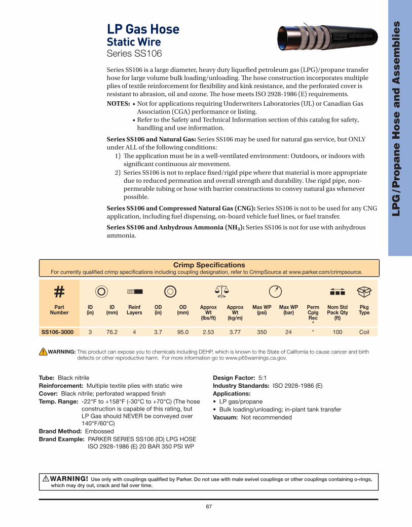
87
LP
G / P
rop
an
e H
ose
an
d A
sse
mb
lie
sLP Gas HoseStatic WireSeries SS106
Series SS106 is a large diameter, heavy duty liquefi ed petroleum gas (LPG)/propane transfer hose for large volume bulk loading/unloading. Th e hose construction incorporates multiple plies of textile reinforcement for fl exibility and kink resistance, and the perforated cover is resistant to abrasion, oil and ozone. Th e hose meets ISO 2928-1986 (E) requirements.
NOTES: • Not for applications requiring Underwriters Laboratories (UL) or Canadian Gas Association (CGA) performance or listing.
• Refer to the Safety and Technical Information section of this catalog for safety, handling and use information.
Series SS106 and Natural Gas: Series SS106 may be used for natural gas service, but ONLY under ALL of the following conditions:
1) Th e application must be in a well-ventilated environment: Outdoors, or indoors with signifi cant continuous air movement.
2) Series SS106 is not to replace fi xed/rigid pipe where that material is more appropriate due to reduced permeation and overall strength and durability. Use rigid pipe, non-permeable tubing or hose with barrier constructions to convey natural gas whenever possible.
Series SS106 and Compressed Natural Gas (CNG): Series SS106 is not to be used for any CNG application, including fuel dispensing, on-board vehicle fuel lines, or fuel transfer.
Series SS106 and Anhydrous Ammonia (NH3): Series SS106 is not for use with anhydrous ammonia.
Crimp Specifi cationsFor currently qualifi ed crimp specifi cations including coupling designation, refer to CrimpSource at www.parker.com/crimpsource.
Part Number
ID(in)
ID (mm)
ReinfLayers
OD (in)
OD(mm)
Approx Wt
(lbs/ft)
Approx Wt
(kg/m)
Max WP (psi)
Max WP (bar)
PermCplgRec
*
Nom Std Pack Qty
(ft)
Pkg Type
SS106-3000 3 76.2 4 3.7 95.0 2.53 3.77 350 24 * 100 Coil
WARNING! Use only with couplings qualifi ed by Parker. Do not use with male swivel couplings or other couplings containing o-rings, which may dry out, crack and fail over time.
!
WARNING: This product can expose you to chemicals including DEHP, which is known to the State of California to cause cancer and birth
defects or other reproductive harm. For more information go to www.p65warnings.ca.gov.
Tube: Black nitrileReinforcement: Multiple textile plies with static wireCover: Black nitrile; perforated wrapped fi nishTemp. Range: -22°F to +158°F (-30°C to +70°C) (The hose
construction is capable of this rating, but LP Gas should NEVER be conveyed over 140°F/60°C)
Brand Method: EmbossedBrand Example: PARKER SERIES SS106 (ID) LPG HOSE
ISO 2928-1986 (E) 20 BAR 350 PSI WP
Design Factor: 5:1Industry Standards: ISO 2928-1986 (E)Applications:
• LP gas/propane• Bulk loading/unloading; in-plant tank transferVacuum: Not recommended

88
LP
G / P
rop
an
e H
ose
an
d A
sse
mb
lie
s LP Gas Vapor HoseSeries 7122
Series 7122 is a fl exible, lightweight, light duty hose connector for transfer of LP Gas vapor in space heaters for chicken brooders and other light applications. Th e hose construction incorporates multiple textile plies of reinforcement for fl exibility and kink resistance. Th e perforated cover is resistant to mild chemicals, oil and ozone.
NOTES: • Do not use to transfer liquid LP gas in gas grill or other applications requiring Underwriters Laboratories (UL) or Canadian Standards Association (CSA) performance or listing.
• Refer to the Safety and Technical Information section of this catalog for safety, handling and use information.
Series 7122 and Natural Gas: Series 7122 may be used for natural gas service, but ONLY under ALL of the following conditions:
1) Th e application must be in a well-ventilated environment: Outdoors, or indoors with signifi cant continuous air movement.
2) Series 7122 is not to replace fi xed/rigid pipe where that material is more appropriate due to reduced permeation and overall strength and durability. Use rigid pipe, non-permeable tubing or hose with barrier constructions to convey natural gas whenever possible.
Crimp Specifi cationsFor currently qualifi ed crimp specifi cations including coupling designation, refer to CrimpSource at www.parker.com/crimpsource.
Part Number
ID(in)
ID (mm)
ReinfLayers
OD (in)
OD(mm)
Approx Wt
(lbs/ft)
Approx Wt
(kg/m)
MinBendRad(in)
MinBendRad(mm)
Max WP (psi)
Max WP (bar)
PermCplgRec
*
Nom Std Pack Qty(ft)
Pkg Type
7122-38200 3/8 9.5 2 0.7 16.7 0.15 0.22 4 97 125 9 HY 700 Reel
WARNING: This product can expose you to chemicals including DEHP, which is known to the State of California to cause cancer and birth
defects or other reproductive harm. For more information go to www.p65warnings.ca.gov.
Tube: Black nitrileReinforcement: Multiple textile pliesCover: Red chloroprene; perforated smooth fi nishTemp. Range: -20°F to +160°F (-29°C to +71°C) (The hose
construction is capable of this rating, but LP Gas should NEVER be conveyed over 140°F/60°C)
Brand Method: Black inkBrand Example: PARKER SERIES 7122 LPG VAPOR HOSE
125 PSI MAX WPDesign Factor: 4:1
Industry Standards: None applicableApplications:
• LP gas – vapor ONLY• Chicken brooders, space heaters• Agriculture, light industrialVacuum: Not recommendedCompare to: Gates LPG Vapor

89
LP
G / P
rop
an
e H
ose
an
d A
sse
mb
lie
sLP Gas HoseStainless Steel Reinforced – Textile CoverSeries SS25UL/7243
Series SS25UL/7243 is a textile-covered, small diameter, extremely durable liquefi ed petroleum gas (LPG)/propane transfer hose in applications such as fuel line hose on forklifts and utility equipment. Th e hose meets all Underwriter Laboratories (UL21) requirements. Th e construction incorporates high tensile stainless steel braided reinforcement for superior strength, durability and kink resistance. Th e textile cover is resistant to abrasion, mild chemicals, and ozone. Series SS25UL/7243 is qualifi ed with Parker crimp couplings and is compatible with Parker Series 20 fi eld reattachable fi ttings.NOTE: Refer to the Safety and Technical Information section of this catalog for safety,
handling and use information.Series SS25UL/7243 and Natural Gas: SS25UL/7243 may be used for natural gas service, but ONLY under ALL of the following conditions:
1) Th e application must be in a well-ventilated environment: Outdoors, or indoors with signifi cant continuous air movement.
2) Series SS25UL/7243 is not to replace fi xed/rigid pipe where that material is more appropriate due to reduced permeation and overall strength and durability. Use rigid pipe, non-permeable tubing or hose with barrier constructions to convey natural gas whenever possible.
Series SS25UL/7243 and Compressed Natural Gas (CNG): Series SS25UL/7243 is not to be used for any CNG application, including fuel dispensing, on-board vehicle fuel lines, or fuel transfer.
Crimp Specifi cationsFor currently qualifi ed crimp specifi cations including coupling designation, refer to CrimpSource at www.parker.com/crimpsource.
Part Number
ID(in)
ID (mm)
ReinfLayers
OD (in)
OD(mm)
Approx Wt
(lbs/ft)
Approx Wt
(kg/m)
MinBendRad(in)
MinBendRad(mm)
Max WP (psi)
Max WP (bar)
Nom Std Pack Qty(ft)
Pkg Type
SS25UL/7243-251 1/4 6.4 1 0.6 14.8 0.13 0.19 2 43 350 24 500 Reel
SS25UL/7243-311 5/16 7.9 1 0.7 17.1 0.18 0.27 2 51 350 24 500 Reel
SS25UL/7243-401 13/32 10.3 1 0.8 19.5 0.21 0.31 2 58 350 24 500 Reel
SS25UL/7243-501 1/2 12.7 1 0.9 23.4 0.29 0.43 3 71 350 24 500 Reel
Reattachable Couplings: Parker Series 20.
WARNING! Use only with couplings qualifi ed by Parker. Do not use with male swivel couplings or other couplings containing o-rings, which may dry out, crack and fail over time.
!
WARNING: This product can expose you to chemicals including Carbon Black, which is known to the State of California to cause cancer. For
more information go to www.p65warnings.ca.gov.
Tube: Black nitrileReinforcement: One stainless steel braidCover: Black chloroprene-impregnated textile braidTemp. Range: -40°F to +180°F (-40°C to +82°C) (The hose
construction is capable of this rating, but LP Gas should NEVER be conveyed over 140°F/60°C)
Brand Method: White ink with dashed spiral stripeBrand Example: Side one: PARKER SERIES SS25UL/7243
CAUTION LP GAS HOSE MH6737 C ISSUE NO. XXXX 350 PSI MAX WP
Side Two: CAUTION FOR LP GAS USE ONLY 1750 PSI MIN BURST
Design Factor: 5:1Industry Standards: UL21Applications:
• LP gas/propane• Fork liftsVacuum: Not recommendedCompare to: Gates Stainless Steel LPG

Material Handling Hose

91
Ma
teri
al H
an
dlin
g H
ose
WARNINGS!Failure to properly inspect, maintain, test and use steam hose assemblies may result in property damage, personal injury or death. Refer to
ARPM publication IP-11-1, “Guide for Use, Testing and Inspection of Steam Hose.” Water changes to hot water and phases of steam when subjected to heat and pressure. The greater the pressure, the higher the
temperature required to achieve and maintain a steam phase. If steam escapes, dangerous quantities of heat may be released very suddenly. Exposure to hot water, low pressure steam and high pressure steam may cause severe scalding or fatal burns.
Use only hoses designated for steam service for steam acpplications. Use ONLY Parker recommended hose/coupling combinations for steam applications. Refer to CrimpSource® at www.parker.com/crimpsource.
Prior to use with detergents or rust inhibitors, refer to the chemical guide in this catalog or contact Parker.Drain steam hose after each use to reduce the possibility of hose popcorning while in service.Couplings attached with bands or clamps may reduce the working pressure of the hose assembly to less than the maximum rated working
pressure of the hose. Refer to the NAHAD Industrial Hose Assembly Guidelines.
!
MPW-1000®
High Pressure Wire Braid Multipurpose HoseSeries 7204Series 7204 hose construction incorporates a premium grade tube especially suited for high temperature materials. Th e high tensile wire braid reinforcement provides durability, kink resistance, high pressure capability and superior coupling retention, and the cover is resistant to heat, oil and weathering. Th e tube resists popcorning and oil-based detergents and rust inhibitors found in steam systems.
NOTES: • Do not use in hot, dry air applications. • Do not use to dispense or transfer biodiesel, diesel fuel or gasoline in regulated service (API, NFPA, UL, ULC or any other agency approval or listing). • Do not use in vehicle engine applications. • Refer to the Refi ned Fuel/Hose Compatibility Table in the Media Compatibility
section.
WARNING: This product can expose you to chemicals including Carbon Black, which is known to the State of California to cause cancer.
For more information go to www.p65warnings.ca.gov.
Tube: Black nitrileReinforcement: One wire braidCover: Black chloroprene; perforated wrapped fi nishTemp. Range: Air: -20°F to +158°F (-29°C to +70°C)Steam: -20°F to +368°F (-29°C to +187°C) saturated steam
to 150 psi max WPOther: -20°F to +300°F (-29°C to +149°C) / 350°F (177°C) intermittent
Brand Method: EmbossedBrand Example: PARKER SERIES 7204 - MPW XXX PSI
MAX WPDesign Factor: 4:1 (10:1 steam @ 150 psi/10 bar)Industry Standards: None applicable
Applications:
• Air, mild chemicals, oil, water; hot asphalt, glue, oil, tar and wax; steam; biodiesel (to B20 in dedicated and non-dedicated service), diesel, ethanol, gasoline
• High pressure washdown; cleaning containment vessels and manufacturing equipment; cleaning and heating processing equipment
• General industrial, manufacturing and processing plants, refi neries
Vacuum: Not recommendedCompare to: Boston Hot Tar Pumping; ContiTech Pyrofl ex;
Gates 319MB Gold Master
Crimp Specifi cationsFor currently qualifi ed crimp specifi cations including coupling designation, refer to CrimpSource at www.parker.com/crimpsource.
Part Number
ID(in)
ID (mm)
ReinfLayers
OD (in)
OD(mm)
Approx Wt
(lbs/ft)
Approx Wt
(kg/m)
Min Bend Rad (in)
Min Bend Rad (mm)
Max WP (psi)
Max WP (bar)
PermCplgRec
*
Nom Std
Pack Qty(ft)
Pkg Type
Non-Steam Applications
7204-751 3/4 19.1 1 1.2 30.1 0.52 0.77 10 254 1000 69 43 500 Reel
7204-1001 1 25.4 1 1.5 38.1 0.75 1.12 12 305 1000 69 43 500 Reel

92
Ma
teri
al H
an
dlin
g H
ose WILDCATTER®
Hot Tar HoseSeries SW387
Series SW387 is a suction and discharge hose for high temperature materials such as hot asphalt, glue, oil, tar and wax to 300°F continuous. Th e hose construction incorporates a dual wire helix that provides full suction capability, kink resistance and a path to conduct a static electrical charge to ground. Th e cover is resistant to abrasion, heat, oil and weathering.
NOTE: For other hot tar and asphalt hoses, refer to Series 7204.
Th e Wildcatter trade name indicates the product is designed and manufactured for premium service in oilfi eld applications. However, Wildcatter products may be used in other industries, markets and applications where the product meets the required performance criteria.
Crimp Specifi cationsFor currently qualifi ed crimp specifi cations including coupling designation, refer to CrimpSource at www.parker.com/crimpsource.
Part Number
ID(in)
ID (mm)
ReinfLayers
OD (in)
OD(mm)
Approx Wt
(lbs/ft)
Approx Wt
(kg/m)
MinBendRad(in)
MinBendRad(mm)
Max WP (psi)
Max WP (bar)
Nom Std Pack Qty(ft)
Pkg Type
SW387-1500 1-1/2 38.1 2 2.1 54.0 0.98 1.46 6 152 150 10 100 Coil
SW387-2000 2 50.8 2 2.6 66.7 1.43 2.13 8 203 150 10 100 Coil
SW387-2500 2-1/2 63.5 2 3.4 85.7 1.84 2.74 10 254 150 10 100 Coil
SW387-3000 3 76.2 2 3.8 95.3 2.42 3.61 12 305 150 10 100 Coil
SW387-4000 4 101.6 2 4.8 122.2 3.60 5.36 18 457 150 10 100 Coil
WARNING! Do not use for continuous service at 350°F. Do not use above 350°F for any service or any duration. Using above the recommended service duration or temperature may lead to premature hose failure and property damage, personal injury or death.
!
WARNING: This product can expose you to chemicals including Carbon Black, which is known to the State of California to cause cancer. For
more information go to www.p65warnings.ca.gov.
Tube: Black nitrile; ARPM Class A oil resistanceReinforcement: Multiple textile plies with dual wire helixCover: Black nitrile; ARPM Class A oil resistance; wrapped
fi nishTemp. Range: -40°F to +300°F (-40°C to +177°C)Brand Method: Black text on red stripeBrand Example: PARKER SW387 HOT TAR
HOSE 150 PSI MAX WPDesign Factor: 4:1
Industry Standards: None applicableApplications:
• Hot asphalt, glue, oil, tar• In-plant and storage tank transfer• Delivery, transport applicator trucksVacuum: 29" Hg (737 mm Hg)Compare to: Boston Black Cat; ContiTech Pyrofl ex;
Thermoid Transporter

93
Ma
teri
al H
an
dlin
g H
oseHigh Pressure Jetting
HoseSeries SS111
Series SS111 is a heavy duty jetting hose. Th e hose construction provides high pressure, high volume fl ow for cleanup and washdown applications, and the SBR cover is resistant to abrasion and weathering.
Crimp Specifi cationsFor currently qualifi ed crimp specifi cations including coupling designation, refer to CrimpSource at www.parker.com/crimpsource.
Part Number
ID(in)
ID (mm)
ReinfLayers
OD (in)
OD(mm)
Approx Wt
(lbs/ft)
Approx Wt
(kg/m)
Max WP (psi)
Max WP (bar)
PermCplgRec
*
Nom Std Pack Qty
(ft)
Pkg Type
SS111-2000 2 50.8 6 2.8 71.4 1.13 1.68 800 55 * 100 Coil
SS111-2500 2-1/2 63.5 6 3.3 84.2 1.37 2.04 800 55 * 100 Coil
SS111-3000 3 76.2 6 3.8 96.8 2.42 3.61 800 55 * 100 Coil
SS111-4000 4 101.6 6 4.8 122.2 3.10 4.62 800 55 * 100 Coil
SS111-5000 5 127.0 6 5.8 147.6 3.77 5.62 500 35 * 100 Coil
SS111-6000 6 152.4 8 7.0 177.8 5.23 7.79 500 35 * 100 Coil
WARNING! Couplings attached with bands or clamps may reduce the working pressure of the hose assembly to less than the maximum rated working pressure of the hose. Refer to the NAHAD Industrial Hose Assembly Guidelines.
!
WARNING: This product can expose you to chemicals including Carbon Black, which is known to the State of California to cause cancer. For
more information go to www.p65warnings.ca.gov.
Tube: Black SBRReinforcement: Multiple textile pliesCover: Black SBR; wrapped fi nishTemp. Range: -40°F to +180°F (-40°C to +82°C)Brand Method: Black text on blue stripeBrand Example: PARKER SERIES SS111 HIGH PRESSURE
WATER JETTING XXX PSI WPDesign Factor: 4:1
Industry Standards: None applicableApplications:
• Slurries, water• Cable cover, cleaning, stripping, washdown• Construction, general industrial, oilfi eld, shipyardsVacuum: Not recommended

94
Ma
teri
al H
an
dlin
g H
ose WILDCATTER®
Slim Hole Rotary Drill HoseSeries 7234
Series 7234 is a heavy duty, high pressure, versatile hose designed to handle cement solutions, mild chemicals, oil and water in oilfi eld applications such as rotary service on portable drilling units, reverse circulation systems, seismic equipment and workover rigs. Th e hose construction incorporates multiple plies of high tensile wire reinforcement that provide high pressure capability, crush resistance, durability, kink resistance and a path to conduct a static electrical charge to ground. Th e nitrile/PVC cover is resistant to abrasion, oil and weathering.
Th e Wildcatter trade name indicates the product is designed and manufactured for premium service in oilfi eld applications. However, Wildcatter products may be used in other industries, markets and applications where the product meets the required performance criteria.
Crimp Specifi cationsFor currently qualifi ed crimp specifi cations including coupling designation, refer to CrimpSource at www.parker.com/crimpsource.
Part Number
ID(in)
ID (mm)
ReinfLayers
OD (in)
OD(mm)
Approx Wt
(lbs/ft)
Approx Wt
(kg/m)
MinBendRad(in)
MinBendRad(mm)
Max WP (psi)
Max WP (bar)
PermCplgRec
*
Nom Std Pack Qty(ft)
Pkg Type
7234-2002 2 50.8 4 2.6 65.9 2.75 4.10 13 318 3000 207 * 100 Coil
WARNING! Couplings attached with bands or clamps may reduce the working pressure of the hose assembly to less than the maximum rated working pressure of the hose. Refer to the NAHAD Industrial Hose Assembly Guidelines.
!
WARNING: This product can expose you to chemicals including Carbon Black, which is known to the State of California to cause cancer. For
more information go to www.p65warnings.ca.gov.
Tube: Black synthetic rubberReinforcement: Multiple wire pliesCover: Black synthetic rubber; wrapped fi nishTemp. Range: (2" ID) -40°F to +200°F (-40°C to +93°C)
(3" ID) -40°F to +250°F (-40°C to +121°C)Brand Method: Yellow text on blue stripeBrand Example: PARKER 7234 SLIM HOLE
ROTARY DRILL HOSE 3000 PSI MAX WPDesign Factor: (2" ID) 3.3:1
(3" ID) 2.5:1Industry Standards: None applicable
Applications:
• Cement solutions, mild chemicals, oil, water• Portable drilling units, workover rigs• General industrial, oilfi eldVacuum: Not recommendedCompare to: Gates Powerbraid Plus Slim Rotary Hole

95
Ma
teri
al H
an
dlin
g H
ose
WARNING! Do not use for continuous service at 350°F. Do not use above 350°F for any service or any duration. Using above the recommended service duration or temperature may lead to premature hose failure and property damage, personal injury or death.
!
WILDCATTER®
Multipurpose Fracking HoseSeries 7331/7331XT
Series 7331/7331XT is a high pressure oilfi eld stimulation/fracking suction & discharge hose designed to handle oil and refi ned fuels such as biodiesel (to B20 in dedicated service), diesel, ethanol and gasoline, as well as brine, mild chemicals, fracking fl uids, drilling mud, petroleum waste, slurries and water. Th e heavy duty multipurpose hose construction provides an extended service life in multiple applications, and incorporates a wire helix that provides full suction capability, kink resistance, fl exibility for ease of handling and a path to conduct a static electrical charge to ground. Th e cover is resistant to abrasion, oil and weathering.
Th e Wildcatter trade name indicates the product is designed and manufactured for premium service in oilfi eld applications. However, Wildcatter products may be used in other industries, markets and applications where the product meets the required performance criteria.
Crimp Specifi cationsFor currently qualifi ed crimp specifi cations including coupling designation, refer to CrimpSource at www.parker.com/crimpsource.
Part Number
ID(in)
ID (mm)
ReinfLayers
OD (in)
OD(mm)
Approx Wt
(lbs/ft)
Approx Wt
(kg/m)
MinBendRad(in)
MinBendRad(mm)
Max WP (psi)
Max WP (bar)
PermCplgRec
*
Nom Std Pack Qty(ft)
Pkg Type
7331-2000 2 50.8 2 2.6 64.8 1.16 1.73 8 203 400 28 * 100 Coil
7331-3000 3 76.2 2 3.6 91.7 1.98 2.95 15 381 400 28 * 100 Coil
7331-4000 4 101.6 4 4.9 124.2 3.90 5.81 20 508 400 28 * 100 Coil
7331-6000 6 152.4 6 7.1 179.0 7.65 11.40 36 914 400 28 * 100 Coil
7331XT-6000 6 152.4 6 7.1 179.3 7.08 10.54 36 914 400 28 * 100 Coil
Tube: Black nitrile; ARPM Class A oil resistanceReinforcement: Multiple textile plies with one or multiple
wire helixesCover: 7331: Black nitrile blend; wrapped fi nish
7331XT: Black nitrile blend with sleek UHMWPE abrasion resistant fi nish
Temp. Range: -40°F to +200°F (-40°C to +93°C)Brand Method: Blue text on yellow stripeBrand Example: PARKER (7331) (7331XT)
SUCTION HOSE 400 PSIDesign Factor: 4:1
Industry Standards: None applicableApplications:
• Biodiesel (to B20 in dedicated service), diesel, ethanol, gasoline, oil
• Brine, mild chemicals, fracking fl uids, drilling mud, petroleum waste, slurries, water
• General industrial, oilfi eldVacuum: 29" Hg (737 mm Hg)
WARNING: This product can expose you to chemicals including Carbon Black, which is known to the State of California to cause cancer. For
more information go to www.p65warnings.ca.gov.

96
Ma
teri
al H
an
dlin
g H
ose Sand Blast Hose
Natural Rubber TubeSeries 7244
Series 7244 is designed to blast sand and other abrasive materials to clean, condition or strip cement, steel, stone and other materials in a variety of applications. Th e thick, static dissipating natural rubber tube provides abrasion resistance and a heavy wall provides kink resistance. Th e blended rubber cover is resistant to abrasion and weathering.
Part Number
ID(in)
ID (mm)
ReinfLayers
OD (in)
OD(mm)
Approx Wt
(lbs/ft)
Approx Wt
(kg/m)
Max WP (psi)
Max WP (bar)
Nom Std Pack Qty
(ft)
Pkg Type
7244-500 1/2 12.7 2 1.1 26.7 0.33 0.49 300 21 50 Coil
7244-750 3/4 19.1 4 1.5 38.6 0.68 1.01 300 21 50 Coil
7244-1000 1 25.4 4 1.9 47.4 0.95 1.42 300 21 50 Coil
7244-1250 1-1/4 31.8 4 2.1 53.8 1.12 1.67 300 21 50 Coil
7244-1500 1-1/2 38.1 4 2.4 60.1 1.28 1.91 300 21 50 Coil
7244-2000 2 50.8 4 2.9 72.8 1.61 2.40 300 21 50 Coil
WARNING: This product can expose you to chemicals including Carbon Black, which is known to the State of California to cause cancer. For
more information go to www.p65warnings.ca.gov.
Tube: Black natural rubber; static dissipating ; Abrasion resistance <60mm3 per DIN 53516/ASTM 5963/ISO 4649
Reinforcement: Multiple textile pliesCover: Black synthetic rubber blendTemp. Range: -20°F to +160°F (-29°C to +71°C)Brand Method: EmbossedBrand Example: PARKER SERIES 7244 SAND BLAST
HOSE 300 PSI WPDesign Factor: 3:1
Industry Standards: ASME B30.27-2014Applications:
• Abrasive materials, sand• Clean, condition or strip cement, steel, stone and other
materials• Construction, general industrial, shipyardsVacuum: Not recommendedCompare to: ContiTech Plicord Blast; Kuriyama Sand Blast;
XF Blast

97
Ma
teri
al H
an
dlin
g H
oseSUPER-FLEX®
Corrugated Material Handling HoseSuction / Vacuum3/16" Natural Rubber / SBR Blend TubeSeries 7363
Series 7363 is a fl exible suction and discharge hose for dry or wet abrasive materials in applications such as loading/unloading barges, hoppers and railcars, and debris evacuation. Th e static dissipating 3/16" natural rubber/SBR blend tube provides abrasion resistance, and the wire helix provides full suction capability and kink resistance. Th e corrugated natural rubber blend cover provides fl exibility and is resistant to abrasion and weathering.
Part Number
ID(in)
ID (mm)
ReinfLayers
OD (in)
OD(mm)
Approx Wt
(lbs/ft)
Approx Wt
(kg/m)
MinBendRad(in)
MinBendRad(mm)
Max WP (psi)
Max WP (bar)
Nom Std Pack Qty(ft)
Pkg Type
7363-2000 2 50.8 3 2.7 69.6 1.53 2.28 6 152 100 7 100 Coil
7363-3000 3 76.2 3 3.8 96.6 2.35 3.50 9 229 100 7 100 Coil
7363-4000 4 101.6 3 4.8 123.1 3.26 4.86 12 305 100 7 100 Coil
7363-5000 5 127.0 3 5.9 150.6 4.64 6.91 15 381 100 7 100 Coil
7363-6000 6 152.4 3 6.9 176.2 5.60 8.34 18 457 100 7 100 Coil
WARNING! Couplings attached with bands or clamps may reduce the working pressure of the hose assembly to less than the maximum rated working pressure of the hose. Refer to the NAHAD Industrial Hose Assembly Guidelines.
!
WARNING: This product can expose you to chemicals including Carbon Black, which is known to the State of California to cause cancer. For
more information go to www.p65warnings.ca.gov.
Tube: Black natural rubber/SBR blend; static dissipatingReinforcement: Multiple textile plies with wire helixCover: Black natural rubber/SBR blend; corrugated
wrapped fi nishTemp. Range: -40°F to +160°F (-40°C to +71°C)Brand Method: White text on black stripeBrand Example: PARKER SERIES 7363 SUPER-FLEX®
ABRASIVE SUCTION AND DISCHARGE 100 PSI MAX WP
Design Factor: 3:1
Industry Standards: None applicableApplications:
• Abrasive materials, debris, water• Loading/unloading barges, hoppers and railcars• Construction, general industrial, mining, sewer cleaningVacuum: 29" Hg (737 mm Hg)Compare to: Boston Sabertooth; ContiTech Plicord HD
Vacuum; Diversifl ex; Gates 688SB

98
Ma
teri
al H
an
dlin
g H
ose DAY-LITE®
Corrugated Material Handling HoseSuction / VacuumNatural Rubber / SBR Blend TubeSeries 8341
Series 8341 is a fl exible suction/vacuum and discharge hose for dry or wet abrasive materials such as debris evacuation by mobile vacuum trucks in sewer cleaning and similar applications. Th e static dissipating natural rubber/SBR blend tube provides abrasion resistance, and the wire helix provides full suction capability and kink resistance. Th e corrugated natural rubber/SBR cover provides fl exibility and is resistant to abrasion and weathering.
Part Number
ID(in)
ID (mm)
ReinfLayers
OD (in)
OD(mm)
Approx Wt
(lbs/ft)
Approx Wt
(kg/m)
MinBendRad(in)
MinBendRad(mm)
Max WP (psi)
Max WP (bar)
Nom Std Pack Qty(ft)
Pkg Type
8341-1500 1-1/2 38.1 2 2.0 50.0 0.77 1.15 5 114 75 5 100 Coil
8341-2000 2 50.8 2 2.5 63.0 1.00 1.49 6 152 75 5 100 Coil
8341-3000 3 76.2 2 3.5 90.0 1.62 2.41 9 229 75 5 100 Coil
8341-4000 4 101.6 2 4.6 117.2 2.47 3.68 12 305 75 5 100 Coil
8341-6000 6 152.4 2 6.7 170.0 4.41 6.57 18 457 75 5 100 Coil
8341-8000 8 203.2 3 8.7 221.0 5.91 8.81 24 610 75 5 100 Coil
WARNING! Couplings attached with bands or clamps may reduce the working pressure of the hose assembly to less than the maximum rated working pressure of the hose. Refer to the NAHAD Industrial Hose Assembly Guidelines.
!
WARNING: This product can expose you to chemicals including Lead, which is known to the State of California to cause cancer and birth defects or other
reproductive harm. For more information go to www.p65warnings.ca.gov.
Tube: Black natural rubber/SBR blendReinforcement: Multiple textile plies with wire helixCover: Black natural rubber/SBR; corrugated wrapped
fi nishTemp. Range: -40°F to +180°F (-40°C to +83°C)Brand Method: Black text on green stripeBrand Example: PARKER SERIES 8341 DAY-LITE®
SUCTION AND DISCHARGE HOSEDesign Factor: 3:1
Industry Standards: None applicableApplications:
• Abrasive materials, debris, water• Construction, general industrial, sewer cleaningVacuum: 29" Hg (737 mm Hg)Compare to: ContiTech Plicord Vacuum

99
Ma
teri
al H
an
dlin
g H
oseDAY-LITE®
Corrugated Material Handling Hose Suction / VacuumNatural Rubber / SBR Blend TubeSeries 8341HD
Parker's new Day-Lite 8341HD designed for use in daylighting to both excavate and remove soil allowing to safely expose utility lines and underground pipes. Daylighting construction applications include exposing buried lines and cables, potholing, and debris removal. DAY-LITE 8341HD off ers an increased tube thickness of 3/16", full vacuum and 3:1 safety factor. Th e static dissipating natural rubber/SBR blend tube provides abrasion resistance, and wire helix provides full suction capability and kink resistance. Th e corrugated natural rubber/SBR cover provides fl exibility and is resistant to abrasion and weathering.
Part Number
Size/ID
HoseO.D.
Weight Min. Bend Radius
Max Working Pressure
Vacuum Packaging
in in mm (lbs/ft) (kg/m) in mm
8341HD-8000-33 8 9.3 236 9.8 4.4 28 711 75 Full 33 ft. (1 piece, continuous, coiled)
WARNING! Couplings attached with bands or clamps may reduce the working pressure of the hose assembly to less than the maximum rated working pressure of the hose. Refer to the NAHAD Industrial Hose Assembly Guidelines.
!
WARNING: This product can expose you to chemicals including Lead, which is known to the State of California to cause cancer and birth defects or other
reproductive harm. For more information go to www.p65warnings.ca.gov.
Tube: Black natural rubber/SBR blendReinforcement: Multiple textile plies with wire helixCover: Black natural rubber/SBR; corrugated wrapped
fi nishTemp. Range: -40°F to +180°F (-40°C to +83°C)Brand Method: Black text on green stripeBrand Example: PARKER SERIES 8341HD DAY-LITE®
SUCTION AND DISCHARGE HOSEDesign Factor: 3:1
Industry Standards: None applicableApplications:
• Abrasive materials, debris, water• Construction, general industrial, sewer cleaningVacuum: 29" Hg (737 mm Hg)Compare to: ContiTech Plicord Vacuum

100
Ma
teri
al H
an
dlin
g H
ose WILDCATTER®
Material Handling Hose1/8" SBR TubeSeries SS135
Series SS135 is a lightweight, low pressure discharge hose for dry abrasive materials such as cement and powders. Th e static dissipating 1/8" SBR tube provides abrasion resistance and the SBR cover is resistant to abrasion, cuts, scuff s and weathering.
Th e Wildcatter trade name indicates the product is designed and manufactured for premium service in oilfi eld applications. However, Wildcatter products may be used in other industries, markets and applications where the product meets the required performance criteria.
Part Number
ID(in)
ID (mm)
ReinfLayers
OD (in)
OD(mm)
Approx Wt
(lbs/ft)
Approx Wt
(kg/m)
Max WP (psi)
Max WP (bar)
Nom Std Pack Qty
(ft)
Pkg Type
SS135-4000 4 101.6 2 4.5 114.3 1.49 2.22 65 5 100 Coil
SS135-4500 4-1/2 114.3 2 5.0 127.0 1.71 2.55 65 5 100 Coil
SS135-5000 5 127.0 2 5.5 139.7 1.90 2.83 65 5 100 Coil
SS135-6000 6 152.4 2 6.6 166.6 2.32 3.46 65 5 100 Coil
WARNING! Couplings attached with bands or clamps may reduce the working pressure of the hose assembly to less than the maximum rated working pressure of the hose. Refer to the NAHAD Industrial Hose Assembly Guidelines.
!
WARNING: This product can expose you to chemicals including Carbon Black, which is known to the State of California to cause cancer. For
more information go to www.p65warnings.ca.gov.
Tube: 1/8" Black SBR; static dissipatingReinforcement: Multiple textile pliesCover: Black SBR; wrapped fi nishTemp. Range: -40°F to +180°F (-40°C to +83°C)Brand Method: Black text on white stripeBrand Example: PARKER SS135 DRY CEMENT
DISCHARGE 65 PSI WPDesign Factor: 4:1Industry Standards: None applicable
Applications:
• Abrasive materials, dry cement, lime, powders, silica• Bulk transport trucks• Construction, general industrialVacuum: Not recommendedCompare to: Boston Lynx HD; ContiTech Black Softwall;
Gates Dry Cement Delivery; Thermoid Transporter

101
Ma
teri
al H
an
dlin
g H
oseWILDCATTER®
Material Handling Hose1/4" SBR TubeSeries SS247
Series SS247 is a fl exible, heavy duty discharge hose for dry abrasive materials such as pebble lime and sand. Th e static dissipating 1/4" SBR tube provides abrasion resistance and the SBR cover is resistant to abrasion, cuts, scuff s and weathering.
Th e Wildcatter trade name indicates the product is designed and manufactured for premium service in oilfi eld applications. However, Wildcatter products may be used in other industries, markets and applications where the product meets the required performance criteria.
Part Number
ID(in)
ID (mm)
ReinfLayers
OD (in)
OD(mm)
Approx Wt
(lbs/ft)
Approx Wt
(kg/m)
Max WP (psi)
Max WP (bar)
Nom Std Pack Qty
(ft)
Pkg Type
SS247-4000 4 101.6 2 4.8 120.7 2.49 3.71 75 5 100 Coil
SS247-4500 4-1/2 114.3 2 5.3 133.4 2.79 4.16 75 5 100 Coil
SS247-5000 5 127.0 2 5.8 146.1 3.11 4.63 75 5 100 Coil
SS247-6000 6 152.4 2 6.8 171.5 3.69 5.50 70 5 100 Coil
SS247-8000 8 203.2 2 8.8 222.3 4.88 7.27 60 4 100 Coil
WARNING! Couplings attached with bands or clamps may reduce the working pressure of the hose assembly to less than the maximum rated working pressure of the hose. Refer to the NAHAD Industrial Hose Assembly Guidelines.
!
WARNING: This product can expose you to chemicals including Carbon Black, which is known to the State of California to cause cancer. For
more information go to www.p65warnings.ca.gov.
Tube: 1/4" Black SBR; static dissipatingReinforcement: Multiple textile pliesCover: Black SBR; wrapped fi nishTemp. Range: -40°F to +180°F (-40°C to +83°C)Brand Method: Black text on blue stripeBrand Example: PARKER SS247 HEAVY DUTY
DRY CEMENT XXX PSI WPDesign Factor: 3:1Industry Standards: None applicable
Applications:
• Dry abrasive materials, cement, pebble lime, powders, sand, silica
• In-plant transfer/loading, bulk transport trucks• Construction, general industrialVacuum: Not recommendedCompare to: Boston Lynx HD; ContiTech Black Softwall;
Gates Dry Cement Delivery; Thermoid Transporter

102
Ma
teri
al H
an
dlin
g H
ose Sand Recovery Hose
Suction / Vacuum3/16" Natural Rubber TubeSeries SW409
Series SW409 is a heavy duty suction and discharge hose for transfer and recovery of sand and severely abrasive materials. Th e static dissipating 3/16" natural rubber tube provides abrasion resistance, and the dual wire helix provides full suction capability and kink resistance. Th e SBR cover is resistant to abrasion, cuts, scuff s and weathering.
Part Number
ID(in)
ID (mm)
ReinfLayers
OD (in)
OD(mm)
Approx Wt
(lbs/ft)
Approx Wt
(kg/m)
MinBendRad(in)
MinBendRad(mm)
Max WP (psi)
Max WP (bar)
Nom Std Pack Qty(ft)
Pkg Type
SW409-2000 2 50.8 2 2.8 69.9 1.41 2.10 6 152 200 14 100 Coil
SW409-3000 3 76.2 2 3.8 95.3 2.42 3.61 12 305 175 12 100 Coil
SW409-4000 4 101.6 2 4.8 120.7 3.16 4.71 16 406 150 10 100 Coil
SW409-5000 5 127.0 2 5.8 147.6 4.25 6.33 20 508 100 7 100 Coil
SW409-6000 6 152.4 2 6.8 173.0 5.30 7.90 24 610 100 7 100 Coil
WARNING! Couplings attached with bands or clamps may reduce the working pressure of the hose assembly to less than the maximum rated working pressure of the hose. Refer to the NAHAD Industrial Hose Assembly Guidelines.
!
WARNING: This product can expose you to chemicals including Carbon Black, which is known to the State of California to cause cancer. For
more information go to www.p65warnings.ca.gov.
Tube: 3/16" Black natural rubber; static dissipatingReinforcement: Multiple textile plies with dual wire helixCover: Black SBR; wrapped fi nishTemp. Range: -40°F to +150°F (-40°C to +66°C)Brand Method: Black text on red stripeBrand Example: PARKER SERIES SW409 SAND
RECOVERY HOSE XXX PSI WP
Design Factor: 4:1Industry Standards: None applicableApplications:
• Abrasive materials, debris, sand• Construction, general industrial, mining, sand clean-up/
recoveryVacuum: 29" Hg (737 mm Hg)

103103
Oil Field Hose
103103103000
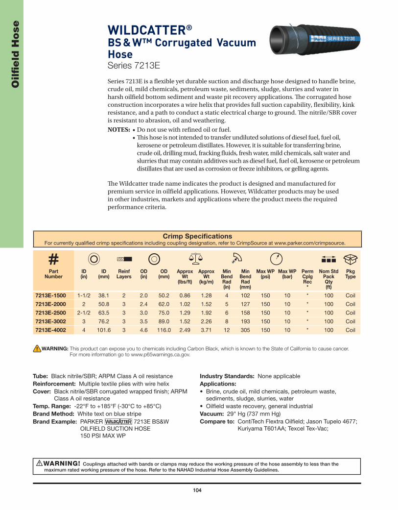
104
Oilfi
eld
Ho
se
104
WILDCATTER®
BS & W™ Corrugated Vacuum HoseSeries 7213E
Series 7213E is a fl exible yet durable suction and discharge hose designed to handle brine, crude oil, mild chemicals, petroleum waste, sediments, sludge, slurries and water in harsh oilfi eld bottom sediment and waste pit recovery applications. Th e corrugated hose construction incorporates a wire helix that provides full suction capability, fl exibility, kink resistance, and a path to conduct a static electrical charge to ground. Th e nitrile/SBR cover is resistant to abrasion, oil and weathering.
NOTES: • Do not use with refi ned oil or fuel. • Th is hose is not intended to transfer undiluted solutions of diesel fuel, fuel oil,
kerosene or petroleum distillates. However, it is suitable for transferring brine, crude oil, drilling mud, fracking fl uids, fresh water, mild chemicals, salt water and slurries that may contain additives such as diesel fuel, fuel oil, kerosene or petroleum distillates that are used as corrosion or freeze inhibitors, or gelling agents.
Th e Wildcatter trade name indicates the product is designed and manufactured for premium service in oilfi eld applications. However, Wildcatter products may be used in other industries, markets and applications where the product meets the required performance criteria.
Crimp Specifi cationsFor currently qualifi ed crimp specifi cations including coupling designation, refer to CrimpSource at www.parker.com/crimpsource.
Part Number
ID(in)
ID (mm)
ReinfLayers
OD (in)
OD(mm)
Approx Wt
(lbs/ft)
Approx Wt
(kg/m)
MinBendRad(in)
MinBendRad(mm)
Max WP (psi)
Max WP (bar)
PermCplgRec
*
Nom Std Pack Qty(ft)
Pkg Type
7213E-1500 1-1/2 38.1 2 2.0 50.2 0.86 1.28 4 102 150 10 * 100 Coil
7213E-2000 2 50.8 3 2.4 62.0 1.02 1.52 5 127 150 10 * 100 Coil
7213E-2500 2-1/2 63.5 3 3.0 75.0 1.29 1.92 6 158 150 10 * 100 Coil
7213E-3002 3 76.2 3 3.5 89.0 1.52 2.26 8 193 150 10 * 100 Coil
7213E-4002 4 101.6 3 4.6 116.0 2.49 3.71 12 305 150 10 * 100 Coil
WARNING! Couplings attached with bands or clamps may reduce the working pressure of the hose assembly to less than the maximum rated working pressure of the hose. Refer to the NAHAD Industrial Hose Assembly Guidelines.
!
WARNING: This product can expose you to chemicals including Carbon Black, which is known to the State of California to cause cancer.
For more information go to www.p65warnings.ca.gov.
Tube: Black nitrile/SBR; ARPM Class A oil resistanceReinforcement: Multiple textile plies with wire helixCover: Black nitrile/SBR corrugated wrapped fi nish; ARPM
Class A oil resistanceTemp. Range: -22°F to +185°F (-30°C to +85°C)Brand Method: White text on blue stripeBrand Example: PARKER 7213E BS&W
OILFIELD SUCTION HOSE 150 PSI MAX WP
Industry Standards: None applicableApplications:
• Brine, crude oil, mild chemicals, petroleum waste, sediments, sludge, slurries, water
• Oilfi eld waste recovery, general industrialVacuum: 29" Hg (737 mm Hg)Compare to: ContiTech Flextra Oilfi eld; Jason Tupelo 4677;
Kuriyama T601AA; Texcel Tex-Vac;

105
Oilfi
eld
Ho
seWILDCATTER®
Hot Oiler HoseSeries 7301
Series 7301 is a heavy duty, high pressure hose for hot oil at 275°F continuous/300°F intermittent (135°C/149°C). Th e hose construction incorporates multiple wire braids of reinforcement for crush resistance, durability, kink resistance and a path to conduct a static electrical charge to ground. Th e cover is resistant to abrasion, heat, oil and weathering.
Th e Wildcatter trade name indicates the product is designed and manufactured for premium service in oilfi eld applications. However, Wildcatter products may be used in other industries, markets and applications where the product meets the required performance criteria.
Crimp Specifi cationsFor currently qualifi ed crimp specifi cations including coupling designation, refer to CrimpSource at www.parker.com/crimpsource.
Part Number
ID(in)
ID (mm)
ReinfLayers
OD (in)
OD(mm)
Approx Wt
(lbs/ft)
Approx Wt
(kg/m)
MinBendRad(in)
MinBendRad(mm)
Max WP (psi)
Max WP (bar)
PermCplgRec
*
Nom Std Pack Qty(ft)
Pkg Type
7301-1502150 1-1/2 38.1 2 2.1 53.3 1.70 2.53 13 330 2250 155 * 150 Coil
WARNING! Couplings attached with bands or clamps may reduce the working pressure of the hose assembly to less than the maximum rated working pressure of the hose. Refer to the NAHAD Industrial Hose Assembly Guidelines.
!
WARNING: This product can expose you to chemicals including Carbon Black, which is known to the State of California to cause cancer. For
more information go to www.p65warnings.ca.gov.
Tube: Black chloropreneReinforcement: Multiple wire braidsCover: Black chloroprene; perforated wrapped fi nishTemp. Range: -40°F to +275°F/300°F (-40°C to
+135°C/149°C)Brand Method: Red text on black stripeBrand Example: PARKER 7301 HOT OILER
HOSE (ID) 2250 PSI MAX WP TEMP RATING 275°F CONTINUOUS 300°F INTERMITTENT
Design Factor: 3:1
Industry Standards: None applicableApplications:
• Hot asphalt, glue, tar, oil, wax• In-plant transfer; delivery trucks• Construction, general industrial, oilfi eldVacuum: Not recommended

106
Oilfi
eld
Ho
se WILDCATTER®
Multipurpose Fracking HoseSeries 7311N / 7311NXT
Series 7311N/7311NXT is a high pressure oilfi eld stimulation/fracking discharge hose designed to handle oil and refi ned fuels such as biodiesel (to B20 in dedicated service), diesel, ethanol and gasoline, as well as brine, mild chemicals, fracking fl uids, drilling mud, petroleum waste, slurries and water. Th e heavy duty multipurpose hose construction helps to extend service life in multiple applications, and incorporates dual static wires that provide a path to conduct an electrical charge to ground. Th e cover is resistant to abrasion, oil and weathering.
Series 7311NXT features a layer of ultra high molecular weight polyethylene (UHMWPE) bonded to the cover for extreme abrasion resistance and service life.
Th e Wildcatter trade name indicates the product is designed and manufactured for premium service in oilfi eld applications. However, Wildcatter products may be used in other industries, markets and applications where the product meets the required performance criteria.
Crimp Specifi cationsFor currently qualifi ed crimp specifi cations including coupling designation, refer to CrimpSource at www.parker.com/crimpsource.
Part Number
ID(in)
ID (mm)
ReinfLayers
OD (in)
OD(mm)
Approx Wt
(lbs/ft)
Approx Wt
(kg/m)
Max WP (psi)
Max WP (bar)
PermCplgRec
*
Nom Std Pack Qty
(ft)
Pkg Type
7311N-1500 1-1/2 38.1 4 2.0 50.8 0.76 1.13 400 28 * 100 Coil
7311N-2000 2 50.8 4 2.6 66.0 1.16 1.73 400 28 * 100 Coil
7311N-3000 3 76.2 4 3.7 93 1.77 2.64 400 28 * 100 Coil
7311N-4000 4 101.6 4 4.8 121.2 2.61 3.89 400 28 * 100 Coil
7311N-6000 6 152.4 6 7.0 177.8 5.21 7.75 400 28 * 100 Coil
7311NXT-3000 3 76.2 4 3.7 94.7 1.94 2.89 400 28 * 100 Coil
7311NXT-4000 4 101.6 4 4.8 122.7 2.78 4.14 400 28 * 100 Coil
WARNING! Couplings attached with bands or clamps may reduce the working pressure of the hose assembly to less than the maximum rated working pressure of the hose. Refer to the NAHAD Industrial Hose Assembly Guidelines.
!
WARNING: This product can expose you to chemicals including Carbon Black, which is known to the State of California to cause cancer. For
more information go to www.p65warnings.ca.gov.
Tube: Black nitrile; ARPM Class A oil resistanceReinforcement: Multiple textile plies with dual static wiresCover: 7311N: Black nitrile blend; wrapped fi nish
7311NXT: Black nitrile blend; sleek UHMWPE abrasion resistant fi nish
Temp. Range: -40°F to +200°F (-40°C to +93°C)Brand Method: Black text on yellow stripeBrand Example: PARKER (7311N) (7311NXT)
DISCHARGE HOSE 400 PSI WPDesign Factor: 4:1
Industry Standards: None applicableApplications:
• Refi ned fuels, oil• Brine, mild chemicals, fracking fl uids, drilling mud,
petroleum waste, slurries, water• General industrial, oilfi eldVacuum: Not recommended

PetroleumTransfer Hose

108
Pe
tro
leu
m T
ran
sfe
r H
ose WILDCATTER®
Tank Truck HoseSeries 7216E
Series 7216E is a lightweight suction and discharge hose designed to handle oil and refi ned fuels such as biodiesel (to B20 in dedicated service), diesel, ethanol and gasoline. Th e hose construction incorporates a wire helix that provides full suction capability, kink resistance, and a path to conduct a static electrical charge to ground. Th e cover is resistant to abrasion, oil and weathering.
NOTE: Refer to the Refi ned Fuel/Hose Compatibility Table in the Media Compatibility section.
Th e Wildcatter trade name indicates the product is designed and manufactured for premium service in oilfi eld applications. However Wildcatter products may be used in other industries, markets and applications where the product meets the required performance criteria.
Crimp Specifi cationsFor currently qualifi ed crimp specifi cations including coupling designation, refer to CrimpSource at www.parker.com/crimpsource.
Part Number
ID(in)
ID (mm)
ReinfLayers
OD (in)
OD(mm)
Approx Wt
(lbs/ft)
Approx Wt
(kg/m)
MinBendRad(in)
MinBendRad(mm)
Max WP (psi)
Max WP (bar)
PermCplgRec
*
Nom Std Pack Qty(ft)
Pkg Type
7216E-1002 1 25.4 2 1.3 33.0 0.47 0.70 3 76 150 10 43 100 Coil
7216E-1252 1-1/4 38.1 2 1.7 42.4 0.65 0.97 4 102 150 10 43 100 Coil
7216E-1502 1-1/2 38.1 2 2.0 49.8 0.92 1.37 5 127 150 10 43 100 Coil
7216E-2002 2 50.8 2 2.5 63.8 1.10 1.64 6 152 150 10 43 100 Coil
7216E-2502 2-1/2 63.5 2 3.0 76.9 1.55 2.31 7 178 150 10 * 100 Coil
7216E-3002 3 76.2 2 3.7 93.0 2.08 3.10 8 203 150 10 * 100 Coil
7216E-4002 4 102.0 2 4.7 117.5 2.80 4.17 11 279 150 10 * 100 Coil
WARNINGS!Couplings attached with bands or clamps may reduce the working pressure of the hose assembly to less than the maximum rated working
pressure of the hose. Refer to the NAHAD Industrial Hose Assembly Guidelines.Do not use for oil or fuel transfer service in or on open water.
!
WARNING: This product can expose you to chemicals including DEHP, which is known to the State of California to cause cancer and birth
defects or other reproductive harm. For more information go to www.p65warnings.ca.gov.
Tube: Black nitrileReinforcement: Multiple textile plies with dual wire helixCover: Black synthetic rubber; wrapped fi nishTemp. Range: -35°F to +180°F (-37°C to +82°C)Brand Method: Black text on orange stripeBrand Example: PARKER 7216E TANK TRUCK
HOSE 150 PSI MAX WPIndustry Standards: None applicable
Applications:
• Biodiesel (to B20 in dedicated service), diesel, ethanol, gasoline, oil
• In-plant and storage tank transfer• Delivery, transportVacuum: 29" Hg (737 mm Hg)Compare to: Boston Puma; ContiTech Plicord Flexwing
Petroleum; Gates Longhorn; Kuriyama T605AA

109
Pe
tro
leu
m T
ran
sfe
r H
oseTITANFLEX®
Corrugated Tank Truck HoseSeries SWC609 (Black) and
Series SWC609R (Red)
Series SWC609/SWC609R is an extremely fl exible, high pressure suction and discharge hose. Th e corrugated hose construction incorporates a dual wire helix that provides full suction capability, superior kink resistance, minimal force-to bend and a path to conduct a static electrical charge to ground. Th e cover is resistant to abrasion, oil and weathering.
NOTE: Refer to the Refi ned Fuel/Hose Compatibility Table in the Media Compatibility section.
Series SWC609 (Black) and Series SWC609R (Red)
Crimp Specifi cationsFor currently qualifi ed crimp specifi cations including coupling designation, refer to CrimpSource at www.parker.com/crimpsource.
Part Number
SWC609 or SWC609R
ID(in)
ID (mm)
ReinfLayers
OD (in)
OD(mm)
Approx Wt
(lbs/ft)
Approx Wt
(kg/m)
MinBendRad(in)
MinBendRad(mm)
Max WP (psi)
Max WP (bar)
PermCplgRec
*
Nom Std Pack Qty(ft)
Pkg Type
-1250* 1-1/4 31.8 2 1.7 42.9 0.63 0.94 1 33 250 17 * 100 Coil
-1500 1-1/2 38.1 2 2.0 49.5 0.78 1.16 2 38 250 17 43 100 Coil
-2000 2 50.8 2 2.5 62.2 1.00 1.49 2 51 250 17 43 100 Coil
-2500 2-1/2 63.5 2 3.0 76.2 1.44 2.15 3 64 200 14 * 100 Coil
-3000 3 76.2 2 3.6 90.9 1.70 2.53 3 76 200 14 * 100 Coil
-4000 4 101.6 2 4.6 117.5 2.41 3.59 6 152 150 10 * 100 Coil
-6002* 6 152.4 2 6.8 172.2 4.75 7.08 12 305 150 10 * 100 Coil
-8002* 8 203.2 2 8.8 223.3 6.95 10.36 16 406 150 10 * 100 Coil
* Series SWC609 only.
WARNINGS!Couplings attached with bands or clamps may reduce the working pressure of the hose assembly to less than the maximum rated working
pressure of the hose. Refer to the NAHAD Industrial Hose Assembly Guidelines.Do not use for oil or fuel transfer service in or on open water.
!
WARNING: This product can expose you to chemicals including DEHP, which is known to the State of California to cause cancer and birth
defects or other reproductive harm. For more information go to www.p65warnings.ca.gov.
Tube: Black nitrileReinforcement: Multiple textile plies with dual wire helixCover: SWC609: Black nitrile; corrugated wrapped fi nish
SWC609R: Red nitrile; corrugated wrapped fi nishTemp. Range: -40°F to +200°F (-40°C to +93°C)Brand Method: SWC609: Red text on black stripe
SWC609R: White text on red stripeBrand Example: PARKER SERIES SWC609(R) TITANFLEX®
PETROLEUM SUCTION & DISCHARGE HOSE XXX PSI WP
Design Factor: 4:1Industry Standards: None applicableApplications:
• Biodiesel (to B100 in dedicated service), diesel, ethanol, gasoline, oil
• In-plant and storage tank transfer• Delivery, transportVacuum: 29" Hg (737 mm Hg)Compare to: Boston Bobcat; ContiTech Flextra; Gates
Longhorn; Thermoid Transporter

110
Pe
tro
leu
m T
ran
sfe
r H
ose Arctic Translite® Hose
Low Temp/Corrugated Tank Truck HoseSeries SWC325
Series SWC325 is a fl exible, lightweight, low temperature suction and discharge hose. Th e corrugated hose construction incorporates a dual wire helix that provides full suction capability, fl exibility and kink resistance — even in the harshest cold climate conditions — and a path to conduct a static electrical charge to ground. Th e cover is resistant to abrasion, oil and weathering.
NOTE: Refer to the Refi ned Fuel/Hose Compatibility Table in the Media Compatibility section
Crimp Specifi cationsFor currently qualifi ed crimp specifi cations including coupling designation, refer to CrimpSource at www.parker.com/crimpsource.
Part Number
ID(in)
ID (mm)
ReinfLayers
OD (in)
OD(mm)
Approx Wt
(lbs/ft)
Approx Wt
(kg/m)
MinBendRad(in)
MinBendRad(mm)
Max WP (psi)
Max WP (bar)
PermCplgRec
*
Nom Std Pack Qty
(ft)
Pkg Type
SWC325-1500 1-1/2 38.1 2 2.1 52.3 0.97 1.44 4 102 150 10.3 * 100 Coil
SWC325-2000 2 50.8 2 2.6 65.4 1.33 1.98 5 127 150 10.3 * 100 Coil
SWC325-2500 2-1/2 63.5 2 3.2 80.0 1.86 2.77 6 152 150 10.3 * 100 Coil
SWC325-3000 3 76.2 2 3.7 93.8 2.52 3.75 8 203 150 10.3 * 100 Coil
SWC325-4000 4 101.6 2 4.6 117.9 2.93 4.36 10 254 150 10.3 * 100 Coil
SWC325-6000 6 152.4 2 6.8 172.8 5.86 8.72 16 406 125 8.6 * 100 Coil
WARNINGS!Couplings attached with bands or clamps may reduce the working pressure of the hose assembly to less than the maximum rated working
pressure of the hose. Refer to the NAHAD Industrial Hose Assembly Guidelines.
!
WARNING: This product can expose you to chemicals including DEHP, which is known to the State of California to cause cancer and birth
defects or other reproductive harm. For more information go to www.p65warnings.ca.gov.
Tube: Black nitrileReinforcement: Multiple textile plies with dual wire helixCover: Black nitrile; corrugated wrapped fi nishTemp. Range: -67°F to +180°F (-55°C to +82°C)Brand Method: Side 1: White text on blue stripe
Side 2: Solid refl ective silver stripeBrand Example: PARKER SWC325 ARCTIC TRANSLITE®
-67°F LOW-TEMP TANK TRUCK HOSE XXX PSI MAX WP
Design Factor: 4:1
Industry Standards: None applicableApplications:
• Biodiesel (to B100 in dedicated and non-dedicated service), diesel, ethanol, gasoline, oil
• Low temperature in-plant and storage tank transfer• Low temperature delivery, transportVacuum: 29" Hg (737 mm Hg)Compare To: ContiTech LW Arctic Tank Truck

111
Pe
tro
leu
m T
ran
sfe
r H
oseGREEN LABEL™
Corrugated Tank Truck HoseSeries 7705
Series 7705 is a fl exible, medium pressure suction and discharge biodiesel hose. Th e corrugated hose construction incorporates a dual wire helix that provides full suction capability, fl exibility, kink resistance, and a path to conduct a static electrical charge to ground. Th e nitrile/PVC cover is resistant to abrasion, oil and weathering.
NOTE: Refer to the Refi ned Fuel/Hose Compatibility Table in the Media Compatibility section.
Crimp Specifi cationsFor currently qualifi ed crimp specifi cations including coupling designation, refer to CrimpSource at www.parker.com/crimpsource.
Part Number
ID(in)
ID (mm)
ReinfLayers
OD (in)
OD(mm)
Approx Wt
(lbs/ft)
Approx Wt
(kg/m)
MinBendRad(in)
MinBendRad(mm)
Max WP (psi)
Max WP (bar)
PermCplgRec
*
Nom Std Pack Qty(ft)
Pkg Type
7705-1000 1 25.4 2 1.4 36.5 0.55 0.82 2 51 200 14 43 100 Coil
7705-1250 1-1/4 31.8 2 1.7 43.0 0.70 1.04 3 64 200 14 * 100 Coil
7705-1500 1-1/2 38.1 2 2.0 50.0 0.83 1.24 3 76 200 14 43 100 Coil
7705-2000 2 50.8 2 2.4 62.8 1.00 1.49 4 102 200 14 43 100 Coil
7705-2500 2-1/2 63.5 2 3.0 75.0 1.37 2.04 5 127 200 14 * 100 Coil
7705-3000 3 76.2 2 3.5 88.6 1.75 2.61 5 127 200 14 * 100 Coil
7705-4000 4 101.6 2 4.5 115.0 2.33 3.47 6 152 150 10 * 100 Coil
WARNINGS!Couplings attached with bands or clamps may reduce the working pressure of the hose assembly to less than the maximum rated working
pressure of the hose. Refer to the NAHAD Industrial Hose Assembly Guidelines.Do not use for oil or fuel transfer service in or on open water.
!
Tube: Black nitrileReinforcement: Multiple textile plies with dual wire helixCover: Black nitrile/PVC; corrugated wrapped fi nishTemp. Range: -20°F to +180°F (-29°C to +82°C)Brand Method: Black text on green stripeBrand Example: PARKER SERIES 7705 GREEN LABEL™
TANK TRUCK HOSE XXX PSI MAX WPDesign Factor: 4:1
Industry Standards: None applicableApplications:
• Biodiesel (to B100 in dedicated and non-dedicated service), diesel, ethanol, gasoline, oil
• In-plant and storage tank transfer• Delivery, transportVacuum: 29" Hg (737 mm Hg)
WARNING: This product can expose you to chemicals including DEHP, which is known to the State of California to cause cancer and birth
defects or other reproductive harm. For more information go to www.p65warnings.ca.gov.

PVC Hoseand Tubing

PV
C H
ose
an
d T
ub
ing
113
NEXCLEAR®
Clear PVC TubingSeries 100
Series 100 is fl exible PVC tubing featuring a smooth interior that is abrasion resistant and will not impart taste or odor, and allows full-fl ow. Th e clear PVC construction permits visual observation of materials being conveyed. Also provides excellent general industrial service for low pressure air, distilled water, wine and wire harness applications.
(Continued on the following page)
WARNING! Working pressures are at +68°F (+20°C). Higher temperatures reduce the available working pressure. See the PVC and Thermoplastic Temperature/Pressure chart in the Media Compatibility section.
!
WARNING: This product can expose you to chemicals including DEHP, which is known to the State of California to cause cancer and birth
defects or other reproductive harm. For more information go to www.p65warnings.ca.gov.
Tube: Clear PVC, 75A durometerTemp. Range: +25°F to +150°F (-5°C to +65°C)
Working pressures are at +68°F (+20°C). Higher temperatures reduce the available working pressure. See the PVC and Thermoplastic Temperature/Pressure chart in the Media Compatibility section.
Brand Method: Black inkBrand Example: NEXCLEAR® FOOD GRADE PVC TUBING
BY PARKER NEXGEN® (P/N) (ID) X (OD) NSF-51 MAX TEMP 150°F (65C)
Industry Standards:
• FDA ingredients*, NSF 51 certifi ed to 180°F (82°C)***, USP Class VI Rated Materials*
• GSA A-A-52047 Type VI Compliant• EU: Meets requirements and amendments of Resolution
AP(89) for food contactApplications:
• Beverages, potable and pure water, wine• Air, drain, light vacuum, wire harness• General industrial, laboratories, wineriesVacuum: Light

114
PV
C H
ose
an
d T
ub
ing Series 100 — NEXCLEAR® Clear PVC Tubing (Continued)
WARNING: This product can expose you to chemicals including DEHP, which is known to the State of California to cause cancer and birth
defects or other reproductive harm. For more information go to www.p65warnings.ca.gov.
Part Number
ID(in)
ID (mm)
Wall(in)
Wall(mm)
OD (in)
OD(mm)
Approx Wt
(lbs/ft)
Approx Wt
(kg/m)
Max WP@ 68°F
(psi)
Max WP@ 20°C
(bar)
Nom Std Pack Qty
(ft)
Pkg Type
100-01020502 1/16 1.6 0.031 0.8 1/8 3.2 0.02 0.03 50 3 500 Coil
100-02040102 1/8 3.2 0.062 1.6 1/4 6.4 0.02 0.03 65 5 100 Coil
100-03040102
3/16 4.8
0.032 0.8 1/4 6.4 0.02 0.03 50 3 100 Coil
100-03050102 0.062 1.6 5/16 7.9 0.02 0.03 554
100 Coil
100-03060102 0.094 2.4 3/8 9.5 0.04 0.06 60 100 Coil
100-04060102
1/4 6.4
0.062 1.6 3/8 9.5 0.04 0.06 55
4
100 Coil
100-04070102 0.094 2.4 7/16 11.1 0.04 0.06 58 100 Coil
100-04080102 0.125 3.2 1/2 12.7 0.09 0.13 60 100 Coil
100-05070102
5/16 7.9
0.062 1.6 7/16 11.1 0.04 0.06 50 3 100 Coil
100-05080102 0.094 2.4 1/2 12.7 0.07 0.10 554
100 Coil
100-05090102 0.125 3.2 9/16 14.3 0.09 0.13 60 100 Coil
100-060801023/8 9.5
0.062 1.6 1/2 12.7 0.04 0.06 453
100 Coil
100-06090102 0.094 2.4 9/16 14.3 0.07 0.10 50 100 Coil
100-06100102 3/8 9.5 0.125 3.2 5/8 15.9 0.11 0.16 55 4 100 Coil
100-08100102
1/2 12.7
0.062 1.6 5/8 15.9 0.07 0.10 30 2 100 Coil
100-08110102 0.094 2.4 11/16 17.5 0.09 013 403
100 Coil
100-08120102 0.125 3.2 3/4 19.1 0.13 0.19 45 100 Coil
100-10120102
5/8 15.9
0.062 1.6 3/4 19.1 0.07 0.10 25 2 100 Coil
100-10130102 0.094 2.4 13/16 20.6 0.11 0.16 35 2 100 Coil
100-10140102 0.125 3.2 7/8 22.2 0.15 0.22 40 3 100 Coil
100-12160100
3/4 19.1
0.125 3.2 1 25.4 0.18 0.27 35 2 100 Coil
100-12180100 0.187 4.7 1-1/8 28.6 0.29 0.43 403
100 Coil
100-12200100 0.250 6.4 1-1/4 31.8 0.42 0.63 45 100 Coil
100-14180100 7/8 22.2 0.125 3.2 1-1/8 28.6 0.20 0.30 30 2 100 Coil
100-16200100
1 25.4
0.125 3.2 1-1/4 31.8 0.24 0.36 25
2
100 Coil
100-16220100 0.187 4.7 1-3/8 34.9 0.37 0.55 30 100 Coil
100-16240100 0.250 6.4 1-1/2 38.1 0.53 0.79 35 100 Coil
100-202401001-1/4 31.8
0.125 3.2 1-1/2 38.1 0.29 0.43 20 1 100 Coil
100-20280100 0.250 6.4 1-3/4 44.5 0.62 0.92 40 3 100 Coil
100-243001001-1/2 38.1
0.187 4.7 1-7/8 47.6 0.53 0.79 302
100 Coil
100-24320100 0.250 6.4 2 50.8 0.73 1.09 35 100 Coil
100-32400100 2 50.8 0.250 6.4 2-1/2 63.5 0.93 1.39 30 2 100 Coil
* All compound ingredients used in this tubing are listed in the US FDA CFR, Title 21. Tubing NSF 51 Listed. Compound USP Class VI rated.

115
PV
C H
ose
an
d T
ub
ingPVC General Purpose Hose
Series GPH™
Series GPH is a versatile, fl exible and lightweight PVC hose.Th e multiple plies of textile reinforcement provide strength and fl exibility, and the fl ame resistant cover is also resistant to abrasion, mild chemicals, ultraviolet light and weathering. Th e hose is electrically nonconductive with a minimum resistance of one megaohm per inch at 1000 volts DC.
NOTES: • Th e user must determine if the hose is suitable for applications subject to electrical hazard. Contact Parker for additional information. • Series GPH does not contain red phosphorous.
(Continued on the following page)
Other cover colors available:
GPH-BLU
GPH-YEL
WARNINGS!Couplings attached with bands or clamps may reduce the working pressure of the hose assembly to less than the maximum rated working
pressure of the hose. Refer to the NAHAD Industrial Hose Assembly Guidelines. Working pressures are at +68°F (+20°C). Higher temperatures reduce the available working pressure. See the PVC and Thermoplastic
Temperature/Pressure chart in the Media Compatibility section.
!
!
WARNING: This product can expose you to chemicals including N-Methylpyrrolidone, which is known to the State of California to cause
birth defects or other reproductive harm. For more information go to www.p65warnings.ca.gov.
Tube: Black PVCReinforcement: Multiple textile pliesCover: Black, blue, gray, red or yellow PVC; perforated
smooth fi nishTemp. Range: -15°F to +150°F (-25°C to +65°C).
Working pressures are at +68°F (+20°C) ambient temperature. Higher temperatures reduce the available working pressure. See the PVC and Thermoplastic Temperature/Pressure chart in the Media Compatibility section.
Brand Method: White ink on black, blue and red hoseBlack ink on gray and yellow hose
Brand Example: PARKER GPH – (dash ID) – (fraction ID) – XXX PSI – GENERAL PURPOSE
Design Factor: 4:1Industry Standards: Electrically nonconductive with a
minimum resistance of one megaohm per inch at 1000 volts DC
Applications:
• Air (including oil mist), mild chemicals, water• Agriculture, construction, general industrialVacuum: See table on the following pageCompare to: Boston Polyforce II; ContiTech Pliovic 300

116
PV
C H
ose
an
d T
ub
ing Series GPH™ – PVC General Purpose Hose (Continued)
Crimp Specifi cationsFor currently qualifi ed crimp specifi cations including coupling designation, refer to CrimpSource at www.parker.com/crimpsource.
Part Number
ID(in)
ID (mm)
ReinfLayers
OD (in)
OD(mm)
Approx Wt
(lbs/ft)
Approx Wt
(kg/m)
MinBendRad(in)
MinBendRad(mm)
Max WP
@ 68°F (psi)
Max WP
@ 20°C(bar)
Vacuum Hg(in)
PermCplgRec
*
Nom Std Pack
Qty(ft)
Pkg Type
GPH-3GRA500RL 3/16 4.8 2 0.4 10.2 0.06 0.09 1 15 300 21 25 * 500 Coil
GPH-4BLK500RL
1/4 6.4 2 0.5 13.0 0.08 0.12 1 20 300 21 23 HY 500 Coil
GPH-4BLU500RL
GPH-4GRA500RL
GPH-4RED500RL
GPH-4YEL500RL
GPH-5GRA500 5/16 7.9 2 0.6 14.0 0.09 0.13 1 20 300 21 23 * 500 Coil
GPH-6BLK500RL
3/8 9.5 2 0.6 16.3 0.12 0.18 1 25 300 21 23 HY 500 Coil
GPH-6BLU500RL
GPH-6GRA500RL
GPH-6RED500RL
GPH-6YEL500RL
GPH-8BLK500RL
GPH-8BLU500RL
1/2 12.7 2 0.8 20.3 0.17 0.25 2 38 300 21 17 HY 500 CoilGPH-8GRA500RL
GPH-8RED500RL
GPH-8YEL500RL
GPH-10BLK250
5/8 15.9 2 0.9 23.1 0.22 0.33 3 64 300 21 10 HY 250 CoilGPH-10GRA250
GPH-10RED250
GPH-12BLK100
3/4 19.1 2 1.1 27.2 0.25 0.37 3 71 300 21 10 HY 100 CoilGPH-12BLU100
GPH-12GRA100
GPH-12RED100
GPH-16BLK1001 25.4 2 1.3 33.8 0.36 0.54 4 102 250 17 5 HY 100 Coil
GPH-16RED100
WARNING: This product can expose you to chemicals including N-Methylpyrrolidone, which is known to the State of California to cause
birth defects or other reproductive harm. For more information go to www.p65warnings.ca.gov.

117
PV
C H
ose
an
d T
ub
ingNEXBRAID®
Clear PVC HoseSeries 125 (Standard Wall) and
Series 126 (Heavy Duty)
Series 125 (standard wall) and Series 126 (thick wall) are fl exible PVC transfer hoses for dry abrasive materials such as grains, granules, pellets and powders; beverages and potable water; non-fatty and non-oily foods; and sanitary products. Th e hoses feature a smooth tube that is abrasion resistant and will not impart taste or odor, and allows full-fl ow, while the clear PVC construction permits visual observation of materials being conveyed. Series 125 and Series 126 also provide excellent general industrial service in air breathing supply pneumatics, fl exible conduit, harness and light vacuum applications.
(Continued on the following page)
WARNINGS!Couplings attached with bands or clamps may reduce the working pressure of the hose assembly to less than the maximum rated working
pressure of the hose. Refer to the NAHAD Industrial Hose Assembly Guidelines. Working pressures are at +68°F (+20°C). Higher temperatures reduce the available working pressure. See the PVC and Thermoplastic
Temperature/Pressure chart in the Media Compatibility section.
!
!
Tube: Clear PVCReinforcement: Multiple textile pliesCover: Blue tint PVC; smooth fi nishTemp. Range: +25°F to +150°F (-5°C to +65°C)
Working pressures are at +68°F (+20°C). Higher temperatures reduce the available working pressure. See the PVC and Thermoplastic Temperature/Pressure chart in the Media Compatibility section.
Brand Method: Black inkBrand Example: Series 125: NEXBRAID® SW FOOD
GRADE PVC BY PARKER NEXGEN® (P/N) (ID) MAX WP XXX PSI AT 68°F (20°C) NSF-51 MAX TEMP 150°F (65°C)
Series 126: NEXBRAID® HD FOOD GRADE PVC BY PARKER NEXGEN® (P/N) (ID) MAX WP XXX PSI AT 68°F (20°C) NSF-51 MAX TEMP 150°F (65°C)
Industry Standards:
• FDA ingredients**, NSF 51 certifi ed to 180°F (82°C)**, USP Class VI Rated**
• EU: Meets requirements and amendments of Resolution AP(89) for food contact
Applications:
• Beverages, potable water, pure water• Dry abrasive materials, fl our, grains, granules, pellets,
powders, sugar• Air, fl exible conduit, light vacuum, wire harnessVacuum: Light

118
PV
C H
ose
an
d T
ub
ing Series 125 / 126 — NEXBRAID® Clear PVC Hose (Continued)
Crimp Specifi cationsFor currently qualifi ed crimp specifi cations including coupling designation, refer to CrimpSource at www.parker.com/crimpsource.
Series 125 (Standard Wall)
Part Number
ID(in)
ID (mm)
ReinfLayers
OD (in)
OD(mm)
Approx Wt
(lbs/ft)
Approx Wt
(kg/m)
Max WP (psi)
@ 68°F
Max WP (bar)
@ 20°C
PermCplgRec
*
Nom Std Pack Qty
(ft)
Pkg Type
125-03000300 3/16 4.8 2 0.4 9.5 0.05 0.07 250 17 * 300 Coil
125-04000300 1/4 6.4 2 0.4 11.1 0.06 0.09 250 17 * 300 Coil
125-05000300 5/16 7.9 2 0.5 13.3 0.08 0.12 250 17 * 300 Coil
125-06000300 3/8 9.5 2 0.6 15.1 0.09 0.13 225 16 * 300 Coil
125-08000300 1/2 12.7 2 0.8 19.1 0.14 0.21 200 14 * 300 Coil
125-10000300 5/8 15.9 2 0.9 22.2 0.17 0.25 200 14 * 300 Coil
125-12000300 3/4 19.1 2 1.0 26.2 0.22 0.33 150 10 * 300 Coil
125-16000200 1 25.4 2 1.3 33.0 0.31 0.46 125 9 * 200 Coil
125-20000100 1-1/4 31.8 2 1.6 41.3 0.45 0.67 100 7 * 100 Coil
125-24000100 1-1/2 38.1 2 1.9 49.2 0.64 0.95 100 7 * 100 Coil
125-32000100 2 50.8 2 2.5 63.3 0.95 1.42 75 5 * 100 Coil
* All tube compound ingredients used in this hose are listed in the U.S. FDA CFR, Title 21. Hose NSF 51 listed. Compound USP Class VI rated.
Series 126 (Heavy Duty)
Part Number
ID(in)
ID (mm)
ReinfLayers
OD (in)
OD(mm)
Approx Wt
(lbs/ft)
Approx Wt
(kg/m)
Max WP (psi)
@ 68°F
Max WP (bar)
@ 20°C
PermCplgRec
*
Nom Std Pack Qty
(ft)
Pkg Type
126-04000300 1/4 6.4 2 0.5 12.7 0.08 0.12 350 24 * 300 Coil
126-05000300 5/16 7.9 2 0.6 14.3 0.09 0.13 275 19 * 300 Coil
126-06000300 3/8 9.5 2 0.6 15.9 0.11 0.16 250 17 * 300 Coil
126-08000300 1/2 12.7 2 0.8 20.6 0.18 0.27 250 17 * 300 Coil
126-12000200 3/4 19.1 2 1.1 28.5 0.30 0.45 200 14 * 200 Coil
* All tube compound ingredients used in this hose are listed in the U.S. FDA CFR, Title 21. Hose NSF 51 listed. Compound USP Class VI rated.
WARNING: This product can expose you to chemicals including DEHP, which is known to the State of California to cause cancer and birth
defects or other reproductive harm. For more information go to www.p65warnings.ca.gov.
WARNING: This product can expose you to chemicals including DEHP, which is known to the State of California to cause cancer and birth
defects or other reproductive harm. For more information go to www.p65warnings.ca.gov.

119
PV
C H
ose
an
d T
ub
ingGULLY WASHER®
Standard Duty Lay Flat PVC Water Discharge HoseSeries 7541
Series 7541 standard duty lay fl at PVC discharge hose is a lightweight, standard duty hose. Th e lay fl at construction rolls up fl at for easy handling, storage and transportation in agriculture, construction, general industrial and mining applications. Th e cover is resistant to abrasion, mild chemicals, ultraviolet light and weathering.
Part Number
ID(in)
ID (mm)
ReinfLayers
Wall Thickness
(in)
OD (in)
OD(mm)
Approx Wt
(lbs/ft)
Approx Wt
(kg/m)
Max WP (psi)
@ 68°F
Max WP (bar)
@ 20°C
Nom Std Pack Qty
(ft)
Pkg Type
7541-1501 1-1/2 38.1 3 0.055 1.6 40.7 0.14 0.21 70 5 300 Coil
7541-2001 2 50.8 3 0.055 2.1 53.4 0.18 0.27 70 5 300 Coil
7541-2501 2-1/2 63.5 3 0.059 2.6 66.2 0.24 0.36 60 4 300 Coil
7541-3001 3 76.2 3 0.059 3.1 79.0 0.30 0.45 60 4 300 Coil
7541-4001 4 101.6 3 0.059 4.1 104.6 0.36 0.54 60 4 300 Coil
7541-6001 6 152.4 3 0.071 6.1 156.0 0.71 1.06 45 3 300 Coil
7541-8001 8 204.0 3 0.083 8.1 206.8 1.28 1.91 45 3 300 Coil
WARNINGS!Couplings attached with bands or clamps may reduce the working pressure of the hose assembly to less than the maximum rated working
pressure of the hose. Refer to the NAHAD Industrial Hose Assembly Guidelines. Working pressures are at +68°F (+20°C). Higher temperatures reduce the available working pressure. See the PVC and Thermoplastic
Temperature/Pressure chart in the Media Compatibility section.
!
!
WARNING: This product can expose you to chemicals including DEHP, which is known to the State of California to cause cancer and birth
defects or other reproductive harm. For more information go to www.p65warnings.ca.gov.
Tube: Black PVC (not oil resistant)Reinforcement: Multiple textile pliesCover: Blue PVCTemp. Range: -5°F to +170°F (-20°C to +76°C)
Working pressures are at +68°F (+20°C). Higher temperatures reduce the available working pressure. See the PVC and Thermoplastic Temperature/Pressure chart in the Media Compatibility section.
Brand Method: White inkBrand Example: PARKER SERIES 7541 GULLY WASHER
(ID) XXX PSI WPDesign Factor: 3:1
Industry Standards: None applicableApplications:
• Mild chemicals, water• Agriculture, construction, general industrial, miningVacuum: Not recommendedCompare to: ContiTech Spiralfl ex; Gates Master-Flex
500; Kanafl ex 4501, 4502; Kuriyama NuFlo, VinylFlow; Petzetakis 11252; Sun-Flow SF-10; Superfl ex DH

120
PV
C H
ose
an
d T
ub
ing GULLY WASHER®
Medium Duty Lay Flat PVC Water Discharge HoseSeries 7542
Series 7542 medium duty lay fl at PVC discharge hose is a lightweight, medium duty hose. Th e lay fl at construction rolls up fl at for easy handling, storage and transportation in agriculture, construction, general industrial and mining applications. Th e red fl ame resistant cover meets MSHA requirements and is also resistant to abrasion, mild chemicals, ultraviolet light and weathering.
Part Number
ID(in)
ID (mm)
ReinfLayers
Wall Thickness
(in)
OD (in)
OD(mm)
Approx Wt
(lbs/ft)
Approx Wt
(kg/m)
Max WP@ 68°F
(psi)
Max WP@ 20°C
(bar)
Nom Std Pack Qty
(ft)
Pkg Type
7542-1501 1-1/2 38.1 3 0.075 1.7 42.1 0.23 0.34 150 10 300 Coil
7542-2001 2 50.8 3 0.079 2.2 55.0 0.30 0.45 150 10 300 Coil
7542-2501 2-1/2 63.5 3 0.083 2.7 68.1 0.37 0.55 150 10 300 Coil
7542-3001 3 76.2 3 0.091 3.2 80.8 0.46 0.69 150 10 300 Coil
7542-4001 4 101.6 3 0.098 4.2 106.8 0.66 0.98 140 10 300 Coil
7542-6001 6 152.4 3 0.106 6.2 158.2 1.02 1.52 100 7 300 Coil
7542-8001 8 203.2 3 0.118 8.2 209.3 1.51 2.25 80 6 300 Coil
WARNINGS!Couplings attached with bands or clamps may reduce the working pressure of the hose assembly to less than the maximum rated working
pressure of the hose. Refer to the NAHAD Industrial Hose Assembly Guidelines. Working pressures are at +68°F (+20°C). Higher temperatures reduce the available working pressure. See the PVC and Thermoplastic
Temperature/Pressure chart in the Media Compatibility section.
!
!
WARNING: This product can expose you to chemicals including DEHP, which is known to the State of California to cause cancer and birth
defects or other reproductive harm. For more information go to www.p65warnings.ca.gov.
Tube: Black PVC (not oil resistant)Reinforcement: Multiple textile pliesCover: Red PVCTemp. Range: -5°F to +170°F (-20°C to +76°C)
Working pressures are at +68°F (+20°C). Higher temperatures reduce the available working pressure. See the PVC and Thermoplastic Temperature/Pressure chart in the Media Compatibility section.
Brand Method: White inkBrand Example: SERIES 7542 GULLY WASHER (ID) XXX
PSI WP FLAME RESISTANT US MSHA IC-257/0
Design Factor: 3:1Industry Standards: MSHAApplications:
• Mild chemicals, water• Agriculture, construction, general industrial, miningVacuum: Not recommendedCompare to: Jason 4510; Kuriyama Ironsides; Petzetakis
11298; Sun-Flow SF-30, SF-50

Steam Hose

122
Ste
am
Ho
se DRAGON BREATH® IIChlorobutyl Barber Pole Steam HoseNon-Skive E-Z CrimpSeries 7285
Series 7285 is a distinctive hose designed for long-lasting steam service—one of the toughest applications for hose, where the hot-cold/wet-dry cycling attacks rubber compounds externally as well as internally. Th e hose construction incorporates a premium, high-performance chlorobutyl tube which resists heat and popcorning, and a wire braid reinforcement for crush-resistant durability, kink resistance and a path to conduct a static electrical charge to ground. Th e EPDM cover resists abrasion, cracking, hardening and ozone, and the red/black barber pole cover provides color-coded identifi cation from all angles and great distances. Series 7285 is qualifi ed with Parker non-skive crimp couplings for easy and quick assembly fabrication as well as maintenance-free service.
Crimp Specifi cationsFor currently qualifi ed crimp specifi cations including coupling designation, refer to CrimpSource at www.parker.com/crimpsource.
Part Number
ID(in)
ID (mm)
ReinfLayers
OD (in)
OD(mm)
Approx Wt
(lbs/ft)
Approx Wt
(kg/m)
MinBendRad(in)
MinBendRad(mm)
Max WP (psi)*
Max WP (bar)*
PermCplgRec
*
Nom Std Pack Qty(ft)
Pkg Type
7285-502 1/2 12.7 2 1.0 26.2 0.50 0.75 7.0 178 261 18 * 50 Carton
7285-752 3/4 19.1 2 1.3 32.6 0.64 0.95 9.5 241 261 18 CS 50 Carton
7285-1002 1 25.4 2 1.6 39.3 0.81 1.21 12.0 305 261 18 CS 50 Carton
* 261 psi saturated steam; 250 psi superheated steam • 18 bar saturated steam; 17 bar superheated steam
WARNINGS!Failure to properly inspect, maintain, test and use steam hose assemblies may result in property damage, personal injury or death. Refer to
ARPM publication IP-11-1, “Guide for Use, Testing and Inspection of Steam Hose.” Water changes to hot water and phases of steam when subjected to heat and pressure. The greater the pressure, the higher the
temperature required to achieve and maintain a steam phase. If steam escapes, dangerous quantities of heat may be released very suddenly. Exposure to hot water, low pressure steam and high pressure steam may cause severe scalding or fatal burns.
Use only hoses designated for steam service for steam applications. Prior to use with detergents or rust inhibitors, refer to the chemical guide in this catalog or contact Parker.Drain steam hose after each use to reduce the possibility of hose popcorning while in service.Couplings attached with bands or clamps may reduce the working pressure of the hose assembly to less than the maximum rated working
pressure of the hose. Refer to the NAHAD Industrial Hose Assembly Guidelines.
!
WARNING: This product can expose you to chemicals including Carbon Black, which is known to the State of California to cause cancer. For
more information go to www.p65warnings.ca.gov.
Tube: Black chlorobutylReinforcement: Multiple wire braidsCover: Black and red EPDM in alternating spirals;
perforated wrapped fi nishTemp. Range: -40°F to +406°F saturated steam/+450°F
superheated steam(-40°C to +208°C saturated steam/+232°C superheated steam)
Brand Method: EmbossedBrand Example: PARKER SERIES 7285 DRAGON BREATH®
II STEAM HOSE 250 PSI MAX WP
Design Factor: 20:1Industry Standards: ISO 6134 Type 2Applications:
• Saturated and superheated steam• Cleaning containment vessels and manufacturing
equipment; cleaning and heating process equipment• Manufacturing and processing plants, refi neriesVacuum: Not recommendedCompare to: Boston Concord Standard Steam—Spiral
Stripe, Steam Slayer; Goodall N2711 Inferno Steam

123
Ste
am
Ho
seSTEAM-LANCE® 250EPDM Compact Steam HoseNon-Skive E-Z CrimpSeries 7263C
Series 7263C is a compact, slim profi le hose for long-lasting steam service, one of the toughest applications for hose, where the hot-cold/wet-dry cycling attacks rubber compounds externally as well as internally. Th e hose construction incorporates an EPDM tube that resists heat and popcorning, and a wire braid reinforcement for crush-resistant durability, kink resistance and a path to conduct a static electrical charge to ground. Th e EPDM cover is resistant to abrasion, cracking, hardening and ozone. Series 7263C is qualifi ed with Parker non-skive crimp couplings for easy and quick assembly fabrication as well as maintenance-free service.
WARNINGS!Failure to properly inspect, maintain, test and use steam hose assemblies may result in property damage, personal injury or death. Refer to
ARPM publication IP-11-1, “Guide for Use, Testing and Inspection of Steam Hose.” Water changes to hot water and phases of steam when subjected to heat and pressure. The greater the pressure, the higher the
temperature required to achieve and maintain a steam phase. If steam escapes, dangerous quantities of heat may be released very suddenly. Exposure to hot water, low pressure steam and high pressure steam may cause severe scalding or fatal burns.
Use only hoses designated for steam service for steam applications.Prior to use with detergents or rust inhibitors, refer to the chemical guide in this catalog or contact Parker.Drain steam hose after each use to reduce the possibility of hose popcorning while in service.Couplings attached with bands or clamps may reduce the working pressure of the hose assembly to less than the maximum rated working
pressure of the hose. Refer to the NAHAD Industrial Hose Assembly Guidelines.
!
Crimp Specifi cationsFor currently qualifi ed crimp specifi cations including coupling designation, refer to CrimpSource at www.parker.com/crimpsource.
Series 7263C
Part Number
ID(in)
ID (mm)
ReinfLayers
OD (in)
OD(mm)
Approx Wt
(lbs/ft)
Approx Wt
(kg/m)
MinBendRad(in)
MinBendRad(mm)
Max WP (psi)*
Max WP (bar)*
PermCplgRec
*
Nom Std Pack
Qty(ft)
Pkg Type
7263C-502 1/2 12.7 2 1.0 24.1 0.37 0.55 7 178 261 18 * 50 Carton
7263C-1002 1 25.4 2 1.5 37.3 0.63 0.94 12 305 261 18 CS 50 Carton
* 261 psi saturated steam; 250 psi superheated steam • 18 bar saturated steam; 17 bar superheated steam
WARNING: This product can expose you to chemicals including Carbon Black, which is known to the State of California to cause cancer. For
more information go to www.p65warnings.ca.gov.
Tube: Black EPDMReinforcement: Multiple wire braidsCover: Black or red EPDM; perforated wrapped fi nishTemp. Range: -40°F to +406°F saturated steam/+450°F
superheated steam(-40°C to +208°C saturated steam/+232°C superheated steam)
Brand Method: EmbossedBrand Example: PARKER SERIES (7263C) STEAM-LANCE®
E-Z CRIMP 250 PSI MAX WPDesign Factor: 20:1
Industry Standards: ISO 6134 Type 2Applications:
• Saturated and superheated steam• Cleaning containment vessels and manufacturing
equipment; cleaning and heating process equipment• Manufacturing and processing plants, refi neriesVacuum: Not recommendedCompare to: Boston Concord 250; ContiTech Flexsteel 250
Steam; Gates 205MB Steam King; Goodall N2576 Thermofl ex; Thermoid Burstproof Regular

124
Ste
am
Ho
se STEAM-LANCE® 250EPDM Compact Steam HoseNon-Skive E-Z CrimpSeries 7264C
Series 7264C is a compact, slim profi le hose for long-lasting steam service, one of the toughest applications for hose, where the hot-cold/wet-dry cycling attacks rubber compounds externally as well as internally. Th e hose construction incorporates an EPDM tube that resists heat and popcorning, and a wire braid reinforcement for crush-resistant durability, kink resistance and a path to conduct a static electrical charge to ground. Th e EPDM cover is resistant to abrasion, cracking, hardening and ozone; the red cover provides color-coded identifi cation. Series 7264C is qualifi ed with Parker non-skive crimp couplings for easy and quick assembly fabrication as well as maintenance-free service.
WARNINGS!Failure to properly inspect, maintain, test and use steam hose assemblies may result in property damage, personal injury or death. Refer to
ARPM publication IP-11-1, “Guide for Use, Testing and Inspection of Steam Hose.” Water changes to hot water and phases of steam when subjected to heat and pressure. The greater the pressure, the higher the
temperature required to achieve and maintain a steam phase. If steam escapes, dangerous quantities of heat may be released very suddenly. Exposure to hot water, low pressure steam and high pressure steam may cause severe scalding or fatal burns.
Use only hoses designated for steam service for steam applications.Prior to use with detergents or rust inhibitors, refer to the chemical guide in this catalog or contact Parker.Drain steam hose after each use to reduce the possibility of hose popcorning while in service.Couplings attached with bands or clamps may reduce the working pressure of the hose assembly to less than the maximum rated working
pressure of the hose. Refer to the NAHAD Industrial Hose Assembly Guidelines.
!
Crimp Specifi cationsFor currently qualifi ed crimp specifi cations including coupling designation, refer to CrimpSource at www.parker.com/crimpsource.
Series 7264C
Part Number
ID(in)
ID (mm)
ReinfLayers
OD (in)
OD(mm)
Approx Wt
(lbs/ft)
Approx Wt
(kg/m)
MinBendRad(in)
MinBendRad(mm)
Max WP (psi)*
Max WP (bar)*
PermCplgRec
*
Nom Std Pack
Qty(ft)
Pkg Type
7264C-752 3/4 19.1 2 1.2 30.5 0.47 0.70 9 229 261 18 CS 50 Carton
* 261 psi saturated steam; 250 psi superheated steam • 18 bar saturated steam; 17 bar superheated steam
WARNING: This product can expose you to chemicals including Carbon Black, which is known to the State of California to cause cancer. For
more information go to www.p65warnings.ca.gov.
Tube: Black EPDMReinforcement: Multiple wire braidsCover: Black or red EPDM; perforated wrapped fi nishTemp. Range: -40°F to +406°F saturated steam/+450°F
superheated steam(-40°C to +208°C saturated steam/+232°C superheated steam)
Brand Method: EmbossedBrand Example: PARKER SERIES (7264C) STEAM-LANCE®
E-Z CRIMP 250 PSI MAX WPDesign Factor: 20:1Industry Standards: ISO 6134 Type 2
Applications:
• Saturated and superheated steam• Cleaning containment vessels and manufacturing
equipment; cleaning and heating process equipment• Manufacturing and processing plants, refi neriesVacuum: Not recommendedCompare to: Boston Concord 250; ContiTech Flexsteel 250
Steam; Gates 205MB Steam King; Goodall N2576 Thermofl ex; Thermoid Burstproof Regular

125
Ste
am
Ho
se
Series 7264 (Red) Crimp Specifi cations
For currently qualifi ed crimp specifi cations including coupling designation, refer to CrimpSource at www.parker.com/crimpsource.
Part Number
ID(in)
ID (mm)
ReinfLayers
OD (in)
OD(mm)
Approx Wt
(lbs/ft)
Approx Wt
(kg/m)
MinBendRad(in)
MinBendRad(mm)
Max WP
(psi)*
Max WP
(bar)*
PermCplgRec
*
Nom Std Pack Qty(ft)
Pkg Type
7264-752 3/4 19.1 2 1.3 34.1 0.70 1.04 10 241 261 18 43, CS, * 50 Carton
* 261 psi saturated steam; 250 psi superheated steam • 18 bar saturated steam; 17 bar superheated steam
WARNING: This product can expose you to chemicals including Carbon Black, which is known to the State of California to cause cancer. For
more information go to www.p65warnings.ca.gov.
STEAM-LANCE® 250EPDM Steam HoseSeries 7264 (Red)
Series 7264 is a traditional hose designed for long-lasting steam service, one of the toughest applications for hose, where the hot/cold wet/dry cycling attacks rubber compounds externally as well as internally. Th e hose construction incorporates an EPDM tube that resists heat and popcorning, and a wire braid reinforcement for crush-resistant durability, kink resistance and a path to conduct a static electrical charge to ground. Th e EPDM cover is resistant to abrasion, cracking, hardening and ozone; the red cover of 7264 provides color-coded identifi cation.
Tube: Black EPDMReinforcement: Multiple wire braidsCover: Black or red EPDM; perforated wrapped fi nishTemp. Range: -40°F to +406°F saturated steam/+450°F
superheated steam (-40°C to +208°C saturated steam/+232°C superheated steam)
Brand Method: EmbossedBrand Example: PARKER SERIES (7264) STEAM-LANCE®
250 PSI MAX WPDesign Factor: 10:1 (20:1 for 1/2", 3/4" and 1" sizes only)Industry Standards: ISO 6134 Type 2
Applications:
• Saturated and superheated steam• Cleaning containment vessels and manufacturing
equipment; cleaning and heating process equipment• Manufacturing and processing plants, refi neriesVacuum: Not recommendedCompare to: Boston Concord 250; ContiTech Flexsteel 250
Steam; Gates 205MB Steam King; Goodall N2576 Thermofl ex; Thermoid Burstproof Regular

126
Ste
am
Ho
se STEAM-LANCE® 250EPDM Steam HoseSeries 7263/7263(E)
Series 7263/7263(E) is a traditional hose designed for long-lasting steam service, one of the toughest applications for hose, where the hot/cold wet/dry cycling attacks rubber compounds externally as well as internally. Th e hose construction incorporates an EPDM tube that resists heat and popcorning, and a wire braid reinforcement for crush-resistant durability, kink resis-tance and a path to conduct a static electrical charge to ground. Th e EPDM cover is resistant to abrasion, cracking, hardening and ozone.
WARNINGS!Failure to properly inspect, maintain, test and use steam hose assemblies may result in property damage, personal injury or death. Refer to
ARPM publication IP-11-1, “Guide for Use, Testing and Inspection of Steam Hose.” Water changes to hot water and phases of steam when subjected to heat and pressure. The greater the pressure, the higher the
temperature required to achieve and maintain a steam phase. If steam escapes, dangerous quantities of heat may be released very suddenly. Exposure to hot water, low pressure steam and high pressure steam may cause severe scalding or fatal burns.
Use only hoses designated for steam service for steam applications.Prior to use with detergents or rust inhibitors, refer to the chemical guide in this catalog or contact Parker.Drain steam hose after each use to reduce the possibility of hose popcorning while in service.Couplings attached with bands or clamps may reduce the working pressure of the hose assembly to less than the maximum rated working
pressure of the hose. Refer to the NAHAD Industrial Hose Assembly Guidelines.
WARNING: This product can expose you to chemicals including Carbon Black, which is known to the State of California to cause cancer. For
more information go to www.p65warnings.ca.gov.
Tube: Black EPDMReinforcement: Multiple wire braidsCover: Black or red EPDM; perforated wrapped fi nishTemp. Range: -40°F to +406°F saturated steam/+450°F
superheated steam (-40°C to +208°C saturated steam/+232°C superheated steam)
Brand Method: EmbossedBrand Example: PARKER SERIES 7263/7263E STEAM-
LANCE® 250 PSI MAX WPDesign Factor: 10:1 (20:1 for 1/2", 3/4" and 1" sizes only)Industry Standards: ISO 6134 Type 2
Applications:
• Saturated and superheated steam• Cleaning containment vessels and manufacturing
equipment; cleaning and heating process equipment• Manufacturing and processing plants, refi neriesVacuum: Not recommendedCompare to: Boston Concord 250; ContiTech Flexsteel 250
Steam; Gates 205MB Steam King; Goodall N2576 Thermofl ex; Thermoid Burstproof Regular
Crimp Specifi cationsFor currently qualifi ed crimp specifi cations including coupling designation, refer to CrimpSource at www.parker.com/crimpsource.
Series 7263(E) (Black)
Part Number
ID(in)
ID (mm)
ReinfLayers
OD (in)
OD(mm)
Approx Wt
(lbs/ft)
Approx Wt
(kg/m)
MinBendRad(in)
MinBendRad(mm)
Max WP (psi)*
Max WP (bar)*
PermCplgRec
*
Nom Std Pack Qty(ft)
Pkg Type
7263-502 1/2 12.7 2 1.0 26.2 0.48 0.72 7 178 261 18 43 50 Carton
7263-752 3/4 19.1 2 1.3 34.1 0.66 0.98 10 241 261 18 43, CS 50 Carton
7263-10021 25.4 2 1.6 40.5 0.85 1.27 12 305 261 18
CS, 43 50 Carton
7263-1002A CS, 43 500 Reel
7263-1252 1-1/4 31.8 2 1.9 47.6 1.14 1.70 17 419 261 18 71 50 Carton
7263E-1502 1-1/2 38.1 2 2.2 55.6 1.44 2.15 20 508 261 18 43 50 Carton
7263E-2002 2 50.8 2 2.7 67.8 1.76 2.62 25 635 261 18 * 50 Carton
* 261 psi saturated steam; 250 psi superheated steam • 18 bar saturated steam; 17 bar superheated steam

127
Ste
am
Ho
seDRAGON BREATH® 250Oil Resistant Steam HoseSeries 7288
Series 7288 is a traditional oil resistant hose designed for long-lasting steam service, one of the toughest applications for hose, where the hot/cold wet/dry cycling attacks rubber compounds externally as well as internally. Th e hose construction incorporates an EPDM tube that resists heat and popcorning, and a wire braid reinforcement for crush-resistant durability, kink resistance and a path to conduct a static electrical charge to ground. Th e red chloroprene cover is resistant to weathering and oil—an important criteria for oil refi neries and petrochemical plants—and provides color-coded identifi cation.
Crimp Specifi cationsFor currently qualifi ed crimp specifi cations including coupling designation, refer to CrimpSource at www.parker.com/crimpsource.
Part Number
ID(in)
ID (mm)
ReinfLayers
OD (in)
OD(mm)
Approx Wt
(lbs/ft)
Approx Wt
(kg/m)
MinBendRad(in)
MinBendRad(mm)
Max WP (psi)*
Max WP (bar)*
PermCplgRec
*
Nom Std Pack Qty(ft)
Pkg Type
7288-502 1/2 12.7 2 1.0 26.2 0.52 0.77 7 178 261 18 43 50 Carton
7288-752 3/4 19.1 2 1.3 34.1 0.73 1.09 10 241 261 18 CS, 43 50 Carton
* 261 psi saturated steam; 250 psi superheated steam • 18 bar saturated steam; 17 bar superheated steam
WARNINGS!Failure to properly inspect, maintain, test and use steam hose assemblies may result in property damage, personal injury or death. Refer to
ARPM publication IP-11-1, “Guide for Use, Testing and Inspection of Steam Hose.” Water changes to hot water and phases of steam when subjected to heat and pressure. The greater the pressure, the higher the
temperature required to achieve and maintain a steam phase. If steam escapes, dangerous quantities of heat may be released very suddenly. Exposure to hot water, low pressure steam and high pressure steam may cause severe scalding or fatal burns.
Use only hoses designated for steam service for steam applications.Prior to use with detergents or rust inhibitors, refer to the chemical guide in this catalog or contact Parker.Drain steam hose after each use to reduce the possibility of hose popcorning while in service.Couplings attached with bands or clamps may reduce the working pressure of the hose assembly to less than the maximum rated working
pressure of the hose. Refer to the NAHAD Industrial Hose Assembly Guidelines.
!
WARNING: This product can expose you to chemicals including Carbon Black, which is known to the State of California to cause cancer. For
more information go to www.p65warnings.ca.gov.
Tube: Black EPDMReinforcement: Multiple wire braidsCover: ARPM Class B oil resistant red chloroprene;
perforated wrapped fi nishTemp. Range: -40°F to +406°F saturated steam/+450°F
superheated steam (-40°C to +208°C saturated steam/+232°C superheated steam)
Brand Method: EmbossedBrand Example: PARKER SERIES 7288 DRAGON
BREATH® STEAM HOSE 250 PSI MAX WP OIL RESISTANT
Design Factor: 20:1
Industry Standards: ISO 6134 Type 2Applications:
• Saturated and superheated steam• Cleaning containment vessels and manufacturing
equipment; cleaning and heating process equipment• Manufacturing and processing plants, refi neriesVacuum: Not recommendedCompare to: Boston Concord 250 OR; ContiTech Flexsteel
250 ORS; Gates 232MB Steam Queen; Thermoid Burstproof Oil Resistant

128
Ste
am
Ho
se Hydrocarbon Drain HoseOil ResistantNon-Skive E-Z CrimpSeries 7200
Series 7200 is designed to evacuate hot, liquefi ed residue from steam cleaning operations. Th e wire braid reinforcement provides crush-resistant durability, kink resistance and a path to conduct a static electrical charge to ground. Th e vivid blue chloroprene cover is resistant to oil and weathering, and provides color-coded identifi cation. Series 7200 is qualifi ed with Parker non-skive crimp couplings for easy and quick assembly fabrication as well as maintenance-free service.
NOTE: Do not use for steam service.
Crimp Specifi cationsFor currently qualifi ed crimp specifi cations including coupling designation, refer to CrimpSource at www.parker.com/crimpsource.
Part Number
ID(in)
ID (mm)
ReinfLayers
OD (in)
OD(mm)
Approx Wt
(lbs/ft)
Approx Wt
(kg/m)
MinBendRad(in)
MinBendRad(mm)
Max WP (psi)
Max WP (bar)
PermCplgRec
*
Nom Std Pack Qty(ft)
Pkg Type
7200-751050 3/4 19.1 1 1.2 30.1 0.52 0.77 10 241 350 24 43 50 Carton
7200-1001050 1 25.4 1 1.5 38.1 0.76 1.13 12 305 350 24 43 50 Carton
WARNINGS! Use only hoses designated for steam service for steam applications. Couplings attached with bands or clamps may reduce the working pressure of the hose assembly to less than the maximum rated working
pressure of the hose. Refer to the NAHAD Industrial Hose Assembly Guidelines.
!
WARNING: This product can expose you to chemicals including Carbon Black, which is known to the State of California to cause cancer. For
more information go to www.p65warnings.ca.gov.
Tube: Black nitrile; ARPM Class A oil resistanceReinforcement: One wire braidCover: Blue chloroprene; wrapped fi nishTemp. Range: -20°F to +300°F (-29°C to +149°C)/+350°F
(+177°C) intermittentBrand Method: Blue text on green stripeBrand Example: PARKER SERIES 7200 HYDROCARBON
DRAIN HOSE 350 PSI WP Design Factor: 4:1
Industry Standards: None applicableApplications:
• NOT FOR STEAM SERVICE• Drainage of hot residue from steam cleaning operations• Manufacturing and processing plants, refi neriesVacuum: Not recommendedCompare to: Boston Hydrocarbon Drain Hose

Water Hose and Assemblies

130
SUPER-FLEX®
EPDM Water Suction HoseSeries 7392E
Series 7392E is a lightweight suction and discharge hose for water. Th e construction incorporates a wire helix that provides full suction capability and kink resistance. Th e EPDM cover is resistant to abrasion, heat, mild chemicals and weathering.
Crimp Specifi cationsFor currently qualifi ed crimp specifi cations including coupling designation, refer to CrimpSource at www.parker.com/crimpsource.
Part Number
ID(in)
ID (mm)
ReinfLayers
OD (in)
OD(mm)
Approx Wt
(lbs/ft)
Approx Wt
(kg/m)
MinBendRad(in)
MinBendRad(mm)
Max WP (psi)
Max WP (bar)
PermCplgRec
*
Nom Std Pack Qty(ft)
Pkg Type
7392E-1500 1-1/2 38.1 2 1.9 48.0 0.72 1.07 6 152 150 10 * 100 Coil
7392E-2000 2 50.8 2 2.4 62.0 1.08 1.61 7 178 150 10 * 100 Coil
7392E-2500 2-1/2 63.5 2 3.0 74.9 1.45 2.16 8 203 150 10 * 100 Coil
7392E-3000 3 76.2 2 3.5 88.9 1.80 2.68 10 254 150 10 * 100 Coil
7392E-4000 4 107.0 2 4.5 115.1 2.43 3.62 22 559 150 10 * 100 Coil
7392E-6000 6 152.4 4 6.6 168.3 3.71 5.53 30 711 100 10 * 100 Coil
7392E-600020 6 152.4 4 6.6 168.3 3.71 5.53 30 711 100 10 * 20 Coil
WARNING! Couplings attached with bands or clamps may reduce the working pressure of the hose assembly to less than the maximum rated working pressure of the hose. Refer to the NAHAD Industrial Hose Assembly Guidelines.
!
WARNING: This product can expose you to chemicals including Carbon Black, which is known to the State of California to cause cancer. For
more information go to www.p65warnings.ca.gov.
Tube: Black synthetic rubberReinforcement: Multiple textile plies with dual wire helixCover: Black EPDM; wrapped fi nishTemp. Range: -40°F to +180°F (-40°C to +82°C)Brand Method: White text on blue stripeBrand Example: PARKER SERIES 7392E WATER SUCTION
HOSE – XXX PSI MAX WPIndustry Standards: None applicable
Applications:
• Alkalies, brine, glycols, herbicides, mild chemicals, slurries, water
• Agriculture, construction, general industrial, irrigation, surface mining
Vacuum: 29" Hg (737 mm Hg)Compare to: ContiTech Plicord Con-Ag Water S&D; Gates
Barracuda
Wa
ter
Ho
se a
nd
Ass
em
blie
s

131
Wa
ter
Ho
se a
nd
Ass
em
blie
s
131
Lightweight High Pressure Water Jetting HoseSeries SS122
Series SS122 is a lightweight, high pressure, high volume water jetting hose. Th e SBR cover is resistant to abrasion and weathering.
Crimp Specifi cationsFor currently qualifi ed crimp specifi cations including coupling designation, refer to CrimpSource at www.parker.com/crimpsource.
Part Number
ID(in)
ID (mm)
ReinfLayers
OD (in)
OD(mm)
Approx Wt
(lbs/ft)
Approx Wt
(kg/m)
Max WP (psi)
Max WP (bar)
PermCplgRec
*
Nom Std Pack Qty
(ft)
Pkg Type
SS122-1250 1-1/4 31.8 2 1.7 43.7 0.52 0.77 500 35 * 100 Coil
SS122-1500 1-1/2 38.1 2 2.0 50.0 0.63 0.94 500 35 * 100 Coil
SS122-2000 2 50.8 2 2.5 63.0 0.82 1.22 500 35 * 100 Coil
SS122-2500 2-1/2 63.5 4 3.1 78.7 1.28 1.90 500 35 * 100 Coil
SS122-3000 3 76.2 4 3.7 92.7 1.59 2.37 500 35 * 100 Coil
SS122-4000 4 101.6 4 4.7 118.4 2.10 3.13 500 35 * 100 Coil
WARNING! Couplings attached with bands or clamps may reduce the working pressure of the hose assembly to less than the maximum rated working pressure of the hose. Refer to the NAHAD Industrial Hose Assembly Guidelines.
!
WARNING: This product can expose you to chemicals including Carbon Black, which is known to the State of California to cause cancer. For
more information go to www.p65warnings.ca.gov.
Tube: Black SBRReinforcement: Multiple textile pliesCover: Black SBR; wrapped fi nishTemp. Range: -40°F to +180°F (-40°C to +82°C)Brand Method: Black text on blue stripeBrand Example: PARKER SS122 HIGH PRESSURE
JETTING HOSE XXX PSI WP Design Factor: 4:1
Industry Standards: None applicableApplications:
• Slurries, water• Cleaning, stripping, washdown • Construction, general industrial, oilfi eld, shipyardsVacuum: Not recommended

132
STINGER™ IIHigh Pressure Mine and Multipurpose HoseSeries 7268E
Series 7268E is a versatile, high pressure hose commonly used in mining. Th e construction incorporates high tensile wire braid reinforcement that provides durability, kink resistance, high pressure capability, and superior coupling retention. Th e fl ame resistant bright yellow cover meets MSHA requirements and is also resistant to abrasion and oil.
Crimp Specifi cationsFor currently qualifi ed crimp specifi cations including coupling designation, refer to CrimpSource at www.parker.com/crimpsource.
Part Number
ID(in)
ID (mm)
ReinfLayers
OD (in)
OD(mm)
Approx Wt
(lbs/ft)
Approx Wt
(kg/m)
MinBendRad(in)
MinBendRad(mm)
Max WP (psi)
Max WP (bar)
PermCplgRec
*
Nom Std Pack Qty(ft)
Pkg Type
7268E-751
3/4 19.1 1 1.0 26.5 0.34 0.51 6 152 1000 69 HY, 43
524 Reel
7268E-751050 50 Coil
7268E-751100 100 Coil
7268E-1001
1 25.4 1 1.3 34.0 0.50 0.75 8 203 1000 69 HY, 43
524 Reel
7268E-1001050 50 Coil
7268E-1001100 100 Coil
7268E-12510501-1/4 31.8 1 1.6 41.4 0.67 1.00 12 305 1000 69 HY, 43
50 Coil
7268E-1251100 100 Coil
7268E-15010501-1/2 38.1 1 1.9 48.0 0.86 1.28 14 356 1000 69 43
50 Coil
7268E-1501100 100 Coil
7268E-20012 50.8 1 2.4 62.0 1.14 1.70 18 457 1000 69 43
50 Coil
7268E-2001100 100 Coil
WARNING! Couplings attached with bands or clamps may reduce the working pressure of the hose assembly to less than the maximum rated working pressure of the hose. Refer to the NAHAD Industrial Hose Assembly Guidelines.
!
WARNING: This product can expose you to chemicals including Carbon Black, which is known to the State of California to cause cancer. For
more information go to www.p65warnings.ca.gov.
Tube: Black chloropreneReinforcement: One wire braidCover: Yellow nitrile/PVC; perforated wrapped fi nishTemp. Range: -20°F to +212°F (-29°C to +100°C)Brand Method: Embossed (1-1/2" black ink)Brand Example: PARKER SERIES 7268E STINGER II (ID)
1000 PSI MAX WP MSHA #Design Factor: 4:1Industry Standards: MSHA
Applications:
• Air, mild chemicals, oil, water• Heavy duty air tools, compressors; drill hose, dust
suppression in mines• Construction, general industrial, mines and quarriesVacuum: Not recommendedCompare to: Boston Concord Yellow Jack; ContiTech
Minespray, Super Ortac; Gates 1000MP/Mine Spray
Wa
ter
Ho
se a
nd
Ass
em
blie
s

Wa
ter
Ho
se a
nd
Ass
em
blie
s
133133
HURRICANE™Pressure Washer HoseSeries 7258
Series 7258/7258BL hose construction incorporates a high tensile wire braid reinforcement that provides durability, kink resistance and superior coupling retention. Both cover colors are resistant to oil and weathering.
NOTE: Do not use for carpet cleaning or steam service.
Crimp Specifi cationsFor currently qualifi ed crimp specifi cations including coupling designation, refer to CrimpSource at www.parker.com/crimpsource.
Part Number
ID(in)
ID (mm)
ReinfLayers
OD (in)
OD(mm)
Approx Wt
(lbs/ft)
Approx Wt
(kg/m)
MinBendRad(in)
MinBendRad(mm)
Max WP (psi)
Max WP (bar)
PermCplgRec
*
Nom Std Pack Qty(ft)
Pkg Type
7258-250BK 1/4 6.4 1 0.500 12.7 0.14 0.21 2 38 3000 207 HY, 43 500 Reel
7258-380BK 3/8 9.5 1 0.620 15.7 0.19 0.28 2 51 3000 207 HY, 43 500 Reel
7258-501BK 1/2 12.7 1 0.700 18.9 0.23 0.34 3 76 2500 172 HY, 43 500 Reel
7258-250BL 1/4 6.4 1 0.500 12.7 0.14 0.21 2 38 3000 207 43 500 Reel
7258-380BL 3/8 9.5 1 0.620 15.7 0.19 0.28 2 51 3000 207 43 500 Reel
7258-501BL HY, 43
Factory Assemblies: Available from stock in popular confi gurations. Refer to the following page.
WARNING! Couplings attached with bands or clamps may reduce the working pressure of the hose assembly to less than the maximum rated working pressure of the hose. Refer to the NAHAD Industrial Hose Assembly Guidelines.
!
WARNING: This product can expose you to chemicals including Carbon Black, which is known to the State of California to cause cancer. For
more information go to www.p65warnings.ca.gov.
Tube: Black chloropreneReinforcement: One wire braidCover: Black (BK) chloroprene, wrapped fi nish;
Blue (BL) chloroprene; perforated wrapped fi nishTemp. Range: -40°F to +250°F (-40°C to +121°C)Brand Method: White inkBrand Example: PARKER SERIES 7258 HURRICANE™
3000 PSI MAX WPDesign Factor: 4:1 (1/2" @ 3.5:1)Industry Standards: None applicable
Applications:
• Hot water, mild chemicals• Agriculture, construction, general industrial, oilfi eld,
shipyardsVacuum: Not recommendedCompare to: Gates Power Clean

134
HURRICANE™Pressure Washer Hose – Factory AssembliesSeries 7258BK (Black) and 7258BL (Blue)
Series 7258BK (Black)
Part Number
ID(in)
Length(ft)
Approx Wt
(lbs/ea)
Max WP (psi)
Fitting1
ThreadSize(in)
Fitting2
ThreadSize(in)
Std Pack Qty(ea)
Pkg Type
725825BKRS-600 1/4 50 7.25 3000 101HY-4-4 1/4 - 18 113HY-4-4 1/4 - 18 5 Carton
725838BKRS-600 3/8 50 9.85 3000 10143-6-6 3/8 - 18 11343-6-6 3/8 - 18 5 Carton
Series 7258BL (Blue)
Part Number
ID(in)
Length(ft)
Approx Wt
(lbs/ea)
Max WP (psi)
Fitting1
ThreadSize(in)
Fitting2
ThreadSize(in)
Std Pack Qty(ea)
Pkg Type
725825BLRS-600 1/4 50 7.25 3000 101HY-4-4 1/4 - 18 113HY-4-4 1/4 - 18 5 Carton
725838BLRS-600 3/8 50 9.85 3000 10143-6-6 3/8 - 18 11343-6-6 3/8 - 18 5 Carton
Black Molded PVC Strain Relievers / Bend RestrictorsNOTE: Use only with Series 7258BK / 7258BL
Part Number
HoseID(in)
HoseID
(mm)
Strain Reliever
ID(in)
Strain Reliever
ID(mm)
Length(in)
Length(mm)
Std Pack
Qty(ea)
S81550 1/4 6.4 0.530 13.5 7 177.8 Per Order
S81551 3/8 9.5 0.630 16.0 7 177.8 Per Order
WARNING: This product can expose you to chemicals including Carbon Black, which is known to the State of California to cause cancer. For
more information go to www.p65warnings.ca.gov.
WARNING: This product can expose you to chemicals including Carbon Black, which is known to the State of California to cause cancer. For
more information go to www.p65warnings.ca.gov.
WARNING: This product can expose you to chemicals including Lead, which is known to the State of California to cause cancer and birth defects or other
reproductive harm. For more information go to www.p65warnings.ca.gov.
Temp Range: -40°F to +250°F (-40°C to +121°C)Design Factor: 4:1Crimped-on Carbon Steel Rigid Male x Swivel Male, Black PVC Bend Restrictors Each End
Coiled and Tied, No Center DiscNOTE: Refer to the previous page for bulk hose information.
Wa
ter
Ho
se a
nd
Ass
em
blie
s

135
Wa
ter
Ho
se a
nd
Ass
em
blie
s
135
PWD™High Pressure Washdown HoseSeries 7143
Series 7143 hose construction incorporates textile braided reinforcement for kink resistance and superior coupling retention. Th e non-marking cover is resistant to abrasion, heat, and fatty, oily foods.
NOTE: Do not use for steam service.
Crimp Specifi cationsFor currently qualifi ed crimp specifi cations including coupling designation, refer to CrimpSource at www.parker.com/crimpsource.
Part Number
ID(in)
ID (mm)
ReinfLayers
OD (in)
OD(mm)
Approx Wt
(lbs/ft)
Approx Wt
(kg/m)
MinBendRad(in)
MinBendRad(mm)
Max WP (psi)
Max WP (bar)
PermCplgRec
*
Nom Std Pack Qty(ft)
Pkg Type
7143-382BK
3/8 9.5 2 0.7 18.6 0.20 0.30 4 102 1500 103 HY 700 Reel7143-382GY
7143-382YL
WARNING! Couplings attached with bands or clamps may reduce the working pressure of the hose assembly to less than the maximum rated working pressure of the hose. Refer to the NAHAD Industrial Hose Assembly Guidelines.
!
Other cover colors available:
BK = BLACK
YL = YELLOW
WARNING: This product can expose you to chemicals including Carbon Black, which is known to the State of California to cause cancer.
For more information go to www.p65warnings.ca.gov.
Tube: Black EPDMReinforcement: Multiple textile braidsCover: Black (BK), Gray (GY), Yellow (YL) EPDM; smooth
fi nishTemp. Range: -40°F to +250°F (-40°C to +121°C)Brand Method: Black ink on gray and yellow hose; white ink
on black hoseBrand Example: PARKER SERIES 7143 PWD (ID) XXXX PSI
MAX WPDesign Factor: 3.5:1Industry Standards: None applicable
Applications:
• Hot water, mild chemicals• Breweries, dairies, food/poultry processing plants, general
industrialVacuum: Not recommendedCompare to: Boston Washdown 1250; ContiTech Fortress;
Gates Cyclone

136
ECW™Economy White Washdown HoseSeries 7079
Series 7079 hose construction incorporates multiple plies of textile reinforcement that provide fl exibility, and the white, non-marking cover is resistant to abrasion, heat and ozone.
NOTE: Do not expose to fatty or oily foods. Do not use for steam service.
Crimp Specifi cationsFor currently qualifi ed crimp specifi cations including coupling designation, refer to CrimpSource at www.parker.com/crimpsource.
Part Number
ID(in)
ID (mm)
ReinfLayers
OD (in)
OD(mm)
Approx Wt
(lbs/ft)
Approx Wt
(kg/m)
MinBendRad(in)
MinBendRad(mm)
Max WP (psi)
Max WP (bar)
PermCplgRec
*
Nom Std Pack Qty(ft)
Pkg Type
7079-753043/4 19.1 4 1.2 29.4
0.50 0.755 127 300 21
HY 400 Reel
7079-7530450 0.50 0.75 HY 50 Carton
WARNING! Couplings attached with bands or clamps may reduce the working pressure of the hose assembly to less than the maximum rated working pressure of the hose. Refer to the NAHAD Industrial Hose Assembly Guidelines.
!
WARNING: This product can expose you to chemicals including Carbon Black, which is known to the State of California to cause cancer. For
more information go to www.p65warnings.ca.gov.
Tube: Black EPDMReinforcement: Multiple textile pliesCover: White EPDM; perforated smooth fi nishTemp. Range: -40°F to +212°F (-40°C to +100°C)Brand Method: Black inkBrand Example: PARKER SERIES 7079 ECW™ ECONOMY
WASHDOWN (ID) 300 PSI MAX WPDesign Factor: 4:1
Industry Standards: None applicableApplications:
• Hot water, mild chemicals• Breweries, dairies, food processing plants, general
industrialVacuum: Not recommendedCompare to: ContiTech Sani-Wash 300
Wa
ter
Ho
se a
nd
Ass
em
blie
s

137
Wa
ter
Ho
se a
nd
Ass
em
blie
s
137
HDW™Heavy Duty White Creamery Washdown HoseSeries 7080
Series 7360 hose construction incorporates multiple plies of textile reinforcement that provide fl exibility, and the white, non-marking cover is resistant to abrasion, heat and ozone.
NOTE: Do not expose to fatty or oily foods.
Crimp Specifi cationsFor currently qualifi ed crimp specifi cations including coupling designation, refer to CrimpSource at www.parker.com/crimpsource.
Part Number
ID(in)
ID (mm)
ReinfLayers
OD (in)
OD(mm)
Approx Wt
(lbs/ft)
Approx Wt
(kg/m)
MinBendRad(in)
MinBendRad(mm)
Max WP (psi)
Max WP (bar)
PermCplgRec
*
Nom Std Pack Qty(ft)
Pkg Type
7080-753043/4 19.1 4 1.3 31.8 0.48 0.72 7 165 300 21
HY 400 Reel
7080-7530450 HY 50 Carton
WARNING! Couplings attached with bands or clamps may reduce the working pressure of the hose assembly to less than the maximum rated working pressure of the hose. Refer to the NAHAD Industrial Hose Assembly Guidelines.
!
WARNING: This product can expose you to chemicals including Carbon Black, which is known to the State of California to cause cancer. For
more information go to www.p65warnings.ca.gov.
Tube: Black EPDMReinforcement: Multiple textile pliesCover: White EPDM; perforated smooth fi nishTemp. Range: -40°F to +212°F (-40°C to +100°C)Brand Method: Black inkBrand Example: PARKER SERIES 7080 HDW™
CREAMERY WASHDOWN (ID) 300 PSI MAX WP
Design Factor: 4:1
Industry Standards: None applicableApplications:
• Hot water, mild chemicals• Breweries, dairies, food processing plants, general
industrialVacuum: Not recommendedCompare to: ContiTech Plicord Washdown

Wa
ter
Ho
se a
nd
Ass
em
blie
s
138
White Washdown HoseSeries 7360
Series 7360 hose construction incorporates multiple plies of textile reinforcement that provide fl exibility, and the white, non-marking cover is resistant to abrasion, heat and ozone.
NOTE: Do not expose to fatty or oily foods.
Crimp Specifi cationsFor currently qualifi ed crimp specifi cations including coupling designation, refer to CrimpSource at www.parker.com/crimpsource.
Part Number
ID(in)
ID (mm)
ReinfLayers
OD (in)
OD(mm)
Approx Wt
(lbs/ft)
Approx Wt
(kg/m)
MinBendRad(in)
MinBendRad(mm)
Max WP (psi)
Max WP (bar)
PermCplgRec
*
Nom Std Pack Qty(ft)
Pkg Type
7360-751503/4 19.1 2 1.3 31.8 0.45 0.67 6 152 150 10
* 50 Coil
7360-75150100 * 100 Coil
WARNING! Couplings attached with bands or clamps may reduce the working pressure of the hose assembly to less than the maximum rated working pressure of the hose. Refer to the NAHAD Industrial Hose Assembly Guidelines.
!
WARNING: This product can expose you to chemicals including Carbon Black, which is known to the State of California to cause cancer. For
more information go to www.p65warnings.ca.gov.
Tube: White SBRReinforcement: Multiple textile pliesCover: White SBR; wrapped fi nishTemp. Range: -20°F to +212°F (-29°C to +100°C)Brand Method: White text on blue stripeBrand Example: PARKER SERIES 7360 WASHDOWN
HOSE 150 PSI WPDesign Factor: 4:1
Industry Standards: None applicableApplications:
• Hot water• Breweries, dairies, food processing plants, general
industrial, oil rigs, paper millsVacuum: Not recommendedCompare to: ContiTech Plicord Washdown

139
Wa
ter
Ho
se a
nd
Ass
em
blie
sContractor’s Water Hose – Factory AssembliesSeries 7055 (Black) and
Series 7093CW (Black)
Series 7055 is designed as a lightweight, abrasion and weather resistant hose for general industrial water service. Th e factory-installed, crimped-on lightweight brass couplings provide a secure hose/fi tting interface, and the male and female garden hose ends provide easy, quick and secure connections.
Series 7093CW is designed as a lightweight, abrasion and weather resistant rubber hose for general industrial water service. Th e factory-installed, crimped-on lightweight brass male and female garden hose couplings provide a secure hose/fi tting interface, along with easy, quick and secure connections.
Series 7055 (Black)
Part Number
ID(in)
ID (mm)
Length(ft)
Length(m)
Approx Wt
(lbs/ea)
Approx Wt
(kg/ea)
Max WP (psi)
Max WP (bar)
Std Pack Qty(ea)
Pkg Type
7055GHT63-300 5/8 15.9
25 7.62 4.91 2.23100 7
10 Carton
7055GHT63-600 50 15.24 9.32 4.23 5 Carton
7055GHT75-300 3/4 19.1
25 7.62 7.23 3.28100 7
6 Carton
7055GHT75-600 50 15.24 13.87 6.29 3 Carton
Series 7093CW (Black)
Part Number
ID(in)
ID (mm)
Length(ft)
Length(m)
Approx Wt
(lbs/ea)
Approx Wt
(kg/ea)
Max WP (psi)
Max WP (bar)
Std Pack Qty(ea)
Pkg Type
7093BCWGH-600 3/4 19.1 50 15.24 16.21 7.35 200 14 3 Carton
WARNING: This product can expose you to chemicals including Carbon Black, which is known to the State of California to cause cancer.
For more information go to www.p65warnings.ca.gov.
WARNING: This product can expose you to chemicals including Carbon Black, which is known to the State of California to cause cancer.
For more information go to www.p65warnings.ca.gov.
Temp Range: -40°F to +180°F (-40°C to +82°C)Design Factor: 4:1Crimped-on Brass: Male x Female Garden Hose Thread
Couplings
Coiled and Tied: No Center Disc

140
Wa
ter
Ho
se a
nd
Ass
em
blie
s Softwall Furnace Door Coolant HoseNonconductiveSeries 7385
Series 7385 is an industrial cooling/water hose for worksites that require a hose to withstand extreme external temperatures. Th e durable, heat resistant aramid cover withstands steel splashes and external heat radiation. Th e hose construction is electrically nonconductive with a minimum resistance of one megaohm per inch at 1000 volts DC.
NOTE: Th e user must determine if the hose is suitable for applications subject to electrical hazard. Contact Parker for additional information.
Crimp Specifi cationsFor currently qualifi ed crimp specifi cations including coupling designation, refer to CrimpSource at www.parker.com/crimpsource.
Part Number
ID(in)
ID (mm)
ReinfLayers
OD (in)
OD(mm)
Approx Wt
(lbs/ft)
Approx Wt
(kg/m)
MinBendRad(in)
MinBendRad(mm)
Max WP (psi)
Max WP (bar)
PermCplgRec
*
Nom Std Pack Qty(ft)
Pkg Type
7385-0500 1/2 12.7 2 1.0 24.6 0.33 0.49 5 127 150 10 * 100 Coil
7385-0750 3/4 19.1 2 1.3 32.0 0.49 0.73 6 152 150 10 * 100 Coil
7385-1000 1 25.4 2 1.4 36.6 0.51 0.76 8 203 150 10 * 100 Coil
7385-1250 1-1/4 31.8 2 1.7 43.6 0.66 0.98 9 229 150 10 * 100 Coil
7385-1500 1-1/2 38.1 2 2.1 54.2 1.11 1.65 12 305 150 10 * 100 Coil
7385-2000 2 50.8 4 2.7 68.1 1.38 2.06 24 610 150 10 * 100 Coil
WARNING! Couplings attached with bands or clamps may reduce the working pressure of the hose assembly to less than the maximum rated working pressure of the hose. Refer to the NAHAD Industrial Hose Assembly Guidelines.
!
WARNING: This product can expose you to chemicals including Carbon Black, which is known to the State of California to cause cancer. For
more information go to www.p65warnings.ca.gov.
Tube: Black SBRReinforcement: Multiple textile pliesCover: Off-white aramid fabric; wrapped fi nishTemp. Range: Internal: -20°F to +212°F (-29°C to +100°C) External: to +572°F (+300°C)Brand Method: Not brandedDesign Factor: 4:1Industry Standards: Nonconductive
Applications:
• Hot water• Furnaces and industrial cooling systems• Foundries, glassworks, steel millsVacuum: Not recommendedCompare to: ContiTech Plicord Furnace Door; Kuriyama
Furnace Door Coolant
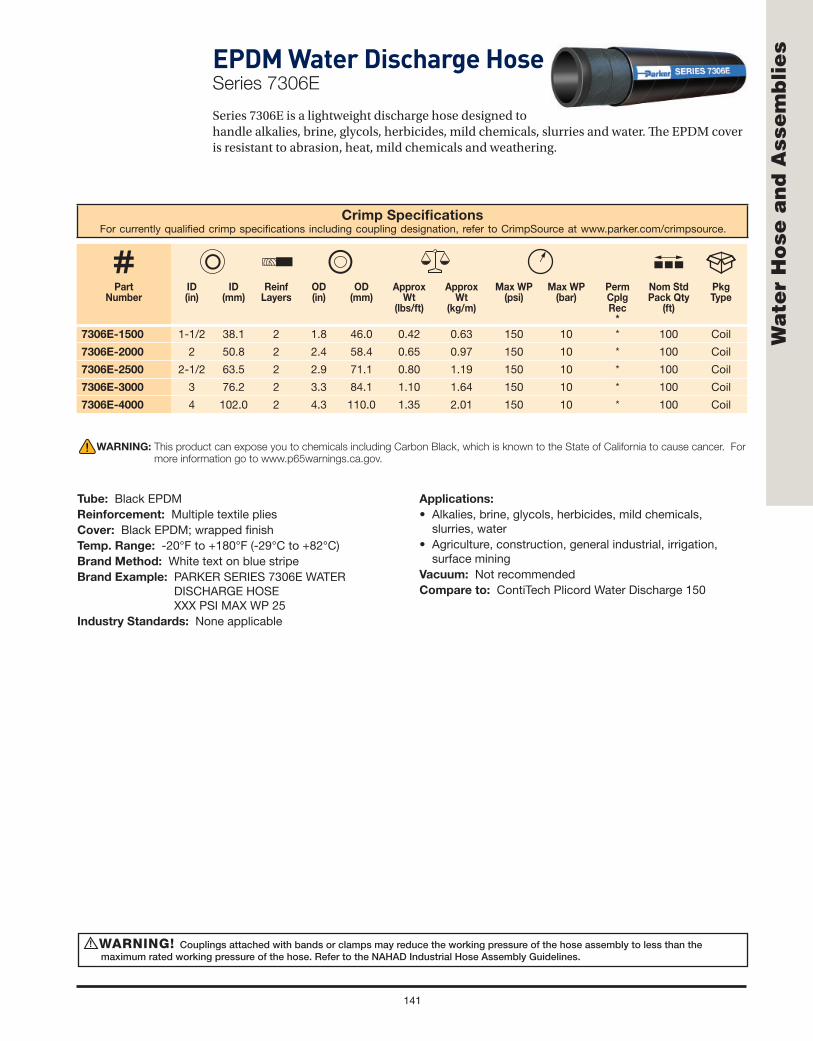
141
Wa
ter
Ho
se a
nd
Ass
em
blie
s
Crimp Specifi cationsFor currently qualifi ed crimp specifi cations including coupling designation, refer to CrimpSource at www.parker.com/crimpsource.
Part Number
ID(in)
ID (mm)
ReinfLayers
OD (in)
OD(mm)
Approx Wt
(lbs/ft)
Approx Wt
(kg/m)
Max WP (psi)
Max WP (bar)
PermCplgRec
*
Nom Std Pack Qty
(ft)
Pkg Type
7306E-1500 1-1/2 38.1 2 1.8 46.0 0.42 0.63 150 10 * 100 Coil
7306E-2000 2 50.8 2 2.4 58.4 0.65 0.97 150 10 * 100 Coil
7306E-2500 2-1/2 63.5 2 2.9 71.1 0.80 1.19 150 10 * 100 Coil
7306E-3000 3 76.2 2 3.3 84.1 1.10 1.64 150 10 * 100 Coil
7306E-4000 4 102.0 2 4.3 110.0 1.35 2.01 150 10 * 100 Coil
WARNING! Couplings attached with bands or clamps may reduce the working pressure of the hose assembly to less than the maximum rated working pressure of the hose. Refer to the NAHAD Industrial Hose Assembly Guidelines.
!
WARNING: This product can expose you to chemicals including Carbon Black, which is known to the State of California to cause cancer. For
more information go to www.p65warnings.ca.gov.
EPDM Water Discharge HoseSeries 7306E
Series 7306E is a lightweight discharge hose designed to handle alkalies, brine, glycols, herbicides, mild chemicals, slurries and water. Th e EPDM cover is resistant to abrasion, heat, mild chemicals and weathering.
Tube: Black EPDMReinforcement: Multiple textile pliesCover: Black EPDM; wrapped fi nishTemp. Range: -20°F to +180°F (-29°C to +82°C)Brand Method: White text on blue stripeBrand Example: PARKER SERIES 7306E WATER
DISCHARGE HOSE XXX PSI MAX WP 25
Industry Standards: None applicable
Applications:
• Alkalies, brine, glycols, herbicides, mild chemicals, slurries, water
• Agriculture, construction, general industrial, irrigation, surface mining
Vacuum: Not recommendedCompare to: ContiTech Plicord Water Discharge 150

142
Wa
ter
Ho
se a
nd
Ass
em
blie
s Premium Contractor’s Water Hose – Factory AssembliesSeries PR (Black EPDM)
Series PR is designed as a durable, lightweight, abrasion and weather resistant hose for agriculture, construction or general industrial water service. Th e factory-installed, crimped-on lightweight, crush resistant nickel-plated brass couplings provide a secure hose/fi tting interface, and the male and female garden hose ends provide easy, quick and secure connections.
Premium Hot Water Hose – Factory AssembliesSeries HWR (Red EPDM)
Series HWR is designed as a lightweight, abrasion and weather resistant hose for general industrial/commercial hot water (to 212°F) water service. Th e factory-installed, crimped-on crush resistant nickel-plated brass couplings provide a secure hose/fi tting interface, and the male and female garden hose ends provide easy, quick and secure connections.
WARNING: This product can expose you to chemicals including Carbon Black, which is known to the State of California to cause cancer. For
more information go to www.p65warnings.ca.gov.
WARNING: This product can expose you to chemicals including Lead, which is known to the State of California to cause cancer and birth defects or other
reproductive harm. For more information go to www.p65warnings.ca.gov.
Part Number
ID(in)
ID (mm)
Length(ft)
Length(m)
Approx Wt
(lbs/ea)
Approx Wt
(kg/ea)
Max WP (psi)
Max WP (bar)
Std Pack Qty(ea)
Pkg Type
PR5825
5/8 15.9
25 7.62 5.58 2.53
125 9
8 Carton
PR5850 50 15.24 10.66 4.84 4 Carton
PR5875 75 22.86 15.86 7.19 3 Carton
PR58100 100 30.48 20.94 9.50 2 Carton
PR3450 3/4 19.1 50 15.24 14.07 6.38 125 9 3 Carton
Temp Range: -40°F to +180°F (-40°C to +82°C) Male x Female Garden Hose Thread CouplingsDesign Factor: 4:1 Display Coils with Parker Center Retail Packaging DiscCrimped-on Crush Resistant Nickel Plated Brass
Part Number
ID(in)
ID (mm)
Length(ft)
Length(m)
Approx Wt
(lbs/ea)
Approx Wt
(kg/ea)
Max WP (psi)
Max WP (bar)
Std Pack Qty(ea)
Pkg Type
HWR5825
5/8 15.9
25 7.62 5.73 2.60
125 9
8 Carton
HWR5850 50 15.24 10.95 4.97 4 Carton
HWR5875 75 22.86 16.30 7.39 3 Carton
HWR58100 100 30.48 21.52 9.76 2 Carton
HWR3450 3/4 19.1 50 15.24 14.36 6.51 125 9 2 Carton
Temp Range: -40°F to +212°F (-40°C to +100°C) Male x Female Garden Hose Thread CouplingsDesign Factor: 4:1 Display Coils with Parker Center Retail Packaging Disc

143
Wa
ter
Ho
se a
nd
Ass
em
blie
sPremium Rubber Garden Hose – Factory AssembliesSeries RGR (Green EPDM)
Series RGR is designed as a lightweight, abrasion and weather resistant hose for general consumer/commercial water service. Th e green color naturally blends in with grass, plants and a garden/landscape environment. Th e factory-installed, crimped-on crush resistant nickel-plated brass couplings provide a secure hose/fi tting interface, and the male and female garden hose ends provide easy, quick and secure connections.
WARNING: This product can expose you to chemicals including Lead, which is known to the State of California to cause cancer and birth defects or other
reproductive harm. For more information go to www.p65warnings.ca.gov.
Part Number
ID(in)
ID (mm)
Length(ft)
Length(m)
Approx Wt
(lbs/ea)
Approx Wt
(kg/ea)
Max WP (psi)
Max WP (bar)
Std Pack Qty(ea)
Pkg Type
RGR12501/2 12.7
50 15.24 7.68 3.48100 7
6 Carton
RGR12100 100 30.48 14.78 6.70 3 Carton
RGR58255/8 15.9
25 7.62 5.81 2.64125 9
8 Carton
RGR5850 50 15.24 11.01 4.99 4 Carton
RGR58755/8 15.9
75 22.86 16.20 7.35125 9
3 Carton
RGR58100 100 30.48 21.39 9.70 2 Carton
Temp Range: -40°F to +180°F (-40°C to +82°C) Male x Female Garden Hose Thread CouplingsDesign Factor: 4:1 (1/2" @ 3.5:1) Display Coils with Parker Center Retail Packaging DiscCrimped-on Crush Resistant Nickel Plated Brass,

Welding Hose
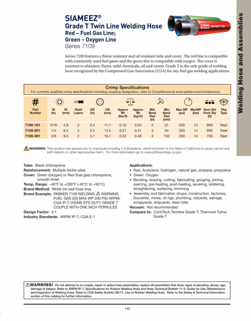
145
We
ldin
g H
ose
an
d A
sse
mb
lie
sSIAMEEZ®
Grade T Twin Line Welding HoseRed – Fuel Gas Line; Green – Oxygen LineSeries 7109
Series 7109 features a fl ame resistant and oil resistant tube and cover. Th e red line is compatible with commonly used fuel gases and the green line is compatible with oxygen. Th e cover is resistant to abrasion, fl ame, mild chemicals, oil and ozone. Grade T is the only grade of welding hose recognized by the Compressed Gas Association (CGA) for oxy-fuel gas welding applications.
Crimp Specifi cationsFor currently qualifi ed crimp specifi cations including coupling designation, refer to CrimpSource at www.parker.com/crimpsource.
Part Number
ID(in)
ID (mm)
ReinfLayers
OD (in)
OD(mm)
Approx Wt
(lbs/ft)
Approx Wt
(kg/m)
MinBendRad(in)
MinBendRad(mm)
Max WP (psi)
MaxWP (bar)
Nom Std Pack Qty
(ft)
Pkg Type
7109-191 3/16 4.8 2 0.4 11.1 0.16 0.24 2 51 200 14 800 Reel
7109-251 1/4 6.4 2 0.5 13.5 0.21 0.31 3 64 200 14 800 Reel
7109-381 3/8 9.5 2 0.7 16.7 0.32 0.48 4 102 200 14 700 Reel
WARNING! Do not attempt to re-couple, repair or splice hose assemblies; replace all assemblies that show signs of abrading, abuse, age, damage or fatigue. Refer to ARPM IP-7, Specifi cations for Rubber Welding Hose and Hose Technical Bulletin 11-5, Guide for Use, Maintenance and Inspection of Welding Hose. Refer to CGA Safety Bulletin SB-11, Use of Rubber Welding Hose. Refer to the Safety & Technical Information section of this catalog for further information.
!
WARNING: This product can expose you to chemicals including 1,3-Butadiene, which is known to the State of California to cause cancer and
birth defects or other reproductive harm. For more information go to www.p65warnings.ca.gov.
Tube: Black chloropreneReinforcement: Multiple textile pliesCover: Green (oxygen) or Red (fuel gas) chloroprene;
smooth fi nishTemp. Range: -40°F to +200°F (-40°C to +93°C)Brand Method: White ink (red hose line)Brand Example: PARKER 7109 WELDING ! WARNING
FUEL GAS (ID) MAX WP 200 PSI ARPM/CGA IP-7-(YEAR) STD DUTY GRADE T COUPLE WITH ONE INCH FERRULES
Design Factor: 4:1Industry Standards: ARPM IP-7; CGA E-1
Applications:
• Red: Acetylene, hydrogen, natural gas, propane, propylene• Green: Oxygen• Bending, brazing, cutting, fabricating, gouging, joining,
piercing, pre-heating, post-heating, severing, soldering,straightening, surfacing, trimming
• Assembly and fabrication shops, construction, factories,foundries, mines, oil rigs, plumbing, railyards, salvage,scrapyards, shipyards, steel mills
Vacuum: Not recommendedCompare to: ContiTech Twinline Grade T; Thermoid Tuline
Grade T

146
We
ldin
g H
ose
an
d A
sse
mb
lie
s Grade T Single Line Welding Hose Series 7141 (Red – Fuel Gas Line)
Series 7142 (Green – Oxygen Line)
Series 7141/7142 features a fl ame resistant and oil resistant tube and cover. Red series 7141 is only for fuel service. Green Series 7142 is only for oxygen service. Single line welding hose is available in long continuous lengths, providing maximum versatility and ease of handling. Th e hose cover is resistant to abrasion, mild chemicals, fl ame, oil and ozone—signifi cant for combination plasma/oxy-fuel welding and cutting equipment applications, which frequently generate intense amounts of ozone and also require Grade T fuel gas hose. Grade T is the only grade of welding hose recognized by the Compressed Gas Association (CGA) for oxy-fuel gas welding applications.NOTE: Grade T is also suitable for use with inert gas.
Series 7141 (Red – Fuel Gas Line)
Crimp Specifi cationsFor currently qualifi ed crimp specifi cations including coupling designation, refer to CrimpSource at www.parker.com/crimpsource.
Part Number
ID(in)
ID (mm)
ReinfLayers
OD (in)
OD(mm)
Approx Wt
(lbs/ft)
Approx Wt
(kg/m)
MinBendRad(in)
MinBendRad(mm)
Max WP (psi)
Max WP (bar)
PermCplgRec
*
Nom Std Pack Qty(ft)
Pkg Type
7141-19200 3/16 4.8 2 0.4 11.1 0.08 0.12 2 51 200 14 * 800 Reel
7141-25200 1/4 6.4 2 0.5 13.5 0.10 0.15 3 64 200 14 * 800 Reel
7141-38200 3/8 9.5 2 0.7 16.7 0.16 0.24 4 102 200 14 HY 700 Reel
7141-50200 1/2 12.7 4 0.9 22.2 0.29 0.43 5 127 200 14 HY 500 Reel
7141-75200 3/4 19.1 4 1.2 29.4 0.43 0.64 6 152 200 14 HY, CGHBL, * 400 Reel
Welding Couplings: As specifi ed in CGA publication E-1. Bulk welding hose couplings are not sold separately by Parker (except 3/4").
WARNING: This product can expose you to chemicals including 1,3-Butadiene, which is known to the State of California to cause cancer and
birth defects or other reproductive harm. For more information go to www.p65warnings.ca.gov.
Tube: Black chloropreneReinforcement: Multiple textile pliesCover: Series 7141: Red chloroprene; ribbed fi nish (3/4"
smooth fi nish)Series 7142: Green chloroprene; ribbed fi nish (3/4" smooth fi nish)
Temp. Range: -40°F to +200°F (-40°C to +93°C)Brand Method: Series 7141: White ink
Series 7142: Black inkBrand Example: Series 7141: PARKER 7141 WELDING !
WARNING FUEL GAS (ID) MAX WP 200 PSI ARPM/CGA IP-7-(YEAR) STD DUTY GRADE T COUPLE WITH ONE INCH FERRULESSeries 7142: PARKER 7142 WELDING ! WARNING OXYGEN (ID) MAX WP 200 PSI ARPM/CGA IP-7-(YEAR) STD DUTY GRADE T COUPLE WITH ONE INCH FERRULES
Design Factor: 4:1Industry Standards: ARPM IP-7; CGA E-1Applications:
• Series 7141 (red): Acetylene hydrogen, natural gas, propane, propylene Series 7142 (green): Oxygen
• Bending, brazing, cutting, fabricating, gouging, joining, piercing, pre-heating, post-heating, severing, soldering, straightening, surfacing, trimming
• Assembly and fabrication shops, construction, factories, foundries, mines, oil rigs, plumbing, rail yards, salvage, scrapyards, shipyards, steel mills
Vacuum: Not recommendedCompare to: ContiTech Varifl ex Single Line Grade T;
Thermoid Single Line Corrugated Grade T Welding

147
We
ldin
g H
ose
an
d A
sse
mb
lie
s
Grade T Single Line Welding Hose Series 7141 (Red – Fuel Gas Line)
Series 7142 (Green – Oxygen Line)
Series 7141/7142 features a fl ame resistant and oil resistant tube and cover. Red series 7141 is only for fuel service. Green Series 7142 is only for oxygen service. Single line welding hose is available in long continuous lengths, providing maximum versatility and ease of handling. Th e hose cover is resistant to abrasion, mild chemicals, fl ame, oil and ozone—signifi cant for combination plasma/oxy-fuel welding and cutting equipment applications, which frequently generate intense amounts of ozone and also require Grade T fuel gas hose. Grade T is the only grade of welding hose recognized by the Compressed Gas Association (CGA) for oxy-fuel gas welding applications.
NOTE: Grade T is also suitable for use with inert gas.
Series 7142 (Green – Oxygen Line)
Crimp Specifi cationsFor currently qualifi ed crimp specifi cations including coupling designation, refer to CrimpSource at www.parker.com/crimpsource.
Part Number
ID(in)
ID (mm)
ReinfLayers
OD (in)
OD(mm)
Approx Wt
(lbs/ft)
Approx Wt
(kg/m)
MinBendRad(in)
MinBendRad(mm)
Max WP (psi)
Max WP (bar)
PermCplgRec
*
Nom Std Pack Qty(ft)
Pkg Type
7142-19200 3/16 4.8 2 0.4 11.1 0.08 0.12 2 51 200 14 * 800 Reel
7142-25200 1/4 6.4 2 0.5 13.5 0.10 0.15 3 64 200 14 * 800 Reel
7142-38200 3/8 9.5 2 0.7 16.7 0.16 0.24 4 102 200 14 HY 700 Reel
7142-50200 1/2 12.7 4 0.9 22.2 0.29 0.43 5 127 200 14 HY 500 Reel
7142-75200 3/4 19.1 4 1.2 29.4 0.43 0.64 6 152 200 14 HY, CGHBL, * 400 Reel
Welding Couplings: As specifi ed in CGA publication E-1. Bulk welding hose couplings are not sold separately by Parker (except 3/4").
WARNING! Do not attempt to re-couple, repair or splice hose assemblies; replace all assemblies that show signs of abrading, abuse, age, damage or fatigue. Refer to ARPM IP-7, Specifi cations for Rubber Welding Hose and Hose Technical Bulletin 11-5, Guide for Use, Maintenance and Inspection of Welding Hose. Refer to CGA Safety Bulletin SB-11, Use of Rubber Welding Hose. Refer to the Safety & Technical Information section of this catalog for further information.
!
WARNING: This product can expose you to chemicals including 1,3-Butadiene, which is known to the State of California to cause cancer and
birth defects or other reproductive harm. For more information go to www.p65warnings.ca.gov.
Tube: Black chloropreneReinforcement: Multiple textile pliesCover: Series 7141: Red chloroprene; ribbed fi nish (3/4" smooth
fi nish)Series 7142: Green chloroprene; ribbed fi nish (3/4" smooth fi nish)
Temp. Range: -40°F to +200°F (-40°C to +93°C)Brand Method: Series 7141: White inkSeries 7142: Black inkBrand Example: Series 7141: PARKER 7141 WELDING !
WARNING FUEL GAS (ID) MAX WP 200 PSI ARPM/CGA IP-7-(YEAR) STD DUTY GRADE T COUPLE WITH ONE INCH FERRULESSeries 7142: PARKER 7142 WELDING ! WARNING OXYGEN (ID) MAX WP 200 PSI ARPM/CGA IP-7-(YEAR) STD DUTY GRADE T COUPLE WITH ONE INCH FERRULES
Design Factor: 4:1Industry Standards: ARPM IP-7; CGA E-1Applications:
• Series 7141 (red): Acetylene hydrogen, natural gas, propane, propylene Series 7142 (green): Oxygen
• Bending, brazing, cutting, fabricating, gouging, joining, piercing, pre-heating, post-heating, severing, soldering, straightening, surfacing, trimming
• Assembly and fabrication shops, construction, factories, foundries, mines, oil rigs, plumbing, rail yards, salvage, scrapyards, shipyards, steel mills
Vacuum: Not recommendedCompare to: ContiTech Varifl ex Single Line Grade T; Thermoid
Single Line Corrugated Grade T Welding

148
We
ldin
g H
ose
an
d A
sse
mb
lie
s SIAMEEZ®
Grade R Twin Line Welding Hose Red – Acetylene Only; Green – Oxygen LineSeries 7126
Series 7126 red line is compatible ONLY with acetylene fuel gas, and the green line is compatible with oxygen. Multiple plies of textile reinforcement provides fl exibility. Th e cover is resistant to abrasion, heat, mild chemicals and ozone.
Crimp Specifi cationsFor currently qualifi ed crimp specifi cations including coupling designation, refer to CrimpSource at www.parker.com/crimpsource.
Part Number
ID(in)
ID (mm)
ReinfLayers
OD (in)
OD(mm)
Approx Wt
(lbs/ft)
Approx Wt
(kg/m)
MinBendRad(in)
MinBendRad(mm)
Max WP (psi)
Max WP (bar)
Nom Std Pack
Qty(ft)
Pkg Type
7126-191 3/16 4.8 2 0.4 11.1 0.13 0.19 2 51 200 14 800 Reel
7126-251 1/4 6.4 2 0.5 13.5 0.20 0.30 3 64 200 14 800 Reel
7126-381 3/8 9.5 2 0.7 16.7 0.29 0.43 4 102 200 14 700 Reel
Factory Assemblies: Available from stock in popular confi gurations. See the following page.
WARNING! Do not attempt to re-couple, repair or splice hose assemblies; replace all assemblies that show signs of abrading, abuse, age, damage or fatigue. Refer to ARPM IP-7, Specifi cations for Rubber Welding Hose and Hose Technical Bulletin 11-5, Guide for Use, Maintenance and Inspection of Welding Hose. Refer to CGA Safety Bulletin SB-11, Use of Rubber Welding Hose. Refer to the Safety & Technical Information section of this catalog for further information.
!
WARNING: This product can expose you to chemicals including Carbon Black, which is known to the State of California to cause cancer.
For more information go to www.p65warnings.ca.gov.
Tube: Black EPDMReinforcement: Multiple textile pliesCover: Red (acetylene) or Green (oxygen) EPDM; smooth
fi nishTemp. Range: -40°F to +200°F (-40°C to +93°C)Brand Method: White ink on red hoseBrand Example: PARKER 7126 WELDING ! WARNING
ACETYLENE ONLY (ID) MAX WP 200 PSI ARPM IP-7-(YEAR) STD DUTY GRADE R COUPLE WITH ONE INCH FERRULES
Design Factor: 4:1Industry Standards: ARPM IP-7
Applications:
• Red: Acetylene ONLY Green: Oxygen• Bending, brazing, cutting, fabricating, gouging, joining,
piercing, pre-heating, post-heating, severing, soldering, straightening, surfacing, trimming
• Assembly and fabrication shops, construction, factories, foundries, mines, oil rigs, plumbing, rail yards, salvage, scrapyards, shipyards, steel mills
Vacuum: Not recommendedCompare to: ContiTech Twinline Grade R; Thermoid Tuline
Grade R

149
We
ldin
g H
ose
an
d A
sse
mb
lie
sGrade R Single Line Welding HoseSeries 7120 (Red – Acetylene Only)
Series 7121 and Series 7031(R)
(Green – Oxygen Line)
Series 7120/7121 is a single line acetylene/oxygen welding hose. Red Series 7120 is only for acetylene service. Green Series 7121 is only for oxygen service. Single line welding hose is available in long continuous lengths, providing maximum versatility and ease of handling in a variety of applications where only single line hose is needed or where the fuel gas and oxygen sources are separated, and twin line hose is not practical. Th e cover is resistant to abrasion, heat, mild chemicals and ozone.
NOTES: • For 3/4" Grade R oxygen hose, refer to Series 7031(R). • Grade R is also suitable for use with inert gas.
Series 7120 (Red – Acetylene line only)
Crimp Specifi cationsFor currently qualifi ed crimp specifi cations including coupling designation, refer to CrimpSource at www.parker.com/crimpsource.
Part Number
ID(in)
ID (mm)
ReinfLayers
OD (in)
OD(mm)
Approx Wt
(lbs/ft)
Approx Wt
(kg/m)
MinBendRad(in)
MinBendRad(mm)
Max WP (psi)
Max WP (bar)
PermCplgRec
*
Nom Std Pack Qty(ft)
Pkg Type
7120-19200 3/16 4.8 2 0.4 11.1 0.08 0.12 2 51 200 14 * 800 Reel
7120-25200 1/4 6.4 2 0.5 13.5 0.10 0.15 3 64 200 14 * 800 Reel
7120-38200 3/8 9.5 2 0.7 16.7 0.14 0.21 4 102 200 14 * 700 Reel
7120-50200 1/2 12.7 4 0.9 22.2 0.26 0.39 5 127 200 14 * 500 Reel
Welding Couplings: As specifi ed in CGA publication E-1. Bulk welding hose couplings are not sold separately by Parker (except 3/4")
WARNING: This product can expose you to chemicals including Carbon Black, which is known to the State of California to cause cancer.
For more information go to www.p65warnings.ca.gov.
Tube: Black EPDMReinforcement: Multiple textile pliesCover: Series 7120: Red (acetylene) EPDM; ribbed fi nish
Series 7121: Green (oxygen) EPDM; ribbed fi nish Series 7031(R): Green (oxygen) EPDM; smooth fi nish
Temp. Range: -40°F to +200°F (-40°C to +93°C)Brand Method: Series 7120: White ink Series 7121/7031(R): Black inkBrand Example: Series 7120: PARKER 7120 WELDING !
WARNING ACETYLENE ONLY (ID) MAX WP 200 PSI ARPM IP-7-(YEAR) STD DUTY GRADE R COUPLE WITH ONE INCH FERRULESSeries 7121: PARKER 7121 WELDING ! WARNING OXYGEN (ID) MAX WP 200 PSI ARPM IP-7-(YEAR) STD DUTY GRADE R COUPLE WITH ONE INCH FERRULESSeries 7031(R): PARKER 7031 GST® II/OXYGEN (ID) MAX WP 300 PSI (200 PSI OXYGEN) ARPM IP-7-(YEAR) STD DUTY GRADE R)
Design Factor: 4:1Industry Standards: ARPM IP-7Applications:• Series 7120 (red): Acetylene ONLY
Series 7121 and 7031(R) (green): Oxygen• Bending, brazing, cutting, fabricating, gouging, joining,
piercing, pre-heating, post-heating, severing, soldering, straightening, surfacing, trimming
• Assembly and fabrication shops, construction, factories, foundries, mines, oil rigs, plumbing, rail yards, salvage, scrapyards, shipyards, steel mills
Vacuum: Not recommendedCompare to: Thermoid Green GP/Oxygen
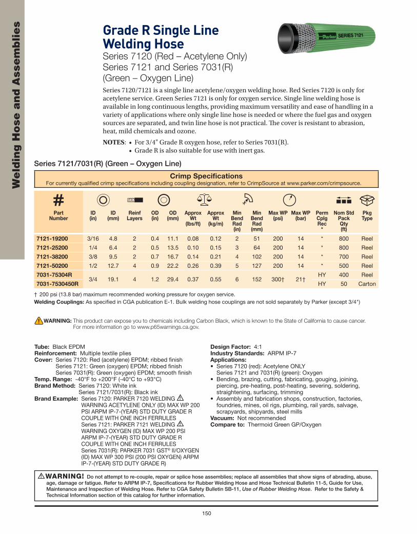
150
We
ldin
g H
ose
an
d A
sse
mb
lie
s
Series 7121/7031(R) (Green – Oxygen Line)
Crimp Specifi cationsFor currently qualifi ed crimp specifi cations including coupling designation, refer to CrimpSource at www.parker.com/crimpsource.
Part Number
ID(in)
ID (mm)
ReinfLayers
OD (in)
OD(mm)
Approx Wt
(lbs/ft)
Approx Wt
(kg/m)
MinBendRad(in)
MinBendRad(mm)
Max WP (psi)
Max WP (bar)
PermCplgRec
*
Nom Std Pack Qty(ft)
Pkg Type
7121-19200 3/16 4.8 2 0.4 11.1 0.08 0.12 2 51 200 14 * 800 Reel
7121-25200 1/4 6.4 2 0.5 13.5 0.10 0.15 3 64 200 14 * 800 Reel
7121-38200 3/8 9.5 2 0.7 16.7 0.14 0.21 4 102 200 14 * 700 Reel
7121-50200 1/2 12.7 4 0.9 22.2 0.26 0.39 5 127 200 14 * 500 Reel
7031-75304R3/4 19.1 4 1.2 29.4 0.37 0.55 6 152 300† 21†
HY 400 Reel
7031-7530450R HY 50 Carton
† 200 psi (13.8 bar) maximum recommended working pressure for oxygen service.Welding Couplings: As specifi ed in CGA publication E-1. Bulk welding hose couplings are not sold separately by Parker (except 3/4")
WARNING! Do not attempt to re-couple, repair or splice hose assemblies; replace all assemblies that show signs of abrading, abuse, age, damage or fatigue. Refer to ARPM IP-7, Specifi cations for Rubber Welding Hose and Hose Technical Bulletin 11-5, Guide for Use, Maintenance and Inspection of Welding Hose. Refer to CGA Safety Bulletin SB-11, Use of Rubber Welding Hose. Refer to the Safety & Technical Information section of this catalog for further information.
!
WARNING: This product can expose you to chemicals including Carbon Black, which is known to the State of California to cause cancer.
For more information go to www.p65warnings.ca.gov.
Grade R Single Line Welding HoseSeries 7120 (Red – Acetylene Only)
Series 7121 and Series 7031(R)
(Green – Oxygen Line)
Series 7120/7121 is a single line acetylene/oxygen welding hose. Red Series 7120 is only for acetylene service. Green Series 7121 is only for oxygen service. Single line welding hose is available in long continuous lengths, providing maximum versatility and ease of handling in a variety of applications where only single line hose is needed or where the fuel gas and oxygen sources are separated, and twin line hose is not practical. Th e cover is resistant to abrasion, heat, mild chemicals and ozone.
NOTES: • For 3/4" Grade R oxygen hose, refer to Series 7031(R). • Grade R is also suitable for use with inert gas.
Tube: Black EPDMReinforcement: Multiple textile pliesCover: Series 7120: Red (acetylene) EPDM; ribbed fi nish
Series 7121: Green (oxygen) EPDM; ribbed fi nish Series 7031(R): Green (oxygen) EPDM; smooth fi nish
Temp. Range: -40°F to +200°F (-40°C to +93°C)Brand Method: Series 7120: White ink
Series 7121/7031(R): Black inkBrand Example: Series 7120: PARKER 7120 WELDING !
WARNING ACETYLENE ONLY (ID) MAX WP 200 PSI ARPM IP-7-(YEAR) STD DUTY GRADE R COUPLE WITH ONE INCH FERRULESSeries 7121: PARKER 7121 WELDING ! WARNING OXYGEN (ID) MAX WP 200 PSI ARPM IP-7-(YEAR) STD DUTY GRADE R COUPLE WITH ONE INCH FERRULESSeries 7031(R): PARKER 7031 GST® II/OXYGEN (ID) MAX WP 300 PSI (200 PSI OXYGEN) ARPM IP-7-(YEAR) STD DUTY GRADE R)
Design Factor: 4:1Industry Standards: ARPM IP-7Applications:• Series 7120 (red): Acetylene ONLY
Series 7121 and 7031(R) (green): Oxygen• Bending, brazing, cutting, fabricating, gouging, joining,
piercing, pre-heating, post-heating, severing, soldering, straightening, surfacing, trimming
• Assembly and fabrication shops, construction, factories, foundries, mines, oil rigs, plumbing, rail yards, salvage, scrapyards, shipyards, steel mills
Vacuum: Not recommendedCompare to: Thermoid Green GP/Oxygen

151
We
ldin
g H
ose
an
d A
sse
mb
lie
sInert Gas HoseSeries 7123
Series 7123 hose construction incorporates multiple plies of textile reinforcement that provide fl exibility, and the cover is resistant to abrasion, heat, mild chemicals and ozone.
Part Number
ID(in)
ID (mm)
ReinfLayers
OD (in)
OD(mm)
Approx Wt
(lbs/ft)
Approx Wt
(kg/m)
MinBendRad(in)
MinBendRad(mm)
Max WP (psi)
Max WP (bar)
Nom Std Pack
Qty(ft)
Pkg Type
7123-25200 1/4 6.4 2 0.5 12.7 0.09 0.13 3 64 200 14 800 Reel
Welding Couplings: As specifi ed in CGA publication E-1. Bulk inert gas hose couplings are not sold separately by Parker.
WARNING: This product can expose you to chemicals including Carbon Black, which is known to the State of California to cause cancer.
For more information go to www.p65warnings.ca.gov.
Tube: Black EPDMReinforcement: Multiple textile pliesCover: Black EPDM; ribbed fi nishTemp. Range: -40°F to +200°F (-40°C to +93°C)Brand Method: White inkBrand Example: PARKER 7123 INERT GAS (ID) MAX WP
200 PSIDesign Factor: 4:1
Industry Standards: CGA E-1 color requirementsApplications:
• Air, argon, carbon dioxide, helium, nitrogen• Shield gas• Arc welding systemsVacuum: Not recommended

152
We
ldin
g H
ose
an
d A
sse
mb
lie
s Cable Cover HoseNonconductiveSeries 7172
Series 7172 hose construction is electrically nonconductive with a minimum resistance of one megaohm per inch at 1000 volts DC. Th e cover is resistant to abrasion, mild chemicals and ozone.
NOTES: Th e user must determine if the hose is suitable for applications subject to electrical hazard. Contact Parker for additional information.
Part Number
ID(in)
ID (mm)
ReinfLayers
OD (in)
OD(mm)
Approx Wt
(lbs/ft)
Approx Wt
(kg/m)
MinBendRad(in)
MinBendRad(mm)
Max WP (psi)
Max WP (bar)
Nom Std Pack
Qty(ft)
Pkg Type
7172-19200 3/16 4.8 2 0.4 10.5 0.06 0.09 2 38 200 14 750 Reel
7172-25200 1/4 6.4 2 0.5 12.1 0.07 0.10 2 51 200 14 750 Reel
7172-31200 5/16 7.9 2 0.5 12.7 0.08 0.12 3 64 200 14 750 Reel
7172-38200 3/8 9.5 2 0.6 15.3 0.11 0.16 3 76 200 14 650 Reel
Welding Couplings: Bulk welding hose couplings are not sold separately by Parker.
WARNING: This product can expose you to chemicals including DEHP, which is known to the State of California to cause cancer and birth
defects or other reproductive harm. For more information go to www.p65warnings.ca.gov.
Tube: Black nitrile/SBR blendReinforcement: Multiple textile pliesCover: Black EPDM; smooth fi nishTemp. Range: -20°F to +212°F (-29°C to +100°C)Brand Method: White inkBrand Example: PARKER SERIES 7172 ELECTRICALLY
NON-CONDUCTIVE CABLE COVER / WATER COOLANT HOSE (ID) 200 PSI MAX WP
Design Factor: 4:1
Industry Standards: NonconductiveApplications:
• Air, water• Cable cover and coolant hose for arc welding systemsVacuum: Not recommended

153
We
ldin
g H
ose
an
d A
sse
mb
lie
s
Crimp Specifi cationsFor currently qualifi ed crimp specifi cations including coupling designation, refer to CrimpSource at www.parker.com/crimpsource.
Part Number
ID(in)
ID (mm)
ReinfLayers
OD (in)
OD(mm)
Approx Wt
(lbs/ft)
Approx Wt
(kg/m)
MinBendRad(in)
MinBendRad(mm)
Max WP (psi)
Max WP (bar)
PermCplgRec
*
Nom Std Pack
Qty(ft)
Pkg Type
7293-0500 1/2 12.7 4 1.0 25.2 0.38 0.57 4 89 500 35 * 100 Coil
7293-0750 3/4 19.1 4 1.3 32.4 0.54 0.80 4 89 500 35 * 100 Coil
7293-1000 1 25.4 4 1.5 38.8 0.68 1.01 5 114 500 35 * 100 Coil
7293-1250 1-1/4 31.8 4 1.9 49.0 1.08 1.61 5 127 500 35 * 100 Coil
7293-1500 1-1/2 38.1 4 2.2 55.2 1.24 1.85 7 178 500 35 * 100 Coil
7293-2000 2 50.8 4 2.8 70.2 1.69 2.52 14 356 500 35 * 100 Coil
Oxygen Charging HoseSeries 7293
Series 7293 is designed for high pressure oxygen lancing and scarfi ng applications. Th e hose construction incorporates fl ame and oil resistant tube and cover compounds. Th e green cover is resistant to abrasion and weathering. Th e tube is cleaned and the ends are capped at the factory to prevent contamination.
WARNING! Couplings attached with bands or clamps may reduce the working pressure of the hose assembly to less than the maximum rated working pressure of the hose. Refer to the NAHAD Industrial Hose Assembly Guidelines.
!
WARNING: This product can expose you to chemicals including DEHP, which is known to the State of California to cause cancer and birth
defects or other reproductive harm. For more information go to www.p65warnings.ca.gov.
Tube: Black chloropreneReinforcement: Multiple textile pliesCover: Green chloroprene; wrapped fi nishTemp. Range: -22°F to +176°F (-30°C to +80°C)Brand Method: EmbossedBrand Example: PARKER SERIES 7293 OXYGEN
CHARGING 500 PSI MAX WP Design Factor: 4:1
Industry Standards: None applicableApplications:
• High pressure oxygen• Lancing, scarfi ng• Foundries, steel millsVacuum: Not recommended

Couplings

155
Co
up
lin
gsSeries HY
101HY Male NPTF Pipe – Straight Rigid
Part Number
HoseID(in)
ThreadID (in)
Thread Dash Size
Dimensions Approx Wt
Per Ctn (lbs)
Std Pack Qty(per
carton)
Pkg Type
A(in)
A(mm)
H(in)
B(in)
B(mm)
101HY-2-4 1/4 1/8x27 -2 2.34 59 5/8 1.00 25 1.94 20 Carton
101HY-4-4 1/4 1/4x18 -4 2.53 64 9/16 1.19 30 2.73 25 Carton
101HY-4-6 3/8 1/4x18 -4 2.55 65 11/16 1.19 30 3.06 20 Carton
101HY-6-4 1/4 3/8x18 -6 2.53 64 3/4 1.19 30 2.68 20 Carton
101HY-6-6 3/8 3/8x18 -6 2.55 65 3/4 1.19 30 4.20 25 Carton
101HY-6-8 1/2 3/8x18 -6 2.72 69 7/8 1.38 35 4.54 20 Carton
101HY-8-6 3/8 1/2x14 -8 2.73 69 7/8 1.38 35 4.36 20 Carton
101HY-8-8 1/2 1/2x14 -8 2.91 74 7/8 1.41 40 6.53 25 Carton
101HY-8-10 5/8 1/2x14 -8 2.94 75 1-1/8 1.59 40 7.26 20 Carton
101HY-8-12 3/4 1/2x14 -8 3.08 78 1-1/4 1.50 38 4.33 10 Carton
101HY-12-8 1/2 3/4x14 -12 2.91 74 1-1/16 1.56 40 7.60 20 Carton
101HY-12-10 5/8 3/4x14 -12 2.98 76 1-1/8 1.59 40 3.80 10 Carton
101HY-12-12 3/4 3/4x14 -12 3.08 78 1-1/4 1.50 38 4.58 10 Carton
101HY-12-16 1 3/4x14 -12 3.23 82 1-3/8 1.63 41 5.40 10 Carton
101HY-16-12 3/4 1x11-1/2 -16 3.27 83 1-3/8 1.69 43 5.10 10 Carton
101HY-16-16 1 1x11-1/2 -16 3.42 87 1-3/8 1.81 46 6.29 10 Carton
S101HY-20-20 1-1/4 1-1/4 x 11-1/2 -20 3.84 98 1-3/4 2.00 51 6.62 4 Carton
Crimp Specifi cationsFor currently qualifi ed crimp specifi cations including coupling designation, refer to CrimpSource at www.parker.com/crimpsource.
WARNING: This product can expose you to chemicals including Lead, which is known to the State of California to cause cancer and birth defects or other
reproductive harm. For more information go to www.p65warnings.ca.gov.

156
Co
up
lin
gs Series HY
106HY Female JIC 37°– Straight Swivel
Part Number
HoseID(in)
ThreadID (in)
Thread Dash Size
Dimensions ApproxWt
Per Ctn(lbs)
Std Pack Qty(per
carton)
Pkg Type
A(in)
A(mm)
H(in)
W(in)
B(in)
B(mm)
106HY-4-4 1/4 7/16x20 -4 2.60 66 9/16 9/16 1.25 32 3.18 25 Carton
106HY-4-6 3/8 7/16x20 -4 2.67 68 3/4 9/16 1.31 33 3.30 20 Carton
106HY-5-4 1/4 1/2x20 -5 2.65 67 9/16 5/8 1.31 33 2.52 20 Carton
106HY-6-4 1/4 9/16x18 -6 2.67 68 5/8 11/16 1.31 33 2.62 20 Carton
106HY-6-6 3/8 9/16x18 -6 2.69 68 11/16 11/16 1.34 34 8.35 50 Carton
106HY-6-8 1/2 9/16x18 -6 2.86 73 7/8 9/16 1.50 38 4.80 20 Carton
106HY-8-6 3/8 3/4x16 -8 2.72 69 7/8 7/8 1.38 35 3.96 20 Carton
106HY-8-8 1/2 3/4x16 -8 2.90 74 7/8 7/8 1.56 40 13.20 50 Carton
106HY-8-10 5/8 3/4x16 -8 2.98 76 1-1/8 7/8 1.59 40 7.06 20 Carton
106HY-8-12 3/4 3/4x16 -8 3.08 78 1-1/4 7/8 1.53 39 2.64 10 Carton
106HY-10-8 1/2 7/8x14 -10 2.98 76 1 1 1.63 41 6.20 20 Carton
106HY-10-10 5/8 7/8x14 -10 3.06 78 1-1/8 1 1.69 43 9.95 25 Carton
106HY-10-12 3/4 7/8x14 -10 3.16 80 1-1/4 1 1.59 40 5.23 10 Carton
106HY-12-8 1/2 1-1/16x12 -12 3.05 77 1-1/8 1-1/4 1.69 43 3.84 10 Carton
106HY-12-10 5/8 1-1/16x12 -12 3.12 79 1-1/8 1-1/4 1.75 44 4.48 10 Carton
106HY-12-12 3/4 1-1/16x12 -12 3.22 82 1-1/4 1-1/4 1.66 42 13.08 25 Carton
106HY-12-16 1 1-1/16x12 -12 3.38 86 1-3/8 1-1/4 1.75 44 6.40 10 Carton
106HY-16-16 1 1-5/16x12 -16 3.45 88 1-3/8 1-1/2 1.84 47 6.86 10 Carton
106HY-20-20 1-1/4 1-5/8x12 -20 4.09 104 2 2 2.25 57 5.00 4 Carton
WARNING: This product can expose you to chemicals including Lead, which is known to the State of California to cause cancer and birth defects or other
reproductive harm. For more information go to www.p65warnings.ca.gov.
Series HY113HY Male NPTF Pipe – Straight Swivel
Part Number
HoseID(in)
ThreadID (in)
Thread Dash Size
Dimensions Approx Wt
Per Ctn (lbs)
Std Pack Qty(per
carton)
Pkg Type
A(in)
A(mm)
H(in)
W(in)
B(in)
B(mm)
113HY-4-4 1/4 1/4x18 -4 3.06 78 9/16 5/8 1.72 44 2.95 25 Carton
113HY-6-6 3/8 3/8x18 -6 3.11 79 11/16 11/16 1.75 44 6.23 25 Carton
113HY-8-8 1/2 1/2x14 -8 3.50 89 7/8 7/8 2.16 55 8.55 25 Carton
113HY-12-12 3/4 3/4x14 -12 3.95 100 1-1/4 1-1/4 2.38 60 7.50 10 Carton
113HY-16-16 1 1x11-1/2 -16 4.23 107 1-1/2 1-1/2 2.63 67 11.52 10 Carton
Material: Plated steelWARNING: This product can expose you to chemicals including Lead, which is known to the State of California to cause cancer and birth defects or other
reproductive harm. For more information go to www.p65warnings.ca.gov.

157
Co
up
lin
gsSeries 43
10143 Male NPTF Pipe – Straight Rigid
Part Number
HoseID(in)
ThreadID (in)
Thread Dash Size
Dimensions Approx Wt
Per Ctn (lbs)
Std Pack Qty(per
carton)
Pkg Type
A(in)
A(mm)
H(in)
B(in)
B(mm)
10143-4-4 1/4 1/4x18 -4 2.01 51 9/16 1.26 32 3.00 25 Carton
10143-6-6 3/8 3/8x18 -6 2.37 60 3/4 1.34 34 4.25 25 Carton
10143-8-8 1/2 1/2x14 -8 2.84 72 7/8 1.58 40 5.30 20 Carton
10143-12-12 3/4 3/4x14 -12 3.09 78 1-1/16 1.65 42 4.35 10 Carton
10143-16-16 1 1x11-1/2 -16 2.59 66 1-3/8 1.97 50 3.71 5 Carton
10143-20-20 1-1/4 1-1/4x11-1/2 -20 4.08 104 1-3/4 2.39 61 5.50 5 Carton
10143-24-24 1-1/2 1-1/2x11-1/2 -24 3.50 89 2 2.13 54 8.06 5 Carton
10143-32-32 2 2x11-1/2 -32 4.05 103 2-1/2 2.27 58 13.37 5 Carton
Material: Plated steel
WARNING: This product can expose you to chemicals including Lead, which is known to the State of California to cause cancer and birth defects or other
reproductive harm. For more information go to www.p65warnings.ca.gov.
Series 4310643 Female JIC 37° – Straight Swivel
Part Number
HoseID(in)
ThreadID (in)
Thread Dash Size
Dimensions Approx Wt
Per Ctn (lbs)
Std Pack Qty(per
carton)
Pkg Type
A(in)
A(mm)
H(in)
W(in)
B(in)
B(mm)
10643-4-4 1/4 7/16x20 -4 1.94 49 9/16 9/16 1.19 30 2.63 25 Carton
10643-6-6 3/8 9/16x18 -6 2.29 58 11/16 11/16 1.26 32 4.33 25 Carton
10643-8-8 1/2 3/4x16 -8 2.63 67 13/16 7/8 1.37 35 5.14 20 Carton
10643-12-12 3/4 1-1/16x12 -12 3.17 81 1-1/16 1-1/4 1.73 44 2.35 5 Carton
10643-16-16 1 1-5/16x12 -16 3.62 92 1-3/8 1-1/2 2.00 51 4.15 5 Carton
10643-20-20 1-1/4 1-5/8x12 -20 3.94 100 1-7/8 2 2.25 57 7.60 5 Carton
10643-24-24 1-1/2 1-7/8x12 -24 3.84 98 2-1/8 2-1/4 2.47 63 4.00 2 Carton
10643-32-32 2 2-1/2x12 -32 4.73 120 2-1/2 2-7/8 2.95 75 3.08 1 Carton
Material: Plated steel
Crimp Specifi cationsFor currently qualifi ed crimp specifi cations including coupling designation, refer to CrimpSource at www.parker.com/crimpsource.
WARNING: This product can expose you to chemicals including Lead, which is known to the State of California to cause cancer and birth defects or other
reproductive harm. For more information go to www.p65warnings.ca.gov.

158
Co
up
lin
gs Series 43
11343 Male NPTF Pipe – Straight Swivel
Part Number
HoseID(in)
ThreadID (in)
Thread Dash Size
Dimensions Approx Wt
Per Ctn (lbs)
Std Pack Qty(per
carton)
Pkg Type
A(in)
A(mm)
H(in)
B(in)
B(mm)
11343-4-4 1/4 1/4X18 -4 2.68 68 5/8 1.93 49 1.53 10 Carton
11343-6-6 3/8 3/8X18 -6 3.08 78 3/4 2.05 52 2.55 10 Carton
11343-8-8 1/2 1/2X14 -8 3.52 89 7/8 2.26 57 3.70 10 Carton
Material: Plated steel
WARNING: This product can expose you to chemicals including Lead, which is known to the State of California to cause cancer and birth defects or other
reproductive harm. For more information go to www.p65warnings.ca.gov.
Crimp Specifi cationsFor currently qualifi ed crimp specifi cations including coupling designation, refer to CrimpSource at www.parker.com/crimpsource.
Series CC101CC Male NPTF Pipe – Straight Rigid
Part Number
HoseID(in)
ThreadID (in)
Thread Dash Size
Dimensions Approx Wt
Per Ctn (lbs)
Std Pack Qty(per
carton)
Pkg Type
A(in)
A(mm)
H(in)
B(in)
B(mm)
101CC-16-16CW 1 1x11-1/2 -16 3.94 100 1-3/8 2.00 51 18.60 20 Carton
101CC-20-20CW 1-1/4 1-1/4x11-1/2 -20 4.06 103 1-3/4 2.39 61 3.00 – Carton
101CC-24-24CW 1-1/2 1-1/2x11-1/2 -24 3.50 89 2 2.13 54 5.00 5 Carton
101CC-32-32CW 2 2x11-1/2 -32 5.39 137 2-5/8 2.14 54 13.00 2 Carton
Material: Stainless Steel Inserts, Carbon Steel Ferrules
WARNING: This product can expose you to chemicals including Lead, which is known to the State of California to cause cancer and birth defects or other
reproductive harm. For more information go to www.p65warnings.ca.gov.

159
Co
up
lin
gsSeries WC
1APWC Male API – Straight Rigid
Part Number
HoseID(in)
ThreadID (in)
Thread Dash Size
Dimensions Approx Wt
Per Ctn (lbs)
Std Pack Qty(per
carton)
Pkg Type
A(in)
A(mm)
H(in)
B(in)
B(mm)
1APWC-32-32 2 2x11-1/2 -32 7.17 182 2-5/8 3.92 99 2.00 2 Carton
Material: Plated steel
Series WC101WC Male NPTF Pipe – Straight Rigid
Part Number
HoseID(in)
ThreadID (in)
Thread Dash Size
Dimensions Approx Wt
Per Ctn (lbs)
Std Pack Qty(per
carton)
Pkg Type
A(in)
A(mm)
H(in)
B(in)
B(mm)
101WC-32-32 2 2x11-1/2 -32 5.39 137 2-5/8 2.14 54 2.00 2 Carton
Material: Plated steel
Series WC106WC Female JIC 37° – Straight Swivel
Part Number
HoseID(in)
ThreadID (in)
Thread Dash Size
Dimensions Approx Wt
Per Ctn (lbs)
Std Pack Qty(per
carton)
Pkg Type
A(in)
A(mm)
H(in)
W(in)
B(in)
B(mm)
106WC-32-32 2 2-1/2x12 -32 5.95 151 2-5/8 2-7/8 2.70 69 2.00 2 Carton
Material: Plated steel
Crimp Specifi cationsFor currently qualifi ed crimp specifi cations including coupling designation, refer to CrimpSource at www.parker.com/crimpsource.
WARNING: This product can expose you to chemicals including Lead, which is known to the State of California to cause cancer and birth defects or other
reproductive harm. For more information go to www.p65warnings.ca.gov.
WARNING: This product can expose you to chemicals including Lead, which is known to the State of California to cause cancer and birth defects or other
reproductive harm. For more information go to www.p65warnings.ca.gov.
WARNING: This product can expose you to chemicals including Lead, which is known to the State of California to cause cancer and birth defects or other
reproductive harm. For more information go to www.p65warnings.ca.gov.

160
Co
up
lin
gs Series 7661/TY-FF
Female NPTF Pipe – Straight Rigid
Part Number
HoseID(in)
ThreadID (in)
Thread Dash Size
Dimensions Approx Wt
Per Ctn (lbs)
Std Pack Qty(per
carton)
Pkg Type
A(in)
A(mm)
H(in)
B(in)
B(mm)
7661-04FF04TY 1/4 1/4x18 -4 2.47 63 11/16 1.15 26 3.23 25 Carton
Material: Plated steel
Series 7661/TY-FJFemale JIC 37° – Straight Swivel
Part Number
HoseID(in)
ThreadID (in)
Thread Dash Size
Dimensions Approx Wt
Per Ctn (lbs)
Std Pack Qty(per
carton)
Pkg Type
A(in)
A(mm)
H(in)
W(in)
B(in)
B(mm)
7661-04FJ04TY 1/4 7/16x20 -4 2.60 66 9/16 9/16 1.25 32 3.18 25 Carton
7661-08FJ08TY 1/2 3/4x16 -8 2.90 74 7/8 7/8 1.56 40 26.40 100 Carton
Material: Plated steel
Crimp Specifi cationsFor currently qualifi ed crimp specifi cations including coupling designation, refer to CrimpSource at www.parker.com/crimpsource.
WARNING: This product can expose you to chemicals including Lead, which is known to the State of California to cause cancer and birth defects or other
reproductive harm. For more information go to www.p65warnings.ca.gov.
WARNING: This product can expose you to chemicals including Lead, which is known to the State of California to cause cancer and birth defects or other
reproductive harm. For more information go to www.p65warnings.ca.gov.
Series 7661/TY-MPMale NPTF Pipe – Straight Rigid
Part Number
HoseID(in)
ThreadID (in)
Thread Dash Size
Dimensions Approx Wt
Per Ctn (lbs)
Std Pack Qty(per
carton)
Pkg Type
A(in)
A(mm)
H(in)
B(in)
B(mm)
7661-04MP04TY 1/4 1/4x18 -4 2.53 64 9/16 1.19 30 7.00 50 Carton
7661-08MP08TY 1/2 1/2x14 -8 2.91 74 7/8 1.56 40 30.00 100 Carton
7661-12MP08TY 1/2 3/4x14 -12 2.91 74 1-1/16 1.56 40 80.00 80 Carton
Material: Plated steel
WARNING: This product can expose you to chemicals including Lead, which is known to the State of California to cause cancer and birth defects or other
reproductive harm. For more information go to www.p65warnings.ca.gov.

161
Co
up
lin
gs
Part Number
HoseID(in)
ThreadID (in)
Thread Dash Size
Dimensions Approx Wt
Per Ctn (lbs)
Std Pack Qty(per
carton)
Pkg Type
A(in)
A(mm)
H(in)
W(in)
B(in)
B(mm)
7661-32FJ32LA 2 2-1/2x12 -32 5.39 137 2-5/8 2-7/8 2.70 69 27.20 7 Carton
Material: Plated steel
Series 7661/LA-FJFemale JIC 37° – Straight Swivel
Crimp Specifi cationsFor currently qualifi ed crimp specifi cations including coupling designation, refer to CrimpSource at www.parker.com/crimpsource.
WARNING: This product can expose you to chemicals including Lead, which is known to the State of California to cause cancer and birth defects or other
reproductive harm. For more information go to www.p65warnings.ca.gov.
Series 7661/LA-NPMale NPTF Pipe – Straight Rigid
Part Number
HoseID(in)
ThreadID (in)
Thread Dash Size
Dimensions Approx Wt
Per Ctn (lbs)
Std Pack Qty(per
carton)
Pkg Type
A(in)
A(mm)
H(in)
B(in)
B(mm)
7661-32NP32LA 2 2x11-1/2 -32 5.39 137 2-5/8 2.14 54 26.90 8 Carton
Material: Plated steel
Series 7661/LAR-FJFemale JIC 37° – Straight Swivel with Internal O-Ring
Part Number
HoseID(in)
ThreadID (in)
Thread Dash Size
Dimensions Approx Wt
Per Ctn (lbs)
Std Pack Qty(per
carton)
Pkg Type
A(in)
A(mm)
H(in)
W(in)
B(in)
B(mm)
7661-16FJ16LAR 1 1-5/16x12 -16 3.55 90 1-3/8 1-3/8 1.81 46 17.15 25 Carton
Material: Plated steel
WARNING: This product can expose you to chemicals including Lead, which is known to the State of California to cause cancer and birth defects or other
reproductive harm. For more information go to www.p65warnings.ca.gov.
WARNING: This product can expose you to chemicals including Lead, which is known to the State of California to cause cancer and birth defects or other
reproductive harm. For more information go to www.p65warnings.ca.gov.

162
Co
up
lin
gs
Series CS101CS Male NPTF Pipe – Straight Rigid
Part Number
HoseID(in)
ThreadID (in)
Thread Dash Size
Dimensions Approx Wt
Per Ctn (lbs)
Std Pack Qty(per
carton)
Pkg Type
A(in)
A(mm)
H(in)
B(in)
B(mm)
101CS-12-12 3/4 3/4x14 -12 3.56 90 1-1/8 1.75 44 16.05 25 Carton
101CS-16-16 1 1x11-1/2 -16 3.94 100 1-3/8 2.00 51 27.43 25 Carton
Material: Plated steel
WARNING: This product can expose you to chemicals including Lead, which is known to the State of California to cause cancer and birth defects or other
reproductive harm. For more information go to www.p65warnings.ca.gov.
Series 7661/LAR-MPMale NPTF Pipe – Straight Rigid with Internal O-Ring
Part Number
HoseID(in)
ThreadID (in)
Thread Dash Size
Dimensions Approx Wt
Per Ctn (lbs)
Std Pack Qty(per
carton)
Pkg Type
A(in)
A(mm)
H(in)
B(in)
B(mm)
7661-16MP16LAR 1 1x11-1/2 -16 3.42 87 1-3/8 1.69 43 15.73 25 Carton
Material: Plated steel
Crimp Specifi cationsFor currently qualifi ed crimp specifi cations including coupling designation, refer to CrimpSource at www.parker.com/crimpsource.
WARNING: This product can expose you to chemicals including Lead, which is known to the State of California to cause cancer and birth defects or other
reproductive harm. For more information go to www.p65warnings.ca.gov.
Series 7610/CSCrimp Coupling for Steam HoseFemale Ground Joint NPSM with Wing Nut and O-Ring
Part Number
Description HoseID(in)
Thread(in)
Dimensions Approx Wt
Per Ctn(lbs)
Std Pack Qty(per
carton)
Pkg Type
A(in)
A(mm)
B(in)
B(mm)
7610-12CSGJF With Wing Nut 3/4 1-1/2 3.70 94 1.57 40 4.00 4 Carton
7610-12CSGJFS Spud 3/4 1-1/2 n/a n/a n/a n/a 4.00 4 Carton
7610-16CSGJF With Wing Nut 1 1-1/2 3.97 100 1.53 39 4.00 4 Carton
Material: Coupling, plated steel; Wing Nut, malleable iron
WARNING: This product can expose you to chemicals including Lead, which is known to the State of California to cause cancer and birth defects or other
reproductive harm. For more information go to www.p65warnings.ca.gov.

163
Co
up
lin
gsSeries 20
Reattachable Couplings for LPG Fuel HoseFemale SAE 45° – Straight Swivel
Part Number
HoseID(in)
ThreadID (in)
Thread Dash Size
Dimensions Approx Wt
Per Ctn (lbs)
Std Pack Qty(per
carton)
Pkg Type
A(in)
A(mm)
H(in)
J(in)
W(in)
B(in)
B(mm)
20820-6-6 5/16 5/8x18 -6 2.36 60 3/4 13/16 3/4 1.44 37 4.20 25 Carton
Material: Plated steel
WARNING: This product can expose you to chemicals including Lead, which is known to the State of California to cause cancer and birth defects or other
reproductive harm. For more information go to www.p65warnings.ca.gov.

Safety & Technical Information

Sa
fety
& T
ec
hn
ica
l In
form
ati
on
165
The electrical conductivity or nonconductivity of Hose, Tube and Fittings is de-pendent upon many factors and may be susceptible to change. These factors include but are not limited to the various materials used to make the Hose and the Fittings, Fitting fi nish (some Fitting fi nishes are electrically conductive while others are nonconductive), manufacturing methods (including moisture control), how the Fittings contact the Hose, age and amount of deterioration or damage or other changes, moisture content of the Hose at any particular time, and other factors.
The following are considerations for electrically nonconductive and conductive Hose. For other applications consult the individual catalog pages and the ap-propriate industry or regulatory standards for proper selection.
2.1.1 Electrically Nonconductive Hose: Certain applications require that the Hose be nonconductive to prevent electrical current fl ow or to maintain electrical isolation. For applications that require Hose to be electrically nonconductive, including but not limited to applications near high voltage electric lines, only special nonconductive Hose can be used. The manufacturer of the equip-ment in which the nonconductive Hose is to be used must be consulted to be certain that the Hose, Tube and Fittings that are selected are proper for the application. Do not use any Parker Hose or Fittings for any such application requiring nonconductive Hose, including but not limited to applications near high voltage electric lines or dense magnetic fi elds, unless (i) the application is expressly approved in the Parker technical publication for the product, (ii) the Hose is marked “nonconductive”, and (iii) the manufacturer of the equip-ment on which the Hose is to be used specifi cally approves the particular Parker Hose, Tube and Fittings for such use.
2.1.2 Electrically Conductive Hose: Parker manufactures special Hose for certain applications that require electrically conductive Hose. Parker manufactures special Hose for conveying paint in airless paint spraying applications. This Hose is labeled “Electrically Conductive Airless Paint Spray Hose” on its lay-line and packaging. This Hose must be properly connected to the appropriate Parker Fittings and properly grounded in order to dissipate dangerous static charge buildup, which occurs in all airless paint spraying applications. Do not use any other Hose for airless paint spraying, even if electrically con-ductive. Use of any other Hose or failure to properly connect the Hose can cause a fi re or an explosion resulting in death, personal injury, and property damage. All hoses that convey fuels must be grounded.
Parker manufactures a special Hose for certain compressed natural gas (“CNG”) applications where static electricity buildup may occur. Parker CNG Hose assemblies comply with the requirements of ANSI/IAS NGV 4.2; CSA 12.52, “Hoses for Natural Gas Vehicles and Dispensing Systems” (www.ansi.org). This Hose is labeled “Electrically Conductive for CNG Use” on its layline and packaging. This Hose must be properly connected to the appropriate Parker Fittings and properly grounded in order to dissipate dangerous static charge buildup, which occurs in, for example, high velocity CNG dispensing or transfer. Do not use any other Hose for CNG applications where static charge buildup may occur, even if electrically conductive. Use of other Hoses in CNG applications or failure to properly connect or ground this Hose can cause a fi re or an explosion resulting in death, personal injury, and property damage. Care must also be taken to protect against CNG permeation through the Hose wall. See section 2.6, Permeation, for more information. Parker CNG Hose is intended for dispenser and vehicle use within the specifi ed temperature range. Parker CNG Hose should not be used in confi ned spaces or unventilated areas or areas exceeding the specifi ed temperature range. Final assemblies must be tested for leaks. CNG Hose Assemblies should be tested on a monthly basis for conductivity per ANSI/IAS NGV 4.2; CSA 12.52.
1.0 GENERAL INSTRUCTIONS
1.1 Scope: This safety guide provides instructions for selecting and using (including assembling, installing, and maintaining) these Products. For convenience, all rubber and/or thermoplastic products commonly called “hose” or “tubing” are called “Hose” in this safety guide. Metallic tube or pipe are called “tube”. All assemblies made with Hose are called “Hose Assemblies”. All assemblies made with Tube are called “Tube Assemblies”. All products commonly called “fi ttings”, “couplings” or “adapters” are called “Fittings”. Valves are fl uid system components that control the passage of fl uid. Related accessories are ancillary devices that enhance or monitor performance including crimping, fl aring, fl anging, presetting, bending, cutting, deburring, swaging machines, sensors, tags, lockout handles, spring guards and associated tooling. This safety guide is a supplement to and is to be used with the specifi c Parker publications for the specifi c Hose, Fittings and Related Accessories that are being considered for use. Parker publications are available at www.parker.com. SAE J1273 (www.sae.org) and ISO 17165-2(www.ansi.org) also provide recommended practices for hydraulic Hose Assemblies, and should be followed.
1.2 Fail-Safe: Hose, Hose Assemblies, Tube, Tube Assemblies and Fittings can and do fail without warning for many reasons. Design all systems and equipment in a fail-safe mode, so that failure of the Hose, Hose Assembly, Tube, Tube Assembly or Fitting will not endanger persons or property.
1.3 Distribution: Provide a copy of this safety guide to each person responsible for selecting or using Hose, Tube and Fitting products. Do not select or use Parker Hose, Tube or Fittings without thoroughly reading and understanding this safety guide as well as the specifi c Parker publications for the Products.
1.4 User Responsibility: Due to the wide variety of operating conditions and applications for Hose, Tube and Fittings. Parker does not represent or warrant that any particular Hose, Tube or Fitting is suitable for any specifi c end use system. This safety guide does not analyze all technical parameters that must be considered in selecting a product. The user, through its own analysis and testing, is solely responsible for:
• Making the fi nal selection of the Products. • Assuring that the user’s requirements are met and that the
application presents no health or safety hazards. • Following the safety guide for Related Accessories and being
trained to operate Related Accessories. • Providing all appropriate health and safety warnings on the
equipment on which the Products are used. • Assuring compliance with all applicable government and
industry standards.1.5 Additional Questions: Call the appropriate Parker technical service
department if you have any questions or require any additional information. See the Parker publication for the Products being considered or used, or call 1-800-CPARKER, or go to www.parker.com, for telephone numbers of the appropriate technical service department.
2.0 HOSE, TUBE AND FITTINGS SELECTION INSTRUCTIONS
2.1 Electrical Conductivity: Certain applications require that the Hose be nonconductive to prevent electrical current fl ow. Other applications require the Hose and the Fittings and the Hose/Fitting interface to be suffi ciently con-ductive to drain off static electricity. Extreme care must be exercised when selecting Hose, Tube and Fittings for these or any other applications in which electrical conductivity or nonconductivity is a factor.
Parker Safety Guide for Selecting and Using Hose, Tubing, Fittings, Connectors,Conductors, Valves and Related Accessories
Parker Publication No. 4400-B.1
WARNING: Failure or improper selection or improper use of hose, tubing, fi ttings, assemblies, valves, connectors,
conductors or related accessories (“Products”) can cause death, personal injury and property damage. Possible
consequences of failure or improper selection or improper use of these Products include but are not limited to:
• Fittings thrown off at high speed.• High velocity fl uid discharge.• Explosion or burning of the conveyed fl uid.• Electrocution from high voltage electric powerlines.• Contact with suddenly moving or falling objects that are controlled by the conveyed fl uid.• Injections by high-pressure fl uid discharge.• Dangerously whipping Hose.
Before selecting or using any of these Products, it is important that you read and follow the instructions below. No product from any division in Parker Fluid Connectors Group is approved for in-fl ight aerospace applications. For hoses and fi ttings used in in-fl ight aerospace applications, please contact Parker Aerospace Group.
!
• Tube or pipe burst.• Weld joint fracture.• Contact with conveyed fl uids that may be hot, cold, toxic or otherwise injurious.• Sparking or explosion caused by static electricity buildup or other sources of electricity.• Sparking or explosion while spraying paint or fl ammable liquids.• Injuries resulting from inhalation, ingestion or exposure to fl uids.

166
Sa
fety
& T
ec
hn
ica
l In
form
ati
on Parker Safety Guide, Parker Publication No. 4400-B.1 (Continued)
Parker manufactures special Hose for aerospace in-fl ight applications. Aerospace in-fl ight applications employing Hose to transmit fuel, lubricating fl uids and hydraulic fl uids require a special Hose with a conduc-tive inner tube. This Hose for in-fl ight applications is available only from Parker’s Stratofl ex Products Division. Do not use any other Parker Hose for in-fl ight applications, even if electrically conductive. Use of other Hoses for in-fl ight applications or failure to properly connect or ground this Hose can cause a fi re or an explosion resulting in death, personal injury and property damage. These Hose assemblies for in-fl ight applications must meet all applicable aerospace industry, aircraft engine and aircraft requirements.
2.2 Pressure: Hose, Tube and Fitting selection must be made so that the published maximum working pressure of the Hose, Tube and Fittings are equal to or greater than the maximum system pressure. The maximum working pressure of a Hose, or Tube Assembly is the lower of the respective published maximum working pressures of the Hose, Tube and the Fittings used. Surge pressures or peak transient pressures in the system must be below the published maximum working pressure for the Hose, Tube and Fitting. Surge pressures and peak pressures can usually only be determined by sensitive electrical instrumentation that measures and indicates pressures at millisecond intervals. Mechanical pressure gauges indicate only average pressures and cannot be used to determine surge pressures or peak transient pressures. Published burst pressure ratings for Hose is for manufacturing test purposes only and is no indication that the Product can be used in applications at the burst pressure or otherwise above the published maximum recommended working pressure.
2.3 Suction: Hoses used for suction applications must be selected to insure that the Hose will withstand the vacuum and pressure of the system. Improperly selected Hose may collapse in suction application.
2.4 Temperature: Be certain that fl uid and ambient temperatures, both steady and transient, do not exceed the limitations of the Hose, Tube, Fitting and Seals. Temperatures below and above the recommended limit can degrade Hose, Tube, Fittings and Seals to a point where a failure may occur and release fl uid. Tube and Fittings performances are normally degraded at elevated temperature. Material compatibility can also change at temperatures outside of the rated range. Properly insulate and protect the Hose Assembly when routing near hot objects (e.g. manifolds). Do not use any Hose in any application where failure of the Hose could result in the conveyed fl uids (or vapors or mist from the conveyed fl uids) contacting any open fl ame, molten metal, or other potential fi re ignition source that could cause burning or explosion of the conveyed fl uids or vapors.
2.5 Fluid Compatibility: Hose, and Tube Assembly selection must assure compatibility of the Hose tube, cover, reinforcement, Tube, Plating and Seals with the fl uid media used. See the fl uid compatibility chart in the Parker publication for the product being considered or used. This information is offered only as a guide. Actual service life can only be determined by the end user by testing under all extreme conditions and other analysis.
Hose, and Tube that is chemically compatible with a particular fl uid must be assembled using Fittings and adapters containing likewise compatible seals. Flange or fl are processes can change Tube material properties that may not be compatible with certain requirements such as NACE
2.6 Permeation: Permeation (that is, seepage through the Hose or Seal) will occur from inside the Hose or Fitting to outside when Hose or Fitting is used with gases, liquid and gas fuels, and refrigerants (including but not limited to such materials as helium, diesel fuel, gasoline, natural gas, or LPG). This permeation may result in high concentrations of vapors which are potentially fl ammable, explosive, or toxic, and in loss of fl uid. Dangerous explosions, fi res, and other hazards can result when using the wrong Hose for such applications. The system designer must take into account the fact that this permeation will take place and must not use Hose or Fitting if this permeation could be hazardous. The system designer must take into account all legal, government, insurance, or any other special regulations which govern the use of fuels and refrigerants. Never use a Hose or Fitting even though the fl uid compatibility is acceptable without considering the potential hazardous effects that can result from permeation through the Hose or Tube Assembly.
Permeation of moisture from outside the Hose or Fitting to inside the Hose or Fitting will also occur in Hose or Tube assemblies, regardless of internal pressure. If this moisture permeation would have detrimental effects (particularly, but not limited to refrigeration and air conditioning systems), incorporation of suffi cient drying capacity in the system or other appropriate system safeguards should be selected and used. The sudden pressure re-lease of highly pressurized gas could also result in Explosive Decompression failure of permeated Seals and Hoses.
2.7 Size: Transmission of power by means of pressurized fl uid varies with pressure and rate of fl ow. The size of the components must be adequate to keep pressure losses to a minimum and avoid damage due to heat genera-tion or excessive fl uid velocity.
2.8 Routing: Attention must be given to optimum routing to minimize inherent problems (kinking or fl ow restriction due to Hose collapse, twisting of the Hose, proximity to hot objects or heat sources). For additional routingrecommendations see SAE J1273 and ISO 17165-2. Hose Assemblies have a fi nite life and should be installed in a manner that allows for ease of inspection and future replacement. Hose because of its relative short life, should not be used in residential and commercial buildings inside ofinaccessible walls or fl oors, unless specifi cally allowed in the product literature. Always review all product literature for proper installation and routing instructions.
2.9 Environment: Care must be taken to insure that the Hose, Tube and Fittings are either compatible with or protected from the environment (that is, surrounding conditions) to which they are exposed. Environmental conditions including but not limited to ultraviolet radiation, sunlight, heat, ozone, moisture, water, salt water, chemicals and air pollutants can cause degradation and premature failure.
2.10 Mechanical Loads: External forces can signifi cantly reduce Hose, Tube and Fitting life or cause failure. Mechanical loads which must be considered include excessive fl exing, twist, kinking, tensile or side loads, bend radius, and vibration. Use of swivel type Fittings or adapters may be required to insure no twist is put into the Hose. Use of proper Hose or Tube clamps may also be required to reduce external mechanical loads. Unusual applications may require special testing prior to Hose selection.
2.11 Physical Damage: Care must be taken to protect Hose from wear, snagging, kinking, bending smaller that minimum bend radius and cutting, any of which can cause premature Hose failure. Any Hose that has been kinked or bent to a radius smaller than the minimum bend radius, and any Hose that has been cut or is cracked or is otherwise damaged should be removed and discarded. Fittings with damages such as scratches on sealing surfaces and deforma-tion should be replaced.
2.12 Proper End Fitting: See instructions 3.2 through 3.5. These recommendations may be substantiated by testing to industry standards such as SAE J517 for hydraulic applications, or MIL-A-5070, AS1339, or AS3517 for Hoses from Parker’s Stratofl ex Products Division for aerospace applications.
2.13 Length: When determining the proper Hose or Tube length of an assembly, be aware of Hose length change due to pressure, Tube length change due to thermal expansion or contraction, and Hose or Tube and machine tolerances and movement must be considered. When routing short hose assemblies, it is recommended that the minimum free hose length is always used. Consult the hose manufacturer for their minimum free hose length recommendations. Hose assemblies should be installed in such a way that any motion or fl exing occurs within the same plane.
2.14 Specifi cations and Standards: When selecting Hose, Tube and Fittings, government, industry, and Parker specifi cations and recommendations must be reviewed and followed as applicable.
2.15 Hose Cleanliness: Hose and Tube components may vary in cleanliness levels. Care must be taken to insure that the Hose and Tube Assembly selected has an adequate level of cleanliness for the application.
2.16 Fire Resistant Fluids: Some fi re resistant fl uids that are to be conveyed by Hose or Tube require use of the same type of Hose or Tube as used with petroleum base fl uids. Some such fl uids require a special Hose, Tube, Fitting and Seal, while a few fl uids will not work with any Hose at all. See instructions 2.5 and 1.5. The wrong Hose, Tube, Fitting or Seal may fail after a very short service. In addition, all liquids but pure water may burn fi ercely under certain conditions, and even pure water leakage may be hazardous.
2.17 Radiant Heat: Hose and Seals can be heated to destruction without con-tact by such nearby items as hot manifolds or molten metal. The same heat source may then initiate a fi re. This can occur despite the presence of cool air around the Hose or Seal. Performance of Tube and Fitting subjected to the heat could be degraded.
2.18 Welding or Brazing: When using a torch or arc welder in close proximity to hydraulic lines, the hydraulic lines should be removed or shielded with appropriate fi re resistant materials. Flame or weld spatter could burn through the Hose or Seal and possibly ignite escaping fl uid resulting in a catastrophic failure. Heating of plated parts, includ-ing Hose Fittings and adapters, above 450°F (232°C) such as during welding, brazing or soldering may emit deadly gases. Any elastomer seal on fi ttings shall be removed prior to welding or brazing, any metallic surfaces shall be protected after brazing or welding when necessary. Welding and brazing fi ller material shall be compatible with the Tube and Fitting that are joined.
2.19 Atomic Radiation: Atomic radiation affects all materials used in Hose and Tube assemblies. Since the long-term effects may be unknown, do not expose Hose or Tube assemblies to atomic radiation. Nuclear applications may require special Tube and Fittings.
2.20 Aerospace Applications: The only Hose, Tube and Fittings that may be used for in-fl ight aerospace applications are those available from Parker’s Stratofl ex Products Division. Do not use any other Hose or Fittings for

167
Sa
fety
& T
ec
hn
ica
l In
form
ati
onParker Safety Guide, Parker Publication No. 4400-B.1 (Continued)
in-fl ight applications. Do not use any Hose or Fittings from Parker’s Stratofl ex Products Division with any other Hose or Fittings, unless expressly approved in writing by the engineering manager or chief engineer of Stratofl ex Products Division and verifi ed by the user’s own testing and inspection to aerospace industry standards.
2.21 Unlocking Couplings: Ball locking couplings or other Fittings with quick disconnect ability can unintentionally disconnect if they are dragged over obstructions, or if the sleeve or other disconnect member, is bumped or moved enough to cause disconnect. Threaded Fittings should be considered where there is a potential for accidental uncoupling.
3.0 HOSE AND FITTINGS ASSEMBLY AND INSTALLATION INSTRUCTIONS
3.1 Component Inspection: Prior to assembly, a careful examination of the Hose and Fittings must be performed. All components must be checked for correct style, size, catalog number, and length. The Hose must be examined for cleanliness, obstructions, blisters, cover looseness, kinks, cracks, cuts or any other visible defects. Inspect the Fitting and sealing surfaces for burrs, nicks, corrosion or other imperfections. Do NOT use any component that displays any signs of nonconformance.
3.2 Hose and Fitting Assembly: Do not assemble a Parker Fitting on a Parker Hose that is not specifi cally listed by Parker for that Fitting, unless authorized in writing by the engineering manager or chief engineer of the appropriate Parker division. Do not assemble a Parker Fitting on another manufacturer’s Hose or a Parker Hose on another manufacturer’s Fitting unless (i) the engineering manager or chief engineer of the appropriate Parker division approves the Assembly in writing or that combination is expressly approved in the appropriate Parker literature for the specifi c Parker product, and (ii) the user verifi es the Assembly and the application through analysis and testing. For Parker Hose that does not specify a Parker Fitting, the user is solely responsible for the selection of the proper Fitting and Hose Assembly procedures. See instruction 1.4.
To prevent the possibility of problems such as leakage at the Fitting or sys-tem contamination, it is important to completely remove all debris from the cutting operation before installation of the Fittings. The Parker published instructions must be followed for assembling the Fittings on the Hose. These instructions are provided in the Parker Fitting catalog for the specifi c Parker Fitting being used, or by calling 1-800-CPARKER, or at www.parker.com.
3.3 Related Accessories: Do not crimp or swage any Parker Hose or Fitting with anything but the listed swage or crimp machine and dies in accordance with Parker published instructions. Do not crimp or swage another manufacturer’s Fitting with a Parker crimp or swage die unless authorized in writing by the engineering manager or chief engineer of the appropriate Parker division.
3.4 Parts: Do not use any Parker Fitting part (including but not limited to socket, shell, nipple, or insert) except with the correct Parker mating parts, in accordance with Parker published instructions, unless authorized in writing by the engineering manager or chief engineer of the appropriate Parker division.
3.5 Field Attachable/Permanent: Do not reuse any fi eld attachable Hose Fitting that has blown or pulled off a Hose. Do not reuse a Parker permanent Hose Fitting (crimped or swaged) or any part thereof. Complete Hose Assemblies may only be reused after proper inspection under section 4.0. Do not assemble Fittings to any previously used hydraulic Hose that was in service, for use in a fl uid power application.
3.6 Pre-Installation Inspection: Prior to installation, a careful examination of the Hose Assembly must be performed. Inspect the Hose Assembly for any dam-age or defects. DO NOT use any Hose Assembly that displays any signs of nonconformance.
3.7 Minimum Bend Radius: Installation of a Hose at less than the minimum listed bend radius may signifi cantly reduce the Hose life. Particular attention must be given to preclude sharp bending at the Hose to Fitting juncture. Any bending during installation at less than the minimum bend radius must be avoided. If any Hose is kinked during installation, the Hose must be discarded.
3.8 Twist Angle and Orientation: Hose Assembly installation must be such that relative motion of machine components does not produce twisting.
3.9 Securement: In many applications, it may be necessary to restrain, protect, or guide the Hose to protect it from damage by unnecessary fl exing, pressure surges, and contact with other mechanical components. Care must be taken to insure such restraints do not introduce additional stress or wear points.
3.10 Proper Connection of Ports: Proper physical installation of the Hose Assembly requires a correctly installed port connection insuring that no twist or torque is transferred to the Hose when the Fittings are being tightened or otherwise during use.
3.11 External Damage: Proper installation is not complete without insuring that tensile loads, side loads, kinking, fl attening, potential abrasion, thread damage or damage to sealing surfaces are corrected or eliminated. See instruction 2.10.
3.12 System Checkout: All air entrapment must be eliminated and the system pressurized to the maximum system pressure (at or below the Hose maxi-mum working pressure) and checked for proper function and freedom from leaks. Personnel must stay out of potential hazardous areas while testing and using.
3.13 Routing: The Hose Assembly should be routed in such a manner so if a fail-ure does occur, the escaping media will not cause personal injury or property damage. In addition, if fl uid media comes in contact with hot surfaces, open fl ame or sparks, a fi re or explosion may occur. See section 2.4.
3.14 Ground Fault Equipment Protection Devices (GFEPDs): WARNING! Fire and Shock Hazard. To minimize the danger of fi re if the heating cable of a Multitube bundle is damaged or improperly installed, use a Ground Fault Equipment Protection Device. Electrical fault currents may be insuffi cient to trip a conventional circuit breaker.
For ground fault protection, the IEEE 515: (www.ansi.org) standard for heating cables recommends the use of GFEPDs with a nominal 30 milliampere trip level for “piping systems in classifi ed areas, those areas requiring a high degree of maintenance, or which may be exposed to physical abuse or corrosive atmospheres”.
4.0 TUBE AND FITTINGS ASSEMBLY AND INSTALLATION INSTRUCTIONS
4.1 Component Inspection: Prior to assembly, a careful examination of the Tube and Fittings must be performed. All components must be checked for correct style, size, material, seal, and length. Inspect the Fitting and sealing surfaces for burrs, nicks, corrosion, missing seal or other imperfections. Do NOT use any component that displays any signs of nonconformance.
4.2 Tube and Fitting Assembly: Do not assemble a Parker Fitting with a Tube that is not specifi cally listed by Parker for that Fitting, unless authorized in writing by the engineering manager or chief engineer of the appropriate Parker division. The Tube must meet the requirements specifi ed to the Fitting.
The Parker published instructions must be followed for assembling the Fittings to a Tube. These instructions are provided in the Parker Fitting cata-log for the specifi c Parker Fitting being used, or by calling 1-800-CPARKER, or at www.parker.com.
4.3 Related Accessories: Do not preset or fl ange Parker Fitting components us-ing another manufacturer’s equipment or procedures unless authorized in writ-ing by the engineering manager or chief engineer of the appropriate Parker division. Tube, Fitting component and tooling must be check for correct style, size and material. Operation and maintenance of Related Accessories must be in accordance with the operation manual for the designated Accessory.
4.4 Securement: In many applications, it may be necessary to restrain, protect, or guide the Tube to protect it from damage by unnecessary fl exing, pressure surges, vibration, and contact with other mechanical components. Care must be taken to insure such restraints do not introduce additional stress or wear points.
4.5 Proper Connection of Ports: Proper physical installation of the Tube Assembly requires a correctly installed port connection insuring that no torque is transferred to the Tube when the Fittings are being tightened or otherwise during use.
4.6 External Damage: Proper installation is not complete without insuring that tensile loads, side loads, fl attening, potential abrasion, thread damage or damage to sealing surfaces are corrected or eliminated. See instruction 2.10.
4.7 System Checkout: All air entrapment must be eliminated and the system pressurized to the maximum system pressure (at or below the Tube Assembly maximum working pressure) and checked for proper function and freedom from leaks. Personnel must stay out of potential hazardous areas while testing and using.
4.8 Routing: The Tube Assembly should be routed in such a manner so if a failure does occur, the escaping media will not cause personal injury or property damage. In addition, if fl uid media comes in contact with hot surfaces, open fl ame or sparks, a fi re or explosion may occur. See section 2.4.
5.0 HOSE AND FITTING MAINTENANCE AND REPLACEMENT INSTRUCTIONS
5.1 Even with proper selection and installation, Hose life may be signifi cantly reduced without a continuing maintenance program. The severity of the application, risk potential from a possible Hose failure, and experience with any Hose failures in the application or in similar applications should determine the frequency of the inspection and the replacement for the Products so that Products are replaced before any failure occurs. Certain products require maintenance and inspection per industry requirements. Failure to adhere to these requirements may lead to premature failure. A maintenance program must be established and followed by the user and, at minimum, must include instructions 5.2 through 5.7

168
Sa
fety
& T
ec
hn
ica
l In
form
ati
on
5.2 Visual Inspection Hose/Fitting: Any of the following conditions require immediate shut down and replacement of the Hose Assembly:
• Fitting slippage on Hose; • Damaged, cracked, cut or abraded cover (any reinforcement exposed);
• Hard, stiff, heat cracked, or charred Hose;• Cracked, damaged, or badly corroded Fittings;• Leaks at Fitting or in Hose;• Kinked, crushed, fl attened or twisted Hose; and• Blistered, soft, degraded, or loose cover.
5.3 Visual Inspection All Other: The following items must be tightened,repaired, corrected or replaced as required:
• Leaking port conditions; • Excess dirt buildup;/ • Worn clamps, guards or shields; and • System fl uid level, fl uid type, and any air entrapment.5.4 Functional Test: Operate the system at maximum operating pressure and
check for possible malfunctions and leaks. Personnel must avoid potential hazardous areas while testing and using the system. See section 2.2.
5.5 Replacement Intervals: Hose assemblies and elastomeric seals used on Hose Fittings and adapters will eventually age, harden, wear and deteriorate under thermal cycling and compression set. Hose Assemblies and elastomeric seals should be inspected and replaced at specifi c replacement intervals, based on previous service life, government or industry recommendations, or when failures could result in unacceptable downtime, damage, or injury risk. See section 1.2. Hose and Fittings may be subjected to internal mechanical and/or chemical wear from the conveying fl uid and may fail without warning. The user must determine the product life under such circumstances by testing. Also see section 2.5.
5.6 Hose Inspection and Failure: Hydraulic power is accomplished by utilizing high pressure fl uids to transfer energy and do work. Hoses, Fittings and Hose Assemblies all contribute to this by transmitting fl uids at high pressures. Fluids under pressure can be dangerous and potentially lethal and, therefore, extreme caution must be exercised when working with fl uids under pressure and handling the Hoses transporting the fl uids. From time to time, Hose Assemblies will fail if they are not replaced at proper time intervals. Usually these failures are the result of some form of misapplication, abuse, wear or failure to perform proper maintenance. When Hoses fail, generally the high pressure fl uids inside escape in a stream which may or may not be visible to the user. Under no circumstances should the user attempt to locate the leak by “feeling” with their hands or any other part of their body. High pressure fl uids can and will penetrate the skin and cause severe tissue damage and possibly loss of limb. Even seemingly minor hydraulic fl uid injection injuries must be treated immediately by a physician with knowledge of the tissue damaging properties of hydraulic fl uid.
If a Hose failure occurs, immediately shut down the equipment and leave the area until pressure has been completely released from the Hose Assembly. Simply shutting down the hydraulic pump may or may not eliminate the pressure in the Hose Assembly. Many times check valves, etc., are employed in a system and can cause pressure to remain in a Hose Assembly even when pumps or equipment are not operating. Tiny holes in the Hose, commonly known as pinholes, can eject small, dangerously powerful but hard to see streams of hydraulic fl uid. It may take several minutes or even hours for the pressure to be relieved so that the Hose Assembly may be examined safely.
Once the pressure has been reduced to zero, the Hose Assembly may be taken off the equipment and examined. It must always be replaced if a failure has occurred. Never attempt to patch or repair a Hose Assembly that has failed. Consult the nearest Parker distributor or the appropriate Parker division for Hose Assembly replacement information.
Never touch or examine a failed Hose Assembly unless it is obvious that the Hose no longer contains fl uid under pressure. The high pressure fl uid is extremely dangerous and can cause serious and potentially fatal injury.
5.7 Elastomeric seals: Elastomeric seals will eventually age, harden, wear and deteriorate under thermal cycling and compression set. Elastomeric seals should be inspected and replaced.
5.8 Refrigerant gases: Special care should be taken when working with refrigeration systems. Sudden escape of refrigerant gases can cause blindness if the escaping gases contact the eye and can cause freezing or other severe injuries if it contacts any other portion of the body.
5.9 Compressed natural gas (CNG): Parker CNG Hose Assemblies should be tested after installation and before use, and at least on a monthly basis per instructions provided on the Hose Assembly tag. The recommended procedure is to pressurize the Hose and check for leaks and to visually inspect the Hose for damage and to perform an electrical resistance test.
Caution: Matches, candles, open fl ame or other sources of ignition shall not be used for Hose inspection. Leak check solutions should be rinsed off after use.
6.0 HOSE STORAGE
6.1 Age Control: Hose and Hose Assemblies must be stored in a manner that facilitates age control and fi rst-in and fi rst-out usage based on manufacturing date of the Hose and Hose Assemblies. Unless otherwise specifi ed by the manufacturer or defi ned by local laws and regulations:
6.1.1 The shelf life of rubber hose in bulk form or hose made from two or more materials is 28 quarters (7 years) from the date of manufacture, with an extension of 12 quarters (3 years), if stored in accordance with ISO 2230;
6.1.2 The shelf life of thermoplastic and polytetrafl uoroethylene hose is considered to be unlimited;
6.1.3 Hose assemblies that pass visual inspection and proof test shall not be stored for longer than 2 years.
6.1.4 Storage: Stored Hose and Hose Assemblies must not be subjected to damage that could reduce their expected service life and must be placed in a cool, dark and dry area with the ends capped. Stored Hose and Hose Assemblies must not be exposed to temperature extremes, ozone, oils, corrosive liquids or fumes, solvents, high humidity, rodents, insects, ultraviolet light, electromagnetic fi elds or radioactive materials.
Parker Safety Guide, Parker Publication No. 4400-B.1 (Continued)
THIS DOCUMENT CONTAINS INFORMATION THAT IS CONFIDENTIAL AND PROPRIETARY TO PARKER HANNIFIN. THIS DOCUMENT IS FURNISHED ON THE UNDERSTANDING THAT THE DOCUMENT AND THE INFORMATION IT CONTAINS WILL NOT BE COPIED OR DISCLOSED TO OTHERS EXCEPT WITH THE WRITTEN CONSENT OF PARKER, WILL NOT BE USED FOR ANY PURPOSE OTHER THAN CONDUCTING BUSINESS WITH PARKER, AND WILL BE RETURNED AND ALL FURTHER USE DISCONTINUED UPON REQUEST BY PARKER. COPYRIGHT PARKER. YEAR OF COPYRIGHT IS FIRST YEAR INDICATED ON THIS DOCUMENT. ALL RIGHTS RESERVED
Issue Date ECO Number: Revision Letter: Revision Date: Specifi cation
24-SEP-2015 XXXXXX A 30-OCT-2015 FC-Safety Guide

169
Sa
fety
& T
ec
hn
ica
l In
form
ati
onSafety Overview
It is important to employ safe practices in the use of industrial hose due to the number of potentially dangerous applications encountered and products conveyed, and the number of people that may be involved or exposed. Strictly observe these simple practices to help avoid accidents:
• Training: Train all operators thoroughly.
• Evaluation: Evaluate the application to determine the hose assembly performance requirements.
• Selection: Select the most appropriate hose and couplings for the application; ensure that the couplings are compatible with the media and hose, and securely attached to the hose.
• Service: Regularly inspect and maintain both the hose and couplings while in service.
Industrial Hose AssembliesCoupling Compatibility and Maximum Working Pressure Rating
NOTE: Th is advisory does not apply to hose, hose couplings, hose assemblies and related accessories manufactured by any other Parker Fluid Connector Division worldwide. Products from other Parker divisions must be assembled and applied in strict compliance with their respective catalog instructions, Safety Guide precautions, and other statutory, industry and regulatory requirements.
Safety issues may develop due to the misunderstanding of the relationship between the maximum working pressure ratings of industrial hose assembly components, as well as how to obtain a maximum working pressure rating for a fabricated industrial hose assembly.
It is important to recognize that the pressure rating of any hose assembly is that of the lowest rated component. Th e three components of an industrial hose assembly that are subject to a maximum working pressure rating are the hose, the coupling/coupling end connection, and the hose-to-coupling attachment device. Many OEM- and distributor-fabricated assemblies incorporate the three components manufactured by diff erent companies: Th ese components are not designed and tested together as a compatible system. Confusion may occur because the hose is often boldly marked with its maximum rated working pressure while the coupling and/or attachment device are generally unmarked or diffi cult to read. Th erefore, the pressure rating for the assembly may incorrectly be assumed to be the pressure rating of the hose.
Parker has tested, qualifi ed and validated a group of specifi c hoses and specifi c couplings. When fabricated according to Parker-specifi ed procedure and criteria,
Parker certifi es the assembly pressure rating to be equal to that of the hose. Th ese hose, coupling and attachment specifi cations are available online in the CrimpSource® section of the Parker Hose Products Division website: www.parker.com/crimpsource.
WARNING! When using components or assembly procedures not prescribed in the CrimpSource® specifi cations, the working pressure of the hose assembly may be less than the working pressure of the hose. Couplings and attachment devices that fall into this category are inserts/stems and bands or clamps; inserts and crimped brass ferrules; screw-together reattachable couplings; internally expanded couplings; and swaged couplings. Coupling end connections may also fall into this category. For these items, contact the hose or coupling manufacturer to determine the maximum working pressure rating of a specifi c hose or coupling and end connection. To determine an attachment device rating, test and validate the entire assembly.
WARNING! When using components or assembly procedures not prescribed in the CrimpSource® specifi cations, it is the responsibility of the assembler to ensure the integrity and compatibility of the components and to inform the end user of the assembly’s maximum working pressure rating by permanently marking the assembly with that rating.
Critical Applications
While many industrial hose applications are potentially dangerous, some are of particular concern because their danger may not be readily apparent. Th is is especially true for applications involving untrained or inexperienced operators.
Chemical HoseA chemical hose system failure could cause the release of poisonous, corrosive, or fl ammable material resulting in property damage, serious bodily injury or death. All reputable manufacturers of chemical hose recommend specifi c hose constructions to handle various chemicals. Refer to the chemical guides in this catalog, or contact Parker for technical assistance before using or recommending a hose product. Refer to ARPM publication IP-11-7 “Manual for Maintenance, Testing, and Inspection of Chemical Hose.”
Handling• Use care to prevent mishandling. Crushing or kink-
ing of the hose can cause severe damage to the reinforcement.
• Use proper hose suspension equipment when lifting or dragging a hose to ensure that the recommended
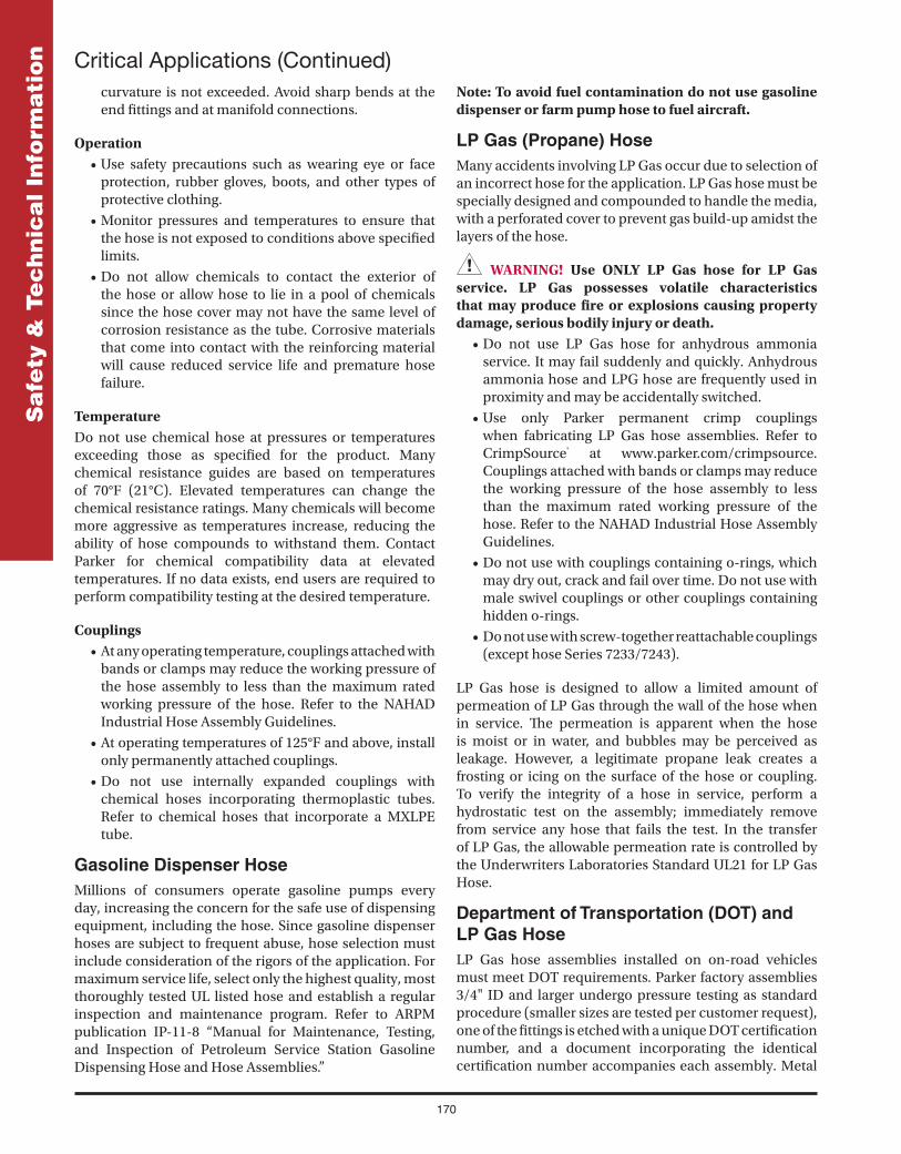
170
Sa
fety
& T
ec
hn
ica
l In
form
ati
on
curvature is not exceeded. Avoid sharp bends at the end fi ttings and at manifold connections.
Operation• Use safety precautions such as wearing eye or face
protection, rubber gloves, boots, and other types of protective clothing.
• Monitor pressures and temperatures to ensure that the hose is not exposed to conditions above specifi ed limits.
• Do not allow chemicals to contact the exterior of the hose or allow hose to lie in a pool of chemicals since the hose cover may not have the same level of corrosion resistance as the tube. Corrosive materials that come into contact with the reinforcing material will cause reduced service life and premature hose failure.
TemperatureDo not use chemical hose at pressures or temperatures exceeding those as specifi ed for the product. Many chemical resistance guides are based on temperatures of 70°F (21°C). Elevated temperatures can change the chemical resistance ratings. Many chemicals will become more aggressive as temperatures increase, reducing the ability of hose compounds to withstand them. Contact Parker for chemical compatibility data at elevated temperatures. If no data exists, end users are required to perform compatibility testing at the desired temperature.
Couplings• At any operating temperature, couplings attached with
bands or clamps may reduce the working pressure of the hose assembly to less than the maximum rated working pressure of the hose. Refer to the NAHAD Industrial Hose Assembly Guidelines.
• At operating temperatures of 125°F and above, install only permanently attached couplings.
• Do not use internally expanded couplings with chemical hoses incorporating thermoplastic tubes. Refer to chemical hoses that incorporate a MXLPE tube.
Gasoline Dispenser HoseMillions of consumers operate gasoline pumps every day, increasing the concern for the safe use of dispensing equipment, including the hose. Since gasoline dispenser hoses are subject to frequent abuse, hose selection must include consideration of the rigors of the application. For maximum service life, select only the highest quality, most thoroughly tested UL listed hose and establish a regular inspection and maintenance program. Refer to ARPM publication IP-11-8 “Manual for Maintenance, Testing, and Inspection of Petroleum Service Station Gasoline Dispensing Hose and Hose Assemblies.”
Note: To avoid fuel contamination do not use gasoline dispenser or farm pump hose to fuel aircraft.
LP Gas (Propane) HoseMany accidents involving LP Gas occur due to selection of an incorrect hose for the application. LP Gas hose must be specially designed and compounded to handle the media, with a perforated cover to prevent gas build-up amidst the layers of the hose.
WARNING! Use ONLY LP Gas hose for LP Gas service. LP Gas possesses volatile characteristics that may produce fi re or explosions causing property damage, serious bodily injury or death.
• Do not use LP Gas hose for anhydrous ammonia service. It may fail suddenly and quickly. Anhydrous ammonia hose and LPG hose are frequently used in proximity and may be accidentally switched.
• Use only Parker permanent crimp couplings when fabricating LP Gas hose assemblies. Refer to CrimpSource® at www.parker.com/crimpsource. Couplings attached with bands or clamps may reduce the working pressure of the hose assembly to less than the maximum rated working pressure of the hose. Refer to the NAHAD Industrial Hose Assembly Guidelines.
• Do not use with couplings containing o-rings, which may dry out, crack and fail over time. Do not use with male swivel couplings or other couplings containing hidden o-rings.
• Do not use with screw-together reattachable couplings (except hose Series 7233/7243).
LP Gas hose is designed to allow a limited amount of permeation of LP Gas through the wall of the hose when in service. Th e permeation is apparent when the hose is moist or in water, and bubbles may be perceived as leakage. However, a legitimate propane leak creates a frosting or icing on the surface of the hose or coupling. To verify the integrity of a hose in service, perform a hydrostatic test on the assembly; immediately remove from service any hose that fails the test. In the transfer of LP Gas, the allowable permeation rate is controlled by the Underwriters Laboratories Standard UL21 for LP Gas Hose.
Department of Transportation (DOT) and LP Gas HoseLP Gas hose assemblies installed on on-road vehicles must meet DOT requirements. Parker factory assemblies 3/4" ID and larger undergo pressure testing as standard procedure (smaller sizes are tested per customer request), one of the fi ttings is etched with a unique DOT certifi cation number, and a document incorporating the identical certifi cation number accompanies each assembly. Metal
Critical Applications (Continued)

171
Sa
fety
& T
ec
hn
ica
l In
form
ati
on
DOT identifi cation bands are also available/attached for an additional charge at customer request. Contact Parker.
NOTE: When using LP Gas hose in a mobile application such as delivery or service vehicles, the inspection procedures detailed in DOT regulation 49CFR 180.416 must be strictly followed.
Natural Gas and LP Gas HoseTh e molecules of natural gas are small, enhancing their ability to permeate through standard rubber or PVC hose constructions. Th e permeation process is more rapid as the working pressure increases, and natural gas accumulates with potentially dangerous consequences. Series 7132, 7132XTC, 7170, 7231, 7232, 7233 and 7243 LP Gas hoses may be used for natural gas service to a 350 psi maximum, but ONLY under ALL of the following conditions:
• Use only in a well-ventilated environment: Outdoors, or indoors with signifi cant continuous air movement.
• Do not use LP Gas hose to replace fi xed/rigid pipe where that material is more appropriate due to reduced permeation, overall strength and durability. Use rigid pipe, non-permeable tubing or hose with barrier constructions to convey natural gas whenever possible.
Compressed Natural Gas (CNG) and LP Gas Hose
• Do not use LP gas hose for CNG engine applications in on-road vehicles, or for high pressure CNG dispenser/transfer applications (typically 2900 psi or greater). In other applications—where CNG is regulated to pressures within the rating of the hose—apply guidelines for natural gas applications stated above. Always review and adhere to all applicable government and industry regulations and standards prior to installing LP gas hose in a CNG or natural gas application.
Petroleum Transfer Hose• Do not use for oil or fuel transfer service in or on open
water. Hose damage or failure may result in spillage and environmental damage. Use hose specifi cally designed for this application.
• Do not immerse in fuel. Th e hose cover compound may not be of suffi cient grade to resist attack by the fuel. Use hose specifi cally designed for this application.
Steam HoseWater changes to hot water and phases of steam when subjected to heat and pressure. Th e greater the pressure, the higher the temperature required to achieve and maintain a steam phase. If steam escapes, dangerous
quantities of heat may be released very suddenly. Refer to ARPM publication IP-11-1 “Guide for Use, Testing and Inspection of Steam Hose.”
WARNING! Use ONLY steam hose for steam service. Hot water, low pressure steam and high pressure steam may escape explosively and will scald skin, eyes and lungs, which may lead to severe bodily injury or death.
• Many steam systems incorporate detergents or rust inhibitors which may attack steam hose. Prior to using a steam hose with detergents or rust inhibitors, refer to the chemical guides in this catalog, or contact Parker.
• Parker recommends using permanent crimp couplings when fabricating steam assemblies. Refer to CrimpSource® at www.parker.com/crimpsource. Couplings attached with bands or clamps may reduce the working pressure of the hose assembly to less than the maximum rated working pressure of the hose. Refer to the NAHAD Industrial Hose Assembly Guidelines.
• Drain steam hose after each use to reduce the possibility of hose popcorning while in service.
Th e chart at the right represents the three forms of water when subjected to various combinations of heat and pressure. Th e red line represents the point at which hot water becomes saturated steam. Th e area below the red line is hot water; the area above the red line is superheated steam.
Welding HoseMany accidents involving welding hose occur due to selection of an incorrect hose for the application. Welding hose must be specially designed and compounded to handle the media, with rubber compounds able to handle fuel gas and oxygen. Due to the extreme volatility of gases, the varying compatibility of gases with the various grades of hose, and the rough environment of many welding applications, it is crucial to select the correct welding hose. Refer to ARPM publications IP-7, “Specifi cations for Rubber Welding Hose” and IP-11-5, “Guide for Use, Maintenance and Inspection of Welding Hose.” Also refer to the Compressed Gas Association publications E-1, “Standard for Rubber Welding Hose and Hose Connections for Gas Welding, Cutting and Allied Processes” and Safety Bulletin SB-11 “Use of Rubber Welding Hose.”
WARNING! Welding gases possess volatile characteristics that may produce fi re or explosions causing property damage, serious bodily injury or death. Use Grades R and RM ONLY with acetylene fuel gas; do not use with any other fuel gases.
• Replace all assemblies that show signs of abrading, abuse, age, damage or fatigue. Do not attempt to re-couple, repair or splice hose assemblies.
Critical Applications (Continued)
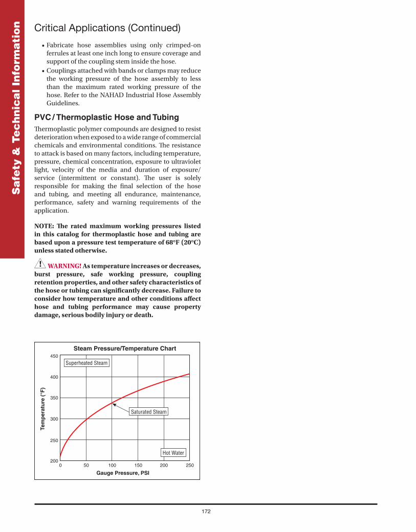
172
Sa
fety
& T
ec
hn
ica
l In
form
ati
on
• Fabricate hose assemblies using only crimped-on ferrules at least one inch long to ensure coverage and support of the coupling stem inside the hose.
• Couplings attached with bands or clamps may reduce the working pressure of the hose assembly to less than the maximum rated working pressure of the hose. Refer to the NAHAD Industrial Hose Assembly Guidelines.
PVC / Thermoplastic Hose and TubingTh ermoplastic polymer compounds are designed to resist deterioration when exposed to a wide range of commercial chemicals and environmental conditions. Th e resistance to attack is based on many factors, including temperature, pressure, chemical concentration, exposure to ultraviolet light, velocity of the media and duration of exposure/service (intermittent or constant). Th e user is solely responsible for making the fi nal selection of the hose and tubing, and meeting all endurance, maintenance, performance, safety and warning requirements of the application.
NOTE: Th e rated maximum working pressures listed in this catalog for thermoplastic hose and tubing are based upon a pressure test temperature of 68°F (20°C) unless stated otherwise.
WARNING! As temperature increases or decreases, burst pressure, safe working pressure, coupling retention properties, and other safety characteristics of the hose or tubing can signifi cantly decrease. Failure to consider how temperature and other conditions aff ect hose and tubing performance may cause property damage, serious bodily injury or death.
Critical Applications (Continued)
Superheated Steam
Saturated Steam
Hot Water

173
Sa
fety
& T
ec
hn
ica
l In
form
ati
onIndustry Publications
Listed below are the titles of publications issued by the Association for Rubber Products Manufacturers (ARPM). Information concerning the latest edition, prices, ordering procedure, etc., may be obtained by contacting them as shown below:
Association for Rubber Products Manufacturers (ARPM)7231 Shadeland Station Way, Suite 285Indianapolis, IN 46256
Phone: 317-863-4072Fax: 317-913-2445Web: www.arpminc.com
Publication Number Title
IP-2 Hose Handbook
IP-7 Specifi cations for Rubber Welding Hose
IP-8 Specifi cations for Rubber Hose for Oil Suction and Discharge
IP-14 Specifi cations for Anhydrous Ammonia Hose
IP-11 Complete Set of Hose Technical Bulletins
IP-11-1 Technical Bulletin – Guide for Use, Testing and Inspection of Steam Hose
IP-11-2 Technical Bulletin – Manual for Use, Maintenance, Testing and Inspection of Anhydrous Ammonia Hose
IP-11-4 Technical Bulletin – Manual for Maintenance, Testing and Inspection of Oil Suction and Discharge Hose
IP-11-5 Technical Bulletin – Guide for Use, Maintenance and Inspection of Welding Hose
IP-11-7 Technical Bulletin – Manual for Maintenance, Testing and Inspection of Chemical Hose
IP-11-8 Technical Bulletin – Manual for Maintenance, Testing and Inspection of Petroleum Service Station Gasoline Dispensing Hose and Hose Assemblies

174
Sa
fety
& T
ec
hn
ica
l In
form
ati
on Offer of Sale
1. Defi nitions. As used herein, the following terms have the meanings indicated. Buyer: means any customer receiving a Quote for Products from
Seller. Goods: means any tangible part, system or component to be supplied
by the Seller. Products: means the Goods, Services and/or Software as described in
a Quote provided by the Seller. Quote: means the off er or proposal made by Seller to Buyer for the
supply of Products. Seller: means Parker-Hannifi n Corporation, including all divisions
and businesses thereof. Services: means any services to be supplied by the Seller. Software: means any software related to the Products, whether
embedded or separately downloaded. Terms: means the terms and conditions of this Off er of Sale or any
newer version of the same as published by Seller electronically at www.parker.com/saleterms.
2. Terms. All sales of Products by Seller are contingent upon, and will be governed by, these Terms and, these Terms are incorporated into any Quote provided by Seller to any Buyer. Buyer’s order for any Products whether communicated to Seller verbally, in writing, by electronic date interface or other electronic commerce, shall constitute acceptance of these Terms. Seller objects to any contrary or additional terms or conditions of Buyer. Reference in Seller’s order acknowledgement to Buyer’s purchase order or purchase order number shall in no way constitute an acceptance of any of Buyer’s terms of purchase. No modifi cation to these Terms will be binding on Seller unless agreed to in writing and signed by an authorized representative of Seller.
3. Price; Payment. The Products set forth in Seller’s Quote are off ered for sale at the prices indicated in Seller’s Quote. Unless otherwise specifi cally stated in Seller’s Quote, prices are valid for thirty (30) days and do not include any sales, use, or other taxes or duties. Seller reserves the right to modify prices at any time to adjust for any raw material price fl uctuations. Unless otherwise specifi ed by Seller, all prices are F.C.A. Seller’s facility (INCOTERMS 2010). All sales are contingent upon credit approval and payment for all purchases is due thirty (30) days from the date of invoice (or such date as may be specifi ed in the Quote). Unpaid invoices beyond the specifi ed payment date incur interest at the rate of 1.5% per month or the maximum allowable rate under applicable law.
4. Shipment; Delivery; Title and Risk of Loss. All delivery dates are approximate. Seller is not responsible for damages resulting from any delay. Regardless of the manner of shipment, delivery occurs and title and risk of loss or damage pass to Buyer, upon placement of the Products with the shipment carrier at Seller’s facility. Unless otherwise agreed, Seller may exercise its judgment in choosing the carrier and means of delivery. No deferment of shipment at Buyers’ request beyond the respective indicated shipping date will be made except on terms that will indemnify, defend and hold Seller harmless against all loss and additional expense. Buyer shall be responsible for any additional shipping charges incurred by Seller due to Buyer’s acts or omissions.
5. Warranty. The warranty related to the Products is as follows: (i) Goods are warranted against defects in material or workmanship for a period of twelve (12) months from the date of delivery or 2,000 hours of use, whichever occurs fi rst; (ii) Services shall be performed in accordance with generally accepted practices and using the degree of care and skill that is ordinarily exercised and customary in the fi eld to which the Services pertain and are warranted for a period of six (6) months from the completion of the Services by Seller; and (iii) Software is only warranted to perform in accordance with applicable specifi cations provided by Seller to Buyer for ninety (90) days from the date of delivery or, when downloaded by a Buyer or end-user, from the date of the initial download. All prices are based upon the exclusive limited warranty stated above, and upon the following disclaimer:
DISCLAIMER OF WARRANTY: THIS WARRANTY IS THE SOLE AND ENTIRE WARRANTY PERTAINING TO PRODUCTS. SELLER DISCLAIMS ALL OTHER WARRANTIES, EXPRESS AND IMPLIED, INCLUDING DESIGN, NONINFRINGEMENT, MERCHANTABILITY, AND FITNESS FOR A PARTICULAR PURPOSE. SELLER DOES NOT WARRANT THAT THE SOFTWARE IS ERROR-FREE OR FAULT-TOLERANT, OR THAT BUYER’S USE THEREOF WILL BE SECURE OR UNINTERRUPTED. BUYER AGREES AND ACKNOWLEDGES THAT UNLESS OTHERWISE AUTHORIZED IN WRITING BY SELLER THE SOFTWARE SHALL NOT BE USED IN CONNECTION WITH HAZARDOUS OR HIGH RISK ACTIVITIES OR ENVIRONMENTS. EXCEPT AS EXPRESSLY STATED HEREIN, ALL PRODUCTS ARE PROVIDED “AS IS”.
6. Claims; Commencement of Actions. Buyer shall promptly inspect all Products upon receipt. No claims for shortages will be allowed unless reported to the Seller within ten (10) days of delivery. Buyer shall notify Seller of any alleged breach of warranty within thirty (30) days after the date the non-conformance is or should have been discovered by Buyer. Any claim or action against Seller based upon breach of contract or any other theory, including tort, negligence, or otherwise must be commenced within twelve (12) months from the date of the alleged breach or other alleged event, without regard to the date of discovery.
7. LIMITATION OF LIABILITY. IN THE EVENT OF A BREACH OF WARRANTY, SELLER WILL, AT ITS OPTION, REPAIR OR REPLACE THE NON-CONFORMING PRODUCT, RE-PERFORM THE SERVICES, OR REFUND THE PURCHASE PRICE PAID WITHIN A REASONABLE PERIOD OF TIME. IN NO EVENT IS SELLER LIABLE FOR ANY SPECIAL, INDIRECT, INCIDENTAL OR CONSEQUENTIAL DAMAGES ARISING OUT OF, OR AS THE RESULT OF, THE SALE, DELIVERY, NON-DELIVERY, SERVICING, NON-COMPLETION OF SERVICES, USE, LOSS OF USE OF, OR INABILITY TO USE THE PRODUCTS OR ANY PART THEREOF, LOSS OF DATA, IDENTITY, PRIVACY, OR CONFIDENTIALITY, OR FOR ANY CHARGES OR EXPENSES OF ANY NATURE INCURRED WITHOUT SELLER’S WRITTEN CONSENT, WHETHER BASED IN CONTRACT, TORT OR OTHER LEGAL THEORY. IN NO EVENT SHALL SELLER’S LIABILITY UNDER ANY CLAIM MADE BY BUYER EXCEED THE PURCHASE PRICE PAID FOR THE PRODUCTS.
8. Loss to Buyer’s Property. Any designs, tools, patterns, materials, drawings, confi dential information or equipment furnished by Buyer or any other items which are or become Buyer’s property, will be considered obsolete and may be destroyed by Seller after two (2) consecutive years have elapsed without Buyer ordering the Products manufactured using such property. Seller shall not be responsible for any loss or damage to such property while it is in Seller’s possession or control.
9. Special Tooling. Special Tooling includes but is not limited to tooling, jigs, fi xtures and associated manufacturing equipment acquired or necessary to manufacture Products. A tooling charge may be imposed for any Special Tooling. Such Special Tooling shall be and remain Seller’s property notwithstanding payment of any charges by Buyer. In no event will Buyer acquire any interest in Special Tooling belonging to Seller that is utilized in the manufacture of the Products, even if such Special Tooling has been specially converted or adapted for such manufacture and notwithstanding any charges paid by Buyer. Unless otherwise agreed, Seller has the right to alter, discard or otherwise dispose of any Special Tooling or other property in its sole discretion at any time.
10. Security Interest. To secure payment of all sums due, Seller retains a security interest in all Products delivered to Buyer and, Buyer’s acceptance of these Terms is deemed to be a Security Agreement under the Uniform Commercial Code. Buyer authorizes Seller as its attorney to execute and fi le on Buyer’s behalf all documents Seller deems necessary to perfect its security interest.
11. User Responsibility. The Buyer through its own analysis and testing, is solely responsible for making the fi nal selection of the Products and assuring that all performance, endurance, maintenance, safety and warning requirements of the application of the Products are met. The Buyer must analyze all aspects of the application and follow applicable industry standards, specifi cations, and other technical information provided with the Product. If Seller provides Product options based upon data or specifi cations provided by the Buyer, the Buyer is responsible for determining that such data and specifi cations are suitable and suffi cient for all applications and reasonably foreseeable uses of the Products. In the event the Buyer is not the end-user, Buyer will ensure such end-user complies with this paragraph.
12. Use of Products, Indemnity by Buyer. Buyer shall comply with all instructions, guides and specifi cations provided by Seller with the Products. Unauthorized Uses. If Buyer uses or resells the Products for any uses prohibited in Seller’s instructions, guides or specifi cations, or Buyer otherwise fails to comply with Seller’s instructions, guides and specifi cations, Buyer acknowledges that any such use, resale, or non-compliance is at Buyer’s sole risk. Buyer shall indemnify, defend, and hold Seller harmless from any losses, claims, liabilities, damages, lawsuits, judgments and costs (including attorney fees and defense costs), whether for personal injury, property damage, intellectual property infringement or any other claim, brought by or incurred by Buyer, Buyer’s employees, or any other person, arising out of: (a) improper selection, application, design, specifi cation or other misuse of Products provided by Seller; (b) any act or omission, negligent or otherwise,

175
Sa
fety
& T
ec
hn
ica
l In
form
ati
onof Buyer; (c) Seller’s use of patterns, tooling, equipment, plans, drawings, designs
or specifi cations or other information or things furnished by Buyer; (d) damage to the Products from an external cause, repair or attempted repair by anyone other than Seller, failure to follow instructions, guides and specifi cations provided by Seller, use with goods not provided by Seller, or opening, modifying, deconstructing or tampering with the Products for any reason; or (e) Buyer’s failure to comply with these Terms. Seller shall not indemnify Buyer under any circumstance except as otherwise provided in these Terms.
13. Cancellations and Changes. Buyer may not cancel or modify any order for any reason, except with Seller’s written consent and upon terms that will indemnify, defend and hold Seller harmless against all direct, incidental and consequential loss or damage. Seller, at any time, may change Product features, specifi cations, designs and availability.
14. Limitation on Assignment. Buyer may not assign its rights or obligations without the prior written consent of Seller.
15. Force Majeure. Seller does not assume the risk and is not liable for delay or failure to perform any of Seller’s obligations by reason of events or circumstances beyond its reasonable control (“Events of Force Majeure”). Events of Force Majeure shall include without limitation: accidents, strikes or labor disputes, acts of any government or government agency, acts of nature, delays or failures in delivery from carriers or suppliers, shortages of materials, or any other cause beyond Seller’s reasonable control.
16. Waiver and Severability. Failure to enforce any provision of these Terms will not invalidate that provision; nor will any such failure prejudice Seller’s right to enforce that provision in the future. Invalidation of any provision of these Terms by legislation or other rule of law shall not invalidate any other provision herein and, the remaining provisions will remain in full force and eff ect.
17. Termination. Seller may terminate any agreement governed by or arising from these Terms for any reason and at any time by giving Buyer thirty (30) days prior written notice. Seller may immediately terminate, in writing, if Buyer: (a) breaches any provision of these Terms (b) appoints a trustee, receiver or custodian for all or any part of Buyer’s property (c) fi les a petition for relief in bankruptcy on its own behalf, or one if fi led by a third party (d) makes an assignment for the benefi t of creditors; or (e) dissolves its business or liquidates all or a majority of its assets.
18. Ownership of Software. Seller retains ownership of all Software supplied to Buyer hereunder. In no event shall Buyer obtain any greater right in and to the Software than a right in the nature of a license limited to the use thereof and subject to compliance with any other terms provided with the Software.
19. Indemnity for Infringement of Intellectual Property Rights. Seller is not liable for infringement of any patents, trademarks, copyrights, trade dress, trade secrets or similar rights (“Intellectual Property Rights”) except as provided in this Section. Seller will defend at its expense and will pay the cost of any settlement or damages awarded in an action brought against Buyer based on a third party claim that one or more of the Products sold hereunder infringes the Intellectual Property Rights of a third party in the country of delivery of the Products by the Seller to the Buyer. Seller’s obligation to defend and indemnify Buyer is contingent on Buyer notifying Seller within ten (10) days after Buyer becomes aware of any such claim, and Seller having sole control over the defense of the claim including all negotiations for settlement or compromise. If one or more Products sold hereunder is subject to such a claim, Seller may, at its sole expense and option, procure for Buyer the right to continue using the Products, replace or modify the Products so as to render them non-infringing, or off er to accept return of the Products and refund the purchase price less a reasonable allowance for depreciation. Seller has no obligation or liability for any claim of infringement: (i) arising from information provided by Buyer; or (ii) directed to any Products provided hereunder for which the designs are specifi ed in whole or part by Buyer; or (iii) resulting from the modifi cation, combination or use in a system of any Products provided hereunder. The foregoing provisions of this Section constitute Seller’s sole and exclusive liability and Buyer’s sole and exclusive remedy for such claims of infringement of Intellectual Property Rights.
20. Governing Law. These Terms and the sale and delivery of all Products are deemed to have taken place in, and shall be governed and construed in accordance with, the laws of the State of Ohio, as applicable to contracts executed and wholly performed therein and without regard to confl icts of laws principles. Buyer irrevocably agrees and consents to the exclusive jurisdiction and venue of the courts of Cuyahoga County, Ohio with respect to any dispute, controversy or claim arising out of or relating to the sale and delivery of the Products.
21. Entire Agreement. These Terms, along with the terms set forth in the main body of any Quote, forms the entire agreement between the Buyer and Seller and constitutes the fi nal, complete and exclusive expression of the terms of sale. In the event of a confl ict between any term set forth in the main body of a
Quote and these Terms, the terms set forth in the main body of the Quote shall prevail. All prior or contemporaneous written or oral agreements or negotiations with respect to the subject matter shall have no eff ect. These Terms may not be modifi ed unless in writing and signed by an authorized representative of Seller.
22. Compliance with Laws. Buyer agrees to comply with all applicable laws, regulations, and industry and professional standards, including those of the United States of America, and the country or countries in which Buyer may operate, including without limitation the U.S. Foreign Corrupt Practices Act (“FCPA”), the U.S. Anti-Kickback Act (“Anti-Kickback Act”), U.S. and E.U. export control and sanctions laws (“Export Laws”), the U.S. Food Drug and Cosmetic Act (“FDCA”), and the rules and regulations promulgated by the U.S. Food and Drug Administration (“FDA”), each as currently amended. Buyer agrees to indemnify, defend, and hold harmless Seller from the consequences of any violation of such laws, regulations and standards by Buyer, its employees or agents. Buyer acknowledges that it is familiar with all applicable provisions of the FCPA, the Anti-Kickback Act, Export Laws, the FDCA and the FDA and certifi es that Buyer will adhere to the requirements thereof and not take any action that would make Seller violate such requirements. Buyer represents and agrees that Buyer will not make any payment or give anything of value, directly or indirectly, to any governmental offi cial, foreign political party or offi cial thereof, candidate for foreign political offi ce, or commercial entity or person, for any improper purpose, including the purpose of infl uencing such person to purchase Products or otherwise benefi t the business of Seller. Buyer further represents and agrees that it will not receive, use, service, transfer or ship any Product from Seller in a manner or for a purpose that violates Export Laws or would cause Seller to be in violation of Export Laws.

176
Sa
fety
& T
ec
hn
ica
l In
form
ati
on Basic Hose Constructions
Construction ElementsA hose is generally composed of three elements, each with an important role in the overall performance of that hose. Th e three elements are:
Th e Tube must be compatible with and able to contain the media being conveyed. Many diff erent materials are used for tube construction, depending upon the media the hose is designed to transmit.
Th e Reinforcement is the strength member of the hose. It enables the hose to withstand internal and external pressure and abuse. Th e reinforcement may be applied by several methods, and consists of synthetic yarns, wire or a combination of these. If suction or vacuum capability is a requirement, a helix wire may be part of the reinforcement.
Th e Cover protects the reinforcement from abuse or damage. Th e cover is usually a rubber compound selected for its resistance to the environment, although, in some cases (Series 7243) the reinforcement will also act as the cover. Typical considerations in selecting a cover stock are the need to resist abrasion, ozone, weather and sunlight, chemical or oil spillage, etc.
Construction MethodsSeveral methods are used to manufacture Parker hose. Application factors such as size and pressure requirements determine the selection of any particular hose style. Th e following is a description of the various construction methods employed by Parker.
Flexible MandrelTh e fl exible mandrel method combines the long-length advantage of non-mandrel hose with the close inside diameter tolerances and high pressure ratings of rigid mandrel hose. Th is is achieved by building the hose on a long length mandrel made of fl exible plastic or rubber.
Typical Size Range: 1-1/2" ID and smaller
Typical Uses: High pressure, air, water, LPG
Advantages: Long lengths, close tolerances on I.D., higher pressure ratings than non-mandrel produced hose
Disadvantages: Higher cost than non-mandrel hose; not available in ID sizes as large as rigid mandrel hose
Rigid MandrelHose produced by this method is supported on a rigid metal mandrel and is handled horizontally during production. While a rigid mandrel limits the hose length, it ensures good control of the inside diameter. It also off ers suffi cient support to the tube that either wire or textile reinforcement may be applied at high tensions, which is necessary in high pressure constructions. After the cover is applied, the hose may be wrapped with nylon tape for curing, giving the familiar “wrapped” fi nish to the cover.
Typical Size Range: 3/4" ID and larger
Typical Uses: Air, chemical and petroleum transfer, LPG, steam, water
Advantages: Close tolerances on inside diameter, high pressure ratings, good length stability
Disadvantages: Higher cost than non-mandrel; lengths restricted to length of mandrels
(Continued)
Non-MandrelNon-mandrel hose is constructed by passing long lengths of extruded tube material through a machine which adds the reinforcement in braided or spiraled layers. In this method, the hose is not built on a mandrel, therefore lengths are not restricted to the lengths of the mandrels.
Typical Size Range: 1-1/2" ID and smaller
Typical Uses: Air, water or general purpose service where operating conditions are not severe
Advantages: Economy and long lengths
Disadvantages: Requires wider ID and OD tolerance range than mandrel made hose, limited pressure capabilities

177
Sa
fety
& T
ec
hn
ica
l In
form
ati
on
Wrapped Ply – Hand BuiltWrapped ply hose may be hand built when the diameter is too large for the building machine or where special built-in ends are desired. Th e plies are laid on by an operator rather than an automated machine process, allowing hand-forming of built-in ends.
Size Range: 1/2" through 60" ID
Typical Uses: Oil suction and discharge, sand suction, acid suction and discharge
Advantages: Special ends can be built into the hose; wide size range; special constructions available in small quantities
Disadvantages: Relatively expensive due to high labor content
Basic Hose Constructions (Continued)
Wrapped Ply – Machine BuiltTh e wrapped ply construction is the oldest method of making hose, applying all hose components (tube, reinforcement and cover) in spiral strips on a rigid mandrel. After a tube is in place on the mandrel, layers or plies of bias cut fabric reinforcement are wrapped around the tube. Th e cover is applied and the hose is wrapped in nylon tape prior to curing. Th is process is capable of producing a hose for suction service when a helix wire(s) is incorporated.
Size Range: 1/2" through 30" ID
Typical Uses: Air; suction and discharge service for chemicals, dry materials, oil and water, conduit
Advantages: Good inside diameter tolerances, many special constructions available without large minimum production runs, special ends available, wide size range
Disadvantages: Higher cost compared to non-mandrel and fl ex mandrel; pressure and length limitations

178
Sa
fety
& T
ec
hn
ica
l In
form
ati
on Age Control of Hose (Shelf Life)
Th e Parker warranty takes precedence over guidelines established by other industry organizations regarding the recommended shelf life of industrial hose. To achieve maximum shelf life, employ proper storage and handling practices and techniques, such as:
• Storage in the original shipping container such as a box, coil, or reel. Hose stored on a reel or in a coil should have its plastic wrapping kept intact.
• Storage in temperatures of 100°F (38°C) or less.• Avoidance of ozone (electrical discharges or fi elds),
water, extreme humidity, corrosive chemicals and ultraviolet radiation (direct sunlight).
• Use on a fi rst-in, fi rst-out (FIFO) basis determined by the manufacturing date on the hose.
For further information pertaining to age control of hose, contact Parker or refer to the current ARPM Hose Handbook, IP-2.
Electrical Properties
of Rubber Hose
Electrical ConductivityIndustrial hoses generally fall into three categories: conductive, nonconductive, or somewhere in-between. Because of its unique properties, it is possible for rubber to be nonconductive at low voltage and conductive at high voltage. When using a hose in an application that has electrical resistance requirements (low electrical resistance for conductive applications or high electrical resistance for nonconductive applications), always select a hose that is specifi cally designed to meet the specifi c need. Since conductivity or nonconductivity is not a consideration for many applications, electrical resistance ratings do not exist for many hoses.
Conductive HoseStatic electricity is generated by the fl ow of material (even some liquids) through a hose. As the material fl ows, molecules collide and generate friction, which creates minute amounts of electrical charge (excess electrons). Th e charge accumulates potential energy at the delivery end of the hose (coupling/nozzle). Th e amount of charge increases with material volume and linear velocity, coarseness of the material, and length of the hose. If not properly grounded, the accumulated charge (potential energy) will seek its own ground. Th e charge will be attracted to external materials in proximity (such as a steel storage container); if not properly grounded, the electrons may arc (jump) to the external material, igniting volatile materials in the hose, or in proximity to the hose.
Electrically conductive wires and conductive rubber components are used in hose to prevent static electricity build-up and discharge as a spark. Electrical engineers diff er in opinion on the eff ects of static electricity and the means of dissipating it. In handling gasoline and other petroleum-based liquids, recognized national associations and companies have confl icting opinions on the need for conductive hoses. Until a consensus is reached among all associations, laboratories and users, and a standard practice is established, it is essential that the user determine the need for static bonded hose based on (a) the intended use of the hose, (b) instructions from the company’s safety division, (c) the insurer, and (d) the laws of the localities and states in which the hose will be used.
Some types of hose include a helical or static wire(s). Th is wire can be used for electrical continuity provided that proper contact is made and maintained between it and the hose couplings.
Nonconductive HoseNonconductive hose constructions are those that resist the fl ow of electrical current. In some specifi c applications, especially around high voltage electrical lines, it is imperative for safety that the hose be nonconductive. Unless the hose is designed particularly to be nonconductive and is so branded, do not conclude that it is nonconductive. Many black rubber compounds are inherently and inadvertently conductive. Nonconductive hose is usually made to a qualifying standard that requires it to be tested to verify the desired electrical properties. Th e hose is frequently (but not necessarily) non-black in color and clearly branded to indicate it is designed for nonconductive applications.
NOTE 1: Parker industrial hose generally uses the non-conduc tivity standard originally developed by Alcoa Aluminum: A minimum resistance of one megaohm per inch at 1,000 volts D.C.
NOTE 2: SAE has a separate standard for nonconduc tiv-ity for high pressure hydraulic applications. Part of the standard requires that nonconductive hose feature an orange cover.
NOTE 3: Nonconductive hoses contain little/no con-ductive rubber compounds, static wires, helical wires, or wire reinforcement. Th erefore, a nonconductive hose would not be recommended for an application requiring an “anti-static/static dissipating/conductive” hose.
WARNING! Unless a hose is described as, or specifi cally and clearly branded to be conducting or nonconducting, assume that the electrical properties are uncontrolled.

179
Sa
fety
& T
ec
hn
ica
l In
form
ati
onForce to Bend /
Minimum Bend RadiusTh e amount of force required to bend a hose and the minimum bend radius are important factors in hose design and selection. Th e minimum bend radius is defi ned as the radius to which the hose can be bent in service without damaging or appreciably shortening the life of the product, and is measured to the inside of the curvature of the bend. Th e bend radius for a given application must be equal to or greater than the rated minimum bend radius. Bending the hose to a smaller bend radius than minimum may kink the hose and result in premature failure.
Perhaps more important in determining fl exibility, the force-to-bend is defi ned as the amount of force required to induce bending around a specifi ed radius. Th e less force that is required, the easier the product is to maneuver in the fi eld. Diff erent hose constructions may require signifi cantly diff erent forces to attain the same minimum bend radius. Generally, the preferred hose is the more fl exible hose, provided all other properties are essentially equivalent.
Oil and Fuel ResistanceRubber compounds are available in diff erent formu-lations, blends and grades. Compounds are selected by hose design engineers based on the intended application of the hose. For instance, a hose recommended for multipurpose applications that may include hydraulic or
lubrication oil service generally contains a lower grade of tube compound. Conversely, a hose recommended for a more rigorous application, such as highly refi ned fuel service, contains a higher grade of compound, often within the same compound family.
Rubber hose is used to convey petroleum products both in the crude and refi ned stages. Th e aromatic content of refi ned gasoline is often adjusted to control the octane rating. Th e presence of aromatic hydrocarbons in this fuel generally has a greater eff ect on rubber components than do aliphatic hydrocarbons. Aromatic materials in contact with rubber tend to soften it and reduce its physical properties. For long-lasting service, the purchaser of fuel hose should inform the hose manufacturer of the aromatic content of the fuel to be handled so that the proper tube compound can be recommended for the specifi c application.
Th e eff ect of oil on rubber depends on a number of factors that include the type of rubber compound, the composition of the oil, the temperature and duration of exposure. Rubber compounds can be classifi ed to their degree of oil resistance based on their physical properties after exposure to a standard test fl uid. In this ARPM classifi cation, the rubber samples are immersed in IRM 903 oil at 212°F (100°C) for seventy hours. (See ASTM Method D-471 for a detailed description of the oil and the testing procedure.) As a guide to users of hose in contact with oil, the oil resistance classes and a corresponding description are listed on the next page.
Example: To make a 90° bend with 2" I.D. hose. Given r = 4.5 inches.
General Formula for Minimum Hose Length(given hose bend radius and degree of bend required)
.25 x 2 x 3.14 x 4.5 = 7" (minimum length of hose to make bend without damage to hose)
The minimum bend radius is measured to the inside of the curvature.
Angle of Bend
360°x 2 r = Minimum length of hose to make bend.
r = Given bend radius of hose.
90360°
x 2 x 3.14 x 4.5
The bend radius for a given application must be equal to or greater than the rated minimum bend radius. Bending the hose to a smaller bend radius than minimum may kink the hose and result in premature failure.
General Formula for Minimum Hose Length (allowing relief from couplings)Overall Length (OAL) = (2 x Length of Coupling) + (2 x Hose OD) + (Angle/360) x 2 r

180
Sa
fety
& T
ec
hn
ica
l In
form
ati
on Physical Properties After Exposure to Oil
Class Volume Change Maximum
Tensile Strength Retained
Class A (High Oil Resistance)
+25% 80%
Class B (Medium/High Oil Resistance)
+65% 50%
Class C (Medium Oil Resistance)
+100% 40%
Th e above ARPM guideline does not imply compatibility with all oil based fl uids. Th ere are many grades of rubber compounds that meet ARPM Class A oil resistance requirements. Some compound grades will be fi ne for multipurpose applications, while higher grades would be required for more rigorous applications.
Oil resistant hoses for multipurpose service tend to be more economical than hoses specifi cally designed and recommended for highly refi ned fuel service. Th ese multipurpose hoses, even if they feature an ARPM Class A tube, are not necessarily recommended for use with highly refi ned fuels. Furthermore, many chemical resistance charts represent data developed from testing of a typical grade of compound used for that family of fl uids. For example, “nitrile” may show compatibility with gasoline, but the nitrile that was tested is likely the nitrile used in gasoline dispenser hose, as opposed to the nitrile commonly used in multipurpose hose.
When selecting a hose for highly refi ned fuels such as aviation fuel, biodiesel, diesel, ethanol, gasoline or kerosene, be guided by the hose manufacturer’s recom-mendation to use a hose designed and manufactured for that specifi c application and/or fl uid. Contact Parker for further information.
Suction and VacuumHose is constructed with high adhesion between the tube and the carcass to prevent tube separation. Most hose is used for pressure service; however, some applications require the hose to resist collapse in suction and vacuum service. Such hose is subjected to crushing forces because the atmospheric pressure outside the hose is greater than the internal pressure. Th e hose can collapse and restrict the fl ow unless the hose is constructed to resist these pressure diff erentials. Th e most common method of preventing hose collapse is to build a helical member(s) (wire or thermoplastic) into the hose body. Th e size and spacing of the helix depends on the size of the hose and the pressure diff erential. In applications approaching a perfect vacuum, most of the plies of reinforcement are applied over the helix.
Suction hose must be specifi cally designed for the service for which it is used. Each element—tube, reinforcement, size, spacing, and location of the helix—must be carefully considered. While suction hose is generally used to convey liquids, vacuum hose carries air under a partial vacuum. Vacuum hose is reinforced to resist collapse and maintain its shape under rough handling and/or mechanical abuse. It does not require the heavy construction of suction hose because the dry materials generally conveyed are much lighter in weight than liquids and the vacuum is usually less than for normal suction service.

181
Sa
fety
& T
ec
hn
ica
l In
form
ati
onCoupling Thread Compatibility
Industrial hose couplings have threads which are usually one of the various “pipe” threads. All pipe threads are com-monly referred to by the generic name of Iron Pipe Thread or IPT. There are several different types of IPT threads and you must know specifically what they are to ensure compatibility with mating threads.
IPT Thread Compatibility ChartDescription Seal Thread
(Female)Compatible
Threads (Male)
American Standard Tapered Pipe Thread Thread Seal (with Sealing Compound)
NPT NPTNPTF
American Standard Tapered Dryseal Pipe Thread Thread Seal (Dryseal)* NPTF NPTFNPT
American Standard Straight Pipe Thread for mechanical joints (includes 2 female types, depending on sealing method, and one male type compatible with both females)
Washer or Mechanical Ground Joint
NPSM NPSMNPTNPTF
American Standard Straight Pipe Threads for hose couplings and nipples
Washer NPSH NPSHNPTNPTF
*When NPTF Threads are used more than once, they require sealing compound after the fi rst use.
In addition, there are various other thread types that may be found on industrial hose couplings. These types are generally not compatible with any other thread types:
Type Description Seal
GHT Garden Hose Thread Washer seal
API American Petroleum Institute Thread Thread seal
JIC (37˚) Joint Industry Council Mechanical seal
SAE (45˚) Society of Automotive Engineers Mechanical seal
NF Welding Hose Threads-Left Hand and Right Hand Mechanical seal
CHT Chemical Hose Thread (for booster hoses) Gasket seal

Chemical Guides

183
Me
dia
Co
mp
ati
bilit
y Media CompatibilityDescription Page
No.
Chemical Guides Introduction 183
Hose and Chemical Table 186
Metal/Coupling Corrosion Resistance Table 213
Names and General Properties of Hose Materials 184
PVC Temperature / Pressure Chart 212
Refi ned Fuel / Hose Compatibility Table 185
Silicone Hose and Chemical Table 215
A complete listing of industry standards is available in the Introduction section. See the pages immediately following the Table of Contents for a complete index by series,
and by product application and name.
Due to continual product improvements, Parker reserves the right to alter specifications without prior notice.
Chemical Guides IntroductionTh e Chemical Guides in this section are off ered as a general indication of the compatibility of the various compounds incorporated in Parker hose with the chemicals, fl uids and media listed. Th e basis for the ratings includes actual service experience, the advice of various polymer suppliers, and the considered opinion of our chemists. When in doubt, a sample of the compound should always be tested with the particular chemical and temperature it is to handle.
Some of the variables that aff ect the resistance of a compound to a chemical attack are:
1. Temperature of the Media Transmitted: Higher temperatures increase the aff ect of chemicals on compounds. Th e amount of increase depends upon the polymer and the chemical. A compound quite suitable at room temperature might fail very quickly at higher temperatures. Working pressures in this catalog are recommended in accordance with ARPM design safety factors at ambient temperatures. Do not operate outside hose temperature limits. Even within hose temperature limits, end fi ttings and hose size can aff ect performance at higher temperatures.
2. Service Conditions: A rubber compound usually swells when exposed to a chemical. Within a given percent of swell, a hose tube may function satisfactorily if the hose is in a static condition, but may fail quickly if the hose is subject to fl exing.
3. Th e Grade or Blend of the Rubber Compound: Basic polymers are sometimes mixed or blended to enhance a particular property for a specifi c service. As an example, the nitrile used as the tube material for Parker aircraft fueling hose varies in its makeup from the nitrile used in the tube of Day-Flo® Special Purpose hose. Consequently, the reaction to a particular chemical may therefore be somewhat diff erent. When in doubt, a sample of the compound should always be tested with the particular chemical it is going to handle.

184
Me
dia
Co
mp
ati
bilit
yNames and General Properties of Hose MaterialsRefer to the guides on the following pages for specifi c applications.
Common Name ASTM Designation
D1418-64
Composition General Properties Primary Hose
Elements
Butyl / Chlorobutyl IIR Isobutene-Isoprene Very good weathering resistance, low permeability to air. Good physical properties. Poor resistance to petroleum based fluids.
Tube / Cover
Chlorinated Polyethylene (CPE)
CM Chloropolyethylene Good long term resistance to UV and weathering. Good oil and chemical resistance. Excellent flame resistance. Good low temperature impact resistance.
Tube
Cross Linked Polyethylene (XLPE)
XPE Cross Linked Polyethylene Excellent resistance to most solvents, oils and chemicals. Do not confuse with chemical properties of standard polyethylene.
Tube
EPDM EPDM Ethylene Propylene Diene Good general purpose polymer. Excellent heat ozone, and and weather resistance. Not oil resistant.
Tube / Cover
Epichlorohydrin ECO Ethylene Oxide Chloromethyl
Excellent oil and ozone resistance. Fair flame resistance and low permeability to gases. Good low temperature properties.
Tube / Cover
Ethyl Vinyl Acetate (EVA) Ethylene Vinyl Acetate Good abrasion and chemical resistance. Lightweight.
Tube / Cover
FKM FKM Fluorocarbon Rubber Excellent high temperature resistance, particularly in air or oil. Very good chemical resistance.
Tube / Cover
Fluorinated Ethylene Propylene / Polytetra-Flouroethylene
FEP / PTFE
Fluorinated Ethylene Propylene / Polytetra-Flouroethylene
Excellent chemical, solvent, and heat resistance, inert to most materials. Smooth anti-adhesive surface – easily cleaned.
Tube
Modifi ed XLPE (MXLPE) Proprietary Excellent chemical resistance with good heat properties.
Tube
Natural Rubber NR Isoprene Excellent physical properties, including abrasion resistance. Not oil resistant.
Tube
Neoprene CR Chloroprene Excellent weathering resistance. Good oil resistance. Good physical properties.
Tube / Cover
Nitrile / Buna-N NBR Nitrile-Butadiene Excellent oil resistance. Good physical properties.
Tube / Cover
Nylon Nylon Excellent chemical resistance. Good temperature resistance.
Tube
Poly Vinyl Chloride (PVC) Poly Vinyl Chloride Good abrasion, chemical and weathering resistance. Lightweight. Poor oil and temperature resistance.
Tube / Cover, Tubing
Poly Vinyl Chloride / Polyurethane (PVC/PU)
Poly Vinyl Chloride/Polyurethane Blend
Good abrasion, chemical and weathering resistance.
Tube / Cover
Polyurethane (PU) AU Polyurethane Good abrasion, chemical and weathering resistance.
Tube / Cover
SBR SBR Styrene-Butadiene Good physical properties, including abrasion resistance. Not oil resistant. Poor weathering and ozone resistance.
Tube / Cover
TPV Thermoplastic Vulcanizate
Excellent chemical and ozone resistance. Good fl exibility. Lightweight.
Tube, Tubing
Ultra-High Molecular Weight Polyethylene (UHMWPE)
UHMW Ultra-High Molecular Weight Polyethylene
Excellent chemical and heat resistance. Tube

185
Me
dia
Co
mp
ati
bilit
y Refi ned Fuel / Hose Compatibility TableLEGEND
A: Acceptable for use with the designated fuel, and can be interchanged/used with other “A” media in the same row.D: Acceptable for use with the designated fuel, but only for DEDICATED service with that designated fuel. Not interchangeable/for use with any other fuel—prior to or subsequnt to—use with the dedicated fuel.X: Not acceptable for use with the designated fuel in any application.
NOTES: “A” or “D” ratings do not imply compliance with government or industry regulations or specifi cations in any application.
Series Tube Av Gas Non-
Regulated
Gasoline
Service
Ethanol Diesel
Fuel
Biodiesel
To E100 To E15 To E85 To B20 To B100
389 Nitrile D A D A A A A X
395 Nitrile D A D A A A A X
397 Nitrile D A D A A A A A
7094/7095 Nitrile X X X X X X X X
7102 Nitrile D A D A A A D X
7107 Nitrile X X X X X X X X
7107 (2" only) Nitrile D A D A A A D X
7114 Nitrile D A D A A A D X
7124 Nitrile D D D A A A D X
7134/7187 Nitrile X X X X X X X X
7137 Nitrile X X X X X X X X
7165 Nylon D A A A A A A A
7174 Nitrile D D D A A A D X
7175 Nitrile D D D A A A D X
7204 Nitrile D A A A A A A X
7208E Nitrile/SBR X X X X X X X X
7212 Nitrile X A X A D A D X
7213E Nitrile/SBR X X X X X X X X
7216/7217 Nitrile D A D A A A D X
7216E Nitrile D A D A A A D X
7219 Nitrile D A A A A A A X
7234 Chloroprene X X D X X X X X
7280 Nitrile D D D A A A D X
7282 Nitrile/THV Barrier D D D A A A D X
7301 Chloroprene X X D X X X X X
7311N/7311NXT Nitrile D A D A A A D X
7331/7331XT Nitrile D A D A A A D X
7396/7397 Nitrile D A D A A A D X
7705 Nitrile A A A A A A A A
7775 Nitrile D A D A A A D D
7776 Nitrile D A D A A A D D
7776CT Nitrile D A D A A A D D
7777 Nitrile D A D A A A D D
SS107/SS107R Nitrile D A D A A A D D
SS269 Nitrile/SBR X X X X X X X X
SWC325 Nitrile D A D A A A D D
SW387 Nitrile D A D A A A D D
SW569 Nitrile D D D D D D D D
SWC316/SWC316R Nitrile D A D A A A D D
SWC609/SWC609R Nitrile D A D A A A D D
Some biodiesel, diesel fuel and gasoline hoses must also meet industry or government standards for regulated applications, such as SAE engine fuel lines or UL gasoline dispenser service. The user is solely responsible for making the fi nal determination if an industry or government (local, state or federal) standard or regulation applies to the application. Contact Parker for more information.

186
Me
dia
Co
mp
ati
bilit
yHose and Chemical Table Refer to “Names and General Properties of Hose Materials” table.
WARNING! The following data is based on tests and believed to be reliable; however, the tabulation should be used as a guide ONLY, since it does not take into consideration all variables, such as elevated temperatures, fl uid contamination, concentration, etc., that may be encountered in actual use. All critical applications should be tested. Refer to the Safety & Technical Information section of this catalog for safety, handling and use information.
!
***Refer to the PVC and Thermoplastic Temperature/Pressure chart in this section.
Thermoplastic hose and tubing achieve their optimum physical properties at room temperature, 68°F (20°C). As thermo-plastic materials are exposed to increased ambient temperatures, they soften and their physical properties change. For hose and tubing, heat sharply reduces the available working pressure and coupling retention. In all cases, test the product in a controlled, secure and safe environment, and consider all operating conditions prior to use.
NOTES: • Data for PVC/thermoplastic materials based on 68°F unless otherwise noted.• Data for other materials based on 70°F unless otherwise noted.
Key: E = Excellent • G = Good • C = Conditional • Blank = No Data • X = Not Recommended
Chemical Or
Material Conveyed
CP
E
CS
M
Ch
loro
bu
tyl
Ch
loro
pre
ne
EP
DM
EV
A**
*
FE
P/P
TF
E
FK
M
MX
LP
E
Na
tura
l
Nit
rile
Nylo
n
PU
***
PV
C**
*
PV
C/P
U**
*
SB
R
TP
V**
*
UH
MW
PE
XL
PE
Acetal C G C G E X G C X C E EAcetaldehyde X E X E G E X X X E X X X X G G EAcetamide G E G E E G E C E X E EAcetate Solvents X C X E C E X G C X C X X X E EAcetic Acid, 10% E E E G E E E E G G X X E G G E E EAcetic Acid, 30% G G C E E E C G X X G G X E EAcetic Acid, 50% E E G C E C E G X C X X G G G C E GAcetic Acid, 80% C X C CAcetic Acid, Glacial E C G C G X E X X X X X C C C G E EAcetic Acid, Vapors G X G GAcetic Anhydride E E G G G C E X C X X X X X X E G EAcetic Ester X G X E E X G X X X E EAcetic Ether C G X E E X G X X X E EAcetic Oxide E G G E X X G G EAcetone G X E X E C E X X X E X X X C G E CAcetone Cyanohydrin C E G E E X C X X E E G EAcetonitrile G E E E E X G X E XAcetophenone X G X E E X X X X X G X XAcetyl Acetone G X E X E E X X X X X G E EAcetyl Chloride E X X X C E G X X X X X G G GAcetyl Oxide E E G G G E X C X X X E E EAcetylene G C E E E X E E G E E G C C C C E EAcetylene Dichloride X C X C E G X X E XAcetylene Tetrachloride X X X X E E X X X X XAcrolein G E C E E X G C X C C X EAcrylic Acid E G X X X E X X X X X XAcrylonitrile E C X X E E X C X E X C C C G C CDi(2Ethylhexyl) Adipate X E X G E C X XAdipic Acid G X E E E E E E E E G G E G EAir E E E E E E E E E E E EAir, +300°F G G G G G E E X G G X E XAlcohol, Aliphatic E E E E G C E E E G E EAlcohol, Aromatic X X C X E E G C C X E EAlk-Tri X X X X E E X X X X X EAllyl Alcohol E E E E E E G E E C X X X G G E EAllyl Bromide X X X X E G X X X G GAllyl Chloride G X X X X C E G X G G X X X G E GAlum E E E E E E E E E E E G G E E G E E EAlum, Papermakers E E GAluminum Acetate E G E C E E E E C C X G E E EAluminum Chloride C E E E E G E E E E E X G E E E E EAluminum Fluoride X E E E E G E E G E G C G G E E E EAluminum Formate X G E E E X X X X E EAluminum Hydroxide E E E E G E E E E G G E E G E E***Refer to the PVC and Thermoplastic Temperature/Pressure chart in this section. (Continued on the following page)

187
Me
dia
Co
mp
ati
bilit
y Hose and Chemical Table (Continued)Refer to Names and General Properties of Hose Materials table.
Chemical Or
Material Conveyed
CP
E
CS
M
Ch
loro
bu
tyl
Ch
loro
pre
ne
EP
DM
EV
A**
*
FE
P/P
TF
E
FK
M
MX
LP
E
Na
tura
l
Nit
rile
Nylo
n
PU
***
PV
C**
*
PV
C/P
U**
*
SB
R
TP
V**
*
UH
MW
PE
XL
PE
Aluminum Nitrate E C E EAluminum Nitrate (AQ) E E E E E E E E E C E E E EAluminum Oxychloride G E EAluminum Phosphate E E E E E E E E E E E EAluminum Sulfate E E E E E E E E E E E E G E E E E E EAlums, NH3-CR-K G E E E E E E E E X G E E E EAmines, Mixed X G G G X G X X C EAmino Xylene X X G X E E X X X X X GAminobenzene G X G X G E E X X C X X G1-Aminobutane C X X C E X X C X XAminodimethylbenzene C C G X X E X X X XAminoethane C G X E E X C X X C2-Aminoethanol G E G G E X G X C X1-Aminopentane C X G E E E X G C C G CO-Aminotoluene GAmmonia (AQ) E E X C C E CAmmonia Anhydrous G E EAmmonia Gas C EAmmonia Gas, Dry E X C CAmmonia Liquid E E E E E E E E G G X X X G E EAmmonia Water G G G E E G E G C G E EAmmonium Carbonate E E E E E E E E E C G E E E E E EAmmonium Chloride G E E E E E E E E E E G E E E E E EAmmonium Fluoride, 25% G C X XAmmonium Hydroxide E E E E E E E G E G X E E EAmmonium Hydroxide, 28% E C C CAmmonium Metaphosphate E E E E E E E E E E G E E E E EAmmonium Nitrate G E E E E E E E E E E G G E E E E E EAmmonium Persulfate E E E G E E E E E X G E E X E EAmmonium Phosphate E E E E E E E E E E G G G E E EAmmonium Phosphate,
DibasicE E E E E E E E E C E E E E
Ammonium Phosphate, Neutral
E G E E
Ammonium Sulfate E E E E E E E E E E E G E E E G E EAmmonium Sulfi de E E E E E E E E E E E E E E E EAmmonium Sulphite E E E E E E E E X E EAmmonium Thiocyanate E E E E E E E E E E G E E E E EAmmonium Thiosulphate E E E E E E E E E X E E EAmyl Acetate X X C X E X E X X X G X X X X G E CAmyl Acetone X G X G E X X X X EAmyl Alcohol E E E E E G E E E E E X C C G E E EAmyl Amine C G C C E X C C GAmyl Borate C E E E E E C E E E E EAmyl Bromide X X X C E G X XAmyl Chloride C X X X X X E E X X E C X X X X X XAmyl Chloronapthalene E E E E E E C E E E E EAmyl Ether C X X X E X XAmyl Napthalene E E E E E E C E E E E EAmyl Oleate E G E G E C G E E E E EAmyl Phenol E E E E E E C E E E E EAnethol X X X X X E G X X G X G GAniline X X E X G X E G X X C X X X X G E EAniline Chlorohydrate X X X XAniline Dyes X G G C G E G G X X X G G E EAniline Hydrochloride X G X G X E G E G G X X X C E EAniline Oil G X G X C E C X X X XAnimal Fats C C C G E E X E E C X C E E***Refer to the PVC and Thermoplastic Temperature/Pressure chart in this section. (Continued on the following page)
Key: E = Excellent G = Good C = Conditional Blank = No Data X = Not Recommended

188
Me
dia
Co
mp
ati
bilit
y
Chemical Or
Material Conveyed
CP
E
CS
M
Ch
loro
bu
tyl
Ch
loro
pre
ne
EP
DM
EV
A**
*
FE
P/P
TF
E
FK
M
MX
LP
E
Na
tura
l
Nit
rile
Nylo
n
PU
***
PV
C**
*
PV
C/P
U**
*
SB
R
TP
V**
*
UH
MW
PE
XL
PE
Animal Grease X X C C E E E X E X E EAnimal Oils X C X C C E E E X E G C C X E EAnsul Ether X X X C E X G X X X E EAnthraquinone E E EAnthraqunonesulfonic Acid E X E EAntifreeze E E E E E E E E E E E EAntimony Chlorides G E X E E E G C E EAntimony Pentachloride X X X X E E E X G X G GAntimony Trichloride E E E EApple Juice or Sauce EAqua Regia G X X X C X E E X X X X C C X X G XArgon X G G E E E X E E E E E EAromatic Hydrocarbons X X X X E E X X X XArquad E E E E E E E E E E E EArsenic Acid E E E E E E E E E E X E E E EArsenic Acid, 80% G X E EArsenic Chloride X X E X E X X C X X XArsenic Trichloride X X E X E X X E X X XArylsulfonic Acid X C CAsphalt G X X C X X E E X G E G C C X G E XASTM Fuel A E G X G X E E X E E G C C X X G GASTM Fuel B G G X X X E E X X E G X X X X G GASTM Fuel C C X X X X E E X G E X X X X X G GASTM Oil #1 G X E X E E X E E E C C X X E EASTM Oil #2 C X E X E E X E XASTM Oil #3 C X G X E E X E X C C XASTM Oil #4 X X X X E X G X X E EAutomatic Transmission
FluidC X G X E E X E G G X X E E
Aviation Gasoline X X X X E E X E X X E EBanana Oil X C X X E E X X X G X X G E XBarium Carbonate E E E E E E E E E E E E E E E EBarium Chloride G E E E E E E E E E E G E E E E E EBarium Hydroxide G E E E E E E E E E E G E E E E E EBarium Sulfate E E E E E E E E E E E E E E EBarium Sulfi de E E E E E E E E E E E E E G E EBeer E E G E E E E E E G E E E E XBeet Sugar Liquors G E E G E E E E E E G X E E E E EBenzal Chloride G E X E E EBenzaldehyde C X G X E C E X X X E X X X X X E EBenzene C X X X X X E G X X G X X C X X G EBenzene Carboxylic Acid G X E E X E E X X X X EBenzene Sulphonic Acid G X G X E E E X X X E EBenzine X X G X E E X E G C X G EBenzine Solvent C X X X E E X E XBenzoic Acid X X G X G E E G X X E X G G X E E EBenzoic Aldehyde X G X E E X E X X X E EBenzol C X X X X X E G X X G X X C X X G EBenzotrichloride X X X E G E X X X G GBenzyl Acetate G E E E E X X X X E E EBenzyl Alcohol E G G G G E E X X C X X X E EBenzyl Chloride X X X X X E E X X X X X E EBenzyl Ether X G X C E X X X G XBismuth Carbonate E E E EBlack Liquor E E EBlack Sulfate Liquor C G G G G E E G G C X G E EBlast Furnace Gas C C E C E E E C C C E E***Refer to the PVC and Thermoplastic Temperature/Pressure chart in this section. (Continued on the following page)
Hose and Chemical Table (Continued)Refer to Names and General Properties of Hose Materials table.
Key: E = Excellent G = Good C = Conditional Blank = No Data X = Not Recommended

189
Me
dia
Co
mp
ati
bilit
y
Chemical Or
Material Conveyed
CP
E
CS
M
Ch
loro
bu
tyl
Ch
loro
pre
ne
EP
DM
EV
A**
*
FE
P/P
TF
E
FK
M
MX
LP
E
Na
tura
l
Nit
rile
Nylo
n
PU
***
PV
C**
*
PV
C/P
U**
*
SB
R
TP
V**
*
UH
MW
PE
XL
PE
Bleach Solutions G G X G E G E X X C X X G GBleach, 12.5% Active CL G C G GBorax Solution C E E E E E E E E G E E E E EBordeaux Mixture E E E E E E E G E G E EBoric Acid X E E E E E E E E E G E E E E E E EBoron Trifl uoride E E E EBrake Fluid DOT #3 E G E C E E X X X E X X X E GBrine G E E E E E E E E E G G E E E E E EBromacil EBromic Acid G X E EBromine C X X X E E G X X X X GBromine Water E C G C X E E X C X X X X E EBromine, Liquid X X X XBromobenzene X X X X X E E X X X X C C1-Bromobutane X X E G X XBromochloromethane X X X X G E C X XBromoethane X X X X E E C G X X3-Bromopropene X X X E G X XBromotoluene X X X E G X X XBugdioxane EBunker Oil X X X X E E X E G X E EButadiene X X X X X E G X X X C C X E EN-Butanal C G C G E X X X CButane X X C X X E E X E E X C C X E EButanoic Acid C G E GButanol (Butyl Alcohol) G E G E G E E E E G X E G E EButanol, Primary G C X XButanol, Secondary G C X XButanone G X E E G X G X X E EButoxyethanol X E X E E X C EButter E E G E E C E C CButyl Acetate C X X X X X X X X X G X X C X E EButyl Acrylate X X X X E X X X G GButyl Alcohol (Butanol) G E G E G E E E E E G C C C E G E EButyl Aldehyde C G C G E X C G E EButyl Amine C C X C E X E G C C E EN-Butylamine X X X C E X X X X XT-Butyl Amine X GButyl Benzene X X X X E X X X E EN-Butylbenzene X E E X X EButyl Benzyl Phthalate X E E C X X E EButyl Bromide X X X X G X X X G GN-Butylbromide X X E G X X GButyl Butyrate X C X G C X X X G GN-Butylbutyrate X E X E E E X X XN-Butylcarbinol E E E E E E E E G E X E EButyl Carbitol C E C E E G X C X E GButyl Cellosolve X E X G E X X C X X X E E EButyl Chloride X C E E X C GButyl Ether X X X X E X X X G X E EButyl Ether Acetaldehyde X G E X X X E EButyl Ethyl Acetaldehyde X C X X X X X X E EButyl Ethyl Ether X X E X G E EButyl Oleate X G X G E E X X XButyl Phenol X C CButyl Phthalate X G E E C X X E***Refer to the PVC and Thermoplastic Temperature/Pressure chart in this section. (Continued on the following page)
Hose and Chemical Table (Continued)Refer to Names and General Properties of Hose Materials table.
Key: E = Excellent G = Good C = Conditional Blank = No Data X = Not Recommended

190
Me
dia
Co
mp
ati
bilit
y
Chemical Or
Material Conveyed
CP
E
CS
M
Ch
loro
bu
tyl
Ch
loro
pre
ne
EP
DM
EV
A**
*
FE
P/P
TF
E
FK
M
MX
LP
E
Na
tura
l
Nit
rile
Nylo
n
PU
***
PV
C**
*
PV
C/P
U**
*
SB
R
TP
V**
*
UH
MW
PE
XL
PE
Butyl Stearate X X X X E E X G G X E EButylene X X C X E E X E G C C C XButyraldehyde X G X C E X G X X X X E EButyric Acid C G X G E G X X G X E EButyric Acid, 20% X C C CButyric Anhydride G C E C C EButyuraldehyde E X G E ECadmium Acetate E E E X E ECalcium Acetate C E G E X E G X X E ECalcium Aluminate E E E E E E ECalcium Bichromate C E E GCalcium Bisulfate E G E G E E E C E C E ECalcium Bisulfi de C X E E E G C GCalcium Bisulfi te E E E E E E E E E E E E E E E ECalcium Carbonate E E E E E E E E E E E E E E E ECalcium Chlorate E G E ECalcium Chloride G E E E E E E E E E E E E E E E ECalcium Hydroxide G G E E E E E E E E E E E E E E ECalcium Hypochlorite G E E C E G E E X X X X E E X C CCalcium Nitrate E E E E E E E E E E X E E E E ECalcium Sulfate E E E E E E E E E E E E E E E ECalcium Sulfi de X E E E E E E X E E E X E ECalcium Sulfi te E E E E E E E E E E E ECaliche Liquor E E E E E E E E E E E ECane Sugar Liquors E E E E G E E E E E E E E ECaprilic Acid G C E C C E ECarbamide E G G E E GCarbitol G E C G E G X G E X G E ECarbitol Acetate X G X G X X X X E ECarbolic Acid G X G X X E E X X X X X X E ECarbon Bisulfi de X X X X X E E X X X X XCarbon Dioxide G G G G E G G E E E G E ECarbon Dioxide (AQ) E E E ECarbon Dioxide Gas, Wet E E E ECarbon Disulfi de X X X X E X X X X X X E CCarbon Monoxide G E E E E G E E C E E G E E G E E ECarbon Tetrachloride C X X X X X E E X C X X X C X X G ECarbon Tetrafl ouride X X X X E X C X C CCarbonic Acid X E E G E G E G E G G E C G G X ECasein E E E ECastor Oil G E G E G C E E E E G G E E E C E ECatsup ECaustic Potash E E G E C E C E E E C E E G E ECaustic Soda E E E G E G G C E E ECellosolve G E X E C E C E G X G C G G E ECellosolve Acetate X G X G E X X X G X X E ECelluguard X E E E E E E E G E ECellulube X G X E C C X X E ECetylic Acid G C G G G E E E E C E G EChina Wood Oil C E X E X E E X E G C XChloracetic Acid X X E EChloral Hydrate C G E EChlordane C X C X E X G G C XChloric Acid, 20% X E EChlorinated Hydrocarbons X X X X X E E X X X X X XChlorinated Solvents X X X X X E E X X X X X X G***Refer to the PVC and Thermoplastic Temperature/Pressure chart in this section. (Continued on the following page)
Hose and Chemical Table (Continued)Refer to Names and General Properties of Hose Materials table.
Key: E = Excellent G = Good C = Conditional Blank = No Data X = Not Recommended
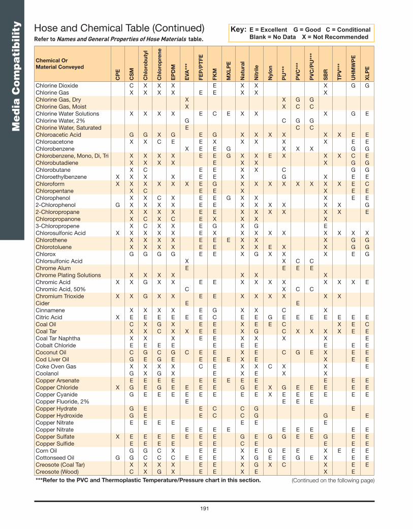
191
Me
dia
Co
mp
ati
bilit
y
Chemical Or
Material Conveyed
CP
E
CS
M
Ch
loro
bu
tyl
Ch
loro
pre
ne
EP
DM
EV
A**
*
FE
P/P
TF
E
FK
M
MX
LP
E
Na
tura
l
Nit
rile
Nylo
n
PU
***
PV
C**
*
PV
C/P
U**
*
SB
R
TP
V**
*
UH
MW
PE
XL
PE
Chlorine Dioxide C X X X E X X X G GChlorine Gas X X X X E E X X XChlorine Gas, Dry X X G GChlorine Gas, Moist X X C CChlorine Water Solutions X X X X E C E X X X G EChlorine Water, 2% G C G GChlorine Water, Saturated E C CChloroacetic Acid G G X G E G X X X X X X E EChloroacetone X X C E E X X X X X E EChlorobenzene X E E G X X X G GChlorobenzene, Mono, Di, Tri X X X X E E G X X E X X X C EChlorobutadiene X X X X E X X X G GChlorobutane X C E E X X C G GChloroethylbenzene X X X X E E X G X E EChloroform X X X X X X E G X X X X X X X X E CChloropentane X C E E X X E EChlorophenol X X C X E E G X X X E E2-Chlorophenol G X X X X E E X X X X X X G2-Chloropropane X X X X E E X X X X X X EChloropropanone X C X C E X X X X3-Chloropropene X C X X E G X G EChlorosulfonic Acid X X X X X E X X X X X X X X XChlorothene X X X X E E E X X X G GChlorotoluene X X X X E E X X E X X G GChlorox G G G G E E X G X X X E GChlorsulfonic Acid X X C CChrome Alum E E E EChrome Plating Solutions X X X X X X XChromic Acid X X G X X E E X X X X X X X EChromic Acid, 50% C X C CChromium Trioxide X X G X X E E X X X X X XCider E ECinnamene X X X X E G X X C XCitric Acid X E E E E E E C E E G E E E E E E ECoal Oil C X G X E E X E E C X E CCoal Tar X X C X X E E X G C X X X X E ECoal Tar Naphtha X X X E E X X X X ECobalt Chloride E E E E E E E E E ECoconut Oil C G C G C E E X E C G E X E ECod Liver Oil G E G E E E E X E X E ECoke Oven Gas X X X X C E X X C X X ECoolanol G X G X E X E X XCopper Arsenate E E E E E E E E E E E ECopper Chloride X G E G E E E E G E X G E E E E ECopper Cyanide G E E E E E E E E X E E E E E ECopper Fluoride, 2% E E E ECopper Hydrate G E E C C G ECopper Hydroxide G E E C C G G ECopper Nitrate E E E E E E ECopper Nitrate E E E E E E E E ECopper Sulfate X E E E E E E E G E G G E E G E ECopper Sulfi de E E E E E E C E E E ECorn Oil G G C X E E X E G E E X E E ECottonseed Oil G G C C C E E E X G E E G E X E ECreosote (Coal Tar) X X X X E E X G X C X E ECreosote (Wood) C X G X E E X E X E***Refer to the PVC and Thermoplastic Temperature/Pressure chart in this section. (Continued on the following page)
Hose and Chemical Table (Continued)Refer to Names and General Properties of Hose Materials table.
Key: E = Excellent G = Good C = Conditional Blank = No Data X = Not Recommended

192
Me
dia
Co
mp
ati
bilit
y
Chemical Or
Material Conveyed
CP
E
CS
M
Ch
loro
bu
tyl
Ch
loro
pre
ne
EP
DM
EV
A**
*
FE
P/P
TF
E
FK
M
MX
LP
E
Na
tura
l
Nit
rile
Nylo
n
PU
***
PV
C**
*
PV
C/P
U**
*
SB
R
TP
V**
*
UH
MW
PE
XL
PE
Cresols X X X X X E E X X X X X X X E GCresote X X XCresylic Acid X X X X E G X X X X X E GCresylic Acid, 50% X X X CCrotonaldehyde X E X E E X X X X C E ECrude Oil, Sour X E C CCrude Oil, Sweet X E C CCumene X X X X E E X X X X E ECupric Carbonate E E E E E C E E ECupric Chloride E E G E E E E C E C E ECupric Hydroxide G E E C C GCupric Nitrate E E E E E E E G E C E ECupric Sulfate E E E E E E G E G X E E ECutting Oil G X G X E E X E E XCyclohexane X X X X C E E X G E G X X X X E ECyclohexanol G X G X E E E X G E C X X X X E ECyclohexanone X X X C E E X X X E X X X X X E XCyclopentane X X E X E E X G E ECyclopentanol X X G X G X E ECyclopentanone X X E X X X ECyclopentyl Alcohol X X G X G X E EP-Cymene X X X X X E E X X X X E EDDT In Deionized Kerosene X X C X E E G X E E G X E EDecahydronapthalene X X X X E E X X E X X XDecahydroxynapthalene CDecalin X X X X E E X X X G X X X X EDecane X X X X A X G X E E1-Decanol E X X X E G X E E X EDecyl Alcohol E X X E G X E E EDecyl Aldehyde X C E X X E EDecyl Butyl Phthalate X E E C X X E EDecyl Carbinol E E E G E EDeveloping Fluid, Photo E G E G E E E E E G E EDextrin E E E EDextron X X G X E X E G XDextrose E E EDiacetone Alcohol X E X E E X X X X X E CDiacetylmethane G X E X E E X X X X X EDiallylphthalate GDiammonium Phosphate E E E E E E E E E E EDiamyl Napthalene X E E C X EDiamyl Phenol X X E E X X X EDiamylamine C E E E X G G X XDiamylene X X X E E X C G EDiazo Salts E E EDibenzyl Ether X G X C E X X X G X E EDibenzylsebacate X G X G E G E C X X E EDibromobenzene X X E E X G EDibromomethane X X X C E G X X XDibutyl Ether X X X X E X X X X X E EDibutyl Phthalate X C X E E C X X E X X E EDibutyl Sebacate X G X G E E X X X X E EDibutylamine X X X X E X X X X X EDicalcium Phosphate E E E E E E EDichloro Difl uoro Methane C E X G C E G X C G E E XDichloro Ethylene X C X X E G C C X***Refer to the PVC and Thermoplastic Temperature/Pressure chart in this section. (Continued on the following page)
Hose and Chemical Table (Continued)Refer to Names and General Properties of Hose Materials table.
Key: E = Excellent G = Good C = Conditional Blank = No Data X = Not Recommended

193
Me
dia
Co
mp
ati
bilit
y
Chemical Or
Material Conveyed
CP
E
CS
M
Ch
loro
bu
tyl
Ch
loro
pre
ne
EP
DM
EV
A**
*
FE
P/P
TF
E
FK
M
MX
LP
E
Na
tura
l
Nit
rile
Nylo
n
PU
***
PV
C**
*
PV
C/P
U**
*
SB
R
TP
V**
*
UH
MW
PE
XL
PE
Dichloroacetic Acid X C E X G C E EDichlorobenzene X X XOrtho-Dichlorobenzene X X X X E E X X E X X XP-Dichlorobenzene X X X X E E G X X X X XPara-Dichlorobenzene X X X X E E X X X X GOrtho-Dichlorobenzol X X X X E E X X E X X X XDichlorobutane X X X C E E X G X X E GDichloroethane X X C X X E G X X C X X X EDichloroethyl Ether X X E X X X EDichloroethylene X X X X E E X X X X C CDichlorohexane X X E E X E EDichloroisopropyl Ether X C X C C X X X E EDichloromethane X X G C E G X X C X X E EDichloropentane X X X E E X X X X E EDichloropropane X X X E E X X E EDichloropropene E E E EDichlorotoluene XDiesel Oil E C X C X E E X E E C C C X X E GDiethanolamine C E E E G G X EDiethyl Benzene X X X X E E G X X X E EDiethyl Ether X X X X X E X X X E E X X X E GDiethyl Ketone X G X E E X X GDiethyl Oxalate X X X X E X X EDiethyl Phthalate X E E C X E EDiethyl Sebacate C G X G E G X X X X EDiethyl Sulfate X G E E E X X X X EDiethyl Triamine C E E G GDiethylamine X G G G G C GDiethylamine C G G G E X G C C G E CDiethylbenzene X X X X E E X X X X E EDiethylene Dioxide X G X G E X E X X X E EDiethylene Glycol E E E E G E E E E E X G G E E EDiethylene Oxide X E EDiethylene Triamine C E E E G X X E EDiglycolic Acid E E EDihydroxy Diethyl Ether E E E E E E E E E E E EDihydroxy Succinic Acid E G C G E E E G EDiisobutyl Ketone X G X E E X X X X X E EDiisobutylene X X C X E E X E X X E EDiisodectyl Phthalate X E E E C X X E EDiisodecyl Phthalate X E X E E C X X XDiisooctyl Adipate X E X E E C X X X E EDiisooctyl Phthalate X E G E C X E EDiisopropanolamine C E E G GDiisopropyl Benzene X X X X E E G X X X E EDiisopropyl Ether C X X X E X X G G X EDiisopropyl Ketone X E X E E X X X X X EDilauryl Ether C D X X E C G X C X E EDimethyl Phenols (DMP) X X X X E X E X X X C CDimethyl Phthalate X G X G E G E X X X X G E EDimethyl Sulfate X G X X E X X X X X E XDimethyl Sulfi de X C X X E C E X X X G GDimethylamine X G X X X E X X E X X X E XDimethylaniline C X X X G E X X X X G GDimethylbenzene C X X X X X E X G X X X EDimethylbutane G***Refer to the PVC and Thermoplastic Temperature/Pressure chart in this section. (Continued on the following page)
Hose and Chemical Table (Continued)Refer to Names and General Properties of Hose Materials table.
Key: E = Excellent G = Good C = Conditional Blank = No Data X = Not Recommended

194
Me
dia
Co
mp
ati
bilit
y
Chemical Or
Material Conveyed
CP
E
CS
M
Ch
loro
bu
tyl
Ch
loro
pre
ne
EP
DM
EV
A**
*
FE
P/P
TF
E
FK
M
MX
LP
E
Na
tura
l
Nit
rile
Nylo
n
PU
***
PV
C**
*
PV
C/P
U**
*
SB
R
TP
V**
*
UH
MW
PE
XL
PE
Dimethylcarbinol E E E G E E E G EDimethylformamide (DMF) C C C C E X E C X C E EDimethylketone G X E X E E X X E X C E EDinitrobenzene X C C C E E G X X X E EDinitrotoluene X X X X E G E X X X E EDioctyl Adipate (DOA) X E X G E C X X EDioctyl Phthalate (DOP) X G X G G E G X X E X X X X E EDioctyl Sebacate (DOS) X G X G E G E X X X E EDioxalanes X X X G E X G X X X X E EDioxane X G X G E X X X E X X E E1,4 Dioxane X G X G E X X X E X X X EDipentene X X X X E E X G X XDipentylamine C E E E X G G X XDiphenyl X X X X A X X X E EDiphenyl Oxide C X X X A X X X E EDi-P-Mentha-1,8-Diene X X X X E E X G X XDipropyl Ketone X G X G E X E X X X E EDipropylamine C E E G GDipropylene Glycol E E E E E EDisodium Phosphate E E E E E E E E E E E E EDivinyl Benzene X X E E X X E EDodecyl Benzene X X X X E E G X X X E EDodecyl Toluene X X X X E E G X X X E EDowell Inhibitor GDowfax 2A1 Solvent EDowfax 2A1 TA EDowfax 6A1 Solvent GDowfax 6A1 Ta EDowfume W 40, 100% C D C C C X X X G GDow-Per X X X X E E G X C X E EDowtherm A & E X X X X X E E E X X X X X E EDowtherm S.R.I. E E E E E E E E E E E EDry Cleaning Fluids X X X X E E C E X X G XDucgkirioebaane XDuro AW16, 31 X E E EDuro FR-HD X E E EEpichlorohydrin C C X G E X G X X X G GEthanoic Acid E C G G E E X X C X X G C E EEthanolamine X G G G E X G G E C X E EEthanol (Ethyl Alcohol) G E E E E E C E E G X E E E E2 (2Aminoethylamino)
EthanolG E G G
2 (2Ethoxyethoxy) Ethanol X G X G E X X X E X X X2-Ethoxyethanol X G X G E X X X X X XEthers G X X X C X E X X X E X X C X CBis (2-Cloroethyl) Ether X X E X X XEthyl Acetate G X G X E C E X X X E X X C X E E G2-Ethoxyethyl Acetate X X G X G E X X X G X X X2 (2Ethoxyethoxy) Ethyl
AcetateX X G X X E X X X X X X
Ethyl Acetoacetate X G X G E X C X C E EEthyl Acetone X G X G E X X X XEthyl Acrylate X G X G E X X X X X X X E GEthyl Alcohol (Ethanol) G E E E E E E E E G X E E E E***Refer to the PVC and Thermoplastic Temperature/Pressure chart in this section. (Continued on the following page)
Hose and Chemical Table (Continued)Refer to Names and General Properties of Hose Materials table.
Key: E = Excellent G = Good C = Conditional Blank = No Data X = Not Recommended

195
Me
dia
Co
mp
ati
bilit
y
Chemical Or
Material Conveyed
CP
E
CS
M
Ch
loro
bu
tyl
Ch
loro
pre
ne
EP
DM
EV
A**
*
FE
P/P
TF
E
FK
M
MX
LP
E
Na
tura
l
Nit
rile
Nylo
n
PU
***
PV
C**
*
PV
C/P
U**
*
SB
R
TP
V**
*
UH
MW
PE
XL
PE
Ethyl Alcohol, 1%-50% G G GEthyl Alcohol, 50%-98% C C CEthyl Aldehyde E C G X E E C X X G X E E E EEthyl Aluminum Dichloride X X E G X X GEthyl Benzene X X X X E E X X X X E XEthyl Benzoate C G C G C X G X E EEthyl Bromide X X X X E E C G X X XEthyl Butanol E E E E E G E E E E EEthyl Butyl Acetate G E E X X X E EEthyl Butyl Ketone X G E X X X E2-Ethyl (Butyraldehyde) X G E X X X EEthyl Cellulose G G G G E X G G C G G E EEthyl Chloride X C E X E X E E C E E C X X G X G CEthyl Dichloride X X X X E G G X X X X G GEthyl Diisobutylthio-Carbamate E E EEthyl Ether G X X X X X E X X X G C X X X C CEthyl Formate G G G G E E X X X E EEthyl Hexanol E E E E E G E E E E E E2-Ethyl-1-Hexanol E G E E E E G E X E E E2-Ethylhexanoic Acid G C E C C2-Ethylhexyl Acetate G E E X X XEthyl Iodide X C X C E G X X G EEthyl Methyl Ketone X G X G E X E C X X E EEthyl Oxalate X X X C E E C X E X E EEthyl Phthalate X E E X X EEthyl Propyl Ether X X X X C E X X X E EEthyl Propyl Ketone X G X G E X G X X X E EEthyl Silicate G E E E E E G E X G E EEthyl Sulfate X G D G E X E X X X E EEthylamine C G X E E X C X E X C EEthylene C X G X E X E X E EEthylene Bromide X X X X X E E G X X X E X X G GEthylene Chloride X C C X X X E G G X X G X X X X X C XEthylene Chlorohydrin C G G G E E C X E E EEthylene Diamine G E E E E X G G E X G E EEthylene Dibromide X X X C E G X X X X G GEthylene G Monobutyl Ether C E C E E X X C X X EEthylene G Monoethyl
AcetateX E X E E E C C X
Ethylene G Monohexyl Ether EEthylene G Monomethyl
EtherG E E G E X X C E
Ethylene Glycol G E E E E E E E E E E G E E E E E EEthylene Oxide X X X X C X E X X X E X X X X E GEthylene Trichloride X X X X E E G X C X G GFatty Acids C X G X C E E X E E C E E X X E EFerric Bromide E E E E E E EFerric Chloride X E E E E E E E E E X E E E E E EFerric Nitrate E E E E E E E E E E E E E E E EFerric Sulfate X E E E E E E E E E E EFerrous Acetate E E E X X X EFerrous Ammonium Sulfate E E E E A E E E E EFerrous Chloride G G G E E E E E E E G E E E EFerrous Hydroxide G E E E E C E G G C E EFerrous Sulfate E E E E E E E E E G E E E E E EFish Oil E E E X E E X E X E EFish Solubles E E E EFluoboric Acid E G E E E E E E X E C C***Refer to the PVC and Thermoplastic Temperature/Pressure chart in this section. (Continued on the following page)
Hose and Chemical Table (Continued)Refer to Names and General Properties of Hose Materials table.
Key: E = Excellent G = Good C = Conditional Blank = No Data X = Not Recommended

196
Me
dia
Co
mp
ati
bilit
y
Chemical Or
Material Conveyed
CP
E
CS
M
Ch
loro
bu
tyl
Ch
loro
pre
ne
EP
DM
EV
A**
*
FE
P/P
TF
E
FK
M
MX
LP
E
Na
tura
l
Nit
rile
Nylo
n
PU
***
PV
C**
*
PV
C/P
U**
*
SB
R
TP
V**
*
UH
MW
PE
XL
PE
Fluorine X X X E G E X X X X C XFluorine Gas, Dry X X X XFluorine Gas, Wet X X X XFluoroboric Acid E E E EFluorosilic Acid E E E E G E C E E E X E E G C C GForic Acid E X E EFormaldehyde G G E G E E E C G X C E E EFormaldehyde (40% AQ) E X GFormalin G G E G E E E C G X C E E EFormamide E E E E E X E E E E E EFormic Acid X E E E E E E X C C X X E E E EFreon 11 E X G X E G E X E EFreon 12 C E C E C G E G C E E E C G E X EFreon 13 E E E E E E E E E EFreon 21 X X G X X X X X E EFreon 22 C E X E E E C C X G X E XFreon 31 G E E E X G X G E EFreon 32 E E E E C E E E E EFreon 112 G X G X E X G X E EFreon 113 E X E X E G X E E G G X EFreon 114 E E E E G E E E E EFreon 114B2 E X E X G X G C E EFreon 115 E E E E G E E E E EFreon 13B1 E E E E E E E E E EFreon 142B E E E E X E E E E EFreon 152A C E E E X E E E E EFreon 218 E E E E E E E E E EFreon 502 E E E G E G E EFreon BF G X G X E X G X E EFreon C316 E E E E E E E E E EFreon C318 E E E E E E E E E EFreon MF B X C X E X E G E EFreon TA E E E E C E E E E EFreon TC E E E G E X E G E EFreon TF E E E E E C E G E EFreon TMC G G G G E G G C E EFreon T-P35 E E E E E E E E E EFreon T-WD 602 G E G G E C E G E EFructose E E EFruit Juices & Pulps E E EFuel Oil E C X G X X E E X E G C G G X E EFumaric Acid G X G X E E E E E E E EFuraldehyde E C E C G E X X X C X X EFuran X X X X E C X X X XFurfural E C E C G X E X X X E X X X X E E EFurfuryl Alcohol X G X G X E C X X G X X E E CGallic Acid G G G G E E E E G G X E E G E CGallotannic Acid E G E E E E E E E E E EGas, 100 Octane X X C X X E XGas, Coal E E E X E GGas, Coke Oven G G GGas, Natural, Dry X C C CGas, Natural, Wet X C C CGasoline E X X X X X E G G X E G C X X X G GGasoline, 100 Octane E E G C X CGasoline, Sour X E C G***Refer to the PVC and Thermoplastic Temperature/Pressure chart in this section. (Continued on the following page)
Hose and Chemical Table (Continued)Refer to Names and General Properties of Hose Materials table.
Key: E = Excellent G = Good C = Conditional Blank = No Data X = Not Recommended

197
Me
dia
Co
mp
ati
bilit
y
Chemical Or
Material Conveyed
CP
E
CS
M
Ch
loro
bu
tyl
Ch
loro
pre
ne
EP
DM
EV
A**
*
FE
P/P
TF
E
FK
M
MX
LP
E
Na
tura
l
Nit
rile
Nylo
n
PU
***
PV
C**
*
PV
C/P
U**
*
SB
R
TP
V**
*
UH
MW
PE
XL
PE
Gelatin E E E E E E E E E E E EGelatine E E E EGlacial Acrylic Acid EGluconic Acid G C E X C EGlucose E E G E E E E E E E C E E E E EGlue E G E E E C E G E G E EGlycerine E E E E E E E E E E E C E E E X E EGlycerol E E E E E E E E E E C E X E EGlycogenic Acid G C E X CGlycolic Acid, 30% E X E EGlycols E E E E E E E E E E E X E E E G E EGlyconic Acid G C E X C EGlycyl Alcohol E E E E E E E E E G C E XGrease E E EGrease, Petroleum Base E X X C X E E X E E E X X E GGreen Liquor E E EGreen Sulfate Liquor G E G E E E G G X E G E EHalon 1211 E EHalowax Oil X X X X E E E X X X E EHelium E E E E E E E E E E E1-Hendaconal EHeptachlor In Petroleum
SolventsX X G X E E G X G X E E
Heptachlor In Petroleum Solvents, Water Spray
X X G X E X G X E E
Heptaldehyde X X E X X EHeptanal X X E X X E E EHeptane E G X G X X E E X E E G C G X E GHeptane Carboxylic Acid G C E X CHeptanoic Acid EHeptanone CHexadecanoic Acid G C G G G E E E E C E G EHexadecanol XHexaldehyde C G E E E X X X G X E EHexane E X E X E E X E E G C C X E E GHexanol G C G G E E E G E X E E EHexanol, Tertiary C G C CHexene G X G X E E X G G X EHexyl Alcohol G C G G E G E G E X E E EHexyl Methyl Ketone X G E X X X EHexylamine C G E X C CHexylene X X G C E E X E X G GHexylene Glycol E E E C E E E EHistowax EHydraulic Fluid, Petroleum E G X G X E E E X E E X X E EHydraulic Fluid, Phospate
Ester BaseX E X E E X E X X X E E
Hydraulic Fluid, Poly Alkylene Glycol Base
E E E E E G E G E E
Hydrazine G E G E E E X G X G EHydrobromic Acid X E E X E E E E X X X X E EHydrobromic Acid, 20% G X E EHydrochloric Acid X C E C C E C E C C X C X E E EHydrochloric Acid, 10% E X E EHydrochloric Acid, 48% G X E EHydrocyanic Acid X E G G E E E G G G X G E E E***Refer to the PVC and Thermoplastic Temperature/Pressure chart in this section. (Continued on the following page)
Hose and Chemical Table (Continued)Refer to Names and General Properties of Hose Materials table.
Key: E = Excellent G = Good C = Conditional Blank = No Data X = Not Recommended

198
Me
dia
Co
mp
ati
bilit
y
Chemical Or
Material Conveyed
CP
E
CS
M
Ch
loro
bu
tyl
Ch
loro
pre
ne
EP
DM
EV
A**
*
FE
P/P
TF
E
FK
M
MX
LP
E
Na
tura
l
Nit
rile
Nylo
n
PU
***
PV
C**
*
PV
C/P
U**
*
SB
R
TP
V**
*
UH
MW
PE
XL
PE
Hydrofl uoric Acid X E G C C E G C C X X C X E EHydrofl uoric Acid, 60% E X G GHydrofl uosilicic Acid X E E G E E E E G X C G G G G EHydrogen C C C CHydrogen Bromide, Dry EHydrogen Chloride,
AnhydrousE X E E
Hydrogen Chloride, Dry EHydrogen Cyanide C X C CHydrogen Dioxide, 10% G C X G E E G C X E EHydrogen Gas C E E E E E E G E E E G E EHydrogen Peroxide, 3% C C C E E E E X C X E EHydrogen Peroxide, 10% E G X G G E E G C C G E E C G GHydrogen Peroxide, 30% X X X X C G E E E X X X C E E X E EHydrogen Peroxide, 50% X C E EHydrogen Peroxide, 90% X X X X C X E G X X X C X X X G GHydrogen Phosphide E E EHydrogen Sulfi de (AQ) E E EHydrogen Sulfi de, Dry E E EHydrogen Sulfi de, Wet X E E E E E C X C C C X E EHydroquinone C G X G E E X E G X E E E G E EHydroxy Benzene C G X C E E X X C2-Chloro-1-Hydroxy-
BenzeneC
Hydroxyisobutyronitrile EHydroxytoluene EHypochlorous Acid E G G G C E G X C E E G E EHyvar Xl EIminodi-2-Propanol EIminodiethanol EInk Oil, Linseed Oil Base G G G G E E G X G X E EInks EInsulating Oil X X G X E E E X E X E EIodine G G X G E E X G X X G E XIodine in Alcohol X X X XIodine Pentafl uoride X X X X E X X X X X C CIodoform X X X E XIRM-902 E X X G X E E X E E G X X E EIRM-903 G X C X E E X E E E X X E EIron Acetate X E X G E X E X X X E EIron Hydroxide G E E G E C E C G C E EIron Salts E E E E E E E E E E E EIron Sulfate E E E E E E E E E E E EIron Sulfi de E E E E E E E E E E E EIsobutane G E E E E E G E G E E EIsobutyl Acetate X E X G E X G X X X E EIsobutyl Aldehyde X G X G E X C X X E EIsobutyl Chloride X X X X E G G X X X G GIsobutyl Ether X X X X E X X X X E EIsobutylamine C E E X C XIsobutylbromide X X E G X XIsobutylcarbinol E E E E E E E E CIsobutylene X X X X E E G X E X E EIsocyanates G G G G E E***Refer to the PVC and Thermoplastic Temperature/Pressure chart in this section. (Continued on the following page)
Hose and Chemical Table (Continued)Refer to Names and General Properties of Hose Materials table.
Key: E = Excellent G = Good C = Conditional Blank = No Data X = Not Recommended

199
Me
dia
Co
mp
ati
bilit
y
Chemical Or
Material Conveyed
CP
E
CS
M
Ch
loro
bu
tyl
Ch
loro
pre
ne
EP
DM
EV
A**
*
FE
P/P
TF
E
FK
M
MX
LP
E
Na
tura
l
Nit
rile
Nylo
n
PU
***
PV
C**
*
PV
C/P
U**
*
SB
R
TP
V**
*
UH
MW
PE
XL
PE
Isomyl Acetate X E X G E X G X X X E EIsomyl Alcohol E E E E E E E E E E G EIsomyl Bromide X X X X E G X X X G GIsomyl Butyrate X C X C E X G X X X G GIsomyl Chloride X C X X E G G X X X G GIsomyl Ether X X X X E X X X X E EIsomyl Phthalate X E X G E C X X X E EIsooctane E G X G X E E X E E G C C X X E EIsopentane X X E X E E G X E X G GIsopropyl Acetate X G X G E X X X G X X X E EIsopropyl Alcohol
(Isopropanol)E E G E E E E E E E X E E E E E
Isopropyl Amine C E E G E X G G G C E EIsopropyl Benzene X X X X E E G X X X E EIsopropyl Chloride X X X X E G X X X G GIsopropyl Ether C X X X E X X G E G X E EIsopropyl Toluene X X X X E E X X X E EJelly EJet Fuels (JP1-JP6) X X X X E E X E C C X X X X E EJP-4 Oil X X X X E E X E C C X XKerosene G X X C X X E E X E E G X C X X E EKetones G C G X E C E X C X E X X X G X C XKraft Liquor G E ELacquer Solvents C X X X X C E X X X E X X X X G GLacquers X C X X E X E X X X G GLactic Acid, 28% E C E ELactic Acid, Cold X E E E E E E E E E G E E ELactic Acid, Hot C X X E E X X X XLard G C G G G E E X E E C E E X E E ELauric Acid C E ELauryl Alcohol E E E E E G E E E E E ELauryl Chloride C E E ELauryl Sulfate X E ELavender Oil X X X X E E X G X X G GLead Acetate C E G E E E E E G G C E E X E ELead Arsenate E E ELead Nitrate C E E E E E E E E E E E ELead Sulfamate G E E E E G G G E ELead Sulfate E E G E E E E E G E ELead Tetra-ethyl E E ELemon Juice ELigroin X X E X E E G X E X E ELime E E E E E E E E E G ELime Bleach G E G E E E E E G ELime Sulfur G E ELime Sulfur, Wet G E E C E E C E G E ELime Water E E E E E X C X ELimonene X X X X E E X XLindol G E X E E X X X E ELinoleic Acid X X C X E G X G C E E X E ELinseed Oil G G G E C C E E X E E G E E X E CLiquid Soap E E E E E E E E E E E ELiquors, Chemical E E ELubricating Oils, SAE G X X C X X E E X E E E G G X X E XLye E E E E X E G G E ELye Solutions C E E E E E G E C G G G C E EMagnesium Acetate E E X E E X X X X X E***Refer to the PVC and Thermoplastic Temperature/Pressure chart in this section. (Continued on the following page)
Hose and Chemical Table (Continued)Refer to Names and General Properties of Hose Materials table.
Key: E = Excellent G = Good C = Conditional Blank = No Data X = Not Recommended

200
Me
dia
Co
mp
ati
bilit
y
Chemical Or
Material Conveyed
CP
E
CS
M
Ch
loro
bu
tyl
Ch
loro
pre
ne
EP
DM
EV
A**
*
FE
P/P
TF
E
FK
M
MX
LP
E
Na
tura
l
Nit
rile
Nylo
n
PU
***
PV
C**
*
PV
C/P
U**
*
SB
R
TP
V**
*
UH
MW
PE
XL
PE
Magnesium Carbonate E E E E E E E E E E E E E E E EMagnesium Chloride G E E E E E E E E E E E E E E E EMagnesium Hydrate E E G E E G E G E EMagnesium Hydroxide G E E E E E E E E E E C E E G E EMagnesium Nitrate E E E E E E E E E E E E E E E EMagnesium Sulfate G E E E E E E E G E E C E E G E EMagnesium Sulfi te E E E E E G E GMalathion 50 In Aromatic
Solvents X X C X E E E X C X E E
Maleic Acid X X X E E E X C X C X E CMaleic Acid (25% AQ) E C E EMaleic Anhydride X X X X E E X X X EMalic Acid G X G X G E E E E X C E E G E EManganese Sulfate E G E E E E G E E E EManganese Sulfi de E E G G E E E C E E E EManganese Sulfi te E E G G E E E C E E E EMAPP E G E GMayonnaise EMercuric Chloride E E C E G E E E G G G G G G E EMercuric Cyanide G X XMercurous Nitrate G G G GMercury G E E E E G E E E E E E G G E E EMercury Vapors E E C E E E C E EMesityl Oxide X C X G E X X X X X E EMethacrylic Acid C G G G X X X X E EMethallyl Alcohol E E E G E E X E EMethallyl Chloride C E G XMethane G X G X E E X E X E EMethanoic Acid X E E E E E X C C X X E EMethanol (Methyl Alcohol) G E E E E E C E E G X E E E CMethoxy Ethanol EMethoxyethoxy Ethanol EMethyl Acetate C G C G X E X X X E X X X X E EMethyl Acetoacetate X G X G E X X X X EMethyl Acetone X G X E E X C X EMethyl Acetylene
PropadieneE G E G
Methyl Acrylate X G C G E X E C X X E EMethyl Allyl Alcohol E E E G E EMethyl Allyl Chloride C X X X X X GMethyl Amyl Carbinol E E E G E E EMethyl Benzene C X X X X E E X X E X X X E XMethyl Bromide X C X C X E E X G E X X X X X G XMethyl Butane X X X X E E E G1-Bromo-3 Methyl Butane X X X X E G X X1-Chloro-3-Methyl Butane X C X X E E X X EMethyl Butanol E E E E E E E E E E X G E G EMethyl-2-Butanol E E E F E E EMethyl-2-Butanone X X G X C E X X X E X X EMethyl Butyl Ketone X E X E E X X X E X X EMethyl Carbitol E E E X C EMethyl Cellosolve C G G G E X X C E X X E EMethyl Chloride C X X X X X E E X X C X X X X X E XMethyl Cyanide G E E E E X G C EMethyl Cyclohexane X X X X E G X X X G GMethyl Ethyl Ketone (MEK) G X E X E C E X X X G X X X X C X GMethyl Formate C G G G E C E C X C G GMethyl Hexanol E E E G E E E E***Refer to the PVC and Thermoplastic Temperature/Pressure chart in this section. (Continued on the following page)
Hose and Chemical Table (Continued)Refer to Names and General Properties of Hose Materials table.
Key: E = Excellent G = Good C = Conditional Blank = No Data X = Not Recommended

201
Me
dia
Co
mp
ati
bilit
y
Chemical Or
Material Conveyed
CP
E
CS
M
Ch
loro
bu
tyl
Ch
loro
pre
ne
EP
DM
EV
A**
*
FE
P/P
TF
E
FK
M
MX
LP
E
Na
tura
l
Nit
rile
Nylo
n
PU
***
PV
C**
*
PV
C/P
U**
*
SB
R
TP
V**
*
UH
MW
PE
XL
PE
Methyl-2-Hexanone C X G X X X EMethyl Isoamyl Ketone C C X XMethyl-4-Isopropyl Benzene CMethyl Methacrylate X C X X E X X X C X X C G GMethyl Normal Amyl Ketone X G E X X X EMethyl-2-Pentanol E E E E E C G GMethyl-2-Pentanone X X C X G E X X X G X X XMethyl-3-Penten-1-One CMethyl 1-2,4-Pentanediol EMethyl-1-Propanol E E E E E E E G X E1-Bromo-2 Methyl Propane X X X E G X X1-Chloro-2-Methyl Propane X X E G X X3-Chloro-2-Methyl Propane GMethyl-2-Propen-1-Ol E E E E E C G GMethyl Propyl Ether G X E X X EMethyl Salicylate G X C E G X XMethyl Styrene CMethyl Sulfate E E EMethyl Sulfi de X C E X XMethyl Sulfuric Acid E X E EMethyl Tertiary Butyl Ether
(MTBE)X G X G X X X G
Methylallyl Acetate G E E X X X EMethylamyl Alcohol E E E E E C G G EMethylated Spirit EMethylene Bromide X X X X E C X X GMethylene Chloride X X X C X E G X X C X X C X X E CMethylhexyl Ketone X G E X X X EMethylisobutyl Carbinol E E E E E C G G CMethylisobutyl Ketone X X C X G E X X X G X X X E EMethylisopropyl Ketone X X G X C E X X X E X X EMethyllactonitrile C E G E X C X X EMethylphenol C X X X E E X X XMethylpropyl Carbinol E E E G E EMethylpropyl Ketone X G X G E X X X X EMil-A-6091 E E E E E E G X EMil-E-9500 E E E E E E E X EMil-F-16884 C X C X E X E C XMil-F-17111 X X G X E X E C XMil-F-25558B G X G X E X E G XMil-F-25576C C X C X E X E C XMil-F-7024A X X X X E X E G XMil-G-10924B G X X X E X E G XMil-G-25013D G X G X E X E C XMil-G-25537A G X G X E X E G XMil-G-4343B G C G C E C G E CMil-G-5572 X X X X E X E G XMil-G-7711A X X X X E X E E XMil-H-13910B G G G E E G G X EMil-H-19457B X E X E C X X X XMil-H-22251 G E G E E G GMil-H-27601A C X G X E X G C XMil-H-5606B G X G C E X E G XMil-H-6083C G X G X E C E G XMil-H-8446B C X G X E X G C XMil-J-5161F X X X X E X G C XMil-J-5624G (JP-3, JP-4,
JP-5)X X X X E X E C X
***Refer to the PVC and Thermoplastic Temperature/Pressure chart in this section. (Continued on the following page)
Hose and Chemical Table (Continued)Refer to Names and General Properties of Hose Materials table.
Key: E = Excellent G = Good C = Conditional Blank = No Data X = Not Recommended
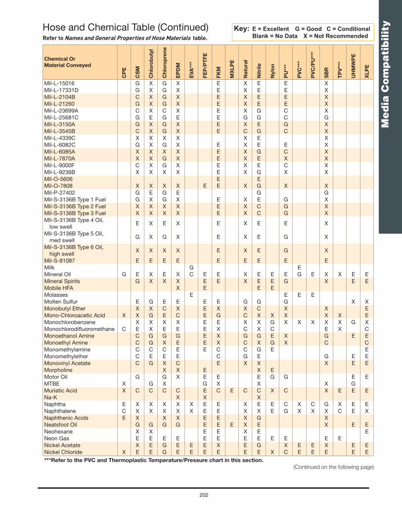
202
Me
dia
Co
mp
ati
bilit
y
Chemical Or
Material Conveyed
CP
E
CS
M
Ch
loro
bu
tyl
Ch
loro
pre
ne
EP
DM
EV
A**
*
FE
P/P
TF
E
FK
M
MX
LP
E
Na
tura
l
Nit
rile
Nylo
n
PU
***
PV
C**
*
PV
C/P
U**
*
SB
R
TP
V**
*
UH
MW
PE
XL
PE
Mil-L-15016 G X G X E X E E XMil-L-17331D G X G X E X E E XMil-L-2104B C X G X E X E E XMil-L-21260 G X G X E X E E XMil-L-23699A C X C X E X G C XMil-L-25681C G E G E E G G C GMil-L-3150A G X G X E X E G XMil-L-3545B C X G X E C G C XMil-L-4339C X X X X X E XMil-L-6082C G X G X E X E E XMil-L-6085A X X X X E X G C XMil-L-7870A X X G X E X E X XMil-L-9000F C X G X E X E C XMil-L-9236B X X X X E X G X XMil-O-5606 E EMil-O-7808 X X X X E E X G X XMil-P-27402 G E G E G GMil-S-3136B Type 1 Fuel G X G X E X E G XMil-S-3136B Type 2 Fuel X X X X E X C G XMil-S-3136B Type 3 Fuel X X X X E X C G XMil-S-3136B Type 4 Oil,
low swellE X E X E X E E X
Mil-S-3136B Type 5 Oil, med swell
G X G X E X E G X
Mil-S-3136B Type 6 Oil, high swell
X X X X E X E G X
Mil-S-81087 E E E E E E E E EMilk G EMineral Oil G E X E X C E E X E E E G E X X E EMineral Spirits G X X X E E X E E G X E EMobile HFA X E E EMolasses E E E EMolten Sulfur E G E E E E G G G X XMonobutyl Ether X X C X E X X C X X EMono-Chloroacetic Acid X X G E C E G C X X X X X EMonochlorobenzene X X X X E E X X G X X X X X G XMonochlorodifl uoromethane C E X E E E X C X C E X CMonoethanol Amine C G G G E X G G E X G E EMonoethyl Amine C G X E E X C X G X C CMonomethylamine C C C E E C C G E EMonomethylether C E E E C G E G E EMonovinyl Acetate C G X C E X X X E EMorpholine X X E X EMotor Oil G G X E E E G G E EMTBE X G X G X X X GMuriatic Acid X C C C C E C E C C X C X E E ENa-K X X XNaphtha E X X X X X E E X E E C X C G X E ENaphthalene C X X X X X E E X X E G X X X C E XNaphthenic Acids E X X X E E X G XNeatsfoot Oil G G G G E E E X E X E ENeohexane X X E E X E ENeon Gas E E E E E E E E E E E ENickel Acetate X E G E E E X E G X E E X E ENickel Chloride X E E G E E E E E E X C E E E E E***Refer to the PVC and Thermoplastic Temperature/Pressure chart in this section.
(Continued on the following page)
Hose and Chemical Table (Continued)Refer to Names and General Properties of Hose Materials table.
Key: E = Excellent G = Good C = Conditional Blank = No Data X = Not Recommended

203
Me
dia
Co
mp
ati
bilit
y
Chemical Or
Material Conveyed
CP
E
CS
M
Ch
loro
bu
tyl
Ch
loro
pre
ne
EP
DM
EV
A**
*
FE
P/P
TF
E
FK
M
MX
LP
E
Na
tura
l
Nit
rile
Nylo
n
PU
***
PV
C**
*
PV
C/P
U**
*
SB
R
TP
V**
*
UH
MW
PE
XL
PE
Nickel Nitrate E E E E E E E E E G E E E E ENickel Plating Solution G G C G E G XNickel Sulfate X E E E E E E E G E G C E E G E ENicotine E C E ENicotine Acid E C E ENietylene ENiter Cake E E E E E E E E E E E ENitric Acid, 1-10% X G E G E G E X X X C X E G X E E ENitric Acid, 10%-25% X G G X E E X X X X X X E ENitric Acid, 25%-40% X C C X G C E C X X X X G G X G GNitric Acid, 40%-60% X X X X X C E C X X X X G G X C CNitric Acid, 70% X X X XNitric Acid, Anhydrous X X X XNitric Acid, Conc (16N) X X X X X E E X X X X X X E GNitric Acid, Red Fuming X X C X X E C X X X X X X X XNitrilotriethanol E G X E E X G C X GNitrobenzene C X G X X X E C X X C X X X X E XNitroethane C G C G E X G X X G E E ENitrogen E E E E E E E E E E E E E ENitrogen Tetraoxide X X X X E X X X X X XNitromethane C G X G E X G X E X C E ENitropropane C E C G E X E C X C E ENitrous Oxide Gas E E G E E E E E E C G E E EN-Nonyl Alcohol E E E G E ENonanoic Acid X E E X EN-Serv E E E CNuto H X E E ENyvac Light E E X EOctadecanoic Acid X G G C E C E X E X E ECis-9-Octadecenoic Acid X G X C C E E X E E G X EOctane X X G X E E G X E X G GN-Octane X X C X E E X E X X G EOctanoic Acid G C E C C2-Octanone X G X G E X X X X XOctyl Acetate E E E X X X EOctyl Alcohol G G G G E G G G X G E EOctyl Aldehyde X C E X X X EOctyl Amine C E E X C C COctyl Carbinol E E E G E E EOctylene Glycol E E E E E E E E E E COil, Petroleum G G X G X G E E X E G G E E X C E EOils & Fats G E E EOleic Acid X G X C C X E E X E E G G G X E EOleum X X X X X X E G X X X X X X X X XOlive Oil G G G G E E E X E E E X G COrange Juice EOrthoxylene C X X X C E E X X G X X X XOxalic Acid X E E G E G E E C G E C E E G E C COxydiethanol E X EOxygen G E E EOxygen, Cold G E E E E E E G C C E EOxygen, Hot X E E E E E G C C E EOzone E G C E X E E X X C E C C X G CPaint Thinner X X X X E G G X X G X X E EPalm Oil G E G G E E E X E X E EPalmitic Acid G C G G G E E E E C E G E E G***Refer to the PVC and Thermoplastic Temperature/Pressure chart in this section. (Continued on the following page)
Hose and Chemical Table (Continued)Refer to Names and General Properties of Hose Materials table.
Key: E = Excellent G = Good C = Conditional Blank = No Data X = Not Recommended

204
Me
dia
Co
mp
ati
bilit
y
Chemical Or
Material Conveyed
CP
E
CS
M
Ch
loro
bu
tyl
Ch
loro
pre
ne
EP
DM
EV
A**
*
FE
P/P
TF
E
FK
M
MX
LP
E
Na
tura
l
Nit
rile
Nylo
n
PU
***
PV
C**
*
PV
C/P
U**
*
SB
R
TP
V**
*
UH
MW
PE
XL
PE
Palmitic Acid, 10% E X E EPalmitic Acid, 70% C X C CPapermakers Alum E E E E EPara Methoxypropenyl
BenzeneX X X E G X G
Paraffi n X X E X C E E E X E E E E X X XParaffi n Wax X X G X E X E E G E E XParaformaldehyde G G G G E C D G X E EParaldehyde X E C E E X C C EParaxylene X X X X E E X C E C XPeanut Oil G C G X E E E X E X E EPelargonic Alcohol E E E G E E EPentachloroethane X X X E E X X EPentadione GPentamethylene X X E X E E X GPentane C X C X E E X E G C C C X G GPentanol E E E E E G E E CPentanone X G X G E X X X E4-Hydroxy-4-Methyl-2-
PentanoneC E C E E X C X G X C E
Pentasol E E E E E G E G X G EPentyl Acetate X G X E E X X G X X XPentyl Alcohol E E E E E E E E G E X E EPentyl Bromide E GPentyl Chloride C X X X X E E X E C X GPentyl Ether C E CPentylamine C G X X E X C C2,4-Di-Sec-Pentylphenol EPeracetic Acid, 40% X X XPerchlorethylene X XPerchloric Acid E G E G E E B G X X E EPerchloric Acid, 10% G X G GPerchloric Acid, 70% G X C CPerchloroethylene C X X X X E E X C E X X X G XPerchloromethane X X E X XPetrol X X XPetrolatum C X E X E X E X E EPetroleum Crude G X G X E E X E G E X E GPetroleum Ether X X C X X E E X E E G C C X E CPetroleum Oils G G X G X E E X E G G X C E CPhenbo X EPhenol X G X X E E X X X X X X X X E CPhenolsulfonic Acid X C E X X X G G GPhenylamine X E X G E E X X CPhenylbromide X X X X E G X X XPhenylbutane CPhenylchloride X X X X E E X X X EPhenylethylene X X X X E G X X C XPhenylhydrazine C G X C E C X X X X E EPhenylhydrazine
HydrochlorideC C
Phenylmethane X X X X E E X X XPhenylmethanol G G X G E E X X C X X X E EPhenylmethyl Acetate G E E X X E EPhorone X E X G E C E X X X E E***Refer to the PVC and Thermoplastic Temperature/Pressure chart in this section. (Continued on the following page)
Hose and Chemical Table (Continued)Refer to Names and General Properties of Hose Materials table.
Key: E = Excellent G = Good C = Conditional Blank = No Data X = Not Recommended

205
Me
dia
Co
mp
ati
bilit
y
Chemical Or
Material Conveyed
CP
E
CS
M
Ch
loro
bu
tyl
Ch
loro
pre
ne
EP
DM
EV
A**
*
FE
P/P
TF
E
FK
M
MX
LP
E
Na
tura
l
Nit
rile
Nylo
n
PU
***
PV
C**
*
PV
C/P
U**
*
SB
R
TP
V**
*
UH
MW
PE
XL
PE
Phosgene, Gas C C CPhosgene, Liquid XPhospahte Esters G X E X E E C X X E X X EPhosphoric Acid, 10% X E G E E E E X E E GPhosphoric Acid, 10%-85% X E G E E E E E G X X X G E EPhosphorous Pentoxide G C CPhosphorous Trichloride X E X E C E E X X X X X E EPhosphorus, Yellow X G GPhotographic Developers E C C CPhotographic Emulsions E C CPhotographic Fixers E C CDi(2Ethylhexyl) Phthalate X G X G E G X X E X XPickling Solution C C C C E G G C C C E EPicric Acid G X X XPicric Acid, H2O Solution X E C C C C C GPicric Acid, H2O Solution C E X G X EPicric Acid, Molten G C C C E C G C C C X XPine Oil X X X X E E X G E X E XPinene X X X X E E X G G X E EPiperidine X X X X E X C X X X G GPitch C X G X E C G X G G G X E EPlating Solution, Brass C E E EPlating Solution, Cadmium C E E EPlating Solution, Chrome C E G E E G E X G X E EPlating Solution, Chromium X G G GPlating Solution, Copper C E E EPlating Solution, Gold C E E EPlating Solution, Judium C E E EPlating Solution, Lead C E E EPlating Solution, Nickel C E E EPlating Solution, Rhodium C E E EPlating Solution, Silver C E E EPlating Solution, Tin C E E EPlating Solution, Zinc C E E EPoly Chlorinated Biphenol E EPolyethylene Glycol E E E E E E E E E E E E EPolyol Ester G G XPolypropylene Glycol E E E E E EPolyvinyl Acetate Emulsion
(PVA) G E G E E C C C C E E
Potassium Acetate C E G E E C E G G X X E EPotassium Acid Sulfate G E E EPotassium Antimonate E E E EPotassium Bichromate E E E EPotassium Bisulfate E E E E E E E E G G E EPotassium Bisulfi te E E E E E E E E E G E E E G E EPotassium Bisulphate E GPotassium Borate, 1% E E E EPotassium Bromate, 10% E E E EPotassium Bromide E E E EPotassium Carbonate E E E E E E E E E E E C E E E E EPotassium Chlorate E G E EPotassium Chloride G E E E E E E E E E E E E E E E EPotassium Chromate C G E E E E G E G G G E EPotassium Chromate, 40% E G E EPotassium Cuprocyanide E E EPotassium Cyanide G E E G E C E E E E E E C C E E E***Refer to the PVC and Thermoplastic Temperature/Pressure chart in this section. (Continued on the following page)
Hose and Chemical Table (Continued)Refer to Names and General Properties of Hose Materials table.
Key: E = Excellent G = Good C = Conditional Blank = No Data X = Not Recommended

206
Me
dia
Co
mp
ati
bilit
y
Chemical Or
Material Conveyed
CP
E
CS
M
Ch
loro
bu
tyl
Ch
loro
pre
ne
EP
DM
EV
A**
*
FE
P/P
TF
E
FK
M
MX
LP
E
Na
tura
l
Nit
rile
Nylo
n
PU
***
PV
C**
*
PV
C/P
U**
*
SB
R
TP
V**
*
UH
MW
PE
XL
PE
Potassium Dichromate X E E E E E E C E G G G G GPotassium Dichromate, 49% E G E EPotassium Ferricyanide E E E EPotassium Fluoride E E E EPotassium Hydrate E E G G E C G G G G G E EPotassium Hydroxide X E G G E E G G G G C G G E EPotassium Hydroxide, 10% E C E EPotassium Hydroxide, 20% E X E EPotassium Hydroxide, 35% G X E EPotassium Hypochlorite E X G GPotassium Nitrate E E E E E E E E E E E E E E E EPotassium Perborate E E E EPotassium Perchlorite G G E EPotassium Permanganate X E X E E E E X X X E EPotassium Permanganate,
10%X G G E
Potassium Permanganate, 5%
G E E E E E E C X X G E G
Potassium Persulfate E E E EPotassium Phosphate EPotassium Silicate E E E E E E E E G E E E EPotassium Sulfate E E E E E E E E E E E E E G E EPotassium Sulfi de E E E E E E E G E E E E E G E EPotassium Sulfi te E E E E E E G E E E G E EPotassium Thiosulfate E E E EPower Steering Fluid E E EPrestone Antifreeze E E G X E E EProducer Gas G X G X E E X E E XPropane X C C CPropanediol E C C E E E E E G EPropanetriol E E E E E E E E E E G C E X E EPropanol (Propyl Alcohol) E E E E X E E E E E1-Amino-2-Propanol C E E X G GPropanolamine EPropanone G X E X E E X C X E X C E E CChloro-2-Propanone X X C E E X X X X XPropargyl Alcohol E E EPropen-1-Ol E G E EPropenediamene EPropenenitrile X X E G XPropenyl Alcohol E E E E E G E E E EPropenylanisole X X E G X XPropionic Acid G E C E E X E C X X EPropionitrile E G E E X E X XPropyl Acetate X G X E E X X X X X E EPropyl Alcohol (Propanol) E E E E E E E E E E X E E E E E EPropyl Aldehyde X G E X C X E EPropyl Benzene CPropyl Chloride X C E G X X E EPropyl Ether EPropyl Nitrate X G X G E X X X X XPropylene X X X X E E X X X XPropylene Diamine C E E G GPropylene Dichloride X X X X X E G X X X X X X G GPropylene Glycol E E E E E E E E E E G X E X E EPrune Juice EPydraul Hydraulic Fluids D G D G E C E X X G X X G GPyranol X X X X E X C X E E***Refer to the PVC and Thermoplastic Temperature/Pressure chart in this section. (Continued on the following page)
Hose and Chemical Table (Continued)Refer to Names and General Properties of Hose Materials table.
Key: E = Excellent G = Good C = Conditional Blank = No Data X = Not Recommended

207
Me
dia
Co
mp
ati
bilit
y
Chemical Or
Material Conveyed
CP
E
CS
M
Ch
loro
bu
tyl
Ch
loro
pre
ne
EP
DM
EV
A**
*
FE
P/P
TF
E
FK
M
MX
LP
E
Na
tura
l
Nit
rile
Nylo
n
PU
***
PV
C**
*
PV
C/P
U**
*
SB
R
TP
V**
*
UH
MW
PE
XL
PE
Pyridine X G X G E X G X X X E EPyroligneous Acid G G G G E C C C E EPyrrole X G X C C C X G E EQuintolubric 822 Series X X X G X GRape Seed Oil G E G G E E E X G X G GRed Oil X G X C C E E X E E G X E CResorcinol X G E E X X G X ERosin Oil G X E X E X E X E ERotenone And Water E E E E E E E E E ESAE Oil #10 G X X C X E E X E E E X X CSalicylic Acid E E X E E E E E E X G E ESea Water E E G E E E E E E E E C E E E E E ESelenic Acid G X E ESewage E G G E E E G E G X G G X EShortening G E GSilicate Esters G C E X E E X G G E X CSilicate of Soda E E E E E E E E E E ESilicic Acid E X E ESilicone Fluids ESilicone Grease E E E E E E E E E E E G ESilicone Oil E E E E E E C E E E E E ESilver Cyanide E E E ESilver Nitrate E E E E E E E E G E E E E E E ESilver Plating Solutions E E E ESkelly Solvent C X G X E X E X E ESkydrol Hydraulic Fluids X E X E E X E X X X E ESoap Solutions G E G G E G E E G E E E E E G E E ESoda Ash G E E E E E E E E G G E E ESoda Lime G E G E E G E G C E ESoda, Caustic C E E E E E X G C G G E C E ESodium Acetate C E G E E E E G G X X E ESodium Acid Sulfate E E E ESodium Aluminate E E E E E E G E G G E ESodium Antimonate E E E ESodium Arsenite E E E ESodium Benzoate E E E ESodium Bicarbonate E E E E E E E E E E E E E E E ESodium Bisulfate X E E E E E E E E G C E E E G E ESodium Bisulfi te E E E E E E E E E E E E E G E ESodium Borate E E E E E E E E E G E E ESodium Bromide E E E ESodium Carbonate G E E E E E E E E E E G G E E E E ESodium Chlorate E G G GSodium Chloride G E G E E E E E E E E E E E E C E ESodium Chromate C E C G E C X X X G GSodium Cyanide G E E E E E E E E E E G E E E E ESodium Dichromate G E G C E E E C E G G E E G E ESodium Ferrocyanide E E E ESodium Fluoride E E E E E E E E E E E E E E E ESodium Hydrate G E G E E G E G G C G ESodium Hydrochlorite E G C G E E C C G C G ESodium Hydroxide C E E G E E C E C G C G C E ESodium Hydroxide, 10% E G E ESodium Hydroxide, 35% E C E ESodium Hydroxide, 50% GSodium Hypochlorite X G G C G E E C X X X C E E C C E G***Refer to the PVC and Thermoplastic Temperature/Pressure chart in this section. (Continued on the following page)
Hose and Chemical Table (Continued)Refer to Names and General Properties of Hose Materials table.
Key: E = Excellent G = Good C = Conditional Blank = No Data X = Not Recommended

208
Me
dia
Co
mp
ati
bilit
y
Chemical Or
Material Conveyed
CP
E
CS
M
Ch
loro
bu
tyl
Ch
loro
pre
ne
EP
DM
EV
A**
*
FE
P/P
TF
E
FK
M
MX
LP
E
Na
tura
l
Nit
rile
Nylo
n
PU
***
PV
C**
*
PV
C/P
U**
*
SB
R
TP
V**
*
UH
MW
PE
XL
PE
Sodium Metaphosphate G G G E E E E E E G E G ESodium Nitrate G E E G E E E E G G E G E E G E ESodium Nitrite E E E E E E E E E E E E E E E ESodium Perborate X G E G E E E G G G G G E ESodium Peroxide X G E G E E E G G X X G E ESodium Phosphate E E C E E E E E E E E E ESodium Phosphate, Acid E U G GSodium Silicate G E E E E E E E E E E G E E E E ESodium Sulfate G E E E E E E E G E E E E E G E ESodium Sulfi de G E E E E E E E G E E E E E G E ESodium Sulfi te E E E E E E E G E E E E E G E ESodium Thiosulfate E E E E E E E E E G E E E G E ESoft Drinks G ESoya Oil ESoybean Oil G E C E X E E X E E G G X E EStannic Chloride X C G C E E E E G E C G E E E E EStannic Sulfi de E E E E E EStannous Chloride E G E C E E E E E G C E E E EStannous Sulfi de E E E E E EStarch EStearic Acid G C G G G E E E C E E E C C G E E EStoddard Solvent G X X C X C E E X E E G C G X X E EStyrene Monomer X X X X E G X X E C X G GSugar Solutions E E E E E E E E E E E E ESulfamic Acid E E G X E E G C X CSulfi te Liquors E E G G E E G G G E ESulfonic Acid C X C X E X X X X G GSulfur F F X F E G X X G G X E XSulfur, Molten E E E E G G GSulfur Chloride G C X C X E E X C C C X E ESulfur Dioxide C G X E E E C X X C G CSulfur Dioxide Gas, Dry E E ESulfur Dioxide Gas, Wet E C CSulfur Dioxide, Liquid X C CSulfur Hexafl uoride E E E E E E E E E E E ESulfur Trioxide B C C C E E G X C C D GSulfur Trioxide, Dry C G X G E E C X X G X X GSulfur, Molten E E E CSulfuric Acid, 1%-60% G E ESulfuric Acid, 70% C E ESulfuric Acid, 95% X X XSulfuric Acid, 95% Fuming X C CSulfuric Acid, 25% X E G E E E E G E X X G E E ESulfuric Acid, 25%-50% X G G E E E E G E X X G E ESulfuric Acid, 50%-96% X C X C G E E X C X X X E ESulfuric Acid, 60% (200°F) X X X X C X X X X XSulfuric Acid, Conc. 96%-
98%X X X X X E G X X X X X E C
Sulfuric Acid, Fuming X X X X X E G X X X X X X XSulfurous Acid, 10% X E E G E E E E G C X G E ESulfurous Acid, 10%-85% X E E C G E G G C X X C X ESulfurous Acid, 30% XSulphur Trioxide X E ESutan E F ETall Oil C X C X E E X E E X E GTallow C G G E E E E C E E E X E ETannic Acid X E E E E E E E E E G E E E G E E E***Refer to the PVC and Thermoplastic Temperature/Pressure chart in this section. (Continued on the following page)
Hose and Chemical Table (Continued)Refer to Names and General Properties of Hose Materials table.
Key: E = Excellent G = Good C = Conditional Blank = No Data X = Not Recommended
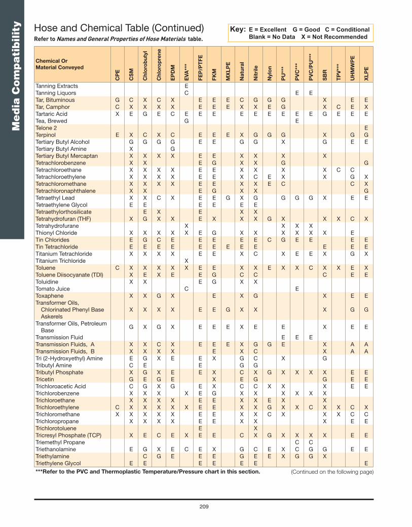
209
Me
dia
Co
mp
ati
bilit
y
Chemical Or
Material Conveyed
CP
E
CS
M
Ch
loro
bu
tyl
Ch
loro
pre
ne
EP
DM
EV
A**
*
FE
P/P
TF
E
FK
M
MX
LP
E
Na
tura
l
Nit
rile
Nylo
n
PU
***
PV
C**
*
PV
C/P
U**
*
SB
R
TP
V**
*
UH
MW
PE
XL
PE
Tanning Extracts ETanning Liquors C E ETar, Bituminous G C X C X E E E C G G G X E ETar, Camphor C X X X X E E E X X E G X C E XTartaric Acid X E G E C E E E E E E E E E G E E ETea, Brewed G ETelone 2 ETerpinol E X C X C E E E X G G G X G GTertiary Butyl Alcohol G G G G E E G G X G E ETertiary Butyl Amine X GTertiary Butyl Mercaptan X X X X E E X X X XTetrachlorobenzene X X E G X X G GTetrachloroethane X X X X E E X X X X C CTetrachloroethylene X X X X E E X C E X X G XTetrachloromethane X X X X E E X X E C C XTetrachloronaphthalene X X E G X X GTetraethyl Lead X X C X E E G X G G G G X E ETetraethylene Glycol E E E E E ETetraethylorthosilicate E X E X XTetrahydrofuran (THF) X G X X E X X X G X X X C XTetrahydrofurane X X X XThionyl Chloride X X X X X E G X X X X X X ETin Chlorides E G C E E E E E C G E E E ETin Tetrachloride E E E E E E E E E E E ETitanium Tetrachloride X X X X E E X C X E E X G XTitanium Trichloride XToluene C X X X X X E E X X E X X C X X E XToluene Diisocyanate (TDI) X E X E E G C C C E EToluidine X X E G X XTomato Juice C EToxaphene X X G X E X G X E ETransformer Oils,
Chlorinated Phenyl Base Askerels
X X X X E E G X X X G G
Transformer Oils, Petroleum Base
G X G X E E E X E E X E E
Transmission Fluid E E ETransmission Fluids, A X X C X E E E X G G E X A ATransmission Fluids, B X X X X E X C X A ATri (2-Hydroxyethyl) Amine E G X E E X G C X GTributyl Amine C E E G GTributyl Phosphate X G X E E X C X G X X X X E ETricetin G E G E X E G G E ETrichloroacetic Acid C G X G E X C C X X X E ETrichlorobenzene X X X X E G X X X X X XTrichloroethane X X X X E E X X E X XTrichloroethylene C X X X X X E E X X G X X C X X C XTrichloromethane X X X X X E E X X C X X X C CTrichloropropane X X X X E E X X X E ETrichlorotoluene E XTricresyl Phosphate (TCP) X E C E X E E C X G X X X X E ETriemethyl Propane C CTriethanolamine E G X E C E X G C E X C G G E ETriethylamine C G E E E G E E X G G XTriethylene Glycol E E E E E E E***Refer to the PVC and Thermoplastic Temperature/Pressure chart in this section. (Continued on the following page)
Hose and Chemical Table (Continued)Refer to Names and General Properties of Hose Materials table.
Key: E = Excellent G = Good C = Conditional Blank = No Data X = Not Recommended

210
Me
dia
Co
mp
ati
bilit
y
Chemical Or
Material Conveyed
CP
E
CS
M
Ch
loro
bu
tyl
Ch
loro
pre
ne
EP
DM
EV
A**
*
FE
P/P
TF
E
FK
M
MX
LP
E
Na
tura
l
Nit
rile
Nylo
n
PU
***
PV
C**
*
PV
C/P
U**
*
SB
R
TP
V**
*
UH
MW
PE
XL
PE
Trihydroxybenzoic Acid G G G G E E E G G X G GTrimethyl Pentanes, Mixed E C X C X E E X E E G X X ETrimethyl Pentene E E ETrimethylamine E E E ETrinitrotoluene (TNT) G X G X G X X X X XTriphenyl Phosphate C E C G E C X X X E ETrisodium Phosphate E E E E E E ETritoyl Phosphate X E X E E E X X G X X ETung Oil C E X E X E E X E G C X E ETurbine Oil G X G X E X G X E ETurpentine X X X X X E E X G E C G X G EUcon Hydrolube Oils X E G E E E E X E X E EUDMH E E G E E X E G X X C C1 Undecanol E E E E E G E E E EUndecyl Alcohol E E E E E G E E E E E EUran E G G G C G G C E EUrea E E G E E E E E G E G E E E EUrethane Formulations E E EUric Acid E G X E EUrine E E E EVarnish C X X X X X E E X G E C X X X EVegetable Oils G C C C X E E X E G E G G X E GVersilube F44 E E E E E E E E E E EVersilube F55 E E E X E E E E E E EVinegar E E G E E E E G G C C E G E EVinegar Acid GVinyl Acetate C E X G X X E X X X X X X E EVinyl Benzene X X X X E G X X C X E GVinyl Chloride X XVinyl Chloride, Gas X G E G E C EVinyl Cyanide E C X C X E C C X E X C XVinyl Ether G X E X X G E EVinyl Styrene X X E E X X E EVinyl Toluene X X E E X X E EVinyl Trichloride X X X E E X X E EVital, 4300, 5310 X E X EVM&P Naphtha X X C X E E X C XWater G E E G E E E E E E E E G E E EWater, Acid E G E EWater, Boiling E E G E G G G X G G G X XWater, Demineralized E E E EWater, Detergent Solution E E G E E E G G E E G G E EWater, Distilled E E E EWater, Fresh E E E E G E E E EWater, Potable E EWater, Salt G E E E E E E E E G G E E G E EWater, Soda E E E E EWemco C X X G X X E XWhey G EWhiskey E E E E E E E E E X C E E EWhite Gasoline X E E EWhite Liquor E G E C E E E E E E E EWhite Oil X X G X E E X E E X E XWhite Pine Oil X X X X E X G XWines E E E E E E E E E X G E E GWood Alcohol E E E E E C E E X E E E***Refer to the PVC and Thermoplastic Temperature/Pressure chart in this section.
Hose and Chemical Table (Continued)Refer to Names and General Properties of Hose Materials table.
Key: E = Excellent G = Good C = Conditional Blank = No Data X = Not Recommended
(Continued on the following page)

211
Me
dia
Co
mp
ati
bilit
y
Chemical Or
Material Conveyed
CP
E
CS
M
Ch
loro
bu
tyl
Ch
loro
pre
ne
EP
DM
EV
A**
*
FE
P/P
TF
E
FK
M
MX
LP
E
Na
tura
l
Nit
rile
Nylo
n
PU
***
PV
C**
*
PV
C/P
U**
*
SB
R
TP
V**
*
UH
MW
PE
XL
PE
Wood Oil C C G X E E X E G C X E EXenon E E E E E E E E E EXylene, Xylol C X X X X X E E X X G C X C X X C XXylidine X G X C E C X C X G GZeolites E E E E E E E EZinc Acetate C E G E E C E G X X X EZinc Carbonate E E E E E E E E E E EZinc Chloride X E E E E E E E E E C G E E E E EZinc Chromate C E E E E E E GZinc Cyanide E E E EZinc Nitrate E E E EZinc Sulfate X E E E E E E E E E E G E E G E E
***Refer to the PVC and Thermoplastic Temperature/Pressure chart in this section.
Hose and Chemical Table (Continued)Refer to Names and General Properties of Hose Materials table.
Key: E = Excellent G = Good C = Conditional Blank = No Data X = Not Recommended

212
Me
dia
Co
mp
ati
bilit
y
Example from the Fahrenheit ChartIf Working Pressure at 68°F is 200 PSI, then the WP at 110°F is 200 x 50%, or 100 PSI.
Example from the Celsius ChartIf Working Pressure at 20°C is 14 bar, then the WP at 50°C is 14 x 40%, or 5.6 bar.
For further information, refer to the Parker Safety Guide No. 4400-B.1 previously in this section and the Parker User Responsibility Statement on the inside front cover of in this catalog.
Effects of Elevated Temperatures on PVC / Thermoplastic Hose and TubingTh ermoplastic hose and tubing achieve their optimum physical properties at room temperature, 68°F (20°C). As thermoplastic materials are exposed to increased ambient temperatures, they soften and their physical properties change. For hose and tubing, heat sharply reduces the available working pressure and coupling retention. Th e charts below illustrate this eff ect. In all cases, test the product in a controlled, secure and safe environment, and consider all operating conditions prior to use.
PVC and Thermoplastic Temperature / Pressure Chart

213
Me
dia
Co
mp
ati
bilit
y
Chemical Or
Material Conveyed
Alu
min
um
Bra
ss
Ca
rbo
n S
tee
l
Sta
inle
ss S
tee
l
20
2, 3
02
, 3
04
, 3
08
Sta
inle
ss S
tee
l 3
16
Sta
inle
ss S
tee
l
41
0, 4
16
, 4
30
Acetate, Solvents, Crude C C E E GAcetate, Solvents, Pure E E E E EAcetic Acid X X X G G GAcetic Acid Vapors C X X G G XAcetic Anhydride G X X G G XAcetone E E E E E EAcetylene E X E E E EAlcohols E G E E E EAluminum Sulfate X X X C G XAlums C C X C G XAmmonia Gas C X E E E EAmmonium Chloride C X X C C XAmmonium Hydroxide G X X E E CAmmonium Nitrate G X E E E EAmmonium Phosphate X E E EAmmonium Phosphate, Acid C G E CAmmonium Phosphate,
NeutralC C X E E E
Ammonium Sulfate X X X G G GAsphalt E E E E E EBeer E E X E E EBeet Sugar Liquors E G C E E GBenzene, Benzol E E E E E EBenzine E E E E E EBiodiesel E X G E E EBorax E G E E EBoric Acid E C C G E CButane, Butylene E E E E E EButadiene E E E E E ECalcium Bisulfate X G E XCalcium Hypochlorite X X X C G CCane Sugar Liquors E E E E E ECarbon Dioxide, Dry E E E E E ECarbon Dioxide, Wet, (AQ) E E G E E ECarbon Disulfi de G C G E E GCarbon Tetrachloride C E E E E EChlorine, Dry X X G G E GChlorine, Wet X C X X C XChromic Acid X X G G CCitric Acid E X X X E CCoke Oven Gas G C E E E ECopper Sulfate X X X E E ECore Oils E E E ECottonseed Oil E C C E E ECreosote E C G E E EEthers E C C E E EEthylene Glycol G G E E EFerric Chloride X X X X X XFerric Sulfate X X X E E C
Chemical Or
Material Conveyed
Alu
min
um
Bra
ss
Ca
rbo
n S
tee
l
Sta
inle
ss S
tee
l
20
2, 3
02
, 3
04
, 3
08
Sta
inle
ss S
tee
l 3
16
Sta
inle
ss S
tee
l
41
0, 4
16
, 4
30
Formaldehyde, 50% G G C E E CFormic Acid X G X E E EFreon E E C E E EFurfural E G E E E EGasoline, Refi ned E E E E E EGasoline, Sour C C E E E CGelatin E C X E E XGlucose E E E E E EGlue E E E E E EGlycerine or Glycerol E G E E E EHydrochloric Acid, 37% X X X X C XHydrocyanic Acid, 10% E X X E E XHydrofl uoric Acid X X X X X XHydrogen E E E E E EHydrogen Fluoride C X E XHydrogen Peroxide E X C G E EHydrogen Sulfi de, Dry C C C G C CHydrogen Sulfi de, Wet X X X G E XLacquers, Lacquer Solvents E G C E E ELactic Acid C X X C G ELime, Sulfur G X G E G ELinseed Oil E E E E E EMagnesium Chloride X C C G X XMagnesium Hydroxide X G E E E EMagnesium Sulfate C G G E E EMercuric Chloride X X X X X XMercury X X E E E EMilk X C X E E GMolasses G E G E E GNatural Gas E G E E E ENickel Chloride X X X C G ENickel Sulfate X C X G E CNitric Acid C X X G G GOleic Acid E C X G E GOxalic Acid X X X G E COxygen E E E E E EPalmitic Acid E E C G E CPetroleum Oils, Sour C E E CPetroleum Oils, Refi ned E E E E E EPhosphoric Acid, 25% X X X C E CPhosphoric Acid, 25%-50% X X X X G CPhosphoric Acid, 50%-85% X X X X G CPicric Acid C X X C E CPotassium Chloride X E C G C CPotassium Hydroxide X X X E E EPotassium Sulfate E C G E E EPropane E E E E E ERosin X E E E
Key: E = Excellent • G = Good • C = Conditional • Blank = No Data • X = Not Recommended
Metal/Coupling Corrosion Resistance TableWARNING! The following data has been complied from generally available sources and should not be relied upon without consulting and following the specifi c recommendations of the manufacturer regarding particular coupling materials.
!
(Continued on the following page)

214
Me
dia
Co
mp
ati
bilit
y
Key: E = Excellent • G = Good • C = Conditional • Blank = No Data • X = Not Recommended
Metal/Coupling Corrosion Resistance Table (Continued)
Chemical Or
Material Conveyed
Alu
min
um
Bra
ss
Ca
rbo
n S
tee
l
Sta
inle
ss S
tee
l
20
2, 3
02
, 3
04
, 3
08
Sta
inle
ss S
tee
l 3
16
Sta
inle
ss S
tee
l
41
0, 4
16
, 4
30
Shellac G G E E ESludge Acid X X C XSoda Ash X C E E E ESodium Bicarbonate X C X E E ESodium Bisulfate C X X E E CSodium Chloride E E C G C ESodium Cyanide X X G E E ESodium Hydroxide X X X G G GSodium Hypochlorite X X X X X XSodium Metaphosphate E X X E E GSodium Nitrate E C E E E ESodium Perborate E C C E E ESodium Peroxide E X X E E ESodium Phosphate, Acid G G G E ESodium Phosphate, Alkaline C C E E ESodium Phosphate, Neutral G C E E ESodium Silicate X C E E E ESodium Sulfate C G E E E ESodium Sulfi de X X E E ESodium Thiosulfate G X X E E EStearic Acid C C X G E GSulfate Liquors X X E E ESulfur C X X G E CSulfur Chloride X X X X X XSulfur Dioxide, Dry E E G E E ESulfur Dioxide, Wet C X G E XSulfuric Acid , 1%-50% C X X X G XSulfuric Acid, 50%-70% X X X X C XSulfuric Acid, 70%-90% X X X X X XSulfuric Acid, 90%-98% X X X X X XSulfurous Acid X X X C G CTannic Acid X C X E E CTar E G E E E GToluene, Toluol E E E E E ETrichlorethylene E E C E E ETurpentine E E E E E EVarnish C X E E CVegetable Oils E G E E E EVinegar X X X G E EWater , Acid X X X E E GWater, Fresh C E E E E EWater, Salt X X X G G CWhiskey G X E E CWines G X E E CXylene, Xylol E E G E E EZinc Chloride X X X C C XZinc Sulfate C C X G E E

215
Me
dia
Co
mp
ati
bilit
y Silicone Hose and Chemical Table
Chemical or Material Conveyed Rating
Acetic acid, dilute, 10% GAcetic acid glacial CAcetic acid anhydride IAcetone XAcetylene CAir 68°F (20°C) EAir 150°F (65°C) EAluminum chloride 150°F
(65°C)E
Aluminum fl uoride 150°F (65°C) GAluminum sulfate 150°F (65°C) EAlums 150°F (65°C) EAmmonia gas, anhydrous IAmmonia 10%water solution EAmmonia 30%water solution CAmmonium chloride CAmmonium hydroxide CAmmonium nitrate EAmmonium phosphate
monobasicE
Ammonium phosphate dibasic EAmmonium phosphate tribasic EAmmonium sulfate EAmyl acetate XAmyl alcohol XAniline, Aniline oil XAniline, dyes XAsphalt IBarium chloride 150°F (65°C) EBarium hydroxide 150°F (65°C) EBarium sulfi de 150°F (65°C) EBeer EBeet sugar liquors EBenzene, Benzol XBenzine, petroleum ether XBenzine, petroleum naphtha XBlack sulfate liquor EBlast furnace gas EBorax GBoric acid EBromine XButane XButyl acetate XButyl alcohol, Butanol CCalcium bisulfate CCalcium chloride ECalcium hydroxide ECalcium hypochlorite CCaliche liquors GCane sugar liquors ECarbolic acid, phenol XCarbon dioxide, dry-wet ECarbon disulfi de XCarbon monoxide 140°F (60°C) E
Chemical or Material Conveyed Rating
Carbon tetrachloride XCastor oil ECellosolve acetate XCFC-12 IChina wood oil, tung oil XChlorine, dry/wet XChlorinated solvents XChloroacetic acid IChlorosulfonic acid XChromic acid CCitric acid ECoke oven gas GCopper chloride 150°F (65°C) ECopper sulfate 150°F (65°C) ECorn oil ECottonseed oil ECreosote, coal tar CCreosote, coal tar wood XCreosoIs, cresylic acid IDichlorobenzene XDichloroethylene XDiesel fuel XDiethanolamine 20% XDiethylamine GDiisopropylamine IDioctylphthalate XEthers XEthyl acetate GEthyl alcohol EEthyl cellulose CEthyl chloride CEthyl glycol EFerric chloride 150°F (65°C) EFerric sulfate 150°F (65°C) GFormaldehyde GFormic acid CFuel oil XFurfural XGasoline, unleaded XGasoline + MTBE XGasoline Hi Test + MTBE XGelatin EGlucose EGlue EGlycerine, glycerol EGreen sulfate liquor EHFC-134 IHydraulic fl uids: Petroleum CHydraulic fl uids: Phosphate
ester alkylX
Hydraulic fl uids: Phosphate ester aryl
X
Hydraulic fl uids: Phosphate ester blends
X
Hydraulic fl uids: Silicate ester X
Chemical or Material Conveyed Rating
Hydraulic fl uids: Water glycol EHydrobromic acid XHydrochloric acid XHydrocyanic acid GHydrofl uoric acid XHydrofl uosilicic acid IHydrogen gas 140°F (60°C) CHydrogen peroxide EHydrogen sulfi de, dry XHydrogen sulfi de, wet XIsobutyl alcohol EIsopropyl alcohol EIsooctane XKerosene XLacquers XLacquers solvents XLactic acid ELinseed oil ELubricating oil, crude CLubricating oil, refi ned CMagnesium chloride 150°F
(65°C)E
Magnesium hydroxide 150°F (65°C)
G
Magnesium sulfate 150°F (65°C) EMercuric chloride EMercury EMethyl alcohol, methanol EMethyl chloride XMethyl ethyl ketone XMethyl isopropyl ketone CMilk EMTBE IMineral oils ENatural gas CNickel chloride 150°F (65°C) ENickel sulfate 150°F (65°C) ENitric acid, crude XNitric acid, diluted 10% CNitric acid, concentrated 70% XNitrobenzene COleic acid XOleum IOxalic acid GOxygen XPalmitic acid XPerchlorethylene CPetroleum oils and crude
200°F (95°C)X
Phosphoric acid, crude CPhosphoric acid, pure 45% CPicric acid, molten XPicric acid, water solution IPotassium chlorite EPotassium cyanide E
Chemical or Material Conveyed Rating
Potassium hydroxide CPotassium sulfate EPropane XSewage GSoap solution ESoda ash, sodium carbonate ESodium bicarbonate, baking
sodaE
Sodium bisulfate ESodium chloride ESodium cyanide ESodium hydroxide to 50%
at 140°FE
Sodium hypochlorite GSodium metaphosphate ESodium nitrate XSodium perborate GSodium peroxide CSodium phosphate, monobasic XSodium phosphate, dibasic XSodium phosphate, tribasic XSodium silicate ESodium sulfate ESodium sulfi de ESodium thiosulfate, hypo ISoybean oil EStannic chloride GSteam 450°F (230°C) IStearic acid ESulfur GSulfur chloride CSulfur dioxide, dry GSulfur trioxide, dry GSulfuric acid, 10% XSulfuric acid, 11% - 75% XSulfuric acid, 76% - 95% XSulfuric acid, fuming XSulfurous acid XTannic acid GTar GTartaric acid EToluene, Toluol XTrichloroethylene XTurpentine XUrea, water solution EVinegar EVinyl acetate XWater, acid mine EWater, fresh EWater, distilled EWhiskey and wines EXylene, xylol XZinc chloride EZinc sulfate E
WARNING! The following data is based on tests and believed to be reliable; however, the tabulation should be used as a guide ONLY, since it does not take into consideration all variables, such as elevated temperatures, fl uid contamination, concentration, etc., that may be encountered in actual use. All critical applications should be tested. Refer to the Safety & Technical Information section of this catalog for safety, handling and use information.
!
Key: E = Excellent • G = Good • C = Conditional • X = Not Recommended • I = Insuffi cient Data

Parker Hannifi n CorporationHose Products Division30240 Lakeland BoulevardWickliffe, OH 44092Customer Service: phone (440) 943-5700 email [email protected]/safehose
Catalog 4800 12/2020© 2018 Parker Hannifi n Corporation Information and specifi cations subject to change without notice and without liability therefor.Trademarks used herein are the property of their respective owners.
Your complete source for quality tube fi ttings, hose & hose fi ttings, brass & composite fi ttings, quick-disconnect couplings, valves and assembly tools, locally available from a worldwide network of authorized distributors.
Fittings:
Available in inch and metric sizes covering SAE, BSP, DIN, GAZ, JIS and ISO thread confi gurations, manufactured from steel, stainless steel, brass, aluminum, nylon and thermoplastic.
Hose, Tubing and Bundles:
Available in a wide variety of sizes and materials including rubber, wire-reinforced, thermoplastic, hybrid and custom compounds.
Worldwide Availability:
Parker operates Fluid Connectors manufacturing locations and sales offi ces throughout North America, South America, Europe and Asia-Pacifi c.
For information, call toll free...
1-800-C-PARKER(1-800-272-7537)
Parker Fluid Connectors GroupNorth American Divisions & Distribution Service Centers
North American Divisions
Fluid System Connectors DivisionOtsego, MIphone 269 694 9411fax 269 694 4614
Hose Products DivisionWickliffe, OHphone 440 943 5700fax 440 943 3129
Parfl ex DivisionRavenna, OHphone 330 296 2871fax 330 296 8433
Quick Coupling DivisionMinneapolis, MNphone 763 544 7781fax 763 544 3418
Tube Fittings DivisionColumbus, OHphone 614 279 7070fax 614 279 7685
Distribution Service Centers
Buena Park, CAphone 714 522 8840fax 714 994 1183
Louisville, KYphone 502 937 1322fax 502 937 4180
Portland, ORphone 503 283 1020fax 503 283 2201
Toledo, OHphone 419 878 7000fax 419 878 7001fax 419 878 7420 (FCG Kit Operations)
CanadaMilton, ONTphone 905 693 3000fax 905 876 1958(Contact Milton for other Service Center locations.)
MexicoToluca, MEXphone (52) 722 2754 200fax (52) 722 2722 168